
Product Guide 2020 - Watts Water Technologies
180
Product Guide 2020 WattsIndustries.com Components and systems for plumbing and heating installations
-
Upload
khangminh22 -
Category
Documents
-
view
0 -
download
0
Transcript of Product Guide 2020 - Watts Water Technologies

Product Guide 2020
WattsIndustries.com
Components and systems
for plumbing and heating installations

2
Innovationis in our DNAWatts has launched a Research & Development programme that’s founded on market research and global development policy. It’s aimed at developing more efficient solutions and geared towards energy saving.
A commitment to environmental issues, such as water quality and conservation, combined with the ambition to deliver the highest levels of comfort has prompted Watts to focus its efforts on the development and manufacture of high-efficiency products.
Thanks to its vast product range, Watts is the ideal partner for developing any type ofsystem engineering solution that integrates different energy sources for the purpose of constructing zero-energy buildings.

3

4
Index
1 BOILER ROOM COMPONENTS 8
1.1 Safety, protection and control devices 10
Safety valves 10
Filling valves 12
Relief valves and check valves 13
Control and safety thermostats, and boiler room accessories 14
Overall dimensions 15
1.2 Modular distribution units 17
Mixing units 17
Hydraulic switches and distribution manifolds 18
Boiler room accessories 21
Overall dimensions 21
2 HOME AUTOMATION AND COMFORT CONTROL 26
Watts Vision® system 28
Milux Chrono-thermostats 33
Chrono-thermostats and thermostats for hard-wiring 34
Climatic controllers 36
Overall dimensions 37
3 PRE-INSULATED FLEXIBLE PIPING 40
Microflex 42
Fittings for 6 bar heating and air conditioning pipes and 16 bar cool pipes 52
Sanitary pipe fittings - 10 bar 53
Waterproofing accessories 56

5
4 BALANCING DEVICES FOR WATER DISTRIBUTION SYSTEMS 60
Automatic balancing valves 62
Static balancing valves 63
Overall dimensions 64
5 DISTRIBUTION SYSTEM 66
5.1 Radiant panel systems 68
Pre-assembled manifolds 68
Mixing valve and pipe for radiant systems 69
Overall dimensions 69
5.2 Modul systems 70
Zone valves 70
Fan coil valves 72
Actuators 73
Modul single manifolds 75
Modul coplanar manifolds 77
Accessories 77
Float-type air vent valves 79
Overall dimensions 81
6 VALVES AND ACCESSORIES FOR RADIATORS 86
Right-angle thermostat-adaptable valves and lockshields TRV Series with copper connection 88
4-way thermostat-adaptable valves for single-pipe and two-pipe systems 89
Thermostatic actuators 90
Manual valves and lockshields 91
Parts for valves 92
Air vents 93
Overall dimensions 94
7 COMPONENTS FOR GAS, DIESEL AND FUEL OIL SYSTEMS 96
7.1 Devices for gas 98
Pressure regulators 98
Slam shut-off and relief valves 103

6
Air/gas ratio control valves 104
Automatic on-off solenoid valves 104
Solenoid valves with manual resetting 105
Gas leak detectors 106
Overall dimensions 107
7.2 Devices for diesel and fuel oil 112
Strainer filters 113
Special filters 117
Parts for strainer filters 118
Self-cleaning filters 120
High-pressure self-cleaning filters 121
Parts for strainer filters 122
System components 123
Level indicators, probes and accessories 123
Diesel safety 124
Overall dimensions 125
8 CONTROL AND PROTECTION OF WATER DISTRIBUTION SYSTEMS 130
Pressure reducing valves with compensated seat 132
Thermostatic mixing valves 134
Thermostatic mixing valves for collective facilities 135
Overall dimensions 137
9 COMPONENTS FOR RENEWABLE ENERGY SYSTEMS 140
Solar thermal 142
Components for biomass systems 144
Overall dimensions 145
10 FITTINGS 146
Fittings for copper 148
Fittings for cross-linked polyethylene and multi-layer pipes 149
Nipples, elbows, solder alloy 149
Overall dimensions 151

7
11 WATER QUALITY SYSTEMS 154
Scale control systems 156
Oneflow® replacement cartidges 157
Filtration - Big Bubba® Filtration Systems 159
Smart Stream Disinfectants 160
Filter Housings 160
Filter Cartridges 161
Resin and Media 163
12 INDUSTRIAL AND COMMERCIAL GAS PRODUCTS 165
Gas safety valves 166
Gas safety shut off valves 168
13 BLACK TEKNIGAS COMBUSTION RANGE 169
Solenoid gas safety shut off valves 170
General purpose solenoid valves 174
Thermo-electric valves and ancillary products 175
Thermo-electric valves 176
Burners. pilots, injectors, burner controllers, accessories etc 177
Pressure, flow, level and photo-electric controls 178

Chapter 1
Boiler roomcomponents
8

TRI - Instrumentmanifold
Quick installationHorizontal or vertical fitting

10
CHAPTER 1.1 SAFETY, PROTECTION AND CONTROL DEVICES
Safety, protection and control devices
Chapter 1.1
VSTDiaphragm safety valve, fixed setting. CW617N brass body and cap. FF connections with
reinforced outlet. Overpressure: 10%; Blowdown: 20%; PN 10.
Operating temperature range: -10÷120°C. Fluids: water with glycol up to 50%.
INAIL approved and set. Compliant with Directive: PED 2014/68/EU Identification number CE1115.
Dimensions at the end of the section.
SAFETY VALVES
Part Number DN bar Qty/Box Box/Carton0212135 1/2” x 3/4” 3,5 1 20
0212145 1/2” x 3/4” 4,5 1 20
0213160 3/4” x 1” 6 1 20
0214122 1” x 1.1/4” 2,25 1 20
0214130 1” x 1.1/4” 3 1 20
0214140 1” x 1.1/4” 4 1 20
TECHNICAL NOTE
INAIL approval certificatesThe approval of individual VIC/A, VST, 464, NVFN and VTFN Series valves governs the relationship between the manufacturer and INAIL.
The manufacturer is required to produce the item within the time limits covered by the approval certificate (5 years or more if renewed).
The expiry of these time limits does not preclude the use of items produced within the specified time limits, even if the approval certificate is not renewed.
In view of their reliability and functionality, safety devices are not considered perishable, and there are no time limits for their use and installation.
In the event of loss of the original certificate, it is possible to order a conforming copy.
For repairs or servicing of INAIL approved products, please contact our sales department.

11
SAFETY, PROTECTION AND CONTROL DEVICES CHAPTER 1.1 1
PT-684Combined temperature and pressure safety valve for protecting storage tanks.
DZR brass body, steel spring, EPDM diaphragm. Models with threaded male/female connections
or male/fitting connection for copper pipe. Vertical or horizontal installation (with bottom discharge
only). PN 10.
Nominal temperature: 92±3°C. Fluids: domestic water.
Compliant with EN 1490, WRAS and Directive PED 2014/68/EU.
Dimensions at the end of the section.
Part Number DN bar Qty/Box Box/Carton68403 1/2”MF 7 1 1
68404 1/2”MF 10 1 1
68450 3/4”MF 3 1 1
68451 3/4”MF 4 1 1
68452 3/4”MF 6 1 1
68453 3/4”MF 7 1 1
68455 3/4”MF 10 1 1
KSG30Safety unit for closed heating systems in accordance with EN 12828, installed on a galvanised
stainless steel manifold, complete with MV series air vent valve, SV series 1/2” safety valve (3 bar)
and pressure gauge (4 bar) with check valve.
1”F safety unit connection. PN 10. Maximum temperature: 110°C.
Part Number Connection bar Qty/Box Box/Carton0270150 1"F PN10 1 1
TECHNICAL NOTE - Installation notes
• The valve must be fitted on the fuel piping, upstream of the burner (Fig. 1), observing the direction of flow
shown by the arrow on the valve body.
• The flow temperature probe must be fitted on the piping within 0.5 m of the generator upstream of any
shut-off valve. The fluid must flow over the probe inside its sheath, preferably against the direction of
installation (Fig. 2 and 3).
• When connecting the valve to the piping, take the utmost care not to damage the capillary. For repair or
servicing of the capillary with INAIL (Italian Normative) setting, contact the sales department.
Fig. 1 Fig. 2
Fig. 3
STS - SECURFLUXThermal safety drain for non-atomised solid fuel boilers with double safety. Nickel-plated CW617N
brass body. Functional testing device. Immersion probe with 145 mm sheath and 1/2”M connection.
PN 10. Set temperature: 97°C, maximum drain capacity temperature: 107°C. Maximum drain
capacity: 6500 l/h at 8 bar.
SVGW approved.Compliant with PED Directive 2014/68/EU Identification number CE1115.
Dimensions at the end of the section.
Part Number DN Capillary Qty/Box Box/Carton0232120 3/4” F Double safety 1300 mm 1 20
0232220 3/4” F Double safety 2000 mm 1 20

12
CHAPTER 1.1 SAFETY, PROTECTION AND CONTROL DEVICES
STS.SThermal safety drain for non-atomised solid fuel boilers with double safety and 360° adjustable
capillary connection. CW617N brass body. Immersion probe with 145 mm sheath and 1/2”M
connection. PN 10. Set temperature: 55°C, 85°C, 93°C, 97°C and 103°C, maximum drain capacity
temperature: 107°C. Maximum drain capacity: 6500 l/h at 8 bar. DN 3/4” F.
Compliant with PED Directive 2014/68/EU Identification number CE1115.
Part Number T°C Capillary Qty/Box Box/Carton0232620 97 1300 mm 1 20
0232624 103 1300 mm 1 20
Dimensions at the end of the section.
RT - AIRSTOPDraught regulator for boilers running on non-atomised fuels, with single safety (Item 0234200) or
double safety (Item 0234100). Connection: DN 3/4”. Wax heat-sensitive element.
Operating temperature range: 40÷100°C.
Dimensions at the end of the section.
Part Number Stroke Temperature Qty/Box Box/Carton0234100 60 mm 125 cm 1 10
0234200 80 mm 125 cm 1 10
ALMAutomatic filling valve complete with check valve, manual shut-off, stainless steel filter, vent screw
and pressure gauge with bottom connection and 50 mm dial, bottom connection 0-4 bar. CW617N
brass body. Impact-resistant plastic cap. 1/4”F pressure gauge connection. Maximum upstream
pressure 10 bar. Adjustable downstream pressure 0.3÷4 bar.
Dimensions at the end of the section.
AL - ALIMATAutomatic filling valve complete with check valve, manual shut-off, stainless steel filter, and vent
screw. CW617N brass body. Impact-resistant plastic cap. 1/4”F pressure gauge connection.
Maximum upstream pressure 10 bar. Adjustable downstream pressure 0.3÷4 bar.
FILLING VALVES
Dimensions at the end of the section.
3110C - FILLMATICAutomatic filling valve complete with 0-6 bar pressure gauge, self-cleaning check valve, manual
shut-off and sintered bronze filter. CW617N brass body. Maximum upstream pressure: 10 bar.
Adjustable downstream pressure: 0.3÷4 bar. Set pressure: 1 bar.
Setting ratio: 1 rev. = 0.4 mWG
Dimensions at the end of the section.
Part Number DN Qty/Box Box/Carton0240100 1/2” MF 1 30
Part Number DN Qty/Box Box/Carton0240200 1/2” MF 1 20
Part Number DN Qty/Box Box/Carton3110C12 1/2” MF 1 15

13
SAFETY, PROTECTION AND CONTROL DEVICES CHAPTER 1.1 1
TECHNICAL NOTE - Filling valves
SettingThe filling valve is factory-set to a pressure of 1 bar.
To adjust to pressures other than the factory setting, simply turn the screw clockwise to increase
the pressure (max 4 bar) or anticlockwise to decrease it (min 0.3 bar).
InstallationInstall the valve according to the direction of the arrow stamped on the valve body. For quicker
filling, make sure the regulating valve is fully open, although it is advisable to introduce the water
slowly enough to avoid the formation of water pockets, which are difficult to expel. When filling,
the device ensures that all water supplied from the mains is filtered.
√
466 - THERMATICRelief valve for systems with manual or automatic shut-off elements on the radiators (thermostatic
valves, two-way zone valves).
CW617N brass body and ABS cap. PN 10. Overpressure: 10-15%.
Maximum operating temperature: 110°C. Fluids: water with glycol up to 50%.
Dimensions at the end of the section.
USVRRelief valve for systems with manual or automatic shut-off elements on the radiators (thermostatic
valves, two-way zone valves). Female inlet connections, male union outlet. CW617N brass body and
cap. Adjustment: Position “0” = Fully open
Dimensions at the end of the section.
RELIEF VALVES AND CHECK VALVES
Part Number DN bar Qty/Box Box/Carton4660C12 1/2” FF 0,05 - 0,7 1 1
4662C1 1” FF 0,05 - 0,7 1 1
Part Number DN bar Qty/Box Box/Carton0265220 3/4” FM 0,03 - 0,50 1 30
0265225 1” FM 0,03 - 0,55 1 20
0265232 1.1/4” FM 0,06 - 0,46 1 15
RDFCheck valve with manual stop for systems with thermostat-controlled recirculating pump.
CW617W brass body. Impact-resistant plastic knob. Adjust by turning the knob in the direction
shown by the arrow.
N= normal position with operation as check valve, eliminating natural circulation when the pump is
OFF;
A= open position, for operation without check valve, allowing natural circulation in the event of
pump failure;
F= closed position, if you want to shut off the heating system. This must be done with the pump
OFF.
The valve can be fitted either vertically or horizontally, preceded by a straight run (>70 cm).
PN 10. Opening pressure 25-26 mbar. Operating temperature range: 105°C.
Maximum temperature: 130°C.
Dimensions at the end of the section.
Part Number DN Connection Qty/Box Box/Carton0262125 1” FF 1 20
0262132 1.1/4” FF 1 20

14
CHAPTER 1.1 SAFETY, PROTECTION AND CONTROL DEVICES
TRE TUImmersion control thermostat with 3 switching contacts. Shuts off the heat supply when the water
temperature reaches the set-point, which is adjustable from 30÷90°C (tolerance ± 3°C). Sensitive
bulb with 1/2”M sheath 100 mm long. Plastic case with external setting knob.
Contact rating: 16(5) A 250V; 400V 10(1)A.
ENEC 03 compliantINAIL approved. Compliant with LVD 2014/35/EU
Dimensions at the end of the section.
CONTROL AND SAFETY THERMOSTATS, AND BOILER ROOM ACCESSORIES
Part Number Protection Qty/Box Box/Carton0405101TU IP 40 1 50
TS TUImmersion shut-off thermostat with positive safety, manual resetting and fixed set-point. Shuts off
the heat supply when the water temperature reaches the set-point. Set temperature: 97°C (tolerance
+3÷-5°C). Sensitive bulb with 1/2” M sheath 89.7 mm long. 6.3 mm Fast-On terminals with screw
fitting.
Contact rating: 16 (5)A 250V.
INAIL (Italian normative) approved. Compliant with LVD 2014/35/EU
Dimensions at the end of the section.
Part Number Protection Qty/Box Box/Carton0405201TU IP 43 1 50
TRS TUImmersion control and shut-off bi-thermostat with manual resetting.
Control temperature: 30÷90°C (tolerance ± 3°C). Shut-off temperature 95°C. Sensitive bulb with
1/2” M sheath 100 mm long. Plastic case with external setting knob and manual resetting. Contact
rating: 16(5) A 250V; 400V 10(1)A.
ENEC 03 compliantINAIL (Italian normative) approved. Compliant with LVD 2014/35/EU.
Dimensions at the end of the section.
Part Number Protection Qty/Box Box/Carton0405301TU IP 40 1 25

15
SAFETY, PROTECTION AND CONTROL DEVICES CHAPTER 1.1 1
L
DN
H
DN
h
DN L H h
1/2” x 3/4” 37 119 25
3/4” x 1” 48 165 29
1” x 1.1/4” 54 173 34.5
VST
OVERALL DIMENSIONS
68403-68404
46
M 1/2"
F 1/2"
33Ø
18
88
5
68450-68451-68452-68453-68455
48
M 3/4"
F 3/4"
33Ø
18
88
5
PT-684
G h H L
1/2” 145 129 1300
1/2” 145 129 2000
3/8” 108 127 1300
G3/4
”
G3/4
”
H
h
G60
L
60
121
36
Ø 16
G
145
L
G 3/4"
STS.S
Part no. T °C G L
0232620 97 1/2” 1300
0232621 85 1/2” 1300
0232622 93 1/2” 1300
0232623 55 1/2” 1300
0232624 103 1/2” 1300
0232625 97 1/2” 2000
0232626 97 1/2” 4000
DN A B
1/2” 61 45
3/4” 65 57
1” 78 68
1.1/4” 113 97
IS

16
CHAPTER 1.1 SAFETY, PROTECTION AND CONTROL DEVICES
RT L
3/4”
187
1000
84,5
Stroke L
60 100
80 187.5
OVERALL DIMENSIONS
DN A B C
1/2”x 1/2” 135 32 36
3/4”x 3/4” 141 35 41
1”x 1” 195 41 46
DN L H h
3/4” 70 120 26
1. 83.5 138 33
1.1/4” 100 148 39
466AL-ALM USVR3110C
142
78,5
63,5
73 52
125
53 64
11719
136
33
106
139
C
D1
A
B
DN
L
H
DN
DN
h
RDF
DN
DN
H
L
DN L H
1. 83.5 59
1.1/4” 83.5 59
57
14
21
89.7
14
1/2
" G
AS
CO
NIC
ACH
22
77
20
54
Ch.Es.20
MADE IN ITALY
Ø8
TS TU TRE TU
57
12.5
21
89.7
14
1/2
" G
AS
CO
NIC
ACH
22
77
20
54
Ch.Es.20
MADE IN ITALY
50 60
80
70
0
30
40
90
Ø8
Ø37
107
77
110
90
1/2
" G
AS
CO
NIC
A
18
57
14
7050
80
60
40
30
90
0
MADE IN ITALY
Ø14
Ch.Es.20
TRS TU

MODULAR DISTRIBUTION UNITS CHAPTER 1.2
17
1
2
MIXING UNITS
PASCompact, pre-assembled domestic hot water and mixing unit for DN 25 and DN 32 heating and
cooling systems. Complete with shut-off valves with built-in thermometer, gravity flow stop system,
EPP insulation, fittings and bracket for wall mounting. Supplied without pump, it suits all system
requirements. Compatible with high-efficiency pumps (ErP ready), with different centre distances.
PN 10. Operating temperature range: -10÷40°C. Fluid temperature: 90°C.
Dimensions at the end of the section.
PASFCompact, pre-assembled, fixed-point domestic hot water and mixing unit for DN 25 heating systems
with thermostatic mixing valve adjustable from 20 to 43°C. Complete with shut-off valves with built-
in thermometer, gravity flow stop system, EPP insulation, fittings and bracket for wall mounting.
Supplied without pump, it suits all system requirements. Compatible with high-efficiency pumps (ErP
ready) with centre distances of 130 and 150 mm. PN 10. Operating temperature range: -10÷40°C.
Fluid temperature: 90°C.
Dimensions at the end of the section.
PASMCompact, pre-assembled, modulating domestic hot water and mixing unit for DN 25 and DN 32
heating and cooling systems with 3-way mixing valve and WATTS CLASSIC 230V 3-point modulating
electronic actuator. Complete with shut-off valves with built-in thermometer, gravity flow stop system,
EPP insulation, fittings and bracket for wall mounting. Supplied without pump, it suits all system
requirements. Compatible with high-efficiency pumps (ErP ready) with centre distance of 180 mm
(and 130 mm with adaptor). PN 10.
Operating temperature range: -10÷40°C. Fluid temperature: 90°C.
Dimensions at the end of the section.
Part Number DN Description Qty/Box Box/Carton10026450 25 Pumping group 1 1
10026881 32 Pumping group 1 1
PA-130 25 Pump adaptor 130 mm 1 1
Part Number DN Description Qty/Box Box/Carton10027565 25 Pumping group and mixing 1 1
Part Number DN Description Qty/Box Box/Carton10026451 25 Mixing valve Kvs=6,3 1 1
10026883 32 Mixing valve Kvs=18 1 1
PA-130 25 Pump adaptor 130 mm 1 1
Modular distribution units
Chapter 1.2

CHAPTER 1.2 MODULAR DISTRIBUTION UNITS
18
HKPre-assembled domestic hot water and mixing unit for DN 40 and DN 50 heating and cooling
systems. Complete with 2” F shut-off valves, built-in thermometer, gravity flow stop system and EPP
insulation. Supplied without pump, it suits all system requirements. Compatible with high-efficiency
pumps (ErP ready).
Dimensions at the end of the section.
HKMPre-assembled, modulating domestic hot water and mixing unit for DN 40 and DN 50 heating and
cooling systems with 3-way mixing valve and 230V 3-point modulating electronic actuator. Complete
with 2” F shut-off valves, built-in thermometer, gravity flow stop system and EPP insulation. Supplied
without pump, it suits all system requirements.
Compatible with high-efficiency pumps (ErP ready).
Dimensions at the end of the section.
HYDRAULIC SWITCHES AND DISTRIBUTION MANIFOLDS
HW-Q60/80Compact stainless steel hydraulic switch for PAS, PASF and PASM domestic hot water and mixing
units complete with EPP insulation and predisposition for immersion temperature probe (1/2” F – Ø
6.5 mm sleeve). 1.1/2” M x 1.1/2” F flat sealing connections with union nut. Compatible with VB32
manifolds (maximum 2 circuits). PN 6.
Dimensions at the end of the section.
HWSteel hydraulic switch for VB32 and HKV50 distribution manifolds, complete with EPP insulation, air
release valve, fill/drain cock, wall-mounting brackets and predisposition for immersion temperature
probe (1/2” F – Ø 6.5 mm sleeve).
Flat sealing connections:- HK80/120 1.1/2” M connections (4 m3/h)
- HK40/140 2” M connections complete with two 2” F x 1.1/4” F union nuts (10 m3/h).
Pre-insulated pipes are available for connecting the HK80/120 hydraulic switch to VB32 manifolds.
PN 6.
Dimensions at the end of the section.
Part Number DN Pump wheelbase Qty/Box Box/Carton10027651 40 220 mm 1 1
10027652 50 280 mm 1 1
Part Number DN Pump wheelbase Qty/Box Box/Carton10027653 40 220 mm 1 1
10027650 50 280 mm 1 1
Part Number Flow Notes Qty/Box Box/Carton10010424 1,5 m3/h – 17 kW (ΔT = 10 K) - 1 1
Part Number Description ConnectionQty/Box
Box/Carton
10010376 Separator 4 m3/h – 44 kW (ΔT = 10 K) 1. 1/2" 1 1
10010419 Separator 10 m3/h – 114 kW (ΔT = 10 K) 2" 1 1
10010378Pair of pipes to connect HK80/120 to
manifolds VB32- 1 1
10006335 Set of two swivel fittings 1.1/2"Fx1"F 1 1
MODULAR DISTRIBUTION UNITS CHAPTER 1.2
19
1
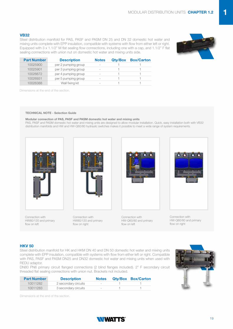
2VB32Steel distribution manifold for PAS, PASF and PASM DN 25 and DN 32 domestic hot water and
mixing units complete with EPP insulation, compatible with systems with flow from either left or right.
Equipped with 3 x 1.1/2” M flat sealing flow connections, including one with a cap, and 1.1/2” F flat
sealing connections with union nut on domestic hot water and mixing units side.
Connection with
HW80/120 and primary
flow on left
Connection with
HW80/120 and primary
flow on right
Connection with
HW-Q60/80 and primary
flow on left
Connection with
HW-Q60/80 and primary
flow on right
TECHNICAL NOTE - Selection Guide
Modular connection of PAS, PASF and PASM domestic hot water and mixing unitsPAS, PASF and PASM domestic hot water and mixing units are designed to allow modular installation. Quick, easy installation both with VB32
distribution manifolds and HW and HW-Q60/80 hydraulic switches makes it possible to meet a wide range of system requirements.
HKV 50Steel distribution manifold for HK and HKM DN 40 and DN 50 domestic hot water and mixing units
complete with EPP insulation, compatible with systems with flow from either left or right. Compatible
with PAS, PASF and PASM DN25 and DN32 domestic hot water and mixing units when used with
REDU adaptor.
DN80 PN6 primary circuit flanged connections (2 blind flanges included). 2” F secondary circuit
threaded flat sealing connections with union nut. Brackets not included.
Dimensions at the end of the section.
Dimensions at the end of the section.
Part Number Description Notes Qty/Box Box/Carton10025900 per 2 pumping group - 1 1
10025901 per 3 pumping group - 1 1
10026672 per 4 pumping group - 1 1
10026931 per 5 pumping group - 1 1
10026388 Wall fixing kit - 1 1
Part Number Description Notes Qty/Box Box/Carton10011282 2 secondary circuits - 1 1
10011283 3 secondary circuits - 1 1

CHAPTER 1.2 MODULAR DISTRIBUTION UNITS
20
VB50/80-ECKAngle connector kit for HKV50 distribution manifold, consisting of two pre-insulated flanged corner
fittings.
HKV-FUSSFloor-mounting kit for HKV50 distribution manifolds, consisting of two height-adjustable pedestals
and respective fasteners for connection to the manifolds.
REDUAdaptor for connecting PAS, PASF and PASM DN25 and DN32 domestic hot water and mixing
units to HKV50 distribution manifolds, complete with EPP insulation.
Connection with
HW80/120 and primary
flow on left
Connection with
HW80/120 and primary
flow on right
Connection with
HW-Q60/80 and primary
flow on left
Connection with
HW-Q60/80 and primary
flow on right
TECHNICAL NOTE - Selection Guide
Modular connection of PAS, PASF and PASM domestic hot water and mixing unitsPAS, PASF and PASM domestic hot water and mixing units are designed to allow modular installation. Quick, easy installation both with VB32
distribution manifolds and HW and HW-Q60/80 hydraulic switches makes it possible to meet a wide range of system requirements.
Dimensions at the end of the section.
Part Number Connection Pressure Qty/Box Box/Carton10011284 Flange DN80 PN6 1 1
Part Number Height Notes Qty/Box Box/Carton
10011285Adjustable from 650 to
850mm- 1 1
Part Number Connection Notes Qty/Box Box/Carton10011286 2" M x 1.1/2" F free nut 1 1

MODULAR DISTRIBUTION UNITS CHAPTER 1.2
21
1
2ERD - EUROVENTAutomatic/manual double de-aerator with expansion vessel. Tropicalised sheet steel body. OT58
brass cover. PN 8. Maximum temperature: 115°C.
Dimensions at the end of the section.
BOILER ROOM ACCESSORIES
Part Number DN Qty/Box Box/Carton0253625 1” 1 20
0253640 1.1/2” 1 12
SAAir separator with 5 threaded female instrument connections (DN 3/8” ÷ 1/2”). Painted,
malleable, cast iron body.
Dimensions at the end of the section.
Part Number DN Qty/Box Box/Carton0260125 1” 1 1
0260132 1.1/4” 1 1
0260140 1.1/2” 1 1
0260150 2” 1 1
0260165 2.1/2” 1 1
0260180 3” 1 1
PAS, PASF, PASM HK, HKM
DN A B
25 1”F 1.1/2”M
35 1.1/4”F 2”M
DN A
40 528F
50 288
125
370
300 240
65A
B
410
72
2
250
180
OVERALL DIMENSIONS

CHAPTER 1.2 MODULAR DISTRIBUTION UNITS
22
HW-Q60/80
A
A
25 1
53
140
1.1/2"F 1.1/2"F
80
60
1251.1/2"M 1.1/2"M
125
250
125
HW
530
180 120
400
65
HW
4m3
HW
10m3
740
260 220
250
440
155
85
OVERALL DIMENSIONS

MODULAR DISTRIBUTION UNITS CHAPTER 1.2
23
1
2
Type Circuits L L1
VB32-2 2 600 175
VB32-3 3 900 325
VB32-4 4 1200 475
VB32-5 5 1500 625
VB32
OVERALL DIMENSIONS
205
180 180230
B
A
11590 2" F
450
250C120x120
200
125
125
1/2" F
1/2" F
200
30
30
65
0 ÷
85
01
50
150
17
HKV50, HKV-FUSS
Type Circuits L
HKV50-2 2 1000
HKV50-3 3 1410

CHAPTER 1.2 MODULAR DISTRIBUTION UNITS
24
ERDSA
DN A B C L H
1. 1/2” 3/4” 70 152 87
1.1/4” 1/2” 3/4” 70 152 87
1.1/2” 1/2” 3/4” 70 152 87
2. 3/4” 1. 87 189 115
1.1/2” 1. 1. 128 300 203
3. 1. 1. 128 300 203
OVERALL DIMENSIONS
Hh
DD
L
Ø49
A
DN A L H l
1. 60x50 94 153 26
1.1/2” 60x50 104 191 32

MODULAR DISTRIBUTION UNITS CHAPTER 1.2
25
1
2

26
Chapter 2
Home automation and comfort control

27
BT-CT02 RFCentral control unit
Vision
Easy to install and configure
Intuitive operation with remote
control via an App
The system can be extended to radiant heating
systems and electrical equipment

28
CHAPTER 2 HOME AUTOMATION AND COMFORT CONTROL
26
Watts Vision® : comfort control and regulation
Chapter 2
Watts has developed a new home automation system called Watts Vision® for temperature control, air conditioning, security and device management
for residential applications. The system enables you to programme and view the settings of all your devices across multiple zones.
It's a wireless solution for use in conjunction with Watts second-generation RF thermostats, for room-by-room temperature control.
• Provides full supervision of all devices using a Wi-Fi connection via pre-loaded
web pages and type of browser (on PC, tablet or smartphone) or via a
dedicated app (iOS, Android).
• Scalable system, easy to update with a wide range of products
• Provides individual radiator control in underfloor and conventional heating
systems
• Controls various types of electrical devices
Programmable RF
thermostatic headAntenna
Digital RF
thermostatProgrammable RF
chrono-thermostat
Analogue RF
thermostatRF central control unit
Modular RF box -
6/10/12 zones
RF repeater
RF 16A electric
socket
RF 10A wall-mounting
receiver Flush-mounting
16A RF contact
SYSTEM
SYSTEM OPERATION
Vision
Vision
Vision
For Underfloor Heating Manifolds please see Section 5.

29
HOME AUTOMATION AND COMFORT CONTROL CHAPTER 2
2- GSM remote control
- WEB-based remote control
- Climate control
- Electronic control of radiators
- Thermal and electrical energy indication
- Underfloor heating control
- Heating/air conditioning control
SIMPLIFIED DIAGRAM FOR THE SOLE PURPOSE OF ILLUSTRATING THE PRODUCTS COVERED IN THIS SECTION
Compact
climatic control unit
for heating/
air conditioning
FBC-HC 8180
Electronic chrono-thermostat
with analogue programming
BATTERY
ELECTRONIC
Electronic thermostat
for fan-coils
FAN CONFORT 2T
Digital electronic RF thermostat
BTDP02-RF
Digital electronic thermostat
BTD
Digital thermostat
MILUX 2 WEEKLY
Two-channel programming clock
WFHC-TIMER
Modular connection box - 4/6 zones
WFHC
Radiant panel systems
Section 8.1
Modul systems
Section 8.2
1
1
234
5 6
78
6
2
7
3
8
4
9
9
10
5
10
APPLICATION EXAMPLE
Vision

30
CHAPTER 2 HOME AUTOMATION AND COMFORT CONTROL
Part Number Temp. Setting Protection Qty/Box Box/CartonP07710 5÷37°C IP30 1 100
Part Number Room Temp. Temp. Setting Qty/Box Box/CartonP06681 0÷50°C 5 ÷30°C 1 250
BT-A02 RF Electronic thermostat with analogue radio frequency control (868 MHz) designed to control different types of heating systems. Temperature control is based on internal sensors. An external sensor can be connected without any additional external power supply. A LED indicates whether the heating switch-on signal is activated and can be used during configuration. Operating temperature range: 0÷50°C. Electrical protection Class II. Temperature control range: 5÷35°C. Control characteristics: proportional band (PWM 2°C for 10min/cycle). Power supply 2 AAA LR03 1.5V Alkaline. Life ~2 years. Sensor: internal and/or external (opt.) NTC 10kW at 25°C. Radio frequency 868 MHz, <10mW.Compliant with: EMC 2014/30/EU - RoHS 2011/65/EU.
BT-D03 RF SeriesThe Wireless digital room thermostat with back-light LCD display is designed to control differenttypes of heating and cooling systems. Temperature control is based on internal sensors. An externalsensor (SENSOR 10K - P01228) can be connected without any additional external power supply.A logo on display indicates whether the heating switch-on signal is activated.- Smartphone App control capability when associated to Central Unit BT-CT02 RF- LCD display with back-light- 3 sensitive touch buttons- Open window detection- Different temperature modes setting- Anti-freeze function- Configurable Hysteresis or PWM regulation- Pin Code & screws lock for public area- Wall or Desk mounting with a stand (included)- 2 parameter menus User and Pro
BT-CT02 RF WATTS®Vision® central control unit manages water-based and electric underfloor climate control systems, radiators, lights and other electrical devices. Thanks to a built-in WiFi module, you can manage and monitor all the control parameters of your home via an app on your smartphone, tablet or PC.Operating temperature (220 V): -30÷40°C. Operating temperature (battery): 0÷40°C. Installation Class II. Display precision 0.1°C. Temperature setting range: - Comfort 5÷30°C with sensitivity of 0.5°C - Reduced 5÷30°C with sensitivity of 0.5°C - Anti-freeze 5÷10°C.Power supply (flush-mounting) 85-265VAC 50-60 Hz. USB power supply (not included). Radio frequency 868 MHz, <10mW.Compliant with: LVD 2014/35/EU - EMC 2014/30/EU - RoHS 2011/65/EU.
BT-TH02 RF Electronic chrono-thermostat for radiators. Can be used in stand-alone mode (9 pre-set and 4 custom programmes) or in conjunction with the Watts Vision® central control unit (BT-CT02 RF/WiFi) and BT02-RF Series thermostats. The central control unit is necessary for communication with the thermostats. Stroke speed 2mm-1mm/s. Protection rating IP20 Class I. Power supply 2 AA LR06 1.5V Alkaline. Actuator force 70N. Compliant with: EMC 2014/30/EU - RoHS 2011/65/EU.
WATTS®VISION® SYSTEM
Part Number Description Protection Qty/Box Box/CartonP07255 white screen IP30 1 100
Part Number Temp. Setting Protection Qty/Box Box/CartonP06670 5÷35°C IP30 1 100
Dimensions at the end of the section.
Dimensions at the end of the section.
Dimensions at the end of the section.
Dimensions at the end of the section.

31
HOME AUTOMATION AND COMFORT CONTROL CHAPTER 2
2
BT-DP02 RF/BT-DP02 RF RH Digital radio frequency (868MHz) room chrono-thermostat with LCD display for controlling different
types of heating system. Temperature control is based on an internal sensor. An external sensor can
be connected without any additional external power supply. A red LED indicates that the heating
system is ON.
Operating temperature 0÷50°C. Installation Class II. Precision 0.1°C.
Control ranges: Comfort, Reduced, Timer 5÷37°C in steps of 0.5°C.
Vacation mode. Anti-freeze: 7°C (programmable).
Control characteristics: proportional band (PWM 2°C/10min) or hysteresis of 0.5°C.
Power supply 2 AAA LR03 1.5V Alkaline. Life ~2 years.
Sensor: internal and/or external (opt.) NTC 10kW at 25°C.
Radio frequency 868 MHz, <10mW. Compatible receivers Wall, Socket, Ver.02
*Version with humidity sensor.Compliant with: EMC 2014/30/EU - RoHS 2011/65/EU.
BT-HCM02 RF
Modular RF connection box (868 MHz) designed to control underfloor heating and cooling
systems. Can be integrated with the WATTS®Vision® system only by means of RF communication
(868MHz) with BT-M6Z02 RF Series boxes. The box receives requests for heating/cooling through
the various inputs listed:
- free contact input from the output of a heat pump;
- free contact input from a manual switch;
- from an NTC sensor for measuring flow water temperature;
- from a BT-CT02-RF Series touch-screen panel (BT-HCM02-RF configured in slave mode,
connection with module M6Z02 required).
The BT-HCM02-RF Series module has the following outputs for activating the:
- system pump;
- dehumidifier, associated with BT-D (P) 02-RF series RH thermostats);
- boiler or air conditioning unit.
Equipped with 2 LED indicators (pump status, heating/cooling management), 3 pushbuttons for
user configuration and an internal DIP switch for system configuration. IP30. 1 5A/230V pump
relay, 3 free contact relays. Compliant with: LVD 2014/35/EC - EMC 2014/30/EU - RoHS 2011/65/EU.
Part Number Temp. Setting Protection Qty/Box Box/CartonP06672 5÷37°C IP30 1 100
Part Number Voltage Protection Qty/Box Box/CartonP06066 230V IP30 1 100
Part Number Temp. Setting Protection Qty/Box Box/CartonP06671 5÷37°C IP30 1 100
P06773* 5÷37°C IP30 1 100
BT-D02 RF/BT-D02 RF RH Electronic thermostat with radio frequency back-lit LCD display (868 MHz) designed to control different types of heating systems. Temperature control is based on internal sensors. An external sensor can be connected without any additional external power supply. A LED indicates whether the heating switch-on signal is activated. Operating temperature: 0÷50°C. Electrical protection Class II. Temperature control range: 5÷37°C. Control characteristics: proportional band (PWM 2°C for 10min/cycle). Power supply 2 AAA LR03 1.5V Alkaline. Life ~2 years. Sensor: internal and/or external (opt.) NTC 10kW at 25°C. Radio frequency 868 MHz, <10mW.*Version with humidity sensor.Compliant with: EMC 2014/30/EU - RoHS 2011/65/EU.
Dimensions at the end of the section.
Dimensions at the end of the section.
Dimensions at the end of the section.

32
CHAPTER 2 HOME AUTOMATION AND COMFORT CONTROL
BT-WR02 RF The BT-WR02 RF Series receiver is a wall-mounting RF receiver designed for controlling climatic control systems in conjunction with the 02 Series of BT-A02 RF, BT-D02 RF or BT-DP02 RF thermostats. The receiver can also be managed by means of a touch-screen central control unit
(BT-CT02 RF RF/BT-CT02 RF WiFi) for complete system supervision. Operating temperature range: 0÷40°C. Power supply 230VAC 50Hz. Electrical protection Class II. Output live/free.10A 230VAC relay. Max. load up to 10A - 230Vac 50Hz (2 wires L,N). Radio frequency and signal coverage 868 MHz <10mW (bidirectional transmission). Coverage 100 m (open field). Coverage 30 m (residential environment).
Compliant with: LVD 2014/35/EU - EMC 2014/30/EU - RoHS 2011/65/EU.
BT-S4Z02 RF/BT-S6Z02 RFExpansion module (RF 868 MHz) for modular boxes for controlling underfloor systems. Extends the
number of controlled zones to 12 with ease.
Can be combined with BT RF 02 Series thermostats and/or the WATTS®Vision®.system.
Operating temperature 0÷50°C. Control characteristics: integral proportional control or hysteresis
control depending on the type of thermostat connected to the individual channel.
Power supply: 230VAC±10% 50Hz; 24VAC.
Pump or accessories outputs: Relay 5A/230VAC (open contact).
Actuator outputs (NC) or (NO): Relay 5A/230VAC (L, N).
Combinations: 10 zones 1 Master 6z + 1 Slave 4 zones; 12 Zone 1 Master 6z + 1 Slave 6
zones
Compliant with: LVD 2014/35/EU - EMC 2014/30/EU - RoHS 2011/65/EU.
Part Number Description Protection Qty/Box Box/CartonP06679 S6Z02 RF IP30 1 68
P06680 S4Z02 RF IP30 1 48
Part Number RF Coverage Protection Qty/Box Box/Carton
P06674100m (external),
30m (internal)IP20 1 120
Part Number Voltage Protection Qty/Box Box/CartonP06678 230V IP30 1 100
BT-M6Z02 RF Modular RF connection box (868 MHz) designed to control underfloor heating systems with C or
NO ON/OFF electrothermal actuators. Easy to expand up to 12 zones with additional modules.
Can be combined with BT02-RF Series thermostats and/or the WATTS®Vision®.system. Operating
temperature: 0÷50°C.
Control characteristics: integral proportional control or hysteresis control depending on the type of
thermostat connected to the individual channel.
Power supply: 230VAC ± 10% 50Hz; 24VAC. Pump or accessories outputs: Relay 5A/230VAC
(open contact). Actuator outputs (NC) or (NO): Relay 5A/230VAC (L, N).
Radio frequency and signal coverage 868 MHz, <10mW (bidirectional transmission); coverage
approximately 180 m (open field); coverage approximately 50 m (residential environment).
Combinations 10 Zones 1 Master 6z+1 Slave 4 zones;
12 Zones 1 Master 6z+1 Slave 6 zones.Compliant with: EMC 2014/30/EU - RoHS 2011/65/EU.
Dimensions at the end of the section.
Dimensions at the end of the section.
Dimensions at the end of the section.
BT-AA02 RFThe antenna extends the radio reception range for the following products: BT-CT02 RF Series central
control unit and BT-M6Z02 RF Series master box. 230VAC power supply with wall-socket and USB
cable.
Part Number Description Protection Qty/Box Box/CartonP06094 RF Signal repeater IP20 1 50

33
HOME AUTOMATION AND COMFORT CONTROL CHAPTER 2
2BT-WR02 HC RF The BT-WR02 HC RF receiver is designed to control heating/cooling systems in one zone in conjunction with 02 BT-D02 RF or BT-DP02 RF Series thermostats (dotato di DVE relays 5A, 230V), uno per gestione/consenso freddo e l’altro per caldo. The receiver can be controlled by means of the WATTS®Vision® system (BT-CT02RF/BT-CT02RF WiFi) for full control from a single point. Operating temperature range: 0÷40°C. Power supply 230VAC 50Hz. Electrical protection Class II. Output: powered/voltage-free contact. Particularly suitable for controlling boilers (switch-on permissive). Equipped with cables for relay output configuration. 2 x 5A 230VAC relays. Max. load up to 5A-230VAC 50Hz (2 wires L,N). Radio frequency and signal coverage: 868 MHz <10mW (bidirectional transmission). Coverage 100 m (open field). Coverage 30 m (residential environment).
Compliant with: CE R&TTE 1999/5/EC-LVD 2014/35/UE-EMC 2014/30/UE-RoHS 2011/65/UE.
Part Number RF Coverage Protection Qty/Box Box/Carton
P06402100m (external),
30m (internal)IP20 1 120
BT-FR02 RF The BT-FR02 RF Series receiver is a flush-wall-mounting receiver designed for controlling heating systems in conjunction with 02 Series RF thermostat models BT-A02RF, BT-D02RF or BT-DP02RF. The receiver enables you to connect a hard-wired floor sensor directly in the floor temperature monitoring and control unit. The receiver can also be managed by means of a touch-screen central control unit (BT-CT02 RF) for complete system supervision. Operating temperature: 0÷40°C. Power supply 230VAC 50Hz. Protection Class II. Optional: IP21 insulation. Output (1 powered contact) 16A 230VAC relay. Max. load: up to 16A - 230VAC 50Hz (2 wires L,N). Radio frequency and signal coverage: 868MHz <10mW (bidirectional transmission). Coverage 100m (open field). Coverage 30m (residential environment). Optional floor sensor: NTC 10kΩ at 25°C.
Compliant with: LVD 2014/35/EU - EMC 2014/30/EU - RoHS 2011/65/EU.
Part Number RF Coverage Protection Qty/Box Box/Carton
P06675100m (external)
30m (internal)IP20 1 96
MILUX CHRONO-THERMOSTATS
MILUX 2 WEEKLYDigital electronic room chrono-thermostat with minute-by-minute weekly programming, for heating and air conditioning systems. Switch between summer and winter modes directly from keypad. 5 pre-set and 2 custom programmes available. Constant display of room temperature, time and operating status on LCD display. White frame with removable front panel for access to the batteries and connections. Easy wiring: two-wire connection (three-position connector) for heating or air conditioning systems, contact rating < 5A/400V. Automatic or manual operating modes.Complete with 2 LR3 (AAA) 1.5V batteries: life > 2 years. Batteries can be changed without losing programme settings. Temperature control range: 5÷35°C. Two temperature levels: comfort and night energy saving programmes. Anti-freeze (0.5-10°C). PWM control in 15min intervals on a band of 2°C. Power supply: 2 LR3 AAA 1.5V batteries. Protection rating IP 30, Class II.Special functions: - manual selector for standby and keypad lock mode; - vacation mode to suspend operation temporarily when away from home; - ITCS (optional): Intelligent Temperature Control System, automatic advance response to heating/cooling demand. Compliant with: EMC 2004/108/CE, RoHS 2011/65/EU, EU 811/2013 and 2010/30/EU, Energy class IV (2%).
Part Number Temp. Setting Programs Qty/Box Box/CartonP06584 5÷37°C 9 +4 Customizable 1 48
Dimensions at the end of the section.
Dimensions at the end of the section.
Dimensions at the end of the section.

34
CHAPTER 2 HOME AUTOMATION AND COMFORT CONTROL
BTDDigital electronic room thermostat for heating/cooling systems. Back-lit LCD display, 2 temperature
levels (comfort and night energy saving programmes), anti-freeze function and vacation mode. Can
be connected to a temperature probe (indoor, floor or outdoor).
Temperature control range: 5÷35°C. NTC sensitive element. PWM control or 0.5°K differential.
Complete with 2 LR03 (AAA) 1.5V batteries. Life 2 years.
Voltage-free contact rating: 3A-230 VAC. Protection rating IP 30.
Compliant with Directives LVD 2014/35/EU - EMC 2014/30/EU.
BTDPDigital electronic room chrono-thermostat with weekly programming, for heating/air conditioning
systems. 9 pre-set and 4 custom programmes available. Constant display of room temperature,
time and operating status on back-lit LCD display. Can be connected to a temperature probe (indoor,
floor or outdoor). Temperature control range: 5÷35°C. NTC sensitive element. Two temperature
levels: comfort and night energy saving programmes. Anti-freeze (0.5÷10°C). PWM control or 0.5°K
differential. Complete with 2 LR03 (AAA) 1.5V batteries. Life 2 years. Voltage-free contact rating:
3A-230 VAC. Protection rating IP30.
Special functions:
- reset, keypad lock (to prevent accidental changes to settings);
- vacation mode to suspend operation temporarily when away from home;
- automatic or manual adjustment to/from daylight saving time.
Compliant with Directives LVD 2014/35/EU - EMC 2014/30/EU.
Part Number Temp. Setting Protection Qty/Box Box/CartonP04543 5÷35°C IP30 1 100
Part Number Temp. Setting Protection Qty/Box Box/CartonP04542 5÷35°C IP30 1 100
BATTERY ELECTRONIC Electronic room chrono-thermostat with analogue programming, for heating and air conditioning
systems. Protective front panel for clock and control knob. Minimum setting range: 15 min (daily)
60 min (weekly) 2 selectable temperature modes (comfort - low-energy).
Timer OFF mode selector: the thermostat maintains the selected temperature level (comfort or low-
energy) with minimum anti-freeze temperature (5°C). Temperature control range: 5÷35°C. Differential:
0.5K. Operating temperature: 0÷50°C. Protection class: Class II.
Power supply: 2 LR6 (AA) 1.5V alkaline batteries (NOT INCLUDED). Contact rating: 8 (3) A 230V.
Compliant with Directives LVD 2014/35/EU - EMC 2014/30/EU.
Part Number Voltage Protection Qty/Box Box/CartonP03869 (daily) 2 batteries 1,5V IP30 1 38
CHRONO-THERMOSTATS AND THERMOSTATS FOR HARD-WIRING
BTA Electronic room thermostat with analogue control for heating systems.
Can be connected to a temperature probe (indoor, floor or outdoor).
Temperature control range: 5÷35°C, ON/OFF switch.
PWM control. NTC sensitive element. Complete with 2 LR03 (AAA) 1.5V batteries. Life 2 years.
Voltage-free contact rating: 3A-230 VAC. Protection rating IP 30.
Compliant with Directives LVD 2014/35/EU - EMC 2014/30/EU.
Part Number Temp. Setting Protection Qty/Box Box/CartonP05609 5÷35°C IP30 1 100
Dimensions at the end of the section.
Dimensions at the end of the section.
Dimensions at the end of the section.
Dimensions at the end of the section.

35
HOME AUTOMATION AND COMFORT CONTROL CHAPTER 2
2BELUXTI Room thermostat with saturated vapour expansion diaphragm temperature sensor, with 2 switching
contacts. Stainless steel diaphragm. Temperature locking device on back of knob. Adjustment
range: 5÷30°C.
Differential at 20°C: 0.8K. Contact rating: 10 (2.5) A/230V. 1000/1000 silver contacts.
Compliant with Directives LVD 2014/35/EU - EMC 2014/30/EU. EN 6100 and EN 60730 compliant.
Part Number Voltage Protection Qty/Box Box/Carton0403202 230V IP30 1 112
BELUXTIC Room thermostat with saturated vapour expansion diaphragm temperature sensor, with
2 switching contacts and summer/winter switch. Stainless steel diaphragm. Temperature locking
device on back of knob. Adjustment range: 5÷30°C.
Differential at 20°C: 0.8K. Contact rating: 10 (2.5) A/230V. 1000/1000 silver contacts.
Compliant with Directives LVD 2014/35/EU - EMC 2014/30/EU. EN 6100 and EN 60730 compliant.
BELUXTOF Room thermostat with saturated vapour expansion diaphragm temperature sensor, with 2 switching
contacts and ON/OFF switch and indicator light. Stainless steel diaphragm. Temperature locking
device on back of knob. Adjustment range: 5÷30°C.
Differential at 20°C: 0.8K. Contact rating: 10 (2.5) A/230V. 1000/1000 silver contacts.
Compliant with Directives: LVD 2014/35/EU - EMC 2014/30/EU. EN 6100 and EN 60730 compliant.
Part Number Voltage Protection Qty/Box Box/Carton0403302 230V IP30 1 112
Part Number Voltage Protection Qty/Box Box/Carton0403162 230V IP30 1 112
WFHC 4- or 6-zone modular connection box. Can be connected with 4/6 thermostats. Each thermostat can
control up to 4/6 actuators. Protection rating IP30. Master module with electric pump control relay.
Slave module with plug-in connector for connecting to master unit.
Part Number Description Size (mm) Qty/Box Box/CartonP2096 4 ZONE (SLAVE) NC 178 Lx88Hx58P 1 24
P2090 6 ZONE (MASTER) NC 210Lx88Hx58P 1 36
P2092 6 ZONE (SLAVE) NC 210Lx88Hx58P 1 36
WFHC-TIMER Weekly programming clock for two channels, suitable for radiant panel systems, can be connected
to WFHC-4 and WFHC-6 modular boxes for managing 4, 6, 8, 10 or 12 different heating zones. Has
9 pre-set programmes and 1 custom programme for configuration by the user.
Part Number Size (mm) Protection Qty/Box Box/CartonP2101 158Lx88Hx 62P IP30 1 24
Dimensions at the end of the section.
Dimensions at the end of the section.
Dimensions at the end of the section.

36
CHAPTER 2 HOME AUTOMATION AND COMFORT CONTROL
CLIMATIC CONTROLLERS
RCL-HC Digital climatic controller for heating only and heating/air conditioning systems with outdoor
air temperature compensation. Recommended for flow temperature control with mixing
valve with 230VAC 3-point actuator. Weekly programming, 9 pre-set programmes and 4
custom programmes, controlled on basis of outdoor temperature, outdoor temperature
and water temperature display, maximum and minimum temperature limit, pump control,
possible to connect a room thermostat. Predisposed for the installation of an antenna for use
with RF 433 MHz thermostats and MILUX-HY (antenna Series AN433 not included) Series
humidistat. Ideal for controlling radiant panel heating/cooling systems. Flow water temperature
0÷100°C. Power supply 230VAC 50 Hz. Pump control: 5A 250 VAC relay. Heating generator control:
5A 230 VAC relay. Air conditioning unit control: 5A 230 VAC relay. Mixing valve control: 3-point
modulating (2 Triacs 75W Max 230 VAC).
Kit includes:
- climatic control unit;
- outdoor temperature probe with 2 m cable CTN 10 KΩ;
- flow water temperature probe CTN 10 KΩ (1/8” M straight);
Option for WSENS return water temperature probe.
Can be combined with MILUX RF WEEKLY chrono-thermostat.
Part Number Voltage Protection Qty/Box Box/CartonP04013/02 230 Vac 50Hz IP30 1 100
WSENS Water temperature probe (flow or return) CTN 10 kΩ.
Operating temperature: -20÷100°C. Connection: 1/8 M cyl. (P04371). Cable: 2.5m.
AN433 Antenna for RCL-HC Series climatic control units for receiving 433 Mhz RF signals. Enables you
to connect the following to RCL control units: MILUX HY thermostat/humidistat, OS-RF outdoor
temperature sensor and all room thermostats and chrono-thermostats with radio frequency of 433
MHz Watts. Cable length 3m, dimensions 2cmx39cmx1.5cm, adhesive base.
Part Number Receiving Cable Qty/Box Box/CartonP04510 433Mhz 3m 1 120
Part Number Note Size (mm) Qty/Box Box/Carton
PPLELE06019Sensor to be used with TP
pocket4x45 1 50
Dimensions at the end of the section.

37
HOME AUTOMATION AND COMFORT CONTROL CHAPTER 2
2
8369
52
BT-THR02 RF BT-CT02 RF
BT-D02 RF/BT-DP02 RFBT-D02 RF RH/BT-DP02 RF RH
83
80
60
27
BT-A02 RF
123
160
88
78
65
BT-S4Z02 RF
187
225
88
78
65
BT-S6Z02 RF/BT-M6Z02 RF/BT-HCM02 RF
OVERALL DIMENSIONS

38
CHAPTER 2 HOME AUTOMATION AND COMFORT CONTROL
87
872032
BT-FR02 RF BT-WR02 RF/BT-WR02 HC RF
135
98
37
BATTERY ELECTRONIC
120
80
34
MILUX WEEKLY - MILUX WEEKLY RFMILUX-HY
BTA/BTD/BTDP
OVERALL DIMENSIONS
71
71
38,5
BELUXTI/TIC/TOF

39
HOME AUTOMATION AND COMFORT CONTROL CHAPTER 2
2
BT-D03 RF SeriesRCL-HC
OVERALL DIMENSIONS
17 mm
83
,5 m
m
60 mm

40
Chapter 3
Pre-insulated flexible piping

41
MICROFLEX
Flexible and quick to install
Double-wall outer casing
10-year warranty

42
CHAPTER 3 MICROFLEX: PRE-INSULATED FLEXIBLE PIPING
Pre-insulated flexible piping
Chapter 3
MICROFLEX UNO HEATINGMicroflex pre-insulated flexible piping for heating and air conditioning systems with single internal
pipe in PEX-a SDR11 with oxygen diffusion barrier (DIN 4726), suitable for fluids at temperatures of
-10÷95°C and pressures up to 6 bar, in accordance with EN ISO 15875.
Multi-layer thermal insulation in CFC-free expanded PEX cross-linked polyethylene with closed-cell
structure. Double-wall corrugated outer casing in PE-HD high-density polyethylene.
Supplied in lengths to customer specification. Maximum length 100m.
Part Number
Pipe PEX -a external Ø thickness
mm
DNØ outside
casing mmWeight kg/m
Bending radius cm
PN
M7525CWI 25/2.3 20 75 0,68 20 6
M9032CWI 32/2.9 25 90 1,00 25 6
M16040CWI 40/3.7 32 160 2,32 35 6
M16050CWI 50/4.6 40 160 2,48 45 6
M16063CWI 63/5.8 50 160 2,78 55 6
M20075CWI 75/6.8 65 200 4,16 80 6
M20090CWI 90/8.2 75 200 4,73 110 6
M200110CWI 110/10 90 200 5,64 120 6
M200125CWI 125/11.4 100 200 6,00 140 6
ACCESSORIES
Dust capsEPDM end
capsFitting MJ341 Fix point
PipePart
NumberPart Number Part Number
Ø male thread
Ø external Pipe mm
Part Number
M7525CWI MS7525 MG751832 MJ3413425/23 3/4” 25/2.3 MFP34
M9032CWI MS9032 MG901840 MJ3414432/29 1” 32/2.9 MFP44
M12525CWI MS12525 MG1251832 MJ3413425/23 3/4” 25/2.3 MFP34
M12532CWI MS12532 MG1251832 MJ3414432/29 1” 32/2.9 MFP44
M16032CWI MS16032 MG1603250 MJ3414432/29 1” 32/2.9 MFP44
M16040CWI MS16040 MG1603250 MJ3415440/37 1.1/4” 40/3.7 MFP54
M16050CWI MS16050 MG1603250 MJ3416450/46 1.1/2” 50/4.6 MFP64
M16063CWI MS16063 MG1606390 MJ341263/58 2” 63/5.8 MFP2
M20075CWI MS20075 MG20075125 MJ34121275/68 2.1/2” 75/6.8 MFP212
M20090CWI MS20090 MG20075125 MJ341390/82 3” 90/8.2 MFP3
M200110CWI MS200110 MG20075125 MJ3414110/10 4” 110/10 MFP4
M200125CWI MS200125 MG20075125 MJ3414125/114 4” 125/11.4 MFP4

43
MICROFLEX: PRE-INSULATED FLEXIBLE PIPING CHAPTER 3
3
MICROFLEX UNO PRIMO HEATING AND AIR CONDITIONING Microflex pre-insulated flexible piping for heating and air conditioning systems with single internal
pipe in PEX-a SDR11 with oxygen diffusion barrier (DIN 4726), suitable for fluids at temperatures of
-10÷95°C and pressures up to 6 bar in accordance with EN ISO 15875.Multi-layer thermal insulation in CFC-free expanded PEX cross-linked polyethylene with closed-cell
structure.
Double-wall corrugated outer casing in PE-HD high-density polyethylene.
Supplied in lengths to customer specification. Maximum length 100m.
Part Number
Pipe PEX -a Ø external thickness
mm
DNØ outside
casing mmWeight kg/m
Bending radius cm
PN
M9040CWI 40/3.7 32 90 1,11 30 6
M12540CWI 40/3.7 32 125 1,72 30 6
M12550CWI 50/4.6 40 125 1,92 40 6
M12563CWI 63/5.8 50 125 2,16 50 6
M16075CWI 75/6.8 65 160 3,2 75 6
M16090CWI 90/8.2 75 160 3,85 100 6
(*) Alternatively Shrink cap Serie MH
ACCESSORIES
Dust capsEPDM end
capsFitting MJ341 Fix point
PipePart
NumberPart Number Part Number
Ø male thread
Ø external Pipe mm
Part Number
M9040CWI MS9040 MG901840 MJ3415440/37 1.1/4” 40/3.7 MFP54
M12540CWI MS12540 MG1254063 MJ3415440/37 1.1/4” 40/3.7 MFP54
M12550CWI MS12550 MG1254063 MJ3416450/46 1.1/2” 50/4.6 MFP64
M12563CWI MS12563 MG1254063 MJ341263/58 2” 63/5.8 MFP2
M16075CWI MS16075 MG1606390 MJ34121275/68 2.1/2” 75/6.8 MFP212
M16090CWI MS16090 MG1606390 MJ341390/82 3” 90/8.2 MFP3

44
CHAPTER 3 MICROFLEX: PRE-INSULATED FLEXIBLE PIPING
MICROFLEX DUO HEATING AND AIR CONDITIONINGMicroflex pre-insulated flexible piping for heating and air conditioning systems with two internal
pipes in PEX-a SDR11 with oxygen diffusion barrier (DIN 4726), suitable for fluids at temperatures of
-10÷95°C and pressures up to 6 bar, in accordance with EN ISO 15875.Multi-layer thermal insulation in CFC-free expanded PEX cross-linked polyethylene with closed-cell
structure. Double-wall corrugated outer casing in PE-HD high-density polyethylene.
Supplied in lengths to customer specification. Maximum length 100m.
Part Number
Pipe PEX -a Ø external thickness
mm
DNØ outside
casing mmWeight kg/m
Bending radius cm
PN
MD16025CWI 25/2.3 20 160 2,21 50 6
MD16032CWI 32/2.9 25 160 2,41 50 6
MD16040CWI 40/3.7 32 160 2,63 60 6
MD20050CWI 50/4.6 40 200 4,03 80 6
MD20063CWI 63/5.8 50 200 4,64 120 6
(*) Alternatively Shrink cap Serie MH(**) Needed two fix points
ACCESSORIES
Dust capsEPDM end
capsFitting MJ341 Fix point
PipePart
NumberPart Number Part Number
Ø male thread
Ø external Pipe mm
Part Number
MD16025CWI MSD16025 MGD1602550 MJ3413425/23 3/4” 25/2.3 MFP34
MD16032CWI MSD16032 MGD1602550 MJ3414432/29 1” 32/2.9 MFP44
MD16040CWI MSD16040 MGD1602550 MJ3415440/37 1.1/4” 40/3.7 MFP54
MD20050CWI MSD20050 MGD2004063 MJ3416450/46 1.1/2” 50/4.6 MFP64
MD20063CWI MSD20063 MGD2004063 MJ341263/58 2” 63/5.8 MFP2

45
MICROFLEX: PRE-INSULATED FLEXIBLE PIPING CHAPTER 3
3
MICROFLEX DUO PRIMO HEATING AND AIR CONDITIONING Microflex pre-insulated flexible piping for heating and air conditioning systems with two internal
pipes in PEX-a SDR11 with oxygen diffusion barrier (DIN 4726), suitable for fluids at temperatures
of -10÷95°C and pressures up to 6 bar, in accordance with EN ISO 15875.Multi-layer thermal insulation in CFC-free expanded PEX cross-linked polyethylene with closed-
cell structure. Double-wall corrugated outer casing in PE-HD high-density polyethylene.
Supplied in lengths to customer specification. Maximum length 100m.
Part Number
Pipe PEX -a Ø external thickness
mm
DNØ outside
casing mmWeight kg/m
Bending radius cm
PN
MD12525CWI 25/2.3 20 125 1,57 30 6
MD12532CWI 32/2.9 25 125 1,77 30 6
MD16050CWI 50/4.6 40 160 3,55 50 6
(*) Alternatively Shrink caps Serie MH(**) Needed two fix points
ACCESSORIES
Dust capsEPDM end
capsFitting MJ341 Fix point
PipePart
NumberPart Number Part Number
Ø male thread
Ø external Pipe mm
Part Number
MD12525CWI MSD12525 MGD1251832 MJ3413425/23 3/4” 25/2.3 MFP34
MD12532CWI MSD12532 MGD1251832 MJ3414432/29 1” 32/2.9 MFP44
MD16050CWI MSD16050 MGD1602550 MJ3416450/46 1.1/2” 50/4.6 MFP64

46
CHAPTER 3 MICROFLEX: PRE-INSULATED FLEXIBLE PIPING
MICROFLEX QUADRO FOR HEATING, AIR CONDITIONING AND DHWMicroflex pre-insulated flexible piping for heating, air conditioning and domestic water systems,
with four internal pipes in PEX-a, in accordance with EN ISO 15875:
- two SDR11 pipes with oxygen diffusion barrier (DIN 4726), suitable for fluids at temperatures
of -10÷95°C and pressures up to 6 bar
- two SDR7,4 pipes, suitable for water up to 95°C and pressures up to 10 bar.
Multi-layer thermal insulation in CFC-free expanded PEX cross-linked polyethylene with closed-cell
structure. Double-wall corrugated outer casing in PE-HD high-density polyethylene.
Supplied in lengths to customer specification. Maximum length 100m.
Part Number
Pipe PEX -a Ø external thickness
mm
DNØ outside
casing mmWeight kg/m
Bending radius cm
PN
MQ16025C2520SWI
2x25/2.3
1x25/3.5
1x20/2.8
20
20
15
160 2,40 60
6
10
10
MQ16032C2520SWI
2x32/2.9
1x25/3.5
1x20/2.8
25
20
15
160 2,60 60
6
10
10
MQ16032C3225SWI
2x32/2.9
1x32/4.4
1x25/3.5
25
23
20
160 2,70 60
6
10
10
Dust capsEPDM end
capsFitting MJ341 Fix point
PipePart
NumberPart Number Part Number
Ø male thread
Ø external Pipe mm
Part Number
MQ16025C2520SWI MSQ160252520 MGQ1601832
MJ3413425/23
MJ3413425/35
MJ3413420/28
3/4”
3/4”
3/4”
25/2.3
25/3.5
20/2.8
MFP34
MFP34
MFP34
MQ16032C2520SWI MSQ160322520 MGQ1601832
MJ3414432/29
MJ3413425/35
MJ3413420/28
1”
3/4”
3/4”
32/2.9
25/3.5
20/2.8
MFP44
MFP34
MFP34
MQ16032C3225SWI MSQ160323225 MGQ1601832
MJ3414432/29
MJ3414432/44
MJ3413425/35
1”
1”
3/4”
32/2.9
32/4.4
25/3.5
MFP44
MFP44
MFP34
(*) Alternatively Shrink caps Serie MH(**) Needed two fix points
ACCESSORIES

47
MICROFLEX: PRE-INSULATED FLEXIBLE PIPING CHAPTER 3
3
MICROFLEX UNO FOR DOMESTIC WATER Microflex pre-insulated flexible piping for domestic water systems with single internal pipe in PEX-a
SDR7,4 suitable for water up to 95°C and pressures up to 10 bar in accordance with EN ISO 15875. Multi-layer thermal insulation in CFC-free expanded PEX cross-linked polyethylene with
closed-cell structure free from CFC. Double-wall corrugated outer casing in PE-HD high-density
polyethylene.
Supplied in lengths to customer specification. Maximum length 100m.
Part Number
Pipe PEX -a Ø external thickness
mm
DNØ outside
casing mmWeight kg/m
Bending radius cm
PN
M7525SWI 25/3.5 20 75 0,75 20 10
M9032SWI 32/4.4 23 90 1,12 25 10
M12540SWI 40/5.5 32 125 1,89 40 10
M12550SWI 50/6.9 40 125 2,19 50 10
M12563SWI 63/8.7 50 125 2,59 55 10
ACCESSORIES
Dust capsEPDM end
capsFitting MJ341 Fix point
Pipe Part Number Part Number Part NumberØ male thread
Ø external Pipe mm
Part Number
M7525SWI MS7525 MG751832 MJ3413425/35 3/4” 25/3.5 MFP34
M9032SWI MS9032 MG901840 MJ3414432/44 1” 32/4.4 MFP44
M12540SWI MS12540 MG1254063 MJ3415440/55 1.1/4” 40/5.5 MFP54
M12550SWI MS12550 MG1254063 MJ3416450/69 1.1/2” 50/6.9 MFP64
M12563SWI MS12563 MG1254063 MJ341263/87 2” 63/8.7 MFP2
(*) Alternatively Shrink caps Serie MH

48
CHAPTER 3 MICROFLEX: PRE-INSULATED FLEXIBLE PIPING
MICROFLEX DUO FOR DOMESTIC WATER Microflex pre-insulated flexible piping for domestic water systems with two internal pipes in PEX-a
SDR7.4 suitable for water up to 95°C and pressures up to 10 bar in accordance with EN ISO 15875. Multi-layer thermal insulation in CFC-free expanded PEX cross-linked polyethylene with
closed-cell structure free from CFC.
Double-wall corrugated outer casing in PE-HD high-density polyethylene.
Supplied in lengths to customer specification. Maximum length 100m.
Part Number
Pipe PEX -a Ø external thickness
mm
DNØ outside
casing mmWeight kg/m
Bending radius cm
PN
MD16025SWI 2x25/3.5 20 160 2,35 50 10
MD1603225SWI1x32/4.4
1x25/3.5
23
20160 5,50 50 10
MD1604025SWI1x40/5.5
1x25/3.5
32
20160 2,71 60 10
MD1605025SWI1x50/6,9
1x25/3,5
40
20160 2,89 60 10
MD1605032SWI1x50/6.9
1x32/4.4
40
23160 3,04 60 10
ACCESSORIES
Dust capsEPDM end
capsFitting MJ341 Fix point
PipePart
NumberPart
NumberPart Number
Ø male thread
Ø external Pipe mm
Part Number
MD16025SWI MSD16025 MGD1602550 MJ3413425/35 3/4" 2x25/3.5 MFP34
MD1603225SWI MSD1603225 MGD1602550MJ3414432/44 1” 1x32/4.4 MFP44
MJ3413425/35 3/4" 1x25/3.5 MFP34
MD1604025SWI MSD1604025 MGD1602550MJ3415440/55 1.1/4” 1x40/5.5 MFP54
MJ3413425/35 3/4" 1x25/3.5 MFP34
MD1605025SWI MSD1605025 MGD1602550MJ3416450/69 1.1/2" 1x50/6,9 MFP64
MJ3413425/35 3/4" 1x25/3,5 MFP34
MD1605032SWI MSD1605032 MGD1602550MJ3416450/69 1.1/2” 1x50/6.9 MFP64
MJ3414432/44 1" 1x32/4.4 MFP44
(*) Alternatively Shrink caps Serie MH(**) Needed two fix points

49
MICROFLEX: PRE-INSULATED FLEXIBLE PIPING CHAPTER 3
3
MICROFLEX DUO PRIMO FOR DOMESTIC WATER Microflex pre-insulated flexible piping for domestic water systems with two internal pipes in PEX-a
SDR7.4 suitable for water up to 95°C and pressures up to 10 bar, in accordance with EN ISO 15875. Multi-layer thermal insulation in CFC-free expanded PEX cross-linked polyethylene with
closed-cell structure.
Double-wall corrugated outer casing in PE-HD high-density polyethylene.
Supplied in lengths to customer specification. Maximum length 100m.
Part Number
Pipe PEX -a Ø external thickness
mm
DNØ outside
casing mmWeight kg/m
Bending radius cm
PN
MD1252520SWI25/3.5
20/2.8
20
15125 1,65 30 10
MD1253225SWI32/4.4
25/3.5
23
20125 2 30 10
ACCESSORIES
Dust capsEPDM end
capsFitting MJ341 Fix point
PipePart
NumberPart Number Part Number
Ø male thread
Ø external Pipe mm
Part Number
MD1252520SWI MSD1252520 MGD1251832MJ3413425/35 3/4” 25/3.5 MFP34
MJ3413420/28 3/4” 20/2.8 MFP34
MD1253225SWI MSD1253225 MGD1251832MJ3414432/44 1” 32/4.4 MFP34
MJ3413425/35 3/4” 25/3.5 MFP44
(*) Alternatively Shrink caps Serie MH

50
CHAPTER 3 MICROFLEX: PRE-INSULATED FLEXIBLE PIPING
MICROFLEX COOL UNO WITH HEATING CABLEMicroflex pre-insulated flexible piping with self-regulating heating cable (10 W/m) for domestic
water systems with single internal pipe in PE-HD SDR11 suitable for potable water up to 25°C
and pressures up to 16 bar, in accordance with EN 12201. Multi-layer thermal insulation in
CFC-free expanded PEX cross-linked polyethylene with closed-cell structure.
Double-wall corrugated outer casing in PE-HD high-density polyethylene.
Supplied in lengths to customer specification. Maximum length 100m.
Part Number
Pipe PEX -a Ø external thickness
mm
DNØ outside
casing mmWeight kg/m
Bending radius cm
PN
MV7532PEWI 32/2.9 25 75 0,84 20 16
MV9040PEWI 40/3.7 32 90 1,20 30 16
MV12550PEWI 50/4.6 40 125 2,00 40 16
MV12563PEWI 63/5.8 50 125 2,25 50 16
MV16075PEWI 75/6.8 65 160 3,30 75 16
MV16090PEWI 90/8.2 75 160 3,95 100 16
MV200110PEWI 110/1.0 90 200 5,84 120 16
MV200125PEWI 125/11.4 100 200 6,10 140 16
ACCESSORIES
Dust capsEPDM end
capsFitting MJ341
Pipe Part Number Part Number Part NumberØ male thread
Ø external Pipe mm
M9032PEWI MS7532 MG751832 MJ3414432/29 1” 32/2.9
M9040PEWI MS9040 MG901840 MJ3415440/37 1.1/4” 40/3.7
M12550PEWI MS12550 MG1254063 MJ3416450/46 1.1/2” 50/4.6
M12563PEWI MS12563 MG1254063 MJ341263/58 2” 63/5.8
M16075PEWI MS16075 MG1606390 MJ34121275/68 2.1/2” 75/6.8
M16090PEWI MS16090 MG1606390 MJ341390/82 3” 90/8.2
M200110PEWI MS200110 MG20075125 MJ3414110/10 4” 110/1.0
M200125PEWI MS200125 MG20075125 MJ3414125/114 4” 125/11.4
(*) Alternatively Shrink caps Serie MH

51
MICROFLEX: PRE-INSULATED FLEXIBLE PIPING CHAPTER 3
3
MICROFLEX COOL UNO Microflex pre-insulated flexible piping for domestic water systems with single internal pipe in PE-HD
SDR11 suitable for potable water up to 25°C and pressures up to 16 bar in accordance with EN ISO 12201. Multi-layer thermal insulation in CFC-free expanded PEX cross-linked polyethylene
with closed-cell structure. Double-wall corrugated outer casing in PE-HD high-density polyethylene.
Supplied in lengths to customer specification. Maximum length 100m.
Part Number
Pipe PEX -a Ø external thickness
mm
DNØ outside
casing mmWeight kg/m
Bending radius cm
PN
M9032PEWI 32/2.9 25 90 0,78 25 16
M9040PEWI 40/3.7 32 90 1 50 16
M12550PEWI 50/4.6 40 125 1,4 50 16
M12563PEWI 63/5.8 50 125 1,8 50 16
M16075PEWI 75/6.8 65 160 2,5 55 16
M16090PEWI 90/8.2 75 160 3,3 55 16
M200110PEWI 110/1.0 90 200 5,74 120 16
ACCESSORIES
Dust capsEPDM end
capsFitting MJ341
Pipe Part Number Part Number Part NumberØ male thread
Ø external Pipe mm
M9032PEWI MS7532 MG751832 MJ3414432/29 1” 32/2.9
M9040PEWI MS9040 MG901840 MJ3415440/37 1.1/4” 40/3.7
M12550PEWI MS12550 MG1254063 MJ3416450/46 1.1/2” 50/4.6
M12563PEWI MS12563 MG1254063 MJ341263/58 2” 63/5.8
M16075PEWI MS16075 MG1606390 MJ34121275/68 2.1/2” 75/6.8
M16090PEWI MS16090 MG1606390 MJ341390/82 3” 90/8.2
M200110PEWI MS200110 MG20075125 MJ3414110/10 4” 110/1.0
(*) Alternatively Shrink caps Serie MH

52
CHAPTER 3 MICROFLEX: PRE-INSULATED FLEXIBLE PIPING
MJ341DZR threaded end fitting for Microflex PN6 pipes and Microflex COOL PN 16 pipes.
FITTINGS FOR 6 BAR HEATING AND AIR CONDITIONING PIPES AND 16 BAR COOL PIPES
MJ270Straight fitting for PEX-a x PEX-a pipes in DZR brass for Microflex PN6 pipes and Microflex COOL
PN 16 pipes.
Part Number Ø Pipe / thickness mm Ø male threadMJ3413425/23 25/2.3 3/4”
MJ3414432/29 32/2.9 1”
MJ3415440/37 40/3.7 1.1/4”
MJ3416450/46 50/4.6 1.1/2”
MJ341263/58 63/5.8 2”
MJ34121275/68 75/6.8 2.1/2”
MJ341390/82 90/8.2 3”
MJ3414110/10 110/10 4”
MJ3414125/114 125/11.4 4”
Part Number Ø Pipe/thickness mmMJ27025/23 25/2.3
MJ27032/29 32/2.9
MJ27040/37 40/3.7
MJ27050/46 50/4.6
MJ27063/58 63/5.7
MJ27075/68 75/6.9
MJ27090/82 90/8.2
MJ270110/10 110/10
MJ270125/114 125/11.4
Product composed of parts to be assembled
MJ90Elbow fitting for PEX-a x PEX-a pipes in DZR brass for Microflex PN6 pipes and Microflex COOL
PN 16 pipes.
Part Number Ø Pipe/thickness mmMJ9025/23 25/2.3
MJ9032/29 32/2.9
MJ9040/37 40/3.7
MJ9050/46 50/4.6
MJ9063/58 63/5.8
MJ9075/68 75/6.8
MJ9090/82 90/8.2
MJ90110/10 110/10
MJ90125/114 125/11.4

53
MICROFLEX: PRE-INSULATED FLEXIBLE PIPING CHAPTER 3
3
MJ130T-fitting for PEX-a x PEX-a x PEX-a pipes in DZR brass for Microflex PN6 pipes and Microflex
COOL PN 16 pipes.
Product composed of parts to be assembled
Part Number Ø pipe Ø Pipe/thickness mmMJ13025/23 25-25-25 25/2,3
MJ13032/29 32-32-32 32/2,9
MJ1304032/37 40-32-40 40/3,7+32/2,9
MJ13040/37 40-40-40 40/3,7
MJ1305040/46 50-40-50 50/4,6+40/3,7
MJ13050/46 50-50-50 50/4,6
MJ1306350/58 63-50-63 63/5,8+50/4,6
MJ13063/58 63-63-63 63/5,8
MJ13075/68 75-75-75 75/6,8
MJ13090/82 90-90-90 90/8,2
MJ130110/10 110-110-110 110/10
MJ130125/114 125-125-125 125/11.4
MJ270Straight fitting for PEX-a x PEX-a pipes in DZR brass for Microflex PN10 pipes.
Product composed of parts to be assembled
MJ341DZR brass threaded end fitting for Microflex PN10 pipes.
SANITARY PIPE FITTINGS - 10 BAR
Part Number Ø Pipe/thickness mm Ø male threadMJ3413420/28 20/2.8 3/4"
MJ3413425/35 25/3.5 2/4"
MJ3414432/44 32/4.4 1"
MJ3415440/55 40/5.5 1.1/4"
MJ3416450/69 50/6.9 1.1/2"
MJ341263/87 63/8.7 2.1/2"
Part Number Ø Pipe/thickness mmMJ27025/35 25/3.5
MJ27032/44 32/4.4
MJ27040/55 40/5.5
MJ27050/69 50/6.9
MJ27063/87 63/8.7
MJ90Elbow fitting for PEX-a x PEX-a pipes in DZR brass for Microflex PN10 pipes.
Product composed of parts to be assembled
Part Number Ø Pipe/thickness mmMJ9025/35 25/3.5
MJ9032/44 32/4.4
MJ9040/55 40/5.5
MJ9050/69 50/6.9
MJ9063/87 63/8.7

54
CHAPTER 3 MICROFLEX: PRE-INSULATED FLEXIBLE PIPINGCHAPTER 5 MICROFLEX: PRE-INSULATED FLEXIBLE PIPING
MJ130T-fitting for PEX-a x PEX-a pipes in DZR brass for Microflex PN10 pipes.
Product composed of parts to be assembled
Part Number Ø pipe Ø Pipe/thickness mmMJ13025/35 25-25-25 25/3,5
MJ13032/44 32-32-32 32/4,4
MJ1304032/55 40-32-40 40/5,5+32/3,5
MJ13040/55 40-40-40 40/5,5
MJ13050/69 50-50-50 50/6,9
MJ1306350/87 63-50-63 63/8,7+50/6,9
MJ13063/87 63-63-63 63/8,7
MFPBronze threaded fitting for creating a fixed point for absorbing expansion forces on Microflex PN
6/10/16 pipes.
VW270Bronze F-F threaded sleeve - PN 6/10/16.
8065Copper-based anti-seize lubricant for all MJ series fittings.
ACCESSORIES
Part Number Operating temperature Stick gLOCTITE8065 -30÷980°C 20
Part Number DNMFP34 3/4”
MFP44 1”
MFP54 1.1/4”
MFP64 1.1/2”
MFP2 2”
MFP212 2.1/2”
MFP3 3”
MFP4 4”
Part Number DNVW27034 3/4”
VW27044 1”
VW27054 1.1/4”
VW27064 1.1/2”
VW2702 2”
VW270212 2.1/2”
VW2703 3”
VW2704 4”

55
MICROFLEX: PRE-INSULATED FLEXIBLE PIPING CHAPTER 3
366
MICROFLEX: PRE-INSULATED FLEXIBLE PIPING CHAPTER 5
VW90Bronze F-F threaded elbow - PN 6/10/16.
Part Number DNVW9034 3/4”
VW9044 1”
VW9054 1.1/4”
VW9064 1.1/2”
VW902 2”
VW90212 2.1/2”
VW903 3”
VW904 4”
VW130Bronze F-F threaded T-fitting - PN 6/10/16.
VW241DZR brass M-F threaded reduction - PN 6/10/16.
Part Number DNVW13034 3/4”
VW13044 1”
VW13054 1.1/4”
VW13064 1.1/2”
VW1302 2”
VW130212 2.1/2”
VW1303 3”
VW1304 4”
Part Number Thread M Thread FVW2414434 1” 3/4”
VW2415434 1.1/4” 3/4”
VW2415444 1.1/4” 1”
VW2416434 1.1/2” 3/4”
VW2416444 1.1/2” 1”
VW2416454 1.1/2” 1.1/4”
VW241234 2” 3/4”
VW241244 2” 1”
VW241254 2” 1.1/4”
VW241264 2” 1.1/2”
VW24121254 2.1/2” 1.1/4”
VW24121264 2.1/2” 1.1/2”
VW2412122 2.1/2” 2”
VW241344 3” 1”
VW241354 3” 1.1/4”
VW241364 3” 1.1/2”
VW24132 3” 2”
VW2413212 3” 2.1/2”
VW24142 4” 2”
VW2414212 4” 2.1/2”
VW24143 4” 3”

56
CHAPTER 3 MICROFLEX: PRE-INSULATED FLEXIBLE PIPING
VW280DZR brass M-M threaded nipple - PN 6/10/16.
WATERPROOFING ACCESSORIES
MK - UNOShrink caps to prevent water from entering pipes
Microflex UNO.
VW290DZR brass M-M threaded stop - PN 6/10/16.
MDFGalvanised steel threaded flange - PN 6/10.
Part Number DNVW28034 3/4”
VW28044 1”
VW28054 1.1/4”
VW28064 1.1/2”
VW2802 2”
VW280212 2.1/2”
VW2803 3”
VW2804 4”
Part Number DNVW29034 3/4”
VW29044 1”
VW29054 1.1/4”
VW29064 1.1/2”
VW2902 2”
VW290212 2.1/2”
VW2903 3”
VW2904 4”
Part Number DNMDF34 3/4”
MDF44 1”
MDF54 1.1/4”
MDF64 1.1/2”
MDF2 2”
MDF212 2.1/2”
MDF3 3”
MDF4 4”
Part Number Ø outside casing mm Ø Pipe mmMK2000 75 25
MK2100 75 / 90 32 o 40
MK2200 125 40 o 50
MK2400 125 63
MK2340 160 40 o 50
MK2500 160 da 63 a 90
MK2600 200 da 75 a 125

57
MICROFLEX: PRE-INSULATED FLEXIBLE PIPING CHAPTER 3
3
MK - DUOShrink caps to prevent water from entering pipes.
Microflex DUO.
LSMICRO SEAL wall feed-through sealing sleeves.
1. Drill a hole according to
minimum and maximum
dimensions.
2. Fit the LS sleeve
around the outer casing. Make
sure that
there is a straight line
of at least 60 cm
before and after the sleeve.
Bends are not allowed.
3. Slide the pipe
complete with sleeve into the
through-hole in the wall.
4. Tightening the bolts
of the evenly spaced links
uniformly compresses
the pressure plates,
thus filling the annular
space between the pipe
and the through-hole
in the wall.
A B
TECHNICAL NOTE
Part Number Ø outside casing mm Ø Pipe mmMK3280 125 2 x 32
MK3350-01 160 2 x 25 o 2 x 32
MK3350-02 160 2 x 40
MK3350-01 160 1 x 32 / 1 x 25
MK3350-02 160 1 x 40 / 1 x 25
MK3360-01 160 1 x 50 / 1 x 25
MK3350-03 160 2 x 50
MK3350-03 200 2 x 50
MK3350-05 200 2 x 63
Part Number
Ø outside casing mm
lenght bolts included
ø wall opening
mm
Torque Nm
9LS200 75 75 100 - 102 min. 3,0 - max.3,5
7LS300 75 100 110 - 115 min. 9,0 - max.11,0
8LS300 90 100 128 - 132 min. 9,0 - max.11,0
9LS315 90 100 134 - 136 min. 10,0 - max.12,0
7LS475 125 135 194 - 210 min. 26,0 - max.32,5
6LS325 125 125 175 - 180 min. 11,8 - max.14,5
7LS325 160 125 209 - 212 min. 11,8 - max.14,5
7LS400 160 135 240 - 245 min. 30,0 - max.37,0
13LS300 160 100 200 - 202 min. 9,0 - max.11,0
9LS325 200 125 250 - 255 min. 11,8 - max.14,5
8LS400 200 135 275 - 282 min. 30,0 - max.37,0
10LS575 200 145 301 - 320 min. 47,0 - max.61,0

58
CHAPTER 3 MICROFLEX: PRE-INSULATED FLEXIBLE PIPING
MMDVMMDV wall feed-through sleeves.
MHMMHM shrink sleeve for repairing the outer casing of Microflex pipes.
MHTape for repairing the outer casing of Microflex pipes.
MTRWarning tape to indicate the location of underground Microflex pipes during excavation work.
MMInsulated I-piece kit for straight, underground joints, complete with insulation material, sealant and
stainless steel fasteners.
L1
L2
Part Number Description Lenght m Band width mmMHB200 Shrink sleeve tape 10 200
MHK150 Coating tape applicable
to cold10 150
Part Number Description SizeMTRW Pipe for water (red) 250 x 0,08
MTRBPipe for heating cable for water
acqua (blue)250 x 0,08
Part Number Ø outside casing mm L1 mm L2 mmMM129075 125/90/75 960 290
MM201612 200/160/125 1170 345
Part NumberØ outside casing
mmexternal Ø wall
feed-trough pipeø wall opening
mmMMDV75 75 110 210
MMDV90 90 110 210
MMDV125 125 160 260
MMDV160 160 200 300
MMDV200 200 235 350
Part Number Ø outside casing mm ø wall opening mmMHM75/90 75-90 220 mm
MHM125 125 220 mm
MHM160 160 220 mm
MHM200 200 220 mm
MHM235 200 220 mm
MMInsulation kit I-variant for straight, underground joints, complete with insulation material and shrink
sleeves.
Part Number Ø outside casing mm Lenght mnMM75/90 75/90 700
MM125 125 850
MM160 160 1000
MM200 200 1000

59
MICROFLEX: PRE-INSULATED FLEXIBLE PIPING CHAPTER 3
3
MTInsulated T-piece kit for underground T-joints, complete with insulation material, sealant and
stainless steel fasteners.
MDTInsulated T-piece kit for underground double T-joints, complete with insulation material, sealant and
stainless steel fasteners.
MHInsulated elbow kit for underground elbow-joints, complete with insulation material, sealant and
stainless steel fasteners.
MBRInsulated trouser piece kit for joining two single pipes to one double pipe, complete with insulation
material, sealant and stainless steel fasteners.
Part Number Ø outside casing mm L1 mm L2 mmMT129075 125/90/75 960 590
MT201612 200/160/125 1170 750
Part Number Ø outside casing mm L1 mm L2 mmMDT201612 200/160/125 1200 1200
Part Number Ø outside casing mm LxWXH (mm)MH201612 200/160/125 740x740x270
Part Number Ø outside casing mm LxWXH (mm) Note
MBR201612 200/160/125 1170X460X230IN: 200/160/125
OUT: 160/125
L2L1
L1
L2
MRReduction for using pipes with outer casing diameter of less than 160 mm with insulated-piece kit
MM201612 and insulated T-piece kit MT201612. Length 1m.
MISInspection chamber with six connection points for creating inspectable underground branches.
Complete with sealant and stainless steel fasteners.
MHMShrink sleeves for inspection chambers.
Part Number Ø outside casing mmMR24116075 Riduce da 160 a 75 mm
Part Number Ø outside casing mmØ Inspector
chamber mm Height
mm MIS 200/160/125 810 770
Part Number ø outside casing mm Lenght mmMHM125 125 220
MHM160 160 220
MHM235 200 220

60
Chapter 4
Balancing devices for water distribution systems

61
iDROSET Series CFInnovative static balancing valve
Easy to read and adjustPrecision calibration using patented technologyNo external devices neededReal-time results

62
CHAPTER 4 BALANCING DEVICES FOR WATER DISTRIBUTION SYSTEMS
Balancing devices for water distribution systems
Chapter 4
MHThe MH Series patented valve is designed for dynamic balancing and flow control in underfloor
heating systems. The possibility of regulating the pressure drop makes it suitable for various systems
and various flow rates. The MH series valve eliminates flow and temperature fluctuations in the
underfloor branches of the system, thus enhancing comfort. G1” nut inlet connection, G1” threaded
outlet connection. Max. flow rate: 2500l/h. Kvs: 5.6. Capillary supplied
AUTOMATIC BALANCING VALVES
MH-ACCESSORIES
Note: installation of the MH series valve requires the use of an AS fitting and respective ball-valves, according to
the manifold in question.
Part Number ConnectionStetting range
PNWorking Temp.
Qty/Box Box/Carton
MH001WBinlet nut G1”,
outlet M G1”15-50KPa 10 bar 5÷80°C 1 1
MH100WBinlet M G1”,
outlet nut G1”15-50KPa 10 bar 5÷80°C 1 1
Part Number Description Connection Qty/Box Box/CartonKH-MH001100 Ball valve 1”F x 1” F rotary nut 1 1
- Shutoff ball valves with test point for connecting the capillary (KH-MH001034, KH-MH001100).
- 1” Fitting with test point for connecting the capillary (AS-MH00118).
TECHNICAL NOTE - the advantages offered by the differential pressure regulation. In systems with manifold distribution, the flow rate of the hydronic loops can change
on the base of the achievement of the set temperature and the opening / closing of the
branch of the circuit due to the electrothermal actuator.
However, the good performance of the variable flow system have some issues due to
the dynamic adjustments of the differential pressures.
The MH valve eliminates these upstream adjustments of the distribution manifold.
Thanks to the easy installation and adjustment, acting on the adjustment knob and
checking the flow level on the level indicators (flow meters) in each loop, the automatic
balancing valve MH allows:
- to facilitate hydraulic balancing;
- eliminate pressure peaks by stabilizing the network;
- avoid the risks of noise due to the high speed of the fluid.
By using this valve, when a loop closes, the flow rate on the other loops remains
constant.
The valve MH compensates any upstream hydraulic variations (e.g. changes in other
collectors) keeping the outlet pressure constant (downstream) too.
Dimensions at the end of the section.

63
BALANCING DEVICES FOR WATER DISTRIBUTION SYSTEMS CHAPTER 4
4
WATTFLOW BPInclined-seat balancing valve with threaded connections for heating and cooling systems, complete
with built-in flow meter for direct flow rate reading and mechanical memory of setting position. PN
10. Operating temperature range: -20÷100°C. Measuring accuracy ± 10% of flow rate read. Brass
body, EPDM seals, impact-resistant and temperature-resistant plastic flow meter. Can be installed
in any position and suitable for water with glycol. Adjust with hex wrench.
Part Number DN Flow Kvs Qty/Box Box/Carton10010156 1” 5-50 l/min 5,5 1 1
10049587 1.1/4” 10-80 l/min 9,0 1 1
10049588 1.1/2” 15-120 l/min 13,0 1 1
10010162 2” 20-200 l/min 18,0 1 1
iDROSET Series CFiDROSET Series CF is our brand-new static balancing and control valve with free nut connection
from DN15 to DN50 for heating, cooling and domestic water distribution systems. Featuring new
patented technology that allows instant setting and reading of the flow rate without special tools.
The valve body is manufactured from brass and composite with an ergonomic shape that allows
the valve to be deployed in a range of ways. A multi-functional hand wheel sets the flow rate. It has
a nominal pressure of 16 Bar. Operating temperature range from -10°C to 110°C. Balancing turn
down ratio 25:1. Fluids: water with glycol up to 50%.
STATIC BALANCING VALVES
Part Number DN Flow Kvs Qty/Box Box/Carton
PAP-S015 1/2” 35/700 1,7 1 1
PAP-S020 3/4” 35/700 1,7 1 1
PAP-M025 1” 50/1600 4,4 1 1
PAP-L032 1 1/4” 250/6000 14 1 1
PAP-L040 1 1/2” 250/6000 14 1 1
PAPXL050 2” 400/10000 25 1 1
Dimensions at the end of the section.
Dimensions at the end of the section.

64
CHAPTER 4 BALANCING DEVICES FOR WATER DISTRIBUTION SYSTEMS
64
WATTFLOW BP
DN
H
H1
L
DN L H H1
25 120 73 69
32 135 77 77
40 153 80 78
50 176 85 87
OVERALL DIMENSIONS
MH
72
152,5G
1"
134,5
G 1
"
Accessories
G1
"
G1
"
G1/8"
54,5
AS-MH
Fitting
Part no. AS-MH00118
G 1
"
60
G 1/8”
G 1
"
KH-MH
Shutoff ball valves
Part no. KH-MH001034 per 1”x3/4”
Part no. KH-MH001100 per 1”x1”

65
BALANCING DEVICES FOR WATER DISTRIBUTION SYSTEMS CHAPTER 4
4
G H L
1/2” 83 152
3/4” 83 145
1” 83 146
1 1/4” 132,5 200
1 1/2” 132,5 198
2” 186 208
G
H
L
L
G
H
L
G
H
G
L
H
iDROSET Series CF 1/2, 3/4”
iDROSET Series CF 1 1/4, 1 1/2”
iDROSET Series CF 1”
iDROSET Series CF 2”
OVERALL DIMENSIONS

66
Chapter 5
Distribution systems

67
HKV - 2013A - VAPre-assembled manifold
With micrometric control and flow meters
Stainless steel: corrosion-resistant
Easy to install: supplied pre-assembled

68
CHAPTER 5.1 RADIANT PANEL SYSTEMS
Radiant panel systems
Chapter 5.1
TECHNICAL NOTE - ISOTHERM DIAGRAM
Return
from radiant
panels
Flow
to radiant
panels
Flow temperature
to radiant
panels
Mixing point
Boiler
Boiler
PRE-ASSEMBLED MANIFOLDS
ISOTHERM Mixing, pumping and fixed-point control unit for radiant panel systems. The unit is suitable for direct
connection to HKV2013 series pre-assembled manifolds.
The system can be supplied at boiler temperature (70÷80°C) and have the outlets at controlled low
temperature.
The unit consists of:
- 3-way thermostatic with setting range of 30÷42°C;
- Wilo Yonos para 15/6 electric circulation pump;
- adjustable safety thermostat for pump cut-out;
- panel flow precision thermometer;
- suitable for maximum power of approximately 10 kW.
Maximum operating temperature: 90°C. PN 10.
Part Number Operating max temp. Qty/Box Box/Carton10026289 90°C 1 1
Dimensions at the end of the section.

69
RADIANT PANEL SYSTEMS CHAPTER 5.1
5
MIXING VALVE AND PIPES FOR RADIANT SYSTEMS
63C - AQUAMIX Thermostatic mixing valve for radiant panel systems with 10 setting positions and fixed bypass
against overtemperature. Setting range: 25÷50°C.
Maximum differential pressure: 2 bar.
Part Number DN Qty/Box Box/Carton6310C34 3/4” FF 1 36
6311C1 1” FF 1 36
TECHNICAL NOTE - AQUAMIX DIAGRAM
Example configuration of AQUAMIX valve for radiant panel system with distribution manifold unit (Serie 822MM-822MR) complete with balancing
valve (Serie FO-BV) in housing.
From boiler
room
Qmix
; Tmix
Q2 ; T2
Q1 ; T1
Mix
Safety
thermostat
Dimensions at the end of the section.
OVERALL DIMENSIONS
210
0 90
ϒC
210
350
ISOTHERMD
A
C
B
63C
DN A B C D
3/4” 70 107 52 45
1. 80 110 55 45

70
CHAPTER 5.2 MODUL SYSTEMS
Modul systems
Chapter 5.2
ZONE VALVES
571TTwo-way bronze zone valve, normally closed (NC). ON/OFF operation with an electrothermal actuator
(580T Series) with bayonet fitting for connection to body. PN 10.
Maximum differential pressure (Series 580T): 1.5 bar. Operating temperature range: 4÷100°C.
Disc stroke: 4mm.
560TThree-way bronze zone valve, normally closed (NC). ON/OFF operation with an electrothermal
actuator (580T Series) with bayonet fitting for connection to body. PN 10. Max. differential pressure
(580T Series): 1.5 bar. Operating temperature range: 4÷100°C. Disc stroke: 4mm. Predisposed for
fitting a 566T series bypass setting valve.
To connect the zone valve and the setting valve to the Modul coplanar manifolds, use 565T Series
eccentric unions.
561T4-way normally closed (NC) zone valve with bronze connections and built-in bypass setting system.
ON/OFF operation with an electrothermal actuator (580T Series) with bayonet fitting for connection
to body. PN 10. Max. differential pressure (580T Series): 1.5 bar. Operating temperature range:
4÷100°C. Disc stroke: 4 mm. To connect the zone valve to the Modul coplanar manifolds, use 531C
series eccentric unions.
Part Number DN Kvs Stroke Qty/Box Box/Carton571T34 3/4” FF 5,5 4mm 1 30
Part Number DN Kvs Kvs By-pass Qty/Box Box/Carton560T1 1” FF 6,8 3,6 1 30
Part number Dn Kvs Kvs By-pass Qty/Box Box/Carton
561T1 1” FF 6,8 3,6 1 16
Dimensions at the end of the section.
Dimensions at the end of the section.
Dimensions at the end of the section.

71
MODUL SYSTEMS CHAPTER 5.2
5
580TTwo-position electrothermal actuator for 561T, 560T and 571T Series zone valves. Normally open
(NO) auxiliary microswitch for supplementary controls (e.g. pump, metering). Anti-tamper device, can
be lead-sealed.
Bayonet-fitting for connection to valve body. External manual opening control.
Positioning time: 4-5 min. Power consumption: 20W (230V), 18W (24V).
Compliant with Directives LVD 2014/35/EU and EMC 2014/30/EU.
TECHNICAL NOTE - Electrical connections for 571T, 560T and 561T Series zone valves for multi-zone installation
When a heat generator supplies multiple heating zones, it is possible to use the auxiliary contacts of the 580T Series to reduce energy wastage
caused by the unnecessary operation of pumps or generators. When the thermostats (and hence the heating zones) require heat, the zone valves
open, and the auxiliary contacts close, thus switching the heat generator pump on. When heat is no longer required, the auxiliary contacts open
and switch the pump off. The rating of the auxiliary contacts is limited, as shown in the diagram. You are advised to use an auxiliary relay to con-
nect the pump.
Part Number Voltage ProtectionPositioning
timeQty/Box
Box/Carton
580T220VX 230V IP20 4-5min 1 10
580T24VX 24V IP20 4-5min 1 10
VU022-way brass zone valve, normally closed (NC). ON/OFF operation with ETE actuators. PN 16.
Maximum differential pressure: 1,5 bar.
Operating temperature: 4÷110°C. Disc stroke: 4mm.
VU33-way brass zone valve, normally closed (NC). ON/OFF operation with ETE actuators. PN 16.
Maximum differential pressure: 1,5 bar.
Operating temperature: 4÷110°C. Disc stroke: 4mm.
Part Number DN Kvs Qty/Box Box/CartonVU0220 3/4” FF 4,0 1 40
VU0225 1” FF 6,5 1 36
Part Number DN Kvs Kvs By-pass Qty/Box Box/CartonVU320 3/4” FF 4,0 2,8 1 40
VU325 1” FF 6,5 3,3 1 36
Dimensions at the end of the section.
Dimensions at the end of the section.
Dimensions at the end of the section.

72
CHAPTER 5.2 MODUL SYSTEMS
VU4T-fitting for creating a bypass in VU3 valves.
TECHNICAL NOTE - Brass zone valve for fan coils
The VU zone control valves are automatic (NC) devices
generally used for controlling flows of hot and cold water to
heating and/or air conditioning systems in response to an
ON/OFF control (also predisposed for ETM modulating
actuators).
The electric actuator of the ETE thermal expansion servo-
control with automatic limit switch is totally silent and reliable;
simple bayonet fitting for connection to the valve body. A
special device allows direct manual operation of the VU valve.
Avoid installing the valve with the servo-motor facing down
(infiltration, condensation).
Zone 1
Zone 2
Zone 3
Outlet
Inlet
Rising columns
By-pass
circuit
Part Number DN Qty/Box Box/CartonVU400 3/4” FF 1 30
VU401 1” FF 1 10
FAN COIL VALVES
21312-way brass valve for fan coils. ON/OFF operation with 22C, 22CX, 22CX5 and 26LC Series
actuators. Maximum operating temperature. 110°C. Disc stroke: 2,5mm.
PN 16. Fittings Series 840.
Part Number DN Kvs Qty/Box Box/Carton213112 1/2” MM 1,7 1 100
213134 3/4” MM 2,8 1 100
21311 1” MM 4,5 1 36
31313-way brass valve for fan coils. ON/OFF operation with 22C, 22CX, 22CX5 and 26LC Series
actuators. Max. operating temperature: 110°C. Disc stroke: 2,5 mm. Can be used both as a mixing
valve and diverter valve. PN 16. The Kvs and Kvs bypass values apply to use of the valve as a
diverter. 840 Series fittings.
Part Number DN Kvs Kvs By-pass Qty/Box Box/Carton313112 1/2” MM 1,7 1,3 1 100
313134 3/4” MM 2,8 1,8 1 100
31311 1” MM 4,5 3,1 1 36
Dimensions at the end of the section.
Dimensions at the end of the section.
Dimensions at the end of the section.

73
MODUL SYSTEMS CHAPTER 5.2
5
41313-way 4-connection brass valve for fan coils. ON/OFF operation with 22C, 22CX, 22CX5 and 26LC
Series actuators. Max. operating temperature: 110°C. Disc stroke: 2,5 mm. Can be used both as a
mixing valve and diverter valve. PN 16.
148SD2Thermostatic actuator with remote immersion probe for flow control based on the temperature of the
radiant panels or tanks or water-air heat exchangers.
840Soft seal connection unions with nut for 2131, 3131 and 4131 Series zone valves.
ACTUATORS
148SD12Sheath for 148SD2 Series actuator sensor. With O-Ring.
Part Number DN Kvs Kvs By-bass Qty/Box Box/Carton413112 1/2” MM 1,7 1,3 1 100
413134 3/4” MM 2,8 1,8 1 36
Part Number DN Qty/Box Box/Carton8401212GAS 1/2” X 1/2" 1 1
Part NumberBulb
thicknessBulb Calibration Qty/Box
Box/Carton
148SD2070 12mm 66 mm 20-70 °C 1 100
Part Number Connection Qty/BoxBox/
Carton148SD122050 1/2"M 1 100
148SD122070 1/2"M 1 100
Dimensions at the end of the section.
Dimensions at the end of the section.

74
CHAPTER 5.2 MODUL SYSTEMS
22C Compact electrothermal actuator with ON/OFF operation compatible with thermostat-adaptable
radiator valves, valves for fan coils and manifolds. Self-extinguishing polymer cap. M30x1,5
nickel-plated threaded brass ring-nut. Normally closed (NC). Normally open (NA). Stroke: 3.5mm.
Disc thrust: 100N (NC version) - 80N (NO version). Room temperature: 0÷50°C. 4-wire version
(NA4 – NC4) complete with auxiliary microswitch. Auxiliary contact rating: 700mA.
Compliant with: LVD 2014/35/EU, EMC 2014/30/EU. TÜV approved.
22CXCompact electrothermal actuator with ON/OFF operation compatible with thermostat-adaptable
radiator valves, valves for fan coils and manifolds. Self-extinguishing polymer cap. M30x1.5
nickel-plated threaded brass ring-nut. Normally closed (NC). Normally open (NA). Stroke: 3,5 mm.
Disc thrust: 100N (NC version) - 80N (NA version). Room temperature: 0÷50°C. 4-wire version
(NA4 – NC4) complete with auxiliary microswitch. Auxiliary contact rating: 700mA.
Compliant with: LVD 2014/35/EU, EMC 2014/30/EU. TÜV approved.
With ø = 7.2mm cable
With ø = 5.5mm cable
Part Number Voltage Protection Qty/Box Box/Carton22C24NC2 24V IP44 1 10
22C230NA2 230V IP44 1 10
22C24NA2 24V IP44 1 10
22C230NA4 230V IP44 1 10
22C24NA4 24V IP44 1 10
Part Number Voltage Protection Qty/Box Box/Carton22C230NA2-5 230V IP44 1 10
Part Number Voltage Protection Qty/Box Box/Carton22CX230NC2 230V IP54 1 50
22CX24NC2 24V IP54 1 50
22CX230NC4 230V IP54 1 50
22CX24NC4 24V IP54 1 50
22CX230NA2 230V IP54 1 50
Dimensions at the end of the section.
Dimensions at the end of the section.

75
MODUL SYSTEMS CHAPTER 5.2
5
26LCCompact electrothermal actuator with ON/OFF operation compatible with thermostat-adaptable
radiator valves, valves for fan coils and manifolds. Self-extinguishing plastic cap. M30x1.5 nickel-
plated threaded brass ring-nut. Normally closed (NC) 24VAC and 230VAC low energy consumption.
Stroke: 3.5mm. Cable is easy to remove thanks to safety-latch connector.
LED operating status indicator (ON/OFF). Version with 4-pole cable (NC4) complete with auxiliary
microswitch (NA contact).
Compliant with: LVD 2014/35/EU, EMC 2014/30/EU. TÜV approved.
EMUJCCompact electronic actuator for terminal units. Three-point or proportional control signal. Connection
to 2131, 3131 and 4131 Series valves by means of M30x1.5 threaded brass ring-nut. LED actuator
operating status indicator: ON/OFF, travel limit reached, positioning in progress. Power cable length: 2m.
Nominal thrust: 120N. Protection rating IP43. Room temperature: 0÷50°C.
ETEElectrothermal actuator with ON/OFF operation for VU zone valves. Normally open (NO) auxiliary
microswitch for supplementary controls (e.g. pump, metering). Bayonet-fitting for connection to
valve body. Manual control device. Consumption: 18W. Stroke: 4mm. Disc thrust: 250N. Positioning
time: 4min.
Compliant with EN60730-1:95, EN60730-2-8:95 and subsequent additions.Compliant with EMC 2014/30/EU.
805MSingle modular CW617N brass manifold with pre-assembled gasket and locking nut.
Side outlets: 1/2"M-3/4"M. MF head connections: 3/4"-1"-1.1/4".
MODUL SINGLE MANIFOLDS
Part Number Voltage Microswitch Qty/Box Box/Carton26LC230NC2 230V a.c. no 1 50
26LC24NC2 24V a.c. no 1 50
26LC230NC4 230V a.c. sì 1 50
26LC24NC4 24V a.c. sì 1 50
Part NumberCommand
signalVoltage Power Qty/Box
Box/Carton
EMUJC-24 three point 24V 2,5VA 1 1
EMUJC-010Proportional
0-10V (2-10V)24V 2,5VA 1 1
Part Number Voltage Protection Qty/Box Box/CartonETE24BO 24V IP20 1 30
ETE220BO 230V IP20 1 30
Part Number DN Outlets Wheelbase Qty/Box Box/Carton805M34TMN2 3/4” 2-1/2” M 35 mm 10 10
805M34TMN3 3/4” 3-1/2” M 35 mm 10 10
805M34TMN4 3/4” 4-1/2” M 35 mm 10 10
805M54TMN3 1.1/4” 3-1/2” M 50 mm 10 10
805M54TMN4 1.1/4” 4-1/2” M 50 mm 10 10
805M1TN2X 1” 2-1/2” M 50 mm 10 10
805M1TN3X 1” 3-1/2” M 50 mm 10 10
Dimensions at the end of the section.
Dimensions at the end of the section.
Dimensions at the end of the section.
Dimensions at the end of the section.

76
CHAPTER 5.2 MODUL SYSTEMS
807MSingle modular CW617N brass manifold.
Part Number DN Outlets Wheelbase Qty/BoxBox/
Carton807MT234 3/4” FF 2-1/2” M 35 mm 10 10
807MT334 3/4” FF 3-1/2” M 35 mm 10 10
807MT434 3/4” FF 4-1/2” M 35 mm 10 10
822MMSingle modular brass return manifold with pre-assembled gasket and locking nut.
Built-in thermostat-adaptable control valves with 22C, 22CX, 22CX5 and 26LC Series electrothermal
actuators. Side outlets: 1/2”M-3/4”M. MF head connections: 3/4”-1”-1.1/4”.
Differential pressure: 1.5 bar. Kvs outlets: 2.28. Centre distance 50mm.
822MRSingle modular brass flow manifold with pre-assembled gasket, locking nut and built-in shut-off
lockshields. Side outlets: 1/2”M - 3/4”M. MF head connections: 3/4”-1”-1.1/4”. Kvs outlets: 2.61.
Centre distance 50mm.
Part Number DN Outlets Qty/Box Box/Carton822MM1TMN2 1” MF 2-1/2” M 5 5
822MM1TMN3 1” MF 3-1/2” M 5 5
822MM1TMN4 1” MF 4-1/2” M 5 5
822MM1TM2 1” MF 2-3/4” M 5 5
822MM1TM3 1” MF 3-3/4” M 5 5
822MM1TM4 1” MF 4-3/4” M 5 5
822MM54TMN3 1.1/4” MF 3-1/2” M 5 5
822MM54TMN4 1.1/4” MF 4-1/2” M 5 5
822MM54TM3 1.1/4” MF 3-3/4” M 5 5
822MM54TM4 1.1/4” MF 4-3/4” M 5 5
Part Number DN Outlets Qty/Box Box/Carton822MR1TMN2 1” MF 2-1/2” M 5 5
822MR1TMN3 1” MF 3-1/2” M 5 5
822MR1TMN4 1” MF 4-1/2” M 5 5
822MR1TM2 1” MF 2-3/4” M 5 5
822MR1TM3 1” MF 3-3/4” M 5 5
822MR1TM4 1” MF 4-3/4” M 5 5
822MR54TMN3 1.1/4” MF 3-1/2” M 5 5
822MR54TMN4 1.1/4” MF 4-1/2” M 5 5
822MR54TM3 1.1/4” MF 3-3/4” M 5 5
822MR54TM4 1.1/4” MF 4-3/4” M 5 5
FLMRSingle modular brass flow manifold complete with FL flow meter for controlling and measuring the
flow rate in the circuits, with pre-assembled gasket and locking nut. Side outlets: 3/4”M. MF head
connections: 1”-1.1/4”. Measuring range: 0-6 l/min. Differential pressure: 1,0 bar. Kvs outlets: 1,8.
Centre distance 50mm.
Part Number DN Outlets Qty/Box Box/CartonFLMR1TM2 1” 2-3/4” 1 24
FLMR1TM3 1” 3-3/4” 1 16
FLMR1TM4 1” 4-3/4” 1 12
Dimensions at the end of the section.
Dimensions at the end of the section.
Dimensions at the end of the section.
Dimensions at the end of the section.

77
MODUL SYSTEMS CHAPTER 5.2
5
FLDevice for controlling and measuring the flow rate in the individual circuits in FLMR manifolds.
Measuring range: 0-6 l/min.
Part Number Description Qty/Box Box/CartonFLMR Flowmeter 24 24
MODUL COPLANAR MANIFOLDS
KHT-1Pair of shut-off ball valves with precision thermometer (scale 0÷60°C) for HKV2013 Series manifolds.
1” Fx1” F connections, flat sealing nut.
ES-QSPair of terminal valves for HKV2013 Series manifolds with manual air vent device and 3/4” system fill/
drain cock complete with safety plug.
1” F connection, flat sealing nut.
DFM38-ADevice for controlling and measuring the flow rate in the individual circuits in HKV2013 Series
manifolds. Measuring range: 0-6 l/min. 3/8” connection.
823MPTerminal fitting with pre-assembled gasket and locking nut. Equipped with: 2 x 1/2” connections for
fitting the immersion thermometer.
ACCESSORIES
Part Number Description Qty/Box Box/Carton3114065 Brass 1 1
3114065N Brass nickel plated 1 1
Part Number Description Qty/Box Box/Carton3036115 Brass 1 1
3036120N Brass nickel plated 1 1
Part Number Description Qty/Box Box/Carton10010893 Flowmeter 1 24
Part Number DN Outlets Connection Qty/Box Box/Carton823MP13812 1” 1/2” e 3/8” 2+2 10 10
210Shut-off ball valve with three-piece union for manifold head connections. Maximum operating
pressure: 25 bar up to 95°C; 16 bar up to 120°C.
Dimensions at the end of the section.
Dimensions at the end of the section.
Dimensions at the end of the section.
Part Number DN Qty/Box Box/Carton2101212 1/2” MF 5 5
2103434 3/4” MF 5 5
21011 1” MF 5 5
210114114 1.1/4” MF 5 5

78
CHAPTER 5.2 MODUL SYSTEMS
823MTTerminal for brass manifolds. Connections for air vent valve and for 3/8”F drain cock. Connection
for additional outlet: 1/2”F.
Part Number DN Qty/Box Box/Carton823MT1 1” M 10 10
823MT114 1.1/4” M 10 10
238Drain cock with packing gland and hose fitting.
290Drain cock for boilers with hose fitting, plug and chain.
Part Number DN Qty/Box Box/Carton23814 1/4” 25 100
23838 3/8” 25 100
Part Number DN connection DN stopper Qty/Box Box/Carton29038 3/8” 1/2” 10 200
29012 1/2” 3/4” 10 150
29034 3/4” 1” 10 100
840MRUniversal telescopic brackets for assembling distribution units made up of 805M, 806M, 807M,
E807M, 822MM, 822MR and FLMR Series modular manifolds with DN 3/4” to 1.1/4” and accessories.
The brackets are equipped with plastic spacers in different sizes and colours for assembly to the
U-mountings to adapt any type of manifold with height from min. 23 to max. 45.
The construction solution:
- makes it possible to have different centre distances between the flow and return manifolds
according to system requirements: Min. 170 - Max. 270;
- makes the distribution unit quick and easy to install in the inspection box;
- facilitates the connection of copper, pex and multi-layer pipes to the side outlets,
thanks to the inclination of the bottom bracket to be fixed to the inspection box;
- enables the distribution unit to be installed in the inspection box without rails, or to be wall-mounted,
using 4 spacer feet at the ends of the brackets supplied.
These spacer feet must not be used with inspection boxes with rails.
The package includes fixing screws:
- Qty. 4 M6x14
- Qty. 4 M6x164 M6x20
Part Number Qty/Box Box/Carton
840MR80 1 10
Dimensions at the end of the section.
Dimensions at the end of the section.
Dimensions at the end of the section.
Dimensions at the end of the section.

79
MODUL SYSTEMS CHAPTER 5.2
5
Model DN Centre distance Dimensions Plates805M 3/4” 35 24 BEIGE/BEIGE
805M 1. 35 30 BEIGE/BEIGE
805M 1. 50 31 BLACK/BEIGE
805M 1.1/4” 50 41 BLACK/GREY
807M 3/4” 35 30 BEIGE/BEIGE
822MM 1. 50 39 BLACK/GREY
822MR 1. 50 39 BLACK/GREY
FLMR 1. 50 39 BLACK/GREY
822MM 1.1/4” 50 45 BLACK/GREY
822MR 1.1/4” 50 45 BLACK/GREY
FLMR 1.1/4” 50 45 BLACK/GREY
Use of spacer plates: Black, Grey, Beige.
Spacer plate selection table
with dimensions of Watts manifold
Key:
1. U-mounting
2. Spacer plates
3. Bottom bracket
4. Top bracket
5. U-mounting
Example
FLOAT-TYPE AIR VENT VALVES
MKV - MICROVENTVertical automatic air vent valve. CW617N brass body and cover, with O-Ring. Maximum operating
pressure: 10 bar. Maximum operating temperature: 110°C. Also suitable for water with additive
(glycol up to 30%).
Model 0251310 is complete with RIA automatic shut-off valve.
Part Number DN Qty/Box Box/Carton0251210 3/8” 10 120
Dimensions at the end of the section.

80
CHAPTER 5.2 MODUL SYSTEMS
RIAAutomatic shut-off valve for MVD, MV, MKV and MKL Series air vent valves. Complete with device
for total, rapid drainage of water from the valve.
Part Number DN Qty/Box Box/Carton0259010 3/8”x3/8" 10 400
0259016 3/8”x1/2" 10 400
2161C - FLOATVENTVertical automatic air vent valve, with O-Ring. Suitable for installation on the head connections of
coplanar manifolds. CW617N brass body. Maximum pressure: 10 bar.
Maximum temperature: 110°C. Suitable for water with additive (glycol up to 50%).
2311C - CHECKVENTPre-sealed check valve for 2161C38 vertical automatic air vent valve.
MXV - MAXIVENTHigh-flow automatic air vent valve. Equipped with manual vent valve. Cast iron body and cover with
epoxy paint finish. Maximum operating pressure: 12 bar. Maximum operating temperature: 115°C.
3/8”F air outlet connection.
Part Number DN Qty/Box Box/Carton2161C38 3/8” 1 60
2161C12 1/2” 1 60
2161C34 3/4” 1 60
2161C1 1” 1 60
Part Number DN Qty/Box Box/Carton2311C38 3/8” 50 300
Part Number DN Qty/Box Box/Carton0253020 3/4” 1 1
0253025 1” 1 1
0253032 1.1/4” 1 1
Dimensions at the end of the section.
Dimensions at the end of the section.
Dimensions at the end of the section.
Dimensions at the end of the section.

81
MODUL SYSTEMS CHAPTER 5.2
5
OVERALL DIMENSIONS
A
B
25
C
A
B
C
A
B
C
561T560T571T
88
62
73
580T
A
C
B
VU3
B
C
A
VU02
DN A B C
3/4” 90 61 25
1. 100 61 25
1.1/4” 103 59 25
DN A B C
3/4” 90 78 25
1” 100 78 25
DN A B C
3/4” 78 61 30
1”FF 83 61 30
DN A B C
3/4”FF 78 77 30
1”FF 83 77 30
DN A B C
3/4” 90 130 50
1” 100 140 60
VU4
80
40 40
43 43
86
DD
C B
A
4131
DN A B C
1/2” 52 83 35
3/4” 56 96 50

82
CHAPTER 5.2 MODUL SYSTEMS
OVERALL DIMENSIONS
A
D D
B
2131
A
D
D D
C
B
3131
4151
54
71
26LC EMUJC
DN A B C
1/2” 52 56 25
3/4” 56 58 34
1” 82 93 41
DN A B
1/2” 52 43
3/4” 56 43
1” 83 70
49
85
97 m
m
Ø12
148SD2050
49
66 m
m
85
Ø12
148SD2070
40.5 49.5
52
M30 x 1,5
22CX
22C
38 mm
51
mm
51
mm
50 mm
M30X1,5

83
MODUL SYSTEMS CHAPTER 5.2
5
85
70
ETE E807M
C B AL
D
DN
DL
805M
3/4
"
30
29 35 16
1/2"
L
807M
DN DL L A B C D
3/4” 2x1/2” 98 28.5 35 34.5 28
3/4” 3x1/2” 133 28.5 35 34.5 28
3/4” 4x1/2” 168 28.5 35 34.5 28
1” 2x1/2” 97 24 35 38 33
1” 3x1/2” 132 24 35 38 33
1” 4x1/2” 167 24 35 38 33
1” 2x1/2” 114.5 24.5 50 41 33
1” 3x1/2” 164.5 24.5 50 41 33
1” 4x1/2” 214.5 24.5 50 41 33
1” 2x3/4” 114.5 24.5 50 41 33
1” 3x3/4” 164.5 24.5 50 41 33
1” 4x3/4” 214.5 24.5 50 41 33
1.1/4” 3x1/2” 168.5 27.5 50 41 36
1.1/4” 4x1/2” 218.5 27.5 50 41 36
1.1/4” 3x3/4” 168.5 27.5 50 41 36
1.1/4” 4x3/4” 218.5 27.5 50 41 36
29 35 35 28
L
1/2"
30
3/4
"
DN Side outlets L
3/4” 2 92
3/4” 3 127
3/4” 4 162
DN Side outlets L
3/4” 2 80
3/4” 3 115
3/4” 4 150
A B C
L
D
E
822MM/822MME
DN L L L A B C D E
2 Outlets 3 Outlets 4 Outlets
3/4” 115 165 215 37.5 50 27.5 29 72
1” 115 169 215 40 50 24.5 33 80
1.1/4” - 169 219 41 50 24.5 33 86
DN L L L A B C D E
2 Outlets 3 Outlets 4 Outlets
3/4” 115 165 215 37.5 50 27.5 29 72
1” 115 169 215 40 50 24.5 33 72
1.1/4” - 169 219 41 50 27.5 36 77
DN L L L A B C D E
2 Outlets 3 Outlets 4 Outlets
1” 114 164 214 40 50 24.5 33 72
1.1/4” - 168 218 41 50 27.5 36 77
A B C
L
D
E
822MR/822MRE
34
E 106 (
1”)
111 (
1.1
/4)
D
A CB
L
FLMR/FLMRE/FL
OVERALL DIMENSIONS

84
CHAPTER 5.2 MODUL SYSTEMS
A
B C
D
823MT
1/2”M
1/2”F
58
209
A
B
238
A
B
290
DN A B C D
1” 61.5 42 19.5 49
1.1/4” 63.5 42 19.5 49
DN A B
1/4” 28 47
3/8” 28 47
DN A B
1/8” 25 60
1/2” 30 75
3/8” 40 90
OVERALL DIMENSIONS
210A
C
DN
B
DN
DN A B C
1/2” 46 50 76
3/4” 46 53 94
1” 66 65 109
1.1/4” 66 70 128
A B B B B B A
CD
FE
L
DN Side outlets L A B C D E F
3/4” 2 x 2 125 45 35 31 50 18 28.5
3/4” 4 x 4 195 45 35 31 50 18 28.5
3/4” 6 x 6 265 45 35 31 50 18 28.5
3/4” 8 x 8 335 45 35 31 50 18 28.5
1” 4 x 4 215 55 35 34 60 21 35.5
1” 6 x 6 285 55 35 34 60 21 35.5
1” 8 x 8 355 55 35 34 60 21 35.5
1” 10 x 10 425 55 35 34 60 21 35.5
825M
Rücklauf / return
Vorlauf / supply
55 50
1”
210
L
3/4”
No. of outlets L
2 160
3 210
4 260
5 310
6 360
7 410
8 460
9 510
10 560
11 610
12 660
HKV 2013-VA
823MPA
D
B C
E
DN A B C D E
1”G 69.5 40 25.5 27 27
1.1/4”G 69.5 41 28.5 27 27
210A
C
DN
B
DN
DN A B C
1/2” 46 50 76
3/4” 46 53 94
1” 66 65 109
1.1/4” 66 70 128

85
MODUL SYSTEMS CHAPTER 5.2
5
85
CHAPTER 8.2 MODUL SYSTEMS
MKV
OVERALL DIMENSIONS
CH
DN
B
C
2161C RIA
DN B C CH
3/8” 8 11 19
1/2” 8 11 24
DN A B C D
3/8” 30 10 77 36
1/2” 30 10 77 36
3/4” 32 12 79 36
1” 37 12 79 36
MXV
MHV-MHV/R
68
48
46
CH 22
G 3/8”
Min 170 - Max 278
840MR

86
Chapter 6
Valves andaccessories for radiators

87
TRV Thermostatic valve
Easy to pre-set
Quick to install
Suitable for reverse flow operation

88
CHAPTER 6 VALVES AND ACCESSORIES FOR RADIATORS
Valves and accessories for radiators
Chapter 6
178UMNickel-plated thermostat-adaptable valve. Right-angle body. Connection for iron pipe. Straight
tailpiece with O-ring. ABS handwheel with moving stem. Compatible with 148 and 148A series
thermostatic actuators, BT-TH02 RF series electronic thermostatic actuators and 22C, 22CX,
22CX5 and 26LC series electrothermal actuators. Keymark certified.
RIGHT-ANGLE THERMOSTAT-ADAPTABLE VALVES AND LOCKSHIELDS WITH IRON CONNECTION - EN215
130UMNickel-plated body. Right-angle thermostatic valve with easy-to-remove protection cap for installation
with 148 and 148A Series thermostatic actuators, BT-TH02 RF series electronic thermostatic
actuators and 22C, 22CX, 22CX5 and 26LC Series electrothermal actuators. Connection for iron
pipe. Straight tailpiece with O-Ring. Nine-position pre-setting device. Keymark certified.
130SNNickel-plated body. Right-angle thermostatic valve with easy-to-remove protection cap for installation
with 148 and 148A Series thermostatic actuators, BT-TH02 RF Series electronic thermostatic
actuators and 22C, 22CX, 22CX5 and 26LC Series electrothermal actuators. Nine-position pre-
setting device. Connection for iron pipe. Knurled tapered tailpiece to facilitate sealing with hemp.
Compatible with RV178 handwheel for thermostat-adaptable valves.
Part Number DN Body DN Pipe Kvs Qty/Box Box/Carton130SN1 1” 1” 3,3 1 100
130SN12 1/2” 1/2” 2.6 1 100
Part Number DN Body DN Pipe Kvs Qty/Box Box/Carton130UMSN38 3/8” 3/8” 2,1 10 100
130UMSN12 1/2” 1/2” 2,6 10 100
130UMSN34 3/4” 3/4” 3,3 10 50
Part Number DN Body DN Pipe Kvs Qty/Box Box/Carton178UMSN38 3/8” 3/8” 2,1 10 100
Dimensions at the end of the section.
Dimensions at the end of the section.
Dimensions at the end of the section.

89
VALVES AND ACCESSORIES FOR RADIATORS CHAPTER 6
6
195SNickel-plated micrometric lockshield. Right-angle body. Connection for iron pipe. Knurled tapered
tailpiece to facilitate sealing with hemp. ABS cap.
131UMNickel-plated thermostatic valve with easy-to-remove protection cap for installation with 148 and
148A Series thermostatic actuators, BT-TH02 RF Series electronic thermostatic actuators and 22C,
22CX, 22CX5 and 26LC Series electrothermal actuators. Straight body. Connection for iron pipe.
Straight tailpiece with O-Ring. Nine-position pre-setting device. Keymark certified.
196UMNickel-plated micrometric lockshield. Straight body. Connection for iron pipe. Straight tailpiece with
O-Ring. ABS cap.
4-WAY THERMOSTAT-ADAPTABLE VALVES FOR SINGLE-PIPE AND TWO-PIPE SYSTEMS
102M4-way nickel-plated thermostat-adaptable valve with nine-position pre-setting device for
single-pipe systems with fixed bypass. Equipped with pre-setting device. Built-in lockshield.
Connection for copper or plastic pipe. O-Ring-sealed straight tailpiece complete with flow separation
probe. ABS handwheel. Differential pressure (148 and 148A): 1.5 bar.
Kvn with 2K proportional band:
- DN 1/2” = 1.76
- DN 3/4” = 1.84
Flow rate to heater: 50%
Compatible with 148 and 148A Series thermostatic actuators, BT-TH02 RF Series electronic
thermostatic actuators and 22C, 22CX, 22CX5 and 26LC Series electrothermal actuators.
Part Number DN Body DN Pipe Kvs Qty/Box Box/Carton102M12AM12 1/2” 1/2” 2 1 50
102M12AM34 3/4” 1/2” 2,15 1 50
Part Number DN Body DN Pipe Kvs Qty/Box Box/Carton196UMSN12 1/2” 1/2” 1,7 10 100
196UMSN34 3/4” 3/4” 3,5 10 50
Part Number DN Body DN Pipe Kvs Qty/Box Box/Carton131UMSN12 1/2” 1/2” 1,8 10 100
131UMSN34 3/4” 3/4” 2,6 10 50
Part Number DN Body DN Pipe Kvs Qty/Box Box/Carton195SN1 1” 1” 8,9 1 5
Dimensions at the end of the section.
Dimensions at the end of the section.
Dimensions at the end of the section.
Dimensions at the end of the section.
195UMNickel-plated micrometric lockshield. Right-angle body. Connection for iron pipe. Straight tailpiece
with O-Ring. ABS cap.
Dimensions at the end of the section.
Part Number DN Body DN Pipe Kvs Q.ty/Box Box/Carton195UMSN38 3/8” 3/8” 1,9 10 100
195UMSN12 1/2” 1/2” 2,1 10 100
195UMSN34 3/4” 3/4” 5,0 10 50

90
CHAPTER 6 VALVES AND ACCESSORIES FOR RADIATORS
TECHNICAL NOTE- Selection guide for single-fill valves
The 4-way valves incorporate, in just one piece, the different valve and lockshield functions.
For the thermostat function, connect the delivery port to the connection under the head.
For two-pipe systemsValves 120B Series (without by-pass) allow building two-pipe heating systems where, for reasons of
style or installation, it is preferable to keep just one connection point (at the bottom) to the radiator with
consequent less masonry work and quicker installation.
For one-pipe systemsValves 102M Series allow distribution of the water flow calculated for the entire ring into a part reserved
for the heat exchange and into a part leading towards the next radiator. The permanently open
by-pass allows constant recirculation of the heat carrier fluid when the valve is closed.
148SDThermostatic actuator with remote sensor. Temperature limiting and locking device. ABS handwheel.
Capillary length 2 metres. Anti-freeze position: 8°C. TRV-G for Valves TRV Series included in the seal
pack.
THERMOSTATIC ACTUATORS
148Thermostatic actuator with oil-filled sensitive element. Temperature limiting and locking device. ABS
handwheel. Anti-freeze position: 8°C.
UNI EN 215 certified with Valves 130,178,179,188 Series. TELL certification, class A (with 130D valve).
148GATamper-proof cover for 148 and 148A Series thermostatic actuators.
Provision for limiting and locking temperature range on rivettable closing position. Complete with
standard fixing screws and break-stem rivets.
Part Number
Qty/BoxBox/
Carton148GA 1 100
Part Number
Max pressure
Graduated scale
Regulation Qty/BoxBox/
Carton148SD 1,5 bar 0-5 0-28°C 1 60
Part Number
Max pressure
Graduated scale Regulation Qty/BoxBox/
Carton148 1,5 bar 0-5 0-28°C 1 100
Dimensions at the end of the section.
Dimensions at the end of the section.
Dimensions at the end of the section.

91
VALVES AND ACCESSORIES FOR RADIATORS CHAPTER 6
6
TECHNICAL NOTE - Concise instructions on the use of thermostatic valves
Thermostat-adaptable valves can be connected to thermostatic actuators (148 and 148A series) in a single, simple step,
and thus converted into thermostatic valves with the system still running.
1) Remove the manual handwheel (Fig. 1)
2) Turn the thermostatic actuator to the fully open position (position 5)
3) Approach the actuator to the valve body with the reference pointer clearly visible, then screw the nickel-plated ring-nut fully home (Fig. 2)
Avoid positioning the actuator vertically; use the two setting blocks and position them to coincide with the required min./max. values (Fig. 3).
EFFICIENCY AND ENERGY SAVINGTo find out which Watts thermostat-adaptable valves are UNI EN 215 approved, go to
www.wattswater.eu, where you will find all the information you need.
2 1
Radial slotshigh sensitivity in
room temperature
measurement
5 temperature levelsQuick and easy setting
of the required temperature
Threaded ring-nutPractical and quick in
installation operations
Adjustment riders:Provision for adjusting
or locking the pre-set
temperature range
3
Closed 12 °C8 °C
Anti-freeze 16°C 20 °C 24 °C 28 °C
1 2 30 4 5
MANUAL VALVES AND LOCKSHIELDS
193RNickel-plated micrometric lockshield. Right-angle body. Soft-seal disc. Connection for iron pipe.
Knurled tapered tailpiece to facilitate sealing with hemp. Nickel-plated brass cap.
Part Number DN DN Pipe Kvs Qty/Box Box/Carton193SN12R 1/2” 1/2” 1,9 1 80
Dimensions at the end of the section.

92
CHAPTER 6 VALVES AND ACCESSORIES FOR RADIATORS
PARTS FOR VALVES
234Straight tailpiece with nickel-plated nut for UM Series valves and lockshields with soft seal on
radiator side and valve side.
RP-30Disc unit for 822M Series (model 130) thermostatic valves, thermostat-adaptable valves and
manifolds, TRV Series non-pre-set valves (model RP320) and TRV Series pre-set valves (RP330).
RV119Handwheel for 119SX Series single-pipe valves.
RV178White handwheel for 178UM-179UM-1178UM-1179UM,120B, 102M Series thermostat-adaptable
valves.
RV188 - RVTRVWhite handwheel for 188UM-189UM-1188UM-1189UM Series (model RV188) thermostat-adaptable
valves and TRV Series valves (model RVTRV).
RV195 - RV395White cap for 195 - 196 - 1195 - 1196 Series (models RV195) lockshields and TRV Series
lockshields (model RV395).
Part Number DNQty/Box
Box/Carton
RV195B 3/8” - 1/2” 10 200
RV19534B 3/4” 10 100
Part Number DNQty/Box
Box/Carton
RV188-189W Standard 10 50
Part Number DNQty/Box
Box/Carton
RV178 Standard 10 100
Part Number DNQty/Box
Box/Carton
RV119B Standard 10 100
Part Number DNQty/Box
Box/Carton
RP130 M22 x 1,5 10 100
Part Number DNQty/Box
Box/Carton
234SN12 1/2” MF 10 150

93
VALVES AND ACCESSORIES FOR RADIATORS CHAPTER 6
6
Part Number DNQty/Box
Box/Carton
0256208 1/4” 100 1000
0256210 3/8” 100 500
AIR VENTS
228C - HYGROVENTAutomatic air vent valve with check device and discharge nozzle. Chrome-plated CW614N brass
body. PN 6.
238CManual air vent valve with discharge nozzle.
Chrome-plated CW614N brass body. PN 10.
VMMManual air vent valve for radiators with adjustable discharge nozzle. Manual discharge opening with
a screwdriver or coin. Chrome-plated CW617N brass body. Fibreglass-reinforced nylon handwheel
and discharge nozzle body. Sealed on radiator by means of an O-Ring. PN 10.
Part Number DNQty/Box
Box/Carton
2381C18X 1/8” 25 500
2382C14X 1/4” 25 500
Part Number DNQty/Box
Box/Carton
2280C18X 1/8” 25 500
2281C14X 1/4” 25 500
2282C38X 3/8” 25 500
Dimensions at the end of the section.
Dimensions at the end of the section.
Dimensions at the end of the section.

94
CHAPTER 6 VALVES AND ACCESSORIES FOR RADIATORS
OVERALL DIMENSIONS
178UM 130UM
195S
35
72
31
40
130SN
DN A B C D E
3/8” 49 20 56 18 35
1/2” 53 23 56 18 35
3/4” 61 28 56 18 35
DN A B C E
1” 70 29 57 46
DN A B C D E
3/8” 49 20 40 18 35
1/2” 53 23 40 18 35
3/4” 61 28 40 18 35
131UM
DN A B C D E
3/8” 49 26 46.5 24.5 35
1/2” 53 29 46.5 24.5 35
3/4” 61 34 46.5 24.5 35
147/14865
80
90
49
85
32
Ø18
148SD
193R
DN A B C E
3/8” 48 22 21 23
1/2” 50.5 25 21 23
195UM
DN A B C E
3/8” 48 21 36 31
1/2” 52 25 40 31
3/4” 60 29 50 41

95
VALVES AND ACCESSORIES FOR RADIATORS CHAPTER 6
6
148GA 228C 120B/102M
238C
CH
A
B
D
VMM
DN A B C D E
1/8” 29 17 12 11 17
1/4” 29 17 12 11 17
3/8” 29 19 10 11 17
DN A B CH
1/1” 24 6 14
3/8” 26 7 17
OVERALL DIMENSIONS

96
Chapter 7
Components forgas, dieseland fuel oilsystems

97
EV - Solenoid valve with manual resetting
Explosion-proof versionModels with position indicatorVarious supply voltages

98
CHAPTER 7.1 DEVICES FOR GAS
PRESSURE REGULATORS
FGDAluminium pressure regulator with built-in filter, to EN 88-1. Max. inlet pressure 200 mbar.
Maximum outlet pressure 160 mbar. Suitable for manufactured gas, natural gas, liquefied petroleum
gas (LPG), non-aggressive gas and air.
Operating temperature range: -15÷60°C.
Type Part Number Connection DescriptionQty/Box
Box/carton
FGD15 009.0020.101 1/2” With neutral spring 10 - 30 mbar 1 1
FGD15 009.0020.102 1/2” With green spring 5 - 15 mbar 1 1
FGD15 009.0220.103 1/2” With violet spring 25 - 80 mbar 1 1
FGD15 009.0020.104 1/2” With brown spring 70 - 160 mbar 1 1
FGD20 009.0021.101 3/4” With neutral spring 10 - 30 mbar 1 1
FGD20 009.0021.102 3/4” With green spring 5 - 15 mbar 1 1
FGD20 009.0021.103 3/4” With violet spring 25 - 80 mbar 1 1
FGD20 009.0021.104 3/4” With brown spring 70 - 160 mbar 1 1
FGD25 009.0022.101 1” With neutral spring 10 - 30 mbar 1 1
FGD25 009.0022.102 1” With green spring 5 - 15 mbar 1 1
FGD25 009.0022.103 1” With violet spring 25 - 80 mbar 1 1
FGD25 009.0022.104 1” With brown spring 70 - 160 mbar 1 1
FGD32 009.0023.101 1.1/4” With neutral spring 10 - 30 mbar 1 1
FGD32 009.0023.102 1.1/4” With green spring 5 - 15 mbar 1 1
FGD32 009.0023.103 1.1/4” With violet spring 20 - 70 mbar 1 1
FGD32 009.0023.104 1.1/4” With brown spring 65 - 130 mbar 1 1
FGD32 009.0023.106 1.1/4” With white spring 120 - 160 mbar 1 1
FGD40 009.0024.101 1.1/2” With neutral spring10 - 30 mbar 1 1
FGD40 009.0024.102 1.1/2” With green spring 5 - 15 mbar 1 1
FGD40 009.0024.103 1.1/2” With violet spring 20 - 70 mbar 1 1
FGD40 009.0024.104 1.1/2” With brown spring 65 - 130 mbar 1 1
FGD40 009.0024.106 1.1/2” With white spring 120 - 160 mbar 1 1
FGD50 009.0025.101 2” With neutral spring 10 - 30 mbar 1 1
FGD50 009.0025.102 2” With green spring 5 - 15 mbar 1 1
FGD50 009.0025.103 2” With violet spring 30 - 80 mbar 1 1
FGD50 009.0025.104 2” With brown spring 70 - 160 mbar 1 1
Dimensions at the end of the section.
Devices for gas
Chapter 7.1

99
DEVICES FOR GAS CHAPTER 7.1
7
FGDRAluminium pressure regulator with built-in filter, to EN 88-1.
Maximum inlet pressure 500 mbar. Maximum outlet pressure 350 mbar.
Closure control. Suitable for manufactured gas, natural gas, liquefied petroleum gas (LPG), non-
aggressive gas and air. Operating temperature range: -15÷60°C.
Type Part Number Connection DescriptionQty/Box
Box/carton
FGDR15 009.0220.101 1/2” With neutral spring10 - 30 mbar 1 1
FGDR15 009.0220.102 1/2” With green spring 5 - 15 mbar 1 1
FGDR15 009.0220.103 1/2” With violet spring 25 - 80 mbar 1 1
FGDR15 009.0220.104 1/2” With brown spring 70 - 160 mbar 1 1
FGDR15 009.0220.105 1/2” With blue spring 150 - 280 mbar 1 1
FGDR15 009.0220.106 1/2” With white spring 270 - 350 mbar 1 1
FGDR20 009.0221.101 3/4” With neutral spring10 - 30 mbar 1 1
FGDR20 009.0221.102 3/4” With green spring 5 - 15 mbar 1 1
FGDR20 009.0221.103 3/4” With violet spring 25 - 80 mbar 1 1
FGDR20 009.0221.104 3/4” With brown spring 70 - 160 mbar 1 1
FGDR20 009.0221.105 3/4” With blue spring 150 - 280 mbar 1 1
FGDR20 009.0221.106 3/4” With white spring 270 - 350 mbar 1 1
FGDR25 009.0222.101 1” With neutral spring 10 - 30 mbar 1 1
FGDR25 009.0222.102 1” With green spring 5 - 15 mbar 1 1
FGDR25 009.0222.103 1” With violet spring 25 - 80 mbar 1 1
FGDR25 009.0222.104 1” With brown spring 70 - 160 mbar 1 1
FGDR25 009.0222.105 1” With blue spring 150 - 280 mbar 1 1
FGDR25 009.0222.106 1” With white spring 270 - 350 mbar 1 1
FGDR32 009.0223.101 1.1/4” With neutral spring 10 - 25 mbar 1 1
FGDR32 009.0223.102 1.1/4” With green spring 5 - 15 mbar 1 1
FGDR32 009.0223.103 1.1/4” With violet spring 20 - 70 mbar 1 1
FGDR32 009.0223.104 1.1/4” With brown spring 65 - 130 mbar 1 1
FGDR32 009.0223.106 1.1/4” With white spring 120 - 250 mbar 1 1
FGDR32 009.0223.107 1.1/4” With black spring 240 - 350 mbar 1 1
FGDR40 009.0224.101 1.1/2” With neutral spring 10 - 25 mbar 1 1
FGDR40 009.0224.102 1.1/2” With green spring 5 - 15 mbar 1 1
FGDR40 009.0224.103 1.1/2” With violet spring 20 - 70 mbar 1 1
FGDR40 009.0224.104 1.1/2” With brown spring 65 - 130 mbar 1 1
FGDR40 009.0224.106 1.1/2” With white spring 120 - 250 mbar 1 1
FGDR40 009.0224.107 1.1/2” With black spring 240 - 350 mbar 1 1
FGDR50/40 009.0234.101 2” With neutral spring 10 - 25 mbar 1 1
FGDR50/40 009.0234.102 2” With green spring 5 - 15 mbar 1 1
FGDR50/40 009.0234.103 2” With violet spring 20 - 70 mbar 1 1
FGDR50/40 009.0234.104 2” With brown spring 65 - 130 mbar 1 1
FGDR50/40 009.0234.106 2” With white spring 120 - 250 mbar 1 1
FGDR50/40 009.0234.107 2” With black spring 240 - 350 mbar 1 1
FGDR50 009.0225.101 2” With neutral spring 10 - 35 mbar 1 1
FGDR50 009.0225.102 2” With green spring 5 - 15 mbar 1 1
FGDR50 009.0225.103 2” With violet speing 30 - 80 mbar 1 1
FGDR50 009.0225.104 2” With brown spring 70 - 220 mbar 1 1
FGDR50 009.0225.105 2” With blue spring 210 - 350 mbar 1 1
Dimensions at the end of the section.

100
CHAPTER 7.1 DEVICES FOR GAS
FSDRFlanged aluminium pressure regulator with built-in filter, to EN 88-1. Maximum inlet pressure 500
mbar. Maximum outlet pressure 350 mbar. Closure control. Suitable for manufactured gas, natural
gas, liquefied petroleum gas (LPG), non-aggressive gas and air.
Operating temperature range: -10÷60°C.
Type Part Number Connection DescriptionQty/Box
Box/carton
FSDR65 009.0226.201 DN 65 With neutral spring 10-30 mbar 1 1
FSDR65 009.0226.203 DN 65 With red spring 25-80 mbar 1 1
FSDR65 009.0226.204 DN 65 With violet spring 60-120 mbar 1 1
FSDR65 009.0226.206 DN 65 With blue spring 100-220 mbar 1 1
FSDR65 009.0226.207 DN 65 With white spring 200- 350 mbar 1 1
FSDR80 009.0227.201 DN 80 With neutral spring 10-30 mbar 1 1
FSDR80 009.0227.203 DN 80 With red spring 25-80 mbar 1 1
FSDR80 009.0227.204 DN 80 With violet spring 60-120 mbar 1 1
FSDR80 009.0227.206 DN 80 With blue spring 100-220 mbar 1 1
FSDR80 009.0227.207 DN 80 With white spring 200- 350 mbar 1 1
STRFlanged aluminium pressure regulator to EN 88-1. Maximum inlet pressure 500 mbar. Maximum
outlet pressure 350 mbar, 200 mbar for STR DN 125-150. Closure control. Suitable for manufactured
gas, natural gas, liquefied petroleum gas (LPG), non-aggressive gas and air.
Operating temperature range: -15÷60°C.
Type Part Number Connection DescriptionQty/Box
Box/carton
STR65 009.0240.201 DN 65 With neutral spring 10-30 mbar 1 1
STR80 009.0241.201 DN 80 With neutral spring 10-30 mbar 1 1
STR100 009.0242.201 DN 100 With neutral spring 10-40 mbar 1 1
STR125 009.0243.001 DN 125 With neutral spring10-30 mbar 1 1
STR150 009.0244.001 DN 150 With neutral spring10-30 mbar 1 1
Dimensions at the end of the section.
Dimensions at the end of the section.

101
DEVICES FOR GAS CHAPTER 7.1
7
SPRINGS
Type Part Number Governors DescriptionQty/Box
Box/carton
E836D 014.0223.001 ST4B, ST4B..BM 20 - 25 - 32 - 40 65-120 mbar - brown 1 1
E619d 014.0232.001 ST4B, ST4B..BM 50 25-70 mbar - violet 1 1
E631d 014.0233.001 ST4B, ST4B..BM 50 65-150 mbar - brown 1 1
PARTS KIT
Type Part Number Governors Description Qty/Box Box/carton3235 014.0500.001 FGD, FGDR, FG1B 15 - 20 - 25 Filter element + filter's cover gasket 1 1
3236 014.0501.001 FGD, FGDR, FG1B 32 - 40 - 50/40 Filter element + filter's cover gasket 1 1
3233 014.0153.001 FGD, FGDR, FG1B 50 Filter element + filter's cover gasket 1 1
3234 014.0155.001 FSDR, FS1B 65 - 80 Filter element + filter's cover gasket 1 1
SPRINGS
Type Part Number Governors Range and Colour Qty/Box Box/carton504.0037.020 014.0504.001 FGD, FGDR 15 - 20 - 25 5-15 mbar - green 1 1
504.0031.020 014.0505.001 FGD, FGDR, FG1B 15 - 20 - 25 10-30 mbar - neutral 1 1
504.0032.020 014.0506.001 FGD, FGDR, FG1B 15 - 20 - 25 25-80 mbar - violet 1 1
504.0033.020 014.0507.001 FGD, FGDR, FG1B 15 - 20 - 25 70-160 mbar - brown 1 1
E816D 014.0220.001 FGD, FGDR 32 - 40 - 50/40 5-15 mbar - green 1 1
504.0016.020 014.0221.001 FGD, FGDR, FG1B 32 - 40 - 50/40 10-25 mbar - neutral 1 1
504.0017.020 014.0222.001 FGD, FGDR, FG1B 32 - 40 - 50/40 20-70 mbar - violet 1 1
E836D 014.0223.001 FGD, FGDR, FG1B 32 - 40 - 50/40 65-130 mbar - brown 1 1
504.0018.020 014.0225.001 FGD 32 - 40 120-160 mbar - white 1 1
E405 014.0241.001 FSDR, FS1B, STR, ST1B 65 - 80 10-30 mbar - neutral 1 1
E406 014.0242.001 FSDR, FS1B, STR, ST1B 65 - 80 25-80 mbar - red 1 1
E417D 014.0243.001 FSDR, FS1B, STR, ST1B 65 - 80 60-120 mbar - violet 1 1
E473 014.0245.001 FSDR, FS1B, STR, ST1B 65 - 80 100-220 mbar - blue 1 1
504.0021.020 014.0247.001 FSDR, STR 65 - 80 200-350 mbar - white 1 1
504.0021.020 014.0247.001 FS1B, ST1B 65 - 80 200-450 mbar - white 1 1
E466D 014.0251.001 STR, ST1B 100 10-40 mbar - neutral 1 1
E535 014.0252.001 STR, ST1B 100 30-70 mbar - red 1 1
E468 014.0253.001 STR, ST1B 100 60-110 mbar - violet 1 1
E475 014.0254.001 STR, ST1B 100 100-210 mbar - brown 1 1
504.0065.000 014.0256.001 STR 100 200-350 mbar - white 1 1
504.0050.000 014.0560.000 STR, ST1B 125/150 10-30 mbar - neutral 1 1
504.0053.000 014.0561.000 STR, ST1B 125/150 25-75 mbar - red 1 1
504.0051.000 014.0562.000 STR, ST1B 125/150 70-120 mbar - violet 1 1
504.0062.000 014.0563.000 STR, ST1B 125/150 110-170 mbar - brown 1 1
504.0064.000 014.0564.000 STR, ST1B 125/150 140-200 mbar - white 1 1

102
CHAPTER 7.1 DEVICES FOR GAS
SPRING SELECTION GUIDE
Model/Colour FGD 15 - 20 - 25 FGD 32 - 40 FGD 50
GREEN 5-15 mbar (014.0504.001) 5-15 mbar (014.0220.001) 5-15 mbar (014.0230.001)
NEUTRAL 10-30 mbar (014.0505.001) 10-25 mbar (014.0221.001) 10-35 mbar (014.0231.001)
PURPLE 25-80 mbar (014.0506.001) 20-70 mbar (014.0222.001) 30-80 mbar (014.0232.001)
BROWN 70-160 mbar (014.0507.001) 65-130 mbar (014.0223.001) 70-160 mbar (014.0233.001)
WHITE / 120-160 mbar (014.0225.001) /
Model/Colour FGDR/COM 15-20
RED 20-55 mbar (014.0202.001)
BLUE 50-200 mbar (014.0204.001)
Model/Colour FSDR - STR 65 - 80 STR 100
NEUTRAL 10-30 mbar (014.0241.001) 10-40 mbar (014.0251.001)
RED 25-80 mbar (014.0242.001) 30-70 mbar (014.0252.001)
PURPLE 60-120 mbar (014.0243.001) 60-110 mbar (014.0253.001)
BROWN / 100-210 mbar (014.0254.001)
BLUE 100-220 mbar (014.0245.001) /
WHITE 200-350 mbar (014.0247.001) 200-350 mbar (014.0256.001)
Model/Colour FGDR 15 - 20 - 25 FGDR 32 - 40 -50/40 FGDR 50
GREEN 5-15 mbar (014.0504.001) 5-15 mbar (014.0220.001) 5-15 mbar (014.0230.001)
NEUTRAL 10-30 mbar (014.0505.001) 10-25 mbar (014.0221.001) 10-35 mbar (014.0231.001)
PURPLE 25-80 mbar (014.0506.001) 20-70 mbar (014.0222.001) 30-80 mbar (014.0232.001)
BROWN 70-160 mbar (014.0507.001) 65-130 mbar (014.0223.001) 70-160 mbar (014.0233.001)
BLUE 150-280 mbar (014.0508.001) / 210-350 mbar (014.0234.001)
WHITE 270-350 mbar (014.0509.001) 120-250 mbar (014.0225.001) /
BLACK / 240-350 mbar (014.0520.001) /

103
DEVICES FOR GAS CHAPTER 7.1
7
MBAluminium maximum pressure shut-off valve to EN 88-2.
Maximum inlet pressure 1 bar. Suitable for manufactured gas, natural gas, liquefied petroleum gas
(LPG), non-aggressive gas and air. Operating temperature range: -10÷60°C.
SLAM SHUT-OFF AND RELIEF VALVES
Type Part Number Connection DescriptionQty/Box
Box/carton
MB50 019.0006.001 2" With neutral spring 80-550 mbar 1 1
MSAluminium relief valve. Maximum inlet pressure 6 bar. Suitable for manufactured gas, natural gas,
liquefied petroleum gas (LPG), non-aggressive gas and air.
Operating temperature range: -10÷60°C.
SPRINGS
Type Part Number Connection DescriptionQty/Box
Box/carton
MS20 002.0004.001 3/4" With blue spring 80-550 mbar 1 1
MS25 002.0005.001 1" With blue spring 80-550 mbar 1 1
Type Part Number Relief valve
Range and colourQty/Box
Box/carton
E1211D 014.0212.001 MS 30-130 mbar - red 1 1
Dimensions at the end of the section.
Dimensions at the end of the section.
MB/6BAluminium maximum pressure shut-off valve to EN 88-2. Maximum inlet pressure 6 bar. Suitable
for manufactured gas, natural gas, liquefied petroleum gas (LPG), non-aggressive gas and air.
Operating temperature range: -10÷60°C.
Type Part Number Connection DescriptionQty/Box
Box/carton
MB50/6B 019.0026.001 2" With neutral spring 80-550 mbar 1 1
MB65/6B 019.0027.101 DN65 With neutral spring 80-550 mbar 1 1
MB80/6B 019.0028.101 DN80 With neutral spring 80-550 mbar 1 1
SPRINGS
Type Part Number Shut-off valve Range and colourQty/Box
Box/carton
E737 014.0204.001 MB, MB/6B 30-120 mbar - blue 1 1
Dimensions at the end of the section.

104
CHAPTER 7.1 DEVICES FOR GAS
GAVRAir/gas ratio control valve with max. inlet pressure of 200mbar. Maximum air inlet pressure 120mbar.
Ratio 1:1. Adjustable minimum flow rate. Suitable for manufactured gas, natural gas, liquefied
petroleum gas (LPG), non-aggressive gas and air.
Operating temperature range: -10÷60°C.
AIR/GAS RATIO CONTROL VALVES
VRGAAir/gas ratio control valve with maximum inlet pressure of 200mbar. Maximum air inlet pressure
120mbar. Ratio 1:1. Adjustable minimum flow rate. Suitable for manufactured gas, natural gas,
liquefied petroleum gas (LPG), non-aggressive gas and air.
Operating temperature range: -10÷60°C.
Type Part Number Connection DescriptionQty/Box
Box/carton
GAVR15 020.0001.101 1/2" outlet pressure 2-120 mbar 1 1
GAVR20 020.0002.101 3/4" outlet pressure 2-120 mbar 1 1
GAVR25 020.0003.101 1" outlet pressure 2-120 mbar 1 1
GAVR32 020.0004.101 1.1/4" outlet pressure 2-120 mbar 1 1
GAVR40 020.0005.101 1.1/2" outlet pressure 2-120 mbar 1 1
GAVR50 020.0006.101 2" outlet pressure 2-120 mbar 1 1
Type Part Number Connection DescriptionQty/Box
Box/carton
VRGA65 020.0007.101 DN65 outlet pressure 2-120 mbar 1 1
VRGA80 020.0008.101 DN80 outlet pressure 2-120 mbar 1 1
VRGA100 020.0009.001 DN100 outlet pressure 2-120 mbar 1 1
GSAV-RAutomatic ON-OFF normally closed class A gas solenoid valve with threaded connections. Quick
opening and closing with adjustable flow rate. Aluminium body. Coil with IP65 connector (1/2"-3/4"-
1"). Coil with IP54 electrical enclosure (1/4"1/2"-2"). Suitable for manufactured gas, natural gas,
liquefied petroleum gas (LPG), non-aggressive gas and air.
Operating temperature range: -20÷60°C.
Type Part Number Connection DescriptionQty/Box
Box/carton
GSAV20R 021.0011.001 3/4"Voltage 230 Vac Max.
Press. 0,5bar1 1
AUTOMATIC ON-OFF SOLENOID VALVES
GHAVAutomatic ON-OFF normally closed class A gas solenoid valve with threaded connections. Actuated
by IP54 electro-hydraulic actuator. Aluminium body. Suitable for manufactured gas, natural gas,
liquefied petroleum gas (LPG), non-aggressive gas and air. Operating temperature range: -20÷60°C.
Type Part Number Connection DescriptionQty/Box
Box/carton
GHAV150 021.0104.001 DN150 Voltage 230 Vac Max. Press. 1bar 1 1
Dimensions at the end of the section.
Dimensions at the end of the section.
Dimensions at the end of the section.

105
DEVICES FOR GAS CHAPTER 7.1
7
PARTS KIT
Type Part Number Valve DescriptionQty/Box
Box/ carton
511.0219.001 014.0306.001 GSAV20/02B - GSAV25/02B Coil RAC 230 Vac 1 1
511.0023.990 014.0280.001 GSAV15-20-25R, AMSV205-255RKit Connector RAC 230
Vac + LED1 1
SOLENOID VALVES WITH MANUAL RESETTING
EVNormally closed gas solenoid valve with manual resetting. Aluminium body. Coil with IP65 connector.
Suitable for manufactured gas, natural gas, liquefied petroleum gas (LPG), non-aggressive gas and
air. Operating temperature range: -20÷60°C. Maximum operating pressure: 0.5 bar.
Type Part Number Connection DescriptionQty/Box
Box/ carton
EV15 010.0180.001 1/2" Voltage 230 Vac 1 1
EV40 010.0184.001 1.1/2" Voltage 230 Vac 1 1
EV65 010.0186.101 DN65 Voltage 230 Vac 1 1
Dimensions at the end of the section.
EV/6BNormally closed gas solenoid valve with manual resetting. Aluminium body. Coil with IP65 connector.
Suitable for manufactured gas, natural gas, liquefied petroleum gas (LPG), non-aggressive gas and
air. Operating temperature range: -20÷60°C. Maximum operating pressure: 6 bar.
Type Part Number Connection DescriptionQty/Box
Box/car-ton
EV150/6B 010.0230.001 DN150 Voltage 230 Vac 1 1
Dimensions at the end of the section.

106
CHAPTER 7.1 DEVICES FOR GAS
EV/6BEEXDNormally closed gas solenoid valve with manual resetting. Aluminium body. Coil with IP67
connector. Suitable for manufactured gas, natural gas, liquefied petroleum gas (LPG),
non-aggressive gas and air. Operating temperature range: -20÷60°C. Maximum operating pressure:
6 bar. Explosion-proof version with EExd coil.
Type Part Number Connection DescriptionQty/Box
Box/car-ton
EV150/6BEEXD 010.0430.001 DN150 Voltage 230 Vac 1 1
PARTS KIT
GSX - GAS SENTINEL
Surface wall-mounting electronic domestic gas leak detector with acoustic and illuminating alarm,
for connection to one or more normally closed solenoid valves (GSAVR, GHAV, EV, EVO series) or
normally open solenoid valves (MSV, MSVO series).
White, wall-mounting version.
GAS LEAK DETECTORS
Type Part Number Description Qty/BoxBox/
cartonGSX 0941030 Detection of Methane and Natural gas 1 1
GSX 0941530 Detection of LPG, Propane and Butane 1 1
Dimensions at the end of the section.
Dimensions at the end of the section.
Type Part Number Valve DescriptionQty/Box
Box/ carton
511.0219.001 014.0306.001 MSV 125 - 150 Coil RAC 230 Vac 1 1

107
DEVICES FOR GAS CHAPTER 7.1
7
OVERALL DIMENSIONS
FG
FS1B - ST1B
TECHNICAL NOTE
Measurement E must be increased by approximately 400 mm
to facilitate filter cleaning and inspection.
FG.50/40: model with 2” threaded connections
but with the overall dimensions of the 1 1/2" model (FG..40).
TECHNICAL NOTE
For the FS1B series (with built-in filter unit)
the measurement “E” must be increased
by approximately 400 mm to facilitate
cleaning and inspection of the filter.
Model Connections A B C D E
FG..15 Rp 1/2” UNI-ISO 7/1
FG..20 Rp 3/4” UNI-ISO 7/1 146 73 58 137 42
FG..25 Rp 1” UNI-ISO 7/1
FG..32 Rp 1 1/4" UNI-ISO 7/1
FG..40 Rp 1 1/2" UNI-ISO 7/1 194 98 80 175 52
FG..50/40 Rp 2” UNI-ISO 7/1
FG..50 Rp 2” UNI-ISO 7/1 260 135 90 250 65
Model Connections A B C D E
FS1B65 DN 65 PN16 EN 1092-4 85 185 320 300 340
FS1B80 DN 80 PN16 EN 1092-4 85 200 320 300 340
ST1B65 DN 65 PN16 EN 1092-4 85 185 320 300 340
ST1B80 DN 80 PN16 EN 1092-4 85 200 320 300 340
ST1B100 DN100 PN16 EN 1092-4 100 220 370 360 410

108
CHAPTER 7.1 DEVICES FOR GAS
FGDR/COM
STR - ST1B
FSDR - STR
TECHNICAL NOTE
For the FSDR series (with built-in filter unit) measurement "E" must
be increased by approximately 400 mm to facilitate filter cleaning
and inspection.
A
D
E
B C
Model Connections A B C D E
FGDR/COM15 Rp 1/2” UNI ISO 7/1 98 55 41.5 108.5 35.5
FGDR/COM20 Rp 3/4” UNI ISO 7/1 98 55 41.5 108.5 35.5
Model Connections A B C D E
FSDR65 DN 65 Pn16 EN 1092-4 85 185 320 300 340
FSDR80 DN 80 Pn16 EN 1092-4 85 200 320 300 340
STR65 DN 65 Pn16 EN 1092-4 85 185 320 300 340
STR80 DN 80 Pn16 EN 1092-4 85 200 320 300 340
STR100 DN100 Pn16 En 1092-4 100 220 370 360 410
Model Connections A B C D E
ST1B125-STR125 DN 125 PN16 EN 1092-4 125 250 505 480 565
ST1B150-STR150 DN 150 PN16 EN 1092-4 150 288 505 480 565
OVERALL DIMENSIONS

109
DEVICES FOR GAS CHAPTER 7.1
7
MB
MS
OVERALL DIMENSIONS
A
D
E
MA
DE
IN
I
TALY
F
B C
G 1
/8”
A
D
MA
DE
IN
I
TALY
B
E
C
F
G 1
/8”
A
E
BC
D
Mod. MB15 MB20 MB25 MB32 MB40 MB50 MB65 MB80 MB100 MB125 MB150
MB15/6B MB20/6B MB25/6B MB32/6B MB40/6B MB50/6B MB65/6B MB80/6B MB100/6B MB125/6B MB150/6B
A Rp 1/2” Rp 3/4” Rp 1” Rp 1”1/4 Rp 1”1/2 Rp 2” DN 65 DN 80 DN 100 DN 125 DN 150
B 25 35 35 52 52 64 93 100 110 125 142
C 175 175 175 175 175 175 197 197 197 180 180
D 76 96 96 154 154 173 300 300 360 480 480
E 15 25 25 31 31 39 100 100 105 170 170
F 120 140 140 170 170 170 230 230 230 370 370
Tipo A B C D E
MS20 Rp 3/4” 25 145 170 96
MS25 Rp 1” 25 145 170 96

110
CHAPTER 7.1 DEVICES FOR GAS
VRGA-GAVR
OVERALL DIMENSIONS
Model Connections A B C D E F
GAVR 15 Rp 1/2” UNI ISO 7/1
GAVR 20 Rp 3/4” UNI ISO 7/1 146 73 58 - 38 138
GAVR 25 Rp 1” UNI ISO 7/1
GAVR 32 Rp 1”1/4 UNI ISO 7/1
GAVR 40 Rp 1”1/2 UNI ISO 7/1 194 98 80 - 52 179
GAVR 50/40 Rp 2” UNI ISO 7/1
GAVR 50 Rp 2” UNI ISO 7/1 260 135 85 - 65 250
VRGA 65 DN 65 PN 16 DN65 185 320 300 340 -
VRGA 80 DN 80 PN 16 DN80 200 320 300 340 -
VRGA 100 DN 100 PN 16 DN100 220 370 360 410 -
GSAV..R
Model GSAV15R GSAV20R GSAV25R GSAV32R GSAV40R GSAV50R
Connections Rp 1/2” Rp 3/4” Rp 1” Rp 1.1/4” Rp 1.1/2” Rp 2”
A 76 96 96 154 154 173
B 15 25 25 31 31 39
C 101 137 137 193 193 194
D 52 70 70 105 105 127

111
DEVICES FOR GAS CHAPTER 7.1
7
EV - EV/6B
OVERALL DIMENSIONS
D
CB
A
B
D
C
A
Mod. EV15 EV20 - EV25 EV32 - EV40 EV50 EV65 - EV80 EV100 EV125 - EV150 EV200 EV300
EV15/6B EV20/6B EV32/6B EV50/6B EV65/6B EV100/6B EV125/6B EV200/6B EV300/6B
EV25/6B EV40/6B EV80/6B EV150/6B
A Rp 1/2” Rp 3/4”-1” Rp 1.1/4”-Rp 1.1/2” Rp 2” DN 65-80 DN 100 DN 125-150 DN 200 DN 300
B 120 140 170 170 230 230 390 445 585
C 15 25 31 39 100 115 170 230 320
D 76 96 154 173 300 360 480 600 720
GSX

112
CHAPTER 7.2 DEVICES FOR DIESEL AND FUEL OIL
1. Jerk-handle on/off valve lever
2. Shut-off solenoid valve
3. Jerk handle on/off valve
4. Water separator filter
5. Self-cleaning filter
6. Fuel shut-off valve
7. Strainer filter
8. Boiler
9. Burner
Devices for diesel and fuel oil
Chapter 7.2
ACCESSORIES FOR A LIQUID FUEL LINE
12
1
2 3
45
6
9
7
8

113
DEVICES FOR DIESEL AND FUEL OIL CHAPTER 7.2
7
70452AStrainer filter for diesel, fuel oil and air with aluminium cover and bowl.
Maximum temperature: 90°C. PN 2. NBR gaskets. 1/4” threaded connections.
70452PStrainer filter for diesel, fuel oil and air with aluminium cover and transparent plastic bowl.
Maximum temperature: 50°C. PN 2. NBR gaskets. 1/4” threaded connections.
70451AStrainer filter for diesel, fuel oil and air with aluminium cover and bowl.
Maximum temperature: 90°C. PN 2. NBR gaskets. 3/8” threaded connections.
STRAINER FILTERS
Other quantities available to order - Dimensions at the end of the section.
Other quantities available to order - Dimensions at the end of the section.
Other quantities available to order - Dimensions at the end of the section.
SERIES 70450
Type Part Number Cartridge Filter Qty/BoxBox/
Carton70452/0015AP 001.0030.001 Paper filtering element 15 µ 50 50
70452/01AG 001.0030.005Pleated stainless steel
filtering element100 µ 50 50
Type Part Number Cartridge Filter Qty/BoxBox/
Carton
70452/01PL 001.0031.006Smooth stainless steel
filtering element100 µ 50 50
Type Part Number Cartridge Filter Qty/BoxBox/
Carton70451/0015AP 001.0032.001 Paper filtering element 15 µ 50 50
70451/01AL 001.0032.006Smooth stainless steel
filtering element100 µ 50 50
70451PStrainer filter for diesel, fuel oil and air with aluminium cover and transparent plastic bowl.
Maximum temperature: 50°C. PN 2. NBR gaskets.
3/8” threaded connections.
Other quantities available to order - Dimensions at the end of the section.
Type Part Number Cartridge Filter Qty/BoxBox/
Carton70451/0015PP 001.0033.001 Paper filtering element 15 µ 50 50
70451/006PG 001.0033.003Pleated stainless steel
filtering element60 µ 50 50

114
CHAPTER 7.2 DEVICES FOR DIESEL AND FUEL OIL
70301AStrainer filter for diesel, fuel oil and air with aluminium cover and bowl.
Maximum temperature: 90°C. PN 2. NBR gaskets. 3/8” threaded connections.
ACCESSORIES
70302AStrainer filter for diesel, fuel oil and air with aluminium cover and bowl.
Maximum temperature: 90°C. PN 2. NBR gaskets. 1/2” threaded connections.
70302PStrainer filter for diesel, fuel oil and air with aluminium cover and transparent plastic bowl.
Maximum temperature: 50°C. PN 2. NBR gaskets. 1/2” threaded connections.
Other quantities available to order - Dimensions at the end of the section.
Other quantities available to order - Dimensions at the end of the section.
Other quantities available to order - Dimensions at the end of the section.
SERIES 70300
Type Part Number Description Note Qty/BoxBox/
Carton
70410 014.0050.000 Bracket and screwsFilter Mod.
704501 1
Type Part Number Cartridge Filter Qty/BoxBox/
Carton
70301/006A 001.0052.003Pleated stainless steel
filtering element60 µ 20 20
Type Part Number Cartridge Filter Qty/BoxBox/
Carton
70302/01A 001.0054.004Pleated stainless steel
filtering element100 µ 20 20
Type Part Number Cartridge Filter Qty/BoxBox/
Carton
70302/006P 001.0055.003Pleated stainless steel
filtering element60 µ 20 20
70302/01P 001.0055.004Pleated stainless steel
filtering element100 µ 20 20
ACCESSORIES
Type Part Number Description Note Qty/BoxBox/
Carton
70358 014.0051.000 Bracket and screwsFilter Mod.
70370/RE1 1

115
DEVICES FOR DIESEL AND FUEL OIL CHAPTER 7.2
7
70313PStrainer filter for diesel, fuel oil and air with aluminium cover and transparent plastic bowl.
Maximum temperature: 50°C. PN 2. NBR gaskets. 1/4” threaded connections.
SERIES 70310
Type Part Number Cartridge Filter Qty/BoxBox/
Carton
70313/006P 001.0071.003Pleated stainless steel
filtering element60 µ 10 10
70311AStrainer filter for diesel, fuel oil and air with aluminium cover and bowl.
Maximum temperature: 90°C. PN 2. NBR gaskets. 3/8” threaded connections.
Type Part Number Cartridge Filter Qty/BoxBox/
Carton
70311/01A 001.0072.004Pleated stainless steel
filtering element100 µ 10 10
70312AStrainer filter for diesel, fuel oil and air with aluminium cover and bowl.
Maximum temperature: 90°C. PN 2. NBR gaskets. 1/2” threaded connections.
Dimensions at the end of the section.
Type Part Number Cartridge Filter Qty/BoxBox/
Carton
70312/01A 001.0074.004Pleated stainless steel
filtering element100 µ 10 10
70312PStrainer filter for diesel, fuel oil and air with aluminium cover and transparent plastic bowl.
Maximum temperature: 50°C. PN 2. NBR gaskets. 1/2” threaded connections.
Type Part Number Cartridge Filter Qty/BoxBox/
Carton
70312/006P 001.0075.003Pleated stainless steel
filtering element60 µ 10 10
70312/01P 001.0075.004Pleated stainless steel
filtering element100 µ 10 10
ACCESSORIES
Type Part Number Description Note Qty/BoxBox/
Carton
70358 014.0051.000 Bracket and screwsFilter Mod.
703001 1
Dimensions at the end of the section.
Dimensions at the end of the section.
Dimensions at the end of the section.

116
CHAPTER 7.2 DEVICES FOR DIESEL AND FUEL OIL
70107Strainer filter for diesel, fuel oil and air with aluminium cover and bowl. Maximum temperature: 90°C.
PN 2. NBR gaskets. 1/2” threaded connections.
70104Strainer filter for diesel, fuel oil and air with aluminium cover and bowl. Maximum temperature: 90°C.
PN 2. NBR gaskets. 3/4” threaded connections.
70101Strainer filter for diesel, fuel oil and air with aluminium cover and bowl. Maximum temperature: 90°C.
PN 2. NBR gaskets. 1” threaded connections.
70501Strainer filter for diesel, fuel oil and air with aluminium cover and bowl.
Maximum temperature: 90°C. PN 4. NBR gaskets. 1” threaded connections.
SERIES 70100
SERIES 70500
Type Part Number Cartridge Filter Qty/BoxBox/
Carton
70107/01 001.0110.003Pleated stainless steel
filtering element100 µ 6 6
Type Part Number Cartridge Filter Qty/BoxBox/
Carton
70104/01 001.0112.003Pleated stainless steel
filtering element100 µ 6 6
Type Part Number Cartridge Filter Qty/BoxBox/
Carton
70101/006 001.0111.002Pleated stainless steel
filtering element60 µ 6 6
70101/01 001.0111.003Pleated stainless steel
filtering element100 µ 6 6
70101/03 001.0111.004Galvanized steel filtering
element300 µ 6 6
Type Part Number Cartridge Filter Qty/BoxBox/
Carton
70501/01 001.0140.003Pleated stainless steel
filtering element100 µ 1 1
70501/03 001.0140.004Galvanized steel filtering
element300 µ 1 1
Dimensions at the end of the section.
Dimensions at the end of the section.
Dimensions at the end of the section.
Dimensions at the end of the section.

117
DEVICES FOR DIESEL AND FUEL OIL CHAPTER 7.2
7
70503Strainer filter for diesel, fuel oil and air with aluminium cover and bowl.
Maximum temperature: 90°C. PN 4. NBR gaskets. 1.1/2” connections.
70504Strainer filter for diesel, fuel oil and air with aluminium cover and bowl. Maximum temperature: 90°C.
PN 4. NBR gaskets. 2” connections.
Type Part Number Cartridge Filter Qty/BoxBox/
Carton
70503/01 001.0142.003Pleated stainless steel
filtering element100 µ 1 1
70503/03 001.0142.004Galvanized steel filtering
element300 µ 1 1
Type Part Number Cartridge Filter Qty/BoxBox/
Carton
70504/006 001.0143.002Pleated stainless steel
filtering element60 µ 1 1
70700FStrainer filter for diesel, fuel oil and air with aluminium cover and bowl. Maximum temperature: 90°C.
PN 4. NBR gaskets. DN50” flanged connections.
SERIES 70700
Type Part Number Cartridge Filter Qty/BoxBox/
Carton
70700/006F 001.0161.002Pleated stainless steel
filtering element60 µ 1 1
70370Water separator filter for diesel, fuel oil and air with aluminium cover and transparent bowl.
Maximum temperature: 50°C. PN 2. NBR gaskets. 3/8” connections.
SPECIAL FILTER
Type Part Number Cartridge Filter Qty/BoxBox/
Carton70370/01 001.0080.003 Stainless steel filter element 100 µ 10 10
Dimensions at the end of the section.
Dimensions at the end of the section.
Dimensions at the end of the section.
Dimensions at the end of the section.

118
CHAPTER 7.2 DEVICES FOR DIESEL AND FUEL OIL
ACCESSORIES
Type Part Number Description Note Qty/BoxBox/
Carton
70410 014.0050.000 Bracket and screwsFilter Mod.
70450 1 1
70358 014.0051.000 Bracket and screwsFilter Mod.
703101 1
1543 014.0052.000 Bracket and screwsFilter Mod.
701001 1
1604 014.0025.00Electronic heater NL 300W
set 70°C IP65- 1 1
60300Pleated cartridges for filters 70301- 70302- 70303- 70351- A, AP, P, PP. For filters 70371RE and
70372RE.
60450Pleated cartridges for filters 70451 - 70452 - AL, AG, PL, PG, AGE, AP, PP. Pleated cartridge only
for filter 70370.
PARTS FOR STRAINER FILTERS
Type Part Number Description Filter Qty/BoxBox/
Carton
60450/006L 014.4032.001Smooth stainless steel
filtering element60 µ 1 1
60450/01G 014.4031.003Pleated stainless steel
filtering element100 µ 1 1
60450/01L 014.4032.002Smooth stainless steel
filtering element100 µ 1 1
Type Part Number Description Filter Qty/BoxBox/
Carton60300/0015P 014.4050.001 Paper filtering element 15 µ 1 1
60300/006 014.4051.002 Pleated stainless steel
filtering element60 µ 1 1
60300/01 014.4051.003 Pleated stainless steel
filtering element100 µ 1 1
60200Pleated cartridges for filters 70311 - 70312- 70313- 70207- A, AP, P, PP.
Type Part Number Description Filter Qty/BoxBox/
Carton60200/0015P 014.4070.001 Paper filtering element 15 µ 1 1
60200/01 014.4071.003Pleated stainless steel
filtering element100 µ 1 1

119
DEVICES FOR DIESEL AND FUEL OIL CHAPTER 7.2
7
60100Pleated cartridges for filters 70101 - 70104 - 70107.
60500Pleated cartridges for filters 70501 - 70502 - 70503 - GL, NL, M, GLM, NLM.
60700Pleated cartridges for filters 70700.
SSReplacement cartridge for filters RG2, RV2-RV1-RZ-V1.
Type Part Number Description Filter Qty/BoxBox/
Carton
60100/006 014.4110.002Pleated stainless steel
filtering element60 µ 1 1
60100/01 014.4110.003Pleated stainless steel
filtering element100 µ 1 1
60100/03 014.4110.004Galvanized steel filtering
element300 µ 1 1
Type Part Number Description Filter Qty/BoxBox/
Carton
60500/006 014.4140.002Pleated stainless steel
filtering element60 µ 1 1
60500/01 014.4140.003Pleated stainless steel
filtering element100 µ 1 1
Type Part Number Description Filter Qty/BoxBox/
Carton
60700/01 014.4160.003Pleated stainless steel
filtering element100 µ 1 1
Type Part Number Description Filter Qty/BoxBox/
Carton
SS 0199016Smooth filter element
for RV2-RV1-RZ-V1200 µ 1 10

120
CHAPTER 7.2 DEVICES FOR DIESEL AND FUEL OIL
GASKET KIT
Type Part Number Filter Cartridge Qty/BoxBox/
Carton3198 014.0065.002 70450 Smooth and Paper NBR 1 1
3198V 014.0065.005 70450 Smooth VITON 1 1
3204V 014.0066.002 70300 Pleated. VITON 1 1
3203 014.0067.001 70310 Paper pleated. NBR 1 1
3207V 014.0070.002 70100 Pleated. VITON 1 1
3197 014.0074.001 70500 Pleated. NBR 1 1
3197V 014.0074.002 70500 Pleated. VITON 1 1
BOWL KIT
Type Part Number Filter Note Qty/BoxBox/
CartonC70301 014.0352.000 70301 - 70311 - 1 1
COVER KIT
Type Part Number Filter Note Qty/BoxBox/
CartonB70450P 014.0400.000 70450P - 1 1
SELF-CLEANING FILTERS
21008Self-cleaning filter for diesel and fuel oil with aluminium cover and bowl. PN 4. 1”x1” threaded
connections.
31008Self-cleaning filter for diesel and fuel oil with aluminium cover and bowl. PN 4. 1”x1” threaded
connections.
Type Part Number Filter Qty/Box Box/Carton21008/01 003.0043.001 100 µ 1 1
21008/03 003.0043.002 300 µ 1 1
21008/06 003.0043.003 600 µ 1 1
Type Part Number Filter Qty/Box Box/Carton31008/01 003.0051.001 100 µ 1 1
Dimensions at the end of the section.
Dimensions at the end of the section.

121
DEVICES FOR DIESEL AND FUEL OIL CHAPTER 7.2
7
51000Self-cleaning filter for diesel and fuel oil with aluminium cover and bowl. PN 4. 2”x2” threaded
connections.
51000FSelf-cleaning filter for diesel and fuel oil with aluminium cover and bowl. PN 4. DN50 flanged
connections.
PARTS AND ACCESSORIES
Type Part Number Filter Qty/Box Box/Carton51000/075 003.0070.003 750 µ 1 1
Type Part Number Filter Qty/Box Box/Carton51000/05F 003.0071.002 500 µ 1 1
HIGH-PRESSURE SELF-CLEANING FILTERS
45000High-pressure self-cleaning filter for diesel and fuel oil with aluminium cover and bowl. PN 15.
1.1/2”x1.1/2” threaded connections.
Type Part Number Filter Qty/Box Box/Carton45000/03 003.0090.002 300 µ 1 1
45000/06 003.0090.003 600 µ 1 1
31008/REHeated self-cleaning filter for diesel and fuel oil with aluminium cover and bowl. PN 4. 1”x1”
threaded connections.
Type Part Number Filter Qty/Box Box/Carton31008/01RE 003.0051.004 100 µ 1 1
Dimensions at the end of the section.
Dimensions at the end of the section.
Dimensions at the end of the section.
Dimensions at the end of the section.
Type Part Number DescriptionQty/Box
Box/Carton
1604 014.0025.000 Electronic heater NL 300W 70°C IP65 1 1

122
CHAPTER 7.2 DEVICES FOR DIESEL AND FUEL OIL
PARTS AND ACCESSORIES
41000NLHeated self-cleaning filter for diesel and fuel oil with aluminium cover and bowl. PN 4. 1.1/2”x1.1/2”
threaded connections.
Type Part Number Filter Qty/Box Box/Carton41000/03NL 003.0060.008 300 µ 1 1
PARTS FOR STRAINER FILTERS
U41000Part for self-cleaning filter, comprising cover and filter element.
Type Part Number Type - FilterQty/Box
Box/Carton
U41000/03 004.0060.002 41000/41000RB/41000NL - 300 µ 1 1
U45000Part for self-cleaning filter, comprising cover and filter element.
Type Part Number Type - Filter Qty/Box Box/CartonU45000/03 004.0080.002 45000 - 300 µ 1 1
U45000/06 004.0080.003 45000 - 600 µ 1 1
U51000Part for self-cleaning filter, comprising cover and filter element.
Type Part Number Type - FilterQty/Box
Box/Carton
U51000/05 004.0070.00251000/51000RB/51000NL/51000F/
51000FRB/51000FNL - 500 µ1 1
Type Part Number DescriptionQty/Box
Box/Carton
1328 015.0040.001Electric motor 230 V. 50-60 Hz. for type
21000 - 310001 1
Dimensions at the end of the section.

123
DEVICES FOR DIESEL AND FUEL OIL CHAPTER 7.2
7
SYSTEM COMPONENTS
M10M15Normally closed (NC) solenoid valve for automatic diesel shut-off in burner fuel lines. For diesel and
fuel oil applications with threaded filters. Brass body. Protection rating: IP65.
Ambient temperature: -5÷60°C. PN 4.
Type Part Number Connection - Voltage Qty/Box Box/CartonM10M15 0150215 1/2" - Voltage 230 Vac 1 25
LEVEL INDICATORS, PROBES AND ACCESSORIES
TLM - TELEVARUniversal remote pneumatic level indicator. For tanks of any shape and height between 900 and
3000 mm (item 103) and between 3000 and 5000 mm (item 105). Standard dial in percentage
volume for cylindrical tanks. Tank connection suitable for pipe with external diameter of 6mm. Case
with 3 external mounting slots.
PE50Polythene hose for connecting TELEVAR remote indicator to G20 Series diesel probe. Hose Ø 4x6
mm. Roll length: 50 metres.
G20Diesel probe. Fitted on tank for connection to TELEVAR remote indicator. 1” metal fitting with
connection for 6 mm hose (external Ø). Perbunan pick-up tube with bottom spacer.
Type Part Number Description Qty/Box Box/CartonTLM 0101103 Tank height max 3m 1 10
TLM 0101105 Tank height da 3 a 5m 1 10
Type Part Number Description Qty/Box Box/CartonPE50 0105150 Roll 50m 50 1
Type Part Number Connection - Lenght Qty/Box Box/CartonG20 0104130 1” - 320cm 1 5
G20 0104150 1” - 520cm 1 5
Dimensions at the end of the section.
Dimensions at the end of the section.

124
CHAPTER 7.2 DEVICES FOR DIESEL AND FUEL OIL
MECAHUniversal mechanical level indicator with horizontal reading, complete with seal for tight tank
connection. Set by means of external screw. High-impact plastic case and cover.
Measuring range: 0-2000 mm.
MECAVUniversal mechanical level indicator with vertical reading, complete with seal for tight tank
connection. Set by means of external screw. High-impact plastic case and cover.
Measuring range: 0-2000 mm.
Type Part Number Connection Qty/Box Box/CartonMECAV 0103100 1.1/2” 1 20
Type Part Number Connection Qty/Box Box/CartonMECAH 0103200 1.1/2” 1 20
VRUCheck valve for diesel lines, complete with kit of fittings for connection to Ø 6x8, 8x10 and 10x12
mm pipes. CW617N brass body. Pressure drop at 50 l/h: 11 mbar. Pressure drop at 100 l/h: 18
mbar.
Type Part Number Connection Qty/BoxBox/
CartonVRU 0120140 3/8” F 1 50
CTSCap for tank vent pipe, without thread, with fixed spacers for adaptation to press-fit pipes, with
fastening screws. High-impact plastic body, metal mesh.
Type Part Number Connection Qty/Box Box/CartonCTS 0160140 1.1/2” - 2” 10 10
DIESEL SAFETY
Dimensions at the end of the section.
Dimensions at the end of the section.

125
DEVICES FOR DIESEL AND FUEL OIL CHAPTER 7.2
7
Note:
measurement “D” in the table is divided
for versions with aluminium bowl (Al.) and
versions with transparent bowl (Pl.).
Note:
measurement “D” in the table is divided
for versions with aluminium bowl (Al.) and
versions with transparent bowl (Pl.).
* These models are available with transparent bowl
** Standard filtration rating (other ratings available to order)
P - ***: paper filter
G: pleated steel cartridge
L: smooth steel cartridge
Item DimensionsA - B: UNI-ISO 7/1 threads
C - D - E: dimensions in mm
Filtration rating Filtration area cm2
A B C DAl.
DPI.
E Microns ** P G L
70451 * Rp 3/8” Rp 3/8” 61 75 75 - 15 ***
60 - 100 190 50 2870452 * Rp 1/4” Rp 1/4” 61 75 75 -
Item DimensionsA - B: UNI-ISO 7/1 threads
C - D - E: dimensions in mm
Filtration rating Filtration area cm2
A B C DAl.
DPI.
E Microns ** P G L
70301 * Rp 3/8” Rp 3/8” 81 85 89 -15 ***
60 - 100360 85 -70302 * Rp 1/2” Rp 1/2” 81 85 89 -
70303 * Rp 1/4” Rp 1/4” 81 85 89 -
70450A - 70450P
70300A - 70300P
* These models are available with transparent bowl
** Standard filtration rating (other ratings available to order)
P - ***: paper filter
G: pleated steel cartridge
OVERALL DIMENSIONS

126
CHAPTER 7.2 DEVICES FOR DIESEL AND FUEL OIL
Item DimensionsA - B: UNI-ISO 7/1 threads
C - D - E: dimensions in mm
Filtration rating Filtration area cm2
A B C DAl.
DPI.
E Microns ** P G L
70101 Rp 1” Rp 1” 120 175 N/A -
60
100 - 300- 330 -
70104 Rp 3/4” Rp 3/4” 120 175 N/A -
70107 Rp 1/2” Rp 1/2” 120 175 N/A -
70151 NL/GL Rp 1” Rp 1” 120 - N/A 235
70154 NL/GL Rp 3/4” Rp 3/4” 120 - N/A 235
70157 NL/GL Rp 1/2” Rp 1/2” 120 - N/A 235
70151 M Rp 1” Rp 1” 120 - N/A 205
70154 M Rp 3/4” Rp 3/4” 120 - N/A 205
70157 M Rp 1/2” Rp 1/2” 120 - N/A 205
Item DimensionsA - B: UNI-ISO 7/1 threads
C - D - E: dimensions in mm
Filtration rating Filtration area cm2
A B C DAl.
DPI.
E Microns ** P G L
70311 * Rp 3/8” Rp 3/8” 81 117 140 -15 ***
60 - 100 - 300750 185 -70312 * Rp 1/2” Rp 1/2” 81 117 140 -
70313 * Rp 1/4” Rp 1/4” 81 117 140 -
** Standard filtration rating (other ratings available to order)
P - ***: paper filter
G: pleated steel cartridge
70310A - 70310P
70100 - 70150
Note:
measurement “D” in the table is divided
for versions with aluminium bowl (Al.)
and versions with transparent bowl (Pl.).
* These models are available with transparent bowl
** Standard filtration rating (other ratings available to order)
P - ***: paper filter
G: pleated steel cartridge
OVERALL DIMENSIONS

127
DEVICES FOR DIESEL AND FUEL OIL CHAPTER 7.2
7
70500
70700F
70370 70370RE
OVERALL DIMENSIONS
With electronic
heater
** Standard filtration rating (other ratings available to order).
G: pleated steel cartridge.
Item DimensionsA - B: UNI-ISO 7/1 threads
C - D - E: dimensions in mm
Filtration
rating
Filtration
area cm2
A B C DAl.
DPI.
E Microns ** P G L
70501 Rp 1” Rp 1” 190 255 N/A -
60
100 - 300- 820 -
70502 Rp 1.1/4” Rp 1.1/4” 190 255 N/A -
70503 Rp 1.1/2” Rp 1.1/2” 190 255 N/A -
70504 Rp 2” Rp 2” 182 275 N/A -
70501 NL/GL/M/NLM/GLM Rp 1” Rp 1” 190 - N/A 300
70502 NL/GL/M/NLM/GLM Rp 1.1/4” Rp 1.1/4” 190 - N/A 300
70503 NL/GL/M/NLM/GLM Rp 1.1/2” Rp 1.1/2” 190 - N/A 300
70504 NL/GL/M/NLM/GLM Rp 2” Rp 2” 182 - N/A 220

128
CHAPTER 7.2 DEVICES FOR DIESEL AND FUEL OIL
OVERALL DIMENSIONS
21000 - 31000
D
H
B
A
C
M
IL
E
G
F
N
O
CONNECTIONS
A - inlet
B - return
C - outlet
With electric motor.
Type A B C D E F G H I L M N O
21003 Rp 1” Rp 1/2” Rp 1”
21005 Rp 1/2” - Rp 1/2” 28 185 92 277 46 55 60 24 85 255
21008 Rp 1” - Rp 1”
31003 Rp 1” Rp 1/2” Rp 1” 28 273 92 365 46 55 60 24 85 255
31008 Rp 1” - Rp 1”
320
260
165 100
214
380
320
160
110
50
51000
260
180
110
Rp 1
"1/2
125
315
430
115
48
178
242
110
M14
77
77
110
45000

129
DEVICES FOR DIESEL AND FUEL OIL CHAPTER 7.2
7
160
10040
176
17096
Ø6
95
ca.2
70
G1.1/2”
99
42
Ø 95
ca.2
70
G1.1/2”
99
42
42
12
TLM MECAV MECAH
OVERALL DIMENSIONS
M10 M15
50
90

130
Chapter 8
Control and protection ofwater distribution systems

131
E-ULTRAMIXThe new anti-legionella system
Electronic control of water temperatureProgramming of thermal disinfection cyclesRemote control

132
CHAPTER 8 CONTROL AND PROTECTION OF WATER DISTRIBUTION SYSTEMS
Part Number Connection Qty/Box Box/Carton82500 3/4” M x rotary nut 3/4“ F 1 40
82501 1/2“ F / 3/4” Mx1/2“ F / 3/4” M 1 40
Part Number Connection Qty/Box Box/Carton82900 1/2“ F / 3/4” M x rotary nut 3/4“ F 1 18
Control and protection of water distribution systems
Chapter 8
PRESSURE REDUCING VALVES WITH COMPENSATED SEAT
REDUBARNickel-plated brass ultra-compact pressure reducing valve. PN15. Adjustable downstream pressure:
1.5÷4 bar (factory settings 3±0.5 bar). Max. operating temperature: 70°C.
Available in version with 1/2” F - 3/4” M multi-thread connections on both sides and with 3/4”M
connection for 3/4“F union nut.
Compliant with: ACS (Attestation de Conformité Sanitaire)
REDUBLOCCompact brass pressure reducing valve offering 3 functions in 1:
- pressure reduction;
- controllable check valve;
- shut-off valve.
PN15. Adjustable downstream pressure: 1.5÷4 bar (factory settings 3±0.5 bar).
Max. operating temperature: 70°C. 1/2”F - 3/4”M downstream connections and 3/4”M upstream
connections with union nut for direct connection to flow meters.
Check valve to French standards (NF).
Dimensions at the end of the section.
Dimensions at the end of the section.

133
CONTROL AND PROTECTION OF WATER DISTRIBUTION SYSTEMS CHAPTER 8
8
Part Number DN Qty/Box Box/Carton0501115 1/2” MM 1 20
0501120 3/4” MM 1 20
0501125 1” MM 1 12
0501132 1.1/4” MM 1 1
0501140 1.1/2” MM 1 1
0501150 2” MM 1 1
DRVDiaphragm pressure reducing valve with compensated seat complete with unions. CW617N brass
body and cap. Stainless steel strainer. Plastic valve seat. Interchangeable filter-regulator unit. PN25.
Adjustable downstream pressure: 1.5÷6 bar. Can be used for water, compressed air and neutral
gases up to 30°C. Pressure drops less than 1.3 bar at DIN characteristic flow rate.
Noise < 20 dB - Class 1 in Germany. Compliant with DVGW, SVGW, TIN, NF (DN 1/2” and 3/4” only).
20
18
16
14
12
10
8
6
4
2
00 1 2 3
(bar)
(bar)
Downstream pressure
Up
stre
am
pre
ssure
4 5 6 7
A Cavitation zone B Transition zone C Work zone
A
B
C
CAVITATIONThe cavitation diagram shows three operating zones of the pressure reducing
valve plotted against the upstream and downstream pressures:
Zone C: normal duty, no cavitation
Zone B: medium duty, risk of cavitation
Zone A: heavy duty, the pressure reducing valve shows cavitation.
Continuous operation in the red cavitation zone could cause rapid
deterioration of the internal parts.
SIZINGExample 1 (cavitation)Pressure reducing valve with:
Inlet pressure P1 = 14 bar
Outlet pressure P2 = 3 bar
From the cavitation diagram it can be seen that the pressure reducing valve is
constantly working in the red zone. To avoid rapid deterioration, two pressure
reducing valves could be used, one connected upstream of the other.
Upstream pressure reducing valve: pressure drop from 14 to 6 bar
(green zone).
Downstream pressure reducing valve: pressure drop from 6 to 3 bar
(green zone).
TECHNICAL NOTE - Cavitation diagram for DRV series pressure reducing valves
Dimensions at the end of the section.

134
CHAPTER 8 CONTROL AND PROTECTION OF WATER DISTRIBUTION SYSTEMS
Part Number DN Qty/Box Box/Carton0502515 1/2” MM 1 20
0502520 3/4” MM 1 20
0502525 1” MM 1 15
0502532 1.1/4” MM 1 1
0502540 1.1/2” MM 1 1
0502550 2” MM 1 1
Part Number DN Qty/Box Box/Carton0599001 1/2” MM 1 10
0599003 1” MM 1 10
0599005 1.1/2” MM 1 10
0599006 2” MM 1 10
Part Number DN bar Qty/Box Box/Carton0504068 65 1,5 - 6 1 1
0504083 80 1,5 - 6 1 1
0504103 100 1,5 - 6 1 1
DRVNPatented diaphragm pressure reducing valve with compensated seat, outlet pressure adjuster knob
and external graduated scale for easy reading of set pressure. Complete with unions. Pressed,
shotblasted CW617N brass body. Stainless steel filter cartridge. Pressure gauge connection on both
sides: 1/4”. Materials in contact with fluids are KTW certified. PN25.
Adjustable downstream pressure: 1.5 and 6 bar. Max. operating temperature: 30°C.
Can be used for water, air and neutral gases. Noise < 20 dB - Class 1 in Germany.
PARTS DRVD
Pair of replacement unions complete with nut and gaskets for DRV series pressure reducing valves.
DRVD16Flanged pressure reducing valve with single spring-compensated seat with 1/4” (DN 50-65) and
3/8” (DN 80-200) pressure gauge connections upstream and downstream. Cast iron body, cap and
flanges with epoxy paint finish. PN16. Adjustable downstream pressures: standard execution: 1.5÷6
bar. Special execution: 2÷8 bar/4÷12 bar. Pressure control: turn clockwise to increase pressure, turn
anticlockwise to reduce pressure. Suitable for installation on both vertical and horizontal pipes (latter
preferable), observing the direction of flow. Can be used for water, air and neutral gases up to 40°C.
UNI 1092-2 flanged connections.
61C - AQUAMIX
Thermostatic mixing valve with 4 setting positions. Anti-scald safety.
Setting range: 32÷50°C. Max. differential pressure: 2 bar. Female connections.
Compliant with EN 1111 and EN 1287.
THERMOSTATIC MIXING VALVES
Part Number DN Qty/Box Box/Carton6109C12 1/2” F 1 36
6110C34 3/4” F 1 36
6111C1 1” F 1 36
Dimensions at the end of the section.
Dimensions at the end of the section.
Dimensions at the end of the section.
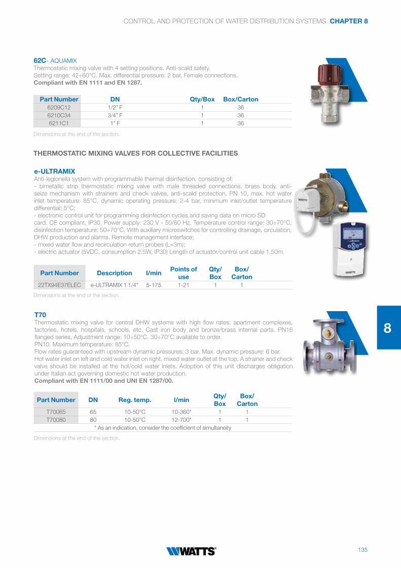
135
CONTROL AND PROTECTION OF WATER DISTRIBUTION SYSTEMS CHAPTER 8
8
62C- AQUAMIX
Thermostatic mixing valve with 4 setting positions. Anti-scald safety.
Setting range: 42÷60°C. Max. differential pressure: 2 bar. Female connections.
Compliant with EN 1111 and EN 1287.
Part Number DN Qty/Box Box/Carton6209C12 1/2” F 1 36
6210C34 3/4” F 1 36
6211C1 1” F 1 36
e-ULTRAMIXAnti-legionella system with programmable thermal disinfection, consisting of:
- bimetallic strip thermostatic mixing valve with male threaded connections, brass body, anti-
seize mechanism with strainers and check valves, anti-scald protection, PN 10, max. hot water
inlet temperature: 85°C, dynamic operating pressure: 2-4 bar, minimum inlet/outlet temperature
differential: 5°C;
- electronic control unit for programming disinfection cycles and saving data on micro SD
card. CE compliant, IP30. Power supply: 230 V - 50/60 Hz. Temperature control range: 30÷70°C,
disinfection temperature: 50÷70°C. With auxiliary microswitches for controlling drainage, circulation,
DHW production and alarms. Remote management interface;
- mixed water flow and recirculation return probes (L=3m);
- electric actuator (5VDC, consumption 2.5W, IP30) Length of actuator/control unit cable 1.50m.
THERMOSTATIC MIXING VALVES FOR COLLECTIVE FACILITIES
Part Number Description l/minPoints of
useQty/Box
Box/Carton
22TX94E37ELEC e-ULTRAMIX 1 1/4" 5-175 1-21 1 1
Dimensions at the end of the section.
Dimensions at the end of the section.
T70Thermostatic mixing valve for central DHW systems with high flow rates: apartment complexes,
factories, hotels, hospitals, schools, etc. Cast iron body and bronze/brass internal parts. PN16
flanged series. Adjustment range: 10÷50°C. 30÷70°C available to order.
PN10. Maximum temperature: 85°C.
Flow rates guaranteed with upstream dynamic pressures: 3 bar. Max. dynamic pressure: 6 bar.
Hot water inlet on left and cold water inlet on right, mixed water outlet at the top. A strainer and check
valve should be installed at the hot/cold water inlets. Adoption of this unit discharges obligation
under Italian act governing domestic hot water production.
Compliant with EN 1111/00 and UNI EN 1287/00.
Part Number DN Reg. temp. l/minQty/Box
Box/Carton
T70065 65 10-50°C 10-360* 1 1
T70080 80 10-50°C 12-700* 1 1
* As an indication, consider the coefficient of simultaneity
Dimensions at the end of the section.

136
CHAPTER 8 CONTROL AND PROTECTION OF WATER DISTRIBUTION SYSTEMS
PARTS CAR-TX90
Replacement cartridge for TX90 ULTRAMIX series thermostatic mixing valves.
TX90 - ULTRAMIX
Visible thermostatic mixing valves for collective facilities such as swimming pools, sports centres,
schools, military bases, factories, camp sites, hospitals, spas, etc., for setting the mixed water to a
constant temperature and keeping it at that temperature even in the event of pressure fluctuations
(max. 1.5 bar). Brass body.
Grey epoxy cover with blue graduated knob (Code E).
Chrome-plated cover with white graduated knob (Code C).
Anti-seize mechanism with strainers and check valves.
Steel bimetallic strip coated with rilsan to protect against scale formation.
Temperature control range: 10÷50°C and 30÷70°C (only for models with epoxy cover) with locking
function. Anti-scald protection: water shut off in less than two seconds in the absence of cold water.
PN10. Max. hot water temperature: 85°C.
Flow rates guaranteed with upstream dynamic pressure: 3 bar.
Hot water inlet on left, mixed water outlet at the top.
Minimum inlet/outlet temperature differential: 5°C.
Calculation software is available on www.wattsindustries.it to help with sizing and selecting the right
model of UltramixTX90 thermostatic mixing valve.
Compliant with EN 1111/00 and UNI EN 1287/02.
Part Number DN Reg. temp.Points of
usel/min
Qty/Box
Box/Carton
TX91E 3/4"M 10-50°C 1-7 3-56 * 1 1
TX92E 3/4"M 10-50°C 1-10 3-80 * 1 1
TX93E 1"M 10-50°C 1-15 3-120 * 1 1
TX94E 1.1/4"M 10-50°C 1-21 5-175 * 1 1
TX95E 1.1/2"M 10-50°C 1-32 5-260 * 1 1
TX96E 2"M 10-50°C 1-50 6-400 * 1 1
TX91C 3/4"M 10-50°C 1-7 3-56 * 1 1
TX92C 3/4"M 10-50°C 1-10 3-80 * 1 1
TX93C 1"M 10-50°C 1-15 3-120 * 1 1
TX94C 1.1/4"M 10-50°C 1-21 5-175 * 1 1
TX95C 1.1/2"M 10-50°C 1-32 5-260 * 1 1
TX96C 2"M 10-50°C 1-50 6-400 * 1 1
TX91E37 3/4"M 30-70°C 1-7 3-56 * 1 1
TX92E37 3/4"M 30-70°C 1-10 3-80 * 1 1
TX93E37 1"M 30-70°C 1-15 3-120 * 1 1
TX94E37 1.1/4"M 30-70°C 1-21 5-175 * 1 1
TX95E37 1.1/2"M 30-70°C 1-32 5-260 * 1 1
TX96E37 2"M 30-70°C 1-50 6-400 * 1 1
* As an indication, consider the coefficient of simultaneity
Dimensions at the end of the section.
Part Number Versions l/minQty/Box
Box/Carton
TX1 TX91E,TX91C 3-56 1 1
TX2 TX92E,TX92C 3-80 1 1
TX3 TX93E,TX93C 3-120 1 1
TX4 TX94E,TX94C 5-175 1 1
TX5 TX95E,TX95C 5-260 1 1

137
CONTROL AND PROTECTION OF WATER DISTRIBUTION SYSTEMS CHAPTER 8
8
OVERALL DIMENSIONS
DRV/DRVM DRVN/DRVMN
L1
D
L
DH
1
H
L1L
D
H
D
H1
DN L L1 H H1
1/2” 97 152 135 48
3/4” 110 171 155 58
1” 120 191 182 66
1.1/4” 140 211 227 75
1.1/2” 160 246 255 82
2” 175 261 262 88
DN L L1 H H1
1/2” 84 135 113 16.5
3/4” 94 151 133 20.5
1” 104 161 140 26
1.1/4” 109 175 192 29.5
1.1/2” 134 214 200 36
2” 144 224 205 42
18.5 mm
86.5 mm
37.5 mm 49 mm
95 m
m M
ax
i
35 m
m
53.5
mm
3532
67
3/4
”
Ø375
4 m
ax
50
min
15
.5
Ø37
3332
65
M3
/4”,
F1
/2”
M3
/4”,
F1
/2” 54
ma
x
50
min
15
.5
part number 82501
part number 82500
REDUBAR REDUBLOC
L
DNB
DN
H1
H
DN L H H1 B (PN16) B (PN25)
50 230 383 83 165 165
65 290 440 90 185 185
80 310 490 100 200 200
100 350 561 121 220 235
125 400 712 152 250 270
150 450 839 169 285 300
200 550 1684 234 340 360
DRVD16 - DRVD25

138
CHAPTER 8 CONTROL AND PROTECTION OF WATER DISTRIBUTION SYSTEMS
OVERALL DIMENSIONS
3499 DF-3499 RF/RC
ø G ”
ø G mm
L mm
H mm
3/4 20/27 80 69
3/4 20/27 110 69
1 26/34 130 69
1499 DF
DN ”
DN mm
Amm
B mm
C mm
D mm
E mm
3/4 20/27 100 125 185 105 190
3/4 20/27 100 125 185 165 267
499 DFB-499 DFC
ø mm
A mm
B mm
L mm
H mm
15 3/4 20/27 170 120
20 1 26/34 190 120
25 1 1/4 33/42 260 130
32 1 1/2 40/49 260 130
40 2 50/60 300 145
50 2 1/2 66/76 300 145
A
C
B
Ø
61C/62C
DN A B C Ø
1/2” 70 107 52 45
3/4” 70 107 52 45
1” 80 110 52 45
TX90
DN A B C
3/4”M 117 120 81
1”M 144 142 95
1.1/4”M 182 166 107
1.1/2”M 218 199 129
2”M 242 224 144
DN D E F
3/4”M 93 18 98
1”M 101 23 116
1.1/4”M 116 24 145
1.1/2”M 127 32 175
2”M 141 36 198
A
B
C
D
E
T70
DN A B C D E
2.1/2” 294 215 90 185 145
3” 336 270 105 200 160
4” 404 270 125 220 180

139
CONTROL AND PROTECTION OF WATER DISTRIBUTION SYSTEMS CHAPTER 8
8
OVERALL DIMENSIONS
E-ULTRAMIX ELECTRONIC CONTROL UNIT
Front view Side view Rear view
E-ULTRAMIX THERMOSTATIC MIXING VALVE WITH ACTUATOR
Amm
B mm
C mm
D mm
E mm
F mm
ø fitting mm
3/4" 117 120 81 126 19 98 G 3/4"
1" 144 142 96 133 23 116 G 1"
1 1/4" 182 160 108 149 24 145 G 1 1/4"
1 1/2" 218 200 129 164 36 175 G 1 1/2"
2" 242 217 144 173 36 198 G 2"

140
Chapter 9
Components forrenewable energysystems

141
MMV-S - Thermostatic mixing valve
Thermostatic mixing valveFor high-temperature solar energy systems Anti-scald safety

CHAPTER 9 COMPONENTS FOR RENEWABLE ENERGY SYSTEMS
142
Components for renewable energy systems
Chapter 9
SOLARKITThermostatic unit for thermal integration of solar thermal systems and boilers, consisting of an
MMV-S series mixing valve, a T-fitting and a diverter valve. CW602N DZR brass body. Setting
positions: 5. Mixed water temperature: 30-65 ± 2°C.
Flow rate at 3 bar: 63 l/min - Minimum flow rate: 5 l/min. PN 10. Operating pressure: 0.2÷5 bar.
Mixing valve side hot water operating temperature: 52÷110°C. Mixing valve side cold water operating
temperature: 5÷20°C. Diverter valve opening temperature: 45°C.
SOLAR THERMAL
MMV-SThermostatic mixing valve for solar energy systems. Nickel-plated brass body.
Setting positions: 5. Mixed water temperature: 30-65 ± 2°C. Flow rate at 3 bar: 63 l/min.
Minimum flow rate: 5 l/min. PN10. Operating pressure: 0.2÷5 bar.
Hot water operating temperature: 52÷110°C. Cold water operating temperature: 5÷25°C.
Compliant with EN1111/00 and EN 1287/02.
Part Number DN Setting Qty/Box Box/Carton97590 1” M 5 1 1
Part Number DN Finishing Qty/Box Box/Carton97501 1” with fitting 3/4” M Brass 1 1
97560 1” M Brass 1 1
Dimensions at the end of the section.
Dimensions at the end of the section.

COMPONENTS FOR RENEWABLE ENERGY SYSTEMS CHAPTER 9
143
9
TECHNICAL NOTE SOLARKIT operation
The SOLARKIT thermostatic unit for
thermal integration of solar thermal
systems and boilers is a fully automatic
component for controlling solar thermal
systems for domestic hot water
production. Without drawing energy
from any external sources, the unit uses
thermostats to divert the water to a back-
up boiler when there is not enough solar
energy to heat the domestic hot water to
the desired temperature.
Boiler off Boiler on
Cold water Cold water
Solar collector
water T > 45°C
Solar collector
water T < 45°C
Mixed
water
Mixed
water
SVE-SOLDiaphragm safety valve for solar energy systems. CW617N brass body and cap, EN12165-99.
Elastomer diaphragm. Pre-set and sealed discharge pressure.
Max. operating temperature: -10÷160°C. Fluids: water with glycol up to 50% as per DIN 4757 Part 1.
TÜV SOLAR certified. Compliant with PED Directive 2014/68/EU Identification number CE1115.
Part Number DN bar Qty/Box Box/Carton0215835 1/2” x 3/4” 3,5 1 40
0215840 1/2” x 3/4” 4 1 40
0215860 1/2” x 3/4” 6 1 40
0215880 1/2” x 3/4” 8 1 40
RIA/MV-SOLAutomatic shut-off valve for MV-SOL air vent valves. Makes it possible to change the valve with the
system running. CW614N brass body, EN12164-01. Gasket: high-strength elastomer.
Plug: high-strength polymer. Spring: stainless steel. MF 3/8” and 1/2” DIN - ISO 228/1 connections.
Part Number DN Spring Qty/Box Box/Carton0259315 1/2” x 1/2” stainless steel 10 400
QUICKFILLBrass filling valve for solar circuits, equipped with double closure valve to facilitate filling and draining
the system.
Quick to install, in any position.
Part Number Description Note Qty/Box Box/Carton
3499635with compression
fitting22 mm- 1 1
Dimensions at the end of the section.
Dimensions at the end of the section.

CHAPTER 9 COMPONENTS FOR RENEWABLE ENERGY SYSTEMS
144
STPt1000 temperature sensors:
- in silicone sheath, up to 105°C, length 3 metres (suitable for tank);
- in PVC sheath, up to 180°C, length 1.5 metres (suitable for solar collector).
Part Number Lenght Max temp. Qty/Box Box/CartonPPLELE00061 1,5 m - 180 °C 1 1
PPLELE00060 3,0 m - 105 °C 1 1
Part Number Description Connection Qty/Box Box/Carton10026343 GRUNDFOS ALPHA 2L 25-60 1” 1 1
KLS 8180-FLOWBOX
Compact circulation unit for solid-fuel-fired boilers with thermostatic anti-condensation unit. Pre-
wired circulation pump (centre distance 180mm), dynamic anti-condensation bypass with boiler
return temperature of 58±2°C. Shut-off valves with built-in thermometer and manual/automatic
check valve. 1”M union connections and wall-mounting bracket. EPP insulation. Suitable for heat
output of up to 50 KW.
COMPONENTS FOR BIOMASS SYSTEMS
A
AB
B1
B2
A = return
AB = mixed
B1 and B2 = draw-off from flow
(cap the unused port)
TECHNICAL NOTE - KLV thermostatic anti-condensation valve
During combustion in a boiler, the moisture naturally present in biomass is released into the flue gases in the form of water vapour. If cooled at a
temperature below the dew point, this vapour (which is often acidic) condenses, causing the boiler to corrode and drastically reducing its service life.
When the boiler starts up, the KLV thermostatic anti-condensation valve brings the system rapidly up to temperature, and if the water in the return
circuit gets too cold during normal operation, the KLV valve mixes it with flow water before it reaches the boiler.
For HK Pumps see section 5.

COMPONENTS FOR RENEWABLE ENERGY SYSTEMS CHAPTER 9
145
9
OVERALL DIMENSIONS
MMV-S 1/2” MMV-S 3/4” MMV-S 1”
SVE-SOL
72
3/4”
24,5
1/2”
34
SOLARKIT
RIA/MV-SOL
CH
DN
B
C
DN B C CH
3/8” 8 11 19
1/2” 8 11 24
Cold
water
Hot
water
Mixed
waterG 1/2”
43
73
G 1
/2”
76
70,5 70,5
Cold
water
Hot
water
Mixed
water G 3/4”
43
35
G 3
/4”
72
76
72
Cold
water
Hot
water
Mixed
water
43
35
G 1
”
G 1
”
76
44

146
Chapter 10
Fittings

147
RAFIT + Soft-seal fitting
Quick installation: cuts connection times for copper pipe
Cutting ring withstands high pull-out forces on the pipe
Compact dimensions

148
CHAPTER 10 FITTINGS
Fittings
Chapter 10
872M - RAFIT+ Soft-seal one-piece fitting for quick connection of copper pipes (UNI EN 1057) to male-threaded
valves, lockshields and manifolds. EPDM taper ferrule with steel reinforcement core. High pull-out
strength (cutting ring).
* 1/2”S M24x1.5 thread (for 102S and 119SX single-pipe valves with 1/2”S pipe-side connection)
FITTINGS FOR COPPER
(Fig.1) (Fig.2) (Fig.3)
TECHNICAL NOTE - Installation of RAFIT one-piece quick fittings
1 - When cutting the pipe, carefully deburr the ends if necessary.
2 - Insert the pipe in the fitting by pushing it in until it butts up against the end stop (Fig.1) and holding it still in this position during
tightening; the seal will thus be thrust outwards from the fitting body (Fig.2).
3 - Approach the fitting to the threaded end-piece until the head of the taper ferrule engages inside it, then tighten by hand.
4 - Fully tighten with the respective wrench (Art. 829M), in accordance with the recommended tightening torques (Fig.3).
Part Number DN Ø Pipe Qty/Box Box/Carton872M1215 1/2” 15 25 300
Dimensions at the end of the section.

149
FITTINGS CHAPTER 10
10
820RThree-piece compression fitting for copper pipes (chrome-plated pipe lock nut, brass taper ferrule
and reinforcement core) for connecting copper pipes to male-threaded valves, lockshields and
manifolds. Metal seal.
* 1/2”S M24x1.5 thread (for 102M and 119SX single-pipe valves with 1/2”S pipe-side connection)
Dimensions at the end of the section.
829MSteel wrench for tightening RAFIT+ and 820R fittings.
Part Number DN Ø Pipe Qty/Box Box/Carton820R1210 1/2” 10 10 150
820R1212 1/2” 12 10 150
820R3418 3/4” 18 10 100
820R3422 3/4” 22 10 100
Part Number DN Qty/Box Box/Carton829M2025 3/8” - 1/2” 1 1
817M Three-piece nickel-plated compression fitting for cross-linked polyethylene pipes to UNI 9338.
EPDM O-Ring. Not suitable for oils.
* 1/2”S M24x1.5 thread (for 102M and 119SX single-pipe valves with 1/2”S pipe-side connection)
Dimensions at the end of the section.
FITTINGS FOR CROSS-LINKED POLYETHYLENE AND MULTI-LAYER PIPES
Part Number DN Ø Pipe Qty/Box Box/Carton817MC12142 1/2” 14 x 2,0 10 200
817MC1215 1/2” 15 x 2,5 10 200
817MC341713 3/4” 17 x 2,0 10 150
220 Three-piece nickel-plated elbow fitting.
Dimensions at the end of the section.
NIPPLES, ELBOWS, SOLDER ALLOY
Part Number DN Qty/Box Box/Carton220SN12 1/2” 10 100
220SN34 3/4” 10 65
220SN1 1” 10 35

150
CHAPTER 10 FITTINGS
221 Three-piece nickel-plated straight fitting.
892GL Nipple fitting with male threaded connections.
833M Brass male/male adaptor.
890GL Nipple fitting with male threaded connections.
Part Number DN Qty/Box Box/Carton221SN12 1/2” 10 100
221SN34 3/4” 10 60
221SN1 1” 10 35
Part Number DN Qty/Box Box/Carton892GL12 1/2” MM 10 300
892GL34 3/4” MM 10 100
Part Number DN Qty/Box Box/Carton890GL12 1/2” MM 10 150
Part Number DN Qty/Box Box/Carton833M1234 1/2” - 3/4” 10 150
821M Brass male/female adaptor.
Part Number DN Qty/Box Box/Carton821M12M38F 1/2” M x 3/8” F 10 300
821M12M34F 1/2” M x 3/4” F 10 150
834M Brass female plugs.
Part Number DN Qty/Box Box/Carton834M12 1/2” 10 400
834M34 3/4” 10 50
834M1 1” 10 50
Dimensions at the end of the section.
Dimensions at the end of the section.
Dimensions at the end of the section.
Dimensions at the end of the section.
Dimensions at the end of the section.
Dimensions at the end of the section.

151
FITTINGS CHAPTER 10
10
OVERALL DIMENSIONS
872M 820R
817M - 817MS
221 892GL
220
A
DN
DN
Ch
iave
ABC
DN A B C Wrench
1/2” 23 8 21 20
1/2”S 26 8 22 25
3/4” 24 8 22 32
AKey
Ch
iave
ABC
DN A B C Wrench
3/8” 17 24 9 20
1/2” 19 24 10 25
1/2”S 20 24 11 25
3/4” 20 24 11 32
L1
H1
L H
DN H H1 L L1
3/8”MF 47 27 14 14
1/2”MF 53 34 16 18
3/4”MF 60 37 19 21
1”MF 77 46 23 27
H
L
DN H L
3/8”MF 28 43
1/2”MF 35 51
3/4”MF 42 58
1”MF 54 62
DN A
3/8” 22
1/2” 25
3/4” 28
DN A Rafit wrench
3/8” 25 20
1/2” 27 25
1/2”S 29 27

152
CHAPTER 10 FITTINGS
OVERALL DIMENSIONS
833M890GL
834M
A
DN
DN
DN
DN
A
DN A B
3/8” 7 19
1/2” 9 25
3/4” 18 35
1” 18 38
DN A
3/8” x 1/2” 24
3/8” x 3/4” 28
1/2” x 3/4” 30
DN A
1/2“ x 1“ 34
3/4“ x 1“ 35DN A
1/2” 26
B
A

153
FITTINGS CHAPTER 10
10

154
Chapter 11
Water Quality Systems

155
Water Quality Systems
A full range of water treatment solutions to match the unique needs of any location

156
CHAPTER 11 WATER QUALITY
WATER CONDITIONING
OneFlow® Anti Scale System
OneFlow® Cartridge System
Features
The OneFlow® Anti-Scale System provides protection from scale formation on internal and external plumbing surfaces.
The OneFlow® system is a single cartridge/media-based system that may be installed on a cold water line prior to a water-using
device (water heater, hot-beverage system, appliance, steamer, etc.) that requires protection from the ill effects of hard water.
OneFlow® prevents scale by transforming dissolved hardness minerals into harmless, inactive microscopic crystal particles.
These crystals stay suspended in the water and are passed to a drain, thereby having a greatly reduced ability to react
negatively with plumbing surfaces, as opposed to dissolved hardness minerals. These particles make their way through plumbing
systems without latching on to pipes, inside fixtures, valves, or heating elements.
The system requires very little maintenance, no backwashing, no salt and no electricity. Typical hardness problems,
especially build-up of scale in pipes, water heaters, boilers are no longer a concern.
OneFlow® is not a water softener. It does not add chemicals. It is a scale prevention device with proven third party laboratory
test data and years of successful Domestic and Commercial applications. OneFlow® is the intelligent scale solution and
is a great alternative to water softening (ion exchange) or scale sequestering devices.
This range of OneFlow® conditioners has the TAC media contained within easily
replaceable cartridges.
The flow rates are shown on each product and are typically used for smaller domestic
and point of use applications.
• Chemical free scale control - converts hardness minerals to
harmless, inactive microscopic crystals making OneFlow®
an effective alternative technology to a water softener for
the prevention of scale due to water hardness
• Virtually maintenance free - No salt bags or
other chemicals to constantly add or maintain
• No control valve, no electricity and no wastewater
• Uses environmentally friendly “green” technology
• Improves efficiency of all water appliances
whether heating the water or not
• Simple sizing & installation – all you need to know
is pipe size and flow rate
• Inlet ball valve for easy isolation shutoff and filter changes
• OneFlow® does not remove the essential minerals in water
• OneFlow® cartridge-based systems are easily maintained;
change the cartridge once per year
• Treated water is safe for human consumption
SCALE CONTROL SYSTEMS
ONEFLOW® SCALE CONTROL SYSTEMS
Models OF110-1, OF120-2 and OF140-4
Connection Sizes: ½" and ¾" (15 and 20mm)
Flow Rates: From 0.5 gpm to 4 gpm (1.9 lpm to 15.2 lpm)
TYPEPRODUCT
CODEPEAK
FLOW RATECONNECTION
SIZE
OneFlow® Anti Scale WWQ-OF110–1 1 gpm (4 lpm) ½"
OneFlow® Anti Scale WWQ-OF120–2 2 gpm (8 lpm) ½"
OneFlow® Anti Scale WWQ-OF140–4 4 gpm (15 lpm) ¾"
WWQ-OF110-1
WWQ-OF120-2
WWQ-OF140-4

157
WATER QUALITY CHAPTER 11
11
SCALE CONTROL SYSTEMS
Model OFTWH-R - For Residential Tankless Water Heaters
Connection Sizes: ¾"
Flow Rates: 10 gpm (1.9 lpm to 38 lpm)
TYPEPRODUCT
CODEPEAK
FLOW RATECONNECTION
SIZE
OneFlow® Anti Scale WWQ-OFTWH 10 gpm (38 lpm) ¾"
Model OFTWH
Connection Sizes: ¾"
Flow Rates: 6 gpm (22.71 lpm)
TYPEPRODUCT
CODEPEAK
FLOW RATECONNECTION
SIZE
OneFlow® System 6 GPM WWQ-OFTWH-R 6 gpm (23 lpm) ¾"
Model OF220-2
TYPEPRODUCT
CODEMAXIMUM
FLOW RATECONNECTION
SIZE
OneFlow® System 2 GPM WWQ- OF220–2 2 gpm (8 lpm) ½"
Connection Sizes: ½"
Flow Rate: 2 gpm
The OneFlow® Anti-Scale System with two filter housings provides protection from scale
formation and reduces chlorine and other off tastes to improve overall water quality in Food
Service applications. The OneFlow® system is a dual cartridge-based system that may be
installed on a cold water line prior to a water-using device (coffee maker, espresso machine,
post-mix system or other appliance) that requires protection from the ill effects of hard water.
OneFlow® works exceptionally well where the water is being heated or brought to steam.
OneFlow® Media Systems
This range of OneFlow® conditioners for larger applications uses replacement TAC media.
The flow rates are shown for each product and are typically used for larger domestic point of entry and commercial solutions.
ONEFLOW REPLACEMENT CARTRIDGES
OneFlow Replacement Cartridges
REPLACEMENT CARTRIDGE PRODUCT CODE
FOR ONEFLOW® SYSTEM FREQUENCY
WWQ-OF110RM WWQ-OF110RM Cartridge should be replaced every 12 months
WWQ-OF120RM WWQ-OF120RM Cartridge should be replaced every 12 months
WWQ-OF140RM WWQ-OF140RM Cartridge should be replaced every 12 months
WWQ-OF220RC WWQ-OF220RC Cartridge should be replaced every 6 months
WWQ-OF-TWHRM WWQ-OF-TWHRM Cartridge should be replaced every 2 years
WWQ-OF-TWHRM-R WWQ-OF-TWHRM-R Cartridge should be replaced every 2 years

158
CHAPTER 11 WATER QUALITY
Connection Size: 1"
Flow Rate: Up to 16 gpm (60 lpm)
OneFlow® Residential Anti-Scale Systems provide a system with protection from internal hardness
related scale formation on plumbing surfaces. Water using appliances and plumbing fixtures also
enjoy a longer lifespan because hardness scale build up on internal parts no longer occurs.
Series OFRES - Residential
TYPEPRODUCT
CODECONN. SIZE
MINERAL TANK SIZE
MEDIA LITRES
MAXIMUMSERVICE FLOW*
PRESSURE DROP(PSI)**
FLOOR SPACE
(L X W X H)
Residential OneFlow® WWQ-OFRES-0835 1" 8"x35" 2 8 gpm (30 lpm) <15 13"x9"x40"
Residential OneFlow® WWQ-OFRES-0935 1" 9"x35" 3 12 gpm (45 lpm) <15 13.5"x10"x40"
Residential OneFlow® WWQ-OFRES-1035 1" 10"x35" 4 16 gpm (60 lpm) <15 14"x11"x40"
SCALE CONTROL SYSTEMS
Series OF
Models OF744-10, OF844-12, OF948-16, OF1054-20 and OF1252-30
Connection Sizes: 1"
Flow Rates: 10 gpm to 30 gpm (38 lpm to 114 lpm)
TYPEPRODUCT
CODEDESCRIPTION
OneFlow® System 10 GPM WWQ-OF744-10-C 10 gpm (38 lpm), 1"
OneFlow® System 12 GPM WWQ-OF844-12-C 12 gpm (45 lpm), 1"
OneFlow® System 16 GPM WWQ-OF948-16-C 16 gpm (60 lpm), 1"
OneFlow® System 20 GPM WWQ-OF1054-20-C 20 gpm (76 lpm), 1"
OneFlow® System 30 GPM WWQ-OF1252-30-C 30 gpm (114 lpm), 1"
WWQ-
OF1054-20
WWQ-
OF1252-30
WWQ-
OF744-10
WWQ-
OF844-12
WWQ-
OF948-16
Replacement Media
REPLACEMENT CARTRIDGE PRODUCT CODE
FOR ONEFLOW® SYSTEM FREQUENCY
WWQ-OFRES-0835RM OFRES-0835 Cartridge should be replaced every 3 years
WWQ-OFRES-0935RM OFRES-0935 Cartridge should be replaced every 3 years
WWQ-OFRES-1035RM OFRES-1035 Cartridge should be replaced every 3 years
WWQ-OF744RM OF744-10C Cartridge should be replaced every 3 years
WWQ-OF844RM OF844-12C Cartridge should be replaced every 3 years
WWQ-OF948RM OF948-16C Cartridge should be replaced every 3 years
WWQ-OF1054RM OF1054-20C Cartridge should be replaced every 3 years
WWQ-OF1252RM OF1252-30C Cartridge should be replaced every 3 years

159
WATER QUALITY CHAPTER 11
11
Carbon Filter for Big Bubba® Housing 2"
TYPE PRODUCT CODE MAX FLOW CAPACITYCHLORINE
REDUCTION
Big Bubba® Carbon WWQ-BBC-150-ACP 15 GPM 140,000 Gals. 90%
Ideal for more critical applications, offering greater efficiency, more surface area
for greater throughput and reduced cost.
Big Bubba® filters are available in a range of different specifications, Pleated, Melt
Blown and Activated Carbon. The difference between these and any of our other
filter range is that they are bigger. They are able to cope with very high levels of
turbidity and can withstand high flow rates up to 36m3/Hr.
Replacement Pleated Cartridge for Big Bubba® Housing
TYPE PRODUCT CODE MEDIA TYPE MICRON RATING
Big Bubba® P1 WWQ-BBC-150-P1 PP 1
Big Bubba® P5 WWO-BBC-150-P5 PP 5
Big Bubba® P20 WWQ-BBC-150-P20 PE 20
Big Bubba® P50 WWQ-BBC-150-P50 PE 50
Big Bubba® PM150 WWQ-BBC-150-PM150 Mesh 150
Melt blown Polypropylene cartridges are recommended when depth filtration is necessary
for gelatinous substances and when chemical resistance may be a requirement.
The Watts Big Bubba® Filter Housing is a high capacity polypropylene filter housing
designed to suit for high flow rates, the filter housing is a non-metallic made from
rugged, glass-reinforced polypropylene, which will not chip, rust or dent.
The non-metallic construction makes this the perfect economical replacement
for stainless steel filtration equipment and ideal for sea water applications or
when chemical compatibility is an issue.
Replacement Depth Cartridge for Big Bubba® Housing
TYPE PRODUCT CODE MEDIA TYPE MICRON RATING
Big Bubba® D1 WWQ-BBC-150-D1 PP 1
Big Bubba® D5 WWO-BBC-150-D5 PP 5
Big Bubba® D20 WWQ-BBC-150-D20 PP 20
Big Bubba® D50 WWQ-BBC-150-D50 PP 50
Big Bubba® Housing 2"
TYPE PRODUCT CODE PIPE FITTING OVERALL HEIGHT
Big Bubba® Housing WWQ-BBH-150 2" 40"
FILTRATION - BIG BUBBA® FILTRATION SYSTEM

160
CHAPTER 11 WATER QUALITY
SMARTSTREAM™ DISINFECTANT SYSTEMS
Watts SmartStream™ B and C Series UV Systems
Lamps, Quartz Sleeves and Sleeve Oring
B SERIES B SERIES PARTS
TYPE PRODUCT CODE FLOW RATE (GPM)
SIZE (IN) REPLACEMENT LAMP
PRODUCT CODE
REPLACEMENT SLEEVE
PRODUCT CODE
REPLACEMENT ORING SLEEVE
PRODUCT CODE
Watts SmartStream™ Systems With B Series Controllers
B Series WWQ-WB001ABCX 1 3/8" M WWQ-T7401024 WWQ-T7401104 WWQ-T7402102
B Series WWQ-WB002ABCX 2 3/8" M WWQ-T7401025 WWQ-T7401105 WWQ-T7402102
B Series WWQ-WB006ADCX 6 3/4" M WWQ-T7401026 WWQ-T7401106 WWQ-T7402102
B Series WWQ-WB012BFCX 12 1" M WWQ-T7401027 WWQ-T7401107 WWQ-T7402102
C SERIES C SERIES PARTS
Watts SmartStream™ Systems With C Series Controllers
C Series WWQ-WC012BFCX 123/4" & 1"
COMBOWWQ-T7401029 WWQ-T7401109 WWQ-T7402102
C Series WWQ-WC016BFCX 163/4" & 1"
COMBOWWQ-T7401030 WWQ-T7401110 WWQ-T7402102
C Series WWQ-WC025BGCX 251" & 11/2"
COMBOWWQ-T7401031 WWQ-T7401111 WWQ-T7402102
FILTER HOUSINGS
Our comprehensive selection of plastic filter housings include products from the brands and
companies of Flowmatic®, Pentair, and Watts.
TYPE MODEL NO. SIZE PR SUMP CAPPIPE SIZE
NO./ CASE
Flowmatic WWQ-FH4200BL34PR 10" Yes Blue Black 3/4" 12
Flowmatic WWQ-FH4200CW34PR 10" Yes Clear White 3/4" 12
Flowmatic WWQ-FH4200WW12 10" No White White 1/2" 12
TYPE MODEL NO. SIZE DESCRIPTION PR SUMP CAPPIPE SIZE
NO./ CASE
Watts WWQ-W10CPH34CBPR 10" Standard Yes Clear Black 3/4" 12
Watts WWQ-W10FFPH1BLPR 10" Big Blue Yes Blue Black 1" 6
TYPE MODEL NO.
Watts Wrench WWQ-WW-C
Watts Bracket WWQ-WBKT-FF-1
Watts Screws WWQ-GAFFSCREW
FullFlow Wrench WWQ-WW-FF
Flowmatic Wrench WWQ-WR100
Flowmatic - 10" Plastic Filter Housings
Watts - 10" Plastic Filter Housings
Filter Housing Accessories
B Series

161
WATER QUALITY CHAPTER 11
11
FILTER CARTRIDGES
Carbon Block Filters - Watts
Carbon Block Filters - Long Life and High Chlorine Reducer
TYPE MODEL NO. TYPE OD LENGTHMICRON RATING*
CHLORINE REDUCTION*
NO. / CASE
Carbon Block Filter WWQ-WCBFF975 Thick Wall 41/2" 93/4" 5 nominal 25,000 gal @ 3 gpm 4
Carbon Block Filter WWQ-F109009 Thick Wall 21/2" 93/4" 5 nominal 10,000 gal @ 1 gpm 25
Carbon Block Filter WWQ-MAXPB-975 Lead + cysts 27/8" 93/4" 1 nominal 20,000 gal @ 1 gpm 12
Carbon Block Filter WWQ-MAXVOC-975 Water washed 27/8" 93/4" 1 nominal 20,000 gal @ 1 gpm 12
GAC Filters - Flowmatic
TYPE MODEL NO. TYPE OD LENGTHCAPACITY
(GALS.)NO. / CASE
GAC Filter WWQ-GAC10N GAC 23/4" 93/4" 2,500 24
GAC Filter WWQ-GAC-BB20 Watts 41/2" 20" 15,000 4
Water Washed, Coconut Shell Granular, Activated Carbon Cartridges
Thick wall carbon construction for superior performance. Low cost for economy!
Top-of-the-line coconut shell carbon block filter cartridge for chlorine, taste, odour and sediment reduction.
• Competitively priced!
• Outperform GAC cartridges four ways:
1. Superior chlorine reduction
2. Lower pressure drop
3. Will not channel
4. Lower cost
• 100% Coconut shell Carbon
• >90% chlorine reduction*
• FDA grade components & materials
Carbon Block Filters - Watts
TYPE MODEL NO. BRANDS OD LENGTHMICRON RATING
CHLORINE REDUCTION
NO. / CASE
Carbon Block Filter WWQ-F109020 Watts 21/2" 20" 5 nominal 20,000 gal @ 1 gpm 25
TYPE MODEL NO. TYPE OD LENGTHMICRON RATING
CHLORINE REDUCTION
NO. / CASE
Chlorine Reducer MAXCL-975 Thick Wall 27/8" 93/4" 1 nominal 20,000 gal @ 1 gpm 12
Chlorine Reducer MAXCL-FF975 Thick Wall 45/8" 93/4" 1 nominal 80,000 gal @ 3 gpm 4

162
CHAPTER 11 WATER QUALITY
FILTER CARTRIDGES
Flow-Pro® Melt Blown Sediment Cartridges
TYPE MODEL NO. BRANDS OD LENGTHMICRON RATING
NO. / CASE
Flow-Pro® WWQ-FPMB1-978 FlowPro 21/2" 97/8" 1 nominal 48
Flow-Pro® WWQ-FPMB5-978 FlowPro 21/2" 97/8" 5 nominal 48
Flow-Pro® WWQ-FPMB-BB5-10 FlowPro 41/2" 93/4" 5 nominal 24
Flow-Pro® WWQ-FPMB1-20 FlowPro 21/2" 20" 1 nominal 24
Flow-Pro® WWQ-FPMB-BB5-20 FlowPro 41/2" 20" 5 nominal 12
Watts Sediment Cartridges
TYPE MODEL NO. BRANDS OD LENGTHMICRON RATING
NO. / CASE
Sediment Cartridge WWQ-WPC5-975 Watts 23/4" 10" 5 nominal 25
FullFlow WWQ-WPC5FF975 Watts 41/2" 93/4" 5 nominal 18
FullFlow WWQ-WPC1FF20 Watts 41/2" 20" 1 nominal 9
FullFlow WWQ-WPC50FF20 Watts 41/2” 20” 50 nominal 9
String Wound (Standard / High temp)
TYPE MODEL NO. BRANDS OD LENGTHMICRON RATING
NO. / CASE
String Wound WWQ-SF1-978 Watts 21/2" 10" 1 nominal 25
String Wound WWQ-SF5-978 Watts 21/2" 10" 5 nominal 25
String Wound WWQ-SF5-10-425 Watts 41/2" 10" 5 nominal 8
String Wound WWQ-SF1-20 Watts 21/2" 20" 1 nominal 25
String Wound WWQ-SF5-20-425 Watts 41/2" 20" 5 nominal 4
Watts Water Quality offer a wide range of micron ratings and cartridge sizes, please
contact us for more information.

163
WATER QUALITY CHAPTER 11
11
Granular Activated Carbon (GAC) is a natural material derived from bituminous coal, lignite, wood, coconut
shell, etc, activated by steam and other means. Carbon is very popular due to its ability to correct many
water quality problems.
Micro Z - Superior Filtration Media
Micro-Z™ granular filter media outperforms conventional multimedia materials due to its unique structure,
allowing particulate to penetrate deeply into the filter bed to provide superior filtration at increased flow rates.
RESIN AND MEDIA
TYPE MODEL NO. DESCRIPTIONCUBIC FEET PER
BAGCONTAINER
WT. (LBS)PACKAGE
PERPALLET
Micro Z Media Bag WWQ-A7200 Micro-Z 1 55 Bag 40
Granular Activated Carbon (GAC)
TYPE MODEL NO. DESCRIPTION TYPE MESHCUBIC FEET
PER BAGCONTAINER
WT. (LBS)PER
PALLET
Activated Carbon Media WWQ-A9231-AL Coconut shell Coconut 12 X 40 1 27.5 40
TYPE MODEL NO. DESCRIPTION APPLICATIONCUBIC FEET
PER BAGCONTAINER
WT. (LBS)PER
PALLET
Media BIRM Regular WWQ-A8006 Birm (regular) Iron, HS reduction 1 44 40
TYPE MODEL NO. DESCRIPTION APPLICATIONCUBIC FEET
PER BAGCONTAINER
WT. (LBS)PER
PALLET
KDF55 Media WWQ-KDF55-DRUM KDF-55 Chlorine reduction 0.33 57 48
KDF
Birm
Birm is a black granular filter material used for removal of iron and/or manganese from water in pressure
or gravity systems.
It contains an active insoluble catalyst to precipitate iron and/or manganese. Because the presence of iron
is most common, iron removal is the usual application for Birm. Under suitable conditions, the iron and
dissolved oxygen in water react on contact with the Birm filter bed and, as a result, the iron is precipitated
in the form of hydroxide. This is a flocculent material which is filtered out in the bed of Birm. Periodic
backwashing flushes out the accumulated iron and the Birm is again ready to perform its function.
Birm is not consumed in the iron removal operation.
KDF (Kinetic Degradation Fluxion) process media are high-purity copper-zinc granules that reduce
contaminants in water using an oxidation/reduction (redox) reaction. They are used in pretreatment, primary
treatment and wastewater treatment applications in order to extend system life and to reduce heavy metal
contamination, chlorine and hydrogen sulfide.
KDF 55 granules: designed for removing or reducing chlorine and soluble heavy metals.

164
Chapter 12
Industrial & Commercial Gas Products

165
Industrial & Commercial Gas Products
The Powerseat® electro-hydraulic gas shut-
off valve allows the control and safety shut-off
of low pressure combustible gases in pipes
from 40mm to 250mm.

166
CHAPTER 12 POWERSEAT
GAS SAFETY VALVES
Powerseat® Eco Electro Hydraulic Gas Safety Shut Off Valve
Powerseat® Eco Electro Hydraulic Gas Safety Shut Off Valve Aluminiuim Body - Screwed Connections
The Powerseat® electro-hydraulic gas shut-off valve allows the control and safety shut-off of low pressure combustible gases
in pipes from 40mm to 250mm, whilst focusing on being energy efficient and environmentally friendly. The Powerseat® Eco
shut-off valve is kept open by a hydraulic pump where hydraulic fluid is forced into a cylinder driving the valve open.
New and improved features
• LED to display “ON” and “Manual Re-set Required” status
• Increased environmental protection approved to IP56
• Manual re-set switch incorporated on all versions
• Screwless quick connections for installation of electrics
• Volt free contacts for BMS connection
Power consumption
• Uses just 6% of the power of a comparable magnetic solenoid valve
• Reduced electricity running costs: Uses just a fraction of the energy
required by permanently energized magnetic solenoid valves
• Improved energy efficiency from previous model,
reduced from 26VA to 10VA
Environmental factors
• Around 768kg less carbon emissions than
with a comparable magnetic solenoid valve
• Saves equivalent carbon emissions
of 3,758 miles in a car
Quality
• 3 year warranty as standard
• UK manufactured
• EC certified
• IP56 standard:
- Dust protected - no harmful deposit
- Splash protected - from any direction
• Certified to EN161, Class A Group 2 construction
TYPE PRODUCT CODE SIZE POWER CONNECTION
Powerseat® Eco PE6683110V 1.1/2" BSP 110V Range Screwed
Powerseat® Eco PE6684110V 2" BSP 110V Range Screwed
Powerseat® Eco PE6685110V 2.1/2" BSP 110V Range Screwed
Powerseat® Eco PE6686110V 3" BSP 110V Range Screwed
Powerseat® Eco PE6683230V 1.1/2" BSP 230V Range Screwed
Powerseat® Eco PE6684230V 2" BSP 230V Range Screwed
Powerseat® Eco PE6685230V 2.1/2" BSP 230V Range Screwed
Powerseat® Eco PE6686230V 3" BSP 230V Range Screwed
Powerseat® Eco Electro Hydraulic Gas Safety Shut Off Valve Cast iron Body - Flanged Connections
Powerseat® Electro Hydraulic Gas Safety Shut Off Valve Cast iron Body - Flanged Connections. 8" & 10" available in Powerseat® specifications.
TYPE PRODUCT CODE SIZE POWER CONNECTION
Powerseat® Eco PE6685FL4110V 65 110V Range Flanged
Powerseat® Eco PE6686FL4110V 80 110V Range Flanged
Powerseat® Eco PE6687FL4110V 100 110V Range Flanged
Powerseat® Eco PE6689FL4110V 150 110V Range Flanged
Powerseat® Eco PE6658FL4230V 65 230V Range Flanged
Powerseat® Eco PE6686FL4230V 80 230V Range Flanged
Powerseat® Eco PE6687FL4230V 100 230V Range Flanged
Powerseat® Eco PE6689FL4230V 150 230V Range Flanged
TYPE PRODUCT CODE SIZE POWER CONNECTION
Powerseat® BC66810FL4110V 200 110V Range Flanged
Powerseat® BC66811FL4110V 250 110V Range Flanged
Powerseat® BC66810FL4230V 200 230V Range Flanged
Powerseat® BC66811FL4230V 250 230V Range Flanged

167
POWERSEAT CHAPTER 12
12
GAS SAFETY SHUT-OFF VALVES
OPTIONAL
EXTRASDESCRIPTION UNIT
BC668*/SW Open Position Switch each
110V 50Hz AC version + each
OPTIONAL
EXTRASDESCRIPTION UNIT
BC66RSR PowerSet Manual Reset Switch (Remote) each
BC66ETF PowerLink Thermal Fuse each
BC66MRF PowerLink Resettable Thermal Fuse each
BC66ESB PowerSev Emergency Switch (Die-cast) each
BC66ESB/P PowerSev Emergency Switch (Plastic) each
BC66ESB/K PowerSev Emergency Switch - Key op each
N101706000 Thermal Fuse for BC66ETF each
Powerseat® Electro-Hydraulic Valves - Spare Parts
ACTUATOR
CODETYPE
PRODUCT
CODETYPE
Spare ActuatorPowerseat Eco Electro Hydraulic Gas Safety Shut
Off Valves Aluminium Screwed Connections110V Range
PE668S110V 6683 - 110V PE6683110V 11/2" BSP
PE668S110V 6684 - 110V PE6684110V 2" BSP
PE668LS110V 6685 - 110V PE6685110V 21/2" BSP
PE668LS110V 6686 - 110V PE6686110V 3" BSP
230v Range
PE668S230V 6683 - 230V PE6683230V 11/2" BSP
PE668S230V 6684 - 230V PE6684230V 2" BSP
PE668LS230V 6685 - 230V PE6685230V 21/2" BSP
PE668LS230V 6686 - 230V PE6686230V 3" BSP
Spare ActuatorPowerseat Eco Electro Hydraulic Gas Safety Shut
Off Valves Cast Iron Flanged Connections110V Range
PE668HS110V 6685 - 110V PE6685FL4110V 6685 FL 110V 65mm Valve
PE668HS110V 6686 - 110V PE6686FL4110V 6686 FL 110V 80mm Valve
PE6687S110V 6687 - 110V PE6687FL4110V 6687 FL 110V 100m Valve
PE6689S110V 6689 - 110V PE6689FL4110V 6689 FL 110V 150m Valve
230V Range
PE668HS230V 6685 - 230V PE6685FL4230V 6685 FL 230V 65mm Valve
PE668HS230V 6686 - 230V PE6686FL4230V 6686 FL 230V 80mm Valve
PE6687S230V 6687 - 230V PE6687FL4230V 6687 FL 230V 100m Valve
PE6689S230V 6689 - 230V PE6689FL4230V 6689 FL 230V 150m Valve
Spare ActuatorPowerseat Electro Hydraulic Gas Safety Shut
Off Valves Cast Iron Flanged Connections110V Range
BC66810S110V 66810 - 110V BC66810FL4110V 66810FL 110V 200mm Valve
BC66810S230V 66810 - 230V BC66811FL4110V 66810FL 110V 250mm Valve
230V Range
BC66811S110V 66811 - 110V BC66810FL4230V 66810FL 110V 200mm Valve
BC66811S230V 66811 - 230V BC66811FL4230V 66810FL 110V 250mm Valve
Powerseat® Replacement Actuators
Spares for series 660x, 662x and 664x are no longer available.

168
Chapter 13
Black Teknigas Combustion Range

169
Series 2000 Solenoid Operated Valves
Class A Safety Shut Off Valves, Normally Closed.Gas Families 1, 2 & 3.Cast Aluminium Bodies.Closure within 1 sec. of power being removed.

170
CHAPTER 13 BLACK TEKNIGAS COMBUSTION RANGE
SOLENOID GAS SAFETY SHUT-OFF VALVES
Series 2000 Solenoid Operated Valves
Series 2000 - Class A Safety Shut Off Valves, Normally Closed.
Gas Families 1, 2 & 3.
Cast Aluminium Bodies.
Closure within 1 sec. of power being removed.
Fast Opening - Full Wave Rectified, with Flow Adjustment
PRODUCT CODE
SIZE/STYLE UNIT
2005 230V 3/4" BSP each
2006 230V 1" BSP each
2007 230V 11/4" BSP each
2008 230V 11/2" BSP each
2009 230V 2" BSP each
Fast Opening - Full Wave Rectified, with Flow Adjustment and CPI
PRODUCT CODE
SIZE/STYLE UNIT
2005 230VC 3/4" BSP each
2006 230VC 1" BSP each
2007 230VC 11/4" BSP each
2008 230VC 11/2" BSP each
2009 230VC 2" BSP each
Other Voltages and Accessories
PRODUCT CODE
SIZE/STYLE UNIT
110V 50Hz Change 230V to 110V - extra each
24V 50Hz Change 230V to 24V - extra each
N101717100 PG11 Cable Gland for all Series 2000 Valves each
Cooksafe & Labsafe Automatic Gas Proving and Isolation System
A range of gas proving systems for use on schools, laboratories & kitchens.
Used in conjunction with Gas Safety Shut-off Valves approved to BS EN 161.
Essential for use in all locations where manual gas controls can cause the
possibility of leakage and/or explosion, etc.
See BS EN 6715 for requirements in catering establishments.
PRODUCT CODE
DESCRIPTION UNIT
PGCS003 Provengas ‘Cooksafe’ Proving System each
PGLS001 Provengas ‘Labsafe’ Proving System each
PRODUCT CODE
SIZE/STYLE UNIT
PGLSPAN Labsafe Control Panel each
PGCSPAN Cooksafe Control Panel each
PGLS/CSTRAN Pressure Transducer for Labsafe/Cooksafe each
KEYPGSMED Spare Key for Labsafe/Cooksafe each
Cooksafe & Labsafe Automatic Gas Proving System - Spare Part

171
BLACK TEKNIGAS COMBUSTION RANGE CHAPTER 13
13
SOLENOID GAS SAFETY SHUT-OFF VALVES
Solenoid Operated Valves - Spare Parts
New Series 2000.
Fast Opening.
PRODUCT CODE
SIZE/STYLE VOLTAGE UNIT
20056S 230V 2005/2006 + ‘C’ models 230V 50Hz AC each
20056S 110V 2005/2006 + ‘C’ models 110V 50Hz AC each
20056S 24V 2005/2006 + ‘C’ models 24V 50Hz AC each
20078S 230V 2007/2008 + ‘C’ models 230V 50Hz AC each
20078S 110V 2007/2008 + ‘C’ models 110V 50Hz AC each
20078S 24V 2007/2008 + ‘C’ models 24V 50Hz AC each
2009S 230V 2009 + ‘C’ models 230V 50Hz AC each
2009S 110V 2009 + ‘C’ models 110V 50Hz AC each
2009S 24V 2009 + ‘C’ models 24V 50Hz AC each
Tekni Solenoid Operated Valves
Series 24 to 29 - Gas Safety Shut-off Valves, Normally Closed.
Gas Families 1, 2 & 3.
Brass Bodies - 1/8" & 1/4".
Aluminium Bodies - Remainder.
Series 24 - Class “B”, Half Wave Rectified (*Class “A”) - Single Bodied Valves
PRODUCT CODE
SIZE/STYLE UNIT
2411001-00 1/8" BSP * each
2421001-00 1/4" BSP * each
2431211-00 3/8" BSP each
2441211-00 1/2" BSP each
Series 29 - Class ‘A’ - Single Bodied Valves
PRODUCT CODE
SIZE/STYLE UNIT
2911001-00 1/8" BSP * each
2921001-00 1/4" BSP * each
2931211-00 3/8" BSP each
2941211-00 1/2" BSP each
Series 28 - Class ‘A’ - Single Bodied Valves
PRODUCT CODE
SIZE/STYLE UNIT
2811001-00 1/8" BSP * each
2821001-00 1/4" BSP * each
2831211-00 3/8" BSP each
2841211-00 1/2" BSP each

172
CHAPTER 13 BLACK TEKNIGAS COMBUSTION RANGE
SOLENOID GAS SAFETY SHUT-OFF VALVES
Double Bodied “Multifunctional” Valves
PRODUCT CODE
SIZE/STYLE UNIT
2542000-00 1/2" BSP - 2 Safety Shut-off Valves each
2543112-001/2" BSP - 2 Safety Shut-off
Valves and Governoreach
Double Bodied ‘Multifunctional’ Valves
PRODUCT CODE
SIZE/STYLE UNIT
2842112-00 1/2" BSP - 2 Safety Shut-off Valves each
2843112-001/2" BSP - 2 Safety Shut-off
Valves and Governoreach
Tekni Solenoid Operated Valves
Double Bodied “Multifunctional” Valves
PRODUCT CODE
SIZE/STYLE UNIT
2442112-00 1/2" BSP - 2 Safety Shut-off Valves each
2443112-001/2" BSP - 2 Safety Shut-off
Valves and Governoreach
2445112-001/2" BSP - 1 Safety Shut-off
Valve and Governoreach
Series 25 - Class “B”, Full Wave Rectified (* Class “A”) - Single Bodied Valves
PRODUCT CODE
SIZE/STYLE UNIT
2511001-00 1/8" BSP * each
2521001-00 1/4" BSP * each
2531211-00 3/8" BSP each
2541211-00 1/2" BSP each
Series 24 to 29 - Gas Safety Shut-off Valves, Normally Closed.
Gas Families 1, 2 & 3.
Brass Bodies - 1/8" & 1/4".
Aluminium Bodies - Remainder.
Automatic Gas Solenoid Valve N.C. GSAV-R
PRODUCT CODE
SIZE/STYLE UNIT
GSAV20R 3/4" Voltage. 230 Vac. Press. max 0.5bar each

173
BLACK TEKNIGAS COMBUSTION RANGE CHAPTER 13
13
GENERAL PURPOSE SOLENOID VALVES
Series 3000 Valves
Series 3000 - General Purpose Valves, normally closed. (Energise to open).
For Water, Hot Water, Air, Oil, etc. Fast opening and closing.
Brass body with a choice of diaphragm material, Nitrile, EPDM or Viton.
Electrical connection by DIN socket.
Nitrile Diaphragm
PRODUCT CODE
SIZE/STYLE UNIT
3001 230V-N 3/8" BSP each
3002 230V-N 1/2" BSP each
3003 230V-N 3/4" BSP each
3004 230V-N 1" BSP each
3005 230V-N 11/4" BSP each
3006 230V-N 11/2" BSP each
3007 230V-N 2" BSP each
EPDM Diaphragm
PRODUCT CODE
SIZE/STYLE UNIT
3001 230V-E 3/8" BSP each
3002 230V-E 1/2" BSP each
3003 230V-E 3/4" BSP each
3004 230V-E 1" BSP each
3005 230V-E 11/4" BSP each
3006 230V-E 11/2" BSP each
3007 230V-E 2" BSP each
Viton Diaphragm
PRODUCT CODE
SIZE/STYLE UNIT
3001 230V-V 3/8" BSP each
3002 230V-V 1/2" BSP each
3003 230V-V 3/4" BSP each
3004 230V-V 1" BSP each
3005 230V-V 11/4" BSP each
3006 230V-V 11/2" BSP each
3007 230V-V 2" BSP each
Coil Only
PRODUCT CODE
SIZE/STYLE UNIT
3000 A 230V 230 V 50 Hz each
3000 A 110V 110 V 50 Hz each
3000 A 24V 24 V 50 Hz each

174
CHAPTER 13 BLACK TEKNIGAS COMBUSTION RANGE
THERMO-ELECTRIC VALVES AND ANCILLARY PRODUCTS
PRODUCT CODE
SIZE/STYLE UNIT
7000/04 Perl, Black 5503 each
7000/05 Perl A, B, C, D & E each
7000/12 Evered 9189, White Rodgers, Robertshaw each
7000/13 Teddington TJ each
7000/15 Speryn T582 each
7000/26 Junkers, S.I.T. each
7000/304 M10 Split Nut each
7000/305 M9 Split Nut each
7000/306 11/32" Split Nut each
7000/307 M8 Split Nut each
PRODUCT CODE
SIZE/STYLE UNIT
701062 36" (900mm) 9mm Fixed Nut each
701082 48" (1200mm) 9mm Fixed Nut each
701092 60" (1500mm) 9mm Fixed Nut each
PRODUCT CODE
SIZE/STYLE UNIT
710022 320mm each
710042 600mm each
710072 1000mm each
710092 1500mm each
Additional Adaptor Packs for Universal Thermocouples
Customer Specific Series Thermocouples
Sperryn Series T2066
Thermocouples
High Quality Universal, specific duty and replacement type thermocouples.
Normal working temp. range 400 to 600°C. Max. operating temp. 1000°C.
Drop out time typically 30 to 40 seconds.

175
BLACK TEKNIGAS COMBUSTION RANGE CHAPTER 13
13
THERMO-ELECTRIC VALVES AND ANCILLARY PRODUCTS
PRODUCT CODE
SIZE/STYLE UNIT
7/S38 Thorn Apollo each
7S/39A Burco 54561 each
703044 24" (600mm) Q309A Type each
703064 36" (900mm) Q309A Type each
703084 48" (1200mm) Q309A Type each
705060 36" (900)mm ITT Type each
705080 48" (1200mm) ITT Type each
712044 Thorn Olympic each
717033 Robinson Willey Bantam each
717052 Ideal Mexico each
721202A Potterton 8929547 each
7220212A Main Medway Super each
722213 Main Medway each
724223 Valor Dream each
725171 Glowworm Fireblaze each
726041 Valor Heartbeat each
727064 Thorn M each
728143 Cannon Carress each
728214 Vokera Flowmatic each
Replacement Type Thermocouples
Thermocouples
High Quality Universal, specific duty and replacement type thermocouples.
Normal working temp. range 400 to 600°C. Max. operating temp. 1000°C.
Drop out time typically 30 to 40 seconds.
THERMO-ELECTRIC VALVES
Series 37 and G840
Thermo-Electric Valves
PRODUCT CODE
SIZE/STYLE UNIT
3701/110 Push Button Assembly - 3701/3703/3705 each
3702/127 Push Button Assembly - 3702/3706 each
T3622 Push Button Assembly - G840/880 1/2" each
T1941 Push Button Assembly - G840/880 3/4" each
MB1/FSElectro-mag.hood assy.
- 3701/3703 and G840/880 1/2"each
3702/140 Pilot Assembly - 3702 each
3705/100 Pilot Assembly - 3705 each
3706/104 Pilot Assembly - 3706 each

176
CHAPTER 13 BLACK TEKNIGAS COMBUSTION RANGE
BURNERS, PILOTS, INJECTORS, BURNER CONTROLLERS, ACCESSORIES, ETC
PRODUCT CODE
SIZE/STYLE UNIT
DEN12230V2 valve, 2 probe control
for atmos. burners each
SM 11 KIT Electrical Termination kit for above each
Electronic Burner Sequence Controllers
Atmospheric and Forced Draught Burners.
Series ‘Microflat’ - Fully Automatic Control.
Integral Spark, Flame Rectification (Ionisation) only
PRODUCT CODE
SIZE/STYLE UNIT
1201/230V Spark Generator - 230V each
1201/110V Spark Generator - 110V each
ME39/FS Electrode (probe) - 6" each
Accessories for above
PRODUCT CODE
SIZE/STYLE UNIT
1300/N Natural Gas each
1300/LPG Liquified Petroleum Gas each
PRODUCT CODE
SIZE/STYLE UNIT
1300/N Natural Gas each
1300/LPG Liquified Petroleum Gas each
Pilot Burners
Various models and Styles for Domestic, Commercial and Industrial applications.
Industrial Pilot Assemblies for Natural Gas and LPG.
Series 1300 - for use with Flame Rectification Units, includes 2 Probes
Series 1101 - for use with Tekni 7000 series Thermocouples in arduous conditions
PRODUCT CODE
SIZE/STYLE UNIT
See above See above each
Standard connection is 6mm comp. But 4mm can be supplied to special order
Series CTB Monogas and Universal Pilot Burners 1, 2, & 3 Flame Models
PRODUCT CODEs consist of four elements, as follows:
First Element - ‘CTB/” - i.e. series.
Second Element - either ‘MV/’ (Monogas or ‘U/’ (Universal).
Third Element - ‘1/’, ‘2/’ or ‘3/’ - i.e. No. of flames required”.
Fourth Element - Bracket type ‘STD’ (Standard) or ‘EXT’ (Extended).
In addition orders for Monogas Pilots should indicate if pilot is for “/LPG”.

177
BLACK TEKNIGAS COMBUSTION RANGE CHAPTER 13
13
BURNERS, PILOTS, INJECTORS, BURNER CONTROLLERS, ACCESSORIES, ETC
PRESSURE, FLOW, LEVEL AND PHOTO-ELECTRIC CONTROLS
PRODUCT CODE
SIZE/STYLE UNIT
5600001 SM1 - 0.1 to 1.0 bar each
5600002 SM2 - 0.4 to 2.5 bar each
5600003 SM3 - 1.0 to 10 bar each
5600004 SM4 - 4.0 to 25 bar each
Degreased Version of any above extra
PRODUCT CODE
SIZE/STYLE UNIT
4831001 EAF 110, 24v, 0.6-15m/s each
4832001 EAF 180, 24v, 0.6-15m/s, t/o each
4880001 EAF 250, 24v, 0.3min to 2-15max each
4880004 EAF 250 Sensor Only each
4880006 EAF 250 Control Unit Only each
4880003 EAF 260, 24v, 0-20m/s each
PRODUCT CODE
SIZE/STYLE UNIT
7400003 41018, 240v, 2-2000lux each
7400004 41047, 240v, on 45, off 90lux each
7430003 36096, 200/240v, 2 - 20,000lux each
Series Supermin - Miniature Positive and Negative Pressure Switches
Series Minilux - Night/Day Photo Switches
Pressure Switches - High Pressure
Londex Air Flow Controls
Londex Photo-Electric Devices
Air and Liquid Flow Switches and Controllers
PRODUCT CODE
SIZE/STYLE UNIT
MG18 CTB Electrode each
MG20 Piezo Ignitor each
MG21 H.T. Cable metre
MG22 Flat Connector each
MG25 Ring Connector each
Accessories

GENERAL TERMS AND CONDITIONS1. Sales conditions applicable here included are meant to be authomatically fully accepted by the customer upon submission of the order.
2. An order only constitutes a booking and does not commit the company to make total or partial delivery. The order shall only be accepted when
Watts Industries Italia S.r.l. send to the client a copy of the proposed order confirmation, containing the general conditions applicable.
3. Orders for a net amount of less than 500,00 Euro cannot be fulfilled. Any delivery costs will be charged to the client for an amount of at least
15,00 Euro
4. Any amendment to the contract (Orders and Orders confirmations) shall be made in writing, dated and signed by both parties.
5. Product description and pictures included in the present document are for information purposes only. Watts Industries Italia S.r.l. reserves the
right to change or modify product design, construction, specifications, or material without prior notice or without incurring in any obligation.
6. All contracts (Orders and Orders confirmations) shall be governed by the Italian law.
7. The prices shown in the trade list below are quoted net of VAT.
DELIVERY TERMS8. The delivery dates are purely indicative; any delay in delivery after the specified date shall not entitle the customer to any compensation.
Deliveries, even if in partial, cannot be rejected by the customer and cannot give any right to cancel the order.
9. In case of Force Majeure, strikes or lock-outs, total lack or reduced supply of raw materials, transport problems, wars, riots, interruptions in
communications for any reason, malfunctions of plant or any other unforeseeable event, Watts Industries Italia S.r.l. reserves the right to suspend
deliveries or to cancel duly accepted orders, in which case the customer shall not be entitled to compensation.
10. The goods will normally be delivered ex works, unless otherwise agreed and expressly stated in the order. Euro 15,00 will be charge to the
client as packaging cost.
Our liability ceases on delivery to the customer or the carrier. The goods travel at the customer’s risk, even if carriage is paid to the place of de-
stination, and no claims for any breakageor interference can therefore be accepted. Any agreements with shipping agents, including the amount
and payment of the cost of transport, shall always be deemed to be entered into on behalf of the customer, which hereby accepts and ratifies our
actions. Any delivery costs will be charged to the client for an amount of at least 15,00 Euro
11. No claims are accepted for any shortage, damage or tampering in case of:
− orders for quantities different from standard box
− transport done directly by the customer or by a carrier appointed himself.
PAYMENTS12. All payments shall be disposed at our offices within the agreed period. In the event of any delay in payment Watts Industries Italia S.r.l. is entitled
to take any legal action to obtain the outstanding payments.
The customer shall pay interest from the due date according to Italian Law 231/2002. If the prices are expressed in a foreign currency invoices
shall be paid in the currency indicated in the invoice. If the currency indicated in the invoice should cease to exist, payment shall be made in the
currency which replaced the one indicated in the invoice.
13. In the event of failure to comply with the terms of payment, Watts Industries Italia S.r.l. shall be entitled to suspend all or part of the delivery of
the goods, even if it relates to proposed order confirmations duly accepted under the terms of these general conditions of sale.
CLAIMS AND DAMAGES14. Any claim for defected material should be received in written within eight (8) days from the receiving of the material. The customer could return
the defected material to Watts Industries Italia S.r.l. at his own cost and only after written authorization.
15. Any damage or injury caused by incorrect operation of the product shall be notified within 24 hours, giving the name of the claimant and the
approximate amount of the claim. Photographs of the damage or injury, together with the product allegedly responsible, shall subsequently be
sent for laboratory examination. All evidence demonstrating the extent of the damage or injury (goods, etc.) shall be held at the disposal of Watts
Industries Italia until the claim has been settled.
16. Watts Industries Italia S.r.l. declines all liability for injury to persons or animals or damage to property deriving from use of equipment without
observing the safety instructions, or the use of equipment installed incorrectly and/or without performing the usual checks.
17. Any claims or disputes shall not entitle the customer to refuse to pay for the goods or to delay payment thereof.
WARRANTY18. All Watts Industries Italia S.r.l. products are thoroughly tested; they are consequently guaranteed for two years from the date of issue of the
invoice. The said guarantee covers replacement or repair, free of charge, of those components of the goods supplied which present manufacturing
defects. I.I.P. brand products may be collected by I.I.P. for the conduct of tests, either directly from the market or from users, customers, retailers,
sites, etc. The customer shall allow I.I.P.’s representatives access to perform tests and inspections to establish whether the products conform
to the applicable standards. The warranty exclude any damage due to normal product usage or friction and do not include any modified or not
authorized repairing. Excluding with this any responsibility from Watts Industries Italia S.r.l. in particular we will not accept any request for damage
compensation. Any claims or disputes shall not entitle the customer to refuse to pay for the goods or to delay payment thereof
COMPLIANCE WITH U.S. EXPORT CONTROLS AND SANCTIONS LAWS19. Both Watts Industries Italia S.r.l. and the client shall comply with applicable export controls and sanctions laws of the United States of America,
including, but not limited to, the Export Administration Regulations administered by the Department of Commerce, Bureau of Industry and Security,
and the various economic sanctions programs administered by the Department of the Treasury, Office of Foreign Assets Control. The client may
not undertake any activity, or cause or require Watts Industries Italia S.r.l. to undertake any activity that would be reasonably likely to result in Watts
Industries Italia S.r.l. or any of its representatives as a United States person, violating U.S. export controls and/or sanction laws.
PRIVACY20. INFORMATION NOTICE REQUIRED BY THE LAW. For the purpose of entering into and performing contracts with you, we hold data relating to
you, acquired in writing or verbally, directly or through third parties, which will be treated by us in accordance with the applicable law. Please make
reference to our website www.wattsindustries.com for more information.
APPLICABLE LAW AND JURISDICTION21. All disputes arising out of or in connection with this Agreement, including but not limited to disputes over interpretation, enforcement, termina-
tion or breach of the Agreement, shall be submitted to the exclusive jurisdiction of Italian Courts, in Milan .
GENERAL CONDITIONS

<>
�
,0
�,, '4- • �-� ,,� lo
�
I ... ··� ,. --:;. ,.. ) /
•• •• f, ....... '
' ' <t·· ,. , '
D:.��.,,,Vi�
���� � ' '
. ,\ '1 �-,.,.��
�' o�
.,:. '� � \ -�'c..,,' �
-�e,.----.· �., .... : """"�-(") ()
8
J
'-
C. C(,

Watts Industries UK LtdColmworth Business Park, Eaton Socon, St. Neots, PE19 8YX, UK T: +44 (0) 1480 407074 • F: +44 (0) 1480 407076
[email protected] • wattsindustries.co.ukListino-IT-W-UK-06-19 Rev.0 - © 2020 Watts
The descriptions and photographs contained in this product specification sheet are supplied by way of information only and are not binding. Watts Industries reserves the right to carry out
any technical and design improvements to its products without prior notice. Warranty: All sales and contracts for sale are expressly conditioned on the buyer’s assent to Watts terms and
conditions found on its website at www.wattswater.eu. Watts hereby objects to any term, different from or additional to Watts terms, contained in any buyer communication in any form,
unless agreed to in a writing signed by an officer of Watts.