BUILDING TECHNOLOGIES - BMTPC
158
Compendium of BUILDING TECHNOLOGIES CSIR- Central Building Research Institute, Roorkee Ministry of Science and Technology, Government of India Building Materials & Technology Promotion Council, Ministry of Housing & Urban Affairs, Government of India
-
Upload
khangminh22 -
Category
Documents
-
view
2 -
download
0
Transcript of BUILDING TECHNOLOGIES - BMTPC
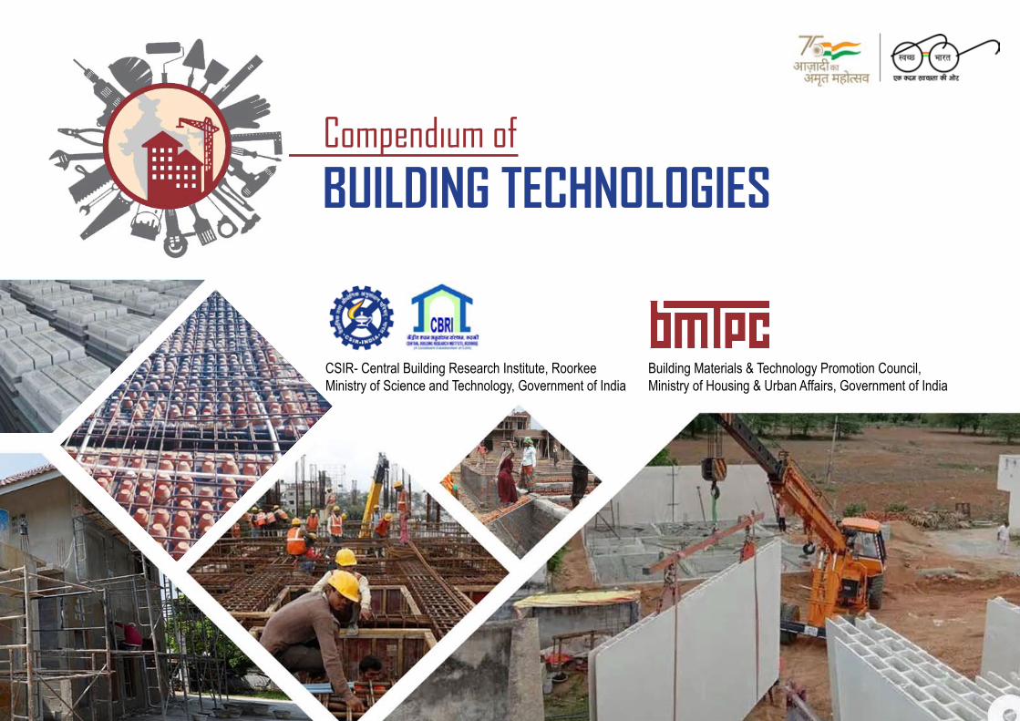
Compendium of
BUILDING TECHNOLOGIES
CSIR- Central Building Research Institute, RoorkeeMinistry of Science and Technology, Government of India
Building Materials & Technology Promotion Council,Ministry of Housing & Urban Affairs, Government of India

Compendium of
BUILDING TECHNOLOGIES
A joint publication of
CSIR- Central Building Research Institute, RoorkeeMinistry of Science and TechnologyGovernment of India
Building Materials & Technology Promotion Council,Ministry of Housing & Urban AffairsGovernment of India
and

PrEfaCE
Housing for all by 75th year of our independence for urban as well as rural households in India triggered major construction technology transi-tion to bring resource-efficient, climate-responsive, disaster-resilient, cost-effective sustainable building technologies. Through Pradhan Mantri Awas Yojna (Urban & Rural), sustainable building materials, local design & skills and innovative construction methodologies are being dis-
seminated for their large-scale adoption to beneficiaries, state govts, professionals and artisans. The overall objective is to ensure sustainable, safe and affordable house to each household. Looking at the target of 11.2 million houses in urban areas & 10 million in next three years in rural area, it is well-nigh impossible to achieve it with traditional brick, mortar & cast-in-situ RCC construction. The age-old practices are no longer sustainable in the light of fast depletion of natural resources, climate change, green house gas emissions, energy scarcity. In addition, the prevalent construction practices are labor-intensive and time consuming. Therefore, it is prudent to bring in forefront alternative & innovative building materials & construction tech-nologies in the construction sector.
The quest of mankind to have a shelter which can protect them from the vagaries of nature has been as old as our civilization. Earlier methods of construction employ locally available materials such as stone, soil, lime & wood. The use of sun-dried bricks as well as fired clay bricks also dates back to 3500 BC. The 19th century saw the biggest transformation in the history of construction when steel & cement were introduced as chief building materials. Today, the concrete is an ubiquitous material being used for small hamlets to skyscrapers to specialized structures. The reinforced concrete construction is versatile and time-tested; however, its sustainability is being questioned. The amount of green house gases (GHG) being emitted dur-ing production of cement, energy being consumed and natural resources being exploited in addition to the air/noise/land pollution puts the onus on Reinforced Concrete (RCC) Construction in its present form gradually untenable specially in fast growing economies such as India.
The majority of RCC construction is cast-in-situ and being performed manually to this day. It is time to bring industrialization in building construction by introducing off-site construction concepts. The mechanization/automation concepts have already been introduced in a few countries with success and India is also introducing them in mass housing projects. Form work systems, pre-engineered buildings, pre-cast concrete construction, dry wall construction are few such concepts which are now widely accepted by the construction fraternity in India. Govt. of India is also keen to introduce cutting edge technologies in the sector and have organized Global Housing Technology Challenge (GHTC) -India through Ministry of Housing & Urban Affairs in March 2019. In this process, 54 new construction systems have been identified which are clubbed into six broad categories namely (i) 3D precast volumetric concrete construction (ii) Precast concrete construction with precast building components (iii) Light Gauge steel structural system & pre-engineered steel structural system (iv) Prefabricated sandwich panel systems (v)Formwork systems (vi) Stay in Place form work systems. Now these systems are being showcased though construction of light house projects in different parts of India.
Nonetheless, these systems are ideally suited for mass housing and to take them to individual household level will not be feasible and therefore, a new set of building systems are required which not only take care of local aspiration, local materials, local skills but also offer sustainability, affordability and disaster resilience. Also, there is need to create synergy between traditional building techniques and the modern methods & knowledge. Both can learn from each other and blending both can produce cost-effective sustainable construction.
CSIR-CBRI being premier research institute in the area of building science & technology for more than 7 decades has developed many such building materi-als, components & technologies and BMTPC since its inception has been into technology transfer for field level applications. Both the organization joined hands to bring out this compendium on Building Technologies. The publication contains 66 existing technologies covering following broad components:
1. Floor/roof construction technologies2. Roof construction technologies3. Wall construction technologies4. Foundation construction technologies5. System level technologies6. Services7. Materials
Each system has been explained in detail along with technical specifications, tools & equipment, salient features, cost, sustainability & economic aspects, material requirements, limitations, market linkages, structural drawings/detailing and relevant standards & references. Also, the geo-climatic suitability of the technology region has been specified. These building technologies are time-tested and proven and the data presented is the outcome of the R & D done by scientists of CSIR-CBRI and their field level applications over the years. The document is ready to use and can be successfully used in the field for Beneficiary Led Construction for low-rise to mid-rise structures. The compendium will serve as a useful resource for construction of individual houses and can help State Governments to introduce these systems in their ongoing housing schemes.
The compendium is a stepping platform to create a technical databank of various existing alternate materials & construction technologies which are time-tested & proven and can readily be used in the field. However, more and more technologies will be added as and when developed and verified. In view of the clarion call given by Hon’ble PM for Atamnirbhar Bharat, it is opportune time to promote technology & innovations in housing especially for low to mid rise structures based on local materials, local skills & construction techniques amalgamated with updated knowledge to achieve affordability, sustainabil-ity, disaster resilience facilitating faster construction. The compendium is an attempt to bring together such indigenous innovations at a common platform and to take stock of alternate materials & technologies for field level applications.
(Dr. N. Gopalakrishnan) (Dr. Shailesh Kr. Agrawal) Director, CSIR-CBRI Executive Director, BMTPC
aCkNOwLEDGEmENTS
The compendium on building technologies is the product of R & D efforts being put up by CSIR-CBRI over the years in the area of alternate cost-effective building materials, precast building components and housing technologies. The CSIR-CBRI being premier research Institute of India has been extending S & T support to Housing for All mission and is knowledge partner to Ministry of Housing & Urban Affair (MoHUA), Govt. of India
& BMTPC. I gratefully acknowledge the help & support of CSIR-CBRI for the entire journey.
The idea of bringing out a publication on existing building materials & technologies germinated by Shri Durga Shankar Mishra, Secretary, MoHUA and the entire team show their gratitude towards him for his enlightened guidance & constant encouragement. Thanks are also due to Shri Amrit Abhijat, the then Joint Secretary & Mission Director, Housing for all, for reposing faith in us and giving us insights from time to time.
I would be failing in my duties, if I do not profusely thank Dr. N. Gopalakrishnan, Director, CSIR-CBRI who on my request immediately agreed to develop the publication in time bound manner without any financial support. His pro-active approach & technical advice for development of the compendium is duly acknowledged.
I would also like to place on record my deep appreciation to the entire team of scientists, technical officers & project assistants at CSIR-CBRI under the able guidance of Dr. S.K. Negi, Chief Scientist & Head, Development, Construction & Extension Group & Dr. Ajay Chourasia, Sr. Principal Scientist, Structural Engineering Division who untiringly have put best of their efforts for preparing & bringing out this compendium. The team members of CSIR-CBRI which are involved in the preparation of compendium are (i) Dr. N. Gopalakrishnan (Director) (ii) S.K. Negi (Chief Scientist & Head, Development, Construction & Extension Group) (iii) Ajay Chourasia, (Sr. Principal Scientist, Structural Engineering Division) (iv) H.K. Jain (Consultant, Development, Construction & Extension Group) (v) Ashish Pippal (Scientist & Head, Development, Construction & Extension Group) (vi) Nimisha Samadhiya (Project Assistant) (vii) Nitin Sahu (Project Assistant) (viii) Gaurav Sharma (Project Assistant) (ix) Ashutosh Singh (Project Assistant) (x) Sugam Kashyap (Technical Officer) (xi) Shubham Singhal (PhD. Scholar) (xii) Neelam Chauhan (Project Assistant). The help & support of other members of CSIR-CBRI who directly or indirectly helped in the publication are also duly acknowledged.
At last but not the least, the team at BMTPC specially Shri Sharad Kr. Gupta, Dy. Chief (TDE & IC) & Shri Dalip Kumar, Sr. Field Officer deserve special mention for reading & editing the publication and bringing it to printable form.
BMTPC wishes to express its deepest gratitude to Shri Hardeep Singh Puri, Hon’ble Minister of Housing & Urban Affairs & President, BMTPC for un-stinted support, constant encouragement & sincere advice. BMTPC is also indebted to HFA directorate & Housing division of MoHUA for supporting BMTPC’s endeavors.
(Dr. Shailesh Kr. Agrawal)Executive Director, BMTPC

CONTENTS
Sr. No. Description Page No.
FlooR/RooF ConSTRUCTIon TeCHnoloGIeS1. Precast R.C. Plank and Partially Precast Joist System 22. Precast Brick Panel and Partially Precast Joist System 43. Precast Channel Unit 64. Precast R.C. Waffle Unit 85. Precast Cored Unit 106. Precast L-panel 127. Reinforced Brick Concrete (RBC) slabs 148. Reinforced Cement Concrete slabs 169. Filler slabs 1810. Ribbed slabs 20
RooF ConSTRUCTIon TeCHnoloGIeS1. Timber Roof Truss 242. Steel Roof Truss 263. Roof Coverings 284. Stone coated Steel Roofing 305. Funicular shell Roof 326. Ferro-cement Roofing channels 347. Brick Pyramidal Roof 368. Green Roof 389. Integrated Solar Roof 40
WAll ConSTRUCTIon TeCHnoloGIeS1. Brick Masonry 442. Rat trap bond Masonry 463. Staggered Masonry 484. Solid Concrete Block Masonry 50
Sr. No. Description Page No.5. Precast Stone block Masonry 526. Hollow Concrete Block Masonry 547. Autoclaved Aerated Concrete (AAC) Blocks 568. Ashlar Masonry 589. Random Rubble Masonry 6010. Rammed Earth Masonry 6211. Compressed Earth Block Masonry 6412. RC Precast Wall 6613. Containment Masonry 6814. Bamboo Strip Walling 7015. Kath Kuni Wall 7216. Dhajji Wall 7417. Prefabricated Sandwich Panels 7618. Light Weight EPS Concrete In-Situ filling between Boards 78
FoUndATIon ConSTRUCTIon TeCHnoloGIeS1. Brick/Block Masonry Strip Foundation 822. Stone Masonry Strip Foundation 843. RC Column Foundation 864. RC Raft foundation 885. RC Pile Foundation 906. Precast RC driven Pile Foundation 927. Under Reamed Pile Foundation 948. Bored Compaction Pile Foundation 969. Pedestal Pile Foundation 9810. Stilt Foundation 100
Sr. No. Description Page No.11. Inverted Arch Foundation 10212. Granular Anchor Pile Foundation 104
SySTeM level TeCHnoloGIeS1. E.P.S. Wall Panel 1082. Reinforced Concrete (RC) Framed Construction 1103. Confined Masonry 1124. Precast Large Concrete Panel System 1145. Monolithic Concrete Construction system 1166. Glass Fibre Reinforced Gypsum (GFRG) Panel Building System 1187. Light Gauge Framed Structure 1208. Speed Floor Construction 1229. Cyclone shelter 124
SeRvICeS1. Rainwater harvesting 1282. Plumbing and Drainage System 130
MATeRIAlS 1. Fly Ash Bricks 1342. Rice Husk Ash Concrete 1363. Cellular Light Weight Concrete 1384. Bamboo Mat Corrugated Sheet 1405. Compressed Earth Brick/Block 1426. Textile Reinforced Concrete 144

1
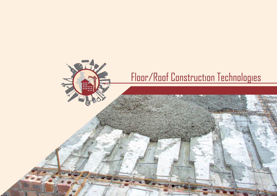
Floor/Roof Construction Technologies
2
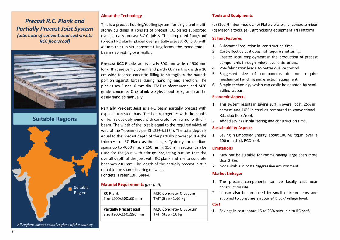
This is a precast flooring/roofing system for single and multi-storey buildings. It consists of precast R.C. planks supportedover partially precast R.C.C. joists. The completed floor/roof(precast RC planks placed over partially precast RC joist) with40 mm thick in-situ concrete filling forms the monolithic T-beam slab resting over walls .
Pre-cast RCC Planks are typically 300 mm wide x 1500 mmlong, that are partly 30 mm and partly 60 mm thick with a 10cm wide tapered concrete filling to strengthen the haunchportion against forces during handling and erection. Theplank uses 3 nos. 6 mm dia. TMT reinforcement, and M20grade concrete. One plank weighs about 50kg and can beeasily handled manually.
Partially Pre-cast Joist is a RC beam partially precast withexposed top steel bars. The beam, together with the plankson both sides duly joined with concrete, form a monolithic T-beam. The width of the joist is equal to the required width ofweb of the T-beam (as per IS 13994:1994). The total depth isequal to the precast depth of the partially precast joist + thethickness of RC Plank as the flange. Typically for mediumspans up to 4000 mm, a 150 mm x 150 mm section can beused for the joist with stirrups projecting out, so that theoverall depth of the joist with RC plank and in-situ concretebecomes 210 mm. The length of the partially precast joist isequal to the span + bearing on walls.For details refer CBRI BRN-4.
RC Plank Size 1500x300x60 mm
M20 Concrete- 0.02cumTMT Steel- 1.60 kg
Partially Precast joistSize 3300x150x150 mm
M20 Concrete- 0.075cumTMT Steel- 10 kg
Material Requirements (per unit)1. The precast components can be locally cast near
construction site.2. It can also be produced by small entrepreneurs and
supplied to consumers at State/ Block/ village level.
Precast R.C. Plank and Partially Precast Joist System(alternate of conventional cast-in-situ
RCC floor/roof)
Suitable Regions
All regions except costal regions of the country
About the Technology Tools and Equipments
(a) Steel/timber moulds, (b) Plate vibrator, (c) concrete mixer(d) Mason’s tools, (e) Light hoisting equipment, (f) Platform
Salient Features1. Substantial reduction in construction time.2. Cost-effective as it does not require shuttering.3. Creates local employment in the production of precast
components through micro level enterprises.4. Pre- fabrication leads to better quality control.5. Suggested size of components do not require
mechanical handling and erection equipment.6. Simple technology which can easily be adapted by semi-
skilled labour.Economic Aspects1. This system results in saving 20% in overall cost, 25% in
cement and 10% in steel as compared to conventionalR.C. slab floor/roof.
2. Added savings in shuttering and construction time.Sustainability Aspects1. Saving in Embodied Energy: about 100 MJ /sq.m. over a
100 mm thick RCC roof.
Limitations1. May not be suitable for rooms having large span more
than 3.8m.2. Not suitable in costal/aggressive environment.
Market Linkages
Cost1. Savings in cost: about 15 to 25% over in-situ RC roof.
Suitable Region
3
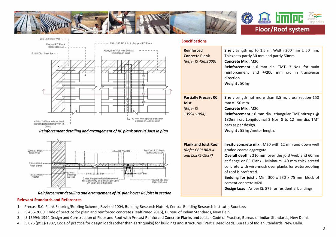
Reinforced Concrete Plank(Refer IS 456:2000)
Size : Length up to 1.5 m, Width 300 mm ± 50 mm,Thickness partly 30 mm and partly 60mmConcrete Mix : M20Reinforcement : 6 mm dia. TMT- 3 Nos. for mainreinforcement and @200 mm c/c in transversedirectionWeight : 50 kg
Partially Precast RC Joist(Refer IS 13994:1994)
Size : Length not more than 3.5 m, cross section 150mm x 150 mmConcrete Mix : M20Reinforcement : 6 mm dia., triangular TMT stirrups @130mm c/c Longitudinal 3 Nos. 8 to 12 mm dia. TMTbars as per design.Weight : 55 kg /meter length.
Plank and Joist Roof(Refer CBRI BRN-4 and IS:875-1987)
In-situ concrete mix : M20 with 12 mm and down wellgraded coarse aggregateOverall depth : 210 mm over the joist/web and 60mmat flange or RC Plank. Minimum 40 mm thick screedconcrete with wire-mesh over planks for waterproofingof roof is preferred.Bedding for joist : Min. 300 x 230 x 75 mm block ofcement concrete M20.Design Load : As per IS: 875 for residential buildings.
Floor/Roof systemSpecifications
Relevant Standards and References 1. Precast R.C. Plank Flooring/Roofing Scheme, Revised 2004, Building Research Note-4, Central Building Research Institute, Roorkee.2. IS 456-2000, Code of practice for plain and reinforced concrete (Reaffirmed 2016), Bureau of Indian Standards, New Delhi.3. IS 13994: 1994 Design and Construction of Floor and Roof with Precast Reinforced Concrete Planks and Joists - Code of Practice, Bureau of Indian Standards, New Delhi.4. IS 875 (pt.1)-1987, Code of practice for design loads (other than earthquake) for buildings and structures : Part 1 Dead loads, Bureau of Indian Standards, New Delhi.
Reinforcement detailing and arrangement of RC plank over RC joist in plan
Reinforcement detailing and arrangement of RC plank over RC joist in section
Floor/Roof system
4
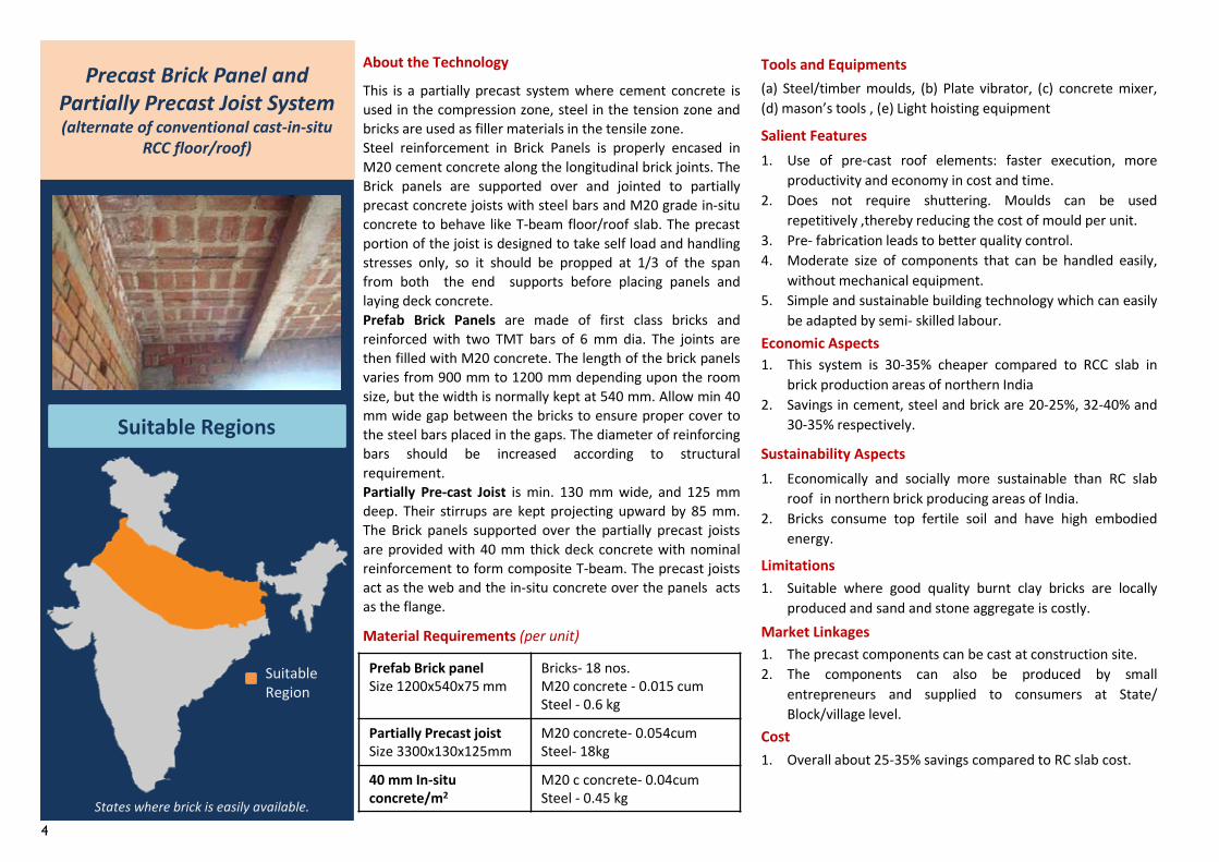
This is a partially precast system where cement concrete isused in the compression zone, steel in the tension zone andbricks are used as filler materials in the tensile zone.Steel reinforcement in Brick Panels is properly encased inM20 cement concrete along the longitudinal brick joints. TheBrick panels are supported over and jointed to partiallyprecast concrete joists with steel bars and M20 grade in-situconcrete to behave like T-beam floor/roof slab. The precastportion of the joist is designed to take self load and handlingstresses only, so it should be propped at 1/3 of the spanfrom both the end supports before placing panels andlaying deck concrete.Prefab Brick Panels are made of first class bricks andreinforced with two TMT bars of 6 mm dia. The joints arethen filled with M20 concrete. The length of the brick panelsvaries from 900 mm to 1200 mm depending upon the roomsize, but the width is normally kept at 540 mm. Allow min 40mm wide gap between the bricks to ensure proper cover tothe steel bars placed in the gaps. The diameter of reinforcingbars should be increased according to structuralrequirement.Partially Pre-cast Joist is min. 130 mm wide, and 125 mmdeep. Their stirrups are kept projecting upward by 85 mm.The Brick panels supported over the partially precast joistsare provided with 40 mm thick deck concrete with nominalreinforcement to form composite T-beam. The precast joistsact as the web and the in-situ concrete over the panels actsas the flange.
Material Requirements (per unit)1. The precast components can be cast at construction site.2. The components can also be produced by small
entrepreneurs and supplied to consumers at State/Block/village level.
About the Technology Tools and Equipments(a) Steel/timber moulds, (b) Plate vibrator, (c) concrete mixer,(d) mason’s tools , (e) Light hoisting equipment
Salient Features1. Use of pre-cast roof elements: faster execution, more
productivity and economy in cost and time.2. Does not require shuttering. Moulds can be used
repetitively ,thereby reducing the cost of mould per unit.3. Pre- fabrication leads to better quality control.4. Moderate size of components that can be handled easily,
without mechanical equipment.5. Simple and sustainable building technology which can easily
be adapted by semi- skilled labour.Economic Aspects1. This system is 30-35% cheaper compared to RCC slab in
brick production areas of northern India2. Savings in cement, steel and brick are 20-25%, 32-40% and
30-35% respectively.
Sustainability Aspects1. Economically and socially more sustainable than RC slab
roof in northern brick producing areas of India.2. Bricks consume top fertile soil and have high embodied
energy.
Limitations1. Suitable where good quality burnt clay bricks are locally
produced and sand and stone aggregate is costly.Market Linkages
Cost1. Overall about 25-35% savings compared to RC slab cost.
Precast Brick Panel and Partially Precast Joist System(alternate of conventional cast-in-situ
RCC floor/roof)
Suitable Regions
States where brick is easily available.
Prefab Brick panel Size 1200x540x75 mm
Bricks- 18 nos.M20 concrete - 0.015 cum Steel - 0.6 kg
Partially Precast joistSize 3300x130x125mm
M20 concrete- 0.054cumSteel- 18kg
40 mm In-situ concrete/m2
M20 c concrete- 0.04cumSteel - 0.45 kg
Suitable Region
5
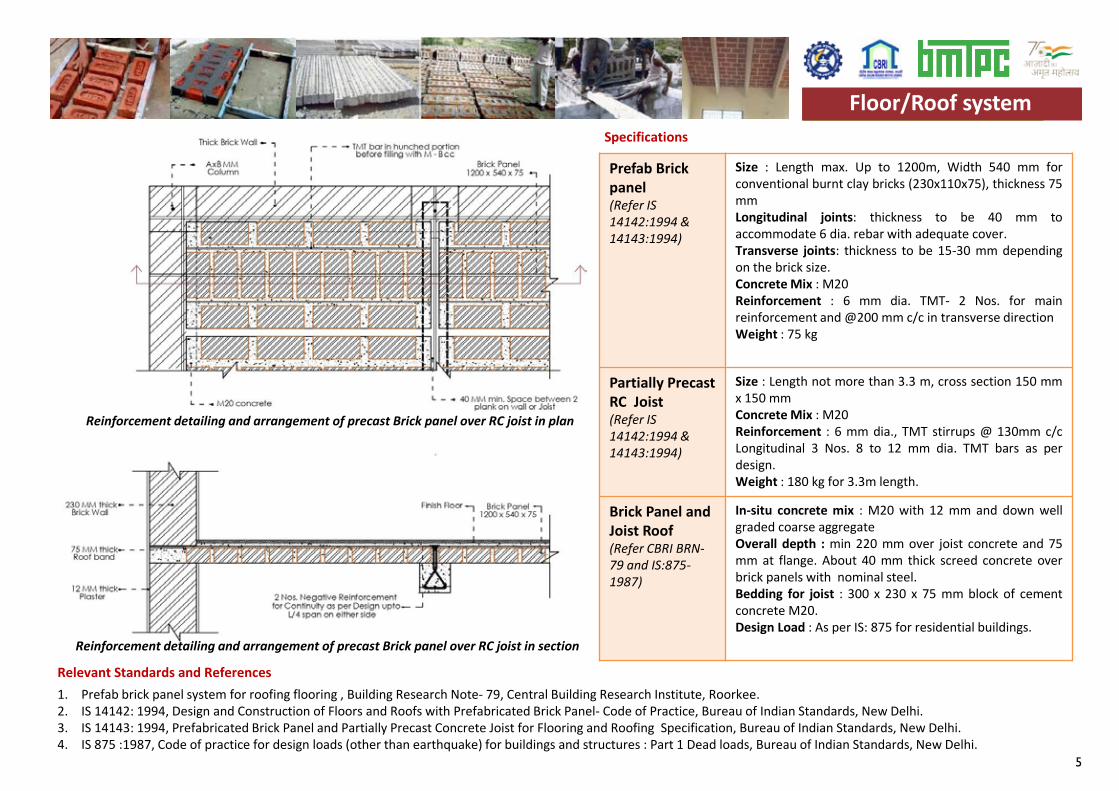
Prefab Brick panel(Refer IS 14142:1994 & 14143:1994)
Size : Length max. Up to 1200m, Width 540 mm forconventional burnt clay bricks (230x110x75), thickness 75mmLongitudinal joints: thickness to be 40 mm toaccommodate 6 dia. rebar with adequate cover.Transverse joints: thickness to be 15-30 mm dependingon the brick size.Concrete Mix : M20Reinforcement : 6 mm dia. TMT- 2 Nos. for mainreinforcement and @200 mm c/c in transverse directionWeight : 75 kg
Partially PrecastRC Joist(Refer IS 14142:1994 & 14143:1994)
Size : Length not more than 3.3 m, cross section 150 mmx 150 mmConcrete Mix : M20Reinforcement : 6 mm dia., TMT stirrups @ 130mm c/cLongitudinal 3 Nos. 8 to 12 mm dia. TMT bars as perdesign.Weight : 180 kg for 3.3m length.
Brick Panel and Joist Roof(Refer CBRI BRN-79 and IS:875-1987)
In-situ concrete mix : M20 with 12 mm and down wellgraded coarse aggregateOverall depth : min 220 mm over joist concrete and 75mm at flange. About 40 mm thick screed concrete overbrick panels with nominal steel.Bedding for joist : 300 x 230 x 75 mm block of cementconcrete M20.Design Load : As per IS: 875 for residential buildings.
Specifications
Relevant Standards and References 1. Prefab brick panel system for roofing flooring , Building Research Note- 79, Central Building Research Institute, Roorkee.2. IS 14142: 1994, Design and Construction of Floors and Roofs with Prefabricated Brick Panel- Code of Practice, Bureau of Indian Standards, New Delhi.3. IS 14143: 1994, Prefabricated Brick Panel and Partially Precast Concrete Joist for Flooring and Roofing Specification, Bureau of Indian Standards, New Delhi.4. IS 875 :1987, Code of practice for design loads (other than earthquake) for buildings and structures : Part 1 Dead loads, Bureau of Indian Standards, New Delhi.
Floor/Roof system
Reinforcement detailing and arrangement of precast Brick panel over RC joist in plan
Reinforcement detailing and arrangement of precast Brick panel over RC joist in section
Floor/Roof system
6
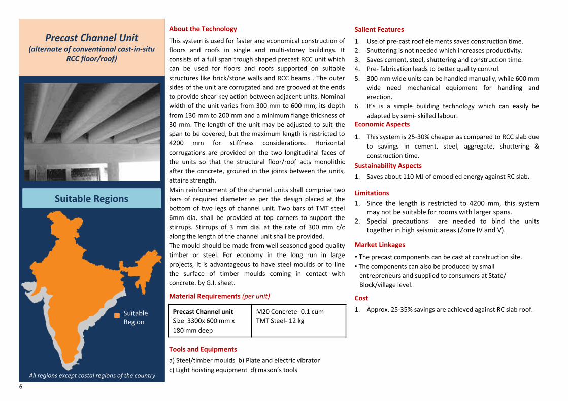
This system is used for faster and economical construction offloors and roofs in single and multi-storey buildings. Itconsists of a full span trough shaped precast RCC unit whichcan be used for floors and roofs supported on suitablestructures like brick/stone walls and RCC beams . The outersides of the unit are corrugated and are grooved at the endsto provide shear key action between adjacent units. Nominalwidth of the unit varies from 300 mm to 600 mm, its depthfrom 130 mm to 200 mm and a minimum flange thickness of30 mm. The length of the unit may be adjusted to suit thespan to be covered, but the maximum length is restricted to4200 mm for stiffness considerations. Horizontalcorrugations are provided on the two longitudinal faces ofthe units so that the structural floor/roof acts monolithicafter the concrete, grouted in the joints between the units,attains strength.Main reinforcement of the channel units shall comprise twobars of required diameter as per the design placed at thebottom of two legs of channel unit. Two bars of TMT steel6mm dia. shall be provided at top corners to support thestirrups. Stirrups of 3 mm dia. at the rate of 300 mm c/calong the length of the channel unit shall be provided.The mould should be made from well seasoned good qualitytimber or steel. For economy in the long run in largeprojects, it is advantageous to have steel moulds or to linethe surface of timber moulds coming in contact withconcrete. by G.I. sheet.
Precast Channel unitSize 3300x 600 mm x 180 mm deep
M20 Concrete- 0.1 cumTMT Steel- 12 kg
Material Requirements (per unit)
• The precast components can be cast at construction site.• The components can also be produced by small
entrepreneurs and supplied to consumers at State/Block/village level.
About the Technology
Tools and Equipmentsa) Steel/timber moulds b) Plate and electric vibratorc) Light hoisting equipment d) mason’s tools
Salient Features1. Use of pre-cast roof elements saves construction time.2. Shuttering is not needed which increases productivity.3. Saves cement, steel, shuttering and construction time.4. Pre- fabrication leads to better quality control.5. 300 mm wide units can be handled manually, while 600 mm
wide need mechanical equipment for handling anderection.
6. It’s is a simple building technology which can easily beadapted by semi- skilled labour.
Economic Aspects
1. This system is 25-30% cheaper as compared to RCC slab dueto savings in cement, steel, aggregate, shuttering &construction time.
Sustainability Aspects1. Saves about 110 MJ of embodied energy against RC slab.
Limitations1. Since the length is restricted to 4200 mm, this system
may not be suitable for rooms with larger spans.2. Special precautions are needed to bind the units
together in high seismic areas (Zone IV and V).
Market Linkages
Cost1. Approx. 25-35% savings are achieved against RC slab roof.
Precast Channel Unit (alternate of conventional cast-in-situ
RCC floor/roof)
Suitable Regions
All regions except costal regions of the country
Suitable Region
7
Precast Channel unit(Refer IS 14201: 1994,14215: 1994 and IS 456:2000)
Size : Length up to 4200mm (preferred up to3500mm), Width 300 to 600 mm and depth 130to 200mm.
Concrete Mix : M20 concrete with 12 mm anddown well graded aggregate
Reinforcement : 8mm dia. TMT- 2 Nos. at topcorners and Stirrups of 3 mm dia. @300 mm c/calong the length of the channel unit. 2 mainreinforcement bars 10 to 14 mm at bottom legs asper span and design.
Weight : 240 Kg for 3300x600x180 mm size
Design load: As per IS 875-1987 and 456-2000 forresidential buildings.
In-situ concrete(Refer CBRI BRN-52)
In-situ concrete mix : M20 with 10 mm and downwell graded coarse aggregate. All concrete work tobe well compacted using electric vibrator.
Specifications
Relevant Standards and References 1. Precast channel unit for floor/ roof , Building Research Note- 52, Central Building Research Institute, Roorkee.2. IS 14201 : 1994, Precast Reinforced Concrete Channel Units for Construction of Floors and Roofs – Specification, Bureau of Indian Standards, New Delhi.3. IS 14215 : 1994, Design and Construction of Floors and Roofs with Precast Reinforced Concrete Channel Units- Code of Practice, Bureau of Indian Standards, New Delhi.4. IS 456-2000, Code of practice for plain and reinforced concrete (Reaffirmed 2016), Bureau of Indian Standards, New Delhi.5. IS 875 :1987, Code of practice for design loads (other than earthquake) for buildings and structures : Part 1 Dead loads, Bureau of Indian Standards, New Delhi.
Floor/Roof system
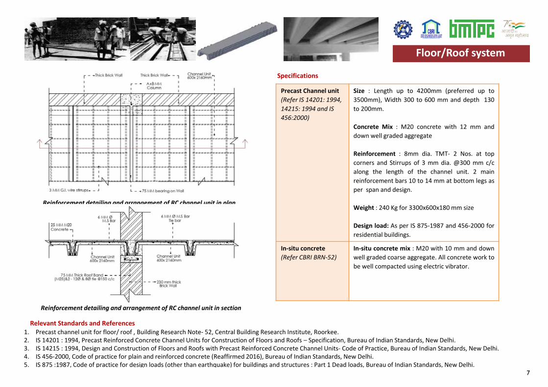
Reinforcement detailing and arrangement of RC channel unit in plan
Reinforcement detailing and arrangement of RC channel unit in section
Floor/Roof system
8
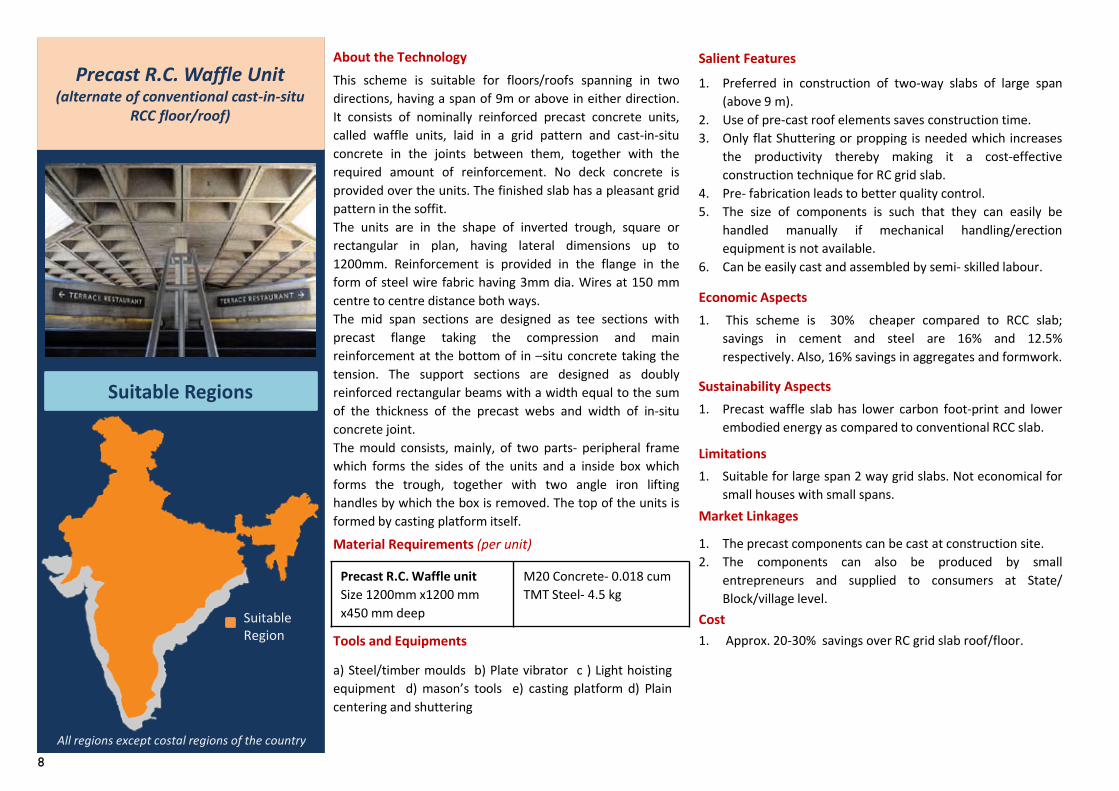
This scheme is suitable for floors/roofs spanning in twodirections, having a span of 9m or above in either direction.It consists of nominally reinforced precast concrete units,called waffle units, laid in a grid pattern and cast-in-situconcrete in the joints between them, together with therequired amount of reinforcement. No deck concrete isprovided over the units. The finished slab has a pleasant gridpattern in the soffit.The units are in the shape of inverted trough, square orrectangular in plan, having lateral dimensions up to1200mm. Reinforcement is provided in the flange in theform of steel wire fabric having 3mm dia. Wires at 150 mmcentre to centre distance both ways.The mid span sections are designed as tee sections withprecast flange taking the compression and mainreinforcement at the bottom of in –situ concrete taking thetension. The support sections are designed as doublyreinforced rectangular beams with a width equal to the sumof the thickness of the precast webs and width of in-situconcrete joint.The mould consists, mainly, of two parts- peripheral framewhich forms the sides of the units and a inside box whichforms the trough, together with two angle iron liftinghandles by which the box is removed. The top of the units isformed by casting platform itself.
Precast R.C. Waffle unitSize 1200mm x1200 mm x450 mm deep
M20 Concrete- 0.018 cumTMT Steel- 4.5 kg
Material Requirements (per unit) 1. The precast components can be cast at construction site.2. The components can also be produced by small
entrepreneurs and supplied to consumers at State/Block/village level.
About the Technology
Tools and Equipments
a) Steel/timber moulds b) Plate vibrator c ) Light hoistingequipment d) mason’s tools e) casting platform d) Plaincentering and shuttering
Salient Features1. Preferred in construction of two-way slabs of large span
(above 9 m).2. Use of pre-cast roof elements saves construction time.3. Only flat Shuttering or propping is needed which increases
the productivity thereby making it a cost-effectiveconstruction technique for RC grid slab.
4. Pre- fabrication leads to better quality control.5. The size of components is such that they can easily be
handled manually if mechanical handling/erectionequipment is not available.
6. Can be easily cast and assembled by semi- skilled labour.
Economic Aspects1. This scheme is 30% cheaper compared to RCC slab;
savings in cement and steel are 16% and 12.5%respectively. Also, 16% savings in aggregates and formwork.
Sustainability Aspects1. Precast waffle slab has lower carbon foot-print and lower
embodied energy as compared to conventional RCC slab.
Limitations1. Suitable for large span 2 way grid slabs. Not economical for
small houses with small spans.Market Linkages
Cost1. Approx. 20-30% savings over RC grid slab roof/floor.
Precast R.C. Waffle Unit(alternate of conventional cast-in-situ
RCC floor/roof)
Suitable Regions
All regions except costal regions of the country
Suitable Region
9
Precast R.C. Waffle unit(Refer IS 10505:1983 and IS 456:2000)
Size : to be designed as per loads and span.
Concrete Mix : M20 concrete with 10 mm anddown well graded aggregate
Reinforcement : As per design
Weight : 70 to 150 kg as per size
Design: As per IS 456:2000 and loading forresidential buildings as per IS 875:1987.
In-situ concrete In-situ concrete mix : M20 with 10 mm and downwell graded coarse aggregate with required steelin the gaps between the waffle units.
Specifications
Relevant Standards and References 1. IS 10505-1983 code of practice for construction of floors and roofs using precast concrete waffle units, Bureau Of Indian Standards, New Delhi.2. IS 456-2000, code of practice for plain and reinforced concrete (reaffirmed 2016), Bureau Of Indian Standards, New Delhi.3. IS 875-1987, Code of practice for design loads (other than earthquake) for buildings and structures : Part 1 Dead loads, Bureau of Indian Standards, New Delhi.
Floor/Roof system
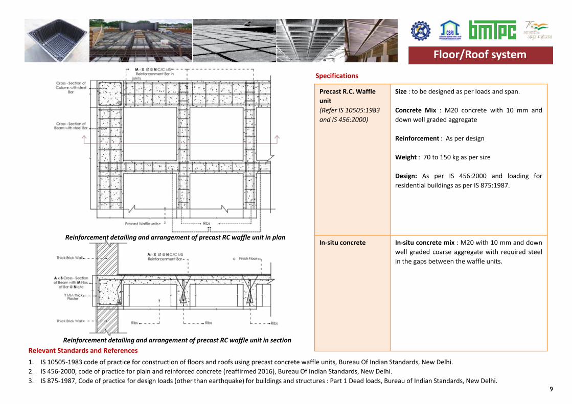
Reinforcement detailing and arrangement of precast RC waffle unit in plan
Reinforcement detailing and arrangement of precast RC waffle unit in section
Floor/Roof system
10
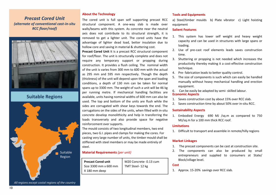
The cored unit is full span self supporting precast RCCstructural component. A one-way slab is made overwalls/beams with this system. As concrete near the neutralaxis does not contribute to its structural strength, it isremoved to get a lighter unit. The cored units have theadvantage of lighter dead load, better insulation due tohollow core and saving in material & shuttering cost.Precast Cored Unit It is a precast RCC structural componentfor roof/floor. The unit is structurally complete and does notrequire any temporary support or propping duringconstruction. It provides a flush ceiling. The nominal widthof the unit is varies from 300 mm to 600 mm with the actualas 295 mm and 595 mm respectively. Though the depth(thickness) of the unit will depend upon the span and loadingconditions, a depth of 130 mm can be taken for normalspans up to 3300 mm. The weight of such a unit will be 46 kgper running metre. If mechanical handling facilities areavailable, units having nominal widths of 600 mm can also beused. The top and bottom of the units are flush while thesides are corrugated with shear keys towards the end. Thecorrugations on the sides of the units, when filled with in-situconcrete develop monolithicity and help in transferring theloads transversely and also provide space for negativereinforcement over supports.The mould consists of two longitudinal members, two end pieces, two G.I. pipes and clamps for making the cores. For casting very large number of units, the timber mould shall be stiffened with steel members or may be made entirely of steel.
Precast Cored unitSize 3300 mm x 600 mm X 180 mm deep
M20 Concrete- 0.13 cumTMT Steel- 12 kg
Material Requirements (per unit)
1. The precast components can be cast at construction site.2. The components can also be produced by small
entrepreneurs and supplied to consumers at State/Block/village level.
About the Technology Tools and Equipmentsa) Steel/timber moulds b) Plate vibrator c) Light hoistingequipmentSalient Features
1. This system has lower self weight and heavy weightcapacity and can be used in structures with large spans orloading.
2. Use of pre-cast roof elements leads saves constructiontime.
3. Shuttering or propping is not needed which increases theproductivity thereby making it a cost-effective constructiontechnique.
4. Pre- fabrication leads to better quality control.5. The size of components is such which can easily be handled
manually without heavy mechanical handling and erectionequipment.
6. Can be easily be adapted by semi- skilled labour.Economic Aspects1. Saves construction cost by about 15% over RCC slab.2. Saves construction time by about 50% over in-situ RCC.
Sustainability Aspects1. Embodied Energy 690 MJ /sq.m as compared to 750
MJ/sq.m for a 100 mm thick RCC roof.Limitations1. Difficult to transport and assemble in remote/hilly regions
Market Linkages
Cost1. Approx. 15-20% savings over RCC slab.
Precast Cored Unit(alternate of conventional cast-in-situ
RCC floor/roof)
Suitable Regions
Suitable Region
All regions except costal regions of the country
11
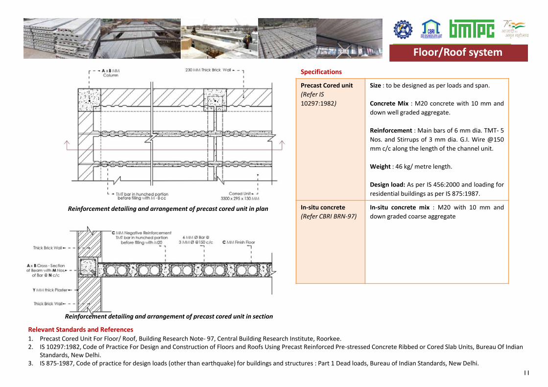
Precast Cored unit(Refer IS 10297:1982)
Size : to be designed as per loads and span.
Concrete Mix : M20 concrete with 10 mm anddown well graded aggregate.
Reinforcement : Main bars of 6 mm dia. TMT- 5Nos. and Stirrups of 3 mm dia. G.I. Wire @150mm c/c along the length of the channel unit.
Weight : 46 kg/ metre length.
Design load: As per IS 456:2000 and loading forresidential buildings as per IS 875:1987.
In-situ concrete(Refer CBRI BRN-97)
In-situ concrete mix : M20 with 10 mm anddown graded coarse aggregate
Specifications
Relevant Standards and References 1. Precast Cored Unit For Floor/ Roof, Building Research Note- 97, Central Building Research Institute, Roorkee.2. IS 10297:1982, Code of Practice For Design and Construction of Floors and Roofs Using Precast Reinforced Pre-stressed Concrete Ribbed or Cored Slab Units, Bureau Of Indian
Standards, New Delhi.3. IS 875-1987, Code of practice for design loads (other than earthquake) for buildings and structures : Part 1 Dead loads, Bureau of Indian Standards, New Delhi.
Reinforcement detailing and arrangement of precast cored unit in plan
Reinforcement detailing and arrangement of precast cored unit in section
Floor/Roof systemFloor/Roof system
12
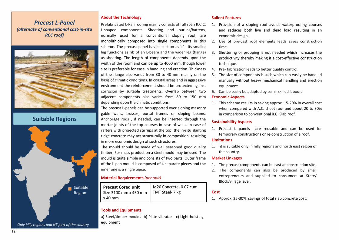
Prefabricated L-Pan roofing mainly consists of full span R.C.C.L-shaped components. Sheeting and purlins/battens,normally used for a conventional sloping roof, aremonolithically composed into single components in thisscheme. The precast panel has its section as 'L' . Its smallerleg functions as rib of an L-beam and the wider leg (flange)as sheeting. The length of components depends upon thewidth of the room and can be up to 4000 mm, though lowersize is preferable for ease in handling and erection. Thicknessof the flange also varies from 30 to 40 mm mainly on thebasis of climatic conditions. In coastal areas and in aggressiveenvironment the reinforcement should be protected againstcorrosion by suitable treatments. Overlap between twoadjacent components also varies from 80 to 150 mmdepending upon the climatic conditions.The precast L-panels can be supported over sloping masonrygable walls, trusses, portal frames or sloping beams.Anchorage rods , if needed, can be inserted through themortar joints of the top courses in case of walls. In case ofrafters with projected stirrups at the top, the in-situ slantingridge concrete may act structurally in composition, resultingin more economic design of such structures.The mould should be made of well seasoned good qualitytimber. For mass production a steel mould may be used. Themould is quite simple and consists of two parts. Outer frameof the L-pan mould is composed of 4 separate pieces and theinner one is a single piece.
Precast Cored unitSize 3100 mm x 450 mm x 40 mm
M20 Concrete- 0.07 cumTMT Steel- 7 kg
Material Requirements (per unit)
1. The precast components can be cast at construction site.2. The components can also be produced by small
entrepreneurs and supplied to consumers at State/Block/village level.
About the Technology
Tools and Equipmentsa) Steel/timber moulds b) Plate vibrator c) Light hoistingequipment
Salient Features1. Provision of a sloping roof avoids waterproofing courses
and reduces both live and dead load resulting in aneconomic design.
2. Use of pre-cast roof elements leads saves constructiontime.
3. Shuttering or propping is not needed which increases theproductivity thereby making it a cost-effective constructiontechnique.
4. Pre- fabrication leads to better quality control.5. The size of components is such which can easily be handled
manually without heavy mechanical handling and erectionequipment.
6. Can be easily be adapted by semi- skilled labour.Economic Aspects1. This scheme results in saving approx. 15-20% in overall cost
when compared with A.C. sheet roof and about 20 to 30%in comparison to conventional R.C. Slab roof.
Sustainability Aspects1. Precast L panels are reusable and can be used for
temporary constructions or re-construction of a roof.Limitations1. it is suitable only in hilly regions and north east region of
the country.Market Linkages
Cost1. Approx. 25-30% savings of total slab concrete cost.
Precast L-Panel(alternate of conventional cast-in-situ
RCC roof)
Suitable Regions
Suitable Region
Only hilly regions and NE part of the country
13
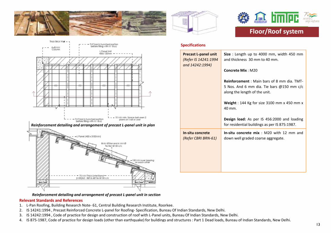
Precast L-panel unit(Refer IS 14241:1994and 14242:1994)
Size : Length up to 4000 mm, width 450 mmand thickness 30 mm to 40 mm.
Concrete Mix : M20
Reinforcement : Main bars of 8 mm dia. TMT-5 Nos. And 6 mm dia. Tie bars @150 mm c/calong the length of the unit.
Weight : 144 Kg for size 3100 mm x 450 mm x40 mm.
Design load: As per IS 456:2000 and loadingfor residential buildings as per IS 875:1987.
In-situ concrete(Refer CBRI BRN-61)
In-situ concrete mix : M20 with 12 mm anddown well graded coarse aggregate.
Specifications
Relevant Standards and References 1. L-Pan Roofing, Building Research Note- 61, Central Building Research Institute, Roorkee.2. IS 14241:1994 , Precast Reinforced Concrete L-panel for Roofing- Specification, Bureau Of Indian Standards, New Delhi.3. IS 14242:1994 , Code of practice for design and construction of roof with L-Panel units, Bureau Of Indian Standards, New Delhi.4. IS 875-1987, Code of practice for design loads (other than earthquake) for buildings and structures : Part 1 Dead loads, Bureau of Indian Standards, New Delhi.
Floor/Roof system
Reinforcement detailing and arrangement of precast L-panel unit in plan
Reinforcement detailing and arrangement of precast L-panel unit in section
Floor/Roof system
14
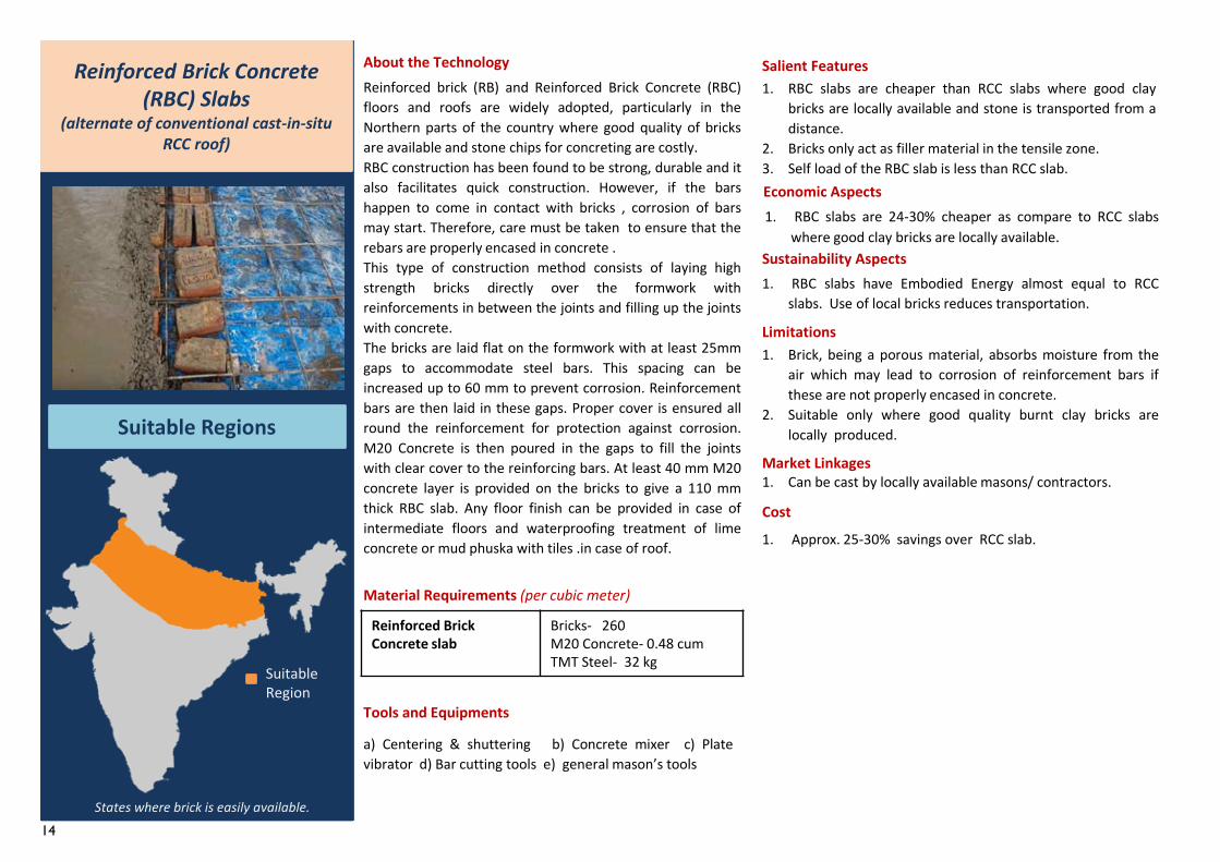
Reinforced brick (RB) and Reinforced Brick Concrete (RBC)floors and roofs are widely adopted, particularly in theNorthern parts of the country where good quality of bricksare available and stone chips for concreting are costly.RBC construction has been found to be strong, durable and italso facilitates quick construction. However, if the barshappen to come in contact with bricks , corrosion of barsmay start. Therefore, care must be taken to ensure that therebars are properly encased in concrete .This type of construction method consists of laying highstrength bricks directly over the formwork withreinforcements in between the joints and filling up the jointswith concrete.The bricks are laid flat on the formwork with at least 25mmgaps to accommodate steel bars. This spacing can beincreased up to 60 mm to prevent corrosion. Reinforcementbars are then laid in these gaps. Proper cover is ensured allround the reinforcement for protection against corrosion.M20 Concrete is then poured in the gaps to fill the jointswith clear cover to the reinforcing bars. At least 40 mm M20concrete layer is provided on the bricks to give a 110 mmthick RBC slab. Any floor finish can be provided in case ofintermediate floors and waterproofing treatment of limeconcrete or mud phuska with tiles .in case of roof.
Reinforced Brick Concrete slab
Bricks- 260M20 Concrete- 0.48 cumTMT Steel- 32 kg
Material Requirements (per cubic meter)
1. Can be cast by locally available masons/ contractors.
About the Technology
Tools and Equipments
a) Centering & shuttering b) Concrete mixer c) Platevibrator d) Bar cutting tools e) general mason’s tools
Salient Features1. RBC slabs are cheaper than RCC slabs where good clay
bricks are locally available and stone is transported from adistance.
2. Bricks only act as filler material in the tensile zone.3. Self load of the RBC slab is less than RCC slab.Economic Aspects1. RBC slabs are 24-30% cheaper as compare to RCC slabs
where good clay bricks are locally available.Sustainability Aspects1. RBC slabs have Embodied Energy almost equal to RCC
slabs. Use of local bricks reduces transportation.
Limitations1. Brick, being a porous material, absorbs moisture from the
air which may lead to corrosion of reinforcement bars ifthese are not properly encased in concrete.
2. Suitable only where good quality burnt clay bricks arelocally produced.
Market Linkages
Cost
1. Approx. 25-30% savings over RCC slab.
Reinforced Brick Concrete (RBC) Slabs
(alternate of conventional cast-in-situ RCC roof)
Suitable Regions
Suitable Region
States where brick is easily available.
15
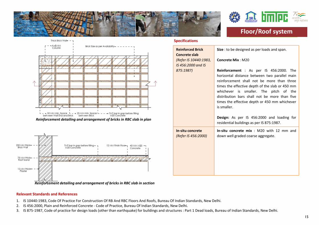
Reinforced Brick Concrete slab(Refer IS 10440:1983,IS 456:2000 and IS 875:1987)
Size : to be designed as per loads and span.
Concrete Mix : M20
Reinforcement : As per IS 456:2000. Thehorizontal distance between two parallel mainreinforcement shall not be more than threetimes the effective depth of the slab or 450 mmwhichever is smaller. The pitch of thedistribution bars shall not be more than fivetimes the effective depth or 450 mm whicheveris smaller.
Design: As per IS 456:2000 and loading forresidential buildings as per IS 875:1987.
In-situ concrete(Refer IS 456:2000)
In-situ concrete mix : M20 with 12 mm anddown well graded coarse aggregate.
Specifications
Relevant Standards and References 1. IS 10440:1983, Code Of Practice For Construction Of RB And RBC Floors And Roofs, Bureau Of Indian Standards, New Delhi.2. IS 456:2000, Plain and Reinforced Concrete - Code of Practice, Bureau Of Indian Standards, New Delhi.3. IS 875-1987, Code of practice for design loads (other than earthquake) for buildings and structures : Part 1 Dead loads, Bureau of Indian Standards, New Delhi.
Floor/Roof system
Reinforcement detailing and arrangement of bricks in RBC slab in plan
Reinforcement detailing and arrangement of bricks in RBC slab in section
Floor/Roof system
16
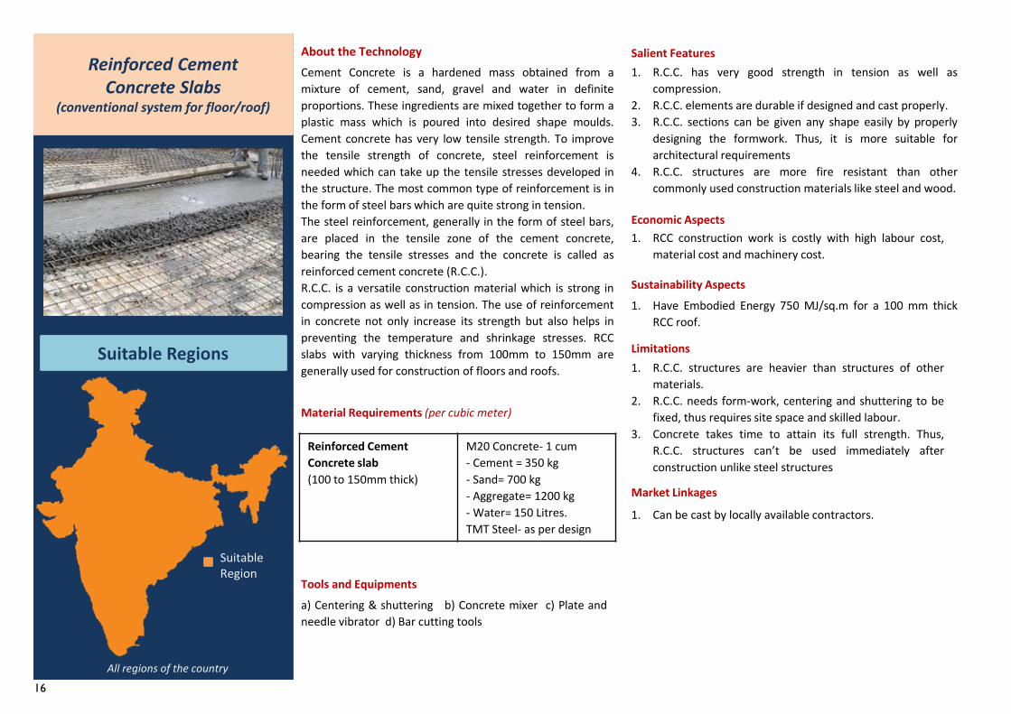
Cement Concrete is a hardened mass obtained from amixture of cement, sand, gravel and water in definiteproportions. These ingredients are mixed together to form aplastic mass which is poured into desired shape moulds.Cement concrete has very low tensile strength. To improvethe tensile strength of concrete, steel reinforcement isneeded which can take up the tensile stresses developed inthe structure. The most common type of reinforcement is inthe form of steel bars which are quite strong in tension.The steel reinforcement, generally in the form of steel bars,are placed in the tensile zone of the cement concrete,bearing the tensile stresses and the concrete is called asreinforced cement concrete (R.C.C.).R.C.C. is a versatile construction material which is strong incompression as well as in tension. The use of reinforcementin concrete not only increase its strength but also helps inpreventing the temperature and shrinkage stresses. RCCslabs with varying thickness from 100mm to 150mm aregenerally used for construction of floors and roofs.
Reinforced CementConcrete slab (100 to 150mm thick)
M20 Concrete- 1 cum- Cement = 350 kg- Sand= 700 kg- Aggregate= 1200 kg- Water= 150 Litres.TMT Steel- as per design
Material Requirements (per cubic meter)
About the Technology Salient Features1. R.C.C. has very good strength in tension as well as
compression.2. R.C.C. elements are durable if designed and cast properly.3. R.C.C. sections can be given any shape easily by properly
designing the formwork. Thus, it is more suitable forarchitectural requirements
4. R.C.C. structures are more fire resistant than othercommonly used construction materials like steel and wood.
Economic Aspects1. RCC construction work is costly with high labour cost,
material cost and machinery cost.
Sustainability Aspects1. Have Embodied Energy 750 MJ/sq.m for a 100 mm thick
RCC roof.
Limitations1. R.C.C. structures are heavier than structures of other
materials.2. R.C.C. needs form-work, centering and shuttering to be
fixed, thus requires site space and skilled labour.3. Concrete takes time to attain its full strength. Thus,
R.C.C. structures can’t be used immediately afterconstruction unlike steel structures
Market Linkages
Reinforced CementConcrete Slabs
(conventional system for floor/roof)
Suitable Regions
Suitable Region
All regions of the country
Tools and Equipmentsa) Centering & shuttering b) Concrete mixer c) Plate andneedle vibrator d) Bar cutting tools
1. Can be cast by locally available contractors.
17
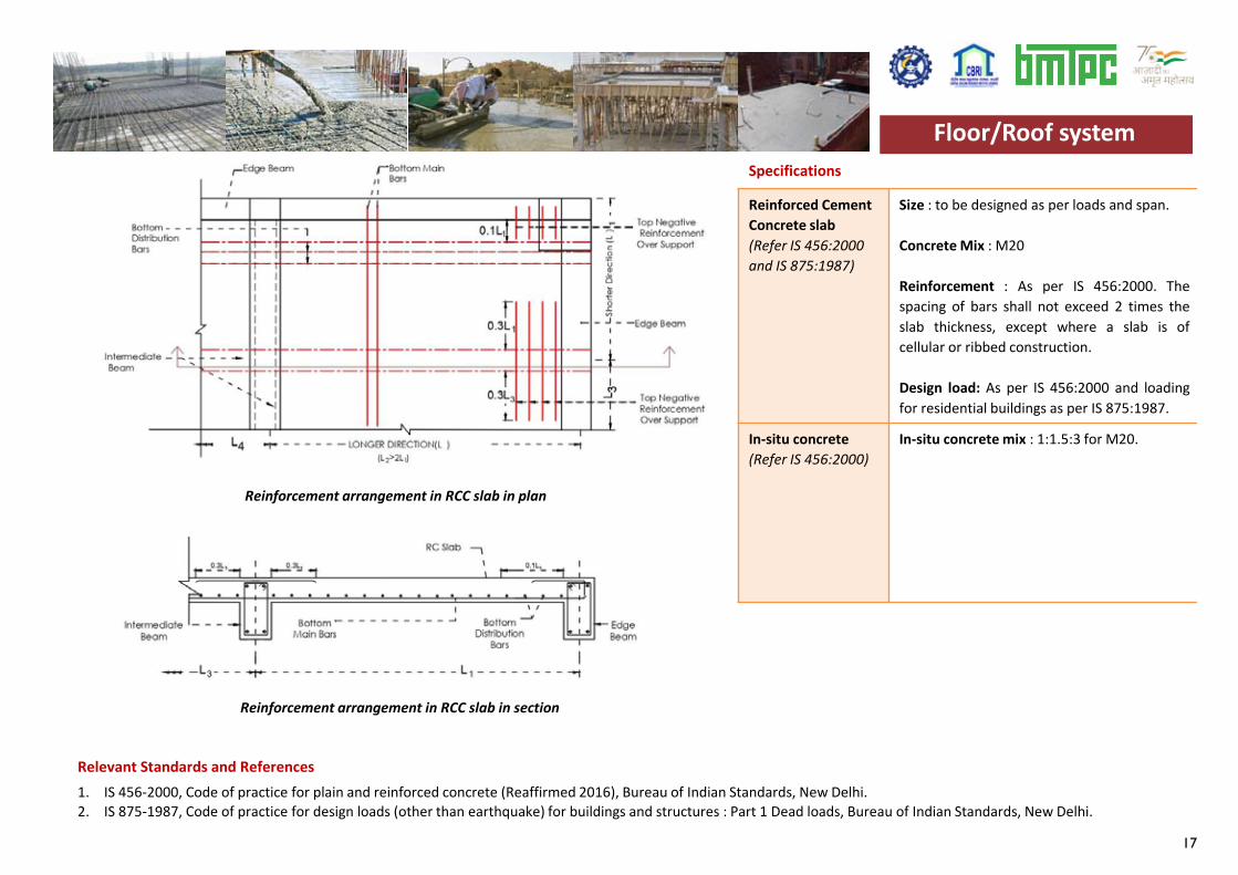
Reinforced Cement Concrete slab(Refer IS 456:2000 and IS 875:1987)
Size : to be designed as per loads and span.
Concrete Mix : M20
Reinforcement : As per IS 456:2000. Thespacing of bars shall not exceed 2 times theslab thickness, except where a slab is ofcellular or ribbed construction.
Design load: As per IS 456:2000 and loadingfor residential buildings as per IS 875:1987.
In-situ concrete(Refer IS 456:2000)
In-situ concrete mix : 1:1.5:3 for M20.
Specifications
Relevant Standards and References 1. IS 456-2000, Code of practice for plain and reinforced concrete (Reaffirmed 2016), Bureau of Indian Standards, New Delhi.2. IS 875-1987, Code of practice for design loads (other than earthquake) for buildings and structures : Part 1 Dead loads, Bureau of Indian Standards, New Delhi.
Floor/Roof system
Reinforcement arrangement in RCC slab in plan
Reinforcement arrangement in RCC slab in section
Floor/Roof system
18
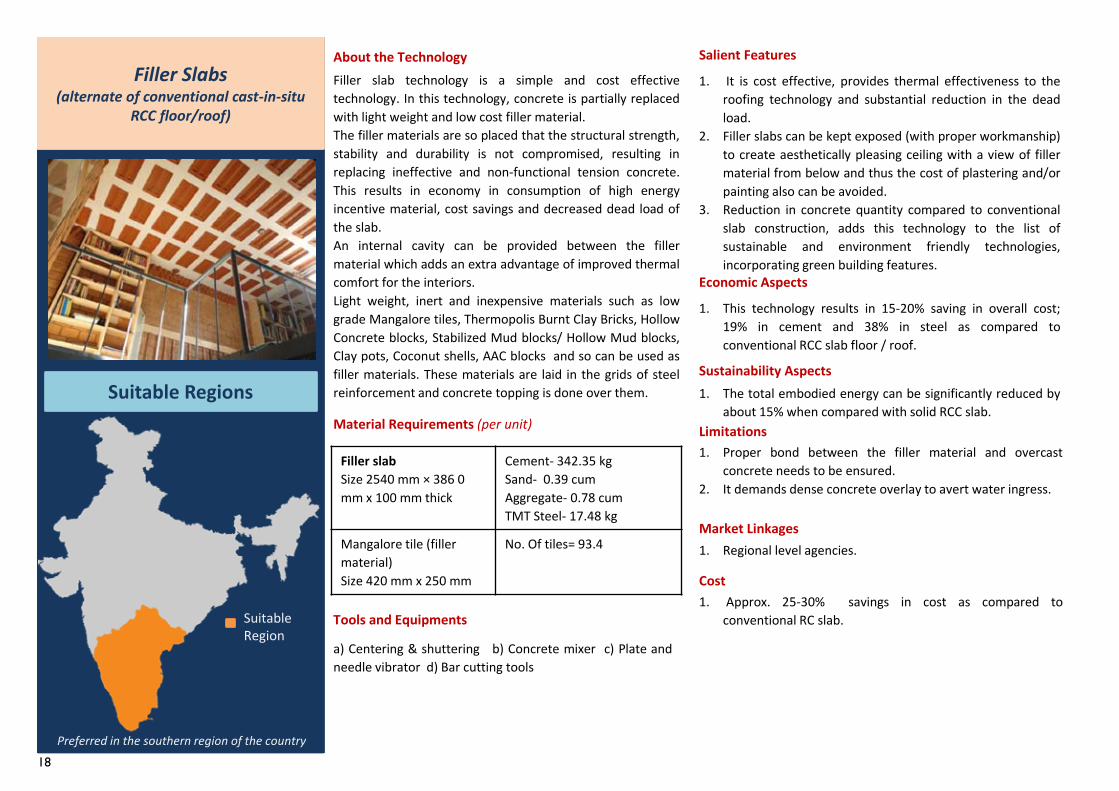
Filler slab technology is a simple and cost effectivetechnology. In this technology, concrete is partially replacedwith light weight and low cost filler material.The filler materials are so placed that the structural strength,stability and durability is not compromised, resulting inreplacing ineffective and non-functional tension concrete.This results in economy in consumption of high energyincentive material, cost savings and decreased dead load ofthe slab.An internal cavity can be provided between the fillermaterial which adds an extra advantage of improved thermalcomfort for the interiors.Light weight, inert and inexpensive materials such as lowgrade Mangalore tiles, Thermopolis Burnt Clay Bricks, HollowConcrete blocks, Stabilized Mud blocks/ Hollow Mud blocks,Clay pots, Coconut shells, AAC blocks and so can be used asfiller materials. These materials are laid in the grids of steelreinforcement and concrete topping is done over them.
Filler slabSize 2540 mm × 386 0 mm x 100 mm thick
Cement- 342.35 kgSand- 0.39 cumAggregate- 0.78 cumTMT Steel- 17.48 kg
Mangalore tile (filler material)Size 420 mm x 250 mm
No. Of tiles= 93.4
Material Requirements (per unit)
1. Regional level agencies.
About the Technology Salient Features
1. It is cost effective, provides thermal effectiveness to theroofing technology and substantial reduction in the deadload.
2. Filler slabs can be kept exposed (with proper workmanship)to create aesthetically pleasing ceiling with a view of fillermaterial from below and thus the cost of plastering and/orpainting also can be avoided.
3. Reduction in concrete quantity compared to conventionalslab construction, adds this technology to the list ofsustainable and environment friendly technologies,incorporating green building features.
Economic Aspects
1. This technology results in 15-20% saving in overall cost;19% in cement and 38% in steel as compared toconventional RCC slab floor / roof.
Sustainability Aspects1. The total embodied energy can be significantly reduced by
about 15% when compared with solid RCC slab.Limitations1. Proper bond between the filler material and overcast
concrete needs to be ensured.2. It demands dense concrete overlay to avert water ingress.
Market Linkages
Cost1. Approx. 25-30% savings in cost as compared to
conventional RC slab.
Filler Slabs(alternate of conventional cast-in-situ
RCC floor/roof)
Suitable Regions
Suitable Region
Preferred in the southern region of the country
Tools and Equipments
a) Centering & shuttering b) Concrete mixer c) Plate andneedle vibrator d) Bar cutting tools
19
Filler slab(Refer IS 456:2000 and IS 875:1987)
Size : To be designed as per loads and span.Minimum thickness of the slab should be 100mm.Concrete Mix : M20For a 200 sq.m house slab-Cement- 6847 kgCourse aggregate- 15.51 cumFine aggregate- 7.76 cumReinforcement : As per IS 456:2000. Thedistance between two parallel mainreinforcement shall not be more than threetimes the effective depth of the slab or 450mm whichever is smaller. The pitch of thedistribution bars shall not be more than fivetimes the effective depth or 450 mmwhichever is smaller.For a 200 sq.m house slab-Steel- 349.58 kgFiller material: The distance between eachunit of filler unit should be 75mm.For a 200 sq.m house slab with Mangalore tilesas filler material-Number of tiles- 1468.73Design load: As per IS 456:2000 and loadingfor residential buildings as per IS 875:1987.
In-situ concrete(Refer IS 456:2000)
In-situ concrete mix : M20 with 12 mm anddown well graded coarse aggregate.
Specifications
Relevant Standards and References
Floor/Roof system
1. IS 456-2000, Code of practice for plain and reinforced concrete (Reaffirmed 2016), Bureau of Indian Standards, New Delhi.2. IS 875-1987, Code of practice for design loads (other than earthquake) for buildings and structures : Part 1 Dead loads, Bureau of Indian Standards, New Delhi.
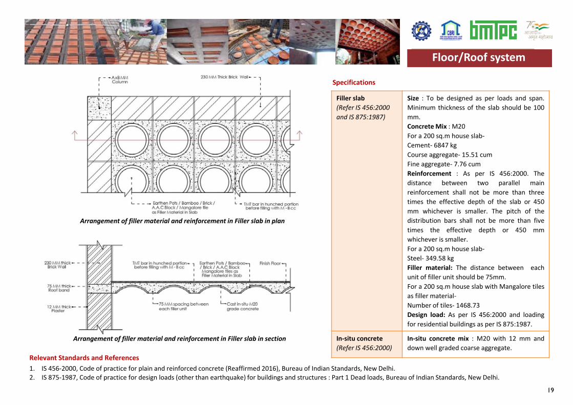
Arrangement of filler material and reinforcement in Filler slab in plan
Arrangement of filler material and reinforcement in Filler slab in section
Floor/Roof system
20
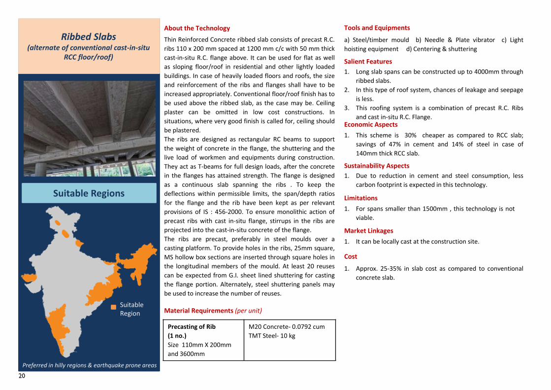
Thin Reinforced Concrete ribbed slab consists of precast R.C.ribs 110 x 200 mm spaced at 1200 mm c/c with 50 mm thickcast-in-situ R.C. flange above. It can be used for flat as wellas sloping floor/roof in residential and other lightly loadedbuildings. In case of heavily loaded floors and roofs, the sizeand reinforcement of the ribs and flanges shall have to beincreased appropriately. Conventional floor/roof finish has tobe used above the ribbed slab, as the case may be. Ceilingplaster can be omitted in low cost constructions. Insituations, where very good finish is called for, ceiling shouldbe plastered.The ribs are designed as rectangular RC beams to supportthe weight of concrete in the flange, the shuttering and thelive load of workmen and equipments during construction.They act as T-beams for full design loads, after the concretein the flanges has attained strength. The flange is designedas a continuous slab spanning the ribs . To keep thedeflections within permissible limits, the span/depth ratiosfor the flange and the rib have been kept as per relevantprovisions of IS : 456-2000. To ensure monolithic action ofprecast ribs with cast in-situ flange, stirrups in the ribs areprojected into the cast-in-situ concrete of the flange.The ribs are precast, preferably in steel moulds over acasting platform. To provide holes in the ribs, 25mm square,MS hollow box sections are inserted through square holes inthe longitudinal members of the mould. At least 20 reusescan be expected from G.I. sheet lined shuttering for castingthe flange portion. Alternately, steel shuttering panels maybe used to increase the number of reuses.
Precasting of Rib(1 no.)Size 110mm X 200mm and 3600mm
M20 Concrete- 0.0792 cumTMT Steel- 10 kg
Material Requirements (per unit)
1. It can be locally cast at the construction site.
About the Technology Tools and Equipmentsa) Steel/timber mould b) Needle & Plate vibrator c) Lighthoisting equipment d) Centering & shuttering
Salient Features1. Long slab spans can be constructed up to 4000mm through
ribbed slabs.2. In this type of roof system, chances of leakage and seepage
is less.3. This roofing system is a combination of precast R.C. Ribs
and cast in-situ R.C. Flange.Economic Aspects1. This scheme is 30% cheaper as compared to RCC slab;
savings of 47% in cement and 14% of steel in case of140mm thick RCC slab.
Sustainability Aspects1. Due to reduction in cement and steel consumption, less
carbon footprint is expected in this technology.
Limitations1. For spans smaller than 1500mm , this technology is not
viable.
Market Linkages
Cost1. Approx. 25-35% in slab cost as compared to conventional
concrete slab.
Ribbed Slabs(alternate of conventional cast-in-situ
RCC floor/roof)
Suitable Regions
Suitable Region
Preferred in hilly regions & earthquake prone areas
21
Ribbed slab(Refer CBRI BRN-5, IS 456:2000 and IS 875:1987)
Size : To be designed as per loads and span.
Concrete Mix : M20 with 20 mm an d down,graded coarse aggregate, thoroughlycompacted by plate vibrator.
Reinforcement : 6 mm dia. bars for mainreinforcement @ 150 mm c/c longitudinallyand @ 100 mm c/c in transverse direction.
Design load: As per IS 456:2000 and loadingfor residential buildings as per IS 875:1987.
In-situ concrete(Refer CBRI BRN-5 )
In-situ concrete mix : M20 with 12 mm anddown, graded coarse aggregate is then laidover the shuttering and ribs and compacted toa thickness of 50 mm by a plate vibrator.
Specifications
Relevant Standards and References
1. Thin R.C. Ribbed Slab For Floors And Roofs , Building Research Note- 5, Central Building Research Institute, Roorkee.2. IS 456-2000, Code of practice for plain and reinforced concrete (Reaffirmed 2016), Bureau of Indian Standards, New Delhi.3. IS 875-1987, Code of practice for design loads (other than earthquake) for buildings and structures : Part 1 Dead loads, Bureau of Indian Standards, New Delhi.
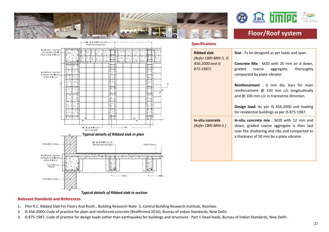
Typical details of Ribbed slab in plan
Typical details of Ribbed slab in section
Floor/Roof systemFloor/Roof system

22
23
Roof Construction Technologies
24
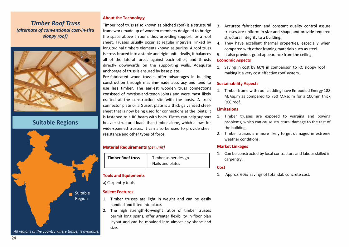
Timber roof truss (also known as pitched roof) is a structuralframework made up of wooden members designed to bridgethe space above a room, thus providing support for a roofsheet. Trusses usually occur at regular intervals, linked bylongitudinal timbers elements known as purlins. A roof trussis cross-braced into a stable and rigid unit. Ideally, it balancesall of the lateral forces against each other, and thrustsdirectly downwards on the supporting walls. Adequateanchorage of truss is ensured by base plate.Pre-fabricated wood trusses offer advantages in buildingconstruction through machine-made accuracy and tend touse less timber. The earliest wooden truss connectionsconsisted of mortise-and-tenon joints and were most likelycrafted at the construction site with the posts. A trussconnector plate or a Gusset plate is a thick galvanized steel-sheet that is now being used for connections at the joints; itis fastened to a RC beam with bolts. Plates can help supportheavier structural loads than timber alone, which allows forwide-spanned trusses. It can also be used to provide shearresistance and other types of force.
Timber Roof truss - Timber as per design- Nails and plates
Material Requirements (per unit)1. Can be constructed by local contractors and labour skilled in
carpentry.
About the Technology
Tools and Equipmentsa) Carpentry tools
Salient Features
3. Accurate fabrication and constant quality control assuretrusses are uniform in size and shape and provide requiredstructural integrity to a building.
4. They have excellent thermal properties, especially whencompared with other framing materials such as steel.
5. It also provides good appearance from the ceiling.Economic Aspects1. Saving in cost by 60% in comparison to RC sloppy roof
making it a very cost effective roof system.
Sustainability Aspects1. Timber frame with roof cladding have Embodied Energy 188
MJ/sq.m as compared to 750 MJ/sq.m for a 100mm thickRCC roof.
Limitations1. Timber trusses are exposed to warping and bowing
problems, which can cause structural damage to the rest ofthe building.
2. Timber trusses are more likely to get damaged in extremeweather conditions.
Market Linkages
Cost1. Approx. 60% savings of total slab concrete cost.
Timber Roof Truss(alternate of conventional cast-in-situ
sloppy roof)
Suitable Regions
All regions of the country where timber is available.
Suitable Region 1. Timber trusses are light in weight and can be easily
handled and lifted into place.2. The high strength-to-weight ratios of timber trusses
permit long spans, offer greater flexibility in floor planlayout and can be moulded into almost any shape andsize.
25
Timber frame(Refer IS 883:2016,2366:1983 and IS 875:1987)
Size : suitable for spans up to 18m.Design load: As per IS 875:1987 for residentialbuildings.
Specifications
Relevant Standards and References 1. IS 883 : 2016, Design of Structural Timber in Buildings - Code of Practice (Fifth Revision), Bureau of Indian Standards, New Delhi.2. IS 2366 : 1983, Code of practice for nail-jointed timber construction, Bureau of Indian Standards, New Delhi.3. IS 456-2000, Code of practice for plain and reinforced concrete (Reaffirmed 2016), Bureau of Indian Standards, New Delhi.4. IS 875-1987, Code of practice for design loads (other than earthquake) for buildings and structures : Part 1 Dead loads, Bureau of Indian Standards, New Delhi.
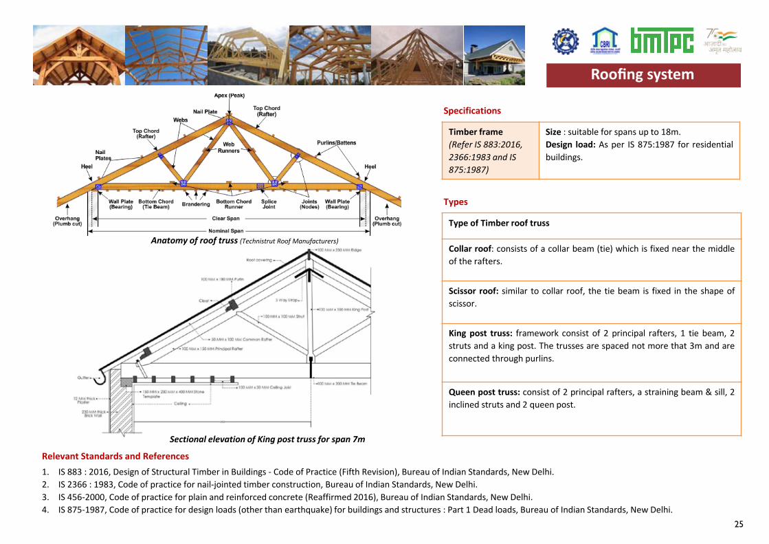
Type of Timber roof truss
Collar roof: consists of a collar beam (tie) which is fixed near the middleof the rafters.
Scissor roof: similar to collar roof, the tie beam is fixed in the shape ofscissor.
King post truss: framework consist of 2 principal rafters, 1 tie beam, 2struts and a king post. The trusses are spaced not more that 3m and areconnected through purlins.
Queen post truss: consist of 2 principal rafters, a straining beam & sill, 2inclined struts and 2 queen post.
Types
Roofing system
Anatomy of roof truss (Technistrut Roof Manufacturers)
Sectional elevation of King post truss for span 7m
Roofing system
26
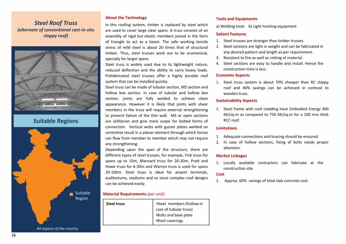
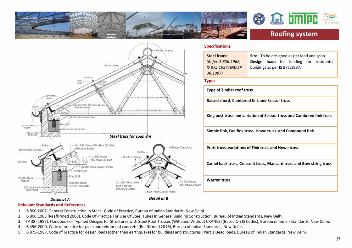
In this roofing system, timber is replaced by steel whichare used to cover large clear spans. A truss consists of anassembly of rigid but elastic members joined in the formof triangle to act as a beam. The safe working tensilestress of mild steel is about 20 times that of structuraltimber. Thus, steel trusses work out to be economical,specially for larger spans.Steel truss is widely used due to its lightweight nature,reduced deflection and the ability to carry heavy loads.Prefabricated steel trusses offer a highly durable roofsystem that can be installed quickly.Steel truss can be made of tubular section, MS section andhollow box section. In case of tubular and hollow boxsection, joints are fully welded to achieve cleanappearance. However it is likely that joints with shearmembers in the truss will require external strengtheningto prevent failure of the thin wall. MS or open sectionsare utilitarian and give more scope for bolted forms ofconnection. Vertical webs with gusset plates welded oncentreline result in a planar element through which forcescan flow from member to member which may not requireany strengthening.Depending upon the span of the structure, there aredifferent types of steel trusses, for example, Fink truss forspans up to 10m, Mansard truss for 20-30m, Pratt andHowe truss for 6-30m and Warren truss is used for spans20-100m. Steel truss is ideal for airport terminals,auditoriums, stadiums and so since complex roof designscan be achieved easily.
Steel truss •Steel members (hollow in case of tubular truss)•Bolts and base plate•Roof coverings
Material Requirements (per unit)
About the Technology Tools and Equipments
Salient Features1. Steel trusses are stronger than timber trusses.2. Steel sections are light in weight and can be fabricated in
any desired pattern and length as per requirement.3. Resistant to fire as well as rotting of material.4. Steel sections are easy to handle and install. Hence the
construction time is less.Economic Aspects1. Steel truss system is about 70% cheaper than RC sloppy
roof and 40% savings can be achieved in contrast towooden truss.
Sustainability Aspects
1. Steel frame with roof cladding have Embodied Energy 460MJ/sq.m as compared to 750 MJ/sq.m for a 100 mm thickRCC roof.
Limitations
1. Adequate connections and bracing should be ensured.2. In case of hollow sections, fixing of bolts needs proper
attention.
Market Linkages
Cost1. Approx. 60% savings of total slab concrete cost.
Steel Roof Truss(alternate of conventional cast-in-situ
sloppy roof)
Suitable Regions
Suitable Region
All regions of the country
a) Welding tools b) Light hoisting equipment
1. Locally available contractors can fabricate at theconstruction site.
27
Specifications
Relevant Standards and References 1. IS 800:2007, General Construction In Steel - Code of Practice, Bureau of Indian Standards, New Delhi.2. IS 806:1968 (Reaffirmed 2008), Code Of Practice For Use Of Steel Tubes In General Building Construction, Bureau of Indian Standards, New Delhi.3. SP 38 (1987): Handbook of Typified Designs for Structures with Steel Roof Trusses (With and Without CRANES) (Based On IS Codes), Bureau of Indian Standards, New Delhi.4. IS 456-2000, Code of practice for plain and reinforced concrete (Reaffirmed 2016), Bureau of Indian Standards, New Delhi.5. IS 875-1987, Code of practice for design loads (other than earthquake) for buildings and structures : Part 1 Dead loads, Bureau of Indian Standards, New Delhi.
Steel frame(Refer IS 806:1968, IS 875:1987 AND SP 38:1987)
Size : To be designed as per load and span.Design load: for loading for residentialbuildings as per IS 875:1987.
Type of Timber roof truss
Raised chord, Cambered fink and Scissor truss
King post truss and variation of Scissor truss and Cambered fink truss
Simple fink, Fan fink truss, Howe truss and Compound fink
Pratt truss, variations of Fink truss and Howe truss
Camel back truss, Crescent truss, Mansard truss and Bow string truss
Warren truss
Types
Roofing system
Steel truss for span 8m
Detail at A Detail at B
Roofing system
28
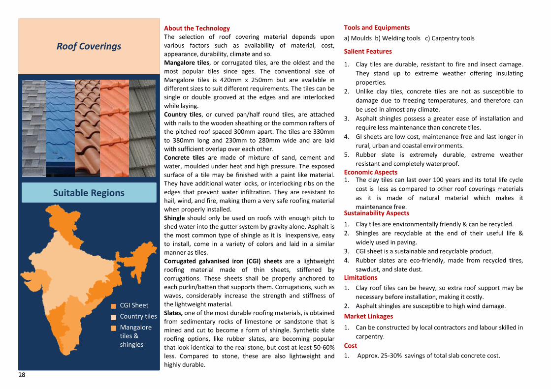
1. Clay tiles are durable, resistant to fire and insect damage.They stand up to extreme weather offering insulatingproperties.
2. Unlike clay tiles, concrete tiles are not as susceptible todamage due to freezing temperatures, and therefore canbe used in almost any climate.
3. Asphalt shingles possess a greater ease of installation andrequire less maintenance than concrete tiles.
4. GI sheets are low cost, maintenance free and last longer inrural, urban and coastal environments.
5. Rubber slate is extremely durable, extreme weatherresistant and completely waterproof.
The selection of roof covering material depends uponvarious factors such as availability of material, cost,appearance, durability, climate and so.Mangalore tiles, or corrugated tiles, are the oldest and themost popular tiles since ages. The conventional size ofMangalore tiles is 420mm x 250mm but are available indifferent sizes to suit different requirements. The tiles can besingle or double grooved at the edges and are interlockedwhile laying.Country tiles, or curved pan/half round tiles, are attachedwith nails to the wooden sheathing or the common rafters ofthe pitched roof spaced 300mm apart. The tiles are 330mmto 380mm long and 230mm to 280mm wide and are laidwith sufficient overlap over each other.Concrete tiles are made of mixture of sand, cement andwater, moulded under heat and high pressure. The exposedsurface of a tile may be finished with a paint like material.They have additional water locks, or interlocking ribs on theedges that prevent water infiltration. They are resistant tohail, wind, and fire, making them a very safe roofing materialwhen properly installed.Shingle should only be used on roofs with enough pitch toshed water into the gutter system by gravity alone. Asphalt isthe most common type of shingle as it is inexpensive, easyto install, come in a variety of colors and laid in a similarmanner as tiles.Corrugated galvanised iron (CGI) sheets are a lightweightroofing material made of thin sheets, stiffened bycorrugations. These sheets shall be properly anchored toeach purlin/batten that supports them. Corrugations, such aswaves, considerably increase the strength and stiffness ofthe lightweight material.Slates, one of the most durable roofing materials, is obtainedfrom sedimentary rocks of limestone or sandstone that ismined and cut to become a form of shingle. Synthetic slateroofing options, like rubber slates, are becoming popularthat look identical to the real stone, but cost at least 50-60%less. Compared to stone, these are also lightweight andhighly durable.
About the Technology Tools and Equipmentsa) Moulds b) Welding tools c) Carpentry tools
Salient Features
Economic Aspects1. The clay tiles can last over 100 years and its total life cycle
cost is less as compared to other roof coverings materialsas it is made of natural material which makes itmaintenance free.
Sustainability Aspects1. Clay tiles are environmentally friendly & can be recycled.2. Shingles are recyclable at the end of their useful life &
widely used in paving.3. CGI sheet is a sustainable and recyclable product.4. Rubber slates are eco-friendly, made from recycled tires,
sawdust, and slate dust.Limitations1. Clay roof tiles can be heavy, so extra roof support may be
necessary before installation, making it costly.2. Asphalt shingles are susceptible to high wind damage.Market Linkages
Cost1. Approx. 25-30% savings of total slab concrete cost.
Roof Coverings
Suitable Regions
1. Can be constructed by local contractors and labour skilled incarpentry.
CGI SheetCountry tilesMangalore tiles & shingles
29
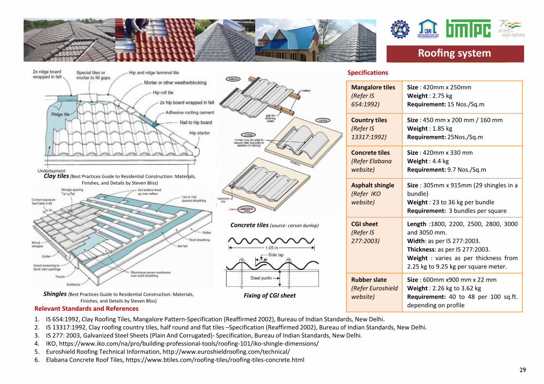
Specifications
Relevant Standards and References 1. IS 654:1992, Clay Roofing Tiles, Mangalore Pattern-Specification (Reaffirmed 2002), Bureau of Indian Standards, New Delhi.2. IS 13317:1992, Clay roofing country tiles, half round and flat tiles –Specification (Reaffirmed 2002), Bureau of Indian Standards, New Delhi.3. IS 277: 2003, Galvanized Steel Sheets (Plain And Corrugated)- Specification, Bureau of Indian Standards, New Delhi.4. IKO, https://www.iko.com/na/pro/building-professional-tools/roofing-101/iko-shingle-dimensions/5. Euroshield Roofing Technical Information, http://www.euroshieldroofing.com/technical/6. Elabana Concrete Roof Tiles, https://www.btiles.com/roofing-tiles/roofing-tiles-concrete.html
Mangalore tiles(Refer IS 654:1992)
Size : 420mm x 250mmWeight : 2.75 kgRequirement: 15 Nos./Sq.m
Country tiles(Refer IS 13317:1992)
Size : 450 mm x 200 mm / 160 mmWeight : 1.85 kgRequirement: 25Nos./Sq.m
Concrete tiles(Refer Elabanawebsite)
Size : 420mm x 330 mmWeight : 4.4 kgRequirement: 9.7 Nos./Sq.m
Asphalt shingle(Refer IKO website)
Size : 305mm x 915mm (29 shingles in abundle)Weight : 23 to 36 kg per bundleRequirement: 3 bundles per square
CGI sheet(Refer IS 277:2003)
Length :1800, 2200, 2500, 2800, 3000and 3050 mm.Width: as per IS 277:2003.Thickness: as per IS 277:2003.Weight : varies as per thickness from2.25 kg to 9.25 kg per square meter.
Rubber slate(Refer Euroshieldwebsite)
Size : 600mm x900 mm x 22 mmWeight : 2.26 kg to 3.62 kgRequirement: 40 to 48 per 100 sq.ft.depending on profile
Roofing system
Clay tiles (Best Practices Guide to Residential Construction: Materials, Finishes, and Details by Steven Bliss)
Concrete tiles (source: carson dunlop)
Shingles (Best Practices Guide to Residential Construction: Materials, Finishes, and Details by Steven Bliss)
Fixing of CGI sheet
Roofing system
30
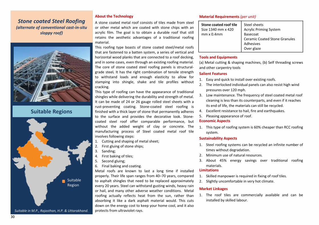
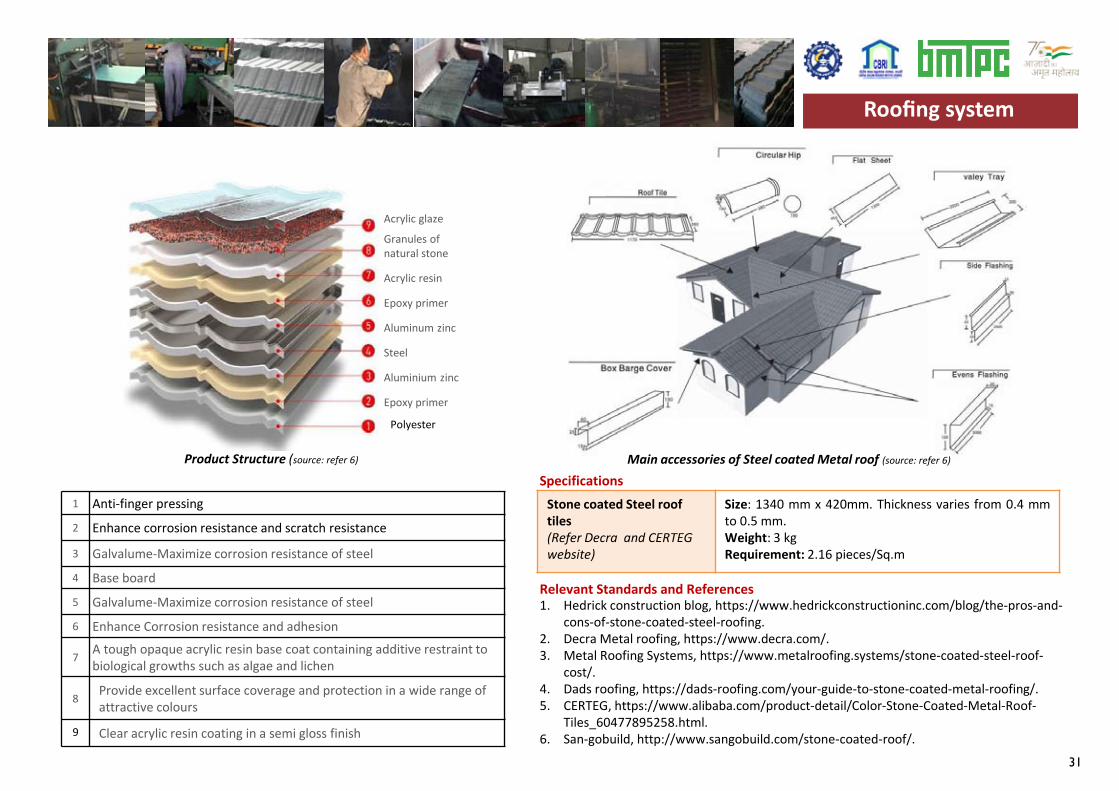
Stone coated roof tileSize 1340 mm x 420 mm x 0.4mm
Steel sheetsAcrylic Priming SystemBasecoatCeramic Coated Stone GranulesAdhesives Over glaze
1. Easy and quick to install over existing roofs.2. The interlocked individual panels can also resist high wind
pressures over 120 mph.3. Low maintenance. The frequency of steel coated metal roof
cleaning is less than its counterparts, and even if it reaches its end of life, the materials can still be recycled.
4. Excellent resistance to hail, fire and earthquakes.5. Pleasing appearance of roof.
A stone coated metal roof consists of tiles made from steelor other metal which are coated with stone chips with anacrylic film. The goal is to obtain a durable roof that stillretains the aesthetic advantages of a traditional roofingmaterial.This roofing type boasts of stone coated steel/metal roofsthat are fastened to a batten system, a series of vertical andhorizontal wood planks that are connected to a roof decking,and in some cases, even through an existing roofing material.The core of stone coated steel roofing panels is structural-grade steel. It has the right combination of tensile strengthto withstand loads and enough elasticity to allow forstamping into shingle, shake and tile profiles withoutcracking.This type of roofing can have the appearance of traditionalshingles while delivering the durability and strength of metal.It can be made of 24 or 26 gauge rolled steel sheets with arust-preventing coating. Stone-coated steel roofing isfinished with a thick layer of stone that permanently adheresto the surface and provides the decorative look. Stone-coated steel roof offer comparable performance, butwithout the added weight of clay or concrete. Themanufacturing process of Steel coated metal roof tileinvolves following steps:1. Cutting and shaping of metal sheet;2. First gluing of stone ships;3. Sanding;4. First baking of tiles;5. Second gluing;6. Final baking and coating.Metal roofs are known to last a long time if installedproperly. Their life span ranges from 40–70 years, comparedto asphalt shingles that need to be replaced approximatelyevery 20 years. Steel can withstand gusting winds, heavy rainor hail, and many other adverse weather conditions. Metalroofing actually reflects heat from the sun, rather thanabsorbing it like a dark asphalt material would. This cutsdown on the energy cost to keep your home cool, and it alsoprotects from ultraviolet rays.
1. The roof tiles are commercially available and can beinstalled by skilled labour.
About the Technology
Tools and Equipments(a) Metal cutting & shaping machines, (b) Self threading screwsand other carpentry toolsSalient Features
Economic Aspects1. This type of roofing system is 60% cheaper than RCC roofing
system.Sustainability Aspects1. Steel roofing systems can be recycled an infinite number of
times without degradation.2. Minimum use of natural resources.3. About 45% energy savings over traditional roofing
materials.Limitations1. Skilled manpower is required in fixing of roof tiles.2. Slightly uncomfortable in very hot climate.
Market Linkages
Stone coated Steel Roofing(alternate of conventional cast-in-situ
sloppy roof)
Suitable Regions
Suitable in M.P., Rajasthan, H.P. & Uttarakhand.
Suitable Region
Material Requirements (per unit)
31
Stone coated Steel roof tiles(Refer Decra and CERTEG website)
Size: 1340 mm x 420mm. Thickness varies from 0.4 mmto 0.5 mm.Weight: 3 kgRequirement: 2.16 pieces/Sq.m
Specifications
Relevant Standards and References 1. Hedrick construction blog, https://www.hedrickconstructioninc.com/blog/the-pros-and-
cons-of-stone-coated-steel-roofing.2. Decra Metal roofing, https://www.decra.com/.3. Metal Roofing Systems, https://www.metalroofing.systems/stone-coated-steel-roof-
cost/.4. Dads roofing, https://dads-roofing.com/your-guide-to-stone-coated-metal-roofing/.5. CERTEG, https://www.alibaba.com/product-detail/Color-Stone-Coated-Metal-Roof-
Tiles_60477895258.html.6. San-gobuild, http://www.sangobuild.com/stone-coated-roof/.
Roofing system
1 Anti-finger pressing
2 Enhance corrosion resistance and scratch resistance
3 Galvalume-Maximize corrosion resistance of steel
4 Base board
5 Galvalume-Maximize corrosion resistance of steel
6 Enhance Corrosion resistance and adhesion
7 A tough opaque acrylic resin base coat containing additive restraint to biological growths such as algae and lichen
8 Provide excellent surface coverage and protection in a wide range of attractive colours
9 Clear acrylic resin coating in a semi gloss finish
Acrylic glaze
Granules of natural stone
Acrylic resin
Epoxy primer
Aluminum zinc
Steel
Aluminium zinc
Epoxy primer
Polyester
Product Structure (source: refer 6) Main accessories of Steel coated Metal roof (source: refer 6)
Roofing system
32
Funicular shell roofSize as per architectural and structural design
•M20 Concrete•TMT Steel•Full Bricks
1. Allows ample flexibility in design- funicular shells can takeany shape – square, rectangular, triangular or trapezoidal.
2. For construction above the intermediate floor, the funicularroof provides greater flexibility for locating walls since theload distribution is uniform because of arch action of theshell.
3. Design of the funicular roof can be very well adapted toseismic design requirements.
4. Simple technology which can easily be adapted by semi-skilled labour with minimum supervision.
A Funicular Shell is a 3 dimensional catenary on a rectilinearbase. The roofing system consists of doubly curved shellsmade with materials of good compressive strength such aswaste stone pieces and brick tiles and supported onreinforced concrete edge beams. A series of these shells invariable geometric configurations supported on a grid ofconcrete beams, identical to a coffer slab, provides anattractive roof for small to medium spans.Edge Beam is a reinforced concrete beam which supportsand distributes the horizontal thrust of the funicular shell.The beam can be conventionally cast along with the funicularshell. As per the span, the beam is designed for a coffer slabor a grid of beams. Alternatively, the beam can be partiallyprecast, in which case a pre-welded reinforcement cage isplaced along the grid and cast half. The cage is fabricated asa truss girder (see overleaf for details) which improves theload bearing capacity of beam considerably, whilesimultaneously reducing the beam section.Funicular Shell The entire area to be roofed is divided into agrid depending on the size of the funicular shell required orthe size / shape of moulds available. The rise to span ratio is1:6, thus the optimal span of the shell is 3 m though it canspan up to 15 m. The mould is supported between the edgebeams. Timber planks are used to bridge the gap betweenthe edge of the mould and the edge beam. The shellcomprises of the materials – bricks, stone waste – laid in thefunicular profile topped with cement-sand mortar andconcrete screed.Concrete In-fill After the shells have been cast, the valleyspaces which are formed between the shells can be filledwith light-weight material like brick jelly lime concrete andfinished flat. The infill will enable the construction of anintermediate floor which can be used to build above.
1. Roof components can be locally produced and deliveredthrough micro level enterprise.
2. The roof can be cast in-situ or precast as per designssuggested by CSIR-SERC and CSIR-CBRI.
About the Technology
Salient Features
Economic Aspects1. Compared to RCC roof, Funicular Shell roof offers savings in
Steel (60%) and cement (35%).
Sustainability Aspects1. Uses locally available waste stone, normally available from
stone cutting and polishing units.Limitations1. Adequate care in jointing edge is required for leak proof
elements.
Market Linkages
Funicular shell Roof(alternate of conventional cast-in-situ
RCC roof)
Suitable Regions
All regions of the country
Tools and Equipments
a) Steel/masonry moulds b) Table vibrator c) Light hoisting equipment
Material Requirements (per unit)
Suitable Region
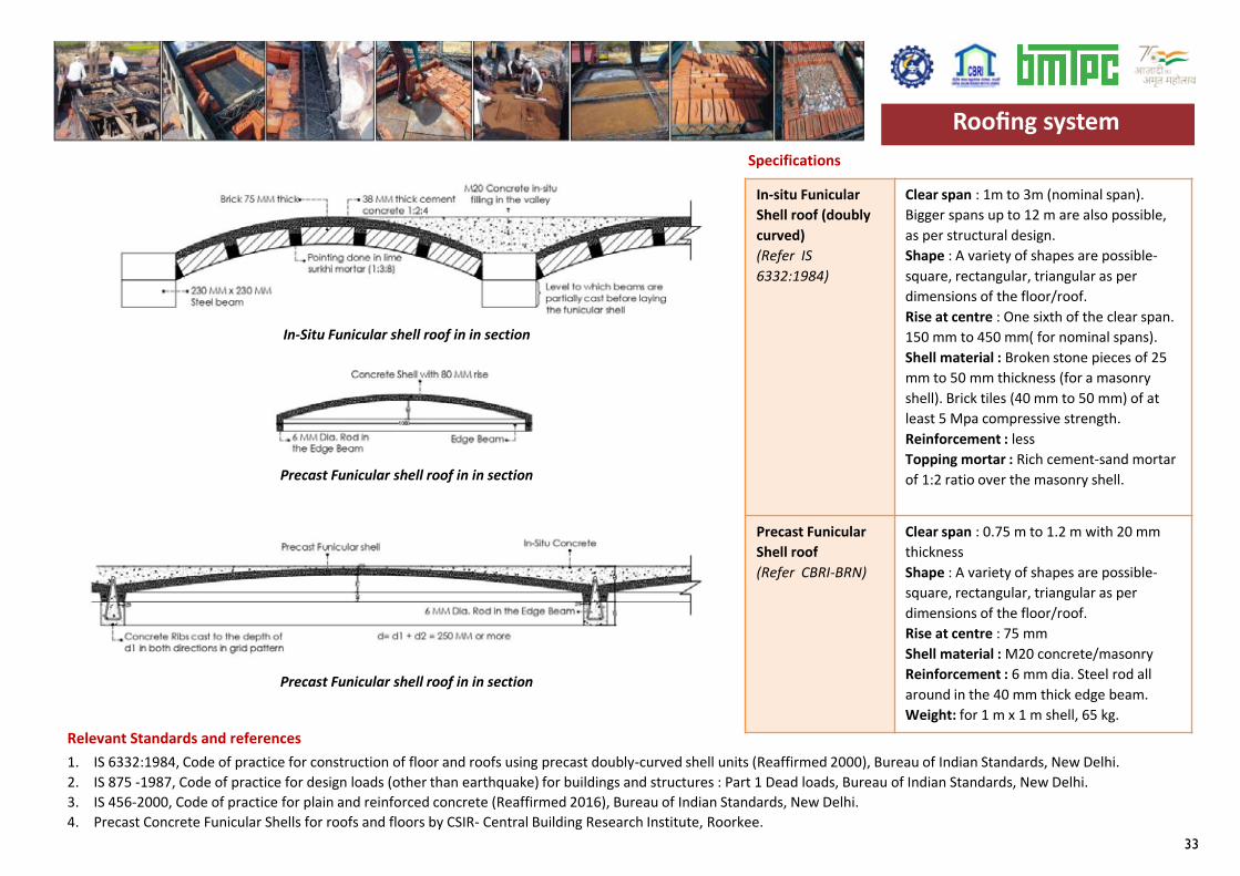
33
Specifications
Relevant Standards and references
In-situ Funicular Shell roof (doubly curved)(Refer IS 6332:1984)
Clear span : 1m to 3m (nominal span). Bigger spans up to 12 m are also possible, as per structural design.Shape : A variety of shapes are possible-square, rectangular, triangular as per dimensions of the floor/roof.Rise at centre : One sixth of the clear span. 150 mm to 450 mm( for nominal spans). Shell material : Broken stone pieces of 25 mm to 50 mm thickness (for a masonry shell). Brick tiles (40 mm to 50 mm) of at least 5 Mpa compressive strength. Reinforcement : less Topping mortar : Rich cement-sand mortar of 1:2 ratio over the masonry shell.
Precast Funicular Shell roof (Refer CBRI-BRN)
Clear span : 0.75 m to 1.2 m with 20 mm thickness Shape : A variety of shapes are possible-square, rectangular, triangular as per dimensions of the floor/roof.Rise at centre : 75 mmShell material : M20 concrete/masonryReinforcement : 6 mm dia. Steel rod all around in the 40 mm thick edge beam.Weight: for 1 m x 1 m shell, 65 kg.
1. IS 6332:1984, Code of practice for construction of floor and roofs using precast doubly-curved shell units (Reaffirmed 2000), Bureau of Indian Standards, New Delhi.2. IS 875 -1987, Code of practice for design loads (other than earthquake) for buildings and structures : Part 1 Dead loads, Bureau of Indian Standards, New Delhi.3. IS 456-2000, Code of practice for plain and reinforced concrete (Reaffirmed 2016), Bureau of Indian Standards, New Delhi.4. Precast Concrete Funicular Shells for roofs and floors by CSIR- Central Building Research Institute, Roorkee.
Roofing system
Funicular shell roof in plan
Precast Funicular shell roof in in section
Precast Funicular shell roof in in section
In-Situ Funicular shell roof in in section
Roofing system
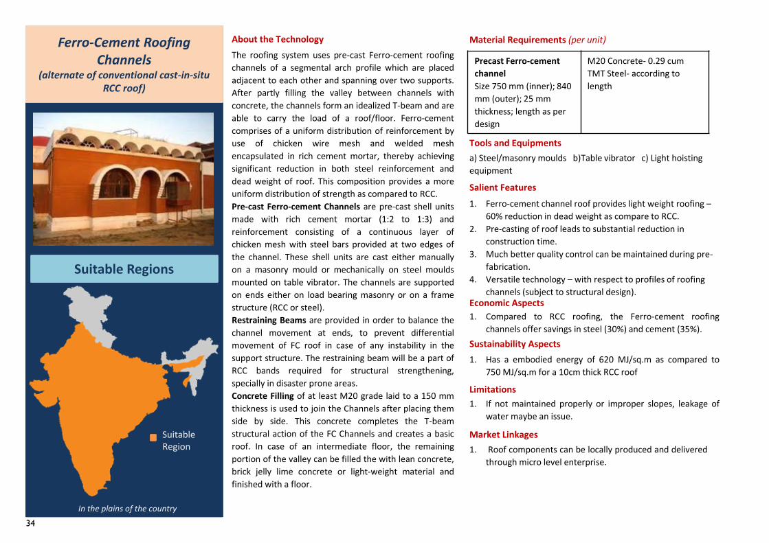
34
Precast Ferro-cementchannelSize 750 mm (inner); 840 mm (outer); 25 mm thickness; length as per design
M20 Concrete- 0.29 cumTMT Steel- according to length
1. Ferro-cement channel roof provides light weight roofing –60% reduction in dead weight as compare to RCC.
2. Pre-casting of roof leads to substantial reduction in construction time.
3. Much better quality control can be maintained during pre-fabrication.
4. Versatile technology – with respect to profiles of roofing channels (subject to structural design).
The roofing system uses pre-cast Ferro-cement roofingchannels of a segmental arch profile which are placedadjacent to each other and spanning over two supports.After partly filling the valley between channels withconcrete, the channels form an idealized T-beam and areable to carry the load of a roof/floor. Ferro-cementcomprises of a uniform distribution of reinforcement byuse of chicken wire mesh and welded meshencapsulated in rich cement mortar, thereby achievingsignificant reduction in both steel reinforcement anddead weight of roof. This composition provides a moreuniform distribution of strength as compared to RCC.Pre-cast Ferro-cement Channels are pre-cast shell unitsmade with rich cement mortar (1:2 to 1:3) andreinforcement consisting of a continuous layer ofchicken mesh with steel bars provided at two edges ofthe channel. These shell units are cast either manuallyon a masonry mould or mechanically on steel mouldsmounted on table vibrator. The channels are supportedon ends either on load bearing masonry or on a framestructure (RCC or steel).Restraining Beams are provided in order to balance thechannel movement at ends, to prevent differentialmovement of FC roof in case of any instability in thesupport structure. The restraining beam will be a part ofRCC bands required for structural strengthening,specially in disaster prone areas.Concrete Filling of at least M20 grade laid to a 150 mmthickness is used to join the Channels after placing themside by side. This concrete completes the T-beamstructural action of the FC Channels and creates a basicroof. In case of an intermediate floor, the remainingportion of the valley can be filled the with lean concrete,brick jelly lime concrete or light-weight material andfinished with a floor.
1. Roof components can be locally produced and deliveredthrough micro level enterprise.
About the Technology
Salient Features
Economic Aspects1. Compared to RCC roofing, the Ferro-cement roofing
channels offer savings in steel (30%) and cement (35%).Sustainability Aspects1. Has a embodied energy of 620 MJ/sq.m as compared to
750 MJ/sq.m for a 10cm thick RCC roof
Limitations1. If not maintained properly or improper slopes, leakage of
water maybe an issue.
Market Linkages
Ferro-Cement Roofing Channels
(alternate of conventional cast-in-situ RCC roof)
Suitable Regions
In the plains of the country
Tools and Equipmentsa) Steel/masonry moulds b)Table vibrator c) Light hoisting equipment
Material Requirements (per unit)
Suitable Region
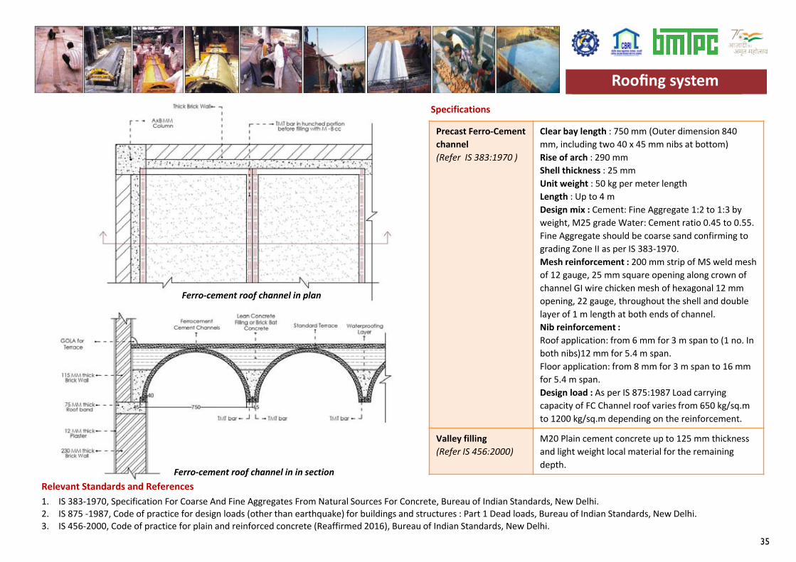
35
Specifications
Relevant Standards and References
Precast Ferro-Cement channel(Refer IS 383:1970 )
Clear bay length : 750 mm (Outer dimension 840 mm, including two 40 x 45 mm nibs at bottom) Rise of arch : 290 mm Shell thickness : 25 mm Unit weight : 50 kg per meter length Length : Up to 4 m Design mix : Cement: Fine Aggregate 1:2 to 1:3 by weight, M25 grade Water: Cement ratio 0.45 to 0.55. Fine Aggregate should be coarse sand confirming to grading Zone II as per IS 383-1970.Mesh reinforcement : 200 mm strip of MS weld mesh of 12 gauge, 25 mm square opening along crown of channel GI wire chicken mesh of hexagonal 12 mm opening, 22 gauge, throughout the shell and double layer of 1 m length at both ends of channel.Nib reinforcement :Roof application: from 6 mm for 3 m span to (1 no. In both nibs)12 mm for 5.4 m span.Floor application: from 8 mm for 3 m span to 16 mm for 5.4 m span.Design load : As per IS 875:1987 Load carrying capacity of FC Channel roof varies from 650 kg/sq.mto 1200 kg/sq.m depending on the reinforcement.
Valley filling(Refer IS 456:2000)
M20 Plain cement concrete up to 125 mm thickness and light weight local material for the remaining depth.
1. IS 383-1970, Specification For Coarse And Fine Aggregates From Natural Sources For Concrete, Bureau of Indian Standards, New Delhi.2. IS 875 -1987, Code of practice for design loads (other than earthquake) for buildings and structures : Part 1 Dead loads, Bureau of Indian Standards, New Delhi.3. IS 456-2000, Code of practice for plain and reinforced concrete (Reaffirmed 2016), Bureau of Indian Standards, New Delhi.
Roofing system
Ferro-cement roof channel in plan
Ferro-cement roof channel in in section
Roofing system
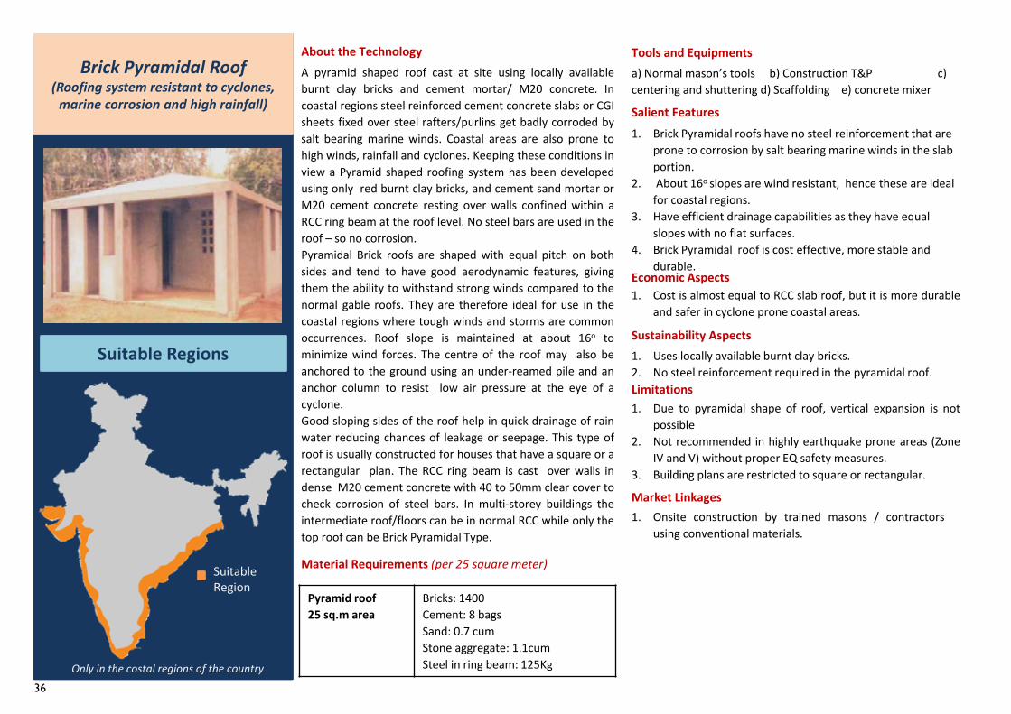
36
Pyramid roof25 sq.m area
Bricks: 1400Cement: 8 bagsSand: 0.7 cumStone aggregate: 1.1cum Steel in ring beam: 125Kg
1. Brick Pyramidal roofs have no steel reinforcement that are prone to corrosion by salt bearing marine winds in the slab portion.
2. About 16o slopes are wind resistant, hence these are ideal for coastal regions.
3. Have efficient drainage capabilities as they have equal slopes with no flat surfaces.
4. Brick Pyramidal roof is cost effective, more stable and durable.
A pyramid shaped roof cast at site using locally availableburnt clay bricks and cement mortar/ M20 concrete. Incoastal regions steel reinforced cement concrete slabs or CGIsheets fixed over steel rafters/purlins get badly corroded bysalt bearing marine winds. Coastal areas are also prone tohigh winds, rainfall and cyclones. Keeping these conditions inview a Pyramid shaped roofing system has been developedusing only red burnt clay bricks, and cement sand mortar orM20 cement concrete resting over walls confined within aRCC ring beam at the roof level. No steel bars are used in theroof – so no corrosion.Pyramidal Brick roofs are shaped with equal pitch on bothsides and tend to have good aerodynamic features, givingthem the ability to withstand strong winds compared to thenormal gable roofs. They are therefore ideal for use in thecoastal regions where tough winds and storms are commonoccurrences. Roof slope is maintained at about 16o tominimize wind forces. The centre of the roof may also beanchored to the ground using an under-reamed pile and ananchor column to resist low air pressure at the eye of acyclone.Good sloping sides of the roof help in quick drainage of rainwater reducing chances of leakage or seepage. This type ofroof is usually constructed for houses that have a square or arectangular plan. The RCC ring beam is cast over walls indense M20 cement concrete with 40 to 50mm clear cover tocheck corrosion of steel bars. In multi-storey buildings theintermediate roof/floors can be in normal RCC while only thetop roof can be Brick Pyramidal Type.
1. Onsite construction by trained masons / contractorsusing conventional materials.
About the Technology
Salient Features
Economic Aspects1. Cost is almost equal to RCC slab roof, but it is more durable
and safer in cyclone prone coastal areas.
Sustainability Aspects1. Uses locally available burnt clay bricks.2. No steel reinforcement required in the pyramidal roof.Limitations1. Due to pyramidal shape of roof, vertical expansion is not
possible2. Not recommended in highly earthquake prone areas (Zone
IV and V) without proper EQ safety measures.3. Building plans are restricted to square or rectangular.
Market Linkages
Brick Pyramidal Roof(Roofing system resistant to cyclones,
marine corrosion and high rainfall)
Suitable Regions
Suitable Region
Only in the costal regions of the country
Tools and Equipmentsa) Normal mason’s tools b) Construction T&P c) centering and shuttering d) Scaffolding e) concrete mixer
Material Requirements (per 25 square meter)
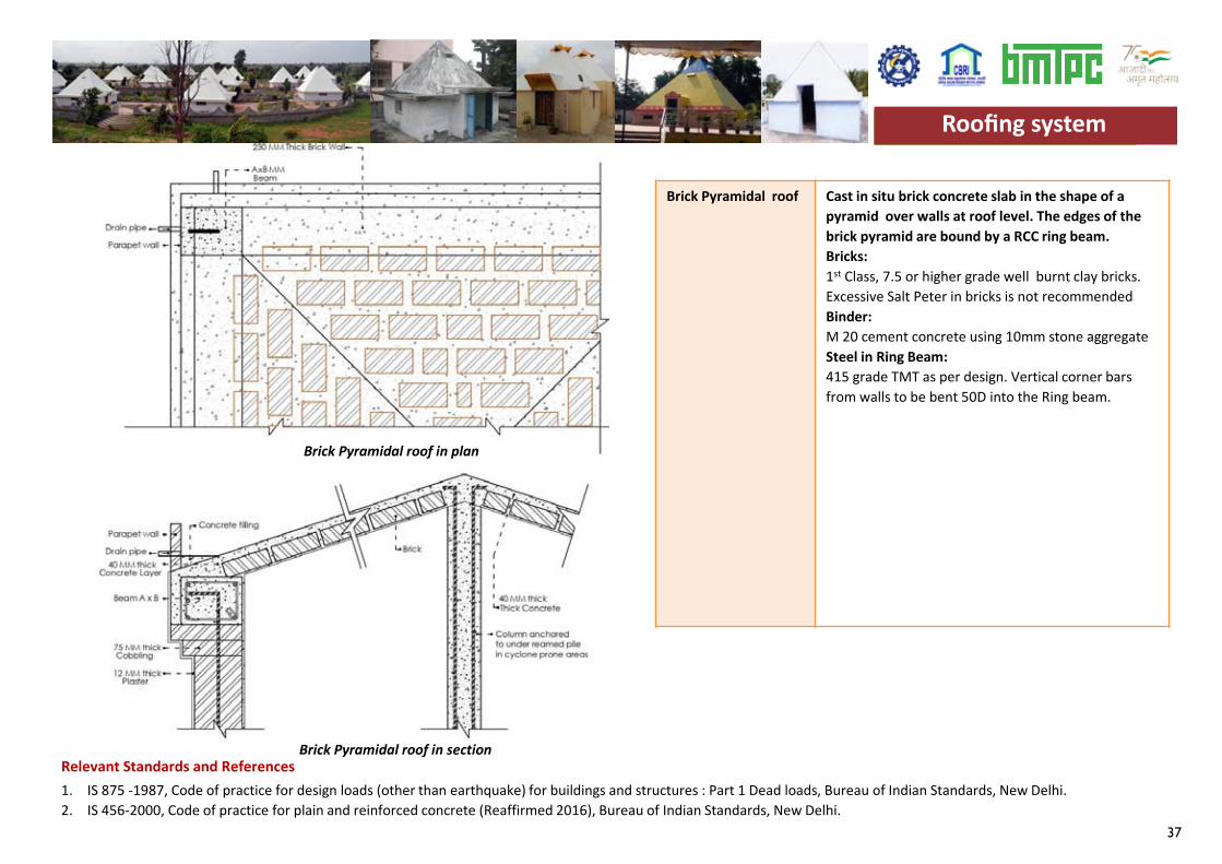
37
Specifications
Relevant Standards and References
Brick Pyramidal roof Cast in situ brick concrete slab in the shape of a pyramid over walls at roof level. The edges of the brick pyramid are bound by a RCC ring beam.Bricks: 1st Class, 7.5 or higher grade well burnt clay bricks. Excessive Salt Peter in bricks is not recommendedBinder:M 20 cement concrete using 10mm stone aggregateSteel in Ring Beam:415 grade TMT as per design. Vertical corner bars from walls to be bent 50D into the Ring beam.
1. IS 875 -1987, Code of practice for design loads (other than earthquake) for buildings and structures : Part 1 Dead loads, Bureau of Indian Standards, New Delhi.2. IS 456-2000, Code of practice for plain and reinforced concrete (Reaffirmed 2016), Bureau of Indian Standards, New Delhi.
Brick Pyramidal roof in plan
Brick Pyramidal roof in section
Roofing systemRoofing system
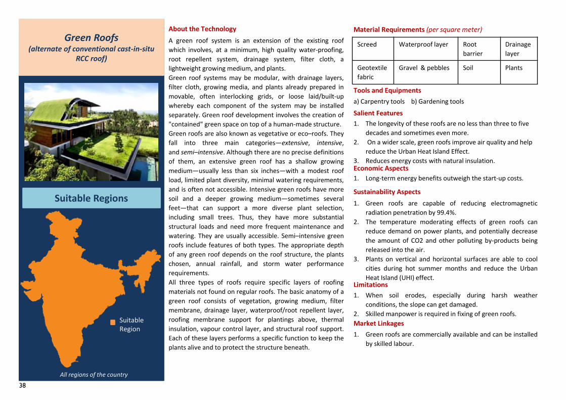
38
Screed Waterproof layer Root barrier
Drainagelayer
Geotextile fabric
Gravel & pebbles Soil Plants
1. The longevity of these roofs are no less than three to five decades and sometimes even more.
2. On a wider scale, green roofs improve air quality and help reduce the Urban Heat Island Effect.
3. Reduces energy costs with natural insulation.
A green roof system is an extension of the existing roofwhich involves, at a minimum, high quality water-proofing,root repellent system, drainage system, filter cloth, alightweight growing medium, and plants.Green roof systems may be modular, with drainage layers,filter cloth, growing media, and plants already prepared inmovable, often interlocking grids, or loose laid/built-upwhereby each component of the system may be installedseparately. Green roof development involves the creation of"contained" green space on top of a human-made structure.Green roofs are also known as vegetative or eco–roofs. Theyfall into three main categories—extensive, intensive,and semi–intensive. Although there are no precise definitionsof them, an extensive green roof has a shallow growingmedium—usually less than six inches—with a modest roofload, limited plant diversity, minimal watering requirements,and is often not accessible. Intensive green roofs have moresoil and a deeper growing medium—sometimes severalfeet—that can support a more diverse plant selection,including small trees. Thus, they have more substantialstructural loads and need more frequent maintenance andwatering. They are usually accessible. Semi–intensive greenroofs include features of both types. The appropriate depthof any green roof depends on the roof structure, the plantschosen, annual rainfall, and storm water performancerequirements.All three types of roofs require specific layers of roofingmaterials not found on regular roofs. The basic anatomy of agreen roof consists of vegetation, growing medium, filtermembrane, drainage layer, waterproof/root repellent layer,roofing membrane support for plantings above, thermalinsulation, vapour control layer, and structural roof support.Each of these layers performs a specific function to keep theplants alive and to protect the structure beneath.
About the Technology
Tools and Equipmentsa) Carpentry tools b) Gardening toolsSalient Features
Economic Aspects1. Long-term energy benefits outweigh the start-up costs.
Sustainability Aspects1. Green roofs are capable of reducing electromagnetic
radiation penetration by 99.4%.2. The temperature moderating effects of green roofs can
reduce demand on power plants, and potentially decreasethe amount of CO2 and other polluting by-products beingreleased into the air.
3. Plants on vertical and horizontal surfaces are able to coolcities during hot summer months and reduce the UrbanHeat Island (UHI) effect.
Limitations1. When soil erodes, especially during harsh weather
conditions, the slope can get damaged.2. Skilled manpower is required in fixing of green roofs.
Green Roofs(alternate of conventional cast-in-situ
RCC roof)
Suitable Regions
Suitable Region
All regions of the country
1. Green roofs are commercially available and can be installedby skilled labour.
Market Linkages
Material Requirements (per square meter)
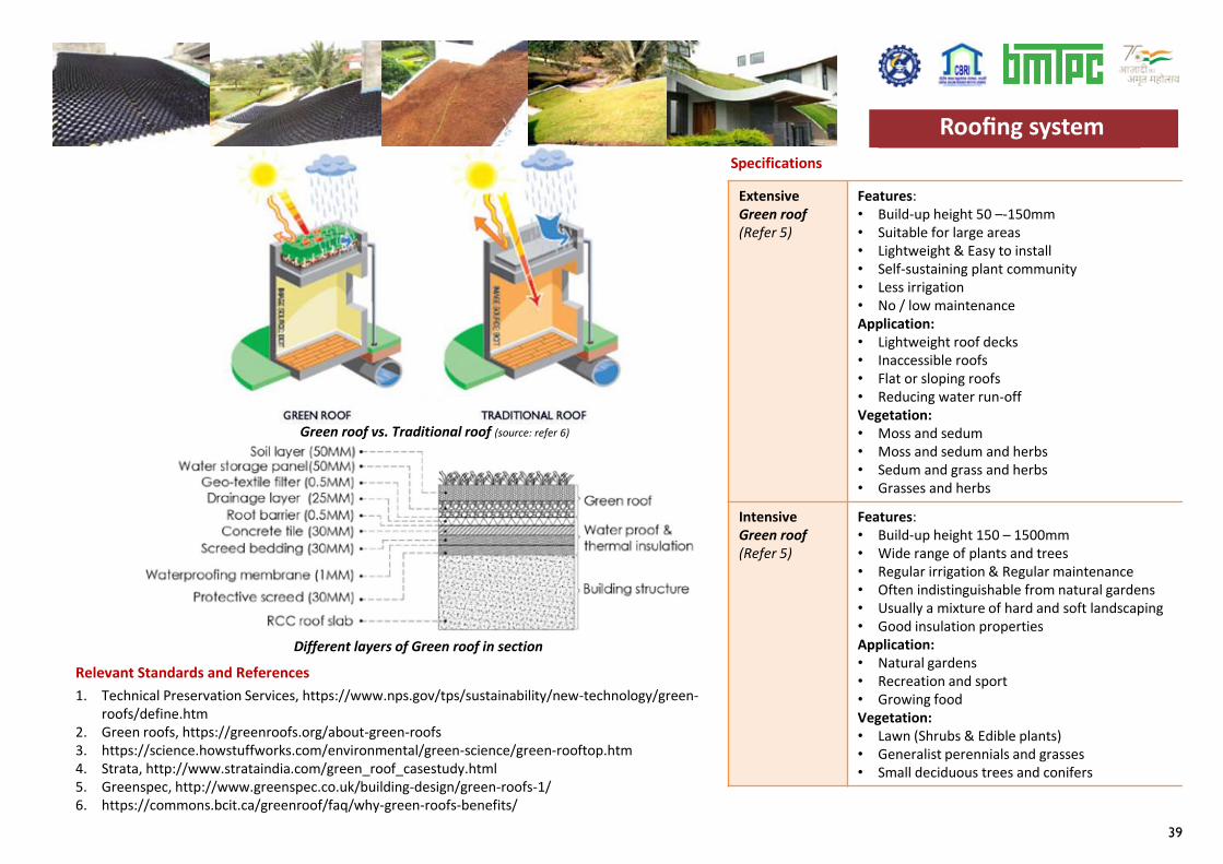
39
Specifications
Relevant Standards and References
ExtensiveGreen roof(Refer 5)
Features:• Build-up height 50 –-150mm• Suitable for large areas• Lightweight & Easy to install• Self-sustaining plant community• Less irrigation• No / low maintenanceApplication:• Lightweight roof decks• Inaccessible roofs• Flat or sloping roofs• Reducing water run-offVegetation:• Moss and sedum• Moss and sedum and herbs• Sedum and grass and herbs• Grasses and herbs
IntensiveGreen roof(Refer 5)
Features:• Build-up height 150 – 1500mm• Wide range of plants and trees• Regular irrigation & Regular maintenance• Often indistinguishable from natural gardens• Usually a mixture of hard and soft landscaping• Good insulation propertiesApplication:• Natural gardens • Recreation and sport• Growing foodVegetation:• Lawn (Shrubs & Edible plants)• Generalist perennials and grasses• Small deciduous trees and conifers
1. Technical Preservation Services, https://www.nps.gov/tps/sustainability/new-technology/green-roofs/define.htm
2. Green roofs, https://greenroofs.org/about-green-roofs3. https://science.howstuffworks.com/environmental/green-science/green-rooftop.htm4. Strata, http://www.strataindia.com/green_roof_casestudy.html5. Greenspec, http://www.greenspec.co.uk/building-design/green-roofs-1/6. https://commons.bcit.ca/greenroof/faq/why-green-roofs-benefits/
Roofing system
Green roof vs. Traditional roof (source: refer 6)
Different layers of Green roof in section
Roofing system
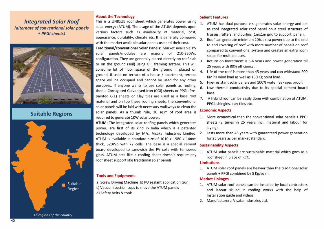
40
1. ATUM has dual purpose viz. generates solar energy and actas roof integrated solar roof panel on a steel structure oftrusses, rafters, and purlins (1mx1m grid to support panel).
2. Roof can generate minimum 20% extra power due to the endto end covering of roof with more number of panels on roofcompared to conventional system and creates an extra roomspace for multiple uses.
3. Return on Investment is 5-6 years and power generation till25 years with 80% efficiency.
4. Life of the roof is more than 45 years and can withstand 200KMPH wind load as well as 150 Kg point load.
5. Fire-resistant solar panels and 100% water leakages proof.6. Low thermal conductivity due to its special cement board
base.7. A hybrid roof can be easily done with combination of ATUM,
PPGI, shingles, clay tiles etc.
This is a UNIQUE roof sheet which generates power usingsolar energy (ATUM). The usage of the ATUM depends uponvarious factors such as availability of material, cost,appearance, durability, climate etc. It is generally comparedwith the market available solar panels use and their cost.Traditional/conventional Solar Panels: Market available PVsolar panels/modules are majorly of 210-350Wpconfiguration. They are generally placed directly on roof slabor on the ground (soil) using G.I. framing system. This willconsume lot of floor space of the ground if placed onground, if used on terrace of a house / apartment, terracespace will be occupied and cannot be used for any otherpurposes. If anyone wants to use solar panels as roofing,then a Corrugated Galvanised Iron (CGI) sheets or PPGI (Pre-painted G.I.) sheets or Clay tiles are used as a base roofmaterial and on top these roofing sheets, the conventionalsolar panels will be laid with necessary walkways to clean thesolar panels. As a thumb rule, 10 sq.m of roof area isrequired to generate 1KW solar power.ATUM: The integrated solar roofing panels which generatespower, are first of its kind in India which is a patentedtechnology developed by M/s. Visaka Industries Limited.ATUM is available in standard size of 1010 x 1980 x 14mmthick, 320Wp with 72 cells. The base is a special cementboard developed to sandwich the PV cells with temperedglass. ATUM acts like a roofing sheet doesn’t require anyroof sheet support like traditional solar panels.
About the Technology Salient Features
Economic Aspects1. More economical than the conventional solar panels + PPGI
sheets (2 times in 25 years incl. material and labour forlaying).
2. Lasts more than 45 years with guaranteed power generationfor 25 years as per market standard.
Sustainability Aspects1. ATUM solar panels are sustainable material which goes as a
roof sheet in place of RCC.Limitations1. ATUM solar roof panels are heavier than the traditional solar
panels + PPGI combined by 5 Kg/sq m.Market Linkages
Integrated Solar Roof(alternate of conventional solar panels
+ PPGI sheets)
Suitable Regions
1. ATUM solar roof panels can be installed by local contractorsand labour skilled in roofing works with the help ofInstallation guide and videos.
2. Manufacturers: Visaka Industries Ltd.
Suitable Region
All regions of the country
Tools and Equipmentsa) Screw Driving Machine b) PU sealant application Gunc) Vacuum suction cups to move the ATUM panelsd) Safety belts & tools.
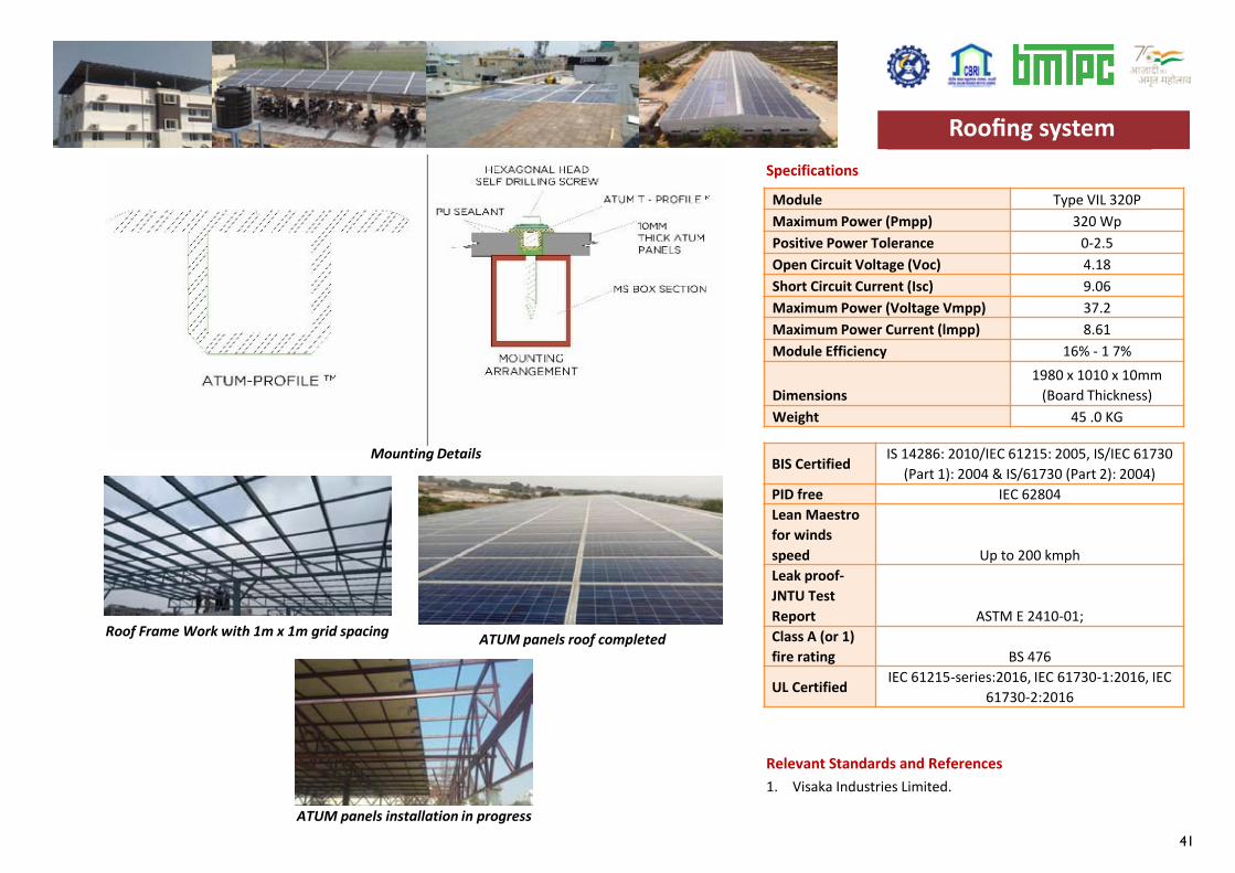
41
Specifications
Roof Frame Work with 1m x 1m grid spacing
ATUM panels installation in progress
ATUM panels roof completed
Module Type VIL 320PMaximum Power (Pmpp) 320 WpPositive Power Tolerance 0-2.5Open Circuit Voltage (Voc) 4.18Short Circuit Current (Isc) 9.06Maximum Power (Voltage Vmpp) 37.2Maximum Power Current (lmpp) 8.61Module Efficiency 16% - 1 7%
Dimensions1980 x 1010 x 10mm
(Board Thickness)Weight 45 .0 KG
BIS Certified IS 14286: 2010/IEC 61215: 2005, IS/IEC 61730 (Part 1): 2004 & IS/61730 (Part 2): 2004)
PID free IEC 62804Lean Maestro for winds speed Up to 200 kmphLeak proof-JNTU Test Report ASTM E 2410-01;Class A (or 1) fire rating BS 476
UL Certified IEC 61215-series:2016, IEC 61730-1:2016, IEC 61730-2:2016
Roofing system
Relevant Standards and References 1. Visaka Industries Limited.
Mounting Details
Roofing system

42
43
Wall Construction Technologies
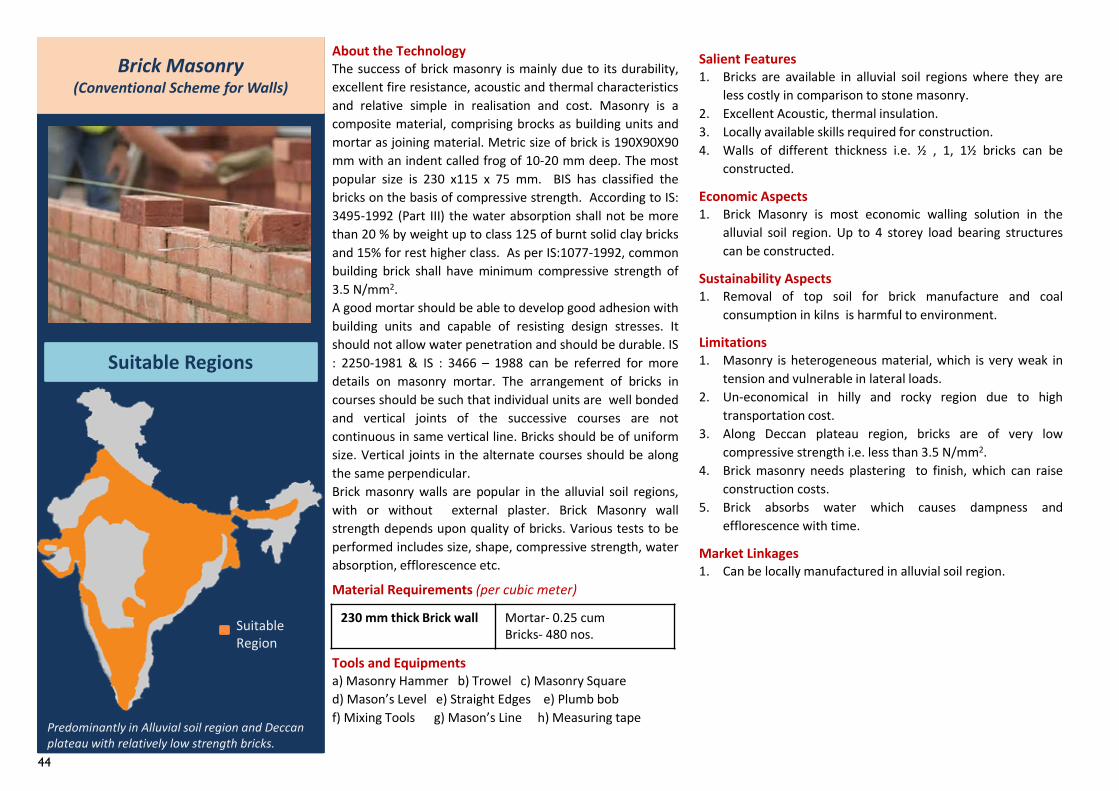
44
230 mm thick Brick wall Mortar- 0.25 cumBricks- 480 nos.
Brick Masonry(Conventional Scheme for Walls)
Suitable Regions
Predominantly in Alluvial soil region and Deccan plateau with relatively low strength bricks.
About the TechnologyThe success of brick masonry is mainly due to its durability,excellent fire resistance, acoustic and thermal characteristicsand relative simple in realisation and cost. Masonry is acomposite material, comprising brocks as building units andmortar as joining material. Metric size of brick is 190X90X90mm with an indent called frog of 10-20 mm deep. The mostpopular size is 230 x115 x 75 mm. BIS has classified thebricks on the basis of compressive strength. According to IS:3495-1992 (Part III) the water absorption shall not be morethan 20 % by weight up to class 125 of burnt solid clay bricksand 15% for rest higher class. As per IS:1077-1992, commonbuilding brick shall have minimum compressive strength of3.5 N/mm2.A good mortar should be able to develop good adhesion withbuilding units and capable of resisting design stresses. Itshould not allow water penetration and should be durable. IS: 2250-1981 & IS : 3466 – 1988 can be referred for moredetails on masonry mortar. The arrangement of bricks incourses should be such that individual units are well bondedand vertical joints of the successive courses are notcontinuous in same vertical line. Bricks should be of uniformsize. Vertical joints in the alternate courses should be alongthe same perpendicular.Brick masonry walls are popular in the alluvial soil regions,with or without external plaster. Brick Masonry wallstrength depends upon quality of bricks. Various tests to beperformed includes size, shape, compressive strength, waterabsorption, efflorescence etc.
Material Requirements (per cubic meter)
Tools and Equipmentsa) Masonry Hammer b) Trowel c) Masonry Square d) Mason’s Level e) Straight Edges e) Plumb bob f) Mixing Tools g) Mason’s Line h) Measuring tape
Salient Features1. Bricks are available in alluvial soil regions where they are
less costly in comparison to stone masonry.2. Excellent Acoustic, thermal insulation.3. Locally available skills required for construction.4. Walls of different thickness i.e. ½ , 1, 1½ bricks can be
constructed.
Economic Aspects1. Brick Masonry is most economic walling solution in the
alluvial soil region. Up to 4 storey load bearing structurescan be constructed.
Sustainability Aspects1. Removal of top soil for brick manufacture and coal
consumption in kilns is harmful to environment.
Limitations1. Masonry is heterogeneous material, which is very weak in
tension and vulnerable in lateral loads.2. Un-economical in hilly and rocky region due to high
transportation cost.3. Along Deccan plateau region, bricks are of very low
compressive strength i.e. less than 3.5 N/mm2.4. Brick masonry needs plastering to finish, which can raise
construction costs.5. Brick absorbs water which causes dampness and
efflorescence with time.
Market Linkages1. Can be locally manufactured in alluvial soil region.
Suitable Region
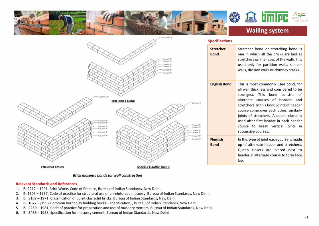
45
Stretcher Bond
Stretcher bond or stretching bond isone in which all the bricks are laid asstretchers on the faces of the walls. It isused only for partition walls, sleeperwalls, division walls or chimney stacks.
English Bond This is most commonly used bond, forall wall thickness and considered to bestrongest. This bond consists ofalternate courses of headers andstretchers. In this bond joints of headercourse come over each other, similarlyjoints of stretchers. A queen closer isused after first header in each headercourse to break vertical joints insuccessive courses.
Flemish Bond
In this type of joint each course is madeup of alternate header and stretchers.Queen closers are placed next toheader in alternate course to form facelap.
Specifications
Relevant Standards and References1. IS: 2212 – 1991, Brick Works-Code of Practice, Bureau of Indian Standards, New Delhi.2. IS: 1905 – 1987, Code of practice for structural use of unreinforced masonry, Bureau of Indian Standards, New Delhi.3. IS : 3102 – 1971, Classification of burnt clay solid bricks, Bureau of Indian Standards, New Delhi.4. IS : 1077 – j1992 Common burnt clay building bricks – specification, , Bureau of Indian Standards, New Delhi.5. IS : 2250 – 1981, Code of practice for preparation and use of masonry mortars, Bureau of Indian Standards, New Delhi.6. IS : 3466 – 1988, Specification for masonry cement, Bureau of Indian Standards, New Delhi.
Walling system
Brick masonry bonds for wall construction
Walling system
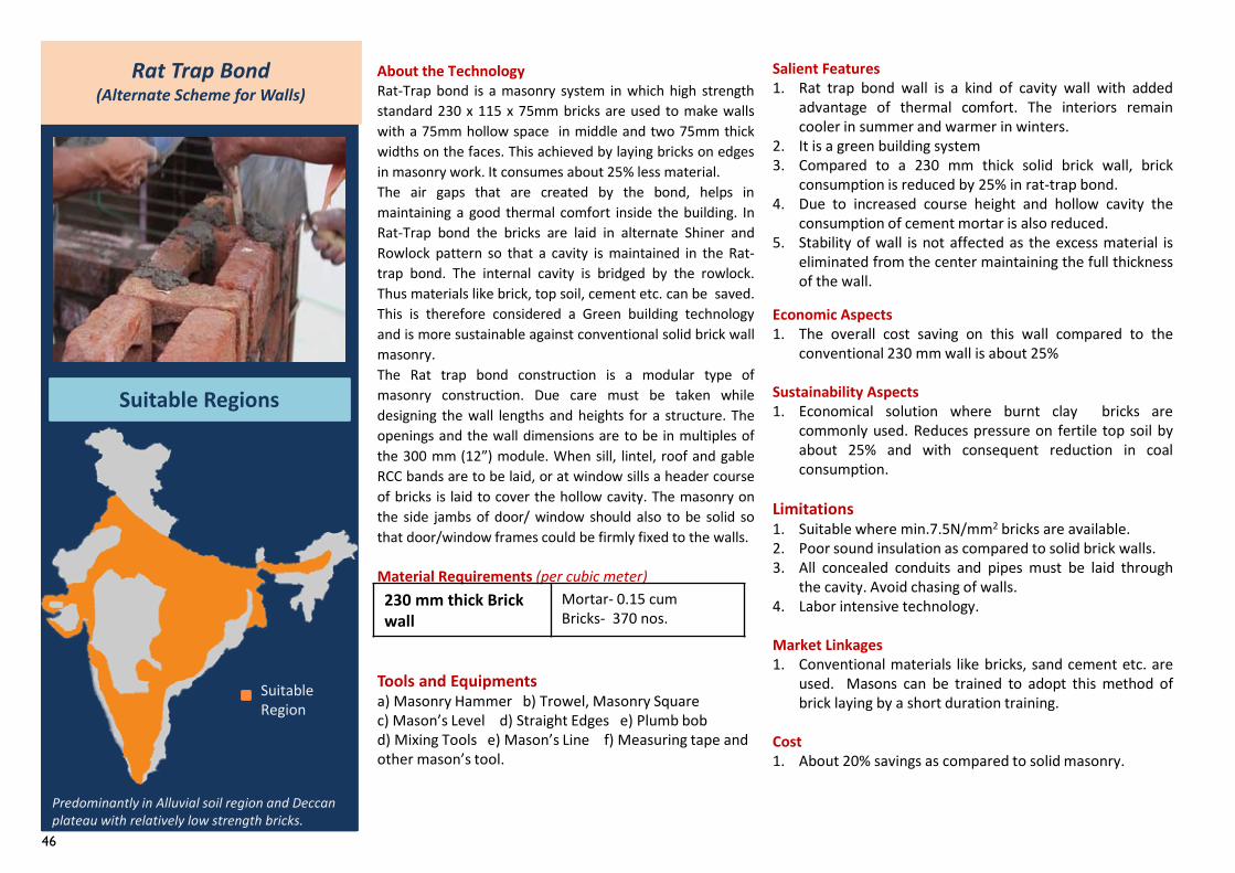
46
Rat Trap Bond(Alternate Scheme for Walls)
Suitable Regions
Predominantly in Alluvial soil region and Deccan plateau with relatively low strength bricks.
About the TechnologyRat-Trap bond is a masonry system in which high strengthstandard 230 x 115 x 75mm bricks are used to make wallswith a 75mm hollow space in middle and two 75mm thickwidths on the faces. This achieved by laying bricks on edgesin masonry work. It consumes about 25% less material.The air gaps that are created by the bond, helps inmaintaining a good thermal comfort inside the building. InRat-Trap bond the bricks are laid in alternate Shiner andRowlock pattern so that a cavity is maintained in the Rat-trap bond. The internal cavity is bridged by the rowlock.Thus materials like brick, top soil, cement etc. can be saved.This is therefore considered a Green building technologyand is more sustainable against conventional solid brick wallmasonry.The Rat trap bond construction is a modular type ofmasonry construction. Due care must be taken whiledesigning the wall lengths and heights for a structure. Theopenings and the wall dimensions are to be in multiples ofthe 300 mm (12”) module. When sill, lintel, roof and gableRCC bands are to be laid, or at window sills a header courseof bricks is laid to cover the hollow cavity. The masonry onthe side jambs of door/ window should also to be solid sothat door/window frames could be firmly fixed to the walls.
Material Requirements (per cubic meter)
Tools and Equipmentsa) Masonry Hammer b) Trowel, Masonry Squarec) Mason’s Level d) Straight Edges e) Plumb bobd) Mixing Tools e) Mason’s Line f) Measuring tape andother mason’s tool.
Salient Features1. Rat trap bond wall is a kind of cavity wall with added
advantage of thermal comfort. The interiors remaincooler in summer and warmer in winters.
2. It is a green building system3. Compared to a 230 mm thick solid brick wall, brick
consumption is reduced by 25% in rat-trap bond.4. Due to increased course height and hollow cavity the
consumption of cement mortar is also reduced.5. Stability of wall is not affected as the excess material is
eliminated from the center maintaining the full thicknessof the wall.
Economic Aspects1. The overall cost saving on this wall compared to the
conventional 230 mm wall is about 25%
Sustainability Aspects1. Economical solution where burnt clay bricks are
commonly used. Reduces pressure on fertile top soil byabout 25% and with consequent reduction in coalconsumption.
Limitations1. Suitable where min.7.5N/mm2 bricks are available.2. Poor sound insulation as compared to solid brick walls.3. All concealed conduits and pipes must be laid through
the cavity. Avoid chasing of walls.4. Labor intensive technology.
Market Linkages1. Conventional materials like bricks, sand cement etc. are
used. Masons can be trained to adopt this method ofbrick laying by a short duration training.
Cost1. About 20% savings as compared to solid masonry.
Suitable Region
230 mm thick Brick wall
Mortar- 0.15 cumBricks- 370 nos.
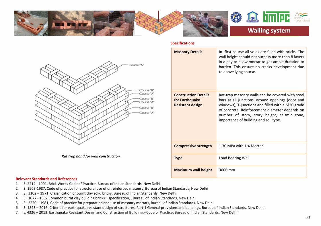
47
Masonry Details In first course all voids are filled with bricks. Thewall height should not surpass more than 8 layersin a day to allow mortar to get ample duration toharden. This ensure no cracks development dueto above lying course.
Construction Details for Earthquake Resistant design
Rat-trap masonry walls can be covered with steelbars at all junctions, around openings (door andwindows), T-junctions and filled with a M20 gradeof concrete. Reinforcement diameter depends onnumber of story, story height, seismic zone,importance of building and soil type.
Compressive strength 1.30 MPa with 1:4 Mortar
Type Load Bearing Wall
Maximum wall height 3600 mm
Specifications
Relevant Standards and References1. IS: 2212 - 1991, Brick Works-Code of Practice, Bureau of Indian Standards, New Delhi2. IS: 1905-1987, Code of practice for structural use of unreinforced masonry, Bureau of Indian Standards, New Delhi3. IS : 3102 – 1971, Classification of burnt clay solid bricks, Bureau of Indian Standards, New Delhi4. IS : 1077 - 1992 Common burnt clay building bricks – specification, , Bureau of Indian Standards, New Delhi5. IS : 2250 – 1981, Code of practice for preparation and use of masonry mortars, Bureau of Indian Standards, New Delhi6. IS: 1893 – 2016, Criteria for earthquake resistant design of structures, Part-1 General provisions and buildings, Bureau of Indian Standards, New Delhi7. Is: 4326 – 2013, Earthquake Resistant Design and Construction of Buildings--Code of Practice, Bureau of Indian Standards, New Delhi
Walling system
Rat trap bond for wall construction
Walling system
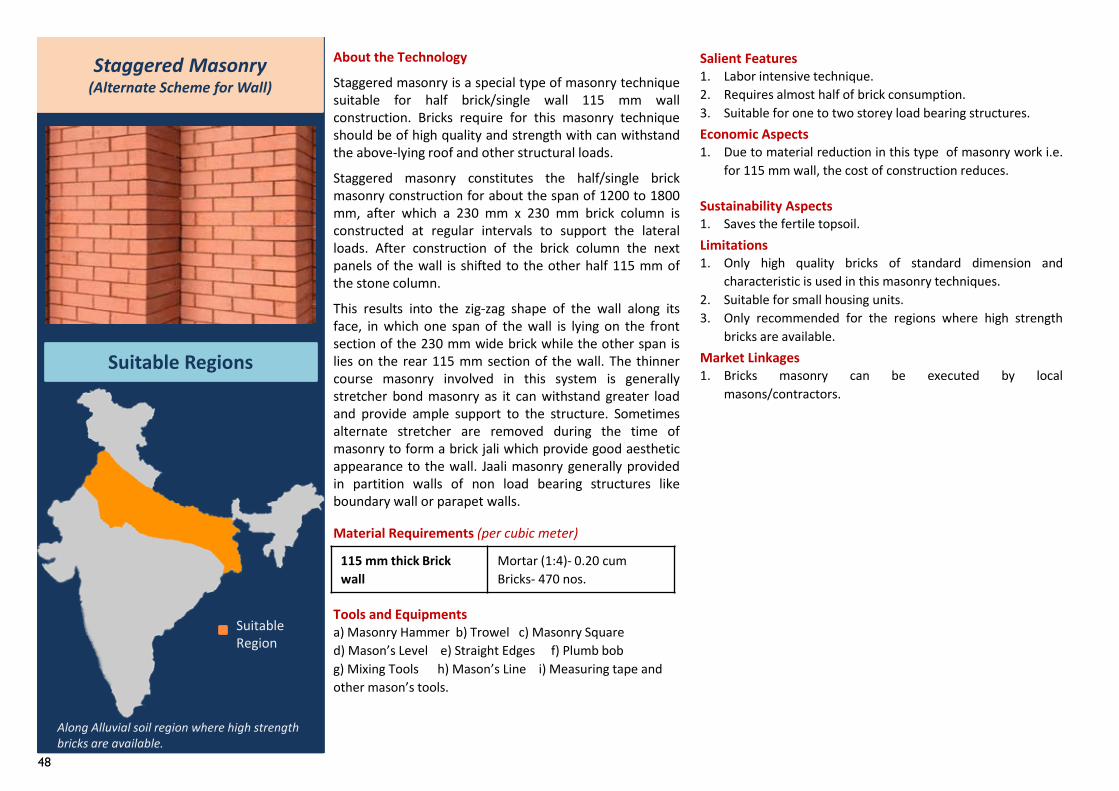
48
About the Technology
Staggered masonry is a special type of masonry techniquesuitable for half brick/single wall 115 mm wallconstruction. Bricks require for this masonry techniqueshould be of high quality and strength with can withstandthe above-lying roof and other structural loads.
Staggered masonry constitutes the half/single brickmasonry construction for about the span of 1200 to 1800mm, after which a 230 mm x 230 mm brick column isconstructed at regular intervals to support the lateralloads. After construction of the brick column the nextpanels of the wall is shifted to the other half 115 mm ofthe stone column.
This results into the zig-zag shape of the wall along itsface, in which one span of the wall is lying on the frontsection of the 230 mm wide brick while the other span islies on the rear 115 mm section of the wall. The thinnercourse masonry involved in this system is generallystretcher bond masonry as it can withstand greater loadand provide ample support to the structure. Sometimesalternate stretcher are removed during the time ofmasonry to form a brick jali which provide good aestheticappearance to the wall. Jaali masonry generally providedin partition walls of non load bearing structures likeboundary wall or parapet walls.
Material Requirements (per cubic meter)
Tools and Equipmentsa) Masonry Hammer b) Trowel c) Masonry Square d) Mason’s Level e) Straight Edges f) Plumb bob g) Mixing Tools h) Mason’s Line i) Measuring tape and other mason’s tools.
115 mm thick Brick wall
Mortar (1:4)- 0.20 cumBricks- 470 nos.
Staggered Masonry (Alternate Scheme for Wall)
Suitable Regions
Along Alluvial soil region where high strength bricks are available.
Salient Features1. Labor intensive technique.2. Requires almost half of brick consumption.3. Suitable for one to two storey load bearing structures.Economic Aspects1. Due to material reduction in this type of masonry work i.e.
for 115 mm wall, the cost of construction reduces.
Sustainability Aspects1. Saves the fertile topsoil.Limitations1. Only high quality bricks of standard dimension and
characteristic is used in this masonry techniques.2. Suitable for small housing units.3. Only recommended for the regions where high strength
bricks are available.Market Linkages1. Bricks masonry can be executed by local
masons/contractors.
Suitable Region
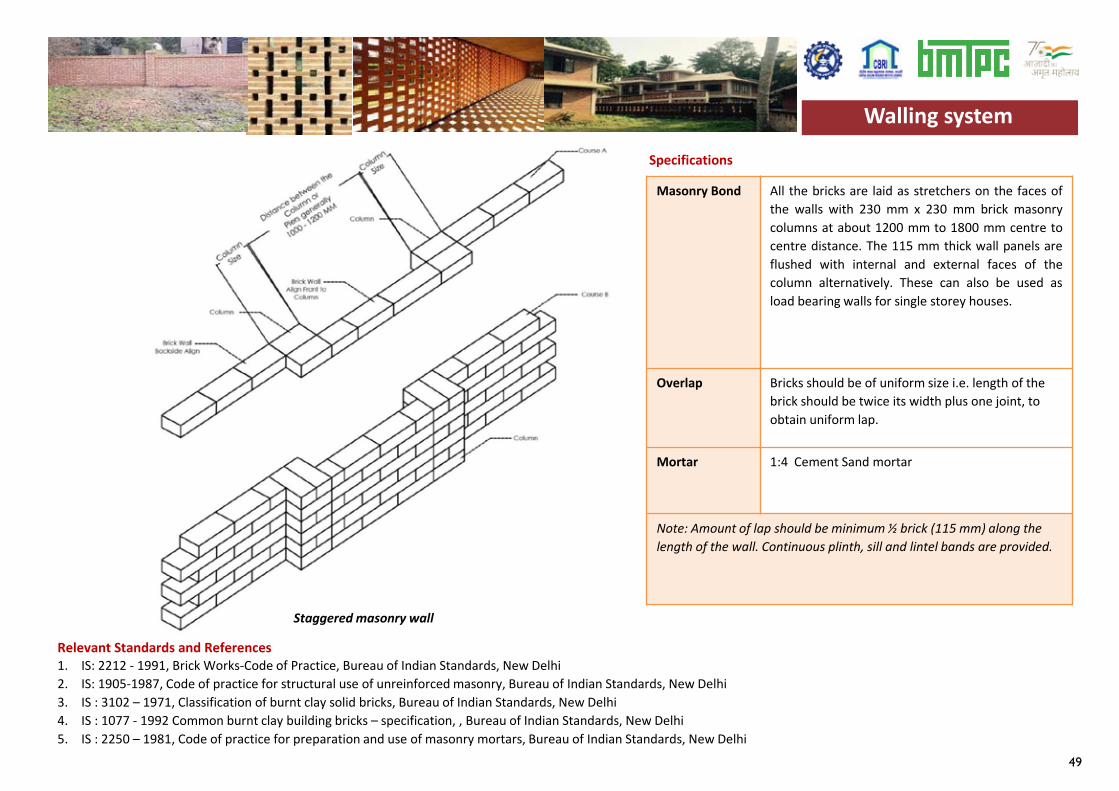
49
Masonry Bond All the bricks are laid as stretchers on the faces ofthe walls with 230 mm x 230 mm brick masonrycolumns at about 1200 mm to 1800 mm centre tocentre distance. The 115 mm thick wall panels areflushed with internal and external faces of thecolumn alternatively. These can also be used asload bearing walls for single storey houses.
Overlap Bricks should be of uniform size i.e. length of the brick should be twice its width plus one joint, to obtain uniform lap.
Mortar 1:4 Cement Sand mortar
Note: Amount of lap should be minimum ½ brick (115 mm) along the length of the wall. Continuous plinth, sill and lintel bands are provided.
Specifications
Relevant Standards and References1. IS: 2212 - 1991, Brick Works-Code of Practice, Bureau of Indian Standards, New Delhi2. IS: 1905-1987, Code of practice for structural use of unreinforced masonry, Bureau of Indian Standards, New Delhi3. IS : 3102 – 1971, Classification of burnt clay solid bricks, Bureau of Indian Standards, New Delhi4. IS : 1077 - 1992 Common burnt clay building bricks – specification, , Bureau of Indian Standards, New Delhi5. IS : 2250 – 1981, Code of practice for preparation and use of masonry mortars, Bureau of Indian Standards, New Delhi
Walling system
Staggered masonry wall
Walling system
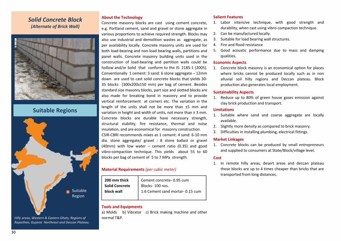
50
About the TechnologyConcrete masonry blocks are cast using cement concrete,e.g. Portland cement, sand and gravel or stone aggregate invarious proportions to achieve required strength. Blocks mayalso use industrial and demolition wastes as aggregate, asper availability locally. Concrete masonry units are used forboth load-bearing and non-load bearing walls, partitions andpanel walls. Concrete masonry building units used in theconstruction of load-bearing and partition walls could behollow and/or Solid that conform to the IS: 2185-1 (2005).Conventionally 1 cement: 3 sand: 6 stone aggregate – 12mmdown are used to cast solid concrete blocks that yields 30-35 blocks (300x200x150 mm) per bag of cement. Besidesstandard size masonry blocks, part size and slotted blocks arealso made for breaking bond in masonry and to providevertical reinforcement at corners etc. The variation in thelength of the units shall not be more than ±5 mm andvariation in height and width of units, not more than ± 3 mm.Concrete blocks are durable have necessary strength,structural stability, fire resistance, thermal and noiseinsulation, and are economical for masonry construction.CSIR-CBRI recommends mixes as 1 cement: 4 sand: 6-10 mmdia. stone aggregate/ gravel : 8 stone ballast or gravel(40mm) with low water – cement ratio (0.35) and goodvibro-compaction technique. This yields about 55 to 60blocks per bag of cement of 5 to 7 MPa strength.
Material Requirements (per cubic meter)
Tools and Equipmentsa) Molds b) Vibrator c) Brick making machine and othernormal T&P.
200 mm thick Solid Concrete block wall
Cement concrete- 0.95 cumBlocks- 100 nos.1:6 Cement sand mortar- 0.15 cum
Solid Concrete Block (Alternate of Brick Wall)
Suitable Regions
Hilly areas, Western & Eastern Ghats, Regions of Rajasthan, Gujarat Northeast and Deccan Plateau.
Salient Features1. Labor intensive technique, with good strength and
durability, when cast using vibro-compaction technique.2. Can be manufactured locally.3. Suitable for load bearing wall structures.4. Fire and flood resistance5. Good acoustic performance due to mass and damping
qualities.Economic Aspects1. Concrete block masonry is an economical option for places
where bricks cannot be produced locally such as in nonalluvial soil hilly regions and Deccan plateau. Blockproduction also generates local employment.
Sustainability Aspects1. Reduce up to 80% of green house gases emission against
clay brick production and transport.Limitations1. Suitable where sand and coarse aggregate are locally
available.2. Slightly more density as compared to brick masonry.3. Difficulties in installing plumbing, electrical fittings.
Market Linkages1. Concrete blocks can be produced by small entrepreneurs
and supplied to consumers at State/Block/village level.
Cost1. In remote hilly areas, desert areas and deccan plateau
these blocks are up to 4 times cheaper than bricks that aretransported from long distances.
Suitable Region
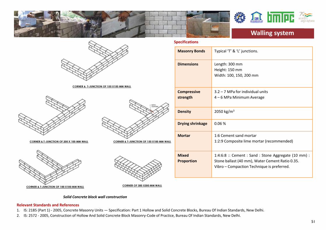
51
Masonry Bonds Typical ‘T’ & ‘L’ junctions.
Dimensions Length: 300 mmHeight: 150 mmWidth: 100, 150, 200 mm
Compressive strength
3.2 – 7 MPa for individual units4 – 6 MPa Minimum Average
Density 2050 kg/m3
Drying shrinkage 0.06 %
Mortar 1:6 Cement sand mortar1:2:9 Composite lime mortar (recommended)
MixedProportion
1:4:6:8 :: Cement : Sand : Stone Aggregate (10 mm) :Stone ballast (40 mm), Water Cement Ratio 0.35.Vibro – Compaction Technique is preferred.
Specifications
Relevant Standards and References1. IS: 2185 (Part 1) - 2005, Concrete Masonry Units — Specification: Part 1 Hollow and Solid Concrete Blocks, Bureau Of Indian Standards, New Delhi.2. IS: 2572 - 2005, Construction of Hollow And Solid Concrete Block Masonry-Code of Practice, Bureau Of Indian Standards, New Delhi.
Walling system
Solid Concrete block wall construction
Walling system
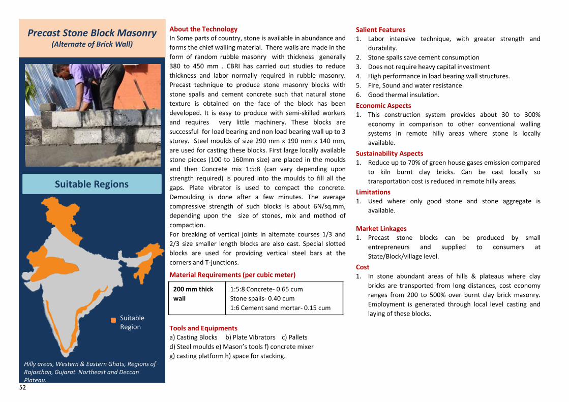
52
Precast Stone Block Masonry (Alternate of Brick Wall)
Suitable Regions
About the TechnologyIn Some parts of country, stone is available in abundance andforms the chief walling material. There walls are made in theform of random rubble masonry with thickness generally380 to 450 mm . CBRI has carried out studies to reducethickness and labor normally required in rubble masonry.Precast technique to produce stone masonry blocks withstone spalls and cement concrete such that natural stonetexture is obtained on the face of the block has beendeveloped. It is easy to produce with semi-skilled workersand requires very little machinery. These blocks aresuccessful for load bearing and non load bearing wall up to 3storey. Steel moulds of size 290 mm x 190 mm x 140 mm,are used for casting these blocks. First large locally availablestone pieces (100 to 160mm size) are placed in the mouldsand then Concrete mix 1:5:8 (can vary depending uponstrength required) is poured into the moulds to fill all thegaps. Plate vibrator is used to compact the concrete.Demoulding is done after a few minutes. The averagecompressive strength of such blocks is about 6N/sq.mm,depending upon the size of stones, mix and method ofcompaction.For breaking of vertical joints in alternate courses 1/3 and2/3 size smaller length blocks are also cast. Special slottedblocks are used for providing vertical steel bars at thecorners and T-junctions.
Material Requirements (per cubic meter)
Tools and Equipmentsa) Casting Blocks b) Plate Vibrators c) Pallets d) Steel moulds e) Mason’s tools f) concrete mixer g) casting platform h) space for stacking.
Salient Features1. Labor intensive technique, with greater strength and
durability.2. Stone spalls save cement consumption3. Does not require heavy capital investment4. High performance in load bearing wall structures.5. Fire, Sound and water resistance6. Good thermal insulation.Economic Aspects1. This construction system provides about 30 to 300%
economy in comparison to other conventional wallingsystems in remote hilly areas where stone is locallyavailable.
Sustainability Aspects1. Reduce up to 70% of green house gases emission compared
to kiln burnt clay bricks. Can be cast locally sotransportation cost is reduced in remote hilly areas.
Limitations1. Used where only good stone and stone aggregate is
available.
Market Linkages1. Precast stone blocks can be produced by small
entrepreneurs and supplied to consumers atState/Block/village level.
Cost 1. In stone abundant areas of hills & plateaus where clay
bricks are transported from long distances, cost economyranges from 200 to 500% over burnt clay brick masonry.Employment is generated through local level casting andlaying of these blocks.Suitable
Region
Hilly areas, Western & Eastern Ghats, Regions of Rajasthan, Gujarat Northeast and Deccan Plateau.
200 mm thickwall
1:5:8 Concrete- 0.65 cumStone spalls- 0.40 cum1:6 Cement sand mortar- 0.15 cum
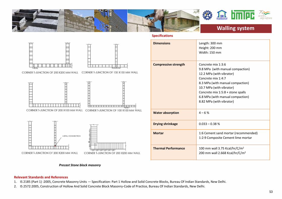
53
Dimensions Length: 300 mmHeight: 200 mmWidth: 150 mm
Compressive strength Concrete mix 1:3:69.8 MPa (with manual compaction)12.2 MPa (with vibrator)Concrete mix 1:4:78.3 MPa (with manual compaction)10.7 MPa (with vibrator)Concrete mix 1:5:8 + stone spalls6.8 MPa (with manual compaction)8.82 MPa (with vibrator)
Water absorption 4 – 6 %
Drying shrinkage 0.033 – 0.38 %
Mortar 1:6 Cement sand mortar (recommended)1:2:9 Composite Cement lime mortar
Thermal Performance 100 mm wall 3.75 Kcal/hr/C/m2
200 mm wall 2.668 Kcal/hr/C/m2
Specifications
Relevant Standards and References 1. IS 2185 (Part 1) :2005, Concrete Masonry Units — Specification: Part 1 Hollow and Solid Concrete Blocks, Bureau Of Indian Standards, New Delhi.2. IS 2572:2005, Construction of Hollow And Solid Concrete Block Masonry-Code of Practice, Bureau Of Indian Standards, New Delhi.
Walling system
Precast Stone block masonry
Walling system
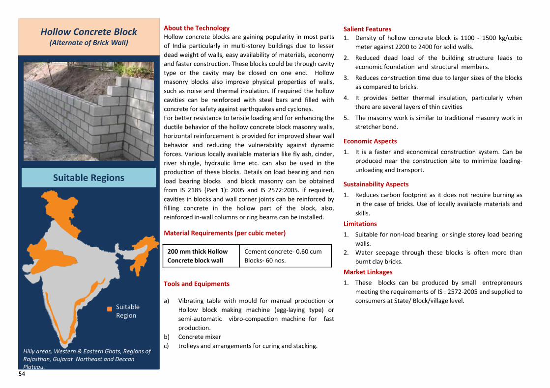
54
Hollow Concrete Block(Alternate of Brick Wall)
Suitable Regions
About the TechnologyHollow concrete blocks are gaining popularity in most partsof India particularly in multi-storey buildings due to lesserdead weight of walls, easy availability of materials, economyand faster construction. These blocks could be through cavitytype or the cavity may be closed on one end. Hollowmasonry blocks also improve physical properties of walls,such as noise and thermal insulation. If required the hollowcavities can be reinforced with steel bars and filled withconcrete for safety against earthquakes and cyclones.For better resistance to tensile loading and for enhancing theductile behavior of the hollow concrete block masonry walls,horizontal reinforcement is provided for improved shear wallbehavior and reducing the vulnerability against dynamicforces. Various locally available materials like fly ash, cinder,river shingle, hydraulic lime etc. can also be used in theproduction of these blocks. Details on load bearing and nonload bearing blocks and block masonry can be obtainedfrom IS 2185 (Part 1): 2005 and IS 2572:2005. if required,cavities in blocks and wall corner joints can be reinforced byfilling concrete in the hollow part of the block, also,reinforced in-wall columns or ring beams can be installed.
Material Requirements (per cubic meter)
Tools and Equipments
a) Vibrating table with mould for manual production orHollow block making machine (egg-laying type) orsemi-automatic vibro-compaction machine for fastproduction.
b) Concrete mixerc) trolleys and arrangements for curing and stacking.
Salient Features1. Density of hollow concrete block is 1100 - 1500 kg/cubic
meter against 2200 to 2400 for solid walls.2. Reduced dead load of the building structure leads to
economic foundation and structural members.3. Reduces construction time due to larger sizes of the blocks
as compared to bricks.4. It provides better thermal insulation, particularly when
there are several layers of thin cavities5. The masonry work is similar to traditional masonry work in
stretcher bond.
Economic Aspects1. It is a faster and economical construction system. Can be
produced near the construction site to minimize loading-unloading and transport.
Sustainability Aspects1. Reduces carbon footprint as it does not require burning as
in the case of bricks. Use of locally available materials andskills.
Limitations1. Suitable for non-load bearing or single storey load bearing
walls.2. Water seepage through these blocks is often more than
burnt clay bricks.Market Linkages1. These blocks can be produced by small entrepreneurs
meeting the requirements of IS : 2572-2005 and supplied toconsumers at State/ Block/village level.
Suitable Region
Hilly areas, Western & Eastern Ghats, Regions of Rajasthan, Gujarat Northeast and Deccan Plateau.
200 mm thick Hollow Concrete block wall
Cement concrete- 0.60 cumBlocks- 60 nos.
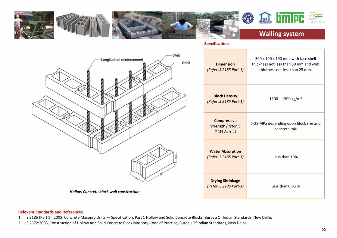
55
Walling system
Dimension(Refer IS 2185 Part-1)
390 x 190 x 190 mm with face shell thickness not less than 30 mm and web
thickness not less than 25 mm.
Block Density(Refer IS 2185 Part-1)
1100 – 1500 kg/m3
Compressive Strength (Refer IS
2185 Part-1)
5-28 MPa depending upon block size and concrete mix
Water Absorption (Refer IS 2185 Part-1) Less than 10%
Drying Shrinkage (Refer IS 2185 Part-1) Less than 0.06 %
Specifications
Relevant Standards and References 1. IS 2185 (Part 1) :2005, Concrete Masonry Units — Specification: Part 1 Hollow and Solid Concrete Blocks, Bureau Of Indian Standards, New Delhi.2. IS 2572:2005, Construction of Hollow And Solid Concrete Block Masonry-Code of Practice, Bureau Of Indian Standards, New Delhi.
Walling system
Hollow Concrete block wall construction
Walling system
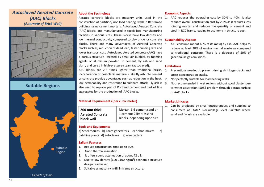
56
Autoclaved Aerated Concrete (AAC) Blocks
(Alternate of Brick Wall)
Suitable Regions
All parts of India
About the TechnologyAerated concrete blocks are masonry units used in theconstruction of partition/ non load bearing walls in RC framedbuildings using cement mortars. Autoclaved Aerated Concrete(AAC) Blocks are manufactured in specialized manufacturingfacilities in various sizes. These Blocks have low density andlow thermal conductivity compared to clay bricks or concreteblocks. There are many advantages of Aerated Concreteblocks such as, reduction of dead load, faster building rate andlower transport cost. Autoclaved Aerated concrete (AAC) havea porous structure created by small air bubbles by foamingagents or aluminum powder in cement, fly ash and sandslurry and cured in high-pressure steam (autoclaved).AAC blocks are 2-3 times lighter than traditional bricks.Incorporation of pozzolanic materials like fly ash into cementor concrete provide advantages such as reduction in the heat,low permeability and resistance to sulphate attack. Fly ash isalso used to replace part of Portland cement and part of fineaggregates for the production of AAC blocks.
Material Requirements (per cubic meter)
Tools and Equipmentsa) Steel-moulds b) Foam generators c) ribbon mixers c)batching plants d) autoclaves e) wire cutters
Salient Features1. Reduce construction time up to 50%.2. Good thermal insulation.3. It offers sound attenuation of about 42 dB.4. Due to low density (600-1100 Kg/m3) economic structure
design is achieved.5. Suitable as masonry in-fill in frame structure.
Economic Aspects1. AAC reduces the operating cost by 30% to 40%. It also
reduces overall construction cost by 2.5% as it requires lessjointing mortar and reduces the quantity of cement andsteel in RCC frame, leading to economy in structure cost.
Sustainability Aspects1. AAC consume (about 60% of its mass) fly ash. AAC helps to
reduce at least 30% of environmental waste as comparedto traditional concrete. There is a decrease of 50% ofgreenhouse gas emissions.
Limitations1. Precautions needed to prevent drying shrinkage cracks and
stress concentration cracks.2. Not perfectly suitable for load bearing walls.3. Not recommended in wet regions without good plaster due
to water absorption (50%) problem through porous surfaceof AAC blocks.
Market Linkages1. Can be produced by small entrepreneurs and supplied to
consumers at State/ Block/village level. Suitable wheresand and fly ash are available.
Suitable Region
200 mm thick Aerated Concrete block wall
Mortar- 1:6 cement sand or 1 cement: 2 lime: 9 sandBlocks- depending upon size
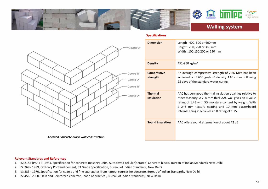
57
Dimension Length : 400, 500 or 600mmHeight : 200, 250 or 360 mmWidth : 100,150,200 or 250 mm
Density 451-950 kg/m3
Compressivestrength
An average compressive strength of 2.86 MPa has beenachieved on 0.650 gm/cm3 density AAC cubes following28 days of the standard water-curing.
ThermalInsulation
AAC has very good thermal insulation qualities relative toother masonry. A 200 mm thick AAC wall gives an R-valuerating of 1.43 with 5% moisture content by weight. Witha 2–3 mm texture coating and 10 mm plasterboardinternal lining it achieves an R rating of 1.75.
Sound insulation AAC offers sound attenuation of about 42 dB.
Specifications
Relevant Standards and References1. IS: 2185 (PART 3) 1984, Specification for concrete masonry units, Autoclaved cellular(aerated) Concrete blocks, Bureau of Indian Standards New Delhi2. IS: 269 - 1989, Ordinary Portland Cement, 33 Grade Specification, Bureau of Indian Standards, New Delhi3. IS: 383 - 1970, Specification for coarse and fine aggregates from natural sources for concrete, Bureau of Indian Standards, New Delhi4. IS: 456 - 2000, Plain and Reinforced concrete - code of practice , Bureau of Indian Standards, New Delhi
Walling system
Aerated Concrete block wall construction
Walling system
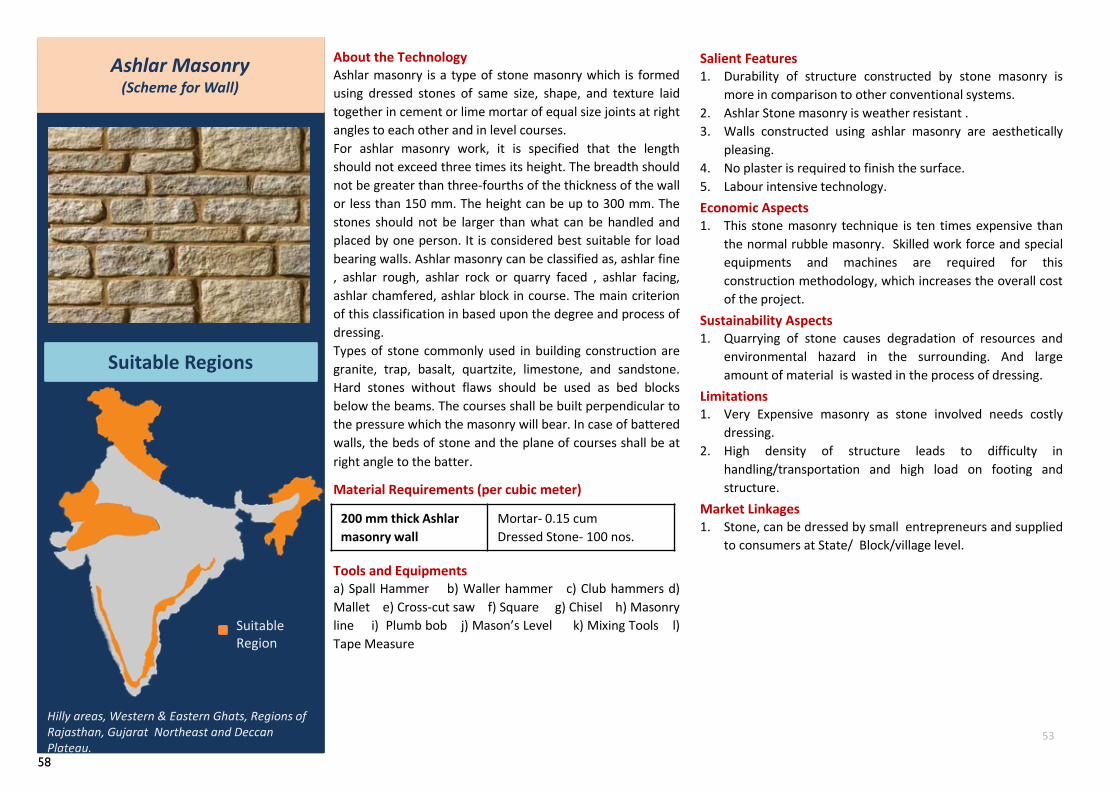
58
Ashlar Masonry(Scheme for Wall)
Suitable Regions
Hilly areas, Western & Eastern Ghats, Regions of Rajasthan, Gujarat Northeast and Deccan Plateau.
About the TechnologyAshlar masonry is a type of stone masonry which is formedusing dressed stones of same size, shape, and texture laidtogether in cement or lime mortar of equal size joints at rightangles to each other and in level courses.For ashlar masonry work, it is specified that the lengthshould not exceed three times its height. The breadth shouldnot be greater than three-fourths of the thickness of the wallor less than 150 mm. The height can be up to 300 mm. Thestones should not be larger than what can be handled andplaced by one person. It is considered best suitable for loadbearing walls. Ashlar masonry can be classified as, ashlar fine, ashlar rough, ashlar rock or quarry faced , ashlar facing,ashlar chamfered, ashlar block in course. The main criterionof this classification in based upon the degree and process ofdressing.Types of stone commonly used in building construction aregranite, trap, basalt, quartzite, limestone, and sandstone.Hard stones without flaws should be used as bed blocksbelow the beams. The courses shall be built perpendicular tothe pressure which the masonry will bear. In case of batteredwalls, the beds of stone and the plane of courses shall be atright angle to the batter.
Material Requirements (per cubic meter)
Tools and Equipmentsa) Spall Hammer b) Waller hammer c) Club hammers d)Mallet e) Cross-cut saw f) Square g) Chisel h) Masonryline i) Plumb bob j) Mason’s Level k) Mixing Tools l)Tape Measure
Salient Features1. Durability of structure constructed by stone masonry is
more in comparison to other conventional systems.2. Ashlar Stone masonry is weather resistant .3. Walls constructed using ashlar masonry are aesthetically
pleasing.4. No plaster is required to finish the surface.5. Labour intensive technology.Economic Aspects1. This stone masonry technique is ten times expensive than
the normal rubble masonry. Skilled work force and specialequipments and machines are required for thisconstruction methodology, which increases the overall costof the project.
Sustainability Aspects1. Quarrying of stone causes degradation of resources and
environmental hazard in the surrounding. And largeamount of material is wasted in the process of dressing.
Limitations1. Very Expensive masonry as stone involved needs costly
dressing.2. High density of structure leads to difficulty in
handling/transportation and high load on footing andstructure.
Market Linkages1. Stone, can be dressed by small entrepreneurs and supplied
to consumers at State/ Block/village level.
Suitable Region
53
200 mm thick Ashlarmasonry wall
Mortar- 0.15 cumDressed Stone- 100 nos.
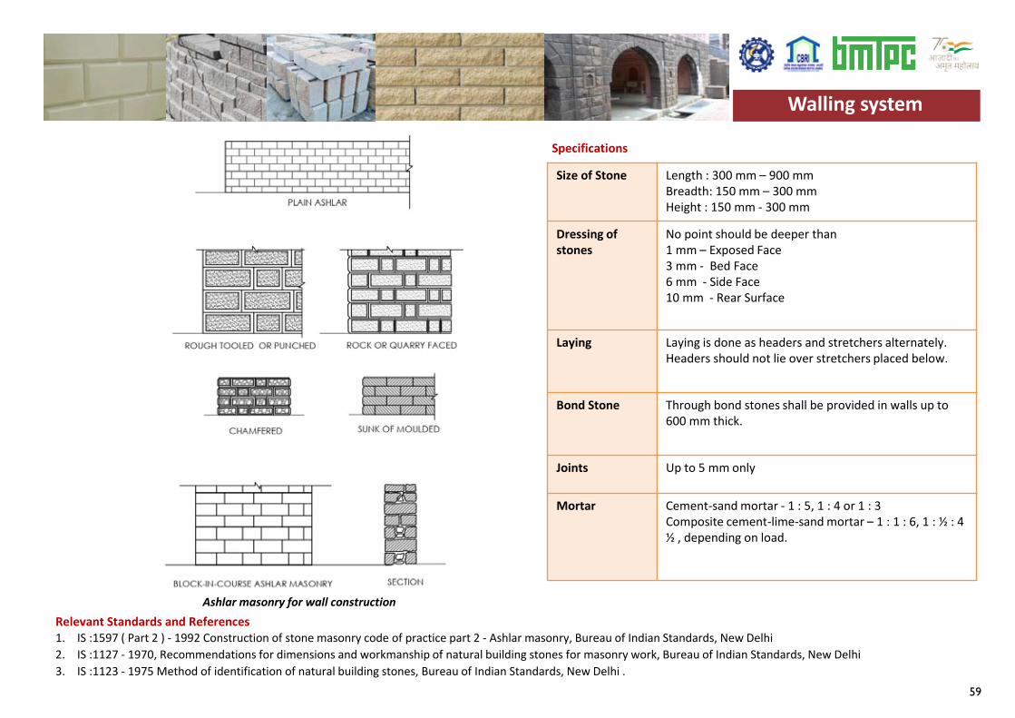
59
Size of Stone Length : 300 mm – 900 mmBreadth: 150 mm – 300 mmHeight : 150 mm - 300 mm
Dressing of stones
No point should be deeper than1 mm – Exposed Face3 mm - Bed Face6 mm - Side Face10 mm - Rear Surface
Laying Laying is done as headers and stretchers alternately. Headers should not lie over stretchers placed below.
Bond Stone Through bond stones shall be provided in walls up to 600 mm thick.
Joints Up to 5 mm only
Mortar Cement-sand mortar - 1 : 5, 1 : 4 or 1 : 3 Composite cement-lime-sand mortar – 1 : 1 : 6, 1 : ½ : 4 ½ , depending on load.
Specifications
Relevant Standards and References 1. IS :1597 ( Part 2 ) - 1992 Construction of stone masonry code of practice part 2 - Ashlar masonry, Bureau of Indian Standards, New Delhi2. IS :1127 - 1970, Recommendations for dimensions and workmanship of natural building stones for masonry work, Bureau of Indian Standards, New Delhi3. IS :1123 - 1975 Method of identification of natural building stones, Bureau of Indian Standards, New Delhi .
Walling system
Ashlar masonry for wall construction
Walling system
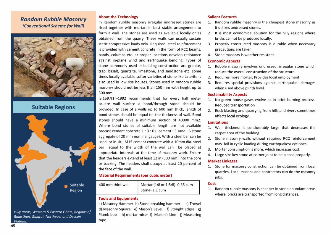
60
About the TechnologyIn Random rubble masonry irregular undressed stones arefixed together with mortar, in best stable arrangement toform a wall. The stones are used as available locally or asobtained from the quarry. These walls can usually sustainstatic compressive loads only. Required steel reinforcementis provided with cement concrete in the form of RCC beams,bands, columns etc. at proper locations develop resistanceagainst in-plane wind and earthquake bending. Types ofstone commonly used in building construction are granite,trap, basalt, quartzite, limestone, and sandstone etc. sometimes locally available softer varieties of stone like Laterite isalso used in low rise houses. Stones used in random rubblemasonry should not be less than 150 mm with height up to300 mm.IS:1597(1)–1992 recommends that for every half metersquare wall surface a bond/through stone should beprovided. In case of a walls up to 600 mm thick, length ofbond stones should be equal to the thickness of wall. Bondstones should have a minimum section of 40000 mm2.Where bond stones of suitable length are not availableprecast cement concrete 1 : 3 : 6 (I cement : 3 sand : 6 stoneaggregate of 20 mm nominal gauge). With a steel bar can beused or in-situ M15 cement concrete with a 10mm dia. steelbar equal to the width of the wall can be placed atappropriate intervals at the time of masonry work. Ensurethat the headers extend at least 12 in (300 mm) into the coreor backing. The headers shall occupy at least 20 percent ofthe face of the wall.Material Requirements (per cubic meter)
Tools and Equipmentsa) Masonry Hammer b) Stone breaking hammer c) Troweld) Masonry Square e) Mason’s Level f) Straight Edges g)Plumb bob h) mortar mixer i) Mason’s Line j) Measuringtape
400 mm thick wall Mortar (1:8 or 1:5:8)- 0.35 cumStone- 1.1 cum
Random Rubble Masonry (Conventional Scheme for Wall)
Suitable Regions
Hilly areas, Western & Eastern Ghats, Regions of Rajasthan, Gujarat Northeast and Deccan Plateau.
Salient Features1. Random rubble masonry is the cheapest stone masonry as
it utilizes undressed stones.2. It is most economical solution for the hilly regions where
bricks cannot be produced locally.3. Properly constructed masonry is durable when necessary
precautions are taken4. Stone masonry is weather resistant.Economic Aspects1. Rubble masonry involves undressed, irregular stone which
reduce the overall construction of the structure.2. Requires more mortar, Provides local employment3. Requires special provisions against earthquake damages
when used above plinth level.Sustainability Aspects1. No green house gases evolve as in brick burning process.
Reduced transportation2. Rock blasting and quarrying from hills and rivers sometimes
affects local ecology.Limitations1. Wall thickness is considerably large that decreases the
carpet area of the building.2. Stone masonry walls without required RCC reinforcement
may fail in cyclic loading during earthquakes/ cyclones.3. Mortar consumption is more, which increases cost.4. Large size key stone at corner joint to be placed properly.Market Linkages1. Stone for masonry construction can be obtained from local
quarries. Local masons and contractors can do the masonryjobs.
Cost1. Random rubble masonry is cheaper in stone abundant areas
where bricks are transported from long distances.
Suitable Region
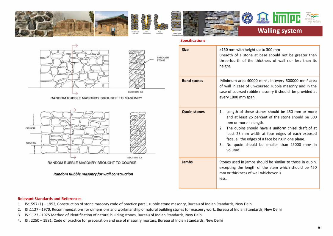
61
Size >150 mm with height up to 300 mmBreadth of a stone at base should not be greater thanthree-fourth of the thickness of wall nor less than itsheight.
Bond stones Minimum area 40000 mm2 , In every 500000 mm2 areaof wall in case of un-coursed rubble masonry and in thecase of coursed rubble masonry it should be provided atevery 1800 mm span.
Quoin stones 1. Length of these stones should be 450 mm or moreand at least 25 percent of the stone should be 500mm or more in length.
2. The quoins should have a uniform chisel draft of atleast 25 mm width at four edges of each exposedface, all the edges of a face being in one plane.
3. No quoin should be smaller than 25000 mm2 involume.
Jambs Stones used in jambs should be similar to those in quoin,excepting the length of the stem which should be 450mm or thickness of wall whichever isless.
Specifications
Relevant Standards and References 1. IS:1597 (1) – 1992, Construction of stone masonry code of practice part 1 rubble stone masonry, Bureau of Indian Standards, New Delhi2. IS :1127 - 1970, Recommendations for dimensions and workmanship of natural building stones for masonry work, Bureau of Indian Standards, New Delhi3. IS :1123 - 1975 Method of identification of natural building stones, Bureau of Indian Standards, New Delhi4. IS : 2250 – 1981, Code of practice for preparation and use of masonry mortars, Bureau of Indian Standards, New Delhi
Walling system
Random Rubble masonry for wall construction
Walling system
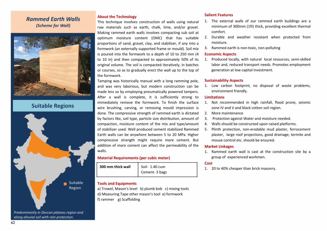
62
Rammed Earth Walls (Scheme for Wall)
Suitable Regions
Predominantly in Deccan plateau region and along alluvial soil with rain protection.
About the TechnologyThis technique involves construction of walls using naturalraw materials such as earth, chalk, lime, and/or gravel.Making rammed earth walls involves compacting sub soil atoptimum moisture content (OMC) that has suitableproportions of sand, gravel, clay, and stabilizer, if any into aformwork (an externally supported frame or mould). Soil mixis poured into the formwork to a depth of 10 to 250 mm (4to 10 in) and then compacted to approximately 50% of itsoriginal volume. The soil is compacted iteratively, in batchesor courses, so as to gradually erect the wall up to the top ofthe formwork.Tamping was historically manual with a long ramming pole,and was very laborious, but modern construction can bemade less so by employing pneumatically powered tampers.After a wall is complete, it is sufficiently strong toimmediately remove the formwork. To finish the surfacewire brushing, carving, or removing mould impression isdone. The compressive strength of rammed earth is dictatedby factors like, soil type, particle size distribution, amount ofcompaction, moisture content of the mix and type/amountof stabilizer used. Well produced cement stabilized RammedEarth walls can be anywhere between 5 to 20 MPa. Highercompressive strength might require more cement. Butaddition of more cement can affect the permeability of thewalls.
Material Requirements (per cubic meter)
Tools and Equipmentsa) Trowel, Mason's level b) plumb bob c) mixing toolsd) Measuring Tape other mason’s tool e) formworkf) rammer g) Scaffolding
Salient Features1. The external walls of our rammed earth buildings are a
minimum of 300mm (1ft) thick, providing excellent thermalcomfort.
2. Durable and weather resistant when protected frommoisture.
3. Rammed earth is non-toxic, non-pollutingEconomic Aspects1. Produced locally, with natural local resources, semi-skilled
labor and, reduced transport needs. Promotes employmentgeneration at low capital investment.
Sustainability Aspects1. Low carbon footprint, no disposal of waste problems,
environment friendly.Limitations1. Not recommended in high rainfall, flood prone, seismic
zone IV and V and black cotton soil region.2. More maintenance3. Protection against Water and moisture needed.4. Walls should be constructed upon raised platforms.5. Plinth protection, non-erodable mud plaster, ferrocement
plaster, large roof projections, good drainage, termite andmouse control etc. should be ensured.
Market Linkages1. Rammed earth wall is cast at the construction site by a
group of experienced workmen.Cost1. 20 to 40% cheaper than brick masonry.
Suitable Region
300 mm thick wall Soil- 1.40 cumCement- 3 bags
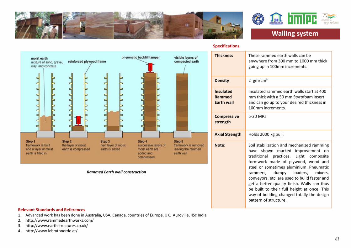
63
Thickness These rammed earth walls can be anywhere from 300 mm to 1000 mm thick going up in 100mm increments.
Density 2 gm/cm³
Insulated Rammed Earth wall
Insulated rammed earth walls start at 400 mm thick with a 50 mm Styrofoam insert and can go up to your desired thickness in 100mm increments.
Compressive strength
5-20 MPa
Axial Strength Holds 2000 kg pull.
Note: Soil stabilization and mechanized ramminghave shown marked improvement ontraditional practices. Light compositeformwork made of plywood, wood andsteel or sometimes aluminium. Pneumaticrammers, dumpy loaders, mixers,conveyors, etc. are used to build faster andget a better quality finish. Walls can thusbe built to their full height at once. Thisway of building changed totally the designpattern of structure.
Specifications
Relevant Standards and References 1. Advanced work has been done in Australia, USA, Canada, countries of Europe, UK, Auroville, IISc India.2. http://www.rammedearthworks.com/3. http://www.earthstructures.co.uk/4. http://www.lehmtonerde.at/.
Walling system
Rammed Earth wall construction
Walling system
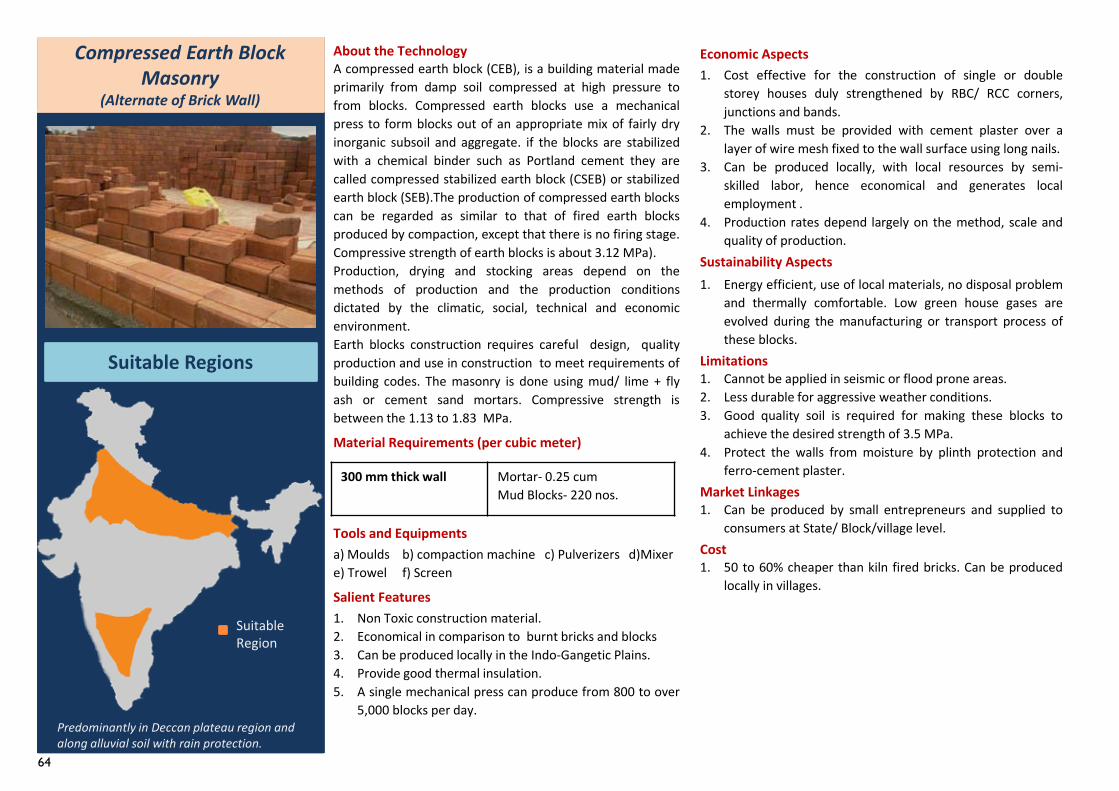
64
Compressed Earth Block Masonry
(Alternate of Brick Wall)
Suitable Regions
About the TechnologyA compressed earth block (CEB), is a building material madeprimarily from damp soil compressed at high pressure tofrom blocks. Compressed earth blocks use a mechanicalpress to form blocks out of an appropriate mix of fairly dryinorganic subsoil and aggregate. if the blocks are stabilizedwith a chemical binder such as Portland cement they arecalled compressed stabilized earth block (CSEB) or stabilizedearth block (SEB).The production of compressed earth blockscan be regarded as similar to that of fired earth blocksproduced by compaction, except that there is no firing stage.Compressive strength of earth blocks is about 3.12 MPa).Production, drying and stocking areas depend on themethods of production and the production conditionsdictated by the climatic, social, technical and economicenvironment.Earth blocks construction requires careful design, qualityproduction and use in construction to meet requirements ofbuilding codes. The masonry is done using mud/ lime + flyash or cement sand mortars. Compressive strength isbetween the 1.13 to 1.83 MPa.
Material Requirements (per cubic meter)
Tools and Equipmentsa) Moulds b) compaction machine c) Pulverizers d)Mixere) Trowel f) Screen
Salient Features1. Non Toxic construction material.2. Economical in comparison to burnt bricks and blocks3. Can be produced locally in the Indo-Gangetic Plains.4. Provide good thermal insulation.5. A single mechanical press can produce from 800 to over
5,000 blocks per day.
Economic Aspects1. Cost effective for the construction of single or double
storey houses duly strengthened by RBC/ RCC corners,junctions and bands.
2. The walls must be provided with cement plaster over alayer of wire mesh fixed to the wall surface using long nails.
3. Can be produced locally, with local resources by semi-skilled labor, hence economical and generates localemployment .
4. Production rates depend largely on the method, scale andquality of production.
Sustainability Aspects1. Energy efficient, use of local materials, no disposal problem
and thermally comfortable. Low green house gases areevolved during the manufacturing or transport process ofthese blocks.
Limitations1. Cannot be applied in seismic or flood prone areas.2. Less durable for aggressive weather conditions.3. Good quality soil is required for making these blocks to
achieve the desired strength of 3.5 MPa.4. Protect the walls from moisture by plinth protection and
ferro-cement plaster.Market Linkages1. Can be produced by small entrepreneurs and supplied to
consumers at State/ Block/village level.Cost1. 50 to 60% cheaper than kiln fired bricks. Can be produced
locally in villages.
Suitable Region
Predominantly in Deccan plateau region and along alluvial soil with rain protection.
300 mm thick wall Mortar- 0.25 cumMud Blocks- 220 nos.
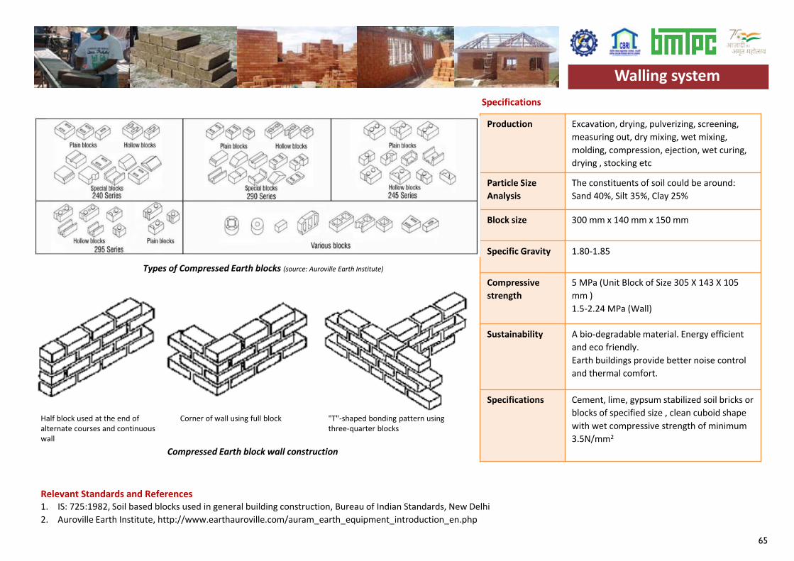
65
Production Excavation, drying, pulverizing, screening, measuring out, dry mixing, wet mixing, molding, compression, ejection, wet curing, drying , stocking etc
Particle Size Analysis
The constituents of soil could be around: Sand 40%, Silt 35%, Clay 25%
Block size 300 mm x 140 mm x 150 mm
Specific Gravity 1.80-1.85
Compressivestrength
5 MPa (Unit Block of Size 305 X 143 X 105mm ) 1.5-2.24 MPa (Wall)
Sustainability A bio-degradable material. Energy efficientand eco friendly.Earth buildings provide better noise control and thermal comfort.
Specifications Cement, lime, gypsum stabilized soil bricks or blocks of specified size , clean cuboid shape with wet compressive strength of minimum 3.5N/mm2
Specifications
Relevant Standards and References 1. IS: 725:1982, Soil based blocks used in general building construction, Bureau of Indian Standards, New Delhi2. Auroville Earth Institute, http://www.earthauroville.com/auram_earth_equipment_introduction_en.php
Walling system
Types of Compressed Earth blocks (source: Auroville Earth Institute)
Compressed Earth block wall construction
Half block used at the end of alternate courses and continuous wall
Corner of wall using full block "T"-shaped bonding pattern using three-quarter blocks
Walling system
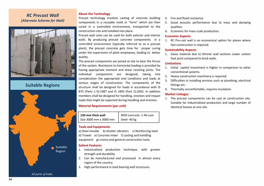
66
RC Precast Wall (Alternate Scheme for Wall)
Suitable Regions
About the TechnologyPrecast technology involves casting of concrete buildingcomponents in a reusable mold or "form" which are thencured in a controlled environment, transported to theconstruction site and installed into place.Precast wall units can be used for both exterior and interiorwalls. By producing precast concrete components in acontrolled environment (typically referred to as a precastplant), the precast concrete gets time for proper curingunder the supervision of plant employees, leading to betterquality.The precast components are joined at site to bear the forcesof the system. Resistance to horizontal loading is provided byhaving appropriate moment and shear resisting joints. Theindividual components are designed, taking intoconsideration the appropriate end conditions and loads atvarious stages of construction. The components of thestructure shall be designed for loads in accordance with IS875 (Parts 1-5):1987 and IS 1893 (Part 1):2002. In additionmembers shall be designed for handling, erection and impactloads that might be expected during handling and erection.
Material Requirements (per unit)
Tools and Equipmentsa) Steel moulds b) shutter vibrators c) Reinforcing steel d) Trowel e) Concrete mixer f) casting and handling equipment g) cranes and general construction tools.
Salient Features1. Industrialized production technique, with greater
strength and durability.2. Can be manufactured and processed in almost every
region of the country.3. High performance in load bearing wall structures.
4. Fire and flood resistance5. Good acoustic performance due to mass and damping
qualities.6. Economic for mass scale production.Economic Aspects1. RC Pre-cast wall is an economical option for places where
fast construction is required.Sustainability Aspects1. Saves material due to thinner wall sections Lower carbon
foot print compared to brick walls.Limitations1. Initial capital investment is higher in comparison to other
conventional systems.2. Heavy construction machinery is required.3. Difficulties in installing services such as plumbing, electrical
fittings etc.4. Thermally uncomfortable, requires insulation.Market Linkages1. The precast components can be cast at construction site.
Suitable for industrialized production and large number ofidentical houses at one site.
Suitable Region
All parts of India
150 mm thick wallSize 3000 mm x 3000 mm
M20 concrete- 1.40 cumSteel- 40 kg
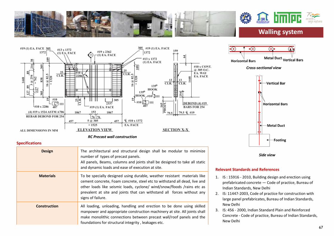
67
Design The architectural and structural design shall be modular to minimizenumber of types of precast panels.All panels, Beams, columns and joints shall be designed to take all staticand dynamic loads and ease of execution at site.
Materials To be specially designed using durable, weather resistant materials likecement concrete, Foam concrete, steel etc to withstand all dead, live andother loads like seismic loads, cyclone/ wind/snow/floods /rains etc asprevalent at site and joints that can withstand all forces without anysigns of failure.
Construction All loading, unloading, handling and erection to be done using skilledmanpower and appropriate construction machinery at site. All joints shallmake monolithic connections between precast wall/roof panels and thefoundations for structural integrity , leakages etc.
Specifications
Relevant Standards and References
1. IS : 15916 - 2010, Building design and erection using prefabricated concrete — Code of practice, Bureau of Indian Standards, New Delhi
2. IS: 11447-2003, Code of practice for construction with large panel prefabricates, Bureau of Indian Standards, New Delhi
3. IS: 456 - 2000, Indian Standard Plain and Reinforced Concrete - Code of practice, Bureau of Indian Standards, New Delhi
RC Precast wall construction
Side view
Walling system
Cross-sectional view
Walling system
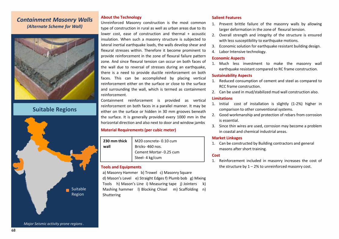
68
Containment Masonry Walls (Alternate Scheme for Wall)
Suitable Regions
Major Seismic activity prone regions .
About the TechnologyUnreinforced Masonry construction is the most commontype of construction in rural as well as urban areas due to itslower cost, ease of construction and thermal + acousticinsulation. When such a masonry structure is subjected tolateral inertial earthquake loads, the walls develop shear andflexural stresses within. Therefore it become prominent toprovide reinforcement in the zone of flexural failure patternzone. And since flexural tension can occur on both faces ofthe wall due to reversal of stresses during an earthquake,there is a need to provide ductile reinforcement on bothfaces. This can be accomplished by placing verticalreinforcement either on the surface or close to the surfaceand surrounding the wall, which is termed as containmentreinforcement.Containment reinforcement is provided as verticalreinforcement on both faces in a parallel manner. It may beeither on the surface or hidden in 30 mm grooves beneaththe surface. It is generally provided every 1000 mm in thehorizontal direction and also next to door and window jambs
Material Requirements (per cubic meter)
Tools and Equipmentsa) Masonry Hammer b) Trowel c) Masonry Squared) Mason’s Level e) Straight Edges f) Plumb bob g) MixingTools h) Mason’s Line i) Measuring tape j) Jointers k)Mashing hammer l) Blocking Chisel m) Scaffolding n)Shuttering
Salient Features1. Prevent brittle failure of the masonry walls by allowing
larger deformation in the zone of flexural tension.2. Overall strength and integrity of the structure is ensured
with less susceptibility to earthquake motions.3. Economic solution for earthquake resistant building design.4. Labor Intensive technology.Economic Aspects1. Much less investment to make the masonry wall
earthquake resistant compared to RC frame construction.Sustainability Aspects1. Reduced consumption of cement and steel as compared to
RCC frame construction.2. Can be used in mud/stabilized mud wall construction also.Limitations1. Initial cost of installation is slightly (1-2%) higher in
comparison to other conventional systems.2. Good workmanship and protection of rebars from corrosion
is essential.3. Since thin wires are used, corrosion may become a problem
in coastal and chemical industrial areas.Market Linkages1. Can be constructed by Building contractors and general
masons after short training. Cost 1. Reinforcement included in masonry increases the cost of
the structure by 1 – 2% to unreinforced masonry cost.
Suitable Region
230 mm thickwall
M20 concrete- 0.10 cumBricks- 460 nos.Cement Mortar- 0.25 cumSteel- 4 kg/cum
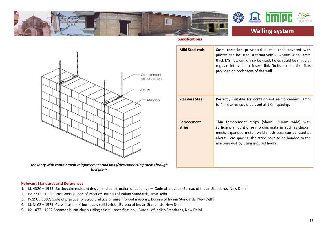
69
Mild Steel rods 6mm corrosion prevented ductile rods covered withplaster can be used. Alternatively 20-25mm wide, 3mmthick MS flats could also be used, holes could be made atregular intervals to insert links/bolts to tie the flatsprovided on both faces of the wall.
Stainless Steel Perfectly suitable for containment reinforcement, 3mmto 4mm wires could be used at 1.0m spacing.
Ferrocementstrips
Thin ferrocement strips (about 150mm wide) withsufficient amount of reinforcing material such as chickenmesh, expanded metal, weld mesh etc.; can be used atabout 1.2m spacing; the strips have to be bonded to themasonry wall by using grouted hooks.
Specifications
Relevant Standards and References 1. IS: 4326 – 1993, Earthquake resistant design and construction of buildings — Code of practice, Bureau of Indian Standards, New Delhi2. IS: 2212 - 1991, Brick Works-Code of Practice, Bureau of Indian Standards, New Delhi 3. IS:1905-1987, Code of practice for structural use of unreinforced masonry, Bureau of Indian Standards, New Delhi 4. IS: 3102 – 1971, Classification of burnt clay solid bricks, Bureau of Indian Standards, New Delhi 5. IS: 1077 - 1992 Common burnt clay building bricks – specification, , Bureau of Indian Standards, New Delhi
Walling system
Masonry with containment reinforcement and links/ties connecting them through bed joints
Walling system
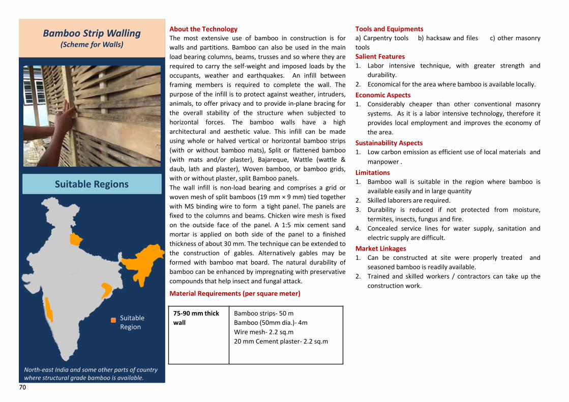
70
Bamboo Strip Walling(Scheme for Walls)
Suitable Regions
North-east India and some other parts of country where structural grade bamboo is available.
About the TechnologyThe most extensive use of bamboo in construction is forwalls and partitions. Bamboo can also be used in the mainload bearing columns, beams, trusses and so where they arerequired to carry the self-weight and imposed loads by theoccupants, weather and earthquakes. An infill betweenframing members is required to complete the wall. Thepurpose of the infill is to protect against weather, intruders,animals, to offer privacy and to provide in-plane bracing forthe overall stability of the structure when subjected tohorizontal forces. The bamboo walls have a higharchitectural and aesthetic value. This infill can be madeusing whole or halved vertical or horizontal bamboo strips(with or without bamboo mats), Split or flattened bamboo(with mats and/or plaster), Bajareque, Wattle (wattle &daub, lath and plaster), Woven bamboo, or bamboo grids,with or without plaster, split Bamboo panels.The wall infill is non-load bearing and comprises a grid orwoven mesh of split bamboos (19 mm × 9 mm) tied togetherwith MS binding wire to form a tight panel. The panels arefixed to the columns and beams. Chicken wire mesh is fixedon the outside face of the panel. A 1:5 mix cement sandmortar is applied on both side of the panel to a finishedthickness of about 30 mm. The technique can be extended tothe construction of gables. Alternatively gables may beformed with bamboo mat board. The natural durability ofbamboo can be enhanced by impregnating with preservativecompounds that help insect and fungal attack.
Material Requirements (per square meter)
Tools and Equipmentsa) Carpentry tools b) hacksaw and files c) other masonrytoolsSalient Features1. Labor intensive technique, with greater strength and
durability.2. Economical for the area where bamboo is available locally.Economic Aspects1. Considerably cheaper than other conventional masonry
systems. As it is a labor intensive technology, therefore itprovides local employment and improves the economy ofthe area.
Sustainability Aspects1. Low carbon emission as efficient use of local materials and
manpower .Limitations1. Bamboo wall is suitable in the region where bamboo is
available easily and in large quantity2. Skilled laborers are required.3. Durability is reduced if not protected from moisture,
termites, insects, fungus and fire.4. Concealed service lines for water supply, sanitation and
electric supply are difficult.Market Linkages1. Can be constructed at site were properly treated and
seasoned bamboo is readily available.2. Trained and skilled workers / contractors can take up the
construction work.
Suitable Region
75-90 mm thickwall
Bamboo strips- 50 mBamboo (50mm dia.)- 4mWire mesh- 2.2 sq.m20 mm Cement plaster- 2.2 sq.m
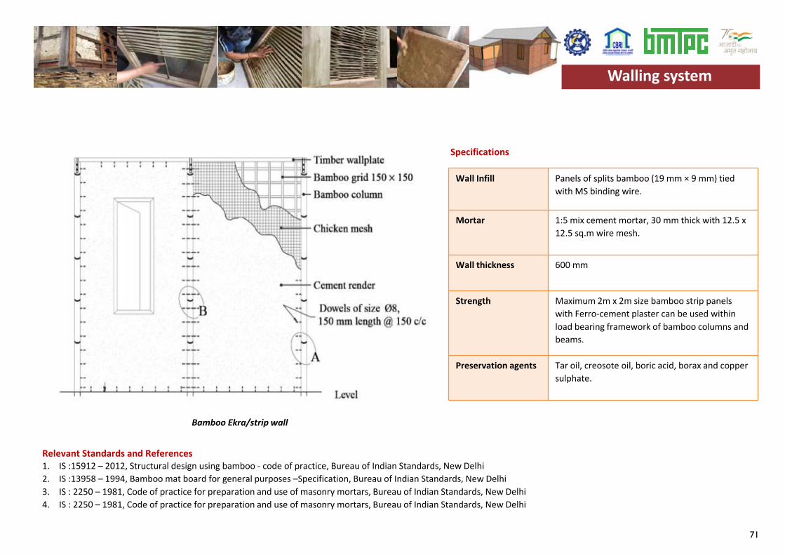
71
Wall Infill Panels of splits bamboo (19 mm × 9 mm) tied with MS binding wire.
Mortar 1:5 mix cement mortar, 30 mm thick with 12.5 x 12.5 sq.m wire mesh.
Wall thickness 600 mm
Strength Maximum 2m x 2m size bamboo strip panels with Ferro-cement plaster can be used within load bearing framework of bamboo columns and beams.
Preservation agents Tar oil, creosote oil, boric acid, borax and copper sulphate.
Relevant Standards and References1. IS :15912 – 2012, Structural design using bamboo - code of practice, Bureau of Indian Standards, New Delhi2. IS :13958 – 1994, Bamboo mat board for general purposes –Specification, Bureau of Indian Standards, New Delhi3. IS : 2250 – 1981, Code of practice for preparation and use of masonry mortars, Bureau of Indian Standards, New Delhi4. IS : 2250 – 1981, Code of practice for preparation and use of masonry mortars, Bureau of Indian Standards, New Delhi
Walling system
Specifications
Bamboo Ekra/strip wall
Walling system
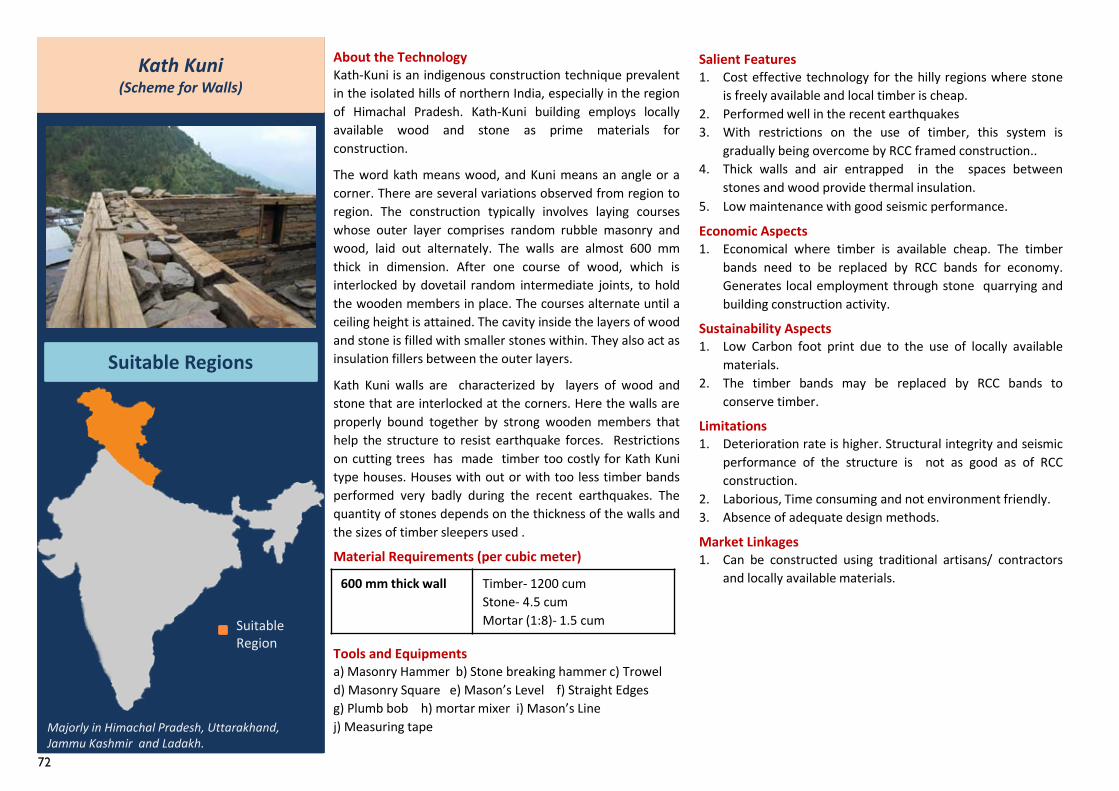
72
About the TechnologyKath-Kuni is an indigenous construction technique prevalentin the isolated hills of northern India, especially in the regionof Himachal Pradesh. Kath-Kuni building employs locallyavailable wood and stone as prime materials forconstruction.
The word kath means wood, and Kuni means an angle or acorner. There are several variations observed from region toregion. The construction typically involves laying courseswhose outer layer comprises random rubble masonry andwood, laid out alternately. The walls are almost 600 mmthick in dimension. After one course of wood, which isinterlocked by dovetail random intermediate joints, to holdthe wooden members in place. The courses alternate until aceiling height is attained. The cavity inside the layers of woodand stone is filled with smaller stones within. They also act asinsulation fillers between the outer layers.
Kath Kuni walls are characterized by layers of wood andstone that are interlocked at the corners. Here the walls areproperly bound together by strong wooden members thathelp the structure to resist earthquake forces. Restrictionson cutting trees has made timber too costly for Kath Kunitype houses. Houses with out or with too less timber bandsperformed very badly during the recent earthquakes. Thequantity of stones depends on the thickness of the walls andthe sizes of timber sleepers used .
Material Requirements (per cubic meter)
Tools and Equipmentsa) Masonry Hammer b) Stone breaking hammer c) Troweld) Masonry Square e) Mason’s Level f) Straight Edgesg) Plumb bob h) mortar mixer i) Mason’s Linej) Measuring tape
Kath Kuni(Scheme for Walls)
Suitable Regions
Salient Features1. Cost effective technology for the hilly regions where stone
is freely available and local timber is cheap.2. Performed well in the recent earthquakes3. With restrictions on the use of timber, this system is
gradually being overcome by RCC framed construction..4. Thick walls and air entrapped in the spaces between
stones and wood provide thermal insulation.5. Low maintenance with good seismic performance.
Economic Aspects1. Economical where timber is available cheap. The timber
bands need to be replaced by RCC bands for economy.Generates local employment through stone quarrying andbuilding construction activity.
Sustainability Aspects1. Low Carbon foot print due to the use of locally available
materials.2. The timber bands may be replaced by RCC bands to
conserve timber.
Limitations1. Deterioration rate is higher. Structural integrity and seismic
performance of the structure is not as good as of RCCconstruction.
2. Laborious, Time consuming and not environment friendly.3. Absence of adequate design methods.
Market Linkages1. Can be constructed using traditional artisans/ contractors
and locally available materials.
Suitable Region
Majorly in Himachal Pradesh, Uttarakhand, Jammu Kashmir and Ladakh.
600 mm thick wall Timber- 1200 cumStone- 4.5 cumMortar (1:8)- 1.5 cum
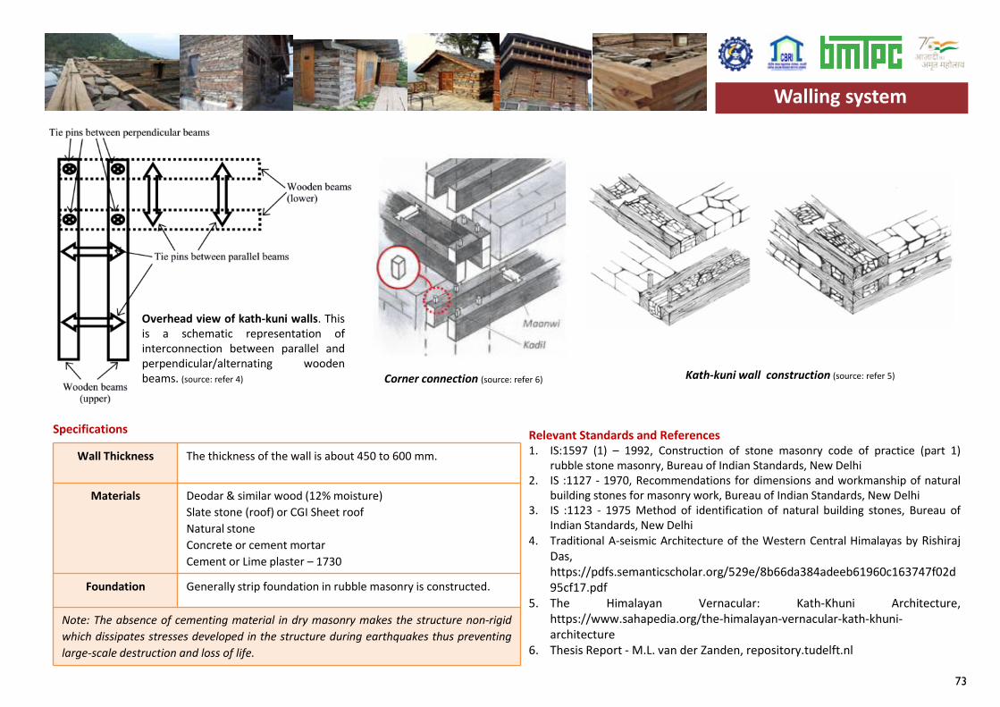
73
Wall Thickness The thickness of the wall is about 450 to 600 mm.
Materials Deodar & similar wood (12% moisture)Slate stone (roof) or CGI Sheet roofNatural stoneConcrete or cement mortarCement or Lime plaster – 1730
Foundation Generally strip foundation in rubble masonry is constructed.
Note: The absence of cementing material in dry masonry makes the structure non-rigidwhich dissipates stresses developed in the structure during earthquakes thus preventinglarge-scale destruction and loss of life.
Specifications Relevant Standards and References 1. IS:1597 (1) – 1992, Construction of stone masonry code of practice (part 1)
rubble stone masonry, Bureau of Indian Standards, New Delhi2. IS :1127 - 1970, Recommendations for dimensions and workmanship of natural
building stones for masonry work, Bureau of Indian Standards, New Delhi3. IS :1123 - 1975 Method of identification of natural building stones, Bureau of
Indian Standards, New Delhi4. Traditional A-seismic Architecture of the Western Central Himalayas by Rishiraj
Das,https://pdfs.semanticscholar.org/529e/8b66da384adeeb61960c163747f02d95cf17.pdf
5. The Himalayan Vernacular: Kath-Khuni Architecture,https://www.sahapedia.org/the-himalayan-vernacular-kath-khuni-architecture
6. Thesis Report - M.L. van der Zanden, repository.tudelft.nl
Walling system
Overhead view of kath-kuni walls. Thisis a schematic representation ofinterconnection between parallel andperpendicular/alternating woodenbeams. (source: refer 4) Corner connection (source: refer 6) Kath-kuni wall construction (source: refer 5)
Walling system
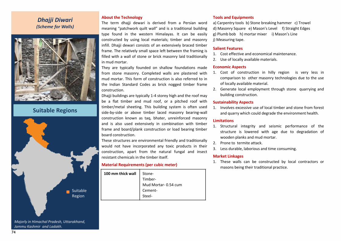
74
Dhajji Diwari(Scheme for Walls)
Suitable Regions
About the TechnologyThe term dhajji dewari is derived from a Persian wordmeaning “patchwork quilt wall” and is a traditional buildingtype found in the western Himalayas. It can be easilyconstructed by using local materials; timber and masonryinfill. Dhajji dewari consists of an extensively braced timberframe. The relatively small space left between the framing isfilled with a wall of stone or brick masonry laid traditionallyin mud mortar.They are typically founded on shallow foundations madefrom stone masonry. Completed walls are plastered withmud mortar. This form of construction is also referred to inthe Indian Standard Codes as brick nogged timber frameconstruction.Dhajji buildings are typically 1-4 storey high and the roof maybe a flat timber and mud roof, or a pitched roof withtimber/metal sheeting. This building system is often usedside-by-side or above timber laced masonry bearing-wallconstruction known as taq, bhater, unreinforced masonryand is also used extensively in combination with timberframe and board/plank construction or load bearing timberboard construction.These structures are environmental friendly and traditionallywould not have incorporated any toxic products in theirconstruction, apart from the natural fungal and insectresistant chemicals in the timber itself.
Material Requirements (per cubic meter)
Salient Features1. Cost effective and economical maintenance.2. Use of locally available materials.
Economic Aspects1. Cost of construction in hilly region is very less in
comparison to other masonry technologies due to the useof locally available material.
2. Generate local employment through stone quarrying andbuilding construction.
Sustainability Aspects1. Involves excessive use of local timber and stone from forest
and quarry which could degrade the environment health.
Limitations1. Structural integrity and seismic performance of the
structure is lowered with age due to degradation ofwooden planks and mud mortar.
2. Prone to termite attack.3. Less durable, laborious and time consuming.
Market Linkages1. These walls can be constructed by local contractors or
masons being their traditional practice.
Suitable Region
Majorly in Himachal Pradesh, Uttarakhand, Jammu Kashmir and Ladakh.
100 mm thick wall Stone-Timber-Mud Mortar- 0.54 cumCement-Steel-
Tools and Equipmentsa) Carpentry tools b) Stone breaking hammer c) Troweld) Masonry Square e) Mason’s Level f) Straight Edgesg) Plumb bob h) mortar mixer i) Mason’s Linej) Measuring tape.
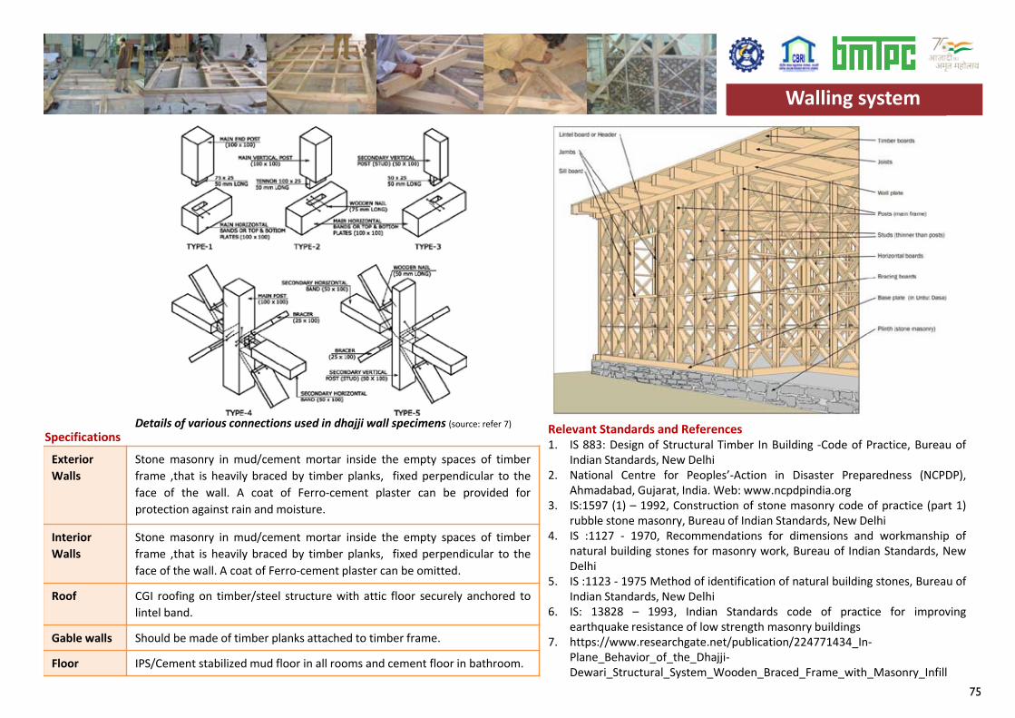
75
Exterior Walls
Stone masonry in mud/cement mortar inside the empty spaces of timberframe ,that is heavily braced by timber planks, fixed perpendicular to theface of the wall. A coat of Ferro-cement plaster can be provided forprotection against rain and moisture.
Interior Walls
Stone masonry in mud/cement mortar inside the empty spaces of timberframe ,that is heavily braced by timber planks, fixed perpendicular to theface of the wall. A coat of Ferro-cement plaster can be omitted.
Roof CGI roofing on timber/steel structure with attic floor securely anchored tolintel band.
Gable walls Should be made of timber planks attached to timber frame.
Floor IPS/Cement stabilized mud floor in all rooms and cement floor in bathroom.
Specifications Relevant Standards and References1. IS 883: Design of Structural Timber In Building -Code of Practice, Bureau of
Indian Standards, New Delhi2. National Centre for Peoples’-Action in Disaster Preparedness (NCPDP),
Ahmadabad, Gujarat, India. Web: www.ncpdpindia.org3. IS:1597 (1) – 1992, Construction of stone masonry code of practice (part 1)
rubble stone masonry, Bureau of Indian Standards, New Delhi4. IS :1127 - 1970, Recommendations for dimensions and workmanship of
natural building stones for masonry work, Bureau of Indian Standards, NewDelhi
5. IS :1123 - 1975 Method of identification of natural building stones, Bureau ofIndian Standards, New Delhi
6. IS: 13828 – 1993, Indian Standards code of practice for improvingearthquake resistance of low strength masonry buildings
7. https://www.researchgate.net/publication/224771434_In-Plane_Behavior_of_the_Dhajji-Dewari_Structural_System_Wooden_Braced_Frame_with_Masonry_Infill
Walling system
Details of various connections used in dhajji wall specimens (source: refer 7)
Walling system
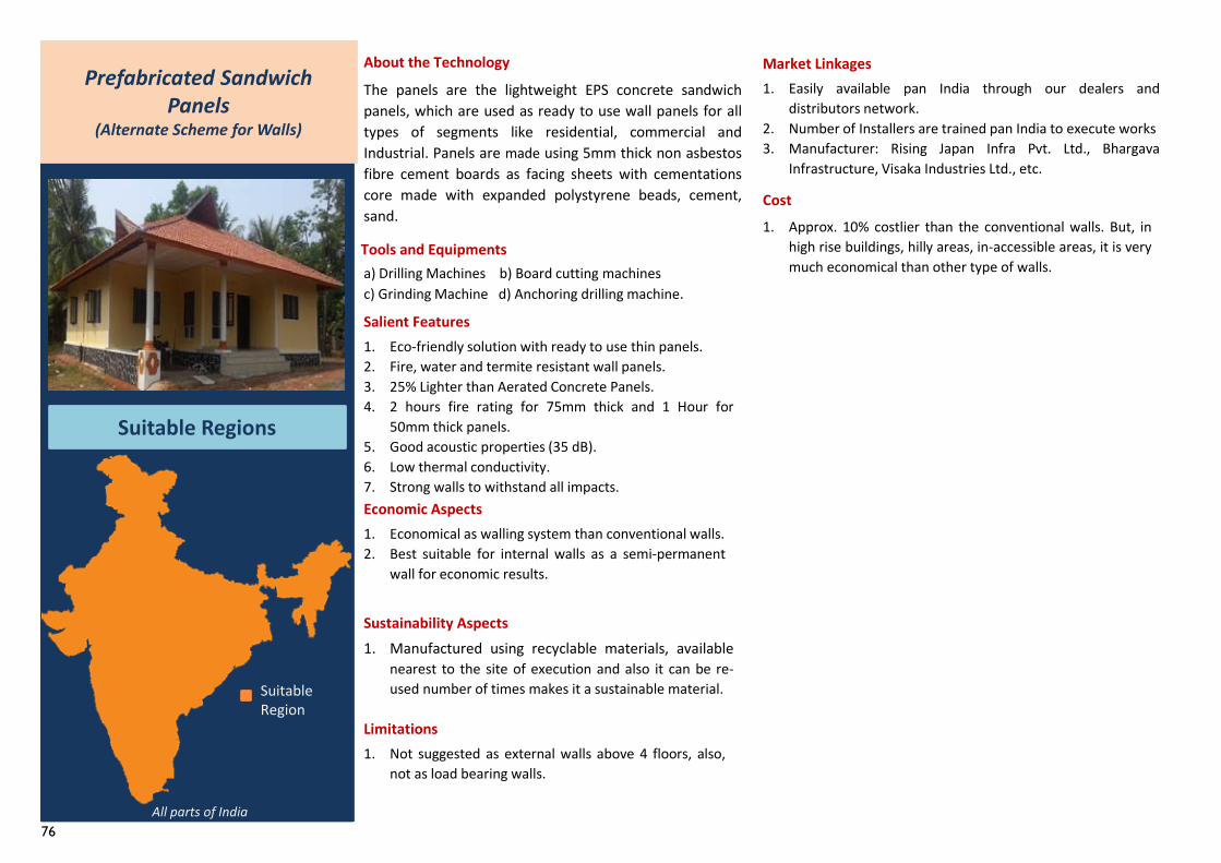
76
About the Technology
Salient Features
Economic Aspects
Sustainability Aspects
Limitations
Market Linkages
Cost
Prefabricated Sandwich Panels
(Alternate Scheme for Walls)
Suitable Regions
The panels are the lightweight EPS concrete sandwichpanels, which are used as ready to use wall panels for alltypes of segments like residential, commercial andIndustrial. Panels are made using 5mm thick non asbestosfibre cement boards as facing sheets with cementationscore made with expanded polystyrene beads, cement,sand.
a) Drilling Machines b) Board cutting machinesc) Grinding Machine d) Anchoring drilling machine.
Tools and Equipments
1. Eco-friendly solution with ready to use thin panels.2. Fire, water and termite resistant wall panels.3. 25% Lighter than Aerated Concrete Panels.4. 2 hours fire rating for 75mm thick and 1 Hour for
50mm thick panels.5. Good acoustic properties (35 dB).6. Low thermal conductivity.7. Strong walls to withstand all impacts.
1. Economical as walling system than conventional walls.2. Best suitable for internal walls as a semi-permanent
wall for economic results.
1. Manufactured using recyclable materials, availablenearest to the site of execution and also it can be re-used number of times makes it a sustainable material.
1. Not suggested as external walls above 4 floors, also,not as load bearing walls.
1. Easily available pan India through our dealers anddistributors network.
2. Number of Installers are trained pan India to execute works3. Manufacturer: Rising Japan Infra Pvt. Ltd., Bhargava
Infrastructure, Visaka Industries Ltd., etc.
1. Approx. 10% costlier than the conventional walls. But, inhigh rise buildings, hilly areas, in-accessible areas, it is verymuch economical than other type of walls.
Suitable Region
All parts of India
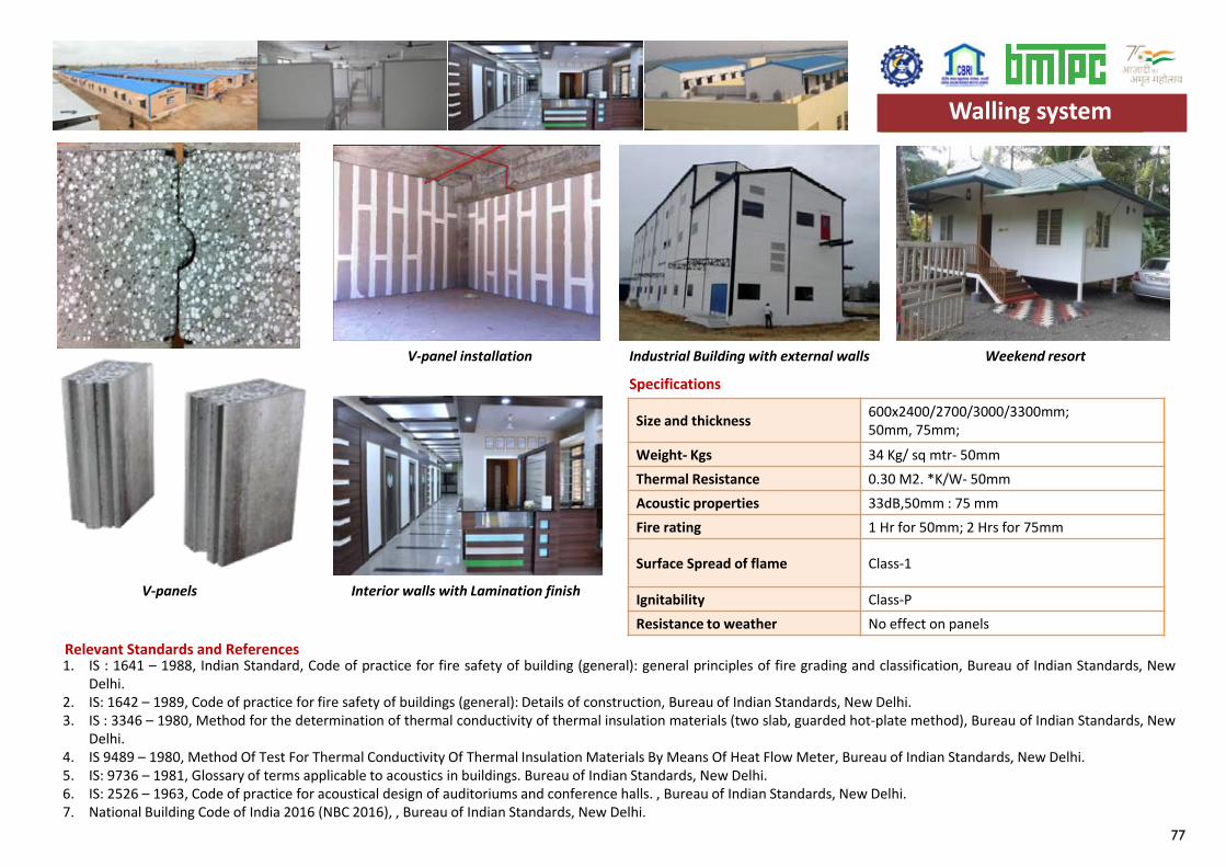
77
Specifications
Size and thickness 600x2400/2700/3000/3300mm;50mm, 75mm;
Weight- Kgs 34 Kg/ sq mtr- 50mmThermal Resistance 0.30 M2. *K/W- 50mmAcoustic properties 33dB,50mm : 75 mmFire rating 1 Hr for 50mm; 2 Hrs for 75mm
Surface Spread of flame Class-1
Ignitability Class-PResistance to weather No effect on panels
Weekend resort
Interior walls with Lamination finish
Industrial Building with external wallsV-panel installation
1. IS : 1641 – 1988, Indian Standard, Code of practice for fire safety of building (general): general principles of fire grading and classification, Bureau of Indian Standards, NewDelhi.
2. IS: 1642 – 1989, Code of practice for fire safety of buildings (general): Details of construction, Bureau of Indian Standards, New Delhi.3. IS : 3346 – 1980, Method for the determination of thermal conductivity of thermal insulation materials (two slab, guarded hot-plate method), Bureau of Indian Standards, New
Delhi.4. IS 9489 – 1980, Method Of Test For Thermal Conductivity Of Thermal Insulation Materials By Means Of Heat Flow Meter, Bureau of Indian Standards, New Delhi.5. IS: 9736 – 1981, Glossary of terms applicable to acoustics in buildings. Bureau of Indian Standards, New Delhi.6. IS: 2526 – 1963, Code of practice for acoustical design of auditoriums and conference halls. , Bureau of Indian Standards, New Delhi.7. National Building Code of India 2016 (NBC 2016), , Bureau of Indian Standards, New Delhi.
Walling system
Relevant Standards and References
V-panels
Walling system
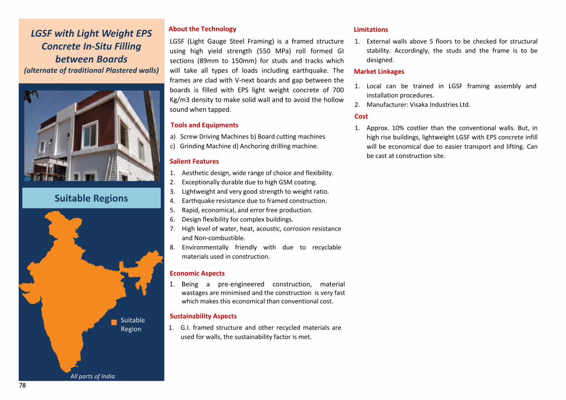
78
About the Technology
Salient Features
Economic Aspects
Sustainability Aspects
Limitations
Market Linkages
Cost
LGSF with Light Weight EPS Concrete In-Situ Filling
between Boards(alternate of traditional Plastered walls)
Suitable Regions
LGSF (Light Gauge Steel Framing) is a framed structureusing high yield strength (550 MPa) roll formed GIsections (89mm to 150mm) for studs and tracks whichwill take all types of loads including earthquake. Theframes are clad with V-next boards and gap between theboards is filled with EPS light weight concrete of 700Kg/m3 density to make solid wall and to avoid the hollowsound when tapped.
a) Screw Driving Machines b) Board cutting machinesc) Grinding Machine d) Anchoring drilling machine.
Tools and Equipments
1. Aesthetic design, wide range of choice and flexibility.2. Exceptionally durable due to high GSM coating.3. Lightweight and very good strength to weight ratio.4. Earthquake resistance due to framed construction.5. Rapid, economical, and error free production.6. Design flexibility for complex buildings.7. High level of water, heat, acoustic, corrosion resistance
and Non-combustible.8. Environmentally friendly with due to recyclable
materials used in construction.
1. Being a pre-engineered construction, materialwastages are minimised and the construction is very fastwhich makes this economical than conventional cost.
1. G.I. framed structure and other recycled materials areused for walls, the sustainability factor is met.
1. External walls above 5 floors to be checked for structuralstability. Accordingly, the studs and the frame is to bedesigned.
1. Local can be trained in LGSF framing assembly andinstallation procedures.
2. Manufacturer: Visaka Industries Ltd.
1. Approx. 10% costlier than the conventional walls. But, inhigh rise buildings, lightweight LGSF with EPS concrete infillwill be economical due to easier transport and lifting. Canbe cast at construction site.
Suitable Region
All parts of India
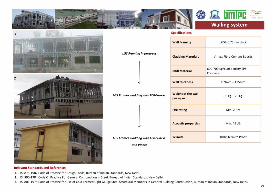
79
Specifications
Wall Framing LGSF-0.75mm thick
Cladding Materials V-next Fibre Cement Boards
Infill Material 600-700 Kg/cum density EPS Concrete
Wall thickness 109mm – 175mm
Weight of the wall-per sq.m 93 kg- 120 Kg
Fire rating Min. 2 Hrs
Acoustic properties Min. 45 dB
Termite 100% termite Proof
LGS Framing in progress
LGS Frames cladding with FCB-V-next
LGS Frames cladding with FCB-V-next
and Planks
1. IS: 875-1987 Code of Practice for Design Loads, Bureau of Indian Standards, New Delhi.2. IS: 800-1984 Code Of Practice For General Construction In Steel, Bureau of Indian Standards, New Delhi.3. IS: 801-1975 Code of Practice for Use of Cold Formed Light Gauge Steel Structural Members In General Building Construction, Bureau of Indian Standards, New Delhi.
Walling system
Relevant Standards and References
1
2
3
Walling system

80
81
Foundation Construction Technologies
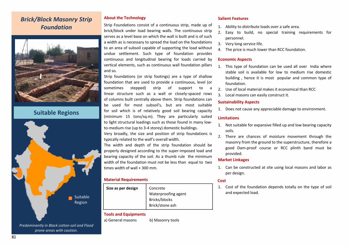
82
1. This type of foundation can be used all over India wherestable soil is available for low to medium rise domesticbuilding , hence it is most popular and common type offoundation.
2. Use of local material makes it economical than RCC3. Local masons can easily construct it.
Brick/Block Masonry Strip Foundation
Suitable Regions
Predominantly in Black cotton soil and Flood prone areas with caution.
About the TechnologyStrip Foundations consist of a continuous strip, made up ofbrick/block under load bearing walls. The continuous stripserves as a level base on which the wall is built and is of sucha width as is necessary to spread the load on the foundationsto an area of subsoil capable of supporting the load withoutundue settlement. Such type of foundation providescontinuous and longitudinal bearing for loads carried byvertical elements, such as continuous wall foundation pillarsand so.Strip foundations (or strip footings) are a type of shallowfoundation that are used to provide a continuous, level (orsometimes stepped) strip of support to alinear structure such as a wall or closely-spaced rowsof columns built centrally above them. Strip foundations canbe used for most subsoil's, but are most suitablefor soil which is of relatively good soil bearing capacity(minimum 15 tons/sq.m). They are particularly suitedto light structural loadings such as those found in many low-to-medium rise (up to 3-4 storey) domestic buildings.Very broadly, the size and position of strip foundations istypically related to the wall’s overall width.The width and depth of the strip foundation should beproperly designed according to the super-imposed load andbearing capacity of the soil. As a thumb rule the minimumwidth of the foundation must not be less than equal to twotimes width of wall + 300 mm.
Material Requirements
Tools and Equipmentsa) General masons b) Masonry tools
Salient Features
1. Ability to distribute loads over a safe area.2. Easy to build, no special training requirements for
personnel.3. Very long service life.4. The price is much lower than RCC foundation.
Economic Aspects
Sustainability Aspects
Limitations1. Not suitable for expansive filled up and low bearing capacity
soils.2. There are chances of moisture movement through the
masonry from the ground to the superstructure, therefore agood Dam-proof course or RCC plinth band must beprovided.
Market Linkages
Cost
1. Does not cause any appreciable damage to environment.
1. Can be constructed at site using local masons and labor asper design.
1. Cost of the foundation depends totally on the type of soiland expected load.
Size as per design ConcreteWaterproofing agentBricks/blocksBrick/stone ash
Suitable Region

83
Specifications
1. IS 1080-1985: Code of practice for design and construction of Shallow foundations in soils, Bureau of Indian Standards, New Delhi.2. IS 2212-1962: Brick Works-Code Of Practice, Bureau of Indian Standards, New Delhi.3. IS 3764-1966 : Code of safety for excavation work, Bureau of Indian Standards, New Delhi.4. IS 1905-1987: Code of practice for structural use of unreinforced masonry, Bureau of Indian Standards, New Delhi.5. IS 456:2000, Code of practice for plain and reinforced cement concrete (Reaffirmed 2016), Bureau of Indian Standards, New Delhi.
Excavation(Refer IS 3764:1966)
The plan dimensions of excavation for foundationsshould be wide enough to ensure safe and efficientworking.
Design (Refer IS 456:1987
and IS 1905:1987)
The cement concrete foundation ( plain or reinforced )should be designed in accordance with IS : 456-1978and masonry foundation in accordance with IS : 1905-1987.
Size (Refer IS 2212:1962)
The width of the footings shall be such that maximumstress in the concrete or masonry remains within thepermissible limits.The width of wall foundation shall not be less than thatGiven by: B = W + 300 mm, where B = width at base incm & W = width of supported wall in cm.
Construction (Refer IS 1080:1985)
Brick masonry construction should conform to IS : 2212-1962. Masonry should be constructed over the base concreteAfter curing the base of concrete for at least 3 days.Before laying concrete, the bed of the foundationpit/trench should be thoroughly compacted by manualramming.
Relevant Standards and References
Foundation
Brick masonry Strip foundation
Foundation
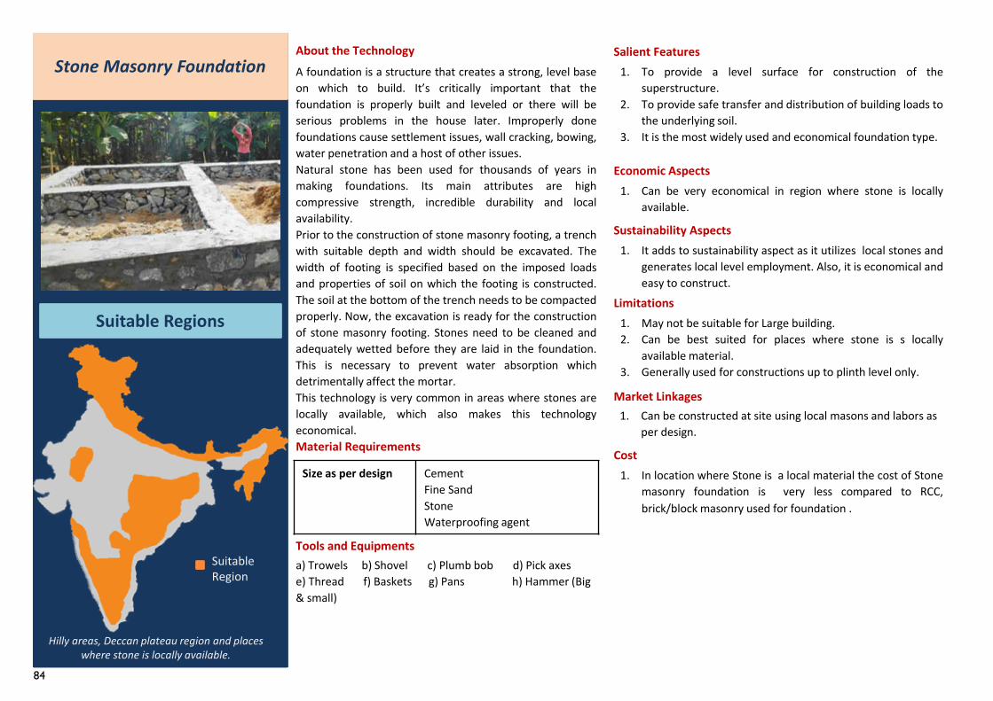
84
Size as per design Cement Fine Sand Stone Waterproofing agent
Stone Masonry Foundation
Suitable Regions
About the Technology
Tools and Equipmentsa) Trowels b) Shovel c) Plumb bob d) Pick axese) Thread f) Baskets g) Pans h) Hammer (Big & small)
Salient Features1. To provide a level surface for construction of the
superstructure.2. To provide safe transfer and distribution of building loads to
the underlying soil.3. It is the most widely used and economical foundation type.
Economic Aspects
Sustainability Aspects
Limitations1. May not be suitable for Large building.2. Can be best suited for places where stone is s locally
available material.3. Generally used for constructions up to plinth level only.
Market Linkages
Cost
1. Can be very economical in region where stone is locallyavailable.
1. In location where Stone is a local material the cost of Stonemasonry foundation is very less compared to RCC,brick/block masonry used for foundation .
1. It adds to sustainability aspect as it utilizes local stones andgenerates local level employment. Also, it is economical andeasy to construct.
A foundation is a structure that creates a strong, level baseon which to build. It’s critically important that thefoundation is properly built and leveled or there will beserious problems in the house later. Improperly donefoundations cause settlement issues, wall cracking, bowing,water penetration and a host of other issues.Natural stone has been used for thousands of years inmaking foundations. Its main attributes are highcompressive strength, incredible durability and localavailability.Prior to the construction of stone masonry footing, a trenchwith suitable depth and width should be excavated. Thewidth of footing is specified based on the imposed loadsand properties of soil on which the footing is constructed.The soil at the bottom of the trench needs to be compactedproperly. Now, the excavation is ready for the constructionof stone masonry footing. Stones need to be cleaned andadequately wetted before they are laid in the foundation.This is necessary to prevent water absorption whichdetrimentally affect the mortar.This technology is very common in areas where stones arelocally available, which also makes this technologyeconomical.
Hilly areas, Deccan plateau region and places where stone is locally available.
1. Can be constructed at site using local masons and labors as per design.
Suitable Region
Material Requirements
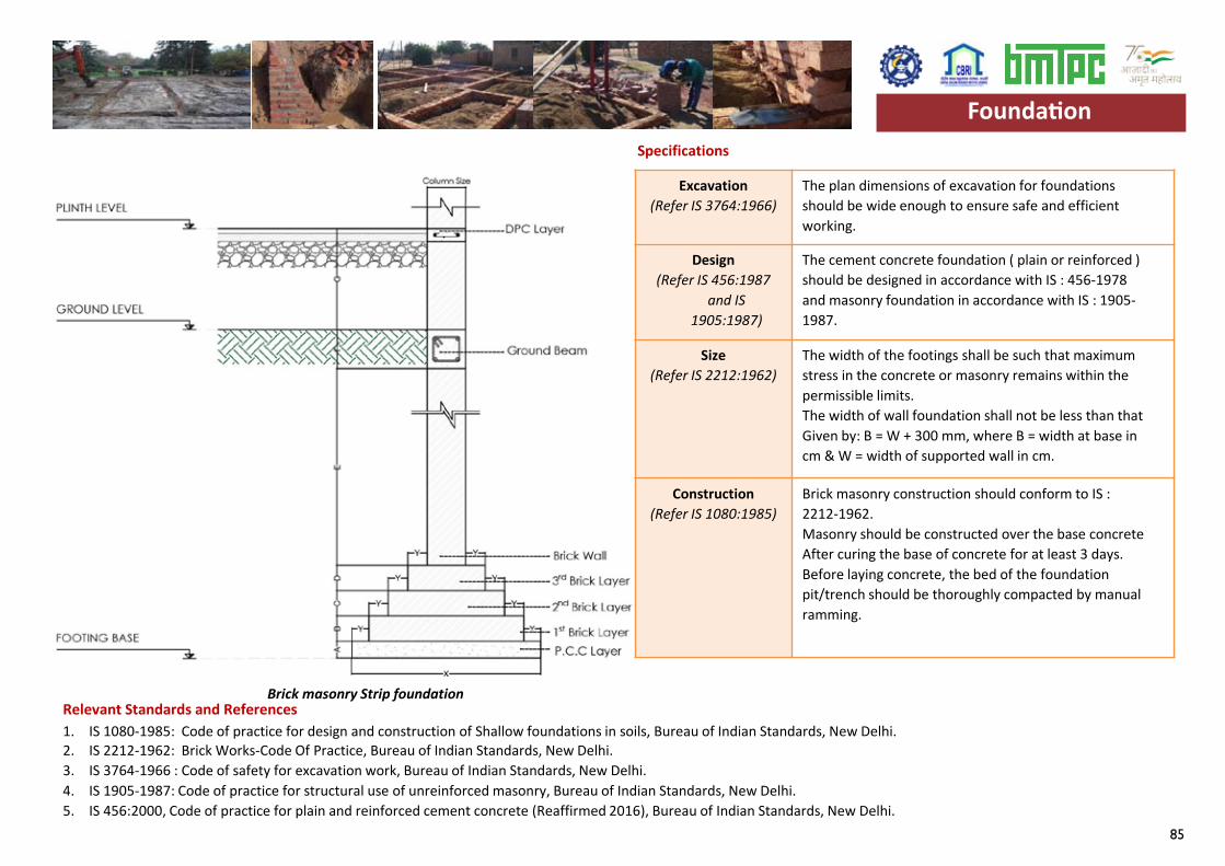
85
Specifications
1. Stone work specifications 91 - 92 – CPWD.2. IS – 1597-1 (1992) Construction Of Stone Masonry Code Of Practice , Bureau of Indian Standards, New Delhi.3. IS 1080-1985: Code of practice for design and construction of Shallow foundations in soils, Bureau of Indian Standards, New Delhi.4. IS 6403: 1981, Indian standard code of practice for determination of bearing capacity of shallow foundations, Bureau of Indian Standards, New Delhi.
Quality of stone The stone should be Durable, Free from cracks, Free from cavity, hard and tough, and thickness should be one fourth of their width.
Construction(Refer IS 1597:1992)
1. The stone masonry construction should conform to IS 1597 ( Parts 1 and 2 )-1992.
2. If possible, the width of each stone used for the construction of footing first course should match the stone masonry footing width. If such stones are not available, then joints can be provided with through stones at short intervals.
3. The quality of mortar is of importance to achieve good strength. An example of a good mix is:- 4 parts cement- 1 part lime- 12 parts clean sand- sufficient water to make a workable mix.
4. Construction should start on firm, uniform strong subsoil. It should not be started on grass, black cotton soil, filled up materials or mud.
5. Under the foundation there should be a layer of lean concrete (min. 100 mm) or tamped sand; minimum depth 400 mm.
6. The plain concrete layer should extend about 150mm from the stone masonry foundation on each side of bottom course. So, the width of plain concrete is 300mm wider than the bottom course of stone masonry footing.
7. One through stone for every 106mm2 of wall area is provided.
8. In earthquake areas, reinforcement with wire mesh or steel rods is required, but professional advice should be sought.
Foundation
Relevant Standards and References
Stone masonry foundation
Specifications
1. IS 1080-1985: Code of practice for design and construction of Shallow foundations in soils, Bureau of Indian Standards, New Delhi.2. IS 2212-1962: Brick Works-Code Of Practice, Bureau of Indian Standards, New Delhi.3. IS 3764-1966 : Code of safety for excavation work, Bureau of Indian Standards, New Delhi.4. IS 1905-1987: Code of practice for structural use of unreinforced masonry, Bureau of Indian Standards, New Delhi.5. IS 456:2000, Code of practice for plain and reinforced cement concrete (Reaffirmed 2016), Bureau of Indian Standards, New Delhi.
Excavation(Refer IS 3764:1966)
The plan dimensions of excavation for foundationsshould be wide enough to ensure safe and efficientworking.
Design (Refer IS 456:1987
and IS 1905:1987)
The cement concrete foundation ( plain or reinforced )should be designed in accordance with IS : 456-1978and masonry foundation in accordance with IS : 1905-1987.
Size (Refer IS 2212:1962)
The width of the footings shall be such that maximumstress in the concrete or masonry remains within thepermissible limits.The width of wall foundation shall not be less than thatGiven by: B = W + 300 mm, where B = width at base incm & W = width of supported wall in cm.
Construction (Refer IS 1080:1985)
Brick masonry construction should conform to IS : 2212-1962. Masonry should be constructed over the base concreteAfter curing the base of concrete for at least 3 days.Before laying concrete, the bed of the foundationpit/trench should be thoroughly compacted by manualramming.
Relevant Standards and References
Foundation
Brick masonry Strip foundation
Foundation
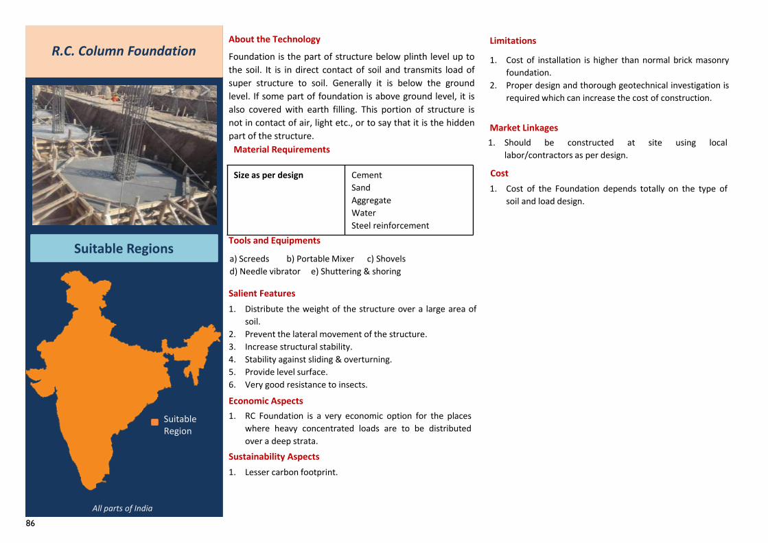
86
Size as per design Cement Sand Aggregate Water Steel reinforcement
R.C. Column Foundation
Suitable Regions
About the Technology
Foundation is the part of structure below plinth level up tothe soil. It is in direct contact of soil and transmits load ofsuper structure to soil. Generally it is below the groundlevel. If some part of foundation is above ground level, it isalso covered with earth filling. This portion of structure isnot in contact of air, light etc., or to say that it is the hiddenpart of the structure.
Material Requirements
Tools and Equipments
a) Screeds b) Portable Mixer c) Shovels d) Needle vibrator e) Shuttering & shoring
Salient Features1. Distribute the weight of the structure over a large area of
soil.2. Prevent the lateral movement of the structure.3. Increase structural stability.4. Stability against sliding & overturning.5. Provide level surface.6. Very good resistance to insects.
Economic Aspects
Sustainability Aspects
Limitations
Market Linkages
Cost
1. RC Foundation is a very economic option for the placeswhere heavy concentrated loads are to be distributedover a deep strata.
All parts of India
1. Should be constructed at site using locallabor/contractors as per design.
1. Cost of the Foundation depends totally on the type ofsoil and load design.
1. Lesser carbon footprint.
1. Cost of installation is higher than normal brick masonryfoundation.
2. Proper design and thorough geotechnical investigation isrequired which can increase the cost of construction.
Suitable Region
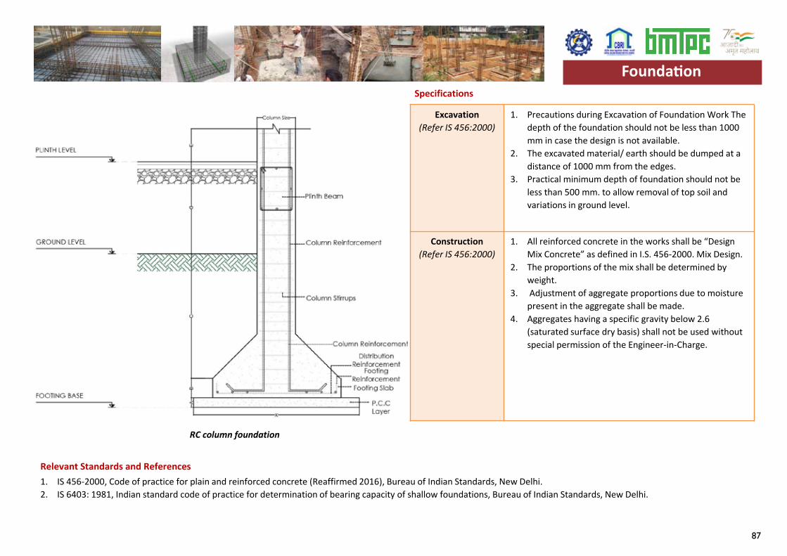
87
Specifications
1. IS 456-2000, Code of practice for plain and reinforced concrete (Reaffirmed 2016), Bureau of Indian Standards, New Delhi.2. IS 6403: 1981, Indian standard code of practice for determination of bearing capacity of shallow foundations, Bureau of Indian Standards, New Delhi.
Excavation (Refer IS 456:2000)
1. Precautions during Excavation of Foundation Work The depth of the foundation should not be less than 1000 mm in case the design is not available.
2. The excavated material/ earth should be dumped at a distance of 1000 mm from the edges.
3. Practical minimum depth of foundation should not be less than 500 mm. to allow removal of top soil and variations in ground level.
Construction (Refer IS 456:2000)
1. All reinforced concrete in the works shall be “Design Mix Concrete” as defined in I.S. 456-2000. Mix Design.
2. The proportions of the mix shall be determined by weight.
3. Adjustment of aggregate proportions due to moisture present in the aggregate shall be made.
4. Aggregates having a specific gravity below 2.6 (saturated surface dry basis) shall not be used without special permission of the Engineer-in-Charge.
Foundation
Relevant Standards and References
RC column foundation
Foundation
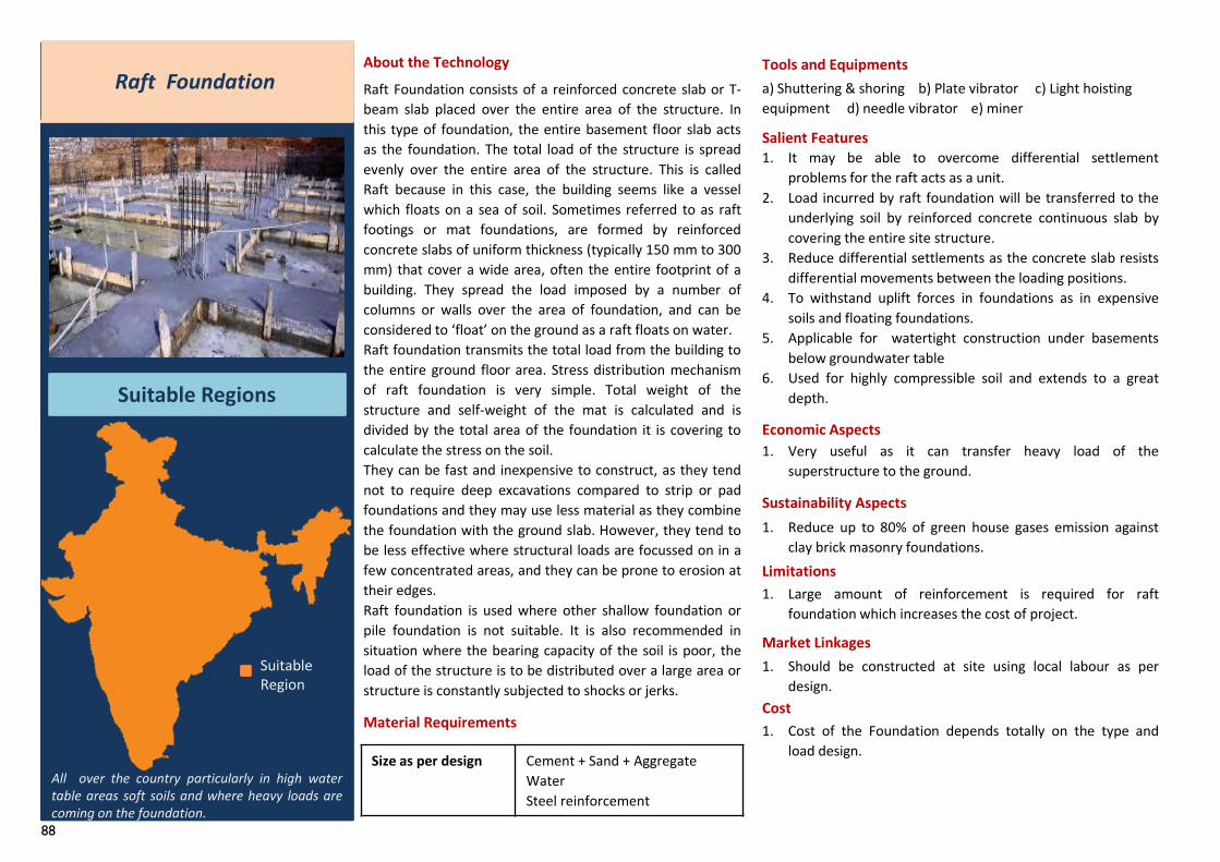
88
Raft Foundation
Suitable Regions
About the Technology
Raft Foundation consists of a reinforced concrete slab or T-beam slab placed over the entire area of the structure. Inthis type of foundation, the entire basement floor slab actsas the foundation. The total load of the structure is spreadevenly over the entire area of the structure. This is calledRaft because in this case, the building seems like a vesselwhich floats on a sea of soil. Sometimes referred to as raftfootings or mat foundations, are formed by reinforcedconcrete slabs of uniform thickness (typically 150 mm to 300mm) that cover a wide area, often the entire footprint of abuilding. They spread the load imposed by a number ofcolumns or walls over the area of foundation, and can beconsidered to ‘float’ on the ground as a raft floats on water.Raft foundation transmits the total load from the building tothe entire ground floor area. Stress distribution mechanismof raft foundation is very simple. Total weight of thestructure and self-weight of the mat is calculated and isdivided by the total area of the foundation it is covering tocalculate the stress on the soil.They can be fast and inexpensive to construct, as they tendnot to require deep excavations compared to strip or padfoundations and they may use less material as they combinethe foundation with the ground slab. However, they tend tobe less effective where structural loads are focussed on in afew concentrated areas, and they can be prone to erosion attheir edges.Raft foundation is used where other shallow foundation orpile foundation is not suitable. It is also recommended insituation where the bearing capacity of the soil is poor, theload of the structure is to be distributed over a large area orstructure is constantly subjected to shocks or jerks.
Material Requirements
Tools and Equipmentsa) Shuttering & shoring b) Plate vibrator c) Light hoisting equipment d) needle vibrator e) miner
Salient Features1. It may be able to overcome differential settlement
problems for the raft acts as a unit.2. Load incurred by raft foundation will be transferred to the
underlying soil by reinforced concrete continuous slab bycovering the entire site structure.
3. Reduce differential settlements as the concrete slab resistsdifferential movements between the loading positions.
4. To withstand uplift forces in foundations as in expensivesoils and floating foundations.
5. Applicable for watertight construction under basementsbelow groundwater table
6. Used for highly compressible soil and extends to a greatdepth.
Economic Aspects1. Very useful as it can transfer heavy load of the
superstructure to the ground.
Sustainability Aspects1. Reduce up to 80% of green house gases emission against
clay brick masonry foundations.Limitations1. Large amount of reinforcement is required for raft
foundation which increases the cost of project.
Market Linkages
Cost
1. Should be constructed at site using local labour as perdesign.
1. Cost of the Foundation depends totally on the type andload design.
All over the country particularly in high watertable areas soft soils and where heavy loads arecoming on the foundation.
Suitable Region
Size as per design Cement + Sand + Aggregate Water Steel reinforcement
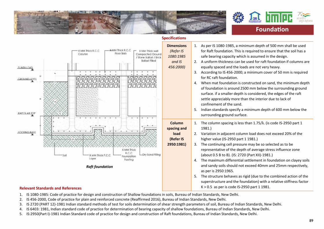
89
Specifications
1. IS 1080-1985: Code of practice for design and construction of Shallow foundations in soils, Bureau of Indian Standards, New Delhi.2. IS 456-2000, Code of practice for plain and reinforced concrete (Reaffirmed 2016), Bureau of Indian Standards, New Delhi.3. IS 2720 (PART 12)-1981 Indian standard methods of test for soils determination of shear strength parameters of soil, Bureau of Indian Standards, New Delhi.4. IS 6403: 1981, Indian standard code of practice for determination of bearing capacity of shallow foundations, Bureau of Indian Standards, New Delhi.5. IS:2950(Part I)-1981 Indian Standard code of practice for design and construction of Raft foundations, Bureau of Indian Standards, New Delhi.
Dimensions(Refer IS
1080:1985 and IS
456:2000)
1. As per IS 1080-1985, a minimum depth of 500 mm shall be used for Raft foundation. This is required to ensure that the soil has a safe bearing capacity which is assumed in the design.
2. A uniform thickness can be used for raft foundation if columns are equally spaced and the loads are not very heavy.
3. According to IS 456-2000; a minimum cover of 50 mm is required for RC raft foundation.
4. When mat foundation is constructed on sand, the minimum depth of foundation is around 2500 mm below the surrounding ground surface. if a smaller depth is considered, the edges of the raft settle appreciably more than the interior due to lack of confinement of the sand.
5. Indian standards specify a minimum depth of 600 mm below the surrounding ground surface.
Column spacing and
load(Refer IS
2950:1981)
1. The column spacing is less than 1.75/λ. (is code IS-2950 part 1 1981.)
2. Variation in adjacent column load does not exceed 20% of the higher value (IS-2950 part 1 1981.)
3. The continuing cell pressure may be so selected as to be representative of the depth of average stress influence zone (about 0.5 B to B). (IS: 2720 (Part XII)-1981.)
4. The maximum differential settlement in foundation on clayey soils and sandy soils should not exceed 40mm and 25mm respectively, as per is 2950:1965.
5. The structure behaves as rigid (due to the combined action of the superstructure and the foundation) with a relative stiffness factor K > 0.5 as per is code IS-2950 part 1 1981.
Foundation
Relevant Standards and References
Raft foundation
Foundation
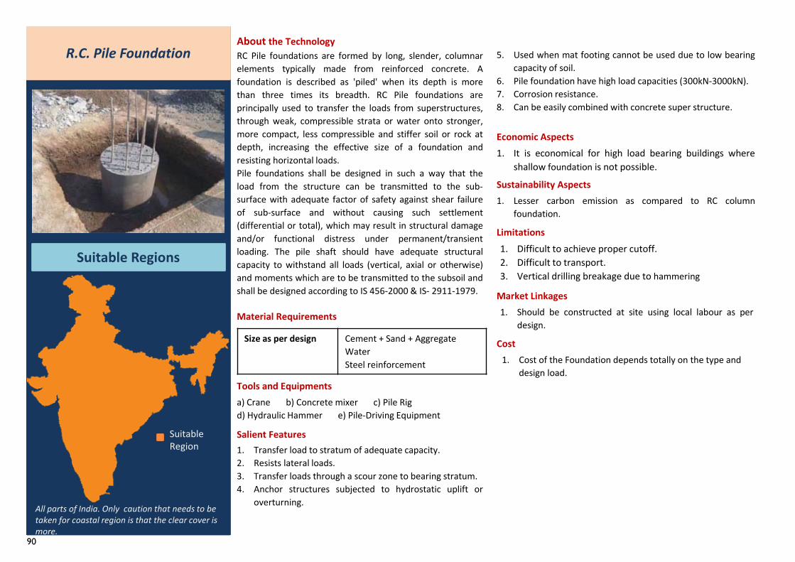
90
R.C. Pile Foundation
Suitable Regions
About the TechnologyRC Pile foundations are formed by long, slender, columnarelements typically made from reinforced concrete. Afoundation is described as 'piled' when its depth is morethan three times its breadth. RC Pile foundations areprincipally used to transfer the loads from superstructures,through weak, compressible strata or water onto stronger,more compact, less compressible and stiffer soil or rock atdepth, increasing the effective size of a foundation andresisting horizontal loads.Pile foundations shall be designed in such a way that theload from the structure can be transmitted to the sub-surface with adequate factor of safety against shear failureof sub-surface and without causing such settlement(differential or total), which may result in structural damageand/or functional distress under permanent/transientloading. The pile shaft should have adequate structuralcapacity to withstand all loads (vertical, axial or otherwise)and moments which are to be transmitted to the subsoil andshall be designed according to IS 456-2000 & IS- 2911-1979.
Material Requirements
Tools and Equipmentsa) Crane b) Concrete mixer c) Pile Rig d) Hydraulic Hammer e) Pile-Driving Equipment
Salient Features
5. Used when mat footing cannot be used due to low bearingcapacity of soil.
6. Pile foundation have high load capacities (300kN-3000kN).7. Corrosion resistance.8. Can be easily combined with concrete super structure.
Economic Aspects
Sustainability Aspects
Limitations
Market Linkages
Cost
1. Difficult to achieve proper cutoff.2. Difficult to transport.3. Vertical drilling breakage due to hammering
1. It is economical for high load bearing buildings whereshallow foundation is not possible.
1. Should be constructed at site using local labour as perdesign.
1. Cost of the Foundation depends totally on the type and design load.
All parts of India. Only caution that needs to be taken for coastal region is that the clear cover is more.
1. Lesser carbon emission as compared to RC columnfoundation.
Suitable Region
Size as per design Cement + Sand + Aggregate Water Steel reinforcement
1. Transfer load to stratum of adequate capacity.2. Resists lateral loads.3. Transfer loads through a scour zone to bearing stratum.4. Anchor structures subjected to hydrostatic uplift or
overturning.
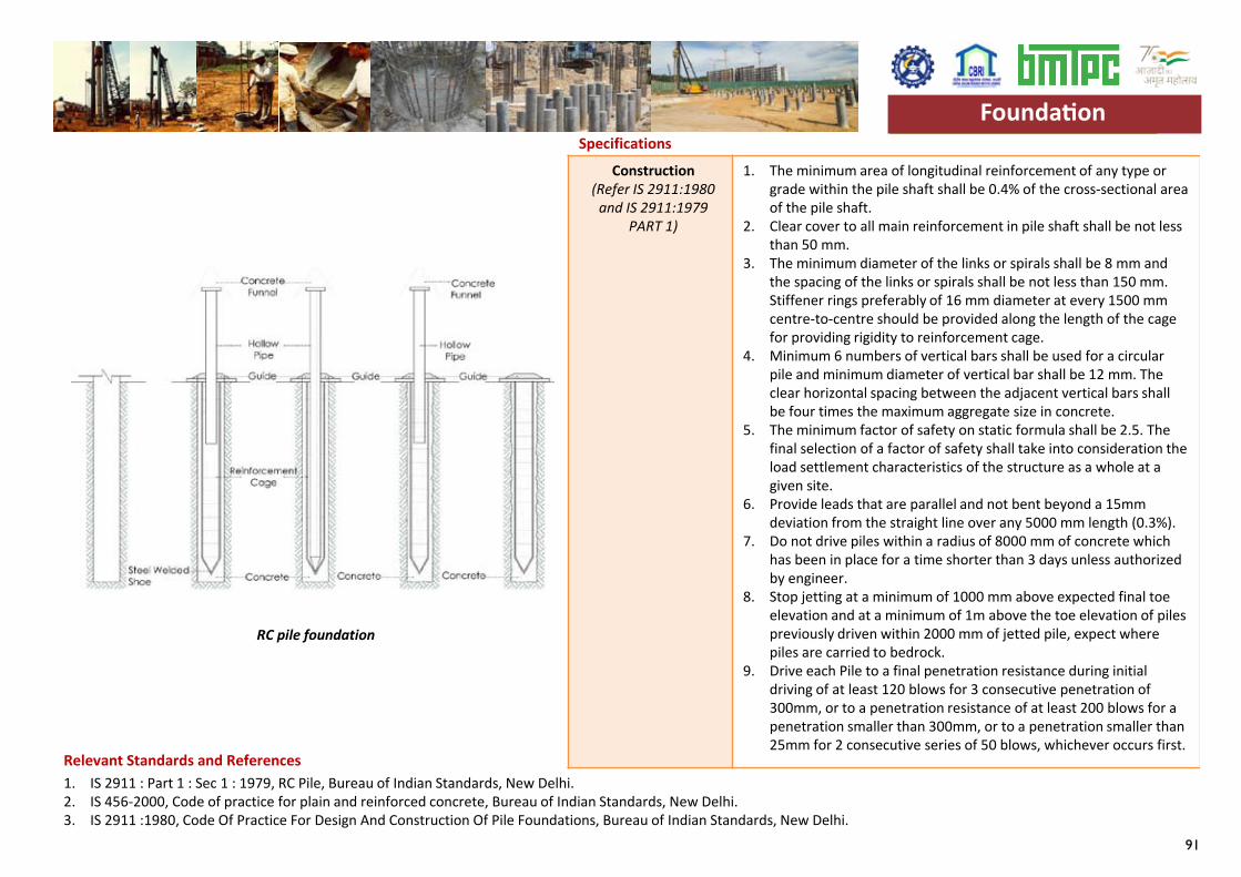
91
Specifications
1. IS 2911 : Part 1 : Sec 1 : 1979, RC Pile, Bureau of Indian Standards, New Delhi.2. IS 456-2000, Code of practice for plain and reinforced concrete, Bureau of Indian Standards, New Delhi.3. IS 2911 :1980, Code Of Practice For Design And Construction Of Pile Foundations, Bureau of Indian Standards, New Delhi.
Construction(Refer IS 2911:1980
and IS 2911:1979 PART 1)
1. The minimum area of longitudinal reinforcement of any type or grade within the pile shaft shall be 0.4% of the cross-sectional area of the pile shaft.
2. Clear cover to all main reinforcement in pile shaft shall be not less than 50 mm.
3. The minimum diameter of the links or spirals shall be 8 mm and the spacing of the links or spirals shall be not less than 150 mm. Stiffener rings preferably of 16 mm diameter at every 1500 mm centre-to-centre should be provided along the length of the cage for providing rigidity to reinforcement cage.
4. Minimum 6 numbers of vertical bars shall be used for a circular pile and minimum diameter of vertical bar shall be 12 mm. The clear horizontal spacing between the adjacent vertical bars shall be four times the maximum aggregate size in concrete.
5. The minimum factor of safety on static formula shall be 2.5. The final selection of a factor of safety shall take into consideration the load settlement characteristics of the structure as a whole at a given site.
6. Provide leads that are parallel and not bent beyond a 15mm deviation from the straight line over any 5000 mm length (0.3%).
7. Do not drive piles within a radius of 8000 mm of concrete which has been in place for a time shorter than 3 days unless authorized by engineer.
8. Stop jetting at a minimum of 1000 mm above expected final toe elevation and at a minimum of 1m above the toe elevation of piles previously driven within 2000 mm of jetted pile, expect where piles are carried to bedrock.
9. Drive each Pile to a final penetration resistance during initial driving of at least 120 blows for 3 consecutive penetration of 300mm, or to a penetration resistance of at least 200 blows for a penetration smaller than 300mm, or to a penetration smaller than 25mm for 2 consecutive series of 50 blows, whichever occurs first.
Relevant Standards and References
Foundation
RC pile foundation
Foundation
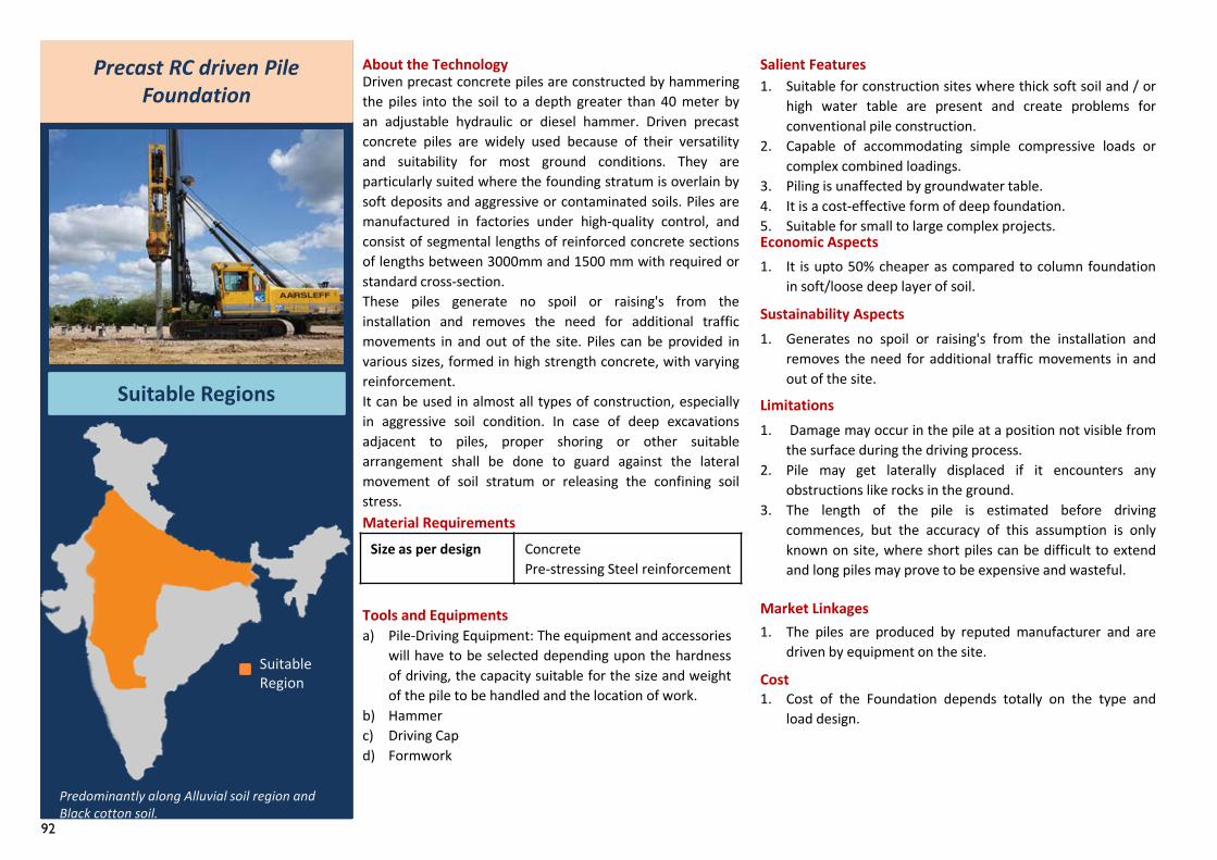
92
Size as per design Concrete Pre-stressing Steel reinforcement
Precast RC driven Pile Foundation
Suitable Regions
About the TechnologyDriven precast concrete piles are constructed by hammeringthe piles into the soil to a depth greater than 40 meter byan adjustable hydraulic or diesel hammer. Driven precastconcrete piles are widely used because of their versatilityand suitability for most ground conditions. They areparticularly suited where the founding stratum is overlain bysoft deposits and aggressive or contaminated soils. Piles aremanufactured in factories under high-quality control, andconsist of segmental lengths of reinforced concrete sectionsof lengths between 3000mm and 1500 mm with required orstandard cross-section.These piles generate no spoil or raising's from theinstallation and removes the need for additional trafficmovements in and out of the site. Piles can be provided invarious sizes, formed in high strength concrete, with varyingreinforcement.It can be used in almost all types of construction, especiallyin aggressive soil condition. In case of deep excavationsadjacent to piles, proper shoring or other suitablearrangement shall be done to guard against the lateralmovement of soil stratum or releasing the confining soilstress.Material Requirements
Tools and Equipmentsa) Pile-Driving Equipment: The equipment and accessories
will have to be selected depending upon the hardnessof driving, the capacity suitable for the size and weightof the pile to be handled and the location of work.
b) Hammerc) Driving Capd) Formwork
Salient Features1. Suitable for construction sites where thick soft soil and / or
high water table are present and create problems forconventional pile construction.
2. Capable of accommodating simple compressive loads orcomplex combined loadings.
3. Piling is unaffected by groundwater table.4. It is a cost-effective form of deep foundation.5. Suitable for small to large complex projects.Economic Aspects1. It is upto 50% cheaper as compared to column foundation
in soft/loose deep layer of soil.
Sustainability Aspects1. Generates no spoil or raising's from the installation and
removes the need for additional traffic movements in andout of the site.
Limitations1. Damage may occur in the pile at a position not visible from
the surface during the driving process.2. Pile may get laterally displaced if it encounters any
obstructions like rocks in the ground.3. The length of the pile is estimated before driving
commences, but the accuracy of this assumption is onlyknown on site, where short piles can be difficult to extendand long piles may prove to be expensive and wasteful.
Market Linkages
Cost
1. The piles are produced by reputed manufacturer and aredriven by equipment on the site.
Predominantly along Alluvial soil region and Black cotton soil.
1. Cost of the Foundation depends totally on the type andload design.
Suitable Region
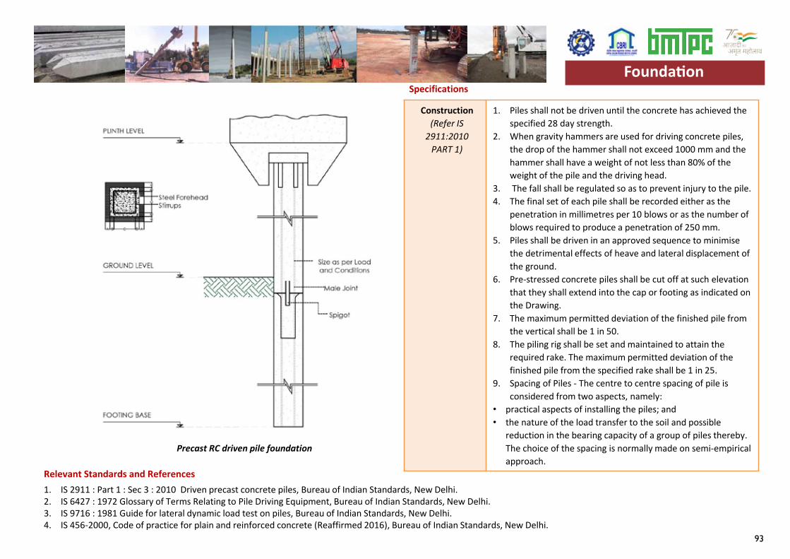
93
Specifications
1. IS 2911 : Part 1 : Sec 3 : 2010 Driven precast concrete piles, Bureau of Indian Standards, New Delhi.2. IS 6427 : 1972 Glossary of Terms Relating to Pile Driving Equipment, Bureau of Indian Standards, New Delhi.3. IS 9716 : 1981 Guide for lateral dynamic load test on piles, Bureau of Indian Standards, New Delhi.4. IS 456-2000, Code of practice for plain and reinforced concrete (Reaffirmed 2016), Bureau of Indian Standards, New Delhi.
Construction(Refer IS
2911:2010PART 1)
1. Piles shall not be driven until the concrete has achieved the specified 28 day strength.
2. When gravity hammers are used for driving concrete piles, the drop of the hammer shall not exceed 1000 mm and the hammer shall have a weight of not less than 80% of the weight of the pile and the driving head.
3. The fall shall be regulated so as to prevent injury to the pile.4. The final set of each pile shall be recorded either as the
penetration in millimetres per 10 blows or as the number of blows required to produce a penetration of 250 mm.
5. Piles shall be driven in an approved sequence to minimise the detrimental effects of heave and lateral displacement of the ground.
6. Pre-stressed concrete piles shall be cut off at such elevation that they shall extend into the cap or footing as indicated on the Drawing.
7. The maximum permitted deviation of the finished pile from the vertical shall be 1 in 50.
8. The piling rig shall be set and maintained to attain the required rake. The maximum permitted deviation of the finished pile from the specified rake shall be 1 in 25.
9. Spacing of Piles - The centre to centre spacing of pile is considered from two aspects, namely:
• practical aspects of installing the piles; and • the nature of the load transfer to the soil and possible
reduction in the bearing capacity of a group of piles thereby. The choice of the spacing is normally made on semi-empirical approach.
Foundation
Relevant Standards and References
Precast RC driven pile foundation
Foundation
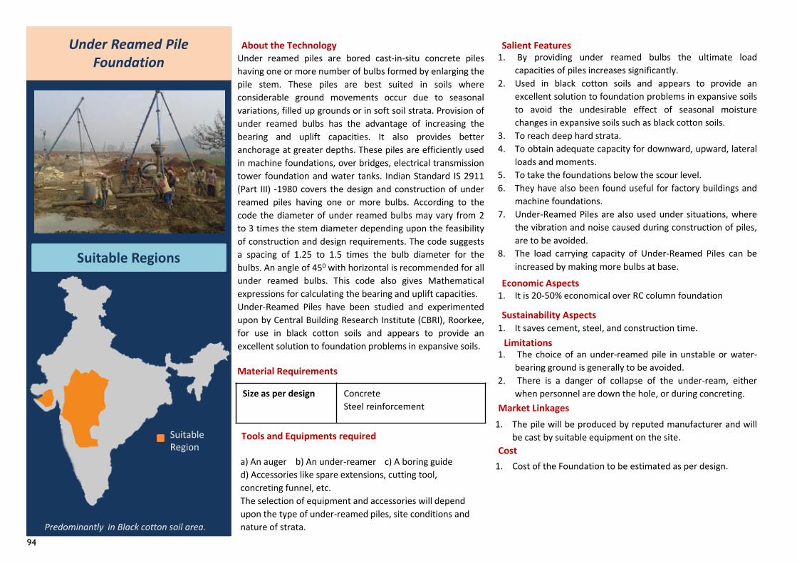
94
Size as per design Concrete Steel reinforcement
Under Reamed Pile Foundation
Suitable Regions
About the TechnologyUnder reamed piles are bored cast-in-situ concrete pileshaving one or more number of bulbs formed by enlarging thepile stem. These piles are best suited in soils whereconsiderable ground movements occur due to seasonalvariations, filled up grounds or in soft soil strata. Provision ofunder reamed bulbs has the advantage of increasing thebearing and uplift capacities. It also provides betteranchorage at greater depths. These piles are efficiently usedin machine foundations, over bridges, electrical transmissiontower foundation and water tanks. Indian Standard IS 2911(Part III) -1980 covers the design and construction of underreamed piles having one or more bulbs. According to thecode the diameter of under reamed bulbs may vary from 2to 3 times the stem diameter depending upon the feasibilityof construction and design requirements. The code suggestsa spacing of 1.25 to 1.5 times the bulb diameter for thebulbs. An angle of 450 with horizontal is recommended for allunder reamed bulbs. This code also gives Mathematicalexpressions for calculating the bearing and uplift capacities.Under-Reamed Piles have been studied and experimentedupon by Central Building Research Institute (CBRI), Roorkee,for use in black cotton soils and appears to provide anexcellent solution to foundation problems in expansive soils.
Material Requirements
Tools and Equipments required
a) An auger b) An under-reamer c) A boring guide d) Accessories like spare extensions, cutting tool,concreting funnel, etc.The selection of equipment and accessories will depend upon the type of under-reamed piles, site conditions and nature of strata.
Salient Features1. By providing under reamed bulbs the ultimate load
capacities of piles increases significantly.2. Used in black cotton soils and appears to provide an
excellent solution to foundation problems in expansive soilsto avoid the undesirable effect of seasonal moisturechanges in expansive soils such as black cotton soils.
3. To reach deep hard strata.4. To obtain adequate capacity for downward, upward, lateral
loads and moments.5. To take the foundations below the scour level.6. They have also been found useful for factory buildings and
machine foundations.7. Under-Reamed Piles are also used under situations, where
the vibration and noise caused during construction of piles,are to be avoided.
8. The load carrying capacity of Under-Reamed Piles can beincreased by making more bulbs at base.
Economic Aspects1. It is 20-50% economical over RC column foundation
Sustainability Aspects1. It saves cement, steel, and construction time.
Limitations1. The choice of an under-reamed pile in unstable or water-
bearing ground is generally to be avoided.2. There is a danger of collapse of the under-ream, either
when personnel are down the hole, or during concreting.Market Linkages
Cost
1. The pile will be produced by reputed manufacturer and willbe cast by suitable equipment on the site.
Predominantly in Black cotton soil area.
1. Cost of the Foundation to be estimated as per design.
Suitable Region
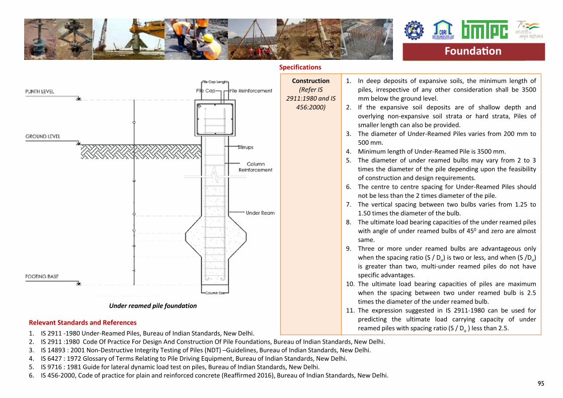
95
Specifications
1. IS 2911 -1980 Under-Reamed Piles, Bureau of Indian Standards, New Delhi.2. IS 2911 :1980 Code Of Practice For Design And Construction Of Pile Foundations, Bureau of Indian Standards, New Delhi.3. IS 14893 : 2001 Non-Destructive Integrity Testing of Piles (NDT) –Guidelines, Bureau of Indian Standards, New Delhi.4. IS 6427 : 1972 Glossary of Terms Relating to Pile Driving Equipment, Bureau of Indian Standards, New Delhi.5. IS 9716 : 1981 Guide for lateral dynamic load test on piles, Bureau of Indian Standards, New Delhi.6. IS 456-2000, Code of practice for plain and reinforced concrete (Reaffirmed 2016), Bureau of Indian Standards, New Delhi.
Construction(Refer IS
2911:1980 and IS 456:2000)
1. In deep deposits of expansive soils, the minimum length ofpiles, irrespective of any other consideration shall be 3500mm below the ground level.
2. If the expansive soil deposits are of shallow depth andoverlying non-expansive soil strata or hard strata, Piles ofsmaller length can also be provided.
3. The diameter of Under-Reamed Piles varies from 200 mm to500 mm.
4. Minimum length of Under-Reamed Pile is 3500 mm.5. The diameter of under reamed bulbs may vary from 2 to 3
times the diameter of the pile depending upon the feasibilityof construction and design requirements.
6. The centre to centre spacing for Under-Reamed Piles shouldnot be less than the 2 times diameter of the pile.
7. The vertical spacing between two bulbs varies from 1.25 to1.50 times the diameter of the bulb.
8. The ultimate load bearing capacities of the under reamed pileswith angle of under reamed bulbs of 450 and zero are almostsame.
9. Three or more under reamed bulbs are advantageous onlywhen the spacing ratio (S / Du) is two or less, and when (S /Du)is greater than two, multi-under reamed piles do not havespecific advantages.
10. The ultimate load bearing capacities of piles are maximumwhen the spacing between two under reamed bulb is 2.5times the diameter of the under reamed bulb.
11. The expression suggested in IS 2911-1980 can be used forpredicting the ultimate load carrying capacity of underreamed piles with spacing ratio (S / Du ) less than 2.5.
Relevant Standards and References
Foundation
Under reamed pile foundation
Foundation
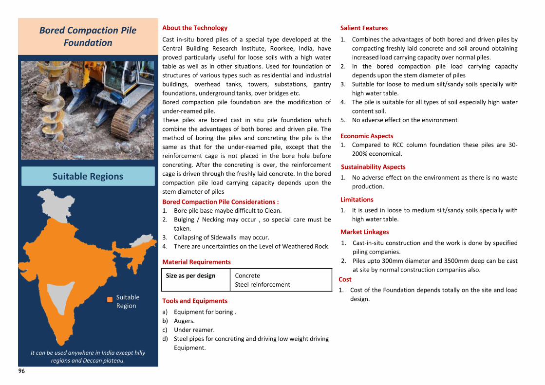
96
Bored Compaction Pile Foundation
Suitable Regions
About the TechnologyCast in-situ bored piles of a special type developed at theCentral Building Research Institute, Roorkee, India, haveproved particularly useful for loose soils with a high watertable as well as in other situations. Used for foundation ofstructures of various types such as residential and industrialbuildings, overhead tanks, towers, substations, gantryfoundations, underground tanks, over bridges etc.Bored compaction pile foundation are the modification ofunder-reamed pile.These piles are bored cast in situ pile foundation whichcombine the advantages of both bored and driven pile. Themethod of boring the piles and concreting the pile is thesame as that for the under-reamed pile, except that thereinforcement cage is not placed in the bore hole beforeconcreting. After the concreting is over, the reinforcementcage is driven through the freshly laid concrete. In the boredcompaction pile load carrying capacity depends upon thestem diameter of piles
Tools and Equipmentsa) Equipment for boring . b) Augers.c) Under reamer.d) Steel pipes for concreting and driving low weight driving
Equipment.
Salient Features1. Combines the advantages of both bored and driven piles by
compacting freshly laid concrete and soil around obtainingincreased load carrying capacity over normal piles.
2. In the bored compaction pile load carrying capacitydepends upon the stem diameter of piles
3. Suitable for loose to medium silt/sandy soils specially withhigh water table.
4. The pile is suitable for all types of soil especially high watercontent soil.
5. No adverse effect on the environment
Economic Aspects
Sustainability Aspects1. No adverse effect on the environment as there is no waste
production.
Limitations
Market Linkages
Cost
1. It is used in loose to medium silt/sandy soils specially withhigh water table.
Bored Compaction Pile Considerations :1. Bore pile base maybe difficult to Clean.2. Bulging / Necking may occur , so special care must be
taken.3. Collapsing of Sidewalls may occur.4. There are uncertainties on the Level of Weathered Rock.
It can be used anywhere in India except hilly regions and Deccan plateau.
1. Cast-in-situ construction and the work is done by specifiedpiling companies.
2. Piles upto 300mm diameter and 3500mm deep can be castat site by normal construction companies also.
1. Cost of the Foundation depends totally on the site and loaddesign.
1. Compared to RCC column foundation these piles are 30-200% economical.
Suitable Region
Size as per design Concrete Steel reinforcement
Material Requirements
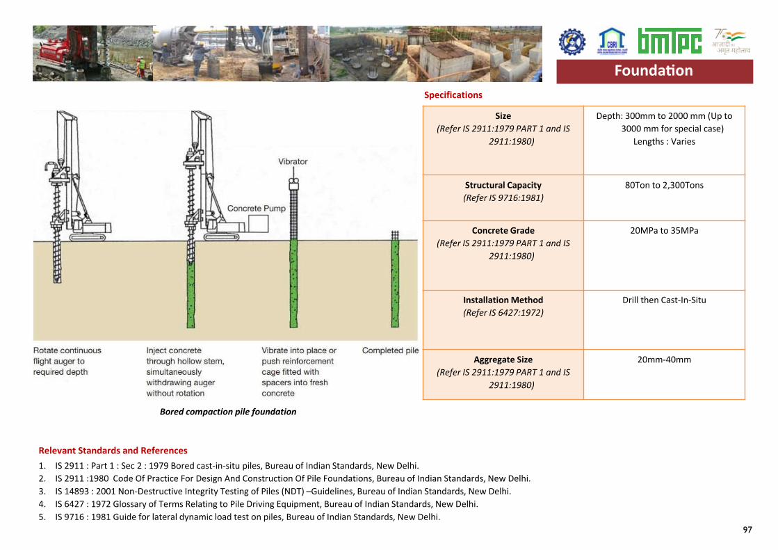
97
Specifications
1. IS 2911 : Part 1 : Sec 2 : 1979 Bored cast-in-situ piles, Bureau of Indian Standards, New Delhi. 2. IS 2911 :1980 Code Of Practice For Design And Construction Of Pile Foundations, Bureau of Indian Standards, New Delhi. 3. IS 14893 : 2001 Non-Destructive Integrity Testing of Piles (NDT) –Guidelines, Bureau of Indian Standards, New Delhi. 4. IS 6427 : 1972 Glossary of Terms Relating to Pile Driving Equipment, Bureau of Indian Standards, New Delhi. 5. IS 9716 : 1981 Guide for lateral dynamic load test on piles, Bureau of Indian Standards, New Delhi.
Size (Refer IS 2911:1979 PART 1 and IS
2911:1980)
Depth: 300mm to 2000 mm (Up to 3000 mm for special case)
Lengths : Varies
Structural Capacity (Refer IS 9716:1981)
80Ton to 2,300Tons
Concrete Grade (Refer IS 2911:1979 PART 1 and IS
2911:1980)
20MPa to 35MPa
Installation Method (Refer IS 6427:1972)
Drill then Cast-In-Situ
Aggregate Size (Refer IS 2911:1979 PART 1 and IS
2911:1980)
20mm-40mm
Relevant Standards and References
Foundation
Bored compaction pile foundation
Foundation
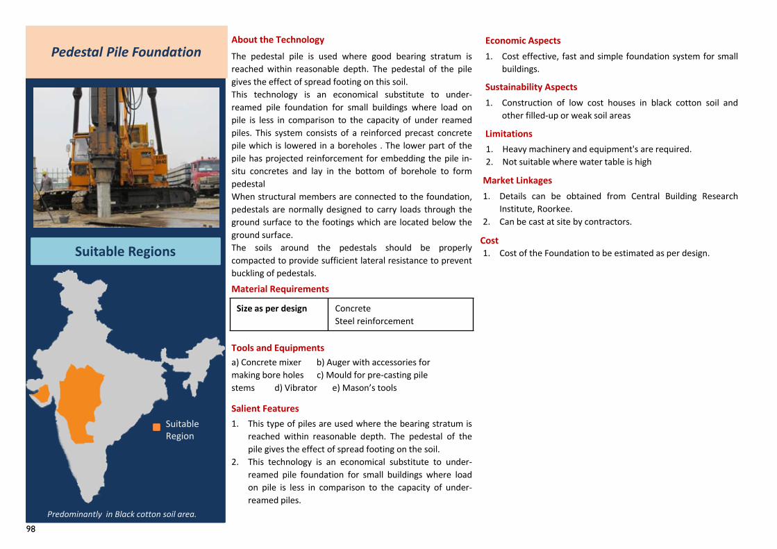
98
Pedestal Pile Foundation
Suitable Regions
About the TechnologyThe pedestal pile is used where good bearing stratum isreached within reasonable depth. The pedestal of the pilegives the effect of spread footing on this soil.This technology is an economical substitute to under-reamed pile foundation for small buildings where load onpile is less in comparison to the capacity of under reamedpiles. This system consists of a reinforced precast concretepile which is lowered in a boreholes . The lower part of thepile has projected reinforcement for embedding the pile in-situ concretes and lay in the bottom of borehole to formpedestalWhen structural members are connected to the foundation,pedestals are normally designed to carry loads through theground surface to the footings which are located below theground surface.The soils around the pedestals should be properlycompacted to provide sufficient lateral resistance to preventbuckling of pedestals.
Tools and Equipmentsa) Concrete mixer b) Auger with accessories formaking bore holes c) Mould for pre-casting pilestems d) Vibrator e) Mason’s tools
Salient Features1. This type of piles are used where the bearing stratum is
reached within reasonable depth. The pedestal of thepile gives the effect of spread footing on the soil.
2. This technology is an economical substitute to under-reamed pile foundation for small buildings where loadon pile is less in comparison to the capacity of under-reamed piles.
Economic Aspects1. Cost effective, fast and simple foundation system for small
buildings.
Sustainability Aspects1. Construction of low cost houses in black cotton soil and
other filled-up or weak soil areas
Limitations
1. Details can be obtained from Central Building ResearchInstitute, Roorkee.
2. Can be cast at site by contractors.
Market Linkages
Cost
Predominantly in Black cotton soil area.
1. Cost of the Foundation to be estimated as per design.
1. Heavy machinery and equipment's are required.2. Not suitable where water table is high
Suitable Region
Size as per design Concrete Steel reinforcement
Material Requirements
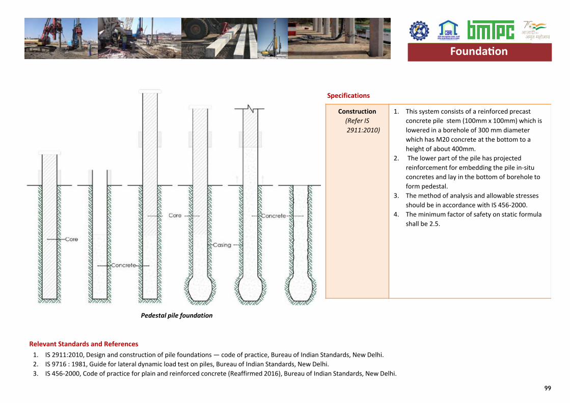
99
Specifications
1. IS 2911:2010, Design and construction of pile foundations — code of practice, Bureau of Indian Standards, New Delhi. 2. IS 9716 : 1981, Guide for lateral dynamic load test on piles, Bureau of Indian Standards, New Delhi. 3. IS 456-2000, Code of practice for plain and reinforced concrete (Reaffirmed 2016), Bureau of Indian Standards, New Delhi.
Construction (Refer IS 2911:2010)
1. This system consists of a reinforced precast concrete pile stem (100mm x 100mm) which is lowered in a borehole of 300 mm diameterwhich has M20 concrete at the bottom to a height of about 400mm.
2. The lower part of the pile has projected reinforcement for embedding the pile in-situ concretes and lay in the bottom of borehole to form pedestal.
3. The method of analysis and allowable stresses should be in accordance with IS 456-2000.
4. The minimum factor of safety on static formula shall be 2.5.
Relevant Standards and References
Foundation
Pedestal pile foundation
Foundation
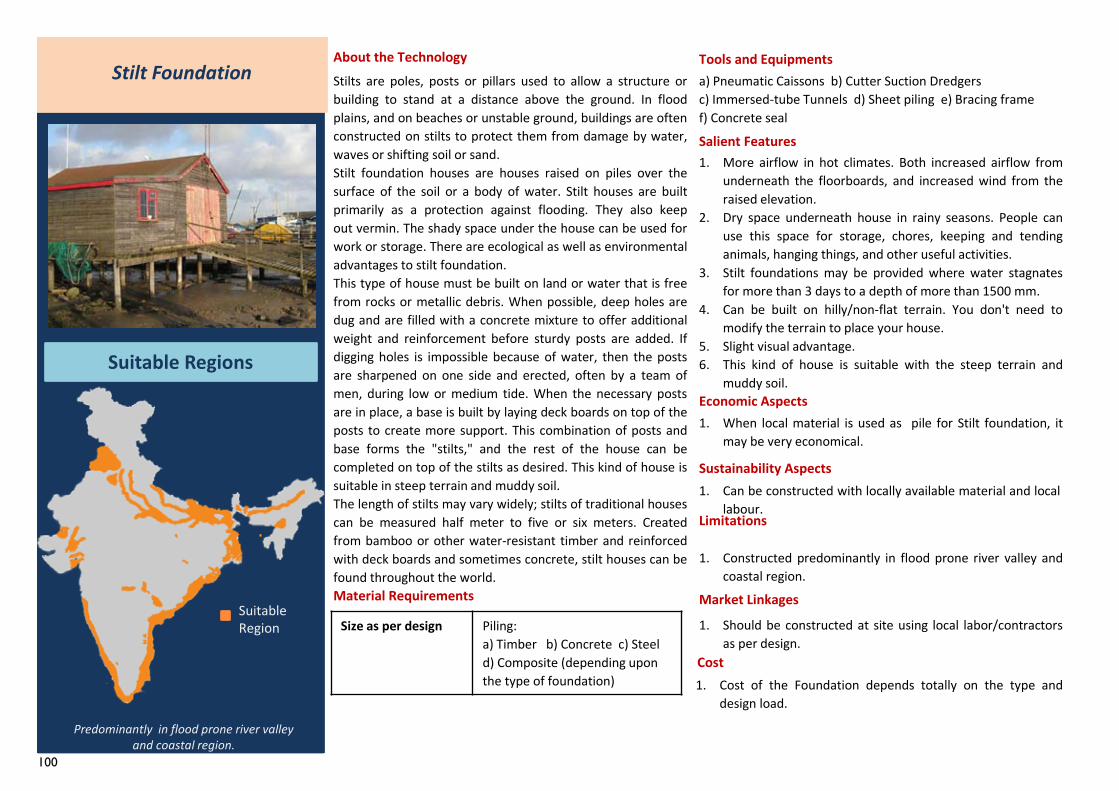
100
Size as per design Piling:a) Timber b) Concrete c) Steeld) Composite (depending upon the type of foundation)
Stilt Foundation
Suitable Regions
About the TechnologyStilts are poles, posts or pillars used to allow a structure orbuilding to stand at a distance above the ground. In floodplains, and on beaches or unstable ground, buildings are oftenconstructed on stilts to protect them from damage by water,waves or shifting soil or sand.Stilt foundation houses are houses raised on piles over thesurface of the soil or a body of water. Stilt houses are builtprimarily as a protection against flooding. They also keepout vermin. The shady space under the house can be used forwork or storage. There are ecological as well as environmentaladvantages to stilt foundation.This type of house must be built on land or water that is freefrom rocks or metallic debris. When possible, deep holes aredug and are filled with a concrete mixture to offer additionalweight and reinforcement before sturdy posts are added. Ifdigging holes is impossible because of water, then the postsare sharpened on one side and erected, often by a team ofmen, during low or medium tide. When the necessary postsare in place, a base is built by laying deck boards on top of theposts to create more support. This combination of posts andbase forms the "stilts," and the rest of the house can becompleted on top of the stilts as desired. This kind of house issuitable in steep terrain and muddy soil.The length of stilts may vary widely; stilts of traditional housescan be measured half meter to five or six meters. Createdfrom bamboo or other water-resistant timber and reinforcedwith deck boards and sometimes concrete, stilt houses can befound throughout the world.
Tools and Equipmentsa) Pneumatic Caissons b) Cutter Suction Dredgers c) Immersed-tube Tunnels d) Sheet piling e) Bracing frame f) Concrete seal
Salient Features1. More airflow in hot climates. Both increased airflow from
underneath the floorboards, and increased wind from theraised elevation.
2. Dry space underneath house in rainy seasons. People canuse this space for storage, chores, keeping and tendinganimals, hanging things, and other useful activities.
3. Stilt foundations may be provided where water stagnatesfor more than 3 days to a depth of more than 1500 mm.
4. Can be built on hilly/non-flat terrain. You don't need tomodify the terrain to place your house.
5. Slight visual advantage.6. This kind of house is suitable with the steep terrain and
muddy soil.Economic Aspects
Sustainability Aspects
Limitations
1. Constructed predominantly in flood prone river valley andcoastal region.
Market Linkages
Cost
1. When local material is used as pile for Stilt foundation, itmay be very economical.
Predominantly in flood prone river valley and coastal region.
1. Should be constructed at site using local labor/contractorsas per design.
1. Cost of the Foundation depends totally on the type anddesign load.
1. Can be constructed with locally available material and locallabour.
Suitable Region
Material Requirements
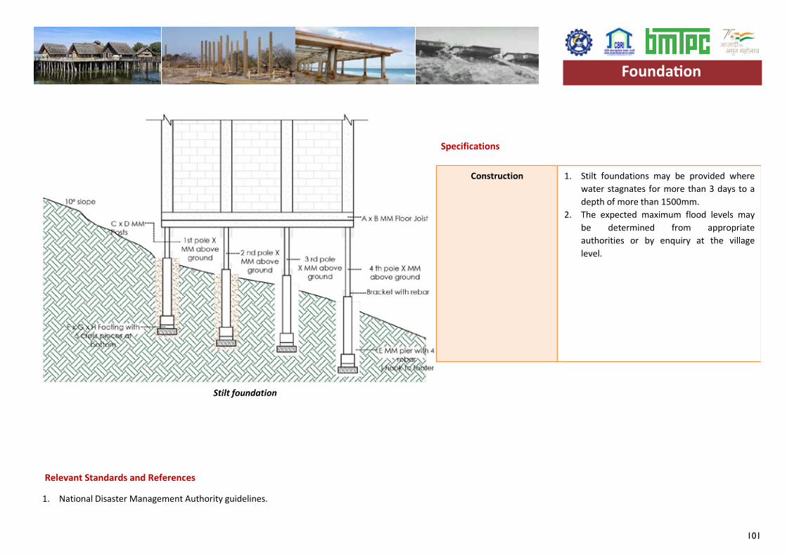
101
Specifications
1. National Disaster Management Authority guidelines.
Construction 1. Stilt foundations may be provided wherewater stagnates for more than 3 days to adepth of more than 1500mm.
2. The expected maximum flood levels maybe determined from appropriateauthorities or by enquiry at the villagelevel.
Foundation
Relevant Standards and References
Stilt foundation
Foundation
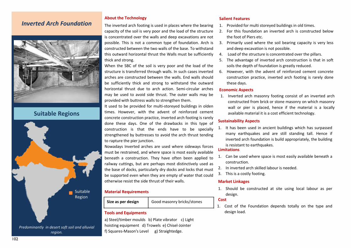
102
Size as per design Good masonry bricks/stones
The inverted arch footing is used in places where the bearingcapacity of the soil is very poor and the load of the structureis concentrated over the walls and deep excavations are notpossible. This is not a common type of foundation. Arch isconstructed between the two walls of the base. To withstandthis outward horizontal thrust the Walls must be sufficientlythick and strong.When the SBC of the soil is very poor and the load of thestructure is transferred through walls. In such cases invertedarches are constructed between the walls. End walls shouldbe sufficiently thick and strong to withstand the outwardhorizontal thrust due to arch action. Semi-circular archesmay be used to avoid side thrust. The outer walls may beprovided with buttress walls to strengthen them.It used to be provided for multi-storeyed buildings in oldentimes. However, with the advent of reinforced cementconcrete construction practice, inverted arch footing is rarelydone these days. One of the drawbacks in this type ofconstruction is that the ends have to be speciallystrengthened by buttresses to avoid the arch thrust tendingto rapture the pier junction.Nowadays Inverted arches are used where sideways forcesmust be restrained, and where space is most easily availablebeneath a construction. They have often been applied torailway cuttings, but are perhaps most distinctively used asthe base of docks, particularly dry docks and locks that mustbe supported even when they are empty of water that couldotherwise resist the side thrust of their walls.
About the TechnologyInverted Arch Foundation
Suitable Regions
Material Requirements
Tools and Equipmentsa) Steel/timber moulds b) Plate vibrator c) Light hoisting equipment d) Trowels e) Chisel-Jointer f) Squares-Mason's Level g) Straightedge.
Salient Features1. Provided for multi storeyed buildings in old times.2. For this foundation an inverted arch is constructed below
the foot of Piers etc.3. Primarily used where the soil bearing capacity is very less
and deep excavation is not possible.4. Load of the structure is concentrated over the pillars.5. The advantage of inverted arch construction is that in soft
soils the depth of foundation is greatly reduced.6. However, with the advent of reinforced cement concrete
construction practice, inverted arch footing is rarely donethese days.
Economic Aspects1. Inverted arch masonry footing consist of an inverted arch
constructed from brick or stone masonry on which masonrywall or pier is placed, hence if the material is a locallyavailable material it is a cost efficient technology.
Sustainability Aspects1. It has been used in ancient buildings which has surpassed
many earthquakes and are still standing tall. Hence ifinverted arch foundation is build appropriately, the buildingis resistant to earthquakes.
Limitations1. Can be used where space is most easily available beneath a
construction.2. In inverted arch skilled labour is needed.3. This is a costly footing.
Market Linkages
Cost
Predominantly in desert soft soil and alluvial region.
1. Should be constructed at site using local labour as perdesign.
1. Cost of the Foundation depends totally on the type anddesign load.
Suitable Region
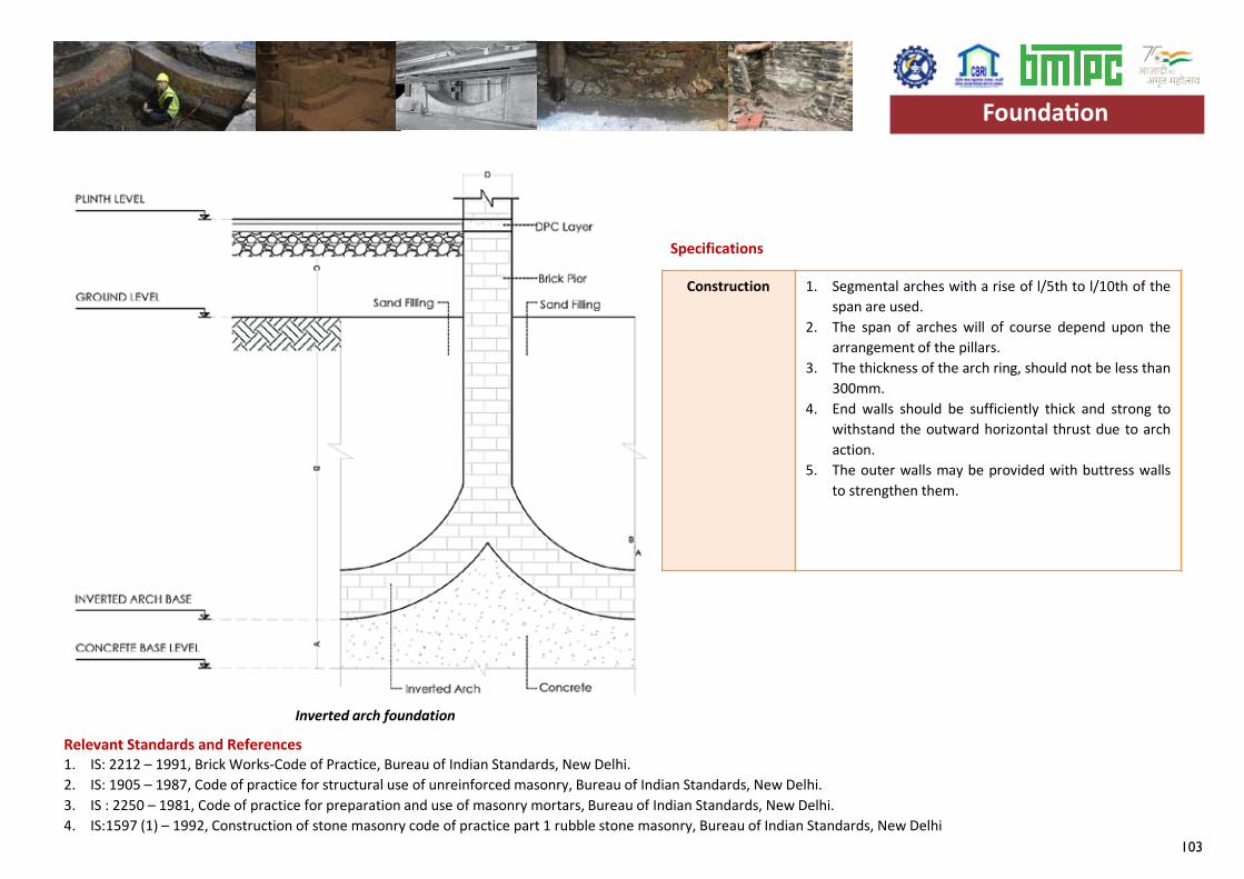
103
Specifications
Construction 1. Segmental arches with a rise of l/5th to l/10th of thespan are used.
2. The span of arches will of course depend upon thearrangement of the pillars.
3. The thickness of the arch ring, should not be less than300mm.
4. End walls should be sufficiently thick and strong towithstand the outward horizontal thrust due to archaction.
5. The outer walls may be provided with buttress wallsto strengthen them.
Relevant Standards and References1. IS: 2212 – 1991, Brick Works-Code of Practice, Bureau of Indian Standards, New Delhi.2. IS: 1905 – 1987, Code of practice for structural use of unreinforced masonry, Bureau of Indian Standards, New Delhi.3. IS : 2250 – 1981, Code of practice for preparation and use of masonry mortars, Bureau of Indian Standards, New Delhi.4. IS:1597 (1) – 1992, Construction of stone masonry code of practice part 1 rubble stone masonry, Bureau of Indian Standards, New Delhi
Foundation
Inverted arch foundation
Foundation
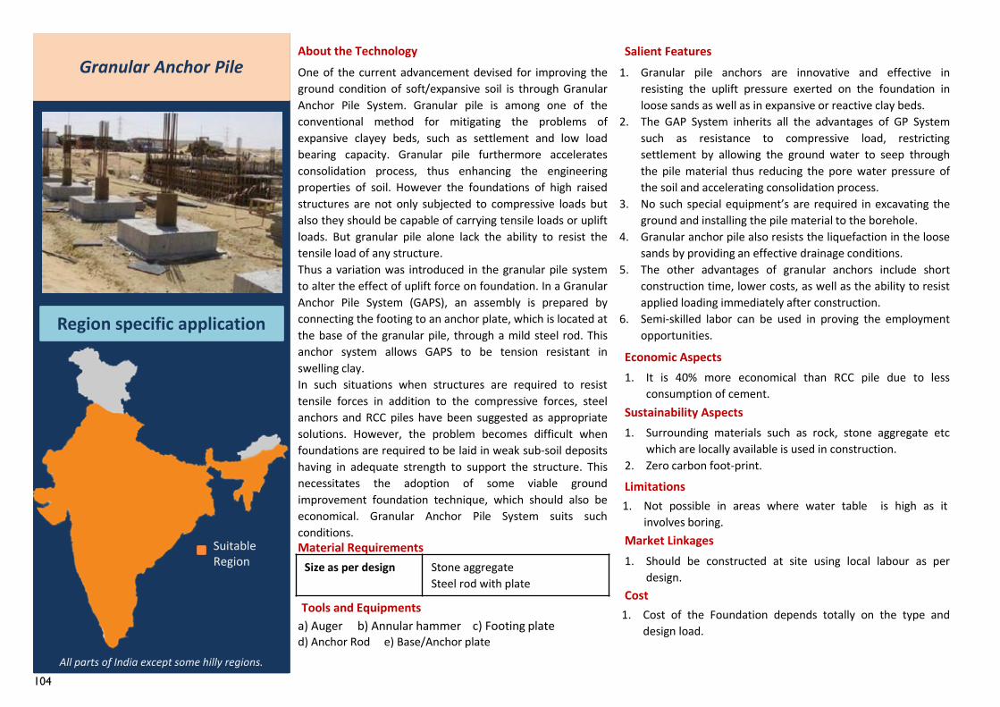
104
Granular Anchor Pile
Region specific application
About the TechnologyOne of the current advancement devised for improving theground condition of soft/expansive soil is through GranularAnchor Pile System. Granular pile is among one of theconventional method for mitigating the problems ofexpansive clayey beds, such as settlement and low loadbearing capacity. Granular pile furthermore acceleratesconsolidation process, thus enhancing the engineeringproperties of soil. However the foundations of high raisedstructures are not only subjected to compressive loads butalso they should be capable of carrying tensile loads or upliftloads. But granular pile alone lack the ability to resist thetensile load of any structure.Thus a variation was introduced in the granular pile systemto alter the effect of uplift force on foundation. In a GranularAnchor Pile System (GAPS), an assembly is prepared byconnecting the footing to an anchor plate, which is located atthe base of the granular pile, through a mild steel rod. Thisanchor system allows GAPS to be tension resistant inswelling clay.In such situations when structures are required to resisttensile forces in addition to the compressive forces, steelanchors and RCC piles have been suggested as appropriatesolutions. However, the problem becomes difficult whenfoundations are required to be laid in weak sub-soil depositshaving in adequate strength to support the structure. Thisnecessitates the adoption of some viable groundimprovement foundation technique, which should also beeconomical. Granular Anchor Pile System suits suchconditions.
a) Auger b) Annular hammer c) Footing plate d) Anchor Rod e) Base/Anchor plate
Salient Features1. Granular pile anchors are innovative and effective in
resisting the uplift pressure exerted on the foundation inloose sands as well as in expansive or reactive clay beds.
2. The GAP System inherits all the advantages of GP Systemsuch as resistance to compressive load, restrictingsettlement by allowing the ground water to seep throughthe pile material thus reducing the pore water pressure ofthe soil and accelerating consolidation process.
3. No such special equipment’s are required in excavating theground and installing the pile material to the borehole.
4. Granular anchor pile also resists the liquefaction in the loosesands by providing an effective drainage conditions.
5. The other advantages of granular anchors include shortconstruction time, lower costs, as well as the ability to resistapplied loading immediately after construction.
6. Semi-skilled labor can be used in proving the employmentopportunities.
Economic Aspects1. It is 40% more economical than RCC pile due to less
consumption of cement.Sustainability Aspects1. Surrounding materials such as rock, stone aggregate etc
which are locally available is used in construction.2. Zero carbon foot-print.
Limitations1. Not possible in areas where water table is high as it
involves boring.Market Linkages
Cost
All parts of India except some hilly regions.
1. Cost of the Foundation depends totally on the type anddesign load.
1. Should be constructed at site using local labour as perdesign.
Suitable Region Size as per design Stone aggregate
Steel rod with plate
Material Requirements
Tools and Equipments
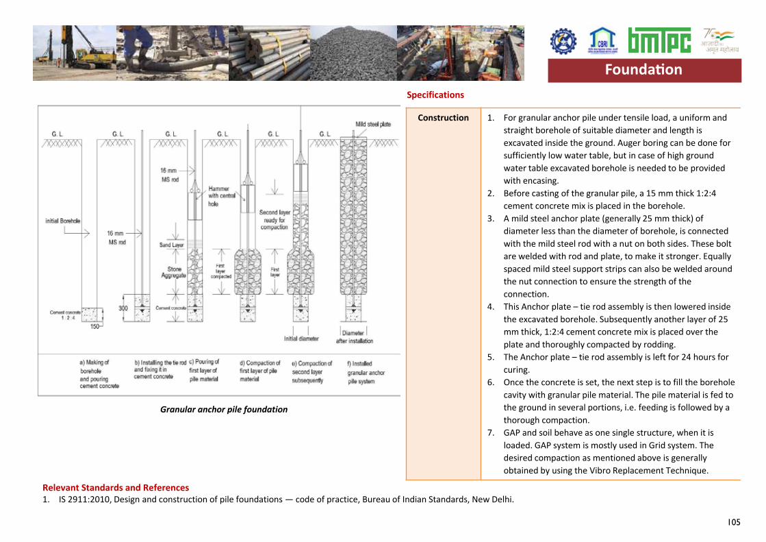
105
Specifications
Construction 1. For granular anchor pile under tensile load, a uniform and straight borehole of suitable diameter and length is excavated inside the ground. Auger boring can be done for sufficiently low water table, but in case of high ground water table excavated borehole is needed to be provided with encasing.
2. Before casting of the granular pile, a 15 mm thick 1:2:4 cement concrete mix is placed in the borehole.
3. A mild steel anchor plate (generally 25 mm thick) of diameter less than the diameter of borehole, is connected with the mild steel rod with a nut on both sides. These bolt are welded with rod and plate, to make it stronger. Equally spaced mild steel support strips can also be welded around the nut connection to ensure the strength of the connection.
4. This Anchor plate – tie rod assembly is then lowered inside the excavated borehole. Subsequently another layer of 25 mm thick, 1:2:4 cement concrete mix is placed over the plate and thoroughly compacted by rodding.
5. The Anchor plate – tie rod assembly is left for 24 hours for curing.
6. Once the concrete is set, the next step is to fill the borehole cavity with granular pile material. The pile material is fed to the ground in several portions, i.e. feeding is followed by a thorough compaction.
7. GAP and soil behave as one single structure, when it is loaded. GAP system is mostly used in Grid system. The desired compaction as mentioned above is generally obtained by using the Vibro Replacement Technique.
Relevant Standards and References1. IS 2911:2010, Design and construction of pile foundations — code of practice, Bureau of Indian Standards, New Delhi.
Foundation
Granular anchor pile foundation
Foundation

106
107
System Level Technologies
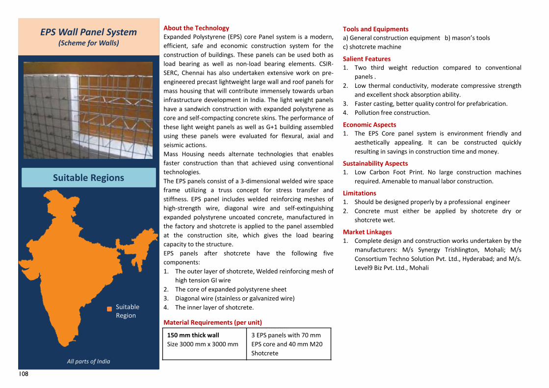
108
EPS Wall Panel System(Scheme for Walls)
Suitable Regions
About the TechnologyExpanded Polystyrene (EPS) core Panel system is a modern,efficient, safe and economic construction system for theconstruction of buildings. These panels can be used both asload bearing as well as non-load bearing elements. CSIR-SERC, Chennai has also undertaken extensive work on pre-engineered precast lightweight large wall and roof panels formass housing that will contribute immensely towards urbaninfrastructure development in India. The light weight panelshave a sandwich construction with expanded polystyrene ascore and self-compacting concrete skins. The performance ofthese light weight panels as well as G+1 building assembledusing these panels were evaluated for flexural, axial andseismic actions.Mass Housing needs alternate technologies that enablesfaster construction than that achieved using conventionaltechnologies.The EPS panels consist of a 3-dimensional welded wire spaceframe utilizing a truss concept for stress transfer andstiffness. EPS panel includes welded reinforcing meshes ofhigh-strength wire, diagonal wire and self-extinguishingexpanded polystyrene uncoated concrete, manufactured inthe factory and shotcrete is applied to the panel assembledat the construction site, which gives the load bearingcapacity to the structure.EPS panels after shotcrete have the following fivecomponents:1. The outer layer of shotcrete, Welded reinforcing mesh of
high tension GI wire2. The core of expanded polystyrene sheet3. Diagonal wire (stainless or galvanized wire)4. The inner layer of shotcrete.
Material Requirements (per unit)
Tools and Equipmentsa) General construction equipment b) mason’s toolsc) shotcrete machine
Salient Features1. Two third weight reduction compared to conventional
panels .2. Low thermal conductivity, moderate compressive strength
and excellent shock absorption ability.3. Faster casting, better quality control for prefabrication.4. Pollution free construction.
Economic Aspects1. The EPS Core panel system is environment friendly and
aesthetically appealing. It can be constructed quicklyresulting in savings in construction time and money.
Sustainability Aspects1. Low Carbon Foot Print. No large construction machines
required. Amenable to manual labor construction.
Limitations1. Should be designed properly by a professional engineer2. Concrete must either be applied by shotcrete dry or
shotcrete wet.
Market Linkages1. Complete design and construction works undertaken by the
manufacturers: M/s Synergy Trishlington, Mohali; M/sConsortium Techno Solution Pvt. Ltd., Hyderabad; and M/s.Level9 Biz Pvt. Ltd., Mohali
Suitable Region
Suitable Region
All parts of India
150 mm thick wallSize 3000 mm x 3000 mm
3 EPS panels with 70 mm EPS core and 40 mm M20 Shotcrete
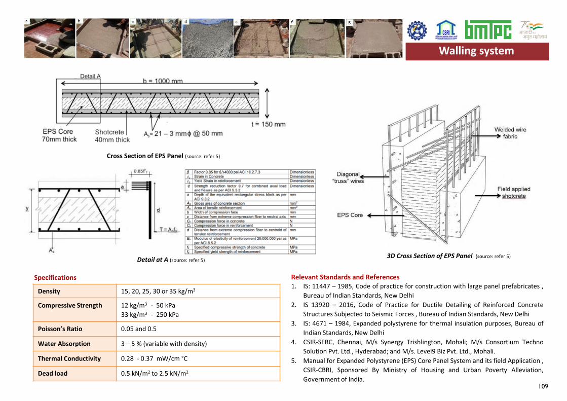
109
Density 15, 20, 25, 30 or 35 kg/m3
Compressive Strength 12 kg/m3 - 50 kPa33 kg/m3 - 250 kPa
Poisson’s Ratio 0.05 and 0.5
Water Absorption 3 – 5 % (variable with density)
Thermal Conductivity 0.28 - 0.37 mW/cm °C
Dead load 0.5 kN/m2 to 2.5 kN/m2
Specifications Relevant Standards and References1. IS: 11447 – 1985, Code of practice for construction with large panel prefabricates ,
Bureau of Indian Standards, New Delhi2. IS 13920 – 2016, Code of Practice for Ductile Detailing of Reinforced Concrete
Structures Subjected to Seismic Forces , Bureau of Indian Standards, New Delhi3. IS: 4671 – 1984, Expanded polystyrene for thermal insulation purposes, Bureau of
Indian Standards, New Delhi4. CSIR-SERC, Chennai, M/s Synergy Trishlington, Mohali; M/s Consortium Techno
Solution Pvt. Ltd., Hyderabad; and M/s. Level9 Biz Pvt. Ltd., Mohali.5. Manual for Expanded Polystyrene (EPS) Core Panel System and its field Application ,
CSIR-CBRI, Sponsored By Ministry of Housing and Urban Poverty Alleviation,Government of India.
Walling system
Cross Section of EPS Panel (source: refer 5)
Detail at A (source: refer 5)3D Cross Section of EPS Panel (source: refer 5)
Walling system
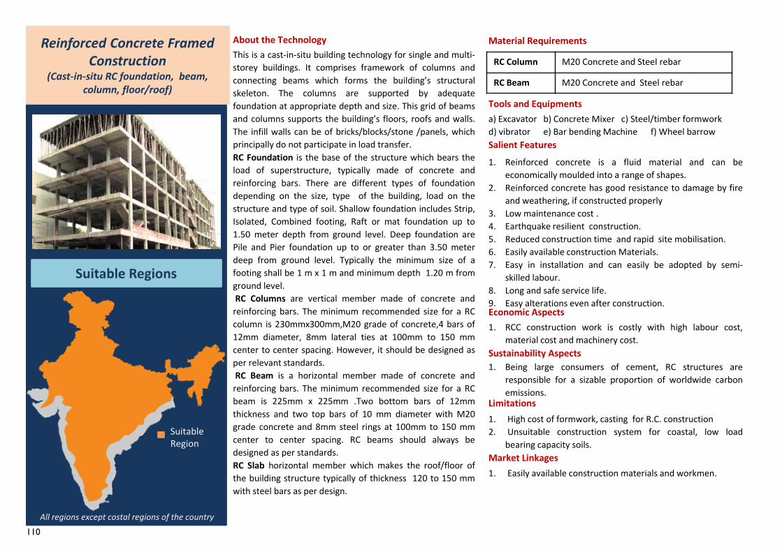
110
RC Column M20 Concrete and Steel rebar
RC Beam M20 Concrete and Steel rebar
1. Easily available construction materials and workmen.
Reinforced Concrete Framed Construction
(Cast-in-situ RC foundation, beam, column, floor/roof)
Suitable Regions
About the TechnologyThis is a cast-in-situ building technology for single and multi-storey buildings. It comprises framework of columns andconnecting beams which forms the building’s structuralskeleton. The columns are supported by adequatefoundation at appropriate depth and size. This grid of beamsand columns supports the building’s floors, roofs and walls.The infill walls can be of bricks/blocks/stone /panels, whichprincipally do not participate in load transfer.RC Foundation is the base of the structure which bears theload of superstructure, typically made of concrete andreinforcing bars. There are different types of foundationdepending on the size, type of the building, load on thestructure and type of soil. Shallow foundation includes Strip,Isolated, Combined footing, Raft or mat foundation up to1.50 meter depth from ground level. Deep foundation arePile and Pier foundation up to or greater than 3.50 meterdeep from ground level. Typically the minimum size of afooting shall be 1 m x 1 m and minimum depth 1.20 m fromground level.RC Columns are vertical member made of concrete and
reinforcing bars. The minimum recommended size for a RCcolumn is 230mmx300mm,M20 grade of concrete,4 bars of12mm diameter, 8mm lateral ties at 100mm to 150 mmcenter to center spacing. However, it should be designed asper relevant standards.RC Beam is a horizontal member made of concrete and
reinforcing bars. The minimum recommended size for a RCbeam is 225mm x 225mm .Two bottom bars of 12mmthickness and two top bars of 10 mm diameter with M20grade concrete and 8mm steel rings at 100mm to 150 mmcenter to center spacing. RC beams should always bedesigned as per standards.RC Slab horizontal member which makes the roof/floor ofthe building structure typically of thickness 120 to 150 mmwith steel bars as per design.
Material Requirements
Tools and Equipmentsa) Excavator b) Concrete Mixer c) Steel/timber formwork d) vibrator e) Bar bending Machine f) Wheel barrowSalient Features1. Reinforced concrete is a fluid material and can be
economically moulded into a range of shapes.2. Reinforced concrete has good resistance to damage by fire
and weathering, if constructed properly3. Low maintenance cost .4. Earthquake resilient construction.5. Reduced construction time and rapid site mobilisation.6. Easily available construction Materials.7. Easy in installation and can easily be adopted by semi-
skilled labour.8. Long and safe service life.9. Easy alterations even after construction.Economic Aspects1. RCC construction work is costly with high labour cost,
material cost and machinery cost.Sustainability Aspects1. Being large consumers of cement, RC structures are
responsible for a sizable proportion of worldwide carbonemissions.
Limitations1. High cost of formwork, casting for R.C. construction2. Unsuitable construction system for coastal, low load
bearing capacity soils.Market Linkages
All regions except costal regions of the country
Suitable Region
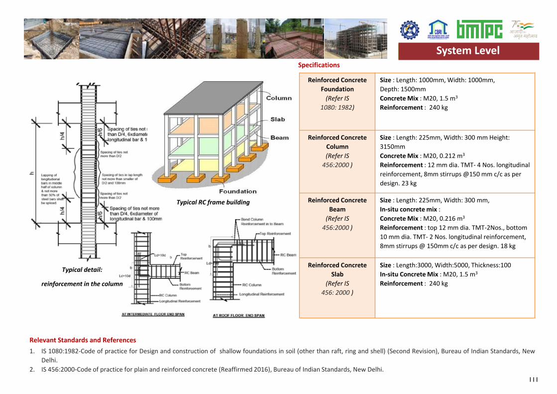
111
Reinforced ConcreteFoundation
(Refer IS 1080: 1982)
Size : Length: 1000mm, Width: 1000mm,Depth: 1500mmConcrete Mix : M20, 1.5 m3
Reinforcement : 240 kg
Reinforced ConcreteColumn(Refer IS
456:2000 )
Size : Length: 225mm, Width: 300 mm Height:3150mmConcrete Mix : M20, 0.212 m3
Reinforcement : 12 mm dia. TMT- 4 Nos. longitudinal reinforcement, 8mm stirrups @150 mm c/c as per design. 23 kg
Reinforced ConcreteBeam
(Refer IS 456:2000 )
Size : Length: 225mm, Width: 300 mm,In-situ concrete mix :Concrete Mix : M20, 0.216 m3
Reinforcement : top 12 mm dia. TMT-2Nos., bottom 10 mm dia. TMT- 2 Nos. longitudinal reinforcement, 8mm stirrups @ 150mm c/c as per design. 18 kg
Reinforced ConcreteSlab
(Refer IS 456: 2000 )
Size : Length:3000, Width:5000, Thickness:100 In-situ Concrete Mix : M20, 1.5 m3
Reinforcement : 240 kg
Specifications
1. IS 1080:1982-Code of practice for Design and construction of shallow foundations in soil (other than raft, ring and shell) (Second Revision), Bureau of Indian Standards, NewDelhi.
2. IS 456:2000-Code of practice for plain and reinforced concrete (Reaffirmed 2016), Bureau of Indian Standards, New Delhi.
Typical RC frame building
System Level
Relevant Standards and References
Typical detail:
reinforcement in the column
System Level
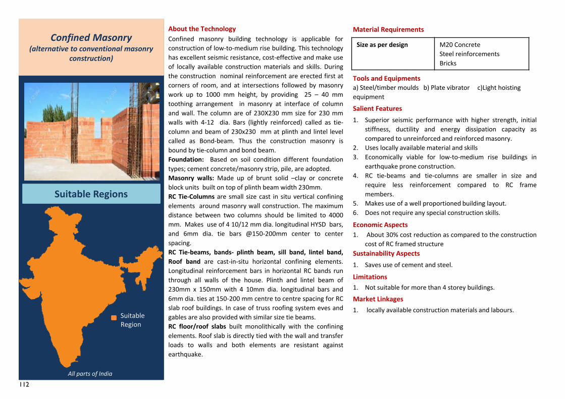
112
1. locally available construction materials and labours.
Confined Masonry(alternative to conventional masonry
construction)
Suitable Regions
About the TechnologyConfined masonry building technology is applicable forconstruction of low-to-medium rise building. This technologyhas excellent seismic resistance, cost-effective and make useof locally available construction materials and skills. Duringthe construction nominal reinforcement are erected first atcorners of room, and at intersections followed by masonrywork up to 1000 mm height, by providing 25 – 40 mmtoothing arrangement in masonry at interface of columnand wall. The column are of 230X230 mm size for 230 mmwalls with 4-12 dia. Bars (lightly reinforced) called as tie-column and beam of 230x230 mm at plinth and lintel levelcalled as Bond-beam. Thus the construction masonry isbound by tie-column and bond beam.Foundation: Based on soil condition different foundationtypes; cement concrete/masonry strip, pile, are adopted.Masonry walls: Made up of brunt solid –clay or concreteblock units built on top of plinth beam width 230mm.RC Tie-Columns are small size cast in situ vertical confiningelements around masonry wall construction. The maximumdistance between two columns should be limited to 4000mm. Makes use of 4 10/12 mm dia. longitudinal HYSD bars,and 6mm dia. tie bars @150-200mm center to centerspacing.RC Tie-beams, bands- plinth beam, sill band, lintel band,Roof band are cast-in-situ horizontal confining elements.Longitudinal reinforcement bars in horizontal RC bands runthrough all walls of the house. Plinth and lintel beam of230mm x 150mm with 4 10mm dia. longitudinal bars and6mm dia. ties at 150-200 mm centre to centre spacing for RCslab roof buildings. In case of truss roofing system eves andgables are also provided with similar size tie beams.RC floor/roof slabs built monolithically with the confiningelements. Roof slab is directly tied with the wall and transferloads to walls and both elements are resistant againstearthquake.
Material Requirements
Tools and Equipmentsa) Steel/timber moulds b) Plate vibrator c)Light hoisting equipmentSalient Features1. Superior seismic performance with higher strength, initial
stiffness, ductility and energy dissipation capacity ascompared to unreinforced and reinforced masonry.
2. Uses locally available material and skills3. Economically viable for low-to-medium rise buildings in
earthquake prone construction.4. RC tie-beams and tie-columns are smaller in size and
require less reinforcement compared to RC framemembers.
5. Makes use of a well proportioned building layout.6. Does not require any special construction skills.
Economic Aspects1. About 30% cost reduction as compared to the construction
cost of RC framed structureSustainability Aspects1. Saves use of cement and steel.
Limitations1. Not suitable for more than 4 storey buildings.Market Linkages
Size as per design M20 ConcreteSteel reinforcementsBricks
All parts of India
Suitable Region
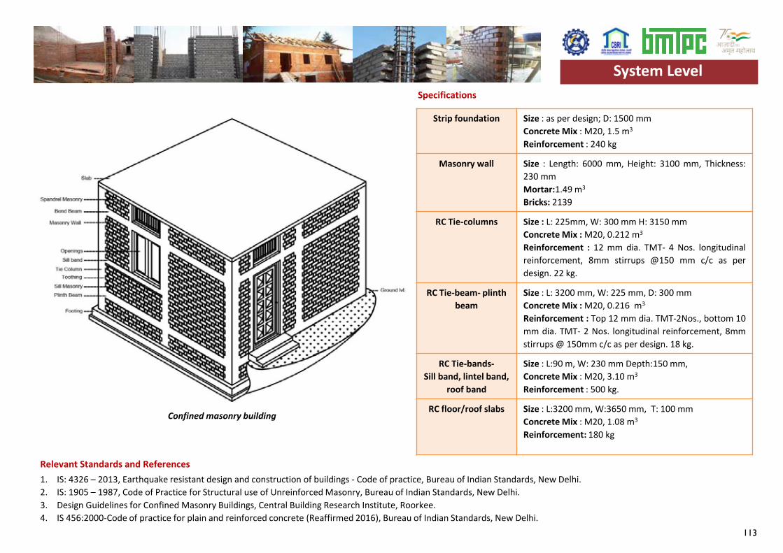
113
Strip foundation Size : as per design; D: 1500 mmConcrete Mix : M20, 1.5 m3
Reinforcement : 240 kg
Masonry wall Size : Length: 6000 mm, Height: 3100 mm, Thickness:230 mmMortar:1.49 m3
Bricks: 2139
RC Tie-columns Size : L: 225mm, W: 300 mm H: 3150 mmConcrete Mix : M20, 0.212 m3
Reinforcement : 12 mm dia. TMT- 4 Nos. longitudinalreinforcement, 8mm stirrups @150 mm c/c as perdesign. 22 kg.
RC Tie-beam- plinth beam
Size : L: 3200 mm, W: 225 mm, D: 300 mmConcrete Mix : M20, 0.216 m3
Reinforcement : Top 12 mm dia. TMT-2Nos., bottom 10mm dia. TMT- 2 Nos. longitudinal reinforcement, 8mmstirrups @ 150mm c/c as per design. 18 kg.
RC Tie-bands-Sill band, lintel band,
roof band
Size : L:90 m, W: 230 mm Depth:150 mm,Concrete Mix : M20, 3.10 m3
Reinforcement : 500 kg.
RC floor/roof slabs Size : L:3200 mm, W:3650 mm, T: 100 mmConcrete Mix : M20, 1.08 m3
Reinforcement: 180 kg
Specifications
1. IS: 4326 – 2013, Earthquake resistant design and construction of buildings - Code of practice, Bureau of Indian Standards, New Delhi.2. IS: 1905 – 1987, Code of Practice for Structural use of Unreinforced Masonry, Bureau of Indian Standards, New Delhi.3. Design Guidelines for Confined Masonry Buildings, Central Building Research Institute, Roorkee.4. IS 456:2000-Code of practice for plain and reinforced concrete (Reaffirmed 2016), Bureau of Indian Standards, New Delhi.
Relevant Standards and References
System Level
Confined masonry building
System Level
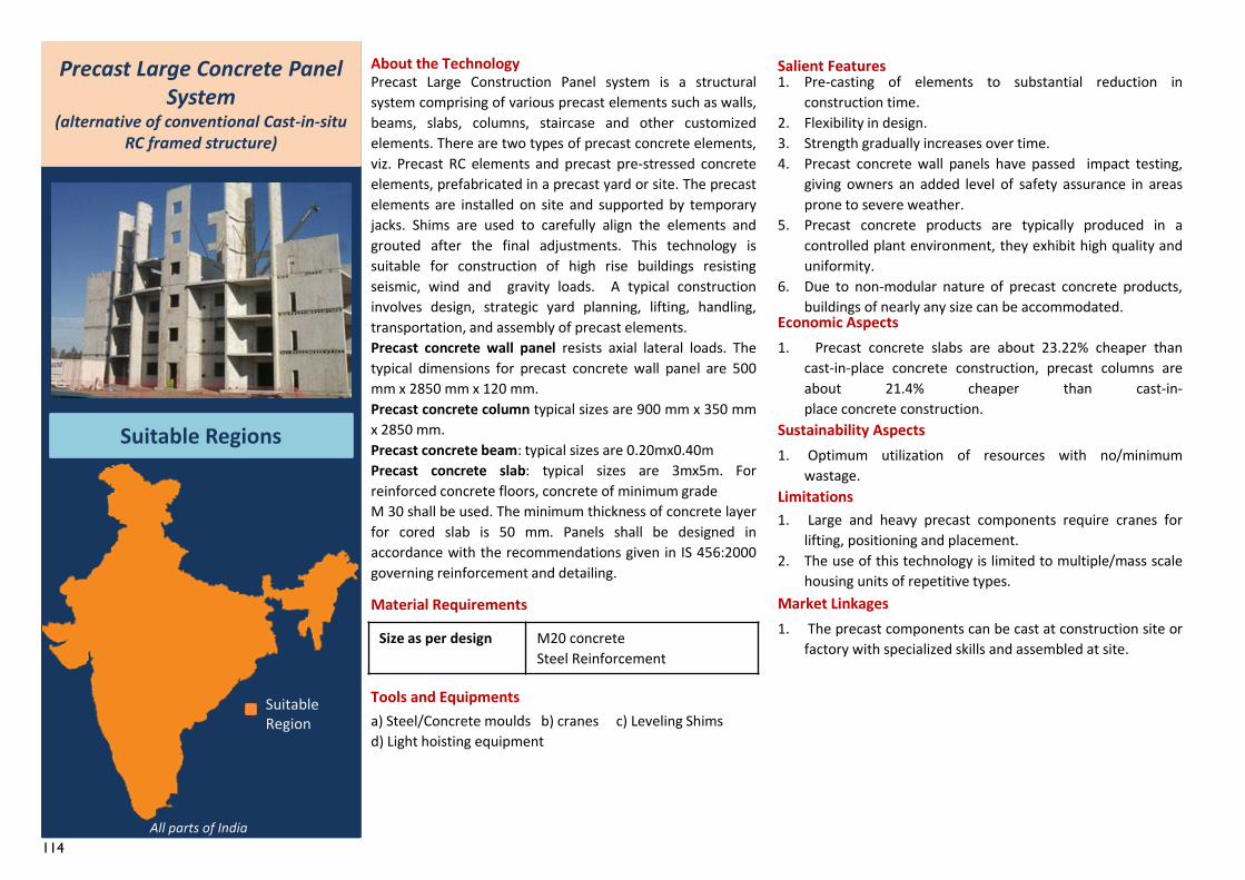
114
1. The precast components can be cast at construction site orfactory with specialized skills and assembled at site.
Precast Large Concrete Panel System
(alternative of conventional Cast-in-situ RC framed structure)
Suitable Regions
About the Technology
Material Requirements
Tools and Equipmentsa) Steel/Concrete moulds b) cranes c) Leveling Shims d) Light hoisting equipment
Salient Features1. Pre-casting of elements to substantial reduction in
construction time.2. Flexibility in design.3. Strength gradually increases over time.4. Precast concrete wall panels have passed impact testing,
giving owners an added level of safety assurance in areasprone to severe weather.
5. Precast concrete products are typically produced in acontrolled plant environment, they exhibit high quality anduniformity.
6. Due to non-modular nature of precast concrete products,buildings of nearly any size can be accommodated.
Economic Aspects1. Precast concrete slabs are about 23.22% cheaper than
cast-in-place concrete construction, precast columns areabout 21.4% cheaper than cast-in-place concrete construction.
Sustainability Aspects1. Optimum utilization of resources with no/minimum
wastage.Limitations1. Large and heavy precast components require cranes for
lifting, positioning and placement.2. The use of this technology is limited to multiple/mass scale
housing units of repetitive types.Market Linkages
Precast Large Construction Panel system is a structuralsystem comprising of various precast elements such as walls,beams, slabs, columns, staircase and other customizedelements. There are two types of precast concrete elements,viz. Precast RC elements and precast pre-stressed concreteelements, prefabricated in a precast yard or site. The precastelements are installed on site and supported by temporaryjacks. Shims are used to carefully align the elements andgrouted after the final adjustments. This technology issuitable for construction of high rise buildings resistingseismic, wind and gravity loads. A typical constructioninvolves design, strategic yard planning, lifting, handling,transportation, and assembly of precast elements.Precast concrete wall panel resists axial lateral loads. Thetypical dimensions for precast concrete wall panel are 500mm x 2850 mm x 120 mm.Precast concrete column typical sizes are 900 mm x 350 mmx 2850 mm.Precast concrete beam: typical sizes are 0.20mx0.40mPrecast concrete slab: typical sizes are 3mx5m. Forreinforced concrete floors, concrete of minimum gradeM 30 shall be used. The minimum thickness of concrete layerfor cored slab is 50 mm. Panels shall be designed inaccordance with the recommendations given in IS 456:2000governing reinforcement and detailing.
Size as per design M20 concreteSteel Reinforcement
All parts of India
Suitable Region
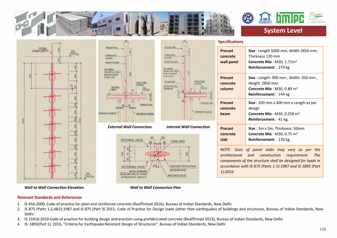
115
Precast concrete wall panel
Size : Length 5000 mm, Width 2850 mm, Thickness 120 mmConcrete Mix : M30, 1.71m3
Reinforcement : 274 kg
Precast concrete column
Size : Length: 900 mm , Width: 350 mm , Height: 2850 mmConcrete Mix : M30, 0.89 m3
Reinforcement : 144 kg
Precast concrete beam
Size : 200 mm x 400 mm x Length as per designConcrete Mix : M30, 0.256 m3
Reinforcement : 41 kg.
Precast concrete slab
Size : 3m x 5m, Thickness: 50mmConcrete Mix : M30, 0.75 m3
Reinforcement : 120 kg.
NOTE- Sizes of panel slabs may vary as per thearchitectural and construction requirement. Thecomponents of the structure shall be designed for loads inaccordance with IS 875 (Parts 1-5):1987 and IS 1893 (Part1):2016.
Specifications
1. IS 456:2000, Code of practice for plain and reinforced concrete (Reaffirmed 2016), Bureau of Indian Standards, New Delhi.2. IS 875 (Parts 1,2,4&5):1987 and IS 875 (Part 3) 2015, Code of Practice for Design loads (other than earthquake) of buildings and structures, Bureau of Indian Standards, New
Delhi.3. IS 15916:2010 Code of practice for building design and erection using prefabricated concrete (Reaffirmed 2013), Bureau of Indian Standards, New Delhi.4. IS: 1893(Part 1): 2016, "Criteria for Earthquake Resistant Design of Structures“, Bureau of Indian Standards, New Delhi
System Level
Relevant Standards and References
Wall to Wall Connection Elevation
External Wall Connection Internal Wall Connection
Wall to Wall Connection Plan
System Level
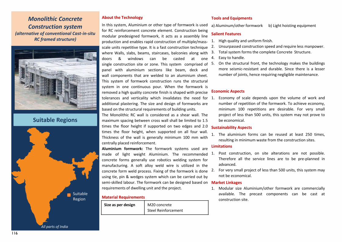
116
1. Modular size Aluminium/other formwork are commerciallyavailable. The precast components can be cast atconstruction site.
Monolithic Concrete Construction system
(alternative of conventional Cast-in-situ RC framed structure)
Suitable Regions
About the TechnologyIn this system, Aluminium or other type of formwork is usedfor RC reinforcement concrete element. Construction beingmodular predesigned formwork, it acts as a assembly lineproduction and enables rapid construction of multiple/mass-scale units repetitive type. It is a fast construction techniquewhere Walls, slabs, beams, staircases, balconies along withdoors & windows can be casted at onesingle construction site or zone. This system comprised ofpanel with aluminium sections like beam, deck andwall components that are welded to an aluminium sheet.This system of formwork construction runs the structuralsystem in one continuous pour. When the formwork isremoved a high quality concrete finish is shaped with precisetolerances and verticality which invalidates the need foradditional plastering. The size and design of formworks arebased on the structural requirements of building units.The Monolithic RC wall is considered as a shear wall. Themaximum spacing between cross wall shall be limited to 1.5times the floor height if supported on two edges and 2.0times the floor height, when supported on all four wall.Thickness of the wall is generally minimum 100 mm withcentrally placed reinforcement.Aluminium formwork: The formwork systems used aremade of light weight Aluminium. The recommendedconcrete forms generally use robotics welding system formanufacturing. A soft alloy weld wire is utilized in theconcrete form weld process. Fixing of the formwork is doneusing tie, pin & wedges system which can be carried out bysemi-skilled labour. The formwork can be designed based onrequirements of dwelling unit and the project.
Material Requirements
Tools and Equipmentsa) Aluminum/other formwork b) Light hoisting equipment
Salient Features1. High quality and uniform finish.2. Unsurpassed construction speed and require less manpower.3. Total system forms the complete Concrete Structure.4. Easy to handle.5. On the structural front, the technology makes the buildings
more seismic-resistant and durable. Since there is a lessernumber of joints, hence requiring negligible maintenance.
Economic Aspects1. Economy of scale depends upon the volume of work and
number of repetition of the formwork. To achieve economy,minimum 100 repetitions are desirable. For very smallproject of less than 500 units, this system may not prove tobe economical.
Sustainability Aspects1. The aluminium forms can be reused at least 250 times,
resulting in minimum waste from the construction sites.Limitations1. Post construction, on site alterations are not possible.
Therefore all the service lines are to be pre-planned inadvanced.
2. For very small project of less than 500 units, this system maynot be economical.
Market Linkages
Size as per design M20 concreteSteel Reinforcement
All parts of India
Suitable Region
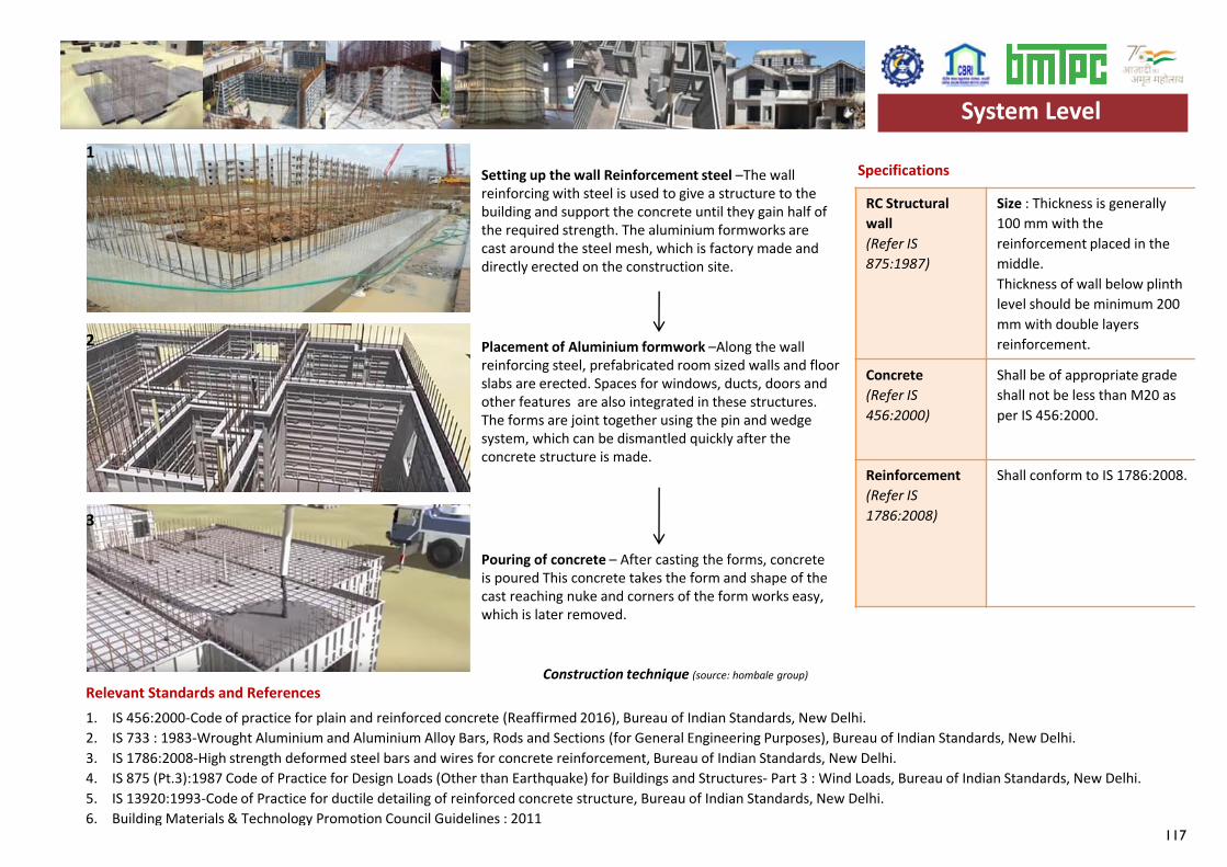
117
RC Structural wall(Refer IS 875:1987)
Size : Thickness is generally 100 mm with the reinforcement placed in the middle. Thickness of wall below plinth level should be minimum 200 mm with double layers reinforcement.
Concrete(Refer IS 456:2000)
Shall be of appropriate grade shall not be less than M20 as per IS 456:2000.
Reinforcement(Refer IS 1786:2008)
Shall conform to IS 1786:2008.
Specifications
1. IS 456:2000-Code of practice for plain and reinforced concrete (Reaffirmed 2016), Bureau of Indian Standards, New Delhi.2. IS 733 : 1983-Wrought Aluminium and Aluminium Alloy Bars, Rods and Sections (for General Engineering Purposes), Bureau of Indian Standards, New Delhi.3. IS 1786:2008-High strength deformed steel bars and wires for concrete reinforcement, Bureau of Indian Standards, New Delhi.4. IS 875 (Pt.3):1987 Code of Practice for Design Loads (Other than Earthquake) for Buildings and Structures- Part 3 : Wind Loads, Bureau of Indian Standards, New Delhi.5. IS 13920:1993-Code of Practice for ductile detailing of reinforced concrete structure, Bureau of Indian Standards, New Delhi.6. Building Materials & Technology Promotion Council Guidelines : 2011
System Level
Relevant Standards and References
1
2
3
Construction technique (source: hombale group)
Setting up the wall Reinforcement steel –The wallreinforcing with steel is used to give a structure to thebuilding and support the concrete until they gain half ofthe required strength. The aluminium formworks arecast around the steel mesh, which is factory made anddirectly erected on the construction site.
Placement of Aluminium formwork –Along the wallreinforcing steel, prefabricated room sized walls and floorslabs are erected. Spaces for windows, ducts, doors andother features are also integrated in these structures.The forms are joint together using the pin and wedgesystem, which can be dismantled quickly after theconcrete structure is made.
Pouring of concrete – After casting the forms, concreteis poured This concrete takes the form and shape of thecast reaching nuke and corners of the form works easy,which is later removed.
System Level
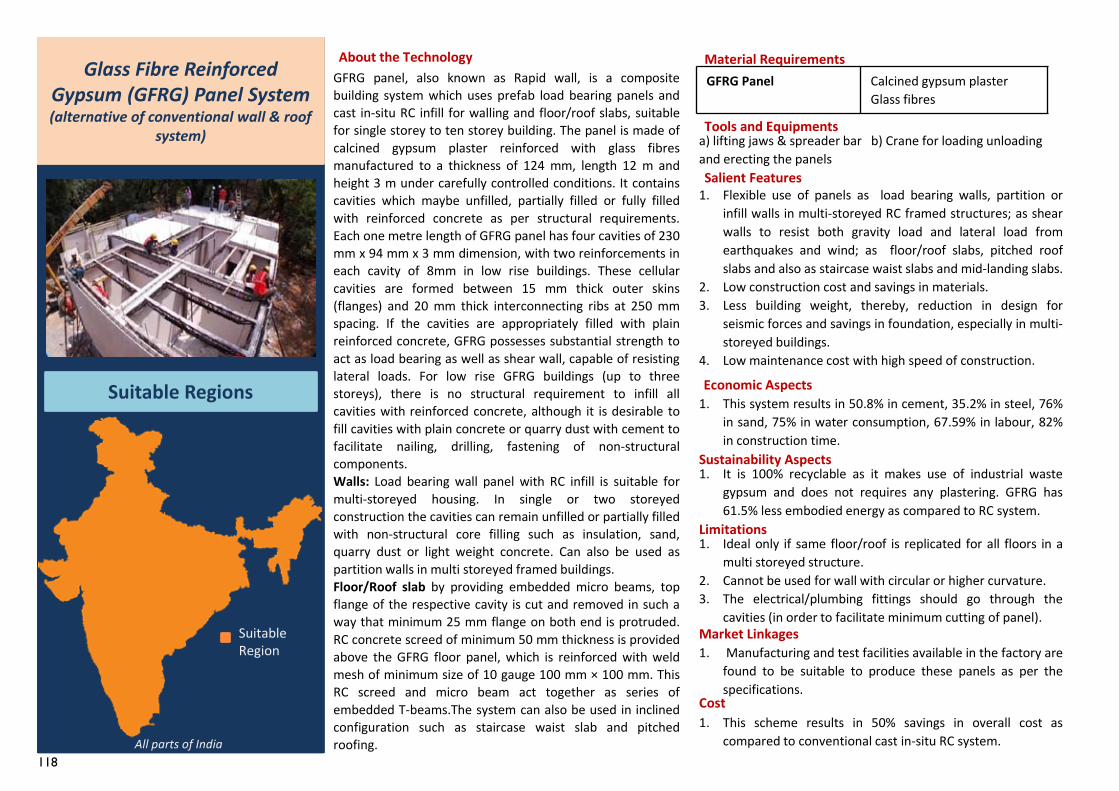
118
GFRG Panel Calcined gypsum plasterGlass fibres
Tools and Equipmentsa) lifting jaws & spreader bar b) Crane for loading unloading and erecting the panels
GFRG panel, also known as Rapid wall, is a compositebuilding system which uses prefab load bearing panels andcast in-situ RC infill for walling and floor/roof slabs, suitablefor single storey to ten storey building. The panel is made ofcalcined gypsum plaster reinforced with glass fibresmanufactured to a thickness of 124 mm, length 12 m andheight 3 m under carefully controlled conditions. It containscavities which maybe unfilled, partially filled or fully filledwith reinforced concrete as per structural requirements.Each one metre length of GFRG panel has four cavities of 230mm x 94 mm x 3 mm dimension, with two reinforcements ineach cavity of 8mm in low rise buildings. These cellularcavities are formed between 15 mm thick outer skins(flanges) and 20 mm thick interconnecting ribs at 250 mmspacing. If the cavities are appropriately filled with plainreinforced concrete, GFRG possesses substantial strength toact as load bearing as well as shear wall, capable of resistinglateral loads. For low rise GFRG buildings (up to threestoreys), there is no structural requirement to infill allcavities with reinforced concrete, although it is desirable tofill cavities with plain concrete or quarry dust with cement tofacilitate nailing, drilling, fastening of non-structuralcomponents.Walls: Load bearing wall panel with RC infill is suitable formulti-storeyed housing. In single or two storeyedconstruction the cavities can remain unfilled or partially filledwith non-structural core filling such as insulation, sand,quarry dust or light weight concrete. Can also be used aspartition walls in multi storeyed framed buildings.Floor/Roof slab by providing embedded micro beams, topflange of the respective cavity is cut and removed in such away that minimum 25 mm flange on both end is protruded.RC concrete screed of minimum 50 mm thickness is providedabove the GFRG floor panel, which is reinforced with weldmesh of minimum size of 10 gauge 100 mm × 100 mm. ThisRC screed and micro beam act together as series ofembedded T-beams.The system can also be used in inclinedconfiguration such as staircase waist slab and pitchedroofing.
1. Manufacturing and test facilities available in the factory arefound to be suitable to produce these panels as per thespecifications.
Glass Fibre Reinforced Gypsum (GFRG) Panel System(alternative of conventional wall & roof
system)
Suitable Regions
About the Technology Material Requirements
Salient Features1. Flexible use of panels as load bearing walls, partition or
infill walls in multi-storeyed RC framed structures; as shearwalls to resist both gravity load and lateral load fromearthquakes and wind; as floor/roof slabs, pitched roofslabs and also as staircase waist slabs and mid-landing slabs.
2. Low construction cost and savings in materials.3. Less building weight, thereby, reduction in design for
seismic forces and savings in foundation, especially in multi-storeyed buildings.
4. Low maintenance cost with high speed of construction.
Economic Aspects1. This system results in 50.8% in cement, 35.2% in steel, 76%
in sand, 75% in water consumption, 67.59% in labour, 82%in construction time.
Sustainability Aspects1. It is 100% recyclable as it makes use of industrial waste
gypsum and does not requires any plastering. GFRG has61.5% less embodied energy as compared to RC system.
Limitations1. Ideal only if same floor/roof is replicated for all floors in a
multi storeyed structure.2. Cannot be used for wall with circular or higher curvature.3. The electrical/plumbing fittings should go through the
cavities (in order to facilitate minimum cutting of panel).Market Linkages
Cost1. This scheme results in 50% savings in overall cost as
compared to conventional cast in-situ RC system.All parts of India
Suitable Region
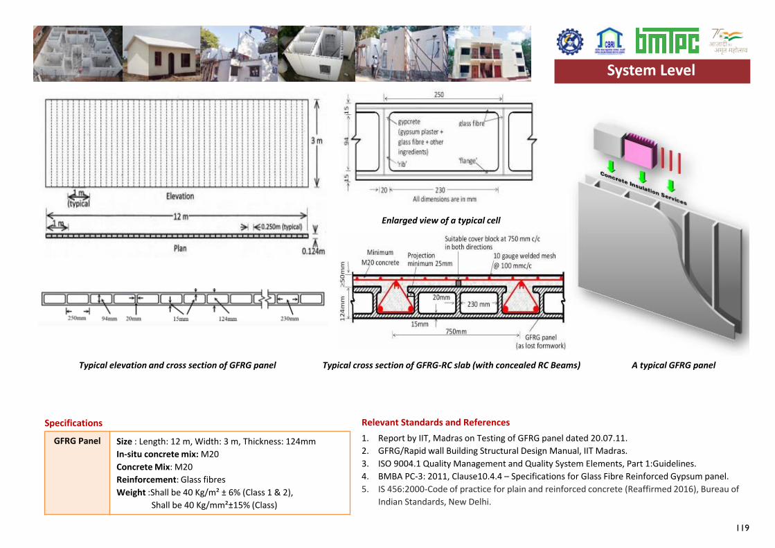
119
GFRG Panel Size : Length: 12 m, Width: 3 m, Thickness: 124mmIn-situ concrete mix: M20Concrete Mix: M20Reinforcement: Glass fibres Weight :Shall be 40 Kg/m² ± 6% (Class 1 & 2),
Shall be 40 Kg/mm²±15% (Class)
Specifications1. Report by IIT, Madras on Testing of GFRG panel dated 20.07.11.2. GFRG/Rapid wall Building Structural Design Manual, IIT Madras.3. ISO 9004.1 Quality Management and Quality System Elements, Part 1:Guidelines.4. BMBA PC-3: 2011, Clause10.4.4 – Specifications for Glass Fibre Reinforced Gypsum panel.5. IS 456:2000-Code of practice for plain and reinforced concrete (Reaffirmed 2016), Bureau of
Indian Standards, New Delhi.
Relevant Standards and References
System Level
Typical elevation and cross section of GFRG panel
Enlarged view of a typical cell
Typical cross section of GFRG-RC slab (with concealed RC Beams) A typical GFRG panel
System Level
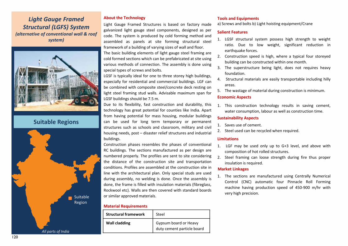
120
1. The sections are manufactured using Centrally NumericalControl (CNC) automatic four Pinnacle Roll Formingmachine having production speed of 450-900 m/hr withvery high precision.
Light Gauge Framed Structures is based on factory madegalvanized light gauge steel components, designed as percode. The system is produced by cold forming method andassembled as panels at site forming structural steelframework of a building of varying sizes of wall and floor.The basic building elements of light gauge steel framing arecold formed sections which can be prefabricated at site usingvarious methods of connection. The assembly is done usingspecial types of screws and bolts.LGSF is typically ideal for one to three storey high buildings,especially for residential and commercial buildings. LGF canbe combined with composite steel/concrete deck resting onlight steel framing stud walls. Advisable maximum span forLGSF buildings should be 7.5 m.Due to its flexibility, fast construction and durability, thistechnology has great potential for counties like India. Apartfrom having potential for mass housing, modular buildingscan be used for long term temporary or permanentstructures such as schools and classroom, military and civilhousing needs, post – disaster relief structures and industrialbuildings.Construction phases resembles the phases of conventionalRC buildings. The sections manufactured as per design arenumbered properly. The profiles are sent to site consideringthe distance of the construction site and transportationconditions. Profiles are assembled at the construction site inline with the architectural plan. Only special studs are usedduring assembly, no welding is done. Once the assembly isdone, the frame is filled with insulation materials (fibreglass,Rockwool etc). Walls are then covered with standard boardsor similar approved materials.
Structural framework Steel
Wall cladding Gypsum board or Heavy duty cement particle board
Light Gauge Framed Structural (LGFS) System
(alternative of conventional wall & roof system)
Suitable Regions
About the Technology
Material Requirements
Tools and Equipments
Salient Features1. LGSF structural system possess high strength to weight
ratio. Due to low weight, significant reduction inearthquake forces.
2. Construction speed is high, where a typical four storeyedbuilding can be constructed within one month.
3. The superstructure being light, does not requires heavyfoundation.
4. Structural materials are easily transportable including hillyareas.
5. The wastage of material during construction is minimum.Economic Aspects
Sustainability Aspects
Limitations1. LGF may be used only up to G+3 level, and above with
composition of hot rolled structures.2. Steel framing can loose strength during fire thus proper
insulation is required.Market Linkages
a) Screws and bolts b) Light hoisting equipment/Crane
1. Saves use of cement.2. Steel used can be recycled when required.
All parts of India
Suitable Region
1. This construction technology results in saving cement,water consumption, labour as well as construction time.
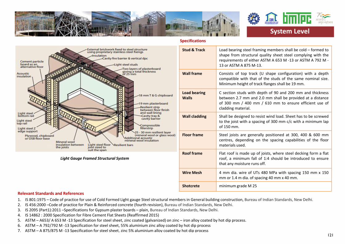
121
1. IS 801:1975 – Code of practice for use of Cold Formed Light gauge Steel structural members in General building construction, Bureau of Indian Standards, New Delhi.2. IS 456:2000 –Code of practice for Plain & Reinforced concrete (fourth revision), Bureau of Indian Standards, New Delhi.3. IS 2095 (Part1):2011 –Specifications for Gypsum plaster boards – plain, Bureau of Indian Standards, New Delhi.4. IS 14862 : 2000 Specification for Fibre Cement Flat Sheets (Reaffirmed 2015)5. ASTM – A653/ A 653 M -13 Specification for steel sheet, zinc coated (galvanized) on zinc – iron alloy coated by hot dip process.6. ASTM – A 792/792 M -13 Specification for steel sheet, 55% aluminium zinc alloy coated by hot dip process7. ASTM – A 875/875 M -13 Specification for steel sheet, zinc 5% aluminium alloy coated by hot dip process
Stud & Track Load bearing steel framing members shall be cold – formed toshape from structural quality sheet steel complying with therequirements of either ASTM A 653 M -13 or ASTM A 792 M -13 or ASTM A 875 M-13.
Wall frame Consists of top track (U shape configuration) with a depthcompatible with that of the studs of the same nominal size.Minimum height of track flanges shall be 19 mm.
Load bearing Walls
C section studs with depth of 90 and 200 mm and thicknessbetween 2.7 mm and 2.0 mm shall be provided at a distanceof 300 mm / 400 mm / 610 mm to ensure efficient use ofcladding material.
Wall cladding Shall be designed to resist wind load. Sheet has to be screwedto the joist with a spacing of 300 mm c/c with a minimum lapof 150 mm.
Floor frame Steel joists are generally positioned at 300, 400 & 600 mmcentres, depending on the spacing capabilities of the floormaterials used.
Roof frame Flat roof is made up of joists, where steel decking form a flatroof, a minimum fall of 1:4 should be introduced to ensurethat any moisture runs off.
Wire Mesh 4 mm dia. wire of UTs 480 MPa with spacing 150 mm x 150mm or 1.4 m dia. of spacing 40 mm x 40 mm.
Shotcrete minimum grade M 25
Specifications
System Level
Relevant Standards and References
Light Gauge Framed Structural System
System Level
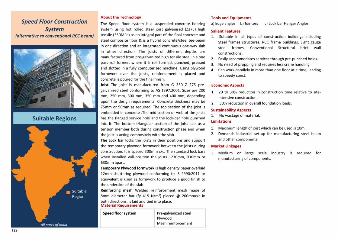
122
Speed floor system Pre-galvanized steel PlywoodMesh reinforcement
1. Medium or large scale industry is required formanufacturing of components.
Speed Floor Construction System
(alternative to conventional RCC beam)
Suitable Regions
About the TechnologyThe Speed floor system is a suspended concrete flooringsystem using hot rolled steel joist galvanised (Z275) hightensile (350MPa) as an integral part of the final concrete andsteel composite floor & is a hybrid concrete/steel tee-beamin one direction and an integrated continuous one-way slabin other direction. The joists of different depths aremanufactured from pre-galvanized high tensile steel in a onepass roll former, where it is roll formed, punched, pressedand slotted in a fully computerized machine. Using plywoodformwork over the joists, reinforcement is placed andconcrete is poured for the final finish.Joist The joist is manufactured from G 350 Z 275 pre-galvanized steel conforming to AS 1397:2001. Sizes are 200mm, 250 mm, 300 mm, 350 mm and 400 mm, dependingupon the design requirements. Concrete thickness may be75mm or 90mm as required. The top section of the joist isembedded in concrete .The mid section or web of the joistshas the flanged service hole and the lock-bar hole punchedinto it. The bottom triangular section of the joist acts as atension member both during construction phase and whenthe joist is acting compositely with the slab.The Lock bar locks the joists in their positions and supportthe temporary plywood formwork between the joists duringconstruction. It is spaced 300mm c/c. The standard lock barswhen installed will position the joists 1230mm, 930mm or630mm apart.Temporary Plywood formwork is high density paper overlaid12mm shuttering plywood conforming to IS 4990:2011 orequivalent is used as formwork to produce a good finish tothe underside of the slab.Reinforcing mesh Welded reinforcement mesh made of8mm diameter bar (fy 415 N/m2) placed @ 200mmc/c inboth directions, is laid and tied into place.Material Requirements
Tools and Equipmentsa) Edge angles b) Jointers c) Lock bar Hanger Angles
Salient Features1. Suitable in all types of construction buildings including
Steel frames structures, RCC frame buildings, Light gaugesteel frames, Conventional Structural brick wallconstructions .
2. Easily accommodates services through pre-punched holes.3. No need of propping and requires less crane handling4. Can work parallely in more than one floor at a time, leading
to speedy const.
Economic Aspects1. 20 to 30% reduction in construction time relative to site-
intensive construction.2. 30% reduction in overall foundation loads.Sustainability Aspects1. No wastage of material.Limitations1. Maximum length of joist which can be used is 10m.2. Demands industrial set-up for manufacturing steel beam
and other components.Market Linkages
All parts of India
Suitable Region
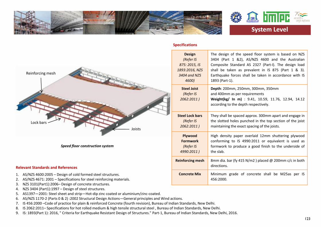
123
Design (Refer IS
875: 2015, IS 1893:2016, NZS 3404 and NZS
4600)
The design of the speed floor system is based on NZS3404 (Part 1 &2), AS/NZS 4600 and the AustralianComposite Standard AS 2327 (Part-I). The design loadshall be taken as prevalent in IS 875 (Part 1 & 3).Earthquake forces shall be taken in accordance with IS1893 (Part-1).
Steel Joist(Refer IS
2062:2011 )
Depth: 200mm, 250mm, 300mm, 350mmand 400mm as per requirementsWeight(kg/ In m) : 9.41, 10.59, 11.76, 12.94, 14.12according to the depth respectively.
Steel Lock bars(Refer IS
2062:2011 )
They shall be spaced approx. 300mm apart and engage inthe slotted holes punched in the top section of the joistmaintaining the exact spacing of the joists.
Plywood Formwork
(Refer IS4990:2011 )
High density paper overlaid 12mm shuttering plywoodconforming to IS 4990:2011 or equivalent is used asformwork to produce a good finish to the underside ofthe slab.
Reinforcing mesh 8mm dia. bar (fy 415 N/m2 ) placed @ 200mm c/c in bothdirections.
Concrete Mix Minimum grade of concrete shall be M25as per IS456:2000.
Specifications
1. AS/NZS 4600:2005 – Design of cold formed steel structures.2. AS/NZS 4671: 2001 – Specifications for steel reinforcing materials.3. NZS 3101(Part1):2006– Design of concrete structures.4. NZS 3404 (Part1):1997 – Design of steel structures.5. AS1397—2001: Steel sheet and strip—Hot-dip zinc coated or aluminium/zinc-coated.6. AS/NZS 1170-2 (Parts 0 & 2) :2002 Structural Design Actions—General principles and Wind actions.7. IS 456:2000 –Code of practice for plain & reinforced Concrete (fourth revision), Bureau of Indian Standards, New Delhi. 8. IS 2062:2011– Specifications for hot rolled medium & high tensile structural steel , Bureau of Indian Standards, New Delhi. 9. IS: 1893(Part 1): 2016, " Criteria for Earthquake Resistant Design of Structures." Part-1, Bureau of Indian Standards, New Delhi, 2016.
System Level
Relevant Standards and References
Speed floor construction system
Joists Lock bars
Reinforcing mesh
System Level
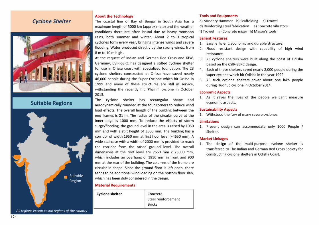
124
Cyclone Shelter
Suitable Regions
About the TechnologyThe coastal line of Bay of Bengal in South Asia has amaximum length of 5000 km (approximate) and the weatherconditions there are often brutal due to heavy monsoonrains, both summer and winter. About 2 to 3 tropicalcyclones form every year, bringing intense winds and severeflooding. Water produced directly by the strong winds, from8 m to 10 m high .At the request of Indian and German Red Cross and KfW,Germany, CSIR-SERC has designed a stilted cyclone shelterfor use in Orissa coast with specialized foundation. The 23cyclone shelters constructed at Orissa have saved nearly46,000 people during the Super Cyclone which hit Orissa in1999 and many of these structures are still in service,withstanding the recently hit ‘Phailin’ cyclone in October2013.The cyclone shelter has rectangular shape andaerodynamically rounded at the four corners to reduce windload effects. The overall length of the building between theend frames is 21 m. The radius of the circular curve at theinner edge is 1000 mm. To reduce the effects of stormsurge/flooding, the ground level in the area is raised by 1050mm and with a stilt height of 3500 mm. The building has acorridor of width 1950 mm at first floor level (+4650 mm). Awide staircase with a width of 2000 mm is provided to reachthe corridor from the raised ground level. The overalldimensions at the roof level are 7650 mm x 23000 mm,which includes an overhang of 1950 mm in front and 900mm at the rear of the building. The columns of the frame arecircular in shape. Since the ground floor is left open, theretends to be additional wind loading on the bottom floor slab,which has been duly considered in the design.
Material Requirements
Tools and Equipmentsa) Masonry Hammer b) Scaffolding c) Troweld) Reinforcing steel fabrication e) Concrete vibratorsf) Trowel g) Concrete mixer h) Mason’s tools
Salient Features1. Easy, efficient, economic and durable structure.2. Flood resistant design with capability of high wind
resistance.3. 23 cyclone shelters were built along the coast of Odisha
based on the CSIR-SERC design.4. Each of these shelters saved nearly 2,000 people during the
super cyclone which hit Odisha in the year 1999.5. 75 such cyclone shelters cover about one lakh people
during Hudhud cyclone in October 2014.
Economic Aspects1. As it saves the lives of the people we can't measure
economic aspects.
Sustainability Aspects1. Withstood the fury of many severe cyclones.
Limitations1. Present design can accommodate only 1000 People /
Shelter.
Market Linkages1. The design of the multi-purpose cyclone shelter is
transferred to The Indian and German Red Cross Society forconstructing cyclone shelters in Odisha Coast.
All regions except costal regions of the country
Suitable Region
Cyclone shelter ConcreteSteel reinforcementBricks
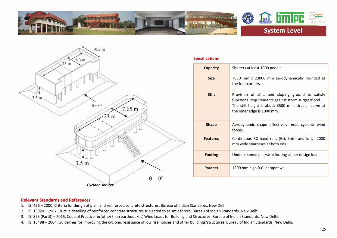
125
Capacity Shelters at least 1000 people.
Size 7650 mm x 23000 mm aerodynamically rounded atthe four corners
Stilt Provision of stilt, and sloping ground to satisfyfunctional requirements against storm surges/flood.The stilt height is about 3500 mm. circular curve atthe inner edge is 1000 mm.
Shape Aerodynamic shape effectively resist cyclonic windforces.
Features Continuous RC hand rails (GI), lintel and loft. 2000mm wide staircases at both eds.
Footing Under-reamed pile/strip footing as per design load.
Parapet 1200 mm high R.C. parapet wall.
Specifications
1. IS: 456 – 2000, Criteria for design of plain and reinforced concrete structures, Bureau of Indian Standards, New Delhi.2. IS: 13920 – 1987, Ductile detailing of reinforced concrete structures subjected to seismic forces, Bureau of Indian Standards, New Delhi.3. IS: 875 (Part3) – 2015, Code of Practice for(other than earthquakes) Wind Loads for Building and Structures, Bureau of Indian Standards, New Delhi.4. IS: 15498 – 2004, Guidelines for improving the cyclonic resistance of low rise houses and other buildings/structures, Bureau of Indian Standards, New Delhi.
Relevant Standards and References
System Level
Cyclone shelter
System Level

126
127
Services
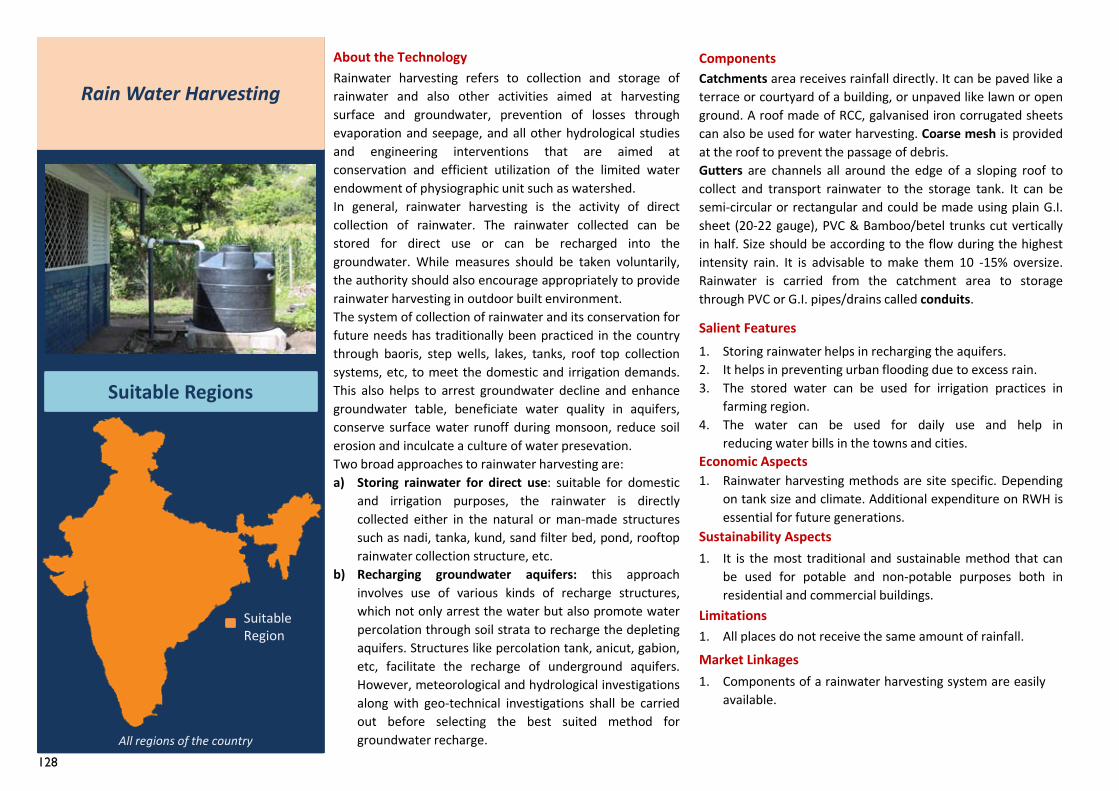
128
Catchments area receives rainfall directly. It can be paved like aterrace or courtyard of a building, or unpaved like lawn or openground. A roof made of RCC, galvanised iron corrugated sheetscan also be used for water harvesting. Coarse mesh is providedat the roof to prevent the passage of debris.Gutters are channels all around the edge of a sloping roof tocollect and transport rainwater to the storage tank. It can besemi-circular or rectangular and could be made using plain G.I.sheet (20-22 gauge), PVC & Bamboo/betel trunks cut verticallyin half. Size should be according to the flow during the highestintensity rain. It is advisable to make them 10 -15% oversize.Rainwater is carried from the catchment area to storagethrough PVC or G.I. pipes/drains called conduits.
1. Storing rainwater helps in recharging the aquifers.2. It helps in preventing urban flooding due to excess rain.3. The stored water can be used for irrigation practices in
farming region.4. The water can be used for daily use and help in
reducing water bills in the towns and cities.
Rainwater harvesting refers to collection and storage ofrainwater and also other activities aimed at harvestingsurface and groundwater, prevention of losses throughevaporation and seepage, and all other hydrological studiesand engineering interventions that are aimed atconservation and efficient utilization of the limited waterendowment of physiographic unit such as watershed.In general, rainwater harvesting is the activity of directcollection of rainwater. The rainwater collected can bestored for direct use or can be recharged into thegroundwater. While measures should be taken voluntarily,the authority should also encourage appropriately to providerainwater harvesting in outdoor built environment.The system of collection of rainwater and its conservation forfuture needs has traditionally been practiced in the countrythrough baoris, step wells, lakes, tanks, roof top collectionsystems, etc, to meet the domestic and irrigation demands.This also helps to arrest groundwater decline and enhancegroundwater table, beneficiate water quality in aquifers,conserve surface water runoff during monsoon, reduce soilerosion and inculcate a culture of water presevation.Two broad approaches to rainwater harvesting are:a) Storing rainwater for direct use: suitable for domestic
and irrigation purposes, the rainwater is directlycollected either in the natural or man-made structuressuch as nadi, tanka, kund, sand filter bed, pond, rooftoprainwater collection structure, etc.
b) Recharging groundwater aquifers: this approachinvolves use of various kinds of recharge structures,which not only arrest the water but also promote waterpercolation through soil strata to recharge the depletingaquifers. Structures like percolation tank, anicut, gabion,etc, facilitate the recharge of underground aquifers.However, meteorological and hydrological investigationsalong with geo-technical investigations shall be carriedout before selecting the best suited method forgroundwater recharge.
1. Components of a rainwater harvesting system are easilyavailable.
About the Technology
Salient Features
Economic Aspects1. Rainwater harvesting methods are site specific. Depending
on tank size and climate. Additional expenditure on RWH isessential for future generations.
Sustainability Aspects1. It is the most traditional and sustainable method that can
be used for potable and non-potable purposes both inresidential and commercial buildings.
Limitations1. All places do not receive the same amount of rainfall.
Market Linkages
Rain Water Harvesting
Suitable Regions
Suitable Region
Components
All regions of the country
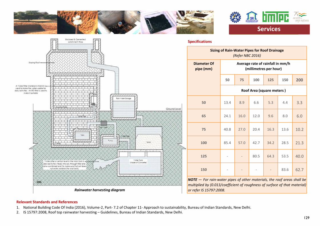
129
Specifications
Relevant Standards and References
Sizing of Rain-Water Pipes for Roof Drainage(Refer NBC 2016)
Diameter Of pipe (mm)
Average rate of rainfall in mm/h(millimetres per hour)
50 75 100 125 150 200
Roof Area (square meters )
50 13.4 8.9 6.6 5.3 4.4 3.3
65 24.1 16.0 12.0 9.6 8.0 6.0
75 40.8 27.0 20.4 16.3 13.6 10.2
100 85.4 57.0 42.7 34.2 28.5 21.3
125 - - 80.5 64.3 53.5 40.0
150 - - - - 83.6 62.7
NOTE — For rain-water pipes of other materials, the roof areas shall bemultiplied by (0.013/coefficient of roughness of surface of that material)or refer IS 15797:2008.
1. National Building Code Of India (2016), Volume-2, Part- 7.2 of Chapter 11- Approach to sustainability, Bureau of Indian Standards, New Delhi.2. IS 15797:2008, Roof top rainwater harvesting – Guidelines, Bureau of Indian Standards, New Delhi.
Services
Rainwater harvesting diagram
Services
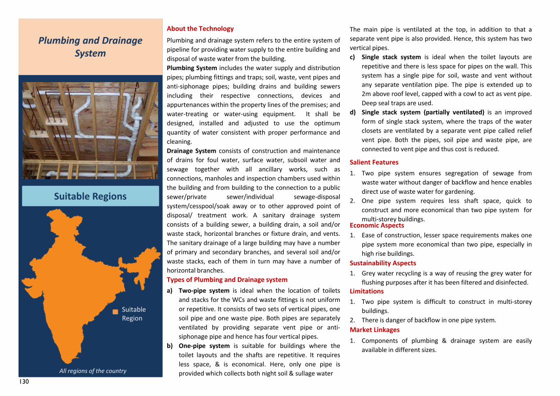
130
1. Ease of construction, lesser space requirements makes onepipe system more economical than two pipe, especially inhigh rise buildings.
The main pipe is ventilated at the top, in addition to that aseparate vent pipe is also provided. Hence, this system has twovertical pipes.c) Single stack system is ideal when the toilet layouts are
repetitive and there is less space for pipes on the wall. Thissystem has a single pipe for soil, waste and vent withoutany separate ventilation pipe. The pipe is extended up to2m above roof level, capped with a cowl to act as vent pipe.Deep seal traps are used.
d) Single stack system (partially ventilated) is an improvedform of single stack system, where the traps of the waterclosets are ventilated by a separate vent pipe called reliefvent pipe. Both the pipes, soil pipe and waste pipe, areconnected to vent pipe and thus cost is reduced.
Plumbing and drainage system refers to the entire system ofpipeline for providing water supply to the entire building anddisposal of waste water from the building.Plumbing System includes the water supply and distributionpipes; plumbing fittings and traps; soil, waste, vent pipes andanti-siphonage pipes; building drains and building sewersincluding their respective connections, devices andappurtenances within the property lines of the premises; andwater-treating or water-using equipment. It shall bedesigned, installed and adjusted to use the optimumquantity of water consistent with proper performance andcleaning.Drainage System consists of construction and maintenanceof drains for foul water, surface water, subsoil water andsewage together with all ancillary works, such asconnections, manholes and inspection chambers used withinthe building and from building to the connection to a publicsewer/private sewer/individual sewage-disposalsystem/cesspool/soak away or to other approved point ofdisposal/ treatment work. A sanitary drainage systemconsists of a building sewer, a building drain, a soil and/orwaste stack, horizontal branches or fixture drain, and vents.The sanitary drainage of a large building may have a numberof primary and secondary branches, and several soil and/orwaste stacks, each of them in turn may have a number ofhorizontal branches.
1. Components of plumbing & drainage system are easilyavailable in different sizes.
About the Technology
Salient Features
Economic Aspects
Sustainability Aspects1. Grey water recycling is a way of reusing the grey water for
flushing purposes after it has been filtered and disinfected.Limitations1. Two pipe system is difficult to construct in multi-storey
buildings.2. There is danger of backflow in one pipe system.Market Linkages
Plumbing and Drainage System
Suitable Regions
Types of Plumbing and Drainage systema) Two-pipe system is ideal when the location of toilets
and stacks for the WCs and waste fittings is not uniformor repetitive. It consists of two sets of vertical pipes, onesoil pipe and one waste pipe. Both pipes are separatelyventilated by providing separate vent pipe or anti-siphonage pipe and hence has four vertical pipes.
b) One-pipe system is suitable for buildings where thetoilet layouts and the shafts are repetitive. It requiresless space, & is economical. Here, only one pipe isprovided which collects both night soil & sullage water
1. Two pipe system ensures segregation of sewage fromwaste water without danger of backflow and hence enablesdirect use of waste water for gardening.
2. One pipe system requires less shaft space, quick toconstruct and more economical than two pipe system formulti-storey buildings.
All regions of the country
Suitable Region
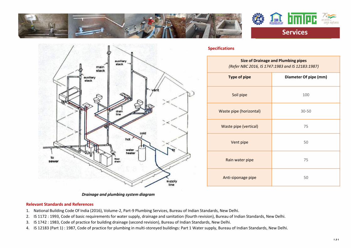
131
Specifications
Relevant Standards and References
Size of Drainage and Plumbing pipes(Refer NBC 2016, IS 1747:1983 and IS 12183:1987)
Type of pipe Diameter Of pipe (mm)
Soil pipe 100
Waste pipe (horizontal) 30-50
Waste pipe (vertical) 75
Vent pipe 50
Rain water pipe 75
Anti-siponage pipe 50
1. National Building Code Of India (2016), Volume-2, Part-9 Plumbing Services, Bureau of Indian Standards, New Delhi.2. IS 1172 : 1993, Code of basic requirements for water supply, drainage and sanitation (fourth revision), Bureau of Indian Standards, New Delhi.3. IS 1742 : 1983, Code of practice for building drainage (second revision), Bureau of Indian Standards, New Delhi.4. IS 12183 (Part 1) : 1987, Code of practice for plumbing in multi-storeyed buildings: Part 1 Water supply, Bureau of Indian Standards, New Delhi.
Services
Drainage and plumbing system diagram
Services

132
133
Materials
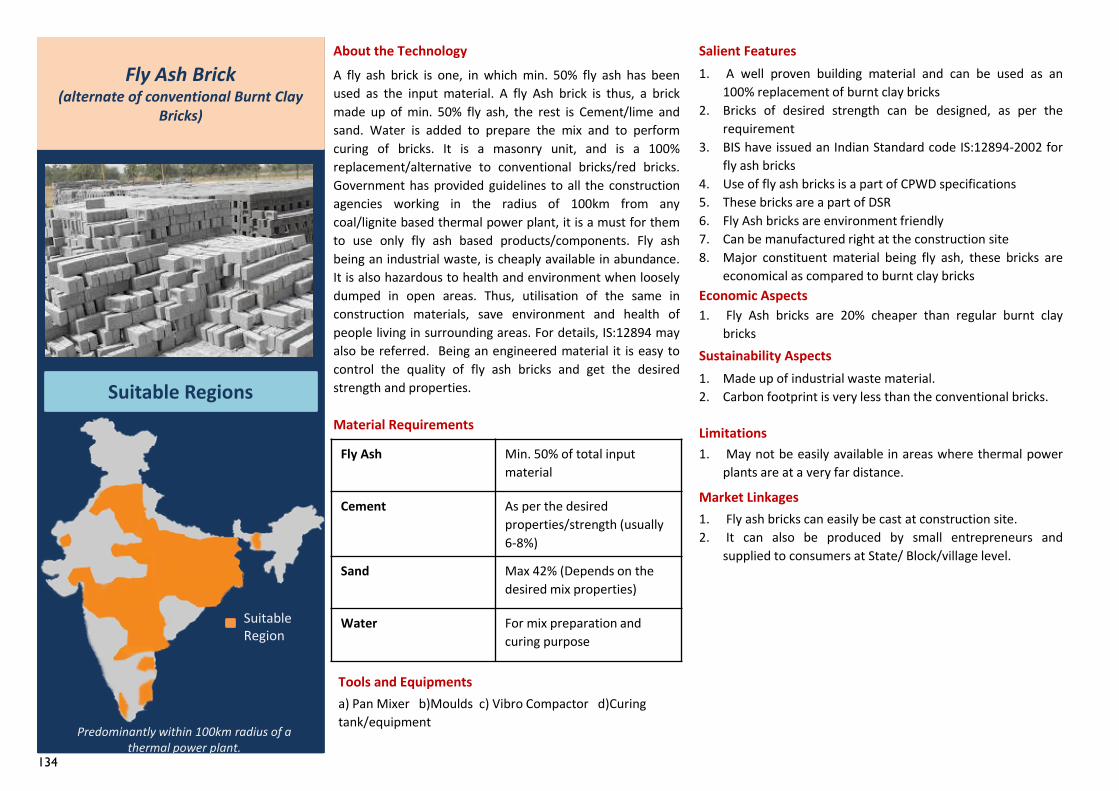
134
Fly Ash Min. 50% of total input material
Cement As per the desired properties/strength (usually 6-8%)
Sand Max 42% (Depends on the desired mix properties)
Water For mix preparation and curing purpose
1. Fly ash bricks can easily be cast at construction site.2. It can also be produced by small entrepreneurs and
supplied to consumers at State/ Block/village level.
Fly Ash Brick(alternate of conventional Burnt Clay
Bricks)
Suitable Regions
About the TechnologyA fly ash brick is one, in which min. 50% fly ash has beenused as the input material. A fly Ash brick is thus, a brickmade up of min. 50% fly ash, the rest is Cement/lime andsand. Water is added to prepare the mix and to performcuring of bricks. It is a masonry unit, and is a 100%replacement/alternative to conventional bricks/red bricks.Government has provided guidelines to all the constructionagencies working in the radius of 100km from anycoal/lignite based thermal power plant, it is a must for themto use only fly ash based products/components. Fly ashbeing an industrial waste, is cheaply available in abundance.It is also hazardous to health and environment when looselydumped in open areas. Thus, utilisation of the same inconstruction materials, save environment and health ofpeople living in surrounding areas. For details, IS:12894 mayalso be referred. Being an engineered material it is easy tocontrol the quality of fly ash bricks and get the desiredstrength and properties.
Material Requirements
Tools and Equipmentsa) Pan Mixer b)Moulds c) Vibro Compactor d)Curing tank/equipment
Salient Features1. A well proven building material and can be used as an
100% replacement of burnt clay bricks2. Bricks of desired strength can be designed, as per the
requirement3. BIS have issued an Indian Standard code IS:12894-2002 for
fly ash bricks4. Use of fly ash bricks is a part of CPWD specifications5. These bricks are a part of DSR6. Fly Ash bricks are environment friendly7. Can be manufactured right at the construction site8. Major constituent material being fly ash, these bricks are
economical as compared to burnt clay bricksEconomic Aspects1. Fly Ash bricks are 20% cheaper than regular burnt clay
bricksSustainability Aspects1. Made up of industrial waste material.2. Carbon footprint is very less than the conventional bricks.
Limitations1. May not be easily available in areas where thermal power
plants are at a very far distance.
Market Linkages
Predominantly within 100km radius of a thermal power plant.
Suitable Region
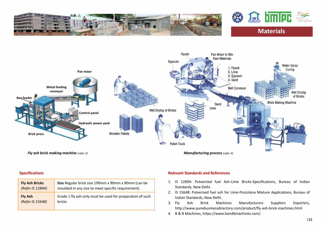
135
Fly Ash Bricks(Refer IS 12894)
Size Regular brick size 190mm x 90mm x 90mm (can be moulded in any size to meet specific requirement)
Fly Ash(Refer IS 15648)
Grade 1 fly ash only must be used for preparation of such bricks
Specifications Relevant Standards and References
1. IS 12894: Pulverized fuel Ash-Lime Bricks-Specifications, Bureau of IndianStandards, New Delhi.
2. IS 15648: Pulverised fuel ash for Lime-Pozzolana Mixture Applications, Bureau ofIndian Standards, New Delhi.
3. Fly Ash Brick Machines Manufacturers Suppliers Exporters,http://www.punebusinessdirectory.com/product/fly-ash-brick-machines.html
4. B & B Machines, https://www.bandbmachines.com/.
Materials
Fly ash brick making machine (refer 3) Manufacturing process (refer 4)
Pan mixer
Metal feeding conveyor
Control panel
Hydraulic power pack
Brick press
Box feeder
Materials
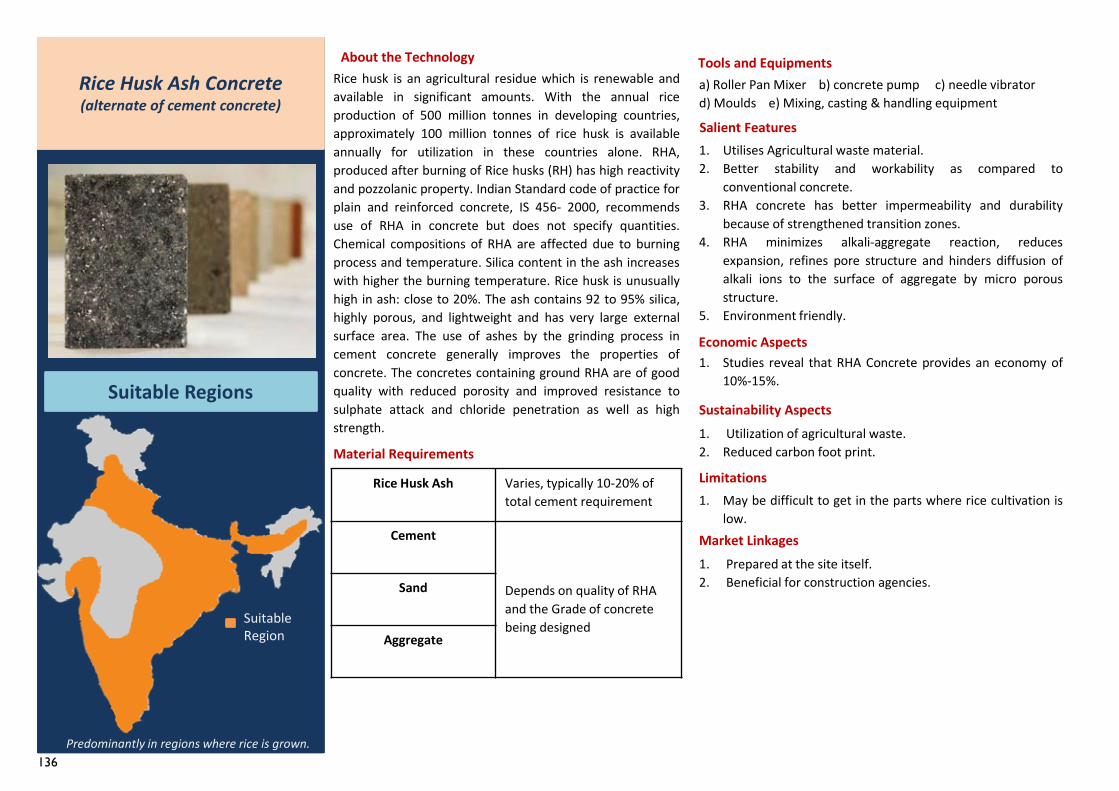
136
Rice Husk Ash Varies, typically 10-20% of total cement requirement
Cement
Depends on quality of RHA and the Grade of concrete being designed
Sand
Aggregate
1. Prepared at the site itself.2. Beneficial for construction agencies.
Rice Husk Ash Concrete(alternate of cement concrete)
Suitable Regions
About the TechnologyRice husk is an agricultural residue which is renewable andavailable in significant amounts. With the annual riceproduction of 500 million tonnes in developing countries,approximately 100 million tonnes of rice husk is availableannually for utilization in these countries alone. RHA,produced after burning of Rice husks (RH) has high reactivityand pozzolanic property. Indian Standard code of practice forplain and reinforced concrete, IS 456- 2000, recommendsuse of RHA in concrete but does not specify quantities.Chemical compositions of RHA are affected due to burningprocess and temperature. Silica content in the ash increaseswith higher the burning temperature. Rice husk is unusuallyhigh in ash: close to 20%. The ash contains 92 to 95% silica,highly porous, and lightweight and has very large externalsurface area. The use of ashes by the grinding process incement concrete generally improves the properties ofconcrete. The concretes containing ground RHA are of goodquality with reduced porosity and improved resistance tosulphate attack and chloride penetration as well as highstrength.
Material Requirements
Tools and Equipmentsa) Roller Pan Mixer b) concrete pump c) needle vibratord) Moulds e) Mixing, casting & handling equipment
Salient Features1. Utilises Agricultural waste material.2. Better stability and workability as compared to
conventional concrete.3. RHA concrete has better impermeability and durability
because of strengthened transition zones.4. RHA minimizes alkali-aggregate reaction, reduces
expansion, refines pore structure and hinders diffusion ofalkali ions to the surface of aggregate by micro porousstructure.
5. Environment friendly.
Economic Aspects1. Studies reveal that RHA Concrete provides an economy of
10%-15%.
Sustainability Aspects1. Utilization of agricultural waste.2. Reduced carbon foot print.
Limitations1. May be difficult to get in the parts where rice cultivation is
low.Market Linkages
Predominantly in regions where rice is grown.
Suitable Region
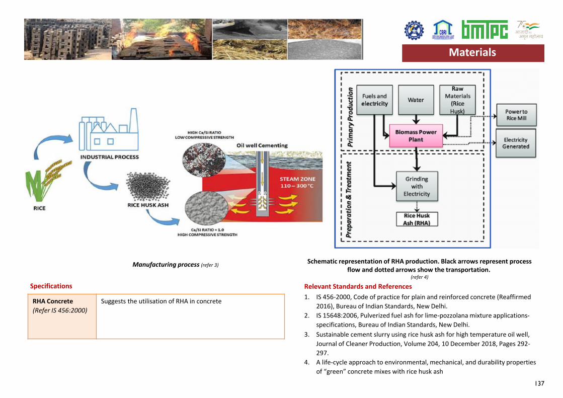
137
RHA Concrete(Refer IS 456:2000)
Suggests the utilisation of RHA in concrete
Specifications Relevant Standards and References1. IS 456-2000, Code of practice for plain and reinforced concrete (Reaffirmed
2016), Bureau of Indian Standards, New Delhi.2. IS 15648:2006, Pulverized fuel ash for lime-pozzolana mixture applications-
specifications, Bureau of Indian Standards, New Delhi.3. Sustainable cement slurry using rice husk ash for high temperature oil well,
Journal of Cleaner Production, Volume 204, 10 December 2018, Pages 292-297.
4. A life-cycle approach to environmental, mechanical, and durability properties of “green” concrete mixes with rice husk ash
Manufacturing process (refer 3)Schematic representation of RHA production. Black arrows represent process
flow and dotted arrows show the transportation.(refer 4)
Materials Materials
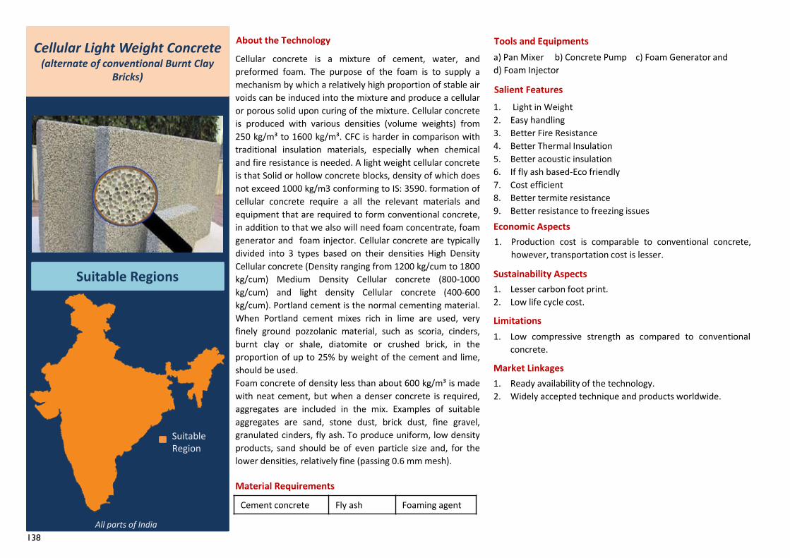
138
1. Ready availability of the technology.2. Widely accepted technique and products worldwide.
Cellular Light Weight Concrete(alternate of conventional Burnt Clay
Bricks)
Suitable Regions
About the Technology
Cellular concrete is a mixture of cement, water, andpreformed foam. The purpose of the foam is to supply amechanism by which a relatively high proportion of stable airvoids can be induced into the mixture and produce a cellularor porous solid upon curing of the mixture. Cellular concreteis produced with various densities (volume weights) from250 kg/m³ to 1600 kg/m³. CFC is harder in comparison withtraditional insulation materials, especially when chemicaland fire resistance is needed. A light weight cellular concreteis that Solid or hollow concrete blocks, density of which doesnot exceed 1000 kg/m3 conforming to IS: 3590. formation ofcellular concrete require a all the relevant materials andequipment that are required to form conventional concrete,in addition to that we also will need foam concentrate, foamgenerator and foam injector. Cellular concrete are typicallydivided into 3 types based on their densities High DensityCellular concrete (Density ranging from 1200 kg/cum to 1800kg/cum) Medium Density Cellular concrete (800-1000kg/cum) and light density Cellular concrete (400-600kg/cum). Portland cement is the normal cementing material.When Portland cement mixes rich in lime are used, veryfinely ground pozzolanic material, such as scoria, cinders,burnt clay or shale, diatomite or crushed brick, in theproportion of up to 25% by weight of the cement and lime,should be used.Foam concrete of density less than about 600 kg/m³ is madewith neat cement, but when a denser concrete is required,aggregates are included in the mix. Examples of suitableaggregates are sand, stone dust, brick dust, fine gravel,granulated cinders, fly ash. To produce uniform, low densityproducts, sand should be of even particle size and, for thelower densities, relatively fine (passing 0.6 mm mesh).
Tools and Equipmentsa) Pan Mixer b) Concrete Pump c) Foam Generator and d) Foam Injector
Salient Features1. Light in Weight2. Easy handling3. Better Fire Resistance4. Better Thermal Insulation5. Better acoustic insulation6. If fly ash based-Eco friendly7. Cost efficient8. Better termite resistance9. Better resistance to freezing issuesEconomic Aspects1. Production cost is comparable to conventional concrete,
however, transportation cost is lesser.
Sustainability Aspects1. Lesser carbon foot print.2. Low life cycle cost.
Limitations1. Low compressive strength as compared to conventional
concrete.
Market Linkages
All parts of India
Suitable Region
Cement concrete Fly ash Foaming agent
Material Requirements
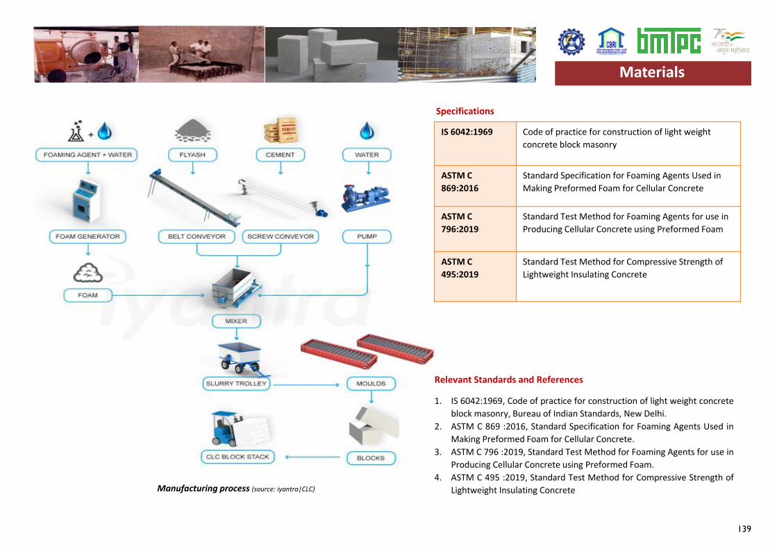
139
IS 6042:1969 Code of practice for construction of light weight concrete block masonry
ASTM C 869:2016
Standard Specification for Foaming Agents Used in Making Preformed Foam for Cellular Concrete
ASTM C 796:2019
Standard Test Method for Foaming Agents for use in Producing Cellular Concrete using Preformed Foam
ASTM C 495:2019
Standard Test Method for Compressive Strength of Lightweight Insulating Concrete
Specifications
Relevant Standards and References
1. IS 6042:1969, Code of practice for construction of light weight concreteblock masonry, Bureau of Indian Standards, New Delhi.
2. ASTM C 869 :2016, Standard Specification for Foaming Agents Used inMaking Preformed Foam for Cellular Concrete.
3. ASTM C 796 :2019, Standard Test Method for Foaming Agents for use inProducing Cellular Concrete using Preformed Foam.
4. ASTM C 495 :2019, Standard Test Method for Compressive Strength ofLightweight Insulating ConcreteManufacturing process (source: iyantra|CLC)
Materials Materials
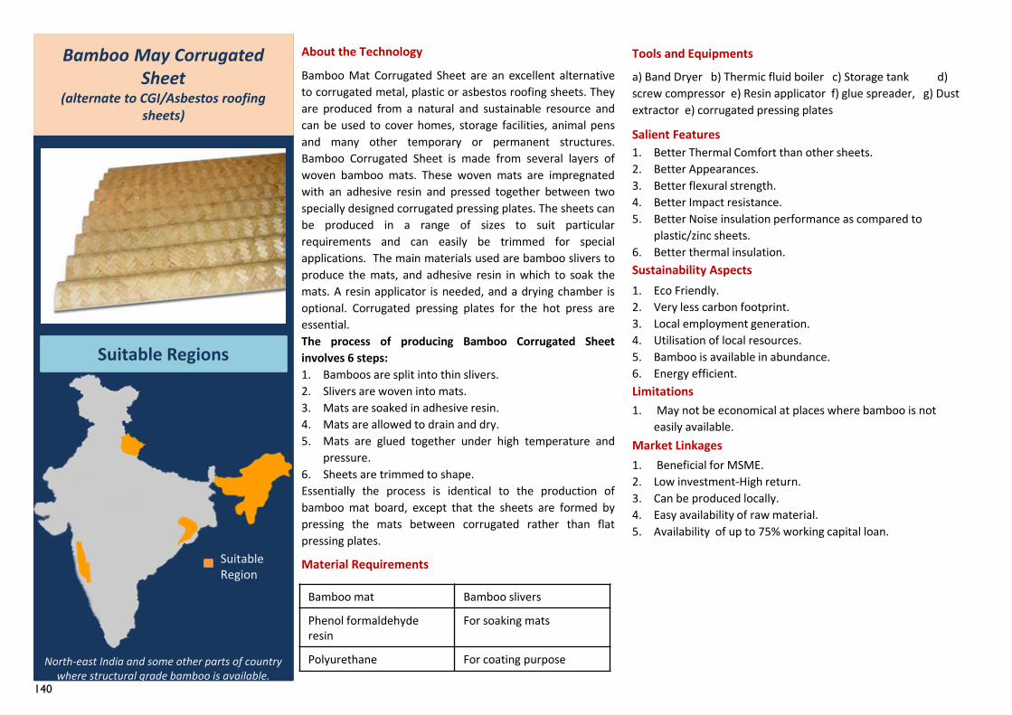
140
Bamboo mat Bamboo slivers
Phenol formaldehyde resin
For soaking mats
Polyurethane For coating purpose
1. Beneficial for MSME.2. Low investment-High return.3. Can be produced locally.4. Easy availability of raw material.5. Availability of up to 75% working capital loan.
Bamboo May Corrugated Sheet
(alternate to CGI/Asbestos roofing sheets)
Suitable Regions
About the Technology
Bamboo Mat Corrugated Sheet are an excellent alternativeto corrugated metal, plastic or asbestos roofing sheets. Theyare produced from a natural and sustainable resource andcan be used to cover homes, storage facilities, animal pensand many other temporary or permanent structures.Bamboo Corrugated Sheet is made from several layers ofwoven bamboo mats. These woven mats are impregnatedwith an adhesive resin and pressed together between twospecially designed corrugated pressing plates. The sheets canbe produced in a range of sizes to suit particularrequirements and can easily be trimmed for specialapplications. The main materials used are bamboo slivers toproduce the mats, and adhesive resin in which to soak themats. A resin applicator is needed, and a drying chamber isoptional. Corrugated pressing plates for the hot press areessential.The process of producing Bamboo Corrugated Sheetinvolves 6 steps:1. Bamboos are split into thin slivers.2. Slivers are woven into mats.3. Mats are soaked in adhesive resin.4. Mats are allowed to drain and dry.5. Mats are glued together under high temperature and
pressure.6. Sheets are trimmed to shape.Essentially the process is identical to the production ofbamboo mat board, except that the sheets are formed bypressing the mats between corrugated rather than flatpressing plates.
Material Requirements
Tools and Equipments
a) Band Dryer b) Thermic fluid boiler c) Storage tank d) screw compressor e) Resin applicator f) glue spreader, g) Dust extractor e) corrugated pressing plates
Salient Features1. Better Thermal Comfort than other sheets.2. Better Appearances.3. Better flexural strength.4. Better Impact resistance.5. Better Noise insulation performance as compared to
plastic/zinc sheets.6. Better thermal insulation.Sustainability Aspects1. Eco Friendly.2. Very less carbon footprint.3. Local employment generation.4. Utilisation of local resources.5. Bamboo is available in abundance.6. Energy efficient.Limitations1. May not be economical at places where bamboo is not
easily available.Market Linkages
North-east India and some other parts of country where structural grade bamboo is available.
Suitable Region
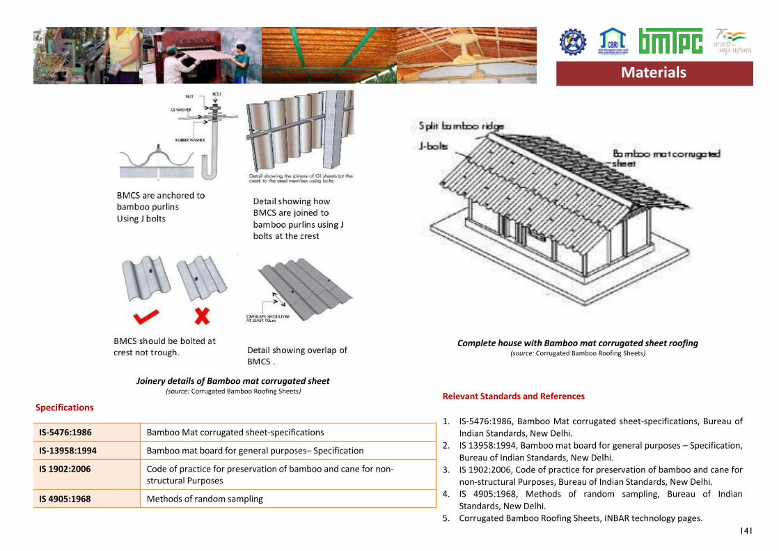
141
IS-5476:1986 Bamboo Mat corrugated sheet-specifications
IS-13958:1994 Bamboo mat board for general purposes– Specification
IS 1902:2006 Code of practice for preservation of bamboo and cane for non-structural Purposes
IS 4905:1968 Methods of random sampling
SpecificationsRelevant Standards and References
1. IS-5476:1986, Bamboo Mat corrugated sheet-specifications, Bureau ofIndian Standards, New Delhi.
2. IS 13958:1994, Bamboo mat board for general purposes – Specification,Bureau of Indian Standards, New Delhi.
3. IS 1902:2006, Code of practice for preservation of bamboo and cane fornon-structural Purposes, Bureau of Indian Standards, New Delhi.
4. IS 4905:1968, Methods of random sampling, Bureau of IndianStandards, New Delhi.
5. Corrugated Bamboo Roofing Sheets, INBAR technology pages.
Joinery details of Bamboo mat corrugated sheet(source: Corrugated Bamboo Roofing Sheets)
Materials
Complete house with Bamboo mat corrugated sheet roofing(source: Corrugated Bamboo Roofing Sheets)
Materials
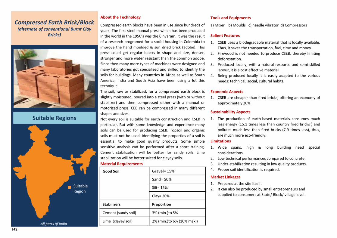
142
Good Soil Gravel= 15%
Sand= 50%
Silt= 15%
Clay= 20%
Stabilizers Proportion
Cement (sandy soil) 3% (min.)to 5%
Lime (clayey soil) 2% (min.)to 6% (10% max.)
1. Prepared at the site itself.2. It can also be produced by small entrepreneurs and
supplied to consumers at State/ Block/ village level.
Compressed Earth Brick/Block(alternate of conventional Burnt Clay
Bricks)
Suitable Regions
About the Technology
Compressed earth blocks have been in use since hundreds ofyears, The first steel manual press which has been producedin the world in the 1950’s was the Cinvaram. It was the resultof a research programed for a social housing in Colombia toimprove the hand moulded & sun dried brick (adobe). Thispress could get regular blocks in shape and size, denser,stronger and more water resistant than the common adobe.Since then many more types of machines were designed andmany laboratories got specialized and skilled to identify thesoils for buildings. Many countries in Africa as well as SouthAmerica, India and South Asia have been using a lot thistechnique.The soil, raw or stabilized, for a compressed earth block isslightly moistened, poured into a steel press (with or withoutstabilizer) and then compressed either with a manual ormotorized press. CEB can be compressed in many differentshapes and sizes.Not every soil is suitable for earth construction and CSEB inparticular. But with some knowledge and experience manysoils can be used for producing CSEB. Topsoil and organicsoils must not be used. Identifying the properties of a soil isessential to make good quality products. Some simplesensitive analysis can be performed after a short training.Cement stabilization will be better for sandy soils. Limestabilization will be better suited for clayey soils.Material Requirements
Tools and Equipmentsa) Mixer b) Moulds c) needle vibrator d) Compressors
Salient Features1. CSEB uses a biodegradable material that is locally available.
Thus, it saves the transportation, fuel, time and money.2. Firewood is not needed to produce CSEB, thereby limiting
deforestation.3. Produced locally, with a natural resource and semi skilled
labour, it is a cost effective material.4. Being produced locally it is easily adapted to the various
needs: technical, social, cultural habits.
Economic Aspects1. CSEB are cheaper than fired bricks, offering an economy of
approximately 20%.
Sustainability Aspects1. The production of earth-based materials consumes much
less energy (15.1 times less than country fired bricks ) andpollutes much less than fired bricks (7.9 times less), thus,are much more eco-friendly.
Limitations1. Wide spans, high & long building need special
considerations.2. Low technical performances compared to concrete.3. Under-stabilization resulting in low quality products.4. Proper soil identification is required.
Market Linkages
All parts of India
Suitable Region
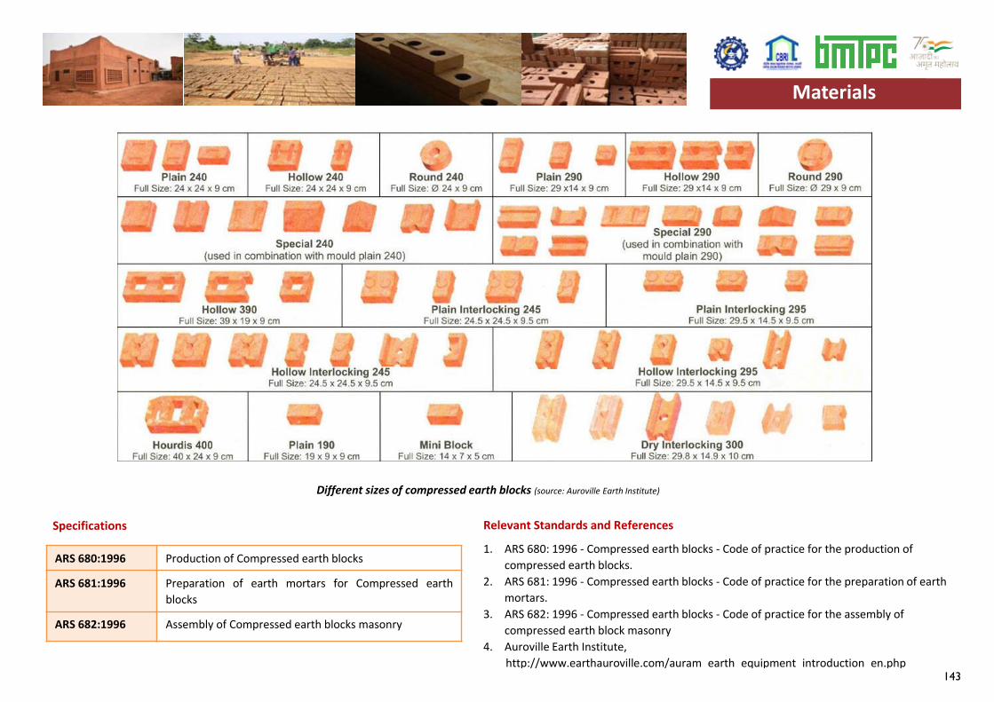
143
Specifications Relevant Standards and References
1. ARS 680: 1996 - Compressed earth blocks - Code of practice for the production of compressed earth blocks.
2. ARS 681: 1996 - Compressed earth blocks - Code of practice for the preparation of earth mortars.
3. ARS 682: 1996 - Compressed earth blocks - Code of practice for the assembly of compressed earth block masonry
4. Auroville Earth Institute,http://www.earthauroville.com/auram_earth_equipment_introduction_en.php
Different sizes of compressed earth blocks (source: Auroville Earth Institute)
Materials
ARS 680:1996 Production of Compressed earth blocks
ARS 681:1996 Preparation of earth mortars for Compressed earthblocks
ARS 682:1996 Assembly of Compressed earth blocks masonry
Materials
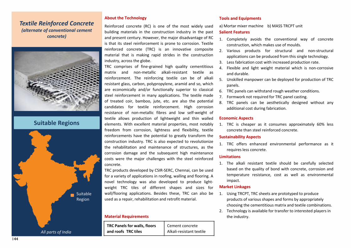
144
TRC Panels for walls, floorsand roofs TRC tiles
Cement concreteAlkali-resistant textile
1. Using TRCPT, TRC sheets are prototyped to produce products of various shapes and forms by appropriately choosing the cementitious matrix and textile combinations.
2. Technology is available for transfer to interested players in the industry.
Textile Reinforced Concrete(alternate of conventional cement
concrete)
Suitable Regions
About the Technology
Reinforced concrete (RC) is one of the most widely usedbuilding materials in the construction industry in the pastand present century. However, the major disadvantage of RCis that its steel reinforcement is prone to corrosion. Textilereinforced concrete (TRC) is an innovative compositematerial that is making rapid strides in the constructionindustry, across the globe.TRC comprises of fine-grained high quality cementitiousmatrix and non-metallic alkali-resistant textile asreinforcement. The reinforcing textile can be of alkaliresistant glass, carbon, polypropylene, aramid and so, whichare economically and/or functionally superior to classicalsteel reinforcement in many applications. The textile madeof treated coir, bamboo, jute, etc. are also the potentialcandidates for textile reinforcement. High corrosionresistance of non-metallic fibres and low self-weight oftextile allows production of lightweight and thin walledelements. With excellent material properties, most notablyfreedom from corrosion, lightness and flexibility, textilereinforcements have the potential to greatly transform theconstruction industry. TRC is also expected to revolutionizethe rehabilitation and maintenance of structures, as thecorrosion damage and the subsequent high maintenancecosts were the major challenges with the steel reinforcedconcrete.TRC products developed by CSIR-SERC, Chennai, can be usedfor a variety of applications in roofing, walling and flooring. Anovel technology was also developed to produce light-weight TRC tiles of different shapes and sizes forwall/flooring applications. Besides these, TRC can also beused as a repair, rehabilitation and retrofit material.
Material Requirements
Tools and Equipmentsa) Mortar mixer machine b) MASS TRCPT unitSalient Features1. Completely avoids the conventional way of concrete
construction, which makes use of moulds.2. Various products for structural and non-structural
applications can be produced from this single technology.3. Less fabrication cost with increased production rate.4. Flexible and light weight material which is non-corrosive
and durable.5. Unskilled manpower can be deployed for production of TRC
panels.6. TRC panels can withstand rough weather conditions.7. Formwork not required for TRC panel casting.8. TRC panels can be aesthetically designed without any
additional cost during fabrication.
Economic Aspects1. TRC is cheaper as it consumes approximately 60% less
concrete than steel reinforced concrete.Sustainability Aspects1. TRC offers enhanced environmental performance as it
requires less concrete.Limitations1. The alkali resistant textile should be carefully selected
based on the quality of bond with concrete, corrosion andtemperature resistance, cost as well as environmentalimpact.
Market Linkages
All parts of India
Suitable Region
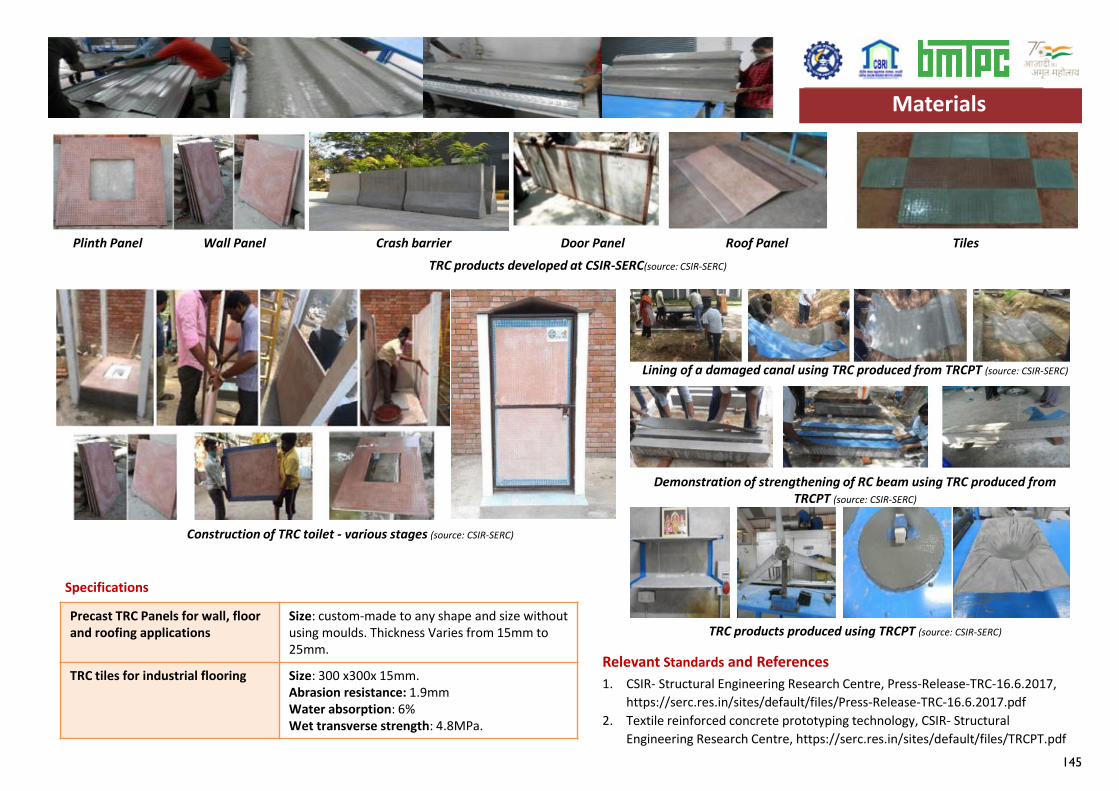
145
Specifications
Relevant Standards and References1. CSIR- Structural Engineering Research Centre, Press-Release-TRC-16.6.2017,
https://serc.res.in/sites/default/files/Press-Release-TRC-16.6.2017.pdf2. Textile reinforced concrete prototyping technology, CSIR- Structural
Engineering Research Centre, https://serc.res.in/sites/default/files/TRCPT.pdf
TRC products developed at CSIR-SERC(source: CSIR-SERC)
Precast TRC Panels for wall, floorand roofing applications
Size: custom-made to any shape and size without using moulds. Thickness Varies from 15mm to 25mm.
TRC tiles for industrial flooring Size: 300 x300x 15mm.Abrasion resistance: 1.9mmWater absorption: 6%Wet transverse strength: 4.8MPa.
Materials
Plinth Panel Wall Panel Door Panel Roof Panel Tiles Crash barrier
Construction of TRC toilet - various stages (source: CSIR-SERC)
Lining of a damaged canal using TRC produced from TRCPT (source: CSIR-SERC)
Demonstration of strengthening of RC beam using TRC produced from TRCPT (source: CSIR-SERC)
TRC products produced using TRCPT (source: CSIR-SERC)
Materials