Watts Bar Nuclear Plant (WBN) - Unit 2
148
Tennessee Valley Authority, Post Office Box 2000, Spring City, TN 37381-2000 April 6, 2009 10 CFR 50.54f U.S. Nuclear Regulatory Commission ATTN: Document Control Desk Mail Stop: OWFN P1-35 Washington, D.C. 20555-0001 In the Matter of ) Docket No. 50-391 Tennessee Valley Authority ) WATTS BAR NUCLEAR PLANT (WBN) - UNIT 2 - ADDITIONAL INFORMATION REGARDING WBN UNIT 2 CORRECTIVE ACTION PROGRAMS (TAC NO. MD9182 and MD9424) The purpose of this letter is to provide additional information regarding the following WBN Unit 2 Corrective Action Programs (CAPs): Cable Issues, Electrical Issues, Quality Assurance (QA) Records and the Replacement Items Program (Piece Parts). The CAPs are discussed in Reference 1, section 1.13.1, under items (1) Cable Issues, (5) Electrical Issues, (13) QA Records, and (15) Replacement Items Program, respectively. Regarding the Cable Issues Program, TVA submitted a proposed approach to resolution of sub-issues of the Cable Issues CAP at WBN Unit 2 different from the approach used for WBN Unit 1 to the NRC on May 29, 2008 (Reference 2). TVA submitted a proposed approach to resolve sub-issues of the Cable Issues CAP using the WBN Unit 1 approach on September 26, 2008 (Reference 3). In Reference 4, the NRC requested additional information. TVA responded to the NRC's request for additional information on January 14, 2009 (Reference 5). Subsequently, a teleconference was held on February 10, 2009, and a public meeting on March 17, 2009 (Reference 6). At the public meeting, TVA presented information to answer the questions from the teleconference. Enclosure 1 provides the NRC questions from the February 10 teleconference and TVA's responses. Enclosure 2 provides TVA responses to additional NRC questions provided at the March 10 public meeting. Printed on recycled paper
-
Upload
khangminh22 -
Category
Documents
-
view
0 -
download
0
Transcript of Watts Bar Nuclear Plant (WBN) - Unit 2

Tennessee Valley Authority, Post Office Box 2000, Spring City, TN 37381-2000
April 6, 2009 10 CFR 50.54f
U.S. Nuclear Regulatory CommissionATTN: Document Control DeskMail Stop: OWFN P1-35Washington, D.C. 20555-0001
In the Matter of ) Docket No. 50-391Tennessee Valley Authority )
WATTS BAR NUCLEAR PLANT (WBN) - UNIT 2 - ADDITIONAL INFORMATIONREGARDING WBN UNIT 2 CORRECTIVE ACTION PROGRAMS (TAC NO. MD9182and MD9424)
The purpose of this letter is to provide additional information regarding the following WBNUnit 2 Corrective Action Programs (CAPs): Cable Issues, Electrical Issues, QualityAssurance (QA) Records and the Replacement Items Program (Piece Parts). The CAPsare discussed in Reference 1, section 1.13.1, under items (1) Cable Issues, (5) ElectricalIssues, (13) QA Records, and (15) Replacement Items Program, respectively.
Regarding the Cable Issues Program, TVA submitted a proposed approach to resolutionof sub-issues of the Cable Issues CAP at WBN Unit 2 different from the approach used forWBN Unit 1 to the NRC on May 29, 2008 (Reference 2). TVA submitted a proposedapproach to resolve sub-issues of the Cable Issues CAP using the WBN Unit 1 approachon September 26, 2008 (Reference 3). In Reference 4, the NRC requested additionalinformation. TVA responded to the NRC's request for additional information onJanuary 14, 2009 (Reference 5). Subsequently, a teleconference was held onFebruary 10, 2009, and a public meeting on March 17, 2009 (Reference 6). At the publicmeeting, TVA presented information to answer the questions from the teleconference.
Enclosure 1 provides the NRC questions from the February 10 teleconference and TVA'sresponses. Enclosure 2 provides TVA responses to additional NRC questions provided atthe March 10 public meeting.
Printed on recycled paper

U. S. Nuclear Regulatory CommissionPage 2April 6, 2009
TVA submitted a proposed approach to resolve sub-issues of the Electrical Issues CAPusing the WBN Unit 1 approach on September 26, 2008 (Reference 3). The ElectricalIssues CAP was also discussed at the public meeting that was held on March 17, 2009(Reference 6). Enclosure 2 provides TVA responses to NRC questions pertaining to theElectrical Issues CAP that were raised at the March 17 public meeting.
In Reference 3, TVA requested NRC close the QA Records CAP. In Reference 7, NRCrequested additional clarification. Based on a subsequent discussion, TVA will statisticallysample the WBN Unit 2 QA records by record type to determine their retrievability, storageintegrity and completeness. TVA will resolve any technical or quality problems found.
In Reference 3, TVA requested NRC review and approval of the approach for closing theReplacement Items CAP. In Reference 6, NRC requested additional clarification. Basedon a subsequent discussion, TVA will perform back checks of the previously installedreplacement items to ensure that a proper documentation trail exists from the warehouseto maintenance history for each of the small number of safety-related components that arenot refurbished.
Enclosure 3 provides the listing of open actions required for licensing made in this letterand in Enclosures 1 and 2. 1 declare under penalty of perjury that the foregoing is trueand correct. Executed on the 6 th day of April, 2009.
If you have any questions, please contact me at (423) 365-2351.
Sincerely,
Masoud Baj~e niWatts Bar t2 Vice Preside nt
Enclosurescc (See page 4):

U. S. Nuclear Regulatory CommissionPage 3April 6, 2009
References: 1. NRC Safety Evaluation Report Related to the Operation of Watts BarNuclear Plant, Unit 2 NUREG-0847 Supplement 21, February 2009
2. TVA letter dated May 29, 2008, 'Watts Bar Nuclear Plant (WBN) -Unit 2 - Cable Issues Corrective Action Program for Completion ofWBN Unit 2" (T02 080529 001)
3. TVA letter dated September 26, 2008, 'Watts Bar Nuclear Plant (WBN)- Unit 2 - Regulatory Framework for the Completion of Constructionand Licensing Activities for Unit 2 - Corrective Action and SpecialPrograms, and Unresolved Safety Issues" (T02 080926 001)
4. NRC letter dated November 25, 2008, "Watts Bar Nuclear Plant - Unit 2- Request for Additional Information Regarding Cable Issues CorrectiveAction Program (JAC NO. MD9182)" (A02 081203 001)
5. TVA letter dated January 14, 2009,'Watts Bar Nuclear Plant (WBN) -Unit 2 - Response to Request for Additional Information RegardingCable Issues Corrective Action Program (TAC NO. MD9182)"(J02 090114 001)
6. 2009/03/17 - Slides and Handouts from TVA Public Meeting (ADAMSAccession No. ML090771062)
7. NRC letter dated February 11, 2009, "Watts Bar Nuclear Plant - Unit 2- Status of Regulatory Framework for the Completion of CorrectiveAction and Special Programs and Unresolved Safety Issues (TAC NO.MD9424)" (A02 090223 001)

U. S. Nuclear Regulatory CommissionPage 4April 6, 2009
cc (Enclosures):Lakshminarasimh RaghavanU.S. Nuclear Regulatory CommissionMS 08H4AOne White Flint North11555 Rockville PikeRockville, Maryland 20852-2738
Patrick D. Milano, Senior Project Manager (WBN Unit 2)U.S. Nuclear Regulatory CommissionMS 08H4One White Flint North11555 Rockville PikeRockville, Maryland 20852-2738
Loren R. Plisco, Deputy Regional Administrator for ConstructionU. S. Nuclear Regulatory CommissionRegion IISam Nunn Atlanta Federal Center, Suite 23T8561 Forsyth Street, SW,Atlanta, Georgia 30303-8931
U. S. Nuclear Regulatory CommissionRegion IISam Nunn Atlanta Federal Center61 Forsyth Street, SW, Suite 23T85Atlanta, Georgia 30303-8931
NRC Resident Inspector Unit 2Watts Bar Nuclear Plant1260 Nuclear Plant RoadSpring City, Tennessee 37381

Enclosure 1
Response to Cable Issues Questions as a Result of February 10, 2009Conference Call
1. NRC Question 5j, page 27: NRC questioned the calculated length of cable2PP675A. NRC calculated circuit as 2732 (a), 2722 (b) and 2772 (c) ft. vs TVAcalculation (ICRDS) of 4787 ft.
TVA Response:
See Enclosure 2, Section 11, "CCRS Software and Database Verification andValidation"
2. NRC Question 4a, page 21: TVA to provide additional clarification that thecondulet was used as a pull point and that the size of the opening was enough tonot cause a problem with the bend radius of the cable. Also confirm that909 condulet was only used for /& C cable.
TVA Response:
Ninety-degree condulets were used in other applications in addition toinstrumentation and control cables. The cables that were of concern for the "pullthrough" issue were smaller gauge cables, since it is impractical to "pull through"larger gauge cables.
As part of the Bend Radius Baseline verification, condulet sizes are beingdetermined for all conduits containing safety-related cable. Sizes will bevalidated against current TVA standards.
3. NRC Question 5k, page 28: NRC requested additional clarification on the notethat indicated further research is needed to determine the exact insulation type.
TVA Response:
This note was added to non-environmentally qualified (EQ) cables that had thesame mark number as EQ cables. EQ cables must have a documentation trail tothe original contract to ascertain a trail to a specific manufacturer and applicableEQ test. TVA ONMark is used to connect non-EQ cables to data pertinent forcalculation basis, such as insulation type, number of conductors, gauge, etc.This note only makes the user of the Integrated Cables and Raceway DesignSystem (ICRDS) aware of the fact that the EQ collected data for cable with asimilar mark number is not applicable to this particular cable.
4. NRC Question la, page 3: Confirm cables were typically hand pulled and that noindications of jamming occurred. Staff finds TVA's methodology based on asingle conductor is too restrictive. High tensions from jamming are not includedin the TVA pulling tensions calculations that go into calculating SWBP. Thereforethe staff finds that TVA's selection process is questionable. Based on this TVAmust confirm that all safety-related cables were hand pulled or, if not hand pulled,
1

describe how pulling tensions were monitored for potential jamming and howdeviations between calculated and actual pulling tensions were justified.
TVA Response:
See the responses to Questions a and b under "Jamming" in Enclosure 2.
5. NRC Question lb, page 5: NRC requested the voltage level and cable size forthe 6 cables in the chart.
TVA Response:
Cable No: Manufacturer Type Size1 PL4961A Triangle XLPE w/ PVC 3-1/C-400MCM,
jacket 600V1PL4975A Triangle XLPE w/ PVC 3-1/C-400MCM,
jacket 600V1PL4982B Brand Rex XLPE w/ PVC 3-1/C-400MCM,
jacket 600V1PL4985B Okonite EPR w/ICSPE 3-1/C-400MCM,
jacket 600V2PL4975A Okonite EPR w/ICSPE 3-1/C-400MCM,
jacket 600V2PL4978A Okonite EPR w/ICSPE 3-1/C-400MCM,
jacket 600V
The complete list of cables including their size, type, voltagedelineated in calculation WBPEVAR8905050, Table 4.1.
level, and length is
6. NRC Question 1d, page 6: NRC requested additional information on theexception to G-38. Provide the date of the exception and describe how the 6 to10 foot interval taping or tying was achieved.
TVA Response:
Exception G-38-WBN-32 was approved on March 3,1994.
As documented in Exception G-38-WBN-32, this was a pull of less than 70 feet ina 5-inch conduit. DCN W-29725-A included design work to install cables1 PP1 042 and 1 PP1 043 from containment penetration 1 -PENT-293-4 to the WBNUnit 1 reactor coolant pump motor 1 -MTR-68-73. There is no documentation inthe implementing work order (WO) 94-04231-00 with respect to how the taping ortying the cable at 6-10 foot interval was achieved. However, because theevidence shows that all three conductors of these cables were cut from one reel(Reel No. WB1 5554), it is logical to conclude that three 70-foot length pieces,one conductor for each phase A, B, and C, were cut and then shaped into triplexformation before the cable was pulled. Page 43 of the WO documents thatNuclear Engineering (NE) instructions were followed and an NE cable specialistwitnessed the cable pull. Please note that Exception G-38-WBN-32 was written
2

for a Unit 1 cable. There are no exceptions in G-38 against Unit 2 cables. In thefuture, if there are any exceptions, the requirements of G-38 will be followed.
7. NRC Question 2a, page 11: Type and size of the four cables. When wasparachute cord used at WBN?
TVA Response:
2PS284D: 1/2C No. 14AWG, Copper, Insulation Type PXMJ: 600V; MarkNumber WHB-12PM516D: 1/4C No. 16AWG, Insulation Type MS: 300V; Mark Number WVC2PM871 D: 1/4C No. 16AWG, Insulation Type MS: 300V; Mark Number WVC1M2451B: 1/2C No. 14AWG, Copper, Insulation Type PXMJ: 600V;MarkNumber WHB-1
A review of specification G-38, revision 2, shows that for cables No. 4 AWG andsmaller the specification permitted use of twine or fish line with a known "break"test of less than maximum tension specified for the cable size. For cables largerthan No. 4 AWG, specification permitted use of Manila Rope or reliable break-links of known break strength in place of break ropes. WBN cannot establish thetime frame when parachute cord was used to pull cables into conduits.
8. NRC Question 2d, page 13: NRC wants the test report for the coefficient offriction. Justify deviations from the 1185 recommendations for a successful cablepullby (65% vs 20% fill). Also describe what happened to conduits with between60% an'd 65% fill.
TVA Response:
See response to Question e under Jamming in Enclosure 2 for discussion onfriction test.
Conduits were categorized in fill groups. The 60% fill group included cablesbetween 55.00 to 64.99%.
For the WBN Unit 2 project, a review of 5,279 Unit 2 safety-related conduitsshows that 5,012 conduits are less than or equal to 40% full. Thus,approximately 95% of the total number of Unit 2 safety-related conduits arewithin the fill range allowed by G-38/G-40 (i.e., less than or equal to 40% full)..Engineering has documented an exception to the requirement of design criteriaWB-DC-30-22 for the remaining 267 overfilled conduits. This is based on currentas-designed data.
For conduits in the pullby evaluation, which are moderate and high risk, cablesare eliminated based on the following factors:- They have not experienced a pullby,- They are less than 20 feet long, or- They are being replaced.
3

There are 8 conduits with fills greater than 35% and 3 conduits with fills greaterthan 40% using as-installed data. None are greater than 49%. These overfillconditions are justified in ICRDS.
The moderate and high-risk conduits have had the as-constructed data compiled(cables not pulled and actual conduit size identified). For low-risk conduits, theas-constructed data is still being compiled. It is expected that the as-constructedfill will be less than the as-designed fill in many cases.
9. NRC Question 2e, page 14: How many cables in the 492 cable segments werehigh-pot tested?
TVA Response:
441 cables were tested.
The complete list of cables that were hi-pot tested to validate the thresholdbetween low risk category and moderate risk category can be found incalculation WBPEVAR9006013, Attachment P2. Note that no low risk cablesfailed the hi-pot test as a result of pullby damage.
10. NRC Question 3b, page 17: What do the cable manufacturers do to meet thepurchase specifications? Describe how TVA confirmed that the cablemanufacturers met the purchase specification (e.g., SWBP).
TVA Response:
For current 1 E cable purchases, the allowable sidewall pressure is specified inthe Certificate of Compliance from the vendor.
11. NRC Question 3d, pages 17-19: Provide the cable types, manufacturers and
construction details (size and number) for the 52 conduits.
TVA Response:
The requested information is shown in the table that follows. The manufacturerlisted is based on the current as-designed data. The as-constructed Unit 2 datais in the process of being compiled, and therefore, the manufacturer listed issubject to change. Additionally, many of the cables have been subsequently re-pulled or deleted for various reasons. Therefore, the manufacturer for the cablespresent during the SWP evaluation may not be available. This is noted by N/A.
No. Conduit No. Mark Cable No. Size ManufacturerNumber Cables Number Type Cond.
25 WVK MS 2 16 TIME/Anaconda/N/A3 WVA MS 2 16 TIME/Anaconda
2 2PM6426D 4 WVA MS 2 16 N/A2 WVA MS 2 16 N/A
3 2PM6444E 2 WVC MS 2 16_ 1 4 WHB-1 PXMJ 2 14
4

4 2PM7269G 7 WVA MS 2 16 Eaton/Anaconda4 WTK COAX 23 N/A2 WWK COAX 20
5 2PM7400B 2 vW COX01 WVB XLPE 3 1619 WVA MS 2 163 WWK COAX 20, N/A22 WVA MS 2 16
6 2 P M 74 0 1A 1 W Y B L E 3 161 WvVB XLPE 3 16 •
4 WTK COAX 237 2PM7869D 1 WVA MS 2 16 N/A8 2PM7872F 1 WVA MS 2 16 N/A9 2PS704E 4 WHB-1 PXMJ 2 14 AIW10 2RM438A 2 WTK COAX 23 N/A
14 WHB-1 PXMJ 2 14 N/A3 WHC-1 PXMJ 3 142 WHE-1 PXMJ 5 141 WGK PJJ 12 121 WGM PJJ 16 12 Cyprus
12 2M3360A 1 WFG-1 PXMJ 7 10 Okonite1' WGH PJJ 9 12 Cyprus2 WHD-1 PXMJ 4 14 N/A2 WHB-1 PXMJ 2 141 WHG-1 PXMJ 7 142 WGD-1 PXMJ 4 121 WFH-1 PXMJ 9 10
__2 WGG-1 PXMJ 7 12
14 2PLC1184A 1 WHC PJJ 3 14 Cyprus1 WHB-1 PXMJ 2 14 AIW1 WHC PJJ 3 14 Cyprus
15 2PLC1185B 1 "C PX 2 14 MW1 WHB-1 PXMJ 2 114 AIW
1 WHE PJJ 5 14 N/A16 2PLC1928CWHB- PXMJ 2 14
10 WHB-1 PXMJ 2 14 N/A1 WHC PJJ 2 141 WVA MS 2 162 WLN CPJJ 2 1017 2PLC215B 1 WB PJ 2 11 WGB PJJ 2 12
1 WGC-1 PXMJ 3 121 WGC PJJ 3 122 WHE-I PXMJ 5 141 WGD PJJ 4 12 Cyprus4 WGB-1 PXMJ 2 12 AMW
18 2PLC2303A 1 WHB-1 PXMJ 2 14 AIW2 WHC PJJ 3 14 Cyprus1 WGE PJJ 5 12 Cyprus
19 2PLC2519A 3 WDO CPJ 1 400 N/A20 2PV825E 2 WLN CPJJ 2 10 Plastic
2 WDE-1 PXJ 1 6 AIW21 2VC1259B 10 WPA SROAJ 1 14 Rockbestos22 2VC2035B 1 WGE PJJ 5 12 Cyprus-
5

1 WGC-1 PXMJ 3 12 AIW1 WGB-1 PXMJ 2 12 N/A
23 2VC2069B 1 WGB PJJ 2 121 WGK-1 PXMJ 12 124 WHL-1 PXMJ 16 14 Okonite/Plastic1 WHH PJJ 9 14 Cyprus
25 2VC2577A 8 WPA SROAJ 1 14 N/A26 2VC2650B 6 WHB-1 PXMJ 2 14 Rockbestos/AIW/Later27 2PLCI136A 3 WPJ SROAJ 1 1/0 Rockbestos28 2PLC1276A 3 WDO CPJ 1 400 N/A29 2PLC1280B 3 WDH-1 PXJ 1 1/0 N/A
1 WGC-1 PXMJ 3 12 N/A1 WMT CPJJ 3 12
31 2PLC2763A 3 WDO CPJ 1 400 N/A32 2PLC2766A 3 WDO CPJ 1 400 N/A33 2PLC2841B 3 WDO CPJ 1 400 Okonite34 2PLC2844B 3 WDO CPJ 1 400 General Cable35 2PLC2850A 3 WDO CPJ 1 400 N/A36 2PLC2855A 3 WDO CPJ 1 400 N/A37 2PLC2882A 3 WIDO CPJ 1 400 Plastic36 2PLC2922B 3 WDO CPJ 1 400 Plastic39 2PLC631B 1 WLO CPJJ 1 10 Plastic40 2PLC852A 3 WDO CPJ 1 400 AIW/General Cable41 2PLC853B 3 WDO CPJ 1 400 General/Plastic /Later42 2PLC860A 3 WDQ CPJ 1 750 Plastic
1 WFC-1 PXMJ 3 10 AIW43 2VC1078A 2 WLO CPJJ 3 10 Plastic
1 WGC-1 PXMJ 3 12 AIW1 WFC-1 PXMJ 3 10 AIW
44 2VC1083B 2 WLO CPJJ 3 10 Plastic1 WGC-1 PXMJ 3 12 AIW
45 2PP2183A 3 WNB-1 ESPJ 1 2/0 Anaconda46 2PP2190B 3 WNB CPSJ 1 2/0 Anaconda47 2PP2191A 3 WNB CPSJ 1 2/0 Anaconda48 2PP2291A 3 WNB CPSJ 1 2/0 N/A49 2PP2292A 3 WNB CPSJ 1 2/0 N/A50 2PP2296B 3 WNB CPSJ 1 2/0 N/A51 2PP2297B 3 WNB CPSJ 1 2/0 N/A52 2PP2656A 3 WNB CPSJ 1 2/0 N/A
12. NRC Question 3g, page 19: How was the SWBP corrected for 1B1054G,
additional information needed on DCN M- 14241 ?
TVA Response:
Conduit 1 BI 054G was reworked in accordance with Design ChangeM-1 4241 -A as follows:
6

a. Cables 1 B26G, 1 B27G, 1 B31 G and 1 B32G were removed from theconduit 1 B1 054G and replaced.
b. Conduit 1 B1 054G was removed in its entirety.c. In addition to a shortened 1 B1 054G, two new conduits and two new pull
boxes were added to the installation to reduce the length between pullpoints and hence, sidewall bearing pressure (SWBP).
13. NRC Question 3h, page 20: Provide additional clarification on the sample. Howmany cables in the 40 conduits?
TVA Response:
The total number of cables in the 40 conduits was 203.
TVA calculation WBPEVAR8603006, Section 5.1, describes the overall programfor the resolution of the SWBP issue. TVA established a "smart" sample program
* that involved approximately 10,400 conduits containing Class 1 E cables fromvoltage levels V2, V3, V4, and V5. Screening calculations were performed toreduce this number to 1,914 conduits containing Class 1 E cables with potential ofexceeding the cable SWBP.
After one failure was identified out of 81 conduits in the original sample, the NRCstaff asked TVA to walk down an additional 40 conduits in harsh environment toconfirm that no other violations of SWBP occurred. The available populationincluded:
Total number of conduits with potential of exceeding SWBP: 1,914Number of conduits initially walked down to select 81 worst cases: 727Remaining number of conduits: (1914-727): 1,187
The process of random sample selection is documented in TVA calculationWBPEVAR901 0001, page 11. It included the following steps:
The list of 1,187 conduits was entered into a database. This file was printed outto identify a record number for each of the 1,1 87 records. Random numberswere then generated and compared to the record numbers in the database file.The corresponding conduit identifiers were then cross-checked against TVA'sComputerized Cable Routing System (CCRS) and the plant environmentaldrawings to determine those conduit records that had no open design changeagainst them. This cross-check resulted in 40 conduits located in harshenvironment with no design change against them.
TVA has previously described the entire population in the sample, which included121 conduits (81 + 40), a statistically significant sample.
7

14. NRC Question 6a, page 29: Confirm that all cables important to safety areincluded in the WBN Unit 2 CAP program.
TVA Response:
The cables included in the Unit 2 Cable Issues CAP are safety related, as well asEQ and Appendix R cables. Associated cables are evaluated for appropriateelectrical separation.
8

Enclosure 2
Response to Cable Issues and Electrical Issues Questions from theMarch 17, 2009 Public Meeting
1. Silicone Rubber Insulated Cable
NRC Question a: TVA to provide the number of silicone rubber insulated conduitsamples taken from Unit 1 and Unit 2.
TVA Response:
Silicone rubber insulated cables manufactured by Anaconda and Rockbestos Corp.were installed in the WBN Unit 1 and Unit 2 reactor buildings. These cables have45 mils of silicone rubber insulation covered by either an asbestos fiber braid jacketor an Aramid fiber braid jacket. Units 1 and 2 cables were pulled using the sameprocedures and by the same personnel, with Unit 2 cable being pulled withinapproximately six months after Unit 1 cable. The testing samples consisted of five (5)critical case conduits containing Anaconda cable and five (5) critical case conduitscontaining Rockbestos cable. The following table shows the conduits selected fromeach unit.
Cable Manufacturer No. of Unit 1 No. of Unit 2Conduits conduits
Rockbestos samples 5 -Anaconda samples 2 3
NRC Question b: TVA to provide the total number of silicone rubber insulated cablesinstalled in Unit 2.
TVA Response:
The following table provides the quantity of silicone rubber insulated cables in Unit 2.
Voltage Level No. ofCables
V4-Low Voltage Power 52V3- Control Power 419
V2-Sheilded cables carrying medium-level signals 0V1 -Shelded cables carrying low-level signals 0
Total 471
NRC Question c: TVA to provide the process/justification used to qualify Unit 2cables for 40 year life.
TVA Response:
With respect to EQ testing of the silicone rubber insulated cables, the samples ofAnaconda and Rockbestos cables removed from WBN Units 1 and 2 were sent toWyle Laboratories for testing. These samples were aged according to the plant's
1

environmental conditions. The samples were then subjected to a simulated loss ofcoolant accident environment, including steam/chemical spray. After completion ofthe accident simulation, the cables were subjected to a mandrel re-bend and asuccessful hi-pot withstand test for margin assessment.
The silicone rubber insulated cables are rated at 125' C. Although these cableshave been installed in situ for over 25 years, most of the Unit 2 cables have neverbeen energized and have remained in an ambient environment. This situation is nodifferent than if a reel of these cables was stored in the warehouse for that duration.As part of the EQ program, the impact on life due to external heating, i.e., ambienttemperatures, will be assessed. It is expected that this impact will be minimal sincethe ambient temperature is significantly less than the cable rating.
2. Jamming
NRC Question a: TVA to provide the results of their review of cable pullingtechniques including hand pulled versus assisted pull findings.
TVA Response:
TVA Quality Control Procedure WBNP-QCP-3.5, paragraph 6.3.5.2 required theresponsible engineer to provide the following pulling instructions for individual cableson the cable pull slip:* Maximum allowable pull tension in lbs.* Rope pull device size.* Indicate if the pull required power assist.* Special pull instructions.
The WBN Unit 2 project is reviewing cable pull slips for each Class 1 E cable to verifyand validate their as-installed configuration. The project is also reviewing the pullslip for each Class 1 E cable to determine if a power assist pull was documented forthat cable by the responsible engineer. As of March 25, 2009, the project hasreviewed approximately 1,400 cables out of a total Unit 2 Class 1 E cable populationof approximately 4,000. This review has found no Unit 2 Class 1 E cable that waspulled using a power assist pull.
NRC Question b: If cases are found where cables were assisted pull, provide theevaluation methodology for ensuring jamming did not occur.
TVA Response:
If a single-conductor Class 1 E cable is found to be installed using a power assistedpull, TVA will evaluate the controls in place during the pull and the jam ratio of thecable. Appropriate corrective action will be taken based on this evaluation. Theevaluation and corrective action will be available for review.
NRC Question c: TVA to provide a discussion of the technique for taping singleconductors into a triplex configuration along with clarification that the cables inquestion were reactor coolant pump cables.
2

TVA Response:
As documented in Exception G-38-WBN-32, this was a pull of less than 70 feet in a 5inch conduit. DCN W-29725-A issued a design to install cables 1 PP1 042 and1 PP1 043 from containment penetration 1 -PENT-293-4 to the WBN Unit 1 reactorcoolant pump motor 1 -MTR-68-73. There is no documentation in the implementingWO 94-04231 -00 with respect to how taping or tying the cable at 6-10 foot intervalswas achieved. However, because the documentation shows that all threeconductors of these cables were cut from one reel (Reel No. WB1 5554) it is logical toconclude that three 70-foot lengths, one conductor for each phase A, B and C, werecut and then shaped into triplex formation before the cable was pulled. The WOdocuments that NE instructions were followed and a NE cable specialist witnessedthe cable pull.
NRC Question d: Explain why single conductor cables are more likely to jam ascompared to the multi-conductor cables.
TVA Response:
IEEE 690-1984 describes the critical jamming ratio as follows:
'When three single-conductor cables are pulled into a conduit it is possible for thecenter cable to be forced between the two outer cables, when being pulled around abe nd .....................
The technical basis for the above statement is as follows:
Single conductor cables, especially conductor size larger than 1/0 AWG, are verystiff and require a high pull tension to pull them through a conduit. High pull tensioncan result in excessive SWBP. Because these large conductors are under excessivepull tension, there is greater likelihood that the middle conductor will slip between thetwo outer conductors when going around a bend thus resulting in a jam. This isespecially true if D/d (where D is conduit inside diameter and d is cable outsidediameter) approaches 3. When jamming occurs, the pull tension increasesexponentially. On the other hand, the multi-conductor cables consist of severalindividually insulated small conductors with foam or fiber filling the intersticesbetween conductors to provide a round cable shape. Because of this construction,the multi-conductor cables are more pliable and change shape to fit in the availablespace, making them less likely to jam. Therefore, industry is more concerned withlarge single conductor cable pulls. Single conductor cable pulls are used fordistribution system applications and are generally used as 3 single conductor feedersfor auxiliary power distribution in nuclear power plants.
NRC Question e: TVA to provide a discussion of how the coefficient of friction wasdetermined and supporting docketed documentation.
3

TVA Response:
To determine static and kinetic coefficients of friction for cable-to-cable friction withand without lubricant, TVA performed testing in 1989 using the inclined plane methodwith low normal loads.
The tests were performed with only the weight of the cable sample as a load and twoor more cables of one jacket material as the bearing surface. The cable surfaceswere made as flat and straight as possible. The test set had cables of each jackettype as a bearing surface for each type of cable to be tested. The sample cableswere 6 inches long for each jacket for testing with and without lubricant.
Each test was repeated at least ten times to ensure sufficient data for an average,which became the recorded coefficient of friction for that set. This was done withand without lubricant for static and kinetic coefficients of friction.
The results were presented to NRC at a meeting on November 17, 1989, andsubmitted to NRC on December 20, 1989, as part of the resolution plan for Unit 1.
NRC Question f: How many Unit 2 conduits were included in the total population of
76 conduits walked down to resolve the jamming issue?
TVA Response:
Thirty nine (39) conduits were Unit 1 conduits and thirty seven (37) conduits wereUnit 2 conduits.
3. Support in Vertical Conduits
NRC Question a: TVA to provide a definition and characterization of "rework"regarding conduits.
TVA Response:
Rework means that the installation will be modified such that it meets therequirements of TVA specifications. In this case, the specification is G-38, "GeneralConstruction Specification for Installing Insulated Cables Rated up to 15,000 Volts",Section 8.7.1, "Cables Routed in Vertical Conduits-Support Intervals." This sectionprovides the spacing requirements for vertical conduit supports. Cable supports willbe added to ClasslE conduits according to the methods described in Section 8.7.2of G-38, which includes selection of support type and installation practices.
NRC Question b: TVA to provide a justification for the determination that "creep" didnot occur in the vertical conduits.
TVA Response:
As discussed in the response to Question c, the "looseness" of the cable will beassessed to demonstrate that the cable was subjected to minimal pressure.Calculation WBPEVAR9005001 assessed the impact of the SWBP on the cable atthe transition due to the weight of the cable vertical drop. This was done based on
4

the cable being at rated temperature. The Unit 2 specific cables have been de-energized and therefore have been at a much lower temperature than rated. Thislower temperature, in conjunction with the verification that the cable is "loose,"provides assurance that insulation creep has not occurred.
NRC Question c: TVA to provide the basis for "hand-lifting" cables.
TVA Response:
Class 1 E cables are supported at or near the top of a conduit run by the curvature ofa conduit, the inside radius of condulets, or a pull box. A visual inspection of thoseconduits that do not meet the G-38 vertical support requirements will be conducted todetermine if the cables are loose. This will be measured by a craft's ability to lift thecables off the support point with one hand and without mechanical assistance. Thebasis for this is that looseness of the cable indicates an insignificant pressure on thecable jacket that is in contact with the surface supporting it. If the cables are found tobe under tension, which is indicated by the craft's inability to lift them off the supportpoint, the portion of these cables that has stayed under tension since their originalinstallation will be replaced.
4. Support in Vertical Tray
NRC Question a; TVA to amend the submittal to summarize how the vertical cabletrays were assessed to determine that no. cable damage occurred.
TVA Response:
WBN performed the following actions to determine that no damage occurred to thesafety-related cables in long vertical tray runs:a. Identified those families of cable trays containing safety-related cables where the
potential existed that an adequate support was not provided to meet therecommended requirements of NEC (1987) Article.300-1 9.
b. Performed walkdowns of the trays to determine their exact configuration.c. Where the length of the vertical drop exceeded the support requirement
stipulated in the NEC and a discrete support was not present, prepared acalculation to determine the impact of unsupported load with respect to cable andany connected equipment at the top resulting from (1) the weight on the copperconductors and potential for the load to stretch the copper; (2) pullout ofconductors from crimped lugs at termination; (3) potential cutting of cables by tiewraps used to secure cables in trays; and (4) static SWBP at support points.
d. Issued design changes to add tray supports where required.
NRC Question b: TVA to provide a discussion that codifies that no credit was takenfor tie-wraps to support vertical cables.
TVA Response:
TVA Specification G-38, Section 8.6.3.2, allows the use of cable tie wraps for thefollowing applications:(a) Where required to maintain a neat orderly arrangement of cables. Cable ties
shall be installed at intervals not exceeding 10 feet.
5

(b) To maintain required nominal spacing between medium-voltage circuits.
TVA calculation WBPEVAR9005001 states that no credit is taken for full supportfrom tie wraps due to lack of EQ of the wraps, and a review of the calculation showsthat no credit was taken for such support. This calculation also evaluates the effectof the horizontal section above a vertical tray section. It states that the presence ofthe cable ties, Vimasco, and fire stops in a horizontal section is considered inestablishing a coefficient of friction. However, credit cannot be taken for cable ties ina horizontal section to provide support to a vertical tray section since they are notqualified. The restraint provided by the horizontal section is based on the coefficientof friction between cable jacket and the bottom of the tray in the horizontal section.This coefficient of friction is based on EPRI EI-3333, Table 5-2.
It should be noted that specific direction on applying a tie wrap to cable is provided inG-38, Section 8.6.4.3, thus negating the concern of indenting the cable jacket bymaking the wrap too tight.
5. Proximity to Hot Pipe
NRC Question a: TVA to provide a definition and characterization of "rework"regarding raceways, including examples.
TVA Response:
A review of TVA calculation WBN-OSG4-139, 'Walkdown of Electrical RacewaysWithin Close Proximity to Hot Pipes; Data Tabulation and Violation Evaluation,"indicates that following actions were taken to correct the clearance violationsbetween Class 1 E raceways and hot pipes:" Installed heat shield., Restrained flexible conduit to obtain 2 inch clearance.• Relocated conduit to obtain required clearance.• Relocated tubing to obtain required clearance.• Installed additional insulation on the pipe to obtain required surface temperature.
This is the rework that was performed on raceways to address this issue.
NRC Question b: TVA to include the methodology used for developing the criteriafor "Hot Pipe" configurations in the submittal.
TVA Response:
TVA calculation WBN-OSG4-138, "Class 1 E Electrical Cable/Hot Pipe ClearanceRequirements," delineates the criteria for evaluation of "Hot Pipe" configurations.
The primary consideration in developing these criteria in Construction SpecificationG-40 was the establishment of clearances for electrical cables and piping that mustbe maintained in order to prevent the electrical cables from overheating due to closeproximity to hot pipes that could cause premature aging of the cables.
6

The clearance requirements were established for electrical cables run in conduits orcable trays, either parallel to, or at an angle to, a hot pipe, and located in any of theenvironmental situations listed on environmental drawings.
The clearance requirements are based on heat transfer analyses that determine thetemperature rise in cables caused by the presence of a nearby hot pipe. Theseanalyses account for (1) the resistance heating of the cables, (2) the heat transferwith the surroundings by natural convection and radiation, (3) the heat transfer byradiation between the cable or conduit surface and the piping insulation surface, and(4) the heat transfer by convection between the cables and the boundary layer of theplume arising from the pipe.
Separate treatment is required for different geometries that may exist in the plant.This is because certain geometries require significantly more clearance than others.Trying to force the more restrictive clearance requirements to be met for allgeometries is not economical or feasible.
The geometries that were analyzed in the TVA calculation were considered to besufficiently varied to cover the vast majority of cases that exist in the plant. However,if geometries existed that did not conform to any that were analyzed, specificanalyses was performed for such cases.
NRC Question c: TVA to provide the basis and assumptions for characterizing the
piping fluid and ambient room temperatures.
TVA Response:
TVA calculation WBN-OSG4-138 documents the assumptions for characterizing thepiping fluid temperatures as follows:1. All insulated pipes are assumed to have insulation outside diameter of 39 inches
or smaller and to have a maximum operating temperature of 6500 F. The pipesthat do not meet these requirements are considered special cases and requirespecific analyses.
2. All uninsulated pipes are assumed to be 2 inches in diameter or smaller and tohave an operating temperature of 600°F or less. The pipes that do not meetthese requirements are considered special cases and require specific analyses.
3. Piping with a surface temperature of 1350 F or less is not considered to be hotpipe. Electrical conduits in proximity to piping having this surface temperaturerequire no thermal clearance.
The basis for ambient room temperatures is the WBN plant environmentaldrawings 47E-235 series. These drawings provide ambient temperature in eachroom of the plant under normal operating as well as accident conditions.
NRC Question d: TVA stated that walk downs of "Hot Pipe" configurations will beconducted as part of project completion to ensure field run conduit configurationsmeet installation specifications. Include this statement in the submittal.
7
TVA Response:
TVA will conduct a final walkdown of the plant after construction is completed todetermine if any violation exists with respect to clearance between the hot pipes andClass 1 E electrical raceways. Violations will be evaluated and resolved.
NRC Question e: TVA to provide TVA's G-40 specification with the submittal.
TVA response:
TVA has included the G-40 specification on the accompanying disk.
6. Puliby
NRC Question a: A discrepancy was noted in Section 8.3 of the WBN Final SafetyAnalysis Report (FSAR) that indicated that the cable fill criteria did not call forevaluation if the fill percentage was exceeded. TVA will submit a correction to theFSAR that will define when evaluations can be performed.
TVA Response:
WBN FSAR paragraph 8.3.4.1.4, "Cable Derating and Raceway Fill," states:
"Conduit containing only one cable is sized for a maximum of 53% cable fill. Conduitcontaining two cables is sized for a maximum of 31% cable fill, and conduitcontaining three or more is sized for a maximum of 40% cable fill of the inside areaof the conduit."
TVA will add the following statement to this paragraph: "Exceptions for conduit fillsof greater than 40% will be evaluated and justified by engineering."
NRC Question b: Include the current configuration of WBN Unit 2 conduit fillpercentages. Specifically, provide the number of conduits with greater than 35% and40% fill for moderate and high risk cables.
TVA Response:
For conduits in the pullby evaluation, which are moderate and high-risk conduits, ifcables are eliminated based on the following factors:- They have not experienced a pullby.- They are less than 20 feet long.- The cables are being replaced.
There are 8 conduits with fills greater than 35% and 3 conduits with fills greater than40% using as-installed data. None are greater than 49%. All of these overfillconditions are justified in ICRDS.
NRC Question c: TVA to include a commitment to pull new cables in accordancewith TVA's G-38 specification in the submittaL
8

TVA Response:
All new Class 1 E cable pulls that involve cable pullby will be accomplished inaccordance with TVA's specification G-38.
7. Bend Radius
NRC Question a: Include the Bend Radius Report that contains interviews withcable vendors, in the submittal.
TVA Response:
The bend radius report, WBN Training Radius Program, R1, is being forwarded toNRC on the accompanying disk.
8. Splices
NRC Question a: Provide a definition and characterization of "rework" regardingsplices for cables in mild environments.
TVA Response:
For this issue, rework involved the replacement of intermediate splices for Class 1Ecables in mild environments that are susceptible to moisture intrusion from flood, linebreak, or sprinkler activation.
9. Sidewall Bearing Pressure (SWBP)
NRC Question a: Provide a discussion of how the 43 cable samples evaluated wereextrapolated to all cable configurations and how margin was applied to SWBPlimitations.
TVA Response:
As documented in Attachment 1 of the TVA Central Laboratory Test Procedure,"Sidewall Bearing Pressure Test Composite Results," 43 samples of various cabletypes and construction from approximately 17 cable manufacturers were tested.,Representative test results for each voltage class are summarized below.
For low voltage power and control cables, representative results are:
Cable Description Cable Manufacturer Max SWBP lbs/ft1/C No. 6 AWG Anaconda 20271/C No. 2 AWG American Insulated Wire 1957
1/C No. 2/0 AWG Triangle Wire and Cable 28897/C No. 14 AWG Okonite 15637/C No. 12 AWG Pacific Wire and Cable 1563
9

Based on the above test result, TVA selected a conservative value of 1,000 lbs/ft asa permissible SWBP value for low voltage power and control cables. Using1,000 lbs/ft provides a minimum margin of 56.3% (1563-1000/1000) and as much as188.9% (2889-1000/1000) for a 1/C 2/0.
Similarly, representative test results for signal level cables are tabulated below:
Cable Description Cable Manufacturer Max SWBP lbs/ft3/C No. 16 AWG, Eaton 643
Shielded2/C No. 16 AWG, Rockbestos 770
Shielded12/C No. 16 AWG, Brand Rex 1496
Shielded5/C No. 16AWG, ITT 937
Shielded
Based on the above test result, TVA selected a conservative value of 500 lbs/ft as apermissible SWBP value for low voltage signal cables. Using 500 lbs/ft provides aminimum margin of 28.6% (643-500/500) and as much as 199.2% (1496-500/500)for a 12/C No.16AWG, Shielded.
Similarly, for coax cables, representative test results are tabulated below:
Cable Description Cable Manufacturer Max SWBP lbs/ftCoax RG59B/U Raychem 3732 Coax W/TPs Teledyne 1242
Based on the above test result, TVA selected a conservative value of 300 lbs/ft as apermissible SWBP value for coax cables. Using 300 lbs/ft provides a minimummargin of 24.3% (373-300/300) and as much as 314.0% (1242-300/300) for an8/C coax special. As was the case on Unit 1, Unit 2 EQ coax cable will be replacedwith double jacketed cable.
10. Pulling Cables through 900 Condulets and Mid-Route Flexible Conduits
NRC Question a: Provide a discussion of why 12 and 14 gauge wire wasdetermined to be limiting in the submittal.
TVA Response:
As delineated under the silicone rubber insulated cable issue, five critical caseconduits containing at lease two 900 condulets in their route were selected thatcontained cables manufactured by Anaconda and Rockbestos. The installed cablesfrom these conduits were removed and were used as samples for EQ testing. Thereason for selecting these No.12 AWG and No. 14 AWG was that, in practice, only
* small gauge cable can be pulled through a condulet without using the condulet as apull point. Therefore, testing would reveal any insulation damage that may haveoccurred if the cables had been installed in this manner. These cables weresuccessfully tested for 40 year life.
10
11. CCRS Software and Database Verification and Validation
NRC Question a: Provide a discussion on how cable materials are tracked and canbe recovered via mark numbers.
TVA Response:
The ONMark database, which is part of ICRDS, identifies the conductor type,including insulation type, associated with a cable mark number. Additionally, the pullrecord for safety related cables identifies the reel number for the pulled cable. Thisreel number can be traced to the contract under which the cable was purchased viawarehouse records. For EQ cables, the contract number is associated with aspecific qualification report, as documented in the EQ binder. In addition, thecontract is identified on the cable jacket.
NRC Question b: Provide documentation on how the use of mark numbers isaccomplished at the site.
TVA Response:
The process for the use of cable mark numbers is described in ICRDS. The ICRDSprocedure states that a WBN cable reel number is recorded on the cable installationrecord. This cable reel number can be linked to the purchase contract number orTVA's interplant cable transfer documentation through the Warehouse Ledger. TheWBN Unit 2 project is currently reviewing cable installation records to establish thepedigree of each Class 1 E cable in Unit 2.
NRC Question c: Provide the percent of cables found deficient during the Unit 1Verification and Validation of the CCRS database to the resident.
TVA Response:
The following information is being provided to the resident:
The percent of cables found deficient during the Unit 1 Verification and Validation ofthe CCRS database is documented in paragraph 4.2 of the Cable Issues CorrectiveAction Program Plan, Revision 3, submitted to the NRC on January 13, 1994.
Out of 4,256 cable records reviewed for EQ cables, 4,012 cables had an exact matchbetween the design and the installation records. This resulted in a discrepancy rateof (4256-4012)/4256=5.7%.
Out of the 244 discrepant cables, 110 cable record inconsistencies were resolvedthrough a document search resulting in database update in some cases (e.g.,illegible pull cards, misaligned card printer, or mismatch of pull card revision number,mark number, and routing differences).
The remaining 134 cables required field verification of mark number, contractnumber, and/or routing. This field verification resulted in 100 cables where thedesign and the installation records matched exactly.
1I

NRC Question d: TVA to provide clarification of design cable length versus installedcable lengths and a discussion'of which length is applied to better explain thecalculations for cable 2PP675A, which were presented at the meeting.
TVA Response:
The current record (Rev. 5) in ICRDS for cable 2PP675A shows an overall designlength of 4,787 ft. and an overall installed length of 3,155 ft. This cable is broken upinto 7 route parts in ICRDS.
The ICRDS program automatically provides the design length based on the route ofthe cable. When determining the design length for a cable record, the ICRDSprogram sums the length of each raceway listed in the route of the cable plus anylisted non-routed lengths of cable not in raceway but required at the ends fortermination. If there is more than one route part, the ICRDS program determines thelength of each route part as if it were a separate cable record and then calculates therecord design length by summing the part lengths from the route parts of the cable(in this case, 463 + 188 + 16 + 2065 + 188 + 19 + 1848 = 4787). Since ICRDScalculates length in a cumulative manner, it cannot recognize that individual routeparts may be a single phase instead of all three phases. In this case, the designlength should be determined as follows:
For one of the conductors Route Part 1 (463) + Route Part 2 (188) + RoutePart 3 (16) + Route Part 4 (2065) = 2732 ft.
For the other 2 conductors Route Part 1 (463) + Route Part 2 (188) + RoutePart 3 (16) + Route Part 5 (188) + Route Part 6 (19) + Route Part 7 (1848) =
2722 ft. for each conductor
A review of the cable installation card (with a written date of 5/4/78 and a stampeddate of SEP 23 1986), indicates this cable was installed in 2 pieces. One of the pullswas from 3 reels with the cable length from the reels being recorded as havingvalues of 2200 ft, 2175 ft. and 2190 ft. The other pull was from 3 reels with the,recorded cable length from the cable reels of 972 ft., 962 ft. and 966 ft. The sum ofthese lengths (2200 + 2175 + 2190 + 972 + 962 + 966 = 9465), divided by 3 providesthe average length for one conductor (9465 + 3 = 3155). These are the only lengthsshown on the installation cards (there are no records of lengths of cable beingtrimmed from the cables during the termination process). The calculation of recordused 3155 feet as the installed length since this is the most conservative length. Thisis an in-service cable required for Unit 1 operation.
12. Cable Issues CAP
NRC Question a: TVA to provide a discussion outlining the, medium voltage cabletesting program and the results of this program.
12

TVA Response:
TVA conducts Very Low Frequency (VLF) testing of underground medium voltagecables in accordance with G-38, Section 19.4.8.1. This specification describes VLFas follows:
Withstand tests performed with a Very Low Frequency (0.1 Hz) alternating current,sinusoidal waveform have been shown to be more revealing of defective cableinsulation than high potential DC. Unlike DC, VLF hipots have been shown to benon-destructive to otherwise sound insulation.
WBN Unit 1 has performed VLF testing on all but one essential raw cooling water(ERCW) pump feeder cable. Testing the remaining ERCW pump feeder cable is inprogress. To date, data for the seven pumps for which testing has been completedindicate sound cable systems with no problems or anomalies observed. Testing ofthe diesel generator output supply cables is currently scheduled to be performedduring the Unit 1, Cycle 9 refueling outage. After performance testing, periodictesting is planned at 5 year intervals.
13. Flexible Conduit Installation
NRC Question a: TVA to include the G-40 specification to document themethodology used for installation of conduit.
TVA Response:
Section 3.6.2 of the G-40 specification provides the methodology for the installationof flexible conduits. The specification is being provided to NRC on theaccompanying disk.
NRC Question b: TVA to provide specific discussions for each item in theFebruary 15, 1989 CAP that resolved the Flexible Conduit Installation issue.
TVA Response:
The problems identified with flexible conduits were:" Inadequate length to account for seismic/thermal movement." Lack of compliance with minimum bend radius requirements." Loose fittings.
To resolve these issues for Unit 1, TVA revised design output documents to morespecifically define flexible conduit requirements for:- Seismic/thermal movement.- Minimum bend radius.- Tightness of fittings.
A list of flexible conduits attached to Class 1 E pipe mounted devices was thendeveloped to identify those flexible conduits that would experience both seismic andthermal movement. Finally, TVA walked down all Class 1 E flexible conduits andreworked those found to be damaged or in noncompliance with the design outputdocuments.
13

14. Physical Separation and Electrical Isolation
NRC Question a: TVA to provide specific discussions for each item in theFebruary 15, 1989 CAP that resolved the Physical Separation and Electrical Isolationissue.
TVA Response:
Resolution of this issue was broken down into three parts:
Inadequate separation between redundant divisions of Class 1 E conduits
For WBN Unit 1, as corrective action for the originally identified condition, NEissued design output documents to specify separation requirements. TVArevised site implementing procedures to strengthen inspections for separationrequirements. This was followed by reworking the raceways to meet theminimum 1-inch separation requirement.
The long-term corrective action to prevent recurrence was to revise siteimplementing procedures to require specific signoffs for raceway separationattributes
* Inadequate internal panel separation between redundant divisions of Class 1 Ecables
For Unit 1, Design Criteria WB-DC-30-4 was revised to include more detailedrequirements for internal panel cables, an engineering output document wasissued to define the requirements for internal panel cable separation, and a list ofall panels with redundant divisions of Class 1 E cables was developed.
This was followed by walkdowns of panels containing cables of redundantdivisions to identify cables that did not comply with the revised engineeringoutput documents. Once identified, nonconforming cables were evaluated todetermine acceptability or reworked to meet required separation distances.
In order to prevent recurrence, engineering output documents were revised toensure that requirements were defined as appropriate, and site implementingprocedures were also revised to specify installation requirements and inspectionattributes for separation of internal panel cable.
* Coil-to-contact and contact-to-contact isolation between Class 1 E and non-Class1E circuits
For Unit 1, a calculation was developed to determine when coil-to-contact andcontact-to contact isolation were acceptable, design criteria were revised tospecify acceptable isolation methods, and the existing Class 1 E coil and contactdevices used as isolators were reviewed to determine if they were qualified fortheir intended use.
14
15. Torque Switch and Overload Relay Bypass Capability for Active Safety RelatedValves
NRC Question a: TVA will provide specific discussions for each item in theFebruary 15, 1989 CAP that resolved the Torque Switch and Overload Relay BypassCapability for Active Safety Related Valves.
TVA Response:
For Unit 1, TVA issued design criteria and corresponding calculations to provide thebasis for determining which active valves were required to have their thermaloverload relays and torque switches bypassed. System design cri teria or systemdescriptions were revised to identify which valves within a system required thermaloverload and torque switches bypass capability. Design output documents werethen revised, and thermal overload and torque switch bypasses were installed wherethey did not already exist.
To prevent recurrence, Engineering issued the required design input documents.
15

Enclosure 3Listing of Open Actions Required for Licensing
1. TVA will statistically sample the WBN Unit 2 QA records by record type todetermine their retrievability, storage, and completeness. TVA will resolve anytechnical or quality problems found.
2. TVA will perform back checks of the previously installed replacement items toensure that a proper documentation trail exists from the warehouse tomaintenance history for each of the small number of safety-related componentsthat are not refurbished.
3. If a single-conductor Class 1 E cable is found to be installed using a powerassisted pull, TVA will evaluate the controls in place during the pull and the jamratio of the cable. Appropriate corrective action will be taken based on thisevaluation. The evaluation and corrective action will be available for review.
4. A visual inspection of the supports of vertical conduits that do not meet the G-38vertical support requirements will be conducted. If cables are found to be undertension, the portion under tension will be replaced.
5. A walkdown for "hot pipe" configurations will be conducted after constructioncompletion.
6. TVA will submit an update to the FSAR Section 8.3.4.1 to allow engineeringevaluations of pullby if fill percentages are exceeded.

CERTIFIED TEST REPORT AND CERTIFICATE OF dOMPLIANCE
THE OKONITE COMPANY2276 ROWESVILLE ROADORANGEBURG SC 29115
Report No: 6326DATE : 03/31104Rag No :42-5405Page 1 of •t_
Customer;- TENNESSEE VALLEY AUTHORITY NUCLEARCustomer Order Number 31967 Item No: I Code No: WNB-52 / CBR257AManufacturing Order No: 04-2939-1 Product Code No: 115.23-2928Manufaicturing Spec: WAN E12.6.01 REV 4 7/21103Cable Description: 1/C 210 19X COPPER-8S-140 OKOGUARD EPR-024 SC EPR-005 TINNED
COPPER TAPE-NOS OKOLON-SEQ.PRINT-SKV
CERTIFICATE OF COMPLIANCE; Issued in conjunction with and subject to OKONITE's standardWarranty and Limitation Liability.
THE OKONITE COMPANY hereby certifies to the customer named above that the abovedescribed materials were duly tested during manufacture and thatthe materials meet or exceed the applicable requirements.
QuantityOrderedCable QCLength No.474"07A474307B
Quantity Accepted6,000 for Shipment 6,120
Shipping Sequential NumbersFootage Top End Test Hole End3060 4006168 40031003080 4003068 4000000
Numberof Reels 2
CERTIFIED TEST REPORTThe Insulated conductor(s) withstood the following tests:2$ Kv Ac for 5 MinThe Insulated cable conductor(s) has an INSULATION RESISTANCEof rnot less than that corresponding to a constant of 50000 at 15.6 C.The DC RESISTANCE of the conductor(s) at 26 C does not exceedICEA values of 0.08260 Ohms per 1,000 ft.Conductor Continuity PASSED
ShIed Continuity PASSEDCorona Level per AEIC Ca6 PASSEDThis report covers material shipped from ORANGEBURG, SC
to WAN /BROWNS FERRY
We hereby cedify this to be a true and accurate 6opy of results of testsconducted In accordance with orders and specifications listed.Special Statements for this CTRICOC'CABLES SHIPPED ARE SAME IN DESIGN AND MATERIALS, ANDMANUFACTURED UNDER SAME PROCESS AND QUALITY CONTROLSAS CABLE QUAULFIED BY OKONITE EQ REPORT NQRN 3 R4
MAXIMUM SIDE WALL PRESSURE DURING INSTALLATION - IOOOLBS.,
'REELS ARE SUITABLE FOR EXPOSURE TO AN OUTDOORENVIRONMENT FOR AT LEAST TWO YEARS.-
*CABLE SUPPLIED IN ACCORDANCE WITH OKONITE 0S MANUALREV.5 DTD 8/97.!
'SOFT I ANNEALED COPPER WIRES PRODUCED FOR STRANDEDCONDUCTORS HAVE ACHIEVED ELONGATION AND FINISHREQUIREMENTS OF ASTM 83 DURING MANUFACTURE."
*1 "CABLE SHIPPED MEETS FLAME RESISTANCE REQUIREMENTSOF IEEE 383-1974"
THE OKONITE COMPANY
DON HOLZ6HUHENGINEER /MANAGER OF TESTQ-123-C-01 REV 11.2 02/20/02 S

%-O ~ DI-AOIOFM FROM~ ?OCKBESTQS1
CTZPO~~ F C.U.?4O~Sheet I ot 9
7M@UMS VALM U'I' JTGTY 'Sall" Ordr *go.
nrb(MJ FaRny UCWL.& PLAAT wif 3Pvrhasl Or-er Mo, E1042-RL-017-0 0-c C&d )I.-
specillcliIorn ho. U-125.016 sti vro.jt Coe*
Ocrpticn 11c It A1w (7 ST) TC XLP/Hyp 90cC ouWAT$Y
P.O. Item No. 22mark wTyp1e 1'xj
6964 f t.
T~e Rookboatop Reel umesnoted belzoiw compxiae tho total. popula~tio~n02teinpotior lo tad above.
92LOS 77G
IT I HER1EBY CERT3:FIED TEMAT THE CAB LS SUEDLItEDON TVA. CONTR~.CT218ALO,-QOt.s WXTT ALL APPIEtCBLQURMN OTEFCLFS
-IT Xg ALSO CERTIFm~ TrHA.T THE CARtJES StPPLjZQ Afl THE JAME SN LBSIGN AN~D'"iTEV.TALS Ant HTRD AND TrSTED UND~ S OE~CESS AND QUALITY,
UTROW'j AS THOSE CABLES QUALJlY4.D BY ROVXBBSTO-5 QUALIFIchTj:ON TEO1 T p~'foaTJNBER QR 5005 RIEV 2.
ITTjSALSO CSRTHJZ D TH' THE R ZiS AND PAOAC1GING SUPPLIED ON TVA CONTIRAcJ2 O2BL-0 GQSIALE FOR EX VUSURE TO AN OUTDOOR EKVIRONXIN'T FOR AT
LJEASTL TWO YEARS AND NUT THE REQUIRBMENTO OP' A14SI N45.2-21 LZVEL. DCZLASSUIPATION,
IT JS ALJOCHRTI-PIED THJ'AT THE !4ATESRIAL DES CRIsmi WAS .mArruAcTURRDoNTESE A RT C KO TOS COMZPANY II EMST 01IY CT.
IT IS 2Lt-9O C TXVIED TU4T T E ARDVPR 2AT2I1IAL HEBTS THE PFRMŽnrzxCY Or ?RINT~REQUIRB21ENTS AS STTE IN 2-C-91.5B.
IT 1S ALSO C ATX?!tD T'{A.T THE býA1CI2UX ALLOWABLE SIDEW'ThLL PRESSUR~E 3:r1000 POUNDS tIER'PoOT OF' 33m~ PADILS.
O jALSO CERTIFIED THAT TEE TTEM~ SUPPLIBD DOES NOT EXCEED TFS 1m!xv1mtM4TsDE D;AM)YT.VX 10D WEZ1r#T PER FO=T FROKt TIC, TAB=E S*140n1' Zir
R."QZ$ISTION 21.O42-BLO!.7 P.V 2,
Ij 6 ALSO CRPR'rX:ZD THAT REEL NO. CS3BQ78C-, WHICH WAS USBD ToD X NSTRATE FASSNG RESWJrS OF T113 1EE-3 83-i974 VERTICAL TRAY FI4JOTIETEST AS URSP t2 D1N TVA SgC1?TXCTXOX SS.Z2S.Qj.6 Al THOUGR N~OT174CLUDSO I& W aRL91,29 y.2ASED rO1A SHIPMENT, WAS %{UP~ACT.qD1FR0%'
'1'T{R 291fE LO R i IALS AND AT THE SAn't TIME AS T E RtEE H~ QiWERaý
RELVfq'EDxOR NHIER, T.

ntr
u 639U 22 003
March 22, 1996
M. C. Brickey, JOB IG-WBN
WATTS BAR NUCLEAR PLANTREVISION 1 TO THE CABLE BEND RADIUS PROGRAM PLAN
Beginning July 20, 1995, Kent W. Brown of my staff visited Brand Rex, Rockbestos and TheOkonite Company for the purpose of reviewing the activities that WBN has undertaken to resolvethe issue of tight cable bend radius. As you know, these meetings were held in response to a WBNcommitment to the NRC to review the "long-term" portion of the plan for resolution with our majorsuppliers. Per our agreement with the NRC, the vendors were not requested to "approve" the plan,but to only provide a verbal assessment.
Following those initial meetings, the vendors found that the TVA program was satisfactory as wasdescribed in some detail in my memo to you dated July 28, 1995 (B43 950728 005).
It was originally intended that those 10 CFR 50.49, single conductor, low voltage power cableswhich were found to be above the lower bound but below the ICEA radius would be accepted basedon a reduction in life directly proportional to the additional stress. That method would have entailedan assumption that no synergistic effect existed between the additional physical stress and aging andrequired laboratory confirmation of that assumption as was described in revision 0 of the plan.However, subsequent walkdowns and inspections showed that all single conductor, low voltagepower cables within the scope of 10 CFR 50.49 were trained at or above the ICEA limit, obviatingthe need for further research in this area and resulting in a reduction in the scope of the plan.
The changes to the long term bend radius plan were discussed with each of the above vendorsfollowing their review of a draft of that revision (B43 960321 003). The purpose of that review wasto ensure that the vendors still agreed that the plan would achieve the desired objective. The resultsof those discussions were as follows:
El Brand Rex, in a letter to K. W. Brown dated February 29, 1996 (B43 960321 00 l), noted thatthey concurred that the plan would ensure early identification of adverse trends and couldnot identify any deficiencies in the TVA approach for addressing bend radius concerns.
E] Robert Gehm, Sr of Rockbestos discussed his review of the draft plan with K. W. Brown onFebruary 27, 1996. Gehm noted that Rockbestos had no technical objections to the revisedplan.
LI John Cancelosi of Okonite discussed his review of the draft plan with K. W. Brown onMarch 13, 1996. Cancelosi noted that Okonite also had no technical objections to the revised
plan.
We have included a discussion of the results of the 1995 meetings, the reason for revision I and theresults of the 1996 discussions in the revised plan so that it is as comprehensive as possible. Pleaseforward the attachment to licensing so that the NRC commitment can be revised as necessary. If youhave questions regarding the above comments please contact Mr. Brown at 751-8227.
R. C. WilliamsChief Electrical and I&C EngineerLP4H-C
cc (attachment):RIMS, CSTI3B-C, w/attachment

Watts Bar Nuclear Plant - Training Radius Program, Revision 1
Background
In the late 1970s and early 1980s as TVA wasconstructing its Watts Bar Nuclear Plant, cables wereinstalled which could not, or did not, meet industrystandard training radius requirements. The substandardbends resulted from a variety of causes. For example,the Watts Bar tray system was bought with 12" radiusfittings, which resulted in potential violations for all ofthe larger 8kV cables. In other cases, both low andmedium voltage cables were bent too tightly as a resultof undersized termination housings supplied by endequipment manufacturers. Finally, TVA's constructionforces incorrectly installed some cables as a result ofinattention to detail and as a result of insufficientdirection from engineering.
While at least one deviation from I.CEA' standards hasbeen noted for almost every category of cable, the mostpervasive violations were in the areas of mediumvoltage power cables and low voltage multiconductorcontrol cables. In the former category, TVA hadcontacted its major suppliers in the early 1980s and beengranted some relief from the ICEA 12x requirements(see Table I and Attachment 1). Those relaxations hadbeen incorporated into the referenced internal TVAstandard2 (Attachment 2).
In the latter category, TVA had established its allowablebend radius based on multiples of the diameter of asingle conductor from a multiconductor cable, ratherthan from its overall diameter. When applied to cableswith a large number of singles, this methodologyrepresented a significant deviation from ICEArequirements (Attachments 2 and'3).
In the mid-1980s, as a result of internal reviews and
NRC inspection frmdings, bend radius violations weredeemed as potentially programmatic. The reviews andfindings indicated that TVA standards lacked adocumented basis for deviations from industryrequirements. It was further noted that installationsexisted where bends were in violation even of thecomparatively relaxed TVA standards.
When vendors were contacted to identify the basis fortheir previous relaxations of low- and medium-voltagebend radius requirements, most were withdrawn.
Table 11983 Training Radius Relaxation, Medium Voltage
Vendor ] Multiplier
Okonite 4.4
Collyer 8.0
Anaconda-Ericsson 8.4
Rome Cable Corporation 10.9
Essex 7.0
General Cable 7.0
Triangle-Plastic Wire and Cable 7.0
Method of Resolution:
In order to properly assess the significance of the subjectdeficiencies, TVA embarked upon a program of testingand analysis with the following salient points:
- Definition of potential degradation mechanismsresulting from the tight bends and theconsequent impact on performance.
- Limited literature search and informal industrysurvey to identify the results of previousresearch.
- Testing to establish the point of onset for thedegrading mechanism(s).
- Definition of an inspection/acceptance criteriabased on the above findings and conclusionswith consideration for the cables' normal and
'ICEA Standards S-68-516 , "Ethylene-Propylene-Rubber-[nsulated Wire and Cable for theTransmission and Distribution of ElectricalEnergy" and S-66-524 "Cross-Linked-Thermosetting-Polyethylene-Insulated Wire and Cable for theTransmission and Distribution of Electrical Energy".
2Design Standard DS-E12.1.5, Revision 3,"Minimum Radius for Field Installed Insulated CablesRated 15,000 Volts or Less."
I

Watts Bar Nuclear Plant - Training Radius Program, Revision I
accident service conditions.
- Initiation of a long-term plan comprised ofcondition monitoring, inspections, failuretrending, ongoing upgrades and industryparticipation to ensure early identification ofadverse trends. Following development, apresentation of the program was made to thethree primary suppliers of nuclear grade cableto TVA. Each supplier was asked to identifyany deficiencies in the TVA approach.
An overview of each of the efforts is provided in thesections which follow.
Evaluation of Mechanism:
Excess bending of safety-related cable is of concern dueto the potential impact on performance. To evaluate thatimpact, the influence of bending was reviewed withrespect to the constituent components of the variouscable constructions. For the potential bend radiusviolations under consideration, the effects fell into twomajor categories. The first is the impact of thesupplemental elongation imparted to the primaryinsulation as a consequence of the tight bend, while thelatter is the permanent mechanical deformation ofcritical cable components (i.e. disruption of the extrudedshielding system, deformation of the conductor ormetallic tape shield). Each of these categories wasreviewed for low- and medium-voltage cable types sothat subsequent analysis would account for all knownphenomena.
Medium VoltageFor medium-voltage cables, three mechanisms werejudged to be of potential. concern.
First, bends with radii below those permitted byindustry standards result in an additional elongatingstress to the insulation system. Since a cable'squalified life is generally defined in terms ofretention of elongation, such an additional pre-stress may be viewed as a potential reduction inlife. The stress developed in a bend may be readilydetermined by the following formula:
Elongation%. 1002 .BendRadiusFactor* I
The incremental increase in stress above thatexperienced by a cable with a "standard" bend isthen determined by subtracting the "standard" stressfrom the value for the overbend. Based on theinstalled configurations, conversations with itsprimary suppliers and testing conducted for T"VA'sBrowns Ferry Nuclear Plant, a minimum trainingradius of 8x had been established as a target forresolving WBN issues (this selection was alsosupported by ICEA1 standards which permit mediumvoltage cables to be shipped on reels with drumdiameters sized to ensure a 7x bend radius). For the8x bends under consideration in medium voltagecables, the incremental stress is less than 2% (5.9%-4%, see Table 2). Thus, unlike low voltage powercables bent to l x, 2x or 3x, no special considerationwas given to a possible synergisms between physicalstress and aging for this category.
Table 2Elongation as a Function of Bend Radius, %
Multiples of Cable OD Elongating Stress, %
1 33.3
2 20.0
3 14.3
4 I1:1.
5 9.1
6 7.7
8 5.9
10 4.8
12 4.0
Second, overbending may result in interfacialdisruptions between a medium-voltage cable's stress
3ICEA Standard A9-428, "Drum Diametersof Reels for Wires and Cables"
2

Watts Bar Nuclear Plant - Training Radius Program, Revision I
control layers and the insulation. These layers(strand shield, insulation, and insulation shield)must remain in intimate contact to ensure properelectric stress distribution and provide protectionagainst corona inception. Additionally, thehelically wound copper tape shield must notbecome so deformed as to potentially pinch orgouge the insulation and/or insulation shield. Suchaction would again result in the increasedlikelihood of corona- induced degradation.Therefore, it was decided that tests undertaken byTVA would include direct evaluation of both tapeshield and interfacial integrity.
The third consideration was for conductordeformation resulting from the bend. Concernexisted that such deformation might result in aresidual radial mechanical stress on the insulationsystem, Therefore, TVA's test program wasdesigned to consider conductor integrity for bothoverbent specimens and retrained overbentspecimens.
Low VoltageFor low-voltage cables, no such interfacial concernsexist due to the absence of electric stress controllayers. Only the issues of additional elongatingstress and conductor deformation are applicable andwere included in TVA's short-term evaluation.However, as a result of the higher level ofincremental mechanical stress imparted to tightlybent low voltage power cables, it was recognizedthat some potential exists for a synergism betweenphysical stress and aging. This latter phenomenonis discussed as a part of the long-term program.
While the above discussion addresses thesignificant factors associated with single conductorcable bends, TVA recognized that an additionalinfluence may be present in multiconductor cables.For these designs, tight bends result in a flatteningof the overall jacket such that the cables' crosssection becomes oval rather than circular. In sucha bend, mechanical stresses are imparted to theindividual conductors from the jacket, otherconductors and drain wires (where applicable). Themagnitude of such forces is influenced by thespecific construction of the cable (size and numberof conductors, presence of drain wires, tightness of
the core and jacket, type of filler material, etc.).Because of the number of variables involved, TVAopted to follow an existing precedent' within theindustry for multiconductor cables and confirm itsuse through limited bending tests described below(Attachment 4).
Literature Search and Informal Industry Survey:
Literature Search
The potential for synergistic effects on nuclear powerplant cables has been the subject of considerable interestwithin the industry since the publication ofNUREG/CR-3538', which documented the failure ofcertain EPR/CPE cables during an in-containmentaccident simulation test. The authors of the reportpostulated (amongst other things) that the failure duringtheir simultaneous testing of material which hadsuccessfully endured the vendor's sequential tests mayhave been the result of a synergism not noted during theoriginal tests. Consequently, several Sandia programshave evaluated the interplay of thermal and radiationaging6. During the same time frame, the IEEE
4Table I, column A of Rockbestos TechnicalBulletin No. 28, "Bending Radii and InstallationPractices"
5NUREG/CR-3538, The Effect of LOCASimulation Procedures on Ethylene PropyleneRubber's Mechanical and Electrical Properties", LarryD. Bustard, Sandia National Laboratories, October1983.
6NUREG/CR-3629, "The Effect of Thermaland Irradiation Aging Simulation Procedures onPolymer Properties", Bustard et al, Sandia NationalLaboratories, April 1984. NUREG/CR-409 1, "TheEffect of Alternative Aging and Accident Simulationson Polymer Properties". NUREG/CR-4536,"Superheated-Steam Test of Ethylene PropyleneRubber Cables Using a Simultaneous Aging andAccident Environment", Bennett et al, SandiaNational Laboratories, June 1986. SAND91-0822,"Aging Predictions in Nuclear Power Plants -Crosslinked Polyolefin and EPR Cable Insulation
3

Watts Bar Nuclear Plant - Training Radius Program, Revision I
Dielectric and Electrical Insulation Society formed aTechnical Committee on Multifactor Stress. Its primaryresearch seems to have been directed to high-voltageinsulation systems and the combination of dielectricstresses with other factors. However, an informalliterature search has noted the existence of severalpapers, guides and standards which bear on the issue orprovide guidance in the performance of such testing toquantify the effects.
A short review of some of the findings appears below:
IEEE 1064-19917 - This document providesdirection for the design and performance ofmultistress aging programs such as described belowto address the cables of concern. The guide addsnothing which impacts directly on the potentialthermal-mechanical synergism given a constantmechanical stress. Instead, the guide seems toassume that such stress is cyclical, being eithervibratory or related to thermal expansion andcontraction. It suggests that such multistress testsare appropriate when the absence of factorinteraction is not confidently known. The IEC alsohas two documents5 which address this same set ofissues. The documents are unavailable within theTVA system and were not consulted as a part of
Materials", Gillen and Clough, Sandia NationalLaboratories, June 1991. SAND88-0754, "Time-Temperature-Dose Rate Superposition: AMethodology for Predicting Cable Degradation UnderAmbient Nuclear Power Plant Aging Conditions",Gillen and Clough, Sandia Natio nal Laboratories,August 1988. SAND90-2009, "Predictive AgingResults for Cable Materials in Nuclear Power Plants",Gillen and Clough, Sandia National Laboratories,November 1990.
7IEEE 1064-1991, "IEEE Guide forMultifactor Stress Functional Testing of ElectricalInsulation Systems"
$IEC 792, part 1, "Multi-Factor FunctionalTesting of Electrical Insulation Systems, Part 1: TestProcedures", 1985 and IEC 792, part 2, "Multi-FactorFunctional Testing of Electrical Insulation Systems,Part 2: Bibliography", 1993.
this study.
IEEE 775-1993' - This document provides someguidance for the performance of a multistress agingprogram in a radiation environment but adds nothingwhich bears directly on the potential thermal-mechanical synergism. Given the low radiationexposure outside of containment, no specialconsideration is given for this potential stressor.
llstad, et all0 - The subject paper reports on thefindings of a study of the influence of mechanicalstress on the rate of water tree growth. The authorssharply coiled 12 kV XLPE insulated cables onmandrels, immersed them in room temperature waterand energized them at twice their rated potential.Following conclusion of the six month period ofaccelerated aging they noted, "The enhancedinitiation and growth of vented water trees in thestretched zones is clearly demonstrated". This canbe observed from Table I of the subject paper,which is reproduced in Table 2 of this document.The authors hold to a mechanical damage theory ofwater tree growth, wherein induced Maxwellstresses at the root of a water-filled craze work topropagate the fracture. They postulate that theincreased stressel resulting from the tight bendsupplement the Maxwell stresses and stimulate thegrowth rate. Since the WBN program is limited tocables in IOCFR50.49 service (where there is nolong-term submergence), the concern identified bythis paper is not applicable.
de Mattos, et all - The subject paper involved the
9 IEEE-775 "IEEE Guide for DesigningMultistress Aging Tests of Electrical Insulation in aRadiation Environment"
10"Influence of Mechanical Stress andFrequency on Water Treeing in XLPE CableInsulation", E. llstad, H. Bardsen, H. Faremo and B.Knutsen, 1990 IEEE International Symposium onElectrical Insulation, Toronto, Canada.
""Multiple Stress Aging of HV PolymericInsulation", E. L. de Mattos and C. H. de Tourreil,IEEE Transactions on Electrical Insulation, Vol. 25,
4

Watts Bar Nuclear Plant - Training Radius Program, Revision I
testing of EPDM, EPM and silicone rubber weathersheds used in [IV transmission line insulators. Theprogram was multifaceted in that it assessed agingas a function of mechanical, thermal, and electricalstressors in an UV environment. One portion of theprogram involved the analysis of the effect onaging of mechanical stressors when applied to theslabs of the EPDM and EPM materials only.According to the paper, "The specimens wereplaced on steel frames in such a way that thenarrow part of the specimen was stretched by 0, 30,or 60%. Two specimens of each material at each ofthe three stress levels were aged for 1000, 2000 and3000 hours. This aging was done in an airconditioned room at about 230C and about 40%relative humidity ...... At the end of each agingperiod elongation at rupture tests were performed.The variations of the elongation at rupture values ofmaterials A and B aged for up to 3000 hours wasless than 10% of the value measured on the newspecimens even for the stretch value of 60%. Thesevariations are within the accuracy of themeasurement." The absence of significant thermalstresses on the specimens which were elongatedmakes this paper of limited value for power cables,while at the same time it confirms the assumptionsmade with respect to control and instrumentationcables.
Wyle test report 17503-I - Item 3.2 of the subjectreport, a PE insulated, PVC jacketed cable, wasaged (40 years at 750C), irradiated (I Mrad) andaccident tested while bent to approximately 1.5x.The cable successfully withstood the 320'Fexposure and subsequent post-LOCA hipot. Thus,no synergism was noted, though the results for thissemi-crystalline material may be deceptive forreasons described in the section entitled "LongTerm Program".
No. 3, June 1990, pages 52 1-526.
12Wyle test report 17503-1, "NuclearEnvironmental Qualification Test Program onSequoyah Nuclear Station Control Equipment andCables", TVA contract TV-5607 IA.
Wyle test report 17732-1I" - This test programinvolved the preaging of 41 low- and medium-voltage specimens followed by a simulated accidentexposure. The specimens (PE, XLPE and EPRinsulated) were installed on mandrels which resultedin the cables being bent at their minimum ICEAradius. The intent of the use of the small radius wasto permit as many specimens as possible to beinstalled in a single chamber and not intentionally toevaluate bend radius. Two sets of specimens wereprepared. One set received thermal aging equivalentto 40 years and the second 20 years, both at 600C(based on conservative activation energies). The 40year set received 75 Mrads of radiation (aging plusaccident), while the 20 year set received 65 Mrads.All radiation was applied prior to thermal aging.The peak accident temperature was 255°F.Numerous lab related anomalies were recorded, butall cables were found to be qualified either duringthe initial exposure or during a subsequent re-test (asa result of the anomalies). Thus no synergism wasnoted, though the results on semicrystallinematerials may be deceptive as noted above.
Wyle test report 17740-1' - This program wassimilar to the 17732-1 report noted above, exceptthat it was limited to II PE and XLPE specimenswhich had undergone the 17732-I exposure and thepeak accident temperature was approximately 340°F.Two specimen related anomalies were noted. Thefirst involved a breakdown near the splice to the testlead and was successfully dispositioned. The second
13Wyle test report 17732-1, NuclearEnvironmental Qualification Test Program on VariousCables Used Outside Containment (Profile 3) forTennessee Valley Authority for Use in Sequoyah andWatts Bar Nuclear Generating Stations", TVAcontract TV-56071 A.
14Wyle test report 17740- I, NuclearEnvironmental Qualification Test Program on VariousCables for use in Sequoyah Nuclear Plant East andWest Steam Valve Rooms and East Steam ValveVault Instrument Rooms and Watts Bar Nuclear PlantNorth and South Steam Valve Rooms and NorthSteam Valve Vault Instrument Rooms", TVA contractTV-5607 IA.
5

Watts Bar Nuclear Plant - Training Radius Program, Revision I
involved a failure on one XLPE/PVC/PVCspecimen, near its connection (though outside thedefined transitional area). Thus, this cable wasdeemed to have failed the valve vault profile. Sincethis was the second accident test for this specimen(the first having been passed), no direct conclusionregarding bend related synergisms can be drawn.
SAND 78-071815 - This report is a part of a largerprogram undertaken to assess possible synergisticeffects of different aging'and accident scenarios. Inthis segment of the program, numerous cablespecimens were prepared with small radius bends(of an unspecified diameter but well below the 40xof IEEE 383, based on evaluation of the reportphotographs). The cables (neoprene, EPR andXLPE insulated) were aged and then exposed to acombined thermal-radiation-pressure-spray LOCA.
All cables held rated voltage and current throughoutthe test and it was concluded that no significantsynergisms existed. Some cracking of the cablesjackets was noted in the bend areas (particularlyspecimen A). This should not have beenunexpected since the thermal aging portion of thepre-aging was carried out at 175 0C, well above thecapability for most CSPEjackets. As is the case forthe WyleiTVA programs, the results for semi-crystalline materials may be deceptive as notedabove.
Bruning and Campbell" - The subject paper dealsextensively with multistress aging of polyimideinsulation (Kapton) as used by the US Navy. Themulti-layer tape insulation is applied in aircraftwiring since its thin walls permit reduction inweight and congestion. Kapton's high thermal
15SAND78-0718, Preliminary Data Report,Testing to Evaluate Synergistic Effects from LOCAEnvironments, Frank V. Thoms, Sandia NationalLaboratories, April 1978
16"Aging in Wire Insulation underMultifactor Stress", A. M. Bruning and F. J.Campbell, IEEE Transactions on Electrical Insulation,Vol. 28 No. 5, October 1993, pages 729-754.
rating likewise permits the use of high currentdensities and thus small gauge wire.
Their research showed- that the combination ofmoisture, high temperature and mechanical strainhad led to the premature degradation. In testsconducted by Bruning, cables exposed to 100*Cwater for only 64 hours while bent to approximatelyl.5x, developed cracks. Unlike so many of thepapers noted above, electrical aging was not thefocus of the program and dielectric stress was onlyapplied during periodic hipot testing to assess for theexistence of cracks.
Bruning stated that the process at work here ischemical in nature and that the ordinary Arrheniusrelationship is altered by virtue of a change in theactivation energy resulting from the mechanicalstrain.
In this equation, E, is the material's activation energyas developed in a single stress test (such as thermalaging) and E,,, is the stress energy. Thus, theeffective activation energy, E,fr, of the reaction ofthe polyimide with the sorbed water is reduced byimposition of the strain. The reaction is said to leadto chain scission which lowers the overall molecularweight of the polymer. Thus, its aging is acceleratedbeyond the single stress model.
In principle many of the conclusions noted above forKapton should also be true for the XLPE and EPRinsulations which are the focus of the WBN study.However, certain qualifiers limit the implied effects.First, the relative stress applied to the WBN cablesis far below that imposed by the Bruning study.Shugg17 notes that the elongation of Kapton at breakis only 70%, compared to 250-500% for the othermaterials. Thus, in the case of Kapton, even astandard ICEA bend represents a significant
17"Handbook of Electrical and ElectronicInsulating Materials", W. Tillar Shugg, Van NostrandReinhold, NY, 1986.
6

U
Watts Bar Nuclear Plant - Training Radius Program, Revision I
mechanical stress. In contrast, even the reducedbend radii utilized at WBN do not represent asignificant percentage of those material's ultimateelongation. From this we conclude that anyreduction of the activation energy by E,,. would beminor.
Second, the Kapton degradation occurred via thehydrolysis process which is not a factor for XLPEor EPR. For insulations typically utilized in thenuclear environment, moisture is not considered anaging stressor. As will be noted below, severalindividuals contacted as a part of the industrysurvey noted a similar process involving somematerials (notably neoprene) in an ozone richenvironment, but none for the WBN materials andenvironments.
1992 EPRI Workshop"3 - The workshop, jointlysponsored by EPRI, the Office of Naval Researchand the Strategic Defense Initiative Organizationincluded eight invited presentations and severalbreakout sessions among the 65 engineers andscientists from 17 countries who gathered byspecial invitation. Only the presentations by A. M.Bruning and J. P. Crine seem to have dealt with theissue of mechanical stress as applied to cableinsulation. Bruning's presentation was an overviewof the work which has been discussed above. Crinenoted, "In the case of mechanical aging of polymersan exponential regime was found at high stressesand a tail at low stresses that is very similar toelectrical aging. In a plot of log of time-to-breakdown versus mechanical stress, one finds aplateau stress for nearly infinite life". Though itappears that Crine's remarks' 9 were given in the
18"Proceedings: Multi-Factor Aging
Mechanisms and Models 1992 Workshop", EPRIreport TR- [ 03172, June 1994.
19 Similar comments are made in, "A Modelof Solid Dielectrics Aging", J. P. Crine, ConferenceRecord of the 1990 IEEE International Symposium onElectrical Insulation, Toronto, pages 25-26, Canada,1990 and in "Aging of Extruded Dielectric PowerCables: Theory", EPRI report TR-1 0 1660, December1992.
context of combined mechanical and electrical stressrather than mechanical-thermal, the conclusion thatlow stresses (such as those under consideration)have no effect seems to testify to the notion that thelow stresses do not alter the apparent activationenergy, a process described above by Bruning andCampbell.
G. C. Stone20 - Stone notes that though models toevaluate mechanical stress are well known formetals, they have infrequently been used forelectrical insulation. He suggests that a modelproposed for magnetically induced mechanicalstresses in turbine generator end-turns might beappropriate for evaluating insulation fatigue at tightcable bends due to load cycling. The proposedmodels tend to follow the relationship, "...for metalfatigue,
L H.S.
where S is the amplitude of displacement, L is thenumber of mechanical cycles to failure (which canbe converted to time if the mechanical fatiguefrequency is constant, e.g. 120 Hz), and H and J arecalculated constants". Stone notes that there hasbeen little experimental verification of this model forelectrical insulation, "perhaps since there are fewsituations where mechanical aging is the dominantform of aging". In consideration of the above, thismodel obviously would not apply to non-powercircuits since no "load-cycling" would occur.Likewise, its impact would be minimal for typicalgenerating station power cables since their period ofthermal-mechanical cycling is typically measured inhours or days rather than so many cycles per secondas in the case of the end-turns.
EPRI transmission cable study" - In addition to the
20"The Statistics of Aging Models andPractical Reality", G. C. Stone, IEEE Transactions onElectrical Insulation, Vol. 28 No. 5, October 1993,pages 716-728.
21 "Multi-Stress Aging of Extruded Insulation
Systems for Transmission Cables", EPRI TR-100268,
7

Watts Bar Nuclear Plant - Training Radius Program, Revision 1
inverse power model noted above by Stone, thereport notes the existence of several exponentialmodels which appear similar in nature to that usedby Bruning and Campbell in that they consider themechanical energy of the stress as reducingeffective activation energy of the material.
The report also provided a review of existing testdata. One study of a 275 kV cable had shown someconductor movement through the insulation whenthe operating temperature was in the overloadregion (90'C to 130*C) as a result of the lateralforces imposed by the conductor and the reductionin the XLPE's compressive modulus at the elevatedtemperature. It was noted that, "... conductordisplacement at 900C was very small..." and thustheir recommendations dealt only with the properselection of the emergency overload temperature.Though the cited study does not deal with "aging"in a classical sense, it does deal with the concern forinterfacial disruptions. TVA's various load cycleand corona tests, described below, would haveevaluated this creep tendency on a macro scale, inthat substantial conductor displacement would haveresulted in detectable corona discharge.
DOE Aging Management Guide' - The draft guideincludes a discussion of several mechanical agingstressors that are considered significant. Includedwere vibratory stresses, bending and flexing duringmaintenance activities and thermomechanical-gravitational forces (the latter being a "ratcheting"effect which can occur when power cables aresubject to unsupported vertical drops and loadcycled). The report does note the possibility of a"tensile failure" as a result of this latter conditionbut the concern is for the load on the equipmenttermination as a result of the ratcheting and not anytensile load on the insulation itself.
May 1992.
22"Aging Management Guideline forCommercial Nuclear Power Plants - Electrical Cableand Terminations", Draft Report, April 28, 1995,prepared by Ogden Environmental and EnergyServices Company for the Department of Energy.
Industry SurveyDuring the period from 1989 to 1992, TVA'sCorporate Cable Specialist contacted several of theleading engineers and chemists in the industry todiscuss the WBN cable bend radius program. Thecontacts were of an informal nature and littledocumentation of the discussions exists. The intentof the contacts was to ensure that all known effectshad been evaluated and to identify the appropriateprotocols when laboratory work was required. Thelisting of course does not imply that thoseindividuals ever reviewed or approved of the WBNprogram, only that they were surveyed as a part ofits development.
Nme I295 AffiliationJack Lasky Okonite
Lasky, the chief engineer at Okonite, suggested thatbird caging of the copper was a greater concern thanany synergism at the stress levels underconsideration. Lasky also had a concern for plasticdeformation of certain multiconductor cables undertight bend conditions. He proposed a bend-and-AC-hipot test and believed that there would not be anysynergism unless an ozone environment was present.
Bob Gehm RockbestosGehm, the chief engineer at Rockbestos, believedthat one could readily bend cables to one-half of theICEA limits without degradation. He noted thatICEA limits were typically fabricated with powercables in mind. Thus, when evaluatinginstrumentation and control applications,considerable margin exists. Suggested a bend testwhere the exposed copper was evaluated fordeformation.
Keith Petty SWECPetty, the SWEC Corporate Cable Specialist,participated in a bend radius test program withRockbestos in the late 1970s to assist Palo Verde,Limerick and Perry Nuclear Stations. The programsincluded bending followed by visual inspection,assessment of conductor deformation, insulationresistance and dielectric breakdown. Petty alsonoted that ICEA was considering establishing thebend radius of multiconductor cables as a functionof the OD of the singles, rather than as a function ofthe completed cable.
8
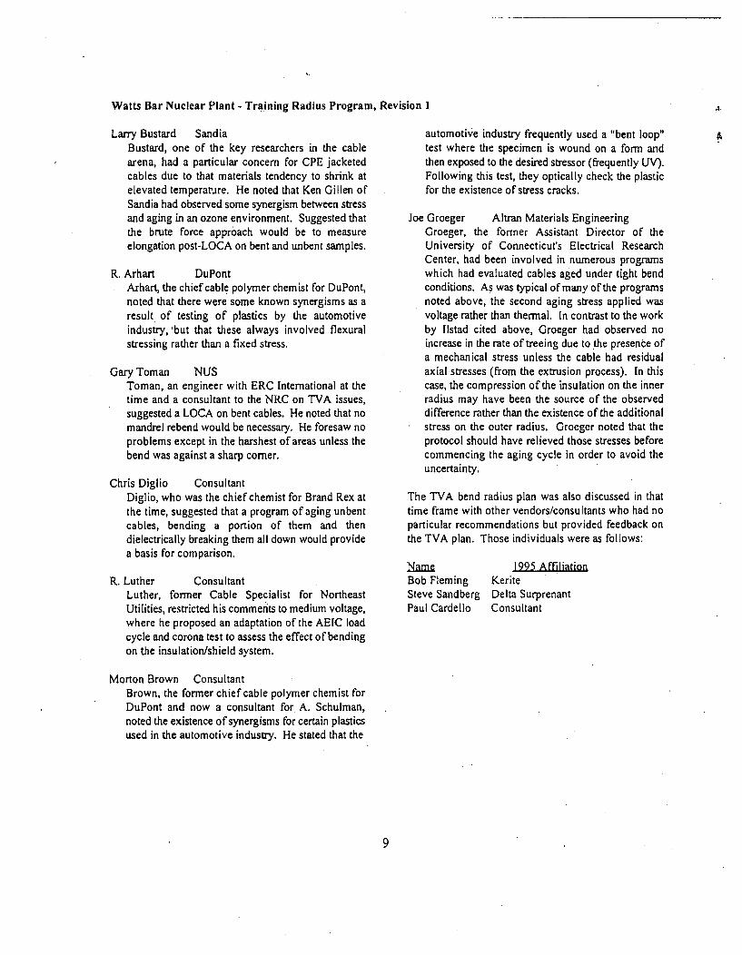
Watts Bar Nuclear Plant - Training Radius Program, Revision 1 .A
Larry Bustard SandiaBustard, one of the key researchers in the cablearena, had a particular concern for CPE jacketedcables due to that materials tendency to shrink atelevated temperature. He noted that Ken Gillen ofSandia had observed some synergism between stressand aging in an ozone environment. Suggested thatthe brute force approach would be to measureelongation post-LOCA on bent and unbent samples.
R. Arhart DuPontArhart, the chief cable polymer chemist for DuPont,noted that there were some known synergisms as aresult of testing of plastics by the automotiveindustry,'but that these always involved flexuralstressing rather than a fixed stress.
Gary Toman NUSToman, an engineer with ERC International at thetime and a consultant to the NRC on TVA issues,suggested a LOCA on bent cables. He noted that nomandrel rebend would be necessary. He foresaw noproblems except in the harshest of areas unless thebend was against a sharp comer.
Chris Diglio ConsultantDiglio, who was the chief chemist for Brand Rex atthe time, suggested that a program of aging unbentcables, bending a portion of them and thendielectrically breaking them all down would providea basis for comparison.
R. Luther ConsultantLuther, former Cable Specialist for NortheastUtilities, restricted his commenits to medium voltage,where he proposed an adaptation of the AEIC loadcycle and corona test to assess the effect of bendingon the insulation/shield system.
Morton Brown ConsultantBrown, the former chief cable polymer chemist forDuPont and now a consultant for A. Schulman,noted the existence of synergisms for certain plasticsused in the automotive industry. He stated that the
automotive industry frequently used a "bent loop"test where the specimen is wound on a form andthen exposed to the desired stressor (frequently UV).Following this test, they optically check the plasticfor the existence of stress cracks.
Joe Groeger Altran Materials EngineeringGroeger, the former Assistant Director of theUniversity of Connecticut's Electrical ResearchCenter, had been involved in numerous programswhich had evaluated cables aged under tight bendconditions. As was typical of many of the programsnoted above, the second aging stress applied wasvoltage rather than thermal, In contrast to the workby [lstad cited above, Groeger had observed noincrease in the rate of treeing due to the presence ofa mechanical stress unless the cable had residualaxial stresses (from the extrusion process). In thiscase, the compression of the insulation on the innerradius may have been the source of the observeddifference rather than the existence of the additionalstress on the outer radius. Groeger noted that theprotocol should have relieved those stresses beforecommencing the aging cycle in order to avoid theuncertainty.
The TVA bend radius plan was also discussed in thattime frame with other vendors/consultants who had noparticular recommendations but provided feedback onthe TVA plan. Those individuals were as follows:
NameBob FlemingSteve SandbergPaul Cardello
1995 AffiihationKeriteDelta SurprenantConsultant
9

Watts Bar Nuclear Plant - Training Radius Program, Revision 1
Table 2 (Table I of listad et. al.)Measured number of vented water trees from the insulation
screen of the sharply coiled cable per 5 mm long section (equal to an area of 230 mm 2)
Number per circumference positionRadius of Aging timecurvature (years) tension compression
(mm)2 3 4 5 6
50 0.3 32 32 32 13 14 9
0.5 68 72 58 10 4 6
70 0.3 21 25 42 14 11 5
0.5 26 71 71 17 10 2
100 0.3 33 16 32 8 8 12
0.5 51 90 91 19 2 to
Testing to Establish "Lower Bound":
In order to assess the parameters discussed above, testswere initiated by TVA at its Central LaboratoriesServices Department23 (CLSD) in Chattanooga and atThe Okonite Company2" in Ramsey, NJ. Theseevaluations, which are type test in nature, wereconducted in accordance with each lab's qualityassurance program.
The first CLSD program consisted of the bending ofsingle conductor cables, ranging in size from 16 AWGto 500 MCM, (low and medium voltage) on speciallyconstructed forms. The "lower bound" for such a
specimen was tentatively regarded as the radius at whichsignificant deformation occurred plus one cablediameter (lx) or the minimum practical bend, if nodeformation was noted. An additional specimen wasthen bent to this "lower bound" and subsequentlyretrained to a larger radius (typically the ICEA radius).This step was intended to demonstrate that thenonelastic components (conductor, tape shield, etc.)would not deform during the retraining. In order tosimulate conditions in "mid-run", the strands of theconductor were soldered together so that they could notmove past one another to relieve the bending stress.This was deemed a conservative factor, since many ofthe tight bends actually occur in the near vicinity of thetermination where such movements are indeed possible.
In the case of the medium-voltage test program, if thetape shield integrity was still present (no separation, nogouging or pinching, etc.) and excessive conductordeformation (i.e., birdcaging) had not occurred, the"lower bound" value was confirmed. In all cases, thelower bound for medium voltage cables turned out to bea function of the theoretical loss of overlap of themetallic tape shield rather than conductor deformationor interracial disruptions. The postulated separation wasdetermined by comparing the minimum permissible tapeoverlap (10%) as directed by ICEA requirements orTVA procurement specifications with the bend factorwhich results in that degree of stress. Since the tape
23 CLSD Report 90-1014, "Test to DocumentCable Bend Radius Damage", June 1990. CLSDReport 90-1817, "Multi-Conductor Cable BendRadius Damage Tests", January 1992. Additionaltests were also performed for TVA's BellefonteNuclear Plant and reported in 92-0459. Those resultswere consistent with the WBN programs.
24The Okonite Company Report 02-6451,"Final Test Report for Cable Bend Radius, Corona andLoad Cycle Testing of 8Kv Medium Voltage Cables",1992.
I0

Watts Bar Nuclear Plant - Training Radius Program, Revision I
does not stretch, the bend was assumed to haveproduced a loss of overlap corresponding to the stress.Thus, for medium voltage the lower bound2 3 wasdetermined to be four2 6.
As noted above, WBN's target training radius for itsmedium voltage (8 kV rated) cables used in Class I Eapplications is 8 times the cable's outer diameter whichproduces less than two percent additional elongatingstress than the ICEA recommended value of twelvetimes. Compared to the ultimate capability of theseinsulations, this increase is insignificant. The criticalissue for these cables is the insulation-to-shield integrity.Using the same method used by the industry to qualifya cable system design (Load Cycling and CoronaTesting), WBN developed and performed a series oftests to address this issue. However, in contrast to theprotocol in AEIC Specifications CS5 and CS61', WBN'stests were performed on cable bent to a four times (4x)multiplier and retrained to 8x, The cables tested met theAEIC requirements and thus established the integrity ofthe insulation-to-shield systems even when subjected toa moderate bending stress.
For low voltage cables, the lower bound was reachedwhen the non-standard bend produced a 3% conductordeformation 2" or at the minimum practical bend when
that did not occur (the 3% criteria was establishedfollowing discussions with various cable vendors). Thelower bound for low-voltage cables 10 AWG andsmaller was set at a bend radius factor of one and wasset at two for cables 8 AWG and larger.
In order to ensure that the guidance provided inRockbestos Technical Bulletin 28 was adequate formulticonductor cables which had been previously bentdown to, but not below the lower bound and thenretrained, additional testing was performed on tenspecimens. Since the concern for this construction typeis for insulation deformation (as opposed to theconductor), the test plan called for the measurement ofinsulation thickness at the point of greatest deformation.The cables were deemed to be acceptable as long as thewall thickness measured at that point exceeded theICEA minimum (ie 90% of the nominal wall thickness).All specimens met the above criteria.
Development of Inspection/Acceptance Criteria:
Having thus defined the mechanisms of concern andhaving established lower bound values, a review wasinitiated to correlate this information with industrystandards, vendor letters, voltage and current loadingrequirements, cable construction, and environmentalparameters.
2 As noted above, the "lower bound" valuesdefined the onset of damage and were not used toestablish permissible training radii in the field.
26Additional tests were performed for TVA'sBrowns Ferry Nuclear Plant on 5kv cables bent to 6x.Those tests were conducted at Cable TechnologiesLaboratories in New Brunswick, NJ. The results,documented in Report 93-007, were consistent withthe Okonite findings.
27Association of Edison IlluminatingCompanies Specifications, CS5, "Thermoplastic andCross-Linked Polyethylene Insulated Shielded PowerCables Rated 5 through 35 KV" and CS6, "EthylenePropylene Rubber Insulated Shielded Power CablesRated 5 through 69 KV"
28Percent conductor deformation wasdetermined by dividing its post-bend diameter by the
Given the severity of the environmental conditionspostulated in certain areas (and its regulatoryenvironment), WBN decided to take a conservativeapproach in primary containment and the main steamvalve vault and utilize less restrictive criteria elsewherebased on test results and analysis. Results aresummarized in Table 4. Several comments regardingthe table are warranted:
- Class I E 10 CFR 50.492" cables located insideof primary containment and the main steam
pre-bend diameter and subtracting I from the result.
2910 CFR 50.49, Title 10 of the Code of
Federal Regulations, Part 50 (Domestic Licensing ofProduction and Utilization Facilities), section 49,"Environmental Qualification of Electric EquipmentImportant to Safety for Nuclear Power Plants".
II
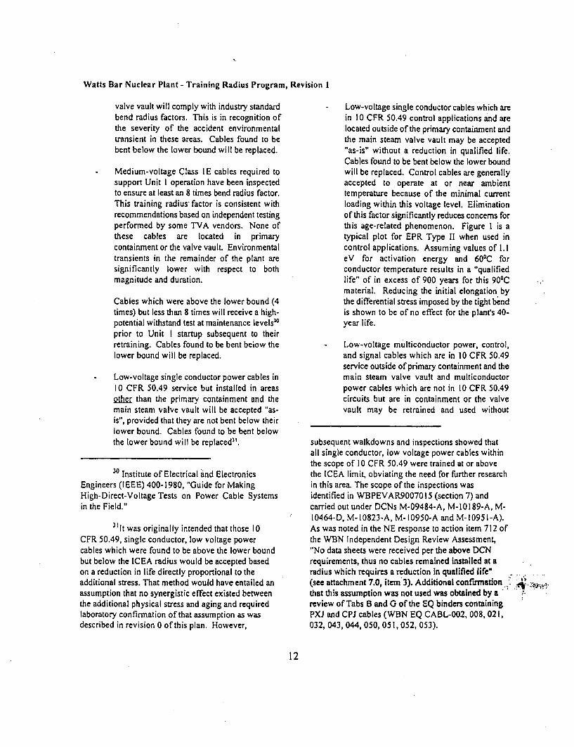
Watts Bar Nuclear Plant - Training Radius Program, Revision 1
valve vault will comply with industry standardbend radius factors. This is in recognition ofthe severity of the accident environmentaltransient in these areas. Cables found to bebent below the lower bound will be replaced.
- Medium-voltage Class I E cables required tosupport Unit I operation have been inspectedto ensure at least an 8 times bend radius factor.This training radius, factor is consistent withrecommendations based on independent testingperformed by some TVA vendors. None ofthese cables are located in primarycontainment or the valve vault. Environmentaltransients in the remainder of the plant aresignificantly lower with respect to bothmagnitude and duration.
Cables which were above the lower bound (4times) but less than 8 times will receive a high-potential withstand test at maintenance levels30
prior to Unit I startup subsequent to theirretraining. Cables found to be bent below thelower bound will be replaced.
Low-voltage single conductor power cables in10 CFR 50.49 service but installed in areasohe.r than the primary containment and themain steam valve vault will be accepted "as-is", provided that they are not bent below theirlower bound. Cables found to be bent belowthe lower bound will be replaced31 .
30 Institute of Electrical and Electronics
Engineers (IEEE) 400-1980, "Guide for MakingHigh-Direct-Voltage Tests on Power Cable Systemsin the Field."
311t was originally intended that those 10CFR 50.49, single conductor, low voltage powercables which were found to be above the lower boundbut below the ICEA radius would be accepted basedon a reduction in life directly proportional to theadditional stress. That method would have entailed anassumption that no synergistic effect existed betweenthe additional physical stress and aging and requiredlaboratory confirmation of that assumption as wasdescribed in revision 0 of this plan. However,
Low-voltage single conductor cables which arein 10 CFR 50.49 control applications and arelocated outside of the primary containment andthe main steam valve vault may be accepted"as-is" without a reduction in qualified life.Cables found to be bent below the lower boundwill be replaced. Control cables are generallyaccepted to operate at or near ambienttemperature because of the minimal currentloading within this voltage level. Eliminationof this factor significantly reduces concerns forthis age-related phenomenon. Figure 1 is atypical plot for EPR Type 1I when used incontrol applications. Assuming values of 1. 1eV for activation energy and 601C forconductor temperature results in a "qualifiedlife" of in excess of 900 years for this 90'Cmaterial. Reducing the initial elongation bythe differential stress imposed by the tight bendis shown to be of no effect for the plant's 40-year life.
Low-voltage multiconductor power, control,and signal cables which are in 10 CFR 50.49service outside of primary containment and themain steam valve vault and multiconductorpower cables which are not in 10 CFR 50.49circuits but are in containment or the valvevault may be retrained and used without
subsequent walkdowns and inspections showed thatall single conductor, low voltage power cables withinthe scope of 10 CFR 50,49 were trained at or abovethe ICEA limit, obviating the need for further researchin this area. The scope of the inspections wasidentified in WBPEVAR,9007015 (section 7) andcarried out under DCNs M-09484-A, M-10189-A, M-10464-D, M- 10823-A, M- 10950-A and M- 1095 I-A).As was noted in the NE response to action item 712 ofthe WBN Independent Design Review Assessment,"No data sheets were received per the above DCNrequirements, thus no cables remained installed at aradius which requires a reduction in qualified life"(see attachment 7.0, item 3). Additional confirationthat this assumption was not used was obtained by areview of Tabs B and G of the EQ binders containingPXJ and CPJ cables (WBN EQ CABL-002, 008,021,032, 043, 044, 050, 051, 052, 053).
12
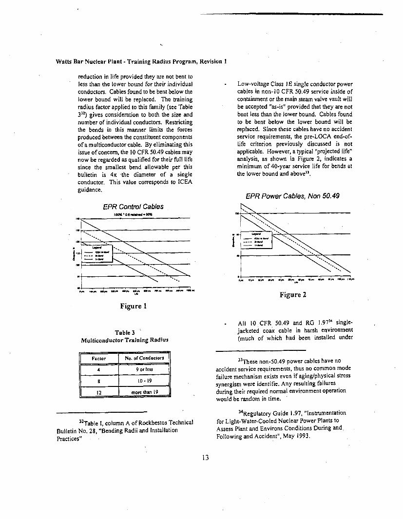
Watts Bar Nuclear Plant - Training Radius Program, Revision 1
reduction in life provided they are not bent toless than the lower bound for their individualconductors. Cables found to be bent below thelower bound will be replaced. The trainingradius factor applied to this family (see Table332) gives consideration to both the size andnumber of individual conductors. Restrictingthe bends in this manner limits the forcesproduced between the constituent componentsof a multiconductor cable. By eliminating thisissue of concern, the 10 CFR 50.49 cables maynow be regarded as qualified for their full lifesince the smallest bend allowable per thisbulletin is 4x the diameter of a singleconductor. This value corresponds to ICEAguidance.
Low-vo)tage Class I E single conductor powercables in non-10 CFR 50.49 service inside ofcontainment or the main steam valve vault willbe accepted "as-is" provided that they are notbent less than the lower bound. Cables foundto be bent below the lower bound will bereplaced. Since these cables have no accidentservice requirements, the pre-LOCA end-of-life criterion previously discussed is notapplicable. However, a typical "projected life"analysis, as shown in Figure 2, indicates aminimum of 40-year service life for bends atthe lower bound and above3".
EPR Power Cables, Non 50.49
EPR Control Cables180% 0,,a@luh-Q0%
Figure 2
Figure 1
Table 3 'Multiconductor Training Radius
Factor [ No. of Conductor3
4 9 or less
8 10-19
12 mom than 19
All 10 CFR 50.49 and RG 1.9711 single-jacketed coax cable in harsh environment(much of which had been installed under
33These non-50.49 power cables have noaccident service requirements, thus no common modefailure mechanism exists even if aging/physical stresssynergism were identifie. Any resulting failuresduring their required normal environment operationwould be random in time.
'"Regulatory Guide 1.97, "Instrumentationfor Light-Water-Cooled Nuclear Power Plants toAssess Plant and Environs Conditions During and,Following and Accident", May 1993.
32Table I, column A of Rockbestos TechnicalBulletin No. 28, "Bending Radii and InstallationPractices"
13

Watts Bar Nuclear Plant - Training Radius Program, Revision 1
* relaxed requirements, Attachments 2 and 5)has been replaced as a result of a concern forjacket integrity following the installationprocess. While jackets are generallyconsidered sacrificial for most other cabletypes, a breach in a coaxial cable's jacket couldlead to moisture wicking up the braid andshorting out the connector. To ensure theintegrity of this moisture barrier, TVA adopteda new design for its harsh environment coaxialcables. The new design incorporates a secondjacket, which serves as the "sacrificial layer",while the inner jacket acts as the moisturebarrier. The new double-jacketed cables willbe installed to meet ICEA requirements.
The remaining cables will be used "as-is."These cables either are not exposed to accidentservice conditions or are not required tomitigate the consequences of such an accident.As such, the margins associated with theremaining cables exceed even those describedabove.
Long-Term Program:
In order to ensure the mechanisms pertinent to cableperformance under small bend radius conditions havebeen properly evaluated for age-related consequences ofsuch bends on normal and accident service, a long-termcable bend radius program plan has been established.It's key components include a condition monitoring,inspections, failure trending, ongoing upgrades and.industry participation.
Cable Condition Monitoring
TVA has initiated a cable monitoring and trendingprogram for WBN. The program invokes a combinationof meggering, high-potential testing and visualinspection to ensure the continued integrity of cables insafety-related systems. WBN's cable conditionmonitoring program has been developed to comply withthe recommendations set forth in IEN 86-493s.
3SUSNRC IE Information Notice (IEN) 86-
49, "Age/Environment Induced Electrical CableFailures."
Since the scope of lEN 86-49 is much broader than bendradius, the cable condition monitoring aspect of TVA'slong-term bend radius program addresses mediumvoltage power, control voltage, and instrumentationvoltage as well as the previously mentioned low voltagepower cables. However, the program does emphasizemonitoring of feeder cables to large motors (100 hp orlarger), because of their consequent higher rate of agingdue to their thermal loading and cycling. This results inthe routine dielectric examination of the very circuitsexpected to first display signs of postulated degradationwhen overbent.
Additional confidence is provided by implementation ofa program that merges the following test and inspectiondata to ensure the early identification of undesirabletrends.
Periodic Testing
Periodic insulation resistance testing on a randomselection of 80 percent of 100 horsepower and largerClass IE motors will be performed on an interval notto exceed 2 refueling outages for WBN. This testingwill be governed by the plant preventivemaintenance program36 . The specific details of thetest and acceptance criteria are addressed on a caseby case basis by the governing maintenanceinstruction".
Testing of Class IE 6.9kV and 480V motors 100 hpand larger is initially done from the breaker cubicles,with motor connected, and therefore, includesverification of the motor power cables. If resultsindicate degraded or questionable insulation, andcleaning or drying of the motor windings, etc. isunsuccessful in bringing the motor/cable intocompliance with the acceptance criteria, the motorleads are then disconnected from the power feedercables and each is tested separately. A generaldescription of the test is provided below but may
36Site Standard Practice (SSP)-6.02,
"Maintenance Management System."
37Maintenance Instruction (MI)-57.108,"Insulation Resistance and Continuity Tests forRotating Machinery, Cables, and Transformers."
14
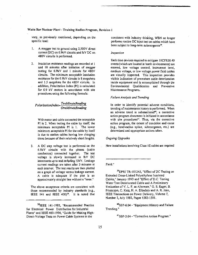
Watts Bar Nuclear Plant - Training Radius Program, Revision I
vary, as previously mentioned, depending on thespecific load:
1. A megger test to ground using 2,500V directcurrent (DC) on 6.9kV circuits and 1kV DC on480V circuits is performed.
2. Insulation resistance readings are recorded at Iand 10 minutes after initiation of meggertesting for 6.9kV 'and 1 minute for 480Vcircuits. The minimum acceptable insulationresistance for the 6.9kV circuits is 8 megohmsand 1.5 megohms for the 480V circuits. Inaddition, Polarization Index (PI) is calculatedfor 6.9 kV motors in accordance with siteprocedures using the following formula:
PolarizationIndex- TenMinuteReadingOneMinuteReading
With motor and cable connected the acceptablePI is 2. When testing the cable by itself, theminimum acceptable PI is 1. The lowerminimum acceptable PI for the cable by itselfis due to station cables having low chargingtimes because of their relatively short lengths.
3. A DC step voltage test is performed on the6.9kV circuits with the phases (cableconductors) connected together. The testvoltage is slowly increased in IkV DCincrements up to and including 13kV. Leakagecurrent readings are taken after 3 minutes ateach interval. The test results are then plottedon a graph of voltage versus leakage current.A cable is adequate if the plot is anapproximately straight line without a "knee."
The above acceptance criteria are consistent withthose recommended by industry standards (e.g.,IEEE 141 and IEEE 400)"'. It is noted that
38IEEE 141-1993, "Recommended Practicefor Electrical Power Distribution for IndustrialPlants" and IEEE 400-1990, "Guide for Making High-Direct-Voltage Tests on Power Cable Systems in the
consistent with industry thinking, WBN no longerperforms routine DC hipot test on cables which havebeen subject to long-term submergence".
Inspection
Each time devices required to mitigate IOCFR50.49events (which are located in harsh environments) areentered, low voltage control, instrument level,medium voltage, or low voltage power field cablesare visually inspected. This inspection providesvisible indication of premature cable deteriorationinside equipment and is accomplished through theEnvironmental Qualification and PreventiveMaintenance Programs.
Failure Analysis and Trending
In order to identify potential adverse conditions,trending of maintenance history is performed. Whenan adverse trend is substantiated"°, a correctiveaction program document is initiated in accordancewith site procedures"1. Thus, via the correctiveaction program, the extent of condition and cause(e.g., bend-radius splice, submergence, etc.) aredetermined and appropriate actions taken.
Ongoing Upgrades
New installations involving Class I E cables are required
Field."
39EPRI TR- 10 1245, "Effect of DC Testing onExtruded Cross-Linked Polyethylene InsulatedCables," January 1993 and "Effect of D.C. TestingWater Tree Deteriorated Cable and A PreliminaryEvaluation of V. L. F. as Alternate," G. S. Eager, B.Fryszczyn, C. Katz, H. A. Elbadaly and A. R. Jean,IEEE Transactions on Power Delivery, Volume 7,Number 3, July 1992, Pages 1582-1591.
4SSP-6.04 - "Equipment History and FailureTrending."
41SSP-3.04 - "Corrective Action Program."
15

Watts Bar Nuclear Plant - Training Radius Program, Revision I
to meet the current Corporate42 and Site procedures 43 ,which were revised to reflect industry standards, Theseprocedures also require that during maintenance andmodification activities an attempt is to be made to bringthe portion(s) of previously installed Class IE cablebeing disturbed into compliance with currentrequirements.
Industry Participation
TVA is currently actively participating in thedevelopment of standards and test methodologiesrelating to cable installation issues. TVA personnel areparticipating in IEEE working groups responsible forIEEE-422, 690, and 1185 and are members of 383 and1186". Furthermore, TVA is one of the major sponsors
42TVA Design Standard, DS-E12.1.5,Revision 4, dated June 22, 1994, "Minimum Radiusfor Field-Installed Insulated Cables Rated 15,000Volts and Less and "General ConstructionSpecification G-38, "Installation, Modification,Maintenance of'Insulated Cables Rated Up to 15,000Volts".
4MMI-57.113 - "Cable Bend Radius",
Instrument Maintenance Instruction (IM I)- 101 -"Instrument Maintenance Planning and Work ActivityGuidelines", IMI-200 - "Periodic Calibration of PlantInstrumentation and Control Equipment", "CablePulling for Modification/Addition Instruction (MAI) -3.3 - "Cable Terminating, Splicing, and Testing forCables Rated Up To 15,000 Volts" andModification/Addition Instruction (MAT) - 3.2 -"Cable Pulling for Insulated Cables Rated Up to15,000 Volts."
44 IEEE 383-1992, "Standard for Type Test ofClass I E Electric Cables, Field Splices, andConnections for Nuclear Power Generating Stations",IEEE 422-1986, "Guide for the Design andInstallation of Cable Systems in Power GeneratingStations", IEEE 690-1984, "Standard for the Designand Installation of Cable Systems for Class I ECircuits in Nuclear Power Generating Stations", IEEE•1185-1994, "Guidelines for Installation Methods forGenerating Station Cables" and IEEE-P 1186,"Recommended Practices for the Evaluation of
of EPRI Cable Life Program and a member of the peerreview group for EPRI Cable Diagnostics Project. As aresult, TVA will be cognizant of developments withinthe industry concerning condition monitoring and bendradius and will incorporate them as appropriate.
Vendor Feedback
In July 1995, Corporate Cable Specialist, Kent W.Brown visited Brand Rex, Rockbestos and The OkoniteCompany for the purpose of reviewing Revision 0s ofthe plan that WBN had undertaken to resolve the issueof tight cable bend radius.
Prior to the meetings an overview of this issue wasprepared and provided to the three companies. Becauseof the detail provided in the white paper, no formalpresentation of the issue was made. Mr. Brown gave ageneral overview of the key points and providedclarifications as requested. Per our agreement with theNRC, the vendors were not requested to "approve" theplan, but to only provide a verbal assessment. A generalreview of the vendor response is as follows:
July 20, 1995BICC Brand Rex, Willimantic, CT 860-456-8000
John L. Macchia PresidentJerry Liskom Market ManagerEd Aberbach Product EngineerRichard Metz QA EngineerChris Durland Senior Applications Engineer,
B ICC, West Nyack, NY
Following the discussions, Mr. Macchia stated thatBrand Rex believed that the bends in questionshould pose no problems for the subject cables. Hestated that industry bend radii were known to beconservative but acknowledged that the degree ofconservatism has not been established. While he didnot believe that such a program should have beennecessary, he noted that BICC Brand Rex was inagreement with the actions to date, as well as those
Installed Cable Systems for Class IE Circuits inNuclear Power Generating Stations."
45 Memo from R. C. Willimas to M. C.Brickey dated July 28, 1996 (B43 950728.005).
16

Watts Bar Nuclear Plant - Training Radius Program, Revision I
remaining to be completed.
July 24 and 25, 1995Rockbestos, East Granby, CT 860-653-8300
Robert Gehm, Sr. Chief EngineerRobert Konnick, Jr. Product Engineer
As at Brand Rex, Mr. Brown provided a generaloverview of the history of cable problems at WBNrelating to the issue of bend radius. Mr. Gehm, whohad been one of those originally surveyed, believedthat the proposed program was sound, thoughbeyond that which should have been required ofTVA. In support of that position he cited threeconsiderations beyond his original comments.
First, he noted that most of the ICEA limits weredeveloped in support of paper-lead cables. Thehelically wound paper tapes have practically noelasticity and required conservative measures toensure that the layers did not tear or buckle. Whenextruded dielectrics .came into wide usage, Mr.Gehm stated that there simply was no compellingreason to change the then current bend radiusfactors.
Second46 , he noted that nuclear grade Raychemproducts (typically cross-linked polyolefins)function by ensuring that there is a residual recoveryforce present after heat-shrinking. Extensive testingof these products for nuclear service has failed toidentify any synergism between that stress andthermal aging. Third, Mr. Gehm noted that it didnot appear that WBN had taken full credit for thefact that even power cables do not run at or near900C. He observed that the reduction of the stressorcertainly results in a corresponding reduction of anypotential synergism.
Regarding ICEA bend radius limits, TVA agrees withGehm's position but note that the basis for selection of
46Comments two and three pertain to thepostulated synergism between physical stress andaging and have thus been made moot (along with theTVA responses) given the absence of bends belowICEA allowables for single conductor power cables in10 CFR 50.49 service.
the appropriate multiplier (paper-lead or polymeric) hasnot been published and thus it is difficult to take creditfor when bending the latter type tighter than thestandards based on the earlier materials permitted.
With respect to the residual stress in Raychem products,Gehm is correct. However, the concerns expressed forthe thermal annealing of other semi-crystalline materialswould likewise apply to the previous Raychem testing.It is for that reason that Raychem products are tested inboth the aged and unaged condition since the unagedproduct would have a higher residual stress andtherefore have a higher for potential for splitting.Raychem takes great pains in choosing its applicationranges to limit those forces. Gehm conceded thatRaychem had thus not been aged in such a manner as tofully retain the stress but noted that this had elicited noregulatory concern and could see no reason why theWBN cables under similar conditions should be of anymore concern. Thus, while the parallel is true, thesuccessful testing of one material applied within itsdesign limit (Raychem) does not automatically cover theuse of another material stressed beyond its design limit(cable).
We agree that there is substantial margin in our cablesizing process given the use of load multipliers, theassumption of no load or time diversity, the assumptionof filled raceways and the use of maximum normalambients. As with other conservatisms, the greatdifficulty lies in the quantification of those margins.Furthermore, this approach assumes that the affect ofaging and stress is small and can thus be offset by theapplication of margin, but this involves assuming thatwhich we have been asked to prove.
July 26 and 27, 1995The Okonite Company, Ramsey, NJ 201-825-0300
John Cancelosi Mgr. of Application Eng
Following the customary review and discussion, Mr.Cancelosi stated that Okonite had no problem withWBN's program as described. It was their opinionthat much of the work was well beyond that whichshould have been necessary but that the program asdescribed was logical anid comprehensive. It was hisopinion that the results of the work would be ofgeneral interest to the industry and that TVA shouldconsider publication or presentation of the data.
17

Watts Bar Nuclear Plant - Training Radius Program, Revision I
The changes to the long term bend radius plan whichnecessitated revision 1 of this document were discussedwith each of the above vendors by K. W. Brown inFebruary and March 1996 following their review of adraft of that revision (B43 960321 003). The purpose ofthat review was to ensure that the vendors still agreedthat the plan would achieve the desired objective. Theresults of those discussions were as follows:
Brand Rex reviewed the draft plan and in a letter to K.W. Brown dated February 29, 1996 (B43 960321 001)noted that they concurred that the plan would ensureearly identification of adverse trends and could notidentify any deficiencies in the TVA approach inaddressing bend radius concerns.
Robert Gehm, Sr of Rockbestos discussed his review ofthe draft plan with K. W. Brown on February 27, 1996.Gehm noted that Rockbestos had no technical objectionsto the revised plan.
John Cancelosi of Okonite discussed his review of thedraft plan with K. W. Brown on March 13, 1996.Cancelosi noted that Okonite had no technicalobjections to the revised plan.
Conclusigon
As a result of the actions undertaken by TVA, includingtesting, field inspection, and rework; 10 CFR 50.49cables inside containment and main steam valve vaultsmeet industry standard bend radius criteria. For theremaining cable population, TVA will utilize lessrestrictive bend radius criteria with correspondingadjustment of qualified life, where appropriate.Ongoing condition monitoring, inspections and failureanalysis, will provide TVA the necessary confirmationof the foregoing evaluations.
Attachments1.0 Okonite, letters dated June 7, 1983 (EEB
830610014), September 29, 1983 (EEB831004003) and August 19, 1986 (B43860821003).
2.0 TVA Design Standard, DS-E12.1.5, Revision0, dated September 20, 1983, "MinimumRadius for Field-Installed Insulated CablesRated 15,000 Volts and Less".
3.0 Rockbestos, letters dated September 8, 1983
(EEB 830913008) and July 25, 1986 (B43860729003).
4.0 Rockbestos Technical Bulletin No. 28, revision3, dated April 25, 1979.
5.0 Brand Rex, letters dated August 29, 1983 (EEB830906006), September 26, 1983 (EEB830930009) and July 29, 1986 (B43860820004).
6.0 TVA Design Standard, DS-E12.1.5, Revision4, dated June 21, 1994, "Minimum Radius forField-Installed Insulated Cables Rated 15,000Volts and Less".
7.0 NE response to action item 712, WBN Unit 1,Independent Design Review Assessment,12/27/1994 (see item 3).
18
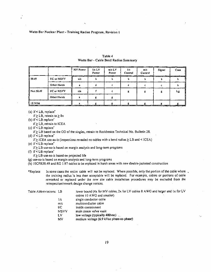
Watts Bar Nuclear Plant - Training Radius Program, Revision I
Table 4Watts Bar - Cable Bend Radius Summary
MV Power I/c LV f m/c LV I/c ta/c Signal Coax
Power Power Control Control
50.49 I/C or NISVV n/a b b b b b h
Other larsh a d C e C C h
Non 50.49 I/C or MSVV n/a f c 9g g h,g
Other larsh a g 9
IE Mild a g gg g g g
(a) if< LB, replace*if> LB, retrain to > 8x
(b) if< LB replace'if> LB, retrain to ICEA
(c) if< LB replace"if> LB based on the OD of the singles, retrain to Rockbestos Technical No. Bulletin 28.
(d) if< LB replace*if> [CEA use-as-is (inspections revealed no cables with a bend radius > LB and < [CEA)
(e) if< LB replace'if> LB use-as-is based on margin analysis and long-term programs
(f if< LB replace'if> LB use-as-is based on projected life
(g) use-as-is based on margin analysis and long-term programs(h) IOCFR50.49 and RG 1.97 cables to be replaced in harsh areas with new double-jacketed construction
*Replace In some cases the entire cable will not be replaced. Where possible, only the portion of the cable wherethe training radius'is less than acceptable will be replaced. For example, cables or portions of cablereworked or replaced under the new site cable installation procedures may be excluded from thereinspection/rework design change notices.
Table Abbreviations: LB
l/cmi/cI/CMSVVLVMV
lower bound (4x for MV cables, 2x for LV cables 8 AWG and larger and Ix for LVcables 10 AWO and smaller)single conductor cablemulticonductor cableinside containmentmain steam valve vaultlow voltage (typically 480vac)medium voltage (6.9 kVac phase-to-phase)
19

FRONT SIDE OF SPECIFICATION REVISION NOTICE (SRN)FOR A GENERAL ENGINEERING SPECIFICATION
QA RECORDJune 23, 2004
Holders of G-40
TVA GENERAL ENGINEERING SPECIFICATION G-40 (R15) FOR " INSTALLATION, MODIFICATIONAND MAINTENANCE OF ELECTRICAL CONDUIT, CABLE TRAYS, BOXES, CONTAINMENTELECTRICAL PENETRATIONS, ELECTRIC CONDUCTOR SEAL ASSEMBLIES, LIGHTING ANDMISCELLANEOUS SYSTEMS"SPECIFICATION REVISION NOTICE SRN-G-40-79
AFFECTS: All Plants; section 3.12.10, 3.12.11 and 3.12,12.
INSTRUCTIONS: The attached pages constitute an advance revision to the subject specification.Insert these pages in that specification in accordance with the instructions on the reverse side of thismemo and then file the memo in the front of each controlled copy of the specification.
SIGN ES/APPROVAL:
PRIZARED
DESIGF4 VFVEIF 1CATJ0N--•.
APPR&
JO oDATE
DATE
The effective date of this SRN is 90 days from the date of issue or sooner upon incorporation into siteprocedures.
The requirements of this SRN are not retroactive. The RIMS number of the SA/SE for this SRN is B43040623 002.
C. R. ButcherManager, Electrical EngineeringCorporate Engineering (LP 4H-C)
kwbAttachmentcc (Attachment):
EDMS,K.W. Brown
DCRM,
WR4Q-CLP 4H-C
LP 4D-C Attached is the SIGNED ORIGINAL; please distribute copies of thismemo and its attachment(s) to all holders of controlled copies of thisgeneral engineering specification and release the RIMS copy.

BACK SIDE OF SPECIFICATION REVISION NOTICE (SRN)
Page 1 of 1
SRN-G-40-79, FILING INSTRUCTIONSREMOVE AND DESTROY I REPLACE WITH
General Engineering Specification G-40 INDEXdated August 25, 2004
Pages: 75
From-G40 R15
General Engineering Specification G-40 INDEXdated June 23, 2004
Pages: 75
From SRN-G-40-79
TENNESSEE VALLEY AUTHORITY
NUCLEAR POWER
ELECTRICAL ENGINEERING
GENERAL ENGINEERING SPECIFICATION
G-40
INSTALLATION. MODIFICATION AND MAINTENANCE OFELECTRICAL CONDUIT, CABLE TRAYS. BOXES, CONTAINMENT
ELECTRICAL PENETRATIONS. ELECTRIC CONDUCTOR SEALASSEMBLIES. LIGHTING AND MISCELLANEOUS SYSTEMS
11111 I1 11111 I11 1 i liii5754552786CHAT GCS ALLG-40082400 15
REVISION R14 R15 R16 R17 R18RO
f R-EPARED CHSudduth KW Brov,,n
VERIFIED
APPROVED
FWChandler JK Greene
"'I I
'j L Nk(,C-?.DBWeaver RC Williams f~.C. tVU[ia*t•
LATE 08/06/75 1/20/1999DATE 08/06/75 1/20/1999
1 /24106

INSTALLATION, MODIFICATION AND MAINTENANCE OF G-40ELECTRICAL CONDUIT CABLE TRAYS, BOXES, REV 15CONTAINMENT ELECTRICAL PENETRATIONS, ELECTRICCONDUCTOR SEAL ASSEMBLIES, LIGHTING ANDMISCELLANEOUS SYSTEMS
Revision Log
Rev. No. DESCRIPTION OF CHANGE- Date14 This revision incorporates the following SRNs: 01/20/1999
* SRN-G-40-74 (B43 950614 001) - Revised section-3.2.1.12-B for BrownsFerry Nuclear Plant.
0 SRN-G-40-75 (B43 950709001).- Revised sections 3,2.1.15.A and 3.2.2.9for Watts Bar Nuclear Plant.
a SRN-G-40-76 (B43 950713 007) - Removed Appendices W_ X Y and Z forAll Plants.
Duplicate notes for Figure 3.2.6-3-1 were deleted from the end of section3.2.6.3. the font size of the notes was reduced to distinguish them from thebody of the Gspec and allow them to be on the same page as the formula.The page reference in the definition of FL was therefore eliminated.
No Safety Assessment was performed for this revision since one had beenperformed on June 14. 1997 (B43 970614 001) on G40 rev. 13 along withSRNs 74, 75 and 76.
The effective date and retroactivity of any SRN included in this revision is asnoted in the SRN.
15 This revision incorporates the following SRNs: 08/25/2000
SRN-G-40-77 (B43 990721 001) - Revised section 3.2.2.9 on internalconduit sealing. An SA/SE was performed for this SRN (T25 990721 957)_
SRN-G-40-78 (B43 991116 001) - Revised sections 1.1.2. 3.2_1.15.A,3.2.2.4. 3.2-6. l.G.4- 3.3.5 and 6 as a result of the Triennial Reviewof the
Gspec. An SA/SE was performed for this SRN (B43 991115-001).
The following editorial changes were also made during this revision:
Re-added:the heading to section 3.2.6, "Flexible Conduit" which had beeninadvertently dropped during earlier revisions
• Corrected the spelling of"Patel" in Table 3.2.6.3-2.* In note 2 for Table 3-2.6.3-2*and reference 6.19 changed the calculation
identifier to CD-Q0999-000001. In order to maintain the tie to its originalidentifier: included the following: "(previously' CEB-CQS-449, B41 940620001)".
No Safetv Assessment was performed for this revision since one had beenperformed for revision 13 along with all subsequent SRNs as noted above.
The effective date and retroactivit- of any SRN included in this revision is asnoted in the SRN.
ii_

INSTALLATION, MODIFICATION AND MAINTENANCE OF G-40ELECTRICAL CONDUIT CABLE TRAYS, BOXES, REV 15CONTAINMENT ELECTRICAL PENETRATIONS, ELECTRICCONDUCTOR SEAL ASSEMBLIES, LIGHTING ANDMISCELLANEOUS SYSTEMS
TABLE OF CONTENTS
Page
PR E FA C E . ...................... ................................................................ ............... v
1.0 GENERAL ...................................................... 1
1 .1 S co p e ............................................. ........... .................. ........... 11.2 Drawings and Other Documents .....- ............................... .............. 31.3 Responsibilities .............................. ................. 51.4 D efi nitions ......... ......... ......................................................................... 5
2.0 M A T E R IA L S ............................................ I. ............................................... 6
2.1 General ................................................. 62.2.. M ajor or Special M aterials................................. ... ....................................... 72.3 M iscellaneous M aterials ................................................................................ 82.4 Material Storage and Handling ...................................... 15
3.0 IN ST A L L A T IO N ...................................................................................................... 16
3 .1 G eneral . .................................................... ..................... . ... 163.2 Conduit .................................................... 163.3 Conduit Boxes ........................................................ 663.4 Cable Trays ........................................... ...... 693.5 Manholes and Handholes ........................................ 713.6 Cable Trenches and Underfloor Ducts .................................. 723.7 Electric Conductor Seal Assemblies (ECSAs) ............................................. 723.8 Containment Electrical Penetrations ............................................... 733.9 Lighting System .................... ........................ .733.10 Communication System ......................... ' ............ . 743.11 Secunity Systems ........................................................ 743.12 M arking and Identification ....................................... 743.13 T olerances .................................. ............ ................................... 76
4-0 VERIFICATION REQUIREM ENTS ........................................................................ 77
4.1 Exposed Conduit ....... .................. .......................................... 774.2 Embedded Conduit ............................................................ 78
iii
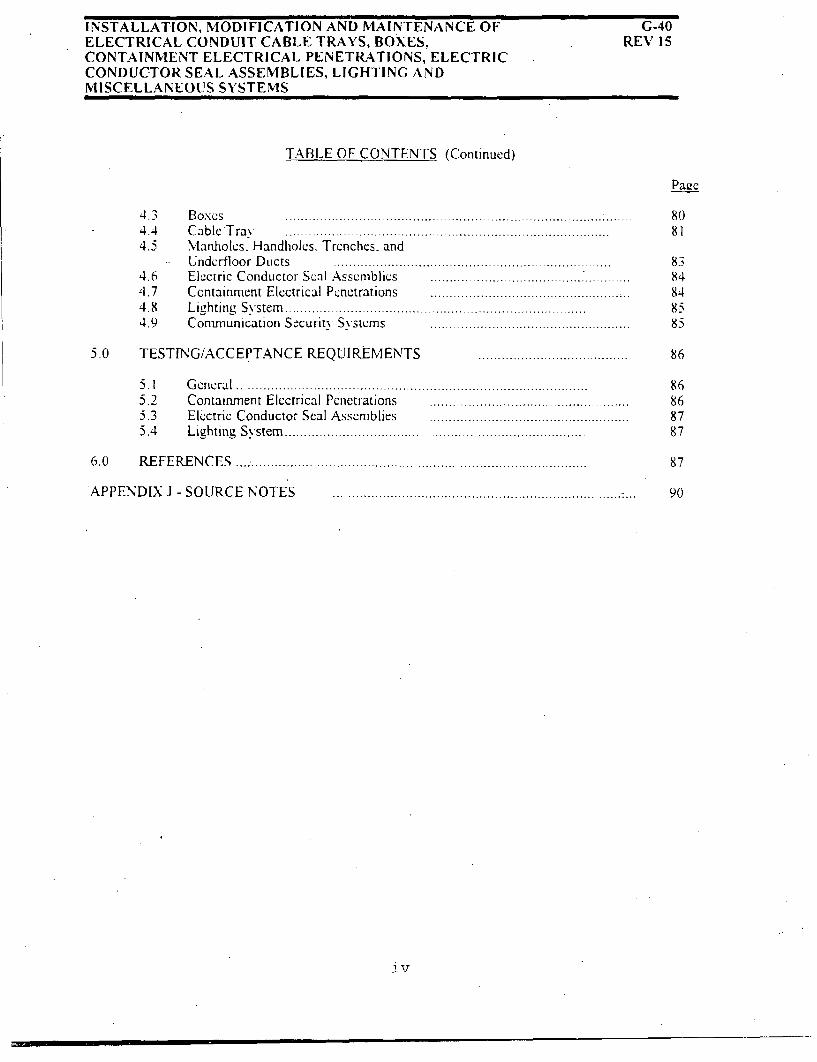
INSTALLATION, MODIFICATION AND MAINTENANCE OFELECTRICAL CONDUIT CABLE TRAYS, BOXES,CONTAINMENT ELECTRICAL PENETRATIONS, ELECTRICCONDUCTOR SEAL ASSEMBLIES, LIGHTING ANDMISCELLANEOUS SYSTEMS
G-40REV 15
TABLE OF CONTENTS (Continued)
Paac
4.3 Boxes4.4 Cable Tray4.5 Manholes. Handholes. Trenches. and
Undcrfloor Ducts4.6 Electric ConductorS .ss , bfics ........ SI A......s.........bli..................4.7 Containm ent Electrical Penetrations ................................................4 .8 L ig h ting S y stem ..............................................................................4.9 Com m unication Security System s ........... ..................................
5.0 TESTING/ACCEPTANCE REQUIREMENTS
8081
8384848585
86
86868787
87
90
5.15.25.35.4
G e n e ra l .......................................................................... ................Containm ent Electrical Penetrations ........ ................Electric Conductor Seal Assemblies .....................................Lighting System ........................................................................
6 .0 R E F E R E N C E S .................................................. ...............................
APPENDIX J - SOURCE NOTES
jv

INSTALLATION, MODIFICATION AND MAINTENANCE OF G-40ELECTRICAL CONDUIT CABLE TRAYS, BOXES, REV 15CONTAINMENT ELECTRICAL PENETRATIONS, ELECTRICCONDUCTOR SEAL ASSEMBLIES, LIGHTING ANDMISCELLANEOUS SYSTEMS
PREFACE-
This. General Engineering Specification supersedes TVA General Construction Specification No. G-3 forBrowns Ferr, Nuclear Plant and all future nuclear plants. It also supersedes Sequoyah Nuclear PlantProject Construction Specification No. N2E-860.
This specification is intended to be-a general guide: therefore, it does not define installation procedures forall possible configurations.
The materials used in the construction of nuclear plants (and other projects) are continually reviewved by theDivision of Occupational Health and Safety (OC H&S). Policy and Coordination Branch, for theiracceptability to the health. and safety of personnel. Should a. material, specified herein become restrictedfrom use. an equivalent materialfapproved by the, OC H&S. Policy and Coordination Branch, shall be used.
Since this specification applies to more than one plant. generic wording must be used to express therequirements. Interpretations or specific applications for each plant which differ from the wording in thisspecification shall be addressed by the Nuclear Engineering group at the site.. This shall be accomplishedby obtaining NE review and concurrence with revisions to site procedures which implement thespecification interpretations. Changes which incorporate wording in this specification verbatim or areoutside the scope of this specification do not require NE review.
V

INSTALLATION, MODIFICATION AND MAINTENANCE OF G-40ELECTRICAL CONDUIT CABLE TRAYS, BOXES, REV 15CONTAINMENT ELECTRICAL PENETRATIONS. ELECTRICCONDUCTOR SEAL ASSEMBLIES, LIGHTING ANDMISCELLANEOUS SYSTEMS
1.0 GENERAL
1.1 Scope
1.1.1 This general engineering specification describes the minimum engineeringrequirements for materials receiving, storage and handling, andinstallation, modifications and maintenance of electrical conduit, cabletrays, boxes, containment electric penetrations, electric conductor sealassemblies, lighting and miscellaneous systems for all nuclear plants, withthe exception of those portions of the design under separate contract.Procedures or instructions provided by the contractor shall be followed forthose portions of the design under separate contract. This specificationsupplements and amplifies the instructions given on the design drawings.
1. 1 .2 Preapproved (prior to construction) variances / exceptions, which havebeen dispositioned by engineering, but do not constitute a generic changeto the requirements of this specification are issued in Exception Manualswvhich are issued and distributed by the applicable site in accordance withNEDP 10. Distribution of these manuals shall be made to all holders ofcontrolled copies of this specification (G-40).
1. 1.3 Browns Ferrv Nuclear Plant:
1.1.3.1 During maintenance activities, only that portion of the. TVAfield-installed conduit raceway system being disturbed is requiredto meet G-40 requirements. Restoration maintenance are thoseconditions wvhere electrical equipment requires a disconnection ofits externally connected conduit system so that maintenance orrework can be performed. Examples of restoration maintenanceare:
A. When a failed electrical component- such as a solenoidvalve, has to be replaced (via a work request).
B. Equipment rework, such as the need to rewind a motor.which requires moving the equipment to a service center.
C. When conduit is temporarily moved to facilitate theremoval/addition of equipment such as a tank, piping. orventilation, duct.
i

INSTALLATION, MODIFICATION AND MAINTENANCE OF G-40ELECTRICAL CONDUIT CABLE TRAYS, BOXES, REV 15CONTAINMENT ELECTRICAL PENETRATIONS, ELECTRICCONDUCTOR SEAL ASSEMBLIES, LIGHTING ANDMISCELLANEOUS SYSTEMS
1.0 GENERAL (Continued)
I 1.3.2 Restoration maintenance to flexible conduit that does not meetG-40 requirements at BFN can be made, provided the followingconditions are met:
A. When specified. the flexible conduit shall be reconnectedas dcfined on design drawings.
B. When not defined on design drawings, flexible conduitcontaining cables listed as safety-related on the Q-listshould be reconnected to meet the requirements of Section3.2.6 unless an approved variance is provided inAppendix W.
C. Flexible conduits which do not contain Q-list cables maybe installed or replaced to the best availableconfiguration.
1.1.3.3 When conduit systems that are part of the vendor furnishedequipment (such as panels, racks, skid-mounted assemblies,motors. etc.) are required to be removed or replaced formaintenance, it may be returned to the as-found length. Theremoval and reconnection of vendor conduit does not constituterestoration maintenance. The replacement of vendor installedconduit is considered restoration maintenance. The repair orreplacement of vendor supplied conduit systems shall be inaccordance with established plant procedures/instructions.

INSTALLATION, MODIFICATION AND MAINTENANCE OFELECTRICAL CONDUIT CABLE TRAYS, BOXES,CONTAINMENT ELECTRICAL PENETRATIONS, ELECTRICCONDUCTOR SEAL ASSEMBLIES, LIGHTING ANDMISCELLANEOUS SYSTEMS
G-40REV 15
I I II III ll I
1.0 GENERAL(Continued)
1.2 Drawintzs and Other Documents
1.2.1 It is the responsibility of engineering to prepare detailed design drawingsand standards for the installation of conduit systems and conduit boxes,The latest revision of the documents or a site-specific document with thesame number listed below, in effect at the time of installation, shall befollowed.
DS-El.2.1
DS-E 1.2.2
DS-E13.1.4
DS-E13.1.6
DS-E13.1.7
• DS-E13. 1.11
* DS-E13.6.1
D DS-E13.6.2
Electrical Nameplates (Browns FerryNuclear Plant and all hvdroelectric- andfossil-fuel plants)
Electrical Equipment Nameplates -Sequoyah and Subsequent NuclearPlants
Conduit - Maximum Cable Diameter for
Various Rigid Steel Conduits
Spacing of Locknuts on Steel Conduit
Dimensions of Rigid and Flexible MetalConduit Bends
PVC Conduit
Raceways, Conduit BoxMinimum Requirements
Design -
Racewavs. Use of Conduit Bodies inConduit Systems
SD-E 13.1.1 Expansion/ContractionEmbedded Aluminum,Metal. and Steel Conduit
Joint forIntermediate
SD-E13.1-2
SD-El.3,4.1
Expansion and Deflection Fitting forEmbedded Aluminum. IntermediateMetal, and Steel Conduit
Concrete Reinforcement Bar Insulationto Reduce Induction Heating

INSTALLATION, MODIFICATION AND MAINTENANCE OFELECTRICAL CONDUIT CABLE TRAYS, BOXES,CONTAINMENT ELECTRICAL PENETRATIONS, ELECTRICCONDUCTOR SEAL ASSEMBLIES, LIGHTING ANDMISCELLANEOUS SYSTEMS
G-40REV 15
1.0 GENERAL (Continued)
1.2.1 (Continued)
* SD-EI3.6.3
SD-EI3.6.5
SD-E15.3.3
SD-EIS.3.4
N3C-944
G-14
G-29
G-34
- Conduit Boxes. Frames, and Covers
- Conduit Box Connection (Watertight)
Conduit. Cable and Wire IdentificationTags (Browns Ferry Nuclear Plant andall non-nuclear projects)
Racewavs. Cable and Wire identificationTags (Sequovah Nuclear Plant and AllSubsequent Nuclear Projects)
Watts Bar Nuclear Plant - EngineeringRequirements Specification. "Conduitand Conduit Support. Installations"
TVA General Engineering Specification."Selecting, Specifying. Applying. andInspecting Paint and Coatings"
TVA General Engineering Specification(Volume VII), "Process Specification forWelding, Heat Treatment.Nondestructive Examination, and AlliedField Fabrication Operations"
TVA General Engineering Specification."Repair of Concrete"
TVA General Engineering Specification."Surface Preparation, Application, andInspection of Special Protective Coatingsfor Nuclear Plants"
G-55
4

INSTALLATION, N1ODIFICATION AND MAINTENANCE OF G-40ELECTRICAL CONDUIT CABLE TRAYS, BOXES, REV 15CONTAINMENT ELECTRICAL PENETRATIONS, ELECTRICCONDUCTOR SEAL ASSEMBLIES, LIGHTING ANDMISCELLANEOUS SYSTEMS
1.0 GENERAL (Continued)
1-2.2 Where specific instructions are lacking on design documents, engineeringshall be requested to provide the necessary information on a case-by-casebasis.
1.2.3 It shall be the joint responsibility of engineering. construction andmodifications/maintenance to record changes on the design drawings thatwere made during construction, modification or maintenance for theas-built record in accordance with established administrative and qualityassurance procedures.
1.3 Responsibilities
Corporate Engineering Electrical (CE-E) is responsible for the contents of thisdocument. The respective site construction manager. engineering manager,modifications manager or maintenance manager. acting directly or throughproperly authorized agents, is responsible for enforcing the requirements of this
general engineering specification.
The Lead Engineer in the site engineering organization is responsible for enforcing
the requirements of this specification.
1.4 Definitions
1.4.1 Class I E. The safety classification of electrical equipment and systemsthat are essential to emergency reactor shutdown, containment isolation,reactor core cooling and containment and reactor heat removal orotherwise are essential in preventing significant release of radioactivematerial to the environment.
1.4.2 Compatible. A material suitable for use with adjoining materials and theenvironment (i.e., proper size, similar materials, such that no adversereaction occurs, able to withstand temperature, radiation and otherharmful parameters for the area, as recommended for use by therespective manufacturer).
5
INSTALLATION, MODIFICATION AND MAINTENANCE OF G-40ELECTRICAL CONDUIT CABLE TRAYS, BOXES, REV 15CONTAINMENT ELECTRICAL PENETRATIONS, ELECTRICCONDUCTOR SEAL ASSEMBLIES, LIGHTING ANDMISCELLANEOUS SYSTEMS
1.0 GENERAL (Continued)
1.4.3 Seismic Catevorv I (Class I at BFN). Those structures. systems orcomponents which perform primary safety functions. They are designedand. constructed to assure achievement of their primary safety functions atall times including a concurrent Safe Shutdown Earthquake (SSE).
1.4.4 Seismic Cateteorv I(L) (Class.II at BFN). Those portions of structures,systems or components which perform secondary safety functions to theextent that only limited-structural integrity is required. They are designedand constructed to assure achievement of their limited structural integrityat all times including a concurrent SSE.
1.4.5 Safe Shutdown Earthquake (SS.E). An--earthquake which produces themaximum vibratory ground motion for- which structures, systems and
.components which perform a primar- safety function are designed toremain functional.
1.4.6 Verif-. An act of confirming. substantiating and assuring that an activityor condition has been implemented in conformance -with the specifiedrequirements. Observation of each activity (event) is required.
1.4.7 Wet Location. Installation underground or in concrete slabs or masonry indirect contact with the earth, and locations subject to saturation withwater or liquids, and locations exposed to-weather and unprotected:
210 MATERIALS
2.1 General
2.1.1 Materials used in the installation of electrical raceway systems shall be inaccordance with TVA standard specifications: otherwise, they shall meetthe requirements of recognized industrv standards (i.e., Undervriter'sLaboratories [ULI: National Electrical Manufacturer's Association[NEMA]) for the cla~s of service for which they are intended or shall beapproved by engineering. The materials shall be compatible with theenvironment and configuration in which they are to be located.
6

INSTALLATION, MODIFICATION AND MAINTENANCE OF G-40ELECTRICAL CONDUIT CABLE TRAYS, BOXES, REV 15CONTAINMENT ELECTRICAL PENETRATIONS, ELECTRICCONDUCTOR SEAL ASSEMBLIES, LIGHTING ANDMISCELLANEOUS SYSTEMS
2.0 MATERIALS (Continued)
2.1.2 Standard specifications applicable to the procurement of electrical conduitand fittings are:* SS-E2 1.000 - Rigid Aluminum Conduit
• SS-E21 -001 - Rigid Steel Conduit (Zinc Coated)* SS-E21.002 - Fittings for Conduit and Outlet Boxes
2.1.3 Throughout this specification materials are referenced as "similar to" orequal to" a specific vendor or manufacturer. Where this occurs,
engineering shall -be consulted for an approved "similar" or "equal"material.
2.2 Maior or Special Materials
Major materials and those of a special nature used in the installation shall bedesignated on detailed design drawings or standard drawings, described in theelectrical bill of material.
7

INSTALLATION, MODIFICATION AND MAINTENANCE OF G-40ELECTRICAL CONDUIT CABLE TRAYS, BOXES, REV 15CONTAINMENT ELECTRICAL PENETRATIONS, ELECTRICCONDUCTOR SEAL ASSEMBLIES, LIGHTING ANDMISCELLANEOUS SYSTEMS
2.0 MATERIALS (Continued)
2.3 Miscellaneous Materials
These materials are of a standard nature and shall be purchased directly byconstruction, modifications- or maintenance, Included are conduit bodies and covers,conduit fittings, joints and terminations, flexible conduit and other minor materialsnecessary for installation. Refer to General Engineering Specification G-38 forrequirements for cable ties, tags and markers.
2.3. 1. a. Conduit accessories such as metallic conduit bodies, fittings, joints,standard couplings, and terminations (except for slip joints aspermitted 'in Sections 3.2.3,7 and 3.2.3.8 and as noted below) shall beof the threaded type and approved for use with conduit systems whichserve as the equipment grounding conductor.
b. Die cast zinc conduit fittings and connectors shall not-be used-insidethe reactor building primary containment which has a boric acidcontainment spray system-
c. Onfly malleable iron or steel fittings shall be used.-
d. Nonmalleable cast iron fittings and bodies may be used with aluminumconduit, only when approved by Nuclear Engineering on a case basis.
8

INSTALLATION, MODIFICATION AND MAINTENANCE OF G-40ELECTRICAL CONDUIT CABLETRAYS, BOXES, REV 15CONTAINMENT ELECTRICAL PENETRATIONS, ELECTRICCONDUCTOR SEAL ASSEMBLIES, LIGHTING ANDMISCELLANEOUS SYSTEMS
2.0 MATERIALS (Continued)
2.3.2 In certain embedded conduit applications, it may be impractical. or verycostly to use threaded couplings. When these situations are encountered,threadless couplings (such as manufactured by Thomas and Betts orequivalent) may be used if the following conditions are satisfied:
23.2.1 The manufacturers instructions regarding installation ofthrcadless couplings shall be followed.
2.3.2.2 Threadless couplings shall. be concrete tight.
2.3.2.3 Threadless couplings shall be made watertight andrustproof in accordance with Section 3.2,4.2.
2.3.2.4 The conduit systems shall be .adequately braced orsupported on each side of the threadless coupling tomaintain the integrity of the fitting during concrete pours.
2.325 The threadless couplings shall be electrical!y continuousor shall be made electrically continuous by means of abonding strap or ground cable attached to the conduitsystem on each side of the fitting.
2.3-4 Split couplings shall not be used in new installations inside category Istructures. Engineering approval for their use as a replacement.of existingsplit couplingsis contingent upon the following:
2.3.4.1 The manufacturer.s instructions concerning installation ofthe split couplings (such as tightening of bolts) shall becarefullv observed.
2.3.4.2 Where grounding of the conduit system is required and tobe accomplished by brazing a ground wire to the top ofthe split coupling, the neoprene gasket shall betemporarily removed before the brazing process. Brazingshall be done in accordance with General EngineeringSpecification G-29 (Volume VII).
2.3.4.3 The joint shall be made watertight and rustproof inaccordance with Section 3.2,4.2.
9

INSTALLATION, MODIFICATION AND MAINTENANCE OF G-40ELECTRICAL CONDUIT CABLE TRAYS, BOXES, REV 15CONTAINMENT ELECTRICAL PENETRATIONS, ELECTRICCONDUCTOR SEAL ASSEMBLIES, LIGHTING ANDMISCELLANEOUS SYSTEMS
2.0 MATERIALS (Continued)
2.3.5 Threads on conduit or conduit stubups. which have been damaged to theextent of preventing the installation of couplings, shall be rethreadedusing conventional threading equipment. Where this repair method isimpractical, Threadmaker Conduit Fittings (Crouse-Hinds). orequivalent. may be used for extending the conduit system.
Copper-silicon alloy. brass. or plastic conduit plugs shall be used wherespare conduits are terminated in wet places, except for conduitspenetrating fire barrier (see Section 3.2.1.9).
If additional restrictions or limitations are required on miscellaneousmaterials to be purchased by construction, modifications.or maintenance,these restrictions shall be so stated on the design drawings.
2.3.6 Bellefonte Nuclear Plant
2.3.6.1 Stainless steel flexible conduit -shall be used insideprimary containment. The. following types of stainlesssteel flexible conduit are acceptable for these application:
A. ServicAir Company SS60. SS63 or SS63C series, or
B. American Boa, Inc-, type NBI-0 or NBI-l series, orequal.
Connector fittings of compatible material available fromthe respectable manufacturer shall be used. The stainlesssteel flexible conduit and appropriate connector fittingsshall be installed in accordance with the manufacturer'sinstructions: however, no pressure test of the stainlesssteel flexible conduit is required, unless required as a partof equipment seal.
2.3.6.2 Pressure-tight stainless steel flexible conduit (ServicAirSS63C extra flexible stainless steel), as defined on designdrawings and as approved for use by engineering, shall beused for installations where an equipment seal is required.
10

.INSTALLATION, MODIFICATION AND MAINTENANCE OF G-40ELECTRICAL CONDUIT CABLE TRAYS, BOXES, REV 15CONTAINMENT ELECTRICAL PENETRATIONS, ELECTRICCONDUCTOR SEAL ASSEMBLIES, LIGHTING ANDMISCELLANEOUS SYSTEMS
2.0 MATERIALS (Continued)
2.3.6.3 In areas outside primary containment/dcwvell, liquid-tightflexible metal conduit with a svnthetic jacket (similar tothe Anaconda Company. Brass Division. "Scaltite- typeUA" for available sizes, or equal) and connectors (similarto Ideal Industries, Incorporatedr "Vap-Oil-Tight" series,or equal) shall be used for flexible conduit applications,unless otherwise noted on design-drawings. Stainless steelflexible conduit described above may be used in theseareas.
2.3.7 Sequoyah Nuclear Plant
2.3.7.1 The following flexible conduit shall be used forapplications inside primar- containment and may be usedoutside primal containment. Liquid-tight flexible metalconduit with a synthetic jacket in trade sizes through 4inches shall meet the requirements of UL 360, and liquid-tight connector fittings shall be used which meet therequirements of UL 5 14B. Anemet Inc. Type EF withcompatible connector fittings shall be used for 5-inch and6-inch trade sizes.
2.3.7.2 Stainless steel flexible conduit with a convolute corestructure (similar to ServicAir Company type SS60,SS63 or SS63C; or American Boa, Incorporated, typeNB1-0 or NBI-1 series) and connector fittings orcompatible material (available from the respectivesupplier) may be used in other areas, except insideprimary containment. The stainless steel flexible conduitand appropriate connector fittings shall be installed in'accordance with the manufacturer's instructions. however.no pressure test of the stainless steel flexible conduit is.required. unless required as part of the equipment seal.Stainless steel flexible conduit installations for Class IEapplications shall be analyzed by Civil Engineering forseismic qualification.
2.3.7.3 Flexible conduit connector fittings shall be of the typeapproved for providing continuous ground continuity.
i1

iNSTALLATION, MODIFICATION AND MAINTENANCE OF G-40ELECTRICAL CONDUIT CABLE TRAYS, BOXES, REV 15CONTAINMENT ELECTRICAL PENETRATIONS, ELECTRICCONDUCTOR SEAL ASSEMBLIES, LIGHTING ANDMISCELLANEOUS SYSTEMS.
2.0 MATERIALS (Continued)
2_-.8 Watts Bar Nuclear Plant
2.3:8. I American Boa. Incorporated. Type NBI-0 stainless steelflexible conduit and connector fittings of compatiblematerial (available from the supplier) shall be used insideprimary containment and the main steam valve vaults.The stainless steel flexible conduit and appropriateconnector fittings shall be installed in accordance with themanufacturer's instructions.
The manufacturer instructions requiring the application ofthe primer to the inside of the conduit and the threadedportion of the seal and the instruction to apply RTVcompound-to the threaded portion.of the conduit seal- isnot required.
Liquid-tight flexible conduit installed inside containmentprior to April 1. 1994. is acceptable. ýNTiN. , After April 1.1994. if rework involving replacement of liquid-tightflexible conduit inside containment occurs, AmericanBOA shall be used and installed in accordance w\ith therequirements. of this section.
2.3.8.2 Liquid-tight flexible metal conduit with a synthetic jacketand liquid-tight connector fittings may be used in all otherareas. Trade sizes through 4 inches shall meet therequirements of UL standards. Anemet Inc.. Type *EFwith compatible connector fittings shall be used for 5-inchand 6-inch trade sizes.
Note: Unless otherwise restricted by design dravings.American BOA. Inc flexible metal conduit as specified insection 2.3.8-1 may be used in any location where use ofliquid-tight flexible metal conduit with a synthetic jacketis permitted.
123

INSTALLATION, MODIFICATION AND MAINTENANCE OF G-40ELECTRICAL CONDUIT CABLE TRAYS, BOXES, REV 15CONTAINMENT ELECTRICAL PENETRATIONS, ELECTRICCONDUCTOR SEAL ASSEMBLIES, LIGHTING ANDMISCELLANEOUS SYSTEMS
2.0 MATERIALS (Continued)
2.3.8.3 Replacement of ServicAir Company stainless steelflexible conduit shall be as follows:
A. The replacement of TVA installed, ServicAir Companystainless steel flexible conduits utilized in Class Itapplications inside primary containment and the mainsteam valve vaults shall comply wvith Section 2.3.8.1.Replacement of TVA installed ServicAir stainless steelflexible conduit in the Turbine Building is not requiredunless the flexible conduit is subsequently reworked. Ifrework does occur in the future, the Service Air Companystainless steel flexible conduit shall be replaced inaccordance with Section 2.3.8.2. In all other plant areas,the replacement of TVA installed Service Air Companystainless steel flexible conduits utilized in Class IEapplications shall comply with Section 2.3.8.2.
B. Replacement of TVA installed Service Air Companystainless steel flexible conduits utilized in non-Class IEapplications is not required unless the flexible conduit issubsequently reworked. If rework does occur in thefuture, the Service Air Company stainless steel flexibleconduit shall be replaced in accordance with Section2.3.8, 1 or 2.3.8.27 as applicable.
C. Vendor installed Service Air Company stainless steelflexible conduits on a vendor qualified (Class IE)packaged unit does not require replacement except asfollows. If TVA has modified the vendor's configurationin the past or if TVA modifies the vendors configurationin the future (relocate components, add components. etc).then change out of the vendor installed Service AirCompany stainless steel flexible conduits shall also beperformed: replacement shall be the same as described forTVA Class IE installations in section 2.3.8.3.A above.Change out of vendor installed Service Air Companystainless steel flexible conduits on a vendor's packagedunit which is unqualified shall be the same as for TVAnon-Class IE installations described in Section 2.3.8.3.Babove, W',N-7
1.3

INSTALLATION, MODIFICATION AND MAINTENANCE OF G-40ELECTRICAL CONDUIT.CABLE TRAYS, BOXES, REV 15CONTAINMENT ELECTRICAL PENETRATIONS, ELECTRICCONDUCTOR SEAL ASSEMBLIES, LIGHTING ANDMISCELLANEOUS SYSTEMS
2.0 MATERIALS (Continued)
2.3.9 Browns Ferry Nuclear Plant
2.3.9. I Liquid-tight flexible metal conduit with a synthetic jacketand liquid-tight conncctor fittings may be used in allareas. Trade sizes through 4-inch shall meet therequirements of UL standards. Anemet Incorporated.Type EF or Electric-flex type LT with compatibleconnector fittings shall be used for 5-inch, trade sizes.
23.9.2 Wh'en shown on design.drawings. it shall be permissibleto use pressure-tight stainless steel flexible conduit with aconvolute core structure (similar to Service Air CompanyType SS60. SS63. or SS63C: American BoaIncorporated. Type NB 1-0 or NB 1-I series or Patel/EGS)and connector fittings of compatible material (availablefrom the respective supplier) at BFN_
Pressure-tight stainless steel flexible conduit (ServicAirSS63C extra flexible stainless steel), as defined on thedesign drawings and as approved for use by engineering,shall be used for installations where an equipment seal isrequired.
2.3.9.3 Liquid-tight flexible metal conduit with a synthetic jacket(similar to the Anaconda Company, Brass Division."Sealtite type UA" for available sizes or equal) andconnectors (similar to Ideal Industries. Incorporated."Vap-OiI-Tight" series or equal) shall be used for flexibleconduit applications, unless otherwise noted on designdrawings. Stainless steel flexible conduit described abovemay be used in these areas.
14

INSTALLATION, MODIFICATION AND MAINTENANCE OF G40ELECTRICAL CONDUIT CABLE TRAYS, BOXES, REV 15CONTAINMENT ELECTRICAL PENETRATIONS, ELECTRICCONDUCTOR SEAL ASSEMBLIES, LIGHTING ANDMISCELLANEOUS SYSTEMS
2.0 MATERIALS (Continued)
2.4 Material Storage and Handling
2.4.1 External threaded. ends of conduit and fittings- shall be protected during-shipment, storage, and handling to prevent damage and exclude dirt, moisture,and other foreign substances.
2.4.2 Conduit shall not be stored on end, but must be sloped for-drainage whenstored in an ANSI N45.2.2 Class D environment.
2.4.3 Conduit, conduit fittings and conduit boxes may be stored to ANSI N45.2.2Class D requirements.
2.4.4 To prevent warping during storage, plastic conduit shall be stacked on a.smooth, flat surface in an area not directly exposed to the rays of the sun.Spacers of 1-inch soft wood, approximately 2 feet apart, should be usedbetween layers. of conduit. Manufacturer's shipping bundles may also be usedfor direct storage.
15

INSTALLATION, MODIFICATION AND MAINTENANCE OF G-40ELECTRICAL CONDUIT CABLE TRAYS, BOXES, REV 15CONTAINMENT ELECTRICAL PENETRATIONS, ELECTRICCONDUCTOR SEAL ASSEMBLIES, LIGHTING ANDMISCELLANEOUS SYSTEMS
3.0 INSTALLATION
3.1 General
3.1.I Installation of conduit. boxes. fittings and accessories shall conform tothe latest design drawings, standards and specifications described inSection 1-2 and manufacturer's instructions provided in the vendorcatalog for the particular part number or instructions provided with thecontract. In the event of a conflict between design drawings. standards orthis specification. this specification shall govern: however, for Watts Bar.conflicts between these documents and N3C-944, the N3C-944 shallgovern.
3.1.2 Unless specifically called for on the detailed design drawings or otherwisepermitted (see Section 3.2.2.4) by site specific procedures. structuralsteel or reinforcing bars- shall not be cut or drilled in category Istructures.
3.2 Conduit
3.2.1 General
3.2.1.1 Conduit exposed to the weather, embedded in concrete orin wet locations shall, be sloped for drainage. If it is notpossible to slope or if the slope causes interferences -theinstallation shall be analyzed by engineering and resolvedprior to completion. Embedded conduit systems shall berigidly supported and braced in position to avoid settlingor floating and to prevent the formation of air pockets ifheavv batches of concrete are placed on the conduit.
16
INSTALLATION, MODIFICATION AND MAINTENANCE OF G-40ELECTRICAL CONDUIT CABLE TRAYS, BOXES, REV 15CONTAINMENT ELECTRICAL PENETRLATIONS. ELECTRICCONDUCTOR SEAL ASSEMBLIES, LIGHTING ANDMISCELLANEOUS SYSTEMS
3.0 [NSTALLATION (Continued)
3.2.1.2 To protect the cables during installation, a bushing, chasenipplc or conduit bodies (such as a condulet) shall be usedat the end of aconduit run where it terminates at a pieceof equipment or cable tray. Where equipment, designprohibits their use due to space limitations, these conduitaccessories max be omitted provided the end of theconduit is deburred and one of the following optionsexercised:
A. *The end of the conduit shall be beveledor rounded to atleast a 1/16-inch radius. or
B. The end of the conduit shall be fitted with a collar (i-e.. aplastic protective end cap for protecting cable. duringinstallation).
NOTE: Conduit bushings may be eliminated at Watts BarNuclear Plant (-WBN) equipment for flexible conduitfittings and other connectors if all the followingconditions apply: (1) there are no sharp edges or burrswhich could contact the cable, (2) the edge of the fittingor connector is rounded by the manufacturer to aminimum 1/16-inch or contains an insulated' sleeve, topreclude any damage, (3) the cable jacket has not beenremoved, and (4) the cables are not pulled tightly acrossthe edge of the fitting.
3.2.1.3 The total sum of all bends in a conduit run shall notexceed 360' between pullpoints.
17

INSTALLATION, MODIFICATION AND MAINTENANCE OF G-40ELECTRICAL, CONDUIT CABLE TRAYS, BOXES, REV 15CONTAINMENT ELECTRICAL PENETRATIONS, ELECTRICCONDUCTOR SEAL ASSEMBLIES, LIGHTING ANDMISCELLANEOUS SYSTEMS
3.0 INSTALLATION (Continued)r
3.2.1.4 Field-installed pullpoints, such as conduit bodies. shall beadcquately sized to accommodate the required splices orlerrninations (e.g.. interfaces wvith devices with pigtails) asapplicable, or in accordance with Design StandardDS-E13.6.2. and to accommodate- the minimum trainingradius of the cable (see Section 3.2.1.3 of GeneralEngineering Specification G-38). Conduit bodies shall beinspected for sharp edges or burrs which-could contactthe cables, and if present. ground smooth prior toinstallation.
A- Conduit bodies shall not be installed as pull points inconduit systems to be used-for the installation of mediumvoltage (5 to 15KV) power cables.
B. Standard conduit bodies shall not be. installed as pullpoints for 300 kcmil and larger low voltage power cables:however, mogul fittings may be used if they allow thecable to maintain minimum training radius requirementsat all times (G-38 Section 3.2. 1.3). 'F, .• Straight conduitbodies may be installed for injecting lubricant.
3.2.1.5 Provisions shall be made for supporting cables in verticalconduit runs if required by General EngineeringSpecification G-38, Section 3.2.1.9. Conduit bodies(ELLS, TEES) shall not be installed at the top of verticalconduit sections that exceed:
* 25 feet in length for conduit sizes 1-1/2" andsmaller,
, 20 feet in length for 2" and 2-1/2" conduit.• 15 feet in length for 3" conduit.* 12.5 feet in length-for 4:' conduit, and* 10 feet in length for 5" conduit, unless othervise
authorized by engineering:
If a pullpoint is required at the top of a vertical sectionexceeding the lengths above, a conduit box shall beinstalled. For vertical runs less than the lengths above.standard conduit bends are preferred at the top of thevertical run in lieu of conduit bodies. The minimum cabletraining radius shall not be violated-(see Section 3.2.1.3,General Engineering Specification G-38). kk-8--
18

INSTALLATION, MODIFICATION AND MAINTENANCE OF G-40ELECTRICAL CONDUIT CABLE TRAYS, BOXES, REV 15CONTAINMENT ELECTRICAL PENETRATIONS, ELECTRICCONDUCTOR SEAL ASSEMBLIES, LIGHTING ANDMISCELLANEOUS SYSTEMS
3.0 INSTALLATION (Continued)
3.2. 1.6 After a conduit run is completed. it shall be examined andcleaned out. Anv accumulation of trapped liquids shall beremoved.
3.2 1.7 Conduit identification tagging shall accompany the conduitinstallation. The tagging and identification shall be asdesignated on the conduit design drawings and/or conduitschedule and in accordance with Standard DrawingSD-E 15.3.3 or SD-E 15.3.4. Unscheduled- lighting conduitsarc exempted from this requirement.
In yard areas where conduits are exposed to the naturalenvironment, the conduit tag may be of 1/2-inch minimumwidth stainless steel or aluminum ribbon material wvith thedesignation made using a Dvmo tapewriter (or equivalent).For additional identification requirements of exposed
conduits see Section 3.2.6.
3.2.1.8 Reducers (or enlargers) may be used in the followingapplications:
A. To mate up the incoming conduit (rigid. or flexible) to adevice supplied with hubs or knockouts which do not match,the size of the incoming conduit (reduction in conduit size.unless specified on design drawings, must be approved byengineering and documented on appropriate drawings) or
B. To mate up rigid conduit to flexible conduit wheremismatched conduit sizes are specified on design drawvings.or to oversized conduit fittings.
Coat male threads as defined on design drawings: wvhere notdefined, coat per Section 3.2.4.2 or Section 3.2.4.3.
3.2.1.9 Where design drawings do not specify otherwise. spareconduits and wall sleeves wvhich penetrate fire barriers shallbe sealed and end capped with steel- conduit plugs. Ifconduit/sleeve configurations do not permit steel conduitplugs or caps to be used. refer to design drawings foraltemate methods of sealing.
19

INSTALLATION, MODIFICATION AND MAINTENANCE OF G-40ELECTRICAL CONDUIT CABLE TRAYS, BOXES, REV 15CONTAINMENT ELECTRICAL PENETRATIONS, ELECTRICCONDUCTOR SEAL ASSEMBLIES, LIGHTING ANDMISCELLANEOUS SYSTEMS
3_0 INSTALLATION (Continued)
3._?1.10 Rigid conduit fittings shall be installed wrench tight usingcommonly available tools: wrench tight shall be defined as"not being able to rotate or remove by hand at the joint orfitting". Rigid conduit fittings may be backed off up to amaximum of one full turn for alignment purposes. Whenthis occurs, a lock nut or a Right Angle K-Clamp (byAppleton Electric Co.) shall be installed at the fitting toensure-electrical continuity.
3.2.1.11 Sequoyah Nuclear Plant
A. Separation of Conduit From Pipes
I. Rigid and flexible conduits shall be separated from hotpipes and their insulation (system numbers 0L 03. 05.06 12. 15 43 44 62. 68. 74. and all branch lines two-inches and larger connecting to these systems up to thefirst normally closed isolation or check valve) as notedbelow (valve stems and bonnets are considered part ofthe pipe):
a. Conduits and Vertical Hot Pipes
Conduits running adjacent to hot pipes (bothparallel and nonparallel) shall have a minimumseparation of six inches.
b. Conduit and Horizontal Hot Pipes
Conduits running parallel to and above hotpipes shall be separated from the pipe aminimum of 1.5 times the diameter of the pipeincluding the insulation. The zone of influenceshall also include the area six inches outside thepipe insulation (see -Figure 3.2.1.11-I).Conduits running adjacent to and below hotpipes (both parallel and nonparallel) shall beseparated b\ a minimum of six inches-Conduits in nonparallel configurations locatedabove hot pipes shall be separated by aminimum of six inches.
20

INSTALLATION, MODIFICATION AND MAINTENANCE OF G-40ELECTRICAL CONDUIT CABLE TRAYS, BOXES, REV 15CONTAINMENT ELECTRICAL PENETRATIONS, ELECTRICCONDUCTOR SEAL ASSEMBLIES, LIGHTING ANDMISCELLANEOUS SYSTEMS
3.0 INSTALLATION (Continued)
3.2.1.11 (Continued)
NOTES:
(0)- Flexible conduits connecting to enddevices attached to hot pipes should beoriented perpendicular to the pipe-andshall, not be routed above the hot pipe,unless approved by engineering.
(2) If the.pipe insulation- has- been removed.an insulation thickness- of four andone-half inches shall be- used fordetermining separation distances or thedesign insulation thickness shall beobtained from the drawNings.
(3) No conduit separation. from. instrumentsensing lines is required for temperatureconsiderations.
(4) Conduits and pipes are considered to beparallel if they form an angle of less than20' to each other.
21_

INSTALLATION, MODIFICATION AND MAINTENANCE OF G-40ELECTRICAL CONDUIT CABLE TRAYS, BOXES, REV 15CONTAINMENT ELECTRICAL PENETRATIONS, ELECTRICCONDUCTOR SEAL ASSEMBLIES, LIGHTING ANDMISCELLANEOUS SYSTEMS
3.0 INSTALLATION (Continued)
3.2. I.1 (Continued)
B. Appendix R Conduit Separation
1. Compliance -with the intent of IOCFR50 Appendix R isbased on physical separation between cables forredundant functions. Essential Appendix R Fire SafeShut Down (FSSD) conduits identified in CCRS shall
be installed within the areas identified-on the AppendixR separation sketches and instructions provided in thedesign change notice (DCN) or engineering changenotice (ECN)-Mod package.
2. As-installed location of essential Appendix R conduitsshall be field- verified; Nuclear Construction (NC)shall notif' the Nuclear Engineering (NE) leadelectrical engineer upon completion of essentialAppendix R conduit installation.
3. Essential Appendix R (FSSD) conduits shall not berelocated (more than- 6- inches- horizontal) without NEnotification and vritten concurrence.
22

INSTALLATION, MODIFICATION AND MAINTENANCE OFG-40ELECTRICAL CONDUIT CABLE TRAYS, BOXES, REV 15CONTAINMENT ELECTRICAL PENETRATIONS, ELECTRICCONDUCTOR SEAL ASSEMBLIES, LIGHTING ANDMISCELLANEOUS SYSTEMS
3.0 INSTALLATION (Continued)
3.2.1.12 Browns Ferry Nuclear Plant
A. Separation of Conduit from Pipes
New installations of rigid and flexible conduits shall beseparated from hot pipes and their insulation as notedbelow:
1. Conduits and Vertical Hot Pipes
Conduits running adjacent to insulated hot pipes(both parallel and nonparallel) shall have aminimum separation of six inches.
2, Conduit and Horizontal Hot Pipes
Conduits running parallel to and above insulatedhot pipes shall be separated from the pipe aminimum of 1.5 times the diameter of the pipeincluding the insulation. The zone of influenceshall also include the area six inches outside thepipe insulation (see. Figure 3.2.1.1 - 1). Conduitsrunning adjacent to and belowv hot pipes (bothparallel and nonparallel) shall be. separated by aminimum of six inches. Conduits in nonparallelconfigurations located above hot pipes shall beseparated by a minimum of six inches.
23
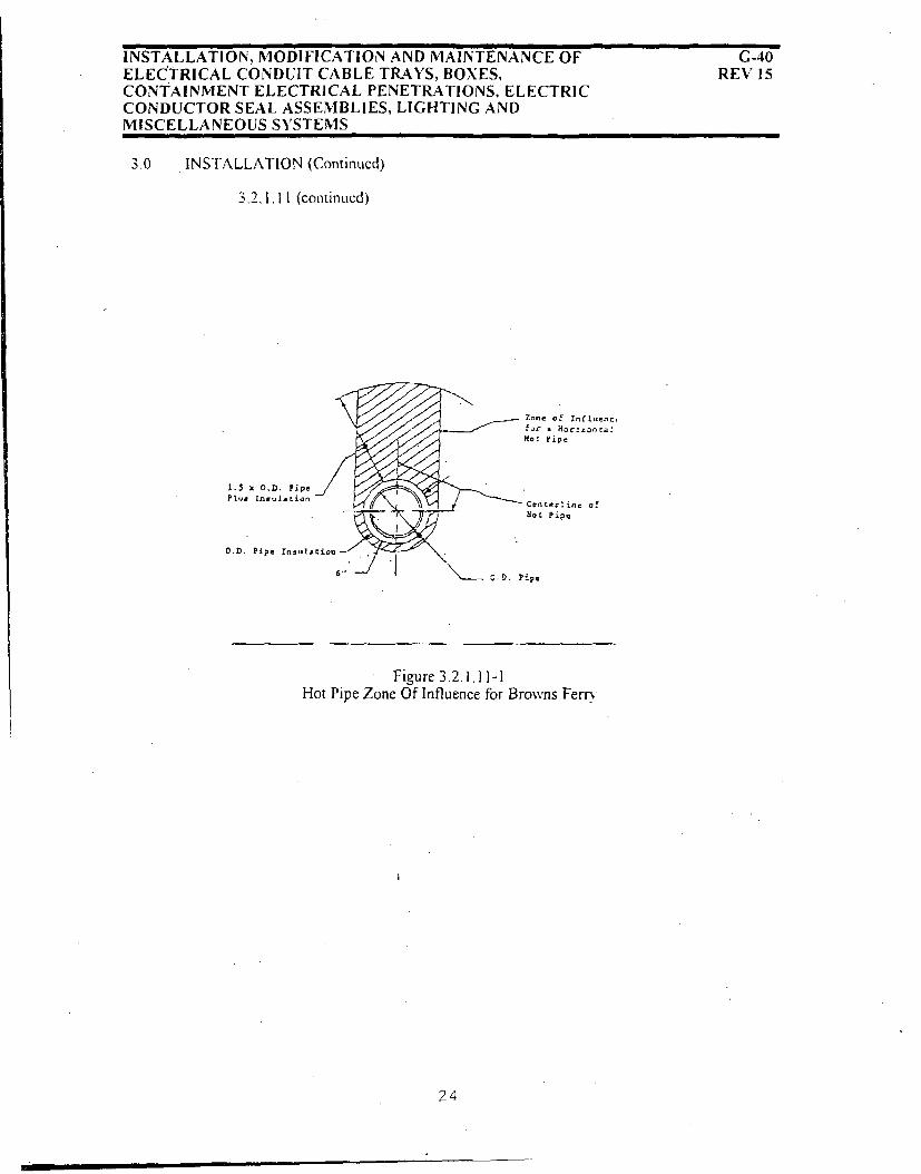
INSTALLATION, MODIFICATION AND MAINTENANCE OFELECTRICAL CONDUIT CABLE TRAYS, BOXES,CONTAINMENT ELECTRICAL PENETRATIONS, ELECTRICCONDUCTOR SEAL ASSEMBLIES, LIGHTING ANDMISCELLANEOUS SYSTEMS
G-40REV 15
3.0 INSTALLATION (Continued)
3.2. 1.11 (continued)
1.5 x O.D. Pipe /
Plu.. uti
O.A. Pipe InsultiOu
- Zone of Intluenc,f., a H szon z LHom ripe
Ceacecrlna ofPoc Pipe
Pipe
Figure 3.2.1.11-1Hot Pipe Zone Of Influence for Browns Ferr
24

INSTALLATION, MODIFICATION AND MAINTENANCE OF 1G-40ELECTRICAL CONDUIT CABLE TRAYS, BOXES, REV 15CONTAINMENT ELECTRICAL PENETRATIONS, ELECTRICCONDUCTOR SEAL ASSEMBLIES, LIGHTING ANDMISCELLANEOUS SYSTEMS
3.0 INSTALLATION (Continued)
3-2.1.12 (Continucd)
NOTES:
(1) FleCihle .conduit• connecting tit end devices attached to hot pipes should beoriented perpendicular to the pipe and shall not he routed above the hot pipe.unless approved by engineering.
(2) If the pipe insulation has been removed. an insulation thickness of three inchesshall bhe used t6r determnining separation distances or the design insulation
thickness shall be obtained irom the drawings.
(3) No conduit separation fiom instrument senslng lines is required for temperature
considerations.
(4) Conduits and pipes are considered to he parallel if they lbrm an angle ofless than2(0' to each other.
25

INSTALLATION, MODIFICATION AND MAINTENANCE OF G-40ELECTRICAL CONDUITCABLE TRAYS, BOXES, REV 15CONTAINMENT ELECTRICAL PENETRATIONS, ELECTRICCONDUCTOR SEAL ASSEMBLIES, LIGHTING ANDMISCELLANEOUS SYSTEMS
3.0 INSTALLATION (Continued)
3-2.1-13 Conduit. conduit fittings and conduit bodies shall be sealed asrequired by design output documents.
3.2.1.14 Conduits greater than six feet in length containing mediumvoltage (V5) and low voltage (V4) power cables shall beseparated. from other conduits by a minimum of one fourth thediameter of the larger conduit.
26
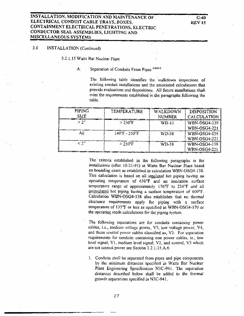
INSTALLATION, MODIFICATION AND MAINTENANCE OF G-40ELECTRICAL CONDUIT CABLE TRAYS, BOXES, REV 15CONTAINMENT ELECTRICAL PENETRATIONS, ELECTRICCONDUCTOR SEAL ASSEMBLIES, LIGHTING ANDMISCELLANEOUS SYSTEMS
3.0 INSTALLATION (Continued)
3.2.1.15 Watts Bar Nuclear Plant
A. Separation of Conduits From Pipes 'c'r'.
The following table identifies the walkdown inspections ofexisting conduitinstallations and the associated calculations thatprovide evaluations and dispositions. All future installations shallmeet the requirements established in the paragraphs following thetable.
PIPING 1 TEMPERATURE [ WALKDOWN DISPOSITIONSIZE NUMBER CALCULATION> 2" > 250"F WD-11 WBN-OSG4-139
WBN-OSG4-221All 140"F - 250"F WD-38 WBN-OSG4-139
WBN-OSG4-221< 2" > 250°F WD-38 WBN-OSG4-139
I WBN-OSG4-221
The. criteria established in the following paragraphs is forinstallations (after 10-21-91) at Watts Bar Nuclear Plant basedon bounding cases as established in calculation WBN-OSG4-138.This calculation is based on all insulated hot piping having anoperating temperature of 650'F and an insulation surfacetemperature range of approximately 176°F to 224°F and alluninsulated hot piping having a surface temperature of 600'F.Calculation WBN-OSG4-138 also establishes that no thermalclearance requirements apply for piping with a surfacetemperature of 135°F or less as specified in WBN-OSG4-170 orthe operating mode calculations for the piping system.
The following separations are for conduits containing powercables, i.e., medium voltage power, V5, low voltage power, V4,and those control power cables classified as, V3. For separationrequirements for conduits containing non power cables, ie., lowlevel signal, V1, medium level signal, V2, and control, V3 whichare not control power see Section 3.2.1.15.A.6.
1. Conduits shall be separated from pipes and pipe componentsby the minimum distances specified in Watts Bar NuclearPlant Engineering Specification N3C-941. The separationdistances described below shall be added to the thermalgrowth separations specified in N3C-941.
27

INSTALLATION, MODIFICATION AND MAINTENANCE OF G-40ELECTRICAL CONDUIT CABLE TRAYS, BOXES, REV 15CONTAINMENT ELECTRICAL PENETRATIONS, ELECTRICCONDUCTOR SEAL ASSEMBLIES, LIGHTING ANDMISCELLANEOUS SYSTEMS
3_0 [NSTALLATION (Continued)
3.2. I 15 (Continued)
2- Where running .parallel. rigid and flexibleconduits shall be separated from insulated hotpiping up to 39" O.D. (including insulation) asnoted below. Hot piping includes piping forsystems 01. 02. 03A. 03B, 05, 06, 15, 43, 62,63. 68. 74. and all branch lines two inches andlarger connecting.to these systems up to the firstnormally closed isolation or check valve. Valvestems and bonnets are considered part of thepipe.
a. Conduits adjacent to or below insulatedhot piping (horizontal and vertical)
Conduits running parallel to hot pipingand located adjacent to or below thispiping shall have a minimum separationof six inches from the pipe.
b. Conduit above insulated hot piping(horizontal and vertical)
Conduits running parallel to and aboveinsulated hot piping shall be located
outside the zone of influence for the hotpipe- The zone of influence is as shownin Figure 3-2.1.15-1 where "X" is equalto 1.5 except for those pipes in roomsidentified in Table "A". For the roomsidentified in Table "A". use the specificdistance or the value of "X" shown inTable "A", as applicable.

iNSTALLATION, MODIFICATION AND MAINTENANCE OF G-40ELECTRICAL CONDUIT CABLE TRAYS, BOXES, REV 15CONTAINMENT ELECTRICAL PENETRATIONS, ELECTRICCONDUCTOR SEAL ASSEMBLIES, LIGHTING ANDMISCELLANEOUS SYSTEMS
3.0 INSTALLATION (Continued)
3.2. I. 15 (Continued)
3. Where , unning parallel, rigid and flexibleconduits shall bc separated from uninsulated hotpiping and tubing 2" and smaller as noted below.Hot piping includes piping. tubing. valve stems,
and bonnets for systems 01, 02. 03A. 03B, 05.06, 7. 12, 15. 43. 44. 62. 63'68. 74. and 77.wu'h
a. Conduits. adjacent to or below 2" and smalleruninsulated hot piping and tubing (horizontaland vertical).
Conduits running parallel to uninsulated hotpiping and located, adjacent to or below thatpiping shall have a minimum separation of 1'-10" from the pipe.
b. Conduits running above uninsulated hot pipingand tubing (2" and smaller, horizontal andvertical).
Conduits running parallel to and above hotpipes- shall be located outside the zone ofinfluence for the hot pipe. The zone ofinfluence is as shown in Figure 3.2.1-1S-2.using the distances of 1'-1 1" for 1/2" or lesspiping and tubing, 3'-2" for piping and tubinggreater than 1/2" up to I", and 4'-4" for pipingand tubing greater than 1" up to 2".
29

INSTALLATION, MODIFICATION AND MAINTENANCE OFELECTRICAL CONDUIT CABLE TRAYS, BOXES, REV 15
CONTAINMENT ELECTRICAL PENETRATIONS, ELECTRIC
CONDUCTOR SEAL ASSEMBLIES, LIGHTING ANDMISCELLANEOUS SYSTEMS
3.0 rNSTALLATION(Continucd)
3.2.1.15 (Continued)
4. Where running non-parallcl (see note 3), .rigid andflexible conduits shall be separated from insulated anduninsulatcd hot piping and tubing (horizontal orvertical) as noted below for systems 01. 02, 03A. 038.06. 15, 43. 62. 63. 68 74, and branch lines two inchesand larger connecting to these systems up to the firstnormally closed isolation or check valve. Theseseparation requirements also. apply to. uninsulatedpiping and tubing for systems 7- 12. 44. and 77. Valvestems and bonnets are considered part of the pipe: WO,-
a. For conduits running non-parallel to hot pipingand tubing insulated or uninsulated and locatedadjacent to or below that piping and tubing; theminimum separations distance shall be sixinches from the pipe.
b. Conduits running above and. non-parallel toinsulated hot piping and tubing shall be locatedoutside the zone of influence for the hot pipe.The zone of influence is as shownk in Figure3.2.1.15-1 using a distance of 10" for piping 4-3/8" O.D. and smaller 3-5" for piping with anO.13 greater than 4-3/8" up to 39". PipingO.D. includes insulation.
c. Conduits running above and non-parallel touninsulated hot pipes and tubing shall belocated outside the zone of influence for the hotpipe. The zone of- influence is as shown inFigure 3.2.1.15-2 using a distance of 1-3" fortubing less than 1/2" O.D. and 2'-9" for 2"OD. down to 1/2" O.D. pipe and tubing.
5. Piping for systems other than those identified inparagraphs 21 3 and 4 have no thermal clearancerequirements. Separation distances shall satisfy" therequirements of Engineering Specification N3C-941 inall cases.
30

INSTALLATION, MODIFICATION AND MAINTENANCE OF G-40ELECTRICAL CONDUIT CABLE TRAYS, BOXES, REV 15CONTAINMENT ELECTRICAL PENETRATIONS, ELECTRICCONDUCTOR SEAL ASSEMBLIES, LIGHTING ANDMISCELLANEOUS SYSTEMS
3.0 INSTALLATION (Continued)
3,2-1.15 (Continued)
6. Conduits shall be separated from pipes and pipecomponents by minimum distances specified in N3C-941. The separation distances described below shall beadded to the thermal growth separations specified inN3C-941. Conduits containing non power cables. i.e..low voltage signal. V I. medium voltage signal, V2 andcontrol. V3. which are not control power shall beseparated from hot piping by distances specified inTable B. These clearances apply to hot piping and allbranch lines connecting to this piping up to the firstnormally closed isolation or check valve. Valve stemsand bonnets are considered part of the pipe.
31

INSTALLATION, MODIFICATION AND MAINTENANCE OF G-40ELECTRICAL CONDUIT CABLE TRAYS, BOXES, REV 15CONTAINMENT ELECTRICAL PENETRATIONS, ELECTRICCONDUCTOR SEAL ASSEMBLIES, LIGHTING ANDMISCELLANEOUS SYSTEMS
3.0 INSTALLATION (Continued)
3.2. I.15 (Continued)
NOTES (For paragraphs 2. 3. 4. 5. and 6)
(I) Flexible conduits connecting to end devices attached to hot pipes shall he routed to minimize intrusion into the zone of
influence. Flexible conduit shall be rcstraincd as iccessary to assure that separation requirements are maintained fbr normaloperating conditions.
(2) If the pipe insulation hits been removed, an insulation thickness of' lbur and one-half inches shall be used for deterniningseparation distances or the tl'sien insulation thickness shall he obtained li-rom the drawingq.
(3) Conduits and pipes arc considered to he parallel irthex form an angle ofles, than 20' to each other.
(4) For vertical conduit that runs parallel wvith vertical hot piping tbr more than ten feet. Engineering shall be contacted to provide
the necessary clearanccs.
(5) For conduits (I E only) being installed in the RB-SO I. 2. 3. and 4 rooms and Titration. Radio Chemlab and Counting rooms.
Engineering shall he contact:ed to provide the hecessaiw clearances required to any hot piping.
(6) The separation of conduits from hot piping is baLsed on cables with a rating of 9O7C or ahove qualilication temperature (see3.2 1A15A).
(7) The conduit separation requirements are ba.,ed on insulated pipe maximum O.D. (including insulation) of 39" (for all voltage
levels), uninsulated hot pipe maximum O.D. of 2" (for NV3 control povter. NV4. and NV5 leves) and uninsulated pipemaximum O.D. of 39" (for N\VI. NV2. and V3 control levels). Engineering shall be contacted to provide the necessary
clearances lor larger hot pipe OD.
(8) An existing conduit may he removed and replaced with it conduit of the same size or smaller in the same location withoutverilication of separation distances, except in those cases where the original installation required the modilication (e.g.
notching) of-piping insulation. In such cases. NE approval must he obtained prior to reinstallation of'the conduit.
(9) No conduit separation from instrument sensing lines is required for temperature considerations.
32

INSTALLATION, MODIFICATION AND MAINTENANCEO G-40ELECTRICAL CONDUIT CABLE TRAYS, BOXES, REV 15CONTAINMENT ELECTRICAL PENETRATIONS, ELECTRICCONDUCTOR SEAL ASSEMBLIES, LIGHTING ANDMISCELLANEOUS SYSTEMS
3.0 INSTALLATION (Continued)
2 15 (Continued)
B. Appendix R Conduit Separation
I Compliance with the intent of I OCFR50 Appendix R isbased on physical separation between cables forredundant functions. Essential Appendix R Fire SafeShut Down (FSSD) conduits identified in CCRS shallbe installed within the areas identified on the AppendixR separation sketches and instructions provided in thedesign change notice (DCN) or engineering changenotice (ECN)-Mod package.
2. As-installed location of essential Appendix R conduitsshall be field verified. Nuclear Construction. (NC).shall notif the Nuclear Engineering (NE) leadelectrical engineer upon completion of essentialAppendix R conduit installation.
3. Essential Appendix R (FSSD) conduits shall not berelocated (more than 6 inches horizontal) without NEnotification and written concurrence.
23

INSTALLATION, MODIFICATION AND MAINTENANCE OFELECTRICAL CONDUIT CABLE TRAYS, BOXES, CONTAINMENTELECTRICAL PENETRATIONS, ELECTRIC CONDUCTOR SEALASSEMBLIES, LIGHTING AND MISCELLANEOUS SYSTEMS
G-40REV 15
3.0 INSTALLATION (Continued)
3.2.1.15 (Continued)
TABLE "A" **
CLEARANCE VALUES BY ROOM NUMBERS FOR PARALLELCONDUITS INSTALLED ABOVE HOT INSULATED PIPING
DISTANCE OR "X" FOR FIGURE 3.2,1.1 5-1 OUTSIDE DLAMETER OF INSULATED PIPE
ROOM NO'S" ELEVATION
A1, A2, Al1I, A 10,A12, A13 729.0
RB ANNULUS ALL
RB-LOWER COM PT,
RACEWAY & PRESS RMS ALL
RB-INSTR. ROOM 716.0
Al, A2, A3, A4, A7, AIO, A13, 77Z0A14, A15, A1S
Al, A2, A3, A4, A5, A9, A17, 757.0A21, A22, A23, A24, A25, A26,A27, A28
A2 737.0
C3, C4, C5, C6, C7, C8, C9 6920
C6, C12, C13' C15 7255.0
G1, C4 705,0
R C UPPER COMPT. ALL
Al 786.5
A I, A2 763.5
Al 77.5.25
A14, A15 729,0"
C1, C2, CIO 692.0
C1 755.0
R•lACCUM & FAN t•MS ALL
All 772.0
4,5 742.0
1,2. 3, 4, 5, 6, 7, 8, 9, 10, 11, 12, 760.513, 14.
PIPING LESS THAN 4-3/8" UP TO 23" (VALUE " 23- UP TO 39"
4-3/8" (DISTANCE) OF "X" in inches) (VALUE OF X"in inches)
1-4" 3.55 1.70
1-4" 2.90 1.50
1'4" 1.87 1.50
0'-6' 1.50 1.50
Al ,A2, A3, A4 782,0
Room descriptions and location drawings are shown on 47E235-00 drawing series.This table applies to insulated piping systems 01, 02, 03A, 03B, 05, 06, 15, 43, 62, 6a, and 74.
OEM

INSTALLATION, MODIFICATION AND MAINTENANCE OF G-40ELECTRICAL CONDUIT CABLE TRAYS, BOXES, REV 15CONTAINMENT ELECTRICAL PENETRATIONS, ELECTRICCONDUCTOR SEAL ASSEMBLIES, LIGHTING ANDMISCELLANEOUS SYSTEMS
3.0 INSTALLATION (Continuedd)3.2.1 15 Watts Bar Nuclcar Plant (Continued)
Zoii of hrflarre for aHorizntal ln-tlatedhot Pipe
S.eý ihotes belowof Hot
O.D. Pipe Insulation
6",
Figure 3.2.1.15-1 (For Watts Bar only)
Notes:
A) For separation of insulated piping in systems 01. 02. 03A. 03b. 05. 06. 15, 43.62. 63. 68 and 74from conduits containing NV3-control power. NV4. or NV5 cables.
1) For rooms listed in Table "A". this dimension equals the specific distance provided or"X" \ O.D. pipe insulation. where a value of "X" is provided.
2) For rooms not listed in Table "A". this dimension equals the specific distance providedin the applicable paragraph for conduits located above pipe. or 1_5 x O.D. pipeinsulation.. where no specific distance is provided.
3) The minimum distance in all cases is 6"-
_2.5

INSTALLATION, MODIFICATION AND MAINTENANCE OF G-40ELECTRICAL CONDUIT CABLE TRAYS, BOXES, REV 15CONTAINMENT ELECTRICAL PENETRATIONS, ELECTRICCONDUCTOR SEAL ASSEMBLIES, LIGHTING ANDMISCELLANEOUS SYSTEMS
3.0 INSTALLATION3.2.1.15 (continued)
Zonre of1ritfence for a
Horiwntal UnmmilatedHot Pipe
Centerline of Hot PipeSee nxotes below J
1-,- 101,
Figure 3.2.1.15Zone Of Influence For Horizontal Uninsulated Hot Pipes (For Watts Bar Only)
NOTES:A) For separation of uninsulated piping in systems 01.02. 03A. 03B, 05, 06. 07, 12. 15. 43, 44. 62.
63. 68. 74. and 77 from conduits containing NV3-control power, NV4. or NV5 cables.
1) This dimension equals the specific distance provided in the applicable paragraph (see3.2.1- 15.3.b. and 3.2.1,15.4.c ) for conduits running above pipe.
2) The minimum dimension is 1'- 10" in all cases.

INSTALLATION, MODIFICATION AND MAINTENANCE OFELECTRICAL CONDUIT CABLE TRAYS, BOXES,CONTAINMENT ELECTRICAL PENETRATIONS, ELECTRICCONDUCTOR SEAL ASSEMBLIES, LIGHTING ANDMISCELLANEOUS SYSTEMS
G-4VREV 15
3.0 INSTALLATION
3.2.1, 15 (Continued)
TABLE B*
CLEARANCE VALUES FOR CONDUITS CONTAINING CONTROL LEVEL. V3,. MEDIUMLEVEL SIGNAL. V2. AND LOW LEVEL SIGNAL VI CABLES FROM HOT PIPES
Conduits above, and parallel All other conduits to pipe
to pipe orientations
Insulated Pipes
Systems 01. 03A. 03B. 15. 5 inches 1 inch43.62. 63. 68. and 74
All other systems See Section 3.2. I.15.A.5 See Section 32. .15.A.5
Uninsulated Pipes
Piping diameter 2" and less 8 inches 2 inchesin Systems 01 02. 03A.03B. 05. 06. 07. 12. 15. 43,44. 62. 63. 68. 74, and 77
Piping diameter greater than2" in System 01. 02. 03A. 36 inches. 6 inches03B. 05. 06. 07. 12, 14. 43,44. 62. 63. 68, 74. and 77
All other uninsulated piping See Section 3.2.1.15.A.5 See Section 3.2.1.15.A.5
* QIR MNMWBN93007 RO (T31 930408 986)
37

INSTALLATION, MODIFICATION AND MAINTENANCE OF G40ELECTRICAL CONDUIT CABLE TRAYS, BOXES, REV 15CONTAINMENT ELECTRICAL PENETRATIONS, ELECTRICCONDUCTOR SEAL ASSEMBLIES, LIGHTING ANDMISCELLANEOUS SYSTEMS
3.0 INSTALLATION (Continued)
3.2.2 Exposed Conduit
3.2.2.1 Exposed conduits shall be run in straight lines parallel to column lines,walls or beams. Where conduits are grouped, the bends and fittings shallbe installed to present an orderly appearance. Unnecessary bending orcrossing shall be avoided.
3.2.2.2 In seismic Category I structures (Class I at BFNP), exposed conduitsshall be supported as defined by design drawings.
Rigid conduit attachments to end devices (i.e., all conduit bodies formaking- splices, oversized conduit bodies for accommodating minimumtraining radius requirements, rigid conduit for installing equipment seals,etc.) shall be installed in accordance to design drawings to ensure that theend device will not be damaged due to stress created by excessiveweight.w-9
3 2.2.3 Malleable iron 1-hole pipe straps, clamps, U-bolts, hangers or closebracket-type pipe suppprts may be used.. Pipe backspacers should beused for the.' 1-hole malleable iron pipe supports where it is desired tohold a conduit run away from the surface to eliminate offsetting theconduit at the fittings.
3.2.2.4 In nonseismic (non category I) structures, galvanized steel members maybe drilled or punched for conduit supporting bolts provided the holes areimmediately coated with zinc-dust zinc-oxide paint (in accordance wvithASTM A780, Annex A2) and galvanized or rust-resisting bolts are used.Threaded stud bolts, Nelson stud anchors or equivalent may be usedinstead of drilling or punching steel members.
3.2.2.5 In moist locations and in locations where appearance is of importance,.precautions shall be taken, such. as by use of strap-type wrenches orequivalent means, to avoid injuring the galvanized coating of steelconduits or surface of stainless steel conduit:
38

INSTALLATION, MODIFICATION AND MAINTENANCE OF G-40ELECTRICAL CONDUIT CABLE TRAYS, BOXES, REV 15.CONTAINMENT ELECTRICAL PENETRATIONS, ELECTRICCONDUCTOR SEAL ASSEMBLIES, LIGHTING ANDMISCELLANEOUS SYSTEMS
3.0 INSTALLATION (Continued)
3.2.2.6 Beginning with the Watts Bar Nuclear Plant. exposed conduit containingClass I E wiring shall have its division of separation identified (bymarking. tagging. or taping) with the respective background color code atintenrals not to exceed 15 feet in accordance with Electrical StandardDrawing SD-E 15.3.4.
3.2.2.7 When in the vicinity of piping which must be insulated, the conduit shallbe adequately spaced away from the pipe to avoid interferences when thepipe is insulated.
3.2.2.8 Two conduit bodies having three conduit openings each (e.g.. two "Tee"condulets) ma- be used where one conduit body having four conduitopenings (e.g.7 an "X", condulet) is specified on design drawings. Theconduit interconnecting the two conduit bodies shall be sized inaccordance with Design Standard DS-E 13.1.4.
This configuration is treated as a single conduit body. and the conduitinterconnection is not required to be uniquely identified if it is 12 inches- orless in length. Contact engineering when the interconnecting conduit isgreater than 12 inches in length.
322.29 Watts Bar Nuclear Plant-
Conduits containing 10 CFR50.49 cables shall not have threaded portions(i.e.. condulets. junction boxes, couplings or unions, etc.) and flexiblesections located below, postulated HELB flood levels identified on theEnvironmental Data Drawings 47E235 series. When more than oneapplicable flood level is provided, the highest level shall be used. When aconduit passes through a wall/floor, the conduit shall be evaluated basedon the new conduit location. If it becomes necessary to route conduitsbelow the HELB flood levels identified in 47E235 series drawings. contactSite Engineering to determine if they contain 10 CFR 50.49 cables.
After 7/7/95. installation of conduits containing 10 CFR 50.49 cablesbelow the postulated MELB flood levels identified on the EnvironmentalData Drawings shall require specific approval on design outputdocuments.
Unless otherwise stated on Design Output Drawing. any conduit which
exits a room below the postulated MELB flood level for that room shall be
sealed in accordance with drawing 45W883. Sheet 6 to preN ent wateregress to other areas."2 N-4
39

INSTALLATION, MODIFICATION AND MAINTENANCE OF G-40ELECTRICAL CONDUIT CABLE TRAYS, BOXES, REV 15CONTAINMENT ELECTRICAL PENETRATIONS, ELECTRICCONDUCTOR SEAL ASSEMBLIES, LIGHTING ANDMISCELLANEOUS SYSTEMS
3.0 INSTALLATION (Continued)
Conduit scaling to prevent water accumulation in conduit or enteringequipment, on a case-by-case basis with prior SE approval on the WorkInstruction Document at a location specified by SE, is permitted. Sealing shallbe accomplished by packing approximately I" depth of ceramic fiber dammingaround cables and in voids between cables/conduits (damming shall be used oneither side of silicone foam) and injecting 3" minimum Dow Corning 3-6548Silicone RTV Foam. CAUTION: The above seal is not to be used as afirestop, nor as a 50.49 pressure / moisture seal.
3.2.3 Embedded Conduit
3.2.3.1 A minimum 2-inch clearance shall be maintained between conduits embedded inpoured concrete walls or floor slabs, except that detailed- design dimensionsshall be adhered to adjacent to conduit terminations, etc., where area isrestricted.
Conduits and conduit sleeves, when located in a bank or group form in a wallpour, may be adjusted as required to line up the -bottom outside edge of thesmaller sized conduit with the bottom outside edge of the largest conduit in thegroup in order to continue the group run on a common exposed support.
Likewise, grouped conduits in a floor or ceiling slab may be shifted enough totake advantage of a common exposed wall or column support. For tolerancesfor embedded conduit runs, see Section 3.13.2.
Conduits embedded in switchyards and transformer yards shall maintain a1-inch minimum clearance between conduits.
3.2.312 In switchyards and transformer yards all single conduit or groups of conduitsshall be encased in concrete with the outer coverage a minimum of 2-1/2 inches.
3.2.3.3 Where embedded in concrete, extreme care shall be taken to anchor aluminumand nonmetallic conduit so that it will not be floated when the concrete Isplaced.
3.2.3.4 Embedded conduit shall be rigidly supported to withstand concrete vibrators orbatches of mass concrete placements.
3.2.3.5 In supporting embedded steel, aluminum or plastic conduit, extreme care shallbe taken to avoid-damage to the surface of the conduit if welding or brazing isused near the conduit. In no case-shall the- conduit be welded or brazed to thesupport. Plastic conduit in duct runs shall not be supported by reinforcing steelforming closed magnetic loops; preformed plastic spacers shall be used- SeeElectrical Standard Drawing SD-E1 3.4.1.
40

INSTALLATION, MODIFICATION AND MAINTENANCE OF G-40ELECTRICAL CONDUIT CABLE TRAYS, BOXES, REV 15CONTAINMENT ELECTRICAL PENETRATIONS, ELECTRICCONDUCTOR SEAL ASSEMBLIES, LIGHTING ANDMISCELLANEOUS SYSTEMS
3.0 INSTALLATION (Continued)
3.2.3.6 Concrete curbs shall be provided where specified on design drawings.3.2.37 Slip joints shall be installed in accordance with Electrical Standard
Drawing SD-E13.1.1. where embedded conduits cross expansion orcontraction joints. as defined and located on design drawings.
3.2.3.8 Wherever slip joints are used. suitable bonding in accordance withElectrical Standard Drawing SD-EI311.1 shall be provided around thejoint to ensure a continuous- ground circuit: Where use of expansion anddeflection-type fittings (see Standard Drawing SD-E13.1.2) are defined indesign drawings. the manufacturer's instructions shall be followed inmaking ground connections.
3.2.3.9 Except as noted below or unless othcrwise specified on design drawings,all embedded conduits turning out of poured concrete shall terminate witha standard coupling flush with the surface of the concrete. Where thethickness of the concrete is not adequate to accommodate the minimumbending radius of the conduit (see DS-E13.1.7). one of the followingoptions max' be exercised:
A. A short radius elbow may be used where approval has beenobtained from engineering. (Short radius elbows must also beshown on design drawings. See Section 3.2.4. 1 Item G).
B. Where terminating into surface of floor-mounted boxes orequipment, a standard radius field bend or manufacturer's bendmay be used and extended beyond the concrete surface asneeded to complete the 90-degree bend. If necessary to avoidinterferences or to accommodate the minimum bending radius ofthe cables. the end of the 90-degree bend projecting beyond theconcrete surface may be cut, if the cut end is deburred andhandled in accordance with Section 3.2.1.2 Items A or B.
4-'

INSTALLATION, MODIFICATION AND MAINTENANCE OF .- 40ELECTRICAL CONDUIT CABLE TRAYS, BOXES, REV 15CONTAINMENT ELECTRICAL PENETRATIONS, ELECTRICCONDUCTOR SEAL ASSEMBLIES, LIGHTING ANDMISCELLANEOUS SYSTEMS
3.0 INSTALLATION (Continued)
3.2.3.9 (Continued)
C. Where the conduit bend must be terminated in a coupling toallow the conduit system to be extended beyond the wall or floorsurface- the coupling may extend beyond the surfce as needed.to complete the 90-degree bend.
D. Where the difference in being able to comply with Section3.2,3.9 and. DS-EI3,1.7 is small, the straight portion of thebend may be cut as required, if the minimum bending radius(dimension A. DS-El3.1.7) is not altered and the bend isrethreaded to the original specifications.
3.2.3.10 In duct runs the metallic conduit shall be grounded at eachmanhole or handhole by brazing the ground wire to the top of the
conduit coupling or by using grounding bushings.
3.2.3.11 Holes for conduits may be drilled in hardened concrete: however.no reinforcing steel will be cut or damaged during the drillingoperation. The reinforcing steel may be located by removing thecover concrete. Holes may be relocated up to 8 inches in anydirection from the dimensions specified on design drawings andmay be canted from one face to the other to avoid the reinforcingsteelý After installation of the conduit, the damaged concrete shallbe repaired in accordance with, TVA General EngineeringSpecification No. G-34.
3.2.3.12 The conduits shall be identified in such a manner that permanenttag identification can be made at a later date.
3.2.3.13 The conduits shall be swabbed immediately (before any concrete,which may have sipped inside the conduit has had a chance toharden) after the concrete pour is complete.

INSTALLATION, MODIFICATION AND IMAIFNTENANCE OF .- 40ELECTRICAL CONDUIT CABLE TRAYS, BOXES. REV 15CONTAINMENT ELECTRICAL PENETRATIONS, ELECTRICCONDUCTOR SEAL ASSEMBLIES, LIGHTING ANDMISCELLANEOUS SYSTEMS
3.0 INSTALLATION (Continued)
3.2.4 Rigid Metal Conduit
3.2.4,1 General
A. Metallic conduit systems, whether embedded or exposed, shall beinstalled in accordance with those portions of the NEC, whichensure that the systems will be adequately grounded andelectrically continuous to function as the equipment groundingconductor.
B. When necessary to achieve electrical continuity (per NEC).bonding jumpers shall be installed between the rigid metal conduitand the enclosure (ie.. box. cabinet. switchgear cable tray). Thisshall be accomplished by using UL-listed ground clamps orfittings approved for grounding. These bonding jumpers shall besized in accordance with conduit size as listed in Table 3.2.4. 1-I.
C. When boxes-do not have threaded hubs or bosses (or as in Section3.3.1.3). conduits shall be securely fastened to boxes andcabinets, each-..vith a locknut and a bushing inside the box and alocknut outside. (See Electrical Design Standard DS-E13_1-6 forlocknut spacing requirements.) The conduits shall be of suchlength that when-the bushings are screwed tight against the endsof the. conduits, no appreciable space will be left between thebushings and the locknuts.
D. To avoid hotspots or sparking during fault conditions. locknutsshall be firmly tightened against the box. Care shall be taken toprevent deforming the box. As an alternative, a coupling may beused on the end of the conduit system and a chase nipple inside theenclosure (box or cabinet) to connect the enclosure and conduittogether. To ensure that the enclosure and conduit are electricallycontinuous, theT&B grounding wedge having the UL label shallbe used. Unless otherwise specified by the manufacturer, theWedge may be installed inside or outside (preferred) the enclosure.
43

INSTALLATION, MODIFICATION AND MAINTENANCE OFELECTRICAL CONDUIT CABLE TRAYS, BOXES,CONTAINMENT ELECTRICAL PENETRATIONS, ELECTRICCONDUCTOR SEAL ASSEMBLIES, LIGHTING ANDMISCELLANEOUS SYSTEMS
G-40REV 15
3.0 INSTALLATION (Continued)
3.2.4.1 (Continued)
Table 3.24.1-1Bonding Jumpers for Ensuring
Electrical Continuity of Electrical Conduit System
Conduit Size
1/2
Copper Jumper Size (AWG)for Power Conduits
#6
Copper Jumper Size (AWG)for Control, Medium-Level Signaland Low-Level Signa[-Conduits-
#6
3/41
1-1/2
2-1/2
#6
#4
#2
3
#2/0
#2/0
#2/0*#2/0
#6
#4
#2
#2
#2
#2
#2
4
These AWG sizes may be reduced to match the largest available ground cable in thevicinity when it is not practical or possible to extend the bonding jumper to a larger groundcable. Engineering must review and approve such deviations on a case by case basis. Ifrequired to match existing ground cables, cable sizes may be increased without engineeringapproval.
NOTE: Bonding jumpers for ensuring electrical continuity of electrical conduit systems shall beinstalled such that the ground cable is held firmly in place. Torquing is not required.Compound 'Kopr-Shield' shall be applied to the mating surfaces of the connections.

INSTALLATION, MODIFICATION AND MAINTENANCE OF G-40ELECTRICAL CONDUIT CABLE TRAYS, BOXES, REV 15CONTAINMENT ELECTRICAL PENETRATIONS, ELECTRICCONDUCTOR SEAL ASSEMBLIES, LIGHTING ANDMISCELLANEOUS SYSTEMS
3 0 INSTALLATION (Continued)
3..14.1 (Continued)
E. Running threads on field threaded conduits shall not be used onmetal conduits except for short nipples which are used to extendthe conduit systems.
F. Welded or brazed grounds on conduit runs shall be done on thetop of couplings onlh. and extreme care shall be taken to avoidiniurv to the inner surface of the conduit by excessive heating.The welded or brazed joint shall be coated with asphaltum, RTVsealants or equivalent.
G. Unless otherwise noted. standard radius field bends (see ElectricalDesign Standard DS-E13.1.7) or manufacturer's bends (bendingradius as specified in NEC) shall be used wNhere. needed in metal-conduit systems. Special. long radius bends (bending radiusgreater than Electrical Design Starhdard DS-El3.1.7 or NECrequirements) shall be used where specifically called for on designdrawings or where otherwise needed to complete the installation ofthe conduit system- Short radius elbows. (bending radius less thanElectrical Design Standard DS-EI3.1.7 or NEC requirements)shall not be used unless specified on design drawings.
45

INSTALLATION, MODIFICATION AND MAINTENANCE OF G-40ELECTRICAL CONDUIT CABLE TRAYS, BOXES, REV 15CONTAINMENT ELECTRICAL PENETRATIONS, ELECTRICCONDUCTOR SEAL ASSEMBLIES, LIGHTING ANDMISCELLANEOUS SYSTEMS
3.0 INSTALLATION (Continued)
3.2.4.1 (Continued)
H. Field Bends
1. Field bends for metal conduit-shallbe made such that theinternal diameter of the conduit is not materially changedand the protective coating on the inside and outside of theconduit is not significantly damaged.
2. WVhcn making field bends, a certain amount of necking,flattening- nicks, kinks. splits, dents and/or damage to theprotective coating can be expected to occur.
Field bends which result in a kink or split in the conduitshall be abandoned. Likewise. if a nick should occurwhich actually penetrates the wall of the conduit. the bendshall not be used.
'4- Nicks and abrasions resulting in significant damage to theprotective coating should be repaired by spraying orpainting galvanize on the damaged areas.
46

INSTALLATION, MODIFICATION AND MAINTENANCE OF GELECTRICAL CONDUIT CABLE TRAYS, BOXES, REV 15CONTAINMENT ELECTRICAL PENETRATIONS, ELECTRICCONDUCTOR SEAL ASSEMBLIES, LIGHTING ANDMISCELLANEOUS SYSTEMS
3.0 INSTALLATION (Continued)
3.2*4. 1 (Continued)
z '. When the following conditions are satisfied, less severenecking, flattening. dents, and nicks which could notresult in damage to the cable insulation during-pulling areacceptable:
a. The bending equipment being used- is correct forthe application.
b. The manufacturer's instructions andrecommendations pertaining to the use of thebending equipment are being followed.
c. The bending equipment is functioning properly(i.e.. making bends which do not result in kinks.splits, or damage to the conduit coating).
Heat shall not be applied in making any metalconduit bend. (See Section 3.2.5.4 for fieldbends for nonmetallic conduit.)
1. Die cast zinc conduit fittings and connectors shall not be usedinside. the reactor building primary containments w\hich have aboric acid containment spray system.
J. Except for conduits containing battern board supply cables.sections of existing aluminum conduit runs may be replaced withrigid steel conduit without requiring revision to drawings.
47

INSTALLATION, MODIFICATION AND MAINTENANCE OF G-40ELECTRICAL CONDUIT CABLE TRAYS, BOXES, REV 15CONTAINMENT ELECTRICAL PENETRATIONS, ELECTRICCONDUCTOR SEAL ASSEMBLIES, LIGHTING ANDMISCELLANEOUS SYSTEMS
3.0 INSTALLATION (Continued)
3.2.4.1 (Continued)
K. Conduit fittings and conduit bodies (tees, LBs) installed within the rigidconduit system shall be compatible to the strength requirements of theconduit.
1. For rigid conduit, the bodies and.fittings shall be malleable ironor steel- See Standard Specifications referenced in 2.1.2
2- Nonmalleable cast iron fittings and bodies may be used withaluminum conduit only wvhen approved by TVA NuclearEngineering on a case by case basis.
3.2.4.2 Steel Conduit and Intermediate Metal Conduit
Steel and intermediate metal conduit joints and connections shall be madeweathertight and rustproof by means of the application of a-thread compoundwhich will not insulate the joint. Each field-cut thread shall be cleaned toremove the cutting oil before the compound is applied. An electricallyconductive antiseize compound for metal surfaces (Thomas and Betts Company"Kopr-Shield"'; Jet-Lube, Incorporated, "SS-30"; Burndy "Penetrox E"; orequivalent) shall be applied, to the male- conduit threads-
3 .2.4.3 Alumninum Conduit
A. Rigid aluminum. conduit installed outdoors or in wet locations shall beprovided with aluminum fittings. The use of aluminum conduit inareas containing corrosive materials should be avoided. Galvanizedfittings (such as type EYS) may be used in special cases as designatedby engineering. Care must be taken to prevent the contact of aluminumconduit with corrosive materials in places where moisture canaccumulate.
B_ Strap-type wrenches should be used to avoid scratching and gougingthe aluminum conduit.
48

INSTALLATION, MODIFICATION AND MAINTENANCE OF G-40ELECTRICAL CONDUIT CABLE TRAYS, BOXES, REV 15CONTAINMENT ELECTRICAL PENETRATIONS, ELECTRICCONDUCTOR SEAL ASSEMBLIES, LIGHTING ANDMISCELLANEOUS SYSTEMS
3.0 INSTALLATION (Continued)
3.2.4.3 (Continued)
C. Aluminum conduit joints at couplings or fittings shall be madewcathertight by application of an clectrically conductive. antiseizecompound for metal surfaces (Thomas & Bctts Company"Kopr-Shicld" or "Aluma-Shield:" Jct-Lube. Incorporated,"SS-30(" Bumdv Corporation "Penetrox E." or equivalent)-
Satisfactor' mixtures such as zinc dust and vaseline (50-50 byweight). or a heavy cup greasc containing 25-percent graphitemay be used. Aluminum threads shall not be coated-with red leador other lead compounds- Each field cut.thread shall be cleaned toremove the cutting oil before the compound is applied-
D. Standard benders may be used for aluminum conduit except thatelectrical metallic tubing (EMT) benders shall be used for conduitI inch in diameter and below. Use an EMT bender 1/4-inchlarger than the conduit size. i.e.. 1-1/4 inches for, 1-inch rigid, Iinch for 3/4-inch rigid-
E. In addition to the methods described in Section 3.2.4.1. aluminumconduit may be grounded by inserting a galvanized steel couplingin the run, brazing the ground \wire to the top of the coupling andcarefully coating the joint with asphaltum, RTV sealant orequivalent-
F_ Aluminum conduit, conduit fittings or components shall not beused inside reactor, building primary' containments that have aboric acid spray system that would react with aluminum toproduce excessive hydrogen.
49

INSTALLATION, MODIFIiCATION AND MAINTENANCE OF G-40ELECTRICAL CONDUIT CABLE TRAYS, BOXES, REV 15CONTAINMENT ELECTRICAL PENETRATIONS, ELECTRICCONDUCTOR SEAL ASSEMBLIES, LIGHTING ANDMISCELLANEOUS SYSTEMS
3.0 INSTALLATION (Continued)
3._,4A4 Electrical Metallic Tubing (EMT)
EMT. a thrcadless,. thin-wall steel conduit requiring special threadlessfittings for couplings and terminations may be used in exposed andembedded applications in office and service buildings- Installation shallbe in accordance with Article 348 of the National Electrical Code. latestedition.
3.2.5 Plastic Conduit (PVC)3.2.5.1 To prevent warping during storage, plastic conduit shall be stacked on
smooth. flat surface in an area not directly exposed to the rays of the sun.Spacers of 1-inch soft wood. approximately 2 feet apart, should be usedbetwcen layers of conduit. Manufacturer's shipping bundles may also beused for direct storage.
3.2.5.2 Refer to DS-E 13.1.11 for applications of embedded PVC conduit. Whereplastic conduits are encased in concrete (such as in duct banks betweenbuildings), the conduits shall be anchored with preformed, plastic spacersbefore concrete placement. The conduits and spacers shall be located asshown on design drawings.
3.2.5.3 Plastic conduit may be cut with a hacksaw. After cutting, ends shall betrimnmed and rough edges smoothed. The area to be solvent welded(outside of conduit and inside of coupling or fitting) shall be free fromdust, dirt, grease. and moisture. Use PVC cleaner for cleaning. Polyvinlchloride (PVC) solvent shall be brushed liberally on the and of the conduitand inside the fitting or coupling when making a joint. After fitting hasbeen pushed on. it should be twisted one-fourth turn to spread the solventevenly. Continue to hold joint for 15 seconds so that conduit does notpush out of fitting.
3.2.5.4 Bends for nonmetallic conduit are usually purchased as required for theconduit system, but for special cases may be made in the field. Extremecaution should be observed when anv source of heat is near plasticconduit. Field bending can be accomplished by the use of a "hot air-coldair" blower- a hand-type hair dryer is reconmmended by the manufacturers.
50

INSTALLATION, MODIFICATION AND MAINTENANCE OF G-40ELECTRICAL CONDUIT CABLE TRAYS, BOXES, REV 15CONTAINMENT ELECTRICAL PENETRATIONS, ELECTRICCONDUCTOR SEAL ASSEMBLIES, LIGHTING ANDMISCELLANEOUS SYSTEMS
3.0 INSTALLATION (Continued)
3.2.6 Flexible Conduit
3.2.6-1 General
A- Flexible conduit shall be used to interface the rigid conduit systemwith electric equipment and devices that rotate, vibrate, aresubject to thermal movement, or where seismic considerationsmust be taken into account. '•: It shall also be used forconnecting flush and recessed lighting fixtures to rigid conduitsystems when so indicated on design drawings-
B. Flexible conduit installed in straight lengths (reference Section32.1.1 Item J of G-38) mav be used within a rigid, exposedconduit run to;
1. Avoid interferences.
2. Cross an expansion-contraction joint .%here the rigidconduit is attached to the structure on each side of thejoint.
3, It mav.also be used to interface between cable trays and/orequipment. Attachment of flexible conduit to cable traysshall require site engineering approval prior toinstallation.
C. Flexible conduit secured with P2558 series unistrut 2-hole straps,instead of connecting to equipment with standard flexible conduitfittings, may utilize ferrules supplied by approved flexible conduitconnector vendors on the end(s) of the flexible conduit to protectthe cables. Ferrules must have rounded ends and be of thescrew-in type to ensure position retention.
51

INSTALLATION, MODIFICATION AND MAINTENANCE OF G-40ELECTRICAL CONDUIT CABLE TRAYS, BOXES, REV 15CONTAINMENT ELECTRICAL PENETRATIONS, ELECTRICCONDUCTOR SEAL ASSEMBLIES, LIGHTING ANDMISCELLANEOUS SYSTEMS
3.0 INSTALLATION (Continued)
3.2.6.1 (Continued)
D. The electrical continuity of the conduit system shall be preserved-
I. This electrical continuitv shall be achieved bv installing abonding strap or ground cable across stainless steel orliquid-tight flexible conduit by connecting to the racewayand/or equipment/end device. This shall be accomplishedby using UL-listed ground clamps or fittings approved forgrounding. Bonding jumpers shall be sized in accordancewith conduit size-as listed in Table 3.2.4.1-1. For supportpurposes, cable ties shall be adequate. to secure thegrounding conductor to the flexible conduit.
This bonding jumper is not required on 1/2". 3/4". and 1"liquid-tight flexible metal conduit if a, b. and c below aremet:
a. The installed length of flexible conduit is 6 footor less and the rigid conduit section or the endcomponent are adequately grounded and providesa ground return path (NEC 350-5, and 351-9).
b. All fittings are UL-listed. and
c. The conduit is used only for control,medium-level, or low-level signal cables or lowvoltage power (20 amps or lower).
For conditions where the bonding jumper is presently notinstalled, any future rework of existing stainless steel orliquid-tight flexible conduits will require the installationof the above required bonding jumpers concurrent withthe rework activities-
52

INSTALLATION, MODIFICATION AND MAINTENANCE OF G-40ELECTRICAL CONDUIT CABLE TRAYS, BOXES, REV 15CONTAINMENT ELECTRICAL PENETRATIONS, ELECTRICCONDUCTOR SEAL ASSEMBLIES, LIGHTING ANDMISCELLANEOUS SYSTEMS
3-0 INSTALLATION (Continued)
32.6.1 (Continued)
For equipment with more than one flexible conduit connection(i.e.. MCC's. switchgear, valves, R-panels. etc.). which havecommon end points, it is acceptable to provide only one groundjumper from the rigid conduits/cable tray to the equipment as longas:
a. All conduits are jumpered together either at the commonsupport or at the equipment.
b. The ground cable is sized for the largest conduit, and
c. The flexible conduits are attached to a common point atthe equipment.
d. For flexible conduits which are not physicalIy/electricallyattached to the equipment and/or raceway, the groundjumper shall extend from the equipment to the. raceway.
Flexible conduits routed from different supports will require,separate ground jumpers, sized as indicated in Table 3.2.4.1-1.
53

INSTALLATION, MODIFICATION AND MAINTENANCE OF G-40ELECTRICAL CONDUIT CABLE TRAYS, BOXES, REV 15CONTAINMENT ELECTRICAL PENETRATIONS, ELECTRICCONDUCTOR SEAL ASSEMBLIES, LIGHTING ANDMISCELLANEOUS SYSTEMS
3.0 INSTALLATION (Continued)
3.2.6.1 (Continued)
E. Flexible conduit.shall be installed between conduit fittings in exposedlengths not exceeding 72 inches, except as noted on design outputdocuments. Rigid conduit should be located as near the equipment anddevice as practical. The flexible conduit shall be prepared, assembled,and installed in accordance with manufacturer's instructions providedin the vendor catalog for the particular part number or instructionsprovided with the contract. If the flexible. conduit fitting vendorrequires the compression nut to be torqued, the vendor supplied valvesshall be used. If torquing is not required by the flexible conduit fittingvendor, the compression nut shall be installed wrench tight usingcommonly available tools. Wrench tight shall be defined as "not beingable to rotate. or remove by hand at the joint or fitting. ,WBN-12
NOTE: Based on the justification provided- in Appendix Y variance 4for W/BN and Letter from T&B (A) torquing of T&B flex-conduit fittings to a numerical value other than wrench tight isnot required. This applies to all sites.
NOTE: Flexible conduit connector bodies should be installed andtightened into the end device prior to installing the flexiblcconduit. When compression nuts are torqued or tightened, careshall be taken not to exceed the maximum torque value for theend device.
F. The minimum recommended bend radii listed in Table 3.2.6.3-2 shallnot be violated'."-l" (Other types of flexible conduit max, beacceptable; however, engineering approval shall be required prior toinstallation.) Flexible conduit should be installed without twist andoriented away from heat radiating sources, such as a hot pipe and itsinsulation (see Section 3.2. 1. 11 for separation distances for Watts Barand Sequoyah Nuclear Plants and Section 3.2.1.12 for Browns FerryNuclear Plants). After installation, the flexible conduit shall not bestretched tight between flexible conduit fittings.
54

INSTALLATION, MODIFICATION AND MAINTENANCE OF G-40ELECTRICAL CONDUIT CABLE TRAYS, BOXES, REV 15CONTAINMENT ELECTRICAL PENETRATIONS, ELECTRICCONDUCTOR SEAL ASSEMBLIES, LIGHTING ANDMISCELLANEOUS SYSTEMS
3.0 INSTALLATION (Continued)
3.2.6.1 (Continued)
G. Flexible conduit entering the top or side of boxes. equipment, anddevices requiring external sealing in accordance with Engineeringdesign documents shall be installed utilizing a vendor supplied orvendor recommended 0-ring seal between the box, equipment, ordevice and the flexible conduit fitting. This is not a requirementitf
I. The box- equipment. or device has a threaded hub.
2. Welded hub is provided as part of the enclosure, or
3. No open terminations exist inside the enclosure.
4. This is not a requirement for BFN if. it is sealed inaccordance with drawing 0-45 B891-1.
5. For BLN. the joint between the installed conduit.connector and the outside of the electrical enclosure iscoated with a minimum of a 1/8" bead. of RTV 738sealant or approved equal.
Where. design output documents for Watts Bar Nuclear Plantshow flexible conduits, short.sections of rigid conduit of equalsize or larger, may be substituted for a portion of the flexibleconduit where the conduit enters a fitting, provided the rigidsection is for seismic support anchoring, has been approved byCivil Engineering, and the remaining length of flexible conduitmeets all requirements of this specification.
55

INSTALLATION, MODIFICATION AND MAINTENANCE OF G-40ELECTRICAL CONDUIT CABLE TRAYS, BOXES, REV 15CONTAINMENT ELECTRICAL PENETRA-kTIONS, ELECTRICCONDUCTOR SEAL ASSEMBLIES, LIGHTING ANDMISCELLANEOUS SYSTEMS
3.0 INSTALLATION (Continued)
3.2.6. 1 (Continued)
H, Where liquid tight (synthetic jacket) flexible metal conduit hasdamage which penetrates the PVC jacket. it shall be replaced, or.repaired as noted below:
a. Liquid Tight PVC Jacket Flex Conduit
I . Ensure there is no significant damage to themetallic core of the conduit (no sharp, edgesinside the conduit). If the metallic core has beenpenetrated or is broken, the flexible conduitshould be replaced.
2. Clean the area where the damage has occurredusing a clean rag and denatured alcohol, orequivalent.
3. Wrap at least one half-lapped layer of 3MCompany Scotch 22 Electrical Tape or equivalentfor a minimum 2-inch distance on each sideof thedamaged synthetic jacket, or to the end of theconduit such that it extends under the gland nut.
NOTE: Where the above flexible conduit exists insidednvwell at Browns Ferry Nuclear Plant and insideprimary' containment or in the main steam valvevault at other nuclear plants, it shall not berepaired but replaced.

INSTALLATION, MODIFICATION AND MAINTENANCE OF G-40ELECTRICAL CONDUIT CABLE TRAYS, BOXES, REV 15CONTAINMENT ELECTRICAL PENETRATIONS, ELECTRICCONDUCTOR SEAL ASSEMBLIES, LIGHTING ANDMISCELLANEOUS SYSTEMS
3.0 INSTALLATION (Continued)
3.2.6.1 (Continued)
b. ServicAir Stainless Steel Conduit
ServicAir flexible conduit is considered damaged and shall bereplaced if any core damage. any broken strands of the braid orany burn marks exist prior to installing the cable. since there is norepair method. If conditions exist to the extent described belowafter cable installation the conduit shall also be replaced. If thedamage has been caused due to a bend radius violation, the morerestrictive requirements contained in the notes for Table 3.2.6-3-2apply instead of those listed bclow:
I. Core (metallic bellows) is visibly damaged (e-g.flattening/ distortion of cross section or kinks).
2. For conduits which serve as a pressure boundary(environmental seal), greater than 10% of the braidstrands are visibly broken. For conduits which do notserve as a pressure boundary, greater than 20% of thebraid strands are visibly broken.
3. Burn marks in outer braid. which occurred from anoutside source (i.e. not from a fault inside the conduit) areacceptable provided that there are no bum marks ordiscoloration on the core and bum does not result inbroken strands in excess of item 2 above.
4. Conduit is pulled loose from end connectors and theflexible conduit or connector parts are visibly damaged(bent or broken). Reassembly is acceptable if the partsare not visibly damaged and the flex conduit can bereconnected as originally installed. The cable shall beinspected by Nuclear Engineering for damage at theexposed location in accordance with G-38 section 3.7,prior to reconnection.
57

INSTALLATION, MODIFICATION AND MAINTENANCE OFELECTRICAL CONDUIT CABLE TRAYS, BOXES, REV 15CONTAINMENT ELECTRICAL PENETRATIONS, ELECTRICCONDUCTOR SEAL ASSEMBLIES, LIGHTING ANDMISCELLANEOUS SYSTEMS
3.0 INSTALLATION (Continued)
3.2.6.1 (Continued)
c. American Boa Stainless Steel Conduit
American Boa flexible conduit is considered damaged and shall'bereplaced if any core damage, or any burn marks exist prior toinstalling the cable, since there are no repair methods. Ifconditions exist to the extent described below after cableinstallation the- flexible conduit shall also be replaced. If thedamage has been caused due to a bend radius violation, the morerestrictive requirements contained in the notes for Table 3.2.6.3-2apply instead of those listed below:
1. Flattening/distortion, kinks or excessive indentation ofcore (metallic bello\\s). Indentations in the outer surfaceof the bellows not exceeding 1/8 inch in depth on no morethan 10% of the bellows are acceptable provided the wallis not broken or torn.
2. Conduit is pulled loose from end connectors and theflexible conduit or connector parts are visibly damaged(bent or broken). Reassemblv is acceptable if the partsare not visibly damaged and the flexible conduit can bereconnected as originally installed, The cable shall beinspected by Nuclear Engineering for damage at theexposed location in accordance with G-38 Section 3.7,prior to reconnection.
Bum marks on the core.
INSTALLATION, MODIFICATION AND MAINTENANCE OF G-40ELECTRICAL CONDUIT CABLE TRAYS, BOXES, REV 15CONTAINMENT ELECTRICAL PENETRATIONS, ELECTRICCONDUCTOR SEAL ASSEMBLIES, LIGHTING ANDMISCELLANEOUS SYSTEMS
3.0 INSTALLATION (Continued)
3.2.6.1 (Continued)
1. Flexible conduits at the end devices max- be increased by onestandard size above the design specified size without engineeringapprov.al or- revision of design drawings, provided the last tworigid conduit supports are sized to accommodate the largerflexible conduit.
J. For Watts Bar Nuclear Plant rework or maintenance of installedflexible conduits in Category I structures after May 26. 1989.shall comply with the following criteria to ensure conformancewith the critical case evaluation by Civil engineering
I. Flexible conduit may be removed and reinstalled orreplaced without increasing the length of the flexible-conduit or changing the length of the cantilevered sectionof rigid conduit. including couplings and fittings.
2. Flexible conduit may be removed and reinstalled orreplaced meeting the requirements of this specification,except as defined on WBEP design output documents.
3. Flexible conduit removed and reinstalled or replaced notmeeting the requirements of Section 3.2.6.1 Item J.1 orJ.2 shall be approved by engineering.
K. Wire mesh grips max' be installed at the Flex conduit connector inorder to prevent pull out of the flex conduit from the connector.The wire mesh grip may be installed as a new installation or forrepair of existing installations.
Approved Manufacturers of these devices are Crouse-Hinds.Thomas & Betts. Appleton, Kellems. The wire mesh grip shall beinstalled in accordance with the manufacturers instructions.
59

INSTALLATION, MODIFICATION AND MAINTENANCE OF G-40ELECTRICAL CONDUIT CABLE TRAYS, BOXES, REV 15CONTAINMENT ELECTRICAL PENETRATIONS, ELECTRICCONDUCTOR SEAL ASSEMBLIES, LIGHTING ANDMISCELLANEOUS SYSTEMS
3.0 INSTALLATION (Continued)
3.2.6.2 Floor-Mounted Equipment and Devices. Seismic Thermal MovementConsiderations in Seismic Category I (Class I at BFN) Structures •\L3
During a- seismic event. flexiblc conduit will allow for relative displacement ofequipment or devices and a rigid conduit system. To ensure that movement of therigid conduit system and movement of floor mounted equipment (such as motors,electrical boards. and panels) are independent during a seismic event, thefollowing installation procedures shall. be observed unless otherwise noted ondesign drawvings:
A. When conduits connect to seismic Category I (L) floor-mountedequipment. an 18-inch minimum exposed length of flexible conduit shallbe installed between the flexible conduit fittings at the rigid conduitcoupling and the equipment. The actual minimum conduit length requiredfor a particular installation shall be as specified on design drawings or ascalculated using the equation in Figure 3.2.6.3-1. This minimum length offlexible conduit will, ensure that floor-mounted: Class IE equipment iscapable of sufficient movement (i.e.. combined thermal/seismicmovements) in any direction. The minimum bend radii for flexible conduitgiven in Table 3.2.6.3-2 shall not be violated.
B. Where physical limitations prevent the installation of flexible conduits inaccordance with Section .3.2.6.2 Item A minimum requirements, theconstruction, -modifications, or maintenance electrical engineer shall benotified for resolution.(by established procedures) with site engineering.
C. In cases where flexible conduit is used for alignment purposes only andboth ends of the flexible conduit are rigidly attached to the same seismicstructure, the relative displacement between ends is zero and thereforeexempt from thermal/seismic considerations.
D. Conduit connections to cable trays should be avoided: however, if conduitsare connected to seismic Category I cable trays, an 18-inch minimumlength of flexible conduit shall be installed as indicated-in Section 3.2.6.2Item A.
60

INSTALLATION, MODIFICATION AND MAINTENANCE OF G-40ELECTRICAL CONDUIT CABLE TRAYS, BOXES, REV 15CONTAINMENT ELECTRICAL PENETRATIONS, ELECTRICCONDUCTOR SEAL ASSEMBLIES, LIGHTING ANDMISCELLANEOUS SYSTENSIS
3-0 INSTALLATION (Continued)
3.2-6.3 Pipe-Mounted Devices. Thermal Seismic Movcment Considerations "'i.
A. Where electrical connections must be made to devices (such asmotor-operated valves, solenoid-operated valves and temperatureswitches) w\hich are attached to a mechanical flow system designed forthermal movements, flexible conduit shall be used to compensate for anyexpansion/contraction and seismic movement.
B. Typically. flexible conduit connected to pipe-mounted electrical deviceswhich are subject to thermal movements are in the 1/2-inch through1-1/2-inch range. Excessive lengths in smaller flexible conduit sizesshould be avoided to decrease stress and prevent pull-out at flexibleconduit fittings.
C. Seismic Category I (Class I at BFN) Structures
Flexible conduit to pipe-mounted devices in seismic Category I structuresshall be installed to compensate for. combined thermal/seismic movements.The minimum length of flexible conduit shall be as specified on design
drawings or as calculated using the equation in Figure 3.2.6.3-1. Thisminimum length of flexible conduit wiii ensure that pipe-mounted devicesare capable of sufficient movement in any direction. The minimum bendradii for flexible conduit given in Table 3.2.6.3-2 shall not be violated.
D. Nonseismic Structures
Flexible conduit to pipe-mounted devices in nonseismic structures shall beinstalled to compensate for thermal movements only. However. installineconduit per the equation given for seismic Category I structures willprovide adequate compensation for nonseismic thermal movements.
61

INSTALLATION, MODIFICATIO N AND MAINTENANCE OF G-40ELECTRICAL CONDUIT CABLE TRAYS, BOXES, REV 15CONTAINMENT ELECTRICAL PENETRATIONS, ELECTRICCONDUCTOR SEAL ASSEMBLIES, LIGHTING ANDMISCELLANEOUS SYSTEMS
3.0 INSTALLATION (Continued)
3.2.6.3 (Continued)
Ritgid Conduit
-Rigid Conduit Support
Coupling
flexible Conduit Fitting
~-~~-YExposed Flexible-Condui r
Rigid Conduit Support
.-- Flexible Conduit Fitting
• --- 7-Exposed Flexible
'Top of Floor.-MountedEquipment
Figure 3.2.6.3-1
Typical Arrangement of Floor-Mounted Equipment or Pipe-Mounted Devices
The equation for calculating the minimum length of exposed flexible conduit required betweenflexible conduit fittings, between flexible conduit fitting and an intermediate support point orbetween intermediate support points, is as follows:
62

INSTALLATION, MODIFICATION AND MAINTENANCE OF C-40ELECTRICAL CONDUIT CABLE TRAYS, BOXES, REV 15CONTAINMENT ELECTRICAL PENETRATIONS, ELECTRICCONDUCTOR SEAL ASSEMBLIES, LIGHTING ANDMISCELLANEOUS SYSTEMS
3.0 INSTALLATION (Continucd)
3.2-6.3. (Continued)
FL= SD-+-K
Where.
FL Minimum. exposed Ilexible conduit lengh between 1clxiblc conduit litiing•s. (See Notes I and 2 page 65)
SD7 Field measured straight-line distance between the center line points of the flexible conduit linings. (ifthe straight-line distance is obstructed such that an exact measurcment cannot he made. the field engineer shall conservativelyestimate thedistancc using a combination of measurements if required.)
K I inch tr floor-mounted equipment and for conduits crossing seismic interce boundaries for maximumseismic movement:
(WBN)
3-1.-4. inches for connections to the steel containment vessel for maximum combined
seismic thermal'DI3A movement:
4 inches for conduits attached to cable trays or cable tray supports for maximum seismic movement: or
4 inches for pipermounted devices for maximum comhined seismic,'thennal movements, except as notedon design drawings.
(Movements are in any direction.) (Note that for items anached to the steel containment vessel, the movementsmust he added i.e.. for a cable tray attached to the steel containment vessel, the maximum total movem;!nt would he7-1 4 inches.)
K I* inch for floor-mounted equipment or(all other
nuclear ,4 inches for pipe-mounted devicesplanLt)
(1 inch llexihle conduit length is required for maximum seismic movement in any direction: 4-inchflexible conduit length is required for maximum combined seismic'thermal movement in any direction
at all nuclear plants).
Note I: For flexible conduit cut length. the field shall add to the minimum calculated length (FL)- the flexible conduit length requiredfor conduit fittings and any additional length required for bend radii. The minimum bend radii for flexible conduit given if)Table 3.2.6-3-2 shall not be violated. Any exceptions to minimum calculated lengths (FL) andlor minimum bend radii shall beapproved by engineering.
Note 2: Exposed flexible conduit lengths shall not exceed 72 inches or he less than IX inches (28 inches for ServicAJr S63C). exceptas noted on design output documents. For exceptions not noted on design output documents including conduit supportdrawings or an approved variance in Appendices W..X Y or Z. contact engineering for resolution.
63

INSTALLATION, MODIFICATION AND MAINTENANCE OFELECTRICAL CONDUIT CABLE TRAYS, BOXES, CONTAINMENTELECTRICAL PENETRATIONS, ELECTRIC CONDUCTOR SEALASSEMBLIES, LIGHTING AND MISCELLANEOUS SYSTEMS
G-40REV 15
3.0 INSTALLATION (Continued)3.2.6.3. (Continued)
A - Radius
Table 3.2.6.3-2
Minimum Bend Radii for Flexible Metal Conduit
All Dimensions are in inches
Conduit Trade Size 1/2 3/4 1 1-1/2 2 2-1/2 1 3 4 5 6
Flexible ConduitManufacturer and A - Radius to inside of conduit as shown in figure aboveType
SEE NOTES ON FOLLOWING PAGE
Anaconda Seal Tite 3.5 50 6.0 5.5 7.0 9.5 15.0 17.0 20.0 30.0Type UA
O-Z Gedney Flexi- 3.0 3.5 6.0 5.0 7.0 9.5 11.5 14.0 --Guard Type.UAG
Liquatite Electric- 3.0 4.2 5.5 4:5 6:0 8.0 10.0 12D0 --
Flex Type LA (Type - - (17.5) (22.5)LT)___________
American Flexible 3.25 425 6.5 9.0 11.13 14.63 17.5 24.0 - -
Conduit Ameri-TiteType UIL
American Boa Type - 1.23 1.38 2.55 3.81 4.54 5.27 8.74 12.20 14.71* NBI-O and NBI-1 see note see note see note see note see note 1
see note 1 1 1 1 1
ServicAir SS60, 2.5 3,8 5.0 7.5 10.0 12.0 15.0 20.0 25.0 30.0
SS63 and SS63C
Anemet, Inc. - .............. 22.0 30.0
Patel/EGS - 75 ............--

INSTALLATION, MODIFICATION AND MAINTENANCE OF G-40ELECTRICAL CONDUIT CABLE TRAYS, BOXES, REV 15CONTAINMENT ELECTRICAL PENETRATIONS, ELECTRICCONDUCTOR SEAL ASSEMBLIES, LIGHTING ANDMISCELLANEOUS SYSTEMS
3.0 INSTALLATION. (Continued)
3.2.6.3 (Continued)
NOTES FOR TABLE 3.2.6.3-2:
American Boa (Type NBI-0 and NB1-1) flexible metal conduit larger than 2 inch (trade size) shall not be used for attachments to pipe-
mounted devices,
2 The values contained in this table are based on manufacturers information and TVA calculation CD-Q0999-000001 (previously CEB-
CQS-449, B41 940620 001).
3. Once flexible conduit has been inalled per the requirements of-this specification, the as-found bend radius configuration of the flex is
acceptable as long as no damage has occurred including:
a. Kinking of flexible conduit so that the minimum bend radius (listed above) is obviously violated.
b. Obvious surface damage of flexible conduit from denting, weld arc strikes, tearing of'stainless steel or pvc jacket as applicable,
or fatigue cracks (See Section 3.2.6.1).
c_ Pullout of flexible conduit from its end connections (See Section 3.2.6.1).
When detected, bend radius damage shall be evaluated by engineering and corrected accordingly.
4. The flexible conduit types which have numerical bend radius values provided in this table are the only types which are approved by
this specification for installation (i.e. those sizes with "'-" are not approved and have not been approved unless justified in anexception contained in this specification), Additional types must be approved by listing the required bend radius values in thisspecification prior to procurement or installation. This will be accomplished by an engineering analysis of the materials, engineering
data.and construction of the conduiL Other brands even though similarrare not to be assumed to be equal.
65

INSTALLATION, MODIFICATION AND MAINTENANCE OF . G-40ELECTRICAL CONDUIT CABLE TRAYS, BOXES, REV 15CONTAINMENT ELECTRICAL PENETRATIONS, ELECTRICCONDUCTOR SEAL ASSEMBLIES, LIGHTING ANDMISCELLANEOUS SYSTEMS
3.0 INSTALLATION (Continued)
3.3 Conduit Boxes
3.3.1 General
3.3.1.1 Boxes shall be of the type and size as specified on design drawings. Theyshall be located as shown on design drawings and shall not be installed ifdamaged. Where large boxes are embedded. they shall be'properly bracedon the inside so that concrete placement will not deflect them. Threadedholes in box frames shall be protected from damage. -
3.3.1.2 Outlet boxes in architectural tile or masonry unit walls shall be installedstrictly in accordance with design drawings and for best appearance,
3.3.1.3 Where watertight conduit connections to junction boxes without threadedhubs or bosses -are required (see Electrical Standard DrawingSD-EI3.6_5), Appleton type HUB conduit hubs. or equivalent, may beused in place of welded hubs.
3.3.1.4 Exposed noncurrent-carr.ing metal parts of fixed equipment and boxesshall be grounded. Equipment not secured to, and in. metallic contactwith, grounded structural steel shall be connected to the grounding systemby brazing the grounding cable to the equipment and then carefullycoating the joint with asphaltum. RTV sealant, or equivalent; or bybolted-connections to the box. or equipment.
3-3.1-5 For general information concerning field fabricated boxes, see ElectricalStandard Drawing SD-E13.6.3-1.
3.3.1.6 Appleton type "PTC" threaded pull boxes may be used as cable pullboxes or to install splices in order to achieve cable or splice bend radius.All such installations in Category I structures shall be installed inaccordance to approved design output documents.
66

INSTALLATION, MODIFICATION AND MAINTENANCE OF G-40ELECTRICAL CONDUIT CABLE TRAYS, BOXES, REV 15CONTAINMENT ELECTRICAL PENETRATIONS, ELECTRICCONDUCTOR SEAL ASSEMBLIES, LIGHTING ANDMISCELLANEOUS SYSTEMS
3.0 INSTALLATION (Continued)
3-3.2 Painting
Field-fabricated surface-mounted boxes shall be painte& inside and outside.immediately after fabrication. Field-fabricated flush-mounted boxes shall bepainted on the inside and the exposed parts only. Primer paints shall be lead free.Boxes outside the primary_ containment shall be primed in accordance withGeneral Engineering Specification G-147 Part No. 1-310 and finish coated thesame color and type of coating as the surrounding area. Boxes located-inside theprimary containments shall be coated in accordance with General EngineeringSpecification G-55 and the plant-specific coating specification as follows:
• BFN Project Engineering Specification NIA-930BFNP-N-955
* SQN Project Engineering Specification N2A-93SNP-N-971
* WBN Project Engineering Specification N3A-932WBNP- N-9711
• BLN Project Engineering Specification N4A-933BLN-N-971Boxes that are purchased may be touched up if paint is nicked using the above
requirements.
3.3.3 Seismic Mounting
Surface-mounted conduit boxes located in seismic Categor. I structures shall beseismically mounted. Where the mounting. surface is poured concrete. boxes shallbe attached to embedded steel plates or mounted to the concrete with bolt anchorsas shown on equipment seismic support design drawings. Seismic mounting offlush or surface boxes to masonry- walls shall be in accordance with specificdesign details.
67

INSTALLATION, MODIFICATION AND MAINTENANCE OF G-40ELECTRICAL CONDUIT CABLE TRAYS, BOXES, REV 15CONTAINMENT ELECTRICAL PENETRATIONS, ELECTRICCONDUCTOR SEAL ASSEMBLIES, LIGHTING ANDMISCELLANEOUS SYSTEMS
3.0 INSTALLATION (Continued)
3.3.4 Identification MarkinE
Junction boxes and/or pull boxes shall be labeled in accordance with theapplicable design drawings with the applicable color scheme defined for therespective nuclear plant (see applicable Electrical Design Standard DS-El.2.1 orDS-EI.2.2). For those not shown on design drawings, the size lettering shall bedetermined by construction. modifications. or maintenance, depending on the boxsize. The use of self-sticking mylar markers (e.g., AMP Special Industries orLEM. Products. Incorporated). self-adhesive polyester markers (eg:, W. H. BradyCompany), or equivalent- is a suitable means for. box identification markings.
For future work at Bellefonte only beginning after 07/01/93 Junction boxes and/orfabricated pull boxes as shown on design drawings shall be labeled in accordancewith the Design Standard drawing DS-E1.2.2. Fittings (i.e. TEE's & X's) that areshown on design drawings and are utilized as pull boxes shall be considered anextension of the conduit system and identified in accordance with ElectricalStandard drawing SD-E15.3.4. Box identification shall be as shown on designdrawings.
3.3.5 Internal Protection Against Rust and Corrosion
In most instances, boxes are installed well in advance of actual cable terminations.Many boxes or panels may also have electrical components installed therein. Toprovide. protection against rust or corrosion until the cables are terminated and theinstallation completed. one of the following methods may be used. For the firstand second methods, the applicable portions of the TVAN Safety and Health'Manual shall be observed during the applications of coating and subsequentpreparation of terminal blocks for permanent cable connections. Section 3.3.5Item C is the preferred method.
A. Use of CRC No. 2-26 for 1-2 year storage period. Before terminatingcables, clean terminal blocks by brushing (using linseed oil if necessar))and then burnishing.
B. Use of CRC Lectra Shield coating on terminal blocks for 2-5 -ear storage(or even for 1-5 year storage). Use Exxon's Stoddard Solvent No. 627, oran equivalent, to remove the coating from terminal blocks and thenburnish them before making final electrical connections.
68

INSTALLATION, MODIFICATION AND MAINTENANCE OF 40ELECTRICAL CONDUIT CABLE TRAYS, BOXES, REV 15CONTAINMENT ELECTRICAL PENETRATIONS, ELECTRICCONDUCTOR SEAL ASSEMBLIES, LIGHTING ANDMISCELLANEOUS SYSTEMS
3.0 INSTALLATION (Continued)
3.3.5 (Continued)
C. Use of Zerust vapor capsules or Cortec VCI-160 tape. Inspection and/orreplacement shall be in accordance with manufacturer's specifications.
3.3.6 On a casc-by-casc basis, with prior Nuclear Engineering approval on theWork Instruction Document. weep holes up to 1/4" in diameter may be drilledin the low points of non-safety junction/pull boxes, as required, to preventwater accumulation.
3.4 Cable Trays
3.4.1 Cable trays and accessories shall be installed in accordance with design drawingsand engineering approved instructions.
3.4.2 Tray segments. fittings, connectors and hold down clips should be aligned beforefasteners are installed. Bolt holes shall not be enlarged unless approved byengineering.
3.4.3 Bolted fasteners shall be torqued in accordance with design approved documents.Bolts through a tray side rail shall bc drawn up flush with the tray siderail'sinterior surface with the bolt head inside the tray and the lockwasher (if required)and nut outside. Rivets shall be installed in accordance with engineering outputdocuments.
3.4.4 Vendor supplied hex head bolts may be substituted when too short to pass throughmultiple thicknesses of tray side rails and connector fittings. Bolt substitutionshall be in accordance with the following:
* Minimum ASTM A307* Same diameter as the vendor-supplied bolt* Free of sharp edges or burrs* Of suffilent length to ensure adequate thread engagement
69

INSTALLATION, MODIFICATION AND MAINTENANCE OF " G40ELECTRICAL CONDUIT CABLE TRAYS, BOXES, REV 15CONTAINMENT ELECTRICAL PENETRATIONS, ELECTRICCONDUCTOR SEAL ASSEMBLIES, LIGHTING ANDMISCELLANEOUS SYSTEMS
3.0 INSTALLATION (Continued)
3.4.5 Sharp edges shall be avoided at splice-connector joints, expansion joints, dividersand tray cover cutouts. Tray dropouts shall be installed where cables exitdownward, at tray end points or through the tray bottom. Cables resting ondivider edges end plate edges and exiting tray covers shall have chafe protectionprovided by applying a 6" + or - 1/2" length of Hypalon cable jacket material(PXJ. PXN'IJ or EPSJ) which has been slit to allow it to fit around thecablC(s)/cable tray hardware (e.g. siderails. rungs. end plates, etc.). or the cover-opening or divider shall be lined with rubber or weather resistant polyethylenegrommeting material. The--width shall be sufficient to insure protection of thecable surface and the edge. The.jacket covering material shall be fastened to thecable/cable tray hardware by use of nylon or tefzel tie wraps which meet therequirements of G-38 Sections 2.2.8.J and 2,2.8.2 (Reference G-38 Section3.2.1.8 Item B for other requirements on placing cables in trays). Therequirements of this paragraph are not intended to replace requirements forvertical cable support contained in G-38 Section 3.2.1.8.6.
3.4.6 Provisions for attaching vertical cable supports (such as Kellums grips) to seismicstructures such as walls, ceilings, etc.. other than the cable tray itself shall beprovided at the time of tray installation. This may be a structural steel supportmounted on a wall or floor or to the tray support structure as specified by designoutput documentation. To identify when this is required see G-38 section 2.2.8.1and 2.2.8.2-.
3.4.7 Cut edges of trays shall be smooth and clean. The cut surface shall be coated withzinc-rich paint immediately after the cut. Bent or dented travs.or fittings shall notbe installed without approval by engineering.
/70
INSTALLATION, MODIFICATION AND MAINTENANCE OF G-40ELECTRICAL CONDUIT CABLE TRAYS, BOXES, REV 15CONTAINMENT ELECTRICAL PENETRATIONS, ELECTRICCONDUCTOR SEAL ASSEMBLIES, LIGHTING ANDMISCELLANEOUS SYSTEMS
3.0 INSTALLATION (Continued)
3-4.7 The tray system shall be electrically continuous and grounded in accordance withdesign drawing details and General Engineering Specification G-47.
3.4.8 Outside trays of vertical stacks penetrating any floor or platform'.shall.have. coversextending 6 feet above the floor or platform to provide physical protection of theenclosed cable unless design drawings dictate othervise. Additional tray coversshall be installed in accordance with design drawings.
3.4:9 At expansion Joints, tray shall be installed in accordance with dimensions, edgedetails. cable support distances. and special. fitting details shown on designdrawings.
3.4-10 Vertical spacing between cable trays within the same tier or stack shall be 12inches bottom-to-bottom of trays unless otherwise specified on design drawings-
3.5 Manholes and Handholcs
3.5.1 Manholes and- handholes shall be constructed in accordance with approvedengineering output documents. Precast manholes shall be free of damage andinstalled according to engineering-approved instructions.
3.5.2 Concrete inserts for cable rack or tray supports shall be installed on manhole andhandhole walls in accordance with design drawings. Cable supports shall beinstalled as designated on design drawings:
3.5.3 Manhole and handhole excavation, backfill and concrete, materials. shall be inaccordance with design output documents.
3.5.4 End bells shall be used to terminate nonmetallic conduits inside manholes. Allmetallic conduit shall be terminated with appropriate insulated grounding bushingsor chase nipples.
3.5.5. All exposed metallic parts within the manhole/handhole, including conduitbushings shall be grounded to an internal loop and connected to the grotind grid inaccordance with General Engineering Specification G-47.
3-5.6 Any space remaining, where ductbanks do not fully occupy the space for theconduits at the wall shall be sealed with concrete grout.
71

INSTALLATION, MODIFICATION AND MAINTENANCE OF G-40ELECTRICAL CONDUIT CABLE TRAYS, BOXES,. REV 15CONTAINMENT ELECTRICAL PENETRATIONS, ELECTRICCONDUCTOR SEAL ASSEMBLIES, LIGHTING ANDMISCELLANEOUS SYSTEMS
3.0 UNSTALLATION (Continued)
3-5.7 Manholes and handholes shall be maintained free of standing water to the extentpractical. Provisions (i.c., sump pumps or drains) shall be made to removestanding water. Standing water as a result of low areas. uneven surfaces orsurfaces designed to drain to other sumps. or surfaces designed for minimal waterlevels (i.e.. handholes or french drains) is acceptable as long as the water level inthe manholes and handholcs containing safety related-cables is below all cablesand electrical devices. Also see section 3.2. 1 .1
3.5.8 Manholes and handholes shall be identified as shown on design output documents.
3.6 Cable Trenches and Underfloor Ducts
3.6_1 Underfloor duct systems and cable trenches shall be free of damage and installedin sizes and locations as shown on design drawvings and in accordance withengineering-approved instructions.
3.6.2 Excavation. backfill and concrete materials shall be in accordance with designoutput documents.
3.6.3 Underfloor duct systems and cable trenches shall be. identified as shown on designoutput documents.
3.7 Electric Conductor Seal Assemblies (ECSAs) .
3.7.1 ECSAs for conduit shall be installed at instruments and at end devices as specifiedon design drawings.
3.7.2 ECSAs shall be free of damage and installed and terminated in accordance withengineering-approved instructions and supported in accordance with designdrawings.
3.7.3 ECSAs shall be identified as shown on design output documents.
/2
INSTALLATION, MODIFICATION AND MAINTENANCE OF G-40ELECTRICAL CONDUIT CABLE TRAYS, BOXES, REV 15CONTAINMENT ELECTRICAL PENETRATIONS, ELECTRICCONDUCTOR SEAL ASSEMBLIES, LIGHTING ANDMISCELLANEOUS SYSTEMS
3.0 INSTALLATION (Continued)
3.8 Containment Electrical Penetrations
3.8.1 Containment electrical penetrations shall be free of damage and installed inaccordance with design drawings and engineering-approved instructions.
3.8.2 Cables at containment electrical penetrations shall be terminated in accordance
with General Engineering Specification G-38.
38.3 Fit-up. welding, verification and testing of penetration connection to containmentvessel shall be done in accordance with ASME B&PV. Division I. Section III,Subsection NE for Class MC components.
3.8.4 Containment electrical penetrations shall be identified in accordance %xith designoutput documents.
3.9 Lightinq System
3.9.1 Installation of the lighting s-stem, including lighting transformers. lighting panels.fixtures, switches. contactors. eight-hour battery packs, unscheduled lightingconduits, branch circuits and associated supports. -shall be performed inaccordance with design drawings.
3,9.2 Fixture assemblies shall be installed with all lamps and appurtenances (i.e..starters/ballasts. individual lighting transformers. and fixture wiring). Bent.dented or-broken fixtures shall not be installed without engineering approval.
3.9.3 Lighting fixtures in Seismic Categorv I (Class I at BFN) areas shall bemounted/secured as shown on design output documents.
3.9.4 Lighting cable and terminations shall be installed in accordance with GeneralEngineering Specification G-38.
3.9.5 Components (i:e.. boxes) which make up the lighting system shall be grounded inaccordance with this specification.
3.9.6 Lighting conduits, fixtures and components shall be identified as shown on thedrawings.
73
INSTALLATION, MODIFICATION AND MAINTENANCE OF G-40ELECTRICAL CONDUIT CABLE TRAYS, BOXES, REV 15CONTAINMENT ELECTRICAL PENETRATIONS, ELECTRICCONDUCTOR SEAL ASSEMBLIES, LIGHTING ANDMISCELLANEOUS SYSTEMS
3.0 INSTALLATION (Continued)
3.10 Communication System
3.10.1 Installation of the- communication systems, including low-level intraplant pagingand communications. telephone. sound-powered phone jacks, radiocommunications. alarm equipment. fire/emergency communications, unscheduledconduits and support systems shall be located and installed in accordance withdesign drawings and enginecring-approved instructions.
3.10.2 Communication system equipment in seismic Category I areas shall bemounted/secured in accordance with design output documents.
•3.10.3 Communication cable and terminations shall be installed in accordance withGeneral Engineering Specification G-38.
3.10.4 Conduits and-components (i.e., boxes) which make up the communications systemshall be grounded in accordance with this specification.
3.10.5 Communication fixtures and components shall be identified as shown on thedrawings.
3.11 Security System
Security system hardWare and components of an electrical nature shall be- installed inaccordance with design drawings and engineering-approved instructions. Wiring shall bein accordance with design drawings and General Engineering Specification G-38.
3.12 Marking and Identification
3.12.1 Exposed Class lE and associated circuit raceway systems shall be permanentlymarked in accordance with Electrical Standard Drawing SD-E]5.3.3 orSD-E15.3.4 at end points and should be marked at points of entry and exit fromenclosed areas.
3.12-2 Cable tray marking shall normally be done when the cable tray installationsarecompleted and before cable installation. The cable tray identification markingsshall be as defined on the respective engineering project cable tray drawings.
7/4

I-NSTALLATION, MODIFICATION AND MAINTENANCE OF G-40 REV 15ELECTRICAL CONDUIT CABLE TRAYS, BOXES, CONTAINMENTELECTRICAL PENETRATIONS, ELECTRIC CONDUCTOR SEALASSEMBLIES, LIGHTING AND MISCELLANEOUS SYSTEMS
3.0 INSTALLATION (Continued)
3.12.3 Beginning with Watts Bar Nuclear Plant and subsequent nuclear plants, the respectivevoltage level markers shall be located on at least one exterior side surface of cable traysdesignated for Class I E circuits (train or channel) at intervals not to exceed 15 feet and atpoints of entry to and exit from enclosed areas.
3.12.4 Each cable tray system (by voltage level) shall be identified with node numbers (forcomputer routing of cables) at intermediate points as shown on design drawings (cabletray node diagrams). These markers shall conform with the color code scheme defined foreach respective nuclear plant (see Table A, B, or C on Electrical Standard DrawingSD-E15.3,4). Markers for trays designated for nondivisional cables shall be whitebackground with black lettering. The markers shall be of the self-sticking Mylar type orself-adhesive. polyester type (Brady's B-361 or Electrotag's T-1002-R) installed permanufacturer's instructions.
3.12.5 All exposed non-Class I E raceway systems except lighting systems shall be permanentlyand distinctively marked to identify the system as non-Class 1E in accordance withSD-E15.3.3 or SD-E 15.3.4.
3.12.6 Boxes, ECSAs and containment electrical penetrations shall be identified in accordancewith engineering app roved output documents.
3.12.7 All conduit at the faces of manholes and handholes shall have permanent identificationtags or markers in accordance with Section 3.2.1.7.
3.12.8 Manholes and handholes shall be permanently identified in accordance with designdrawings.
3.12.9 Lighting, communications equipment and security equipment shall be tagged or markedwhere required by design drawings.
3.12.10 When cables are directly buried, a 4" wide (minimum) red warning tape (SetonIdentification Products or equal) shall be placed approximately 6" above the cables to alertpersonnel to their presence. [SRN 79]
3.12.11 When conduits are directly buried (with or without a protective concrete cap) a 4" wide(minimum) red warning tape (Seton Identification Products or equal) shall be placedapproximately 6" above the condufits (or protective concrete cap) to alert personnel to theirpresence. Where a group of conduits. is so routed and its width exceeds twice that of thetape, additional tapes shall be placed on 12"-A3" centers. [SRN 79]
3.12.12 Duct banks shall be overlaid with a 4" wide (minimum) red warning tape (SetonIdentification Products or equal) shall be placed approximately 6" above the top of theconcrete to alert personnel to its presence. Where the width of the duct bank exceeds twicethat of the tape, additional tapes shall be placed on 12"-1 " centers. [SRN 79]
75

INSTALLATION, MODIFICATION AND MAINTENANCE OF G-40ELECTRICAL CONDUIT CABLE TRAYS, BOXES, REV 15CONTAINMENT ELECTRICAL PENETRATIONS, ELECTRICCONDUCTOR SEAL ASSEMBLIES, LIGHTING ANDMISCELLANEOUS SYSTEMS
3-0 INSTALLATION (Continued)
3ý13 Tolerances
Horizontal and vertical spacibig between trays and conduit of different divisions ofseparation shall be maintained as shown on design drawings within tolerances of minus 0inch for horizontal spacing. and minus 0 inch for vertical.
3.13.1 Cable tray installation tolerances shall be in accordance with design drawings orengineering approved instructions. For installation tolerances not covered bydesign drawings or instructions. use:
A. Horizontal locations shall be ±2 inches of specified dimensions in. both.-lateral and loniitudinal directions- except as noted above.
B. Vertical locations shall be ±1/2-inch of specified dimensions except asnoted above.
.3.13.2 Embedded conduit terminations shall be located within 1/2-diameter of the conduitor 1-inch, -whichever is greater unless greater accuracy is required to avoidinterference, to allow spacing and clearance for fittings, or to permit insertion intoterminating devices.
3.13.3 The maximum variance for elevations of ductbanks at manhole faces shall notexceed +6 inches to -I inch. Also see section 3.2. 1.1.
3.13.4 On pre-engineered designs, the conduit and box location tolerance shall be ± 6inches. For field-routed and located equipment, tolerance limits are notapplicable.
76
INSTALLATION, MODIFICATION AND MAINTENANCE OF G-40ELECTRICAL CONDUIT CABLE TRAYS, BOXES, REV 15CONTAINMENT ELECTRICAL PENETRATIONS, ELECTRICCONDUCTOR SEAL ASSEMBLIES, LIGHTING ANDMISCELLANEOUS SYSTEMS
3.0 INSTALLATION (Continued)
3.13.5 Lighting fixtures shall be located in accordance with the following:
A. Lighting fixtures, except for emergency and standby lighting units. maybe relocated up to ± 12 inches of design location as long as no unlightedareas are created.
B. Standby and emergency lighting unit locations may be adjusted as long asall areas needcd for operation of safe shutdown equipment and access andegress routes remain illuminated.
C. Fixtures in grid systems or suspended ceilings shall be installed as-locatedon design drawings with. tolerances to accommodate grid location.
4.0 VERIFICATION REQUIREMENTS
This paragraph shall definethe activities and physical attributes that must be verified toassure that the installed or restored condition conforms to design requirements. Theserequirements apply to new installation and modifications. For maintenance activities, only"those attributes being affected by the. activity are applicable. The context of "verification'as used in this paragraph does not define a specific organization's responsibility.
4.1 Conduit
41.1 Verify" that conduit is of the correct type and size. (Section 3.1. 1)
4.1.2 Verify that conduit utilizes acceptable fittings/hardware and- that allcouplings/fittings are w\rench tight (i.e.. cannot be loosened by hand). (Sections3.2.1.4, 3.2.1-10, 3.2.2.8 and 3.2.4.1 Item K)
4. 1.3 Verify. that conduit (routing dimensioned on drawings) is installed in accordancewith drawings. (Section 3. 1. 1)
4.1.4 Verify' that conduit terminates at correct equipment/devices and correctly utilizesany designated routing such as embedded sleeves, penetrations. etc. (Section3.1.1)
4.1.5 Verify bv visual examination that conduit and fittings are not damaged. (Section3.I.1)

INSTALLATION, MODIFICATION AND MAINTENANCE OF G-40ELECTRICAL CONDUIT CABLE TRAYS, BOXES, REV 15CONTAINMENT ELECTRICAL PENETRATIONS, ELECTRICCONDUCTOR SEAL ASSEMBLIES, LIGHTING ANDMISCELLANEOUS SYSTEMS
4.0 VERIFICATION REQUIREMENTS (Continued)
4.1.6 Verif' that conduit is correctly identified.
4.1.7 Verify" that provisions for cable supports in vertical conduit are installed whererequired, (Section 3.2.1.5)
4.1.8 Verify the use of thrcadcompounds and that conduit is touched up with zinc-richpaint when galvanization is damaged.
4.1.9 Verify that the number of bends between pullpoints does not exceed 3600.(Section 3.2.1.3)
4.1.10 Verifv that conduit is grounded as required (grounding bushings, expansion jointsjumped, flexible.conduit jumped). (Section 3.2.4.1 Item A)
4.1.11 Vcrify that conduit is installed in accordance to design drawings to maintain.required physical separations between redundant safety divisions.
4.1.12 Verify conduit attachments to end devices. (Section 3.2.2.2)
4.1.13 Verify- that flexible conduit lengths meet the requirements of Section 3.2.6.
4.1_ 14 Verify that flexible conduit bend radius is in accordance to Table 3.2.6.3-2.
4.1.15 Verifr correct span distance between supports (Section 3.2.2.2).
4.1.16 Verify proper distances from piping (Section 3.2.1.11, 3.2-1.12 and 3.2.2. 7)-
4.2 Embedded Conduit
4-2.1 Verify that conduit is the correct type and size. (Section 3.1.1)
4.2.2 Verify that conduit utilizes acceptable fittings/hardware and that allcouplings/fittings are wrench tight such that they cannot be loosened by hand.(Sections 3.2.1.4. 3.2.1.10, 3.2.2.8 and 3 2.4.1 Item K)
4.2.3 Verif- that conduit end points or points where conduit exits concrete are installedin accordance with design drawings.
4.2.4 Verify" bv visual examination that conduit and fittings are not damaged.
7 8

INSTALLATION, MODIFICATION AND MAINTENANCE OF G-40ELECTRICAL CONDUIT CABLE TRAYS, BOXES, REV 15CONTAINMENT ELECTRICAL PENETRATIONS, ELECTRICCONDUCTOR SEAL ASSEMBLIES, LIGHTING ANDMISCELLANEOUS SYSTEMS
4.0 VERIFICATION REQUIREMENTS (Continued)
4.2.5 Verify correct use of thread compounds for metallic conduit and verify thatconduit is touched up with zinc-rich paint when galvanized coating is damaged.(Sections 3.2.4.2 and 3.2-4-3 Item C)
4.2.6 Verify that conduit is supported and secured to avoid movement during concrete
placement, (Section 3.2.3.3)
4.2.7 Verilf the required.spacing between adjacent conduits. (Section 3-2.3.1)
4.2.8 Verify that conduits have minimum concrete cover as specified on designdrawings. (Section 3.2.3.2)
4.2.9 Verif' that conduit terminations at walls. floors and ceilings are capped and thatspare sleeves are sealed and capped. (Section 3.2. 1.9)
4.2.10 Verify that conduit exits the concrete perpendicular-to the surface (± 10 degrees).(Section 3.2.3.9)
4.2. 11 Verify that bonding for continuous ground across expansion joints has beeninstalled. (Sections 3.2.4.1 Item A and 3.2.3.8)
4.2.12 Verifx that PVC joint-compound is applied in accordance with PVC manufacturer
recommendations. (Section 3_2.5)
4.2.13 Verify that conduit slopes towards manholes and handholes. (Section 3.2. 1. 1)
4.2.14 Verify that ductbank plastic spacers are adequately installed. (Section 3.2.3-5)
4.2.15 Verify conduits to be embedded are positioned correctly before concrete is placed.(Section 3.2.3. 1)
4.2.16 Verif- all embedded conduit bends before concrete placement. (Section 3.2.3.9)
4.2.17 Verify that conduit is properly identified after concrete placement. (Section3.2.1.7., and 3.12.7)
4.2.18 Verify' that conduits are swabbed immediately after concrete placement. (Section3.2). 3.13)
79

INSTALLATION, MODIFICATION AND MAINTENANCE OF G-40ELECTRICAL CONDUIT CABLE TRAYS, BOXES, REV 15CONTAINMENT ELECTRICAL PENETRATIONS, ELECTRICCONDUCTOR SEAL ASSEMBLIES, LIGHTING AND,MISCELLANEOUS SYSTEMS
4.0 VERIFICATION REQUIEMENTS (Continued)
4.2.19 VerifW that conduit caps/plugs are installed where required and that plastic oraluminum conduit plugs arc not used in fire barriers. (Section 3.2.1.9)
4.3 Boxes
4.3.1
4.3.2
4.3.3
4.3.4
4.3.5
4.3.6
4.3.7
4.3.8
4.3-9
Verify that the box is type specified on drawings. (Section 3.3.1)
Verify that the box is of the correct size. (Section 3.3.1)
Verify that the box is installed in accordance with design drawings. (Section3.3.1)
Verifv by visual examination that the box is not damaged. (Section 3.3. 1)
Verifý- that damaged paint or finish is touched up. (Section 3.3.2)
Verify that exposed metal parts of boxes are grounded. (Section 3.3.1.4)
Verify that embedded boxes are attached to the forms before concrete is placed.(Section 3.3.1.1)
Verify boxes are labeled properly. (Section 3.3.4)
Verify that weepholes are provided where required. (Section 3.3. 1)
80

INSTALLATION, MNODIFICATION AND MAINTENANCE OF G-40ELECTRICAL CONDUIT CABLE TRAYS, BOXES, REV 15CONTAINMENT ELECTRICAL PENETRATIONS, ELECTRICCONDUCTOR SEAL ASSEMBLIES, LIGHTING ANDMISCELLANEOUS SYSTEMS
4.0 VERIFICATION REQUIREMENTS (Continued)
4.4 Cable Tray
4.4. 1 Verifi that all cable trays arc located, installed and identified in accordance withdesign output documents and applicable site procedures. (Section 3.4.])
4.4.2 Verify' that cable tray identification is in accordance with the following:
4-4-2.1 Browns Ferry:
A. Drv•vell trays
Self-sticking mylar markers (e.g., LEM Products. Inc.)shall be used to -identifv tray designations. Letter sizesand background color are the same as those described inSection 4.4.2 Item B.
B. Trays outside primary containment
1. Nondivisional trays are identified by a whiterectangle 3-1/2 inches high by 12 inches long
painted on the side of the tray. The traydesignation is painted on the white background inblack. block letters 3 inches high.
2. Travs used for ESS cables are identified by avellow rectangle 3-1/2 inches high. with lenghsrequired. painted on the side of the tray. The traydesignation is painted on the yellow backgroundin black. block letters 3 inches high. followed byES-I or ES-Il in black, block letters 2 incheshigh.
Painting material shall be in accordance withGeneral Engineering Specification G- 14.
4.4.2.2 Sequovah. Watts Bar and Bellefonte:
In accordance with design output documents.
81

INSTALLATION, MODIFICATION AND MAINTENANCE OF G-40ELECTRICAL CONDUIT CABLE TRAYS, BOXES, REV 15CONTAINMENT ELECTRICAL PENETRATIONS, ELECTRICCONDUCTOR SEAL ASSEMBLIES, LIGHTING ANDMISCELLANEOUS SYSTEMS
4-0 VERIFICATION REQUIREMENTS (Continued)
4.4.3 Verif, that cable tray components are in good condition, free from handling orinstallation damage. and without burrs or protrusions caused by field cutting.(Section 3.46)
4.4.4 Verify that cut edges and other bare metal tray surfaces are coated, and alldamaged protective coatings repaired in accordance with General Engineering-Specification G-14 and applicable site procedures. (Section 3.4.6)
4.4.5 Verify that all cable tray covers are installed when required as shown on designoutput documents with the fasteners attaching covers to tray properly torqued orsecured in accordance with design output documents. (Section 3.4.8)
4.4.6 Verify that cable trays are grounded in accordance with design output documentsand General Engineering Specification G-47. (Section 3.4.7)
4.4.7 In accordance with design output documents, and applicable site procedures,
verifn that tray fasteners: (Section 3.4.4)
A. Are the proper size and type
B. Have the proper thread engagement (minimum thread engagement shall bethe thickness of one nominal bolt diameter).
C. Have lockwashers, where applicable, properly installed and visibly seated.
D. Have spline bolt heads, where applicable, properly installed and visiblyseated.
E. Have proper torque %%here applicable
F. Have protrusions oriented toward the outside of the tray-
62
I -

INSTALLATION, MODIFICATION AND MAINTENANCE OF G-40ELECTRICAL CONDUIT CABLE TRAYS, BOXES, REV 15CONTAINMENT ELECTRICAL PENETRATIONS, ELECTRICCONDUCTOR SEAL ASSEMBLIES, LIGHTING ANDMISCELLANEOUS SYSTEMS
4.0 VERIFICATION REQUIREMENTS (Continued)
4.5 Manholes. Handholes. Trenches. and Underfloor Ducts
4.5.1 Verify that manholes. handholes. trenches- and underfloor ducts are of the correcttypes as specified by design drawings. (Section 3.5. 1)
4.5.2 Verify that manholes. handholes, trenches. and underfloor ducts are installed inaccordance with design drawings. (Section 3.5.1)
4-5.3 Verify by visual examination that manholes. handholes. trenches, and underfloorducts are not damaged. (Sections 3.5.1. and 3.6.1)
4.5.4 Verif, that manholes, handholes, trenches, and underfloor ducts are identified andmarked. (Sections 3.5.8 and 3.6.3)
4.5.5 Verify, that end bells for nonmetallic conduit are installed in manholes andhandholes where required. (Section 3.5.4)
4.5.7 Verify that metallic conduit ends in manholes and handholes are terminated withappropriate insulated grounding bushings or chase nipples. (Section 3.5-4)
4.5.8 Verify' ductbank entr' into manholes and handholes for complete sealing. (Section3.5.6)
4.5.9 Verify that grounding is installed in accordance with design drawings. (Section3.5.5)
4.5.10 Periodically verify that manholes and handholes containing safety related cablesare free of standing water as defined in Section 3.5.7. (Section 3.5.7)
83

INSTALLATION, MODIFICATION AND MAINTENANCE OF G-40ELECTRICAL CONDUIT CABLE TRAYS, BOXES, REV 15CONTAINMENT ELECTRICAL PENETRATIONS, ELECTRICCONDUCTOR SEAL ASSEMBLIES, LIGHTING ANDMISCELLANEOUS SYSTEMS
4.0 VERIFICATION REQUIREMENTS (Continued)
4.6 Electric Conductor Seal Assemblies (ECSAs)
4.6.1 Verif\" that each ECSA is the correct type as specified on design drawings.(Section 3.7. 1)
4.6-2 Verif that ECSA is installed in accordance with design drawings,engineering-approved instructions, and site procedures. Verify that ECSAterminates at the correct equipment. (Section 3.7.2)
4,6.3 Verify by visual examination that ECSAs are not damaged. (Section 3.7.2)
4.6.4 Verif-y that ECSA is properly identified. (Section 3.7.3)
4.7 Containment.Electrical Penetrations
4.7.1 Verif,: that each containment electrical penetration is the correct type as specifiedand located on drawings. (Section 3.8. 1)
4.7.2 Veri,' that contaiiment electrical penetrations are properly installed in accordancewith design drawings and engineering-approved instructions. (Section 3.8.1)
4.7.3 Verifx- by visual examination that containment electrical penetrations are notdamaged. (Section 3.8.1)
4.7.4 Review containment test records to ensure that all tests were performed andrecorded for plant records. (Section 3.8.3)
4.7.5 Verify that containment electrical penetrations are identified correctly. (Section3.8.4)

INSTALLATION, MODIFICATION AND MAINTENANCE OFG-ELECTRICAL CONDUIT CABLE TRAYS, BOXES, REV 15CONTAINMENT ELECTRICAL PENETRATIONS, ELECTRICCONDUCTOR SEAL ASSEMBLIES, LIGHTING ANDMISCELLANEOUS SYSTEMS
4.0 VERIFICATION REQUIREMENTS (Continued)
4.8 Lightin" Systcm
4.8.t1 Veri lighting system installation to ensure that components are as specified onthe design drawings. (Section 3.9- 1)
4-8.2 Verify that lighting system components are installed in accordance with designdrawings and that any specified lighting levels are achieved. (Sections 3.9.1. 39.2and 3.9.6)
4.8.3 Verify that lighting sy'stem components are not damaged. (Section 3.9.2)
4.8.4 Verify that components are identified as required b% design drawings. (Section.3.9.6)
4.9 Communication and Security Systems
4.9.1 Verify that components are as specified on design drawings. (Section 3.10.1)
4.9.2 Verify- that components are installed in accordance with design drawings.(Sections 3.10.1 and 3.10.2)
4.9.3 Verify that components are not damaged. (Section 3.10.1)
4.9.4 Verify that components are identified as required by design drawings. (Section3.1.0_5)
4.9.5 Watts Bar Nuclear Plant
Verify that the essential Appendix R Fire Safety Shut Down (FSSD) conduits areinstalled within the boundaries identified on the Appendix R separation sketchesand instructions provided in the DCN or ECN-Mod package. Verification is notrequired for DCNs/ECN-Mod packages which do not include Appendix Rseparation sketches or instructions.
85

INSTALLATION, MODIFICATION AND MAINTENANCE OF G-40ELECTRICAL CONDUIT CABLE TRAYS, BOXES, REV 15CONTAINMENT ELECTRICAL PENETRATIONS, ELECTRICCONDUCTOR SEAL ASSEMBLIES, LIGHTING ANDMISCELLANEOUS SYSTEMIS
5.0 TESTrNG/ACCEPTANCE REQUIREMENTS
Testing. and acceptance criteria are delineated belowý. Site procedures- shall provide-detailed implementing instructions including documentation methods and forms- Testsspecified in this section are installation acceptance tests unless otherwise stated.
5.1 General
Tests and checks shall be made in accordance with engineering-approved test equipmentinstructions or engineering instructions.
5.2 Containment Electrical Penetrations
5.2.1 Gas leak-rate test shall be performed on each electrical penetration assembly.including the aperture seal(s). The test shall be performed with the equivalentleak-rate of dry nitrogen at design pressure and at ambient.temperature. The totalleak-rate shall not exceed a value equivalent to (1)10- std cm'/s of dry nitrogen orless as specified by engineering-approved instructions.
NOTE: When the method of penetration attachment is by welding, the apertureseals (the welds) should be tested as part of the containment integratedleak-rate test (ILRT).
5.2.2 Electrical Tests
After the penetration -assembly is installed, each conductor shall be tested inaccordance with the following:
5.2.2.1 Cables shall be tested for continuity and insulation resistance tested at500V dc. Medium-voltage power cables shall have a minimum resistanceof 100 megohm between conductors and between conductor and ground.Other cables shall have a minimum resistance of 10 megohm.
5.2.2.2 High-voltage dielectric strength tests shall not be performed onpenetration cables unless directed by engineering.
8 6

INSTALLATION, MODIFICATION AND MAINTENANCE OF G-40ELECTRICAL CONDUIT CABLE TRAYS, BOXES, REV 15CONTAINMENT ELECTRICAL PENETRATIONS, ELECTRICCONDUCTOR SEAL ASSEMBLIES, LIGHTING ANDMISCELLANEOUS SYSTEMS
5.0 TESTING/ACCEPTANCE REQUIREMENTS (Continued).
5.2.2 (Continued)
5.2.2.3 The preceding electrical tests may be performed before or after external (field)cables are connected to the penetration assembly. In either case, the lesser ofallowable test voltages for external cables or penetration cables shall beutilized. (External field cables shall be tested in accordance with GeneralEngineering Specification G-38).
5.3 Electric Conductor Seal Assemblies
Electric conductor seal assemblies with integral cables and requiring in-line splices shall betested prior to termination for continuity and insulation resistance in accordance withmanufacturer's instructions. In the absence 'of manufacturer's instructions, testing shall be inaccordance with General Engineering Specification G-38. After termination, no special testing.of electric conductor seal assemblies-is required.. This.section does not preclude or eliminate therequirement for the performance of post-pulling tests on the external cable.
5.4 Lightin,-Systern
5.4.1 Cable shall be installed and tested in accordance with General EngineeringSpecification G-38.
5.4.2 Fixtures and lamps shall be functionally tested.
5.4.3 Areas designated for preoperational testing shall be tested for adequate illumination inaccordance with test instructions.
6.0 REFERENCES
6.1 General6.1.1 TVAN Standard Drawings, Design Standards, Design Guides and General Engineering
Specifications listed in section 1.2.16.1.2 ANSI N45.2.4-1972, Installation, Inspection, and Testing Requirements for
Instrumentation and Electric Equipment During the Construction of Nuclear PowerGenerating Stations - Section 4, first paragraph, second sentence to end of section.
6.1.3 TVAN Standard Specification, SS-E21.000, Rigid Aluminum Conduit6.1.4 TVAN Standard Specification, SS-E21.001, Rigid Steel Conduit (Zinc Coated)6.1.5 TVAN Standard Specification, SS-E21_002, Fittings for Conduit and Outlet Boxes6.1.6 General Engineering Specification- G-38, Installation; Modification. and Maintenance of
Insulated Cables Rated Up to 15,000 Volts6.1.7 NEDP-10, Design Output,6.1,8 UL 360, UL Standard for Safeýy Liquid-Tight Flexible Steel Conduit6.1.9 Calculatiori CD-Q0999-000001 (previously CEB-CQS-449, B41 940620 001), G-40 Bend
Radii for American Boa Flexible Conduit
87

INSTALLATION, MODIFICATION AND MAINTENANCE OF G-40 REV 15ELECTRICAL CONDUIT CABLE TRAYS, BOXES, CONTAINMENTELECTRICAL PENETRATIONS, ELECTRIC CONDUCTOR SEALASSEMBLIES, LIGHTING AND MISCELLANEOUS SYSTEMS
6.1.10 UL 5 14B, UL Standard.ftr Safit' Fittinz.-Yfor Conduit and Outlet Boxes
6.1.11 General Engineering Specification G-47. Installation. Modification and Maintenance ofElectrical Grounding Sv.szem.s and Lightning Proiection Sysvitems
6.1.12 General Engineering Specification G-29. Welding. Materials and Nondestructive Examination6.1.13 General Engineering Specification G-34. RCqUirements Jol- Repair of Concrete During
Construction. Modification0N and Mfaintenance6.1-14 General, Engineering Specification G-55. Technical and Programmatic Requirements for the
Protective Coating Programn for T"A Nuclear Plants6.1.15 General Engineering Specification G- 14. Selecting. Specifiing, Applying and Inspecting Paint
and Cocitings6.1.16 Code of Federal Regulations. I0CFR50 Appendix R6.1.17 Code of Federal Regulations. 101CFR50.496.1.18 NFPA 70. National Electric Code6.1.19 7TVIN .Yaqfl and Health Manual6.1.20 ASTM A307' Standard Specification f/or Carbon Steels Bolts and Study. 60.000 psi Tensile
Strength6.1.21 ASME B&PV, Division 17 Section III, Subsection NE. Rules for Construction of Nuclear Power
Plant Components. Class MC Components. Non-lnierfiled
6.2 Browns Ferry6.2. I No. G-3. Construction Specification ./or Browns Ferry Nuclear Plant and all Future Nuclear
Plants (withdrawni. included as historical reference only)6.2.2 Drawing 0-45B891-1. Conduit and Grounding. Details of Electrical Equipment Waterproofing
and Sealing.6.2.3 NIA-930. BFNP-N-955, BFN Project Engineering Specification. Special Protective Coating
Syistems Approved for Use in Coating Service Levels I and II and Corrosive Environments
6.3 Sequoyah6.3.1 N2E-860, Sequo 'ah Nuclear Plant Project Construction Specification. (withdrawn, included as
historical reference only)6.3.2 SQN Project Engineering Specification. N2A-93 1. SNP-N-97 1. Special Protective Coating
Systems Approved far Use in Coating Service Levels I and II and Corrosive Environments
6.4 Watts Bar6.4.1 WBN-OSG4-139, Walkdown of Electrical Racewayvs within Close Proximit, to Hot Pipes, Data
Tabulation and Violation Evaluation.6,4,2 WBN-OSG4-22 1, Class IE Electrical Cable Hot Pipe Requirements for Special Cases6.4.3 WBN-OSG4-138, Class IE Electrical CablelHot Pipe Clearance Requirements6.4.4- WBN-OSG4-170, Mechanical Systems Operating at 135For Greater6.4.5 Watts Bar Nuclear Plant Engineering Specification, N3C-944, Conduit and Conduit Support
Installations6.4.6 Watts Bar Nuclear Plant Engineering Specification. N3C-941, Commodity Clearance
Requirements6.4.7 Environmental Data Drawings 47E235 series. Environmental Data, Environment - Mild and
Harsh6.4.8 QIR MNMWBN93007 RO (T31 930408 986), Separation Requirements for Non-Pmoer Cables
in 69 roximi7 to Hot Pipes for Incorporation Into G-406.4.9 ASTM A780. Standard Practice for Repair of Damaged and Uncoated Areas of Hot-Dip
Galvanized Coatings6.4. 10 45W883. Sheet 6. Conduit and Grounding. Penetration Sealing and Fire Stop Details
88
INSTALLATION, MODIFICATION AND MAINTENANCE OFELECTRICAL CONDUIT CABLE TRAYS, BOXES, CONTAINMENTELECTRICAL PENETRATIONS, ELECTRIC CONDUCTOR SEALASSEMBLIES, LIGHTING AND MIISCELLANEOUS SYSTEMS
G-40 REV 15
6-4. I WBN Project Engineering Specification. N3A-932. WBNP- N-971 I. Special Protective CoatingSi'stems Approved.cbr Use in Coating S-vice Levels I and II and Corrosive Environments
6.5 Bellefonte6.5.1 BLN Proqect Engineering Specification. N4A-933. BLN-N-971, Special Protective Coating
Systems Approved for Use .in Coating Service Levels I and 11 and Corrosive Environments.
89

INSTALLATION, MODIFICATION AND MAINTENANCE OF G-40 REV 15ELECTRICAL CONDUIT CABLE TRAYS, BOXES, CONTAINMENTELECTRICAL PENETRATIONS, ELECTRIC CONDUCTOR SEALASSEMBLIES, LIGHTING AND MISCELLANEOUS SYSTEMS
APPENDIX J
SOURCE NOTES
SOURCE SOURCE NOTE APPLICABLENOTE TRACKING DOCUMENT SECTION
NUMBERS
BLN-I NCO850468001 & NCO850468002 326.1 G
WBN-1 L4485 1003807 3,2.1.5
WBN-2 L44860128806. MSC-00991. NC0920042754. 3.2. 1.3MC851220804001
WBN-3 L44860819807. WBRD 50-390/86-27. 3.2-6.- .A.NCO860099003. WBRD 50-391/86-23. 3_2.6.2.MSC-03978. NCO890048003 3.2.6.3
WBN-4 L44900305802. NC09000200(06. WBP890421 3.2.2.9
WBN-5 L4490101 1801. NRC CDR 390/90-03. 3.2.I-15.AWBP900264SCA,.NCO880283004
WBN-6 L449006 15802. NCO900002020. WBP900256PER 3.2,1.4.B-
WBN-7 WBSCA930163 2.3.8.3 C
WBN-8 NCO.880283056 3.2. 1,1 5.A
WBN-9 L448703168053.22
WBN- 10 SCRWBNEEB8548 R- 2.3-8.1I
WBN-l I MSC-03979. NCO890048004. L448902 15801, Watts Bar 3.2.6. 1.FElectrical Issues CAP
WBN-12 MSC-03980. NCO890048005. L44890215801. Watts Bar 3.2.6. 1.FElectrical Issues CAP
, ,• : J
90
m III