watts bar nuclear plant (wbn) unit 2
194
Tennessee Valley Authority, Post Office Box 2000, Spring City, TN 37381-2000 June 18, 2010 U.S. Nuclear Regulatory Commission ATTN: Document Control Desk Mail Stop: OWFN P1-35 Washington, D.C. 20555-0001 Watts Bar Nuclear Plant, Unit 2 10 CFR 50.4 NRC Docket No. 50-391 Subject: WATTS BAR NUCLEAR PLANT (WBN) UNIT 2 - INSTRUMENTATION AND CONTROLS STAFF INFORMATION REQUESTS Reference: Licensee Open Items to be Resolved for SER Approval List The purpose of this letter is to provide TVA's responses to NRC's information requests on the "Licensee Open Items to be Resolved for SER Approval List." Enclosure 1 to this letter provides TVA's responses to the information requested by NRC. The Attachments for Enclosure 1 are contained on the Optical Storage Media (OSM). Enclosure 1, Attachment 4, contains the proprietary Sorrento/GA Version 1.1 Software V&V Report. TVA requests that this proprietary Software V&V report be withheld from public disclosure in accordance with 10 CFR § 2.390. In accordance with TVA's agreement with NRC, the proprietary.documents attached to this response are provided for NRC review without affidavits. TVA will provide the non-proprietary version and the withholding affidavit by July 14, 2010. Enclosure 2 provides the regulatory commitments contained in this letter. I declare under the penalty of perjury that the foregoing is true and correct. Executed on the 1 8 th day of June, 2010. If you have any questions, please contact William Crouch at (423) 365-2004. Sincerely, Masoud Bajesa ni Watts Bar•/t 2 Vice President Printed on recycled paper
-
Upload
khangminh22 -
Category
Documents
-
view
1 -
download
0
Transcript of watts bar nuclear plant (wbn) unit 2

Tennessee Valley Authority, Post Office Box 2000, Spring City, TN 37381-2000
June 18, 2010
U.S. Nuclear Regulatory CommissionATTN: Document Control DeskMail Stop: OWFN P1-35Washington, D.C. 20555-0001
Watts Bar Nuclear Plant, Unit 2 10 CFR 50.4NRC Docket No. 50-391
Subject: WATTS BAR NUCLEAR PLANT (WBN) UNIT 2 - INSTRUMENTATION AND
CONTROLS STAFF INFORMATION REQUESTS
Reference: Licensee Open Items to be Resolved for SER Approval List
The purpose of this letter is to provide TVA's responses to NRC's information requests onthe "Licensee Open Items to be Resolved for SER Approval List." Enclosure 1 to this letterprovides TVA's responses to the information requested by NRC.
The Attachments for Enclosure 1 are contained on the Optical Storage Media (OSM).Enclosure 1, Attachment 4, contains the proprietary Sorrento/GA Version 1.1 Software V&VReport. TVA requests that this proprietary Software V&V report be withheld from publicdisclosure in accordance with 10 CFR § 2.390. In accordance with TVA's agreement withNRC, the proprietary.documents attached to this response are provided for NRC reviewwithout affidavits. TVA will provide the non-proprietary version and the withholding affidavitby July 14, 2010.
Enclosure 2 provides the regulatory commitments contained in this letter. I declare under thepenalty of perjury that the foregoing is true and correct. Executed on the 18 th day of June, 2010.
If you have any questions, please contact William Crouch at (423) 365-2004.
Sincerely,
Masoud Bajesa niWatts Bar•/t 2 Vice President
Printed on recycled paper

U.S. Nuclear Regulatory CommissionPage 2June 18, 2010
Enclosures:
1. Responses to Licensee Open Items To Be Resolved For SER Approval2. Regulatory Commitments
cc (Enclosures):
U. S. Nuclear Regulatory CommissionRegion IIMarquis One Tower245 Peachtree Center Ave., NE Suite 1200Atlanta, Georgia 30303-1257
NRC Resident Inspector Unit 2Watts Bar Nuclear Plant1260 Nuclear Plant RoadSpring City, Tennessee 37381

U.S. Nuclear Regulatory CommissionPage 3June 18, 2010
GPA: ETK:CLHbcc (Enclosures):
Lakshminarasimh RaghavanU.S. Nuclear Regulatory CommissionMS 08H4AOne White Flint North11555 Rockville PikeRockville, Maryland 20852-2738
Stephen CampbellU.S. Nuclear Regulatory CommissionMS 08H4AOne White Flint North11555 Rockville PikeRockville, Maryland 20852-2738
Patrick D. Milano, Senior Project ManagerU.S. Nuclear Regulatory CommissionMS 08H4One White Flint North11555 Rockville PikeRockville, Maryland 20852-2738
Loren R. Plisco, Deputy Regional Administrator for ConstructionU. S. Nuclear Regulatory CommissionRegion IIMarquis One Tower245 Peachtree Center Ave., NE Suite 1200Atlanta, Georgia 30303-1257
G. P. Arent, LP 5A-C*M. Bajestani, EQB 1B-WBN*R. R. Baron, EQB 1B-WBN*A. S. Bhatnagar, LP 6A-C*M. K. Brandon, ADM I L-WBN*W. D. Crouch, EQB 1B-WBND. E. Grissette, ADM 1V-WBN*S. A. Hilmes, EQB 1B-WBN*R. M. Krich, LP 3R-C*D. T. Langley, OSA 1A-BLN*A. L. Sterdis, LP 5A-C*E. J. Vigluicci, WT 6A-K*K. W. Whittenburg, SP 2B-C*EDMS, WT 3B-K
*These CCs did not receive the attached documents. The attached documents can be
obtained by contacting the WBN Unit 2 Licensing office.

ENCLOSUREI
Responses To Licensee Open Items To Be Resolved For SER Approval
This enclosure provides TVA's responses to NRC's information requests contained in the"Licensee Open Items to be Resolved for SER Approval List." Each of the following NRCinformation requests is identified by the unique numbering system utilized in the aforementionedNRC list of open actions.
1. NRC Request (Item No. 19)
Verify that the containment purge isolation radiation monitor is the same as used in WattsBar Unit 1, or identify any hardware changes.
TVA Response:
TVA letter dated April 27, 2010 (Reference 5--see Reference list on page 23) responded tothis request for information (Enclosure 1, Item No. 6) for the ratemeter.
Unit 2 uses a Model RD-52 detector assembly, which is the replacement for the obsoleteRD-32 detector assembly used in Unit 1. The detector assembly upgrade is due tocomponent obsolescence and to improve reliability.
2. NRC Request (Item No. 21)
For the Foxboro Spec 200 platform, identify any changes in hardware from the precedentsystems. Provide the design report and the equipment qualification information.
TVA Response:
A vendor system description is not available for the Foxboro Spec 200 system. Thehardware description and qualification documents are provided on a component level basis.A TVA-generated system description is provided to assist the reviewer. The hardwaredifferences from the Unit 1 systems are provided in the loop and card comparisondocuments. As agreed with the reviewer, the component level documents are not requiredto be submitted at this time, but may be required later based on the review of attacheddocuments. The following TVA-generated documents are provided (Attachment 1):
1. Analog loop comparison.
2. Analog card comparison.
3. Analog system description.
1

ENCLOSURE 1
Responses To Licensee Open Items To Be Resolved For SER Approval
3. NRC Request (Item No. 41)
Please provide the following Westinghouse documents:
(1) WNA-DS-01617-WBT Rev. 1, "PAMS System Requirements Specification"
(2) WNA-DS-01667-WBT Rev. 0, "PAMS System Design Specification"
(3) WNA-CD-00018-GEN Rev. 3, "CGD for QNX version 4.5g"
Please provide the following Westinghouse documents or pointers to where the materialwas reviewed and approved in the CQ TR or SPM:
(4) WNA-PT-00058-GEN Rev. 0, "Testing Process for Common Q Safety systems"
(5) WNA-TP-00357-GEN Rev. 4, "Element Software Test Procedure"
TVA Response:
Items (1) and (2) were docketed by TVA letter dated April 8, 2010 (Reference 2).
Items (3), (4) and (5) WNA-CD-00018-GEN Rev. 3, "CGD for QNX version 4.5g," WNA-PT-00058-GEN Rev. 0, "Testing Process for Common Q Safety systems" and WNA-TP-00357-GEN Rev. 4, "Element Software Test Procedure" are available for audit at the WestinghouseRockville office (Westinghouse letter WBT-D-1 526, Reference 6).
4. NRC Request (Item No. 42)
On December 16, 2009: EICB stated to DORL: "I am having trouble reading the drawings inthe binder that was given to me. Is it possible to produce a set of full size drawing that arein the FSAR?"
On February 23, 2010: EICB received a set of enlarged Chapter 7 FSAR pages (drawings)that are still unreadable.
... Please produce a large and legible set of drawing that are the ones in Chapter 7 of theFSAR.
TVA Response:
Attachment 2 provides a drawing cross reference list for Final Safety Analysis Report(FSAR) Chapter 7 and electronic copies of the legible current drawings previously submittedin full size hard copies.
2

ENCLOSUREI
Responses To Licensee Open Items To Be Resolved For SER Approval
5. NRC Request (Item No. 43)
The PAMS ISG6 compliance matrix supplied as Enclosure 1 to TVA letter dated February 5,2010 is a first draft of the information needed. The shortcomings of the first three lines inthe matrix are:
Line 1: Section 11 of the Common Q topical report did include a commercial gradededication program, but this program was not approved in the associated SE.Westinghouse stated that this was the program and it could now be reviewed. The NRCstated that TVA should identified [identify] what they believe was previously reviewed andapproved.
Line 2: TVA stated the D3 analysis was not applicable to PAMS, but provided nojustification. The NRC asked for justification since SRP Chapter 7.5 identified SRM toSEC V-93-087 Item /1.Q as being SRP acceptance criteria for PA MS.
Line 3: TVA identified that the Design report for computer integrity was completed as part ofthe common Q topical report. The NRC noted that this report is applicable for a system in aplant, and the CQ topical report did no[t] specifically address this PAMS system at Watts BarUnit 2.
NRC then concluded that TVA should go through and provide a more complete andthorough compliance matrix.
TVA Response:
Attachment 3 contains the revised Common Q PAMS ISG-6 Compliance Matrix, datedJune 11, 2010, that addresses these items (Reference 13). This revised matrix resultedfrom input that TVA provided Westinghouse.
6. NRC Request (Item No. 44)
The PAMS system described in Section 7.5 of the FSAR is implemented in variousmanners. TVA should identify:
(1) Those variables that are implemented identical to what was reviewed and approved forUnit 1.
(2) Those variable that are implemented identical to Unit 1, but that have been changed(e.g., under 50.59) and not reviewed by the NRC.
(3) Those variables that are implemented in a manner that is unique to Unit 2 (e.g., usingCommon Q).
TVA should supply supporting information appropriate to the manner of implementation.
3
ENCLOSURE1
Responses To Licensee Open Items To Be Resolved For SER Approval
TVA Response:
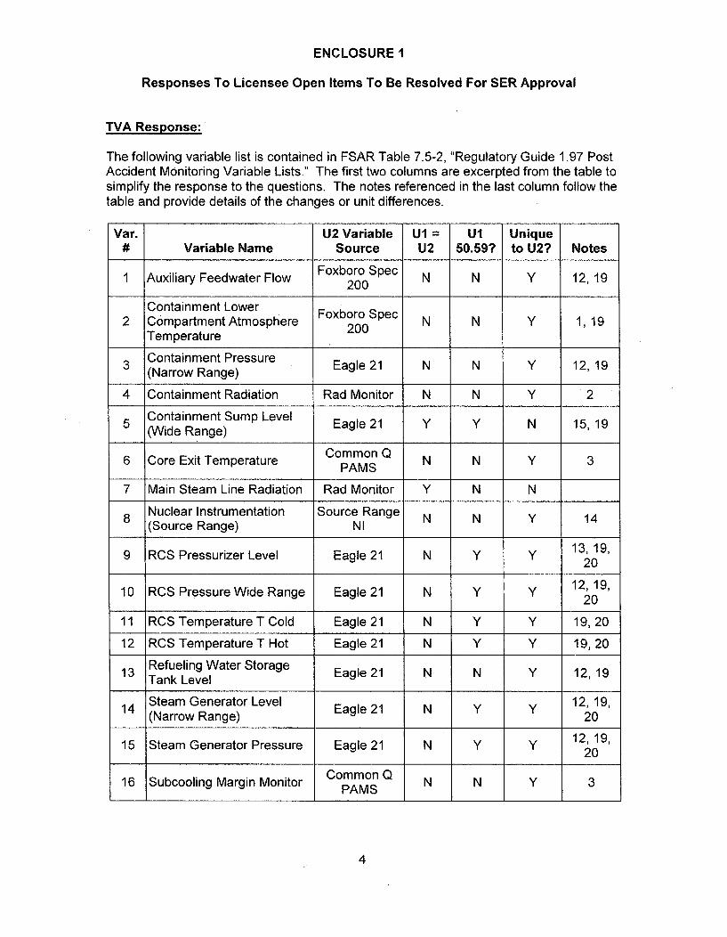
The following variable list is contained in FSAR Table 7.5-2, "Regulatory Guide 1.97 PostAccident Monitoring Variable Lists." The first two columns are excerpted from the table tosimplify the response to the questions. The notes referenced in the last column follow thetable and provide details of the changes or unit differences.
Var. U2 Variable U1 = Ul Unique# Variable Name Source U2 50.59? to U2? Notes
1 Auxiliary Feedwater Flow Foxboro Spec N N Y 12,19200
Containment Lower Foxboro Spec N N Y 1,192 Compartment Atmosphere 200
Temperature
3 Containment Pressure Eagle 21 N N Y 12,19(Narrow Range)
4 Containment Radiation Rad Monitor N N Y 2
5 Containment Sump Level Eagle 21 Y Y N 15,19(Wide Range)
6 Core Exit Temperature CommonQ N N Y 3PAMS7 Main Steam Line Radiation Rad Monitor Y N N
8 Nuclear Instrumentation Source Range N N Y 14(Source Range) NI
9 RCS Pressurizer Level Eagle 21 N Y y 13, 19,20
10 RCS Pressure Wide Range Eagle 21 N Y Y 12,19,20
11 RCS Temperature T Cold Eagle 21 N Y Y 19, 20
12 RCS Temperature T Hot Eagle 21 N Y Y 19, 20
13 Refueling Water Storage Eagle 21 N N Y 12,19Tank Level
14 Steam Generator Level Eagle 21 N Y y 12, 19,(Narrow Range) 20
15 Steam Generator Pressure Eagle 21 N Y Y 12, 19,20
16 Subcooling Margin Monitor CommonQ N N Y 3PAMS
4

ENCLOSURE1
Responses To Licensee Open Items To Be Resolved For SER Approval
U2 VariableSource
U1 = U1 UniqueU2 50.59? to U2?Variable Name Notes
Unit 1Auxiliary Building Passive Racks
Sump Level Instrument N/A N N/A 4Racks
18 Containment Isolation ValvePosition Indication
Valve LimitSwitches Y N N
Containment19 Containment Hydrogen Hydrogen N N Y 5ConcentrationMoir Monitor
20 Control Rod Position CERPI Y Y N 17
21 Nuclear Instrumentation Intermediate N N 14(Intermediate Range) Range NI
22 Reactor Vessel Level CommonQ N N Y 3, 13PAMS23 Containment Pressure Foxboro Spec N N y 12, 19,
(Wide Range) 200 20
24 Shield Building Vent (Noble Rad Monitor Y N NGas Activity)
25 ABGTS High Pressure Unit 1 N/A N N/A 4Alarm Per Fan Instruments
Unit 126 ACAS Pressure Unt N/A N N/A 4Instruments
27 AFW Valve Status Valve Limit Y N NSwitches
Accumulator Flow Isolation Valve LimitValve Status Switches
29 Accumulator Tank Level Foxboro IA N N Y 8,12,19
30 Accumulator Tank Pressure Foxboro IA N N Y 8,12, 19
31 Annulus Pressure Foxboro IA N N Y 8, 12,19
Aux. Feed Pump Turbine Valve Limit32 Steam Supply Isolation Switches Y N N
Valve Status33 Battery Current (125 V DC Ammeter y N N 11
Vital) Shunt
34 Bus Voltage (1 25V DC Vital) Direct Y N N 11
35 Bus Voltage (480V Direct Y N NShutdown)
5

ENCLOSUREI
Responses To Licensee Open Items To Be Resolved For SER Approval
Var. U2 Variable UI = U1 Unique# Variable Name Source U2 50.59? to U2? Notes
36 Bus Voltage (6.9KV PT Y N NShutdown)
37 CCS Surge Tank Level Foxboro IA N N Y 8,12,19
38 Centrifugal Charging Pump Foxboro IA N N Y 8,12Total Flow
39 Charging Header Flow Foxboro IA N N Y 8,12
40 Component Cooling Water Foxboro Spec N N Y 1,12To ESF Flow 200
41 Component Cooling Water Foxboro Spec N N 1,12Supply Temperature 200
42 Condensate Storage Tank Standalone y N N 11Water Level loop
43Containment Air Return Fan Breaker limitNNStatus switches
44 Containment Cooling Valve Valve Limit y N NStatus Switches
45 containment Spray Flow Eagle 21 N N Y 12, 19
Containment Spray HX
46Outlet - Outlet Temperature FobrIA N NY 81
47Containment Sump Water FobrIA N NY 8147Level (Narrow Range) FxooI ,1
48Containment Sump Water Eagle 21 N N Y 1948Temperature
49 Diesel Generator Power EI-82-70A Y N N 11
50 Diesel Generator Volts EI-82-66A Y N N 11
51 ECCS Valve Status VleLmt Y N NSwitches
52 ERCW Header Flow Foxboro Spec N N 1,1,9200N NY 1,1,9
53 ERCW Supply Temperature ICS Y Y N 9, 11
54 Emergency Gas Treatment Damper Limit y N NDamper Position Switches
55 Emergency Ventilation Damper Limit y N N 11Damper Status Switches
56 Hydrogen Recombiner NAN •NY1Status - Not Used in Unit 2 NAN NY1
6

ENCLOSURE 1
Responses To Licensee Open Items To Be Resolved For SER Approval
Var. U2 Variable U1 = Ul Unique# Variable Name Source U2 50.59? to U2? Notes
57 ~BreakerN N57 Igniter Group Status Position Y N N
58 Inverter Current (120V ac Ammeter y y N 10Vital) shunt
59 Inverter Voltage (120V ac Direct Y Y N 10Vital)
60 Letdown Flow Foxboro IA N N Y 8,12Common
61 MCR Pressure Pressure Inst. N/A N N/A 6, 11
62 MCR Radiation Level Commonirs N/A N N/A 6,R11Monitors NA N NA 61
63 Main Feedwater Flow Eagle 21 Y Y N 12,19,20
64 Normal Emergency Boration Foxboro IA N N Y 8,12Flow
65 There is no Variable 65 N/A N/A N/A N/A
Pressurizer Heater Status66 (Electric Current) ICS Y Y N
PORV &CODE -Acoustic
Pressurizer Pressure Relief Monit
67 Valve Position (PORV, System Y N NBlock, and Code) BLOCK-
Valve LimitSwitches
68 Pressurizer Relief Tank FoxboroIA N N Y 8,12,19Level
69 Pressurizer Relief Tank Foxboro IA N N Y 8,12,19Pressure
70 Pressurizer Relief Tank Foxboro IA N N Y 8,12,19Temperature
71 RCP Seal Injection Flow Foxboro IA N N Y 8, 12,72 RCS Head Vent Valve Foxboro Spec N N Y 1, 19
Status 200
RHR Heat Exchanger Outlet Foxboro IA N Y Y 8, 12, 20Temperature
7

ENCLOSUREI
Responses To Licensee Open Items To Be Resolved For SER Approval
Var. U2 Variable Ul = Ul Unique# Variable Name Source U2 50.59? to U2? Notes
RHR Pump Flow (RHR Foxboro IA N N Y 8,12System Flow)
75 ~Valve LimitN N75 RHR Valve Status Y N NSwitches
76 Reactor Coolant Pump CT Y N NStatus (Motor Current)
77 Safety Injection Pump Flow Foxboro IA N N Y 8,12
78 Safety Injection System Valve Limit Y N NValve Status Switches
79 Spent Fuel Pool Level Common N/A N N/A 6,11Alarm
80 Spent Fuel Pool Common N/A N N/A 6,11Temperature Alarm
81 Steam Generator Blowdown Valve Limit N NIsolation Valve Status Switches
82 Steam Generator Level Eagle 21 N 12,19,(Wide Range) 20
83 Main Steam Flow Eagle 21 N Y y 12,19,20
84 Tritiated Drain Collector Common N/A N N/A 6Tank Level
85 Volume Control Tank Level Foxboro IA N N Y 8,1286 Waste Gas Decay Tank Common N/A N N/A 6
Pressure
87 Radiation Exposure Meters Not used N/A N/A N/A
88 Airborne Radio-halogens Portable y N/A N/Aand Particulates Monitor
89 Plant and Environs Portable Y N/A N/ARadiation Monitor
Plant and Environs PortableRadioactivity Monitor
91 Auxiliary Building Vent Common N/A N N/A 6(Noble Gas) Rad Monitor
92 Auxiliary Building Vent Common /A N N/A 6(Flow Rate) Rad Monitor
93 Auxiliary Building Vent Common N/A N N/A 6(Particulates and Halogens) Rad Monitor
8

ENCLOSURE1
Responses To Licensee Open Items To Be Resolved For SER Approval
Var. U2 Variable U1 = UI Unique# Variable Name Source U2 50.59? to U2? Notes
Condenser Vacuum Pump Foxboro IA N N Y 8,12Exhaust Vent (Flow Rate)
95 Condenser Vacuum Pump Rad Monitor N N Y 18Exhaust Vent (Noble Gas)
96 ERCW Radiation Monitors Common N/A N N/A 6Rad Monitor
97POST ACCIDENT N/A N/A N/A N/ASAMPLING
Grab sampleReactor Coolant Chloride with sa te
97a Cnetainwith onsite Y N Y7Concentration aayianalysis
GrabsmlReactor Coolant Dissolved ab sample
97b Hydrogewith onsite Y N YHydrogen analysis
Reactor Coolant Dissolved Grab sample97c with onsite Y N Y 7Oxygen analysis
Reactor Coolant Total Grab sample97d Dissolved Gas with onsite Y N Y 7
analysis
Grab sample97e Reactor Coolant Boron with onsite Y N Y 7
analysis
Grab sample97f Reactor Coolant pH with onsite Y N Y 7
analysis
Reactor Coolant Sample Grab sample97g Actor with onsite Y N Y 7
analysis
Reactor Coolant Gamma Grab sample
97h Spectrumwith onsite Y N Y 7Spectrum analysis
98 CONTAINMENT AIR N/A N/A N/A N/A
Not used98a Containment Air Hydrogen Deviation 22 N/A N/A N/A
98b Oxygen Content Not Used for N/A N/A N/AWBN 1 or 2
9

ENCLOSURE1
Responses To Licensee Open Items To Be Resolved For SER Approval
Var. U2 Variable UI = U1 Unique# Variable Name Source U2 50.59? to U2? Notes
98c Gamma Spectrum Sample Grab Sample Y N N
99 Shield Building Vent Flow Rad Monitor Y N N
100 Shield Building Vent Monitor Rad Monitor Y N N(Particulate and Iodine)
Steam Generator Discharge Acoustic101 Vent (Flow Rate and Noble Monitor Y N Y 21
Gas) System
102 METEOROLOGY N/A N/A N/A N/A
102a Vertical Temperature Common N/A N N/A 6
Difference
102b Wind Direction Common N/A N N/A 6
102c Wind Speed Common N/A N N/A 6
103 Radiation Exposure Rate Portable N/A N/A N/AMonitor
NOTES:
1. In Unit 2, this variable is provided by the Foxboro Spec 200 hardware upgrade.2. In Unit 2, this variable is provided by the RM1000 digital Containment High Range
Radiation monitors.3. In Unit 2, this variable is provided by the Common Q Post Accident Monitoring System
(PAMS).4. These variables are common for both units and are provided by the Unit 1 systems.5. In Unit 2, this variable is provided by the single non-safety-related hydrogen monitor.6. These variables are common for both units and are provided by common systems.7. These variables are obtained via portable sampling equipment and laboratory analysis.8. In Unit 2, this variable is provided by the non-safety-related Foxboro Intelligent
Automation (IA) Distributed Control System (DCS).9. In Unit 1, this variable was within the scope of the 10 CFR 50.59 for the Integrated
Computer System (ICS) modification which replaced the plant P2500 and EmergencyResponse Facility Data System (ERFDS) mainframe computers.
10. In Unit 1, this variable was within the scope of the 50.59 for the vital inverter replacementmodification.
11. In service for Unit 1 Operation.12. In Unit 2, the transmitters for this variable have been changed to Rosemount, and the
transmitter range has changed to 4-20ma.13. In Unit 2, the transmitter range for this variable has changed to 4-20ma.14. The source/intermediate range replacement in Unit 2 uses the same digital component
(shutdown monitor), but the analog electronics and detectors have been upgraded.
10

ENCLOSURE1
Responses To Licensee Open Items To Be Resolved For SER Approval
NOTES: (Continued)
15. In Unit 1, the transmitter and transmitter configuration were changed to improvereliability due to problems with the fill fluid in the original capillary type transmitters(DCN 39608). This included changing the transmitters, recorder and indicators to4-20ma technology. Unit 2 copied the Unit 1 change (EDOCR 52419 excerpts submittedMarch 12, 2010).
16. For Unit 2, the hydrogen recombiners are abandoned in place.17. Unit 1 replaced the rod position indication with the Combustion Engineering Rod Position
Indication system (CERPI) in 2003 (DCN 51072) under 10 CFR 50.59. The Unit 1system has been upgraded several times, most recently in 2009. Unit 2 copied the Unit1 system including all upgrades through 2009.
18. In Unit 2, the separate medium and high range monitors are replaced with a singleextended range monitor.
19. In Unit 2, the indicators and recorders have been replaced with 4-20ma devices.20. In Unit 1, the recorders have been replaced due to obsolescence.21. In Unit 2, the accelerometers and pre-amplifiers have been replaced due to
obsolescence. Other components were replaced due to end of qualified life with newermodels of the same components.
7. NRC Request (Item No. 481
Reference 16 of the PAMS System Requirements Specification (SysRS) is the Unit 1Precautions Limitations and Setpoints document [PLS]. When and how will the transition tothe Unit 2 document be made.
TVA Response:
To ensure technical fidelity with the Unit 1 ICCM-86 system, the Unit 1 PLS was used as aninput to the Common Q PAMS System Requirements Specification. This was done toensure the Unit 2 PAMS had at a minimum the same capabilities and accuracy as the Unit 1system.
The Unit 2 Common Q PAMS PLS section was developed based on the actual Common QPAMS system design as reflected in the System Requirements Specification. As such, theCommon Q PAMS PLS section is an output of the Common Q PAMS System RequirementsSpecification. Therefore, no "transition" from the Unit I to the Unit 2 PLS is required.
The Unit 2 PLS is scheduled to be issued December 13, 2010.
8. NRC Request (Item No. 49)
Please provide 00000-ICE-30156 Rev. 6. The PAMS SysRS incorporates sections of thisdocument by reference.
TVA Response:
Per Westinghouse letter WBT-D-2024 (Reference 7), this document is available for audit atthe Westinghouse Rockville office.
11

ENCLOSURE1
Responses To Licensee Open Items To Be Resolved For SER Approval
9. NRC Request (Item No. 50)
How should the "shall" statements [in the Common Q PAMS System RequirementsSpecification] outside of the bracketed requirements be interpreted?
TVA Response:
These sections are descriptive text and not requirements. The next revision of the WattsBar Unit 2 PAMS System Requirements Specification will remove 'shall" from the wording inthose sections. The next revision of the Unit 2 Common Q PAMS System RequirementsSpecification will be provided to NRC no later than August 31, 2010.
10. NRC Request (Item No. 54)
Please describe all the different environments in which the RM-1000 will be required tooperate. Please group these environments into two categories (a) Harsh environment, per10 CFR 50.49, and (b) Mild Environment.
TVA Response:
The only safety-related application for the RM-1 000 is the Containment High Rangeradiation monitors. The Containment High Range monitors will be installed in the maincontrol room, a mild environment. The detectors will be installed remotely in thecontainment.
For WBN Unit 2, a mild environment is defined as:
A defined room or building zone where (1) the temperature, pressure, or relative humidityresulting from the direct effects of a design basis event (DBE) (e.g, temperature rise due tosteam release) are no more severe than those which would occur during an abnormal plantoperational condition, (2) the temperature will not exceed 130°F due to the indirect effects ofa DBE (e.g., increased heat loads from electrical equipment), (3) the event radiation dose isless than or equal to 1 x 10⁴ rads, and (4) the total event plus the 40 year TID (totalintegrated dose) is less than or equal to 5 x 10⁴ rads. (Reference 3).
11. NRC Request (Item No. 55)
The "Qualification Test Report Supplement, RM-1000 Upgrades, "Document No. 04508905-1SP Rev. A states that the qualification was done in accordance with IEEE 323-1974 and -1983. Please describe and justify all differences in this qualification methodology and thatendorsed by Regulatory Guide 1.209. Specifically address EMI and RFI.
12

ENCLOSUREI
Responses To Licensee Open Items To Be Resolved For SER Approval
TVA Response:
Regulatory Guide (RG) 1.209 endorses IEEE 323-2003 for seismic and environmentalqualification. It also endorses EPRI TR 102323 (Sept. 94) for Radio Frequency Interference(EMI-RFI) testing. The major difference between IEEE 323-2003 and IEEE 323-1974 and1983 is that 2003 contains an allowance that harsh environment qualification testing is notrequired for Safety-Related Computer-Based Instrumentation and Control Systems locatedin mild environments. RG 1.209 accepts this allowance.
The RM-1 000 was qualified to the previous versions of IEEE 323 which does not contain anallowance for harsh environment qualification. As a result, the qualification testing of theRM-1000 was done for service in a harsh environment. Therefore, the qualification testingof the RM-1000 exceeds the IEEE 323-2003 requirements of RG 1.209.
The RM-1 000 was tested for Electro-Magnetic Interference and Radio FrequencyInterference (EMI-RFI) in accordance with EPRI TR 102323 (Sept. 94) as documented in theEquipment Qualification Test Report submitted under TVA letter dated March 12, 2010,(Reference 4). Therefore, RM-1 000 meets the requirements of RG 1.209 for EMI/RFItesting.
For WBN Unit 2, a harsh environment is defined as:
A defined room or building zone where either (1) the temperature, pressure, and relativehumidity resulting from the direct effects of a DBE (e.g., temperature rise due to steamrelease) are more severe than those which would occur during an abnormal plantoperational condition, (2) the temperature will exceed 130°F due to the indirect effects ofDBE (e.g., increased heat loads from electrical equipment), (3) the event radiation dose isgreater than 1 x 10⁴ rads, or (4) the total event plus the 40-year TID is greater than 5 x 10⁴
rads. (Reference 3)
12. NRC Request (Item No. 56)
The "RM-1000 Version 1.2 Software Verification and Validation Report," Document No.04508006 Rev. A, is an incremental report. That is to say it addresses the verification an[d]validation for changes that resulted in Version 1.2; therefore, the NRC has not received asoftware verification and validation report for all other aspects of the software. Pleaseprovide the last complete verification and validation report, and all incremental reports afterthe complete report.
TVA Response:
The initial draft Software Verification and Validation (V&V) report document, version 1.0,was never issued.
Attachment 4 contains the latest complete proprietary version 1.1 Software V&V report(04508005). The non-proprietary version and withholding affidavit will be submitted byJuly 14, 2010. Submittal of the non-proprietary version and withholding affidavit is trackedby Responses to Licensee Open Items to be Resolved for SER Approval item 119.
13

ENCLOSURE1
Responses To Licensee Open Items To Be Resolved For SER Approval
The latest proprietary version is 1.2 (an incremental report that addresses the differencesfrom the version 1.1 report), and was submitted by TVA letter dated March 12, 2010(Reference 4). Submittal of the non-proprietary version and withholding affidavit is trackedby Responses to Licensee Open Items to be Resolved for SER Approval item 101, dueJune 30, 2010.
13. NRC Request (Item No. 57)
Please describe the ability to change the software of the RM-1000 at site, including allrequired equipment and administrative controls (e.g., temporary digital connections).
TVA Response:
Firmware/software changes are done by connecting a laptop to a port on the front of theRM-1000 and placing the Operate/Calibrate switch in the Calibrate position. The firstphysical barrier to access is the location of the RM-1 000 in the main control room which haslimited access. The RM-1000 Operate/Calibrate switch is located behind the hinged frontpanel. The front panel must be opened (held closed by two thumbscrews) to access theswitch. This provides a physical barrier to inadvertent switch operation. The systemmalfunction alarm is visible locally and will annunciate on the control board when the switchis in the Calibrate position.
Administrative control of software/firmware updates is in accordance with TVA StandardSpecification SS-El 8.15.01, Software Requirements for Real-Time Data Acquisition andControl Computer Systems, and TVA procedures SPP-9.3, Plant Modifications andEngineering Change Control, and SPP-2.6, Computer Software Control. Approved changesto software/firmware are implemented utilizing the TVA work order process.
14. NRC Request (Item No. 58)
Please describe all digital communications used in the [RM-1000] installed configuration.
TVA Response:
There are no digital communications between the RM-1 000 and any other plant system orcomponent.
15. NRC Request (Item No. 59)
Previously TVA provided the "RM-1000 Digital Radiation Processor Technical Manual,"Document No. 04508100-1TM Revision C dated October 2003. The "RM-1000 Version 1.2Software Verification and Validation Report, "Document No. 04508006 Rev. A is dated April2008.
(a) What software version does the technical manual address?
(b) When was Version 1.2 implemented?
14

ENCLOSUREI
Responses To Licensee Open Items To Be Resolved For SER Approval
TVA Response:
(a) The technical manual is applicable to versions 1.1 and 1.2 of the software.
(b) Version 1.2 was implemented April 1, 2008.
16. NRC Request (Item No. 66)
By letter dated March 12, 2010 TVA stated that the target submittal date for the "Watts Bar 2PAMS Software Design Description (two documents, one for flat panel display and one forAC160)" was March 31, 2010.
TVA Response:
Per Westinghouse letter WBT-D-1961 (Reference 8), these items are available for audit atthe Westinghouse Rockville office.
17. NRC Request (Item No. 67)
By letter dated March 12, 2010 TVA stated that the target submittal date for the"Commercial Grade Dedication Instructions for A1687, A1688, Upgraded PC node box andflat panels." was September 28, 2010.
TVA Response:
The following status is from the revised WB2 Common Q PAMS ISG-6 Compliance Matrixsubmitted in response to Item 43:
a. A1687, A1688 - Scheduled for September 28, 2010
b. Upgraded PC node box and flat panel displays - Per Westinghouse letter WBT-D-2024(Reference 7), these items are available for audit at the Westinghouse Rockville office.
c. Power supplies - Per Westinghouse letter WBT-D-2035 (Reference 12), these items are
available for audit at the Westinghouse Rockville office.
18. NRC Request (Item No. 68)
By letter dated March 12, 2010 TVA stated that the target submittal date for the "SummaryReport on acceptance of A1687, A1688, Upgraded PC node box, flat panels, and powersupplies." was September 28, 2010.
TVA Response:
The following status is from the revised WB2 Common Q PAMS ISG-6 Compliance Matrixsubmitted in response to Item 43:
a. A1687, A1688 - Scheduled for September 28, 2010
15

ENCLOSUREI
Responses To Licensee Open Items To Be Resolved For SER Approval
b. Upgraded PC node box - Per Westinghouse letter WBT-D-2024 (Reference 7), this itemis available for audit at the Westinghouse Rockville office.
c. Flat panel displays - Per Westinghouse letter WBT-D-2024 (Reference 7), this item isavailable for audit at the Westinghouse Rockville office.
d. Power supplies - Per Westinghouse letter WBT-D-2035 (Reference 12), these items are
available for audit at the Westinghouse Rockville office.
19. NRC Request (Item No. 70)
By letter dated March 12, 2010 TVA stated that the target submittal date for the "Conceptand Definition Phase V&V Report" was March 31, 2010.
TVA Response:
Per Westinghouse letter WBT-D-1 961, (Reference 8) this document is available for audit atthe Westinghouse Rockville office.
20. NRC Request (Item No. 77)
By letter dated March 12, 2010 TVA stated that the target submittal date for seven otherdocuments was "TDB" [TBD]. Please provide a schedule for the docketing of the remainingdocuments.
TVA Response:
The availability dates for these documents are included in the revised WBN Unit 2 CommonQ ISG-6 Compliance Matrix submitted in response to item 43. As stated in the March 12,2010 letter (Reference 4), the dates in the matrix are the dates the documents will beavailable to TVA to prepare for submittal or being "Available for Audit". They do not reflectthe dates the documents will be submitted to the NRC. Expected submittal date is twoweeks after TVA receives the document.
Note: There is a typo in the matrix in line item 33. The power supply entry date says TBD.Per Westinghouse letter WBT-D-2035 (Reference 12) this item is complete and thedocuments are available for audit at the Westinghouse Rockville office.
21. NRC Request (item No. 81)
The PAMS Licensing Technical Report (WNA-LI-00058-WBT Rev. 0, Dated April 2010), inSection 7, lists codes and standards applicable to the Common Q PAMS. This list containsreferences to old revisions of several regulatory documents, for example:
1. RG 1.29 - September 1978 vs. March 20072. RG 1.53- June 1973 vs. November 2003
a. IEEE 379-1994 vs. -20003. RG 1.75 - September 1975 vs. February 2005
a. IEEE 384-1992 vs. -1992
16

ENCLOSURE I
Responses To Licensee Open Items To Be Resolved For SER Approval
4. RG 1.100- June 1988 vs. September 2009a. IEEE 344-1987 vs. -2004
5. RG 1.152 - January 1996 vs. January 2006a. IEEE 7-4.33.2-1993 vs. -2003
6. RG 1.168 - September 1997 vs. February 2004a. IEEE 1012-1986 vs. -1998b. IEEE 1028-1988 vs. -1997
7. IEEE 279-1991 vs. 603-19918. IEEE 323-1983 vs. -1974 (RG 1.89 Rev. 1 June 1984 endorses 323-1974)
However, LIC- 110, "Watts Bar Unit 2 License Application Review," states: "Design featuresand administrative programs that are unique to Unit 2 should then be reviewed inaccordance with the current staff positions." Please identify all differences between theversions referenced and the current staff positions. Please provide a justification for theacceptability PAMS with respect to these differences.
TVA Response:
The codes and standards documents listed in Section 7 of the Common Q PAMS LicensingTechnical Report are the documents that the Common Q platform was licensed to when theNRC approved the original topical report and issued the approved SER. The WBN Unit 2Common Q PAMS is designed in accordance with the approved Common Q topical reportand approved SER and the codes and standards on which the SER was based. Since thecurrent versions referenced are not applicable to WBN Unit 2, there is no basis for acomparison review.
22. NRC Request (Item No. 84)
Please provide: TVA Design Criteria WB-DC-30-7 Rev. 22, Post Accident MonitoringInstrumentation.
TVA Response:
Attachment 5 contains Design Criteria WB-DC-30-7 Rev. 22, Post Accident MonitoringInstrumentation.
23. NRC Request (Item No. 86)
The PAMS Licensing Technical Report (WNA-LI-00058-WBT Rev. 0, Dated April 2010), inSection 6, lists references applicable to the Common Q PAMS. This list contains referencesto old revisions of several regulatory documents, for example:
(1) DI&C-ISGO4 - Rev. 0 (ML072540138) vs. Rev. I (ML083310185)
However, LIC-1 10, "Watts Bar Unit 2 License Application Review, "states: "Design featuresand administrative programs that are unique to Unit 2 should then be reviewed inaccordance with the current staff positions." Please identify all differences between theversions referenced and the current staff positions. Please provide a justification for theacceptability PAMS with respect to these differences.
17

ENCLOSUREI
• Responses To Licensee Open Items To Be Resolved For SER Approval
TVA Response:
The regulatory documents listed in the Common Q PAMS Licensing Technical Report arethe documents that the Common Q platform was licensed to when the NRC approved theoriginal topical report and issued the approved SER. The WBN Unit 2 Common Q PAMS isdesigned in accordance with the approved Common Q topical report and approved SER andthe regulatory documents on which the SER was based. Since the current versionsreferenced are not applicable to WBN Unit 2, there is no basis for a comparison review.
24. NRC Request (Item No. 87)
Regarding the Sorrento RM-1000 Digital Radiation Processor: Please identify the model andversion to be installed. Please include explicit identification of software version.
TVA Response:
The rate meter is model RM-1 000. The software is version 1.2
25. NRC Request (Item No. 88)
Regarding the Sorrento RM- 1000 Digital Radiation Processor: Please provide prior softwareV&V reports. The latest report only addresses Version 1.2.
TVA Response:
See response to Item 12.
26. NRC Request (Item No. 91)
TVA to submit excerpts of EDCRs 52421, 52987, 52321, 52351 and 52601
TVA Response:
1. Attachment 6 contains the EDCR 52421 excerpt.
2. Attachment 7 contains the EDCR 52987 excerpt.
3. EDCR 52321 is scheduled to be issued Oct 13, 2010. Submittal of EDCR 52321excerpts is tracked by Responses to Licensee Open Items to be Resolved for SERApproval item 103 due October 31, 2010.
4. EDCR 52351 is scheduled to be issued November 30, 2010. Submittal of EDCR 52351excerpts is tracked by Responses to Licensee Open Items to be Resolved for SERApproval item 104 due December 15, 2010.
5. Attachment 8 contains the EDCR 52601 (RVLIS) excerpt. The RVLIS EDCR has beensplit into two EDCRs. The second EDCR is 55385. Submittal of EDCR 55385 excerptsis tracked by "Responses to Licensee Open Items to be Resolved for SER Approval"item 118, due November 15, 2010.
18

ENCLOSURE I
Responses To Licensee Open Items To Be Resolved For SER Approval
27. NRC Request (Item No. 102)
Provide a schedule for resolution of items 80, 82 and 83
TVA Response:
Item 80 - no later than July 23, 2010.
Item 82 - no later than July 23, 2010.
Item 83- no later than July 23, 2010.
28. NRC Request (Item No. 106)
Confirm that the Unit I and Unit 2 CERPI systems utilize the same processor (ACI 10 orAC160).
TVA Response:
Westinghouse Unit 2 Drawing 6D31420 (Reference 9), Watts Bar 2- CERPI AC160 ChassisConfiguration, Rev. 2, shows the processors are Model AC160, which are the same that areutilized for Unit 1, as shown on Westinghouse drawing 2D82995 Rev. 0 (Reference 10),Watts Bar CERPI AC 160 Chassis Configuration.
29. NRC Request (Item No. 107)
Describe any control functions associated with the RM-1000 radiation monitors.
TVA Response:
The RM-1 000 radiation monitors do not provide any control functions.
30. NRC Request (Item No. 111)
The reviewer was unable to locate information (SER) on the plant computer or annunciatorsystems and asked us to provide the location within the FSAR where these systems aredescribed.
TVA Response:
The annunciator system is not described in the WBN Unit 1 Updated FSAR (UFSAR). Assuch it is not included in the WBN Unit 2 FSAR.
With the exception of the ERFDS functions in Section 7.5, the plant computer is notdescribed in the WBN Unit 1 UFSAR. As such it is not included in the WBN Unit 2 FSAR.
31, NRC Request (Item No. 113)
Are the new model Eagle 21 power supplies installed in Unit 1 ?
19

ENCLOSUREI
Responses To Licensee Open Items To Be Resolved For SER Approval
TVA Response:
Yes. Attachment 9 provides a work order excerpt and unit difference form.
32. NRC Request (Item No. 114)
Provide the resolution of the Eagle 21 Rack 5 lockup on update issue.
TVA Response:
The following non-proprietary response was developed from proprietary Westinghouse letterWBT-D-2027 (Reference 11), which provided the resolution of this issue. Westinghouseapproved this non-proprietary response via e-mail from A. Drake to M. Clark on June 15,2010.
As documented in WBT-D-1917, "Eagle-21 Rack 5 LCP Diagnostic Failures",(Reference 14), Westinghouse noted an occasional diagnostic failure while performing theparameter update function on Rack 5 during the factory acceptance testing for the Unit 2Eagle-21 System.
Subsequently, TVA provided to Westinghouse for testing and examination, a Loop ControlProcessor (LCP) board removed by TVA from Unit 1 Rack 5 for life cycle-based preventivemaintenance. TVA personnel familiar with Unit 1 had indicated they had not experiencedproblems when performing parameter updates on Unit 1 Rack 5.
Based on Westinghouse examination and testing, a difference in hardware was identifiedbetween the Unit 1 LCP shipped to Westinghouse, the new Unit 2 Rack 5 LCP, and an olderLCP (older than the Unit 1 LCP) from the Westinghouse Eagle 21 test bed. A differentversion of an 80287 math coprocessor chip (80287 XL) was installed on the Unit 1 LCP.This version of the 80287 had an improved specification for calculation speed. Use of thischip on both the Unit 2 LCP and the test bed LCP allowed proper performance of the LCPwhen making parameter updates using the Unit 1/Unit 2 Rack 5 software. Also, use of theslower 80287 on any of the three LCP boards caused failure in parameter update with theUnit 1/Unit 2 Rack 5 software.
Through investigation of historical records, Westinghouse found that the 80287 XL chip hadbeen evaluated and used by its former Process Control Division (now Emerson) for thisapplication, but the current Westinghouse documentation had not been updated. This parthas now been evaluated, and the Westinghouse documentation and drawing have beenrevised to allow use of the 80287 XL coprocessor. The 80287 XL coprocessor has beeninstalled on the Unit 2 Rack 5 LCP, and the appropriate factory acceptance testing has beensuccessfully conducted using this updated board. Additionally, the LCP boards in thebalance of the Unit 2 racks have been updated with the 80287 XL coprocessor.
33. NRC Request (Item No. 115)
Provide a list of digital 1E systems that have a digital communications path to non safetyrelated systems and if it has:a. Been reviewed before for unit 1b. Or been installed in unit I under 50.59, orc. is unique to unit 2
20

ENCLOSUREI
Responses To Licensee Open Items To Be Resolved For SER Approval
TVA Response:
Safety Non Unit I Review Unit 2 Interface ReviewRelated SafetySystem Related
Interface
Eagle 21 Plant While Eagle was installed The digital Eagle to ICS interfaceComputer prior to Unit 1 Licensing, in Unit 1 is via node boxes on a(ICS) the interfaces to the ring network. The interface for
ERFDS/P2500 main frame Unit 2 is direct from the Eaglecomputers were analog, cabinets to a network switch on aWith the replacement of star network. While the Unit 2the ERFDS/P2500 ICS computer hardware interfacemainframes by the is different than Unit 1, the EagleIntegrated Computer interface is the same in both units;System (ICS), the interface via a mono-directionalbecame digital. Since ICS communication path described inwas installed under 50.59, Reference 1. Due to thethe Unit 1 digital difference in the ICS connection,communications interface the Unit 2 interface is unique.has not been reviewed.
Common Q Plant Common Q is not installed The Common Q to Plant ComputerComputer in Unit 1 interface is via the safety-related(ICS) Maintenance and Test Panel
(MTP) fiber optic interface whichblocks all except the minimum lowlevel TCP/IP commandsnecessary to supportcommunications. A detaileddescription of the MTPcommunications is contained inWNA-LI-00058-WBT, Revision 0,Watts Bar Unit 2 (WBN2) PostAccident Monitoring System(PAMS) Licensing TechnicalReport submitted underReference 2. Additionalcommunication isolation isprovided by non-safety-relateddata diodes (one for each train).The Common Q to ICS interface isunique to Unit 2.
21

ENCLOSUREI
Responses To Licensee Open Items To Be Resolved For SER Approval
34. TVA Identified (Item No. 127)
Provide the status of the Eagle 21 Rack 2 RTD accuracy issue.
TVA Response:
The following non-proprietary response was developed from proprietary Westinghouse letterWBT-D-2034 (Reference 15), which provided the details of this issue. Westinghouseapproved this non-proprietary response via e-mail from A. Drake to M. Clark on June 16,2010.
During the Watts Bar Unit 2 Eagle 21 Factory Acceptance Test (FAT) of Rack 2, it wasdiscovered that the narrow range Resistance Temperature Detector (RTD) temperatureinputs were consistently reading about 0.20 F higher than expected. Investigation revealedthat these inputs are configured in the Loop Calculation Processor software as a sharedRTD. This is incorrect. Rack 2 RTDs are not shared. Racks 6, 10 and 13 RTDs areshared. Configuration as a shared RTD input alters the equation used for the temperaturecalculation. Watts Bar Unit 1 uses identical software to Unit 2.
Further investigation by Westinghouse showed this configuration error causes the NarrowRange Temperatures for only Division I to read 0.2 to 0.270 F higher over the Narrow Rangespan of 510-6500 F. The 0.20 F shift affects Thot and Tcold equally and thus will not affect theindication-of Delta T. Tavg will indicate high by 0.20 F, which will decrease the Overtemperature and Overpower set points; which is in the conservative direction. The indicatedhigh 0.2' F Tavg, if selected for control (via auctioneered high), would cause the controllingtemperature to result in an actual temperature 0.20 F low; which is in the conservativedirection for consideration of DNB. The Tavg - Low-Low function (P-12) would be non-conservative by 0.20 F, which would cause the permissive/interlock for block of steam dumppost reactor trip to be delayed slightly via that channel. This delay would not be consideredsignificant. Westinghouse will discuss this issue with Watts Bar Unit 1 personnel inaccordance with their Part 21/Potential Issue process.
Westinghouse initiated a corrective action item (CAP # 10-140-M021) and performed anEvaluation of Potential Nuclear Safety Issue. Based upon the above investigations,Westinghouse determined that this issue does not represent a substantial safety hazard atWatts Bar Unit 1, even if left uncorrected.
A report on the final resolution of the Eagle 21 RTD input issue will be provided no later thanDecember 3, 2010.
References:
1. TVA letter to NRC dated August 25, 2008, "Watts Bar Nuclear Plant (WBN) - Unit 2 -Westinghouse Eagle 21 Process Protection System, Response to NRC I&C BranchRequest for Additional Information (TAC No. MD631 1)" (ML082410088) (T02 080826 001)
22

ENCLOSUREI
Responses To Licensee Open Items To Be Resolved For SER Approval
References: (Continued)
2. TVA letter to NRC dated April 8, 2010, "Watts Bar Nuclear Plant (WBN) Unit 2 -AdditionalInformation Regarding Final Safety Analysis Report (FSAR), Chapter 7, "InstrumentationAnd Controls" Review - Requested Common Q Proprietary Documents (T02 100408 001)
3. Watts Bar Design Criteria Document WB-DC-40-54, Environmental Qualification To10CFR50.49, Rev. 4.
4. TVA letter to NRC dated March 12, 2010, "Watts Bar Nuclear Plant (WBN) Unit 2 -Additional Information Regarding Final Safety Analysis Report (FSAR), Chapter 7,'Instrumentation And Controls' Review - Requested Common Q Proprietary Documents"(T02 100312 001)
5. TVA letter to NRC dated April 27, 2010, "Watts Bar Nuclear Plant (WBN) Unit 2 - StaffInformation Requests Resulting From NRC December 15, 2009, Meeting With TennesseeValley Authority (TVA) Regarding Digital Instrumentation And Controls Review And NRCClarifications To The Requests Provided During February 18, 2010, TelephoneConference Call (TAC No. ME0853)" (T02 100427 002)
6. Westinghouse letter WBT-D-1 526, Tennessee Valley Authority Watts Bar Nuclear PlantUnit 2, NRC Access to Common Q Documents at the Westinghouse Rockville Office
7. Westinghouse letter WBT-D-2024, Tennessee Valley Authority Watts Bar Nuclear PlantUnit 2, NRC Access to Common Q Documents at the Westinghouse Rockville Office
8. Westinghouse letter WBT-D-1 961, Tennessee Valley Authority Watts Bar Nuclear PlantUnit 2, NRC Access to Common Q Documents at the Westinghouse Rockville Office
9. Westinghouse Unit 2 Drawing 6D31420 Revision 2, Watts Bar 2- CERPI AC160 Chassis
Configuration
10. Westinghouse drawing 2D82995 Rev. 0, Watts Bar CERPI AC 160 Chassis Configuration
11. Westinghouse letter WBT-D-2027, Tennessee Valley Authority Watts Bar Nuclear PlantUnit 2, Unit 2 Eagle-21 Rack 5 Testing and Hardware Release
12. Westinghouse letter WBT-D-2035, Tennessee Valley Authority Watts Bar Nuclear PlantUnit 2, NRC Access to Common Q Documents at the Westinghouse Rockville Office
13. Westinghouse letter WBT-D-2044, Tennessee Valley Authority Watts Bar Nuclear PlantUnit 2, Updated Common Q PAMS ISG-6 Compliance Matrix
14. Westinghouse letter WBT-D-1917, Tennessee Valley Authority Watts Bar Nuclear PlantUnit 2, Eagle -21 Rack 5 LCP Diagnostic Failures
15. Westinghouse letter WBT-D-2034, Tennessee Valley Authority Watts Bar Nuclear PlantUnit 2, Eagle-21 Rack 2 Deviation and Release
23
ENCLOSURE 1
Responses To Licensee Open Items To Be Resolved For SER Approval
ATTACHMENT I
(This Attachment contained on the OSM)
1. Analog Loop Comparison
2. Analog Card Comparison
3. Analog System Description

Foxboro Analog Spec 200 Unit I to Unit 2 Loop Comparison5/27/2010
Page 1 of 3
Same as< ChangeSystem~ Unit 1 PackageNumber Loop Number Loop Function Y/N~ Comments No.
46 2-F-46-57 Turbine Driven AFW Y Flow control Loop 52343Pump Control
3 2-P-3-122A Auxiliary Feedwater N Pressure Loop 52427Pump 2A-A DifferentalPressure
3 2-P-3-1 220 Auxiliary Feedwater Y Pressure Loop 52343Pump 2A-A DifferentalPressure Aux Control
3 2-P-3-132A Auxiliary Feedwater N Pressure Loop 52427Pump 2B3-B3 DifferentialPressure
3 2-P-3-1 320 Auxiliary Feedwater Y Pressure Loop 52343Pump 2B3-B DifferentalPressure Aux Control
3 2-F-3-147A Steam Generator 3 N Flow control Loop 52427Auxiliary Feedwater Flow
3 2-F-3-147B Steam Generator 3 N Flow control Loop 52343Auxiliary Feedwater Flow
3 2-F-3-1 55A Steam Generator 2 N Flow control Loop 52343Auxiliary Feedwater Flow
3 2-F-3-1 55B Steam Generator 2 N Flow control Loop 52427Auxiliary Feedwater Flow
3 2-F-3-163A Steam Generator 1 N Flow control Loop 52427Auxiliary Feedwater Flow
3 2-F-3-1 63B3 Steam Generator I N Flow control Loop 52343Auxiliary Feedwater Flow
3 2-F-3-1 70A Steam Generator 4 N Flow control Loop 52343Auxiliary Feedwater Flow
3 2-F-3-1 70B Steam Generator 4 N Flow control Loop 52427_______Auxiliary Feedwater Flow
30 2-P-30-310 Containment Pressure N Pressure Loop 52427_______(Train A)
30 2-P-30-311I Containment Pressure N Pressure Loop 52427_______ ______________ (Train B)
30 2-T-30-1 032 Lower Containment N Temperature Loop 52427Ambient Temperature(Train A)

Foxboro Analog Spec 200 Unit I to Unit 2 Loop Comparison5/27/2010
Page 2 of 3
Same as Chiange~System Unit I KPackageNumber Loop Number Loop Function YIN Comments No.
30 2-T-30-1 033 Lower Containment N Temperature Loop 52427Ambient Temperature(Train B)
30 2-T-30-1 034 Lower Containment N Temperature Loop 52427Ambient Temperature(Train A)
30 2-T-30-1 035 Lower Containment N Temperature Loop 52427Ambient Temperature(Train B)
70 2ý-F-70-165A RHR Heat Exchanger N Flow Loop 52427213-13 Supply HeaderFlow
70 2-F-70-215A & - Sample Heat Exchanger N Flow Loop - Each loop 52427215B Header Differential Flow - shares a common Summer
with one output
3 2-L-3-148 Steam Generator 3 Motor YIN Flow loop - (YES) Like U-1 52343Driven AFW Level - for Main Control SystemPump B (ACR & MCR) and (NO) for
signals to Indicators (ACR &MCR) and Annunciator
3 2-L-3-156 Steam Generator 2 Motor Y/N Flow loop - (YES) Like UI 52343Driven AFW Level - for Main Control SystemPump A (ACR & MCR) and (NO) for
signals to Indicators (ACR &MCR) and Annunciator
3 2-L-3-164 Steam Generator 1 Motor Y/N Flow loop -(YES) Like U1 52343Driven AFW Level - for Main Control SystemPump A (ACR & MCR) and (NO) for
signals to Indicators (ACR &MCR) and Annunciator
3 2-L-3-171 Steam Generator 4 Motor Y/N Flow loop - (YES) Like U-1 52343Driven AFW Level - for Main Control SystemPump B (ACR & MCR) and (NO) for
signals to Indicators (ACR &MCR) and Annunciator
3 2-L-3-172 Steam Generator 3 Y/N Flow loop - (Y 'ES) Like U1 52343Turbine Driven AFW for Main Control Systemlevel (Train A) (PNL 2-L-381A (Local) &
MCR) and (NO) for signalsto Indicators (ACR & MCR)and Annunciator

Foxboro Analog Spec 200 Unit I to Unit 2 Loop Comparison5/27/2010
Page 3 of 3
Same asChange~System Uniit 1, PackageNumber Loop Number Loop Function YiNj Comments No.
3 2-L-3-173 Steam Generator 2 Y/N Flow loop - (YES) Like U1 52343Turbine Driven AFW for Main Control Systemlevel (Train B) (PNL 2-L-381A (Local) &
MCR) and (NO) for signalsto Indicators (ACR & MCR)and Annunciator
3 2-L-3-174 Steam Generator 1 Y/N Flow loop - (YES) Like U1 52343Turbine Driven AFW for Main Control Systemlevel (Train B) (PNL 2-L-381A (Local) &
MCR) and (NO) for signalsto Indicators (ACR & MCR)and Annunciator
3 2-L-3-175 Steam Generator 4 Y/N Flow loop - (YES) Like U1 52343Turbine Driven AFW for Main Control Systemlevel (Train A) (PNL 2-L-381A (Local) &
MCR) and (NO) for signalsto Indicators (ACR & MCR)and Annunciator
68 2-F-68-397-A Reactor Vessel Head N Flow Loop 53765Vent Throttle ManualLoading Station (Train A)
68 2-F-68-396-B Reactor Vessel Head N Flow Loop 53765Vent Throttle ManualLoading Station (Train B)

same as Lhunge
System Unit 1 PackageNumber Loop Number Loop Function Y/N Comments No. Unit 1 Component U1 Manufacturer/Model # Unit 2 Component U2 Manufacturer/Model #
2-F-46-57/ 2
46 F-3-142 Turbine Driven AFW Pump Control Y Flow control loop 52343 I-FC-46-57A Foxboro/f-Z2AUKAM Z-FC-46-57A foxboro/N-ZAl+AM
1-FC-46-57B Foxboro/N-2AX÷A4 2-FC-46-57B Foxboro/N-2AX-M3+A4F-FpC-46em7AF Foxboro/N-2AX+M2NH 2-FIC-46-57A Foxboro/N-2AXiM2NH
1-FIC-46-57B Foxboro/N-25cHM-M2NH-F 2iFIC-46-onB Foxboro/N-25oH-M-M2NH-F
1-FM-46-57A Foxboro/N-2AI-H2V 2-FM-46-57A Foxboro/N-2A0-12V1-FM-46-578 Foxboro/N-2AO-V2H
This loop controls the Turbine driven Auxiliary Feedwater Pump outlet flow (fro. 2-FT-3-142) by varying the speed of the Turbine driven Auxiliary 1-FM-46-57D Robertshaw/572-C2 2-FM-46-57D Foxboro/N-2AO-VAI
Feedwater pump. Flow indicating controller 2-FIC-46-57A (on panel 2-M-4) can be used in either manual or automatic mode, this Main Control Room IF-65 PSP112202F-65 obr/-A-2-
controller is used when transfer switch 2-XS-46-57 (in junction box JB-8017) is in the normal position. When transfer switch 2-XS-46-S7 (in junction box IP-65AFxooN2XP9
JB-8017) or transfer switch 2-XS-46-S7A (in junction box JB-2235) is in the auxiliary position the loop is transferred into automatic mode. While the loop 1-FM-3-142A APCS/SE160-2t3310 2-FM-3-142A Foxboro/N-2AP+SQE
is in the auxiliary mode local flow indicating controller 2-FIC-46-57B (on panel 2-L-381) is used, this controller can transfer the loop back into manual -FM-3-142A APCS/SE139-217610 2-FM-3-142A Foxboro/N-2AO-VAII1-F-M-3-14213 APCS/S1139-2176100 2-FM-3-142B Foohoro/N-2A0-VAI
control for local operator control or it can be left in manual mode. When the turbine driven auxiliary feedwater pump outlet flow reaches its high 1-FM-3-142C APCS/51139-2176100 2-FM-3-142C Foxboro/N-2AO-VAI
setpoint a warning annunciation light is illuminated on panel 2-L-381 and the loop is transferred to automatic mode to prevent turbine over speed. Main 2-Fr-42A
Control Room hand switch 2-HS-46-57 is used as a "reset" to transfer this loop out of automatic mode after plant conditions have initiated a transfer it 2-FS-46-57A Foxboro/N-2AO-L2C-R
into automatic mode. This loop also provides input into the ICS. Flow indicator 2-FI-3-142A (on panel 2-M-4) provides main control room indication of 2-FS-46-57B Foxboro/N-2AO-L2C-R
the turbine driven auxiliary feedwater pump outlet flow. Flow indicator 2-FI-3-142C (on panel 2-L-10) provides auxiliary control room indication turbine 2-FS-46-S7C Foxboro/N-2AO-L2C-R
driven auxiliary feedwater pump outlet flow. 2-FS-46-57D Foxboro/N-2A0-L2C-R
2-FS-46-57E Foxboro/N-2AP+ALM-AR2-FS-46-57FA Foxboro/N-2A1-C2L
2-FS-46-S7FB Foxboro/N-2A1-C2L
2-FX-46-S7A Foxboro/N-2AX+DSl (N-ECEP-8629)
2-FX-46-57R Foxboro/N-2AX+DS1 (N-ECEP-8629)2-FX-46-57C Fouhoro/N-2AXcDSS (N-ECRP-R625(
This loop Is functionally equivalent to Unit 1. 2-XM-46-57 Foxboro/N-2AO-VAI
Auxiliary Feedwater Pump 2A-A Differental3 12-P-3-122A iPressure N I Pressure Loop 152427 1-PDIC-3-122A GE/549 2-PDIC-3-122A Foxboro/N-2SOHM-M2NH-F
1-PDM-3-122A Ct/SSt 2-PDM-3-122A Fouboro/N-2A0-VAIThis loop controls the differential pressure of the Auxiliary Feedwater Pump 2A-A by varying valve 2-PCV-3-122. Differential Pressure Indicating 1-PM-3-122 Fisher/546
Controller 2-PdIC-3-122A (on panel 2-M-4) can be used either in manual mode or in automatic mode. This loop controls this valve from the Main Control 2-PDM-3-122AE Foxboro/N-2Al-12VRoom when transfer switch 2-XS-3-122 (on panel 2-L-11A) is in the normal position. 2-PDC-3-122A Foxboro/N-2AC+A4
This loop is functionally equivalent to Unit 1. 2-PDM-3-122AA Foxboro/N-2AO-VAIAuxiliary Feedwater Pump 2A-A Differental
3 2-P-3-122C Pressure Aux Control N Pressre Loop 152343 1-PDIC-3-122C GE/549 2-PDIC-3-122C Foxboro/N-250HM-M2NH-F
This loop controls the differential pressure of the Auxiliary Feedwater Pump 2A-A by varping valve 2-PCV-3-122. Differential Pressure Indicating I-PM-3-122 Fisher/546
Controller 2-PdIC-3-122C (on panel 2-L-10) can be used either in manual mode or in automatic mode. This loop controls this valve from the Auxiliary 2-PDM-3-122CE Foxboro/N-2Ai-12V
Control Room when transfer switch 2-XS-3-122 (on panel 2-L-11A) is in the auxiliary position. 2-PDC-3-122C Foxboro/N-2AC+A4
This loop Is functionally equivalent to Unit 1. 2-PDM-3-122CA :oxboro/N-2AO-VAI2Auxiliary Feedwater Pump 2B-13 Differential
3 2-P-3-132A Pressure N Pressure loop 52427 1-PDC-3-132A GE/549 2-PDMC-3-132A Foxboro/N-2AOHM-M2NI-F
This loop controls the differential pressure of the Auxiliary Feedwater Pump 2B-B by varying valve 2-PCV-3-132. Differential Pressure Indicating 1-PM-3-132 ie/246
Controller 2-PdIC-3-132A (on panel 2-M-4) can be used either in manual mode or in automatic mode. This loop controls this valve from the Main Control --PM-3-132 bishel/546
Room when transfer switch 2-XS-3-132 (on panel 2-L-11B) is in the normal position. 2-PDM-3-132A Foxboro/N-2AC+A4
This loop Is functionally equivalent to Unit 1. 2-PDM-3-132AA Foxboro/N-2AO-VAI
1Auxiliary Feedwater Pump 2R-R Sifferental3 2-P-3-132C Pressure Aux Control I N Pressure Loop 152343 -PDIC-3-132C- G1549 2-PDIC-3-132C Fooboro/N-250HM-M2 N--F
This loop controls the differential pressure of the Auxiliary Feedwater Pump 2BoB by varying valve 2-PCV-3-132. Differential Pressure Indicating I-PM-3-132 Fisher/546
Controller 2-PdlC-3-132C (on panel 2-L-10) can be used either in manual mode or in automatic mode. This loop controls this valve from the Auxiliary 2-PDM-3-132CE Foxboro/N-2Al-12VControl Room when transfer switch 2-XS-3-122 (on panel 2-L-11B) is in the auxiliary position. 2-PDC-3-132C Foxboro/N-2AC+A4
This loop is functionally equivalent to Unit 1. __ -PDM-3-532CA Foxboro/N-2AO-VAI,- ,-.. . . ... .M..r,/, .. . t-- - - A ... . . . . . . .... . ... .. . .... ..... ..
3 12-F-3-147A ISteam Generator 3 Auxiliary Feedwater Flow I N I Flow control Loop 152427 1-FM-3-147AA Moore/SRT 2-FM-3-147AA noXboro/N-2AP+5AE!-xhoro/N-?An-VAl 51-FM-3-147AB Robertshaw/572-C2 Z-FM-3-147AB P-9206)
This loop provides Main Control Room indication of Steam Generator 3 Auxiliary Feedwater Flow. Flow indicator 2-FI-3-147A (on panel 2-M-3) is used as 1-FM-3-147AD IMoore/SCT 12-FM-3-147AD

a PAM category I device. This loop also provides input into the ICS. 1-PX-3-147A
LOG PT Y0703A
1-FM-3-147BA
Robertshaw/513-Al
This loop is functionally equivalent to Unit 1.m3 12-F-S-147B (team Generator 3 Auxiliary Feedwater Flow I N lFlow control Loop 152343 GE/S50 2-FM-3-147BA Foxhoro/N-2AO-VAI
This loop provides Main Control Room indication of Steam Generator 3 Auxiliary Feedwater Flow, flow indicator 2-FI-3-147B (on panel 2-M-3) is used as 1-FM-3-1470B GE/565 2-FM-3-147BB Foxboro/N-2AP+SQE
a PAM category 2 device. Flow indicator, 2-FI-3-147C (on panel 2-L-10), provides Auxiliary Control Room indication of Steam Generator 3 Auxiliary 1-FM-3-147D E-Max lnst/175D 127-S 2-FM-3-147D Foxboro/N-2AO-VAIFeedwater Flow. This loop provides local flow indication, 2-FI-3-147D (on panel 2-L-381), outside of the Turbine Driven Auxiliary Feedwater Pump Room.
1-PX-3-147B GE/57O-SO___________________This loop is functionally equivalent to Unit 1. 2-FM-3-147BE Foxboro/N-2AI-12V
3 2-F-3-SSA ]Steam Generator 2 Auxiliary Feedwater Flow N Flow control Loop 152343 1-FM-3-155AA GE/550 2-FM-3-155AA Foxboro/N-2AO-VAI
This loop provides Main Control Room indication of Steam Generator 2 Auxiliary Feedwater Flow, flow indicator 2-FI-3-155A (on panel 2-M-3) is used as 1-FM-3-1SSAB GE/565 2-FM-3-1SSAB Foxboro/N-2AP+SQE
a PAM category 1 device. Flow indicator, 2-FI-3-155C (on panel 2-L-10), provides Auxiliary Control Room indication of Steam Generator 2 Auxiliary 1-FM-3-15SD E-Max lnst/175D 127-5 2-FM-3-ISSD Foxboro/N-2AO-VAI
Feedwater Flow. This loop provides local flow indication, 2-FI-3-155D (on panel 2-L-381), outside of the Turbine Driven Auxiliary Feedwater Pump Room.1-PX-3-155A GE/570-06
This loop is functionally equivalent to Unit 1. 2-FM-3-155AE Foxboro/N-2AI-12V3 2-F-3-SSSR Steam Generator 2 Auxiliary Feedwater Flow N Flow control Loop 12427 1-FM-3-155BA Moore/SRT 2-FM-3-ISSBA Foxboro/N-2AP+SQE
1-FM-3-155BB Robertshaw/572-C2 2-FM-3-155BB Foxboro/N-2AO-VAI (N-ECEP-9206)
This loop provides Main Control Room indication of Steam Generator 2 Auxiliary Feedwater Flow. Flow indicator 2-FI-3-155R (on panel 2-M-3) is used as S-FM-3-155RD Moore/SCT 2-FM-3-155BD Foxboro/N-2AO-VAI
a PAM category 2 device. This loop also provides input into the ICS. 1-PX-3-1558 Robertshaw/513-A1LOG PT Y0704A N/A LOG PT Y0704A N/A
This loop is functionally equivalent to Unit 1. 2-FM-3-155BE Foxboro/N-2Al-12V
3 2-F-3-563A Steam Generator 1 Auxiliary Feedwater Flow N lFow control Loop 52427 1-FM-3-163AA Moore/SRT 2-FM-3-163AA Foxboro/N-2AP+SQE1-FM-3-163AS Robertshaw/572-C2 2-FM-3-163AB Foxboro/N-2AO-VAI (N-ECEP-9206)
This loop provides Main Control Room indication of Steam Generator 1 Auxiliary Feedwater Flow. Flow indicator 2-FI-3-163A (on panel 2-M-3) is used as 1-FM-3-163AD Moore/SCT 2-FM-3-163AD foxboro/N-2AO-VAI
a PAM category 1 device. This loop also provides input into the ICS. I-PX-3-163A Robertshaw//13-A1l
LOG PT Y0708A N/A LOG PT Y0708A N/A
This loop is functionally equivalent to Unit 1. 2-FM-3-163AE foxboro/N-2A1-12V
3 2-F-3-563B Steam Generator 1 Auxiliary Feedwater Flow N Flow control Loop 152343 -FM-3-163BA GE/550 2-FM-3-163BA Foxboro/N-2AO-VAI
This loop provides Main Control Room indication of Steam GeneratorS Auxiliary Feedwater Flow, flow indicator 2-FI-3-163B (on panel 2-M-3) is used as 1-FM-3-163BB GE/565 2-FM-3-163BB Foxboro/N-2AP+SQE
a PAM category 2 device. Flow indicator, 2-FI-3-163C (on panel 2-L-10) provides Auxiliary Control Room indication of Steam Generator 1 Auxiliary 1-FM-3-163D E-Max lnst/175D 127-5 2-FM-3-163D Foxboro/N-2AO-VAI
Feedwater Flow. This loop provides local indication, 2-FI-3-163D (on panel 2-L-381), outside of the Turbine Driven Auxiliary Feedwater Pump Room. S-PS-3-S63R GE/570-6
This loop is functionally equivalent to Unit 1. 2-FM-3-163BE Foxboro/N-2AI-12V
3 2-F-3-70A ISteam Generator 4 Auoiliary Feedwater Flow N Flow control Loop 52343 1-FM-3-170AA GE/SSG 2-FM-3-170AA Foxboro/N-2AO-VAI
This loop provides Main Control Room indication of Steam Generator 4 Auxiliary Feedwater Flow, flow indicator 2-FI-3-170A (on panel 2-M-3) is used as 1-FM-3-170AB GE/565 2-FM-3-170AB Foxboro/N-2AP+SQE
a PAM category 1 device. Flow indicator, 2-FI-3-170C (on panel 2-L-10) provides Auxiliary Control Room indication of Steam Generator 4 Auxiliary 1-FM-3-17GD E-Max Inst/175D 127-5 2-FM-3-170D Foxboro/N-2AO-VAI
Feedwater Flow. This loop provides local indication, 2-FI-3-170D (on panel 2-L-381), outside of the Turbine Driven Auxiliary Feedwater Pump Room. 1-PX-3-170A GE/570-06
This loop is functionally equivalent to Unit 1. 2-FM-3-170AE Foxboro/N-2Al-12V
3 2-F-3-575 I Steam Generator 4 Auxiliary Feedwater Flow I N IrFlow control Loop 52427 1-FM-3-170BA Moore/SRT 2-FM-3-170BA Foxboro/N-2AP+SQE
S-FM-3-17OBB Robertshaw/572-C2 2-FM-3-170BB Foxboro/N-2AO-VAI (N-ECEP-9206)
This loop provides Main Control Room indication of Steam Generator 4 Auxiliary Feedwater Flow, flow indicator 2-FI-3-170B (on panel 2-M-3) is used as 1-FM-3-170BD Moore/SCT 2-FM-3-1700D Foxboro/N-2AO-VAI
a PAM category 2 device. This loop also provides input into the ICS. S-PX-3-17OB Robertshaw/513-A1
LOG PT Y0709A N/A LOG PT Y0709A N/A
This loop is functionally equivalent to Unit 1. 2-FM-3-170BE Foxboro/N-2AI-12V
30 2-P-30-310 Containment Pressure (Train A) I N I Pressure Loop 52427 1-PM-30-310 APCS/S1139-2166100 2-PM-30-310 Foxboro/N-2AO-VAI (N-ECEP-9206)1-PO-30-310 APCS/PS108-2020500__________________
This loop provides Main Control Room indication of Containment Pressure, pressure indicator 2-PI-3-310 (on panel 2-M-9) is used as a PAM category S I-PT Pl10 N/A 1GPTP12A /
device. This loop also provides input into the ICS. LOG-PTP1121A N/A LOG PTP1121A N/A
2-PM-30-310A Foohoro/N-2A0-VAIThis loop is functionally equivalent to Unit 1. 2-PM-30-310E Foxboro/N-2A1-12V
30 2-P-30-311 Containment Pressure (Train 8) 1-N I Pressure Loop 52427 1-PM-30-311 APCS/SI139-2166100 2-PM-30-311 Foxboro/N-2AO-VAI (N-ECEP-9206)1-PX-30-351 APCS/PS108-252000___________ __________________
This loop provides Main Control Room indication of Containment Pressure, pressure indicator 2-PI-3-311 (on panel 2-M-9) is used as a PAM category 2 1' T X01 N/A OGPTP02A 0
device. This loop also provides input into the ICS. 2-PM-30-31S2A Foxboro/N-2AO-VAN
This loop is functionally equivalent to Unit 1. 2-PM-30-311E Foxboro/N-2A1-12V
jLo.er Containment Ambient Temperature (Train
30 2-T-30-1032 A) N Temperature Loop 12427 1-TM-30-1032 Moore/RBT 2-TM-30-1032 Foxboro/N-2AI-P2V (N-ECEP-9808O
This loop provides two Main Control Room indications of Containment Ambient temperature, temperature indicator 2-TI-3-1032A (on panel 2-M-6) is
used as a PAM category I device, and temperature indicator 2-TI-3-1034A (on panel 2-M-9) is used as a PAM category S device. 2-TM-30-1032E ýoxboro/N-2AO-VAI

T1k loop is funcatl- ehalent to Unit 1. 2-TM-3D-ID32D Foxb-1N-2AD-VA)
T----- L-ower Containment Ambient Temperature (Train30 2-T-30-1033 B) IIn 1 ' Temperature Loop 52427 1-TM-30-1033 Moore/RBT 2-TM-30-1033 Foxboro/N-2AI-P2V (N-ECEP-9808)
This loop provides two Main Control Room indications of Containment Ambient temperature, temperature indicator 2-TI-3-1033A (on panel 2-M-6) is
used as a PAM category 2 device, and temperature indicator 2-TI-3-1035A (on panel 2-M-9) is used as a PAM category 2 denice. 2-TM-30-1033E Foxboro/N-2AO-VAI
This loop is functionally equalalent to Unit 1. 2-TM-30-1033D Foxboro/N-2AO-VAILower Containment Ambient Temperature (Train
30 2-T-30-1034 A) N Temperature Loop 152427 -TM-30-1034A Moore/RBT 2-TM-30-1034A Foxboro/N-2AI-P2V (N-ECEP-980R)
This loop provides two Main Control Room indications of Containment Ambient temperature, temperature indicator 2-TI-3-10328 (on panel 2-M-6) is 1-TM-30-1034B Moore/SCX 2-TM-30-10348 Foxboro/N-2AO-VAI (N-ECEP-9206)used as a PAM category I device, and temperature indicator 2-TI-3-10348 (on panel 2-M-9) is used as a PAM category S device. This loop also provides LOG PT T4009A N/A LOG PT T4009A N/A
input into the ICS. 2-TM-30-1034E Foxboro/N-2AO-VAI
This loop is functionally equivalent to Unit 1. 2-TM-30-1034D Foxboro/N-2AO-VAI
Lower.Containment Ambient Temperature (Train
30 2-T-30-1035 () N Temperature Loop 52427 1-TM-30-1035A Moore/ROT 2-TM-30-1035A Foxboro/N-2AI-P2V (N-ECEP-980R)This loop provides two Main Control Room indications of Containment Ambient temperature, temperature indicator 2-TI-3-1033B (on panel 2-M-6) is 1-TM-30-1035B Moore/SCX 2-TM-30-1035B Foxboro/N-2AO-VAI (N-ECEP-9206)
used as a PAM category 2 device, and temperature indicator 2-TI-3-1035B (on panel 2-M-9) is used as a PAM category 2 device. This loop also provides LOG PTT4010A N/A LOG PT T4010A N/Ainput into the ICS. 2-TM-30-1035E Foxboro/N-2AO-VAI
This loop is functionally equlvalent to Unit 1. 2-TM-30-1035D Foxboro/N-2AO-VAI
70 12-F-70-SOSA IRHO Heat Exchanger 2B-3 Supply Header Flow I N IFlow Loop 512427 1-FM-70-16SA GE/SOS 2-FM-70-165A Fooboro/N-2AP+SQE1-FM-70-16SB Fobertshaw/572-C2 2-FM-70-165B Foxboro/N-2AO-VAI
This loop provides Main Control Room indication of RHR Heat Exchanger 2B-B Supply Header Flow on flow indicator 2-FI-70-165A (on panel 0-M-27B). 1-FS-70-165A GE/560
1-PX-70-165A GE/570-06This loop Is functionally equivalent to Unit 1. 2-FM-70-16SAE Foxboro/N-2Al-12V
-F7-5A&-Flow Loop- Each ioop sbae a.. common.70 25 Sample Heat Exchanger IH r Dithoneoutput. 5227 1-FDS-70-215 Oobertshaw/553-C2-B2-RS 2-FDS-70-215 Foxboro/N-2AO-L2C-R
1-FM-70-215A Robertshaw/570-C2 2-FM-70-215A Foxboro/N-2AP+SQE
1-FM-70-215B Oobertshaw/570-C2 2-FM-70-215B Foxboro/N-2AP+SQE
This loop controls the flow through the Sample Heat Exchanger by varying valve 2-FCV-70-183. Moore/ASM/2X15-[-MA/7N0-S-FM-70-215D S0MA/SS7VAC/-KO(AR( 2-FM-70-215D Fouboro/N-2AP+SUM
2-FM-70-215AE Foxboro/N-2AI-12V
2-FM-70-215BE Foxboro/N-2Al-12V
This loop is functionally equivalent to Unit 1. 2-FDS-70-215A Foxboro/N-2AP+ALM-AR
ýFlow loop - (YES) Like US for Main ControlSteam Generator3 Motor Drinen AFW Lenel- System (ACR & MCR) and (NO) for signals to
3 Pump B Y/N Indicators (ACR & MCR) and Annunciator 52343 1-LC-3-148A Foxboro/N-2AX+AM 2-LC-3-148A Foxboro/N-2AX+AM
S-LC-3-140B Foxboro/N-2AX+A4 2-LC-3-148B Foxboro/N-2AC-M3+A41-UC-3-148A Foxboro/N-2AX+M2NH 2-LIC-3-48A Foxboro/N-2AX+M2NH
1-UC-3-140B Foxboro/N-25OHM-M2NH-F 2-LIC-3-148B Foxboro/N-2SOHM-M2NH-F
This loop controls Steam Generator 3 level by varying valves 2-LCV-3-148 and 2-LCV-3-148A which control the amount of water input from Auxiliary 1-LM-3-4 E/ 2LM-3-4 Foxboro/N-2A0-VAI
Feedwater Pump 20-P. This loop is controlled from the main control room by level indicating controller 2-LIC-3-148A (on panel 2-M-4) when transfer S-LM-3-148A Masoneilaw/7OOSN _.-M-3148 Fboo/N2AOVA
switch 2-XS-3-148A (on panel 2-L-11B) is in the normal position. This controller can beused in either automatic or manual mode. Level indicator 2-U-3- 1-LM-3-1400 OoberosNaw/O72-C2 2-LM-3-148C Foxboro/N-2AO-VAI
148 (on panel 2-M-3) provides main control room indication. When transfer switch 2-XS-3-148A is transferred to the auxiliary position the loop is put 1-LM-3-148C :oxboro/No2AI-H 2-LM-3-148C Foxboro/N-2Al-V
into automatic mode and control is transferred to the auxiliary control room level indicating controller 2-LIC-3-148B (on panel 2-L-SIB). This controller 1-LM-3-148D Fooboro/N-2A5-H2V 2-LM-3-148D Foxboro/N-2AO-12V
can be put into manual mode or left in automatic. Level indicator 2-LI-3-148C (on panel 2-L-10) provides auxiliary control room indication. Transfer 1-LS-3-148B/D GE/S6O 2-LS-3-148B/D Fooboro/N-2A0-L2C-O
switch 2-XS-3-148 (on panel 2-L-11B) transfers this loop from manual to automatic control. This loop provides main control room annunciation when 1-LX-3-1480/B (SPARE) GE/50
steam generator 3 level is high (window box 3C, window 62B), and when transfer switch 2-XS-3-148Ais in the auxiliary position (widow box 6F, window I-PX-3148g GE/570
148C). 2-LM-3-148E Foxboro/N-2Al-12V
2-LS-3-148A Foxboro/N-2AP+ALM-AR
2-LS-3-148EB Foxboro/N-2AI-C2L
2-LS-3-14SEA Foxboro/N-2AI-C2L
This loop is functionally eqaivalent to UnitS. 2-LS-3-148F Foxboro/N-2AO-L2C-R
2-LX-3-148ABC Foxboro/N-2AX+DS1 (N-ECEP-8629)
Flow loop - (YES) Like US for Main ControlSteam Generator 2 Motor Driven AFW Level - System (ACR & MCR) and (NO) for signals to
3 2-L-3-156 Pump A I /N Indicators (ACR & MCR) and Annunciator 52343 1-LC-3-156A Foxboro/N-2AX+AM 2-LC-3-S56A Foxboro/N-2AX+AM
S-LC-3-S16B Foxboro/N-2AX+A4 2-LC-3-156B Foxboro/N-2AC-M3+A41-LIC-3-S16A JFoxboro/N-2AX+M2NH 12-LIC-3-156A tFoxboro/N-2AX+M2NH

This loop controls Steam Generator 2 lenl by varying valves 2-LCV-3-156 and 2-LCV-3-156A which control the amount of water input from Auxiliary
Feedwater Pump 2A-A. This loop is controlled from the main control mom by level indicating controller 2-LIC-3-156A (on panel 2-M-4) when transfer
switch 2-XS-3-156A (on panel 2-L-11A) is in the normal position. This controller can be used in either automatic or manual mode. Level indicator 2-UI-3-
156 (on panel 2-M-3) provides main control room indication. When transfer switch 2-XS-3-156A is transferred to the auxiliary position the loop is put
into automatic mode and control is transferred to the auxiliary control room level indicating controller 2-LIC-3-156B (on panel 2-L-11A). This controllercan be put into manual mode or left in automatic. Level indicator 2-LI-3-156C (on panel 2-L-10) provides auxiliary control room indication. Transfer
switch 2-XS-3-156 (on panel 2-L-11A) transfers this loop from manual to automatic control. This loop provides main control room annunciation when
steam generator 2 level is high (window box 3C, window 61B), when transfer switch 2-XS-3-156A is in the auxiliary position (widow box 6F, window
148B), and when there is a power failure in panel 2-L-11A (window box 6F, window 146D).
This loop Is functionally equivalent to Unit 1.
11-LM-3-156A Masoneilan/gO05A
1-LM-3-156B Robertshaw/572-C2 2-LM-3-156B Foxboro/N-2AO-VAI
1-LM-3-156C Foxboro/N-2AO-V2H 2-LM-3-156C Foxboro/N-2AO-VAI
1-LM-3-156D Foxboro/N-2AI-H2V 2-LM-3-156D Foxboro/N-2Al-12V
1-LS-3-156B/D tE/560 2-LS-3-156B/D Foxboro/N-2AO-L2C-R
1-LS-3-156D/B (SPARE) GE/3601-PX-3-156 GE/S70
2-LM-3-156E Foxboro/N-2Al-12V
S2-LS-315lS6A IFoxboro/N-2AP+ALM-AR2-LS-3-156EB Foxboro/N-2AI-C2L
boro/N-2AX+DS1 (N-ECEP-g629)
-L31 Pump A Flow loop - (YES) Like Ut for Main Control
Steam Generator/ Motor Drinen AFW Lenel - System (ACR & MCR) and (No) for signals to
23 -/N Indicators (ACR & MCR) and Annunciator 52343il-LC-34ruuuFoxboo, -2AXc+AM
4j1-C-uenM oxorj-2
I-LC-3-164B Foxboro/N-2AX+A4 2-LC-3-164B Foxboro/N-2AC-M3+A4
This loop controls Steam Generator I level by varying valves 2-LCV-3-164 and 2-LCV-3-164A which control the amount of water input from AuxiliaryFeedwater Pump 2A-A. This loop is controlled from the main control room by level indicating controller 2-LIC-3-164A (on panel 2-M-4) when transfer
switch 2-XS-3-164A (on panel 2-L-11A) is in the normal position. This controller can be used in either automatic or manual mode. Level indicator 2-LI-3-164 (on panel 2-M-3) provides main control room indication. When transfer switch 2-XS-3-164A is transferred to the auxiliary position the loop is put
into automatic mode and control is transferred to the auxiliary control room level indicating controller 2-LIC-3-164B (on panel 2-L-11A). This controller
can be put into manual mode or left in automatic. Level indicator 2-LI-3-164C (on panel 2-L-10) provides auxiliary control room indication. Transfer
switch 2-XS-3-164 (on panel 2-L-11A) transfers this loop from manual to automatic control. This loop provides main control room annunciation when
steam generator 1 level is high (window box 3C, window 60B), and when transfer switch 2-XS-3-164A is in the auxiliary position (widow box 6F, window
148B).
This loop Is functionally equivalent to Unit 1.
I-LIC-3-164A Foxboro/N-2AX+M2NH 2-LIC-3-164A Foxboro/N-2AX+M2NH
S-LIC-3-164B Foxboro/N-25OHM-M2NH-F 2-LIC-3-164B Foxboro/N-25OHM-M2NH-F
O-LM-3-164 GE/5S0 2-LM-3-164 Foxboro/N-2AO-VAI
1-LM-3-164A Masoneilan/800SA1-LM-3-164B Robertshaw/572-C2 2-LM-3-164B Foxboro/N-2AO-VAI
O-LM-3-164C Foxboro/N-2AO-V2H 2-LM-3-164C Foxboro/N-2AO-VAI
O-LM-3-164D Foxboro/N-2AI-H2V 2-LM-3-164D Foxboro/N-2AI-12V
1-LS-3-164B/D GE/560 2-LS-3-164B/D Foxboro/N-2AO-L2C-R
O-LS-3-164D/R (SPARE) GE/S601-PX-3-164 GE/5701-PX-3-164A Foxboro/N-2AX-PS9A
2-LM-3-164E Foxboro/N-2Al-12V
2-LS-3-164A Foxboro/N-2AP+ALM-AR
2-LS-3-164EB Foxboro/N-2AI-C2L
2-LS-3-164EA Foxboro/N-2AI-C2L
F
ABC
Flow loop - (YES) Like U 1 for Main ControlSteam Generator 4 Motor Driven AFW Level - System (ACR & MCR) and (NO) for signals to
3 2-1-3-171 Pump 8 Y/N Indicators (ACR & MCR) and Annunciator 12545 0-LC-3-171A 'oxboro/N-2AX+AM 2-LC-3-171A
2-LC-3-171B
2-IIC-3-171A
2-LIC-3-171B
Foxboro/N-2AX+AM
Foxboro/N-2AC-M3+A4X+M2NH
1-LIC-3-171B :oxboro/N-25OHM-M2NH-F Foxboro/N-25OHM-M2NH-F
This loop controls Steam Generator 4 level by varying valves 2-LCV-3-171 and 2-LCV-3-171A which control the amount of water input from Auxiliary
Feedwater Pump 2BB. This loop is controlled from the main control room by level indicating controller 2-LIC-3-171A (on panel 2-M-4) when transfer
switch 2-XS-3-171A (on panel 2-L-11B) is in the normal position. This controller can be used in either automatic or manual mode. Level indicator 2-LI-3-
171 (on panel 2-M-3) provides main control room indication. When transfer switch 2-XS-3-171A is transferred to the auxiliary position the loop is put
into automatic mode and control is transferred to the auxiliary control room level indicating controller 2-IIC-3-171B (on panel 2-L-11B). This controller
can be put into manual mode or left in automatic. Level indicator 2-LI-3-171C (on panel 2-L-10) provides auxiliary control room indication. Transfer
switch 2-XS-3-171 (on panel 2-L-11B) transfers this loop from manual to automatic control. This loop provides main control room annunciation when
steam generator 4 level is high (window box 3C, window 63B), when transfer switch 2-XS-3-171A is in the auxiliary position (widow box 6F, window
148C(, and when there is a power failure in panel 2-L-118 (window box 6F, window 146D).
1-LM-3-171 GE/550 2-LM-3-171 Foxboro/N-2AO-VAI
1-LM-3171A Masoneilan/g0OSA-ILM-3-171B Robertshaw/572-C2 2-LM-3-171B Foxboro/N-2AO-VAI
1-LM-3-171C Foxboro/N-2AO-V2H 2-LM-3-171C Foxboro/N-2AO-VAI
1-LM-3-171D Fooboro/N-2AI-H2V 2-LM-3-171D Foxboro/N-2Al-12V
1-LS-3-171B/D GE/560 2-LS-3-171B/D Foxboro/N-2AO-L2C-R
O-LS-3-71D/B (SPARE) GE/5601-PX-3-171 GE/570
j2-LM3-171E lFoxboro/N-2AJ-12V2-L-S-3-71A2-LS-3-171EB
2-LS-3-171EA
2-LS-3-O71F
Foxboro/N-2AP+ALM-AR
This loop Is functionally equivalent to Unit 1.2-LX-3-171ABC Foxboro/N-2AX+DS1 (N-ECEP-8629)

Steam Generator 3 Turbine Driven AFW level
3 2-L-3-172 (Train A)
Flaw naop - (YES) Like 31 tar Main ContralSystem (PNL 2-L-381A (Local) & MC.) and (NO)
for signals to Indicators (ACR & MCR) and
Y/N Annunciator 52343 1-LC-3-172A Foxboro/N-2AX+AMFoxboro/N-2AX+A4
Foxboro/N-2AX+M2NH
Foxboro/N-250HM-M2N H-F
t-LC-3-172A :obohro/N-2AX+AM+
I ooboroIN-2AC-M3+A4A :: FoxborolN-2AXvM2NHA
I-LIC-3-172B --LIC-3-172B :oxboro/N-25DHM-M2NH-F
This loop controls Steam Generator 3 level by varying valve 2-LCV-3-172 which controls the amount of water input from the Turbine Driven Auxiliary
Feedwater Pump. This loop is controlled from the main control room by level indicating controller 2-LIC-3-172A (on panel 2-M-4) when transfer switch 2
XS-3-172A (on panel 2-L-11A) is in the normal position. This controller can be used in either automatic or manual mode. Level indicator 2-LI-3-172 (on
panel 2-M-3) provides main control room indication. When transfer switch 2-XS-3-172A is transferred to the auxiliary position the loop is put into
automatic mode and control is transferred to level indicating controller 2-LIC-3-172B (on panel 2-L-381) located on a local panel outside of the turbine
driven auxiliary feedwater pump room. This controller can be put into manual mode or left in automatic. Transfer switch 2-XS-3-172 (on panel 2-L-11A)
transfers this loop from manual to automatic control. This loop provides input into the AMSAC system. This loop provides main control room
annunciation when steam generator 3 level is high (window box 3C, window 62B), when transfer switch 2-XS-3-172A is in the auxiliary position (widow
box 6F, window 148B), and when there is a power failure in panel 2-L-3BSA compartment A (window box 6F, window 147D).
This loop is functionally equivalent to Unit 1.
1-LM-3-172I-LM-3-172A
1-LM-3-172C
1-LM-3-172D
a-L
oxboro/N-2AO-VAI
AI-H2V I-LM-3-172D -0oboro/N-2AI-12V
1-LS-3-172B/D GE/SR6 .-LS-3-172B/D -oxboro/N-2AO-L
.- L.-.-.75/. -- SPARFi GE/SRi+ '+
1-LS-3-172EMoore/DCA/10-SMA/SL2/117VAC/-AD,-RE,-RF,-[AB] Z-LM-3-172E :oxboro/N-2Al-12V
1-PX-3-172 GE/570
1-PX-3-172A Foxboro/N-2AX-PS9A
t-S-3-172EB :oxboro/N-2Al-C2L
t-LS-3-172EA :oxboro/N-2A[-C2L
+ I
Steam Generator 2 Turbine Driven AFW level
3 2-L-3-173 (Train B)
Flow loop - (YES) Like U for Main ControlSystem (PNL 2-L-381A (Local) & MCR) and (NO)
for signals to Indicators (ACR & MCR) and
Y/N Annunciator 52343 1-LC-3-173A l-LC-3-173A -oxboro/N-2AX+AM
C-LM-C223i NIB li-LC-3-173B IFoxboro/N-2AC-M3+A4
1-LIC-3-173A 2-LIC-3-173A :oxboro/N-2AX+M2NH-
1-LIC-3-173B Foxboro/N-25OHM-M2NH-F --LIC-3-173B :oxboro/N-2
This loop controls Steam Generator 2 level by varying valve 2-LCV-3-173 which controls the amount of water input from the Turbine Driven Auxiliary
Feedwater Pump. This loop is controlled from the main control room by level indicating controller 2-LIC-3-173A (on panel 2-M-4) when transfer switch 2
XS-3-173A (on panel 2-L-11B) is in the normal position. This controller can be used in either automatic or manual mode. Level indicator 2-LI-3-173 (on
panel 2-M-3) provides main control room indication. When transfer switch 2-XS-3-173A is transferred to the auxiliary position the loop is put into
automatic mode and control is transferred to level indicating controller 2-LIC-3-173B (on panel 2-L-381) located on a local panel outside of the turbine
driven auxiliary feedwater pump room. This controller can be put into manual mode or left in automatic. Transfer switch 2-XS-3-173 (on panel 2-L-11B)
transfers this loop from manual to automatic control. This loop provides input into the AMSAC system. This loop provides main control room
annunciation when steam generator 2 level is high (window box 3C, window 61B), when transfer switch 2-XS-3-173A is in the auxiliary position (widow
box 6F, window 14BC).
This loop Is functionally equivalent to Unit 1.
1-LM-3-173
1-LM-3-173A
1-LM-3-173C
1-LM-3-173D
:oxboro/N-2AO-VAI
A--H2V 2-LM-3-173D -oxboro/N-2AI-12V
1-LS-3-1738/D GE/S6D 2-LS-3-173B/D :oxboro/N-2AO-L2C-R
5-15-3-173D/B (SPARE) FF1/560
1-LS-3-173EMoore/DCA/10-SOMA/SL2/117VAC/-AD,-RE,-RF,-[AB] Z-LM-3-173E :oxboro/N-2Al-12V
1-PX-3-173 GE/5702-LS-3-173A Foxboro/N-2AP+ALM-AR
2-LS-3-173EB :Foxboro/N-2A[-C2L
2-LS-3-173EA Foxboro/N-2A[-C2L
2-LS-3-173F iFoxboro/N-2AO-L2C-Rt-LSX-1-73 ABC Foxboro/N-2AX+DS11N-ECEP-86291
4-B-LX-3- 13B -oxbro/-2AXDSI(N-EEP-62
Steam Generator 1 Turbine Driven AFW level
3 2-L-3-174 (Train B)
Flow loop - (YES) Like US for Main ControlSystem (PNL 2-L-381A (Local) & MCR) and (NO)
for signals to Indicators (ACR & MCR( and
Y/N Annunciator 52343 I-LC-3-174A
1-LC-3-174BI-LIC-3-174A
1-LIC-3-174B1-LM-3-174
Foxhoro/N-2AX.AMFooboro/s-2AIXcA4Fooboro/N-2811.MltdFoxboro/N-250HlM-MýAPCS/S1139-2176100
l-LC-3-174Al-LC-3-174B
Z-LIC-3-174A
t-LIC-3-174B
:oxboro/N-2AX+AM:oxboro/N-2AC-M3+A4
:oxboro/N-2AX+M2NH
-oxboro/N-2SOHM-M2NH-F
This loop controls Steam Generator I level by varying valve 2-LCV-3-174 which controls the amount ofwater input from the Turbine Driven Auxiliary
Feedwater Pump. This loop is controlled from the main control room by level indicating controller 2-LIC-3-174A (on panel 2-M-4) when transfer switch 2
XS-3-174A (on panel 2-L-11B) is in the normal position. This controller can be used in either automatic or manual mode. Level indicator 2-LI-3-174 (on
panel 2-M-3) provides main control room indication. When transfer switch 2-XS-3-174A is transferred to the auxiliary position the loop isput into
automatic mode and control is transferred to level indicating controller 2-LIC-3-174B (on panel 2-L-381) located on a local panel outside of the turbine
driven auxiliary feedwater pump room. This controller can be put into manual mode or left in automatic. Transfer switch 2-XS-3-174 (on panel 2-L-11B)
transfers this oop from manual to automatic control. This loop provides input into the AMSAC system. This loop provides main control room
annunciation when steam generator I level is high (window box 3C, window GOB), when transfer switch 2-XS-3-174A is in the auxiliary position (widow
a-LM-3-174 :oxboro/N-2AO-VAI
.L-LM-3-174A Masoneilan/8005N
1-LM-3-174C1-LM-3-174D
1-LS-3-174B/D1-LS-3-174D/B (SPARE)
GE/560GE/560Moore/DCA/10-SOMA/SL2/
1i7VAC/-AD.-RE.-RF.-rABl
Z-LS-3-174B/D
2-LM-3-174E
Foxboro/N-2AO-L2C-R
:oxboro/N-2Al-12V1-1S-3-174E
1-PX-3-174 jGE/57G........I____________I__________________

I-PX-3-174A Foxboro/N-2AX-PS9A
2-LS-3-174A Foxboro/N-2AP+ALM-AR
2-LS-3-174EB Foxboro/N-2AI-C2L
2-LS-3-174EA Foxboro/N-2AI-C2L
2-LS-3-174F Foxboro/N-2AO-L2C-RThis loop Is functionally equivalent to Unit 1.
2-LX-3-174ABC Foxboro/N-2AX+DS1 (N-ECEP-g629)
Flow loop - (YES) Like U1 for Main ControlSystem (PNL 2-L-381A (Local) & MCR( and (No)
Steam Generator 4 Turbine Driven AFW level for signals to Indicators (ACR & MCR) and
3 2-L-3-175 (Train A) Y/N Annunciator 52343 1-LC-3-175A Foxboro/N-2AX+AM 2-LC-3-175A Foxboro/N-2AX+AM
1-LC-3-175B Foxboro/N-2AX+A4 2-LC-3-175B Foxboro/N-2AC-M3+A4
1-LIC-3-175A Foxboro/N-2AX+M2NH 2-LIC-3-175A Foxboro/N-2AX+M2NH
I-LIC-3-175B Foxboro/N-250HM-M2NH-F 2-LIC-3-175B Foxboro/N-250HM-M2NH-F
This loop controls Steam Generator 4 level by varying wive 2-LCV-3-175 which controls the amount of water input from the Turbine Driven Auxiliary 1-LM-3-175 APCS/SI139-2176100 2-LM-3-175 Foxboro/N-2AO-VAI
Feedwater Pump. This loop is controlled from the main control room by level indicating controller 2-LIC-3-175A (on panel 2-M-4) when transfer switch 2- 1-LM-3-175A Masoneilan/8RGSN
XS-3-17SA (on panel 2-L-11A) is in the normal position. This controller can be used in either automatic or manual mode. Level indicator 2-LI-3-175 (on 1-LM-3-175C Foxboro/N-2AO-V2H 2-LM-3-175C Foxboro/N-2AO-VAI
panel 2-M-3) provides main control room indication. When transfer switch 2-XS-3-175A is transferred to the auxiliary position the loop is put into 1-LM-3-175D Foxboro/N-2Al-H2V 2-LM-3-175D Foxboro/N-2AI-12V
automatic mode and control is transferred to level indicating controller 2-LIC-3-175B (on panel 2-L-381) located on a local panel outside of the turbine 1-LS-3-175B/D GE/S560 2-LS-3-175B/D Foxboro/N-2AO-L2C-R
driven auxiliary feedwater pump room. This controller can be put into manual mode or left in automatic. Transfer switch 2-XS-3-175 (on panel 2-L-11A) S-LS-3-175D/B (SPARE) GE/Sh6
transfers this loop from manual to automatic control. This loop provides input into the AMSAC system. This loop provides main control room Moore/DCA/10-50MA/SL2/
annunciation when steam generator 4 level is high (window box 3C, window 63B), when transfer switch 2-XS-3-175A is in the auxiliary position (widow 1-LS-3-175E 117VAC/-AD,-RE,-RF,-[ABR 2-LM-3-175E Foxboro/N-2Al-12V
box 6F, window 148B). 1-PX-3-175 GE/570
2-LS-3-175A Foxboro/N-2AP+ALM-AR
2-LS-3-175EB Foxboro/N-2AI-C2L
2-LS-3-17SEA Foxboro/N-2AI-C2L2-LS-3-57SF Fooboro/N-2A0-L2C-R
This loop is functionally equivalent to Unit 1. 2-LS-3-175F Foxboro/No2A+- EC E 2
2-LX-3-175ABC Fooboro/N-2AXcDSS (N-ECEP-8E2R(IReactor Vessel Head Vent Throttle Manual Loading Westinghousel7SHC3000 208-
68 2-F-6O-397-A Station (Train A) N Flow Loop 53756 1-HIC-68-397 101 2212 2-HIC-68-397 Foxboro/N-255HM-V
This loop controls reactor vessel head vent throttle valve 2-FSV-68-397. This nvoie is controlled in the Main Control Room by hand indicating controller 2 1-FM-68-397 Target Roco2/3IT592-
HIC-68-397 (on panel 2-M-4. 2-FM-68-397A Foxboro/N-2A0-VAI
This loop is functionally equivalent to Unit 1. 2-HC-68-397 Foxboro/N-2AX+DIO
IReactor(Vesse Head Vent Throttle Manual Loading Westinghouse/75HC3000 208-68 2-F-68-396-B Station Train B) N Flow Loop 53756 1-HIC-68-396 101 2212 2-HIC-68-396 Foxboro/N-255HM-V
1-FM-6g-3R6 Targot Rock/300592-1This loop controls reactor vessel head vent throttle valve 2-FSV-68-396. This valve is controlled in the Main Control Room by hand indicating controller 2 2-FM-68-396A Foxboro/N-2AI-T2V+VE
HIC-68-396 (on panel 2-M-4). 2-FM-68-396A Foxboro/N-2A0-VAI
This loop is functionally equivalent to Unit 1. 12-HC-68-396 Foxboro/N-2AX+DIO

Review of Invensys Process Systems (Foxboro) SPEC 200 Safety-Related Analog Control System
Subject: Review of Invensys Process Systems (IPS) Foxboro SPEC 200 Safety-Related AnalogControl System for use at Watts Bar Nuclear Plant Unit 2
Supporting documentation for the use of the Foxboro SPEC 200 control system in Safety-Related applications at Watts Bar Nuclear Plant Unit 2 has be reviewed and approved byBechtel Engineering. The review included the Foxboro Certificate of Conformance (COC)submitted for each component supplied. The COC for each component is included in IPSdocument number 800063-106. The document contains the calibration data sheets, Record oftest results, certificate of conformance, and commercial grade dedication, if applicable, for eachcomponent supplied for the Auxiliary Feedwater and Emergency Gas Treatment Systems, TVAcontract number 69016. The COC documents the qualifications of components in accordancewith the requirements of the TVA approved Design Specification issued for the procurement ofthe safety-related control system.
Additionally, documents that support the qualification of the SPEC 200 system for safety-relatedapplications are panel seismic qualification reports and EMI/RFI qualification report. The seismicqualification reports for panel 0-L-430 (EGTS) and 2-L-381A (AFW) were reviewed andapproved by Bechtel Equipment Seismic Qualification (ESQ) group while the EMI/FRIqualification report was reviewed and approved by TVA Corporate EMI Specialist.
A listing of all the qualification documentation associated with the Foxboro SPEC 200 controlsystem is listed below.
The documentation is assembled per cabinets with internal components, controllers, andhousing for controls. Each section has Certificate of Conformance for each component withreference to the qualification reports.
Emergency Gas Treatment System (EGTS):* Nuclear Qualification Service (NQS) seismic report 1703A Revl for Panel 0-L-430* United Controls International, Seismic Analysis Report for Emergency Gas Treatment
System Test Panel Train A & B, Report No. SA-3264-2
Auxiliary Feedwater System (AFW):* United Controls International, Seismic Analysis Report for Invensys system, Inc.,
Auxiliary Feedwater System, Panel 2-L-381A, Report No. SA-3264-1
Common Reports for EGTS and AFW systems:" IPS Electromagnetic Compatibility Test Reports, Document No. 800063-19300 TVA Corporate EMI/RFI test review work sheet for Foxboro SPEC 200 System R1 (B43
090731 001)* Evaluation of Foxboro report number 800063-1820 (AFW & EGTS Seismic,
Environmental Qualification Report)
May 27, 2010 Page 1 of 3

Review of Invensys Process Systems (Foxboro) SPEC 200 Safety-Related Analog Control System
Common External Requirement Specifications:" 10CFR50 Appendix B* IEEE-313-1974* IEEE-344-1975
Common Internal Requirement Specifications:" ASME NQA-1 Part-1 as defined in Invensys Systems, Inc. Corporate Quality Assurance
Program Requirement, QMS-2, Revision S" Foxboro (IPS) Component Qualification Reports" Electroswitch - Qualification Reports 2970-2A; 3151-1; ESC-Std-1 000 Technical
Publication; NQS-Report 1702A
All Reports referenced in this document are availed upon request. Each component listed has atleast the cover sheet of the referenced report as an aid. See "References" Section for reportsreferenced.
Table of Contents:
SECTION 1:(EMERGENCY GAS TREATMENT SYSTEM)Cabinet 0-L-430
a) Nest - Model No. N-2ANU-Pb) Current to Voltage Converter - Model No. N-2AI-12Vc) Controller with Removable Manual - Model No. N-2ACd) Control Module - Model No. N-2AX+A4e) Voltage to Current Converter - Model No. N-2AO-V21f) Contact Output Isolator - Model No. N-2AO-L2C-Rg) Power Supply - Model No. N-2AX+PS9A
SECTION 2:(AUXILIARY FEEDWATER SYSTEM)Cabinet 2-L-381A
a) Nest - Model No. N-2ANU-Pb) Current to Voltage Converter - Model No. N-2AI-12Vc) Auto/Manual Balance and Bias Card - Model No. N-2AC-M3d) Auto/Manual Balance and Bias Card - Model No. N-2AX+AMe) Alarm, Relay Output - Model No. N-2APf) Alarm, Relay Output - Model No. N-2AX+ALM-ARg) Square Root Converter - Model No. N-2AX+SQEh) Distribution Module - Model No. N-2AX+DSI, N-ECP-8269Bi) Power Supply - Model No. N2AX+PS9A, N-ECEP-90029j) Contact Output Isolator - Model No. N-2AO-L2C-Rk) Voltage to Current Converter - Model No. N-2AO-VAII) Contact Input Isolator - Model no. N-2AI-C2Lm) Control Module - Model No. N-2AX+A4
May 27, 2010 Page 2 of 3

Review of Invensys Process Systems (Foxboro) SPEC 200 Safety-Related Analog Control System
SECTION 3:(Control Stations and Supporting Hardware)
a) 250 Series, Style E, Display Station - Model No. N-2AX+M2NHb) 250 Series, Style E, Display Station - Model No. N-250HM-M2NH-Fc) Display Housing - Model No. N-2AX+H144d) Display Housing - Model No. N-2AX+H048e) Retaining Bar - Model No. N-2AX+RB01f) Transfer Switches - ELECTROSWITCH - Model No. 72426M-2g) Internal Wiring - COC dated 07/22/2009h) External Communication Cables
1. 20' Cable - Model No. N-2AK-FF020 - S/N 5683071 to 56830742. 20' Cable - Model No. N-2AK-FF020 - S/N 56830753. 125' Cable - Model No. N-2AK-FF125 - S/N 56830844. 150' Cable - Model No. N-2AK-FF150 - S/N 5683085 to 56830895. 150' Cable - Model No. N-2AK-FF150 - S/N 56830906. 200' Cable - Model No. N-2AK-FF200 - S/N 5683062 to 56830637. 270' Cable - Model No. N-2AK-FF270 - S/N 5683064 to 56830678. 310' Cable - Model No. N-2AK-FF310 - S/N 56830689. 525' Cable - Model No. N-2AK-FF525 - S/N 5683069 to 5683070
SECTION 4:(References)
1) Nuclear Qualification Service (NQS) seismic report 1703A Revi for Panel 0-L-4302) United Controls International, Seismic Analysis Report for Emergency Gas Treatment
System Test Panel Train A & B, Report No. SA-3264-23) United Controls International, Seismic Analysis Report for Invensys system, Inc.,
Auxiliary Feedwater System, Panel 2-L-381A, Report No. SA-3264-14) IPS Electromagnetic Compatibility Test Reports, Document No. 800063-19305) TVA Corporate EMI/RFI test review work sheet for Foxboro SPEC 200 System R1 (B43
090731 001)6) Evaluation of Foxboro report number 800063-1820 (AFW & EGTS Seismic,
Environmental Qualification Report)7) Foxboro (IPS) Component Qualification Reports8) Electroswitch - Qualification Reports 2970-2A; 3151-1; ESC-Std-1 000 Technical
Publication; NQS-Report 1702A
May 27, 2010 Page 3 of 3

ENCLOSURE 1
Responses To Licensee Open Items To Be Resolved For SER Approval
ATTACHMENT 2
(This Attachment contained on the OSM)
1. Drawing Cross Reference List for FSAR Chapter 7
2. Electronic Copies of Legible Current Drawings

FSAR Chapter 7 Drawing Cross Reference ListMay 27, 2010
Page 1 of 2
Figure # Title Drawing No.Figure 7.1-1 Protection System Block Diagram NAFigure 7.1-2 Powerhouse-Units 1 and 2 Wiring Diagrams 45W1 640
Control Boards Critical Wiring Braid Installation Providing 2-45W2640and 2-45W2640-1which provide U2separation details.
Figure 7.1-3-SH-1 Train A and Train B Process Interlocks NAFigure 7.1-3-SH-2 Train A and Train B Process Interlocks NAFigure 7.1-3-SH-3 Train A and Train B Process Interlocks NAFigure 7.1-3-SH-4 Train A and Train B Process Interlocks NAFigure 7.2-1-SH-1 Powerhouse Unit I Electrical Logic Diagrams - 47W611-99-1
Reactor Protection SystemFigure 7.2-1-SH-2 Powerhouse Unit 1 Electrical Logic Diagrams - 47W611-99-2
Reactor Protection SystemFigure 7.2-1-SH-3 Powerhouse Unit 1 Electrical Logic Diagrams - 47W611-99-6
Reactor Protection SystemFigure 7.2-1-SH-4 powerhouse Unit 1 Electrical Logic Diagrams - 47W611-3-8
Reactor Protection SystemFigure 7.2-2 Setpoint Reduction Function for Overpower and NA
Overtemperature AT TripsFigure 7.3-1 ESF Test Circuits (Typical) NAFigure 7.3-2 Deleted by Amendment 81 NAFigure 7.3-3-SH-1 Powerhouse Units 1 & 2 Electrical Logic Diagram 47W611-3-2
Feedwater SystemFigure 7.3-3-SH-2 Powerhouse Units 1 & 2 Auxiliary Feedwater 47W611-3-4
System Logic DiagramFigure 7.3-3-SH-3 Powerhouse Units 1 & 2 Electrical Logic Diagram 47W611-63-1
for Safety Injection SystemFigure 7.3-3-SH-4 Powerhouse Units 1 & 2 Logic Electrical Diagram 47W611-88-1
for Containment Isolation Not SentFigure 7.6-1 Deleted by Amendment 65 NAFigure 7.6-2 Deleted by Amendment 65 NAFigure 7.6-3 Powerhouse Unit 1 Electrical Logic Diagram for 47W611-63-7
Safety Injection SystemFigure 7.6-4 Powerhouse Auxiliary Building Units 1& 2 Wiring 45W760-63-2
Diagrams for Safety Injection SystemFigure 7.6-5 Reactor Building Unit 1 Variable Processing for 47W611-68-3
Low Temperature Interlocks for RCS PressureControl
Figure 7.6-6-SH-1 Powerhouse Unit 1 Electrical Logic Diagram for 47W611-63-2Safety Injection System
Figure 7.6-6-SH-2 Powerhouse Unit I Electrical Logic Diagram for 47W611-63-5Safety Injection System
Figure 7.6-6-SH-3 Powerhouse Electrical Logic Diagram Residual 47W611-74-1Heat Removal System
Figure 7.6-7-SH-1 RHR Suction Isolation Valve Interlocks NA
(,A

FSAR Chapter 7 Drawing Cross Reference ListMay 27, 2010Page 2 of 2
Figure # Title Drawing No.Figure 7.6-7-SH-2 RHR Bypass Valve Logic FCV-74-8 T (FCV-7 4-9) NAFigure 7.7-1 Simplified Block Diagram of Reactor Control NA
SystemFigure 7.7-10 Typical Location of Control Board Systems NAFigure 7.7-11 Simplified Block Diagram Rod Control System NAFigure 7.7-12 Control Bank D Partial Simplified Schematic NA
Diagram Power Cabinets 1 BD and 2BDFigure 7.7-2 Control Bank Rod Insertion Monitor NAFigure 7.7-3 Rod Deviation Comparator NAFigure 7.7-4 Block Diagram of Pressurizer Pressure Control NA
SystemFigure 7.7-5 Block Diagram of Pressurizer Level Control NA
SystemFigure 7.7-6 Block Diagram of Steam Generator Water Level NA
Control SystemFigure 7.7-7 Block Diagram of Main Feedwater Pump Speed NA
Control SystemFigure 7.7-8 Block Diagram of Steam Dump Control System NAFigure 7.7-9 Incore Instrument Sysem NAFigure 7A-1 Instrumentation Symbols and Tabulation from NA
TVA DS E18.3.3Figure 7A-2 Mechanical System Identification Numbers 85M430B617-2DFigure 7A-3 Mechanical Flow and Control Diagram Symbols NAFigure 7A-4 Mechanical Basic Instrumentation and Radiation NA
SymbolsFigure 7A-5 Mechanical Application of Basic Instrumentation NA
SymbolsFigure 7A-6 Mechanical Digital Logic Symbols (and/or) NA

l-i9-09m*-t I IýIs
lii 11 1 I I 4 4 II I I I . I1,8 I 9 1,0 1 111 1 I 12 1
02990O 00 .. No 4003 `ofAl I-IS-63-3 800 NEE TCR 0220200
'2 ~II
1.2. C____ 0 6 , )021D- )NER)C
4020 - bo -I- OPE-- - -02,2- SEAL300
CLOSE OPEN SI
______4-E-N; 0002 N 02E '. I 0. LIOS TEAL 2.
I 2. N -3E Do 2C.-00 029 B02000
N324, -.-- 00=000-
SEE ICO2- N- I 44C. E
N~~ .,/ N
CLSEo t -G'2o -
10FC -V-63 3-A C402 22.TAT 04 0040402 CT03N otooo SOVE29200
400....o 4 -2-20..... 4 0...232..4j NOR. 22 20
LET CS -N0.N 31-4A- - 2442%6E A I
L•2 mEN B12
B • • 07 , b o
4024 O• = 0, ,t _ 0,-
SCLo O • 2• I 1 04
4-32- 222 44BI200ý7 90A. 04
22 202. . 3 - 2
2 A0 I -63-11- 14 0440029. I 62 400 b0-3
4 I2 4IF 090
2-~c 4000- 400S
IF~ D.~ 2~: 0 0 05
1-. t0L 6042240-400C I C o
22 % 4171Yo
0-o, -220--
OPE UN L• A.1
C 2--o OREDLI.2DX
- I -1CA0
CL 13-1402 -B
- -PASS00
)
NOTS:I- ALL EQU P"N' Is LOCATED ' THE 'A"O 'ROM .1-,ITS A - TIC)E
LOAD is KIEREO 1NLESS OTFER.ISE OZSCHATED.S 33.4S IS 0 POS2200O4 SlIEC4 4 OUN00 ON T4E 2`OF 2 HE -O AND IS
0 092 2020 20422.UO•EDCNIC AU40 FB UN.1 20[SlGNAII AIDE UNIT A PREFIX F442 I 4O 2. L 0R2-PREFIX. COTROL R0T NUM4ERS. RELAY 00 0ERS9 ECT0 ARE THE
SAME UNLESS NOT-4. AEL SYSTEM N•N AT IL ppEAR ICC IR ON A SHEET1o- iTIN IT5S APPI"ECAIBLIE' ` SIEUI AEIS
IS=-'- k - 5. FUISE NUMBEARS OWR IN TABLEXSLS""O 08 B r"ERMUINO.*T"IN• H APPLICAL 1B80 D IRFI 'ISTEC BELO' TOPF LI
INTE 'LOC EC( O ORS -U2I-' IISAL IN CHEMlCAýL`AXO"VOLUMlE C'I;T B8DS: O-rU-217-
I -FU-2 --XIIO/IIN~ I -.. CIACR TO 2 FOR UNIT 2 80-OS
42c
7 '-0-1 SEAL 11
-1 INTERLOCKB 26
1 1
S)
7, TOR AND LlIIT SWITCHES FOR ALL NO• OROPRATED VALVES SHOULDBE ~ ~ ~ ~ ~ ~ ~ ~~ST FE AOR[N IOTELTS EII GNRLCN TOPIISPECIFICATIO 0-50-TLE AND SIT EFITC SETIE1NGS I TI.
B. ERAIED VALVES.
9. l[IERlINATE CABLIS AT THE LOD. SIDE OF THE BBEANER 1. .11 2EDUpMEN, ONLY QB B)
-0 CONTROL KIER fUSES AID THERMAL OYERLOADS BEFERENCIND THIS NOTE1AVE BEEN REMOVED TO ISOBLATE UNIT I/ UNIT2 INTERFACE POINTS.
11. PKNER CABLES REF[NINCI N THE NOTE FAVE SEEN EIETERINATEC) AT THELOAD SITE OF THE BRAKEB To ISLAE-NT I ON UEIT R2N INTFACEPOINTS. (UNIT 2 ONLY)
1 -FCV-63-4-B
REFERENCE DRAIINGS:~SI NCRE LINES.
lD - 3 -1 -70. -•. 2
- IXTERNAL CONNECTION DIAGRAMS;
/--- 02CA 02000000 4400440
C9.TC --- 00NIT0 COTI 20000104 IN000IN 0 2OROLROO
F240F09022041 •-- 2220400 UNIT 4/02IT 02422TERFPCE p8N 42N23AF24T-42L2420)
400024C23-F223 C(- 222422 204 4/UN2T2 10T0RF202 2042 4044043-22044224E
00 0 ONNECTI 00 CONTACT)
-402 00 TOR0NEA LO0CA OPENS 2 000242 0 I 00220022.
COM...... T ERA~TCHOES•OEIGM{HIA VROD
4 , 4 I L . ELA2 002. ENTERI I I I , M ITAC ..., BPASS JIETAFI -'NR•IX CONTROL SIITC IS R• S,- L CD"E IIT tJA.. UENUBR
CODPONENT YALYE NOMENCLATURE -'RD•RE,4220O. 000 N40V.1 NN REI COSTROL 08,40420 I P2TI-. I2 LOS HB!-OI. .
I -FC-6 18; 3 SLS PUMPS R CIN TO BIT IXI-A I. 1;..Sj- C. -S` JAIIO/IIN All
SEAL -12,, -
121
F-
T0- CONFICURATO COTROL DROAF SUENREDES 2 NIT IAS -CONSTRUCTED BRAWII No 5T76-63-2 RE, .,
020 00 1 0200 0 01 - 0 ES0 I - BE0- 0100. .BEVISED PER OCA'S D50301-3619-0 & -3620-0 (STC 34).
DELE TED SYSTEM BOUNDARIES PER ADMIN.
REV CHANGE REF 1 PREPAPER I CHECKER I APPROVED I DATE----- -- ------
PROJECT FACILITYAUXILIARY BUILDINGUNIT 1 & 2
WIRING DIAGRAMSSAFETY INJECTIION SYSTEMSCHEMATIC DIAGRAM
1 WATTS BAR NUCLEAR, PLANTTENNESSEE VALLEY AUTHORITY Q
DESIGN INITIAL ISSUE ENGINEERINGAPPROVAL
DRAFTER 0002KER RO ISSUE PERCHI S. CHqO j ,D N•OYR I D.p. PERRER
DESIGNER 240RE4I2E8 24 5.17 0 IMS 2 R2T.GRA4A4020 '0 0040 0702.0. COOPUON 2.4.22004322 30C.0.04 400 20
A FSAR FIG. 7.6-4
H- 224N . -422 0. . 42 I ..... . .. I 04940 I ....... I1021 422.o. 0PR24 040 S IT U 0 r U - 4222 I 42042 24
I S UE,. 202000AR 01220/204 BATE7-21 -90 IJ, I 1-45W760-63-2 R9
4 , 4 , , , , , I , I ,I , , , ,,4 4 , , , ,-I, I ,I I , ,I , , ,,I I , , , , I ,I , , I ,4 , , ', , , I , , 414~ ~~~~~ 1 1 '' 'A ''' I'- ''AT ____________________________________
12 1 1 1 1 1 1 1 1 1 31 1- 1 1 ` I I I I 1 41 1 1 1 1 1 1 1 1 1 51 1 1 1 1 1 1 1 ý ý 16 1 1 1 1 1 1 1 1 1 81 1 1 1
AINTAINED DRAWING I (CONFIGURATION CONTROL DRAW ING

z-c- L L9iL*-L F32i I I2 X-
lII II I I I I I1 11 I ~ I I1 1 11 1 I llll~~l*ll I .,,,'*'..,,, 1.1 .... O....I... I U 11 I 12I-I I.'' * l l l lIl I I I I lI I I I I I I II II IIIIII I I I II I I IlIll[ l 11 1 1 1 1! 1 11 11 1 11 11 1 I 1~ 1 II111I
A-
C-
F7 0 0: 0RC 1 N OIL PRESS. I IDA POL E-IAN1
NeP TA BRG oIL PNss. 1 1o0 MG PS-46-70
OPE Ný CLOSE... rJ-•, ...
,tFE,00E0e[N N¢0-N
SWIN 0 H C LNONSER
NsE•sI' Ss r... .
000 C...... 0 •Tp6EN STOH CLOSE
TUTIOSILSA LO IS i3761 90 0 • OI
OLE-INE -A3T I -- FCC T OO
t I0-0R .NY.
TEST
OPE STOP It
0
SEEANA CNETRI
.A SE C
TILEAF E POIN EN SO
STEAM FLOW1FAEM LASEMSEIr-'---E JSTEAMI SEN E.I
A---------------
SATE SYTrEM {~A. --1
1 L - , I ,LEE - - -.- --- - .
OPEN 'S N CLOSE .+ O I
AXL 1 _ 0[OAER •t1
L2--33
S00<0 CLOSE KI ,DERUC M0 .WEPRESSUREK 7 T- o AJSTBEN XISTOP F LE
I 17u C
CONTROLN•O.[!II I2L.. E....T...PT. . 'i
[C A-ARE'3-OS
------------- E---------I 0..
-------------L' IS
3-1 A I-SSA 3L-11A s' 3-SI I A
L' IS R /'ýTS
1, 12 S.. 2,NY -EL
FEIIIN, TIONAC 'VýAS-Al I ED' T
ISQ.T.%. On, .4
LEEI: -73DTLýP 2 ýL
4C
2/1 &ýAAULT
E.I. -72D,R .1171611-99-1.
-- j __H- NAROOM A2
IENEL
I'!' "06UP
F-
TRIP FE I IN p II IFEEDIATER -DEISATE-S ECOSTIA
PUMPS1-1 41-1-2
C, A
0 10
I AR-1
.- I
Ip
22-Lsl'!E-ýs-ý-ALýT--
Jý S!ýLE ALýA OUTLET IA-
IST ýAn TLETýC
EE. S.
I5- AS STEAM CEN 1)
'ffls. . TWA
OF TRAIN A
ONE
L I It 'I . A
NoUTTER- 'A
ý,c
ýL-S. I A
-D
-E
-FI- III TI LNRES.K: IN
S' I TC-E S"I w,"IA (SAME AS
-UTO PIT
START'7'-`L-'\' STOP Tok,!.ý,Al PRE To 'I"' I-
LOCA RATE. ILAAF
As IRESET AN
TEST SAFE ST.
PAT
FROM HITIELL
-FAKIJ
0
(is-\ (-plý
Is
I.ýECEIIIIIIATEPIDIEN%1I,I. I TN IN
L to IAJ
C c F7FR(.MR,
I INo. I TRWAII IUNPS. IN
Is- AS .P 1A)
-C - It.. -1. RIAS10 S.C. SETPOINT
Eýl V
-- - - - -- 1- 47-1 -6COOK A:3
I. TAM SYMBOLS ANX GENARAL NO0. SEA SEET I
A TOIS rEECIRTER ISOLETION AII SI L ISUSED IS I PROCSS S010ALA1 IS 6OT PERT 00 THE AATETT-YELATEE 0 yT
SIP[RSEDE$ UNIT I ASW•II WTD
23 1 D01 IN E i I JEW YLS I01I3oREVISLO 00 0D0I0 TO CORRECT DRAWING DISCREPANCIES IOENTIFIED ByPER 167198 (T71 090511 8000.REV I CHANCE... I P.EPT.E. I CHECKER I PPRO.VED I DATE
..... • .... • , , . ...... .•. .....CALE HTS
REFERE[NCE DRAIINCS :
I IR I -N -0. 0 CLONTROL 0I0.02. PELENOTEROT7NI10-RE-I --.. 00001- CERASE. INECIIIAA AETE
ASRIO-E- . 0 CAMONSOTA STSTE2 EXANTI 0g1 1020 AIRD1-4597W-3-O. 10. A, 11 -- SIX CAM XL TOTER SENAT.C IACANALS
-57-=-= - HEATER XAINS 030 LOT SYSTEM SEXOMATIC 30ACR00645A760-514-I - - - JEC1l30 A MALI SCHEM..IC DIACRA0 0
00E160 13-1. IA. E-. - -3 - - - pA-ETS 03T000 I LA(P ANOS
PROJECT FACILITY
POWERHOUSEUNITS I & 2
ELECTRICALLOGIC DIAGRAMFEEDWATER SYSTEM1 WATTS BAR NUCLEAR PLANT
TENNESSEE VALLEY AUTHORITY QDESIGN INITIAL ISSUE ENGINEERING
DROTIET CHECTER RD ISSUE PER EOAL
S..... R EP .1 7 a RIMSDES0 NER ICEVEIER 1 B26 "05 0329 377 2R'TAH1LEO
-CEEPAIOX 0 -K, TOLAE 3LTOOTAM
wp leSTBI NE`PANE AS NFP 1.1
FSARFIG. 7.3-3 SH. 1& FIC. 10.4-18
r "1 . . .. -......... . ..ioouLu
o, :
Is ulo III CATE I.. I I . .1~I 11 111 I I I 1 11 11 111 11 11 II I II I 1 111 11 l1 11 II II lII ll ~ l l~l ll l~l l, LEOROOULXO1RE 151-0 13 I
110R 0 R22AL
1 I 2 I 3 I4 . I . . . .0 1I1 1'A1 1 1 1-1 II AA -1,If I' II IOE " I I I I I I I I P N I I J 1I .. ý I, NE NE It HE . I A. CI 'I NE E 11 NE AN Iý M. A, .. MR
AINTAINED DRAWING CONFIGURATION CONTROL DRAWING)

F _ _ I __ I -[T3 * 4- _3 I R1H- II
ITT TILL Ill L~TTTL LLLT~TLL T~ II I *T I liii I II I III I I , , , , 1 11I I I I
I1 I I . ..J.I I .I I , . . . .
A-
D-
F -
AGE, RS A.
TOP Vl?"S"'K.
IIRIL"'
r IL
NOTE 7~
-D -S N.EET O TES I
HOTTE - rE
NO IS
ýj
ýl I.E T 111A-A, B, .1.
.,ý:L -11 _111L A"Ll.1,11 TEED PLLUPS; IGAEROUT
ILOGE S Noo AECTo RESETPULL L"XL.P
ýO
ItOSE0
AUX/'X XON F -- IXIA IC-1-4.
IS. L,
A XB PERPUMP -114.
FOR STINESU LOS AEND HTE CETL NO ES TOE SEEDUSTSTTESTEIE
S. I TOUOO-STI T- I.• .,S SESS ,SSE STLL COOE •SUEO OSL L..-S-SOS-
•. • AL C.TL XPE 11 AUX CNTL -1 L• LS•DA H • • •
A O AC PM t"L 0TRAINU A IIVS ISTA IN-E I 6 lEllO TR - VA LVES 'ILL BE
TO .OEfSTEUT OF OTHSTTO X 0S IE S 0T PRESENT. IPTEAEES T ALLOWED TO 1-11ET T- I.IT CIST OT -EOHOTTT T - TOI ALUtOETEDT PSOSBEET -55 A ES OSOSSOET.
8. TRA E7ER FREN AUTO TO E. ON TH.EO ALTTO EIU SUET • C•O•H TRALSUTR ISAUTO tEWE TT"- C
SE . I. 3 .AN- S.]I. IS E. . A RO IS TRA
3FERRED TO AUTO UE.
-- - --- --- ------ ---- --- --- ---- ---
-A
E
E
S-EE TETWTE III) TE-
NOT I L_
ENO-TETS TT
.. .'.TH .'D E DE'"" ET
I5S E IXTR ý 1
I I Ol TES E E DS TI-
L ~ ~ ~ ~ ~ ~ ~ ~ ~ ~ ~ ~~~U F 56__ __IR•O••ml AUFEOAR
E-TTE LE L ST
1. . L -- - - I. I.. . -- ----!A
STEOOSLT TO TEETH
DT-2 ---------- -------E:NT "
• Y •UNITS1E&1
L IT SSE. IA R TM"TETD SXTATSI T S IEEDWATER SY
CLOSE' NTS El~lI1"
F11 01T P ,OR _RH----S No.ISS
TRAI2
LOGIC RP~ DIAGRA
Lcm- IAUXILIA RY .GA FEEDWATERSY
ESI
. .
RON, I.TOSEHOSS~ TRTSIETS --E TW
ED~~ ES 0M TSIU
SD~SELTTEC IT SE
ELSE SOO STOD lST EO ON1ETE0555151NS ISES ISLP AOSE0TESSETEE IHES ETSIT UFATTIS_-TS
REETWETEE~~1-S 0S-2 ETS TEDSTL
THOS~~~~~~~~~ COTEOEDSEE SSSSIOS TE-ESTONEECAU ITESEN 5-lSS TOOS-TT ISE
-F
TOOSESEC T~ES
STEM
..... _[,,UXILI.Rl FEEII,.E.F.ýGAA A.- - IAS-171411-3-IA
WATTS BAR NUCLEAR PLANTTENNESSEE VALLEY AUTHORITY
DESIGN ( INITIALUSSEH-
FSARFIG. 10.4-20 &FIG. 7.3-3 SH 2
DRTE CCED SD ISSUEINRREP 5.1 RATESOTO CHI2N 9OIDULE T2E 50 0329 537
ENGINEERINOG
( "l. 'R E.TOSTOAILS
13 Jl.-OXIORA•g
[SSULED NY RII .N• S••R OAE I-ES-SO 1. 1 , 1 1 -47W611 -3-4 REB-J ________________________________________________________I I I III I I I III I I 1 1 1 1 ýI I I 1 1 3j1 11 1 1 1 1 1 4T1 , 1 1 1 P11 151 1 11 1 1 1 11 61 1 j j II .1 71 1 1 1 UII I 191
I I I ..... .AEG . A ri I l # # I I r I I I J I I ] • I II•~ H~~OSEOST:ESUAEE ~ ~ ~ ~ ~ ~ .SITUSAA.TST ONDWA, A X ETE MIX SITN'I
CAD MAINTAINED DRAWINGI (CONFIGURATION CONTROL DRAWING
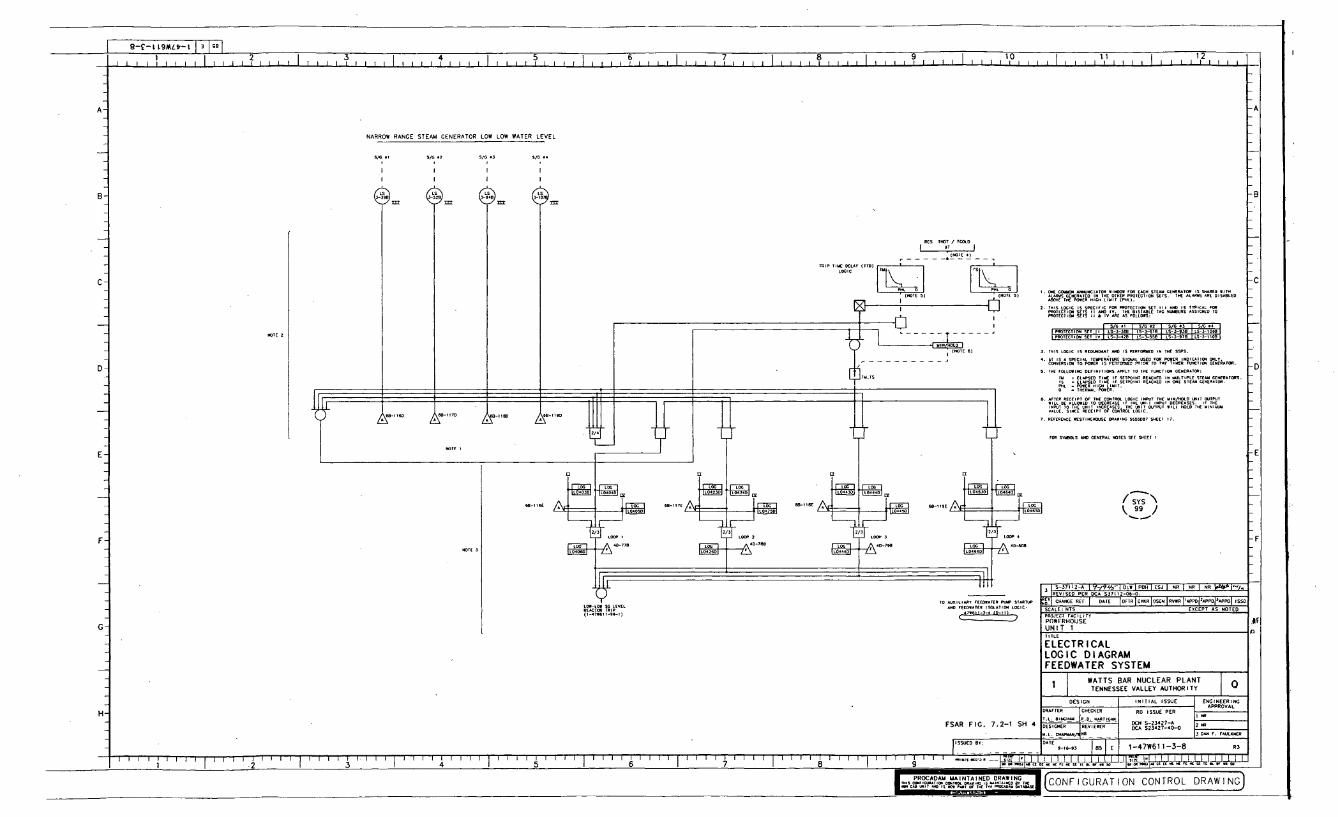
I 9--i~-bMt-I iIo
1 I 2 I 5 I 4 I b I / ST1 2 1 b1 1 .15 1 1 1 4
1 10 1 11 1 ILI I I I . . . . . . . . I I I I I I I I I I • I I I I I I I I i i f I I I
2
A- -A
NARROW RANGE STEAM GENERATOR LOW LOW WATER LEVEL
DiG otiI
I
SIC, ,2II
I
SIG I3
1
I
S/C ..
-B
- X
ITEýAIA S=ED,118T"ED IS flý4 5, ED
2. -Sl-C IS $-111C FOXI PIEETECT- SET -= _l A- CAL -LC A, SQD I.
ECIZ SSEE;ss !ý :%ILE Nslleolls=;
I PRIDTIXTIOR SET I II -TEL- SlI .1 L- mD
3. 'I'S LOGIC IS 'ECIADDAIIt AIDE IS PE110ADIED 11 TIE ESPS.
1. 6ý,ýS 1 SPEE- T- 1;TURE S- 1. USED FEIR PEXER INDICATIOR (XILY.C CISI. TO -E. IS YO11- PI!!IXY 1. 1-1 1- 'U.- -ERAFER.
5. TIE FULL~ DEF1.111ORS APPLY 10 IK 1- 10II CEIER.TOR:IT- I 1 1. LIIPLI STEAAA CEIIEFUIORS.
" : 'I IIIAPS D . !, SET I RE- III DIUE STE- CE- 10R.
-R "1%.E."'T_._L .
TRE . 1. EZES ET6. AFT" RrCT'PT OF T"' _`lL IC InT TAIMD" "ES" IT,?UTlAU
.ILI TIC LLMED 1. - -E ýl
IALIE. EIRIE IECCIPI 01To THE "" "R .... iX L.:Cý`U'PU ' -1 .1D
1. TIEICIE.E IDEITI.- DRA- 1ESSER11 S.11 11.
FOX -1 AAKI GEllRAL IKITES SEE SIIEET I
SY'S
99
F
S--T IA-C 4- O IC POEH ESJ S SE NR I NR
CTACE REF [ OATS OOFR ICSEIPSASNITCRT [' IPoPEoiA PoI 2 swSSCALE:NTS EXCEPT AS NOTEDPRO JECT FACILITY
POWERHOUSE
UNIT 1
ELECTRICALLOGIC DIAGRAMFEEDWATER SYSTEM
WATTS BAR NUCLEAR PLANTI1 1 TENNESSEE VALLEY AUTHORITY
H-
DESIGN INITIAL ISSUE ENGINEERINGDRAFT ,EP R . ISSUE CER
TSSICSEP RE IER DETAS-2342-O .ERA 523427-40-00-S
Al. CERSPEMAM ER 3 AAP.PCER
FSAR FIG. 7.2-1 SH 4
IISSOSO BT: . 1Z 5 .1 E I1-47W61 1-3-8 R3
I ~----J _______________________________111111 IlilililI Ii 111111 I 111111111 Till -. ~ IT*.CT'iR
I IIT
a ___________________________________________________PROCADAM MAINTA.INED DRAWINGFI U
= T.ý,Slmnll I- AIONCONTROL DRAWING1I- I v 71C

I L-C9- IL9ML,-L 1 3 1 9.1
I,,,,* 1 . .I , 1 1. . . . I . . . 1, . . .1 8 1 1 1 y I I ) 1 1 ý I
HIGH STEAM PRESSURE RATE (RATE-LAG COMPENSAL G I LOOP 2 LOOP I
00 . L- P -I-C 100D IP044sD LS-- t 4 1- -
P00020r P022 02 PS-I200
I- 0A ...... 6W04 P - 221, WO
P000P520I410 P 3
STEM IN CtN SGAL,
TED) LOW STEAM LINE PRESSURE (LEAD-LAG COMPENSATED)LOO 4 LOOP LOOP I LOOW LO
P0402 P4P-1-20 I N4 p- P0424D L P0260 P5--CO P04660LI-- J- Ps-I 27A
PS-1-27 IT 00 W 4 0
-A0 6816A- 11 1- 1,
P0= 070= [ E = P02210=-
CO TA NM N PRESSURE
TYPICAL MOV CONTROL•
N O PE N TP IS
I. 02 SI S INR 102N 01 WTO 640 500 INS12L NTAT140440 002IPENIOIATI4 510,N2A12. LATEST ISSIIO.
1 . 1 FILLEI TIN ERE RONT UNIQUEA LIMIT631 2
2. LOG04I2102 WAN l 01 10140MU E I. TIC4E*12 0 OF 0401W
4.~ ~ ~ I ED=P•••INLpt ~ I AE paNINt
N POTES TO T•N~ EICTOSAER NN RL
tO 11 TI- S *1LL1 200004 - NOE P ILI SERT . REPER 0 lTOT
4040 0 148r 024 tOON( WQ•IRW•r {.¢e¢ Wt0 .-. U. .r .UAND IENTI FICTIONL STAND0RD1. LTECT I 1 4UES
FOR _ ETC INS IVIDUALLYO SANED COPNNT SEPAATIHD ON TATL
C- 104 A0I440140 S01040NAL1 WIAGRAM 471510-63-1 p NTS 20 60UR0
10 10 ]C0020L0 P540 TO[tO E 2*0 -2 01 N
-A
-8
I ESSI-ER PRESSURE GREATERIII NORMAL SITMlIT
PRESSI-E IRESSINE GNE.TE.,NA. SETP-1IS~-
11 UAIIIR PRESSURE GREATERTlNO L SETPOINTIS
2/3 __,ýq O PIE DRIZERNISSURE
HS -E.-RD63-1 6 TO I's -- A'.
TlIKS SHEET 6 1 7. .0,1.E I.RIZERSSO I
IA-69A PS-S.-UND
LIT 11.1,SSIRIZEI,REG EIS-W-D
SE-IDA
2/1
ULICTRAIN
0495D FR6,-263- PS--T.TA 4A-69B TRAIN A I -A IN AD-".
F 148OG
PRESSURIZER PRESSURE
-C
-DREFERENCE D AIINGS:-S', - I --- -------- -'EIC '.IN1ý411V _63 IIES2 ---- CONTRIN. UIACAAH
.. IF TARANLA I.56-87 SERIES 4-slli- l FUNCTIONAL CIAGRANS-. 1- ------------- III DI AGRAN
STMINES*-LOCATED I ELECTRIC L SNIICHCEAR
-IGUITED IN AUILI IT GUNIRCE RGEMTEST SWITCH-LOCAL I I I CH
I -A- DE
SAFETY IA-[CTSON SIGNAL
'TRAI I _2 _
-E
THIS CONFIGURATION C0NTR50 0RAWI0 N SLIPERSEODS UNIIT I S-CSTRUCTE -F
, , , 143 I AD41 I (SI I LOW I -S?< I -S ,J
REVISED BY 0D0IN TO CORRECT D0A1ING DISCREPANCY IDENTIFIED ByD0 PER 133185. CAOI (T71 080002 20O)
REV ICHANCE REF IPREPARER K H ER I APPROVED DATE
PROJECT FACILITYELECTRICALUNIT I
P *5470524I -4.-,-, r-7 4710 I * --01 2756 0T 40 14000
00.611-0-I.-. 074711 -1-4.-A 161-2I.[TOI -A-PAUMP511-lTITLE
ELECTRICALLOGIC DIAGRAMSAFETY INJECTION SYSTEM
471541-51-0.-. ..4.-1.-6.,- .-S --- 7.3-3 04002
FSAR FIG-7.3-3 SH. 3
WATTS BAR NUCLEAR PLANTTENNESSEE VALLEY AUTHORITY
H-DESIGN 101T101 ISSUE EN4GINEERING
DRAFTER ITENRO 00 ISSUE PER APPR00VAL
A..6440 4.0.0IF I-L0R011001040CAR- WOOP.5.17 RIMS4 12
005104*1 REAIE REO -CMlI8..00004 0..00o0 02 20 376 r OTRIC
111SUID. BY:-.- FOR 1.DATE
1 o ýot [, 1 1 -47W611 -63-1- R13-I-.. ..............................................................I. I
I . 1 1 1 1 . i - I I I i 1 1 i 1 1 1 1 1 ý, I I I I I I I I I ý I I I I I I I d I I t I I I I I I i I I I I I I I I I g I I I I I I I I I ý I I I - - A - , I I I k-uz3 A.-LLLLLLLLLL-t.ý-j
CAD MAINTAI NED DRAWING I CONFIGURATION CONTROL DRAWING)

I ~ -9-I9ML-1 I3 09
., ' I I I I I ? I I II t I b 7 '91 1 1 1 1 1 . . . . . . . . . . . . . . . I
A-
.TO OFF OPEN CLOSE
.- CIT
OFF
ITS CLOSE
A II
IS EAICT I
A
MY IT C,.,131 CONTRO,
LC 11A OPEN CLOSE
I. AN.
-FS 2 1 3
*El"ll 1 11-S,..C
DELETEDL:. 63-5
F-ET
B NOTES
IET'TO CONT11 NIIE I
I -1-111-72-1
ISI REFLE VATER
IS.1.2R
JOFI-
1-11709,A
-0 rH;'ý OFFT2
CLOSE-A
. ýX.7
n-..
CLOSE
'L7C
-C
OPEN
CONTROL
I=- -N
005 /'OS\ CLOSE
L OE. CLOSE
-IAR
C3-CT0725 4250 ISEL ,00 rLOS VOLVO 0200L
C 1 UELY 04 jUICY ECOSCO (STEM S5)
LL
•;- CCLOSE
F - EV.tE - 5.3 ,
00 40- 200 PEN IIC-11C 0 L
r r • • ILL CLOSEDOS
CLOSII
1: ro S EO N CI•V AL •0TEI S•EE0 -7• •,
CE00 • .. . .CRI RCA .•rco&45T1r=S[ ES- - iNSTE N E.- U TO1C
-A
-B
-C
-0
I
IXI.IT I
EIETEIFCY
S. l-72III03. -E
.IF 3 TO SAFETY -ECII ON
.2
(SYSI\11
H-
SI0000LIOCVO5-7215511A)
_7,.51;O0.5-72475
SO ,-""SIE5 I0 7277 I7V .. 0S I W R *IE5 11NCORPORATED ýYS 63 EIOUNDARPIES.
,D.I ....G.1 1 DATE 10Io RIC-RoIlS- "-RM 'APPE, I ..SCALE: NTS E0CEPT AS 0CTEDPROJ[CT FACILITY
POWERHOUSEUNIT 1
TITLE
ELECTRICALLOGIC DIAGRAMSAFETY INJECTION SYSTEM
WATTS BAR NUCLEAR PLANTTENNESSEE VALLEY AUTHORITY .0
DESIGN INITIAL ISSUE ENGINEERINGDRAFTERAPPROVIAL
ORFTEV CHE00E4 DO I SSUE PERS.. C _ 74 IRONL07 L 2R 0.E- LESTER
DESIGNER REVE2WE EA1-3.10ASS ES 2AN . 024
RON 4. LEITER201'. r0550 30.0. 7>70 00I 0
CNIMI FLOORL(VEL LO0•
FSAR FIG. 7.6-6 SH. 1
1S-ID BY:... 1851 E I 1-47W611-63-2 R5... * I-
-t '.....,...............,,,.,.,.,.. '------L 202r i I I I I I I I I I I 7 I I I 2 I I '.,.7s51o*05.......IGS' 101 I I I I I I I I I I I I I ITS Is I Ii I I I I I I I I I I
______~~ ~ ~~~~ 9 KI " Of i .3I4IIUIIIBI9.570007600E~3
P... c AININ RAI LCON ,GURATION CONTROL DRAWING)

S-C9-LLML-l i-L I I I - I.. I I 1EI I 1 10 I 1 1 1 12
!I I I I I I II I I I I II I I I I I I I I I I I I I I I I I I I I I I I I I I I Il ll1 1 1 1 1 1
A SEEY N SC•
DCONTOL-
ISTEM.SRI
'. S-o S -~o~ -, EC-~ .O'S SEE -•1-•I1. r N oý CONTPOLS SEE O• 1-461 1- .
3. ~ ~ ~ C_ M SO•VN AV R 1 O, •EN-STIPPCITN OUEE TOA S;&EVOMS VSJCV.L, FR EN O i~SUST• •CO I
-A
-------------- (
OOTAi-.T S- ToS - - FC-DO-F3LDTEDLtEO
REO(SFC RD CEE-OF-2 (ROD0RI
lo-E-E- .- -.- L
I0R DIEDCLOSE
NOTES ; 1 3
TO CV• •1•
L-TO-- I~ uIcOC . ,
NOTýý 2. S
FRON - .1.1 E.0-[ A
FESE-R RRE-' 7SE*E
jDETAlLS O
OPEN -S CLOSE
COT S TRE TO D TS
-RSOFD-F'[T;% - -..D.~ C-OR OSIFR-..
l1o H EAT E-C ECR 8 v071
To SS-61 MGSýS2. E-9
To - NoNo LOOP
C RS I-E.- E . ý
,-OSF0R4 ,R
Ii DCDCCE SC 03 DOOSOEFEE
TOOO OCT CEE CR CERIDE I COOSR ITAPDFFDIRCFIDD IESC
PROJECT FACI-iTY
POWERHOUSEUNIT 1
( SYS~63~ ELECTRICALLOGIC DIAGRAMSAFETY INJECTION SYSTEM
WATTS BAR NUCLEAR PLANTTENNESSEE VALLEY AUTHORITY
To Cvcs DESIGN INITIAL ISSUE ERLFINEERLDkAPPROVAL
DRAFTER CDCE E I E PER ECR. CL. - 1000LOELA FIL I DOS E. LESTER
.. . .. .K-IFEE l 3.00 A I 25 R LSIDT2D 02 ISO EL.
CO .LERFER D.L. DORESTRDC-C RD D
FSAR FIG. 7.6-6 SH. 2
. . ..- .7 - . . . .. . . . .[ ,-, I., I , I 1-47W61 1-63-5R... - R4
II ~ F F ~ I I I4 ý - .~T D.o . . L I1 ~ CFCFIFICIiCCFCIIF*L A
A I.. D A..N9ýC A MAIN17 CONFIGURATION CONTROL DLtl NGýX-

I L-c9-tL9mLtl-FL I -I I'~ ~ 4 I 1 . I I I 1110 1 1 1 1 1 ,1 . . . . I . . . 1,2
. il
ONEN H CLNOOSIEERNT
NUWNNTONTO
S EIOsEOtsEo¢NIE.ILLC NONES SSIIOS 1-- EEW61 L3- S
N. S. R-rI. SEEI-N-.
I.TO F-•N NAAEIý 1. -~•T SAFETY
eu• vE ALV .Lt¢.' € •J S.(SEE - 1L•
T-•o
1 5 . - iENT.IT
E"
ITIT
j
M ONE.
S
-
r.,\ CLOSES.
-GANAL
YS
AGANAL
A11-1R1
I SEOT'E. NS CLOSE
IT
I I ATTY
I GUTSE
f
WE"
TITS
CLOSE
I AS
VC1
IL
-T
VENT
Iý IATEIN
"c" IF --
1- Y
1.47 A11-L.-•. F-12
C NOLS = ASF--
'C'
TWEACT"G -' EITAIIT-
CON OLOSE G ES 2 T3
TO~T TILTT NIN _S(IsY'S\63
-FI•'J1-.Ol- NO RCS LOOP
RN SI INS NO COT LEG_ S I,_lo.ITS, _INETE; 17 1 I To "S'TE IT LINE
1-47.1 •--8. C-IQ
PIP i.--00 I EHN I PRO I JAT I NI I NR I NR I NR I NO
CMIN PET EEE CTR ICOCO jSON 1-ONIAP]EPE~PO ISTN
G
H-
P•ECT FACILITY
POWERHOUSEUNIT 1TITLE
ELECTRICALLOGIC DIAGRAMSAFETY INJECTION SYSTEM
1 t WATTS BAR NUCLEAR PLANTTENNESSEE VALLEY AUTHORITY
DESIGN INITIAL ISSUE ENTINEERING
OONCTEE ANAOER R0 ISSUE PEL AOPROVAL
NR E. LESTEN RI. IONESE 00.0.T 805 R3C.C LE IE ACE
FSAR FIG. 7.6-3
111-ID TE,: .ONT I 1IETNEg TO C 1-47W&1 1-63-7 R2
i 1 11 1 1 1 I, 7 .I I I I I I I 1a ON ~ ~ ~ .. AINV NNO NN E* N- FaS im0NE O . ON -- TN* A. O
GAY.. _A !.I A-, -I CON- GURAT ION COTOL DAWING]

I £-89-LL9WL~-L I I~II . . . I . . . I . . . ? . . . I I . . . . 9 1 4 i 5 1 0 1 I,,,,8 1 . . .9 , 1 . . . , . . I . . . 1 1 1.. I . . 1.2 . .
-i .. ,,,,.....,,.,,., ........ o..ooo....ooo...o....,.,.o.o..ooo..ooo.oo...ooooo..oo,,,rrrrirroo,,,oooogoori;r I.-
A-
B-
C-
E-
F-
G-
TO
I-.
or
FS095FICI C S E( S4
- E, PRESs E - EL GE
0o. 0000(03 n r0* 000000 0 0300S0*0 0300001 0:0
00 0-..0-50-- 3---- ---] -- ---- -- -
I ~ ~ ~ ~ ~ RER -E L•R•E .,-
o-I L ---------- ---- ---
STE : T
---.-•},-,.,---I
i LVII
,, - .2,
0
........ ] ( I--
1--
E-23000* 1 II
- . ~,-oI,
DETAIL Al
NOTE,
e~ ~ ~ ~~~~A E e!----•!:]".:[A_-SJ ESJ NR IN R• l
IEICr0 000 I oATE IDFo-,ICR[DoIVo.0lo• ,0,H I00Po-oI'AoI SSo
REACTOR BUILDINGUNIT 1
ELECTRICALLOGIC DIAGRAMREACTOR COOLANT SYSTEM
H-
LOOP .TE 0* - -0-....a ..00 ..03 -as L- r J- ----T-' . -,
0-0060-0-0 3.,- -,0300T IENP IRE 000* 1 / 00030 900 i0
jO[;i ~ ~ Ro 0.70`-301-4a100.-4-0 . 4 E-1 300 30 -
0-00500 aO.0- (- J . -00-s-a
DESIGN . 0N1000L ISSUE EN00;NEER0'00030 0(EI'o 'SS 0000
oISue PER
03001130000'' 03.00 kl•,1 .000(10 0 00 amoo
000I0000 i001090 025 392 0009 500 2 0.0. 005003
1300 00000 3.0..0300003 L.0. FOR 0.
1 WATTS BAR NUCLEAR PLANT "TENNESSEE VALLEY AUTHORITY I
FSAR.FIG 7.6-5
I-E .1; B 0,00 0-0-9 851 E I 1-47W61 1-68-3 IR.I .
i . . . . I . . . . • ' ' I I . . I I I , I , 6~~~~ ~ ~ ~ ~ ~ ~ ~ ~ 1 I 1 11, " 11 -Ua.a ITý,!, ,111 .. I. I3 iu i:. hI , nri" . 'a'0.1,30 I ii 131 i
PRODA IA NTARD DRA!!ND0NC*C~l~.F i f .

L - IL-LL9Mi.-L I T~I I I 1 1 1 1 1 1 1 1 1 1 1 1 ? I I I , I I ý I I ý I I I I . 1 1 . I I I I 1 5 1 1 , , I I I ý I I . . . . 1 .1 1 , , I 1,2 1 1 1 1
ISET RD N
SETP IIS-.1
III FULLY A ll
.IST.. I.UCTIONA•
,.TE LOOK AjYNE l.S
AORMAL I •
AUXLIARI
A• PR A. P-A•
jUAR I ELN.
VA•V FULLYI
-n~NIST•ATIV %
CENTERjSIE NOTE I
VALVE FULLYCLOSED{8•12
- TO
OFFN A CO-SE
OPENPE CLOSE . ...
P-TYPICAL OV CONTROL
TO LLOCLON SEE CONTROLLNOO. ~T• I• , 47 C-OS-I.( );S ) + N NCTEEENLETE
TOO-NT-B OPEN TS4B. AL NSINTRENTNESISSRE BEOTINPESE INSTRENNNERS.
FROMR ON POAeI .EB.ONOTE-EOLETAE
PUSSCTO BlEl STONER PTIC FORP[E [ECNRIS NT NSUSDT IPETLLTLSCHE• HO T.UGIG....9 SE-E -2 OPR IST DINSTRMN T T• O S C NETN POINT.
pSMPSCLOSE TLS.TOS-74- LLT E9ESE HAE ROEN PREO EPENSCARL. RECOT3 TO TPREVENNOt
SELL CLSED A -CO IT I AD- OSELO 0A0FECT ING OTEOSSFTyLU*OLS F S IA
TAS ETPMPINOENSTP LSEI-NTS. O-TS-T•NSERES---S RNMO IC ITN LOSALN EPO TFULLY CLOSED EF , 0RE -P10DRINGS -
TCV-OT72- E 1
FROM CONTAP IENT-45 F60-74-SOTER 1.1-- - NEOTED BEO i EISRUETTINA
FULLY CLOSED 'E' C~ad(A~3 NOTE DE)JLETED_
FR. A -F IA NO E DELETED
TD
ED)
FR•HOT LEC
IA-. IT1--E3- ýE-) 1- 1-471111-74-2
CONTROL SAME AS COOREINATE. E-ITOV-7C-N EECEPT
EC ,12 1T•ON- . ...
RELITE USLUR TO AIR PUIVA N-B
FAR SYS ]SIR eYASS VALIE
SEE o TE I (O 104
O TOPY CL
AD ITI STRORIOR S'P TCLOPINTELOET OPN I IS
(SENO R FI AT -I
Cs-E -A TENOTE C LS
RCS PTESSURE
.PEE NOTE
P-AUT
RNOT N 15T00
ISOLAT ION VALVE
ARH SYS PSLN BYPASS V"LIE
OPEN L WS CLOLS
AD•,NIST•ATI/ STE ' COP
INOBALDONAT I 1
(SEE NOTE S.
NCI PRES SLRE SEE NOTE ID
OPEN CLOSE
(97,/
=11 I IER
ýý7'V AA T I I
E-A.H. )NA-St-------- LOCII DIA.A.
I511AI :::-ý;El ON 11111RIGIL SITIT"REAR
L. ED A AU_,AR, CON POLA --- TEST S.ITCHL --- LOCAL MCIANTED EQUIPIUSIT -F
A CEO > SEN ROINT
TN-SB TORR TON-LNE- I
TS-
6A_11•B
7 1 I. I j AF I SF I OLDo -I. -COI I I f I --
REVISEN TO INCORPORATE ADMIN (T25002t6941).DELETEO SYSTEM BOUNODARY DESIGNATIONS PER AOMIN.
SEV I CHANGE ROF I PREPTRER I CUECTER I APPROVED I 0A0E
PROJECT FACILITY
POWERHOUSEUNIT I
ELECTR I CALLOGIC DIAGRAMRESIDUAL HEAT REMOVAL SYSTEM
1 WATTS BAR NUCLEAR PLANTTENNESSEE VALLEY AUTHORITY
DESIGN INITIAL ISSUE ENGINEORING
LEAFTER CHECKER TO (S0UE PER
J.A. TELLE IR AN ERBLNTINHLOE T2 TON3 C. LESTERSE ,LSTNO R RECIEN ER 0128 0 ' & 01 807 20000000. LEOT 1 8
RON N. LEN N R ONESTER 3 0 . LETE R EONEO
H-
7.6-6 SH. 3
1U,1ED NY: CTE 0-Cl-NC 18SIl E 1-47W611-74-1 R7I.L, ELLIOT/TIO
, i i i I i I I I I I i i i i I I I i3 4 i i i I I I I I I I i ; I I i I I I I i i ; I I I I I I I I i i I I I i i i i I i I I I I I I I I A5 6 7 8 9
PROCADAM MIAINOTAIND RAINPROCASAiTAER•,,TAW,.I CON F I OURAT ION CONTROL DRAW I NC
.. . - AONDI.NE 001. 0 DG5CISCN

F- 16-L-st INALAI II I , I I I I i ' , i t i I ,TTT~T,,TT I 1 7 1 8 1 9 1 10 1 11 1 12
-t 1
A-
B-
C-
E -
F -
H-
I n i=4-T 1VU1Wt~
I ~ ~~~ . .. . .. . .7I
REV I -EAEE REFl pREIPARER I C-ECRRR I trP•Ovr I DATE
POWERHIOUSEUNIT I
ELECTRICALLOGIC DIAGRAMREACTOR PROTECTION SYSTEM
WATTS BAR NUCLEAR PLANTTENNESSEE VALLEY AUTHORITY
DESIGN -NTILS i N; VOGN[ [NTERRER TEERR RTRETPTE APPROVAL
TEATCRR•A£_i_ R RTOE IEAR ER ET............ .. . [ .0 2
FSARFIG 7.2-1 SH.1 -EIl A I 1-47W611-99-1
R7
I I I I I I I I I I i . . . . . . . . . . . . , . ..... . . . . , . . . . . . . . , ? . . .. ..... . . . . . . . . . . . . .I • I I I •]• •0 I_______ Z I A T T V I b I 7 I 8 I N lUAAU.ARUAAAAIAAIA~.AAAA IUA.RNTAAAAAUIA.AAATA.U*AtEt~~
CA L M° TAN. O...NA.IN CObNF ICURATION CONTROL DRAWING

Z-66- L 9MLV- L 1 3 S IIII 2 4 5I 6 7I ! 9 l i ' I I I I I I I I I IIi iIiIIIi l l III I I 101 1,1 12
A- SOURCE RANGE REACTOR TRIP INTERMEDIATE RANGE REACTOR TRIP POWER RANGE REACTOR TRIP POWER RANGE HIGH NEUTRONFLUX RATE REACTOR TRIP
B-
C-
TRIP(
NA-A0L POSOT EC
-IT 10 . 8-T 1 RT -
I RUN, AN1
LOGII NA -IA C
TR A -IN A TH NAI.
F
.A
RAIN 81
rp-t
I EC - I -
1 411 1 4 R A F
FL-m-lD IN ... 1. 16R.I.&I
01-
;:e A I -A I I I I I
1-11G
E14FFF'TRAIý CONARLAL
11 ISR 8LOO ""IROD TO,
L CTRAIN
LI, -'ANO I'D .211.IN P(HIG SETPDINt)
7*61, -S_A-11D CýCTOR TRIP
4D-.CG r-C-. 1
IA-I,. A POWER RANG E TURB I NE POWER
HIGH IEVIROI FLVI 1-81 NE I NPULSE CHAIDER PRES
Lo"?" 7o:P'IFAXTIR TI
NO NO
-A
-B
-C
TNAýA G,4-ALA- . .. IDO,
TRAIN
THAI. N
TOY
0-30R93 INTERMEDIATE RANGE
F-
G-
PRESSURIZER HIGH PRESSURE
A -ALO11 I P41 i
TO Is TRAIN31
0--9 T X003
PRESSURIZERALOW PRESSURE101000 SET POINT 0E01/LOG NOIFNSATIONI
AIM =11o
Nuýý 01 - -G NO.'41) 1-1D Too-
1.,Do- ,oo33D
ý/4 .- -VA, 01.1-H
-14C
ANN RG.
RN IDD,
.0 E)
A
A -71E
S'
41-150c-P
A 4A-70G (TO SWROE RA-0
.ICA AN, RG,
L CPRESSURIZER HIGH WATER LEVEL
--A
- -A C O
lo'EslIý IGI SlINSOLS AND GENERAL NOTES SEC 1-171611-99-1
Yoo - DNOO
N LE O
POWER
jtF7 . .- SR
12 1 ........ i oM I IEJ I ULO 1-.....-1REVISED PEN RC P C03205-00-0 lPOG DA.
COS C OLE TITS EOXCENOT COSO PTO AS GOOND
POWERHOUSEUNIT 1
ELECTRICALLOGIC DIAGRAMREACTOR PROTECTION SYSTEM
WATTS BAR NUCLEAR PLANTTENNESSEE VALLEY AUTHORITY
H-
PROCADAMMAINTAINNEDRAINN
GE5GIN INlTIE ISSUE OSCIRCEGOISD3000AFTER OO TO ISSUE PER
I 00-3 10 N RIMSNOSI~ ~~~~~2 900 I0000 O 2 0225 059 00 RCN
KG0'00-2! DA00 0-0- 19 5 I~~ 1-47W611-99-2 R12
1 I 2I3I 4 IS B 7 I 999R2900992293100900 OOR0IANAAA.9993099 .2 1 .19.0
THISCADA? TIL AINTIEWWH CO NTIGURAT ION CONTROL DRAWINGC.. GAG .1 ANO A-1 9

9-66- 1 L9MLVo- 1 N I
I~ 5 4 7ii a II 0II I I 21 1 l 1 1 1 l i I I II I 1 1 1 II 1 1 1 1 1 11 . 1 11 I 1 1 ' i i
A-
B-
C
MAIN STEAM VALVE VAULT ROOM Al FLOOD LEVEL MAIN STEAM VALVE VAULT ROOM A2 FLOOD LEVEL
-A I
E. 3 1-oC 3 404 0-SOC 00-010 003-01- - 0-SIC
-A00 IC-7 C AC - -.-. c -11C 1O-S1-O1C
U C ER 11s -E)
UNDERVOLTAGE RCP-BUSSES UNDERFREQUENCY RCP-BUSSES
I sC
.... ... .. ....5 s 4 -"s ~I -NON 2T VS TE O l j01 C 2) NOTE 2S NIS 2 1 VSOE1
0002 TO0-112
CCCIOR OOJ~
I10 TOCO 2'TCCI "E0' 0
I'll
2•
0~
sl P -1E CC-ED
-z
IILIE ILLLT CLIOsEO
TO OIL LO
TIP
1-11-71
LE A N.N.L. ["ý ji'E5'7 Ni -I 14
T'O,EOI
-A
-B
-C
-O
-E
-F
I I . , II1. .1E~ FIT -- 11oE=Ar I~r~
E-
F -
00V0I~J
21,
-J 7 r NA
417-0 A Y . .....
U"IER40LTTAGE
1EACT REACTOR -1 TRIP TRIP
-A- AIRFICI LOOP 2
Fý Is 08-60 1-29' -21. -11
.0 F.-O F 121. F .21.9
"0"0 1-21
Y
L
ANtt' 2
I TRII TRIP
ýV' 2 1I~ BREAKER tALT)
a3o- AUTO NoU1IT131AWlL•1 S1SEis7 I-.)
EIIO
3 ...
1. 4. I-Ol
-4-0LOC L1-IND F 411. 10.W
A
2/ý
I'll TRIP 4E1-30 C3
3 000
E100 300030-I 0A0610 T-A4 1 TRI
211REACTOR00 RIP
TRIP 001 010 0
v 10001 100060) 10000R 000000
I
4 M-39911-A I E0 J I PUP I °C° 0-2-90
1REVI0G PER EGA U39911-336-V.
0EV CHANGE REF I P.EPNE... I .CHCKER AI.P.O.E VANE
SCALE; NIS EXCEPT NO 31TEDPROJECT FACILITY
POWERHOUSEUNIT I
ELECTRICALLOGIC DIAGRAMREACTOR PROTECTION SYS
WATTS BAR NUCLEAR PLANT
TENNESSEE VALLEY AUTHORITY
DE51GN INITIAL ISSUE ENGINEERINGRATE OICH 0 ISSUE PER APPROVAL
N , FOGLOY IP-TANTI OA. DEIN N-16617-C 1 NP. . .. . 67 .... . . RO 1 6 7 • 1 -O ICNNO 0 1I0 0 DCN S 2 60-0 80 -A E N 1A7 5F .2 F IU.C.CNOO"/IOOI oW EOA SCOO0S-N3-0 0003 OICCOV VAL•[
3. s1C
2/4
4D-71F
LOW 'LOW ANO PEACTOR TRP-ET I
--I
H- REACTO 10'00
FSAR FIG. 7.2-1
I 5SUEO BY:I.L. ELLIOTT / 0.•, ffOOT °IIV -OV-oI 1I E 1-47W611-99-6
I .1 I I I 111. I ooll000.oo2i~lL~I1 061000000000010161000I~~ r 7 .' I I I I I I . I I I I I I I I I I I I I I ~ . I I I I I II A '
l '"C0130610 C0000030 01l1 IITPRCAA I MANANDDAI G 003-IG ION CONTROL DRAW INC

0~
I
CODE' SYSTEM STS' I D[ m I .. "0
1
2
3
67R
910
11
13
1'4
16
i718
1920
21
22
23
2152627
28
21
3fl
31
IIMSX, NP SfL&, MIMICS, MISC 3Q1=!?., & LOCAL PANUMAIN STEAM SYSTEM
COW•T•MB SYSTEM
K4II AMD AtUXIARY FEEDWATER SYSTEM
"LACTION SEtm SYSTU
NUTS MAIM & 13"MBy
TURBINE EXTRACTION TRAPS & DRAINS SYSTEM
MISCELLANEOUS TURBINE CONNECTIONS
MISCILELOIMU T•nl= VENTS SYTTIN
AUXILIARY BOILER SYSTEM
FIRE DETECTION SYSTEM
CONDENSATE DEMINERALIZER SYSTEM
STEAM GEN. BLOWDOWN SYSTEM
FUEL OIL SYSTEM
CENTRAL LUBRICATING OIL SYSTEM
RAW COOLING WATER SYSTEM
RAW SERVICE WATER SYSTEM
HIGH-PRESSURE FIRE-PROTECTION SYSTEM
CONDENSER CIRCULATING WATER SYSTEM
WATER-TREATMENT SYSTEM
POTABLE (TREATED) WATER DISTRIBUATION SYSTEM
VENTILATING SYSTEM
AIR CONDITIONING (ZOOLING-HEATING) SYSTEM
31435
3738
39
40
laO
4142
"344
45
46
"47118k950
52.
5354
55
56
57
'960
6162636146566
AOYTOR COOLING SYSTEMS
PM• lCOJKf =3499W SYSTEM
GLAND SEAL WATER SYSTEM
INSULATION OIL SYSTEM
C02 MUGAOE, FJIN PROTMIMON & PURGING SYSTEM
STATION DPAImNI SYSTEMLAYUP WATER TREATMENT SYSTEM
CHEMICAL CLEANING SYSTEM
SAWLING & WATer QtAL!T! SYSTEM
BUhILING HEATING SYSTEM
TURBOGENERATOR CCURL SYBTEK
BREATHING AIR SYSrEM
HYPERCHLORI TE SYSTEM
SYSTEM TEST FACILITY (INSTRUMENTATION)
INJECTION WATER SYSTEM
ANNUNCIATOR & SEQUENTIAL EVENTS RECORDING SYSTEM
TEMPERATURE MONITORING SYTEM
ASSOCIATED ELECTRICAL SYSTEMS
GENERATOR BUS COOLING SYSTEM
DElI WATER & CASK OECO! SYS
IrC CONDENSER SYTEM
CIMMICAL & VOLUME CONTROL SYSTEM
SAFETY INJECTION SYSTEM
EMERGENCY GAS TREATMENT SYSTEM
676869
70
72
72
73
74
75
76
77
7879808182
8384
858687
8889
90
91
92
939495
96
97
9899
ESSENTIAL RAW COOLING WAT= SYSIUS
REACTOR COOIAI SYS
COMPONENT COOLTIC SYSTEM
CONTAINMENT SPRAY SYSTEM
RESIDUAL HEAT REMOVAL SYSTEM
VOLUME REDUCTION AND SOLIDIFICATION SYSTEM
WASTE DISPOSAL SYSTE
SPENT FM PIT COOL= BY&FUEL HANDLING AND STORAE SYSTEM
PR3IMA CONZUM' COOUNG BYSTES
pRDNT w5m? MR= 83TN -
STABS! DIESEL IIAIM SY•ST
HYDROGEN RECOMBINATION SYSTEMS
FLOOD MODE BORATION MAKEUP SYSTEM
CO1TML ROD DIM 618=
UPPER HEAD INJECTION SYSTEM
CONTAINMENT ISOLATION SYSTEM
RADIATION MONITORING SYSTEM
NEUTRON MONITORING SYSTEM
IN-CORE FLUX DETECTORS
1*
32
33
CONTROL AIR SYSTEM
SERVICE AIR SYSTEM
REACTOR PROTECTION SYSTEM
- INSTRUMENTATION SYMBOLsMECHANICAL
WATTS BAR NUE PLANT SYSTEM IDENTIFICATION1•0 NUMBERSUNT 1WATTS
BAR NUCLEAR PLANTTENNESSEE VALLEY AUTI4OHDELETED NOTE 1. TABLE 11 REFERENCE AN LINT2 1•
REFERENCE PER ADiIN (T25981201846). DRAWING S 30H617-R"0REV ICWACE REF1 PREPARER I CECK(ER IAPPROVED I DATE(T I
_IRS

ENCLOSURE 1
Responses To Licensee Open Items To Be Resolved For SER Approval
ATTACHMENT 3
(This Attachment contained on the OSM)
Revised Common Q PAMS ISG-6 Compliance Matrix

Watts Bar 2 - Common Q PAMS ISG-6 Compliance Matrix
ISG-6 Document
(Draft dated Feb/12/2010)WEC Equivalent Document WEC Document Number
TVASubmittal (S)or Available
.for Audit (A)
Non-PropRqr'd
(Y/N)
Target SubmittalDate
(WEC to TVA)
ProprietaryIssued
Date / Letter
Applicationfor.
WithholdingIssued
Date / Letter
Non-PropIssued,
Date / Letter
or Forecast (F)
Common Q Topical Report (Section 11)
Approved in SER ML003 740165 (P. 4, "The staff made several visits tothe CENP sites in Windsor, Connecticut and Rockville, Maryland Duringthe site visits, the staff inspected CENP procedures that are referenced inthe topical report and audited reports of commercial-grade dedication Approved Approved Approved
Commercial Grade Dedication Plan activities. " P. 36, "However, during a visit to a CENP site, the staff did ML050350234 N/A N/A DONE Topical Topical Topical Reportaudit a sampling of CENP's manuals for CGD activities. On the basis of Report Reportthe audit, the stafffinds that the procedures and processes in the manualscorrespond to the requirements of IEEE 7-4.3.2 and the guidance of EPRITR-106439 and, therefore, provide an acceptable program for thededication of commercial-grade items. ")
WB2 PAMS D3 Analysis Technical Report: WNA-LI-00058-WBT, WBT-D-1800 WBT-D-1800 June 30, 20102 D3 Analysis This will addressed in Plant Specific Action Item PSA176.11 'in the Rev 0 S Y TVA Action April 6,2010 April 6,2010 (F)
Technical Report
Common Q Topical Report (Sections 6.4 and 9)
This citation in the Common Q Topical Report applies to the platform.For system test and calibration and fault detection the following
Design Report on Computer documents apply: Approved Approved3 Integrity, Test and Calibration, and ML050350234 N/A N/A DONE Topical Topical Approved
Fault Detection 1. WNA-DS-01667-WBT, Watts Bar 2 PAMS System Design Report Report. TopicalReportSpecification
2. WNA-DS-01617-WBT, Watts Bar 2 PAMS specific SystemRequirements Specification
Common Q Topical Report (Sections 6.2 and 6.3)
This citation in the Common Q Topical Report applies to the platform.For system theory of operation description the following documentsapply- Approved Approved Approved
4 Theory of Operation Description 1. WNA-DS-O1667-WBT, Watts Bar 2 PAMS System Design ML050350234 N/A N/A DONE Topical Topical TopicalReportSpciiato A W W B PReport ReportSpecification"-
2. WNA-DS-01617-WBT, Watts Bar 2 PAMS specific SystemRequirements Specification
Common Q Topical Report (Section 8)
The Common Q equipment was qualified according to the plan specified Approved Approved Approved5 EQ Testing Plans in the Common Q Topical Report. All EQ activities were ultimately ML050350234 N/A N/A DONE Topical Topical Topical Report
approved by the NRC. Any open items on equipment qualification were Report Reportidentified as Plant Specific Action Items.
Common Q Software Program Manual (Section 4)SER: "On the basis of the foregoing review of CENP's softwaredevelopment process for application software, the staff concludes that the Approved Approved Approved
6 SQA Plans and Procedures SPMspecifies plans that willprovide a quality software life cycle process, ML050350234 N/A N/A DONE Topical - Topical Topical Reportand that these plans commit to documentation of life cycle activities that Report Report
will perm it the staff or others to evaluate the quality of the design featuresupon which the safety determination will be based."
WB2 Common Q ISG-6 Conipliance Matrix (Jun 11 2010).doc Page I of 8

Watts Bar 2 - Common Q PAMS ISG-6 Compliance Matrix
ISG-6 Document
(Draft dated Feb/12/2010)WEC Equivalent Document WEC Document Number
TVASubmittal (S)or Availablefor Audit (A)
Non-PropRqr'd
(Y/N)
Target SubmittalDate
(WEC to TVA)
ProprietaryIssued
Date / Letter
Applicationfor
WithholdingIssued
Date / Letter
Non-PropIssued,
Date / Letter
or Forecast (F)
WBT-D-1680 WBT-D-1680System Description to Block
B-160 W TD68Diagram Level Watts Bar 2 PAMS System Design Specification WNA-DS-01 667-WBT, Rev. I S 1 TVA Action March 3, March 3, 2010 June 25, 2010
2010
WBT-D- WBT-D-1680 June 25, 2010WNA-DS-01667-WBT, Rev. I S Y TVA Action 1680, March
HW and SW Architecture Watts Bar 2 PAMS System Design Specification and Software Requirements 3,_2010_Marh_3,_2010_(F)Descriptions Specification WBT-D- WBT-D-1786 June 25, 2010
WNA-SD-00239-WBT, Rev. I S Y TVA Action 1686, March5,2010 April6,2010 (F)
9 FMEA Watts Bar 2 PAMS specific FMEA WNA-AR-00180-WBT S TVA-TBD 8/31/10
N/A
. SPM Safety Plan states, "It applies to all Common Q safety criticalsoftware whose failure could result in severe consequences to public healthand safety. For Common Q systems, safety critical software is defined assoftware belonging to the "Protection " class as defined in Section 1."
1 SPMExhibit 4-1 ASSIGNMENT OF COMMON Q SOFTWARE TO Approved Approved ApprovedI0 Safety Analysis CLASSES, classifies PAMS as Important To Safety. N/A N/A N/A DONE Topical Topical Topical Report
. SER states, ""On the basis of the foregoing review ofCENP's software Report Report
development process for application software, the staff concludes that theSPM specifies plans that will provide a quality software life cycle process,and that these plans commit to documentation of life cycle activities thatwill permit the staff or others to evaluate the quality of the design featuresupon which the safety determination will be based.
WBT-D-1680 WBT-D-1680I System Requirements Specification Watts Bar 2 PAMS specific System Requirements Specification WNA-DS-01617-WBT, Rev. 1 5 Y TVA Action March 3 March 3,2010 June 25, 2010
2010
WBT-D-1526,
January 28,12 System Test Plan Testing Process for Common Q Safety Systems WNA-PT-00058-GEN, Rev. 0 A N DONE N/A N/A 2010
Document at WRockville Office
WBT-D-1961,
13 Software Design Spec Watts Bar 2 PAMS Software Design Description (two documents, one for flat WNA-SD-00248-WBT, Rev. 0 (FPDS) A N May 5, 1010 N/A N/A May 21,, 2010panel display and one for AC 160) WNA-SD-00250-WBT, Rev. 0 (AC 160) May 12, 2010 Document at W
Rockville Office
WBT-D-1526,
14 Software Development Plan Watts Bar 2 PAMS Software Project Plan WNA-PD-00073-WBT, Rev. 0 A N DONE N/A N/A January 28,2010
Document at WRockville Office
WB2 Common Q ISG-6 Compliance Matrix (Jun 11 201 0).doc Page 2 of 8

Watts Bar 2 - Common Q PAMS ISG-6 Compliance Matrix
r I '. 1* p
ISG-6 Document
(Draft dated Feb/12/2010)WEC Equivalent Document WEC Document Number
TVASubmittal (S)or Available
for Audit (A)
Non-PropRqr'd
(Y/N)
Target SubmittalDate
(WEC to TVA)
ProprietaryIssued
Date / Letter
Applicationfor
WithholdingIssued
Date / Letter
- Non-PropIssued,
Date/ Letter
or Forecast (F)
Common Q Software Program Manual (Section 7)
SER: "On the basis of the foregoing review of CENP's software15 Software Maintenance Plan development process for application software, the staff concludes that the Approved. Approved . Approved
SPMspecifies plans that willprovide a quality software life cycle process, ML050350234 N/A N/A DONE Topical Topical Topical Reportand that these plans commit to documentation of life cycle activities that Report Reportwill permit the staff or others to evaluate the quality of the design featuresupon which the safety determination will be based."
4-6 Seft:'ae Operation Plan • W.Vatt BAr 2 PA41S Tznhieail MIan',ual (Not required per Feb 12, 2010 ISG-6 N/A N/A N/A DELETED DELETED DELETED DELETEDdraft)
WBT-D- WBT-D-178617 Application SRS Watts Bar 2 PAMS Software Requirements Specification WNA-SD-00239-WBT, Rev. I S Y TVA Action 1686, March June 25, 2010
5,2010 April 6, 2010
Common Q Software Program Manual (Section 3)
* SPM Safety Plan states, "It applies to all Common Q safety criticalsoftware whose failure could result in severe consequences to public healthand safety. For Common Q systems, safety critical software is defined assoftware belonging to the "Protection " class as defined in Section 1."
* SPM Exhibit 4-1 ASSIGNMENT OF COMMON Q SOFTWARE TO Approved Approved Approved18 Software Safety Plan CLASSES, classifies PAMS as Important To Safety. N/A N/A N/A DONE Topical Topical Ap pr t
* SER states, ""On the basis of the foregoing review of CENP's software Report Report Topical Report
development process for application software, the staff concludes that theSPM specifies plans that will provide a quality software life cycle process,and that these plans commit to documentation of life cycle activities thatwill permit the staff or others to evaluate the quality of the design featuresupon which the safety determination will be based."
WBT-D-1526,
January 28,19 Software Test Plan Testing Process for Common Q Safety Systems WNA-PT-00058-GEN, Rev. 0 A N DONE N/A N/A 2010
Document at WRockville Office
WB2 Common Q ISG-6 Compliance Matrix (Jun 11 2010).doc Page 3 of 8

Watts Bar 2 - Common Q PAMS ISG-6 Compliance Matrix
I' ¶ * 9 9 V
ISG-6 Document
(Draft dated Feb/12/2010)WEC Equivalent Document WEC Document Number
TVASubmittal (S)or Availablefor Audit (A)
Non-PropRqr'd
(YIN)
Target SubmittalDate
(WEC to TVA)
ProprietaryIssued
Date / Letter
Applicationfor
WithholdingIssued
Date / Letter
Non-PropIssued,
Date / Letter
or Forecast (F)1~ 4 4 4 4 4
20 Software Tool Verification Program
1) 00000-ICE-37722, Rev 00, dated November 11, 1999, "Commercial GradeDedication Report for the QNX Operating System for Common QApplications";
2) WNA-CD-00018-GEN, Rev 03, dated October 8, 2008, "CommercialDedication Report for QNX 4.25G For Common Q Applications";
3) GWK F 700 778, Rev. 01, dated February 18, 2000, "Generic OperatingHistory Eyaluation Report on Previously-Developed Software in ABBAC 160, 1/0 Modules and Tool Software";
4) GWK F 700 777, Rev. 02, dated February 22, 2000, "Design and LifeCycle Evaluation Report on Previously-Developed Software in ABBAC 160, I/O Modules and Tool Software"
Common Q SER ML003740165
P.2 "As regards to the commercial dedication of the Common Q platform,including the previously
developed software and tools, CENP conducted a quality evaluation of theA C6O programmable logic controller (PLC) system planned to be used inimplementing the safety functions of the reactor protection system for theOskarshamn Modernization Project in Sweden. "
P.4 "CENP submitted the six proprietary reports:
" 2008677-IC-TR560-10, Rev. 00, dated September 24, 1999,"Seismic Qualification Test Report for Common Q Applications"
" 2008677-IC-TR560-11, Rev. 00, dated September 24, 1999,"Environmental Test Report for Module Equipment Qualificationfor Common Q Applications"
" 2008677-IC-TR560-12, Rev. 00, dated October 8, 1999, "EMIQualification Test Report for Module Equipment Qualification forCommon Q Applications"
" 00000-ICE-37722, Rev 00, datedNovember 11, 1999,"Commercial Grade Dedication Report for the QNX OperatingSystem for Common Q Applications"
" GWK F 700 778, Rev. 01, dated February 18, 2000, "GenericOperating History Evaluation Report on Previously-DevelopedSoftware in ABB AC] 60, I/0 Modules and Tool Software"
" GWK F 700 777, Rev. 02, dated February 22, 2000, "Design andLife Cycle Evaluation Report on Previously-Developed Softwarein ABB ACI60, I/0 Modules and Tool Software"
P. 28 "CENP did not dedicate the software development tools. IEEE Std 7-4.3.2 does not require that the software tools be dedicated if the V&Vprocess will detect errors that the tools may introduce. The CENP V& Vprocedures are specified in the SPM and have been evaluated in this safetyevaluation. IEEE Std 7-4.3.2 requires that the tools be identified andplaced under software configuration management control. CENPconfiguration management is evaluated andfound acceptable in Section4.3. l.k. On the basis of the above, the staff concludes that it is acceptablethat the PDS development tools from QSSL not be dedicated. "
00000-ICE-37722, Rev. 00
WNA-CD-0001 8-GEN, Rev. 03
GWK F 700 778, Rev. 02
GWK F 700 777, Rev. 02
A N DONE N/A N/A
WBT-D-1526,
January 28,2010
Document at WRockville Office
WB2 Common Q ISG-6 Compliance Matrix (Jun II 2010).doc
Page 4 of 8
W132 Common Q ISG-6 Compliance Matrix (Jun 11 201 0).doc Page 4 of 8

Watts Bar 2 - Common Q PAMS ISG-6 Compliance Matrix
I. Y 7 1 7
ISG-6 Document
(Draft dated Feb/12/2010)WEC Equivalent Document WEC Document Number
TVASubmittal (S)or Availablefor Audit (A)
Non-PropRqr'd
(Y/N)
Target SubmittalDate
(WEC to TVA)
ProprietaryIssued
Date / Letter
Applicationfor
WithholdingIssued
Date / Letter
Non-PropIssued,
Date / Letter
or Forecast (F)
24I- Seftmu'ar TrFaining PlanAW A'atcBr 21 Sefrvare Training Plan (Utility Respensilty (Not required per N/A N/A DELETED DELETED DELETED DE LETEDFeb 12, 2010 ISG-6 draft)
Common Q Software Program Manual (Section 5)
SER states, ""On the basis of the foregoing review of CENP's softwaredevelopment process for application software, the staff concludes. that the Approved Approved Approved
22 Software V&V Plan and Procedures SPMspecifies plans that will provide a quality software life cycle process, ML050350234 N/A N/A DONE Topical Topical Topical Reportand that these plans commit to documentation of life cycle activities that Report Reportwill permit the staff or others to evaluate the quality of the design featuresupon which the safety determination will be based."
WBT-D-1961,Concept & Definition Phase: WNA-VR- A N DONE N/A N/A May 21,, 2010
* 00279-WBT, Rev 0 Document at W
Rockville Office23 Rqirment TacabiltyWatts Bar 2 PAMS specific RTM23 Requirements Traceability Matrix (Lifecycle Document, same ID, different revision depending on phase) Design Phase A N July 9, 2010 N/A N/A
Implementation Phase A N Sept 10, 2010 N/A N/A
Integration Phase A N Oct 8, 2010 N/A N/A
Final A N Nov 12,2010 N/A N/A
A1867/AI688 A N Sept 28, 2010 N/A N/A
WBT-D-2024,PC Node Box & Flat Panel Display A N DONE N/A N/A June 9, 2010
(CDI372, Re 7 CD-380, Rv 8Document at W24 Commercial Grade Dedication Commercial Grade Dedication Instructions for A1687, A1688, Upgraded PC (CDI-3722, Rev 7 & CDI-3803, Rev 8R) ockville OfficeReport node box and flat panels, power supply _ockvileOffice
WBT-D-2035,
Power Supply (CDI-4057, Rev 4) A N DONE N/A N/A June 11,2010Document at WRockville Office
* WEC Level II QA Procedures WEC WBT-D-1526,
Commercial Grade Dedication WEC Level II QA Procedures WEC 7.2, 7.3; RRAS Level II Procedures NA 7.2 (Rev 1), WEC 7.3 (Rev. 0) January 28,Procedures 7.4, * RRAS Level III Procedures NA 7.4
(Rev. 0) Document at WRockville Office
26 Final Design Description (As Final Watts Bar 2 PAMS specific SysRS and SRS. .WNA-DS-01617-WBT, Rev. >1 S Y Nov. 30, 2010Built/End of FAT) (Lifecycle Document(s), final revision identification unknown.) WNA-SD-00239-WBT, Rev. >1 S Y Nov. 30, 2010
27 Final Logic Diagrams Watts Bar 2 PAMS specific logic diagrams CD with print out of final delivered function A N Nov. 30, 2010
chart code
28 Final Reliability Analysis Watts Bar 2 PAMS specific reliability analysis TBD A N August 31, 2010 N/A N/A
29 Final Report on Acceptance of Summary report on acceptance of A1687, A1688, Upgraded PC node box, flat A1867/AI688 A N Sept 28, 2010 N/A N/A
WB2 Common Q ISG-6 Compliance Matrix (Jun 11 2010).doc Page 5 of 8

Watts Bar 2 - Common Q PAMS ISG-6 Compliance Matrix
V r I
ISG-6 Document
(Draft dated Feb/12/2010)WEC Equivalent Document WEC Document Number
TVASubmittal (S)or Available
for Audit (A)
Non-PropRqr'd
(Y/N)
Target SubmittalDate
(WEC to TVA)
ProprietaryIssued
Date / Letter
Applicationfor
WithholdingIssued
Date / Letter
Non-PropIssued,
Date / Letter
or Forecast (F)
Commercial Grade Dedication panels and power supply WBT-D-2024,
PC Node Box - LTR-EQ-10-50 A N DONE N/A N/A June 9, 2010Document at WRockville Office
WBT-D-2024,
Flat Panel Display- LTR-EQ-10-50 A N DONE N/A N/A June 9, 2010
Document at WRockville Office
WBT-D-2035,Power Supply - EQ-TP-105-GEN, EQ-TP- A N DONE N/A N/A June 11, 20101i7-GEN, EQ-TP- I14-GEN Document at W
Rockville Office
30 Final System Configuration Watts Bar 2 PAMS specific configuration drawings TBD A N Nov. 30, 2010 N/A N/ADocumentation
31 Final Factory Acceptance Test Watts Bar 2 PAMS specific FAT report TBD A N October 20 10 N/A N/AReports
-n-stallatien Tpt Planq and Watts Bar 2 P.44S speeifie SAT test plan and prazadure (Not required per Feb N/A N/A N/A DELETED DELETED DELETED DELETEDPFeeedFeS 12, 2010 ISG-6 draft)
A1867/A1688 A N July 2, 2010 N/A N/A
PC Node Box & Flat Panel Display WBT-D-1961,
33 Qualification Test Procedures EQ test procedures for A1687, A1688, Upgraded PC node box and flat panels, (EQTP33GEN, EQ-TP-35-GEN, A N DONE N/A N/A May 21,, 2010power supply EQ-Document at W
EQ-TP-60-GEN) Rockville Office
Power Supply A N TBD N/A N/A
A1867/A1688 A N Sept 28, 2010 N/A N/A34 Summary of Final EQ Test Results EQ Summary report for A1687, A1688, Upgraded PC node box and flat panels,34oumareofFialEQTespRsutsPC Node Box & Flat Panel Display A N Sept 17, 2010 N/A N/A
power supplyPower Supply A N Sept 17, 2010 N/A N/A
WBT-D-1961,
Concept & Definition Phase: WNA-VR- A N DONE N/A N/A May 21,, 201000283-WBT, Rev 0 Document at W
Rockville Office3 Summary of Test Results (including Watts Bar 2 PAMS specific IV&V Phase Summary Reports
FAT)Design Phase A N July 30, 2010 N/A N/A
Implementation Phase A N Sept 30, 2010 N/A N/A
Integration Phase A N October 29, 2010 N/A N/A
Final Report S Y Nov 30, 2010
36 System Test Procedures Watts Bar 2 PAMS specific FAT Procedure TBD A N Sept 30 2010
WB2 Common Q ISG-6 Compliance Matrix (Jun 11201 0).doc Page 6 of 8

Watts Bar 2 - Common Q PAMS ISG-6 Compliance Matrix
T I I Y I 7 7
ISG-6 Document
(Draft dated Feb/12/2010)WEC Equivalent Document WEC Document Number
TVASubmittal (S)or Availablefor Audit (A)
Non-PropRqr'd
(Y/N)
Target SubmittalDate
(WEC to TVA)
ProprietaryIssued
Date / Letter
Applicationfor
WithholdingIssued
Date / Letter
Non-PropIssued,
Date / Letter
or Forecast (F)
WBT-D-1526,January 28,37 leftware Management Watts Bar 2 PAMS specific Project Plan and Software Project Plan WNA-PD-00073-WBT, Rev. 0 A N DONE N/A N/A 2010
Implementation ProceduresDocument at WRockville Office
WBT-D-1526,January 28,
38 Software Project Risk Management Watts Bar 2 PAMS specific Project Plan and Software Project Plan WNA-PD-00073-WBT, Rev. 0 A N DONE N/A N/A 2010Report
Document at WRockville Office
WBT-D-1526,January 28,
1) Element Software Test Procedure, WNA-TP-00357-GEN WNA-TP-00357-GEN, Rev. 4 A N DONE N/A N/A 2010
Document at W39 Software Test Procedures Rockville Office
2) Watts Bar 2 PAMS specific Processor Module Software Test TBD A N August 31, 20 10 N/A N/A
WBT-D-1526,
January 28,40 Software Tool Analysis Report See Software Tool Verification Program See Software Tool Verification Program A N/A DONE N/A N/A 2010
(Item # 20)Document at WRockville Office
See item #35 for See item #35 See item #3541 V&V Reports Watts Bar 2 PAMS specific IV&V Phase Summary reports See item #35 for list A N Sedule for Sedule for Sedule
schedule for schedule for schedule
42 System Build Documents Software Release Records TBD A N Nov. 30, 2010 N/A N/A
Common Q Software Program Manual (Section 5)
SER states, ""On the basis of the foregoing review of CENP's softwaredevelopment process for application software, the staff concludes that the Approved Approved
43 Software Configuration SPMspecifies plans that will provide a quality software life cycle process, " Appical Apical ApprovedManagement Plan and that these plans commit to documentation of life cycle activities that will ML050350234 N/A N/A DONE Topical Topical Topical Report
permit the staff or others to evaluate the quality of the design features upon Report Reportwhich the safety determination will be based."
WBT-D-2024,
44 TVA/NRC Open Items List 5-0- N/A 00000-ICE-30156 Rev. 6 A N DONE N/A N/A June 9, 20102010 Document at W
Rockville Office
WB2 Common Q ISG-6 Compliance Matrix (Jun 11 2010).doc Page 7 of 8

Watts Bar 2 - Common Q PAMS ISG-6 Compliance Matrix
ISG-6 Document
(Draft dated Feb/12/2010)WEC Equivalent Document WEC Document Number
TVASubmittal (S)or Availablefor Audit (A)
Non-PropRqr'd
(Y/N)
Target SubmittalDate
(WEC to TVA)
ProprietaryIssued
Date / Letter
Applicationfor
WithholdingIssued
Date / Letter
Non-PropIssued,
Date / Letter
or Forecast (F)
I) C1527 AFI00 Peripheral Component Interconnect (PCI) interface card
2) Common Q TC514 AF100 Fiber Optic Modems (Evolutionary Product These components can be found in theMaintenance/Improvements) Summary Qualification Report Of WBT-D-2024,
45 New or modified items listed in the 3) PM646A Processor Module Hardware Testing For Common Q A N DONE N/A N/A June 9, 2010technical report Applications, 00000-ICE-37764, Rev 3 and Document at W
4) C1631 AF100 Communication Interface Module TWICE Qualification Status Report, WNA- Rockville Office5) D0620 Digital Output Card QR-000I I-SSP
W1B2 Common Q ISG-6 Compliance Matrix (Jun 11 2010).doc Page 8 of 8

ENCLOSURE 1
Responses To Licensee Open Items To Be Resolved For SER Approval
ATTACHMENT 5
(This Attachment contained on the OSM)
Design Criteria WB-DC-30-7 Revision 22, "Post Accident Monitoring Instrumentation"

TENNESSEE VALLEY AUTHORITY
Division of Nuclear Engineering ii
RIMSQA RECORD
N/ADESIGN CRITERIA DOCUMENT
No. WB-DC-30-7
WATTS BARNUCLEAR PLANTUNIT 1 / UNIT 2
TITLE: POST ACCIDENT MONITORING INSTRUMENTATION
*Signatures on original
REVISION RO R21 R22
DATE: * 1-29-2007 8-27-2008
PREPARED * H.Henderson R.Pachigolla
CHECKED D.C.Mather
VERIFIED J.L.Seeley D.C.Mather
APPROVED * R.M.Johnson V.L.Lotspeich
TVA MGMT S.A.Hilmes

TVAREVISION LOG
TITLE: POST ACCIDENT MONITORING INSTRUMENTATION WB-DC-30-7REVISION DATE
NO. DESCRIPTION OF REVISION APPROVED
Revisions were required to remove the "holds" originallyplaced on the unresolved portions of this criteria. Other 12/18/84minor changes were also incorporated.
The "hold" shown on paragraph 3.4.1.6 will be resolved wheninformation requested from NEB is received per memorandumsfrom F. W. Chandler to J. A. Raulston dated August 31, 1984(EEB 840904 980), and November 15, 1984 (EEB 841115 918).
This is a general revision of the Design Criteria which2 complies with the requirements of Supplement 1 to NUREG-0737 09/22/88
and the guidance of Regulatory Guide 1.97 Rev 2.
The revision introduces Type and Category definitions whichare consistent with R.G. 1.97 Rev. 2. The category "SupportInstrumentation" is no longer included or defined :references to Support Instrumentation have been deleted.
Included in the revision are changes which were introducedthrough revision of the set of design input calculationslisted in the References (Section 9).
The substantial number of changes in this revision has madeit impractical to indicate the changes with lines in themargin.
This revision incorporated Commitments and Requirements inthe C/R Data Base as of May 16, 1986.
Type D variables will be identified at a later date.This is a general revision of the design criteria which
3 complies with the requirements of supplement 1 to NUREG - 06/15/900737 and the guidance of Regulatory Guide 1.97 revision 2.
The following Design Input Memorandums have been incorporatedwith editorial changes where required.
DIM-WB-DC-30-7-2 (B26 890405 014)DIM-WB-DC-30-7-3 (B26 891025 077)DIM-WB-DC-30-7-4 (B26 890814 076)DIM-WB-DC-30-7-5 (B26 891215 076)DIM-WB-DC-30-7-6 (B26 900419 077)DIM-WB-DC-30-7-7 (B26 900426 076)
DIM-WB-DC-30-7-1 does not exist and is an invalid number.
Other editorial changes were made throughout the document toclarify the requirements for post accident monitoringinstrumentation and its circuitry.
Also included in this revision are changes which wereintroduced through revision of the design input calculationslisted in the reference section. (Section 9.0)
The revision levels have been deleted from the calculationsreferenced in the reference section. (Section 9.0)
ii

TVAREVISION LOG
TITLE: POST ACCIDENT MONITORING INSTRUMENTATION WB-DC-30-7REVISION DATE
NO. DESCRIPTION OF REVISION APPROVED
Appendix B "Required Accuracies" has been deleted. The3 Category 1 required accuracies are given in calculation WBN-
(cont'd) OSG4-111. (Reference 9.1.14). [PL-08-0485 thru -0489]
The substantial changes in this revision have made itimpractical to indicate the changes with revision bars in themargin.
DCN DCN RIMS No. B26 900928 801S-12931-A 09/28/90
Revised Sections 3.4.1.4, 3.5.1.1, 3.5.1.4, 3.5.1.5, and4.3.1.1 to correct discrepancies and clarify the languageregarding separation and isolation. Paragraph3.4.1.4 waschanged to delete an improper reference and clarify thatisolation devices shall be 1E qualified for that application.
Paragraphs 3.5.1.1, 3.5.1,4, 3.5.1,5, and 4.3.1.1 wererevised to clarify the requirements for separation of PAMchannels 1, 2, and 3 (PAM 1, PAM 2, and PAM 3).
Revised Appendix A, Table A-1 to specify a third SG NR levelloop instead of using the SG WR level as the SG level PAM 3channel and changed the diverse parameter for auxiliaryfeedwater flow from SG NR level to SG WR level.
Revised pages: 12, 16, 21, Appendix A, Table A-1 (seerevision bars).This is a general revision of the design criteria. Minor
4 changes, corrections, and editorial comments were 05/28/91incorporated.
References 9.1.5, 9.1.16, 9.1.17, and 9.3.4 were deleted.
In Table A-1, "Steam Generator Power Operated Relief andSafety Valves Status" was revised to read "Main Steam Flow",as allowed by R.G. 1.97.
Revised 3.4.1.5, 3.4.1.6, and 3.4.2.6 to clarify recordingrequirements.
Added recording requirements for Category 3 variables.Added requirements for instrument accuracy calculation.
Revised Section 6.0 "Quality Assurance" and added therequirement to identify Category 2 non-Class 1E cables inCCRS as required by CAQR WBP 90021P.
Added Appendix B - Table B-1.Incorporated OIDB-288 7-RO0.No pages were deleted in this revision.
The following pages were revised: 2-4, 7, 10-15, 18-24, 26-28, A-I, A-2, Table A-1, page numbers 1, 2, 3, 6, 8, 9, 10,i1, 12, and 14.
iii

TVA~REVISION LOG
TITLE: POST ACCIDENT MONITORING INSTRUMENTATION WB-DC-30-7REVISION DATE
NO. DESCRIPTION OF REVISION APPROVED
DCN DCN RIMS NO T56920410957M-18087-A Revised Appendix A Table A-I Page 5 VAR NUM 36 to have an 04-10-92
Analog Scale Range from 6400 to 7400 and a digital displayfrom 0 to 9999 and a Non-lE Power Supply.
Page added: Revision Log - VDCN DCN RIMS NO. T56920918899S-20605-A Revised Appendix A Table A-i Page 5 VAR NUM 36 to have a 09-18-92
digital display from 6400 to 7400.DCN DCN RIMS NO. T56921116957M-21497-A Revise variable number 70 pressurizer relief tank temperature 11-16-92
to show vertical line "range to" to read 400.
PP revised: Rev Log P. V, P. 8 of Appendix A, Table A-IDCN DCN RIMS NO. T56921116962M-18200-A Revised Appendix A, Table A-I, Pages 1 & 14, to rescale 11-16-92
Auxiliary Feedwater Flow Transmitters to 0-700 GPM.
Pages revised: V, Page 1 & 14 of Appendix A, Table A-IDCN DCN RIMS NO T56 921124 882S-21610-A 11-24-92
Revised Section 3.4.1.7 to clarify accuracy calculationrequirements for PAM Category 2 instruments. Revised Page 12and Page V.
Total pages affected equals 2.DCN DCN RIMS No. T56 930222 930S-23452-A 02-21-93
Revised Post Accident Monitoring Variables List, Appendix ATable A-i, VAR NUM 17.
DCN DCN RIMS No. T56 930529 805S-25193-A 05-08-93
Appendix A, Table A-I revised to correct range units forvariables 92, 94 and 99. (Pages 10, 11 & 12).
Appendix B, Table B-I revised to add variable 92, AuxiliaryBuilding Vent Flow Rate (Page B-I).
DCN DCN RIMS No. T56 930618 892M-09964-A 06/18/93
Revised Post Accident Monitoring Instrumentation ComponentQualification Matrix, Appendix A, Page A-I and Section3.5.2.2 to indicate PAM Category 2 control power requirementsas "highly reliable (diesel or battery backed) non-divisionalpower sources." Revised Appendix A, Table A-i to reviseType/Category requirements for Main Steam Line Radiation,Variable Number 7, from Al, CI, E2" to "C2, E2".
DCN DCN RIMS No. T56 931124 971W-25945-A 11/23/93
Revised Table B-I to correct the variable names, primaryelements, and computer addresses to agree with the ERFDS I/OList (45B901) [PL-08-0490] and the PAM Category 2 Variablecalculation (WBPEVAR9202003). [PL-08-0491 thru -0500]
Added page vii and revised Page B-I of Appendix B.
iv

TVAREVISION LOG
TITLE: POST ACCIDENT MONITORING INSTRUMENTATION WB-DC-30-7REVISION DATE
NO. DESCRIPTION OF REVISION APPROVED
Revised to add Source Notes 1 and 2.5 Made minor administrative changes throughout the document. 11/30/93
Pages Revised: i, Coordination Log, vi, 4, 5, 8, 12, 13,14, 20, 22, 27, 28, 30, 32, through 46.
Pages Added: 48Pages Deleted: NoneRevised to delete the MCR Particulate Monitor and to delete
6 deviation 14 by meeting the R.G. 1.97 required range. 01/27/94
Revised Sections 3.4.1.6 and 3.4.2.4 to clarify category 2isolation.
Pages Revised: 12, 14, 39, 42, 46No Pages added or deleted.
DCN DCN RIMS No. T56 940519 812S-30679-A 05/18/94
Revised name, primary element, and computer address forVariable 94.
Added Page: viaRevised Page: 47
DCN DCN RIMS No. T56 940926 882S-31881-A 09/23/94
Revised to add Source Note 3.CATD 22911-WBN-01
Revised Pages: via, 48Added Pages: NoneDeleted Pages: None
DCN DCN RIMS No. T56 950408 838S-35446-A 04/08/95
Revised Sheet 12, Section 3.4.1.7 to add additional detailfound in the FSAR.
Revised Pages: via, 12Added Pages: NoneDeleted Pages: NoneRevised to add deviations to Reg Guide 1.97 R2, add
7 additional references, added variable 95 to the ERFDS PAM 05/08/95display, and to make revisions to the ranges for variables 95& 96 are a result of revision to WBNAPS3-048 R8. [PL-08-0501]
Pages Revised: i, vii, Coordination Log, (viii), 4, 28, 32,43, 47
Pages Added: 49 thru 67Pages Deleted: None
DCN DCN RIMS No. T56 950526 960S-36511-A 05/26/95
Revised Table B-1 to correct instrument I. D. number andTable A-1 to correct range.
Revised Pages: via, 44, 47
V

TVAREVISION LOG
TITLE: POST ACCIDENT MONITORING INSTRUMENTATION WB-DC-30-7REVISION DATE
NO. DESCRIPTION OF REVISION APPROVED
DCN DCN RIMS No. T56 950617 869S-36997-A 06/17/95
Revised sheet 43, to revise the range of the condenser vacuumpump exhaust vent (noble gas) to agree with Revision 10 ofWBNAPS3-048. [PL-08-0501]
Pages Revised: vii, 43Pages Added: NonePages Deleted: None
Revised to add deviation 14 per Revision 11 of WBNAPS3-0488 [PL-08-0501] and correct typographical error on page 33. 09/11/95
Pages Revised: vii, viii, 28, 32, 33, 42, 46, 55Pages Added: ixPages Deleted: NoneRevised to clarify Appendix A, Component Qualification
9 Matrix, added note 12 to Appendix A, Table A-1, and correct 10/13/95typographical errors in Table A-1. Revised instrument numberin Table B-1.
Pages Revised: viii, 28, 30, 33, 34, 39, 46, 47, 55Pages Added: 46aPages Deleted: None
DCN DCN RIMS No. T56 951107 810S-38398-A 11/07/95
Revised to clarify Appendix A, Component Qualification Matrixand Appendix A, Table A-1, Post Accident Monitoring VariablesList per DCN S-38398-A.
Pages Revised: 30, 44, 45, viiiPages Added: NonePages Deleted: NoneRevised to change Appendix A, table A-1, Variable Number 29
10 (Accumulator Tank Level), Range From to 7450 Gallons and 04/03/96Range To to 8080 Gallons. This change was incorporated inthe field based on DCN W-26189-A. Corrected typographicalerrors and pages numbers. Correctly identified Appendix C.
Deviation 15 (in Table C) justified a large deviation fromthe Range recommended in RG 1.97 for this Variable. The newrange is slightly different from that discussed in thejustification, but the basis for the acceptability of thedeviation from the RG 1.97 Recommended Range does not change.Therefore, no revision to Deviation 15 is necessary.
Pages Revised: viii, ix, 4, 36, 45, 50 through 68, 46a toend of the document renumbered to delete pagenumber 46a.
Pages Added: NonePages Deleted: None
vi

TVAREVISION LOG
TITLE: POST ACCIDENT MONITORING INSTRUMENTATION WB-DC-30-7REVISION DATE
NO. DESCRIPTION OF REVISION APPROVED
* DCN E-50024-A (T56 981023 800) changed DS-E18.1.20,11 "Instrumentation and Control, Labeling of Components" to 12/11/98
DS-E18.1.24, "Human Factors Engineering" in Section3.4.1.3, 3.4.2.3, 4.3.2.5, and 9.3.11, added Deviation 37and other minor corrections.
* Renumbered entire document, which changed page numbers onTable of Contents (pages xi through xiv).
Pages Revised: AllTotal Pages: 79 (includes i through xiv and 1-65)
In accordance with PER 99-010239, administrative change to11A add effective date of Revision 11 on Coversheet and Revision 7/27/99
Admin Log page ix, and to add names on Coversheet of Preparer,Change Verifier, and Approver. Deleted RIMS No. on Coversheet
Total Pages: 79 (includes i-xiv and 1-65)Incorporates DCNs as follows:
12 * DCN M-39608-A (T56 980407 801) revised design criteria to 8/24/99change Appendix-C, Table C, Deviation 32, transmitter rangefrom 20 ft. to 200 inches. This change will be reflectedupon field completion of DCN M-39608-A. Regulatory Guide1.97, Post Accident Monitoring Variable List, Appendix A,Table A-1, variable number 5, Containment Sump Level (WideRange) range to 20 ft. has been changed to 200 inches.Added Reference 9.1.29.
* DCN M-39911-A (T56 981215 803): Modification M-39911-Areplaces the obsolete Unit 1 Westinghouse P2500 PlantProcess Computer with a new Plant Integrated ComputerSystem. This Plant Computer System provides an operatorfriendly, state of the art, real time process computersystem for the WBN plant operators. After thismodification, the new Plant Computer will be operationaland performing all the functions of the existing PlantComputer (WB-DC-30-29) and Emergency Response FacilitiesData System (ERFDS) (WB-DC-30-8). Therefore, DesignCriteria's WB-DC-30-8 and WB-DC-30-29 have been combinedinto one Design Criteria WB-DC-30-29, "Plant IntegratedComputer System." Design Criteria WB-DC-30-7 has beenrevised to incorporate this change by removing referencesto the Emergency Response Facilities Data System (ERFDS),Technical Support Center Computer or P2500 and replacingthem with Plant Computer references. Revised Section3.4.2.4, Appendix A, and Appendix B - Table B-1.
* Deleted Coordination Log, which is not required perNEDP-10.
" Renumbered entire document, which changed page numbers onthe Table of Contents (pages x-xii).
Total Pages: 74 (includes i-xii and 1-62)
Incorporates DCN as follows:13 * DCN 50885-A revised Section 3.4.1.4 to clarify that the 10/25/2001
requirement for isolation from components which performautomatic safety control functions applies to non-Class 1Ecomponents.
* Reformatted and renumbered pages i-x.
Total Pages: 72 (includes i-x and 1-62)
vii

TVAREVISION LOG
TITLE: POST ACCIDENT MONITORING INSTRUMENTATION WB-DC-30-7REVISION DATE
NO. DESCRIPTION OF REVISION APPROVED
Incorporates DCN as follows:14 9 DCN 50917-A revised TABLE B-I for PAM variable 46. Variable 3-29-2002
46 was changed from recorder points to Plant Computer Systemfor MCR indication.
* Renumbered pages i-xi due to adding page to the RevisionLog.
Total Pages: 73 (includes pages i-xi and 1-62)Incorporates EDC as follows:
15 * EDC 51161-A revised design criteria to include a requirement 9-6-2002to identify Category 3 components in MEL and to define highquality for Category 3 components. Added Note 14 and mademinor corrections to Appendix A, Table A-I. RevisedSections 3.4.3.1, 4.3.1.4, 4.3.3, added Section 4.3.3.1,revised Section 6.3 and Appendix A Table A-I.
* Renumbered pages 1-62 due to adding Section 4.3.3.1, whichchanged page numbers on the Table of Contents (pages ix-xi).
Total Pages: 73 (includes pages i-xi and 1-62)Incorporates DCN as follows:
16 * DCN 50189-A revised design criteria to delete reference to 10-30-2003Note 8 for Variable Number 23 (Containment Pressure - WideRange) in Appendix A, Table A-I, Page No. 4.
Total Pages: 73 (includes pages i-xi and 1-62)Incorporates DCNs as follows:
17 * DCN 50933-A revised Appendix A, Component Qualification 4-22-2004Matrix, to clarify recording requirements for Category 1variables. Revised Appendix A, Table A-i, for variablenumber 4 to delete trending on non-divisional trendrecorder. Revised Appendix B, Table B-I, to add variablenumber 4 and 96.
* DCN 51075-A revised Appendix A, Table A-I, and Appendix C,Table C, for Variable Number 41 and Deviation 7 to changethe WBN recommended range from 50 to 30 Deg F.
Total Pages: 73 (includes pages i-xi and 1-62)Incorporates DCN as follows:
18 * DCN 51239-A revised Appendix A, Component Qualification 8-31-2004Matrix, and Appendix A, Table A-i, Post Accident MonitoringVariables List.
Total Pages: 73 (includes pages i-xi and 1-62)Incorporates EDC as follows:
19 * EDC 51787-A revised Appendix A Table A-I and Appendix C 5-26-2005Deviation 14 to change the lower range for particulates inaccordance with calculation WBNAPS3-048 Revision 15.[PL-08-0501]
Total Pages: 73 (includes pages i-xi and 1-62)Incorporates EDC as follows:
20 * EDC 51723-A revised Appendix A to add footnote 15 for 11-29-2006variable Number 18. Added References 9.1.30 and 9.1.31.
Total Pages: 73 (includes pages i-xi and 1-62)
viii

TVAREVISION LOG
TITLE: POST ACCIDENT MONITORING INSTRUMENTATION WB-DC-30-7REVISION DATE
NO. DESCRIPTION OF REVISION APPROVED
21Incorporates DCN as follows:* DCN 51856 replaces the mineral insulated cable inside
containment from the reactor vessel head to the containmentpenetrations. The reference junction boxes are alsoremoved including the cold reference RTDs in the boxes.The cold reference RTDs are replaced by RTDs which areintegral with the cable at the transition from chromel andalumel to copper in the Incore Instrument Room (IIR). Thereplacement cable is routed in the same raceways, conduit,and reactor vessel refueling cavity wall penetration as theexisting cable, no change in routing of the cable isoccurring and mineral insulated cable is routed to the IIR.Appendix C Table C, Deviation 30: Revised to deletereference junction boxes.
* Renumbered pages i-xii, due to adding a page to theRevision Log.
1-29-2007
Total Pages: 74 (includes pages i-xii and 1-62)I
22This DCD has been reviewed and determined to be fullyapplicable to both Unit 1 and Unit 2.
Outstanding WITEL Punchlist items are listed below:
8-27-2008
PL-08-0482,PL-08-0483,PL-08-0484,PL-08-0485,PL-08-0486,PL-08-0487,PL-08-0488,PL-08-0489,PL-08-0490,PL-08-0491,PL-08-0492,PL-08-0493,PL-08-0494,PL-08-0495,PL-08-0496,PL-08-0497,
PL-08-0498,PL-08-0499,PL-08-0500,PL-08-0501,19; SectionAppendix C,PL-08-0502,PL-08-0503,PL-08-0504,
seesee
seeseeseeseeseeseeseeseeseeseeseeseeseesee
seeseeseesee
Section 9.2.10Appendix A, Table A-1, Note 15
Appendix B, Table B-1Rev.Rev.Rev.Rev.Rev.Rev.Rev.Rev.Rev.Rev.Rev.Rev.Rev.Rev.Rev.Rev.Rev.
3 and Section 9.1.143 and Section 9.1.143 and Section 9.1.14
3 and Section 9.1.143 and Section 9.1.14DCN W-25945-ADCN W-25945-ADCN W-25945-ADCN W-25945-ADCN W-25945-ADCN W-25945-ADCN W-25945-ADCN W-25945-ADCN W-25945-ADCN W-25945-ADCN W-25945-A7; Rev. DCN S-36997-A; Rev. 8; Rev.
9.1.15; Appendix A, Table A-1, Note 7 andTable Csee Section 4.1, and Section 9.1.11
see Section 4.3.1.3; and Section 4.3.2.2see Section 4.3.1.4; and Section 4.3.2.3
ix

TVAREVISION LOG
TITLE: POST ACCIDENT MONITORING INSTRUMENTATION WB-DC-30-7REVISION DATE
NO. DESCRIPTION OF REVISION APPROVED
22(cont'd)
* PL-08-0505," PL-08-0506,
* PL-08-0507,* PL-08-0508,* PL-08-0509,* PL-08-0510,* PL-08-0511,* PL-08-0512,* PL-08-0513,* PL-08-0514,* PL-08-0515,* PL-08-0516,* PL-08-0517," PL-08-0518," PL-08-0519,* PL-08-0520,* PL-08-0521," PL-08-0522,* PL-08-0523,
* PL-08-0524,* PL-08-0525,* PL-08-0526,* PL-08-0527,* PL-08-0528,* PL-08-0529," PL-08-0530," PL-08-0531,* PL-08-0532," PL-08-0533,* PL-08-0534,* PL-08-0535,* PL-08-0536,* PL-08-0537,* PL-08-0538,
" PL-08-0539,* PL-08-0540,
Note 15* PL-08-0541,
Pages Revised:
Total Pages:
seeseeseeseeseeseeseeseesee
seeseeseeseeseeseeseeseeseeseeseeseeseeseeseeseeseeseeseeseeseeseeseeseesee
seesee
SectionSectionSectionSectionSectionSectionSectionSectionSection
SectionSectionSectionSectionSectionSectionSectionSectionSectionSectionSectionSectionSectionSectionSectionSectionSectionSectionSectionSectionSectionSectionSectionSectionSection
SectionSection
9.1.79.1.89.1.99.1.99.1.99.1.9
9.1.9
9.1.9
9.1.9
9.1.9
9.1.9
9.1.9
9.1.12
9.1.13
9.1.13
9.1.18
9.1.18
9.1.18
9.1.18
9.1.18
9.1.18
9.1.18
9.1.18
9.1.189.1.189.1.239.1.239.1.239.1.239.1.239.1.239.1.239.1.239.1.239.1.239.1.31
andandandandandandand
andandand
SectionSectionSectionSectionSectionSectionSection
SectionSectionSection
9.1.309.1.30
9.1.30
9.1.30
9.1.30
9.1.30
9.1.30
9.1.30
9.1.30
9.1.30
and Appendix A, Table A-I,
see Section 9.2.1
Coversheet, iii, iv, v, vi, viii, ix, x, 14,16, 17, 20, 21, 22, 39, 40, 41, 60
75 (includes pages i-xiii and 1-62)
X

TVA
Title: POST ACCIDENT MONITORING INSTRUMENTATION WB-DC-30-7
TABLE OF CONTENTS
Section Title Page
1 .0 SCOPE ............................................................ 1
1 .1 Purpose .................................................... 11.2 Scope of Coverage .......................................... 1
2.0 DEFINITIONS ...................................................... 1
2.1 Type A Variables............................................ 12.2 Type B Variables ........................................... 22.3 Type C Variables ........................................... 22.4 Type D Variables ........................................... 22.5 Type E Variables ........................................... 22.6 Immediately Accessible Information .......................... 22.7 Primary Information ........................................ 22.8 Key Variable ............................................... 22.9 Backup Variable ............................................ 22.10 Categories 1, 2, and 3 ..................................... 22.11 Diverse Variable ........................................... 32.12 Critical Safety Functions .................................. 3
3.0 DESIGN BASES ...................................................... 3
3.1 Functional Requirements .................................... 3
3.1.1 Variable Type Determination ....................... 43.1.2 Selection of Variable Category ...................... 4
3.1.2.1 Selection Criteria for Category 1 ..... 43.1.2.2 Selection Criteria for Category 2 ..... 53.1.2.3 Selection Criteria for Category 3 ..... 5
3.2 Design Basis Events ......................................... 53.3 Plant Environmental Conditions ............................... 53.4 Specific Instrumentation Requirements ........................ 5
3.4.1 Category 1 Instrumentation ........................ 5
3.4.1.1 General Qualification Requirements .... 53.4.1.2 Single Failure Criteria ................ 63.4.1.3 Unique Identification In The MCR ...... 63.4.1.4 Interface to Non-Class 1E Components .. 63.4.1.5 Display Means ........................... 73.4.1.6 Recording Requirements ................. 73.4.1.7 Instrument Accuracy Calculations ...... 7
3.4.2 Category 2 Instrumentation ........................ 8
3.4.2.1 General Qualification Requirements .... 83.4.2.2 Single failure Criteria ................ 83.4.2.3 Unique Identification In The MCR ...... 83.4.2.4 Interface to Non-Class 1E Components .. 83.4.2.5 Display Means ......................... 93.4.2.6 Recording Requirements ................. 9
xi

TVA
Title: POST ACCIDENT MONITORING INSTRUMENTATION WB-DC-30-7
TABLE OF CONTENTS (continued)
Section Title3.4.3 Category
3.4.3.13.4.3.23.4.3.3
3 Instrumentation ........................General Qualification Requirements ....Display Means ..........................Recording Requirements ................
3.4.4 Common Requirements ...............................3.4.4.1 Human Factors .........................3.4.4.2 Direct Measurement ....................3.4.4.3 Routine Use ...........................
3.5 Electrical Requirements ....................................3.5.1 Category 1 ........................................
3.5.1.1 Redundancy ............................3.5.1.2 Signal Isolation ......................3.5.1.3 Control Power .........................3.5.1.4 Separation and Isolation ..............3.5.1.5 Third Channels ........................
Page9999
99910
10101010101111
3.5.2 Category3.5.2.13.5.2.23.5.2.33.5.2.4
3.5.3 Category3.5.3.13.5.3.23.5.3.3
2 . . . . . . . . . . . . . . . . . . . . . . . . . . . . . . . . . . . . . . . .Redundancy ............................Control Power .........................Separation ............................Additional Requirements ...............
3 . . . . . .. . . . . . .. . .. . . . . . . . . . . . . . . . . . . . . . . .Separation and Redundancy .............Control Power .........................Additional Requirements ...............
1212131313
13131313
131414
141414
14
3.6 Mechanical Requirements ....................................3.6.1 Category 1 ........................................
3.6.1.1 Category I Structures .................
3.6.2 Category 2 ........................................3.6.2.1 Seismic Operability Required ..........3.6.2.2 Seismic Operability Not Required ......
3.6.3 Category 3 ........................................
4.0 LAYOUT AND ARRANGEMENT ........................................... 14
4.1 General Description ..................4.2 Location ..............................
4.2.1 Category 1 ..................4.2.2 Category 2 and 3 ............4.2.3 Control-Display Integration.
4.3 Identification ......4.3.1 Category 1.
4.3.1.14.3.1.24.3.1.34.3.1.44.3.1.54.3.1.6
Derived Indication ...Unique IdentificationControl Diagrams .....Components ...........Cables ...............Color Coded Nameplate
In The MCR
1415151515
1515151616161717
xii

TVA
Title: POST ACCIDENT MONITORING INSTRUMENTATION WB-DC-30-7
TABLE OF CONTENTS (continued)
Section Title Page
4.3.2 Category4.3.2.14.3.2.24.3.2.34.3.2.44.3.2.5
2 . . . . . . . . . . . . . . . .. . .. . .. . . . . . . . . . . . . . . . . .Unique Identification In The MCR .........Control Diagrams..........................Components ...............................Cables ...................................Color Coded Nameplate ....................
171717171818
4.3.3 Category 3 ........................................ 184.3.3.1 Components ............................... 18
5.0 TESTING AND SURVEILLANCE REQUIREMENTS ............................ 18
5.1 General Servicing, Testing, and Surveillance Requirements..
5.1.15.1.25.1.35.1.45.1.55.1.6
Programs ..........................................Channel Removal from Service ......................Administrative Control ............................Minimize Anomalous Indications ....................Repair ............................................Capability for Verifying Operability .............
18
181819191919
5.2 Surveillance Requirements Category 1 and 2 Instrumentation. 19
6.0 QUALITY ASSURANCE ................................................ 19
6.1 Category 1 Variables .......................................6.2 Category 2 Variables .......................................6.3 Category 3 Variables .......................................
191920
7.0 EXCEPTIONS ....................................................... 20
8.0 ADDITIONAL REQUIREMENTS ..........................................
9.0 REFERENCES........................................................
9.1 Design Input ................................................9.2 Background .................................................9.3 Design Criteria and Standards ..............................
Appendix A - Post Accident Monitoring InstrumentationComponent Qualification ..................................
20
20
202222
23
- Post Accident Monitoring Instrumentation Requirements ..... 24
- Post Accident Monitoring Instrument Variables List ........ 26
Appendix B - Post Accident Monitoring VariablesUtilizing The Plant Computer System for MCR Indication ...
Source Notes ...........................................................
Appendix C - Reg Guide 1.97 R2 Deviation and Justificationsfor Deviations ............................................
41
42
43
xiii

TVA
Title: POST ACCIDENT MONITORING INSTRUMENTATION WB-DC-30-7
1.0 SCOPE
This document establishes the requirements for instrumentation used toassess plant and environs conditions during and following an accident atWatts Bar Nuclear Plant.
1.1 Purpose
This document establishes the method of meeting several requirementsderived from General Design Criteria 13, 19, and 64 of Appendix A toTitle 10 Code of Federal Regulations Part 50 (10CFR50), and ofSupplement 1 to NUREG-0737 "Requirements for Emergency ResponseCapability." In particular, it specifies WBN's approach to satisfyingthe intent of Regulatory Guide 1.97 (R2)1,2 as required by Supplement 1.
This document is not a governing document for all plant monitoringinstrumentation. Some instrumentation may have more stringentrequirements placed upon it to perform a function outside the scope ofthis criteria. Instrumentation with specifications less stringent thanthose placed on it by the requirements of this criteria must be upgradedas appropriate or have an approved exception entered in either Section7.0 or Appendix A of this criteria. Per NEP 3.2, approval will requireindependent review of the exception request by both ElectricalEngineering and Nuclear Engineering.
1.2 Scope of Coverage
Instrumentation used by plant operators to assess plant and environsconditions during and following an accident includes a subset ofinstrumentation used for normal plant operation plus instrumentation forspecific accident monitoring functions. The plant parameters includedin this Design Criteria are listed in Appendix A.
The Category 1 instrumentation provides essential information requiredby the operator to diagnose and monitor significant accident conditions.
Category 2 and Category 3 instrumentation provide additionalnonessential information to the operator to diagnose and monitorsignificant accident conditions as well as information required todetermine the magnitude of radioactive material releases and continuallyassess such releases.
2.0 DEFINITIONS
2.1 Type A Variables
Those variables to be monitored that provide the primary informationrequired to permit the control room operator to identify events and takespecific manually-controlled actions required by the emergencyinstructions for which no automatic control is provided and that arerequired for safety systems to accomplish their safety functions fordesign basis events.
1

TVA
Title: POST ACCIDENT MONITORING INSTRUMENTATION WB-DC-30-7
2.2 Type B Variables
Those variables that provide information to monitor the process ofaccomplishing critical safety functions.
2.3 Type C Variables
Those variables that indicate the potential for breaching or the actualbreach of barriers to fission product release (including high levelradioactive release through identifiable release points; i.e., plantvents).
2.4 Type D Variables
Those variables that provide information to indicate the operation ofindividual safety systems and other plant systems. These variables areto help the operator make appropriate decisions in using the individualsystems in mitigating the consequences of an accident.
2.5 Type E Variables
Those variables to be monitored as required for use in determining themagnitude of the release of radioactive materials and continuallyassessing such releases.
2.6 Immediately Accessible Information
Information that is available to an operator within human response timeonce the decision that the information is needed has been made.
2.7 Primary Information
Primary information is information that is essential for the directaccomplishment of the specified safety functions; it does not includethose variables that are associated with contingency actions that mayalso be identified in written procedures.
2.8 Key Variable
A key variable is that single variable (or minimum number ofvariables) that provides primary information and most directlyindicates the accomplishment of a safety function (in the case ofTypes B and C) or the operation of a safety system (in the case ofType D) or radioactive material release (in the case of Type E.)
2.9 Backup Variable
Additional variables beyond those classified as key, that providediagnostic or confirmatory information.
2.10 Categories 1, 2, and 3
Regulatory Guide 1.97 classifies the qualification criteria forinstrumentation into three categories: Category 1 for the moststringent requirements, Category 2 for less stringent requirements,and Category 3 for the remainder of instrumentation. The discussionof specific instrumentation requirements is contained in Section 3.4.
2

TVA
Title: POST ACCIDENT MONITORING INSTRUMENTATION WB-DC-30-7
2.11 Diverse Variable
Where failure of a Category 1 channel results in information ambiguitythat can lead the operator to defeat or fail to accomplish a requiredsafety function, a second variable shall be identified to allow theoperators to deduce the actual condition in the plant. The secondvariable, qualified identically to the first, is called a diversevariable. It is an independent channel to monitor the differentvariable that bears a known relationship to the multiple channels.
A diverse variable may be an additional channel of the same variableor of a different variable of a known relationship.
Diverse variables are identified in Table A-1. Additional, redundantinstrumentation is discussed in Sections 3.5.1.1 and 3.5.1.5.
2.12 Critical Safety Functions
Those safety functions that are essential to prevent a direct andimmediate threat to the health and safety of the public. These arethe accomplishing or maintaining of:
1. Reactivity Control
2. Reactor core cooling and heat removal from primary system
3. Reactor coolant system integrity
4. Radioactivity control
5. Containment
3.0 DESIGN BASES
3.1 Functional Requirements
The function of post accident monitoring instrumentation is to providedata to assist control room operators in mitigating the consequencesof design basis events.
Among the data to be provided are those plant parameters necessary tothe operator to execute WBN Emergency Instructions. Specifically, theinstrumentation provides information needed to:
a. Enable the operator to monitor plant conditions or take thecorrect manual action during the course of a Condition II, III,or IV event or during recovery from a Condition II, III, or IVevent.
b. Maintain safe shutdown
Type B and C variables will also provide monitoring capability beyondCondition II, III, or IV events as addressed by the emergencyinstructions.
3

TVA
Title: POST ACCIDENT MONITORING INSTRUMENTATION WB-DC-30-7
3.1.1 Variable Type Determination
Variable types are defined in Section 2. Calculations have beenperformed in which the definitions are used to identify the type to beassigned to specific plant parameters. The following calculations andR.G. 1.97 provide input to the Type and Category column of Table A-1.
Type Reference
A 9.1.7B and C 9.1.8D 9.1.9E 9.1.15
A variable included as a type A does not preclude it from beingincluded as a Type B, C, D, or E or vice versa.
3.1.2 Selection of Variable Category
Description of the type determination method is given inSection 3.1.1. The definitions for key and backup variables aregiven in Section 2. The sections below provide selection criteriafor Category 1, 2, and 3 variables and are based on guidanceprovided in Reference 9.1.1.
3.1.2.1 Selection Criteria for Category 1
The selection criteria for Category 1 variables are subdividedaccording to the variable type. Type A variables are all keyvariables and are used for accident diagnosis and providinginformation necessary for manual operator action and shall bedesignated as Category 1.
For Type B, those key variables which are used for monitoring theprocess of accomplishing or maintaining critical safety functionsshall normally be designated as Category 1. For Type C, those keyvariables which are used for monitoring the potential for breach oractual breach of a fission product barrier shall normally bedesignated as Category 1. For Type D, these variables are notdesignated Category 1 unless required by R.G. 1.97 R2. Exceptionsto the Category 1 designation of Type B and C variables shall beallowed for those Type B and C variables identified in RG 1.97 R2as having either a Category 2 or 3 classification. The variablescategory assignments will be identified in Table A-1. Category 1accident monitoring instrumentation is designed with redundant ordiverse channels so that a single failure does not prevent theoperator from determining the need for operator action and theresponse of the plant to the safety measures in operation.
4

TVA
Title: POST ACCIDENT MONITORING INSTRUMENTATION WB-DC-30-7
3.1.2.2 Selection Criteria for Category 2
The selection criteria for Category 2 variables are subdividedaccording to the variable type. No Type A variables shall beidentified as Category 2. For Types B and C, those variables whichprovide backup information for safety related functions shall bedesignated as Category 2. For Type D, those key variables used formonitoring the performance of safety systems shall be designated asCategory 2. For Type E, those key parameters to be monitored foruse in determining the magnitude of the release of radioactivematerials and for continuously assessing such releases shall bedesignated Category 2.
.3.1.2.3 Selection Criteria for Category 3
The selection criteria for Category 3 variables are subdividedaccording to the variable type. No Type A variables shall beidentified as Category 3. For Types B, C, D and E, those variableswhich provide backup information shall be designated Category 3.
3.2 Design Basis Events
3.2.1 Indication of Type A variables is required for mitigation of designbasis events (Condition II, III, and IV events as analyzed inChapter 15 of the Watts Bar Nuclear Plant Final Safety AnalysisReport, Reference 9.2.2) where manual action is required.
Indication of Type B and C variables provides support to controlroom operators in the mitigation of design basis events and eventsbeyond the design basis. The ranges of some of the instrumentsmonitoring Type C variables shall be selected to extend beyond therange of the parameter's expected value during design basis events.
3.3 Plant Environmental Conditions
3.3.1 The environmental conditions for normal operation and design basisevent conditions are defined in Reference 9.2.1.
3.4 Specific Instrumentation Requirements
3.4.1 Category 1 Instrumentation
3.4.1.1 General Qualification Requirements
Category 1 instrumentation located in a harsh environment andrequired to function for the 10 CFR 50.49 events shall satisfy therequirements in WB-DC-40-54 (Ref. 9.3.5).
Category 1 instrumentation located in a mild environment shall besuitable for operation within the environmental conditions forwhich it is located. Refer to WB-DC-40-54 for the definition ofharsh and mild environments.
5
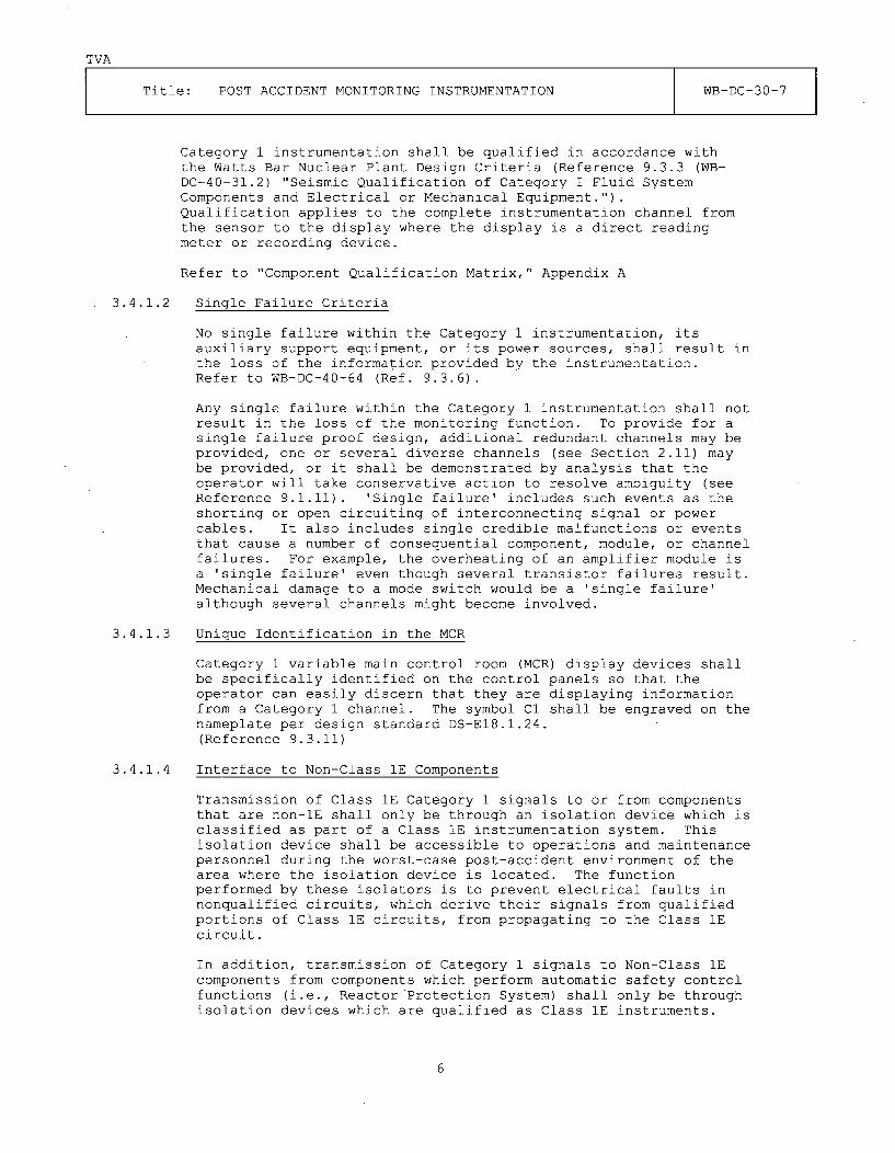
TVA
Title: POST ACCIDENT MONITORING INSTRUMENTATION WB-DC-30-7
Category 1 instrumentation shall be qualified in accordance withthe Watts Bar Nuclear Plant Design Criteria (Reference 9.3.3 (WB-DC-40-31.2) "Seismic Qualification of Category I Fluid SystemComponents and Electrical or Mechanical Equipment.").Qualification applies to the complete instrumentation channel fromthe sensor to the display where the display is a direct readingmeter or recording device.
Refer to "Component Qualification Matrix," Appendix A
3.4.1.2 Single Failure Criteria
No single failure within the Category 1 instrumentation, itsauxiliary support equipment, or its power sources, shall result inthe loss of the information provided by the instrumentation.Refer to WB-DC-40-64 (Ref. 9.3.6).
Any single failure within the Category 1 instrumentation shall notresult in the loss of the monitoring function. To provide for asingle failure proof design, additional redundant channels may beprovided, one or several diverse channels (see Section 2.11) maybe provided, or it shall be demonstrated by analysis that theoperator will take conservative action to resolve ambiguity (seeReference 9.1.11). 'Single failure' includes such events as theshorting or open circuiting of interconnecting signal or powercables. It also includes single credible malfunctions or eventsthat cause a number of consequential component, module, or channelfailures. For example, the overheating of an amplifier module isa 'single failure' even though several transistor failures result.Mechanical damage to a mode switch would be a 'single failure'although several channels might become involved.
3.4.1.3 Unique Identification in the MCR
Category 1 variable main control room (MCR) display devices shallbe specifically identified on the control panels so that theoperator can easily discern that they are displaying informationfrom a Category 1 channel. The symbol Cl shall be engraved on thenameplate per design standard DS-E18.1.24.(Reference 9.3.11)
3.4.1.4 Interface to Non-Class 1E Components
Transmission of Class 1E Category 1 signals to or from componentsthat are non-lE shall only be through an isolation device which isclassified as part of a Class 1E instrumentation system. Thisisolation device shall be accessible to operations and maintenancepersonnel during the worst-case post-accident environment of thearea where the isolation device is located. The functionperformed by these isolators is to prevent electrical faults innonqualified circuits, which derive their signals from qualifiedportions of Class 1E circuits, from propagating to the Class 1Ecircuit.
In addition, transmission of Category 1 signals to Non-Class 1Ecomponents from components which perform automatic safety controlfunctions (i.e., Reactor Protection System) shall only be throughisolation devices which are qualified as Class 1E instruments.
6

TVA
Title: POST ACCIDENT MONITORING INSTRUMENTATION WB-DC-30-7
3.4.1.5 Display Means
Category 1 instrumentation signals shall be displayed on anindividual continuous display and immediately accessible in themain control room. Category 1 parameters which are displayed ondisplays that are continuously available (reactor vessel level andcore exit temperature) are considered continuously displayed andtherefore meets the requirements of this section.
3.4.1.6 Recording Requirements
Parameters which have safety related trends are identified inReference 9.1.12, "Determination of R.G. 1.97 Variables RequiringTrend Indication." Reference 9.1.13 "Determination of DevicesRequired for Indicating Safety Related Trends for WBNP PAM"determines the hardware required to display the trends. At leastone of the channels used to monitor each Category 1 analogparameter shall be recorded in an immediately accessible manner toprovide a historical record. Non-iE recorders or a computer-based data acquisition and display system may be used whereprimary indication is provided by a qualified meter or otherqualified display. Non-Class 1E recorders provided for the latterfunction shall be isolated from the instrument circuit asdescribed in Section 3.4.1.4 above and qualified to Category 2S2isolation requirements in accordance with Section 3.4.2.
3.4.1.7 Instrument Accuracy Calculations
Where two or more instruments are needed to cover a particularrange, overlapping of instrument spans and accuracies will beprovided to ensure one of the two instruments will be on scale atall times.
All Category 1 or 2 instruments located in a I0CFR50.49 harshenvironment shall have a demonstrated instrument accuracycalculation performed.
Category 2 instruments which receive their input signal from aCategory 1 loop do not require an accuracy calculation.
Range and accuracy requirements are determined through theanalysis of Condition II, III, or IV events as described in FSARChapter 15. The display system meets the following requirements:
a. The range of the readouts extends over the maximumexpected range of the variables being measured.
b. The combined indicated accuracies are within the errorsused in the safety analysis.
7

TVA
Title: POST ACCIDENT MONITORING INSTRUMENTATION WB-DC-30-7
3.4.2 Category 2 Instrumentation
3.4.2.1 General Qualification Requirements
Category 2 instrumentation located in harsh environments andrequired to function for I0CFR50.49 events shall be qualified inaccordance with WB-DC-40-54 (Reference 9.3.5) 2. Seismicqualification is required per seismic Category I requirements,(see Section 3.6.2), if the instrument is part of a safety-relatedsystem. Where the channel signal is to be processed or displayedon demand, qualification applies to the complete instrumentationchannel from the sensor through the isolator/input buffer. Thelocation of the isolation device or input buffer should be suchthat it shall be accessible for maintenance during accidentconditions. Category 2 instrumentation which does not experienceharsh environmental conditions may be designed and installedaccording to Category 3 requirements (See Section 3.4.3).
A variable designated as Category 2 shall be designed andinstalled to the higher of the qualification requirementsdetermined in this design criteria or in the respective systemdescription.
Refer to "Qualification Matrix," Appendix A
3.4.2.2 Single Failure Criteria
The single failure criteria do not apply to Category 2instruments.
3.4.2.3 Unique Identification in the MCR
Category 2 MCR instruments shall be specifically identified on thecontrol panels so that the operator can easily discern that theyare displaying information from a Category 2 channel. Thedesignation C2 shall be engraved on the nameplate per designstandard DS-E18.1.24 (Reference 9.3.11). Section 4.3.2.1 containsidentification requirements for computer or annunciator basedCategory 2 displays.
3.4.2.4 Interface to Non-Class 1E Components
Category 2 instrumentation that is Class 1E for its normal systemfunction shall be isolated from non-Class 1E circuits inaccordance with Section 3.4.1.4.
Category 2 instrumentation that is non-lE shall have isolationfrom other non-lE circuits by means of typical industry methods(optional isolation, transformer or resistor networks, etc.).
This isolation is to ensure that other non-IE circuits will notaffect Category 2 instrumentation loops. An example of adequateisolation is provided by the annunciator system that uses opticalisolation of all inputs coming into the system. This prevents anyinput failure or fault from affecting the annunciator system andother loops. Another example is the plant computer system whichuses transformer and optical isolation.
8

TVA
Title: POST ACCIDENT MONITORING INSTRUMENTATION WB-DC-30-7
3.4.2.5 Display Means
The instrumentation signal may be displayed on an individualinstrument or it may be processed for display on demand by acomputer based data acquisition and display system or by otherappropriate means.
The display device need not be Class 1E. If a non-class 1Edisplay device is used on a Class 1E channel, the interfacerequirements of Section 3.4.2.4 above shall be met.
3.4.2.6 Recording Requirements
Category 2 effluent radioactivity monitors and area radiationmonitors shall be recorded. No other safety-related recording isrequired for Category 2.
3.4.3 Category 3 Instrumentation
3.4.3.1 General Qualification Requirements
The instrumentation shall be of high-quality commercial grade. Ahigh quality device demonstrates superiority and excellence inattributes that are determined to be critical characteristics suchas reliability, durability, long life, safety, physicalconstruction, and design. Refer to "Qualification Matrix,"Appendix A
3.4.3.2 Display Means
The instrumentation signal may be displayed on an individualinstrument or it may be processed for display on demand by acomputer based data acquisition and display system or by otherappropriate means.
3.4.3.3 Recording Requirements
Category 3 meteorology data shall be recorded either on a recorderor on the computer. No other recording is required for Category 3.
3.4.4 Common Requirements
3.4.4.1 Human Factors
Human factors principles shall be used in determining type andlocation of displays. (See Reference 9.3.7, WB-DC-30-23 "HumanFactors")
3.4.4.2 Direct Measurement
To the extent practical, monitoring instrumentation inputs shallbe from sensors that directly measure the desired variables. Anindirect measurement shall be made only when it can be shown byanalysis to provide unambiguous information.
9

TVA
Title: POST ACCIDENT MONITORING INSTRUMENTATION WB-DC-30-7
3.4.4.3 Routine Use
To the extent practical, the same instruments shall be used foraccident monitoring as are used for the normal operations of theplant to enable the operators to use, during accident situations,instruments with which they are most familiar. However, where therequired range of monitoring instrumentation results in a loss ofinstrumentation sensitivity in the normal operating range,separate instruments shall be used.
Means shall be provided for checking, with a high degree ofconfidence, the operational availability of each system inputsensor during reactor operation.
This may be accomplished in various ways, for example:
(1) By perturbing the monitored variable; or (2) By introducingand varying, as appropriate, a substitute input to the sensor ofthe same nature as the measured variable; or (3) By cross checkingbetween channels that bear a known relationship to each other andthat have readouts available.
3.5 Electrical Requirements
3.5.1 Category 1
3.5.1.1 Redundancy
Normally, Category 1 circuits shall be required to have tworedundant channels, post-accident monitoring channel 1 (PAM 1) andpost-accident monitoring channel 2 (PAM 2). The single failureanalysis (Reference 9.1.11) may require a third redundant post-accident monitoring channel 3 (PAM 3) to be used.
3.5.1.2 Signal Isolation
Transmission of Class 1E category 1 signals to components that arenon-lE shall only be through isolation devices which areclassified as part of the Class 1E instrumentation and meet allthe requirements of the system. No credible failure at the outputof an isolation device shall prevent the associated monitoringsystem channel from meeting the minimum performance requirementsconsidered in the design bases. Examples of credible failureinclude short circuits, open circuits, grounds, and theapplication of the maximum credible AC or DC potential (140 V DCor 118 V AC).
3.5.1.3 Control Power
Control power for Category 1 variables shall be supplied from thestation standby power sources, meaning Class 1E battery backedpower. Circuits requiring 125 VDC power shall be supplied by the125 VDC vital battery boards. Circuits requiring 120 VAC powershall be supplied by the 120 VAC vital instrument power boards.
Control power for PAM 1 circuits shall be supplied from either anA-train source, 125 VDC battery boards I or III, or 120 VAC vitalinstrument power boards I or III.
10

TVA
Title: POST ACCIDENT MONITORING INSTRUMENTATION WB-DC-30-7
Control power for PAM 2 circuits shall beB-train source, 125 VDC battery boards IIvital instrument power boards II or IV.
Control power for PAM 3 circuits shall be125 VDC battery boards I, II, III, or IV,instrument power boards I, II, III, or IVthe same power supply as the PAM 1 or PAMvariable.
supplied from either aor IV, or the 120 VAC
supplied from any of theor the 120 VAC vitalbut shall not be from2 channels for that same
See Table 1 "Category 1 Power Requirements."
3.5.1.4 Separation and Isolation
Redundant channels shall be electrically independent andphysically separated from each other and shall meet therequirements set forth in WB-DC-30-4, "Separation/Isolation"(Reference 9.3.1). The same requirements apply to separation ofPAM 3 cables from PAM 1 and PAM 2 cables.
3.5.1.5 Third Channels
Specific variables which require three channels (identified in thesingle failure analysis Reference 9.1.11 and designated in TableA-1) of information to be displayed in the MCR shall have thethird channel cables routed and separated as described in Section3.5.1.4. The control power supply for these channels shall bederived as described in Section 3.5.1.3 above.
11

TVA
Title: POST ACCIDENT MONITORING INSTRUMENTATION WB-DC-30-7
3.5.2 Category 2
3.5.2.1 Redundancy
Redundant circuitry is not required.
IChannell 125V DC Control Power 1 120 V AC Control Power II IIII PAM 1 1 TRAIN I BATTERY1 - BATTERYI I 120V I I 120V I
I A I IBD-I I IBD-III I AC I I AC II IVITALI VITALI FINSTRI IINSTRI POWERI POWER I
I I I I I I JBD-I I F BD-III I II PAM 2 1 1 TRAIN I IBATTERY1 IBATTERY1 1120V I 1120V ACII I F B I IBD-Ill I BD-IVI AC I VITAL I
F IVITALI FINSTR II FINSTRI POWER I
I I I IPOWERI FBD-IV II F F F F F F BD-II I
I PAM 3 1 1 IBATTERYFBATTERYIBATTERYFBATTERYF120V 1120V 1120V AC 1120V ACII F I I BD-I* I BD-II*IBD-III*F BD-IV*F AC I AC VITAL VITAL I
I FVITAL VITAL IINSTR FINSTR II FINSTR IINSTR POWER POWER I
I I I F FPOWER POWER FBD-III* FBD-IV* II F BD-I* FBD-II* I
*Must not be the same power supply as PAM 1 or PAM 2 for that same variable.
TABLE 1
CATEGORY 1 INSTRUMENT POWER REQUIREMENTS
12

TVA
Title: POST ACCIDENT MONITORING INSTRUMENTATION WB-DC-30-7
3.5.2.2 Control Power
If Class 1E power is required due to system functional requirementsas specified in the respective system description, then the channelshall be installed in the Class 1E division selected by the designerand shall satisfy the requirements appropriate to that division.(See Reference 9.3.2) Where non-Class 1E power is used, then controlpower shall be derived from highly reliable (diesel or batterybacked) non-divisional power sources.
3.5.2.3 Separation
Separation is not required by Regulatory Guide 1.97 for Category 2instrumentation. However, separation may be required because ofother regulatory, functional, power, or system requirements. Inthose cases, the most stringent requirements shall be met andseparation shall be implemented according to WB-DC-30-4,"Separation/Isolation" (See Reference 9.3.1).
3.5.2.4 Additional Requirements
Some circuits have more stringent requirements placed upon them dueto other design or regulatory requirements. The most stringentrequirements shall apply (i.e., PAM may allow non-lE power and no QAbut the normal system function requires 1E power and full QA.).
3.5.3 Category 3
3.5.3.1 Separation and Redundancy
Separation and redundant circuitry are not required for PAM. Thecable routing shall be in accordance with the requirements for non-divisional circuits from Reference 9.3.1. However, separation may berequired because of other regulatory, functional, power, or systemrequirements.
3.5.3.2 Control Power
The control power supply for these circuits may be derived from non-divisional power sources.
3.5.3.3 Additional Requirements
Some circuits may have more stringent requirements placed upon themdue to other design or regulatory requirements. The most stringentrequirements shall apply.
3.6 Mechanical Requirements
References 9.3.3 and 9.3.8 describe the requirements outlined in thefollowing sections.
13

TVA
Title: POST ACCIDENT MONITORING INSTRUMENTATION WB-DC-30-7
3.6.1 Category 1
3.6.1.1 Category I Structures
Components located in seismic Category I structures shall continue toperform the required function following a design basis seismic event.
3.6.2 Category 2
No specific requirements exist for seismic operability due to theguidance of Reference 9.1.1. However, specific system requirementsmay exist for seismic operability; if so, the instrumentation shallbe qualified as described below or as specified in the instrument'srespective system description.
3.6.2.1 Seismic Operability Required
Components required to be operable after a seismic event due tonormal system requirements shall be qualified to Seismic Category Irequirements (Reference 9.3.3).
3.6.2.2 Seismic Operability Not Required
Components not required to be operable after a seismic event shall bedesigned and mounted such that they do not have an adverse effect onsafety systems during or following a design basis seismic event.This shall be accomplished through qualification to Seismic CategoryI (L) requirements for components located in Category I structures(Reference 9.3.8).
3.6.3 Category 3
3.6.3.1 Components shall be designed and mounted such that they do not havean adverse effect on safety systems during or following a designbasis seismic event. This shall be accomplished throughqualification to Seismic Category I (L) requirements for componentslocated in a Category I structure (Reference 9.3.8).
4.0 LAYOUT AND ARRANGEMENT
4.1 General Description
Category 1 parameters shall be monitored by at least two redundantchannels PAM 1 and PAM 2. The single failure analysis calculation(WBN-OSG4-051 Reference 9.1.11) defines the variables that require athird redundant channel. [PL-08-0502] The third redundant channelwill be designated as PAM 3. Instrumentation for Category 2 and 3variables shall consist of at least one channel, but theinstrumentation may have redundant channels if they have beenprovided to satisfy other regulatory or design requirements.
14

TVA
Title: POST ACCIDENT MONITORING INSTRUMENTATION WB-DC-30-7
4.2 Location
4.2.1 Category 1
All Category 1 variables shall be displayed on individual instrumentslocated in the MCR.
4.2.2 Category 2 and 3
Category 2 and 3 variables may be displayed on individual instrumentsor the variables may be displayed on one of the computer-baseddisplays.
Some Category 2 and 3 variables will not be required to be in theMCR. The types of instrumentation not required to be displayed inthe MCR can be categorized as portable or post-accident samplinginstrumentation. Additional instrumentation not requiring a displayin the MCR is identified in Table A-1 with the entry "localindication" and meet the following guidelines:
1. The information displayed is of a non-critical or diagnostic nature.
2. The local panel display is accessible under accident conditions.
3. The information can be retrieved in a timeframe necessary to supportthe operator's action.
4. The parameter changes slowly such that only infrequent updates areneeded.
4.2.3 Control - Display Integration
Individual display instruments shall be located with related-systemcontrols and displays. Human factors principles shall be used in theconfiguration of the control board layout (See Reference 9.3.7)
4.3 Identification
4.3.1 Category 1
4.3.1.1 Derived Indication
In general, PAM Category 1 components and cables shall.be identifiedby the unique identifier and separation suffix as assigned for theirnormal safety function from the sensor to the indicator and shallconform to the requirements of WB-DC-30-4 "Separation/Isolation"(Reference 9.3.1).
Where a PAM indication is derived from the reactor protection system,the signal to the indicator shall be isolated from the protectioninstrumentation at the protection rack. The isolated cables andindicators shall be designated "J" for PAM 1 or "K" for PAM 2 .andshall follow the separation criteria in WB-DC-30-4. The isolatedcables and indicators of the third PAM channel PAM 3, where required,shall be separated and identified with a suffix as specified in WB-DC-30-4. Indicators shall bear the same suffix as their cables.
15

TVA
Title: POST ACCIDENT MONITORING INSTRUMENTATION WB-DC-30-7
Where an instrument loop is designed and installed specifically for aPAM Category 1 variable and has no other safety function thecomponents and cables shall use the separation suffix "J" for PAM 1and "K" for PAM 2 from the sensor to the indicator and shall bepurchased, designed, qualified, and installed as 1E equipment.
4.3.1.2 Unique Identification in the MCR
Category 1 display devices shall be uniquely identified in the maincontrol room. The symbol C1 shall be engraved on the nameplate.(Reference Table 2)
4.3.1.3 Control Diagrams
Category 1 PAM instrumentation loops shall be identified on thecontrol diagrams (47W610-series) [PL-08-0503]. The symbol P1, P2, orP3 shall be placed on the drawing adjacent to the loop indicatorsymbol and the symbol shall be enclosed in a small box to accent itsappearance. P1, P2, and P3 shall correspond with PAM 1, PAM 2, andPAM 3 respectively. (Reference Table 2)
4.3.1.4 Components
Each Category 1 variable loop component shall be identified on theinstrument tabulation drawings (47B601-series) [PL-08-0504]. Thewords PAM 1, PAM 2, or PAM 3 shall be placed in the remarks field foreach component that is required to meet Category 1 qualificationrequirements. (Reference Table 2) Those components shall onlyinclude the ones required to provide indication for the post accidentmonitoring function including transmitters, modifiers, powersupplies, isolators, and indicators. Those components not requiredfor indication such as isolated outputs to other systems, isolatedlocal indicators, isolated controllers, and other devices not in theindicating circuit shall not be identified as PAM. The isolatorseparating non-PAM devices from the PAM portion of the loop shall beidentified as PAM.
Each Category 1 and 2 variable in the 50.49 program shall beidentified as PAM on the "I0CFR 50.49 List" similar to the instrumenttabulation except that only the word "PAM" is used. It is notrequired to identify cables as PAM on the "10CFR 50.49 List".(Reference Table 2)
CATEGORY PAM DEVICE I TAB I CONTROL MCR I Q 1 50.491 DIAGRAM I TAG LIST I EQUIP*
1 1 CHANNEL 1 1 PAM 1 1 [P1] Cl ** PAM1 1 CHANNEL 2 PAM 2 [P2] Cl ** PAM1 CHANNEL 3 PAM 3 [P3] Cl ** PAM2 ANY PAM C2 -- C2 *** PAM3 ANY PAM C3 ........
* Not required for the cable "I0CFR 50.49
** Device shall be listed on the Q-list asList".'IQ,,.
*** Device shall be10CFR 50.49 pro
listed on the Q list as "Q" if it is required to be in thegram.
IDENTIFICATION SYMBOLS FOR PAM DEVICESTABLE 2
16

TVA
Title: POST ACCIDENT MONITORING INSTRUMENTATION WB-DC-30-7
4.3.1.5 Cables
PAM 1, PAM 2, and PAM 3 cables shall be identified and separatedaccording to Section 4.4.5 of Reference 9.3.1 "Separation/Isolation."
4.3.1.6 Color Coded Nameplate
Nameplates and tags on Category 1 components shall be consistent withthe requirements of DS-El.2.2 "Electrical Equipment Nameplates,Sequoyah and subsequent Nuclear Plants," with the exception of themain control room tags which shall be consistent with DS-E18.1.20"Instrumentation and Control, Labeling of Components." (Reference9.3.10 and 9.3.11)
Cable tags and labeling shall be consistent with standard drawing SD-E15.3.4. (Reference 9.3.9)
4.3.2 Category 2
4.3.2.1 Unique Identification in the MCR
Category 2 display devices shall be uniquely identified in the maincontrol room with the symbol C2 engraved on the nameplate orannunciator window. Where Category 2 variables are displayed on acomputer screen, they shall be uniquely identified on the screen asCategory 2 parameters. A special screen may be used to display allpost accident monitoring variables in one display and in such casesit is not required to additionally identify variables as PAM wherethey are used on other screens for normal system requirements.(Reference Table 2)
4.3.2.2 Control Diagrams
There is no requirement to identify Category 2 devices on the 47W610-series drawings. [PL-08-0503]
4.3.2.3 Components
Each Category 2 variable component shall be identified on theinstrument tabulation drawings (47B601-series) [PL-08-0504]. Thewords PAM C2 shall be placed in the remarks field for each componentthat is required to meet Category 2 qualification requirements(Reference table 2). Those components shall only include the onesrequired to provide indication for the post accident monitoringfunction including transmitters, modifiers, power supplies,isolators, and indicators. Those components not required forindication such as isolated local indicators or local controllersshall not be identified. Any isolators separating non-PAM devicesfrom the PAM portion shall be identified as PAM. (Reference Table 2)
Each Category 2 variable that has been included in the I0CFR50.49program shall be identified as PAM on the "lOCFR 50.49 List" similarto the instrument tabulation except that only the word "PAM" is used.It is not required to identify cables as "PAM" on the cable "I0CFR50.49 List" (Reference Table 2)
17

TVA
Title: POST ACCIDENT MONITORING INSTRUMENTATION WB-DC-30-7
4.3.2.4 Cables
Cables for Category 2 PAM circuits shall follow the requirements imposedby their normal system functions. Additionally, Category 2 non-Class 1Ecables that are not in the 10CFR 50.49 program shall be identified as PAMin the computerized cable routing system (CCRS) data base in accordancewith Reference 9.2.10.
4.3.2.5 Color Coded Nameplate
Nameplates and tags on Category 2 components shall be consistent with therequirements of DS-El.2.2 "Electrical Equipment Nameplates, Sequoyah andsubsequent Nuclear Plants," with the exception of the main control roomtags which shall be consistent with DS-E18.1.24 "Human FactorsEngineering" (Reference 9.3.10 and 9.3.11).
4.3.3 Category 3
4.3.3.1 Components
Each Category 3 variable component shall be identified in the MasterEquipment List (MEL) on the instrument tab of the component specificationtemplate. The words "PAM C3" shall be placed in the remarks field foreach component that is required to meet Category 3 qualificationrequirements (Reference Table 2). Those components shall only include theones required to provide indication for the post accident monitoringfunction including transmitters, modifiers, power supplies, isolators, andindicators. Those components not required for indication such as isolatedlocal indicators or local controllers shall not be identified. Anyisolators separating non-PAM devices from the PAM portion shall beidentified as PAM. Components required to meet Category 1 or Category 2requirements should not be identified as Category 3 (PAM C3) in MEL.
5.0 TESTING AND SURVEILLANCE REQUIREMENTS
5.1 General Servicing, Testing, and Surveillance Requirements
5.1.1 Programs
Servicing, testing, and calibration programs shall be specified tomaintain the capability of the monitoring instrumentation. For thoseinstruments where the required interval between testing will be less thanthe normal time interval between generating station shutdowns, acapability for testing during power operation shall be provided.
5.1.2 Channel Removal From ServiceWhenever a means for removing channels from service is included in thedesign, the design shall facilitate administrative control of the accessto such removal means. The system shall be designed to permit any onechannel to be maintained when required during power operation. Duringsuch operation, the active parts of the system need not themselvescontinue to meet the single failure criterion. As such, monitoringsystems comprised of two redundant channels are permitted to violate thesingle failure criterion during channel bypass provided that acceptablereliability of operation can be otherwise demonstrated. The bypass timeinterval allowed for a maintenance operation is specified in the planttechnical specifications. Bypass indication is applied eitheradministratively or automatically.
18

TVA
Title: POST ACCIDENT MONITORING INSTRUMENTATION WB-DC-30-7
5.1.3 Administrative Control
The design shall facilitate administrative control of the access to allsetpoint adjustments, module calibration adjustments, and test points.Access to all setpoint adjustments, module calibration adjustments, andtest points shall be administratively controlled.
5.1.4 Minimize Anomalous Indications
The monitoring instrumentation design should minimize the development ofconditions that would cause meters, annunciators, recorders, alarms, etc.,to give anomalous indications potentially confusing to the operator.
5.1.5 Repair
The instrumentation shall be designed to facilitate the recognition,location, replacement, repair, or adjustment of malfunctioning componentsor modules.
5.1.6 Capability for Verifying Operability
Means shall be provided for verifying the operability of the monitoringsystem channels. Where channels exhibit a dynamic response during normalplant operation or are required frequently for normal plant operation,verification of operability is inherent in the normal functioning of thechannels. For channels which monitor a normally static parameter,provisions shall be included to allow periodic testing thereby verifyingchannel operability. Identification of malfunctions are adequatelyidentified by cross checking between duplicate redundant channels or crosschecking between channels that bear a known relationship to each otherduring normal plant operation.
5.2 Surveillance Requirements Category 1 and 2 Instrumentation
Category 1 channels shall have an out of service interval specified in theplant technical specifications. Category 2 and Category 3 channels do nothave such a requirement unless required by the normal system requirements.
6.0 QUALITY ASSURANCE
6.1 Category 1 VariablesA description of the Quality Assurance Program for Category 1instrumentation is given in TVA Nuclear Quality Assurance Plan TVA-NQA-PLN89-A (Reference 9.2.5). Each Category 1 device identified as a PAM 1,PAM 2, or PAM 3 component shall be listed in the Watts Bar Q-list and bedesignated as "Q". (Reference Table 2)
6.2 Category 2 VariablesFor Category 2 instrumentation, the need for quality assurancerequirements will be limited to components located in a harsh environment.In general, quality assurance program requirements are not required to beimposed on nonsafety-related Category 2 instrumentation unless theinstrumentation is part of the 10 CFR 50.49 Environmental QualificationProgram (see Section 3.4.2 and Reference 9.3.5). Devices identified asPAM C2 shall be included in the Watts Bar Q-list if they have beenincluded in the 10 CFR 50.49 program and shall be designated as "Q."Other Category 2 devices shall follow normal system requirements.(Reference Table 2)
19

TVA
Title: POST ACCIDENT MONITORING INSTRUMENTATION WB-DC-30-7
6.3 Category 3 Variables
The instrumentation should be of high-quality commercial grade andshould be selected to withstand the specified environment. SeeSection 3.4.3.1 for a definition of "high quality." (ReferenceTable 2)
7.0 EXCEPTIONS
None
8.0 ADDITIONAL REQUIREMENTS
None
9.0 REFERENCES
9.1 Design Input
9.1.1 NRC Regulatory Guide 1.97 R2 and R3, "Instrumentation for Light-Water-Cooled Nuclear Power Plants to Assess Plant and EnvironsConditions During and Following an Accident."
9.1.2 Deleted
9.1.3 American Nuclear Society Report ANS-4.5-1980, "FunctionalRequirements for Post Accident Monitoring Capability for theControl Room Operator of a Nuclear Power Generating Station."Paragraph 6.3.6.
9.1.4 NRC Regulatory Guide, 1.89 Rl, "Qualification of Class 1E Equipmentfor Nuclear Power Plants."
9.1.5 Deleted
9.1.6 USNRC, Supplement 1 to NUREG-0737, "Requirements for EmergencyResponse Capability" Generic Letter 82-33, December 1982.
9.1.7 WBN, "PAM Type A Variables Determination," (WBN-OSG4-047). [PL-08-0505]
9.1.8 WBN, "Basis for R.G. 1.97 R2 Type B and C Variables Determination,"(WBN-OSG4-082). [PL-08-0506]
9.1.9 WBN, "R.G. 1.97 Type D Variable Selection." (WBN-OSG4-112)[PL-08-0507 thru -0516]
9.1.10 Deleted.
9.1.11 WBN, "Single Failure Analysis for R.G. 1.97 Category 1 Variables,"(WBN-OSG4-051). [PL-08-0502]
9.1.12 WBN, "Determination of R.G. 1.97 Variables Requiring TrendRecording," (WBN-OSG4-076). [PL-08-0517]
9.1.13 WBN, "Determination of Devices Required for Indicating SafetyRelated Trends." (WBEVAR8902002) [PL-08-0518 and -0519]
20

TVA
Title: POST ACCIDENT MONITORING INSTRUMENTATION WB-DC-30-7
9.1.14 WBN, "R.G. 1.97 Cat 1 and Type A, B, C, D Required Range and AccDeterm" (WBN-OSG4-111) [PL-08-0485 thru -0489]
9.1.15 WBN, "Range and Accuracy Requirements and Demonstrated Range ofInstrumentation Provided to Measure Regulatory Guide 1.97 Type EVariables" (WBN-APS3-048) [PL-08-0501]
9.1.16 Deleted
9.1.17 Deleted
9.1.18 WBN, "R.G. 1.97 Determination of Containment Isolation ValvesRequired Position Indication (WBN-OSG4-114) [PL-08-0520 thru -0529]
9.1.19 10 CFR50.49 "Environmental Qualification of Electric EquipmentImportant To Safety For Nuclear Power Plants"
9.1.20 10 CFR 50 Appendix A, "General Design Criteria for Nuclear PowerPlants", Criteria 13, 19, and 64.
9.1.21 TVA letter to NRC dated August 31, 1990, Watts Bar Nuclear Plant (WBN)Conformance to Regulatory Guide (RG) 1.97 Revision 2 (L44 900831 804).
9.1.22 TVA letter to NRC dated October 29, 1991, Watts Bar Nuclear Plant(WBN) - Emergency Response Capability, Regulatory Guide 1.97, Revision2 - Request for addition information response (T04 911029 848).
9.1.23 WBN "PAM Instrumentation Evaluation and Verification Methodology,Standards, and Guidelines" (WBPEVAR8809048). [PL-08-0530 thru -0539]
9.1.24 WBN Unit 1 and 2 - Supplemental Safety Evaluation Report (SSER)-9(RIMS Number T03 920722 912)
9.1.25 TVA letter to NRC dated May 9, 1994, "Watts Bar Nuclear Plant (WBN)Units 1 and 2 - Regulatory Guide (RG) 1.97, Revision 2, Post-Accident Monitoring System (PAM) - Supplemental Response (RIMST04940509901)
9.1.26 TVA letter to NRC dated April 21, 1995, "Watts Bar Nuclear Plant(WBN) Units 1 and 2 - Regulatory Guide (RG) 1.97, Revision 2, Post-Accident Monitoring System (PAM) - Supplemental Response (RIMST04950421117)
9.1.27 WBN Units 1 & 2 - Supplemental Safety Evaluation Report NUREG-0847Supplement No. 14 and 15.
9.1.28 Licensing Request, dated October 6, 1995, for Deviation 14. (RIMSNo. T24 951006 479)
9.1.29 TVA Letter to NRC dated October 12, 1995, "Watts Bar Nuclear Plant (WBN)Unit 1 & 2" - Regulatory Guide (RG) 1.97, Revision 2, Post-AccidentMonitoring System (PAM) - Supplemental Response (T04 951012 228)
9.1.30 Regulatory Guide 1.97 - Determination of Containment Isolation valvesRequiring Position Indication (WBNOSG4-114) [PL-08-0520 thru -0529]
9.1.31 Flooding Levels in the North and South Valve Vaults (WBNAPS2001)[PL-08-0540]
21

TVA
Title: POST ACCIDENT MONITORING INSTRUMENTATION WB-DC-30-7
9.2 Background
9.2.1 Watts Bar Nuclear Plant Environmental Drawings 47E235-Series.[PL-08-0541]
9.2.2 Watts Bar Nuclear Plant Final Safety Analysis Report.
9.2.3 R.G. 1.97, Revision 2, "Type A Variables Determination" (NEB 820402 268).
9.2.4 Memorandum from J. A. Raulston to F. W. Chandler (NEB 820322 260).
9.2.5 TVA-NQA-PLN89-A, TVA Nuclear Quality Assurance Plan
9.2.6 "Single Failure Analysis for PAM Variables" (NEB 820319 251).
9.2.7 Letter from J. A. Domer to E. Adensam dated September 19, 1985 (L44850919 806).
9.2.8 Memorandum from L. M. Mills to E. Adensam dated January 30, 1984 (27840130 016).
9.2.9 L. M. Mills letter to E. Adensam of USNRC dated June 7, 1983.
9.2.10 EAI-3.15, "Cable and Conduit Record Development and Issue Procedure".[PL-08-0482]
9.3 Design Criteria and Standards
9.3.1 WB-DC-30-4, "Separation/Isolation."
9.3.2 WB-DC-30-27, "AC and DC Control Power System."
9.3.3 WB-DC-40-31.2, "Seismic Qualification of Category I Fluid SystemComponents and Electrical or Mechanical Equipment".
9.3.4 Deleted
9.3.5 WB-DC-40-54 "Environmental Qualification to IOCFR50.49".
9.3.6 WB-DC-40-64 "Design Basis Events Design Criteria" (Appendix B), "SingleFailure"
9.3.7 WBN-DC-30-23 "Human Factors"
9.3.8 WB-DC-40-31.13 "Seismic Qualification of Category I(L) Fluid SystemComponents and Electrical or Mechanical Equipment"
9.3.9 SD-E15.3.4 "Electrical Standard Drawing, Raceways, and CA&WIdentification Tags (Sequoyah Nuclear Plant and all subsequent nuclearprojects)
9.3.10 DS-El.2.2 "Electrical Equipment Nameplates, (Sequoyah and subsequentnuclear plants)."
9.3.11 DS-E18.1.24 "Human Factors Engineering"
22

TVA
Title: POST ACCIDENT MONITORING INSTRUMENTATION WB-DC-30-7
APPENDIX APOST ACCIDENT MONITORING INSTRUMENTATION
COMPONENT QUALIFICATION MATRIX
(See Note)
Category 2Criteria
Redundancy
Category 1
EQ (10 CFR 50.49)
Seismic
QA
Power Supply
Physical Separation
At least 2 channels required
Qualify Per WB-DC-40-54,components placed inl0CFR50.49 Program
Must function after seismicevent per WB-DC-40.31.2
Yes - See Section 6.1
Class-lEPer WB-DC-30-27
Required per WB-DC-30-4
Non-lE circuit interfacesshall be through qualifiedisolation devices. (SeeWB-DC-30-4)
Hardwired indicator (RVLISand CET use plasma displayand recorder), light
Qualify per WB-DC-40-54,components placed inI0CFR50.49 Program
Not Required
Yes - See Section 6.2
Non-Class 1E, diesel orbattery-backed
Not required
Not required
Meter, indicator light,computer display, orannunciator window
Not Required
Category 3
Not Required
Not Required
Not Required
Not required
Non-Class 1E
Not Required
ElectricalSeparation
Indication
Not Required
Meter, indicatorlight, computerdisplay, orannunciatorwindow
Special Labeling onMCR Board
Cl engraved on MCRlabel or window.
C2 engraved on MCRlabel or window.
Not Required
Testing andMaintenance
Required
Required
Required Required
Isolation DeviceAccessibility
Recording At least 1 channel per analogvariable shall be recorded.
Where primary indication isprovided by qualified meter ordisplay, non-divisional trendrecorders or computer based dataacquisition & display system maybe used for at least 1 of theredundant loops of the variablesindicated in Table A-1. Recordingshall be qualified to Category 2requirements.
Required for loopswith isolation devices
Effluent and arearadiation monitors shallbe recorded.Not required for others
Not required
Recorder orcomputer formeteorology.
Not requiredfor others.
Note: These are only post accident monitoring requirements. Normal system requirementsmay impose more stringent qualification requirements on components selected forPAM use and in those cases the most stringent requirements shall be met.
A-1
23

TVA
Title: POST ACCIDENT MONITORING INSTRUMENTATION WB-DC-30-7
APPENDIX A
POST ACCIDENT MONITORING INSTRUMENTATION REQUIREMENTS
Table A-1 provides a listing of specific design requirements which areidentified in Reference 9.1.6. The table represents minimum requirements.Additional instrumentation or qualification may be provided as a result ofother plant, system, or design requirements. The topics described are:
o Variable Nameo Type and Categoryo Redundant Channelso Range, Range Units
o Environmental qualification (EQ)o Seismic Qualification (SQ)o Quality Assurance (QA)o Power Supply
Type and Category
The variable's type(s) and associated category are identified. Entries inthis column are derived from the Type selection calculations (References9.1.7 through 9.1.10) and R.G. 1.97 (Reference 9.1.1).
Redundancy - The number of instrument channels required to monitor thevariable. For Category 1 variables, the number of channels is determinedfrom Section 3.4.1.2 and Reference 9.1.11. Diverse indication used tosupplement or replace redundant information is also identified in Reference9.1.11 and in Note 1.
Range - The required range and engineering units of the instrumentation aredeveloped in the Type selection calculations, the required range andaccuracy calculation, (Reference 9.1.14) or are identified in Reference9.1.1.
Qualification (EQ) and Seismic (SQ)
Environmental and Seismic Qualification requirements are derived from theassignment of variable category. The qualification requirements for eachcategory are listed in Section 3. The environmental operating times forCategory 1 and Category 2 are specified in the Category and Operating TimesCalculations.
Quality Assurance (QA) - A "Yes" entry indicates that the instrumentationmust be included in the WBN QA program. A "No" entry indicates that theinstrumentation is not required to be included in the QA program. Thedetermination of "Yes" or "No" is made from the variable's assignedcategory.
A-2
24

TVA
Title: POST ACCIDENT MONITORING INSTRUMENTATION WB-DC-30-7
Category 2 equipment requiring environmental qualification to IOCFR50.49shall be included in the QA program, while other Category 2 equipment neednot be placed in the QA program to satisfy requirements of this DesignCriteria.
Power Supply - The minimum required source of electrical power for postaccident monitoring is identified as follows:
1E - Class 1E powerNon-lE - Non-Class IE*Batteries installed in portable instrumentation
The requirement for electrical power source is derived from the variable'scategory and the design criteria of Section 3.
* Instrumentation shall be powered from lE sources if system function
requires it.
Deviations
The deviations are given in Appendix C. These deviations are found inReferences 9.1.21, 9.1.22, 9.1.25, 9.1.26 and 9.1.28. The deviation numberis given in the "Notes" column of Table A-1.
A-3
25

TVA
Title: POST ACCIDENT MONITORING INSTRUMENTATION WB-DC-30-7
Page No. 1Regulatory Guide 1.97
Post Accident Monitoring Variables ListAppendix A Table A-1
WB-DC-30-7
VARNUM
RedundantChannels Range From Range To
RangeUnits
Power,SQ QA Supply NotesVariable Name Type/Category EQ
1 Auxiliary Feedwater Flow
2 Containment LowerCompartmentAtmosphere Temperature
3 Containment Pressure(Narrow Range)
4 Containment Radiation
5 Containment Sump Level
(Wide Range)
6 Core Exit Temperature
Al D2
Al D2
P1 P22 ChannelsPer Loop
P1 P22 Channels
4 Channels(See Note 14)
0
0
700
350
GPM YES YES YES 1E (See Note 1)
Deg F YES YES YES 1E Deviation #8
Al Bl Cl D2 -2 15 PSIG YES YES YES 1E Deviation #24Note 8
Al C3 El
Al Bi Cl D2
Al Bl C1 D2
P1 P22 Upper2 Lower
P1 P2
P1 P28 PAM 18 PAM 2
1 1.0E7
0
R/hr YES YES YES 1E Deviation #36
200 Inches YES
Deg F YES
YES YES 1E Deviation #32
200 2300 YES YES 1E Minimum of16 OperableThermocouples,4 From EachQuadrant (SeeNote 1,8,&10)Deviation #30& #37
26

TVA
Title: POST ACCIDENT MONITORING INSTRUMENTATION WB-DC-30-7
Page No. 2
Regulatory Guide 1.97Post Accident Monitoring Variables List
Appendix A Table A-1WB-DC-30-7
VARNUM
7
Variable Name
Main Steam Line Radiation
Type/Category
C2 E2
Al Bl D2
RedundantChannels Range From
1 Channel 1.0E-lPer SteamGenerator
P1 P2 1.0E-18 Nuclear Instrumentation(Source Range)
9 RCS Pressurizer Level
10 RCS Pressure Wide Range
11 RCS Temperature T Cold
12 RCS Temperature T Hot
13 Refueling Water StorageTank Level
14 Steam Generator Level
(Narrow Range)
Range To
1.0E3
2.0E5
100
3000
700
700
RangeUnits
uCi/cc YES NO YES NON-lE (See Note 7)
PowerEQ SQ QA Supply Notes
Al
Al
Al
Dl
Bl
Bl
Cl
Cl
D2
D2
Al D2
Al D2
Al Bl
P1 P2 P3
P1 P2 P3
4 Channels1 Per Loop
4 Channels1 Per Loop
P1 P2
P1 P2 P3
3 ChannelsPer SteamGenerator
0
0
50
50
CPS YES YES YES 1E Note 8
% YES YES YES 1E Note 8 & 12
PSIG YES YES YES 1E Note 8 & 12
Deg F YES YES YES 1E (See Note 1& 8)
Deviation #1
Deg F YES YES YES 1E (See Note 1& 8)
Deviation #1
% YES YES YES 1E Note 8
% YES YES YES 1E (See Note 1, 8& 12
0
0
100
100
27

TVA
Title: POST ACCIDENT MONITORING INSTRUMENTATION WB-DC-30-7
Page No. 3Regulatory Guide 1.97
Post Accident Monitoring Variables ListAppendix A Table A-1
WB-DC-30-7
VARNUM Variable Name Type/Category
RedundantChannels Range From
RangeRange To Units
PowerEQ SQ QA Supply Notes
15 Steam Generator Pressure Al B1 D2 PlP22 ChannelsPer SG
0 1300
16 Subcooling Margin Monitor Al B2 Cl D2 P1 P2 200 35
PSIG YES YES YES 1E Deviation #3Notes 1 & 8
Deg F YES YES YES iE 200 Deg.Subcooling to35 Deg.SuperheatNotes 8 & 10
Inches YES YES YES 1E Note 817 Auxiliary Building Passive Bl ClSump Level
P1 P2 12.5 72.5
18 Containment IsolationValve Position Indication
19 Containment HydrogenConcentration
20 Control Rod Position
21 Nuclear Instrumentation(Intermediate Range)
22 REACTOR VESSEL LEVEL
22a Static Mode(Pumps Not Running)
B1 D2 1 Per Valve Closed NotCLOSED
N/A YES YES YES 1E Deviation #20Note 15
YES YES YES IE Deviation #2Bl Cl D2 P1 P2 0
0
10 %
D3 1 ChannelPer Bank
235 Steps NO NO NO Non-lE Deviation #35
Bl D2 P1 P2
P1 P2
1.OE-8 200
See Note 5
% Power YES YES YES 1E Note 8
Bl C1 D2 YES YES YES 1E (See Note 5,8, & 10)
0 100 9- 0% RepresentsReactor VesselEmpty. 100%representsreactor vesselfull.
28

TVA
Title: POST ACCIDENT MONITORING INSTRUMENTATION WB-DC-30-7
Page No. 4Regulatory Guide 1.97
Post Accident Monitoring Variables ListAppendix A Table A-1
WB-DC-30-7
Redundant RangeVariable Name Type/Category Channels Range From Range To Units EQ
Dynamic Mode 20 100(Pumps Running)
VARNUM
22b
PowerSQ QA Supply Notes
100%RepresentsReactorVessel Full
23
24
25
26
27
28
29
30
31
32
Containment Pressure(Wide Range)
Shield Building Vent(Noble Gas Activity)
ABGTS High PressureAlarm
ACAS Pressure
AFW Valve Status
Accumulator FlowAlarm Valve Status
Accumulator Tank Level
Accumulator TankPressure
Annulus Pressure
Aux. Feed Pump TurbineSteam Supply IsolationValve Status
Cl
C2 E2
D2
D2
Dl
D3
D3
D3
D2
D3
P1 P2
1 Channel
1 ChannelPer Fan
1 ChannelPer Train
1 ChannelPer Valve
1 ChannelPer Valve
1 ChannelPer Tank
1 ChannelPer Tank
1 Channel
1 ChannelPer Valve
-5
1.OE-6
NA
0
Open
Open
7450
0
-10
Open
60
1 .0E4
-0.2
150
Closed
Closed
8080
700
0
Closed
PSIG YES YES
uCi/cc YES NO
In.H20 YES NO
PSIG YES NO
NA YES YES
NA NO NO
GAL NO NO
PSIG NO NO
In. H20 YES
NA NO NO
YES
YES
YES
YES
YES
NO
NO
NO
NO
NO
1E
NON-1E
NON-lE
NON-lE
1E
NON-lE
NON-lE
NON-lE
YES
NON-lE
Deviation #16
Deviation #15
Deviation #6
NON-lE
29

TVA
Title: POST ACCIDENT MONITORING INSTRUMENTATION WB-DC-30-7
Page No. 5
VARNUM
33
34
35
36
Variable Name
Battery Current(125V dc Vital)
Bus Voltage(125V dc Vital)
Bus Voltage (480VShutdown)
Bus Voltage(6.9KV Shutdown)
Regulatory Guide 1.97Post Accident Monitoring Variables
Appendix A Table A-iWB-DC-30-7
RedundantType/Category Channels Range From Range To
D2 1 Channel -200 +600Per Battery
D2 1 Channel 75 150Per Battery
D2 1 Channel 0 600Per Train
D2 1 Channel 6400 7400Per Train
List
RangeUnits
AMPS
VOLTS
VOLTS
VOLTS
EQ
YES
YES
YES
YES
SQ
NO
NO
NO
NO
PowerQA Supply Notes
YES N/A
YES N/A
YES N/A
YES NON-lE AnalogScale,DigitalDisplay
37
38
39
40
41
42
CCS Surge Tank Level
Centrifugal ChargingPump Total Flow
Charging Header Flow
Component CoolingWater To ESF Flow
Component Cooling WaterSupply Temperature
Condensate Storage TankWater Level
D3
D2
D3
D2
D2
D3
1 ChannelPer Train
1 Channel
1 Channel
1 ChannelPer Hx
1 ChannelPer Train
1 ChannelPer Tank
0
0
0
0
30
0
100
1000
110
5561
150
385,000
GPM
GPM
GPM
Deg F
GAL
NO
YES
NO
YES
YES
NO
NO
NO
NO
NO
NO
NO
NO
YES
NO
YES
YES
NO
NON-lE
NON-lE
NON-lE
NON-lE
NON-lE
NON-lE
Deviation #17
Deviation #7
Not PrimarySource of Aux.Feedwater.SeeVariable 27
30

TVA
Title: POST ACCIDENT MONITORING INSTRUMENTATION WB-DC--30-7
Page No. 6
Regulatory Guide 1.97Post Accident Monitoring Variables List
Appendix A Table A-lWB-DC-30-7
VARNUM
43
44
45
46
47
48
Variable Name Type/Category
Containment Air Return D2Status
Containment Cooling Valve D3Status
Containment Spray Flow D2
Containment Spray HX D2Outlet Temperature
Containment Sump Water D3Level (Narrow Range)
Containment Sump Water D2Temperature
RedundantChannels
1 ChannelPer Fan
1 ChannelPer Valve
1 ChannelPer Train
1 ChannelPer HX
1 Channel
1 Channel
Range From
On
Open
0
0
2
50
RangeRange To Units
Off NA
Closed NA
4400 GPM
200 Deg F
66 Inches
400 Deg F
EQ
YES
NO
YES
YES
NO
YES
SQ
NO
NO
NO
NO
NO
NO
QA
YES
NO
YES
YES
NO
YES
PowerSupply Notes
NON-lE (BreakerStatus)
NON-lE
NON-lE
NON-IE
NON-lE Deviation #12
NON-lE Used RHRInletTemperatureLoop
49
50
51
52
Diesel Generator Power
Diesel Generator Volts
ECCS Valve Status
ERCW Header Flow
D2
D2
D2
D2
1 ChannelPer DG
1 ChannelPer DG
1 ChannelPer Valve
1 ChannelPer Header
0
0
Open
0
4.84
6900
Closed
20,000
MWATTS
VOLTS
NA
GPM
YES
YES
YES
YES
NO
NO
NO
NO
YES
YES
YES
YES
N/A
N/A
NON-lE
NON-lE
31

TVA
Title: POST ACCIDENT MONITORING INSTRUMENTATION WB-DC-30-7
Page No. 7
Regulatory Guide 1.97Post Accident Monitoring Variables List
Appendix A Table A-1WB-DC-30-7
VARNUM Variable Name Type/Category
D2
RedundantChannels Range From
53 ERCW Supply Temperature
54 Emergency Gas TreatmentDamper Position
55 Emergency VentilationDamper Status
56 Hydrogen RecombinerStatus
57 Igniter Group Status
58 Inverter Current(120V ac Vital)
59 Inverter Voltage(120V ac Vital)
60 Letdown Flow
61 MCR Pressure
62 MCR Radiation Level
1 Channel 32Per Header
D2
D2
D3
D3
D2
D2
D3
D3
D2
1 ChannelPer Damper
1 ChannelPer Damper
1 ChannelPerRecombiner
1 ChannelPer Group
1 ChannelPer Inverter
1 Channel
Open
Open
On
Range To
200
Closed
Closed
Off
RangeUnits
Deg F
NA
NA
NA
EQ
YES
YES
YES
NO
NO
SQ
NO
NO
NO
NO
NO
QA
YES
YES
YES
NO
NO
PowerSupply Notes
NON-lE
NON-lE
NON-lE
NON-lE
On
0
Off
167
125
144
0.50
NA NON-IE
115
AMPS YES NO YES N/A LocalIndicationNote 9 & 13
VOLTS YES NO YES N/A LocalIndicationNote 9 & 13
GPM NO NO NO NON-lE Deviation #181 Channel 0
1 Channel 0 In. H20 NO NO NO NON-IE
1 Channel 1.0E-I 1.0E4 MR/Hr YES NO YES NON-lE
32

TVA
Title: POST ACCIDENT MONITORING INSTRUMENTATION WB-DC-30-7
Page No. 8
Regulatory Guide 1.97Post Accident Monitoring Variables List
Appendix A Table A-1WB-DC-30-7
VARNUM
Redundant RangeVariable Name Type/Category Channels Range From Range To Units
PowerEQ SQ QA Supply Notes
63 Main Feedwater Flow D3 1 ChannelPer Loop
1 Channel
0 4,372,720 lb/hr No
GPM YES
No No NON-lE
NO YES NON-lEDeviation #464
65
66
67
68
69
70
71
72
73
Normal Emergency Boration D2Flow
THIS LINE INTENTIONALLY LEFT BLANK
Pressurizer Heater Status D2(Electric Current)
Pressurizer Pressure D2Relief Valve Position(PORV, Block, and Code)
Pressurizer Relief Tank D3Level
Pressurizer Relief Tank D3Pressure
Pressurizer Relief Tank D3Temperature
RCP Seal Injection Flow D3
RCS Head Vent Valve Status D2
RHR Heat Exchanger Outlet D2Temperature
0 150
1 ChannelPer Group
1 ChannelPer Valve
1 Channel
1 Channel
1 Channel
1 ChannelPer RCP
1 ChannelPer Valve
1 ChannelPer HX
0
Closed
0
0
502
0
Closed
50
50.5
NotClosed
100
100
4002
13.2
NotClosed
400
AMPS
N/A
PSIG
Deg F
GPM
NA
Deg F
YES
YES
NO
NO
NO
NO
YES
YES
NO
NO
NO
NO
NO
NO
NO
NO
YES
YES
NO
NO
NO
NO
YES
YES
NON-lE(See Note 3)
NON-lE
NON-lE
NON-lE
NON-iEDeviation #11
NON-lE
NON-IE
NON-iEDeviation #9
33

TVA
Title: POST ACCIDENT MONITORING INSTRUMENTATION WB -DC -30-7
Page No. 9
VARNUM Variable Name
74 RHR Pump Flow (RHRSystem Flow)
75 RHR Valve Status
76 Reactor Coolant PumpStatus (Motor Current)
77 Safety Injection PumpFlow
78 Safety Injection SystemValve Status
79 Spent Fuel Pool LevelAlarm
80 Spent Fuel PoolTemperature Alarm
81 Steam Generator BlowdownIsolation Valve Status
82 Steam Generator Level(Wide Range)
83 Main Steam Flow
Type/Catego
D2
D3
D3
D2
D3
D2
Regulatory Guide 1.97Post Accident Monitoring Variables List
Appendix A Table A-1WB-DC-30-7
Redundant Rry Channels Range From Range To U
1 Channel 0 5500Per Pump
1 Channel Open ClosedPer Valve
1 Channel 0 712Per Pump
1 Channel 0 715Per Pump
1 Channel Open ClosedPer Valve
1 Channel 74811-1/2 749'2-1/2
ange Powernits EQ SQ QA Supply Notes
GPM YES NO YES NON-IE
NA NO NO NO NON-lE
AMPS NO NO NO NON-IE
GPM YES NO YES NON-lE
N/A NO NO NO NON-lE
ft,in YES NO YES NON-iERangeReflectsLow and HighAlarmSetpoints
Deg F YES NO YES NON-lEUpper rangeIs AlarmSetpoint
D2
D2
D1
D2
1 Channel
1 ChannelPer Valve
4 Channels1 Per SG
1 ChannelPer SG
127
Closed
0
0
Not NAClosed
100 %
4,500,000 lb/Hr
YES
YES
YES
NO
YES
NO
YES
YES
YES
NON-lE
NON-iEDeviation #10Notes 1 & 8
NON-IE
34

TVA
Title: POST ACCIDENT MONITORING INSTRUMENTATION WB-DC -30-7
Page No. 10
Regulatory Guide 1.97Post Accident Monitoring Variables List
Appendix A Table A-iWB-DC-30-7
VARNUM Variable Name Type/Category
RedundantChannels
1 ChannelPer Train
Range FromRange
Range To UnitsPower
EQ SQ QA Supply Notes
84 Tritiated Drain CollectorTank Level
85 Volume Control Tank Level
86 Waste Gas Decay TankPressure
87 Radiation Exposure Meters
88 Airborne Radiohalogensand Particulates
89 Plant and EnvironsRadiation
90 Plant and EnvironsRadioactivity
91 Auxiliary Building Vent(Noble Gas)
92 Auxiliary Building Vent(Flow Rate)
93 Auxiliary Building Vent(Particulates andHalogens
D3
D3
D3
E3
E3
E3
E3
E2
E2
E3
4 96 NO NO NO NON-iELocalIndicationDeviation #25
1 Channel 0 100
1501 ChannelPer Tank
0
% NO NO NO NON-lEDeviation #19
PSIG NO NO NO NON-lELocalIndicationDeviation #23
NA NA NA NA NA NA NA NA Deviation #22
Portable
Portable
Portable
1. OE-9
1. 0E-32
1.OE-3 uCi/cc NO
1.0E42 R/hr NO
NO NO NA Airborne1-131 andparticulates
NO NO NA
NA NA NA YES NO YES NA Multi ChannelGamma RaySpectrometer
1 Channel 1.0E-6
1 Channel 0
1.OE-2 uCi/cc YES
250,800 CFM YES
Note 11 uCi/cc NO
NO YES NON-lEDeviation #13
NO YES NON-lE
NO NO NON-lESampling withOnsiteAnalysisCapabilityDeviation #14
1 Channel Note 11
35

TVA
Title: POST ACCIDENT MONITORING INSTRUMENTATION WB-DC-30-7
Page No. 11
N'AR[UM Variable Name
94 Condenser Vacuum PumpExhaust Vent (Flow Rate)
95 Condenser Vacuum PumpExhaust Vent (Noble Gas)
96 ERCW Radiation Monitors
97 POST ACCIDENT SAMPLESYSTEM
97a Reactor CoolantChloride Concentration
97b Reactor CoolantDissolved Hydrogen
97c Reactor CoolantDissolved Oxygen
97d Reactor CoolantTotal Dissolved Gas
97e Reactor Coolant Boron
Type/Catego
E2
C3 E2
E2
E3
E3
E3
E3
E3
E3
Regulatory Guide 1.97Post Accident Monitoring Variables List
Appendix A Table A-1WB-DC-30-7
Redundant Rangery Channels Range From Range To Units EQ
1 Channel 0 45 SCFM YES
1 Channel 4.OE-7 2.4E3 uCi/cc YES
1 Channel 3.3E-4 1.65E-2 uCi/cc YESPer DischargePoint
1 System See below NO
SQ
NO
NO
NO
PowerQA Supply Notes
YES NON-lE
YES NON-iEDeviation #33
YES NON-lE
NA
NA
NA
NA
NA
10
10
100
50
20
2000
20
2000
6000
ppm
cc/kg(STP)
ppm
cc/kg(STP)
ppm
NO NO NON-lESampling withOnsiteAnalysisCapability
Deviation #29
Deviation #21
Deviation #34
Deviation #34
Deviation #26
36
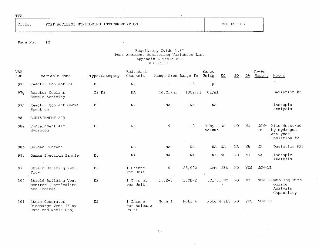
TVA
Title: POST ACCIDENT MONITORING INSTRUMENTATION WB -DC- 30-7
Page No. 12
Regulatory Guide 1.97Post Accident Monitoring Variables List
Appendix A Table A-IWB-DC-30-
VARNUM Variable Name
97f Reactor Coolant PH
97g Reactor CoolantSample Activity
97h Reactor Coolant GammaSpectrum
98 CONTAINMENT AIR
Type/CategoryRedundantChannels
RangeRange To Units EQ
PowerSQ QA Supply NotesRange From
E3
C3 E3
NA
NA
NA
1 13
lOuCi/ml loCi/ml Ci/ml Deviation #5
pH
E3 NA NA NA IsotopicAnalysis
98a Containment AirHydrogen
98b Oxygen Content
E3 NA 0 10 % by NOVolume
NO NO NON- Also Measured1E by Hydrogen
AnalyzerDeviation #2
NA
NA
NA
NA
NA
NA
NA NA NA NA NA Deviation #27
NA NO NO NO NA IsotopicAnalysis
98c Gamma Spectrum Sample
99 Shield Building VentFlow
100 Shield Building VentMonitor (ParticulateAnd Iodine)
101 Steam GeneratorDischarge Vent (FlowRate and Noble Gas)
E3
E2
E3
1 ChannelPer Unit
1 ChannelPer Unit
0 28,000 CFM YES NO YES NON-IE
1.OE-3 1.0E-2 uCi/cc NO NO NO NON-lESampling withOnsiteAnalysisCapability
E2 1 ChannelPer ReleasePoint
Note 4 Note 4 Note 4 YES NO YES NON-IE
37

TVA
Title: POST ACCIDENT MONITORING INSTRUMENTATION WB-DC-30-7
Page No. 13
Regulatory Guide 1.97Post Accident Monitoring Variables List
Appendix A Table A-lWB-DC-30-7
VARNUM
102
102a
102b
102c
103
Variable Name
METEROROLOGY
Vertical TemperatureDifference
Wind Direction
Wind Speed
Radiation ExposureRate
Type/CategoryRedundant RangeChannels Range From Range To Units EQ SQ QA
PowerSupply Notes
NON-IEE3
E3
E3
E3
1 Channel
1 Channel
1 Channel
Portable
-9
0
0
1. 0E-3
+18
360
50
1. 0E4
Deg F NO NO NO
Deg
MPH
R/Hr
NO
NO
NO
NO NO
NO NO
NO NO
NON-lE
NON-lE
NA
Deviation #28
Deviation #31
38

TVA
Title: POST ACCIDENT MONITORING INSTRUMENTATION WB-DC-30-7
Page No. 14APPENDIX A
POST ACCIDENT MONITORING VARIABLES LISTTABLE A-i
Notes:
1. The following parameters are identified as diverse in Reference 9.1.11.
Parameter Diverse Parameter
T (Hot) Core Exit TemperatureCore Exit Temperature T (Hot)T (Cold) SG PressureAuxiliary Feedwater Flow SG NR/WR Level
2. Deleted
3. Pressurizer Heater Status required only for safety-related heater banks (backup heater IA-A and lB-B). Rangeis given in amps per element.
4. Recorder shall be provided for duration of release from all discharge points.
Noble Gas Activity (See Main Steam Line Radiation, Var No. 7)Steam Flow Rate 0 to 4945200 lb/hr PORV and Safety Valves
0 to 63375 lb/hr To Aux. Feedwater Pump Turbine
5. Vessel level on the plasma display is the compensated actual vessel level derived from a microprocessor algorithmusing the upper range, lower range, dynamic range differential pressure, wide range temperature, and wide rangepressure.
6. Deleted.
7. Also monitors steam generator discharge vent noble gas activity. Required range of sensitivity specified is met byindication displaying in units of dose rate. Conversion to required range is performed using conversion factorspecified in Calc. WBNAPS3-048. [PL-08-0501]
8. At least one of the redundant loops is trended on a non-divisional trend recorder qualified to meet Category 2requirements.
9. Justification for local indication is found in Reference 9.1.22.
10. The Core Exit T/C Temperature (hottest), reactor vessel level, and Saturation Margin are trended on redundant Class1E plasma displays (the last 30 minutes trending only) in the Main Control Room.
39

TVA
Title: POST ACCIDENT MONITORING INSTRUMENTATION WB-DC-30-7
Page No. 15APPENDIX A
POST ACCIDENT MONITORING VARIABLES LISTTABLE A-I
Notes:
11. The ranges for particulates and halogens: 5x10⁻¹⁰ to 10-5uCi/cc for particulates, 10. 9 to 10- 4uCi/cc for halogens(iodine).
12. The requirements for Category I variables which require a third independent channel to resolve ambiguityresulting when redundant displays disagree are being implemented at WBN as follows:
The loop instrumentation for each channel is assigned to a redundant protection set (I, II, III, and IV) andelectrical independence is maintained from sensor to display. Physical separation is maintained from thesensor to the isolator in the Auxiliary Instrument Room. From the isolator to the indicator in the MainControl Room, third channel (PAM 3) cables may be routed with either PAM 1 or PAM 2 cables (but not both)depending on its associated protection set.
13. The 120V AC Vital Inverter has a trouble alarm in the MCR which notifies of trouble on the bus.
14. Four channels are provided for this variable. Two channels are designated as PAM 1, and two channels aredesignated as PAM 2. Reference 9.1.11 evaluated three channels for this variable and determined that threechannels are adequate for eliminating ambiguous readings.
15. In accordance with Technical Specification Bases B 3.3.3, PAM position indication is not required forcontainment isolation valves when the valves are closed and power removed. MSIV bypass valves (Main Steamwarming valves, 1-FCV-147, -148, -149, and -150) are normally closed during power operation (modes 1 and 2)with power removed. Consequently, position indication is not required for the valves in this configuration.The valves are powered and open during modes 3 and 4. Thus, position indication is required in thisoperational configuration. However, valves 1-FCV-147, -150, [PL-08-0483] and associated position indicationinstrumentation are subject to flooding subsequent to a feedwater line break. As evaluated in Reference9.1.31 (WBNAPS2001, Rev. 4), the valves will close prior to flooding .[PL-08-0540]. Flooding will result inpower being removed from the valves and instrumentation. Consequently, valve position indication is onlyrequired for these valves prior to loss of power due to flooding.
40

TVA
Title: POST ACCIDENT MONITORING INSTRUMENTATION WB-DC-30-7
APPENDIX BTABLE B-I
POST ACCIDENT MONITORING VARIABLES UTILIZING THEPLANT COMPUTER SYSTEM FOR MCR INDICATION
IA TYPE / COMPUTERVAR VARIABLE NAME CATEGORY PRIMARY ELEMENT ADDRESS
46 CONTAINMENT SPRAY D2 1-TE-72-31 T0168AHX OUTLET 1-TE-72-6 T0169ATEMPERATURE
47 CONTAINMENT SUMP D3 I-LT-77-125 L0471AWATER LEVEL(NARROW RANGE)
53 ERCW SUPPLY D2 -1-TE-67-455 T2612ATEMPERATURE 1-TE-67-456 T2613A
2-TE-67-455 T2614A2-TE-67-456 T2615A
61 MCR PRESSURE D3 0-PDT-31-1D P4002A66 PRESSURIZER HEATER D2 I-EM-68-341A E4003A
STATUS l-EM-68-341D E4004A92 AUXILIARY BUILDING E2 0-EM-90-300C F2704A
VENT (FLOW RATE)
94 CONDENSER VACUUM E2 1-FT-2-256 F2700APUMP EXHAUST VENT(FLOW RATE)
95 CONDENSER VACUUM C3 E2 1-RE-90-404A, R9061APUMP EXHAUST VENT 1-RE-90-404B R9062A(NOBLE GAS)
101 STEAM GENERATOR E2 1-XE-1-300 A-F, 1-ZE-1-5 F9051ADISCHARGE VENT I-PT-1-5-GFLOW RATE
1-XE-1-301 A-F, 1-ZE-1-12 F9052A1-PT-i-12-F
1-XE-1-302 A-F, 1-ZE-1-23 F9053A1-PT-1-23-F
1-XE-1-303 A-F, I-ZE-1-30 F9054AI-PT-1-30-G
1-FT-1-17 F9050A1-FCV-1-15 FD9300
4 Containment Al 1-RE-90-271 R9018ARadiation C3 1-RE-90-272 R9019A
El I-RE-90-273 R9020A1-RE-90-274 R9021A
96 ERCW RADIATION E2 O-RE-90-133A R1032AMONITORS 0-RE-90-134A R1033A
0-RE-90-140 R1035A0-RE-90-141 R1036A
[PL-08-0484]
B-I
41

TVA
Title: POST ACCIDENT MONITORING INSTRUMENTATION WB-DC-30-7
SOURCE NOTES
SOURCE NOTE TRACKINGNUMBER/DOCUMENTSOURCE NOTE NUMBER APPLICABLE SECTION
1
2
Letter to the NRC datedAugust 31, 1990(L44 900831 804)
Letter to the NRC datedOctober 29, 1991(T04 911029 848)
CATD 22911-WBN-01
1.1
1.1, 3.4.1.6,3.4.2.1, andApp. A, Table A-I(Pages 40 & 42)
Various, notspecifically notedin text
3
42

TVA
Title: POST ACCIDENT MONITORING INSTRUMENTATION WB-DC-30-7
APPENDIX C
TABLE C
REG GUIDE 1.97 R2 DEVIATION ANDJUSTIFICATION FOR DEVIATIONS
DEVIATION 1
VARIABLES (11 AND 12)
Reactor Coolant System (RCS) Cold- and Hot-Leg Water Temperatures
DEVIATION FROM REGULATORY GUIDE (RG) 1.97 GUIDANCE
The range recommended in RG 1.97, Revision 2, is 50 to 750 F; therecommendation for Watts Bar Nuclear Plant (WBN) is 50 to 700 F.
JUSTIFICATION
The Reactor Coolant System Description N3-68-4001 states that the designtemperature of the RCS is 650 F. The RG 1.97, Revision 2 recommended range is50-750 F. However, NRC has revised its position on this range and RG 1.97,Revision 3, now recommends a range of 50-700 F will provide a 50 F margin overthe design limit for both temperatures, which should provide the operator withadequate information for all transients. NRC concurs with WBN that an upperlimit of 700 F is acceptable. (Reference: NRC letter from Youngblood toWhite dated July 24, 1986.)
DEVIATION FROM RG 1.97 GUIDANCE
RG 1.97, Revision 2, recommends that the RCS hot-leg water temperature(Variable 12) parameter be a Bl variable. WBN recommends that this be an Aland D2 variable.
JUSTIFICATION
Type B variables provide information to indicate whether plant safetyfunctions are being accomplished. WBN's position is that RCS pressure (TypeAl, Bl, Cl and D2), core exit temperature (Type Al, Bl, Cl, and D2), reactorvessel level (Type Bl, Cl, and D2), and subcooling margin (Al, B2, Cl, and D2)are sufficient to monitor for adequate core cooling and the approach tosuperheat conditions in order to determine the margin by which the corecooling safety function is being accomplished. Therefore, it is WBN'sposition the RCS hot-leg water temperature be required only as a Type Al andD2 variable.
DEVIATION 2
VARIABLE (19)
Containment Hydrogen Concentration
C-1
43

TVA
Title: POST ACCIDENT MONITORING INSTRUMENTATION WB-DC-30-7
APPENDIX C
TABLE CREG GUIDE 1.97 R2 DEVIATION AND
JUSTIFICATION FOR DEVIATIONS
DEVIATION FROM RG 1.97 GUIDANCE
The range recommended in RG 1.97, Revision 2, is 0 to 30 percent, whereas WBN hasprovided instrumentation for this variable with a range of 0 to 10 percent.
JUSTIFICATION
WBN has performed an analysis that shows the worst-case hydrogen concentration willbe less than 4 percent post-loss-of-coolant (LOCA) with one of the hydrogenrecombiners operating. Also, the hydrogen igniter system handles degraded corehydrogen releases as specified in 10 CFR 50.44 and will also keep the hydrogenconcentration below 10 percent for these events. Therefore, the instrumentationwill always be on scale. The hydrogen recombiner status is indicated by a PAM D3variable.
DEVIATION 3
VARIABLE (15)
Steam Generator (SG) Pressure
DEVIATION FROM RG 1.97 GUIDANCE
The range recommended in RG 1.97, Revision 2, is 0 psig to 20 percent above thelowest safety valve setting (corresponding to 1422 psig at WBN); the recommendedrange for WBN is 0-1300 psig.
JUSTIFICATION
The design pressure for the main steam system at WBN is 1185 psig. The main steamsafety valves are designed to maintain system pressure less than 110 percent ofdesign pressure, which is 1303.5 psig. RG 1.97, Revision 2, recommends a range of 0psig to 20 percent above the lowest safety valve set pressure, which corresponds toa range of 0 to 1422 psig. The highest main steam safety valve set pressure is 1224psig and the accumulation pressure for each of the highest pressure safety valves is1284 psig. Therefore, since the accumulation pressure is below 1300 psig and the110 percent design pressure of approximately 1300 psig, the WBN recommended range of0-1300 psig is adequate to cover the design range. The RG 1.97, Revision 2 range iswell above the design requirements for the system and the ASME Code requirements forrelief valves. Thus it is concluded that the WBN SG pressure range providesadequate feedback to the operator on SG pressure response to accidents ortransients, and should be acceptable.
DEVIATION 4
VARIABLE (64)Normal/Emergency Boration Flow (Boric Acid Charging Flow)
DEVIATION FROM RG 1.97 GUIDANCEWBN recommends that this variable not be environmentally qualified (as required forRG 1.97, Revision 2, Category 2 variables) since other variables perform therequired emergency boration monitoring function.
C-2
44

TVA
Title: POST ACCIDENT MONITORING INSTRUMENTATION WB-DC-30-7
APPENDIX C
TABLE CREG GUIDE 1.97 R2 DEVIATION AND
JUSTIFICATION FOR DEVIATIONS
JUSTIFICATION
The flow path monitored by this variable is a normally isolated path that requiresoperator action to utilize. This path is used for manual boration of the RCS. Thispath is not required for mitigation of any event. Postaccident reactivity controlis accomplished by the Emergency Core Cooling System (ECCS) injecting borated waterfrom the refueling water storage tank (RWST) into the RCS. Manual boration is notutilized. The ECCS flow is monitored by the centrifugal charging pump total flow(high pressure injection flow), the safety injection (SI) pump flow (low pressureinjection flow), and the residual heat removal (RHR) pump flow (RHR System flow)/These three variables are in the environmental qualification program and meet the110 percent design flow measurement requirement.
DEVIATION 5
VARIABLE 97g
Radiation Level in Circulating Primary Coolant (Reactor Coolant Sample Activity).
DEVIATION FROM RG 1.97 GUIDANCE
This variable has been identified in RG 1.97, Revision 2, as Type C, Category 1,whereas WBN has identified this variable as Type C, Category 3.
JUSTIFICATION
For the fuel cladding integrity safety function, RG 1.97 recommends core exittemperature and RCS activity as key variables and gamma spectrum analysis of thereactor coolant as a Category 3 variable. Core-exit temperature provides primaryindication of a significant breach or potential breach of fuel throughout theemergency instructions (EIs), functional restoration guidelines (FRGs), and FinalSafety Analysis Report (FSAR). Therefore, this variable was included as theCategory 1 or key indication. Radiation level in circulating primary coolant was'considered; however, it indicates conditions following fuel damage and provides lesstimely information. Thus, this variable is considered to be less useful to theoperators and was included as a backup variable. TVA meets the intent of the RG1.97 recommended range by monitoring this variable using the gross activity analysisof primary coolant samples taken in the post accident sampling facility.
DEVIATION 6
VARIABLE (30)
Safety Injection (Cold-Leg) Accumulator Tank Pressure
DEVIATION FROM RG 1.97 GUIDANCE
RG 1.97, Revision 2, recommends that the pressure instruments meet the D2 criteriawith a range of 0 to 750 psig. WBN recommends retaining this variable as D3, with arange of 0 to 700 psig.
C-3
45

TVA
Title: POST ACCIDENT MONITORING INSTRUMENTATION WB-DC-30-7
APPENDIX C
TABLE C
REG GUIDE 1.97 R2 DEVIATION ANDJUSTIFICATION FOR DEVIATIONS
JUSTIFICATION
The primary function of these instruments is to monitor the preaccident status ofthe accumulators to ensure the passive safety function of the system. By designthey do not perform any safety function postaccident. Other seismically andenvironmentally qualified instruments such as RCS pressure can be monitored todetermine if a cold-leg accumulator injection has occurred.
The design pressure of the cold-leg accumulator tanks is 700 psig. The precautions,limitations, and setpoints (PLS) limit the nitrogen cover gas to a maximum pressureof 632 psig. Therefore, WBN's position is that monitoring of the tanks to pressureshigher than the relief setpoints is not needed. WBN considers the existing range of0 to 700 psig to the acceptable.
DEVIATION 7
VARIABLE (41)
Component Cooling Water (CCW) Temperature to Engineered Safety Features (ESF)Equipment
DEVIATION FROM RG 1.97 GUIDANCE
The range recommended in Rg 1.97, Revision 2, is 32 to 200 F; the recommendation forWBN is 30 to 150 F.
JUSTIFICATION
WBN analysis has determined that the highest expected CCW temperature (post-LOCAsafety injection) is 120 F.
An upward trend of the CCW temperature above 120 F could be readily detected andwould be expected to be slow moving. Thus, there would be sufficient time wellwithin the 150 F upper range to alert the operator to the condition and the need tocheck other PAM-related variables for potential manual actions.
DEVIATION 8
VARIABLE (2)
Containment Atmosphere Temperature (Containment Lower Compartment AtmosphereTemperature)
DEVIATION FROM RG 1.97 GUIDANCE
The range for this variable is recommended to be 40 to 400 F in accordance with RG1.97, Revision 2. WBN recommends the range to be 0 to 350 F.
C-4
46

TVA
Title: POST ACCIDENT MONITORING INSTRUMENTATION WB-DC-30-7
APPENDIX C
TABLE CREG GUIDE 1.97 R2 DEVIATION AND
JUSTIFICATION FOR DEVIATIONS
JUSTIFICATION
WBN is an ice condenser plant and, therefore, has a lower containment temperaturepost-accident than dry containments. The maximum temperature expected post-LOCA atWBN is 250 F as compared to 275 to 290 F for dry containments. The maximumtemperature expected at WBN after a steam line break is 327 F as compared to 380 to450 F for dry containments. The minimum expected containment atmospherictemperature will be 60 F. This minimum temperature is due to the minimum allowableRWST water temperature which could be sprayed into containment by inadvertentoperation of the containment spray. Therefore, it is WBN's position that a range of0 to 350 F is adequate.
DEVIATION 9
VARIABLE (73)
Residual Heat Removal (RHR) Heat Exchanger Outlet Temperature
DEVIATION FROM RG 1.97 GUIDANCE
The range recommended in RG 1.97, Revision 2, is 32 to 350 F; the recommendation forWBN is 50 to 400 F.
JUSTIFICATION
NRC letter from Youngblood to White dated July 24, 1986, states that RG 1.97,Revision 3, increased the minimum required range of this variable to 40 F and thatWBN's range of 50 to 400 F was acceptable due to the minor deviation.
DEVIATION 1Q
VARIABLE (82)
SG Level Wide Range
DEVIATION FROM RG 1.97 GUIDANCE
RG 1.97, Revision 2, recommends this variable as a Type D, Category 1 variable,which requires redundancy in the instrumentation. WBN recommends this variable beCategory 1, Type D, but utilizing only one wide range transmitter per SG.
JUSTIFICATION
SG wide range level indication is utilized as a diverse variable to auxiliaryfeedwater (AFW) flow for gross indication of flow to the SGs. The WBN AFW monitorsare Types Al and D2. WBN's position is that since SG wide range level is only usedas a backup to redundant AFW flow monitors, it does not require redundancy.
C-5
47

TVA
Title: POST ACCIDENT MONITORING INSTRUMENTATION WB-DC-30-7
APPENDIX C
TABLE CREG GUIDE 1.97 R2 DEVIATION AND
JUSTIFICATION FOR DEVIATIONS
DEVIATION 11
VARIABLE (70)
Quench Tank (Pressurizer Reflief Tank [PRT]) Temperature
DEVIATION FROM RG 1.97 GUIDANCE
The range for this variable is recommended to be 50 to 750 F in accordance with RG1.97, Revision 2. WBN recommends the range to be 50 to 400 F.
JUSTIFICATION
The purpose of this variable is to monitor operation. The PRT rupture disk isdesigned to operate between 86-100 psig. Assuming that the rupture disk operates at100 psig and the pressurizer is at 2500 psig at saturated conditions, the maximumtemperature during discharge when all valves in the line are open could beapproximately 350 F. High temperature due to discharges or leakage into the tank formthe pressurizer or other sources would produce an early upward trend in PRTtemperature above normal. Temperatures far below the RG 1.97 recommended temperatureof 750 F or the 400 F WBN recommended temperature would be sufficient to alert theoperator to an abnormal condition and the potential need to check related PAMvariables. Therefore, the recommended range of 50 to 400 F is sufficient to permitthe operator to monitor plant operation.
DEVIATION 12
VARIABLE (47)
Containment Sump Water Level (Narrow Range)
DEVIATION FROM RG 1.97 GUIDANCE
RG 1.97, revision 2, recommends this variable as Types B and C, Category 2. WBNrecommends this variable as Type D, Category 3.
JUSTIFICATIONThe operator does not monitor this variable to perform any required safety function.In addition Chapter 15 of the FSAR takes no credit for monitoring this variable forany design bases event. This variable is used primarily to monitor RCS leakage. Thisvariable, along with the lower containment atmosphere particulate radioactivitymonitoring systems are used to detect RCS leakage. These small leakages do not causeplant perturbations or detect RCS leakage. These small leakages do not cause plantperturbations or transients that would cause a reactor trip or SI signal to begenerated. Therefore, the operator does not enter the emergency procedures to detector mitigate these leakages and corrective actions based on the emergency proceduresand the use of PAM equipment are inappropriate. However, for the purpose ofmonitoring gross leakage, this variable will be designated as a Type D3 variable.
The containment sump water level (wide range) is a Type Al, Bl, Cl, and D2 variableand is used at WBN to monitor the containment water level for the mitigation ofaccidents.
C-6
48

TVA
Title: POST ACCIDENT MONITORING INSTRUMENTATION WB-DC-30-7
APPENDIX C
TABLE C
REG GUIDE 1.97 R2 DEVIATION ANDJUSTIFICATION FOR DEVIATIONS
DEVIATION 13
VARIABLE (91)
Auxiliary Building Exhaust Vent Radiation Level - Noble Gas Release
DEVIATION FROM RG 1.97 GUIDANCE
The range recommended in RG 1.97, Revision 2, is 10-6 to 10 3 microcuries/cubiccentimeter (cc); the recommendation for WBN is 10-6 to 10-2 microcuries/cc.
JUSTIFICATION
The Auxiliary Building vent monitor is provided to continuously monitor the airborneradioactivity released through the Auxiliary Building exhaust vent. An accidentcausing Auxiliary Building radiation level to be high will cause all ventilationpaths exhausting into the Auxiliary Building vent duct to automatically close andthe Auxiliary Building gas treatment system to be activated. Because the isolationfunction occurs before accident-range activity is reached, a normal-range monitoronly is employed to monitor activity in the Auxiliary Building exhaust vent.-6-2
Therefore, the recommended range of 10-6 to 10 microcuries/cc is adequate fordetecting and measuring noble gas concentrations.
DEVIATION 14
VARIABLE (93)
Auxiliary Building Exhaust Vent Radiation Level - Particulates and Halogens
DEVIATION FROM RG 1.97 GUIDANCE. -32
The range recommended in RG 1.97, Revision 2, is 10 to 10 microcuries/cc; therecommendation for WBN is 5x10⁻¹' to 10-5 for particulates and 10-9 to 10'microcuries/cc for halogens (iodine).
JUSTIFICATION
The Auxiliary Building Exhaust Vent monitor is provided to continuously monitor theradioiodine and particulate radioactivity released through the Auxiliary Buildingvent. A Design Basis Fuel Handling Accident in the Auxiliary Building or a DesignBasis LOCA in the Reactor Building will cause all ventilation paths exhausting intothe Auxiliary Building vent duct to automatically close and the Auxiliary BuildingGas Treatment system to be activated. Because the isolation function occurs beforeaccident range activity is reached, a normal range monitor only is employed tomonitor activity in the Auxiliary Building vent. Therefore, the recommended rangeof 5x10⁻¹⁰ to 10-5 microcuries/cc for particulates and 10-9 to 10-4 microcuries/cc forhalogens is adequate for detecting and measuring normal operation particulate andradioiodine concentrations. Laboratory analysis of collected samples allowsmeasurement over a wide range.
C-7
49

TVA
Title: POST ACCIDENT MONITORING INSTRUMENTATION WB-DC-30-7
APPENDIX C
TABLE CREG GUIDE 1.97 R2 DEVIATION AND
JUSTIFICATION FOR DEVIATIONS
DEVIATION 15
VARIABLE (29)
Safety Injection (Cold-Leg) Accumulator Tank Level
DEVIATION FROM RG 1.97 GUIDANCE
The range recommended in RG 1.97, Revision 2, is 10 to 90 percent volume using a D2variable. WBN recommends a range of 75 to 82 percent volume, using a D3 variable.
JUSTIFICATION
The present accumulator tank level indication range of 7632 to 8264 gallonscorresponds to 75 to 82 percent of volume.
Postaccident level does not serve any safety function since the passive injection ofthe cold-leg accumulators (CLA) into the RCS would be observed through otherqualified instrumentation such as RCS pressure. Hence, level instrumentation whichmeets the requirements of a D3 variable is appropriate.
DEVIATION 16
VARIABLE (28)
Cold-Leg Accumulator Isolation Valve Position Indication
DEVIATION FROM RG 1.97 GUIDANCE
RG 1.97, Revision 2, recommends that the position indication of the CLA isolation valvebe qualified to D2 requirements. WBN recommends designating this variable as D3.
JUSTIFICATION
The CLA isolation valves do not need to change from their normally open position inthe event of an accident which requires CLA injection. These valves will alreadyhave been opened during startup soon after the RCS pressure sufficiently exceeds theCLA normal operating pressure. Then the associated motive power will be removed.
There is no accident event in which instantaneous emptying of all four CLAs could causeinadequate core cooling or cold overpressurization of the RCS. The steamline break isthe only Condition IV event other than a LOCA that causes a rapid depressurization ofthe RCS. However, even for that accident the RCS depressurizes rapidly down to 900 psiwhere the pressure stabilizes or rises. Further depressurizations are at a much morecontrolled rate, giving the operator time to react.
For a Condition III event, such as a 4- or 6-inch break (small break LOCA), thedepressurization of the RCS may cause emptying of the CLA. Even under such cases,emptying the CLAs will not cause inadequate core cooling or cold overpressurization ofthe RCS.
C-8
50

TVA
Title: POST ACCIDENT MONITORING INSTRUMENTATION WB-DC-30-7
APPENDIX CTABLE C
REG GUIDE 1.97 R2 DEVIATION ANDJUSTIFICATION FOR DEVIATIONS
Furthermore, closing the CLA isolation valves is not a safety function for accidentmitigation that necessitates environmentally qualified valve position indication.Hence, there is no need to environmentally qualify these valves.
WBN recommends designating the position indication of the CLA isolation valve as a D3variable.
DEVIATION 17
VARIABLE (39)
Chemical and Volume Control System (CVCS) Makeup Flow-In (Charging Header Flow)
DEVIATION FROM RG 1.97 GUIDANCE
The RG 1.97, Revision 2, recommends that the design flow should be monitored using a D2variable. WBN recommends designating this variable as D3.
JUSTIFICATIONThis variable is used to monitor operation. The charging flow is isolated on a SIsignal. While certain events may produce a harsh environment'for the flow instruments,makeup flow is not required to mitigate these events. Thus, the installedinstrumentation qualified to D3 requirements is appropriate for the intended monitoringfunction at WBN.
DEVIATION 18
VARIABLE (60)CVCS Letdown Flow-Out (Let Down Flow)
DEVIATION FROM RG 1.97 GUIDANCERG 1.97, Revision 2, recommends 0 to 110 percent design flow monitoring using D2variables to monitor flow. TVA recommends this variable as D3.
JUSTIFICATIONThis variable is used to monitor normal operation. The letdown flow isolation valvesclose on a SI signal, low pressurizer level, or Phase A isolation signal. While certainevents may produce a harsh environment for the flow instruments, letdown flow is notrequired to mitigate these events. Thus, the installed instrumentation qualified to D3requirements is appropriate for the intended monitoring function at WBN.
DEVIATION 19
VARIABLE (85)Volume Control Tank (VCT) Level
DEVIATION FROM RG 1.97 GUIDANCEThe RG 1.97, Revision 2, recommends that the VCT level be monitored from top to bottomwith a D2 variable. TVA recommends using a D3 variable and a range slightly less thantop to bottom.
C-9
51

TVA
Title: POST ACCIDENT MONITORING INSTRUMENTATION WB-DC-30-7
APPENDIX C
TABLE C
REG GUIDE 1.97 R2 DEVIATION ANDJUSTIFICATION FOR DEVIATIONS
JUSTIFICATION
The VCT is isolated on a SI signal. While certain events may produce a harshenvironment for the level instruments, the VCT itself is not required to mitigate theevents. Hence the D3 type and category variable is appropriate for its performancerequirements.
The present VCT indication reads from 0 to 100 percent over a range of 70 inches whichis entirely within the approximately 80-inch cylindrical portion of the tank. Extendingthe range to include the top and bottom hemispherical portions of the tank would resultin nonlinear readings at the extreme ends of the scale. Including the hemisphere andthe remaining 10 inches of the vertical cylinder would not add significantly tomonitoring capability.
DEVIATION 20
VARIABLE 18
Containment Isolation Valve (CIV) Position
DEVIATION FROM RG 1.97 GUIDANCE
RG 1.97, Revision 2, recommends that the CIV position indication should meet therequirements of a Bl variable (which encompasses position indication for the duration ofthe event). WBN's reactor coolant system (RCS) letdown CIVs flow control valves (FCV)-62-72, -73, -74, and -76 will be submerged postaccident inside containment. Thesevalves' limit switches are not qualified for operation during post submergence.
In addition, safety relief valves which are also designated as CIVs are not monitoredfor position.
JUSTIFICATION
The RCS letdown CIVs close on an SI signal, Phase A signal, or a low pressurizer levelsignal. The valves and associated position indication limit switches are qualified toperform their intended safety functions prior to being submerged. The limit switch forthe valve position indication is located on the valve and hence subject to submergence.The limit switch is not qualifiable for submergence. The limit switch performs itsintended safety function well before submergence. Valve positions are indicated both inthe Main Control Room and the Technical Support Center.
Once the limit switches are flooded, it must be assumed that the control circuit fuseswill be blown and position indication will be lost. This indication circuit, however,is isolated from the other CIV indication circuits.
The solenoids for these valves are included in WBN's environmental qualification (EQ)program and will vent to automatically close the FCVs as required under accidentconditions. An analysis in WBN's EQ binder demonstrates that once closed, a submergencefailure of the solenoid will not cause the FCV to change position. Hence the valves areconsidered closed and no further indication is required.
C-10
52

TVA
Title: POST ACCIDENT MONITORING INSTRUMENTATION WB-DC-30-7
APPENDIX C
TABLE C
REG GUIDE 1.97 R2 DEVIATION ANDJUSTIFICATION FOR DEVIATIONS
For safety relief valves, position indication is not necessary since these valves areconstantly in their containment isolation position (i.e., closed). Verification thatthese valves have accomplished their containment isolation function is not necessarysince they do not change position to provide this function.
DEVIATION 21
VARIABLE (97B)
Reactor Coolant Dissolved Hydrogen
DEVIATION FROM RG 1.97 GUIDANCE
The RG 1.97, Revision 2 (refer to Table 2, Type E variables), recommends that primarycoolant grab sample capability exists for hydrogen analysis.
JUSTIFICATION
The WBN postaccident sampling facility (PASF) will have two independent methods formeasuring dissolved hydrogen in the RCS. It will have the capability to measuredissolved hydrogen in the range from 10-2000 cc/kg with an inline ion chromatograph.In addition, it will have a total dissolved gas analyzer to measure the totaldissolved gas in the pressurized coolant in the range from 100-2000 cc/kg. Dissolvedoxygen will be separately measured with a dissolved oxygen analyzer. These lattertwo measurements provide another determination of the dissolved hydrogen. The twoavailable methods provide sufficient backup monitoring capability for dissolvedhydrogen and will eliminate the need for handling highly radioactive, undiluted,pressurized reactor coolant grab samples. Diluted, unpressurized reactor coolantgrab samples may be obtained as necessary at the PASF for other analyses.
DEVIATION 22
VARIABLE (87)
Radiation Exposure Meters
DEVIATION FROM RG 1.97 GUIDANCE
Rg 1.97, Revision 2, recommends that Type E radiation exposure meters with continuousindication be available at fixed locations. No category is specified. WBNrecommends not classifying these meters as a RG 1.97 variable.
JUSTIFICATION
RG 1.97, Revision 2, was issued with an outstanding question regarding thepracticality of deploying radiation monitors at fixed locations. A study (NUREG/CR-2644) concluded that it is unlikely that a few fixed-station area monitors couldprovide sufficiently reliable information to be of use in detecting releases fromunmonitored containment release points.
C-11
53

TVA
Title: POST ACCIDENT MONITORING INSTRUMENTATION WB-DC-30-7
APPENDIX C
TABLE C
REG GUIDE 1.97 R2 DEVIATION ANDJUSTIFICATION FOR DEVIATIONS
NRC agreed with this conclusion and in Revision 3 of RG 1.97 deleted the environsradiation monitors from the pressure water reactor (PWR) table of variables.
TVA thereby requests a deviation from RG 1.97, Revision 2 specification of this TypeE variable.
DEVIATION 23
VARIABLE (86)
Waste (Radioactive) Gas Holdup Tank Pressure (Waste Gas Decay Tank Pressure)
DEVIATION FROM RG 1.97 GUIDANCE
RG 1.97, Revision 2, recommends that waste (radioactive) gas holdup tank pressure bemonitored from 0 to 150 percent of design pressure. WBN recommends that the pressurebe monitored from 0 to 100 percent of design pressure. (150 psig).
JUSTIFICATION
The design pressure of the waste gas decay tanks is 150 psig. The waste gas decaytanks are equipped with pressure relief valves set at 150 psig. Therefore, WBN'sposition is that monitoring of the tanks to pressures higher than the reliefsetpoints is not necessary. WBN considers the existing range of 0 to 100 percent ofdesign to be acceptable.
DEVIATION 24
VARIABLE (3)
Containment Pressure (Narrow Range)
DEVIATION FROM RG 1.97 GUIDANCE
RG 1.97, Revision 2, recommends Type B and Type C variable which covers a range of -5psig to the design pressure. WBN recommends a lower range of -2 psig using a TypeAl, Bl, Cl, and D2 variable (with no deviation to the upper range).
JUSTIFICATION
The WBN containment vessel design net external pressure is 2 psig. Inadvertentcontainment spray initiation will cause rapid depressurization inside containment.However, for this event the pressure will drop below the minimum design pressure.Another event that can cause a depressurization inside containment is continuousinadvertent air return fan operation. However, this will occur slowly enough toallow the operators sufficient time to observe trending of containmentdepressurization and afford ample opportunity to terminate the air fan operation andmanually open the lower compartment pressure reflief line.
C-12
54

TVA
Title: POST ACCIDENT MONITORING INSTRUMENTATION WB-DC-30-7
APPENDIX C
TABLE C
REG GUIDE 1.97 R2 DEVIATION ANDJUSTIFICATION FOR DEVIATIONS
In addition, the containment pressure wide range instrumentation (-5 to 60 psig)overlaps the -2 psig lower range instrumentation. The -2 psig value is the lowerdesign limit and is consistent with the use of upper range design limit of 15 psig.Hence, a lower range value of -2 psig is appropriate for WBN.
DEVIATION 25
VARIABLE (84)
High Level Radioactive Liquid Tank Level (Tritiated Drain Collector Tank)
DEVIATION FROM RG 1.97 GUIDANCE
RG 1.97, Revision 2, recommends a range for this variable from top to bottom. WBNrecommends a range from 11 to 133 inches from the bottom of the tank.
JUSTIFICATION
The capacity of the tank is approximately 24,700 gallons. The quantity of water thatis excluded from the range of the indication is approximately 1000 gallons at thebottom and an equal amount at the top. Thus, the present range is capable ofmonitoring approximately 22,700 gallons which is about 92 percent of the totalcapacity of the tank. TVA thereby considers the proposed range for the existinglevel taps (11 to 133 inches from the bottom of the tank) to be sufficient forindicating postaccident storage volume for this tank.
DEVIATION 26
VARIABLE (97E)
Reactor Coolant Boron
DEVIATION FROM RG 1.97 GUIDANCE
RG 1.97, Revision 2, recommends that the analysis range for boron content in theprimary coolant and sump be between 0 to 6,000 parts per million (ppm) and bemonitored with a Type B3 and E3 variable. WBN recommends that the range be between50 to 6,000 ppm and be monitored with a Type E3 variable.
JUSTIFICATION
For boron concentrations below 500 ppm, the tolerance for WBN's instrumentation wouldbe limited to plus or minus 50 ppm. This tolerance band is considered by WBN to beacceptable for ensuring that postaccident shutdown margin is maintained. WBN'sposition is that the current range capability for boron analysis (50 to 6,000 ppm) issufficient.
C-13
55

TVA
Title: POST ACCIDENT MONITORING INSTRUMENTATION WB-DC-30-7
APPENDIX C
TABLE C
REG GUIDE 1.97 R2 DEVIATION ANDJUSTIFICATION FOR DEVIATIONS
RCS boron concentration used in conjunction with control rod position indication andRCS cold-leg temperature only provides indirect indication. These are backupvariables for monitoring reactivity control. Neutron flux is a direct variable thatallows the operator to determine if reactivity is under control (i.e., the reactorhas tripped and the core is in a subcritical condition). Neutron flux is a Type B1and D2 variable at WBN. Therefore, the boron concentration is not required fordirect reactivity control determination. It is available as a Type E3 variable forbackup verification of reactivity control.
DEVIATION 27
VARIABLE (98b)
Containment Air Oxygen Content
DEVIATION FROM RG 1.97 GUIDANCE
RG 1.97, Revision 2 recommends a measurement range of 0-30 percent volume forcontainment air oxygen content. WBN recommends that the measurement of this variableshould not be required.
JUSTIFICATION
The measurement of containment air oxygen content is not required by NUREG-0737.Following a design basis LOCA at WBN, the combustible gas control system will operateas described in System Description N3-83-4001 R1 to maintain the hydrogenconcentration in containment below the lower flammability limit of 4 percent volume.Therefore, the oxygen concentration in containment is not important for combustioncontrol. A measurement of the containment oxygen concentration is not needed for anyother reason after an accident.
DEVIATION 28
VARIABLE (102c)
Meteorology (Wind Speed)
DEVIATION FROM RG 1.97 GUIDANCE
RG 1.97, Revision 2, recommends that the wind speed measurement range be 0 to 67 mph.WBN recommends that the range be 0 to 50 mph.
JUSTIFICATION
RG 1.97, Revision 3, recommends that the wind speed measurement range be 0 to 50 mph.Also, NRC letter from Youngblood to White dated July 24, 1986, states that since WBNmeets the range recommended in RG 1.97, Revision 3, the 0 to 50 mph range isacceptable.
C-14
56

TVA
Title: POST ACCIDENT MONITORING INSTRUMENTATION WB-DC-30-7
APPENDIX C
TABLE C
REG GUIDE 1.97 R2 DEVIATION ANDJUSTIFICATION FOR DEVIATIONS
DEVIATION 29
VARIABLE 97a
Reactor Coolant Chloride Concentration
DEVIATION FROM RG 1.97 GUIDANCE
RG 1.97, Revision 2, recommends a range of 0 to 20 ppm forconcentration. WBN recommends a range of 1 to 20 ppm.
reactor coolant chloride
JUSTIFICATION
The WBN recommended range of 1 to 20 ppm accurately represents TVA's commitment tothe NRC.
DEVIATION 30
VARIABLE 6
DEVIATION FROM RG 1.97 GUIDANCE
The two channels/trains of the core thermocouple system at the bundling at the commonreactor vessel refueling cavity wall penetration do not meet the separationrequirement of RG 1.97.
JUSTIFICATION
The design and the installation of the mineral insulated cables used for the corethermocouples within the reactor cavity was completed prior to upgrading the systemto satisfy RG 1.97 requirements. The design within the refueling cavity isacceptable because:
1. Only a small self-generated signal exists in the cabling from the thermocouplesto the Incore Instrument Room and, therefore, no chance exists for a postulatedpropagating fault.
2. Due to the interference provided by the rod control mechanisms and rod positionindicator stack, no likelihood exists for rendering all thermocouplesinoperable.
C-15
57

TVA
Title: POST ACCIDENT MONITORING INSTRUMENTATION WB-DC-30-7
APPENDIX C
TABLE C
REG GUIDE 1.97 R2 DEVIATION ANDJUSTIFICATION FOR DEVIATIONS
DEVIATION 31
VARIABLE 103
DEVIATION FROM RG 1.97 GUIDANCE
RG 1.97, Revision 2, includes exposure rate monitors as Type E (Category 2)variables. These monitors are required to have a range of 1.0 E-1 Rem per hour(R/hr) to 1.0 E4 R/hr and are to be located inside buildings or areas where access isrequired to service equipment important to safety. The area monitors are intendedfor use in detection of significant releases, release assessment, and long-termsurveillance.
RG 1.97, Revision 2, also included radiation exposure rate monitors, with ranges of1.0 E-1 R/hr to 1.0 E4 R/hr as Type C variables (these monitors were to be installedinside buildings or areas in direct contact with primary containment wherepenetrations and hatches were located). This variable was removed from RG 1.97 inRevision 3 and will not be addressed further.
WBN RG 1.97 monitoring instrumentation does not include installed high-range exposurerate monitors as Type E variables. The intended objectives of such instrumentationwill be achieved in a different manner than that described in RG 1.97. The followingparagraphs describe how WBN's program is designed to monitor radiation exposurerates.
A large number of useful missions outside the MCR during accident conditions may bepostulated. These missions would be for activities, such as equipment maintenance,grab sample acquisition, and laboratory analyses of grab samples, that might enhanceaccident mitigation. Exposure rates encountered on these missions would vary over awide range. This variability arises from the fact that most high exposure outsidethe containment during accident conditions would be attributable to contained sourcesand, therefore, be strong functions of distance from the sources. Because of thewide exposure rate variability, the installation of even a large number of high-rangeexposure rate monitoring instruments at selected locations on projected missionroutes might not contribute substantially, either to the planning of missions foraccident mitigation purposes or to the minimization of dose equivalent to personnelperforming the missions.
Based on the above considerations, the WBN radiation monitoring system design usesportable high-range exposure rate instruments in lieu of installed high-rangeexposure rate monitors. Crews attempting missions outside the MCR following anaccident would include Radiological Control personnel provided with high-rangeexposure rate instrumentation. The range of the Type E portable instrumentationavailable for this purpose is 1.0 E-3 R/hr to 1.0 E4 R/hr, which is consistent withthe range required for area exposure rate monitoring.
C-16
58

TVA
Title: POST ACCIDENT MONITORING INSTRUMENTATION WB-DC-30-7
APPENDIX C
TABLE C
REG GUIDE 1.97 R2 DEVIATION ANDJUSTIFICATION FOR DEVIATIONS
Additionally, the TVA radiation monitoring system presently includes normal-rangearea monitors, each with a range from 1.0 E-1 MR/hr to 1.0E4 MR/hr. These monitorsare located throughout the plant in areas where personnel access is common. Althoughthe area monitors are not required to be within the scope of the environmentalqualification program and they are not included in the Postaccident Monitoring (PAM)program, monitors located outside the primary containment and other locations of highpostaccident exposure rates can be expected to remain on scale and to continue toprovide exposure rate indication with required accuracy during accident conditions.The monitors that remain on scale will provide useful input to MCR personnel forassessment of plant exposure rate levels during accident conditions. Based upon thisassessment and WBN Radiological Emergency Plan dose limitations, a decision will bemade as to whether or not missions outside the MCR would be attempted.
In summary, the WBN position on high-range accident monitoring is that high-rangeexposure rate instrumentation will not be installed and that high-range monitoringwill be provided by portable monitoring instrumentation that meets the RG 1.97required range.
DEVIATION 32
VARIABLE (5)
Containment Sump Level (Wide Range)
DEVIATION FROM RG 1.97 GUIDANCE
The range recommended in RG 1.97, Revision 2, is "Bottom of containment to 600,000gallon level equivalent." Watts Bar recommends a range from 0-200 inches (with the"0" level starting at six inches above the reactor floor) (see Note).
JUSTIFICATION
Watts Bar utilizes a containment sump level monitoring system that starts measuringat six inches above the containment floor (level tap located at elevation 703' 3-3/8"). The range of the instrument is 200 inches (719' 11-3/8"). The total volumeof water available to flood containment post-LOCA is 844,000 gallons, which isapproximately equivalent to 717' 2-2/5" steady state maximum flood level. Therefore,the recommended range is fully adequate to monitor the maximum equilibrium floodlevel that would be experienced.
Note: The containment sump level monitoring system is utilized only during anaccident. During normal operation reactor coolant leakage is monitored by thereactor building floor and equipment drain pocket sump. For post accidentmonitoring, the operator is aware that the "0" level actually begins at 6"above the floor and will realize that there is extra water inside containmentwhen the sump monitor begins to indicate.
C-17
59

TVA
Title: POST ACCIDENT MONITORING INSTRUMENTATION WB-DC-30-7
APPENDIX C
TABLE CREG GUIDE 1.97 R2 DEVIATION AND
JUSTIFICATION FOR DEVIATIONSDEVIATION 33
VARIABLE 95
Condenser Vacuum Pump Exhaust Vent (Noble gas)
DEVIATION FROM RG 1.97 GUIDANCE
The RG 1.97, Revision 2, required range for the condenser vacuum pump exhaustmonitors is 1.0 E-6 to 1.0 E+5uCi/cc.
JUSTIFICATION
TVA has determined the total gas required range of the condenser vacuum pump exhaustmonitors to be less than the 1.0E-6 value in RG for the low end of the range and2.4E+3uCi/cc at the upper end of the range.
The steam generator tube rupture (SGTR) is the only credible accident monitored bythe condenser vacuum pump exhaust monitor. NUREG-0800, Revision 2 requires that theSGTR accident be analyzed using the highest isotope concentrations allowed by theWatts Bar Technical Specifications. The specific activity of the reactor coolant islimited to:
a) Less than or equal to 1 microcurie per gram dose equivalent Iodine-131, andb) Less than or equal to 100/EuCi/gm
The dose equivalent 1-131 is more than 4 times more restrictive that the 100/E limit.The 100/E is more conservative and is selected to demonstrate that the monitor willremain on scale during the most severe accident. The highest concentration of mixednoble gas isotopes that can be present under the 100/E limit is 1.45E+3 uCi/cc asdetermined in TVA calculation WBNAPS3-048 [PL-08-0501]. For the SGTR sourcespectrum, the maximum measurable concentration for the condenser vacuum pump exhaustmonitors is 3.53E+4. Therefore, the Watts Bar required range for the condenservacuum pump exhaust monitors meets the intent of RG 1.97, Revision 2 based on eitherthe mixed gas or the SGTR specific source spectrum.
DEVIATION 34
VARIABLE 97c & 97dPrimary Coolant Dissolved Total Gas (97d) and Dissolved Oxygen (97c)
DEVIATION FROM RG 1.97 GUIDANCERG 1.97, R2 indicates the range for variable 97d is from 0 to 2000 cc/Kg and therange from variable 97c is 0 to 20 ppm. The TVA required range for variable 97d is100 to 2000 cc/Kg, and 1 to 20 ppm for variable 97c.
JUSTIFICATIONThe TVA required ranges for variable 97c and 97d permit adequate assessment of theprimary system for these dissolved gases, and therefore, meets the intent of RG 1.97.
C-18
60

TVA
Title: POST ACCIDENT MONITORING INSTRUMENTATION WB-DC-30-7
APPENDIX C
TABLE C
REG GUIDE 1.97 R2 DEVIATION ANDJUSTIFICATION FOR DEVIATIONS
DEVIATION 35
VARIABLE (20)
Control Rod Position
DEVIATION FROM RG 1.97 GUIDANCE
RG 1.97 recommends that control rod position indication be a Type B. Category 3variable (B3) to monitor for reactivity control. Watts Bar recommends that thisvariable be a Type D, Category 3 variable (D3).
JUSTIFICATION
Control rod position indication is an indirect variable. It provides backupindication for monitoring reactivity control. Neutron flux (category 1) is a directvariable that allows the operator to determine if reactivity is under control (i.e.,the reactor has tripped and the core is in a subcritical condition). Since thisprovides backup indication, utilizing it as a Type D variable is sufficient.
DEVIATION 36
VARIABLE 4
Containment Area Radiation, High Range
DEVIATION FROM RG 1.97 GUIDANCE
Note 7 of RG 1.97, R2 for the subject variable states, "detectors should respond togamma photons within any energy range from 60 KeV to 3 MeV with an energy responseaccuracy of 20 percent at any specific photon energy from 0.1 MeV to 1 MeV. Overallsystem accuracy should be within a factor of 2 over the entire range. TVA meets therequirements of RG 1.97, R3 Note 7 for the subject variable, which states, "Detectorsshould respond to gamma radiation photons within any range from 60 KeV to 3 MeV witha dose rate response accuracy within a factor of 2 over the entire range."
JUSTIFICATION
It is acceptable to meet the requirements of RG 1.97, R3.
C-19
61

TVA
Title: POST ACCIDENT MONITORING INSTRUMENTATION WB-DC-30-7
APPENDIX C
TABLE CREG GUIDE 1.97 R2 DEVIATION AND
JUSTIFICATION FOR DEVIATIONS
DEVIATION 37
VARIABLE 6
Core Exit Temperature
DEVIATION FROM RG 1.97 R2 GUIDANCE
This Type A, Category 1 variable has been provided with a minimum of two independentchannels (PAM 1 and PAM 2) for monitoring core exit temperature. Where failure of achannel would present ambiguous or confusing information to the operator, preventingthe operator from taking action or misleading the operator, RG 1.97 recommends thatan additional redundant (PAM 3) channel be provided. One channel of the WBN coreexit temperature indication is subject to direct failure as a result of a specificpipe break jet impingement and/or pipe whip impact on the cable/conduit routed nearthe safety injection (SI) accumulator cold leg injection line in Loop 1. The WBNdesign does not include a third redundant channel for this variable.
JUSTIFICATION
The core exit thermocouples were added to the plant design to provide directindication of degrading core cooling conditions following transient events similar tothat experienced at Three Mile Island (TMI). These events typically developgradually over time and involve a great deal of operator action and control. Thecore exit temperature indication was intended to prevent erroneous operatortermination of emergency core cooling system (ECCS) flow to the reactor coolantsystem (RCS) after small breaks or transients that do not rapidly depressurize theRCS.
The challenge to the channel redundancy in this case is due to a specific primaryloop pipe break at the cold leg injection check valve. The injection line is 10-inches diameter, schedule 140 pipe and the postulated break is a full guillotinerupture which results in a blowdown flow area from the primary loop side of the breakof 60 in 2 or 0.4176 ft 2 . This break is included in the loss-of-coolant-accident(LOCA) break size spectrum and is considered an intermediate size break. FSARChapter 15 analyses show that breaks in this range rapidly depressurize the primarysystem, causing automatic ECCS response which refloods the core and terminates thecore heatup transient. However, should such a break occur, the affected channel isexpected to fail open and not give erroneous indication that could confuse theoperators.
It is the WBN position that the RG 1.97 R2 indication provided by reactor vessellevel, RCS pressure, RCS temperatures Thot and Tcold, and containment pressure andtemperature will enable the operators to compensate for a loss of one channel of CETdue to this specific pipe break plus a single failure of the redundant channel. Theoperators will be able to correctly assess the accident scenario and determine theeffectiveness of postaccident core cooling system response during performance of theEmergency Operating Procedures.
C-20
62

ENCLOSURE I
Responses To Licensee Open Items To Be Resolved For SER Approval
ATTACHMENT 6
(This Attachment contained on the OSM)
EDCR 52421 Excerpt

01.
LEGIBILITY EVALUATED ANDEDCR 52421-A
ACCEPTED FOR ISSUE. Page_ _
9Dre~LVA4 / ~AT L.N t)¶?ýeJ V_ (dSIGNATURE IJEN A A_ Aw•(,& DATE
EDCR COVER SHEET J / 7. I /
GENERAL INFORMATION Page No. 1EDCR TYPE F-1 EDCR # Rev.
(Check One Box Only) [ EDCR-2 # 52421 Rev. A
EL Check here if this is a Streamlined EDCR.[] Check here if this EDCR is for Documentation change only & No construction work is required.[j SR Li QR Check appropriate box if field material procurement quality requirements included.
92,99,235,261 RXB, AUX, 702, 737, 729,
278,293,55 CTL, AEB 755, 759, 757 SR I&C N/A
System Building Elevation Quality Lead Code/ClassClass Discipline
WORK SCOPE STATEMENT:Replace unqualified Westinghouse Source / Intermediate range Neutron Monitoring system with a Reg Guide 1.97 qualified systemfrom Thermo-Fisher Scientific, procured under contract 75148. Detailed Workscope is contained on the following pages.
PREPARE
Aaron Trelease 865 632-75Design Engineer/'-\hne Dt
I APPROVALS:/ j
-- lCtivi l EGI S D t
N/A
Mechanical EGS Date
N/A
Plant Design EGS Date
Project Engineering Manager DateACCEPTANCE:
Responsible Superintendent Date
Fd En eer Date
(-1 .A40TA KEngi berinag Manager Date
VERIFIED:
Engineer aDate'I INTER DISCIPLINE REVIEWS:
Civil E nMc ,er Date
I&C Engineer- Date
Electric/ Engineh V -40-A CUOe35 Oate I
NIA 7Mechanical Engineer Date
N/A
Plant Design Engineer D t
Project QA Manager IDateOTHER ORGANIZATIONS:
N/A
Signature/Org'n.: Date
N/A
Signature/Org'n.: Date
N/A
Signature/Org'n.: Date
Refer to the electronic documents in TVA Business Support Library (BSL) for current revision.
25402-3DP-GO4G-00081-005 Page I of 9

EDCR 52421-APage la
EDCR COVER SHEET
GENERAL INFORMATION Page No. laEDCR TYPE EEDCR # Rev.
(Check One Box Only) [ EDCR-2 # 52421 Rev. A
El Check here if this is a Streamlined EDCR.E3 Check here if this EDCR is for Documentation change only & No construction work is required.U SR [] QR Check appropriate box if field material procurement quality requirements included.
92,99,235,261 RPB, AUX, 702, 737, 729,
278,293,55 CTL, AEB 755, 759, 757 SR I&C N/A
System Building Elevation Quality Lead Code/ClassClass Discipline
WORK SCOPE STA TEMENT:Replace unqualified Westinghouse Source / Intermediate range Neutron Monitoring system with a Reg Guide 1.97 qualified systemfrom Thermo-Fisher Scientific, procured under contract 75148. Detailed Workscope is contained on the following pages.
1PREPARED:
Aaron Trelease (865) 632-7519Design Engineer Phone DateAPPROVALS:
Civil EGS Date
I&C EGS Date
Electrical EGS Date
N/A
Mechanical EGS Date
N/A
Plant Design EGS Date
Project Engineering Manager DateACCEPTANCE:
Rsonsible Superintendent -'Dar'e
Field Erfglne-er Ali Hemmati Date
TVA Engineering Manager Date
VERIFIED:
Engineer DateINTER DISCIPLINE REVIEWS:
C eEngi PPnr, DCivil Engineer Date
l&C Engineer Date
Electrical Engineer Date
N/A
Mechanical Engineer Date
N/A
Plant Design Engineer Date
Project QA Manager DateOTHER ORGANIZATIONS:
N/A
Signature/Org'n.: Date
N/A
Signature/Org'n.: Date
N!A
Signature/Org'n.: Date
Refer to the electronic documents in TVA Business Support Library (BSL) for current revision.
25402-3DP-GO4G-00081-005 Page 1 of 9

EDCR 52421-APage I-
EDCR COVER SHEET (CONTINUED)
EDCR# 52421 Rev. A Page No. 2
WORK SCOPE STATEMENT (CONTINUED):
The currently installed Unit 2 Neutron Monitoring system is not qualified for post accident monitoring required byReg. Guide 1.97. This EDCR replaces the unqualified Westinghouse system with Class 1E qualified NeutronMonitoring system and cable.
The following actions are required to upgrade the Neutron Monitoring System for Regulatory Guide 1.97compliance
(1) Remove the following existing unqualified Westinghouse source and intermediate range equipmentsupplied on TVA contract 54114 from the field if installed, and from MEL:
Remote:2-NMD-92-NE31-D2-NMD-92-NE32-E2-NMD-92-NE35-D2-NMD-92-NE36-E
Westinghouse Channel 1 Detector Source RangeWestinghouse Channel 2 Detector Source RangeWestinghouse Channel 1 Detector Intermediate RangeWestinghouse Channel 2 Detector Intermediate Range
(2) Install qualified Thermo-Fisher Scientific equipment procured under contract 75148. (Reference MR#25402-011-MRA-JA37-00001). Construction is to notify RADCON prior to installing or moving thedetectors.
Remote2-NMD-92-131-D2-NMD-92-132-E2-NM-92-131-D2-NM-92-132-E2-NM-92-138-D2-TB-92-1 -E2-TB-92-2-D
2-L-102-NI-92-138
2-M-132-NI-92-131-D2-NI-92-132-E2-NI-92-133-D2-NI-92-134-E2-NI-92-135-D2-NI-92-136-E
Channel 1 Detector (Source and Intermediate range)Channel 2 Detector (Source and Intermediate range)Channel 1 Wide range AmplifierChannel 2 Wide range AmplifierOptical IsolatorChannel 2 Junction BoxChannel 1 Junction Box
Appendix R Wide Range Signal Processor
Channel 1 Source Range Signal ProcessorChannel 2 Source Range Signal ProcessorChannel 1 Shutdown MonitorChannel 2 Shutdown MonitorChannel 1 Intermediate Range Signal ProcessorChannel 2 Intermediate Range Signal Processor
Note: contact the Special Nuclear Material Custodian (SNMC) prior to movement of 2-NMD-92-131 -Dand 2-NMD-92-132-E
Refer to the electronic documents in TVA Business Support Library (BSL) for current revision.
25402-3DP-GO4G-00081-005 Page 2. of 9

EDCR 52421-APage
(3) Delete the existing cables and internal wiring associated with the Westinghouse source andintermediate range equipment
(4) Add the new cables and internal wiring required to implement the replacement of the existingWestinghouse source and intermediate range equipment with the new Thermo-Fisher Scientificequipment.
(5) Control Diagram 2-47W610-92-1 has been created to reflect the configuration of the Neutron MonitoringSystem
(6) Schematic Diagrams 2-45W600-92-1 and 2-45W600-92-2 have been created to reflect theconfiguration of the source and intermediate ranges of the Neutron Monitoring System.
(7) New UNIDs have been assigned for the new Thermo-Fisher Scientific source and intermediate range
neutron monitoring equipment.
(8) The remaining UNIDs for the current Westinghouse system have been deleted.
Construction shall provide U2 operation labeling group all required data (MEL, drawings, DRAs) requiring IDtags / labels needed for completion of this EDCR.
The cables that will be installed as a part of this EDCR will be pulled via bulk cable pull packages. Thefollowing list of cables identifies the new cables added to support this EDCR. Each cable number is listed by itsCable ID number, and the bulk cable pull package that will physically pull the cable.
Cable Pull Package2NM2330E EDCR546372NM2331 E EDCR546392NM2332E EDCR546392NM2333D EDCR546372NM2334D EDCR546392NM2335D EDCR546392NM2336E EDCR546372NM2337E EDCR546372NM2339D EDCR546372NM2340D EDCR546372NM2341 D EDCR546372NM2342D EDCR546372NM2343D EDCR54637
Cable Pull Package2NM2344D EDCR546372NM2345 EDCR546372NM2346 EDCR546372NM2347 EDCR546372NM2348 EDCR546322NM2349 EDCR546322NM2350 EDCR546322NM2351 EDCR546322PV326D EDCR546362PV327 EDCR546362PV328D EDCR546362PV329E EDCR546362NM2338E EDCR54637
Special Precautions to the Unit I Interface:EDCR-2 52421 is based on the 0-TI-2 (revision 0) and 25402-3DP-GO4G-00081 (revision 5) procedures. Thepackage installs equipment in an area that contains Unit 1 operating equipment. The installation of thisequipment should have no adverse affect on Unit 1 operating equipment or common systems and components.This EDCR installs a wide range amplifier in Panel 2-L-10 In the auxiliary control room. The following items areUnit 1 associated devices. These items are energized and are required for Unit I operation. Do not touchthem, and use caution when working in their vicinity.
2-FI-67-61 C2-FI-67-62C2-LI-70-63C2-LI-70-99C2-FI-70-164C
2-FI-70-159C2-HS-70-63C2-HS-70-66C2-PI-70-17C
Refer to the electronic documents in TVA Business Support Library (BSL) for current revision.
25402-3DP-GO4G-00081-005 Page 3 of 9

EDCR 52421-APage 4
In addition, connections will be made to 120V AC Vital Instrument Power Boards 2-1 and 2-11. DCN 52602moves interface points from the terminal blocks to the breakers in the 120 VAC Power Boards 2-1 and 2-11, aswell as changing terminal blocks L3A & L3B designations from non-safety related to safety related. DCN 52602is a prerequisite to EDCR 52421. The following breakers will be utilized on Vital Power board 2-1: 18, 30, 45 and46. On Vital power board 2-11, Breakers 45, and 46 will be used. The Vital power Boards are consideredUnit 0 boundaries, and extreme caution must be taken to avoid interfering with the operating plantequipment. The connections to these boards will require outage conditions.
New Thermo Fisher Equipment
Channel 2
2-NMD-92-132-E 2-NM-92-132-E 2-NI-92-136-E 2-NI-92-132-E 2-NI-92-134-E
180 degrees Az FIl EL729 M-13 M-13 M-13M-13M-13MCRDetector well Addtnl equipt bldg MCR MCR M or
Amplifier IR Monitor SR Monitor
2-NI-92-138L-D
Channel 1 AC RApp. R Monitor
2-NMD-92-131-D 2-NM-92-131 -D 2-NM-92-138-D 2-NI-92-135-D 2-NI-92-131-D 2-NI-92-133-D
0 degrees Az FI EL 737 FI EL 737 M-13 M-13 M-13
Detector well Aux bldg Aux bldg MCR MCR MCR
Amplifier Optical Isolator IR Monitor SR Monitor SD Monitor
This EDCR will install the Unit 2 Source and Intermediate Range Neutron Monitoring System for Unit 2,replacing the obsolete Westinghouse system with an upgraded system that is reg guide 1.97 compliant. Unit 1work was performed under DCN 03206.
Due to the nature of the differences in core orientation between Unit 1 and Unit 2, the NIS channels will followthe placement of the core geometry (see figure below), rendering the placement of the detectors opposite toUnit 1 in terms of the containment. This change will propagate through the setup and routing of the installedsystem, and will create a unit difference (see the unit difference form.)
Unit 2 Channel 1 Wide Range Amplifier [2-NM-92-131-D] shall be mounted in a similar manner to the Unit 1Channel 2 Wide Range Amplifier, at elevation 737' in the Aux Building on the Unit 2 side of spent fuel pit heatexchanger room. Mounting the wide range amplifier in this location will require the relocation of a fireextinguisher. Mounting details shall be in accordance with the vendor documents, civil DRAs and seismiccalculations. The mounting of the amplifier and optical isolator are seismically qualified under WCG-ACQ-051 1.
Unit 2 Channel 2 Wide Range Amplifier [2-NM-92-132-E] shall be installed in a manner similar to the Unit 1Channel I Wide Range Amplifier in the additional equipment building room A15 approximately 15 feet off thefloor. Note that as of January 2 0 th 2010, the wall that contains door A214 (an access to additional equipment
Refer to the electronic documents in TVA Business Support Library (BSL) for current revision.
25402-3DP-GO4G-00081-005 Page 4 of 9

EDCR 52421-APage !
building room Al 5) is part of the ABSCE boundary. The mounting elevation for the Wide Range Amplifier is dueto the requirement that source range instrumentation equipment be above the design basis flood plain, andshall be accessible during the flood. In order to comply with Design Criteria WB-DC-40-29, when the reactorvessel head is on, the source range neutron flux level shall be available to verify that decay heat in the reactorcore is being safely removed by natural circulation in the reactor coolant loops. The criteria states that themaximum flood level is 736.9 feet, and mounting the device lower would subject it to be lower than design basisflood levels. The amplifier is housed in a spray-tight NEMA-12 enclosure, which is not qualified to operatesubmerged. The equipment will therefore be mounted in a manner similar to Unit 1, above the design basisflood plain.
Optical Isolator [2-NM-92-138-D] shall be mounted along with the Unit 2 Channel 1 Wide Range Amplifier atelevation 737' in the Aux Building on the Unit 2 side of the spent fuel pit heat exchanger room. The OpticalIsolator's function is to isolate the signal from the Wide Range Amplifier, and send the signal to the Wide RangeSignal Processor in the Auxiliary Control Room to provide neutron indication in the case of an Appendix R eventthat causes evacuation of the MCR. The decision was made to keep the Optical Isolator associated withChannel 1 so that the Wide Range Signal Processor in the L-1 0 panel is associated with the same core locationas in Unit 1.
In Unit 1, the Optical Isolator's classification is safety related and 1 E but not EQ. The Optical Isolator isqualified by the vendor to the same conditions as the Wide Range Amplifier, and is contained in a similar.NEMA-12 enclosure as the amplifier. The Unit 2 Optical Isolator will be in a harsh environment. CalculationWBNOSG4027 will be updated to reflect the addition of the Optical Isolator to a harsh environment, and is listedas an open item in the package.
Wide Range Signal Processor [2-NI-92-138] shall be mounted in panel 2-L-1 0 in the Auxiliary Control Room.The purpose of this device is to satisfy 1 OCFR50 Appendix R or Branch Technical Position CMEB 9.5-1 (fire inthe control room) remote shutdown monitoring requirements. The cutout shall be revised under EDCR 53338,while EDCR-2 52421 shall address the mounting. The Wide Range Signal Processor shall be mounted in placeof the Westinghouse backup source range drawer and utilize the existing Westinghouse slides. The mountingof the signal processor to panel 2-L-1 0 and the structural integrity of the panel areseismically qualified undercalculation: WCG-ACQ-0427.
The Signal Processor is mounted in a different location in the panel as Unit 1. The reason for this is that in Unit1, Gamma Metrics / Thermo- fisher Scientific equipment had not been used to start up the plant, so the existingbackup Westinghouse Source Range Drawer was kept in the plant to monitor the plant in case of a failure of theGamma Metrics equipment. The Unit 1 Gamma-Metrics equipment has demonstrated its reliability, and thesystem has been used in Unit 1 startup operations successfully in the past, so the Westinghouse BackupSource Range Drawer is no longer needed. This device has been removed from the plant, and will be replacedphysically and functionally by the Wide Range Signal Processor.
Source I Intermediate Range Signal Processors, Channels 1&2 shall be mounted in panel 2-M-13. Theexisting unqualified Westinghouse drawers were physically removed from panel 2-M-13. The drawers willutilize the existing Westinghouse slides for mounting purposes. Unit 1 added seismic screws to the signalprocessors for additional security. This change will be implemented in this EDCR. Mounting hardware will besupplied by Westinghouse under WBS: 3.2. Currently, there are no shutdown monitors installed in 2-M-1 3, andthis is new equipment that will be installed per this package. The shutdown monitors are provided on astandard 19-inch mounted plate to mount the monitors. The mounting of the source/ intermediate rangedrawers and shutdown monitors to panel 2-M-1 3 and the panel structural integrity are seismically qualified byWestinghouse report WBT-D-0524. The anchorage of the panel is seismically qualified under calculation WCG-ACQ-0516.
Addressed UNIDs:2-NI-92-135-D Channel 1 intermediate range monitor drawer (2-M-1 3)2-NI-92-136-E Channel 2 intermediate range monitor drawer (2-M-1 3)2-NI-92-131-D Channel 1 source range monitor drawer (2-M-13
Refer to the electronic documents in TVA Business Support Library (BSL) for current revision.
25402-3DP-GO4G-00081-005 Page 5 of 9

EDCR 52421-APage b
2-NI-92-132-E Channel 2 source range monitor drawer (2-M-1 3)2-NI-92-133-D Channel 1 shutdown monitor (2-M-1 3)2-NI-92-134-E Channel 2 shutdown monitor (2-M-13)
UNIT 1 UNIT 2
NCHANNEL I CHANNEL II
CONTAINMENT
GEOMETRY1 801. 1 80-
.9Q' WY2 270O Z7 0' 270 90 90
0* 0*
\, CORE QEOMETRY.-/
CHANNEL II CHANNEL I
Documentation Review:
Calculations WBN-OSG4-051 (single failure analysis for RG 1.97 category 1 variables), WBN-OSG4-076(Determination of category 1 RG 1.97 variables requiring trend indication), WBN-OSG4-082 (Basis for RG 1.97R2 type B and C Variables Determination), and WBN-OSG4-112 (RG 1.97-type D Variable selection) werereviewed for Unit 2 applicability, and no action was found necessary. Calculation WBN-OSG4-1 11 (RegulatoryGuide 1.97 category 1 and type A, B, C, D variable required range and accuracy determination) was reviewedfor changes needed, and will require revision for Unit 2 applicability.
Appendix R:
System 092 is a required Appendix R system. Replacement of the obsolete equipment with upgradedcomponents is being implemented to ensure that redundant components are in accordance with Appendix Rseparation requirements and will be included in the new fire protection report. A single wide range signalprocessor is being added in the auxiliary control room to satisfy 1 OCFR Appendix R (fire in the control room).Cables and conduit will not be pulled via this EDCR, and therefore, fire and hazard barriers will not beimpacted.
The addition of combustible loading in each fire zone is 4 lbs or less and thus does not create an Appendix Rconcern.
Refer to the electronic documents in TVA Business Support Library (BSL) for current revision.
25402-3DP-GO4G-00081-005 Page 6 of 9

EDCR 52421-APage.•
Post Accident Monitoring:
The currently installed Unit 2 Neu•-pn Monitoring System is not qualified for Post Accident Monitoring (PAM)required by Reg. Guide 1.97. Thtis EDCR replaces the unqualified Westinghouse system with Class 1Equalified Neutron Monitoring system and cable.
The new Thermo- Fisher Scientific equipment is PAM category 1. The system is evaluated under calculations
WBNEEBIDQ29990901 and WBNEEBIDQ29990903.
General Construction Notes and Design Implementation
The vendor assembly drawing for the system, 900231, shows the system interconnection and the mountingdetails for the detector assemblies. Each of the assemblies is first mounted in its permanent location and thenthe assemblies are interconnected. Construction should mount the assemblies and route the cables with theaid of the Vendor Manual and use Thermo-Fisher Scientific Field service for interconnection, powering andcheckout of assemblies in each channel.
The detector assemblies are delivered ready to install and with the ends of the cables prepared for theconnectors and covered with packing. The connectors are provided in separate plastic bags. Care should betaken to protect the cable ends from being bent or damaged.
Notes:1. The cable must not be damaged and the detector assemblies must be handled carefully to prevent
accidental damage, especially to the area where the cable exits the detector.
2. System isolation from plant ground must be maintained. Great care should be exercised when handlingthe detectors to avoid kinking the associated detector cables. Each detector assembly with integralcable and the junction boxes must be installed isolated from plant ground. They should all be verifiedas isolated from plant ground with insulation resistances of greater than 105 Ohms at 50 volts. Formounting details and part numbers, refer to the vendor assembly drawing list and outline drawings inthe vendor manual.
3. Due to the very low level input signal, the Wide Range Amplifiers are highly sensitive. To avoidexcessive source range noise, it is important to use care in routing the amplifier cable assemblies. Thefollowing precautions must be observed:
a. The cable assemblies must be physically separated from all power-handling cables by aminimum of 5 feet at all points where they are not enclosed by conduit.
b. The cable may be routed in instrumentation-only cable trays provided that no annunciator orrelay signals are carried by other wiring in the trays. Such signals are proven noise generators.
c. The cable must remain physically separated, by a minimum of 5 feet, at all points from cablessupplying control rod or control rod drive mechanisms.
d. The signal wires should be kept separate from power cables inside the electronic enclosuresand should be run in separate conduits between enclosures.
e. When attaching conduits to the electronic enclosures, enter the enclosure as close as possibleto the destination terminal block to eliminate excess wire lengths inside the enclosures.
f. The enclosures should be tied securely to the plant ground with a ground strap.
g. The ground termination on the power terminal block should be tied securely to the plant ground.
Refer to the electronic documents in TVA Business Support Library (BSL) for current revision.
25402-3DP-GO4G-00081-005 Page 7 of 9

EDCR 52421-APage S
Installation can be broken down to those actions normally preformed by Construction, and the actions normally
preformed by Thermo-Fisher Scientific Field service.
OPERATIONS TO BE PERFORMED BY CONSTRUCTION:
- Installation of detector assemblies and junction boxes, routing of the detector cables, andensuring that these components are isolated from ground.
- Installation (mounting) of the electronic boxes: Wide Range Amplifiers and Optical Isolator
- Installation (mounting) of the source range signal processors, the Intermediate Range SignalProcessors, and the Wide Range Signal Processors, and the shutdown monitors
- Installation of AC power to equipment (do not power up until inspected by Thermo-FisherScientific field service.)
- Interconnection between the Wide Range Amplifiers, Optical Isolator, Signal Processors, andcustomer-connection to the equipment outputs.
OPERATIONS TO BE PERFORMED BY THERMO-FISHER SCIENTIFIC:
- Routing of cable ends into the junction boxes for the detector cables and in-containment cableassemblies and installation of the cable-end connectors to the junction boxes.
- Connection of triaxial connectors to the penetrations (in-containment and amplifier cable
assemblies).
- Installation of the amplifier cable-assembly connectors for connection to the preamplifiers.
- Cable checkout using a megohmeter or time delay reflectometer (if required) and verification ofcable isolation from ground.
- Application of power and inspection of equipment.
BACKGROUND:
Unit 1 upgraded the corresponding Neutron Monitoring System from Westinghouse to Gamma- Metricsequipment under DCN 03206. This change was implemented because the existing Westinghouse equipmentwas not qualified for post accident monitoring as identified in 10CFR50 Appendix A criteria 13 and 19, andidentified in REG Guide 1.97. DCN 03206 completed all support work, including installing the system, revisingpanel cutouts, revising annunciator windows, routing cables, moving conflicting equipment, installing cables,etc. EDCR 52421 will focus on the physical installation, interconnection and mounting of equipment. Theremaining work is covered by other EDCRs as follows. Cable routing will be covered by EDCRs 54637-A,54639-A, 54632-A, and 54636-A. Panel 2-L-1 0 will be revised by EDCR 53338. Annunciator windows arerevised under EDCR 52315.
Several DCNs subsequent to DCN03206 have modified the unit 1 system. EDCR 52421 evaluates andincorporates relevant information from these DCNs as follows.
DCN 51239-A re-ranged the Unit 1 source range instrumentation due to the increase in boron concentration inthe reactor coolant system during startup and refueling conditions. The increase in boron concentration isrequired to support the tritium production program. It was determined that Unit 2 should also incorporate thischange in order to maintain unit consistency, and to address core improvements (low core leakage).
DCN 36179-A provided local neutron flux indication by implementing the capability to temporarily move the
Wide Range Signal Processor from panel 2-L-1 0 to connect it to the amplifiers. This change was required for
Refer to the electronic documents in TVA Business Support Library (BSL) for current revision.
25402-3DP-GO4G-00081-005 Page 8 of 9

EDCR 52421-APage
Unit 1 because of the concern that the power supply to 1-NI-92-138 and the D-channel Optical Isolator, as wellas the signal circuits to the E-channel Short Range/intermediate Range Amplifier, could be lost simultaneouslyduring an Appendix R event. Previously mentioned cable-routing EDCRs are routing cables such that there isno Appendix R concern, therefore this DCN will not require incorporation into Unit 2.
Refer to the electronic documents in TVA Business Support Library (BSL) for current revision.
25402-3DP-GO4G-00081-005 Page 9 of 9

EDCR 52421-A
Page Ig.
9EDCR UNIT DIFFERENCE FORM
EDCR# 82421 Rev. A Page No. 2L4
Operations Difference Is Identified as follows:WBN Unit 1 currently has the Gamma-Metrics source intermediate range system model RCS-300, This model isobsolete, so Watts Bar Unit 2 will receive the new 3001 NFMS (neutron flux monitoring system). The 3001 system hasseveral upgrades to the RCS-300.
Sourge Range / Intermediate Range Sianal Processor Imorovements:
* The source and Intermediate signal processors come with upgraded bar graph liquid crystal displays, as the Unit1 analog meters are obsolete.
* In Unit 1, the source and Intermediate range signal processors have "Counts per second "or "Percent powerlevel" displays, respectively. Unit 2 source and intermediate range signal processors come with "Decades perminute" on the drawer fronts in addition to the other displays.
" The selector knobs for Unit 2 on the Intermediate range signal processor are set up differently than on Unit 1.There are a total of 3 dials on Unit 1, including level trip, adjust, and operation selector. On Unit 2, there are atotal of 5 knobs, including test selector and output selector in addition to those previously mentioned.
" The shutdown monitor on the Unit 2 side will not contain an alarm reset button, which was used to manuallydisable the alarm during the drawer latching process. The alarm reset function is now obsolete, as this featurecan be handled at the annunciator.
" Training differences will be required due to this upgrade. Detailed Information on the new equipment can befound In the Thermo-FIsher Scientific vendor manual for the source/Intermediate range neutron monitoringsystem.
The wide range signal processor In panel 2-L-10 will be in a different location than in Unit 1. The backup source rangedrawer is being removed from 2-L-10 due to obsolescence, and the wide range signal processor will be mounted In Itsplace.
In Unit I .due to Improper cable routing, there was a potential for both channels to be functionally disabled due to apossible appendix R event. To address this, unit 1 provided the ability to remove the wide range signal processor fromthe auxiliary control room, and take the device down to get signal directly from the channel 1 optical Isolator, and getpower from channel 2 amplifier. Unit 2 will rout cables for the device in such a way that appendix R will not be a concem.Operations should be aware that it is no longer required to move the wide range signal processor for Unit 2. Quickdisconnects in the optical isolator, channel I amplifier and wide range signal processors are not required in unit 2, andwill not be In'alledJo %qis EDCR.
:1.:
ZfA <JP. r lAfllt?IJhIt7TVA Operatlont Acceptance (Mgropr Designee): -" Date: ' /
Refer to the electronic documents In TVA Business Support Library (BSL) for current revision.
25402-3DP-G04G-00081-005 Page I of 3
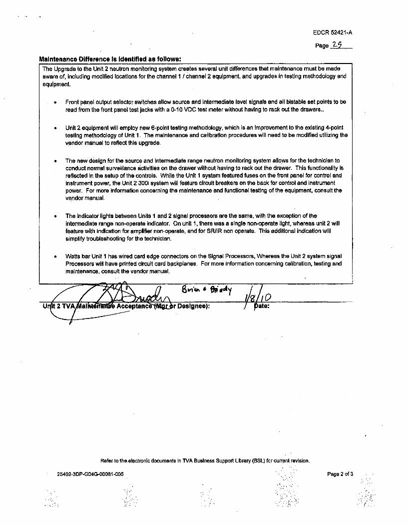
EDCR 52421-A
Page 2-5
Maintenance Difference Is Identified as follows:The Upgrade to the Unit 2 neutron monitoring system creates several unit differences that maintenance must be madeaware of, including modified locations for the channel 1 / channel 2 equipment, and upgrades In testing methodology andequipment.
Front panel output selector switches allow source and intermediate level signals and all bistable set points to beread from the front panel test jacks with a 0-10 VDC test meter without having to rack out the drawers..
* Unit 2 equipment will employ new 6-point testing methodology, which is an improvement to the existing 4-pointtesting methodology of Unit 1. The maintenance and calibration procedures will need to be modified utilizing thevendor manual to reflect this upgrade.
The new design for the source and Intermediate range neutron monitoring system allows for the technician toconduct normal surveillance activities on the drawer without having to rack out the drawer. This functionality isreflected In the setup of the controls. While the Unit 1 system featured fuses on the front panel for control andinstrument power, the Unit 2 300i system will feature circuit breakers on the back for control and instrumentpower. For more Information concerning the maintenance and functional testing of the equipment, consult thevendor manual.
The indicator lights between Units 1 and 2 signal processors are the same, with the exception of the
intermediate range non-operate indicator. On unit 1, there was a single non-operate light, whereas unit 2 willfeature with Indication for amplifier non-operate, and for SR/IR non operate. This additional indication willsimplify troubleshooting for the technician.
* Watts bar Unit 1 has wired card edge connectors on the Signal Processors, Whereas the Unit 2 system signalProcessors will have printed circuit card backplanes. For more Information concerning calibration, testing andmaintenance, consult the vendor manual.
-)
11
Refer to theelectronic documents In TVA Business Support Library (BSL) for current revision.
25402-3DP-GO4G-00081 -005 Page 2 of 3

EDCR 52421 -A
Page
'Engi-neerding Difference is identified asfoJlow...%
T TT.hechanrel I wide range amplifier and optical Isolator will be mounteditin the auxiliary building, floor elevation 737'. In:.:,Unit 1, thec devices were mounted in th eadditiona equipment builing, room A4 Thisidifference in relative location isdue to the re•versed core orentationh of Unit :2.Seethe :EDCR work scope statement for more information.The.ch6lannel 2 wide range. ampifir is. moU nte in th e U nit:2. Additinail Equipmet. building, Room.MA5;. Th e U n it I•channel 2 wide range amplifier was mounted inthe Auxiliary building, floor elevation 737'.. This dcifference is due to the.reversed corýdeoientation o.6f Unit 2. Seew wrk scope statemenht for more-informa~tion.As.'tientio~ned, WBN Unit 1 currently ýhas. the Gamm*a-Metrics aorc inttermediate range systemn model RCS300.ý ThisModel is obsolete, andnthe new i ystFem (Nutrn Fiu I monitogbentaled in Unit.2...The system will
retain all. of the fu ncti.0na!ity o f the ... Unit I sys tThe fo1lwing differences are listed as improv•ments-over the Unit -1-system:
.. Bettercables: The-Unit 2 vendor cable assemblies (2.01712 and 201722) feture hiermetic seals for -fixed center pin:.alignTent relative to thepoaxial shielde castle'1 for better Amphenol Taxia penetration cnneions.
S Better juncti on b.oxes: the"Unit 2.junction boxes in the new sys m -add.v er-test.fitting that. io:n fcimplete evacuation and backfill; improving Its initial installation.
* ,Better Amplifier High VoltiagePower Suippy (HVPS) UnittIhal,2~ generation poweirdesigns (000288-001),that failedhigh to 000 Vdc: Unit 2 will be provided with the.latest 20ý0460rev H:models.
.Watts bar Unit I has wired card edge. connectors on'the signal processors, whereas thebUnit 2 systemp signal processorswilhav pited circuit card backplaes
0, Ciruit breakers:gthesigl pr(cessors onrWattsBar Unit. Ihave AC power fuses on the front panel, whereas the Unit 2
- system has rear panel1 AC circuit breakers.,• Cable interconnection between wide range amplifier and source I intermediate range signal processors wil be slightly - .
far dif nt. Whereas Unit i Interconnected ables betweenboth amplifier and source and intermediate range drawers, Unit
2, cablesill M alifi ie to the intermediate range signal pr ssor.:From there the cables interconnectt. tho source range.signai represets.no difference in. perationsh or mainteance,.andrepresents an
improvem.ent on theUnit I system..S WB:.!, nitI sgna procesorse had Gamnma -t.P'ak.isolator 2002• 6-101 along with resistive bffered outputs,. ile Unit 2
will have the improved 101033 series.quad isolators with separately isolated •utputs.' WSN Unit 1i signal piocessors originally had •1600022 series log amplifiers ilater upgraded to 100623-101 series. Unit 2
: will .hav.e. Improved ,i00950 srelog ampl ifiers.S" The unit 2 front panel trip and priSsive indicators on the SR I IR drawers will. have low voltage DC LED indicators.
This is a significanit Improvement over the Unit 1 120VAC incandescent jindicators, as the LEbs' last longer. have lower,power requirements and have a different failure mechanism in that theymfadeaway instead of burning out. This is an
improvement because tiheoperator can now tell whena light is goingbadinstead of having to react when the light. goesout.'
.* Signal procesorswillfeature improvedtesting methodology, allowing normal surveillance activities to be completed Witha 0- OVDC test meter from the front of the"proceessor without the need to rack out.the drawer.
' Due to the pressure test fitting on the front of the vendor supplied junctionbox, the unit 2 junction box that Will house thevendor supplied junction,box will need to bedeeper. An equivalent junctionboxwill beobtained for unit 2with a deperdimaensIon to tousethe pressure test fittinga..
Due to cable routingUnit . had-to.create the.abiity move the wide range signal procesr to the field for emergency .y.
neutron monitoring due to an appendixgR iSsue (see Operations differences). Unit 2 :cbles willbe routed properly, andthat fu*nctionali will not ber•euired.. Theriefore,.equipment corresponding to this design. change (including quickdisconn6t~t~ wid rang sgaprocessor and optical isoliator) ar o eddfrnu Unt 2.::/j:Uni-..v TVA nieering Accetance (Mgr orDesignee): Date:W : ft: : : :: :: : : :PrePared By:W ate:SE1SG1TO ROUTE A COPY OF THIS COMPLETED FORM TO TVA TRAINING MANAGER AND TO UNIT 2• •::L IC E N S iN G : •:.•• •:• •:•••••: ••:••••:•:••i•:: ••::
StreamlinedE: DCi•. ED. R Approved byt : TA Oversight Wn A::Refer to the electronic documenhts in TVA business Suppoirt Library .(BSL) for current revision.
25402-ZPýGCKGý00081-.006 ::Page 3..of 3.

ENCLOSURE 1
Responses To Licensee Open Items To Be Resolved For SER Approval
ATTACHMENT 7
(This Attachment contained on the OSM)
EDCR 52987 Excerpt

LEGISILzrY EVALUATED AND
* A TD FOR ISSUE.
1TV no= C TTM.SC .e 10 h TYR .' .6:01, A ,hnN &='-mmm~ •..+k q~ <
'.TY Rovdla •• •• •. A~
aOb udf . t worf u6 radIwe
qi sRC]ed wihe a bypems t bu.aoxn Mh iongW s~ m idW RCmn s "to rumuwst tMpeaum hs wamsdd i ii klo11 ouutco~~n. holnhoue s rong wqowlsand RTD mu
~~inf~imbuAw sitm wedsude .61
PMPAR Matuan dwhe& OWN
* =7 ~: r=-,I *PlVflin• •r .% • I I~- .- ~
ak-1 I. IL
tot tftI ea*zobJ I
1 ~MI..few
LA.~.A.DabhI-k- -r 'wi-~w'-*"~ - DM6
mcI',+ l m .i ._, ' / /
IklmmlWd 4ogll
Raft!210.0t
p0
F+., ld .. . •.
I a!!ýwdmq low
NIA
A w • J
j~~z VL ;6 1& toI -____I__.__ , . ", V/A8 !'_ D , ,Ao,do-I')l. ,
Doo f .we
-/gw
xo&e 1(3/(o
PwI Ofln
SAomt
D3

Ur-EDCR COVER SHEET
GENERAL INFORMATION Page No. I AEDCR TYPE 0 EDCR # 52987 Rev. A
(Check One Box Only) E5 EDCR-2 # Rev.0 Check here if this EDCR Is for Documentation change only & No construction work is required.[ SR E0 QR Check appropriate box If field material procurement quality requirements included.
ASME Class 1; 1E;068 RB Various SR I&C seismic cot 1
System Building Elevation Quality Lead Code/ClassClass Discipline
WORK SCOPE STATEMENT:Installs new thermowells and RTD's for the RCS hot and cold legs on unit two. Originally unit I and 2 wereequipped with a bypass line around the steam generators and RCPs to measure temperature. This wasmodified in unit I Into the current configuration. Westinghouse is procuring thermowells and RTDs andperforming thermowell welds under WBS 2.6.1.9
I PREPARED: Mat Merten
Design Engineer Phone DateAPPROVALS:
Civil EGS Date
I&C EGS Date
Electrical EGS Date
Mechanical EGS Date
Plant Design EGS Date
Project Engineering Manager DateI ACCEPTANCE:
-Responsible Srup§ntendent Date
/Field Engineer M e Dite
TVA Engineering Manager Date
VERIFIED: Charles Fisher
Engineer DateF INTER DISCIPLINE REVEWS:
Ciil Enneer Dat
I&C Engineer Date
Electrical Engineer Date
Mechanical Engineer Date
Plant Design Engineer Date
Project QA Manager DateOTHER ORGANIZAT7ONS:
Signature/Org'n.: Date
Signature/Org'n.: Date
SignaturelOrg'n.: Date
Refer to the electronic documents in IVA Business Support Library (BSL) for current revision.
25402-3DP-GO4G-00081-003 Page 1 of 1

EDCR COVER SHEET
GENERAL INFORMATION Page No. I PEDCR TYPE [ EDCR # 52987 Rev. A
(Check One Box Only) El EDCR-2 # Rev.El Check here if this EDCR is for Documentation change only & No construction work is required.Z SR fl QR Check appropriate box if field material procurement quality requirements included.
ASME Class 1; IE;068 RB Various SR I&C Seismic Cat 1
System Building Elevation Quality Lead Code/ClassClass Discipline
WORK SCOPE STATEMENT:Installs new thermowells and RTD's for the RCS hot and cold legs on unit two. Originally unit I and 2 wereequipped with a bypass line around the steam generators and RCPs to measure temperature. This wasmodified in unit 1 into the current configuration. Westinghouse is procuring thermowells and RTDs andperforminq thermowell welds under WBS 2.6.1.9
I PREPARED: Mat Merten I I VERIFIED: Charles Fisher
632-6626 , IDesign Engineer - one ate
APPROVALS:I EngineerI INTER DISCIPLINE REVIEWS:
/o-fZ -9o7Date
I __j
to V3E1Z05
Civi-EGFDate
I& EGA& PJLL a 0A~ IJ8I' ~~4ou~uLA 4AX~ 0
•Civil Enoir •3•>. •- "z Date
I&C EnierDate
Chrll Ue6u,i I2j0/0 0Mechanical Engineer Date I
Plant De • e Date
Priolct.Enginsering Mnae Dhte'ACCEPTANCE:
faee y- I iAResponsible Superintendent Date
Field Engineer Date
TVA Engineering Manager Date
Plant Design Enbine7r -' Date
Prject QA Manager ,V. 49,f~,• •,---; Dite /~•,P
OTHER ORGANIZATIONS:
SignaturelOrg'n.: Date
SignaturelOrg'n.: Date
Signature/Org'n.: Datee10ý1ývll
Refer to the electronic documents in TVA Business Support Library (BSL) for current revision.
25402-3DP-GO4G-00081-003 Page 1 of 1

EDCR 52987-APage: 2
Statement of WorkEDCR 52987 - RTD Bypass Engineering - WBS 2.6.1.9
The Design Review Board and Final Design Review meetings havebeen waived by TVA.
The EDCR procedure 25402-3DP-GO4G-00081 rev 4 was reviewed andthe sole correction made was to the Unit Difference Form. No other
technical changes need to be made to this in-process EDCR.
Discussion: This EDCR completes the install of new thermowells and RTD's on unit two. ThisEDCR was initially part of EDCR 52326 - RTD bypass removal - but was split off intothree EDCRs (the other is for FIS removal - 53188).
Originally unit one and two were equipped with a bypass line around the steam generators andreactor coolant pumps (RCP) to measure temperature. This was modified in unit I into thecurrent configuration which utilizes thermowells installed in the hot/cold legs and RTDs placedinside the thermowells.
In unit 1, every loop has... In unit 2, each loop currently has...- 3 Narrow range (NR) That 2 NR Th"at - being removed as part of EDCR 52326- 2 NR Tcold 2 NR Tcold- being removed as part of EDCR 52326- 2 wide range (WR) Thot 2 WR Thot- 1 WR TCOId 1 WR Tcod
Related EDCRs- EDCR 52319 will install the Eagle-21 system- EDCR 53301 will install all the external wiring for Eagle-21. This will pick up at the
outboard side of the steel containment vessel penetrations.- EDCR 52326 removes the bypass line (work is complete)- EDCR 53756 installs thermocouples in pre-existing hot leg thermowells that feed the
auxiliary control room.- EDCR 54639 installs low voltage cabling in the reactor building. This is a co-requisite to
this EDCR
Applicable DCNsIECNsThe package that did the bypass elimination effort for unit 1 was the ECN Modification packageECN El10012.
DCN S08146 - added that the WR Tcold RTDs are required for Regulatory Guide 1.97 PostAccident Monitoring. The following items were physically or administratively done and must beaccounted for within this EDCR- Revise "I-tabs" - this is being done with the MEL package.- Revise Demonstrated Accuracy Calc 1-TE-68-001 - this is being done as an open item- Revise the 1 QCFR50.49 list to add PAM designators to the conduit seal assemblies. This is
being done by the Electrical group's MEL package.

EDCR 52987-APage 3
- Revise system 68 category and operating times calculation WBN-OSG4-017 to incorporatethe PAM category and operating times (WBN-OSG4-049). This is being done as an openitem.
o This calculation has a UVA that all unit 1 design changes will be made to unit 2via EDCRs and DCNs. This calculation is applicable and has been added as anopen item.
DCN S018147 - added that the WR Thot RTDs are required for Regulatory Guide 1.97 PostAccident Monitoring. The following items were physically or administratively done and must beaccounted for within this EDCR.- Revise "I-tabs" - this is being done with the MEL package.- Revise Demonstrated Accuracy Calc 1-TE-68-001 -this is being done as an open item- Revise the 10CFR50.49 list to add PAM designators to the conduit seal assemblies. This is
being done by the Electrical group's MEL package.- Revise system 68 category and operating times calculation WBN-OSG4-017 to incorporate
the PAM category and operating times (WBN-OSG4-049).o This calculation has a UVA that all unit 1 design changes will be made to unit 2
via EDCRs and DCNs. This calculation is applicable and has been added as anopen item.
Thermowells - The bypass line being removed by EDCR 52326 is connected to the loops inthree places. The first was a set of three 2" connections between the vessel and S/G (hot leg).The next was a single 3" line between the S/G and RCP (cold leg), and the last was a single 2"line between the RCP and vessel. See the as designed drawing 47W813-1.- The 2 WR Thot and 1 WR Tcold thermowells in each loop currently exist and will be re-used.
These are not, and were never part of the bypass line.- The 3 NR Thor thermowells per loop will be constructed from the three 2" connections where
the bypass line connects between the vessel and S/G. These are 1200 apart with oneconnection at 00.
- I of the 2 NR Tcld thermowells per loop will be machined where the other 2" bypass linewas - which was at the top of the pipe (or 0°). The other NR T,,d thermowell in each loopwill be newly machined.
o In unit 1, loop 2, 3, and 4's NR T•,,dthermowells/RTDs are installed at the 12 o'clockand 10 o'clock positions while looking into the core. Loop l's are at the 12 o'clockand 2 o'clock positions.
o The Westinghouse FCN (WBT-D-318; FCN-WBTM-1 0764) will make loops 1 and 3be at the 12 o'clock and 10 o'clock positions while loops 2 and 4 will be at the 12o'clock and 2 o'clock positions. Bechtel Engineering believes this is acceptablebecause loops 1 and 3 flow clockwise while loops 2 and 4 flow counter-clockwise.Note there is interference with the already existing loop 3 WR thermowell that forcesthis configuration.
A total of twenty thermowells will be machined in some capacity.
Thermowells and associated welds are ASME class 1.
Thermowells will be installed per Westinghouse's FCN (see index) and welding specification(see welding section).

EDCR 52987-APage 4
3" CapsThe predecessor EDCR 52326 left around 3 feet of the 3" pipe. This EDCR will cut this downbefore welding the caps. See plant design's DRA's and the associated FCN for details. Thecaps do not have UNIDs.
Installation of caps will be per Westinghouse's FCN (see index) and welding specification.
RTD'sThis EDCR will install 4 WR Thot and 4 WR TCod RTDs in the pre-existing thermowells. Thesewill be RDF Corporation's model 21205. The other four remaining WR Thot (one per loop)sensors are thermocouples and are for the auxiliary control room. Installation of the auxiliarycontrol room thermocouples are part of EDCR 53756.
This EDCR will install RTD's in each of the newly machined NR thermowells (three for hot and
two for cold) for a total of five per loop. These will be RDF Corporation model 21465.
Therefore a total of 28 RTDs will be installed.
RTDs will be installed according respective sections of their associated technical manuals,already processed and approved in BSL. Construction notes have been added to DRA's52987-001 through 004.
NR RTD model 21465 VR-WBC-0169 section 4.0WR RTD model 21205 VR-WBC-0170 section 4.0
The pigtails will connect to their associated junction box. If there is excess cable, route andstore excess cable in a coil box. All junction boxes exist, the coil boxes do not. The field willinstall the coil boxes per standard installation details 47A056-217 series. The coil boxes aresafety related and mounted to seismic category I (note the boxes themselves were procured asquality related only, but mounted as safety related). These coil boxes were never assignedUNIDs for unit 1.
The exact location of the coil boxes will be determines by the field. There are multiple surfacesin these areas available for mounting. If the field determines that the boxes need to be mountedto high density concrete as defined in EDCR 52977 (mostly on the environmental shield wall inthis vicinity), an FCR and Civil Engineering concurrence will have to be obtained prior toinstallation. There is open item 01-52987-11 for evaluation of mounting location by ESQ/civil.
The field will support the RTD pigtails in accordance to the instructions on Westinghousedrawings 3D20476 and 2650C31 along with Category I Support Conduit Typical drawing47A056-200B. (Only deviation is to the Narrow Range RTD pigtails - 3D20476 is morerestrictive in their support requirements at 24" between clamps vice 4 ft 6"). In order for the 15"requirement to the first support to be met, an additional support will need to be engineered.This is a planned FCR. The Unistrut will be supported according to 47A051-46 series.
Conduit SealsThe narrow range RTDs supplied by Westinghouse will have their own environmentally qualifiedconduit seals (Conax is the provider). This is like the arrangement for unit 1. These do nothave associated UNIDs.

EDCR 52987-APage 5
The wide range RTDs supplied by Westinghouse will not have conduit seals. These will beprocured separately under MR 25402-011-MRA-EYM0-00002 from electrical. These seals haveUNIDs, are part of the MEL package, and are separate EQ components. Construction is toinstall them according to detail F3 on AD drawing 45W883-3 (there is a DRA to change thisdrawing to make it like unit 1).
RTD CablingThere is no cabling in this EDCR.
Weldingq
All welding will be done by PCI Energy Services, a subsidiary of Westinghouse ElectricCompany Welding & Machining, LLC. The welding will be in accordance with PCI's weldingprogram and approved Westinghouse Equipment Specification 679170. (25402-011-ViA-MG00-01362-001).
Appendix RThe WR RTDs are appendix R components.
Items to ProcureConduit seals (or Conax seals), coil boxes - electrical
Open ItemsSee open items form
Acceptance TestingAcceptance testing will be handled by startup.
Applicable DC/DS/TS/ES" WB-DC-40-36 The Classification of Piping Pumps, Valves, and Vessels* WBNP-DS-1935-2473 - ASME Section III, nuclear class I piping system* WB-DC-40-31.12 - Seismic/Structural Qualification of Seismic Category I and I(L) In-line
Valves and Other In-line Fluid System ComponentsSee section 2.3
* WB-DC-30-7 R22 - Post Accident Monitoring Instrumentation. Establishes that widerange Thot and Tcold are variables that fall under Regulation Guide 1.97. See table A-i,variable number 11, 12.
PERS in question* 149850 - This PER started when a TVV downstream of the steam isolation valves began
leaking nuclear steam in Browns Ferry. A huge analysis was done to find other TW inthe plant that could cause similar problems. The concern is FIV - flow induced

EDCR 52987-APage 6
vibrations - that is more of a concern for steam systems due to the higher velocity. Allthe other thermowells found to have potential for the same problem were all for thesecondary system. Therefore this PER is not applicable to these thermowells since theyare for the primary.
a 74383o This began with a GE augmented task report T0316 "augmented main steam,
feedwater, and recirculation TW Evaluation for Flow induced vibrations - FIV"o Looking at the list of TW that would need design change modifications, all were
secondary TWs. This PER is not relevant to this EDCR.* 145147 - Westinghouse RTD cables were not installed correctly according to the
drawings. For example the drawings require no more than 24" separation, but this wasroutinely violated. This is applicable to the RVLIS RTD's
o This appears to mostly be a construction issue, but there were not as gooddocument control as exists currently so it was difficult to identify applicablevendor drawings.
0 172642 - Install RTD cables inflexible stainless steel conduits. This EDCR is resolvingthis PER
Important Documents47W8132-47W610-68-1 to 42326D525365C47
1836E261847E849558D951847E831871 E465365C 172D33462WBN2-PD-068-141-01WBN2-PD-068-141-02WBN2-PD-068-141-03WBN2-PD-068-141-042-47w611-68-1,2,3
45N2616-845N1616-8WBN2-E-275-485-00WBN2-E-275-577-00WBN2-E-275-589-00WBN2-E-275-598-00
SSD-T-68-01SSD-T-68-18SSD-T-68-24SSD-T-68-41SSD-T-68-43SSD-T-68-60SSD-T-68-65
RCS flow diagram - see both AD and AC drawingsReactor coolant control diagrams - u2NR Tc thermowell for newly drilledNR T, boss for newly drilledNR T, install instructions for newly drilledNR Th thermowellsNR Th scoopsNR T, thermowell where bypass wasNR T, install instructions and nozzle where bypass wasCapNozzle and capwalkdown Flow diagram loop 1walkdown Flow diagram loop 2walkdown Flow diagram loop 3walkdown Flow diagram loop 4Logic diagram - inputs from the WR RTDs
RTD wiring diagram U2 ADRTD wiring diagram U1 ACR-2 walkdownR-6 walkdownR-10 walkdownR-13 walkdown
RCS Loop 1 wide range hot leg temperature (by Vý)RCS Loop 1 wide range cold leg temperature (by )RCS Loop 2 wide range hot leg temperature (by MRCS Loop 2 wide range cold leg temperature (by ARCS Loop 3 wide range hot leg temperature (by \RCS Loop 3 wide range cold leg temperature (by MRCS Loop 4 wide range hot leg temperature (by W_0

EDCR 52987-APage 7
SSD-T-68-83 RCS Loop 4 wide range cold leg temperature (by
SSD-T-68-02 RCS Loop 1 delta T average (by VV)SSD-T-68-25 RCS Loop 2 delta T average (by \SSD-T-68-44 RCS Loop 3 delta T average (by )SSD-T-68-67 RCS Loop 4 delta T average (by W)
AREAS OF RESPONSIBILITIES:
Control Systems - Lead on package
Electrical- Procurement of conduit seals, coil boxes- MEL package conduit seals, coil boxes
CivilIESQ- Certification of safety related RTDs and their installation details. Approval of seismic reports
from Westinghouse (open itemed).- Approval of mounting of coil boxes.
Mechanical- DRA for 47W813-1 - RCS flow diagram
Plant Design- Piping removal related to this piping system is addressed in EDCR 52326 and documented
in stress calculations as shown in the listed EDCR package. Loop modifications in additionto thermowells are addressed by Westinghouse's FCN.
WestinghouselPCI- Procurement for thermowells, RTDs, bosses and caps- Welding of thermowells and caps (Westinghouse has hired PCI Energy Services - contact is
Barry Smith and Ileana Santiago)- FSAR markups

rr-OCe -Sa`(84-A
EDCR UNIT DIFFERENCE FORM
EDCR# 52987 Rev. A Page No. 17
.Operations Difference is identified as follows:In unit 1, loops 2, 3, and 4's narrow range.(NR) Ted thermowells1RTDs are installed at the 12*o'clock and 10o'clock positions while looking into the corg. Loop I 's are at the 12 o'clock and 2 o'clock positions, In unit 2Westinghouse's FCN (WBT-D-318, FCN-WBTM-1 0764) modifies this to make loop I and 3 the same (12 and10 o'clock) and loops 2 and 4 the same (12 and 2 o'clock).
Due to the difference in orientation of the thermowells in unit I, loop I which is different than the rest has thelowest of all the loop temperatures for the ."B" RTD, or the RTD at 600 from the vertical. However, thisdifference is minimal. Using TVA's DataWare historical data program and examihing the temperatures anddifferent times In life (Sep 2009, August 2005, and August 2002 were examined and plotted), loop l's "B" RTDis always the coldest, but sometimes by'0.1 0F, sometimes 0.5 0F, but never'greater than I OF from the nextcoldest.
In conclusion, the operational difference is that the "B" RTDs will have slightly different values than seen on unit1. Bechtel Engineering believes this minimal difference shown by historical data to be no more that 10F isacceptable. "
f A
Unlt2 TVA Operations A6¶%ptance (Mgr of Dresignee): •Oate"
Maintenance Difference Is Identified as follows:
The same model number of RTDs will be used as in unit 1. There will'be no maintenance difference.
UEngineeri Dierencca (Mgr or Designee): /sflos
Engineering Difference Is Identified as follows:
- The location of the NR TcoI thermowells compared to unit 1 (discussed in detail in the Operationssection) is an engineering difference. The same components a~re being used so there will be no.weightdifferences. This difference is too specific to have any impacts to the System Descriptions (N3-68-4002Reactor Coolant System and N3-99-4003 Reactor Protection System were reviewed) nor licensing basisdocuments.
- The thermowells and RTDs will have the same manufacturer and model numbers- The coil boxes will have UNIDs, unlike the unit 1 -coil boxes.
'LIAK Qý --- 4 - 1 u0// (" &Unit 2 TVA Engineering Acceptance (Mgr or Designee): Date:
Mat Merten 10115/09Prepared By:-- Date:
SESG TO ROUTE A COPY OF THIS COMPLETED FORM TO TVA TRAINING MANAGER AND TO UNIT 2LICENSING.
Streamlined EDCR approved by TVA Oversight 1 1
Refer to the electronic documents in TVA Business Support Library (BSL) for current revision."25402-3DP-G04G-00081-004 Page I of 1.v

ENCLOSURE I
Responses To Licensee Open Items To Be Resolved For SER Approval
ATTACHMENT 8
(This Attachment contained on the OSM)
EDCR 52601 (RVLIS) Excerpt

NRC RAI Letter 6/18/10Attachment 8
LEGIBILITY EVALUATED AND
ACCEPTED FOR ISSUE.
SIGNATURE DATE
EDCR COVER SHEET , • 1 .. v AGENERAL INFORMATION Page No. 1
EDCR TYPE L] EDCR # Rev.(Check One Box Only) 0 EDCR-2 # 52601 Rev. A
17 Check here if this is a Streamlined EDCR.1- Check here if this EDCR is for Documentation change only & No construction work is required.0 SR Z QR Check appropriate box if field material procurement quality requirements included.068, 304, 663 RB/AB various SR I&C ASME class 2
System Building Elevation Quality Lead Code/ClassClass Discipline
WORK SCOPE STATEMENT:Installs the unistrut, capillary, density compensating RTDs, and piping for the Reactor Vessel Level IndicationSystem (RVLIS). The remainder of RVLIS, mostly consisting of local panel instruments, will be done on EDCR55385. Reference Westinghouse contract WBS 2.6.2.7.
-Mat &Mer~tenCPE 632-6626 t VERIFIED:
Ni.tT-rcAEu_ A-miT.A-mo ,5/Z7//C)Design Engineer Phone DateAPPROVALS:
Civil , Date
57Z.11
Engineer DateINTER DISCIPLINE REVIEWS:
Civil Engineer ', 1.. ,•.,) DateFM4¶c)AaL# Ait~At rAo3
AN~t C, ?&A3CqAll-09
Date
1I121 l1 t
P4/APlantfresign EGS Date
Project Engineering Ma~ager Ilatde
ACCEPTANCE:
Responsible f Ult~iendent
(If Constructability Walkdown is Datewaived, this is NIA)
S ee. poop t-c...Field Engineeti '. Date(If C stru tability Walkdowr..sw/ T dAE•giisNeeIA)
TVA Engbineering ManagrDt
A/i1APant D'esign Engineer Date
/v tA-DELETED Date
I OTHER ORGANIZATIONS:Rc*tsM-i M(Lvo.X5 *k
Z, PO&t' Qe4UA.Q#eI4 tb
Signature/Org'n.: Date
/v1ASignature/Org'n.: Date
Signattre/Org'n.: Date
Refer to the electronic documents in TVA Business Support Library (BSL) for current revision. -~
25402-3DP-G04G-00081 EFFECTIVE 4-22-10
"/ttlia/h * oJ( tev p{les o•f L')04- so
P lof-eLAACev1 oV A-1. 1.-

NRC RAI Letter 6/18/10Attachment 8
EDCR COVER SHEETGENERAL INFORMATION Page No. I..
EDCR TYPE I] EDCR # _ _Rev.
(Check One Box Only) 0 EDCR-2 # 52601 Rev. A[3 Check here if this is a Streamlined EDCR.El Check here if this EDCR is for Documentation change only & No construction work is required.0 SR 19 QR Check appropriate box if field material procurement quality requirements included.0680 304, 663 RB/AR various SR I&C ASME class 2
System Buiding Elevation Quality Lead Code/ClassClass Discipline
WORK SCOPE STATEMENT:Installs the unistrut, capillary, density compensating RTDs, and piping for the Reactor Vessel Level IndicationSystem (RVLIS). The remainder of RVLIS, mostly consisting of local panel instruments, will be done on EDCR55385. Reference Westinghouse contract WBS 2.6.2.7.
PREPARED: VERIFIED:
Mat Merten, PE 632-6626Design Engineer Phone DateAPPROVALS:
Civil EGS Date
I&C EGS Date
Electrical EGS Date
Mechanical EGS Date
Plant Design EGS Date
Project Engineering Manager DateACCEPTANCE:
Y-i0"es C. C4 bai /O,
Piponsible Superintendt-t(If Constructabllty Walkdown Is Datewaived, tjh1 qs N/e ' (2io
Fiel n 9'er $ /2 //tY Date(if C nstructabllity Watkdown iswaived, this Is N/A)
Engineer DateINTER DISCIPLINE REVIEWS:
Civil Engineer Date
I&C Engineer Date
Electrical Engineer Date
Mechanical Engineer Date
Plant Design Engineer Date
DELETED DateEOTHER ORGANIZATIONS:
Signature!Org'n.: Date
Signature/Org'n., Date
iVA Engineering Manager teSgaulr'i.DeD ate Signature/Org'n, Date
Page -00f AV

NRC RAI Letter 6/18/10Attachment 8 EDCR 52601-A
Page 2
EDCR COVER SHEET (continued)
WORK SCOPE STATEMENT (CONTINUED):
The EDCR procedure was reviewed and no corrections need to be made to the in-processEDCR to comply with the technical requirements listed herein.
This EDCR is to install the first phase of the Reactor Vessel Level Indication System. The rest of thesystem will be installed in EDCR 55385 (this is being driven by the receipt of as-built hardwaredrawings).
Phase 1 (EDCR 52601) consists of• Unistrut (reactor and auxiliary buildings)* Capillary tubing* Compensating RTDs* Steel containment vessel penetration connection" concrete shield wall sleeves(DCN 55050(ABSCE Reversal) is a predecessor for doing the
work on the concrete shield wall sleeves)* crane wall sleeves* Piping (done by FCR)
Phase 2 (EDCR 55385)" Local panel work* Mounting rest of instruments* Tee "above seal table"* System Fill
EDCR 55385 is a co-requisite to this EDCR.
Applicable WITEL codes areAP2 New EDCRXP9 ASME RelatedL19 FSARCP1 1 Instrument Sensing LinesCP6 Equipment Seismic Qualification
BACKGROUND:
Unit one and two RVLIS systems were designed with ECN 2329 in September 1980. ECN 5513separated the two unit's RVLIS systems in 1985. From 1985 and 1987 unit 1 and 2 RVLIS systemswere being designed separately. The last modification done to unit 2 was with ECN 6772. Allsubsequent modifications (ECNs and DCNs) were done on unit 1 only. RVLIS was partiallyinstalled in unit 2.
Refer to the electronic documents in TVA Business Support Library (BSL) for current revision.
25402-3DP-GO4G-00081 EFFECTIVE 4-22-10 Page 3 of 10

NRC RAI Letter 6/18/10• Attachment 8 EDCR 52601-A
Page 3
EDCR COVER SHEET (continued)
This EDCR does not incorporate any electronic signal once it leaves any component and enters intoCommon Q (EDCR 52351) or Eagle 21. This EDCR begins at the tap upstream of each root valve forthe hot legs and head, and at the seal table tee for the bottom connection.
The tee below the seal table for mid-loop monitoring will be installed with EDCR 53756; howeverWestinghouse is supplying it under the RVLIS WBS.
Changes made to unit one's RVLIS system- DCN 51287 - Replaced RVLIS tee fitting at Seal Table with a Swagelok deep bore
compression fitting. This tee is being installed under EDCR 55385.- DCN 17371 - SCV (secondary containment vessel) penetrations have capillary tubes rigidly
attached to them. DCN reworks tubes to provide sufficient flexibility at SCV attachment(Penetrations: X-084B, X-084C, X-084D, X-087B, X-087C, X-087D). This is to meet therequirements of N3E-934 3.21.2.3. Additionally this relieves the requirement of placing clipsevery 2ft 3in and allows 60 in while penetrating the concrete shield wall sleeves due to theirdepth.
" The requirement is to leave an extra 5" to the actual distance between theconnections. No more than 18" can be used.
" Allows maximum span of 60" through the shield building sleeve since it is not possibleto place clips within the sleeve.
I This is being accomplished with construction note #7 and #8 on DRA 52601-09DCN 51459 - Replaced valve 1-RTV-068-0454A due to external borated water leakage. Thechange was for a same type valve. No modification necessaryEDC 51844 - Provides alternate support design of the capillary tubing while it goes throughthe "refueling water canal". Has a two part clamp - see 47A052-43,43A,43B
o DCN allows for an alternative connection on the top half of the mount via a separatebolt. It includes a sheet metal cover to the clamps and tubing.
o Change being incorporated- DCN 16781 - Went through and made various repairs to the welding on the Unistrut. This
correlates with the two calculations which qualified the capillary discussed later in thisdocument. Change being incorporated with construction note on DRA 052601-09
- DCN 17380 -Adding new supports and welds to capillary trays. Change being incorporatedwith construction note on DRA 052601-09
- SCR WBNNEB8522RO (associated PER 143774) - SEE WRITE-UP IN "Affected PERS"SECTION OF THIS DOCUMENT
- DCN 30066 - In the vicinity of the Unistrut from train A's seal table connection there is the 10"cold leg injection pipe. During a pipe rupture, the Unistrut and capillary tube could undergodamage and thus extra supports were added. No action taken in this package. See routingcapillary section for explanation and more details.
Affected PERS- Significant condition report (SCR) WBNNEB8522 (tracked under PER 143774) stated that the
RVLIS RTDs were not adequately qualified for chemical spray. The corrective action was toprotect the pigtails from submergence and chemical spray by providing a qualified seal
o Westinghouse is providing a Minco RTD with an ethylene propylene rubber insulationand hypalon jacket which is weather proof. See 2654C65.
Refer to the electronic documents in TVA Business Support Library (BSL) for current revision.
25402-3DP-GO4G-00081 EFFECTIVE 4-22-10 Page 4 of 10

NRC RAI Letter 6/18/10& Attachment 8 EDCR 52601-A
Page 4
EDCR COVER SHEET (continued)
o Still must be protected against flood since multiple RTDs are below the flood level of720ft. See drawing 47E235-45
o The corrective action is to have the cable termination assembly above the flood line.On Bechtel's request, Westinghouse will provide 3 additional RTDs with 75 ft pigtailsfor the keyway.
Related EDCRs- 55385 - RVLIS phase 2- 52319 - Eagle-21 system- 53301 - external wiring for Eagle-21- 52351 - Common Q system - signals from RTDs go to Common Q.- 53756 - Installs the tee "below the seal table" as part of the MID Loop Monitoring installation.
(the tee will be provided with the RVLIS WBS 2.6.2.7)- 55231 - bulk cabling package reactor building
Items to procure(Fittings and tubin-g to be procured on this EDCR. Other material to be procured on laterpacka-ges.)
- Westinghouse provided components - specifically RTDs and capillary - see WBS 2.6.2.7 (thisWBS procures other items for EDCR 55385)
- Fittings, tubing, pipe- Isolation valves
Unistrut and associated clamps for capillary routing as needed. Construction will procure assafety related. The needed parts for each clamp are below. See 47A051-46.
o P1000 Unistrut (or N1 000 for nuclear version)o Clamp- P1006-1420 (or N1006-1420)o ¼" nuto ¼" bolt, at least 1.5" long to clear the top of the Unistrut. This is construction's
decision.Sleeve materials to be procured as quality related
This EDCR's material requirements were reviewed with the PQAM or designee.
ASMEOn the loops and head connections, there is a flow restrictor that changes the classification to TVAclass B corresponding to ASME class 2. Downstream of the sensor bellows, the classification is"TVA Instrument Class" in accordance to N3E-934. This requires that the capillary system thatpenetrates primary containment shall be installed, fabricated, and inspected to TVA class Brequirements (not procured).
Stress analysis will be done by plant design on the coded piping - see 01-52601-04.
There is an inconsistency between design criteria WB-DC-30-17 Diaphragm and Bellows Seals andCapillary Systems and Engineering Specification N3E-934 Instrument and Instrument Line Installationand Inspection.
Refer to the electronic documents in TVA Business Support Library (BSL) for current revision.
25402-3DP-GO4G-00081 EFFECTIVE 4-22-10 Page 5 of 10

NRC RAI Letter 6/18/10Attachment 8
EDCR 52601-A
EDCR COVER SHEET (continued) Page 5
The former states for capillary systems penetrating containment the "diaphragms shall be designed incompliance with ASME Section III, Paragraph ... " However, the latter lower tier document gives"special instructions... to account for material that cannot be supplied as ASME material". It states"diaphragm seal assemblies ... are considered outside ASME Section III Code requirements..." Unitl's sensor bellows are not ASME code components.
WB-DC-30-17 will be revised or an exception made with EDCR 55385. There is no action requiredfor this EDCR.
Steel Containment Vessel Penetrations See drawing 47W331-2 for penetration detailsThe penetration assemblies (X84 and x87) consist of a 6" diameter piece of bar stock, 3/8" thick withfour 3/4" holes 90 degrees apart, which will hold four 3/4" pipes. Three of these pipes are used byRVLIS and the last is capped or used for something else.
Civil Engineering calculations WCG-1-1119 and WCG-1-1 122 are complete for stress loading on thepenetrations (see EDCR index).
The penetration assembly in unit 1 uses a piece of machined bar stock as part of the pieces to getfrom %" pipe to 3/16" tubing. This is not desired in unit two so a %" to ½" coupling unit will be used.This would then be connected to a ½/" to ¼" tube adapter (Parker's Weld-Lok). These will both besocket welded for ease of install (vice butt welded). See detail on DRA 52601-09.
X87 - train A - MK 102 - 721' 6" - 3060X84 - train B - MK 101 - 723' 0" - 307' 30'
Sleeves throughout Reactor BuildingThe two sleeves through the concrete shield wall are MK 102 and MK 101. The capillary will be stuckthrough a hole and filled with a sealant placed in the gap. See 47W600-109 note 9 - "fill sleeve withRTV foam, Dow-Corning silicone product..." The sleeves currently exist filled with a black substance,but there is no capillary going through.
According to DCN 17371, it allowed the capillary clips to be placed at 60" through the sleeve vice therequired 25".
There are four other crane wall sleeves. The first two are MK484 and MK 485 that come from theseal table and goes inwards to meet with other tubing. The second of the two are MK411 and MK365for all the capillaries leaving the inside of the crane wall to eventually exit the reactor building.
BossesThe weld bosses are in Westinghouse's scope in accordance with the original WBS. However it hasbeen determined that the bosses are installed.
RTD'sThe RTDs exist for density compensation purposes for vertical sections of tubing. In unit 1 there aresix RTD's on train A and five on train B. Less RTDs needed for unit 2 due to the difference in routing.
Refer to the electronic documents in TVA Business Support Library (BSL) for current revision.
25402-3DP-GO4G-00081 EFFECTIVE 4-22-10 Page 6 of 10

NRC RAI Letter 6/18/10Attachment 8 EDCR 52601-A
Page 6
EDCR COVER SHEET (continued)
For example, there will be none used for the hot legs since this is horizontal. However this plan couldchange as the field begins their verification that the pre-existing Unistrut is mounted to seismic CAT Istandards. If the field needs to make adjustments and these adjustments change the route, more orless RTDs could be used. See construction note #3 on DRA 009.
Since approximately 90% of the Unistrut is present, the location of the RTDs has been determined.See LSWP 1334.
A RTD consist of a sensor that is banded to capillary held inside Unistrut, and the MI (mineralinsulated) cable which is part of the pigtail. This pigtail can reach 75ft long, will connect to the fieldcable, and will eventually connect to Common Q PAMS. See more details in the following section.
- Common Q can accept a maximum of eight RTDs per train.- The excess MI pigtail will coiled and spliced per EDCR 55231.
The field will support the RTD pigtails in accordance to the instructions on Westinghousedrawing 2654C65 along with Category I Support Conduit Typical drawing 47A056-200B. The Unistrutwill be supported according to 47A051-46 series.
Junction Boxes, Coil Boxes, and Conduit SealsThe RTD's excess pigtail will be coiled and spliced with a conduit seal. All conduit seals must beabove the surge flood level of 720ft (reference 2-47E235-41). A coil box may or may not be used.The conduit seals, coil/junction box, and termination to the pigtail are being done with EDCR 55231(specifically with an FCR).
What follows is the approximate location of the coil boxes obtained via walkthrough to be used withEDCR 55231. The boxes will be installed by the field at their discretion. These are possible locationsbased on the limitations of the situation (flood level, pigtail length, box size, and available space).
TE-68-376 and 383 - train A and B - Guide Tube RTDs in KeywayDue to limited unit I documentation, how the pigtail exits the Keyway is not known.
TE-68-377 - Train A - Seal Table and HeadElevation 726.1 ftAzimuth 72 degreesMounted on the lower azimuth side of pressurizer relief tank
TE-68-378 - train A - Head RTD #1Vicinity of 46 degreesMounted on ceilingElevation (Approx) 754ftWithin 1Oft of blowout window
TE-68-379 - train A - Head RTD #2Elevation 740ftAzimuth 72 degreesCrane wall
TE-68-384 - train B - Seal Table and HeadElevation 725.6ftMounted on inboard side of pressurizer housing 9ft above grating - this avoids the permanent ladder.
Refer to the electronic documents in TVA Business Support Library (BSL) for current revision.
25402-3DP-GO4G-00081 EFFECTIVE 4-22-10 Page 7 of 10

NRC RAI Letter 6/18/10Attachment 8 EDCR 52601-A
Page 7
EDCR COVER SHEET (continued)
Azimuth (approx) 110 degrees
TE-68-385 - train B - Head RTD #1Mounted on ceilingVicinity of 90 degreesElevation 754 ftWithin 1Oft of blowout window
TE-68-386 - train B - Head RTD #2Elevation 739ftAzimuth 100 degreesCrane Wall
TE-68-393 - train B - Seal table and HeadElevation >720ftAzimuth 2020On inside of crane wall
Installation and Routingc of Capillary Tubing and Capillary RTDsThe pre-existing unistrut will be utilized to route as much capillary as possible. There are howevergaps of a few feet, see LSWP 1334.
Note that Westinghouse will provide 11 RTDs with 25ft pigtails (2 for 1" tubing and 9 for 3/16" tubing -but both with 25ft pigtails), and three more with 75ft pigtails.
The use of Unistrut mounted in a circle to wind up excess capillary will not be used (these arereferred to as "Christmas trees"). All capillary will be cut to fit.
There is a series of documents that provide guidance and establish requirements on how toroute/mount capillary tubing within Unistrut.
47A051 series - see specifically 47A05t -46 series along with 47A051 -01 series- Max distance between welds or braces is 65" (5ft and 5in)- Max space between bolt w/ spring nut and holding plate is 2'-3"- Maximum of 7 capillaries in each tray- Torque requirements of bolt and lock nut.- Maximum cantilevered free end length is 6"N3E-934 - engineering specifications- Instrument lines shall not be field routed within NUREG-0612 interaction areas as shown on
44W411. See 3.7.2.1.1o According to 44W411-7 the head sensor bellows are located within a NUREG
interaction area. However this program has not come alive yet for unit 2, so nocoordination can be done.
- Minimum bend radius is 3 inches. Bending will be performed by hand.- Capillary systems which penetrate containment shall be installed, fabricated, and inspected to
TVA class B (ASME class 2) requirements- Brazing of SS cap tubing will be iaw G-29 Process Specification 1 .E.2.3- Trains separated by minimum of 18"- The pressure test will be to 1.5 times design pressure.47W600-0-4
Refer to the electronic documents in TVA Business Support Library (BSL) for current revision.
25402-3DP-G04G-00081 EFFECTIVE 4-22-10 Page 8 of 10

NRC RAI Letter 6/18/10, Attachment 8 EDCR 52601-A
Page 8EDCR COVER SHEET (continued)
- Capillary tubing < 3/16" shall be routed in P-1000 Unistrut.- Maximum interval between bolt/spring/plate assemblies is 48". Note this is greater than the
25" mentioned in 47A051.- Continuous support at corners is not required- Exposed capillary kept to less than 6"47A052 series- This has a separate setup than the Unistrut that is only used in the "refueling water canal".
See DCN 51844M for more information.
In unit 1, train A's seal table Unistrut had to be reinforced in two places with DCN 30066 (see DRAW30066-01). This was due to a 10" cold injection pipe that was deemed too close that during arupture, damage to the capillary and Unistrut would be caused by jet impingement. Therefore twoextra supports were added. This similar work will be captured with the jet impingement program andany corrective actions from this will be captured via FCR.
Applicable DCIDSITSIES and Procedures and other requirements- WB-DC-30-16 - Instrument Sense Lines - slope and separations. This is not for closed
capillary systems. This DC is mostly applicable to capillary before the sensor bellows,however there are a few applicable requirements.
o Minimum separation between trained capillary is 18"o Minimize line length due to increased potential of having sensing line configurations
which can trap gas or air at high points in liquid filled lines.o If it is necessary to route a liquid filled sense line with an upward slope, a vent valve
shall be placed at the high point in the line and have a loop seal at the root.- WB-DC-30-17 - Diaphragm And Bellows Seals and Capillary Systems
o Volumetric displacement of the pressure sensing device shall be less than full spanvolumetric displacement of the diaphragm/bellows seal.
o Section 3.7.1 states the diaphragms shall be designed in compliance with ASMEsection III paragraph NC-3649 -- this seems contradictory to N3E-934 and the ASMEcode. See a more detailed comment in the ASME section.
o Armored capillary shall be used when available to reduce potential for physicaldamage to the capillary tube.
o Minimum bend radius supplied by manufacturer. If no specification is provided, thenassume the minimum bend radius shall be 3 times the outside diameter of the capillarytubing.
- N3E-934 - Instrument line installation inspection - Engineering Specificationso States that capillary tubing which penetrate primary containment shall be installed,
fabricated, and inspected to TVA class B (ASME class two) requirements.o See Appendix E for capillary lines exiting containment.
- WB-DC-40-36 The Classification of Piping Pumps, Valves, and Vessels- WBNP-DS-1935-2618 - ASME Section ///, Nuclear Class 2 Piping System- IMI-t22.004 backfilling, venting, flushing and/or draining of instrument sensing lines and
instruments- MAI-4.4A instrument line installation- TI-208 Design of supports for category I piping and instrument lines- 47W600-0-4 - various mounting and routing requirements
o Has requirement that 3/16" OD or less must be in UNISTRUT - see 47a051
Refer to the electronic documents in TVA Business Support Library (BSL) for current revision.
25402-3DP-GO4G-00081 EFFECTIVE 4,22-10 Page 9 of 10

NRC RAI Letter 6/18/10• Attachment 8
EDCR COVER SHEET (continued)
EDCR 52601-APage 9
- WB-DC-40-34 - Containment Isolation System - Section 7.6.1 states RVLIS should not useany containment isolation valves because it would jeopardize the performance of the system.
- WB-DC-30-7 - Post Accident Monitoring Instrumentation - establishes that reactor vessellevel is a post accident monitoring needed parameter, see table A-1 variable 22.
- WB-DC-40-31.9 - Criteria For Design of Piping Supports and Supplemental Steel in CategoryI Structures
Planned Open ItemsSee open items list.
Note that NUREG section 0612 (see N3E-934 3.7.2.1) interaction area interference evaluation will bedone separately. Any changes to RVLIS from this would be with the FCN process unless thisprogram comes alive before the final package.
Required Calculations- Qualification of capillary clamps in refueling water canal (47W052043)- SCV Penetration X-84 nozzle and shell evaluation (WCG-1-1119)- SCV Penetration X-87 nozzle and shell evaluation (WCG-1-1122)
There were two calculations done for unit 1 that certified the routing of the capillary for each train.These were performed due to limited guidance for the field routing of the capillary at the time ofinstallation. See...
- Qualification of capillary tray instrument panel L-388 (TEACEBEMG43)- Qualification of capillary tray instrument panel L-340 (TEACEBEMG44)
For the Unit 2 installation, the requirements in section 3.21 of N3E-934 are imposed upon this EDCRand thus the qualification of capillary tray verification calculations are not required.
Refer to the electronic documents in TVA Business Support Library (BSL) for current revision.
25402-3DP-GO4G-00081 EFFECTIVE 4-22-10 Page 10 of 10

NRC RAI Letter 6/18/10Attachment 8
EDCR OPEN ITEM FORM
EDCR 52601-APage /I
EDCR# 52601 Rev. A Page No. /9
Open Item Type Check allApplicable
Calculation X
Vendor Information X
ICRDS Reports
Drawing/DRA X
DELETED
DELETED
Environmental Qualification - EQCS XIssuance
Appendix R
DELETEDOther:
Open Item Details:
Open Item Open Item Description:Number
01-52601-01 Setpoint and Scaling Document (SSD) supporting calculation(s). Name to bedetermined.
01-52601-02 EQ Change Supplements for the RVLIS RTDs.
01-52601-03 Approve RVLIS RTD Seismic Report (Westinghouse).
01-52601-04 Sense line interface configuration drawings (4) associated with root valves 2-RTV-68-453A (head), 2-RTV-68-454A (hot leg 1), 2-RTV-68-455A (hot leg 3), and 2-RTV-68-387A (seal table), along with physical DRAs.
01-52601-05 Revise Reactor Coolant system (68) NUREG-0588 Category and OperatingTimes calculation
Refer to the electronic documents in TVA Business Support Library (BSL) for current revision.
25402-3DP-GO4G-00081 Effective 5/19/10 Page 1 of 2

NRC RAI Letter 6/18/10Attachment 8
Action Plan for Open Item:
EDCR 52601-APage /
EDCR OPEN ITEM FORM
Open Item Open Item Action PlanNumber
01-52601-01 Receive, review, and approve SSD supporting calculations from (at time of thiswriting) Westinghouse.Ensure that supporting calculations are received for all relevant SSDs as listed inthe Electrical and I&C Calculation Checklist. Note that one supporting calculationmay be relevant to multiple SSDs.The resolution of this open item will not require a revision to this EDCR.
01-52601-02 Issue change supplement.The resolution of this open item will not require a revision to this EDCR.
01-52601-03 Approve RTD seismic reports (Westinghouse).The resolution of this open item will not require a revision to this EDCR.
01-52601-04 I&C prepare isometric drawings. Plant Design prepare stress analysis on rootvalve piping and generate physical DRAs. Remove "HOLD" on DRA 52601-009.The resolution of this open item will require a revision to this EDCR.
01-52601-05 Revise Reactor Coolant system (68) NUREG-0588 Category and OperatingTimes calculation WBNOSG4017 to incorporate the design that two of the RTDsthat are used in unit 1 will not be used in unit 2 (see scope statement for why thisis occurring). These two RTDs are TE-68-373 and TE-68-380.The resolution of this open item wiil not require a revision to this EDCR.
Action Taken:
Open Item Action Taken for Closure:Number
01-52601-01
01-52601-02
01-52601-03
01-52601-04
01-52601-05
Completed By: Date:
Verified By: Date:
Refer to the electronic documents in IVA Business Support Library (BSL) for current revision.
25402-3DP-GO4G-00081 Effective 5/19/10 Page 2 of 2

NRC RAI Letter 6/18/10Attachment 8 Attachment 1
Page 1 of 23Technical Evaluation Considerations of 0-TI-2
EDCR 52601-APage Z
This attachment provides topics to be considered when evaluating the technical and safetyaspect of changes being implemented in WBN Unit 0 and/or Unit 1 by the EDCR-2 process;see Reference 5.OA. It is not intended to be an all inclusive list of items to be considered. It isto be used as an aid in determining attributes that should be addressed in a technicalevaluation. Information is also provided to aid in determining coordination interfaces. Theseare minimum guidelines which are primarily excerpts from SPP-9.3. It should be recognizedthat many topics and changes involve multiple disciplines and organizations and technicalconsiderations must be coordinated accordingly. All parts of Attachment 1 must be consideredfor applicability for the associated EDCR-2.

NRC RAI Letter 6/18/10Attachment 8 ,coo. -,Pao--A
EDCR UNIT DIFFERENCE FORM
EDCR# 52601 Rev. A Page No. t
Operations Difference Is Identified as follows:RVLIS is being installed in the same fashion as unit I and there should be no operatina difference.
Note that RVLIS signals feed into ICCM-86 in unit I and Common Q, PAMS (EDCR 52351) for unit2. This is a significant unit difference, but this change does not affect RVLIS or this EDCR. Theanalysislof these differences will be done with EDCR 52351.
-n f'l•A porat'ons Acceptance (Mgr or Designee:- Date. I
Maintenance Difference Is Identified as follows:The number and location of the RVLIS RTDs will be different This is based on the routing of thecapillary being different. This will affect corrective maintenance if the RTD fails.
The unistrut which contains the capillary was mostly installed in unit 2. and to save cost will beused. The Unistrut was field routed in both units so they are not the same. This has caused thelocation and number of the Unit 2 RTDs to be different than Unit 1.
Unit 2 Dif•fe-rec intentnie Ac s eoll (Mgrows: 1ese): W,S C_, S-I''¢-rl' -I"Design Difference is Identified as follows": -
The routing of the capillary will be different. Approximately 80% of the Unistrut is alreadyinstalled and will be used. Since RVLIS is a filled system, the route (including slope) will haveno affect on the functioning of the system. Therefore this difference is technically acceptable.
o The difference in route causes the location of the RTDs to be different. Thesedifferent elevations are factored into Common Q with addressable constants in Itsreactor vessel level calculation.
. The mounting of the capillary to the 3%" pipe as part of the steel containment penetration (SCV)sleeve assembly will be different. There will be no piece of machined barstock as in unit 1. Allitems will be welded and this connection will be just a good of a union as on unit 1. Thereforethis difference is technically acceptable.
New Unistrut will be the nuclear grade version vice generic (the company Unistrut did not makenuclear grade version at the time of install into unit 1). The nuclear grade Unistrut (N1000) isessentially the same as the non nuclear grade (P1000) except it has better materialtraceability.
o There are some very small differences in beam loading and column loading betweenthe P1000 and N1000 versions of Unistrut. For example with an un-braced height of
Refer to the electrnlc documents In TVA Business Support Library (BSL) for current revision.
25402-3DP-G04G-00081 EFFECTIVE 4-22-10 Page 1 of 2
Jiv~tjk-Iewývs

NRC RAI Letter 6/18/10 FPcA. f%6& -AAttachment 8 P If
72 in (47A051-46 requires 65") and a "K" value of 0.65 (mathematically describesthe column end conditions - this value is a typical), vendor details stipulate amaximum column load of 48401bs for P1000 and 48001bs for N1000. This differenceis negligible.
Therefore this difference is technically acceptable.
One of the RTDs on each train will be in a Unistrut containing both a head and seal tablecapillary lines. Since no differential pressure is taken across these two taps, vertical sectionsmust be temperature compensated. A single RTD will be used, vice two, and fed into CommonQ which is sophisticated enough to use a single RTD for both compensation calculations.Therefore this difference is technically acceptable. This decision was made to save cost.
The seal table isolation valve RTV-68-387A will be a changed to a 1/2" valve (unit 1 is a 3/4").This valve has better isolation characteristics and is readably available.
.o This valve does contain a stellite disk (contains cobalt). This has been fully justifiedin the ALARA checklist of this package and has been agreed to by TVA radiationprotection as being technically acceptable. The basic justification is this valve hasno flow and is very far from the reactor (other end of the thimble tube).
o The size of the valve does not affect any flow characteristics because there is noflow in this line, besides the minimal amounts of flow as pressure rises or falls (thisvalve is part of a sense line).
o The size of the valve should not affect any response time because the orifice size is0.25" (reference 47VD600-9-1) while the there is 3/8" tubing in this section of piping(in both unit 1 and unit 2). The 3/8" tubing is mark number 15A corresponding to0.065" wall thickness (reference 47BM600-6) which corresponds with a 0.245"internal bore. Since the 3/8" tubing internal bore is smaller than the internal bore ofthe valve, this difference will not change any response time and is technicallyacceptable.
" Downstream of the sensor bellows into the filled portion of RVLIS, the mainsection of capillary is even smaller 3/16" tubing which makes this changeeven more insignificant.
" Note that regardless of the above argument, RVLIS has no response timerequirement in the licensing basis.
" Note that there is some conflicting documentation in unit 1 that states thisvalve is a 1/2" valve (making unit 2 the same). It is believed this piece ofinformation is in error (MEL related documents). This analysis has taken theapproach that said unit 1 valve is 3/4".
There will be other unit differences with the remainder of the RVLIS system installed under EDCR55385. This is installing the local panels, sensor bellows, and high volume vents.
Refer to the electronic documents in TVA Business Support Library (BSL) for current revision.
25402-3DP-GO4G-00081 EFFECTIVE 4-22-10 Page 2 of 3

NRC RAI Letter 6/18/10At hment 8
Unit 2 TVA Engineering Acceptance (Mgr or Designee):
Mat Med enByrPrepared By: "' 6
•4601-A
Date:
5/812010Date:
Streamlined EDCR approved by TVA Oversight __1__4
SESG TO ROUTE A COPY OF THIS COMPLETED FORM TO TVA TRAINING MANAGER AND TO UNIT2 LICENSING.
Refer to the electronic documents in TVA Business Support Library (BSL) for current revision.
25402-3DP-GO4G-00081 EFFECTIVE 4-22-10 Page 3 of 3

NRC RAI Letter 6/18/10Attachment 8 Ck 5-A f -A
EDCR UNIT DIFFERENCE FORM
EDCR# 52601 Rev. A Page No. _,
This second unit difference form is to encompass another difference asan action item from the Constructability Walkdown.
Operations Difference is identified as follows:[ See previous unit difference form.
N/AUnit 2 TVA Operations Acceptance (Mgr or Designee): Date:
Maintenance Difference is identified as follows:{ See previous unit difference form.
NIA
Unit 2 TVA Maintenance Acceptance (Mgr or Designee): Date:
Design Difference is identified as follows:
A crane wall sleeve used for train A will change from MK-417 (a 20" sleeve) used in unit 1 to MK-365 (a 4" sleeve) to be used in unit 2. The Unistrut is already routed to this sleeve and appears tobe the sleeve unit 2 construction was intending to use. This sleeve is within a few feet of theoriginally planned sleeve, but is far enough to meet train separation criteria. Since RVLIS is a filledcapillary system, the route does not matter so the sleeve used does not matter to the functionalityof the system. Therefore this difference is technically acceptable.
Ui -nit 2 Engineering Acceptance (Mgr or Designee): Date:
Mat Merten, " 511312010Prepared By: Date:
Streamlined EDCR approved by TVA OversightSESG TO ROUTE A COPY OF THIS COMPLETED FORM TO TVA TRAINING MANAGER AND TO UNIT
2 LICENSING.
Refer to the electronic documents in TVA Business Support Library (BSL) for cuDrevisio.n- JIM^' p,•- j
25402-3DP-G04G-00081 EFFECTIVE 4-22-10 Page I of 1

ENCLOSURE 1
Responses To Licensee Open Items To Be Resolved For SER Approval
ATTACHMENT 9
(This Attachment contained on the OSM)
New Eagle 21 Power Supplies In WBN Unit I
Work Order Excerpt and Unit Difference Form

EDCR: 52319-APAGE: 79
9 oEDCR UNIT DIFFERENCE FORM
EDCR# 52319 Rev. A Page No.
Operations Difference Is Identified as follows:No.Operations-Differences have been identified. Unit 2 Eagle.21 is functionally the same as Unit 1Eagle 21. Any design differences will be transparent to Operations.
Unit2TVA K)piratlons Acceptance (lgr or'Designee):. aL/1A
Refer to the electronic documents in TVA Business Support Library (BSL) for current revision.
25402-3DP-G04G-00081 Page 1 of 4

EDCR: 52319-APAGE: 80
Maintenance Difference Is Identified as follows:1. Unit 2 current input loops will be 4-20 mA. Unit I uses a combination of 4-20 mA and 10-50
mA current input loops. Per WBS 3.1 Unit 2 will use 4-20 mA transmitters in Eagle 21. 4-20mA transmitters are the industry standard, require less power than the 10-50 mAtransmitters, and qualified 4-20 mA transmitters are more widely available than the 10-50rnA transmitters. Some 10-50 transmitters used in Unit I are obsolete and no longeravailable for procurement. Unit I has already changed a number of Eagle 21 transmitters tothe 4-20 mA standard.
2. Unit 2 Eagle 21 current output loops will be 4-20 mA. Unit I uses 10-50 mA output loops.Per WBS 3.1 Unit 2 will use 4-20 mA current loops in Eagle 21. 4-20 mA current loops arethe Industry standard. Indicators, recorders, etc. are more widely available for 4-20 mA than10-50 mA loops.
3. Transmitter Auxiliary Power Supplies (TAPS) will not be required or provided for Unit 2.This is due to Unit 2 using 4-20 mA transmitters. 4-20 mA transmitters do not require theTAPS power supplies.
4. Eagle Analog Output Board impedance switch settings will differ from Unit 1. This is due tothe 4-20 mA output signal change, changes in Westinghouse Inadequate Core CoolingMonitor (ICCM) design, and Foxboro Digital Control System changes.
5. Unit 2 Eagle 21 Racks will have a Luxcom OMI01-AUI Fiber Optic Converter with SC typefiber connectors. Unit 1 uses a Fiber Corn 7498 Fiber Optic Converter with ST typeconnectors In Racks 2, 6, 10, and 13 only. The Unit I Luxcom Fiber Optic Converter isobsolete and Is no longer available for procurement.
6. Unit 2 Fiber Optic Converters will be powered from the associated Serial to EthernetController through the AUI cable. Unit I Fiber Optic Converters are powered from theassociated Rack 15V power supply bus. This is due to the different power requirements ofthe Unit 2 Luxcom Fiber Optic Converter. See Item 5 above for more Information.
7. Unit 2 Fiber network will be of the direct link type. Unit I uses a Dual Ring type fibernetwork. The Unit 2 Luxcom Fiber Optic Converters cannot be configured to operate In aring fashion, the way the Unit I Fiber Corn Fiber Optic Converters operate. See item 5above for more information.
8. Upper level configuration drawings and assembly drawings for Unit 2 will differ from Unit 1.This is a change initiated by Westinghouse. See items 8, 9, and 10 in the Design Differencesection for more information.
9. Two Man Machine Interface (MMI) Carts will be included in the Unit 2 Eagle 21 installation.These new MMI Carts are of a new generation and will have an updated touch screen andprinter. The Fluke model touch screen and printer provided in the original Unit I MMI Cartsare obsolete and are no longer available for procurement. MMI Carts provided with the Unit2 installation are compatible with the Unit I Racks, and MMI Carts provided with the Unit 1installation are compatible with the Unit 2 Racks.
10. The Eagle 21 Configuration Control Specification (411A66) will be revised by Westinghouseto reflect the Unit 2 Eagle 21 changes.
Brian Briody /i / 10Unit 2 alnance Acc an (Mgr or Designee): Onte:
Refer to the electronic documents in TVA Business Support Library (BSL) for current revision.
I25402-3DP-G04G-00081 Page 2 of 4

EDCR: 52319-APAGE: 81
Design Difference is identified and justified as follows:1. All Unit 2 current input loops will be 4-20 mA. Unit 1 uses a combination of 4-20 mA and
10-50 mA input loops. This difference in input current loops is achieved by using a 50 ohmdropping resistor in the input channel for a 4-20 mA input and a 20 ohm dropping resistor inthe input channel for a 10-50 mA input. Unit 2 Eagle Analog Input Boards will remain thesame as Unit 1.
2. All Unit 2 current output loops will be 4-20 mA. Unit 1 uses 10-50 mA output loops. This,difference in output loops is achieved by using a type I Eagle Analog Output Board (EAO-01) for 4-20 mA loops. Unit 1 uses a type 2 Eagle Analog Output Board for 10-50 mA loops(EAO-02). Unit 2 will use a 50 ohm dropping resistor in the current output loops to developthe output test signal. Unit 1 uses a 20 ohm dropping resistor in the current output loops todevelop the output test signal.
3. Transmitter Auxiliary Power Supplies (TAPS) will not be required or provided for Unit 2.Unit 1 uses the TAPS for the 10-50 mA transmitters that require a higher input voltage thanthe Eagle 21 Analog Input (EAI) Boards can provide. The voltage output of the EAI Boardsis enough to drive the Unit 2 4-20 mA transmitters.
4. Eagle Analog Output (EAO) Board impedance switch settings will differ from Unit 1 in Racks2, 6, 10, and 13. This is due to the 4-20 mA output signal change, changes inWestinghouse Inadequate Core Cooling Monitor (ICCM) design, and Foxboro DigitalControl System changes.
5. All Unit 2 Eagle 21 Racks will have a Luxcom OM101-AUI Fiber Optic Converter with SCtype fiber connectors. Unit I uses a Fiber Com 7498 Fiber Optic Converter with ST typeconnectors in Racks 2, 6, 10, and 13. This change was necessary due to the Fiber ComFiber Optic Converters being no longer manufactured and not available for procurement.
6. Unit 2 Fiber Optic Converters will be powered from the associated Serial to EthernetController through the AUI cable. Unit 1 Fiber Optic Converters are powered from theassociated Rack 15V power supply bus.
7. Unit 2 Fiber network will be of the direct link type. A Fiber Optic Converter in each Eagle 21Rack will transmit to a 16 port network switch located in Rack 177. Unit I uses a Dual Ringtype fiber network. A Fiber Optic Converter in Racks 2, 6, 10, and 13 transmit in a ringfashion to another Fiber Optic Converter in Rack 155. The Unit 2 Luxcom Fiber OpticConverters cannot be configured to operate in a ring fashion, the way the Unit 1 Fiber ComFiber Optic Converters operate.
8. Upper level configuration drawings for Unit 2 will differ from Unit 1. Unit 2 CabinetConfiguration Drawings will be 1C83609-Series. Unit I Cabinet Configuration Drawings are8250C10-Series. This change is due to the fact that Racks 2, 6, 10, and 13 will be updatedin the Unit 2 Eagle 21 installation. Racks 2, 6, 10, and 13 in Unit 1 are of an earlier Eagle21 design that was upgraded after installation to be functionally equivalent to the latestEagle 21 design used in the other Unit 1 Protection Set Racks.
9. Input J Output board location drawings for Unit 2 will differ from Unit 1. Unit 2 1/0 Boardlocation drawings will be 6D31444-Series. Unit 1 I/O board location drawings are 2007E88-Series. This change is due to the 4-20 mA input/output loop change.
10. Assembly drawings for Unit 2 will differ from Unit 1. Racks 2, 6, 10, and 13 in Unit 1 are ofan earlier Eagle 21 design. 2005E44-Series, 2005E40-Series, and 3D21739-Series are thegeneral assembly drawings for the Cabinet, Card Cage, and Status Panel for all Unit 2Eagle 21 Racks and Racks 1, 3-5, 7-9, 11, 12, and 28 in Unit 1. 1870E97-Series, 1870E94-Series, and 3D20240 are the general assembly drawings for the Cabinet, Card Cage, andStatus Panel for Racks 2, 6, 10, and 13.in Unit 1. This change is due to the fact that Racks2, 6, 10, and 13 will be updated in the Unit 2 Eagle 21 installation.
Refer to the electronic documents in TVA Business Support Library (BSL) for current revision.
25402-3DP-G04G-00081 Page 3 of 4

EDCR: 52319-APAGE: 82
11. Two Man Machine Interface (MMI) Carts will be included in the Unit 2 Eagle 21 installation.These new MMI Carts are of a new generation and will have an updated touch screen andprinter. The Fluke model touch screen and printer provided in the original Unit I MMI Cartsare no longer being manufactured and are not available. The operation and functionality ofthe MMI Carts are not changed. MMI Carts provided with the Unit 2 installation arecompatible with the Unit I Racks, and MMI Carts provided with the Unit 1 installation arecompatible with the Unit 2 Racks.
12. In Unit 1, all 'analog' Log point data created by Eagle 21 is routed from Eagle 21's outputboards to the Plant Computer, In Unit 2, modifications performed during the installation ofthe Foxboro IA system have redirected some of the Eagle Log point outputs so that the Logdata jpesent to the Plant Computer (ICS) via Foxboro IA's network link.
A/// ""U, ffl-ýý 64-) 4 -rL- (•Unit 2 TVA'Eigigneering Acceptance (Mgr or Designee): Date:
Jeremy Paxton L.,7_. j4_z_ L oY/IO71Zo oPrepared By: C/ - Date:
Streamlined EDCR approved by TVA Oversight NA
SESG TO ROUTE A COPY OF THIS COMPLETED FORM TO TVA TRAINING MANAGER AND TO UNIT2 LICENSING.
Refer to the electronic documents in TVA Business Support Library (BSL) for current revision.
25402-3DP-G04G-00081 Page 4 of 4

PM WORK ORDER
UNID: WBN-I-PX -099-0500A -E WO NO: 08-813412-000
EQUIP DESCRIPTION: POWER SUPPLY FOR LCP BOARD IN RACK 1-R-5
PART A: SENSITIVE EQUIPMENT
1. Sensitive Equipment/High Risk 1. Yes No_ _
2". Risk review per SPP-7.1 and critical evolutions as required. 2. Yes 2
PART B: OPERATIONS WORK PRE APPROVAL
1. Work Scope is Fully Understood 1. Yes 1/2. Technical Specifications and Impact Evaluation Complete 2. Yes N/A
3. LCO -Entry Required, IF Yes, LCO# 3. Yes NiA____
4. The PMT Specified is Adequate to Meet Plant, Tech Specs, /and Surveillance Requirements 4. Yes N/A_ __
5. Does the Work Involved Invalidate a Previously Satisified Tech Spec
Surveillance Requirement 5. Yes _ No
6. Clearance Required, If Yes, Tagout*Section# . , _ 6. Yes N/A
7. All Clearance Constraints Listed in the Work Package and/or
Procedures are identified on the Clearance set 7.,Yes N/A
a. Operations Notificatio isR d to tarting Work NCR____ WCC- NIA
9. Operations Work Approval< S ROPS isgnee Signature */
Cosments:
PART C: RESPONSIBLE SECTION PRE APPROVAL
1. Work Scope is Fully Understood 1. Yes _____
2. All Required Permits Identified NA 2. Yes ' N/A_ _
3. All Req Pre-testing Identified NONE 3. Yes- N/A
4. All Support Identified OPS , 4. Yes ,, N/A
5. Radcon/ALARA RadCon Location 0/1 ALARA N
RWP Required N RWP#
(RadCon completes for activities in the RCA or hat require an RWP. otherwise Reap Supv N/As)
Review Complete or N/Aad_ __ _ _ _ /I &_ _ e
6. Pre-Approval to Begia Work
Work Supervisor / Date
PART D: RESPONSIBLE SECTIONS APPROVAL TO BEGI WORK
1. Clearance in accordance with SPP-l0.2, Tagout-Section# 1
1. Yes N/A
2. Clearance boundary adequate for work scope. 2. Yes_ _ /A
3. All Initial Permits Required are Obtained 3. Yes .- N/A
4. Material, M&TE, Support and Qualified Personnel Available 4ý Yes j,
5. All Required Pretesting Completed T.Yes > N/A
6. Pre Job/Test Overview/Safety Briefings Completed as Required - 6. Yes,,<'_N/A -
7. Procedures and Drawings Verified for Use 7. Yes B N/A- _
8. If Part A Sensitive Equipment/High Risk Checked Yes,
Department Head or Designee Approval Required
Department Head or Designee / Date'
9. If Part B.8 Operations Notification Checked MCR or WCC,
Then OPS Approval Required Prior o Start "D
SRO/OPS Designee I Date
10. Approval to Begin Work______ E --- _
Work Supervisor \ / Date

UNID: WBN-1-PX -099-0500A -E
EQUIP DESCRIPTION: POWER SUPPLY FOR LCP BOARD IN RACK I-R-S
WO NO: 08-813412-000
PART E-1: WORK FIELD COMPLETE RESPONSIBLE SECTION1. Physical Field Work Complete 1. Yes t'/" N/A
2. Jobsite Cleaned 2. Yes / N/A _
3. All Field Documentation Complete 3. Yes . N /A
4. Ready for PMT/RT0 4. Yes N/A
5. If PMT affects in-service equipment, then OPS review is required. 5. Yes / N/A
Operatio_ Date/
Work Supervisor Signature Date Section
PART E-2: WORK CLOSURE RESPONSIBLE SECTION
1. All Tech Spec Acceptance Criteria Met for Return To Service
(Note 1)
2. Clearance Released When Ready for PMT/RTO.
3. PMT Complete 4
Signature Date
4. Post Job Review complete as required, (i.e. TVA Form 40899)
PART E-3: DCN DOCUMENTATION CLOSURE SECTION
1. Yes / N/A_
2. Yes N/A 4t-
3. Yes _ NA__-____
4. Yes N/A
1. Modification Turnover Package Form SPP-9.3-12 has been
completed as required. 1. YesN/A
2. Operability Checklist (0-TI-GXX-000-000.0)
has been completed as required. (SQN Only) 2. Yes N/A
3. Notify Operations that all Clearances can be released. 3. Yes N/A
4. Ready for Operations Acceptance
Signature Date Section
PART F: OPERATIONS ACCEPTANCE FOR WORK CLOSURE
1. All FMTs Completed or Transferred to Document# _ _ _' _ 1. Yes - N/A.
2. All Technical Specification Acceptance Criteria Met for Return
to Service(Note 1) 2. Yes7 N/A
3. Equipment Ready for Unrestricted Return to Service (Note 1) 3. Yes _ / N/A
4. Operations Acceptance
o~kti'ws / Date
PART G: WORK PACKAGE COMPLETE(REVIEW BY RESPONSIBLE SECTION):
Signature / Date
1. Was work performed on equipment within the scope of the 10CFR50.49(EQ) program ?
If yes, obtain the signature of the EQ Coordinator. 1. Yes N/A
EQ Coordinator
NOTE i: List any equipment not ready for return to service and/or
that does not satisfy tech spec acceptance c ritr:
/ Date
UNID DESCRIPTION OF PROBLE,. ER ER WO NUMBER
4.-'
_____________________________________ ____________________________________

NW
WO INSTRUCTION REVIEW/APPROVAL SHEET
UNID: WBN-1-PX -099-0500A -E
EQUIP DESCRIPTION: POWER SUPPLY FOR LCP BOARD IN RACK l-R-5
WO NO: 08-813412-000
SIGNATURE/DATE REASON
Rev. 0
PLANNER: I m - ___/ - "•- 09 Initial Planning
TECH REVIEWER: ISee original Appendix B for initial approvals.
IQR ISee original Appendix B for initial approvals.
OPS Review*: ISee Work Approval Form For Rev 0
IiRev. _
PLANNER: i /,TECH REVIEWER: __/ - /
IQR __ /_ _ _ _
OPS Review*: I / I
Rev. ./PLANNER. _______________/_______,___ _______"____
TECH REVIEWER: /
IQR /_,,-
OPS Review*: / /
Rev. _ I
PLANNER: ITECH REVIEWER: _
IQR /
OPS Review*: I
Rev. _
PLANNER: ITECH REVIEWER: /
IQR /
OPS Review*:
Rev. _
PLANNER: I /
TECH REVIEWER: _ __ /.
IQR I "__ /
OPS Review*: _ _/_/.
Rev.
PLANNER :
TECH REVIEWER:IQR
OPS Review* :
*The OPS Review is required for scope and any PMT revision in Work Order package. N/A otherwise.

I IIIMINI1llIIi11111 iINg11111111111liiiIII1111111111 1110lI INIllPPPP N MP p MMHMM
SPPPP M M M
P M M REPETITIVE TASK FORM RESPONSIBLE SECTION: MIG
WO NO: 08-813412-000
UNID: WBN-1-PX -099-0500A -E FILE #: 2 REV#: 10
EQUIP DESC: POWER SUPPLY FOR LCP BOARD IN RACK
I-R-5
SAFETY CLASS:SR EQ:N 1E:Y SECTION XI:N SECT XI R/R:N COMPLIANCE:N MULTISKILL ACTIVITY:
QR CODES:Q10 RELIAJILITY CLASSIFICATION CRITICAL
WORK DESCRIPTION: PROTECTION SET II EAGLE 21 POWER SUPPLY & LCP NVRAM &
CLOCK CHIP REPLACEMENT AND ICCM TRAIN B POWER SUPPLY
REPLACEMENT. PM 0287W
JOB LOCATION: 708'
CLEARANCE RECOMENDED: (Y/N): N
QC HOLDPOINTS: N SCAFFOLD: N INSULATION: N FME LEVEL :2
DRAWINGS
NONE
VENDOR MANUAL REFERENCES:
VTM-W120-2991
VTM-W120-3004
PROCEDURES/REFERENCES:
PMUG 0287W
* Drawings and procedures marked with an * are required for work performance.
SCHEDULE EARLY START: 09/06/2009 DUE DATE: 09/06/2009 LATE DATE: 09/06/2009
REFERENCE NO: 600123128 PM INSTRUCTION: 0287W
PM CLASSIFICATION: MANDATORY 'N REGULATORY: N CRITICAL: COMMITMENT: Y
CONCURRENT TASK: NONE
SOURCE DOCUMENT: VM, PER WBPER970111
PM FREQUENCY: 54M
OUTAGE CODES: RO 3R 3C 3C
TVAWOPRT.V8.5 PRINTED: 02/06/2009 11:39:49
0

ENCLOSURE2
Responses To Licensee Open Items To Be Resolved For SER Approval
Regulatory Commitments
1. The non-proprietary version of Sorrento/GA Software V&V Report Version 1.1 04508005and withholding affidavit will be submitted by July 14, 2010. This item has been added tothe "Licensee Open Items to be Resolved for SER Approval List," as Item 119.
2. Submit EDCR 55385 excerpts by November 15, 2010. This item is tracked by "LicenseeOpen Items to be Resolved for SER Approval List," Item 118.
3. Submit EDCR 52321 excerpts by October 31, 2010. This item is tracked by "Licensee OpenItems to be Resolved for SER Approval List," Item 103.
4. Submit EDCR 52351 excerpts by December 15, 2010. This item is tracked by "LicenseeOpen Items to be Resolved for SER Approval List," Item 104.
5. The next revision of the Unit 2 Common Q PAMS System Requirements Specification will beprovided to NRC no later than August 31, 2010. This item has been added to the "LicenseeOpen Items to be Resolved for SER Approval List," as Item 122.
6. The report on the final resolution of the Eagle 21 Rack 2 RTD input issue will be provided nolater than December 3, 2010. This item has been added to the "Licensee Open Items to beResolved for SER Approval List," as Item 128.