LEAD FREE* Series LFM513-14 - Watts
16
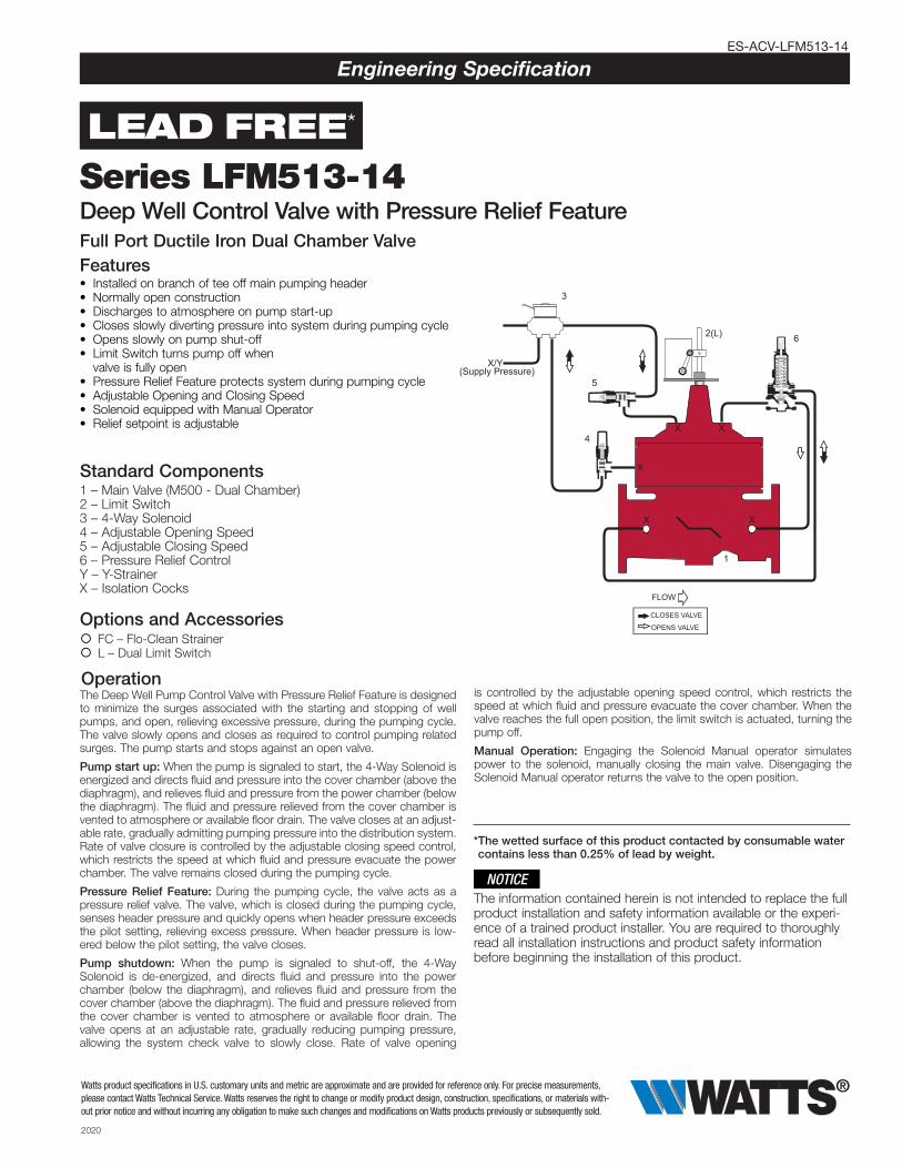
2020 ES-ACV-LFM513-14 Engineering Specification Deep Well Control Valve with Pressure Relief Feature Full Port Ductile Iron Dual Chamber Valve Features • Installed on branch of tee off main pumping header • Normally open construction • Discharges to atmosphere on pump start-up • Closes slowly diverting pressure into system during pumping cycle • Opens slowly on pump shut-off • Limit Switch turns pump off when valve is fully open • Pressure Relief Feature protects system during pumping cycle • Adjustable Opening and Closing Speed • Solenoid equipped with Manual Operator • Relief setpoint is adjustable 1 4 X X X X X 6 2(L) 5 CLOSES VALVE OPENS VALVE FLOW X/Y (Supply Pressure) 3 Standard Components Options and Accessories { FC – Flo-Clean Strainer { L – Dual Limit Switch Operation Watts product specifications in U.S. customary units and metric are approximate and are provided for reference only. For precise measurements, please contact Watts Technical Service. Watts reserves the right to change or modify product design, construction, specifications, or materials with- out prior notice and without incurring any obligation to make such changes and modifications on Watts products previously or subsequently sold. 1 – Main Valve (M500 - Dual Chamber) 2 – Limit Switch 3 – 4-Way Solenoid 4 – Adjustable Opening Speed 5 – Adjustable Closing Speed 6 – Pressure Relief Control Y – Y-Strainer X – Isolation Cocks LEAD FREE * The Deep Well Pump Control Valve with Pressure Relief Feature is designed to minimize the surges associated with the starting and stopping of well pumps, and open, relieving excessive pressure, during the pumping cycle. The valve slowly opens and closes as required to control pumping related surges. The pump starts and stops against an open valve. Pump start up: When the pump is signaled to start, the 4-Way Solenoid is energized and directs fluid and pressure into the cover chamber (above the diaphragm), and relieves fluid and pressure from the power chamber (below the diaphragm). The fluid and pressure relieved from the cover chamber is vented to atmosphere or available floor drain. The valve closes at an adjust- able rate, gradually admitting pumping pressure into the distribution system. Rate of valve closure is controlled by the adjustable closing speed control, which restricts the speed at which fluid and pressure evacuate the power chamber. The valve remains closed during the pumping cycle. Pressure Relief Feature: During the pumping cycle, the valve acts as a pressure relief valve. The valve, which is closed during the pumping cycle, senses header pressure and quickly opens when header pressure exceeds the pilot setting, relieving excess pressure. When header pressure is low- ered below the pilot setting, the valve closes. Pump shutdown: When the pump is signaled to shut-off, the 4-Way Solenoid is de-energized, and directs fluid and pressure into the power chamber (below the diaphragm), and relieves fluid and pressure from the cover chamber (above the diaphragm). The fluid and pressure relieved from the cover chamber is vented to atmosphere or available floor drain. The valve opens at an adjustable rate, gradually reducing pumping pressure, allowing the system check valve to slowly close. Rate of valve opening is controlled by the adjustable opening speed control, which restricts the speed at which fluid and pressure evacuate the cover chamber. When the valve reaches the full open position, the limit switch is actuated, turning the pump off. Manual Operation: Engaging the Solenoid Manual operator simulates power to the solenoid, manually closing the main valve. Disengaging the Solenoid Manual operator returns the valve to the open position. The information contained herein is not intended to replace the full product installation and safety information available or the experi- ence of a trained product installer. You are required to thoroughly read all installation instructions and product safety information before beginning the installation of this product. NOTICE *The wetted surface of this product contacted by consumable water contains less than 0.25% of lead by weight. Series LFM513-14
-
Upload
khangminh22 -
Category
Documents
-
view
3 -
download
0
Transcript of LEAD FREE* Series LFM513-14 - Watts
2020
ES-ACV-LFM513-14
Engineering Specification
Deep Well Control Valve with Pressure Relief FeatureFull Port Ductile Iron Dual Chamber ValveFeatures• Installed on branch of tee off main pumping header• Normally open construction• Discharges to atmosphere on pump start-up• Closes slowly diverting pressure into system during pumping cycle• Opens slowly on pump shut-off• Limit Switch turns pump off when
valve is fully open• Pressure Relief Feature protects system during pumping cycle• Adjustable Opening and Closing Speed • Solenoid equipped with Manual Operator• Relief setpoint is adjustable
1
4X X
X
X
X
62(L)
5
CLOSES VALVE
OPENS VALVE
FLOW
X/Y(Supply Pressure)
3
Standard Components
Options and Accessories { FC – Flo-Clean Strainer { L – Dual Limit Switch
Operation
Watts product specifications in U.S. customary units and metric are approximate and are provided for reference only. For precise measurements, please contact Watts Technical Service. Watts reserves the right to change or modify product design, construction, specifications, or materials with-out prior notice and without incurring any obligation to make such changes and modifications on Watts products previously or subsequently sold.
1 – Main Valve (M500 - Dual Chamber)2 – Limit Switch 3 – 4-Way Solenoid 4 – Adjustable Opening Speed5 – Adjustable Closing Speed6 – Pressure Relief ControlY – Y-Strainer X – Isolation Cocks
LEAD FREE*
The Deep Well Pump Control Valve with Pressure Relief Feature is designed to minimize the surges associated with the starting and stopping of well pumps, and open, relieving excessive pressure, during the pumping cycle. The valve slowly opens and closes as required to control pumping related surges. The pump starts and stops against an open valve.
Pump start up: When the pump is signaled to start, the 4-Way Solenoid is energized and directs fluid and pressure into the cover chamber (above the diaphragm), and relieves fluid and pressure from the power chamber (below the diaphragm). The fluid and pressure relieved from the cover chamber is vented to atmosphere or available floor drain. The valve closes at an adjust-able rate, gradually admitting pumping pressure into the distribution system. Rate of valve closure is controlled by the adjustable closing speed control, which restricts the speed at which fluid and pressure evacuate the power chamber. The valve remains closed during the pumping cycle.
Pressure Relief Feature: During the pumping cycle, the valve acts as a pressure relief valve. The valve, which is closed during the pumping cycle, senses header pressure and quickly opens when header pressure exceeds the pilot setting, relieving excess pressure. When header pressure is low-ered below the pilot setting, the valve closes.
Pump shutdown: When the pump is signaled to shut-off, the 4-Way Solenoid is de-energized, and directs fluid and pressure into the power chamber (below the diaphragm), and relieves fluid and pressure from the cover chamber (above the diaphragm). The fluid and pressure relieved from the cover chamber is vented to atmosphere or available floor drain. The valve opens at an adjustable rate, gradually reducing pumping pressure, allowing the system check valve to slowly close. Rate of valve opening
is controlled by the adjustable opening speed control, which restricts the speed at which fluid and pressure evacuate the cover chamber. When the valve reaches the full open position, the limit switch is actuated, turning the pump off.
Manual Operation: Engaging the Solenoid Manual operator simulates power to the solenoid, manually closing the main valve. Disengaging the Solenoid Manual operator returns the valve to the open position.
The information contained herein is not intended to replace the full product installation and safety information available or the experi-ence of a trained product installer. You are required to thoroughly read all installation instructions and product safety information before beginning the installation of this product.
NOTICE
* The wetted surface of this product contacted by consumable water contains less than 0.25% of lead by weight.
Series LFM513-14
ES-ACV-LFM513-14 2020 © 2020 Watts
M Series Basic ValvesDeep Well Control Valve with Pressure Relief FeatureFull Port Ductile Iron Dual Chamber Basic Valve
ACV Schematic - Series LFM513-14
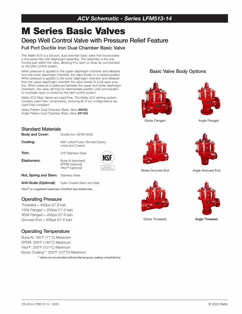
This Watts ACV is a full port, dual chamber basic valve that incorporates a one-piece disc and diaphragm assembly. This assembly is the only moving part within the valve, allowing it to open or close as commanded by the pilot control system.
When pressure is applied to the upper diaphragm chamber and released from the lower diaphragm chamber, the valve travels to a closed position. When pressure is applied to the lower diaphragm chamber and released from the upper diaphragm chamber the valve travels to a full open posi-tion. When pressure is balanced between the upper and lower diaphragm chambers, the valve will hold an intermediate position until commanded to modulate open or closed by the pilot control system.
Watts ACV Main Valves are Lead Free. The Watts ACV piloting system contains Lead Free* components, ensuring all of our configurations are Lead Free compliant.
Globe Pattern Dual Chamber Basic Valve (M500) Angle Pattern Dual Chamber Basic Valve (M1500
Threaded = 400psi (27.6 bar)150# Flanged = 250psi (17.2 bar)300# Flanged = 400psi (27.6 bar) Grooved End = 400psi (27.6 bar)
Operating Pressure
Standard Materials
Viton® is a registered trademark of DuPont Dow Elastomers.
Body and Cover: Ductile Iron ASTM A536
Coating: NSF Listed Fusion Bonded Epoxy Lined and Coated
Trim: 316 Stainless Steel
Elastomers: Buna-N (standard) EPDM (optional) Viton® (optional)
Nut, Spring and Stem: Stainless Steel
Anti-Scale (Optional): Xylan Coated Stem and Seat
Operating TemperatureBuna-N: 160°F (71°C) MaximumEPDM: 300°F (140°C) MaximumViton®: 250°F (121°C) MaximumEpoxy Coating**: 225°F (107°C) Maximum
** Valves can be provided without internal epoxy coating consult factory
Globe Flanged Angle Flanged
Globe Threaded
Globe Grooved End
Angle Threaded
Angle Grooved End
Angle Threaded
Basic Valve Body Options
ES-ACV-LFM513-14 2020 © 2020 Watts
Flow Data
Valve Travel
Valve Cover Chamber Capacity
21/2 4 106 82 3 12 14 1621/2 4 106 82 3 12 14 16
Valve Size (in) 2 2 1/2 3 4 6 8 10 12 14 16 Travel (in) 1/2 5/8 3/4 1 1 1/2 2 2 1/2 3 3 1/2 4
Valve Size (in) 2 2 1/2 3 4 6 8 10 12 14 16fl.oz. 4 10 16 22 70
U.S. Gal 1 1/4 2 1/2 4 6 1/2 9 1/2
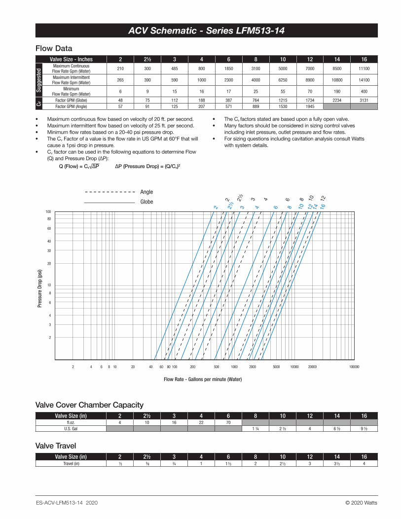
Valve Size - Inches 2 2 1/2 3 4 6 8 10 12 14 16Maximum Continuous Flow Rate Gpm (Water) 210 300 485 800 1850 3100 5000 7000 8500 11100
Maximum Intermittent Flow Rate Gpm (Water) 265 390 590 1000 2300 4000 6250 8900 10800 14100
Minimum Flow Rate Gpm (Water) 6 9 15 16 17 25 55 70 190 400
Factor GPM (Globe) 48 75 112 188 387 764 1215 1734 2234 3131Factor GPM (Angle) 57 91 125 207 571 889 1530 1945
Pres
sure
Dro
p (p
si)
2
3
4
6
8
10
20
30
40
60
80
100
Flow Rate - Gallons per minute (Water)
2 4 10 20 40 60 80 100 200 500 1000 2000 5000 10000 20000 10000086
14 161210864321/22
1210864321/22
Angle
Globe
CVSu
gges
ted
• Maximum continuous flow based on velocity of 20 ft. per second.• Maximum intermittent flow based on velocity of 25 ft. per second.• Minimum flow rates based on a 20-40 psi pressure drop.• The Cv Factor of a value is the flow rate in US GPM at 60°F that will
cause a 1psi drop in pressure.• Cv factor can be used in the following equations to determine Flow
(Q) and Pressure Drop (∆P):
Q (Flow) = Cv√∆P ∆P (Pressure Drop) = (Q/Cv)2
• The Cv factors stated are based upon a fully open valve. • Many factors should be considered in sizing control valves
including inlet pressure, outlet pressure and flow rates. • For sizing questions including cavitation analysis consult Watts
with system details.
ACV Schematic - Series LFM513-14
ES-ACV-LFM513-14 2020 © 2020 Watts
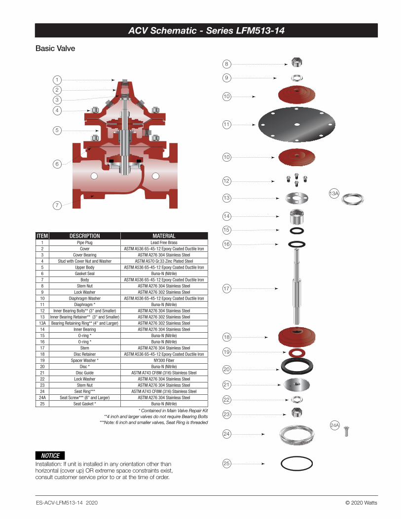
Basic Valve
Installation: If unit is installed in any orientation other than horizontal (cover up) OR extreme space constraints exist, consult customer service prior to or at the time of order.
NOTICE
8
9
10
10
12
13A13
14
15
16
17
18
19
20
21
22
23
24
24A
25
11
1
2
3
4
5
6
7
ITEM DESCRIPTION MATERIAL1 Pipe Plug Lead Free Brass2 Cover ASTM A536 65-45-12 Epoxy Coated Ductile Iron3 Cover Bearing ASTM A276 304 Stainless Steel4 Stud with Cover Nut and Washer ASTM A570 Gr.33 Zinc Plated Steel5 Upper Body ASTM A536 65-45-12 Epoxy Coated Ductile Iron6 Gasket Seal Buna-N (Nitrile)7 Body ASTM A536 65-45-12 Epoxy Coated Ductile Iron8 Stem Nut ASTM A276 304 Stainless Steel9 Lock Washer ASTM A276 302 Stainless Steel10 Diaphragm Washer ASTM A536 65-45-12 Epoxy Coated Ductile Iron11 Diaphragm * Buna-N (Nitrile)12 Inner Bearing Bolts** (3" and Smaller) ASTM A276 304 Stainless Steel13 Inner Bearing Retainer** (3" and Smaller) ASTM A276 302 Stainless Steel
13A Bearing Retaining Ring** (4" and Larger) ASTM A276 302 Stainless Steel14 Inner Bearing ASTM A276 304 Stainless Steel15 O-ring * Buna-N (Nitrile)16 O-ring * Buna-N (Nitrile)17 Stem ASTM A276 304 Stainless Steel18 Disc Retainer ASTM A536 65-45-12 Epoxy Coated Ductile Iron19 Spacer Washer * NY300 Fiber20 Disc * Buna-N (Nitrile)21 Disc Guide ASTM A743 CF8M (316) Stainless Steel22 Lock Washer ASTM A276 304 Stainless Steel23 Stem Nut ASTM A276 304 Stainless Steel24 Seat Ring*** ASTM A743 CF8M (316) Stainless Steel
24A Seat Screw*** (8" and Larger) ASTM A276 304 Stainless Steel25 Seat Gasket * Buna-N (Nitrile)
* Contained in Main Valve Repair Kit**4 inch and larger valves do not require Bearing Bolts
***Note: 6 inch and smaller valves, Seat Ring is threaded
8
9
10
10
12
13A13
14
15
16
17
18
19
20
21
22
23
24
24A
25
11
1
2
3
4
5
6
7
ACV Schematic - Series LFM513-14 ACV Schematic - Series LFM513-14
ES-ACV-LFM513-14 2020 © 2020 Watts
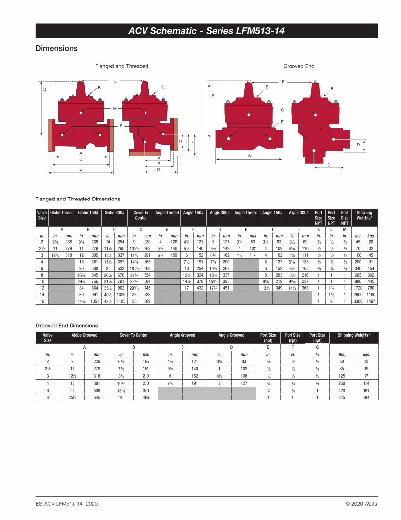
Dimensions
Flanged and Threaded Grooved End
Valve Size
Globe Grooved Cover To Center Angle Grooved Angle Grooved Port Size(npt)
Port Size(npt)
Port Size(npt)
Shipping Weights*
A B C D E F G
in. in. mm in. mm in. mm in. mm in. in. 1/4 lbs. kgs.
2 9 229 6 1/2 165 4 3/4 121 3 1/4 83 3/8 1/2 1/2 50 23
21⁄2 11 279 7 1/2 191 51⁄2 140 4 102 1/2 1/2 1/2 85 39
3 121⁄2 318 8 1/4 210 6 152 4 1/4 108 1/2 1/2 1/2 125 57
4 15 381 10 5/8 270 7 1/2 191 5 127 3/4 3/4 3/4 250 114
6 20 508 13 3/8 340 3/4 3/4 1 420 191
8 253⁄8 645 16 406 1 1 1 845 384
Grooved End Dimensions
LK K
M
D
K
A
B
C
H I J
EFG
A
B
FE
G
E
E
C
D
Valve Size
Globe Thread Globe 150# Globe 300# Cover to Center
Angle Thread Angle 150# Angle 300# Angle Thread Angle 150# Angle 300# Port Size NPT
Port Size NPT
Port Size NPT
Shipping Weights*
A B C D E F G H I J K L Min. in. mm in. mm in. mm in. mm in. mm in. mm in. mm in. mm in. mm in. mm in. in. in. lbs. kgs.2 9 3/8 238 9 3/8 238 10 254 9 230 4 120 4 3/4 121 5 127 3 1/4 83 3 1/4 83 3 1/2 89 3/8 1/2 1/4 45 20
2 1/2 11 279 11 279 11 5/8 295 10 5/16 262 5 1/2 140 5 1/2 140 5 7/8 149 4 102 4 102 4 5/16 110 1/2 1/2 1/2 70 32
3 12 1/2 318 12 305 13 1/4 337 11 1/2 291 6 1/4 159 6 152 6 3/8 162 4 1/2 114 4 102 4 3/8 111 1/2 1/2 1/2 100 45
4 15 381 15 5/8 397 14 3/8 365 7 1/2 191 7 7/8 200 5 127 5 5/16 135 3/4 3/4 1/2 200 91
6 20 508 21 533 18 7/16 468 10 254 10 1/2 267 6 152 6 1/2 165 3/4 3/4 3/4 340 154
8 25 3/8 645 26 3/8 670 21 3/4 554 12 3/4 324 13 1/4 337 8 203 8 1/2 216 1 1 1 665 302
10 29 3/4 756 31 1/8 791 23 3/8 594 14 7/8 378 15 9/16 395 8 5/8 219 9 5/16 237 1 1 1 980 445
12 34 864 35 1/2 902 29 5/16 745 17 432 17 3/4 451 13 3/4 349 14 1/2 368 1 1 1/4 1 1720 780
14 39 991 40 1/2 1029 33 838 1 1 1/2 1 2600 1180
16 41 3/8 1051 43 1/2 1105 35 889 1 2 1 3300 1497
Flanged and Threaded Dimensions
ACV Schematic - Series LFM513-14
© 2020 WattsES-ACV-LFM513-14 2020
ACV Standard Components - Series LFM513-14
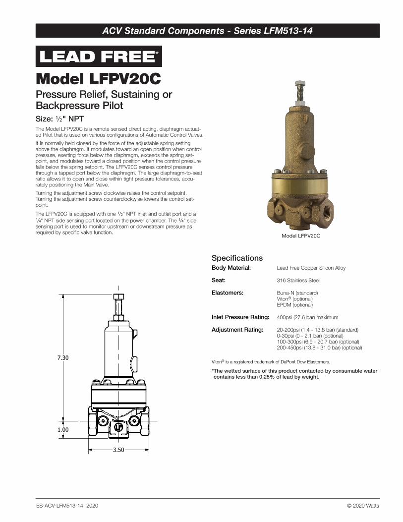
Model LFPV20CPressure Relief, Sustaining or Backpressure Pilot
* The wetted surface of this product contacted by consumable water contains less than 0.25% of lead by weight.
Model LFPV20CPressure Relief, Sustaining or Backpressure PilotSize: 1/2" NPTThe Model LFPV20C is a remote sensed direct acting, diaphragm actuat-ed Pilot that is used on various configurations of Automatic Control Valves.
It is normally held closed by the force of the adjustable spring setting above the diaphragm. It modulates toward an open position when control pressure, exerting force below the diaphragm, exceeds the spring set-point, and modulates toward a closed position when the control pressure falls below the spring setpoint. The LFPV20C senses control pressure through a tapped port below the diaphragm. The large diaphragm-to-seat ratio allows it to open and close within tight pressure tolerances, accu-rately positioning the Main Valve.
Turning the adjustment screw clockwise raises the control setpoint. Turning the adjustment screw counterclockwise lowers the control set-point.
The LFPV20C is equipped with one 1/2" NPT inlet and outlet port and a 1/4" NPT side sensing port located on the power chamber. The 1/4" side sensing port is used to monitor upstream or downstream pressure as required by specific valve function.
3.50
7.30
1.00
Body Material: Lead Free Copper Silicon Alloy
Seat: 316 Stainless Steel
Elastomers: Buna-N (standard) Viton® (optional) EPDM (optional)
Inlet Pressure Rating: 400psi (27.6 bar) maximum
Adjustment Rating: 20-200psi (1.4 - 13.8 bar) (standard) 0-30psi (0 - 2.1 bar) (optional) 100-300psi (6.9 - 20.7 bar) (optional) 200-450psi (13.8 - 31.0 bar) (optional)
Specifications
Viton® is a registered trademark of DuPont Dow Elastomers.
Model LFPV20C
LEAD FREE*
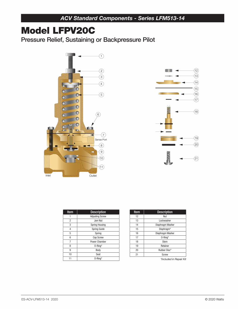
Item Description1 Adjusting Screw
2 Jam Nut
3 Spring Housing
4 Spring Guide
5 Spring
6 Cap Screw
7 Power Chamber
8 O-Ring*
9 Body
10 Seat
11 O-Ring*
Item Description12 Nut
13 Lockwasher
14 Diaphragm Washer
15 Diaphragm*
16 Diaphragm Washer
17 O-Ring*
18 Stem
19 Retainer
20 Rubber Disc*
21 Screw
*Included in Repair Kit
Sense Port
OutletInlet
1
2
3
4
5
7
9
10
11
8
6
12
13
14
16
17
18
19
20
21
15
17
Sense Port
OutletInlet
1
2
3
4
5
7
9
10
11
8
6
12
13
14
16
17
18
19
20
21
15
17
© 2020 WattsES-ACV-LFM513-14 2020
ACV Standard Components - Series LFM513-14
Model LFPV20CPressure Relief, Sustaining or Backpressure Pilot
* The wetted surface of this product contacted by consumable water contains less than 0.25% of lead by weight.
Model LFPV20CPressure Relief, Sustaining or Backpressure PilotSize: 1/2" NPTThe Model LFPV20C is a remote sensed direct acting, diaphragm actuat-ed Pilot that is used on various configurations of Automatic Control Valves.
It is normally held closed by the force of the adjustable spring setting above the diaphragm. It modulates toward an open position when control pressure, exerting force below the diaphragm, exceeds the spring set-point, and modulates toward a closed position when the control pressure falls below the spring setpoint. The LFPV20C senses control pressure through a tapped port below the diaphragm. The large diaphragm-to-seat ratio allows it to open and close within tight pressure tolerances, accu-rately positioning the Main Valve.
Turning the adjustment screw clockwise raises the control setpoint. Turning the adjustment screw counterclockwise lowers the control set-point.
The LFPV20C is equipped with one 1/2" NPT inlet and outlet port and a 1/4" NPT side sensing port located on the power chamber. The 1/4" side sensing port is used to monitor upstream or downstream pressure as required by specific valve function.
3.50
7.30
1.00
Body Material: Lead Free Copper Silicon Alloy
Seat: 316 Stainless Steel
Elastomers: Buna-N (standard) Viton® (optional) EPDM (optional)
Inlet Pressure Rating: 400psi (27.6 bar) maximum
Adjustment Rating: 20-200psi (1.4 - 13.8 bar) (standard) 0-30psi (0 - 2.1 bar) (optional) 100-300psi (6.9 - 20.7 bar) (optional) 200-450psi (13.8 - 31.0 bar) (optional)
Specifications
Viton® is a registered trademark of DuPont Dow Elastomers.
Model LFPV20C
LEAD FREE*
Item Description1 Adjusting Screw
2 Jam Nut
3 Spring Housing
4 Spring Guide
5 Spring
6 Cap Screw
7 Power Chamber
8 O-Ring*
9 Body
10 Seat
11 O-Ring*
Item Description12 Nut
13 Lockwasher
14 Diaphragm Washer
15 Diaphragm*
16 Diaphragm Washer
17 O-Ring*
18 Stem
19 Retainer
20 Rubber Disc*
21 Screw
*Included in Repair Kit
Sense Port
OutletInlet
1
2
3
4
5
7
9
10
11
8
6
12
13
14
16
17
18
19
20
21
15
17
Sense Port
OutletInlet
1
2
3
4
5
7
9
10
11
8
6
12
13
14
16
17
18
19
20
21
15
17
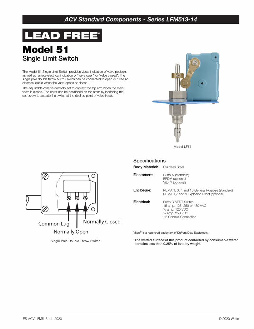
Model LF51
Single Pole Double Throw Switch
© 2020 Watts
LEAD FREE*
Specifications
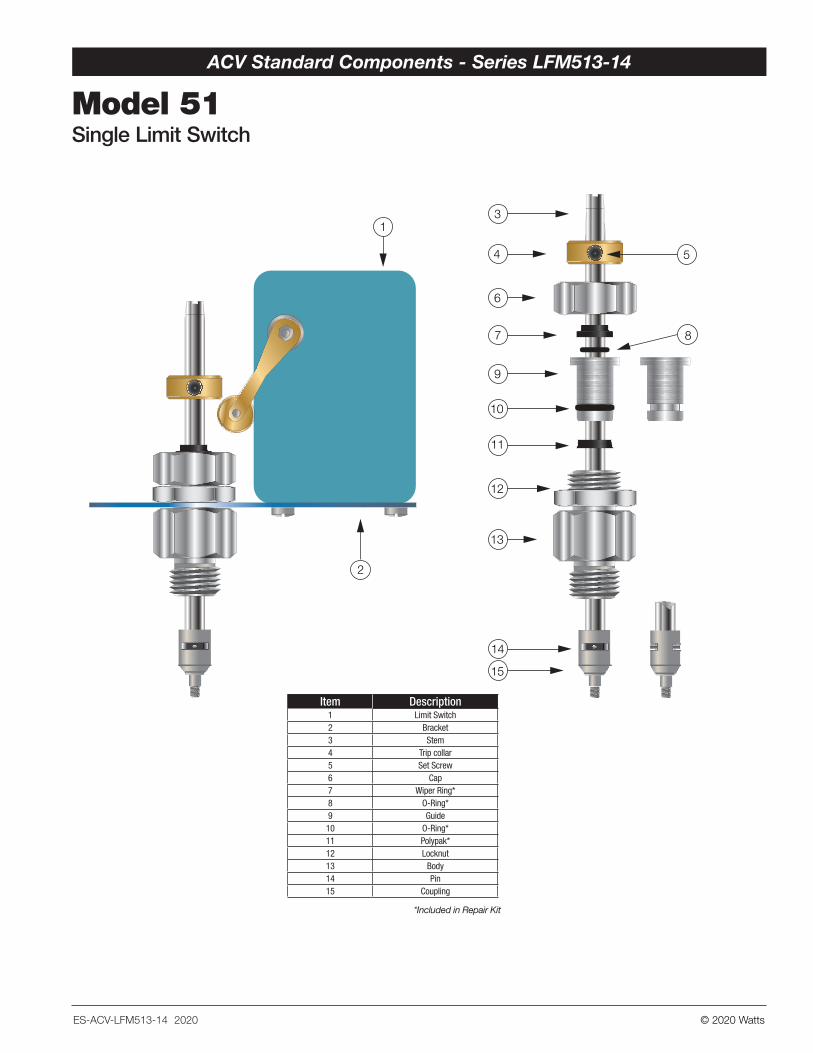
Model 51Single Limit Switch
Body Material: Stainless Steel
Elastomers: Buna-N (standard) EPDM (optional) Viton® (optional)
Enclosure: NEMA 1, 3, 4 and 13 General Purpose (standard) NEMA 1,7 and 9 Explosion Proof (optional)
Electrical: Form C SPDT Switch 15 amp. 125, 250 or 480 VAC ½ amp. 125 VDC ¼ amp. 250 VDC ½" Conduit Connection
Single Pole Double Throw Switch
Common LugNormally Open
Normally Closed
* The wetted surface of this product contacted by consumable water contains less than 0.25% of lead by weight.
Viton® is a registered trademark of DuPont Dow Elastomers.
The Model 51 Single Limit Switch provides visual indication of valve position, as well as remote electrical indication of "valve open" or "valve closed". The single pole double throw Micro-Switch can be connected to open or close an electrical circuit when the valve opens or closes.
The adjustable collar is normally set to contact the trip arm when the main valve is closed. The collar can be positioned on the stem by loosening the set-screw to actuate the switch at the desired point of valve travel.
ES-ACV-LFM513-14 2020
ACV Standard Components - Series LFM513-14
© 2020 Watts
Body Material: Stainless Steel
Elastomers: Buna-N (standard) EPDM (optional) Viton® (optional)
Enclosure: NEMA 1, 3, 4 and 13 General Purpose (standard) NEMA 1,7 and 9 Explosion Proof (optional)
Electrical: Form C SPDT Switch 15 amp. 125, 250 or 480 VAC ½ amp. 125 VDC ¼ amp. 250 VDC ½" Conduit Connection
Item Description1 Limit Switch2 Bracket3 Stem4 Trip collar5 Set Screw6 Cap7 Wiper Ring*8 O-Ring*9 Guide10 O-Ring*11 Polypak*12 Locknut13 Body14 Pin 15 Coupling
*Included in Repair Kit
Model 51Single Limit Switch
10
11
12
14
6
7
9
13
15
8
54
3
2
1
ES-ACV-LFM513-14 2020
ACV Standard Components - Series LFM513-14
© 2020 Watts
LEAD FREE*
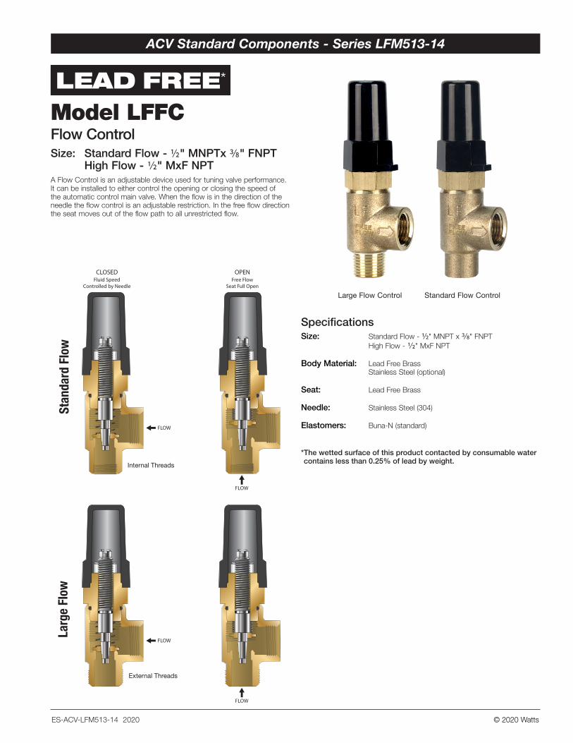
Model LFFC Flow ControlSize: Standard Flow - ½" MNPTx 3/8" FNPT High Flow - 1/2" MxF NPTA Flow Control is an adjustable device used for tuning valve performance. It can be installed to either control the opening or closing the speed of the automatic control main valve. When the flow is in the direction of the needle the flow control is an adjustable restriction. In the free flow direction the seat moves out of the flow path to all unrestricted flow.
Specifications
Standard Flow ControlLarge Flow Control
FLOW
FLOW
CLOSEDFluid Speed
Controlled by Needle
FLOW
External Threads
Internal Threads
FLOW
OPENFree Flow
Seat Full Open
Size: Standard Flow - ½" MNPT x 3/8" FNPT High Flow - 1/2" MxF NPT
Body Material: Lead Free Brass Stainless Steel (optional)
Seat: Lead Free Brass
Needle: Stainless Steel (304)
Elastomers: Buna-N (standard)
* The wetted surface of this product contacted by consumable water contains less than 0.25% of lead by weight.
ES-ACV-LFM513-14 2020
ACV Standard Components - Series LFM513-14
© 2020 Watts
LEAD FREE*
Model LFFC Flow ControlSize: Standard Flow - ½" MNPTx 3/8" FNPT High Flow - 1/2" MxF NPTA Flow Control is an adjustable device used for tuning valve performance. It can be installed to either control the opening or closing the speed of the automatic control main valve. When the flow is in the direction of the needle the flow control is an adjustable restriction. In the free flow direction the seat moves out of the flow path to all unrestricted flow.
Specifications
Standard Flow ControlLarge Flow Control
FLOW
FLOW
CLOSEDFluid Speed
Controlled by Needle
FLOW
External Threads
Internal Threads
FLOW
OPENFree Flow
Seat Full Open
Size: Standard Flow - ½" MNPT x 3/8" FNPT High Flow - 1/2" MxF NPT
Body Material: Lead Free Brass Stainless Steel (optional)
Seat: Lead Free Brass
Needle: Stainless Steel (304)
Elastomers: Buna-N (standard)
* The wetted surface of this product contacted by consumable water contains less than 0.25% of lead by weight.
ES-ACV-LFM513-14 2020
ACV Standard Components - Series LFM513-14
LEAD FREE*
* The wetted surface of this product contacted by consumable water contains less than 0.25% of lead by weight.
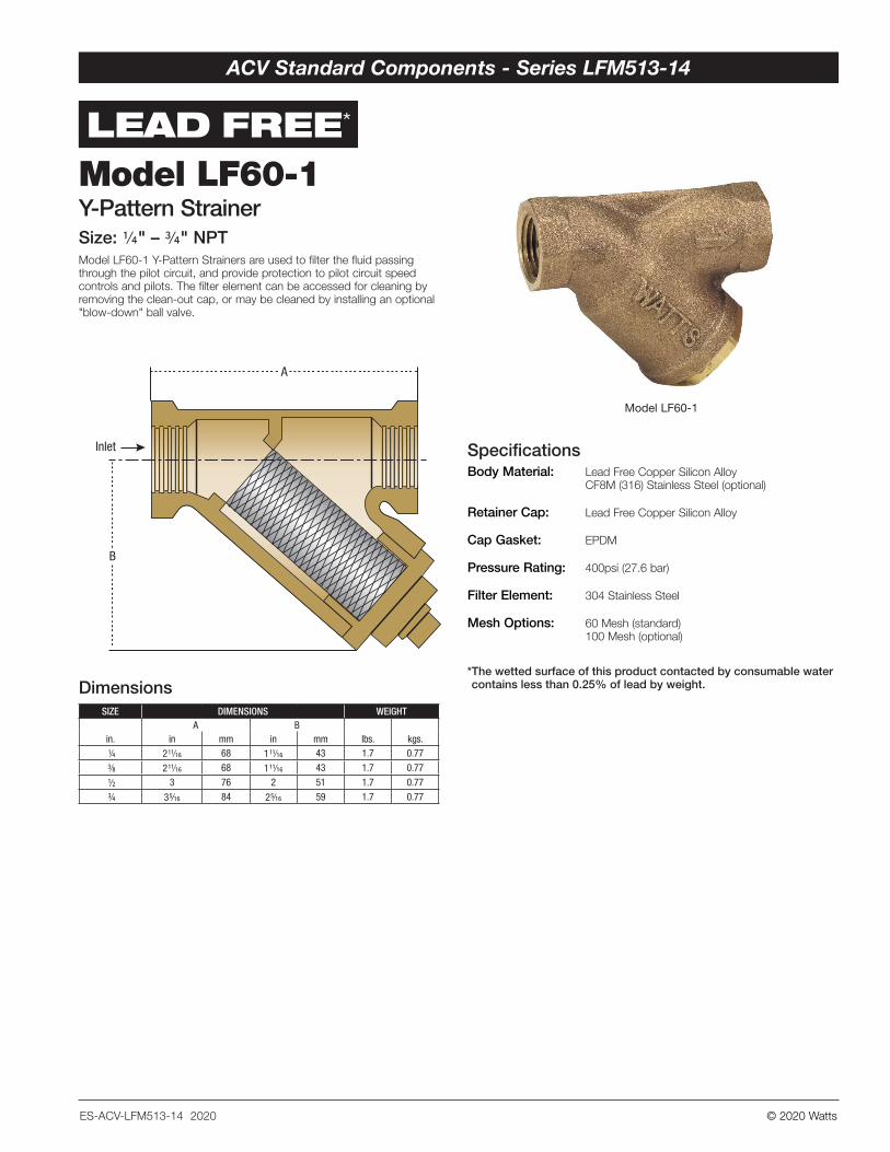
Body Material: Lead Free Copper Silicon Alloy CF8M (316) Stainless Steel (optional)
Retainer Cap: Lead Free Copper Silicon Alloy
Cap Gasket: EPDM
Pressure Rating: 400psi (27.6 bar)
Filter Element: 304 Stainless Steel
Mesh Options: 60 Mesh (standard) 100 Mesh (optional)
Specifications
DimensionsSIZE DIMENSIONS WEIGHT
A Bin. in mm in mm lbs. kgs.
1/4 2 11/16 68 1 11/16 43 1.7 0.77
3/8 2 11/16 68 1 11/16 43 1.7 0.77
1/2 3 76 2 51 1.7 0.77
3/4 3 5/16 84 2 5/16 59 1.7 0.77
Model LF60-1Y-Pattern StrainerSize: 1/4" – 3/4" NPTModel LF60-1 Y-Pattern Strainers are used to filter the fluid passing through the pilot circuit, and provide protection to pilot circuit speed controls and pilots. The filter element can be accessed for cleaning by removing the clean-out cap, or may be cleaned by installing an optional "blow-down" ball valve.
Inlet
B
A
Model LF60-1
© 2020 Watts
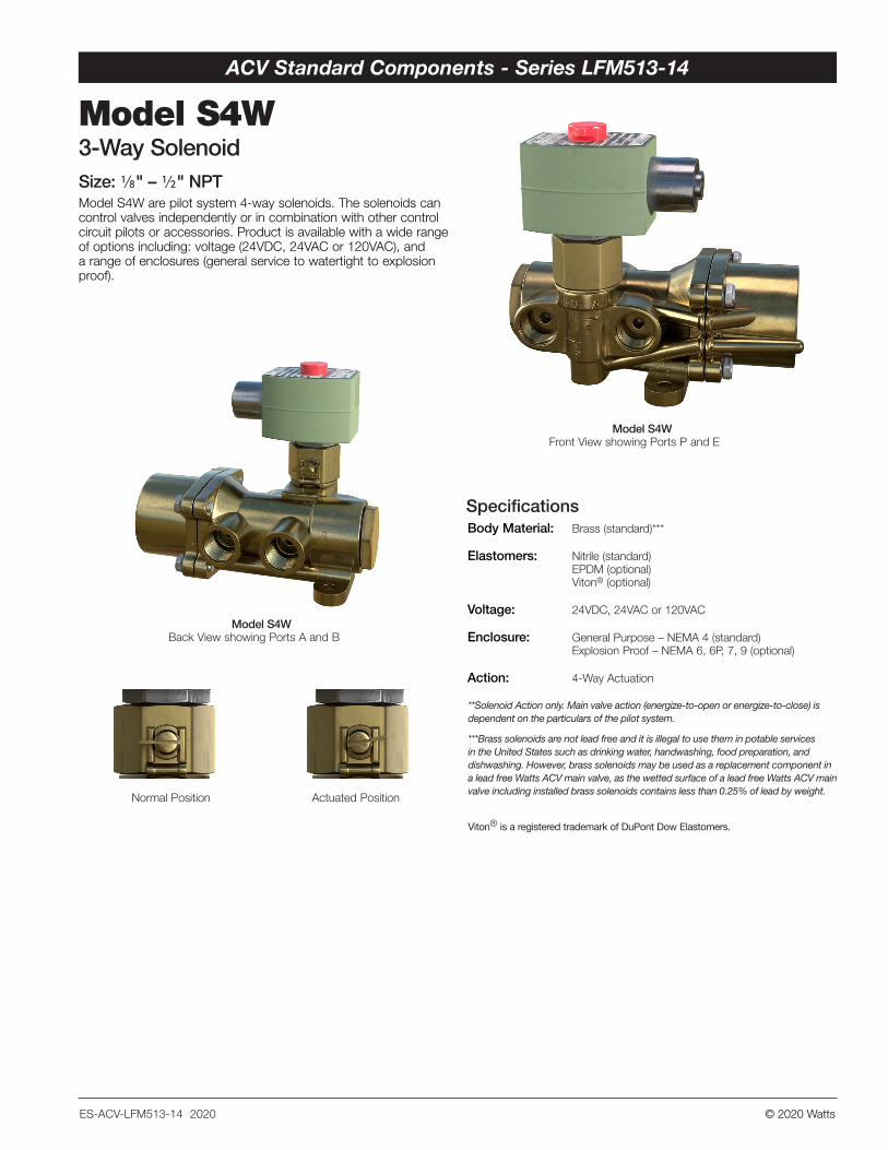
Model S4W Front View showing Ports P and E
Model S4W Back View showing Ports A and B
Normal Position Actuated Position
Specifications
Model S4W3-Way SolenoidSize: 1/8" – 1/2" NPTModel S4W are pilot system 4-way solenoids. The solenoids can control valves independently or in combination with other control circuit pilots or accessories. Product is available with a wide range of options including: voltage (24VDC, 24VAC or 120VAC), and a range of enclosures (general service to watertight to explosion proof).
Body Material: Brass (standard)***
Elastomers: Nitrile (standard) EPDM (optional) Viton® (optional)
Voltage: 24VDC, 24VAC or 120VAC
Enclosure: General Purpose – NEMA 4 (standard) Explosion Proof – NEMA 6, 6P, 7, 9 (optional)
Action: 4-Way Actuation
Viton® is a registered trademark of DuPont Dow Elastomers.
**Solenoid Action only. Main valve action (energize-to-open or energize-to-close) is dependent on the particulars of the pilot system.
***Brass solenoids are not lead free and it is illegal to use them in potable services in the United States such as drinking water, handwashing, food preparation, and dishwashing. However, brass solenoids may be used as a replacement component in a lead free Watts ACV main valve, as the wetted surface of a lead free Watts ACV main valve including installed brass solenoids contains less than 0.25% of lead by weight.
ES-ACV-LFM513-14 2020
ACV Standard Components - Series LFM513-14
LEAD FREE*
* The wetted surface of this product contacted by consumable water contains less than 0.25% of lead by weight.
Body Material: Lead Free Copper Silicon Alloy CF8M (316) Stainless Steel (optional)
Retainer Cap: Lead Free Copper Silicon Alloy
Cap Gasket: EPDM
Pressure Rating: 400psi (27.6 bar)
Filter Element: 304 Stainless Steel
Mesh Options: 60 Mesh (standard) 100 Mesh (optional)
Specifications
DimensionsSIZE DIMENSIONS WEIGHT
A Bin. in mm in mm lbs. kgs.
1/4 2 11/16 68 1 11/16 43 1.7 0.77
3/8 2 11/16 68 1 11/16 43 1.7 0.77
1/2 3 76 2 51 1.7 0.77
3/4 3 5/16 84 2 5/16 59 1.7 0.77
Model LF60-1Y-Pattern StrainerSize: 1/4" – 3/4" NPTModel LF60-1 Y-Pattern Strainers are used to filter the fluid passing through the pilot circuit, and provide protection to pilot circuit speed controls and pilots. The filter element can be accessed for cleaning by removing the clean-out cap, or may be cleaned by installing an optional "blow-down" ball valve.
Inlet
B
A
© 2020 Watts
LEAD FREE*
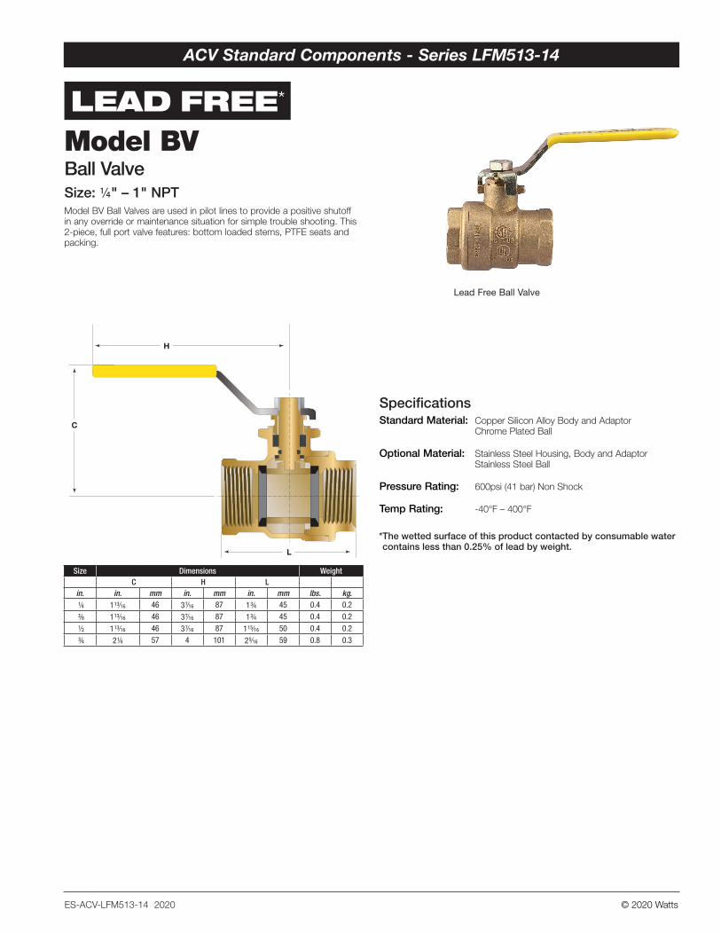
Lead Free Ball Valve
SpecificationsStandard Material: Copper Silicon Alloy Body and Adaptor Chrome Plated Ball
Optional Material: Stainless Steel Housing, Body and Adaptor Stainless Steel Ball
Pressure Rating: 600psi (41 bar) Non Shock
Temp Rating: -40°F – 400°F
C
H
L
Model BVBall ValveSize: ¼" – 1" NPT Model BV Ball Valves are used in pilot lines to provide a positive shutoff in any override or maintenance situation for simple trouble shooting. This 2-piece, full port valve features: bottom loaded stems, PTFE seats and packing.
Size Dimensions WeightC H L
in. in. mm in. mm in. mm lbs. kg. 1/4 1 13/16 46 3 7/16 87 1 3/4 45 0.4 0.2
3/8 1 13/16 46 3 7/16 87 1 3/4 45 0.4 0.2
1/2 1 13/16 46 3 7/16 87 1 15/16 50 0.4 0.2
3/4 2 1/4 57 4 101 2 5/16 59 0.8 0.3
* The wetted surface of this product contacted by consumable water contains less than 0.25% of lead by weight.
ES-ACV-LFM513-14 2020
ACV Standard Components - Series LFM513-14
© 2020 Watts
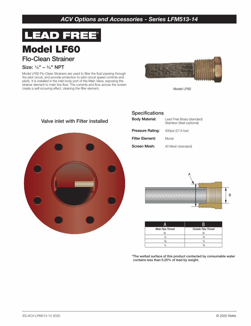
Body Material: Lead Free Brass (standard) Stainless Steel (optional)
Pressure Rating: 400psi (27.6 bar)
Filter Element: Monel
Screen Mesh: 40 Mesh (standard)
Specifications
B
A
A BMale Pipe Thread Female Pipe Thread
in. in. 1/4 1/8 3/8 1/4 1/2 3/8
* The wetted surface of this product contacted by consumable water contains less than 0.25% of lead by weight.
Valve inlet with Filter installed
Model LF60Flo-Clean StrainerSize: 1/4" – 3/4" NPTModel LF60 Flo-Clean Strainers are used to filter the fluid passing through the pilot circuit, and provide protection to pilot circuit speed controls and pilots. It is installed in the inlet body port of the Main Valve, exposing the strainer element to main line flow. The currents and flow across the screen create a self-scouring effect, cleaning the filter element.
LEAD FREE*
Model LF60
ES-ACV-LFM513-14 2020
ACV Options and Accessories - Series LFM513-14
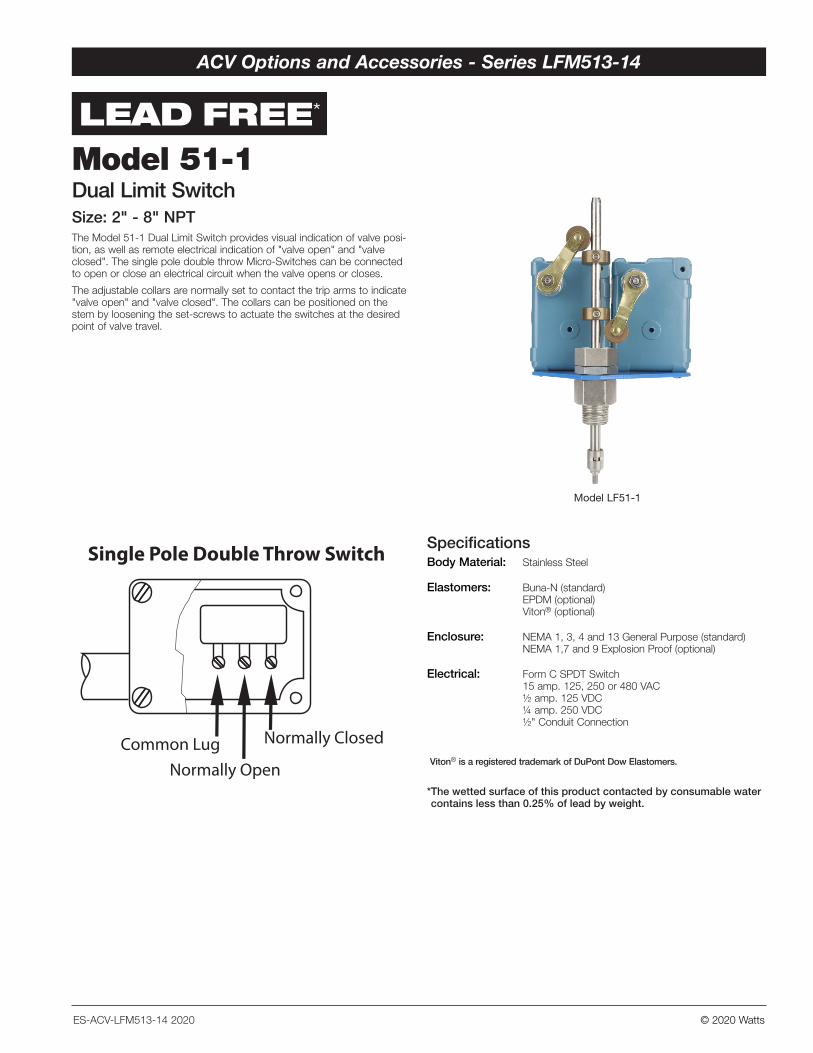
Model LF51-1
© 2020 Watts
Specifications
B
A
LEAD FREE*
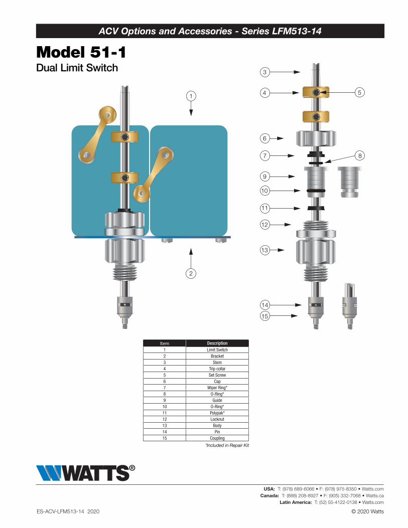
Model 51-1Dual Limit SwitchSize: 2" - 8" NPTThe Model 51-1 Dual Limit Switch provides visual indication of valve posi-tion, as well as remote electrical indication of "valve open" and "valve closed". The single pole double throw Micro-Switches can be connected to open or close an electrical circuit when the valve opens or closes.
The adjustable collars are normally set to contact the trip arms to indicate "valve open" and "valve closed". The collars can be positioned on the stem by loosening the set-screws to actuate the switches at the desired point of valve travel.
Body Material: Stainless Steel
Elastomers: Buna-N (standard) EPDM (optional) Viton® (optional)
Enclosure: NEMA 1, 3, 4 and 13 General Purpose (standard) NEMA 1,7 and 9 Explosion Proof (optional)
Electrical: Form C SPDT Switch 15 amp. 125, 250 or 480 VAC ½ amp. 125 VDC ¼ amp. 250 VDC ½" Conduit Connection
Single Pole Double Throw Switch
Common LugNormally Open
Normally Closed Viton® is a registered trademark of DuPont Dow Elastomers.
* The wetted surface of this product contacted by consumable water contains less than 0.25% of lead by weight.
ES-ACV-LFM513-14 2020
ACV Options and Accessories - Series LFM513-14
© 2020 Watts
Item Description1 Limit Switch2 Bracket3 Stem4 Trip collar5 Set Screw6 Cap7 Wiper Ring*8 O-Ring*9 Guide10 O-Ring*11 Polypak*12 Locknut13 Body14 Pin 15 Coupling
*Included in Repair Kit
Body Material: Stainless Steel
Elastomers: Buna-N (standard) EPDM (optional) Viton® (optional)
Enclosure: NEMA 1, 3, 4 and 13 General Purpose (standard) NEMA 1,7 and 9 Explosion Proof (optional)
Electrical: Form C SPDT Switch 15 amp. 125, 250 or 480 VAC ½ amp. 125 VDC ¼ amp. 250 VDC ½" Conduit Connection
10
11
12
14
6
7
9
13
15
8
54
3
2
1
Model 51-1Dual Limit Switch
ES-ACV-LFM513-14 2020
ACV Options and Accessories - Series LFM513-14
USA: T: (978) 689-6066 • F: (978) 975-8350 • Watts.comCanada: T: (888) 208-8927 • F: (905) 332-7068 • Watts.ca
Latin America: T: (52) 55-4122-0138 • Watts.com