
TECHNOFLEX® The Power to Perform
152
TECHNOFLEX ® The Power to Perform PERMANENT MAGNETIC SYSTEMS ALUMINUM HOUSINGS FLEXIBLE COUPLINGS TORSIONSKUPPLUNGEN/ TORSIONAL COUPLINGS SPIDEX - DIE ELASTICHE KUPPLUNG SPIDEX - THE ELASTIC COUPLING DENTEX FL - DIE FLEXIBLE KUPPLUNG DENTEX FL - THE FLEXIBLE COUPLING FLEXIBLE RUBBERBUSH COUPLINGS TYPE JKA MARINE COUPLINGS BETWEEN GEAR AND PROPELLER SHAFT ACN und DCN Öl-Luftkühler ACN and DCN Oil-Air Coolers Öl-Wasserkühler BNZ mit alu-Lamellen und festem Rohrbündel Oil-Water Cooler BNZ with aluminium fins and rigid tube stack 3-5 9-10 93-119 21-60 65-76 81-88 13-16 123-124 147-158 135-142
-
Upload
khangminh22 -
Category
Documents
-
view
8 -
download
0
Transcript of TECHNOFLEX® The Power to Perform
TECHNOFLEX®
The Power to PerformTECHNOFLEX®
The Power to Perform
TECHNOFLEX®
The Power to Perform
TECHNOFLEX Aluminum Housings
Today, there are thousands of TECHNOFLEX aluminum housings in service
throughout the world. Together with our original. TECHNOFLEX flywheel
coupling and our torsionally stiff DENTEX FL flywheel couplings, our aluminum
housings tackle tough gas and diesel engine applications.
The housings take up very little space, while supporting a significant amount of
weight. They are available With a wide variety of mounts and sensor options.
Design Characteristics:
Sturdy Aluminum Castings
Heat treated aluminum housings
Thick walls for extra support and thread engagement
Mounts
Foot mounts
Side mounts
Face Mounts
Top MountsSpecial pump mount options are always available
Features and Advantages:
Sturdy .High-Strength . aluminum construction
Custom fit to engine starter plates
SAE and non-SAE pump mounting
Standard and special engine mounts
Custom/personalized housings available upon request
Thick wall design for heavy pump applications
Painted housings (available upon request)
Competitively priced and normally in stock
Applications:
TECHNOFLEX Aluminum Housings
Today, there are thousands of TECHNOFLEX aluminum housings in service
throughout the world. Together with our original. TECHNOFLEX flywheel
coupling and our torsionally stiff DENTEX FL flywheel couplings, our aluminum
housings tackle tough gas and diesel engine applications.
The housings take up very little space, while supporting a significant amount of
weight. They are available With a wide variety of mounts and sensor options.
Design Characteristics:
Sturdy Aluminum Castings
Heat treated aluminum housings
Thick walls for extra support and thread engagement
Mounts
Foot mounts Side mounts
Face Mounts
Top Mounts
Special pump mount options are always available
Features and Advantages:
Sturdy .High-Strength . aluminum construction
Custom fit to engine starter plates
SAE and non-SAE pump mounting
Standard and special engine mounts
Custom/personalized housings available upon request
Thick wall design for heavy pump applications
Painted housings (available upon request)
Competitively priced and normally in stock
Applications:
„ I n n o v a t i o n i s m o t i o n ”
Berv ina Kf t . • H -1145 Erzsébet k i rá lyné ú t ja 41/B • Te l . :+36 -1-222-20-79 • Fax: +36 -1-252-48-29 • berv ina@berv ina.com
WE HAVE A GOOD GRIP OF THE POWER TRANSMISSION
FLEXIBLE COUPLINGS
TAPER BUSHES
TIMING BELTS
PULLEYS FOR T IMING BELTS
TIMING BELTS FOR FOOD INDUSTRY
DRAW DOWN BELTS
HEAT RESISTANT BELTS
SPECIAL T IMING BELTS
w w w . b e r v i n a . c o m
• Drehelastisch• Schwingungsdämpfend• Axial steckbar• Durchschlagsicher• Wartungsfrei• Nabenwerkstoffe:
Aluminium (Al), Grauguss (GG/GGG), Sinterstahl (Si), Stahl (St)
SPIDEX® – die elastische KupplungSPIDEX® – the elastic coupling
• Torsional elasticity• Dampening• Blind assembly• Safe against break-down• No maintenance• Hub material:
Aluminium (Al), Cast Iron (GG/GGG), Sintered Steel (Si), Steel (St)
DENTEX®/DENTEX® FL – die flexible KupplungDENTEX®/DENTEX® FL – the flexible coupling
• Ausgleichaxialer,radialerundwinkligerWellenverlagerungendurchdoppelkarda-nischeWirkungsweise
• Einfache,zeitsparendeMontage• SehrguteselektrischesIsoliervermögen• HohethermischeBeständigkeit• Wartungsfrei
• Compensationofaxial,radialandangularmisalignmentofshaftsthroughdoublecar-danicaction
• Simpleandeasyassembly• Highelectricalinsulatingproperty• Highthermalstability• Nomaintenance
ACN und DCN Öl-Luftkühler mit Drehstromantrieb (3 x 400 V) und mit Gleichstromantrieb (12/24 V)
ACN and DCN Oil-Air Coolers with Alternate Current Drives (3 x 400 V) and Direct Current Drives (12/24 V)
• Kompakter Öl-Luftkühler• Hohe Kühlleistung• Hoher Betriebsdruck• Niedriger Druckverlust• Niedriger Geräuschpegel
• Compact Oil-Air Cooler• High cooling capacity• High operating pressure• Low pressure loss• Low noise level
Öl-Wasserkühler BNZ mit Alu-Lamellen und festem Rohrbündel
Oil-Water Cooler BNZ with aluminium fins and rigid tube stack
• Vervielfachung der Kühloberfläche• Kompakte Bauweise• Geringer Druckverlust• Integrierte Messpunkte• Kühlleistung bis 500 kW• Volumenstrom bis 850 l/min
• Extended cooling surface• Compact design• Low pressure loss• Integrated test ports• Cooling capacity up to 500 kW• Flow rate up to 850 l/min
Permanent magnetic SyStemS Permanent magnetic SyStemS
aLUminUm HOUSingS aLUminUm HOUSingS
FLexibLe cOUPLingS FLexibLe cOUPLingS
tOrSiOnSkUPPLUngen/tOrSiOnaL cOUPLingS
tOrSiOnSkUPPLUngen/tOrSiOnaL cOUPLingS
SPiDex - Die eLaSticHe kUPPLUngSPiDex - tHe eLaStic cOUPLing
SPiDex - Die eLaSticHe kUPPLUngSPiDex - tHe eLaStic cOUPLing
Dentex FL - Die FLexibLe kUPPLUngDentex FL - tHe FLexibLe cOUPLing
Dentex FL - Die FLexibLe kUPPLUngDentex FL - tHe FLexibLe cOUPLing
FLexibLe rUbberbUSH cOUPLingS tyPe Jka
FLexibLe rUbberbUSH cOUPLingS tyPe Jka
marine cOUPLingSbetWeen gear anD PrOPeLLer SHaFt
marine cOUPLingSbetWeen gear anD PrOPeLLer SHaFt
acn und Dcn Öl-Luftkühleracn and Dcn Oil-air coolers
acn und Dcn Öl-Luftkühleracn and Dcn Oil-air coolers
Öl-Wasserkühler bnZ mit alu-Lamellen und festem rohrbündelOil-Water Cooler BNZ with aluminium fins and rigid tube stack
Öl-Wasserkühler bnZ mit alu-Lamellen und festem rohrbündelOil-Water Cooler BNZ with aluminium fins and rigid tube stack
3-5 3-5
9-10 9-10
93-119 93-119
21-60 21-60
65-76 65-76
81-88 81-88
13-16 13-16
123-124 123-124
147-158 147-158
135-142 135-142

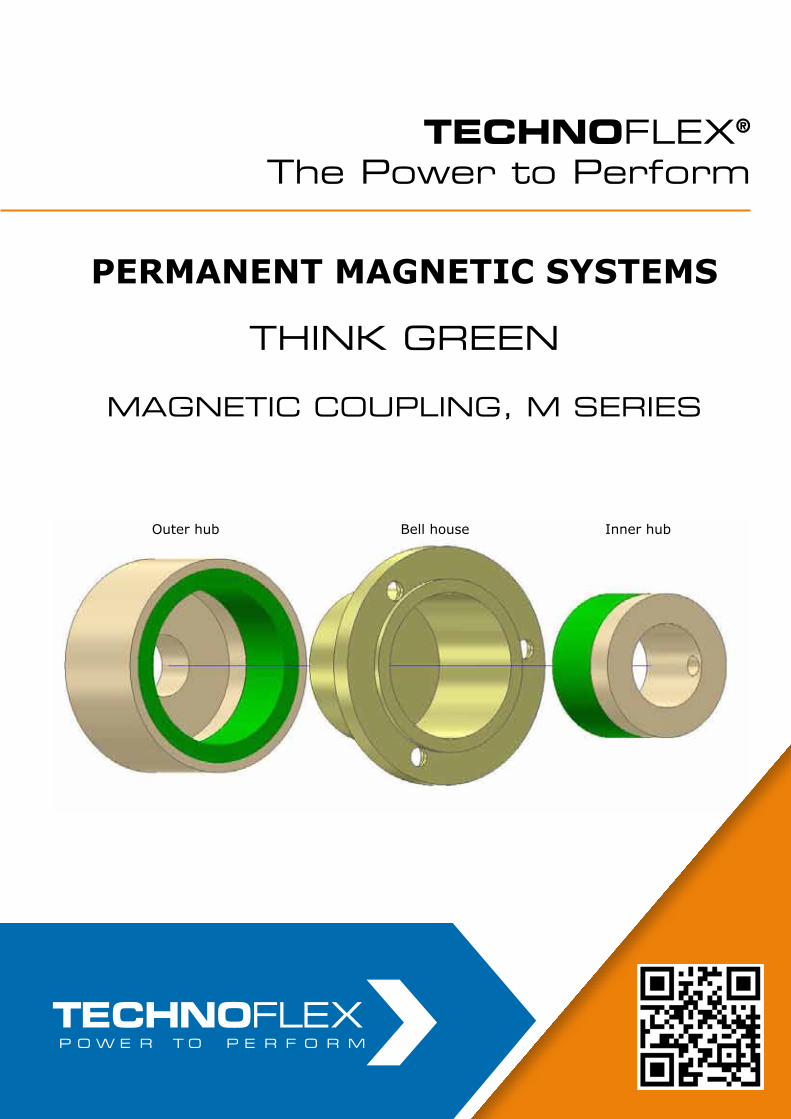
Permanent magnetic SyStemS
Think grEEn
MagnETic couPLing, M SEriES
TECHNOFLEX®
The Power to Perform
Outer hub Bell house Inner hub
Permanent magnetic SyStemS
Think grEEn
MagnETic couPLing, M SEriES
TECHNOFLEX®
The Power to Perform
Outer hub Bell house Inner hub
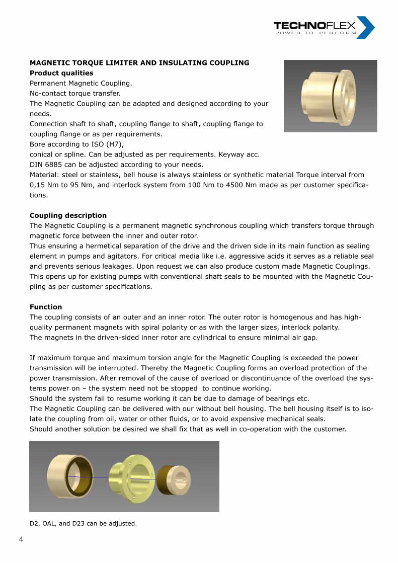
magnetic tOrQUe Limiter anD inSULating cOUPLingProduct qualitiesPermanent Magnetic Coupling. No-contact torque transfer. The Magnetic Coupling can be adapted and designed according to your needs. Connection shaft to shaft, coupling flange to shaft, coupling flange to coupling flange or as per requirements. Bore according to ISO (H7), conical or spline. Can be adjusted as per requirements. Keyway acc. DIN 6885 can be adjusted according to your needs. Material: steel or stainless, bell house is always stainless or synthetic material Torque interval from 0,15 Nm to 95 Nm, and interlock system from 100 Nm to 4500 Nm made as per customer specifica-tions.
Coupling descriptionThe Magnetic Coupling is a permanent magnetic synchronous coupling which transfers torque through magnetic force between the inner and outer rotor.Thus ensuring a hermetical separation of the drive and the driven side in its main function as sealing element in pumps and agitators. For critical media like i.e. aggressive acids it serves as a reliable seal and prevents serious leakages. Upon request we can also produce custom made Magnetic Couplings. This opens up for existing pumps with conventional shaft seals to be mounted with the Magnetic Cou-pling as per customer specifications.
FunctionThe coupling consists of an outer and an inner rotor. The outer rotor is homogenous and has high-quality permanent magnets with spiral polarity or as with the larger sizes, interlock polarity. The magnets in the driven-sided inner rotor are cylindrical to ensure minimal air gap.
If maximum torque and maximum torsion angle for the Magnetic Coupling is exceeded the power transmission will be interrupted. Thereby the Magnetic Coupling forms an overload protection of the power transmission. After removal of the cause of overload or discontinuance of the overload the sys-tems power on – the system need not be stopped to continue working.Should the system fail to resume working it can be due to damage of bearings etc.The Magnetic Coupling can be delivered with our without bell housing. The bell housing itself is to iso-late the coupling from oil, water or other fluids, or to avoid expensive mechanical seals.Should another solution be desired we shall fix that as well in co-operation with the customer.
D2, OAL, and D23 can be adjusted.
4 4
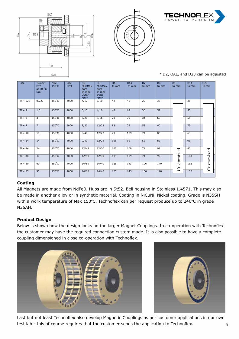
CoatingAll Magnets are made from NdFeB. Hubs are in St52. Bell housing in Stainless 1.4571. This may also be made in another alloy or in synthetic material. Coating in NiCuNi Nickel coating. Grade is N35SH with a work temperature of Max 150°C. Technoflex can per request produce up to 240°C in grade N35AH.
Product Design Below is shown how the design looks on the larger Magnet Couplings. In co-operation with Technoflex the customer may have the required connection custom made. It is also possible to have a complete coupling dimensioned in close co-operation with Technoflex.
Last but not least Technoflex also develop Magnetic Couplings as per customer applications in our own test lab - this of course requires that the customer sends the application to Technoflex.
* D2, OAL, and D23 can be adjusted * D2, OAL, and D23 can be adjusted
Size Tkmax
Dyn at 20 °C
Nm
tMax
150°C
Max
RPM
D5
Min/Max bore
In mm Outer rotor
D8
Min/Max bore
In mm Inner rotor
OAL
In mm
D14
In mm
D2
In mm
D4
In mm
D13
In mm
D11
In mm
D23
In mm
TFM-022 0,220 150°C 4000 4/12 5/10 42 46 20 38
35
TFM-2 1,5 150°C 4000 5/15 4/10 46 62 30 52 53
TFM-3 3 150°C 4000 5/20 5/16 70 79 34 60 55
TFM-7 7 150°C 4000 9/30 12/22 92 79 58 60 75
TFM-10 10 150°C 4000 9/40 12/22 79 109 71 86 63
TFM-14 14 150°C 4000 9/40 12/22 105 96 58 86 98
TFM-24 24 150°C 4000 12/48 12/30 105 109 71 99 83
TFM-40 40 150°C 4000 12/50 12/30 119 109 71 99 103
TFM-60 60 150°C 4000 14/60 14/40 125 143 106 140 112
TFM-95 95 150°C 4000 14/60 14/40 125 143 106 140 132
Coating in NiCuNi Nickel coating. Grade is N35SH with a work temperature of Max
150C.
Technoflex can per request produce up to 240C in grade N35AH.
Custo
miz
ed
Custo
miz
ed
5 5

nOteS nOteS „ I n n o v a t i o n i n m o t i o n ”
Berv ina Kf t . • H -1145 Erzsébet k i rá lyné út ja 41/B • Te l . :+36 -1-222-20-79 • Fax: +36 -1-252-48-29 • berv ina@berv ina.com
page 19
NOTES FOR BELTS
„ I n n o v a t i o n i n m o t i o n ”
Berv ina Kf t . • H -1145 Erzsébet k i rá lyné út ja 41/B • Te l . :+36 -1-222-20-79 • Fax: +36 -1-252-48-29 • berv ina@berv ina.com
page 19
NOTES FOR BELTS
6 6

aLUminUm HOUSingS aLUminUm HOUSingS

TECHNOFLEX®
The Power to Perform
TECHNOFLEX Aluminum Housings
Today, there are thousands of TECHNOFLEX aluminum housings in service
throughout the world. Together with our original. TECHNOFLEX flywheel
coupling and our torsionally stiff DENTEX FL flywheel couplings, our aluminum
housings tackle tough gas and diesel engine applications.
The housings take up very little space, while supporting a significant amount of
weight. They are available With a wide variety of mounts and sensor options.
Design Characteristics:
Sturdy Aluminum Castings
Heat treated aluminum housings
Thick walls for extra support and thread engagement
Mounts
Foot mounts
Side mounts
Face Mounts
Top MountsSpecial pump mount options are always available
Features and Advantages:
Sturdy .High-Strength . aluminum construction
Custom fit to engine starter plates
SAE and non-SAE pump mounting
Standard and special engine mounts
Custom/personalized housings available upon request
Thick wall design for heavy pump applications
Painted housings (available upon request)
Competitively priced and normally in stock
Applications:
TECHNOFLEX Aluminum Housings
Today, there are thousands of TECHNOFLEX aluminum housings in service
throughout the world. Together with our original. TECHNOFLEX flywheel
coupling and our torsionally stiff DENTEX FL flywheel couplings, our aluminum
housings tackle tough gas and diesel engine applications.
The housings take up very little space, while supporting a significant amount of
weight. They are available With a wide variety of mounts and sensor options.
Design Characteristics:
Sturdy Aluminum Castings
Heat treated aluminum housings
Thick walls for extra support and thread engagement
Mounts
Foot mounts Side mounts
Face Mounts
Top Mounts
Special pump mount options are always available
Features and Advantages:
Sturdy .High-Strength . aluminum construction
Custom fit to engine starter plates
SAE and non-SAE pump mounting
Standard and special engine mounts
Custom/personalized housings available upon request
Thick wall design for heavy pump applications
Painted housings (available upon request)
Competitively priced and normally in stock
Applications:
TECHNOFLEX Aluminum Housings
Today, there are thousands of TECHNOFLEX aluminum housings in service
throughout the world. Together with our original. TECHNOFLEX flywheel
coupling and our torsionally stiff DENTEX FL flywheel couplings, our aluminum
housings tackle tough gas and diesel engine applications.
The housings take up very little space, while supporting a significant amount of
weight. They are available With a wide variety of mounts and sensor options.
Design Characteristics:
Sturdy Aluminum Castings
Heat treated aluminum housings
Thick walls for extra support and thread engagement
Mounts
Foot mounts Side mounts
Face Mounts
Top Mounts
Special pump mount options are always available
Features and Advantages:
Sturdy .High-Strength . aluminum construction
Custom fit to engine starter plates
SAE and non-SAE pump mounting
Standard and special engine mounts
Custom/personalized housings available upon request
Thick wall design for heavy pump applications
Painted housings (available upon request)
Competitively priced and normally in stock
Applications:
TECHNOFLEX®
The Power to PerformTECHNOFLEX®
The Power to Perform
TECHNOFLEX Aluminum Housings
Today, there are thousands of TECHNOFLEX aluminum housings in service
throughout the world. Together with our original. TECHNOFLEX flywheel
coupling and our torsionally stiff DENTEX FL flywheel couplings, our aluminum
housings tackle tough gas and diesel engine applications.
The housings take up very little space, while supporting a significant amount of
weight. They are available With a wide variety of mounts and sensor options.
Design Characteristics:
Sturdy Aluminum Castings
Heat treated aluminum housings
Thick walls for extra support and thread engagement
Mounts
Foot mounts
Side mounts
Face Mounts
Top MountsSpecial pump mount options are always available
Features and Advantages:
Sturdy .High-Strength . aluminum construction
Custom fit to engine starter plates
SAE and non-SAE pump mounting
Standard and special engine mounts
Custom/personalized housings available upon request
Thick wall design for heavy pump applications
Painted housings (available upon request)
Competitively priced and normally in stock
Applications:
TECHNOFLEX Aluminum Housings
Today, there are thousands of TECHNOFLEX aluminum housings in service
throughout the world. Together with our original. TECHNOFLEX flywheel
coupling and our torsionally stiff DENTEX FL flywheel couplings, our aluminum
housings tackle tough gas and diesel engine applications.
The housings take up very little space, while supporting a significant amount of
weight. They are available With a wide variety of mounts and sensor options.
Design Characteristics:
Sturdy Aluminum Castings
Heat treated aluminum housings
Thick walls for extra support and thread engagement
Mounts
Foot mounts Side mounts
Face Mounts
Top Mounts
Special pump mount options are always available
Features and Advantages:
Sturdy .High-Strength . aluminum construction
Custom fit to engine starter plates
SAE and non-SAE pump mounting
Standard and special engine mounts
Custom/personalized housings available upon request
Thick wall design for heavy pump applications
Painted housings (available upon request)
Competitively priced and normally in stock
Applications:
TECHNOFLEX Aluminum Housings
Today, there are thousands of TECHNOFLEX aluminum housings in service
throughout the world. Together with our original. TECHNOFLEX flywheel
coupling and our torsionally stiff DENTEX FL flywheel couplings, our aluminum
housings tackle tough gas and diesel engine applications.
The housings take up very little space, while supporting a significant amount of
weight. They are available With a wide variety of mounts and sensor options.
Design Characteristics:
Sturdy Aluminum Castings
Heat treated aluminum housings
Thick walls for extra support and thread engagement
Mounts
Foot mounts Side mounts
Face Mounts
Top Mounts
Special pump mount options are always available
Features and Advantages:
Sturdy .High-Strength . aluminum construction
Custom fit to engine starter plates
SAE and non-SAE pump mounting
Standard and special engine mounts
Custom/personalized housings available upon request
Thick wall design for heavy pump applications
Painted housings (available upon request)
Competitively priced and normally in stock
Applications:
TECHNOFLEX®
The Power to Perform
TECHNOFLEX Aluminum Housings
Today, there are thousands of TECHNOFLEX aluminum housings in service
throughout the world. Together with our original. TECHNOFLEX flywheel
coupling and our torsionally stiff DENTEX FL flywheel couplings, our aluminum
housings tackle tough gas and diesel engine applications.
The housings take up very little space, while supporting a significant amount of
weight. They are available With a wide variety of mounts and sensor options.
Design Characteristics:
Sturdy Aluminum Castings
Heat treated aluminum housings
Thick walls for extra support and thread engagement
Mounts
Foot mounts
Side mounts
Face Mounts
Top Mounts
Special pump mount options are always available
Features and Advantages:
Sturdy .High-Strength . aluminum construction Custom fit to engine starter plates
SAE and non-SAE pump mounting
Standard and special engine mounts
Custom/personalized housings available upon request
Thick wall design for heavy pump applications
Painted housings (available upon request)
Competitively priced and normally in stock
Applications:
TECHNOFLEX Aluminum Housings
Today, there are thousands of TECHNOFLEX aluminum housings in service
throughout the world. Together with our original. TECHNOFLEX flywheel
coupling and our torsionally stiff DENTEX FL flywheel couplings, our aluminum
housings tackle tough gas and diesel engine applications.
The housings take up very little space, while supporting a significant amount of
weight. They are available With a wide variety of mounts and sensor options.
Design Characteristics:
Sturdy Aluminum Castings
Heat treated aluminum housings
Thick walls for extra support and thread engagement
Mounts
Foot mounts
Side mounts
Face Mounts
Top Mounts
Special pump mount options are always available
Features and Advantages:
Sturdy .High-Strength . aluminum construction
Custom fit to engine starter plates
SAE and non-SAE pump mounting
Standard and special engine mounts
Custom/personalized housings available upon request
Thick wall design for heavy pump applications
Painted housings (available upon request)
Competitively priced and normally in stock
Applications:
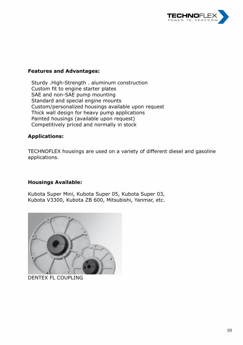
TECHNOFLEX housings are used on a variety of different diesel and gasoline
applications.
Housings Available:
Kubota Super Mini, Kubota Super 05, Kubota Super 03,
Kubota V3300, Kubota ZB 600, Mitsubishi, Yanmar, etc.
DENTEX FL COUPLING
TECHNOFLEX housings are used on a variety of different diesel and gasoline
applications.
Housings Available:
Kubota Super Mini, Kubota Super 05, Kubota Super 03,
Kubota V3300, Kubota ZB 600, Mitsubishi, Yanmar, etc.
DENTEX FL COUPLING
TECHNOFLEX housings are used on a variety of different diesel and gasoline
applications.
Housings Available:
Kubota Super Mini, Kubota Super 05, Kubota Super 03, Kubota V3300, Kubota ZB 600, Mitsubishi, Yanmar, etc.
DENTEX FL COUPLING
TECHNOFLEX®
Industrivej 21
8653 Them
tlf. +45 8724 4545
www.technoflex.dk
TECHNOFLEX®
The Power to Perform
Møl
legå
rden
s G
rafis
k ·
ww
w.m
grafi
sk.d
k
TECHNOFLEX Aluminum Housings
Today, there are thousands of TECHNOFLEX aluminum housings in service
throughout the world. Together with our original. TECHNOFLEX flywheel
coupling and our torsionally stiff DENTEX FL flywheel couplings, our aluminum
housings tackle tough gas and diesel engine applications.
The housings take up very little space, while supporting a significant amount of
weight. They are available With a wide variety of mounts and sensor options.
Design Characteristics:
Sturdy Aluminum Castings
Heat treated aluminum housings
Thick walls for extra support and thread engagement
Mounts
Foot mounts
Side mounts
Face Mounts
Top Mounts
Special pump mount options are always available
Features and Advantages:
Sturdy .High-Strength . aluminum construction Custom fit to engine starter plates
SAE and non-SAE pump mounting
Standard and special engine mounts
Custom/personalized housings available upon request
Thick wall design for heavy pump applications
Painted housings (available upon request)
Competitively priced and normally in stock
Applications:
TECHNOFLEX Aluminum Housings
Today, there are thousands of TECHNOFLEX aluminum housings in service
throughout the world. Together with our original. TECHNOFLEX flywheel
coupling and our torsionally stiff DENTEX FL flywheel couplings, our aluminum
housings tackle tough gas and diesel engine applications.
The housings take up very little space, while supporting a significant amount of
weight. They are available With a wide variety of mounts and sensor options.
Design Characteristics:
Sturdy Aluminum Castings
Heat treated aluminum housings
Thick walls for extra support and thread engagement
Mounts
Foot mounts
Side mounts
Face Mounts
Top Mounts
Special pump mount options are always available
Features and Advantages:
Sturdy .High-Strength . aluminum construction
Custom fit to engine starter plates
SAE and non-SAE pump mounting
Standard and special engine mounts
Custom/personalized housings available upon request
Thick wall design for heavy pump applications
Painted housings (available upon request)
Competitively priced and normally in stock
Applications:
TECHNOFLEX Aluminum Housings
Today, there are thousands of TECHNOFLEX aluminum housings in service
throughout the world. Together with our original. TECHNOFLEX flywheel
coupling and our torsionally stiff DENTEX FL flywheel couplings, our aluminum
housings tackle tough gas and diesel engine applications.
The housings take up very little space, while supporting a significant amount of
weight. They are available With a wide variety of mounts and sensor options.
Design Characteristics:
Sturdy Aluminum Castings
Heat treated aluminum housings
Thick walls for extra support and thread engagement
Mounts
Foot mounts
Side mounts
Face Mounts
Top Mounts
Special pump mount options are always available
Features and Advantages:
Sturdy .High-Strength . aluminum construction
Custom fit to engine starter plates
SAE and non-SAE pump mounting
Standard and special engine mounts
Custom/personalized housings available upon request
Thick wall design for heavy pump applications
Painted housings (available upon request)
Competitively priced and normally in stock
Applications:
TECHNOFLEX housings are used on a variety of different diesel and gasoline
applications.
Housings Available:
Kubota Super Mini, Kubota Super 05, Kubota Super 03,
Kubota V3300, Kubota ZB 600, Mitsubishi, Yanmar, etc.
DENTEX FL COUPLING
TECHNOFLEX housings are used on a variety of different diesel and gasoline
applications.
Housings Available:
Kubota Super Mini, Kubota Super 05, Kubota Super 03,
Kubota V3300, Kubota ZB 600, Mitsubishi, Yanmar, etc.
DENTEX FL COUPLING
TECHNOFLEX housings are used on a variety of different diesel and gasoline
applications.
Housings Available:
Kubota Super Mini, Kubota Super 05, Kubota Super 03, Kubota V3300, Kubota ZB 600, Mitsubishi, Yanmar, etc.
DENTEX FL COUPLING
TECHNOFLEX®
Industrivej 21
8653 Them
tlf. +45 8724 4545
www.technoflex.dk
TECHNOFLEX®
The Power to Perform
Møl
legå
rden
s G
rafis
k ·
ww
w.m
grafi
sk.d
k
10 10

Flexible rubberbush couplings type JKA Flexible rubberbush couplings type JKA
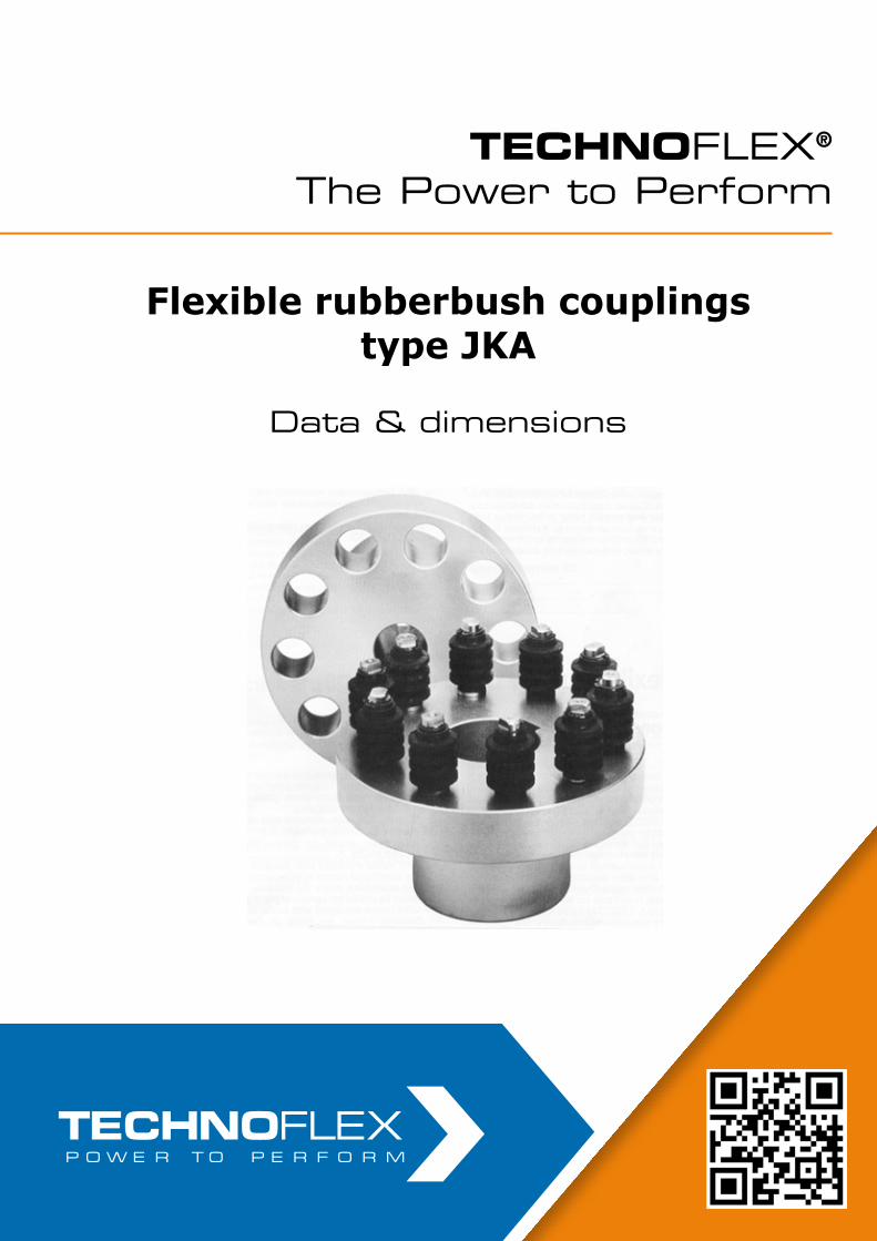
Flexible rubberbush couplings type JKA
Data & dimensions
Flexible rubberbush couplings type JKA
Data & dimensions
TECHNOFLEX®
The Power to PerformTECHNOFLEX®
The Power to Perform

Z= number of rubbersleeves, weight and moment of inertia given with max. boring.
Design and operating characteristics
Z= number of rubbersleeves, weight and moment of inertia given with max. boring.
Design and operating characteristics
Z= number of rubbersleeves, weight and moment of inertia given with max. boring.
Design and operating characteristics
Z= number of rubbersleeves, weight and moment of inertia given with max. boring.
Design and operating characteristics
Size Tkn
Nm
Tkmax
Nm
D1/2
max
mm
Pilot
boring
mm
D3
mm
D5
mm
L1
mm
L2
mm
L3
mm
L4
mm
L5
mm
M
mm
Nmax
RPM
Z
pcs.
Moment
of inertia
Kgm2
Weight
kg.
335 4800 12000 120 70 180 335 140 140 65 25 5,5 142 2100 10 1,1 80
400 7.500 19.000 140 80 205 400 160 160 90 35 5,5 195 1750 8 2,9 146
450 12.000 30.000 160 85 240 450 180 180 90 35 5,5 195 1550 10 4,8 196
520 19.000 48.000 180 95 275 520 200 200 125 50 7 270 1350 8 11,6 340
600 30.000 75.000 200 105 310 600 220 220 125 50 7 270 1200 10 20,7 470
630 48.000 120.000 220 130 370 630 240 240 125 125 7 310 1000 16 32,8 660
750 75.000 190.000 240 145 440 750 280 280 125 125 7 310 800 20 68,4 1040
900 120.000 300.000 260 165 165 900 300 300 125 125 7 310 630 26 138,6 1500
14 14
Design and operating characteristics
Alignment instructions
General mounting instructionsThe coupling halves are mounted on the shafts without pins. Small couplings can be drawn onto the shaft with an appropriate tool, using the threads in the ends of the shafts. Larger couplings should be heated prior to mounting to +80°C-120° C depending on the fitting tolerance. Heat cautiously with direct flame.
After mounting, the coupling halves must be cleaned so that oil cannot damage the rubber sleeves of the couplings. The shaft alignment should be checked and for maximum life of the rubber sleeves it is then advantageous that the misalignment in both coupling halves is restricted to parallel misalign-ment.
Checking the alignment of the shafts.After mounting of the coupling halves the shaft alignment must be checked so that the misalignment of the shafts is as small as possible. This can be done by means of dial indicator, feeler or ruler.
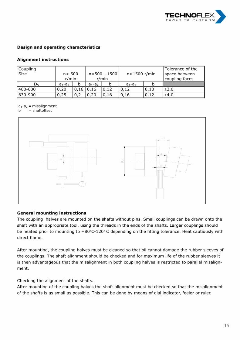
Alignment instructions.
Coupling
Size
n< 500
r/min
n=500 …1500
r/min
n>1500 r/min
Tolerance of the
space between
coupling faces
D5 a1-a2 b a1-a2 b a1-a2 b
400-600 0,20 0,16 0,16 0,12 0,12 0,10 ±3,0
630-900 0,25 0,2 0,20 0,16 0,16 0,12 ±4,0
a1-a2 = misalignment
b = shaftoffset
General mounting instructions.
The coupling halves are mounted on the shafts without pins. Small couplings can be
drawn onto the shaft with an appropriate tool, using the threads in the ends of the
shafts. Larger couplings should be heated prior to mounting to +80o…+120o
depending on the fitting torerance. Heat in an oil bath or cautionsly with direct flame.
After mounting, the coupling halves must be cleaned so that oil cannot damage the
rubber sleeves of the couplings. The shaft alignment should be checked and for
maximum life of the rubber sleeves it is then advantageous that the misalignment in
both coupling halves is restricted to parallel misalignment.
Checking the alignment of the shafts.
After mounting of the couplings halves the shaft alignment must be checked so that
the misalignment of the shafts is as small as possible. This can be done by means of
dial indicator, feeler or ruler.
15 15
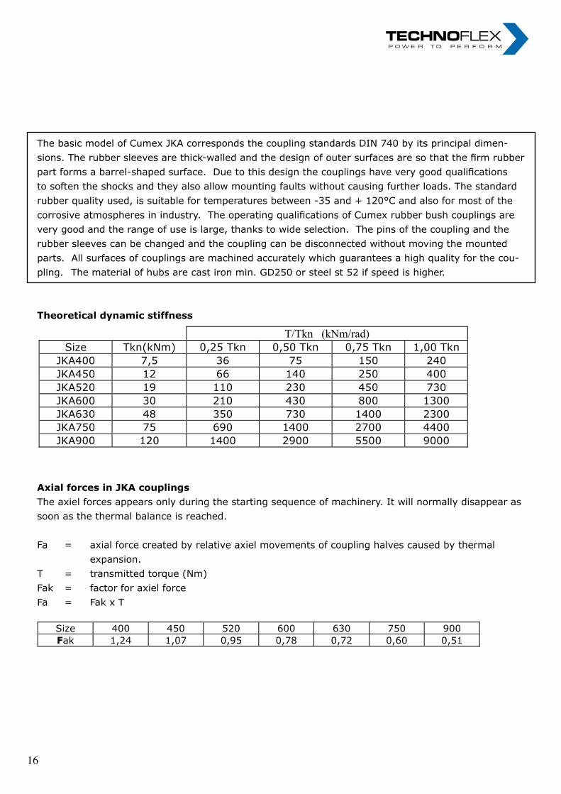
The basic model of Cumex JKA corresponds the coupling standards DIN 740 by its principal dimen-sions. The rubber sleeves are thick-walled and the design of outer surfaces are so that the firm rubber part forms a barrel-shaped surface. Due to this design the couplings have very good qualifications to soften the shocks and they also allow mounting faults without causing further loads. The standard rubber quality used, is suitable for temperatures between -35 and + 120°C and also for most of the corrosive atmospheres in industry. The operating qualifications of Cumex rubber bush couplings are very good and the range of use is large, thanks to wide selection. The pins of the coupling and the rubber sleeves can be changed and the coupling can be disconnected without moving the mounted parts. All surfaces of couplings are machined accurately which guarantees a high quality for the cou-pling. The material of hubs are cast iron min. GD250 or steel st 52 if speed is higher.
Theoretical dynamic stiffness
Axial forces in JKA couplingsThe axiel forces appears only during the starting sequence of machinery. It will normally disappear as soon as the thermal balance is reached.
Fa = axial force created by relative axiel movements of coupling halves caused by thermal expansion.T = transmitted torque (Nm)Fak = factor for axiel forceFa = Fak x T
The basic model of Cumex JKA corresponds the coupling standards DIN 740 by its principal
dimensions. The rubber sleeves are thick-walled and the design of outer surfaces are so that
the firm rubber part forms a barrel-shaped surface. Due to this design the couplings have very
good qualifications to soften the shocks and they also allow mounting faults without causing
further loads. The standard rubber quality used, is suitable for temperatures between -35 and
+ 120°C and also for most of the corrosive atmospheres in industry. The operating
qualifications of Cumex rubber bush couplings are very good and the range of use is large,
thanks to wide selection. The pins of the coupling and the rubber sleeves can be changed and
the coupling can be disconnected without moving the mounted parts. All surfaces of couplings
are machined accurately which guarantees a high quality for the coupling. The material of
hubs are cast iron min. GD250. ore steel st 52 if speed is higher.
Theoretical dynamic stiffness
T/Tkn (kNm/rad)
Size Tkn(kNm) 0,25 Tkn 0,50 Tkn 0,75 Tkn 1,00 Tkn
JKA400 7,5 36 75 150 240
JKA450 12 66 140 250 400
JKA520 19 110 230 450 730
JKA600 30 210 430 800 1300
JKA630 48 350 730 1400 2300
JKA750 75 690 1400 2700 4400
JKA900 120 1400 2900 5500 9000
Axial forces in JKA couplings
The axiel forces appears only during the starting sequence of machinery. It will normally
disappear as soon as the thermal balance is reached.
Fa = axial force created by relative axiel movements of coupling halves caused by
thermal
expansion.
T = transmitted torque (Nm)
Fak = factor for axiel force
Fa = Fak x T
Size 400 450 520 600 630 750 900
Fak 1,24 1,07 0,95 0,78 0,72 0,60 0,51
TechnoFlex ApS
Industrivej 21
DK-8653 Them Phone:+45-87244545 / Fax:+45-87244549 e-mail: [email protected]
16 16

nOteS „ I n n o v a t i o n i n m o t i o n ”
Berv ina Kf t . • H -1145 Erzsébet k i rá lyné út ja 41/B • Te l . :+36 -1-222-20-79 • Fax: +36 -1-252-48-29 • berv ina@berv ina.com
page 19
NOTES FOR BELTS
nOteS „ I n n o v a t i o n i n m o t i o n ”
Berv ina Kf t . • H -1145 Erzsébet k i rá lyné út ja 41/B • Te l . :+36 -1-222-20-79 • Fax: +36 -1-252-48-29 • berv ina@berv ina.com
page 19
NOTES FOR BELTS
17 17

nOteS „ I n n o v a t i o n i n m o t i o n ”
Berv ina Kf t . • H -1145 Erzsébet k i rá lyné út ja 41/B • Te l . :+36 -1-222-20-79 • Fax: +36 -1-252-48-29 • berv ina@berv ina.com
page 19
NOTES FOR BELTS
nOteS „ I n n o v a t i o n i n m o t i o n ”
Berv ina Kf t . • H -1145 Erzsébet k i rá lyné út ja 41/B • Te l . :+36 -1-222-20-79 • Fax: +36 -1-252-48-29 • berv ina@berv ina.com
page 19
NOTES FOR BELTS
18 18

Torsionskupplungen/Torsional Couplings Torsionskupplungen/Torsional Couplings
TECHNOFLEX®
The Power to Perform
Torsionskupplungen / Torsional Couplings
• LF Torsionskupplungen
• LK Torsionskupplungen
• Pumpen-Montageplatten und -Gehäuse
• LM Torsionskupplungen
• LF Torsional Coupling system
• LK Torsional Coupling system
• Pump mounting plates and housings
• LM Torsional Coupling system
3
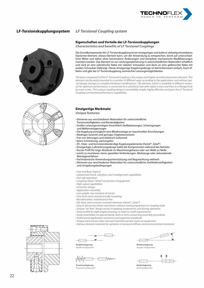
LF-TorsionskupplungssystemLF Torsional Coupling system
EigenschaftenundVorteilederLF-TorsionskupplungenCharacteristics and benefits of LF Torsional Couplings
Die Grundkomponente der LF-Torsionskupplung ist ein einzigartiges und äußerst vielseitig einsetzbares Elastomer-Element. Dieses Element kann, um der Anwendung zu entsprechen, leicht auf unterschied-liche Weise und daher ohne konstruktive Änderungen und komplexe mechanische Modifizierungen montiert werden. Das Element ist zur Leistungsoptimierung in unterschiedlichen Materialien erhältlich und wird an eine zylindrische Nabe mit radialen Schrauben und dann an eine geflanschte Nabe mit axialen Schrauben befestigt. Dieses einzigartige Kupplungsdesign ist bemerkenswert einfach, hoch ef-fektiv und gibt der LF-Torsionskupplung unerreichte Leistungsmöglichkeiten.
The basic component of the LF Torsional Coupling is the unique and highly versatile elastomeric element. This element can be easily mounted in a number of different ways according to the application, and without spe-cial design changes or complex hardware modifications. The element, which is available in different materi-als for optimum performance, is connected to a cylindrical hub with radial screws and then to a flanged hub by axial screws. This unique coupling design is remarkably simple, highly effective, and gives the LF Torsional Coupling unmatched performance capabilities.
EinzigartigeMerkmale:Unique features:
• Elemente aus verschiedenen Materialien für unterschiedliche Torsionssteifigkeiten und Beständigkeiten
• Großes Leistungsvermögen hinsichtlich Stoßbelastungen, Schwingungen und Wellenverlagerungen
• Die Kupplung ermöglicht eine Blindmontage an maschinellen Einrichtungen • Niedriges Gewicht und geringes Trägheitsmoment• Frei von Störungen und elektrisch isolierend• Keine Schmierung, wartungsfrei• Öl-, hitze- und korrosionsbeständige Kupplungselemente (Hytrel®, Zytel®)• Einzigartiges Luftströmungsdesign kühlt die Komponenten während des Betriebs• Kurzes Profil für enge Abstände im Maschinengehäuse oder von Welle zu Welle• Leicht zu montieren, keine speziellen Verbindungen, Werkzeuge oder zeitraubende
Montageverfahren• Fachmännische Anwendungsunterstützung und Begutachtung weltweit• Elemente aus verschiedenen Materialien für unterschiedliche Drehfedersteifigkeiten
und Umgebungsbedingungen
• Free end float (Type S)• Substantial shock, vibration, and misalignment capabilities• Fail-safe operation• Coupling allows "blind" connection of equipment• High-speed capabilities• Economic design• Application versatility• Low weight, low moment of inertia• Free from noise and electrically insulating• No lubrication, maintenance free• Oil, heat, and corrosion resistant elements (Hytrel ®, Zytel ®)• Easy to disconnect driver and driven without moving equipment or coupling hubs• Unique "air flow" design assists in keeping components cool during operation• Short profile for tight engine housing, or shaft-to-shaft requirements• Easily assembled, no special bands, tools or time consuming assembly procedures• Professional application assistance and expertise worldwide• Torque transmission does not exert harmful reaction loads on equipment• Various element materials for variation in torsional stiffness and environmental resistance
ParallelverlagerungParallel misalignment
WinkelverlagerungAngular misalignment
TorsionsverlagerungTorsional misalignment
AxialverlagerungAxial misalignment
3
LF-TorsionskupplungssystemLF Torsional Coupling system
EigenschaftenundVorteilederLF-TorsionskupplungenCharacteristics and benefits of LF Torsional Couplings
Die Grundkomponente der LF-Torsionskupplung ist ein einzigartiges und äußerst vielseitig einsetzbares Elastomer-Element. Dieses Element kann, um der Anwendung zu entsprechen, leicht auf unterschied-liche Weise und daher ohne konstruktive Änderungen und komplexe mechanische Modifizierungen montiert werden. Das Element ist zur Leistungsoptimierung in unterschiedlichen Materialien erhältlich und wird an eine zylindrische Nabe mit radialen Schrauben und dann an eine geflanschte Nabe mit axialen Schrauben befestigt. Dieses einzigartige Kupplungsdesign ist bemerkenswert einfach, hoch ef-fektiv und gibt der LF-Torsionskupplung unerreichte Leistungsmöglichkeiten.
The basic component of the LF Torsional Coupling is the unique and highly versatile elastomeric element. This element can be easily mounted in a number of different ways according to the application, and without spe-cial design changes or complex hardware modifications. The element, which is available in different materi-als for optimum performance, is connected to a cylindrical hub with radial screws and then to a flanged hub by axial screws. This unique coupling design is remarkably simple, highly effective, and gives the LF Torsional Coupling unmatched performance capabilities.
EinzigartigeMerkmale:Unique features:
• Elemente aus verschiedenen Materialien für unterschiedliche Torsionssteifigkeiten und Beständigkeiten
• Großes Leistungsvermögen hinsichtlich Stoßbelastungen, Schwingungen und Wellenverlagerungen
• Die Kupplung ermöglicht eine Blindmontage an maschinellen Einrichtungen • Niedriges Gewicht und geringes Trägheitsmoment• Frei von Störungen und elektrisch isolierend• Keine Schmierung, wartungsfrei• Öl-, hitze- und korrosionsbeständige Kupplungselemente (Hytrel®, Zytel®)• Einzigartiges Luftströmungsdesign kühlt die Komponenten während des Betriebs• Kurzes Profil für enge Abstände im Maschinengehäuse oder von Welle zu Welle• Leicht zu montieren, keine speziellen Verbindungen, Werkzeuge oder zeitraubende
Montageverfahren• Fachmännische Anwendungsunterstützung und Begutachtung weltweit• Elemente aus verschiedenen Materialien für unterschiedliche Drehfedersteifigkeiten
und Umgebungsbedingungen
• Free end float (Type S)• Substantial shock, vibration, and misalignment capabilities• Fail-safe operation• Coupling allows "blind" connection of equipment• High-speed capabilities• Economic design• Application versatility• Low weight, low moment of inertia• Free from noise and electrically insulating• No lubrication, maintenance free• Oil, heat, and corrosion resistant elements (Hytrel ®, Zytel ®)• Easy to disconnect driver and driven without moving equipment or coupling hubs• Unique "air flow" design assists in keeping components cool during operation• Short profile for tight engine housing, or shaft-to-shaft requirements• Easily assembled, no special bands, tools or time consuming assembly procedures• Professional application assistance and expertise worldwide• Torque transmission does not exert harmful reaction loads on equipment• Various element materials for variation in torsional stiffness and environmental resistance
ParallelverlagerungParallel misalignment
WinkelverlagerungAngular misalignment
TorsionsverlagerungTorsional misalignment
AxialverlagerungAxial misalignment
22 22
4rl-hydraulics.com
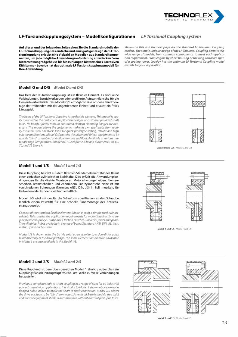
LF-Torsionskupplungssystem–ModellkonfigurationenLF Torsional Coupling system
ModellOundO/SModel O and O/S
Das Herz der LF-Torsionskupplung ist ein flexibles Element. Es sind keine Verbindungen, Spezialwerkzeuge oder profilierte Aufspannflansche für die Elemente erforderlich. Das Modell O/S ermöglicht eine schnelle Blindmon-tage der treibenden mit der angetriebenen Einheit und erlaubt ein freies Längsspiel.
The heart of the LF Torsional Coupling is the flexible element. This model is eas-ily mounted to the customer’s application designs or customer provided shaft hubs. No bands, special tools, or contoured element clamping flanges are nec-essary. This model allows the customer to make his own shaft hubs from read-ily available steel bar stock. Ideal for quick prototype testing, retrofit and high volume applications. Model O/S permits the driver and driven equipment to be quickly "blind" assembled and allows for free end float. Available in various ma-terials: High-Temperature, Rubber (HTR), Neoprene (CR) and durometers: 50, 60, 70, and 75 Shore A.
Modell1und1/SModel 1 and 1/S
Diese Kupplung besteht aus dem flexiblen Standardelement (Modell 0) mit einer einfachen zylindrischen Stahlnabe. Dies erfüllt die Anwendungsbe-dingungen für die direkte Montage an Motorschwungscheiben, Riemen-scheiben, Bremsscheiben und Zahnrädern. Die zylindrische Nabe ist mit verschiedenen Bohrungen (Normen: ANSI, DIN, JIS) in Zoll, metrisch, für Keilwellen oder kundenspezifisch erhältlich.
Modell 1/S wird mit der für die S-Bauform spezifischen axialen Schraube (ähnlich einem Passstift) für eine schnelle Blindmontage des Antriebs-strangs gezeigt.
Consists of the standard flexible element (Model 0) with a simple steel cylindri-cal hub. This satisfies the application requirements for mounting directly to en-gine flywheels, pulleys, brake discs, friction clutches, universal joints and gears. The cylindrical hub is available in a range of bores (Standard ANSI, DIN, JIS) inch, metric, spline and custom.
Model 1/S is shown with the S-style axial screw (similar to a dowel) for quick blind assembly of the drive package. The same element combinations available in Model 1 are also available in the Model 1/S.
Modell2und2/SModel 2 and 2/S
Diese Kupplung ist dem oben gezeigten Modell 1 ähnlich, außer dass ein Kupplungsflansch hinzugefügt wurde, um Welle-zu-Welle-Verbindungen herzustellen.
Provides a complete shaft-to-shaft coupling in a range of sizes for all industrial power transmission applications. It is similar to Model 1 shown above, except a flanged hub is added to make the shaft to shaft connection. Model 2/S allows the drive package to be "blind" connected. As with all S-style models, free axial end float of equipment shafts is accomplished without harmful push-pull force.
Modell O und O/S Model O and O/S
Modell 2 und 2/S Model 2 and 2/S
Modell 1 und 1/S Model 1 and 1/S
AufdieserundderfolgendenSeitesehenSiedieStandardmodellederLF-Torsionskupplung.DaseinfacheundeinzigartigeDesignderLFTor-sionskupplungerlaubteineVielzahlanModellenausStandardkompo-nenten,umjedemöglicheAnwendungsanforderungabzudecken.VomMotorschwungradgehäusebishinzurlangenDistanzeineskorrosivenKühlturms–LovejoyhatdasoptimaleLFTorsionskupplungsmodellfürIhreAnwendung.
Shownon thisand thenextpageare the standardLFTorsionalCouplingmodels.Thesimple,uniquedesignoftheLFTorsionalCouplingpermitsthiswide rangeofmodels, from common components, tomeet eachapplica-tionrequirement.Fromengineflywheelhousingorthelongcorrosivespanofacoolingtower,LovejoyhastheoptimumLFTorsionalCouplingmodelavaibleforyourapplication.
4rl-hydraulics.com
LF-Torsionskupplungssystem–ModellkonfigurationenLF Torsional Coupling system
ModellOundO/SModel O and O/S
Das Herz der LF-Torsionskupplung ist ein flexibles Element. Es sind keine Verbindungen, Spezialwerkzeuge oder profilierte Aufspannflansche für die Elemente erforderlich. Das Modell O/S ermöglicht eine schnelle Blindmon-tage der treibenden mit der angetriebenen Einheit und erlaubt ein freies Längsspiel.
The heart of the LF Torsional Coupling is the flexible element. This model is eas-ily mounted to the customer’s application designs or customer provided shaft hubs. No bands, special tools, or contoured element clamping flanges are nec-essary. This model allows the customer to make his own shaft hubs from read-ily available steel bar stock. Ideal for quick prototype testing, retrofit and high volume applications. Model O/S permits the driver and driven equipment to be quickly "blind" assembled and allows for free end float. Available in various ma-terials: High-Temperature, Rubber (HTR), Neoprene (CR) and durometers: 50, 60, 70, and 75 Shore A.
Modell1und1/SModel 1 and 1/S
Diese Kupplung besteht aus dem flexiblen Standardelement (Modell 0) mit einer einfachen zylindrischen Stahlnabe. Dies erfüllt die Anwendungsbe-dingungen für die direkte Montage an Motorschwungscheiben, Riemen-scheiben, Bremsscheiben und Zahnrädern. Die zylindrische Nabe ist mit verschiedenen Bohrungen (Normen: ANSI, DIN, JIS) in Zoll, metrisch, für Keilwellen oder kundenspezifisch erhältlich.
Modell 1/S wird mit der für die S-Bauform spezifischen axialen Schraube (ähnlich einem Passstift) für eine schnelle Blindmontage des Antriebs-strangs gezeigt.
Consists of the standard flexible element (Model 0) with a simple steel cylindri-cal hub. This satisfies the application requirements for mounting directly to en-gine flywheels, pulleys, brake discs, friction clutches, universal joints and gears. The cylindrical hub is available in a range of bores (Standard ANSI, DIN, JIS) inch, metric, spline and custom.
Model 1/S is shown with the S-style axial screw (similar to a dowel) for quick blind assembly of the drive package. The same element combinations available in Model 1 are also available in the Model 1/S.
Modell2und2/SModel 2 and 2/S
Diese Kupplung ist dem oben gezeigten Modell 1 ähnlich, außer dass ein Kupplungsflansch hinzugefügt wurde, um Welle-zu-Welle-Verbindungen herzustellen.
Provides a complete shaft-to-shaft coupling in a range of sizes for all industrial power transmission applications. It is similar to Model 1 shown above, except a flanged hub is added to make the shaft to shaft connection. Model 2/S allows the drive package to be "blind" connected. As with all S-style models, free axial end float of equipment shafts is accomplished without harmful push-pull force.
Modell O und O/S Model O and O/S
Modell 2 und 2/S Model 2 and 2/S
Modell 1 und 1/S Model 1 and 1/S
AufdieserundderfolgendenSeitesehenSiedieStandardmodellederLF-Torsionskupplung.DaseinfacheundeinzigartigeDesignderLFTor-sionskupplungerlaubteineVielzahlanModellenausStandardkompo-nenten,umjedemöglicheAnwendungsanforderungabzudecken.VomMotorschwungradgehäusebishinzurlangenDistanzeineskorrosivenKühlturms–LovejoyhatdasoptimaleLFTorsionskupplungsmodellfürIhreAnwendung.
Shownon thisand thenextpageare the standardLFTorsionalCouplingmodels.Thesimple,uniquedesignoftheLFTorsionalCouplingpermitsthiswide rangeofmodels, from common components, tomeet eachapplica-tionrequirement.Fromengineflywheelhousingorthelongcorrosivespanofacoolingtower,LovejoyhastheoptimumLFTorsionalCouplingmodelavaibleforyourapplication.
23 23
5
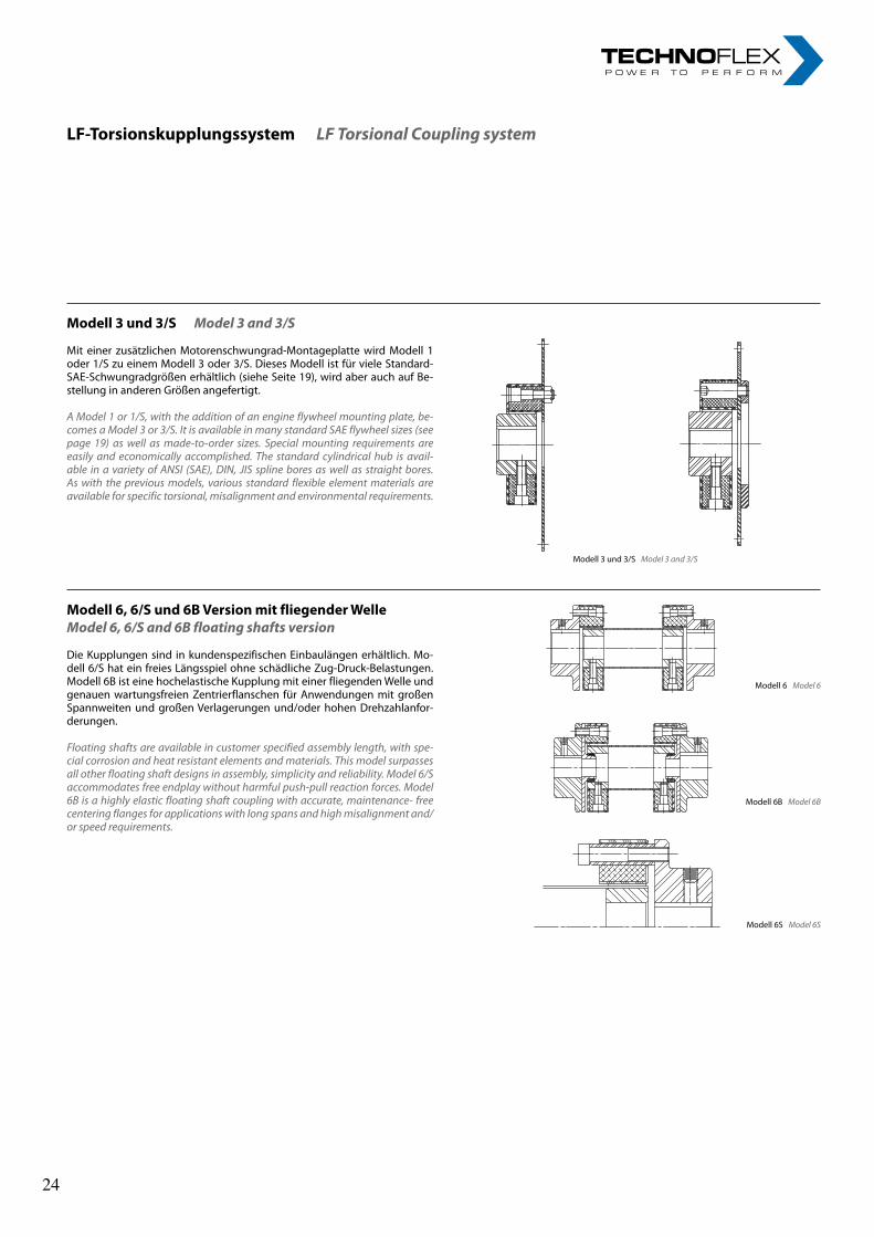
LF-TorsionskupplungssystemLF Torsional Coupling system
Modell 3 und 3/S Model 3 and 3/S
Modell 6S Model 6S
Modell 6 Model 6
Modell 6B Model 6B
Modell3und3/SModel 3 and 3/S
Mit einer zusätzlichen Motorenschwungrad-Montageplatte wird Modell 1 oder 1/S zu einem Modell 3 oder 3/S. Dieses Modell ist für viele Standard-SAE-Schwungradgrößen erhältlich (siehe Seite 19), wird aber auch auf Be-stellung in anderen Größen angefertigt.
A Model 1 or 1/S, with the addition of an engine flywheel mounting plate, be-comes a Model 3 or 3/S. It is available in many standard SAE flywheel sizes (see page 19) as well as made-to-order sizes. Special mounting requirements are easily and economically accomplished. The standard cylindrical hub is avail-able in a variety of ANSI (SAE), DIN, JIS spline bores as well as straight bores. As with the previous models, various standard flexible element materials are available for specific torsional, misalignment and environmental requirements.
Modell6,6/Sund6BVersionmitfliegenderWelleModel 6, 6/S and 6B floating shafts version
Die Kupplungen sind in kundenspezifischen Einbaulängen erhältlich. Mo-dell 6/S hat ein freies Längsspiel ohne schädliche Zug-Druck-Belastungen. Modell 6B ist eine hochelastische Kupplung mit einer fliegenden Welle und genauen wartungsfreien Zentrierflanschen für Anwendungen mit großen Spannweiten und großen Verlagerungen und/oder hohen Drehzahlanfor-derungen.
Floating shafts are available in customer specified assembly length, with spe-cial corrosion and heat resistant elements and materials. This model surpasses all other floating shaft designs in assembly, simplicity and reliability. Model 6/S accommodates free endplay without harmful push-pull reaction forces. Model 6B is a highly elastic floating shaft coupling with accurate, maintenance- free centering flanges for applications with long spans and high misalignment and/or speed requirements.
5
LF-TorsionskupplungssystemLF Torsional Coupling system
Modell 3 und 3/S Model 3 and 3/S
Modell 6S Model 6S
Modell 6 Model 6
Modell 6B Model 6B
Modell3und3/SModel 3 and 3/S
Mit einer zusätzlichen Motorenschwungrad-Montageplatte wird Modell 1 oder 1/S zu einem Modell 3 oder 3/S. Dieses Modell ist für viele Standard-SAE-Schwungradgrößen erhältlich (siehe Seite 19), wird aber auch auf Be-stellung in anderen Größen angefertigt.
A Model 1 or 1/S, with the addition of an engine flywheel mounting plate, be-comes a Model 3 or 3/S. It is available in many standard SAE flywheel sizes (see page 19) as well as made-to-order sizes. Special mounting requirements are easily and economically accomplished. The standard cylindrical hub is avail-able in a variety of ANSI (SAE), DIN, JIS spline bores as well as straight bores. As with the previous models, various standard flexible element materials are available for specific torsional, misalignment and environmental requirements.
Modell6,6/Sund6BVersionmitfliegenderWelleModel 6, 6/S and 6B floating shafts version
Die Kupplungen sind in kundenspezifischen Einbaulängen erhältlich. Mo-dell 6/S hat ein freies Längsspiel ohne schädliche Zug-Druck-Belastungen. Modell 6B ist eine hochelastische Kupplung mit einer fliegenden Welle und genauen wartungsfreien Zentrierflanschen für Anwendungen mit großen Spannweiten und großen Verlagerungen und/oder hohen Drehzahlanfor-derungen.
Floating shafts are available in customer specified assembly length, with spe-cial corrosion and heat resistant elements and materials. This model surpasses all other floating shaft designs in assembly, simplicity and reliability. Model 6/S accommodates free endplay without harmful push-pull reaction forces. Model 6B is a highly elastic floating shaft coupling with accurate, maintenance- free centering flanges for applications with long spans and high misalignment and/or speed requirements.
24 24
6rl-hydraulics.com
LF-Torsionskupplungen–FlexibleElemente LF Torsional flexible elements
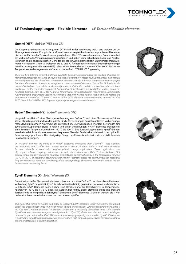
Gummi(HTR)Rubber (HTR and CR)
Die Kupplungselemente aus Naturgummi (HTR) sind in der Verdrehung weich und werden bei der Montage komprimiert. Komprimierter Gummi kann im Vergleich mit nichtkomprimierten Elementen bis zum fünffachen der Torsionsbelastung aufnehmen. Die LF-Torsionselemente aus Gummi verarbei-ten wirksam Stöße, Verlagerungen und Vibrationen und geben keine schädlichen Radial und Axialbe-lastungen an die angeschlossenen Einheiten ab. Jedes Gummielement ist in unterschiedlichen Duro-meter-Härtegraden (Shore-A-Skala) von 50, 60 und 70 für besondere Torsionsvibrationsbedingungen lieferbar. Naturgummi-Elemente (HTR) haben einen Betriebsbereich von -40 °C bis 90 °C. Für höhere Temperaturanforderungen wenden Sie sich bitte an R+L HYDRAULICS Engineering.
There are two different element materials available. Both are classified under the heading of rubber ele-ments: Natural rubber (HTR) and one synthetic rubber element of Neoprene (CR). Both rubber elements are torsionally soft and are placed into compression during assembly. Rubber in compression can carry up to five times the amount of torque, as compared to non-compressed elements. The rubber LF Torsional ele-ments effectively accommodate shock, misalignment, and vibration and do not exert harmful radial and axial forces on the connected equipment. Each rubber element material is available in various durometer hardness (Shore A Scale) of 50, 60, 70 and 75 for particular torsional vibration requirements. The synthetic rubber elements are primarily used in environments that are hostile to natural rubber and can operate in a temperature range of -40 °C to 80 °C. Natural rubber (HTR) elements have an operating range of -40 °C to 90 °C. Consult R+L HYDRAULICS Engineering for higher temperature requirements.
Hytrel®Elemente(HY)Hytrel ® elements (HY)
Hergestellt aus Hytrel®, einer Elastomer-Verbindung von DuPontTM, sind diese Elemente etwa 20 mal steifer als Naturgummi und wurden primär für die Verwendung in flanschmontierten Verbrennungs-motor/Hydraulikpumpen-Anwendungen entwickelt. Diese Anwendungen erfordern gewöhnlich eine zuverlässige Kupplungsleistung in heißen und öligen Umgebungen. Hytrel®-Elemente arbeiten effi-zient in einem Temperaturbereich von -50 °C bis 120 °C. Eine Torsionskupplung mit Hytrel®-Element verschiebt schädliche Vibrationsresonanzfrequenzen über den Betriebsdrehzahlbereich der Hydraulik-Pumpenbaugruppe hinaus. Das einzigartige Design des Elements reduziert zudem schädliche axiale Reaktionsbelastungen.
LF Torsional elements are made of a Hytrel® elastomer compound from DuPontTM. These elements are torsionally much stiffer than natural rubber – about 20 times stiffer – and were developed for use primarily in combustion engine/hydraulic pump applications. These applications usu-ally require reliable coupling performance in hot, oily environments. Hytrel® elements have 20 % greater torque capacity compared to rubber elements and operate efficiently in the temperature range of -50 °C to 120 °C. The torsional coupling with the Hytrel® element places the harmful vibration resonance frequency above the operating speed range of the power package. The unique element design also reduces harmful axial reactionary forces.
Zytel®Elemente(X)Zytel® elements (X)
Diese torsionssteifen Elemente sind extrem robust und aus einer DuPontTM hochbelastbarer Elastomer-Verbindung Zytel® hergestellt. Zytel® ist sehr widerstandsfähig gegenüber Korrosion und chemischer Belastung. Zytel® Elemente können ohne eine Herabsetzung der Betriebswerte in Temperaturbe-reichen von -40 °C bis +150 °C eingesetzt werden. Der Aufbau dieser Elemente ergibt eine dreifache Torsionssteife im Vergleich zu den Hytrel®-Elementen. Zytel®-Elemente (X) zeigen weniger als 1° Ver-drehwinkel beim Nenndrehmoment und sind absolut spielfrei.
This element is extremely rugged and made of Dupont's highly stressable Zytel® elastomeric compound. Zytel® has excellent resistance to most chemical attacks and corrosion. Operational temperature range is -40 °C to 150 °C without derating. This element composition is torsionally about three times stiffer than the Hytrel® elements. Maximum angular misalignment is 1°. Zytel®(X) elements exhibit less than 1° wind up at nominal torque and zero backlash. With more torque carrying capacity, compared to Hytrel®, this element is particularly suited for applications where heat, moisture, high torque/high speed and corrosion resistance are important factors in coupling selection.
6rl-hydraulics.com
LF-Torsionskupplungen–FlexibleElemente LF Torsional flexible elements
Gummi(HTR)Rubber (HTR and CR)
Die Kupplungselemente aus Naturgummi (HTR) sind in der Verdrehung weich und werden bei der Montage komprimiert. Komprimierter Gummi kann im Vergleich mit nichtkomprimierten Elementen bis zum fünffachen der Torsionsbelastung aufnehmen. Die LF-Torsionselemente aus Gummi verarbei-ten wirksam Stöße, Verlagerungen und Vibrationen und geben keine schädlichen Radial und Axialbe-lastungen an die angeschlossenen Einheiten ab. Jedes Gummielement ist in unterschiedlichen Duro-meter-Härtegraden (Shore-A-Skala) von 50, 60 und 70 für besondere Torsionsvibrationsbedingungen lieferbar. Naturgummi-Elemente (HTR) haben einen Betriebsbereich von -40 °C bis 90 °C. Für höhere Temperaturanforderungen wenden Sie sich bitte an R+L HYDRAULICS Engineering.
There are two different element materials available. Both are classified under the heading of rubber ele-ments: Natural rubber (HTR) and one synthetic rubber element of Neoprene (CR). Both rubber elements are torsionally soft and are placed into compression during assembly. Rubber in compression can carry up to five times the amount of torque, as compared to non-compressed elements. The rubber LF Torsional ele-ments effectively accommodate shock, misalignment, and vibration and do not exert harmful radial and axial forces on the connected equipment. Each rubber element material is available in various durometer hardness (Shore A Scale) of 50, 60, 70 and 75 for particular torsional vibration requirements. The synthetic rubber elements are primarily used in environments that are hostile to natural rubber and can operate in a temperature range of -40 °C to 80 °C. Natural rubber (HTR) elements have an operating range of -40 °C to 90 °C. Consult R+L HYDRAULICS Engineering for higher temperature requirements.
Hytrel®Elemente(HY)Hytrel ® elements (HY)
Hergestellt aus Hytrel®, einer Elastomer-Verbindung von DuPontTM, sind diese Elemente etwa 20 mal steifer als Naturgummi und wurden primär für die Verwendung in flanschmontierten Verbrennungs-motor/Hydraulikpumpen-Anwendungen entwickelt. Diese Anwendungen erfordern gewöhnlich eine zuverlässige Kupplungsleistung in heißen und öligen Umgebungen. Hytrel®-Elemente arbeiten effi-zient in einem Temperaturbereich von -50 °C bis 120 °C. Eine Torsionskupplung mit Hytrel®-Element verschiebt schädliche Vibrationsresonanzfrequenzen über den Betriebsdrehzahlbereich der Hydraulik-Pumpenbaugruppe hinaus. Das einzigartige Design des Elements reduziert zudem schädliche axiale Reaktionsbelastungen.
LF Torsional elements are made of a Hytrel® elastomer compound from DuPontTM. These elements are torsionally much stiffer than natural rubber – about 20 times stiffer – and were developed for use primarily in combustion engine/hydraulic pump applications. These applications usu-ally require reliable coupling performance in hot, oily environments. Hytrel® elements have 20 % greater torque capacity compared to rubber elements and operate efficiently in the temperature range of -50 °C to 120 °C. The torsional coupling with the Hytrel® element places the harmful vibration resonance frequency above the operating speed range of the power package. The unique element design also reduces harmful axial reactionary forces.
Zytel®Elemente(X)Zytel® elements (X)
Diese torsionssteifen Elemente sind extrem robust und aus einer DuPontTM hochbelastbarer Elastomer-Verbindung Zytel® hergestellt. Zytel® ist sehr widerstandsfähig gegenüber Korrosion und chemischer Belastung. Zytel® Elemente können ohne eine Herabsetzung der Betriebswerte in Temperaturbe-reichen von -40 °C bis +150 °C eingesetzt werden. Der Aufbau dieser Elemente ergibt eine dreifache Torsionssteife im Vergleich zu den Hytrel®-Elementen. Zytel®-Elemente (X) zeigen weniger als 1° Ver-drehwinkel beim Nenndrehmoment und sind absolut spielfrei.
This element is extremely rugged and made of Dupont's highly stressable Zytel® elastomeric compound. Zytel® has excellent resistance to most chemical attacks and corrosion. Operational temperature range is -40 °C to 150 °C without derating. This element composition is torsionally about three times stiffer than the Hytrel® elements. Maximum angular misalignment is 1°. Zytel®(X) elements exhibit less than 1° wind up at nominal torque and zero backlash. With more torque carrying capacity, compared to Hytrel®, this element is particularly suited for applications where heat, moisture, high torque/high speed and corrosion resistance are important factors in coupling selection.
25 25
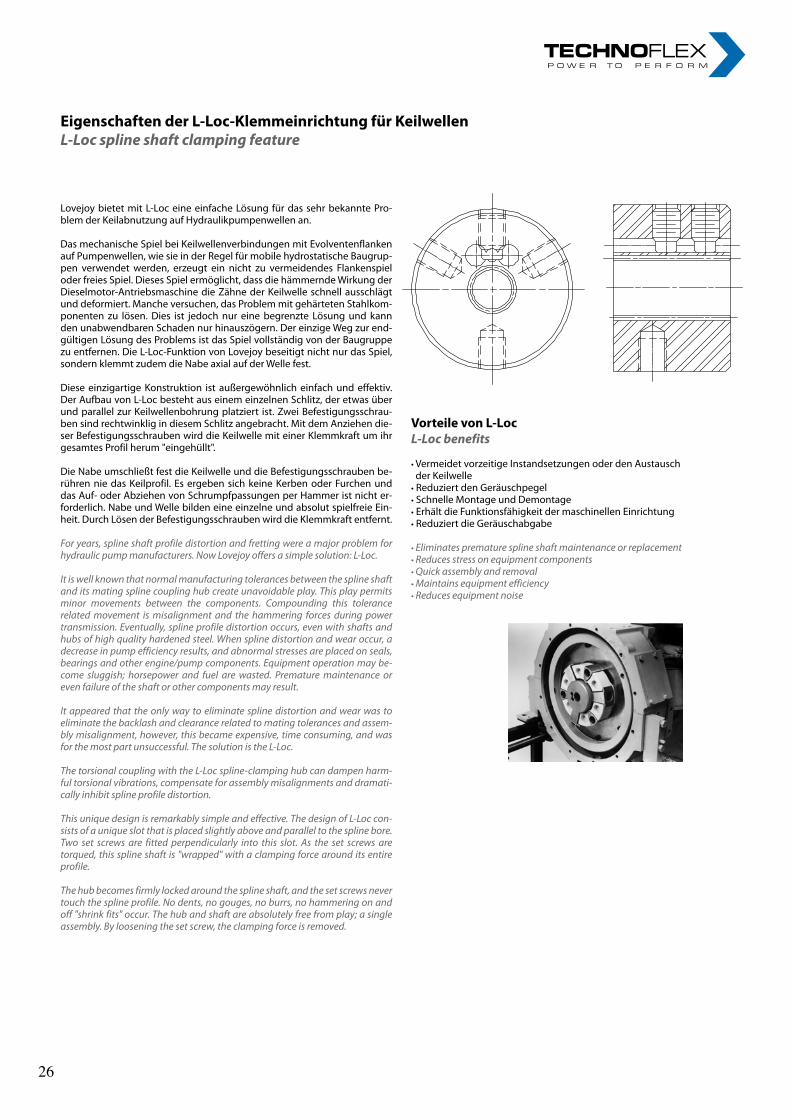
7
EigenschaftenderL-Loc-KlemmeinrichtungfürKeilwellenL-Loc spline shaft clamping feature
Lovejoy bietet mit L-Loc eine einfache Lösung für das sehr bekannte Pro-blem der Keilabnutzung auf Hydraulikpumpenwellen an.
Das mechanische Spiel bei Keilwellenverbindungen mit Evolventenflanken auf Pumpenwellen, wie sie in der Regel für mobile hydrostatische Baugrup-pen verwendet werden, erzeugt ein nicht zu vermeidendes Flankenspiel oder freies Spiel. Dieses Spiel ermöglicht, dass die hämmernde Wirkung der Dieselmotor-Antriebsmaschine die Zähne der Keilwelle schnell ausschlägt und deformiert. Manche versuchen, das Problem mit gehärteten Stahlkom-ponenten zu lösen. Dies ist jedoch nur eine begrenzte Lösung und kann den unabwendbaren Schaden nur hinauszögern. Der einzige Weg zur end-gültigen Lösung des Problems ist das Spiel vollständig von der Baugruppe zu entfernen. Die L-Loc-Funktion von Lovejoy beseitigt nicht nur das Spiel, sondern klemmt zudem die Nabe axial auf der Welle fest.
Diese einzigartige Konstruktion ist außergewöhnlich einfach und effektiv. Der Aufbau von L-Loc besteht aus einem einzelnen Schlitz, der etwas über und parallel zur Keilwellenbohrung platziert ist. Zwei Befestigungsschrau-ben sind rechtwinklig in diesem Schlitz angebracht. Mit dem Anziehen die-ser Befestigungsschrauben wird die Keilwelle mit einer Klemmkraft um ihr gesamtes Profil herum "eingehüllt".
Die Nabe umschließt fest die Keilwelle und die Befestigungsschrauben be-rühren nie das Keilprofil. Es ergeben sich keine Kerben oder Furchen und das Auf- oder Abziehen von Schrumpfpassungen per Hammer ist nicht er-forderlich. Nabe und Welle bilden eine einzelne und absolut spielfreie Ein-heit. Durch Lösen der Befestigungsschrauben wird die Klemmkraft entfernt.
For years, spline shaft profile distortion and fretting were a major problem for hydraulic pump manufacturers. Now Lovejoy offers a simple solution: L-Loc.
It is well known that normal manufacturing tolerances between the spline shaft and its mating spline coupling hub create unavoidable play. This play permits minor movements between the components. Compounding this tolerance related movement is misalignment and the hammering forces during power transmission. Eventually, spline profile distortion occurs, even with shafts and hubs of high quality hardened steel. When spline distortion and wear occur, a decrease in pump efficiency results, and abnormal stresses are placed on seals, bearings and other engine/pump components. Equipment operation may be-come sluggish; horsepower and fuel are wasted. Premature maintenance or even failure of the shaft or other components may result.
It appeared that the only way to eliminate spline distortion and wear was to eliminate the backlash and clearance related to mating tolerances and assem-bly misalignment, however, this became expensive, time consuming, and was for the most part unsuccessful. The solution is the L-Loc.
The torsional coupling with the L-Loc spline-clamping hub can dampen harm-ful torsional vibrations, compensate for assembly misalignments and dramati-cally inhibit spline profile distortion.
This unique design is remarkably simple and effective. The design of L-Loc con-sists of a unique slot that is placed slightly above and parallel to the spline bore. Two set screws are fitted perpendicularly into this slot. As the set screws are torqued, this spline shaft is "wrapped" with a clamping force around its entire profile.
The hub becomes firmly locked around the spline shaft, and the set screws never touch the spline profile. No dents, no gouges, no burrs, no hammering on and off "shrink fits" occur. The hub and shaft are absolutely free from play; a single assembly. By loosening the set screw, the clamping force is removed.
VorteilevonL-LocL-Loc benefits
• Vermeidet vorzeitige Instandsetzungen oder den Austausch der Keilwelle• Reduziert den Geräuschpegel• Schnelle Montage und Demontage• Erhält die Funktionsfähigkeit der maschinellen Einrichtung• Reduziert die Geräuschabgabe
• Eliminates premature spline shaft maintenance or replacement• Reduces stress on equipment components• Quick assembly and removal• Maintains equipment efficiency• Reduces equipment noise
26 26
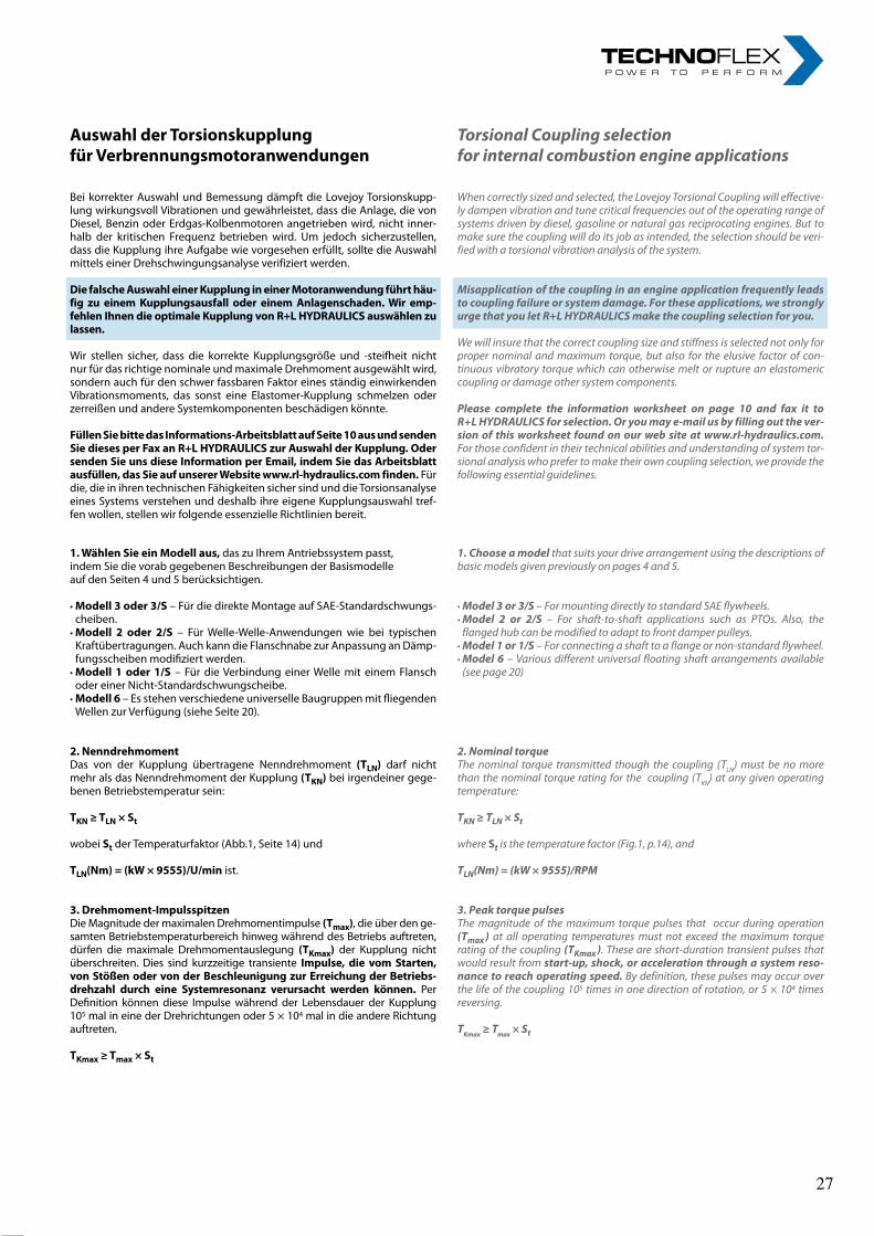
8rl-hydraulics.com
AuswahlderTorsionskupplungfürVerbrennungsmotoranwendungen
Bei korrekter Auswahl und Bemessung dämpft die Lovejoy Torsionskupp-lung wirkungsvoll Vibrationen und gewährleistet, dass die Anlage, die von Diesel, Benzin oder Erdgas-Kolbenmotoren angetrieben wird, nicht inner-halb der kritischen Frequenz betrieben wird. Um jedoch sicherzustellen, dass die Kupplung ihre Aufgabe wie vorgesehen erfüllt, sollte die Auswahl mittels einer Drehschwingungsanalyse verifiziert werden.
DiefalscheAuswahleinerKupplungineinerMotoranwendungführthäu-fig zu einemKupplungsausfall oder einemAnlagenschaden.Wir emp-fehlenIhnendieoptimaleKupplungvonR+LHYDRAULICSauswählenzulassen.
Wir stellen sicher, dass die korrekte Kupplungsgröße und -steifheit nicht nur für das richtige nominale und maximale Drehmoment ausgewählt wird, sondern auch für den schwer fassbaren Faktor eines ständig einwirkenden Vibrationsmoments, das sonst eine Elastomer-Kupplung schmelzen oder zerreißen und andere Systemkomponenten beschädigen könnte.
FüllenSiebittedasInformations-ArbeitsblattaufSeite10ausundsendenSiediesesperFaxanR+LHYDRAULICSzurAuswahlderKupplung.OdersendenSieunsdieseInformationperEmail,indemSiedasArbeitsblattausfüllen,dasSieaufunsererWebsitewww.rl-hydraulics.comfinden. Für die, die in ihren technischen Fähigkeiten sicher sind und die Torsionsanalyse eines Systems verstehen und deshalb ihre eigene Kupplungsauswahl tref-fen wollen, stellen wir folgende essenzielle Richtlinien bereit.
Torsional Coupling selection for internal combustion engine applications
When correctly sized and selected, the Lovejoy Torsional Coupling will effective-ly dampen vibration and tune critical frequencies out of the operating range of systems driven by diesel, gasoline or natural gas reciprocating engines. But to make sure the coupling will do its job as intended, the selection should be veri-fied with a torsional vibration analysis of the system.
Misapplication of the coupling in an engine application frequently leads to coupling failure or system damage. For these applications, we strongly urge that you let R+L HYDRAULICS make the coupling selection for you.
We will insure that the correct coupling size and stiffness is selected not only for proper nominal and maximum torque, but also for the elusive factor of con-tinuous vibratory torque which can otherwise melt or rupture an elastomeric coupling or damage other system components.
Please complete the information worksheet on page 10 and fax it to R+L HYDRAULICS for selection. Or you may e-mail us by filling out the ver-sion of this worksheet found on our web site at www.rl-hydraulics.com. For those confident in their technical abilities and understanding of system tor-sional analysis who prefer to make their own coupling selection, we provide the following essential guidelines.
1. Choose a model that suits your drive arrangement using the descriptions of basic models given previously on pages 4 and 5.
• Model 3 or 3/S – For mounting directly to standard SAE flywheels.• Model 2 or 2/S – For shaft-to-shaft applications such as PTOs. Also, the
flanged hub can be modified to adapt to front damper pulleys.• Model 1 or 1/S – For connecting a shaft to a flange or non-standard flywheel.• Model 6 – Various different universal floating shaft arrangements available
(see page 20)
2. Nominal torqueThe nominal torque transmitted though the coupling (TLN) must be no more than the nominal torque rating for the coupling (TKN) at any given operating temperature:
TKN ≥ TLN × St
where St is the temperature factor (Fig.1, p.14), and
TLN(Nm) = (kW × 9555)/RPM
3. Peak torque pulsesThe magnitude of the maximum torque pulses that occur during operation (Tmax ) at all operating temperatures must not exceed the maximum torque rating of the coupling (TKmax ). These are short-duration transient pulses that would result from start-up, shock, or acceleration through a system reso-nance to reach operating speed. By definition, these pulses may occur over the life of the coupling 105 times in one direction of rotation, or 5 × 10⁴ times reversing.
TKmax ≥ Tmax × St
1.WählenSieeinModellaus, das zu Ihrem Antriebssystem passt,indem Sie die vorab gegebenen Beschreibungen der Basismodelleauf den Seiten 4 und 5 berücksichtigen.
• Modell3oder3/S – Für die direkte Montage auf SAE-Standardschwungs-cheiben.
• Modell 2 oder 2/S – Für Welle-Welle-Anwendungen wie bei typischen Kraftübertragungen. Auch kann die Flanschnabe zur Anpassung an Dämp-fungsscheiben modifiziert werden.
• Modell1oder1/S – Für die Verbindung einer Welle mit einem Flansch oder einer Nicht-Standardschwungscheibe.
• Modell6 – Es stehen verschiedene universelle Baugruppen mit fliegenden Wellen zur Verfügung (siehe Seite 20).
2.NenndrehmomentDas von der Kupplung übertragene Nenndrehmoment (TLN) darf nicht mehr als das Nenndrehmoment der Kupplung (TKN) bei irgendeiner gege-benen Betriebstemperatur sein:
TKN≥TLN×St
wobei St der Temperaturfaktor (Abb.1, Seite 14) und
TLN(Nm)=(kW×9555)/U/min ist.
3.Drehmoment-ImpulsspitzenDie Magnitude der maximalen Drehmomentimpulse (Tmax), die über den ge-samten Betriebstemperaturbereich hinweg während des Betriebs auftreten, dürfen die maximale Drehmomentauslegung (TKmax) der Kupplung nicht überschreiten. Dies sind kurzzeitige transiente Impulse, die vomStarten,vonStößenodervonderBeschleunigungzurErreichungderBetriebs-drehzahl durch eine Systemresonanz verursacht werden können. Per Definition können diese Impulse während der Lebensdauer der Kupplung 105 mal in eine der Drehrichtungen oder 5 × 10⁴ mal in die andere Richtung auftreten.
TKmax≥Tmax×St
27 27
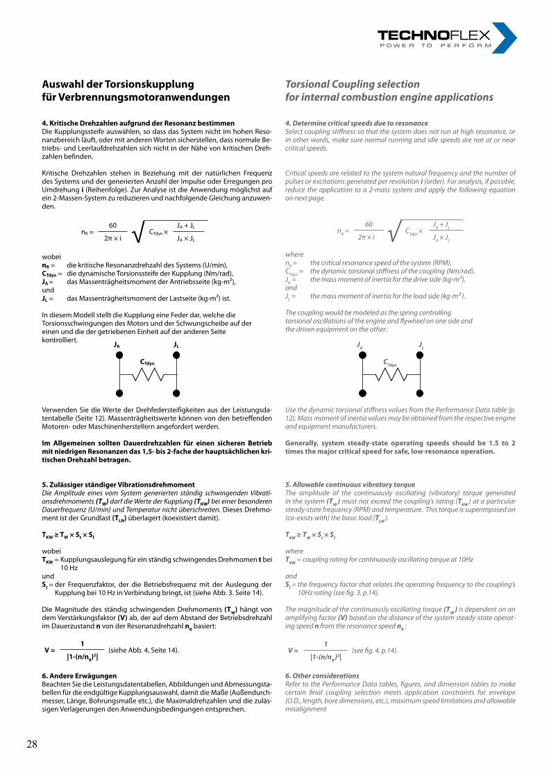
9
wobeinR = die kritische Resonanzdrehzahl des Systems (U/min),CTdyn = die dynamische Torsionssteife der Kupplung (Nm/rad),JA= das Massenträgheitsmoment der Antriebsseite (kg-m²),undJL = das Massenträgheitsmoment der Lastseite (kg-m²) ist.
In diesem Modell stellt die Kupplung eine Feder dar, welche dieTorsionsschwingungen des Motors und der Schwungscheibe auf dereinen und die der getriebenen Einheit auf der anderen Seitekontrolliert.
nR =60 √ CTdyn ×
JA + JL
2π × i JA × JL
JA JL
CTdyn
Verwenden Sie die Werte der Drehfedersteifigkeiten aus der Leistungsda-tentabelle (Seite 12). Massenträgheitswerte können von den betreffenden Motoren- oder Maschinenherstellern angefordert werden.
Im Allgemeinen sollten Dauerdrehzahlen für einen sicheren BetriebmitniedrigenResonanzendas1,5-bis2-fachederhauptsächlichenkri-tischenDrehzahlbetragen.
5.ZulässigerständigerVibrationsdrehmomentDie Amplitude eines vom System generierten ständig schwingenden Vibrati-onsdrehmoments (TW) darf die Werte der Kupplung (TKW) bei einer besonderen Dauerfrequenz (U/min) und Temperatur nicht überschreiten. Dieses Drehmo-ment ist der Grundlast (TLN) überlagert (koexistiert damit).
TKW≥TW×St×Sf
wobeiTKW= Kupplungsauslegung für ein ständig schwingendes Drehmoment bei
10 HzundSf= der Frequenzfaktor, der die Betriebsfrequenz mit der Auslegung der
Kupplung bei 10 Hz in Verbindung bringt, ist (siehe Abb. 3. Seite 14).
Die Magnitude des ständig schwingenden Drehmoments (TW) hängt von dem Verstärkungsfaktor (V) ab, der auf dem Abstand der Betriebsdrehzahl im Dauerzustand n von der Resonanzdrehzahl nR basiert:
6.AndereErwägungenBeachten Sie die Leistungsdatentabellen, Abbildungen und Abmessungsta-bellen für die endgültige Kupplungsauswahl, damit die Maße (Außendurch-messer, Länge, Bohrungsmaße etc.), die Maximaldrehzahlen und die zuläs-sigen Verlagerungen den Anwendungsbedingungen entsprechen.
wherenR = the critical resonance speed of the system (RPM),CTdyn = the dynamic torsional stiffness of the coupling (Nm/rad),JA = the mass moment of inertia for the drive side (kg-m²),andJL = the mass moment of inertia for the load side (kg-m² ).
The coupling would be modeled as the spring controllingtorsional oscillations of the engine and flywheel on one side andthe driven equipment on the other:
Use the dynamic torsional stiffness values from the Performance Data table (p. 12). Mass moment of inertia values may be obtained from the respective engine and equipment manufacturers.
Generally, system steady-state operating speeds should be 1.5 to 2timesthemajorcriticalspeedforsafe,low-resonanceoperation.
5. Allowable continuous vibratory torqueThe amplitude of the continuously oscillating (vibratory) torque generated in the system (TW ) must not exceed the coupling's rating (TKW ) at a particular steady-state frequency (RPM) and temperature. This torque is superimposed on (co-exists with) the basic load (TLN ).
TKW ≥ TW × St × Sf
whereTKW = coupling rating for continuously oscillating torque at 10Hz
andSf = the frequency factor that relates the operating frequency to the coupling’s
10Hz rating (see fig. 3, p.14).
The magnitude of the continuously oscillating torque (TW ) is dependent on an amplifying factor (V) based on the distance of the system steady-state operat-ing speed n from the resonance speed nR :
6. Other considerationsRefer to the Performance Data tables, figures, and dimension tables to make certain final coupling selection meets application constraints for envelope (O.D., length, bore dimensions, etc.), maximum speed limitations and allowable misalignment
V≈1
(siehe Abb. 4, Seite 14).|1-(n/nR)
2|V ≈
1(see fig. 4, p.14).
|1-(n/nR )2|
JA JL
CTdyn
AuswahlderTorsionskupplungfürVerbrennungsmotoranwendungen
4.KritischeDrehzahlenaufgrundderResonanzbestimmenDie Kupplungssteife auswählen, so dass das System nicht im hohen Reso-nanzbereich läuft, oder mit anderen Worten sicherstellen, dass normale Be-triebs- und Leerlaufdrehzahlen sich nicht in der Nähe von kritischen Dreh-zahlen befinden.
Kritische Drehzahlen stehen in Beziehung mit der natürlichen Frequenz des Systems und der generierten Anzahl der Impulse oder Erregungen pro Umdrehung i (Reihenfolge). Zur Analyse ist die Anwendung möglichst auf ein 2-Massen-System zu reduzieren und nachfolgende Gleichung anzuwen-den.
Torsional Coupling selection for internal combustion engine applications
4. Determine critical speeds due to resonanceSelect coupling stiffness so that the system does not run at high resonance, or in other words, make sure normal running and idle speeds are not at or near critical speeds.
Critical speeds are related to the system natural frequency and the number of pulses or excitations generated per revolution i (order). For analysis, if possible, reduce the application to a 2-mass system and apply the following equation on next page.
nR =60 √ CTdyn ×
JA + JL
2π × i JA × JL
28 28
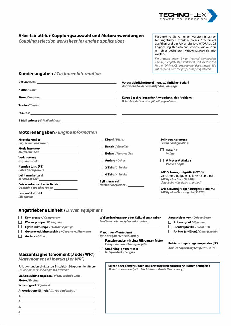
10rl-hydraulics.comR+LHYDRAULICSEngineeringFax+49(2392)509509
ArbeitsblattfürKupplungsauswahlundMotoranwendungenCoupling selection worksheet for engine applications
Für Systeme, die von einem Verbrennungsmo-tor angetrieben werden, dieses Arbeitsblatt ausfüllen und per Fax an das R+L HYDRAULICS Engineering Department senden. Wir werden mit einer geeigneten Kupplungsauswahl ant-worten.For systems driven by an internal combustion engine, complete this worksheet and fax it to the R+L HYDRAULICS engineering department. We will respond with the proper coupling selection.
Kundenangaben/ Customer information
Datum/Date:
Name/Name:
Firma/Company:
Telefon/Phone:
Fax/Fax:
E-Mail-Adresse/E-Mail address:
Motorenangaben / Engine informationMotorherstellerEngine manufacturer:
ModellnummerModel number:
VerlagerungDisplacement:
Nennleistung(PS)Rated horsepower:
beiNenndrehzahlat rated speed:
BetriebsdrehzahloderBereichOperating speed or range:
LeerlaufdrehzahlIdle speed:
Diesel/Diesel
Benzin/Gasoline
Erdgas/Natural Gas
Andere/ Other
2-Takt/ 2-Stroke
4-Takt/ 4-Stroke
ZylinderanzahlNumber of cylinders:
ZylinderanordnungPiston Configuration:
InReihe In-line
V-MotorV-Winkel: Vee vee angle:
SAE-Schwungradgröße(J620D):(Zeichnung beifügen, falls kein Standard) SAE flywheel size (J620D):(Attach drawing if non-standard)
SAE-Schwungradgehäusegröße(J617C)SAE flywheel housing size(J617C):
AngetriebeneEinheit/Driven equipment
Kompressor/ Compressor Wasserpumpe/ Water pump Hydraulikpumpe/ Hydraulic pump: Generator/Lichtmaschine/ Generator/Alternator Andere/ Other
WellendurchmesseroderKeilwellenangabenShaft diameter or spline information:
Maschinen-MontageartType of equipment mounting:
FlanschmontiertmiteinerFührungamMotor Flange-mounted to engine pilot
UnabhängigvomMotor Independent of engine
Angetriebenvon/Driven from: Schwungrad/Flywheel Frontzapfwelle/Front PTO Andere(erklären)/Other (explain)
Betriebsumgebungstemperatur(°C)Ambient operating temperature (°C):
Massenträgheitsmoment(JoderWR2)Mass moment of inertia (J or WR2)Falls vorhanden ein Massen-Elastizität- Diagramm beifügen)Provide mass-elastic diagram if available
Einheitenbitteangeben / Please include unitsMotor / Engine: Schwungrad/ Flywheel:
AngetriebeneEinheit/Driven equipment:
1.
2.
3.
4
SkizzeoderBemerkungen(fallserforderlichzusätzlicheBlätterbeifügen):Sketch or remarks (attach additional sheets if necessary):
VoraussichtlicheBestellmenge/JährlicherBedarf Anticipated order quantity/ Annual usage:
KurzeBeschreibungderAnwendung/desProblemsBrief description of application/problem:
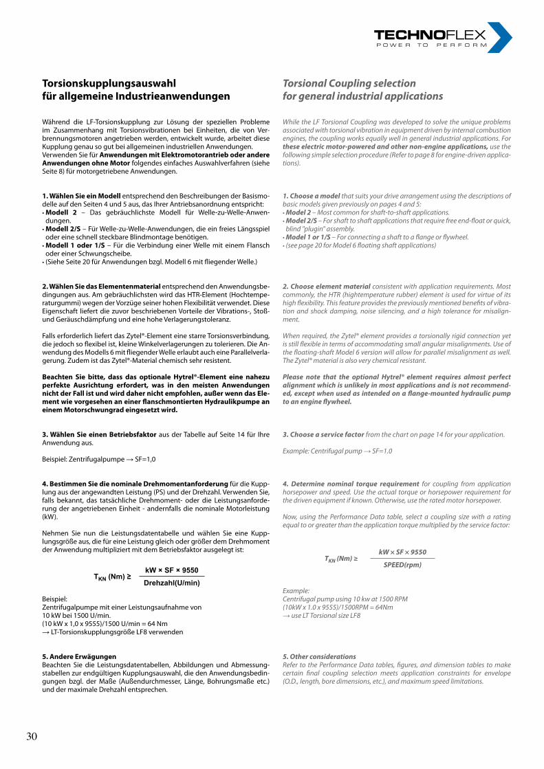
11
TorsionskupplungsauswahlfürallgemeineIndustrieanwendungen
Während die LF-Torsionskupplung zur Lösung der speziellen Probleme im Zusammenhang mit Torsionsvibrationen bei Einheiten, die von Ver-brennungsmotoren angetrieben werden, entwickelt wurde, arbeitet diese Kupplung genau so gut bei allgemeinen industriellen Anwendungen.Verwenden Sie für AnwendungenmitElektromotorantrieboderandereAnwendungenohneMotor folgendes einfaches Auswahlverfahren (siehe Seite 8) für motorgetriebene Anwendungen.
1.WählenSieeinModell entsprechend den Beschreibungen der Basismo-delle auf den Seiten 4 und 5 aus, das Ihrer Antriebsanordnung entspricht:• Modell 2 – Das gebräuchlichste Modell für Welle-zu-Welle-Anwen-
dungen.• Modell2/S – Für Welle-zu-Welle-Anwendungen, die ein freies Längsspiel
oder eine schnell steckbare Blindmontage benötigen.• Modell1oder1/S – Für die Verbindung einer Welle mit einem Flansch
oder einer Schwungscheibe.• (Siehe Seite 20 für Anwendungen bzgl. Modell 6 mit fliegender Welle.)
2.WählenSiedasElementenmaterial entsprechend den Anwendungsbe-dingungen aus. Am gebräuchlichsten wird das HTR-Element (Hochtempe-raturgummi) wegen der Vorzüge seiner hohen Flexibilität verwendet. Diese Eigenschaft liefert die zuvor beschriebenen Vorteile der Vibrations-, Stoß- und Geräuschdämpfung und eine hohe Verlagerungstoleranz.
Falls erforderlich liefert das Zytel®-Element eine starre Torsionsverbindung, die jedoch so flexibel ist, kleine Winkelverlagerungen zu tolerieren. Die An-wendung des Modells 6 mit fliegender Welle erlaubt auch eine Parallelverla-gerung. Zudem ist das Zytel®-Material chemisch sehr resistent.
Beachten Sie bitte, dass das optionale Hytrel®-Element eine nahezuperfekte Ausrichtung erfordert, was in den meisten AnwendungennichtderFallistundwirddahernichtempfohlen,außerwenndasEle-mentwievorgesehenaneinerflanschmontiertenHydraulikpumpeaneinemMotorschwungradeingesetztwird.
3.WählenSieeinenBetriebsfaktor aus der Tabelle auf Seite 14 für Ihre Anwendung aus.
Beispiel: Zentrifugalpumpe → SF=1,0
4.BestimmenSiedienominaleDrehmomentanforderung für die Kupp-lung aus der angewandten Leistung (PS) und der Drehzahl. Verwenden Sie, falls bekannt, das tatsächliche Drehmoment- oder die Leistungsanforde-rung der angetriebenen Einheit - andernfalls die nominale Motorleistung (kW).
Nehmen Sie nun die Leistungsdatentabelle und wählen Sie eine Kupp-lungsgröße aus, die für eine Leistung gleich oder größer dem Drehmoment der Anwendung multipliziert mit dem Betriebsfaktor ausgelegt ist:
Beispiel:Zentrifugalpumpe mit einer Leistungsaufnahme von10 kW bei 1500 U/min.(10 kW x 1,0 x 9555)/1500 U/min = 64 Nm→ LT-Torsionskupplungsgröße LF8 verwenden
5.AndereErwägungenBeachten Sie die Leistungsdatentabellen, Abbildungen und Abmessung-stabellen zur endgültigen Kupplungsauswahl, die den Anwendungsbedin-gungen bzgl. der Maße (Außendurchmesser, Länge, Bohrungsmaße etc.) und der maximale Drehzahl entsprechen.
Torsional Coupling selection for general industrial applications
While the LF Torsional Coupling was developed to solve the unique problems associated with torsional vibration in equipment driven by internal combustion engines, the coupling works equally well in general industrial applications. For these electric motor-powered and other non-engine applications, use the following simple selection procedure (Refer to page 8 for engine-driven applica-tions).
1. Choose a model that suits your drive arrangement using the descriptions of basic models given previously on pages 4 and 5:• Model 2 – Most common for shaft-to-shaft applications.• Model 2/S – For shaft to shaft applications that require free end-float or quick,
blind "plugin" assembly.• Model 1 or 1/S – For connecting a shaft to a flange or flywheel.• (see page 20 for Model 6 floating shaft applications)
2. Choose element material consistent with application requirements. Most commonly, the HTR (hightemperature rubber) element is used for virtue of its high flexibility. This feature provides the previously mentioned benefits of vibra-tion and shock damping, noise silencing, and a high tolerance for misalign-ment.
When required, the Zytel® element provides a torsionally rigid connection yet is still flexible in terms of accommodating small angular misalignments. Use of the floating-shaft Model 6 version will allow for parallel misalignment as well. The Zytel® material is also very chemical resistant.
Please note that the optional Hytrel® element requires almost perfect alignment which is unlikely in most applications and is not recommend-ed, except when used as intended on a flange-mounted hydraulic pump to an engine flywheel.
3. Choose a service factor from the chart on page 14 for your application.
Example: Centrifugal pump → SF=1.0
4. Determine nominal torque requirement for coupling from application horsepower and speed. Use the actual torque or horsepower requirement for the driven equipment if known. Otherwise, use the rated motor horsepower.
Now, using the Performance Data table, select a coupling size with a rating equal to or greater than the application torque multiplied by the service factor:
Example:Centrifugal pump using 10 kw at 1500 RPM(10kW x 1.0 x 9555)/1500RPM = 64Nm→ use LT Torsional size LF8
5. Other considerationsRefer to the Performance Data tables, figures, and dimension tables to make certain final coupling selection meets application constraints for envelope (O.D., length, bore dimensions, etc.), and maximum speed limitations.
TKN (Nm) ≥kW × SF × 9550
SPEED(rpm)
TKN (Nm) ≥kW × SF × 9550Drehzahl(U/min)
30 30
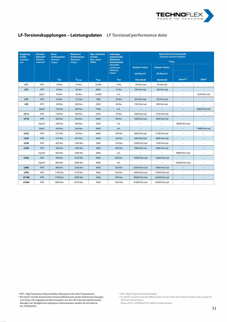
12rl-hydraulics.com
* HTR = High Temperature Natural Rubber (Naturgummi für hohe Temperaturen).^ Bei Hytrel® sind die dynamischen Torsionssteifheitswerte auf das Drehmoment bezogen
nicht linear. Die angegebenen Werte beziehen sich auf 100 % des Nenndrehmoments. Bezüglich der Steifigkeit bei niedrigeren Drehmomenten wenden Sie sich bitte an R+L HYDRAULICS.
LF-Torsionskupplungen–LeistungsdatenLF Torsional performance data
* HTR = High Temperature Natural Rubber^ For Hytrel®, dynamic torsional stiffness values are non-linear with respect to torque. Value is given for
100 % of nominal torque. Please call R+L HYDRAULICS for stiffness at lower torques.
KupplungGrößeCouplingsize
ElementMaterial*Elementmaterial*
Nenn-DrehmomentNominaltorque
MaximumDrehmomentMaximumtorque
Max.Drehzahl(U/min)Max.speed(RPM)
ZulässigesandauerndesVibrations-DrehmomentAllowablecontinuousvibratorytorque
DynamischeTorsionssteifeDynamictorsionalstiffness
CTdyn
GummiRubber GummiRubber
60ShoreA 50ShoreA
TKN TKmax nmax TKW (Standard) (Optional) Hytrel®^ Zytel®
LF1 HTR 10 Nm 25 Nm 10.000 5 Nm 140 Nm/rad 90 Nm/rad – –
LF2 HTR 20 Nm 60 Nm 8000 10 Nm 290 Nm/rad 180 Nm/rad – –
Zytel® 30 Nm 60 Nm 10.000 k.A. – – – 6230 Nm/rad
LF4 HTR 50 Nm 125 Nm 7000 20 Nm 850 Nm/rad 550 Nm/rad – –
LF8 HTR 100 Nm 280 Nm 6500 40 Nm 1500 Nm/rad 900 Nm/rad – –
Zytel® 120 Nm 280 Nm 7000 k.A. – – – 46820 Nm/rad
LF12 HTR 140 Nm 360 Nm 6500 50 Nm 4400 Nm/rad 2700 Nm/rad – –
LF16 HTR 200 Nm 560 Nm 6000 80 Nm 3400 Nm/rad 2000 Nm/rad – –
Hytrel® 200 Nm 560 Nm 5500 k.A. – – 36000 Nm/rad –
Zytel® 240 Nm 560 Nm 6000 k.A. – – – 74000 Nm/rad
LF22 HTR 275 Nm 750 Nm 6000 100 Nm 9000 Nm/rad 6100 Nm/rad – –
LF25 HTR 315 Nm 875 Nm 5000 125 Nm 4500 Nm/rad 2800 Nm/rad – –
LF28 HTR 420 Nm 1200 Nm 5000 150 Nm 12000 Nm/rad 7500 Nm/rad – –
LF30 HTR 500 Nm 1400 Nm 4000 200 Nm 7800 Nm/rad 4800 Nm/rad – –
Hytrel® 500 Nm 1400 Nm 4000 k.A. – – 88000 Nm/rad –
LF50 HTR 700 Nm 2100 Nm 4000 300 Nm 19000 Nm/rad 12000 Nm/rad – –
Hytrel® 800 Nm 2000 Nm 4000 k.A. – – 262000 Nm/rad –
LF80 HTR 900 Nm 2100 Nm 4000 320 Nm 25000 Nm/rad 16000 Nm/rad – –
LF90 HTR 1100 Nm 3150 Nm 3600 450 Nm 16000 Nm/rad 10500 Nm/rad – –
LF140 HTR 1700 Nm 4900 Nm 3600 700 Nm 40000 Nm/rad 26500 Nm/rad – –
LF250 HTR 3000 Nm 8750 Nm 3000 1250 Nm 67000 Nm/rad 43000 Nm/rad – –
31 31
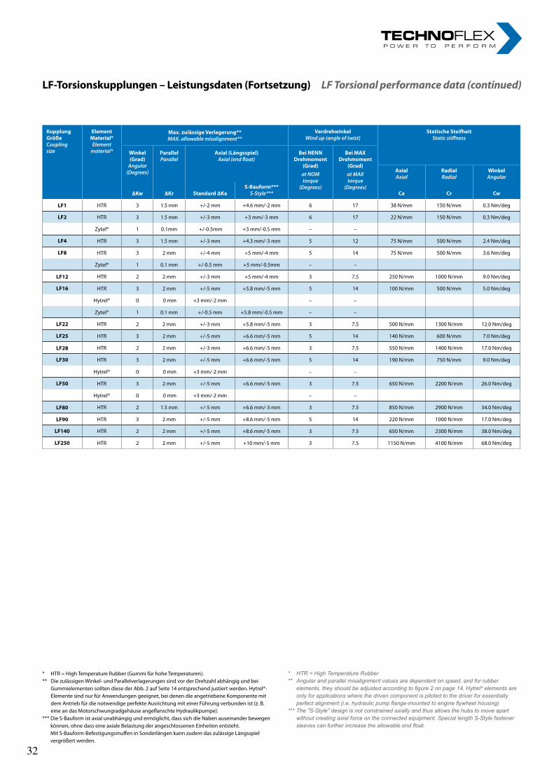
13
LF-Torsionskupplungen–Leistungsdaten(Fortsetzung)LF Torsional performance data (continued)
* HTR = High Temperature Rubber (Gummi für hohe Temperaturen).** Die zulässigen Winkel- und Parallelverlagerungen sind vor der Drehzahl abhängig und bei
Gummielementen sollten diese der Abb. 2 auf Seite 14 entsprechend justiert werden. Hytrel®-Elemente sind nur für Anwendungen geeignet, bei denen die angetriebene Komponente mit dem Antrieb für die notwendige perfekte Ausrichtung mit einer Führung verbunden ist (z. B. eine an das Motorschwungradgehäuse angeflanschte Hydraulikpumpe).
*** Die S-Bauform ist axial unabhängig und ermöglicht, dass sich die Naben auseinander bewegen können, ohne dass eine axiale Belastung der angeschlossenen Einheiten entsteht. Mit S-Bauform-Befestigungsmuffen in Sonderlängen kann zudem das zulässige Längsspiel vergrößert werden.
* HTR = High Temperature Rubber** Angular and parallel misalignment values are dependent on speed, and for rubber
elements, they should be adjusted according to figure 2 on page 14. Hytrel® elements are only for applications where the driven component is piloted to the driver for essentially perfect alignment (i.e. hydraulic pump flange-mounted to engine flywheel housing)
*** The "S-Style" design is not constrained axially and thus allows the hubs to move apart without creating axial force on the connected equipment. Special length S-Style fastener sleeves can further increase the allowable end float.
KupplungGrößeCouplingsize
ElementMaterial*Elementmaterial*
Max.zulässigeVerlagerung**MAX.allowablemisalignment**
VerdrehwinkelWindup(angleoftwist)
StatischeSteifheitStaticstiffness
Winkel(Grad)
Angular (Degrees)
ParallelParallel
Axial(Längsspiel)Axial(endfloat)
BeiNENNDrehmoment
(Grad)atNOMtorque
(Degrees)
BeiMAXDrehmoment
(Grad)atMAXtorque
(Degrees)
AxialAxial
RadialRadial
WinkelAngular
∆Kw ∆Kr Standard∆KaS-Bauform***S-Style*** Ca Cr Cw
LF1 HTR 3 1.5 mm +/-2 mm +4.6 mm/-2 mm 6 17 38 N/mm 150 N/mm 0.3 Nm/deg
LF2 HTR 3 1.5 mm +/-3 mm +3 mm/-3 mm 6 17 22 N/mm 150 N/mm 0.3 Nm/deg
Zytel® 1 0.1mm +/-0.5mm +3 mm/-0.5 mm – –
LF4 HTR 3 1.5 mm +/-3 mm +4.3 mm/-3 mm 5 12 75 N/mm 500 N/mm 2.4 Nm/deg
LF8 HTR 3 2 mm +/-4 mm +5 mm/-4 mm 5 14 75 N/mm 500 N/mm 3.6 Nm/deg
Zytel® 1 0.1 mm +/-0.5 mm +5 mm/-0.5mm – –
LF12 HTR 2 2 mm +/-3 mm +5 mm/-4 mm 3 7.5 250 N/mm 1000 N/mm 9.0 Nm/deg
LF16 HTR 3 2 mm +/-5 mm +5.8 mm/-5 mm 5 14 100 N/mm 500 N/mm 5.0 Nm/deg
Hytrel® 0 0 mm +3 mm/-2 mm – –
Zytel® 1 0.1 mm +/-0.5 mm +5.8 mm/-0.5 mm – –
LF22 HTR 2 2 mm +/-3 mm +5.8 mm/-5 mm 3 7.5 500 N/mm 1300 N/mm 12.0 Nm/deg
LF25 HTR 3 2 mm +/-5 mm +6.6 mm/-5 mm 5 14 140 N/mm 600 N/mm 7.0 Nm/deg
LF28 HTR 2 2 mm +/-3 mm +6.6 mm/-5 mm 3 7.5 550 N/mm 1400 N/mm 17.0 Nm/deg
LF30 HTR 3 2 mm +/-5 mm +6.6 mm/-5 mm 5 14 190 N/mm 750 N/mm 9.0 Nm/deg
Hytrel® 0 0 mm +3 mm/-2 mm – –
LF50 HTR 3 2 mm +/-5 mm +6.6 mm/-5 mm 3 7.5 650 N/mm 2200 N/mm 26.0 Nm/deg
Hytrel® 0 0 mm +3 mm/-2 mm – –
LF80 HTR 2 1.5 mm +/-5 mm +6.6 mm/-3 mm 3 7.5 850 N/mm 2900 N/mm 34.0 Nm/deg
LF90 HTR 3 2 mm +/-5 mm +8.6 mm/-5 mm 5 14 220 N/mm 1000 N/mm 17.0 Nm/deg
LF140 HTR 2 2 mm +/-5 mm +8.6 mm/-5 mm 3 7.5 650 N/mm 2300 N/mm 38.0 Nm/deg
LF250 HTR 2 2 mm +/-5 mm +10 mm/-5 mm 3 7.5 1150 N/mm 4100 N/mm 68.0 Nm/deg
32 32

14rl-hydraulics.com
LF-Torsionskupplungen–TechnischeAuswahldatenLF Torsional technical selection data
LeitfadenfürBetriebsfaktorenService factor guideRührwerke Agitators ............................................................................................. 1.0Kneter Beaters ....................................................................................................... 1.5Lüfter Blowers ........................................................................................................ 1.0-1.25Getränkefüllanlagen Can filling machinery .................................................. 1.0Waggonkipper Car dumpers ............................................................................ 2.5Waggonwinden Car pullers ............................................................................... 1.5Schraubenkompressoren Compressors (screws) ........................................ 1.0-1.25Kolbenkompressoren R+L HYDRAULICS konsultieren Compressors (reciprocating) consult R+L HYDRAULICSFörderer Conveyors .............................................................................................. 1.0-1.25Arbeitswalzen, Rüttler Live roll, shaker & reciprocating ............................ 3.0Förderer (rauer Betrieb) Conveyors (heavy duty) ......................................... 1.25-2.5Krane und Winden Cranes & Hoists .................................................................. 2.0Brecher Crushers ................................................................................................... 3.0Bagger Dredges ..................................................................................................... 1.5-2.0Aufzüge Elevators ................................................................................................. 1.5-2.0Verdampfer Evaporators ..................................................................................... 1.0Lüfter Fans .............................................................................................................. 1.0-1.5Speiser Feeders ..................................................................................................... 1.0 Hubkolben Reciprocating ............................................................................. 2.5Generatoren Generators Nicht für Schweißen Not welding ............................................................... 1.0 Schweißen Welding ........................................................................................2.0 Lift Hoist .............................................................................................................1.5Hammermühlen Hammer mills........................................................................2.0Brennöfen Kilns .....................................................................................................1.5Waschmaschinen Laundry washers mit Drehrichtungsumkehr Reversing ........................................................ 2.0Deckentransmission Line shafting .................................................................1.5Sägewerke Lumber machinery ........................................................................ 2.0Werkzeugmaschinen Machine tools .............................................................. 1.5-2.0Metallformungsmaschinen Metal forming machines .... ......................... 1.5-2.5Walzwerke (drehend) Mills, rotary type ........................................................2.0Mischmaschinen Mixers ..................................................................................... 1.5-1.8Papiermühlen-Einrichtungen Paper mills equipment .... ......................... 1.2-2.0Pumpen Pumps Zentrifugal Centrifugal ................................................................................... 1.0 Zahnrad, Drehkolben oder Flügel Gear, rotary or vane ...................... 1.25 Hubkolben. 1 Zyl., Einfach- oder Doppelwirkung Reciprocating 1 Cyl. single or double acting .............................................. 2.0 2 Zyl. Einfachwirkung 2 Cyl. single acting ................................................ 2.0 2 Zyl. Doppelwirkung 2 Cyl. double acting .............................................. 1.75 3 oder mehr Zyl. 3 or more Cyl. .................................................................... 1.5Gummiverarbeitungsmaschinen Rubber machinery ............................... 2.0-2.5Stoker Stokers .......................................................................................................... 1.0Textilmaschinen Textile machinery ................................................................. 1.2Bauwinden Windlass ............................................................................................ 2.0Holzverarbeitungsmaschinen Woodworking machinery ........................ 1.0
Abb. 1 - TemperaturfaktorFig. 1 - Temperature factor
0.5
1
1.5
2
30 50 70 90* Nur HTR* HTR only
Grad CelciusDegrees C
S t
Abb. 2 - Zulässige Verlagerung bezogen auf die DrehzahlFig. 2 - Permissible misalignment vs. speed
Code: A = little or no effect; B = moderate effect; C = severe effect* Additives in antifreeze may attack these elastomers severely.
Kodierung: A = kleine oder keine Einwirkung, B = moderate Einwirkung, C = starke Einwirkung* Zusätze im Frostschutz können diese Elastomere stark angreifen.
Abb. 3 - FrequenzfaktorFig. 3 - Frequency factor
Abb. 4 - Resonanzfaktor Vr und relativer Dämpfungsfaktor Ψ Fig. 4 - Resonance factor Vr and relative damping factor Ψ
Betr
iebs
dreh
zahl
(U/m
in)
Ope
ratin
g Sp
eed
(RPM
)
Prozent des Nennwertes für zulässigen Versatz bei TKNPercent of rating for allowable misalignment at TKN
HTR (Winkel und parallel)HTR (angular and parallel)
Zytel® (Winkel)Zytel® (angular)
ÖlundHydraulikfluidsOils&Hydraulicfluids Hytrel® Zytel® LösungenundTreibstoffe
Solvents&Fuels Hytrel® Zytel® SäurenundLaugenAcids&Bases Hytrel® Zytel® Sonstiges
Miscellaneous Hytrel® Zytel®
AutomatikgetriebeAutomatic Transmissions A A Benzin
Gasoline A A Schwefelsäure (20 %) Sulfuric Acid (20 %) A C Athylenglykol *
Ethylene Glycol* A A, B
Fluidtyp A& F Fluid Type A & F A A Nujol, JP4-Kerosin
Nujol, JP4 Kerosene A A Chlorwasserstoffsäure (20 %)Hydrochloric Acid(20 %) B C Dampf
Steam B B
Hydraulikfluid Hydraulic Fluid A A Halokarbone, Freon
Halocarbons, Freon A A Kalium oder NatriumPotassium or Sodium
Flüssiges AmmoniakLiquid Ammonia A
Phosphatester Phosphate Ester A A Trichloräthylen
Trichlorethylene C C Hydroxide (20 %)Hydroxide (20 %) A B
SchmierölLube Oil A A Karbontetrachlorid
Carbon Tetrachloride B A
ElastischesElementElasticElement Vr Ψ
HTR 50 Shore A 10 0.6
HTR 60 Shore A 8 0.78
Hytrel® – 0.5
Zytel® – 0.4
Betriebsfrequenzf(Hz)Operating frequency f (Hz) ≤10 >10
Frequenzfaktor sfFrequency factor sf
1 √ f/10
33 33
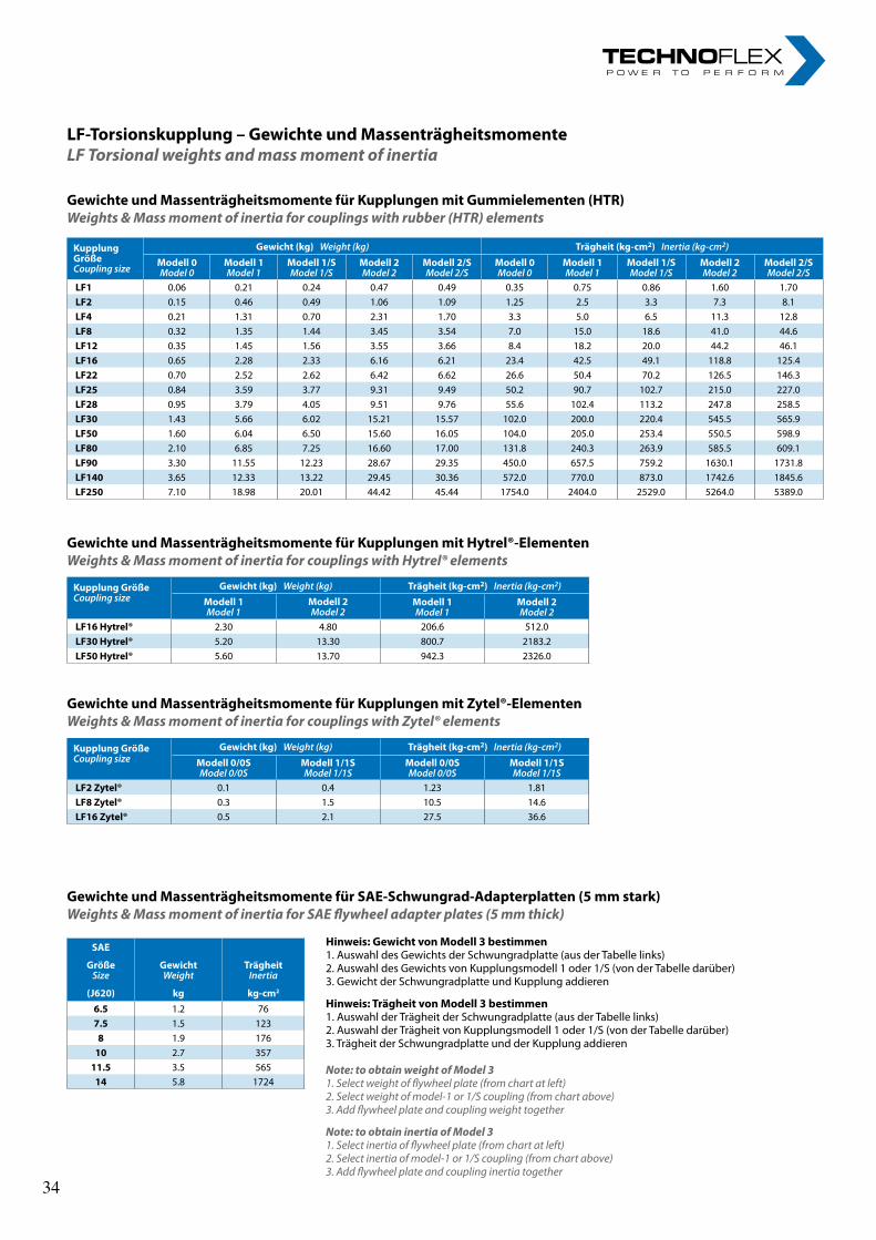
15
LF-Torsionskupplung–GewichteundMassenträgheitsmomenteLF Torsional weights and mass moment of inertia
GewichteundMassenträgheitsmomentefürKupplungenmitGummielementen(HTR)Weights & Mass moment of inertia for couplings with rubber (HTR) elements
GewichteundMassenträgheitsmomentefürKupplungenmitHytrel®-ElementenWeights & Mass moment of inertia for couplings with Hytrel® elements
GewichteundMassenträgheitsmomentefürSAE-Schwungrad-Adapterplatten(5mmstark)Weights & Mass moment of inertia for SAE flywheel adapter plates (5 mm thick)
Hinweis:GewichtvonModell3bestimmen1. Auswahl des Gewichts der Schwungradplatte (aus der Tabelle links)2. Auswahl des Gewichts von Kupplungsmodell 1 oder 1/S (von der Tabelle darüber)3. Gewicht der Schwungradplatte und Kupplung addieren
Hinweis:TrägheitvonModell3bestimmen1. Auswahl der Trägheit der Schwungradplatte (aus der Tabelle links)2. Auswahl der Trägheit von Kupplungsmodell 1 oder 1/S (von der Tabelle darüber)3. Trägheit der Schwungradplatte und der Kupplung addieren
Note: to obtain weight of Model 31. Select weight of flywheel plate (from chart at left)2. Select weight of model-1 or 1/S coupling (from chart above)3. Add flywheel plate and coupling weight together
Note: to obtain inertia of Model 31. Select inertia of flywheel plate (from chart at left)2. Select inertia of model-1 or 1/S coupling (from chart above)3. Add flywheel plate and coupling inertia together
KupplungGrößeCouplingsize
Gewicht(kg)Weight(kg) Trägheit(kg-cm2)Inertia(kg-cm2)
Modell1Model1
Modell2Model2
Modell1Model1
Modell2Model2
LF16Hytrel® 2.30 4.80 206.6 512.0LF30Hytrel® 5.20 13.30 800.7 2183.2LF50Hytrel® 5.60 13.70 942.3 2326.0
KupplungGrößeCouplingsize
Gewicht(kg)Weight(kg) Trägheit(kg-cm2)Inertia(kg-cm2)
Modell0/0SModel0/0S
Modell1/1SModel1/1S
Modell0/0SModel0/0S
Modell1/1SModel1/1S
LF2Zytel® 0.1 0.4 1.23 1.81LF8Zytel® 0.3 1.5 10.5 14.6LF16Zytel® 0.5 2.1 27.5 36.6
KupplungGrößeCouplingsize
Gewicht(kg)Weight(kg) Trägheit(kg-cm2)Inertia(kg-cm2)
Modell0Model0
Modell1Model1
Modell1/SModel1/S
Modell2Model2
Modell2/SModel2/S
Modell0Model0
Modell1Model1
Modell1/SModel1/S
Modell2Model2
Modell2/SModel2/S
LF1 0.06 0.21 0.24 0.47 0.49 0.35 0.75 0.86 1.60 1.70LF2 0.15 0.46 0.49 1.06 1.09 1.25 2.5 3.3 7.3 8.1LF4 0.21 1.31 0.70 2.31 1.70 3.3 5.0 6.5 11.3 12.8LF8 0.32 1.35 1.44 3.45 3.54 7.0 15.0 18.6 41.0 44.6LF12 0.35 1.45 1.56 3.55 3.66 8.4 18.2 20.0 44.2 46.1LF16 0.65 2.28 2.33 6.16 6.21 23.4 42.5 49.1 118.8 125.4LF22 0.70 2.52 2.62 6.42 6.62 26.6 50.4 70.2 126.5 146.3LF25 0.84 3.59 3.77 9.31 9.49 50.2 90.7 102.7 215.0 227.0LF28 0.95 3.79 4.05 9.51 9.76 55.6 102.4 113.2 247.8 258.5LF30 1.43 5.66 6.02 15.21 15.57 102.0 200.0 220.4 545.5 565.9LF50 1.60 6.04 6.50 15.60 16.05 104.0 205.0 253.4 550.5 598.9LF80 2.10 6.85 7.25 16.60 17.00 131.8 240.3 263.9 585.5 609.1LF90 3.30 11.55 12.23 28.67 29.35 450.0 657.5 759.2 1630.1 1731.8LF140 3.65 12.33 13.22 29.45 30.36 572.0 770.0 873.0 1742.6 1845.6LF250 7.10 18.98 20.01 44.42 45.44 1754.0 2404.0 2529.0 5264.0 5389.0
SAE
GrößeSize
GewichtWeight
TrägheitInertia
(J620) kg kg-cm2
6.5 1.2 767.5 1.5 1238 1.9 17610 2.7 35711.5 3.5 56514 5.8 1724
GewichteundMassenträgheitsmomentefürKupplungenmitZytel®-ElementenWeights & Mass moment of inertia for couplings with Zytel® elements
34 34
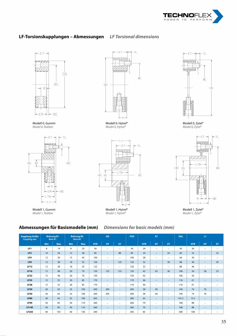
16rl-hydraulics.com
LF-Torsionskupplungen–AbmessungenLF Torsional dimensions
Modell 0, GummiModel 0, Rubber
Modell 0, Zytel®Model 0, Zytel®
Modell 0, Hytrel®Model 0, Hytrel®
Modell 1, Gummi Model 1, Rubber
Modell 1, Zytel®Model 1, Zytel®
Modell 1, Hytrel®Model 1, Hytrel®
AbmessungenfürBasismodelle(mm)Dimensions for basic models (mm)
KupplungGrößeCouplingsize
BohrungB1BoreB1
BohrungB2BoreB2
OD FOD ET OAL L1
Min Max Min Max HTR HY ZY HTR HY ZY HTR HY ZY
LF1 8 19 8 25 56 – – 56 24 – – 50 26 – –
LF2 10 26 12 38 85 – 88 85 24 – 24 60 32 – 32
LF4 12 30 15 45 100 – – 100 28 – – 64 34 – –
LF8 12 38 18 55 120 – 125 120 32 – 30 88 46 – 45
LF12 12 38 18 55 122 – – 120 32 – – 88 46 – –
LF16 15 48 20 70 150 155 155 150 42 43 36 106 56 58 53
LF22 15 48 20 70 150 – – 150 42 – – 106 56 – –
LF25 15 55 20 85 170 – – 170 46 – – 116 61 – –
LF28 15 55 20 85 170 – – 170 46 – – 116 61 – –
LF30 20 65 25 100 200 205 – 200 58 58 – 140 74 76 –
LF50 20 65 25 100 200 205 – 200 58 58 – 140 74 76 –
LF80 20 65 25 100 205 – – 200 65 – – 141.5 75.5 – –
LF90 30 85 30 110 260 – – 260 70 – – 168 88 – –
LF140 30 85 30 110 260 – – 260 70 – – 168 88 – –
LF250 40 105 40 130 340 – – 340 85 – – 208 108 – –
35 35
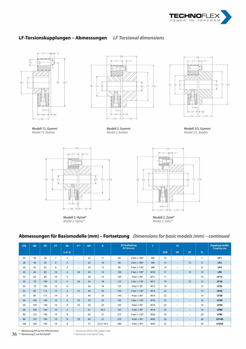
17
Modell 1S, GummiModel 1S, Rubber
Modell 2/S, GummiModel 2/S, Rubber
Modell 2, GummiModel 2, Rubber
Modell 2, Hytrel®Model 2, Hytrel ®
Modell 2, Zytel®Model 2, Zytel ®
AbmessungenfürBasismodelle(mm)–FortsetzungDimensions for basic models (mm) – continued
* Abmessung ER nur für HTR (Gummi).** Abmessung S nur für Hytrel®.
* Dimension ER for HTR (rubber) only.** Dimension S for Hytrel® only.
LTB HD FD FT BE S** ER* R BC/AufteilungBC/division
T TS KupplungGrößeCouplingsize
(+3/-2) HTR HY ZY TL
24 30 36 7 2 – 22 11 44 2 bei @ 180° M6 10 – – 7 LF1
28 40 55 8 4 – 20 10 68 2 bei @ 180° M8 14 – 15 8 LF2
30 45 65 8 4 – 24 12 80 3 bei @ 120° M8 14 – – 8 LF4
42 60 80 10 4 20 28 14 100 3 bei @ 120° M10 17 – 19 10 LF8
42 60 80 10 4 – 28 14 100 4 bei @ 90° M11 17 – – 10 LF12
50 70 100 12 6 26 36 18 125 3 bei @ 120‘ M12 19 – 22 12 LF16
50 70 100 12 6 – 36 18 125 4 bei @ 90° M12 19 – – 12 LF22
55 85 115 14 6 27 40 20 140 3 bei @ 120° M14 22 – – 14 LF25
55 85 115 14 6 – 40 20 140 4 bei @ 90° M14 22 – – 14 LF28
66 100 140 16 8 35 50 25 165 3 bei @ 120° M16 25 – – 16 LF30
66 100 140 16 8 35 50 25 165 4 bei @ 90° M16 25 – – 16 LF50
66 100 140 16 4 – 61 30.5 165 4 bei @ 90° M16 25 – – 16 LF80
80 125 160 19 8 – 62 31 215 3 bei @ 120° M20 32 – – 20 LF90
80 125 160 19 8 33 62 31 215 4 bei @ 90° M20 32 – – 20 LF140
100 160 195 19 8 – 77 22.5 / 54.5 280 4 bei @ 90° M20 32 – – 20 LF250
LF-Torsionskupplungen–AbmessungenLF Torsional dimensions
36 36
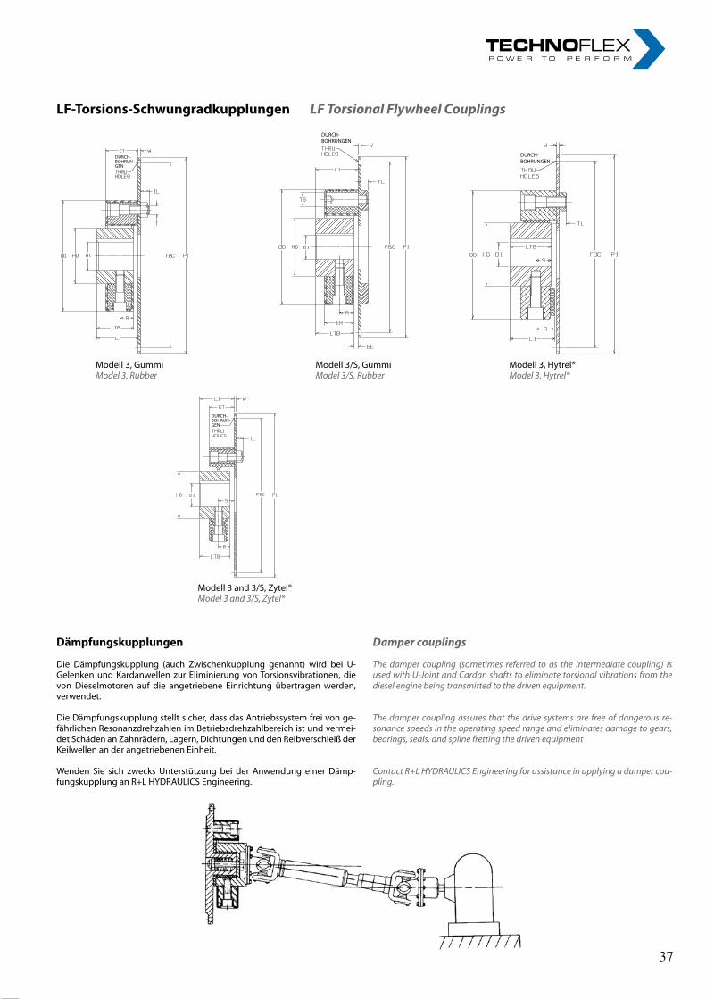
18rl-hydraulics.com
LF-Torsions-SchwungradkupplungenLF Torsional Flywheel Couplings
Dämpfungskupplungen
Die Dämpfungskupplung (auch Zwischenkupplung genannt) wird bei U-Gelenken und Kardanwellen zur Eliminierung von Torsionsvibrationen, die von Dieselmotoren auf die angetriebene Einrichtung übertragen werden, verwendet.
Die Dämpfungskupplung stellt sicher, dass das Antriebssystem frei von ge-fährlichen Resonanzdrehzahlen im Betriebsdrehzahlbereich ist und vermei-det Schäden an Zahnrädern, Lagern, Dichtungen und den Reibverschleiß der Keilwellen an der angetriebenen Einheit.
Wenden Sie sich zwecks Unterstützung bei der Anwendung einer Dämp-fungskupplung an R+L HYDRAULICS Engineering.
Damper couplings
The damper coupling (sometimes referred to as the intermediate coupling) is used with U-Joint and Cardan shafts to eliminate torsional vibrations from the diesel engine being transmitted to the driven equipment.
The damper coupling assures that the drive systems are free of dangerous re-sonance speeds in the operating speed range and eliminates damage to gears, bearings, seals, and spline fretting the driven equipment
Contact R+L HYDRAULICS Engineering for assistance in applying a damper cou-pling.
Modell 3, GummiModel 3, Rubber
Modell 3, Hytrel®Model 3, Hytrel®
Modell 3/S, GummiModel 3/S, Rubber
Modell 3 and 3/S, Zytel®Model 3 and 3/S, Zytel®
37 37

19
SAESchwungrad
Größe
SAEflywheelsize
FührungP1
PilotP1
Schrauben-KreisFBC
BoltcircleFBC
Durchg.-Bohr.Thruholes
VorgeschlageneKupplungsgrößenbezogenaufSAE-SchwungradgrößenSuggestedcouplingsizesforSAEflywheelsizes
ANZ.
NO
NENN-Durchm.
NOMDIA
HTR HY ZY
Modell3&3SModel3&3S
Modell3Model3
Modell3Model3
6-1/2 215.9 200.02 6 9 8, 16 8, 16 8, 16
7-1/2 241.3 222.25 8 9 8, 16 8, 16 8, 16
8 263.52 244.47 6 11 16, 25 16, 30 16
10 314.32 295.27 8 11 25, 30 30, 50
50, 90 140
11-1/2 352.42 333.37 8 11 30, 50 50, 140
90, 140 250
250
14 466.72 438.15 8 13 90, 140 140 k.A.
250 250
16 517.5 488.95 8 13 250 250 k.A.
Schwungrad-Kupplungsmodell3,3/S–Abmessungen(mm)Flywheel Couplings Model 3, 3/S – dimensions (mm)
* Abmessung ER nur für HTR (Gummi). * Dimension ER for HTR (rubber) only.
* Nur Hytrel®. * Hytrel ® only.
SAEJ620Schwungradabmessungen(mm)fürModelle3,3SSAE J620 flywheel dimensions for Model 3, 3S (mm) Durchboh-
rungenThru holes
KupplungGrößeCouplingsize
BohrungB1BoreB1
OD ET TL L1 ER* W R LTB
Min Max HTR HY ZY HTR HY ZY HTR HY ZY
LF1 8 19 56 – – 24 – – 7 26 – – 22 – 11 24
LF2 10 26 85 – 88 24 – 24 8 32 – 32 20 – 10 28
LF4 12 30 100 – – 28 – – 8 34 – – 24 – 12 30
LF8 12 38 120 – 125 32 – 30 10 46 – 45 28 5 14 42
LF12 12 38 122 – – 32 – – 10 46 – – 28 5 14 42
LF16 15 48 150 155 155 42 43 36 12 56 58 53 36 5 18 50
LF22 15 48 150 – – 42 – – 12 56 – – 36 5 18 50
LF25 15 55 170 – – 46 – – 14 61 – – 40 5 20 55
LF28 15 55 170 – – 46 – – 14 61 – – 40 5 20 55
LF30 20 65 200 205 – 58 58 – 16 74 76 – 50 5 25 66
LF50 20 65 200 205 – 58 58 – 16 74 76 – 50 5 25 66
LF80 20 65 205 – – 65 – – 16 75.5 – – 61 5 30.5 66
LF90 30 85 260 – – 70 – – 20 88 – – 62 5 31 80
LF140 30 85 260 – – 70 – – 20 88 – – 62 5 31 80
LF250 40 105 340 – – 85 – – 20 108 – – 77 13/19 22.5/54.5 100
KupplungGrößeCouplingsize
BE S* U* L4* HD BC/AufteilungBC/division
T ET
(+3/-2) (+3/-2) HTR HY ZY
LF1 2 – – – 30 44 2 bei/at 180° M6 10 – –
LF2 4 – – – 40 68 2 bei/at 180° M8 14 – 15
LF4 4 – – – 45 80 3 bei/at 120° M8 14 – –
LF8 4 20 – – 60 100 3 bei/at 120° M10 17 – 19
LF12 4 – – – 60 100 4 bei/at 90° M10 17 – –
LF16 6 26 – – 70 125 3 bei/at 120° M12 19 – 22
LF22 6 – – – 70 125 4 bei/at 90° M12 19 – –
LF25 6 27 – – 85 140 3 bei/at 120° M14 22 – –
LF28 6 – – – 85 140 4 bei/at 90° M14 22 – –
LF30 8 35 44 11 100 165 3 bei/at 120° M16 25 – –
LF50 8 35 30 22 100 165 4 bei/at 90° M16 25 – –
LF80 4 – – – 100 165 4 bei/at 90° M16 25 – –
LF90 8 – – – 125 215 3 bei/at 120° M20 32 – –
LF140 8 33 31.5 10.5 125 215 4 bei/at 90° M20 32 – –
LF250 8 – – – 160 280 4 bei/at 90° M20 32 – –
LF-Torsions-SchwungradkupplungenLF Torsional Flywheel Couplings
38 38
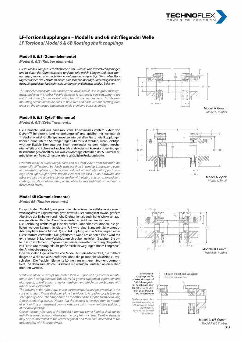
20rl-hydraulics.com
Modell6,6/S(Gummielemente)Model 6, 6/S (Rubber elements)
Dieses Modell kompensiert erhebliche Axial-, Radial- und Winkelverlagerungen und ist durch das Gummielement torsional sehr weich. Längen sind nicht stan-dardisiert, werden aber nach Kundenanforderungen gefertigt. Die axialen Mon-tageschrauben der S-Bauform bieten eine schnelle Montage und ermöglichen ein freies Längsspiel der Nabe ohne die verbundenen Einheiten axial zu belasten.
This model compensates for considerable axial, radial, and angular misalign-ment, and with the rubber flexible elements is torsionally very soft. Lengths are not standardized, but made according to customer requirements. S-style axial mounting screws allow the hubs to have free end float without exerting axial loads on the connected equipment, while providing quick assembly.
Modell6,6/S(Zytel®-Elemente)Model 6, 6/S (Zytel ® elements)
Die Elemente sind aus hoch-robustem, korrosionsresistentem Zytel® von DuPontTM hergestellt, sind verdrehungssteif und spielfrei mit weniger als 1° Verdrehwinkel. Große Spannweiten wie bei allen Ganzmetallkupplungen können ohne interne Stützlagerungen überbrückt werden, wenn leichtge-wichtige flexible Elemente aus Zytel® verwendet werden. Naben, mecha-nische Teile und Rohre sind auch in Edelstahl oder mit korrosionsbeständigen Beschichtungen erhältlich. Die axialen Montageschrauben der S-Bauform er-möglichen ein freies Längsspiel ohne schädliche Reaktionskräfte.
Elements made of super-tough, corrosion resistant Zytel® from DuPontTM are torsionally stiff without backlash, with less than 1° windup. Large spans, equal to all-metal couplings, can be accommodated without internal support bear-ings when lightweight Zytel® flexible elements are used. Hubs, hardware and tubes are also available in stainless steel or with plating and corrosion resistant coatings. S-style, axial mounting screws allow for free end-float without harm-ful reaction forces.
Model6B(Gummielemente)Model 6B (Rubber elements)
Entspricht dem Modell 6, ausgenommen dass die mittlere Welle von internem wartungsfreiem Lagermaterial gestützt wird. Dies ermöglicht sowohl größere Abstände der Einheiten und hohe Drehzahlen als auch hohe Winkelverlage-rungen, die mit flexiblen Gummielementen erreicht werden können.Die Zeichnung rechts zeigt eine der vielen Sonderkonstruktionen, die ge-liefert werden können. In diesem Fall wird eine Standard- Schwungrad-Adapterplatte (siehe Modell 3) zur Ankupplung an das Schwungrad eines Dieselmotors verwendet. Die geflanschte Nabe am anderen Ende wird mit extra langen S-Bauform-Verbindungsschrauben geliefert. (Beachten Sie bit-te, dass das Element umgekehrt zu seiner normalen Richtung dargestellt ist.) Diese Anordnung erlaubt große axiale Bewegungen (freies Längsspiel) der Antriebsbaugruppe.Eine der vielen Eigenschaften von Modell 6 ist die Möglichkeit, die mittlere fliegende Welle radial zu entfernen, ohne die gekuppelte Maschine zu ver-schieben. Die flexiblen Elemente können am mittleren Segment vormon-tiert und dann zum Abschluss schnell mit wenigen Bauteilen an die Naben montiert werden.
Similar to Model 6, except the center shaft is supported by internal mainte-nance-free bearing material. This allows for greater equipment separation and high speeds, as well as high angular misalignment, which can be obtained with rubber flexible elements. The drawing at the right shows one of the many special designs available. In this case, a standard flywheel adapter plate (see Model 3) is used to couple to a die-sel engine flywheel. The flanged hub on the other end is supplied with extra long S-style connecting screws. (Notice that the element is reversed from its normal direction). This arrangement permits extensive axial movement (free end float) of the drive package. One of the many features of the Model 6 is that the center floating shaft can be radially removed without displacing the coupled machines. Flexible elements may be pre-assembled to the center segment and then final assembled to the hubs quickly, with little hardware.
Modell 6, GummiModel 6, Rubber
Modell 6, Zytel®Model 6, Zytel®
Modell 6B, GummiModel 6B, Rubber
Modell 3, 6/S GummiModel 3, 6/S Rubber
Schwungrad-Adapterplatte für
direkte Montage auf SAE-Schwungräder
mit Kupplungen über der Achse. Siehe Seite 18 für SAE-Schwung-
radabmessungen
Flywheel adapter plate for direct mounting to SAE over center clutch
type flywheel.See p 18 SAE flywheel
dimensions.
5 Bolzen ermöglichen Längsspiel5 pins permit axial-float
LF-Torsionskupplungen–Modell6und6BmitfliegenderWelleLF Torsional Model 6 & 6B floating shaft couplings
39 39
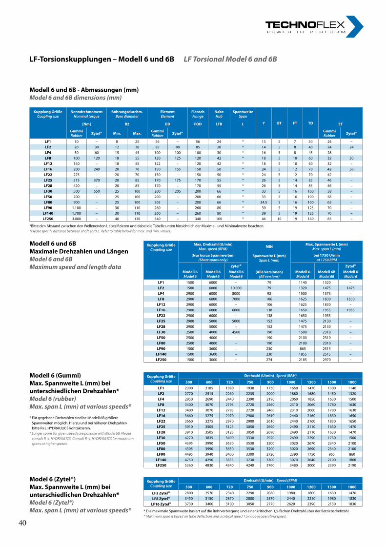
21
LF-Torsionskupplungen–Modell6und6BLF Torsional Model 6 and 6B
* Bitte den Abstand zwischen den Wellenenden L spezifizieren und dabei die Tabelle unten hinsichtlich der Maximal- und Minimalwerte beachten.* Please specify distance between shaft ends L. Refer to table below for max. and min. values.
Modell6und6BMaximaleDrehzahlenundLängenModel 6 and 6B Maximum speed and length data
Modell6(Gummi)Max.SpannweiteL(mm)beiunterschiedlichenDrehzahlen*Model 6 (rubber) Max. span L (mm) at various speeds*
* Für gegebene Drehzahlen sind bei Modell 6B größere Spannweiten möglich. Hierzu und bei höheren Drehzahlen bitte R+L HYDRAULICS kontaktieren.
* Longer spans for given speeds are possible with Model 6B. Please consult R+L HYDRAULICS. Consult R+L HYDRAULICS for maximum spans at higher speeds.
Model6(Zytel®)Max.SpannweiteL(mm)beiunterschiedlichenDrehzahlen*Model 6 (Zytel®) Max. span L (mm) at various speeds*
KupplungGrößeCouplingsize
Drehzahl(U/min)Speed(RPM)
500 600 720 750 900 1000 1200 1500 1800LF1 2390 2185 1980 1930 1750 1650 1470 1300 1140LF2 2770 2515 2260 2235 2000 1880 1680 1450 1320LF4 2950 2690 2440 2390 2190 2060 1850 1630 1500LF8 3400 3070 2795 2720 2460 2310 2060 1780 1630LF12 3400 3070 2795 2720 2460 2310 2060 1780 1630LF16 3660 3275 2970 2900 2610 2440 2160 1830 1650LF22 3660 3275 2970 2900 2610 2440 2160 1830 1650LF25 3910 3505 3125 3050 2690 2490 2110 1630 1470LF28 3910 3505 3125 3050 2690 2490 2110 1630 1470LF30 4270 3835 3400 3330 2920 2690 2290 1730 1500LF50 4395 3990 3630 3530 3200 3020 2670 2340 2100LF80 4395 3990 3630 3530 3200 3020 2690 2340 2100LF90 4495 3940 3400 3300 2720 2390 1750 965 860LF140 4750 4290 3835 3730 3300 3070 2640 2100 1860LF250 5360 4830 4340 4240 3760 3480 3000 2390 2190
KupplungGrößeCouplingsize
Drehzahl(U/min)Speed(RPM)
500 600 720 750 900 1000 1200 1500 1800
LF2Zytel® 2800 2570 2340 2290 2080 1980 1800 1630 1470LF8Zytel® 3450 3150 2870 2800 2570 2440 2210 1980 1830LF16Zytel® 3730 3400 3100 3050 2770 2620 2390 2130 1830
KupplungGrößeCouplingsize
NenndrehmomentNominaltorque
Bohrungsdurchm.Borediameter
ElementElement
FlanschFlange
NabeHub
SpannweiteSpan
Y BT FT TD[Nm] B2 OD FOD LTB L ET
GummiRubber Zytel® Min. Max. Gummi
Rubber Zytel® GummiRubber Zytel®
LF1 10 – 8 25 56 – 56 24 * 13 5 7 30 24 –LF2 20 30 12 38 85 88 85 28 * 14 5 8 40 24 24LF4 50 60 15 45 100 100 100 30 * 16 5 8 45 28 –LF8 100 120 18 55 120 125 120 42 * 18 5 10 60 32 30LF12 140 – 18 55 122 – 120 42 * 18 5 10 60 32 –LF16 200 240 20 70 150 155 150 50 * 24 5 12 70 42 36LF22 275 – 20 70 150 – 150 50 * 24 5 12 70 42 –LF25 315 370 20 85 170 175 170 55 * 26 5 14 85 46 –LF28 420 – 20 85 170 – 170 55 * 26 5 14 85 46 –LF30 500 550 25 100 200 205 200 66 * 33 5 16 100 58 –LF50 700 – 25 100 200 – 200 66 * 33 5 16 100 58 –LF80 900 – 25 100 205 – 200 66 * 34.5 5 16 100 65 –LF90 1.100 – 30 110 260 – 260 80 * 39 5 19 125 70 –LF140 1.700 – 30 110 260 – 260 80 * 39 5 19 125 70 –LF250 3.000 – 40 130 340 – 340 100 * 46 10 19 160 85 –
KupplungGrößeCouplingsize
Max.Drehzahl(U/min)Max.speed(RPM) MIN Max.SpannweiteL(mm)
Max.spanL(mm)
(NurkurzeSpannweiten)(Shortspansonly)
SpannweiteL(mm)SpanL(mm)
bei1750U/minat1750RPM
Zytel® Zytel®Modell6Model6
Modell6Model6
Modell6Model6
(AlleVersionen)(Allversions)
Modell6Model6
Modell6BModel6B
Modell6Model6
LF1 1500 6000 – 79 1140 1320 –LF2 1500 6000 10.000 79 1320 1475 1475LF4 2900 6000 8000 92 1500 1575 –LF8 2900 6000 7000 106 1625 1830 1830LF12 2900 6000 – 106 1625 1830 –LF16 2900 6000 6000 138 1650 1955 1955LF22 2900 6000 – 138 1650 1955 –LF25 2900 5000 5000 152 1475 2130 –LF28 2900 5000 – 152 1475 2130 –LF30 2500 4000 4500 190 1500 2310 –LF50 2500 4000 – 190 2100 2310 –LF80 2500 4000 – 190 2100 2310 –LF90 1500 3600 – 230 865 2515 –LF140 1500 3600 – 230 1855 2515 –LF250 1500 3000 – 274 2185 2970 –
* Die maximale Spannweite basiert auf die Rohrverbiegung und einer kritischen 1,5-fachen Drehzahl über der Betriebsdrehzahl.* Maximum span is based on tube deflection and a critical speed 1.5x above operating speed.
Modell6und6B-Abmessungen(mm)Model 6 and 6B dimensions (mm)
40 40
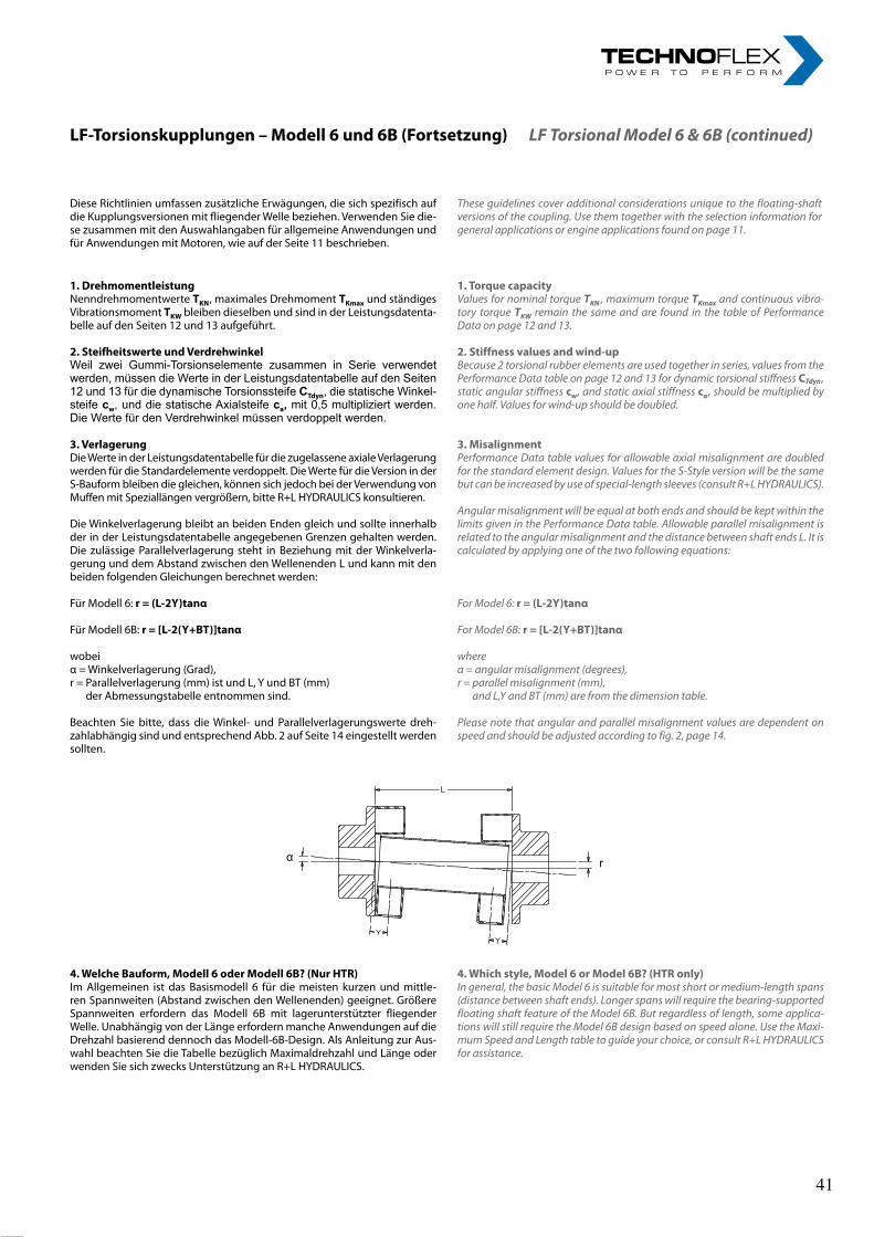
22rl-hydraulics.com
LF-Torsionskupplungen–Modell6und6B(Fortsetzung)LF Torsional Model 6 & 6B (continued)
1.DrehmomentleistungNenndrehmomentwerte TKN, maximales Drehmoment TKmax und ständiges Vibrationsmoment TKW bleiben dieselben und sind in der Leistungsdatenta-belle auf den Seiten 12 und 13 aufgeführt.
2.SteifheitswerteundVerdrehwinkelWeil zwei Gummi-Torsionselemente zusammen in Serie verwendet werden, müssen die Werte in der Leistungsdatentabelle auf den Seiten 12 und 13 für die dynamische Torsionssteife CTdyn, die statische Winkel-steife cw, und die statische Axialsteife ca, mit 0,5 multipliziert werden. Die Werte für den Verdrehwinkel müssen verdoppelt werden.
3.VerlagerungDie Werte in der Leistungsdatentabelle für die zugelassene axiale Verlagerung werden für die Standardelemente verdoppelt. Die Werte für die Version in der S-Bauform bleiben die gleichen, können sich jedoch bei der Verwendung von Muffen mit Speziallängen vergrößern, bitte R+L HYDRAULICS konsultieren.
Die Winkelverlagerung bleibt an beiden Enden gleich und sollte innerhalb der in der Leistungsdatentabelle angegebenen Grenzen gehalten werden. Die zulässige Parallelverlagerung steht in Beziehung mit der Winkelverla-gerung und dem Abstand zwischen den Wellenenden L und kann mit den beiden folgenden Gleichungen berechnet werden:
Für Modell 6:r=(L-2Y)tanα
Für Modell 6B:r=[L-2(Y+BT)]tanα
wobeiα = Winkelverlagerung (Grad),r = Parallelverlagerung (mm) ist und L, Y und BT (mm)
der Abmessungstabelle entnommen sind.
Beachten Sie bitte, dass die Winkel- und Parallelverlagerungswerte dreh-zahlabhängig sind und entsprechend Abb. 2 auf Seite 14 eingestellt werden sollten.
4.WelcheBauform,Modell6oderModell6B?(NurHTR)Im Allgemeinen ist das Basismodell 6 für die meisten kurzen und mittle-ren Spannweiten (Abstand zwischen den Wellenenden) geeignet. Größere Spannweiten erfordern das Modell 6B mit lagerunterstützter fliegender Welle. Unabhängig von der Länge erfordern manche Anwendungen auf die Drehzahl basierend dennoch das Modell-6B-Design. Als Anleitung zur Aus-wahl beachten Sie die Tabelle bezüglich Maximaldrehzahl und Länge oder wenden Sie sich zwecks Unterstützung an R+L HYDRAULICS.
1.TorquecapacityValues for nominal torque TKN , maximum torque TKmax and continuous vibra-tory torque TKW remain the same and are found in the table of Performance Data on page 12 and 13.
2.Stiffnessvaluesandwind-upBecause 2 torsional rubber elements are used together in series, values from the Performance Data table on page 12 and 13 for dynamic torsional stiffness CTdyn , static angular stiffness cw, and static axial stiffness ca , should be multiplied by one half. Values for wind-up should be doubled.
3.MisalignmentPerformance Data table values for allowable axial misalignment are doubled for the standard element design. Values for the S-Style version will be the same but can be increased by use of special-length sleeves (consult R+L HYDRAULICS).
Angular misalignment will be equal at both ends and should be kept within the limits given in the Performance Data table. Allowable parallel misalignment is related to the angular misalignment and the distance between shaft ends L. It is calculated by applying one of the two following equations:
For Model 6: r=(L-2Y)tanα
For Model 6B:r=[L-2(Y+BT)]tanα
whereα = angular misalignment (degrees),r = parallel misalignment (mm),
and L,Y and BT (mm) are from the dimension table.
Please note that angular and parallel misalignment values are dependent on speed and should be adjusted according to fig. 2, page 14.
4.Whichstyle,Model6orModel6B?(HTRonly)In general, the basic Model 6 is suitable for most short or medium-length spans (distance between shaft ends). Longer spans will require the bearing-supported floating shaft feature of the Model 6B. But regardless of length, some applica-tions will still require the Model 6B design based on speed alone. Use the Maxi-mum Speed and Length table to guide your choice, or consult R+L HYDRAULICS for assistance.
α r
Diese Richtlinien umfassen zusätzliche Erwägungen, die sich spezifisch auf die Kupplungsversionen mit fliegender Welle beziehen. Verwenden Sie die-se zusammen mit den Auswahlangaben für allgemeine Anwendungen und für Anwendungen mit Motoren, wie auf der Seite 11 beschrieben.
These guidelines cover additional considerations unique to the floating-shaft versions of the coupling. Use them together with the selection information for general applications or engine applications found on page 11.
41 41
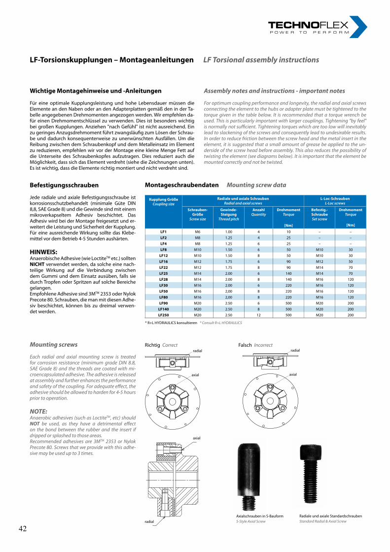
23
LF-Torsionskupplungen–MontageanleitungenLF Torsional assembly instructions
WichtigeMontagehinweiseund-Anleitungen
Für eine optimale Kupplungsleistung und hohe Lebensdauer müssen die Elemente an den Naben oder an den Adapterplatten gemäß den in der Ta-belle angegebenen Drehmomenten angezogen werden. Wir empfehlen da-für einen Drehmomentschlüssel zu verwenden. Dies ist besonders wichtig bei großen Kupplungen. Anziehen "nach Gefühl" ist nicht ausreichend. Ein zu geringes Anzugsdrehmoment führt zwangsläufig zum Lösen der Schrau-be und dadurch konsequenterweise zu unerwünschten Ausfällen. Um die Reibung zwischen dem Schraubenkopf und dem Metalleinsatz im Element zu reduzieren, empfehlen wir vor der Montage eine kleine Menge Fett auf die Unterseite des Schraubenkopfes aufzutragen. Dies reduziert auch die Möglichkeit, dass sich das Element verdreht (siehe die Zeichnungen unten). Es ist wichtig, dass die Elemente richtig montiert und nicht verdreht sind.
Assembly notes and instructions - important notes
For optimum coupling performance and longevity, the radial and axial screws connecting the element to the hubs or adapter plate must be tightened to the torque given in the table below. It is recommended that a torque wrench be used. This is particularly important with larger couplings. Tightening "by feel" is normally not sufficient. Tightening torques which are too low will inevitably lead to slackening of the screws and consequently lead to undesirable results. In order to reduce friction between the screw head and the metal insert in the element, it is suggested that a small amount of grease be applied to the un-derside of the screw head before assembly. This also reduces the possibility of twisting the element (see diagrams below). It is important that the element be mounted correctly and not be twisted.
Befestigungsschrauben
Jede radiale und axiale Befestigungsschraube ist korrosionsschutzbehandelt (minimale Güte DIN 8,8, SAE Grade 8) und die Gewinde sind mit einem mikroverkapseltem Adhesiv beschichtet. Das Adhesiv wird bei der Montage freigesetzt und er-weitert die Leistung und Sicherheit der Kupplung. Für eine ausreichende Wirkung sollte das Klebe-mittel vor dem Betrieb 4-5 Stunden aushärten.
HINWEIS:Anaerobische Adhesive (wie LoctiteTM etc.) sollten NICHT verwendet werden, da solche eine nach-teilige Wirkung auf die Verbindung zwischen dem Gummi und dem Einsatz ausüben, falls sie durch Tropfen oder Spritzen auf solche Bereiche gelangen.Empfohlene Adhesive sind 3MTM 2353 oder Nylok Precote 80. Schrauben, die man mit diesen Adhe-siv beschichtet, können bis zu dreimal verwen-det werden.
Mounting screws
Each radial and axial mounting screw is treated for corrosion resistance (minimum grade DIN 8.8, SAE Grade 8) and the threads are coated with mi-croencapsulated adhesive. The adhesive is released at assembly and further enhances the performance and safety of the coupling. For adequate effect, the adhesive should be allowed to harden for 4-5 hours prior to operation.
NOTE:Anaerobic adhesives (such as LoctiteTM, etc) should NOT be used, as they have a detrimental effect on the bond between the rubber and the insert if dripped or splashed to those areas.Recommended adhesives are 3MTM 2353 or Nylok Precote 80. Screws that we provide with this adhe-sive may be used up to 3 times.
MontageschraubendatenMounting screw data
Richtig Correctradial
axial
Falsch Incorrectradial
axial
radial
axial
* R+L HYDRAULICS konsultieren * Consult R+L HYDRAULICS
Axialschrauben in S-BauformS-Style Axial Screw
Radiale und axiale StandardschraubenStandard Radial & Axial Screw
KupplungGrößeCouplingsize
RadialeundaxialeSchraubenRadialandaxialscrews
L-Loc-SchraubenL-Locscrews
Schrauben-Größe
Screwsize
Gewinde-Steigung
Threadpitch
AnzahlQuantity
DrehmomentTorque
Befestig.-SchraubeSetscrew
DrehmomentTorque
[Nm] [Nm]
LF1 M6 1.00 4 10 – –
LF2 M8 1.25 4 25 – –
LF4 M8 1.25 6 25 – –
LF8 M10 1.50 6 50 M10 30
LF12 M10 1.50 8 50 M10 30
LF16 M12 1.75 6 90 M12 50
LF22 M12 1.75 8 90 M14 70
LF25 M14 2.00 6 140 M14 70
LF28 M14 2.00 8 140 M16 120
LF30 M16 2.00 6 220 M16 120
LF50 M16 2,00 8 220 M16 120
LF80 M16 2,00 8 220 M16 120
LF90 M20 2.50 6 500 M20 200
LF140 M20 2.50 8 500 M20 200LF250 M20 2.50 12 500 M20 200
42 42
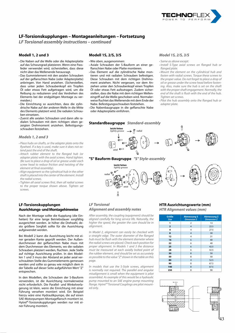
24rl-hydraulics.com
LF-Torsionskupplungen–Montageanleitungen–FortsetzungLF Torsional assembly instructions – continued
Modell1,2und3• Die Naben auf die Welle oder die Adapterplatte
auf das Schwungrad platzieren. Wenn eine Pass-feder verwendet wird, sicherstellen, dass diese nicht über das Wellenende herausragt.
• Das Gummielement mit den axialen Schrauben auf der geflanschten Nabe (oder Adapterplatte) anbringen. Von Hand anziehen. (Sicherstellen, dass unter jeden Schraubenkopf ein Tropfen Öl oder etwas Fett aufgetragen wird, um die Reibung zu reduzieren und das Verdrehen des Elements bei der endgültigen Montage zu ver-meiden.)
• Die Einrichtung so ausrichten, dass die zylin-drische Nabe auf der anderen Welle in die Mitte des Elements platziert wird. Die radialen Schrau-ben einsetzen.
• Zuerst alle axialen Schrauben und dann alle ra-dialen Schrauben mit dem richtigen oben ge-zeigten Drehmoment anziehen. Befestigungs-schrauben festziehen.
Models 1, 2 and 3• Place hubs on shafts, or the adapter plate onto the
flywheel. If a key is used, make sure it does not ex-tend past the end of the shaft.• Attach rubber element to the flanged hub (or
adapter plate) with the axial screws. Hand tighten. (Be sure to place a drop of oil or grease under each screw head to reduce friction and twisting of the element at final assembly).• Align equipment so the cylindrical hub in the other
shaft is placed into the center of the element. Install the radial screws.• Tighten all axial screws first, then all radial screws
to the proper torque shown above. Tighten set screws.
Modell1S,2/S,3/S• Wie oben, ausgenommen:• Axiale Schrauben der S-Bauform an einer ge-
flanschten Nabe oder Platte montieren. • Das Element auf die zylindrische Nabe mon-
tieren und mit radialen Schrauben befestigen. Diese Schrauben mit dem richtigen Drehmo-ment anziehen. Nicht vergessen, vor dem An-ziehen unter den Schraubenkopf einen Tropfen Öl oder etwas Fett aufzutragen. Zudem sicher-stellen, dass die Nabe mit dem richtigen Wellen-eingriff auf die Welle geschoben wird. Normaler-weise fluchtet das Wellenende mit dem Ende der Nabe. Befestigungsschrauben festziehen.
• Die Nabenbaugruppe in die geflanschte Nabe oder Adapterplatte einführen.
LF-TorsionskupplungenAusrichtungs-undMontagehinweiseNach der Montage sollte die Kupplung (die Ein-heiten) für eine lange Betriebsdauer sorgfältig ausgerichtet werden. Je höher die Drehzahl, de-sto größere Sorgfalt sollte für die Ausrichtung aufgewendet werden.
Bei Modell 2 kann die Ausrichtung leicht mit ei-ner geraden Kante geprüft werden. Der Außen-durchmesser der geflanschten Nabe muss mit dem Durchmesser des Elements, wo die radialen Schrauben platziert werden, fluchten. Jede Stelle auf richtige Ausrichtung prüfen. In den Model-len 1 und 3 muss der Abstand an jeder axial ver-schraubten Stelle des Gummielements gemessen werden und sollte so genau wie möglich dem in der Tabelle auf dieser Seite aufgeführten Wert "Z" entsprechen.
In den Modellen, die Schrauben der S-Bauform verwenden, ist die Ausrichtung normalerweise nicht erforderlich. Die Parallel- und Winkelverla-gerung ist klein, wenn die Einrichtung mit einer Führung versehen montiert wird. Ein Beispiel hierzu wäre eine Hydraulikpumpe, die auf einen SAE-Motorpumpen-Montageflansch montiert ist. Hytrel®-Torsionskupplungen werden nur mit ei-ner Führung montiert.
StandardbaugruppeStandard-assembly
"S"Bauform-Baugruppe"S" Style-assembly
leichtfettenlightly grease radial
axial
leichtfettenlightly grease
radial
axial
LF Torsional Alignment and assembly notesAfter assembly, the coupling (equipment) should be aligned carefully for long service life. Naturally, the higher the speed, the greater the care should be in alignment.
In Model 2, alignment can easily be checked with a straight edge. The outer diameter of the flanged hub must be flush with the element diameter where the radial screws are placed. Check each position for proper alignment. In Models 1 and 3 the distance must be measured at each axially bolted point of the rubber element, and should be set as accurately as possible to the value "Z" shown in the table on this page.
In models that use the S-Style screws, alignment is normally not required. The parallel and angular misalignment is small when the equipment is pilot assembled. As example of this would be a hydraulic pump mounted to an SAE engine pump mounting flange. Hytrel ® Torsional Couplings are pilot mount-ed only.
GrößeSize
AbmessungSDimensionS
AbmessungZDimensionZ
1 2 132 4 22.54 4 27.58 4 3012 4 3116 6 4022 6 4025 6 42.528 6 42.530 8 5050 8 5080 4 52.590 8 67.5140 8 67.5250 8 90
HTRAusrichtungswerte(mm)HTR Alignment values (mm)
Model 1S, 2/S, 3/S• Same as above except:• Install S-Type axial screws on flanged hub or
flanged plate.• Mount the element on the cylindrical hub and
fasten with radial screws. Torque these screws to the proper value. Do not forget to place a drop of oil or grease under the screw head before fasten-ing. Also, make sure the hub is set on the shaft with the proper shaft engagement. Normally, the end of the shaft is flush with the end of the hub. Tighten set screws.• Pilot the hub assembly onto the flanged hub or
adapter plate.
43 43
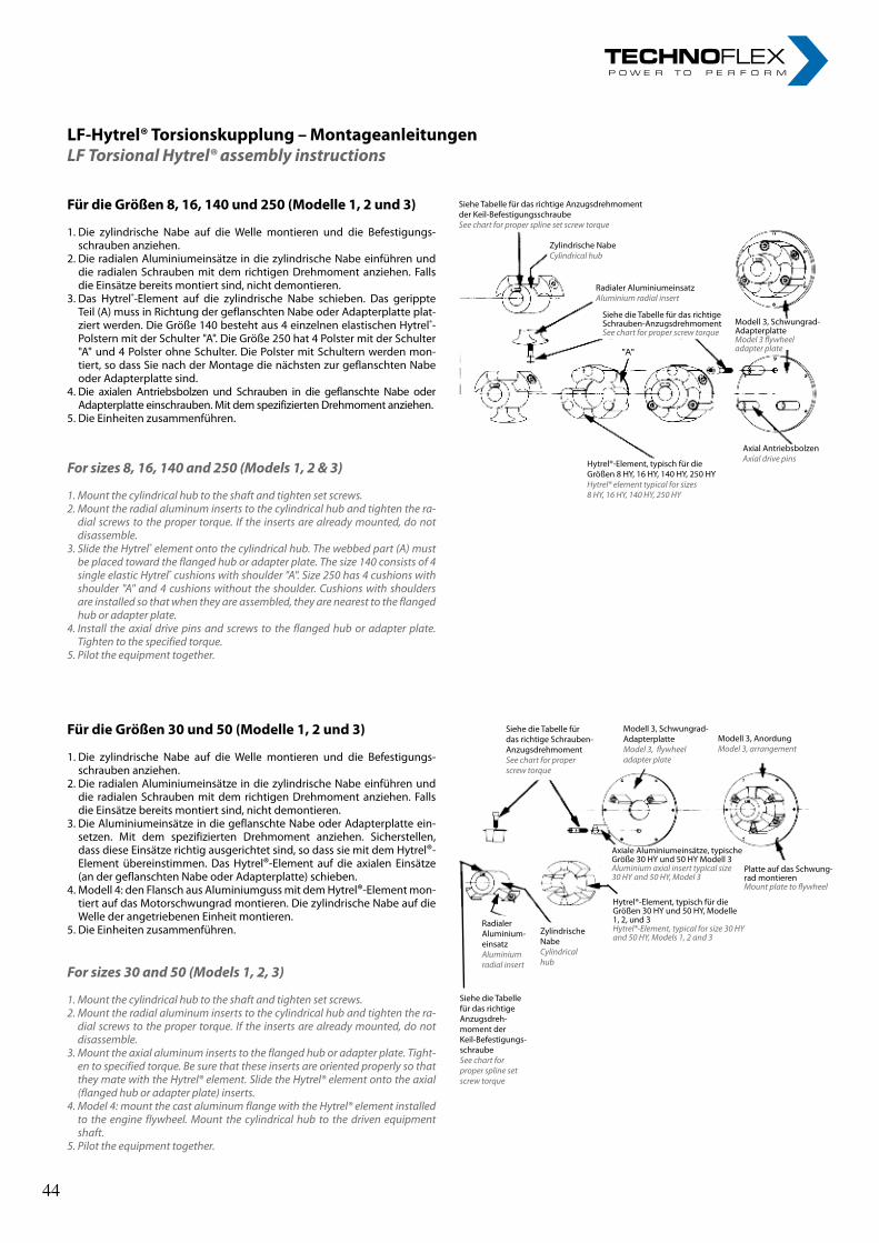
25
LF-Hytrel®Torsionskupplung–MontageanleitungenLF Torsional Hytrel® assembly instructions
FürdieGrößen8,16,140und250(Modelle1,2und3)
1. Die zylindrische Nabe auf die Welle montieren und die Befestigungs-schrauben anziehen.
2. Die radialen Aluminiumeinsätze in die zylindrische Nabe einführen und die radialen Schrauben mit dem richtigen Drehmoment anziehen. Falls die Einsätze bereits montiert sind, nicht demontieren.
3. Das Hytrel®-Element auf die zylindrische Nabe schieben. Das gerippte Teil (A) muss in Richtung der geflanschten Nabe oder Adapterplatte plat-ziert werden. Die Größe 140 besteht aus 4 einzelnen elastischen Hytrel®-Polstern mit der Schulter "A". Die Größe 250 hat 4 Polster mit der Schulter "A" und 4 Polster ohne Schulter. Die Polster mit Schultern werden mon-tiert, so dass Sie nach der Montage die nächsten zur geflanschten Nabe oder Adapterplatte sind.
4. Die axialen Antriebsbolzen und Schrauben in die geflanschte Nabe oder Adapterplatte einschrauben. Mit dem spezifizierten Drehmoment anziehen.
5. Die Einheiten zusammenführen.
For sizes 8, 16, 140 and 250 (Models 1, 2 & 3)
1. Mount the cylindrical hub to the shaft and tighten set screws.2. Mount the radial aluminum inserts to the cylindrical hub and tighten the ra-
dial screws to the proper torque. If the inserts are already mounted, do not disassemble.
3. Slide the Hytrel® element onto the cylindrical hub. The webbed part (A) must be placed toward the flanged hub or adapter plate. The size 140 consists of 4 single elastic Hytrel® cushions with shoulder "A". Size 250 has 4 cushions with shoulder "A" and 4 cushions without the shoulder. Cushions with shoulders are installed so that when they are assembled, they are nearest to the flanged hub or adapter plate.
4. Install the axial drive pins and screws to the flanged hub or adapter plate. Tighten to the specified torque.
5. Pilot the equipment together.
FürdieGrößen30und50(Modelle1,2und3)
1. Die zylindrische Nabe auf die Welle montieren und die Befestigungs-schrauben anziehen.
2. Die radialen Aluminiumeinsätze in die zylindrische Nabe einführen und die radialen Schrauben mit dem richtigen Drehmoment anziehen. Falls die Einsätze bereits montiert sind, nicht demontieren.
3. Die Aluminiumeinsätze in die geflanschte Nabe oder Adapterplatte ein-setzen. Mit dem spezifizierten Drehmoment anziehen. Sicherstellen, dass diese Einsätze richtig ausgerichtet sind, so dass sie mit dem Hytrel®-Element übereinstimmen. Das Hytrel®-Element auf die axialen Einsätze (an der geflanschten Nabe oder Adapterplatte) schieben.
4. Modell 4: den Flansch aus Aluminiumguss mit dem Hytrel®-Element mon-tiert auf das Motorschwungrad montieren. Die zylindrische Nabe auf die Welle der angetriebenen Einheit montieren.
5. Die Einheiten zusammenführen.
For sizes 30 and 50 (Models 1, 2, 3)
1. Mount the cylindrical hub to the shaft and tighten set screws.2. Mount the radial aluminum inserts to the cylindrical hub and tighten the ra-
dial screws to the proper torque. If the inserts are already mounted, do not disassemble.
3. Mount the axial aluminum inserts to the flanged hub or adapter plate. Tight-en to specified torque. Be sure that these inserts are oriented properly so that they mate with the Hytrel® element. Slide the Hytrel® element onto the axial (flanged hub or adapter plate) inserts.
4. Model 4: mount the cast aluminum flange with the Hytrel® element installed to the engine flywheel. Mount the cylindrical hub to the driven equipment shaft.
5. Pilot the equipment together.
Siehe die Tabelle für das richtige Schrauben-AnzugsdrehmomentSee chart for proper screw torque
Modell 3, Schwungrad-Adapterplatte Model 3, flywheel adapter plate
Modell 3, AnordungModel 3, arrangement
Platte auf das Schwung-rad montierenMount plate to flywheel
Hytrel®-Element, typisch für die Größen 30 HY und 50 HY, Modelle 1, 2, und 3 Hytrel®-Element, typical for size 30 HY and 50 HY, Models 1, 2 and 3
Radialer Aluminium-einsatzAluminium radial insert
Zylindrische NabeCylindrical hub
Siehe die Tabelle für das richtige Anzugsdreh-moment der Keil-Befestigungs-schraubeSee chart for proper spline set screw torque
Siehe Tabelle für das richtige Anzugsdrehmoment der Keil-BefestigungsschraubeSee chart for proper spline set screw torque
Zylindrische NabeCylindrical hub
Radialer AluminiumeinsatzAluminium radial insert
Siehe die Tabelle für das richtige Schrauben-AnzugsdrehmomentSee chart for proper screw torque
"A"
Modell 3, Schwungrad-AdapterplatteModel 3 flywheel adapter plate
Axial AntriebsbolzenAxial drive pinsHytrel®-Element, typisch für die
Größen 8 HY, 16 HY, 140 HY, 250 HYHytrel® element typical for sizes 8 HY, 16 HY, 140 HY, 250 HY
Axiale Aluminiumeinsätze, typische Größe 30 HY und 50 HY Modell 3Aluminium axial insert typical size 30 HY and 50 HY, Model 3
44 44
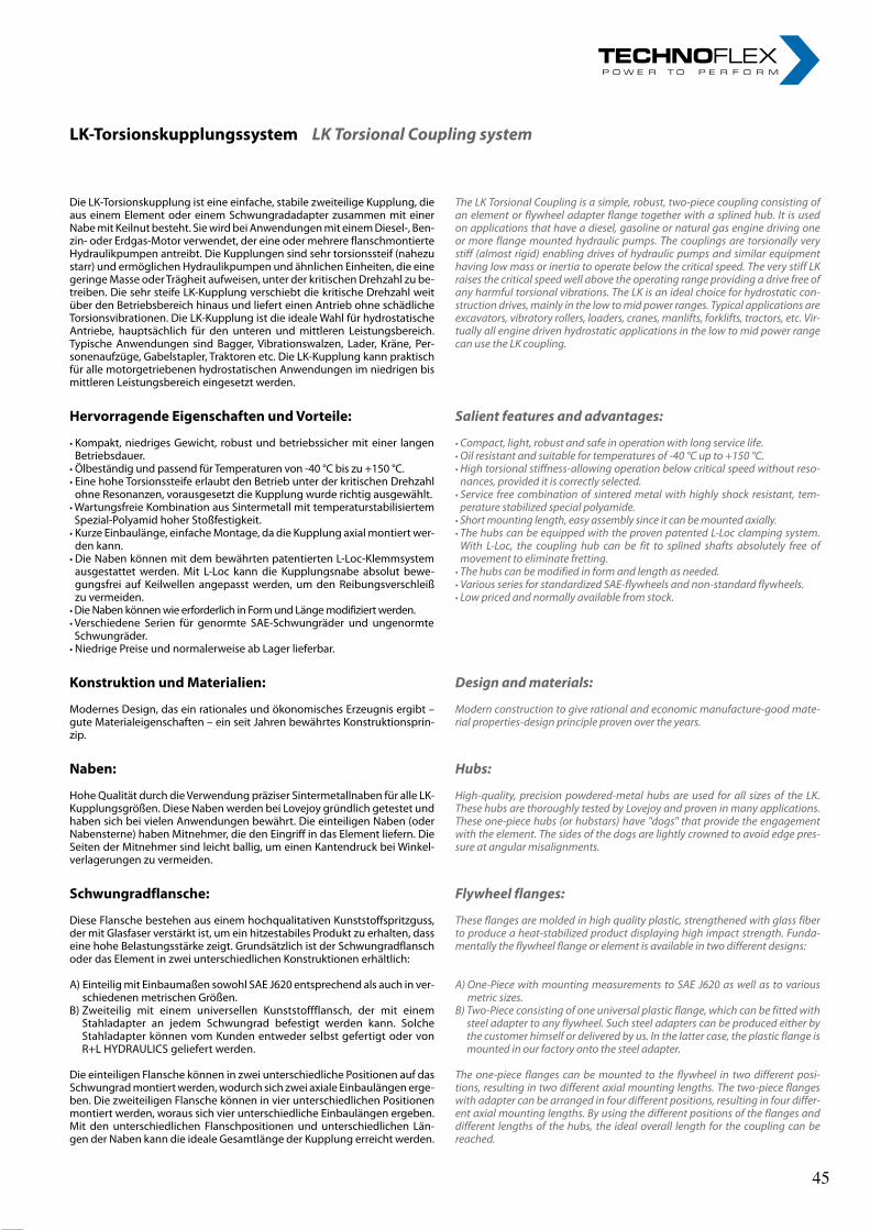
26rl-hydraulics.com
Die LK-Torsionskupplung ist eine einfache, stabile zweiteilige Kupplung, die aus einem Element oder einem Schwungradadapter zusammen mit einer Nabe mit Keilnut besteht. Sie wird bei Anwendungen mit einem Diesel-, Ben-zin- oder Erdgas-Motor verwendet, der eine oder mehrere flanschmontierte Hydraulikpumpen antreibt. Die Kupplungen sind sehr torsionssteif (nahezu starr) und ermöglichen Hydraulikpumpen und ähnlichen Einheiten, die eine geringe Masse oder Trägheit aufweisen, unter der kritischen Drehzahl zu be-treiben. Die sehr steife LK-Kupplung verschiebt die kritische Drehzahl weit über den Betriebsbereich hinaus und liefert einen Antrieb ohne schädliche Torsionsvibrationen. Die LK-Kupplung ist die ideale Wahl für hydrostatische Antriebe, hauptsächlich für den unteren und mittleren Leistungsbereich. Typische Anwendungen sind Bagger, Vibrationswalzen, Lader, Kräne, Per-sonenaufzüge, Gabelstapler, Traktoren etc. Die LK-Kupplung kann praktisch für alle motorgetriebenen hydrostatischen Anwendungen im niedrigen bis mittleren Leistungsbereich eingesetzt werden.
HervorragendeEigenschaftenundVorteile:
• Kompakt, niedriges Gewicht, robust und betriebssicher mit einer langen Betriebsdauer.
• Ölbeständig und passend für Temperaturen von -40 °C bis zu +150 °C.• Eine hohe Torsionssteife erlaubt den Betrieb unter der kritischen Drehzahl
ohne Resonanzen, vorausgesetzt die Kupplung wurde richtig ausgewählt.• Wartungsfreie Kombination aus Sintermetall mit temperaturstabilisiertem Spezial-Polyamid hoher Stoßfestigkeit.• Kurze Einbaulänge, einfache Montage, da die Kupplung axial montiert wer-
den kann.• Die Naben können mit dem bewährten patentierten L-Loc-Klemmsystem
ausgestattet werden. Mit L-Loc kann die Kupplungsnabe absolut bewe-gungsfrei auf Keilwellen angepasst werden, um den Reibungsverschleiß zu vermeiden.
• Die Naben können wie erforderlich in Form und Länge modifiziert werden.• Verschiedene Serien für genormte SAE-Schwungräder und ungenormte Schwungräder.• Niedrige Preise und normalerweise ab Lager lieferbar.
KonstruktionundMaterialien:
Modernes Design, das ein rationales und ökonomisches Erzeugnis ergibt – gute Materialeigenschaften – ein seit Jahren bewährtes Konstruktionsprin-zip.
Naben:
Hohe Qualität durch die Verwendung präziser Sintermetallnaben für alle LK-Kupplungsgrößen. Diese Naben werden bei Lovejoy gründlich getestet und haben sich bei vielen Anwendungen bewährt. Die einteiligen Naben (oder Nabensterne) haben Mitnehmer, die den Eingriff in das Element liefern. Die Seiten der Mitnehmer sind leicht ballig, um einen Kantendruck bei Winkel-verlagerungen zu vermeiden.
Schwungradflansche:
Diese Flansche bestehen aus einem hochqualitativen Kunststoffspritzguss, der mit Glasfaser verstärkt ist, um ein hitzestabiles Produkt zu erhalten, dass eine hohe Belastungsstärke zeigt. Grundsätzlich ist der Schwungradflansch oder das Element in zwei unterschiedlichen Konstruktionen erhältlich:
A) Einteilig mit Einbaumaßen sowohl SAE J620 entsprechend als auch in ver-schiedenen metrischen Größen.
B) Zweiteilig mit einem universellen Kunststoffflansch, der mit einem Stahladapter an jedem Schwungrad befestigt werden kann. Solche Stahladapter können vom Kunden entweder selbst gefertigt oder von R+L HYDRAULICS geliefert werden.
Die einteiligen Flansche können in zwei unterschiedliche Positionen auf das Schwungrad montiert werden, wodurch sich zwei axiale Einbaulängen erge-ben. Die zweiteiligen Flansche können in vier unterschiedlichen Positionen montiert werden, woraus sich vier unterschiedliche Einbaulängen ergeben. Mit den unterschiedlichen Flanschpositionen und unterschiedlichen Län-gen der Naben kann die ideale Gesamtlänge der Kupplung erreicht werden.
The LK Torsional Coupling is a simple, robust, two-piece coupling consisting of an element or flywheel adapter flange together with a splined hub. It is used on applications that have a diesel, gasoline or natural gas engine driving one or more flange mounted hydraulic pumps. The couplings are torsionally very stiff (almost rigid) enabling drives of hydraulic pumps and similar equipment having low mass or inertia to operate below the critical speed. The very stiff LK raises the critical speed well above the operating range providing a drive free of any harmful torsional vibrations. The LK is an ideal choice for hydrostatic con-struction drives, mainly in the low to mid power ranges. Typical applications are excavators, vibratory rollers, loaders, cranes, manlifts, forklifts, tractors, etc. Vir-tually all engine driven hydrostatic applications in the low to mid power range can use the LK coupling.
Salient features and advantages:
• Compact, light, robust and safe in operation with long service life.• Oil resistant and suitable for temperatures of -40 °C up to +150 °C.• High torsional stiffness-allowing operation below critical speed without reso-
nances, provided it is correctly selected.• Service free combination of sintered metal with highly shock resistant, tem-
perature stabilized special polyamide.• Short mounting length, easy assembly since it can be mounted axially.• The hubs can be equipped with the proven patented L-Loc clamping system.
With L-Loc, the coupling hub can be fit to splined shafts absolutely free of movement to eliminate fretting.• The hubs can be modified in form and length as needed.• Various series for standardized SAE-flywheels and non-standard flywheels.• Low priced and normally available from stock.
Design and materials:
Modern construction to give rational and economic manufacture-good mate-rial properties-design principle proven over the years.
Hubs:
High-quality, precision powdered-metal hubs are used for all sizes of the LK. These hubs are thoroughly tested by Lovejoy and proven in many applications. These one-piece hubs (or hubstars) have "dogs" that provide the engagement with the element. The sides of the dogs are lightly crowned to avoid edge pres-sure at angular misalignments.
Flywheel flanges:
These flanges are molded in high quality plastic, strengthened with glass fiber to produce a heat-stabilized product displaying high impact strength. Funda-mentally the flywheel flange or element is available in two different designs:
A) One-Piece with mounting measurements to SAE J620 as well as to various metric sizes.
B) Two-Piece consisting of one universal plastic flange, which can be fitted with steel adapter to any flywheel. Such steel adapters can be produced either by the customer himself or delivered by us. In the latter case, the plastic flange is mounted in our factory onto the steel adapter.
The one-piece flanges can be mounted to the flywheel in two different posi-tions, resulting in two different axial mounting lengths. The two-piece flanges with adapter can be arranged in four different positions, resulting in four differ-ent axial mounting lengths. By using the different positions of the flanges and different lengths of the hubs, the ideal overall length for the coupling can be reached.
LK-TorsionskupplungssystemLK Torsional Coupling system
45 45
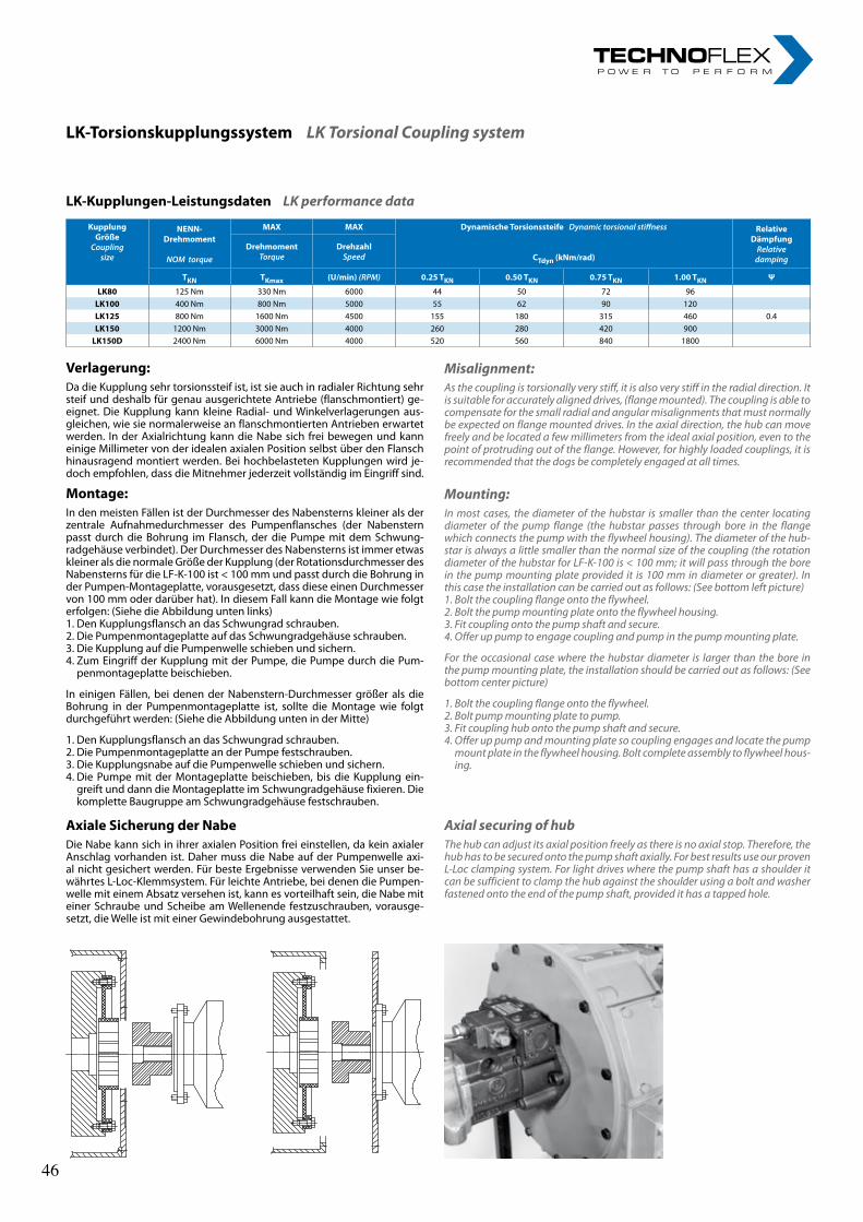
27
LK-Kupplungen-LeistungsdatenLK performance data
Verlagerung:Da die Kupplung sehr torsionssteif ist, ist sie auch in radialer Richtung sehr steif und deshalb für genau ausgerichtete Antriebe (flanschmontiert) ge-eignet. Die Kupplung kann kleine Radial- und Winkelverlagerungen aus-gleichen, wie sie normalerweise an flanschmontierten Antrieben erwartet werden. In der Axialrichtung kann die Nabe sich frei bewegen und kann einige Millimeter von der idealen axialen Position selbst über den Flansch hinausragend montiert werden. Bei hochbelasteten Kupplungen wird je-doch empfohlen, dass die Mitnehmer jederzeit vollständig im Eingriff sind.
Montage:In den meisten Fällen ist der Durchmesser des Nabensterns kleiner als der zentrale Aufnahmedurchmesser des Pumpenflansches (der Nabenstern passt durch die Bohrung im Flansch, der die Pumpe mit dem Schwung-radgehäuse verbindet). Der Durchmesser des Nabensterns ist immer etwas kleiner als die normale Größe der Kupplung (der Rotationsdurchmesser des Nabensterns für die LF-K-100 ist < 100 mm und passt durch die Bohrung in der Pumpen-Montageplatte, vorausgesetzt, dass diese einen Durchmesser von 100 mm oder darüber hat). In diesem Fall kann die Montage wie folgt erfolgen: (Siehe die Abbildung unten links)1. Den Kupplungsflansch an das Schwungrad schrauben.2. Die Pumpenmontageplatte auf das Schwungradgehäuse schrauben.3. Die Kupplung auf die Pumpenwelle schieben und sichern.4. Zum Eingriff der Kupplung mit der Pumpe, die Pumpe durch die Pum-
penmontageplatte beischieben.
In einigen Fällen, bei denen der Nabenstern-Durchmesser größer als die Bohrung in der Pumpenmontageplatte ist, sollte die Montage wie folgt durchgeführt werden: (Siehe die Abbildung unten in der Mitte)
1. Den Kupplungsflansch an das Schwungrad schrauben.2. Die Pumpenmontageplatte an der Pumpe festschrauben.3. Die Kupplungsnabe auf die Pumpenwelle schieben und sichern.4. Die Pumpe mit der Montageplatte beischieben, bis die Kupplung ein-
greift und dann die Montageplatte im Schwungradgehäuse fixieren. Die komplette Baugruppe am Schwungradgehäuse festschrauben.
AxialeSicherungderNabeDie Nabe kann sich in ihrer axialen Position frei einstellen, da kein axialer Anschlag vorhanden ist. Daher muss die Nabe auf der Pumpenwelle axi-al nicht gesichert werden. Für beste Ergebnisse verwenden Sie unser be-währtes L-Loc-Klemmsystem. Für leichte Antriebe, bei denen die Pumpen-welle mit einem Absatz versehen ist, kann es vorteilhaft sein, die Nabe mit einer Schraube und Scheibe am Wellenende festzuschrauben, vorausge-setzt, die Welle ist mit einer Gewindebohrung ausgestattet.
Misalignment:As the coupling is torsionally very stiff, it is also very stiff in the radial direction. It is suitable for accurately aligned drives, (flange mounted). The coupling is able to compensate for the small radial and angular misalignments that must normally be expected on flange mounted drives. In the axial direction, the hub can move freely and be located a few millimeters from the ideal axial position, even to the point of protruding out of the flange. However, for highly loaded couplings, it is recommended that the dogs be completely engaged at all times.
Mounting:In most cases, the diameter of the hubstar is smaller than the center locating diameter of the pump flange (the hubstar passes through bore in the flange which connects the pump with the flywheel housing). The diameter of the hub-star is always a little smaller than the normal size of the coupling (the rotation diameter of the hubstar for LF-K-100 is < 100 mm; it will pass through the bore in the pump mounting plate provided it is 100 mm in diameter or greater). In this case the installation can be carried out as follows: (See bottom left picture)1. Bolt the coupling flange onto the flywheel.2. Bolt the pump mounting plate onto the flywheel housing.3. Fit coupling onto the pump shaft and secure.4. Offer up pump to engage coupling and pump in the pump mounting plate.
For the occasional case where the hubstar diameter is larger than the bore in the pump mounting plate, the installation should be carried out as follows: (See bottom center picture)
1. Bolt the coupling flange onto the flywheel.2. Bolt pump mounting plate to pump.3. Fit coupling hub onto the pump shaft and secure.4. Offer up pump and mounting plate so coupling engages and locate the pump
mount plate in the flywheel housing. Bolt complete assembly to flywheel hous-ing.
Axial securing of hubThe hub can adjust its axial position freely as there is no axial stop. Therefore, the hub has to be secured onto the pump shaft axially. For best results use our proven L-Loc clamping system. For light drives where the pump shaft has a shoulder it can be sufficient to clamp the hub against the shoulder using a bolt and washer fastened onto the end of the pump shaft, provided it has a tapped hole.
KupplungGröße
Coupling size
NENN-Drehmoment
NOMtorque
MAX MAX DynamischeTorsionssteifeDynamictorsionalstiffness
CTdyn(kNm/rad)
RelativeDämpfungRelativedamping
DrehmomentTorque
DrehzahlSpeed
TKN TKmax (U/min)(RPM) 0.25TKN 0.50TKN 0.75TKN 1.00TKN Ψ
LK80 125 Nm 330 Nm 6000 44 50 72 96LK100 400 Nm 800 Nm 5000 55 62 90 120LK125 800 Nm 1600 Nm 4500 155 180 315 460 0.4LK150 1200 Nm 3000 Nm 4000 260 280 420 900LK150D 2400 Nm 6000 Nm 4000 520 560 840 1800
LK-TorsionskupplungssystemLK Torsional Coupling system
46 46
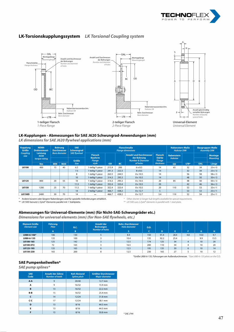
28rl-hydraulics.com
LK-TorsionskupplungssystemLK Torsional Coupling system
LK-Kupplungen-AbmessungenfürSAEJ620Schwungrad-Anwendungen(mm)LK dimensions for SAE J620 flywheel applications (mm)
* Andere kürzere oder längere Nabenlängen sind für spezielle Anforderungen erhältlich.** LK150D benutzt 2 Zytel®-Elemente parallel mit 1 Stahlplatte.
AbmessungenfürUniversal-Elemente(mm)(fürNicht-SAE-Schwungräderetc.)Dimensions for universal elements (mm) (for Non-SAE flywheels, etc.)
*Größe LK80-6-135, Führungen am Außendurchmesser. *Size LK80-6-135 pilots on the O.D.
SAEPumpenkeilwellen*SAE pump splines*
* SAE J744
G
H
1-teiliger Flansch1-Piece flange
2-teiliger Flansch2-Piece Flange
Universal-ElementUniversal Element
OALMontagelänge
Mountinglength Anzahl und Durchmesser der BohrungenNumber and diameter of holes
FlanschstärkeFlange thickness
OD BC
LTBBohr. DurchmesserBore diameter
Nabensternaussendurchm.Hubstar OB
OALMontagelängeMountinglength
Anzahl und Durchmesser der Bohrungen
Number and diameter of holes
ODBC
LTB
Bohr. DurchmesserBore diameter
Nabensternaussendurchm.Hubstar OB
S
A D B C
F
E
Anzahl gleichmäßig verteilter BohrungenNumber of Equally spaced holes
* Other shorter or longer hub lengths available for special requirements.** LK150D uses 2 Zytel® elements in parallel with 1 steel plate.
SAECode
AnzahlderZähneNumberofteeth
Keil-AbstandSplinepitch
GrößterDurchmesserMajordiameter
A-A 9 20/40 12.7 mm
A 9 16/32 15.9 mm
B 13 16/32 22.2 mm
B-B 15 16/32 25.4 mm
C 14 12/24 31.8 mm
C-C 17 12/24 38.1 mm
D 13 8/16 44.5 mm
E 13 8/16 44.5 mm
F 15 8/16 50.8 mm
KupplungGröße
Coupling size
NENN-Drehmoment-
LeistungNOM
torquerating
BohrungDurchmesserBorediameter
SAESchwungradSAEflywheel
FlanschmaßeFlangedimensions
Nabenstern-MaßeHubstarDIM
Baugruppen-MaßeAssemblyDIM
FlanschBauformFlangestyle OD BC
AnzahlundDurchmesserderBohrung
Number&Diameterofholes
FlanschStärkeFlange
thickness
NabensternHubstar
LTB*
MontageMounting
GrößeSizeNm MIN MAX OD OAL Länge
LK100 400 15 40 6.5 1-teilig/1-piece 215.9 200 6 x 8.5 14 65 32 34 23+/-37.5 1-teilig/1-piece 241.3 222.3 8 x 8.5 14 32 34 23+/-38 1-teilig/1-piece 263.5 244.5 8 x 10.5 14 56 58 58+/-3
10 1-teilig/1-piece 314.3 295.3 8 x 10.5 14 48 50 50+/-3LK125 800 20 55 10 1-teilig/1-piece 314.3 295.3 8 x 10.5 20 85 48 50 50+/-3
11.5 1-teilig/1-piece 352.4 333.4 8 x 10.5 20 42 46 36+/-3LK150 1200 25 70 11.5 1-teilig/1-piece 352.4 333.4 8 x 10.5 20 110 53 53 33+/-1
14 2-teilig/1-piece 466.7 438.2 8 x 12.7 5 53 53 25+/-1LK150D 2400 30 70 14 ** 466.7 438.2 8 x 12.7 3.4 110 52 54 25+/-1
ElementGrößeElementsize
FührungPilot
AnzahlderBohrungen
Numberofholes
Bohr.-DurchmesserHolediameterB.C. O.D.
A B S C D E F G HLK80-6-106* 106 130 5 8.4 150 91.4 28.4 4.8 14.0 9.7LK80-6-135 135 100 3 10.4 135 92.2 25.4 * 9.9 15.5LK100-165 125 142 3 12.5 174 125 34 4 10 20LK100-072 72 165 3 16.5 200 110 34 4 10 20LK125-195 135 165 6 12.5 195 135 30 6 10 14LK150-230 165 200 8 12.5 230 165 27 5 10 12
47 47
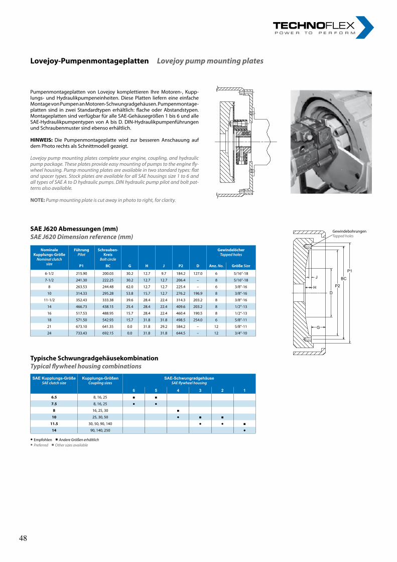
29
Lovejoy-PumpenmontageplattenLovejoy pump mounting plates
Pumpenmontageplatten von Lovejoy komplettieren Ihre Motoren-, Kupp-lungs- und Hydraulikpumpeneinheiten. Diese Platten liefern eine einfache Montage von Pumpen an Motoren-Schwungradgehäusen. Pumpenmontage-platten sind in zwei Standardtypen erhältlich: flache oder Abstandstypen. Montageplatten sind verfügbar für alle SAE-Gehäusegrößen 1 bis 6 und alle SAE-Hydraulikpumpentypen von A bis D. DIN-Hydraulikpumpenführungen und Schraubenmuster sind ebenso erhältlich.
HINWEIS: Die Pumpenmontageplatte wird zur besseren Anschauung auf dem Photo rechts als Schnittmodell gezeigt.
Lovejoy pump mounting plates complete your engine, coupling, and hydraulic pump package. These plates provide easy mounting of pumps to the engine fly-wheel housing. Pump mounting plates are available in two standard types: flat and spacer types. Stock plates are available for all SAE housings size 1 to 6 and all types of SAE A to D hydraulic pumps. DIN hydraulic pump pilot and bolt pat-terns also available.
NOTE: Pump mounting plate is cut away in photo to right, for clarity.
SAEJ620Abmessungen(mm)SAE J620 Dimension reference (mm)
TypischeSchwungradgehäusekombinationTypical flywheel housing combinations
• Empfohlen ■ Andere Größen erhältlich• Preferred ■ Other sizes available
GewindebohrungenTapped holes
P1
BC
P2
D
J
H
G
SAE Kupplungs-GrößeSAEclutchsize
Kupplungs-GrößenCouplingsizes
SAE-SchwungradgehäuseSAEflywheelhousing
6 5 4 3 2 16.5 8, 16, 25 ■ ■
7.5 8, 16, 25 ● ●
8 16, 25, 30 ■
10 25, 30, 50 ● ■ ■
11.5 30, 50, 90, 140 ● ● ■14 90, 140, 250 ●
NominaleKupplungs-GrößeNominalclutch
size
FührungPilot
Schrauben-Kreis
Boltcircle
G H J P2 D
GewindelöcherTappedholes
P1 BC Anz.No. GrößeSize
6-1/2 215.90 200.03 30.2 12.7 9.7 184.2 127.0 6 5/16“-18
7-1/2 241.30 222.25 30.2 12.7 12.7 206.4 – 8 5/16“-18
8 263.53 244.48 62.0 12.7 12.7 225.4 – 6 3/8“-16
10 314.33 295.28 53.8 15.7 12.7 276.2 196.9 8 3/8“-16
11-1/2 352.43 333.38 39.6 28.4 22.4 314.3 203.2 8 3/8“-16
14 466.73 438.15 25.4 28.4 22.4 409.6 203.2 8 1/2“-13
16 517.53 488.95 15.7 28.4 22.4 460.4 190.5 8 1/2“-13
18 571.50 542.93 15.7 31.8 31.8 498.5 254.0 6 5/8“-11
21 673.10 641.35 0.0 31.8 29.2 584.2 – 12 5/8“-11
24 733.43 692.15 0.0 31.8 31.8 644.5 – 12 3/4“-10
48 48
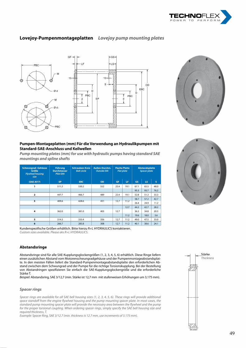
30rl-hydraulics.com
Lovejoy-PumpenmontageplattenLovejoy pump mounting plates
PBC
M
Ø d
M
Ø d
PBC
13
GF
LF
PBCd
D
EP
13
S
GS
LS
PBCD
EBC
OD
d
Pumpen-Montageplatten(mm)FürdieVerwendunganHydraulikpumpenmitStandard-SAE-AnschlussundKeilwellenPump mounting plates (mm) for use with hydraulic pumps having standard SAE mountings and spline shafts
* Kundenspezifische Größen erhältlich. Bitte hierzu Lovejoy kontaktieren.* Custom sizes available. Please ask Lovejoy.
Abstandsringe
Abstandsringe sind für alle SAE-Kupplungsglockengrößen (1, 2, 3, 4, 5, 6) erhältlich. Diese Ringe liefern einen zusätzlichen Abstand vom Motorenschwungradgehäuse und der Pumpenmontageabstandsplat-te. In den meisten Fällen liefert die Standard-Pumpenmontageabstandsplatte den erforderlichen Ab-stand zwischen dem Schwungrad und der Pumpe für die richtige Torsionskupplung. Bei der Bestellung von Abstandringen spezifizieren Sie einfach die SAE-Kupplungsglockengröße und die erforderliche Stärke T.Beispiel: Abstandsring, SAE 3/12,7 (min. Stärke ist 12,7 mm mit stufenweisen Erhöhungen um 3,175 mm).
Spacer rings
Spacer rings are available for all SAE bell housing sizes (1, 2, 3, 4, 5, 6). These rings will provide additional space standoff from the engine flywheel housing and the pump mounting spacer plate. In most cases, the standard pump mounting spacer plate will provide the necessary area between the flywheel and the pump for the proper torsional coupling. When ordering spacer rings, simply specify the SAE bell housing size and required thickness, T. Example: Spacer Ring, SAE 3/12.7 (min. thickness is 12.7 mm, use increments of 3.175 mm).
StärkeThickness
Schwungrad-GehäuseGröße
Flywheelhousingsize
FührungDurchmesser
PilotDIA
Schrauben-KreisBoltcircle
Außen-Durchm.OutsideDIA
FlachePlatteFlatplate
AbstandsplatteSpacerplate
(SAEJ617) EP EBC OD GF LF GS LS S
1 511.2 530.2 552 22.4 19.1 67.1 65.5 48.0
95.3 93.7 76.2
2 447.7 466.7 489 22.4 19.1 52.8 51.3 33.3
58.7 57.2 42.7
26.4 24.9 11.2
12.7 44.2 42.7 28.2
4 362.0 381.0 403 12.7 36.3 34.8 20.3
11.2 19.6 18.0 3.6
5 314.3 333.4 356 12.7 11.2 49.0 47.5 33.0
6 266.7 285.8 308 12.7 11.2 40.1 38.6 24.1
Kundenspezifische Größen erhältlich. Bitte hierzu R+L HYDRAULICS kontaktieren.Custom sizes available. Please aks R+L HYDRAULICS.
3 409.6 428.6 451 12.7 11.2
49 49
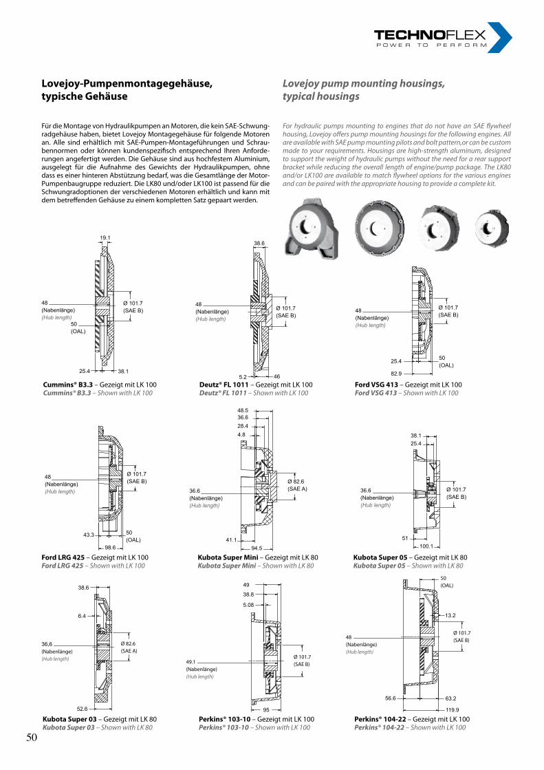
31
36,6(Nabenlänge)(Hub length) 49.1
(Nabenlänge)(Hub length)
48(Nabenlänge)(Hub length)
Ø 82.6(SAE A)
Ø 101.7(SAE B)
Ø 101.7(SAE B)
38.6
6.4
52.6
56.6
50(OAL)
13.2
63.2
119.9
49
38.8
5.08
95
KubotaSuper03 – Gezeigt mit LK 80Kubota Super 03 – Shown with LK 80
Perkins®103-10 – Gezeigt mit LK 100Perkins® 103-10 – Shown with LK 100
Perkins®104-22– Gezeigt mit LK 100Perkins® 104-22 – Shown with LK 100
Lovejoy-Pumpenmontagegehäuse,typischeGehäuse
Für die Montage von Hydraulikpumpen an Motoren, die kein SAE-Schwung-radgehäuse haben, bietet Lovejoy Montagegehäuse für folgende Motoren an. Alle sind erhältlich mit SAE-Pumpen-Montageführungen und Schrau-bennormen oder können kundenspezifisch entsprechend Ihren Anforde-rungen angefertigt werden. Die Gehäuse sind aus hochfestem Aluminium, ausgelegt für die Aufnahme des Gewichts der Hydraulikpumpen, ohne dass es einer hinteren Abstützung bedarf, was die Gesamtlänge der Motor-Pumpenbaugruppe reduziert. Die LK80 und/oder LK100 ist passend für die Schwungradoptionen der verschiedenen Motoren erhältlich und kann mit dem betreffenden Gehäuse zu einem kompletten Satz gepaart werden.
For hydraulic pumps mounting to engines that do not have an SAE flywheel housing, Lovejoy offers pump mounting housings for the following engines. All are available with SAE pump mounting pilots and bolt pattern,or can be custom made to your requirements. Housings are high-strength aluminum, designed to support the weight of hydraulic pumps without the need for a rear support bracket while reducing the overall length of engine/pump package. The LK80 and/or LK100 are available to match flywheel options for the various engines and can be paired with the appropriate housing to provide a complete kit.
48(Nabenlänge)(Hub length)
Ø 101.7(SAE B)
50(OAL)
25.4 38.1
19.1
48(Nabenlänge)(Hub length)
Ø 101.7(SAE B)
5.2 46
38.6
48(Nabenlänge)(Hub length)
Ø 101.7(SAE B)
82.9
25.4 50(OAL)
Cummins®B3.3 – Gezeigt mit LK 100Cummins® B3.3 – Shown with LK 100
Deutz®FL1011 – Gezeigt mit LK 100Deutz® FL 1011 – Shown with LK 100
FordVSG413 – Gezeigt mit LK 100Ford VSG 413 – Shown with LK 100
48(Nabenlänge)(Hub length) 36.6
(Nabenlänge)(Hub length)
36.6(Nabenlänge)(Hub length)
Ø 101.7(SAE B)
Ø 82.6(SAE A)
Ø 101.7(SAE B)
50(OAL)
43.3
98.641.1
94.5
48.536.628.44.8 38.1
25.4
51100.1
FordLRG425 – Gezeigt mit LK 100Ford LRG 425– Shown with LK 100
KubotaSuperMini– Gezeigt mit LK 80Kubota Super Mini– Shown with LK 80
KubotaSuper05– Gezeigt mit LK 80Kubota Super 05 – Shown with LK 80
Lovejoy pump mounting housings, typical housings
50 50
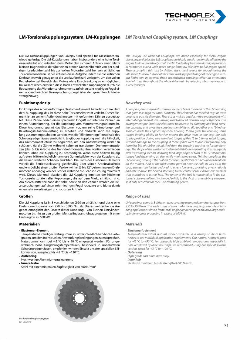
32rl-hydraulics.com
The Lovejoy LM Torsional Couplings, are made especially for diesel engine drives. In particular, the LM couplings are highly elastic torsionally, allowing the engine to drive a relatively small inertia load safely free from damaging torsion-al resonance over a wide speed range from low idle RPM to full engine speed. They accomplish this task by shifting the critical speeds far enough below the idle speed to allow full use of the entire working speed range of the engine with-out limitation. In essence, these sophisticated couplings effect an attenuated level of stress throughout the whole drive train by reducing vibratory torque to a very low level.
How they workA compact, disc-shaped elastomeric element lies at the heart of the LM coupling that gives it its high torsional elasticity. This element has molded cogs or teeth around its outside diameter. These cogs make a backlash-free engagement with internal cogs on an aluminum ring which drives it from the engine flywheel. This arrangement pre-loads the elastomer to increase its damping and load carry-ing capacity, and gives the coupling the ability to slip together and "blind as-semble" inside the engine' s flywheel housing. It also gives the coupling some torque limiting ability to further protect the drive train, as the cogs are able to slip position during rare transient torque spikes (5 to 6 times rated torque) without damage to the coupling. If these spikes were to occur frequently, only harmless bits of rubber would shed from the coupling causing no further dam-age. The shape of the elastomeric element distributes operating stresses equally over its working section, allowing for a large angle of twist (6 to 12° at nominal torque load depending on size) while minimizing stress. This feature places the LM coupling amongst the highest torsional elasticities of all couplings available on the market. And at the thick center portion near the hub, as well as at the cogs, stresses are further reduced to a very low level, providing a very reliable and robust drive. We bond a steel ring to the center of the elastomeric element that assembles to a steel hub. The center of this hub is machined to fit the cus-tomer's driven shaft and is clamped solidly to the shaft at assembly by a tapered split hub, set screws or the L-Loc clamping system.
Range of sizesLM couplings come in 8 different sizes covering a range of nominal torques from 250 to 3800 Nm. This wide range of sizes make these couplings capable of han-dling applications driven from small singlecylinder engines on up to large multi-cylinder engines producing in excess of 600 kW.
Materials• Elastomeric element Temperature-resistant natural rubber available in a variety of Shore hard-
nesses to suit individual application requirements. Our natural rubber is good for -45 °C to +90 °C. For unusually high ambient temperatures, especially in non-ventilated flywheel housings, we recommend using our special silicone version, rated for -45 °C to +120 °C.
• Outer ring High-grade cast aluminum alloy.• Inner hub Steel with minimum tensile strength of 600 N/mm2.
Die LM-Torsionskupplungen von Lovejoy sind speziell für Dieselmotoran-triebe gefertigt. Die LM-Kupplungen haben insbesondere eine hohe Torsi-onselastizität und erlauben dem Motor den sicheren Antrieb einer relativ kleinen Trägheitslast, der über einen breiten Drehzahlbereich von der nied-rigen Leerlaufdrehzahl bis zur vollen Motordrehzahl frei von schädlichen Torsionsresonanzen ist. Sie erfüllen diese Aufgabe indem sie die kritischen Drehzahlen weit genug unter die Leerlaufdrehzahl verlagern, um den vollen Betriebsdrehzahlbereich des Motors ohne Einschränkung zu ermöglichen. Im Wesentlichen erwirken diese hoch entwickelten Kupplungen durch die Reduzierung des Vibrationsdrehmoments auf einen sehr niedrigen Pegel ei-nen abgeschwächten Beanspruchungspegel über den gesamten Antriebs-strang hinweg.
FunktionsprinzipEin kompaktes scheibenförmiges Elastomer-Element befindet sich im Herz der LM-Kupplung, das ihr diese hohe Torsionselastizität verleiht. Dieses Ele-ment ist an seinem Außendurchmesser mit geformten Zähnen ausgestat-tet. Diese Zähne bilden einen spielfreien Eingriff mit internen Zähnen an einem Aluminiumring, der die Kupplung vom Motorschwungrad antreibt. Diese Anordnung spannt das Elastomer vor, um seine Dämpfungs- und Belastungsaufnahmeleistung zu erhöhen und dadurch kann die Kupp-lung zusammengeschoben werden, was die "Blindmontage" innerhalb des Schwungradgehäuses ermöglicht. Es gibt der Kupplung auch die Fähigkeit, das Drehmoment etwas zu begrenzen, um den Antriebsstrang weiter zu schützen, da die Zähne während seltenen transienten Drehmomentspit-zen (das 5- bis 6-fache des Nenndrehmoments) ihre Position verschieben können, ohne die Kupplung zu beschädigen. Wenn diese Spitzen häufig auftreten, blättern lediglich harmlose Gummiteilchen von der Kupplung ab, die keinen weiteren Schaden anrichten. Die Form des Elastomer-Elements verteilt die Betriebsbelastung gleichmäßig über seinen Arbeitsabschnitt und ermöglicht einen großen Verdrehwinkel (6 bis 12° bei nominalem Dreh-moment, abhängig von der Größe), während die Beanspruchung minimiert wird. Dieses Merkmal platziert die LM-Kupplung inmitten der höchsten Torsionselastizitäten aller Kupplungen, die auf dem Markt erhältlich sind. Am dicken Mittelteil nahe der Nabe, sowie an den Zähnen werden die Be-anspruchungen auf einen sehr niedrigen Pegel reduziert und bietet damit einen sehr zuverlässigen und robusten Antrieb.
GrößenDie LM Kupplung ist in 8 verschiedenen Größen erhältlich und deckt eine Drehmomentspanne von 250 bis 3800 Nm ab. Dieses weitreichende An-gebot ermöglicht den Einsatz dieser Kupplung - von kleinen Einzylinder-motoren bis hin zu den großen Mehrzylinderantriebsaggregaten mit einer Leistung bis zu 600 kW.
Materialien• Elastomer-Element Temperaturbeständiger Naturgummi in unterschiedlichen Shore-Härte-
graden, um den individuellen Anwendungsbedingungen zu entsprechen. Naturgummi kann bei -45 °C bis + 90 °C eingesetzt werden. Für unge-wöhnlich hohe Umgebungstemperaturen, besonders in unbelüfteten Schwungradgehäusen, empfehlen wir den Einsatz unserer speziellen Sili-konversion, ausgelegt für -45 °C bis +120 °C.
• Außenring Hochwertige Aluminiumgusslegierung• InnereNabe Stahl mit einer minimalen Zugfestigkeit von 600 N/mm2
LM-TorsionskupplungssystemLM Coupling
LM-Torsionskupplungssystem,LM-KupplungenLM Torsional Coupling system, LM Couplings
51 51
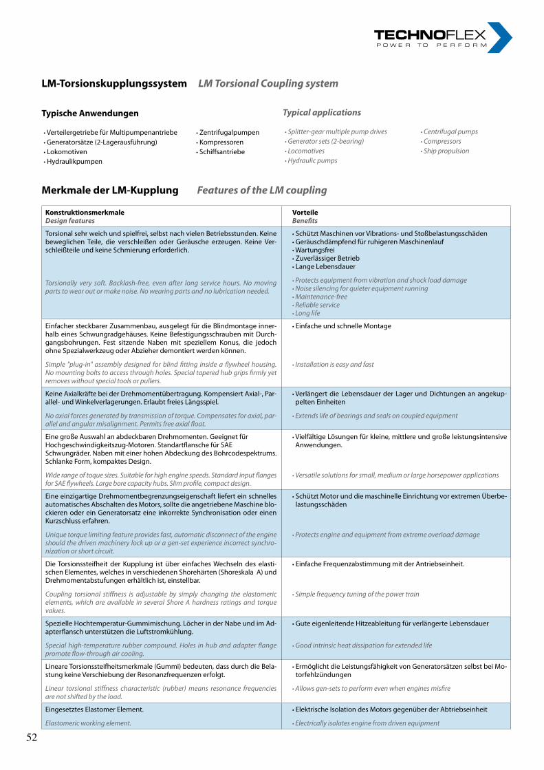
33
LM-TorsionskupplungssystemLM Torsional Coupling system
TypischeAnwendungen
• Verteilergetriebe für Multipumpenantriebe • Zentrifugalpumpen• Generatorsätze (2-Lagerausführung) • Kompressoren• Lokomotiven • Schiffsantriebe• Hydraulikpumpen
Typical applications
• Splitter-gear multiple pump drives • Centrifugal pumps• Generator sets (2-bearing) • Compressors• Locomotives • Ship propulsion• Hydraulic pumps
MerkmalederLM-KupplungFeatures of the LM coupling
KonstruktionsmerkmaleDesign features
VorteileBenefits
Torsional sehr weich und spielfrei, selbst nach vielen Betriebsstunden. Keine beweglichen Teile, die verschleißen oder Geräusche erzeugen. Keine Ver-schleißteile und keine Schmierung erforderlich.
Torsionally very soft. Backlash-free, even after long service hours. No moving parts to wear out or make noise. No wearing parts and no lubrication needed.
• Schützt Maschinen vor Vibrations- und Stoßbelastungsschäden• Geräuschdämpfend für ruhigeren Maschinenlauf• Wartungsfrei• Zuverlässiger Betrieb• Lange Lebensdauer
• Protects equipment from vibration and shock load damage• Noise silencing for quieter equipment running• Maintenance-free• Reliable service• Long life
Einfacher steckbarer Zusammenbau, ausgelegt für die Blindmontage inner-halb eines Schwungradgehäuses. Keine Befestigungsschrauben mit Durch-gangsbohrungen. Fest sitzende Naben mit speziellem Konus, die jedoch ohne Spezialwerkzeug oder Abzieher demontiert werden können.
Simple "plug-in" assembly designed for blind fitting inside a flywheel housing. No mounting bolts to access through holes. Special tapered hub grips firmly yet removes without special tools or pullers.
• Einfache und schnelle Montage
• Installation is easy and fast
Keine Axialkräfte bei der Drehmomentübertragung. Kompensiert Axial-, Par-allel- und Winkelverlagerungen. Erlaubt freies Längsspiel.
No axial forces generated by transmission of torque. Compensates for axial, par-allel and angular misalignment. Permits free axial float.
• Verlängert die Lebensdauer der Lager und Dichtungen an angekup-pelten Einheiten
• Extends life of bearings and seals on coupled equipment
Eine große Auswahl an abdeckbaren Drehmomenten. Geeignet für Hochgeschwindigkeitszug-Motoren. Standartflansche für SAE Schwungräder. Naben mit einer hohen Abdeckung des Bohrcodespektrums. Schlanke Form, kompaktes Design.
Wide range of toque sizes. Suitable for high engine speeds. Standard input flanges for SAE flywheels. Large bore capacity hubs. Slim profile, compact design.
• Vielfältige Lösungen für kleine, mittlere und große leistungsintensive Anwendungen.
• Versatile solutions for small, medium or large horsepower applications
Eine einzigartige Drehmomentbegrenzungseigenschaft liefert ein schnelles automatisches Abschalten des Motors, sollte die angetriebene Maschine blo-ckieren oder ein Generatorsatz eine inkorrekte Synchronisation oder einen Kurzschluss erfahren.
Unique torque limiting feature provides fast, automatic disconnect of the engine should the driven machinery lock up or a gen-set experience incorrect synchro-nization or short circuit.
• Schützt Motor und die maschinelle Einrichtung vor extremen Überbe-lastungsschäden
• Protects engine and equipment from extreme overload damage
Die Torsionssteifheit der Kupplung ist über einfaches Wechseln des elasti-schen Elementes, welches in verschiedenen Shorehärten (Shoreskala A) und Drehmomentabstufungen erhältlich ist, einstellbar.
Coupling torsional stiffness is adjustable by simply changing the elastomeric elements, which are available in several Shore A hardness ratings and torque values.
• Einfache Frequenzabstimmung mit der Antriebseinheit.
• Simple frequency tuning of the power train
Spezielle Hochtemperatur-Gummimischung. Löcher in der Nabe und im Ad-apterflansch unterstützen die Luftstromkühlung.
Special high-temperature rubber compound. Holes in hub and adapter flange promote flow-through air cooling.
• Gute eigenleitende Hitzeableitung für verlängerte Lebensdauer
• Good intrinsic heat dissipation for extended life
Lineare Torsionssteifheitsmerkmale (Gummi) bedeuten, dass durch die Bela-stung keine Verschiebung der Resonanzfrequenzen erfolgt.
Linear torsional stiffness characteristic (rubber) means resonance frequencies are not shifted by the load.
• Ermöglicht die Leistungsfähigkeit von Generatorsätzen selbst bei Mo-torfehlzündungen
• Allows gen-sets to perform even when engines misfire
Eingesetztes Elastomer Element.
Elastomeric working element.
• Elektrische Isolation des Motors gegenüber der Abtriebseinheit
• Electrically isolates engine from driven equipment
52 52
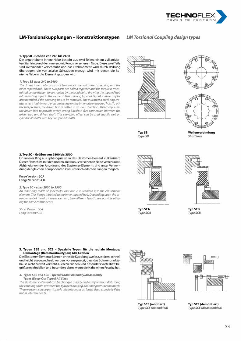
34rl-hydraulics.com
1.TypSB-Größenvon240bis2400Die angetriebene innere Nabe besteht aus zwei Teilen: einem vulkanisier-ten Stahlring und der inneren, mit Konus versehenen Nabe. Diese zwei Teile sind miteinander verschraubt und das Drehmoment wird durch Reibung übertragen, die von axialen Schrauben erzeugt wird, mit denen die ko-nische Nabe in das Element gezogen wird.
1. Type SB sizes 240 to 2400The driven inner hub consists of two pieces: the vulcanized steel ring and the inner tapered hub. These two parts are bolted together and the torque is trans-mitted by the friction force created by the axial bolts, drawing the tapered hub into a mating taper in the element. This is a long tapered fit, but it can easily be disassembled if the coupling has to be removed. The vulcanized steel ring cre-ates a very high inward pressure acting on the inner driven tapered hub. To uti-lize this pressure, the driven hub is slotted in an axial direction. This compresses the driven hub to provide a very strong backlash-free connection between the driven hub and driven shaft. This clamping effect can be used equally well on cylindrical shafts with keys or splined shafts.
2.TypSC–Größenvon2800bis3500Ein innerer Ring aus Sphäroguss ist in das Elastomer-Element vulkanisiert. Dieser Flansch ist mit der inneren, mit Konus versehenen Nabe verschraubt. Abhängig von der Anordnung des Elastomer-Elements sind unter Verwen-dung der gleichen Komponenten zwei unterschiedlichen Längen möglich.
Kurze Version: SCALange Version: SCB
2. Type SC – sizes 2800 to 3500An inner ring made of spheroidal cast iron is vulcanized into the elastomeric element. This flange is bolted to the inner tapered hub. Depending upon the ar-rangement of the elastomeric element, two different lengths are possible utiliz-ing the same components.
Short Version: SCALong Version: SCB
3.Typen SBE und SCE – Spezielle Typen für die radiale Montage/Demontage(Radialausbautypen)AlleGrößen
Die Elastomer-Elemente können ohne die Kupplungswelle zu stören, schnell und leicht ausgewechselt werden, vorausgesetzt, dass das Schwungradge-häuse nicht zu weit vorsteht. Diese Versionen sind besonders vorteilhaft bei größeren Modellen und besonders dann, wenn die Nabe einen Festsitz hat.
3. Types SBE and SCE – special radial assembly/disassembly Types (Drop-Out Types) All Sizes
The elastomeric element can be changed quickly and easily without disturbing the coupling shaft, provided the flywheel housing does not protrude too much. These versions can be particularly advantageous on larger sizes, especially if the hub is interference fit.
TypSBType SB
WellenverbindungShaft lock
TypSCAType SCA
TypSCBType SCB
TypSCE(montiert)Type SCE (assembled)
TypSCE(demontiert)Type SCE (disassembled)
LM-Torsionskupplungen–KonstruktionstypenLM Torsional Coupling design types
53 53
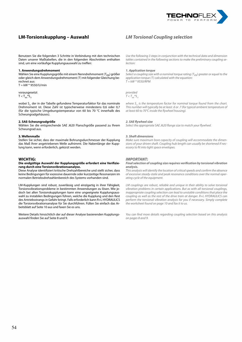
35
LM-Torsionskupplung–Auswahl
Benutzen Sie die folgenden 3 Schritte in Verbindung mit den technischen Daten unserer Maßtabellen, die in den folgenden Abschnitten enthalten sind, um eine vorläufige Kupplungsauswahl zu treffen:
1.AnwendungsdrehmomentWählen Sie eine Kupplungsgröße mit einem Nenndrehmoment (TKN) größer oder gleich dem Anwendungsdrehmoment (T) mit folgender Gleichung be-rechnet aus:T = kW * 9550/U/min
vorausgesetztT < TKN*St1
wobei St1 der in der Tabelle gefundene Temperaturfaktor für das nominale Drehmoment ist. Diese Zahl ist typischerweise mindestens 0,6 oder 0,7 (für die typische Umgebungstemperatur von 60 bis 70 °C innerhalb des Schwungradgehäuses).
2.SAE-SchwungradgrößeWählen Sie die entsprechende SAE J620 Flanschgröße passend zu Ihrem Schwungrad aus.
3.WellenmaßeStellen Sie sicher, dass der maximale Bohrungsdurchmesser der Kupplung das Maß Ihrer angetriebenen Welle aufnimmt. Die Nabenlänge der Kupp-lung kann, wenn erforderlich, gekürzt werden.
WICHTIG:DieendgültigeAuswahlderKupplungsgrößeerforderteineVerifizie-rungdurcheineTorsionsvibrationsanalyse.Diese Analyse identifiziert kritische Drehzahlbereiche und stellt sicher, dass keine Bedingungen für exzessive dauernde oder kurzzeitige Resonanzen im normalen Betriebsdrehzahlenbereich des Systems vorhanden sind.
LM-Kupplungen sind robust, zuverlässig und einzigartig in ihrer Fähigkeit, Torsionsvibrationsprobleme in bestimmten Anwendungen zu lösen. Wie je-doch bei allen Torsionskupplungen kann eine ungeeignete Kupplungsaus-wahl zu instabilen Bedingungen führen, welche die Kupplung und den Rest des Antriebsstrangs in Gefahr bringt. Falls erforderlich kann R+L HYDRAULICS die Torsionsvibrationsanalyse für Sie durchführen. Füllen Sie einfach das Ar-beitsblatt auf Seite 10 aus und faxen Sie es uns.
Weitere Details hinsichtlich der auf dieser Analyse basierenden Kupplungs-auswahl finden Sie auf Seite 8 und 9.
LM Torsional Coupling selection
Use the following 3 steps in conjunction with the technical data and dimension tables contained in the following sections to make the preliminary coupling se-lection:
1. Application torqueSelect a coupling size with a nominal torque rating (TKN) greater or equal to the application torque (T) calculated with the equation:T = kW * 9550/RPM
providedT < TKN*St1
where St1 is the temperature factor for nominal torque found from the chart. This number will typically be at least .6 or .7 (for typical ambient temperature of at least 60 to 70°C inside the flywheel housing).
2. SAE flywheel sizeSelect the appropriate SAE J620 flange size to match your flywheel.
3. Shaft dimensionsMake sure maximum bore capacity of coupling will accommodate the dimen-sions of your driven shaft. Coupling hub length can usually be shortened if nec-essary to fit into tight space envelopes.
IMPORTANT:Final selection of coupling size requires verification by torsional vibration analysis. This analysis will identify the location of critical speeds and confirm the absence of excessive steady-state and peak resonance conditions over the normal oper-ating cycle of the equipment.
LM couplings are robust, reliable and unique in their ability to solve torsional vibration problems in certain applications. But as with all torsional couplings, inappropriate coupling selection can lead to unstable conditions that place the coupling as well as the rest of the drive train at danger. R+L HYDRAULICS can perform the torsional vibration analysis for you if necessary. Simply complete the worksheet found on page 10 and fax it to us.
You can find more details regarding coupling selection based on this analysis on pages 8 and 9.
54 54
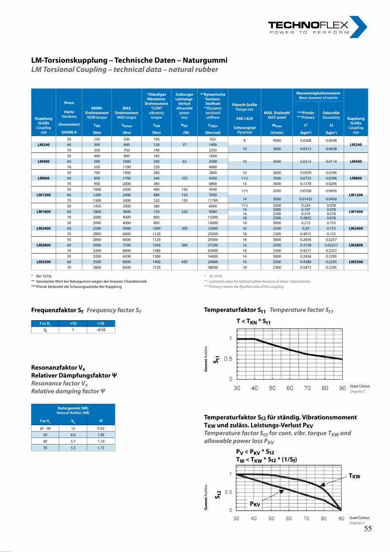
36rl-hydraulics.com
KupplungGröße
Coupling size
Shore
HärteHardness
(Durometer)
SHOREA
NENN-DrehmomentNOMtorque
MAXDrehmomentMAXtorque
*StändigesVibrations-
Drehmoment*CONT
vibratorytorque
ZulässigerLeistungs-VerlustAllowablepower
loss
**DynamischeTorsions-Steifheit**Dynamictorsionalstiffness
FlanschGrößeFlangesize
SAEJ620
SchwungradFlywheel
MAX.DrehzahlMAXspeed
MassenträgheitsmomentMassmomentofinertia
KupplungGröße
Coupling size
***Primär***Primary
SekundärSecondary
TKN TKmax TKW PKV CTdyn Mmax J1 J2
(Nm) (Nm) (Nm) (W) (Nm/rad) (U/min) (kgm2) (kgm2)
50 250 500 100 925 8 4000 0.0208 0.0038LM240LM240 60 300 600 120 37 1400
10 3600 0.0313 0.003870 350 750 140 225050 400 800 160 1600
LM400 60 500 1000 200 62 2500 10 3600 0.0373 0.0114 LM40070 550 1100 220 400050 700 1400 280 2800 10 3600 0.0599 0.0296
LM800 60 850 1700 340 105 4200 11½ 3500 0.0732 0.0296 LM80070 950 2000 380 6800 14 3000 0.1378 0.029550 1000 2000 400 150 4500 11½ 3500 0.0768 0.0456
LM1200LM1200 60 1200 2400 480 150 700014 3000 0.01432 0.045670 1300 3000 520 150 11700
50 1450 2900 580 6000 11½ 3200 0.224 0.07814 3000 0.197 0.078LM1600 60 1800 3600 720 220 9000 LM160016 2500 0.274 0.078
70 2000 4000 800 15000 18 2300 0.3855 0.07850 2000 4000 800 10000 14 3000 0.213 0.153
LM2400 60 2500 5000 1000 300 15000 16 2500 0.29 0.153 LM240070 2800 6000 1120 25000 18 2300 0.4015 0.15350 2800 6000 1120 25000 14 3000 0.2836 0.2257
LM2800 60 3000 7500 1200 360 37500 16 2500 0.3158 0.02257 LM280070 3200 8000 1280 63000 18 2300 0.4271 0.225750 3200 6500 1280 16000 14 3000 0.2836 0.2295
LM3500 60 3500 8000 1400 450 24000 16 2500 0.4388 0.2295 LM350070 3800 8500 1520 38000 18 2300 0.5873 0.2295
LM-Torsionskupplung–TechnischeDaten–NaturgummiLM Torsional Coupling – technical data – natural rubber
* Bei 10 Hz.** Konstanter Wert bei Naturgummi wegen der linearen Charakteristik*** Primär bedeutet die Schwungradseite der Kupplung
* At 10 Hz.** Constant value for natural rubber because of linear characteristic*** Primary means the flywheel side of the coupling
FrequenzfaktorSf Frequency factor Sf
f in Hz <10 >10Sf 1 √f/10
ResonanzfaktorVR
RelativerDämpfungsfaktorΨResonance factor VR
Relative damping factor Ψ
Naturgummi(NR)NaturalRubber(NR)
finHz VR Ψ
35 - 40 12 0.52
50 6.0 1.05
60 5.7 1.10
70 5.5 1.15
TemperaturfaktorSt1 Temperature factor St1
T<TKN*St1
Gum
miR
ubbe
r
Grad Celsius Degrees C
S t1
TemperaturfaktorSt2fürständig.VibrationsmomentTKWundzuläss.Leistungs-VerlustPKV Temperature factor St2 for cont. vibr. torque TKW and allowable power loss PKV
Gum
miR
ubbe
r
PV<PKV*St2TW<TKW*St2*(1/Sf)
S t2
Grad Celsius Degrees C
PKV
TKW
55 55
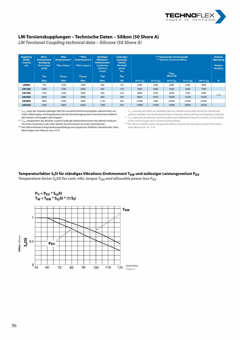
37
LM-Torsionskupplungen–TechnischeDaten–Silikon(50ShoreA)LM Torsional Coupling technical data – Silicone (50 Shore A)
* Tmax1 zeigt den maximal zulässigen Wert für transiente Drehmomentspitzen während dem nor-malen Arbeitszyklus, wie beispielsweise bei der Beschleunigung durch eine Resonanz während dem Starten und Stoppen oder Kuppeln.
** Tmax2 repräsentiert das absolute, maximal zulässige Spitzendrehmoment bei seltenen Anlässen, wie einem Kurzschluss oder einer falscher Synchronisation an einem Generatorsatz.
*** Das Silikonmaterial erzeugt belastungsabhängig eine progressive Steifheits-Charakteristik. Diese Werte haben eine Toleranz von ±15 %.
* Tmax1 indicates the maximum allowable value for transient torque spikes during the normal work cycle, for example, from accelerating through a resonance during starting and stopping or clutching.
** Tmax2 represents the absolute maximum peak torque allowable during rare occasions such as during a short circuit of a gen-set or incorrect synchronization.
*** The silicone material creates a progressive stiffness characteristic dependent on load. These values have tolerance of + or -15 %.
TemperaturfaktorStSIfürständigesVibrations-DrehmomentTKWundzulässigerLeistungsverlustPKVTemperature factor St2SI for cont. vibr. torque TKW and allowable power loss PKV
PV<PKV*St2SITW<TKW*St2SI*(1/Sf)
Silik
onS
ilico
ne
S t2S
I
Grad Celsius Degrees C
KupplungGröße
Coupling size
Nenn-DrehmomentAuslegungNom.torque
rating
*Max.Drehmoment1
*Max.torque1
**Max.Drehmoment2
**Max.torque2
StändigesVibrations-
DrehmomentContinuousvibratorytorque
ZulässigerLeistungs-VerlustAllowablepower
loss
***DynamischeTorsionssteife***Dynamictorsionalstiffness
RelativeDämpfung
Relativedamping
Ctdyn(Nm/rad)TKN TKmax1 TKmax2 TKW PKV
(Nm) (Nm) (Nm) (Nm) (W) 10%TKN 25%TKN 50%TKN 75%TKN 100%TKN Ψ
LM800 700 1050 1400 280 105 2200 2400 2800 3500 4600
LM1200 1000 1500 2000 400 150 3600 3900 4500 5600 7400
LM1600 1450 2200 2900 580 220 4800 5200 6000 7500 9900
LM2400 2000 3000 4000 800 300 8000 8700 10000 12500 16500
LM2800 2800 4200 5600 1120 360 21000 2300 25000 32500 42500
LM3500 3200 4800 6400 1280 450 12800 13900 16000 20000 26500
PKV
TKW
1.15
56 56
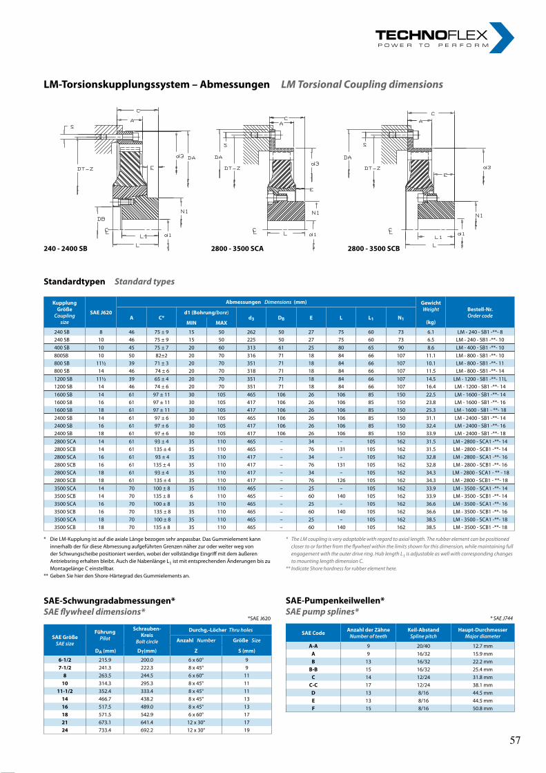
38rl-hydraulics.com
LM-Torsionskupplungssystem–AbmessungenLM Torsional Coupling dimensions
240-2400SB 2800-3500SCA 2800-3500SCB
StandardtypenStandard types
* Die LM-Kupplung ist auf die axiale Länge bezogen sehr anpassbar. Das Gummielement kann innerhalb der für diese Abmessung aufgeführten Grenzen näher zur oder weiter weg von der Schwungscheibe positioniert werden, wobei der vollständige Eingriff mit dem äußeren Antriebsring erhalten bleibt. Auch die Nabenlänge L1 ist mit entsprechenden Änderungen bis zu Montagelänge C einstellbar.
** Geben Sie hier den Shore-Härtegrad des Gummielements an.
* The LM coupling is very adaptable with regard to axial length. The rubber element can be positioned closer to or farther from the flywheel within the limits shown for this dimension, while maintaining full engagement with the outer drive ring. Hub length L1 is adjustable as well with corresponding changes to mounting length dimension C.
** Indicate Shore hardness for rubber element here.
SAE-Schwungradabmessungen*SAE flywheel dimensions* *SAE J620
SAE-Pumpenkeilwellen*SAE pump splines* * SAE J744
SAECode AnzahlderZähneNumberofteeth
Keil-AbstandSplinepitch
Haupt-DurchmesserMajordiameter
A-A 9 20/40 12.7 mmA 9 16/32 15.9 mmB 13 16/32 22.2 mm
B-B 15 16/32 25.4 mmC 14 12/24 31.8 mm
C-C 17 12/24 38.1 mmD 13 8/16 44.5 mmE 13 8/16 44.5 mmF 15 8/16 50.8 mm
KupplungGröße
Coupling size
SAEJ620
Abmessungen Dimensions (mm) GewichtWeight
(kg)
Bestell-Nr.OrdercodeA C*
d1(Bohrung/bore) d3 DB E L L1 N1
MIN MAX
240 SB 8 46 75 ± 9 15 50 262 50 27 75 60 73 6.1 LM - 240 - SB1 -**- 8240 SB 10 46 75 ± 9 15 50 225 50 27 75 60 73 6.5 LM - 240 - SB1 -**- 10400 SB 10 45 75 ± 7 20 60 313 61 25 80 65 90 8.6 LM - 400 - SB1 -**- 10800SB 10 50 82±2 20 70 316 71 18 84 66 107 11.1 LM - 800 - SB1 -**- 10800 SB 11½ 39 71 ± 3 20 70 351 71 18 84 66 107 10.1 LM - 800 - SB1 -**- 11800 SB 14 46 74 ± 6 20 70 318 71 18 84 66 107 11.5 LM - 800 - SB1 -**- 141200 SB 11½ 39 65 ± 4 20 70 351 71 18 84 66 107 14.5 LM - 1200 - SB1 -**- 11L1200 SB 14 46 74 ± 6 20 70 351 71 18 84 66 107 16.4 LM - 1200 - SB1 -**- 141600 SB 14 61 97 ± 11 30 105 465 106 26 106 85 150 22.5 LM - 1600 - SB1 -**- 141600 S8 16 61 97 ± 11 30 105 417 106 26 106 85 150 23.8 LM - 1600 - SB1 -**- 161600 SB 18 61 97 ± 11 30 105 417 106 26 106 85 150 25.3 LM - 1600 - SB1 - **- 182400 SB 14 61 97 ± 6 30 105 465 106 26 106 85 150 31.1 LM - 2400 - SB1 -**- 142400 SB 16 61 97 ± 6 30 105 417 106 26 106 85 150 32.4 LM - 2400 - SB1 -**- 162400 SB 18 61 97 ± 6 30 105 417 106 26 106 85 150 33.9 LM - 2400 - SB1 -**- 182800 SCA 14 61 93 ± 4 35 110 465 – 34 – 105 162 31.5 LM - 2800 - SCA1 -**- 142800 SCB 14 61 135 ± 4 35 110 465 – 76 131 105 162 31.5 LM - 2800 - SCB1 -**- 142800 SCA 16 61 93 ± 4 35 110 417 – 34 – 105 162 32.8 LM - 2800 - SCA1 -**- 162800 SCB 16 61 135 ± 4 35 110 417 – 76 131 105 162 32.8 LM - 2800 - SCB1 -**- 162800 SCA 18 61 93 ± 4 35 110 417 – 34 – 105 162 34.3 LM - 2800 - SCA1 - ** - 182800 SCB 18 61 135 ± 4 35 110 417 – 76 126 105 162 34.3 LM - 2800 - SCB1 - **- 183500 SCA 14 70 100 ± 8 35 110 465 – 25 – 105 162 33.9 LM - 3500 - SCA1 -**- 143500 SCB 14 70 135 ± 8 6 110 465 – 60 140 105 162 33.9 LM - 3500 - SCB1 -**- 143500 SCA 16 70 100 ± 8 35 110 465 – 25 – 105 162 36.6 LM - 3500 - SCA1 -**- 163500 SCB 16 70 135 ± 8 35 110 465 – 60 140 105 162 36.6 LM - 3500 - SCB1 -**- 163500 SCA 18 70 100 ± 8 35 110 465 – 25 – 105 162 38.5 LM - 3500 - SCA1 -**- 183500 SCB 18 70 135 ± 8 35 110 465 – 60 140 105 162 38.5 LM - 3500 - SCB1 -**- 18
SAEGrößeSAEsize
FührungPilot
Schrauben-Kreis
Boltcircle
Durchg.-LöcherThruholes
AnzahlNumber GrößeSize
DA(mm) DT(mm) Z S(mm)
6-1/2 215.9 200.0 6 x 60° 97-1/2 241.3 222.3 8 x 45° 98 263.5 244.5 6 x 60° 1110 314.3 295.3 8 x 45° 11
11-1/2 352.4 333.4 8 x 45° 1114 466.7 438.2 8 x 45° 1316 517.5 489.0 8 x 45° 1318 571.5 542.9 6 x 60° 1721 673.1 641.4 12 x 30° 1724 733.4 692.2 12 x 30° 19
57 57
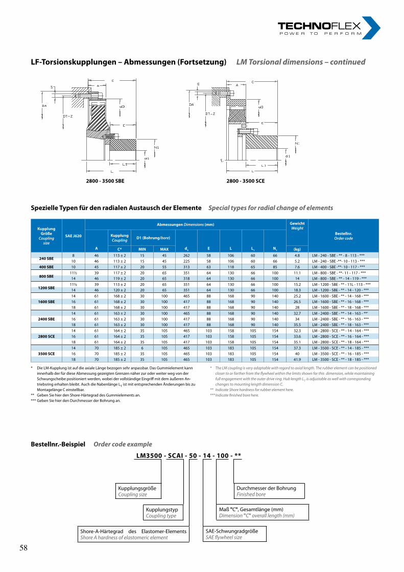
39
LF-Torsionskupplungen–Abmessungen(Fortsetzung)LM Torsional dimensions – continued
SpezielleTypenfürdenradialenAustauschderElementeSpecial types for radial change of elements
* Die LM-Kupplung ist auf die axiale Länge bezogen sehr anpassbar. Das Gummielement kann innerhalb der für diese Abmessung gezeigten Grenzen näher zur oder weiter weg von der Schwungscheibe positioniert werden, wobei der vollständige Eingriff mit dem äußeren An-triebsring erhalten bleibt. Auch die Nabenlänge L1 ist mit entsprechenden Änderungen bis zu Montagelänge C einstellbar.
** Geben Sie hier den Shore-Härtegrad des Gummielements an.*** Geben Sie hier den Durchmesser der Bohrung an.
* The LM coupling is very adaptable with regard to axial length. The rubber element can be positioned closer to or farther from the flywheel within the limits shown for this dimension, while maintaining full engagement with the outer drive ring. Hub length L1 is adjustable as well with corresponding changes to mounting length dimension C.
** Indicate Shore hardness for rubber element here.*** Indicate finished bore here.
2800-3500SBE 2800-3500SCE
KupplungGröße
Couplingsize
SAEJ620
AbmessungenDimensions(mm) GewichtWeight
Bestellnr.Ordercode
A
KupplungCoupling D1(Bohrung/bore)
d3 E L L1 N1C* MIN MAX (kg)
240SBE8 46 113 ± 2 15 45 262 58 106 60 66 4.8 LM - 240 - SBE - ** - 8 - 113 - ***
10 46 113 ± 2 15 45 225 58 106 60 66 5.2 LM - 240 - SBE -**- 10 - 113 - ***400SBE 10 45 117 ± 2 20 55 313 63 118 65 85 7.6 LM - 400 - SBE -**- 10 - 117 - ***
800SBE11½ 39 117 ± 2 20 65 351 64 130 66 100 11.1 LM - 800 - SBE - **- 11 - 117 - ***14 46 119 ± 2 20 65 318 64 130 66 100 14 LM - 800 - SBE - ** - 14 - 119 - ***
1200SBE11½ 39 113 ± 2 20 65 351 64 130 66 100 15.2 LM - 1200 - SBE - ** - 11L - 113 - ***14 46 120 ± 2 20 65 351 64 130 66 100 18.3 LM - 1200 - SBE - ** - 14 - 120 - ***14 61 168 ± 2 30 100 465 88 168 90 140 25.2 LM - 1600 - SBE - ** - 14 - 168 - ***
1600SBE 16 61 168 ± 2 30 100 417 88 168 90 140 26.5 LM - 1600 - SBE - ** - 16 - 168 - ***18 61 168 ± 2 30 100 417 88 168 90 140 28 LM - 1600 - SBE - ** - 18 - 168 - ***14 61 163 ± 2 30 100 465 88 168 90 140 32.7 LM - 2400 - SBE - ** - 14 - 163 - **‘
2400SBE 16 61 163 ± 2 30 100 417 88 168 90 140 34 LM - 2400 - SBE - ** - 16 - 163 - ***18 61 163 ± 2 30 100 417 88 168 90 140 35.5 LM - 2400 - SBE - ** - 18 - 163 - ***14 61 164 ± 2 35 105 465 103 158 105 154 32.3 LM - 2800 - SCE - ** - 14 - 164 - ***
2800SCE 16 61 164 ± 2 35 105 417 103 158 105 154 33.6 LM - 2800 - SCE - ** - 16 - 164 - ***18 61 164 ± 2 35 105 417 103 158 105 154 35.1 LM - 2800 - SCE - ** - 18 - 164 - ***14 70 185 ± 2 6 105 465 103 183 105 154 37.3 LM - 3500 - SCE - ** - 14 - 185 - ***
3500SCE 16 70 185 ± 2 35 105 465 103 183 105 154 40 LM - 3500 - SCE - ** - 16 - 185 - ***18 70 185 ± 2 35 105 465 103 183 105 154 41.9 LM - 3500 - SCE - ** - 18 - 185 - ***
Bestellnr.-BeispielOrder code example
LM3500-SCAI-50-14-100-**
KupplungsgrößeCoupling size
Maß "C", Gesamtlänge (mm)Dimension "C" overall length (mm)
SAE-Schwungradgröße SAE flywheel size
Shore-A-Härtegrad des Elastomer-Elements Shore A hardness of elastomeric element
Durchmesser der BohrungFinished bore
Kupplungstyp Coupling type
58 58
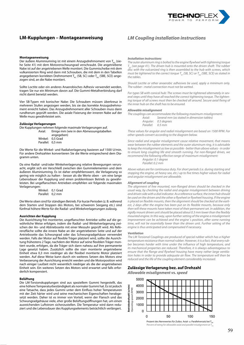
40rl-hydraulics.com
LM-Kupplungen–Montageanweisung
MontageanweisungDer äußere Aluminiumring ist mit einem Anzugsdrehmoment von TA2 (sie-he Seite 41) mit dem Motorenschwungrad verschraubt. Die angetriebene Nabe ist auf der angetriebenen Welle montiert. Die Gummischeibe mit dem vulkanisierten Ring wird dann mit Schrauben, die mit dem in den Tabellen angegebenen korrekten Drehmoment TA1 (SB, SC) oder TA3 (SBE, SCE) ange-zogen sind, an die Nabe montiert.
Sollte Loctite oder ein anderes Anaerobisches Adhesiv verwendet werden, tragen Sie nur ein Minimum davon auf. Die Gummi-Metallverbindung darf nicht damit benetzt werden.
Vier SB-Typen mit konischer Nabe: Die Schrauben müssen überkreuz in mehreren Stufen angezogen werden, bis sie das korrekte Anzugsdrehmo-ment erreicht haben. Das Anzugsdrehmoment aller Schrauben muss dann rundherum geprüft werden. Die axiale Fixierung der inneren Nabe auf der Welle muss gewährleistet sein.
ZulässigeVerlagerungenDie Kupplungen nehmen folgende maximale Verlagerungen auf. Axial: Einige mm (wie in den Abmessungstabellen
angegeben) Winkel: 0,5 Grad Parallel: 0,5 mm
Die Werte für die Winkel- und Radialverlagerung basieren auf 1500 U/min. Für andere Drehzahlen konvertieren Sie die Werte entsprechend dem Dia-gramm unten.
Da eine Radial- und/oder Winkelverlagerung relative Bewegungen verurs-acht, ergibt sich ein Verschleiß zwischen den Gummielementen und dem äußeren Aluminiumring. Es ist daher empfehlenswert, die Verlagerung so gering wie möglich zu halten - besser als die Werte oben - um eine lange Lebensdauer der Kupplung und einen problemlosen Betrieb zu gewähr-leisten. Bei ungeflanschten Antrieben empfehlen wir folgende maximalen Verlagerungen: Winkel: 0,1 Grad Parallel: 0,2 mm
Die Werte oben sind für ständigen Betrieb. Für kurze Perioden (z. B. während dem Starten und Stoppen des Motors, bei schwerem Seegang etc.) sind fünfmal höhere Werte für die Radial- und Winkelverlagerungen zulässig.
AusrichtenderKupplungDie Ausrichtung frei montierter, ungeflanschter Antriebe sollte auf die ge-wöhnliche Weise erfolgen, indem die Radial- und Winkelverlagerung zwi-schen der An- und Abtriebsseite mit einer Messuhr geprüft wird. Als Refe-renzfläche sollte die innere Nabe an der angetriebenen Seite und auf der Antriebsseite das Schwungrad oder das Schwungradgehäuse verwendet werden. Falls der Motor auf flexible Träger platziert wird, sollte die Ausrich-tung frühestens 2 Tage, nachdem der Motor auf seine flexiblen Träger mon-tiert wurde, erfolgen, da die Träger sich dann nahezu auf ihre permanente Lage gesetzt haben. Zusätzlich sollte die starr montierte angetriebene Einheit etwa 0,3 mm niedriger als der flexibel montierte Motor platziert werden. Auf diese Weise kann durch ein weiteres Setzen des Motors eine Verbesserung der Ausrichtung erreicht werden und die Motorposition wird nach einiger Laufzeit nicht wesentlich niedriger als die der angetriebenen Einheit sein. Ein weiteres Setzen des Motors wird erwartet und falls erfor-derlich kompensiert.
BelüftungDie LM-Torsionskupplungen sind aus speziellem Gummi hergestellt, das eine höhere Temperaturbeständigkeit als normaler Gummi hat. Es ist jedoch eine Tatsache, dass jedes Gummi unter dem Einfluss hoher Temperaturen mit der Zeit härter wird und seine mechanischen Eigenschaften herabge-setzt werden. Daher ist es immer von Vorteil, wenn der Flansch und das Schwungradgehäuse viele, eher große Belüftungsöffnungen hat, um einen ausreichenden Luftstrom sicherzustellen. Die Temperatur wird dann redu-ziert und die Lebensdauer des Kupplungselements beträchtlich verlängert.
LM Coupling installation instructions
Installation instructionsThe outer aluminum ring is bolted to the engine flywheel with tightening torque TA2 (see page 41). The driven hub is mounted onto the driven shaft. The rubber disc with the vulcanized ring is then assembled to the hub with screws, which must be tightened to the correct torque TA1 (SB, SC) or TA3 (SBE, SCE) as stated in the tables.
Should Loctite or other anaerobic adhesives be used, apply a minimum only. The rubber - metal connection must not be wetted.
For types SB with conical hub: The screws must be tightened alternately in sev-eral steps until they have all reached the correct tightening torque. The tighten-ing torque of all screws must then be checked all around. Secure axial fixing of the inner hub on the shaft has to be ensured.
Allowable misalignmentThe couplings can accommodate the following maximum misalignment: Axial: Several mm (as stated in dimension tables) Angular: 0.5 degrees Parallel: 0.5 mm
These values for angular and radial misalignment are based on 1500 RPM. For other speeds convert according to the diagram below.
Since radial and angular misalignment cause relative movement, that means wear between the rubber elements and the outer aluminum ring, it is advisable to keep the misalignment as low as possible - better than above values - in order to ensure long coupling life and smooth running. For non-flanged drives, we recommend the following effective range of maximum misalignment: Angular: 0.1 degree Parallel: 0.2 mm
Above values are for continuous duty. For short periods (i.e. during starting and stopping the engine, at heavy sea, etc.) up to five times higher values for radial and angular misalignment are allowable.
Alignment of couplingThe alignment of free mounted, non-flanged drives should be checked in the usual way, by checking the radial and angular misalignment between driving and driven side with a dial indicator. As a reference surface, the inner hub should be used on the driven and the other a flywheel or flywheel housing. If the engine is placed on flexible mounts, then the alignment should be checked at the earli-est, 2 days after the engine has been put on its flexible mounts, because only then will these mounts have taken most of their permanent set. In addition, the rigidly mount driven unit should be placed about 0.3 mm lower than the flexibly mounted engine. In this way, upon further setting of the engine a misalignment improvement can be achieved and the engine´s position, after some running time, will not be essentially lower than the driven unit. Further setting of the engine is thus anticipated and compensated if necessary.
VentilationThe LM Torsional Couplings are produced of special rubber which has a higher temperature resistance than normal rubber. However, it is a fact, that every rub-ber becomes harder with time under the influence of high temperature, and its mechanical properties are reduced. Therefore, it is always advantageous to ensure that the flange and flywheel housing have many rather large ventila-tion holes in order to provide adequate air flow. The temperature will then be reduced and the life of the coupling element considerably increased.
ZulässigeVerlagerungbez.aufDrehzahlAllowable misalignment vs. speed
Betriebs
dreh
zahl(u
/min)
Ope
ratin
g sp
eed
(RPM
)
Prozent des Nennwertes für Zuläss. Axial- u. Parallelversatz bei TKN
Percent of rating for allowable axial and parallel misalignment at TKN
59 59
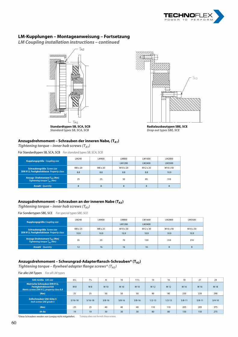
41
LM-Kupplungen–Montageanweisung–FortsetzungLM Coupling installation instructions – continued
StandardtypenSB,SCA,SCBStandard types SB, SCA, SCB
RadialausbautypenSBE,SCEDrop out types SBE, SCE
Anzugsdrehmoment–SchraubenderinnerenNabe,(TA1)Tightening torque – inner hub screws (TA1)
Für Standardtypen SB, SCA, SCB For standard types SB, SCA, SCB
Anzugsdrehmoment–SchraubenanderinnerenNabe(TA3)Tightening torque – inner hub screws (TA3)
Für Sondertypen SBE, SCE For special types SBE, SCE
Anzugsdrehmoment–Schwungrad-Adapterflansch-Schrauben*(TA2)Tightening torque – flywheel adapter flange screws* (TA2 )
Für alle LM-Typen For all LM types
*Diese Schrauben werden von Lovejoy nicht mitgeliefert. *Lovejoy does not furnish these screws.
KupplungsgrößeCouplingsizeLM240 LM400 LM800 LM1600 LM2800
LM1200 LM2400 LM3500
SchraubengrößeScrewsizeDIN912,FestigkeitsklassePropertyclass
M8 x 20 M8 x 20 M10 x 20 M12 x 25 M16 x 40
8.8 8.8 8.8 8.8 10.9
Anzugs-DrehmomentTA1(Nm)TighteningtorqueTA1(Nm) 25 25 50 85 310
AnzahlQuantity 8 8 8 8 8
KupplungsgrößeCouplingsizeLM240 LM400 LM800 LM1600 LM2800 LM3500
LM1200 LM2400
SchraubengrößeScrewsizeDIN912,FestigkeitsklassePropertyclass
M8 x 25 M8 x 25 M10 x 30 M12 x 30 M16 x 40 M16 x 50
10.9 10.9 10.9 10.9 10.9 10.9
Anzugs-DrehmomentTA3(Nm)TighteningtorqueTA3(Nm) 35 35 70 120 310 310
AnzahlQuantity 12 16 16 16 8 8
SAE-GrößeSAEsize 6½ 7½ 8 10 11½ 14 16 18 21 24
MetrischeSchraubenDIN912,Festigkeitsklasse8.8
MetricscrewsDIN912,propertyclass8.8M 8 M 8 M 10 M 10 M 10 M 12 M 12 M 16 M 16 M 18
(Nm) 25 25 50 50 50 90 90 220 220 290
ZollschraubenSAE-Güte5InchscrewsSAEgrade5 5/16-18 5/16-18 3/8-16 3/8-16 3/8-16 1/2-13 1/2-13 5/8-11 5/8-11 3/4-10
(Nm) 25 25 40 40 40 110 110 205 205 375
(ft-Ib) 19 19 30 30 30 80 80 150 150 275
60 60

nOteS „ I n n o v a t i o n i n m o t i o n ”
Berv ina Kf t . • H -1145 Erzsébet k i rá lyné út ja 41/B • Te l . :+36 -1-222-20-79 • Fax: +36 -1-252-48-29 • berv ina@berv ina.com
page 19
NOTES FOR BELTS
nOteS „ I n n o v a t i o n i n m o t i o n ”
Berv ina Kf t . • H -1145 Erzsébet k i rá lyné út ja 41/B • Te l . :+36 -1-222-20-79 • Fax: +36 -1-252-48-29 • berv ina@berv ina.com
page 19
NOTES FOR BELTS
61 61

nOteS „ I n n o v a t i o n i n m o t i o n ”
Berv ina Kf t . • H -1145 Erzsébet k i rá lyné út ja 41/B • Te l . :+36 -1-222-20-79 • Fax: +36 -1-252-48-29 • berv ina@berv ina.com
page 19
NOTES FOR BELTS
nOteS „ I n n o v a t i o n i n m o t i o n ”
Berv ina Kf t . • H -1145 Erzsébet k i rá lyné út ja 41/B • Te l . :+36 -1-222-20-79 • Fax: +36 -1-252-48-29 • berv ina@berv ina.com
page 19
NOTES FOR BELTS
62 62

SPIDEX - die elastiche Kupplung/SPIDEX - the elastic coupling SPIDEX - die elastiche Kupplung/SPIDEX - the elastic coupling
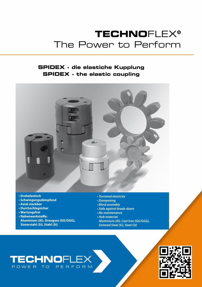
• LF Torsionskupplungen
• LK Torsionskupplungen
• Pumpen-Montageplatten und -Gehäuse
• LM Torsionskupplungen
• LF Torsional Coupling system
• LK Torsional Coupling system
• Pump mounting plates and housings
• LM Torsional Coupling system
• LF Torsionskupplungen
• LK Torsionskupplungen
• Pumpen-Montageplatten und -Gehäuse
• LM Torsionskupplungen
• LF Torsional Coupling system
• LK Torsional Coupling system
• Pump mounting plates and housings
• LM Torsional Coupling system
• Drehelastisch• Schwingungsdämpfend• Axial steckbar• Durchschlagsicher• Wartungsfrei• Nabenwerkstoffe:
Aluminium (Al), Grauguss (GG/GGG), Sinterstahl (Si), Stahl (St)
SPIDEX® – die elastische KupplungSPIDEX® – the elastic coupling
• Torsional elasticity• Dampening• Blind assembly• Safe against break-down• No maintenance• Hub material:
Aluminium (Al), Cast Iron (GG/GGG), Sintered Steel (Si), Steel (St)
TECHNOFLEX®
The Power to PerformTECHNOFLEX®
The Power to Perform
SPIDEX - die elastiche KupplungSPIDEX - the elastic coupling
SPIDEX - die elastiche KupplungSPIDEX - the elastic coupling
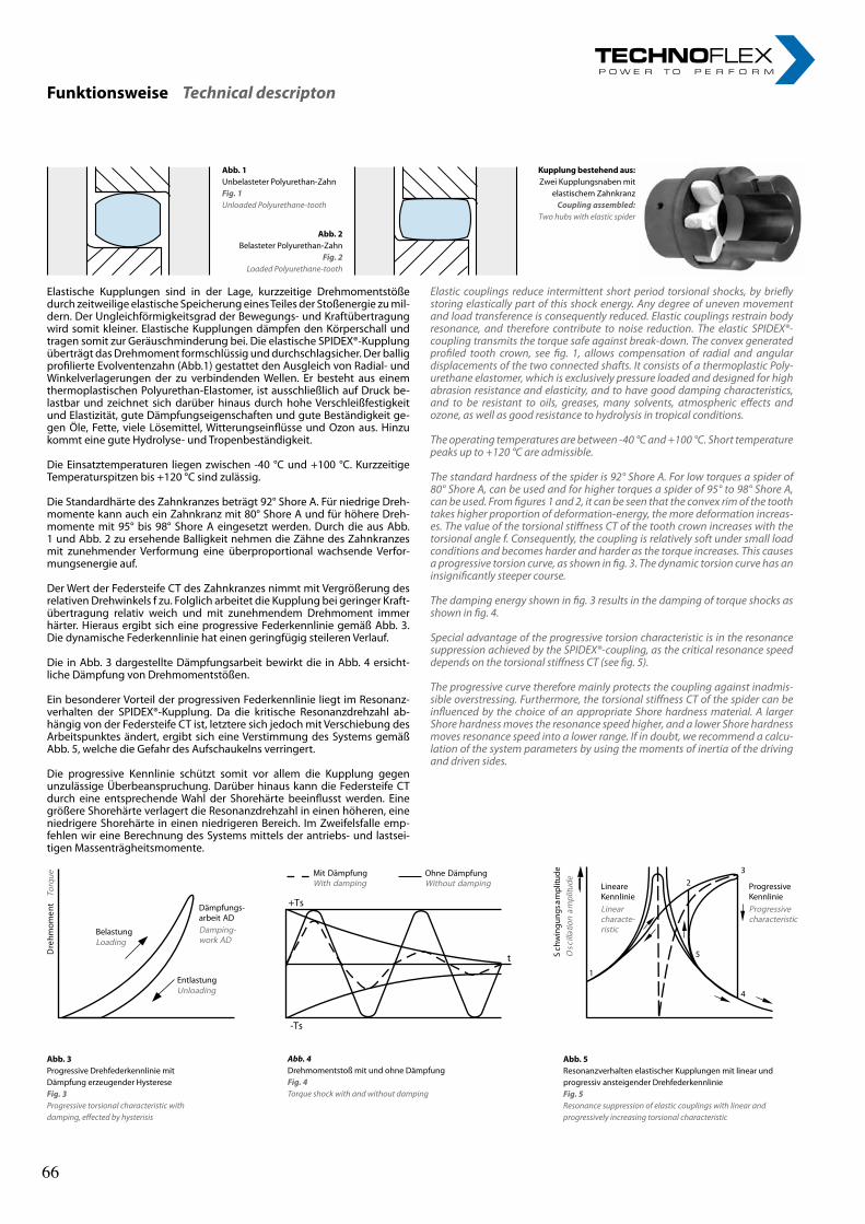
2rl-hydraulics.com
Elastische Kupplungen sind in der Lage, kurzzeitige Drehmomentstöße durch zeitweilige elastische Speicherung eines Teiles der Stoßenergie zu mil-dern. Der Ungleichförmigkeitsgrad der Bewegungs- und Kraftübertragung wird somit kleiner. Elastische Kupplungen dämpfen den Körperschall und tragen somit zur Geräuschminderung bei. Die elastische SPIDEX®-Kupplung überträgt das Drehmoment formschlüssig und durchschlagsicher. Der ballig profilierte Evolventenzahn (Abb.1) gestattet den Ausgleich von Radial- und Winkelverlagerungen der zu verbindenden Wellen. Er besteht aus einem thermoplastischen Polyurethan-Elastomer, ist ausschließlich auf Druck be-lastbar und zeichnet sich darüber hinaus durch hohe Verschleißfestigkeit und Elastizität, gute Dämpfungseigenschaften und gute Beständigkeit ge-gen Öle, Fette, viele Lösemittel, Witterungseinflüsse und Ozon aus. Hinzu kommt eine gute Hydrolyse- und Tropenbeständigkeit.
Die Einsatztemperaturen liegen zwischen -40 °C und +100 °C. Kurzzeitige Temperaturspitzen bis +120 °C sind zulässig.
Die Standardhärte des Zahnkranzes beträgt 92° Shore A. Für niedrige Dreh-momente kann auch ein Zahnkranz mit 80° Shore A und für höhere Dreh-momente mit 95° bis 98° Shore A eingesetzt werden. Durch die aus Abb. 1 und Abb. 2 zu ersehende Balligkeit nehmen die Zähne des Zahnkranzes mit zunehmender Verformung eine überproportional wachsende Verfor-mungsenergie auf.
Der Wert der Federsteife CT des Zahnkranzes nimmt mit Vergrößerung des relativen Drehwinkels f zu. Folglich arbeitet die Kupplung bei geringer Kraft-übertragung relativ weich und mit zunehmendem Drehmoment immer härter. Hieraus ergibt sich eine progressive Federkennlinie gemäß Abb. 3. Die dynamische Federkennlinie hat einen geringfügig steileren Verlauf.
Die in Abb. 3 dargestellte Dämpfungsarbeit bewirkt die in Abb. 4 ersicht-liche Dämpfung von Drehmomentstößen.
Ein besonderer Vorteil der progressiven Federkennlinie liegt im Resonanz-verhalten der SPIDEX®-Kupplung. Da die kritische Resonanzdrehzahl ab-hängig von der Federsteife CT ist, letztere sich jedoch mit Verschiebung des Arbeitspunktes ändert, ergibt sich eine Verstimmung des Systems gemäß Abb. 5, welche die Gefahr des Aufschaukelns verringert.
Die progressive Kennlinie schützt somit vor allem die Kupplung gegen unzulässige Überbeanspruchung. Darüber hinaus kann die Federsteife CT durch eine entsprechende Wahl der Shorehärte beeinflusst werden. Eine größere Shorehärte verlagert die Resonanzdrehzahl in einen höheren, eine niedrigere Shorehärte in einen niedrigeren Bereich. Im Zweifelsfalle emp-fehlen wir eine Berechnung des Systems mittels der antriebs- und lastsei-tigen Massenträgheitsmomente.
Elastic couplings reduce intermittent short period torsional shocks, by briefly storing elastically part of this shock energy. Any degree of uneven movement and load transference is consequently reduced. Elastic couplings restrain body resonance, and therefore contribute to noise reduction. The elastic SPIDEX®-coupling transmits the torque safe against break-down. The convex generated profiled tooth crown, see fig. 1, allows compensation of radial and angular displacements of the two connected shafts. It consists of a thermoplastic Poly-urethane elastomer, which is exclusively pressure loaded and designed for high abrasion resistance and elasticity, and to have good damping characteristics, and to be resistant to oils, greases, many solvents, atmospheric effects and ozone, as well as good resistance to hydrolysis in tropical conditions.
The operating temperatures are between -40 °C and +100 °C. Short temperature peaks up to +120 °C are admissible.
The standard hardness of the spider is 92° Shore A. For low torques a spider of 80° Shore A, can be used and for higher torques a spider of 95° to 98° Shore A, can be used. From figures 1 and 2, it can be seen that the convex rim of the tooth takes higher proportion of deformation-energy, the more deformation increas-es. The value of the torsional stiffness CT of the tooth crown increases with the torsional angle f. Consequently, the coupling is relatively soft under small load conditions and becomes harder and harder as the torque increases. This causes a progressive torsion curve, as shown in fig. 3. The dynamic torsion curve has an insignificantly steeper course.
The damping energy shown in fig. 3 results in the damping of torque shocks as shown in fig. 4.
Special advantage of the progressive torsion characteristic is in the resonance suppression achieved by the SPIDEX®-coupling, as the critical resonance speed depends on the torsional stiffness CT (see fig. 5).
The progressive curve therefore mainly protects the coupling against inadmis-sible overstressing. Furthermore, the torsional stiffness CT of the spider can be influenced by the choice of an appropriate Shore hardness material. A larger Shore hardness moves the resonance speed higher, and a lower Shore hardness moves resonance speed into a lower range. If in doubt, we recommend a calcu-lation of the system parameters by using the moments of inertia of the driving and driven sides.
Funktionsweise Technical descripton
Abb. 1Unbelasteter Polyurethan-ZahnFig. 1Unloaded Polyurethane-tooth
Abb. 2Belasteter Polyurethan-Zahn
Fig. 2Loaded Polyurethane-tooth
Kupplung bestehend aus:Zwei Kupplungsnaben mit
elastischem ZahnkranzCoupling assembled:
Two hubs with elastic spider
ProgressiveKennlinieProgressivecharacteristic
1
23
4
5
Abb. 3Progressive Drehfederkennlinie mit Dämpfung erzeugender HystereseFig. 3Progressive torsional characteristic with damping, effected by hysterisis
Abb. 4Drehmomentstoß mit und ohne DämpfungFig. 4Torque shock with and without damping
Abb. 5Resonanzverhalten elastischer Kupplungen mit linear und progressiv ansteigender DrehfederkennlinieFig. 5Resonance suppression of elastic couplings with linear and progressively increasing torsional characteristic
66 66
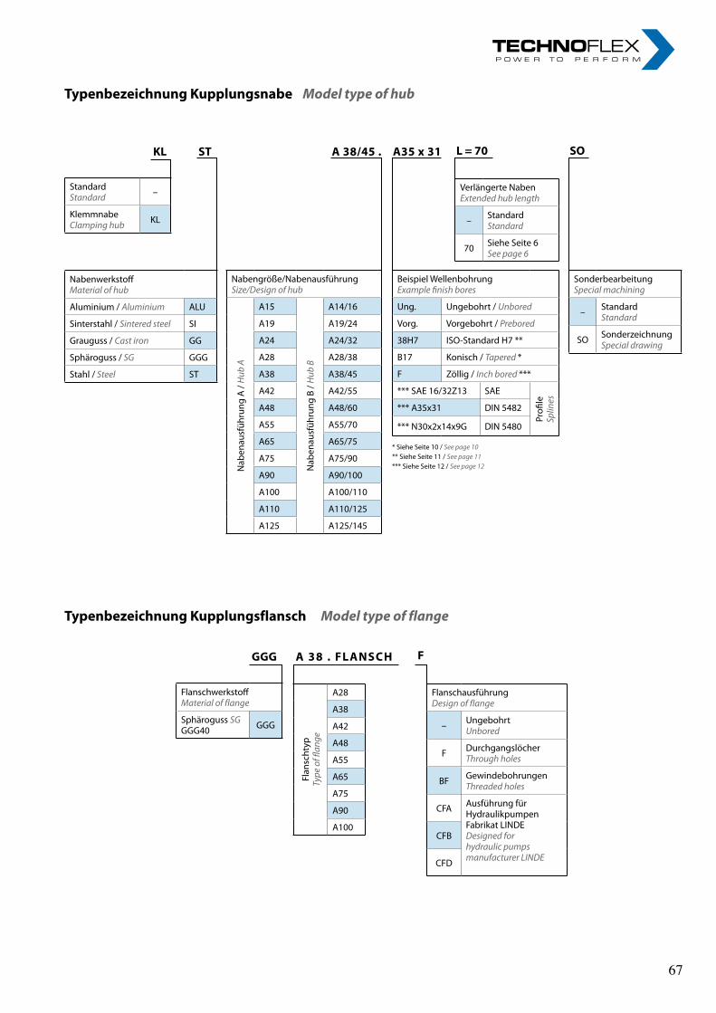
3
Typenbezeichnung Kupplungsflansch Model type of flange
Typenbezeichnung Kupplungsnabe Model type of hub
Flan
scht
ypTy
pe o
f flan
ge
A28
A38
A42
A48
A55
A65
A75
A90
A100
FlanschausführungDesign of flange
– UngebohrtUnbored
F DurchgangslöcherThrough holes
BF GewindebohrungenThreaded holes
CFA Ausführung fürHydraulikpumpenFabrikat LINDEDesigned forhydraulic pumpsmanufacturer LINDE
CFB
CFD
GGG
FlanschwerkstoffMaterial of flange
Sphäroguss SG GGG40 GGG
A 38 . FLANSCH F
StandardStandard –
KlemmnabeClamping hub KL
Beispiel WellenbohrungExample finish bores
Ung. Ungebohrt / Unbored
Vorg. Vorgebohrt / Prebored
38H7 ISO-Standard H7 **
B17 Konisch / Tapered *
F Zöllig / Inch bored ***
*** SAE 16/32Z13 SAE
Profi
leSp
lines
*** A35x31 DIN 5482
*** N30x2x14x9G DIN 5480
Verlängerte NabenExtended hub length
– StandardStandard
70 Siehe Seite 6See page 6
SonderbearbeitungSpecial machining
– StandardStandard
SO SonderzeichnungSpecial drawing
KL A 38/45 . A35 x 31 L = 70 SO
NabenwerkstoffMaterial of hub
Aluminium / Aluminium ALU
Sinterstahl / Sintered steel SI
Grauguss / Cast iron GG
Sphäroguss / SG GGG
Stahl / Steel ST
Nabengröße/NabenausführungSize/Design of hub
Nab
enau
sfüh
rung
A /
Hub
A
A15N
aben
ausf
ühru
ng B
/ H
ub B
A14/16
A19 A19/24
A24 A24/32
A28 A28/38
A38 A38/45
A42 A42/55
A48 A48/60
A55 A55/70
A65 A65/75
A75 A75/90
A90 A90/100
A100 A100/110
A110 A110/125
A125 A125/145
* Siehe Seite 10 / See page 10** Siehe Seite 11 / See page 11*** Siehe Seite 12 / See page 12
ST
3
Typenbezeichnung Kupplungsflansch Model type of flange
Typenbezeichnung Kupplungsnabe Model type of hub
Flan
scht
ypTy
pe o
f flan
ge
A28
A38
A42
A48
A55
A65
A75
A90
A100
FlanschausführungDesign of flange
– UngebohrtUnbored
F DurchgangslöcherThrough holes
BF GewindebohrungenThreaded holes
CFA Ausführung fürHydraulikpumpenFabrikat LINDEDesigned forhydraulic pumpsmanufacturer LINDE
CFB
CFD
GGG
FlanschwerkstoffMaterial of flange
Sphäroguss SG GGG40 GGG
A 38 . FLANSCH F
StandardStandard –
KlemmnabeClamping hub KL
Beispiel WellenbohrungExample finish bores
Ung. Ungebohrt / Unbored
Vorg. Vorgebohrt / Prebored
38H7 ISO-Standard H7 **
B17 Konisch / Tapered *
F Zöllig / Inch bored ***
*** SAE 16/32Z13 SAE
Profi
leSp
lines
*** A35x31 DIN 5482
*** N30x2x14x9G DIN 5480
Verlängerte NabenExtended hub length
– StandardStandard
70 Siehe Seite 6See page 6
SonderbearbeitungSpecial machining
– StandardStandard
SO SonderzeichnungSpecial drawing
KL A 38/45 . A35 x 31 L = 70 SO
NabenwerkstoffMaterial of hub
Aluminium / Aluminium ALU
Sinterstahl / Sintered steel SI
Grauguss / Cast iron GG
Sphäroguss / SG GGG
Stahl / Steel ST
Nabengröße/NabenausführungSize/Design of hub
Nab
enau
sfüh
rung
A /
Hub
A
A15
Nab
enau
sfüh
rung
B /
Hub
B
A14/16
A19 A19/24
A24 A24/32
A28 A28/38
A38 A38/45
A42 A42/55
A48 A48/60
A55 A55/70
A65 A65/75
A75 A75/90
A90 A90/100
A100 A100/110
A110 A110/125
A125 A125/145
* Siehe Seite 10 / See page 10** Siehe Seite 11 / See page 11*** Siehe Seite 12 / See page 12
ST
67 67
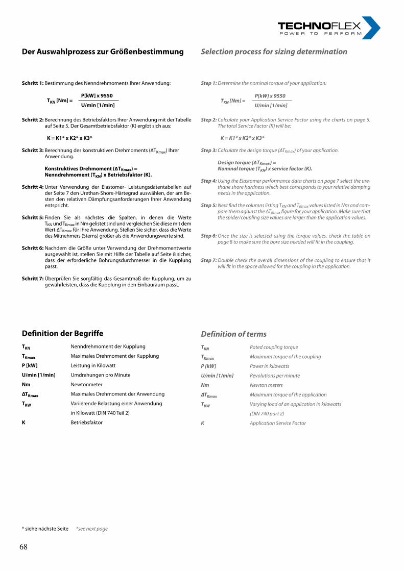
4rl-hydraulics.com
Step 1: Determine the nominal torque of your application:
TKN [Nm] =
P[kW] x 9550
U/min [1/min]
Step 2: Calculate your Application Service Factor using the charts on page 5. The total Service Factor (K) will be:
K = K1* x K2* x K3*
Step 3: Calculate the design torque (∆TKmax) of your application. Design torque (∆TKmax) = Nominal torque (TKN) x service factor (K).
Step 4: Using the Elastomer performance data charts on page 7 select the ure-thane shore hardness which best corresponds to your relative damping needs in the application.
Step 5: Next find the columns listing TKN and TKmax values listed in Nm and com-pare them against the ∆TKmax figure for your application. Make sure that the spider/coupling size values are larger than the application values.
Step 6: Once the size is selected using the torque values, check the table on page 8 to make sure the bore size needed will fit in the coupling.
Step 7: Double check the overall dimensions of the coupling to ensure that it will fit in the space allowed for the coupling in the application.
Definition of termsTKN Rated coupling torque
TKmax Maximum torque of the coupling
P [kW] Power in kilowatts
U/min [1/min] Revolutions per minute
Nm Newton meters
ΔTKmax Maximum torque of the application
TKW Varying load of an application in kilowatts
(DIN 740 part 2)
K Application Service Factor
Schritt 1: Bestimmung des Nenndrehmoments Ihrer Anwendung:
TKN [Nm] =
P[kW] x 9550
U/min [1/min]
Schritt 2: Berechnung des Betriebsfaktors Ihrer Anwendung mit der Tabelle auf Seite 5. Der Gesamtbetriebsfaktor (K) ergibt sich aus:
K = K1* x K2* x K3*
Schritt 3: Berechnung des konstruktiven Drehmoments (∆TKmax) Ihrer Anwendung. Konstruktives Drehmoment (∆TKmax) = Nenndrehmoment (TKN) x Betriebsfaktor (K).
Schritt 4: Unter Verwendung der Elastomer- Leistungsdatentabellen auf der Seite 7 den Urethan-Shore-Härtegrad auswählen, der am Be-sten den relativen Dämpfungsanforderungen Ihrer Anwendung entspricht.
Schritt 5: Finden Sie als nächstes die Spalten, in denen die Werte TKN und TKmax in Nm gelistet sind und vergleichen Sie diese mit dem Wert ∆TKmax für Ihre Anwendung. Stellen Sie sicher, dass die Werte des Mitnehmers (Sterns) größer als die Anwendungswerte sind.
Schritt 6: Nachdem die Größe unter Verwendung der Drehmomentwerte ausgewählt ist, stellen Sie mit Hilfe der Tabelle auf Seite 8 sicher, dass der erforderliche Bohrungsdurchmesser in die Kupplung passt.
Schritt 7: Überprüfen Sie sorgfältig das Gesamtmaß der Kupplung, um zu gewährleisten, dass die Kupplung in den Einbauraum passt.
Definition der BegriffeTKN Nenndrehmoment der Kupplung
TKmax Maximales Drehmoment der Kupplung
P [kW] Leistung in Kilowatt
U/min [1/min] Umdrehungen pro Minute
Nm Newtonmeter
ΔTKmax Maximales Drehmoment der Anwendung
TKW Variierende Belastung einer Anwendung
in Kilowatt (DIN 740 Teil 2)
K Betriebsfaktor
Der Auswahlprozess zur Größenbestimmung Selection process for sizing determination
* siehe nächste Seite *see next page
68 68
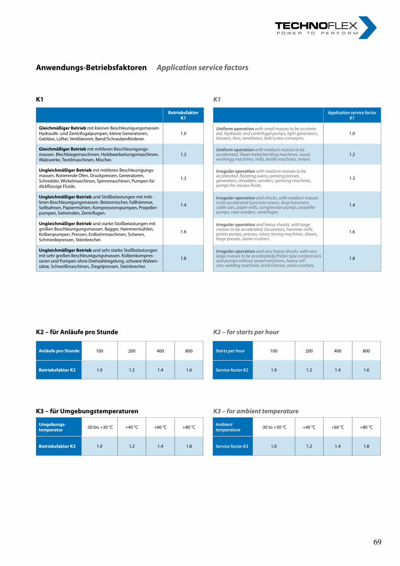
5
Anläufe pro Stunde 100 200 400 800 Starts per hour 100 200 400 800
Betriebsfaktor K2 1.0 1.2 1.4 1.6 Service factor K2 1.0 1.2 1.4 1.6
Umgebungs- temperatur -30 bis +30 °C +40 °C +60 °C +80 °C Ambient
temperature -30 to +30 °C +40 °C +60 °C +80 °C
Betriebsfaktor K3 1.0 1.2 1.4 1.8 Service factor K3 1.0 1.2 1.4 1.8
Anwendungs-Betriebsfaktoren Application service factors
K1 K1
K2 – für Anläufe pro Stunde K2 – for starts per hour
K3 – für Umgebungstemperaturen K3 – for ambient temperature
Betriebsfaktor K1
Application service factor K1
Gleichmäßiger Betrieb mit kleinen Beschleunigungsmassen. Hydraulik- und Zentrifugalpumpen, kleine Generatoren, Gebläse, Lüfter, Venlilatoren, Band/Schraubenförderer.
1.0Uniform operation with small masses to be accelera-ted. Hydraulic and centrifugal pumps, light generators, blowers, fans, ventilators, belt/screw conveyors.
1.0
Gleichmäßiger Betrieb mit mittleren Beschleunigungs-massen. Blechbiegemaschinen, Holzbearbeitungsmaschinen, Walzwerke, Textilmaschinen, Mischer.
1.2Uniform operation with medium masses to be accelerated. Sheet metal bending machines, wood workingg machines, mills, textile machines, mixers.
1.2
Ungleichmäßiger Betrieb mit mittleren Beschleunigungs-massen. Rotierende Öfen, Druckpressen, Generaloren, Schredder, Wickelmaschinen, Spinnmaschinen, Pumpen für dickflüssige Fluide.
1.3Irregular operation with medium masses to be accelerated. Rotating ovens, printing presses, generators, shredders, winders, spinning machines, pumps for viscous fluids.
1.3
Ungleichmäßiger Betrieb und Stoßbelastungen mit mitt-leren Beschleunigungsmassen. Betonmischer, Fallhämmer, Seilbahnen, Papiermühlen, Kompressionspumpen, Propeller-pumpen, Seilwinden, Zentrifugen.
1.4Irregular operation and shocks, with medium masses to be accelerated Goncrete mixers, drop hammers, cable cars, paper mills, compression pumps, propeller pumps, rope winders, centrifuges.
1.4
Ungleichmäßiger Betrieb und starke Stoßbelastungen mit großen Beschleunigungsmassen. Bagger, Hammermühlen, Kolbenpumpen, Pressen, Erdbohrmaschinen, Scheren, Schmiedepressen, Steinbrecher.
1.6Irregular operation and heavy shocks, with large masses to be accelerated. Excavators, hammer mills, piston pumps, presses, rotary boring machines, shears, forge presses, stone crushers.
1.6
Ungleichmäßiger Betrieb und sehr starke Stoßbelastungen mit sehr großen Beschleunigungsmassen. Kolbenkompres-soren und Pumpen ohne Drehzahlregelung, schwere Walzen-sätze, Schweißmaschinen, Ziegelpressen, Steinbrecher.
1.8Irregular operation and very heavy shocks, with very large masses to be acceleratedg Piston type compressors and pumps without speed variations, heavy roll sets, welding machines, brick Dresses, stone crushers.
1.8
69 69
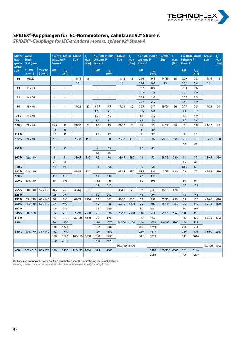
6rl-hydraulics.com
SPIDEX®-Kupplungen für IEC-Normmotoren, Zahnkranz 92° Shore ASPIDEX ®-Couplings for IEC-standard motors, spider 92° Shore A
Die Kupplungsvorauswahl erfolgte für den Normalbetrieb ohne Berücksichtigung von Betriebsfaktoren.Coupling selection made for normal operation. For other conditions please notify the safety factors.
Motor- bau- größe Motor size
Welle Shaft D x I [mm]
n = 750 [1/min] Leistung P Power P
Größe Size
TK
max [Nm]
n = 1000 [1/min] Leistung P Power P
GrößeSize
TK
max [Nm]
n = 1500 [1/min] Leistung P Power P
Größe Size
TK
max [Nm]
n = 3000 [l/min] Leistung P Power P
GrößeSize
TK
max [Nm]
= 1500 [1/min]
= 3000[1/min]
kW TAN
[Nm]kW TAN
[Nm]kW TAN
[Nm]kW TAN
[Nm]
56 9 x 20 – – 14/16 15 – – 14/16 15 0.06 0.4 14/16 15 0.09 0.3 14/16 15
15 15 0.09 0.6 15 0.12 0.4 15
63 11 x 23 – – – – 0.12 0.9 0.18 0.6
– 0.18 1.2 0.25 0.9
71 14 x 30 – – – – 0.25 1.8 0.37 1.3
0.37 2.5 0.55 1.9
80 19 x 40 – – 19/24 20 0.37 3.7 19/24 20 0.55 3.7 19/24 20 0.75 2.5 19/24 20
0.55 5.5 0.75 5.0 1.1 3.7
90 S 24 x 50 – – 0.75 7.9 1.1 7.5 1.5 4.9
90 L – – 1.1 11 1.5 10 2.2 7.4
100 L 28 x 60 0.75 11 24/32 70 1.5 15 24/32 70 2.2 15 24/32 70 3 9.8 24/32 70
1.1 16 3 20
112 M 1.5 21 2.2 22 4 27 4 13
132 S 38 x 80 2.2 29 28/38 190 3 30 28/38 190 5.5 36 28/38 190 5.5 18 28/38 190
7.5 25
132 M 3 40 4 39 7.5 49
5.5 55
160 M 42 x 110 4 54 38/45 380 7.5 74 38/45 380 11 72 38/45 380 11 35 38/45 380
5.5 74 15 49
160 L 7.5 100 11 108 15 98 18.5 60
180 M 48 x 110 42/55 530 42/55 530 18.5 121 42/55 530 22 72 42/55 530
180 L 11 147 15 147 22 144
200 L 55 x 110 15 196 18.5 185 30 195 30 97
22 215 37 117
225 S 60 x 140 55 x 110 18.5 245 48/60 620 48/60 620 37 245 48/60 620
225 M 22 294 30 292 45 294 45 146
250 M 65 x 140 60 x 140 30 390 65/75 1250 37 361 55/70 820 55 357 55/70 820 55 176 48/60 620
280 S 75 x 140 65 x 140 37 490 45 440 65/75 1250 75 487 65/75 1250 75 245 55/70 820
280 M 45 585 55 536 90 584 90 294
315 S 80 x 170 55 715 75/90 2560 75 730 75/90 2560 110 714 75/90 2560 110 350
315 M 75 970 90/100 4800 90 876 132 857 132 420 65/75 1250
315 L 90 1170 110 1070 90/100 4800 160 1030 90/100 4800 160 513
110 1420 132 1280 200 1290 200 641
355 L 95 x 170 75 x 140 132 1710 160 1550 250 1610 250 801 75/90 2560
160 2070 100/110 6600 200 1930 315 2020 315 1010
200 2580 250 2420
100/110 6600 90/100 4800
400 L 100 x 210 80 x 170 250 3230 110/125 9600 315 3040 2280 100/110 6600 355 1140
2560 400 1280
70 70
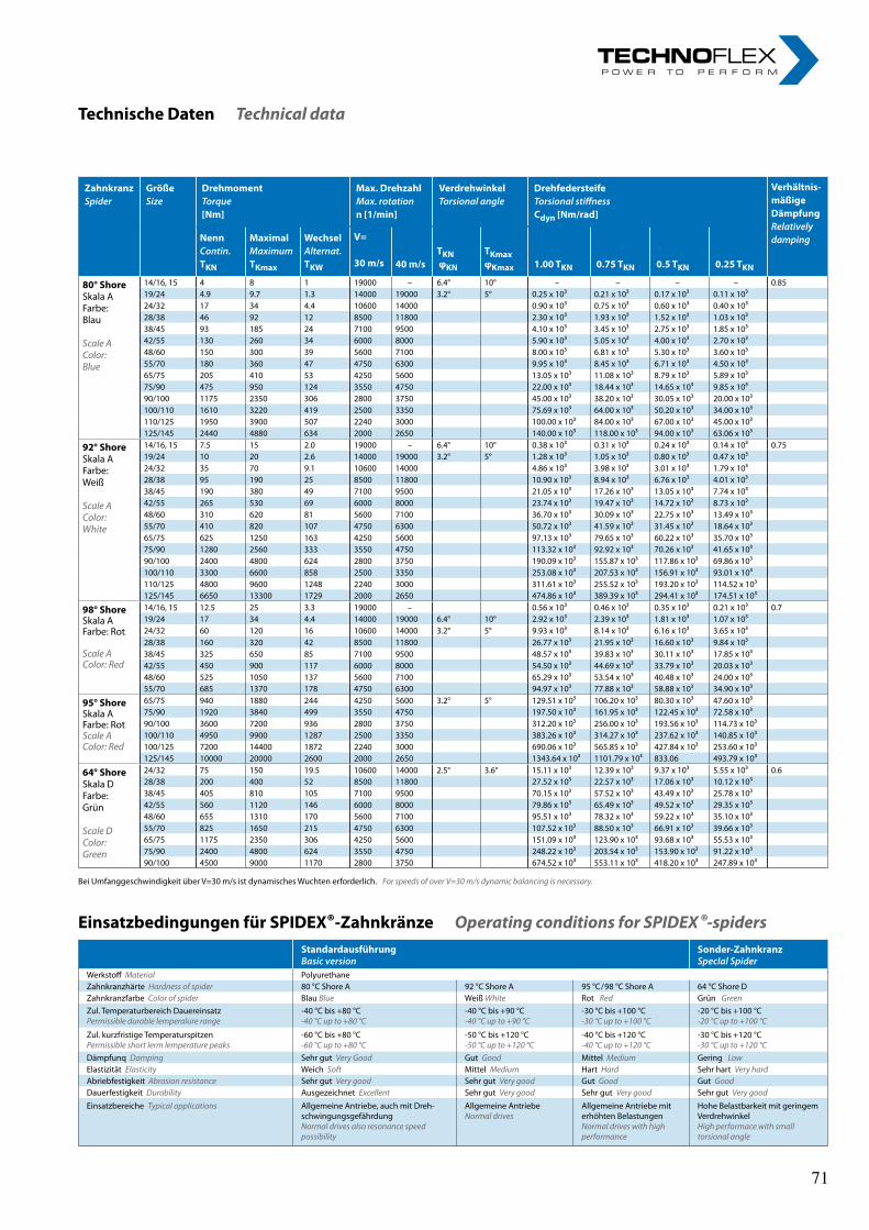
7
Zahnkranz Spider
Größe Size
Drehmoment Torque [Nm]
Max. Drehzahl Max. rotation n [1/min]
Verdrehwinkel Torsional angle
Drehfedersteife Torsional stiffness Cdyn [Nm/rad]
Verhältnis- mäßige Dämpfung Relatively dampingNenn
Contin. TKN
Maximal Maximum TKmax
Wechsel Alternat. TKW
V= 30 m/s
40 m/s
TKN φKN
TKmax φKmax
1.00 TKN
0.75 TKN
0.5 TKN
0.25 TKN
80° Shore Skala A Farbe: Blau Scale A Color: Blue
14/16, 15 4 8 1 19000 – 6.4° 10° – – – – 0.8519/24 4.9 9.7 1.3 14000 19000 3.2° 5° 0.25 x 10³ 0.21 x 10³ 0.17 x 10³ 0.11 x 10³24/32 17 34 4.4 10600 14000 0.90 x 10³ 0.75 x 10³ 0.60 x 10³ 0.40 x 10³28/38 46 92 12 8500 11800 2.30 x 10³ 1.93 x 10³ 1.52 x 10³ 1.03 x 10³38/45 93 185 24 7100 9500 4.10 x 10³ 3.45 x 10³ 2.75 x 10³ 1.85 x 10³42/55 130 260 34 6000 8000 5.90 x 10³ 5.05 x 10³ 4.00 x 10³ 2.70 x 10³48/60 150 300 39 5600 7100 8.00 x 10³ 6.81 x 10³ 5.30 x 10³ 3.60 x 10³55/70 180 360 47 4750 6300 9.95 x 10³ 8.45 x 10³ 6.71 x 10³ 4.50 x 10³65/75 205 410 53 4250 5600 13.05 x 10³ 11.08 x 10³ 8.79 x 10³ 5.89 x 10³75/90 475 950 124 3550 4750 22.00 x 10³ 18.44 x 10³ 14.65 x 10³ 9.85 x 10³90/100 1175 2350 306 2800 3750 45.00 x 10³ 38.20 x 10³ 30.05 x 10³ 20.00 x 10³100/110 1610 3220 419 2500 3350 75.69 x 10³ 64.00 x 10³ 50.20 x 10³ 34.00 x 10³110/125 1950 3900 507 2240 3000 100.00 x 10³ 84.00 x 10³ 67.00 x 10³ 45.00 x 10³125/145 2440 4880 634 2000 2650 140.00 x 10³ 118.00 x 10³ 94.00 x 10³ 63.06 x 10³
92° Shore Skala A Farbe: Weiß Scale A Color: White
14/16, 15 7.5 15 2.0 19000 – 6.4° 10° 0.38 x 10³ 0.31 x 10³ 0.24 x 10³ 0.14 x 10³ 0.7519/24 10 20 2.6 14000 19000 3.2° 5° 1.28 x 10³ 1.05 x 10³ 0.80 x 10³ 0.47 x 10³24/32 35 70 9.1 10600 14000 4.86 x 10³ 3.98 x 10³ 3.01 x 10³ 1.79 x 10³28/38 95 190 25 8500 11800 10.90 x 10³ 8.94 x 10³ 6.76 x 10³ 4.01 x 10³38/45 190 380 49 7100 9500 21.05 x 10³ 17.26 x 10³ 13.05 x 10³ 7.74 x 10³42/55 265 530 69 6000 8000 23.74 x 10³ 19.47 x 10³ 14.72 x 10³ 8.73 x 10³48/60 310 620 81 5600 7100 36.70 x 10³ 30.09 x 10³ 22.75 x 10³ 13.49 x 10³55/70 410 820 107 4750 6300 50.72 x 10³ 41.59 x 10³ 31.45 x 10³ 18.64 x 10³65/75 625 1250 163 4250 5600 97.13 x 10³ 79.65 x 10³ 60.22 x 10³ 35.70 x 10³75/90 1280 2560 333 3550 4750 113.32 x 10³ 92.92 x 10³ 70.26 x 10³ 41.65 x 10³90/100 2400 4800 624 2800 3750 190.09 x 10³ 155.87 x 10³ 117.86 x 10³ 69.86 x 10³100/110 3300 6600 858 2500 3350 253.08 x 10³ 207.53 x 10³ 156.91 x 10³ 93.01 x 10³110/125 4800 9600 1248 2240 3000 311.61 x 10³ 255.52 x 10³ 193.20 x 10³ 114.52 x 10³125/145 6650 13300 1729 2000 2650 474.86 x 10³ 389.39 x 10³ 294.41 x 10³ 174.51 x 10³
98° Shore Skala A Farbe: Rot Scale A Color: Red
14/16, 15 12.5 25 3.3 19000 – 0.56 x 10³ 0.46 x 10³ 0.35 x 10³ 0.21 x 10³ 0.719/24 17 34 4.4 14000 19000 6.4° 10° 2.92 x 10³ 2.39 x 10³ 1.81 x 10³ 1.07 x 10³24/32 60 120 16 10600 14000 3.2° 5° 9.93 x 10³ 8.14 x 10³ 6.16 x 10³ 3.65 x 10³28/38 160 320 42 8500 11800 26.77 x 10³ 21.95 x 10³ 16.60 x 10³ 9.84 x 10³38/45 325 650 85 7100 9500 48.57 x 10³ 39.83 x 10³ 30.11 x 10³ 17.85 x 10³42/55 450 900 117 6000 8000 54.50 x 10³ 44.69 x 10³ 33.79 x 10³ 20.03 x 10³48/60 525 1050 137 5600 7100 65.29 x 10³ 53.54 x 10³ 40.48 x 10³ 24.00 x 10³55/70 685 1370 178 4750 6300 94.97 x 10³ 77.88 x 10³ 58.88 x 10³ 34.90 x 10³
95° Shore Skala A Farbe: RotScale A Color: Red
65/75 940 1880 244 4250 5600 3.2° 5° 129.51 x 10³ 106.20 x 10³ 80.30 x 10³ 47.60 x 10³75/90 1920 3840 499 3550 4750 197.50 x 10³ 161.95 x 10³ 122.45 x 10³ 72.58 x 10³90/100 3600 7200 936 2800 3750 312.20 x 10³ 256.00 x 10³ 193.56 x 10³ 114.73 x 10³100/110 4950 9900 1287 2500 3350 383.26 x 10³ 314.27 x 10³ 237.62 x 10³ 140.85 x 10³100/125 7200 14400 1872 2240 3000 690.06 x 10³ 565.85 x 10³ 427.84 x 10³ 253.60 x 10³125/145 10000 20000 2600 2000 2650 1343.64 x 10³ 1101.79 x 10³ 833.06 493.79 x 10³
64° Shore Skala D Farbe: Grün Scale D Color: Green
24/32 75 150 19.5 10600 14000 2.5° 3.6° 15.11 x 10³ 12.39 x 10³ 9.37 x 10³ 5.55 x 10³ 0.628/38 200 400 52 8500 11800 27.52 x 10³ 22.57 x 10³ 17.06 x 10³ 10.12 x 10³38/45 405 810 105 7100 9500 70.15 x 10³ 57.52 x 10³ 43.49 x 10³ 25.78 x 10³42/55 560 1120 146 6000 8000 79.86 x 10³ 65.49 x 10³ 49.52 x 10³ 29.35 x 10³48/60 655 1310 170 5600 7100 95.51 x 10³ 78.32 x 10³ 59.22 x 10³ 35.10 x 10³55/70 825 1650 215 4750 6300 107.52 x 10³ 88.50 x 10³ 66.91 x 10³ 39.66 x 10³65/75 1175 2350 306 4250 5600 151.09 x 10³ 123.90 x 10³ 93.68 x 10³ 55.53 x 10³75/90 2400 4800 624 3550 4750 248.22 x 10³ 203.54 x 10³ 153.90 x 10³ 91.22 x 10³90/100 4500 9000 1170 2800 3750 674.52 x 10³ 553.11 x 10³ 418.20 x 10³ 247.89 x 10³
Technische Daten Technical data
Bei Umfanggeschwindigkeit über V=30 m/s ist dynamisches Wuchten erforderlich. For speeds of over V=30 m/s dynamic balancing is necessary.
Einsatzbedingungen für SPIDEX®-Zahnkränze Operating conditions for SPIDEX ®-spidersStandardausführung Basic version
Sonder-Zahnkranz SpecIal Spider
Werkstoff Material Polyurethane Zahnkranzhärte Hardness of spider 80 °C Shore A 92 °C Shore A 95 °C/98 °C Shore A 64 °C Shore D Zahnkranzfarbe Color of spider Blau Blue Weiß White Rot Red Grün GreenZul. Temperaturbereich Dauereinsatz Permissible durable lemperalure range
-40 °C bis +80 °C -40 °C up to +80 °C
-40 °C bis +90 °C -40 °C up to +90 °C
-30 °C bis +100 °C -30 °C up to +100 °C
-20 °C bis +100 °C -20 °C up to +100 °C
Zul. kurzfristige Temperaturspitzen Permissible short lerm lemperature peaks
-60 °C bis +80 °C -60 °C up to +80 °C
-50 °C bis +120 °C -50 °C up to +120 °C
-40 °C bis +120 °C -40 °C up to +120 °C
-30 °C bis +120 °C -30 °C up to +120 °C
Dämpfunq Damping Sehr gut Very Good Gut Good Mittel Medium Gering LowElastizität Elasticity Weich Soft Mittel Medium Hart Hard Sehr hart Very hardAbriebfestigkeit Abrasion resistance Sehr gut Very good Sehr gut Very good Gut Good Gut GoodDauerfestigkeit Durability Ausgezeichnet Excellent Sehr gut Very good Sehr gut Very good Sehr gut Very good
Einsatzbereiche Typical applications Allgemeine Antriebe, auch mit Dreh-schwingungsgefährdung Normal drives also resonance speed possibility
Allgemeine Antriebe Normal drives
Allgemeine Antriebe mit erhöhten Belastungen Normal drives with high performance
Hohe Belastbarkeit mit geringem Verdrehwinkel High performace with small torsional angle
71 71
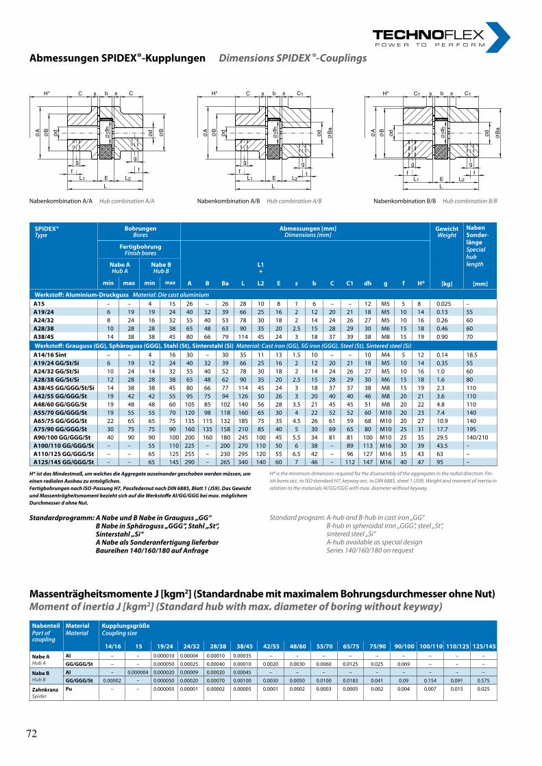
8rl-hydraulics.com
Abmessungen SPIDEX®-Kupplungen Dimensions SPIDEX ®-Couplings
d hØ ØØ
gg
f f
L1 L2
L
E
dd
ØB
ØB
ØA
CsbsCH*
d hØ ØØ
g gf f
L1 L2
L
E
dd
Øa
BØB
ØA
C1sbsCH*
d hØ ØØ
g g
f fL1 L2
LE
dd
Øa
BØB
ØA
C1sbsC1H*
Nabenkombination A/A Hub combination A/A Nabenkombination A/B Hub combination A/B Nabenkombination B/B Hub combination B/B
Massenträgheitsmomente J [kgm2] (Standardnabe mit maximalem Bohrungsdurchmesser ohne Nut)Moment of inertia J [kgm2] (Standard hub with max. diameter of boring without keyway)
H* is the minimum dimension required for the disassembly of the aggregates in the radial direction. Fin-ish bores acc. to ISO standard H7, keyway acc. to DIN 6885, sheet 1 (JS9). Weight and moment of inertia in relation to the materials Al/GG/GGG with max. diameter without keyway.
Standard program: A-hub and B-hub in cast iron „GG“ B-hub in spheroidal iron „GGG“, steel „St“, sintered steel „Si“ A-hub available as special design Series 140/160/180 on request
H* ist das Mindestmaß, um welches die Aggregate auseinander geschoben werden müssen, um einen radialen Ausbau zu ermöglichen. Fertigbohrungen nach ISO-Passung H7, Passfedernut nach DIN 6885, Blatt 1 (JS9). Das Gewicht und Massenträgheitsmoment bezieht sich auf die Werkstoffe Al/GG/GGG bei max. möglichem Durchmesser d ohne Nut.
Standardprogramm: A Nabe und B Nabe in Grauguss „GG“ B Nabe in Sphäroguss „GGG“, Stahl „St“, Sinterstahl „Si“ A Nabe als Sonderanfertigung lieferbar Baureihen 140/160/180 auf Anfrage
SPIDEX®Type
Bohrungen Bores
Abmessungen [mm]Dimensions [mm]
GewichtWeight
NabenSonder- länge Special hub length
Fertigbohrung Finish bores
Nabe A Hub A
Nabe B Hub B
L1 +
min max min max A B Ba L L2 E s b C C1 dh g f H* [kg] [mm]
Werkstoff: Aluminium-Druckguss Material: Die cast aluminiumA15 – – 4 15 26 – 26 28 10 8 1 6 – – 12 M5 5 8 0.025 –A19/24 6 19 19 24 40 32 39 66 25 16 2 12 20 21 18 M5 10 14 0.13 55A24/32 8 24 16 32 55 40 53 78 30 18 2 14 24 26 27 M5 10 16 0.26 60A28/38 10 28 28 38 65 48 63 90 35 20 2.5 15 28 29 30 M6 15 18 0.46 60A38/45 14 38 38 45 80 66 79 114 45 24 3 18 37 39 38 M8 15 19 0.90 70Werkstoff: Grauguss (GG), Sphäroguss (GGG), Stahl (St), Sinterstahl (Si) Material: Cast iron (GG), SG iron (GGG), Steel (St), Sintered steel (Si)
A14/16 Sint – – 4 16 30 – 30 35 11 13 1.5 10 – – 10 M4 5 12 0.14 18.5A19/24 GG/St/Si 6 19 12 24 40 32 39 66 25 16 2 12 20 21 18 M5 10 14 0.35 55A24/32 GG/St/Si 10 24 14 32 55 40 52 78 30 18 2 14 24 26 27 M5 10 16 1.0 60A28/38 GG/St/Si 12 28 28 38 65 48 62 90 35 20 2.5 15 28 29 30 M6 15 18 1.6 80A38/45 GG/GGG/St/Si 14 38 38 45 80 66 77 114 45 24 3 18 37 37 38 M8 15 19 2.3 110A42/55 GG/GGG/St 19 42 42 55 95 75 94 126 50 26 3 20 40 40 46 M8 20 21 3.6 110A48/60 GG/GGG/St 19 48 48 60 105 85 102 140 56 28 3.5 21 45 45 51 M8 20 22 4.8 110A55/70 GG/GGG/St 19 55 55 70 120 98 118 160 65 30 4 22 52 52 60 M10 20 23 7.4 140A65/75 GG/GGG/St 22 65 65 75 135 115 132 185 75 35 4.5 26 61 59 68 M10 20 27 10.9 140A75/90 GG/GGG/St 30 75 75 90 160 135 158 210 85 40 5 30 69 65 80 M10 25 31 17.7 195A90/100 GG/GGG/St 40 90 90 100 200 160 180 245 100 45 5.5 34 81 81 100 M10 25 35 29.5 140/210 A100/110 GG/GGG/St – – 55 110 225 – 200 270 110 50 6 38 – 89 113 M16 30 39 43.5 –A110/125 GG/GGG/St – – 65 125 255 – 230 295 120 55 6.5 42 – 96 127 M16 35 43 63 –A125/145 GG/GGG/St – – 65 145 290 – 265 340 140 60 7 46 – 112 147 M16 40 47 95 –
NabenteilPart of coupling
Material Material
Kupplungsgröße Coupling size
14/16 15 19/24 24/32 28/38 38/45 42/55 48/60 55/70 65/75 75/90 90/100 100/110 110/125 125/145
Nabe A Hub A
AI – – 0.000010 0.00004 0.00010 0.00035 – – – – – – – – –
GG/GGG/St – – 0.000050 0.00025 0.00040 0.00010 0.0020 0.0030 0.0060 0.0125 0.025 0.069 – – –
Nabe B Hub B
AI – 0.000004 0.000020 0.00009 0.00020 0.00045 – – – – – – – – –
GG/GGG/St 0.00002 – 0.000050 0.00020 0.00070 0.00100 0.0030 0.0050 0.0100 0.0183 0.041 0.09 0.154 0.091 0.575
Zahnkranz Spider
Pu – – 0.000003 0.00001 0.00002 0.00005 0.0001 0.0002 0.0003 0.0005 0.002 0.004 0.007 0.015 0.025
72 72
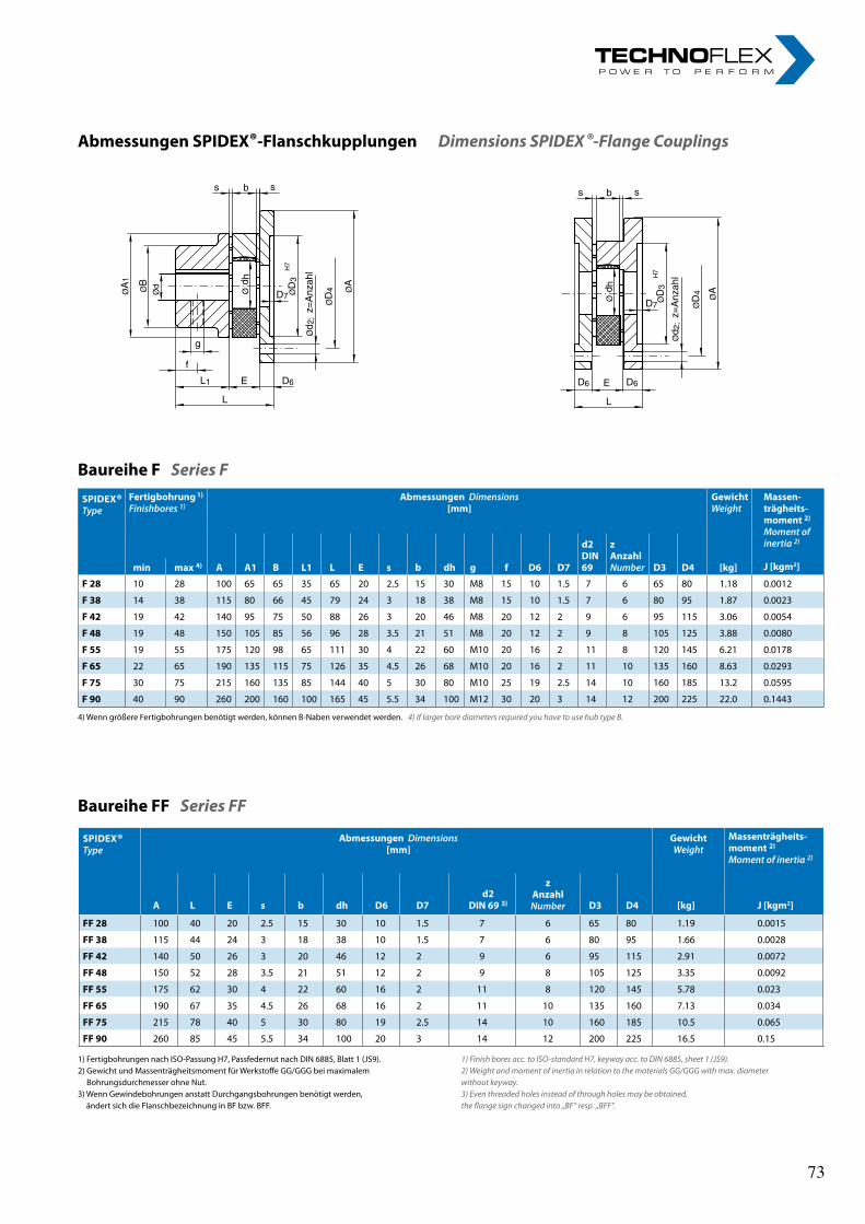
9
d hØ Ø
3D
Ø2;d
Ø4
D ØA
lhaznA
=z
7H
D7
D6D6
s b s
E
L
1Ø
A ØB
Ød d h
Ø Ø3
D
Ø2;d
Ø4
D
ØA
lhaznA
=z
7H
D7
g
f
s b s
L1
L
E D6
Abmessungen SPIDEX®-Flanschkupplungen Dimensions SPIDEX ®-Flange Couplings
Baureihe F Series F
Baureihe FF Series FF
4) Wenn größere Fertigbohrungen benötigt werden, können B-Naben verwendet werden. 4) If larger bore diameters required you have to use hub type B.
1) Fertigbohrungen nach ISO-Passung H7, Passfedernut nach DIN 6885, Blatt 1 (JS9).2) Gewicht und Massenträgheitsmoment für Werkstoffe GG/GGG bei maximalem
Bohrungsdurchmesser ohne Nut.3) Wenn Gewindebohrungen anstatt Durchgangsbohrungen benötigt werden,
ändert sich die Flanschbezeichnung in BF bzw. BFF.
1) Finish bores acc. to ISO-standard H7, keyway acc. to DIN 6885, sheet 1 (JS9).2) Weight and moment of inertia in relation to the materials GG/GGG with max. diameterwithout keyway.3) Even threaded holes instead of through holes may be obtained,the flange sign changed into „BF“ resp. „BFF“.
SPIDEX® Type
Fertigbohrung 1)
Finishbores 1)Abmessungen Dimensions
[mm]Gewicht Weight
Massen-trägheits- moment 2)
Moment of inertia 2)
J [kgm2]min max 4) A A1 B L1 L E s b dh g f D6 D7
d2 DIN 69
z Anzahl Number D3 D4 [kg]
F 28 10 28 100 65 65 35 65 20 2.5 15 30 M8 15 10 1.5 7 6 65 80 1.18 0.0012
F 38 14 38 115 80 66 45 79 24 3 18 38 M8 15 10 1.5 7 6 80 95 1.87 0.0023
F 42 19 42 140 95 75 50 88 26 3 20 46 M8 20 12 2 9 6 95 115 3.06 0.0054
F 48 19 48 150 105 85 56 96 28 3.5 21 51 M8 20 12 2 9 8 105 125 3.88 0.0080
F 55 19 55 175 120 98 65 111 30 4 22 60 M10 20 16 2 11 8 120 145 6.21 0.0178
F 65 22 65 190 135 115 75 126 35 4.5 26 68 M10 20 16 2 11 10 135 160 8.63 0.0293
F 75 30 75 215 160 135 85 144 40 5 30 80 M10 25 19 2.5 14 10 160 185 13.2 0.0595
F 90 40 90 260 200 160 100 165 45 5.5 34 100 M12 30 20 3 14 12 200 225 22.0 0.1443
SPIDEX® Type
Abmessungen Dimensions [mm]
Gewicht Weight
Massenträgheits- moment 2)
Moment of inertia 2)
A L E s b dh D6 D7d2
DIN 69 3)
z Anzahl Number D3 D4 [kg] J [kgm2]
FF 28 100 40 20 2.5 15 30 10 1.5 7 6 65 80 1.19 0.0015
FF 38 115 44 24 3 18 38 10 1.5 7 6 80 95 1.66 0.0028
FF 42 140 50 26 3 20 46 12 2 9 6 95 115 2.91 0.0072
FF 48 150 52 28 3.5 21 51 12 2 9 8 105 125 3.35 0.0092
FF 55 175 62 30 4 22 60 16 2 11 8 120 145 5.78 0.023
FF 65 190 67 35 4.5 26 68 16 2 11 10 135 160 7.13 0.034
FF 75 215 78 40 5 30 80 19 2.5 14 10 160 185 10.5 0.065
FF 90 260 85 45 5.5 34 100 20 3 14 12 200 225 16.5 0.15
73 73
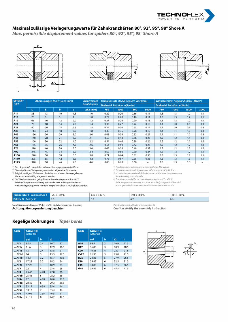
10rl-hydraulics.com
Maximal zulässige Verlagerungswerte für Zahnkranzhärten 80°, 92°, 95°, 98° Shore AMax. permissible displacement values for spiders 80°, 92°, 95°, 98° Shore A
1) The dimension L extends acc. to the mentioned ΔKa-values.2) The above mentioned displacement values are general guidelines.3) In case of angular and radial displacements at the same time you can use
the values only proportionally.4) The values are valid for an operating temperature of T = +30°C.
If the temperature increases, you have to multiply the permissible radial and angular displacement values with the temperature factor St.
Sorgfältiges Ausrichten der Wellen erhöht die Lebensdauer der KupplungAchtung: Montageanleitung beachten
Careful alignment will extend the coupling lifeCaution: Notify the assembly instruction
Kegelige Bohrungen Taper bores
d
b
t2
l
SPIDEX®Type
Abmessungen Dimensions [mm] AxialversatzAxial displace
Radialversatz Radial displace ∆Kr [mm] Winkelversatz Angular displace ∆Kw [°]
Drehzahl Rotation n[1/min] Drehzahl Rotation n[1/min]
L E b s ∆Ka [mm] 750 1000 1500 3000 750 1000 1500 3000A14 35 13 10 1.5 1.0 0.22 0.20 0.16 0.11 1.3 1.3 1.2 1.1A15 28 8 6 1 1.0 0.22 0.20 0.16 0.11 1.3 1.3 1.2 1.1A19 66 16 12 2.0 1.2 0.27 0.24 0.20 0.13 1.3 1.3 1.2 1.1A24 78 18 14 2.0 1.4 0.30 0.27 0.22 0.15 1.1 1.0 0.9 0.8A28 90 20 15 2.5 1.5 0.34 0.30 0.25 0.17 1.1 1.0 0.9 0.8A38 114 24 18 3.0 1.8 0.38 0.35 0.28 0.19 1.1 1.1 1.0 0.8A42 126 26 20 3.0 2.0 0.43 0.38 0.32 0.21 1.1 1.1 1.0 0.8A48 140 28 21 3.5 2.1 0.50 0.44 0.36 0.25 1.2 1.2 1.1 0.9A55 160 30 22 4.0 2.2 0.54 0.46 0.38 0.26 1.2 1.2 1.1 1.0A65 185 35 26 4.5 2.6 0.56 0.50 0.42 0.28 1.2 1.2 1.2 1.0A75 210 40 30 5.0 3.0 0.65 0.58 0.48 0.32 1.3 1.2 1.2 1.0A90 245 45 34 5.5 3.4 0.68 0.60 0.50 0.34 1.3 1.3 1.2 1.1A100 270 50 38 6.0 3.8 0.71 0.64 0.52 0.36 1.3 1.3 1.2 1.1A110 295 55 42 6.5 4.2 0.75 0.67 0.55 0.38 1.3 1.3 1.3 1.1A125 340 60 46 7.0 4.6 0.80 0.70 0.60 – 1.3 1.3 1.3 –
Code Konus 1:8Taper 1:8
ø d
Code Konus 1:5Taper 1:5
b t2 I ø d b t2 I…N/1 9.75 2.4 10.7 17 A10 9.85 2 10.9 11.5…N/1c 11.6 3 12.9 16.5 B17 16.85 3 18.9 18.5…N/1e 13 2.4 13.8 21 C20 19.85 4 220 21.5…N/1d 14 3 15.5 17.5 Cs22 21.95 3 23.8 21.5…N/1b 14.3 3.2 15.7 19.5 D25 24.85 5 27.9 26.5…N/2 17.28 3.2 18.2 24 E30 29.85 6 32.5 31.5…N/2a 17.28 4 18.9 24 F35 34.85 6 37.5 36.5…N/3 22 4 23.4 28 G40 39.85 6 45.5 41.5…N/4 25.46 4.78 27.8 36…N/4b 25.46 5 28.2 36…N/4a 27 4.78 28.8 32.5…N/4g 28.45 6 29.3 38.5…N/5 33.17 6.38 35.4 44…N/5a 33.17 7 35.4 44…N/6 43.05 7.95 46.5 51…N/6a 41.15 8 44.2 42.5
Temperatur T Temperature T -25 < +30 °C +30 < +40 °C +40 < +60 °C +60 < +80 °C
Faktor St Safety St 1.0 0.8 0.7 0.6
1) Das Längenmaß L vergrößert sich um die angegebenen ΔKa-Werte.2) Die aufgeführten Verlagerungswerte sind allgemeine Richtwerte.3) Bei gleichzeitigem Winkel- und Radialversatz können die angegebenen
Werte nur anteilmäßig ausgenutzt werden.4) Die Tabellenwerte sind gültig für eine Betriebstemperatur T = +30°C.
Bei einer Temperaturerhöhung müssen die max. zulässigen Radialund Winkelverlagerungswerte mit dem Temperaturfaktor St multipliziert werden.
74 74
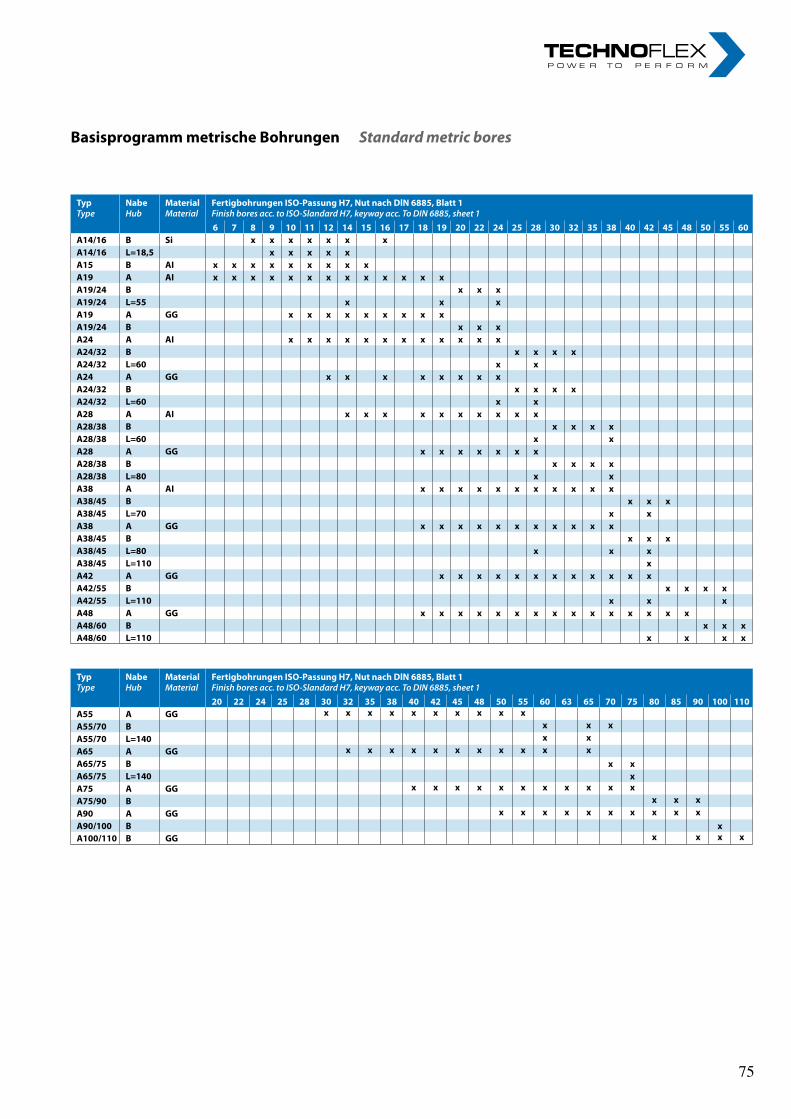
11
Basisprogramm metrische Bohrungen Standard metric bores
Typ Type
Nabe Hub
Material Material
Fertigbohrungen ISO-Passung H7, Nut nach DlN 6885, Blatt 1 Finish bores acc. to ISO-Slandard H7, keyway acc. To DIN 6885, sheet 16 7 8 9 10 11 12 14 15 16 17 18 19 20 22 24 25 28 30 32 35 38 40 42 45 48 50 55 60
A14/16 B Si x x x x x x x A14/16 L=18,5 x x x x x A15 B AI x x x x x x x x x A19 A AI x x x x x x x x x x x x x A19/24 B x x x A19/24 L=55 x x x A19 A GG x x x x x x x x x A19/24 B x x x A24 A AI x x x x x x x x x x x x A24/32 B x x x x A24/32 L=60 x x A24 A GG x x x x x x x x A24/32 B x x x x A24/32 L=60 x x A28 A AI x x x x x x x x x x A28/38 B x x x x A28/38 L=60 x x A28 A GG x x x x x x x A28/38 B x x x x A28/38 L=80 x x A38 A AI x x x x x x x x x x x A38/45 B x x x A38/45 L=70 x x A38 A GG x x x x x x x x x x x A38/45 B x x x A38/45 L=80 x x x A38/45 L=110 x A42 A GG x x x x x x x x x x x x A42/55 B x x x x A42/55 L=110 x x x A48 A GG x x x x x x x x x x x x x x x A48/60 B x x x A48/60 L=110 x x x x
Typ Type
Nabe Hub
Material Material
Fertigbohrungen ISO-Passung H7, Nut nach DlN 6885, Blatt 1 Finish bores acc. to ISO-Slandard H7, keyway acc. To DIN 6885, sheet 120 22 24 25 28 30 32 35 38 40 42 45 48 50 55 60 63 65 70 75 80 85 90 100 110
A55 A GG x x x x x x x x x x A55/70 B x x x A55/70 L=140 x x A65 A GG x x x x x x x x x x x A65/75 B x x A65/75 L=140 x A75 A GG x x x x x x x x x x x A75/90 B x x x A90 A GG x x x x x x x x x x A90/100 B x A100/110 B GG x x x x
75 75
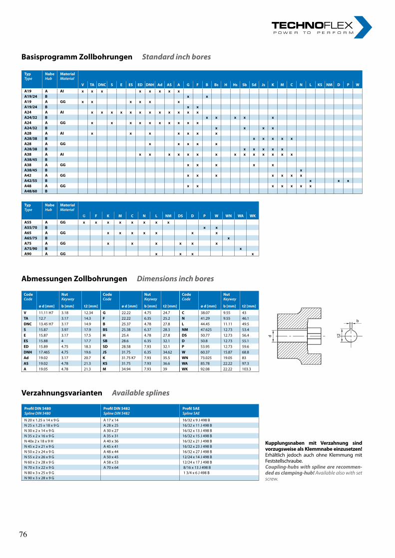
12rl-hydraulics.com
Basisprogramm Zollbohrungen Standard inch bores
Abmessungen Zollbohrungen Dimensions inch bores
Verzahnungsvarianten Available splines
Kupplungsnaben mit Verzahnung sind vorzugsweise als Klemmnabe einzusetzen! Erhältlich jedoch auch ohne Klemmung mit Feststellschraube.Coupling-hubs with spline are recommen-ded as clamping-hub! Available also with set screw.
Typ Type
Nabe Hub
Material Material
V TA DNC S E ES ED DNH Ad AS A G F B Bs H Hs Sb Sd Js K M C N L KS NM D P W
A19 A AI x x x x x x x x A19/24 B x x A19 A GG x x x x x x A19/24 B x x A24 A AI x x x x x x x x x x x x A24/32 B x x x x x A24 A GG x x x x x x x x x x A24/32 B x x x x A28 A AI x x x x x x x A28/38 B x x x x x A28 A GG x x x x x A28/38 B x x x x x A38 A AI x x x x x x x x x x x x x x A38/45 B A38 A GG x x x x x A38/45 B x A42 A GG x x x x x x x A42/55 B x x x A48 A GG x x x x x x x A48/60 B
Typ Type
Nabe Hub
Material Material
G F K M C N L NM DS D P W WN WA WK
A55 A GG x x x x x x x x A55/70 B x x A65 A GG x x x x x x x A65/75 B x A75 A GG x x x x x x A75/90 B x A90 A GG x x x x
CodeCode
NutKeyway
CodeCode
NutKeyway
CodeCode
NutKeyway
ø d [mm] b [mm] t2 [mm] ø d [mm] b [mm] t2 [mm] ø d [mm] b [mm] t2 [mm]
V 11.11 H7 3.18 12.34 G 22.22 4.75 24.7 C 38.07 9.55 43TA 12.7 3.17 14.3 F 22.22 6.35 25.2 N 41.29 9.55 46.1DNC 13.45 H7 3.17 14.9 B 25.37 4.78 27.8 L 44.45 11.11 49.5S 15.87 3.97 17.9 BS 25.38 6.37 28.3 NM 47.625 12.73 53.4E 15.87 3.17 17.5 H 25.4 4.78 27.8 DS 50.77 12.73 56.4ES 15.88 4 17.7 SB 28.6 6.35 32.1 D 50.8 12.73 55.1ED 15.89 4.75 18.3 SD 28.58 7.93 32.1 P 53.95 12.73 59.6DNH 17.465 4.75 19.6 JS 31.75 6.35 34.62 W 60.37 15.87 68.8Ad 19.02 3.17 20.7 K 31.75 K7 7.93 35.5 WN 73.025 19.05 83AS 19.02 4.78 21.3 KS 31.75 7.93 36.6 WA 85.78 22.22 97.3A 19.05 4.78 21.3 M 34.94 7.93 39 WK 92.08 22.22 103.3
Profil DIN 5480 Profil DIN 5482 Profil SAE Spline DIN 5480 Spline DIN 5482 Spline SAE
N 20 x 1.25 x 14 x 9 G A 17 x 14 16/32 x 9 J 498 B N 25 x 1.25 x 18 x 9 G A 28 x 25 16/32 x 11 J 498 BN 30 x 2 x 14 x 9 G A 30 x 27 16/32 x 13 J 498 BN 35 x 2 x 16 x 9 G A 35 x 31 16/32 x 15 J 498 BN 40x 2 x 18 x 9 H A 40 x 36 16/32 x 21 J 498 BN 45 x 2 x 21 x 9 G A 45 x 41 16/32 x 23 J 498 BN 50 x 2 x 24 x 9 G A 48 x 44 16/32 x 27 J 498 BN 55 x 2 x 26 x 9 G A 50 x 45 12/24 x 14 J 498 BN 60 x 2 x 28 x 9 G A 58 x 53 12/24 x 17 J 498 B N 70 x 3 x 22 x 9 G A 70 x 64 8/16 x 13 J 498 BN 80 x 3 x 25 x 9 G 1 3/4 x 6 J 498 BN 90 x 3 x 28 x 9 G
b
d t2
Version 01/13SPIDEX®
R+L HydRauLics GmbH Friedrichstraße 6 D-58791 Werdohl Tel +49 2392 509-0 Fax +49 2392 [email protected] rl-hydraulics.com
© R+L HYDRAULICS GmbH Technische Änderungen vorbehaltenTechnical changes reserved
12rl-hydraulics.com
Basisprogramm Zollbohrungen Standard inch bores
Abmessungen Zollbohrungen Dimensions inch bores
Verzahnungsvarianten Available splines
Kupplungsnaben mit Verzahnung sind vorzugsweise als Klemmnabe einzusetzen! Erhältlich jedoch auch ohne Klemmung mit Feststellschraube.Coupling-hubs with spline are recommen-ded as clamping-hub! Available also with set screw.
Typ Type
Nabe Hub
Material Material
V TA DNC S E ES ED DNH Ad AS A G F B Bs H Hs Sb Sd Js K M C N L KS NM D P W
A19 A AI x x x x x x x x A19/24 B x x A19 A GG x x x x x x A19/24 B x x A24 A AI x x x x x x x x x x x x A24/32 B x x x x x A24 A GG x x x x x x x x x x A24/32 B x x x x A28 A AI x x x x x x x A28/38 B x x x x x A28 A GG x x x x x A28/38 B x x x x x A38 A AI x x x x x x x x x x x x x x A38/45 B A38 A GG x x x x x A38/45 B x A42 A GG x x x x x x x A42/55 B x x x A48 A GG x x x x x x x A48/60 B
Typ Type
Nabe Hub
Material Material
G F K M C N L NM DS D P W WN WA WK
A55 A GG x x x x x x x x A55/70 B x x A65 A GG x x x x x x x A65/75 B x A75 A GG x x x x x x A75/90 B x A90 A GG x x x x
CodeCode
NutKeyway
CodeCode
NutKeyway
CodeCode
NutKeyway
ø d [mm] b [mm] t2 [mm] ø d [mm] b [mm] t2 [mm] ø d [mm] b [mm] t2 [mm]
V 11.11 H7 3.18 12.34 G 22.22 4.75 24.7 C 38.07 9.55 43TA 12.7 3.17 14.3 F 22.22 6.35 25.2 N 41.29 9.55 46.1DNC 13.45 H7 3.17 14.9 B 25.37 4.78 27.8 L 44.45 11.11 49.5S 15.87 3.97 17.9 BS 25.38 6.37 28.3 NM 47.625 12.73 53.4E 15.87 3.17 17.5 H 25.4 4.78 27.8 DS 50.77 12.73 56.4ES 15.88 4 17.7 SB 28.6 6.35 32.1 D 50.8 12.73 55.1ED 15.89 4.75 18.3 SD 28.58 7.93 32.1 P 53.95 12.73 59.6DNH 17.465 4.75 19.6 JS 31.75 6.35 34.62 W 60.37 15.87 68.8Ad 19.02 3.17 20.7 K 31.75 K7 7.93 35.5 WN 73.025 19.05 83AS 19.02 4.78 21.3 KS 31.75 7.93 36.6 WA 85.78 22.22 97.3A 19.05 4.78 21.3 M 34.94 7.93 39 WK 92.08 22.22 103.3
Profil DIN 5480 Profil DIN 5482 Profil SAE Spline DIN 5480 Spline DIN 5482 Spline SAE
N 20 x 1.25 x 14 x 9 G A 17 x 14 16/32 x 9 J 498 B N 25 x 1.25 x 18 x 9 G A 28 x 25 16/32 x 11 J 498 BN 30 x 2 x 14 x 9 G A 30 x 27 16/32 x 13 J 498 BN 35 x 2 x 16 x 9 G A 35 x 31 16/32 x 15 J 498 BN 40x 2 x 18 x 9 H A 40 x 36 16/32 x 21 J 498 BN 45 x 2 x 21 x 9 G A 45 x 41 16/32 x 23 J 498 BN 50 x 2 x 24 x 9 G A 48 x 44 16/32 x 27 J 498 BN 55 x 2 x 26 x 9 G A 50 x 45 12/24 x 14 J 498 BN 60 x 2 x 28 x 9 G A 58 x 53 12/24 x 17 J 498 B N 70 x 3 x 22 x 9 G A 70 x 64 8/16 x 13 J 498 BN 80 x 3 x 25 x 9 G 1 3/4 x 6 J 498 BN 90 x 3 x 28 x 9 G
b
d t2
Version 01/13SPIDEX®
R+L HydRauLics GmbH Friedrichstraße 6 D-58791 Werdohl Tel +49 2392 509-0 Fax +49 2392 [email protected] rl-hydraulics.com
© R+L HYDRAULICS GmbH Technische Änderungen vorbehaltenTechnical changes reserved76 76

nOteS „ I n n o v a t i o n i n m o t i o n ”
Berv ina Kf t . • H -1145 Erzsébet k i rá lyné út ja 41/B • Te l . :+36 -1-222-20-79 • Fax: +36 -1-252-48-29 • berv ina@berv ina.com
page 19
NOTES FOR BELTS
nOteS „ I n n o v a t i o n i n m o t i o n ”
Berv ina Kf t . • H -1145 Erzsébet k i rá lyné út ja 41/B • Te l . :+36 -1-222-20-79 • Fax: +36 -1-252-48-29 • berv ina@berv ina.com
page 19
NOTES FOR BELTS
77 77

nOteS „ I n n o v a t i o n i n m o t i o n ”
Berv ina Kf t . • H -1145 Erzsébet k i rá lyné út ja 41/B • Te l . :+36 -1-222-20-79 • Fax: +36 -1-252-48-29 • berv ina@berv ina.com
page 19
NOTES FOR BELTS
nOteS „ I n n o v a t i o n i n m o t i o n ”
Berv ina Kf t . • H -1145 Erzsébet k i rá lyné út ja 41/B • Te l . :+36 -1-222-20-79 • Fax: +36 -1-252-48-29 • berv ina@berv ina.com
page 19
NOTES FOR BELTS
78 78

DENTEX FL - die flexible Kupplung/DENTEX FL - the flexible coupling DENTEX FL - die flexible Kupplung/DENTEX FL - the flexible coupling
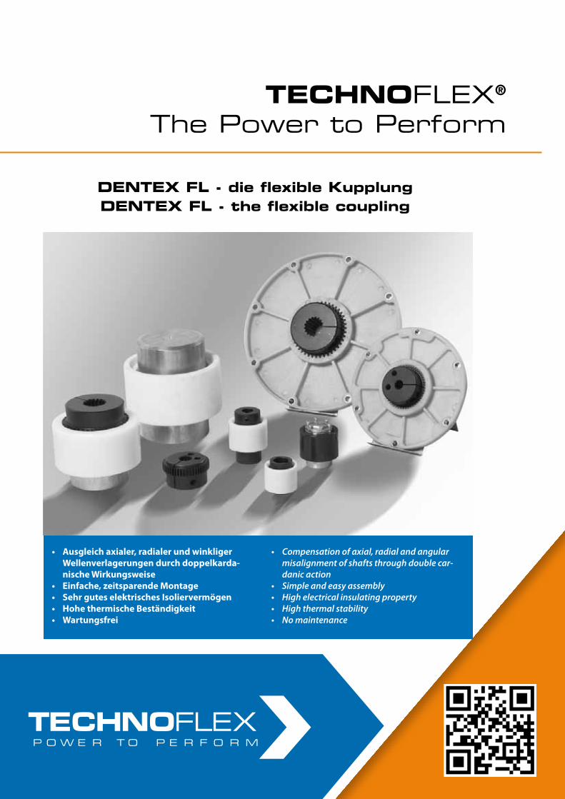
• LF Torsionskupplungen
• LK Torsionskupplungen
• Pumpen-Montageplatten und -Gehäuse
• LM Torsionskupplungen
• LF Torsional Coupling system
• LK Torsional Coupling system
• Pump mounting plates and housings
• LM Torsional Coupling system
• LF Torsionskupplungen
• LK Torsionskupplungen
• Pumpen-Montageplatten und -Gehäuse
• LM Torsionskupplungen
• LF Torsional Coupling system
• LK Torsional Coupling system
• Pump mounting plates and housings
• LM Torsional Coupling system
DENTEX®/DENTEX® FL – die flexible KupplungDENTEX®/DENTEX® FL – the flexible coupling
• Ausgleichaxialer,radialerundwinkligerWellenverlagerungendurchdoppelkarda-nischeWirkungsweise
• Einfache,zeitsparendeMontage• SehrguteselektrischesIsoliervermögen• HohethermischeBeständigkeit• Wartungsfrei
• Compensationofaxial,radialandangularmisalignmentofshaftsthroughdoublecar-danicaction
• Simpleandeasyassembly• Highelectricalinsulatingproperty• Highthermalstability• Nomaintenance
TECHNOFLEX®
The Power to PerformTECHNOFLEX®
The Power to Perform
DENTEX FL - die flexible KupplungDENTEX FL - the flexible coupling
DENTEX FL - die flexible KupplungDENTEX FL - the flexible coupling
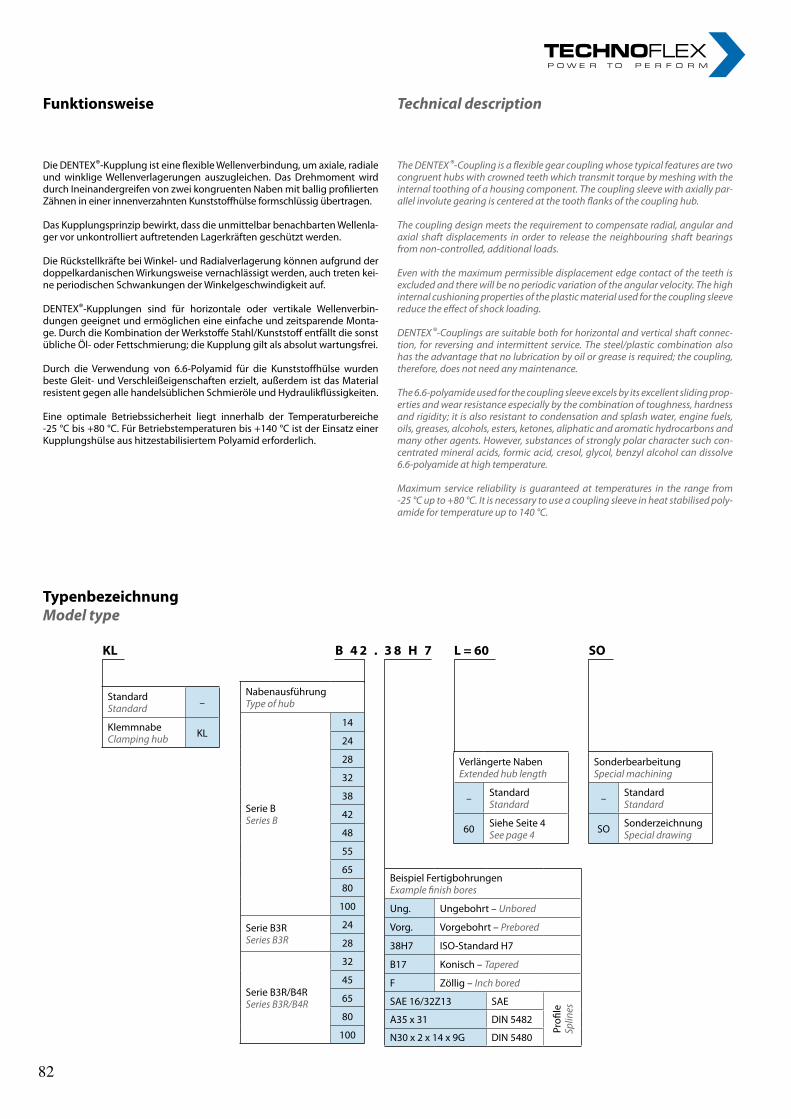
Funktionsweise
Die DENTEX®-Kupplung ist eine flexible Wellenverbindung, um axiale, radiale und winklige Wellenverlagerungen auszugleichen. Das Drehmoment wird durch Ineinandergreifen von zwei kongruenten Naben mit ballig profilierten Zähnen in einer innenverzahnten Kunststoffhülse formschlüssig übertragen.
Das Kupplungsprinzip bewirkt, dass die unmittelbar benachbarten Wellenla-ger vor unkontrolliert auftretenden Lagerkräften geschützt werden.
Die Rückstellkräfte bei Winkel- und Radialverlagerung können aufgrund der doppelkardanischen Wirkungsweise vernachlässigt werden, auch treten kei-ne periodischen Schwankungen der Winkelgeschwindigkeit auf.
DENTEX®-Kupplungen sind für horizontale oder vertikale Wellenverbin-dungen geeignet und ermöglichen eine einfache und zeitsparende Monta-ge. Durch die Kombination der Werkstoffe Stahl/Kunststoff entfällt die sonst übliche Öl- oder Fettschmierung; die Kupplung gilt als absolut wartungsfrei.
Durch die Verwendung von 6.6-Polyamid für die Kunststoffhülse wurden beste Gleit- und Verschleißeigenschaften erzielt, außerdem ist das Material resistent gegen alle handelsüblichen Schmieröle und Hydraulikflüssigkeiten.
Eine optimale Betriebssicherheit liegt innerhalb der Temperaturbereiche -25 °C bis +80 °C. Für Betriebstemperaturen bis +140 °C ist der Einsatz einer Kupplungshülse aus hitzestabilisiertem Polyamid erforderlich.
Technical description
The DENTEX ®-Coupling is a flexible gear coupling whose typical features are two congruent hubs with crowned teeth which transmit torque by meshing with the internal toothing of a housing component. The coupling sleeve with axially par-allel involute gearing is centered at the tooth flanks of the coupling hub.
The coupling design meets the requirement to compensate radial, angular and axial shaft displacements in order to release the neighbouring shaft bearings from non-controlled, additional loads.
Even with the maximum permissible displacement edge contact of the teeth is excluded and there will be no periodic variation of the angular velocity. The high internal cushioning properties of the plastic material used for the coupling sleeve reduce the effect of shock loading.
DENTEX ®-Couplings are suitable both for horizontal and vertical shaft connec-tion, for reversing and intermittent service. The steel/plastic combination also has the advantage that no lubrication by oil or grease is required; the coupling, therefore, does not need any maintenance.
The 6.6-polyamide used for the coupling sleeve excels by its excellent sliding prop-erties and wear resistance especially by the combination of toughness, hardness and rigidity; it is also resistant to condensation and splash water, engine fuels, oils, greases, alcohols, esters, ketones, aliphatic and aromatic hydrocarbons and many other agents. However, substances of strongly polar character such con-centrated mineral acids, formic acid, cresol, glycol, benzyl alcohol can dissolve 6.6-polyamide at high temperature.
Maximum service reliability is guaranteed at temperatures in the range from -25 °C up to +80 °C. It is necessary to use a coupling sleeve in heat stabilised poly-amide for temperature up to 140 °C.
TypenbezeichnungModel type
StandardStandard –
KlemmnabeClamping hub KL
NabenausführungType of hub
Serie BSeries B
14
24
28
32
38
42
48
55
65
80
100
Serie B3RSeries B3R
24
28
Serie B3R/B4RSeries B3R/B4R
32
45
65
80
100
Beispiel FertigbohrungenExample finish bores
Ung. Ungebohrt – Unbored
Vorg. Vorgebohrt – Prebored
38H7 ISO-Standard H7
B17 Konisch – Tapered
F Zöllig – Inch bored
SAE 16/32Z13 SAE
Profi
leSp
lines
A35 x 31 DIN 5482
N30 x 2 x 14 x 9G DIN 5480
Verlängerte NabenExtended hub length
– StandardStandard
60 Siehe Seite 4See page 4
SonderbearbeitungSpecial machining
– StandardStandard
SO SonderzeichnungSpecial drawing
KL B 4 2 . 3 8 H 7 L = 60 SO
82 82
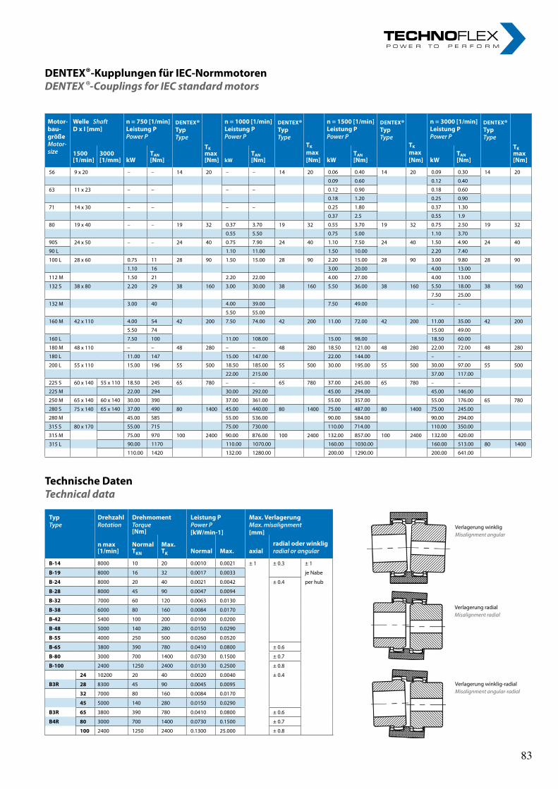
DENTEX®-KupplungenfürIEC-NormmotorenDENTEX ®-Couplings for IEC standard motors
TechnischeDatenTechnical data
Verlagerung winkligMisalignment angular
Verlagerung radialMisalignment radial
Verlagerung winklig-radialMisalignment angular-radial
Motor-bau-größeMotor-size
Welle ShaftDxI[mm]
n=750[1/min]LeistungPPowerP
DENTEX®TypType
n=1000[1/min]LeistungPPowerP
DENTEX®TypType
n=1500[1/min]LeistungPPowerP
DENTEX®TypType
n=3000[1/min]LeistungPPowerP
DENTEX®TypType
TKmax[Nm]
TK
max[Nm]
TK
max[Nm]
TKmax[Nm]
1500[1/min]
3000[1/mm] kW
TAN[Nm] kW
TAN[Nm] kW
TAN[Nm] kW
TAN[Nm]
56 9 x 20 – – 14 20 – – 14 20 0.06 0.40 14 20 0.09 0.30 14 20
0.09 0.60 0.12 0.40
63 11 x 23 – – – – 0.12 0.90 0.18 0.60
0.18 1.20 0.25 0.90
71 14 x 30 – – – – 0.25 1.80 0.37 1.30
0.37 2.5 0.55 1.9
80 19 x 40 – – 19 32 0.37 3.70 19 32 0.55 3.70 19 32 0.75 2.50 19 32
0.55 5.50 0.75 5.00 1.10 3.70
90S 24 x 50 – – 24 40 0.75 7.90 24 40 1.10 7.50 24 40 1.50 4.90 24 40
90 L 1.10 11.00 1.50 10.00 2.20 7.40
100 L 28 x 60 0.75 11 28 90 1.50 15.00 28 90 2.20 15.00 28 90 3.00 9.80 28 90
1.10 16 3.00 20.00 4.00 13.00
112 M 1.50 21 2.20 22.00 4.00 27.00 4.00 13.00
132 S 38 x 80 2.20 29 38 160 3.00 30.00 38 160 5.50 36.00 38 160 5.50 18.00 38 160
7.50 25.00
132 M 3.00 40 4.00 39.00 7.50 49.00 – –
5.50 55.00
160 M 42 x 110 4.00 54 42 200 7.50 74.00 42 200 11.00 72.00 42 200 11.00 35.00 42 200
5.50 74 15.00 49.00
160 L 7.50 100 11.00 108.00 15.00 98.00 18.50 60.00
180 M 48 x 110 – – 48 280 – – 48 280 18.50 121.00 48 280 22.00 72.00 48 280
180 L 11.00 147 15.00 147.00 22.00 144.00 – –
200 L 55 x 110 15.00 196 55 500 18.50 185.00 55 500 30.00 195.00 55 500 30.00 97.00 55 500
22.00 215.00 37.00 117.00
225 S 60 x 140 55 x 110 18.50 245 65 780 – – 65 780 37.00 245.00 65 780 – –
225 M 22.00 294 30.00 292.00 45.00 294.00 45.00 146.00
250 M 65 x 140 60 x 140 30.00 390 37.00 361.00 55.00 357.00 55.00 176.00 65 780
280 S 75 x 140 65 x 140 37.00 490 80 1400 45.00 440.00 80 1400 75.00 487.00 80 1400 75.00 245.00
280 M 45.00 585 55.00 536.00 90.00 584.00 90.00 294.00
315 S 80 x 170 55.00 715 75.00 730.00 110.00 714.00 110.00 350.00
315 M 75.00 970 100 2400 90.00 876.00 100 2400 132.00 857.00 100 2400 132.00 420.00
315 L 90.00 1170 110.00 1070.00 160.00 1030.00 160.00 513.00 80 1400
110.00 1420 132.00 1280.00 200.00 1290.00 200.00 641.00
TypType
DrehzahlRotation
DrehmomentTorque[Nm]
LeistungPPowerP[kW/min-1]
Max.VerlagerungMax.misalignment[mm]
nmax[1/min]
NormalTKN
Max.TK
radialoderwinkligradialorangularNormal Max. axial
B-14 8000 10 20 0.0010 0.0021 ± 1 ± 0.3 ± 1
B-19 8000 16 32 0.0017 0.0033 je Nabe
B-24 8000 20 40 0.0021 0.0042 ± 0.4 per hub
B-28 8000 45 90 0.0047 0.0094
B-32 7000 60 120 0.0063 0.0130
B-38 6000 80 160 0.0084 0.0170
B-42 5400 100 200 0.0100 0.0200
B-48 5000 140 280 0.0150 0.0290
B-55 4000 250 500 0.0260 0.0520
B-65 3800 390 780 0.0410 0.0800 ± 0.6
B-80 3000 700 1400 0.0730 0.1500 ± 0.7
B-100 2400 1250 2400 0.0130 0.2500 ± 0.8
24 10200 20 40 0.0020 0.0040 ± 0.4
B3R 28 8300 45 90 0.0045 0.0095
32 7000 80 160 0.0084 0.0170
45 5000 140 280 0.0150 0.0290
B3R 65 3800 390 780 0.0410 0.0800 ± 0.6
B4R 80 3000 700 1400 0.0730 0.1500 ± 0.7
100 2400 1250 2400 0.1300 25.000 ± 0.8
83 83
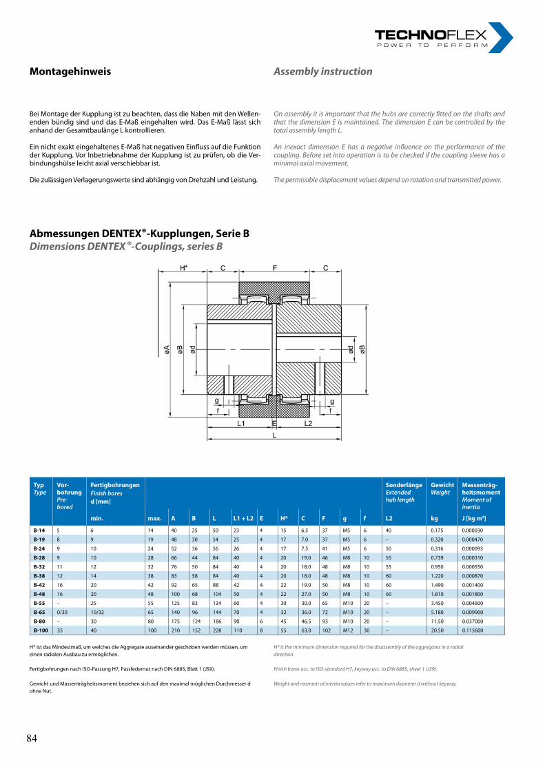
Montagehinweis
Bei Montage der Kupplung ist zu beachten, dass die Naben mit den Wellen-enden bündig sind und das E-Maß eingehalten wird. Das E-Maß lässt sich anhand der Gesamtbaulänge L kontrollieren.
Ein nicht exakt eingehaltenes E-Maß hat negativen Einfluss auf die Funktion der Kupplung. Vor Inbetriebnahme der Kupplung ist zu prüfen, ob die Ver-bindungshülse leicht axial verschiebbar ist.
Die zulässigen Verlagerungswerte sind abhängig von Drehzahl und Leistung.
Assembly instruction
On assembly it is important that the hubs are correctly fitted on the shafts and that the dimension E is maintained. The dimension E can be controlled by the total assembly length L.
An inexact dimension E has a negative influence on the performance of the coupling. Before set into operation is to be checked if the coupling sleeve has a minimal axial movement.
The permissible displacement values depend on rotation and transmitted power.
AbmessungenDENTEX®-Kupplungen,SerieBDimensions DENTEX ®-Couplings, series B
H* ist das Mindestmaß, um welches die Aggregate auseinander geschoben werden müssen, um einen radialen Ausbau zu ermöglichen.
Fertigbohrungen nach ISO-Passung H7, Passfedernut nach DIN 6885, Blatt 1 (JS9).
Gewicht und Massenträgheitsmoment beziehen sich auf den maximal möglichen Durchmesser d ohne Nut.
H* is the minimum dimension required for the disassembly of the aggregates in a radial direction.
Finish bores acc. to ISO-standard H7, keyway acc. to DIN 6885, sheet 1 (JS9).
Weight and moment of inertia values refer to maximum diameter d without keyway.
TypType
Vor-bohrungPre-bored
FertigbohrungenFinishboresd[mm]
SonderlängeExtendedhub length
GewichtWeight
Massenträg-heitsmomentMomentofinertia
min. max. A B L L1+L2 E H* C F g f L2 kg J[kgm2]
B-14 5 6 14 40 25 50 23 4 15 6.5 37 M5 6 40 0.175 0.000030
B-19 8 9 19 48 30 54 25 4 17 7.0 37 M5 6 – 0.320 0.000470
B-24 9 10 24 52 36 56 26 4 17 7.5 41 M5 6 50 0.316 0.000093
B-28 9 10 28 66 44 84 40 4 20 19.0 46 M8 10 55 0.739 0.000310
B-32 11 12 32 76 50 84 40 4 20 18.0 48 M8 10 55 0.950 0.000550
B-38 12 14 38 83 58 84 40 4 20 18.0 48 M8 10 60 1.220 0.000870
B-42 16 20 42 92 65 88 42 4 22 19.0 50 M8 10 60 1.490 0.001400
B-48 16 20 48 100 68 104 50 4 22 27.0 50 M8 10 60 1.810 0.001800
B-55 – 25 55 125 83 124 60 4 30 30.0 65 M10 20 – 3.450 0.004600
B-65 0/30 10/32 65 140 96 144 70 4 32 36.0 72 M10 20 – 5.180 0.009900
B-80 – 30 80 175 124 186 90 6 45 46.5 93 M10 20 – 11.50 0.037000
B-100 35 40 100 210 152 228 110 8 55 63.0 102 M12 30 – 20.50 0.115600
84 84
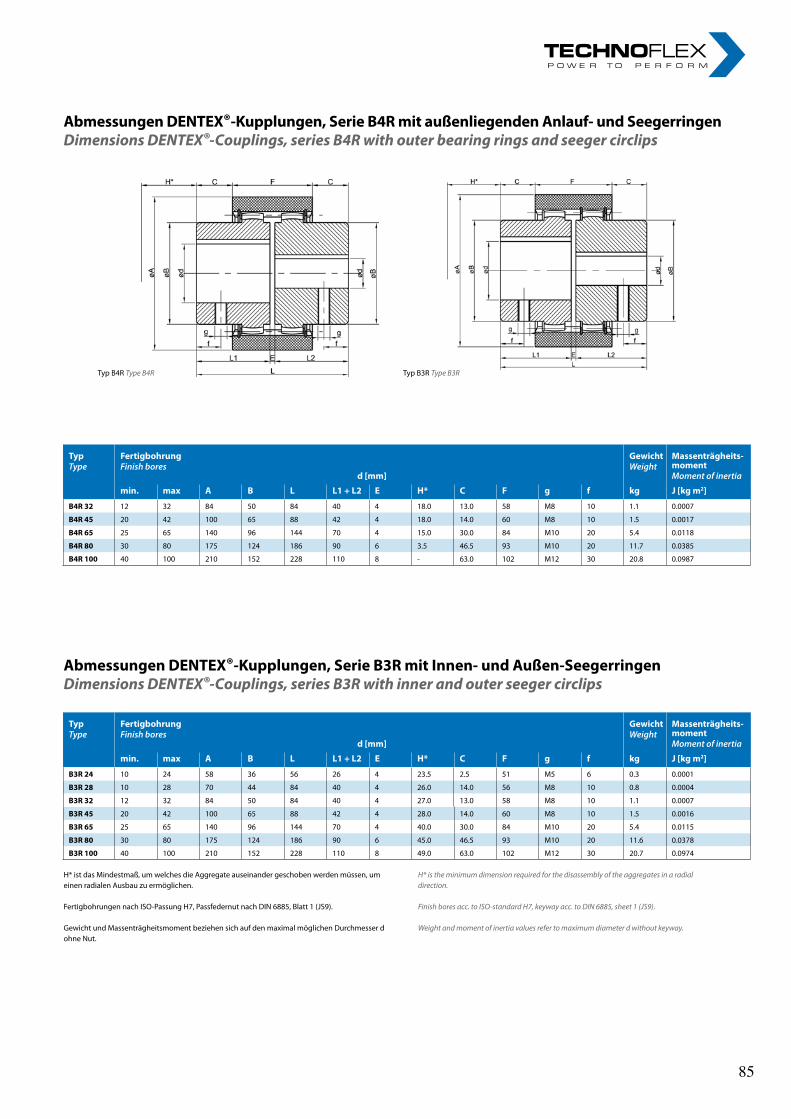
TypType
FertigbohrungFinishbores
d[mm]
GewichtWeight
Massenträgheits-momentMomentofinertia
min. max A B L L1+L2 E H* C F g f kg J[kgm2]
B4R32 12 32 84 50 84 40 4 18.0 13.0 58 M8 10 1.1 0.0007
B4R45 20 42 100 65 88 42 4 18.0 14.0 60 M8 10 1.5 0.0017
B4R65 25 65 140 96 144 70 4 15.0 30.0 84 M10 20 5.4 0.0118
B4R80 30 80 175 124 186 90 6 3.5 46.5 93 M10 20 11.7 0.0385
B4R100 40 100 210 152 228 110 8 - 63.0 102 M12 30 20.8 0.0987
TypType
FertigbohrungFinishbores
d[mm]
GewichtWeight
Massenträgheits-momentMomentofinertia
min. max A B L L1+L2 E H* C F g f kg J[kgm2]
B3R24 10 24 58 36 56 26 4 23.5 2.5 51 M5 6 0.3 0.0001
B3R28 10 28 70 44 84 40 4 26.0 14.0 56 M8 10 0.8 0.0004
B3R32 12 32 84 50 84 40 4 27.0 13.0 58 M8 10 1.1 0.0007
B3R45 20 42 100 65 88 42 4 28.0 14.0 60 M8 10 1.5 0.0016
B3R65 25 65 140 96 144 70 4 40.0 30.0 84 M10 20 5.4 0.0115
B3R80 30 80 175 124 186 90 6 45.0 46.5 93 M10 20 11.6 0.0378
B3R100 40 100 210 152 228 110 8 49.0 63.0 102 M12 30 20.7 0.0974
AbmessungenDENTEX®-Kupplungen,SerieB4RmitaußenliegendenAnlauf-undSeegerringenDimensions DENTEX®-Couplings, series B4R with outer bearing rings and seeger circlips
Typ B4R Type B4R Typ B3R Type B3R
H* ist das Mindestmaß, um welches die Aggregate auseinander geschoben werden müssen, um einen radialen Ausbau zu ermöglichen.
Fertigbohrungen nach ISO-Passung H7, Passfedernut nach DIN 6885, Blatt 1 (JS9).
Gewicht und Massenträgheitsmoment beziehen sich auf den maximal möglichen Durchmesser d ohne Nut.
H* is the minimum dimension required for the disassembly of the aggregates in a radial direction.
Finish bores acc. to ISO-standard H7, keyway acc. to DIN 6885, sheet 1 (JS9).
Weight and moment of inertia values refer to maximum diameter d without keyway.
AbmessungenDENTEX®-Kupplungen,SerieB3RmitInnen-undAußen-SeegerringenDimensions DENTEX®-Couplings, series B3R with inner and outer seeger circlips
TypType
FertigbohrungFinishbores
d[mm]
GewichtWeight
Massenträgheits-momentMomentofinertia
min. max A B L L1+L2 E H* C F g f kg J[kgm2]
B4R32 12 32 84 50 84 40 4 18.0 13.0 58 M8 10 1.1 0.0007
B4R45 20 42 100 65 88 42 4 18.0 14.0 60 M8 10 1.5 0.0017
B4R65 25 65 140 96 144 70 4 15.0 30.0 84 M10 20 5.4 0.0118
B4R80 30 80 175 124 186 90 6 3.5 46.5 93 M10 20 11.7 0.0385
B4R100 40 100 210 152 228 110 8 - 63.0 102 M12 30 20.8 0.0987
TypType
FertigbohrungFinishbores
d[mm]
GewichtWeight
Massenträgheits-momentMomentofinertia
min. max A B L L1+L2 E H* C F g f kg J[kgm2]
B3R24 10 24 58 36 56 26 4 23.5 2.5 51 M5 6 0.3 0.0001
B3R28 10 28 70 44 84 40 4 26.0 14.0 56 M8 10 0.8 0.0004
B3R32 12 32 84 50 84 40 4 27.0 13.0 58 M8 10 1.1 0.0007
B3R45 20 42 100 65 88 42 4 28.0 14.0 60 M8 10 1.5 0.0016
B3R65 25 65 140 96 144 70 4 40.0 30.0 84 M10 20 5.4 0.0115
B3R80 30 80 175 124 186 90 6 45.0 46.5 93 M10 20 11.6 0.0378
B3R100 40 100 210 152 228 110 8 49.0 63.0 102 M12 30 20.7 0.0974
AbmessungenDENTEX®-Kupplungen,SerieB4RmitaußenliegendenAnlauf-undSeegerringenDimensions DENTEX®-Couplings, series B4R with outer bearing rings and seeger circlips
Typ B4R Type B4R Typ B3R Type B3R
H* ist das Mindestmaß, um welches die Aggregate auseinander geschoben werden müssen, um einen radialen Ausbau zu ermöglichen.
Fertigbohrungen nach ISO-Passung H7, Passfedernut nach DIN 6885, Blatt 1 (JS9).
Gewicht und Massenträgheitsmoment beziehen sich auf den maximal möglichen Durchmesser d ohne Nut.
H* is the minimum dimension required for the disassembly of the aggregates in a radial direction.
Finish bores acc. to ISO-standard H7, keyway acc. to DIN 6885, sheet 1 (JS9).
Weight and moment of inertia values refer to maximum diameter d without keyway.
AbmessungenDENTEX®-Kupplungen,SerieB3RmitInnen-undAußen-SeegerringenDimensions DENTEX®-Couplings, series B3R with inner and outer seeger circlips
85 85
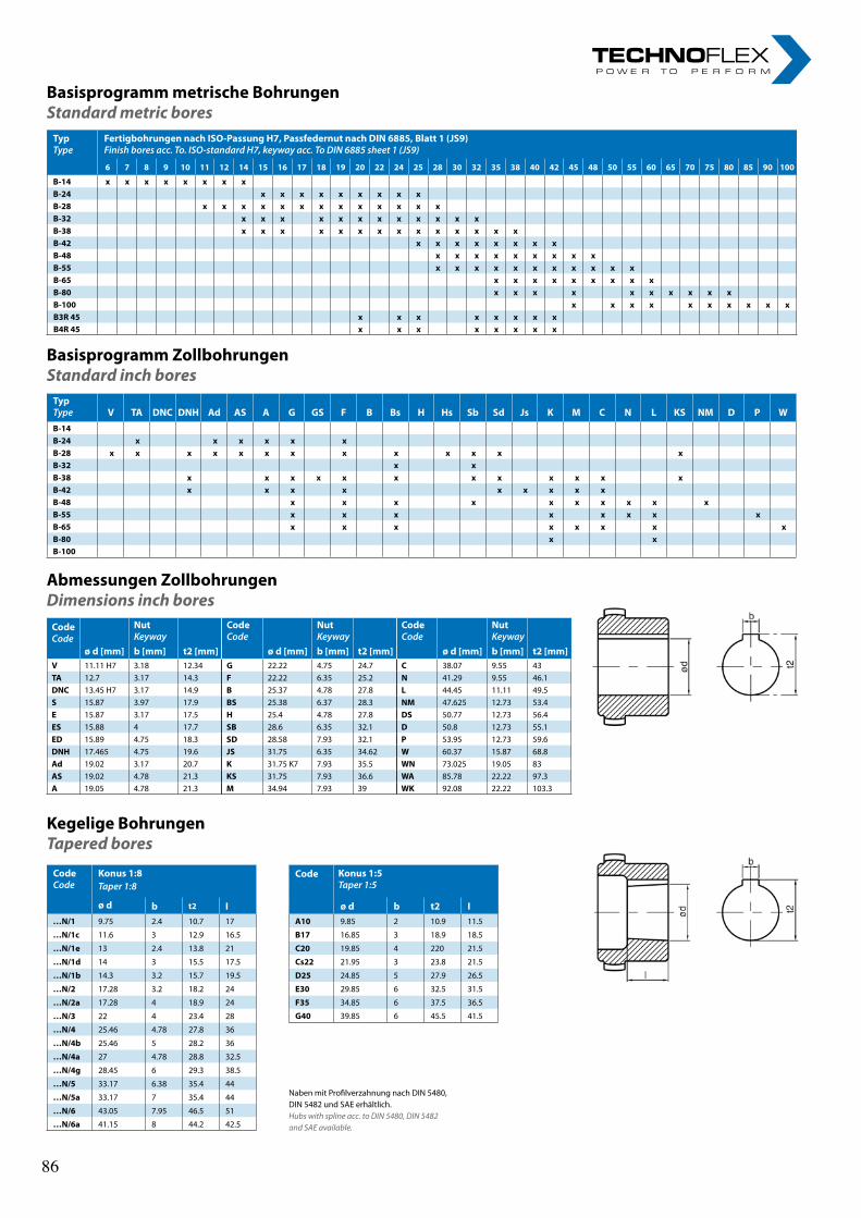
TypType
FertigbohrungennachISO-PassungH7,PassfedernutnachDIN6885,Blatt1(JS9)Finishboresacc.To.ISO-standardH7,keywayacc.ToDIN6885sheet1(JS9)
6 7 8 9 10 11 12 14 15 16 17 18 19 20 22 24 25 28 30 32 35 38 40 42 45 48 50 55 60 65 70 75 80 85 90 100
B-14 x x x x x x x xB-24 x x x x x x x x xB-28 x x x x x x x x x x x x xB-32 x x x x x x x x x x x xB-38 x x x x x x x x x x x x x xB-42 x x x x x x x xB-48 x x x x x x x x xB-55 x x x x x x x x x x xB-65 x x x x x x x x xB-80 x x x x x x x x x xB-100 x x x x x x x x x xB3R45 x x x x x x x xB4R45 x x x x x x x x
BasisprogrammmetrischeBohrungenStandard metric bores
AbmessungenZollbohrungenDimensions inch bores
BasisprogrammZollbohrungenStandard inch bores
KegeligeBohrungenTapered bores
TypType V TA DNC DNH Ad AS A G GS F B Bs H Hs Sb Sd Js K M C N L KS NM D P WB-14B-24 x x x x x xB-28 x x x x x x x x x x x x xB-32 x xB-38 x x x x x x x x x x x xB-42 x x x x x x x x xB-48 x x x x x x x x x xB-55 x x x x x x x xB-65 x x x x x x x xB-80 x xB-100
Naben mit Profilverzahnung nach DIN 5480, DIN 5482 und SAE erhältlich. Hubs with spline acc. to DIN 5480, DIN 5482 and SAE available.
CodeCode
NutKeyway
CodeCode
NutKeyway
CodeCode
NutKeyway
ød[mm] b[mm] t2[mm] ød[mm] b[mm] t2[mm] ød[mm] b[mm] t2[mm]V 11.11 H7 3.18 12.34 G 22.22 4.75 24.7 C 38.07 9.55 43TA 12.7 3.17 14.3 F 22.22 6.35 25.2 N 41.29 9.55 46.1DNC 13.45 H7 3.17 14.9 B 25.37 4.78 27.8 L 44.45 11.11 49.5S 15.87 3.97 17.9 BS 25.38 6.37 28.3 NM 47.625 12.73 53.4E 15.87 3.17 17.5 H 25.4 4.78 27.8 DS 50.77 12.73 56.4ES 15.88 4 17.7 SB 28.6 6.35 32.1 D 50.8 12.73 55.1ED 15.89 4.75 18.3 SD 28.58 7.93 32.1 P 53.95 12.73 59.6DNH 17.465 4.75 19.6 JS 31.75 6.35 34.62 W 60.37 15.87 68.8Ad 19.02 3.17 20.7 K 31.75 K7 7.93 35.5 WN 73.025 19.05 83AS 19.02 4.78 21.3 KS 31.75 7.93 36.6 WA 85.78 22.22 97.3A 19.05 4.78 21.3 M 34.94 7.93 39 WK 92.08 22.22 103.3
CodeCode
Konus1:8Taper1:8
ø d
Code Konus1:5Taper1:5
b t2 I ø d b t2 I…N/1 9.75 2.4 10.7 17 A10 9.85 2 10.9 11.5
…N/1c 11.6 3 12.9 16.5 B17 16.85 3 18.9 18.5
…N/1e 13 2.4 13.8 21 C20 19.85 4 220 21.5
…N/1d 14 3 15.5 17.5 Cs22 21.95 3 23.8 21.5
…N/1b 14.3 3.2 15.7 19.5 D25 24.85 5 27.9 26.5
…N/2 17.28 3.2 18.2 24 E30 29.85 6 32.5 31.5
…N/2a 17.28 4 18.9 24 F35 34.85 6 37.5 36.5
…N/3 22 4 23.4 28 G40 39.85 6 45.5 41.5
…N/4 25.46 4.78 27.8 36
…N/4b 25.46 5 28.2 36
…N/4a 27 4.78 28.8 32.5
…N/4g 28.45 6 29.3 38.5
…N/5 33.17 6.38 35.4 44
…N/5a 33.17 7 35.4 44
…N/6 43.05 7.95 46.5 51
…N/6a 41.15 8 44.2 42.5
86 86
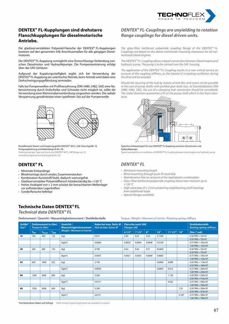
DENTEX® FL-KupplungensinddrehstarreFlanschkupplungenfürdieselmotorische Antriebe.Die glasfaserverstärkten Polyamid-Flansche der DENTEX® FL-Kupplungen basieren auf den genannten SAE-Anschlussmaßen für alle gängigen Diesel-motoren.
Die DENTEX® FL-Kupplung ermöglicht eine formschlüssige Verbindung zwi-schen Dieselmotor und Hydraulikpumpe. Die Pumpenzentrierung erfolgt über das SAE-Gehäuse.
Aufgrund der Kupplungssteifigkeit ergibt sich bei Verwendung der DENTEX® FL-Kupplung ein unkritischer Betrieb, beim Antrieb wird dabei eine Drehschwingungsgefährdung vermieden.
Falls bei Pumpenwellen mit Profilverzahnung (DIN 5480, 5482, SAE) eine Na-bensicherung durch Endscheibe und Schraube nicht möglich ist, sollte die Verwendung einer Klemmnabenverbindung vorgesehen werden. Die radiale Verspannung gewährleistet einen spielfreien Sitz auf der Pumpenwelle.
DENTEX® FL-Couplings are unyielding to rotationflange couplings for diesel driven units.
The glass-fibre reinforced polyamide coupling flange of the DENTEX ® FL- Couplings are based on the above mentioned mounting clearances for all con-ventional Diesel engines.
The DENTEX ® FL-Coupling allows a keyed connection between Diesel engine and hydraulic pump. The pump is to be centred over the SAE-housing.
The application of the DENTEX ® FL-Coupling results in a non-critical service on account of the coupling stiffness, as the hazard of a rotating oscillation during the drive will be avoided.
Should the securing of the hub by means of end-disc and screw not be possible in the case of pump shafts with profiled gear teeth (acc. to Standardization DIN 5480, 5482, SAE), the use of a clamping hub connection should be considered. The radial distortion guaranties a fit on the pump shaft which is free from clear-ance.
Bestellbeispiel: Bauart und Kupplungsgröße DENTEX® 48 FL, SAE-Flanschgröße 10,Fertigungsbohrung und Nabenlänge Ø 40 x 50Ordering example: Type and clutch size DENTEX® 48 FL, SAE flange size 10,manufacturing bore and hub length Ø 40 x 50
DENTEX® FL• Minimale Einbaulänge• Blindmontage durch axiales Zusammenstecken• Kombination Kunststoff/Stahl, dadurch wartungsfrei• Glasfaserverstärker Polyamidflansch hitzebeständig bis +120 °C• Hohes Axialspiel von ± 2 mm schützt die benachbarten Wellenlager vor auftretenden Lagerkräften• Sonderflansche lieferbar
Typisches Einbaubeispiel für eine DENTEX® FL-Kupplung zwischen Dieselmotor undHydraulikpumpeTypical example for an installation of DENTEX® FL-Coupling between diesel engine and hydraulic pump
DENTEX® FL• Minimum mounting length• Blind mounting through push-fit assembly• Maintenance-free on account of the steel/plastic combination• Glass-fibre reinforced polyamide coupling sleeve heat resistant up to
+120 °C• High axial play of ± 2 mm protecting neighbouring shaft bearings from additional loads• Specialflangesavailable
TechnischeDatenDENTEX® FL Technical data DENTEX® FLDrehmoment / Gewicht / Massenträgheitsmoment / Drehfedersteife Torque / Weight / Moment of inertia / Rotating spring stiffness
*Hochbelastbare Naben auf Anfrage *Hubs resistant against high loads are available on request
Größe*Size*
Drehmomentin(Nm)Torquein(Nm)
Gewicht/MassenträgheitsmomentWeight/Momentofinertia
Nabebeimax.Bohr-ØHubatmax.bores-Ø
FlanschenachSAEFlangesSAE
DrehfedersteifeRoatingapringstiffness
TKN TKmax TKW 61/2‘‘ 71/2‘‘ 8‘‘ 10‘‘ 111/2‘‘ 14‘‘ [Nm7rad]42 240 480 120 [kg] 0.675 0.40 0.52 0.50 0.7500 0.30 TKN = 35x103
0.50 TKN = 75x103
[kgm2] 0.0006 0.0025 0.0045 0.0048 0.0100 0.75 TKN = 105x103
1.00 TKN = 125x103
48 240 480 120 [kg] 0.790 0.32 0.43 0.51 0.6400 0.30 TKN = 35x103
0.50 TKN = 75x103
[kgm2] 0.0007 0.0021 0.0035 0.0049 0.0085 0.75 TKN = 105x103
1.00 TKN = 125x103
65 650 1600 325 [kg] 2.190 0.6400 0.890 0.30 TKN = 110x103
0.50 TKN = 160x103
[kgm2] 0.0039 0.0065 0.012 0.75 TKN = 200x103
1.00 TKN = 230x103
80 1200 3000 600 [kg] 5.200 1.120 0.30 TKN = 200x103
0.50 TKN = 410x103
[kgm2] 0.0151 0.022 0.75 TKN = 580x103
1.00 TKN = 700x103
80 1200 3000 600 [kg] 5.200 7.35 0.30 TKN = 200x103
0.50 TKN = 410x103
[kgm2] 0.0151 0.187 0.75 TKN = 580x103
1.00 TKN = 700x103
87 87
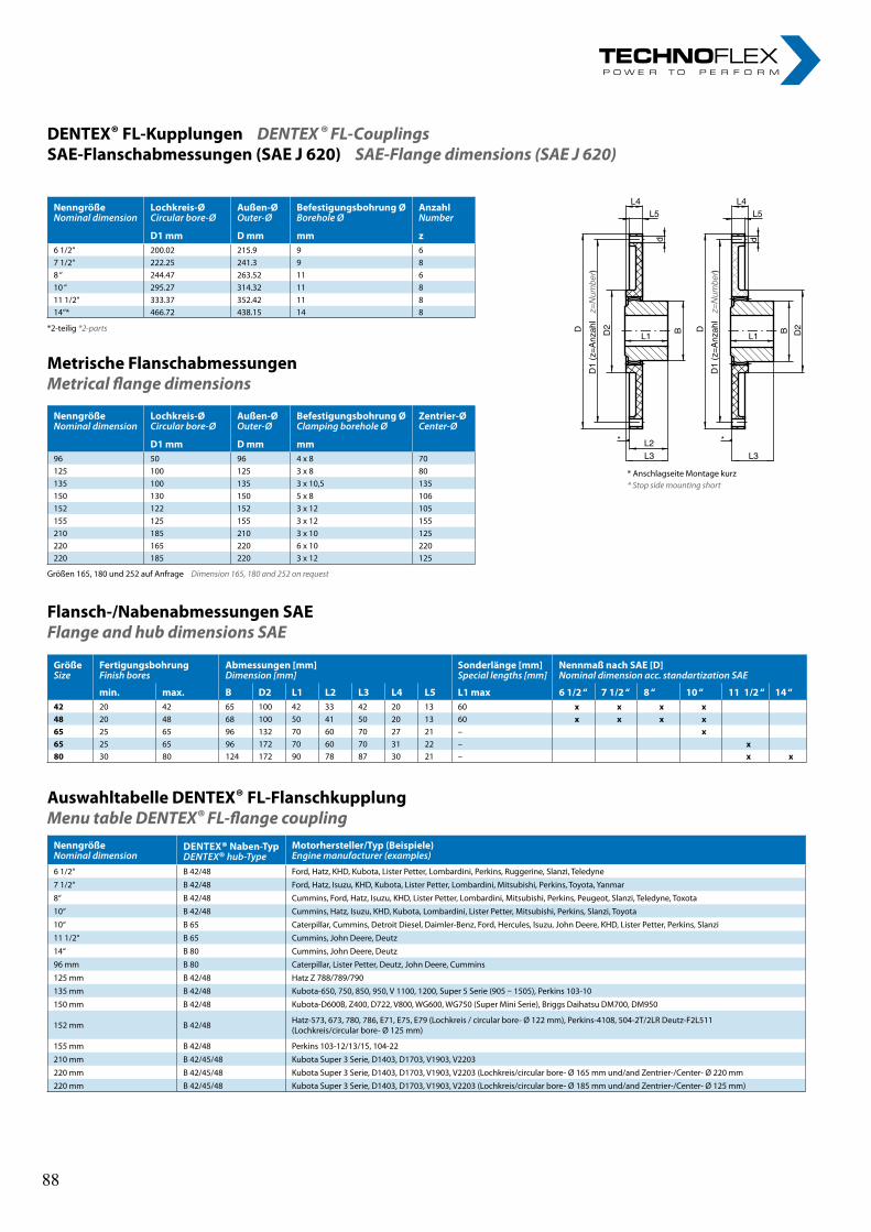
NenngrößeNominaldimension
Lochkreis-ØCircularbore-Ø
Außen-ØOuter-Ø
BefestigungsbohrungØBoreholeØ
AnzahlNumber
D1mm Dmm mm z6 1/2‘‘ 200.02 215.9 9 67 1/2‘‘ 222.25 241.3 9 88 ‘‘ 244.47 263.52 11 610 ‘‘ 295.27 314.32 11 811 1/2‘‘ 333.37 352.42 11 814‘‘* 466.72 438.15 14 8
NenngrößeNominaldimension
Lochkreis-ØCircularbore-Ø
Außen-ØOuter-Ø
BefestigungsbohrungØClampingboreholeØ
Zentrier-ØCenter-Ø
D1mm Dmm mm96 50 96 4 x 8 70125 100 125 3 x 8 80135 100 135 3 x 10,5 135150 130 150 5 x 8 106152 122 152 3 x 12 105155 125 155 3 x 12 155210 185 210 3 x 10 125220 165 220 6 x 10 220220 185 220 3 x 12 125
DENTEX® FL-KupplungenDENTEX ® FL-CouplingsSAE-Flanschabmessungen(SAEJ620)SAE-Flange dimensions (SAE J 620)
*2-teilig *2-parts
Größen 165, 180 und 252 auf Anfrage Dimension 165, 180 and 252 on request
Flansch-/NabenabmessungenSAEFlange and hub dimensions SAE
AuswahltabelleDENTEX® FL-FlanschkupplungMenu table DENTEX® FL-flange coupling
* Anschlagseite Montage kurz* Stop side mounting short
L4L5
L4L5
d d
D
)lhazn
A=z(
1D
rebmu
N=z
2D
L2
L3
L1
B D
)lhazn
A=z(
1D
rebmu
N=z
L3
L1
B 2D
**
GrößeSize
FertigungsbohrungFinishbores
Abmessungen[mm]Dimension[mm]
Sonderlänge[mm]Speciallengths[mm]
NennmaßnachSAE[D]Nominaldimensionacc.standartizationSAE
min. max. B D2 L1 L2 L3 L4 L5 L1max 61/2‘‘ 71/2‘‘ 8‘‘ 10‘‘ 111/2‘‘ 14‘‘42 20 42 65 100 42 33 42 20 13 60 x x x x48 20 48 68 100 50 41 50 20 13 60 x x x x65 25 65 96 132 70 60 70 27 21 – x65 25 65 96 172 70 60 70 31 22 – x80 30 80 124 172 90 78 87 30 21 – x x
NenngrößeNominaldimension
DENTEX®Naben-TypDENTEX®hub-Type
Motorhersteller/Typ(Beispiele)Enginemanufacturer(examples)
6 1/2‘‘ B 42/48 Ford, Hatz, KHD, Kubota, Lister Petter, Lombardini, Perkins, Ruggerine, Slanzi, Teledyne
7 1/2‘‘ B 42/48 Ford, Hatz, Isuzu, KHD, Kubota, Lister Petter, Lombardini, Mitsubishi, Perkins, Toyota, Yanmar
8‘‘ B 42/48 Cummins, Ford, Hatz, Isuzu, KHD, Lister Petter, Lombardini, Mitsubishi, Perkins, Peugeot, Slanzi, Teledyne, Toxota
10‘‘ B 42/48 Cummins, Hatz, Isuzu, KHD, Kubota, Lombardini, Lister Petter, Mitsubishi, Perkins, Slanzi, Toyota
10‘‘ B 65 Caterpillar, Cummins, Detroit Diesel, Daimler-Benz, Ford, Hercules, Isuzu, John Deere, KHD, Lister Petter, Perkins, Slanzi
11 1/2‘‘ B 65 Cummins, John Deere, Deutz
14‘‘ B 80 Cummins, John Deere, Deutz
96 mm B 80 Caterpillar, Lister Petter, Deutz, John Deere, Cummins
125 mm B 42/48 Hatz Z 788/789/790
135 mm B 42/48 Kubota-650, 750, 850, 950, V 1100, 1200, Super 5 Serie (905 – 1505), Perkins 103-10
150 mm B 42/48 Kubota-D600B, Z400, D722, V800, WG600, WG750 (Super Mini Serie), Briggs Daihatsu DM700, DM950
152 mm B 42/48 Hatz-573, 673, 780, 786, E71, E75, E79 (Lochkreis / circular bore- Ø 122 mm), Perkins-4108, 504-2T/2LR Deutz-F2L511 (Lochkreis/circular bore- Ø 125 mm)
155 mm B 42/48 Perkins 103-12/13/15, 104-22
210 mm B 42/45/48 Kubota Super 3 Serie, D1403, D1703, V1903, V2203
220 mm B 42/45/48 Kubota Super 3 Serie, D1403, D1703, V1903, V2203 (Lochkreis/circular bore- Ø 165 mm und/and Zentrier-/Center- Ø 220 mm220 mm B 42/45/48 Kubota Super 3 Serie, D1403, D1703, V1903, V2203 (Lochkreis/circular bore- Ø 185 mm und/and Zentrier-/Center- Ø 125 mm)
MetrischeFlanschabmessungenMetrical flange dimensions
NenngrößeNominaldimension
Lochkreis-ØCircularbore-Ø
Außen-ØOuter-Ø
BefestigungsbohrungØBoreholeØ
AnzahlNumber
D1mm Dmm mm z6 1/2‘‘ 200.02 215.9 9 67 1/2‘‘ 222.25 241.3 9 88 ‘‘ 244.47 263.52 11 610 ‘‘ 295.27 314.32 11 811 1/2‘‘ 333.37 352.42 11 814‘‘* 466.72 438.15 14 8
NenngrößeNominaldimension
Lochkreis-ØCircularbore-Ø
Außen-ØOuter-Ø
BefestigungsbohrungØClampingboreholeØ
Zentrier-ØCenter-Ø
D1mm Dmm mm96 50 96 4 x 8 70125 100 125 3 x 8 80135 100 135 3 x 10,5 135150 130 150 5 x 8 106152 122 152 3 x 12 105155 125 155 3 x 12 155210 185 210 3 x 10 125220 165 220 6 x 10 220220 185 220 3 x 12 125
DENTEX® FL-KupplungenDENTEX ® FL-CouplingsSAE-Flanschabmessungen(SAEJ620)SAE-Flange dimensions (SAE J 620)
*2-teilig *2-parts
Größen 165, 180 und 252 auf Anfrage Dimension 165, 180 and 252 on request
Flansch-/NabenabmessungenSAEFlange and hub dimensions SAE
AuswahltabelleDENTEX® FL-FlanschkupplungMenu table DENTEX® FL-flange coupling
* Anschlagseite Montage kurz* Stop side mounting short
L4L5
L4L5
d d
D
)lhazn
A=z(
1D
rebmu
N=z
2D
L2
L3
L1
B D
)lhazn
A=z(
1D
rebmu
N=z
L3
L1
B 2D
**
GrößeSize
FertigungsbohrungFinishbores
Abmessungen[mm]Dimension[mm]
Sonderlänge[mm]Speciallengths[mm]
NennmaßnachSAE[D]Nominaldimensionacc.standartizationSAE
min. max. B D2 L1 L2 L3 L4 L5 L1max 61/2‘‘ 71/2‘‘ 8‘‘ 10‘‘ 111/2‘‘ 14‘‘42 20 42 65 100 42 33 42 20 13 60 x x x x48 20 48 68 100 50 41 50 20 13 60 x x x x65 25 65 96 132 70 60 70 27 21 – x65 25 65 96 172 70 60 70 31 22 – x80 30 80 124 172 90 78 87 30 21 – x x
NenngrößeNominaldimension
DENTEX®Naben-TypDENTEX®hub-Type
Motorhersteller/Typ(Beispiele)Enginemanufacturer(examples)
6 1/2‘‘ B 42/48 Ford, Hatz, KHD, Kubota, Lister Petter, Lombardini, Perkins, Ruggerine, Slanzi, Teledyne
7 1/2‘‘ B 42/48 Ford, Hatz, Isuzu, KHD, Kubota, Lister Petter, Lombardini, Mitsubishi, Perkins, Toyota, Yanmar
8‘‘ B 42/48 Cummins, Ford, Hatz, Isuzu, KHD, Lister Petter, Lombardini, Mitsubishi, Perkins, Peugeot, Slanzi, Teledyne, Toxota
10‘‘ B 42/48 Cummins, Hatz, Isuzu, KHD, Kubota, Lombardini, Lister Petter, Mitsubishi, Perkins, Slanzi, Toyota
10‘‘ B 65 Caterpillar, Cummins, Detroit Diesel, Daimler-Benz, Ford, Hercules, Isuzu, John Deere, KHD, Lister Petter, Perkins, Slanzi
11 1/2‘‘ B 65 Cummins, John Deere, Deutz
14‘‘ B 80 Cummins, John Deere, Deutz
96 mm B 80 Caterpillar, Lister Petter, Deutz, John Deere, Cummins
125 mm B 42/48 Hatz Z 788/789/790
135 mm B 42/48 Kubota-650, 750, 850, 950, V 1100, 1200, Super 5 Serie (905 – 1505), Perkins 103-10
150 mm B 42/48 Kubota-D600B, Z400, D722, V800, WG600, WG750 (Super Mini Serie), Briggs Daihatsu DM700, DM950
152 mm B 42/48 Hatz-573, 673, 780, 786, E71, E75, E79 (Lochkreis / circular bore- Ø 122 mm), Perkins-4108, 504-2T/2LR Deutz-F2L511 (Lochkreis/circular bore- Ø 125 mm)
155 mm B 42/48 Perkins 103-12/13/15, 104-22
210 mm B 42/45/48 Kubota Super 3 Serie, D1403, D1703, V1903, V2203
220 mm B 42/45/48 Kubota Super 3 Serie, D1403, D1703, V1903, V2203 (Lochkreis/circular bore- Ø 165 mm und/and Zentrier-/Center- Ø 220 mm220 mm B 42/45/48 Kubota Super 3 Serie, D1403, D1703, V1903, V2203 (Lochkreis/circular bore- Ø 185 mm und/and Zentrier-/Center- Ø 125 mm)
MetrischeFlanschabmessungenMetrical flange dimensions
88 88

nOteS „ I n n o v a t i o n i n m o t i o n ”
Berv ina Kf t . • H -1145 Erzsébet k i rá lyné út ja 41/B • Te l . :+36 -1-222-20-79 • Fax: +36 -1-252-48-29 • berv ina@berv ina.com
page 19
NOTES FOR BELTS
nOteS „ I n n o v a t i o n i n m o t i o n ”
Berv ina Kf t . • H -1145 Erzsébet k i rá lyné út ja 41/B • Te l . :+36 -1-222-20-79 • Fax: +36 -1-252-48-29 • berv ina@berv ina.com
page 19
NOTES FOR BELTS
89 89

nOteS „ I n n o v a t i o n i n m o t i o n ”
Berv ina Kf t . • H -1145 Erzsébet k i rá lyné út ja 41/B • Te l . :+36 -1-222-20-79 • Fax: +36 -1-252-48-29 • berv ina@berv ina.com
page 19
NOTES FOR BELTS
nOteS „ I n n o v a t i o n i n m o t i o n ”
Berv ina Kf t . • H -1145 Erzsébet k i rá lyné út ja 41/B • Te l . :+36 -1-222-20-79 • Fax: +36 -1-252-48-29 • berv ina@berv ina.com
page 19
NOTES FOR BELTS
90 90

Flexible Couplings Flexible Couplings
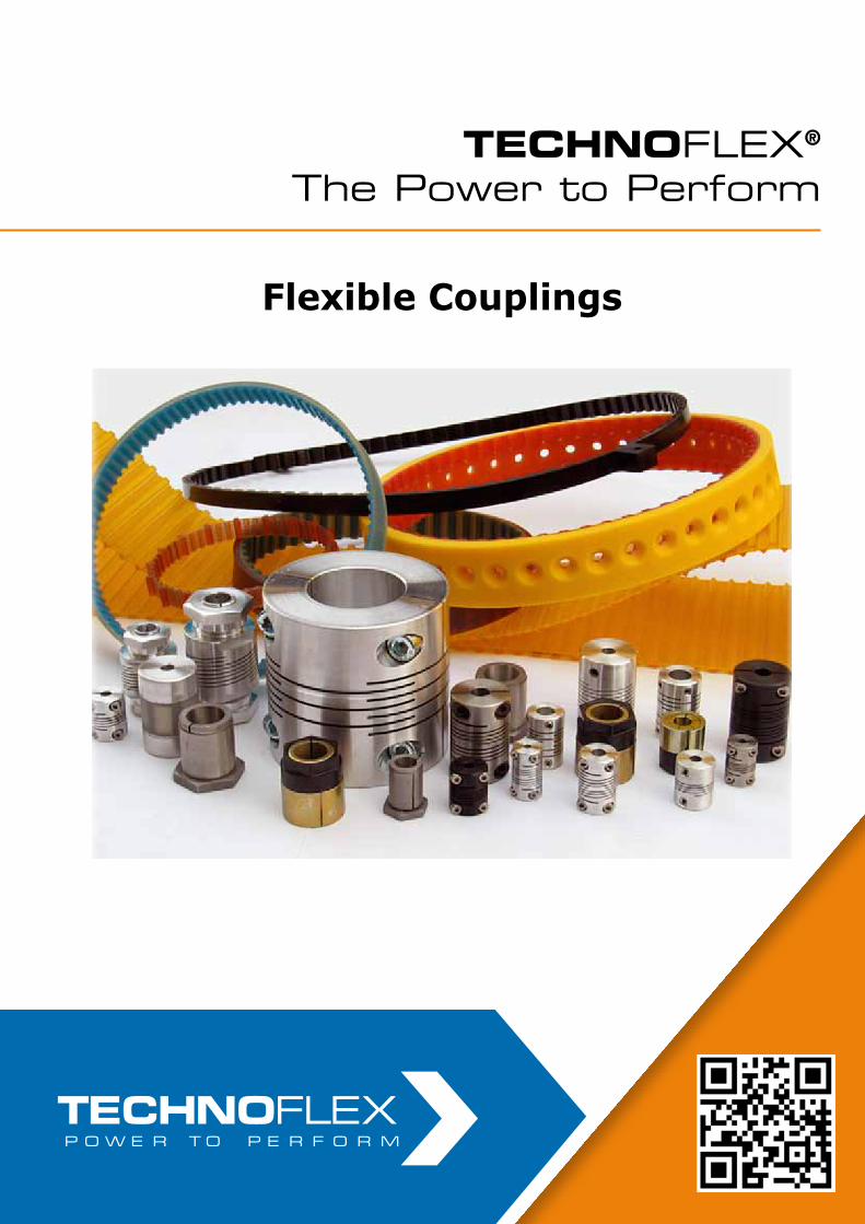
Flexible Couplings
TECHNOFLEX®
The Power to Perform
„ I n n o v a t i o n i s m o t i o n ”
Berv ina Kf t . • H -1145 Erzsébet k i rá lyné ú t ja 41/B • Te l . :+36 -1-222-20-79 • Fax: +36 -1-252-48-29 • berv ina@berv ina.com
WE HAVE A GOOD GRIP OF THE POWER TRANSMISSION
FLEXIBLE COUPLINGS
TAPER BUSHES
TIMING BELTS
PULLEYS FOR T IMING BELTS
TIMING BELTS FOR FOOD INDUSTRY
DRAW DOWN BELTS
HEAT RESISTANT BELTS
SPECIAL T IMING BELTS
w w w . b e r v i n a . c o m
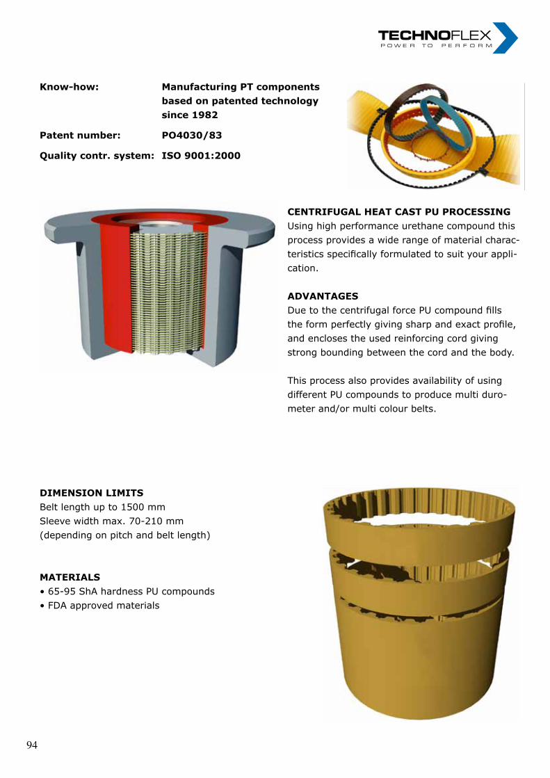
„ I n n o v a t i o n i n m o t i o n ”
Berv ina Kf t . • H -1145 Erzsébet k i rá lyné ú t ja 41/B • Te l . :+36 -1-222-20-79 • Fax: +36 -1-252-48-29 • berv ina@berv ina.com
page 05
PU TECHNOLOGY
Know-how: Patent number: Quality contr. system:
Manufacturing PT components based on patented technology since 1982 PO4030/83 ISO 9001:2000
CENTRIFUGAL HEAT CAST PU PROCESSING Using high performance urethane compound this process provides a wide range of material characteristics specifically formulated to suit your application. ADVANTAGES Due to the centrifugal force PU compound fills the form perfectly giving sharp and exact profile, and encloses the used reinforcing cord giving strong bounding between the cord and the body. This process also provides availability of using different PU compounds to produce multi durometer and/or multi colour belts.
DESIGN Bervina has more than 25 years of experience in designing and manufacturing PU timing belts. Based on our unique PU technology we would like to help you to find the best solution for your special needs. Bervina can assist in designing the correct belt construction for your application. For more information on engineering assistance, please contact us. DIMENSION LIMITS Belt length up to 1500 mm Sleeve width max. 70-210 mm (depending on pitch and belt length) MATERIALS • 65-95 ShA hardness PU compounds • FDA approved materials
Know-how: Manufacturing PT components based on patented technology since 1982
Patent number: PO4030/83
Quality contr. system: ISO 9001:2000
centriFUgaL Heat caSt PU PrOceSSing Using high performance urethane compound this process provides a wide range of material charac- teristics specifically formulated to suit your appli- cation.
aDVantageS Due to the centrifugal force PU compound fills the form perfectly giving sharp and exact profile, and encloses the used reinforcing cord giving strong bounding between the cord and the body.
This process also provides availability of using different PU compounds to produce multi duro- meter and/or multi colour belts.
DimenSiOn LimitSBelt length up to 1500 mmSleeve width max. 70-210 mm (depending on pitch and belt length)
materiaLS• 65-95 ShA hardness PU compounds• FDA approved materials
„ I n n o v a t i o n i n m o t i o n ”
Berv ina Kf t . • H -1145 Erzsébet k i rá lyné ú t ja 41/B • Te l . :+36 -1-222-20-79 • Fax: +36 -1-252-48-29 • berv ina@berv ina.com
page 05
PU TECHNOLOGY
Know-how: Patent number: Quality contr. system:
Manufacturing PT components based on patented technology since 1982 PO4030/83 ISO 9001:2000
CENTRIFUGAL HEAT CAST PU PROCESSING Using high performance urethane compound this process provides a wide range of material characteristics specifically formulated to suit your application. ADVANTAGES Due to the centrifugal force PU compound fills the form perfectly giving sharp and exact profile, and encloses the used reinforcing cord giving strong bounding between the cord and the body. This process also provides availability of using different PU compounds to produce multi durometer and/or multi colour belts.
DESIGN Bervina has more than 25 years of experience in designing and manufacturing PU timing belts. Based on our unique PU technology we would like to help you to find the best solution for your special needs. Bervina can assist in designing the correct belt construction for your application. For more information on engineering assistance, please contact us. DIMENSION LIMITS Belt length up to 1500 mm Sleeve width max. 70-210 mm (depending on pitch and belt length) MATERIALS • 65-95 ShA hardness PU compounds • FDA approved materials
Know-how: Manufacturing PT components based on patented technology since 1982
Patent number: PO4030/83
Quality contr. system: ISO 9001:2000
centriFUgaL Heat caSt PU PrOceSSing Using high performance urethane compound this process provides a wide range of material charac- teristics specifically formulated to suit your appli- cation.
aDVantageS Due to the centrifugal force PU compound fills the form perfectly giving sharp and exact profile, and encloses the used reinforcing cord giving strong bounding between the cord and the body.
This process also provides availability of using different PU compounds to produce multi duro- meter and/or multi colour belts.
DimenSiOn LimitSBelt length up to 1500 mmSleeve width max. 70-210 mm (depending on pitch and belt length)
materiaLS• 65-95 ShA hardness PU compounds• FDA approved materials
„ I n n o v a t i o n i n m o t i o n ”
Berv ina Kf t . • H -1145 Erzsébet k i rá lyné ú t ja 41/B • Te l . :+36 -1-222-20-79 • Fax: +36 -1-252-48-29 • berv ina@berv ina.com
page 05
PU TECHNOLOGY
Know-how: Patent number: Quality contr. system:
Manufacturing PT components based on patented technology since 1982 PO4030/83 ISO 9001:2000
CENTRIFUGAL HEAT CAST PU PROCESSING Using high performance urethane compound this process provides a wide range of material characteristics specifically formulated to suit your application. ADVANTAGES Due to the centrifugal force PU compound fills the form perfectly giving sharp and exact profile, and encloses the used reinforcing cord giving strong bounding between the cord and the body. This process also provides availability of using different PU compounds to produce multi durometer and/or multi colour belts.
DESIGN Bervina has more than 25 years of experience in designing and manufacturing PU timing belts. Based on our unique PU technology we would like to help you to find the best solution for your special needs. Bervina can assist in designing the correct belt construction for your application. For more information on engineering assistance, please contact us. DIMENSION LIMITS Belt length up to 1500 mm Sleeve width max. 70-210 mm (depending on pitch and belt length) MATERIALS • 65-95 ShA hardness PU compounds • FDA approved materials
94 94
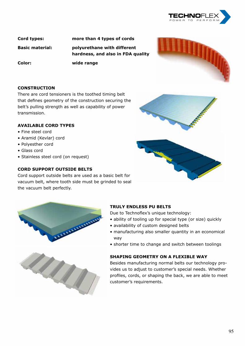
„ I n n o v a t i o n i n m o t i o n ”
Berv ina Kf t . • H -1145 Erzsébet k i rá lyné ú t ja 41/B • Te l . :+36 -1-222-20-79 • Fax: +36 -1-252-48-29 • berv ina@berv ina.com
page 06
CONSTRUCTION OF BELTS
Cord types: Basic material: Color:
more than 4 types of cords polyurethane with different hardness, and also in FDA quality wide range
CONSTRUCTION There are cord tensioners is the toothed timing belt that defines geometry of the construction securing the belt’s pulling strength as well as capability of power transmission. AVAILABLE CORD TYPES • Fine steel cord • Aramid (Kevlar) cord • Polyesther cord • Glass cord • Stainless steel cord (on request) CORD SUPPORT OUTSIDE BELTS Cord support outside belts are used as a basic belt for vacuum belt, where tooth side must be grinded to seal the vacuum belt perfectly.
TRULY ENDLESS PU BELTS Due to Bervina’s unique technology: • ability of tooling up for special type (or size) quickly • availability of custom designed belts • manufacturing also smaller quantity in an economical
way • shorter time to change and switch between toolings SHAPING GEOMETRY ON A FLEXIBLE WAY Besides manufacturing normal belts our technology provides us to adjust to customer's special needs. Whether profiles, cords, or shaping the back, we are able to meet customer's requirements.
Cord types: more than 4 types of cords
Basic material: polyurethane with different hardness, and also in FDA quality
Color: wide range
cOnStrUctiOnThere are cord tensioners is the toothed timing belt that defines geometry of the construction securing the belt’s pulling strength as well as capability of power transmission.
aVaiLabLe cOrD tyPeS• Fine steel cord• Aramid (Kevlar) cord• Polyesther cord• Glass cord• Stainless steel cord (on request)
cOrD SUPPOrt OUtSiDe beLtSCord support outside belts are used as a basic belt for vacuum belt, where tooth side must be grinded to seal the vacuum belt perfectly.
trULy enDLeSS PU beLtS Due to Technoflex’s unique technology: • ability of tooling up for special type (or size) quickly • availability of custom designed belts • manufacturing also smaller quantity in an economical way • shorter time to change and switch between toolings
SHaPing geOmetry On a FLexibLe Way Besides manufacturing normal belts our technology pro- vides us to adjust to customer’s special needs. Whether profiles, cords, or shaping the back, we are able to meet customer’s requirements.
„ I n n o v a t i o n i n m o t i o n ”
Berv ina Kf t . • H -1145 Erzsébet k i rá lyné ú t ja 41/B • Te l . :+36 -1-222-20-79 • Fax: +36 -1-252-48-29 • berv ina@berv ina.com
page 06
CONSTRUCTION OF BELTS
Cord types: Basic material: Color:
more than 4 types of cords polyurethane with different hardness, and also in FDA quality wide range
CONSTRUCTION There are cord tensioners is the toothed timing belt that defines geometry of the construction securing the belt’s pulling strength as well as capability of power transmission. AVAILABLE CORD TYPES • Fine steel cord • Aramid (Kevlar) cord • Polyesther cord • Glass cord • Stainless steel cord (on request) CORD SUPPORT OUTSIDE BELTS Cord support outside belts are used as a basic belt for vacuum belt, where tooth side must be grinded to seal the vacuum belt perfectly.
TRULY ENDLESS PU BELTS Due to Bervina’s unique technology: • ability of tooling up for special type (or size) quickly • availability of custom designed belts • manufacturing also smaller quantity in an economical
way • shorter time to change and switch between toolings SHAPING GEOMETRY ON A FLEXIBLE WAY Besides manufacturing normal belts our technology provides us to adjust to customer's special needs. Whether profiles, cords, or shaping the back, we are able to meet customer's requirements.
Cord types: more than 4 types of cords
Basic material: polyurethane with different hardness, and also in FDA quality
Color: wide range
cOnStrUctiOnThere are cord tensioners is the toothed timing belt that defines geometry of the construction securing the belt’s pulling strength as well as capability of power transmission.
aVaiLabLe cOrD tyPeS• Fine steel cord• Aramid (Kevlar) cord• Polyesther cord• Glass cord• Stainless steel cord (on request)
cOrD SUPPOrt OUtSiDe beLtSCord support outside belts are used as a basic belt for vacuum belt, where tooth side must be grinded to seal the vacuum belt perfectly.
trULy enDLeSS PU beLtS Due to Technoflex’s unique technology: • ability of tooling up for special type (or size) quickly • availability of custom designed belts • manufacturing also smaller quantity in an economical way • shorter time to change and switch between toolings
SHaPing geOmetry On a FLexibLe Way Besides manufacturing normal belts our technology pro- vides us to adjust to customer’s special needs. Whether profiles, cords, or shaping the back, we are able to meet customer’s requirements.
„ I n n o v a t i o n i n m o t i o n ”
Berv ina Kf t . • H -1145 Erzsébet k i rá lyné ú t ja 41/B • Te l . :+36 -1-222-20-79 • Fax: +36 -1-252-48-29 • berv ina@berv ina.com
page 06
CONSTRUCTION OF BELTS
Cord types: Basic material: Color:
more than 4 types of cords polyurethane with different hardness, and also in FDA quality wide range
CONSTRUCTION There are cord tensioners is the toothed timing belt that defines geometry of the construction securing the belt’s pulling strength as well as capability of power transmission. AVAILABLE CORD TYPES • Fine steel cord • Aramid (Kevlar) cord • Polyesther cord • Glass cord • Stainless steel cord (on request) CORD SUPPORT OUTSIDE BELTS Cord support outside belts are used as a basic belt for vacuum belt, where tooth side must be grinded to seal the vacuum belt perfectly.
TRULY ENDLESS PU BELTS Due to Bervina’s unique technology: • ability of tooling up for special type (or size) quickly • availability of custom designed belts • manufacturing also smaller quantity in an economical
way • shorter time to change and switch between toolings SHAPING GEOMETRY ON A FLEXIBLE WAY Besides manufacturing normal belts our technology provides us to adjust to customer's special needs. Whether profiles, cords, or shaping the back, we are able to meet customer's requirements.
„ I n n o v a t i o n i n m o t i o n ”
Berv ina Kf t . • H -1145 Erzsébet k i rá lyné ú t ja 41/B • Te l . :+36 -1-222-20-79 • Fax: +36 -1-252-48-29 • berv ina@berv ina.com
page 06
CONSTRUCTION OF BELTS
Cord types: Basic material: Color:
more than 4 types of cords polyurethane with different hardness, and also in FDA quality wide range
CONSTRUCTION There are cord tensioners is the toothed timing belt that defines geometry of the construction securing the belt’s pulling strength as well as capability of power transmission. AVAILABLE CORD TYPES • Fine steel cord • Aramid (Kevlar) cord • Polyesther cord • Glass cord • Stainless steel cord (on request) CORD SUPPORT OUTSIDE BELTS Cord support outside belts are used as a basic belt for vacuum belt, where tooth side must be grinded to seal the vacuum belt perfectly.
TRULY ENDLESS PU BELTS Due to Bervina’s unique technology: • ability of tooling up for special type (or size) quickly • availability of custom designed belts • manufacturing also smaller quantity in an economical
way • shorter time to change and switch between toolings SHAPING GEOMETRY ON A FLEXIBLE WAY Besides manufacturing normal belts our technology provides us to adjust to customer's special needs. Whether profiles, cords, or shaping the back, we are able to meet customer's requirements.
95 95
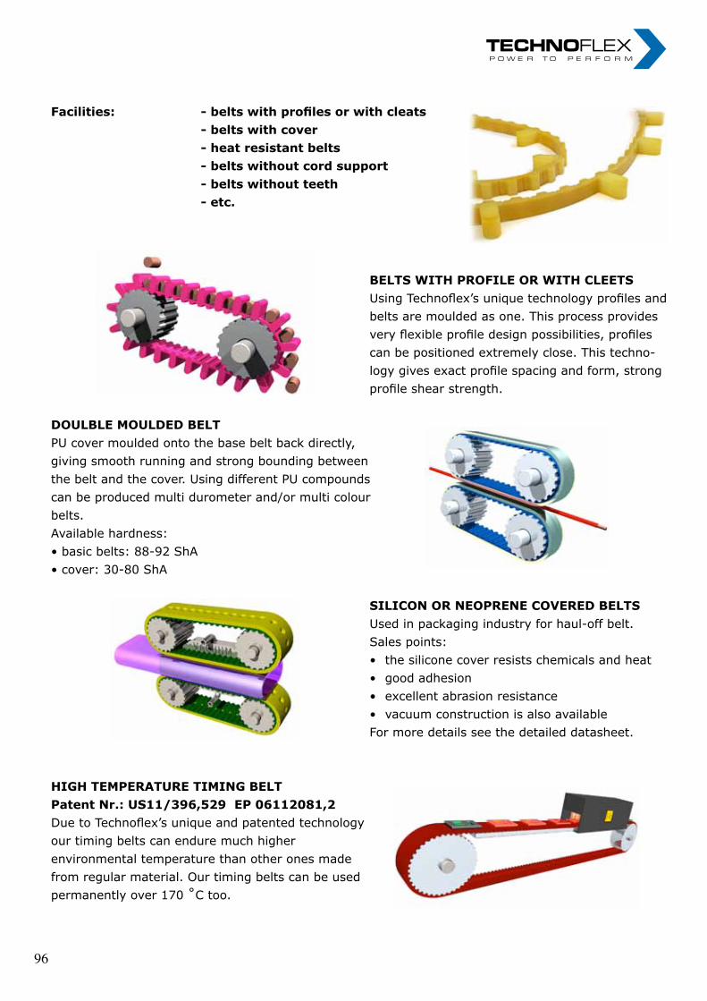
„ I n n o v a t i o n i n m o t i o n ”
Berv ina Kf t . • H -1145 Erzsébet k i rá lyné ú t ja 41/B • Te l . :+36 -1-222-20-79 • Fax: +36 -1-252-48-29 • berv ina@berv ina.com
page 07
SPECIAL BELTS I.
Facilities:
- belts with profiles or with cleats - belts with cover - heat resistant belts - belts without cord support - belts without teeth - etc.
BELTS WITH PROFILE OR WITH CLEETS Using Bervina’s unique technology profiles and belts are moulded as one. This process provides very flexible profile design possibilities, profiles can be positioned extremely close. This technology gives exact profile spacing and form, strong profile shear strength.
DOULBLE MOULDED BELT PU cover moulded onto the base belt back directly, giving smooth running and strong bounding between the belt and the cover. Using different PU compounds can be produced multi durometer and/or multi colour belts. Available hardness: • basic belts: 88-92 ShA • cover: 30-80 ShA
SILICON OR NEOPRENE COVERED BELTS Used in packaging industry for haul-off belt. Sales points: • the silicone cover resists chemicals and heat • good adhesion • excellent abrasion resistance • vacuum construction is also available For more details see the detailed datasheet.
HIGH TEMPERATURE TIMING BELT Patent Nr. : US11/396,529 EP 06112081,2 Due to Bervina’s unique and patented technology our timing belts can endure much higher environmental temperature than other ones made from regular material. Our timing belts can be used permanently over 170 ˚C too.
Facilities: - belts with profiles or with cleats - belts with cover - heat resistant belts - belts without cord support - belts without teeth - etc.
beLtS WitH PrOFiLe Or WitH cLeetS Using Technoflex’s unique technology profiles and belts are moulded as one. This process provides very flexible profile design possibilities, profiles can be positioned extremely close. This techno- logy gives exact profile spacing and form, strong profile shear strength.
DOULbLe mOULDeD beLtPU cover moulded onto the base belt back directly, giving smooth running and strong bounding between the belt and the cover. Using different PU compounds can be produced multi durometer and/or multi colour belts.Available hardness:• basic belts: 88-92 ShA• cover: 30-80 ShA
SiLicOn Or neOPrene cOVereD beLtS Used in packaging industry for haul-off belt. Sales points: • the silicone cover resists chemicals and heat • good adhesion • excellent abrasion resistance • vacuum construction is also available For more details see the detailed datasheet.
HigH temPeratUre timing beLtPatent Nr.: US11/396,529 EP 06112081,2Due to Technoflex’s unique and patented technology our timing belts can endure much higher environmental temperature than other ones made from regular material. Our timing belts can be used permanently over 170 ˚C too.
„ I n n o v a t i o n i n m o t i o n ”
Berv ina Kf t . • H -1145 Erzsébet k i rá lyné ú t ja 41/B • Te l . :+36 -1-222-20-79 • Fax: +36 -1-252-48-29 • berv ina@berv ina.com
page 07
SPECIAL BELTS I.
Facilities:
- belts with profiles or with cleats - belts with cover - heat resistant belts - belts without cord support - belts without teeth - etc.
BELTS WITH PROFILE OR WITH CLEETS Using Bervina’s unique technology profiles and belts are moulded as one. This process provides very flexible profile design possibilities, profiles can be positioned extremely close. This technology gives exact profile spacing and form, strong profile shear strength.
DOULBLE MOULDED BELT PU cover moulded onto the base belt back directly, giving smooth running and strong bounding between the belt and the cover. Using different PU compounds can be produced multi durometer and/or multi colour belts. Available hardness: • basic belts: 88-92 ShA • cover: 30-80 ShA
SILICON OR NEOPRENE COVERED BELTS Used in packaging industry for haul-off belt. Sales points: • the silicone cover resists chemicals and heat • good adhesion • excellent abrasion resistance • vacuum construction is also available For more details see the detailed datasheet.
HIGH TEMPERATURE TIMING BELT Patent Nr. : US11/396,529 EP 06112081,2 Due to Bervina’s unique and patented technology our timing belts can endure much higher environmental temperature than other ones made from regular material. Our timing belts can be used permanently over 170 ˚C too.
Facilities: - belts with profiles or with cleats - belts with cover - heat resistant belts - belts without cord support - belts without teeth - etc.
beLtS WitH PrOFiLe Or WitH cLeetS Using Technoflex’s unique technology profiles and belts are moulded as one. This process provides very flexible profile design possibilities, profiles can be positioned extremely close. This techno- logy gives exact profile spacing and form, strong profile shear strength.
DOULbLe mOULDeD beLtPU cover moulded onto the base belt back directly, giving smooth running and strong bounding between the belt and the cover. Using different PU compounds can be produced multi durometer and/or multi colour belts.Available hardness:• basic belts: 88-92 ShA• cover: 30-80 ShA
SiLicOn Or neOPrene cOVereD beLtS Used in packaging industry for haul-off belt. Sales points: • the silicone cover resists chemicals and heat • good adhesion • excellent abrasion resistance • vacuum construction is also available For more details see the detailed datasheet.
HigH temPeratUre timing beLtPatent Nr.: US11/396,529 EP 06112081,2Due to Technoflex’s unique and patented technology our timing belts can endure much higher environmental temperature than other ones made from regular material. Our timing belts can be used permanently over 170 ˚C too.
„ I n n o v a t i o n i n m o t i o n ”
Berv ina Kf t . • H -1145 Erzsébet k i rá lyné ú t ja 41/B • Te l . :+36 -1-222-20-79 • Fax: +36 -1-252-48-29 • berv ina@berv ina.com
page 07
SPECIAL BELTS I.
Facilities:
- belts with profiles or with cleats - belts with cover - heat resistant belts - belts without cord support - belts without teeth - etc.
BELTS WITH PROFILE OR WITH CLEETS Using Bervina’s unique technology profiles and belts are moulded as one. This process provides very flexible profile design possibilities, profiles can be positioned extremely close. This technology gives exact profile spacing and form, strong profile shear strength.
DOULBLE MOULDED BELT PU cover moulded onto the base belt back directly, giving smooth running and strong bounding between the belt and the cover. Using different PU compounds can be produced multi durometer and/or multi colour belts. Available hardness: • basic belts: 88-92 ShA • cover: 30-80 ShA
SILICON OR NEOPRENE COVERED BELTS Used in packaging industry for haul-off belt. Sales points: • the silicone cover resists chemicals and heat • good adhesion • excellent abrasion resistance • vacuum construction is also available For more details see the detailed datasheet.
HIGH TEMPERATURE TIMING BELT Patent Nr. : US11/396,529 EP 06112081,2 Due to Bervina’s unique and patented technology our timing belts can endure much higher environmental temperature than other ones made from regular material. Our timing belts can be used permanently over 170 ˚C too.
„ I n n o v a t i o n i n m o t i o n ”
Berv ina Kf t . • H -1145 Erzsébet k i rá lyné ú t ja 41/B • Te l . :+36 -1-222-20-79 • Fax: +36 -1-252-48-29 • berv ina@berv ina.com
page 07
SPECIAL BELTS I.
Facilities:
- belts with profiles or with cleats - belts with cover - heat resistant belts - belts without cord support - belts without teeth - etc.
BELTS WITH PROFILE OR WITH CLEETS Using Bervina’s unique technology profiles and belts are moulded as one. This process provides very flexible profile design possibilities, profiles can be positioned extremely close. This technology gives exact profile spacing and form, strong profile shear strength.
DOULBLE MOULDED BELT PU cover moulded onto the base belt back directly, giving smooth running and strong bounding between the belt and the cover. Using different PU compounds can be produced multi durometer and/or multi colour belts. Available hardness: • basic belts: 88-92 ShA • cover: 30-80 ShA
SILICON OR NEOPRENE COVERED BELTS Used in packaging industry for haul-off belt. Sales points: • the silicone cover resists chemicals and heat • good adhesion • excellent abrasion resistance • vacuum construction is also available For more details see the detailed datasheet.
HIGH TEMPERATURE TIMING BELT Patent Nr. : US11/396,529 EP 06112081,2 Due to Bervina’s unique and patented technology our timing belts can endure much higher environmental temperature than other ones made from regular material. Our timing belts can be used permanently over 170 ˚C too.
„ I n n o v a t i o n i n m o t i o n ”
Berv ina Kf t . • H -1145 Erzsébet k i rá lyné ú t ja 41/B • Te l . :+36 -1-222-20-79 • Fax: +36 -1-252-48-29 • berv ina@berv ina.com
page 07
SPECIAL BELTS I.
Facilities:
- belts with profiles or with cleats - belts with cover - heat resistant belts - belts without cord support - belts without teeth - etc.
BELTS WITH PROFILE OR WITH CLEETS Using Bervina’s unique technology profiles and belts are moulded as one. This process provides very flexible profile design possibilities, profiles can be positioned extremely close. This technology gives exact profile spacing and form, strong profile shear strength.
DOULBLE MOULDED BELT PU cover moulded onto the base belt back directly, giving smooth running and strong bounding between the belt and the cover. Using different PU compounds can be produced multi durometer and/or multi colour belts. Available hardness: • basic belts: 88-92 ShA • cover: 30-80 ShA
SILICON OR NEOPRENE COVERED BELTS Used in packaging industry for haul-off belt. Sales points: • the silicone cover resists chemicals and heat • good adhesion • excellent abrasion resistance • vacuum construction is also available For more details see the detailed datasheet.
HIGH TEMPERATURE TIMING BELT Patent Nr. : US11/396,529 EP 06112081,2 Due to Bervina’s unique and patented technology our timing belts can endure much higher environmental temperature than other ones made from regular material. Our timing belts can be used permanently over 170 ˚C too.
„ I n n o v a t i o n i n m o t i o n ”
Berv ina Kf t . • H -1145 Erzsébet k i rá lyné ú t ja 41/B • Te l . :+36 -1-222-20-79 • Fax: +36 -1-252-48-29 • berv ina@berv ina.com
page 07
SPECIAL BELTS I.
Facilities:
- belts with profiles or with cleats - belts with cover - heat resistant belts - belts without cord support - belts without teeth - etc.
BELTS WITH PROFILE OR WITH CLEETS Using Bervina’s unique technology profiles and belts are moulded as one. This process provides very flexible profile design possibilities, profiles can be positioned extremely close. This technology gives exact profile spacing and form, strong profile shear strength.
DOULBLE MOULDED BELT PU cover moulded onto the base belt back directly, giving smooth running and strong bounding between the belt and the cover. Using different PU compounds can be produced multi durometer and/or multi colour belts. Available hardness: • basic belts: 88-92 ShA • cover: 30-80 ShA
SILICON OR NEOPRENE COVERED BELTS Used in packaging industry for haul-off belt. Sales points: • the silicone cover resists chemicals and heat • good adhesion • excellent abrasion resistance • vacuum construction is also available For more details see the detailed datasheet.
HIGH TEMPERATURE TIMING BELT Patent Nr. : US11/396,529 EP 06112081,2 Due to Bervina’s unique and patented technology our timing belts can endure much higher environmental temperature than other ones made from regular material. Our timing belts can be used permanently over 170 ˚C too.
96 96
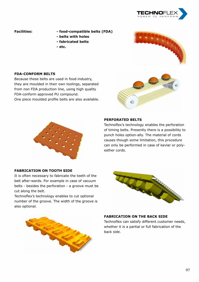
„ I n n o v a t i o n i n m o t i o n ”
Berv ina Kf t . • H -1145 Erzsébet k i rá lyné ú t ja 41/B • Te l . :+36 -1-222-20-79 • Fax: +36 -1-252-48-29 • berv ina@berv ina.com
page 08
SPECIAL BELTS II.
Facilities:
- food-compatible belts (FDA) - belts with holes - fabricated belts - etc.
FDA-CONFORM BELTS Because these belts are used in food-industry, they are moulded in their own toolings, separated from non FDA production line, using high quality FDA-conform approved PU compound. One piece moulded profile belts are also available.
PERFORATED BELTS Bervina’s technology enables the perforation of timing belts. Presently there is a possibility to punch holes option-ally. The material of cords causes though some limitation, this procedure can only be performed in case of kevlar or polyesther cords.
FABRICATION ON TOOTH SIDE It is often necessary to fabricate the teeth of the belt after-wards. For example in case of vacuum belts - besides the perforation - a groove must be cut along the belt. Bervina’s technology enables to cut optional number of the groove. The width of the groove is also optional.
FABRICATION ON THE BACK SIDE Bervina can satisfy different customer needs, whether it is a partial or full fabrication of the back side.
Facilities: - food-compatible belts (FDA) - belts with holes - fabricated belts - etc.
FDa-cOnFOrm beLtSBecause these belts are used in food-industry, they are moulded in their own toolings, separated from non FDA production line, using high quality FDA-conform approved PU compound.One piece moulded profile belts are also available.
PerFOrateD beLtS Technoflex’s technology enables the perforation of timing belts. Presently there is a possibility to punch holes option-ally. The material of cords causes though some limitation, this procedure can only be performed in case of kevlar or poly- esther cords.
FabricatiOn On tOOtH SiDeIt is often necessary to fabricate the teeth of the belt after-wards. For example in case of vacuum belts - besides the perforation - a groove must be cut along the belt. Technoflex’s technology enables to cut optional number of the groove. The width of the groove is also optional.
FabricatiOn On tHe back SiDe Technoflex can satisfy different customer needs, whether it is a partial or full fabrication of the back side.
„ I n n o v a t i o n i n m o t i o n ”
Berv ina Kf t . • H -1145 Erzsébet k i rá lyné ú t ja 41/B • Te l . :+36 -1-222-20-79 • Fax: +36 -1-252-48-29 • berv ina@berv ina.com
page 08
SPECIAL BELTS II.
Facilities:
- food-compatible belts (FDA) - belts with holes - fabricated belts - etc.
FDA-CONFORM BELTS Because these belts are used in food-industry, they are moulded in their own toolings, separated from non FDA production line, using high quality FDA-conform approved PU compound. One piece moulded profile belts are also available.
PERFORATED BELTS Bervina’s technology enables the perforation of timing belts. Presently there is a possibility to punch holes option-ally. The material of cords causes though some limitation, this procedure can only be performed in case of kevlar or polyesther cords.
FABRICATION ON TOOTH SIDE It is often necessary to fabricate the teeth of the belt after-wards. For example in case of vacuum belts - besides the perforation - a groove must be cut along the belt. Bervina’s technology enables to cut optional number of the groove. The width of the groove is also optional.
FABRICATION ON THE BACK SIDE Bervina can satisfy different customer needs, whether it is a partial or full fabrication of the back side.
Facilities: - food-compatible belts (FDA) - belts with holes - fabricated belts - etc.
FDa-cOnFOrm beLtSBecause these belts are used in food-industry, they are moulded in their own toolings, separated from non FDA production line, using high quality FDA-conform approved PU compound.One piece moulded profile belts are also available.
PerFOrateD beLtS Technoflex’s technology enables the perforation of timing belts. Presently there is a possibility to punch holes option-ally. The material of cords causes though some limitation, this procedure can only be performed in case of kevlar or poly- esther cords.
FabricatiOn On tOOtH SiDeIt is often necessary to fabricate the teeth of the belt after-wards. For example in case of vacuum belts - besides the perforation - a groove must be cut along the belt. Technoflex’s technology enables to cut optional number of the groove. The width of the groove is also optional.
FabricatiOn On tHe back SiDe Technoflex can satisfy different customer needs, whether it is a partial or full fabrication of the back side.
„ I n n o v a t i o n i n m o t i o n ”
Berv ina Kf t . • H -1145 Erzsébet k i rá lyné ú t ja 41/B • Te l . :+36 -1-222-20-79 • Fax: +36 -1-252-48-29 • berv ina@berv ina.com
page 08
SPECIAL BELTS II.
Facilities:
- food-compatible belts (FDA) - belts with holes - fabricated belts - etc.
FDA-CONFORM BELTS Because these belts are used in food-industry, they are moulded in their own toolings, separated from non FDA production line, using high quality FDA-conform approved PU compound. One piece moulded profile belts are also available.
PERFORATED BELTS Bervina’s technology enables the perforation of timing belts. Presently there is a possibility to punch holes option-ally. The material of cords causes though some limitation, this procedure can only be performed in case of kevlar or polyesther cords.
FABRICATION ON TOOTH SIDE It is often necessary to fabricate the teeth of the belt after-wards. For example in case of vacuum belts - besides the perforation - a groove must be cut along the belt. Bervina’s technology enables to cut optional number of the groove. The width of the groove is also optional.
FABRICATION ON THE BACK SIDE Bervina can satisfy different customer needs, whether it is a partial or full fabrication of the back side.
„ I n n o v a t i o n i n m o t i o n ”
Berv ina Kf t . • H -1145 Erzsébet k i rá lyné ú t ja 41/B • Te l . :+36 -1-222-20-79 • Fax: +36 -1-252-48-29 • berv ina@berv ina.com
page 08
SPECIAL BELTS II.
Facilities:
- food-compatible belts (FDA) - belts with holes - fabricated belts - etc.
FDA-CONFORM BELTS Because these belts are used in food-industry, they are moulded in their own toolings, separated from non FDA production line, using high quality FDA-conform approved PU compound. One piece moulded profile belts are also available.
PERFORATED BELTS Bervina’s technology enables the perforation of timing belts. Presently there is a possibility to punch holes option-ally. The material of cords causes though some limitation, this procedure can only be performed in case of kevlar or polyesther cords.
FABRICATION ON TOOTH SIDE It is often necessary to fabricate the teeth of the belt after-wards. For example in case of vacuum belts - besides the perforation - a groove must be cut along the belt. Bervina’s technology enables to cut optional number of the groove. The width of the groove is also optional.
FABRICATION ON THE BACK SIDE Bervina can satisfy different customer needs, whether it is a partial or full fabrication of the back side.
„ I n n o v a t i o n i n m o t i o n ”
Berv ina Kf t . • H -1145 Erzsébet k i rá lyné ú t ja 41/B • Te l . :+36 -1-222-20-79 • Fax: +36 -1-252-48-29 • berv ina@berv ina.com
page 08
SPECIAL BELTS II.
Facilities:
- food-compatible belts (FDA) - belts with holes - fabricated belts - etc.
FDA-CONFORM BELTS Because these belts are used in food-industry, they are moulded in their own toolings, separated from non FDA production line, using high quality FDA-conform approved PU compound. One piece moulded profile belts are also available.
PERFORATED BELTS Bervina’s technology enables the perforation of timing belts. Presently there is a possibility to punch holes option-ally. The material of cords causes though some limitation, this procedure can only be performed in case of kevlar or polyesther cords.
FABRICATION ON TOOTH SIDE It is often necessary to fabricate the teeth of the belt after-wards. For example in case of vacuum belts - besides the perforation - a groove must be cut along the belt. Bervina’s technology enables to cut optional number of the groove. The width of the groove is also optional.
FABRICATION ON THE BACK SIDE Bervina can satisfy different customer needs, whether it is a partial or full fabrication of the back side.
„ I n n o v a t i o n i n m o t i o n ”
Berv ina Kf t . • H -1145 Erzsébet k i rá lyné ú t ja 41/B • Te l . :+36 -1-222-20-79 • Fax: +36 -1-252-48-29 • berv ina@berv ina.com
page 08
SPECIAL BELTS II.
Facilities:
- food-compatible belts (FDA) - belts with holes - fabricated belts - etc.
FDA-CONFORM BELTS Because these belts are used in food-industry, they are moulded in their own toolings, separated from non FDA production line, using high quality FDA-conform approved PU compound. One piece moulded profile belts are also available.
PERFORATED BELTS Bervina’s technology enables the perforation of timing belts. Presently there is a possibility to punch holes option-ally. The material of cords causes though some limitation, this procedure can only be performed in case of kevlar or polyesther cords.
FABRICATION ON TOOTH SIDE It is often necessary to fabricate the teeth of the belt after-wards. For example in case of vacuum belts - besides the perforation - a groove must be cut along the belt. Bervina’s technology enables to cut optional number of the groove. The width of the groove is also optional.
FABRICATION ON THE BACK SIDE Bervina can satisfy different customer needs, whether it is a partial or full fabrication of the back side.
97 97
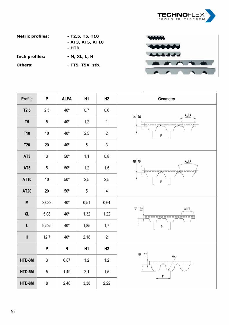
„ I n n o v a t i o n i n m o t i o n ”
Berv ina Kf t . • H -1145 Erzsébet k i rá lyné ú t ja 41/B • Te l . :+36 -1-222-20-79 • Fax: +36 -1-252-48-29 • berv ina@berv ina.com
page 09
BELT PROFILES
Metric profiles: Inch profiles: Others:
- T2,5, T5, T10 - AT3, AT5, AT10 - HTD - M, XL, L, H - TT5, T5V, stb.
Profile P ALFA H1 H2 Geometry
T2,5 2,5 40º 0,7 0,6
T5 5 40º 1,2 1
T10 10 40º 2,5 2
T20 20 40º 5 3
AT3 3 50º 1,1 0,8
AT5 5 50º 1,2 1,5
AT10 10 50º 2,5 2,5
AT20 20 50º 5 4
M 2,032 40º 0,51 0,64
XL 5,08 40º 1,32 1,22
L 9,525 40º 1,85 1,7
H 12,7 40º 2,18 2
P R H1 H2
HTD-3M 3 0,87 1,2 1,2
HTD-5M 5 1,49 2,1 1,5
HTD-8M 8 2,46 3,38 2,22
Metric profiles: - T2,5, T5, T10 - at3, at5, at10 - HtD
Inch profiles: - M, XL, L, H
Others: - TT5, T5V, stb.
„ I n n o v a t i o n i n m o t i o n ”
Berv ina Kf t . • H -1145 Erzsébet k i rá lyné ú t ja 41/B • Te l . :+36 -1-222-20-79 • Fax: +36 -1-252-48-29 • berv ina@berv ina.com
page 09
BELT PROFILES
Metric profiles: Inch profiles: Others:
- T2,5, T5, T10 - AT3, AT5, AT10 - HTD - M, XL, L, H - TT5, T5V, stb.
Profile P ALFA H1 H2 Geometry
T2,5 2,5 40º 0,7 0,6
T5 5 40º 1,2 1
T10 10 40º 2,5 2
T20 20 40º 5 3
AT3 3 50º 1,1 0,8
AT5 5 50º 1,2 1,5
AT10 10 50º 2,5 2,5
AT20 20 50º 5 4
M 2,032 40º 0,51 0,64
XL 5,08 40º 1,32 1,22
L 9,525 40º 1,85 1,7
H 12,7 40º 2,18 2
P R H1 H2
HTD-3M 3 0,87 1,2 1,2
HTD-5M 5 1,49 2,1 1,5
HTD-8M 8 2,46 3,38 2,22
Metric profiles: - T2,5, T5, T10 - at3, at5, at10 - HtD
Inch profiles: - M, XL, L, H
Others: - TT5, T5V, stb.
„ I n n o v a t i o n i n m o t i o n ”
Berv ina Kf t . • H -1145 Erzsébet k i rá lyné ú t ja 41/B • Te l . :+36 -1-222-20-79 • Fax: +36 -1-252-48-29 • berv ina@berv ina.com
page 09
BELT PROFILES
Metric profiles: Inch profiles: Others:
- T2,5, T5, T10 - AT3, AT5, AT10 - HTD - M, XL, L, H - TT5, T5V, stb.
Profile P ALFA H1 H2 Geometry
T2,5 2,5 40º 0,7 0,6
T5 5 40º 1,2 1
T10 10 40º 2,5 2
T20 20 40º 5 3
AT3 3 50º 1,1 0,8
AT5 5 50º 1,2 1,5
AT10 10 50º 2,5 2,5
AT20 20 50º 5 4
M 2,032 40º 0,51 0,64
XL 5,08 40º 1,32 1,22
L 9,525 40º 1,85 1,7
H 12,7 40º 2,18 2
P R H1 H2
HTD-3M 3 0,87 1,2 1,2
HTD-5M 5 1,49 2,1 1,5
HTD-8M 8 2,46 3,38 2,22
98 98

„ I n n o v a t i o n i n m o t i o n ”
Berv ina Kf t . • H -1145 Erzsébet k i rá lyné ú t ja 41/B • Te l . :+36 -1-222-20-79 • Fax: +36 -1-252-48-29 • berv ina@berv ina.com
page 11
NEOPRENE TIMING BELT WITH SILICON COVER
Fields of use: Advantages: Application samlpe:
packaging industry long life-span good adhesion excellent abrasion resistance
optional direction of rotation pulling-off belts of FFS packaging machines
Type Application
sample Pitch (mm)
Length (mm)
Width (mm)
Cord re-inforcement
Material of the basic belt
Color of the basic belt
T5-455 + 3Si 5 455 max 65 glass rubber black
T10-630 + 6Si Rovema/ Kopas 10 630 25, 28, 30, 50 glass rubber black
T10-660 + 3Si SZCS-25 10 660 max 50 glass rubber black
T10-700 + 6Si Wolf 10 700 max 50 glass rubber black
T10-720 + 6Si Altopack 10 720 max 40 glass rubber black
T10-780 + 6Si Rovema 10 780 max 50 glass rubber black
T10-800 + 6Si 10 800 max 50 glass rubber black
T10-920 + 6Si 10 920 max 50 glass rubber black
T10-920 + 3.5Si Bosch 10 920 50 glass rubber black
225L + 4,5Si Hassia 9,525 571,5 25,4 glass rubber black
240 L + 6Si 9,525 609,6 max 50 glass rubber black
255 L + 6Si FMC 700, Simionate 9,525 647,7 max 40 glass rubber black
Type Grinding on tooth
side (mm) Coating
(mm) Coating (ShA)
Vacuum constr.
Perforation type
a b c ØD Ød alfa t
(mm)
T5-455 + 3Si optional 3 35 yes C - - - - - - -
T10-630 + 6Si 16 6 35 optional B / C - - - 12 4 90° 1,5p
T10-660 + 3Si optional 3 35 yes C - - - - - - -
T10-700 + 6Si optional 6 35 yes C - - - - - - -
T10-720 + 6Si 15 6 35 optional A / C 6 20 2 - 6 45° 1,5p
T10-780 + 6Si optional 6 35 yes C - - - - - - -
T10-920 + 6Si optional 6 35 optional A / C 6 28 2 - 5 30° 2p
T10-800 + 6Si optional 6 35 yes C - - - - - - -
T10-920 + 3.5Si 14 3,5 35 optional A / C 6 28 2 - 5 30° 2p
225L + 4,5Si 15 6 35 yes C - - - - - - -
240 L + 6Si optional 6 35 yes C - - - - - - -
255 L + 6Si optional 6 35 yes C - - - - - - -
Notes:
1. The rubber covered belts are coated with a one piece moulded, endless and refined cover, so the direction of rota-tion can be optional
2. The steel cords can be re-placed optionally by Kevlar
Fields of use: packaging industry
Advantages: long life-span good adhesion excellent abrasion resistance optional direction of rotation
Application samlpe: pulling-off belts of FFS packaging machines
„ I n n o v a t i o n i n m o t i o n ”
Berv ina Kf t . • H -1145 Erzsébet k i rá lyné ú t ja 41/B • Te l . :+36 -1-222-20-79 • Fax: +36 -1-252-48-29 • berv ina@berv ina.com
page 11
NEOPRENE TIMING BELT WITH SILICON COVER
Fields of use: Advantages: Application samlpe:
packaging industry long life-span good adhesion excellent abrasion resistance
optional direction of rotation pulling-off belts of FFS packaging machines
Type Application
sample Pitch (mm)
Length (mm)
Width (mm)
Cord re-inforcement
Material of the basic belt
Color of the basic belt
T5-455 + 3Si 5 455 max 65 glass rubber black
T10-630 + 6Si Rovema/ Kopas 10 630 25, 28, 30, 50 glass rubber black
T10-660 + 3Si SZCS-25 10 660 max 50 glass rubber black
T10-700 + 6Si Wolf 10 700 max 50 glass rubber black
T10-720 + 6Si Altopack 10 720 max 40 glass rubber black
T10-780 + 6Si Rovema 10 780 max 50 glass rubber black
T10-800 + 6Si 10 800 max 50 glass rubber black
T10-920 + 6Si 10 920 max 50 glass rubber black
T10-920 + 3.5Si Bosch 10 920 50 glass rubber black
225L + 4,5Si Hassia 9,525 571,5 25,4 glass rubber black
240 L + 6Si 9,525 609,6 max 50 glass rubber black
255 L + 6Si FMC 700, Simionate 9,525 647,7 max 40 glass rubber black
Type Grinding on tooth
side (mm) Coating
(mm) Coating (ShA)
Vacuum constr.
Perforation type
a b c ØD Ød alfa t
(mm)
T5-455 + 3Si optional 3 35 yes C - - - - - - -
T10-630 + 6Si 16 6 35 optional B / C - - - 12 4 90° 1,5p
T10-660 + 3Si optional 3 35 yes C - - - - - - -
T10-700 + 6Si optional 6 35 yes C - - - - - - -
T10-720 + 6Si 15 6 35 optional A / C 6 20 2 - 6 45° 1,5p
T10-780 + 6Si optional 6 35 yes C - - - - - - -
T10-920 + 6Si optional 6 35 optional A / C 6 28 2 - 5 30° 2p
T10-800 + 6Si optional 6 35 yes C - - - - - - -
T10-920 + 3.5Si 14 3,5 35 optional A / C 6 28 2 - 5 30° 2p
225L + 4,5Si 15 6 35 yes C - - - - - - -
240 L + 6Si optional 6 35 yes C - - - - - - -
255 L + 6Si optional 6 35 yes C - - - - - - -
Notes:
1. The rubber covered belts are coated with a one piece moulded, endless and refined cover, so the direction of rota-tion can be optional
2. The steel cords can be re-placed optionally by Kevlar
Fields of use: packaging industry
Advantages: long life-span good adhesion excellent abrasion resistance optional direction of rotation
Application samlpe: pulling-off belts of FFS packaging machines
„ I n n o v a t i o n i n m o t i o n ”
Berv ina Kf t . • H -1145 Erzsébet k i rá lyné ú t ja 41/B • Te l . :+36 -1-222-20-79 • Fax: +36 -1-252-48-29 • berv ina@berv ina.com
page 11
NEOPRENE TIMING BELT WITH SILICON COVER
Fields of use: Advantages: Application samlpe:
packaging industry long life-span good adhesion excellent abrasion resistance
optional direction of rotation pulling-off belts of FFS packaging machines
Type Application
sample Pitch (mm)
Length (mm)
Width (mm)
Cord re-inforcement
Material of the basic belt
Color of the basic belt
T5-455 + 3Si 5 455 max 65 glass rubber black
T10-630 + 6Si Rovema/ Kopas 10 630 25, 28, 30, 50 glass rubber black
T10-660 + 3Si SZCS-25 10 660 max 50 glass rubber black
T10-700 + 6Si Wolf 10 700 max 50 glass rubber black
T10-720 + 6Si Altopack 10 720 max 40 glass rubber black
T10-780 + 6Si Rovema 10 780 max 50 glass rubber black
T10-800 + 6Si 10 800 max 50 glass rubber black
T10-920 + 6Si 10 920 max 50 glass rubber black
T10-920 + 3.5Si Bosch 10 920 50 glass rubber black
225L + 4,5Si Hassia 9,525 571,5 25,4 glass rubber black
240 L + 6Si 9,525 609,6 max 50 glass rubber black
255 L + 6Si FMC 700, Simionate 9,525 647,7 max 40 glass rubber black
Type Grinding on tooth
side (mm) Coating
(mm) Coating (ShA)
Vacuum constr.
Perforation type
a b c ØD Ød alfa t
(mm)
T5-455 + 3Si optional 3 35 yes C - - - - - - -
T10-630 + 6Si 16 6 35 optional B / C - - - 12 4 90° 1,5p
T10-660 + 3Si optional 3 35 yes C - - - - - - -
T10-700 + 6Si optional 6 35 yes C - - - - - - -
T10-720 + 6Si 15 6 35 optional A / C 6 20 2 - 6 45° 1,5p
T10-780 + 6Si optional 6 35 yes C - - - - - - -
T10-920 + 6Si optional 6 35 optional A / C 6 28 2 - 5 30° 2p
T10-800 + 6Si optional 6 35 yes C - - - - - - -
T10-920 + 3.5Si 14 3,5 35 optional A / C 6 28 2 - 5 30° 2p
225L + 4,5Si 15 6 35 yes C - - - - - - -
240 L + 6Si optional 6 35 yes C - - - - - - -
255 L + 6Si optional 6 35 yes C - - - - - - -
Notes:
1. The rubber covered belts are coated with a one piece moulded, endless and refined cover, so the direction of rota-tion can be optional
2. The steel cords can be re-placed optionally by Kevlar
99 99
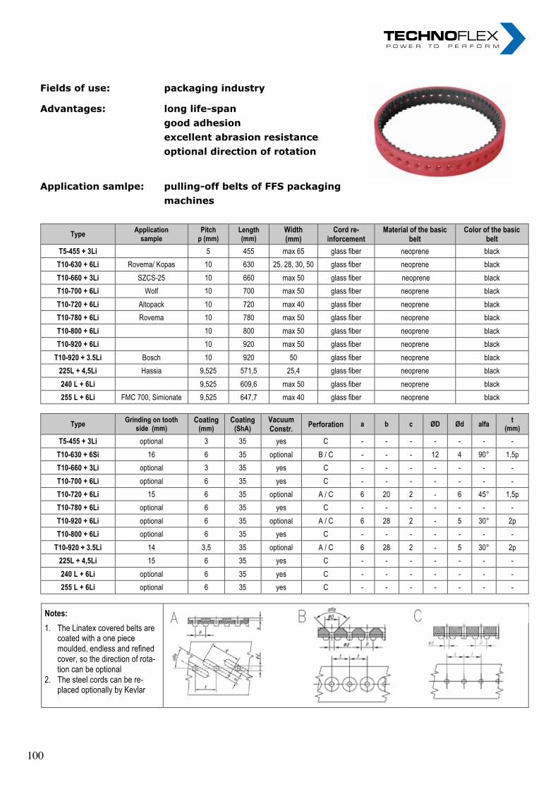
„ I n n o v a t i o n i n m o t i o n ”
Berv ina Kf t . • H -1145 Erzsébet k i rá lyné ú t ja 41/B • Te l . :+36 -1-222-20-79 • Fax: +36 -1-252-48-29 • berv ina@berv ina.com
page12
NEOPRENE TIMING BELT WITH LINATEX COVER
Fields of use: Advantages: Application sample:
packaging industry long life-span good adhesion excellent abrasion resistance
optional direction of rotation pulling-off belts of FFS packaging machines
Type Application
sample Pitch
p (mm) Length (mm)
Width (mm)
Cord re-inforcement
Material of the basic belt
Color of the basic belt
T5-455 + 3Li 5 455 max 65 glass fiber neoprene black
T10-630 + 6Li Rovema/ Kopas 10 630 25, 28, 30, 50 glass fiber neoprene black
T10-660 + 3Li SZCS-25 10 660 max 50 glass fiber neoprene black
T10-700 + 6Li Wolf 10 700 max 50 glass fiber neoprene black
T10-720 + 6Li Altopack 10 720 max 40 glass fiber neoprene black
T10-780 + 6Li Rovema 10 780 max 50 glass fiber neoprene black
T10-800 + 6Li 10 800 max 50 glass fiber neoprene black
T10-920 + 6Li 10 920 max 50 glass fiber neoprene black
T10-920 + 3.5Li Bosch 10 920 50 glass fiber neoprene black
225L + 4,5Li Hassia 9,525 571,5 25,4 glass fiber neoprene black
240 L + 6Li 9,525 609,6 max 50 glass fiber neoprene black
255 L + 6Li FMC 700, Simionate 9,525 647,7 max 40 glass fiber neoprene black
Type Grinding on tooth
side (mm) Coating
(mm) Coating
(ShA) Vacuum Constr.
Perforation a b c ØD Ød alfa t
(mm)
T5-455 + 3Li optional 3 35 yes C - - - - - - -
T10-630 + 6Si 16 6 35 optional B / C - - - 12 4 90° 1,5p
T10-660 + 3Li optional 3 35 yes C - - - - - - -
T10-700 + 6Li optional 6 35 yes C - - - - - - -
T10-720 + 6Li 15 6 35 optional A / C 6 20 2 - 6 45° 1,5p
T10-780 + 6Li optional 6 35 yes C - - - - - - -
T10-920 + 6Li optional 6 35 optional A / C 6 28 2 - 5 30° 2p
T10-800 + 6Li optional 6 35 yes C - - - - - - -
T10-920 + 3.5Li 14 3,5 35 optional A / C 6 28 2 - 5 30° 2p
225L + 4,5Li 15 6 35 yes C - - - - - - -
240 L + 6Li optional 6 35 yes C - - - - - - -
255 L + 6Li optional 6 35 yes C - - - - - - -
Notes:
1. The Linatex covered belts are coated with a one piece moulded, endless and refined cover, so the direction of rota-tion can be optional
2. The steel cords can be re-placed optionally by Kevlar
Fields of use: packaging industry
Advantages: long life-span good adhesion excellent abrasion resistance optional direction of rotation
Application samlpe: pulling-off belts of FFS packaging machines
„ I n n o v a t i o n i n m o t i o n ”
Berv ina Kf t . • H -1145 Erzsébet k i rá lyné ú t ja 41/B • Te l . :+36 -1-222-20-79 • Fax: +36 -1-252-48-29 • berv ina@berv ina.com
page12
NEOPRENE TIMING BELT WITH LINATEX COVER
Fields of use: Advantages: Application sample:
packaging industry long life-span good adhesion excellent abrasion resistance
optional direction of rotation pulling-off belts of FFS packaging machines
Type Application
sample Pitch
p (mm) Length (mm)
Width (mm)
Cord re-inforcement
Material of the basic belt
Color of the basic belt
T5-455 + 3Li 5 455 max 65 glass fiber neoprene black
T10-630 + 6Li Rovema/ Kopas 10 630 25, 28, 30, 50 glass fiber neoprene black
T10-660 + 3Li SZCS-25 10 660 max 50 glass fiber neoprene black
T10-700 + 6Li Wolf 10 700 max 50 glass fiber neoprene black
T10-720 + 6Li Altopack 10 720 max 40 glass fiber neoprene black
T10-780 + 6Li Rovema 10 780 max 50 glass fiber neoprene black
T10-800 + 6Li 10 800 max 50 glass fiber neoprene black
T10-920 + 6Li 10 920 max 50 glass fiber neoprene black
T10-920 + 3.5Li Bosch 10 920 50 glass fiber neoprene black
225L + 4,5Li Hassia 9,525 571,5 25,4 glass fiber neoprene black
240 L + 6Li 9,525 609,6 max 50 glass fiber neoprene black
255 L + 6Li FMC 700, Simionate 9,525 647,7 max 40 glass fiber neoprene black
Type Grinding on tooth
side (mm) Coating
(mm) Coating
(ShA) Vacuum Constr.
Perforation a b c ØD Ød alfa t
(mm)
T5-455 + 3Li optional 3 35 yes C - - - - - - -
T10-630 + 6Si 16 6 35 optional B / C - - - 12 4 90° 1,5p
T10-660 + 3Li optional 3 35 yes C - - - - - - -
T10-700 + 6Li optional 6 35 yes C - - - - - - -
T10-720 + 6Li 15 6 35 optional A / C 6 20 2 - 6 45° 1,5p
T10-780 + 6Li optional 6 35 yes C - - - - - - -
T10-920 + 6Li optional 6 35 optional A / C 6 28 2 - 5 30° 2p
T10-800 + 6Li optional 6 35 yes C - - - - - - -
T10-920 + 3.5Li 14 3,5 35 optional A / C 6 28 2 - 5 30° 2p
225L + 4,5Li 15 6 35 yes C - - - - - - -
240 L + 6Li optional 6 35 yes C - - - - - - -
255 L + 6Li optional 6 35 yes C - - - - - - -
Notes:
1. The Linatex covered belts are coated with a one piece moulded, endless and refined cover, so the direction of rota-tion can be optional
2. The steel cords can be re-placed optionally by Kevlar
Fields of use: packaging industry
Advantages: long life-span good adhesion excellent abrasion resistance optional direction of rotation
Application samlpe: pulling-off belts of FFS packaging machines
„ I n n o v a t i o n i n m o t i o n ”
Berv ina Kf t . • H -1145 Erzsébet k i rá lyné ú t ja 41/B • Te l . :+36 -1-222-20-79 • Fax: +36 -1-252-48-29 • berv ina@berv ina.com
page12
NEOPRENE TIMING BELT WITH LINATEX COVER
Fields of use: Advantages: Application sample:
packaging industry long life-span good adhesion excellent abrasion resistance
optional direction of rotation pulling-off belts of FFS packaging machines
Type Application
sample Pitch
p (mm) Length (mm)
Width (mm)
Cord re-inforcement
Material of the basic belt
Color of the basic belt
T5-455 + 3Li 5 455 max 65 glass fiber neoprene black
T10-630 + 6Li Rovema/ Kopas 10 630 25, 28, 30, 50 glass fiber neoprene black
T10-660 + 3Li SZCS-25 10 660 max 50 glass fiber neoprene black
T10-700 + 6Li Wolf 10 700 max 50 glass fiber neoprene black
T10-720 + 6Li Altopack 10 720 max 40 glass fiber neoprene black
T10-780 + 6Li Rovema 10 780 max 50 glass fiber neoprene black
T10-800 + 6Li 10 800 max 50 glass fiber neoprene black
T10-920 + 6Li 10 920 max 50 glass fiber neoprene black
T10-920 + 3.5Li Bosch 10 920 50 glass fiber neoprene black
225L + 4,5Li Hassia 9,525 571,5 25,4 glass fiber neoprene black
240 L + 6Li 9,525 609,6 max 50 glass fiber neoprene black
255 L + 6Li FMC 700, Simionate 9,525 647,7 max 40 glass fiber neoprene black
Type Grinding on tooth
side (mm) Coating
(mm) Coating
(ShA) Vacuum Constr.
Perforation a b c ØD Ød alfa t
(mm)
T5-455 + 3Li optional 3 35 yes C - - - - - - -
T10-630 + 6Si 16 6 35 optional B / C - - - 12 4 90° 1,5p
T10-660 + 3Li optional 3 35 yes C - - - - - - -
T10-700 + 6Li optional 6 35 yes C - - - - - - -
T10-720 + 6Li 15 6 35 optional A / C 6 20 2 - 6 45° 1,5p
T10-780 + 6Li optional 6 35 yes C - - - - - - -
T10-920 + 6Li optional 6 35 optional A / C 6 28 2 - 5 30° 2p
T10-800 + 6Li optional 6 35 yes C - - - - - - -
T10-920 + 3.5Li 14 3,5 35 optional A / C 6 28 2 - 5 30° 2p
225L + 4,5Li 15 6 35 yes C - - - - - - -
240 L + 6Li optional 6 35 yes C - - - - - - -
255 L + 6Li optional 6 35 yes C - - - - - - -
Notes:
1. The Linatex covered belts are coated with a one piece moulded, endless and refined cover, so the direction of rota-tion can be optional
2. The steel cords can be re-placed optionally by Kevlar
100 100

„ I n n o v a t i o n i n m o t i o n ”
Berv ina Kf t . • H -1145 Erzsébet k i rá lyné ú t ja 41/B • Te l . :+36 -1-222-20-79 • Fax: +36 -1-252-48-29 • berv ina@berv ina.com
page 13
POLYURETHAN TIMING BELT WITH LINATEX COVER
Fields of use: Advantages: Application sample:
packaging industry long life-span good adhesion excellent abrasion resistance
optional direction of rotation pulling-off belts of FFS packaging machines
Type Application
sample Pitch
p (mm) Length (mm)
Width (mm)
Cord re-inforcement
Material of the basic belt
Color of the basic belt
Construction of the basic belt
T2,5-330 + 2,9Li 2,5 330 20 kevlar PU (90±2 ShA) natur cord support inside
T5-455 + 3Li 5 455 max 65 steel PU (90±2 ShA) blue cord support inside
T10-630 + 6Li Rovema 10 630 25, 28, 30, 50 kevlar PU (90±2 ShA) red-brown cord s. outside
T10-630 + 6Li 10 630 max 50 kevlar PU (90±2 ShA) red-brown cord s. outside
T10-630 + 4Li 10 630 max 50 kevlar PU (90±2 ShA) red-brown cord s. outside
T10-660 + 3Li SZCS-25 10 660 max 50 steel PU (90±2 ShA) natur cord support inside
T10-700 + 6Li Wolf 10 700 max 50 kevlar PU (90±2 ShA) red-brown cord support inside
T10-780 + 6Li 10 780 max 50 kevlar PU (90±2 ShA) red-brown cord s. outside
T10-920 + 6Li 10 920 max 50 kevlar PU (90±2 ShA) red-brown cord s. outside
T10-920 + 3.5Li Bosch 10 920 50 kevlar PU (90±2 ShA) red-brown cord s. outside
255 L + 6Li FMC 700,Simionate 9,525 647,7 max 40 kevlar PU (90±2 ShA) red-brown cord support inside
Type Grinding on tooth
side (mm) Coating
(mm) Coating
(ShA) Vacuum Constr.
Perforation a b c ØD Ød alfa t
(mm)
T2,5-330 + 2,9Li - 2,9 35 yes C - - - - - - -
T5-455 + 3Li optional 3 35 no - - - - - - - -
T10-630 + 6Li 16 6 35 optional B / C - - - 12 4 90° 1,5p
T10-630 + 6Li optional 6 35 yes C - - - - - - -
T10-630 + 4Li optional 4 35 optional B / C - - - 8 4 90° 1,5p / 2p
T10-660 + 3Li optional 3 35 no -
- - - - - - -
T10-700 + 6Li optional 6 35 yes C - - - - - - -
T10-780 + 6Li optional 6 35 optional B / C - - - 12 4 90° 1,5p / 2p
T10-920 + 6Li optional 6 35 optional B / C - - - 12 4 90° 1,5p / 2p
T10-920 + 3.5Li 14 3,5 35 optional A / C 6 28 2 - 5 30° 2p
255 L + 6Li optional 6 35 yes C - - - - - - -
Notes:
1. The Linatex covered belts are coated with a one piece moulded, endless and refined cover, so the direction of rota-tion can be optional
2. The steel cords can be re-placed optionally by Kevlar
Fields of use: packaging industry
Advantages: long life-span good adhesion excellent abrasion resistance optional direction of rotation
Application samlpe: pulling-off belts of FFS packaging machines
„ I n n o v a t i o n i n m o t i o n ”
Berv ina Kf t . • H -1145 Erzsébet k i rá lyné ú t ja 41/B • Te l . :+36 -1-222-20-79 • Fax: +36 -1-252-48-29 • berv ina@berv ina.com
page 13
POLYURETHAN TIMING BELT WITH LINATEX COVER
Fields of use: Advantages: Application sample:
packaging industry long life-span good adhesion excellent abrasion resistance
optional direction of rotation pulling-off belts of FFS packaging machines
Type Application
sample Pitch
p (mm) Length (mm)
Width (mm)
Cord re-inforcement
Material of the basic belt
Color of the basic belt
Construction of the basic belt
T2,5-330 + 2,9Li 2,5 330 20 kevlar PU (90±2 ShA) natur cord support inside
T5-455 + 3Li 5 455 max 65 steel PU (90±2 ShA) blue cord support inside
T10-630 + 6Li Rovema 10 630 25, 28, 30, 50 kevlar PU (90±2 ShA) red-brown cord s. outside
T10-630 + 6Li 10 630 max 50 kevlar PU (90±2 ShA) red-brown cord s. outside
T10-630 + 4Li 10 630 max 50 kevlar PU (90±2 ShA) red-brown cord s. outside
T10-660 + 3Li SZCS-25 10 660 max 50 steel PU (90±2 ShA) natur cord support inside
T10-700 + 6Li Wolf 10 700 max 50 kevlar PU (90±2 ShA) red-brown cord support inside
T10-780 + 6Li 10 780 max 50 kevlar PU (90±2 ShA) red-brown cord s. outside
T10-920 + 6Li 10 920 max 50 kevlar PU (90±2 ShA) red-brown cord s. outside
T10-920 + 3.5Li Bosch 10 920 50 kevlar PU (90±2 ShA) red-brown cord s. outside
255 L + 6Li FMC 700,Simionate 9,525 647,7 max 40 kevlar PU (90±2 ShA) red-brown cord support inside
Type Grinding on tooth
side (mm) Coating
(mm) Coating
(ShA)
Vacuum Constr.
Perforation a b c ØD Ød alfa t
(mm)
T2,5-330 + 2,9Li - 2,9 35 yes C - - - - - - -
T5-455 + 3Li optional 3 35 no - - - - - - - -
T10-630 + 6Li 16 6 35 optional B / C - - - 12 4 90° 1,5p
T10-630 + 6Li optional 6 35 yes C - - - - - - -
T10-630 + 4Li optional 4 35 optional B / C - - - 8 4 90° 1,5p / 2p
T10-660 + 3Li optional 3 35 no -
- - - - - - -
T10-700 + 6Li optional 6 35 yes C - - - - - - -
T10-780 + 6Li optional 6 35 optional B / C - - - 12 4 90° 1,5p / 2p
T10-920 + 6Li optional 6 35 optional B / C - - - 12 4 90° 1,5p / 2p
T10-920 + 3.5Li 14 3,5 35 optional A / C 6 28 2 - 5 30° 2p
255 L + 6Li optional 6 35 yes C - - - - - - -
Notes:
1. The Linatex covered belts are coated with a one piece moulded, endless and refined cover, so the direction of rota-tion can be optional
2. The steel cords can be re-placed optionally by Kevlar
„ I n n o v a t i o n i n m o t i o n ”
Berv ina Kf t . • H -1145 Erzsébet k i rá lyné ú t ja 41/B • Te l . :+36 -1-222-20-79 • Fax: +36 -1-252-48-29 • berv ina@berv ina.com
page 13
POLYURETHAN TIMING BELT WITH LINATEX COVER
Fields of use: Advantages: Application sample:
packaging industry long life-span good adhesion excellent abrasion resistance
optional direction of rotation pulling-off belts of FFS packaging machines
Type Application
sample Pitch
p (mm) Length (mm)
Width (mm)
Cord re-inforcement
Material of the basic belt
Color of the basic belt
Construction of the basic belt
T2,5-330 + 2,9Li 2,5 330 20 kevlar PU (90±2 ShA) natur cord support inside
T5-455 + 3Li 5 455 max 65 steel PU (90±2 ShA) blue cord support inside
T10-630 + 6Li Rovema 10 630 25, 28, 30, 50 kevlar PU (90±2 ShA) red-brown cord s. outside
T10-630 + 6Li 10 630 max 50 kevlar PU (90±2 ShA) red-brown cord s. outside
T10-630 + 4Li 10 630 max 50 kevlar PU (90±2 ShA) red-brown cord s. outside
T10-660 + 3Li SZCS-25 10 660 max 50 steel PU (90±2 ShA) natur cord support inside
T10-700 + 6Li Wolf 10 700 max 50 kevlar PU (90±2 ShA) red-brown cord support inside
T10-780 + 6Li 10 780 max 50 kevlar PU (90±2 ShA) red-brown cord s. outside
T10-920 + 6Li 10 920 max 50 kevlar PU (90±2 ShA) red-brown cord s. outside
T10-920 + 3.5Li Bosch 10 920 50 kevlar PU (90±2 ShA) red-brown cord s. outside
255 L + 6Li FMC 700,Simionate 9,525 647,7 max 40 kevlar PU (90±2 ShA) red-brown cord support inside
Type Grinding on tooth
side (mm) Coating
(mm) Coating
(ShA) Vacuum Constr.
Perforation a b c ØD Ød alfa t
(mm)
T2,5-330 + 2,9Li - 2,9 35 yes C - - - - - - -
T5-455 + 3Li optional 3 35 no - - - - - - - -
T10-630 + 6Li 16 6 35 optional B / C - - - 12 4 90° 1,5p
T10-630 + 6Li optional 6 35 yes C - - - - - - -
T10-630 + 4Li optional 4 35 optional B / C - - - 8 4 90° 1,5p / 2p
T10-660 + 3Li optional 3 35 no -
- - - - - - -
T10-700 + 6Li optional 6 35 yes C - - - - - - -
T10-780 + 6Li optional 6 35 optional B / C - - - 12 4 90° 1,5p / 2p
T10-920 + 6Li optional 6 35 optional B / C - - - 12 4 90° 1,5p / 2p
T10-920 + 3.5Li 14 3,5 35 optional A / C 6 28 2 - 5 30° 2p
255 L + 6Li optional 6 35 yes C - - - - - - -
Notes:
1. The Linatex covered belts are coated with a one piece moulded, endless and refined cover, so the direction of rota-tion can be optional
2. The steel cords can be re-placed optionally by Kevlar
Fields of use: packaging industry
Advantages: long life-span good adhesion excellent abrasion resistance optional direction of rotation
Application samlpe: pulling-off belts of FFS packaging machines
„ I n n o v a t i o n i n m o t i o n ”
Berv ina Kf t . • H -1145 Erzsébet k i rá lyné ú t ja 41/B • Te l . :+36 -1-222-20-79 • Fax: +36 -1-252-48-29 • berv ina@berv ina.com
page 13
POLYURETHAN TIMING BELT WITH LINATEX COVER
Fields of use: Advantages: Application sample:
packaging industry long life-span good adhesion excellent abrasion resistance
optional direction of rotation pulling-off belts of FFS packaging machines
Type Application
sample Pitch
p (mm) Length (mm)
Width (mm)
Cord re-inforcement
Material of the basic belt
Color of the basic belt
Construction of the basic belt
T2,5-330 + 2,9Li 2,5 330 20 kevlar PU (90±2 ShA) natur cord support inside
T5-455 + 3Li 5 455 max 65 steel PU (90±2 ShA) blue cord support inside
T10-630 + 6Li Rovema 10 630 25, 28, 30, 50 kevlar PU (90±2 ShA) red-brown cord s. outside
T10-630 + 6Li 10 630 max 50 kevlar PU (90±2 ShA) red-brown cord s. outside
T10-630 + 4Li 10 630 max 50 kevlar PU (90±2 ShA) red-brown cord s. outside
T10-660 + 3Li SZCS-25 10 660 max 50 steel PU (90±2 ShA) natur cord support inside
T10-700 + 6Li Wolf 10 700 max 50 kevlar PU (90±2 ShA) red-brown cord support inside
T10-780 + 6Li 10 780 max 50 kevlar PU (90±2 ShA) red-brown cord s. outside
T10-920 + 6Li 10 920 max 50 kevlar PU (90±2 ShA) red-brown cord s. outside
T10-920 + 3.5Li Bosch 10 920 50 kevlar PU (90±2 ShA) red-brown cord s. outside
255 L + 6Li FMC 700,Simionate 9,525 647,7 max 40 kevlar PU (90±2 ShA) red-brown cord support inside
Type Grinding on tooth
side (mm) Coating
(mm) Coating
(ShA)
Vacuum Constr.
Perforation a b c ØD Ød alfa t
(mm)
T2,5-330 + 2,9Li - 2,9 35 yes C - - - - - - -
T5-455 + 3Li optional 3 35 no - - - - - - - -
T10-630 + 6Li 16 6 35 optional B / C - - - 12 4 90° 1,5p
T10-630 + 6Li optional 6 35 yes C - - - - - - -
T10-630 + 4Li optional 4 35 optional B / C - - - 8 4 90° 1,5p / 2p
T10-660 + 3Li optional 3 35 no -
- - - - - - -
T10-700 + 6Li optional 6 35 yes C - - - - - - -
T10-780 + 6Li optional 6 35 optional B / C - - - 12 4 90° 1,5p / 2p
T10-920 + 6Li optional 6 35 optional B / C - - - 12 4 90° 1,5p / 2p
T10-920 + 3.5Li 14 3,5 35 optional A / C 6 28 2 - 5 30° 2p
255 L + 6Li optional 6 35 yes C - - - - - - -
Notes:
1. The Linatex covered belts are coated with a one piece moulded, endless and refined cover, so the direction of rota-tion can be optional
2. The steel cords can be re-placed optionally by Kevlar
101 101
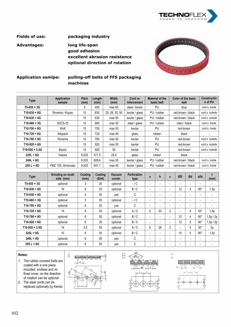
„ I n n o v a t i o n i n m o t i o n ”
Berv ina Kf t . • H -1145 Erzsébet k i rá lyné ú t ja 41/B • Te l . :+36 -1-222-20-79 • Fax: +36 -1-252-48-29 • berv ina@berv ina.com
page 14
POLYURETHAN AND NEOPRENE TIMING BELT WITH RUBBER COVER
Fields of use: Advantages: Application samlpe:
packaging industry long life-span good adhesion excellent abrasion resistance
optional direction of rotation pulling-off belts of FFS packaging machines
Type Application
sample Pitch (mm)
Length (mm)
Width (mm)
Cord re-inforcement
Material of the basic belt
Color of the basic belt
Construction of PU
basic belt kivitele
T5-455 + 3G 5 455 max 65 steel / kevlar PU blue cord s. inside
T10-630 + 6G Rovema / Kopas 10 630 25, 28, 30, 50 kevlar / glass PU / rubber red-brown / black cord s. outside
T10-630 + 4G 10 630 max 50 kevlar / glass PU / rubber red-brown / black cord s. outside
T10-660 + 3G SZCS-25 10 660 max 50 steel / glass PU / rubber natur / black cord s. inside
T10-700 + 6G Wolf 10 700 max 50 kevlar PU red-brown cord s. inside
T10-720 + 6G Altopack 10 720 max 40 glass rubber black -
T10-780 + 6G Rovema 10 780 max 50 kevlar PU red-brown cord s. outside
T10-920 + 6G 10 920 max 50 kevlar PU red-brown cord s. outside
T10-920 + 3.5G Bosch 10 920 50 kevlar PU red-brown cord s. outside
225L + 6G Hassia 9,525 571,5 25,4 glass rubber black -
240L + 6G 9,525 609,6 max 50 kevlar / glass PU / rubber red-brown / black cord s. inside
255 L + 6G FMC 700, Simionate 9,525 647,7 max 40 kevlar / glass PU / rubber red-brown / black cord s. inside
Type Grinding on tooth
side (mm) Coating
(mm) Coating (ShA)
Vacuum constr.
Perforation type
a b c ØD Ød alfa t
(mm)
T5-455 + 3G optional 3 35 optional - / C - - - - - - -
T10-630 + 6G 16 6 35 optional B / C - - - 12 4 90° 1,5p
T10-630 + 4G optional 4 35 yes C - - - - - - -
T10-660 + 3G optional 3 35 optional - / C - - - - - - -
T10-700 + 6G optional 6 35 yes C - - - - - - -
T10-720 + 6G 15 6 35 optional A / C 6 20 2 - 6 45° 1,5p
T10-780 + 6G optional 6 35 optional B / C - - - 12 4 90° 1,5p / 2p
T10-920 + 6G optional 6 35 optional B / C - - - 12 4 90° 1,5p / 2p
T10-920 + 3.5G 14 3,5 35 optional A / C 6 28 2 - 5 30° 2p
225L + 6G 15 6 35 optional B / C - - - 10 5 90° 1,5p
240L + 6G optional 6 35 yes C - - - - - - -
255 L + 6G optional 6 35 yes C - - - - - - -
Notes:
1. The rubber covered belts are coated with a one piece moulded, endless and re-fined cover, so the direction of rotation can be optional
2. The steel cords can be replaced optionally by Kevlar
Fields of use: packaging industry
Advantages: long life-span good adhesion excellent abrasion resistance optional direction of rotation
Application samlpe: pulling-off belts of FFS packaging machines
„ I n n o v a t i o n i n m o t i o n ”
Berv ina Kf t . • H -1145 Erzsébet k i rá lyné ú t ja 41/B • Te l . :+36 -1-222-20-79 • Fax: +36 -1-252-48-29 • berv ina@berv ina.com
page 14
POLYURETHAN AND NEOPRENE TIMING BELT WITH RUBBER COVER
Fields of use: Advantages: Application samlpe:
packaging industry long life-span good adhesion excellent abrasion resistance
optional direction of rotation pulling-off belts of FFS packaging machines
Type Application
sample Pitch (mm)
Length (mm)
Width (mm)
Cord re-inforcement
Material of the basic belt
Color of the basic belt
Construction of PU
basic belt kivitele
T5-455 + 3G 5 455 max 65 steel / kevlar PU blue cord s. inside
T10-630 + 6G Rovema / Kopas 10 630 25, 28, 30, 50 kevlar / glass PU / rubber red-brown / black cord s. outside
T10-630 + 4G 10 630 max 50 kevlar / glass PU / rubber red-brown / black cord s. outside
T10-660 + 3G SZCS-25 10 660 max 50 steel / glass PU / rubber natur / black cord s. inside
T10-700 + 6G Wolf 10 700 max 50 kevlar PU red-brown cord s. inside
T10-720 + 6G Altopack 10 720 max 40 glass rubber black -
T10-780 + 6G Rovema 10 780 max 50 kevlar PU red-brown cord s. outside
T10-920 + 6G 10 920 max 50 kevlar PU red-brown cord s. outside
T10-920 + 3.5G Bosch 10 920 50 kevlar PU red-brown cord s. outside
225L + 6G Hassia 9,525 571,5 25,4 glass rubber black -
240L + 6G 9,525 609,6 max 50 kevlar / glass PU / rubber red-brown / black cord s. inside
255 L + 6G FMC 700, Simionate 9,525 647,7 max 40 kevlar / glass PU / rubber red-brown / black cord s. inside
Type Grinding on tooth
side (mm) Coating
(mm) Coating (ShA)
Vacuum constr.
Perforation type
a b c ØD Ød alfa t
(mm)
T5-455 + 3G optional 3 35 optional - / C - - - - - - -
T10-630 + 6G 16 6 35 optional B / C - - - 12 4 90° 1,5p
T10-630 + 4G optional 4 35 yes C - - - - - - -
T10-660 + 3G optional 3 35 optional - / C - - - - - - -
T10-700 + 6G optional 6 35 yes C - - - - - - -
T10-720 + 6G 15 6 35 optional A / C 6 20 2 - 6 45° 1,5p
T10-780 + 6G optional 6 35 optional B / C - - - 12 4 90° 1,5p / 2p
T10-920 + 6G optional 6 35 optional B / C - - - 12 4 90° 1,5p / 2p
T10-920 + 3.5G 14 3,5 35 optional A / C 6 28 2 - 5 30° 2p
225L + 6G 15 6 35 optional B / C - - - 10 5 90° 1,5p
240L + 6G optional 6 35 yes C - - - - - - -
255 L + 6G optional 6 35 yes C - - - - - - -
Notes:
1. The rubber covered belts are coated with a one piece moulded, endless and re-fined cover, so the direction of rotation can be optional
2. The steel cords can be replaced optionally by Kevlar
Fields of use: packaging industry
Advantages: long life-span good adhesion excellent abrasion resistance optional direction of rotation
Application samlpe: pulling-off belts of FFS packaging machines
„ I n n o v a t i o n i n m o t i o n ”
Berv ina Kf t . • H -1145 Erzsébet k i rá lyné ú t ja 41/B • Te l . :+36 -1-222-20-79 • Fax: +36 -1-252-48-29 • berv ina@berv ina.com
page 14
POLYURETHAN AND NEOPRENE TIMING BELT WITH RUBBER COVER
Fields of use: Advantages: Application samlpe:
packaging industry long life-span good adhesion excellent abrasion resistance
optional direction of rotation pulling-off belts of FFS packaging machines
Type Application
sample Pitch (mm)
Length (mm)
Width (mm)
Cord re-inforcement
Material of the basic belt
Color of the basic belt
Construction of PU
basic belt kivitele
T5-455 + 3G 5 455 max 65 steel / kevlar PU blue cord s. inside
T10-630 + 6G Rovema / Kopas 10 630 25, 28, 30, 50 kevlar / glass PU / rubber red-brown / black cord s. outside
T10-630 + 4G 10 630 max 50 kevlar / glass PU / rubber red-brown / black cord s. outside
T10-660 + 3G SZCS-25 10 660 max 50 steel / glass PU / rubber natur / black cord s. inside
T10-700 + 6G Wolf 10 700 max 50 kevlar PU red-brown cord s. inside
T10-720 + 6G Altopack 10 720 max 40 glass rubber black -
T10-780 + 6G Rovema 10 780 max 50 kevlar PU red-brown cord s. outside
T10-920 + 6G 10 920 max 50 kevlar PU red-brown cord s. outside
T10-920 + 3.5G Bosch 10 920 50 kevlar PU red-brown cord s. outside
225L + 6G Hassia 9,525 571,5 25,4 glass rubber black -
240L + 6G 9,525 609,6 max 50 kevlar / glass PU / rubber red-brown / black cord s. inside
255 L + 6G FMC 700, Simionate 9,525 647,7 max 40 kevlar / glass PU / rubber red-brown / black cord s. inside
Type Grinding on tooth
side (mm) Coating
(mm) Coating (ShA)
Vacuum constr.
Perforation type
a b c ØD Ød alfa t
(mm)
T5-455 + 3G optional 3 35 optional - / C - - - - - - -
T10-630 + 6G 16 6 35 optional B / C - - - 12 4 90° 1,5p
T10-630 + 4G optional 4 35 yes C - - - - - - -
T10-660 + 3G optional 3 35 optional - / C - - - - - - -
T10-700 + 6G optional 6 35 yes C - - - - - - -
T10-720 + 6G 15 6 35 optional A / C 6 20 2 - 6 45° 1,5p
T10-780 + 6G optional 6 35 optional B / C - - - 12 4 90° 1,5p / 2p
T10-920 + 6G optional 6 35 optional B / C - - - 12 4 90° 1,5p / 2p
T10-920 + 3.5G 14 3,5 35 optional A / C 6 28 2 - 5 30° 2p
225L + 6G 15 6 35 optional B / C - - - 10 5 90° 1,5p
240L + 6G optional 6 35 yes C - - - - - - -
255 L + 6G optional 6 35 yes C - - - - - - -
Notes:
1. The rubber covered belts are coated with a one piece moulded, endless and re-fined cover, so the direction of rotation can be optional
2. The steel cords can be replaced optionally by Kevlar
102 102
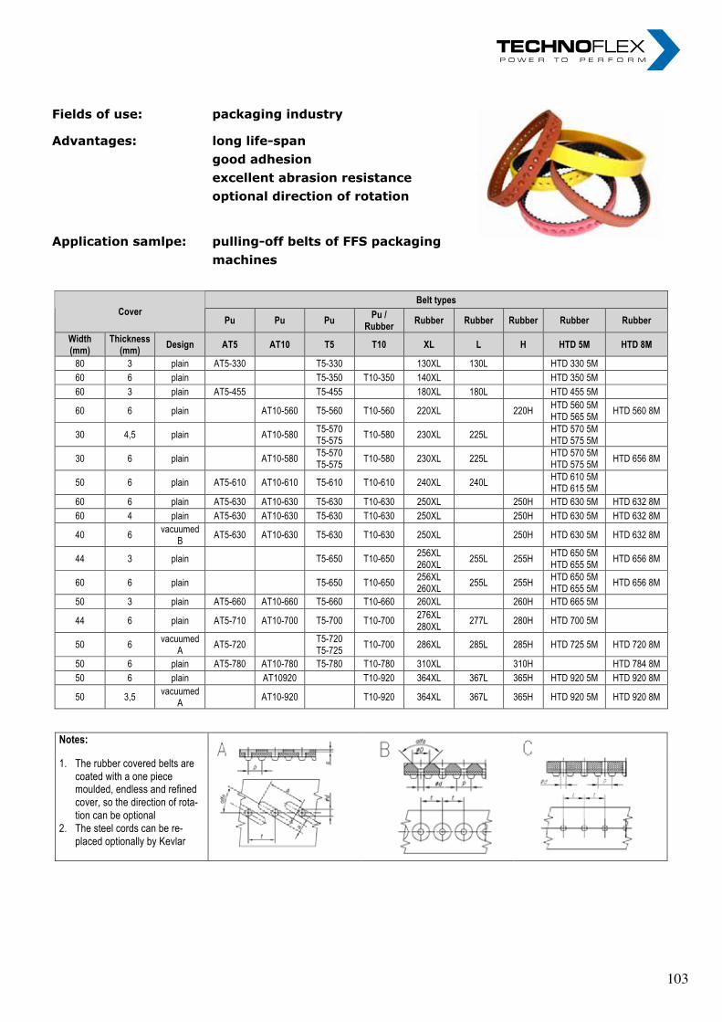
„ I n n o v a t i o n i n m o t i o n ”
Berv ina Kf t . • H -1145 Erzsébet k i rá lyné ú t ja 41/B • Te l . :+36 -1-222-20-79 • Fax: +36 -1-252-48-29 • berv ina@berv ina.com
page 15
SUMMARY FOR THE BELTS WITH SILICON, LINATEX AND RUBBER COVER
Fields of use: Advantages: Application samlpe:
packaging industry long life-span good adhesion excellent abrasion resistance
optional direction of rotation pulling-off belts of FFS packaging machines
Belt types Cover
Pu Pu Pu Pu /
Rubber Rubber Rubber Rubber Rubber Rubber
Width (mm)
Thickness (mm)
Design AT5 AT10 T5 T10 XL L H HTD 5M HTD 8M
80 3 plain AT5-330 T5-330 130XL 130L HTD 330 5M
60 6 plain T5-350 T10-350 140XL HTD 350 5M
60 3 plain AT5-455 T5-455 180XL 180L HTD 455 5M
60 6 plain AT10-560 T5-560 T10-560 220XL 220H HTD 560 5M HTD 565 5M
HTD 560 8M
30 4,5 plain AT10-580 T5-570 T5-575
T10-580 230XL 225L HTD 570 5M HTD 575 5M
30 6 plain AT10-580 T5-570 T5-575
T10-580 230XL 225L HTD 570 5M HTD 575 5M
HTD 656 8M
50 6 plain AT5-610 AT10-610 T5-610 T10-610 240XL 240L HTD 610 5M HTD 615 5M
60 6 plain AT5-630 AT10-630 T5-630 T10-630 250XL 250H HTD 630 5M HTD 632 8M
60 4 plain AT5-630 AT10-630 T5-630 T10-630 250XL 250H HTD 630 5M HTD 632 8M
40 6 vacuumed
B AT5-630 AT10-630 T5-630 T10-630 250XL 250H HTD 630 5M HTD 632 8M
44 3 plain T5-650 T10-650 256XL 260XL
255L 255H HTD 650 5M HTD 655 5M
HTD 656 8M
60 6 plain T5-650 T10-650 256XL 260XL
255L 255H HTD 650 5M HTD 655 5M
HTD 656 8M
50 3 plain AT5-660 AT10-660 T5-660 T10-660 260XL 260H HTD 665 5M
44 6 plain AT5-710 AT10-700 T5-700 T10-700 276XL 280XL
277L 280H HTD 700 5M
50 6 vacuumed
A AT5-720
T5-720 T5-725
T10-700 286XL 285L 285H HTD 725 5M HTD 720 8M
50 6 plain AT5-780 AT10-780 T5-780 T10-780 310XL 310H HTD 784 8M
50 6 plain AT10920 T10-920 364XL 367L 365H HTD 920 5M HTD 920 8M
50 3,5 vacuumed
A AT10-920 T10-920 364XL 367L 365H HTD 920 5M HTD 920 8M
Notes:
1. The rubber covered belts are coated with a one piece moulded, endless and refined cover, so the direction of rota-tion can be optional
2. The steel cords can be re-placed optionally by Kevlar
Fields of use: packaging industry
Advantages: long life-span good adhesion excellent abrasion resistance optional direction of rotation
Application samlpe: pulling-off belts of FFS packaging machines
„ I n n o v a t i o n i n m o t i o n ”
Berv ina Kf t . • H -1145 Erzsébet k i rá lyné ú t ja 41/B • Te l . :+36 -1-222-20-79 • Fax: +36 -1-252-48-29 • berv ina@berv ina.com
page 15
SUMMARY FOR THE BELTS WITH SILICON, LINATEX AND RUBBER COVER
Fields of use: Advantages: Application samlpe:
packaging industry long life-span good adhesion excellent abrasion resistance
optional direction of rotation pulling-off belts of FFS packaging machines
Belt types Cover
Pu Pu Pu Pu /
Rubber Rubber Rubber Rubber Rubber Rubber
Width (mm)
Thickness (mm)
Design AT5 AT10 T5 T10 XL L H HTD 5M HTD 8M
80 3 plain AT5-330 T5-330 130XL 130L HTD 330 5M
60 6 plain T5-350 T10-350 140XL HTD 350 5M
60 3 plain AT5-455 T5-455 180XL 180L HTD 455 5M
60 6 plain AT10-560 T5-560 T10-560 220XL 220H HTD 560 5M HTD 565 5M
HTD 560 8M
30 4,5 plain AT10-580 T5-570 T5-575
T10-580 230XL 225L HTD 570 5M HTD 575 5M
30 6 plain AT10-580 T5-570 T5-575
T10-580 230XL 225L HTD 570 5M HTD 575 5M
HTD 656 8M
50 6 plain AT5-610 AT10-610 T5-610 T10-610 240XL 240L HTD 610 5M HTD 615 5M
60 6 plain AT5-630 AT10-630 T5-630 T10-630 250XL 250H HTD 630 5M HTD 632 8M
60 4 plain AT5-630 AT10-630 T5-630 T10-630 250XL 250H HTD 630 5M HTD 632 8M
40 6 vacuumed
B AT5-630 AT10-630 T5-630 T10-630 250XL 250H HTD 630 5M HTD 632 8M
44 3 plain T5-650 T10-650 256XL 260XL
255L 255H HTD 650 5M HTD 655 5M
HTD 656 8M
60 6 plain T5-650 T10-650 256XL 260XL
255L 255H HTD 650 5M HTD 655 5M
HTD 656 8M
50 3 plain AT5-660 AT10-660 T5-660 T10-660 260XL 260H HTD 665 5M
44 6 plain AT5-710 AT10-700 T5-700 T10-700 276XL 280XL
277L 280H HTD 700 5M
50 6 vacuumed
A AT5-720
T5-720 T5-725
T10-700 286XL 285L 285H HTD 725 5M HTD 720 8M
50 6 plain AT5-780 AT10-780 T5-780 T10-780 310XL 310H HTD 784 8M
50 6 plain AT10920 T10-920 364XL 367L 365H HTD 920 5M HTD 920 8M
50 3,5 vacuumed
A AT10-920 T10-920 364XL 367L 365H HTD 920 5M HTD 920 8M
Notes:
1. The rubber covered belts are coated with a one piece moulded, endless and refined cover, so the direction of rota-tion can be optional
2. The steel cords can be re-placed optionally by Kevlar
Fields of use: packaging industry
Advantages: long life-span good adhesion excellent abrasion resistance optional direction of rotation
Application samlpe: pulling-off belts of FFS packaging machines
„ I n n o v a t i o n i n m o t i o n ”
Berv ina Kf t . • H -1145 Erzsébet k i rá lyné ú t ja 41/B • Te l . :+36 -1-222-20-79 • Fax: +36 -1-252-48-29 • berv ina@berv ina.com
page 15
SUMMARY FOR THE BELTS WITH SILICON, LINATEX AND RUBBER COVER
Fields of use: Advantages: Application samlpe:
packaging industry long life-span good adhesion excellent abrasion resistance
optional direction of rotation pulling-off belts of FFS packaging machines
Belt types Cover
Pu Pu Pu Pu /
Rubber Rubber Rubber Rubber Rubber Rubber
Width (mm)
Thickness (mm)
Design AT5 AT10 T5 T10 XL L H HTD 5M HTD 8M
80 3 plain AT5-330 T5-330 130XL 130L HTD 330 5M
60 6 plain T5-350 T10-350 140XL HTD 350 5M
60 3 plain AT5-455 T5-455 180XL 180L HTD 455 5M
60 6 plain AT10-560 T5-560 T10-560 220XL 220H HTD 560 5M HTD 565 5M
HTD 560 8M
30 4,5 plain AT10-580 T5-570 T5-575
T10-580 230XL 225L HTD 570 5M HTD 575 5M
30 6 plain AT10-580 T5-570 T5-575
T10-580 230XL 225L HTD 570 5M HTD 575 5M
HTD 656 8M
50 6 plain AT5-610 AT10-610 T5-610 T10-610 240XL 240L HTD 610 5M HTD 615 5M
60 6 plain AT5-630 AT10-630 T5-630 T10-630 250XL 250H HTD 630 5M HTD 632 8M
60 4 plain AT5-630 AT10-630 T5-630 T10-630 250XL 250H HTD 630 5M HTD 632 8M
40 6 vacuumed
B AT5-630 AT10-630 T5-630 T10-630 250XL 250H HTD 630 5M HTD 632 8M
44 3 plain T5-650 T10-650 256XL 260XL
255L 255H HTD 650 5M HTD 655 5M
HTD 656 8M
60 6 plain T5-650 T10-650 256XL 260XL
255L 255H HTD 650 5M HTD 655 5M
HTD 656 8M
50 3 plain AT5-660 AT10-660 T5-660 T10-660 260XL 260H HTD 665 5M
44 6 plain AT5-710 AT10-700 T5-700 T10-700 276XL 280XL
277L 280H HTD 700 5M
50 6 vacuumed
A AT5-720
T5-720 T5-725
T10-700 286XL 285L 285H HTD 725 5M HTD 720 8M
50 6 plain AT5-780 AT10-780 T5-780 T10-780 310XL 310H HTD 784 8M
50 6 plain AT10920 T10-920 364XL 367L 365H HTD 920 5M HTD 920 8M
50 3,5 vacuumed
A AT10-920 T10-920 364XL 367L 365H HTD 920 5M HTD 920 8M
Notes:
1. The rubber covered belts are coated with a one piece moulded, endless and refined cover, so the direction of rota-tion can be optional
2. The steel cords can be re-placed optionally by Kevlar
103 103
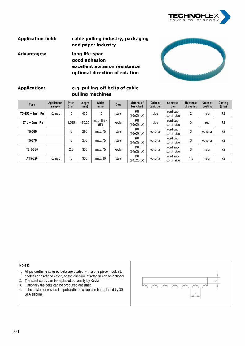
„ I n n o v a t i o n i n m o t i o n ”
Berv ina Kf t . • H -1145 Erzsébet k i rá lyné ú t ja 41/B • Te l . :+36 -1-222-20-79 • Fax: +36 -1-252-48-29 • berv ina@berv ina.com
page 16
POLIURETHANE COVERED TIMING BELTS
Application field: Advantages: Application:
cable pulling industry, packaging and paper industry
long life-span good adhesion
excellent abrasion resistance
optional direction of rotation e.g. pulling-off belts of cable pulling machines
Type Application
sample Pitch (mm)
Lenght (mm)
Width (mm)
Cord Material of basic belt
Color of basic belt
Construc-tion
Thickness of coating
Color of coating
Coating (ShA)
T5-455 + 2mm Pu Komax 5 455 16 steel PU
(90±2ShA) blue
cord sup-port inside
2 natur 72
187 L + 3mm Pu 9,525 476,25 max. 152,4
(6”) kevlar
PU (90±2ShA)
blue cord sup-port inside
3 red 72
T5-260 5 260 max. 75 steel PU
(90±2ShA) optional
cord sup-port inside
3 optional 72
T5-270 5 270 max. 75 steel PU
(90±2ShA) optional
cord sup-port inside
3 optional 72
T2,5-330 2,5 330 max. 75 kevlar PU
(90±2ShA) optional
cord sup-port inside
3 natur 72
AT5-320 Komax 5 320 max. 80 steel PU
(90±2ShA) optional
cord sup-port inside
1,5 natur 72
Notes:
1. All poliurethane covered belts are coated with a one piece moulded, endless and refined cover, so the direction of rotation can be optional
2. The steel cords can be replaced optionally by Kevlar 3. Optionally the belts can be produced antistatic 4. If the customer wishes the poliurethane cover can be replaced by 30
ShA silicone
Application field: cable pulling industry, packaging and paper industry
Advantages: long life-span good adhesion excellent abrasion resistance optional direction of rotation
Application: e.g. pulling-off belts of cable pulling machines
„ I n n o v a t i o n i n m o t i o n ”
Berv ina Kf t . • H -1145 Erzsébet k i rá lyné ú t ja 41/B • Te l . :+36 -1-222-20-79 • Fax: +36 -1-252-48-29 • berv ina@berv ina.com
page 16
POLIURETHANE COVERED TIMING BELTS
Application field: Advantages: Application:
cable pulling industry, packaging and paper industry
long life-span good adhesion
excellent abrasion resistance
optional direction of rotation e.g. pulling-off belts of cable pulling machines
Type Application
sample Pitch (mm)
Lenght (mm)
Width (mm)
Cord Material of basic belt
Color of basic belt
Construc-tion
Thickness of coating
Color of coating
Coating (ShA)
T5-455 + 2mm Pu Komax 5 455 16 steel PU
(90±2ShA) blue
cord sup-port inside
2 natur 72
187 L + 3mm Pu 9,525 476,25 max. 152,4
(6”) kevlar
PU (90±2ShA)
blue cord sup-port inside
3 red 72
T5-260 5 260 max. 75 steel PU
(90±2ShA) optional
cord sup-port inside
3 optional 72
T5-270 5 270 max. 75 steel PU
(90±2ShA) optional
cord sup-port inside
3 optional 72
T2,5-330 2,5 330 max. 75 kevlar PU
(90±2ShA) optional
cord sup-port inside
3 natur 72
AT5-320 Komax 5 320 max. 80 steel PU
(90±2ShA) optional
cord sup-port inside
1,5 natur 72
Notes:
1. All poliurethane covered belts are coated with a one piece moulded, endless and refined cover, so the direction of rotation can be optional
2. The steel cords can be replaced optionally by Kevlar 3. Optionally the belts can be produced antistatic 4. If the customer wishes the poliurethane cover can be replaced by 30
ShA silicone
Application field: cable pulling industry, packaging and paper industry
Advantages: long life-span good adhesion excellent abrasion resistance optional direction of rotation
Application: e.g. pulling-off belts of cable pulling machines
„ I n n o v a t i o n i n m o t i o n ”
Berv ina Kf t . • H -1145 Erzsébet k i rá lyné ú t ja 41/B • Te l . :+36 -1-222-20-79 • Fax: +36 -1-252-48-29 • berv ina@berv ina.com
page 16
POLIURETHANE COVERED TIMING BELTS
Application field: Advantages: Application:
cable pulling industry, packaging and paper industry
long life-span good adhesion
excellent abrasion resistance
optional direction of rotation e.g. pulling-off belts of cable pulling machines
Type Application
sample Pitch (mm)
Lenght (mm)
Width (mm)
Cord Material of basic belt
Color of basic belt
Construc-tion
Thickness of coating
Color of coating
Coating (ShA)
T5-455 + 2mm Pu Komax 5 455 16 steel PU
(90±2ShA) blue
cord sup-port inside
2 natur 72
187 L + 3mm Pu 9,525 476,25 max. 152,4
(6”) kevlar
PU (90±2ShA)
blue cord sup-port inside
3 red 72
T5-260 5 260 max. 75 steel PU
(90±2ShA) optional
cord sup-port inside
3 optional 72
T5-270 5 270 max. 75 steel PU
(90±2ShA) optional
cord sup-port inside
3 optional 72
T2,5-330 2,5 330 max. 75 kevlar PU
(90±2ShA) optional
cord sup-port inside
3 natur 72
AT5-320 Komax 5 320 max. 80 steel PU
(90±2ShA) optional
cord sup-port inside
1,5 natur 72
Notes:
1. All poliurethane covered belts are coated with a one piece moulded, endless and refined cover, so the direction of rotation can be optional
2. The steel cords can be replaced optionally by Kevlar 3. Optionally the belts can be produced antistatic 4. If the customer wishes the poliurethane cover can be replaced by 30
ShA silicone
104 104
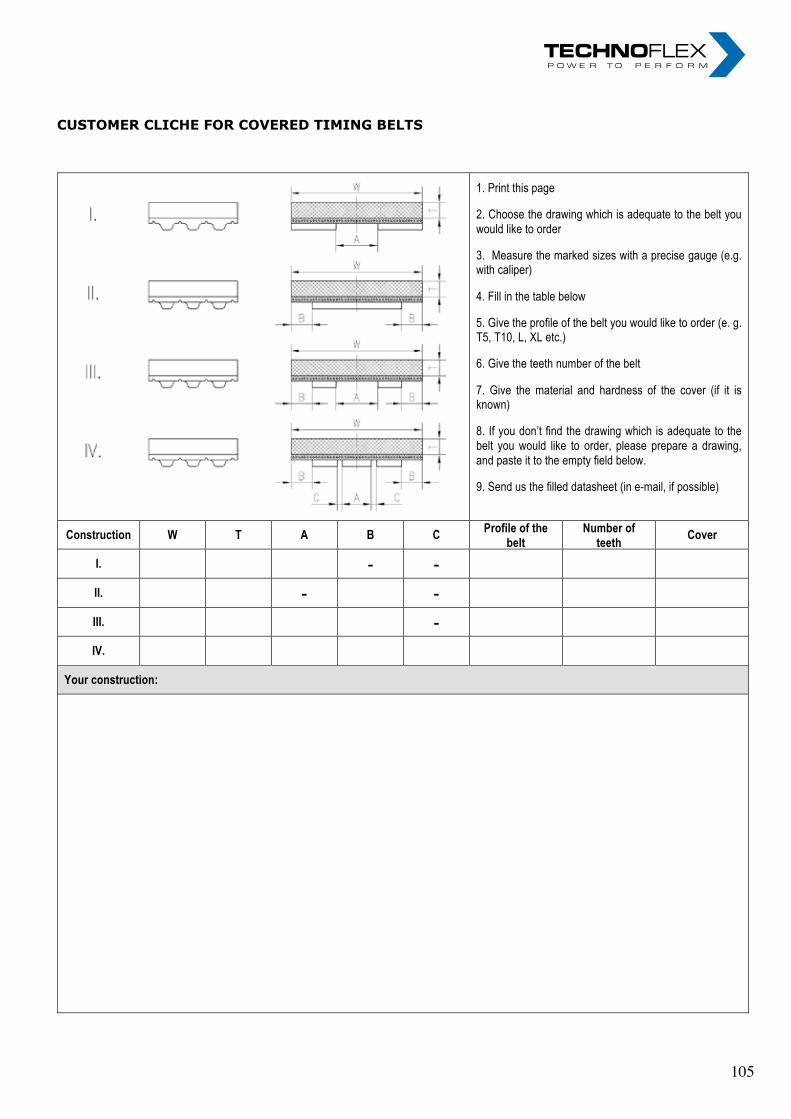
cUStOmer cLicHe FOr cOVereD timing beLtS „ I n n o v a t i o n i n m o t i o n ”
Berv ina Kf t . • H -1145 Erzsébet k i rá lyné ú t ja 41/B • Te l . :+36 -1-222-20-79 • Fax: +36 -1-252-48-29 • berv ina@berv ina.com
page 18
CUSTOMER CLICHE FOR COVERED TIMING BELTS
1. Print this page
2. Choose the drawing which is adequate to the belt you would like to order
3. Measure the marked sizes with a precise gauge (e.g. with caliper)
4. Fill in the table below
5. Give the profile of the belt you would like to order (e. g. T5, T10, L, XL etc.)
6. Give the teeth number of the belt
7. Give the material and hardness of the cover (if it is known)
8. If you don’t find the drawing which is adequate to the belt you would like to order, please prepare a drawing, and paste it to the empty field below.
9. Send us the filled datasheet (in e-mail, if possible)
Construction W T A B C Profile of the
belt Number of
teeth Cover
I. - -
II. - -
III. -
IV.
Your construction:
105 105

nOteS FOr beLtS „ I n n o v a t i o n i n m o t i o n ”
Berv ina Kf t . • H -1145 Erzsébet k i rá lyné út ja 41/B • Te l . :+36 -1-222-20-79 • Fax: +36 -1-252-48-29 • berv ina@berv ina.com
page 19
NOTES FOR BELTS
nOteS FOr beLtS „ I n n o v a t i o n i n m o t i o n ”
Berv ina Kf t . • H -1145 Erzsébet k i rá lyné út ja 41/B • Te l . :+36 -1-222-20-79 • Fax: +36 -1-252-48-29 • berv ina@berv ina.com
page 19
NOTES FOR BELTS
106 106
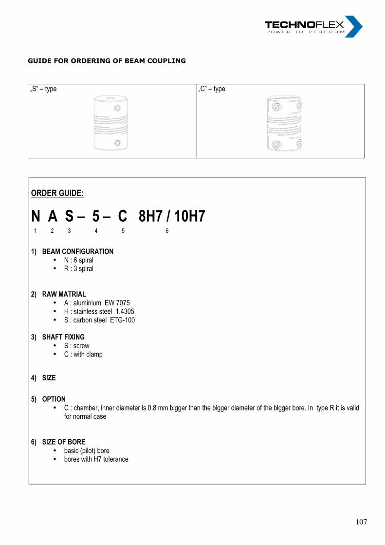
gUiDe FOr OrDering OF beam cOUPLing „ I n n o v a t i o n i n m o t i o n ”
Berv ina Kf t . • H -1145 Erzsébet k i rá lyné ú t ja 41/B • Te l . :+36 -1-222-20-79 • Fax: +36 -1-252-48-29 • berv ina@berv ina.com
page 20
GUIDE FOR ORDERING OF BEAM COUPLING
„S” – type
„C” – type
ORDER GUIDE:
N A S – 5 – C 8H7 / 10H7
1 2 3 4 5 6
1) BEAM CONFIGURATION • N : 6 spiral • R : 3 spiral
2) RAW MATRIAL
• A : aluminium EW 7075 • H : stainless steel 1.4305 • S : carbon steel ETG-100
3) SHAFT FIXING
• S : screw • C : with clamp
4) SIZE
5) OPTION • C : chamber, inner diameter is 0.8 mm bigger than the bigger diameter of the bigger bore. In type R it is valid
for normal case
6) SIZE OF BORE
• basic (pilot) bore • bores with H7 tolerance
107 107
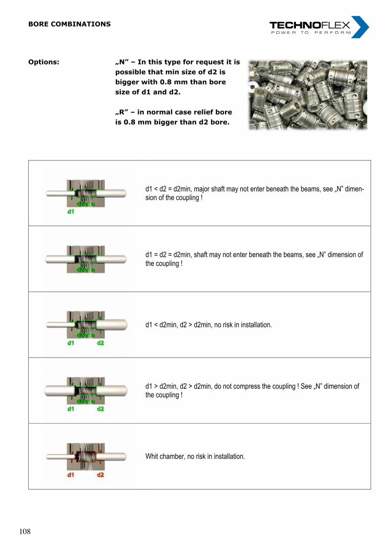
„ I n n o v a t i o n i n m o t i o n ”
Berv ina Kf t . • H -1145 Erzsébet k i rá lyné ú t ja 41/B • Te l . :+36 -1-222-20-79 • Fax: +36 -1-252-48-29 • berv ina@berv ina.com
page 21
BORE COMBINATIONS
Options:
„N” – In this type for request it is possible that min size of d2 is bigger with 0.8 mm than bore size of d1 and d2. „R” – in normal case relief bore is 0.8 mm bigger than d2 bore.
d1 < d2 = d2min, major shaft may not enter beneath the beams, see „N” dimen-sion of the coupling !
d1 = d2 = d2min, shaft may not enter beneath the beams, see „N” dimension of the coupling !
d1 < d2min, d2 > d2min, no risk in installation.
d1 > d2min, d2 > d2min, do not compress the coupling ! See „N” dimension of the coupling !
Whit chamber, no risk in installation.
Options: „N” – In this type for request it is possible that min size of d2 is bigger with 0.8 mm than bore size of d1 and d2.
„R” – in normal case relief bore is 0.8 mm bigger than d2 bore.
bOre cOmbinatiOnS
„ I n n o v a t i o n i n m o t i o n ”
Berv ina Kf t . • H -1145 Erzsébet k i rá lyné ú t ja 41/B • Te l . :+36 -1-222-20-79 • Fax: +36 -1-252-48-29 • berv ina@berv ina.com
page 21
BORE COMBINATIONS
Options:
„N” – In this type for request it is possible that min size of d2 is bigger with 0.8 mm than bore size of d1 and d2. „R” – in normal case relief bore is 0.8 mm bigger than d2 bore.
d1 < d2 = d2min, major shaft may not enter beneath the beams, see „N” dimen-sion of the coupling !
d1 = d2 = d2min, shaft may not enter beneath the beams, see „N” dimension of the coupling !
d1 < d2min, d2 > d2min, no risk in installation.
d1 > d2min, d2 > d2min, do not compress the coupling ! See „N” dimension of the coupling !
Whit chamber, no risk in installation.
Options: „N” – In this type for request it is possible that min size of d2 is bigger with 0.8 mm than bore size of d1 and d2.
„R” – in normal case relief bore is 0.8 mm bigger than d2 bore.
bOre cOmbinatiOnS
„ I n n o v a t i o n i n m o t i o n ”
Berv ina Kf t . • H -1145 Erzsébet k i rá lyné ú t ja 41/B • Te l . :+36 -1-222-20-79 • Fax: +36 -1-252-48-29 • berv ina@berv ina.com
page 21
BORE COMBINATIONS
Options:
„N” – In this type for request it is possible that min size of d2 is bigger with 0.8 mm than bore size of d1 and d2. „R” – in normal case relief bore is 0.8 mm bigger than d2 bore.
d1 < d2 = d2min, major shaft may not enter beneath the beams, see „N” dimen-sion of the coupling !
d1 = d2 = d2min, shaft may not enter beneath the beams, see „N” dimension of the coupling !
d1 < d2min, d2 > d2min, no risk in installation.
d1 > d2min, d2 > d2min, do not compress the coupling ! See „N” dimension of the coupling !
Whit chamber, no risk in installation.
108 108
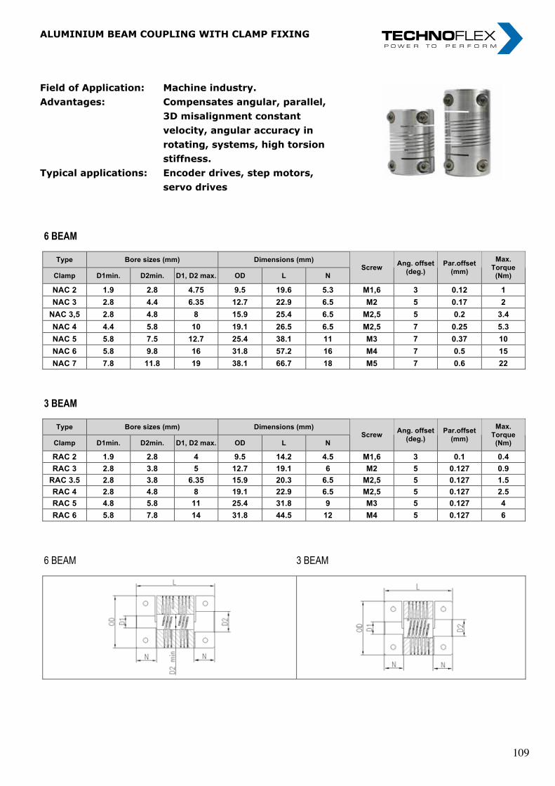
„ I n n o v a t i o n i n m o t i o n ”
Berv ina Kf t . • H -1145 Erzsébet k i rá lyné ú t ja 41/B • Te l . :+36 -1-222-20-79 • Fax: +36 -1-252-48-29 • berv ina@berv ina.com
page 22
ALUMINIUM BEAM COUPLING WITH CLAMP FIXING
Field of Application:
Advantages: Typical applications:
Machine industry.
Compensates angular, parallel, 3D misalignment constant velocity, angular accuracy in rotating, systems, high torsion stiffness. Encoder drives, step motors, servo drives
6 BEAM
Type Bore sizes (mm) Dimensions (mm)
Clamp D1min. D2min. D1, D2 max. OD L N Screw
Ang. offset
(deg.)
Par.offset
(mm)
Max.
Torque (Nm)
NAC 2 1.9 2.8 4.75 9.5 19.6 5.3 M1,6 3 0.12 1
NAC 3 2.8 4.4 6.35 12.7 22.9 6.5 M2 5 0.17 2
NAC 3,5 2.8 4.8 8 15.9 25.4 6.5 M2,5 5 0.2 3.4
NAC 4 4.4 5.8 10 19.1 26.5 6.5 M2,5 7 0.25 5.3
NAC 5 5.8 7.5 12.7 25.4 38.1 11 M3 7 0.37 10
NAC 6 5.8 9.8 16 31.8 57.2 16 M4 7 0.5 15
NAC 7 7.8 11.8 19 38.1 66.7 18 M5 7 0.6 22
3 BEAM
Type Bore sizes (mm) Dimensions (mm)
Clamp D1min. D2min. D1, D2 max. OD L N Screw
Ang. offset
(deg.)
Par.offset
(mm)
Max.
Torque (Nm)
RAC 2 1.9 2.8 4 9.5 14.2 4.5 M1,6 3 0.1 0.4
RAC 3 2.8 3.8 5 12.7 19.1 6 M2 5 0.127 0.9
RAC 3.5 2.8 3.8 6.35 15.9 20.3 6.5 M2,5 5 0.127 1.5
RAC 4 2.8 4.8 8 19.1 22.9 6.5 M2,5 5 0.127 2.5
RAC 5 4.8 5.8 11 25.4 31.8 9 M3 5 0.127 4
RAC 6 5.8 7.8 14 31.8 44.5 12 M4 5 0.127 6
6 BEAM 3 BEAM
Field of Application: Machine industry.Advantages: Compensates angular, parallel, 3D misalignment constant velocity, angular accuracy in rotating, systems, high torsion stiffness.Typical applications: Encoder drives, step motors, servo drives
aLUminiUm beam cOUPLing WitH cLamP Fixing
„ I n n o v a t i o n i n m o t i o n ”
Berv ina Kf t . • H -1145 Erzsébet k i rá lyné ú t ja 41/B • Te l . :+36 -1-222-20-79 • Fax: +36 -1-252-48-29 • berv ina@berv ina.com
page 22
ALUMINIUM BEAM COUPLING WITH CLAMP FIXING
Field of Application:
Advantages: Typical applications:
Machine industry.
Compensates angular, parallel, 3D misalignment constant velocity, angular accuracy in rotating, systems, high torsion stiffness. Encoder drives, step motors, servo drives
6 BEAM
Type Bore sizes (mm) Dimensions (mm)
Clamp D1min. D2min. D1, D2 max. OD L N Screw
Ang. offset
(deg.)
Par.offset
(mm)
Max.
Torque (Nm)
NAC 2 1.9 2.8 4.75 9.5 19.6 5.3 M1,6 3 0.12 1
NAC 3 2.8 4.4 6.35 12.7 22.9 6.5 M2 5 0.17 2
NAC 3,5 2.8 4.8 8 15.9 25.4 6.5 M2,5 5 0.2 3.4
NAC 4 4.4 5.8 10 19.1 26.5 6.5 M2,5 7 0.25 5.3
NAC 5 5.8 7.5 12.7 25.4 38.1 11 M3 7 0.37 10
NAC 6 5.8 9.8 16 31.8 57.2 16 M4 7 0.5 15
NAC 7 7.8 11.8 19 38.1 66.7 18 M5 7 0.6 22
3 BEAM
Type Bore sizes (mm) Dimensions (mm)
Clamp D1min. D2min. D1, D2 max. OD L N Screw
Ang. offset
(deg.)
Par.offset
(mm)
Max.
Torque (Nm)
RAC 2 1.9 2.8 4 9.5 14.2 4.5 M1,6 3 0.1 0.4
RAC 3 2.8 3.8 5 12.7 19.1 6 M2 5 0.127 0.9
RAC 3.5 2.8 3.8 6.35 15.9 20.3 6.5 M2,5 5 0.127 1.5
RAC 4 2.8 4.8 8 19.1 22.9 6.5 M2,5 5 0.127 2.5
RAC 5 4.8 5.8 11 25.4 31.8 9 M3 5 0.127 4
RAC 6 5.8 7.8 14 31.8 44.5 12 M4 5 0.127 6
6 BEAM 3 BEAM
Field of Application: Machine industry.Advantages: Compensates angular, parallel, 3D misalignment constant velocity, angular accuracy in rotating, systems, high torsion stiffness.Typical applications: Encoder drives, step motors, servo drives
aLUminiUm beam cOUPLing WitH cLamP Fixing
„ I n n o v a t i o n i n m o t i o n ”
Berv ina Kf t . • H -1145 Erzsébet k i rá lyné ú t ja 41/B • Te l . :+36 -1-222-20-79 • Fax: +36 -1-252-48-29 • berv ina@berv ina.com
page 22
ALUMINIUM BEAM COUPLING WITH CLAMP FIXING
Field of Application:
Advantages: Typical applications:
Machine industry.
Compensates angular, parallel, 3D misalignment constant velocity, angular accuracy in rotating, systems, high torsion stiffness. Encoder drives, step motors, servo drives
6 BEAM
Type Bore sizes (mm) Dimensions (mm)
Clamp D1min. D2min. D1, D2 max. OD L N Screw
Ang. offset
(deg.)
Par.offset
(mm)
Max.
Torque (Nm)
NAC 2 1.9 2.8 4.75 9.5 19.6 5.3 M1,6 3 0.12 1
NAC 3 2.8 4.4 6.35 12.7 22.9 6.5 M2 5 0.17 2
NAC 3,5 2.8 4.8 8 15.9 25.4 6.5 M2,5 5 0.2 3.4
NAC 4 4.4 5.8 10 19.1 26.5 6.5 M2,5 7 0.25 5.3
NAC 5 5.8 7.5 12.7 25.4 38.1 11 M3 7 0.37 10
NAC 6 5.8 9.8 16 31.8 57.2 16 M4 7 0.5 15
NAC 7 7.8 11.8 19 38.1 66.7 18 M5 7 0.6 22
3 BEAM
Type Bore sizes (mm) Dimensions (mm)
Clamp D1min. D2min. D1, D2 max. OD L N Screw
Ang. offset
(deg.)
Par.offset
(mm)
Max.
Torque (Nm)
RAC 2 1.9 2.8 4 9.5 14.2 4.5 M1,6 3 0.1 0.4
RAC 3 2.8 3.8 5 12.7 19.1 6 M2 5 0.127 0.9
RAC 3.5 2.8 3.8 6.35 15.9 20.3 6.5 M2,5 5 0.127 1.5
RAC 4 2.8 4.8 8 19.1 22.9 6.5 M2,5 5 0.127 2.5
RAC 5 4.8 5.8 11 25.4 31.8 9 M3 5 0.127 4
RAC 6 5.8 7.8 14 31.8 44.5 12 M4 5 0.127 6
6 BEAM 3 BEAM
109 109
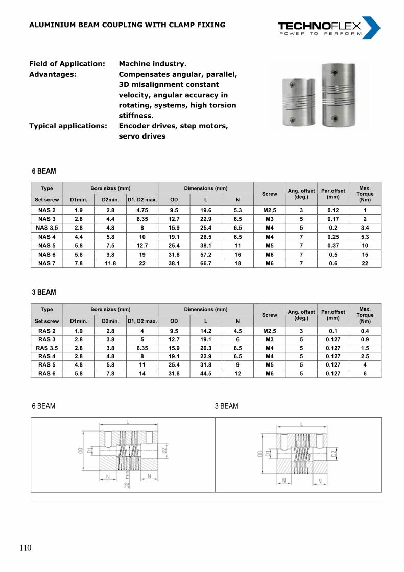
„ I n n o v a t i o n i n m o t i o n ”
Berv ina Kf t . • H -1145 Erzsébet k i rá lyné ú t ja 41/B • Te l . :+36 -1-222-20-79 • Fax: +36 -1-252-48-29 • berv ina@berv ina.com
page 23
ALUMINIUM BEAM COUPLING WITH SCREW FIXING
Application field:
Advantages:
Typical applications:
Machine industry
Compensates angular, parallel, 3D misalignment constant velocity, angular accuracy in rotating, systems, high torsion stiffness.
Encoder drives, step motors, servo drives
6 BEAM
Type Bore sizes (mm) Dimensions (mm)
Set screw D1min. D2min. D1, D2 max. OD L N Screw
Ang. offset
(deg.)
Par.offset
(mm)
Max.
Torque (Nm)
NAS 2 1.9 2.8 4.75 9.5 19.6 5.3 M2,5 3 0.12 1
NAS 3 2.8 4.4 6.35 12.7 22.9 6.5 M3 5 0.17 2
NAS 3,5 2.8 4.8 8 15.9 25.4 6.5 M4 5 0.2 3.4
NAS 4 4.4 5.8 10 19.1 26.5 6.5 M4 7 0.25 5.3
NAS 5 5.8 7.5 12.7 25.4 38.1 11 M5 7 0.37 10
NAS 6 5.8 9.8 19 31.8 57.2 16 M6 7 0.5 15
NAS 7 7.8 11.8 22 38.1 66.7 18 M6 7 0.6 22
3 BEAM
Type Bore sizes (mm) Dimensions (mm)
Set screw D1min. D2min. D1, D2 max. OD L N Screw
Ang. offset
(deg.)
Par.offset
(mm)
Max.
Torque (Nm)
RAS 2 1.9 2.8 4 9.5 14.2 4.5 M2,5 3 0.1 0.4
RAS 3 2.8 3.8 5 12.7 19.1 6 M3 5 0.127 0.9
RAS 3.5 2.8 3.8 6.35 15.9 20.3 6.5 M4 5 0.127 1.5
RAS 4 2.8 4.8 8 19.1 22.9 6.5 M4 5 0.127 2.5
RAS 5 4.8 5.8 11 25.4 31.8 9 M5 5 0.127 4
RAS 6 5.8 7.8 14 31.8 44.5 12 M6 5 0.127 6
6 BEAM 3 BEAM
Field of Application: Machine industry.Advantages: Compensates angular, parallel, 3D misalignment constant velocity, angular accuracy in rotating, systems, high torsion stiffness.Typical applications: Encoder drives, step motors, servo drives
aLUminiUm beam cOUPLing WitH cLamP Fixing
„ I n n o v a t i o n i n m o t i o n ”
Berv ina Kf t . • H -1145 Erzsébet k i rá lyné ú t ja 41/B • Te l . :+36 -1-222-20-79 • Fax: +36 -1-252-48-29 • berv ina@berv ina.com
page 23
ALUMINIUM BEAM COUPLING WITH SCREW FIXING
Application field:
Advantages:
Typical applications:
Machine industry
Compensates angular, parallel, 3D misalignment constant velocity, angular accuracy in rotating, systems, high torsion stiffness.
Encoder drives, step motors, servo drives
6 BEAM
Type Bore sizes (mm) Dimensions (mm)
Set screw D1min. D2min. D1, D2 max. OD L N Screw
Ang. offset
(deg.)
Par.offset
(mm)
Max.
Torque (Nm)
NAS 2 1.9 2.8 4.75 9.5 19.6 5.3 M2,5 3 0.12 1
NAS 3 2.8 4.4 6.35 12.7 22.9 6.5 M3 5 0.17 2
NAS 3,5 2.8 4.8 8 15.9 25.4 6.5 M4 5 0.2 3.4
NAS 4 4.4 5.8 10 19.1 26.5 6.5 M4 7 0.25 5.3
NAS 5 5.8 7.5 12.7 25.4 38.1 11 M5 7 0.37 10
NAS 6 5.8 9.8 19 31.8 57.2 16 M6 7 0.5 15
NAS 7 7.8 11.8 22 38.1 66.7 18 M6 7 0.6 22
3 BEAM
Type Bore sizes (mm) Dimensions (mm)
Set screw D1min. D2min. D1, D2 max. OD L N Screw
Ang. offset
(deg.)
Par.offset
(mm)
Max.
Torque (Nm)
RAS 2 1.9 2.8 4 9.5 14.2 4.5 M2,5 3 0.1 0.4
RAS 3 2.8 3.8 5 12.7 19.1 6 M3 5 0.127 0.9
RAS 3.5 2.8 3.8 6.35 15.9 20.3 6.5 M4 5 0.127 1.5
RAS 4 2.8 4.8 8 19.1 22.9 6.5 M4 5 0.127 2.5
RAS 5 4.8 5.8 11 25.4 31.8 9 M5 5 0.127 4
RAS 6 5.8 7.8 14 31.8 44.5 12 M6 5 0.127 6
6 BEAM 3 BEAM
Field of Application: Machine industry.Advantages: Compensates angular, parallel, 3D misalignment constant velocity, angular accuracy in rotating, systems, high torsion stiffness.Typical applications: Encoder drives, step motors, servo drives
aLUminiUm beam cOUPLing WitH cLamP Fixing
„ I n n o v a t i o n i n m o t i o n ”
Berv ina Kf t . • H -1145 Erzsébet k i rá lyné ú t ja 41/B • Te l . :+36 -1-222-20-79 • Fax: +36 -1-252-48-29 • berv ina@berv ina.com
page 23
ALUMINIUM BEAM COUPLING WITH SCREW FIXING
Application field:
Advantages:
Typical applications:
Machine industry
Compensates angular, parallel, 3D misalignment constant velocity, angular accuracy in rotating, systems, high torsion stiffness.
Encoder drives, step motors, servo drives
6 BEAM
Type Bore sizes (mm) Dimensions (mm)
Set screw D1min. D2min. D1, D2 max. OD L N Screw
Ang. offset
(deg.)
Par.offset
(mm)
Max.
Torque (Nm)
NAS 2 1.9 2.8 4.75 9.5 19.6 5.3 M2,5 3 0.12 1
NAS 3 2.8 4.4 6.35 12.7 22.9 6.5 M3 5 0.17 2
NAS 3,5 2.8 4.8 8 15.9 25.4 6.5 M4 5 0.2 3.4
NAS 4 4.4 5.8 10 19.1 26.5 6.5 M4 7 0.25 5.3
NAS 5 5.8 7.5 12.7 25.4 38.1 11 M5 7 0.37 10
NAS 6 5.8 9.8 19 31.8 57.2 16 M6 7 0.5 15
NAS 7 7.8 11.8 22 38.1 66.7 18 M6 7 0.6 22
3 BEAM
Type Bore sizes (mm) Dimensions (mm)
Set screw D1min. D2min. D1, D2 max. OD L N Screw
Ang. offset
(deg.)
Par.offset
(mm)
Max.
Torque (Nm)
RAS 2 1.9 2.8 4 9.5 14.2 4.5 M2,5 3 0.1 0.4
RAS 3 2.8 3.8 5 12.7 19.1 6 M3 5 0.127 0.9
RAS 3.5 2.8 3.8 6.35 15.9 20.3 6.5 M4 5 0.127 1.5
RAS 4 2.8 4.8 8 19.1 22.9 6.5 M4 5 0.127 2.5
RAS 5 4.8 5.8 11 25.4 31.8 9 M5 5 0.127 4
RAS 6 5.8 7.8 14 31.8 44.5 12 M6 5 0.127 6
6 BEAM 3 BEAM
110 110
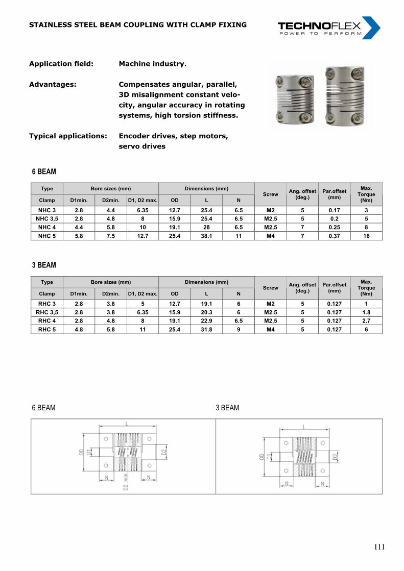
„ I n n o v a t i o n i n m o t i o n ”
Berv ina Kf t . • H -1145 Erzsébet k i rá lyné ú t ja 41/B • Te l . :+36 -1-222-20-79 • Fax: +36 -1-252-48-29 • berv ina@berv ina.com
page 24
STAINLESS STEEL BEAM COUPLING WITH CLAMP FIXING
Application field:
Advantages:
Typical applications:
Machine industry.
Compensates angular, parallel, 3D misalignment constant velocity, angular accuracy in rotating systems, high torsion stiffness.
Encoder drives, step motors, servo drives
6 BEAM
Type Bore sizes (mm) Dimensions (mm)
Clamp D1min. D2min. D1, D2 max. OD L N Screw
Ang. offset
(deg.)
Par.offset
(mm)
Max.
Torque (Nm)
NHC 3 2.8 4.4 6.35 12.7 25.4 6.5 M2 5 0.17 3
NHC 3,5 2.8 4.8 8 15.9 25.4 6.5 M2,5 5 0.2 5
NHC 4 4.4 5.8 10 19.1 28 6.5 M2,5 7 0.25 8
NHC 5 5.8 7.5 12.7 25.4 38.1 11 M4 7 0.37 16
3 BEAM
Type Bore sizes (mm) Dimensions (mm)
Clamp D1min. D2min. D1, D2 max. OD L N Screw
Ang. offset
(deg.)
Par.offset
(mm)
Max.
Torque (Nm)
RHC 3 2.8 3.8 5 12.7 19.1 6 M2 5 0.127 1
RHC 3,5 2.8 3.8 6.35 15.9 20.3 6 M2.5 5 0.127 1.8
RHC 4 2.8 4.8 8 19.1 22.9 6.5 M2,5 5 0.127 2.7
RHC 5 4.8 5.8 11 25.4 31.8 9 M4 5 0.127 6
6 BEAM 3 BEAM
Application field: Machine industry.
Advantages: Compensates angular, parallel, 3D misalignment constant velo- city, angular accuracy in rotating systems, high torsion stiffness.
Typical applications: Encoder drives, step motors, servo drives
StainLeSS SteeL beam cOUPLing WitH cLamP Fixing
„ I n n o v a t i o n i n m o t i o n ”
Berv ina Kf t . • H -1145 Erzsébet k i rá lyné ú t ja 41/B • Te l . :+36 -1-222-20-79 • Fax: +36 -1-252-48-29 • berv ina@berv ina.com
page 24
STAINLESS STEEL BEAM COUPLING WITH CLAMP FIXING
Application field:
Advantages:
Typical applications:
Machine industry.
Compensates angular, parallel, 3D misalignment constant velocity, angular accuracy in rotating systems, high torsion stiffness.
Encoder drives, step motors, servo drives
6 BEAM
Type Bore sizes (mm) Dimensions (mm)
Clamp D1min. D2min. D1, D2 max. OD L N Screw
Ang. offset
(deg.)
Par.offset
(mm)
Max.
Torque (Nm)
NHC 3 2.8 4.4 6.35 12.7 25.4 6.5 M2 5 0.17 3
NHC 3,5 2.8 4.8 8 15.9 25.4 6.5 M2,5 5 0.2 5
NHC 4 4.4 5.8 10 19.1 28 6.5 M2,5 7 0.25 8
NHC 5 5.8 7.5 12.7 25.4 38.1 11 M4 7 0.37 16
3 BEAM
Type Bore sizes (mm) Dimensions (mm)
Clamp D1min. D2min. D1, D2 max. OD L N Screw
Ang. offset
(deg.)
Par.offset
(mm)
Max.
Torque (Nm)
RHC 3 2.8 3.8 5 12.7 19.1 6 M2 5 0.127 1
RHC 3,5 2.8 3.8 6.35 15.9 20.3 6 M2.5 5 0.127 1.8
RHC 4 2.8 4.8 8 19.1 22.9 6.5 M2,5 5 0.127 2.7
RHC 5 4.8 5.8 11 25.4 31.8 9 M4 5 0.127 6
6 BEAM 3 BEAM
Application field: Machine industry.
Advantages: Compensates angular, parallel, 3D misalignment constant velo- city, angular accuracy in rotating systems, high torsion stiffness.
Typical applications: Encoder drives, step motors, servo drives
StainLeSS SteeL beam cOUPLing WitH cLamP Fixing
„ I n n o v a t i o n i n m o t i o n ”
Berv ina Kf t . • H -1145 Erzsébet k i rá lyné ú t ja 41/B • Te l . :+36 -1-222-20-79 • Fax: +36 -1-252-48-29 • berv ina@berv ina.com
page 24
STAINLESS STEEL BEAM COUPLING WITH CLAMP FIXING
Application field:
Advantages:
Typical applications:
Machine industry.
Compensates angular, parallel, 3D misalignment constant velocity, angular accuracy in rotating systems, high torsion stiffness.
Encoder drives, step motors, servo drives
6 BEAM
Type Bore sizes (mm) Dimensions (mm)
Clamp D1min. D2min. D1, D2 max. OD L N Screw
Ang. offset
(deg.)
Par.offset
(mm)
Max.
Torque (Nm)
NHC 3 2.8 4.4 6.35 12.7 25.4 6.5 M2 5 0.17 3
NHC 3,5 2.8 4.8 8 15.9 25.4 6.5 M2,5 5 0.2 5
NHC 4 4.4 5.8 10 19.1 28 6.5 M2,5 7 0.25 8
NHC 5 5.8 7.5 12.7 25.4 38.1 11 M4 7 0.37 16
3 BEAM
Type Bore sizes (mm) Dimensions (mm)
Clamp D1min. D2min. D1, D2 max. OD L N Screw
Ang. offset
(deg.)
Par.offset
(mm)
Max.
Torque (Nm)
RHC 3 2.8 3.8 5 12.7 19.1 6 M2 5 0.127 1
RHC 3,5 2.8 3.8 6.35 15.9 20.3 6 M2.5 5 0.127 1.8
RHC 4 2.8 4.8 8 19.1 22.9 6.5 M2,5 5 0.127 2.7
RHC 5 4.8 5.8 11 25.4 31.8 9 M4 5 0.127 6
6 BEAM 3 BEAM
111 111
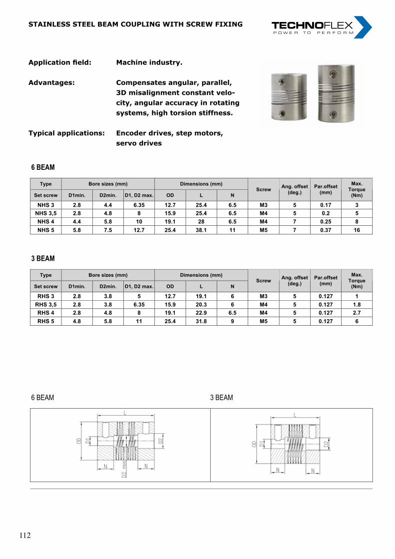
„ I n n o v a t i o n i n m o t i o n ”
Berv ina Kf t . • H -1145 Erzsébet k i rá lyné ú t ja 41/B • Te l . :+36 -1-222-20-79 • Fax: +36 -1-252-48-29 • berv ina@berv ina.com
page 25
STAINLESS STEEL BEAM COUPLING WITH SCREW FIXING
Application field:
Advantages:
Typical applications:
Machine industry.
Compensates angular, parallel, 3D misalignment constant velocity, angular accuracy in rotating systems, high torsion stiffness.
Encoder drives, step motors, servo drives
6 BEAM
Type Bore sizes (mm) Dimensions (mm)
Set screw D1min. D2min. D1, D2 max. OD L N Screw
Ang. offset
(deg.)
Par.offset
(mm)
Max.
Torque (Nm)
NHS 3 2.8 4.4 6.35 12.7 25.4 6.5 M3 5 0.17 3
NHS 3,5 2.8 4.8 8 15.9 25.4 6.5 M4 5 0.2 5
NHS 4 4.4 5.8 10 19.1 28 6.5 M4 7 0.25 8
NHS 5 5.8 7.5 12.7 25.4 38.1 11 M5 7 0.37 16
3 BEAM
Type Bore sizes (mm) Dimensions (mm)
Set screw D1min. D2min. D1, D2 max. OD L N Screw
Ang. offset
(deg.)
Par.offset
(mm)
Max.
Torque (Nm)
RHS 3 2.8 3.8 5 12.7 19.1 6 M3 5 0.127 1
RHS 3,5 2.8 3.8 6.35 15.9 20.3 6 M4 5 0.127 1.8
RHS 4 2.8 4.8 8 19.1 22.9 6.5 M4 5 0.127 2.7
RHS 5 4.8 5.8 11 25.4 31.8 9 M5 5 0.127 6
6 BEAM 3 BEAM
Application field: Machine industry.
Advantages: Compensates angular, parallel, 3D misalignment constant velo- city, angular accuracy in rotating systems, high torsion stiffness.
Typical applications: Encoder drives, step motors, servo drives
StainLeSS SteeL beam cOUPLing WitH ScreW Fixing
„ I n n o v a t i o n i n m o t i o n ”
Berv ina Kf t . • H -1145 Erzsébet k i rá lyné ú t ja 41/B • Te l . :+36 -1-222-20-79 • Fax: +36 -1-252-48-29 • berv ina@berv ina.com
page 25
STAINLESS STEEL BEAM COUPLING WITH SCREW FIXING
Application field:
Advantages:
Typical applications:
Machine industry.
Compensates angular, parallel, 3D misalignment constant velocity, angular accuracy in rotating systems, high torsion stiffness.
Encoder drives, step motors, servo drives
6 BEAM
Type Bore sizes (mm) Dimensions (mm)
Set screw D1min. D2min. D1, D2 max. OD L N Screw
Ang. offset
(deg.)
Par.offset
(mm)
Max.
Torque (Nm)
NHS 3 2.8 4.4 6.35 12.7 25.4 6.5 M3 5 0.17 3
NHS 3,5 2.8 4.8 8 15.9 25.4 6.5 M4 5 0.2 5
NHS 4 4.4 5.8 10 19.1 28 6.5 M4 7 0.25 8
NHS 5 5.8 7.5 12.7 25.4 38.1 11 M5 7 0.37 16
3 BEAM
Type Bore sizes (mm) Dimensions (mm)
Set screw D1min. D2min. D1, D2 max. OD L N Screw
Ang. offset
(deg.)
Par.offset
(mm)
Max.
Torque (Nm)
RHS 3 2.8 3.8 5 12.7 19.1 6 M3 5 0.127 1
RHS 3,5 2.8 3.8 6.35 15.9 20.3 6 M4 5 0.127 1.8
RHS 4 2.8 4.8 8 19.1 22.9 6.5 M4 5 0.127 2.7
RHS 5 4.8 5.8 11 25.4 31.8 9 M5 5 0.127 6
6 BEAM 3 BEAM
Application field: Machine industry.
Advantages: Compensates angular, parallel, 3D misalignment constant velo- city, angular accuracy in rotating systems, high torsion stiffness.
Typical applications: Encoder drives, step motors, servo drives
StainLeSS SteeL beam cOUPLing WitH ScreW Fixing
„ I n n o v a t i o n i n m o t i o n ”
Berv ina Kf t . • H -1145 Erzsébet k i rá lyné ú t ja 41/B • Te l . :+36 -1-222-20-79 • Fax: +36 -1-252-48-29 • berv ina@berv ina.com
page 25
STAINLESS STEEL BEAM COUPLING WITH SCREW FIXING
Application field:
Advantages:
Typical applications:
Machine industry.
Compensates angular, parallel, 3D misalignment constant velocity, angular accuracy in rotating systems, high torsion stiffness.
Encoder drives, step motors, servo drives
6 BEAM
Type Bore sizes (mm) Dimensions (mm)
Set screw D1min. D2min. D1, D2 max. OD L N Screw
Ang. offset
(deg.)
Par.offset
(mm)
Max.
Torque (Nm)
NHS 3 2.8 4.4 6.35 12.7 25.4 6.5 M3 5 0.17 3
NHS 3,5 2.8 4.8 8 15.9 25.4 6.5 M4 5 0.2 5
NHS 4 4.4 5.8 10 19.1 28 6.5 M4 7 0.25 8
NHS 5 5.8 7.5 12.7 25.4 38.1 11 M5 7 0.37 16
3 BEAM
Type Bore sizes (mm) Dimensions (mm)
Set screw D1min. D2min. D1, D2 max. OD L N Screw
Ang. offset
(deg.)
Par.offset
(mm)
Max.
Torque (Nm)
RHS 3 2.8 3.8 5 12.7 19.1 6 M3 5 0.127 1
RHS 3,5 2.8 3.8 6.35 15.9 20.3 6 M4 5 0.127 1.8
RHS 4 2.8 4.8 8 19.1 22.9 6.5 M4 5 0.127 2.7
RHS 5 4.8 5.8 11 25.4 31.8 9 M5 5 0.127 6
6 BEAM 3 BEAM
112 112
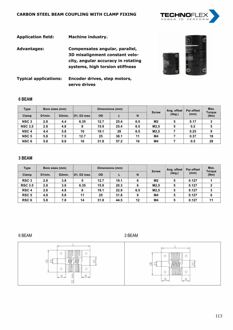
„ I n n o v a t i o n i n m o t i o n ”
Berv ina Kf t . • H -1145 Erzsébet k i rá lyné ú t ja 41/B • Te l . :+36 -1-222-20-79 • Fax: +36 -1-252-48-29 • berv ina@berv ina.com
page 26
CARBON STEEL BEAM COUPLING WITH CLAMP FIXING
Application field:
Advantages:
Typical applications:
Machine industry
Compensates angular, parallel, 3D misalignment constant velocity, angular accuracy in rotating systems, high torsion stiffness
Encoder drives, step motors, servo drives
6 BEAM
Type Bore sizes (mm) Dimensions (mm)
Clamp D1min. D2min. D1, D2 max. OD L N Screw
Ang. offset
(deg.)
Par.offset
(mm)
Max.
Torque (Nm)
NSC 3 2.8 4.4 6.35 12.7 25.4 6.5 M2 5 0.17 3
NSC 3,5 2.8 4.8 8 15.9 25.4 6.5 M2,5 5 0.2 5
NSC 4 4.4 5.8 10 19.1 28 6.5 M2,5 7 0.25 9
NSC 5 5.8 7.5 12.7 25 38.1 11 M4 7 0.37 18
NSC 6 5.8 9.8 16 31.8 57.2 16 M4 7 0.5 28
3 BEAM
Type Bore sizes (mm) Dimensions (mm)
Clamp D1min. D2min. D1, D2 max. OD L N Screw
Ang. offset (deg.)
Par.offset (mm)
Max. Torque
(Nm)
RSC 3 2.8 3.8 5 12.7 19.1 6 M2 5 0.127 1
RSC 3.5 2.8 3.8 6.35 15.9 20.3 6 M2,5 5 0.127 2
RSC 4 2.8 4.8 8 19.1 22.9 6.5 M2,5 5 0.127 3
RSC 5 4.8 5.8 11 25 31.8 9 M4 5 0.127 6
RSC 6 5.8 7.8 14 31.8 44.5 12 M4 5 0.127 11
6 BEAM 3 BEAM
Application field: Machine industry.
Advantages: Compensates angular, parallel, 3D misalignment constant velo- city, angular accuracy in rotating systems, high torsion stiffness
Typical applications: Encoder drives, step motors, servo drives
carbOn SteeL beam cOUPLing WitH cLamP Fixing
„ I n n o v a t i o n i n m o t i o n ”
Berv ina Kf t . • H -1145 Erzsébet k i rá lyné ú t ja 41/B • Te l . :+36 -1-222-20-79 • Fax: +36 -1-252-48-29 • berv ina@berv ina.com
page 26
CARBON STEEL BEAM COUPLING WITH CLAMP FIXING
Application field:
Advantages:
Typical applications:
Machine industry
Compensates angular, parallel, 3D misalignment constant velocity, angular accuracy in rotating systems, high torsion stiffness
Encoder drives, step motors, servo drives
6 BEAM
Type Bore sizes (mm) Dimensions (mm)
Clamp D1min. D2min. D1, D2 max. OD L N Screw
Ang. offset
(deg.)
Par.offset
(mm)
Max.
Torque (Nm)
NSC 3 2.8 4.4 6.35 12.7 25.4 6.5 M2 5 0.17 3
NSC 3,5 2.8 4.8 8 15.9 25.4 6.5 M2,5 5 0.2 5
NSC 4 4.4 5.8 10 19.1 28 6.5 M2,5 7 0.25 9
NSC 5 5.8 7.5 12.7 25 38.1 11 M4 7 0.37 18
NSC 6 5.8 9.8 16 31.8 57.2 16 M4 7 0.5 28
3 BEAM
Type Bore sizes (mm) Dimensions (mm)
Clamp D1min. D2min. D1, D2 max. OD L N Screw
Ang. offset (deg.)
Par.offset (mm)
Max. Torque
(Nm)
RSC 3 2.8 3.8 5 12.7 19.1 6 M2 5 0.127 1
RSC 3.5 2.8 3.8 6.35 15.9 20.3 6 M2,5 5 0.127 2
RSC 4 2.8 4.8 8 19.1 22.9 6.5 M2,5 5 0.127 3
RSC 5 4.8 5.8 11 25 31.8 9 M4 5 0.127 6
RSC 6 5.8 7.8 14 31.8 44.5 12 M4 5 0.127 11
6 BEAM 3 BEAM
Application field: Machine industry.
Advantages: Compensates angular, parallel, 3D misalignment constant velo- city, angular accuracy in rotating systems, high torsion stiffness
Typical applications: Encoder drives, step motors, servo drives
carbOn SteeL beam cOUPLing WitH cLamP Fixing
„ I n n o v a t i o n i n m o t i o n ”
Berv ina Kf t . • H -1145 Erzsébet k i rá lyné ú t ja 41/B • Te l . :+36 -1-222-20-79 • Fax: +36 -1-252-48-29 • berv ina@berv ina.com
page 26
CARBON STEEL BEAM COUPLING WITH CLAMP FIXING
Application field:
Advantages:
Typical applications:
Machine industry
Compensates angular, parallel, 3D misalignment constant velocity, angular accuracy in rotating systems, high torsion stiffness
Encoder drives, step motors, servo drives
6 BEAM
Type Bore sizes (mm) Dimensions (mm)
Clamp D1min. D2min. D1, D2 max. OD L N Screw
Ang. offset
(deg.)
Par.offset
(mm)
Max.
Torque (Nm)
NSC 3 2.8 4.4 6.35 12.7 25.4 6.5 M2 5 0.17 3
NSC 3,5 2.8 4.8 8 15.9 25.4 6.5 M2,5 5 0.2 5
NSC 4 4.4 5.8 10 19.1 28 6.5 M2,5 7 0.25 9
NSC 5 5.8 7.5 12.7 25 38.1 11 M4 7 0.37 18
NSC 6 5.8 9.8 16 31.8 57.2 16 M4 7 0.5 28
3 BEAM
Type Bore sizes (mm) Dimensions (mm)
Clamp D1min. D2min. D1, D2 max. OD L N Screw
Ang. offset (deg.)
Par.offset (mm)
Max. Torque
(Nm)
RSC 3 2.8 3.8 5 12.7 19.1 6 M2 5 0.127 1
RSC 3.5 2.8 3.8 6.35 15.9 20.3 6 M2,5 5 0.127 2
RSC 4 2.8 4.8 8 19.1 22.9 6.5 M2,5 5 0.127 3
RSC 5 4.8 5.8 11 25 31.8 9 M4 5 0.127 6
RSC 6 5.8 7.8 14 31.8 44.5 12 M4 5 0.127 11
6 BEAM 3 BEAM
113 113
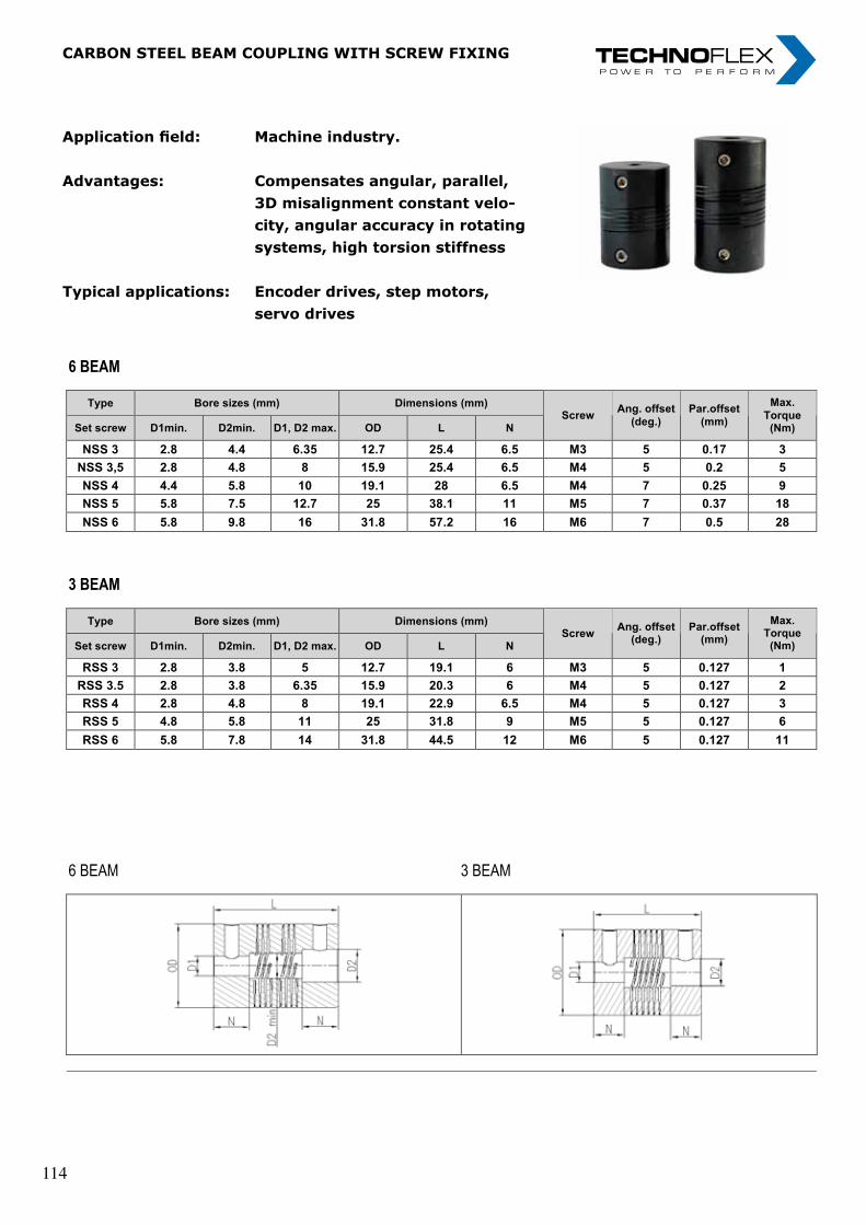
„ I n n o v a t i o n i n m o t i o n ”
Berv ina Kf t . • H -1145 Erzsébet k i rá lyné ú t ja 41/B • Te l . :+36 -1-222-20-79 • Fax: +36 -1-252-48-29 • berv ina@berv ina.com
page 27
CARBON STEEL BEAM COUPLING WITH SCREW FIXING
Application field:
Advantages:
Typical applications:
Machine industry
Compensates angular, parallel, 3D misalignment constant velocity, angular accuracy in rotating, systems, high torsion stiffness
Encoder drives, step motors, servo drives
6 BEAM
Type Bore sizes (mm) Dimensions (mm)
Set screw D1min. D2min. D1, D2 max. OD L N Screw
Ang. offset
(deg.)
Par.offset
(mm)
Max.
Torque (Nm)
NSS 3 2.8 4.4 6.35 12.7 25.4 6.5 M3 5 0.17 3
NSS 3,5 2.8 4.8 8 15.9 25.4 6.5 M4 5 0.2 5
NSS 4 4.4 5.8 10 19.1 28 6.5 M4 7 0.25 9
NSS 5 5.8 7.5 12.7 25 38.1 11 M5 7 0.37 18
NSS 6 5.8 9.8 16 31.8 57.2 16 M6 7 0.5 28
3 BEAM
Type Bore sizes (mm) Dimensions (mm)
Set screw D1min. D2min. D1, D2 max. OD L N Screw
Ang. offset (deg.)
Par.offset (mm)
Max. Torque
(Nm)
RSS 3 2.8 3.8 5 12.7 19.1 6 M3 5 0.127 1
RSS 3.5 2.8 3.8 6.35 15.9 20.3 6 M4 5 0.127 2
RSS 4 2.8 4.8 8 19.1 22.9 6.5 M4 5 0.127 3
RSS 5 4.8 5.8 11 25 31.8 9 M5 5 0.127 6
RSS 6 5.8 7.8 14 31.8 44.5 12 M6 5 0.127 11
6 BEAM 3 BEAM
Application field: Machine industry.
Advantages: Compensates angular, parallel, 3D misalignment constant velo- city, angular accuracy in rotating systems, high torsion stiffness
Typical applications: Encoder drives, step motors, servo drives
carbOn SteeL beam cOUPLing WitH ScreW Fixing
„ I n n o v a t i o n i n m o t i o n ”
Berv ina Kf t . • H -1145 Erzsébet k i rá lyné ú t ja 41/B • Te l . :+36 -1-222-20-79 • Fax: +36 -1-252-48-29 • berv ina@berv ina.com
page 27
CARBON STEEL BEAM COUPLING WITH SCREW FIXING
Application field:
Advantages:
Typical applications:
Machine industry
Compensates angular, parallel, 3D misalignment constant velocity, angular accuracy in rotating, systems, high torsion stiffness
Encoder drives, step motors, servo drives
6 BEAM
Type Bore sizes (mm) Dimensions (mm)
Set screw D1min. D2min. D1, D2 max. OD L N Screw
Ang. offset
(deg.)
Par.offset
(mm)
Max.
Torque (Nm)
NSS 3 2.8 4.4 6.35 12.7 25.4 6.5 M3 5 0.17 3
NSS 3,5 2.8 4.8 8 15.9 25.4 6.5 M4 5 0.2 5
NSS 4 4.4 5.8 10 19.1 28 6.5 M4 7 0.25 9
NSS 5 5.8 7.5 12.7 25 38.1 11 M5 7 0.37 18
NSS 6 5.8 9.8 16 31.8 57.2 16 M6 7 0.5 28
3 BEAM
Type Bore sizes (mm) Dimensions (mm)
Set screw D1min. D2min. D1, D2 max. OD L N Screw
Ang. offset (deg.)
Par.offset (mm)
Max. Torque
(Nm)
RSS 3 2.8 3.8 5 12.7 19.1 6 M3 5 0.127 1
RSS 3.5 2.8 3.8 6.35 15.9 20.3 6 M4 5 0.127 2
RSS 4 2.8 4.8 8 19.1 22.9 6.5 M4 5 0.127 3
RSS 5 4.8 5.8 11 25 31.8 9 M5 5 0.127 6
RSS 6 5.8 7.8 14 31.8 44.5 12 M6 5 0.127 11
6 BEAM 3 BEAM
Application field: Machine industry.
Advantages: Compensates angular, parallel, 3D misalignment constant velo- city, angular accuracy in rotating systems, high torsion stiffness
Typical applications: Encoder drives, step motors, servo drives
carbOn SteeL beam cOUPLing WitH ScreW Fixing
„ I n n o v a t i o n i n m o t i o n ”
Berv ina Kf t . • H -1145 Erzsébet k i rá lyné ú t ja 41/B • Te l . :+36 -1-222-20-79 • Fax: +36 -1-252-48-29 • berv ina@berv ina.com
page 27
CARBON STEEL BEAM COUPLING WITH SCREW FIXING
Application field:
Advantages:
Typical applications:
Machine industry
Compensates angular, parallel, 3D misalignment constant velocity, angular accuracy in rotating, systems, high torsion stiffness
Encoder drives, step motors, servo drives
6 BEAM
Type Bore sizes (mm) Dimensions (mm)
Set screw D1min. D2min. D1, D2 max. OD L N Screw
Ang. offset
(deg.)
Par.offset
(mm)
Max.
Torque (Nm)
NSS 3 2.8 4.4 6.35 12.7 25.4 6.5 M3 5 0.17 3
NSS 3,5 2.8 4.8 8 15.9 25.4 6.5 M4 5 0.2 5
NSS 4 4.4 5.8 10 19.1 28 6.5 M4 7 0.25 9
NSS 5 5.8 7.5 12.7 25 38.1 11 M5 7 0.37 18
NSS 6 5.8 9.8 16 31.8 57.2 16 M6 7 0.5 28
3 BEAM
Type Bore sizes (mm) Dimensions (mm)
Set screw D1min. D2min. D1, D2 max. OD L N Screw
Ang. offset (deg.)
Par.offset (mm)
Max. Torque
(Nm)
RSS 3 2.8 3.8 5 12.7 19.1 6 M3 5 0.127 1
RSS 3.5 2.8 3.8 6.35 15.9 20.3 6 M4 5 0.127 2
RSS 4 2.8 4.8 8 19.1 22.9 6.5 M4 5 0.127 3
RSS 5 4.8 5.8 11 25 31.8 9 M5 5 0.127 6
RSS 6 5.8 7.8 14 31.8 44.5 12 M6 5 0.127 11
6 BEAM 3 BEAM
114 114
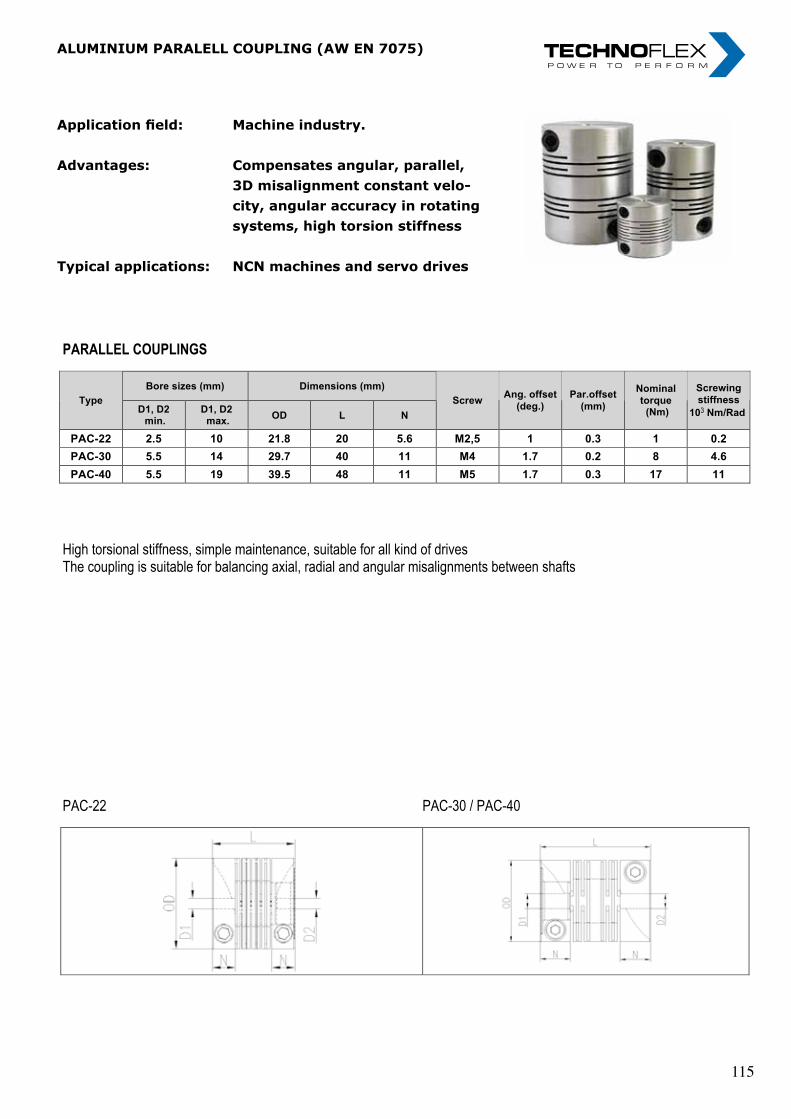
„ I n n o v a t i o n i n m o t i o n ”
Berv ina Kf t . • H -1145 Erzsébet k i rá lyné ú t ja 41/B • Te l . :+36 -1-222-20-79 • Fax: +36 -1-252-48-29 • berv ina@berv ina.com
page 28
ALUMINIUM PARALELL COUPLING (AW EN 7075)
Field of Application:
Advantages: Typical applications:
Machine industry
Compensates angular, parallel, 3D misalignment constant velocity, angular accuracy in rotating, systems, high torsion stiffness NCN machines and servo drives
PARALLEL COUPLINGS
Bore sizes (mm) Dimensions (mm)
Type D1, D2 min.
D1, D2 max.
OD L N
Screw Ang. offset
(deg.)
Par.offset
(mm)
Nominal
torque (Nm)
Screwing
stiffness
103 Nm/Rad
PAC-22 2.5 10 21.8 20 5.6 M2,5 1 0.3 1 0.2
PAC-30 5.5 14 29.7 40 11 M4 1.7 0.2 8 4.6
PAC-40 5.5 19 39.5 48 11 M5 1.7 0.3 17 11
High torsional stiffness, simple maintenance, suitable for all kind of drives
The coupling is suitable for balancing axial, radial and angular misalignments between shafts
PAC-22 PAC-30 / PAC-40
Application field: Machine industry.
Advantages: Compensates angular, parallel, 3D misalignment constant velo- city, angular accuracy in rotating systems, high torsion stiffness
Typical applications: NCN machines and servo drives
ALUMINIUM PARALELL COUPLING (AW EN 7075)
„ I n n o v a t i o n i n m o t i o n ”
Berv ina Kf t . • H -1145 Erzsébet k i rá lyné ú t ja 41/B • Te l . :+36 -1-222-20-79 • Fax: +36 -1-252-48-29 • berv ina@berv ina.com
page 28
ALUMINIUM PARALELL COUPLING (AW EN 7075)
Field of Application:
Advantages: Typical applications:
Machine industry
Compensates angular, parallel, 3D misalignment constant velocity, angular accuracy in rotating, systems, high torsion stiffness NCN machines and servo drives
PARALLEL COUPLINGS
Bore sizes (mm) Dimensions (mm)
Type D1, D2 min.
D1, D2 max.
OD L N
Screw Ang. offset
(deg.)
Par.offset
(mm)
Nominal
torque (Nm)
Screwing
stiffness
103 Nm/Rad
PAC-22 2.5 10 21.8 20 5.6 M2,5 1 0.3 1 0.2
PAC-30 5.5 14 29.7 40 11 M4 1.7 0.2 8 4.6
PAC-40 5.5 19 39.5 48 11 M5 1.7 0.3 17 11
High torsional stiffness, simple maintenance, suitable for all kind of drives
The coupling is suitable for balancing axial, radial and angular misalignments between shafts
PAC-22 PAC-30 / PAC-40
Application field: Machine industry.
Advantages: Compensates angular, parallel, 3D misalignment constant velo- city, angular accuracy in rotating systems, high torsion stiffness
Typical applications: NCN machines and servo drives
ALUMINIUM PARALELL COUPLING (AW EN 7075)
„ I n n o v a t i o n i n m o t i o n ”
Berv ina Kf t . • H -1145 Erzsébet k i rá lyné ú t ja 41/B • Te l . :+36 -1-222-20-79 • Fax: +36 -1-252-48-29 • berv ina@berv ina.com
page 28
ALUMINIUM PARALELL COUPLING (AW EN 7075)
Field of Application:
Advantages: Typical applications:
Machine industry
Compensates angular, parallel, 3D misalignment constant velocity, angular accuracy in rotating, systems, high torsion stiffness NCN machines and servo drives
PARALLEL COUPLINGS
Bore sizes (mm) Dimensions (mm)
Type D1, D2 min.
D1, D2 max.
OD L N
Screw Ang. offset
(deg.)
Par.offset
(mm)
Nominal
torque (Nm)
Screwing
stiffness
103 Nm/Rad
PAC-22 2.5 10 21.8 20 5.6 M2,5 1 0.3 1 0.2
PAC-30 5.5 14 29.7 40 11 M4 1.7 0.2 8 4.6
PAC-40 5.5 19 39.5 48 11 M5 1.7 0.3 17 11
High torsional stiffness, simple maintenance, suitable for all kind of drives
The coupling is suitable for balancing axial, radial and angular misalignments between shafts
PAC-22 PAC-30 / PAC-40
115 115
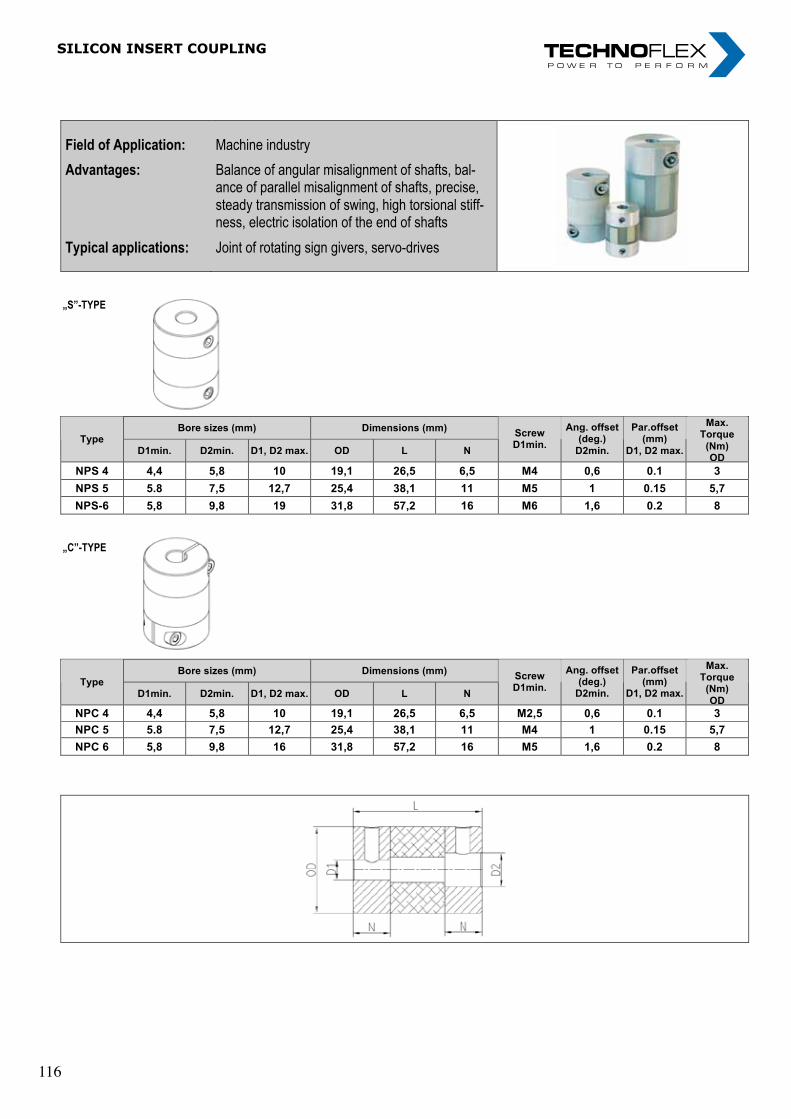
SiLicOn inSert cOUPLing „ I n n o v a t i o n i n m o t i o n ”
Berv ina Kf t . • H -1145 Erzsébet k i rá lyné ú t ja 41/B • Te l . :+36 -1-222-20-79 • Fax: +36 -1-252-48-29 • berv ina@berv ina.com
page 29
SILICON INSERT COUPLING
Field of Application:
Advantages:
Typical applications:
Machine industry
Balance of angular misalignment of shafts, bal-ance of parallel misalignment of shafts, precise, steady transmission of swing, high torsional stiff-ness, electric isolation of the end of shafts
Joint of rotating sign givers, servo-drives
„S”-TYPE
Bore sizes (mm) Dimensions (mm) Type
D1min. D2min. D1, D2 max. OD L N
Screw D1min.
Ang. offset (deg.)
D2min.
Par.offset (mm)
D1, D2 max.
Max. Torque
(Nm) OD
NPS 4 4,4 5,8 10 19,1 26,5 6,5 M4 0,6 0.1 3
NPS 5 5.8 7,5 12,7 25,4 38,1 11 M5 1 0.15 5,7
NPS-6 5,8 9,8 19 31,8 57,2 16 M6 1,6 0.2 8
„C”-TYPE
Bore sizes (mm) Dimensions (mm) Type
D1min. D2min. D1, D2 max. OD L N
Screw D1min.
Ang. offset (deg.)
D2min.
Par.offset (mm)
D1, D2 max.
Max. Torque
(Nm)
OD
NPC 4 4,4 5,8 10 19,1 26,5 6,5 M2,5 0,6 0.1 3
NPC 5 5.8 7,5 12,7 25,4 38,1 11 M4 1 0.15 5,7
NPC 6 5,8 9,8 16 31,8 57,2 16 M5 1,6 0.2 8
116 116
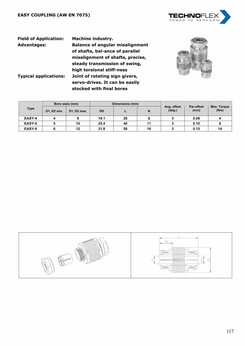
„ I n n o v a t i o n i n m o t i o n ”
Berv ina Kf t . • H -1145 Erzsébet k i rá lyné ú t ja 41/B • Te l . :+36 -1-222-20-79 • Fax: +36 -1-252-48-29 • berv ina@berv ina.com
page 30
EASY COUPLING (AW EN 7075)
Field of Application:
Advantages:
Typical applications:
Machine industry
Balance of angular misalignment of shafts, bal-ance of parallel misalignment of shafts, precise, steady transmission of swing, high torsional stiff-ness
Joint of rotating sign givers, servo-drives. It can be easily stocked with final bores
Bore sizes (mm) Dimensions (mm)
Type D1, D2 min. D1, D2 max. OD L N
Ang. offset (deg.)
Par.offset (mm)
Max. Torque (Nm)
EASY-4 4 8 19.1 28 8 3 0.08 4
EASY-5 5 10 25.4 40 11 3 0.10 8
EASY-6 6 12 31.8 58 16 3 0.15 14
Field of Application: Machine industry.Advantages: Balance of angular misalignment of shafts, bal-ance of parallel misalignment of shafts, precise, steady transmission of swing, high torsional stiff-nessTypical applications: Joint of rotating sign givers, servo-drives. It can be easily stocked with final bores
EASY COUPLING (AW EN 7075)
„ I n n o v a t i o n i n m o t i o n ”
Berv ina Kf t . • H -1145 Erzsébet k i rá lyné ú t ja 41/B • Te l . :+36 -1-222-20-79 • Fax: +36 -1-252-48-29 • berv ina@berv ina.com
page 30
EASY COUPLING (AW EN 7075)
Field of Application:
Advantages:
Typical applications:
Machine industry
Balance of angular misalignment of shafts, bal-ance of parallel misalignment of shafts, precise, steady transmission of swing, high torsional stiff-ness
Joint of rotating sign givers, servo-drives. It can be easily stocked with final bores
Bore sizes (mm) Dimensions (mm)
Type D1, D2 min. D1, D2 max. OD L N
Ang. offset (deg.)
Par.offset (mm)
Max. Torque (Nm)
EASY-4 4 8 19.1 28 8 3 0.08 4
EASY-5 5 10 25.4 40 11 3 0.10 8
EASY-6 6 12 31.8 58 16 3 0.15 14
Field of Application: Machine industry.Advantages: Balance of angular misalignment of shafts, bal-ance of parallel misalignment of shafts, precise, steady transmission of swing, high torsional stiff-nessTypical applications: Joint of rotating sign givers, servo-drives. It can be easily stocked with final bores
EASY COUPLING (AW EN 7075)
„ I n n o v a t i o n i n m o t i o n ”
Berv ina Kf t . • H -1145 Erzsébet k i rá lyné ú t ja 41/B • Te l . :+36 -1-222-20-79 • Fax: +36 -1-252-48-29 • berv ina@berv ina.com
page 30
EASY COUPLING (AW EN 7075)
Field of Application:
Advantages:
Typical applications:
Machine industry
Balance of angular misalignment of shafts, bal-ance of parallel misalignment of shafts, precise, steady transmission of swing, high torsional stiff-ness
Joint of rotating sign givers, servo-drives. It can be easily stocked with final bores
Bore sizes (mm) Dimensions (mm)
Type D1, D2 min. D1, D2 max. OD L N
Ang. offset (deg.)
Par.offset (mm)
Max. Torque (Nm)
EASY-4 4 8 19.1 28 8 3 0.08 4
EASY-5 5 10 25.4 40 11 3 0.10 8
EASY-6 6 12 31.8 58 16 3 0.15 14
117 117
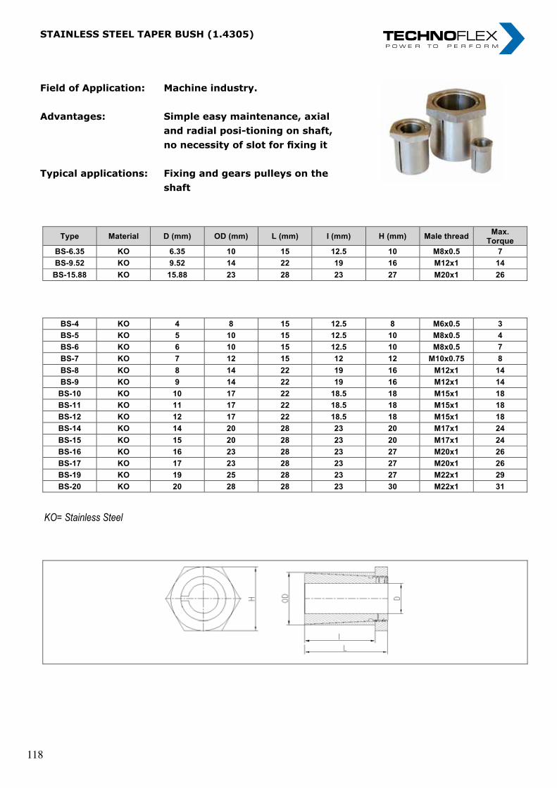
„ I n n o v a t i o n i n m o t i o n ”
Berv ina Kf t . • H -1145 Erzsébet k i rá lyné ú t ja 41/B • Te l . :+36 -1-222-20-79 • Fax: +36 -1-252-48-29 • berv ina@berv ina.com
page 31
STAINLESS STEEL TAPER BUSH (1.4305)
Field of Application:
Advantages:
Typical applications:
Machine industry
Simple easy maintenance, axial and radial posi-tioning on shaft, no necessity of slot for fixing it
Fixing and gears pulleys on the shaft
Type Material D (mm) OD (mm) L (mm) I (mm) H (mm) Male thread Max.
Torque
BS-6.35 KO 6.35 10 15 12.5 10 M8x0.5 7
BS-9.52 KO 9.52 14 22 19 16 M12x1 14
BS-15.88 KO 15.88 23 28 23 27 M20x1 26
BS-4 KO 4 8 15 12.5 8 M6x0.5 3
BS-5 KO 5 10 15 12.5 10 M8x0.5 4
BS-6 KO 6 10 15 12.5 10 M8x0.5 7
BS-7 KO 7 12 15 12 12 M10x0.75 8
BS-8 KO 8 14 22 19 16 M12x1 14
BS-9 KO 9 14 22 19 16 M12x1 14
BS-10 KO 10 17 22 18.5 18 M15x1 18
BS-11 KO 11 17 22 18.5 18 M15x1 18
BS-12 KO 12 17 22 18.5 18 M15x1 18
BS-14 KO 14 20 28 23 20 M17x1 24
BS-15 KO 15 20 28 23 20 M17x1 24
BS-16 KO 16 23 28 23 27 M20x1 26
BS-17 KO 17 23 28 23 27 M20x1 26
BS-19 KO 19 25 28 23 27 M22x1 29
BS-20 KO 20 28 28 23 30 M22x1 31
KO= Stainless Steel
Field of Application: Machine industry.
Advantages: Simple easy maintenance, axial and radial posi-tioning on shaft, no necessity of slot for fixing it
Typical applications: Fixing and gears pulleys on the shaft
Field of Application: Machine industry.
Advantages: Simple easy maintenance, axial and radial posi-tioning on shaft, no necessity of slot for fixing it
Typical applications: Fixing and gears pulleys on the shaft
STAINLESS STEEL TAPER BUSH (1.4305) STAINLESS STEEL TAPER BUSH (1.4305) „ I n n o v a t i o n i n m o t i o n ”
Berv ina Kf t . • H -1145 Erzsébet k i rá lyné ú t ja 41/B • Te l . :+36 -1-222-20-79 • Fax: +36 -1-252-48-29 • berv ina@berv ina.com
page 31
STAINLESS STEEL TAPER BUSH (1.4305)
Field of Application:
Advantages:
Typical applications:
Machine industry
Simple easy maintenance, axial and radial posi-tioning on shaft, no necessity of slot for fixing it
Fixing and gears pulleys on the shaft
Type Material D (mm) OD (mm) L (mm) I (mm) H (mm) Male thread Max.
Torque
BS-6.35 KO 6.35 10 15 12.5 10 M8x0.5 7
BS-9.52 KO 9.52 14 22 19 16 M12x1 14
BS-15.88 KO 15.88 23 28 23 27 M20x1 26
BS-4 KO 4 8 15 12.5 8 M6x0.5 3
BS-5 KO 5 10 15 12.5 10 M8x0.5 4
BS-6 KO 6 10 15 12.5 10 M8x0.5 7
BS-7 KO 7 12 15 12 12 M10x0.75 8
BS-8 KO 8 14 22 19 16 M12x1 14
BS-9 KO 9 14 22 19 16 M12x1 14
BS-10 KO 10 17 22 18.5 18 M15x1 18
BS-11 KO 11 17 22 18.5 18 M15x1 18
BS-12 KO 12 17 22 18.5 18 M15x1 18
BS-14 KO 14 20 28 23 20 M17x1 24
BS-15 KO 15 20 28 23 20 M17x1 24
BS-16 KO 16 23 28 23 27 M20x1 26
BS-17 KO 17 23 28 23 27 M20x1 26
BS-19 KO 19 25 28 23 27 M22x1 29
BS-20 KO 20 28 28 23 30 M22x1 31
KO= Stainless Steel
„ I n n o v a t i o n i n m o t i o n ”
Berv ina Kf t . • H -1145 Erzsébet k i rá lyné ú t ja 41/B • Te l . :+36 -1-222-20-79 • Fax: +36 -1-252-48-29 • berv ina@berv ina.com
page 31
STAINLESS STEEL TAPER BUSH (1.4305)
Field of Application:
Advantages:
Typical applications:
Machine industry
Simple easy maintenance, axial and radial posi-tioning on shaft, no necessity of slot for fixing it
Fixing and gears pulleys on the shaft
Type Material D (mm) OD (mm) L (mm) I (mm) H (mm) Male thread Max.
Torque
BS-6.35 KO 6.35 10 15 12.5 10 M8x0.5 7
BS-9.52 KO 9.52 14 22 19 16 M12x1 14
BS-15.88 KO 15.88 23 28 23 27 M20x1 26
BS-4 KO 4 8 15 12.5 8 M6x0.5 3
BS-5 KO 5 10 15 12.5 10 M8x0.5 4
BS-6 KO 6 10 15 12.5 10 M8x0.5 7
BS-7 KO 7 12 15 12 12 M10x0.75 8
BS-8 KO 8 14 22 19 16 M12x1 14
BS-9 KO 9 14 22 19 16 M12x1 14
BS-10 KO 10 17 22 18.5 18 M15x1 18
BS-11 KO 11 17 22 18.5 18 M15x1 18
BS-12 KO 12 17 22 18.5 18 M15x1 18
BS-14 KO 14 20 28 23 20 M17x1 24
BS-15 KO 15 20 28 23 20 M17x1 24
BS-16 KO 16 23 28 23 27 M20x1 26
BS-17 KO 17 23 28 23 27 M20x1 26
BS-19 KO 19 25 28 23 27 M22x1 29
BS-20 KO 20 28 28 23 30 M22x1 31
KO= Stainless Steel
118 118
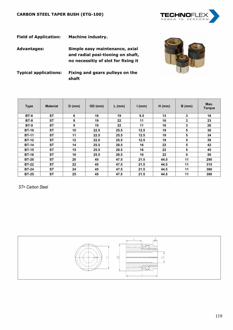
„ I n n o v a t i o n i n m o t i o n ”
Berv ina Kf t . • H -1145 Erzsébet k i rá lyné ú t ja 41/B • Te l . :+36 -1-222-20-79 • Fax: +36 -1-252-48-29 • berv ina@berv ina.com
page 32
CARBON STEEL TAPER BUSH (ETG-100)
Field of Application:
Advantages:
Typical applications:
Machine industry
Simple easy maintenance, axial and radial posi-tioning on shaft, no necessitiy of slot for fixing it
Fixing and gears pulleys on the shaft
Type Material D (mm) OD (mm) L (mm) I (mm) H (mm) B (mm) Max.
Torque
BT-6 ST 6 16 19 9.5 13 3 16
BT-8 ST 8 19 22 11 16 3 23
BT-9 ST 9 19 22 11 16 3 26
BT-10 ST 10 22.5 25.5 12.5 19 5 30
BT-11 ST 11 22.5 25.5 12.5 19 5 34
BT-12 ST 12 22.5 25.5 12.5 19 5 39
BT-14 ST 14 25.5 28.5 16 22 5 42
BT-15 ST 15 25.5 28.5 16 22 5 45
BT-16 ST 16 25.5 28.5 16 22 5 50
BT-20 ST 20 45 47.5 21.5 44.5 11 290
BT-22 ST 22 45 47.5 21.5 44.5 11 315
BT-24 ST 24 45 47.5 21.5 44.5 11 380
BT-25 ST 25 45 47.5 21.5 44.5 11 390
ST= Carbon Steel
Field of Application: Machine industry.
Advantages: Simple easy maintenance, axial and radial posi-tioning on shaft, no necessitiy of slot for fixing it
Typical applications: Fixing and gears pulleys on the shaft
Field of Application: Machine industry.
Advantages: Simple easy maintenance, axial and radial posi-tioning on shaft, no necessitiy of slot for fixing it
Typical applications: Fixing and gears pulleys on the shaft
CARBON STEEL TAPER BUSH (ETG-100) CARBON STEEL TAPER BUSH (ETG-100) „ I n n o v a t i o n i n m o t i o n ”
Berv ina Kf t . • H -1145 Erzsébet k i rá lyné ú t ja 41/B • Te l . :+36 -1-222-20-79 • Fax: +36 -1-252-48-29 • berv ina@berv ina.com
page 32
CARBON STEEL TAPER BUSH (ETG-100)
Field of Application:
Advantages:
Typical applications:
Machine industry
Simple easy maintenance, axial and radial posi-tioning on shaft, no necessitiy of slot for fixing it
Fixing and gears pulleys on the shaft
Type Material D (mm) OD (mm) L (mm) I (mm) H (mm) B (mm) Max.
Torque
BT-6 ST 6 16 19 9.5 13 3 16
BT-8 ST 8 19 22 11 16 3 23
BT-9 ST 9 19 22 11 16 3 26
BT-10 ST 10 22.5 25.5 12.5 19 5 30
BT-11 ST 11 22.5 25.5 12.5 19 5 34
BT-12 ST 12 22.5 25.5 12.5 19 5 39
BT-14 ST 14 25.5 28.5 16 22 5 42
BT-15 ST 15 25.5 28.5 16 22 5 45
BT-16 ST 16 25.5 28.5 16 22 5 50
BT-20 ST 20 45 47.5 21.5 44.5 11 290
BT-22 ST 22 45 47.5 21.5 44.5 11 315
BT-24 ST 24 45 47.5 21.5 44.5 11 380
BT-25 ST 25 45 47.5 21.5 44.5 11 390
ST= Carbon Steel
„ I n n o v a t i o n i n m o t i o n ”
Berv ina Kf t . • H -1145 Erzsébet k i rá lyné ú t ja 41/B • Te l . :+36 -1-222-20-79 • Fax: +36 -1-252-48-29 • berv ina@berv ina.com
page 32
CARBON STEEL TAPER BUSH (ETG-100)
Field of Application:
Advantages:
Typical applications:
Machine industry
Simple easy maintenance, axial and radial posi-tioning on shaft, no necessitiy of slot for fixing it
Fixing and gears pulleys on the shaft
Type Material D (mm) OD (mm) L (mm) I (mm) H (mm) B (mm) Max.
Torque
BT-6 ST 6 16 19 9.5 13 3 16
BT-8 ST 8 19 22 11 16 3 23
BT-9 ST 9 19 22 11 16 3 26
BT-10 ST 10 22.5 25.5 12.5 19 5 30
BT-11 ST 11 22.5 25.5 12.5 19 5 34
BT-12 ST 12 22.5 25.5 12.5 19 5 39
BT-14 ST 14 25.5 28.5 16 22 5 42
BT-15 ST 15 25.5 28.5 16 22 5 45
BT-16 ST 16 25.5 28.5 16 22 5 50
BT-20 ST 20 45 47.5 21.5 44.5 11 290
BT-22 ST 22 45 47.5 21.5 44.5 11 315
BT-24 ST 24 45 47.5 21.5 44.5 11 380
BT-25 ST 25 45 47.5 21.5 44.5 11 390
ST= Carbon Steel
119 119

nOteS nOteS „ I n n o v a t i o n i n m o t i o n ”
Berv ina Kf t . • H -1145 Erzsébet k i rá lyné út ja 41/B • Te l . :+36 -1-222-20-79 • Fax: +36 -1-252-48-29 • berv ina@berv ina.com
page 19
NOTES FOR BELTS
„ I n n o v a t i o n i n m o t i o n ”
Berv ina Kf t . • H -1145 Erzsébet k i rá lyné út ja 41/B • Te l . :+36 -1-222-20-79 • Fax: +36 -1-252-48-29 • berv ina@berv ina.com
page 19
NOTES FOR BELTS
120 120

marine cOUPLingS betWeen gear anD PrOPeLLer SHaFt marine cOUPLingS betWeen gear anD PrOPeLLer SHaFt
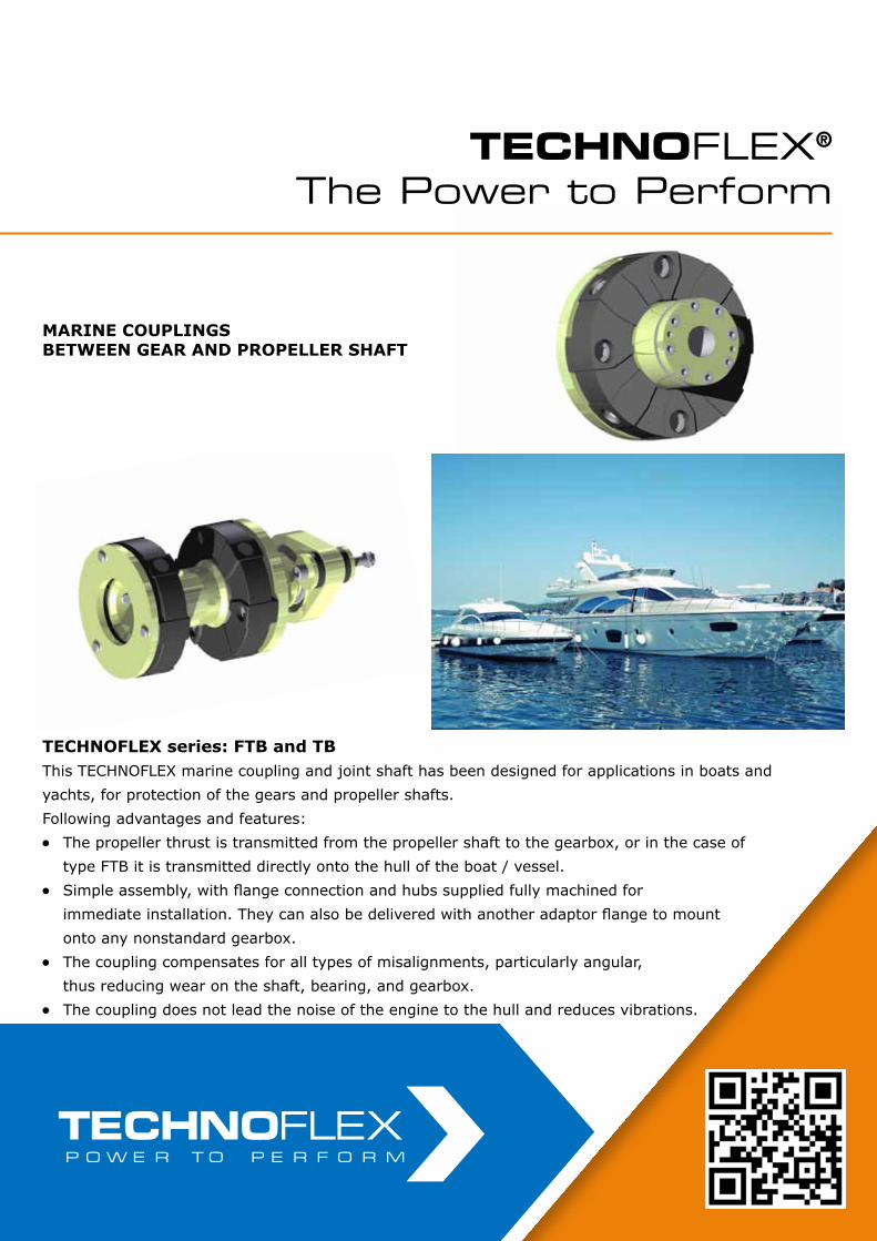
marine cOUPLingSbetWeen gear anD PrOPeLLer SHaFt
TECHNOFLEX®
The Power to Perform
tecHnOFLex series: Ftb and tbThis TECHNOFLEX marine coupling and joint shaft has been designed for applications in boats and yachts, for protection of the gears and propeller shafts.Following advantages and features:l The propeller thrust is transmitted from the propeller shaft to the gearbox, or in the case of type FTB it is transmitted directly onto the hull of the boat / vessel.l Simple assembly, with flange connection and hubs supplied fully machined for immediate installation. They can also be delivered with another adaptor flange to mount onto any nonstandard gearbox.l The coupling compensates for all types of misalignments, particularly angular, thus reducing wear on the shaft, bearing, and gearbox.l The coupling does not lead the noise of the engine to the hull and reduces vibrations.
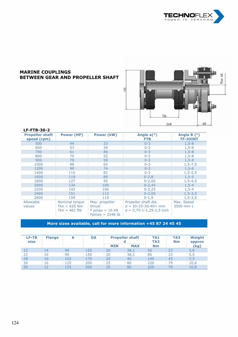
marine cOUPLingSbetWeen gear anD PrOPeLLer SHaFt
marine cOUPLingSbetWeen gear anD PrOPeLLer SHaFt
LF-FTB-30-2 Propeller shaft speed (rpm)
Power (HP) Power (kW) Angle a(°) FTB
Angle B (°) TF-JOINT
500 44 33 0-3 1,5-8 600 53 39 0-3 1,5-8 700 61 46 0-3 1,5-8 800 70 52 0-3 1,5-8 900 79 59 0-3 1,5-8 1000 88 65 0-3 1,5-7,5 1200 99 74 0-3 1,5-6 1400 110 82 0-3 1,5-5,5 1600 119 89 0-2,8 1,5-5 1800 127 95 0-2,65 1,5-4,5 2000 134 100 0-2,45 1,5-4 2200 142 106 0-2,25 1,5-4 2400 151 112 0-2,05 1,5-3,5 2600 159 119 0-1,9 1,5-3,5
Allowable values
Nominal torque Tkn = 625 Nm Tkn = 461 ftb
Max. propeller thrust F pmax = 10 kN Fpmax = 2248 Ib
Propeller shaft dia. d = 20-25-30-40+ mm d = 0,75-1-1,25-1,5 inch
Max. Speed 3500 min-1
More sizes available, call for more information +45 87 24 45 45
LF-TB size
Flange A DA Propeller shaft d
TA1 TA2
TA3 Nm
Weight approx
MIN MAX Nm (kg) 12 14 99 120 20 38,1 50 23 3,9 22 10 99 150 20 38,1 85 23 5,5 28 10 102 170 20 40 140 45 7,3 30 10 125 200 25 80 220 79 10,6 50 12 125 200 25 80 220 79 10,8
124 124

nOteS nOteS „ I n n o v a t i o n i n m o t i o n ”
Berv ina Kf t . • H -1145 Erzsébet k i rá lyné út ja 41/B • Te l . :+36 -1-222-20-79 • Fax: +36 -1-252-48-29 • berv ina@berv ina.com
page 19
NOTES FOR BELTS
„ I n n o v a t i o n i n m o t i o n ”
Berv ina Kf t . • H -1145 Erzsébet k i rá lyné út ja 41/B • Te l . :+36 -1-222-20-79 • Fax: +36 -1-252-48-29 • berv ina@berv ina.com
page 19
NOTES FOR BELTS
125 125

nOteS nOteS „ I n n o v a t i o n i n m o t i o n ”
Berv ina Kf t . • H -1145 Erzsébet k i rá lyné út ja 41/B • Te l . :+36 -1-222-20-79 • Fax: +36 -1-252-48-29 • berv ina@berv ina.com
page 19
NOTES FOR BELTS
„ I n n o v a t i o n i n m o t i o n ”
Berv ina Kf t . • H -1145 Erzsébet k i rá lyné út ja 41/B • Te l . :+36 -1-222-20-79 • Fax: +36 -1-252-48-29 • berv ina@berv ina.com
page 19
NOTES FOR BELTS
126 126

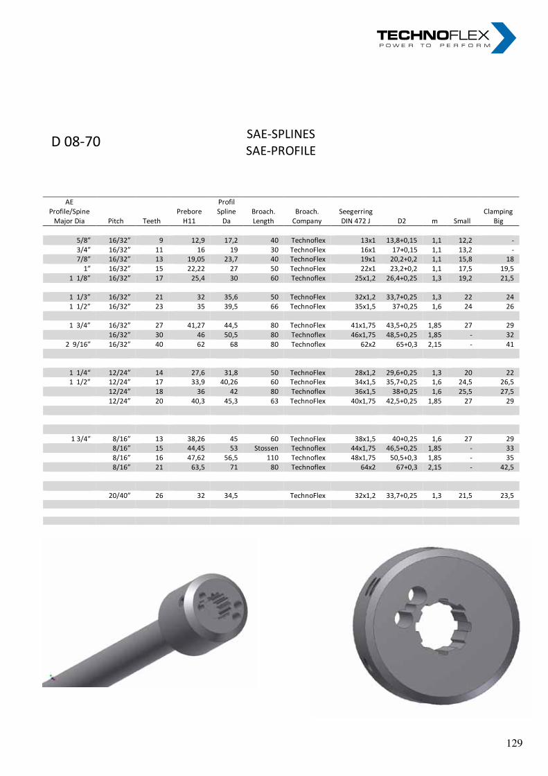
SAE-SPLINES SAE-PROFILE
D 08-70
AE Profile/Spine
Major Dia Pitch Teeth Prebore
H11
Profil Spline
Da Broach. Length
Broach. Company
Seegerring DIN 472 J D2 m Small
Clamping Big
5/8” 16/32” 9 12,9 17,2 40 Technoflex 13x1 13,8+0,15 1,1 12,2 - 3/4” 16/32” 11 16 19 30 TechnoFlex 16x1 17+0,15 1,1 13,2 - 7/8” 16/32” 13 19,05 23,7 40 TechnoFlex 19x1 20,2+0,2 1,1 15,8 18
1” 16/32” 15 22,22 27 50 TechnoFlex 22x1 23,2+0,2 1,1 17,5 19,5 1 1/8” 16/32” 17 25,4 30 60 Technoflex 25x1,2 26,4+0,25 1,3 19,2 21,5
1 1/3” 16/32” 21 32 35,6 50 TechnoFlex 32x1,2 33,7+0,25 1,3 22 24 1 1/2” 16/32” 23 35 39,5 66 TechnoFlex 35x1,5 37+0,25 1,6 24 26
1 3/4” 16/32” 27 41,27 44,5 80 TechnoFlex 41x1,75 43,5+0,25 1,85 27 29
16/32” 30 46 50,5 80 Technoflex 46x1,75 48,5+0,25 1,85 - 32 2 9/16” 16/32” 40 62 68 80 Technoflex 62x2 65+0,3 2,15 - 41
1 1/4“ 12/24” 14 27,6 31,8 50 TechnoFlex 28x1,2 29,6+0,25 1,3 20 22 1 1/2” 12/24” 17 33,9 40,26 60 TechnoFlex 34x1,5 35,7+0,25 1,6 24,5 26,5
12/24” 18 36 42 80 Technoflex 36x1,5 38+0,25 1,6 25,5 27,5 12/24” 20 40,3 45,3 63 TechnoFlex 40x1,75 42,5+0,25 1,85 27 29
1 3/4” 8/16” 13 38,26 45 60 TechnoFlex 38x1,5 40+0,25 1,6 27 29 8/16” 15 44,45 53 Stossen Technoflex 44x1,75 46,5+0,25 1,85 - 33 8/16” 16 47,62 56,5 110 Technoflex 48x1,75 50,5+0,3 1,85 - 35 8/16” 21 63,5 71 80 Technoflex 64x2 67+0,3 2,15 - 42,5 20/40” 26 32 34,5 TechnoFlex 32x1,2 33,7+0,25 1,3 21,5 23,5
129
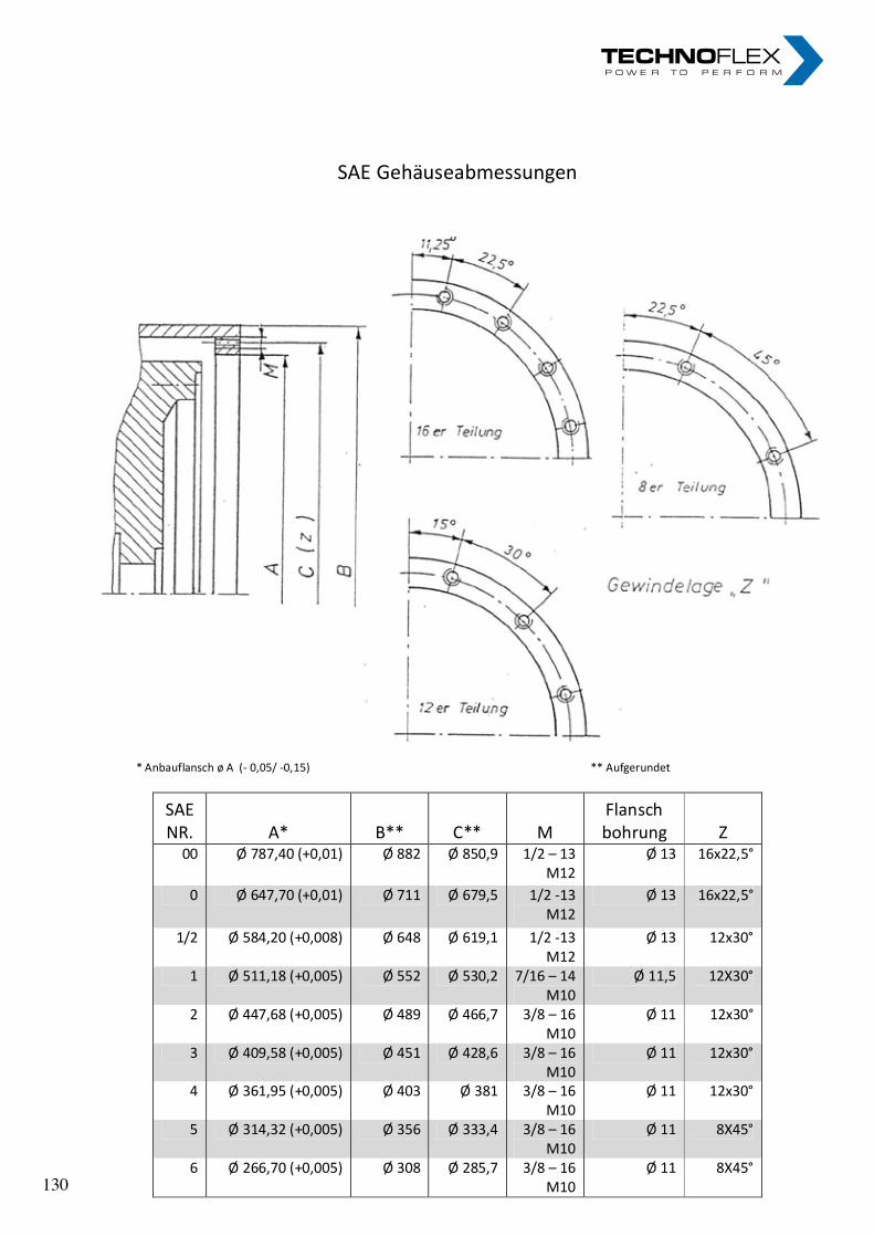
SAE Gehäuseabmessungen
* Anbauflansch ø A (- 0,05/ -0,15) ** Aufgerundet
SAE NR. A* B** C** M
Flansch bohrung Z
00 Ø 787,40 (+0,01) Ø 882 Ø 850,9 1/2 – 13 M12
Ø 13 16x22,5°
0 Ø 647,70 (+0,01) Ø 711 Ø 679,5 1/2 -13 M12
Ø 13 16x22,5°
1/2 Ø 584,20 (+0,008) Ø 648 Ø 619,1 1/2 -13 M12
Ø 13 12x30°
1 Ø 511,18 (+0,005) Ø 552 Ø 530,2 7/16 – 14 M10
Ø 11,5 12X30°
2 Ø 447,68 (+0,005) Ø 489 Ø 466,7 3/8 – 16 M10
Ø 11 12x30°
3 Ø 409,58 (+0,005) Ø 451 Ø 428,6 3/8 – 16 M10
Ø 11 12x30°
4 Ø 361,95 (+0,005) Ø 403 Ø 381 3/8 – 16 M10
Ø 11 12x30°
5 Ø 314,32 (+0,005) Ø 356 Ø 333,4 3/8 – 16 M10
Ø 11 8X45°
6 Ø 266,70 (+0,005) Ø 308 Ø 285,7 3/8 – 16 M10
Ø 11 8X45°
SAE Gehäuseabmessungen
* Anbauflansch ø A (- 0,05/ -0,15) ** Aufgerundet
SAE NR. A* B** C** M
Flansch bohrung Z
00 Ø 787,40 (+0,01) Ø 882 Ø 850,9 1/2 – 13 M12
Ø 13 16x22,5°
0 Ø 647,70 (+0,01) Ø 711 Ø 679,5 1/2 -13 M12
Ø 13 16x22,5°
1/2 Ø 584,20 (+0,008) Ø 648 Ø 619,1 1/2 -13 M12
Ø 13 12x30°
1 Ø 511,18 (+0,005) Ø 552 Ø 530,2 7/16 – 14 M10
Ø 11,5 12X30°
2 Ø 447,68 (+0,005) Ø 489 Ø 466,7 3/8 – 16 M10
Ø 11 12x30°
3 Ø 409,58 (+0,005) Ø 451 Ø 428,6 3/8 – 16 M10
Ø 11 12x30°
4 Ø 361,95 (+0,005) Ø 403 Ø 381 3/8 – 16 M10
Ø 11 12x30°
5 Ø 314,32 (+0,005) Ø 356 Ø 333,4 3/8 – 16 M10
Ø 11 8X45°
6 Ø 266,70 (+0,005) Ø 308 Ø 285,7 3/8 – 16 M10
Ø 11 8X45° 130 130
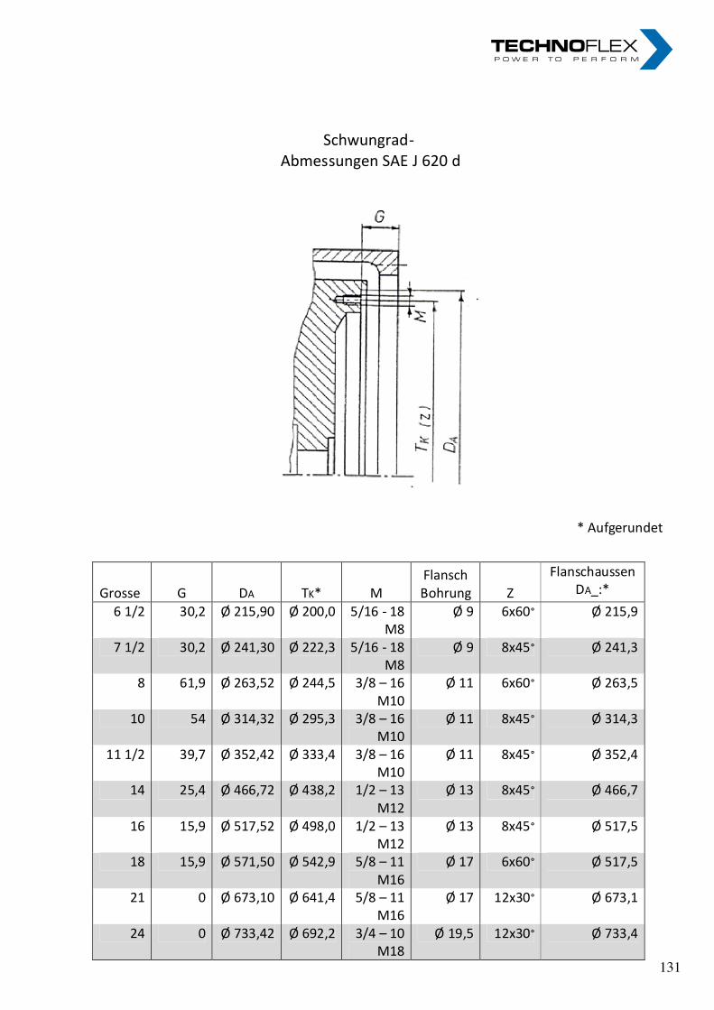
Schwungrad- Abmessungen SAE J 620 d
* Aufgerundet
Grosse G DA TK* M Flansch Bohrung Z
Flanschaussen DA_:*
6 1/2 30,2 Ø 215,90 Ø 200,0 5/16 - 18 M8
Ø 9 6x60° Ø 215,9
7 1/2 30,2 Ø 241,30 Ø 222,3 5/16 - 18 M8
Ø 9 8x45° Ø 241,3
8 61,9 Ø 263,52 Ø 244,5 3/8 – 16 M10
Ø 11 6x60° Ø 263,5
10 54 Ø 314,32 Ø 295,3 3/8 – 16 M10
Ø 11 8x45° Ø 314,3
11 1/2 39,7 Ø 352,42 Ø 333,4 3/8 – 16 M10
Ø 11 8x45° Ø 352,4
14 25,4 Ø 466,72 Ø 438,2 1/2 – 13 M12
Ø 13 8x45° Ø 466,7
16 15,9 Ø 517,52 Ø 498,0 1/2 – 13 M12
Ø 13 8x45° Ø 517,5
18 15,9 Ø 571,50 Ø 542,9 5/8 – 11 M16
Ø 17 6x60° Ø 517,5
21 0 Ø 673,10 Ø 641,4 5/8 – 11 M16
Ø 17 12x30° Ø 673,1
24 0 Ø 733,42 Ø 692,2 3/4 – 10 M18
Ø 19,5 12x30° Ø 733,4
131 131

nOteS nOteS „ I n n o v a t i o n i n m o t i o n ”
Berv ina Kf t . • H -1145 Erzsébet k i rá lyné út ja 41/B • Te l . :+36 -1-222-20-79 • Fax: +36 -1-252-48-29 • berv ina@berv ina.com
page 19
NOTES FOR BELTS
„ I n n o v a t i o n i n m o t i o n ”
Berv ina Kf t . • H -1145 Erzsébet k i rá lyné út ja 41/B • Te l . :+36 -1-222-20-79 • Fax: +36 -1-252-48-29 • berv ina@berv ina.com
page 19
NOTES FOR BELTS
132 132

Öl-Wasserkühler bnZ mit alu-Lamellen und festem rohrbündelOil-Water Cooler BNZ with aluminium fins and rigid tube stack
Öl-Wasserkühler bnZ mit alu-Lamellen und festem rohrbündelOil-Water Cooler BNZ with aluminium fins and rigid tube stack
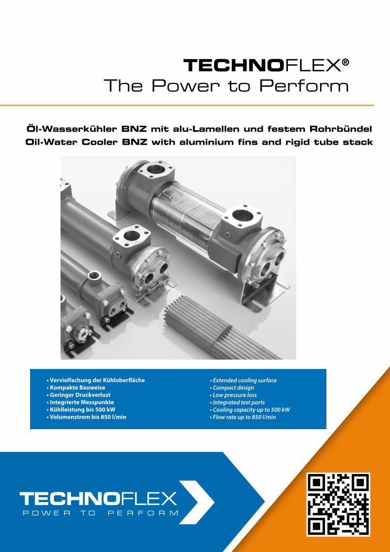
• LF Torsionskupplungen
• LK Torsionskupplungen
• Pumpen-Montageplatten und -Gehäuse
• LM Torsionskupplungen
• LF Torsional Coupling system
• LK Torsional Coupling system
• Pump mounting plates and housings
• LM Torsional Coupling system
• LF Torsionskupplungen
• LK Torsionskupplungen
• Pumpen-Montageplatten und -Gehäuse
• LM Torsionskupplungen
• LF Torsional Coupling system
• LK Torsional Coupling system
• Pump mounting plates and housings
• LM Torsional Coupling system
Öl-Wasserkühler BNZ mit Alu-Lamellen und festem Rohrbündel
Oil-Water Cooler BNZ with aluminium fins and rigid tube stack
• Vervielfachung der Kühloberfläche• Kompakte Bauweise• Geringer Druckverlust• Integrierte Messpunkte• Kühlleistung bis 500 kW• Volumenstrom bis 850 l/min
• Extended cooling surface• Compact design• Low pressure loss• Integrated test ports• Cooling capacity up to 500 kW• Flow rate up to 850 l/min
TECHNOFLEX®
The Power to PerformTECHNOFLEX®
The Power to Perform
Öl-Wasserkühler BNZ mit alu-Lamellen und festem RohrbündelOil-Water Cooler BNZ with aluminium fins and rigid tube stack
Öl-Wasserkühler BNZ mit alu-Lamellen und festem RohrbündelOil-Water Cooler BNZ with aluminium fins and rigid tube stack
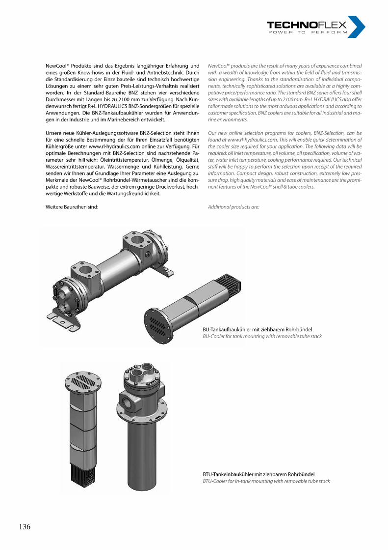
NewCool® Produkte sind das Ergebnis langjähriger Erfahrung und eines großen Know-hows in der Fluid- und Antriebstechnik. Durch die Standardisierung der Einzelbauteile sind technisch hochwertige Lösungen zu einem sehr guten Preis-Leistungs-Verhältnis realisiert worden. In der Standard-Baureihe BNZ stehen vier verschiedene Durchmesser mit Längen bis zu 2100 mm zur Verfügung. Nach Kun-denwunsch fertigt R+L HYDRAULICS BNZ-Sondergrößen für spezielle Anwendungen. Die BNZ-Tankaufbaukühler wurden für Anwendun-gen in der Industrie und im Marinebereich entwickelt.
Unsere neue Kühler-Auslegungssoftware BNZ-Selection steht Ihnen für eine schnelle Bestimmung der für Ihren Einsatzfall benötigten Kühlergröße unter www.rl-hydraulics.com online zur Verfügung. Für optimale Berechnungen mit BNZ-Selection sind nachstehende Pa-rameter sehr hilfreich: Öleintrittstemperatur, Ölmenge, Ölqualität, Wassereintrittstemperatur, Wassermenge und Kühlleistung. Gerne senden wir Ihnen auf Grundlage Ihrer Parameter eine Auslegung zu. Merkmale der NewCool® Rohrbündel-Wärmetauscher sind die kom-pakte und robuste Bauweise, der extrem geringe Druckverlust, hoch-wertige Werkstoffe und die Wartungsfreundlichkeit.
Weitere Baureihen sind:
NewCool® products are the result of many years of experience combined with a wealth of knowledge from within the field of fluid and transmis-sion engineering. Thanks to the standardisation of individual compo-nents, technically sophisticated solutions are available at a highly com-petitive price/performance ratio. The standard BNZ series offers four shell sizes with available lengths of up to 2100 mm. R+L HYDRAULICS also offer tailor made solutions to the most arduous applications and according to customer specification. BNZ coolers are suitable for all industrial and ma-rine environments.
Our new online selection programs for coolers, BNZ-Selection, can be found at www.rl-hydraulics.com. This will enable quick determination of the cooler size required for your application. The following data will be required: oil inlet temperature, oil volume, oil specification, volume of wa-ter, water inlet temperature, cooling performance required. Our technical staff will be happy to perform the selection upon receipt of the required information. Compact design, robust construction, extremely low pres-sure drop, high quality materials and ease of maintenance are the promi-nent features of the NewCool® shell & tube coolers.
Additional products are:
BU-Tankaufbaukühler mit ziehbarem RohrbündelBU-Cooler for tank mounting with removable tube stack
BTU-Tankeinbaukühler mit ziehbarem RohrbündelBTU-Cooler for in-tank mounting with removable tube stack
136 136
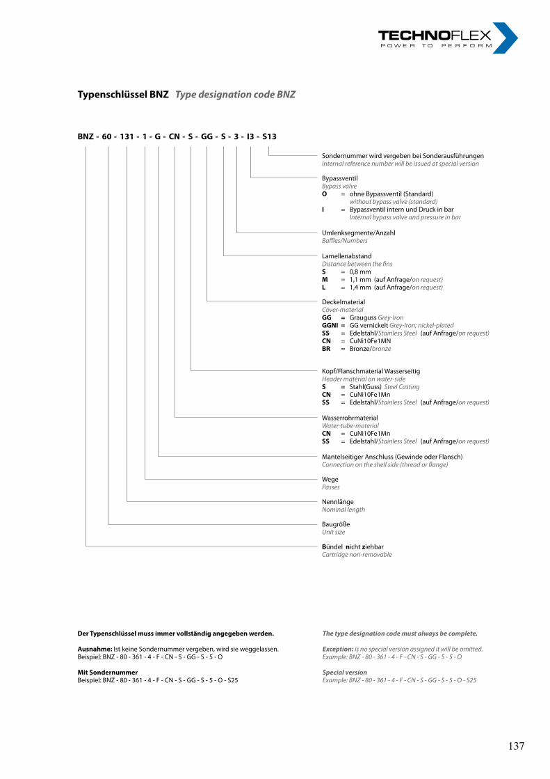
Sondernummer wird vergeben bei SonderausführungenInternal reference number will be issued at special version
BypassventilBypass valveO = ohne Bypassventil (Standard) without bypass valve (standard) I = Bypassventil intern und Druck in bar Internal bypass valve and pressure in bar
Umlenksegmente/AnzahlBaffles/Numbers
LamellenabstandDistance between the finsS = 0,8 mmM = 1,1 mm (auf Anfrage/on request)L = 1,4 mm (auf Anfrage/on request)
DeckelmaterialCover-materialGG = Grauguss Grey-Iron GGNI = GG vernickelt Grey-Iron; nickel-platedSS = Edelstahl/Stainless Steel (auf Anfrage/on request)CN = CuNi10Fe1MNBR = Bronze/bronze
Kopf/Flanschmaterial WasserseitigHeader material on water-side S = Stahl(Guss) Steel Casting CN = CuNi10Fe1Mn SS = Edelstahl/Stainless Steel (auf Anfrage/on request)
Wasserrohrmaterial Water-tube-material CN = CuNi10Fe1MnSS = Edelstahl/Stainless Steel (auf Anfrage/on request)
Mantelseitiger Anschluss (Gewinde oder Flansch)Connection on the shell side (thread or flange)
WegePasses
NennlängeNominal length
BaugrößeUnit size
Bündel nicht ziehbarCartridge non-removable
Typenschlüssel BNZ Type designation code BNZ
BNZ - 60 - 131 - 1 - G - CN - S - GG - S - 3 - I3 - S13
Der Typenschlüssel muss immer vollständig angegeben werden.
Ausnahme: Ist keine Sondernummer vergeben, wird sie weggelassen. Beispiel: BNZ - 80 - 361 - 4 - F - CN - S - GG - S - 5 - O
Mit SondernummerBeispiel: BNZ - 80 - 361 - 4 - F - CN - S - GG - S - 5 - O - S25
The type designation code must always be complete.
Exception: is no special version assigned it will be omitted.Example: BNZ - 80 - 361 - 4 - F - CN - S - GG - S - 5 - O
Special versionExample: BNZ - 80 - 361 - 4 - F - CN - S - GG - S - 5 - O - S25
137 137
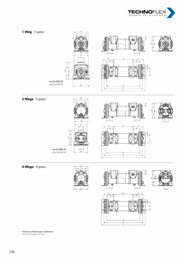
2-Wege 2-pass
4-Wege 4-pass
nur für BNZ 60only for BNZ 60
1-Weg 1-pass
nur für BNZ 60only for BNZ 60
Technische Änderungen vorbehaltenTechnical changes reserved
2-Wege 2-pass
4-Wege 4-pass
nur für BNZ 60only for BNZ 60
1-Weg 1-pass
nur für BNZ 60only for BNZ 60
Technische Änderungen vorbehaltenTechnical changes reserved
138 138
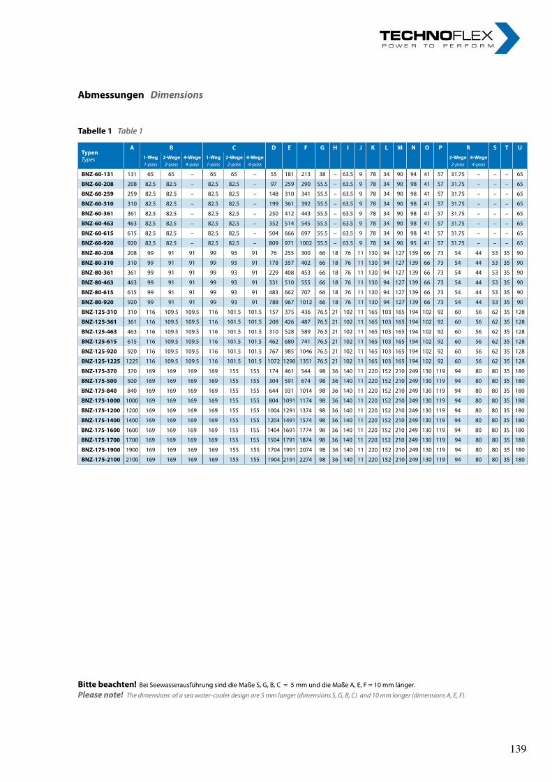
Abmessungen Dimensions
TypenTypes
A B C D E F G H I J K L M N O P R S T U
1-Weg1-pass
2-Wege2-pass
4-Wege4-pass
1-Weg1-pass
2-Wege2-pass
4-Wege4-pass
2-Wege2-pass
4-Wege4-pass
BNZ-60-131 131 65 65 – 65 65 – 55 181 213 38 – 63.5 9 78 34 90 94 41 57 31.75 – – – 65
BNZ-60-208 208 82.5 82.5 – 82.5 82.5 – 97 259 290 55.5 – 63.5 9 78 34 90 98 41 57 31.75 – – – 65
BNZ-60-259 259 82.5 82.5 – 82.5 82.5 – 148 310 341 55.5 – 63.5 9 78 34 90 98 41 57 31.75 – – – 65
BNZ-60-310 310 82.5 82.5 – 82.5 82.5 – 199 361 392 55.5 – 63.5 9 78 34 90 98 41 57 31.75 – – – 65
BNZ-60-361 361 82.5 82.5 – 82.5 82.5 – 250 412 443 55.5 – 63.5 9 78 34 90 98 41 57 31.75 – – – 65
BNZ-60-463 463 82.5 82.5 – 82.5 82.5 – 352 514 545 55.5 – 63.5 9 78 34 90 98 41 57 31.75 – – – 65
BNZ-60-615 615 82.5 82.5 – 82.5 82.5 – 504 666 697 55.5 – 63.5 9 78 34 90 98 41 57 31.75 – – – 65
BNZ-60-920 920 82.5 82.5 – 82.5 82.5 – 809 971 1002 55.5 – 63.5 9 78 34 90 95 41 57 31.75 – – – 65
BNZ-80-208 208 99 91 91 99 93 91 76 255 300 66 18 76 11 130 94 127 139 66 73 54 44 53 35 90
BNZ-80-310 310 99 91 91 99 93 91 178 357 402 66 18 76 11 130 94 127 139 66 73 54 44 53 35 90
BNZ-80-361 361 99 91 91 99 93 91 229 408 453 66 18 76 11 130 94 127 139 66 73 54 44 53 35 90
BNZ-80-463 463 99 91 91 99 93 91 331 510 555 66 18 76 11 130 94 127 139 66 73 54 44 53 35 90
BNZ-80-615 615 99 91 91 99 93 91 483 662 707 66 18 76 11 130 94 127 139 66 73 54 44 53 35 90
BNZ-80-920 920 99 91 91 99 93 91 788 967 1012 66 18 76 11 130 94 127 139 66 73 54 44 53 35 90
BNZ-125-310 310 116 109.5 109.5 116 101.5 101.5 157 375 436 76.5 21 102 11 165 103 165 194 102 92 60 56 62 35 128
BNZ-125-361 361 116 109.5 109.5 116 101.5 101.5 208 426 487 76.5 21 102 11 165 103 165 194 102 92 60 56 62 35 128
BNZ-125-463 463 116 109.5 109.5 116 101.5 101.5 310 528 589 76.5 21 102 11 165 103 165 194 102 92 60 56 62 35 128
BNZ-125-615 615 116 109.5 109.5 116 101.5 101.5 462 680 741 76.5 21 102 11 165 103 165 194 102 92 60 56 62 35 128
BNZ-125-920 920 116 109.5 109.5 116 101.5 101.5 767 985 1046 76.5 21 102 11 165 103 165 194 102 92 60 56 62 35 128
BNZ-125-1225 1225 116 109.5 109.5 116 101.5 101.5 1072 1290 1351 76.5 21 102 11 165 103 165 194 102 92 60 56 62 35 128
BNZ-175-370 370 169 169 169 169 155 155 174 461 544 98 36 140 11 220 152 210 249 130 119 94 80 80 35 180
BNZ-175-500 500 169 169 169 169 155 155 304 591 674 98 36 140 11 220 152 210 249 130 119 94 80 80 35 180
BNZ-175-840 840 169 169 169 169 155 155 644 931 1014 98 36 140 11 220 152 210 249 130 119 94 80 80 35 180
BNZ-175-1000 1000 169 169 169 169 155 155 804 1091 1174 98 36 140 11 220 152 210 249 130 119 94 80 80 35 180
BNZ-175-1200 1200 169 169 169 169 155 155 1004 1291 1374 98 36 140 11 220 152 210 249 130 119 94 80 80 35 180
BNZ-175-1400 1400 169 169 169 169 155 155 1204 1491 1574 98 36 140 11 220 152 210 249 130 119 94 80 80 35 180
BNZ-175-1600 1600 169 169 169 169 155 155 1404 1691 1774 98 36 140 11 220 152 210 249 130 119 94 80 80 35 180
BNZ-175-1700 1700 169 169 169 169 155 155 1504 1791 1874 98 36 140 11 220 152 210 249 130 119 94 80 80 35 180
BNZ-175-1900 1900 169 169 169 169 155 155 1704 1991 2074 98 36 140 11 220 152 210 249 130 119 94 80 80 35 180
BNZ-175-2100 2100 169 169 169 169 155 155 1904 2191 2274 98 36 140 11 220 152 210 249 130 119 94 80 80 35 180
Tabelle 1 Table 1
Bitte beachten! Bei Seewasserausführung sind die Maße S, G, B, C = 5 mm und die Maße A, E, F = 10 mm länger.Please note! The dimensions of a sea water-cooler design are 5 mm longer (dimensions S, G, B, C) and 10 mm longer (dimensions A, E, F).
139 139
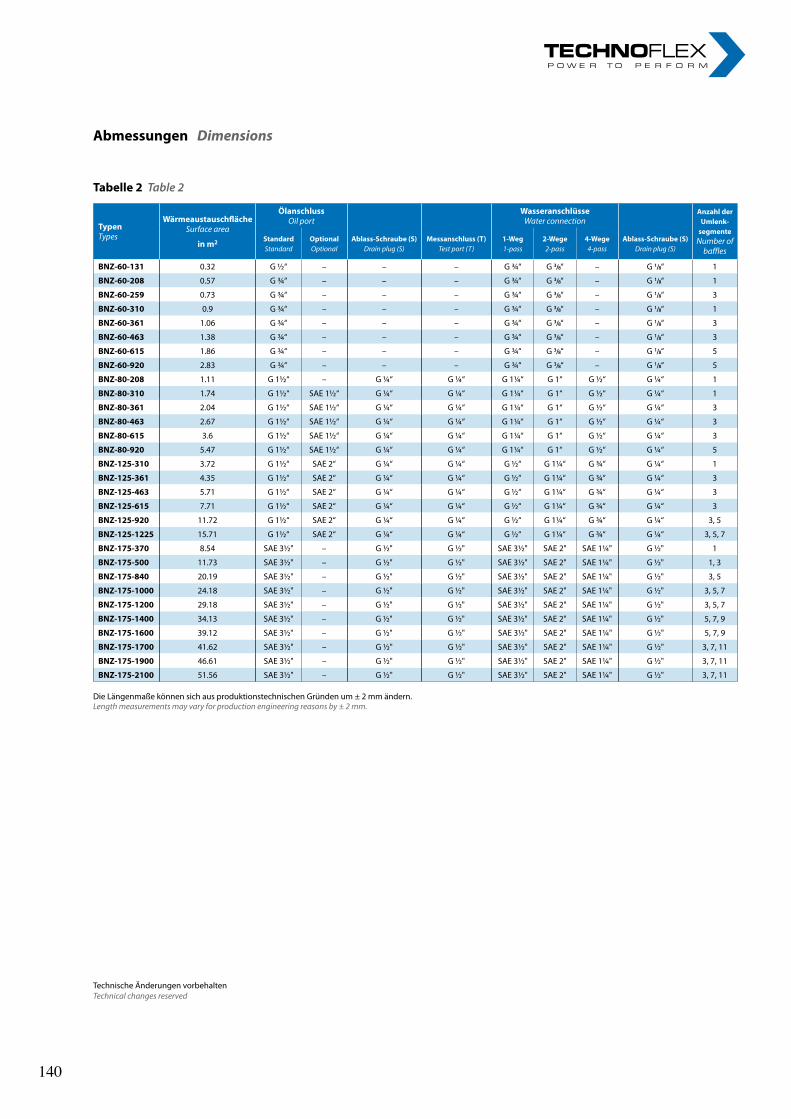
TypenTypes
WärmeaustauschflächeSurface area
in m2
ÖlanschlussOil port
WasseranschlüsseWater connection
Anzahl der Umlenk-
segmente Number of
bafflesStandardStandard
OptionalOptional
Ablass-Schraube (S)Drain plug (S)
Messanschluss (T)Test port (T)
1-Weg1-pass
2-Wege2-pass
4-Wege4-pass
Ablass-Schraube (S)Drain plug (S)
BNZ-60-131 0.32 G ½“ – – – G ¾“ G 3/8“ – G 1/8“ 1
BNZ-60-208 0.57 G ¾“ – – – G ¾“ G 3/8“ – G 1/8“ 1
BNZ-60-259 0.73 G ¾“ – – – G ¾“ G 3/8“ – G 1/8“ 3
BNZ-60-310 0.9 G ¾“ – – – G ¾“ G 3/8“ – G 1/8“ 1
BNZ-60-361 1.06 G ¾“ – – – G ¾“ G 3/8“ – G 1/8“ 3
BNZ-60-463 1.38 G ¾“ – – – G ¾“ G 3/8“ – G 1/8“ 3
BNZ-60-615 1.86 G ¾“ – – – G ¾“ G 3/8“ – G 1/8“ 5
BNZ-60-920 2.83 G ¾“ – – – G ¾“ G 3/8“ – G 1/8“ 5
BNZ-80-208 1.11 G 1½“ – G ¼“ G ¼“ G 1¼“ G 1“ G ½“ G ¼“ 1
BNZ-80-310 1.74 G 1½“ SAE 1½“ G ¼“ G ¼“ G 1¼“ G 1“ G ½“ G ¼“ 1
BNZ-80-361 2.04 G 1½“ SAE 1½“ G ¼“ G ¼“ G 1¼“ G 1“ G ½“ G ¼“ 3
BNZ-80-463 2.67 G 1½“ SAE 1½“ G ¼“ G ¼“ G 1¼“ G 1“ G ½“ G ¼“ 3
BNZ-80-615 3.6 G 1½“ SAE 1½“ G ¼“ G ¼“ G 1¼“ G 1“ G ½“ G ¼“ 3
BNZ-80-920 5.47 G 1½“ SAE 1½“ G ¼“ G ¼“ G 1¼“ G 1“ G ½“ G ¼“ 5
BNZ-125-310 3.72 G 1½“ SAE 2“ G ¼“ G ¼“ G ½“ G 1¼“ G ¾“ G ¼“ 1
BNZ-125-361 4.35 G 1½“ SAE 2“ G ¼“ G ¼“ G ½“ G 1¼“ G ¾“ G ¼“ 3
BNZ-125-463 5.71 G 1½“ SAE 2“ G ¼“ G ¼“ G ½“ G 1¼“ G ¾“ G ¼“ 3
BNZ-125-615 7.71 G 1½“ SAE 2“ G ¼“ G ¼“ G ½“ G 1¼“ G ¾“ G ¼“ 3
BNZ-125-920 11.72 G 1½“ SAE 2“ G ¼“ G ¼“ G ½“ G 1¼“ G ¾“ G ¼“ 3, 5
BNZ-125-1225 15.71 G 1½“ SAE 2“ G ¼“ G ¼“ G ½“ G 1¼“ G ¾“ G ¼“ 3, 5, 7
BNZ-175-370 8.54 SAE 3½" – G ½" G ½" SAE 3½" SAE 2" SAE 1¼" G ½" 1
BNZ-175-500 11.73 SAE 3½" – G ½" G ½" SAE 3½" SAE 2" SAE 1¼" G ½" 1, 3
BNZ-175-840 20.19 SAE 3½" – G ½" G ½" SAE 3½" SAE 2" SAE 1¼" G ½" 3, 5
BNZ-175-1000 24.18 SAE 3½" – G ½" G ½" SAE 3½" SAE 2" SAE 1¼" G ½" 3, 5, 7
BNZ-175-1200 29.18 SAE 3½" – G ½" G ½" SAE 3½" SAE 2" SAE 1¼" G ½" 3, 5, 7
BNZ-175-1400 34.13 SAE 3½" – G ½" G ½" SAE 3½" SAE 2" SAE 1¼" G ½" 5, 7, 9
BNZ-175-1600 39.12 SAE 3½" – G ½" G ½" SAE 3½" SAE 2" SAE 1¼" G ½" 5, 7, 9
BNZ-175-1700 41.62 SAE 3½" – G ½" G ½" SAE 3½" SAE 2" SAE 1¼" G ½" 3, 7, 11
BNZ-175-1900 46.61 SAE 3½" – G ½" G ½" SAE 3½" SAE 2" SAE 1¼" G ½" 3, 7, 11
BNZ-175-2100 51.56 SAE 3½" – G ½" G ½" SAE 3½" SAE 2" SAE 1¼" G ½" 3, 7, 11
Tabelle 2 Table 2
Die Längenmaße können sich aus produktionstechnischen Gründen um ± 2 mm ändern.Length measurements may vary for production engineering reasons by ± 2 mm.
Abmessungen Dimensions
Technische Änderungen vorbehaltenTechnical changes reserved
140 140
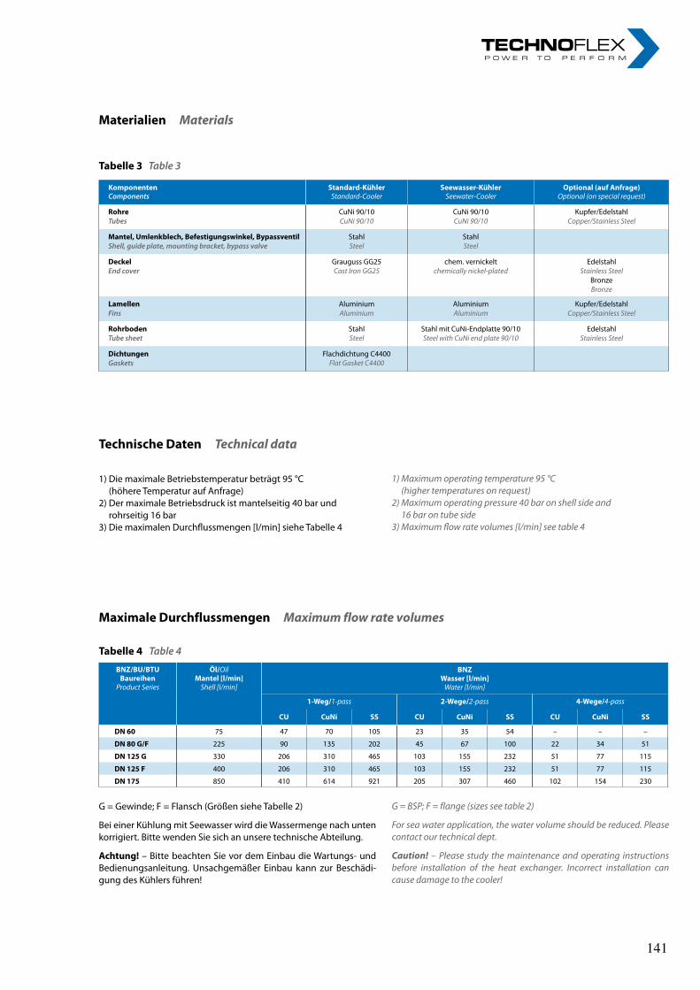
KomponentenComponents
Standard-KühlerStandard-Cooler
Seewasser-KühlerSeewater-Cooler
Optional (auf Anfrage)Optional (on special request)
RohreTubes
CuNi 90/10CuNi 90/10
CuNi 90/10CuNi 90/10
Kupfer/Edelstahl Copper/Stainless Steel
Mantel, Umlenkblech, Befestigungswinkel, BypassventilShell, guide plate, mounting bracket, bypass valve
StahlSteel
StahlSteel
DeckelEnd cover
Grauguss GG25Cast Iron GG25
chem. vernickeltchemically nickel-plated
EdelstahlStainless Steel
BronzeBronze
LamellenFins
AluminiumAluminium
AluminiumAluminium
Kupfer/EdelstahlCopper/Stainless Steel
RohrbodenTube sheet
StahlSteel
Stahl mit CuNi-Endplatte 90/10Steel with CuNi end plate 90/10
EdelstahlStainless Steel
DichtungenGaskets
Flachdichtung C4400Flat Gasket C4400
Materialien Materials
Tabelle 3 Table 3
Technische Daten Technical data
1) Die maximale Betriebstemperatur beträgt 95 °C (höhere Temperatur auf Anfrage)
2) Der maximale Betriebsdruck ist mantelseitig 40 bar und rohrseitig 16 bar
3) Die maximalen Durchflussmengen [l/min] siehe Tabelle 4
1) Maximum operating temperature 95 °C (higher temperatures on request)
2) Maximum operating pressure 40 bar on shell side and 16 bar on tube side
3) Maximum flow rate volumes [l/min] see table 4
Maximale Durchflussmengen Maximum flow rate volumes
Tabelle 4 Table 4
BNZ/BU/BTUBaureihen
Product Series
Öl/OilMantel [l/min]
Shell [l/min]
BNZWasser [l/min]
Water [l/min]
1-Weg/1-pass 2-Wege/2-pass 4-Wege/4-pass
CU CuNi SS CU CuNi SS CU CuNi SS
DN 60 75 47 70 105 23 35 54 – – –
DN 80 G/F 225 90 135 202 45 67 100 22 34 51
DN 125 G 330 206 310 465 103 155 232 51 77 115
DN 125 F 400 206 310 465 103 155 232 51 77 115
DN 175 850 410 614 921 205 307 460 102 154 230
G = Gewinde; F = Flansch (Größen siehe Tabelle 2)
Bei einer Kühlung mit Seewasser wird die Wassermenge nach unten korrigiert. Bitte wenden Sie sich an unsere technische Abteilung.
Achtung! – Bitte beachten Sie vor dem Einbau die Wartungs- und Bedienungsanleitung. Unsachgemäßer Einbau kann zur Beschädi-gung des Kühlers führen!
G = BSP; F = flange (sizes see table 2)
For sea water application, the water volume should be reduced. Please contact our technical dept.
Caution! – Please study the maintenance and operating instructions before installation of the heat exchanger. Incorrect installation can cause damage to the cooler!
141
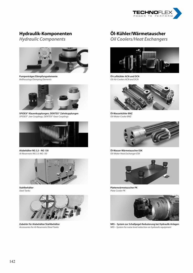
Hydraulik-KomponentenHydraulic Components
Öl-Luftkühler acN und dcNOil-Air Coolers ACN and DCN
Pumpenträger/dämpfungselementeBellhousings/Damping Elements
Öl-Wasserkühler BNZOil-Water Cooler BNZ
sPidex® Klauenkupplungen, deNtex® Zahnkupplungen SpIDEx® Jaw Couplings, DEntEx® Gear Couplings
Plattenwärmetauscher PKPlate Cooler PK
stahlbehälterSteel Tanks
NRs – system zur schallpegel-Reduzierung bei Hydraulik-anlagennRS – System for noise level reduction on hydraulic equipment
Zubehör für alubehälter/stahlbehälterAccessories for Al-Reservoirs/Steel tanks
Öl-Wasser-Wärmetauscher esKOil-Water Heat Exchanger ESK
alubehälter NG 3,5 - NG 130Al-Reservoirs nG 3.5-nG 130
Öl-Kühler/WärmetauscherOil Coolers/Heat Exchangers
142 142

nOteS nOteS „ I n n o v a t i o n i n m o t i o n ”
Berv ina Kf t . • H -1145 Erzsébet k i rá lyné út ja 41/B • Te l . :+36 -1-222-20-79 • Fax: +36 -1-252-48-29 • berv ina@berv ina.com
page 19
NOTES FOR BELTS
„ I n n o v a t i o n i n m o t i o n ”
Berv ina Kf t . • H -1145 Erzsébet k i rá lyné út ja 41/B • Te l . :+36 -1-222-20-79 • Fax: +36 -1-252-48-29 • berv ina@berv ina.com
page 19
NOTES FOR BELTS
143 143

nOteS nOteS „ I n n o v a t i o n i n m o t i o n ”
Berv ina Kf t . • H -1145 Erzsébet k i rá lyné út ja 41/B • Te l . :+36 -1-222-20-79 • Fax: +36 -1-252-48-29 • berv ina@berv ina.com
page 19
NOTES FOR BELTS
„ I n n o v a t i o n i n m o t i o n ”
Berv ina Kf t . • H -1145 Erzsébet k i rá lyné út ja 41/B • Te l . :+36 -1-222-20-79 • Fax: +36 -1-252-48-29 • berv ina@berv ina.com
page 19
NOTES FOR BELTS
144 144

acn und Dcn Öl-Luftkühleracn and Dcn Oil-air coolers
acn und Dcn Öl-Luftkühleracn and Dcn Oil-air coolers
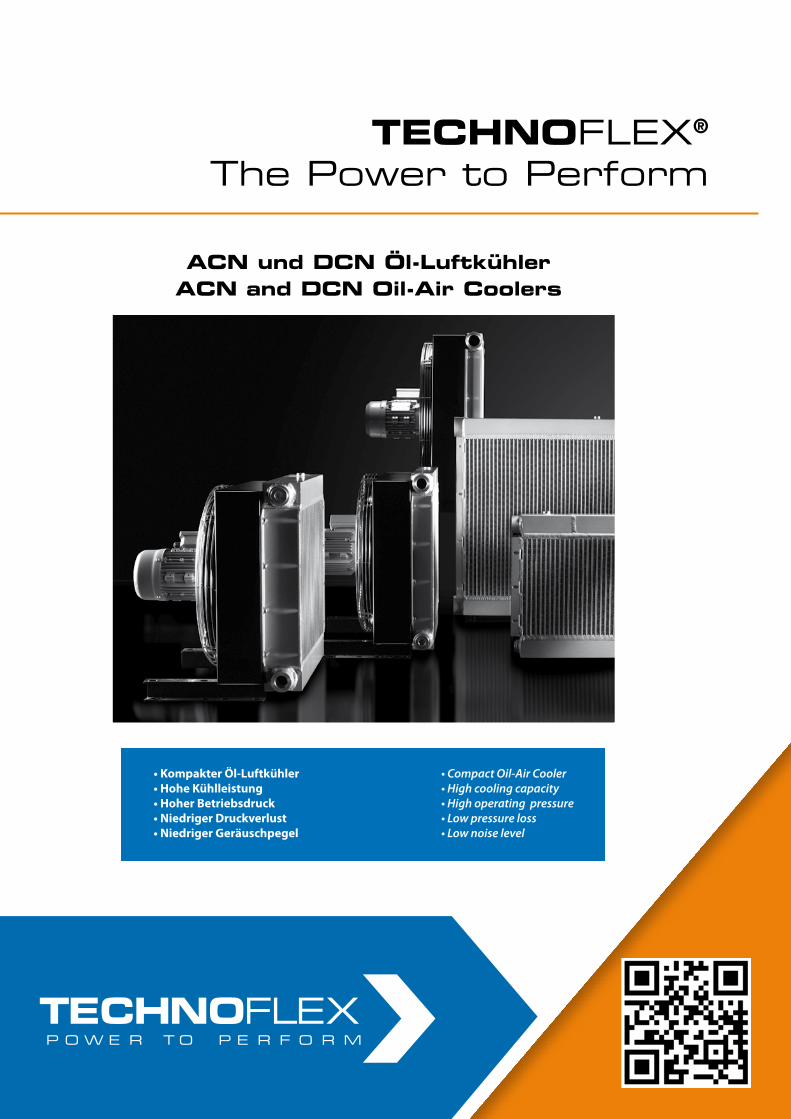
ACN und DCN Öl-Luftkühler mit Drehstromantrieb (3 x 400 V) und mit Gleichstromantrieb (12/24 V)
ACN and DCN Oil-Air Coolers with Alternate Current Drives (3 x 400 V) and Direct Current Drives (12/24 V)
• Kompakter Öl-Luftkühler• Hohe Kühlleistung• Hoher Betriebsdruck• Niedriger Druckverlust• Niedriger Geräuschpegel
• Compact Oil-Air Cooler• High cooling capacity• High operating pressure• Low pressure loss• Low noise level
TECHNOFLEX®
The Power to PerformTECHNOFLEX®
The Power to Perform
ACN und DCN Öl-LuftkühlerACN and DCN Oil-Air Coolers
ACN und DCN Öl-LuftkühlerACN and DCN Oil-Air Coolers
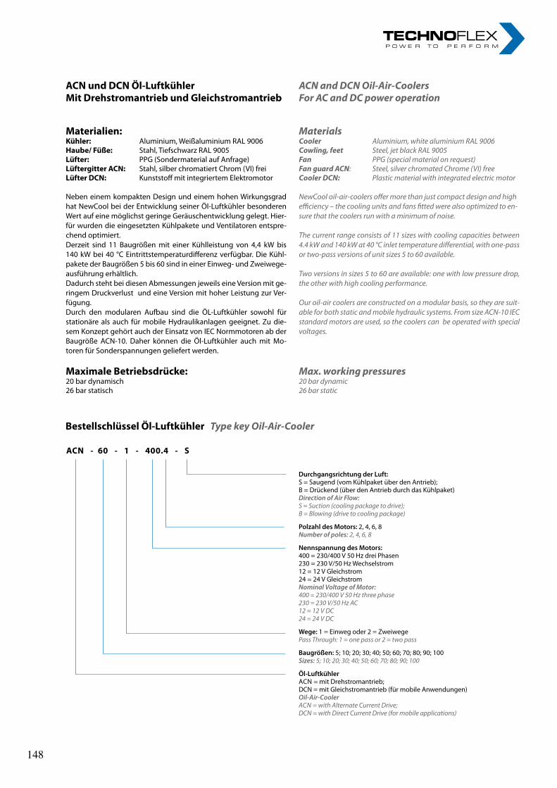
ACN und DCN Öl-LuftkühlerMit Drehstromantrieb und Gleichstromantrieb
Materialien:Kühler: Aluminium, Weißaluminium RAL 9006Haube/ Füße: Stahl, Tiefschwarz RAL 9005Lüfter: PPG (Sondermaterial auf Anfrage)Lüftergitter ACN: Stahl, silber chromatiert Chrom (VI) freiLüfter DCN: Kunststoff mit integriertem Elektromotor
Neben einem kompakten Design und einem hohen Wirkungsgrad hat NewCool bei der Entwicklung seiner Öl-Luftkühler besonderen Wert auf eine möglichst geringe Geräuschentwicklung gelegt. Hier-für wurden die eingesetzten Kühlpakete und Ventilatoren entspre-chend optimiert.Derzeit sind 11 Baugrößen mit einer Kühlleistung von 4,4 kW bis 140 kW bei 40 °C Eintrittstemperaturdifferenz verfügbar. Die Kühl-pakete der Baugrößen 5 bis 60 sind in einer Einweg- und Zweiwege-ausführung erhältlich.Dadurch steht bei diesen Abmessungen jeweils eine Version mit ge-ringem Druckverlust und eine Version mit hoher Leistung zur Ver-fügung. Durch den modularen Aufbau sind die ÖL-Luftkühler sowohl für stationäre als auch für mobile Hydraulikanlagen geeignet. Zu die-sem Konzept gehört auch der Einsatz von IEC Normmotoren ab der Baugröße ACN-10. Daher können die Öl-Luftkühler auch mit Mo-toren für Sonderspannungen geliefert werden.
Maximale Betriebsdrücke:20 bar dynamisch26 bar statisch
ACN and DCN Oil-Air-CoolersFor AC and DC power operation
MaterialsCooler Aluminium, white aluminium RAL 9006Cowling, feet Steel, jet black RAL 9005Fan PPG (special material on request)Fan guard ACN: Steel, silver chromated Chrome (VI) freeCooler DCN: Plastic material with integrated electric motor
NewCool oil-air-coolers offer more than just compact design and highefficiency – the cooling units and fans fitted were also optimized to en-sure that the coolers run with a minimum of noise.
The current range consists of 11 sizes with cooling capacities between 4.4 kW and 140 kW at 40 °C inlet temperature differential, with one-pass or two-pass versions of unit sizes 5 to 60 available.
Two versions in sizes 5 to 60 are available: one with low pressure drop, the other with high cooling performance.
Our oil-air coolers are constructed on a modular basis, so they are suit-able for both static and mobile hydraulic systems. From size ACN-10 IEC standard motors are used, so the coolers can be operated with special voltages.
Max. working pressures20 bar dynamic26 bar static
Bestellschlüssel Öl-Luftkühler Type key Oil-Air-Cooler
ACN - 60 - 1 - 400.4 - S
Durchgangsrichtung der Luft:S = Saugend (vom Kühlpaket über den Antrieb);B = Drückend (über den Antrieb durch das Kühlpaket)Direction of Air Flow:S = Suction (cooling package to drive);B = Blowing (drive to cooling package)
Polzahl des Motors: 2, 4, 6, 8Number of poles: 2, 4, 6, 8
Nennspannung des Motors:400 = 230/400 V 50 Hz drei Phasen230 = 230 V/50 Hz Wechselstrom12 = 12 V Gleichstrom24 = 24 V GleichstromNominal Voltage of Motor:400 = 230/400 V 50 Hz three phase230 = 230 V/50 Hz AC12 = 12 V DC24 = 24 V DC
Wege: 1 = Einweg oder 2 = ZweiwegePass Through: 1 = one pass or 2 = two pass
Baugrößen: 5; 10; 20; 30; 40; 50; 60; 70; 80; 90; 100Sizes: 5; 10; 20; 30; 40; 50; 60; 70; 80; 90; 100
Öl-Luftkühler ACN = mit Drehstromantrieb;DCN = mit Gleichstromantrieb (für mobile Anwendungen)Oil-Air-CoolerACN = with Alternate Current Drive;DCN = with Direct Current Drive (for mobile applications)
148 148
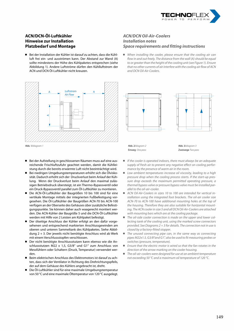
ACN/DCN-Öl-LuftkühlerHinweise zur InstallationPlatzbedarf und Montage
Bei der Installation der Kühler ist darauf zu achten, dass die Kühl-luft frei ein- und ausströmen kann. Der Abstand zur Wand (A) sollte mindestens der Höhe des Kühlpaketes entsprechen (siehe Abbildung 1). Andere Luftströme dürfen den Kühlluftstrom der ACN und DCN Öl-Luftkühler nicht kreuzen.
ACN/DCN Oil-Air-CoolersInstallation notesSpace requirements and fitting instructions
When installing the cooler, please ensure that the cooling air can flow in and out freely. The distance from the wall (A) should be equal to or greater than the height of the cooling unit (see Figure 1). Ensure that no other currents of air interfere with the cooling air flow of ACN and DCN Oil-Air-Coolers.
Abb. 1/diagram 1 Abb. 2/diagram 2
Einweg One pass
Abb. 3/diagram 3
Zweiwege Two pass
Bei der Aufstellung in geschlossenen Räumen muss auf eine aus-reichende Frischluftzufuhr geachtet werden, damit die Kühllei-stung durch die bereits erwärmte Luft nicht beeinträchtigt wird.
Bei niedrigen Umgebungstemperaturen erhöht sich die Ölvisko-sität. Dadurch erhöht sich der Druckverlust beim Anlauf der Küh-lung. Wenn der Druckverlust beim Anlauf den maximal zuläs-sigen Betriebsdruck übersteigt, ist ein Thermo-Bypassventil oder ein Druck-Bypassventil parallel zum Öl-Luftkühler zu montieren.
Die ACN-Öl-Luftkühler der Baugrößen 10 bis 100 sind für eine vertikale Montage mittels der integrierten Fußbefestigung vor-gesehen. Die Öl-Luftkühler der Baugrößen ACN-70 bis ACN-100 verfügen an der Oberseite des Gehäuses über zusätzliche Befesti-gungspunkte. Sie können daher auch waagerecht montiert wer-den. Die ACN-Kühler der Baugröße 5 und die DCN-Öl-Luftkühler werden mit Hilfe von 2 Leisten am Kühlpaket befestigt.
Der ölseitige Anschluss der Kühler erfolgt an den dafür vorge-sehenen und entsprechend markierten Anschlussgewinden am oberen und unteren Sammeltank des Kühlpaketes. Siehe Abbil-dung 2 + 3. Der jeweils nicht benötigte Anschluss wird ab Werk mit einem Verschlussstopfen verschlossen.
Der nicht benötigte Anschlussstutzen kann ebenso wie die An-schlussstutzen M22 x 1,5, G3/8“ und G1“ zum Anschluss von Messfühlern oder Schaltern (Druck, Temperatur) verwendet wer-den.
Beim elektrischen Anschluss des Elektromotors ist darauf zu ach-ten, dass sich der Ventilator in Richtung des Drehrichtungspfeils, der auf dem Gehäuse des Kühlers angebracht ist, dreht.
Die Öl-Luftkühler sind für eine maximale Umgebungstemperatur von 50 °C und eine maximale Öltemperatur von 120 °C ausgelegt.
LuftstromAir Flow
A A
A
If the cooler is operated indoors, there must always be an adequate supply of fresh air to prevent any negative effect on cooling perfor-mance by the presence of warm air in the room.
Low ambient temperatures increase oil viscosity, leading to a high pressure drop when the cooling process starts. If the start-up pres-sure drop exceeds the maximum permitted operating pressure, a thermal bypass valve or pressure bypass valve must be installed par-allel to the oil-air-cooler.
ACN Oil-Air-Coolers in sizes 10 to 100 are intended for vertical in-stallation using the integrated foot brackets. The oil-air cooler size ACN-70 to ACN-100 have additional mounting holes at the top of the housing. Therefore they are also suitable for horizontal mount-ing. The ACN cooler in size 5 and all DCN Oil-Air-Coolers are attached with mounting bars which are at the cooling package.
The oil-side cooler connection is made on the upper and lower col-lecting tank of the cooling unit, using the marked screw connectors provided. See Diagrams 2 + 3 for details. The connection not in use is closed by a factory-fitted stopper.
The unused connecting pipe can, in the same way as connecting pipes M22x1.5, G3/8“and G1”, also be used to fit measuring probes or switches (pressure, temperature).
Ensure that the electric motor is wired so that the fan rotates in the direction of the arrow marking on the cooler housing.
The oil-air-coolers were designed for use at an ambient temperature not exceeding 50 °C and a maximum oil temperature of 120 °C.
149 149
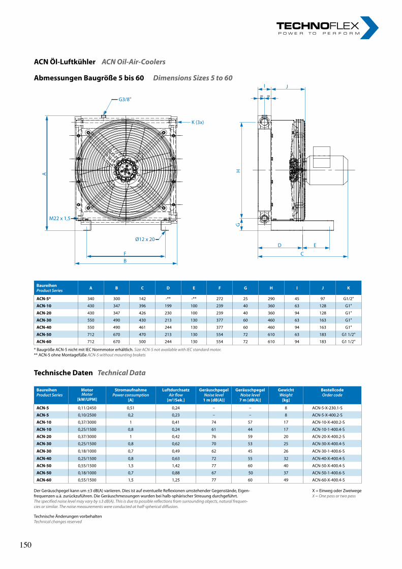
Abmessungen Baugröße 5 bis 60 Dimensions Sizes 5 to 60
BaureihenProduct Series A B C D E F G H I J K
ACN-5* 340 300 142 -** -** 272 25 290 45 97 G1/2"
ACN-10 430 347 396 199 100 239 40 360 63 128 G1"
ACN-20 430 347 426 230 100 239 40 360 94 128 G1"
ACN-30 550 490 430 213 130 377 60 460 63 163 G1"
ACN-40 550 490 461 244 130 377 60 460 94 163 G1"
ACN-50 712 670 470 213 130 554 72 610 63 183 G1 1/2"
ACN-60 712 670 500 244 130 554 72 610 94 183 G1 1/2"
Technische Daten Technical Data
BaureihenProduct Series
MotorMotor
[kW/UPM]
StromaufnahmePower consumption
[A]
LuftdurchsatzAir flow
[m3/Sek.]
GeräuschpegelNoise level
1 m [dB(A)]
GeräuschpegelNoise level
7 m [dB(A)]
GewichtWeight
[kg]
BestellcodeOrder code
ACN-5 0,11/2450 0,51 0,24 – – 8 ACN-5-X-230.1-S
ACN-5 0,10/2500 0,2 0,23 – – 8 ACN-5-X-400.2-S
ACN-10 0,37/3000 1 0,41 74 57 17 ACN-10-X-400.2-S
ACN-10 0,25/1500 0,8 0,24 61 44 17 ACN-10-1-400.4-S
ACN-20 0,37/3000 1 0,42 76 59 20 ACN-20-X-400.2-S
ACN-30 0,25/1500 0,8 0,62 70 53 25 ACN-30-X-400.4-S
ACN-30 0,18/1000 0,7 0,49 62 45 26 ACN-30-1-400.6-S
ACN-40 0,25/1500 0,8 0,63 72 55 32 ACN-40-X-400.4-S
ACN-50 0,55/1500 1,5 1,42 77 60 40 ACN-50-X-400.4-S
ACN-50 0,18/1000 0,7 0,88 67 50 37 ACN-50-1-400.6-S
ACN-60 0,55/1500 1,5 1,25 77 60 49 ACN-60-X-400.4-S
ACN Öl-Luftkühler ACN Oil-Air-Coolers
G3/8"
M22 x 1,5
Ø12 x 20
K (3x)
BF
A
I J
= =
D E
C
GH
Der Geräuschpegel kann um ±3 dB(A) variieren. Dies ist auf eventuelle Reflexionen umstehender Gegenstände, Eigen-frequenzen u.ä. zurückzuführen. Die Geräuschmessungen wurden bei halb-sphärischer Streuung durchgeführt.The specified noise level may vary by ±3 dB(A). This is due to possible reflections from surrounding objects, natural frequen-cies or similar. The noise measurements were conducted at half-spherical diffusion.
X = Einweg oder ZweiwegeX = One pass or two pass
* Baugröße ACN-5 nicht mit IEC Normmotor erhältlich. Size ACN-5 not available with IEC standard motor.** ACN-5 ohne Montagefüße ACN-5 without mounting brakets
Technische Änderungen vorbehaltenTechnical changes reserved
150 150
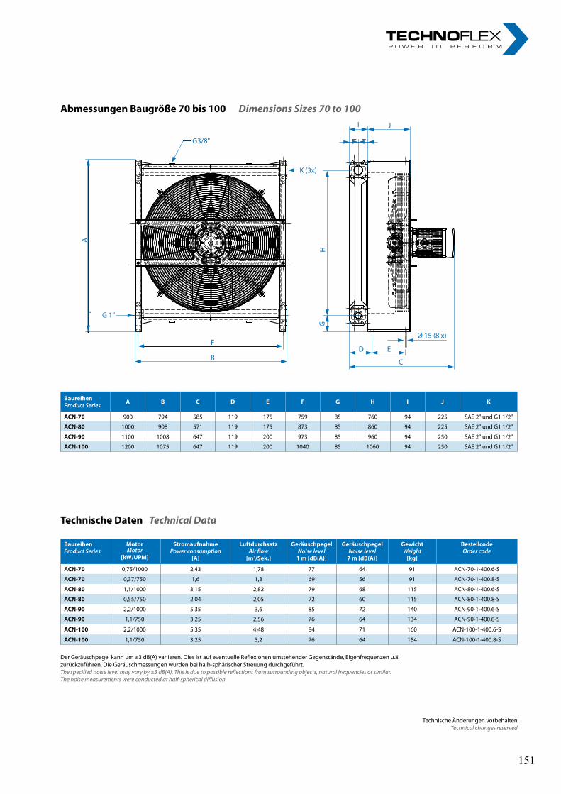
Technische Änderungen vorbehaltenTechnical changes reserved
Abmessungen Baugröße 70 bis 100 Dimensions Sizes 70 to 100
BaureihenProduct Series A B C D E F G H I J K
ACN-70 900 794 585 119 175 759 85 760 94 225 SAE 2" und G1 1/2"
ACN-80 1000 908 571 119 175 873 85 860 94 225 SAE 2" und G1 1/2"
ACN-90 1100 1008 647 119 200 973 85 960 94 250 SAE 2" und G1 1/2"
ACN-100 1200 1075 647 119 200 1040 85 1060 94 250 SAE 2" und G1 1/2"
BaureihenProduct Series
MotorMotor
[kW/UPM]
StromaufnahmePower consumption
[A]
LuftdurchsatzAir flow
[m3/Sek.]
GeräuschpegelNoise level
1 m [dB(A)]
GeräuschpegelNoise level
7 m [dB(A)]
GewichtWeight
[kg]
BestellcodeOrder code
ACN-70 0,75/1000 2,43 1,78 77 64 91 ACN-70-1-400.6-S
ACN-70 0,37/750 1,6 1,3 69 56 91 ACN-70-1-400.8-S
ACN-80 1,1/1000 3,15 2,82 79 68 115 ACN-80-1-400.6-S
ACN-80 0,55/750 2,04 2,05 72 60 115 ACN-80-1-400.8-S
ACN-90 2,2/1000 5,35 3,6 85 72 140 ACN-90-1-400.6-S
ACN-90 1,1/750 3,25 2,56 76 64 134 ACN-90-1-400.8-S
ACN-100 2,2/1000 5,35 4,48 84 71 160 ACN-100-1-400.6-S
ACN-100 1,1/750 3,25 3,2 76 64 154 ACN-100-1-400.8-S
Technische Daten Technical Data
Der Geräuschpegel kann um ±3 dB(A) variieren. Dies ist auf eventuelle Reflexionen umstehender Gegenstände, Eigenfrequenzen u.ä. zurückzuführen. Die Geräuschmessungen wurden bei halb-sphärischer Streuung durchgeführt.The specified noise level may vary by ±3 dB(A). This is due to possible reflections from surrounding objects, natural frequencies or similar. The noise measurements were conducted at half-spherical diffusion.
G3/8"
K (3x)
A
G 1“
F
B
GH
I J
= =
Ø 15 (8 x)
D E
C
151 151
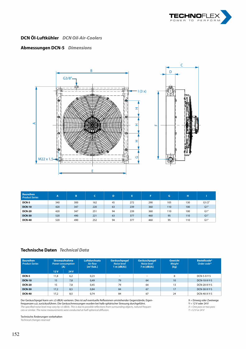
Technische Änderungen vorbehaltenTechnical changes reserved
Abmessungen DCN-5 Dimensions
DCN Öl-Luftkühler DCN Oil-Air-Coolers
BaureihenProduct Series A B C D E F G H I
DCN-5 340 300 162 45 272 290 105 130 G1/2"
DCN-10 420 347 220 63 239 360 110 100 G1"
DCN-20 420 347 251 94 239 360 110 100 G1"
DCN-30 520 490 221 63 377 460 95 110 G1"
DCN-40 520 490 252 94 377 460 95 110 G1"
Technische Daten Technical Data
BaureihenProduct Series
StromaufnahmePower consumption
[A]
LuftdurchsatzAir flow
[m3/Sek.]
GeräuschpegelNoise level
1 m [dB(A)]
GeräuschpegelNoise level
7 m [dB(A)]
GewichtWeight
[kg]
Bestellcode*Order code*
12 V 24 V
DCN-5 11,8 6,2 0,23 – – 8 DCN-5-X-Y-S
DCN-10 15 7,8 0,49 79 64 10 DCN-10-X-Y-S
DCN-20 15 7,8 0,45 79 64 13 DCN-20-X-Y-S
DCN-30 17,2 8,5 0,84 84 67 17 DCN-30-X-Y-S
DCN-40 17,2 8,5 0,74 84 67 24 DCN-40-X-Y-S
X = Einweg oder Zweiwege Y = 12 V oder 24 V X = One pass or two pass Y =12 V or 24 V
Der Geräuschpegel kann um ±3 dB(A) variieren. Dies ist auf eventuelle Reflexionen umstehender Gegenstände, Eigen-frequenzen u.ä. zurückzuführen. Die Geräuschmessungen wurden bei halb-sphärischer Streuung durchgeführt.The specified noise level may vary by ±3 dB(A). This is due to possible reflections from surrounding objects, natural frequen-cies or similar. The noise measurements were conducted at half-spherical diffusion.
152 152
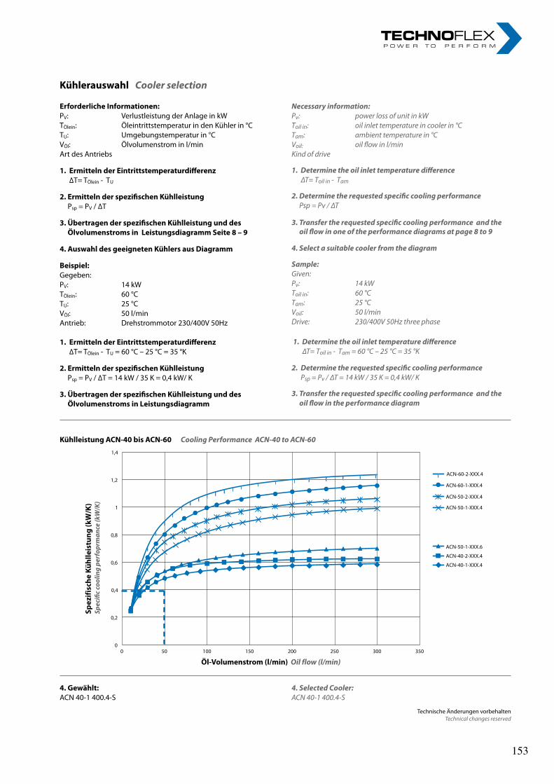
Technische Änderungen vorbehaltenTechnical changes reserved
X = Einweg oder Zweiwege Y = 12 V oder 24 V X = One pass or two pass Y =12 V or 24 V
Erforderliche Informationen:PV: Verlustleistung der Anlage in kWTÖlein: Öleintrittstemperatur in den Kühler in °CTU: Umgebungstemperatur in °CVÖl: Ölvolumenstrom in l/minArt des Antriebs
1. Ermitteln der Eintrittstemperaturdifferenz ∆T= TÖlein - TU
2. Ermitteln der spezifischen Kühlleistung Psp = PV / ∆T
3. Übertragen der spezifischen Kühlleistung und des Ölvolumenstroms in Leistungsdiagramm Seite 8 – 9
4. Auswahl des geeigneten Kühlers aus Diagramm
Beispiel:Gegeben:PV: 14 kWTÖlein: 60 °CTU: 25 °CVÖl: 50 l/minAntrieb: Drehstrommotor 230/400V 50Hz
1. Ermitteln der Eintrittstemperaturdifferenz ∆T= TÖlein - TU = 60 °C – 25 °C = 35 °K
2. Ermitteln der spezifischen Kühlleistung Psp = PV / ∆T = 14 kW / 35 K = 0,4 kW/ K
3. Übertragen der spezifischen Kühlleistung und des Ölvolumenstroms in Leistungsdiagramm
Kühlerauswahl Cooler selection
4. Gewählt:ACN 40-1 400.4-S
Kühlleistung ACN-40 bis ACN-60 Cooling Performance ACN-40 to ACN-60
Öl-Volumenstrom (l/min) Oil flow (l/min)
Spez
ifisc
he K
ühlle
istu
ng (k
W/K
)Sp
ecifi
c co
olin
g pe
rfop
rman
ce (k
W/K
)
0
0,2
0,4
0,6
0,8
1
1,2
1,4
0 50 100 150 200 250 300 350
ACN-40-1-XXX.4
ACN-40-2-XXX.4
ACN-50-1-XXX.6
ACN-50-1-XXX.4
ACN-50-2-XXX.4
ACN-60-1-XXX.4
ACN-60-2-XXX.4
Necessary information:Pv: power loss of unit in kWToil in: oil inlet temperature in cooler in °CTam: ambient temperature in °CVoil: oil flow in l/minKind of drive
1. Determine the oil inlet temperature difference ∆T= Toil in - Tam
2. Determine the requested specific cooling performance Psp = Pv / ∆T
3. Transfer the requested specific cooling performance and the oil flow in one of the performance diagrams at page 8 to 9
4. Select a suitable cooler from the diagram
Sample:Given:Pv: 14 kWToil in: 60 °CTam: 25 °CVoil: 50 l/minDrive: 230/400V 50Hz three phase
1. Determine the oil inlet temperature difference ∆T= Toil in - Tam = 60 °C – 25 °C = 35 °K
2. Determine the requested specific cooling performance Psp = Pv / ∆T = 14 kW / 35 K = 0,4 kW/ K
3. Transfer the requested specific cooling performance and the oil flow in the performance diagram
4. Selected Cooler:ACN 40-1 400.4-S
Technische Änderungen vorbehaltenTechnical changes reserved
X = Einweg oder Zweiwege Y = 12 V oder 24 V X = One pass or two pass Y =12 V or 24 V
Erforderliche Informationen:PV: Verlustleistung der Anlage in kWTÖlein: Öleintrittstemperatur in den Kühler in °CTU: Umgebungstemperatur in °CVÖl: Ölvolumenstrom in l/minArt des Antriebs
1. Ermitteln der Eintrittstemperaturdifferenz ∆T= TÖlein - TU
2. Ermitteln der spezifischen Kühlleistung Psp = PV / ∆T
3. Übertragen der spezifischen Kühlleistung und des Ölvolumenstroms in Leistungsdiagramm Seite 8 – 9
4. Auswahl des geeigneten Kühlers aus Diagramm
Beispiel:Gegeben:PV: 14 kWTÖlein: 60 °CTU: 25 °CVÖl: 50 l/minAntrieb: Drehstrommotor 230/400V 50Hz
1. Ermitteln der Eintrittstemperaturdifferenz ∆T= TÖlein - TU = 60 °C – 25 °C = 35 °K
2. Ermitteln der spezifischen Kühlleistung Psp = PV / ∆T = 14 kW / 35 K = 0,4 kW/ K
3. Übertragen der spezifischen Kühlleistung und des Ölvolumenstroms in Leistungsdiagramm
Kühlerauswahl Cooler selection
4. Gewählt:ACN 40-1 400.4-S
Kühlleistung ACN-40 bis ACN-60 Cooling Performance ACN-40 to ACN-60
Öl-Volumenstrom (l/min) Oil flow (l/min)Sp
ezifi
sche
Küh
lleis
tung
(kW
/K)
Spec
ific
cool
ing
perf
oprm
ance
(kW
/K)
0
0,2
0,4
0,6
0,8
1
1,2
1,4
0 50 100 150 200 250 300 350
ACN-40-1-XXX.4
ACN-40-2-XXX.4
ACN-50-1-XXX.6
ACN-50-1-XXX.4
ACN-50-2-XXX.4
ACN-60-1-XXX.4
ACN-60-2-XXX.4
Necessary information:Pv: power loss of unit in kWToil in: oil inlet temperature in cooler in °CTam: ambient temperature in °CVoil: oil flow in l/minKind of drive
1. Determine the oil inlet temperature difference ∆T= Toil in - Tam
2. Determine the requested specific cooling performance Psp = Pv / ∆T
3. Transfer the requested specific cooling performance and the oil flow in one of the performance diagrams at page 8 to 9
4. Select a suitable cooler from the diagram
Sample:Given:Pv: 14 kWToil in: 60 °CTam: 25 °CVoil: 50 l/minDrive: 230/400V 50Hz three phase
1. Determine the oil inlet temperature difference ∆T= Toil in - Tam = 60 °C – 25 °C = 35 °K
2. Determine the requested specific cooling performance Psp = Pv / ∆T = 14 kW / 35 K = 0,4 kW/ K
3. Transfer the requested specific cooling performance and the oil flow in the performance diagram
4. Selected Cooler:ACN 40-1 400.4-S
153 153
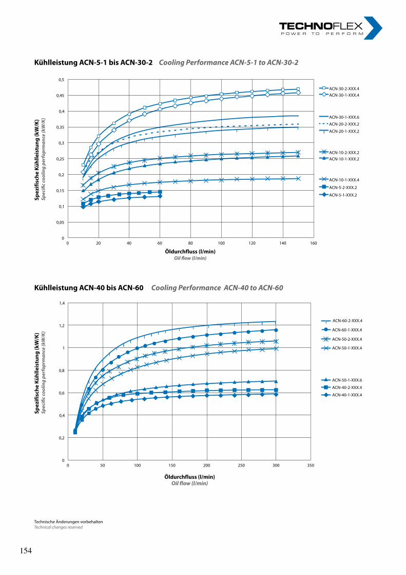
Technische Änderungen vorbehaltenTechnical changes reserved
Kühlleistung ACN-5-1 bis ACN-30-2 Cooling Performance ACN-5-1 to ACN-30-2
Kühlleistung ACN-40 bis ACN-60 Cooling Performance ACN-40 to ACN-60
0
0,05
0,1
0,15
0,2
0,25
0,3
0,35
0,4
0,45
0,5
0 20 40 60 80 100 120 140 160
Kühlleistung ACN-5-1 - ACN-30-2 Cooling performance ACN-5-1 - ACN-30-2
ACN-5-1-XXX.2
ACN-5-2-XXX.2
ACN-10-1-XXX.2
ACN-10-1-XXX.4
ACN-10-2-XXX.2
ACN-20-1-XXX.2
ACN-20-2-XXX.2
ACN-30-1-XXX.6
ACN-30-1-XXX.4 ACN-30-2-XXX.4
Spez
ifisc
he K
ühlle
istu
ng (k
W/K
)Sp
ecifi
c co
olin
g pe
rfop
rman
ce (k
W/K
)
Öldurchfluss (l/min)Oil flow (l/min)
Öldurchfluss (l/min)Oil flow (l/min)
Spez
ifisc
he K
ühlle
istu
ng (k
W/K
)Sp
ecifi
c co
olin
g pe
rfop
rman
ce (k
W/K
)
0
0,2
0,4
0,6
0,8
1
1,2
1,4
0 50 100 150 200 250 300 350
ACN-40-1-XXX.4
ACN-40-2-XXX.4
ACN-50-1-XXX.6
ACN-50-1-XXX.4
ACN-50-2-XXX.4
ACN-60-1-XXX.4
ACN-60-2-XXX.4
154 154
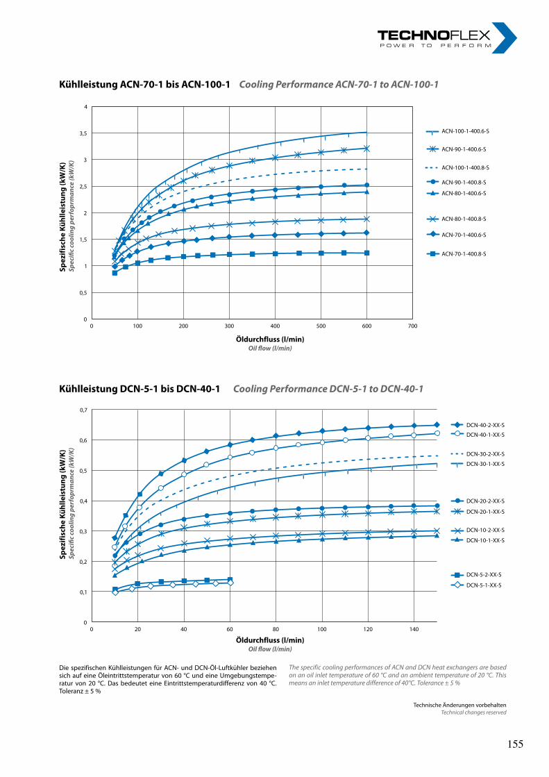
Kühlleistung DCN-5-1 bis DCN-40-1 Cooling Performance DCN-5-1 to DCN-40-1
0
0,1
0,2
0,3
0,4
0,5
0,6
0,7
0 20 40 60 80 100 120 140
DCN-5-1-XX-S
DCN-5-2-XX-S
DCN-10-1-XX-S
DCN-10-2-XX-S
DCN-20-1-XX-S
DCN-20-2-XX-S
DCN-30-1-XX-S
DCN-30-2-XX-S
DCN-40-1-XX-S
DCN-40-2-XX-S
Spez
ifisc
he K
ühlle
istu
ng (k
W/K
)Sp
ecifi
c co
olin
g pe
rfop
rman
ce (k
W/K
)
Öldurchfluss (l/min)Oil flow (l/min)
Die spezifischen Kühlleistungen für ACN- und DCN-Öl-Luftkühler beziehen sich auf eine Öleintrittstemperatur von 60 °C und eine Umgebungstempe-ratur von 20 °C. Das bedeutet eine Eintrittstemperaturdifferenz von 40 °C. Toleranz ± 5 %
The specific cooling performances of ACN and DCN heat exchangers are based on an oil inlet temperature of 60 °C and an ambient temperature of 20 °C. This means an inlet temperature difference of 40°C. Tolerance ± 5 %
Technische Änderungen vorbehaltenTechnical changes reserved
Kühlleistung ACN-70-1 bis ACN-100-1 Cooling Performance ACN-70-1 to ACN-100-1
0
0,5
1
1,5
2
2,5
3
3,5
4
0 100 200 300 400 500 600 700
ACN-70-1-400.6-S
ACN-70-1-400.8-S
ACN-80-1-400.6-S
ACN-80-1-400.8-S
ACN-90-1-400.6-S
ACN-90-1-400.8-S
ACN-100-1-400.6-S
ACN-100-1-400.8-S
Spez
ifisc
he K
ühlle
istu
ng (k
W/K
)Sp
ecifi
c co
olin
g pe
rfop
rman
ce (k
W/K
)
Öldurchfluss (l/min)Oil flow (l/min)
Kühlleistung DCN-5-1 bis DCN-40-1 Cooling Performance DCN-5-1 to DCN-40-1
0
0,1
0,2
0,3
0,4
0,5
0,6
0,7
0 20 40 60 80 100 120 140
DCN-5-1-XX-S
DCN-5-2-XX-S
DCN-10-1-XX-S
DCN-10-2-XX-S
DCN-20-1-XX-S
DCN-20-2-XX-S
DCN-30-1-XX-S
DCN-30-2-XX-S
DCN-40-1-XX-S
DCN-40-2-XX-S
Spez
ifisc
he K
ühlle
istu
ng (k
W/K
)Sp
ecifi
c co
olin
g pe
rfop
rman
ce (k
W/K
)Öldurchfluss (l/min)
Oil flow (l/min)
Die spezifischen Kühlleistungen für ACN- und DCN-Öl-Luftkühler beziehen sich auf eine Öleintrittstemperatur von 60 °C und eine Umgebungstempe-ratur von 20 °C. Das bedeutet eine Eintrittstemperaturdifferenz von 40 °C. Toleranz ± 5 %
The specific cooling performances of ACN and DCN heat exchangers are based on an oil inlet temperature of 60 °C and an ambient temperature of 20 °C. This means an inlet temperature difference of 40°C. Tolerance ± 5 %
Technische Änderungen vorbehaltenTechnical changes reserved
Kühlleistung ACN-70-1 bis ACN-100-1 Cooling Performance ACN-70-1 to ACN-100-1
0
0,5
1
1,5
2
2,5
3
3,5
4
0 100 200 300 400 500 600 700
ACN-70-1-400.6-S
ACN-70-1-400.8-S
ACN-80-1-400.6-S
ACN-80-1-400.8-S
ACN-90-1-400.6-S
ACN-90-1-400.8-S
ACN-100-1-400.6-S
ACN-100-1-400.8-S
Spez
ifisc
he K
ühlle
istu
ng (k
W/K
)Sp
ecifi
c co
olin
g pe
rfop
rman
ce (k
W/K
)
Öldurchfluss (l/min)Oil flow (l/min)
155 155
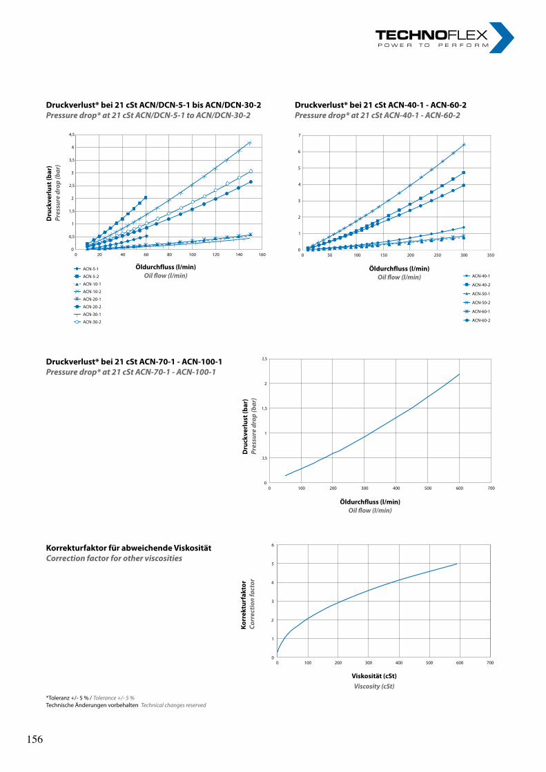
Druckverlust* bei 21 cSt ACN-70-1 - ACN-100-1Pressure drop* at 21 cSt ACN-70-1 - ACN-100-1
0
0,5
1
1,5
2
2,5
3
3,5
4
4,5
0 20 40 60 80 100 120 140 160
ACN-5-1
ACN-5-2
ACN-10-1
ACN-10-2
ACN-20-1
ACN-20-2
ACN-30-1
ACN-30-2
Dru
ckve
rlus
t (ba
r)
Pres
sure
dro
p (b
ar)
Druckverlust* bei 21 cSt ACN/DCN-5-1 bis ACN/DCN-30-2 Pressure drop* at 21 cSt ACN/DCN-5-1 to ACN/DCN-30-2
Öldurchfluss (l/min)Oil flow (l/min)
Druckverlust* bei 21 cSt ACN-40-1 - ACN-60-2 Pressure drop* at 21 cSt ACN-40-1 - ACN-60-2
0
1
2
3
4
5
6
7
0 50 100 150 200 250 300 350
ACN-40-1
ACN-40-2
ACN-50-1
ACN-50-2
ACN-60-1
ACN-60-2
Öldurchfluss (l/min)Oil flow (l/min)
0
0,5
1
1,5
2
2,5
3
3,5
4
4,5
0 20 40 60 80 100 120 140 160
ACN-5-1
ACN-5-2
ACN-10-1
ACN-10-2
ACN-20-1
ACN-20-2
ACN-30-1
ACN-30-2
0
1
2
3
4
5
6
7
0 50 100 150 200 250 300 350
ACN-40-1
ACN-40-2
ACN-50-1
ACN-50-2
ACN-60-1
ACN-60-2
0
0,5
1
1,5
2
2,5
0 100 200 300 400 500 600 700
Dru
ckve
rlus
t (ba
r)
Pres
sure
dro
p (b
ar)
Öldurchfluss (l/min)Oil flow (l/min)
Viskosität (cSt)Viscosity (cSt)
Korr
ektu
rfak
tor
Corr
ectio
n fa
ctor
Korrekturfaktor für abweichende ViskositätCorrection factor for other viscosities
0
1
2
3
4
5
6
0 100 200 300 400 500 600 700
*Toleranz +/- 5 % / Tolerance +/- 5 %Technische Änderungen vorbehalten Technical changes reserved
156 156
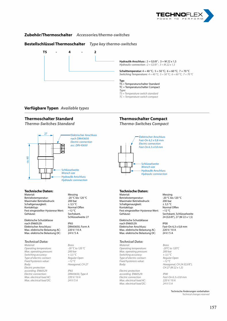
Bestellschlüssel Thermoschalter Type key thermo-switches
TS - 4 - 2
Hydraulik-Anschluss : 2 = G3/8“ ; 3 = M 22 x 1,5Hydraulic-connection : 2 = G3/8“ ; 3 = M 22 x 1,5
Schalttemperatur: 4 = 40 °C; 5 = 50 °C; 6 = 60 °C; 7 = 70 °CSwitching Temperature: 4 = 40 °C; 5 = 50 °C; 6 = 60 °C; 7 = 70 °C
Typ: TS = Temperaturschalter StandardTC = Temperaturschalter CompactType:TS = Temperature switch standardTC = Temperature switch compact
Technical Data:Material: BrassOperating temperature: -20 °C to 120 °CMax. operating pressure: 200 barSwitching accuracy: ± 3,5 °CType of electric contact: Regular OpenFixed hysteresis value: ~12 °C Body: Hexagonal, CH 27Electric protection according EN60529 IP65Electric connection: DIN43650, Type AMax. electrical load AC: 220 V / 10 A Max. electrical load DC: 24 V / 5 A
Zubehör/Thermoschalter Accessories/thermo-switches
Technical Data:Material: BrassOperating temperature: -20°C to 120°CMax. operating pressure: 200 barSwitching accuracy: ± 3,5 °CType of electric contact: Regular OpenFixed hysteresis value: ~12 °C Body: Hexagonal, CH 24 (G3/8”), CH 27 (M 22 x 1,5)Electric protection according EN60529: IP00Electric connection Fast-On 6.3 x 0.8 mmMax. electrical load AC: 220 V / 10 A Max. electrical load DC: 24 V / 5 A
Verfügbare Typen Available types
Technische Änderungen vorbehaltenTechnical changes reserved
Technische Daten:Material: MessingBetriebstemperatur: -20 °C bis 120 °CMaximaler Betriebsdruck: 200 barSchaltgenauigkeit: ± 3,5 °CKontakttyp: Normal Offen Fest eingestellter Hysterese Wert: ~12 °C Gehäuse: Sechskant, Schlüsselweite 24 (G3/8“), 27 (M 22 x 1,5)Elektrische Schutzklasse nach EN60529: IP00Elektrischer Anschluss: Fast-On 6,3 x 0,8 mmMax. elektrische Belastung AC: 220 V / 10 A Max. elektrische Belastung DC: 24 V / 5 A
Technische Daten:Material: MessingBetriebstemperatur: -20 °C bis 120 °CMaximaler Betriebsdruck: 200 barSchaltgenauigkeit: ± 3,5 °CKontakttyp: Normal Offen Fest eingestellter Hysterese Wert: ~12 °C Gehäuse: Sechskant, Schlüsselweite 27Elektrische Schutzklasse nach EN60529: IP65Elektrischer Anschluss: DIN43650, Form AMax. elektrische Belastung AC: 220 V / 10 A Max. elektrische Belastung DC: 24 V / 5 A
Thermoschalter StandardThermo-Switches Standard
Thermoschalter CompactThermo-Switches Compact
Elektrischer AnschlussFast-On 6,3 x 0,8 mm
Schlüsselweite
Hydraulik-Anschluss
Electric connectionFast-On 6.3 x 0.8 mm
Wrench size
Hydraulic connnection
Elektrischer Anschlussnach DIN43650Electric connectionacc. DIN 43650
Schlüsselweite
Hydraulik-AnschlussWrench size
Hydraulic connnection
27
ca. 6
0
157 157
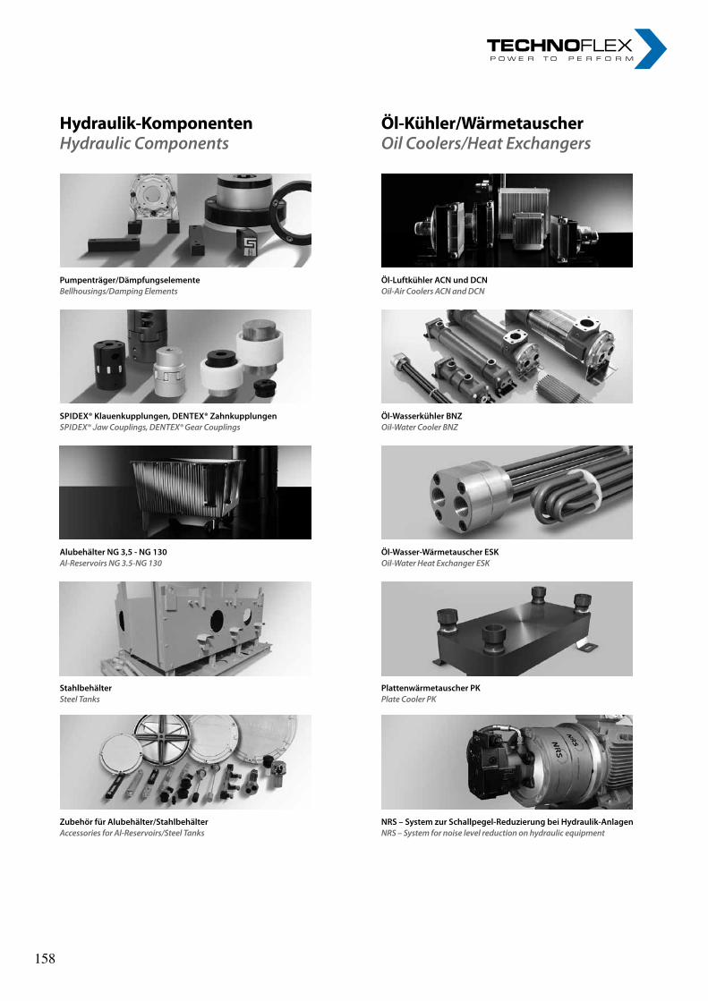
Hydraulik-KomponentenHydraulic Components
Öl-Luftkühler ACN und DCNOil-Air Coolers ACN and DCN
Pumpenträger/DämpfungselementeBellhousings/Damping Elements
Öl-Wasserkühler BNZOil-Water Cooler BNZ
SPiDex® Klauenkupplungen, DeNTex® Zahnkupplungen SPiDEx® Jaw Couplings, DENTEx® Gear Couplings
Plattenwärmetauscher PKPlate Cooler PK
StahlbehälterSteel Tanks
NRS – System zur Schallpegel-Reduzierung bei Hydraulik-AnlagenNRS – System for noise level reduction on hydraulic equipment
Zubehör für Alubehälter/StahlbehälterAccessories for Al-Reservoirs/Steel Tanks
Öl-Wasser-Wärmetauscher eSKOil-Water Heat Exchanger ESK
Alubehälter NG 3,5 - NG 130Al-Reservoirs NG 3.5-NG 130
Öl-Kühler/WärmetauscherOil Coolers/Heat Exchangers
158 158

nOteS nOteS „ I n n o v a t i o n i n m o t i o n ”
Berv ina Kf t . • H -1145 Erzsébet k i rá lyné út ja 41/B • Te l . :+36 -1-222-20-79 • Fax: +36 -1-252-48-29 • berv ina@berv ina.com
page 19
NOTES FOR BELTS
„ I n n o v a t i o n i n m o t i o n ”
Berv ina Kf t . • H -1145 Erzsébet k i rá lyné út ja 41/B • Te l . :+36 -1-222-20-79 • Fax: +36 -1-252-48-29 • berv ina@berv ina.com
page 19
NOTES FOR BELTS
159 159

nOteS nOteS „ I n n o v a t i o n i n m o t i o n ”
Berv ina Kf t . • H -1145 Erzsébet k i rá lyné út ja 41/B • Te l . :+36 -1-222-20-79 • Fax: +36 -1-252-48-29 • berv ina@berv ina.com
page 19
NOTES FOR BELTS
„ I n n o v a t i o n i n m o t i o n ”
Berv ina Kf t . • H -1145 Erzsébet k i rá lyné út ja 41/B • Te l . :+36 -1-222-20-79 • Fax: +36 -1-252-48-29 • berv ina@berv ina.com
page 19
NOTES FOR BELTS
160 160

nOteS nOteS „ I n n o v a t i o n i n m o t i o n ”
Berv ina Kf t . • H -1145 Erzsébet k i rá lyné út ja 41/B • Te l . :+36 -1-222-20-79 • Fax: +36 -1-252-48-29 • berv ina@berv ina.com
page 19
NOTES FOR BELTS
„ I n n o v a t i o n i n m o t i o n ”
Berv ina Kf t . • H -1145 Erzsébet k i rá lyné út ja 41/B • Te l . :+36 -1-222-20-79 • Fax: +36 -1-252-48-29 • berv ina@berv ina.com
page 19
NOTES FOR BELTS
161 161

nOteS nOteS „ I n n o v a t i o n i n m o t i o n ”
Berv ina Kf t . • H -1145 Erzsébet k i rá lyné út ja 41/B • Te l . :+36 -1-222-20-79 • Fax: +36 -1-252-48-29 • berv ina@berv ina.com
page 19
NOTES FOR BELTS
„ I n n o v a t i o n i n m o t i o n ”
Berv ina Kf t . • H -1145 Erzsébet k i rá lyné út ja 41/B • Te l . :+36 -1-222-20-79 • Fax: +36 -1-252-48-29 • berv ina@berv ina.com
page 19
NOTES FOR BELTS
162 162