Material Characterization of FRP Pre-Cured Laminated Used ...
Upload
khangminh22Category
view
2download
0
Int. J. of Applied Mechanics and Engineering, 2019, vol.24, No.3, pp.509-526 DOI: 10.2478/ijame-2019-0032
FAILURE ANALYSIS OF LAMINATED COMPOSITE PLATE UNDER
HYGRO- THERMO MECHANICAL LOAD AND OPTIMISATION
A. CHOUDHURY*, S.C. MONDAL and S. SARKAR Department of Mechanical Engineering, Jadavpur University
Kolkata, INDIA E-mail: [email protected]
Failure analysis of laminated composite plates for different mechanical, thermo mechanical and hygro-thermo mechanical loads for different ply thicknesses, stacking sequences, fiber orientation angles and composite material systems is presented in the paper. A comparative study of different failure theories is also presented in the paper. The effect of fiber orientation angles on the first ply failure load is also studied. A hybrid composite laminate is developed based on the first ply failure load which minimizes weight and cost. The last ply failure load based on fully discounted method is calculated for different stacking sequences. An optimum composite material system and laminate layup is studied for a targeted strength ratio which minimizes weight.
Key words: first ply failure load, last ply failure load, strength ratio, fiber orientation angle, hybrid composite.
1. Introduction
A composite is a system of materials consisting of two or more phases on a macroscopic scale, whose properties are superior to these of its constituent materials. The reinforcement phase is discontinuous, stiffer and stronger as compared to the matrix phase. In some cases of chemical interaction an additional inter phase exists in between the above two phases. Applications of composite materials continue to expand due to their high stiffness, high strength and low density. They include aerospace, aircraft, automotive, biomedical, sports, military and civilian applications. Stiffness and strength of composite materials can be adjusted according to the design load. Airbuses use hybrid composites which combine the advantage and mitigate the disadvantage of individual composite. Sandwich composites also find wide range of applications in light weight structures with high in-plane and flexural stiffness. Failure analysis of a laminate is more complex than that of a single lamina; it requires accurate prediction of strength of each lamina by assessing the stresses to its principle (or local) axis in each lamina and by applying suitable failure criteria. Strength of a laminate depends on lamina orientation angle, strength, stiffness, coefficient of thermal and moisture expansion, stacking sequence and finally the fabrication process which affects the residual stresses, which in turn affect the strength of the laminate. When a single lamina fails, it does not mean that the whole laminate fails but it is the beginning of the failure process. Load at which the first lamina fails is called the first ply failure (FPF)load. A laminate may fail by the failure of individual lamina (intra-laminar failure) or by separation of lamina or layers (inter-laminar failure).FPF can be determined by performing a stress analysis of the laminate under given loading conditions, determining the state of stress in each layer and assessing the strength of each layer by applying a selected failure criteria. FPF approach is conservative and it is used with low factor of safety (or strength ratio). In ultimate laminate failure (ULF), a laminate fails when the maximum load level is reached. In progressive failure scheme, after each ply failure, the influence and contribution of the damaged ply on the remaining plies must be evaluated until the final lamina fails. ULF can occur at much higher load than FPF. After FPF, the failure process continues up to ULF. Laminate efficiency is the ratio of FPF and ULF. Failures of a composite material can take place in different ways. In the paper, two methods have been discussed. The first ply failure (FPF) occurs when the first lamina of the laminate fails either in a
* To whom correspondence should be addressed

510 A.Choudhury, S.C.Mondal and S.Sarkar
longitudinal or in a transverse direction of fibers. Then the last ply failure occurs when the laminate is not capable of taking any further additional load. A laminate can fail by (a) breaking of fibers (b) matrix cracking (c) debonding of fiber and matrix (d) delamination of one lamina from another. Lee [1] performed the failure analysis of a laminated composite plate with a circular hole using the finite element method. Reddy and Pandey [2] performed the first ply failure analysis based on the first order shear deformation theory of a laminated composite plate subjected to in-plane and transverse load using the finite element method. Reddy and Pandey [3] then extended their work on FPF to progressive failure analysis using the linear finite element method. Ochoa and Engblom [4] performed a progressive failure analysis of a composite laminate subjected to uniaxial tension using a higher order plate theory. Reddy and Reddy [5] in their next paper compared the first ply failure load obtained from linear and non-linear analyses and found that the difference is large for transverse loading and small for in-plane loading (tensile). Hwang and Sun [6] used the finite element analysis with modified Newton-Raphson method to predict the failure of composite laminates. Tan [7] investigated the progressive failure of laminates with cut-out holes under in-plane tensile loading by using the material-degradation approach. Tan and Perez [8] extended the same approach for compressive loading. Tolson et al. [9] presented a failure models for determining the first ply failure (FPF) and the last ply failure (LPF) by a progressive stiffness reduction technique using the finite element method and compare results with experimental analyses. Samsudin et al. [10] simulated and analysed the failure, modes of failure and deformations of a symmetric and anti-symmetric graphite epoxy composite laminate using ANSYS for different fiber orientation angles. Chen et al. [11] developed a finite element (FE) model, which includes in-ply and delamination damage effects for the progressive failure analysis of composite laminates. This model can be successfully applied to the simulations of composite laminates susceptible to delamination failure. Zhang et al. [12] presented a progressive failure analysis model involving hygrothermal effects for predicting failure of composite structures in hygrothermal environments. The model introduces a constitutive equations accounting for the hygrothermal strains. Taetragool et al. [13] developed honeycomb structure inspired by Nest-Site Selection (NeSS) optimization algorithm. They used the third order shear and normal deformable plate theory (TSNDT), to find an optimum stacking sequence that maximizes the first failure load according to the Tsai-Wu criterion by the finite element method. They used progressive failure analysis to determine the ultimate load by degrading elasticity of the material at an integration point where the failure criterion had just been satisfied. In this paper, an overall study of the failure analysis of a laminated composite plate for different loading conditions using different failure theories is presented. The effect of thermal and hygrothermal load on the strength ratio of the laminate is studied for a range of fiber orientation angles. The failure analysis is conducted based on the first ply failure load. A hybrid composite material is developed which minimises cost and weight. The last ply failure load is also calculated using fully discounted method. Lastly, an optimum design of the laminate is presented for a given strength ratio and thickness.
2. Failure theories
Single failure criteria are not sufficient to predict the failure of all types of laminates. Failure theories are classified into three groups:
1. Non- interactive theories (maximum stress, maximum strain theory). 2. Interactive theories (Tsai-Hill, Tsai- Wu failure theory). 3. Failure mode based theories (Hashin- Rotem, Puck theory).
Non-interactive theories such as the maximum stress, maximum strain theory are simple to apply and can be used to determine modes of failure but interactive theories such as the Tsai-Hill, Tsai- Wu failure theory cannot predict modes of failure but explain the interaction of stresses in failure. Failure mode based theories such as the Hashin- Rotem, Puck theory are used to determine modes of failure effectively. In the present study, interactive and non-interactive theories are used to determine the strength ratio (or safety factor) of a laminated composite plate under in-plane loadings and moments, hygro-thermal loading and their combinations. Also, a comparative study of these theories is conducted for the above types of loadings. The maximum strain theory is used to determine modes of failure.

Failure analysis of laminated composite plate ... 511
2.1. Maximum stress criteria Failure is predicted in a lamina, if any of the normal or shear stresses in the local axes of a lamina is equal to or exceeds the corresponding ultimate strengths of the unidirectional lamina. The lamina is considered to be failed if
c T1 1 1
ult ult ,
c T2 2 2
ult ult , (2.1)
12 12 12ult ult
is violated.
2.2. Maximum strain criteria Failure is predicted in a lamina, if any of the normal or shearing strains in the local axes of a lamina equals or exceeds the corresponding ultimate strains of the unidirectional lamina. A lamina is considered to be failed if
c T1 1 1
ult ult ,
c T2 2 2
ult ult , (2.2)
12 12 12ult ult is violated.
2.3. Tsai–Wu failure theory This failure theory is based on the total strain energy failure theory. Tsai-Wu failure criteria are quadratic failure criteria which take into account the interaction of stress components but it cannot be used to determine the mode of failure. A lamina is considered to be failed if
2 2 21 1 2 2 6 12 11 1 22 2 12 1 2 66 12H H H H H 2H H 1 , (2.3)
is violated. This failure theory is more general than the Tsai–Hill failure theory because it distinguishes between the compressive and tensile strengths of a lamina. The components H1, H2, H6, H11, H22, and H66 of the failure theory are found using the five strength parameters of a unidirectional lamina. 2.4. Tsai–Hill failure theory This theory is based on the distortion energy failure theory of Von-Misses. Hill adopted the Von-Mises’ distortional energy yield criterion to anisotropic materials. Then, Tsai adapted it to a unidirectional lamina. Based on the distortion energy theory, he proposed that a lamina has failed if
,
2 2 22 3 1 1 3 2 1 2 3 3 1 2
2 2 22 1 3 1 2 3 4 23 5 13 6 12
G G G G G G 2G
2G 2G 2G 2G 2G 1
(2.4)
is violated. The components G1, G2, G3, G4, G5, and G6 of the strength criterion depend on the failure strengths.

512 A.Choudhury, S.C.Mondal and S.Sarkar
2.5. Strength ratio The failure theories only state whether the lamina fails or not when the inequalities are violated but it cannot state how much the load can be increased or decreased if the lamina is safe or fails respectively. The strength ratio is defined as
Maximum load applied ultimate strength
SRLoad applied applied stress
(2.5)
3. Modes of failure Modes of failure are determined by using the maximum strain theory, which states that:
1 0 , longitudinal tensile failure (1T)
1 0 , longitudinal compressive failure (1C)
2 0 , transverse tensile failure (2T)
2 0 , transverse compressive failure (2C) S= shear failure ,12 120 0 . (3.1) If SR > 1, then the lamina is safe and the applied stress can be increased by a factor of SR. If SR < 1, the lamina is unsafe and the applied stress needs to be reduced by a factor of SR. A value of SR = 1 implies the failure load. 4. Constitutive model A laminated structure is a collection of lamina arranged in a specified manner. Consider a laminated composite plate made up of a number of laminae bonded together perfectly and reinforced by fibers in a definite orientation and which is symmetric to its mid plane subjected to mechanical (in-plane normal and shear load, bending and twisting moment) and hygrothermal load. The classical lamination theory (CLT) is applicable for thin laminates, i.e. the thickness is small relative to the lateral dimensions and deformation is small. Stress and strain with reference to the local axes (1, 2) see Fig.1a, in each layer can be determined by the classical lamination theory or first order deformation theory because both the theories yield the same stress. The constitutive equations for a general linear elastic materials narrate the stress and strain tensors as given in the paper [14]. Moreover, in this case the stress- strains relations in the local axis: 1-2 is [Fig.1a]
1 111 12 16
2 12 22 2
663 12
Q Q Q
Q Q 0
0 0 Q
where 111
12 21
EQ
1
, 2
2212 21
EQ
1
,
(4.1)
12 212
12 21
EQ
1
, 66 12Q G , 12 21
1 2E E
.
Stress strain relation in the global axis: x – y (Fig.1a)

Failure analysis of laminated composite plate ... 513
11 12 16x x
y 12 22 26 y
xy xy16 26 66
Q Q Q
Q Q Q
Q Q Q
. (4.2)
Force per unit length (N) and the bending moment per unit length (M) of a laminate are given as
0xx x11 12 16 11 12 16
0y 12 22 26 y 12 22 26 y
016 26 66 16 26 66xy xyxy
N kA A A B B B
N A A A B B B k
A A A B B BN k
, (4.3)
0xx x11 12 16 11 12 16
0y 12 22 26 y 12 22 26 y
016 26 66 16 26 66xy xyxy
M kB B B D D D
M B B B D D D k
B B B D D DM k
, (4.4)
,x yN N - normal force per unit length, xyN - shear force per unit length,
,x yM M - bending moment per unit length, xyM -twisting moments per unit length
0 - mid plane strains of laminate in x-y coordinate and k - laminate curvature. Combining the above two matrices as
0N A B
B DM k
, (4.5)
ijA (extensional stiffness matrix) = , , , , , ,n
ij k k 1kk 1
Q h h i 1 2 6 j 1 2 6
.
ijB (extension-bending coupling matrix) = , , , , , ,n
2 2ij k k 1k
k 1
1Q h h i 1 2 6 j 1 2 6
2
. (4.6)
ijD (bending stiffness matrix) = , , , , , ,n
3 3ij k k 1k
k 1
1Q h h i 1 2 6 j 1 2 6
3
.
The mid plane strain and curvature can be determined from ABD matrix as
10 A B N
B D Mk
. (4.7)
Stress and strain with reference to the local axes (1, 2) in each layer
, , ,[ ] * [ ] [ ] , [ ] [ ] *[ ]k 0 k k1 2 1 2 1 2k
T Q h k inv Q . (4.8)

514 A.Choudhury, S.C.Mondal and S.Sarkar
(a) (b)
Fig.1. (a) Local (1, 2) and global (x, y) axes. (b) Geometry of the laminated plate subjected to in plane, bending, twisting and shear load.
5. Failures of laminate Laminate failure is not catastrophic. If one ply fails the other ply in the laminate is still capable of taking more loads until all the plies fail. When a ply fails, fully discount the ply. Then replace the ply of near zero stiffness and strength. The procedure followed in this paper for finding the first ply and last ply failure load following the fully ply discounted method is as [14, 15]:
I. Enter the basic lamina properties , , ,1 2 12 12E E G .
II. Compute the ply stiffness 12Q referred to their local axis (principle material axis) [Eq.(4.1)].
III. Enter the orientation k , number of layers n, through the thickness coordinate z.
IV. Find out the transformed layer stiffness [ ]kxyQ referred to the laminate (global) coordinate system (x, y)
[Eq.(4.2)]. V. Calculate the laminate stiffness matrices [A], [B], [D] and their compliance matrices [Eq.(4.6)]
VI. Enter the mechanical loading, [ ] ,[ ]xy xyN M . Apply the actual temperature change and moisture
content, ,T C
VII. Calculate the mid plane strain 0
xy and curvature [ ]xyk using laminate analysis [Eq.(4.7)].
VIII. Calculate the layer strain ,[ ]k1 2 and stress ,[ ]k
1 2 with reference to the local axes (1, 2) in each layer
under the given load [Eq.(4.8)]. IX. Enter the five lamina strength and using a suitable failure theory as discussed in the paper find out the
strength ratio (or safety factor) of each of the lamina. Then the minimum strength ratio is the desired strength ratio of the laminate.
X. Multiply the minimum strength ratio to the applied load to get the load level of the failure of the first ply. This load is called the First Ply Failure load (FPF).
XI. Calculate the laminate strength by applying unit stress in the respective direction. XII. Degrade fully the stiffness of damaged ply or plies. Apply the actual load level of previous failure.
XIII. Go to step VII to find the strength ratio in the undamaged plies. If the strength ratio is more than one, multiply the strength ratio to the applied load to get the load level of the next ply failure and go to step VII. If the strength ratio is less than one, degrade the stiffness and strength properties of all the damaged plies and go to step XII.
XIV. Repeat the preceding steps until all the plies in the laminate have failed. The load at which all the plies in the laminate have failed is called the last ply failure.

Failure analysis of laminated composite plate ... 515
6. Result and discussion
6.1. Effect of fiber orientation angles on failure analysis
6.1.1. Symmetric angle ply composite subjected to different mechanical loading condition Consider four layers of symmetric angle ply laminated composite plate subjected to in-plane normal ( ,x yN N ) and shear loading ( xyN ), bending ( ,x yM M ) and twisting moment ( xyM ). The plate is made up
of a graphite epoxy composite. The effect of fiber orientation angle on the strength ratio based on the first ply failure is presented in this paper.
(a) (b)
(c) Fig.2. Strength ratio calculated using maximum stress criteria based on FPF for angle ply laminate for a
range of fiber orientation angles subjected to (a) in-plane normal and shear loading (only , , ,x y xy x y xyN 1 N 1 N 1 N N N 1 ) (b) bending and twisting moment (only
, ,x yM 1 M 1 ,xy x y xyM 1 M M M 1 ) and (c) combination of all loadings
( , ,x x y y xy xyN M 1 N M 1 N M 1 ).
Figure 2 shows the strength ratio calculated using maximum stress criteria based on the first ply failure load for symmetric angles ply laminate for a range of fiber orientation angles subjected to in-plane normal, shear loading, bending and twisting moment and their combination. The strength ratio multiplied to the applied load gives the first ply failure load. Since the load taken is unity, so the strength ratio and first ply failure load is same. For loading only ,x xN M and x xN M , the failure criteria shows that the laminate is
0 10 20 30 40 50 60 70 80 90
0
5000000
10000000
15000000
20000000
25000000
30000000
Nx=Ny=Nxy
Nxy Ny
Nx
Str
eng
th r
atio
or
Firs
t Ply
failu
re lo
ad
Fiber Orientataion Angle (Degree)
Nx Ny Nxy Nx= Ny= Nxy
0 10 20 30 40 50 60 70 80 90
0
20000
40000
60000
80000
100000
Nxy=Mxy
Ny=My
Nx=Mx
Str
eng
th R
atio
or
Fir
st P
ly F
ailu
re lo
ad
Fiber Orientation Angle (Degree)
Nx=Mx Ny= My Nxy= Mxy
0 10 20 30 40 50 60 70 80 90
0
20000
40000
60000
80000
100000
Mx=My=Mxy
Mxy
MyMx
Str
ength
Ratio
(S
R)
or
FP
F lo
ad
Fiber Orientation Angle (Degree)
Mx My Mxy Mx=My=Mxy
516 A.Choudhury, S.C.Mondal and S.Sarkar
strongest at 0° fiber orientation angle (θ) and the strength ratio or first ply failure load decreases with the increase in θ. Whereas it is opposite for loading only ,y yN M and y yN M , the laminate is strongest at 90°
fiber orientation angle (θ) and the strength ratio or first ply failure load increases with the increase in θ. For only shear loading xyN or twisting moment, xyM , the laminate is strongest at optimum angle of 45° and the
strength ratio first increases from 0° attaining the maximum value at 45° and then decreases to the initial value at 90°. The same behaviour is followed by the laminate subjected to loading
,x y xy x y xyN N N M M M , xy xyN M and the optimum design of the laminate under these loading is
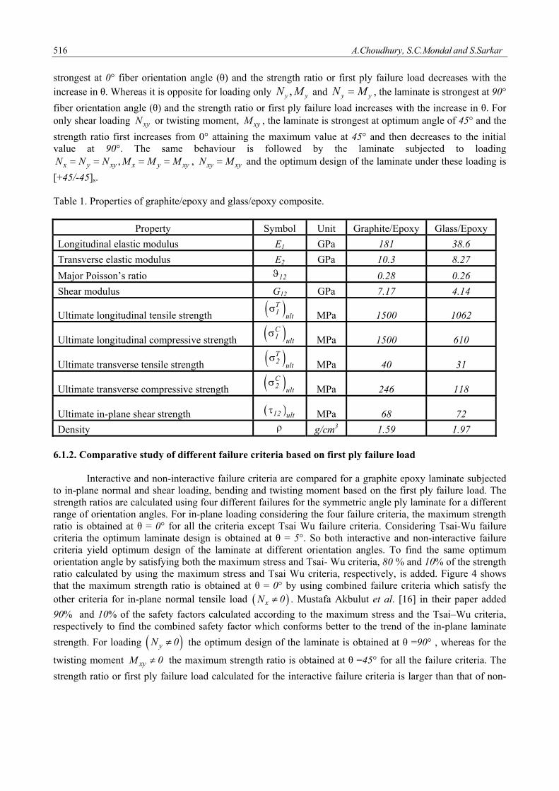
[+45/-45]s. Table 1. Properties of graphite/epoxy and glass/epoxy composite.
Property Symbol Unit Graphite/Epoxy Glass/Epoxy
Longitudinal elastic modulus E1 GPa 181 38.6
Transverse elastic modulus E2 GPa 10.3 8.27
Major Poisson’s ratio 12 0.28 0.26
Shear modulus G12 GPa 7.17 4.14
Ultimate longitudinal tensile strength T1
ult
MPa 1500 1062
Ultimate longitudinal compressive strength C1
ult
MPa 1500 610
Ultimate transverse tensile strength T2
ult
MPa 40 31
Ultimate transverse compressive strength C2
ult
MPa 246 118
Ultimate in-plane shear strength 12 ult MPa 68 72
Density g/cm3 1.59 1.97 6.1.2. Comparative study of different failure criteria based on first ply failure load Interactive and non-interactive failure criteria are compared for a graphite epoxy laminate subjected to in-plane normal and shear loading, bending and twisting moment based on the first ply failure load. The strength ratios are calculated using four different failures for the symmetric angle ply laminate for a different range of orientation angles. For in-plane loading considering the four failure criteria, the maximum strength ratio is obtained at θ = 0° for all the criteria except Tsai Wu failure criteria. Considering Tsai-Wu failure criteria the optimum laminate design is obtained at θ = 5°. So both interactive and non-interactive failure criteria yield optimum design of the laminate at different orientation angles. To find the same optimum orientation angle by satisfying both the maximum stress and Tsai- Wu criteria, 80 % and 10% of the strength ratio calculated by using the maximum stress and Tsai Wu criteria, respectively, is added. Figure 4 shows that the maximum strength ratio is obtained at θ = 0° by using combined failure criteria which satisfy the other criteria for in-plane normal tensile load xN 0 . Mustafa Akbulut et al. [16] in their paper added
90% and 10% of the safety factors calculated according to the maximum stress and the Tsai–Wu criteria, respectively to find the combined safety factor which conforms better to the trend of the in-plane laminate
strength. For loading yN 0 the optimum design of the laminate is obtained at θ =90° , whereas for the
twisting moment xyM 0 the maximum strength ratio is obtained at θ =45° for all the failure criteria. The
strength ratio or first ply failure load calculated for the interactive failure criteria is larger than that of non-

Failure analysis of laminated composite plate ... 517
interactive failure criteria for all the cases of loading for the angle ply composite. For the cross ply composite, the maximum strength ratio calculated by maximum stress criteria is greater than that of other criteria. Figure 5 shows the comparison of the maximum strength ratio calculated for all the criteria for the cross ply composite.
(a) (b)
(c) Fig.3. Strength ratio calculated using interative and non interactive failure criteria for the angle ply
laminate subjected to (a) in-plane normal tensile loading xN 0 (b) twisting moment xyM 0
and (c) in-plane loading yN 0 for a range of fiber orientation angles.
0 10 20 30 40 50 60 70 80 90
0
5000000
10000000
15000000
20000000
25000000
30000000
35000000
Str
en
gth
Ra
tio o
r F
PF
loa
d
Fiber Orientation Angle (Degree)
Max. Stress criteria Max. Strain criteria Tsai- Wu criteria Tsai-Hill criteria
0 10 20 30 40 50 60 70 80 900
10000
20000
30000
40000
50000
60000
Str
en
gth
Ra
tioFiber Orientation Angle (Degree)
Max. Stress Criteria Tsai-Wu Criteria Tsai- Hill Criteria Max. Strain Criteria
0 10 20 30 40 50 60 70 80 90
0
5000000
10000000
15000000
20000000
25000000
30000000
Str
eng
th R
atio
Fiber Orientation Angle(Degree)
Max. Stress Criteria Tsai- Wu Criteria Tsai-Hill Criteria

518 A.Choudhury, S.C.Mondal and S.Sarkar
Fig.4. Comparison of strength ratio calculated using maximum stress, Tsai –Wu and modified failure criteria for the angle ply laminate subjected to in-plane normal tensile loading xN 0 for a range
of fiber orientation angles.
Fig.5. Strength ratio calculated using interactive and non-interactive failure criteria for the cross ply laminate subjected to in-plane normal tensile loading ( xN 0 , yN 0 ).
6.1.3. Composite subjected to hygro-thermo mechanical loading
During fabrication, composite laminates are subjected to a variety of thermal and moisture environments which introduce residual stresses in them. These stresses are called hygro thermal stresses which affects the performance of composite laminates. If the laminate is exposed to only a thermal environment, i.e. it is cooled from curing temperature to room temperature or heated from room temperature to processing temperature, then the stress generated in them is called residual thermal stress. Now when the same laminate is subjected to mechanical load, then the stress developed is called thermo mechanical stress and if it is exposed to moisture along with thermal and mechanical load, then hygro-thermo-mechanical stress is developed. A comparison of the strength ratio calculated by Tsai- Wu failure criteria for a graphite epoxy laminated composite plate subjected to mechanical, thermo mechanical; hygro-thermo mechanical loading is presented. The strength ratio is calculated for the angle from 0° to 90° at an increment of 15°. It is assumed that any change in value within 15° is neglected. Figures 6 and 7 show the strength ratio for a range of orientation angles of the angle ply laminate subjected to mechanical loadings and their combination with thermal (positive temperature difference) and hygrothermal loading. Figure 6a illustrates the application of in-plane tensile
0 10 20 30 40 50 60 70 80 90
0
5000000
10000000
15000000
20000000
25000000
30000000
35000000
Str
engt
h R
atio
or
FP
F lo
ad
Fiber Orientation angle (Degree)
Max. Stress Criteria (a) Tsai-Wu Criteria (b) Modified Criteria (80%a - 20% b) Modified Criteria (90% a- 10% b)
7,44E+06
7,45E+06
7,46E+06
7,47E+06
7,48E+06
7,49E+06
Max Strain
Criteria
Max Stress
Criteria
Tsai-Wu Criteria
Tsai- Hill Criteria
Nx
Ny

Failure analysis of laminated composite plate ... 519
mechanical loading and Fig.6b, a combination of tensile load and bending moment. In both the cases the maximum and minimum strength ratios are obtained at 0° and 90°, respectively, and they are same for all types of loading and the strength ratio of hygro-thermo mechanical loading is greater than thermo mechanical loading which is again greater than mechanical loading for orientation angles. Also, the strength ratio of mechanical loading is greater than that of combined mechanical loading. Figure 7 shows that due to the presence of negative residual thermal stress (negative temperature difference), the strength ratio of thermo mechanical load is less than that of mechanical load but in the previous case (Fig.6), positive thermal stress increases the thermo mechanical load. In all the cases hygro-thermo mechanical load is greater than the other loading. This shows that the presence of moisture increases the stresses more than that of other loading. Figure 8 shows a comparison of the strength ratio using Tsai –Wu failure criteria for thermo mechanical loading for a range of temperature changes. The strength ratio increases with the increase in temperature difference, whereas it is same for the orientation angle of 0° and 90° which shows that the temperature change has no effect on the strength ratio for the above stated orientation angles. Figure 9 shows a comparison of the strength ratio calculated by Tsai Wu failure criteria, based on FPF load for a cross ply composite subjected to in-plane tensile load. The strength ratio of hygro-thermomechanical load is greater than that of other loading.
(a) (b)
Fig.6. Comparison of the strength ratio calculated using Tsai-Wu criteria based on FPF for an angle ply laminate for a range of fiber orientation angles subjected to (a) hygro-thermo mechanical loading (b) combined hygro-thermo mechanical loading for positive temperature difference .
Fig.7. Comparison of the strength ratio calculated using Tsai-Wu criteria subjected to hygro-thermo mechanical loading for negative temperature difference.
0 10 20 30 40 50 60 70 80 90
0
5000000
10000000
15000000
20000000
25000000
30000000
Str
eng
th R
atio
or
FP
F L
oad
Fiber Orientation Angle (Degree)
Mechanical load (Nx) Thermo mechanical load (75 deg C) Hygro thermo mechanical load
0 10 20 30 40 50 60 70 80 90
0
20000
40000
60000
80000
100000
Str
en
gth
Ra
tio o
r F
PF
loa
d
Fiber Orientation Angle (Degree)
combined mechanical load (Nx and Mx) combined thermo mechanical load (75 deg C) combined hygro thermo mechanical load
0 10 20 30 40 50 60 70 80 90
0
5000000
10000000
15000000
20000000
25000000
30000000
Str
eng
th R
atio
or
FP
F lo
ad
Fiber Orientation Angle (Degree)
Thermo mechanical (75 deg C) Hygro thermo mechanical Mechanical load (Nx)

520 A.Choudhury, S.C.Mondal and S.Sarkar
Fig.8. Comparison of the strength ratio calculated using Tsai-Wu criteria subjected to thermo mechanical
loading for a range of temperature difference.
Fig.9. Comparison of the strength ratio calculated using Tsai-Wu criteria subjected to hygro-thermo-
mechanical loading for a cross ply composite. 6.1.4. Comparative study of the symmetric and anti-symmetric angle ply laminate Consider four layers of a symmetric and anti-symmetric angle ply laminated composite plate subjected to thermo mechanical loading. The strength ratio is calculated using Tsai-Wu criteria, based on the first ply failure load for a symmetric and antisymmetric angle ply laminate for a range of fiber orientation angles. The strength ratio of the symmetric angle ply laminate is greater than that of the antisymmetric laminate for a range of fiber orientation angles except 0° and 90° orientation angle. The strength ratio is same for symmetric and anti-symmetric angle ply laminates in the case of 0° and 90° orientation angle which shows that symmetric and antisymmetric orientation of fiber has no effect on the strength ratio for 0° and 90° fiber orientation angle as shown in Fig.10.
0 15 30 45 60 75 90
0
5000000
10000000
15000000
20000000
25000000
30000000
Str
engt
h R
atio
(S
R)
Fiber Orientation Angle
-75 deg C -45 deg C 75 deg C 85 deg C 95 deg C 120 deg C
0,00E+002,00E+064,00E+066,00E+068,00E+061,00E+071,20E+071,40E+071,60E+071,80E+07
Mechanical load (Nx)
Thermo mechanical
(75°C)
Hygro Thermo
mechanical (75°C)
Thermo mechanical
(-75°C)
Hygro Thermo
mechanical (-75°C)
Strength Ratio

Failure analysis of laminated composite plate ... 521
Fig.10. Comparison of the strength ratio calculated using Tsai-Wu criteria subjected to thermo mechanical
loading for a symmetric and anti-symmetric angle ply laminate. 6.2. First ply failure analysis of hybrid composite plate under in plane loading Laminated composite design includes optimization of cost, mass, strength ratio; stiffness, etc. A hybrid composite is the optimum combination of different composite materials. It minimizes cost and mass without compromising the strength. The strength ratio using Tsai-Wu criteria is calculated for a cross ply hybrid composite and is compared with a glass and graphite epoxy composite. The graphite epoxy composite forms the outer layer and the glass epoxy composite forms the inner layer. The longitudinal tensile and compressive strengths are larger in the graphite epoxy lamina than in the glass epoxy lamina. Table 2 shows a comparison of the strength ratio, cost and mass of four layers of cross ply hybrid composite with the other composite. The thickness of each layer is assumed constant. Based on the first ply failure analysis, the strength ratio (SR) of the hybrid composite is larger than the glass epoxy composite and smaller than the SR of graphite epoxy. Also, the cost of the hybrid composite is smaller than that of the graphite epoxy composite and the mass is smaller than the glass epoxy and slightly greater than the graphite epoxy composite. Table 2. Comparison of four layers of cross ply [0/90/90/0] glass epoxy and graphite epoxy composite with
hybrid composite, thickness/layer: 5 mm, length: 1m and width: 0.2 m under in-plane tensile load (1MN).
Type of composite Strength
Ratio Cost/ply Total cost Mass
Graphite/Epoxy 7.47 2.5 unit 10 unit 6.36 kg
Glass/Epoxy 1.77 1 unit 4 unit 8 kg Gr-E/Gl-E/Gl-E/Gr-E (Hybrid composite)
5.55 7 unit 7.12 kg
6.3. Last ply failure analysis of laminate under tensile loading After failure of the first ply in a laminate, the next weaker ply fails and it continues up to the last ply when the whole laminate fails. The load at which the last ply fails is called the last ply failure load. The last ply failure load is determined by the fully discounted method [14] which states that when a ply fails, fully
0 15 30 45 60 75 90
0
5000000
10000000
15000000
20000000
25000000
30000000
Str
engt
h R
atio
Orientation Angle(Degree)
SYM Angle Ply ANTI SYM Angle Ply

522 A.Choudhury, S.C.Mondal and S.Sarkar
discount the ply and replace the ply of near zero stiffness and strength, and continue up to last ply failure. The first ply failure and fully discounted method are discussed in this section. The modes of failure are determined by using the maximum strain theory (Tab.4). Table 3 shows the first ply failure and last ply failure load for different stacking sequence of the laminate. For symmetric angle ply composite FPF and LPF load are same. Table 3. First ply failure load (FPF) and last ply failure load (LPF) for different laminates under tensile load
(1MN), thickness/ply: 5 mm, Graphite epoxy composite laminate.
Stacking sequence FPF (MN)
LPF (MN)
Laminate efficiency
0/90/0 [14] 7.28 15 48.5 0/90/90/0 7.47 15 49.7 45/-45/-45/45 2.46 2.46 100 45/45/45/45 1.29 1.29 100
7. Modes of failure The mode of failure is determined by using the maximum strain theory. Tables 4, 5 show the mode of failure for the symmetric angle ply and cross ply composite laminate under in-plane tensile loading. Table 4. Modes of failure of the symmetric angle ply composite laminate under in-plane tensile load.
Angle Position SR MODE Ply No. Position SR MODE
0 TOP 30 1T
-45 TOP 2.72 ST
BOTTOM 30 1T BOTTOM 2.72 ST
0 TOP 30 1T
45 TOP 2.72 SC
BOTTOM 30 1T BOTTOM 2.72 SC
0 TOP 30 1T
60 TOP 1.6104 SC
BOTTOM 30 1T BOTTOM 1.6104 SC
0 TOP 30 1T
-60 TOP 1.6104 ST
BOTTOM 30 1T BOTTOM 1.6104 ST
30 TOP 5.9827 SC
-60 TOP 1.6104 ST
BOTTOM 5.9827 SC BOTTOM 1.6104 ST
-30 TOP 5.9827 ST
60 TOP 1.6104 SC
BOTTOM 5.9827 ST BOTTOM 1.6104 SC
-30 TOP 5.9827 ST
90 TOP 0.8 2T
BOTTOM 5.9827 ST BOTTOM 0.8 2T
30 TOP 5.9827 SC
-90 TOP 0.8 2T
BOTTOM 5.9827 SC BOTTOM 0.8 2T
45 TOP 2.72 SC
-90 TOP 0.8 2T
BOTTOM 2.72 SC BOTTOM 0.8 2T
-45 TOP 2.72 ST
90 TOP 0.8 2T
BOTTOM 2.72 ST BOTTOM 0.8 2T

Failure analysis of laminated composite plate ... 523
Table 5. Mode of failure of the symmetric cross ply composite laminate under in-plane tensile load. Notation for the mode of failure [14] 1T- longitudinal tensile failure 2T- transverse tensile failure 1C – longitudinal compressive failure 2C – transverse compressive failure ST- tensile shear failure SC- compressive shear failure, 8. Optimization of laminate for different composite materials The optimum design of a composite laminate involves many degrees of freedom, both the number and orientation of plies. The main objective of design is to determine a specific laminate configuration, the number and orientation of plies for a given loading condition and the strength ratio (safety factor). However, if a basic laminate layup and targeted designed strength ratio is selected, the design optimization is restricted to finding the number of layers and allowable thickness. It is required to find out the optimum composite material system, layup, thickness and number of layers (or plies) to achieve a given designed allowable strength ratio (2 in this paper) and minimize weight for a given in-plane tensile loading. The investigation is carried out for three different composite materials: graphite epoxy, glass epoxy and boron epoxy composite and for two types of layup: symmetric angle ply and symmetric cross ply. The optimization is carried out for different loading conditions mentioned in Tab.6. Table 6. Comparative study of different composite materials for a defined strength ratio.
Angle-Ply Sym. [+-0]ns Glass-Epoxy Graphite-Epoxy Boron-Epoxy
NX=1e6 N, SR=2
Ply thickness (t,m) 0.000165 0.000165 0.000165
Optimum angle (deg) 0 0 0
SR (n=1) 0.5257 0.7425 0.6237
no. of lamina (n) 12 9 10
optimum SR 2.1 2.2 2.07
optimum laminate thickness h, mm 1.98 1.485 1.65
allowable thickness(ho, mm) 1.89 1.35 1.59
Weight(kg) 0.78012 0.47223 0.609
Angle Position SR MODE
0 TOP 15.9102 1T
BOTTOM 15.9102 1T
90 TOP 7.4556 2T
BOTTOM 7.4556 2T
90 TOP 7.4556 2T
BOTTOM 7.4556 2T
0 TOP 15.9102 1T
BOTTOM 15.9102 1T

524 A.Choudhury, S.C.Mondal and S.Sarkar
Angle-Ply SYM [+-0]ns Glass-Epoxy Graphite-Epoxy Boron-Epoxy
NY=1e6 N, SR=2
Ply thickness (t,m) 0.000165 0.000165 0.000165
Optimum angle (deg) 90 90 90
SR (n=1) 0.5257 0.7425 0.6237
No. of lamina (n) 12 9 10
Optimum SR 2.1 2.2 2.07
Optimum laminate thickness (h,mm) 1.98 1.485 1.65
Allowable thickness(ho, mm) 1.89 1.35 1.59
Weight(kg) 0.78012 0.47223 0.609
Angle-Ply SYM [+-0]ns Glass-Epoxy Graphite-Epoxy Boron-Epoxy
Nxy=1e6 N, SR=2
Ply thickness (t,m) 0.000165 0.000165 0.000165
Optimum angle (deg) 45 45 50
SR (n=1) 0.0535 0.1929 0.2461
no. of lamina (n) 140 35 31
optimum SR 2.04 2 2.0468
optimum laminate thickness h, mm 23.1 5.775 5.115
allowable thickness(ho, mm) 22.65 5.78 5.00 Weight(kg) 9.1 2.36 1.88
Angle-Ply SYM [+-0]ns Glass-Epoxy Graphite-Epoxy Boron-Epoxy
NX=NY=NXY=1e6 N, SR=2
Ply thickness (t,m) 0.000165 0.000165 0.000165
Optimum angle (deg) 45 45 45
SR (n=1) 0.0268 0.1201 0.1174
no. of lamina (n) 282 66 68
optimum SR 2.07 2.08 2.07
optimum laminate thickness h, mm 46.53 10.89 11.22
allowable thickness(ho, mm) 44.96 10.47 10.84
Weight(kg) 18.33282 3.46302 4.55
CROSS PLY [0M/90N] sym Glass-Epoxy Graphite-Epoxy Boron-Epoxy
Nx=1e6 N, SR=2
Ply thickness (t,m) 0.000165 0.000165 0.000165
M 68 17 18
N 72 18 18
no. of lamina (n) 140 35 36
optimum SR 2.01 2.1 2.19
LAMINATE THICKNESS 23.1 5.775 5.94
allowable thickness(ho, mm) 22.99 5.50 5.42
Weight(kg) 9.1014 1.83645 1.096

Failure analysis of laminated composite plate ... 525
Conclusions The effect of fiber orientation angle on the first ply failure load and strength ratio for different loading conditions is presented in the paper. The strength ratio decreases as the fiber orientation angle increases for the composite plate subjected to in-plane tensile load. The maximum strength ratio is obtained at 0° orientation angle. The strength ratio is calculated and compared for mechanical, thermo mechanical and hygro-thermo mechanical loading conditions for a range of fiber orientation angles. The effect of temperature change on the strength ratio is also studied. The strength ratio increases with the increase in temperature load. The last failure load is calculated for the symmetric angle ply and cross ply laminate. An optimum composite material system and laminate layup is investigated for a targeted strength ratio which minimizes weight. A comprehensive failure analysis of a laminated plate for different loading conditions, ply thickness, stacking sequence, fiber orientation angle and composite material system is presented in the paper. This study will help to design laminated composite structures for different applications. Nomenclature E, G young’s and shear modulus ,h z total thickness of laminate, distance from neutral axis
K shear correction coefficient ,M T bending moment and transformation matrix respectively
Qij reduced stiffness coefficient ijQ transformed reduced stiffness matrix
, , and , ,x y z 1 2 3 global and local axes respectively
shear strain at plane (MPa)
12 ult ultimate in-plane shear strain in plane 12
strain tensor
T1
ult , T
2ult
ultimate longitudinal tensile strain in direction 1 and 2 respectively
c1
ult , c
2ult
ultimate longitudinal compressive strain in direction 1 and 2 respectively
orientation angle (degree) poisson’s ratio stress tensor (MPa)
T1
ult , T
2ult
ultimate longitudinal tensile strength in direction 1 and 2 respectively
c1
ult , c
2ult
ultimate longitudinal compressive strength in direction 1 and 2 respectively
shear stress at plane (MPa) 12 ult
ultimate in-plane shear strength in plane 12
References [1] Lee J.D. (1982): Three dimensional finite element analysis of damage accumulation in composite laminate.
Computers and Structures, vol.15, No.3, pp.335-350.
[2] Reddy and Pandey (1987): A first ply failure analysis of composite laminate. Computer and Structures, vol.25, pp.371-393.
[3] Reddy and Pandey (1987): A post first ply failure analysis of composite laminate. Proceedings of ASME 28th Structures, Structural Dynamics and Materials Conference, pp.788-797.

526 A.Choudhury, S.C.Mondal and S.Sarkar
[4] Ochoa O.O. and Engblom J.J. (1987): Analysis of progressive failure in composites. Composites Science and Technology, vol.28, pp.87-102
[5] Reddy Y.S. and Reddy J.N. (1992): Linear and nonlinear failure analysis of composite laminates with transverse shear. Composite Science and Technology, vol.44, pp.227-255.
[6] Hwang W.C. and Sun C.T. (1989): Failure analysis of laminated composites by using iterative three-dimensional finite element method. Computers and Structures, vol.33, No.1, 4, pp.1-47.
[7] Tan S.C. (1991): Progressive failure model for composite laminates, containing opening. Composite Materials, vol.25, pp.556-577.
[8] Tan S.C. and Perez J. (1993): Progressive failure .of laminated composite with a hole under compressive loading. J. Reinforced Plastics and Composites, vol.12, pp.1043-1057.
[9] Tolsonand S. and Zasaras N. (1991): Finite element analysis of progressive failure in laminated composite plates. Compurers and Structures, vol.38, No.3, pp.361-376.
[10] Azizul Hakim Samsudin, Ahmad KamilHussain and Jamaluddin Mahmud. (2015): Deformation and failure analysis of symmetric and antisymmetric graphite/epoxy laminate due to variations in fiber orientation. ARPN Journal of Engineering and Applied Sciences, vol.10, No.17.
[11] Jing-Fen Chen, Evgeny V. Morozov and Krishnakumar Shankar (2014): Simulating progressive failure of composite laminates including in-ply and delamination damage effects. Composites: Part A 61, pp.185–200.
[12] Jianyu Zhang, DexuanQi, Longwei Zhou, Libin Zhao, NingHua (2015): A progressive failure analysis model for composite structures in hygrothermal environments. Composite Structures, vol.133, pp.331–342.
[13] Taetragool U., Shah P.H., Halls V.A., Zheng J.Q. and Batra R.C. (2017): Stacking sequence optimization for maximizing the first failure initiation load followed by progressive failure analysis until the ultimate load. Composite Structures, vol.180, pp.1007–1021.
[14] Autar K. Kaw (2006): Mechanics of Composite Material. CRC Press Taylor & Francis Group.
[15] Isaac M. and Daniel OriIshai (2013): Engineering Mechanics of Composite Materials. Oxford University Press.
[16] Mustafa Akbulut and Fazil O. Sonmez (2011): Design optimization of laminated composites using a new variant of simulated annealing. Computers and Structures, vol.89, pp.1712–1724.
Received: April 24, 2018
Revised: June 13, 2019
Copyright © 2022 FDOKUMEN


![Prediction of the elastic–plastic behavior of thermoplastic composite laminated plates ([0°/θ°]2) with square hole](https://static.fdokumen.com/doc/165x107/6333426da290d455630a0e97/prediction-of-the-elasticplastic-behavior-of-thermoplastic-composite-laminated.jpg)