— Russellstoll® Pin & sleeve power connectors - ABB
200
— CATALOG Russellstoll® Pin & sleeve power connectors
-
Upload
khangminh22 -
Category
Documents
-
view
1 -
download
0
Transcript of — Russellstoll® Pin & sleeve power connectors - ABB

—C ATALOG
Russellstoll®Pin & sleeve power connectors

R U S S E LL S TO LL® PI N & SL EE V E P OW ER CO N N EC TO R S
— Thomas & Betts is now ABBInstallation Products, but our longlegacy of quality products andinnovation remains the same. Fromconnectors that help wire buildingson Earth to cable ties that help putmachines in space, we continue towork every day to make, market,design and sell products thatprovide a smarter, safer and morereliable flow of electricity, fromsource to socket.

004 – 005 Russellstoll® interconnection systems overview
006 – 047 Max-Gard® interconnection systems
048 –051 GSUL safe ground indicator system
052 – 065 J-Line™ interconnection systems
066– 083 DuraGard® waterproof Connectors
084 – 096 FS/FD™ metallic connections
097– 112 ABB IEC 60 309 international pin and sleeve
113– 138 DuraTite® and Ever-Lok® locking connections
139– 148 Control circuit connections
149– 157 Industrial interlocked receptacles
158– 165 Hazardous location plugs, receptacles and interlocks
166 – 175 Computer system interconnections
176 – 196 Mipco™ connections for refrigerated containers
— Table of contents

4 R U S S E LL S TO LL® PI N & SL EE V E P OW ER CO N N EC TO R S
—Russellstoll® interconnection systemsOverview/application guide This catalog has been divided into sections based on standard application groups. The following is a description of each of the six general categories in which Russellstoll products appear. Applications are not limited to those listed below.
• Industrial hook-ups• Shore-to-ship power connections stations• Portable generator sets• Mills and process plants• Agriculture• Portable power connections• Aerospace manufacturing and airports• Lift stations
• Irrigation and wastewater equipment• Industrial and shipyard welding• Power distribution centers• Job site power: For telephone power
and communications equipment
• Food processing plants• Pharmaceutical manufacturing• Bottling and beverage plants
• Barge and workboat applications• Pulp and paper factories• Outdoor construction sites
• Entertainment (lighting and sound systems)• Machinery• Computer-related equipment
• Welding installations• Construction sites• Facilities’ electrical power
—Heavy industrial/marine applications: outdoor, severe or high abuse environments
—Washdown and light marine applications: watertight/waterproof
—Industrial and commercial applications

5R USSEL L S TO L L® I NTER CO N N EC TI O N S Y S TEMS OV ER V I E W
• Aerospace• Steel mills and mining• Petroleum
• Chemical• Food processing• Waste treatment
• Raised floor applications• Main power connections
• Critical power for test, instrumentation, telephone and medical equipment
Automotive/industrial Interlock systems were designed for the needs of the manufacturing industry. These devices are used where safety requirements mandate a mechanically interlocked system for connection and removal of plugs under full load.
• Automatic press• Heavy-duty portable welding• Portable systems• Machine tool control or Servo systems• Shipyard maintenance power• Battery chargers• Automated welder applications• Food processing• Temporary power connections
—Overview/application guide
Amperage
Type 20 30 50 60 100 200 400
Heavy industrial/marine (pages 6–65)
Max-Gard® – ● – ● ● ● ●
J-Line™ – ● – ● ● ● –
Washdown and light marine (pages 66–96)
DuraGard® ● ● ● ● – – –
FS/FD™ ● ● – – – – –
Mechanically interlocked receptacles ● ● ● – – – –
Industrial and commercial (pages 113–138)
DuraTite™ ● ● – – – – –
Standard Ever-Lok® (+midget) ● ● ● – – – –
Heavy service Ever-Lok – ● – ● ● – –
Control circuit and industrial interlock (pages 139–157)
Control circuit connectors ● – – – – – –
Industrial interlock systems (custom products) ● ● – ● ● ● ●
Hazardous location (pages 158–165)
Max-Gard – ● – ● ● – –
Interlocked switch receptacles ● ● – – – – –
Delayed action circuit breaking receptacles ● ● – – – – –
Safe ground indicator system – – – – – – –
Computer systems (pages 167–175)
FS/FD and angle type DP ● ● ● ● – – –
Spec grade ● ● ● – – – –
DuraGard ● ● ● ● – – –
—Hazardous location applications: Class I, Div. 1/Class II, Div. 1
—Computer systems: data center and OEM products
—Control circuit and industrial interlock applications

6 R U S S E LL S TO LL® PI N & SL EE V E P OW ER CO N N EC TO R S6
30 A–400 A (30–200 A load breaking), maximum 600 V AC/250 V DC receptacles, inlets, plugs, connectors, interlocked receptacles, explosion-proof interlocked receptacles.
Safety• Different power supply ratings can’t mix:
24 single-rate device polarizations ensure exact voltage, frequency and phase differentiation
• Safe connections: Safely connect and disconnect, even in the most extreme conditions such as heavy industrial and explosion-proof environments
• Added safety measures: Explosion-proof rating on all plugs
• Plugs stay in: Standard delayed-action pull-and-turn withdrawal offers all plugs an explosion-proof rating
• Waterproof construction: Standard O-ringed interior components provide environmental separation; watertight mated or unmated
Durability• Built for durability: Rugged cast aluminum
housings with an electrostatic epoxy coating are standard, along with stainless steel hardware
• The best connections for life: Pins and sleeves are made from marine-grade CDA 485 brass; 200 A and 400 A pins and sleeves are silver plated
Performance• Foreign objects stay out: All receptacles and
connectors have a gated rotating disk (gated deadfront) on the face of the interior, which engages upon insertion
• Any configuration you need: Through 4-pole 5-wire configurations, all have a safety center earth ground pin design that makes first and breaks last
• Ease of assembly: Solderless pressure-type screw terminals with hex socket heads and rear-access, take-apart housings provide quick wiring access – No interior removal required for wiring receptacles and connectors
• More control available: Two optional pilot/control pins for contactors, load monitoring circuit, shunt trip or any other communication function you need
• More power: 150% non UL® rating enables Max-Gard installations to be extended up to 600 A custom loads with separate disconnect service
—Max-Gard® interconnection systemsOverview

7M A X- G A R D ® I NTER CO N N EC TI O N S Y S TEMS – OV ER V I E W 7
Electrostatic epoxy powder-coat finish for maximum corrosion resistance
CDA 485 marine-grade brass pins and sleeves
Acme threads prevent “freezing ” of screw collars and covers
Padlock-out access hole in plug shroud
provided as standard safety feature
Compression-type gland bushing for optimal cable seal
• Center ground contacts: Make first, break last• Optional control/pilot contacts: Make last,
break first
Extra thick-wall back boxes
300 series stainless steel hardware for
corrosion resistance (entire line)
Copper-free cast aluminum housings
Optional pilot contacts available for
control or electrical interlocking
Extra-long current contacts with deep-
well arc containment
Gated deadfront construction
Hex-type pressure terminals to ensure tighter connections
—Plug and receptacle with angle adapter and junction box
• Delayed insertion/removal keyways provide explosion-proof approval for standard 30 A, 60 A and 100 A plugs and receptacles
• Available up to 4P5W + pilot; circuit interrupting/load breaking 30 A to 200 A
Neoprene O-rings on pins, sleeves and interiors provide environmental separation and true waterproof integrity

8 R U S S E LL S TO LL® PI N & SL EE V E P OW ER CO N N EC TO R S
Options include: • Shunt trip • Auxiliary switch • Trip ratings
Heavy-duty sliding bar interlock mechanism
(mates with plug padlock-out access hole)
• 30 A–400 A (30–200 A load breaking), maximum 600 V AC/250 V DC receptacles, inlets, plugs, connectors, interlocked receptacles, explosion-proof interlocked receptacles
• NEMA 4X interlocks avail able in 30 A–400 A ranges through 4P5W, with two optional pilot/ control contacts
—Cast aluminum circuit breaker interlocked receptacle (cutaway view)
Standard conduit openings through top or side (cutaway shown), optional sizes and locations
Standard, high A/C or NA breaker switch
(cutaway shown)
Thick-wall cast copper-free aluminum housing with epoxy powder coat finish
(External lockout option kit available)
Heavy on/off handle adds mechanical-to-electrical interlock function
Gated, rotating deadfront receptacle
Protective screw cap (flap cap also available)Watertight = Screw cap coverSplashproof = Flap cover

9M A X- G A R D ® I NTER CO N N EC TI O N S Y S TEMS – OV ER V I E W 9
Door safety switch
Backup door safety latch
Heavy 0.060" steel galvaneel with baked enamel, NEMA 3R/12 construction
Consult Technical Services for additional options
Fully interlocked Max-Gard receptacle
Safety fuse pulls
Angled front receptacle for easier access
• 30 A–400 A (30 A–200 A load breaking), maximum 600 V AC/250 V DC receptacles, inlets, plugs, connectors, interlocked receptacles, explosion-proof interlocked receptacles
• Available in 30 A, 60 A and 100 A sizes, all polarizations through 600 V AC
• Meets Federal specification WS865C, UL file #E5239 Meets UL 98, 50, 1682, 508, 231
• Meets NEC® Table 373-6(b)• Meets major automotive specs* Also available as switch only
—Fused-disconnect switch* interlocked receptacle
Standard 600 V cartridge fuse clips and spacing
Clear shield for test probes
Three externallockout points

10 R U S S E LL S TO LL® PI N & SL EE V E P OW ER CO N N EC TO R S
—Max-Gard® interconnection systemsExplosion-proof waterproof receptaclesMax-Gard DBRE and DSRE series interlocks are explosion proof and waterproof (O-ring sealed), along with optional control contacts, and are fully UL® listed.
—Explosion-proof waterproof circuit breaker interlocked receptacle
Available in 30 A, 60 A and 100 A sizes, all polarizations.
1. Heavy-duty cast aluminum housing, electrostatic epoxy coat finish
2. Standard, high AIC and NA (switched only) breakers available
3. Threaded access (cover not shown) with O-ring for explosion-proof and waterproof integrity
4. Gated deadfront safety5. Drain plug6. Factory-sealed receptacle interior – Accepts
standard Max-Gard plugs
—Explosion-proof waterproof non-interlocked receptacle
Available in 30 A 480 V AC max, all polarizations.• Factory-sealed interior (no filled conduits)• Easy low-cost installation
1. Heavy-duty cast aluminum housing, electrostatic epoxy coat finish
2. Threaded access (cover not shown) with O-ring for explosion-proof and waterproof integrity
3. Gated deadfront for safety4. All standard polarizations available to 480 V AC5. Factory-sealed receptacle interior – Accepts
standard Max-Gard plugs
—01 Approvals• UL and CSA listed for
hazardous locations• Class I, Division 1,
Groups B, C and D• Class II, Division 1,
Groups F and G UL File E10919
• NEMA 7, 8, 9• CSA• DOT shipboard
used above deck “green water”
• NEMA 4X• USCG approved—02 Approvals• UL and CSA listed for
hazardous locations• Class I, Division
1, C and D• Class II, Division 1,
Groups F and G• UL File E10919• NEMA 7, 8, 9• CSA• DOT shipboard
used above deck “green water”
• NEMA 4X• USCG approved
2
3
1
5
4
2
3
1
5
4
—01
—02

11
Feature Russellstoll Max-Gard Crouse-Hinds Arktite®** Appleton Powertite®***
Center ground contact Yes No No
24 single-rated factory polarizations Yes No No
Gated deadfront construction Yes No No
Two optional control contacts Yes No No
Marine-grade CDA485 brass pins/sleeves (200 A–400 A silver-plated)
Yes No No
O-rings/environmental separation, full line Yes No No
Available to 5-wire (4-pole, 5-wire) Yes 30 A and 60 A only No
Complete line epoxy powder coated – Standard Yes No Some
—Receptacles, plugs and connectors
D F 3 414 F R A B K
Gated D deadfront
Flap cover FScrew cover (screw collar for male plugs and male inlets) S
Amperage rating30 A 360 A 6100 A 1200 A 2400 A 4
Voltage assignment numberSee page 38 (voltage selection chart)
Male pins MFemale sleeves F (contacts)
Receptacle RPlug P
Without adapter ØAngle AStraight adapter S
No box ØJunction box BAngle enclosure E
Standard configuration Ø2 Control contacts K
ExampleConnector FPMotor inlet MR For last 3 positions above, Ø can appear in any position.
Standard plugs, etc. will have a ØØØ suffix (example. DS2404MPØØØ).
Feature Russellstoll DBRE/DSRE series Crouse-Hinds EPC series Appleton EBR series (with FB breaker)
Waterproof (DurORing™) O-ring sealing Yes No No
Available to 5-wire (4-pole, 5-wire) through 100 A Yes No No
Gated deadfront Yes No No
Center ground sleeve contact Yes No No
24 single-rated factory polarizations Yes No No
Class I, Div. 1, Groups B, C, D Yes Yes Yes
Class II, Div. 1, Groups F and G Yes Yes Yes*
Meets Coast Guard (was CG259) approvals Yes No No
* Group F excepting electrically conductive dusts. ** Crouse-Hinds and Arktite are trademarks of Cooper Industries, Inc. *** Appleton and Powertite are trademarks of Appleton Electric Inc.
—Interlocked receptacles
D B R E 6 414 060 K S
Gated D deadfront
Switch S*Circuit breaker B
Receptacle R
Explosion-proof EFlap Cap (weathertight) FScrew Cap (watertight) S
Amperage rating30 A 360 A 6100 A 1200 A 2400 A 4
Standard configuration Ø2 Control contacts K
Standard configuration ØAuxiliary switch SShunt trip Z
Voltage assignment numberSee page 38 (voltage selection chart)
Breaker rating or switch codeSee individual product pages for possible breaker ratings and codes
* With S in position 2, positions 9, 10 and 11 must be NAO (Non-Automatic Switch).
M A X- G A R D ® I NTER CO N N EC TI O N S Y S TEMS

12 R U S S E LL S TO LL® PI N & SL EE V E P OW ER CO N N EC TO R S
—Max-Gard® interconnection systems30 A standard service
Pole WireConductor placement
Voltage 60 Hz Cat. no.
Standard bushing I.D.† (in.) Cat. no.
Standard bushing I.D.† (in.) Cat. no. Cat. no. Cat. no. Cat. no.
Product type
Male plug††
Female connector
Female receptacle with angle enclosure
Female receptacle with angle adapter**
and junction box
Female receptacle with angle adapter**
Female receptacle
2 3
G
N1
2 3
G
1
2 3
G
N1
2
G
1
2
G
N1
277 DS3104MPØØØ 7/8 DF3104FPØØØ 7/8 DF3104FRØEØ DF3104FRABØ DF3104FRAØØ DF3104FRØØØ
125 DS3107MPØØØ DF3107FPØØØ DF3107FRØEØ DF3107FRABØ DF3107FRAØØ DF3107FRØØØ
2 3
G
N1
2 3
G
1
2 3
G
N1
2
G
1
2
G
N1
480 DS3204MPØØØ 7/8 DF3204FPØØØ 7/8 DF3204FRØEØ DF3204FRABØ DF3204FRAØØ DF3204FRØØØ
250 DS3207MPØØØ DF3207FPØØØ DF3207FRØEØ DF3207FRABØ DF3207FRAØØ DF3207FRØØØ
600 DS3214MPØØØ DF3214FPØØØ DF3214FRØEØ DF3214FRABØ DF3214FRAØØ DF3214FRØØØ
208 DS3216MPØØØ DF3216FPØØØ DF3216FRØEØ DF3216FRABØ DF3216FRAØØ DF3216FRØØØ
3 4
G
N1
2 3
G
1
2 3
G
N1
2
G
1
2
G
N1
277/480 DS3304MPØØØ 1 DF3304FPØØØ 1 DF3304FRØEØ DF3304FRABØ DF3304FRAØØ DF3304FRØØØ
125/250 DS3307MPØØØ DF3307FPØØØ DF3307FRØEØ DF3307FRABØ DF3307FRAØØ DF3307FRØØØ
120/208 DS3316MPØØØ DF3316FPØØØ DF3316FRØEØ DF3316FRABØ DF3316FRAØØ DF3316FRØØØ
3 4
G
N1
2 3
G
1
2 3
G
N1
2
G
1
2
G
N1
3Ø 480 DS3404MPØØØ 1 DF3404FPØØØ 1 DF3404FRØEØ DF3404FRABØ DF3404FRAØØ DF3404FRØØØ
3Ø 250 DS3407MPØØØ DF3407FPØØØ DF3407FRØEØ DF3407FRABØ DF3407FRAØØ DF3407FRØØØ
3Ø 600 DS3414MPØØØ DF3414FPØØØ DF3414FRØEØ DF3414FRABØ DF3414FRAØØ DF3414FRØØØ
3Ø 208 DS3416MPØØØ DF3416FPØØØ DF3416FRØEØ DF3416FRABØ DF3416FRAØØ DF3416FRØØØ
3Ø 440 DS3421MPØØØ DF3421FPØØØ DF3421FRØEØ DF3421MRABØ DF3421FRAØØ DF3421FRØØØ
4 5
G
N1
2 3
G
1
2 3
G
N1
2
G
1
2
G
N1
3ØY 277/480 DS3504MPØØØ 13/16 DF3504FPØØØ 13/16 DF3504FRØEØ DF3504FRABØ DF3504FRAØØ DF3504FRØØØ
3ØY 347/600 DS3514MPØØØ DF3514FPØØØ DF3514FRØEØ DF3514FRABØ DF3514FRAØØ DF3514FRØØØ
3ØY 120/208 DS3516MPØØØ DF3516FPØØØ DF3516FRØEØ DF3516FRABØ DF3516FRAØØ DF3516FRØØØ
3ØY 250/440 DS3521MPØØØ DF3521FPØØØ DF3521FRØEØ DF3521FRABØ DF3521FRAØØ DF3521FRØØØ
Maximum 600 V AC or 250 V DC.** If receptacle is desired with a straight adapter instead of standard angle adapter, substitute “S” for the “A” in the catalog number of the receptacle with angle adapter or adapter and box.† Standard cable bushings shown; see page 32 for other sizes available at no extra cost if specified on order.†† Always furnished with screw collar. We recommend cup cap with male plug; order catalog number DS3CC. Control contacts for plug/receptacles: Use “K” where noted. Ex: DS3104MP00K. For adapters, junction boxes and accessories, see pages 32–35.
Maximum lug wire 8 AWG 7-strand or flexible, cable entrance 0.187" diameter. Receptacles furnished with flap cap also have screw thread to accept male collar on plug. Catalog numbers shown are for flap cap receptacles; change “DF” to “DS” for ordering screw cap. Boldface figures are for voltage assignment. For different ratings, see page 38.Outlet furnished at location “B” unless otherwise specified. 1" NPT.For full polarization, see page 38.
—Device ratings and polarizations
B
D
A C
43/4"
7 7/8"
8 3/4"
51/8"
Dimensions
Male plug Female connector

13
Pole WireConductor placement
Voltage 60 Hz Cat. no.
Standard bushing I.D.† (in.) Cat. no.
Standard bushing I.D.† (in.) Cat. no. Cat. no. Cat. no. Cat. no.
Product type
Male plug††
Female connector
Female receptacle with angle enclosure
Female receptacle with angle adapter**
and junction box
Female receptacle with angle adapter**
Female receptacle
2 3
G
N1
2 3
G
1
2 3
G
N1
2
G
1
2
G
N1
277 DS3104MPØØØ 7/8 DF3104FPØØØ 7/8 DF3104FRØEØ DF3104FRABØ DF3104FRAØØ DF3104FRØØØ
125 DS3107MPØØØ DF3107FPØØØ DF3107FRØEØ DF3107FRABØ DF3107FRAØØ DF3107FRØØØ
2 3
G
N1
2 3
G
1
2 3
G
N1
2
G
1
2
G
N1
480 DS3204MPØØØ 7/8 DF3204FPØØØ 7/8 DF3204FRØEØ DF3204FRABØ DF3204FRAØØ DF3204FRØØØ
250 DS3207MPØØØ DF3207FPØØØ DF3207FRØEØ DF3207FRABØ DF3207FRAØØ DF3207FRØØØ
600 DS3214MPØØØ DF3214FPØØØ DF3214FRØEØ DF3214FRABØ DF3214FRAØØ DF3214FRØØØ
208 DS3216MPØØØ DF3216FPØØØ DF3216FRØEØ DF3216FRABØ DF3216FRAØØ DF3216FRØØØ
3 4
G
N1
2 3
G
1
2 3
G
N1
2
G
1
2
G
N1
277/480 DS3304MPØØØ 1 DF3304FPØØØ 1 DF3304FRØEØ DF3304FRABØ DF3304FRAØØ DF3304FRØØØ
125/250 DS3307MPØØØ DF3307FPØØØ DF3307FRØEØ DF3307FRABØ DF3307FRAØØ DF3307FRØØØ
120/208 DS3316MPØØØ DF3316FPØØØ DF3316FRØEØ DF3316FRABØ DF3316FRAØØ DF3316FRØØØ
3 4
G
N1
2 3
G
1
2 3
G
N1
2
G
1
2
G
N1
3Ø 480 DS3404MPØØØ 1 DF3404FPØØØ 1 DF3404FRØEØ DF3404FRABØ DF3404FRAØØ DF3404FRØØØ
3Ø 250 DS3407MPØØØ DF3407FPØØØ DF3407FRØEØ DF3407FRABØ DF3407FRAØØ DF3407FRØØØ
3Ø 600 DS3414MPØØØ DF3414FPØØØ DF3414FRØEØ DF3414FRABØ DF3414FRAØØ DF3414FRØØØ
3Ø 208 DS3416MPØØØ DF3416FPØØØ DF3416FRØEØ DF3416FRABØ DF3416FRAØØ DF3416FRØØØ
3Ø 440 DS3421MPØØØ DF3421FPØØØ DF3421FRØEØ DF3421MRABØ DF3421FRAØØ DF3421FRØØØ
4 5
G
N1
2 3
G
1
2 3
G
N1
2
G
1
2
G
N1
3ØY 277/480 DS3504MPØØØ 13/16 DF3504FPØØØ 13/16 DF3504FRØEØ DF3504FRABØ DF3504FRAØØ DF3504FRØØØ
3ØY 347/600 DS3514MPØØØ DF3514FPØØØ DF3514FRØEØ DF3514FRABØ DF3514FRAØØ DF3514FRØØØ
3ØY 120/208 DS3516MPØØØ DF3516FPØØØ DF3516FRØEØ DF3516FRABØ DF3516FRAØØ DF3516FRØØØ
3ØY 250/440 DS3521MPØØØ DF3521FPØØØ DF3521FRØEØ DF3521FRABØ DF3521FRAØØ DF3521FRØØØ
Maximum 600 V AC or 250 V DC.** If receptacle is desired with a straight adapter instead of standard angle adapter, substitute “S” for the “A” in the catalog number of the receptacle with angle adapter or adapter and box.† Standard cable bushings shown; see page 32 for other sizes available at no extra cost if specified on order.†† Always furnished with screw collar. We recommend cup cap with male plug; order catalog number DS3CC. Control contacts for plug/receptacles: Use “K” where noted. Ex: DS3104MP00K. For adapters, junction boxes and accessories, see pages 32–35.
Maximum lug wire 8 AWG 7-strand or flexible, cable entrance 0.187" diameter. Receptacles furnished with flap cap also have screw thread to accept male collar on plug. Catalog numbers shown are for flap cap receptacles; change “DF” to “DS” for ordering screw cap. Boldface figures are for voltage assignment. For different ratings, see page 38.Outlet furnished at location “B” unless otherwise specified. 1" NPT.For full polarization, see page 38.
2 7/8"
41/2"
61/8"
9 5/8"
9 1/8"
9 5/8"
3"
6 3/8"
31/8"
9 7/8"
Dimensions
Female receptacle with angle enclosure
Female receptacle with angle adapter and junction box
Female receptacle with angle adapter Female receptacle
M A X- G A R D ® I NTER CO N N EC TI O N S Y S TEMS

14 R U S S E LL S TO LL® PI N & SL EE V E P OW ER CO N N EC TO R S
Pole WireConductor placement
Voltage60 hz Cat. no.
Standard bushing I.D.† (in.) Cat. no.
Standard bushing I.D.† (in.) Cat. no. Cat. no. Cat. no. Cat. no.
Product type
Female connector
Male plug††
Male inlet with angle enclosure
Male inlet with angle adapter**
and junction box
Male inlet with angle adapter**
Male Inlet††
2 3 277 DF3104FPØØØ 7/8 DS3104MPØØØ 7/8 DS3104MRØEØ DS3104MRABØ DS3104MRAØØ DS3104MRØØØ
125 DF3107FPØØØ DS3107MPØØØ DS3107MRØEØ DS3107MRABØ DS3107MRAØØ DS3107MRØØØ
2 3 480 DF3204FPØØØ 7/8 DS3204MPØØØ 7/8 DS3204MRØEØ DS3204MRABØ DS3204MRAØØ DS3204MRØØØ
250 DF3207FPØØØ DS3207MPØØØ DS3207MRØEØ DS3207MRABØ DS3207MRAØØ DS3207MRØØØ
600 DF3214FPØØØ DS3214MPØØØ DS3214MRØEØ DS3214MRABØ DS3214MRAØØ DS3214MRØØØ
208 DF3216FPØØØ DS3216MPØØØ DS3216MRØEØ DS3216MRABØ DS3216MRAØØ DS3216MRØØØ
3 4 277/480 DF3304FPØØØ 1 DS3304MPØØØ 1 DS3304MRØEØ DS3304MRABØ DS3304MRAØØ DS3304MRØØØ
125/250 DF3307FPØØØ DS3307MPØØØ DS3307MRØEØ DS3307MRABØ DS3307MRAØØ DS3307MRØØØ
120/208 DF3316FPØØØ DS3316MPØØØ DS3316MRØEØ DS3316MRABØ DS3316MRAØØ DS3316MRØØØ
3 4 3Ø 480 DF3404FPØØØ 1 DS3404MPØØØ 1 DS3404MRØEØ DS3404MRABØ DS3404MRAØØ DS3404MRØØØ
3Ø 250 DF3407FPØØØ DS3407MPØØØ DS3407MRØEØ DS3407MRABØ DS3407MRAØØ DS3407MRØØØ
3Ø 600 DF3414FPØØØ DS3414MPØØØ DS3414MRØEØ DS3414MRABØ DS3414MRAØØ DS3414MRØØØ
3Ø 208 DF3416FPØØØ DS3416MPØØØ DS3416MRØEØ DS3416MRABØ DS3416MRAØØ DS3416MRØØØ
3Ø 440 DF3421FPØØØ DS3421MPØØØ DS3421MRØEØ DS3421MRABØ DS3421MRAØØ DS3421MRØØØ
4 5 3ØY 277/480 DF3504FPØØØ 13/16 DS3504MPØØØ 13/16 DS3504MRØEØ DS3504MRABØ DS3504MRAØØ DS3504MRØØØ
3ØY 347/600 DF3514FPØØØ DS3514MPØØØ DS3514MRØEØ DS3514MRABØ DS3514MRAØØ DS3514MRØØØ
3ØY 120/208 DF3516FPØØØ DS3516MPØØØ DS3516MRØEØ DS3516MRABØ DS3516MRAØØ DS3516MRØØØ
3ØY 250/440 DF3521FPØØØ DS3521MPØØØ DS3521MRØEØ DS3521MRABØ DS3521MRAØØ DS3521MRØØØ
—Max-Gard® interconnection systems30 A reverse service
—Device ratings and polarizations
G
N1
2 3
G
1
2 3
G
N1
2
G
1
2
G
N1
G
N1
2 3
G
1
2 3
G
N1
2
G
1
2
G
N1
G
N1
2 3
G
1
2 3
G
N1
2
G
1
2
G
N1
G
N1
2 3
G
1
2 3
G
N1
2
G
1
2
G
N1
G
N1
2 3
G
1
2 3
G
N1
2
G
1
2
G
N1
Maximum 600 V AC or 250 V DC.** If receptacle is desired with a straight adapter instead of standard angle adapter, substitute “S” for the “A” in the catalog number of the receptacle with angle adapter or adapter and box.† Standard cable bushings shown; see page 32 for other sizes available at no extra cost if specified on order.†† Always furnished with screw collar. We recommend cup cap with male plug; order catalog number DS3CC. Control contacts for plug/receptacles: Use “K” where noted. Ex: DS3104MR00K. For adapters, junction boxes and accessories, see pages 32–35.
Dimensions
B
D
A C
43/4"
7 7/8"
8 3/4"
51/8"
Male plugFemale connector

15M A X- G A R D ® I NTER CO N N EC TI O N S Y S TEMS
2 7/8"
5 1/2"
2 1/2"3 1/8"
10 7/8"
6 1/4"9"
3"
9 5/8"
Pole WireConductor placement
Voltage60 hz Cat. no.
Standard bushing I.D.† (in.) Cat. no.
Standard bushing I.D.† (in.) Cat. no. Cat. no. Cat. no. Cat. no.
Product type
Female connector
Male plug††
Male inlet with angle enclosure
Male inlet with angle adapter**
and junction box
Male inlet with angle adapter**
Male Inlet††
2 3 277 DF3104FPØØØ 7/8 DS3104MPØØØ 7/8 DS3104MRØEØ DS3104MRABØ DS3104MRAØØ DS3104MRØØØ
125 DF3107FPØØØ DS3107MPØØØ DS3107MRØEØ DS3107MRABØ DS3107MRAØØ DS3107MRØØØ
2 3 480 DF3204FPØØØ 7/8 DS3204MPØØØ 7/8 DS3204MRØEØ DS3204MRABØ DS3204MRAØØ DS3204MRØØØ
250 DF3207FPØØØ DS3207MPØØØ DS3207MRØEØ DS3207MRABØ DS3207MRAØØ DS3207MRØØØ
600 DF3214FPØØØ DS3214MPØØØ DS3214MRØEØ DS3214MRABØ DS3214MRAØØ DS3214MRØØØ
208 DF3216FPØØØ DS3216MPØØØ DS3216MRØEØ DS3216MRABØ DS3216MRAØØ DS3216MRØØØ
3 4 277/480 DF3304FPØØØ 1 DS3304MPØØØ 1 DS3304MRØEØ DS3304MRABØ DS3304MRAØØ DS3304MRØØØ
125/250 DF3307FPØØØ DS3307MPØØØ DS3307MRØEØ DS3307MRABØ DS3307MRAØØ DS3307MRØØØ
120/208 DF3316FPØØØ DS3316MPØØØ DS3316MRØEØ DS3316MRABØ DS3316MRAØØ DS3316MRØØØ
3 4 3Ø 480 DF3404FPØØØ 1 DS3404MPØØØ 1 DS3404MRØEØ DS3404MRABØ DS3404MRAØØ DS3404MRØØØ
3Ø 250 DF3407FPØØØ DS3407MPØØØ DS3407MRØEØ DS3407MRABØ DS3407MRAØØ DS3407MRØØØ
3Ø 600 DF3414FPØØØ DS3414MPØØØ DS3414MRØEØ DS3414MRABØ DS3414MRAØØ DS3414MRØØØ
3Ø 208 DF3416FPØØØ DS3416MPØØØ DS3416MRØEØ DS3416MRABØ DS3416MRAØØ DS3416MRØØØ
3Ø 440 DF3421FPØØØ DS3421MPØØØ DS3421MRØEØ DS3421MRABØ DS3421MRAØØ DS3421MRØØØ
4 5 3ØY 277/480 DF3504FPØØØ 13/16 DS3504MPØØØ 13/16 DS3504MRØEØ DS3504MRABØ DS3504MRAØØ DS3504MRØØØ
3ØY 347/600 DF3514FPØØØ DS3514MPØØØ DS3514MRØEØ DS3514MRABØ DS3514MRAØØ DS3514MRØØØ
3ØY 120/208 DF3516FPØØØ DS3516MPØØØ DS3516MRØEØ DS3516MRABØ DS3516MRAØØ DS3516MRØØØ
3ØY 250/440 DF3521FPØØØ DS3521MPØØØ DS3521MRØEØ DS3521MRABØ DS3521MRAØØ DS3521MRØØØ
6"
9 5/8"
Maximum lug wire 4 AWG 7-strand or flexible, cable entrance 0.187" diameter. Receptacles furnished with flap cap also have screw thread to accept male collar on plug. Catalog numbers shown are for flap cap receptacles; change “DF” to “DS” for ordering screw cap. Boldface figures are for voltage assignment. For different ratings, see page 38.Outlet furnished at location “B” unless otherwise specified. 1" NPT.For full polarization, see page 38.
Dimensions
Male inlet with angle enclosure
Male inlet with angle adapter and junction box
Male inlet with angle adapter Male inlet

16 R U S S E LL S TO LL® PI N & SL EE V E P OW ER CO N N EC TO R S
Pole WireConductorplacement
Voltage60 Hz Cat. no.
Standardbushing I.D.† (in.) Cat. no.
Standardbushing I.D.† (in.) Cat. no. Cat. no. Cat. no. Cat. no.
Product type
Male plug††
Female connector
Female receptacle with angle enclosure
Female receptacle with angle adapter**
and junction box
Female receptacle with angle adapter**
Female receptacle
2 3 277 DS6104MPØØØ 13/16 DF6104FPØØØ 13/16 DF6104FRØEØ DF6104FRABØ DF6104FRAØØ DF6104FRØØØ
125 DS6107MPØØØ DF6107FPØØØ DF6107FRØEØ DF6107FRABØ DF6107FRAØØ DF6107FRØØØ
2 3 480 DS6204MPØØØ 13/16 DF6204FPØØØ 13/16 DF6204FRØEØ DF6204FRABØ DF6204FRAØØ DF6204FRØØØ
250 DS6207MPØØØ DF6207FPØØØ DF6207FRØEØ DF6207FRABØ DF6207FRAØØ DF6207FRØØØ
600 DS6214MPØØØ DF6214FPØØØ DF6214FRØEØ DF6214FRABØ DF6214FRAØØ DF6214FRØØØ
208 DS6216MPØØØ DF6216FPØØØ DF6216FRØEØ DF6216FRABØ DF6216FRAØØ DF6216FRØØØ
3 4 277/480 DS6304MPØØØ 15/16 DF6304FPØØØ 15/16 DF6304FRØEØ DF6304FRABØ DF6304FRAØØ DF6304FRØØØ
125/250 DS6307MPØØØ DF6307FPØØØ DF6307FRØEØ DF6307FRABØ DF6307FRAØØ DF6307FRØØØ
120/208 DS6316MPØØØ DF6316FPØØØ DF6316FRØEØ DF6316FRABØ DF6316FRAØØ DF6316FRØØØ
3 4 3Ø 480 DS6404MPØØØ 15/16 DF6404FPØØØ 15/16 DF6404FRØEØ DF6404FRABØ DF6404FRAØØ DF6404FRØØØ
3Ø 250 DS6407MPØØØ DF6407FPØØØ DF6407FRØEØ DF6407FRABØ DF6407FRAØØ DF6407FRØØØ
3Ø 600 DS6414MPØØØ DF6414FPØØØ DF6414FRØEØ DF6414FRABØ DF6414FRAØØ DF6414FRØØØ
3Ø 208 DS6416MPØØØ DF6416FPØØØ DF6416FRØEØ DF6416FRABØ DF6416FRAØØ DF6416FRØØØ
3Ø 440 DS6421MPØØØ DF6421FPØØØ DF6421FRØEØ DF6421FRABØ DF6421FRAØØ DF6421FRØØØ
4 5 3ØY 277/480 DS6504MPØØØ 11/2 DF6504FPØØØ 11/2 DF6504FRØEØ DF6504FRABØ DF6504FRAØØ DF6504FRØØØ
3ØY 347/600 DS6514MPØØØ DF6514FPØØØ DF6514FRØEØ DF6514FRABØ DF6514FRAØØ DF6514FRØØØ
3ØY 110/208 DS6516MPØØØ DF6516FPØØØ DF6516FRØEØ DF6516FRABØ DF6516FRAØØ DF6516FRØØØ
3ØY 250/440 DS6521MPØØØ DF6521FPØØØ DF6521FRØEØ DF6521FRABØ DF6521FRAØØ DF6521FRØØØG
N1
2 3
G
1
2 3
G
N1
2
G
1
2
G
N1
G
N1
2 3
G
1
2 3
G
N1
2
G
1
2
G
N1
G
N1
2 3
G
1
2 3
G
N1
2
G
1
2
G
N1
G
N1
2 3
G
1
2 3
G
N1
2
G
1
2
G
N1
G
N1
2 3
G
1
2 3
G
N1
2
G
1
2
G
N1
5 1/2"
9 1/8"
1 0 "
5 3/8"
B
D
A C
—Max-Gard® interconnection systems60 A standard service
—Device ratings and polarizations
Maximum 600 V AC or 250 V DC.** If receptacle is desired with a straight adapter instead of standard angle adapter, substitute “S” for the “A” in the catalog number of the receptacle with angle adapter or adapter and box.† Standard cable bushings shown; see page 32 for other sizes available at no extra cost if specified on order.†† Always furnished with screw collar. We recommend cup cap with male plug; order catalog number DS6CC Control contacts for plug/receptacles: Use “K” where noted. Ex: DS6104MP00K. For adapters, junction boxes and accessories, see pages 32–35.
Dimensions
Male plug Female connector

17M A X- G A R D ® I NTER CO N N EC TI O N S Y S TEMS
Pole WireConductorplacement
Voltage60 Hz Cat. no.
Standardbushing I.D.† (in.) Cat. no.
Standardbushing I.D.† (in.) Cat. no. Cat. no. Cat. no. Cat. no.
Product type
Male plug††
Female connector
Female receptacle with angle enclosure
Female receptacle with angle adapter**
and junction box
Female receptacle with angle adapter**
Female receptacle
2 3 277 DS6104MPØØØ 13/16 DF6104FPØØØ 13/16 DF6104FRØEØ DF6104FRABØ DF6104FRAØØ DF6104FRØØØ
125 DS6107MPØØØ DF6107FPØØØ DF6107FRØEØ DF6107FRABØ DF6107FRAØØ DF6107FRØØØ
2 3 480 DS6204MPØØØ 13/16 DF6204FPØØØ 13/16 DF6204FRØEØ DF6204FRABØ DF6204FRAØØ DF6204FRØØØ
250 DS6207MPØØØ DF6207FPØØØ DF6207FRØEØ DF6207FRABØ DF6207FRAØØ DF6207FRØØØ
600 DS6214MPØØØ DF6214FPØØØ DF6214FRØEØ DF6214FRABØ DF6214FRAØØ DF6214FRØØØ
208 DS6216MPØØØ DF6216FPØØØ DF6216FRØEØ DF6216FRABØ DF6216FRAØØ DF6216FRØØØ
3 4 277/480 DS6304MPØØØ 15/16 DF6304FPØØØ 15/16 DF6304FRØEØ DF6304FRABØ DF6304FRAØØ DF6304FRØØØ
125/250 DS6307MPØØØ DF6307FPØØØ DF6307FRØEØ DF6307FRABØ DF6307FRAØØ DF6307FRØØØ
120/208 DS6316MPØØØ DF6316FPØØØ DF6316FRØEØ DF6316FRABØ DF6316FRAØØ DF6316FRØØØ
3 4 3Ø 480 DS6404MPØØØ 15/16 DF6404FPØØØ 15/16 DF6404FRØEØ DF6404FRABØ DF6404FRAØØ DF6404FRØØØ
3Ø 250 DS6407MPØØØ DF6407FPØØØ DF6407FRØEØ DF6407FRABØ DF6407FRAØØ DF6407FRØØØ
3Ø 600 DS6414MPØØØ DF6414FPØØØ DF6414FRØEØ DF6414FRABØ DF6414FRAØØ DF6414FRØØØ
3Ø 208 DS6416MPØØØ DF6416FPØØØ DF6416FRØEØ DF6416FRABØ DF6416FRAØØ DF6416FRØØØ
3Ø 440 DS6421MPØØØ DF6421FPØØØ DF6421FRØEØ DF6421FRABØ DF6421FRAØØ DF6421FRØØØ
4 5 3ØY 277/480 DS6504MPØØØ 11/2 DF6504FPØØØ 11/2 DF6504FRØEØ DF6504FRABØ DF6504FRAØØ DF6504FRØØØ
3ØY 347/600 DS6514MPØØØ DF6514FPØØØ DF6514FRØEØ DF6514FRABØ DF6514FRAØØ DF6514FRØØØ
3ØY 110/208 DS6516MPØØØ DF6516FPØØØ DF6516FRØEØ DF6516FRABØ DF6516FRAØØ DF6516FRØØØ
3ØY 250/440 DS6521MPØØØ DF6521FPØØØ DF6521FRØEØ DF6521FRABØ DF6521FRAØØ DF6521FRØØØ
3 3/8"
5 1/8"
7 1/2"
9 3/4"
1 0 1/2"
9 3/4"
3 "
1 1 1/8"
4 "
7 1/8"
Maximum lug wire 4 AWG 7-strand or flexible, cable entrance 0.302" diameter. Receptacles furnished with flap cap also have screw thread to accept male collar on plug. Catalog numbers shown are for flap cap receptacles; change “DF” to “DS” for ordering screw cap. Boldface figures are for voltage assignment. For different ratings, see page 38.Outlet furnished at location “B” unless otherwise specified. 11⁄2" NPT. For full polarization, see page 38.
Dimensions
Female receptacle with angle enclosure
Female receptacle with angle adapter and junction box
Female receptacle with angle adapter Female receptacle

18 R U S S E LL S TO LL® PI N & SL EE V E P OW ER CO N N EC TO R S
Pole WireConductorplacement
Voltage60 hz Cat. no.
Standard bushing I.D.† (in.) Cat. no.
Standard bushing I.D.† (in.) Cat. no. Cat. no. Cat. no. Cat. no.
Product type
Female connector
Male plug††
Male inlet with angle enclosure
Male inlet with angle adapter**
and junction box
Male inlet with angle adapter**
Male inlet††
2 3 277 DF6104FPØØØ 13/16 DS6104MPØØØ 13/16 DS6104MRØEØ DS6104MRABØ DS6104MRAØØ DS6104MRØØØ
125 DF6107FPØØØ DS6107MPØØØ DS6107MRØEØ DS6107MRABØ DS6107MRAØØ DS6107MRØØØ
2 3 480 DF6204FPØØØ 13/16 DS6204MPØØØ 13/16 DS6204MRØEØ DS6204MRABØ DS6204MRAØØ DS6204MRØØØ
250 DF6207FPØØØ DS6207MPØØØ DS6207MRØEØ DS6207MRABØ DS6207MRAØØ DS6207MRØØØ
600 DF6214FPØØØ DS6214MPØØØ DS6214MRØEØ DS6214MRABØ DS6214MRAØØ DS6214MRØØØ
208 DF6216FPØØØ DS6216MPØØØ DS6216MRØEØ DS6216MRABØ DS6216MRAØØ DS6216MRØØØ
3 4 277/480 DF6304FPØØØ 15/16 DS6304MPØØØ 15/16 DS6304MRØEØ DS6304MRABØ DS6304MRAØØ DS6304MRØØØ
125/250 DF6307FPØØØ DS6307MPØØØ DS6307MRØEØ DS6307MRABØ DS6307MRAØØ DS6307MRØØØ
120/208 DF6316FPØØØ DS6316MPØØØ DS6316MRØEØ DS6316MRABØ DS6316MRAØØ DS6316MRØØØ
3 4 3Ø 480 DF6404FPØØØ 15/16 DS6404MPØØØ 15/16 DS6404MRØEØ DS6404MRABØ DS6404MRAØØ DS6404MRØØØ
3Ø 250 DF6407FPØØØ DS6407MPØØØ DS6407MRØEØ DS6407MRABØ DS6407MRAØØ DS6407MRØØØ
3Ø 600 DF6414FPØØØ DS6414MPØØØ DS6414MRØEØ DS6414MRABØ DS6414MRAØØ DS6414MRØØØ
3Ø 208 DF6416FPØØØ DS6416MPØØØ DS6416MRØEØ DS6416MRABØ DS6416MRAØØ DS6416MRØØØ
3Ø 440 DF6421FPØØØ DS6421MPØØØ DS6421MRØEØ DS6421MRABØ DS6421MRAØØ DS6421MRØØØ
4 5 3ØY 277/480 DF6504FPØØØ 11/2 DS6504MPØØØ 11/2 DS6504MRØEØ DS6504MRABØ DS6504MRAØØ DS6504MRØØØ
3ØY 347/600 DF6514FPØØØ DS6514MPØØØ DS6514MRØEØ DS6514MRABØ DS6514MRAØØ DS6514MRØØØ
3ØY 120/208 DF6516FPØØØ DS6516MPØØØ DS6516MRØEØ DS6516MRABØ DS6516MRAØØ DS6516MRØØØ
3ØY 250/440 DF6521FPØØØ DS6521MPØØØ DS6521MRØEØ DS6521MRABØ DS6521MRAØØ DS6521MRØØØ
1 0 "
5 3/8"
5 1/2"
9 1/8"
B
D
A C
G
N1
2 3
G
1
2 3
G
N1
2
G
1
2
G
N1
G
N1
2 3
G
1
2 3
G
N1
2
G
1
2
G
N1
G
N1
2 3
G
1
2 3
G
N1
2
G
1
2
G
N1
G
N1
2 3
G
1
2 3
G
N1
2
G
1
2
G
N1
G
N1
2 3
G
1
2 3
G
N1
2
G
1
2
G
N1
—Max-Gard® interconnection systems60 A reverse service
—Device ratings and polarizations
Maximum 600 V AC or 250 V DC.** If receptacle is desired with a straight adapter instead of standard angle adapter, substitute “S” for the “A” in the catalog number of the receptacle with angle adapter or adapter and box.† Standard cable bushings shown; see page 32 for other sizes available at no extra cost if specified on order.†† Always furnished with screw collar. We recommend cup cap with male plug; order catalog number DS6CC Control contacts for plug/receptacles: Use “K” where noted. Ex: DS3104MP00K. For adapters, junction boxes and accessories, see pages 32–35.
Dimensions
Male plugFemale connector

19M A X- G A R D ® I NTER CO N N EC TI O N S Y S TEMS
Pole WireConductorplacement
Voltage60 hz Cat. no.
Standard bushing I.D.† (in.) Cat. no.
Standard bushing I.D.† (in.) Cat. no. Cat. no. Cat. no. Cat. no.
Product type
Female connector
Male plug††
Male inlet with angle enclosure
Male inlet with angle adapter**
and junction box
Male inlet with angle adapter**
Male inlet††
2 3 277 DF6104FPØØØ 13/16 DS6104MPØØØ 13/16 DS6104MRØEØ DS6104MRABØ DS6104MRAØØ DS6104MRØØØ
125 DF6107FPØØØ DS6107MPØØØ DS6107MRØEØ DS6107MRABØ DS6107MRAØØ DS6107MRØØØ
2 3 480 DF6204FPØØØ 13/16 DS6204MPØØØ 13/16 DS6204MRØEØ DS6204MRABØ DS6204MRAØØ DS6204MRØØØ
250 DF6207FPØØØ DS6207MPØØØ DS6207MRØEØ DS6207MRABØ DS6207MRAØØ DS6207MRØØØ
600 DF6214FPØØØ DS6214MPØØØ DS6214MRØEØ DS6214MRABØ DS6214MRAØØ DS6214MRØØØ
208 DF6216FPØØØ DS6216MPØØØ DS6216MRØEØ DS6216MRABØ DS6216MRAØØ DS6216MRØØØ
3 4 277/480 DF6304FPØØØ 15/16 DS6304MPØØØ 15/16 DS6304MRØEØ DS6304MRABØ DS6304MRAØØ DS6304MRØØØ
125/250 DF6307FPØØØ DS6307MPØØØ DS6307MRØEØ DS6307MRABØ DS6307MRAØØ DS6307MRØØØ
120/208 DF6316FPØØØ DS6316MPØØØ DS6316MRØEØ DS6316MRABØ DS6316MRAØØ DS6316MRØØØ
3 4 3Ø 480 DF6404FPØØØ 15/16 DS6404MPØØØ 15/16 DS6404MRØEØ DS6404MRABØ DS6404MRAØØ DS6404MRØØØ
3Ø 250 DF6407FPØØØ DS6407MPØØØ DS6407MRØEØ DS6407MRABØ DS6407MRAØØ DS6407MRØØØ
3Ø 600 DF6414FPØØØ DS6414MPØØØ DS6414MRØEØ DS6414MRABØ DS6414MRAØØ DS6414MRØØØ
3Ø 208 DF6416FPØØØ DS6416MPØØØ DS6416MRØEØ DS6416MRABØ DS6416MRAØØ DS6416MRØØØ
3Ø 440 DF6421FPØØØ DS6421MPØØØ DS6421MRØEØ DS6421MRABØ DS6421MRAØØ DS6421MRØØØ
4 5 3ØY 277/480 DF6504FPØØØ 11/2 DS6504MPØØØ 11/2 DS6504MRØEØ DS6504MRABØ DS6504MRAØØ DS6504MRØØØ
3ØY 347/600 DF6514FPØØØ DS6514MPØØØ DS6514MRØEØ DS6514MRABØ DS6514MRAØØ DS6514MRØØØ
3ØY 120/208 DF6516FPØØØ DS6516MPØØØ DS6516MRØEØ DS6516MRABØ DS6516MRAØØ DS6516MRØØØ
3ØY 250/440 DF6521FPØØØ DS6521MPØØØ DS6521MRØEØ DS6521MRABØ DS6521MRAØØ DS6521MRØØØ
1 0 1/4"3 3/8"
5 1/2"
2 1/2"
7 1/4"
1 0 1/8"
1 0 1/8"
3 "
4 "
1 1 1/2"
6 7/8"
Maximum lug wire 4 AWG 7-strand or flexible, cable entrance 0.302" diameter. Receptacles furnished with flap cap also have screw thread to accept male collar on plug. Catalog numbers shown are for flap cap receptacles; change “DF” to “DS” for ordering screw cap. Boldface figures are for voltage assignment. For different ratings, see page 38.Outlet furnished at location “B” unless otherwise specified. 11⁄2" NPT. For full polarization, see page 38.
Dimensions
Male inlet with angle enclosure
Male inlet with angle adapter and junction box
Male inlet with angle adapter Male inlet††

20 R U S S E LL S TO LL® PI N & SL EE V E P OW ER CO N N EC TO R S
6 1/2"
1 0 1/8"
1 1 1/8"
5 3/8"
B
D
A C
—Max-Gard® interconnection systems100 A standard service
—Device ratings and polarizations
Pole WireConductorplacement
Voltage60 hz Cat. no.
Standard bushing I.D.† (in.) Cat. no.
Standard bushing I.D.† (in.) Cat. no. Cat. no. Cat. no. Cat. no.
Product type
Male plug††
Female connector
Female receptacle with angle enclosure
Female receptacle with angle adapter**
and junction box
Female receptacle with angle adapter**
Female receptacle
2 3 277 DS1104MPØØØ 111/16 DF1104FPØØØ 111/16 DF1104FRØEØ DF1104FRABØ DF1104FRAØØ DF1104FRØØØ
125 DS1107MPØØØ DF1107FPØØØ DF1107FRØEØ DF1107FRABØ DF1107FRAØØ DF1107FRØØØ
2 3 480 DS1204MPØØØ 111/16 DF1204FPØØØ 111/16 DF1204FRØEØ DF1204FRABØ DF1204FRAØØ DF1204FRØØØ
250 DS1207MPØØØ DF1207FPØØØ DF1207FRØEØ DF1207FRABØ DF1207FRAØØ DF1207FRØØØ
600 DS1214MPØØØ DF1214FPØØØ DF1214FRØEØ DF1214FRABØ DF1214FRAØØ DF1214FRØØØ
208 DS1216MPØØØ DF1216FPØØØ DF1216FRØEØ DF1216FRABØ DF1216FRAØØ DF1216FRØØØ
3 4 277/480 DS1304MPØØØ 113/16 DF1304FPØØØ 113/16 DF1304FRØEØ DF1304FRABØ DF1304FRAØØ DF1304FRØØØ
125/250 DS1307MPØØØ DF1307FPØØØ DF1307FRØEØ DF1307FRABØ DF1307FRAØØ DF1307FRØØØ
120/208 DS1316MPØØØ DF1316FPØØØ DF1316FRØEØ DF1316FRABØ DF1316FRAØØ DF1316FRØØØ
3 4 3Ø 480 DS1404MPØØØ 113/16 DF1404FPØØØ 113/16 DF1404FRØEØ DF1404FRABØ DF1404FRAØØ DF1404FRØØØ
3Ø 250 DS1407MPØØØ DF1407FPØØØ DF1407FRØEØ DF1407FRABØ DF1407FRAØØ DF1407FRØØØ
3Ø 600 DS1414MPØØØ DF1414FPØØØ DF1414FRØEØ DF1414FRABØ DF1414FRAØØ DF1414FRØØØ
3Ø 208 DS1416MPØØØ DF1416FPØØØ DF1416FRØEØ DF1416FRABØ DF1416FRAØØ DF1416FRØØØ
3Ø 440 DS1421MPØØØ DF1421FPØØØ DF1421FRØEØ DF1421FRABØ DF1421FRAØØ DF1421FRØØØ
4 5 3ØY 277/480 DS1504MPØØØ 2 DF1504FPØØØ 2 DF1504FRØEØ DF1504FRABØ DF1504FRAØØ DF1504FRØØØ
3ØY 347/600 DS1514MPØØØ DF1514FPØØØ DF1514FRØEØ DF1514FRABØ DF1514FRAØØ DF1514FRØØØ
3ØY 118/208 DS1516MPØØØ DF1516FPØØØ DF1516FRØEØ DF1516FRABØ DF1516FRAØØ DF1516FRØØØ
3ØY 250/440 DS1521MPØØØ DF1521FPØØØ DF1521FRØEØ DF1521FRABØ DF1521FRAØØ DF1521FRØØØ
G
N1
2 3
G
1
2 3
G
N1
2
G
1
2
G
N1
G
N1
2 3
G
1
2 3
G
N1
2
G
1
2
G
N1
G
N1
2 3
G
1
2 3
G
N1
2
G
1
2
G
N1
G
N1
2 3
G
1
2 3
G
N1
2
G
1
2
G
N1
G
N1
2 3
G
1
2 3
G
N1
2
G
1
2
G
N1
Maximum 600 V AC or 250 V DC.** If receptacle is desired with a straight adapter instead of standard angle adapter, substitute “S” for the “A” in the catalog number of the receptacle with angle adapter or adapter and box.† Standard cable bushings shown; see page 32 for other sizes available at no extra cost if specified on order.†† Always furnished with screw collar. We recommend cup cap with male plug; order catalog number DS1CC. Control contacts for plug/receptacles: Use “K” where noted. Ex: DS1104MP00K. For adapters, junction boxes and accessories, see pages 32–35.
Dimensions
Male plug Female connector

21M A X- G A R D ® I NTER CO N N EC TI O N S Y S TEMS
3 5/8"
3 5/8"
7 "
1 0 "
1 0 3/4"
1 0 "
3 3/4"
71⁄2”
4 "
1 1 3/8"
7 1/2"
Pole WireConductorplacement
Voltage60 hz Cat. no.
Standard bushing I.D.† (in.) Cat. no.
Standard bushing I.D.† (in.) Cat. no. Cat. no. Cat. no. Cat. no.
Product type
Male plug††
Female connector
Female receptacle with angle enclosure
Female receptacle with angle adapter**
and junction box
Female receptacle with angle adapter**
Female receptacle
2 3 277 DS1104MPØØØ 111/16 DF1104FPØØØ 111/16 DF1104FRØEØ DF1104FRABØ DF1104FRAØØ DF1104FRØØØ
125 DS1107MPØØØ DF1107FPØØØ DF1107FRØEØ DF1107FRABØ DF1107FRAØØ DF1107FRØØØ
2 3 480 DS1204MPØØØ 111/16 DF1204FPØØØ 111/16 DF1204FRØEØ DF1204FRABØ DF1204FRAØØ DF1204FRØØØ
250 DS1207MPØØØ DF1207FPØØØ DF1207FRØEØ DF1207FRABØ DF1207FRAØØ DF1207FRØØØ
600 DS1214MPØØØ DF1214FPØØØ DF1214FRØEØ DF1214FRABØ DF1214FRAØØ DF1214FRØØØ
208 DS1216MPØØØ DF1216FPØØØ DF1216FRØEØ DF1216FRABØ DF1216FRAØØ DF1216FRØØØ
3 4 277/480 DS1304MPØØØ 113/16 DF1304FPØØØ 113/16 DF1304FRØEØ DF1304FRABØ DF1304FRAØØ DF1304FRØØØ
125/250 DS1307MPØØØ DF1307FPØØØ DF1307FRØEØ DF1307FRABØ DF1307FRAØØ DF1307FRØØØ
120/208 DS1316MPØØØ DF1316FPØØØ DF1316FRØEØ DF1316FRABØ DF1316FRAØØ DF1316FRØØØ
3 4 3Ø 480 DS1404MPØØØ 113/16 DF1404FPØØØ 113/16 DF1404FRØEØ DF1404FRABØ DF1404FRAØØ DF1404FRØØØ
3Ø 250 DS1407MPØØØ DF1407FPØØØ DF1407FRØEØ DF1407FRABØ DF1407FRAØØ DF1407FRØØØ
3Ø 600 DS1414MPØØØ DF1414FPØØØ DF1414FRØEØ DF1414FRABØ DF1414FRAØØ DF1414FRØØØ
3Ø 208 DS1416MPØØØ DF1416FPØØØ DF1416FRØEØ DF1416FRABØ DF1416FRAØØ DF1416FRØØØ
3Ø 440 DS1421MPØØØ DF1421FPØØØ DF1421FRØEØ DF1421FRABØ DF1421FRAØØ DF1421FRØØØ
4 5 3ØY 277/480 DS1504MPØØØ 2 DF1504FPØØØ 2 DF1504FRØEØ DF1504FRABØ DF1504FRAØØ DF1504FRØØØ
3ØY 347/600 DS1514MPØØØ DF1514FPØØØ DF1514FRØEØ DF1514FRABØ DF1514FRAØØ DF1514FRØØØ
3ØY 118/208 DS1516MPØØØ DF1516FPØØØ DF1516FRØEØ DF1516FRABØ DF1516FRAØØ DF1516FRØØØ
3ØY 250/440 DS1521MPØØØ DF1521FPØØØ DF1521FRØEØ DF1521FRABØ DF1521FRAØØ DF1521FRØØØ
Maximum lug wire 0 AWG 19-strand or 1 AWG flexible, cable entrance 0.386" diameter. Receptacles furnished with flap cap also have screw thread to accept male collar on plug. Catalog numbers shown are for flap cap receptacles; change “DF” to “DS” for ordering screw cap. Boldface figures are for voltage assignment. For different ratings, see page 38.Outlet furnished at location “B” unless otherwise specified. 2" NPT. For full polarization, see page 38.
Dimensions
Female receptacle with angle enclosure
Female receptacle with angle adapter and junction box
Female receptacle with angle adapter Female receptacle

22 R U S S E LL S TO LL® PI N & SL EE V E P OW ER CO N N EC TO R S
1 1 1/8"
5 3/8"
6 1/2"
1 0 1/8"
B
D
A C
—Max-Gard® interconnection systems100 A reverse service
—Device ratings and polarizations
Pole WireConductorplacement
Voltage60 hz Cat. no.
Standard bushing I.D.† (in.) Cat. no.
Standard bushing I.D.† (in.) Cat. no. Cat. no. Cat. no. Cat. no.
Product type
Female connector
Male plug††
Male inlet with angle enclosure
Male inlet with angle adapter** and DJB3 junction
box
Male inlet with angle adapter**
Male inlet††
2 3 277 DF1104FPØØØ 111/16 DS1104MPØØØ 111/16 DS1104MRØEØ DS1104MRABØ DS1104MRAØØ DS1104MRØØØ
125 DF1107FPØØØ DS1107MPØØØ DS1107MRØEØ DS1107MRABØ DS1107MRAØØ DS1107MRØØØ
2 3 480 DF1204FPØØØ 111/16 DS1204MPØØØ 111/16 DS1204MRØEØ DS1204MRABØ DS1204MRAØØ DS1204MRØØØ
250 DF1207FPØØØ DS1207MPØØØ DS1207MRØEØ DS1207MRABØ DS1207MRAØØ DS1207MRØØØ
600 DF1214FPØØØ DS1214MPØØØ DS1214MRØEØ DS1214MRABØ DS1214MRAØØ DS1214MRØØØ
208 DF1216FPØØØ DS1216MPØØØ DS1216MRØEØ DS1216MRABØ DS1216MRAØØ DS1216MRØØØ
3 4 277/480 DF1304FPØØØ 113/16 DS1304MPØØØ 113/16 DS1304MRØEØ DS1304MRABØ DS1304MRAØØ DS1304MRØØØ
125/250 DF1307FPØØØ DS1307MPØØØ DS1307MRØEØ DS1307MRABØ DS1307MRAØØ DS1307MRØØØ
120/208 DF1316FPØØØ DS1316MPØØØ DS1316MRØEØ DS1316MRABØ DS1316MRAØØ DS1316MRØØØ
3 4 3Ø 480 DF1404FPØØØ 113/16 DS1404MPØØØ 113/16 DS1404MRØEØ DS1404MRABØ DS1404MRAØØ DS1404MRØØØ
3Ø 250 DF1407FPØØØ DS1407MPØØØ DS1407MRØEØ DS1407MRABØ DS1407MRAØØ DS1407MRØØØ
3Ø 600 DF1414FPØØØ DS1414MPØØØ DS1414MRØEØ DS1414MRABØ DS1414MRAØØ DS1414MRØØØ
3Ø 208 DF1416FPØØØ DS1416MPØØØ DS1416MRØEØ DS1416MRABØ DS1416MRAØØ DS1416MRØØØ
3Ø 440 DF1421FPØØØ DS1421MPØØØ DS1421MRØEØ DS1421MRABØ DS1421MRAØØ DS1421MRØØØ
4 5 3ØY 277/480 DF1504FPØØØ 2 DS1504MPØØØ 2 DS1504MRØEØ DS1504MRABØ DS1504MRAØØ DS1504MRØØØ
3ØY 347/600 DF1514FPØØØ DS1514MPØØØ DS1514MRØEØ DS1514MRABØ DS1514MRAØØ DS1514MRØØØ
3ØY 110/208 DF1516FPØØØ DS1516MPØØØ DS1516MRØEØ DS1516MRABØ DS1516MRAØØ DS1516MRØØØ
3ØY 250/440 DF1521FPØØØ DS1521MPØØØ DS1521MRØEØ DS1521MRABØ DS1521MRAØØ DS1521MRØØØ
G
N1
2 3
G
1
2 3
G
N1
2
G
1
2
G
N1
G
N1
2 3
G
1
2 3
G
N1
2
G
1
2
G
N1
G
N1
2 3
G
1
2 3
G
N1
2
G
1
2
G
N1
G
N1
2 3
G
1
2 3
G
N1
2
G
1
2
G
N1
G
N1
2 3
G
1
2 3
G
N1
2
G
1
2
G
N1
Maximum 600 V AC or 250 V DC.** If receptacle is desired with a straight adapter instead of standard angle adapter, substitute “S” for the “A” in the catalog number of the receptacle with angle adapter or adapter and box.† Standard cable bushings shown; see page 32 for other sizes available at no extra cost if specified on order.†† Always furnished with screw collar. We recommend cup cap with male plug; order catalog number DS1CC. Control contacts for plug/receptacles: Use “K” where noted. Ex: DS1104MR00K. For adapters, junction boxes and accessories, see pages 32–35.
Dimensions
Male plugFemale connector

23M A X- G A R D ® I NTER CO N N EC TI O N S Y S TEMS
1 0 1/8"
3 3/4"
1 0 5/8"3 3/8"
5 1/2"
2 1/2"
6 7/8"
1 0 1/8"
4 "
1 1 1/2"
7 3/8"
Pole WireConductorplacement
Voltage60 hz Cat. no.
Standard bushing I.D.† (in.) Cat. no.
Standard bushing I.D.† (in.) Cat. no. Cat. no. Cat. no. Cat. no.
Product type
Female connector
Male plug††
Male inlet with angle enclosure
Male inlet with angle adapter** and DJB3 junction
box
Male inlet with angle adapter**
Male inlet††
2 3 277 DF1104FPØØØ 111/16 DS1104MPØØØ 111/16 DS1104MRØEØ DS1104MRABØ DS1104MRAØØ DS1104MRØØØ
125 DF1107FPØØØ DS1107MPØØØ DS1107MRØEØ DS1107MRABØ DS1107MRAØØ DS1107MRØØØ
2 3 480 DF1204FPØØØ 111/16 DS1204MPØØØ 111/16 DS1204MRØEØ DS1204MRABØ DS1204MRAØØ DS1204MRØØØ
250 DF1207FPØØØ DS1207MPØØØ DS1207MRØEØ DS1207MRABØ DS1207MRAØØ DS1207MRØØØ
600 DF1214FPØØØ DS1214MPØØØ DS1214MRØEØ DS1214MRABØ DS1214MRAØØ DS1214MRØØØ
208 DF1216FPØØØ DS1216MPØØØ DS1216MRØEØ DS1216MRABØ DS1216MRAØØ DS1216MRØØØ
3 4 277/480 DF1304FPØØØ 113/16 DS1304MPØØØ 113/16 DS1304MRØEØ DS1304MRABØ DS1304MRAØØ DS1304MRØØØ
125/250 DF1307FPØØØ DS1307MPØØØ DS1307MRØEØ DS1307MRABØ DS1307MRAØØ DS1307MRØØØ
120/208 DF1316FPØØØ DS1316MPØØØ DS1316MRØEØ DS1316MRABØ DS1316MRAØØ DS1316MRØØØ
3 4 3Ø 480 DF1404FPØØØ 113/16 DS1404MPØØØ 113/16 DS1404MRØEØ DS1404MRABØ DS1404MRAØØ DS1404MRØØØ
3Ø 250 DF1407FPØØØ DS1407MPØØØ DS1407MRØEØ DS1407MRABØ DS1407MRAØØ DS1407MRØØØ
3Ø 600 DF1414FPØØØ DS1414MPØØØ DS1414MRØEØ DS1414MRABØ DS1414MRAØØ DS1414MRØØØ
3Ø 208 DF1416FPØØØ DS1416MPØØØ DS1416MRØEØ DS1416MRABØ DS1416MRAØØ DS1416MRØØØ
3Ø 440 DF1421FPØØØ DS1421MPØØØ DS1421MRØEØ DS1421MRABØ DS1421MRAØØ DS1421MRØØØ
4 5 3ØY 277/480 DF1504FPØØØ 2 DS1504MPØØØ 2 DS1504MRØEØ DS1504MRABØ DS1504MRAØØ DS1504MRØØØ
3ØY 347/600 DF1514FPØØØ DS1514MPØØØ DS1514MRØEØ DS1514MRABØ DS1514MRAØØ DS1514MRØØØ
3ØY 110/208 DF1516FPØØØ DS1516MPØØØ DS1516MRØEØ DS1516MRABØ DS1516MRAØØ DS1516MRØØØ
3ØY 250/440 DF1521FPØØØ DS1521MPØØØ DS1521MRØEØ DS1521MRABØ DS1521MRAØØ DS1521MRØØØ
Maximum lug wire 0 AWG 19-strand or 1 AWG flexible, cable entrance 0.386" diameter. Receptacles furnished with flap cap also have screw thread to accept male collar on plug. Catalog numbers shown are for flap cap receptacles; change “DF” to “DS” for ordering screw cap. Boldface figures are for voltage assignment. For different ratings, see page 38.Outlet furnished at location “B” unless otherwise specified. 2" NPT. For full polarization, see page 38.
Dimensions
Male inlet with angle enclosure
Male inlet with angle adapter and DJB3 junction box
Male inlet with angle adapter Male inlet

24 R U S S E LL S TO LL® PI N & SL EE V E P OW ER CO N N EC TO R S
9 "
1 3 3/4"
1 5 "
9 1/2"
A C
B
D
—Max-Gard® interconnection systems200 A standard service
—Device ratings and polarizations
Pole WireConductorplacement
Voltage60 hz Cat. no.
Standard bushing I.D.† (in.) Cat. no.
Standard bushing I.D.† (in.) Cat. no. Cat. no. Cat. no.
Product type
Male plug††
Female connector
Female receptacle with angle adapter**
and junction box
Female receptacle with angle adapter**
Female receptacle
2 3 277 DS2104MPØØØ 21/8 DF2104FPØØØ 21/8 DF2104FRABØ DF2104FRAØØ DF2104FRØØØ
125 DS2107MPØØØ DF2107FPØØØ DF2107FRABØ DF2107FRAØØ DF2107FRØØØ
2 3 480 DS2204MPØØØ 21/8 DF2204FPØØØ 21/8 DF2204FRABØ DF2204FRAØØ DF2204FRØØØ
250 DS2207MPØØØ DF2207FPØØØ DF2207FRABØ DF2207FRAØØ DF2207FRØØØ
600 DS2214MPØØØ DF2214FPØØØ DF2214FRABØ DF2214FRAØØ DF2214FRØØØ
208 DS2216MPØØØ DF2216FPØØØ DF2216FRABØ DF2216FRAØØ DF2216FRØØØ
3 4 277/480 DS2304MPØØØ 21/4 DF2304FPØØØ 21/4 DF2304FRABØ DF2304FRAØØ DF2304FRØØØ
125/250 DS2307MPØØØ DF2307FPØØØ DF2307FRABØ DF2307FRAØØ DF2307FRØØØ
120/208 DS2316MPØØØ DF2316FPØØØ DF2316FRABØ DF2316FRAØØ DF2316FRØØØ
3 4 3Ø 480 DS2404MPØØØ 21/4 DF2404FPØØØ 21/4 DF2404FRABØ DF2404FRAØØ DF2404FRØØØ
3Ø 250 DS2407MPØØØ DF2407FPØØØ DF2407FRABØ DF2407FRAØØ DF2407FRØØØ
3Ø 600 DS2414MPØØØ DF2414FPØØØ DF2414FRABØ DF2414FRAØØ DF2414FRØØØ
3Ø 208 DS2416MPØØØ DF2416FPØØØ DF2416FRABØ DF2416FRAØØ DF2416FRØØØ
3Ø 440 DS2421MPØØØ DF2421FPØØØ DF2421FRABØ DF2421FRAØØ DF2421FRØØØ
4 5 3ØY 277/480 DS2504MPØØØ 21/2 DF2504FPØØØ 21/2 DF2504FRABØ DF2504FRAØØ DF2504FRØØØ
3ØY 347/600 DS2514MPØØØ DF2514FPØØØ DF2514FRABØ DF2514FRAØØ DF2514FRØØØ
3ØY 110/208 DS2516MPØØØ DF2516FPØØØ DF2516FRABØ DF2516FRAØØ DF2516FRØØØ
3ØY 250/440 DS2521MPØØØ DF2521FPØØØ DF2521FRABØ DF2521FRAØØ DF2521FRØØØ
G
N1
2 3
G
1
2 3
G
N1
2
G
1
2
G
N1
G
N1
2 3
G
1
2 3
G
N1
2
G
1
2
G
N1
G
N1
2 3
G
1
2 3
G
N1
2
G
1
2
G
N1
G
N1
2 3
G
1
2 3
G
N1
2
G
1
2
G
N1
G
N1
2 3
G
1
2 3
G
N1
2
G
1
2
G
N1
Maximum 600 V AC or 250 V DC.** If receptacle is desired with a straight adapter instead of standard angle adapter, substitute “S” for the “A” in the catalog number of the receptacle with angle adapter or adapter and box.† Standard cable bushings shown; see page 32 for other sizes available at no extra cost if specified on order.†† Always furnished with screw collar. We recommend cup cap with male plug; order catalog number DS2CC. Control contacts for plug/receptacles: Use “K” where noted. Ex: DS2104MP00K. For adapters, junction boxes and accessories, see pages 32–35.
Dimensions
Male plug Female connector

25M A X- G A R D ® I NTER CO N N EC TI O N S Y S TEMS
5 1/4"
6 5/8"
9 1/2"
1 4 3/4"
1 5 3/4"
1 4 5/8"
6 5/8"
—01
—03
—02
—04
—Staten Island FerrySolution 200 A
Pole WireConductorplacement
Voltage60 hz Cat. no.
Standard bushing I.D.† (in.) Cat. no.
Standard bushing I.D.† (in.) Cat. no. Cat. no. Cat. no.
Product type
Male plug††
Female connector
Female receptacle with angle adapter**
and junction box
Female receptacle with angle adapter**
Female receptacle
2 3 277 DS2104MPØØØ 21/8 DF2104FPØØØ 21/8 DF2104FRABØ DF2104FRAØØ DF2104FRØØØ
125 DS2107MPØØØ DF2107FPØØØ DF2107FRABØ DF2107FRAØØ DF2107FRØØØ
2 3 480 DS2204MPØØØ 21/8 DF2204FPØØØ 21/8 DF2204FRABØ DF2204FRAØØ DF2204FRØØØ
250 DS2207MPØØØ DF2207FPØØØ DF2207FRABØ DF2207FRAØØ DF2207FRØØØ
600 DS2214MPØØØ DF2214FPØØØ DF2214FRABØ DF2214FRAØØ DF2214FRØØØ
208 DS2216MPØØØ DF2216FPØØØ DF2216FRABØ DF2216FRAØØ DF2216FRØØØ
3 4 277/480 DS2304MPØØØ 21/4 DF2304FPØØØ 21/4 DF2304FRABØ DF2304FRAØØ DF2304FRØØØ
125/250 DS2307MPØØØ DF2307FPØØØ DF2307FRABØ DF2307FRAØØ DF2307FRØØØ
120/208 DS2316MPØØØ DF2316FPØØØ DF2316FRABØ DF2316FRAØØ DF2316FRØØØ
3 4 3Ø 480 DS2404MPØØØ 21/4 DF2404FPØØØ 21/4 DF2404FRABØ DF2404FRAØØ DF2404FRØØØ
3Ø 250 DS2407MPØØØ DF2407FPØØØ DF2407FRABØ DF2407FRAØØ DF2407FRØØØ
3Ø 600 DS2414MPØØØ DF2414FPØØØ DF2414FRABØ DF2414FRAØØ DF2414FRØØØ
3Ø 208 DS2416MPØØØ DF2416FPØØØ DF2416FRABØ DF2416FRAØØ DF2416FRØØØ
3Ø 440 DS2421MPØØØ DF2421FPØØØ DF2421FRABØ DF2421FRAØØ DF2421FRØØØ
4 5 3ØY 277/480 DS2504MPØØØ 21/2 DF2504FPØØØ 21/2 DF2504FRABØ DF2504FRAØØ DF2504FRØØØ
3ØY 347/600 DS2514MPØØØ DF2514FPØØØ DF2514FRABØ DF2514FRAØØ DF2514FRØØØ
3ØY 110/208 DS2516MPØØØ DF2516FPØØØ DF2516FRABØ DF2516FRAØØ DF2516FRØØØ
3ØY 250/440 DS2521MPØØØ DF2521FPØØØ DF2521FRABØ DF2521FRAØØ DF2521FRØØØ
Maximum lug wire 4/0 AWG 19-strand or flexible, cable entrance 0.625" diameter. Receptacles furnished with flap cap also have screw thread to accept male collar on plug. Catalog numbers shown are for flap cap receptacles; change “DF” to “DS” for ordering screw cap. Boldface figures are for voltage assignment. For different ratings, see page 38.Outlet furnished at location “B” unless otherwise specified. 3" NPT. For full polarization, see page 38.
Dimensions
Female receptacle with angle adapter and junction box
Female receptacle with angle adapter Female receptacle
—01 200 A Max-Gard connections on ferry deck—02 200 A Max-Gard inlets with disconnects—03 30 A and 200 A Max-Gard interlocks—04 200 A Max-Gard interlocks in parallel

26 R U S S E LL S TO LL® PI N & SL EE V E P OW ER CO N N EC TO R S
1 5 "
9 1/2"
9 "
1 3 3/4"
B
D
A C
—Max-Gard® interconnection systems200 A reverse service
—Device ratings and polarizations
Pole WireConductorplacement
Voltage60 hz Cat. no.
Standard bushing I.D.† (in.) Cat. no.
Standard bushing I.D.† (in.) Cat. no. Cat. no. Cat. no.
Product type
Female connector
Male plug††
Male inlet with angle enclosure
Male inlet with angle adapter**
Male inlet††
2 3 277 DF2104FPØØØ 21/8 DS2104MPØØØ 21/8 DS2104MRABØ DS2104MRAØØ DS2104MRØØØ
125 DF2107FPØØØ DS2107MPØØØ DS2107MRABØ DS2107MRAØØ DS2107MRØØØ
2 3 480 DF2204FPØØØ 21/8 DS2204MPØØØ 21/8 DS2204MRABØ DS2204MRAØØ DS2204MRØØØ
250 DF2207FPØØØ DS2207MPØØØ DS2207MRABØ DS2207MRAØØ DS2207MRØØØ
600 DF2214FPØØØ DS2214MPØØØ DS2214MRABØ DS2214MRAØØ DS2214MRØØØ
208 DF2216FPØØØ DS2216MPØØØ DS2216MRABØ DS2216MRAØØ DS2216MRØØØ
3 4 277/480 DF2304FPØØØ 21/4 DS2304MPØØØ 21/4 DS2304MRABØ DS2304MRAØØ DS2304MRØØØ
125/250 DF2307FPØØØ DS2307MPØØØ DS2307MRABØ DS2307MRAØØ DS2307MRØØØ
120/208 DF2316FPØØØ DS2316MPØØØ DS2316MRABØ DS2316MRAØØ DS2316MRØØØ
3 4 3Ø 480 DF2404FPØØØ 21/4 DS2404MPØØØ 21/4 DS2404MRABØ DS2404MRAØØ DS2404MRØØØ
3Ø 250 DF2407FPØØØ DS2407MPØØØ DS2407MRABØ DS2407MRAØØ DS2407MRØØØ
3Ø 600 DF2414FPØØØ DS2414MPØØØ DS2414MRABØ DS2414MRAØØ DS2414MRØØØ
3Ø 208 DF2416FPØØØ DS2416MPØØØ DS2416MRABØ DS2416MRAØØ DS2416MRØØØ
3Ø 440 DF2421FPØØØ DS2421MPØØØ DS2421MRABØ DS2421MRAØØ DS2421MRØØØ
4 5 3ØY 277/480 DF2504FPØØØ 21/2 DS2504MPØØØ 21/2 DS2504MRABØ DS2504MRAØØ DS2504MRØØØ
3ØY 347/600 DF2514FPØØØ DS2514MPØØØ DS2514MRABØ DS2514MRAØØ DS2514MRØØØ
3ØY 110/208 DF2516FPØØØ DS2516MPØØØ DS2516MRABØ DS2516MRAØØ DS2516MRØØØ
3ØY 250/440 DF2521FPØØØ DS2521MPØØØ DS2521MRABØ DS2521MRAØØ DS2521MRØØØ
G
N1
2 3
G
1
2 3
G
N1
2
G
1
2
G
N1
G
N1
2 3
G
1
2 3
G
N1
2
G
1
2
G
N1
G
N1
2 3
G
1
2 3
G
N1
2
G
1
2
G
N1
G
N1
2 3
G
1
2 3
G
N1
2
G
1
2
G
N1
G
N1
2 3
G
1
2 3
G
N1
2
G
1
2
G
N1
Maximum 600 V AC or 250 V DC.** If receptacle is desired with a straight adapter instead of standard angle adapter, substitute “S” for the “A” in the catalog number of the receptacle with angle adapter or adapter and box.† Standard cable bushings shown; see page 32 for other sizes available at no extra cost if specified on order.†† Always furnished with screw collar. We recommend cup cap with male plug; order catalog number DS2CC. Control contacts for plug/receptacles: Use “K” where noted. Ex: DS2104MR00K. For adapters, junction boxes and accessories, see pages 32–35.
Dimensions
Male plugFemale connector

27M A X- G A R D ® I NTER CO N N EC TI O N S Y S TEMS
4 "
9 1/4"
3 1/2"
9 1/4"
1 5 "
1 5 1/2"
1 4 7/8"
6 5/8"
Application:Electrical hook-up of mobile medical imaging (MMI) trailers. Mobile medical units provide trailer-transportable blood banks, dental clinics, magnetic resonance imaging (MRI), X-ray and other diagnostic equipment to many hospitals and clinics throughout the country on a regular leased basis. Safe outdoor usage connections are required for up to 200 A power supplies at each facility. Major specialized custom trailer manufacturers rely on the Max-Gard 200 A interface.
Installation:Site-mounted 200 A receptacles with trailer-mounted plugs and connectors. When a mobile medical unit trailer is at the desired location, a heavy-duty Max-Gard 200 A cable assembly connects the trailer with a corresponding receptacle or connector at each site, usually mounted on an outside wall. A primary safety feature is the receptacle’s gated deadfront construction that ensures no exterior access to live receptacle contacts. With so many different hands involved on a daily basis, the Max-Gard epoxy powder-coat finish and rugged waterproof construction provide hospital-safe long service life.
Pole WireConductorplacement
Voltage60 hz Cat. no.
Standard bushing I.D.† (in.) Cat. no.
Standard bushing I.D.† (in.) Cat. no. Cat. no. Cat. no.
Product type
Female connector
Male plug††
Male inlet with angle enclosure
Male inlet with angle adapter**
Male inlet††
2 3 277 DF2104FPØØØ 21/8 DS2104MPØØØ 21/8 DS2104MRABØ DS2104MRAØØ DS2104MRØØØ
125 DF2107FPØØØ DS2107MPØØØ DS2107MRABØ DS2107MRAØØ DS2107MRØØØ
2 3 480 DF2204FPØØØ 21/8 DS2204MPØØØ 21/8 DS2204MRABØ DS2204MRAØØ DS2204MRØØØ
250 DF2207FPØØØ DS2207MPØØØ DS2207MRABØ DS2207MRAØØ DS2207MRØØØ
600 DF2214FPØØØ DS2214MPØØØ DS2214MRABØ DS2214MRAØØ DS2214MRØØØ
208 DF2216FPØØØ DS2216MPØØØ DS2216MRABØ DS2216MRAØØ DS2216MRØØØ
3 4 277/480 DF2304FPØØØ 21/4 DS2304MPØØØ 21/4 DS2304MRABØ DS2304MRAØØ DS2304MRØØØ
125/250 DF2307FPØØØ DS2307MPØØØ DS2307MRABØ DS2307MRAØØ DS2307MRØØØ
120/208 DF2316FPØØØ DS2316MPØØØ DS2316MRABØ DS2316MRAØØ DS2316MRØØØ
3 4 3Ø 480 DF2404FPØØØ 21/4 DS2404MPØØØ 21/4 DS2404MRABØ DS2404MRAØØ DS2404MRØØØ
3Ø 250 DF2407FPØØØ DS2407MPØØØ DS2407MRABØ DS2407MRAØØ DS2407MRØØØ
3Ø 600 DF2414FPØØØ DS2414MPØØØ DS2414MRABØ DS2414MRAØØ DS2414MRØØØ
3Ø 208 DF2416FPØØØ DS2416MPØØØ DS2416MRABØ DS2416MRAØØ DS2416MRØØØ
3Ø 440 DF2421FPØØØ DS2421MPØØØ DS2421MRABØ DS2421MRAØØ DS2421MRØØØ
4 5 3ØY 277/480 DF2504FPØØØ 21/2 DS2504MPØØØ 21/2 DS2504MRABØ DS2504MRAØØ DS2504MRØØØ
3ØY 347/600 DF2514FPØØØ DS2514MPØØØ DS2514MRABØ DS2514MRAØØ DS2514MRØØØ
3ØY 110/208 DF2516FPØØØ DS2516MPØØØ DS2516MRABØ DS2516MRAØØ DS2516MRØØØ
3ØY 250/440 DF2521FPØØØ DS2521MPØØØ DS2521MRABØ DS2521MRAØØ DS2521MRØØØ
Maximum lug wire 4/0 AWG 19-strand or flexible, cable entrance 0.625" diameter. Receptacles furnished with flap cap also have screw thread to accept male collar on plug. Catalog numbers shown are for flap cap receptacles; change “DF” to “DS” for ordering screw cap. Boldface figures are for voltage assignment. For different ratings, see page 38.Outlet furnished at location “B” unless otherwise specified. 3" NPT. For full polarization, see page 38.
Dimensions
Male inlet with angle enclosure
Male inlet with angle adapter Male inlet
—MMI TrailerSolution 200 A

28 R U S S E LL S TO LL® PI N & SL EE V E P OW ER CO N N EC TO R S
1 9 1/8"
1 0 3/4"
A C
B
D
1 2 5/8"
1 7 5/8"
—Max-Gard® interconnection systems400 A standard service
—Device ratings and polarizations
Pole WireConductorplacement
Voltage60 hz Cat. no.
Standard bushing I.D.† (in.) Cat. no.
Standard bushing I.D.† (in.) Cat. no. Cat. no. Cat. no.
Product type
Male plug††
Female connector
Female receptacle with angle adapter**
and junction box
Female receptacle with angle adapter**
Female receptacle
2 3 277 DS4104MPØØØ 23/4 DF4104FPØØØ 23/4 DF4104FRABØ DF4104FRAØØ DF4104FRØØØ
125 DS4107MPØØØ DF4107FPØØØ DF4107FRABØ DF4107FRAØØ DF4107FRØØØ
2 3 480 DS4204MPØØØ DF4204FPØØØ DF4204FRABØ DF4204FRAØØ DF4204FRØØØ
250 DS4207MPØØØ DF4207FPØØØ DF4207FRABØ DF4207FRAØØ DF4207FRØØØ
600 DS4214MPØØØ DF4214FPØØØ DF4214FRABØ DF4214FRAØØ DF4214FRØØØ
208 DS4216MPØØØ DF4216FPØØØ DF4216FRABØ DF4216FRAØØ DF4216FRØØØ
3 4 277/480 DS4304MPØØØ 3 DF4304FPØØØ 3 DF4304FRABØ DF4304FRAØØ DF4304FRØØØ
125/250 DS4307MPØØØ DF4307FPØØØ DF4307FRABØ DF4307FRAØØ DF4307FRØØØ
120/208 DS4316MPØØØ DF4316FPØØØ DF4316FRABØ DF4316FRAØØ DF4316FRØØØ
3 4 3Ø 480 DS4404MPØØØ DF4404FPØØØ DF4404FRABØ DF4404FRAØØ DF4404FRØØØ
3Ø 250 DS4407MPØØØ DF4407FPØØØ DF4407FRABØ DF4407FRAØØ DF4407FRØØØ
3Ø 600 DS4414MPØØØ DF4414FPØØØ DF4414FRABØ DF4414FRAØØ DF4414FRØØØ
3Ø 208 DS4416MPØØØ DF4416FPØØØ DF4416FRABØ DF4416FRAØØ DF4416FRØØØ
3Ø 440 DS4421MPØØØ DF4421FPØØØ DF4421FRABØ DF4421FRAØØ DF4421FRØØØ
4 5 3ØY 277/480 DS4504MPØØØ 31/4 DF4504FPØØØ 31/4 DF4504FRABØ DF4504FRAØØ DF4504FRØØØ
3ØY 347/600 DS4514MPØØØ DF4514FPØØØ DF4514FRABØ DF4514FRAØØ DF4514FRØØØ
3ØY 110/208 DS4516MPØØØ DF4516FPØØØ DF4516FRABØ DF4516FRAØØ DF4516FRØØØ
3ØY 250/440 DS4521MPØØØ DF4521FPØØØ DF4521FRABØ DF4521FRAØØ DF4521FRØØØ
G
N1
2 3
G
1
2 3
G
N1
2
G
1
2
G
N1
G
N1
2 3
G
1
2 3
G
N1
2
G
1
2
G
N1
G
N1
2 3
G
1
2 3
G
N1
2
G
1
2
G
N1
G
N1
2 3
G
1
2 3
G
N1
2
G
1
2
G
N1
G
N1
2 3
G
1
2 3
G
N1
2
G
1
2
G
N1
Maximum 600 V AC or 250 V DC.** If receptacle is desired with a straight adapter instead of standard angle adapter, substitute “S” for the “A” in the catalog number of the receptacle with angle adapter or adapter and box.† Standard cable bushings shown; see page 32 for other sizes available at no extra cost if specified on order.†† Always furnished with screw collar. We recommend cup cap with male plug; order catalog number DS4CC. Control contacts for plug/receptacles: Use “K” where noted. Ex: DS4104MP00K. For adapters, junction boxes and accessories, see pages 32–35.
Dimensions
Male plug Female connector

29M A X- G A R D ® I NTER CO N N EC TI O N S Y S TEMS
7 "
7 1/8"
1 3 1/4"
2 0 3/4"
2 5 1/4"
2 0 3/4"
1 2 "
Pole WireConductorplacement
Voltage60 hz Cat. no.
Standard bushing I.D.† (in.) Cat. no.
Standard bushing I.D.† (in.) Cat. no. Cat. no. Cat. no.
Product type
Male plug††
Female connector
Female receptacle with angle adapter**
and junction box
Female receptacle with angle adapter**
Female receptacle
2 3 277 DS4104MPØØØ 23/4 DF4104FPØØØ 23/4 DF4104FRABØ DF4104FRAØØ DF4104FRØØØ
125 DS4107MPØØØ DF4107FPØØØ DF4107FRABØ DF4107FRAØØ DF4107FRØØØ
2 3 480 DS4204MPØØØ DF4204FPØØØ DF4204FRABØ DF4204FRAØØ DF4204FRØØØ
250 DS4207MPØØØ DF4207FPØØØ DF4207FRABØ DF4207FRAØØ DF4207FRØØØ
600 DS4214MPØØØ DF4214FPØØØ DF4214FRABØ DF4214FRAØØ DF4214FRØØØ
208 DS4216MPØØØ DF4216FPØØØ DF4216FRABØ DF4216FRAØØ DF4216FRØØØ
3 4 277/480 DS4304MPØØØ 3 DF4304FPØØØ 3 DF4304FRABØ DF4304FRAØØ DF4304FRØØØ
125/250 DS4307MPØØØ DF4307FPØØØ DF4307FRABØ DF4307FRAØØ DF4307FRØØØ
120/208 DS4316MPØØØ DF4316FPØØØ DF4316FRABØ DF4316FRAØØ DF4316FRØØØ
3 4 3Ø 480 DS4404MPØØØ DF4404FPØØØ DF4404FRABØ DF4404FRAØØ DF4404FRØØØ
3Ø 250 DS4407MPØØØ DF4407FPØØØ DF4407FRABØ DF4407FRAØØ DF4407FRØØØ
3Ø 600 DS4414MPØØØ DF4414FPØØØ DF4414FRABØ DF4414FRAØØ DF4414FRØØØ
3Ø 208 DS4416MPØØØ DF4416FPØØØ DF4416FRABØ DF4416FRAØØ DF4416FRØØØ
3Ø 440 DS4421MPØØØ DF4421FPØØØ DF4421FRABØ DF4421FRAØØ DF4421FRØØØ
4 5 3ØY 277/480 DS4504MPØØØ 31/4 DF4504FPØØØ 31/4 DF4504FRABØ DF4504FRAØØ DF4504FRØØØ
3ØY 347/600 DS4514MPØØØ DF4514FPØØØ DF4514FRABØ DF4514FRAØØ DF4514FRØØØ
3ØY 110/208 DS4516MPØØØ DF4516FPØØØ DF4516FRABØ DF4516FRAØØ DF4516FRØØØ
3ØY 250/440 DS4521MPØØØ DF4521FPØØØ DF4521FRABØ DF4521FRAØØ DF4521FRØØØ
Maximum lug wire 500 kcmil 37-strand or flexible, cable entrance 0.937" diameter. Receptacles furnished with flap cap also have screw thread to accept male collar on plug. Catalog numbers shown are for flap cap receptacles; change “DF” to “DS” for ordering screw cap. Boldface figures are for voltage assignment. For different ratings, see page 38.Outlet furnished at location “B” unless otherwise specified. 4" NPT. For full polarization, see page 38.
Dimensions
Female receptacle with angle adapter and junction box
Female receptacle with angle adapter Female receptacle
Application:Shore power to marine vessels – Sightseeing boats. When docked, marine vessels need shore power when their engines aren’t running. Dockside designs need to be as safe as possible during heavy use, rough treatment and adverse weather conditions. High amperage-rated systems are installed using parallel power delivery with cross-network protection.
Installation:400 A male inlets and power connectors with control contacts. Watertight devices are necessary for dockside installations. Max-Gard connections go further with O-rings on both pins and interiors for environmental separation and true waterproof performance. The male inlet center ground pin feature and keyed entry design align easily, make ground first and break last, while quarter-turn insertion delayed-action removal and locking screw collars provide accidental pull-out protection. Upon connector insertion, two auxiliary control contacts complete a contactor circuit, which powers the line through a make-last-and-break-first configuration. Contactors are installed separately in an on-shore sheltered power distribution panel. This can be wired for each contactor or for multiple connections; if one plug is removed, power is cut off.
—Shore-to-ship powerSolution 400 A

30 R U S S E LL S TO LL® PI N & SL EE V E P OW ER CO N N EC TO R S
1 9 1/8"
1 0 3/4"
1 3 5/8"
1 7 5/8"
B
D
A C
—Max-Gard® interconnection systems400 A reverse service
—Device ratings and polarizations
Pole WireConductorplacement
Voltage60 hz Cat. no.
Standard bushing I.D.† (in.) Cat. no.
Standard bushing I.D.† (in.) Cat. no. Cat. no. Cat. no.
Product type
Female connector
Male plug††
Male inlet with angle adapter**
and junction box
Male inlet with angle adapter**
Male inlet††
2 3 277 DF4104FPØØØ 23/4 DS4104MPØØØ 23/4 DS4104MRABØ DS4104MRAØØ DS4104MRØØØ
125 DF4107FPØØØ DS4107MPØØØ DS4107MRABØ DS4107MRAØØ DS4107MRØØØ
2 3 480 DF4204FPØØØ DS4204MPØØØ DS4204MRABØ DS4204MRAØØ DS4204MRØØØ
250 DF4207FPØØØ DS4207MPØØØ DS4207MRABØ DS4207MRAØØ DS4207MRØØØ
600 DF4214FPØØØ DS4214MPØØØ DS4214MRABØ DS4214MRAØØ DS4214MRØØØ
208 DF4216FPØØØ DS4216MPØØØ DS4216MRABØ DS4216MRAØØ DS4216MRØØØ
3 4 277/480 DF4304FPØØØ 3 DS4304MPØØØ 3 DS4304MRABØ DS4304MRAØØ DS4304MRØØØ
125/250 DF4307FPØØØ DS4307MPØØØ DS4307MRABØ DS4307MRAØØ DS4307MRØØØ
120/208 DF4316FPØØØ DS4316MPØØØ DS4316MRABØ DS4316MRAØØ DS4316MRØØØ
3 4 3Ø 480 DF4404FPØØØ DS4404MPØØØ DS4404MRABØ DS4404MRAØØ DS4404MRØØØ
3Ø 250 DF4407FPØØØ DS4407MPØØØ DS4407MRABØ DS4407MRAØØ DS4407MRØØØ
3Ø 600 DF4414FPØØØ DS4414MPØØØ DS4414MRABØ DS4414MRAØØ DS4414MRØØØ
3Ø 208 DF4416FPØØØ DS4416MPØØØ DS4416MRABØ DS4416MRAØØ DS4416MRØØØ
3Ø 440 DF4421FPØØØ DS4421MPØØØ DS4421MRABØ DS4421MRAØØ DS4421MRØØØ
4 5 3ØY 277/480 DF4504FPØØØ 31/4 DS4504MPØØØ 31/4 DS4504MRABØ DS4504MRAØØ DS4504MRØØØ
3ØY 347/600 DF4514FPØØØ DS4514MPØØØ DS4514MRABØ DS4514MRAØØ DS4514MRØØØ
3ØY 120/208 DF4516FPØØØ DS4516MPØØØ DS4516MRABØ DS4516MRAØØ DS4516MRØØØ
3ØY 250/440 DF4521FPØØØ DS4521MPØØØ DS4521MRABØ DS4521MRAØØ DS4521MRØØØ
G
N1
2 3
G
1
2 3
G
N1
2
G
1
2
G
N1
G
N1
2 3
G
1
2 3
G
N1
2
G
1
2
G
N1
G
N1
2 3
G
1
2 3
G
N1
2
G
1
2
G
N1
G
N1
2 3
G
1
2 3
G
N1
2
G
1
2
G
N1
G
N1
2 3
G
1
2 3
G
N1
2
G
1
2
G
N1
Maximum 600 V AC or 250 V DC** If receptacle is desired with a straight adapter instead of standard angle adapter, substitute “S” for the “A” in the catalog number of the receptacle with angle adapter or adapter and box.† Standard cable bushings shown; see page 32 for other sizes available at no extra cost if specified on order.†† Always furnished with screw collar. We recommend cup cap with male plug; order catalog number DS4CC. Control contacts for plug/receptacles: Use “K” where noted. Ex: DS4104MR00K. For adapters, junction boxes and accessories, see pages 32–35.
Dimensions
Male plug††Female connector

31
4 "
9 1/4"
3 1/2"
1 3 1/2"
2 2 3/4"
2 5 1/2"
2 2 3/4"
6 5/8"
Pole WireConductorplacement
Voltage60 hz Cat. no.
Standard bushing I.D.† (in.) Cat. no.
Standard bushing I.D.† (in.) Cat. no. Cat. no. Cat. no.
Product type
Female connector
Male plug††
Male inlet with angle adapter**
and junction box
Male inlet with angle adapter**
Male inlet††
2 3 277 DF4104FPØØØ 23/4 DS4104MPØØØ 23/4 DS4104MRABØ DS4104MRAØØ DS4104MRØØØ
125 DF4107FPØØØ DS4107MPØØØ DS4107MRABØ DS4107MRAØØ DS4107MRØØØ
2 3 480 DF4204FPØØØ DS4204MPØØØ DS4204MRABØ DS4204MRAØØ DS4204MRØØØ
250 DF4207FPØØØ DS4207MPØØØ DS4207MRABØ DS4207MRAØØ DS4207MRØØØ
600 DF4214FPØØØ DS4214MPØØØ DS4214MRABØ DS4214MRAØØ DS4214MRØØØ
208 DF4216FPØØØ DS4216MPØØØ DS4216MRABØ DS4216MRAØØ DS4216MRØØØ
3 4 277/480 DF4304FPØØØ 3 DS4304MPØØØ 3 DS4304MRABØ DS4304MRAØØ DS4304MRØØØ
125/250 DF4307FPØØØ DS4307MPØØØ DS4307MRABØ DS4307MRAØØ DS4307MRØØØ
120/208 DF4316FPØØØ DS4316MPØØØ DS4316MRABØ DS4316MRAØØ DS4316MRØØØ
3 4 3Ø 480 DF4404FPØØØ DS4404MPØØØ DS4404MRABØ DS4404MRAØØ DS4404MRØØØ
3Ø 250 DF4407FPØØØ DS4407MPØØØ DS4407MRABØ DS4407MRAØØ DS4407MRØØØ
3Ø 600 DF4414FPØØØ DS4414MPØØØ DS4414MRABØ DS4414MRAØØ DS4414MRØØØ
3Ø 208 DF4416FPØØØ DS4416MPØØØ DS4416MRABØ DS4416MRAØØ DS4416MRØØØ
3Ø 440 DF4421FPØØØ DS4421MPØØØ DS4421MRABØ DS4421MRAØØ DS4421MRØØØ
4 5 3ØY 277/480 DF4504FPØØØ 31/4 DS4504MPØØØ 31/4 DS4504MRABØ DS4504MRAØØ DS4504MRØØØ
3ØY 347/600 DF4514FPØØØ DS4514MPØØØ DS4514MRABØ DS4514MRAØØ DS4514MRØØØ
3ØY 120/208 DF4516FPØØØ DS4516MPØØØ DS4516MRABØ DS4516MRAØØ DS4516MRØØØ
3ØY 250/440 DF4521FPØØØ DS4521MPØØØ DS4521MRABØ DS4521MRAØØ DS4521MRØØØ
Maximum lug wire 500 kcmil 37-strand or flexible, cable entrance 0.937" diameter. Receptacles furnished with flap cap also have screw thread to accept male collar on plug. Catalog numbers shown are for flap cap receptacles; change “DF” to “DS” for ordering screw cap. Boldface figures are for voltage assignment. For different ratings, see page 38.Outlet furnished at location “B” unless otherwise specified. 4" NPT. For full polarization, see page 38.
Dimensions
Male inlet with angle adapter and junction box
Male inlet with angle adapter Male inlet
M A X- G A R D ® I NTER CO N N EC TI O N S Y S TEMS

32 R U S S E LL S TO LL® PI N & SL EE V E P OW ER CO N N EC TO R S
—Max-Gard® interconnection systemsCable bushings for Max-Gard plugs and connectors
• To order non-standard bushing, add cable bushing number to the end of a catalog number. The bushing is furnished at no additional cost at time of order. Ex: DF2504FP000/DF2032.
• Shaded areas show cable bushings provided with a strain-relief neck; larger bushings are collar style.
Size No. 3 and 6 (identification letter inside hole)
Size No. 10, 20 and 40
Hole diameterfor cable (in.)
Size 330 A
Size 660 A
Size 10100 A
Size 20200 A
Size 40400 A
0.625 JG63
0.750 JG64 JG104
0.875 JG65 Std. 2P3W JG105
1.000 JG66 Std. 3P4W JG106 DF1020 DF2020
1.188 JG67 Std. 4P5W JG107 Std. 2P3W DF1022 DF2022
1.313 JG108 Std. 3P4W DF1024 DF2024
1.375 JG69
1.500 JG610 JG1010 Std. 4P5W DF1026 DF2026
1.625
1.688 JG1011 DF1027 Std. 2P3W DF2027
1.813 DF1029 Std. 3P4W DF2029
1.875 JG1013 DF1030 DF2032 Std. 2P3W
2.000 DF1032 Std. 4P5W
2.125 DF2034 Std. 3P4W
2.250 DF2036 Std. 4P5W
2.500 DF2040
2.625 DF4042
2.750 DF4044
3.000 DF4048 Std. 3P4W
3.250 DF4054 Std. 4P5W
Standard cable bushingsNotes: When ordering, select bushing size slightly larger than your cable O.D. for best fit.Material – Neoprene
—Cable bushings for Max-Gard plugs and connectors

33
—Max-Gard® interconnection systemsAdapters for conduit and fittings & replacement flap covers and screw covers
• Adapters are tapped NPT standard pipe thread to accommodate rigid conduit or standard connectors for armored and non-metallic cable or flexible conduit.
JPA conduit adapters
30 Ampcat. no.
Tapped holesize NPT (in.)
60 Ampcat. no.
Tapped holesize NPT (in.)
100 Ampcat. no.
Tapped holesize NPT (in.)
200 Ampcat. no.
Tapped holesize NPT (in.)
400 Ampcat. no.
Tapped holesize NPT (in.)
JPA62 3/4 JPA104 11/4 DFA14 11/4 DFA25 11/2 DFA46 2
JPA63 1 JPA105 11/2 DFA15 11/2 DFA26 2 DFA47 21/2
JPA64 11/4 JPA106 2 DFA16 2 DFA27 21/2 DFA48 3
JPA65 11/2 – – – – – – – –
Material – Cast aluminum, corrosion-resistant copper-free alloy, electrostatic epoxy coated. Furnished complete with gasket and screws.To specify standard plugs or connectors equipped with one of the above adapters, add the catalog number of the adapter selected to the catalog number of the plug or connector. Complete list price is the list price of the device plus list price of the adapter.Ex.: Cat. no. DS3107MP000 with adapter tapped 1 would be Cat. no. DS3107MP000/JPA63.
—Adapters for conduit and fittings
• For connectors, receptacles and interlocks.
Cat. no. Description Amperage
DFC3 Flap cover assembly (weathertight) 30
DFC6 60
DFC10 100
DFC20 200
DFC40 400
DSC3 Screw cap and STS – Lanyard assembly (watertight) 30
DSC6 60
DSC10 100
DSC20 200
DSC40 400
—Replacement flap covers and screw covers
DFC6DSC6
M A X- G A R D ® I NTER CO N N EC TI O N S Y S TEMS

34 R U S S E LL S TO LL® PI N & SL EE V E P OW ER CO N N EC TO R S
—Max-Gard® interconnection systemsAccessories for receptacles
—Accessories for receptacles
Description30 A
Cat. no.60 A
Cat. no.100 A
Cat. no.200 A
Cat. no.400 A
Cat. no.
Cup caps
For watertight plugs/inlets. Cup caps are used where portable equipment is on a standby basis and plugs are not in use. Effectively protect insulation and contacts from excessive moisture, dirt, dust and corrosion. Material – Cast aluminum, corrosion-resistant copper-free alloy, electrostatic epoxy coated with steel braid cable attached.
DS3CC DS6CC DS1CC DS2CC DS4CC
Adapter flush frames – Single gang
Provide suitable means for mounting box covers of junction box receptacles flush in a wall.
JFA6 JFA10 JFA10 JFA20 –
Adapters for conduit box receptacles
Adapters to fit existing boxes and for special mounting requirements can also be furnished. Consult your ABB representative.
20° Vertical angle adapter JAA6-AB6 JAA10 DAA10 DAA20 –
30° Vertical angle adapter – – – – DAA40
45° Vertical angle adapter JAA6-45 JAA10-45 – – –
Straight adapter JRA6-AB6 JRA10 DRA10 DRA20 DRA40
Junction box – Single gang
JB6-1 JB10-B150 JB10-B200 DJB20 DJB40
Angle enclosure
JE6 JE10 JE10M – –
MACK adapter plates
Enables mounting of Max-Gard receptacles to competitive existing back boxes. This involves removing the existing non-hazardous location receptacle from back box, inserting adapter plate and installing Max-Gard receptacle. Adapter plates are available for competitors’ boxes including Hubbel, Killark, Appleton and Crouse-Hinds.
DCCA3 DCCA6 DCCA10 DCCA20 –
Russellstoll® adapter plates
Adapt Max-Gard receptacles to existing J-Line™, angle type and heavy-service Ever-Lok® back boxes.
DRCA3 DRCA6 DRCA10 – –

35
—Max-Gard® interconnection systemsReplacement interiors for receptacles, connectors, plugs and male inlets
—Accessories for interlocked NEMA 12/3R receptacles
—Replacement interiors for receptacles, connectors, plugs and male inlets
—Accessories for interlocked NEMA 12/3R receptacles
RatingPoles/
wires
Voltage polarization
(V AC)
Corresponding male interior assembly Corresponding female interior assembly
Plug/inlet Male interior Connector/receptacle* Female interior
30 A
2P3W 125 DS3107MP000 DFPU3107 DF3107FP000 DFRU3107
2P3W 250 DS3207MP000 DFPU3207 DF3207FP000 DFRU3207
3P4W 125/250 DS3307MP000 DFPU3307 DF3307FP000 DFRU3307
3P4W 3-ph 480 DS3404MP000 DFPU3404 DF3404FP000 DFRU3404
4P5W 277/480 DS3504MP000 DFPU3504 DF3504FP000 DFRU3504
60 A
2P3W 250 DS6207MP000 DFPU6207 DF6207FP000 DFRU6207
3P4W 125/250 DS6307MP000 DFPU6307 DF6307FP000 DFRU6307
3P4W 3-ph 480 DS6404MP000 DFPU6404 DF6404FP000 DFRU6404
4P5W 277/480 DS6504MP000 DFPU6504 DF6504FP000 DFRU6504
100 A
2P3W 250 DS1207MP000 DFPU1207 DF1207FP000 DFRU1207
3P4W 125/250 DS1307MP000 DFPU1307 DF1307FP000 DFRU1307
3P4W 3-ph 480 DS1404MP000 DFPU1404 DF1404FP000 DFRU1404
4P5W 277/480 DS1504MP000 DFPU1504 DF1504FP000 DFRU1504
200 A
3P4W 277/480 DS2304MP000 DFPU2304 DF2304FP000 DFRU2304
3P4W 3-ph 480 DS2404MP000 DFPU2404 DF2404FP000 DFRU2404
4P5W 277/480 DS2504MP000 DFPU2504 DF2504FP000 DFRU2504
400 A
3P4W 277/480 DS4304MP000 DFPU4304 DF4304FP000 DFRU4304
3P4W 3-ph 480 DS4404MP000 DFPU4404 DF4404FP000 DFRU4404
4P5W 277/480 DS4504MP000 DFPU4504 DF4504FP000 DFRU4504
Note: For other interiors not shown, use same polarization index as plug, connector, etc. Ex: DS6416MP000 plug uses a DFPU6416 interior. If your original product had option “K - Control Contacts,” include a “K” at the end of the replacement part number. Ex: If your plug/inlet is a DS3404MP00K, then the male replacement interior would be a DFPU3404K. If your connector/receptacle is a DF3404FP00K, then your female replacement/interior would be a DFRU3404K.* To order replacement interior parts for the Max-Gard Interlock, replace “DFRU” with “DFIU”.
Description30 A
Cat. no.60 A
Cat. no.100 A
Cat. no.200 A
Cat. no.400 A
Cat. no.
Fused disconnect interlocked receptacle with safety switch 30–100 A
1 NO – 1 NC contact F34757 F34757 F34757 – –
2 NO – 2 NC contact F34758 F34756B – – –
Copper body lugs – 6 lugs per kit F34756A F34756B F34756C – –
Type R fuse clips – 3 per kit F34755A F34755B F34755C – –
Neutral block F34754A F34754B F34754B – –
M A X- G A R D ® I NTER CO N N EC TI O N S Y S TEMS

36 R U S S E LL S TO LL® PI N & SL EE V E P OW ER CO N N EC TO R S
Thermal continuous current amps 120 V
Maximum current amps
600 VMax. volt
ampere240 V 480 V
Make Break Make Break Make Break Make Break Make Break
10 (#12 AWG) 60 6 30 3 15 1.5 12 1.2 7200 720
1.0 Scope1.1 This document covers multi-contact pin
and sleeve, industrial grade, arc-quenching, circuit interrupting-rated electrical plugs, motor plugs, connectors, receptacles, mechanically inter locked receptacles and assorted accessories. Usable in dry, damp, wet, marine and/or hazardous locations for electrical power circuits. Devices are to be rated 30, 60, 100, 200 and/or 400 amperes at 600 V AC, 50–400 Hz and 250 V DC maximum. Devices are also rated for continuous use in temperatures from -40 °C to +130 °C. These devices must provide internal environmental seals for marine and extreme wet applications and can be electrically interlocked.
1.2 The devices described shall be Thomas & Betts/Russellstoll® Max-Gard catalog numbers as specified.
2.0 Product classifications (features)2.1 Gated deadfront – All receptacles and
connectors must have a rotating disk on the face of the interior, which provides live contact isolation and environmental separation.
2.2 Delayed action arc containment – All devices upon disconnect under load shall have provision so the arc is contained and extinguished within the insulation cavity, making it impossible to withdraw a live plug.
2.3 Flap cover or screw cover option – Flap cover option must provide weathertight capability by utilizing a spring actuated self-closing flap. Watertight capability shall be obtained by using a gasketed screw cap.
2.4 Polarization – All devices shall be factory polarized for amperage, voltage, frequency and phase; thus providing a single voltage rating, single interface system.
2.5 Grounding – The grounding of the device shall be accomplished through a separate center ground (earth) make-first and break-last pole on all devices for complete system grounding.
2.6 Pole capabilities – All devices shall accommodate up to four power pins plus a separate center ground pin and they shall be integral with the connector bodies (five pins total).
2.7 Interior type – Interiors must be male (pin type) or female (sleeve type). Pins and sleeves shall also be self-aligning and self-wiping/self-cleaning.
2.8 Control contacts – All devices must have an option for two control contacts, which shall be make-last and break-first for use in electrical interlocks and/or control circuits. See table below.
2.9 Conductor terminals – Pin and sleeve connections shall employ solderless pressure-type screw terminals and be sized to accept stranded or solid copper conductors in AWG sizes (max. O.D.s as noted). The screw terminals shall also have socket heads to ensure proper torquing of wires.
2.10 Environmental seals – Each device must have an environmental seal or O-ring around all interiors and around each pin and sleeve to prevent water and contaminants from entering the wiring compartment. This provides waterproof capability, even when not mated.
2.11 Hazardous location – All standard plugs 30, 60 and 100 A shall be UL® and CSA listed for hazardous location class I division 1, groups C and D; class II division 1, groups F and G. A hazardous location circuit breaker-pro tected interlock shall also be applicable to the same environments and possess all the same product features as outlined above. Enclosures shall meet NEMA 8 hazardous outdoor-duty classifications and shall meet shipboard use above deck in accordance with the Department of Transportation (USCG “Green Water”).
—Max-Gard® interconnection systemsPin and sleeve plugs, receptacles and systems
—Rating for pilot/control contacts
Contact rating code designation A-600, Table 119.1 – UL 508 heavy pilot duty load (720 VA/600 V AC) maximum

37M A X- G A R D ® I NTER CO N N EC TI O N S Y S TEMS
—Max-Gard® interconnection systemsPin and sleeve plugs, receptacles and systems
2.12 Lockout devices – Plug connection lockout is achieved by a padlock through plug sleeve housing hole provided for this purpose. On Hazardous location/explosion proof interlock receptacles, lockout shall additionally be achieved by separate lockout accessory available from the factory. On standard interlocks, lockout accessory/construction is available from the factory.
3.0 Materials requirements3.1 Housings – Plug, motor plug, receptacles,
connectors and interlock housings, associated covers and caps, screw collars, and clamp holders shall be made of copper-free cast aluminum (max. 0.004% copper).
3.2 Finish – All external surfaces except those that provide means of grounding shall be epoxy powder coated to resist corrosion.
3.3 Hardware – All hardware, external and springs, shall be stainless steel. Cable clamps shall be stainless steel or epoxy powder coated, copper-free cast aluminum.
3.4 Insulators – All device body insulators shall be molded from glass-reinforced high-strength thermoset polyester, minimum of UL® 94-V0 flammability rated.
3.5 Contacts – Contacts base material shall be made of a conductive copper alloy (brass CDA485) to prevent dezincification. Accessory material of the contacts shall be made of a compatible corrosion resistant material.
3.6 Environmental seals – Environmental gaskets and O-rings shall be made of Neoprene material.
4.0 Design and construction requirements4.1 circuit interrupting rating – All devices
30, 60, 100 and 200 A shall be tested to be interrupted at 150% of rated current. Additionally, all devices shall be designed and tested to interrupt 100% of rated current.
4.2 Wiring – All devices shall be wired from the rear requiring no disassembly of the pins and/or sleeves from the insulated body.
5.0 Applicable documents (compliances)5.1 Underwriters Laboratories (UL) – The
devices specified herein shall be listed in applicable sections of UL Standards 1010, 231, 1682 and 1686, File Nos. E2630, E57324, E68085, E123752.
5.2 Canadian Standard Association (CSA) – The devices specified shall be listed in the applicable sections of CSA C22.2-182.1, File Number LR14096.
5.3 International Electro-Technical Commission (IEC) – The 30-, 60- and 100 A devices specified shall have been tested and comply with IEC 309-1.
5.4 Federal Department of Transportation – Refrigerated National Shipboard location devices shall meet and comply with Federal Register volume 47, number 68, subpart 111.79.
5.5 Standards – The devices specified shall comply with Military Standards MIL-STD-105 and 1344; ASTM Standards D570 and D2565: NEMA Standard PR4-1983; and OSHA regulations when installed in accordance with the National Electrical Code® (NEC®).
5.6 NEMA 250 enclosures standard NEMA 1 – General Purpose for indoor use;
guards against contact with equipment. NEMA 3R – Outdoor use primarily to protect
against rain, sleet, wind-blown dust and damage from external ice formation.
NEMA 4 – Indoor or outdoor use to protect against windblown dust and rain; splashing and hose-directed water.
NEMA 4X – Watertight, dust-tight corrosion-resistant for indoor or outdoor applications.
NEMA 6 – Watertight, casual/ temporary immersion.
NEMA 7 – Class I (Hazardous) for indoor use in Class I areas, per NEC.
NEMA 8 – Class I (Hazardous) for indoor use in Class I, oil-immersed equipment.
NEMA 9 – Class II (Hazardous) for indoor use in Class II areas, per NEC.
NEMA 12 – Industrial use, dust-tight for indoor use to protect against dust, falling dirt and dripping non-corrosive liquids.
NEC and National Electrical Code are registered trademarks of the National Fire Protection Association, Inc.

38 R U S S E LL S TO LL® PI N & SL EE V E P OW ER CO N N EC TO R S
N-R1-G R1-S2-G N-R1-S2-G R1-S2-T3-G N-R1-S2-T3-G 2P+G(DC)
Voltage assign. no. Voltage
Voltage assign.
no. Voltage
Voltage assign.
no. Voltage
Voltage assign.
no. Voltage
Voltage assign.
no. Voltage
Voltage assign.
no. Voltage Index
101 220 V–50 Hz 201 380 V–50 Hz 301 220/380 V–50 Hz 401 380 V–50 Hz 501 220/380 V–50 Hz – 01
103 127 V–50 Hz 203 220 V–50 Hz 303 220/127 V–50 Hz 403 220 V–50 Hz 503 220/127 V–50 Hz – 03
104 277 V–60 Hz 204 480 V–60 Hz 304 277/480 V–60 Hz 404 3Ø 480 V–60 Hz 504 3ØY 277/480 V–60 Hz – 04
105 250 V–50 Hz 205 440 V–50 Hz 305 250/440 V–50 Hz 405 3Ø 440 V–50 Hz 505 3Ø 250/440 V–50 Hz – 05
107 125 V–60 Hz 207 250 V–60 Hz 307 125/250 V–60 Hz 407 3Ø 250 V–60 Hz 507 3ØY 125/250 V–60 Hz – 07
108 220 V–60 Hz 208 380 V–60 Hz 308 220/380 V–60 Hz 408 3Ø 380 V–60 Hz 508 3Ø 220/380 V–60 Hz – 08
109 100 V–60 Hz 209 220 V–60 Hz 309 100/220 V–60 Hz 409 3Ø 220 V–60 Hz 509 3Ø 100/220 V–60 Hz – 09
111 115 V–400 Hz 211 220 V–400 Hz 311 220/115 V–400 Hz 411 220 V–400 Hz 511 220/115 V–400 Hz – 11
– – – – – 513 230 V DC 613 250 V DC 13
114 347 V–60 Hz 214 600 V–60 Hz 314 347/600 V–60 Hz 414 3Ø 600 V–60 Hz 514 3ØY 347/600 V–60 Hz – 14
115 100 V–50 Hz 215 220 V–50 Hz 315 100/220 V–50 Hz 415 3Ø 220 V–50 Hz 515 3Ø 100/220 V–50 Hz – 15
116 120 V–60 Hz 216 208 V–60 Hz 316 120/208 V–60 Hz 416 3Ø 208 V–60 Hz 516 3ØY 120/208 V–60 Hz – 16
117 120 V–400 Hz 217 208 V–400 Hz 317 120/208 V–400 Hz 417 3Ø 208 V–400 Hz 517 3Ø 120/208 V–400 Hz – 17
– – – – – – – 208 V – 618 28 V DC 18
– – – – – – – – – 20
– – 221 440 V–60 Hz 321 250/440 V–60 Hz 421 3Ø 440 V–60 Hz 521 3ØY 250/440 V–60 Hz – 21
– – – – – – – 250 V Reserved – 22
– – – – – – – 480 V Reserved – 23
– – – – – – – 600 V Reserved – 24
1
G
N 1
2
G
N
2
G
1
2
1
3
G
1 N
32
G
3
N
G
—Max-Gard® interconnection systemsSingle polarization/multiple service* assigned voltages and wiring systems
—Single polarization/multiple service* assigned voltages and wiring systems
Max-Gard receptacles and plugs may be furnished in any of the above voltage and phasing systems.To order any device in a voltage and phasing not shown in the preceding catalog pages, substitute the Voltage Assignment Number in the above chart for that portion of the listed catalog number appearing in boldface type.Example: 200 A weathertight receptacle with flap cover, angle adapter and junction box for 3Ø 480 V (3-pole and ground) is DF2404FRAB0.To change to 3Ø 208 V, the catalog number becomes DF2416FRAB0.Note: All devices may be furnished with two control contacts. Add “K” to the end of the catalog number, in place of last position Ø. * Dual-voltage or multiple-service applications (for any given polarization number) – Example: A factory installation may consist of all receptacles specified and wired at polarization 507. This is a 3-phase. Y–125/250 V–60 Hz supply. However, all circuit requirements “below” 507 ie 407,307,207 and 107 can also all be met. For instance, a 207 plug can draw power from a 507 receptacle. See chart above.For non-interrupting polarizations at 45, 90, 150, 300, 600 A ratings, consult Technical Services.

39M A X- G A R D ® I NTER CO N N EC TI O N S Y S TEMS
A
B
C
A
B
C
A
B
A
B
Amp A (in.) B (in.) C (in.)
30 27/8 21/2 51/2
60 33/8 21/2 51/2
100 33/8 21/2 51/2
200 51/4 31/2 91/4
400 35/8 43/8 91/4
Amp A (in.) B (in.)
30 83/4 51/8
60 10 53/8
100 111/8 53/8
200 15 91/2
400 191/8 103/4
Amp A (in.) B (in.) C (in.)
30 63/8 31/8 97/8
60 71/8 4 111/8
100 71/2 4 113/8
200 – – –
400 – – –
—Max-Gard® interconnection systemsDimensions
—Male plug
—Connector
—* Flap covers shown – Screw covers available. On all, screw covers have nominal effect on outside dimensions.
—Male inlet
—Receptacle with angle enclosure
Dimensions*Dimensions*
Dimensions Dimensions
Amp A (in.) B (in.)
30 43/4 77/8
60 51/2 91/8
100 61/2 101/8
200 9 133/4
400 125/8 175/8

40 R U S S E LL S TO LL® PI N & SL EE V E P OW ER CO N N EC TO R S
—Max-Gard® interconnection systemsDimensions
A
C
B
A
B
A
B
Amp
Dimensions (in.)
A (in.) B (in.) C (in.)
30 91/8 3 95/8
60 101/2 3 93/4
100 103/4 33/4 10
200 153/4 65/8 145/8
400 251/4 12 203/4
—Receptacle with angle adapter and DJB junction box
—Receptacle with angle adapter
—* Flap covers shown — screw covers available. On all, screw covers have nominal effect on outside dimensions.
Amp
Dimensions (in.)
A (in.) B (in.)
30 61/8 95/8
60 71/2 93/4
100 7 10
200 91/2 143/4
400 131/4 203/4
—Receptacle only
Amp
Dimensions (in.)
A (in.) B (in.)
30 27/8 41/2
60 33/8 51/8
100 35/8 53/8
200 51/4 65/8
400 7 71/8
Dimensions*Dimensions*
Dimensions

41
—Max-Gard® interconnection systemsIndustrial interlocked receptacles & sample installation
Industrial interlocked receptacles are available in 30 through 400 A. Switched receptacles have mechanical linkages for added safety. Safety features include:• Plugs cannot be inserted unless power is safely
turned off• Plugs cannot be removed until power is safely
turned off• Specialty designs may also automatically
disengage power if plug is removed while power is on, either mechanically or electrically
ApplicationsApplications where these units are most commonly used are:• Welding stations in automotive and heavy industry• Temporary and portable power distribution
for construction• Marine shore-to-ship power• Industrial machinery installation• Portable power distribution, vehicle and gen-set
power for aerospace• Custom systems in all industries
—Sample installation: Fixed power source (wall) to remote/portable location
1. Receptacle (wall-mounted female)2. Receptacle (panel-mounted female)3. Plug (attachment)4. Female connector5. Male Inlet with angle adapter6. Male inlet with straight adapter
Other installations: generator power sources, custom control circuits, multiple voltage service — contact Technical Services.
13
13
34
34
4
2 5
6
M A X- G A R D ® I NTER CO N N EC TI O N S Y S TEMS

42 R U S S E LL S TO LL® PI N & SL EE V E P OW ER CO N N EC TO R S
Fasteners Screws2 PlacesHoles for Padlock2 Places
C D
BA
F
E
7.50
2.18
ON
OFF
AmpStd. NPT
thread outlet (in.) Max. (in.)
30 11/2 21/2
60 2 21/2
100 2 21/2
Specifications on pages 38–39.
Amp A (in.) B (in.) C (in.) D (in.) E (in.) F (in.)
30 91/2 3/4 253/4 25 223/4 30
60 91/2 3/4 253/4 25 223/4 30
100 91/2 3/4 253/4 25 223/4 30Amp
Poles/wires Voltage
Fused disconnect**interlocked receptacle
NEMA 12/3RCat. no.
MatingMax-Gard plug
Cat. no.
Std.bushingI.D. (in.)
30 2P3W 125 DFRF31070 DS3107MP000 7/8
2P3W 250 DFRF32070 DS3207MP000 7/8
3P4W 3Ø250 DFRF33070 DS3307MP000 1
3P4W 3Ø480 DFRF34040 DS3404MP000 1
4P5W 277/480 DFRF35040 DS3504MP000 13/16
60 2P3W 250 DFRF62070 DS6207MP000 13/16
3P4W 125/250 DFRF63070 DS6307MP000 15/16
3P4W 3Ø480 DFRF64040 DS6404MP000 15/16
4P5W 277/480 DFRF65040 DS6504MP000 11/2
100 2P3W 250 DFRF12070 DS1207MP000 111/16
3P4W 125/250 DFRF13070 DS1307MP000 113/16
3P4W 3Ø480 DFRF14040 DS1404MP000 113/16
4P5W 277/480 DFRF15040 DS1504MP000 2
A B
F
E
C D
2.18
7.50
Fasteners screws
Holes for padlock
2 places
2 places
E5239
—Max-Gard® interconnection systemsMax-Gard fused-disconnect** interlocked receptacle with disconnect switch
Max-Gard fused-disconnect interlocked receptacle with safety switch meets UL®, NEC® and major automotive specifications. This unit is the maximum in:
Safety • Door safety switch with three external lockout points• Safety fuse pulls for standard class R fuses• Backup door safety latch
Durability• Heavy 0.060" steel galvaneel with baked enamel,
NEMA 3R/12 construction• Clear shield for test probes
Performance• Standard 600 V cartridge fuse clips and spacing• Fully interlocked Max-Gard receptacle• Angled front receptacle for easier access
Dimensions
—Ordering information
—Dimensions
—User made possible conduit hubs
Maximum 600 V AC or 250 V DCControl contacts (position 9) use “K” example: DFRF1207K. Always use liquidtight fittings to limit condensation entry.Notes: **Non-fused, non-UL version available:Specify DNRF ________ .Standard polarizations shown. Boldface figures are for voltage assignment; For different ratings, see page 38.
E5239

43M A X- G A R D ® I NTER CO N N EC TI O N S Y S TEMS
Dimensions
—Conduit hubs: (at B or E)
—Ordering information
—Dimensions
Control contacts (position 12) use “K” example: DBRS6104060K0Shunt trip breaker (position 13) add “Z” to above: DBRS6104060KZBreaker trip ratings (positions 9, 10, 11) 30 A use 030; 60 A use 060; alternate trip ratings available – Consult Technical ServicesNon-Auto Sw. NA0 (repl.” DBRF” with “DSRF”)For additional full line and polarization options, see page 38. Boldface figures are for voltage assignment; For different ratings, see page 38.
Max-Gard NEMA 4X interlocks are ideal for demanding non-hazardous areas where dust, dirt, moisture and corrosion might be a problem – such as shipyards, food processing facilities, manufacturing operations or similar areas.
Safety • Gated deadfront waterproof receptacle• Standard, high AIC or NA/switch circuit breaker• Protective screw cap for watertight protection
Durability• Thick-wall cast copper-free aluminum housing
with epoxy powder-coat finish• Heavy-duty sliding bar interlock mechanism
Performance• Heavy on/off handle adds mechanical ability
to electrical interlock function• Standard conduit openings through top or side
E
B-Std.
AmpStd. NPT
thread outlet (in.) Max. (in.)
30 11/2 21/2
60 11/2 21/2
100 2 21/2
200 2 3
400 4 4
Amp A (in.) B (in.) C (in.) D (in.) E (in.) F (in.) G (in.)
30 3/8 83/4 61/2 11/2 161/4 151/8 31/8
60 3/8 83/4 61/2 11/2 161/4 151/8 31/8
100 3/8 83/4 61/2 11/2 161/4 151/8 31/8
200 9/16 121/4 9 21/2 261/4 243/4 5
400 9/16 151/2 12 3 301/2 29 6
Mechanically interlocked receptacle
NEMA 4X Cat. no.
Mating Max-Gard plug
Cat. no.
Std. bushing I.D. (in.)Amp
Poles/ wires Voltage
30 2P3W 125 DBRS310703000 DS3107MP000 7/8
2P3W 250 DBRS320703000 DS3207MP000 7/8
3P4W 3Ø250 DBRS330703000 DS3307MP000 1
3P4W 3Ø480 DBRS340403000 DS3404MP000 1
4P5W 277/480 DBRS350403000 DS3504MP000 13/16
60 2P3W 250 DBRS620706000 DS6207MP000 13/16
3P4W 125/250 DBRS630706000 DS6307MP000 15/16
3P4W 3Ø480 DBRS640406000 DS6404MP000 15/16
4P5W 277/480 DBRS650406000 DS6504MP000 11/2
100 2P3W 250 DBRS120710000 DS1207MP000 111/16
3P4W 125/250 DBRS130710000 DS1307MP000 113/16
3P4W 3Ø480 DBRS140410000 DS1404MP000 113/16
4P5W 277/480 DBRS150410000 DS1504MP000 2
200 3P4W 277/480 DBRS230720000 DS2307MP000 11/4
3P4W 3Ø480 DBRS240420000 DS2404MP000 21/4
4P5W 277/480 DBRS250420000 DS2504MP000 21/2
400 3P4W 277/480 DBRS430740000 DS4307MP000 3
3P4W 3Ø480 DBRS440440000 DS4404MP000 3
4P5W 277/480 DBRS450440000 DS4504MP000 31/4
(Flap-cap available by replacing DBRS with DBRF)
A
B
C
D
G
F
E
—Max-Gard® interconnection systemsMaximum 600 V AC/250 V DC
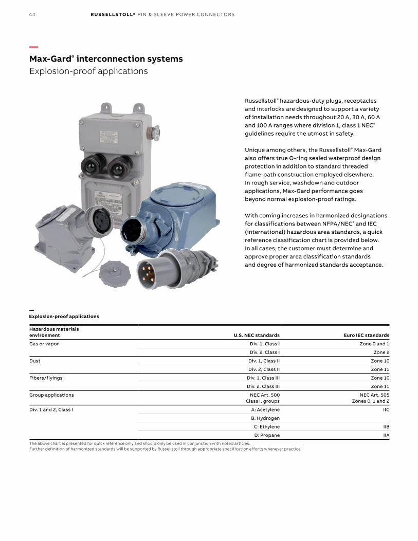
44 R U S S E LL S TO LL® PI N & SL EE V E P OW ER CO N N EC TO R S
—Max-Gard® interconnection systemsExplosion-proof applications
Hazardous materialsenvironment U.S. NEC standards Euro IEC standards
Gas or vapor Div. 1, Class I Zone 0 and 1
Div. 2, Class I Zone 2
Dust Div. 1, Class II Zone 10
Div. 2, Class II Zone 11
Fibers/flyings Div. 1, Class III Zone 10
Div. 2, Class III Zone 11
Group applications NEC Art. 500Class I: groups
NEC Art. 505Zones 0, 1 and 2
Div. 1 and 2, Class I A: Acetylene IIC
B: Hydrogen
C: Ethylene IIB
D: Propane IIA
The above chart is presented for quick reference only and should only be used in conjunction with noted articles. Further definition of harmonized standards will be supported by Russellstoll through appropriate specification efforts whenever practical.
Russellstoll® hazardous-duty plugs, receptacles and interlocks are designed to support a variety of installation needs throughout 20 A, 30 A, 60 A and 100 A ranges where division 1, class 1 NEC® guidelines require the utmost in safety.
Unique among others, the Russellstoll® Max-Gard also offers true O-ring sealed waterproof design protection in addition to standard threaded flame-path construction employed elsewhere. In rough service, washdown and outdoor applications, Max-Gard performance goes beyond normal explosion-proof ratings.
With coming increases in harmonized designations for classifications between NFPA/NEC® and IEC (international) hazardous area standards, a quick reference classification chart is provided below. In all cases, the customer must determine and approve proper area classification standards and degree of harmonized standards acceptance.
—Explosion-proof applications

45M A X- G A R D ® I NTER CO N N EC TI O N S Y S TEMS
—Max-Gard® interconnection systemsMax-Gard DBRE and DSRE series interlocks are the only devices certified both explosion-proof and waterproof, along with optional control contacts, and are fully UL® listed.
—Explosion-proof waterproof circuit breaker interlocked receptacle
Available in 30 A, 60 A and 100 A sizes, all polarizations.
1. Heavy-duty cast aluminum housing, electrostatic epoxy coat finish
2. Standard, high AIC and NA (switched only) breakers available
3. Threaded access (cover not shown) with O-ring for explosion-proof and waterproof integrity
4. Gated deadfront safety5. Drain plug6. Factory-sealed receptacle interior – Accepts
standard Max-Gard plugs
—Explosion-proof waterproof non-interlocked receptacle
Available in 30 A 480 V AC max, all polarizations.• Factory-sealed interior (no filled conduits)• Easy low-cost installation
1. Heavy-duty cast aluminum housing, electrostatic epoxy coat finish
2. Threaded access (cover not shown) with O-ring for explosion-proof and waterproof integrity
3. Gated deadfront for safety4. All standard polarizations available to 480 V AC5. Factory-sealed receptacle interior – Accepts
standard Max-Gard plugs
—01 Approvals• UL and CSA listed for
hazardous locations• Class I, Division 1,
Groups B, C and D• Class II, Division 1,
Groups F and G UL File E10919
• NEMA 7, 8, 9• CSA• DOT shipboard
used above deck “green water”
• NEMA 4X• USCG approved—02 Approvals• UL and CSA listed for
hazardous locations• Class I, Division
1, C and D• Class II, Division 1,
Groups F and G• UL File E10919• NEMA 7, 8, 9• CSA• DOT shipboard
used above deck “green water”
• NEMA 4X• USCG approved
2
3
1
5
4
2
3
1
5
4
—01
—02

46 R U S S E LL S TO LL® PI N & SL EE V E P OW ER CO N N EC TO R S
AmpPoles/
wiresVoltage
(V AC) Cat. no. Cat. no. Cat. no. Std. bushing
I.D.* (in.)
Product type
Explosion-proof interlocked receptacle with circuit breaker, Class I, Class II
Explosion-proof receptacle, Class I, Class II
Male plug
30 2P3W 125 DBRE310703000 DSE3107FR0 DS3107MP000 7/8
2P3W 250 DBRE320703000 DSE3207FR0 DS3207MP000 7/8
3P4W 3Ø250 DBRE330703000 DSE3307FR0 DS3307MP000 1
3P4W 3Ø480 DBRE340403000 DSE3404FR0 DS3404MP000 1
4P5W 277/480 DBRE350403000 DSE3504FR0 DS3504MP000 13/16
60 2P3W 250 DBRE620706000 – DS6207MP000 13/16
3P4W 3Ø250 DBRE630706000 – DS6307MP000 15/16
3P4W 3Ø480 DBRE640406000 – DS6404MP000 15/16
4P5W 277/480 DBRE650406000 – DS6504MP000 11/2
100 2P3W 250 DBRE120710000 – DS1207MP000 111/16
3P4W 3Ø250 DBRE130710000 – DS1307MP000 113/16
3P4W 3Ø480 DBRE140410000 – DS1404MP000 113/16
4P5W 277/480 DBRE150410000 – DS1504MP000 2
—Max-Gard® interconnection systemsMaximum 600 V AC or 250 V DC
* For additional bushing sizes, accessories and specification information, see pages 32–37.Note: For additional full line and polarization options, see page 40. Control contacts (position 12) use “K” example: DBRE6404060K0Shunt trip breaker (position 13) add “Z” to above: DBRE6404060KZBreaker trip ratings (positions 9, 10, 11) 30 amp use 030; 60 A use 060; alternate trip ratings are available – Consult technical servicesNon-auto Sw. NA0 (repl. “DBRE” with “DSRE”)Boldface figures are for voltage assignment; For different ratings, see page 38.
—Explosion-proof applications

47M A X- G A R D ® I NTER CO N N EC TI O N S Y S TEMS
—Max-Gard® interconnection systemsDimensions
—Explosion-proof interlocked receptacle
—Conduit sizing
Dimensions (in.)
Amp A B C D E
30 83/4 71/2 1/2 143/4 20
60 83/4 71/2 1/2 143/4 20
100 83/4 71/2 1/2 143/4 20
Amp Standard (in.)
30 1.25
60 1.50
100 2.00
Note: Range is 0.750–14 NPT through 2.00–11.5 NPT.
Access coverto pigtails for wiring
10.16"
11.35"
7.26"
7.03"1.50"
Conduitlocation
“C”Conduit
location “D”
Conduitlocation
“B” – STD
Conduitlocation
“A”4.00 MTG.
ø.28, 4 PLS
Bottom view (possible conduit sizing are: 0.750–14 NPT, 1.00–11.5 NPT, 1.25–11.5 NPT with 1.00–11.5 NPT at location “B” as standard)
Conduitlocation “C”
Conduitlocation
“B”
Conduitlocation “A”– STD
—Explosion-proof receptacle
A
B
E
D
C

48 R U S S E LL S TO LL® PI N & SL EE V E P OW ER CO N N EC TO R S
—GSUL safe ground indicator systemPrevents operation of pumps without a safe ground for static dissipation.
Class I, Division 1, Groups C, D, and Zone 1, Groups IIB, IIA; NEMA 7 Class II, Division 1, Groups E, F, G; NEMA 9
E33553
—Instant visual confirmation of safe ground The Russellstoll® GSUL safe ground indicator system is designed to ensure that a safe ground has been established for dissipating ever-present static electricity from tank vehicles, carriers, drums and other conductive equipment before allowing the transfer of flammable materials. The GSUL indicates the establishment of a safe ground via two parallel-connected green signal lights. Two lights are used for redundancy – If one lamp burns out, visual indication of safe grounding will be maintained by the other.
—Intrinsically safe circuitryThe GSUL safe ground indicator system features an intrinsically safe, low-energy ground-sensing circuit, which does not carry sufficient electrical energy to cause ignition in classified hazardous locations.
In operation, the ground-sensing circuit extends through the grounding clamp and its connection to the ground indicator, the metal portion of the vehicle between the jaw terminals of the clamp and earth ground electrode.
—Pumps won’t operate until safe ground is establishedA control relay in the GSUL safe ground indicator system provides interlocked control of pump motors at the loading platform. The electronic control circuit will be de-energized while the green lights are off. Attaching the clamps to the tank closes the interlocking contact and energizes the control circuits to the motors.
—01 Unit shown with covers removed
—01
—Applications
Volatile or classified areas such as:• Tank farms • Petrochem• Cosmetics • Grain mills• Vehicular or rail transport
—Specifications
Enclosure: Cast copper-free aluminum with epoxy powder-coated finishOutlets: Regularly furnished tapped 3/4" NPTRelay Contacts: Rated 1 /3 hp, 10 A, 120 V AC; 1 /2 hp, 10 A, 240 V AC Certifications: UL® listed, CSA certified

49G SU L S A FE G R O U N D I N D I C ATO R S Y S TEM
TB1L1 G L2 C N.O. N.C.1 2 3 4 5 6 G
G
G2G1C
TB3
Ground Electrode Connection (1 electrode required) not provided by Russellstoll
Two-Conductor Cable
Weathertight Reel
Grounding ClampCat. No. SGC2
Remote Indicator Pilot Light(Optional)Mounting
Feet
N.O. - N.C. Relay Contacts1/3 H.P. 10 Amp 120 VAC1/2 H.P. 10 Amp 240VAC
To 115 Volts,60 Hz Ground in explosion-proof
portion provided by conduitsystem
Weathertight reel
Ground in explosion-proof portion provided by conduit system
To 115 V, 60 Hz or
240 V AC, 50/60 Hz
Ground electrode connection (1 electrode required not provided by Russellstoll)
Two-conductor cable
N.O. – N.C. relay contacts
1/3 hp 10 A 120 V AC 1/2 hp 10 A 240 V AC
N.O. – N.C. relay contacts
1/3 hp 10 A 120 V AC 1/2 hp 10 A 240 V AC
N.O. – N.C. relay contacts
1/3 hp 10 A 120 V AC 1/2 hp 10 A 240 V AC
Grounding clampCat. no. SGC2
Remote indicatorpilot light (optional)Mounting
feet
—01 Wiring diagram
—01
—GSUL safe operating features• Two redundant, parallel green indicator lights
glow when safe ground is established• Lamps offer approximately 20,000 hours
of operating life• Unit may be ordered without lights where remote
visual indication is desired Intrinsically safe, simplified circuitry
• Integral, intrinsically safe wiring compartment with approved strain-relief fitting for connection of cable from grounding clamp
• Solid-state actuating and control circuits mounted on removable printed circuit board
• Enclosure protects components against moisture• Control relay provided for interlocked control
of pump motor at loading rack• Grounding clamp (ordered separately) provides
dual isolated tip contacts in a heavy-duty cast-aluminum handle design

50 R U S S E LL S TO LL® PI N & SL EE V E P OW ER CO N N EC TO R S
Explosion-proof safe ground indicator
Cat. no. GSUL-2-SSCat. no. GSUL-2-SS-240
Cat. no. Description
GCC1 Ground cup with cover*
GC1 Ground cup without cover*
F06146 Replacement contact tip**
* Hub is tapped for 3⁄4"–10.** Hub is tapped for 1⁄2"–13.
Weatherproof reelCat. no. SGR25
Grounding clamp to fuel carrierCat. no. SGC2
Explosion-proof sealing fittings
To ground electrode
—Typical installation
—01
—02
—Aerospace/industrial static ground devicesStatic grounding receptacles are used in airport and aerospace installations worldwide during fueling, testing and maintenance procedures. Normal mounting is concrete/tarmac floor inset, threaded onto copper ground rod.
Heavy brass construction cup includes optional cover and receptacle’s contact pin. Accommodates a wide variety of single-contact (copper on steel wire) static ground wire clamps in service.
—01 Loading rack illustration suggests a typical installation, which includes an explosion-proof switch, explosion-proof sealing fittings, weathertight reel and the GSUL-2-SS safe ground indicator with 2-wire grounding clamp.—02 GCC1
—GSUL safe ground indicator systemPrevents operation of pumps without a safe ground for static dissipation.

51G SU L S A FE G R O U N D IN D I C ATO R S Y S TEM
13" Dia.7.5"
3.37"
1.25"
3" Sq.
8.5"Rad.
1.56"
.56" Dia. MTG Holes.75" Female Thread
Line Entrance
14.75"
8.25"
2.5"
9.75"3.37" 6.37"
.37"3"2"
4 Holes Pivot MTG (optional)2 Holes Rigid MTG
.37"6.87"
4 Sq
Cat. no. Description
GSUL2SS Safe ground indicator with indicator lights, 120 V, UL®/CSA
GSUL2SS-240 Safe ground indicator with indicator lights, 240 V, CSA
SGC2 Safe ground static clamp
SGR25 Weathertight retracing reel with 25 ft. of 12/2 SJO-W cable
SGR50 Weathertight retracing reel with 50 ft. of 12/2 SJO-W cable
SGR75 Weathertight retracing reel with 75 ft. of 12/2 SJO-W cable
Replacement parts for GSUL
C13662 Printed circuit board, 120 V (includes relay)
GX24RCB Printed circuit board, 240 V (includes relay)
F30674 Control relay
F30602 Lamp socket assembly
ELAG Pilot light globe assembly (green)
310993 Lamp for GSUL2SS
Replacement parts for SGC2
GX2TK Ground clamp repair kit
GSUL-2-SS
5.25"3" mtg.
0.75" NPT conduit
0.75" NPT
10.25" mtg.
9.25"
0.75"
0.3" dia. hole
0.75" NPT conduit
0.75
" m
ax. c
ond
uit
4.5" approx.
0.44"
0.84"3.88"
Indicating lights
(green)
GSUL-2-SS
SGR25, SGR50, SGR75 SGC2
—GSUL safe ground indicator systemMaximum 600 V AC or 250 V DC
1.25" 1.56"
2.5"
3.37"13" dia.
7.5" dia.
9.75"6.37"
2" 3" .37"
14.75"
8.25"
4 sq.
3.37"
3" sq.
8.5" Rad.
6.87"2 holes rigid mtg. 4 holes pivot mtg. (optional)
0.56" dia. mtg. holes 0.75" female thread
Line entrance
SGR25, SGR50, SGR75
2X conductor termination set screws
Cable entry clamp and screw
2X “Rue pin” pivot pin locking
0.14"6 PLSSGC2
0.37"
—Maximum 600 V AC or 250 V DC

52 R U S S E LL S TO LL® PI N & SL EE V E P OW ER CO N N EC TO R S
—Design features
Russellstoll® J-Line load-breaking plugs, connectors and receptacles
1. Circuit-interrupting rated safety2. Cast aluminum, corrosion-resistant copper-free
alloy housings and enclosures provide lightweight and maximum corrosion resistance, along with electrostatic epoxy powder coat finish
3. Quick conversion between weathertight flap cover and watertight screw cap assemblies. Basic receptacle housing accommodates both covers and is the basic component of all complete units. All watertight configured plugs may be used interchangeably
4. Two grounding arrangements (Style No. 1 and Style No. 2)
5. Four complete J-Lines: 30, 60, 100 and 200 A; 600 V AC/250 V DC (plus 150 A/270 A specials)
6. Flap cover can be rotated and locked in any convenient position
7. Pressure-type solderless wiring terminals8. Silver-plated contacts9. One-piece interior assemblies interchangeable
from regular to reverse service in the field with a screwdriver
10. Wiring space ample for maximum requirements11. Cable clamps adjustable for maximum range of
cable size. Oil-resistant neoprene strain-relief bushing compresses around cable tightly, prevents entry of dust and moisture
12. Polarization provides positive non-interchangeability for different electrical systems
13. Reversed contacts flexibility: male–female reversed installation within any housing
2
3
4
7
6
7
8
9
9
10
11
4
—J-Line™ interconnection systemsJ-Line 4P4W max. 30 through 200 A
Robust service in metal for many industrial applications, the J-Line offers a value alternative to Max-Gard® in 3P4W, 30–200 A applications with less severe needs. Unique among competitors, the J-Line™ uses a reversible contract carrier for maximum flexibility in many portable service applications.
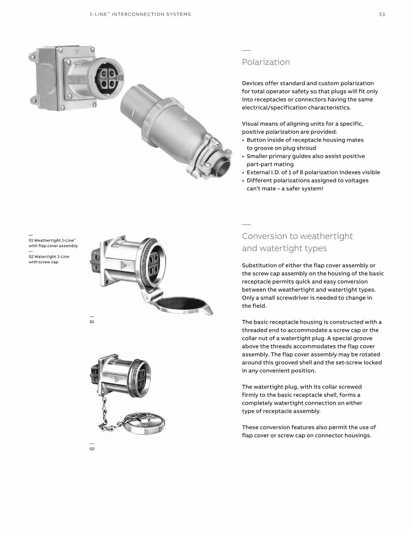
53J - L I N E ™ I NTER CO N N EC TI O N S Y S TEMS
—Polarization
Devices offer standard and custom polarization for total operator safety so that plugs will fit only into receptacles or connectors having the same electrical/specification characteristics.
Visual means of aligning units for a specific, positive polarization are provided:• Button inside of receptacle housing mates
to groove on plug shroud• Smaller primary guides also assist positive
part-part mating• External I.D. of 1 of 8 polarization indexes visible• Different polarizations assigned to voltages
can’t mate – a safer system!
—01
—02
—01 Weathertight J-Line™
with flap cover assembly—02 Watertight J-Linewith screw cap
—Conversion to weathertight and watertight types
Substitution of either the flap cover assembly or the screw cap assembly on the housing of the basic receptacle permits quick and easy conversion between the weathertight and watertight types. Only a small screwdriver is needed to change in the field.
The basic receptacle housing is constructed with a threaded end to accommodate a screw cap or the collar nut of a watertight plug. A special groove above the threads accommodates the flap cover assembly. The flap cover assembly may be rotated around this grooved shell and the set-screw locked in any convenient position.
The watertight plug, with its collar screwed firmly to the basic receptacle shell, forms a completely watertight connection on either type of receptacle assembly.
These conversion features also permit the use of flap cover or screw cap on connector housings.

54 R U S S E LL S TO LL® PI N & SL EE V E P OW ER CO N N EC TO R S
—J-Line™ interconnection systemsFor all weathertight and watertight types
30–200/270 A (30–200 A load breaking), maximum 600 V AC/250 V DC load-breaking receptacles, plugs, connectors and inlets
—Reversed contacts service
All J-Line plugs, receptacles and connectors can be furnished for reverse service – male (plug) interiors in the receptacles and female (receptacle) interiors in the plugs. When ordering reverse service, add a final suffix “R” to the complete catalog number. Price on request.
Example: JRFA334HR
J-Line receptacle and plug interior assemblies of the same amperage may be quickly interchanged from regular to reverse service (or vice versa) in the field. A screwdriver is the only tool required.
Example: Panel-mounted low-profile receptacles with male interiors act as male inlets in remote equipment; receive power from female plugs. (Cup cap also recommended.)
—Regular serviceInterior assemblies placed in normal, standard positions – female interior assembly is positioned in the receptacle housing and the male interior assembly is positioned in the plug housing.
—Reversed serviceNote the complete interior assemblies have now been interchanged so that the male (plug) interior assembly is positioned in the receptacle housing and the female (receptacle) interior assembly is positioned in the plug housing.

55J - L I N E ™ I NTER CO N N EC TI O N S Y S TEMS
—01 Style 1 — Typical 3P3W plug and receptacle—02 Style 2 — Typical 3P4W plug and receptacle
—Style 14P4W (or 3P3W) through metal housings of plug and receptacle
In this system shown above, the equipment grounding conductor in the flexible cable is electrically connected directly to the plug or cable connector housing by a suitable terminal. The receptacle is grounded by being part of a grounded conduit system.
When inserted, the plug housing makes contact with the grounded receptacle or connector housing by means of the receptacle ground spring before the current-carrying contacts engage. On withdrawal, it remains in contact until after the current-carrying contacts disengage.
— Style 23P4W (or 2P3W) through a separate grounding pole in plug and receptacle
In this system shown above, the equipment grounding conductor in the flexible cable is electrically connected to the equipment grounding pole in the plug or cable connector interior. The grounding pole of the receptacle interior is electrically connected by a spring-strap jumper to the receptacle housing, which itself is grounded by being part of the ground spring of the receptacle or con nector housing as described in Style 1.
The grounding contact in a type 2 receptacle is longer than the current-carrying contacts so that the ground connection makes first and breaks last.
NEC and National Electrical Code are registered trademarks of the National Fire Protection Association, Inc.
—Grounding data Effective grounding of portable electrical equipment is necessary to protect operators from electric shock. The National Electrical Code® requires that in most cases, exposed non-current-carrying metal parts of portable equipment shall be grounded if operated at more than 150 V to ground. Grounding must be used in other than residential occupancies when used in damp or wet locations, or by persons standing on the ground or on metal floors or working inside of metal tanks or boilers, except where supplied through an insulating transformer with ungrounded secondary of not over 50 V.
Plugs and receptacles provide for grounding of portable equipment in either of two ways:
Portable cord3 conductors + G
Grounding thruplug & receptaclehousing
Groundingthru conduitsystem onlyEquipment ground
connected toplug shell
Plug Receptacle
Portable cord3 conductors +G
Grounding thru plug and receptacle housing
ReceptaclePlug
Equipment ground connected to plug shell
Grounding through conduit system only
—Corrosive locationsThe National Electrical Code® requires that under conditions favorable to corrosion, the grounding conductor for enclosures and equipment be of copper or other corrosion-resistant material. In alternating current systems, this necessitates running another conductor back to the common grounding electrode. This may be run through the conduit containing the circuit conductors. At the receptacle, this grounding conductor should be connected to the extra (grounding) pole by the pressure connector provided for that purpose. Where such an extra grounding conductor is required, Style 2 receptacles should be used.
Portable cord4 conductors
Grounding thruplug & receptaclehousing
Equipment groundconnected to extrapole and plug shell
Plug Receptacle
Factory installedjumper
4th groundingwire – if desired
Factory-installed jumper
Equipment ground connected to extra pole and plug shell
Portable cord4 conductors
Grounding through plug and receptacle housing
Plug Receptacle
4th grounding wire —
if desired
—02
—01

56 R U S S E LL S TO LL® PI N & SL EE V E P OW ER CO N N EC TO R S
—J-Line™ interconnection systems Plugs, connectors & receptacles
Current rating Weathertight/watertight Configuration Plug Connector Panel mount connector Basic receptacle Standard series receptacle*
● ● ● ● ● ● ● ● ● ● ● ● ● ●
30 A Weathertight(spring hinged flap cover)
2P3W JPS323H __ JCF323H __ JRFX323H __ JRF323H __ JRFA323H __
3P3W* JPS333F JCF333F JRFX333F JRF333F JRFA333F
3P4W JPS334H JCF334H JRFX334H JRF334H JRFA334H
4P4W* JPS344F JCF344F JRFX344F JRF344F JRFA344F
Watertight(screw cover)
2P3W JPS323H JCS323H JRSX323H JRS323H JRSA323H
3P3W* JPS333F JCS333F JRSX333F JRS333F JRSA333F
3P4W JPS334H JCS334H JRSX334H JRS334H JRSA334H
4P4W* JPS344F JCS344F JRSX344F JRS344F JRSA344F
60 A Weathertight(spring hinged flap cover)
2P3W JPS623H JCF623H JRFX623H JRF623H JRFA623H
3P3W* JPS633F JCF633F JRFX633F JRF633F JRFA633F
3P4W JPS634H JCF634H JRFX634H JRF634H JRFA634H
4P4W* JPS644F JCF644F JRFX644F JRF644F JRFA644F
Watertight(screw cover)
2P3W JPS623H JCS623H JRSX623H JRS623H JRSA623H
3P3W* JPS633F JCS633F JRSX633F JRS633F JRSA633F
3P4W JPS634H JCS634H JRSX634H JRS634H JRSA634H
4P4W* JPS644F JCS644F JRSX644F JRS644F JRSA644F
100 A(150 A)**
Weathertight(spring hinged flap cover)
2P3W JPS1023H JCF1023H JRFX1023H JRF1023H JRFA1023H
3P3W* JPS1033F JCF1033F JRFX1033F JRF1033F JRFA1033F
3P4W JPS1034H JCF1034H JRFX1034H JRF1034H JRFA1034H
4P4W* JPS1044F JCF1044F JRFX1044F JRF1044F JRFA1044F
Watertight(screw cover)
2P3W JPS1023H JCS1023H JRSX1023H JRS1023H JRSA1023H
3P3W* JPS1033F JCS1033F JRSX1033F JRS1033F JRSA1033F
3P4W JPS1034H JCS1034H JRSX1034H JRS1034H JRSA1034H
4P4W* JPS1044F JCS1044F JRSX1044F JRS1044F JRSA1044F
200 A(270 A)**
Weathertight(spring hinged flap cover)
2P3W JPS2023H JCF2023H JRFX2023H JRF2023H JRFA2023H
3P3W* JPS2033F JCF2033F JRFX2033F JRF2033F JRFA2033F
3P4W JPS2034H JCF2034H JRFX2034H JRF2034H JRFA2034H
4P4W* JPS2044F JCF2044F JRFX2044F JRF2044F JRFA2044F
Watertight(screw cover)
2P3W JPS2023H JCS2023H JRSX2023H JRS2023H JRSA2023H
3P3W* JPS2033F JCS2033F JRSX2033F JRS2033F JRSA2033F
3P4W JPS2034H JCS2034H JRSX2034H JRS2034H JRSA2034H
4P4W* JPS2044F JCS2044F JRSX2044F JRS2044F JRSA2044F
—Max. 600 V AC/250 V DC
(All plugs come with watertight screw collar)
* Housinggroundonly(Style1grounding),seepage55.+ Shownwith20°angleadapter.Canbefurnishedwith45°angleatsameprice.Whenordering,addsuffix-45tocatalognumber.** Special rated devices (not shown). Consult Customer Service for details.Note: To order reverse service, add a final suffix “R” to catalog number. Example: JRFA334HR–areceptaclehousingwithmaleinterior.● Polarization index (std. shown); consult Technical Services for more information.● Flap cover “F” noted. Screw cover “S” also available.● For reversed contacts, use “R” suffix to any catalog number.
Current rating (A) Bushing I.D. (in.) Max. AWG size
30 7/8 #6 7-strand or #8 flexible
60 13/16 #4 7-strand or flexible
100 11/2 #10 19-strand or #1 flexible
200 2 4/0 19-strand or flexible
See page 63 for other bushings
—Std. cable bushing

57J - L I N E ™ I NTER CO N N EC TI O N S Y S TEMS
Current rating Weathertight/watertight Configuration Plug Connector Panel mount connector Basic receptacle Standard series receptacle*
● ● ● ● ● ● ● ● ● ● ● ● ● ●
30 A Weathertight(spring hinged flap cover)
2P3W JPS323H __ JCF323H __ JRFX323H __ JRF323H __ JRFA323H __
3P3W* JPS333F JCF333F JRFX333F JRF333F JRFA333F
3P4W JPS334H JCF334H JRFX334H JRF334H JRFA334H
4P4W* JPS344F JCF344F JRFX344F JRF344F JRFA344F
Watertight(screw cover)
2P3W JPS323H JCS323H JRSX323H JRS323H JRSA323H
3P3W* JPS333F JCS333F JRSX333F JRS333F JRSA333F
3P4W JPS334H JCS334H JRSX334H JRS334H JRSA334H
4P4W* JPS344F JCS344F JRSX344F JRS344F JRSA344F
60 A Weathertight(spring hinged flap cover)
2P3W JPS623H JCF623H JRFX623H JRF623H JRFA623H
3P3W* JPS633F JCF633F JRFX633F JRF633F JRFA633F
3P4W JPS634H JCF634H JRFX634H JRF634H JRFA634H
4P4W* JPS644F JCF644F JRFX644F JRF644F JRFA644F
Watertight(screw cover)
2P3W JPS623H JCS623H JRSX623H JRS623H JRSA623H
3P3W* JPS633F JCS633F JRSX633F JRS633F JRSA633F
3P4W JPS634H JCS634H JRSX634H JRS634H JRSA634H
4P4W* JPS644F JCS644F JRSX644F JRS644F JRSA644F
100 A(150 A)**
Weathertight(spring hinged flap cover)
2P3W JPS1023H JCF1023H JRFX1023H JRF1023H JRFA1023H
3P3W* JPS1033F JCF1033F JRFX1033F JRF1033F JRFA1033F
3P4W JPS1034H JCF1034H JRFX1034H JRF1034H JRFA1034H
4P4W* JPS1044F JCF1044F JRFX1044F JRF1044F JRFA1044F
Watertight(screw cover)
2P3W JPS1023H JCS1023H JRSX1023H JRS1023H JRSA1023H
3P3W* JPS1033F JCS1033F JRSX1033F JRS1033F JRSA1033F
3P4W JPS1034H JCS1034H JRSX1034H JRS1034H JRSA1034H
4P4W* JPS1044F JCS1044F JRSX1044F JRS1044F JRSA1044F
200 A(270 A)**
Weathertight(spring hinged flap cover)
2P3W JPS2023H JCF2023H JRFX2023H JRF2023H JRFA2023H
3P3W* JPS2033F JCF2033F JRFX2033F JRF2033F JRFA2033F
3P4W JPS2034H JCF2034H JRFX2034H JRF2034H JRFA2034H
4P4W* JPS2044F JCF2044F JRFX2044F JRF2044F JRFA2044F
Watertight(screw cover)
2P3W JPS2023H JCS2023H JRSX2023H JRS2023H JRSA2023H
3P3W* JPS2033F JCS2033F JRSX2033F JRS2033F JRSA2033F
3P4W JPS2034H JCS2034H JRSX2034H JRS2034H JRSA2034H
4P4W* JPS2044F JCS2044F JRSX2044F JRS2044F JRSA2044F
Current rating (A) Bushing I.D. (in.) Max. conduit size (in.)
30 1 11/4
60 11/2 11/2
100 2 2
200 3 3
* Smaller NPT openings available on request.Cable Conduit Adapters, see page 64.
—Conduit size (using JPA_ series conduit adapters)
—Conduit entry location: Standard series
30 and 60 A 100 and 200 A
B Std.
A C
D
B Std.
A C
D
• 30–270 A (30, 60, 100 and 200 A load- breaking, 150 and 270 A special service), maximum 600 V AC/250 V DC receptacles, plugs, connectors and inlets
• For any J-Line™ catalog numbers not shown here, check page 58 for “series” information. For special polarizations (suffixes), contact Technical Services.

58 R U S S E LL S TO LL® PI N & SL EE V E P OW ER CO N N EC TO R S
—J-Line™ interconnection Systems Receptacle mounting options – J-Line construction
Mountingstyle To order use:
Current rating
30 A 60 A 100/150 A 200/270 AStandardseriesJRFA/JRSA ●
Receptacle+
Vertical or square mount box
+Angle
adapter
Basic receptacle*+
JB3-B100 1" Std. conduit size
+JAA3 (20°)
or JAA3-45 (45°)
Basic receptacle*+
JB6-B150 11/2" Std. conduit size
+JAA6-AB6 (20°)
or JAA6-45 (45°)
Basic receptacle*+
JB10-B200 2" Std. conduit size
+JAA10 (20°)
or JAA10-45 (45°)
Basic receptacle*+
JB20 3" Std. conduit size
+JAA20 (20°)
or JAA20-45 (45°)
SeriesJRFR/JRSR ●straight
Receptacle+
Vertical mount box
+Straight adapter
Basic receptacle*+
JB3-B100 1" Std. conduit size
+JRA3
Basic receptacle*+
JB6-B150 11/2" Std. conduit size
+JRA6-AB6
Basic receptacle*+
JB10-B200 2" Std. conduit size
+JRA10
Basic receptacle*+
JB20 21/2" Std. conduit size
+JRA20
SeriesJRFB/JRSB ●
Receptacle+
30° angle adapter
Basic receptacle*+
JAAB3
Basic receptacle*+
JAAB6
Basic receptacle*+
JAAB10
Basic receptacle*+
JAAB20
SeriesJRFE/JRSE ●
Receptacle+
Angle enclosure
Basic receptacle*+
JE3 1" Std. conduit size
Basic receptacle*+
JE6 11/2" Std. conduit size
Basic receptacle*+
JE10 2" Std. conduit size
N/A
SeriesJRFH/JRSH ●horizontal
Receptacle+
Horizontal mount box
+Angle adapter
Basic receptacle*+
JB3-B100 1" Std. conduit size
+JAA10 (20°)
N/A N/A N/A
* Select appropriate receptacle by rating, configuration and voltage on pages 56–57● Note: JRXX 3rd letter denotes flap (F) or screw (S) cover.EX: JRSA – Screw coverJRFA – Flap coverJRF – Flap cover, basic receptacleJRS – Screw cover, basic receptacle
—Progressive assembly
• 30–200/270 A (30–200 A Load Breaking), maximum 600 V AC/250 V DC
• Load-breaking receptacles, plugs, connectors and inlets

59J - L I N E ™ I NTER CO N N EC TI O N S Y S TEMS
—J-Line™ interconnection systems Plugs and connectors & basic receptacles
• 30–200/270 A (30–200 A load breaking), maximum 600 V AC/250 V DC
• Load-breaking receptacles, plugs, connectors and inlets
—Plugs and connectors — Dimensions for 2-, 3- or 4-wire weathertight and watertight units
—Basic Receptacles – Dimensions for 2-, 3- or 4-wire units
Amp A (in.) B (in.) C (in.)Weathertight
F (in.)Watertight
FW (in.)Weathertight
R (in.)Watertight
RW (in.) Y (in.) Z (in.) H (in.)
30 3 21/8 7 81/8 83/8 41/4 3 23/4 23/4 1
60 33/4 29/16 87/8 103/4 103/8 5 33/4 31/2 31/2 33/8
100/150 41/8 213/16 101/4 101/2 107/8 51/4 41/8 4 4 17/8
200/270 53/4 315/16 145/8 147/8 153/8 71/8 53/4 55/8 55/8 21/2
Amp Z (in.) Y (in.) X (in.)Weathertight
S (in.)Watertight
SW (in.)Weathertight
R (in.)Watertight
RW (in.) V (in.) U (in.) T (in.)
30 23/4 23/4 1 33/8 33/4 41/4 3 21/4 21/4 1/4
60 31/2 31/2 11/4 45/8 43/4 5 33/4 27/8 27/8 9/32
100/150 4 4 11/4 5 51/4 51/4 41/8 33/8 33/8 9/32
200/270 55/8 55/8 13/4 61/8 63/8 71/8 53/4 47/8 47/8 11/32
Dimensions
FW
RWDia.
Max.cable
dia
H
F
RZ
Y
Weathertight
Female – connector
Watertight
A C
B
Watertight male – plug
Dimensions
Y T
Z
UMTG.
S
RVMTG.

60 R U S S E LL S TO LL® PI N & SL EE V E P OW ER CO N N EC TO R S
Amp Series Z (in.) Y (in.) X (in.)
Weathertight
Q (in.) P (in.) V (in.) U (in.) T (in.)Panel
openingS (in.) SW (in.) R* (in.) RW† (in.)
30 Panel mount 31/2 31/2 29/16 13/4 2 41/4 3 – – 27/8 27/8 1/4 23/4
Standard (20°) 41/2 3 21/8 7 61/2 63/4 63/4 – – 211/16 311/16 1/4 –
JRFR/JRSR 41/2 3 21/8 61/8 61/2 – – – – 211/16 311/16 1/4 –
JRFB/JRSB 31/8 31/8 – 53/4 53/4 – – – – 21/4 21/4 1/4 21/4
JRFE/JRSE – 31/2 – 51/4 45/8 71/8 71/8 11/4 23/8 – 4 1/4 –
JRFH/JRSH 35/16 41/2 21/8 7 61/2 65/8 65/8 – – 211/16 311/16 1/4 –
60 Panel mount 4 4 37/8 13/4 2 5 33/4 – – 33/8 33/8 9/32 31/4
Standard (20°) 55/8 4 3 91/4 85/8 87/8 9 – – 313/16 413/16 11/32 –
JRFR/JRSR 55/8 4 3 83/8 81/2 – – – – 313/16 415/16 11/32 –
JRFB/JRSB 33/16 35/8 – 73/8 73/8 – – – – 23/16 25/8 9/32 21/2
JRFE/JRSE – 41/4 – 63/8 53/4 93/4 91/2 19/16 311/16 31/8 41/2 9/32 –
100/150 Panel mount 41/4 41/4 47/16 13/4 2 51/4 41/8 – – 35/8 35/8 9/32 31/2
Standard (20°) 51/2 51/2 31/2 101/2 97/8 97/8 93/4 – – 63/4 41/4 11/32 –
JRFR/JRSR 51/2 51/2 31/2 111/4 117/8 – – – – 63/4 41/4 11/32 –
JRFB/JRSB 33/16 35/8 – 81/4 81/4 – – – – 23/16 25/8 9/32 –
200/270 Panel mount 6 6 57/8 2 21/2 71/8 53/4 – – 51/4 51/4 11/32 51/8
Standard (20°) 85/16 85/16 65/16 157/8 155/8 1211 /16 125/16 – – 95/8 71/8 3/8 –
JRFR/JRSR 85/16 85/16 65/16 15 151/2 – – – – 95/8 71/8 3/8 –
JRFB/JRSB 4 4 – 121/4 121/4 – – – – 23/4 23/4 11/32 –
Note: U = horizontal mounting hole centers; V = vertical mounting hole centers.* = Flap cap.† = Screen cap.
—J-Line™ interconnection systems Receptacle mounting options – J-Line construction
Dimensions
Y
Z
T X
R
S
SW
RWV-mtg
U-mtg
Panel mount series
T
Z
YXX
R
SSWU mtg100 A
V mtg100 A
U mtg
V mtg
RW
Standard series JRFA/JRSA
X YSW
ST
V mtgU mtg 100 A
U mtg
Z
Series JRFR/JRSR
YU
z
T
v
SSW
Series JRFB/JRSB
Y
QP
T
RRW
SSW
U mtg
Vmtg
Series JRFE/JRSE
Y
Umtg
Vmtg
RW
T
S
Z
R
SW
Series JRFH/HRSH
—Progressive assembly
V mtg100 & 200 A

61J - L I N E ™ I NTER CO N N EC TI O N S Y S TEMS
—J-Line™ interconnection systems Replacement interiors for receptacles, connectors, plugs and male inlets
Poles/wires
Female interiors: receptacles and connectors cat. nos. Male interiors: plug and male inlets cat. nos.
30 A 60 A 100/150 A 200/270 A 30 A 60 A 100/150 A 200/270 A
2P2W+ JRU322 JRU622 JRU1022 JRU2022 JPU322 JPU622 JPU1022 JPU2022
2P3W JRU323 JRU623 JRU1023 JRU2023 JPU323 JPU623 JPU1023 JPU2023
3P3W* JRU333 JRU633 JRU1033 JRU2033 JPU333 JPU633 JPU1033 JPU2033
3P4W JRU334 JRU634 JRU1034 JRU2034 JPU334 JPU634 JPU1034 JPU2034
4P4W* JRU344 JRU644 JRU1044 JRU2044 JPU344 JPU644 JPU1044 JPU2044
* Includes equipment grounding lug for attachment to enclosure.+ For replacement only – Includes equipment grounding lug.Material – Molded composition with silvered copper contacts.
—Replacement interiors for receptacles, connectors, plugs and male inlets

62 R U S S E LL S TO LL® PI N & SL EE V E P OW ER CO N N EC TO R S
—J-Line™ interconnection systems Cup caps for watertight (series JPS) plugs – Standard or reverse service
Cat. no. Amps
F30717A 30
F30718A 60
F30814A 100
F30815A 200
Cup caps are used:* Where portable equipment is on a standby basis and plugs are not in use.* To effectively protect insulation and contacts from excessive moisture, dirt, dust and corrosion.Material – Cast aluminum, corrosion-resistant copper-free alloy, electrostatic epoxy coated with steel braid cable attached.
—Cup caps for watertight (series JPS) plugs – Standard or reverse service

63J - L I N E ™ I NTER CO N N EC TI O N S Y S TEMS
Notes: Boxed numbers denote standard bushing size supplied.When ordering, select bushing size slightly larger than your cable O.D. for best fit.Material – Neoprene.Identification letter inside hole.Boxed catalog numbers are standard bushing sizes. To order non-standard bushing, specify as follows: example JPS634H/JG65.
Hole diameter for cable (in.)
Size 330 A
Size 660 A
Size 10100/150 A
Size 20200/270 A
0.375 JG31 – – –
0.500 JG32 – – –
0.563 JG325 – – –
0.594 JG32B – – –
0.625 JG33 JG63 – –
0.750 JG34 JG64 JG104 –
0.781 JG341 – – –
0.875 JG35 JG65 JG105 –
0.938 JG355 – – –
1.000 JG36* JG66 JG106 JG206
1.125 JG361* – – –
1.188 – JG67 JG107 JG207
1.313 – – JG108 JG208
1.375 – JG69* – –
1.500 – JG610* JG1010 JG2010
1.688 – – JG1011 JG2011
1.813 – – – JG2012
1.875 – – JG1013* –
2.000 – – – JG2014
2.125 – – – JG2015
2.500 – – – JG2016*
—J-Line™ interconnection systems Cable bushings for J-Line plugs and connectors
—01 Standard cable Bushings – Size no. 3, 6, 10 and 20—02 Oversize cable Bushings – Size no. 3, 6, 10 and 20
—01
—02
—Replacement interiors for receptacles, connectors, plugs and male inlets

64 R U S S E LL S TO LL® PI N & SL EE V E P OW ER CO N N EC TO R S
* JPA65 at 11⁄2" also available.Notes: Material – Cast aluminum, corrosion-resistant copper-free alloy, electrostatic epoxy coated.Furnished complete with gasket and screws. To specify standard plugs or connectors equipped with one of the above adapters, add the catalog number of the adapter selected to the catalog number of the plug or connector.Complete list price is the list price of the device plus list price of the adapter.Adapters are tapped NPT standard pipe thread to accommodate rigid conduit or standard connectors for armored and non-metallic cable or flexible conduit.Example: Cat. no. JPS634H with adapter tapped 1" would be Cat. no. JPS634H/JPA63.
30 ACat. no.
Tapped holesize NPT (in.)
60 ACat. no.
Tapped holesize NPT (in.)
100/150 ACat. no.
Tapped holesize NPT (in.)
200/270 ACat. no.
Tapped holesize NPT (in.)
JPA31 1/2 JPA62 3/4 JPA104 11/4 JPA205 11/2
JPA32 3/4 JPA63 1 JPA105 11/2 JPA206 2
JPA33 1 JPA64 11/4* JPA106 2 JPA207 21/2
—J-Line™ interconnection systems Adapters for conduit and fittings for use on J-Line plugs and connectors
—01 JPA62 Conduit adapter(replaces cable gland assembly)—02 JPA106 Conduit adapter
—01
—02
—Plug or connector sizes
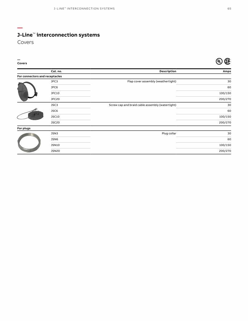
65J - L I N E ™ I NTER CO N N EC TI O N S Y S TEMS
Cat. no. Description Amps
For connectors and receptacles
JFC3 Flap cover assembly (weathertight) 30
JFC6 60
JFC10 100/150
JFC20 200/270
JSC3 Screw cap and braid cable assembly (watertight) 30
JSC6 60
JSC10 100/150
JSC20 200/270
For plugs
JSN3 Plug collar 30
JSN6 60
JSN10 100/150
JSN20 200/270
—J-Line™ interconnection systems Covers
—Covers

66 R U S S E LL S TO LL® PI N & SL EE V E P OW ER CO N N EC TO R S
—DuraGard® waterproof connectionsFeatures and benefits
Non-metallic plugs, connectors, receptacles and inlets – 20, 30, 50 and 60 A, maximum 600 V AC/250 V DC
Safety• Truly waterproof: Not just watertight,
but waterproof (tested under 1000 PSI)• Exclusive waterproof features: The only
thermoplastic connector designed to prevent short circuits due to water ingress under high water pressure
• Different power supply ratings can’t mix: Six single-rate device polarizations ensure exact voltage, frequency and phase differentiation
• Added safety measures: Safety ground makes first, breaks last
• Ultimate waterproof connection: Watertight mated or unmated, while many watertight specifications cover mated connections only
Durability• Designed for durability: DuraV® housing material
specially selected for hot or cold and chemical washdown duty (flame-safe UL® 94-V0 rated housings)
• Versatile functionality: Pin and sleeve design enables higher current flow at cooler temperatures due to large contact circular areas
• Built to last: A longer system life under corrosive environments
Performance• Long life: Round, self-cleaning, constant-pressure
pin and sleeve contacts of solid CDA 360 brass for long, reliable electrical life
• Easy installation: Drop-in assemble interior and easy pressure screw wire termination
• Reliability: DurOring™ sealing system for each pin and sleeve and interior assembly
• Application flexibility: Bushing size available for every cable diameter
• Continuous operation: Superior performance in corrosive environments

67D U R AG A R D ® WATER PR O O F CO N N EC TI O NS
Any application where: • Electrical connections need protection from
water and/or dust entrance to the contacts or the wiring compartment
• Cable-to-connector sealing and device locking designs are critical
—Typical application groups
—Usage
Marine• Lighting connectors• Shore-to-ship power• Low-power welding• Power distribution panels• Shipboard power outlets• Barge power connection
Construction and agricultural• Generator set panels• Portable tools and equipment• Irrigation systems panels• Portable lighting
and equipment
Food processing, brewery/beverage, pulp and paper, pharmaceuticals, portable building power• Welding outlets• Motor power connections• Lighting systems• Machinery interconnections• Process control
power systems
OEMs• Export machinery• Critical power connections and welding systems• Transportable equipment
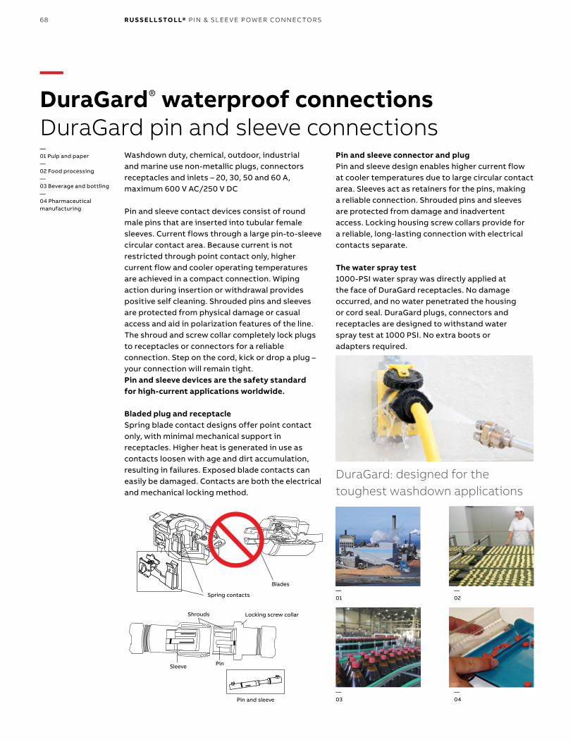
68 R U S S E LL S TO LL® PI N & SL EE V E P OW ER CO N N EC TO R S
—DuraGard® waterproof connectionsDuraGard pin and sleeve connections
Spring contacts
Blades
Pin and sleeve
Shrouds
Sleeve Pin
Locking screw collar
DuraGard: designed for the toughest washdown applications
Washdown duty, chemical, outdoor, industrial and marine use non-metallic plugs, connectors receptacles and inlets – 20, 30, 50 and 60 A, maximum 600 V AC/250 V DC
Pin and sleeve contact devices consist of round male pins that are inserted into tubular female sleeves. Current flows through a large pin-to-sleeve circular contact area. Because current is not restricted through point contact only, higher current flow and cooler operating temperatures are achieved in a compact connection. Wiping action during insertion or withdrawal provides positive self cleaning. Shrouded pins and sleeves are protected from physical damage or casual access and aid in polarization features of the line. The shroud and screw collar completely lock plugs to receptacles or connectors for a reliable connection. Step on the cord, kick or drop a plug – your connection will remain tight. Pin and sleeve devices are the safety standard for high-current applications worldwide.
Bladed plug and receptacleSpring blade contact designs offer point contact only, with minimal mechanical support in receptacles. Higher heat is generated in use as contacts loosen with age and dirt accumulation, resulting in failures. Exposed blade contacts can easily be damaged. Contacts are both the electrical and mechanical locking method.
Pin and sleeve connector and plugPin and sleeve design enables higher current flow at cooler temperatures due to large circular contact area. Sleeves act as retainers for the pins, making a reliable connection. Shrouded pins and sleeves are protected from damage and inadvertent access. Locking housing screw collars provide for a reliable, long-lasting connection with electrical contacts separate.
The water spray test1000-PSI water spray was directly applied at the face of DuraGard receptacles. No damage occurred, and no water penetrated the housing or cord seal. DuraGard plugs, connectors and receptacles are designed to withstand water spray test at 1000 PSI. No extra boots or adapters required.
—01 Pulp and paper—02 Food processing—03 Beverage and bottling—04 Pharmaceutical manufacturing
—01
—03
—04
—02

69
High reliability, high- performance connections:
• CDA 360 solid brass pin and sleeve contacts
Long-lasting self-cleaning connections:
• Full round pin and sleeve contacts
Fast, easy, rear-load wiring and assembly:
• Drop-in assembly interior• Sleeve and cable bushing• Easy-in pressure screw
wiring terminations
DuraGard: designed for the toughest washdown applications
• Washdown duty, chemical, outdoor, industrial and marine use non-metallic plugs, connectors receptacles and inlets – 20, 30, 50 and 60 A, maximum 600 V AC/250 V DC
• 20, 30, 50 and 60 A, 600 V AC, 20 A, 250 V DC
NEC® and National Electrical Code® are registered trademarks of the National Fire Protection Association, Inc.
—The ultimate in waterproof connections
Lockout capable (30/50/60A plugs):
• Access hole (not seen) for padlock hasp• Interlock engagement CDA 360 solid
brass pin and sleeve contacts
Waterproof cable sealing:
• Neoprene compression bushing cable locking system
• Locking bushing nut with external cable clamps
• Bushing sizes available for any cable size
Waterproof locking connections: • Locking screw collars
with O-ring gaskets• Housing mechanical support and pin and sleeve connection
Safety specified voltage connections:• Safety ground makes first breaks last
• Voltage polarized to meet NEC 210-7 and OSHA standards
Durable and UL® 94-V0 flame rated housings:
• DuraV® high-impact body and collars• Thermoset interiors
• Deadfront construction
Dry wiring compartments:
• DurOring™ sealing system for each pin and sleeve and interior assembly
—01 50 A plug and connector shown
—01
D U R AG A R D ® WATER PR O O F CO N N EC TI O NS
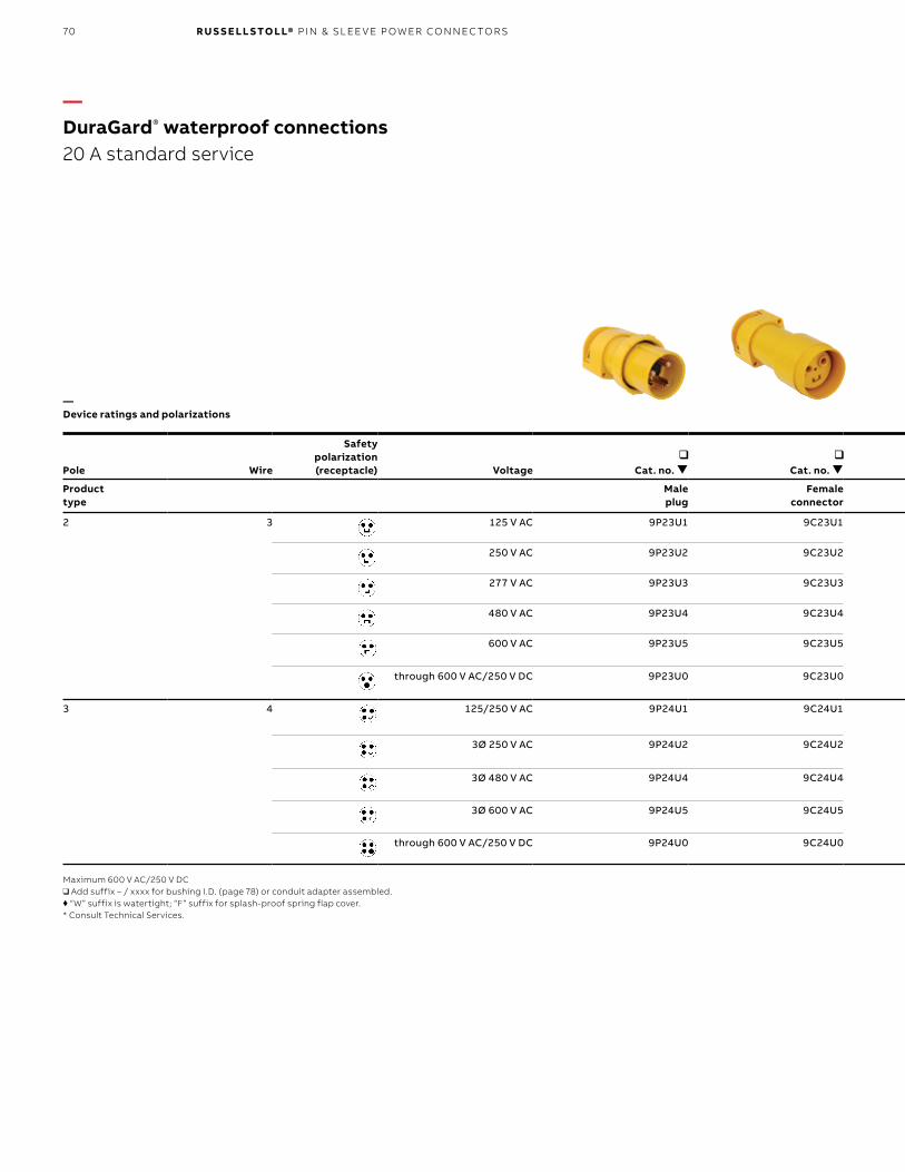
70 R U S S E LL S TO LL® PI N & SL EE V E P OW ER CO N N EC TO R S
Pole Wire
Safetypolarization (receptacle) Voltage
Cat. no.
Cat. no.
Standard bushing I.D.: Plug/conn.*
Cat. no.
Product type
Male plug
Female connector
Female receptacle
2 3 125 V AC 9P23U1 9C23U1 Standard 0.625"; or optional size,
see page 78
9R23U1W
250 V AC 9P23U2 9C23U2 9R23U2W
277 V AC 9P23U3 9C23U3 9R23U3W
480 V AC 9P23U4 9C23U4 9R23U4W
600 V AC 9P23U5 9C23U5 9R23U5W
through 600 V AC/250 V DC 9P23U0 9C23U0 9R23U0W
3 4 125/250 V AC 9P24U1 9C24U1 Standard 0.625"; or optional size,
see page 78
9R24U1W
3Ø 250 V AC 9P24U2 9C24U2 9R24U2W
3Ø 480 V AC 9P24U4 9C24U4 9R24U4W
3Ø 600 V AC 9P24U5 9C24U5 9R24U5W
through 600 V AC/250 V DC 9P24U0 9C24U0 9R24UOW
Maximum 600 V AC/250 V DC❑ Add suffix – / xxxx for bushing I.D. (page 78) or conduit adapter assembled.♦ “W” suffix is watertight; “F” suffix for splash-proof spring flap cover.* Consult Technical Services.
—DuraGard® waterproof connections 20 A standard service
—Device ratings and polarizations

71
Pole Wire
Safetypolarization (receptacle) Voltage
Cat. no.
Cat. no.
Standard bushing I.D.: Plug/conn.*
Cat. no.
Product type
Male plug
Female connector
Female receptacle
2 3 125 V AC 9P23U1 9C23U1 Standard 0.625"; or optional size,
see page 78
9R23U1W
250 V AC 9P23U2 9C23U2 9R23U2W
277 V AC 9P23U3 9C23U3 9R23U3W
480 V AC 9P23U4 9C23U4 9R23U4W
600 V AC 9P23U5 9C23U5 9R23U5W
through 600 V AC/250 V DC 9P23U0 9C23U0 9R23U0W
3 4 125/250 V AC 9P24U1 9C24U1 Standard 0.625"; or optional size,
see page 78
9R24U1W
3Ø 250 V AC 9P24U2 9C24U2 9R24U2W
3Ø 480 V AC 9P24U4 9C24U4 9R24U4W
3Ø 600 V AC 9P24U5 9C24U5 9R24U5W
through 600 V AC/250 V DC 9P24U0 9C24U0 9R24UOW
Maximum 600 V A/250 V DC❑ Add suffix – / xxxx for bushing I.D. (page 78) or conduit adapter assembled.♦ “W” suffix is watertight; “F” suffix for splash-proof spring flap cover.* Consult Technical Services.
D U R AG A R D ® WATER PR O O F CO N N EC TI O NS

72 R U S S E LL S TO LL® PI N & SL EE V E P OW ER CO N N EC TO R S
Pole Wire
Safetypolarization (receptacle) Voltage
Cat. no.
Cat. no.
Standard bushing I.D.: Plug/conn.*
Cat. no.
Cat. no.
Cat. no.
Product type
Male plug
Female connector
Female receptacle
Female plug
Male receptacle
2 3 125 V AC 9P33U1 9C33U1 Standard 0.700"; for optional size,
see page 78
9R33U1W 9F33U1 9B33U1F
250 V AC 9P33U2 9C33U2 9R33U2W 9F33U2 9B33U2F
277 V AC 9P33U3 9C33U3 9R33U3W 9F33U3 9B33U3F
480 V AC 9P33U4 9C33U4 9R33U4W 9F33U4 9B33U4F
600 V AC 9P33U5 9C33U5 9R33U5W 9F33U5 9B33U5F
through 600 V AC/250 V DC 9P33U0 9C33U0 9R33U0W 9F33UØ 9B33UØF
3 4 125/250 V AC 9P34U1 9C34U1 Standard 0.750"; for optional size,
see page 78
9R34U1W 9F34U1 9B34U1F
3Ø 250 V AC 9P34U2 9C34U2 9R34U2W 9F34U2 9B34U2F
3Ø 480 V AC 9P34U4 9C34U4 9R34U4W 9F34U4 9B34U4F
3Ø 600 V AC 9P34U5 9C34U5 9R34U5W 9F34U5 9B34U5F
through 600 V AC/250 V DC 9P34U0 9C34U0 9R34UOW 9F34UØ 9B34UØF
Maximum 600 V AC/250 V DC❑ Add suffix – / xxxx for bushing I.D. (page 78) or conduit adapter assembled.♦ “W” suffix indicates watertight receptacle; “F” suffix indicates splash-proof spring flap cover included.* Consult Technical Services.
❑ Add suffix – / xxxx for bushing I.D. (page 78) or conduit adapter assembled.♦ “W” suffix indicates watertight receptacle; “F” suffix indicates splash-proof spring flap cover included.* Consult Technical Services.
—DuraGard® waterproof connections 30 A standard service and 30 A reverse service
—Device ratings and polarizations
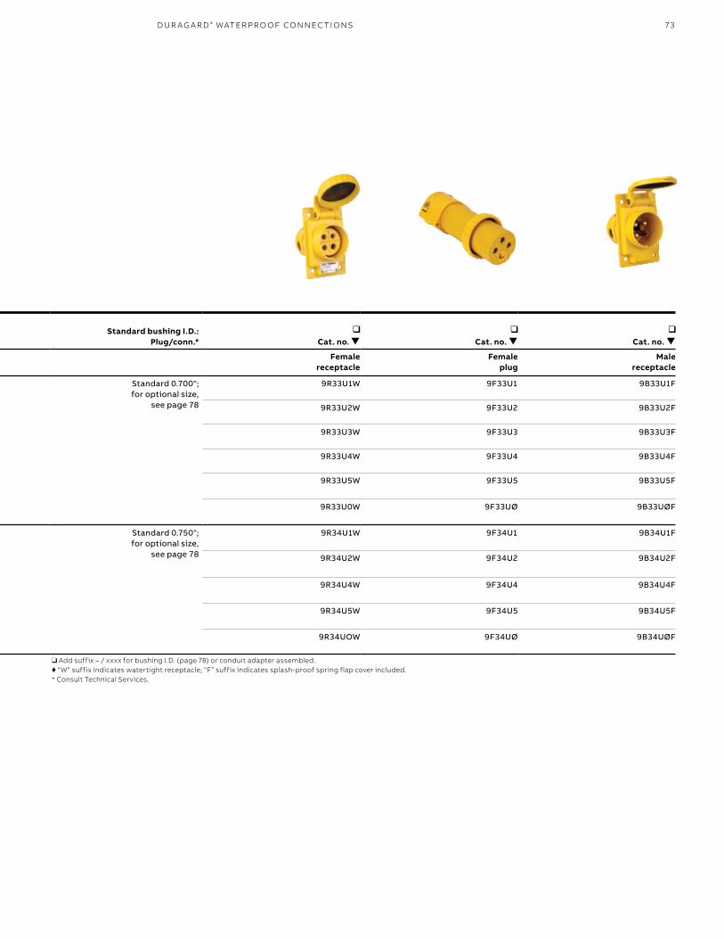
73
Pole Wire
Safetypolarization (receptacle) Voltage
Cat. no.
Cat. no.
Standard bushing I.D.: Plug/conn.*
Cat. no.
Cat. no.
Cat. no.
Product type
Male plug
Female connector
Female receptacle
Female plug
Male receptacle
2 3 125 V AC 9P33U1 9C33U1 Standard 0.700"; for optional size,
see page 78
9R33U1W 9F33U1 9B33U1F
250 V AC 9P33U2 9C33U2 9R33U2W 9F33U2 9B33U2F
277 V AC 9P33U3 9C33U3 9R33U3W 9F33U3 9B33U3F
480 V AC 9P33U4 9C33U4 9R33U4W 9F33U4 9B33U4F
600 V AC 9P33U5 9C33U5 9R33U5W 9F33U5 9B33U5F
through 600 V AC/250 V DC 9P33U0 9C33U0 9R33U0W 9F33UØ 9B33UØF
3 4 125/250 V AC 9P34U1 9C34U1 Standard 0.750"; for optional size,
see page 78
9R34U1W 9F34U1 9B34U1F
3Ø 250 V AC 9P34U2 9C34U2 9R34U2W 9F34U2 9B34U2F
3Ø 480 V AC 9P34U4 9C34U4 9R34U4W 9F34U4 9B34U4F
3Ø 600 V AC 9P34U5 9C34U5 9R34U5W 9F34U5 9B34U5F
through 600 V AC/250 V DC 9P34U0 9C34U0 9R34UOW 9F34UØ 9B34UØF
Maximum 600 V AC/250 V DC❑ Add suffix – / xxxx for bushing I.D. (page 78) or conduit adapter assembled.♦ “W” suffix indicates watertight receptacle; “F” suffix indicates splash-proof spring flap cover included.* Consult Technical Services.
❑ Add suffix – / xxxx for bushing I.D. (page 78) or conduit adapter assembled.♦ “W” suffix indicates watertight receptacle; “F” suffix indicates splash-proof spring flap cover included.* Consult Technical Services.
D U R AG A R D ® WATER PR O O F CO N N EC TI O NS

74 R U S S E LL S TO LL® PI N & SL EE V E P OW ER CO N N EC TO R S
Pole Wire
Safetypolarization (receptacle) Voltage
Cat. no.
Cat. no.
Standard bushing I.D.:Plug/conn.*
Cat. no.
Cat. no.
Cat. no.
Product type
Male plug
Female connector
Female receptacle
Female plug
Male receptacle
2 3 125 V AC 9P53U1 9C53U1 Standard 0.925"; for optional size,
see page 78
9R53U1W 9F53U1 9B53U1F
250 V AC 9P53U2 9C53U2 9R53U2W 9F53U2 9B53U2F
277 V AC 9P53U3 9C53U3 9R53U3W 9F53U3 9B53U3F
480 V AC 9P53U4 9C53U4 9R53U4W 9F53U4 9B53U4F
600 V AC 9P53U5 9C53U5 9R53U5W 9F53U5 9B53U5F
through 600 V AC/250 V DC 9P53U0 9C53U0 9R53U0W 9F53UØ 9B53UØF
3 4 125/250 V AC 9P54U1 9C54U1 Standard 0.925"; for optional size,
see page 78
9R54U1W 9F54U1 9B54U1F
3Ø 250 V AC 9P54U2 9C54U2 9R54U2W 9F54U2 9B54U2F
3Ø 480 V AC 9P54U4 9C54U4 9R54U4W 9F54U4 9B54U4F
3Ø 600 V AC 9P54U5 9C54U5 9R54U5W 9F54U5 9B54U5F
through 600 V AC/250 V DC 9P54U0 9C54U0 9R54U0W 9F54UØ 9B54UØF
Maximum 600 V AC/250 V DC❑ Add suffix – / xxxx for bushing I.D. (page 78) or conduit adapter assembled.♦ “W” suffix is watertight; “F” suffix for splash-proof spring flap cover.
❑ Add suffix – / xxxx for bushing I.D. (page 78) or conduit adapter assembled.♦ “W” suffix is watertight; “F” suffix for splash-proof spring flap cover.* Consult Technical Services.
—DuraGard® waterproof connections 50 A standard service and 50 A reverse service
—Device ratings and polarizations

75
Pole Wire
Safetypolarization (receptacle) Voltage
Cat. no.
Cat. no.
Standard bushing I.D.:Plug/conn.*
Cat. no.
Cat. no.
Cat. no.
Product type
Male plug
Female connector
Female receptacle
Female plug
Male receptacle
2 3 125 V AC 9P53U1 9C53U1 Standard 0.925"; for optional size,
see page 78
9R53U1W 9F53U1 9B53U1F
250 V AC 9P53U2 9C53U2 9R53U2W 9F53U2 9B53U2F
277 V AC 9P53U3 9C53U3 9R53U3W 9F53U3 9B53U3F
480 V AC 9P53U4 9C53U4 9R53U4W 9F53U4 9B53U4F
600 V AC 9P53U5 9C53U5 9R53U5W 9F53U5 9B53U5F
through 600 V AC/250 V DC 9P53U0 9C53U0 9R53U0W 9F53UØ 9B53UØF
3 4 125/250 V AC 9P54U1 9C54U1 Standard 0.925"; for optional size,
see page 78
9R54U1W 9F54U1 9B54U1F
3Ø 250 V AC 9P54U2 9C54U2 9R54U2W 9F54U2 9B54U2F
3Ø 480 V AC 9P54U4 9C54U4 9R54U4W 9F54U4 9B54U4F
3Ø 600 V AC 9P54U5 9C54U5 9R54U5W 9F54U5 9B54U5F
through 600 V AC/250 V DC 9P54U0 9C54U0 9R54U0W 9F54UØ 9B54UØF
Maximum 600 V AC/250 V DC❑ Add suffix – / xxxx for bushing I.D. (page 78) or conduit adapter assembled.♦ “W” suffix is watertight; “F” suffix for splash-proof spring flap cover.
❑ Add suffix – / xxxx for bushing I.D. (page 78) or conduit adapter assembled.♦ “W” suffix is watertight; “F” suffix for splash-proof spring flap cover.* Consult Technical Services.
D U R AG A R D ® WATER PR O O F CO N N EC TI O NS

76 R U S S E LL S TO LL® PI N & SL EE V E P OW ER CO N N EC TO R S
Pole Wire
Safetypolarization (receptacle)
Standard bushing I.D.:Plug/conn.* Voltage
Cat. no.
Cat. no.
Cat. no.
Product type
Male plug
Female connector
Female receptacle
2 3 Standard 1.000"; for optional size,
see page 78
125 V AC 9P63U1 9C63U1 9R63U1
250 V AC 9P63U2 9C63U2 9R63U2
3 4 Standard 1.000"; for optional size,
see page 78
125/250 V AC 9P64U1 9C64U1 9R64U1
3Ø 250 V AC 9P64U2 9C64U2 9R64U2
Maximum 600 V AC or 250 V DC❑ Add suffix — / xxxx for bushing I.D. (page 78) or conduit adapter assembled.♦ “W” suffix is watertight; “F” suffix for splash-proof spring flap cover.
Pole Wire
Safetypolarization (receptacle)
Standard bushing I.D.:Plug/conn.* Voltage
Cat. no.
Cat. no.
Product type
Female plug
Male receptacle
2 3 Standard 1.000"; for optional size,
see page 78
125 V AC 9F63U1 9B63U1
250 V AC 9F63U2 9B63U2
3 4 Standard 1.000"; for optional size,
see page 78
125/250 V AC 9F64U1 9B64U1
3Ø 250 V AC 9F64U2 9B64U2
❑ Add suffix – / xxxx for bushing I.D. (page 78) or conduit adapter assembled.♦ “W” suffix is watertight; “F” suffix for splash-proof spring flap cover.* Consult Technical Services.
—DuraGard® waterproof connections 60 A standard service
—60 A reverse service
—Device ratings and polarizations
—Device ratings and polarizations

77
Cast aluminum Cat. no.
Cast brass Cat. no.
3678A 3678B
TypeCast aluminum
Cat. no.Cast brass
Cat. no. Use with
Single 3711A 3731-RS 20 A
Double 3712A 3732-RS 30 A
DSFD 3781A – 50 A
Note: 3⁄4" NPT hole std. additional accessories are available. Please consult your ABB representative.
Catalog Number 3678A
2.62
4.82
4.12
3.40
45°
1.88 mtg.
3.25 mtg.
Catalog number 3712A
6.50 mtg.
3.00 mtg.
Ø 0.28, 4 PLS
5.47
4.09
2.88
2.881.250.31
1.38"
.31"
4.50"
1.06"
4.12"
3.00"MTG.
2.62"
2.94"
Ø.28", 4 PLS
3.38" MTG
Catalog number 3711A
3.38" mtg.
Ø 0.28", 4 PLS
2.62"
4.12"
3.00" mtg.
2.94"
1.38"
0.31"
4.50"
1.06"
—Type FD
— 45° Angle adapter
—DuraGard® waterproof connections Conduit boxes (for surface mounting)
Dimensions
Dimensions
4.12".31"4.12"
2"
2.62"3.62"
3.18"MTG.
.31"
(2) MTG. Holes
4.37"MTG.
(2) mtg. holes3.18"mtg.
4.37"mtg.
0.31" 0.31"4.12"
2.62"3.62"
2"
4.12"
Catalog number 3781A
D U R AG A R D ® WATER PR O O F CO N N EC TI O NS

78 R U S S E LL S TO LL® PI N & SL EE V E P OW ER CO N N EC TO R S
Size (in.)20 A
Cat. no.30 A
Cat. no.50 A
Cat. no.60 A
Cat. no.1/2 9X2C50 9X3C50 – –3/4 9X2C75 9X3C75 9X5C75 9X6C75
1 – 9X3C10 9X5C10 9X6C10
Max. cable O.D. (in.)20 A
Cat. no.30, 50 & 60 A
Cat. no.
0.375 C16984A –
0.437 C16984B –
0.500 C16984C –
0.545 – 2000-11
0.562 C16984D –
0.606 B16506 –
0.620 – 2000-03
0.625 B16524 –
0.700 – 2000-04
0.750 – 2000-01
0.800 – 2000-06
0.870 – 2000-02
0.925 – 2000-12
1.000 – 2000-05
(Minimum limit 85% of O.D. size for sealing.) Material – Oil-resistant Neoprene. State catalog number followed by slash ( / ) and max. cable O.D.; example: 9P33U1/1000 will order the 1.000" bushing instead of the standard 0.700" bushing for the 9P33U1.
Description20 A
Cat. no.30 A
Cat. no.50 A
Cat. no.60 A
Cat. no.
Screw cap (connector) 9X2PSC 9X3PSC 9X5PSC 9X6PSC
Cup cap (plug) – 9X3CC 9X3CC 9X3CC
Screw cap (receptacle) – 7X3RCW 7X5RCW 7X6RCW
Flap cap (receptacle) – 7X3RCF 7X5RCF 7X6RCF
9X2PSC
7X6RCW9X3CC
7X3RCF
—DuraGard® waterproof connections Conduit adapter kits, cable busings, and replacement caps
—Conduit adapter kits (plugs or connectors)
—Cable bushings
—Replacement caps
20 A cable bushing
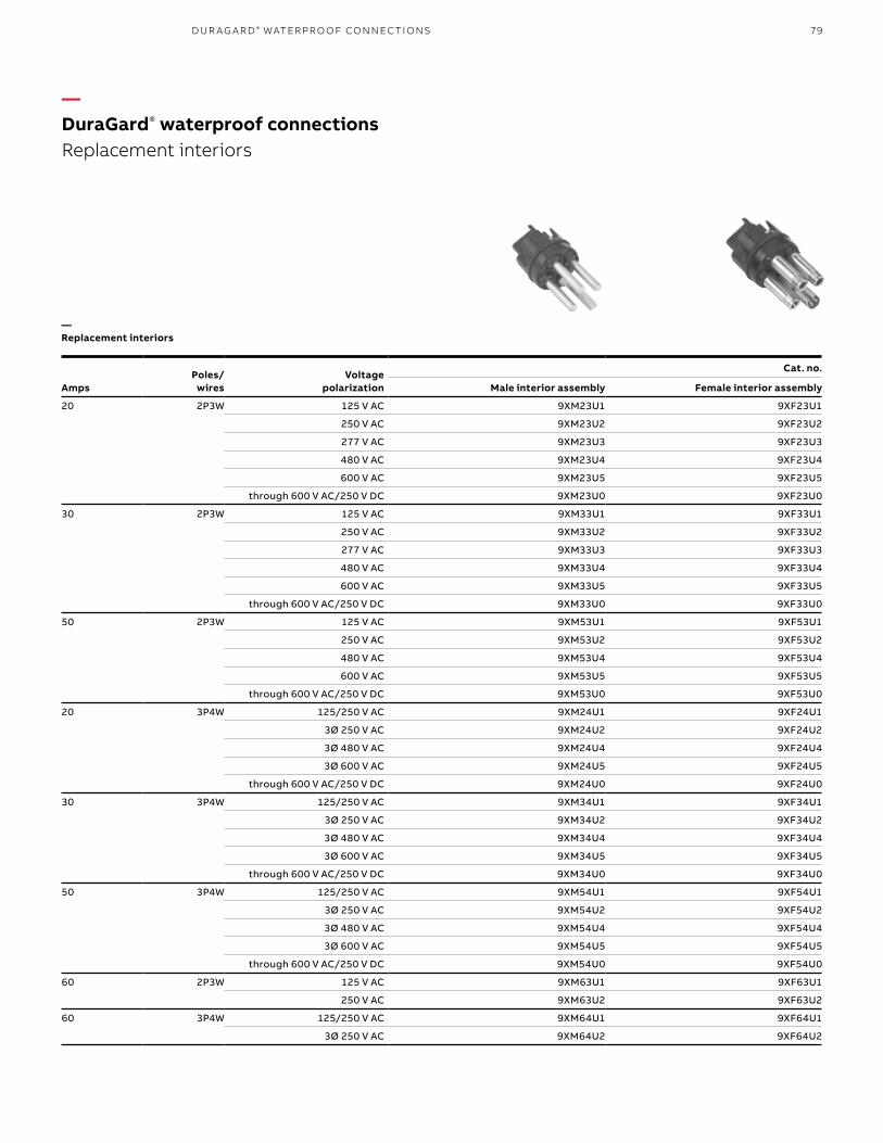
79
AmpsPoles/
wiresVoltage
polarization
Cat. no.
Male interior assembly Female interior assembly
20 2P3W 125 V AC 9XM23U1 9XF23U1
250 V AC 9XM23U2 9XF23U2
277 V AC 9XM23U3 9XF23U3
480 V AC 9XM23U4 9XF23U4
600 V AC 9XM23U5 9XF23U5
through 600 V AC/250 V DC 9XM23U0 9XF23U0
30 2P3W 125 V AC 9XM33U1 9XF33U1
250 V AC 9XM33U2 9XF33U2
277 V AC 9XM33U3 9XF33U3
480 V AC 9XM33U4 9XF33U4
600 V AC 9XM33U5 9XF33U5
through 600 V AC/250 V DC 9XM33U0 9XF33U0
50 2P3W 125 V AC 9XM53U1 9XF53U1
250 V AC 9XM53U2 9XF53U2
480 V AC 9XM53U4 9XF53U4
600 V AC 9XM53U5 9XF53U5
through 600 V AC/250 V DC 9XM53U0 9XF53U0
20 3P4W 125/250 V AC 9XM24U1 9XF24U1
3Ø 250 V AC 9XM24U2 9XF24U2
3Ø 480 V AC 9XM24U4 9XF24U4
3Ø 600 V AC 9XM24U5 9XF24U5
through 600 V AC/250 V DC 9XM24U0 9XF24U0
30 3P4W 125/250 V AC 9XM34U1 9XF34U1
3Ø 250 V AC 9XM34U2 9XF34U2
3Ø 480 V AC 9XM34U4 9XF34U4
3Ø 600 V AC 9XM34U5 9XF34U5
through 600 V AC/250 V DC 9XM34U0 9XF34U0
50 3P4W 125/250 V AC 9XM54U1 9XF54U1
3Ø 250 V AC 9XM54U2 9XF54U2
3Ø 480 V AC 9XM54U4 9XF54U4
3Ø 600 V AC 9XM54U5 9XF54U5
through 600 V AC/250 V DC 9XM54U0 9XF54U0
60 2P3W 125 V AC 9XM63U1 9XF63U1
250 V AC 9XM63U2 9XF63U2
60 3P4W 125/250 V AC 9XM64U1 9XF64U1
3Ø 250 V AC 9XM64U2 9XF64U2
—DuraGard® waterproof connections Replacement interiors
—Replacement interiors
D U R AG A R D ® WATER PR O O F CO N N EC TI O NS

80 R U S S E LL S TO LL® PI N & SL EE V E P OW ER CO N N EC TO R S
AmpsPoles/
wires Voltage
Cat. no.
Safety interlockwith circuit breaker♦1
Circuit breakertrip rating (A)
Matingplug
Rotarycontroller
Replacementinterior
30 3P4W 125/250 V AC 9MT34U1W30B 30 9P34U1 9MI34U1WNAB 9XL34U1
3Ø 250 V AC 9MT34U2W30B 30 9P34U2 9MI34U2WNAB 9XL34U2
3Ø 480 V AC 9MT34U4W30B 30 9P34U4 9MI34U4WNAB 9XL34U4
3Ø 600 V AC 9MT34U5W30B 30 9P34U5 9MI34U5WNAB 9XL34U5
through 600 V AC/3P4W 9MT34U0W30B 30 9P34U0 9MI34U0WNAB 9XL34U0
50 3P4W 125/250 V AC 9MT54U1W50B 50 9P54U1 9MI54U1WNAB 9XL54U1
3Ø 250 V AC 9MT54U2W50B 50 9P54U2 9MI54U2WNAB 9XL54U2
3Ø 480 V AC 9MT54U4W50B 50 9P54U4 9MI54U4WNAB 9XL54U4
3Ø 600 V AC 9MT54U5W50B 50 9P54U5 9MI54U5WNAB 9XL54U5
through 600 V AC/3P4W 9MT54U0W50B 50 9P54U0 9MI54U0WNAB 9XL54U0
Note: 1. Change suffix for alternate trip ratings. Example: 9MT54U2W30B – 50 A, 3P4W, safety interlock with 30 A circuit breaker, conduit top entry. ♦ Change “W” to “F” for flap cap access. Example: 9MI34U2F30B – 30 A, 3P4W, safety interlock with rotary controller and flap cap.(Minimum limit 85% of O.D. size for sealing.)Foot and hardware replacement Kit: Cat. no. 9XLMF (non-metallic) and Cat. no. 9XLMF-SS (stainless steel).
7.005.25�MTG
13.47�MTG13.46 12.00
8.13
“A”�side�entry
“B” conduit�entry standard
8.13
13.47mtg.
5.25MTG
7.00
13.4612.00
“A”Sideentry
“B” conduit entry standard
—DuraGard® waterproof connections Safety interlocks
Circuit breaker interlocked outlet:• 30 A and 50 A ranges and polarizations
to 480 V AC• 22 kA interrupt capacity breaker• Easy handle reset after trip• Auxiliary switch or other options
User friendly – Flexible mounting:• Variable footprint mounting tabs• Compact size fits 8" standard I-beam webs• Conduit entry from top, bottom or side
(3/4", 1" or 11/4" NPT)• Large red handle with lockout access
Flame rated and DuraV® tough housing:• UL® 94-V0 housing and interior with stainless steel
components• High-impact thermoplastic housing• NEMA 4X construction
Dimensions
—Safety interlocks

81
—DuraGard® waterproof connections Dimensions
Dimensions
Dimensions
Amps A* B C* D E Max. AWGTerminal
Ø in./mm
20 Inches 3.87 2.16 2.75 4.75 1.88 12 0.140/0.0055
mm 98.3 54.9 69.9 120.7 47.8
30 Inches 5.385 2.38 4.16 6.25 2.13 8 0.235/0.0092
mm 136.6 60.5 105.7 158.8 54.1
50 Inches 5.75 2.38 4.16 6.25 2.13 6 0.235/0.0092
mm 146.1 60.5 105.7 158.8 54.1
60 Inches 5.75 2.38 4.16 6.25 2.13 6 0.235/0.0092
mm 146.1 60.5 105.7 158.8 54.1
* Dimensions will vary slightly with assembly.
A
B
C
A
B
C
D
E
D
E
Amps F G H I J K M Max. AWGTerminal
Ø in./mm
20 Inches 4.14 3.25 2.66 1.88 1.49 2.26 3.17 12 0.140/0.0055
mm 105.2 82.6 67.6 47.8 37.8 57.4 80.5
30 Inches 4.14 3.25 2.66 1.88 2.44 2.71 4.12 8 0.235/0.0092
mm 105.2 82.6 67.6 47.8 62.0 68.8 104.6
50 Inches 4.14 3.25 2.66 1.88 2.44 2.71 4.12 6 0.235/0.0092
mm 105.2 82.6 67.6 47.8 62.0 68.8 104.6
60 Inches 4.14 3.25 2.66 1.88 2.44 2.71 4.12 6 0.235/0.0092
mm 105.2 82.6 67.6 47.8 62.0 68.8 104.6
Screw cover shown. Flap cover also available; no dimensional changes.
H
I J
K
M
F G
—Plugs and female plugs
—Receptacles and male receptacles
Plugs and female plugs
Connectors
D U R AG A R D ® WATER PR O O F CO N N EC TI O NS

82 R U S S E LL S TO LL® PI N & SL EE V E P OW ER CO N N EC TO R S
Approvals
Application Performance
Dielectric voltage withstand 3000 V
Max. Working voltage 6000 V RMS (minimum creepage and minimum clearance per UL 840)
Circuit interrupting/ load breaking
UL® listed and CSA certified for circuit interrupting at full rated current
Temperature rise Max. 30 °C/86 °F temperature rise at full rated current after 50 cycles of overload at 150% rated current
at 0.75 pf
—Performance – Electrical
* TUV & PSE listed product also available; contact Technical Services.
Application Performance
Impact resistance Per UL 1682 paragraph 34
Cord accommodation Round portable service cords. 10 standard diameters from
0.405" to 1.00", custom sizes to spec
Terminal identification In accordance with UL 1682
Cable pull out force In accordance with UL 1682
Product identification Identification label and molded in name
Lockout/tagout Lockout/tagout hole on plug complies with OSHA Reg. 29 CFR 1910.147
Part Material
Contact carrier interior Molded arc-resistant UL 94-V0 phenolic thermoset
Housing, gland nuts, screw collar rings
DuraV® UL 94-V0, high-impact thermoplastic
O-rings Buna-N (nitrile)
Contacts: pins and sleeves Brass CDA 360
Hinge pins (receptacle) Stainless steel
Terminals Brass CDA 360
Terminal screws, flap springs, assembly screws, nuts, hardware
Stainless steel
Gland friction washer 20 A – nylon 30, 50 and 60 A –
aluminum
Cable clamp bushing Neoprene
—Performance – Mechanical
—Materials
Application Performance
Moisture resistance Per UL 1682 paragraph 49 watertight/flap screw cover on receptacle, O-rings on
all pins and sleeves, interiors and plug shell. Watertight even when not engaged
Flammability V0 or better per UL 94
Operating Maximum continuous: 95 °C/203 °F
Temperatures Minimum: -40 °C/-40 °F without impact
Chemicals Resists standard industrial hydrocarbons, acids, bases and solvents
UV resistance UV resistant housing per UL 746C
—Performance – Environmental
—DuraGard® waterproof connections Plugs, connectors and receptacles
630/E47956 LL14096

83
Application Performance
Dielectric voltage withstand 3000 V
Max. Working voltage 480 V RMS (minimum creepage distance and minimum clearance
per UL® 840) (using circuit breaker)
Circuit interrupting/ load breaking
UL listed and CSA certified for circuit interrupting at full rated current
Temperature rise Max. 30 °C/86 °F temperature rise at full rated current after 50 cycles of overload
at 150% rated current at 0.75 pf
Shrouded contacts Complies with California Code Title 8, Art. 51, S2510.7(b) for devices
exceeding 300 V AC
—Performance – Electrical
Application Performance
Impact resistance Per UL 1682 Paragraph 34
Wiring accommodation Conduit entries at top, side and bottom, 0.750" NPT top entry standard
Terminal identification In accordance with UL 1682
Plug pull out force In accordance with UL 1682
Product identification Identification label
Lockout/tagout Lockout/tagout access on switch complies with OSHA Reg. 29 CFR
1910.147
—Performance – Mechanical
Application Performance
Moisture resistance Per UL 1682 Paragraph 49. Watertight/flap screw cover on receptacle, O-rings on
all pins and sleeves, interiors and plug shell. Watertight even when not engaged
(screw cover closed/locked)
Flammability V0 or better per UL 94
Operating Maximum continuous: 95 °C/203 °F
Temperatures Minimum: -40 °C /-40 °F without impact (Note: per C/B trip at elevated temps.)
Chemicals Resists standard industrial hydrocarbons, acids, bases and solvents
UV resistance UV-resistant housing per UL 746C
—Performance – Environmental
—DuraGard® waterproof connections Safety interlocks
Approvals
Part Material
Contact carrier interior Molded arc-resistant UL 94-V0 thermoset material
Housing, gland nuts, screw collar rings
DuraV® UL 94-V0, high-impact Thermoplastic
O-rings Buna-N (Nitrile)
Contacts: pins and sleeves Brass CDA 360
Hinge pins (receptacle) Stainless steel
Terminals Brass CDA 360
Terminal screws, flap springs, assembly screws, nuts, hardware
Stainless steel
Gland friction washer 20 A – nylon 30, 50 and 60 A –
aluminum
Cable clamp bushing Neoprene
—Materials
D U R AG A R D ® WATER PR O O F CO N N EC TI O NS

84 R U S S E LL S TO LL® PI N & SL EE V E P OW ER CO N N EC TO R S
—FS/FD™ metallic connectionsFeatures and benefits
The FS/FD general-purpose interconnection system is designed for lower-amperage marine and rough service applications with rugged die-cast aluminum housings and epoxy powder-coated finishes. Interlocked receptacles add branch circuit-protected outlet capability and base receptacles fit existing Russellstoll® FS, FD and DSFD single- and multi-gang back boxes. Its versatility and watertight features make it ideal for washdown industrial and light marine applications.
Safety• Circuit-interrupting up to 30 A, 250 V AC
(20 A, 600 V AC)• Factory-polarized interiors permit mating
of same voltage/same type devices through configured ground pins and housing features
• Shell grounding by means of ground strap integral with ground contact for assured assembly safety
Durability• Constructed of copper-free cast aluminum
(brass construction also available)• Optional conduit adapters, strain reliefs and
cable bushings available (modified catalog number construction)
• Non-metallic versions of most metallic plugs and receptacles also available (see DuraGard®, pages 66–83)
Performance• Precision-made, self-aligning and self-wiping
contacts • Devices available in watertight and weathertight
versions• Solderless binding screw terminals for convenient
wiring (20 A, 2P3W devices have set-screw pressure terminals)

85FS/FD ™ M E TA L L I C CO N N EC TI O NS - FE AT U R E S A N D B EN EFITS
—Plug and connector (+ reverse service female plug)
—Receptacle (+ reverse service male inlet)
Gasketed screw collar for watertight connection when plug is mated to receptacle or connector
Ground contacts “make first” and “break last” for safety
Six voltage polarizations available from U0–U5 (2P3W; 3P4W in UØ)
Compression-style cable bushing and gland nut system; external cable
clamping or conduit fitting adapters available separately
or as standard product; modified catalog number can
include special construction or bushing size
Gland nut and oil-resistant neoprene cable bushing
gland to prevent dust and moisture accumulation
Cast aluminum, corrosion-resistant copper-free alloy or cast brass housings for
rough duty or marine service;two-layer electrostatic epoxy
powder-coat finish
Furnished with single-gang conduit box standard; die-cast or heavy-duty thick wall cast boxes available (copper-free aluminum or brass); can be pre-drilled to customer specification
Molded arc-resisting interiors with precision-made, self-wiping, self-
aligning brass contacts; housings positively grounded
by phosphor bronze ground straps integral with ground
contact; contacts “make first” and “break last” for
safe ground; available in brass for marine applications
Waterproof gasketed flap-screw cap
—01 FDWS-62 box shown. See accessories for complete box selections
—01

86 R U S S E LL S TO LL® PI N & SL EE V E P OW ER CO N N EC TO R S
Cable bushings – Oil-resistant, neoprene cable bushing is regularly furnished with hole sizes listed above. Other hole sizes are available at no extra cost when specified on order. See page 90 for available sizes.
Screw caps for connectors can be furnished with retained screw cap at extra cost. For kits order: 9X2PSC 20 A screw cap 9X3PSC 30 A screw cap F26874C 30 A plug cup cap
See the DuraGard® section for thermoplastic families.
—Standard cable bushing hole diameter
Prefix Hole dia.
3720 –
3730 –
3750, 3760 –
3913 5/8
3914 11/16
3933, 3934 3/4
3789 –
3790 –
3809, 3810 –
For other plug and connector accessories, see pages 90–H-93.Plugs can be furnished with adapters to accommodate rigid conduit or standard connectors. For armored cable or flexible conduit, see page 90.
Poles/wires Amps VoltagePolarization (receptacle) Aluminum Cast brass Aluminum Cast brass Aluminum with box * Cast brass with box * Aluminum Cast brass
Aluminum with box FDWS-62
Cast brasswith box 3731
Product type Male plugs Female connectors Female receptacles Female plugs reverse service Male receptacles reverse service
2P3W 15 125 V AC 3720U-2 3720BU-2 3913U-2 3913BU-2 3743U-2 3763U-2 3789U-2 3789BU-2 3776U-2 3779U-2
177 V AC 3720U-3 3720BU-3 3913U-3 3913BU-3 3743U-3 3763U-3 3789U-3 3789BU-3 3776U-3 3779U-3
480 V AC 3720U-4 3720BU-4 3913U-4 3913BU-4 3743U-4 3763U-4 3789U-4 3789BU-4 3776U-4 3779U-4
600 V AC 3720U-5 3720BU-5 3913U-5 3913BU-5 3743U-5 3763U-5 3789U-5 3789BU-5 3776U-5 3779U-5
20 250 V AC 3720 3720B 3913 3913B 3743 3763 3789 3789B 3776 3779
125 V AC 3720U-1 3720BU-1 3913U-1 3913BU-1 3743U-1 3763U-1 3789U-1 3789BU-1 3776U-1 3779U-1
30 250 V AC 3750 3750B 3933 3933B 3753 3773 38091 3809B1 37962 37993
3P4W 10 600 V AC 3730 3730B 3914 3914B 3744 3764 3790 3790B 3777 3780
15 250 V AC 3730 3730B 3914 3914B 3744 3764 3790 3790B 3777 3780
20 600 V AC 3760 3760B 3934 3934B 3754 3774 3810 3810B 3797 3800
30 250 V AC 3760 3760B 3934 3934B 3754 3774 3810 3810B 3797 3800
* Receptacles come with the following boxes:
—FS/FD ™ metallic connections10–30 A
—10–30 A

87FS/FD ™ M E TA L L I C CO N N EC TI O NS
Poles/wires Amps VoltagePolarization (receptacle) Aluminum Cast brass Aluminum Cast brass Aluminum with box * Cast brass with box * Aluminum Cast brass
Aluminum with box FDWS-62
Cast brasswith box 3731
Product type Male plugs Female connectors Female receptacles Female plugs reverse service Male receptacles reverse service
2P3W 15 125 V AC 3720U-2 3720BU-2 3913U-2 3913BU-2 3743U-2 3763U-2 3789U-2 3789BU-2 3776U-2 3779U-2
177 V AC 3720U-3 3720BU-3 3913U-3 3913BU-3 3743U-3 3763U-3 3789U-3 3789BU-3 3776U-3 3779U-3
480 V AC 3720U-4 3720BU-4 3913U-4 3913BU-4 3743U-4 3763U-4 3789U-4 3789BU-4 3776U-4 3779U-4
600 V AC 3720U-5 3720BU-5 3913U-5 3913BU-5 3743U-5 3763U-5 3789U-5 3789BU-5 3776U-5 3779U-5
20 250 V AC 3720 3720B 3913 3913B 3743 3763 3789 3789B 3776 3779
125 V AC 3720U-1 3720BU-1 3913U-1 3913BU-1 3743U-1 3763U-1 3789U-1 3789BU-1 3776U-1 3779U-1
30 250 V AC 3750 3750B 3933 3933B 3753 3773 38091 3809B1 37962 37993
3P4W 10 600 V AC 3730 3730B 3914 3914B 3744 3764 3790 3790B 3777 3780
15 250 V AC 3730 3730B 3914 3914B 3744 3764 3790 3790B 3777 3780
20 600 V AC 3760 3760B 3934 3934B 3754 3774 3810 3810B 3797 3800
30 250 V AC 3760 3760B 3934 3934B 3754 3774 3810 3810B 3797 3800
* Receptacles come with the following boxes:
Note:1. Also in plastic. Use 3809P or 9F33UO.2. Also in plastic. Use 3796P – Aluminum back box (use 3797-P for brass).3. Also in plastic. Use 3799P (Brass J-Box) or 9B33UØF (without J-Box).For 20 A/30 A Thermoplastic devices, see DuraGard® section.Mating with DuraGard line:– 20 A devices will mate and lock across lines.– 30 A metal male devices cannot mate to DuraGard; 30 A female devices can be mixed.
Material Amps Box
Aluminum 10, 15 and 20 FSWS-62
30 FDWS-62
Brass 10, 15 and 20 3721
30 3731
Inlets

88 R U S S E LL S TO LL® PI N & SL EE V E P OW ER CO N N EC TO R S
—FS/FD™ metallic connectionsDimensions
Amps
A B C E F G H
(in.) (mm) (in.) (mm) (in.) (mm) (in.) (mm) (in.) (mm) (in.) (mm) (in.) (mm)
10 1.75 45.66 3.62 92.07 2.25 25.15 2.00 50.80 4.00 101.60 1.87 47.62 0.75 19.050
15 1.75 45.65 3.62 92.07 2.25 57.15 2.00 50.80 4.00 101.60 1.87 47.62 0.75 19.050
20 1.75 45.65 3.62 92.07 2.25 57.15 2.00 50.80 4.00 101.60 1.87 47.62 0.75 19.050
30 1.87 47.62 3.75 92.25 2.25 57.15 2.25 57.15 4.25 107.95 2.25 57.15 1.12 28.57
—Plug, female plug and connector
Standard die-cast aluminum back box(FSWS/FDWS)
.28" Dia. (2) MTG.
Holes
2.75"
4.81"
3.81"
4.25"4.875"mtg.
2.25"mtg.
2.94" (FDWS)2.31" (FDWS)
0.28" dia.(2) mtg.
holes
Dimensions
GF H
G
Max. CableDia.
Connectors
Max. cable dia.
F
G
GH
B
C H E
Max. CableDia.
A
Plugs and female plugs
Max. cable dia.
E
B
C H
A
—Receptacles and male receptacles
Cast aluminum/cast brass back box(3701–3732 series)
4.12"
3.37"mtg.2.62"
3"mtg. 2.94"
(FD)
0.28" dia.(2) mtg.
holes
3.81"
2.31" (FS)
3"mtg.
0.75"

89FS/FD ™ M E TA L L I C CO N N EC TI O NS
Approvals
Application Performance
Dielectric voltage withstand 3000 V
Max. Working voltage 600 V RMS (minimum creepage distance and minimum clearance
per UL® 840)
Circuit interrupting/ load breaking
UL listed and CSA certified for circuit interrupting at full rated current
Temperature rise Max. 30 °C/86 °F temperature rise at full rated current after 50 cycles of overload
at 150% rated current at 0.75 pF
Shrouded contacts Complies with California code title 8, art. 51, S2510.7(b) for devices exceeding
300 V AC
Horsepower Per NEC® 430-151 ratings (non- interrupting)
—Performance – Electrical
—FS/FD™ metallic connectionsPerformance, materials & approvals
E2630/E47956 LL14096
NEC and National Electrical Code are registered trademarks of the National Fire Protection Association, Inc.
Application Performance
Impact resistance Per UL 1682 paragraph 34
Cord accommodation Round portable service cords per UL standard 62 and CSA C22.2 No. 49.1
Terminal identification In accordance with UL 1682
Cable pull out force In accordance with UL 1682
Product identification Identification label and name per UL 1686
Part Material
Contact carrier interior Thermoset
Housing, gland nuts, screw collar rings Cast aluminum or brass
Contacts: pins and sleeves Brass
Hinge pins (receptacle) Stainless steel
Terminals Brass
Terminal screws, flap springs, assembly screws, nuts, hardware
Stainless steel
Gland friction washer Brass or aluminum
Cable clamp bushing Neoprene
—Performance – Mechanical
—Materials
Application Performance
Moisture resistance Per UL 1682 paragraph 49 Watertight/flap screw cover on receptacle
Flammability VØ/5VA per UL 94
Operating Maximum continuous: 95 °C/203 °F
Temperatures Minimum: -40 °C/-40 °F without impact
Chemicals Resists standard industrial hydrocarbons, acids, bases and solvents
—Performance – Environmental

90 R U S S E LL S TO LL® PI N & SL EE V E P OW ER CO N N EC TO R S
—Combination gland nut and cable clamp
—Conduit adapters
—Cable bushings
Type 2Cable bushing
Type 3Cable bushing
Hole diameterfor cable (in.)
Type 210 A
Type 320 and 30 A
0.313 SG05 –
0.375 SG1 JG31
0.438 SG15 –
0.500 SG2 JG32
0.531 SG2A –
0.563 SG25 JG325
0.594 SG2B –
0.625 SG3 JG33
0.688 SG3A –
0.750 SG4 JG34
0.875 – JG35
1.000 – JG36**
1.125 – JG361**
** Special for large O.D. cable.Note: When standard plugs or connectors are required to be furnished with one or more of the above accessories, add the suffix and catalog number of the accessory selected to the catalog number of the plug or connector. Complete list price is the total of the list price of the device plus the list price of the accessory.Examples – Using catalog no. 3934:Combo. gland nut and cable clamp 3934-3906Adapter at 3⁄4" 3934-FSA221⁄2" Cable bushing 3934-JG32Material – Oil-resistant neoprene.
Plug orconnectorsize
Castaluminum
Cat. no.
Castbrass
Cat. no.
Max.cable
dia. (in.)
10–20 A (Ex: 3913) 3905 3905B 0.62
20–30 A (Ex: 3934) 3906 3906B 1.12
Material – Cast aluminum, corrosion-resistant copper-free alloy; cast brass, epoxy powder coat finish.
Plug orconnectorsize
Castaluminum
Cat. no.
Castbrass
Cat. no.Tapped
NPT (in.)
10–20 A (Ex: 3913) FSA11 FSA11B 1/2
FSA12 FSA12B 3/4
20-30 A (Ex: 3934) FSA21 FSA21B 1/2
FSA22 FSA22B 3/4
FSA23 FSA23B 1
Furnished complete with gasket.
• Provides extra clamping protection in hard service applications. Relieves terminals and rubber gland of all cable strain.
• Adapter tapped with NPT thread to accommodate armored and non-metallic cable or flexible conduit.
—FS/FD™ metallic connectionsFor plugs and connectors

91
Gangs Type Cast aluminum Cast brass Overall dimensions* (in.) For use with
Single FS 3701A 3721 4.12 x 2.62 x 2.31 15–20 A
FD 3711A 3731 4.12 x 2.62 x 2.94 30 A
DSFD 3781A – 4.12 x 3.62 x 4.12 30 A
Two FS 3702A 3722 4.12 x 5.5 x 2.25 15–20 A
FD 3712A 3732 4.12 x 5.62 x 2.87 30 A
Single-gang Two-gang DSFD
* Dimensions are overall exclusive of conduit pads and mounting lugsNote: When Type FD devices (20A) are to be mounted in boxes, Type FD boxes should be used. FS boxes will not accommodate FD devices (30A or 3P4W).Mounting – All the above boxes are for surface mounting. For flush mounting, see page 92.Boxes – Cast brass, natural finish; cast aluminum, corrosion-resistant copper-free alloy, epoxy powder-coat finish.Outlets – Unless otherwise specified, furnished with one 0.75" outlet per gang, top or bottom. Additional outlets charged extra – see price list. Specify size and location.Maximum conduit – FS and FD: 1", one per gang top and bottom and one each side.DSFD – One 1.5" or two 0.5" top and bottom.Cast iron available on special order – consult your ABB representative.
A
1.38"
.31"
4.50"
1.06"
4.12"
3.00"MTG.
2.62" Ø.28", 4 PLS
3.38" MTG
• Aluminum boxes have 6-32 cover mounting holes tapped to accommodate all FS and FD cover assemblies.
• Brass boxes have 10-24 cover mounting holes tapped to accommodate all FS and FD cover assemblies.
4.12".31"4.12"
2"
2.62"3.62"
3.18"MTG.
.31"
(2) MTG. Holes
4.37"MTG.
Type A (in.)
FS 2.31
FD 2.94
A (in.) B (in.)
FS FD FS FD
6.50 6.50 5.50 5.62
—Dimensions
Multiple gangFS/FD™ DSFD
2.62"
4.12"
A
1.38"
0.31"
4.50"
1.06"
0.31" 0.31"4.12" 4.12"
2.87"
B"
A"-mtg.
3.62"2.62"
2"3.18"mtg.
4.37"mtg. 3"
mtg.
(2) mtg. holes
4" mtg. holes
3.38" mtg.
3.00" mtg.
ø.28", 4 PLS
—FS/FD™ metallic connectionsType FS (shallow) and Type FD (deep)
FS/FD ™ M E TA L L I C CO N N EC TI O NS
Dimensions
—Type FS (shallow) and Type FD (deep)

92 R U S S E LL S TO LL® PI N & SL EE V E P OW ER CO N N EC TO R S
—Covers standard FS/FD box openings.
—Flush wall mounting extension*
Cat. no. Material
3677A Cast aluminum
3687 Cast brass
* Furnished complete with gasket and screws.
Cat. no. Material
3679A Cast aluminum
3679B Cast brass
* Furnished complete with gasket and screws.
Gangs Cast aluminum Cast brass Overall dimensions (in.)
1 3671A 3681 5 x 3.5
2 3672A 3682 5 x 6.5
Adapters and covers to fit boxes on page 92–93.* Furnished complete with gasket and screws.
—FS/FD™ metallic connectionsAdapter flush frames*
• For mounting to standard wall outlet boxes (2-screw mount)
—Blank cover*
2.95"1.87"
3.25" 4.15"
.15"
1.87"
5" 3.25"
2.62"
3. 5"
4.12"
2 "
3.25"
1.87".21" DIA.4 MTG.Holes
Front BackFront
1.87"
1.87"
3.25" 3.25"
2.62"
4.12"
3.5"
5"
2"
Back
0.21" dia (4) mtg.
holes
2.95"1.87" 0.15"
4.15"3.25"
DimensionsDimensions

93FS/FD ™ M E TA L L I C CO N N EC TI O NS
—Mounts to any FS/FD box.
• Aluminum die-cast boxes with cover mounting holes tapped for 6-32 screws to accommodate all FS and FD cover assemblies
Cat. no.
Conduit entries
Top (in.) Bottom
FSWS-62 3/4 –
FDWS-62 3/4 –
FDWS-622 3/4 3/4
FDWS-63 1 –
FDWS-633 1 1
Cat. no. Material
3678A Cast aluminum
3678B Cast brass
* Furnished complete with gasket and screws.
* Furnished complete with gasket and screws.Notes: Materials – Cast aluminum, corrosion-resistant copper-free alloy, epoxy powder-coat finish; cast brass, natural finish.Boxes – Aluminum die-cast, corrosion-resistant copper-free alloy, epoxy powder-coat finish.Outlets – Standard as listed.Mounting – All of the above boxes are for surface mounting.
2.62"
4.82"
3.40"
4.12"
45°
1.88" mtg.
3.25" mtg.
—FS/FD™ metallic connections45°Angleadapter*
—Type FSWS and FDWS (with mounting shelf for box-mounted devices)
Dimensions
Dimensions
2.25"MTG
2.25" 2.25" .25"
5.37"
2.31".75"
.28" Dia.(2) MTG. Holes
2.25"MTG
4.87"MTG
4.81"
4.87"MTG
.28" Dia.(2) MTG. Holes
0.28" dia. (2) mtg.
holes2.35" mtg.
4.87" mtg.
4.87" mtg.
2.25" mtg.
0.28" dia. (2) mtg.
holes
2.25"
4.81"
5.37"
2.25"0.25"
0.75"2.31"
—Type FSWS and FDWS (with mounting shelf for box-mounted devices)

94 R U S S E LL S TO LL® PI N & SL EE V E P OW ER CO N N EC TO R S
—FS/FD™ metallic connectionsMarine/Industrial series – 20 and 30 A, 250 V AC
Safety• Mechanical linkage prevents plug insertion or
withdrawal unless switch is in “off” position• Circuit breaker protection available on
many models • Ground contacts “make first,” “break last”
Durability• Constructed of copper-free cast aluminum
(some types available in brass)• Sturdy die-cast and sand-cast housings
Performance• Precision-made, self-aligning and self-wiping
contacts• Receptacles provided with spring-actuated,
self-closing flaps• Devices available in watertight and weathertight
versions• Solderless screw terminals for convenient wiring
Mechanically interlocked FS/FD interface receptacle outlets, available through 30 A 250 V AC, provide added electrical safety in branch circuits.
By design, the plug must be fully inserted into the interlocked receptacle before the switch or circuit breaker can be turned to the “ON” position, and the switch or circuit breaker must be in the “OFF” position before the plug can be withdrawn. This design ensures that when properly installed and operated, the circuit is made and broken by the switch or circuit breaker, not by the connectors.
As with all Russellstoll products, mechanically interlocked receptacles were designed with safety, durability and performance in mind.
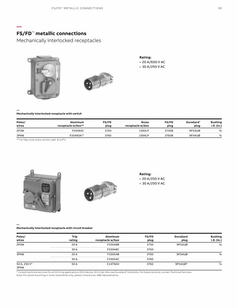
95FS/FD ™ M E TA L L I C CO N N EC TI O NS
—FS/FD™ metallic connectionsMechanically interlocked receptacles
Rating:• 20 A/600 V AC• 30 A/250 V AC
Poles/ wires
Aluminum receptacle w/box**
FS/FDplug
Brass receptacle w/box
FS/FDplug
DuraGard®
plugBushingI.D. (in.)
2P3W F20493C 3750 1593LP 3750B 9P33UØ 5/8
3P4W F20493A** 3760 1594LP 3760B 9P34UØ 3/4** For flap cover brass version, add -B suffix.
—Mechanically interlocked receptacle with switch
Rating:• 20 A/250 V AC• 30 A/250 V AC
Poles/wires
Triprating
Aluminumreceptacle w/box
FS/FDplug
DuraGardplug
BushingI.D. (in.)
2P3W 20 A F33048B 3750 9P33UØ 5/8
30 A F33048C 3750
3P4W 20 A F33054B 3760 9P34UØ 3/4
30 A F33054C 3760
50 A, 250 V*3P4W
50 A C1479AH 3760 9P34UØ* 7/8
* Consult technical services for all 50 A trip applications (30 A device, 50 A trip). Also see DuraGard® Interlocks. For brass versions, contact Technical Services.Note: For panel mounting or cover assemblies only, please consult your ABB representative.
—Mechanically interlocked receptacle with circuit breaker

96 R U S S E LL S TO LL® PI N & SL EE V E P OW ER CO N N EC TO R S
—Interlocked with switch, surface mount
—Interlocked with circuit breaker
4.5"
6.75"
4.81"
2.93" 1.87 "
1.25" Max. ConduitTop & Bottom only
5.06"
5.87"MTG
5.43"
.34" Dia.(4) MTG .Holes
7.50 "6.75"
8.50"
.34"
5.25"
PluggedDrain Hole1/8" 27 NPT
—Standard plug
A
B
C
30/50 A DuraGard®
20/30 A FS/FD™
—Machine panel mount
4.5"
6.75"
2.5"
3.37"
6 .37 "
5.46"
3.12"
3.68"
.37" .87".75"
12 -24 NC28 Tap6 Req’d
.43"
45ϒ3.37"
(also as replacement cover assembly)
Cat. no. F18196B&C and F20493A&B
—Floor extension mount
A
B
D
C
PluggedDrain Hole3⁄8" 18 NPT
W X
Y
Z
V
SwitchCircuit breaker
4.88"
2.13"
Amps A B C
30 Inches 5.38 2.38 4.16
mm 136.6 60.5 105.7
50 Inches 5.75 2.38 4.16
mm 146.1 60.5 105.7
Specifications • Housings: cast brass, natural finish; cast
aluminum, corrosion-resistant copper-free alloy, epoxy powder coat finish
• Cable bushings: oil-resistant, Neoprene strain-relief cable bushings regularly furnished with hole size as listed for plug; other hole sizes available if specified on order; see accessory reference section, bushing sizes on page 90
• Outlets: Unless otherwise specified, boxes are furnished blank
• Receptacle interlocked with switch: maximum conduit outlets 13/4" top and bottom; specify outlets required
• Receptacle interlocked with circuit breaker: maximum conduit outlet 13/4" at locations V, W, X, Y and Z as per diagram; specify outlets required, use symbols
—FS/FD™ metallic connectionsDimensions
—Standard plug
4.81"
2.93"
1.25" max conduittop & bottom only
0.34" dia.(4) mtg. holes Plugged
drain hole1/8" 27 NPT
Pluggeddrain hole3 /8" 18 NPT
12-24 NC28 tap6 req'd
5.06"
3.37"
3.37"
3.12"
4.88"
2.13"
0.43"
0.87"0.75"
0.37"3.68"6.75"
6.37"
5.46"
6.75" 8.50"
7.50"6.75" 5.25"
0.34"
5.43"
5.87"mtg.
4.5"
4.5"45ϒ
2.5"
1.87"
W X
YV
Z
A
B
C
Dimensions

97A B B I EC 6 0 3 0 9 INTER N ATI O N A L P I N A N D SL EE V E
Durability• Designed for durability: The housings are made
of thermoplastic polyester (PBT) grade Valox® 357 material, which guarantees highest possible durability in this industry
• Superb ingress protection: IP69K rated to withstand high pressure steamjet washdown
• Built to last: Interconnectors are highly resistant to chemicals like mineral and organic acid, organic solvents and petroleum. All external screws are made of stainless steel to prevent corrosion.
• Reinforced for high reliability: The contact carrier is made of fiberglass-reinforced nylon material for sizes between 60 A–125 A, which reduces the need for and expense of replacement parts
Performance• Continuing operation: The self-cleaning pin and
sleeve design keeps the connection resistance on the lowest level, reducing down time
• Long lasting: Machine-calibrated sleeves with stainless steel springs provide accurate contact pressure over time
• Resilience: Corrosion-resistant steel screws at terminals provide clamping pressure over time
• Easy installation: Clear terminal markings inside and at the front of the devices
Valox is a registered trademark of SABIC.
—ABB IEC 60 309 international pin and sleeve
Approved according to IEC 60 309-1, -2, -4 – range from 16 up to 125 A, up to 600 V, watertight to IP67 and IP69K
Safety• Proven performance: With more than 30 years
of experience, ABB IEC pin and sleeve connectors are the brand of choice around the globe
• Added safety measures: Plugs and connectors are equipped with a double cable clamp system to prevent cable detachment and provide a higher level of cable strain relief
• Safe connections: Mechanical interlocks guarantee no access to plug insertion or removal until power is off

98 R U S S E LL S TO LL® PI N & SL EE V E P OW ER CO N N EC TO R S
This is the catalog number for a 3P4W 16 A plug that is polarized for use at 380–415 V AC, 50 or 60 Hz, with an IP67 and IP69K rating.
See clock on page 99.
—ABB IEC 60 309 international pin and sleevePart number configuration
Number of wires2 poles, 3 wire 33 poles, 4 wire 44 poles, 5 wire 5
Amp rating16 A 1620 A 2030 A 3032 A 3260 A 6063 A 63100 A 10025 A 125
TypePlugs P Connectors C Receptacles R Inlets BMechanical interlocked receptaclesSwitched MI Fused MF Breakered MB
Position of earthing sleeveAccording to IEC 60 309-2 clock
Degree of protectionIP67 & IP69K W
ABB 4 16 P 6 W

99A B B I EC 6 0 3 0 9 I NTER N ATI O N A L P I N A N D SL EE V E
4P5W3P4W2P3W
Position of earthing sleeve according to IEC 60309-2 (clock) 2P3W 3P4W 4P5W
1 Optional voltage (not stated below) Optional voltage (not stated below) Optional voltage (not stated below)
3 50–250 V DC 380 V 50 Hz to 440 V 60 Hz –
4 100–130 V 50/60 Hz – –
5 277 V 60 Hz 600 V 50/60 Hz 347/600 V 50/60 Hz
6 200–250 V 50/60 Hz 380–415 V 50/60 Hz 200/346–240/415 V 50/60 Hz
7 480 V 50/60 Hz 480 V 50/60 Hz 277/480 V 50/60 Hz
9 – 200–250 V 50/60 Hz 120/208–144/250 V 50/60 Hz
12 Supply from isolating transformer 125/250 V
—ABB IEC 60 309 international pin and sleeveIEC 60 309-2 clock
480 V~
4P5W3P4W2P3W
Ue = 50–600 VIe = 16–125 A
480 V~ 600 V~
347/600 V~277/480 V~
—Standard voltagesColor codes according to IEC 60 309-1, -2

100 R U S S E LL S TO LL® PI N & SL EE V E P OW ER CO N N EC TO R S
Pin and sleeve plugs & connectors are for applications in environments that have high demand of functionality and safety. The robust housing is made of thermoplastic polyester (PBT) grade Valox® 357 material. The product is available as watertight (IP67 & IP69K). The devices are equipped with internal and external cable clamps. The 60 A–125 A devices are equipped with two screws on each terminal.
Clear marking, at the front and the rear of the terminals Ground Neutral NPhase L1, L2, L3
Robust plastic housing that withstands most chemicals found in industrial environments
Clean brass pins
Rear terminals, raised lettering, identification contacts
Internal and external cable clamp
External screws made of stainless steel
Watertight chloropreneonion skin grommet
ABB560P6W
ABB560C6WValox is a registered trademark of SABIC.
Spring loaded replaceable lid covers
—ABB IEC 60 309 international pin and sleevePin and sleeve plugs & connectors
Features• IP67 & IP69K watertight• 16–125 A, 50–600 V AC• IEC 60 309-1, -2• All external screws are made
of stainless steel
Application examples• Food & beverage• Harbors/shipyards• Mines• Industry/workshops
Two screws at each terminal to assure safe and reliable
cable connection (on 60 A–125 A product; lower amperages have
a single screw)

101A B B I EC 6 0 3 0 9 I NTER N ATI O N A L P I N A N D SL EE V E
AmpsPoles &
wires Voltage (V AC*)Clock hour Plug Connector Receptacle Inlet
Plug insert
Connector insert
Back box
16 2P3W 100–130 4h ABB316P4W ABB316C4W ABB316R4W ABB316B4W – – BB 30
2P3W 200–250 6h ABB316P6W ABB316C6W ABB316R6W ABB316B6W – – BB 30
3P4W 380–415 6h ABB416P6W ABB416C6W ABB416R6W ABB416B6W IN420P IN420C BB 30
4P5W 200/346–240/415 6h ABB516P6W ABB516C6W ABB516R6W ABB516B6W – – BB 30
20 2P3W 100–130 4h ABB320P4W ABB320C4W ABB320R4W ABB320B4W – – BB 30
2P3W 200–250 6h ABB320P6W ABB320C6W ABB320R6W ABB320B6W – – BB 30
2P3W 277 5h ABB320P5W ABB320C5W ABB320R5W ABB320B5W – – BB 30
2P3W 480 7h ABB320P7W ABB320C7W ABB320R7W ABB320B7W – – BB 30
3P4W 125/250 12h ABB420P12W ABB420C12W ABB420R12W ABB420B12W IN420P IN420C BB 30
3P4W 3Ø 200–250 9h ABB420P9W ABB420C9W ABB420R9W ABB420B9W IN420P IN420C BB 30
3P4W 3Ø 480 7h ABB420P7W ABB420C7W ABB420R7W ABB420B7W IN420P IN420C BB 30
3P4W 3Ø 600 5h ABB420P5W ABB420C5W ABB420R5W ABB420B5W IN420P IN420C BB 30
4P5W 3ØY 120/208–144/250
9h ABB520P9W ABB520C9W ABB520R9W ABB520B9W IN520P IN520C BB 30
4P5W 3ØY 277/480 7h ABB520P7W ABB520C7W ABB520R7W ABB520B7W IN520P IN520C BB 30
4P5W 3ØY 347/600 5h ABB520P5W ABB520C5W ABB520R5W ABB520B5W IN520P IN520C BB 30
30 2P3W 100–130 4h ABB330P4W ABB330C4W ABB330R4W ABB330B4W IN330P IN330C BB 30
2P3W 200–250 6h ABB330P6W ABB330C6W ABB330R6W ABB330B6W IN330P IN330C BB 30
2P3W 277 5h ABB330P5W ABB330C5W ABB330R5W ABB330B5W IN330P IN330C BB 30
2P3W 480 7h ABB330P7W ABB330C7W ABB330R7W ABB330B7W IN330P IN330C BB 30
3P4W 125/250 12h ABB430P12W ABB430C12W ABB430R12W ABB430B12W IN430P IN430C BB 30
3P4W 3Ø 200–250 9h ABB430P9W ABB430C9W ABB430R9W ABB430B9W IN430P IN430C BB 30
3P4W 3Ø 480 7h ABB430P7W ABB430C7W ABB430R7W ABB430B7W IN430P IN430C BB 30
3P4W 3Ø 600 5h ABB430P5W ABB430C5W ABB430R5W ABB430B5W IN430P IN430C BB 30
4P5W 3ØY 120/208–144/250
9h ABB530P9W ABB530C9W ABB530R9W ABB530B9W IN530P IN530C BB 30
4P5W 3ØY 277/480 7h ABB530P7W ABB530C7W ABB530R7W ABB530B7W IN530P IN530C BB 30
4P5W 3ØY 347/600 5h ABB530P5W ABB530C5W ABB530R5W ABB530B5W IN530P IN530C BB 30
32 2P3W 100–130 4h ABB332P4W ABB332C4W ABB332R4W ABB332B4W IN330P IN330C BB 30
2P3W 200–250 6h ABB332P6W ABB332C6W ABB332R6W ABB332B6W IN330P IN330C BB 30
3P4W 380–415 6h ABB432P6W ABB432C6W ABB432R6W ABB432B6W IN430P IN430C BB 30
3P4W 380 50 Hz/440 60 Hz 3h ABB432P3W ABB432C3W ABB432R3W ABB432B3W IN430P IN430C BB 30
4P5W 200/346–240/415 6h ABB532P6W ABB532C6W ABB532R6W ABB532B6W IN530P IN530C BB 30
* Unless otherwise noted.
—ABB IEC 60 309 international pin and sleeveIP67 & IP69K rated (watertight)
—IP67 & IP69K rated (watertight)

102 R U S S E LL S TO LL® PI N & SL EE V E P OW ER CO N N EC TO R S
AmpsPoles &
wires Voltage (V AC*)Clock hour Plug Connector Receptacle Inlet
Plug insert
Connector insert Back box
60 2P3W 100–130 4h ABB360P4W ABB360C4W ABB360R4W ABB360B4W IN360P4 IN360C4 BB 60
2P3W 200–250 6h ABB360P6W ABB360C6W ABB360R6W ABB360B6W – – BB 60
2P3W 277 5h ABB360P5W ABB360C5W ABB360R5W ABB360B5W IN360P5 IN360C5 BB 60
2P3W 480 7h ABB360P7W ABB360C7W ABB360R7W ABB360B7W IN360P7 IN360C7 BB 60
2P3W 50–250VDC 3h ABB360P3W ABB360C3W ABB360R3W ABB360B3W IN360P3 IN360C3 BB 60
3P4W 125/250 12h ABB460P12W ABB460C12W ABB460R12W ABB460B12W IN460P12 IN460C12 BB 60
3P4W 3Ø 200–250 9h ABB460P9W ABB460C9W ABB460R9W ABB460B9W IN460P9 IN460C9 BB 60
3P4W 3Ø 480 7h ABB460P7W ABB460C7W ABB460R7W ABB460B7W IN460P7 IN460C7 BB 60
3P4W 3Ø 600 5h ABB460P5W ABB460C5W ABB460R5W ABB460B5W IN460P5 IN460C5 BB 60
4P5W 3ØY 120/208–144/250
9h ABB560P9W ABB560C9W ABB560R9W ABB560B9W IN560P9 IN560C9 BB 60
4P5W 3ØY 277/480 7h ABB560P7W ABB560C7W ABB560R7W ABB560B7W IN560P7 IN560C7 BB 60
4P5W 3ØY 347/600 5h ABB560P5W ABB560C5W ABB560R5W ABB560B5W IN560P5 IN560C5 BB 60
63 2P3W 200–250 6h ABB363P6W ABB363C6W ABB363R6W ABB363B6W – – BB 60
3P4W 380–415 6h ABB463P6W ABB463C6W ABB463R6W ABB463B6W – – BB 60
4P5W 200/346–240/415 6h ABB563P6W ABB563C6W ABB563R6W ABB563B6W – – BB 60
100 2P3W 100–130 4h ABB3100P4W ABB3100C4W ABB3100R4W ABB3100B4W IN3100P4 IN3100C4 BB 100
2P3W 200–250 6h ABB3100P6W ABB3100C6W ABB3100R6W ABB3100B6W IN3100P6 IN3100C6 BB 100
2P3W 277 5h ABB3100P5W ABB3100C5W ABB3100R5W ABB3100B5W IN3100P5 IN3100C5 BB 100
2P3W 480 7h ABB3100P7W ABB3100C7W ABB3100R7W ABB3100B7W IN3100P7 IN3100C7 BB 100
3P4W 125/250 12h ABB4100P12W ABB4100C12W ABB4100R12W ABB4100B12W IN4100P12 IN4100C12 BB 100
3P4W 3Ø 200–250 9h ABB4100P9W ABB4100C9W ABB4100R9W ABB4100B9W IN4100P9 IN4100C9 BB 100
3P4W 3Ø 480 7h ABB4100P7W ABB4100C7W ABB4100R7W ABB4100B7W IN4100P7 IN4100C7 BB 100
3P4W 3Ø 600 5h ABB4100P5W ABB4100C5W ABB4100R5W ABB4100B5W IN4100P5 IN4100C5 BB 100
4P5W 3ØY 120/208–144/250
9h ABB5100P9W ABB5100C9W ABB5100R9W ABB5100B9W IN5100P9 IN5100C9 BB 100
4P5W 3ØY 277/480 7h ABB5100P7W ABB5100C7W ABB5100R7W ABB5100B7W IN5100P7 IN5100C7 BB 100
4P5W 3ØY 347/600 5h ABB5100P5W ABB5100C5W ABB5100R5W ABB5100B5W IN5100P5 IN5100C5 BB 100
125 2P3W 200–250 6h ABB3125P6W ABB3125C6W ABB3125R6W ABB3125B6W IN3100P6 IN3100C6 BB 100
3P4W 380–415 6h ABB4125P6W ABB4125C6W ABB4125R6W ABB4125B6W – – BB 100
4P5W 200/346–240/415 6h ABB5125P6W ABB5125C6W ABB5125R6W ABB5125B6W – – BB 100
* Unless otherwise noted.
—ABB IEC 60 309 international pin and sleeveIP67 & IP69K rated (watertight)
—IP67 and IP69K rated (watertight)

103A B B I EC 6 0 3 0 9 I NTER N ATI O N A L P I N A N D SL EE V E
Features• IP67 watertight• 16–125 A, 50–600 V AC• IEC 60 309-2, -4• All external screws are made
of stainless steel
Application examples• Chemical industry• Sawmills• Airports• Hospitals
Mechanically interlocked to prevent making and breaking under load
ABB4100MI6W
Space for wiring and easy access for cables
Material that withstands heavy-duty usage and most chemicals found in
industrial environments
Clear terminal marking, inside and outside the boxGround Neutral NPhase L1, L2, L3
Cover and mounting screws made of stainless steel
Robust hinge mechanism pivots >120° for easy access during installation and maintenance
Pre-wired IEC receptacle accepts all manufacturer’s IEC 60 309-2 plugs
Brass threaded inserts
Padlockable handle
Valox is a registered trademark of SABIC.
—ABB IEC 60 309 international pin and sleeveMechanical interlocks
Mechanical Interlocks are used in applications with high demands on safety, durability and performance. Perfect for applications with frequent connection/disconnection, and to use in public areas.
The housing is made of thermoplastic polyester (PBT) grade Valox® 357 material, which is a tough plastic that withstands heavy-duty usage and most chemicals found in industrial environments.

104 R U S S E LL S TO LL® PI N & SL EE V E P OW ER CO N N EC TO R S
Amps Poles & wires Voltage (V AC) Clock hour Switched Fused Breakered Mating plug
20 2P3W 200–250 6h ABB320MI6W – – ABB320P6W
2P3W 480 7h ABB320MI7W – – ABB320P7W
3P4W 125/250 12h ABB420MI12W ABB420MF12W – ABB420P12W
3P4W 3Ø 200–250 9h ABB420MI9W ABB420MF9W – ABB420P9W
3P4W 3Ø 480 7h ABB420MI7W ABB420MF7W – ABB420P7W
3P4W 3Ø 600 5h ABB420MI5W ABB420MF5W – ABB420P5W
4P5W 3ØY 120/208–144/250 9h ABB520MI9W – – ABB520P9W
4P5W 3ØY 277/480 7h ABB520MI7W – – ABB520P7W
4P5W 3ØY 347/600 5h ABB520MI5W – – ABB520P5W
30 2P3W 100–130 4h ABB330MI4W – – ABB330P4W
2P3W 200–250 6h ABB330MI6W – – ABB330P6W
2P3W 480 7h ABB330MI7W – – ABB330P7W
3P4W 125/250 12h ABB430MI12W ABB430MF12W – ABB430P12W
3P4W 3Ø 200–250 9h ABB430MI9W ABB430MF9W – ABB430P9W
3P4W 3Ø 480 7h ABB430MI7W ABB430MF7W – ABB430P7W
3P4W 3Ø 600 5h ABB430MI5W ABB430MF5W – ABB430P5W
4P5W 3ØY 120/208–144/250 9h ABB530MI9W – – ABB530P9W
4P5W 3ØY 277/480 7h ABB530MI7W ABB530MF7W – ABB530P7W
4P5W 3ØY 347/600 5h ABB530MI5W ABB530MF5W – ABB530P5W
32 3P4W 380 50 Hz/440 60 Hz 3h ABB432MI3W – – ABB332P3W
60 2P3W 100–130 4h ABB360MI4W – – ABB360P4W
2P3W 200–250 6h ABB360MI6W ABB360MF6W – ABB360P6W
2P3W 480 7h ABB360MI7W – – ABB360P7W
3P4W 125/250 12h ABB460MI12W ABB460MF12W – ABB460P12W
3P4W 3Ø 200–250 9h ABB460MI9W ABB460MF9W – ABB460P9W
3P4W 3Ø 480 7h ABB460MI7W ABB460MF7W – ABB460P7W
3P4W 3Ø 600 5h ABB460MI5W ABB460MF5W – ABB460P5W
4P5W 3ØY 120/208–144/250 9h ABB560MI9W ABB560MF9W – ABB560P9W
4P5W 3ØY 277/480 7h ABB560MI7W – – ABB560P7W
4P5W 3ØY 347/600 5h ABB560MI5W – – ABB560P5W
100 2P3W 100–130 4h ABB3100MI4W – – ABB3100P4W
2P3W 200–250 6h ABB3100MI6W – – ABB3100P6W
2P3W 480 7h ABB3100MI7W – – ABB3100P7W
3P4W 125/250 12h ABB4100MI12W – ABB4100MB12W ABB4100P12W
3P4W 3Ø 200–250 9h ABB4100MI9W – ABB4100MB9W ABB4100P9W
3P4W 3Ø 480 7h ABB4100MI7W – ABB4100MB7W ABB4100P7W
3P4W 3Ø 600 5h ABB4100MI5W – – ABB4100P5W
4P5W 3ØY 120/208–144/250 9h ABB5100MI9W – ABB5100MB9W ABB5100P9W
4P5W 3ØY 277/480 7h ABB5100MI7W – ABB5100MB7W ABB5100P7W
—ABB IEC 60 309 international pin and sleeveIP67 and IP69K rated (watertight)
—IP67 and IP69K rated (watertight)

105
—Accessories – Plugblocker
—Accessories – Protective cover 16–125 A, IP67
To fit Cat. no.
Plugs 16–125 A Panel-mounted inlets 16–125 A Surface-mounted inlets 16–125 A
CLF20–100
—Accessories – Liquidtight adapter and wire mesh
For connector and plug
Liquidtight adapter cat. no.
Wire mesh cat. no.
Liquidtight adapter hub size (in.)
16&20 A 3-4W LAA12 5332WMG2 1/2"
16&20 A 5W, 30&32A 3-4W LAB12 5332WMG2 1/2"
16&20 A 5W, 30&32A 3-4W LAB34 5333WMG3 3/4"
30&32 A 5W LAC34 5333WMG3 3/4"
30&32 A 5W LAC100 5334WMG4 1"
60&63 A LAD125 5335WMG5 11/4"
60&63 A LAD34 5333WMG3 3/4"
100&125 A LAE125 5335WMG5 11/4"
—ABB IEC 60 309 international pin and sleeve
• Material in EPDM rubber
• Lockout/tagout for plugs and inlets. Can be used for any IEC 60309-1 and 60309-2 plug or inlet.
A B B I EC 6 0 3 0 9 I NTER N ATI O N A L P I N A N D SL EE V E
For inlet and plug Cat. no.
16 A & 20 A, 2P3W ABB GP320
16 A & 20 A, 3P4W ABB GP420
16 A & 20 A, 4P5W ABB GP520
30 A & 32 A, 2P3W and 3P4W ABB GP330/430
30 A & 32 A, 4P5W ABB GP530
60 A & 63 A, 2P3W, 3P4W and 4P5W ABB GP60
100 A & 125 A, 2P3W, 3P4W and 4P5W ABB GP100

106 R U S S E LL S TO LL® PI N & SL EE V E P OW ER CO N N EC TO R S
—ABB IEC 60 309 international pin and sleeve
—Accessories – Replacement lids for connector and receptacles
For connector and receptacle Cat. no.
3W 16/20 A CA320
4W 16/20 A CA420
5W 16/20 A CA520
3-4W 30 A CA343
5W 30 A CA530
60/63 A CA060
100 A CA100
—Accessories – 20˚ Metal angle enclosure
For receptacle and inlet Cat. no. Hub size (in.)
60/63 A AE6-B125 11/4
60/63 A AE6-B150 11/2
100 A AE10-B150 11/2
100 A AE10-B200 2
—Accessories – 20˚ Metal angle adapter
For receptacle and inlet Cat. no.
60/63 A AA6L
100 A AA10L
—Accessories – Junction box
For receptacle and inlet Cat. no. Hub size (in.)
60/63 A JB6-B125 11/4
60/63 A JB6-B150 11/2
100 A JB10-B150 11/2
100 A JB10-B200 2
—Accessories – Non-metallic backbox adapter
For receptacle and inlet Cat. no.
60/63 A BBA60
100/125 A BBA100
—Accessories – Metal backbox adapter
For receptacle and inlet Cat. no.
16-32 A MBA3060*
60/63 A MBA60
100/125 A MBA100
*Connectsto60A20°angleadapterandenclosure
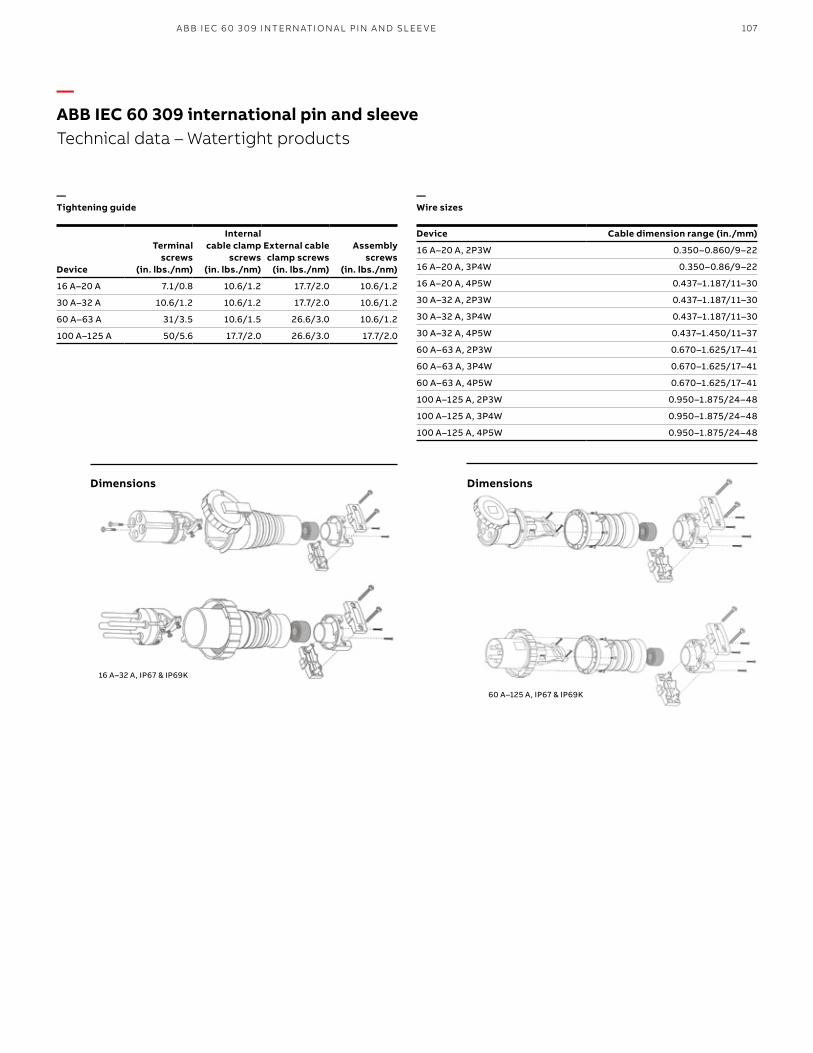
107
—Tightening guide
60 A–125 A, IP67 & IP69K
Device
Terminal screws
(in. lbs./nm)
Internal cable clamp
screws (in. lbs./nm)
External cable clamp screws
(in. lbs./nm)
Assembly screws
(in. lbs./nm)
16 A–20 A 7.1/0.8 10.6/1.2 17.7/2.0 10.6/1.2
30 A–32 A 10.6/1.2 10.6/1.2 17.7/2.0 10.6/1.2
60 A–63 A 31/3.5 10.6/1.5 26.6/3.0 10.6/1.2
100 A–125 A 50/5.6 17.7/2.0 26.6/3.0 17.7/2.0
—ABB IEC 60 309 international pin and sleeveTechnical data – Watertight products
—Wire sizes
Device Cable dimension range (in./mm)
16 A–20 A, 2P3W 0.350–0.860/9–22
16 A–20 A, 3P4W 0.350–0.86/9–22
16 A–20 A, 4P5W 0.437–1.187/11–30
30 A–32 A, 2P3W 0.437–1.187/11–30
30 A–32 A, 3P4W 0.437–1.187/11–30
30 A–32 A, 4P5W 0.437–1.450/11–37
60 A–63 A, 2P3W 0.670–1.625/17–41
60 A–63 A, 3P4W 0.670–1.625/17–41
60 A–63 A, 4P5W 0.670–1.625/17–41
100 A–125 A, 2P3W 0.950–1.875/24–48
100 A–125 A, 3P4W 0.950–1.875/24–48
100 A–125 A, 4P5W 0.950–1.875/24–48
A B B I EC 6 0 3 0 9 I NTER N ATI O N A L P I N A N D SL EE V E
DimensionsDimensions
16 A–32 A, IP67 & IP69K

108 R U S S E LL S TO LL® PI N & SL EE V E P OW ER CO N N EC TO R S
—Connectors
16 A–32 A
Dmax
CA
BDmax
A
B
TypeA
(in./mm)B
(in./mm)C
(in./mm)D max
(in./mm)
16 A–20 A, 2P3W 5.81/147.5 2.80/71 4.47/113.5 0.51/13
16 A–20 A, 3P4W 6.46/164 3.11/79 5.16/131 0.67/17
16 A–20 A, 4P5W 6.61/168 3.43/87 5.28/134 0.67/17
30 A–32 A, 2P3W 6.85/174 3.70/94 4.74/120.5 0.85/21.5
30 A–32 A, 3P4W 6.85/174 3.70/94 5.41/137.5 0.85/21.5
30 A–32 A, 4P5W 7.40/188 3.98/101 5.47/139 0.85/21.5
60 A–63 A, All 10.83/275 4.49/114 8.39/213 1.61/41
100 A–125 A, All 12.32/313 5.12/130 9.53/242 1.89/48
TypeA
(in./mm)B
(in./mm)D max
(in./mm)
16 A–20 A, 2P3W 6.73/171 3.15/80 0.51/13
16 A–20 A, 3P4W 7.40/188 3.46/88 0.67/17
16 A–20 A, 4P5W 7.68/195 3.82/97 0.67/17
30 A–32 A, 2P3W 7.76/197 3.94/100 0.85/21.5
30 A–32 A, 3P4W 7.76/197 3.94/100 0.85/21.5
30 A–32 A, 4P5W 8.27/210 4.29/109 0.85/21.5
60 A–63 A, All 11.26/286 4.37/111 1.61/41
100 A–125 A, All 12.80/325 4.80/122 1.89/48
—Plugs
60 A–125 A 16 A–32 A 60 A–125 A
—Receptacles
TypeC
(in./mm)C1
(in./mm)D
(in./mm)D2
(in./mm)E
(in./mm)E1
(in./mm)H
(in./mm)
16 A–20 A, 2P3W 3.13/79.5 3.13/79.5 3.27/83 3.74/95 1.77/45 2.24/57 3.74/95
16 A–20 A, 3P4W 3.13/79.5 3.13/79.5 3.27/83 3.74/95 1.77/45 2.24/57 3.74/95
16 A–20 A, 4P5W 3.13/79.5 3.13/79.5 3.27/83 3.74/95 1.85/47 2.24/57 3.90/99
30 A–32 A, 2P3W 3.13/79.5 3.13/79.5 3.27/83 3.74/95 2.20/56 2.40/61 4.09/104
30 A–32 A, 3P4W 3.13/79.5 3.13/79.5 3.27/83 3.74/95 2.20/56 2.40/61 4.09/104
30 A–32 A, 4P5W 3.13/79.5 3.13/79.5 3.27/83 3.74/95 2.20/56 2.44/62 4.37/111
60 A–63 A, All 2.40/61 2.40/61 2.76/70 4.09/104 3.50/89 1.89/48 4.37/111
100 A–125 A, All 2.80/71 2.80/71 3.46/88 4.53/115 3.94/100 2.28/58 4.80/122
—ABB IEC 60 309 international pin and sleeveDimensions
D2
C1
CD2
Ø5
D
E1 E
HØ
D2
C1
CD2
Ø5
D
E1 E
HØ
16 A–32 A
C
C1
D2
E1 E
H ØD
Ø 4.2/6.5
60 A–63 A 100 A–125 A
Ø 4.0
C
C
C1
C1
D2
D2
D2
E1E1
EE
HH C
C1
D2
E1 E
H ØD
Ø 4.2/6.5Ø 5.5
Ø D
Ø D Ø D
Ø 5
C
C1
D2
E1 E
H
Dimensions
Dimensions
BB
BB
C
D max
D max
A
A
A
A

109
—Inlets
TypeC
(in./mm)D
(in./mm)D2
(in./mm)E3
(in./mm)E4
(in./mm)F
(in./mm)
16 A–20 A, 2P3W 3.13/79.5 3.27/83 3.74/95 0.40/10 1.85/47 2.80/71
16 A–20 A, 3P4W 3.13/79.5 3.27/83 3.74/95 0.40/10 2.09/53 3.11/79
16 A–20 A, 4P5W 3.13/79.5 3.27/83 3.74/95 0.40/10 3.43/87 3.43/87
30 A–32 A, 2P3W 3.13/79.5 3.27/83 3.74/95 0.47/12 2.36/60 3.70/94
30 A–32 A, 3P4W 3.13/79.5 3.27/83 3.74/95 0.47/12 2.36/60 3.70/94
30 A–32 A, 4P5W 3.13/79.5 3.27/83 3.74/95 0.47/12 2.64/67 3.98/101
60 A–63 A, All 4.41/112 2.40/61 2.76/70 3.86/98 1.97/50 3.15/80
100 A–125 A, All 4.80/122 2.80/71 3.19/81 4.65/118 2.20/56 3.50/89
175
408 463
241
60 A–125 A
160
255306
20516 A–32 A
—Mechanical interlocks: switched (MI), fused (MF) and/or breakered (MB)
6.30"/ 160 mm
10.04"/ 255 mm 12.05"/
306 mm
8.07"/ 205 mm
16.06" / 408 mm
6.89"/ 175 mm
18.23"/ 463 mm
9.49"/ 241 mm
—ABB IEC 60 309 international pin and sleeveDimensions
C
16 A–32 A
C
CE3 E4
Ø 5
ØD
D2
D2F
100 A–125 A
C
C1
D2
E1 E
H ØD
Ø 4.2/6.5
C
C1
D2D2 E1 E
H
60 A–63 A
E4
E3C
C ØD
D2
Ø4.2/6.5
B
Ø 4.0
A B B I EC 6 0 3 0 9 I NTER N ATI O N A L P I N A N D SL EE V E
Dimensions
Ø D
Ø DØ D
Ø 5.5
C
B
C
D2
E3E3
E4
F
E4
Ø 5
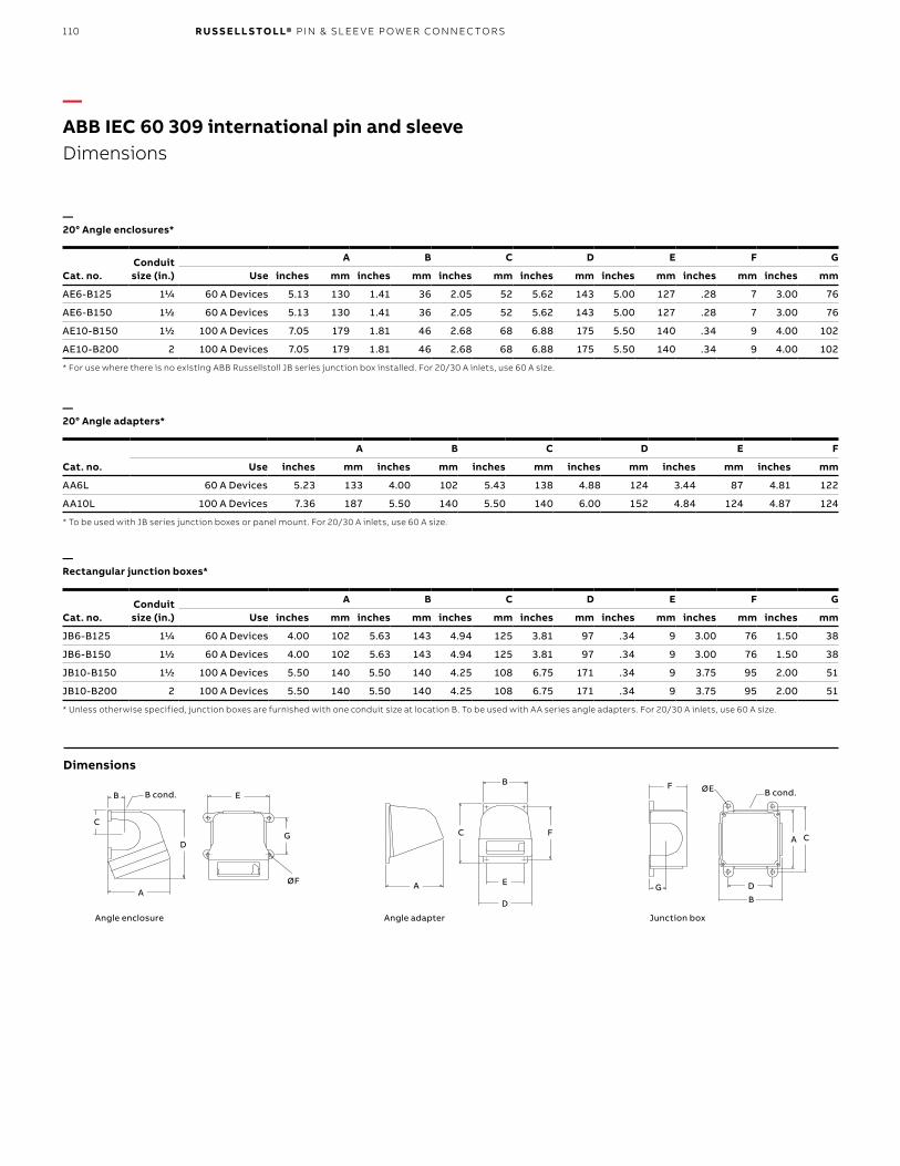
110 R U S S E LL S TO LL® PI N & SL EE V E P OW ER CO N N EC TO R S
Cat. no.Conduit size (in.)
A B C D E F G
Use inches mm inches mm inches mm inches mm inches mm inches mm inches mm
AE6-B125 11/4 60 A Devices 5.13 130 1.41 36 2.05 52 5.62 143 5.00 127 .28 7 3.00 76
AE6-B150 11/2 60 A Devices 5.13 130 1.41 36 2.05 52 5.62 143 5.00 127 .28 7 3.00 76
AE10-B150 11/2 100 A Devices 7.05 179 1.81 46 2.68 68 6.88 175 5.50 140 .34 9 4.00 102
AE10-B200 2 100 A Devices 7.05 179 1.81 46 2.68 68 6.88 175 5.50 140 .34 9 4.00 102
* For use where there is no existing ABB Russellstoll JB series junction box installed. For 20/30 A inlets, use 60 A size.
—20° Angle enclosures*
Cat. no.
A B C D E F
Use inches mm inches mm inches mm inches mm inches mm inches mm
AA6L 60 A Devices 5.23 133 4.00 102 5.43 138 4.88 124 3.44 87 4.81 122
AA10L 100 A Devices 7.36 187 5.50 140 5.50 140 6.00 152 4.84 124 4.87 124
* To be used with JB series junction boxes or panel mount. For 20/30 A inlets, use 60 A size.
—20° Angle adapters*
Cat. no.Conduit size (in.)
A B C D E F G
Use inches mm inches mm inches mm inches mm inches mm inches mm inches mm
JB6-B125 11/4 60 A Devices 4.00 102 5.63 143 4.94 125 3.81 97 .34 9 3.00 76 1.50 38
JB6-B150 11/2 60 A Devices 4.00 102 5.63 143 4.94 125 3.81 97 .34 9 3.00 76 1.50 38
JB10-B150 11/2 100 A Devices 5.50 140 5.50 140 4.25 108 6.75 171 .34 9 3.75 95 2.00 51
JB10-B200 2 100 A Devices 5.50 140 5.50 140 4.25 108 6.75 171 .34 9 3.75 95 2.00 51
* Unless otherwise specified, junction boxes are furnished with one conduit size at location B. To be used with AA series angle adapters. For 20/30 A inlets, use 60 A size.
—Rectangular junction boxes*
—ABB IEC 60 309 international pin and sleeveDimensions
-
B
C
A
E
D
øF
G
B cond.B
C
A E
D
F
B
CA
øE
D
F
G
B cond.
Junction BoxAngle AdapterAngle EnclosureAngle enclosure
AA
A
CC C
D
D
D
E
E
G
GØF
ØE
F
FB
B
B
B cond. B cond.
Angle adapter Junction box
Dimensions

111
Valox is a registered trademark of SABIC.
—ABB IEC 60 309 international pin and sleevePlugs, connectors, receptacles and inlets
—Performance – Electrical
Application Performance
Dielectric voltage withstand 3000 V for 1 minute (devices > 300 V)
2000 V for 1 minute (devices ≤ 300 V)
Maximum working voltage 600 V AC/250 V DC (minimum creepage
and clearances per UL 840)
Current interrupting/ load breaking
Tested to 150% of full rated current for circuit interrupting
Temperature rise Maximum 30 °C rise at full rated current after 50 cycles overload at 150% rated
load at 0.75 pF
Endurance with load per IEC 60 309-1 clause 21
20 A: 5000 cycles – Rated current, voltage
30 A: 1000 cycles – Rated current, voltage
60 A: 1000 cycles – Rated current, voltage
100 A: 250 cycles – Rated current, voltage
Application Performance
Cold (-25 °C) impact resistance Per UL 1682 Section 34 and IEC 60 309-1 Clause 24
Cable O.D. accommodation Round portable service cord from 0.57" O.D. through 1.79" O.D.
Terminal identification In accordance with UL 1682 standards and wIEC 60 309-1: as L1-L2-L3-N-G
Cable pull-out force Per UL 1682 Section 33 and IEC 60 309-1 Clause 23
Product identification Product trademark(s) and UL approved product label
Application Performance
Moisture resistance Watertight to IP67 & IP69K
Flammability All components V2 for internal parts & V0 for external parts on 20 A & 30 A devices per UL94
or CSA 22.2 No. 0.6; V0 on 60 A & 100 A
Operating temperature -55 °C/-67 °F minimum to 55 °C/131 °F maximum for continuous
operations and up to 70 °C/158 °F for intermittent operation
Chemical resistance Resists standard industrial hydrocarbons, acids, bases and solvents
Corrosion resistance All metallic components stainless steel or brass sleeve pressure spring of
stainless steel
UV resistance In accordance with UL® 746C F1
Part Material
Housing Valox®
Contact carriers Polyamide nylon (Fiberglass reinforced for 60 A to 125 A)
Cable clamps Valox
Cable bushing Chloroprene, onion-ring type
O-ring, seals and gaskets Solid chloroprene
Pins & sleeves Brass
Sleeve force ring Stainless steel
Terminal screws Zinc-plated steel
Flap/screw cover springs Stainless steel
Mounting flanges Valox
Approvals and compliances
1682, 1686E109667 E109550E163435
60 309-1, -2, -4LVD 2006/95/ECEMC 2004/108/EC
C22.2 No. 182.1LR 051334
—Performance – Environmental
—Performance – Mechanical
—Materials
A B B I EC 6 0 3 0 9 I NTER N ATI O N A L P I N A N D SL EE V E

112 R U S S E LL S TO LL® PI N & SL EE V E P OW ER CO N N EC TO R S
Approvals and compliances
UL 508 and UL 98 (switch version)UL 231 and UL 489 (circuit breaker version) UL 1682, 1686
IEC 60 309-1, -2, -4
CSA C22.2 No. 14, 182.1
Application Performance
Dielectric voltage withstand 3000 V
Maximum working voltage 480 V RMS (circuit breaker version) 600 V RMS (switch version)
Current interrupting Certified for current interrupting at full rated current and voltage
Short-circuit current rating operations
10,000 RMS symmetrical amperesMechanical:10,000 cycles
Electrical: 6000 cycles
Hp ratings (switch version) Complies with NEC® 430–151 ratings
Circuit breaker UL listed Interrupting rating
22,000 AIC
—ABB IEC 60 309 international pin and sleeveMechanical interlocks (unfused/switched, fused and breakered)
—Performance – Electrical
—Performance – Mechanical
Application Performance
Cold (-35 °C) impact resistance In accordance with UL 746C
Wiring accommodations Suitable for metallic conduit. Conduit entry locations at enclosure top and bottom
Terminal identification In accordance with UL, CSA and IEC 60 309 conventions
Product identification Identification, ratings and color code in accordance with UL, CSA and
IEC 60 309 requirements
Lockout/tagout “ON” and “OFF” lockout/tagout capability at switch handle. Complies with OSHA
Reg. 29CFR 1910.147
Mounting External adjustable feet
Application Performance
Moisture resistance Screw cap version: UL Type 4X & 12K, IP67 & IP69K
Flammability UL 94-5VA and V0 classifications
Operating temperatures Maximum continuous: 60 °C (140 °F)
Minimum continuous: -40 °C (-40 °F)
UV resistance UV-stabilized material in accordance with UL® 746C F1
Chemicals Resists most standard industrial hydrocarbons, acids, bases and solvents
Part Material
Enclosure (all exterior components)
UL 94-5VA/V0, UV-stabilized, impact-modified Valox®
Contact carrier Polyamide nylon (fiberglass reinforced for 60 A to 125 A devices)
Gaskets Chloroprene or EPDM
Contacts (sleeves) Brass
Hardware (screws and springs)
Steel with zinc-plated blue chromate or nickel plating
—Performance – Environmental
—Materials

113D U R ATITE ® A N D E V ER - LO K ® LO CK I N G CO N N EC TI O NS
Industrial “safety grade” construction• 20 A and 30 A plugs and connectors
(600 V AC max.)• Indoor industrial and heavy-duty use• Durable, tough and flame safety rated housings• DuraV® housing material specially selected for hot
or cold washdown duty• Flame safe UL94-V0 rated housings• Superior performance in corrosive environments• High-visibility yellow housings
—DuraTite® and Ever-Lok® locking connectionsIndustrial specification grade redefined.
Non-metallic self-locking plugs, connectors and receptaclesFrom our industry-standard Ever-Lok series of plugs, connectors and receptacles, Russellstoll® has developed DuraTite – the first non-metallic, self-locking pin and sleeve power interconnection system. In 20- and 30 A ranges, DuraTite mates with existing 15–30 A Ever-Lok receptacles already in use.
Safe and reliable power connections: pin and sleeve, voltage polarized• Long life: Round, self-cleaning, constant-pressure
pin and sleeve contacts, of solid CDA 360 brass for long reliable electrical life
• More power, operates cooler: Large circular electrical contact area allows more current flow with lower temperature rise
• Ground pin keyed for voltage polarization (O-ring seal)
• Voltage polarized for safe connection (U-ground) (pins shown with optional O-ring seals)
Easy to wire• “No twist-off” locking plugs: Integral threaded
screw collars and compression-type bushings make wiring a snap
• Fast assembly and wiring: “Drop-In” rear loaded interiors use no assembly screws, versus 3–5 or more with other connectors. 30/50 A connectors use unique E-Z Tite™ external gland lock screw
• Set-screw terminals: Are quick and easy to wire, with complete wire capture in deep pin/sleeve barrels

114 R U S S E LL S TO LL® PI N & SL EE V E P OW ER CO N N EC TO R S
Amps at 250 V
Poles/ wires Voltage
Facerecep./
conn.
Cat. nos.
Plug Connector
Std. I.D.bushing:
plug/conn.(in.)
Receptacle – Ever-Lok
DuraTite Ever-Lok DuraTite Ever-Lok
20 2P3W 125 V AC 5P23U1LD 8013U1 5C23U1LD 8023U1 0.625 8003U1 8083U1
8153U1 8093U1
8593U1 8683U1
250 V AC 5P23U2LD 8013U2 5C23U2LD 8023U2 0.625 8003U2 8083U2
8153U2 8093U2
8593U2 8683U2
277 V AC 5P23U3LD 8013U3 5C23U3LD 8023U3 0.625 8003U3 8083U3
8153U3 8093U3
8593U3 8683U3
480 V AC 5P23U4LD 8013U4 5C23U4LD 8023U4 0.625 8003U4 8083U4
8153U4 8093U4
8593U4 8683U4
600 V AC 5P23U5LD 801345 5C23U5LD 8023U5 0.625 8003U5 8083U5
8153U5 8093U5
8593U5 8683U5
Through 600 V AC (all)
5P23U0LD 8013 5C23U0LD 8023 0.625 8003N 8083N
8153 8093
8593 8683
30 2P3W 125 V AC 5P33U1LD – 5C33U1LD – 0.700 – –
250 V AC 5P33U2LD – 5C33U2LD – 0.700 – –
277 V AC 5P33U3LD – 5C33U3LD – 0.700 – –
480 V AC 5P33U4LD – 5C33U4LD – 0.700 – –
600 V AC 5P33U5LD – 5C33U5LD – 0.700 – –
Through 600 V AC (all)
5P33U0LD 8015 5C33U0LD 8025 0.700 8030N 8005N
8155 8095
8656 8646
20(10,600 V)
3P4W 125/250 V AC 5P24U1LD – 5C24U1LD – 0.625 – –
3Ø 250 V AC 5P24U2LD – 5C24U2LD – 0.625 – –
3Ø 480 V AC 5P24U4LD – 5C24U4LD – 0.625 – –
347/600 V AC 5P24U5LD – 5C24U5LD – 0.625 – –
Through 600 V AC (all)
5P24U0LD 8018 5C24U0LD 8028 0.625 8008 8084
8158 8098
8594 8684
30(20 A,600 V)
3P4W 125/250 V AC 5P34U1LD – 5C34U1LD – 0.750 – –
3Ø 250 V AC 5P34U2LD – 5C34U2LD – 0.750 – –
3Ø 480 V AC 5P34U4LD – 5C34U4LD – 0.750 – –
347/600 V 5P34U5LD – 5C34U5LD – 0.750 – –
Through 600 V AC (all)
5P34U0LD 8014 5C34U0LD 8024 0.750 8031 8004
8154 8094
8597 8687
8657 8647
Note: DuraTite plugs and connectors will mate but not lock to metal plugs and connectors referenced above. DuraTite will lock to existing metal receptacles, from standard Ever-Lok line.
—DuraTite® and Ever-Lok® locking connections

115
Bladed plug and receptacle Spring-blade contact designs offer point contact only, with minimal mechanical support in receptacles. Higher heat is generated with use as contacts loosen due to age and dirt accumulation, resulting in failures. Exposed blade contacts can easily be damaged.
Spring contacts Blades
Application Performance
Dielectric voltage withstand 3000 V
Max. Working voltage 6000 V RMS (minimum creepage and minimum
clearance per UL 840)
Circuit interrupting/ load breaking
UL® listed and CSA certified for circuit interrupting at
full rated current
Temperature rise Max. 30° C temperature rise at full rated current after 50
cycles of overload at 150% rated current at 0.75 pF
Horsepower Per NEC® 430-151 ratings —Approvals
NEC is a registered trademark of the National Fire Protection Association, Inc.
—DuraTite® and Ever-Lok® locking connections
—Performance – Electrical
—Performance – Mechanical
Application Performance
Impact resistance Per UL 1682 Paragraph 34
Cord accommodation Round portable service cords; 10 standard diameters from
0.405" to 1.00", custom sizes to spec
Terminal identification
In accordance with UL 1682
Cable pull-out force In accordance with UL 1682
Product identification
Identification label and molded-in name
D U R ATITE ® A N D E V ER - LO K ® LO CK I N G CO N N EC TI O NS

116 R U S S E LL S TO LL® PI N & SL EE V E P OW ER CO N N EC TO R S
Pin and sleeve
Shrouds
SleevePin
Locking screw collar
Part Material
Contact carrier interior Molded arc-resistant UL 94-V0 phenolic thermoset
Housing, gland nuts DuraV® UL 94-V0, high impact
Screw collar rings Thermoplastic
O-rings Buna-N (Nitrile)
Contacts: pins and sleeves Brass CDA 360
Terminals Brass CDA 360
All hardware Stainless steel
Gland friction 20 A – Nylon
Washer 30 and 50 A – Aluminum
Cable clamp bushing Neoprene
Pin and sleeve connector and plugPin and sleeve design enables higher current flow at cooler temperatures due to the large circular contact area. Sleeves act as retainers for the pins, making a reliable connection. Shrouded pins and sleeves are protected from damage and casual access. Locking screw collars provide for a reliable, long-lasting connection.
—DuraTite® and Ever-Lok® locking connections
—Performance – Environmental
—Material
Application Performance
Moisture resistance Per UL 1682 paragraph 49. Flap cover on receptacle, O-rings optional on all
pins, sleeves and interiors. Watertight interiors with optional O-rings. Meets
require ments for NEMA 3R/12 and IP44
Flammability V0 or better per UL 94
Operating temperatures
Maximum continuous: 95 °C/203 °F Minimum: -40 °C/-40 °F
without impact
Chemicals Resists standard industrial hydro carbons, acids, bases and solvents

117
Plugs Receptacles
DuraTite mates and locks to standard Ever-Lok (see page 120).
—Accessories
Cat. no. 3712A Cat. no. 3678A
Amps A* ØB C* Ød
20 inches 3.87 1.53 4.40 1.79
mm 98.3 38.9 111.8 45.5
30 inches 6.00 1.79 6.25 2.05
mm 152.4 45.5 158.8 52.1
* Dimensions will vary slightly with assembly.
Cast aluminum Cast brass
Single 3711A 3731
Double 3712A 3732
Note: 3⁄4" NPT hole standard.Additional accessories are available. Consult your ABB representative.
Cast aluminum Cast brass
3678A 3678B
Cat. no. 3711A
A
ØB
A
øB
Connectors
D
E
D
E
2.62"
4.12"
2.94"
1.38"
4.50"
1.06"
0.31"
3.00" mtg.
3.00" mtg.
3.25" mtg.
6.50" mtg.5.47" ø 0.28",
4 PLS2.88"
2.62"
3.40"
4.12"
1.88" mtg.
4.82" 45°
4.09"
2.88"1.25"0.31"
3.38" mtg.ø 0.28",
4 PLS
—DuraTite® and Ever-Lok® locking connections
• Additional boxes and accessories available: Ever-Lok section
D U R ATITE ® A N D E V ER - LO K ® LO CK I N G CO N N EC TI O NS
—Dimensions
—Conduit boxes (for surface mounting)
—45° Angle adapter
Dimensions Dimensions

118 R U S S E LL S TO LL® PI N & SL EE V E P OW ER CO N N EC TO R S
When an Ever-Lok connection is made, it is a mechanical attachment that will not pull apart unless it is unlocked by hand. To install, line up the tabs and plug it straight in. External buttons or ribs lock with the mating internal housing automatically. When an Ever-Lok connector plugs in, it stays in. Locked housings do the work so Ever-Lok contacts can carry the load! A firm grip and a counter-clockwise reverse twist-release locking for easy removal.
—DuraTite® and Ever-Lok® locking connections
Standard – 10–50 A, maximum 600 V AC or 250 V DCHeavy service – 30–100 A, maximum 480 V AC or 250 V DC Midget – 10–20 A, maximum 250 V AC or 250 V DC

119
Design features
Automatic locking – Automatic locking feature mechanically attaches the plug casing to the receptacle or connector and eliminates strain on electrical contacts.
Positive grounding – Casings are positively grounded by means of phosphor-bronze ground straps integral with ground contacts. Equipment grounding is secured by separate set of contacts which “make first” and “break last” as required by UL.
Dust-proof – On clamp-type plugs and connectors, a washer is provided in each cap to be forced over the cord. This serves as a shield to prevent metal particles, dust, etc., from entering the interiors of plugs and connectors.
Bushing-type plugs and connectors are furnished with a gland nut and Neoprene cable bushing gland to exclude dust and moisture. A formed glide washer is also provided to facilitate tightening of the gland nut.
Receptacle covers are sealed to boxes by gaskets and have hinged flaps which are gasket-lined and equipped with strong springs to keep them closed and dust out.
Steel-clad – Plugs and connectors are plated steel. Plugs have encased locking spring in machine-assembled non-separable housings.
Cord grip – Plugs and connectors are provided with adjustable cord grips, preventing strains on connections.
Contacts – Contacts are precision-made, self-wiping and self-aligning brass and nickel-plated brass.
Unit assembly – Contacts and terminals are permanently assembled in an arc-resisting composition body, permitting removal of interior as a unit for wiring. All connections are entirely enclosed, thus avoiding accidental short circuits and tampering by inexperienced personnel.
Handles lined – Shell handles have an HDPE liner to contain stray wire ends.
Interiors – All interiors are molded arc-resisting composition.
—DuraTite® and Ever-Lok® locking connections
D U R ATITE ® A N D E V ER - LO K ® LO CK I N G CO N N EC TI O NS
Automatic locking feature
Contacts
Molded arc-resisting interiors
Steel-clad housings
Cord grip

120 R U S S E LL S TO LL® PI N & SL EE V E P OW ER CO N N EC TO R S
—DuraTite® and Ever-Lok® locking connectionsMale plugs and female connectors
—Male plugs and female connectors
Poles/wires
Amps at 250 V AC Rating
Male plug clamp type
Max.cable
dia. (in.)Male plug
bushing type
Cablebushing
hole dia. (in.)Male plug hub type*
Conduitsize (in.)
Female connector Clamp type
Max.cable
rating (in.)Female connector
bushing type
Cablebushing
hole dia. (in.)Female connector
hub type**Conduitsize (in.)
2P3W 15 20 A, 125 V AC 8013 1/2 8153 5/8 85938593CTN**
1/21/2
8023 1/2 8093 5/8 8683N/8683CTN* 1/2
15 A, 250 V AC
10 A, 600 V AC
20 A, 125 V AC 8013U1 1/2 8153U1 5/8 8593U18593U1CT*
1/21/2
8023U1 1/2 8093U1 5/8 8683U1/8683U1CT* 1/2
15 A, 250 V AC 8013U2 1/2 8153U2 5/8 8593U2 1/2 8023U2 1/2 8093U2 5/8 8683U2 1/2
15 A, 277 V AC 8013U3 1/2 8153U3 5/8 8593U3 1/2 8023U3 1/2 8093U3 5/8 8683U3 1/2
15 A, 480 V AC 8013U4 1/2 8153U4 5/8 Consult ABB Representative Consult ABB Representative Consult ABB Representative Consult ABB Representative
15 A, 600 V AC 8013U5 1/2 8153U5 5/8 Consult ABB Representative Consult ABB Representative Consult ABB Representative Consult ABB Representative
30 30 A, 250 V AC 8015
5/8 8155 5/8 8656 3/4 8025 5/8 8095 5/8 8646 3/4
20 A, 600 V AC
3P4W 15 20 A, 125 V AC 8018 1/2 8158 11/16 8594 1/2 8028 1/2 8098 11/16 8684 1/2
10 A, 250 V AC
15 A, 250 V AC
10 A, 600 V AC
30 20 A, 600 V AC 8014 5/8 8154 3/4 85978657
1/23/4
8024 5/8 8094 3/4 8687/8687CT*8647
1/23/430 A, 250 V AC
50 50 A, 250 V AC 8314-S8314
3/411/8
8354 1 83968397
1/23/4
8324S 3/4 8394 1 83868387
1/23/430 A, 250 V AC
30 A, 600 V AC
* Hub with clamp added at size.** Accommodates rigid conduit or standard connectors for armored and non-metallic cable or flexible conduit.Notes: (for plugs and connectors):Cable bushing – Oil-resistant neoprene cable bushing regularly furnished with hole size as listed. Other hole sizes available at no extra cost, when specified on order. See page 131 for available sizes. Bushing-type plugs and connectors can be furnished with adapters to accommodate rigid conduit or standard connectors for armored and non-metallic cable or flexible conduit. See page 130.“N” in catalog number refers to nickel-plated neutral pin replace. Ex: 8013 with 8013N.Special construction options for Ever-Lok plugs include control "dummy plugs” for press lockout function. Consult technical services.
* Hub with clamp added at size.** Accommodates rigid conduit or standard connectors for armored and non-metallic cable or flexible conduit.

121D U R ATITE ® A N D E V ER - LO K ® LO CK I N G CO N N EC TI O NS
Poles/wires
Amps at 250 V AC Rating
Male plug clamp type
Max.cable
dia. (in.)Male plug
bushing type
Cablebushing
hole dia. (in.)Male plug hub type*
Conduitsize (in.)
Female connector Clamp type
Max.cable
rating (in.)Female connector
bushing type
Cablebushing
hole dia. (in.)Female connector
hub type**Conduitsize (in.)
2P3W 15 20 A, 125 V AC 8013 1/2 8153 5/8 85938593CTN**
1/21/2
8023 1/2 8093 5/8 8683N/8683CTN* 1/2
15 A, 250 V AC
10 A, 600 V AC
20 A, 125 V AC 8013U1 1/2 8153U1 5/8 8593U18593U1CT*
1/21/2
8023U1 1/2 8093U1 5/8 8683U1/8683U1CT* 1/2
15 A, 250 V AC 8013U2 1/2 8153U2 5/8 8593U2 1/2 8023U2 1/2 8093U2 5/8 8683U2 1/2
15 A, 277 V AC 8013U3 1/2 8153U3 5/8 8593U3 1/2 8023U3 1/2 8093U3 5/8 8683U3 1/2
15 A, 480 V AC 8013U4 1/2 8153U4 5/8 Consult ABB Representative Consult ABB Representative Consult ABB Representative Consult ABB Representative
15 A, 600 V AC 8013U5 1/2 8153U5 5/8 Consult ABB Representative Consult ABB Representative Consult ABB Representative Consult ABB Representative
30 30 A, 250 V AC 8015
5/8 8155 5/8 8656 3/4 8025 5/8 8095 5/8 8646 3/4
20 A, 600 V AC
3P4W 15 20 A, 125 V AC 8018 1/2 8158 11/16 8594 1/2 8028 1/2 8098 11/16 8684 1/2
10 A, 250 V AC
15 A, 250 V AC
10 A, 600 V AC
30 20 A, 600 V AC 8014 5/8 8154 3/4 85978657
1/23/4
8024 5/8 8094 3/4 8687/8687CT*8647
1/23/430 A, 250 V AC
50 50 A, 250 V AC 8314-S8314
3/411/8
8354 1 83968397
1/23/4
8324S 3/4 8394 1 83868387
1/23/430 A, 250 V AC
30 A, 600 V AC
* Hub with clamp added at size.** Accommodates rigid conduit or standard connectors for armored and non-metallic cable or flexible conduit.Notes: (for plugs and connectors):Cable bushing – Oil-resistant neoprene cable bushing regularly furnished with hole size as listed. Other hole sizes available at no extra cost, when specified on order. See page 131 for available sizes. Bushing-type plugs and connectors can be furnished with adapters to accommodate rigid conduit or standard connectors for armored and non-metallic cable or flexible conduit. See page 130.“N” in catalog number refers to nickel-plated neutral pin replace. Ex: 8013 with 8013N.Special construction options for Ever-Lok plugs include control "dummy plugs” for press lockout function. Consult technical services.
* Hub with clamp added at size.** Accommodates rigid conduit or standard connectors for armored and non-metallic cable or flexible conduit.

122 R U S S E LL S TO LL® PI N & SL EE V E P OW ER CO N N EC TO R S
Specifications• Receptacle housing: plated steel; receptacle with
cover only; furnished with 6–52 mounting screws; for mounting on switch box or outlet box, use adapter plate 8091A; see page 130
• Back boxes: cast aluminum, epoxy powder-coat finish; flap and screw caps aluminum, corrosion-resistant copper-free alloy or steel, CAD plated
• Plug: all cable entry styles of plugs with equivalent ratings fit above receptacles
• Conduit boxes: Type FSWS-62 or FDWS-62 standard, cast aluminum; additional boxes available; see pages 127–128
• Gang type: can be furnished in gang or tandem units and in combination with other FS and FD devices; see pages 127–128
• Outlets: unless otherwise specified, furnished with one 3/4" outlet; additional outlets charged extra, specific size and location; consult technical services
Notes:^ For FS, FD, FSWS, FDWS and similar conduit fittings.* Receptacle with box and cover.** Provided with FDWS62 Box.‡ Two-gang receptacles can also be provided in mixed configurations including NEMA bladed, etc. Consult technical services.Male inlets (reversed contacts service): Use receptacle mountings but accept standard female connector.Horsepower ratings:1 ⁄2hp,1-phase,230VAC 1 hp, 3-phase, 115 V ACNote: Standard Ever-Lok receptacles also accept DuraTite® plugs.
Poles/wires
Amps at 250 V AC Rating
Femalereceptacle
only with flap cover^
Female receptacle
with box FSWS-62* 2-Gang‡
Male receptacle
Male receptaclewith box**
2P3W 15 20 A, 125 V AC 8003 8083 8128 8143 8143D
15 A, 250 V AC
10 A, 600 V AC
20 A, 125 V AC 8003U1 8083U1 8128U1 8143U1 8143U1D
15 A, 250 V AC 8003U2 8083U2 8128U2 8143U2 8143U2D
15 A, 277 V AC 8003U3 8083U3 8128U3 8143U3 8143U3D
15 A, 480 V AC 8003U4 8083U4 8128U4 Consult your ABB representative Consult your ABB representative
15 A, 600 V AC 8003U5 8083U5 8128U5 Consult your ABB representative Consult your ABB representative
30 30 A, 250 V AC 8005 8030 81318146
Consult your ABB representative
20 A, 600 V AC
3P4W 15 20 A, 125 V AC – – – – –
10 A, 250 V AC 8008 8084 8129 – –
15 A, 250 V AC – – – 8144 8144D
10 A, 600 V AC – – – – –
30 20 A, 600 V AC – With FS Box With FD Box – –
30 A, 250 V AC 8004 8031 8132 8147 8147D
50 50 A, 250 V AC – With FD Box With FD Box – –
30 A, 250 V AC 8304 8331 8334 8374 8374
30 A, 600 V AC – – – – –
—DuraTite® and Ever-Lok® locking connectionsStandard service female receptacles and reverse service male receptacles
—Standard service female receptacles and reverse service male receptacles

123D U R ATITE ® A N D E V ER - LO K ® LO CK I N G CO N N EC TI O NS
Poles/wires
Amps at 250 V AC Rating
Femalereceptacle
only with flap cover^
Female receptacle
with box FSWS-62* 2-Gang‡
Male receptacle
Male receptaclewith box**
2P3W 15 20 A, 125 V AC 8003 8083 8128 8143 8143D
15 A, 250 V AC
10 A, 600 V AC
20 A, 125 V AC 8003U1 8083U1 8128U1 8143U1 8143U1D
15 A, 250 V AC 8003U2 8083U2 8128U2 8143U2 8143U2D
15 A, 277 V AC 8003U3 8083U3 8128U3 8143U3 8143U3D
15 A, 480 V AC 8003U4 8083U4 8128U4 Consult your ABB representative Consult your ABB representative
15 A, 600 V AC 8003U5 8083U5 8128U5 Consult your ABB representative Consult your ABB representative
30 30 A, 250 V AC 8005 8030 81318146
Consult your ABB representative
20 A, 600 V AC
3P4W 15 20 A, 125 V AC – – – – –
10 A, 250 V AC 8008 8084 8129 – –
15 A, 250 V AC – – – 8144 8144D
10 A, 600 V AC – – – – –
30 20 A, 600 V AC – With FS Box With FD Box – –
30 A, 250 V AC 8004 8031 8132 8147 8147D
50 50 A, 250 V AC – With FD Box With FD Box – –
30 A, 250 V AC 8304 8331 8334 8374 8374
30 A, 600 V AC – – – – –
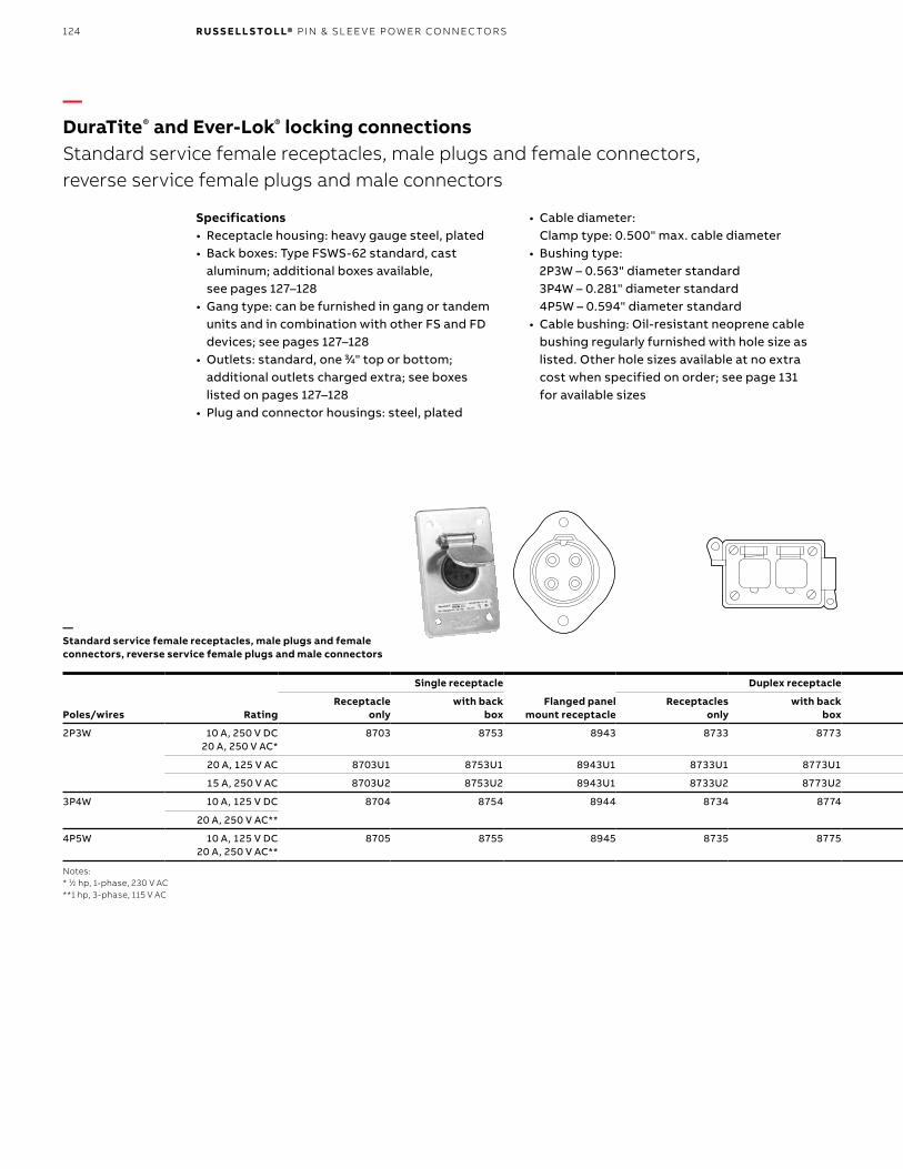
124 R U S S E LL S TO LL® PI N & SL EE V E P OW ER CO N N EC TO R S
Poles/wires Rating
Single receptacle
Flanged panel mount receptacle
Duplex receptacle Clamp type^
Male flanged panel mount
Clamp type^
Receptacle only
with back box
Receptacles only
with back box
Male plug
Female connector
Female plug
Male connector
2P3W 10 A, 250 V DC 20 A, 250 V AC*
8703 8753 8943 8733 8773 8713 8723 8943R 8713R 8723R
20 A, 125 V AC 8703U1 8753U1 8943U1 8733U1 8773U1 8713U1 8723U1 8943U1R 8713U1R 8723U1R
15 A, 250 V AC 8703U2 8753U2 8943U1 8733U2 8773U2 8713U2 8723U2 8943U2R 8713U2R 8723U2R
3P4W 10 A, 125 V DC 8704 8754 8944 8734 8774 8714 8724 8944R 8714R 8724R
20 A, 250 V AC**
4P5W 10 A, 125 V DC 20 A, 250 V AC**
8705 8755 8945 8735 8775 8715 8725 8945R 8715R 8725R
Notes: * 1⁄2 hp, 1-phase, 230 V AC **1 hp, 3-phase, 115 V AC
Specifications• Receptacle housing: heavy gauge steel, plated• Back boxes: Type FSWS-62 standard, cast
aluminum; additional boxes available, see pages 127–128
• Gang type: can be furnished in gang or tandem units and in combination with other FS and FD devices; see pages 127–128
• Outlets: standard, one 3/4" top or bottom; additional outlets charged extra; see boxes listed on pages 127–128
• Plug and connector housings: steel, plated
• Cable diameter: Clamp type: 0.500" max. cable diameter
• Bushing type: 2P3W – 0.563" diameter standard 3P4W – 0.281" diameter standard 4P5W – 0.594" diameter standard
• Cable bushing: Oil-resistant neoprene cable bushing regularly furnished with hole size as listed. Other hole sizes available at no extra cost when specified on order; see page 131 for available sizes
—DuraTite® and Ever-Lok® locking connectionsStandard service female receptacles, male plugs and female connectors, reverse service female plugs and male connectors
—Standard service female receptacles, male plugs and female connectors, reverse service female plugs and male connectors

125
^ Plugs and connectors are also available as bushing or hub type similar to those in standard Ever-Lok. Please consult your ABB representative.
Poles/wires Rating
Single receptacle
Flanged panel mount receptacle
Duplex receptacle Clamp type^
Male flanged panel mount
Clamp type^
Receptacle only
with back box
Receptacles only
with back box
Male plug
Female connector
Female plug
Male connector
2P3W 10 A, 250 V DC 20 A, 250 V AC*
8703 8753 8943 8733 8773 8713 8723 8943R 8713R 8723R
20 A, 125 V AC 8703U1 8753U1 8943U1 8733U1 8773U1 8713U1 8723U1 8943U1R 8713U1R 8723U1R
15 A, 250 V AC 8703U2 8753U2 8943U1 8733U2 8773U2 8713U2 8723U2 8943U2R 8713U2R 8723U2R
3P4W 10 A, 125 V DC 8704 8754 8944 8734 8774 8714 8724 8944R 8714R 8724R
20 A, 250 V AC**
4P5W 10 A, 125 V DC 20 A, 250 V AC**
8705 8755 8945 8735 8775 8715 8725 8945R 8715R 8725R
D U R ATITE ® A N D E V ER - LO K ® LO CK I N G CO N N EC TI O NS

126 R U S S E LL S TO LL® PI N & SL EE V E P OW ER CO N N EC TO R S
—Midget duplex
Clamp type Bushing type Hub type
—DuraTite® and Ever-Lok® locking connectionsDimensions
—Plugs and connectors
Size
Clamp type Bushing type Hub type
A (in.) B (in.) C (in.) D (in.) A (in.) B (in.) C (in.) D (in.) A (in.) B (in.) C (in.) D (in.)
Standard
15–20 A 3.125 1.750 3.187 0.500 3.250 1.750 3.375 0.750 3.125 1.750 3.187 0.500
30 A 3.437 2.125 4.250 0.625 3.750 2.125 4.500 1.125 3.500 2.125 4.250 0.750
50 A 4.750 2.125 4.750 1.125 4.875 2.125 4.875 1.125 4.500 2.125 4.625 0.750
Midget 2.875 1.440 2.875 0.500 3.000 1.440 3.000 0.625 2.875 1.440 2.875 0.500
—Female receptacles and reverse service
Size
Standard service Reverse service
A (in.) B (in.) C (in.) D (in.) A (in.) B (in.) C (in.) D (in.)
Standard
10 A 15 A20 A
0.875 1.375 2.375 2.313 0.875 2.000 1.750 2.937
30 A 0.875 1.500 2.875 2.937 0.875 1.500 2.875 2.937
50 A 1.470 1.875 2.125 2.937 1.470 1.875 2.125 2.937
Midget 0.687 1.810 1.280 NA 0.687 1.810 1.280 NA
Dimensions
Dimensions2.812"
4.312"
1.875"
3.25"
A
C
B
6–32
.25"A D
Without box FDWS-62
A D
2.812"
4.312"
1.875"
3.25"
A
C
B
6–32
.25"A D
With box FSWS-62
0.25"
6"–32"
A B
C
2.812"
4.312"
1.875"
3.25"
A
C
B
6–32
.25"A D
Without box
2.812"
3.25" 4.312"
1.875"
Max.cable dia.
Plug Connector
AD D
B CCB
Max.Cable Dia.
Plug Connector
D DA
Max.cable dia.
Plug Connector
AD D
B C CB
Max.Cable Dia.
Plug Connector
D DA
Max.cable dia.
Plug Connector
AD D
B C
4.875"MTG
4.812"
2.312".75"
.25"
.281"Dia.
2.25"MTG2.75"
At Bottom
2.312"
0.25"
0.75"
4.875"MTG
4.812"
2.312".75"
.25"
.281"Dia.
2.25"MTG2.75"
At Bottom
4.875"MTG
4.812"
2.75"bottom
2.25"MTG
0.281" dia.

127
Type FS (shallow) and Type FD (deep)Aluminum boxes have 6-32 cover mounting holes tapped to accommodate all FS and FD cover assemblies. Brass boxes have 10-24 cover mounting holes tapped to accommodate all FS and FD cover assemblies.
Two-gang DSFD
Notes: When Type FD devices are to be mounted in boxes, Type FD boxes should be used. FS boxes will not accommodate FD devices.Mounting – All the above boxes are for surface mounting. For flush mounting, see page 129.Boxes – Cast brass, natural finish; cast aluminum, corrosion-resistant copper-free alloy, epoxy powder coat finish.
Conduit Entries – Unless otherwise specified, furnished with one 0.75" outlet per gang, top or bottom. Additional conduit entries available – see price list. Specify size and location.Maximum Conduit – FS and FD: 1", one per gang top and bottom and one each side.DSFD – One 1.5" or two 0.5" top and bottom. Cast iron available on special order – consult your ABB representative.
Single-gang
3.37"MTG .28" Dia.
(2) MTG. Holes
3"MTG
2.62"
4.12"
2.31"
4.5"
2.93"
4.5"
B"
A" –MTG.
(4) MTG.Holes
3"MTG.
2.87 "
Multiple-gang
Single-gang
* Dimensions are overall exclusive of conduit pads and mounting lugs.
Type Cast aluminum Cast brass Overall dimensions* (in.) Gangs
FS 3701A 3721-RS 4.12 x 2.62 x 2.31 Single
FD 3711A 3731-RS 4.12 x 2.62 x 2.94
DSFD 3781A – 4.12 x 3.62 x 4.12
FS 3702A 3722-RS 4.12 x 5.5 x 2.25 Two
FD 3712A 3732-RS 4.12 x 5.62 x 2.87
—DuraTite® and Ever-Lok® locking connectionsMounting options for midget and standard Ever-Lok.
Dimensions3.37"mtg.
A"-mtg.
3"mtg.
(4) mtg.holes
3"mtg. 4.12"
2.62" 2.31"
2.87"
2.93"
4.5" 4.5"
B"0.258" dia.
(2) mtg. holes
—Type FS (shallow) and Type FD (deep)
D U R ATITE ® A N D E V ER - LO K ® LO CK I N G CO N N EC TI O NS

128 R U S S E LL S TO LL® PI N & SL EE V E P OW ER CO N N EC TO R S
Type FSWS and FDWS (with mounting shelf for box-mounted devices)Aluminum die-cast boxes with cover mounting holes tapped for 6-32 screws to accommodate all FS and FD cover assemblies.
Notes: Boxes – Aluminum die-cast, corrosion-resistant copper-free alloy, epoxy powder coat finish.Conduit entries – Standard as listed.Mounting – All of the above boxes are for surface mounting.
2.25"MTG
2.25" 2.25" .25"
5.37"
2.31".75"
.28" Dia.(2) MTG. Holes
2.25"MTG
4.87"MTG
4.81"
4.87"MTG
.28" Dia.(2) MTG. Holes
DSFD
4.12".31"4.12"
2"
2.62"3.62"
3.18"MTG.
.31"
(2) MTG. Holes
4.37"MTG.
Gangs
A B
FS (in.) FD (in.) FS (in.) FD (in.)
2-gang 6.50 6.50 5.50 5.62
3-gang 11.25 9.37 10.37 8.50
4-gang 14.12 12.25 13.25 11.37
Cat. no.
Conduit entries
Top (in.) Bottom
FSWS-62 3/4 –
FDWS-62 3/4 –
FDWS-622 3/4 3/4
FDWS-63 1 –
FDWS-633 1 1
—DuraTite® and Ever-Lok® locking connectionsMounting options for midget and standard Ever-Lok.
—Multiple-gang dimensions
Dimensions
Dimensions
3.18"mtg.
4.87"mtg.
4.87"mtg.
2.25"mtg.
2.25"mtg.
4.37"mtg.
0.31" 0.31"
2"
4.12"
2.25"
4.81"5.37"
2.31"0.75"
2.25"0.25"
2.62"3.62"
4.12"
(2) MTG holes
0.28" dia.(2) mtg. holes
0.28" dia.(2) mtg. holes
—Type FSWS and FDWS

129
—Adapter flush frames*
—45° Angle adapter*
* Furnished complete with gasket and screws.Material – Cast aluminum, corrosion-resistant copper-free alloy, epoxy powder-coat finish. Cast brass, natural finish.
* Furnished complete with gasket and screws.Material – Cast aluminum, corrosion-resistant copper-free alloy, epoxy powder-coat finish. Cast brass, natural finish.
* Furnished complete with gasket and screws.Material – Cast aluminum, corrosion-resistant copper-free alloy, epoxy powder-coat finish. Cast brass, natural finish.
* Furnished complete with gasket and screws.Material – Cast aluminum, corrosion-resistant copper-free alloy, epoxy powder-coat finish. Cast brass, natural finish.
—Blank cover*
Cat. no. Material
3679A Cast aluminum
3679B Cast brass
Cat. no. Material
3677A Cast aluminum
3687 Cast brass
Cat. no. Material
3678A Cast aluminum
3678B Cast brass
—Flush wall-mounting extension*
1.87"
5" 3.25"
2.62"
3. 5"
4.12"
2 "
3.25"
1.87".21" DIA.4 MTG.Holes
Front Back
GangsCast
aluminumCast
brassOverall
dimensions (in.)
1 3671A 3681 5 x 3.5
2 3672A 3682 5 x 6.5
Cat. no. 3678A
2.62"
1.88" mtg.
1.87"
1.87"0.21" dia.4 mtg.holes
4.12"3.25" 3.25"
2.62"
3.5"
2"
5"
3.25" MTG
3.40"
4.12"
4.82" 45°
2.95"1.87"
3.25" 4.15"
.15"2.95"
4.15"3.25"
1.87" 0.15"
—DuraTite® and Ever-Lok® locking connections
• Covers standard FS/FD™ box openings.
• Mounts to any FS/FD™ box.
D U R ATITE ® A N D E V ER - LO K ® LO CK I N G CO N N EC TI O NS
Dimensions
DimensionsDimensions
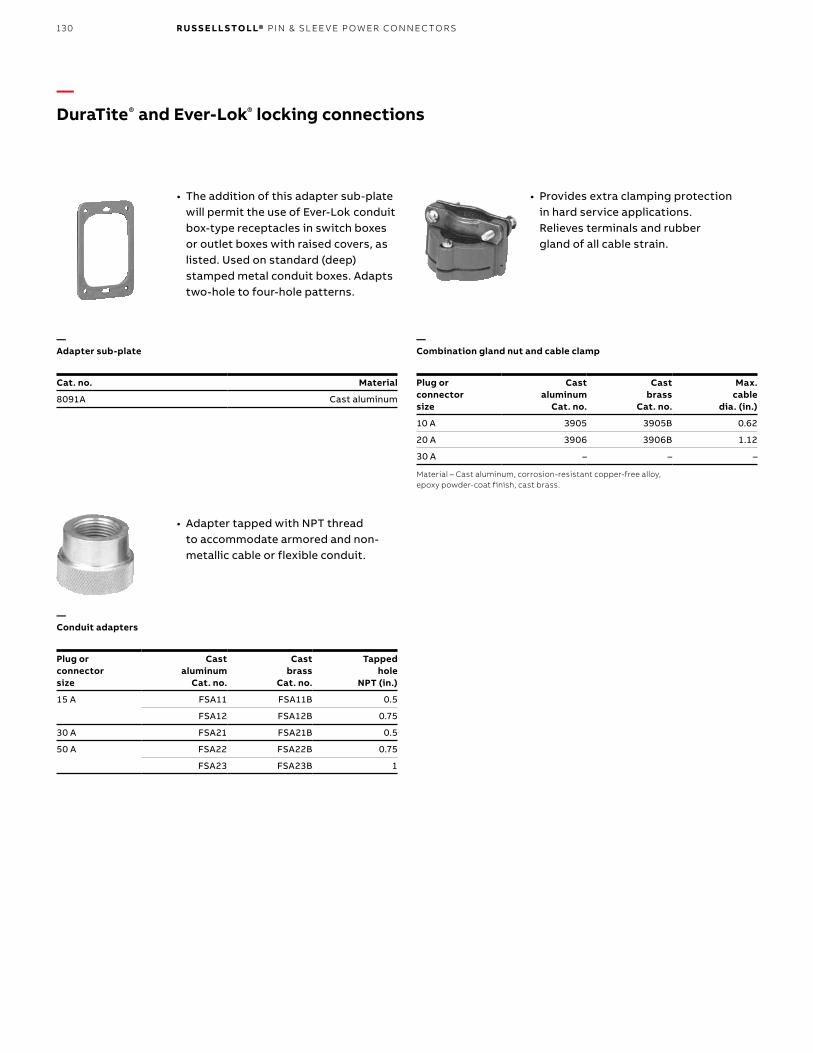
130 R U S S E LL S TO LL® PI N & SL EE V E P OW ER CO N N EC TO R S
• The addition of this adapter sub-plate will permit the use of Ever-Lok conduit box-type receptacles in switch boxes or outlet boxes with raised covers, as listed. Used on standard (deep) stamped metal conduit boxes. Adapts two-hole to four-hole patterns.
Cat. no. Material
8091A Cast aluminum
—DuraTite® and Ever-Lok® locking connections
—Adapter sub-plate
—Combination gland nut and cable clamp
• Provides extra clamping protection in hard service applications. Relieves terminals and rubber gland of all cable strain.
• Adapter tapped with NPT thread to accommodate armored and non-metallic cable or flexible conduit.
—Conduit adapters
Material – Cast aluminum, corrosion-resistant copper-free alloy, epoxy powder-coat finish, cast brass.
Plug orconnectorsize
Castaluminum
Cat. no.
Castbrass
Cat. no.
Tappedhole
NPT (in.)
15 A FSA11 FSA11B 0.5
FSA12 FSA12B 0.75
30 A FSA21 FSA21B 0.5
50 A FSA22 FSA22B 0.75
FSA23 FSA23B 1
Plug orconnectorsize
Castaluminum
Cat. no.
Castbrass
Cat. no.
Max. cable
dia. (in.)
10 A 3905 3905B 0.62
20 A 3906 3906B 1.12
30 A – – –

131
—Cable bushings
Size 2Cable bushing
Size 3Cable bushing
Material – Oil-resistant Neoprene.Size 3 cable bushing:* Style for maximum cable only.** Special minimum wall style.Notes: Bushing specials available at time of order.When standard plugs or connectors are required to be furnished with one or more of the above accessories, add the suffix and catalog number of the accessory selected to the catalog number of the plug or connector. Complete list price is the total of the list price of the device plus the list price of the accessory.Example–Catalogno.SKP3Gwithadaptertapped3⁄8"wouldbecatalogno.SKP3G/JG31.
Hole diameter for cable (in.)
Size 1Midget Ever-Lok
Size 2Std. 15 A
Size 320, 30 and 50 A
0.250 MG0 – –
0.313 – SG05 –
0.375 – SG1 JG31
0.438 MG15 SG15 –
0.500 MG2 SG2 JG32
0.531 – SG2A –
0.563 MG25 SG25 JG325
0.594 MG2B SB2B –
0.625 – SG3 JG33
0.688 – SG3A –
0.750 – SG4 JG34
0.875 – – JG35
1.000 – – JG36*
1.125 – – JG361**
—DuraTite® and Ever-Lok® locking connections
D U R ATITE ® A N D E V ER - LO K ® LO CK I N G CO N N EC TI O NS

132 R U S S E LL S TO LL® PI N & SL EE V E P OW ER CO N N EC TO R S
Design features
Durable cast aluminum, corrosion-resistant, copper-free
alloy, epoxy powder-coated finish housings.
Easy 60 A 1/4-turn handle removal simplifies and speeds up wiring (combination conduit adapter thread/clamp assembly included).
Safety-polarized interiors that can only be assembled in the
correct position.
Molded arc-resisting composition interiors with machined, full-
floating, self-aligning contacts.
30–100 A, 480 V AC/250 V DCHeavy service Ever-Lok components stay plugged in so your portable equipment stays on. The industrial standard for portable welders and other industrial equipment locks in place automatically at insertion – no screw collars to bother with. With its contoured handle, an easy counter-clockwise twist releases the plug for withdrawal, even under full-rated
load/circuit-interrupting conditions.Simple and rugged, the heavy service Ever-Lok self-locking system sets the standard for easy access in facilities, welding and industrial equipment use. All standard receptacle configurations are available, as well as reversed contact service options.
Automatic locking features makes plug casing mechanically fast to receptacle or connector. Provides positive secure connections under the most severe conditions of shock and vibration.Twist of the wrist instantly disengages the plug when required (counter-clockwise 1/8 turn).
—DuraTite® and Ever-Lok® locking connectionsHeavy-duty automatic locking receptacles, plugs and connectors

133
Current rating (A) Bushing (in.) Max. AWG size
30 7/8 #8, 7-strand or flexible
60 13/16 #4, 7-strand or flexible
100 11/2 #2, 7-strand or flexible
Current rating (A) Std. size (in.) Max. size (in.)
30 1 11/4
60 1 1
100 2 2
See page 130 for cable conduit adapters.
—Outlet location – Standard series
D100 A
Box is square and may be rotated to bring outlets into desired position.
Notes: Reverse service available by adding “R” suffix to catalog number. Solder lugs on 100 amp only.Connectors — Can be furnished with conduit adapters to accommodate rigid conduit or standard connectors for armored and non-metallic cable or flexible conduit. See page 130.
Flap covers are standard on all receptacles.*Canbefurnishedwith45°angleadapterwhenspecifiedonorder.Add suffix -45 to catalog number.† 8418 or F27194 automotive 480 VAC version plug.
A C
D30 and 60 A
B Std.B Std.
A
AmpsPoles/
wires Plug ReceptacleHSF series
basic receptacleHSA series*
receptacle
30 2P3W 8407 8443 HSF8403 8403
3P4W 8408 8444 HSF8404 8404
60 2P3W 8417 8453 HSF8413 8413
3P4W 8418† 8454 HSF8414 8414
100 3P4W 8428-72 8464-72 HSF8424-72 8424-72
—Standard cable bushing
—Conduit size
—DuraTite® and Ever-Lok® locking connections
See page 131 for other bushings.
D U R ATITE ® A N D E V ER - LO K ® LO CK I N G CO N N EC TI O NS

134 R U S S E LL S TO LL® PI N & SL EE V E P OW ER CO N N EC TO R S
Mountingstyle To order use:
Current rating
30 A 60 A 100 A
StandardseriesHSA
Receptacle+
Vertical or square mount box
+Angle adapter
or JAA3-45 (45°)
Basic receptacle*+
JB3-B100 1" Std. conduit size
+JAA3 (20°)
or JAA6-45 (45°)
Basic receptacle*+
JB6-B150 11/2" Std. conduit size
+JAA6-AB6 (20°)
or JAA10-45 (45°)
Basic receptacle*+
JB10-B200 2" Std. conduit size
+JAA10 (20°)
SeriesHSRstraight
Receptacle+
Vertical mount
box+
Straight adapter
Basic receptacle*+
JB3-B100 1" Std. conduit size
+JRA3
Basic receptacle*+
JB6-B150 11/2" Std. conduit size
+JRA6-AB6
Basic receptacle*+
JB10-B200 2" Std. conduit size
+JRA10
SeriesHSB
Receptacle+
30° Angle adapter
Basic receptacle*+
JAAB3
Basic receptacle*+
JAAB6
Basic receptacle*+
JAAB10
SeriesHSE
Receptacle+
Angle enclosure 1" Std. conduit size
Basic receptacle*+
JE3 11/2" Std. conduit size
Basic receptacle*+
JE6
–
SeriesHSHhorizontal
Receptacle+
Horizontal mount box
+Angle adapter
Basic receptacle*+
JB3-B100 1" Std. conduit size
+JHA3 (20°)
– –
* Select appropriate receptacle by rating, configuration and voltage on page 133. Ordering – Order individual pairs or use series letters followed by receptacle I.D. (ref. HSA series number). Example: HSB8414. (For HSA, use receptacle catalog numbers only.)
—DuraTite® and Ever-Lok® locking connectionsReceptacle mounting options
—Progressive assembly

135
Amp Y (in.) V (in.) U (in.) T (in.) S (in.) R (in.) Panel opening (in.)
30 2.750 2.250 2.250 0.213 3.250 7.000 2.250 D
60 3.500 2.875 2.875 0.281 4.625 8.875 2.875 D
100 4 3.375 3.375 0.281 5.875 10.500 3
Amp A (in.) B (in.) C* (in.) D (in.) E (in.) F (in.) G (in.) H (in.)
30 2 3 5.625 7 1 7.625 2.750 1.125
60 2.625 3.750 7.687 9.750 1.50 9.625 3.500 1.500
100 2.625 3.750 7.687 11 1.50 10.875 4 1.875
* Length of plug exposed when engaged in receptacle or connector.
S
R
T
Z
Y
Vmtg.
Umtg.
—DuraTite® and Ever-Lok® locking connectionsDimensions
Female – Connector
Max. cable dia.
Max. cable dia.
E
G
G
F H
D
C
A
B
—Dimensions for 2-, 3- or 4-wire weathertight plugs and connectors
—Dimensions for 3- or 4-wire basic receptacles
D U R ATITE ® A N D E V ER - LO K ® LO CK I N G CO N N EC TI O NS
Dimensions
Dimensions

136 R U S S E LL S TO LL® PI N & SL EE V E P OW ER CO N N EC TO R S
Amp Series Z (in.) Y (in.) X (in.) V (in.) U (in.) T (in.) Q (in.) P (in.) S (in.) R (in.)Panel
opening (in.)
30 HSA (20°) 4.500 3.000 2.375 2.687 3.687 0.250 – – 7.375 7.000 –
HSA (45°) 4.500 3.000 2.375 2.687 3.687 0.250 – – 7.875 6.625 –
HSR 4.500 3.000 2.375 2.687 3.687 0.250 – – 6.750 – –
HSB 3.125 3.125 – 2.250 2.250 0.213 – – 6.250 – 2.250
HSE – 3.500 – – 4.000 0.250 1.250 2.375 5.250 7.250 –
HSH 3.937 4.500 2.375 3.687 2.687 0.250 – – 7.250 6.125 –
60 HSA (20°) 5.625 4.000 3.000 3.812 4.937 0.343 – – 9.250 8.875 –
HSA (45°) 5.625 4.000 3.000 3.812 4.937 0.343 – – 9.875 8.250 –
HSR 5.625 4.000 3.000 3.812 4.937 0.343 – – 8.375 – –
HSB 3.187 3.625 – 2.187 2.625 0.281 – – 9.250 – 2.500
HSE – 4.250 – 3.125 4.500 0.281 1.562 3.687 6.750 9.750 –
100 HSA (20°) 5.500 5.500 3.750 6.750 4.250 0.343 – – 10.750 10.500 –
HSA (45°) 5.500 5.500 3.750 6.750 4.250 0.343 – – 11.750 9.500 –
HSR 5.500 5.500 3.750 6.750 4.250 0.373 – – 12.250 – –
HSB 3.187 3.625 – 2.187 2.625 0.281 – – 9.250 – 2.500
Note: U = horizontal mounting hole centers; V = vertical mounting hole centers.
—DuraTite® and Ever-Lok® locking connectionsDimensions
Standard series HSA Series HSR Series HSB
Series HSE Series HSH
Vmtg.
V
Umtg.
Umtg.
U mtg. 100 & 200 A
U mtg. 100 & 200 A
V mtg. 100 & 200 A
V mtg. 30 & 60 A
30 & 60
V mtg. 30 & 60 A
TY YT
YU
Z
T
V
S
S
S
R
X
U mtg. 30 & 60 A U mtg. A
Z
R
S
YY
S
R
QP
T
T
V mtg. 100 & 200 A
mtg.
Dimensions

137
—For receptacles, connectors, plugs and male inlets
Conduit adaptersAdapters are tapped NPT standard pipe thread to accommodate rigid conduit or standard connectors for armored and non-metallic cable or flexible conduit.
Notes: Material – Cast aluminum, corrosion-resistant copper-free alloy, electrostatic epoxy coated. Furnished complete with gasket and screws.To specify standard plugs or connectors equipped with one of the above adapters, add the catalog number of the adapter selected to the catalog number of the plug or connector. Complete list price is the list price of the device plus list price of the adapter. Example: Cat. no. 8443 with adapter tapped 1" would be Cat. no. 8443/JPA33.
JPA62 Conduit adapter
Female interiors: receptacles and connectors Male interiors: plugs
Poles/wires 30 A 60 A 100 A 30 A 60 A 100 A
2P3W ARU323 ARU623 – APU323 APU623 –
3P4W ARU334 ARU634 ARU134-6 APU334 APU634 APU134-6
Notes: Interiors – Arc-resisting composition with machined, full-floating, self-aligning contacts. Solder lug interior will not interchange with mechanical lug. If you have solder lugs, reorder solder lugs.
30 ACat. no.
Tapped holesize NPT (in.)
60 ACat. no.
Tapped holesize NPT (in.)
100 ACat. no.
Tapped holesize NPT (in.)
JPA31 1/2 JPA62 3/4 JPA104 11/4
JPA32 3/4 JPA63 1 JPA105 11/2
JPA33 1 JPA64 11/4 JPA106 2
—DuraTite® and Ever-Lok® locking connectionsReplacement interiors
—Plug or connector sizes
D U R ATITE ® A N D E V ER - LO K ® LO CK I N G CO N N EC TI O NS

138 R U S S E LL S TO LL® PI N & SL EE V E P OW ER CO N N EC TO R S
Boxed catalog numbers are standard bushing sizes. To order non-standard bushing, specify as follows: Example 8418/JG65.
Standard cable bushingsSize no. 3, 6, 10 and 20
Oversize cable bushingsSize no. 3, 6, 10 and 20
Hole diameter for cable (in.) 30 A 60 A 100 A
0.375 JG31 – –
0.500 JG32 – –
0.563 JG325 – –
0.594 JG32B – –
0.625 JG33 JG63 –
0.750 JG34 JG64 JG104
0.781 JG341 – –
0.875 JG35 JG65 JG105
0.937 JG355 – –
1.000 JG38* JG66 JG106
1.125 JG361* – –
1.188 – JG67 JG107
1.313 – – JG108
1.375 – JG69* –
1.500 – JG610* JG1010
1.687 – – JG1011
1.813 – – –
1.875 – – JG1013*
* Oversize cable bushings.Note: When ordering, select bushing size slightly larger than your cable O.D. for best fit.Material – Neoprene.Identification letter inside hole.
—DuraTite® and Ever-Lok® locking connectionsCable bushings
—Cable bushings

139CO NTR O L CI R C U IT CO N N EC TI O NS
• Any application where electrical connections need protection from water and/or dust entering the contacts or the wiring compartment
• Cable or conduit sealing and device locking designs are critical
• Metal connectors are usually preferred for long service life
—Typical application groups
—Usage
General industrial marine• Lighting systems• Shore-to-ship power• Welding stations• Portable distribution centers• Shipboard power outlets• Telephone shore-to-ship
Construction and agriculture• Generator sets and systems• Portable tools and equipment• Irrigation system panels portable
lighting and equipment
Government, municipal and utilities• Portable building power• Army Corps of Engineers• Utilities panels• Emergency power systems• Sewage pumping stations• Lighting and controls
Industrial and OEM• Factory power outlets• HVACR controls• Machine tool controls• Amusement park systems
—Control circuit connections
Russellstoll® line selections for indoor and outdoor applications
SK/SKW Multi-pin control circuit to 11P12W 20 A The toughest multi-circuit, screw-termination circular connector system; use self-locking SK components indoor and collar-locking SKW components outdoor; load breaking at 20 amps. Solid brass (silver-plated) contacts ensure long life and interiors can be rebuilt. All pin counts are available from 3P4W through 11P12W, gasketed interiors in SKW.
Switches 125/250 V AC 10 A, 20 A and 30 A SPST and SPDT tumbler switches are offered in industrial and hazardous-duty styles. Heavy-duty, copper-free aluminum housings (brass available) around selected common ratings. Switches carry AC-only ratings (see Hazardous Duty section for explosion-proof switches).
Interlocks through 4P5W 30 A through 400 A A broad offering of performance interlocks in sheet steel, cast aluminum or brass. Automotive/Industrial welding units include 60 A and 100 A versions, both heavy service Ever-Lok® and Max-Gard® lines. Switched, fused and circuit breaker versions are available as well as switchgear selections. Custom enclosures wall-mount or column-mount in standard 8" I-beam webs.
—Cable bushings

140 R U S S E LL S TO LL® PI N & SL EE V E P OW ER CO N N EC TO R S
20 A, 250 V AC or DC, 600 V AC maximum rating load-breaking multi-circuit receptacles, plugs, connectors and inlets
Notes: For more than 12 circuits, miniature connectors or rectangular format, ask about the ABB Pos-E-Kon® line.
20 A, 250 V AC or DC, 600 V AC maximum rating load-breaking multi-circuit receptacles, plugs, connectors and inlets
Type SK
Type SK multi-circuit receptacles, plugs, inlets and connectors are designed for indoor or NEMA 1 automatic press, tool control and welder applications requiring rugged, shock-resistant devices capable of safely interrupting rated currents under load.
Receptacles and connectors have neoprene gasket mounts and positive grounding path through separate contact. Equipment grounding contacts “make first” and “break last.” Wiring space is generous. Listed ratings are for interrupting currents under load.
The time-tested Ever-Lok® automatic locking feature provides positive connections under the most severe conditions of shock and vibration. Yet a twist of the wrist instantly disengages the plug when required.
Type SKW
Type SKW multi-circuit receptacles, plugs, inlets and connectors are designed for outdoor NEMA 4, rough service and critical environment machinery, HVACR systems, servo control and other automatic/controlled functions requiring rugged, shock-resistant devices capable of safely breaking rated loads. These watertight and oil-tight devices are equipment grounded with ground contacts that “make first” and “break last.” Wiring space is generous. Listed ratings are for full load interrupting currents.
Both series feature simple set-screw wiring termination in a circular connector with up to 11-pole 12-wire circuit capability. A wide selection of cable bushings can be specified upon ordering at no additional charge. Conduit adapters are also available for shielded or construction usage for both SK and SKW series.
—Control circuit connectionsFeatures and benefits

141
Standard service Reverse service
Poles/wires
Female receptacle
style SKRMale plugstyle SKP
Femaleconnectorstyle SKC
Male receptaclestyle SKRR
Connector*/female plugstyle SKCU
Cablebushing
hole I.D. (in.)
2P3W SKR3G SKP3G SKC3G SKRR3G SKCU3G 5/8
3P4W SKR4G SKP4G SKC4G SKRR4G SKCU4G 5/8
4P5W SKR5G SKP5G SKC5G SKRR5G SKCU5G 3/4
5P6W SKR6G SKP6G SKC6G SKRR6G SKCU6G 3/4
6P7W SKR7G SKP7G SKC7G SKRR7G SKCU7G 3/4
7P8W SKR8G SKP8G SKC8G SKRR8G SKCU8G 7/8
8P9W SKR9G SKP9G SKC9G SKRR9G SKCU9G 7/8
9P10W SKR10G SKP10G SKC10G SKRR10G SKCU10G 1
10P11W SKR11G SKP11G SKC11G SKRR11G SKCU11G 1
11P12W SKR12XG SKP12XG SKC12XG SKRR12XG SKCU12XG 1
* Connectors: Both SKCU and SKC connectors will mate with standard service SKP plugs. SKC devices offer external shroud protection for female contacts. Both devices will lock with plug.Note: With conduit fittings, plugs and connectors can be furnished with adapters to accommodate rigid conduit or standard connectors for armored and non-metallic cable or flexible conduit. See page 148. Special construction: press control lockout dummy, Cat. #SKPD-.
—Control circuit connectionsType SK
Specifications• Receptacle housing:
- Furnished with neoprene gasket and 6-32 mounting screws
- Type SKWR – Cast aluminum, corrosion-resistant copper free alloy
- Style SKR – Heavy-gauge steel, plated• Plug housing:
- Type SKP – Steel, zinc-plated with heavy-cast aluminum alloy cable clamp and cable bushing
- Type SKWP – Cast aluminum, corrosion-resistant copper-free alloy, epoxy powder-coat finish; furnished with heavy-cast cable clamp and cable bushing
• Connector housing: cast aluminum, corrosion-resistant copper-free alloy, epoxy powder coat finish; furnished with heavy-cast cable clamp and cable bushing
• Conduit boxes: cast boxes for above receptacles are listed on page 145; Type SK receptacles require FD series or DSFD box; can be furnished with single-gang outlet box at additional cost; when required, add suffix catalog number of box to catalog number of receptacle
• Cable bushing: oil-resistant neoprene strain relief cable bushing regularly furnished with hole size as listed; other hole sizes available at no extra cost if specified on order; see page 148 for additional sizes
• Interiors: contacts are removable and have pressure type terminals for 12 AWG maximum conductors
• Insulating bodies: Arc- and impact-resisting mold composition
• Contacts: silver plated with fully insulated pressure screw-type terminals
• Repair kits: pins/sleeves repair – components for rebuild of 2–4 interiors - Male devices – Cat. no. SKX12MS - Female devices – Cat. no. SKX12FA
Indoor, NEMA 1 20 A load breaking 250 V DC 600 V AC (maximum rating)
CO NTR O L CI R C U IT CO N N EC TI O NS

142 R U S S E LL S TO LL® PI N & SL EE V E P OW ER CO N N EC TO R S
—Standard service
Note: All require FD or DSFD series box mounting.
—Reverse service
—Connector
Male plug – Style SKPFemale receptacle – Style SKR
6-32 mtg. screws
Ground wire on grounded
units only
11 /8” Max.Cable Dia.
1.312"2.125"
1.875"
4.156"
3.250"
2.626"
2.50" 2.625"
11/8" Max.cable dia.
11 /8” Max.Cable Dia.
2.375"
2.25" 5.562"
11/8" Max.cable dia.
Female plug – Style SKCU (non-shrouded connection)Male receptacle – Style SKRR
Female connector – Style SKC (shrouded style)
6-32 MTG.
Screws
11 /8” Max.Cable Dia.
2.812"
3.250"
4.312"
1.875" 1.875"
2.375"
2.25" 5.562"
1.468"
11/8" Max.cable dia.
6-32 mtg. screws
—Control circuit connectionsType SK

143
Specifications• Receptacle housing: Type SKWR – Cast aluminum,
corrosion-resistant copper-free alloy; furnished with neoprene gasket and stainless steel 6-32 mounting screws
• Plug and connector housing: heavy-cast aluminum, corrosion-resistant copper-free alloy, epoxy powder-coat finish; furnished with heavy-cast cable clamp and cable bushing.
• Conduit boxes: cast boxes for above receptacles are on page 145; can be furnished with single-gang outlet box at additional cost; when required, add suffix catalog number of box to catalog number of receptacle
• Cable bushing: oil-resistant, neoprene strain relief cable bushing regularly furnished with hole size as listed; other hole sizes available at no extra cost if specified on order; see page 148 for additional sizes
• Protective caps: waterproof caps complete with mounting cable
• Male devices – Cat. no. F26874C (cup cap) Female devices – Cat. no. F04077 (screw cap)
• Repair Kits: pins/sleeves repair – components for rebuild of 2–4 interiors - Male devices – Cat. no. SKX12MW - Female devices – Cat. no. SKX12FA
Poles/wires
Female receptacle
style SKWRMale plug
style SKWP
Femaleconnector
style SKWC
Malemotor plug
style SKWM
Cablebushing
hole I.D. (in.)
2P3W SKWR3G SKWP3G SKWC3G SKWM3G 5/8
3P4W SKWR4G SKWP4G SKWC4G SKWM4G 5/8
4P5W SKWR5G SKWP5G SKWC5G SKWM5G 3/4
5P6W SKWR6G SKWP6G SKWC6G SKWM6G 3/4
6P7W SKWR7G SKWP7G SKWC7G SKWM7G 3/4
7P8W SKWR8G SKWP8G SKWC8G SKWM8G 7/8
8P9W SKWR9G SKWP9G SKWC9G SKWM9G 7/8
9P10W SKWR10G SKWP10G SKWC10G SKWM10G 1
10P11W SKWR11G SKWP11G SKWC11G SKWM11G 1
11P12W SKWR12XG SKWP12XG SKWC12XG SKWM12XG 11/8
Note: SKWM male inlet accommodates SKWC connector (female). Plugs and connectors can be furnished with adapters to accommodate rigid conduit or standard connectors for armored and non-metallic cable or flexible conduit. See page 148.
—Control circuit connectionsType SKW
Outdoor, NEMA 4 (with screw cap) 20 A load breaking 600 V AC max. 250 V DC
CO NTR O L CI R C U IT CO N N EC TI O NS

144 R U S S E LL S TO LL® PI N & SL EE V E P OW ER CO N N EC TO R S
—ReceptacleStyle SKWR
—ConnectorStyle SKWC
—Plug
—Motor plug
2.25"
2.375"
2.312"
Max. 11/8"cable O.D.
2.25"
2.375"
6.125"
Note: All require FD or DSFD series box mounting.
2.125"
4.156"
1.875"
2.968"
3.25"
1.312"
2.25" 5.625"
2.375"
Max. 11/8"cable O.D.
Style SKWP
Style SKWM
—Control circuit connectionsType SKW
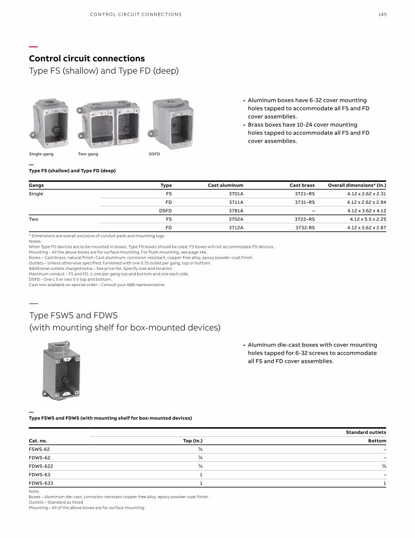
145
Standard outlets
Cat. no. Top (in.) Bottom
FSWS-62 3/4 –
FDWS-62 3/4 –
FDWS-622 3/4 3/4
FDWS-63 1 –
FDWS-633 1 1
Note:Boxes – Aluminum die-cast, corrosion-resistant copper-free alloy, epoxy powder-coat finish.Outlets – Standard as listed.Mounting – All of the above boxes are for surface mounting.
• Aluminum boxes have 6-32 cover mounting holes tapped to accommodate all FS and FD cover assemblies.
• Brass boxes have 10-24 cover mounting holes tapped to accommodate all FS and FD cover assemblies.
Single-gang Two-gang DSFD
Gangs Type Cast aluminum Cast brass Overall dimensions* (in.)
Single FS 3701A 3721–RS 4.12 x 2.62 x 2.31
FD 3711A 3731–RS 4.12 x 2.62 x 2.94
DSFD 3781A – 4.12 x 3.62 x 4.12
Two FS 3702A 3722–RS 4.12 x 5.5 x 2.25
FD 3712A 3732-RS 4.12 x 5.62 x 2.87
* Dimensions are overall exclusive of conduit pads and mounting lugs.Notes:When Type FD devices are to be mounted in boxes, Type FD boxes should be used. FS boxes will not accommodate FD devices.Mounting – All the above boxes are for surface mounting. For flush mounting, see page 146.Boxes – Cast brass, natural finish. Cast aluminum, corrosion-resistant, copper-free alloy, epoxy powder-coat finish.Outlets – Unless otherwise specified, furnished with one 0.75 outlet per gang, top or bottom. Additional outlets charged extra – See price list. Specify size and location.Maximum conduit – FS and FD: 1; one per gang top and bottom and one each side.DSFD – One 1.5 or two 0.5 top and bottom.Cast iron available on special order – Consult your ABB representative.
• Aluminum die-cast boxes with cover mounting holes tapped for 6-32 screws to accommodate all FS and FD cover assemblies.
—Control circuit connectionsType FS (shallow) and Type FD (deep)
—Type FSWS and FDWS (with mounting shelf for box-mounted devices)
CO NTR O L CI R C U IT CO N N EC TI O NS
—Type FSWS and FDWS (with mounting shelf for box-mounted devices)
—Type FS (shallow) and Type FD (deep)

146 R U S S E LL S TO LL® PI N & SL EE V E P OW ER CO N N EC TO R S
GangsCast
aluminumCast
brassOverall
dimensions (in.)
1 3671A 3681 5 x 3.5
2 3672A 3682 5 x 6.5
* Furnished complete with gasket and screws.Material – Cast aluminum, corrosion-resistant copper-free alloy, epoxy powder-coat finish. Cast brass, natural finish.
—Adapter flush frames*
—Blank cover*
—45° Angle adapter*
• The addition of this adapter sub- plate will permit the use of Ever-Lok ® conduit box-type receptacles in switch boxes or outlet boxes with raised covers, as listed. Used on standard (deep) stamped metal conduit boxes. Adapts two-hole to four-hole patterns.
—SKWM mount adapter plate
Cat. no. Material
3677A Cast aluminum
3687 Cast brass
* Furnished complete with gasket and screws.Material – Cast aluminum, corrosion-resistant copper-free alloy, epoxy powder-coat finish. Cast brass, natural finish.
Cat. no. Material
3678A Cast aluminum
3678B Cast brass
* Furnished complete with gasket and screws.Material – Cast aluminum, corrosion-resistant copper-free alloy, epoxy powder-coat finish. Cast brass, natural finish.
Cat. no. Material
SKWMFS Aluminum
Cat. no. Material
3679A Cast aluminum
3679B Cast brass
* Furnished complete with gasket and screws.Material – Cast aluminum, corrosion-resistant copper-free alloy, epoxy powder-coat finish. Cast brass, natural finish.
Cat. no. Material
8091A Cast aluminum
—Flush wall mounting extension*
#8–32 Tap
(4) holes
17/8"
11 /16"15 /8"
15 /8"
15 /16"
13 /16"
1"
113 /16
"Dia
.
—Control circuit connectionsControl circuit connector accessories
• Covers standard FS/FD™ box openings.
• Mounts to any FS/FD™ box.
—Adapter sub-plate
• Used to mount SKWM to FS/FD™ standard series boxes.

147
—Control circuit connectionsDimensions
—Type FS and FD
—Type FSWS and FDWS
No. of gangs
A B
FS FD FS FD
2-gang 6.50" 6.50" 5.50" 5.62"
45° Angle adapter
Multiple-gang
Blank cover
2.25"mtg.
4.87"mtg.
2.28"
4.81"
4.87"mtg.
2.25"mtg.
2.25"0.25"
5.37"
2.31"0.75"
0.28" dia.(2) mtg.
holes
0.28" dia.(2) mtg.
holes
DSFD
Flush mounting extension
5" 3.25"
3.5"
2.62"
4.12"
1.87"
3.25"
2"
.21" dia.(4) mtg.
Holes
1.87"
FS/FD™ FS FD
3.37"mtg.
2.62" 2.31" 2.93"
0.28" dia.(2) mtg. holes
4.5" 4.5"3"
mtg. 4.12"
A" –mtg.B"
2.87"
3"mtg.
(4) mtg. holes
2.95"0.15"
4.15"3.25"
1.87"3.40"
4.12"
2.62"
1.88" mtg.
3.2" mtg.
4.82" 45°
4.12".31"4.12"
2"
2.62"3.62"
3.18"MTG.
.31"
(2) MTG. Holes
4.37"MTG.
3.18"mtg.
4.37"mtg.
4.12"
2.62"3.62"
0.31" 0.31"
2"(2) mtg. holes
4.12"
Single-gang
—Multiple-gang dimensions
CO NTR O L CI R C U IT CO N N EC TI O NS

148 R U S S E LL S TO LL® PI N & SL EE V E P OW ER CO N N EC TO R S
• Adapter tapped with NPT thread to accommodate armored and non-metallic cable or flexible conduit.
Hole diameterfor cable (in.)
Size 320 A
0.375 JG31
0.500 JG32
0.563 JG325
0.625 JG33
0.750 JG34
0.875 JG35
1.000 JG36*
1.125 JG361**
Material – Oil-resistant Neoprene. Size 3 cable bushing: * Style for maximum cable only. ** Special minimum wall style.Notes: When standard plugs or connectors are required to be furnished with one or more of the above accessories, add the suffix and catalog number of the accessory separated by a / to the catalog number of the plug or connector. Complete list price is the total of the list price of the device plus the list price of the accessory.Example: catalog no. SKP9G with 1 bushing would be catalog no. SKP9G/JG36.
—Combination gland nut and cable clamp
—Adapters for conduit
—Cable bushings
Size 3 cable bushing
• Provides extra clamping protection in hard service applications. Relieves terminals and rubber gland of all cable strain.
Plug or connector sizeCast aluminum
Cat. no.Cast brass
Cat. no.Max. cable
dia. (in.)
20 A and SKW 3906 3906B 11/8
Note: Material – Cast aluminum, corrosion-resistant copper-free alloy, epoxy powder-coat finish or cast brass, natural finish.
Plug or connector sizeCast aluminum
Cat. no.Cast brass
Cat. no.Tapped hole
NPSM (in.)
20 A and all SKW FSA21 FSA21B 1/2
FSA22 FSA22B 3/4
FSA23 FSA23B 1
—Control circuit connections

149
Industrial interlocked receptacles are available in 30 through 400 A. Switched receptacles have mechanical linkages for added safety. Safety features include:• Plugs cannot be inserted unless power is safely
turned off• Plugs cannot be removed until power is safely
turned off• Specialty designs may also automatically
disengage power if plug is removed while power is on, either mechanically or electrically
—Sample installation: Fixed power source (wall) to remote/portable location
—01. Receptacle (wall-mounted female)—02. Receptacle (panel-mounted female)—03. Plug (attachment)—04. Female connector—05. Male Inlet with angle adapter—06. Male inlet with straight adapter
Other installations: generator power sources, custom control circuits, multiple voltage service – contact technical services.
—Industrial interlocked receptacles
ApplicationsApplications where these units are most commonly used are:• Welding stations in automotive and heavy
industry• Temporary and portable power distribution
for construction• Marine shore-to-ship power• Industrial machinery installation• Portable power distribution, vehicle and gen-set
power for aerospace• Custom systems in all industries
IN D US TR I A L INTER LO CK ED R ECEP TAC L E S

150 R U S S E LL S TO LL® PI N & SL EE V E P OW ER CO N N EC TO R S
Marine/heavy industrial and custom• Outdoor service NEMA – 3R to 4X• Switched or circuit breaker protection• 30–400 A models, 600 V• Cast aluminum or cast brass• Mounting to customer specifications• Interfaces with Max-Gard®, FS/FD™ and more
—Industrial interlocked receptaclesMounting options
Industrial wall-mount interlocks• Indoor service NEMA 3R• Fused protection• 30–100 A models, 600 V• Heavy service Ever-Lok® or Max-Gard® interfaces
Automotive/heavy industrial I-beam web-mount• Indoor service NEMA 12/3R• Fused or circuit breaker protection• 30–100 A models, 600 V• Stepdown transformer-disconnect designs
with convenience outlets• Cast aluminum and sheet steel housing versions• Mounts inside web of standard 8" I-beam column• Interfaces with heavy service Ever-Lok,
Max-Gard®, standard Ever-Lok and FS/FD™

151
Max-Gard® fused-disconnect interlocked receptacle with safety switch meets UL®, NEC® and major automotive specifications. This unit is the maximum in:
Safety • Door safety switch with three external
lockout points• Safety fuse pulls for standard class R fuses• Backup door safety latchDurability• Heavy 0.060" steel galvaneel with baked enamel,
NEMA 3R/12 construction• Clear shield for test probesPerformance• Standard 600 V cartridge fuse clips and spacing• Fully interlocked Max-Gard® receptacle• Angled front receptacle for easier access
Notes: **Non-fused, non UL® version available: Specify DNRF ________ .Standard polarizations shown. Boldface figures are for voltage assignment; for different ratings, see page 38.
—Ordering informationMaximum 600 V AC or 250 V DC
AmpStd. NPT
thread outlet (in.)Max.
outlet (in.)
30 11/2 21/2
60 2 21/2
100 2 21/2
Specifications on pages 36–37.
Amp
Dimensions (in.)
A B C D E F
30 91/2 3/4 253/4 25 223/4 30
60 91/2 3/4 253/4 25 223/4 30
100 91/2 3/4 253/4 25 223/4 30
—Conduit hubs
AmpsPoles/
wiresVoltage
(V AC)
Fused disconnect**
interlocked receptacle
NEMA 12/3RCat. no.
MatingMax-Gard plug
Cat. no.
Std.bushingI.D. (in.)
30 2P3W 125 DFRF31070 DS3107MP000 7/8
2P3W 250 DFRF32070 DS3207MP000 7/8
3P4W 3Ø250 DFRF33070 DS3307MP000 1
3P4W 3Ø480 DFRF34040 DS3404MP000 1
4P5W 277/480 DFRF35040 DS3504MP000 13/16
60 2P3W 250 DFRF62070 DS6207MP000 13/16
3P4W 125/250 DFRF63070 DS6307MP000 15/16
3P4W 3Ø480 DFRF64040 DS6404MP000 15/16
4P5W 277/480 DFRF65040 DS6504MP000 11/2
100 2P3W 250 DFRF12070 DS1207MP000 111/16
3P4W 125/250 DFRF13070 DS1307MP000 113/16
3P4W 3Ø480 DFRF14040 DS1404MP000 113/16
4P5W 277/480 DFRF15040 DS1504MP000 2
t Control Contacts (position 9) use K example: DFRF1207K. Always use liquidtight fittings to limit condensation entry.
Fasteners Screws2 PlacesHoles for Padlock2 Places
C D
BA
F
E
7.50
2.18
ON
OFF
A B
F
E
C D
7.50"
2.18"
Fasteners screws
Holes for padlock
2 places
2 places E5239
E5239
—Industrial interlocked receptaclesMax-Gard® fused-disconnect** interlocked receptacle with disconnect switch
IN D US TR I A L INTER LO CK ED R ECEP TAC L E S
Dimensions

152 R U S S E LL S TO LL® PI N & SL EE V E P OW ER CO N N EC TO R S
Heavy service Ever-Lok® 60 AStandard fused/non-fused disconnect interlocked receptacle and safety switch is specified by major automotive manufacturers for welding disconnects and other applications. The heavy service Ever-Lok® system features “one-handed” insertion, locking and removal with your choice of switchgear!
Benefits• Specified switchgear: GE or Square D• Door safety switch with external lockout access• Backup door safety latch• Push-in plug locking: no screw collars needed• Full interlocked outlet protection and functions• Angled front receptacle in compact one-handed
interlock
Options (custom capabilities)• Other Russellstoll product interfaces• 30, 60, 100 or 200 A installations• Specialty enclosures for your application• Circuit breaker interlocked mechanismsSee pages H-426–H-432 for full heavy service Ever-Lok line.
Features• Heavy steel galvaneel with baked enamel finish• NEMA 3R/12 construction• Standard 600 V class R fuses• Listed components
Cat. no. Mating plug
TH3362JRS (60 A) 8418 or F27194†
† F27194 Automotive, 480 V AC label.Notes: Mating plugs sold separately. Other styles available.
Cat. no. Mating plug
ESDFH8414F00 8418 or F27194†
† F27194 automotive, 480 V AC label.Notes: Mating plugs sold separately. Other styles available.Also available: Many options for mounting, configuration or interfaces.
19.62 MTG26.45
6.50 MTG
Ø.563 PLS
6.69
7.24
30ϒ
6.665.25
5.559.37
6.50" mtg.
9.375.55
6.665.25
6.69"
30°
Ø 0.56"
26.45"19.62" mtg.
7.24"
3 PLS
—Industrial interlocked receptaclesFused-disconnect interlocked receptacle/safety switch
—GE switchgear
—Square D (mechanism)
Dimensions

153
BenefitsTransformer disconnects offer a combination of voltage outlets from a single facility 480 V 3Ø service drop. Standard configurations include a fused, interlocked 480 V AC, 60 A 3Ø receptacle outlet and separately protected 120 V AC, 15–20 A convenience outlets. Custom configurations are available to meet your application requirements.• Quickest way to expand or build a single voltage
factory or facility, with voltage combinations available at every power drop
• Safest way to operate: with fuses and breaker protection for each recep tacle; 60 A plug cannot be inserted or removed unless power is off
• Most cost-effective way of providing power and convenience outlets in one location; wall mount or column mount in standard 8" I-beam pillars
Mechanical and safety features• Three-point, two-way interlock function
- Blade-type disconnect handle interlocked with door handle
- Main disconnect uses steel rod arm interlock to 480 V AC outlet
• High-strength 3-point door hinge design• Standard 8" I-beam web vertical mounting
or conventional wall mount• Easy access angled front 480 V AC
receptacle position
• Heavy-duty 14-gauge steel NEMA 3R/12 welded enclosure with gasketed door; electrostatic epoxy powder-coat gray finish
• Dual lockout locations on main switch handle and door handle
Optional construction features• Stepdown transformer 2 kVA and secondary• 30/60 A outlet (heavy service Ever-Lok®,
angle type or 30 A Max-Gard®)• Convenience outlet types (including NEMA
bladed styles) and protection
Ordering information• Many other configurations available
—SpecificationsElectrical and safety features:• Fused 480 V AC 60 A 3P4W receptacle
+ fused dual 120 V AC 20 A 2P3W outlets • 20 A combination breaker/GFCI convenience
outlets on door• Heavy-duty (8-hour rated) 2 kVA
480 V AC–120 V AC (fused primary) transformer
Cat. no.480 V AC, 60 A
receptacleMating
plug120 V AC, 20 A
receptacleMating
plug
ERSFH8414FBB 8414Spl. 8418 or F27194† 8003N (x2) 8593CTN*
ERSFH8414FDC 8414Spl. 8418 or F27194† 8003U-1 (x2) 8013U-1*
* Other styles available.† F27194 automotive 480 V AC label.Notes: Mating plugs sold separately.100 A also available – Consult your ABB representative.
60 A, 480 V AC plus 120 or 240 V AC convenience outlets to specification 3P4W (100 A also available)
E57324
—Industrial interlocked receptaclesCombination interlocked transformer disconnect automotive/heavy industrial I-beam web mount
IN D US TR I A L INTER LO CK ED R ECEP TAC L E S
—Combination interlocked transformer disconnect automotive/heavy industrial I-beam web mount

154 R U S S E LL S TO LL® PI N & SL EE V E P OW ER CO N N EC TO R S
6.75
4.00MTG.
Mains Disconnect
Door Handle
Convenience Outletsto spec
Breaker/GFCIProtection to spec
60A Outlet
11.75
7.00
36.37MTG.
37.37
35.37
ø .414 PLS
Main disconnect
6.75"
4.00" mtg.
36.37" mtg.
37.37"
35.37"
Ø 0.41" 4 PLS 7.00"
11.75"
Door handle
Convenience outlets to spec
Breaker/GFCI protection to spec
60 A outlet
RECEPTACLE480 VOLT
CIRCUIT BREAKER GFCI
TWO RECEPTACLES120 VOLT
TRANSFORMER
FUSE HOLDER
FUSEDSWITCH
Circuit breaker GFCI
Off
Test
A-28 in. longA-28 in. long
Line power B-8 in. long
D-10 in. long
Load power B-6 in. long
Panel neutral supplied with GFCI
D-5
in. l
on
g
C-6
in. l
on
g B-6
in. l
g
B-6 in. lg
H1X2
X1 H2
2
22
2
2
3
2
1
1
3
G
G
1
1
1 L1
L2
L3
Load side Line side
B-6
in. l
g
B-6 in. lg
C-5
in. l
on
gB
-5 in
. lo
ng
A-6
in. l
on
gM
arke
d w
ith
gre
en t
ape
Load neutral C-8 in. long
A-28 in. long
Two receptacles120 V Transformer
Fused switch
Fuse holder
Receptacle480 V
480V120 V
2
—Industrial interlocked receptacles
Dimensions
Wiring diagram

155
10.00"Ø 3.62"
Mechanically interlocked switch11/4" NPT top entry std./Other sizes available
Mating plug60 A, 3P4W, 8418 or F27194
ON
OFF12.25"
14.88"
6.12"
20°
480VReceptacle
7.12"Approx.
4.00"MTG.
10.00"MTG.
Ø .284 PlsMTG.
*17" dim. for F32753 unit
Features and benefitsMechanically interlocked between the receptacle and the switch. Designed so that when the plug is fully inserted, the switch interlock is automatically released, permitting the switch to be turned on. The plug cannot be removed from the receptacle until the switch is manually turned off.• Switch: 60 A, 480 V AC, 3-pole, quick “make”
and quick “break”• Housings: heavy-cast aluminum corrosion-
resistant copper-free alloy with gray electrostatic epoxy powder-coat finish; furnished with oil-resistant gaskets
• Handle lock-out feature• Circuit-breaker interlocked version available
in standard and high AIC models• One-handed insertion or removal: unique
auto-locking collar engages upon insertion, 1/8 counter-clockwise turn disengages for removal
• Simple and rugged full interlock safety; plug cannot be inserted or withdrawn while power is on
• Fits in standard 8" I-beam web or wall mounting
Interlock Cat. no.
Matingtype Plug
CFCSRA13-60 Switched only 8418 or F27194†
F32753‡ Circuit breaker 8418 or F27194†
† Automotive 480 V AC.‡ 70 A Trip version F26313 and other variations also available.Notes: CFCSRA13-60 replaces previous Cat. #FCSRA13-60.Mating plugs sold separately.
10.00"Ø3.62"
Ø 0.28 4 PLSmtg.
4.00" mtg.
7.12"Approx.
10.00" mtg.
480 V receptacle
14.88"12.25"
6.12"
20°
60 A, 480 V AC/250 V DC, 3P4W circuit breaker interlocked receptacle option
—Industrial interlocked receptaclesEver-Lok® mechanically interlocked receptacle and switch automotive/heavy industrial I-beam web mount heavy service Ever-Lok mechanically interlocked receptacles and switch
IN D US TR I A L INTER LO CK ED R ECEP TAC L E S
Dimensions

156 R U S S E LL S TO LL® PI N & SL EE V E P OW ER CO N N EC TO R S
OFF ON0.34"4 PLS
5.06"MTG.
5.88"MTG.
4.62"
5.62" Ø 2.25"
Interlocked switch
Mating plug
Features and benefits The FS/FD interlocked switch is made of heavy-duty cast aluminum. The mechanical interlock functions when the plug is fully engaged, enabling the switch to be operated. Basic interlock design has many variations including screw cover, brass and circuit breaker versions.• Male plug cannot be plugged or unplugged
under load
• Deadfront female receptacle for safety• Weathertight receptacle made of cast aluminum,
corrosion-resistant copper-free alloy, gray electrostatic epoxy powder-coat finish
• Compact size for limited space applications• Available with UL® style steel back boxes
to user specifications
Cat. no. Mating plug
F34331 F34332
Mating plugs sold separately.
5.62"
5.88" mtg.
0.34" 4 PLS
5.06"mtg.
4.62"
Ø2.25"
30 A, 480 V AC, 3P4W (other polarizations available)
—Industrial interlocked receptaclesInterlocked switch (30 A, 480 V AC) automotive/heavy industrial I-beam web mount interlocked switch (FS/FD™ interface)
—Interlocked switch (30 A, 480 V AC) automotive/heavy industrial I-beam web mount interlocked switch (FS/FD™ interface)
Dimensions

157
Max-Gard® NEMA 4X interlocks are ideal for demanding non-hazardous areas where dust, dirt, moisture and corrosion might be a problem – such as shipyards, food processing facilities, manufacturing operations or similar areas.
Safety • Gated deadfront waterproof receptacle• Standard, high AIC or NA/switch circuit breaker• Protective screw cap for watertight protection
Durability• Thick-wall cast copper-free aluminum housing
with epoxy powder-coat finish• Heavy-duty sliding bar interlock mechanism
Performance• Heavy on/off handle adds mechanical ability
to electrical interlock function• Standard conduit openings through top or side
E
B-Std.
t Control contacts (position 12) use “K” example: DBRF6104060K0Shunt trip breaker (position 13) add “Z” to above: DBRF6104060KZBreaker trip ratings (positions 9, 10, 11) 30 A use 030; 50 A use 050; 60 A use 060Non-auto Sw. NA0 (repl.” DBRF” with “DSRF”)For additional full line and polarization options, see Max-Gard section on pages 6–47.
AmpStd. NPT
thread outlet (in.)Max.
outlet (in.)
30 11/2 21/2
60 11/2 21/2
100 2 21/2
Amp A (in.) B (in.) C (in.) D (in.) E (in.) F (in.) G (in.)
30 3/8 83/4 61/2 11/2 161/4 151/8 31/8
60 3/8 83/4 61/2 11/2 161/4 151/8 31/8
100 3/8 83/4 61/2 11/2 161/4 151/8 31/8
200 9/16 121/4 9 21/2 261/4 243/4 5
400 9/16 151/2 12 3 301/2 29 6
Boldface figures are for voltage assignment; for different ratings, see page H-346.
Mechanically interlocked receptacle
NEMA 4X Cat. no.
Mating Max-Gard
plug Cat. no.
Std. bushing I.D. (in.)Amps
Poles/wires
Voltage(V AC)
30
2P3W 125 DBRF310703000 DS3107MP000 7/8
2P3W 250 DBRF320703000 DS3207MP000 7/8
3P4W 3Ø250 DBRF330703000 DS3307MP000 1
3P4W 3Ø480 DBRF340403000 DS3404MP000 1
4P5W 277/480 DBRF350403000 DS3504MP000 13/16
60 2P3W 250 DBRF620706000 DS6207MP000 13/16
3P4W 125/250 DBRF630706000 DS6307MP000 15/16
3P4W 3Ø480 DBRF640406000 DS6404MP000 15/16
4P5W 277/480 DBRF650406000 DS6504MP000 11/2
100 2P3W 250 DBRF120710000 DS1207MP000 111/16
3P4W 125/250 DBRF130710000 DS1307MP000 113/16
3P4W 3Ø480 DBRF140410000 DS1404MP000 113/16
4P5W 277/480 DBRF150410000 DS1504MP000 2
200 3P4W 277/480 DBRF230720000 DS2307MP000 11/4
3P4W 3Ø480 DBRF240420000 DS2404MP000 21/4
4P5W 277/480 DBRF250420000 DS2504MP000 21/2
400 3P4W 277/480 DBRF430740000 DS4307MP000 3
3P4W 3Ø480 DBRF440440000 DS4404MP000 3
4P5W 277/480 DBRF450440000 DS4504MP000 31/4
t t
A
B
C
D
G
FE
—Industrial interlocked receptaclesMaximum 600 V AC/250 V DC
—Conduit hubs: (at B or E)
—Dimensions
IN D US TR I A L INTER LO CK ED R ECEP TAC L E S
Dimensions

158 R U S S E LL S TO LL® PI N & SL EE V E P OW ER CO N N EC TO R S
Russellstoll® hazardous-duty plugs, receptacles and interlocks are designed to support a variety of installation needs throughout 20 A, 30 A, 60 A and 100 A ranges where Division 1, Class 1 NEC® guidelines require the utmost in safety.
Unique among others, the Russellstoll Max-Gard® also offers true O-ring sealed waterproof design protection in addition to standard threaded flame-path construction employed elsewhere. In rough service, washdown and outdoor applications, Max-Gard performance goes beyond normal XP ratings.
With coming increases in harmonized designations for classifications between NFPA/NEC® and IEC (international) hazardous area standards, a quick reference classification chart is provided below. In all cases, the customer must determine and approve proper area classification standards and degree of harmonized standards acceptance.
Hazardous materials environment U.S. NEC standards Euro IEC standards
Gas or vapor Div. 1, Class I Zone 0 and 1
Div. 2, Class I Zone 2
Dust Div. 1, Class II Zone 10
Div. 2, Class II Zone 11
Fibers/flyings Div. 1, Class III Zone 10
Div. 2, Class III Zone 11
Group applications NEC art. 500Class I: groups
NEC art. 505Zones 0, 1 and 2
Div. 1 and 2, Class I A: Acetylene IIC
B: Hydrogen
C: Ethylene IIB
D: Propane IIA
The above chart is presented for quick reference only and should only be used in conjunction with noted Articles. Further definition of harmonized standards will be supported by Russellstoll through appropriate specification efforts whenever practical.
—Hazardous location plugs, receptacles and interlocksHazardous-duty applications
—Hazardous-duty applications
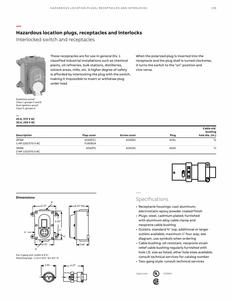
159
5.75"B
5.50"
7"
CA
D4.75" 3.06"
6.25" Max
2.81" 4.37"
These receptacles are for use in general Div. 1 classified industrial installations such as chemical plants, oil refineries, bulk stations, distilleries, solvent areas, mills, etc. A higher degree of safety is afforded by interlocking the plug with the switch, making it impossible to insert or withdraw plug under load.
When the polarized plug is inserted into the receptacle and the plug shell is turned clockwise, it turns the switch to the “on” position and vice-versa.
—Specifications• Receptacle housings: cast aluminum;
electrostatic epoxy powder coated finish • Plugs: steel, cadmium plated; furnished
with aluminum alloy cable clamp and neoprene cable bushing
• Outlets: standard 3/4" top, additional or larger outlets available; maximum 1" four way; see diagram, use symbols when ordering
• Cable bushing: oil-resistant, neoprene strain relief cable bushing regularly furnished with hole I.D. size as listed; other hole sizes available; consult technical services for catalog number
• Two-gang style: consult technical services
For 2-gang unit, width is 9 3/8".Mounting lugs – C to C 101/2" W x 51/2" H
—20 A, 575 V AC 30 A, 250 V AC
Description Flap cover Screw cover Plug
Cable std. bushing
hole dia. (in.)
2P3W1 HP 220/575 V AC
4240FC/F16081A
4240SC 4241 5/8
3P4W2 HP 110/575 V AC
4242FC 4242SC 4243 3/4
2.81" 4.37"
3.06"4.75"
5.75" 6.25" Max
5.50"
7"
C
D
A
B
—Hazardous location plugs, receptacles and interlocksInterlocked switch and receptacles
Approvals: E10919
H A Z A R D O US LO C ATI O N PLU G S , R ECEP TACL E S A N D I NTER LO CK S
Explosion-proof: Class I, groups C and DDust ignition-proof: Class II, groups G
Dimensions

—Explosion-proof waterproof circuit breaker interlocked receptacle
Available in 30, 60 and 100-A sizes, all polarizations. Division 1, Class I and II.
1. Heavy-duty XP cast aluminum housing, electrostatic epoxy coat finish
2. Standard, high AIC and NA (switched only) breakers available
3. Threaded access (cover not shown) with O-ring for XP and waterproof integrity
4. Gated deadfront safety5. Factory-sealed receptacle interior.
Accepts standard XP-rated Max-Gard plugs6. Drain plug
—Explosion-proof waterproof circuit breaker interlocked receptacle
Available in 30 A 480 V AC max., all polarizations• Factory-sealed interior (no filled conduits)• Easy low-cost installation
1. Heavy-duty XP cast aluminum housing, electrostatic epoxy coat finish
2. Threaded access with (cover not shown) O-ring for XP and waterproof integrity
3. Gated deadfront for safety4. All standard polarizations available to 480 V AC5. Factory-sealed receptacle interior
Accepts standard XP-rated Max-Gard plugs
—01 Approvals• UL and CSA listed for
hazardous locations• Class I, division 1,
groups B, C and D• Class II, division 1,
groups F and G UL File E10919
• NEMA 7, 8, 9• CSA• DOT shipboard
used above deck “green water”
• NEMA 4X• USCG approved—02 Approvals• UL and CSA listed for
hazardous locations• Class I, division
1, C and D• Class II, division 1,
groups F and G• UL File E10919• NEMA 7, 8, 9• CSA• DOT shipboard
used above deck “green water”
• NEMA 4X• USCG approved
2
3
1
5
4
—01
—02
160 R U S S E LL S TO LL® PI N & SL EE V E P OW ER CO N N EC TO R S
E68085
E10919
—Hazardous location plugs, receptacles and interlocksMax-Gard® DBRE and DSRE Series Interlocks are certified both explosion-proof and waterproof, along with optional control contacts, and are fully UL® listed.
6
2
3
1
54

161H A Z A R D O US LO C ATI O N PLU G S , R ECEP TACL E S A N D I NTER LO CK S
—Maximum 600 V AC or 250 V DC
Boldface figures are for voltage assignment; for different ratings, see page 38.* For specification information and additional bushing sizes, see Max-Gard® section, pages 6–47.
t Control contacts (position 12) use “K” example: DBRF6104060K0Shunt trip breaker (position 13) add “Z” to above: DBRF6104060KZ
Breaker trip ratings (positions 9, 10, 11) 30 A use 030; 50 A use 050; 60 A use 060Non-auto switch NA0 (repl. “DBRE” with “DSRE”)
Explosion-proof receptacle
—Explosion-proof interlocked receptacle
Amp A (in.) B (in.) C (in.) D (in.) E (in.)
30 83/4 71/2 1/2 143/4 20
60 83/4 71/2 1/2 143/4 20
100 83/4 71/2 1/2 143/4 20
Access coverTo pigtails
for wiring
Conduitlocation
“C”
Conduitlocation “D”
A
BC
D
E
Conduitlocation “B”
Conduitlocation “A”
Bottom view
4.00" MTG.10.16"
11.35"
7.26"
7.03" 1.50"
ø 0.28", 4 PLS
—Hazardous location plugs, receptacles and interlocks
Dimensions
AmpsPoles/
wiresVoltage
(V AC) Cat. no. Cat. no. Cat. no. Std. bushing
I.D.* (in.)
Product type
Explosion-proof interlocked receptacle with circuit breaker, Class I, Class II
Explosion-proof receptacle, Class I, Class II
Male plug
30 2P3W 125 DBRE310703000 DSE3107FR0 DS3107MP000 7/8
2P3W 250 DBRE320703000 DSE3207FR0 DS3207MP000 7/8
3P4W 3Ø250 DBRE330703000 DSE3307FR0 DS3307MP000 1
3P4W 3Ø480 DBRE340403000 DSE3404FR0 DS3404MP000 1
4P5W 277/480 DBRE350403000 DSE3504FR0 DS3504MP000 13/16
60 2P3W 250 DBRE620706000 – DS6207MP000 13/16
3P4W 3Ø250 DBRE630706000 – DS6307MP000 15/16
3P4W 3Ø480 DBRE640406000 – DS6404MP000 15/16
4P5W 277/480 DBRE650406000 – DS6504MP000 11/2
100 2P3W 250 DBRE120710000 – DS1207MP000 111/16
3P4W 3Ø250 DBRE130710000 – DS1307MP000 113/16
3P4W 3Ø480 DBRE140410000 – DS1404MP000 113/16
4P5W 277/480 DBRE150410000 – DS1504MP000 2

162 R U S S E LL S TO LL® PI N & SL EE V E P OW ER CO N N EC TO R S
Circuit-breaking receptacles, plugs and connectors ensure complete circuit breaking under full rated loads. Equipment grounding is provided by means of a separate pole that makes contact before and breaks contact after the circuit poles. The delayed action operation sequence is as follows:
Insert plug, turn left, push in to make electrical contact, then turn right to prevent accidental disconnection. To withdraw plug, the reverse procedure is followed, which provides time for extinction of the arc and cooling before the plug can be completely withdrawn.
Explosion-proof: Div. 1, class 1, groups C and D
Ratings Poles/
wires
Surface mount receptacle** Flush mount receptacles Plug
Cablehole dia. (in.)Straight Angled
Type EFS – – – –
20 A 2P3W 4462 4464FC 4445 4466 9/16
125 V AC or 250 V AC 3P4W – 4465FC 4446 4467 19/32
Type DA – – – –
30 A+ 2P3W – 4233BC _ 4237BC 5/8
250 V AC or 480 V AC 3P4W RA4234BC 4234BC _ 4238BC 3/4
60 A* 2P3W – 4263BC _ 4267BC 11/4
480 V AC 3P4W RA4264BC 4264BC _ 4268BC 11/4
Notes:* Also available for use at 30 A, 480 V AC.** Can be furnished with flap or screw cap covers. When so required, add suffix FC for flap or suffix SC for screw cap to above catalog number. Price on application.
Furnished with plaster gauge plate. Requires wall depth of 4 minimum.+ 30 A Iron-bodied plug family for replacement use only. Not UL listed. (60 A carries full listing.)
—Hazardous location plugs, receptacles and interlocksDelayed-action receptacles
—Delayed-action receptacles
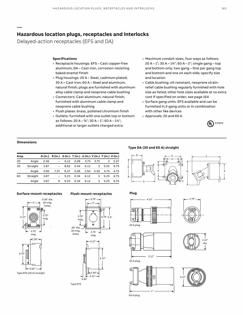
163H A Z A R D O US LO C ATI O N PLU G S , R ECEP TACL E S A N D I NTER LO CK S
Amp D (in.) R (in.) S (in.) T (in.) U (in.) V (in.) Y (in.) Z (in.)
20 Angle 2.56 – 6.12 0.28 3.75 3.75 3 5.37
30 Straight 3.87 – 8.62 0.34 6.12 5 5.25 6.75
Angle 3.06 7.37 8.37 0.28 3.50 5.50 4.75 4.75
60 Straight 3.87 – 9.25 0.34 6.12 5 5.25 6.75
Angle 3.87 9 9.25 0.34 6.12 5 5.25 6.75
1.75" 4.12"
Surface-mount receptacles Flush-mount receptacles Plug
Type EFS (20 A) straight
Type DA (30 and 60 A) straight
Type EFS
20 A plug
3.62"
4.75"
2.56"3"
5.37"3.75"MTG.
3.75" MTG
.28" Dia.(2) MTG. Holes
3.62"
4.75"
2.56"3"
5.37"3.75"MTG.
3.75" MTG
.28" Dia.(2) MTG. Holes
1.75" 4.12"
5.12"
2.12"Dia.
5.12"
2.12"Dia.
3.12"
7"
3.12"
7"
E10919
Specifications• Receptacle housings: EFS – Cast copper-free
aluminum; DA – Cast iron, corrosion-resisting baked enamel finish
• Plug housings: 20 A – Steel, cadmium plated; 30 A – Cast iron; 60 A – Steel and aluminum, natural finish; plugs are furnished with aluminum alloy cable clamp and neoprene cable bushing
• Connectors: Cast aluminum, natural finish; furnished with aluminum cable clamp and neoprene cable bushing
• Flush plates: brass, polished chromium finish• Outlets: furnished with one outlet top or bottom
as follows: 20 A – 3/4"; 30 A – 1"; 60 A – 11/2"; additional or larger outlets charged extra
• Maximum conduit sizes, four ways as follows: 20 A – 1"; 30 A – 11/2"; 60 A – 2"; single gang – top and bottom only; two gang – One per gang top and bottom and one on each side; specify size and location
• Cable bushing: oil-resistant, neoprene strain-relief cable bushing regularly furnished with hole size as listed; other hole sizes available at no extra cost if specified on order; see page 164
• Surface gang units: EFS available and can be furnished in 2-gang units or in combination with other like devices
• Approvals: 20 and 60 A
5.12"
2.12"dia.
3.12"
7"
60 A plug
30 A plug
5.37"
3"
3.75"mtg.
D
Z
S
V
UY
T
S
R Z
D
Z
S
V
VU
T
R
T
Z
3.75"
3"
4.75" 5.5"3.75"MTG.
3.75" MTG.
.28" Dia.(2) MTG.Holes
3.12"
5.37"
3.31"
2.56"
.81"
3.75"
3"
4.75" 5.5"3.75"MTG.
3.75" MTG.
.28" Dia.(2) MTG.Holes
3.12"
5.37"
3.31"
2.56"
.81"
3.75"
3.75"mtg.
3.75" mtg.
4.75" 5.5"
3.12"
5.37"
3.31"2.56"
0.81"
.28" dia.(2) mtg.
holes
3"
3.75" mtg.
2.56"
4.75"
3.62"
4.12" 1.75" 0.28" dia.(2) mtg.
holes
—Hazardous location plugs, receptacles and interlocksDelayed-action receptacles (EFS and DA)
Dimensions

164 R U S S E LL S TO LL® PI N & SL EE V E P OW ER CO N N EC TO R S
Cat. no. Hole diameter for cable (in.)
SG05 0.312
SG1 0.375
SG15 0.438
SG2 0.500
SG2A 0.531
20 ACat. no. Hole diameter for cable (in.)
SG25 0.563
SG2B 0.594
SG3 0.625
SG3A 0.687
SG4 0.750
Notes: Cable outside diameter should be at or slightly less than bushing I.D.Bushings can compress approx. 10% at installation.To order, add suffix as example: 4466/SG3. Material – oil-resistant Neoprene.
Cat. no. Finish Used on cat. no.
F19054C Chrome plated 4445
F19054D Natural finish 4464
—Flap cover assembly
Cat. no. Used on cat. no.
F24853C 4466
F24853D 4467
Material – Cast aluminum alloy, natural finish.
—Combination gland nut and cable clamp
Cable bushingsTo order non-standard bushing, add cable bushing number to end of catalog number. This is furnished at no additional cost at time of order. For 60 A devices, see J-line 60 A chart on page 63.
—Hazardous location plugs, receptacles and interlocksFor explosion-proof plugs and connectors
—For 20 A delayed-action circuit receptacles
—For 20 A delayed-action circuit plugs – provides extra clamping protection in hard service applications
—Cable bushings

165
Cat. no. Description
GCC1 Ground cup with cover*
GC1 Ground cup without cover*
F06146 Replacement contact tip**
* Hub is tapped for 3⁄4"–10.** Hub is tapped for 1⁄2"–13.
Static grounding receptacles are used in airport and aerospace installations worldwide during fueling, testing and maintenance procedures. Normal mounting is concrete/tarmac floor inset, threaded onto copper ground rod.
Heavy brass construction cup includes optional cover and receptacle’s contact pin. Accommodates a wide variety of single-contact (copper on steel wire) static ground wire clamps in service.
F07073(cover only)
—Aerospace/industrial static ground devices
H A Z A R D O US LO C ATI O N PLU G S , R ECEP TACL E S A N D I NTER LO CK S
DuraGard® to 4P4W 20 A through 60 A The toughest construction in thermoplastic safety, durability and performance by design, in UL 94-VO flame-rated DuraV® material. With DurOring sealed pins, sleeves and interiors are watertight even unmated. 30 A and 50 A unique circuit breaker interlock line in DuraV are the best choices in all standard voltage polarization options through 600 V AC (interlock to 480 V AC).
Spec grade to 4P4W 20 A and 30 AOtherwise similar to the DuraGard, spec grade refers to blue Lexan® plugs only made to the same original FS/FD™ design standards as DuraGard, in UL 94-5VA flame-rated material. Spec grade features DurOring sealed pins, and sleeves and interiors are watertight even unmated. Spec grade devices have been superceded by DuraGard ratings for OEM use.
FS/FD™ to 3P4W 15 A through 30 AThe original 15/20/30 A computer system connectors, the FS/FD line in aluminum continues in MRO usage. Many installations can also mate directly or convert to DuraGard® units. Our large installed base can be supported with any construction and product options. Convert to DuraGard® when possible.
Angle type to 3P4W 60 A use The original 60 A main power computer system connector, angle type plugs are also available in specialty UL 94-V0 material (aluminum connectors). As part of the MRO usage 30–200 A angle type line, the 60 A connector is still commonly used today. Other lines such as Max-Gard should be used for changeout when possible.
Max-Gard® 30 A to 4P5W For DP/computer system applications, a special Max-Gard polarization reflects DP installations. Special thermoplastic housing and back handle are supplied for these applications. Use wherever 4P5W installations are required.
—Computer system interconnections
—Hazardous location plugs, receptacles and interlocksAerospace/industrial static ground devices
Russellstoll® line selections for indoor and outdoor applications

166 R U S S E LL S TO LL® PI N & SL EE V E P OW ER CO N N EC TO R S
—Typical application groups
• Telephony equipment• Switching rack systems• Power distribution units• Test and laboratory equipment
More than 30 years ago, Russellstoll® offered the first pin and sleeve connectors that met the demanding needs of the data processing industry, and we’ve been leading the way ever since.
The expanding technology of the computer system industry is creating more sophisticated applications, which require safe, reliable connections that exceed the tough demands of today’s applications. Russellstoll’s commitment to excellence offers you that and more... safety, durability, reliability and performance on our complete line of plugs, receptacles and connectors.
Pin and sleeve power connections are chosen for computer system interconnections because of the absolute performance required in today’s mainframe and peripheral installation. Pin and sleeve connections have been proven to be more reliable in service than any bladed device. Data centers stay in service because Russellstoll keeps them connected.
—Usage
• Any application where electrical connections must be protected from humidity, water, condensation and/or dust entering the wiring compartment and contacts
• Cable-to-connector sealing and device locking designs are critical
—Computer system interconnections
• Thermoplastic connectors preferred: some with aluminum conduit grounded shell
• Connection integrity needs are absolute; data center systems cannot go down
• Underfloor data center applications and wall-mount installations
• Mainframes from 30–270 A• Peripherals• Data storage devices• Military or critical power supplies

167
Series* FS/FD™ and angle type Spec grade DuraGard®
Available ranges (A) 20, 30 and 60* 20 and 30 20, 30, 50 and 60
Safety Grade™ UL® flame-rated high-temp thermoplastic
UL 94-V0 aluminum
UL94-5VA UL94-V0
Easy-to-wire rear-loaded interiors
– ● ●
Single rated safetyvoltage polarizations
20 A 20 A
20 A 30 A
30 A 50 A
60 A
Waterproof O-ring seal (pins, sleeves and interiors)
– ● ●
2nd internal ground lug (cable shielding alt.)
– ● (optional)
External cable clamp ● ● ●
External gland nut lock – ● ●
E2630
LR14096
For TüV listed devices, contact technical services.TüV
* 60 A devices are specially designed versions of Russellstoll angle type (7328DP).
—Computer system interconnectionsQuick selection chart
CO M P U TER S Y S TEM I NTER CO N N EC TI O NS
—Quick selection chart
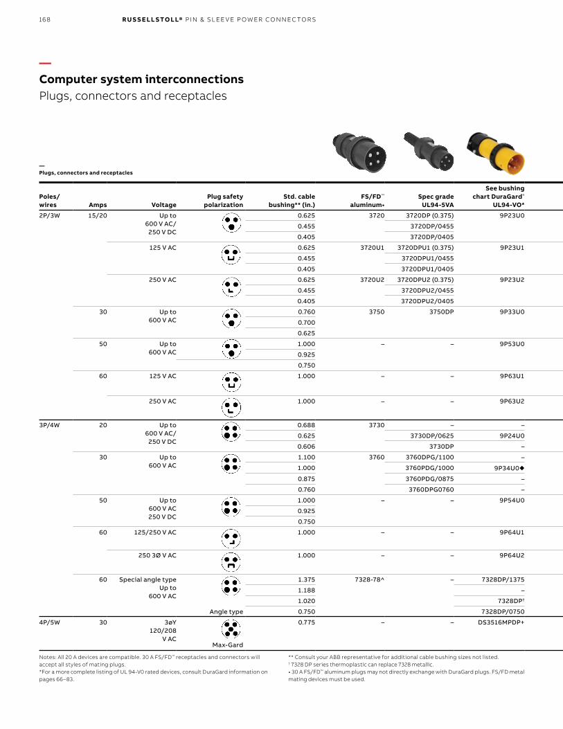
168 R U S S E LL S TO LL® PI N & SL EE V E P OW ER CO N N EC TO R S
Poles/ wires Amps Voltage
Plug safetypolarization
Std. cablebushing** (in.)
FS/FD™
aluminum•Spec grade
UL94-5VA
See bushing chart DuraGard®
UL94-VO*FS/FD™
aluminumDuraGard®
UL94-VO*FS/FD
aluminum•DuraGardUL94-VO*
2P/3W 15/20 Up to600 V AC/
250 V DC
0.625 3720 3720DP (0.375) 9P23U0 3913 9C23U0 3743 9R23U0W t
0.455 3720DP/0455
0.405 3720DP/0405
125 V AC 0.625 3720U1 3720DPU1 (0.375) 9P23U1 3913U1 9C23U1 3743U1 9R23U1W t
0.455 3720DPU1/0455
0.405 3720DPU1/0405
250 V AC 0.625 3720U2 3720DPU2 (0.375) 9P23U2 3913U2 9C23U2 3743U2 9R23U2W t
0.455 3720DPU2/0455
0.405 3720DPU2/0405
30 Up to600 V AC
0.760 3750 3750DP 9P33U0 3933 n –9C33U0 n
–
3753 n 9R33U0W tn
0.700
0.625
50 Up to600 V AC
1.000 – – 9P53U0 – 9C53U0 – 9R53U0W ●
0.925
0.750
60 125 V AC 1.000 – – 9P63U1 – 9C63U1 – 9R63U1
250 V AC 1.000 – – 9P63U2 – 9C63U2 – 9R63U2
3P/4W 20 Up to600 V AC/
250 V DC
0.688 3730 – – 3914 – 3744 9R24U0W t
0.625 3730DP/0625 9P24U0 9C24U0
0.606 3730DP – –
30 Up to600 V AC
1.100 3760 3760DPG/1100 – 3934 n – 3754 n 9R34U0W tn
1.000 3760PDG/1000 9P34U0u 9C34U0 un
0.875 3760PDG/0875 – –
0.760 3760DPG0760 – –
50 Up to600 V AC250 V DC
1.000 – – 9P54U0 – 9C54U0 – 9R54U0W t
0.925
0.750
60 125/250 V AC 1.000 – – 9P64U1 – 9C64U1 – 9R64U1
250 3Ø V AC 1.000 – – 9P64U2 – 9C64U2 – 9R64U2
60 Special angle typeUp to
600 V AC
1.375 7328-78^ – 7328DP/1375 7428-78^
– – SCF7324-78
1.188 –
1.020 7328DP†
Angle type 0.750 7328DP/0750
4P/5W 30 3øY120/208
V AC
0.775 – – DS3516MPDP+ DS3516FP+ – DS3516FR+ –
Max-Gard
Notes: All 20 A devices are compatible. 30 A FS/FD™ receptacles and connectors will accept all styles of mating plugs.*For a more complete listing of UL 94-V0 rated devices, consult DuraGard information on pages 66–83.
** Consult your ABB representative for additional cable bushing sizes not listed.† 7328 DP series thermoplastic can replace 7328 metallic.• 30 A FS/FD™ aluminum plugs may not directly exchange with DuraGard plugs. FS/FD metal mating devices must be used.
—Computer system interconnectionsPlugs, connectors and receptacles
—Plugs, connectors and receptacles

169
Poles/ wires Amps Voltage
Plug safetypolarization
Std. cablebushing** (in.)
FS/FD™
aluminum•Spec grade
UL94-5VA
See bushing chart DuraGard®
UL94-VO*FS/FD™
aluminumDuraGard®
UL94-VO*FS/FD
aluminum•DuraGardUL94-VO*
2P/3W 15/20 Up to600 V AC/
250 V DC
0.625 3720 3720DP (0.375) 9P23U0 3913 9C23U0 3743 9R23U0W t
0.455 3720DP/0455
0.405 3720DP/0405
125 V AC 0.625 3720U1 3720DPU1 (0.375) 9P23U1 3913U1 9C23U1 3743U1 9R23U1W t
0.455 3720DPU1/0455
0.405 3720DPU1/0405
250 V AC 0.625 3720U2 3720DPU2 (0.375) 9P23U2 3913U2 9C23U2 3743U2 9R23U2W t
0.455 3720DPU2/0455
0.405 3720DPU2/0405
30 Up to600 V AC
0.760 3750 3750DP 9P33U0 3933 n –9C33U0 n
–
3753 n 9R33U0W tn
0.700
0.625
50 Up to600 V AC
1.000 – – 9P53U0 – 9C53U0 – 9R53U0W ●
0.925
0.750
60 125 V AC 1.000 – – 9P63U1 – 9C63U1 – 9R63U1
250 V AC 1.000 – – 9P63U2 – 9C63U2 – 9R63U2
3P/4W 20 Up to600 V AC/
250 V DC
0.688 3730 – – 3914 – 3744 9R24U0W t
0.625 3730DP/0625 9P24U0 9C24U0
0.606 3730DP – –
30 Up to600 V AC
1.100 3760 3760DPG/1100 – 3934 n – 3754 n 9R34U0W tn
1.000 3760PDG/1000 9P34U0u 9C34U0 un
0.875 3760PDG/0875 – –
0.760 3760DPG0760 – –
50 Up to600 V AC250 V DC
1.000 – – 9P54U0 – 9C54U0 – 9R54U0W t
0.925
0.750
60 125/250 V AC 1.000 – – 9P64U1 – 9C64U1 – 9R64U1
250 3Ø V AC 1.000 – – 9P64U2 – 9C64U2 – 9R64U2
60 Special angle typeUp to
600 V AC
1.375 7328-78^ – 7328DP/1375 7428-78^
– – SCF7324-78
1.188 –
1.020 7328DP†
Angle type 0.750 7328DP/0750
4P/5W 30 3øY120/208
V AC
0.775 – – DS3516MPDP+ DS3516FP+ – DS3516FR+ –
Max-Gard
Notes: All 20 A devices are compatible. 30 A FS/FD™ receptacles and connectors will accept all styles of mating plugs.* For a more complete listing of UL 94-V0 rated devices, consult DuraGard® information on pages 66–83.** Consult your ABB representative for additional cable bushing sizes not listed.† 7328 DP series thermoplastic can replace 7328 metallic.• 30 A FS/FD™ aluminum plugs may not directly exchange with DuraGard plugs. FS/FD metal mating devices must be used.u Standard 0.750 bushing.n DuraGard receptacles and connectors 30/50 A will accept only DuraGard or Spec Grade. FS/FD Aluminum 30 A plugs must be used with FS/FD metal connectors or receptacles.^ Angle type line+ Max-Gard® line – for further information, see pages 6–47.t Requires 3711A conduit FD box or 3781A DSFD box (50 A).
CO M P U TER S Y S TEM I NTER CO N N EC TI O NS

170 R U S S E LL S TO LL® PI N & SL EE V E P OW ER CO N N EC TO R S
Receptacle size (A) F (in.) G (in.) H (in.) I (in.) J (in.) K (in.) M (in.)
FS/FD 20 41/8 31/4 25/8 17/8 11/8 21/4 21/2
30 41/8 31/4 25/8 17/8 13/8 23/4 25/8
Angle YYPE (metallic)
60 31/2 27/8 31/2 27/8 – 21/2 6
DuraGard 20 41/8 31/4 25/8 17/8 11/2 2 31/8
30 41/8 31/4 25/8 17/8 21/2 23/4 41/8
50 41/8 31/4 25/8 17/8 21/2 23/4 41/8
Receptacle size (A) A (in.) B (in.) C (in.)
FS/FD™ 20 35/8 2 21/4
30 33/4 21/4 23/8
Angle type DP (thermoplastic)
60 8 21/2 33/4
Spec gradeDuraGard®
20 31/4 21/8 21/8
30 5 23/8 35/8
50 51/4 23/8 35/8
—Plugs
—Connectors
—Receptacles
Receptacle size (A) D (in.) E (in.)
FS/FD 20 4 17/8
30 45/8 21/8
Angle type (metallic)
60 91/8 31/2
Spec gradeDuraGard
20 41/8 17/8
30 55/8 21/8
50 55/8 21/8
A
B
C
D
E
A
B
D
E
C
(DuraGard shown)
K
J
MH
GF
I
—Computer system interconnectionsDimensions
DimensionsDimensions
Dimensions

171
Receptacle size (A)
Cat. no.
Single-gang Double-gang
20, 30 and 50 3711A 3712A
60* JB6-1 –
50 3781A –
* Various mounting options available. 4" deep (not shown)
—Angle adapter
• Kit includes gland nuts for plugs or connectors.
Receptacle size (A)
Cat. no.
45° 20°
20, 30 and 50 3678A –
60* JAA6-45 JAA6-AB6
Mounts to conduit boxes to angle receptacle downward for easier access, no moisture retention on surfaces and better plug-cable drop bend relief.* Various mounting options available.
Plug/connectorsize (A)
Tappedhole size (in.)
Cat. no.
FS/FD™ Spec grade DuraGard®
20 1/2 FSA11 – 9X2C503/4 FSA12 – 9X2C751/2 FSA21 – 9X3C50
30 3/4 FSA22 – 9X3C75
1 FSA23 – –
50 3/4 – – 9X5C75
1 – – 9X5C103/4 JPA62 – –
60(angle type)
1 JPA63 – –
11/4 JPA64 – –
11/2 JPA65 – –
Cat. no. 3678A
2.62"
1.88" mtg.
3.25" mtg.
3.40"
4.12"
4.82" 45°
—Computer system interconnectionsAll conduit boxes/angle adapters are copper-free, cast aluminum, epoxy powder coat finish.
—Conduit boxes (for surface mounting)
A
1.38"
.31"
4.50"
1.06"
4.12"
3.00"MTG.
2.62" Ø.28", 4 PLS
3.38" MTG
Cat. no. 3711A
3.38" mtg.
Ø 0.28", 4 PLS
3.00" mtg.
2.62" 0.31"
A
1.38"
4.50"
1.06"
4.12"
Cat. no. 3712A
6.50" mtg.
0.28", 4 PLS
3.00" mtg.
5.47"
4.09"
2.88"
2.88"
1.25"0.31"
—Conduit adapter
CO M P U TER S Y S TEM I NTER CO N N EC TI O NS
Dimensions
Dimensions

172 R U S S E LL S TO LL® PI N & SL EE V E P OW ER CO N N EC TO R S
—Plug/connector replacement items
—Replacement interiors
Poles/wires Amps Voltage polarization
Cat. no.
Male interior assembly Female interior assembly
– – 125 V AC 9XM23U1 9XF23U1
2P3W 20 250 V AC 9XM23U2 9XF23U2
– – Through 600 V AC/250 V DC 9XM23U0 9XF23U0
2P3W 30 Through 600 V AC/250 V DC 9XM33U0 9XF33U0
2P3W 50 Through 600 V AC/250 V DC 9XM53U0 9XF53U0
3P4W 20 Through 600 V AC/250 V DC 9XM24U0 9XF24U0
3P4W 30 Through 600 V AC/250 V DC 9XM34U0 9XF34U0
3P4W 50 Through 600 V AC/250 V DC 9XM54U0 9XF54U0
Notes: For replacement bushings, see DuraGard® section, page 78. Interiors with ground straps are specials.
Spec grade DuraGard® Spec grade DuraGard®
Item color Blue Yellow Blue Yellow Black
Plug/connector amperage (A) 20 20 30 30 50
Gland nut C17077C C17077A C17076CX C17076AX C17076BX
Nylon locking screw – – B16983 B16983 B16983
Bushing, clamp, nut and screw kit(Inc. nylon locking screw – 30/50 A)
B17019CPR B17019APR B17018CPR B17018APR B17018BPR
Bushings To spec To spec To spec To spec To spec
Glide washer 863-8 863-8 500RS 500RS 500RS
Gland nut assembly B17019CR B17019AR B17018CR B17018AR B17018BR
Note: Minimum purchase quantities apply.
—Computer system interconnections

173
FS/FD™ Spec grade DuraGard® Safety Grade™
Contact carrier interior Thermoset/thermoplastic)(20 A and 30 A)
Arc-resistant UL 94-V0 Phenolic thermoset
Arc-resistant UL 94-V0Phenolic thermoset
Housing, gland nuts (in.) Cast aluminum Lexan® UL 94-5VA DuraV® UL 94-V0
Screw collar rings – High-impact thermoplastic High-impact thermoplastic
O-rings – Buna-N (Nitrile) Buna-N (nitrile)
Contacts: pins and sleeves Brass Brass CDA 360 Brass CDA 360
Hinge pins (receptacle) Stainless steel – Stainless steel
Terminals Brass Stainless steel Stainless steel
All hardware Stainless steel Stainless steel Stainless steel
Gland glide washer (or internal cable grip)
Brass Nylon 20 A – Nylon30 and 50 A – Aluminum
Cable clamp bushing Neoprene Neoprene Neoprene
Lexan is a registered trademark of GE.
Application Performance
Impact resistance Per UL 1682 Paragraph 34
Cord accommodation Round portable service cords per UL standard 62 and CSA C22.2 No. 49.1
Terminal identification In accordance with UL 1682
Cable pull-out force In accordance with UL 1682
Product identification Identification label and molded-in name
Lockout/tagout Lockout/tagout hole in 30/50 A DuraGard® plug complies with OSHA Reg. 29 CFR
1910.147 (V0 30 A and 50 A plugs only)
Application Performance
Moisture resistance Per UL 1682 paragraph 49. Watertight flap screw cover on receptacle, o-rings on all V0/5VA pins
and sleeves (excludes 60A)
Flammability V0/5A per UL 94 (DuraV® also 5VA in some applications)
Operating temperatures
Chemicals Resists standard industrial hydrocarbons, acids, bases and solvents (DuraV® and metal)
TüV
—Computer system interconnections
—Performance – Electrical
—Performance – Environmental
—Materials
Application Performance
Dielectric voltage withstand 3000 V
Max. Working voltage 600 V RMS (minimum creepage distance and minimum clearance per UL 840)
Circuit interrupting/load breaking
UL listed and CSA certified for circuit interrupting at full rated current
Temperature rise Max. 30 °C temperature rise at full rated current after 50 cycles of overload at 150%
rated current at 0.75 pF
Shrouded contacts Complies with California code title 8, art. 51, S2510.7(b) for devices exceeding 300 V AC
Horsepower Per NEC® 430–151 ratings
—Performance – Mechanical
VO 5VA Metal
Maximum 95 °C 130 °C 130 °C
Continuous (230 °F) (266 °F) (266 °F)
Minimum -40 °C -29 °C -40 °C
Without impact
(-40 °F) (-20 °F) (-40 °F)
CO M P U TER S Y S TEM I NTER CO N N EC TI O NS
Approvals
Conforms to NEMA 4, 4X and 6 (DuraGard® and spec grade).
Contact technical services.
NEC and National Electrical Code are registered trademarks of the National Fire Protection Association, Inc.

174 R U S S E LL S TO LL® PI N & SL EE V E P OW ER CO N N EC TO R S
Interlocked branch distribution centersUtilize an existing higher amperage service and split it into multiple lower-current service outlets. The outlets are individually interlocked with circuit breaker protection. Branch distribution centers are UL listed and CSA certified and can be configured for many inlet/outlet combinations.
Benefits• Saves rewiring costs in a facility when installing
small-sized, lower-current machines using existing electrical service
• Quickest and most cost-effective way to expand or reconfigure a single service with multiple service outlet combinations possible at every power drop
• Safest way to operate: UL listed 22 kA interrupt capacity interlocked circuit breaker protection for each branch outlet receptacle, in a NEMA 4 enclosure
Electrical and safety features• One: 250 V AC, 3P4W, 60 A, male inlet feeding;
Two: 250 V AC, 3P4W, 30 A, IEC 309-2 (9h Blue) female receptacle outlets, each protected by 22 kAIC circuit breaker; each mechanically interlocked
• Power is manually energized only after plug is inserted; externally visible trip indicator handles on each interlock
• Automatic shut off when plug is removed before contacts disengage; ground sleeves “make first, break last”
• “Trip-free” safety mechanism where outlets are not powered unless plug is inserted
• Full NEMA rated UL 489 listed 22 kA circuit breakers, available to 480 V at 30 A; 60 A and other options available
Applications• Data processing: CPU/disk arrays/peripherals;
new, smaller multiple units • Industrial/manufacturing lines: reorganization,
process reconfiguration • Portable power: machinery, tools, test
and diagnostic equipment
Mechanical and safety features• All internal wiring is complete: a drop-in,
plug-in specified device• DP underfloor (horizontal) installation standard;
vertical or other mounting conventions optional• Electrostatic epoxy powder-coat gray finish over
14-gauge steel, NEMA 4 welded enclosure with gasketed access cover
• Screw cover protects outlet receptacles (flap cap option)
• Long-life stainless steel and nylon external hardware, copper-free aluminum castings, O-ring seals (to device spec) and brass electrical contacts
Cat. no.
Inlet side Outlet side*
250 V AC, 60 A Male inlet
Matingconnector
250 V AC, 30 AOutlet receptacle
Matingplug
ER206M39 7528 Spl. 7428-78 RS430MM9W (x2) RS430P9WV0
* IEC 309-2 configuration, 9h, 3P4W.Notes: External mating plugs and connectors sold separately. Other configurations available. Consult factory or your ABB representative.
—Computer system interconnectionsCustom products
Standard dual configuration• 60 A male inlet • 2–30 A individually interlocked female outlets,
each circuit breaker protected• Heavy-duty NEMA 4 welded, gasketed enclosure
—Custom products

175
Male inlet
Circuit breaker
Receptacle outlet
Interlocked receptacle
—Outline dimensions
—Schematic diagram
ø 0.56", 4 places
14.50" mtg.
13.50" mtg.
15.00"
12.00"
7.00"
—Computer system interconnections
CO M P U TER S Y S TEM I NTER CO N N EC TI O NS

176 R U S S E LL S TO LL® PI N & SL EE V E P OW ER CO N N EC TO R S
Mipco plugs, connectors and receptacles are used extensively in ports, terminals, transport and shipboard applications to provide a safe, watertight electrical connection for refrigerated containers. Mipco construction and design benefits are a quality benchmark:• No corrosion: Aluminum receptacles are copper-
free aluminum castings with a unique two-layer electrostatic epoxy powder-coat finish. Stainless steel and brass components are used extensively.
• Tougher and better: Thermoplastic receptacle, connectors and plugs are made from AMTUF™ high-abuse nylon thermoplastic and DuraV® high-strength thermoplastic. Wide range chemical, UV withstand, impact and overall performance characteristics set the standard for construction.
• Safety listed and approved: We lead with safety in UL/CSA listings, approvals and certifications. “Recognized” or “non-listed” offshore supplier components just aren’t the same.
Safety• Safety ground pin “makes first,” “breaks last”
for optimum operator safety• Internal O-ring seals provide watertight integrity,
even without plug engaged or cap in place• Thermoset interiors provide the safest insulation
under extreme conditions• Color-coded housings provide easy identification
of mating components
Durability• AMTUF housings provide three times the impact
and temperature resistance of polycarbonate; extremely resistant to oil, fuel, grease and most common solvents
• Neoprene cable compression bushings with locking collars provide a watertight, tug-proof connection
Reliability• Solid brass contact sleeves with beryllium
copper compression springs minimize heat rise and corrosion
• Waterproof cable sealings and locking screw collars ensure waterproof connections
Easy installation & service• Fast assembly and wiring with “drop-in”
rear-loaded interiors• A variety of optional bushing sizes available
for plugs and connectors to ensure sealing to your cable
• Readily available service parts: - Interior assemblies - Gland nut assemblies - Screw collars - Flap cap/screw cap assemblies
—The Mipco™ advantage
—Mipco™ connections for refrigerated containersPlug into Mipco power

177M I P CO ™ CO N N EC TI O NS FO R R EFR I G ER ATED CO NTA I N ER S
—Mipco™ connections for refrigerated containers
Waterproof cable sealing:• Nut with cable locking clamps• Neoprene compression
bushing cable sealing/ locking system
Fast, easy, rear-load wiring and assembly:• Terminal set screws
The most durable materials available• AMTUF™ high-impact
housings• Thermoset interiors
Waterproof locking connections:• Locking screw collars
with gasket seals• IP67 minimum
Dry wiring compartments• Interior o-ring seals around
compartments, and each pin and sleeve ensure true “waterproof connections”
Long-lasting, self- cleaning connections
• Full round pin and sleeve contacts for maximum contact
area and coolest connection
High reliability, high- performance connections
• CDA 360 solid brass pin and sleeve
• Ground contacts “make first,” “break last”
Dry wiring compartments• Interior O-ring seals around
compartments, and each pin and sleeve ensure
waterproof connections
333MPXT and 333FCV shown

178 R U S S E LL S TO LL® PI N & SL EE V E P OW ER CO N N EC TO R S
4.16" 105.7 mm
5.38" 136.6 mm
2.38" 60.5 mm
6.50" 165.1 mm
2.62" 66.5 mm
Ÿ2.25" 57.2 mm
2.48" 63 mm
3.75" 95.3 mm
5.75" 146.1 mm
2.38" 605 mm
4.16" 105.7 mm
7.50" 190.5 mm
2.62" 66.5 mm
Ÿ3.80" 96.5 mm
7.50" 190.5 mm
2.62" 66.5 mm
Ÿ3.80" 96.5 mm
—Mipco™ connections for refrigerated containersPlugs
—Male plugs
—Female connectors
Cat. no. Dimensions Rating Cat. no. Dimensions Rating
334MPXT 30 A 250 V AC
60 Hz 3P4W
334FC • 30 A 250 V AC
60 Hz 3P4W
333MPXT ★ 32 A 380/440 V AC
50/60 Hz 3P4W
IEC 309-2 480 V AC USA
333FCV ▲ (DuraV® housing) 32 A 380/440 V AC
50/60 Hz 3P4W
IEC 309-2 480 V AC USA
534MPXT 50 A 250 V AC
60 Hz 3P4W
534FC • 50 A 250 V AC
60 Hz 3P4W
634MP2XT 60 A 250 V AC
60 Hz 3P4W
634FC2 • 60 A 250 V AC
60 Hz 3P4W
634MP4XT 60 A 480 V AC
60 Hz 3P4W
634FC4V ▲ (DuraV housing) 60 A 480 V AC
60 Hz 3P4W
Additional bushing sizes available for plugs and connectors to ensure sealing to your cable. See page 182 for ordering information.• Polycarbonate housing.▲DuraV® housing, UL94V-0 flame rated.★ AMTUF® housing.
Additional bushing sizes available for plugs and connectors to ensure sealing to your cable. See page 182 for ordering information.• Polycarbonate housing.▲DuraV® housing, UL94V-0 flame rated.★ AMTUF® housing.

179
—Male plugs
—Female connectors
Cat. no. Dimensions Rating Cat. no. Dimensions Rating
334MPXT 30 A 250 V AC
60 Hz 3P4W
334FC • 30 A 250 V AC
60 Hz 3P4W
333MPXT ★ 32 A 380/440 V AC
50/60 Hz 3P4W
IEC 309-2 480 V AC USA
333FCV ▲ (DuraV® housing) 32 A 380/440 V AC
50/60 Hz 3P4W
IEC 309-2 480 V AC USA
534MPXT 50 A 250 V AC
60 Hz 3P4W
534FC • 50 A 250 V AC
60 Hz 3P4W
634MP2XT 60 A 250 V AC
60 Hz 3P4W
634FC2 • 60 A 250 V AC
60 Hz 3P4W
634MP4XT 60 A 480 V AC
60 Hz 3P4W
634FC4V ▲ (DuraV housing) 60 A 480 V AC
60 Hz 3P4W
Additional bushing sizes available for plugs and connectors to ensure sealing to your cable. See page 182 for ordering information.• Polycarbonate housing.▲DuraV® housing, UL94V-0 flame rated.★ AMTUF® housing.
Additional bushing sizes available for plugs and connectors to ensure sealing to your cable. See page 182 for ordering information.• Polycarbonate housing.▲DuraV® housing, UL94V-0 flame rated.★ AMTUF® housing.
6.25" 158.8 mm
2.13" 54.1 mm
7.50" 190.5 mm
2.62"66.5 mm
3.63" 92.2mm
Snap cap is not shown in this view
6.25" 158.8mm
2.13" 54.1 mm
9.00" 228.60 mm1.12"
28.45 mm
9.00" 228.60 mm
1.12" 28.45 mm
—Mipco™ connections for refrigerated containersConnectors
M I P CO ™ CO N N EC TI O NS FO R R EFR I G ER ATED CO NTA I N ER S

180 R U S S E LL S TO LL® PI N & SL EE V E P OW ER CO N N EC TO R S
For all Receptacles – Flap cap, order using suffix “F”. Example 3334FRVF. Screw cap, order using suffix “S”. Example 3034FRXTS.Additional bushing sizes available for plugs and connectors to ensure sealing to your cable. See page 182 for ordering information.• Polycarbonate housing.▲DuraV® housing, UL94V-0 flame rated.★ AMTUF® housing.
3.46"87.96mm
2.44"61.98mm
2.75"
2.13"53.98mm
2.75"69.85mm
(4) .203" Dia. 5.16mm Dia.
2.75" 69.85 mm
2.13"
2.13" 53.98 mm
2.75" 69.85 mm
(4) 0.203" dia. 5.16 mm dia.
3.80" 96.52 mm
0.37" 9.40 mm
4.50" 114.30 mm
2.50" 63.50 mm
3.37" 85.60 mm
2.62" 66.55 mm
3.37" 85.60 mm
(4) 0.28" dia. 7.11 mm dia.
3.46"87.96mm
2.44"61.98mm
2.75"69.85mm
2.13"53.98mm
2.75"69.85mm
(4) .203" Dia. 5.16mm Dia.
3.46" 87.96 mm
2.75" 69.85 mm
2.44" 61.98 mm
2.13" 59.98 mm
2.13" 53.98 mm
2.75" 69.85 mm
2.75" 69.85 mm
(4) 0.203" dia. 5.16mm dia.
5.60"141.17mm
3.75"95.25mm
3.50"88.90mm
2.88"73.03mm
2.88"73.03mm
3.50"88.90mm
(4) .28" Dia. 7.11mm Dia.
5.60"141.17mm
3.75"95.25mm
3.50"88.90mm
2.88"73.03mm
2.88"73.03mm
3.50"88.90mm
(4) .28" Dia. 7.11mm Dia.
(4) 0.28" dia. 7.11mm dia.
2.88"73.03 mm
3.75"95.25 mm
5.60" 141.17 mm
3.50" 88.90 mm
2.88" 73.03 mm
3.50"88.90 mm
5.60"141.17mm
3.75"95.25mm
3.50"88.90mm
2.88"73.03mm
(4) .28" Dia. 7.11mm Dia.
5.60"141.17mm
3.75"95.25mm
3.50"88.90mm
2.88"73.03mm
(4) .28" Dia. 7.11mm Dia.
(4) 0.28" dia. 7.11 mm dia.
2.88"73.03 mm
3.75"95.25 mm
5.60" 141.17 mm
3.50" 88.90 mm
2.88" 73.03 mm
3.50"88.90 mm
—Mipco™ connections for refrigerated containersReceptacles
3.46"87.96mm
2.44"61.98mm
2.75"
2.13"53.98mm
2.75"69.85mm
(4) .203" Dia. 5.16mm Dia.
2.44" 61.98 mm
3.46" 87.96 mm
59.98 mm
2.62" 66.55 mm
—Non-metallic female receptacles
—Metallic female receptacles
Cat. no. Dimensions Rating Cat. no. Dimensions Rating
3034FRXTS 30 A 250 V AC
60 Hz 3P4W
3034FRS 30 A 250 V AC
60 Hz 3P4W
3334FRVS ▲ 32 A 380/440 V AC
50/60 Hz 3P4W
IEC 309-2 480 V AC USA
3334FRF 32 A 380/440 V AC
50/60 Hz 3P4W
IEC 309-2 480 V AC USA
5034FRXTS ★ 50 A 250 V AC
60 Hz 3P4W
5034FRS 50 A 250 V AC
60 Hz 3P4W
6234FRXTS ★ 60 A 250 V AC
60 Hz 3P4W
6434FRXTS ★ 60 A 480 V AC
60 Hz 3P4W
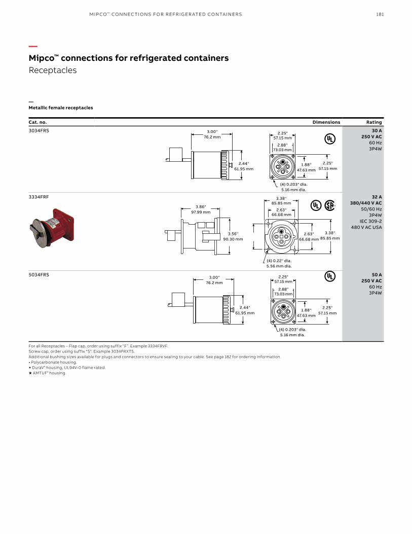
181
—Non-metallic female receptacles
—Metallic female receptacles
Cat. no. Dimensions Rating Cat. no. Dimensions Rating
3034FRXTS 30 A 250 V AC
60 Hz 3P4W
3034FRS 30 A 250 V AC
60 Hz 3P4W
3334FRVS ▲ 32 A 380/440 V AC
50/60 Hz 3P4W
IEC 309-2 480 V AC USA
3334FRF 32 A 380/440 V AC
50/60 Hz 3P4W
IEC 309-2 480 V AC USA
5034FRXTS ★ 50 A 250 V AC
60 Hz 3P4W
5034FRS 50 A 250 V AC
60 Hz 3P4W
6234FRXTS ★ 60 A 250 V AC
60 Hz 3P4W
6434FRXTS ★ 60 A 480 V AC
60 Hz 3P4W
For all Receptacles – Flap cap, order using suffix “F”. Example 3334FRVF. Screw cap, order using suffix “S”. Example 3034FRXTS.Additional bushing sizes available for plugs and connectors to ensure sealing to your cable. See page 182 for ordering information.• Polycarbonate housing.▲DuraV® housing, UL94V-0 flame rated.★ AMTUF® housing.
(4) 0.203" dia.5.16 mm dia.
1.88"47.63 mm
2.44"61.95 mm
3.00" 76.2 mm
2.88" 73.03 mm
2.25"57.15 mm
2.25"57.15 mm
(4) 0.22" dia.5.56 mm dia.
2.63"66.68 mm
3.56"90.30 mm
3.86" 97.99 mm 2.63"
66.68 mm
3.38" 85.85 mm
3.38"85.85 mm
(4) 0.203" dia.5.16 mm dia.
1.88"47.63 mm
2.44"61.95 mm
3.00" 76.2 mm
2.88” 73.03 mm
2.25"57.15 mm
2.25"57.15 mm
—Mipco™ connections for refrigerated containersReceptacles
M I P CO ™ CO N N EC TI O NS FO R R EFR I G ER ATED CO NTA I N ER S

182 R U S S E LL S TO LL® PI N & SL EE V E P OW ER CO N N EC TO R S
—Additional bushing sizes
Cat. no. Washer & bushing I.D. (in.)
B16779AR 0.750
B16779BR 0.875
B16779CR 0.620
B16779DR 0.700
B16779ER 1.000
B16779FR 0.800
B16779GR 0.545
B16779HR 0.925
For 30, 32, 50 and 60 A standard devices.
—Accessories for non-metallic receptacles1
—Accessories for plugs and connectors
—Junction box and straight adapter2
Straight adapter cat. no. Junction box cat. no. Receptacle rating
SAM50 JM99 30 A, 250 V
SAM32 JM99 32 A, 380/440 V (480 V)
SAM50 JM99 50 A, 250 V
SAM60 JM99 60 A, 250 V
SAM60 JM99 60 A, 480 V
—Junction box and straight adapter
Straight adapter cat. no. Junction box cat. no. Receptacle rating
AM50 JM99 30 A, 250 V
AM32 JM99 32A, 380/440 V (480 V)
AM50 JM99 50 A, 250 V
AM60 JM99 60 A, 250 V
AM60 JM99 60 A, 480 V
Notes:1. Does not exclude 32 A metallic receptacles.2. Adapter and junction box may differ from photo.
Angle adapter and junctionbox shown assembled.
JM99
313/16"
415/16"
—Mipco™ connections for refrigerated containersAccessories
Straight adapter and junction box shown assembled.

183
—Female plugs
—Male connectors and receptacles
Cat. no. Dimensions Rating Cat. no. Dimensions
334FP• 30 A250 V AC,
60 Hz3P4W
334MC ▲
30 A250 V AC,
60 Hz3P4W
334MR ▲
534FP• 50 A250 V AC,
60 Hz3P4W
534MC ▲
50 A250 V AC,
60 Hz3P4W
534MR ▲
5.38"136.6 mm
2.38"60.5 mm
4.16"105.7 mm
6.00(152.4)
2.50(63.5)
2.38(60.5)
6.00(152.4)
2.50(63.5)
2.38(60.5)
6.00"153.4 mm
2.38"60.5 mm
2.50"63.5 mm
6.25"158.8mm
2.13"54.1mm
6.25"158.8mm
2.13"54.1mm
6.25"158.8 mm
2.13"54.1 mm
6.25"158.8mm
2.13"54.1mm
6.25"158.8mm
2.13"54.1mm
6.25"158.8mm
2.13"54.1mm
6.25"158.8mm
2.13"54.1mm
2.66"67.6 mm
3.79"96.3 mm
2.4462.0 mm
2.71"68.8 mm
1.88"47.8 mm
4.14"105.2 mm
3.25"82.5 mm
6.25"158.8mm
2.13"54.1mm
6.25"158.8mm
2.13"54.1mm
6.25"158.8mm
2.13"54.1mm
6.25"158.8mm
2.13"54.1mm
2.66"67.6 mm 3.79"
96.3 mm2.44"
62.0 mm
2.71"68.8 mm
1.88"47.8 mm
4.14"105.2 mm
3.25"82.5 mm
6.25"158.8mm
2.13"54.1mm
6.25"158.8mm
2.13"54.1mm
2.13"54.1 mm
6.25"158.8 mm
Note: Many additional bushing sizes available; see page 182.• Polycarbonate housing.▲ DuraV ® housing, UL94V-0 flame rated.★ AMTUF® housing
—Mipco™ connections for refrigerated containersReversed contacts service – 30 A and 50 A, 250 VAC
M I P CO ™ CO N N EC TI O NS FO R R EFR I G ER ATED CO NTA I N ER S

184 R U S S E LL S TO LL® PI N & SL EE V E P OW ER CO N N EC TO R S
Cat. no. Dimensions Rating
3334FRVSMS▲* 32 A380/440 V AC
50/60 Hz,3P4W IEC309-2
480 V AC USA
6234FRMS★* 60 A250 V AC
60 Hz3P4W
* Flap cap also available.• Polycarbonate housing used on 6234FRMS.▲ DuraV® housing used for 3334FRVSMS; replaces 3334FRPSMS.★ AMTUF® housing.
—20 A and Australian
Cat. no. Dimensions Rating Cat. no. Dimensions
Male plugs Female connectors
223MP2 20 A250 V AC,
60 Hz2P3W
223FC2
334MP5 32 AAustralian
standard440/500
V AC,50 Hz3P4W
334FC5
These receptacles include a micro switch mounted at the rear of the interior. The switch is mechanically activated by plug (ground pin) insertion. Applications include electrical
interlocking, control circuits and safe switch or monitor systems. (Micro switch is a separate circuit.)
3.38"85.85 mm
2.63"66.68 mm
(4) 0.22" dia. 5.54 mm dia.
2.63"66.68 mm
3.38"85.85 mm
3.89"96.63 mm
3.55"90.3 mm
2.5"63.5 mm
(4) 0.28" dia. 7.11 mm dia.
5.6"96.63 mm
3.75"95.25 mm
3.5"88.9 mm
2.88"73.03 mm
2.88"73.03 mm
3.5"88.9 mm
—Special rated plugs and connectors
3.87"
2.75"
77 mm 57 mm
15 mm
59 mm
2.16"
4.75"120.7 mm
1.88"47.8 mm
194 mm139 mm
—Mipco™ connections for refrigerated containersFixed receptacles with monitor switches
—Fixed receptacles with monitor switches

185
Flanged connectors are used in many trailer-mount or underslung applications where connector needs to be mounted through a bulkhead plate or other fixed position.
Cat. no. Dimensions Rating
333FCVF▲ 32 A, 380–440 V AC
50/60 Hz, 3P4WIEC 309-2
(480) V AC-USA)
534FCF▲ 50 A, 250 V AC60 Hz, 3P4W
634FC2FXT★ 60 A, 250 V AC60 Hz, 3P4W
634FC4FXTS/0750★ 60 A, 480 V AC60 Hz, 3P4W
* Polycarbonate housing.
▲ DuraV® housing, UL94V-0 flame rated.★ AMTUF® housing.
50"12.7 mm
4.50"114.30 mm
3.50"88.90 mm
2.75"69.85 mm
2.75"69.85 mm
3.50"88.90 mm
8.25"209.55 mm
5.85"48.59 mm
2.75"69.85 mm
2.75"69.85 mm
(4) 0.203" dia.5.16 mm dia.
2.13"53.98 mm
2.13"53.98 mm
2.25"57.15 mm
(4) 0.28" dia.7.11 mm dia.
9.75"247.55 mm
3.75"95.25 mm
3.50"88.90 mm
3.50"88.90 mm
2.88"73.03 mm
2.88"73.03 mm
1.12"28.45 mm
(4) 0.28" dia.7.11 mm dia.
9.75"247.55 mm
3.75"95.25 mm
3.50"88.90 mm
3.50"88.90 mm
2.88"73.03 mm
2.88"73.03 mm
1.12"28.45 mm
—Mipco™ connections for refrigerated containersFlanged connectors
M I P CO ™ CO N N EC TI O NS FO R R EFR I G ER ATED CO NTA I N ER S
—Flanged connectors

186 R U S S E LL S TO LL® PI N & SL EE V E P OW ER CO N N EC TO R S
Cat. no. Dimensions Rating
3260CPV▲ 60 A480 V AC
Female connector
32 A380/440 V Male plug
5060CP 60 A250 V AC
Female connector
50 A250 V AC Male plug
6032CP▲ 32 A380/440 V AC
Female connector
60 A250 V AC Male plug
6050CP 50 A250 V AC
Female connector
60 A250 V AC Male plug
▲ DuraV® housings.
Converter plugs and converter cords facilitate the connection of a plug and receptacle with different ratings. Vessel sharing has become increasingly common, resulting in refrigerated containers with plug configurations that do not match the existing
shipboard or port terminal receptacles. The converter plug eliminates the need for time-consuming and expensive temporary changeovers when these situations are encountered.
—Converter cord sets
Converter cord sets are also available using a Mipco plug and connector, with two feet (0.6 meters) of suitably rated, four-conductor cable.
They are available with any plug/connector combination of the same voltage. Contact Technical Services to specify.
4.07"103.38 mm
5.56"141.22 mm
5.66"143.76 mm
5.56"141.22 mm
3.75"95.25 mm
3.75"95.25 mm
3.80"96.25 mm
5.35"138.89 mm
4.33"109.98 mm
3.80"96.25 mm
5.41"137.41 mm
2.90"73.74 mm
—Mipco™ connections for refrigerated containersConverter plugs
—Converter plugs
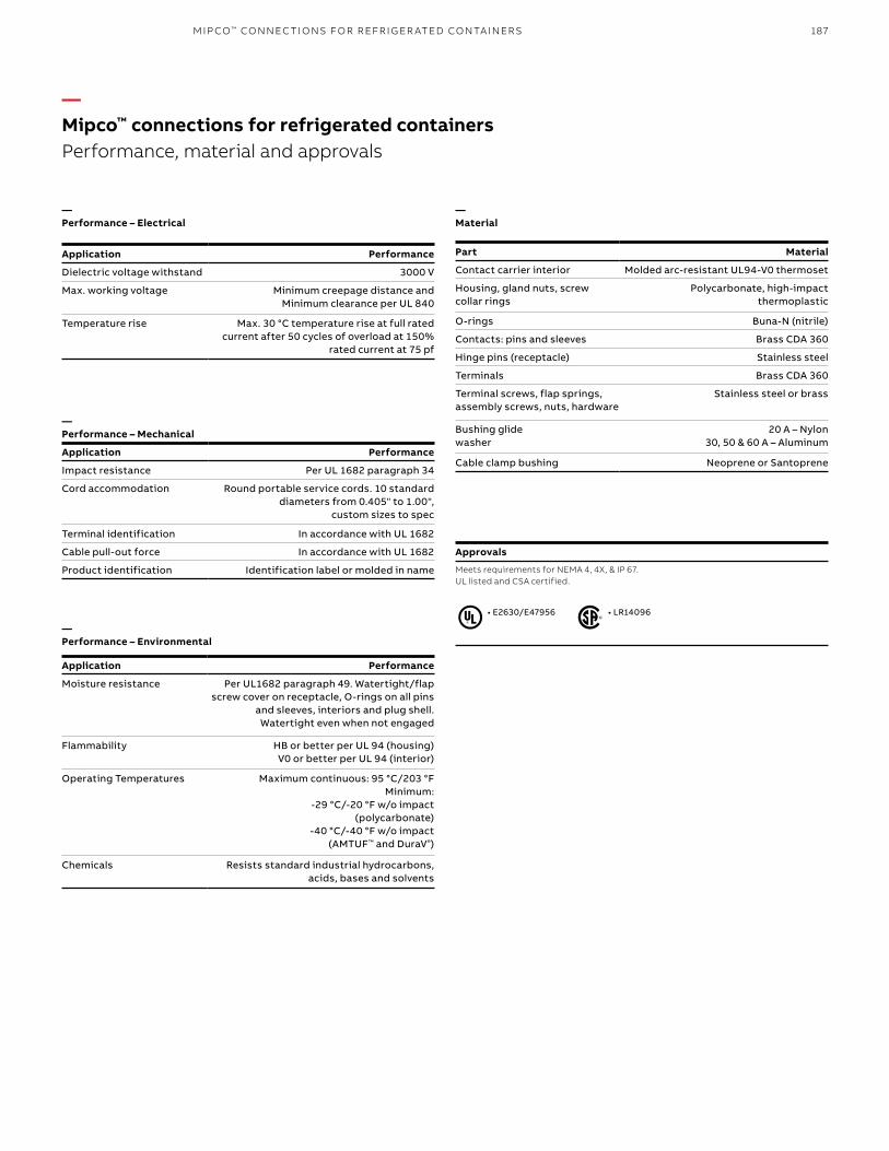
187
—Performance – Electrical
Application Performance
Dielectric voltage withstand 3000 V
Max. working voltage Minimum creepage distance andMinimum clearance per UL 840
Temperature rise Max. 30 °C temperature rise at full rated current after 50 cycles of overload at 150%
rated current at 75 pf
—Performance – Mechanical
Application Performance
Impact resistance Per UL 1682 paragraph 34
Cord accommodation Round portable service cords. 10 standard diameters from 0.405" to 1.00",
custom sizes to spec
Terminal identification In accordance with UL 1682
Cable pull-out force In accordance with UL 1682
Product identification Identification label or molded in name
—Performance – Environmental
Application Performance
Moisture resistance Per UL1682 paragraph 49. Watertight/flap screw cover on receptacle, O-rings on all pins
and sleeves, interiors and plug shell. Watertight even when not engaged
Flammability HB or better per UL 94 (housing)V0 or better per UL 94 (interior)
Operating Temperatures Maximum continuous: 95 °C/203 °FMinimum:
-29 °C/-20 °F w/o impact(polycarbonate)
-40 °C/-40 °F w/o impact (AMTUF™ and DuraV®)
Chemicals Resists standard industrial hydrocarbons, acids, bases and solvents
—Material
Part Material
Contact carrier interior Molded arc-resistant UL94-V0 thermoset
Housing, gland nuts, screw collar rings
Polycarbonate, high-impact thermoplastic
O-rings Buna-N (nitrile)
Contacts: pins and sleeves Brass CDA 360
Hinge pins (receptacle) Stainless steel
Terminals Brass CDA 360
Terminal screws, flap springs, assembly screws, nuts, hardware
Stainless steel or brass
Bushing glidewasher
20 A – Nylon 30, 50 & 60 A – Aluminum
Cable clamp bushing Neoprene or Santoprene
• LR14096• E2630/E47956
—Mipco™ connections for refrigerated containersPerformance, material and approvals
M I P CO ™ CO N N EC TI O NS FO R R EFR I G ER ATED CO NTA I N ER S
Approvals
Meets requirements for NEMA 4, 4X, & IP 67. UL listed and CSA certified.

188 R U S S E LL S TO LL® PI N & SL EE V E P OW ER CO N N EC TO R S
No one does It like MipcoMipco interlocked reefer power outlets are used extensively in port terminals and shipboard applications to provide a safe, watertight electrical connection for refrigerated containers. They feature a heavy-duty, interlocked UL/CSA listed and circuit breaker-protected electrical power outlet. This ensures the outlet cannot be switched “live” until a plug is fully engaged and the actuator rod is pushed to the “on” position. Pulling the actuator rod to the “off” position manually de-energizes the circuit. The circuit de-energizes automatically if the plug is accidentally withdrawn
while in the “on” position. Also, the interlock mechanism “breaks” the circuit while the pin and sleeve contacts are still engaged. This provides total operator safety and protection against shock hazard while eliminating arcing damage to the plug and receptacle.
The modular design pioneered by Mipco allows for quick, easy installation and maintenance. Mipco engineers designed the interlocked reefer power outlet for the utmost safety, durability and reliability.
M433-30F22
M464-30S22
—The Mipco™ advantage
Safety• Interlock mechanism protects against
shock hazard and cannot be overridden like other designs
• Plug cannot be inserted or withdrawn under load; ground pin activates interlock
• Thermoset interiors provide the safest insulation under extreme conditions
• UL 489 listed circuit breaker for optimum operator and circuit protection
• Non-conductive knob is oversize for safe, easy operation
Durability• Heavy-duty 1/2" diameter stainless steel actuator
rod offers superior resistance to corrosion and abuse
• UL 489 listed circuit breaker is resettable after circuit interruption
• Heavy-gauge stainless steel platform and aluminum receptacle housing resists corrosion and physical damage
• O-ring sealed insulator, contact sleeves, ground pin, interlock actuating pin and actuator rod ensure watertight integrity of wiring compartment when screw cover or plug is removed
Reliability• Segmented solid brass contact sleeves with
beryllium copper compression springs minimize heat rise and corrosion
• UL 489 listed circuit breaker provides branch circuit protection per NEC ®
Easy installation and service• Mipco’s “modular design” makes installation
and maintenance fast and inexpensive with easy accessibility to individual parts
• 4-screw, 3-wire receptacle service• One-piece interlock mechanism requires
no adjustment and simplifies maintenance• Complete line of service parts readily available:
- Receptacle assembly - Circuit breaker assembly - Interior assembly - Linkage kits - Hardware kits - Flap cap/screw cap assemblies
NEC and National Electrical Code are registered trademarks of the National Fire Protection Association, Inc.
—Mipco™ connections for refrigerated containersMipco advantage

189
—The compact frame choice with nominal inrush current protection.
Cat. no.M433-30F22 shown
Mechanical interlock mechanism• Protects against shock hazard• Eliminates arcing damage• Automatically de-energizes the
circuit upon plug withdrawal; even if actuating rod is jammed in the on position
Heavy-duty actuating rod• Superior durability
• Located away from the receptacle for maximum operator safety
• Withstands user abuse
Stainless steel self-aligning flap cap
• Ensures a positive environmental seal
• Maximum corrosion resistance• Withstands user abuse
UL 489 listed and CSA certified 22 kAIC circuit breaker• Maximum operator
and circuit protection• Branch circuit
protection per NEC®
Heavy-gauge stainless steel platform• Maximum durability from user abuse• Corrosion resistant
Receptacle mounting design• Easy installation and service
(four stainless steel screws, three wires)
Metallic receptacle housing• Withstands physical abuse• Corrosion resistant
Ground pin actuates interlocking mechanism
• Ensures grounding integrity with ground pin
• Receptacle is de-energized upon plug removal; when plug is
reinserted, switch can be operated
Thermoset interiors• Resist high heat and arcs
O-ring sealed interiors and sleeves• Seals wiring compartment
from environment• Eliminates accidents and burnouts
Segmented contact sleeves with compression springs• Consistent contact pressure• Minimizes heat rise and corrosion• Self-cleaning pins and sleeves for longer life
—Mipco™ connections for refrigerated containers22 kAIC, 480 V interlocked reefer power outlet
M I P CO ™ CO N N EC TI O NS FO R R EFR I G ER ATED CO NTA I N ER S

190 R U S S E LL S TO LL® PI N & SL EE V E P OW ER CO N N EC TO R S
Cat. no.
Amps Voltage ratings Poles, wires Trip rating amps†
Mating plug Cat. no.*Flap cap Screw cap
M432-30F22 M432-30S22 30 250 V, 60 Hz 3P4W 30 334MPXT
M433-30F22 M433-30S22 32 380/440 V 50/60 Hz1 3P4W 30 333MPXT
M452-50F22 M452-50S22 50 250 V, 60 Hz 3P4W 50 534MPXT
M462-50F22 M462-50S22 60 250 V, 60 Hz 3P4W 50 634MP2XT
M464-60F22 M464-60S22 60 480 V, 60 Hz 3P4W 60 634MP4XT
*Mating plugs are sold separately.†Other trip ratings available upon request.1480 V AC/60 Hz US common rating.
7.04"BSee Chart
5.27"
2.69"
6.28"
5.38"
Ø 0.31"
4.38"3 pls
Amperage (A) B (in.)
30 & 50 3.23
32 4.00
60 5.10
—Mipco™ connections for refrigerated containersInterlocks with metallic receptacle housings
M464-30S22M432-30S22 M433-30F22 M452-50S22
Dimensions
Dimensions
—Interlocks with metallic receptacle housings

191
Mipco interlocked reefer power outlet catalog numbers are easily specified using the guide below.Options include auxiliary switch construction.
M _ 4 33 - 30 F 22 _
Indicates field that must be filled in to complete order. Note: Availability of selected configuration will be verified at quotation time.
—Mipco™ connections for refrigerated containersCatalog number construction guide
M I P CO ™ CO N N EC TI O NS FO R R EFR I G ER ATED CO NTA I N ER S
Receptacle housing materialMetallic: Copper-free, cast aluminum; 32 & 60 A modules only; Brass: 30 & 50 A modules only M
Optional module styleOmit for standard interlock“T” style, center push-rod module, 32 A only T
Receptacle rating/configuration 30 A, 250 V AC, 50/60 Hz 3232 A, 380/440 V, 50/60 Hz 3350 A, 250 V AC, 50/60 Hz 5260 A, 250 V AC, 50/60 Hz 6260 A, 440/48 V AC, 50/60 Hz 64
Circuit breaker trip rating30 A 3050 A 5060 A 60Note: Breaker trip rating will not exceed receptacle rating.
Circuit breaker In-rush current rating 18 kAIC at 480 V AC – shock resistant, 15 G 1822 kAIC at 480 V AC (65 kAIC at 250 V AC) 2265 kAIC at 480 V AC 65
Poles/wires3 pole, 4 wire 4
OptionsAuxiliary switch PA
Receptacle coverFlap cap FScrew cap S

192 R U S S E LL S TO LL® PI N & SL EE V E P OW ER CO N N EC TO R S
Cat. no.
Amps Voltage ratings Poles, wires Trip rating amps
Mating plug Cat. no.*Flap cap Screw cap
1BM432-30F22 1BM432-30S22 30 250 V, 60 Hz 3P4W 30 334MPXT
1BM433-30F22 1BM433-30S22 32 380/440 V 50/60 Hz1 3P4W 30 333MPXT
1BM452-30F22 1BM452-30S22 50 250 V, 60 Hz 3P4W 50 534MP2XT
1BM462-30F22 1BM462-30F22 60 250 V, 60 Hz 3P4W 60 634MP4XT
1BM464-30F22 1BM464-30S22 60 480 V, 60 Hz 3P4W 60 634MPXT
* Mating plugs are sold separately.1 480 V AC/60 Hz US common rating.
1BM432-30F22
—Mipco™ connections for refrigerated containersInterlocks complete with single-gang cast aluminum closure
7.00
9.38
6.25 6.75
11.75
2.00
9.38"
6.25"7.00"7.00
9.38
6.25 6.75
11.75
2.00
6.75"
2.00"
11.75"
Dimensions
—Interlocks complete with single-gang cast aluminum closure

193
Cat. no. Rating
SR33341B 32 A, 380–440 V AC50/60 Hz, 3P4W
IEC309-2, 3h480 V AC USA
SR33341B
Cast aluminum (or brass) switched interlocked used for trailer, rail and common-feed shipboard applications. Circuit protection normally is upstream of load.
—Accessories
Single-gang enclosures – Copper-free cast aluminum for maximum corrosion resistance and durability, these can be ordered separately or complete with interlocked outlet by using a “1B" prefix with any interlocked outlet catalog number.Wedge gaskets – Molded neoprene wedge gaskets provide drainage 4° down angle for interlocked outlets; easily installed behind front plate.Large-frame adapter plate kit – Stainless steel adapter plate kit allows small-frame 6-bolt interlocked outlets to replace large-frame 8-bolt outlets. Kit bolts to existing 8-bolt enclosure opening.
Outlet frame size
Cat. no.
Single enclosure
Wedge gasket kit
8-bolt adapter kit
Small frame, 6-bolt 1255-01R 980-50R 523R
—Mipco™ connections for refrigerated containersSpecial rotary switch interlocks
Ground Lug
.37" Typ. Ref.9.40mm
9.60" Ref.243.80mm
6.43" Ref.163.30m
4.62" Ref.117.30mm
3.44" Ref.87.40mm
1.25" Ref.31.70mm
.75 N.P.T.
7.00" Ref177.80mm
2.00" Ref50.80mm
3.44" ref. 87.40 mm
1.25" ref. 31.70 mm
7.00" ref. 177.80 mm
2.00" ref. 50.80mm
.75 N.P.T.
Ground Lug
.37" Typ. Ref.9.40mm
9.60" Ref.243.80mm
6.43" Ref.163.30m
4.62" Ref.117.30mm
3.44" Ref.87.40mm
1.25" Ref.31.70mm
.75 N.P.T.
7.00" Ref177.80mm
2.00" Ref50.80mm
6.43"ref. 163.30 mm
4.62" ref. 117.30 mm
9.60" ref. 243.80 mm
0.37" Typ. ref. 9.40 mm
Ground lug
M I P CO ™ CO N N EC TI O NS FO R R EFR I G ER ATED CO NTA I N ER S
Dimensions
—Special rotary switch interlocks

194 R U S S E LL S TO LL® PI N & SL EE V E P OW ER CO N N EC TO R S
—Performance – Electrical
Application Performance
Dielectric voltage withstand 3000 V
Max. working voltage 480 V AC
Circuit protection UL 489 listed, CSA certified circuit breaker
Fla interrupting capacity Specified breaker rating
Short circuit withstand rating 22,000 AIC or 18,000 AIC (shock resistant)
Operations >10,000 cycles at rated current
—Performance – Mechanical
Application Performance
Mounting (6) 5/16" diameter through holes
Breaker terminals Pressure screw lugs (slotted) accept #14–1/0 AWG wire
Terminal identification In accordance with UL489 and UL1682 A, B, C, G (earth ground) on line side
Product identification External label on face plate
Operations >25,000 cycles of operation
—Performance – Environmental
Application Performance
Moisture Watertight screw cover or spring-loaded self-aligning flap cap. O-rings on all
sleeves, interior, interlock actuating pin and circuit breaker actuator rod
bushings. Gasket on receptacle and module flange
Operating temperatures Min. continuous -20 °F (non-enclosed) Max. continuous +140 °F
Chemicals Resists common industrial hydrocarbons, acids, bases and solvents
UV resistance Polyurethane enamel (32 A) and natural metallic finishes provide maximum
UV protection
—Materials
Part Material
Receptacle housing metallic 30 A/50 A – Brass (natural) 32 A – Copper-free aluminum
356-T6 (red epoxy powder coated) 60 A – Copper-free aluminum
356-T6 (natural)
Non-metallic 30 A/50 A & 60 A – AMTUF™ 32 A – DuraV®
Interior Molded arc-resistant thermoset phenolic (UL 94-V0 flame rating)
Contact sleeves Brass with beryllium copper compression springs
Terminal screws Brass, slotted
O-rings Buna-N (nitrile)
Gaskets Neoprene
Mounting platform Heavy-gauge stainless steel welded construction
Actuator rod 1/2"-inch diameter solid stainless steel. Heavy-duty non-conductive impact-
resistant plastic knob
Ground lug Aluminum terminal screw (slotted) accepts up to #2 AWG wire
Interlock mechanism Sealed self-lubricating thermoplastic
Flap cap 12-gauge stainless steel, gasketed cover
Screw cap High-impact plastic, gasketed
Washers Nylon
Springs, fasteners Stainless steel
Approvals
Underwriters Laboratory (UL) – Sections 489, 1682 and 1686CSA Section – C22.2–182.1 Federal Department of Transportation – Federal register volume 47, number 68, subpart 11.79 United States Coast Guard (USCG)International Electro-Technical Commission (IEC) – 32-amp devices conform to IEC 309-1 and 309-2International Standards Organization (ISO) – ISO 1496/2, Annex 1
—Mipco™ connections for refrigerated containersPerformance, materials and approvals
• LR96445• E47955

195
1.0 Scope1.1 This document covers pin and sleeve marine/
industrial-grade reefer power outlet assemblies. Usable in dry, damp, wet, outdoor marine locations for providing electrical power to refrigerated containers. Assemblies shall be UL listed with enclosures incorporating interlocked reefer power outlets in a modular multi-gang arrangement. Devices are factory wired to a UL recognized power distribution block and rated 30, 32, 50 and/or 60 A at 250 or 480 V AC, 50–60 Hz. Devices are also rated for continuous use in temperatures from -20 ˚F to +140 ˚F. These devices must provide internal environmental seals for marine and extreme wet applications and are to be mechanically interlocked.
1.2 All assemblies specified shall be manufactured by Mipco™ as complete assemblies and shall be marked as stated.
2.0 Product classificationEnclosures:2.1 Construction – All enclosures shall be specified
either 12 or 14 gauge stainless steel and shall conform to NEMA 4X requirements for watertight, dust-tight and corrosion resistance.
2.2 Access panel – Each enclosure shall provide an access panel designed to allow complete wiring compartment accessibility. Bolted plate or hinged panel to be specified.
2.3 Power distribution block – All interlocked reefer power outlet assemblies shall be factory wired to a UL recognized power distribution block. Line lugs shall accommodate a range of wire sizes compatible with the total amperage rating of all enclosed receptacles
Receptacles2.4 Interlocked receptacles – The receptacles shall be
of a modular design, mechanically interlocked to allow the circuit to be energized only after a mating plug is fully inserted into the receptacle and the actuating rod is pushed forward. All interlocked receptacles shall allow the de-energizing of the circuit before mated contacts are disengaged upon plug removal. Plug ground pin will activate interlock mechanism. The mounting dimensions shall be the same for interlocked receptacles with a high (65K) or nominal (greater than or equal to 20K) inrush current circuit breaker to allow for future upgrades.
2.5 Grounding – The grounding of the device shall be accomplished through a separate ground (earth) that will “make first,” “break last.” Plug ground pin will activate interlock mechanism. The ground pole shall be bonded to a UL recognized ground block labeled for connection to the ground conductor. All non-current carrying metallic components must be grounded to ensure complete system grounding.
2.6 Housings – Receptacle housings shall be metallic, copper-free aluminum or thermoplastic with performance equal to or greater than DuraV® or AMTUF™, and have a flame rating no less than UL94 V0.
2.7 Interiors – Receptacle interiors must be molded thermoset UL94 V0 and be replaceable for ease of maintenance.
2.8 Contact sleeves – Quad-slit brass contact sleeves shall have contact pressure springs of electromotively similar material to maintain consistent contact pressure between sleeves and mating male pins and prevent galvanic corrosion.
2.9 Environmental seals – Each device must have an environmental seal or O-ring around all interiors and around each sleeve to prevent water and contaminants from entering the wiring compartment. The seals shall provide waterproof capability if plug or screw cap are removed.
2.10 Circuit protection – Each interlocked receptacle must be protected by a molded cased, thermal-magnetic type UL 489 listed circuit breaker. The circuit breaker must also comply with NEC® Articles 240 and 430 for branch circuit protection.
2.10a High inrush current protection requirements – Circuit breaker shall have a minimum 65,000 A interrupting capacity.
2.10b Nominal inrush current protection requirements – Circuit breaker shall have a minimum (18,000 A high shock) 22,000 A interrupting capacity.
2.11 Flap cover or screw cover option – Flap cover option must provide weather-tight capability to the exposed contacts by utilizing a spring-actuated self-closing flap. Watertight capability shall be obtained by using a gasketed screw cap.
—Mipco™ connections for refrigerated containersEngineering specifications
M I P CO ™ CO N N EC TI O NS FO R R EFR I G ER ATED CO NTA I N ER S

196 R U S S E LL S TO LL® PI N & SL EE V E P OW ER CO N N EC TO R S
3.0 Design and wiring requirements3.1 Wiring – All enclosure assemblies must be factory
wired to conform to guidelines stated in the NEC® for wire sizing, Table 310-16 and wire bending space, Article 373-6. Wiring of individual interlocked reefer outlets must allow for the removal/replacement without opening the access door.
3.2 Conduit entry – Assemblies shall include a conduit entrance with an aluminum conduit hub; size and location to be specified.
4.0 Applicable compliances4.1 Underwriters Laboratories (UL) – The enclosure
assemblies specified herein shall be listed in applicable sections of UL Standards 489, 1682 and 1686.
4.2 Canadian Standard Association (CSA) – The devices shall be listed in the applicable sections of CSA C22.2-182.1.
4.3 American Bureau of Shipping (ABS) 4.4 Federal Department of Transportation – Devices
shall comply with Federal Register volume 47, number 68, subpart 11.79 and the United States Coast Guard (USCG).
4.5 International Electro-Technical Commission (IEC) – The 32-ampere devices specified shall conform to IEC 309-1 and IEC 309-2, EN60309.
4.6 International Standards Organization (ISO) – The 32-ampere devices specified shall conform to ISO 1496/2, Annex L.
NEC is a registered trademark of the National Fire Protection Association, Inc.
—Mipco™ connections for refrigerated containersEngineering specifications (continued)

197N OTE S
—Notes

198 R U S S E LL S TO LL® PI N & SL EE V E P OW ER CO N N EC TO R S
Additional informationWe reserve the right to make technical changes or modify the contents of this document without prior notice. With regard to purchase orders, the agreed particulars shall prevail. ABB AG does not accept any responsibility whatsoever for potential errors or possible lack of information in this document.
We reserve all rights in this document and in the subject matter and illustrations contained therein. Any reproduction, disclosure to third parties or utilization of its contents – in whole or in parts – is forbidden without prior written consent of ABB AG.

199

© Copyright 2018 ABB. All rights reserved. Specifications subject to change without notice. 7T
KK
00
015
6 R
EV
A 2
1.9
.20
18
—USABB Installation ProductsElectrification Products division860 Ridge Lake Blvd.Memphis, TN 38120+1 901-252-5000 tnb.abb.com