SMP & SMPM connectors - Delta RF
28
-
Upload
khangminh22 -
Category
Documents
-
view
1 -
download
0
Transcript of SMP & SMPM connectors - Delta RF


SMP / SMPM Applications
Custom Gang Mounted Female Cable Assemblies - Harness groups of cable assemblies
- Keying Features built - in for proper port alignment - Available for termination to numerous flexible & conformable cable assemblies
- Terminates to variety of other RF connector interfaces
PC Mounted - Available in a variety of mounting configurations
Edge Mount Male Connectors- Provides RF interface at board edge - Ideal for low profile board stacking
Right Angle Female Cable Connectors- Simplifies transition to coax cable - Low profile bend for limited space requirements- Bulkhead mounting feature
Hermetically Sealed Bulkhead Mounted- Engineered for exposed environments - Available in numerous mounting configurations - Available in numerous termination styles
Straight Female Cable Connectors- Simplifies transition to coax cable - Available for termination to numerous flexible, semi-rigid, & conformable cable
2 Hole Flange Mounted Male Receptacles
- Available in standard flange sizes - Easily substitute existing RF interfaces with SMP /SMPM series
-Reduces port to port spacing requirements
“Spring Loaded” Female to Female Bullet Adapters - Increases axial float while minimizing electrical degradation
4 Hole Flange Mounted Male Receptacles - Available in standard flange sizes
- Easily substitute existing RF interfaces with SMP /SMPM series - No modification needed to existing housings
Custom Gang Mounted PCB Males -Simplifies PC assembly
-Sets port to port spacing - No soldering
- Mechanically secured to PC Board - Customized for specific applications
SMP/SMPM Application NotesSMP & SMPM connectors are excellent choices for PC board to board interconnects, as well as module to module interconnects. The unique interface constructions allow for minimal electrical degradation when maximum misalignment occurs. Their overall profile allows for system designers to fit these interconnects in to tighter packaging than the majority of micro-minature RF connectors. Both the SMP and SMPM come in a variety of configurations, each with specific features for whatever engineering challenge a designer is facing.
Delta took this into consideration when developing this catalog and provides any combination of configuration to meet our customers’ needs. Whether you are interfacing in an exposed environment, increasing package density, reducing weight or improving performance at higher frequencies, Delta’s complete line of SMP / SMPM connectors provides a solution. Current applications utilizing the SMP / SMPM connectors include Military / Aerospace, Medical, Networking and Telecommunications.
Applications
2 Delta Electronics Mfg. Corp. deltarf.com 978-927-1060 [email protected]

SMP Specifications
SMP
General Description.................................... 1
Interface Dimensions.................................. 2
Electrical & Mechanical Specifications......... 3
Test Data.................................................... 3
Cable Mount Connectors........................... 4-6
Shrouds...................................................... 7-8
Accessory Pins............................................ 8
Hermetically Sealed Connectors.................. 8
Panel Mounts.............................................. 9
PC Board Mounts ...................................... 10
Edge Mounts.............................................. 11
Female to Female “Bullet” Adapters............ 11
Spring Loaded F to F “Bullet” Adapters...... 12
SMPM
Interface Dimensions.................................. 13
General Description.................................... 13
Electrical & Mechanical Specifications......... 14
Test Data.................................................... 14
Cable Connectors....................................... 15
Shroud(s).................................................... 16
Thread-In Male........................................... 16
Hermetically Sealed.................................... 16-17
Panel Mounts.............................................. 17-18
Surface / Float Mount Female .................... 19
Surface Mount Males.................................. 20
Female to Female Bullet Adapters............... 21
Assembly Procedures................................ 21-23
Index By Delta P/N................................... 23
Notes......................................................... 24
SMP Connectors DC - 40 GHz
Subminiature Modular Plug-in style microwave connectors allow devices to be connected in a modular fashion, without the need for cables or threaded coupling mechanisms.
Central to the SMP design is the floating female to female “Bullet” adapter. This adapter, available in
the interface. The adapter is mated between two males connectors allowing simultaneous multiple microwave interconnects with a minimum center to center spacing of .170 of an inch. This series is ideal for high density module to module or board to board interconnects.
Delta’s SMP series is designed in accordance with DSCC 94007, 94008 and Mil-STD-348A. The SMP interface is available in (3) levels of retention: Full Detent (FD) for maximum retention Limited Detent (LD) for medium retentionSmooth Bore (SB) for minimum retention Also available, for applications requiring maximum self alignment during mating:Catchers Mitt (CM) entry & the absolute minimum retention
increased axial & radial float while maintaining the full mechanical properties of the standard bullet . (see page 12 for details).
General Description
Table of Contents
3
4 Delta Electronics Mfg. Corp. deltarf.com 978-927-1060 [email protected]
SMP Specifications
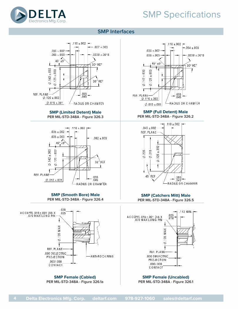
SMP (Limited Detent) MalePER MIL-STD-348A - Figure 326.3
SMP (Full Detent) MalePER MIL-STD-348A - Figure 326.2
SMP (Smooth Bore) MalePER MIL-STD-348A - Figure 326.4
SMP (Catchers Mitt) MalePER MIL-STD-348A - Figure 326.5
SMP Female (Cabled)PER MIL-STD-348A - Figure 326.1a
SMP Female (Uncabled)PER MIL-STD-348A - Figure 326.1
SMP Interfaces

5
SMP Specifications
Electrical Specifications:Nominal Impedance: 50 ohmsFrequency Range: DC-40 GHzTypical VSWR: 1.20 Max thru 26.5 GHz ; 1.5 Max thru 40 GHzInsulation Resistance: 5,000 megohmsDWV (@sea level) : 500 VrmsPower Handling: (@sea level & ambient temperature) : 120W – 5.5f (frequency)RF Leakage: -80db to 3 GHz, -65db to 26.5 GHz
Mechanical Specifications:Durability: 100 min (FD) ; 500 min (LD) ; 1000 (SB & CM) Force to Engage: 9.0 lbs typ (FD) ; 7.0 lbs typ (LD) ; 5.0 lbs typ (SB & CM)Force to Disengage: 7.0 lbs typ (FD) ; 5.0 lbs typ (LD) ; 0.5 lbs typ (SB & CM)Contact Retention: 2 lbs min.Minimum Center Line to Center Line Spacing: .156”Radial Misalignment: +/- .010” Axial Misalignment: .010” Max
Materials:Bodies/Shrouds: Beryllium Copper Per ASTM B196 and/or ASTM B197 or Stainless Steel type 303, Condition A Outer Contacts: Beryllium Copper Per ASTM B196 or ASTM B197Center Contacts: Beryllium Copper Per ASTM B196 or ASTM B197Insulators: PTFE Fluorocarbon per ASTM D1710
Finishes:Bodies: Gold Plate per MIL-G-45204, over Nickel Plate per SAE AMS-QQ-N-290 or Passivated per AMS-QQ-P-35
Contacts: Gold Plate per MIL-G-45204, over Nickel Plate per SAE AMS-QQ-N-290
Environmental Specifications:Temperature Range: -65° C to +165° C Shock: Meets MIL-STD-202 Method 213, Condition IVibration: Meets MIL-STD-202 Method 204, Condition DAltitude: Meets MIL-STD-202, Method 105 Condition CThermal Shock: Meets MIL-STD-202, Method 107 Condition B
Delta Electronics Manufacturing’s SMP interfaces are in accordance with DSCC 94007, 94008 and MIL-STD-348A.
*These specifications are typical and may not apply to all connectors. Detailed specifications for individual connectors are available upon request.
SMP “Bullet” adapter tested using an SMK (2.92) female to a SMP male and a 2.92 calibration kit. The adapters are gated out and the VSWR plot shown is representative of the “Bullet” adapter only. These results are typical and valid only for connectors set up for testing in the configuration shown. Other
Frequency (Ghz)
VS
WR
SMK Female to SMP (FD) Male Adapter
Delta P/N 8628000G001 - 002
As Tested
Test Setup
Electrical and Mechanical Specifications*
SMP Test Data
1.2
0 2713.55.4 21.6
1.1
1.3
1.4
1.5
1.6
1.7
1.0
6 Delta Electronics Mfg. Corp. deltarf.com 978-927-1060 [email protected]
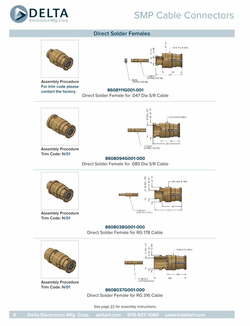
SMP Cable Connectors
8608111G001-001Direct Solder Female for .047 Dia S/R Cable
8608094G001-000Direct Solder Female for .085 Dia S/R Cable
8608038G001-000Direct Solder Female for RG 178 Cable
8608037G001-000Direct Solder Female for RG 316 Cable
See page 22 for assembly instructions.
Assembly ProcedureFor trim code pleasecontact the factory.
Assembly ProcedureTrim Code: N/01
Assembly ProcedureTrim Code: N/01
Assembly ProcedureTrim Code: N/01
Direct Solder Females

SMP Cable Connectors
8676111G001-000R/A Female for .047 Dia S/R Cable
8676037G001-000R/A Female RG 316 Cable
8601094G001-000Direct Solder Panel Mount FD Male for .085 Dia S/R Cable
See page 21 & 22 for assembly instructions.
Assembly ProcedureTrim Code: J/05
Assembly ProcedureTrim Code: J/05
Assembly ProcedureTrim Code: N/01
Cable Mount Male & Female - Direct Solder
7 Delta Electronics Mfg. Corp. deltarf.com 978-927-1060 [email protected]

SMP Cable Connectors
8672111G001-XXXR/A Male for .047 Dia S/R Cable
8672094G001-XXXR/A Male for .085 S/R Cable
8672037G001-XXXR/A Male for RG 316 Cable
See page 21 for assembly instructions.
Assembly ProcedureTrim Code: J/05
Assembly ProcedureTrim Code: J/05
Assembly ProcedureTrim Code: J/05
Right Angle Cable Mount Males
DashNumber
InterfaceType
-003 CM
-002 SB
-001 LD
-000 FD
DashNumber
InterfaceType
-003 CM
-002 SB
-001 LD
-000 FD
DashNumber
InterfaceType
-003 CM
-002 SB
-001 LD
-000 FD
8 Delta Electronics Mfg. Corp. deltarf.com 978-927-1060 [email protected]

SMP Shrouds
8600000G003-XXXSolder-On Shroud
8624000K910 - XXXThread-In Shroud - Passivated Steel
Please contact the factory for mounting instructions. - See page 8 for accessory pins
Shrouds
DashNumber
Dimensions InterfaceTypeA B
-012 .040 .150 SB
-011 .040 .150 LD
-010 .040 .150 FD
-009 .030 .140 SB
-008 .030 .140 LD
-007 .030 .140 FD
-006 .020 .130 SB
-005 .020 .130 LD
-004 .020 .130 FD
-003 .010 .120 SB
-002 .010 .120 LD
-001 .010 .120 FD
Delta P/NDimensions
Thread SMP Interface TypeA B C
8624000K910-016 .040 .150 .190 12-56-UNS-2A Catcher’s Mitt
8624000K910-015 .030 .140 .190 12-56-UNS-2A Catcher’s Mitt
8624000K910-014 .020 .130 .190 12-56-UNS-2A Catcher’s Mitt
8624000K910-013 .010 .120 .190 12-56-UNS-2A Catcher’s Mitt
8624000K910-012 .040 .150 .154 10-48-UNS-2A Smooth Bore
8624000K910-011 .040 .150 .154 10-48-UNS-2A Limited Detent
8624000K910-010 .040 .150 .154 10-48-UNS-2A Full Detent
8624000K910-009 .030 .140 .154 10-48-UNS-2A Smooth Bore
8624000K910-008 .030 .140 .154 10-48-UNS-2A Limited Detent
8624000K910-007 .030 .140 .154 10-48-UNS-2A Full Detent
8624000K910-006 .020 .130 .154 10-48-UNS-2A Smooth Bore
8624000K910-005 .020 .130 .154 10-48-UNS-2A Limited Detent
8624000K910-004 .020 .130 .154 10-48-UNS-2A Full Detent
8624000K910-003 .010 .120 .154 10-48-UNS-2A Smooth Bore
8624000K910-002 .010 .120 .154 10-48-UNS-2A Limited Detent
8624000K910-001 .010 .120 .154 10-48-UNS-2A Full Detent
9 The Delta Di erence - Delivering Interconnect Solutions That Make A Di erence
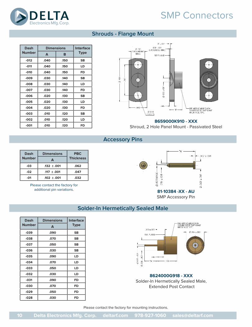
SMP Connectors
8659000K910 - XXX Shroud, 2 Hole Panel Mount - Passivated Steel
8624000G918 - XXXSolder-In Hermetically Sealed Male,
Extended Post Contact
Please contact the factory for mounting instructions.
81-10384 -XX - AUSMP Accessory Pin
Please contact the factory foradditional pin variations.
DashNumber
Dimensions InterfaceTypeA B
-012 .040 .150 SB
-011 .040 .150 LD
-010 .040 .150 FD
-009 .030 .140 SB
-008 .030 .140 LD
-007 .030 .140 FD
-006 .020 .130 SB
-005 .020 .130 LD
-004 .020 .130 FD
-003 .010 .120 SB
-002 .010 .120 LD
-001 .010 .120 FD
DashNumber
Dimensions InterfaceTypeA
-039 .090 SB
-038 .070 SB
-037 .050 SB
-036 .030 SB
-035 .090 LD
-034 .070 LD
-033 .050 LD
-032 .030 LD
-031 .090 FD
-030 .070 FD
-029 .050 FD
-028 .030 FD
DashNumber
Dimensions PBCThicknessA
-03 .132 ± .001 .062
-02 .117 ± .001 .047
-01 .102 ± .001 .032
Shrouds - Flange Mount
Accessory Pins
Solder-In Hermetically Sealed Male
10 Delta Electronics Mfg. Corp. deltarf.com 978-927-1060 [email protected]
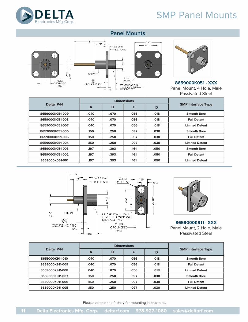
SMP Panel Mounts
8659000K051 - XXXPanel Mount, 4 Hole, Male
Passivated Steel
Please contact the factory for mounting instructions.
8659000K911 - XXXPanel Mount, 2 Hole, Male
Passivated Steel
Panel Mounts
Delta P/NDimensions
SMP Interface TypeA B C D
8659000K051-009 .040 .070 .056 .018 Smooth Bore
8659000K051-008 .040 .070 .056 .018 Full Detent
8659000K051-007 .040 .070 .056 .018 Limited Detent
8659000K051-006 .150 .250 .097 .030 Smooth Bore
8659000K051-005 .150 .250 .097 .030 Full Detent
8659000K051-004 .150 .250 .097 .030 Limited Detent
8659000K051-003 .197 .393 .161 .050 Smooth Bore
8659000K051-002 .197 .393 .161 .050 Full Detent
8659000K051-001 .197 .393 .161 .050 Limited Detent
Delta P/NDimensions
SMP Interface TypeA B C D
8659000K911-010 .040 .070 .056 .018 Smooth Bore
8659000K911-009 .040 .070 .056 .018 Full Detent
8659000K911-008 .040 .070 .056 .018 Limited Detent
8659000K911-007 .150 .250 .097 .030 Smooth Bore
8659000K911-006 .150 .250 .097 .030 Full Detent
8659000K911-005 .150 .250 .097 .030 Limited Detent
11 Delta Electronics Mfg. Corp. deltarf.com 978-927-1060 [email protected]

SMP PCB Males
Please contact the factory for mounting instructions.
Figure 2
8668000G91P - XXXSurface Mount
Figure 1
8668000G001 - XXXPCB Feed Through
8667000G91P - XXXSurface Mount Male - Right Angle Tab Contact
PCB Mount Males
Figure Delta P/NDimensions
SMP Interface TypeA B
1
8668000G001-025 .235 .140 Catcher’s Mitt
8668000G001-024 .218 .140 Smooth Bore
8668000G001-023 .218 .140 Full Detent
8668000G001-022 .218 .140 Limited Detent
8668000G001-021 .235 .100 Catcher’s Mitt
8668000G001-020 .218 .100 Smooth Bore
8668000G001-019 .218 .100 Full Detent
8668000G001-018 .218 .100 Limited Detent
8668000G001-017 .235 .079 Catcher’s Mitt
8668000G001-016 .218 .079 Smooth Bore
8668000G001-015 .218 .079 Full Detent
8668000G001-014 .218 .079 Limited Detent
2
8668000G91P-017 .235 Catcher’s Mitt
8668000G91P-016 .218 Smooth Bore
8668000G91P-015 .218 Full Detent
8668000G91P-014 .218 Limited Detent
DashNumber
Dimensions InterfaceTypeA B C
-013 .235 .275 .200 CM
-012 .162 .200 .150 SB
-011 .162 .200 .150 FD
-010 .162 .200 .150 LD
12 Delta Electronics Mfg. Corp. deltarf.com 978-927-1060 [email protected]
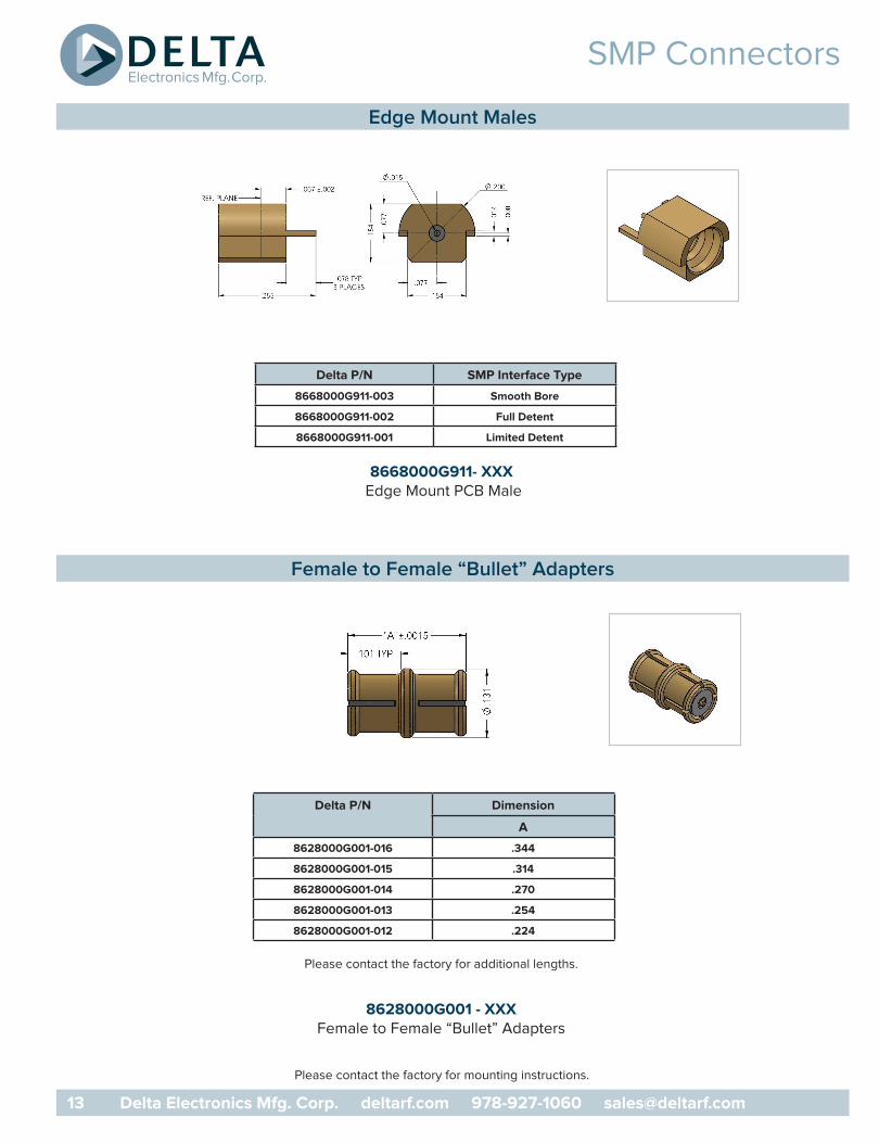
SMP Connectors
8668000G911- XXX Edge Mount PCB Male
8628000G001 - XXXFemale to Female “Bullet” Adapters
Please contact the factory for additional lengths.
Please contact the factory for mounting instructions.
Edge Mount Males
Female to Female “Bullet” Adapters
Delta P/N SMP Interface Type
8668000G911-003 Smooth Bore
8668000G911-002 Full Detent
8668000G911-001 Limited Detent
Delta P/N Dimension
A
8628000G001-016 .344
8628000G001-015 .314
8628000G001-014 .270
8628000G001-013 .254
8628000G001-012 .224
13 Delta Electronics Mfg. Corp. deltarf.com 978-927-1060 [email protected]

SMP “Bullet” Adapters
VSWR: 1.5:1 Max
Frequency Range: DC - 26.5 GHz
Float: Axial .075 / Radial .015
Feature: • Increased axial & radial float • One side has as a low insertion SMP interface• High compression load on interfaces
Benefit:• Enhanced self alignment during mating • Consistently un-mate from the same end• Improved VSWR at higher frequencies
Please contact the factory for additional lengths.
8628000G911 - XXXSpring Loaded Female to Female “Bullet” Adapter
VSWR
Compressed
Frequency (Ghz) Frequency (Ghz)
VS
WR
VS
WR
Spring Loaded - SMP Female to Female “Bullet” Adapter
DeltaP/N
UncompressedLength
Fully CompressedLength
8628000G911-005 1.075 1.000
8628000G911-004 .675 .600
1.2
0 2713.55.4 21.6
1.1
1.3
1.4
1.5
1.6
1.7
1.0
Uncompressed
1.2
0 2713.55.4 21.6
1.1
1.3
1.4
1.5
1.6
1.7
1.0
14 Delta Electronics Mfg. Corp. deltarf.com 978-927-1060 [email protected]

SMPM Specifications
SMPM (Limited Detent) Male SMPM (Full Detent) MalePER MIL-STD-348A - Figure 328.2
SMPM (Smooth Bore) MalePER MIL-STD-348A - Figure 328.3
SMPM (Catchers Mitt) Male
SMPM Female PER MIL-STD-348A - Figure 328.1
SMPM Connectors DC - 65 GHzSimilar in functionality to the SMP series, the SMPM
frequency range of DC to 65 GHz. Center to center mounting spacing is also reduced to .125 of an inch. This gives the SMPM series a distinct advantage in higher density module to module and board to board microwave applications.
For higher frequency board to board applications that require the minimum distance between boards, Delta
see Delta # 8869000G001-001 on page19 for details.
SMPM Interfaces
15 Delta Electronics Mfg. Corp. deltarf.com 978-927-1060 [email protected]
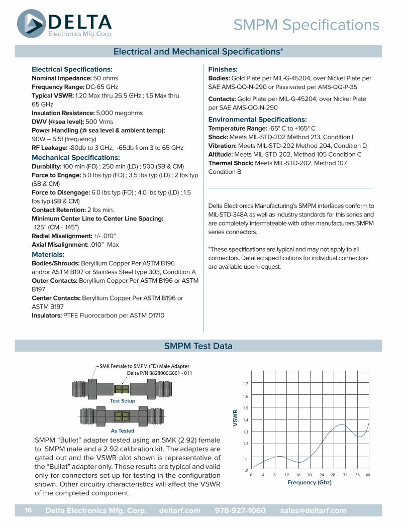
SMPM Specifications
Electrical Specifications:Nominal Impedance: 50 ohms
Frequency Range: DC-65 GHz
Typical VSWR: 1.20 Max thru 26.5 GHz ; 1.5 Max thru
65 GHz
Insulation Resistance: 5,000 megohms
DWV (@sea level): 500 Vrms
Power Handling (@ sea level & ambient temp):
90W – 5.5f (frequency)
RF Leakage: -80db to 3 GHz, -65db from 3 to 65 GHz
Mechanical Specifications:Durability: 100 min (FD) ; 250 min (LD) ; 500 (SB & CM)
Force to Engage: 5.0 lbs typ (FD) ; 3.5 lbs typ (LD) ; 2 lbs typ
(SB & CM)
Force to Disengage: 6.0 lbs typ (FD) ; 4.0 lbs typ (LD) ; 1.5
lbs typ (SB & CM)
Contact Retention: 2 lbs min.
Minimum Center Line to Center Line Spacing:
.125” (CM - .145”)
Radial Misalignment: +/- .010”
Axial Misalignment: .010” Max
Materials:Bodies/Shrouds: Beryllium Copper Per ASTM B196
and/or ASTM B197 or Stainless Steel type 303, Condition A
Outer Contacts: Beryllium Copper Per ASTM B196 or ASTM
B197
Center Contacts: Beryllium Copper Per ASTM B196 or
ASTM B197
Insulators: PTFE Fluorocarbon per ASTM D1710
Finishes:Bodies: Gold Plate per MIL-G-45204, over Nickel Plate per
SAE AMS-QQ-N-290 or Passivated per AMS-QQ-P-35
Contacts: Gold Plate per MIL-G-45204, over Nickel Plate
per SAE AMS-QQ-N-290
Environmental Specifications:Temperature Range: -65° C to +165° C
Shock: Meets MIL-STD-202 Method 213, Condition I
Vibration: Meets MIL-STD-202 Method 204, Condition D
Altitude: Meets MIL-STD-202, Method 105 Condition C
Thermal Shock: Meets MIL-STD-202, Method 107
Condition B
Delta Electronics Manufacturing’s SMPM interfaces conform to
MIL-STD-348A as well as industry standards for this series and
are completely intermateable with other manufacturers SMPM
series connectors.
*These specifications are typical and may not apply to all
connectors. Detailed specifications for individual connectors
are available upon request.
Frequency (Ghz)
VS
WR
SMPM “Bullet” adapter tested using an SMK (2.92) female to SMPM male and a 2.92 calibration kit. The adapters are gated out and the VSWR plot shown is representative of the “Bullet” adapter only. These results are typical and valid only for connectors set up for testing in the configuration
of the completed component.
As Tested
Test Setup
Electrical and Mechanical Specifications*
SMPM Test Data
SMK Female to SMPM (FD) Male AdapterDelta P/N 8828000G001 - 011
0 4
1.1
1.3
1.4
1.5
1.6
1.7
1.0
1.2
8 12 16 20 24 28 32 36 40
16 Delta Electronics Mfg. Corp. deltarf.com 978-927-1060 [email protected]

1517 Delta Electronics Mfg. Corp. deltarf.com 978-927-1060 [email protected]
SMPM Cable Connectors
See page 21 & 23 for assembly instructions.
8808094G001 - 003Female, Direct Solder “One Step” for .085 Semi Rigid Cable
8876094G003 - 000R/A Female, Direct Solder for .085 Semi Rigid Cable
Assembly ProcedureTrim Code: P/01
Assembly ProcedureTrim Code: P/01
Assembly ProcedureTrim Code: J/05
Assembly ProcedureTrim Code: J/05
8876111G003 - 000R/A Female, Direct Solder for .047 Semi Rigid Cable
8808111G003 - 000Female, Direct Solder “One Step” for .047 Semi Rigid Cable
Delta One-Step Cable Attachment for Semi-Rigid Cable
Delta “One - Step” connectors feature captivated contacts and insulators to allow rapid, easy assembly to semi-rigid cable - simply trim the cable jacket and dielectic flush, chamfer the center conductor, insert into the connector, and solder the jacket to the connector body.
Direct Solder Females
Solder
contact
Cable
18 Delta Electronics Mfg. Corp. deltarf.com 978-927-1060 [email protected]
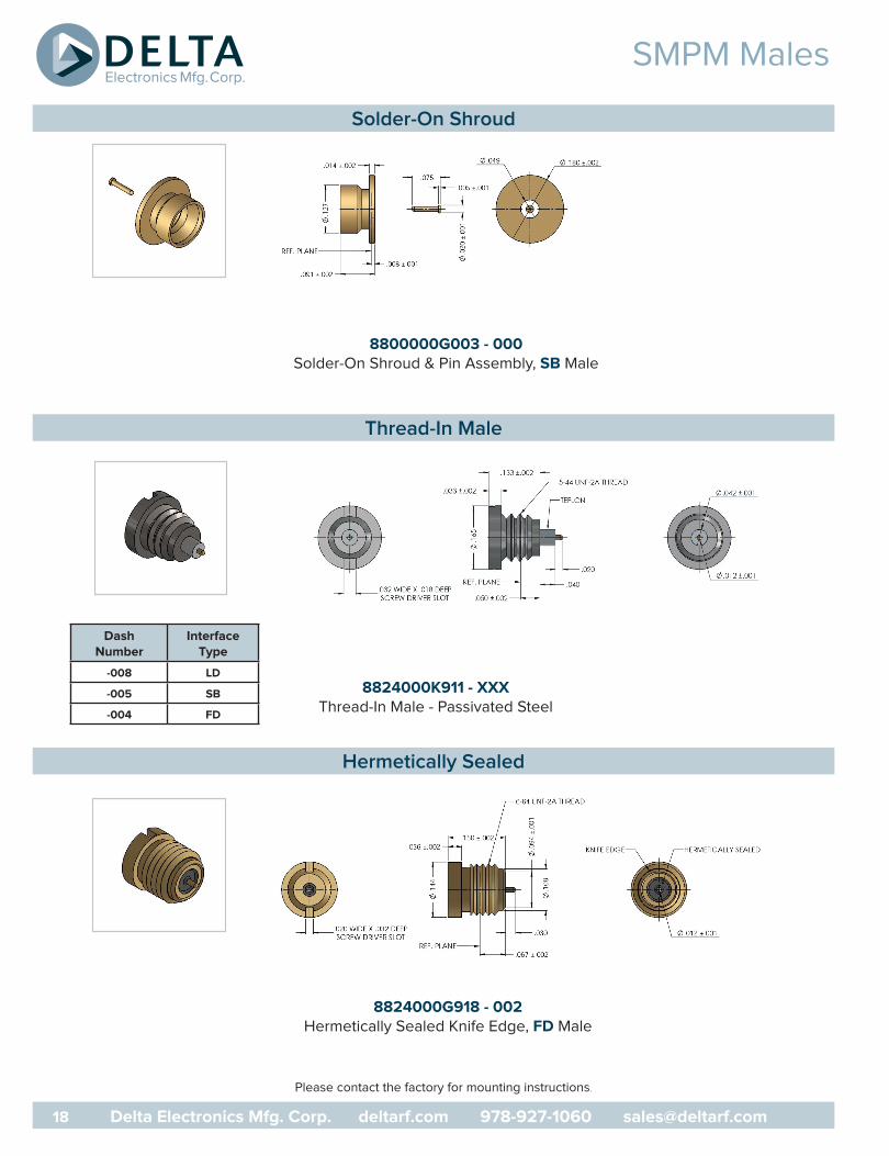
SMPM Males
8800000G003 - 000Solder-On Shroud & Pin Assembly, SB Male
8824000K911 - XXXThread-In Male - Passivated Steel
8824000G918 - 002Hermetically Sealed Knife Edge, FD Male
Please contact the factory for mounting instructions.
Solder-On Shroud
Thread-In Male
Hermetically Sealed
DashNumber
Interface Type
-008 LD
-005 SB
-004 FD

19 Delta Electronics Mfg. Corp. deltarf.com 978-927-1060 [email protected]
SMPM Connectors
Please contact the factory for mounting instructions.
8824000G918 - XXXHermetically Sealed
Solder-In Male - Extended Pin
8859000K051 - XXXPanel Mount - 4 Hole Male
Passivated Steel
8859000K911 - XXXPanel Mount - 2 Hole Male
Passivated Steel
Hermetically Sealed Solder-In Male
Field Replaceable Panel Mounts - Accepts .012 Dia Pin
DashNumber
Interface Type
-003 LD
-002 SB
-001 FD
DashNumber
Interface Type
-002 LD
-001 SB
-000 FD
DashNumber
Dimensions InterfaceTypeA
-027 .090 LD
-026 .090 SB
-025 .090 FD
-024 .070 LD
-023 .070 SB
-022 .070 FD
-021 .050 LD
-020 .050 SB
-019 .050 FD
-018 .030 LD
-017 .030 SB
-008 .030 FD

SMPM Connectors
Please contact the factory for mounting instructions.
8859000K051 - XXXPanel Mount - 4 Hole Male
Passivated Steel
8859000K911 - XXXPanel Mount - 2 Hole Male
Passivated Steel
DashNumber
Interface Type
-006 LD
-005 SB
-004 FD
DashNumber
Interface Type
-005 LD
-004 SB
-003 FD
Panel Mounts - Extended Teflon & Pin
20 Delta Electronics Mfg. Corp. deltarf.com 978-927-1060 [email protected]

SMP Connectors
Please contact the factory for mounting instructions.
8869000G001 - 001Suface/Float Mount Female - Post Contact
Engineered Solutions
Today’s market for low-profile board to board RF interconnects is demanding tighter spacing
SMPM connector on the market today. Our unique design assists in reducing the overall package
The design eliminates the need for a “Bullet” adapter between the two male SMPM connectors. The SMPM female has been incorporated into the PC Board mounted housing requiring only two connectors for the complete interconnect.
Typical Board Layout (Shown mated with Delta P/N 8868000G91P- 004)
Excellent electrical and mechanical performance is still maintained when maximum misalignment conditions occur. Both connectors have a fully captivated center contact eliminating the need for any secondary soldering operation of the contact. The female connector may be mated with any other SMPM male housing. If further reduction in board spacing is needed, designers can choose from a number of shroud and pin
Simplification of the assembly and overall cost reduction makes the low profile surface mount SMPM female a simple solution.
Surface/Float Mount Female
21 Delta Electronics Mfg. Corp. deltarf.com 978-927-1060 [email protected]

SMPM Connectors
Please contact the factory for mounting instructions.
8868000G001 - XXXSurface Mount Male, Post Contact
8868000G91P - XXXSurface Mount Male, Post Contact
8868000G91P - XXXSurface Mount Male, Right Angle Post Contact
Surface Mount Males
DashNumber
Interface Type
-007 LD
-006 SB
-005 FD
DashNumber
Interface Type
-006 LD
-005 FD
-004 SB
DashNumber
Interface Type
-013 CM
-012 SB
-011 FD
-010 LD
22 Delta Electronics Mfg. Corp. deltarf.com 978-927-1060 [email protected]

SMPM Connectors
8828000G001 - XXXFemale to Female “Bullet” Adapters
8828000G001 - 014Female to Female “Bullet” Adapters
Low Profile
1.
2.
Trim cable to dimesions shown. Remove any burrs from outer and center conductor.
Insert cable into body, making sure center conductor is inserted in slot in contact. Solder cable jacket tobody, keeping end of cable flush with step in body as shown. Solder center conductor to contact and press cap into body until fully seated.
Proper assembly technique is important to the overall performance of the cable assemblies. Please contact Delta Electronics for addditional information.
Female to Female Bullet Adapters
Assembly Procedure “J”
Trim Codes
J/05A B
.062 ± .010 .187 ± .010
DashNumber
Interface Type
-011 .236
-004 .315
-003 .290
-002 .265
-001 .210
23 Delta Electronics Mfg. Corp. deltarf.com 978-927-1060 [email protected]
Assembly Procedures
1.
2.
3.
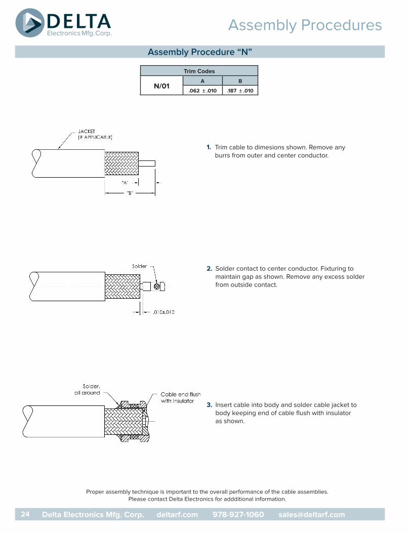
Trim cable to dimesions shown. Remove any burrs from outer and center conductor.
Solder contact to center conductor. Fixturing to maintain gap as shown. Remove any excess solder from outside contact.
Insert cable into body and solder cable jacket tobody keeping end of cable flush with insulator as shown.
Proper assembly technique is important to the overall performance of the cable assemblies. Please contact Delta Electronics for addditional information.
Assembly Procedure “N”
Trim Codes
N/01A B
.062 ± .010 .187 ± .010
24 Delta Electronics Mfg. Corp. deltarf.com 978-927-1060 [email protected]

Assembly Procedures
1.
2.
Trim cable to dimesions shown. Remove any burrs from outer and center conductor.
Insert cable into body and solder cable jacket tobody, keeping end of cable flush with insulator as shown.
Delta P/N Page
81-10384-XX-AU ......................... 8
8600000G003-XXX ......................... 7
8601094G001-000 ......................... 5
8608037G001-000 ......................... 4
8608038G001-000 ......................... 4
8608094G001-000 ......................... 4
8608111G001-001 ......................... 4
8624000G918-XXX ......................... 8
8624000K910-XXX ......................... 7
8628000G001-XXX ......................... 11
8628000G911-XXX ......................... 12
8659000K051-XXX ......................... 9
8659000K910-XXX ......................... 8
8659000K911-XXX ......................... 9
8667000G91P-XXX ......................... 10
8668000G001-XXX ......................... 10
8668000G911-XXX ......................... 11
8668000G91P-XXX ......................... 10
8672037G001-XXX ......................... 6
Delta P/N Page
8672094G001-XXX ......................... 6
8672111G001-XXX ......................... 6
8676037G001-000 ......................... 5
8676111G001-000 ......................... 5
8800000G003-000 ......................... 16
8808094G001-003 ......................... 15
8808111G003-000 ......................... 15
8824000G918-002 ......................... 16
8824000G918-XXX ......................... 17
8824000K911-XXX ......................... 16
8828000G001-XXX ......................... 21
8859000K051-XXX ......................... 17,18
8859000K911-XXX ......................... 17,18
8868000G001-XXX ......................... 20
8868000G91P-XXX ......................... 20
8869000G001-001 ......................... 19
8876094G003-000 ......................... 15
8876111G003-000 ......................... 15
Proper assembly technique is important to the overall performance of the cable assemblies. Please contact Delta Electronics for addditional information.
Assembly Procedure “P”
Index by Delta Part Number
Trim Codes
P/01A B
.062 ± .010 .187 ± .010
25 Delta Electronics Mfg. Corp. deltarf.com 978-927-1060 [email protected]

SMPS
Delta’s SMPS
SMPS Connectors DC-18 GHz (Economical Line) DC - 65 GHz (High Frequency Line)Similar in functionality to the SMPM series, the SMPS series is 30% smaller than the SMPM series. While the SMPS construction allows for higher frequencies up to 65 GHz, Delta recognizedapplications where low interface board-board interconnects were in demand typically did not range above 18 GHz. For this reason Delta has developed 2 lines – The Economical Line (E-Line) and HF Line of SMPS. For higher frequency applications ranging above 40 GHz, tightly tolerance components and extreme handling and processing is required. The end result is a higher manufacturing cost.
The SMPS series has a center to center mounting spacing of .078 of an inch and a minimum board to board spacing of .125” when utilizing its smallest bullet adapter (.098”) and shrouds
(.015 board to reference plane). Board mounts are supplied in numerous configurations – surface mount, thru mount and edge mount and bullets lengths range from .098 to .500” in length for the
Welcome our new and smallest member of our SMPM family, the SMPS. SMPS Connectors DC-18 GHz (Economical Line) DC - 65 GHz (High Frequency Line).
Delta’s New SMPS
26 Delta Electronics Mfg. Corp. deltarf.com 978-927-1060 [email protected]
SMPS
Electrical Specifications:Nominal Impedance: 50 ohmsFrequency Range: DC-65 GHzTypical VSWR: 1.20 Max thru 26.5 GHz ; 1.5 Max thru 65 GHzInsulation Resistance:3,500megohmsDWV (@sea level): 250 VrmsRF Leakage: -80db to 3 GHz, -65db from 3 to 65 GHzMechanical Specifications:Durability: 100 min (FD) ; 250 min (LD) ; 500 (SB & CM) Force to Engage: 4 lbs typ (FD) ; 2 lbs typ (SB &CM) Force to Disengage: 6.0 lbs typ (FD) ; 3 lbs typ(SB & CM) Contact Retention: 1.5 lbs min.Minimum Center Line to Center Line Spacing: .078”Radial Misalignment: +/- .010”Axial Misalignment: .010” MaxMaterials:Bodies/Shrouds: Beryllium Copper Per ASTM B196and/or ASTM B197 or Stainless Steel type 303,Condition A Outer Contacts: Beryllium Copper PerASTM B196 or ASTM B197Center Contacts: Beryllium Copper Per ASTM B196or ASTM B197Insulators: PTFE Fluorocarbon per ASTM D1710 orTorlon per MIL-P-46179
Finishes:Bodies: Gold Plate per MIL-G-45204, over Nickel Plate per SAE AMS-QQ-N-290 or Passivated per AMS-QQ-P-35Contacts: Gold Plate per MIL-G-45204, over Nickel Plate per SAE AMS-QQ-N-290Environmental Specifications:Temperature Range: -65° C to +165° CShock: Meets MIL-STD-202 Method 213, Condition IVibration: Meets MIL-STD-202 Method 204, Condition DAltitude: Meets MIL-STD-202, Method 105 Condition CThermal Shock: Meets MIL-STD-202, Method 107Condition B_________________________________________
*These specifications are typical and may not apply toall connectors. Detailed specifications for individualconnectors are available upon request.
SMPS
27 Delta Electronics Mfg. Corp. deltarf.com 978-927-1060 [email protected]

Delta Electronics Mfg. Corp.
www.deltarf.com978-927-1060
PO Box 53416 Cabot St.
Beverly, MA 01915