mecablitz 64 AF-1 digital
326
www.metz.de mecablitz 64 AF-1 digital für / for Sony-Digitalkameras Bedienungsanleitung, Mode d’emploi, Gebruiksaanwijzing, Operating instruction, Manuale istruzioni, Manual de instrucciones 14/39/26
-
Upload
khangminh22 -
Category
Documents
-
view
1 -
download
0
Transcript of mecablitz 64 AF-1 digital

www.metz.de
mecablitz 64 AF-1 digitalfür / for Sony-DigitalkamerasBedienungsanleitung, Mode d’emploi, Gebruiksaanwijzing, Operating instruction, Manuale istruzioni, Manual de instrucciones
14/3
9/26

Vorwort . . . . . . . . . . . . . . . . . . . . . . . . . . . . . . . . . . . . . . . . . . . . . . . . . 31 Sicherheitshinweise . . . . . . . . . . . . . . . . . . . . . . . . . . . . . . . . . . . . . 42 Dedicated-Blitzfunktionen . . . . . . . . . . . . . . . . . . . . . . . . . . . . . . . . 53 Blitzgerät vorbereiten. . . . . . . . . . . . . . . . . . . . . . . . . . . . . . . . . . . . 63.1 Montage des Blitzgerätes . . . . . . . . . . . . . . . . . . . . . . . . . . . . . . . 63.2 Stromversorgung . . . . . . . . . . . . . . . . . . . . . . . . . . . . . . . . . . . . . . 73.3 Ein- und Ausschalten des Blitzgerätes. . . . . . . . . . . . . . . . . . . . . 83.4 Das Auswahlmenü. . . . . . . . . . . . . . . . . . . . . . . . . . . . . . . . . . . . . 83.5 INFO . . . . . . . . . . . . . . . . . . . . . . . . . . . . . . . . . . . . . . . . . . . . . . . . 93.6 Automatische Geräteabschaltung / Auto - OFF . . . . . . . . . . . . . . 94 LED-Anzeigen am Blitzgerät . . . . . . . . . . . . . . . . . . . . . . . . . . . . . 114.1 Blitzbereitschaftsanzeige . . . . . . . . . . . . . . . . . . . . . . . . . . . . . . 114.2 Belichtungskontrollanzeige . . . . . . . . . . . . . . . . . . . . . . . . . . . . 115 Anzeigen im Display . . . . . . . . . . . . . . . . . . . . . . . . . . . . . . . . . . . . 115.1 Anzeige der Blitzbetriebsart . . . . . . . . . . . . . . . . . . . . . . . . . . . . 125.2 Reichweitenanzeige . . . . . . . . . . . . . . . . . . . . . . . . . . . . . . . . . . 126 Anzeigen im Kamerasucher . . . . . . . . . . . . . . . . . . . . . . . . . . . . . . 137 Blitzbetriebsarten. . . . . . . . . . . . . . . . . . . . . . . . . . . . . . . . . . . . . . 147.1 TTL-Blitzbetrieb . . . . . . . . . . . . . . . . . . . . . . . . . . . . . . . . . . . . . . 147.2 Vorblitz-TTL und ADI-Messung . . . . . . . . . . . . . . . . . . . . . . . . . . 157.3 Manueller Blitzbetrieb . . . . . . . . . . . . . . . . . . . . . . . . . . . . . . . . 157.4 Automatische Kurzzeitsynchronisation (HSS) . . . . . . . . . . . . . . 167.5 Automatik-Blitzbetrieb . . . . . . . . . . . . . . . . . . . . . . . . . . . . . . . . 177.6 Stroboskop-Blitzbetrieb . . . . . . . . . . . . . . . . . . . . . . . . . . . . . . . 188 Manuelle Blitzbelichtungskorrektur . . . . . . . . . . . . . . . . . . . . . . 209 Sonderfunktionen. . . . . . . . . . . . . . . . . . . . . . . . . . . . . . . . . . . . . . 219.1 Motorzoom-Reflektor („Zoom“) . . . . . . . . . . . . . . . . . . . . . . . . . 2110 Der drahtlose Remote-Betrieb. . . . . . . . . . . . . . . . . . . . . . . . . . . 23
10.1 Remote-Master Betrieb. . . . . . . . . . . . . . . . . . . . . . . . . . . . . . . 2410.1.1 Remote-Master-Betrieb einstellen . . . . . . . . . . . . . . . . . . . . 2410.1.2 Blitzbetriebsart am Master-Blitzgerät einstellen . . . . . . . . . 2510.1.3 Teillichtleistung im M-Betrieb am Master-Blitzgerät einstellen . . 2510.1.4 Lichtverhältnisse (RATIO) für die Blitzgruppen
am Master-Blitzgerät definieren . . . . . . . . . . . . . . . . . . . . . . 2610.1.5 Remote-Kanal einstellen . . . . . . . . . . . . . . . . . . . . . . . . . . . . 2710.2 Remote-Slave-Blitzbetrieb . . . . . . . . . . . . . . . . . . . . . . . . . . . . 2710.2.1 Remote-Slave-Blitzbetrieb einstellen . . . . . . . . . . . . . . . . . 2810.2.2 Slave-Kanal einstellen . . . . . . . . . . . . . . . . . . . . . . . . . . . . . . 2810.2.3 Slave-Gruppe einstellen . . . . . . . . . . . . . . . . . . . . . . . . . . . . 2910.2.4 Slave-Betriebsart einstellen . . . . . . . . . . . . . . . . . . . . . . . . . 2910.2.5 Slave-Teillichtleistung bzw. Belichtungskorrekturwert EV
einstellen . . . . . . . . . . . . . . . . . . . . . . . . . . . . . . . . . . . . . . . . 3010.3 Prüfen des Remote-Blitzbetriebes . . . . . . . . . . . . . . . . . . . . . . 3010.4 SERVO-Betrieb. . . . . . . . . . . . . . . . . . . . . . . . . . . . . . . . . . . . . . 3110.4.1 SERVO-Blitzbetrieb einstellen. . . . . . . . . . . . . . . . . . . . . . . . 3110.4.2 Vorblitzunterdrückung bzw. Synchronisation einstellen. . . 3110.4.3 Servo-Betrieb Teillichtleistung einstellen . . . . . . . . . . . . . . 3210.4.4 Lernfunktion. . . . . . . . . . . . . . . . . . . . . . . . . . . . . . . . . . . . . . 3210.4.5 SERVO-Blitzbetrieb ausschalten . . . . . . . . . . . . . . . . . . . . . . 3311 OPTION-Menü . . . . . . . . . . . . . . . . . . . . . . . . . . . . . . . . . . . . . . . . 3411.1 RAPID Betrieb . . . . . . . . . . . . . . . . . . . . . . . . . . . . . . . . . . . . . . 3411.2 Zweitreflektor (SUB-REFL.) . . . . . . . . . . . . . . . . . . . . . . . . . . . . 3411.3 Einstelllicht (MOD. LIGHT). . . . . . . . . . . . . . . . . . . . . . . . . . . . . 3511.4 Zoom Betrieb (ZOOM MODE) . . . . . . . . . . . . . . . . . . . . . . . . . . 3511.4.1 Extended-Zoom-Betrieb. . . . . . . . . . . . . . . . . . . . . . . . . . . . . 3511.4.2 SPOT-Zoom-Betrieb . . . . . . . . . . . . . . . . . . . . . . . . . . . . . . . . 3611.4.3 STANDARD-Zoom-Betrieb . . . . . . . . . . . . . . . . . . . . . . . . . . . 37
2
j

VorwortVielen Dank, dass Sie sich für ein Metz Produkt entschieden haben. Wir freuen uns, Sie als Kunde begrüßen zu dürfen.Natürlich können Sie es kaum erwarten, das Blitzgerät in Betrieb zunehmen. Es lohnt sich aber, die Bedienungsanleitung zu lesen, denn nur solernen Sie, mit dem Gerät problemlos umzugehen.
Dieses Blitzgerät ist geeignet für:• Digitale Sony Spiegelreflex-Kameras mit TTL-Vorblitz und
ADI-Messung.
Für Kameras anderer Hersteller ist das Blitzgerät nicht geeignet !
Schlagen Sie bitte auch die Bildseite am Ende der Anleitung auf.
Erklärung
Fingerzeig, Hinweis
Achtung - Extrem wichtiger Sicherheitshinweis !Bestimmungsgemäßer GebrauchDieses Blitzgerät ist ausschließlich für die Belichtung von Motivenim fotografischen Bereich bestimmt. Es darf nur mit dem in dieserBedienungsanleitung beschriebenen Zubehör bzw. dem von Metzfreigegebenen Zubehör betrieben werden.Das Blitzgerät darf zu keinem anderen Zweck, als dem obenbeschriebenen, verwendet werden.
+
11.5 Aufnahmeformat-Anpassung (ZOOM SIZE) . . . . . . . . . . . . . . . 3711.6 AF-Hilfslicht (AF-BEAM). . . . . . . . . . . . . . . . . . . . . . . . . . . . . . . 3811.7 Reichweitenanzeigen in m oder ft . . . . . . . . . . . . . . . . . . . . . . 3911.8 Blitzbelichtungsreihen (FLASH BRACK.) . . . . . . . . . . . . . . . . . 3911.9 Beep-Funktion (BEEP) . . . . . . . . . . . . . . . . . . . . . . . . . . . . . . . . 4011.10 Verriegelung / Entriegeln . . . . . . . . . . . . . . . . . . . . . . . . . . . . 4111.11 Powerpack anschließen(Zubehör) . . . . . . . . . . . . . . . . . . . . . 4112 Favoritenprogramme . . . . . . . . . . . . . . . . . . . . . . . . . . . . . . . . . . 4213 Blitztechniken. . . . . . . . . . . . . . . . . . . . . . . . . . . . . . . . . . . . . . . . 4413.1 Indirektes Blitzen . . . . . . . . . . . . . . . . . . . . . . . . . . . . . . . . . . . 4413.2 Indirektes Blitzen mit Reflektorkarte . . . . . . . . . . . . . . . . . . . . 4413.3 Nahaufnahmen / Makroaufnahmen . . . . . . . . . . . . . . . . . . . . 4414 Blitzsynchronisation . . . . . . . . . . . . . . . . . . . . . . . . . . . . . . . . . . 4514.1 Automatische Blitzsynchronzeit-steuerung . . . . . . . . . . . . . . 4514.2 Normalsynchronisation . . . . . . . . . . . . . . . . . . . . . . . . . . . . . . 4514.3 Langzeitsynchronisation (SLOW) . . . . . . . . . . . . . . . . . . . . . . . 4514.4 Die Synchronbuchse . . . . . . . . . . . . . . . . . . . . . . . . . . . . . . . . . 4615 Touch-Display Einstellungen . . . . . . . . . . . . . . . . . . . . . . . . . . . . 4715.1 Helligkeit (BRIGHTNESS). . . . . . . . . . . . . . . . . . . . . . . . . . . . . . 4715.2 Rotation (ROTATION) . . . . . . . . . . . . . . . . . . . . . . . . . . . . . . . . . 4716 Wartung und Pflege . . . . . . . . . . . . . . . . . . . . . . . . . . . . . . . . . . . 4816.1 Firmware-Update. . . . . . . . . . . . . . . . . . . . . . . . . . . . . . . . . . . . 4816.2 Formieren des Blitzkondensators . . . . . . . . . . . . . . . . . . . . . . 4816.3 Rückstellen auf Werkseinstellung (RESET) . . . . . . . . . . . . . . . 4817 Hilfe bei Störungen. . . . . . . . . . . . . . . . . . . . . . . . . . . . . . . . . . . . 4918 Technische Daten . . . . . . . . . . . . . . . . . . . . . . . . . . . . . . . . . . . . . 5119 Sonderzubehör . . . . . . . . . . . . . . . . . . . . . . . . . . . . . . . . . . . . . . 52Garantiebestimmungen . . . . . . . . . . . . . . . . . . . . . . . . . . . . . . . . . . 54
3
j

1 SicherheitshinweiseIn Umgebung von entflammbaren Gasenoder Flüssigkeiten (Benzin,Lösungsmittel etc.) darf das Blitzgerätkeinesfalls ausgelöst werden! EXPLOSIONSGEFAHR !Lösen Sie in unmittelbarer Nähe derAugen keinesfalls einen Blitz aus! Ein Blitzlicht direkt vor den Augen vonPersonen und Tieren kann zur Netzhaut-schädigung führen und schwere Sehstö-rungen verursachen - bis hin zurErblindung!Auto-, Bus-, Fahrrad-, Motorrad-, oderZugfahrer etc. niemals während der Fahrtmit einem Blitzgerät fotografieren. Durchdie Blendung kann der Fahrer einenUnfall verursachen!Wurde das Gehäuse so stark beschädigt,dass Innenteile frei liegen, darf dasBlitzgerät nicht mehr betrieben werden.Batterien entnehmen! Berühren Sie kei-ne innenliegenden Bauteile. HOCHSPANNUNG!Nach mehrfachem Blitzen nicht dieReflektorscheibe berühren.Verbrennungsgefahr !Blitzgerät nicht zerlegen! HOCHSPANNUNG ! Im Geräteinneren befinden sich keineBauteile, die von einem Laien repariertwerden können.
• Das Blitzgerät ist ausschließlich zurVerwendung im fotografischen Bereich vor-gesehen und zugelassen!
• Nur die in der Bedienungsanleitungbezeichneten und zugelassenen Strom-quellen verwenden!
• Batterien / Akkus nicht kurzschließen!• Batterien / Akkus nicht übermäßiger Wärme
wie Sonnenschein, Feuer oder dergleichenaussetzen!
• Verbrauchte Batterien / Akkus nicht insFeuer werfen!
• Keine schadhaften Batterien oder Akkusverwenden!
• Aus verbrauchten Batterien kann Laugeaustreten, was zur Beschädigung derKontakte führt. Verbrauchte Batterien des-halb immer aus dem Gerät entnehmen.
• Trockenbatterien dürfen nicht geladenwerden.
• Blitzgerät nicht Tropf- und Spritzwasser(z.B. Regen) aussetzen!
• Schützen Sie Ihr Blitzgerät vor großer Hitzeund hoher Luftfeuchtigkeit! Blitzgerät nichtim Handschuhfach des Autos aufbewahren!
• Bei raschem Temperaturwechsel kannFeuchtigkeitsbeschlag auftreten. Gerätakklimatisieren lassen!
4
j

• Beim Auslösen eines Blitzes darf sich keinlichtundurchlässiges Material unmittelbarvor oder direkt auf der Reflektorscheibebefinden. Die Reflektorscheibe darf nichtverunreinigt sein. Bei Nichtbeachtung kannes, durch die hohe Energie des Blitzlichtes,zu Verbrennungen des Materials bzw. derReflektorscheibe führen.
• Bei Serienblitzaufnahmen mit vollerLichtleistung und kurzen Blitzfolgezeitenist darauf zu achten, dass nach jeweils 20 Blitzen eine Pause von mindestens 3 Minuten eingehalten wird !
• Bei Serienblitzaufnahmen mit vollerLichtleistung und kurzen Blitzfolgezeitenwärmt sich die Streuscheibe bei Zoom-positionen von 35 mm und weniger durchdie hohe Lichtenergie stark auf.
• Das Blitzgerät darf nur dann zusammen miteinem in die Kamera eingebauten Blitz-gerät verwendet werden, wenn dieses voll-ständig ausgeklappt werden kann!
2 Dedicated-BlitzfunktionenDie Dedicated-Blitzfunktionen sind speziellauf das Kamerasystem abgestimmteBlitzfunktionen. In Abhängigkeit vomKameratyp werden dabei verschiedeneBlitzfunktionen unterstützt.• Blitzbereitschaftsanzeige im
Kamerasucher/Kameradisplay.• Automatische Blitzsynchronzeitsteuerung.• TTL-Blitzsteuerung
• Manuelle Blitzbelichtungskorrektur • Vorblitz-TTL und ADI• Automatische Motor-Zoom-Steuerung• Synchronisation auf den 1. oder
2. Verschlussvorhang (REAR) • Extended-Zoom-Betrieb• AF-Messblitzsteuerung• Automatische Blitzreichweitenanzeige• Automatische Kurzzeitsynchronisation HSS
bei TTL und M• Zündungssteuerung /Auto-Flash)• Drahtloser Remote-Blitzbetrieb• Servo-Blitzbetrieb• Spot-Zoom-Betrieb• Extended-Zoom-Betrieb• Wake-Up-Funktion für das Blitzgerät
5
j

Im Rahmen dieser Bedienungsanleitung istes nicht möglich, alle Ka me ra typen mit deneinzelnen Blitzfunktionen detailliert zubeschreiben. Beachten Sie deshalb dieHinweise zum Blitzbetrieb in derBedienungsanleitung Ihrer Kamera, welcheBlitzfunktionen von Ihrem Kameratyp unter-stützt werden bzw. an der Kamera selbst ein-gestellt werden müssen!
Bei der Verwendung von Objektiven ohneCPU (z.B. Objektive ohne Autofokus) ergebensich zum Teil Einschränkungen!
3 Blitzgerät vorbereiten
3.1 Montage des BlitzgerätesBlitzgerät auf die Kamera montieren
Kamera und Blitzgerät vor der Montage oderDemontage ausschalten.• Schutzkappe vom Gerätefuß abziehen.• Rändelmutter � bis zum Anschlag gegen
das Blitzgerät drehen. Der Si che rungs stiftim Fuß ist jetzt vollkommen im Gehäusedes Blitzgerätes versenkt.
• Blitzgerät mit dem Anschlussfuß bis zumAnschlag in den Zubehörschuh der Kameraschieben.
• Rändelmutter � bis zum Anschlag gegendas Kameragehäuse drehen und dasBlitzgerät festklemmen. Bei Kameragehäusen, die kein Sicherungs-loch aufweisen, versenkt sich der federge-lagerte Sicherungsstift im Ge häuse desBlitzgerätes, damit die Oberfläche nichtbeschädigt wird.
Blitzgerät von der Kamera abnehmen
Kamera und Blitzgerät vor der Montage oderDemontage ausschalten.• Rändelmutter � bis zum Anschlag gegen
das Blitzgerät drehen.• Blitzgerät aus dem Zubehörschuh der
Kamera herausziehen.
+
+
+
6
j

3.2 StromversorgungBatterien- bzw. AkkuauswahlDas Blitzgerät kann wahlweise betriebenwerden mit hochwertigen:• 4 Nickel-Metall-Hydrid Akkus 1,2 V,
Typ IEC HR6 (AA / Mignon), deutlich höhere Kapazität als NC–Akku undweniger umweltschädlich, da cadmiumfrei.
• 4 Alkali-Mangan-Trockenbatterien 1,5 V, Typ IEC LR6 (AA / Mignon), wartungsfreie Stromquelle für gemäßigteLeistungsanforderungen.
• 4 Lithium-Batterien 1,5 V, Typ IEC FR6 (AA / Mignon), wartungsfreie Strom quelle mit hoherKapazität und geringer Selbstentladung.
• Power Pack mit Verbindungskabel(Sonderzubehör)
Verwenden Sie nur die oben angegebenenStromquellen. Bei der Verwendung von ande-ren Stromquellen besteht die Gefahr, dassdas Blitzgerät beschädigt wird.
Wenn Sie das Blitzgerät längere Zeit nichtbenutzen, entfernen Sie bitte dieBatterien/Akkus aus dem Gerät.
Batterien austauschenDie Akkus/Batterien sind leer bzw. ver-braucht, wenn die Blitzfolgezeit (Zeit vomAuslösen eines Blitzes mit voller Lichtlei-stung, z.B. bei M, bis zum erneutenAufleuchten der Blitzbereitschaftsanzeige)über 60 Sek. ansteigt. Zusätzlich erscheintim Touch-Display die Batteriewarnanzeige.• Blitzgerät ausschalten, dazu die Taste
� so lange drücken, bis alleAnzeigen erlöschen.
• Den Batteriefachdeckel � nach untenschieben und aufklappen.
• Batterien oder Akkus in Längsrichtung ent-sprechend den angegebenen Batteriesym-bolen einsetzen und Batteriefachdeckel �schließen.
Achten Sie beim Einsetzen der Batterien bzw.Akkus auf die richtige Polarität gemäß denSymbolen im Batteriefach. Vertauschte Polekönnen zur Zerstörung des Gerätes führen!Explosionsgefahr bei unsachgemäßemBetrieb der Batterien. Ersetzen Sie immeralle Batterien durch gleiche, hochwertigeBatterien eines Her stel lertyps mit gleicherKapazität! Verbrauchte Batterien bzw. Akkusgehören nicht in den Hausmüll! Leisten Sieeinen Beitrag zum Umweltschutz und gebenSie verbrauchte Batterien bzw. Akkus bei ent-sprechenden Sammelstellen ab!
+
7
j

3.3 Ein- und Ausschalten desBlitzgerätes
• Blitzgerät mit der Taste � einschalten.Der Startbildschirm erscheint. Das Blitzgerät schaltet danach immer mitder zuletzt verwendeten Betriebsart (z.B.manueller Blitzbetrieb M) ein.
Im Standby-Betrieb blinkt die Taste � rot.Zum Ausschalten die Taste � so lange drücken, bis alle Anzeigen erlöschen.
Wird das Blitzgerät längere Zeit nichtgebraucht, so empfehlen wir: Blitzgerät mitder Taste � ausschalten und dieStromquellen (Batterien, Akkus) entnehmen.
3.4 Das Auswahlmenü• Taste � so oft drücken, bis das
Auswahlmenü erscheint.Das Auswahlmenü ist in 6 Sensortastenunterteilt:Nach Drücken der Taste können dieBetriebsarten eingestellt werden.TTL, Kap. 7.1TTL HSS*, Kap. 7.4A, Kap. 7.5M, Kap. 7.3M HSS*, siehe 7.4STROBO, Kap. 7.6REMOTE MASTER, Kap. 10.1REMOTE SLAVE, Kap. 10.2SERVO, Kap. 10.4 *) nur nach Datenaustausch mit einer Kamera.
D
MODE
D
Nach Drücken der Taste könnendie Blitzparameter eingestellt werden.P (Teillichtleistung), Kap. 7.3; 10.1.3 und10.4.3EV (Belichtungskorrektur), Kap. 8, 10.2.5ZOOM (Reflektorstellung), Kap. 9.1N (Blitzanzahl), Kap. 7.6f (Blitzfrequenz), Kap. 7.6F (Blende)ISO (Lichtempfindlichkeit)RATIO (Lichtverhältnis), siehe 10.1.4CTRL (Remote-Betriebsart), siehe 10.1CHANNEL (Kanal), Kap. 10.2.2.GROUP (Slave-Gruppe), siehe 10.2.3.Die Anzeige der Blitzparameter ist abhängigvon der gewählten Blitzbetriebsart.
Nach Drücken der Taste kann dasTouch-Display konfiguriert werden oder dasBlitzgerät in der Auslieferungszustandzurückversetzt werden.BRIGHTNESS (Helligkeit), Kap. 15.1ROTATION (Bildschirmanzeige schwenken),Kap. 15.2RESET, Kap. 16.3
SERVICE
PARAMETER
8
V 1.0
MB 64AF-1digitalSON
MODE
PARAMETER
SERVICE
PARAMETER OP / EVZOOM
Nf (Hz)
FISO
CHANNELRATIO
CONTROL
MODE OETTL
TTL HSSAM
M HSSSTROBO
REMOTE MASTERREMOTE SLAVE
SERVO
SERVICE O
BRIGHTNESS
RESET
ROTATION
j

Nach Drücken der Taste können dieOptionen eingestellt werden.RAPID (schnelle Blitzfolgezeiten), Kap. 11.1 SUB-REFL. (Zweitreflektor), Kap 11.2ZOOM SIZE (Aufnahmeformat-Anpassung),Kap. 11.5ZOOM MODE (Ausleuchtung), Kap. 11.4STANDBY (Autom. Geräteabschaltung), Kap 3.6MOD.LIGHT (Einstelllicht), Kap. 11.3BEEP (Akustisches Signal), Kap. 11.9m/ft (Entfernung in Meter / Feet), Kap. 11.7POWERPACK (externes Powerpack), Kap. 11.11AF BEAM (AF-Hilfslicht), Kap. 11.6FLASH BRACK. (Blitzbelichtungsreihen), Kap. 11.8Die Anzeige der Optionen ist abhängig vonder gewählten Blitzbetriebsart.Im angezeigten Menü am Blitzgerät sind alleschwarz hinterlegten Felder als Sensortastenausgeführt, die zur Umstellung/Verstellungim Menü gedrückt werden können.In den Bilddarstellungen in derBedienungsanleitung sind immer nur dieSensortaste schwarz markiert, die zurEinstellung der beschriebenen Funktiongedrückt werden müssen.
OPTION 3.5 INFODie aktuellen Einstellungen des Blitzgeräteskönnen während des Betriebs angezeigtwerden.• Auf dem Touch-Display auf die Sensortaste
� drücken. Die Info erscheint.
- EXT (Extended-Zoom-Betrieb) ist eingestellt, (Kap. 11.4.1).
- AF OFF (AFHilflicht) ist ausgeschaltet,(Kap. 11.6).
- (MOD.LIGHT) ist eingestellt, (siehe 11.3).
- (Beep-Funktion) ist eingestellt,(Kap. 11.9)
- (Kanal) wird angezeigt,(Kap. 10.1.5, 10.2.2)
- Die automatische Geräteabschaltung ist auf10 Minuten eingestellt, (Kap. 3.6).
- Die Temperaturanzeige steigt nach intensi-ven Gebrauch an.
3.6 Automatische Geräteabschaltung /Auto - OFF
Werksseitig ist das Blitzgerät so eingestellt,dass es ca. 10 Minuten -• nach dem Einschalten,• nach dem Auslösen eines Blitzes,• nach dem Antippen des Kameraauslösers,• nach dem Ausschalten des
Kamerabelichtungsmesssystems. . . . . . in den Standby-Betrieb schaltet (Auto-
2CH
i
9
OPTION
i
OPTION ORAPID
SUB-REFL. ZOOM SIZEZOOM MODESTANDBY
MOD. LIGHTBEEPm / ft
POWERPACKAF BEAM
FLASH BRACK.
j
200

+
OFF), um Energie zu sparen und dieStromquellen vor unbeabsichtigtem Entladenzu schützen. Die aktive automatischeGeräteabschaltung wird im INFO-Display mitangezeigt. Die Blitzbereitschaftsanzeige �und die Anzeigen auf dem LC-Display verlö-schen.Im Standby-Betrieb blinkt die Taste � rot. Die zuletzt benutzte Betriebseinstellungbleibt nach der automatischen Abschaltungerhalten und steht nach dem Einschaltensofort wieder zur Verfügung. Das Blitzgerät wird durch Drücken derTaste � bzw. durch Antippen desKameraauslösers (Wake-Up-Funktion) wiedereingeschaltet.
Im Slave-/SERVO-Betrieb ist die automati-sche Geräteabschaltung nicht aktiv.
Wenn das Blitzgerät längere Zeit nicht benö-tigt wird, sollte das Gerät grundsätzlichimmer mit der Taste � ausgeschaltetwerden!Bei Bedarf kann die automatischeGeräteabschaltung bereits nach 1 Minuteerfolgen oder ausgeschaltet werden.Das Blitzgerät schaltet ca. 1 Stunde nachdem letzten Gebrauch komplett aus.In allen Betriebsarten wird nach ca. 10 Sek.der Bildschirm auf die Hälfte der Helligkeiteingestellt um Energie zu sparen. Mit jedemTastendruck oder durch Tippen auf denBildschirm wird wieder auf die normaleHelligkeit umgeschaltet.
D
D
Automatische Geräteabschaltung einstellen
• Blitzgerät mit der Taste � einschalten.Der Startbildschirm erscheint. Das Blitzgerät schaltet danach immer mitder zuletzt verwendeten Betriebsart (z.B.manueller Blitzbetrieb M) ein.
• Taste � so oft drücken, bis dasAuswahlmenü erscheint.
• Auf dem Touch-Display die Sensortastedrücken.
• Auf dem Touch-Display die Sensortastendrücken und auswählen.
• Auf dem Touch-Display die Sensortastedrücken.
• Auf dem Touch-Display die Sensortaste fürdie gewünschte Zeit tippen. Die Einstellungwird sofort übernommen.
Im Standby-Betrieb blinkt die Taste � rot.
D
OPTION
STANDBY
STANDBY
D
10
OPTION
OPTION O
q p
ZOOM MODESTANDBY
MOD. LIGHT
STANDBY OOFF
1 min10 min
j
200

4 LED-Anzeigen am Blitzgerät
4.1 BlitzbereitschaftsanzeigeBei aufgeladenem Blitzkondensator leuchtetam Blitzgerät die Taste � grün auf undzeigt damit die Blitzbereitschaft an.Das bedeutet, dass für die nächsteAufnahme Blitzlicht verwendet werden kann.Die Blitzbereitschaft wird auch an die Kameraübertragen und sorgt im Kamerasucher füreine entsprechende Anzeige.Wird eine Aufnahme gemacht, bevor imKamerasucher die Anzeige für dieBlitzbereitschaft erscheint, so wird dasBlitzgerät nicht ausgelöst. Die Aufnahmewird unter Umständen falsch belichtet, fallsdie Kamera bereits auf die Blitzsynchronzeitumgeschaltet hat (siehe 14.1).
4.2 BelichtungskontrollanzeigeBei einer richtigen Belichtung leuchtet dieTaste � für ca. 3 Sekunden rot auf, wenndie Aufnahme in den Blitzbetriebsarten ,Vorblitz-TTL und ADI-Messung sowie imAutomatik-Betrieb (siehe 7.5) richtigbelichtet wurde!Erfolgt keine Belichtungskontrollanzeigenach der Aufnahme, so wurde die Aufnahmeunterbelichtet. Sie müssen dann:- die nächst kleinere Blendenzahl einstellen
(z.B. anstatt Blende 11 die Blende 8), oder
DTTL
A
- die Entfernung zum Motiv bzw. zurReflexfläche (z.B. beim indirekten Blitzen)verkleinern oder
- an der Kamera einen höheren ISO-Wert ein-stellen.
Beachten Sie die Reichweitenanzeige imDisplay des Blitzgerätes (siehe 5.2).
5 Anzeigen im DisplayDie meisten Kameras übertragen die Wertefür ISO, Objektivbrennweite (mm) und Blendean das Blitzgerät. Dieses passt seine erfor-derlichen Einstellungen automatisch an. Eserrechnet aus den Werten und seiner Leitzahldie maximale Reichweite des Blitzlichtes. Blitzbetriebsart, Reichweite, Blende undZoom-Position des Reflektors werden imDisplay des Blitzgerätes angezeigt.Wird das Blitzgerät betrieben ohne das esDaten von der Kamera erhalten hat werdendie am Blitzgerät eingestellten Werte ange-zeigt.DisplaybeleuchtungNach Drücken der Taste � am Blitzgerätoder nach Tippen auf das Touch-Display wirdfür ca. 10 Sek. die Displaybeleuchtung aufmaximalle Helligkeit eingestellt.
D
11
j

+
5.1 Anzeige der BlitzbetriebsartIm Display wird die eingestellte Blitzbetriebs-art angezeigt. Dabei sind je nach Kameratypverschiedene Anzeigen für die jeweils unter-stützte Blitzbetriebsart (z.B. und
) und den manuellen Blitzbetriebmöglich (siehe 7.3).
5.2 ReichweitenanzeigeBeim Einsatz von Kameras und einemObjektiv mit CPU erfolgt am Display eineReichweitenanzeige. Dazu muss ein Datenaustausch zwischenKamera und Blitzgerät stattgefunden haben,z.B. durch Antippen des Kameraauslösers.Die Reichweite kann entweder in Meter (m)oder Feet (ft) angezeigt werden (siehe 11.7).
Es erfolgt keine Reichweitenanzeige . . .
- wenn keine Daten von der Kamera übertragen werden.
- wenn der Reflektorkopf aus seinerNormalposition (nach oben oder seitwärts)abgeschwenkt ist.
- wenn das Blitzgerät im REMOTE MASTER;REMOTE SLAVE oder SERVO-Blitzbetriebarbeitet.
MTTL HSSTTL
Reichweitenanzeige im TTL-/TTL HSS-BlitzbetriebIn den Blitzbetriebsarten und ;siehe 7.1) wird im Display der Wert für dieminimale und maximale Reichweite desBlitzlichtes angezeigt. Der angezeigte Wert bezieht sich auf einenReflexionsgrad von 25% des Motivs, was fürdie meisten Aufnahmesituationen zutrifft.Starke Abweichungen des Reflexionsgrades,z.B. bei sehr stark oder sehr schwach reflek-tierenden Objekten können die Reichweitedes Blitzgerätes beeinflussen.Das Motiv sollte sich im Bereich von etwa40% bis 70% der maximalen Reichweitebefinden. Damit wird der Elektronik genü-gend Spielraum zum Ausgleich gegeben.Zur Vermeidung einer Überbelichtung sollteder im Display angezeigte Mindestabstandzum Motiv nicht unterschritten werden.Die Anpassung an die jeweilige Aufnahme-situation kann z.B. durch Ändern derObjektivblende erreicht werden.
TTL HSSTTL
12
5.5 - 56 m M-Zoom 35 m
m
TTL
iEV
5.5 - 56 m M-Zoom 35 m
m
TTL
iEV
j

Reichweitenanzeige im manuellenBlitzbetrieb Im manuellen Blitzbetrieb wird im Display derEntfernungswert angezeigt, der für eine kor-rekte Blitzbelichtung des Motivs einzuhaltenist. Die Anpassung an die jeweiligeAufnahmesituation kann z.B. durch eineÄnderung der Objektivblende oder durch dieWahl einer manuellen Teillichtleistung (siehe7.3) erreicht werden.Überschreitung des AnzeigebereichsIm Display werden Reichweiten bis maximal99 m bzw. 99 ft angezeigt. Bei hohen ISO-Werten und großenBlendenöffnungen kann der Anzeigebereichüberschritten werden. Dies wird durch einen Pfeil hinter demEntfernungswert angezeigt.
M6 Anzeigen im Kamerasucher Beispiele für Anzeigen im Kamerasucher:Blitzsymbol blinkt vor der AufnahmeDer Kondensator im Blitzgerät wird geladen.Das Blitzgerät ist noch nicht blitzbereit.Blitzsymbol leuchtet:Blitzgerät ist einsatzbereit (bei einigenKameras).Grundsätzlich zur Fehlbelichtung:• Bei Überbelichtung: Nicht blitzen!• Bei Unterbelichtung: Schalten Sie den Blitz
zu oder verwenden Sie ein Stativ und einelängere Belichtungszeit.
In den verschiedenen Belichtungs- undAutomatikprogrammen können unterschied-liche Gründe für Fehlbelichtungen vorliegen.Lesen Sie zu den Anzeigen im Kamerasucherin der Kamerabedienungsanleitung nach,was für Ihren Kameratyp gilt!
13
9.0 mM-Zoom 35 m
m
M
iP1/1
49- 99 m uF 1,4M-
Zoom 200mm
TTL
iEV
j

7 BlitzbetriebsartenJe nach Kameratyp stehen folgendeBlitzbetriebsarten zur Verfügung:• TTL ( ), Kap. 7.1• manuelle Blitzbetrieb ( ), Kap. 7.3• automatische Kurzzeitsynchronisation HSS,
Kap. 7.4• der Automatik-Blitzbetrieb ( ), Kap. 7.5• der Stroboskop-Blitzbetrieb ( ),
Kap. 7.6• der Blitzbetrieb, Kap. 10.1• der Blitzbetrieb, Kap. 10.2• der Servo-Betrieb ( ), Kap. 10.4. Die Einstellung der Blitzbetriebsart erfolgtüber das Touch-Display.Zum Einstellen der Blitzbetriebsarten
und muss vorher ein Daten-austausch zwischen Blitzgerät und Kamerastattfinden, z.B. durch Antippen desKameraauslösers.
7.1 TTL-Blitzbetrieb ( )Bei der Aufnahme werden vor der eigentli-chen Belichtung mehrere fast nicht erkenn-bare Messvorblitze vom Blitzgerät abgege-ben. Das reflektierte Licht der Messvorblitze wirdvon der Kamera ausgewertet. Entsprechendder Auswertung wird die nachfolgendeBlitzbelichtung von der Kamera an dieAufnahmesituation angepasst (näheres sieheKamerabedienungsanleitung).
M HSSTTL HSS
TTL
REMOTE SLAVE
SERVO
TTLM
A
STROBO
REMOTE MASTER
Bei einer korrekt belichteten Aufnahmeleuchtet für ca. 3s die Belichtungskontroll-anzeige (siehe 4.2).Betriebsart einstellen • Blitzgerät mit der Taste � einschalten.
Der Startbildschirm erscheint. Das Blitzgerät schaltet danach immer mitder zuletzt verwendeten Betriebsart (z.B. M-Blitzbetrieb) ein.
• Auf dem Touch-Display so oft auf die ange-zeigte Betriebsart drücken, bis die Anzeigezur Auswahl der Betriebsart erscheint.
• Auf dem Touch-Display die Sensortastendrücken und die gewünschte
Betriebsart auswählen.• Auf die ausgewählte gelb umrandete
Betriebsart drücken. Die Einstellung wirdsofort übernommen.
• An der Kamera eine entsprechendeBetriebsart, z.B. P, S, A etc. einstellen.
• Kameraauslöser antippen, damit einDatenaustausch zwischen Kamera undBlitzgerät erfolgt.
14
V 1.0
MB 64AF-1digitalSON
9.0 mM-Zoom 35 m
m
M
iP1/1
MODE O
q p
TTLTTL HSS
j

7.2 Vorblitz-TTL und ADI-MessungVorblitz-TTL und ADI-Messung sind digitaleTTL-Blitzbetriebsarten und Weiterentwick-lungen des TTL-Blitzbetriebes analoger Kameras. Bei der Aufnahme wird vor der eigentlichen Belichtung ein fast nicht erkenn-barer Messvorblitz vom Blitzgerät abgege-ben. Das reflektierte Licht des Messvorblitzeswird von der Kamera ausgewertet. Entspre-chend der Auswertung wird die nachfolgendeBlitzbelichtung von der Kamera an die Auf-nahmesituation angepasst (näheres sieheKamerabedienungsanleitung). Bei der ADI-Messung gehen zusätzlich Entfernungsdatendes Objektivs in die Blitzbelichtung mit ein.Die Auswahl bzw. Einstellung der Betriebsar-ten Vorblitz-TTL und ADI-Messung erfolgt ander Kamera (siehe Kamerabedienungsan-leitung).Das Blitzgerät muss in die Blitzbetriebsart
geschaltet werden (siehe 7.1).
7.3 Manueller BlitzbetriebIm manuellen Blitzbetrieb M wird vomBlitzgerät ungeregelt die volle Energie abge-strahlt, sofern keine Teillichtleistung einge-stellt ist. Die Anpassung an dieAufnahmesituation kann z.B. durch dieBlendeneinstellung an der Kamera oderdurch Auswahl einer geeigneten manuellenTeillichtleistung erfolgen.Der Einstellbereich erstreckt sich von P 1/1 -P1/256 bei bzw. P 1/1 - P 1/64 bei
.Im Display wird die Entfernung angezeigt, bei
TTL
MM HSS
der das Motiv korrekt belichtet wird (siehe5.2).Betriebsart einstellen • Blitzgerät mit der Taste � einschalten.
Der Startbildschirm erscheint. Das Blitzgerät schaltet danach immer mitder zuletzt verwendeten Betriebsart ein.
• Auf dem Touch-Display so oft dieSensortaste der angezeigte Betriebsartdrücken, bis die Anzeige zur Auswahl derBetriebsart erscheint.
• Auf dem Touch-Display die Sensortastendrücken und auswählen.
• Auf dem Touch-Display die Sensortastedrücken.
• An der Kamera eine entsprechendeBetriebsart, z.B. einstellen.
• Kameraauslöser antippen, damit einDatenaustausch zwischen Kamera undBlitzgerät erfolgt.
Verschiedene Kameras unterstützen denmanuellen Blitzbetrieb nur in derKamerabetriebsart M (Manuell). In anderen Kamerabetriebsarten erfolgt eineFehlermeldung im Display und die Auslösungwird verriegelt.
M
M
M
15
0.8 - 9.0 m M-Zoom 35 m
m
TTL
iEV
0.8 - 9.0 m M-Zoom 35 m
m
TTL
iEV
9.0 mM-Zoom 35 m
m
M
iP1/1
MODE O
q p
AM
M HSS
j

Manuelle TeillichtleistungenIm manuellen Blitzbetrieb kann eineTeillichtleistung eingestellt werden. Einstellvorgang• Auf dem Touch-Display so oft die
Sensortaste für die Teillichtleistung drücken, bis die Auswahl für dieTeillichtleistung erscheint.
• Auf dem Touch-Display die Sensortastendrücken die gewünschte
Teillichtleistung 1/1, 1/2, 1/8 . . . 1/256einstellen.
• Auf dem Touch-Display die Sensortaste fürdie ausgewählte Teillichtleistung drücken.
Die Einstellung wird sofort wirksam und auto-matisch gespeichert.
Die Entfernungsanzeige wird automatisch derTeillichtleistung angepasst (siehe 5.2).
M7.4 Automatische
Kurzzeitsynchronisation (HSS)Verschiedene Kameras unterstützen dieAutomatische Kurzzeitsynchronisation HSS(siehe Kamerabedienungsanleitung). Mit die-ser Blitzbetriebsart ist es möglich, auch beikürzeren Verschlusszeiten als derBlitzsynchronzeit ein Blitzgerät einzu-setzen.Interessant ist diese Betriebsart z.B. beiPortrait-Aufnahmen in sehr hellemUmgebungslicht, wenn durch eine weit geöff-nete Blende (z.B. F 2,0) die Schärfentiefebegrenzt werden soll! Das Blitzgerät unter-stützt die Kurzzeitsynchronisation HSS in denBlitzbetriebsarten und .Physikalisch bedingt, wird jedoch durch dieKurzzeitsynchronisation die Leitzahl, unddamit auch die Reichweite des Blitzgeräteszum Teil erheblich eingeschränkt!Beachten Sie daher die Reichweitenanzeigeam Display des Blitzgerätes! Die Kurzzeitsyn-chronisation HSS wird automatisch ausge-führt, wenn an der Kamera manuell oderautomatisch durch das Belichtungspro-gramm eine kürzere Verschlusszeit als dieBlitzsynchronzeit eingestellt ist.Beachten Sie, dass die Leitzahl des Blitzge-rätes bei der Kurzzeitsynchronisation zusätz-lich von der Verschlusszeit abhängig ist:Je kürzer die Verschlusszeit desto geringerdie Leitzahl!
Die Kurzzeitsynchronisation wird automa-
MTTL
16
j
9.0 mM-Zoom 35 m
m
M
iP1/1
3.1 mM-Zoom 35 m
m
M
iP1/8
P O
q p
1/11/1 - 1/3
P O
q p
1/4 - 2/31/8
1/8 - 1/3

tisch ausgeführt, wenn an der Kamera manu-ell oder automatisch durch das Belichtungs-programm eine kürzere Verschlusszeit als dieBlitzsynchronzeit eingestellt ist.Betriebsart einstellen • Blitzgerät mit der Taste � einschalten.
Der Startbildschirm erscheint. Das Blitzgerät schaltet danach immer mitder zuletzt verwendeten Betriebsart (z.B.TTL-Blitzbetrieb) ein.
• Kameraauslöser antippen, damit einDatenaustausch zwischen Kamera undBlitzgerät erfolgt.
• Auf dem Touch-Display so oft dieSensortaste der angezeigte Betriebsartdrücken, bis die Anzeige zur Auswahl derBetriebsart erscheint.
• Auf dem Touch-Display die Sensortastendrücken und bzw.
auswählen.
• Auf dem Touch-Display die Sensortastedrücken.
Die Einstellung wird sofort wirksam.
Wenn am Blitzgerät die Kurzzeitsynchronisa-tion HSS aktiviert wird, wird dieSynchronisation auf den 2.Verschlussvor-hang (REAR) automatisch deaktiviert!
M HSSTTL HSS
TTL HSS
7.5 Automatik-BlitzbetriebIm Automatik-Blitzbetrieb misst derFotosensor � des Blitzgerätes das vomMotiv reflektierte Licht. Der Fotosensor � hateinen Messwinkel von ca. 25° und misst nurwährend der eigenen Lichtabgabe. Bei ausreichender Lichtmenge schaltet dieBelichtungsautomatik des Blitzgerätes dasBlitzlicht ab. Der Fotosensor � muss auf dasMotiv gerichtet sein.Betriebsart einstellen • Blitzgerät mit der Taste � einschalten.
Der Startbildschirm erscheint. Das Blitzgerät schaltet danach immer mitder zuletzt verwendeten Betriebsart ein.
• Auf dem Touch-Display so oft dieSensortaste der angezeigte Betriebsartdrücken, bis die Anzeige zur Auswahl derBetriebsart erscheint.
• Auf dem Touch-Display die Sensortastendrücken und auswählen.
• Auf dem Touch-Display die Sensortastedrücken.
• An der Kamera eine entsprechendeBetriebsart, z.B. einstellen.
• Kameraauslöser antippen, damit einDatenaustausch zwischen Kamera undBlitzgerät erfolgt.
A
A
A
A
17
9.0 mM-Zoom 35 m
m
M
iP1/1
MODE O
q p
TTL HSSA
M HSS
0.8 - 9.0 m M-Zoom 35 m
m
A
iEV
j
0.8 - 9.0 m M-Zoom 35 m
m
TTL
iEV
9.0 mM-Zoom 35 m
m
TTL HSS
iP1/1
MODE O
q p
TTLTTL HSS
A
7.6 Stroboskop-BlitzbetriebDer Stroboskop-Betrieb ist eine manuelleBlitzbetriebsart. Dabei können mehrereBlitzbelichtungen auf einem Bild gemachtwerden. Das ist besonders interessant beiBewegungsstudien und Effektaufnahmen.Beim Stroboskop-Betrieb werden mehrereBlitze mit einer bestimmten Blitzfrequenzabgegeben. Die Funktion ist daher nur miteiner Teillichtleistung von max. 1/8 oderweniger realisierbar.Für eine Stroboskop-Aufnahme muss dieBlitzfrequenz (Blitze pro Sekunde) und dieAnzahl der Blitze eingestellt werden.Stroboskop-Blitzanzahl (N)Im Stroboskop-Blitzbetrieb kann dieBlitzanzahl (N) pro Auslösung eingestelltwerden.Die Blitzanzahl lässt sich von 2 bis 90 ein-stellen, abhängig von der eingestelltenTeillichtleistung.
Die max. mögliche Blitzanzahl (N) ist abhän-gig von der eingestellten Teillichtleistung(P).Stroboskop-Blitzfrequenz (f) Im Stroboskop-Blitzbetrieb kann dieBlitzfrequenz (f ) eingestellt werden. DieBlitzfrequenz gibt die Anzahl der Blitze proSekunde an. Die Blitzfrequenz lässt sich von 1 bis 100einstellen. Die maximal mögliche Blitzanzahlwird dabei automatisch angepasst.
Sie können zur Erzielung von kurzenBlitzleuchtzeiten die Teillichtleistung manu-ell bis auf den Minimalwert von 1/256 ein-stellen.
Die max. mögliche Blitzfrequenz (f) istabhängig von der eingestelltenTeillichtleistung (P).Betriebsart einstellen • Blitzgerät mit der Taste � einschalten.
Der Startbildschirm erscheint. Das Blitzgerät schaltet danach immer mitder zuletzt verwendeten Betriebsart ein.
• Auf dem Touch-Display so oft dieSensortaste der angezeigten Betriebsartdrücken, bis die Anzeige zur Auswahl derBetriebsart erscheint.
• Auf dem Touch-Display die Sensortastendrücken und auswählen.
• Auf dem Touch-Display die Sensortastedrücken.
• An der Kamera eine entsprechendeBetriebsart, z.B. einstellen.
• Kameraauslöser antippen, damit einDatenaustausch zwischen Kamera undBlitzgerät erfolgt.
STROBO
STROBO
M
18
j
+
+
0.8 - 9.0 m M-Zoom 35 m
m
TTL
iEV
MODE O
q p
M HSSSTROBO
REMOTE MASTER
3.1mM-Zoom 35 m
m
STROBO
iP1/8
f(Hz) 5N 5

19
Blitzanzahl (N) einstellen • Auf dem Touch-Display die Sensortaste für
die Blitzanzahl drücken.
• Auf dem Touch-Display die Sensortastendrücken und die gewünschte
Blitzanzahl auswählen.
Die max. mögliche Blitzanzahl (N) ist abhän-gig von der eingestellten Teillichtleistung(P).• Auf dem Touch-Display die Sensortaste
für die gewünschte Blitzanzahl, im Beispieldrücken.
Die Einstellung wird sofort wirksam.4
N
Blitzfrequenz (f(Hz))einstellen • Auf dem Touch-Display die Sensortaste für
die Blitzfrequenz drücken.
• Auf dem Touch-Display die Sensortastendrücken und die gewünschte
Blitzfrequenz auswählen.
Die max. mögliche Blitzfrequenz (f) istabhängig von der eingestelltenTeillichtleistung (P).• Auf dem Touch-Display die Sensortaste
für die gewünschte Blitzfrequenz, imBeispiel drücken. Die Einstellung wird sofort wirksam.
Im Display wird die zu den eingestelltenParametern gültige Entfernung angezeigt.Durch Verändern des Blendenwertes oder derTeillichtleistung kann der angezeigteEntfernungswert an die Entfernung zumMotiv angeglichen werden.Im Stroboskop-Blitzbetrieb werden keinBlenden- und ISO-Wert im Display angezeigt!
Der Zweitreflektor wird im Stroboskop-Blitzbetrieb nicht unterstützt.
8
f (Hz)
f (Hz) O
q p
789
3.1mM-Zoom 35 m
m
STROBO
iP1/16
f(Hz) 10N 4
3.1mM-Zoom 35 m
m
STROBO
iP1/8
f(Hz) 8N 4
j
+
+
+
3.1mM-Zoom 35 m
m
STROBO
iP1/16
f(Hz) 10N 5
N O
q p
345

20
8 Manuelle Blitzbelichtungs-korrektur
Die Blitzbelichtungsautomatik der meistenKameras ist auf einen Reflexionsgrad von25% (durchschnittlicher Reflexionsgrad vonBlitzmotiven) abgestimmt. Ein dunkler Hintergrund, der viel Licht absor-biert oder ein heller Hintergrund, der starkreflektiert (z.B. Gegenlichtaufnahmen),können zu Über- bzw. Unterbelichtung desMotivs führen.Um den oben genannten Effekt zu kompen-sieren, kann die Blitzbelichtung manuell miteinem Korrekturwert der Aufnahme ange-passt werden. Die Höhe des Korrekturwertesist vom Kontrast zwischen Motiv undBildhintergrund abhängig!Am Blitzgerät können in den A/TTL-Blitzbe-triebsarten manuelle Korrekturwerte für dieBlitzbelichtung von -3 bis +3 Blendenwerten(EV) in Drittel-Stufen eingestellt werden.Tipp:Dunkles Motiv vor hellem Bildhintergrund:Positiver Korrekturwert.Helles Motiv vor dunklem Bildhintergrund:Negativer Korrekturwert.Eine Belichtungskorrektur durch Verändernder Objektivblende ist nicht möglich, da dieBelichtungsautomatik der Kamera die geän-derte Blende wiederum als normaleArbeitsblende betrachtet. Beim Einstelleneines Korrekturwertes kann sich die
Reichweitenanzeige im Display ändern unddem Korrekturwert angepasst werden(abhängig von Kameratyp)!Einstellvorgang• Auf dem Touch-Display so oft die
Sensortaste drücken, bis die Auswahlfür den Korrekturwert erscheint.
• Auf dem Touch-Display die Sensortastendrücken und einen Korrekturwert
einstellen.• Auf dem Touch-Display auf den ausge-
wählten Korrekturwert z.B. drücken. Die Einstellung wird sofort wirksam.
Eine manuelle Blitzbelichtungskorrektur inden TTL-Blitzbetriebsarten kann nur dannerfolgen, wenn die Kamera die Einstellungeines Korrekturwertes am Blitzgerät unter-stützt (siehe Kamerabedienungsanleitung)!Wenn die Kamera diese Funktion nicht unter-stützt bleibt der eingestellte Korrekturwertunwirksam.Bei verschiedenen Kameratypen muss dermanuelle Blitzbelichtungskorrekturwert ander Kamera eingestellt werden. Im Displaydes Blitzgerätes wird dann kein Korrekturwertangezeigt.
Vergessen Sie nicht die manuelleBlitzbelichtungskorrektur nach derAufnahme an der Kamera wieder zu löschen!
EV
-1
+
j
0.8 - 9.0 m M-Zoom 35 m
m
TTL
iEV
EV O
q p
-1 1/3-1
-2/3
1.1- 12 m M-Zoom 35 m
m
TTL
iEV-1

21
Achtung: Stark reflektierende Gegenständeim Bild des Motivs können die Belichtungs-automatik der Kamera stören. Die Aufnahmewird dann unterbelichtet. ReflektierendeGegenstände entfernen oder einen positivenKorrekturwert einstellen.
9 SonderfunktionenJe nach Kameratyp stehen verschiedeneSonderfunktionen zur Verfügung. Zum Aufrufen und Einstellen der Sonder-funktionen muss deshalb vorher einDatenaustausch zwischen Blitzgerät undKamera stattfinden, z.B. durch Antippen desKameraauslösers.Die Einstellung muss unmittelbar nach demAufrufen der Sonderfunktion erfolgen, da dasBlitzgerät sonst nach einigen Sekunden auto-matisch wieder in den normalen Blitzbetriebwechselt!
9.1 Motorzoom-Reflektor („Zoom“)Der Motorzoom-Reflektor des Blitzgeräteskann Objektivbrennweiten ab 24 mm(Kleinbild-Format) ausleuchten. Durch Einsatz der integriertenWeitwinkelstreuscheibe erweitert sich dieAusleuchtung auf 12 mm.
Automatische ZoomsteuerungWenn das Blitzgerät mit einer Kamera betrie-ben wird, die Daten der Objektivbrennweiteüberträgt, passt sich die Zoom-Position desReflektors automatisch der Objektivbrenn-weite an. Nach dem Einschalten desBlitzgerätes wird im Display „Zoom“ und dieaktuelle Zoom-Position des Reflektors ange-zeigt.Die automatische Anpassung erfolgt fürObjektivbrennweiten ab 24 mm. Die automatische Anpassung erfolgt nicht,wenn der Reflektor geschwenkt ist, wenn dieWeitwinkelstreuscheibe ausgezogen oderein Mecabounce (Zubehör) montiert ist.Auf Wunsch kann die Position des Reflektorsmanuell verstellt werden um bestimmteBeleuchtungseffekte zu erzielen (z.B. Spot-Effekt usw.).Manueller Zoom-BetriebBei Kameras die keine Daten der Objektiv-brennweiten übertragen, muss dieZoom-Position des Reflektors manuell an dieObjektivbrennweite angepasst werden.
Der Auto-Zoom-Betrieb ist in diesem Fallnicht möglich! Nach dem Einschalten des Blitzgerätes wirdim Display „Zoom“ und die aktuelleZoom-Position des Reflektors angezeigt.
+
+
j

22
Beispiel: Sie benutzen ein Zoomobjektiv mit einemBrennweitenbereich von 35 mm bis 105 mm.In diesem Beispiel stellen Sie die Positiondes Reflektors des Blitzgerätes auf 35 mm.Rückstellen auf Auto-Zoom• Kameraauslöser antippen, damit ein
Datenaustausch zwischen Blitzgerät undKamera stattfindet.
• Taste � so oft drücken, bis dasAuswahlmenü erscheint.
• Auf dem Touch-Display auf das Sensortastedrücken.
• Auf dem Touch-Display die Sensortastendrücken und auswählen.
• Auf dem Touch-Display auf die Sensortastedrücken.
• Auf dem Touch-Display die Sensortastendrücken und auswählen.
• Auf dem Touch-Display die Sensortastedrücken.
Nach ca. 10 Sek. wird auf auf dieBetriebsanzeige umgeschaltet oder Taste� so oft drücken bis die Betriebsanzeigeerscheint.
D
PARAMETER
ZOOM
ZOOM
AUTOZOOM
AUTOZOOM
D
Einstellvorgang• Taste � so oft drücken, bis das
Auswahlmenü erscheint.
• Auf dem Touch-Display die Sensortastedrücken.
• Auf dem Touch-Display die Sensortastendrücken und auswählen.
• Auf dem Touch-Display die Sensortastedrücken.
• Auf dem Touch-Display die Sensortastendrücken und den gewünschten
Zoomwert auswählen. • Auf dem Touch-Display die Sensortaste
für den gewünschten Zoomwert drücken. Die Einstellung wird sofort wirksam.
Folgende Zoom-Positionen für den Reflektorsind möglich: 24-28-35-50-70-85-105-135-180-200 mm (Kleinbild-Format).Tipp: Wenn Sie nicht immer die volle Leitzahl undReichweite des Blitzgerätes benötigen,können Sie die Reflektor-Position auf derAnfangsbrennweite des Zoomobjektivesbelassen. Damit ist garantiert, dass die Bildränderimmer vollständig ausgeleuchtet werden. Siesparen sich damit die fortwährendeAnpassung an die Objektivbrennweite.
ZOOM
ZOOM
PARAMETER
Dj
PARAMETER
PARAMETER O
q p
P/EVZOOM
F
ZOOM O
q p
7085
105
PARAMETER
PARAMETER O
q p
P/EVZOOM
F
ZOOM
q p
AUTOZOOM24
O

WeitwinkelstreuscheibeMit der integrierten Weitwinkelstreuscheibe können Brennweiten ab 12 mm ausge-leuchtet werden (Kleinbild-Format).Weitwinkelstreuscheibe aus dem Reflektornach vorne bis zum Anschlag herausziehenund loslassen.Die Weitwinkelstreuscheibe klappt auto-matisch nach unten. Der Reflektor wird auto-matisch in die erforderliche Position gesteu-ert. Am Display werden die Entfernungsangabenund der Zoomwert auf 12 mm korrigiert.Die automatische Anpassung desMotorzoom-Reflektor erfolgt nicht bei derVerwendung der Weitwinkelstreuscheibe .Zum Einschieben die Weitwinkelstreuscheibe um 90° nach oben klappen und vollstän-dig einschieben.mecabounce Diffuser MBM-03Wenn der mecabounce (Sonderzubehör;siehe 19) am Reflektor des Blitzgerätesmontiert ist, wird der Reflektor automatischin die erforderliche Position gesteuert. DieEntfernungsangaben und der Zoomwertwerden auf 16 mm korrigiert.
Es erfolgt keine automatische Anpassungdes Motorzoom-Reflektor bei derVerwendung eines mecabounce.Die gleichzeitige Verwendung vonWeitwinkelstreuscheibe und mecabounce istnicht möglich.
10 Der drahtlose Remote-BetriebDas Blitzgerät unterstützt das drahtloseSony-Remote-System in den Betriebsarten„CTRL” und „CTRL+”, abhängig von verwen-deten Kamerasystem. Die Betriebsarten„CTRL” und „CTRL+” werden automatischerkannt. Das Remote-System besteht aus einemMaster-Blitzgerät auf der Kamera und einemoder mehreren Slave-Blitzgeräten. Das - bzw.die Slave-Blitzgeräte werden vom Reflektordes Master-Blitzgerätes drahtlos ferngesteu-ert. Damit sich mehrere Remote-Systeme im glei-chen Raum nicht gegenseitig stören stehenvier unabhängige Remote-Kanäle zurVerfügung. Master- und Slave-Blitzgeräte diezum gleichen Remote-System gehören müs-sen auf den gleichen Remote-Kanal einge-stellt werden. Die Slave-Blitzgeräte müssen mit dem inte-grierten Sensor für Remote-Betrieb dasLicht des Master-Blitzgerätes empfangenkönnen.Der Remote-Blitzbetrieb unterstützt auch dieSynchronisation auf den 2.Verschluss-vorhang. Im Remote-Blitzbetrieb erfolgt keineReichweitenanzeige am Display desBlitzgerätes.
23
+
j

10.1 Remote-Master BetriebDie Slave-Gruppen RMT und RMT2 sind werk-seitig aktiviert. Das Master-Blitzgerät (CTRL) und die Slave-Gruppen RMT und RMT2 können aktiviertoder deaktiviert werden! Bei deaktiviertem Master-Blitzgerät (CTRL)übernimmt das Blitzlicht des Master-Blitzgerätes nur noch die steuernde Funktionund trägt nicht zur Belichtung der Aufnahmebei!10.1.1 Remote-Master-Betrieb einstellen • Blitzgerät mit der Taste � einschalten.
Der Startbildschirm erscheint.• Auf dem Touch-Display so oft die
Sensortaste der angezeigte Betriebsartdrücken, bis die Anzeige zur Auswahl derBetriebsart erscheint.
• Auf dem Touch-Display die Sensortastendrücken und aus-
wählen.• Auf dem Touch-Display die Sensortaste
drücken. Der Remote-Master Betrieb wird eingestellt.
Im Bild ist der Remote-Master Betrieb CTRLdargestellt. Der Master (CTRL) trägt im glei-chen Lichtverhältniss zur Belichtung bei wiedie Slave-Blitzgruppen (RMT) .Master (CTRL) und Slave-Blitzgruppe RMTbzw. Slave-Blitzgruppe RMT2 könnenLichtverhältnisse zugeordnet werden (siehe 10.1.4).
REMOTE MASTER
REMOTE MASTER
Umschalten von CTRL auf CTRL+• Taste � so oft drücken, bis das
Auswahlmenü erscheint.
• Auf dem Touch-Display die Sensortastedrücken.
• Auf dem Touch-Display die Sensortastendrücken und aus-
wählen.• Auf dem Touch-Display die Sensortaste
drücken.
• Auf dem Touch-Display die Sensortaste fürdie gewünschte Betriebsart bzw.
drücken.
Die Einstellung wird sofort wirksam.
Eine Lichtverhältnissteuerung (Ratio) ist nurim CTRL+-Betrieb möglich.
D
PARAMETER
CONTROL
CTRLCTRL+
CONTROL
24
j
0.6- 7.2 m M-Zoom 35 m
m
TTL
iEV
MODE O
q p
STROBOREMOTE MASTER
REMOTE SLAVE
CTRL RMT4 8
REMOTECTRL
TTL
i RATIO
CTRL RMT RMT24 8 1
REMOTECTRL+
TTL
i RATIO
PARAMETER
PARAMETER O
q p
RATIOCONTROL
CTRL/CTRL+ OCTRL
CTRL+
+

10.1.2 Blitzbetriebsart am Master-Blitzgeräteinstellen
• Auf dem Touch-Display so oft dieSensortaste für die Betriebsart drücken, bisdie Auswahl für die Betriebsart erscheint.
• Auf dem Touch-Display die Sensortastendrücken und die gewünschte
Betriebsart auswählen.• Auf dem Touch-Display auf die Sensortaste
der ausgewählten Betriebsart bzw.drücken.
Die eingestellte Betriebsart wird sofort über-nommen.
MTTL
10.1.3 Teillichtleistung im M-Betrieb amMaster-Blitzgerät einstellen
Die Betriebsart wie unter 10.1.2 beschriebenauf einstellen.
• Auf dem Touch-Display so oft dieSensortaste drücken, bis die„Master“ Auswahl erscheint.
• Auf dem Touch-Display die Sensortaste fürdie Teillichtleistung drücken.
• Auf dem Touch-Display die Sensortastendrücken die gewünschte
Teillichtleistung einstellen.
• Auf dem Touch-Display auf die Sensortasteder ausgewählten Teillichtleistung drücken.
Die Einstellung wird automatisch über-nommen.
1/8
M
M
P
25
j
CTRL RMT RMT24 8 1
REMOTECTRL+
M1/1
i RATIO
CTRL RMT RMT24 8 1
REMOTECTRL+
M1/1
i RATIO
CTRL RMT RMT24 8 1
REMOTECTRL+
M1/8
i RATIO
CTRL RMT RMT24 8 1
REMOTECTRL+
TTL
i RATIO
MASTER O
q p
TTLMEV
P O
q p
1/4 - 2/31/8
1/8 - 1/3
MASTER OTTL
M
P

10.1.4 Lichtverhältnisse (RATIO) für dieBlitzgruppen am Master-Blitzgerätdefinieren
Die Lichtverhältnisse des Remote-Systemskönnen eingestellt werden um bestimmteLichteffekte zu erzielen. Die Lichtverhältnissewerden für den Master (CTRL) und dieGruppen (RMT, RMT2) ausschließlich überdas Master-Blitzgerät gesteuert.Ratio ein-/ausschalten• Taste � so oft drücken, bis das
Auswahlmenü erscheint.
• Auf dem Touch-Display die Sensortastedrücken.
• Auf dem Touch-Display die Sensortastendrücken und auswählen.
• Auf dem Touch-Display die Sensortastedrücken.
• Auf dem Touch-Display die Sensortasteoder drücken und die RATIO-
Funktion ein- oder ausschalten.
D
PARAMETER
RATIO
RATIO
OFFON
Lichtverhältniss (Ratio) einstellen• Auf dem Touch-Display die Sensortaste
drücken.
• Auf dem Touch-Display die Sensortastedrücken, für die ein Lichtverhältnis einge-stellt werden soll, im Beispiel RMT2.
• Auf dem Touch-Display die Sensortastendrücken das gewünschte
Lichtverhältnis einstellen oder denLichtbeitrag ausschalten (--).
• Auf dem Touch-Display die Sensortaste fürden gewünschten Korrekturwert drücken.
Die Einstellung wird sofort übernommen.
RATIO
26
j
CTRL RMT RMT24 8 1
REMOTECTRL+
M1/8
i RATIO
PARAMETER
PARAMETER O
q p
CHANNELRATIO
CONTROL
RTM2 O
q p
48
16
RATIO OOFF
ON
8
1
4
ORATIO
CTRL
RMT
RMT2
CTRL RMT RMT24 8 8
REMOTECTRL+
M1/8
i RATIO

10.1.5 Remote-Kanal einstellenDamit sich mehrere Remote-Systeme im glei-chen Raum nicht gegenseitig stören stehenvier unabhängige Remote-Kanäle zurVerfügung. Master- und Slave-Blitzgeräte diezum gleichen Remote-System gehören müs-sen auf den gleichen Remote-Kanal einge-stellt werden.• Taste � so oft drücken, bis das
Auswahlmenü erscheint.
• Auf dem Touch-Display die Sensortastedrücken.
• Auf dem Touch-Display die Sensortastendrücken und auswählen.
• Auf dem Touch-Display die Sensortastendrücken und einen Remote-Kanal
z.B. auswählen.• Auf dem Touch-Display die Sensortaste für
den gewünschte Kanal drücken.
Die Einstellung wird sofort wirksam.Die Kanaleinstellung, im Bsp. CH2, kanndurch Druck auf die Sensortaste �geprüft werden.
i
CHANNEL 2
PARAMETER
CHANNEL
D
10.2 Remote-Slave-BlitzbetriebDas Blitzgerät unterstützt das drahtloseRemote-System im Slave-Blitzbetrieb und istkompatibel zum Sony-System. Dabei können ein oder mehrere Slave-Blitzgeräte von einem Master-Blitzgerät aufder Kamera (z.B. mecablitz 64AF-1S digital)drahtlos ferngesteuert werden.Ein Slave-Blitzgerät kann einer von zwei mög-lichen Slave-Gruppen (RMT, RMT2) zugeord-net werden. Das Master-Blitzgerät kann allediese Slave-Gruppen gleichzeitig steuern unddabei die einzelnen Einstellungen für diejeweilige Slave-Gruppe berücksichtigen.Damit sich mehrere Remote-Systeme im glei-chen Raum nicht gegenseitig stören stehenvier unabhängige Remote-Kanäle (CH 1, 2, 3oder 4) zur Verfügung.Master- und Slave-Blitzgeräte die zum glei-chen Remote-System gehören müssen aufden gleichen Remote-Kanal eingestelltwerden.Die Slave-Blitzgeräte müssen mit dem inte-grierten Sensor für den Remote-Betrieb dasLicht des Master- bzw. Controller-Blitzgerätesempfangen können.In Abhängigkeit vom der Kamera kann auchdas kamerainterne Blitzgerät alsMaster-Blitzgerät arbeiten.
27
j
PARAMETER O
q p
ZOOMCHANNEL
RATIO
CHANNEL O
q p
CHANNEL 1CHANNEL 2CHANNEL 3
PARAMETER

10.2.1 Remote-Slave-Blitzbetrieb einstellen • Blitzgerät mit der Taste � einschalten.
Der Startbildschirm erscheint. Das Blitzgerät schaltet danach immer mitder zuletzt verwendeten Betriebsart(z.B. TTL-Blitzbetrieb) ein.
• Auf dem Touch-Display so oft dieSensortaste der angezeigte Betriebsartdrücken, bis die Anzeige zur Auswahl derBetriebsart erscheint.
• Auf dem Touch-Display die Sensortastendrücken und aus-
wählen.• Auf dem Touch-Display die Sensortaste
drücken.
Der Remote-Slave Betrieb wird eingestellt.
Zusätzlich werden die gewählte Slave-Gruppe (z.B. RMT) und der Remote-Kanal (z.B. CH 1) angezeigt.
REMOTE SLAVE
REMOTE SLAVE
10.2.2 Slave-Kanal einstellen• Auf dem Touch-Display die Sensortaste für
die Kanal-Gruppe (z.B. ) drücken.Die Einblendung zur Auswahl von Kanalund Gruppe erscheint.
• Auf dem Touch-Display die Sensortastendrücken.
• Auf dem Touch-Display die Sensortastendrücken und den gewünschten
Kanal auswählen.• Auf dem Touch-Display die Sensortaste für
den ausgewählten Kanal drücken.
Die Einstellung wird sofort wirksam. Auf demDisplay wird „CH2“ angezeigt.
CHANNEL
RMT I CH1
28
j
0.8- 9.0 m M-Zoom 35 m
m
TTL
iEV
MODE O
q p
REMOTE MASTERREMOTE SLAVE
SERVO
M-Zoom 24
REMOTE
SLAVERMT Ch
2 1
i
mm
P1/1
M-Zoom 24
REMOTE
SLAVERMT Ch
2 2
i
mm
P1/1
M-Zoom 24
REMOTE
SLAVERMT Ch
2 1
i
mm
SLAVE OCHANNEL
GROUP
CHANNEL O
q p
CHANNEL 1CHANNEL 2CHANNEL 3

10.2.3 Slave-Gruppe einstellen• Auf dem Touch-Display die Sensortaste für
die Kanal-Gruppe (z.B. ) drücken.Die Einblendung zur Auswahl von Kanalund Gruppe erscheint.
• Auf dem Touch-Display die Sensortastendrücken.
• Auf dem Touch-Display die Sensortasten fürdie gewünschte Gruppe oderdrücken.
Die Einstellung wird sofort wirksam.
RMT I CH1
GROUP
RMT RMT2
10.2.4 Slave-Betriebsart einstellen• Auf dem Touch-Display die Sensortaste für
die Teillichtleistung oder drücken.
• Auf dem Touch-Display die Sensortaste fürdie gewünschte Betriebsart oder drücken.
Die Einstellung wird automatisch über-nommen.
MTTL
P EV
29
j
M-Zoom 24
REMOTE
SLAVERMT Ch
2
i
mm
P
M-Zoom 24
REMOTE
SLAVERMT Ch
2
i
mm
P1/1
M-Zoom 24
REMOTE
SLAVERMT Ch
2 1
i
mm
SLAVE OCHANNEL
GROUP
GROUP O
RTM2
SLAVE OTTL
M
P
RTM

10.2.5 Slave-Teillichtleistung bzw.Belichtungskorrekturwert EV einstel-len
• Auf dem Touch-Display so oft dieSensortaste bzw. drücken, bis dieAuswahl für den Korrekturwert erscheint.
• Auf dem Touch-Display die Sensortastebzw. drücken.
• Auf dem Touch-Display die Sensortastendrücken die gewünschte
Teillichtleistung einstellen.Die Teillichtleistung wird übernommen.Ist bei den Slave-Blitzgeräten die Blitzbereit-schaft erreicht, blinkt der AF-Messblitz.
P
EV P
EV
10.3 Prüfen des Remote-Blitzbetriebes• Slave-Blitzgeräte so positionieren, wie für
die spätere Aufnahme gewünscht.Verwenden Sie zum Aufstellen des Slave-Blitzgerätes einen Blitzgeräte-StandfußS60.
• Blitzbereitschaft aller beteiligtenBlitzgeräte abwarten. Ist bei denSlave-Blitzgeräten die Blitzbereitschafterreicht, blinkt das AF-Hilfslicht �.
• Am Master-Blitzgerät die Handauslösetaste� drücken und damit einen Testblitz aus-lösen. Die Slave-Blitzgeräte antworten je nachSlave-Gruppe nacheinander verzögert miteinem Testblitz. Wenn ein Slave-Blitzgerätkeinen Testblitz abgibt, überprüfen Sie dieEinstellung von Remote-Kanal undSlave-Gruppe. Korrigieren Sie die Positiondes Slave-Blitzgerätes damit dieses mitdem Sensor das Licht desMaster-Blitzgerätes empfangen kann.
Die Blitzbetriebsart wird automatisch vomMaster übertragen.Wenn das Blitzgerät als Master im drahtlosenRemote-System arbeitet, wird mit demAuslösen des Einstelllichtes über die Kameraauch das Einstelllicht der Slave-Blitzgeräteausgelöst.
30
j
M-Zoom 24
REMOTE
SLAVERMT Ch
2 2
i
mm
P1/1
SLAVE OTTL
M
EV / P
P O
q p
1/4 - 2/31/8
1/8 - 1/3

10.4 SERVO-BetriebDer SERVO-Betrieb ist ein einfacherSlave-Betrieb ohne bzw. mit Vorblitzunter-drückung, bei dem das Slave-Blitzgerätimmer einen Blitz abgibt, sobald es einenLichtimpuls des Kamerablitzgerätes emp-fängt.Im SERVO-Betrieb ist generell nur der manu-elle Blitzbetrieb möglich. Der manuelleBlitzbetrieb wird nach dem Einschalten desSERVO-Betriebes automatisch eingestellt.10.4.1 SERVO-Blitzbetrieb einstellen• Auf dem Touch-Display so oft die
Sensortaste für die angezeigte Betriebsartdrücken, bis die Anzeige zur Auswahl derBetriebsart erscheint.
• Auf dem Touch-Display die Sensortastendrücken und die Betriebsart
auswählen.
• Auf dem Touch-Display die Sensortastedrücken.
Die Betriebsart wird übernommen.Wenn erwünscht, kann eine Teillichtleistungeingestellt werden, siehe 10.4.3.
SERVO
SERVO
10.4.2 Vorblitzunterdrückung bzw.Synchronisation einstellen
• Auf dem Touch-Display so oft dieSensortaste drücken, bis die Anzeigezur Auswahl der Synchronisationsarterscheint.
• Auf dem Touch-Display die Sensortastedrücken:
Synchronisation ohne VorblitzSynchronisation mit Vorblitz
Die Synchronisation wird übernommen
Wenn die hier eingestellte Synchronisationnicht richtig funktioniert, dann verfahren Siewie unter 10.4.4 beschrieben.
SYNC
31
j
0.8- 9.0 m M-Zoom 35 m
m
TTL
iEV
MODE O
q p
REMOTE SLAVESERVO
M-Zoom 24
M-Servo SYNC
iP1/1
mm
SYNC O
LEARN
M-Zoom 24
M-Servo SYNC
iP1/1
mm

10.4.3 Servo-Betrieb Teillichtleistung ein-stellen
• Auf dem Touch-Display so oft dieSensortaste für die Teillichtleistung drücken, bis die Auswahl für dieTeillichtleistung erscheint.
• Auf dem Touch-Display die Sensortastendrücken die gewünschte
Teillichtleistung 1/1, 1/2, 1/8 bis 1/256einstellen.
• Auf dem Touch-Display die Sensortaste fürdie ausgewählte Teillichtleistung (z.B. 1/16) drücken.
Die Teillichtleistung wird übernommen.Ist bei den Slave-Blitzgeräten die Blitzbereit-schaft erreicht, blinkt der AF-Messblitz.
Remote-Kanäle können im SERVO-Betriebnicht eingestellt werden.Das Kamerablitzgerät darf nicht imRemote-Betrieb arbeiten
P
1/16
10.4.4 LernfunktionDie „Lernfunktion“ ermöglicht die individuel-le automatische Anpassung desSlave-Blitzgerätes an die Blitztechnik desKamerablitzgerätes. Dabei können ein oder mehrere Vorblitze,z.B. zur Verringerung des „Rote-Augen-Effektes“, des Kamerablitzgerätes berück-sichtigt werden. Die Auslösung desSlave-Blitzgerätes erfolgt dann zum Zeitpunktdes Hauptblitzes, der die Aufnahme belich-tet.
Wenn das kameraeigene BlitzgerätAF-Meßblitze zur automatischen Fokusierungabgibt, ist systembembedingt keinLernbetrieb möglich.
Verwenden Sie, wenn möglich, eine andereKamerabetriebsart oder stellen auf manuelleFokusierung um.
32
j
+
+
M-Zoom 35
M-Servo SYNC
iP1/1
mm
M-Zoom 35
M-Servo SYNC
iP1/16
mm
P O
q p
1/8 - 2/31/16
1/16 - 1/3
+

Einstellvorgang für die Lernfunktion Die AF-Vorblitzfunktion der Kamera mussausgeschaltet sein.• Auf dem Touch-Display so oft die
Sensortaste drücken bis die Auswahlerscheint.
• Auf dem Touch-Display die Sensortastedrücken.
• Der „Learning Mode” (Lernbetrieb) istbereit zum lernen.
• An der Kamera den Auslöseknopf betäti-gen, sodass das kameraeigene Blitzgerätauslöst.Wenn das SERVO-Blitzgerät einenLichtimpuls empfangen hat, erscheint imDisplay „LEARN OK” als Bestätigung.
Der mecablitz digital hat das Blitzlicht desKamerablitzes gelernt.
Learn
SYNC
10.4.5 SERVO-Blitzbetrieb ausschalten• Auf dem Touch-Display so oft die angezeig-
te Betriebsart drücken, bis die Anzeige zurAuswahl der Betriebsart erscheint.
• Auf dem Touch-Display die Sensortastendrücken und die gewünschte
Betriebsart, z.B. , auswählen.• Auf dem Touch-Display die Sensortaste für
die Betriebsart, z.B. , drücken.
Die ausgewählte Betriebsart wird über-nommen.
TTL
TTL
33
j
M-Zoom 24
M-Servo SYNC
iP1/16
mm
SYNC O
LEARN
M-Zoom 24
M-Servo SYNC
iP1/16
mm
MODE O
q p
TTLA
0.6- 7.5 m M-Zoom 24 m
m
TTL
iEV

11 OPTION-Menü
11.1 RAPID BetriebIn den Blitzbetriebsarten A und TTL hängendie Blitzfolgezeiten davon ab, wieviel Lichtfür die Aufnahme benötigt wird. Ist dieBlitzfolgezeit zu lange, dann kann im A- undTTL-Blitzbetrieb die RAPID-Funktion einge-schaltet werden. Die RAPID-Funktion emp-fiehlt sich besonders in solchen Fällen, wo esauf schnelle Blitzfolgezeiten und weniger aufmaximale Blitzleistung ankommt, z.B. in ver-hältnismassig kleinen Räumen. Die Leitzahlwird dabei jedoch um 1 Stufe reduziert, z.B.von Leitzahl 36 (bei ISO 100-Zoom 35) aufLeitzahl 25 (bei ISO 100 Zoom 35).Einstellvorgang• Taste � so oft drücken, bis das
Auswahlmenü erscheint.
• Auf dem Touch-Display die Sensortastedrücken.
• Auf dem Touch-Display die Sensortastendrücken und auswählen.
• Auf dem Touch-Display die Sensortastedrücken.
• Auf dem Touch-Display die Sensortastebzw. drücken und die
RAPID-Funktion ein- bzw. ausschalten.
Die Einstellung wird sofort übernommen.Nach der Aktivierung der RAPID-Funktion wirdauf dem Display „ ” angezeigt.
OPTION
RAPID
RAPID
OFFON
D
11.2 Zweitreflektor (SUB-REFL.)Der Zweitreflektor dient zur Frontalaufhellungbeim indirekten Blitzen, wenn derHaupreflektor seitlich oder nach oben abge-schwenkt ist. Wenn die Lichtmenge desZweitreflektors zu groß ist, kann diese um dieHälfte reduziert werden.Einstellvorgang• Taste � so oft drücken, bis das
Auswahlmenü erscheint.
• Auf dem Touch-Display die Sensortastedrücken.
• Auf dem Touch-Display die Sensortastendrücken und aus-
wählen.• Auf dem Touch-Display die Sensortaste
drücken.
• Auf dem Touch-Display die Sensortastebzw. bzw. drücken und
den Zweitreflektor ein- bzw. ausschalten. Die Einstellung wird sofort übernommen.
Nach der Aktivierung des Zweitreflektorserscheint im Display.Im INFO-Menü wird „ 1/1” bzw. „ 1/2”angezeigt. 1/1 steht für die volle Lichtleistung, 1/2steht für die halbe Lichtleistung.
SUB-REFL.
OFF1/21/1
SUB-REFL.
OPTION
D
34
j
OPTION
SUB-REFL. OOFF1/11/2
OPTION O
q p
RAPIDSUB-REFL.ZOOM SIZE
OPTION O
q p
RAPIDSUB-REFL.
OPTION
RAPID OOFF
ON

11.3 Einstelllicht (MOD. LIGHT)Beim Einstelllicht (MOD. LIGHT) handelt essich um ein Stroboskop-Blitzlicht mit hoherFrequenz. Bei einer Dauer von ca. 3 Sek. ent-steht der Eindruck eines Quasi-Dauerlichtes.Mit dem Einstelllicht kann die Lichtverteilungund Schattenbildung bereits vor einerAufnahme beurteilt werden.Das Einstelllicht wird mit derHandauslösetaste � ausgelöst.Einstellvorgang• Taste � so oft drücken, bis das
Auswahlmenü erscheint.
• Auf dem Touch-Display die Sensortastedrücken.
• Auf dem Touch-Display die Sensortastendrücken und aus-
wählen.• Auf dem Touch-Display die Sensortaste
drücken.
• Auf dem Touch-Display die Sensortastebzw. drücken und das
Einstelllicht ein- bzw. ausschalten. DieEinstellung wird sofort übernommen.
Nach der Aktivierung der Einstelllichtes wirdim INFO-Menü „ ” angezeigt.
OPTION
MOD. LIGHT
MOD. LIGHT
OFFON
D
11.4 Zoom Betrieb (ZOOM MODE)11.4.1 Extended-Zoom-BetriebBeim Extended-Zoom-Betrieb wird diePosition des Reflektors um eine Stufe gegen-über der Objektivbrennweite der Kamerareduziert. Die daraus resultierende erweiterteund großflächigere Ausleuchtung sorgt inRäumen für zusätzliches Streulicht(Reflexionen) und damit für eine weichereBlitzlicht-Ausleuchtung.Beispiel:Die Objektivbrennweite an der Kamerabeträgt 50 mm. Im Extended-Zoom-Betriebsteuert das Blitzgerät den Reflektor auf dieZoom-Position 35 mm. Im Display wird weiter50 mm angezeigt.Einstellvorgang• Taste � so oft drücken, bis das
Auswahlmenü erscheint.
• Auf dem Touch-Display die Sensortastedrücken.
• Auf dem Touch-Display die Sensortastendrücken und aus-
wählen.• Auf dem Touch-Display die Sensortaste
drücken. • Auf dem Touch-Display die Sensortaste
drücken. Die Einstellung wird sofort übernommen.
Nach der Aktivierung des Extended-Zoom-Betrieb wird im INFO-Menü „EXT” angezeigt.
OPTION
ZOOM MODE
ZOOM MODE
D
EXTENDED
35
j
MOD. LIGHT OOFF
ON
OPTION O
q p
OPTION
OPTION
q p
MOD. LIGHTBEEP
RAPIDSUB-REFL.
STANDBY
OPTION
ZOOMMODE OExtendedStandard
Spot
OPTION O
q p
ZOOM SIZEZOOM MODE
STANDBY
Systembedingt wird der Extended-Zoom-Betrieb für Objektivbrennweiten ab 28 mm(Kleinbild-Format) unterstützt. Die Kameramuss mit einem CPU-Objektiv ausgerüstetsein und die Daten für die Objektivbrenn-weite an das Blitzgerät liefern.11.4.2 SPOT-Zoom-BetriebBeim Spot-Zoom-Betrieb wird dieZoom-Position des Reflektors um eine Stufegegenüber der Objektivbrennweite derKamera vergrößert. Die daraus resultierendeverringerte Ausleuchtung sorgt für eine mit-tenbetonte Ausleuchtung bzw. abgeschatteteRandbeleuchtung.Beispiel:Die Objektivbrennweite an der Kamerabeträgt 50 mm. Im Spot-Zoom-Betrieb steuertdas Blitzgerät den Reflektor auf dieZoom-Position 70 mm. Im Display wird weiter 50 mm angezeigt.
Einstellvorgang• Taste � so oft drücken, bis das
Auswahlmenü erscheint.
• Auf dem Touch-Display die Sensortastedrücken.
• Auf dem Touch-Display die Sensortastendrücken und aus-
wählen.• Auf dem Touch-Display die Sensortaste
drücken.
• Auf dem Touch-Display die Sensortastedrücken.
Die Einstellung wird sofort übernommen.
Nach der Aktivierung des Spot-Zoom-Betriebwird im INFO-Menü „SP” angezeigt.Systembedingt wird der Spot-Zoom-Betriebfür Objektivbrennweiten von 24 mm bis180mm (Kleinbild-Format) unterstützt. Die Kamera muss mit einem CPU-Objektivausgerüstet sein und die Daten für dieObjektivbrennweite an das Blitzgerät liefern.
SPOT
D
OPTION
ZOOM MODE
ZOOM MODE
36
j
ZOOMMODE OEXTENDEDSTANDARD
SPOT
OPTION
OPTION O
q p
ZOOM SIZEZOOM MODE
STANDBY

11.4.3 STANDARD-Zoom-BetriebBeim Standard-Zoom-Betrieb wird die Zoom-Position des Reflektors an dieObjektivbrennweite der Kamera angepasst.
Einstellvorgang• Taste � so oft drücken, bis das
Auswahlmenü erscheint.
• Auf dem Touch-Display die Sensortastedrücken.
• Auf dem Touch-Display die Sensortastendrücken und aus-
wählen.• Auf dem Touch-Display die Sensortaste
drücken.
• Auf dem Touch-Display die Sensortastedrücken.
Die Einstellung wird sofort übernommen.
OPTION
ZOOM MODE
ZOOM MODE
STANDARD
D
11.5 Aufnahmeformat-Anpassung (ZOOM SIZE)
Bei einigen Typen von Digitalkameras kanndie Anzeige für die Position des Reflektorsdem Chip-Format (Abmessungen desBildaufnahmebausteines) mit der Zoom-Size-Funktion angepasst werden.Einstellvorgang• Taste � so oft drücken, bis das
Auswahlmenü erscheint.
• Auf dem Touch-Display die Sensortastedrücken.
• Auf dem Touch-Display die Sensortastendrücken und aus-
wählen.• Auf dem Touch-Display die Sensortaste
drücken.
• Auf dem Touch-Display die Sensortastedrücken. Die Einstellung wird sofort
übernommen.Nach der Aktivierung der Zoom-Size-Funktionwird im INFO-Menü „ ” angezeigt.
Nach der Deaktivierung der Zoom-Size-Funktion wird die Anzeige im INFO-Menü„ ” gelöscht.Bei Kameras welche die Aufnahmeformat-Anpassung nicht unterstützen kann dieZoom-Size-Funktion nicht eingestellt werden!
ON
ZOOM SIZE
ZOOM SIZE
D
OPTION
37
j
OPTION
OPTION O
q p
SUB-REFL.ZOOM SIZE
ZOOM MODE
ZOOM SIZE OOFF
ON
OPTION
OPTION O
q p
ZOOM SIZEZOOM MODE
STANDBY
ZOOMMODE OEXTENDEDSTANDARD
SPOT

11.6 AF-Hilfslicht (AF-BEAM)Wenn das AF-Meßsystem einer digitalenAF-Spiegelreflexkamera wegen mangelnderUmgebungshelligkeit nicht scharf stellenkann, so wird von der Kamera das imBlitzgerät eingebaute AF-Hilfslicht � akti-viert. Dieses projiziert ein Streifenmuster aufdas Motiv, auf das die Kamera dann scharfstellt.Mit der Funktion „AF-BEAM“ kann dasAF-Hilfslicht ein- oder ausgeschaltet werden. Die Reichweite beträgt ca. 6m ... 9m (beiStandardobjektiv 1,7/50 mm). Wegen derParallaxe zwischen Objektiv und AF-Hilfslichtim Blitzgerät beträgt die Naheinstellgrenzemit AF-Hilfslicht ca. 0,7m bis 1m.Damit das AF-Hilfslicht � von der Kameraaktiviert werden kann, muss an der Kameradie Autofokus-Betriebsart „Single-AF (S-AF)“eingestellt sein und das Blitzgerät mussBlitzbereitschaft anzeigen. Einige Kameratypen unterstützen nur daskamerainternen AF-Hilfslicht. DasAF-Hilfslicht des Blitzgerätes wird dann nichtaktiviert (z.B. bei Kompaktkameras; sieheKamerabedienungsanleitung)!Zoomobjektive mit geringer Anfangsblenden-öffnung schränken die Reichweite desAF-Hilfslicht zum Teil erheblich ein!
Einstellvorgang• Taste � so oft drücken, bis das
Auswahlmenü erscheint.
• Auf dem Touch-Display die Sensortastedrücken.
• Auf dem Touch-Display die Sensortastendrücken und aus-
wählen.• Auf dem Touch-Display die Sensortaste
drücken.
• Auf dem Touch-Display die Sensortastebzw. drücken.
Die Einstellung wird sofort übernommen.
OffOn
OPTION
AF BEAM
AF BEAM
D
38
j
OPTION
OPTION O
q p
POWERPACKAF BEAM
AF BEAM OOFF
ON
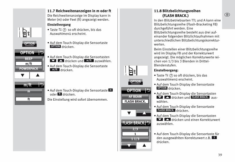
11.7 Reichweitenanzeigen in m oder ftDie Reichweitenanzeige im Display kann inMeter (m) oder Feet (ft) angezeigt werden.Einstellvorgang• Taste � so oft drücken, bis das
Auswahlmenü erscheint.
• Auf dem Touch-Display die Sensortastedrücken.
• Auf dem Touch-Display die Sensortastendrücken und auswählen.
• Auf dem Touch-Display die Sensortastedrücken.
• Auf dem Touch-Display die Sensortaste oder drücken.
Die Einstellung wird sofort übernommen.
mft
m/ft
m/ft
D
OPTION
11.8 Blitzbelichtungsreihen (FLASH BRACK.)
In den Blitzbetriebsarten TTL und A kann eineBlitzbelichtungsreihe (Flash-Bracketing FB)durchgeführt werden. EineBlitzbelichtungsreihe besteht aus drei auf-einander folgenden Blitzlichtaufnahmen mitunterschiedlichen Blitzbelichtungskorrektur-werten.Beim Einstellen einer Blitzbelichtungsreihewird im Display FB und der Korrekturwertangezeigt. Die möglichen Korrekturwerte rei-chen von 1/3 bis 3 Blenden in Drittel-Blendenstufen.Einstellvorgang:• Taste � so oft drücken, bis das
Auswahlmenü erscheint.• Auf dem Touch-Display die Sensortaste
drücken.• Auf dem Touch-Display die Sensortasten
drücken und aus-wählen.
• Auf dem Touch-Display die Sensortastedrücken.
• Auf dem Touch-Display die Sensortastendrücken und einen Korrekturwert
auswählen.
• Auf dem Touch-Display die Sensortaste fürden ausgewählten Korrekturwert z.B.drücken.
1
OPTION
FLASH BRACK.
FLASH BRACK.
D
39
j
OPTION
m/ft Om
ft
OPTION O
q p
BEEPm/ft
POWERPACK
OPTION
FLASH BRACK. O
q p
2/31
1 1/3
OPTION O
q p
AF BEAMFLASH BRACK.

Die Einstellung wird sofort übernommen.• Die erste Aufnahme wird ohne
Korrekturwert ausgeführt. Im Display wirdzusätzlich „FBI“ angezeigt.
• Die zweite Aufnahme erfolgt mit Minus-Korrektur. Im Display wird zusätzlich „FBII“und der Minus-Korrekturwert (EV) ange-zeigt.
• Die dritte Aufnahme erfolgt mit Plus-Korrektur. Im Display wird zusätzlich „FBIII“und der Plus-Korrekturwert (EV) angezeigt.
• Nach der dritten Aufnahme wird dieBlitzbelichtungsreihe automatischgelöscht. Die Anzeige „FB“ im Display ver-lischt.
Beim Einstellen der Blitzbelichtungsreihewird der Korrekturwert immer positiv ange-zeigt!Blitzbelichtungsreihe im TTL-BlitzbetriebEine Blitzbelichtungsreihe im TTL-Blitzbetriebkann nur dann erfolgen, wenn die Kamera dieEinstellung einer manuellenBlitzbelichtungskorrektur am Blitzgerätunterstützt (siehe Kamerabedienungsanlei-tung)! Andernfalls erfolgen die Aufnahmenohne Korrekturwert!Blitzbelichtungsreihe im Automatik-Blitzbetrieb AFür eine Blitzbelichtungsreihe im Automatik-Blitzbetrieb A ist der Kameratyp unerheblich.
11.9 Beep-Funktion (BEEP)Mit der Beep-Funktion kann sich derBenutzer einige Gerätefunktionen desBlitzgerätes akustisch mitteilen lassen.Dadurch kann sich der Fotograf voll auf Motivund Aufnahme konzentrieren und muss nichtauf zusätzliche optische Statusanzeigen ach-ten!Die Beep-Funktion signalisiert akustisch dasErreichen der Blitzbereitschaft oder eineFehlbedienung.Einstellvorgang• Taste � so oft drücken, bis das
Auswahlmenü erscheint.
• Auf dem Touch-Display die Sensortastedrücken.
• Auf dem Touch-Display die Sensortastendrücken und auswählen.
• Auf dem Touch-Display die Sensortastedrücken.
• Auf dem Touch-Display die Sensortastedrücken. Die Einstellung wird sofort
übernommen.Nach der Aktivierung der BEEP-Funktion wirdim INFO-Menü „ ” angezeigt.
OPTION
BEEP
BEEP
ON
D
40
j
OPTION
BEEP OOFF
ON
OPTION O
q p
MOD. LIGHTBEEPm/ft
Akustische Meldung nach dem Einschaltendes Blitzgerätes:• Ein kurzes (ca. 2s) ununterbrochenes Beep-
Signal nach dem Einschalten zeigt dieBlitzbereitschaft des Blitzgerätes an.
Beep-Signale bei den Einstellungen imAutomatik-Blitzbetrieb:• Ein kurzes Beep-Signal als Alarm erfolgt,
wenn im Automatik-Blitzbetrieb dieBlenden- und ISO-Einstellung zu einerÜberschreitung des zulässigenLichtregelbereiches führen würde. DieAutomatik-Blende wird automatisch aufden nächstliegenden zulässigen Wert geän-dert.
11.10 Verriegelung / EntriegelnDie Einstellung am Blitzgerät kann gegenunbeabsichtigtes Verstellen verriegeltwerden.Zum Verriegeln bzw. zum Entriegeln die Taste
� ca. 3 Sekunden lang drücken.Auf dem Bildschirm werden alleSensortasten in weißer Farbe dargestellt undsind nicht mehr bedienbar.Nur die INFO-Sensortaste kann gedrücktwerden.
11.11 Powerpack anschließen(Zubehör)
An das Blitzgerät kann an der Buchse � einPowerpack (Zubehör) angeschlossen werden.Zum Anschließen des Powerpack benötigenSie ein Verbindungskabel (Sonderzubehör).Das Powerpack verlängert die Betriebsdauerdes Blitzgerätes und sorgt für schnellereBlitzfolgezeiten.
D
41
j

Einstellvorgang• Taste � so oft drücken, bis das
Auswahlmenü erscheint.
• Auf dem Touch-Display die Sensortastedrücken.
• Auf dem Touch-Display die Sensortastendrücken und aus-
wählen.• Auf dem Touch-Display die Sensortaste
drücken.
• Auf dem Touch-Display die Sensortastefür schnellste Blitzfolgezeiten
für schnelle Blitzfolgezeiten drücken.
Die Einstellung wird sofort übernommen.
POWERPACK
D
OPTION
POWERPACK
12 FavoritenprogrammeIn der Blitzlichtfotographie gibt es immerwiederkehrende Standardsituationen (z. B.Geburtstagsfeiern im eigenen Wohnzimmero.ä.). Der mecablitz bietet die Möglichkeit,die Einstellungen des Blitzgerätes für solcheStandardsituationen als Favoritenprogrammzu speichern. So können einmal getroffeneBlitzgeräte-Parameter schnell wieder einge-stellt werden.Das Blitzgerät hat 4 Speicherplätze zumsichern der am Blitzgerät getroffenenEinstellungen.Einstellvorgang für das Speichern einesFavoritenprogrammes• Blitzgeräte-Parameter einstellen.• Taste � so oft drücken, bis das
Auswahlmenü erscheint.
• Auf dem Touch-Display die Sensortastedrücken.
• Auf dem Touch-Display die Sensortastedrücken.
• Auf dem Touch-Display die Sensortasten. . . drücken.
Die Einstellung werden auf dem gewähltenSpeicherplatz abgelegt.
F4F1
D
SAVE
42
j
F1
F3 F4
SAVE LOAD
F2
O
OPTION
POWERPACK O
OPTION O
q p
m/ftPOWERPACK
AF BEAM
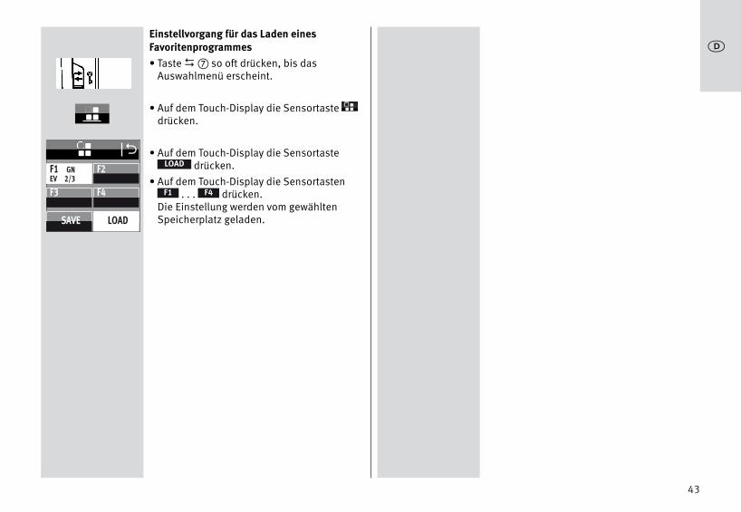
Einstellvorgang für das Laden einesFavoritenprogrammes• Taste � so oft drücken, bis das
Auswahlmenü erscheint.
• Auf dem Touch-Display die Sensortastedrücken.
• Auf dem Touch-Display die Sensortastedrücken.
• Auf dem Touch-Display die Sensortasten. . . drücken.
Die Einstellung werden vom gewähltenSpeicherplatz geladen.
F4F1
LOAD
D
43
j
F1 GNEV 2/3
F3 F4
SAVE LOAD
F2
O

44
13 Blitztechniken
13.1 Indirektes BlitzenDurch indirektes Blitzen wird das Motiv wei-cher ausgeleuchtet und eine ausgeprägteSchattenbildung verringert. Zusätzlich wirdder physikalisch bedingte Lichtabfall vomVordergrund zum Hintergrund vermindert.Für indirektes Blitzen ist der Reflektor desBlitzgerätes horizontal und vertikal schwenk-bar. Reflektor schwenken• Entriegelungsknopf drücken und den
Reflektor aus der Verriegelung lösen und gleich-zeitig in die gewünschte Position drehen.
Der Reflektor ist nur in der Normalpositionverriegelt.Zur Vermeidung von Farbstichen in denAufnahmen sollte die Reflexfläche farb-neutral bzw. weiß sein.Beim Schwenken des Reflektors ist darauf zuachten, dass um einen genügend großenWinkel geschwenkt wird, damit kein direktesLicht vom Reflektor auf das Motiv fallen kann.Deshalb mindestens bis zur 60° Rastpositionschwenken. Bei geschwenktem Reflektorkopf wird derReflektor in eine Position von 70 mm gesteu-ert, damit kein direktes Streulicht zusätzlichdas Motiv beleuchten kann.Dabei erfolgt keine Anzeige der Reichweiteund der Position des Reflektors.
13.2 Indirektes Blitzen mitReflektorkarte
Durch indirektes Blitzen mit der integriertenReflektorkarte � können bei PersonenSpitzlichter in den Augen erzeugt werden:• Den Reflektorkopf um 90° nach oben
schwenken.• Die Reflektorkarte � zusammen mit der
Weitwinkelstreuscheibe oben aus demReflektorkopf nach vorne heraus ziehen.
• Die Reflektorkarte � halten und dieWeitwinkelstreuscheibe in denReflektorkopf zurück schieben.
13.3 Nahaufnahmen / MakroaufnahmenIm Nahbereich und bei Makroaufnahmenkann es durch den Parallaxefehler zwischenBlitzgerät und Objektiv am unteren Bildrandzu Abschattungen kommen. Um dies auszu-gleichen, kann der Hauptreflektor um einenWinkel von -9° nach unten geschwenktwerden. Dazu den Entriegelungsknopf desReflektors drücken und den Reflektor nachunten schwenken.
Ist der Hauptreflektor nach untengeschwenkt, so wird im Display als Hinweisdafür „ “ angezeigt. Der Zweitreflektorwird dabei nicht unterstützt und blitzt nichtmit.Bei Aufnahmen im Nahbereich ist zu beach-ten, dass bestimmte Mindest beleuch-tungsabstände eingehalten werden müssen,um eine Überbelichtung zu vermeiden.
j
+
+

45
14 Blitzsynchronisation
14.1 Automatische Blitzsynchronzeit-steuerung
Je nach Kameratyp und Kamerabetriebsartwird bei Erreichen der Blitzbereitschaft dieVerschlusszeit auf die Blitzsynchronzeitumgeschaltet (siehe Kamerabedienungsan-leitung).Kürzere Verschlusszeiten als die Blitzsyn-chronzeit können nicht eingestellt werden,bzw. werden auf die Blitzsynchronzeit umge-schaltet. Verschiedene Kameras verfügenüber einen Synchronzeitbereich, z.B. 1/60sbis 1/250s (siehe Kamerabedienungsan-leitung). Welche Synchronzeit die Kameraeinsteuert, ist dann von der Kamerabetriebs-art, vom Umgebungslicht und der verwende-ten Objektivbrennweite abhängig.Längere Verschlusszeiten als die Blitzsyn-chronzeit können je nach Kamerabetriebsartund gewählter Blitzsynchronisation verwen-det werden.Bei Kameras mit Zentralverschluss und beiKurzzeitsynchronisation (siehe 7.4) erfolgtkeine automatische Blitzsynchronzeitsteue-rung. Dadurch kann mit allen Verschluss-zeiten geblitzt werden. Sollten Sie die volleLichtleistung des Blitzgerätes benötigen, sosollten Sie keine kürzeren Verschlusszeitenals 1/125s wählen.
14.2 NormalsynchronisationBei der Normalsynchronisation wird dasBlitzgerät zum Beginn der Verschlusszeit aus-gelöst (Synchronisation auf den1.Verschlussvorhang). Die Normalsynchroni-sation ist der Standardbetrieb und wird vonallen Kameras ausgeführt. Sie ist für die mei-sten Blitzaufnahmen geeignet. Die Kamerawird abhängig von ihrer Betriebsart auf dieBlitzsynchronzeit umgeschaltet. Üblich sind Zeiten zwischen 1/30s und1/125s (siehe Kamerabedienungsanleitung). Am Blitzgerät erfolgt keine Anzeige für diesenBetrieb.
14.3 Langzeitsynchronisation (SLOW)Mit der Langzeitbelichtung SLOW wird derBildhintergrund bei geringer Umgebungs-helligkeit stärker zur Geltung gebracht.Erreicht wird dies durch Kameraverschluss-zeiten, die dem Umgebungslicht angepasstsind. Dabei werden von der Kamera automa-tisch Verschlusszeiten, die länger als dieBlitzsynchronzeit sind (z.B. Verschlusszeitenbis zu 30s), eingesteuert. Bei einigenKameratypen wird die Langzeitsynchro-nisation in bestimmten Kameraprogrammen(z.B. Nachtaufnahme-Programm usw.) auto-matisch aktiviert bzw. kann an der Kameraeingestellt werden (siehe Kamerabedie-nungsanleitung). Am Blitzgerät erfolgt keineEinstellung bzw. Anzeige für diesen Betrieb.
j

Die Einstellung für die Langzeitsynchronisa-tion SLOW erfolgt an der Kamera (sieheKamerabedienungsanleitung)! VerwendenSie bei langen Verschlusszeiten ein Stativ umverwackelte Aufnahmen zu vermeiden!
14.4 Die SynchronbuchseDas Blitzgerät kann im Automatik-Blitzbe-trieb , im manuellen Blitzbetrieb undim Stroboskop-Betrieb über dieSynchronbuchse ausgelöst werden.Ein auf der Kamera montierter 64AF-1 kannüber ein Synchronkabel ein weiteresBlitzgerät auslösen.
Ein altes Blitzgerät mit Hochvoltzündung darfnicht an der Synchronbuchse angeschlossenwerden.
MA
46
j
+

15 Touch-Display Einstellungen
15.1 Helligkeit (BRIGHTNESS)Die Bildschirm-Helligkeit kann in fünf Stufenverändert werden .Einstellvorgang• Taste � so oft drücken, bis das
Auswahlmenü erscheint.
• Auf dem Touch-Display die Sensortastedrücken.
• Auf dem Touch-Display die Sensortastedrücken.
• Auf dem Touch-Display die Sensortastendrücken und die gewünschte
Helligkeit auswählen.
• Auf dem Touch-Display die Sensortaste derausgewählten Helligkeit, z.B. ,drücken.
Die Einstellung wird sofort übernommen
D
SERVICE
BRIGHTNESS
80
15.2 Rotation (ROTATION)Beim Schwenken des Blitzgerätes in dieHorizontale kann die Bildschirmanzeigeebenfalls geschwenkt werden .Einstellvorgang• Taste � so oft drücken, bis das
Auswahlmenü erscheint.
• Auf dem Touch-Display auf das Sensortastedrücken.
• Auf dem Touch-Display auf die Sensortastedrücken.
• Auf dem Touch-Display die Sensortastedrücken.
Die Einstellung wird sofort übernommen.
D
SERVICE
ROTATION
ON
47
j
SERVICE
SERVICE O
BRIGHTNESS
RESET
ROTATION
BRIGHTNESS O
q p
6080
100
SERVICE
SERVICE O
BRIGHTNESS
RESET
ROTATION
ROTATION OOFF
ON

16 Wartung und Pflege• Die Reinigung der Bildschirmoberfläche
muss mit einem trockenen, weichenReinigungstuch (z.B. Microfasertuch) erfol-gen.
• Sollten dennoch stärkere Verschmutzungenentstanden sein, kann die Reinigung derBildschirmoberfläche mit einem nur leichtangefeuchteten, weichen Tuch erfolgen.
Spritzen Sie niemals Reinigungsflüssig-keit auf die Bildschirmoberfläche ! SollteReinigungsflüssigkeit in den Rahmen desBildschirms eindringen, werden die dortbefindlichen Bauteile irreparabelbeschädigt.
16.1 Firmware-UpdateDie Firmware-Version (im Beispiel V1.0) desBlitzgerätes wird nach dem Einschalten imStartbildschirm angezeigt.Die Firmware des Blitzgerätes kann über dieUSB Firmwareupdate-Buchse � aktualisiertund im technischen Rahmen an dieFunktionen zukünftiger Kameras angepasstwerden.Nähere Informationen finden Sie im Internetauf der Metz-Homepage: www.metz.de
16.2 Formieren des BlitzkondensatorsDer im Blitzgerät eingebauteBlitzkondensator erfährt eine physikalischeVeränderung, wenn das Gerät längere Zeitnicht eingeschaltet wird. Aus diesem Grundist es notwendig, das Gerät im vierteljährli-chen Abstand für ca. 10 Min. einzuschalten.Die Stromquellen müssen dabei so vielEnergie liefern, dass die Blitzbereitschaftlängstens 1 Min. nach dem Einschalten auf-leuchtet.
16.3 Rückstellen auf Werkseinstellung(RESET)
Das Blitzgerät kann auf die Werkseinstellungbei Auslieferung eingestellt werden.Einstellvorgang• Taste � so oft drücken, bis das
Auswahlmenü erscheint.• Auf dem Touch-Display die Sensortaste
drücken.
• Auf dem Touch-Display die Sensortastedrücken.
• Auf dem Touch-Display die Sensortastedrücken.
Die Einstellung wird sofort übernommenund das Blitzgerät wird in denAuslieferungszustand zurück gesetzt.
Firmware-Updates des Blitzgerätes sinddavon nicht betroffen!
ON
D
SERVICE
RESET
48
j
SERVICE
SERVICE O
BRIGHTNESS
RESET
ROTATION
RESET OOFF
ON

17 Hilfe bei StörungenSollte es einmal vorkommen dass z.B. im Display des Blitzgerätesunsinnige Anzeigen erscheinen oder das Blitzgerät funktioniertnicht so wie es soll, so schalten Sie das Blitzgerät für ca. 10Sekunden mit dem Hauptschalter � aus. Überprüfen Sie die korrek-te Montage des Blitzgerätefußes im Zubehörschuh der Kamera unddie Kameraeinstellungen.Tauschen Sie die Batterien bzw. Akkus gegen neue Batterien bzw.frisch geladene Akkus aus!Das Blitzgerät sollte nach dem Einschalten wieder „normal“ funktio-nieren. Ist dies nicht der Fall, so wenden Sie sich bitte an IhrenFachhändler.Nachfolgend sind einige Probleme aufgeführt, die in der Blitz-Praxisauftreten können. Unter den jeweiligen Punkten sind möglicheUrsachen bzw. Abhilfen für diese Probleme aufgeführt.Im Display erfolgt keine Reichweitenanzeige• Es hat kein Datenaustausch zwischen Blitzgerät und Kamera statt-
gefunden. Kameraauslöser antippen.• Der Reflektor befindet sich nicht in der Normalposition. • Am Blitzgerät ist der Remote-Betrieb eingeschaltetDas AF-Hilfslicht des Blitzgerätes wird nicht aktiviert• Das Blitzgerät ist nicht blitzbereit.• Die Kamera arbeitet nicht in der Betriebsart „Single-AF (S-AF)“.• Die Kamera unterstützt nur den eigenen internen AF-Hilfslicht.• Verschiedene Kameratypen unterstützen nur mit dem zentralen AF-
Sensor der Kamera das AF-Hilfslicht im Blitzgerät.Wird ein dezentraler AF-Sensor gewählt, so wird das AF-Hilfslichtim Blitzgerät nicht aktiviert! Zentralen AF-Sensor aktivieren!
• Die Funktion „AF BEAM” ist ausgeschaltet.„AF BEAM” einschalten, siehe 11.6.
Die Zoom-Position des Reflektors wird nicht automatisch der aktu-ellen Zoom-Position des Objektivs angepasst• Die Kamera überträgt keine Daten an das Blitzgerät.• Es findet kein Datenaustausch zwischen Blitzgerät und Kamera
statt. Kameraauslöser antippen!• Die Kamera ist mit einem Objektiv ohne CPU ausgerüstet.• Das Blitzgerät arbeitet im Extended- oder Spot-Zoom-Betrieb. Auf
Standard-Zoom umschalten (siehe 11.4.3).• Der Reflektor ist aus seiner Normalposition geschwenkt.• Die Weitwinkelscheibe ist vor dem Reflektor geklappt.• Vor dem Reflektor ist ein Mecabounce montiert. Der TTL-Blitzbetrieb lässt sich nicht einstellen• Es hat kein Datenaustausch zwischen Blitzgerät und Kamera statt-
gefunden. Kameraauslöser antippen.• Die Kamera unterstützt den TTL-Blitzbetrieb nicht.Die Einstellung für die manuelle TTL-Blitzbelichtungskorrektur wirdnicht wirksam• Die Kamera unterstützt die manuelle TTL-Blitzbelichtungskorrektur
am Blitzgerät nicht.Es findet keine automatische Umschaltung auf dieBlitzsynchronzeit statt• Die Kamera hat einen Zentralverschluss (die meisten
Kompaktkameras).Die Umschaltung auf Synchronzeit ist daher nicht erforderlich.
• Das Blitzgerät arbeitet mit Kurzzeitsynchronisation. Dabei findetkeine Umschaltung auf die Synchronzeit statt.
• Die Kamera arbeitet mit Verschlusszeiten, die länger als dieBlitzsynchronzeit ist. In Abhängigkeit von der Kamerabetriebsartwird dabei nicht auf die Blitzsynchronzeit umgeschaltet (sieheKamerabedienungsanleitung).
49
j

50
j
Die Aufnahmen sind zu dunkel• Das Motiv liegt außerhalb der Reichweite des Blitzgerätes.
Beachten Sie: Beim indirekten Blitzen verringert sich dieReichweite des Blitzgerätes.
• Das Motiv enthält sehr helle oder reflektierende Bildpartien.Dadurch wird das Messsystem der Kamera bzw. des Blitzgerätesgetäuscht. Stellen Sie eine positive manuelleBlitzbelichtungskorrektur ein, z.B. +1 EV.
Die Aufnahmen sind zu hell• Im Nahbereich kann es zu Überbelichtungen (Aufnahmen sind zu
hell) kommen, wenn die kürzeste Leuchtzeit des Blitzgerätesunterschritten wird.
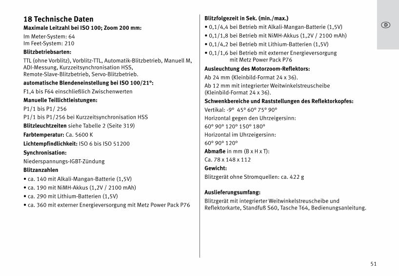
51
j18 Technische DatenMaximale Leitzahl bei ISO 100; Zoom 200 mm:Im Meter-System: 64 Im Feet-System: 210Blitzbetriebsarten:TTL (ohne Vorblitz), Vorblitz-TTL, Automatik-Blitzbetrieb, Manuell M,ADI-Messung, Kurzzeitsynchronisation HSS, Remote-Slave-Blitzbetrieb, Servo-Blitzbetrieb.automatische Blendeneinstellung bei ISO 100/21°:F1,4 bis F64 einschließlich ZwischenwertenManuelle Teillichtleistungen:P1/1 bis P1/ 256P1/1 bis P1/256 bei Kurzzeitsynchronisation HSSBlitzleuchtzeiten siehe Tabelle 2 (Seite 319)
Farbtemperatur: Ca. 5600 K
Lichtempfindlichkeit: ISO 6 bis ISO 51200
Synchronisation: Niederspannungs-IGBT-ZündungBlitzanzahlen• ca. 140 mit Alkali-Mangan-Batterie (1,5V)• ca. 190 mit NiMH-Akkus (1,2V / 2100 mAh)• ca. 290 mit Lithium-Batterien (1,5V)• ca. 360 mit externer Energieversorgung mit Metz Power Pack P76
Blitzfolgezeit in Sek. (min./max.)• 0,1/4,4 bei Betrieb mit Alkali-Mangan-Batterie (1,5V)• 0,1/1,8 bei Betrieb mit NiMH-Akkus (1,2V / 2100 mAh)• 0,1/4,2 bei Betrieb mit Lithium-Batterien (1,5V)• 0,1/1,6 bei Betrieb mit externer Energieversorgung
mit Metz Power Pack P76
Ausleuchtung des Motorzoom-Reflektors:Ab 24 mm (Kleinbild-Format 24 x 36).Ab 12 mm mit integrierter Weitwinkelstreuscheibe(Kleinbild-Format 24 x 36).Schwenkbereiche und Raststellungen des Reflektorkopfes:Vertikal: -9° 45° 60° 75° 90°Horizontal gegen den Uhrzeigersinn:60° 90° 120° 150° 180°Horizontal im Uhrzeigersinn:60° 90° 120°Abmaße in mm (B x H x T):Ca. 78 x 148 x 112Gewicht:Blitzgerät ohne Stromquellen: ca. 422 g
Auslieferungsumfang:Blitzgerät mit integrierter Weitwinkelstreuscheibe undReflektorkarte, Standfuß S60, Tasche T64, Bedienungsanleitung.

52
j19 Sonderzubehör Für Fehlfunktionen und Schäden am Blitzgerät, verursacht durch dieVerwendung von Zubehör anderer Hersteller, wird keineGewährleistung übernommen!• mecabounce Diffuser MBM-03(Bestellnr. 000003902)Mit diesem Diffusor erreichen Sie auf einfachste Weise eine weicheAusleuchtung.Die Wirkung ist großartig, weil die Bilder einen softartigen Effekterhalten. Die Gesichtsfarbe von Personen wird natürlicher wiederge-geben.Die Grenzreichweiten verringern sich entsprechend dem Lichtverlustcirca auf die Hälfte.• Reflexschirm 58-23(Bestellnr. 000058235)Mildert durch sein weiches gerichtetes Licht harte Schlagschatten.• Blitzgeräte-Standfuß S60(Bestellnr. 000000607)Blitzgeräte-Standfuß für den Slave-Betrieb.• Verbindungskabel V58-50(Bestellnr. 000058504)auch passend zum Powerpack P76• Powerpack• Easy Softbox ESB 60-60 (Bestellnr. 009016076)
Abmessungen: 60 × 60 cm
Inklusive Front- und Hintergrund Diffusor, Tragetasche und Bowens-kompatibler Adapter zum Anschluss an Metz Studioblitzgeräte TLoder BL
• Easy Softbox ESB 40-40 (Bestellnr. 009014047)
Abmessungen: 40 × 40 cm
Inklusive Front- und Hintergrund Diffusor, Tragetasche und Bowens-kompatibler Adapter zum Anschluss an Metz Studioblitzgeräte TLoder BL
• Blitzgerätehalter FGH 40-60 (Bestellnr. 009094065)
Adapter zwischen Kompaktblitzgeräten und Easy Softboxen
Höhe des Blitzschuhs verstellbar
Aufsteckbar auf Metz Leuchtenstative LS-247 und LS-200
• Mini Softbox SB 30-20 (Bestellnr. 009013023)
Farbe: weiß, Abmessungen: 30 × 20 cm
• Mini Softbox SB 22-16 (Bestellnr. 009012217)
Farbe: weiß, Abmessungen: 22 × 16 cm
• Mini Softbox SB 18-15 (Bestellnr. 009011817)
Farbe: weiß, Abmessungen: 18 × 15 cm
• Mini Octagon Softbox SB 34-34 (Bestellnr. 009023432)
Farbe: weiß, Abmessungen: Ø 34 cm
• Mini Octagon Softbox SB 20-20 (Bestellnr. 009022029)
Farbe: weiß, Abmessungen: Ø 20 cm

53
j
• Mini Octagon Softbox SB 15-15 (Bestellnr. 009021516)
Farbe: weiß, Abmessungen: Ø 15 cm
• Spot Reflexschirm SD 30-26 W (Bestellnr. 009043021)
Farbe: weiß für neutrales Licht / Abmessungen: 30 × 26 cm
• Spot Reflexschirm SD 30-26 S (Bestellnr. 00904303A)
Farbe: silber für kühles Licht / Abmessungen: 30 × 26 cm
• Spot Reflexschirm SD 30-26 G (Bestellnr: 009043048)
Farbe: gold für warmes Licht / Abmessungen: 30 × 26 cm
Batterie-EntsorgungBatterien/Akkus gehören nicht in den Hausmüll! Bitte bedienen Siesich bei der Rückgabe verbrauchter Batterien/Akkus eines vorhan-denen Rücknahme systems.Bitte geben Sie nur entladene Batterien/Akkus ab. Batterien sind inder Regel dann entladen, wenn das damit betriebene Gerät– nach längerem Gebrauch der Batterien nicht mehr einwandfrei
funktioniert.Zur Kurzschlusssicherheit sollten die Batteriepole mit einemKlebestreifen überdeckt werden.Deutschland: Als Verbraucher sind Sie gesetzlich verpflichtet,gebrauchte Batterien zurückzugeben. Sie können Ihre altenBatterien überall dort unentgeltlich abgeben, wo die Batteriengekauft wurden. Ebenso bei den öffentlichen Sammelstellen in IhrerStadt oder Gemeinde.Diese Zeichen finden Sie auf schadstoffhaltigen Batterien:
Pb = Batterie enthält BleiCd = Batterie enthält CadmiumHg = Batterie enthält QuecksilberLi = Batterie enthält Lithium
Technische Änderungen und Irrtümer vorbehalten !

54
jGarantiebestimmungen Bundesrepublik Deutschland1. Die Garantiebestimmungen gelten ausschließlich für Käufe in der
Bundesrepublik Deutschland.2. Im Ausland gelten die Gewährleistungsregelungen des jeweiligen
Landes bzw. die Garantieregelungen des Verkäufers.3. Die nachfolgenden Bestimmungen haben nur für den privaten
Gebrauch Gültigkeit.4. Die Garantiezeit - 24 Monate - beginnt mit dem Abschluss des
Kaufvertrages bzw. mit dem Tag der Auslieferung des Gerätes anden Käufer (Endverbraucher).
5. Garantieansprüche können nur unter Nachweis des Kaufdatumsdurch Vorlage des vom Verkäufer maschinell erstellten Original-Kaufbeleges geltend gemacht werden.
6. Beanstandete Geräte bitten wir zusammen mit dem Kaufbelegentweder über den Fachhändler oder direkt an die Firma Metz-Werke GmbH & Co KG - Zentralkundendienst - Ohmstrasse 55,90513 Zirndorf, transportsicher verpackt unter genauerSchilderung der Beanstandung einzusenden. Sie können unterden gleichen Bedingungen auch an die autorisiertenKundendienststellen der Firma Metz-Werke GmbH & Co KG einge-sandt werden. Hin- und Rücksendung erfolgen auf Gefahr desKäufers.
7. Die Garantie besteht darin, dass Geräte, die infolge eines aner-kannten Fabrikations- oder Materialfehlers defekt geworden sind,kostenlos repariert oder, soweit eine Reparatur unverhältnismä-ßig ist, ausgetauscht werden. Eine weitergehende Haftung, insbesondere für Schäden, dienicht am Gerät selbst entstanden sind, ist ausgeschlossen. Diesgilt nicht, soweit im Falle des Vorsatzes oder der grobenFahrlässigkeit zwingend gehaftet wird.Garantieleistungen bewirken weder eine Verlängerung derGarantiezeit, noch wird für die ersetzten oder nachgebessertenTeile eine neue Garantiezeit begründet.
8. Unsachgemäße Behandlung und Eingriffe durch den Käufer oderDritte schließen die Garantieverpflichtungen sowie alle weiterenAnsprüche aus.Ausgenommen von der Garantie sind ferner Schäden oder Fehler,die durch Nichtbeachtung der Gebrauchsanleitung, mechanischeBeschädigung, ausgelaufene Batterien oder durch höhereGewalt, Wasser, Blitz etc. entstanden sind. Ferner sindVerschleiß, Verbrauch sowie übermäßige Nutzung von derGarantie ausgenommen. Hiervon sind vor allem folgende Teilebetroffen: Blitzröhre, fest eingebaute Akkus, Kontakte,Verbindungskabel.
9. Durch diese Garantiebestimmungen werden dieGewährleistungsansprüche des Käufers gegenüber demVerkäufer nicht berührt.
Metz-Werke GmbH & Co KG

55
j

Préambule. . . . . . . . . . . . . . . . . . . . . . . . . . . . . . . . . . . . . . . . . . . . . . 571 Consignes de sécurité . . . . . . . . . . . . . . . . . . . . . . . . . . . . . . . . . . 582 Fonctions flash dédiées . . . . . . . . . . . . . . . . . . . . . . . . . . . . . . . . . 593 Préparation du flash . . . . . . . . . . . . . . . . . . . . . . . . . . . . . . . . . . . . 603.1 Montage du flash . . . . . . . . . . . . . . . . . . . . . . . . . . . . . . . . . . . . 603.2 Alimentation . . . . . . . . . . . . . . . . . . . . . . . . . . . . . . . . . . . . . . . . 613.3 Mise en marche et coupure du flash . . . . . . . . . . . . . . . . . . . . . 623.4 Le menu de sélection . . . . . . . . . . . . . . . . . . . . . . . . . . . . . . . . . 623.5 INFO . . . . . . . . . . . . . . . . . . . . . . . . . . . . . . . . . . . . . . . . . . . . . . . 633.6 Coupure automatique du flash / Auto - OFF . . . . . . . . . . . . . . . 634 DEL de signalisation sur le flash . . . . . . . . . . . . . . . . . . . . . . . . . . 654.1 Affichage de disponibilité du flash . . . . . . . . . . . . . . . . . . . . . . 654.2 Témoin de mode de fonctionnement du flash. . . . . . . . . . . . . . 655 Indications sur l’écran . . . . . . . . . . . . . . . . . . . . . . . . . . . . . . . . . . 655.1 Affichage du mode flash . . . . . . . . . . . . . . . . . . . . . . . . . . . . . . . 665.2 Affichage de la portée. . . . . . . . . . . . . . . . . . . . . . . . . . . . . . . . . 666 Signalisations dans le viseur. . . . . . . . . . . . . . . . . . . . . . . . . . . . . 677 Modes de fonctionnement du flash. . . . . . . . . . . . . . . . . . . . . . . . 687.1 Mode flash TTL. . . . . . . . . . . . . . . . . . . . . . . . . . . . . . . . . . . . . . . 687.2 Pré-éclair TTL et mesure ADI . . . . . . . . . . . . . . . . . . . . . . . . . . . . 697.3 Mode flash manuel . . . . . . . . . . . . . . . . . . . . . . . . . . . . . . . . . . . 697.4 Synchronisation automatique haute vitesse (HSS). . . . . . . . . . 707.5 Mode flash automatique . . . . . . . . . . . . . . . . . . . . . . . . . . . . . . 717.6 Mode flash stroboscope . . . . . . . . . . . . . . . . . . . . . . . . . . . . . . . 728 Correction manuelle d’exposition au flash . . . . . . . . . . . . . . . . . 749 Fonctions spéciales . . . . . . . . . . . . . . . . . . . . . . . . . . . . . . . . . . . . 759.1 Asservissement de la tête zoom motorisée („Zoom“) . . . . . . . 75
10 Mode multi-flash sans fil . . . . . . . . . . . . . . . . . . . . . . . . . . . . . . . 7710.1 Mode remote maître . . . . . . . . . . . . . . . . . . . . . . . . . . . . . . . . . 7810.1.1 Régler le mode remote maître. . . . . . . . . . . . . . . . . . . . . . . . 7810.1.2 Régler le mode de flash sur le flash maître . . . . . . . . . . . . . 7910.1.3 Régler la puissance partielle en mode M sur le flash maître . . 7910.1.4 Définir la luminosité (RATIO) pour les groupes
de flash sur le flash maître . . . . . . . . . . . . . . . . . . . . . . . . . . 8010.1.5 Régler le mode remote canal. . . . . . . . . . . . . . . . . . . . . . . . . 8110.2 Mode flash remote slave . . . . . . . . . . . . . . . . . . . . . . . . . . . . . 8110.2.1 Régler le mode flash remote esclave . . . . . . . . . . . . . . . . . . 8210.2.2 Régler le canal esclave . . . . . . . . . . . . . . . . . . . . . . . . . . . . . 8210.2.3 Régler le mode esclave . . . . . . . . . . . . . . . . . . . . . . . . . . . . . 8310.2.4 Régler la puissance partielle de l’esclave . . . . . . . . . . . . . . 8310.2.5 Régler la puissance partielle/correction d’exposition
de l’esclave . . . . . . . . . . . . . . . . . . . . . . . . . . . . . . . . . . . . . . 8410.3 Vérification du mode flash remote. . . . . . . . . . . . . . . . . . . . . . 8410.4 Modo flash SERVO. . . . . . . . . . . . . . . . . . . . . . . . . . . . . . . . . . . 8510.4.1 Régler le mode flash SERVO . . . . . . . . . . . . . . . . . . . . . . . . . 8510.5.2 Régler le pré-éclair ou la synchronisation . . . . . . . . . . . . . . 8510.4.3 Réglage du mode servo puissance partielle . . . . . . . . . . . . 8610.4.4 Fonction d’apprentissage . . . . . . . . . . . . . . . . . . . . . . . . . . . 8610.4.5 Désactiver le mode flash SERVO. . . . . . . . . . . . . . . . . . . . . . 8711 OPTION menú . . . . . . . . . . . . . . . . . . . . . . . . . . . . . . . . . . . . . . . . 8811.1 Mode RAPID. . . . . . . . . . . . . . . . . . . . . . . . . . . . . . . . . . . . . . . . 8811.2 Réflecteur secondaire (SUB-REFL.). . . . . . . . . . . . . . . . . . . . . . 8811.3 Lumière pilote (MOD. LIGHT) . . . . . . . . . . . . . . . . . . . . . . . . . . 8911.4 Mode zoom (ZOOM MODE) . . . . . . . . . . . . . . . . . . . . . . . . . . . . 8911.4.1 Mode zoom étendu . . . . . . . . . . . . . . . . . . . . . . . . . . . . . . . . 8911.4.2 Mode SPOT zoom . . . . . . . . . . . . . . . . . . . . . . . . . . . . . . . . . . 90
56
l

PréambuleNous vous remercions d’avoir choisi un produit Metz et sommesheureux de vous saluer au sein de la grande famille de nos clients.
Nous savons que vous brûlez d’envie d’essayer votre flash.Prenez tout de même le temps de lire les instructions de service.C’est la seule manière de découvrir les potentialités de votre flashet d’apprendre à les utiliser.Ce flash convient aux:• Appareil photo reflex numérique Sony avec fonction pré-éclair TTL
et mesure ADI.Ce flash n’est pas compatible avec les appareils d’autres fabricants !
Veuillez également déplier le rabat en dernière page pour consulterles illustrations.
Explication
Doigt pointé, remarque
Attention : consigne de sécurité extrêmement importante !Utilisation correcteCe flash est exclusivement destiné à l’éclairage de sujets dans ledomaine photographique. Il ne doit être utilisé qu’avec les acces-soires mentionnés dans ce mode d’emploi ou homologués parMetz.Le flash ne doit en aucun cas être utilisé à d’autres fins que cellesdécrites ci-dessus.
+
11.4.3 Mode zoom STANDARD . . . . . . . . . . . . . . . . . . . . . . . . . . . . . 9111.5 Adaptation du format de prise de vue (ZOOM SIZE) . . . . . . . . 9111.6 Lumière auxiliaire AF (AF-BEAM) . . . . . . . . . . . . . . . . . . . . . . . 9211.7 Affichage des portées en mètres ou pieds . . . . . . . . . . . . . . . 9311.8 Séries d’expositions au flash (FLASH BRACK.) . . . . . . . . . . . . 9311.9 Fonction bip (BEEP). . . . . . . . . . . . . . . . . . . . . . . . . . . . . . . . . . 9411.10 Verrouillage / déverrouillage . . . . . . . . . . . . . . . . . . . . . . . . . 9511.11 Raccorder le Powerpack (accessoire) . . . . . . . . . . . . . . . . . . 9512 Programme favori . . . . . . . . . . . . . . . . . . . . . . . . . . . . . . . . . . . . . 9613 Techniques de photographie au flash . . . . . . . . . . . . . . . . . . . . 9813.1 Éclairage indirect au flash . . . . . . . . . . . . . . . . . . . . . . . . . . . . 9813.2 Éclairage indirect au flash avec carte-réflecteur . . . . . . . . . . . 9813.3 Macrophotographie (photographie rapprochée) . . . . . . . . . . 9814 Synchronisation du flash . . . . . . . . . . . . . . . . . . . . . . . . . . . . . . . 9914.1 Commutation automatique sur la vitesse de synchro-flash . . 9914.2 Synchronisation normale . . . . . . . . . . . . . . . . . . . . . . . . . . . . . 9914.3 Synchronisation en vitesse lente (SLOW) . . . . . . . . . . . . . . . . 9914.4 Prise synchro. . . . . . . . . . . . . . . . . . . . . . . . . . . . . . . . . . . . . . 10015 Réglages de l’écran tactile . . . . . . . . . . . . . . . . . . . . . . . . . . . . 10115.1 Luminosité (BRIGHTNESS) . . . . . . . . . . . . . . . . . . . . . . . . . . . 10115.2 Rotation (ROTATION) . . . . . . . . . . . . . . . . . . . . . . . . . . . . . . . . 10116 Maintenance et entretien . . . . . . . . . . . . . . . . . . . . . . . . . . . . . 10216.1 Mise à jour du micrologiciel . . . . . . . . . . . . . . . . . . . . . . . . . . 10216.2 Formation du condensateur de flash. . . . . . . . . . . . . . . . . . . 10216.3 Réinitialisation (RESET) . . . . . . . . . . . . . . . . . . . . . . . . . . . . . 10217 Remède en cas de mauvais fonctionnement . . . . . . . . . . . . . . 10318 Caractéristiques techniques . . . . . . . . . . . . . . . . . . . . . . . . . . . 10519 Accessoires en option . . . . . . . . . . . . . . . . . . . . . . . . . . . . . . . . 106
57
l

1 Consignes de sécuritéNe déclenchez en aucun cas un éclair àproximité de gaz ou de liquides inflamm-ables (essence, diluants, etc.) ! RISQUE D’EXPLOSION !Ne déclenchez jamais le flash à proximi-té des yeux ! L’amorçage d’un éclairdirectement devant les yeux de person-nes ou d’animaux peut entraîner unelésion de la rétine et occasionner degraves troubles visuels pouvant aller jus-qu’à l’aveuglement.Ne photographiez jamais au flash le con-ducteur d’un bus, d’un train, d’une voitu-re, d’une moto ni un cycliste, car sous lecoup de l’éblouissement il risque de pro-voquer un accident !Ne plus utiliser le flash si le boîtier estendommagé à tel point que les piècesintérieures ne sont plus fixées. Retirerles piles ! Ne pas toucher les compo-sants intérieurs. HAUTE TENSION !Après une séquence d’éclairs, la glacedu réflecteur est très chaude. Ne la tou-chez pas, risque de brûlure !Ne démontez pas le flash ! DANGER HAUTE TENSION !Le flash ne renferme pas de pièces sus-ceptibles de pouvoir être réparées par unnon-spécialiste.
• Le flash est conçu et agréé pour l’emploiexclusif en photographie!
• Utilisez exclusivement les sources d’éner-gie autorisées mentionnées dans le moded’emploi!
• Ne pas ouvrir ni court-circuiter les piles !• N’exposez pas les piles ou accus à une trop
grande chaleur, par ex. au soleil, aux flammes ou autre!
• Ne jetez pas au feu les piles ni les accususés!
• N’utilisez pas des piles ou accus défectueux!
• Ne soumettez pas le flash à une trop gran-de chaleur ni à une trop forte humidité del’air ! Ne conservez pas le flash dans la boîte à gants de votre voiture.
• Ne rechargez pas les piles sèches.• Maintenez votre flash et le chargeur à l’abri
de l’eau tombant en gouttes et des projec-tions d’eau!
• Ne soumettez pas le flash à une trop gran-de chaleur ni à une trop forte humidité del’air! Ne conservez pas le flash dans la boîte à gants de votre voiture!
• Un changement rapide de température peutentraîner la formation de buée. Laissez letemps à l’appareil pour s’acclimater !
58
l

• Au moment de déclencher un éclair, il nedoit pas y avoir de matière opaque directe-ment devant ni sur la glace du réflecteur. Laglace du réflecteur ne doit pas non plusêtre souillée. En cas de non-respect de cet-te consigne de sécurité, l’énergie de l’éclairpeut provoquer des brûlures sur la matièreopaque ou sur la glace du réflecteur.
• Si vous êtes amené à faire des séries dephotos au flash à pleine puissance et enrecyclage rapide, veillez à faire une paused’au moins 3 mi nutes après 20 éclairs !
• Si vous effectuez des séries de photos auflash à pleine puissance en bénéficiant detemps de recyclage courts avec une positi-on zoom à 35 mm et en dessous, le diffu-seur grand-angle risque de beaucoupchauffer en raison de la forte énergie del'éclair !
• Le flash ne peut être utilisé conjointementavec le flash intégré de l’appareil photoque si celui-ci peut être complètementdéployé!
2 Fonctions flash dédiéesLes fonctions flash dédiées sont des fonc-tions de flash adaptées spécialement à unsystème d’appareil photo. Les fonctions deflash supportées dépendent alors du typed’appareil.• Témoin de disponibilité du flash dans le
viseur / sur écran de l’appareil photo.• Vitesse de synchro-flash automatique.• Contrôle TTL du flash• Correction manuelle de l’exposition • Pré-éclaire TTL et mesure ADI• Asservissement de la tête zoom motorisée• Synchronisation sur le 1er ou
2ème rideau (REAR)• Mode zoom étendu• Commande de l'éclair d'assistance AF• Affichage automatique de la portée de
l'éclair• Synchronisation haute vitesse (HSS)
automatique en mode TTL et M• Inhibition du flash (AUTO-FLASH)• Modo flash Remote sans fil • Modo Servo• Mode spot zoom• Mode zoom étendu• Fonction de réveil du flash
59
l

Dans le cadre du présent mode d’emploi, iln’est pas possible d’aborder en détail tousles types d’appareils photo et leurs fonctionsflash correspondantes. Nous vous renvoyonsà ce sujet à la description de l’emploi duflash figurant dans le mode d’emploi de l’ap-pareil photo où sont indiquées les fonctionsde flash supportées par votre appareil photoou à régler directement sur l’appareil photo !
Si vous utilisez un objectif sans CPU (par ex.un objectif sans autofocus), vous rencontre-rez en partie des limites !
3 Préparation du flash
3.1 Montage du flashFixation du flash sur l’appareil
Éteindre l’appareil photo et le flash avant lemontage ou le démontage du flash !• Retirez le capuchon de protection de la
base de l'unité.• Tournez l’écrou moleté � jusqu’en butée
contre le flash. À présent, le pion d’immo-bilisation dans le sabot est complètementéclipsé dans le boîtier du flash.
• Engagez le sabot du flash dans la griffe porte-accessoires de l’appareil photo.
• Tournez l’écrou moleté � jusqu’en butéecontre le boîtier de l’appareil photo pourbloquer le flash. Sur les reflex sans troud’immobilisation, le pion monté sur ressortreste éclipsé dans le boîtier du flash etn’abîme pas la surface.
Retirer le flash de l’appareil photo
Éteindre l’appareil photo et le flash avant lemontage ou le démontage du flash !• Tournez l’écrou moleté � jusqu’en butée
contre le flash.• Dégagez le flash de la griffe porte-acces-
soires de l’appareil photo.
+
+
+
60
l

3.2 AlimentationChoix des piles ou accusLe flash peut fonctionner sur :• 4 accus au nickel-hydrure métallique de
1,2 V, type CEI HR6 (AA / Mignon), capacité nettement supérieure à celle desaccus NiCd et moins nuisibles à l’environnement car sans cadmium.
• 4 piles sèches alcalines au manganèse de1,5 V, type CEI LR6 (AA / Mignon), source de courant sans entretien pour exi-gences de performances moyennes.
• 4 piles au lithium de 1,5 V, type CEI FR6 (AA / Mignon), source de cou-rant sans entretien à haute performance etavec une perte de capacité minime.
• Power Pack avec câble de connexion(accessoire en option).
N’utilisez que les sources d’alimentationindiquées ci-dessus. Si vous utilisez d’autres sources d’alimentation, le flash risque d’être endommagé.
Si le flash reste inutilisé pendant une longuepériode, retirez les piles ou accus de l’appa-reil.
Remplacement des pilesLes piles/accus sont vides ou usagés lorsquele temps de recyclage (durée entre le déclen-chement du flash à pleine puissance lumi-neuse, p. ex. pour la série M, jusqu’à ce quele témoin de disponibilité du flash s’allume ànouveau) dépasse les 60 sec. Le messaged’avertissement de pile usée s'affiche égale-ment sur l'écran tactile.• Mettre le flash hors service en appuyant sur
la touche � jusqu’à ce que tous lesaffichages disparaissent.
• Pousser le couvercle du compartiment despiles � vers le bas et ouvrez-le.
• Introduisez les piles ou accus dans le sensde la longueur en vous conformant auxsymboles de piles puis refermez le couver-cle �.
À la mise en place des piles ou accumula-teurs, respectez la polarité conformémentaux symboles de piles figurant dans le comp-artiment à piles. Une inversion de polaritépeut conduire à la destruction de l’appareil!Risque d’explosion en cas d’usage non con-forme des piles. Remplacez toujours toutesles piles par des piles de qualité identiquesd’un même fabricant et de même capacité!Les piles ou accumulateurs usagés ne doi-vent pas être jetés avec les déchets ménagers! Apportez votre contribution à laprotection de l’environnement et remettez lespiles ou accumulateurs usagés aux points decollecte correspondants!
+
61
l

3.3 Mise en marche et coupure du flash
• Mettre le flash en service en appuyant surla touche �.L’écran d‘accueil apparaît. Le flash passe ensuite toujours au derniermode utilisé (p. ex. mode flash manuel M).
En mode veille, la touche � clignote enrouge. Pour mettre hors service, appuyer surla touche � jusqu’à ce que tous les affichages disparaissent.
Si le flash reste inutilisé pendant une périodeprolongée, nous recommandons de mettre leflash hors service avec la touche � et reti-rer les sources d’alimentation (piles, accus).
3.4 Le menu de sélection• Appuyer autant de fois sur la touche �
jusqu’à ce que le menu de sélection s‘affiche.
Le menu de sélection est divisé en 6 tou-ches:les modes peuvent être réglés en appuyantsur la touche .TTL, chap. 7.1TTL HSS*, voir 7.4A, chap. 7.5M, chap. 7.3M HSS*, chap. 7.4STROBO, chap. 7.6REMOTE MASTER, chap. 10.1REMOTE SLAVE, chap. 10.2SERVO, chap. 10.4 *) seulement après échange de données avec un appareil photo
D
D
MODE
Les paramètres du flash peuvent être réglésen appuyant sur la touche .P (puissance partielle), chap. 7.3, 10.1.3 et 10.4.3EV (correction d’exposition), chap. 8, 10.2.4ZOOM (réglage du réflecteur), chap. 9.1N (Nombre d’éclairs), chap. 7.6f (Fréquence des éclairs), chap. 7.6F (diaphragme)ISO (sensibilité lumineuse), RATIO (Luminodité), chap. 10.1.4CTRL (Remote), chap. 10.1CHANNEL (canal), chap. 10.2.2GROUP (Groupe esclave), chap 10.2.3.L’affichage des paramètres du flash dépenddu mode de flash sélectionné.
En appuyant sur la touche , il est possible de paramétrer l'écran tactile ou de réinitialiser le flash à l’état de livraison.
BRIGHTNESS (luminosité), chap. 15.1ROTATION (faire pivoter l’affichage), chap.15.2RESET, chap. 16.3.
PARAMETER
SERVICE
62
V 1.0
MB 64AF-1digitalSON
MODE
PARAMETER
SERVICE
PARAMETER OP / EVZOOM
Nf (Hz)
FISO
CHANNELRATIO
CONTROL
MODE OETTL
TTL HSSAM
M HSSSTROBO
REMOTE MASTERREMOTE SLAVE
SERVO
SERVICE O
BRIGHTNESS
RESET
ROTATION
l

Les options peuvent être paramétrées aprèsavoir appuyé sur la touche .RAPID (temps de recyclage courts), chap. 11.1SUB-REFL. (réflecteur secondaire), chap.11.2ZOOM SIZE (adaptation du format de prisede vue), chap. 11.5ZOOM MODE (éclairage), chap. 11.4STANDBY (arrêt automatique de l‘appareil), chap. 3.6MOD.LIGHT (lumière pilote), chap. 11.3BEEP (signal sonore), chap. 11.9m / ft (mètres / pieds), chap. 11.7POWERPACK (Powerpack externe),chap. 11.11AF BEAM (lumière auxiliaire AF), chap. 11.8FLASH BRACK. (séquences d’exposition auflash), chap. 11.8L’affichage des paramètres du flash dépenddu mode de flash sélectionné.Dans le menu affiché sur le flash, tous leschamps sur fond noir sont des touches surlesquelles il est possible d'appuyer poureffectuer des modifications/réglages dans lemenu.Dans les figures de la notice d’utilisation, nesont marquées en noir que les touches surlesquelles il faut appuyer pour le réglage dela fonction décrite.
OPTION3.5 INFOLes réglages actuels du flash peuvent êtreaffichés pendant le fonctionnement.
• Appuyer sur la touche � de l’écrantactile. Le tableau d’affichage apparaît.
- EXT (mode zoom étendu) est activé, (chap.11.6.1).
- AF OFF (lumière auxiliaire AF) estdésactivé (chap. 11.6).
- (MOD.LIGHT) est activé, (chap. 11.3).
- (fonction bip) est activée, (chap. 11.9)- (canal) est affiché, (chap. 10.1.5,
10.2.2)- L’arrêt automatique de l’appareil est réglé
sur 10 minutes, (chap. 3.6).- Après une utilisation intensive, l’affichage
de la température augmente.
3.6 Coupure automatique du flash / Auto - OFF
En usine, le flash est réglé pour se mettre enveille (Auto-OFF) 10 minutes environ -• après la mise en marche,• après déclenchement d’un éclair,• après l’enfoncement à mi-course du
déclencheur de l’appareil photo,• après l’arrêt du système de mesure
d’exposition de l’appareil photo. . . . . . passage en mode veille (Auto OFF) afind’économiser de l'énergie et pour éviter
i
2CH
63
OPTION
i
l
200
OPTION ORAPID
SUB-REFL. ZOOM SIZEZOOM MODESTANDBY
MOD. LIGHTBEEPm / ft
POWERPACKAF BEAM
FLASH BRACK.

+
toute décharge involontaire des sources d’alimentation. L’activation de l’arrêt auto-matique de l’appareil est indiquée sur l’écranINFO. Le témoin de disponibilité du flash �et les affichages sur l'écran LCD disparais-sent. En mode veille, la touche � clignote enrouge. Les réglages effectués avant l’arrêt automa-tique sont conservés et sont rétablis immédiatement à la remise en marche. Le flash peut être réactivé en appuyant sur latouche � ou en effleurant le déclencheurde l’appareil photo (fonction de réveil).
En mode esclave/SERVO, la mise hors tensi-on automatique n’est pas activée.
Si le flash reste inutilisé pendant une péri-ode prolongée, il est conseillé de couper leflash avec l’interrupteur principal � !Si nécessaire, le flash peut s’éteindre déjàaprès 1 minute ou il est possible de désacti-ver la fonction d’arrêt automatique.Le flash se met totalement hors service aprèsenv. 1h d’inactivité. Dans tous les modes, aubout de 10 secondes environ, l’écran estréglé sur la moitié de la luminosité pour éco-nomiser de l’énergie. La luminosité normaleest réactivée à chaque pression sur une tou-che ou sur l’écran.
D
D
Régler l’arrêt automatique de l'appareil• Mettre le flash en service en appuyant sur
la touche �.L’écran d’accueil apparaît. Le flash passe ensuite toujours au derniermode utilisé (p. ex. mode flash manuel M).
• Appuyer autant de fois sur la touche �jusqu’à ce que le menu de sélection s‘affiche.
• Appuyer sur la touche de l’écrantactile.
• Appuyer sur les touches et sélectionner .
• Appuyer sur la touche de l’écrantactile.
• Appuyer sur la touche pour le réglage dudélai sur l’écran tactile. Le réglage prendeffet immédiatement.
En mode veille, la touche � clignote enrouge.
D
OPTION
STANDBY
STANDBY
D
64
OPTION
OPTION O
q p
ZOOM MODESTANDBY
MOD. LIGHT
STANDBY OOFF
1 min10 min
l
200

4 DEL de signalisation sur le flash
4.1 Affichage de disponibilité du flashLorsque le condensateur du flash est chargé,la touche � clignote en vert sur le flash etindique ainsi la disponibilité du flash.Il signale ainsi que la prochaine photo peutêtre prise avec l'éclairage par le flash. La disponibilité du flash est aussi transmiseà l'appareil photo et est signalée dans leviseur.Si une prise de vue est effectuée avant l’affi-chage de la disponibilité du flash dans leviseur, le flash n’est alors pas déclenché.Dans le cas où l’appareil photo a déjà com-muté en vitesse de synchro-flash, la prise devue peut alors être sous-exposée (voir 14.1).
4.2 Témoin de mode de fonctionnementdu flash
Lorsque l’exposition est bonne, la touche� s’allume alors pendant env. 3 secondes enrouge, si la prise de vue dans les modeset ;(voir 7.1) ainsi qu’en mode auto-matique est correctement exposée !Sans témoin de bonne exposition après laprise de vue, celle-ci est alors sous-exposée. Vous devez alors :- régler sur le plus petit indice d’ouverture
suivant (p. ex. au lieu d’une ouverture de 8,régler sur 11), ou
- vous rapprocher du sujet ou de la surfaceéfléchissante (p. ex. pour les flashes indi-rects) ou
D
PTTLPTTLHSS
A
- régler une valeur ISO plus élevée sur lacaméra.
Observer l'indication de la portée sur l'écrandu flash (voir 5.2).
5 Indications sur l’écranLes appareils photo transmettent les valeursISO, la distance focale de l’objectif (mm) etl’ouverture du diaphragme au flash. Celui-ciadapte alors automatiquement ses réglagesnécessaires. A partir des valeurs et de sonnombre-guide, il calcule la portée maximalede l’éclair. Le type de flash, la portée, l’ouverture du dia-phragme et la position zoom du réflecteurs’affichent sur l’écran du flash.Si le flash est utilisé alors qu’il n’a pas reçules données de l’appareil photo, les réglagessont affichés sur le flash.Éclairage de l’écranEn appuyant sur la touche � du flash ouen effleurant l’écran tactile, l’éclairage del’écran est réglé pendant 10 s environ sur laluminosité maximale.
D
65
l

+
5.1 Affichage du mode flashL’écran affiche le mode flash choisi. A cetégard, différents affichages sont possiblespour le mode flash TTL pris en charge (p.ex. ,
et ) et le mode flash manuel M(voir 7.3), selon le modèle d’appareil photo.
5.2 Affichage de la portéeLors de l'utilisation d'appareils photo et d'unobjectif à CPU, la portée s'affiche à l'écran.Pour cela, un échange de données doit avoireu lieu entre l’appareil photo et le flash, parexemple par l’enfoncement à mi-course dudéclencheur de l’appareil photo. La portéepeut s’afficher soit en mètres (m), soit enpieds (ft - feet) (voir 11.7).
Aucune portée ne s’affiche si . . .
- aucune donnée n’est transmise par l’appareil photo.
- lorsque la tête zoom est orientée différem-ment de sa position normale (vers le hautou le côté)
- lorsque le flash fonctionne en mode REMOTEMASTER, REMOTE SLAVE ou SERVO.
PTTL HSSPTTL
Indication de la portée en mode flash TTL-/TTL HSSEn modes flash et ; voir 7.1),l’écran affiche la valeur de la portée mini-male et maximale de l’éclair.La valeur affichée se rapporte à la réflectancede 25 % du sujet, ce qui est le cas dans laplupart des situations de prise de vue.Des écarts importants du degré de réflectan-ce, par exemple pour des sujets très forte-ment ou très faiblement réfléchissants, peu-vent influencer la portée du flash.Le sujet devrait se situer entre environ 40 et70 % de la portée affichée, pour laisser ausystème électronique une latitude suffisantepour doser la lumière.Pour éviter une surexposition, la distanceminimale au sujet affichée sur l'écran doitêtre respectée.L’adaptation à la situation de prise de vueest possible par exemple en modifiant l’ouverture du diaphragme.
TTL HSSTTL
66
5.5 - 56 m M-Zoom 35 m
m
TTL
iEV
5.5 - 56 m M-Zoom 35 m
m
TTL
iEV
l

Indication de la portée en mode flash manuel En mode flash manuel l’écran indique lavaleur de la distance à respecter pour uneexposition correcte du sujet au flash.L’adaptation à la situation de prise de vueest possible par exemple en modifiant l’ouverture du diaphragme ou en choisissantune puissance partielle manuelle (voir 7.3).Dépassement de la capacité d’affichageL’écran du flash peut afficher une portéemaximale de 99 m ou 99 ft. Pour des valeurs élevées de sensibilité ISOet de grandes ouvertures du diaphragme, ilpeut arriver que la portée maximale afficha-ble soit dépassée. Ceci est signalé par une flèche ou un trianglederrière la valeur de la distance affichée.
M6 Signalisations dans le viseurExemples de signalisations dans le viseur:Symbole éclair s’allume:Le flash est prêt à l’emploi (sur certainsappareils photo).Symbole éclair clignotement lent:Allumez le dispositif flash.Principes à respecter en cas de mauvaiseexposition:• En cas de surexposition : ne pas utiliser de
flash!• En cas de sous-exposition: brancher le
flash ou utiliser un pied et un temps d’ex-position plus long.
Dans les différents programmes d’expositionet modes automatiques, les raisons d’unemauvaise exposition peuvent être variables.Reportez-vous au mode d’emploi de votreappareil photo pour connaître la significationdes signalisations dans le viseur.
67
9.0 mM-Zoom 35 m
m
M
iP1/1
49- 99 m uF 1,4M-
Zoom 200mm
TTL
iEV
l

7 Modes de fonctionnement du flashLes modes de fonctionnement suivants sontdisponibles selon le type d’appareil photo :• Mode flash TTL ( ), chap. 7.1• Mode flash manuel ( ), chap. 7.3• Synchronisation automatique haute vitesse
(HSS), chap. 7.4• Mode flash automatique( ), chap. 7.5• Mode flash stroboscope ( ),
chap. 7.6• Mode , chap. 10.1• Mode , chap. 10.2• Modo flash ( ), chap. 10.4. Le réglage du mode flash se fait à l'aide del’écran tactile.Avant le réglage des modes et ,un échange de données doit avoir lieu entre leflash et l'appareil photo, par exemple en activant le déclencheur de l'appareil photo.
7.1 Mode flash TTL ( )Avant la prise de vue à proprement parler, leflash émet une série de pré-éclairs de mesu-re quasiment imperceptibles.La lumière réfléchie des pré-éclairs de mesu-re est évaluée par l'appareil photo.L'exposition consécutive s'adapte à la situa-tion de la prise de vue (voir détails dans lemode d'emploi de l'appareil photo) en foncti-on de cette évaluation.
TTLM
A
STROBO
REMOTE MASTER
REMOTE SLAVE
SERVO
M HSSTTL HSS
TTL
Lors d'une prise de vue correctement expo-sée, le témoin de bonne exposition s'allumependant environ 3 secondes (voir 4.2).Réglage du mode • Mettre le flash en service en appuyant sur
la touche �. L’écran d’accueil apparaît.Le flash passe ensuite toujours au derniermode utilisé (p. ex. mode flash manuel M).
• Appuyer autant de fois sur l’écran tactilejusqu’à ce que l’affichage de sélection demode apparaisse.
• Appuyer sur les touches del’écran tactile et sélectionner le mode désiré.
• Appuyer sur le mode sur fond contour jau-ne. Le réglage prend effet immédiatement.
• Régler l’appareil photo sur un mode correspondant, p. ex.P, S, A etc.
• Activer le déclencheur de l'appareil pourdéclencher un échange de données entre leflash et l'appareil photo.
68
V 1.0
MB 64AF-1digitalSON
9.0 mM-Zoom 35 m
m
M
iP1/1
MODE O
q p
TTLTTL HSS
l

7.2 Pré-éclair TTL et mesure ADILe pré-éclair TTL et la mesure ADI sont desmodes flash TTL numériques et des variantesperfectionnées du mode flash TTL des appa-reils photo argentiques. Avant la prise de vueà proprement parler, le flash émet un pré-éclair de mesure quasiment imperceptible.La lumière réfléchie du pré-éclair de mesureest analysée par l’appareil photo.L’exposition consécutive est adaptée à lasituation de la prise de vue (voir détails dansle mode d’emploi de l’appareil photo) enfonction de cette évaluation. Lors de lamesure ADI, des données de distance del'objectif sont en plus intégrées dans l'expo-sition au flash. La sélection ou le paramétra-ge des modes pré-éclair TTL et mesure ADI sefait sur l’appareil photo (voir le mode d'em-ploi de l'appareil photo).Le flash doit être placé en mode de fonction-nement (voir 7.1).
7.3 Mode flash manuelEn mode flash manuel M, le flash émet unéclair non dosé avec sa pleine puissance siaucune puissance partielle n’est réglée.L’adaptation à la situation de prise de vues’effectue par exemple en jouant sur le régla-ge de l’ouverture au niveau de l’appareil pho-to ou en sélectionnant une puissance partiel-le manuelle adaptée. La plage de réglage s’étend de P 1/1 àP1/256 en mode ou P 1/1 à P 1/64 enmode .
TTL
MM HSS
L’écran affiche la distance à laquelle le sujetest exposé correctement (voir 5.2).Réglage du mode• Mettre le flash en service en appuyant sur
la touche �.L’écran d’accueil apparaît. Le flash passe ensuite toujours au derniermode utilisé.
• Appuyer autant de fois sur la touche del’écran tactile affichant le mode jusqu’à ce que l’affichage de sélection de modeapparaisse.
• Appuyer sur les touches et sélectionner .
• Appuyer sur la touche de l’écran tactile.
• Choisir un mode correspondant sur l’appareil photo, p. ex .
• Activer le déclencheur de l'appareil pourdéclencher un échange de données entre leflash et l'appareil photo.
Plusieurs modèles d'appareil photo prennenten charge le mode flash manuel exclusive-ment lorsqu'ils sont eux-mêmes en mode defonctionnement manuel M. Dans les autresmodes de fonctionnement de l'appareil photo, un message d'erreur s'affiche àl'écran et le déclenchement se verrouille
M
M
M
69
0.8 - 9.0 m M-Zoom 35 m
m
TTL
iEV
0.8 - 9.0 m M-Zoom 35 m
m
TTL
iEV
9.0 mM-Zoom 35 m
m
M
iP1/1
MODE O
q p
AM
M HSS
l

Puissances partielles manuellesDans le mode manuel , il est égalementpossible de régler une puissance de lumièrepartielle.Procédure de réglage• Appuyer autant de fois sur la touche pour la
puissance partielle sur l’écran tactile jusqu’à ce que la puissance de lumière partielle apparaisse.
• Appuyer sur les touches del’écran tactile et sélectionner la puissancepartielle désirée 1/1, 1/2, 1/8 . . . 1/256.
• Appuyer sur la touche de l’écran tactilepour la puissance partielle.
Le réglage prend immédiatement effet et estautomatiquement enregistré.
L'indication de distance est automatique-ment adaptée à la puissance partielle (voir 5.2).
M7.4 Synchronisation automatique haute
vitesse (HSS)Plusieurs appareils photo prennent en char-ge la synchronisation automatique hautevitesse (voir mode d’emploi de l’appareilphoto). Ce mode flash permet d’utiliser unflash même en cas de temps de pose pluscourt que le temps de synchro-flash. Ce mode est intéressant par exemple pourles portraits en lumière ambiante très claire,si la profondeur de champ doit être limitéepar une large ouverture du diaphragme (parexemple F 2,0) ! Le flash prend en charge lasynchronisation haute vitesse dans les modeflash et ..Cependant, en raison des lois de la physi-que, le nombre-guide et donc aussi la portéedu flash sont parfois considérablement limi-tés par la synchronisation haute vitesse ! C’est pourquoi vous devez tenir compte del’indication de la portée qui s’affiche àl’écran du flash ! La synchronisation hautevitesse est automatiquement utilisée si untemps de pose plus court que la vitesse desynchro-flash est réglé sur l’appareil photode manière manuelle ou automatique par leprogramme d’exposition.Tenez compte du fait que le nombre-guide duflash dépend, en plus, du temps de posepour la synchronisation haute vitesse : plus le temps de pose est court, plus le nom-bre-guide est petit!La synchronisation haute vitesse est automa-
MTTL
70
l
9.0 mM-Zoom 35 m
m
M
iP1/1
3.1 mM-Zoom 35 m
m
M
iP1/8
P O
q p
1/11/1 - 1/3
P O
q p
1/4 - 2/31/8
1/8 - 1/3
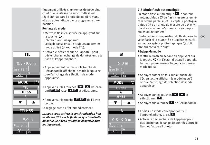
tiquement utilisée si un temps de pose pluscourt que la vitesse de synchro-flash estréglé sur l’appareil photo de manière manu-elle ou automatique par le programme d’ex-position.Réglage du mode• Mettre le flash en service en appuyant sur
la touche .L’écran d’accueil apparaît. Le flash passe ensuite toujours au derniermode utilisé (p. ex. mode TTL).
• Activer le déclencheur de l'appareil pourdéclencher un échange de données entre leflash et l'appareil photo.
• Appuyer autant de fois sur la touche del’écran tactile affichant le mode jusqu’à ceque l’affichage de sélection de mode apparaisse.
• Appuyer sur les touches drückenund resp. et sélectionne.
• Appuyer sur la touche de l’écrantactile.
Le réglage prend effet immédiatement.
Lorsque vous activez la synchronisation hau-te vitesse HSS sur le flash, la synchronisati-on sur le 2e rideau (REAR) se désactive auto-matiquement.
M HSSTTL HSS
TTL HSS
7.5 Mode flash automatiqueEn mode flash automatique le capteurphotographique � du flash mesure la lumiè-re réfléchie par le sujet. Le capteur photogra-phique � a un angle de mesure de 25° envi-ron et ne mesure qu’au cours de sa propreémission de lumière.L’automatisme d’exposition du flash désacti-ve le flash si la quantité de lumière est suffi-sante. Le capteur photographique � doitêtre orienté vers le sujet.Réglage du mode• Mettre le flash en service en appuyant sur
la touche �. L’écran d’accueil apparaît. Le flash passe ensuite toujours au derniermode utilisé.
• Appuyer autant de fois sur la touche del’écran tactile affichant le mode jusqu’à ce que l’affichage de sélection de modeapparaisse.
• Appuyer sur les touches et sélectionner .
• Appuyer sur la touche de l’écran tactile.
• Choisir un mode correspondant sur l’appareil photo, p. ex. .
• Activer le déclencheur de l'appareil pourdéclencher un échange de données entre leflash et l'appareil photo.
A
A
A
A
71
9.0 mM-Zoom 35 m
m
M
iP1/1
MODE O
q p
TTL HSSA
M HSS
0.8 - 9.0 m M-Zoom 35 m
m
A
iEV
l
0.8 - 9.0 m M-Zoom 35 m
m
TTL
iEV
9.0 mM-Zoom 35 m
m
TTL HSS
iP1/1
MODE O
q p
TTLTTL HSS
A

7.6 Mode flash stroboscopeLe mode stroboscope est un mode flashmanuel. Il est possible d’effectuer plusieursexpositions au flash sur une prise de vue.Cela est particulièrement intéressant en casd’études de mouvements et de prises devues à effet. Dans le mode stroboscope, leflash émet plusieurs éclairs à une certainefréquence d’éclairs. C’est pourquoi cettefonction n’est possible qu’avec une puissan-ce partielle maximale de 1/8 ou inférieure.Pour une prise de vue stroboscope, il fautrégler la fréquence des éclairs (éclairs parseconde) et le nombre d’éclairs.Nombre d’éclairs en mode flash stroboscope (N)Il est possible de régler le nombre d’éclairs(N) par déclenchement en mode flash stro-boscope.Le nombre d’éclairs peut être réglé entre 2 et90.
Le nombre maximal d’éclairs possible (N)dépend de la puissance partielle réglée (P). Fréquence des éclairs (f) en mode stroboscopeIl est possible de régler la fréquence deséclairs (f ) en mode flash stroboscope. La fré-quence des éclairs indique le nombred’éclairs par seconde. Il est possible de rég-ler la fréquence des éclairs 1 et 100 .
Il est possible de régler manuellement lapuissance partielle sur la valeur minimale1/256 pour obtenir des durées d’éclairs cour-tes.
La fréquence maximale des éclairs possibles(f) dépend de la puissance partielle réglée(P).Réglage du mode• Mettre le flash en service en appuyant sur
la touche �. L’écran d’accueil apparaît. Le flash passe ensuite toujours au derniermode utilisé.
• Appuyer autant de fois sur la touche del’écran tactile affichant le mode jusqu’à ce que l’affichage de sélection de modeapparaisse.
• Appuyer sur les touches et sélectionner .
• Appuyer sur la touche de l’écrantactile.
• Choisir un mode correspondant sur l’appareil photo, p. ex. .
• Activer le déclencheur de l'appareil pourdéclencher un échange de données entre leflash et l'appareil photo.
STROBO
STROBO
M
72
l
+
+
0.8 - 9.0 m M-Zoom 35 m
m
TTL
iEV
MODE O
q p
M HSSSTROBO
REMOTE MASTER
3.1mM-Zoom 35 m
m
STROBO
iP1/8
f(Hz) 5N 5

73
jRéglage de la nombre d'éclairs(N) • Appuyer sur la touche de l’écran tactile
pour régler le nombre d'éclairs .
• Appuyer sur les touches del’écran tactile et sélectionner le nombred'éclairs désirés.
Le nombre maximal d’éclairs possible (N)dépend de la puissance partielle réglée (P).
• Appuyer sur la touche de l'écran tactilepour sélectionner le nombre d'éclairs dési-ré, dans l’exemple, appuyer sur . Le réglage prend effet immédiatement.
4
N
Réglage de la fréquence des éclairs (f(Hz)) • Appuyer sur la touche de l’écran tactile
pour régler la fréquence des éclairs .
• Appuyer sur les touches del’écran tactile et sélectionner la fréquencedes éclairs désirée.
La fréquence maximale des éclairs possibles (f)dépend de la puissance partielle réglée (P).• Appuyer sur la touche de l'écran tactile
pour sélectionner la fréquence des éclairsdésirée, dans l’exemple, appuyer sur . Le réglage prend effet immédiatement..
L’écran indique la distance valable pour lesparamètres choisis. La valeur de distance affichée pour ladistance au sujet peut être ajustée en modifi-ant la valeur du diaphragme ou la puissancelumineuse partielle.En mode stroboscope, les valeurs de dia-phragme et la valeur ISO ne sont pas affi-chées sur l’écran
Le réflecteur additionnel n'est pas pris encharge en mode flash stroboscope.
f (Hz)
8
f (Hz) O
q p
789
3.1mM-Zoom 35 m
m
STROBO
iP1/16
f(Hz) 10N 4
3.1mM-Zoom 35 m
m
STROBO
iP1/8
f(Hz) 8N 4
l
+
+
+
3.1mM-Zoom 35 m
m
STROBO
iP1/16
f(Hz) 10N 5
N O
q p
345

74
8 Correction manuelle d’exposition au flash
L’automatisme d’exposition au flash de laplupart des appareils photo est calibré pourune réflectance du sujet de 25 % (réflectancemoyenne des sujets photographiés au flash).Un fond sombre qui absorbe beaucoup delumière ou un fond clair très réfléchissant(par exemple les prises de vue à contre-jour)peuvent se traduire respectivement par unesurexposition ou sous-exposition du sujet.Pour compenser l’effet précité, vous pouvezadapter manuellement l’exposition au flash,avec une valeur de correction à la prise devue. L’importance de la valeur de correctiondépend du contraste entre le sujet et le fondde l’image !En modes flash A/TTL, vous pouvez paramé-trer sur le flash des valeurs de correctionmanuelles pour l’exposition au flash entre -3et +3 EV par paliers de tiers.Conseil:Sujet sombre sur fond clair: valeur de correc-tion positive.Sujet clair sur fond sombre: valeur de correc-tion négative.Une correction de l’exposition au flash enjouant sur l’ouverture de l’objectif n’est paspossible parce que l’automatisme d’expositi-on de l’appareil photo considère à nouveaul’ouverture modifiée du diaphragme commeouverture normale. Lors du réglage d’unevaleur de correction, l’affichage de la portée
sur l’écran peut changer et être adapté à lavaleur de correction (en fonction du modèled’appareil photo).Procédure de réglage• Appuyer autant de fois sur la touche de
l’écran tactile jusqu’à ce que la sélectionde la puissance partielle apparaisse.
• Appuyer sur les touches del’écran tactile et régler une valeur de correction.
• Appuyer sur la valeur de correction choisiep. ex. .
Le réglage prend effet immédiatement.
Une correction manuelle d’exposition auflash en mode flash TTL n’est possible que sil’appareil photo prend en charge cette foncti-on (voir mode d’emploi de l’appareil photo) !Si l’appareil photo ne prend pas en chargecette fonction, la valeur de correction para-métrée reste sans effet.Sur différents appareils photo, il est néces-saire de régler la valeur de correction manu-elle d’exposition au flash sur l’appareil pho-to. Aucune valeur de correction ne s’affichealors à l’écran du flash.
N'oubliez pas d'effacer la correction d'expo-sition au flash manuelle sur l'appareil photo,après la prise de vue!
EV
-1
+
l
0.8 - 9.0 m M-Zoom 35 m
m
TTL
iEV
EV O
q p
-1 1/3-1
-2/3
1.1- 12 m M-Zoom 35 m
m
TTL
iEV-1

75
Attention: Les objets fortement réfléchis-sants situés sur la photo du sujet peuventgêner l’automatisme d’exposition de l’appa-reil photo. La prise de vue est alors sous-exposée. Retirer les objets réfléchissants ouconfigurer une valeur de correction positive.
9 Fonctions spécialesSelon le modèle d’appareil photo ou le grou-pe d’appareils photo, vous disposez de plu-sieurs fonctions spéciales. Avant la sélection et le paramétrage desfonctions spéciales, un échange de donnéesdoit donc avoir lieu entre le flash et l’appareilphoto, par exemple par l’enfoncement à mi-course du déclencheur de l’appareil photo.Le paramétrage doit se fait immédiatementaprès la sélection de la fonction spéciale,sinon le flash revient automatiquement enmode normal au bout de quelques secondes.
9.1 Asservissement de la tête zoommotorisée („Zoom“)
L’asservissement de la tête zoom motoriséepermet d’éclairer des distances focales d’aumoins 24 mm (film de petit format). Grâce à l’utilisation du diffuseur grand-angle intégré, l’éclairage s’élargit à 12 mm.
Zoom automatiqueEn cas d’utilisation du flash avec un appareilphoto qui transmet des données concernantla distance focale de l’objectif, la position duzoom du réflecteur s’adapte automatique-ment à cette distance focale. Après la miseen marche du flash, l’indication «Zoom» et laposition actuelle du zoom du réflecteur s’affichent à l’écran.L’adaptation automatique se fait pour desdistances focales de l’objectif à partir de24 mm. L’adaptation automatique ne s’effectue passi le réflecteur est incliné, si le diffuseurgrand angle est sorti ou qu’unMecabounce (accessoire) est montéSi vous le souhaitez, vous pouvez alorsdéplacer manuellement la position du réflec-teur afin d’obtenir certains effets d’éclairage(par exemple effet spot, etc.).Mode zoom manuelAvec les appareils photo qui ne transmettentpas de données concernant la distance foca-le de l’objectif, vous devez adapter manuelle-ment la position du zoom du réflecteur à cet-te distance focale
Le mode zoom automatique n’est pas possi-ble dans ce cas !Après la mise en marche du flash, l’indicati-on «Zoom» et la position actuelle du zoomdu réflecteur s’affichent à l’écran
+
+
l

76
Exemple:Vous utilisez un objectif zoom avec unedistance focale comprise entre 35 et 105mm.Dans ce cas, vous réglez la tête zoom duflash sur 35 mm.Retour au mode zoom automatique• Activer le déclencheur de l'appareil pour
déclencher un échange de données entre leflash et l'appareil photo.
• Appuyer autant de fois sur la touche �jusqu’à ce que le menu de sélection s‘affiche.
• Appuyer sur la touche de l’écrantactile.
• Appuyer sur les touches del'écran tactile et sélectionner .
• Appuyer sur la touche de l’écrantactile.
• Appuyer sur les touches et sélectionner .
• Appuyer sur la touche de l’écrantactile.
Après env. 10 s. l’écran passe automatique-ment à l'affichage du mode ou appuyerautant de fois sur la touche � jusqu'à ceque l'affichage mode apparaisse.
D
PARAMETER
ZOOM
ZOOM
AUTOZOOM
AUTOZOOM
D
Procédure de réglage• Appuyer autant de fois sur la touche �
jusqu’à ce que le menu de sélection s‘affiche.
• Appuyer sur la touche de l’écrantactile.
• Appuyer sur les touches del'écran tactile et sélectionner .
• Appuyer sur la touche de l’écrantactile.
• Appuyer sur les touches del’écran tactile et sélectionner la valeur duzoom désirée.
• Appuyer sur la touche de l’écran tactile poursélectionner la valeur du zoom désirée. Le réglage prend effet immédiatement.
Les positions du zoom suivantes sont possiblespour le réflecteur : 24 - 28 - 35 - 50 - 70 - 85 -105-135-180-200 mm (film de petit format).Conseil:Si vous n’avez pas continuellement besoinde la pleine puissance et portée du flash,vous pouvez laisser la position du réflecteursur la position correspondant à la plus petitedistance focale de l’objectif zoom. Vous avez ainsi la garantie que votre photo seratoujours complètement couverte par l’éclair.Vous vous épargnez par là l’adaptation perma-nente à la focale variable de l’objectif.
D
PARAMETER
ZOOM
ZOOM
l
PARAMETER
PARAMETER O
q p
P/EVZOOM
F
ZOOM O
q p
7085
105
PARAMETER
PARAMETER O
q p
P/EVZOOM
F
ZOOM
q p
AUTOZOOM24
O

Diffuseur grand-angleLe diffuseur grand-angle intégré permetde couvrir des focales d’objectifs à partir de12 mm (film de petit format).Retirez vers l’avant jusqu’en butée le diffuseurgrandangle du réflecteur, puis relâchez-le.Le diffuseur grand-angle se rabat automati-quement vers le bas. Le réflecteur est amenéautomatiquement à la position nécessaire. Les données relatives à la distance et lavaleur du zoom sont corrigées à 12 mm surl’écran.L’adaptation automatique du réflecteur duzoom motorisé ne s’effectue pas si le diffu-seur grand angle est utilisé.Pour l’introduire, relevez le diffuseur grand-angle de 90° et introduisez-le complète-ment.mecabounce Diffuser MBM-03Lorsque le Mecabounce (accessoires en opti-on ; voir 19) est monté sur le réflecteur duflash, le réflecteur est amené automatique-ment dans sa position requise. Les donnéesrelatives à la distance et la valeur du zoomsont corrigées à 16 mm.
L’adaptation automatique du réflecteur duzoom motorisé ne s’effectue pas si unMecabounce est utilisé.L’utilisation simultanée du diffuseur grandangle et d’un mecabounce est impossible.
10 Mode multi-flash sans filLe flash prend en charge le système sans filSony dans les modes «CTRL» et «CTRL+»,selon le système utilisé par l’appareil photo.Les modes «CTRL» et «CTRL+’» sont détectésautomatiquement.Un système remote se compose d'un flashmaître sur l’appareil photo et d'un ou plu-sieurs flashes esclaves. Le ou les flashesesclaves sont commandés à distance sans filpar le réflecteur esclave du flash maître.Pour éviter que plusieurs systèmes remoten’interfèrent mutuellement dans le mêmeespace, il existe quatre canaux remote auto-nomes. Les flashes maîtres et esclaves quifont partie du même système remote doiventêtre réglés sur le même canal remote.Les flashes esclaves doivent pouvoir recevoirla lumière du flash maître avec le photo-cap-teur intégré . Le mode remote prend également en chargela synchronisation sur le 2e rideau. Il n'y a pas d'affichage de la portée surl’écran du flash en mode remote.
77
+
l

10.1 Mode remote maîtreLes groupes d’esclaves RMT et RMT2 sontactivés en usine. Le flash maître (CTRL) et les groupes d’escla-ves RMT et RMT2 peuvent être activés etdésactivés ! Lorsque le flash maître (CTRL) est désactivé,l'éclair du flash maître ne prend en chargeque la fonction de commande et ne contribuepas à l'exposition de la prise de vue.10.1.1 Régler le mode remote maître• Mettre le flash en service en appuyant sur
la touche �.L’écran d’accueil apparaît.
• Appuyer autant de fois sur la touche del’écran tactile affichant le mode jusqu’à ce que l’affichage de sélection de modeapparaisse
• Appuyer sur les touches et sélectionner .
• Appuyer sur la touche del’écran tactile. Le mode remote maître est activé.
Le mode remote maître CTRL est affiché àl’image. Le maître (CTRL) contribue à l’expo-sition dans la même luminosité que les grou-pes de flash esclaves (RMT).
Des luminosités peuvent être affectées aumaître (CTRL) et au groupe de flash esclaveRMT ou RMT2 (voir 10.1.4).
REMOTE MASTER
REMOTE MASTER
Passage de CTRL à CTRL+• Appuyer sur la touche � jusqu’à ce que
le menu de sélection s‘affiche.
• Appuyer sur la touche de l’écrantactile.
• Appuyer sur les touches del’écran tactile et sélectionner .
• Appuyer sur la touche de l’écrantactile.
• Appuyer sur la touche pour sélectionner lemode ou .
Le réglage prend effet immédiatement.
Un réglage de la luminosité (ratio) n’est pos-sible qu’en mode CTRL+.
D
PARAMETER
CONTROL
CONTROL
CTRL+CTRL
78
l
0.6- 7.2 m M-Zoom 35 m
m
TTL
iEV
MODE O
q p
STROBOREMOTE MASTER
REMOTE SLAVE
CTRL RMT4 8
REMOTECTRL
TTL
i RATIO
CTRL RMT RMT24 8 1
REMOTECTRL+
TTL
i RATIO
PARAMETER
PARAMETER O
q p
RATIOCONTROL
CTRL/CTRL+ OCTRL
CTRL+
+

10.1.2 Régler le mode de flash sur le flashmaître
• Appuyer sur la touche de l’écran tactilepour le mode jusqu’à ce que la sélection dumode apparaisse.
• Appuyer sur les touches del’écran tactile et sélectionner le mode duflash.
• Appuyer sur la touche pour sélectionner lemode ou .
Le mode sélectionné prend effet immédiate-ment.
MTTL
10.1.3 Régler la puissance partielle en modeM sur le flash maître
Sélectionner le mode sur comme décritau point 10.1.2.
• Appuyer sur la touche de l’écran tactilejusqu’à ce que la sélection Maître appa-raisse.
• Appuyer sur la touche de l’écran tactilepour la puissance lumineuse partielle.
• Appuyer sur les touches del’écran tactile afin de régler la puissancepartielle désirée.
• Appuyer sur la touche de l’écran tactile dela puissance partielle sélectionnée.
Le réglage prend effet immédiatement.
M
M
P
1/8
79
l
CTRL RMT RMT24 8 1
REMOTECTRL+
M1/1
i RATIO
CTRL RMT RMT24 8 1
REMOTECTRL+
M1/1
i RATIO
CTRL RMT RMT24 8 1
REMOTECTRL+
M1/8
i RATIO
CTRL RMT RMT24 8 1
REMOTECTRL+
TTL
i RATIO
MASTER O
q p
TTLMEV
P O
q p
1/4 - 2/31/8
1/8 - 1/3
MASTER OTTL
M
P

10.1.4 Définir la luminosité (RATIO) pour lesgroupes de flash sur le flash maître
Il est possible de régler la luminosité dusystème remote pour obtenir des effets delumière précis. La luminosité est commandéepour le maître (CTRL) et les groupes (RMT,RMT2) exclusivement via le flash maître.Ratio activer/désactiver• Appuyer sur la touche � jusqu’à ce que
le menu de sélection s‘affiche.
• Appuyer sur la touche de l’écrantactile.
• Appuyer sur les touches del’écran tactile et sélectionner .
• Appuyer sur la touche de l’écran tac-tile.
• Appuyer autant de fois sur la touche ou de l’écran tactile et activer oudésactiver la fonction RATIO.
D
PARAMETER
RATIO
RATIO
ONOFF
Définir la luminosité (RATIO) • Appuyer sur la touche de l’écran
tactile.
• Sur l’écran tactile, appuyer sur la touchepour laquelle une luminosité doit êtreréglée, par exemple RMT2.
• Appuyer sur la touche de l’écrantactile. Régler la luminosité désirée ou cou-per l’apport de lumière (--).
• Appuyer sur la touche de l’écran tactile cor-respondant à la valeur de correction dési-rée.
Le réglage prend effet immédiatement.
RATIO
80
l
CTRL RMT RMT24 8 1
REMOTECTRL+
M1/8
i RATIO
PARAMETER
PARAMETER O
q p
CHANNELRATIO
CONTROL
RTM2 O
q p
48
16
RATIO OOFF
ON
8
1
4
ORATIO
CTRL
RMT
RMT2
CTRL RMT RMT24 8 8
REMOTECTRL+
M1/8
i RATIO

10.1.5 Régler le mode remote canalPour éviter que plusieurs systèmes remoten’interfèrent mutuellement dans le mêmeespace, il existe quatre canaux remote auto-nomes. Les flashes maîtres et esclaves quifont partie du même système remote doiventêtre réglés sur le même canal remote.
• Appuyer autant de fois sur la touche �jusqu’à ce que le menu de sélection s‘affiche.
• Appuyer sur la touche del’écran tactile.
• Appuyer sur la touche de l’écrantactile.
• Sur l’écran tactile, appuyer sur les toucheset sélectionner un canal remote,
par exemple .• Appuyer sur la touche de l’écran tactile
pour sélectionner le canal désiré.
Le réglage prend effet immédiatement.Appuyez sur la touche � du capteur etvérifier le réglage de canal.
D
PARAMETER
CHANNEL
CHANNEL 2
i
10.2 Mode flash remote slaveLe flash prend en charge le système remotesans fil en mode flash slave et est compati-ble avec le système Sony.Ce système permet de télécommander sans filun ou plusieurs flashs esclaves à l’aide d’unflash maître monté sur l’appareil photo (parexemple mecablitz 64AF-1S électronique).Le flash esclave est affecté à l’un des deuxgroupes possibles (RMT, RMT2). Le flash maî-tre peut commander simultanément tous cesgroupes d’esclaves et prendre en compte lesdifférents réglages pour le groupe esclaverespectif.Pour éviter que plusieurs systèmes remote nese dérangent mutuellement dans le mêmeespace, il existe quatre canaux remote auto-nomes (CH 1, 2, 3 ou 4).Les flashs maître et esclaves qui font partiedu même système remote doivent être régléssur le même canal remote. Les flashs esclaves doivent pouvoir recevoirla lumière du flash maître avec le photo-cap-teur intégré pour le mode remote .Selon le modèle d’appareil photo, le flashinterne à l’appareil photo peut égalementtravailler comme flash maître.
81
l
PARAMETER O
q p
ZOOMCHANNEL
RATIO
CHANNEL O
q p
CHANNEL 1CHANNEL 2CHANNEL 3
PARAMETER

10.2.1 Régler le mode flash remote esclave• Mettre le flash en service en appuyant sur
la touche �.L’écran d’accueil apparaît.Le flash passe ensuite toujours au derniermode utilisé (p. ex. mode flash TTL).
• Appuyer autant de fois sur le mode affichésur l’écran tactile jusqu’à ce que l’affichagede sélection de mode apparaisse.
• Appuyer sur les touches del'écran tactile et sélectionner.
• Appuyer sur la touche del’écran tactile.
Le mode remote esclave est activé.
Le groupe esclave (p. ex. RMT) et le canal remote (p. ex. CH 1) sont également affichés.
REMOTE SLAVE
REMOTE SLAVE
10.2.2 Régler le canal esclave• Appuyer sur la touche de l’écran tactile
pour sélectionner le groupe de canaux(p. ex. ).L’écran de sélection de canaux et de groupes s‘affiche.
• Appuyer sur les touches de l’écran tactilepour sélectionner le canal .
• Appuyer sur les touches del’écran tactile et sélectionner le canal désiré.
• Sur l’écran tactile, appuyer sur le canalsélectionné.
Le réglage prend effet immédiatement.«CH2» s'affiche à l'écran.
RMT I CH1
CHANNEL
82
l
0.8- 9.0 m M-Zoom 35 m
m
TTL
iEV
MODE O
q p
REMOTE MASTERREMOTE SLAVE
SERVO
M-Zoom 24
REMOTE
SLAVERMT Ch
2 1
i
mm
P1/1
M-Zoom 24
REMOTE
SLAVERMT Ch
2 2
i
mm
P1/1
M-Zoom 24
REMOTE
SLAVERMT Ch
2 1
i
mm
SLAVE OCHANNEL
GROUP
CHANNEL O
q p
CHANNEL 1CHANNEL 2CHANNEL 3

10.2.3 Régler le mode esclave• Appuyer sur la touche de l’écran tactile
pour la puissance partielle/correction d’ex-position (p. ex. ). La sélectionapparaît.
• Appuyer sur la touche de l’écran tactilepour sélectionner le groupe .
• Appuyer sur les touches de l’écran tactilepour sélectionner le groupe désiré ou
.
Le réglage est enregistré automatiquement.
RMT I CH1
GROUP
RMTRMT2
10.2.4 Régler la puissance partielle de l’es-clave
• Appuyer sur la touche de l’écran tactilepour la puissance lumineuse partielleou .
• Appuyer sur la touche pour sélectionner lemode ou .
Le réglage est enregistré automatiquement.
PEV
MTTL
83
l
M-Zoom 24
REMOTE
SLAVERMT Ch
2
i
mm
P
M-Zoom 24
REMOTE
SLAVERMT Ch
2
i
mm
P1/1
M-Zoom 24
REMOTE
SLAVERMT Ch
2 1
i
mm
SLAVE OCHANNEL
GROUP
GROUP O
RTM2
SLAVE OTTL
M
P
RTM

10.2.5 Régler la puissance partielle/correction d’exposition de l’esclave
• Appuyer sur la touche ou .La sélection apparaît.
• Appuyer sur la touche pour sélectionner lemode ou .
• Appuyer sur les touches del’écran tactile et sélectionner la puissancepartielle désirée 1/1, 1/2, 1/8 ou 1/256.
La puissance partielle prend effet.Lorsque les flashes esclaves sont prêts àfonctionner, le flash de mesure AF clignote.
EVP
EVP
10.3 Vérification du mode flash remote• Positionnez les flashs esclaves comme sou-
haité pour la prise de vue ultérieure. Pour mettre en place le flash esclave, utili-sez un pied S60.
• Attendez que les flashs concernés signa-lent qu’ils sont prêts à fonctionner. En cequi concerne les flashs esclaves, lumièreauxiliaire AF � clignote.
• Appuyez sur le bouton du flash � sur leflash maître ou contrôleur et déclenchezainsi un éclair de test. Les flashs esclaves répondent en fonctiondu groupe esclave les uns après les autres,de manière différée, par un éclair de test. Si un flash esclave n’émet pas d’éclair detest, vérifiez le réglage du canal remote etle groupe esclave. Corrigez la position duflash esclave de manière à ce qu'il puisserecevoir la lumière du flash maître avec lecapteur .
Le type de mode flash est transmis automati-quement par le flash maître.Lorsque le flash fonctionne comme un flashmaître dans le système remote sans fil Metz,le déclenchement de la lumière pilotedéclenche également la lumière pilote duflash esclave.
84
l
M-Zoom 24
REMOTE
SLAVERMT Ch
2 2
i
mm
P1/1
SLAVE OTTL
M
EV / P
P O
q p
1/4 - 2/31/8
1/8 - 1/3

10.4 Modo flash SERVOLe mode SERVO est un mode esclave simpleavec ou sans suppression du pré-éclairagelors duquel un flash est toujours généré àpartir du moment où le flash esclave reçoitune impulsion lumineuse du flash de l’appa-reil photo.En mode SERVO, seul le mode flash manuelM est généralement possible. Le mode flashmanuel est automatiquement réglé une foisle mode SERVO activé.10.4.1 Régler le mode flash SERVO• Appuyer autant de fois sur la touche de
l’écran tactile affichant le mode jusqu’à ceque l’affichage de sélection de mode apparaisse.
• Appuyer sur les touches del’écran tactile et sélectionner le mode
.
• Appuyer sur la touche de l’écrantactile.
Le mode sélectionné prend effet.Si besoin, il est également possible de confi-gurer une puissance partielle, voir 10.4.3.
SERVO
SERVO
10.5.2 Régler le pré-éclair ou la synchronisation
• Appuyer autant de fois sur la touchede l’écran tactile jusqu’à ce que la sélection du type de synchronisation apparaisse.
• Appuyer sur la touche de l’écran tactile:
Synchronisation sans pré-éclairSynchronisation avec pré-éclair
Le synchronisation sélectionné prendeffet.
Dans le cas où la synchronisation réglée nefonctionne pas correctement, suivre la procé-dure décrite au point 10.4.4.
SYNC
85
l
0.8- 9.0 m M-Zoom 35 m
m
TTL
iEV
MODE O
q p
REMOTE SLAVESERVO
M-Zoom 24
M-Servo SYNC
iP1/1
mm
SYNC O
LEARN
M-Zoom 24
M-Servo SYNC
iP1/1
mm

10.4.3 Réglage du mode servo puissancepartielle
• Appuyer autant de fois sur la touchepour la puissance partielle sur l’écran tac-tile jusqu’à ce que le réglage de la puissance partielle apparaisse.
• Appuyer sur les touches del’écran tactile et sélectionner la puissancepartielle désirée 1/1, 1/2, 1/8 jusqu‘à1/256 .
• Appuyer sur la touche de l’écran tactilepour la puissance partielle (p. ex. 1/16).
La puissance partielle prend effet.Lorsque les flashes esclaves sont prêts àfonctionner, le flash de mesure AF clignote.
Les canaux remote ne peuvent pas êtreréglés en mode SERVO.Le flash de l’appareil ne doit pas être utiliséen mode remote.
P
1/16
10.4.4 Fonction d’apprentissageLa «Fonction d’apprentissage» permet uneadaptation individuelle du flash esclave à latechnique de photographie au flash du flashde l’appareil photo.Un ou plusieurs pré-éclairs du flash de l’appareil photo peuvent être utilisés par ex.pour réduire l’effet des «yeux rouges». Le déclenchement du flash esclave a alorslieu au moment de l’éclair principal qui éclaire la prise de vue.
Si le flash de l’appareil photo émet desflashs de mesure AF pour la mise au pointautomatique, aucun mode d’apprentissagen’est possible pour des raisons inhérentesau système.
Utiliser dans la mesure du possible un autremode pour l’appareil photo ou passer enmise au point manuelle.
86
l
+
+
M-Zoom 35
M-Servo SYNC
iP1/1
mm
M-Zoom 35
M-Servo SYNC
iP1/16
mm
P O
q p
1/8 - 2/31/16
1/16 - 1/3
+

Processus de réglage de la fonction d’apprentissageLa fonction pré-éclaire AF de l’appareil photodoit être désactivée.• Appuyer autant de fois sur la touche
de l’écran tactile jusqu’à ce que la sélection apparaisse.
• Appuyer sur la touche de l’écran tactile.
• Le «Learning Mode» (mode apprentissage)est prêt à apprendre.
• Actionner le bouton de déclenchement surl’appareil photo pour déclencher le flash del’appareil.Une fois que le flash SERVO a reçu uneimpulsion lumineuse, «LEARN OK» s’affichesur l’écran en guise de confirmation.
Le mecablitz numérique a capté la lumière duflash de l'appareil photo.
SYNC
Learn
10.4.5 Désactiver le mode flash SERVO
• Appuyer autant de fois sur le mode affichésur l’écran tactile jusqu’à ce que l’affichagede sélection de mode apparaisse.
• Appuyer sur les touches del’écran tactile et sélectionner le mode désiré, p. ex. .
• Appuyer sur la touche de l’écran tactile etsélectionner le mode désiré, p. ex. .
Le mode sélectionné prend effet.
TTL
TTL
87
l
M-Zoom 24
M-Servo SYNC
iP1/16
mm
SYNC O
LEARN
M-Zoom 24
M-Servo SYNC
iP1/16
mm
MODE O
q p
TTLA
0.6- 7.5 m M-Zoom 24 m
m
TTL
iEV

11 OPTION menú
11.1 Mode RAPIDDans les modes A et TTL, les temps de recy-clage dépendent de la lumière nécessairepour la prise de vue. Si le temps de recyclageest trop long, la fonction RAPID peut être acti-vée en mode A ou TTL. La fonction RAPID estparticulièrement recommandée dans les casoù des temps de recyclage courts sont plusimportants qu’une puissance lumineusemaximale, p. ex. dans des pièces relative-ment petites. Le nombre guide est toutefoisréduit d’un niveau, p. ex. du nombre guide36 (pour ISO 100 et zoom 35) à nombre gui-de 25 (pour ISO 100 et zoom 35).Procédure de réglage• Appuyer autant de fois sur la touche �
jusqu’à ce que le menu de sélection s‘affiche.
• Appuyer sur la touche de l’écrantactile.
• Appuyer sur les touches del'écran tactile et sélectionner .
• Appuyer sur la touche de l’écrantactile.
• Appuyer autant de fois sur la toucheou de l’écran tactile et activer oudésactiver la fonction RAPID.
Le réglage prend effet immédiatement.Après l'activation de la fonction RAPID,l’écran affiche « » angezeigt.
D
OPTION
RAPID
RAPID
ONOFF
11.2 Réflecteur secondaire (SUB-REFL.)Le réflecteur secondaire permet l'éclairage fron-tal pour des éclairages au flash indirects lors-que le réflecteur principal est orienté vers lecôté ou vers le haut. Si la quantité de lumièredu réflecteur secondaire est trop importante,celle-ci peut être réduite de moitié.Procédure de réglage• Appuyer autant de fois sur la touche �
jusqu’à ce que le menu de sélection s‘affiche.
• Appuyer sur la touche de l’écrantactile.
• Appuyer sur les touches del'écran tactile et sélectionner .
• Appuyer sur la touche de l’écrantactile.
• Appuyer sur la touche ou oude l’écran tactile et activer ou dés-
activer le réflecteur secondaire. Le réglage prend effet immédiatement.
Après l'activation du réflecteur secondaire,s'affiche à l'écran.
Dans le menu INFO „ 1/1” ou „ 1/2” s’affiche. 1/1 correspond à la puissance lumineusemaximale, 1/2 à la moitié de la puissancelumineuse.
D
OPTION
SUB-REFL.
SUB-REFL.
1/21/1OFF
88
l
OPTION
SUB-REFL. OOFF1/11/2
OPTION O
q p
RAPIDSUB-REFL.ZOOM SIZE
OPTION O
q p
RAPIDSUB-REFL.
OPTION
RAPID OOFF
ON

11.3 Lumière pilote (MOD. LIGHT)La lumière pilote (ML = Modelling Light) estune séquence d’éclairs stroboscopiques àhaute fréquence. Avec une durée de 3 secon-des environ, elle donne l’impression d’unelumière pour ainsi dire continue. La lumièrepilote permet d’évaluer la répartition de lalumière et la formation des ombres avantmême la prise de vue. Elle est déclenchée à l’aide du bouton duflash � ausgelöst.Procédure de réglage• Appuyer autant de fois sur la touche �
jusqu’à ce que le menu de sélection s‘affiche.
• Appuyer sur la touche de l’écrantactile.
• Appuyer sur les touches del'écran tactile et sélectionner
.• Appuyer sur la touche de l’écran
tactile.
• Appuyer autant de fois sur la toucheou de l’écran tactile et activer oudésactiver la lumière pilote. Le réglageprend effet immédiatement.
Après l'activation de la lumière pilote, „ ” s’affiche dans le menu INFO.
D
OPTION
MOD. LIGHT
MOD. LIGHT
ONOFF
11.4 Mode zoom (ZOOM MODE)11.4.1 Mode zoom étenduDans le mode zoom étendu, la position duzoom du réflecteur est réduite d’un cran parrapport à la focale réglée sur l’objectif del’appareil photo. L’élargissement et l’agran-dissement du faisceau procure en intérieurdavantage de lumière diffuse (réflexions) etadoucit ainsi l’éclairage au flash.
Exemple :La focale de l’objectif monté sur l’appareilphoto est de 50 mm. En mode zoom étendu,le flash règle le réflecteur sur la position duzoom à 35 mm. L’écran continue d’afficher50 mm.Procédure de réglage• Appuyer autant de fois sur la touche �
jusqu’à ce que le menu de sélection s‘affiche.
• Appuyer sur la touche de l’écrantactile.
• Appuyer sur les touches c .
• Appuyer sur la touche de l’écrantactile.
• Appuyer sur la touche de l’écrantactile. Le réglage prend effet immédiatement.
Après l'activation du mode zoom étendu,«EXT» s'affiche dans le menu INFO.
D
OPTION
ZOOM MODE
ZOOM MODE
EXTENDED
89
l
MOD. LIGHT OOFF
ON
OPTION O
q p
OPTION
OPTION
q p
MOD. LIGHTBEEP
RAPIDSUB-REFL.
STANDBY
OPTION
ZOOMMODE OExtendedStandard
Spot
OPTION O
q p
ZOOM SIZEZOOM MODE
STANDBY

Pour des raisons inhérentes au système, lemode zoom étendu n'est pris en charge quepar les focales d'objectifs d'au moins 28 mm(film de petit format). L'appareil photo doitêtre équipé d'un objectif à CPU et doit fournirau flash les données pour la focale de l'ob-jectif.11.4.2 Mode SPOT zoomEn mode spot zoom, la position du zoom duréflecteur est augmentée d'un cran par rapport à la focale réglée sur l'objectif del'appareil photo. L’éclairage réduit en résul-tant assure un éclairage centralisé ou latéraldégradé.Exemple :La focale de l'objectif monté sur l'appareilphoto est de 50 mm. En mode spot zoom, leflash règle le réflecteur sur la position duzoom à 70 mm. L'écran continue d'afficher50 mm.
Procédure de réglage• Appuyer autant de fois sur la touche �
jusqu’à ce que le menu de sélection s‘affiche.
• Appuyer sur la touche de l’écrantactile.
• Appuyer sur les touches del'écran tactile et sélectionner
.• Appuyer sur la touche de l’écran
tactile.
• Appuyer sur la touche de l’écrantactile. Le réglage prend effet immédiatement.
Après l'activation du mode spot zoom, «SP»s'affiche dans le menu INFO. Pour des raisons inhérentes au système, lemode spot zoom n'est pris en charge que parles focales d'objectifs d'au moins 24 -180mm (film de petit format). L'appareil photo doit être équipé d'un objec-tif à CPU et doit fournir au flash les donnéespour la focale de l'objectif.
D
OPTION
ZOOM MODE
ZOOM MODE
SPOT
90
l
ZOOMMODE OEXTENDEDSTANDARD
SPOT
OPTION
OPTION O
q p
ZOOM SIZEZOOM MODE
STANDBY

11.4.3 Mode zoom STANDARDEn mode zoom standard, la position du zoomdu réflecteur est adaptée à la focale régléesur l'objectif de l'appareil photo.
Procédure de réglage• Appuyer autant de fois sur la touche �
jusqu’à ce que le menu de sélection s‘affiche.
• Appuyer sur la touche de l’écran tactile.
• Appuyer sur les touches del'écran tactile et sélectionner
.• Appuyer sur la touche de l’écran
tactile.
• Appuyer sur la touche de l’écrantactile. Le réglage prend effet immédiatement.
D
OPTION
ZOOM MODE
ZOOM MODE
STANDARD
11.5 Adaptation du format de prise de vue(ZOOM SIZE)
Sur certains modèles d’appareils photonumériques, l’affichage de la position duréflecteur peut être adaptée au format de lapuce (dimensions du composant de prise devue) grâce à la fonction «zoom size».Procédure de réglage• Appuyer autant de fois sur la touche �
jusqu’à ce que le menu de sélection s‘affiche.
• Appuyer sur la touche de l’écrantactile.
• Appuyer sur les touches del'écran tactile et sélectionner .
• Appuyer sur la touche de l’écrantactile.
• Appuyer sur la touche de l’écran tac-tile. Le réglage prend effet immédiatement.
Après l'activation du mode zoom Size, „” s'affiche dans le menu INFO. Après désactivation de la fonction Zoom-Size, „ ” l’affichage dans le menu INFOs’efface.Sur les appareils photo qui ne prennent pasen charge l’adaptation du format de la prisede vue, il est impossible de choisir la foncti-on «zoom size»!
D
OPTION
ZOOM SIZE
ZOOM SIZE
ON
91
l
OPTION
OPTION O
q p
SUB-REFL.ZOOM SIZE
ZOOM MODE
ZOOM SIZE OOFF
ON
OPTION
OPTION O
q p
ZOOM SIZEZOOM MODE
STANDBY
ZOOMMODE OEXTENDEDSTANDARD
SPOT

11.6 Lumière auxiliaire AF (AF-BEAM)Lorsque le système de mesure AF d’un appa-reil photo reflex numérique AF ne peut paseffectuer la mise au point faute d’une lumi-nosité ambiante suffisante, l’appareil photoactive la lumière auxiliaire AF intégrée �dans le flash. Celle-ci projette sur le sujet unréseau de bandes qui permet à l’appareilphoto de réaliser la mise au point.Avec la fonction «AF-BEAM», il est possibled'activer ou de désactiver la lumière auxiliaire AF.La portée est de 6 à 9 m environ (pour unobjectif standard de 1,7/50 mm). En raisonde l'erreur de parallaxe entre l'objectif et lalumière auxiliaire AF, la limite de mise aupoint rapprochée de la lumière auxiliaire AFest comprise entre 0,7 et 1 m environ. Afin que la lumière auxiliaire AF � puisseêtre activée par l'appareil photo, le modeautofocus «Single-AF (S-AF)» doit être réglésur l'appareil photo et le flash doit afficherqu'il est prêt à fonctionner.Certains modèles d'appareil photo ne pren-nent en charge que la lumière auxiliaire AFinterne. Dans ce cas, la lumière auxiliaire AFdu flash n'est pas activée (par exemple appareils compacts; voir mode d'emploi del'appareil photo) !Les objectifs zoom à petite ouverture initialelimitent parfois considérablement la portéede la lumière auxiliaire !
Procédure de réglage• Appuyer autant de fois sur la touche �
jusqu’à ce que le menu de sélection s‘affiche.
• Appuyer sur la touche de l’écrantactile.
• Appuyer sur les touches del'écran tactile et sélectionner .
• Appuyer sur la touche de l’écrantactile.
• Appuyer sur la touche ou del’écran tactile.
Le réglage prend effet immédiatement.
D
OPTION
AF BEAM
AF BEAM
OffOn
92
l
OPTION
OPTION O
q p
POWERPACKAF BEAM
AF BEAM OOFF
ON

11.7 Affichage des portées en mètres oupieds
La portée peut être indiquée sur l'afficheuren mètres (m) ou en pieds (ft).
Procédure de réglage• Appuyer autant de fois sur la touche �
jusqu’à ce que le menu de sélection s‘affiche.
• Appuyer sur la touche de l’écrantactile.
• Appuyer sur les touches del'écran tactile et sélectionner .
• Appuyer sur la touche de l’écran tactile.
• Appuyer sur la touche ou de l’écrantactile.
Le réglage prend effet immédiatement.
D
OPTION
m/ft
m/ft
ftm
11.8 Séries d’expositions au flash(FLASH BRACK.)
Dans les modes flash TTL et automatique , ilest possible d’effectuer une série d’expositi-ons au flash (FB - Flash-Bracketing). Unesérie d’expositions au flash est composée detrois prises de vue au flash qui se succèdentmais avec des valeurs de correction d’exposi-tion au flash différentes. Au moment de régler une série d’expositionsau flash, „FB“ et la valeur de correction s’affi-chent à l’écran. La valeur de correction estréglable entre 1/3 et 3 EV (IL) par tiers devaleur.Procédure de réglage• Appuyer autant de fois sur la touche �
jusqu’à ce que le menu de sélection s‘affiche.
• Appuyer sur la touche de l’écrantactile.
• Appuyer sur les touches del'écran tactile et sélectionner
• Appuyer sur la touche del’écran tactile.
• Appuyer sur les touches del’écran tactile et sélectionner une valeur decorrection.
• Appuyer sur la touche de l’écran tactilepour sélectionner la valeur de correction, p.ex. .
D
OPTION
FLASH BRACK.
FLASH BRACK.
1
93
lOPTION
m/ft Om
ft
OPTION O
q p
BEEPm/ft
POWERPACK
OPTION
FLASH BRACK. O
q p
2/31
1 1/3
OPTION O
q p
AF BEAMFLASH BRACK.

Le réglage prend effet immédiatement.• La première photo est prise sans valeur de
correction. „FBI“ apparaît également surl’écran.
• La deuxième photo est prise avec unevaleur de correction négative. „FBII“ et lavaleur de correction négative (EV) apparais-sent également sur l’écran.
• La troisième photo est prise avec unevaleur de correction positive. „FBIII“ et lavaleur de correction positive (EV) apparais-sent également sur l’écran.
• Après la troisième photo, la série d’exposi-tions au flash est automatiquement effa-cée. L’affichage „FB“ disparaît de l’écran.
La valeur de correction qui s’affiche est tou-jours positive au moment de régler la séried’expositions au flash !Série d’expositions au flash en mode flashTTLUne série d’expositions au flash en mode TTLn’est seulement possible que si l’appareilphoto prend en charge le réglage d’une cor-rection manuelle d’exposition au flash sur leflash (voir le mode d’emploi de l’appareilphoto) ! Les photos sont sinon prises sansvaleur de correction !Série d’expositions au flash en mode flashautomatique ALe type de l’appareil photo n’a aucune impor-tance pour la série d’expositions au flash enmode flash automatique A.
11.9 Fonction bip (BEEP)L’utilisateur peut souhaiter que certainesfonctions de l’appareil du flash soit signa-lées par un bip sonore. Le photographe peutainsi concentrer toute son attention sur lesujet et la prise de vue et ne doit pas faireattention à des affichages visuels supplé-mentaires de l’état de l’appareil !La fonction bip émet un signal sonore lors-que le flash est prêt ou en cas d’erreur demanipulation.Procédure de réglage• Appuyer autant de fois sur la touche �
jusqu’à ce que le menu de sélection s‘affiche.
• Appuyer sur la touche de l’écrantactile.
• Appuyer sur les touches del'écran tactile et sélectionner .
• Appuyer sur la touche de l’écrantactile.
• Appuyer sur la touche de l’écran tacti-le.Le réglage prend effet immédiatement.
Après l'activation de la fonction bip, « »s’affiche dans le menu INFO.
D
OPTION
BEEP
BEEP
On
94
l
OPTION
BEEP OOFF
ON
OPTION O
q p
MOD. LIGHTBEEPm/ft

Message sonore après la mise en marche duflash :• Un bref bip (env. 2 s) et continu émis après
la mise en marche du flash signale que leflash est prêt à fonctionner.
Signaux acoustiques pour les réglages enmode flash automatique :• Un bref bip fait oeuvre d’alarme lorsque les
réglages de l’ouverture du diaphragme etISO entraîneraient un dépassement de laplage de réglage de la Set lumière autorisée dans le mode flashautomatique. Le diaphragme automati-queest modifié automatiquement à lavaleur autorisée la plus proche.
11.10 Verrouillage / déverrouillageLe réglage sur le flash peut être verrouilléafin d’éviter une modification involontaire.Appuyer sur la touche � pendant env.3 s. pour verrouiller ou déverrouiller.Toutes les touches s’affichent en blanc surl’écran et ne sont plus utilisables.Seule la touche INFO reste disponible.
11.11 Raccorder le Powerpack (accessoire)
Il est possible de raccorder un Powerpack(accessoire) à la prise � du flash. Pour brancher le Powerpack, vous avezbesoin d’un câble de connexion (accessoireen option). Le Powerpack prolonge la durée d’utilisationdu flash et assure des temps de recyclageplus rapides.
D
95
l

Procédure de réglage• Appuyer autant de fois sur la touche �
jusqu’à ce que le menu de sélection s‘affiche.
• Appuyer sur la touche de l’écrantactile.
• Appuyer sur les touches del'écran tactile et sélectionner .
• Appuyer sur la touche del’écran tactile.
• Appuyer sur la touche de l’écrantactile pour sélectionner le temps de recy-clage le plus court ou pour sélectionnerun temps de recyclage court.
Le réglage prend effet immédiatement.
D
OPTION
POWERPACK
POWERPACK
12 Programme favoriEn photographie au flash, on retrouve souv-ent les mêmes situations (par ex. fêtes defamille dans le salon, etc.). Pour ne pas avoirà refaire à chaque fois les mêmes gestes deréglage, le mecablitz permet de sauvegarderles réglages du flash sous forme de program-me favori. Les paramètres du flash peuventalors être rappelés instantanément.
Le flash possède 4 mémoires pour sauvegar-der les réglages effectués.
Marche à suivre pour enregistrer un pro-gramme favori• Régler les paramètres des flashs• Appuyer autant de fois sur la touche �
jusqu’à ce que le menu de sélection s‘affiche.
• Appuyer sur la touche de l’écran tacti-le.
• Appuyer sur la touche de l’écrantactile.
• Appuyer sur la touche . . . del’écran tactile..Les réglages sont sauvegardés dans lamémoire choisie.
D
SAVE
F4F1
96
l
F1
F3 F4
SAVE LOAD
F2
O
OPTION
POWERPACK O
OPTION O
q p
m/ftPOWERPACK
AF BEAM

Marche à suivre pour charger un programmefavori• Appuyer autant de fois sur la touche �
jusqu’à ce que le menu de sélection s‘affiche.
• Appuyer sur la touche de l’écran tacti-le.
• Appuyer sur la touche de l’écrantactile.
• Appuyer sur la touche . . . del’écran tactile.Les réglages sont chargés à partir de lamémoire sélectionnée.
D
LOAD
F4F1
97
l
F1 GNEV 2/3
F3 F4
SAVE LOAD
F2
O

98
13 Techniques de photographieau flash
13.1 Éclairage indirect au flashAvec l’éclairage indirect, le sujet est éclairéen douceur et les ombres portées sont moinsnombreuses. De plus, la perte de lumièredue aux lois de la physique du premier planà l’arrière plan est réduite.Pour l’éclairage indirect au flash, le réflecteurdu flash est orientable dans les sens verticalet horizontal.Pivoter le réflecteur• Appuyer sur le bouton de déverrouillage
, débloquer le réflecteur puis le fairepivoter vers la position désirée.
Le réflecteur n’est verrouillé qu’en positionnormale.Pour éviter des dominantes colorées sur lesprises de vue, la surface réfléchissantedevrait être de teinte neutre ou blanche.Veillez à basculer le réflecteur d’un angle suf-fisant pour empêcher que de la lumièredirecte ne vienne frapper le sujet. Basculez-le donc au moins jusqu’à la position de cran-tage à 60°. Lorsque la tête zoom est basculée, le réflec-teur est amené dans une position de 70 mm,pour qu'aucune lumière diffuse directe nepuisse éclairer en plus le sujet.Dans ce cas, la portée et la position duréflecteur ne s’affichent pas à l’écran.
13.2 Éclairage indirect au flash aveccarte-réflecteur
L’éclairage indirect au flash avec carte-réflec-teur � intégrée permet de générer desreflets de lumière dans les yeux des person-nes :• Orientez la tête zoom de 90° vers le haut.• Retirez par l’avant la carte-réflecteur et le
diffuseur grand-angle hors de la têtezoom.
• Tenez la carte-réflecteur � et introduisez lediffuseur grand-angle dans la tête zoom.
13.3 Macrophotographie (photographierapprochée)
En macrophotographie et en photographierapprochée il peut se produire des obscurcis-sements au bord inférieur de la prise de vueen raison de l’erreur de parallaxe entre leflash et l’appareil photo. Pour compenserl’erreur de parallaxe, le réflecteur principalest orientable vers le bas d’un angle de -9°.Pour l’abaisser, appuyez sur le bouton dedéverrouillage du réflecteur puis basculezce dernier vers le bas.
Si le réflecteur principal est orienté vers lebas, l'écran le précise en affichant „ “ .Dans ce cas, le réflecteur secondaire n'estpas pris en charge et ne fonctionne pas.En macrophotographie, il faut veiller àrespecter une certaine distance d’éclairage minimale au sujet pour éviter unesurexposition.
l
+
+

99
14 Synchronisation du flash
14.1 Commutation automatique sur lavitesse de synchro-flash
Suivant le modèle d’appareil photo et lemode sélectionné, le recyclage du flash s’ac-compagne de la commutation automatiquesur la vitesse de synchro-flash (voir moded’emploi de l’appareil photo).Il n’est pas possible de régler une vitesseplus rapide que la vitesse de synchroflash del’appareil photo ou alors, elle est commutéeautomatiquement sur cette vitesse. Certainsappareils photo disposent d’une plage desynchronisation, par exemple entre 1/60e set 1/250e s (voir mode d’emploi de l’appa-reil photo). La vitesse de synchronisationchoisie par l’appareil photo dépend alors dumode sélectionné sur l’appareil, du niveaude l’éclairage ambiant et de la distance foca-le de l’objectif.Suivant le mode sélectionné sur l’appareil etle mode de synchronisation choisi pour leflash, il est possible de sélectionner unevitesse plus lente que la vitesse de synchro-flash.Sur les appareils photo qui disposent d’unobturateur focal et en cas de synchronisationhaute vitesse (voir 7.4), il ne se produit pasde commutation automatique sur la vitessede synchro-flash. Il est ainsi possible d’opé-rer au flash à toutes les vitesses d’obturati-on. Pour obtenir la pleine puissance lumineu-se du flash, nous recommandons de ne pas
régler sur l’appareil photo une vitesse d’ob-turation inférieure à 1/125e s.
14.2 Synchronisation normaleEn synchronisation normale, le flash estdéclenché au début du temps de pose (syn-chronisation sur le 1er rideau). La synchroni-sation normale est le mode de fonctionne-ment standard et est effectuée par tous lesappa-reils photo. Elle convient à la plupartdes prises de vue au flash. Suivant le modesélectionné, l’appareil photo est commutésur la vitesse de synchro-flash. En général, les vitesses sont comprises entre1/30e s et 1/125e s (voir mode d’emploi del’appareil photo). Ce mode de synchronisation ne s’affiche passur le flash
14.3 Synchronisation en vitesse lente(SLOW)La synchronisation en vitesse lente SLOWpermet une meilleure mise en valeur de l’ar-rière-plan en faible lumière. Cela s’obtient enadaptant la vitesse d’obturation au niveau delumière ambiante. L’appareil photo règlealors automatiquement des vitesses d’obtu-ration plus lentes que la vitesse de synchro-flash (par exemple des temps de pose jus-qu’à 30 s). Sur certains modèles d’appareilphoto, la synchronisation en vitesse lente estactivée automatiquement dans certainsmodes (par exemple programme «nuit» , etc.)ou peut être réglée sur l’appareil photo (voir
l

mode d’emploi de l’appareil photo). Ce moden’exige pas de réglage sur le flash et n’y estpas signalé de façon particulière.Le réglage de la synchronisation en vitesselente SLOW se fait au niveau de l’appareilphoto (voir mode d’emploi de l’appareil pho-to) ! Pour les longs temps de pose, utilisez unpied afin d’éviter tout flou sur la prise de vue.
14.4 Prise synchroLe flash peut être déclenché en mode flashautomatique , en mode manuel et lemode stroboscopique via la prise synchro.Un capteur monté sur l'appareil photo 64AF-1 peut déclencher un autre flash via un câblede synchronisation..
Un flash vieux avec système d'allumage àhaute tension ne peut être raccordé à la prisede synchronisation.
MA
100
l
+

15 Réglages de l’écran tactile
15.1 Luminosité (BRIGHTNESS)La luminosité de l’écran peut être réglée surcinquième niveaux différents.Procédure de réglage• Appuyer autant de fois sur la touche �
jusqu’à ce que le menu de sélection s‘affi-che.
• Appuyer sur la touche de l’écrantactile.
• Appuyer sur la touche del’écran tactile.
• Appuyer sur les touches del’écran tactile et sélectionner la luminositédésirée.
• Appuyer sur la touche de l’écran tactilepour sélectionner la luminosité, p. ex.
Le réglage prend effet immédiatement.
D
SERVICE
BRIGHTNESS
80
15.2 Rotation (ROTATION)En effectuant une rotation du flash vers l’horizontale, l’affichage peut égalementeffectuer une rotation.Procédure de réglage• Appuyer autant de fois sur la touche �
jusqu’à ce que le menu de sélection s‘affiche.
• Appuyer sur la touche de l’écrantactile.
• Appuyer sur la touche de l’écrantactile.
• Appuyer sur la touche de l’écran tactile.Le réglage prend effet immédiatement.
D
SERVICE
ROTATION
ON
101
l
SERVICE
SERVICE O
BRIGHTNESS
RESET
ROTATION
BRIGHTNESS O
q p
6080
100
SERVICE
SERVICE O
BRIGHTNESS
RESET
ROTATION
ROTATION OOFF
ON

16 Maintenance et entretien• Vous devez utiliser un chiffon sec et doux
(par ex. un chiffon en microfibres) pour net-toyer la surface de l’écran.
• En cas de salissures plus importantes, vouspouvez utiliser un chiffon doux légèrementhumidifié pour nettoyer la surface del’écran.
Ne jamais pulvériser un liquide de net-toyage sur la surface de l’écran ! Si duliquide de nettoyage pénètre dans lecadre de l’écran, les composants qui s'y trouvent seront irrémédiablementendommagés.
16.1 Mise à jour du micrologicielLa version du micrologiciel (V1.0 dans l’exemple) du flash est indiquée à l’écran d’accueil après la mise en service.Il est possible de mettre à jour le micrologi-ciel � du flash via la prise USB et de l’adap-ter aux fonctions des futurs appareils photodans le cadre des possibilités techniques.
Vous trouverez de plus amples informationsà ce sujet sur Internet, sur le site Metz àl’adresse www.metz.de
16.2 Formation du condensateur deflash
Si le flash reste longtemps sans être missous tension, le condensateur de flash subitune modification physique. Pour éviter cephénomène, il est nécessaire de mettre leflash en marche pendant 10 minutes env. àintervalles de trois mois environ. La chargedes piles ou accus doit être suffisante pourque le témoin de recyclage s’allume au plustard 1 minute après la mise en marche.
16.3 Réinitialisation (RESET)Vous pouvez réinitialiser le flash aux régla-ges départ usine.Procédure de réglage• Appuyer autant de fois sur la touche �
jusqu’à ce que le menu de sélection s‘affiche.
• Appuyer sur la touche de l’écrantactile.
• Appuyer sur la touche de l’écran tactile.
• Appuyer sur la touche de l’écran tactile. Le réglage prend effet immédiatement et leflash est réinitialisé à l’état de livraison.
Cette réinitialisation n’affecte pas les mises àjour du micrologiciel!
D
SERVICE
RESET
ON
102
l
SERVICE
SERVICE O
BRIGHTNESS
RESET
ROTATION
RESET OOFF
ON

17 Remède en cas de mauvais fonctionnementS’il devait arriver que l’écran de contrôle ACL du flash affiche desvaleurs aberrantes ou que le flash ne fonctionne pas comme il ledevrait dans les différents modes, coupez le flash pendant environ10 secondes au moyen de l’interrupteur principal � . Vérifiez lesréglages sur l’appareil photo et si le pied du flash est engagé correc-tement dans la griffe porte-accessoires.Remplacez les piles ou les accus par des piles neuves ou des accusque vous venez de recharger.Le flash devrait alors refonctionner normalement. Si ce n’est pas lecas, adressez-vous à votre revendeur.Vous trouverez ci-après quelques problèmes qui se sont produitsdans la pratique. Vous trouverez également les causes et solutionspossibles pour ces problèmes.La portée n’est pas indiquée sur l’écran.• Il n’y a pas eu d’échange de données entre le flash et l’appareil
photo. Enfoncez à mi-course le déclencheur de l’appareil photo.• Le réflecteur n’est pas dans sa position usuelle.• Le mode remote est réglé sur le flash.Il est impossible d’activer l’illuminateur AF.• Le flash n’est pas prêt à fonctionner.• L’appareil photo ne fonctionne pas dans le mode „AF-S“.• L’appareil photo ne prend en charge que son propre illuminateur
AF.• Différents types d’appareils photo prennent en charge l’illumina-
teur AF du flash seulement avec le capteur AF central.L’illuminateur AF du flash n’est pas activé en cas de sélection d’uncapteur AF décentralisé ! Activez le capteur AF central !
• La fonction «AF BEAM» est désactivée. Activer «AF BEAM», voir 11.6.
Il est impossible de régler automatiquement la position du réflecteur à la position actuelle du zoom de l’objectif.• L’appareil photo ne transmet aucune donnée au flash• Il n’y a pas d’échange de données entre le flash et l’appareil
photo. Enfoncez à mi-course le déclencheur de l’appareil photo !• L’appareil photo est doté d’un objectif sans CPU.• Le flash travaille en mode zoom manuel «M Zoom». Basculez vers
le zoom automatique (voir 11.4.3).• Le réflecteur est basculé en-dehors de sa position normale
verrouillée.• Le diffuseur grand angle est rabattu devant le réflecteur .• Un Mecabounce est monté devant le réflecteur.Il est impossible de régler le mode flash TTL.• L’échange de données entre le flash et l’appareil photo ne s’est
pas produit. Activez le déclencheur de l’appareil.
• L’appareil photo ne prend pas en charge le mode flash TTL.Le réglage de la correction manuelle d’exposition au flash en mode TTL ne prend pas effet.• L’appareil photo ne prend pas en charge la correction manuelle
d’exposition au flash en mode TTL sur le flash.Pas de commutation automatique sur la vitesse de synchro flash.• L’appareil photo est doté d’un obturateur focal (la plupart des
appareils photo compacts). Il n’est donc pas nécessaire de com-muter sur la vitesse de synchro.
• L’appareil photo fonctionne avec la synchronisation haute vitesseHSS. Aucune commutation sur la vitesse de synchronisation n’a lieu.
• L’appareil photo fonctionne avec des temps de pose plus longs que lavitesse de synchro flash. L’appareil photo ne commute pas sur lavitesse de synchro flash en fonction du mode de fonctionnement del’appareil photo (voir le mode d’emploi de l’appareil photo).
103
l

104
l
Les prises de vue sont trop sombres.• Le sujet est situé en dehors de la portée du flash. Tenez compte
du fait que l’éclairage indirect réduit la portée du flash.• Le sujet comprend des parties très claires ou réfléchissantes. Le
système de mesure de l’appareil photo ou du flash est ainsi induiten erreur. Réglez une correction manuelle d’exposition au flashpositive par ex. + 1 IL.
Les prises de vue sont trop claires.• Il peut se produire des surexpositions (prises de vue claires) en
macrophotographie si le temps d’exposition le plus court du flashn’est pas atteint.

105
l
18 Caractéristiques techniquesNombre-guide max. pour ISO 100/21°, Zoom 200 mm:pour mètres: 64 pour pieds: 210Modes flash:TTL standard non pré-éclair de mesure, pré-éclair TTL, mesure ADI, manuel M, mode flash automatique, synchronisation haute vitesse HSS,remote slave, remote servo.réglage automatique de l’ouverture pour ISO 100/21° :F1,4 jusqu’à F64, valeurs intermédiaires comprisesPotencias parciales manuales:De P1/1 a P1/256 en tercios.P1/1 a P1/256 en synchronisation automatique haute vitesse HSS.Durées de l’éclair (voir Tableau 2, page 319)
Température de couleur: Ca. 5600 K
Sensibilité: ISO 6 à ISO 51200
Synchronisation: amorçage à très basse tensionNombre d’éclairs• Environ 140 avec des piles alcalines au manganèse haute perfor-mance (1,5V)• Environ 190 avec des accumulateurs NiMH (1,2V / 2100 mAh)• Environ 90 avec des piles au lithium (1,5V)• Environ 360 avec Metz Power Pack P76
Temps de recyclage (min./max.)• 0,1/4,4 avec des piles alcalines au manganèse haute performance(1,5V)• 0,1/1,8 avec des accumulateurs NiMH (1,2V / 2100 mAh)• 0,1/4,2 avec des piles au lithium (1,5V)• 0,1/1,6 avec Metz Power P76
Iluminación:Reflector a partir de 24 mm (pequeño formato 24 x 36) Reflector con difusor de gran angular a partir de 12 mm (pequeño for-mato 24 x 36).Orientation et crantages de la tête zoom:vers le haut/bas: -9° 45° 60° 75° 90°vers la gauche:60° 90° 120° 150° 180°vers la droite:60° 90° 120°Dimensions en mm (H x L x P):Ca. 78 x 148 x 112Poids :Flash sans source d’alimentation : env. 422 gFourniture:Flash con difusor de gran angular integrado, Pied de flash S60, Etui ceinture T64, manual de instrucciones.

106
l
19 Accessoires en optionNous déclinons toute responsabilité pour le mauvais fonctionne-ment et l’endommagement du flash dus à l’utilisation d’accessoiresd’autres constructeurs !• mecabounce Diffuser MBM-03(ref. 000003902)Ce diffuseur offre un moyen simple pour obtenir un éclairage doux.L’effet est sensationnel en raison de l’effet soyeux des photos. Lateinte des visages est rendue avec plus de naturel. Les limites de portée sont réduites dans le rapport de la perte delumière, soit environ de moitié• Ecran réfléchissant 58-23(ref. 000058235)Renvoie une lumière diffuse pour atténuer les ombres portées.• Pied de flash S60(ref. 000000607)Pied de flash pour le mode slave.• Câble de connexion V58-50(ref. 000058504)également compatible avec le Powerpack P76• Powerpack• Easy Softbox ESB 60-60 (Référence 009016076)
Dimensions : 60 × 60 cm
Y compris diffuseur frontal et d’arrière plan, étui de transport etadaptateur compatible Bowens pour raccordement aux flashs destudio Metz TL ou BL
• Easy Softbox ESB 40-40 (Référence 009014047)
Dimensions : 40 × 40 cm
Y compris diffuseur frontal et d’arrière plan, étui de transport etadaptateur compatible Bowens pour raccordement aux flashs destudio Metz TL ou BL
• Support de flash FGH 40-60 (Référence 009094065)
Adaptateur entre flashs compacts et Easy Softbox
Hauteur du sabot du flash réglable
enfichable sur trépieds de lampe Metz LS-247 et LS-200
• Mini Softbox SB 30-20 (Référence 009013023)
Coloris: blanc, dimensions : 30 × 20 cm
• Mini Softbox SB 22-16 (Référence 009012217)
Coloris: blanc, dimensions : 22 × 16 cm
• Mini Softbox SB 18-15 (Référence 009011817)
Coloris: blanc, dimensions : 18 × 15 cm
• Mini Octagon Softbox SB 34-34 (Référence 009023432)
Coloris : blanc, dimensions: Ø 34 cm
• Mini Octagon Softbox SB 20-20 (Référence 009022029)
Coloris : blanc, dimensions: Ø 20 cm

107
l
• Mini Octagon Softbox SB 15-15 (Référence 009021516)
Coloris: blanc, dimensions: Ø 15 cm
• Ecran reflex Spot SD 30-26 W (Référence 009043021)
Coloris : blanc pour lumière neutre / Dimensions: 30 × 26 cm
• Ecran reflex Spot SD 30-26 S (Référence 00904303A)
Coloris : argent pour lumière froide / Dimensions: 30 × 26 cm
• Ecran reflex Spot SD 30-26 G (Référence 009043048)
Coloris : or pour lumière chaude / Dimensions: 30 × 26 cm
Elimination des batteriesNe pas jeter les batteries dans les ordures ménagères.Veuillez rendre vos batteries usées là où elles sont éventuellementreprises dans votre pays.Veillez à ne rendre que des batteries/accus déchargés.En règle générale, les batteries/accus sont déchargés lorsque l’appareil qu’elles alimentaient :— arrête de fonctionner et signale «batteriesvides »— ne fonctionne plus très bien au bout d’une longue période
d’utilisation des batteries.Pour éviter les courts—circuits, il est recommandé de couvrirles pôles des batteries de ruban adhésif.
Sous réserve de modifications et d’erreus !

Voorwoord . . . . . . . . . . . . . . . . . . . . . . . . . . . . . . . . . . . . . . . . . . . . 1091 Veiligheidsinstructies . . . . . . . . . . . . . . . . . . . . . . . . . . . . . . . . . 1102 Dedicated flitsfuncties . . . . . . . . . . . . . . . . . . . . . . . . . . . . . . . . . 1113 Flitser gereedmaken. . . . . . . . . . . . . . . . . . . . . . . . . . . . . . . . . . . 1123.1 Het aanbrengen van de flitser . . . . . . . . . . . . . . . . . . . . . . . . . 1123.2 Voeding . . . . . . . . . . . . . . . . . . . . . . . . . . . . . . . . . . . . . . . . . . . 1133.3 In- en uitschakelen van de flitser. . . . . . . . . . . . . . . . . . . . . . . 1143.4 Het keuzemenu . . . . . . . . . . . . . . . . . . . . . . . . . . . . . . . . . . . . 1143.5 INFO . . . . . . . . . . . . . . . . . . . . . . . . . . . . . . . . . . . . . . . . . . . . . . 1153.6 Automatische uitschakeling / Auto – OFF . . . . . . . . . . . . . . . . 1154 LED-aanduidingen op de flitser . . . . . . . . . . . . . . . . . . . . . . . . . . 1174.1 Flitsparaatheids aanduiding . . . . . . . . . . . . . . . . . . . . . . . . . . 1174.2 Belichtingscontrole. . . . . . . . . . . . . . . . . . . . . . . . . . . . . . . . . . 1175 Aanduidingen in het display . . . . . . . . . . . . . . . . . . . . . . . . . . . . 1175.1 Aanduiding van de flitsfunctie . . . . . . . . . . . . . . . . . . . . . . . . . 1185.2 Aanduiding van de reikwijdte. . . . . . . . . . . . . . . . . . . . . . . . . . 1186 Aanduidingen in de zoeker van de camerar. . . . . . . . . . . . . . . . 1197 Flitsfuncties . . . . . . . . . . . . . . . . . . . . . . . . . . . . . . . . . . . . . . . . . 1207.1 TTL-flitsfunctie . . . . . . . . . . . . . . . . . . . . . . . . . . . . . . . . . . . . . . 1207.2 TTL met flits vooraf en ADI-meting . . . . . . . . . . . . . . . . . . . . . . 1217.3 Manual flitsfunctie . . . . . . . . . . . . . . . . . . . . . . . . . . . . . . . . . . 1217.4 Automatische synchronisatie bijkorte belichtingstijden (HSS) . . 1227.5 Automatisch flitsenfunctie . . . . . . . . . . . . . . . . . . . . . . . . . . . . 1237.6 Stroboscopisch flitsen . . . . . . . . . . . . . . . . . . . . . . . . . . . . . . . 1248 Met de hand in te stellen correctie op de flitsbelichting . . . . . 1269 Bijzondere functies . . . . . . . . . . . . . . . . . . . . . . . . . . . . . . . . . . . 1279.1 Motorische zoominstelling van de reflector („Zoom“) . . . . . . 127
10 Flitsen met bediening op afstand . . . . . . . . . . . . . . . . . . . . . . . 12910.1 Remote master-functie . . . . . . . . . . . . . . . . . . . . . . . . . . . . . . 13010.1.1 Remote-masterfunctie instellen . . . . . . . . . . . . . . . . . . . . . 13010.1.2 Flitsfunctie op de masterflitser instellen . . . . . . . . . . . . . . 13110.1.3 Deelvermogen in de M-functie op de masterflitser instellen. 13110.1.4 Verlichtingsverhouding (RATIO) voor de flitsergroepen
op de masterflitser definiëren . . . . . . . . . . . . . . . . . . . . . . 13210.1.5 Remote-kanaal instellen . . . . . . . . . . . . . . . . . . . . . . . . . . . 13310.2 Remote-slaafflitsfunctie . . . . . . . . . . . . . . . . . . . . . . . . . . . . . 13310.2.1 Slaafkanaal instellen. . . . . . . . . . . . . . . . . . . . . . . . . . . . . . 13410.2.2 Slaafgroep instellen . . . . . . . . . . . . . . . . . . . . . . . . . . . . . . 13410.2.3 Slaaffunctie instellen . . . . . . . . . . . . . . . . . . . . . . . . . . . . . 13510.2.4 Slaaf- deelvermogen instellen . . . . . . . . . . . . . . . . . . . . . . 13510.2.5 Slaaf- deelvermogen / belichtings-correctie instellen . . . 13610.3 He testen van de remote flitsfunctie . . . . . . . . . . . . . . . . . . . 13610.4 SERVO-functie . . . . . . . . . . . . . . . . . . . . . . . . . . . . . . . . . . . . . 13710.4.1 SERVO-flitsfunctie instellen . . . . . . . . . . . . . . . . . . . . . . . . 13710.4.2 Onderdrukking van de flits vooraf, c.q. het instellen
van de synchronisatie . . . . . . . . . . . . . . . . . . . . . . . . . . . . 13710.4.3 Deelvermogen in de SERVO-functie . . . . . . . . . . . . . . . . . . 13810.4.4 Leerfunctie . . . . . . . . . . . . . . . . . . . . . . . . . . . . . . . . . . . . . . 13810.4.5 Het uitschakelen van de SERVO-flitsfunctie . . . . . . . . . . . 13911 OPTION-Menu . . . . . . . . . . . . . . . . . . . . . . . . . . . . . . . . . . . . . . . 14011.1 RAPID-functie . . . . . . . . . . . . . . . . . . . . . . . . . . . . . . . . . . . . . 14011.2 Hulpreflector (SUB-REFL.). . . . . . . . . . . . . . . . . . . . . . . . . . . . 14011.3 Instellicht (MOD. LIGHT) . . . . . . . . . . . . . . . . . . . . . . . . . . . . 14111.4 Zoom functie (ZOOM MODE) . . . . . . . . . . . . . . . . . . . . . . . . . 14111.4.1 Extended-zoomfunctie . . . . . . . . . . . . . . . . . . . . . . . . . . . . 14111.4.2 SPOT-zoomfunctie . . . . . . . . . . . . . . . . . . . . . . . . . . . . . . . . 142
108
x

VoorwoordWij bedanken u voor uw beslissing een Metz-product aan te schaffen. Wij verheugen ons u als klant te kunnen begroeten.Natuurlijk kunt u nauwelijks wachten, uw flitser in gebruik tenemen.Het is echter lonend om de gebruiksaanwijzing te lezen want alleendan kunt u leren, zonder problemen met het apparaat om te gaan.Deze flitser is geschikt voor:• Digitale Sony spiegelreflexcamera's met TTL-flits vooraf
en ADI-meting.Voor camera’s van andere fabrikanten is deze flitser niet geschikt!
Sla s.v.p. ook de flap aan het einde van de gebruiksaanwijzingopen.
Toelichting
Vingerwijzing, aanwijzing
Opgelet – extreme belangrijke veiligheidsaanwijzing
GebruiksdoelDeze flitser is uitsluitend bedoeld voor het verlichten van onder-werpen in het fotografisch bereik. Hij mag alleen met de in dezegebruiksaanwijzing beschreven toebehoren, c.q. de door Metz aangegeven accessoires worden gebruikt. De flitser mag voor geen andere doeleinden dan de hierboven vermelde worden gebruikt.
+
11.4.3 Standaard-zoomfunctie . . . . . . . . . . . . . . . . . . . . . . . . . . . 14311.5 Aanpassing aan het opname-formaat (ZOOM SIZE) . . . . . . . 14311.6 AF-hulplicht (AF-BEAM). . . . . . . . . . . . . . . . . . . . . . . . . . . . . . 14411.7 Reikwijdte aanduidden in m of ft. . . . . . . . . . . . . . . . . . . . . . 14511.8 Flitsbelichtingstrapje(FLASH BRACK.) . . . . . . . . . . . . . . . . . . 14511.9 Beep-functie (BEEP) . . . . . . . . . . . . . . . . . . . . . . . . . . . . . . . . 14611.10 Vergrendeling / ontgrendeling. . . . . . . . . . . . . . . . . . . . . . . 14711.11 Powerpack aansluiten(accessoire) . . . . . . . . . . . . . . . . . . . 14712 Favoriete programma . . . . . . . . . . . . . . . . . . . . . . . . . . . . . . . . . 14813 Flitstechnieken . . . . . . . . . . . . . . . . . . . . . . . . . . . . . . . . . . . . . . 15013.1 Indirect flitsen. . . . . . . . . . . . . . . . . . . . . . . . . . . . . . . . . . . . . 15013.2 Indirect flitsen met een reflectiekaart . . . . . . . . . . . . . . . . . . 15013.3 Dichtbijopnamen / macro-opnamen . . . . . . . . . . . . . . . . . . . 15014 Flitssynchronisatie. . . . . . . . . . . . . . . . . . . . . . . . . . . . . . . . . . . 15114.1 Automatische sturing naar de flitssynchronisatietijd. . . . . . 15114.2 Normale synchronisatie . . . . . . . . . . . . . . . . . . . . . . . . . . . . . 15114.3 Synchronisatie bij lange belichtingstijden (SLOW). . . . . . . . 15114.4 Sync-aansluiting . . . . . . . . . . . . . . . . . . . . . . . . . . . . . . . . . . . 15215 Touch-display instellingen . . . . . . . . . . . . . . . . . . . . . . . . . . . . 15315.1 Helderheid (BRIGHTNESS) . . . . . . . . . . . . . . . . . . . . . . . . . . . 15315.2 Rotatie (ROTATION) . . . . . . . . . . . . . . . . . . . . . . . . . . . . . . . . . 15316 Onderhoud en verzorging . . . . . . . . . . . . . . . . . . . . . . . . . . . . . 15416.1 Update van de firmware . . . . . . . . . . . . . . . . . . . . . . . . . . . . . 15416.2 Het formeren van de flitscondensator . . . . . . . . . . . . . . . . . . 15416.3 Fabrieksinstellingen (RESET) . . . . . . . . . . . . . . . . . . . . . . . . . 15417 Troubleshooting . . . . . . . . . . . . . . . . . . . . . . . . . . . . . . . . . . . . . 15518 Technische gegevens. . . . . . . . . . . . . . . . . . . . . . . . . . . . . . . . . 15719 Bijzondere toebehoren . . . . . . . . . . . . . . . . . . . . . . . . . . . . . . . 158
109
x

1 VeiligheidsinstructiesIn de omgeving van ontvlambare gassenof vloei stoffen (benzine, oplosmiddelenenz.) mag de flitser in geen geval wordenontstoken. GEVAAR VOOR EXPLOSIE! !Flits nooit vanaf korte afstand rechts-treeks in de ogen! Rechtstreeks in deogen van personen of dieren flitsen kanleiden tot beschadiging aan het netvliesen daardoor ernstige zichtstoringenveroorzaken - tot blindheid toe!Fotografeer nooit berijders van auto, busof mo torfiets, fietsers of treinbestuur-ders tijdens de rit met een flitser. Doorde verblinding kan de berijder een onge-luk krijgen dan wel veroorzaken!Indien het huis zo zeer beschadigd is,dat het interieur open ligt, mag de flitserniet meer worden gebruikt. Neem dan debatterijen er uit! Raak de binnenliggendeonderdelen niet aan. HOOGSPANNING!Raak na meervoudig flitsen de voorzet-schijf niet aan. Gevaar voor brandwon-den!Demonteer de flitser niet! HOOGSPANNING! Reparaties kunnen uitsluitend door eengeautoriseerde service worden uitgevoerd
• De flitser is alleen bedoeld en toegelatenvoor gebruik in de fotografie.
• Gebruik uitsluitend de in de handleidingaangegeven en toegelaten stroombronnen.
• Batterijen niet openen of kortsluiten!• Stel de batterijen nooit bloot aan hoge tem-
peraturen zoals intensieve zonnestraling,vuur of dergelijke!!
• Verbruikte batterijen / accu's niet in openvuur gooien.
• Gebruik geen beschadigde batterijen ofaccu’s!
• Haal lege batterijen onmiddellijk uit hetapparaat! Uit verbruikte batterijen kunnenchemicaliën lekken (het zogenaamde uitlo-pen) die tot beschadiging van het apparaatleiden!
• Batterijen mogen niet worden opgeladen!• Stel het apparaat niet bloot aan drup- of
spatwater!• Bescherm uw flitser tegen grote hitte en
hoge luchtvochtigheid! Bewaar hembijvoorbeeld niet in het handschoenenvak-je van uw auto.
• Bij snelle wisseling van temperaturen kanvocht op het apparaat neerslaan. Laat deflitser vóór gebruik acclimatiseren!
110
x
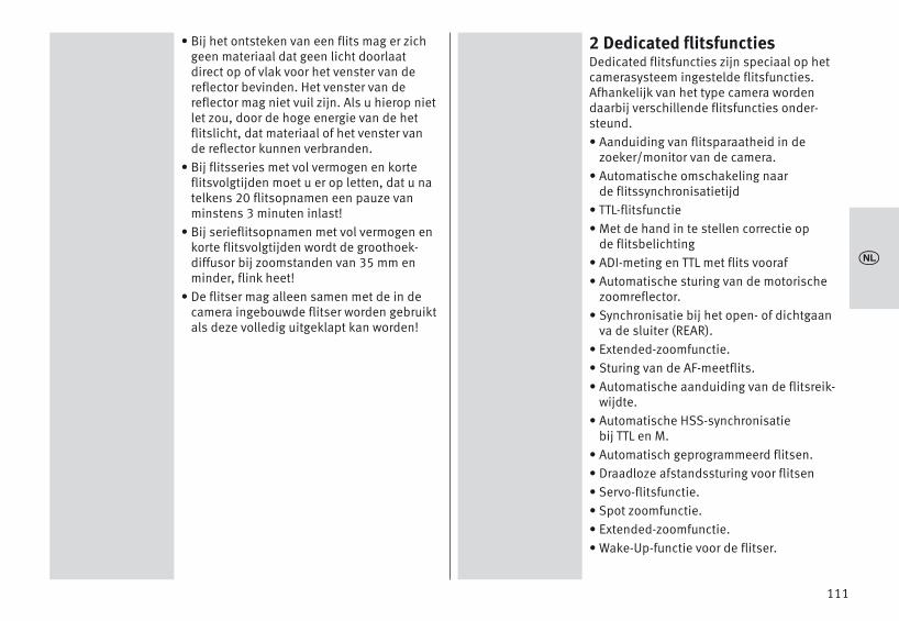
• Bij het ontsteken van een flits mag er zichgeen materiaal dat geen licht doorlaatdirect op of vlak voor het venster van dereflector bevinden. Het venster van dereflector mag niet vuil zijn. Als u hierop nietlet zou, door de hoge energie van de hetflitslicht, dat materiaal of het venster vande reflector kunnen verbranden.
• Bij flitsseries met vol vermogen en korteflitsvolgtijden moet u er op letten, dat u natelkens 20 flitsopnamen een pauze vanminstens 3 minuten inlast!
• Bij serieflitsopnamen met vol vermogen enkorte flitsvolgtijden wordt de groothoek-diffusor bij zoomstanden van 35 mm enminder, flink heet!
• De flitser mag alleen samen met de in decamera ingebouwde flitser worden gebruiktals deze volledig uitgeklapt kan worden!
2 Dedicated flitsfunctiesDedicated flitsfuncties zijn speciaal op hetcamerasysteem ingestelde flitsfuncties.Afhankelijk van het type camera wordendaarbij verschillende flitsfuncties onder-steund.• Aanduiding van flitsparaatheid in de
zoeker/monitor van de camera.• Automatische omschakeling naar
de flitssynchronisatietijd• TTL-flitsfunctie• Met de hand in te stellen correctie op
de flitsbelichting• ADI-meting en TTL met flits vooraf• Automatische sturing van de motorische
zoomreflector.• Synchronisatie bij het open- of dichtgaan
va de sluiter (REAR).• Extended-zoomfunctie.• Sturing van de AF-meetflits.• Automatische aanduiding van de flitsreik-
wijdte.• Automatische HSS-synchronisatie
bij TTL en M.• Automatisch geprogrammeerd flitsen.• Draadloze afstandssturing voor flitsen• Servo-flitsfunctie.• Spot zoomfunctie.• Extended-zoomfunctie.• Wake-Up-functie voor de flitser.
111
x

In het kader van deze gebruiksaanwijzing ishet niet mogelijk, alle cameramodellen methun individuele flitsfuncties gedetailleerd tebeschrijven. Zie daarvoor de aanwijzingen inde gebruiksaanwijzing van uw camera metbetrekking tot de mogelijke flitsfuncties,welke flitsfuncties door uw camera wordenondersteund, c.q. op de camera zelf moetenworden ingesteld!
Bij het gebruik van objectieven zonder CPU(bijv. objectieven zonder autofocus) tredenten dele beperkingen op!
3 Flitser gereedmaken
3.1 Het aanbrengen van de flitserFlitser op de camera monteren
Camera en flitser vóór het aanbrengen ofafnemen uitschakelen.• Verwijder het beschermkapje van de unit
basis.• De gekartelde moer � tot de aanslag tegen
de flitser draaien. De borgpen in de voet isnu geheel in het huis van de flitser verzon-ken.
• Flitser met de aansluitvoet tot de aanslagin de accessoireschoen van de cameraschuiven.
• De gekartelde moer � tot de aanslag tegenhet camerahuis draaien en de flitser vast-klemmen. Bij een camerahuis dat geenborggat bezit, blijft de geveerde borgpen inde flitser zitten, zodat het oppervlak van decamera niet wordt beschadigd.
Flitser van de camera afnemen
Camera en flitser vóór het aanbrengen ofafnemen uitschakelen !• De gekartelde moer � tot de aanslag tegen
het huis van de flitser draaien.• Flitser uit de accessoireschoen schuiven.
+
+
+
112
x

3.2 VoedingBatterij-, c.q. accukeuzeDe flitser kan naar keuze worden gevoed uit:• 4 Nikkel-metaal-hydride accu’s 1,2 V, type
IEC HR6 (AA / Penlight) deze hebben eenduidelijk hogere capaciteit dan de NiCd-accu en zijn minder bezwaarlijk voor hetmilieu omdat ze geen cadmium bevatten.
• 4 super-alkalimangaanbatterijen 1,5 V, typeIEC LR6 (AA / Penlight), onderhoudsvrijevoeding voor gematigde eisen aan de pre-statie.
• 4 Lithiumbatterijen 1,5 V, type IEC FR6 (AA /Penlight), onderhoudsvrijevoeding methoge capaciteit en geringe zelfontlading.
• Power Pack met verbindingskabel (speciaalaccessoire).
Gebruik alleen de hierboven aangegevenstroombronnen. Bij het gebruik van anderestroombronnen ontstaat het gevaar dat deflitser beschadigd raakt.
Als u denkt, de flitser gedurende een langeretijd niet te gebruiken, haal de batterijen erdan s.v.p. uit.
Het vervangen van de batterijen De accu's batterijen zijn leeg, c.q. verbruikt,als de flitsvolgtijd (= tijd tussen het ontste-ken van een flits met volle energie, bijv. bijM, tot het hernieuwd oplichten van deparaatheidsaanduiding) langer duurt dan 60 seconden. Bovendien verschijnt in hetaanraakscherm de aanduiding Batterij-indi-cator.• Schakel de flitser uit, druk daarvoor zolang
op de toets � tot alle aanduidingenverdwenen zijn.
• Schuif het deksel van het batterijvak �naar beneden en klap het open.
• Zet de batterijen in de lengte en overeenko-mend met de aangegeven batterijsymbolenin en sluit het deksel van het batterijvak �.
Let bij het inzetten van de batterijen, c.q.accu’s op de juiste polariteit, overeenkom-stig de symbolen in het batterijvak. Verkeerdingezette batterijen kunnen het apparaat ver-nielen! Vervang altijd alle batterijen tegelijken door dezelfde batterijen van één typefabrikant, met gelijke capaciteit! Verbruiktebatterijen horen niet in het huisvuil! Lever uwbijdrage aan bescherming van het milieu enlever ze in bij de daarvoor bestemde verza-melplaatsen!
+
113
x

3.3 In- en uitschakelen van de flitser• Schakel de flitser via de starttoets � in.
Het opstartscherm verschijnt.De flitser schakelt daarna altijd in met dehet laatste gebruikte functie (bijv. flitsenmet handinstelling M).
In de standby-functie knippert de toets �rood. Om dit uit te schakelen moet u zo langop de toets � drukken tot alle aandui-dingen zijn verdwenen.
Als u denkt, dat u de flitser gedurende lange-re tijd niet gaat gebruiken, bevelen wij aanom de flitser met de toets � auit te scha-kelen en de stroombronnen eruit te nemen.
3.4 Het keuzemenu • Druk zo vaak op de toets �, dat het
keuzemenu verschijnt.Het keuzemenu is in 6 sensortoetsen onder-verdeeld:Na drukken op de toets kunnen devolgende functies worden ingesteld.TTL, zie 7.1TTL HSS*, zie 7.4A, zie 7.5M, zie 7.3M HSS*, zie 7.4STROBO, zie 7.6REMOTE MASTER, zie 10.1REMOTE SLAVE, zie 10.2SERVO, zie 10.4 *) alleen na uitwisseling van gegevens met een camera
D
D
MODE
Na drukken op de toets kunnen deflitsparameters worden ingesteld.P (deelenergie), zie 7.3, 10.1.3 en 10.4.3EV (correctie op de flitsbelichting), zie 8, 10.2.4ZOOM (reflectorstand), zie 9.1N (Aantal flitsen), zie 7.6f (Flitsfrequentie), zie 7.6F (diafragma)ISO (lichtgevoeligheid), RATIO (lichtverhouding), zie 10.1.4CTRL (remote), zie 10.1CHANNEL (Kanal), zie 10.2.2GROUP (slaafgroep), zie 10.2.3.De weergave van de flitsparameters is afhan-kelijk van de gekozen flitsfunctie.
Na drukken op de toets kan het aan-raakscherm worden geconfigureerd, of kande flitser in zijn toestand als bij de afleveringworden teruggezet (gereset). BRIGHTNESS (helderheid), zie 15.1ROTATION (beeldschermweergave zwenken),zie 15.2RESET, zie 16.3
SERVICE
PARAMETER
114
V 1.0
MB 64AF-1digitalSON
MODE
PARAMETER
SERVICE
PARAMETER OP / EVZOOM
Nf (Hz)
FISO
CHANNELRATIO
CONTROL
MODE OETTL
TTL HSSAM
M HSSSTROBO
REMOTE MASTERREMOTE SLAVE
SERVO
SERVICE O
BRIGHTNESS
RESET
ROTATION
x

Nadat u op de toets hebt gedruktkunnen de opties worden ingesteld.RAPID (korte flitsvolgtijden), zie 11.1 SUB-REFL. (hulpreflector), zie 11.2ZOOM SIZE (aanpassing aan het opname-formaat), zie 11.5ZOOM MODE (verlichtingshoek), zie 11.4STANDBY (aut. uitschakeling van het appa-raat), zie 3.6MOD.LIGHT (instellicht), zie 11.3BEEP (akoestisch signaal), zie 11.9m / ft (meter / voet), zie 11.7POWERPACK (extern powerpack), zie 11.11AF BEAM (AF-hulplicht), zie 11.6FLASH BRACK. (flitsbelichtingsvariaties), zie 11.8De weergave van de flitsparameters is afhan-kelijk van de gekozen flitsfunctie.In het aangegeven menu op de flitser zijn allein een zwart vlakje staande velden als sen-sortoetsen uitgevoerd, waarop moeten wor-den gedrukt voor het instellen van debeschreven functie. In de afbeeldingen in deze gebruiksaanwijzingzijn steeds de sensortoetsen, waarop moetenworden gedrukt voor het instellen van debeschreven functie, met zwart gemarkeerd.
OPTION 3.5 INFODe actuele instellingen van de flitser kunnentijdens het gebruik aangegeven worden.• Druk op het aanraakscherm op de sensor-
toets � . De info verschijnt.- EXT (Extended-zoomfunctie) is ingesteld,
(zie 11.6.1).- AF OFF (AF hulplicht) is uitgeschakeld
(zie 11.6),- (MOD.LIGHT) is ingesteld
(zie 11.3),- (Beep-functie) is ingesteld,
(zie 11.9)- (Kanal) verschijnt,
(zie 10.1.5, 10.2.2)- de automatische uitschakeling van het appa-
raat is ingesteld op 10 minuten, (zie 3.6),- de aanduiding van de temperatuur stijgt bij
intensief gebruik van het aapparaat,
3.6 Automatische uitschakeling / Auto – OFF
In de fabriek wordt de flitser zo ingesteld, dathij ong. 10 minuten -• na het inschakelen,• na het ontsteken van een flits,• na het aantippen van de ontspanknop op
de camera,• na het uitschakelen van het belichtings-
meetsysteem van de camera . . . . . . in de standby-functie schakelt (AUTO OFF)in om energie te besparen en de stroombron-
i
2CH
115
OPTION
i
x
200
OPTION ORAPID
SUB-REFL. ZOOM SIZEZOOM MODESTANDBY
MOD. LIGHTBEEPm / ft
POWERPACKAF BEAM
FLASH BRACK.

+
nen tegen onbedoeld ontladen te bescher-men. De geactiveerde automatische uitscha-keling wordt in het INFO-display aangegeven.De flitsparaatheidsaanduiding � en de aan-duidingen op het LC-display doven. In de standby-functie knipper de toets � rood. De het laatst ingestelde flitsfunctie blijft nahet automatisch uitschakelen behouden enstaat na het inschakelen onmiddellijk weerter beschikking. De flitser wordt door te drukken op detoets �, c.q. door het aantippen van deontspanknop op de camera (=Wake-upfunctie) weer ingeschakeld.
In de Slaaf-/SERVO functie is de automati-sche uitschakeling van de flitser niet actief.
Als u de flitser langere tijd niet gaat gebrui-ken, schakel hem dan in principe altijd viazijn hoofdschakelaar � uit!Indien noodzakelijk kan de automatische uit-schakeling reeds na 1 minuut plaatsvindenof worden gedeactiveerd.De flitser schakelt zich ong. 1 uur na het laatste gebruik geheel uit. In alle functieswordt na ongeveer 10 sec. het beeldschermop de helft van zijn helderheid ingesteld omenergie te besparen. Met elke druk op eentoets wordt het beeldscherm weer naar zijnnormale helderheid teruggeschakeld.
D
D
Het instellen van de automatische uitschakeling• Schakel de flitser via de toets � in.
Het opstartscherm verschijnt.De flitser schakelt daarna altijd in met dehet laatst gebruikte flitsfunctie (bijv. flitsenmet handinstelling M).
• Druk zo vaak op de toets �, dat het keuzemenu verschijnt.
• Druk in het aanraakscherm op de sensortoets
• Druk in het aanraakscherm op de toetsenen kies uit.
• Druk in het aanraakscherm op de sensortoets .
• Druk in het aanraakscherm op de sensor-toets voor de gewenste tijd. De instellingtreedt onmiddellijk in werking.
In de Standby-functie knippert de toets � rood.
D
OPTION
STANDBY
STANDBY
D
116
OPTION
OPTION O
q p
ZOOM MODESTANDBY
MOD. LIGHT
STANDBY OOFF
1 min10 min
x
200

4 LED-aanduidingen op de flitser
4.1 Flitsparaatheids aanduidingZodra de flitscondensator is opgeladen lichtop de flitser de toets � groep op en geeftdaarmee aan dat de flitser gereed is om teflitsen (flitsparaatheid). Dat betekent dat voor de eerstvolgendeopname flitslicht kan worden gebruikt. Deflitsparaatheid wordt ook naar de cameraovergebracht en zorgt in de zoeker daarvanvoor de betreffende aanduiding. Als u een opname maakt voordat in de zoe-ker van de camera de signaal dat de flitser isopgeladen, ontsteekt de flitser geen flits. Deopname kan dan mogelijk foutief wordenbelicht wanneer de camera al naar de flits-synchronisatietijd is omgeschakeld (zie14.1).
4.2 BelichtingscontroleNa een correcte belichting licht de toets �gedurende ong. 3 seconden rood op als deopname in de flitsfunctie und( zie 7.1) alsook in de automatisch flitsen-functie correct werd belicht!Volgt deze aanduiding van de belichtings-controle na de opname niet, dan werd deopname onderbelicht. U moet dan: - het eerstvolgend lagere diafragmagetal
instellen (bijv. in plaats van diafragma 8,diafragma 11), of
D
PTTLHSSPTTL
A
- de afstand tot het onderwerp, c.q. hetreflecterend vlak (bijv. bij indirect flitsen)verkleinen of
- de camera een hogere ISO-waarde instellen.Let in het display van het flitsapparaat op de aan-duiding van de reikwijdte van de flits (zie 5.2).
5 Aanduidingen in het displayDe camera’s geven de waarden van ISO,brandpuntsafstand van het objectief (mm) endiafragma door naar de flitser. Deze past zijn vereiste instellingen automa-tisch daaraan aan. Hij berekent uit die waar-den en zijn richtgetal de maximale reikwijdtevan het flitslicht. Flitsfunctie, reikwijdte, werkdiafragma en dezoomstand van de reflector worden in hetdisplay van de flitser aangegeven. Als de flitser wordt gebruikt zonder dat hijgegevens van de camera heeft ontvangen,worden de op de flitser ingestelde waardenaangegeven. DisplayverlichtingNa drukken op de toets � van de flitser oftippen op het aanraakscherm wordt geduren-de ongeveer 10 seconden de displayverlich-ting op zijn maximale helderheid ingesteld.
D
117
x

+
5.1 Aanduiding van de flitsfunctieIn het display wordt ingestelde flitsfunctieaangegeven. Daarbij zijn, afhankelijk van hettype camera verschillende voor de telkensondersteunde TTL-flitsfunctie (bijv. en
) en de manual flitsfunctie M moge-lijk (zie 7.3).
5.2 Aanduiding van de reikwijdteAls de camera is voorzien van een objectiefmet CPU, verschijnt in het display een aan-duiding van de reikwijdte Hiervoor moet een uitwisseling van gegevenstussen camera en flitser plaats hebbengevonden, bijvoorbeeld door het aantippenvan de ontspanknop op de camera. De reik-wijdte kan zowel in meters (m) of in feet (ft)worden aangegeven (zie 11.7).
Er verschijnt geen aanduiding van de reik-wijdte. . .
- als er geen gegevens door de camerawerden overgebracht,
- als de kop van de reflector uit zijn normalepositie (naar boven of zijwaarts) isgezwenkt,
- Wanneer de flitser in de REMOTE MASTER;REMOTE SLAVE of SERVO-flitsfunctie werkt.
PTTLPTTL HSS
Reikwijdte in TTL-/TTL HSS-flitsfunctieIn de TTL-flitsfuncties ( , ; zie7.1) wordt in het display de waarde voor deminimale en de maximale reikwijdte van hetflitslicht aangegeven.De aangegeven waarde geldt voor een reflec-tiegraad van het onderwerp van 25%, watvoor de meeste opnamesituaties een correcte waarde is. Grote afwijkingen van deze reflectiegraad, bijzeer sterk of juist zeer zwak reflecterendeonderwerpen kunnen de reikwijdte van hetflitslicht beïnvloeden.Het onderwerp moet zich in een bereik van onge-veer 40% tot 70% van de aangegeven waardebevinden. De elektronica heeft dan voldoendespeelruimte voor een goede belichting.Om overbelichting te vermijden moet u minstens de afstand die in het display alsminimum staat aangegeven, aanhouden.Het aanpassen aan de betreffende opname-situatie kan bijv. door het veranderen van de dia-fragmaopening van het objectief worden bereikt.
TTL HSSTTL
118
5.5 - 56 m M-Zoom 35 m
m
TTL
iEV
5.5 - 56 m M-Zoom 35 m
m
TTL
iEV
x

Aanduiding van de reikwijdte in de functievan met de hand in te stellen flitser In de functie van de met de hand in te stellen(manual) flitser M wordt in het display deafstandswaarde aangegeven die voor het cor-rect belichten van het onderwerp aangehou-den moet worden. Het aanpassen aan deheersende opnameomstandigheden kan bijv.door het veranderen van de diafragmawaardeop het objectief of door het kiezen van eenmet de hand in te stellen deelvermogen (zie7.3) worden bereikt.Overschrijding van het bereik van de aanduidingenIn het display kunnen reikwijdten tot maxi-maal 99 m, c.q. 99 ft worden aangegeven.Bij hoge ISO-waarden en grote diafragmao-peningen kan het bereik van de aanduidin-gen worden overschreden. Dit wordt door een pijl, c.q. driehoekje achterde afstandswaarde aangegeven.
M6 Aanduidingen in de zoeker van
de camerarVoorbeelden van aanduidingen in de zoekervan de camera:Flitssymbool licht op:De flitser is klaar om te flitsen (bij sommigecamera's).Flitssymbool knippert langzaam:Scakel de flitser in.Basiscorrectie bij een foute belichting:• Bij te ruime belichting: niet flitsen!• Bij te krappe belichting: schakel de flitser
in of gebruik een statief en een langerebelichtingstijd.
In de verschillende belichtings- en automati-sche programma's kunnen er verschillenderedenen zijn voor het optreden van een foutebelichting.Zoek voor de aanduidingen in de zoeker vanuw camera in de gebruiksaanwijzing van decamera wat voor uw camera geldt.
119
9.0 mM-Zoom 35 m
m
M
iP1/1
49- 99 m uF 1,4M-
Zoom 200mm
TTL
iEV
x

7 FlitsfunctiesAfhankelijk van het type camera staan u devolgende flitsfuncties ter beschikking:• TTL-flitsfunctie ( ), chap. 7.1• Manual flitsfunctie ( ), chap. 7.3• Automatische synchronisatie bij korte
belichtingstijden (HSS), chap. 7.4• Automatisch flitsenfunctie ( ), chap. 7.5• Stroboscopisch flitsen ( ),
chap. 7.6• functie, chap. 10.1• functie, chap. 10.2• functie, chap. 10.4. Het instellen van de flitsfuncties vindt plaatsvia het aanraakscherm. Voor het instellen van de flitsfuncties
en moet er eerst een uitwis-seling van gegevens tussen camera en flitserhebben plaatsgevonden, bijv. door het aan-tippen van de ontspanknop van de camera
7.1 TTL-flitsfunctie ( )Bij de opname worden, voorafgaand aan deeigenlijke belichting enkele, nauwelijkszichtbare meetflitsen door de flitser ontstoken.Het gereflecteerde licht van die meetflitsenwordt door de camera geëvalueerd.Overeenkomstig deze evaluatie wordt de danvolgende flitsbelichting door de camera afge-stemd op de opnamesituatie (zie voor naderedetails de gebruiksaanwijzing van uw camera).
TTLM
A
STROBO
REMOTE MASTER
REMOTE SLAVE
SERVO
M HSSTTL HSS
TTL
Na een correct belichte opname licht de aan-duiding van de belichtingscontrole geduren-de ong. 3 sec op (zie 4.2).Het instellen van de flitsfunctie• Schakel de flitser met de toets � in.
Het opstartscherm verschijnt.De flitser schakelt altijd in met de het laatstgebruikte flitsfunctie (bijv. M-flitsfunctie).
• Druk in het aanraakscherm zo vaak op deaangegeven flitsfunctie, tot de aanduidingvoor het kiezen verschijnt.
• Druk in het aanraakscherm op de sensor-toetsen en kies de gewenstefunctie.
• Druk op de in een geel overzicht vlakjestaande functie. De instelling treedt onmiddellijk in werking.
• Stel op de camera een overeenkomendefunctie in, bijv. P, S, A, enz.
• Tip de ontspanknop op de camera evenaan, zodat er een uitwisseling van gege-vens tussen camera en flitser plaats kanvinden.
120
V 1.0
MB 64AF-1digitalSON
9.0 mM-Zoom 35 m
m
M
iP1/1
MODE O
q p
TTLTTL HSS
x

7.2 TTL met flits vooraf en ADI-metingDe TTL met flits vooraf en de ADI-meting zijndigitale TTL-flitsfuncties en nieuwe ontwikke-lingen van de TTL-flitsfuncties van analogecamera's. Bij de opname wordt dan, voor deeigenlijke belichting, een nagenoeg onzicht-bare meetflits door de flitser afgegeven. Hetdoor het onderwerp gereflecteerde lichtwordt door de camera geëvalueerd.Overeenkomstig deze evaluatie wordt deeerstvolgende flitsbelichting door de cameraaan de opnamesituatie aangepast (zie voordetails de gebruiksaanwijzing van uw came-ra). Bij de ADI-meting worden bovendiengegevens betreffende de afstandsinstellingvan het objectief bij het flitsen meegerekend.De keuze, c.q. instelling van de flitsfunctiesTTL met flits vooraf of ADI-meting moet op decamera zelf plaatsvinden (zie de gebruik-saanwijzing van de camera).Op de flitser moet de flitsfunctie wordeningesteld (zie 7.1).
7.3 Manual flitsfunctieIn de manual flitsfunctie M wordt door de flit-ser altijd het volle vermogen afgegeven, alser geen deelvermogen is ingesteld. Het aan-passen aan de opnamesituatie kan bijv. doorde instelling van het diafragma op de cameraof door het kiezen van een geschikt, met dehand in te stellen deelvermogen plaatsvin-den.Het instelbereik strekt zich uit van P 1/1 totP1/256 in de functie, P 1/1 tot P1/32 inde functie.
TTL
MM HSS
In het display wordt de afstand aangegevenwaarbij het onderwerp correct wordt belicht(zie 5.2).Het instellen van de flitsfunctie • Schakel de flitser met de toets � in.
Het opstartscherm verschijnt.De flitser schakelt altijd in met de het laatstgebruikte flitsfunctie.
• Druk in het aanraakscherm zo vaak op desensortoetsen van de aangegeven flits-functie, tot de aanduiding voor het kiezenvan de functie verschijnt.
• Druk in het aanraakscherm op de sensor-toetsen en kies uit.
• Druk in het aanraakscherm op de sensor-toets .
• Stel op de camera een overeenkomendefunctie in, bijv. enz.
• Tip de ontspanknop op de camera evenaan, zodat er een uitwisseling van gege-vens tussen camera en flitser ontstaat.
Sommige camera's ondersteunen de handin-stelling van de flitser alleen in de camera-functie M (manuell). In andere camera's ver-schijnt er een foutmelding in het display enwordt het ontspannen geblokkeerd.
M
M
M
121
0.8 - 9.0 m M-Zoom 35 m
m
TTL
iEV
0.8 - 9.0 m M-Zoom 35 m
m
TTL
iEV
9.0 mM-Zoom 35 m
m
M
iP1/1
MODE O
q p
AM
M HSS
x

Met de hand in te stellen deelvermogens In de met de hand uit te voeren instelling vande flitsfunctie kan een deel van het flits-vermogen worden ingesteld.Het instellen• Druk in het aanraakscherm zo vaak op de
sensortoets voor het deelvermogen, dat hetkeuzemenu voor het deelvermogen ver-schijnt.
• Stel in het aanraakscherm met de sensor-toetsen het gewenste deelvermo-gen 1/1, 1/2, 1/8 . . . 1/256 in.
• Druk in het aanraakscherm op de sensor-toets voor het uitgekozen deelvermogen.
De instelling treedt onmiddellijk in werkingen wordt automatisch opgeslagen.
De aanduiding van de afstand van de reik-wijdte wordt automatisch aan het deelver-mogen (zie 5.2) aangepast.
M
7.4 Automatische synchronisatie bijkorte belichtingstijden (HSS)
Verschillende camera’s ondersteunen deautomatische synchronisatie bij korte belich-tingstijden (zie de gebruiksaanwijzing van decamera). Met deze flitsfunctie is het moge-lijk, ook bij kortere tijden dan de flitssynchro-nisatietijd een flitser te gebruiken. Deze functie is interessant bij bijv. portrettenin een heldere omgeving, als door een vergeopend diafragma (bijv. F 2,0) de scherpte-diepte begrensd moet worden! De flitser ondersteunt de synchronisatie bijkorte belichtingstijden in de functie en
.Natuurkundig bepaald wordt door deze synchronisatie bij korte belichtingstijden hetrichtgetal en daarmee tevens de reikwijdtevan de flitser behoorlijk ingeperkt! Let daarom op de aanduiding van de reik-wijdte in het display van de flitser! De synchronisatie bij korte belichtingstijdenwordt automatisch uitgevoerd als op decamera met de hand, of automatisch doorhet belichtingsprogramma, een korterebelichtingstijd dan de flitssynchronisatietijdis ingesteld.Let er op, dat het richtgetal van de flitser bijde synchronisatie bij korte belichtingstijdenmede afhangt van de gekozen belichting-stijd:hoe korter de belichtingstijd, des te lager hetrichtgetal!
TTLM
122
x
9.0 mM-Zoom 35 m
m
M
iP1/1
3.1 mM-Zoom 35 m
m
M
iP1/8
P O
q p
1/11/1 - 1/3
P O
q p
1/4 - 2/31/8
1/8 - 1/3

De synchronisatie bij korte belichtingstijdenwordt automatisch uitgevoerd als op decamera met de hand, of automatisch doorhet belichtingsprogramma, een korterebelichtingstijd dan de flitssynchronisatietijdis ingesteld.Het instellen van de functie• Schakel de flitser met de toets � in.
Het opstartscherm verschijnt.De flitser schakelt altijd in met de het laatstgebruikte flitsfunctie (bijv. TTL-flitsfunctie).
• Tip de ontspanknop van de camera evenaan, zodat er een uitwisseling van gege-vens tussen camera en flitser plaats kanvinden.
• Druk in het aanraakscherm zo vaak op sensortoets van de aangegeven flitsfunctie,dat het keuzemenu van de functies ver-schijnt.
• Druk in het aanraakscherm de sensortoetsen en kies resp.
uit.
• Druk in het aanraakscherm op de toets.
De instelling treedt onmiddellijk in werking.
Als op de flitser de synchronisatie bij kortebelichtingstijden HSS is geactiveerd, wordtsynchronisatie bij het dichtgaan van de slui-ter (REAR) automatisch gedeactiveerd!
M HSSTTL HSS
TTL HSS
7.5 Automatisch flitsenfunctieIn de automatisch-flitsenfunctie , meetde fotosensor � van de flitser het door hetonderwerp gereflecteerde licht. De fotosen-sor � heeft een meethoek van ong. 25° enmeet alleen tijdens de eigen lichtafgifte. Als de flitser voldoende licht heeft gegeven,schakelt de belichtingsautomaat van de flit-ser hem onmiddellijk uit. De fotosensor �moet op het onderwerp gericht zijn.Het instellen van de flitsfunctie • Schakel de flitser met de toets � in.
Het opstartscherm verschijnt.De flitser schakelt altijd in met de het laatstgebruikte flitsfunctie.
• Druk in het aanraakscherm zo vaak op desensortoetsen van de aangegeven flits-functie, tot de aanduiding voor het kiezenvan de functie verschijnt.
• Druk in het aanraakscherm op de sensor-toetsen en kies uit.
• Druk in het aanraakscherm op de sensor-toets .
• Stel op de camera een overeenkomendefunctie in, bijv. enz.
• Tip de ontspanknop op de camera evenaan, zodat er een uitwisseling van gege-vens tussen camera en flitser ontstaat.
A
A
A
A
123
9.0 mM-Zoom 35 m
m
M
iP1/1
MODE O
q p
TTL HSSA
M HSS
0.8 - 9.0 m M-Zoom 35 m
m
A
iEV
x0.8 - 9.0 m
M-Zoom 35 m
m
TTL
iEV
9.0 mM-Zoom 35 m
m
TTL HSS
iP1/1
MODE O
q p
TTLTTL HSS
A

7.6 Stroboscopisch flitsenDe functie stroboscopisch flitsen is een flits-functie met handinstelling (manual). Hierbijkunnen meerdere flitsbelichtingen op éénenkel beeld gemaakt worden. Dat is bijzon-der interessant bij bewegingsstudies eneffectopnamen. In de stroboscopisch flitsen-functie geeft de flitser meerdere flitsen meteen bepaalde flitsfrequentie af. De functie isdaarom alleen met een deelvermogen vanmax. 1/8 of minder te realiseren.Voor een stroboscoop-opname moet de flits-frequentie (aantal flitsen per seconde) en hetaantal flitsen worden ingesteld. Aantal flitsen (N) bij stroboscopisch flitsenIn deze functie kan het aantal flitsen (N) peropname worden ingesteld. Het aantal flitsen kan tussen 2 en 90 staps-gewijs worden ingesteld.
Het maximaal mogelijke aantal flitsen (N)hangt af van het ingestelde deelvermogen(P).Flitsfrequentie (f) bij stroboscopisch flitsenIn deze functie kan de flitsfrequentie (f ) wor-den ingesteld. De flitsfrequentie geeft hetaantal flitsen per seconde aan. De flitsfre-quentie kan tussen 1 en 100 stapsgewijsworden ingesteld.Om de kortst mogelijke flitsduur te bereikenkunt u het deelvermogen op de minimalewaarde van 1/256 instellen.
De max. mogelijke flitsfrequentie (f) hangt afvan het ingestelde deelvermogen (P).Het instellen van de flitsfunctie • Schakel de flitser met de toets � in.
Het opstartscherm verschijnt.De flitser schakelt altijd in met de het laatstgebruikte flitsfunctie.
• Druk in het aanraakscherm zo vaak op desensortoetsen van de aangegeven flits-functie, tot de aanduiding voor het kiezenvan de functie verschijnt.
• Druk in het aanraakscherm op de sensor-toetsen en kies uit.
• Druk in het aanraakscherm op de sensor-toets .
• Druk in het aanraakscherm op de sensor-toets, bijv. .
• Tip de ontspanknop op de camera evenaan, zodat er een uitwisseling van gege-vens tussen camera en flitser ontstaat.
STROBO
STROBO
M
124
x
+
+
0.8 - 9.0 m M-Zoom 35 m
m
TTL
iEV
MODE O
q p
M HSSSTROBO
REMOTE MASTER
3.1mM-Zoom 35 m
m
STROBO
iP1/8
f(Hz) 5N 5

125
Aantal flitsen (N) instellen • Druk in het aanraakscherm op de sensor-
toets voor het aantal flitsen .
• Druk in het aanraakscherm op de sensor-toetsen en kies het gewensteaantal flitsen.
Het max. mogelijke aantal flitsen (N) hangtaf van het ingestelde deelvermogen (P).
• Druk in het aanraakscherm op de sensor-toets voor het gewenste aantal flitsen, inhet voorbeeld . De instelling treedt onmiddellijk in werking.
4
N
Flitsfrequentie (f(Hz)) instellen • Druk in het aanraakscherm op de sensor-
toets voor de flitsfrequentie .
• Druk in het aanraakscherm op de sensor-toets en kies de gewenste flitsfre-quentie.
De max. mogelijke flitsfrequentie (f) hangt afvan het ingestelde deelvermogen (P).
• Druk in het aanraakscherm op de sensor-toets voor de gewenste flitsfrequentie, inhet voorbeeld . De instelling treedt onmiddellijk in werking.
In het display wordt de voor de ingesteldeparameters geldende afstand aangegeven.Door verandering van de diafragmawaarde ofhet deelvermogen kan de aangegevenafstandswaarde aan de werkelijke afstandtot het onderwerp worden aangepast.In de stroboscoop flitsfunctie worden geendiafragma- en ISO-waarden in het displayaangegeven!
De hulpreflector wordt in de stroboscoop-functie niet ondersteund.
f (Hz)
8
f (Hz) O
q p
789
3.1mM-Zoom 35 m
m
STROBO
iP1/16
f(Hz) 10N 4
3.1mM-Zoom 35 m
m
STROBO
iP1/8
f(Hz) 8N 4
x
+
+
+
3.1mM-Zoom 35 m
m
STROBO
iP1/16
f(Hz) 10N 5
N O
q p
345

126
8 Met de hand in te stellen correctie op de flitsbelichting
De automatiek van de flitsbelichting is in demeeste camera’s gebaseerd op een reflectie-graad van 25% (gemiddelde reflectiegraadvan flitsonderwerpen). Een donkere achtergrond die veel licht absor-beert of een lichte achtergrond die sterkreflecteert (bijv. tegenlichtopnamen), kunnenleiden tot te ruim, c.q. te krap belichte onder-werpen.Om het bovengenoemde effect te compense-ren kan de flitsbelichting via een met dehand in te stellen correctiewaarde wordenaangepast aan de opnamesituatie. De hoog-te van die correctiewaarde hangt af van hetcontrast tussen onderwerp en achtergrond!Op de flitser kunnen in de A/TTL-flitsfunctiesmet de hand correctiewaarden voor de flits-belichting van -3 tot +3 stops (EV) in stappenvan 1/3 stop worden ingesteld.Tip:Donker onderwerp tegen een lichte achter-grond: positieve correctiewaarde.Licht onderwerp tegen donkere achtergrond:negatieve correctiewaarde.Een belichtingscorrectie door veranderen vande diafragmaopening van het objectief is nietmogelijk, omdat de belichtingsautomatiekvan de camera het veranderde diafragmaweer als werkdiafragma ziet. Bij het instellenvan een correctiewaarde kan de aanduiding
van de reikwijdte in het display veranderenen aan de correctiewaarde worden aange-past (hangt af van het type camera)!
Het instellen• Druk zo vaak op de sensortoets , dat
het keuzemenu voor een correctiewaardeverschijnt.
• Druk in het aanraakscherm op de sensor-toetsen en stel een correctie-waarde in.
• Druk in het aanraakscherm op de uitge-kozen correctiewaarde, bijv. .
De instelling treedt onmiddellijk in werking.Een met de hand in te stellen correctiewaar-de voor de flitsbelichting in de TTL-flits-functies kan alleen dan worden uitgevoerdals de camera de instelling van een correctie-waarde op de flitser ondersteunt (zie degebruiksaanwijzing van uw camera)! Wanneer de camera deze functie niet onder-steunt werkt de op de flitser ingestelde cor-rectie niet. Bij sommige cameramodellen moet de cor-rectiewaarde op de flitsbelichting op decamera zelf worden ingesteld, In het displayvan de flitser wordt dan geen correctiewaar-de aangegeven.
Vergeet niet de met de hand ingestelde cor-rectie op de flitsbelichting na de opname opde camera uit te schakelen!
EV
-1
+
x
0.8 - 9.0 m M-Zoom 35 m
m
TTL
iEV
EV O
q p
-1 1/3-1
-2/3
1.1- 12 m M-Zoom 35 m
m
TTL
iEV-1
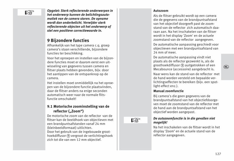
127
Opgelet: Sterk reflecterende onderwerpen inhet onderwerp kunnen de belichtingsauto-matiek van de camera storen. De opnamewordt dan onderbelicht. Verwijder sterkreflecterende objecten uit het onderwerp ofstel een positieve correctiewaarde in.
9 Bijzondere functiesAfhankelijk van het type camera c.q. groepcamera’s staan verschillende, bijzonderefuncties ter beschikking. Voor het oproepen en instellen van de bijzon-dere functies moet er daarom eerst een uit-wisseling van gegevens tussen camera enflitser plaats hebben gevonden, bijv. doorhet aantippen van de ontspanknop op de camera.Het instellen moet onmiddellijk na het oproe-pen van de bijzondere functie plaatsvinden,daar de flitser anders na enige secondenautomatisch weer naar de normale flits-functie omschakelt!
9.1 Motorische zoominstelling van dereflector („Zoom“)
De motorische zoom van de reflector van deflitser kan de beeldhoek van objectieven meteen brandpuntsafstanden vanaf 24 mm(kleinbeeldformaat) uitlichten. Door het gebruik van de ingebouwde groot-hoekdiffusor vergroot de verlichtingshoekzich tot die van een 12 mm objectief.
AutozoomAls de flitser gebruikt wordt op een cameradie de gegevens van de brandpuntsafstandvan het objectief doorgeeft past de zoom-stand van de reflector zich automatisch daa-raan aan. Na het inschakelen van de flitserwordt in het display 'Zoom' en de actuelezoomstand van de reflector aangegeven.De automatische aanpassing geschiedt voorobjectieven met een brandpuntsafstand van24 mm of meer. De automatische aanpassing vindt nietplaats als de reflector gezwenkt is, als degroothoekdiffusor auitgetrokken of eenMecabounce (accessoire) aangebracht is.Naar wens kan de stand van de reflector metde hand worden versteld om bepaalde ver-lichtingseffecten te bereiken (bijv. een spot-light-effect enz.).Manual zoomfunctieBij camera's die geen gegevens van debrandpuntsafstand van het objectiefdoorge-ven moet de zoomstand van de reflector metde hand aan de brandpuntsafstand van hetobjectief worden aangepast.
De autozoomfunctie is in die gevallen nietmogelijk!Na het inschakelen van de flitser wordt in hetdisplay ‘Zoom’ en de actuele stand van dereflector aangegeven.
+
+
x

128
Voorbeeld:U gebruikt een zoomobjectief met een bereikaan brandpuntsafstanden van 35 tot 105mm. In dit voorbeeld stelt u de stand van dezoomreflector van de flitser in op 35 mm.Terugzetten naar autozoom• Tip de ontspanknop op de camera even
aan, zodat er een uitwisseling van gege-vens tussen camera en flitser plaats kanvinden.
• Druk zo vaak op de toets �, dat het keuzemenu verschijnt.
• Druk in het aanraakscherm op de sensor-toets .
• Druk in het aanraakscherm op de sensor-toetsen en kies uit.
• Druk in het aanraakscherm op de sensor-toets .
• Druk in het aanraakscherm op de sensor-toetsen en kies de gewenste zoom-waarde uit.
• Druk in het aanraakscherm op de sensor-toetsen
Na ong. 10 sec. wordt naar de functieaandui-ding omgeschakeld of druk zo vaak op detoets � tot de functieaanduiding ver-schijnt.
D
PARAMETER
ZOOM
ZOOM
AUTOZOOM
AUTOZOOM
D
Het instellen• Druk zo vaak op de toets �, dat het
keuzemenu verschijnt.
• Druk in het aanraakscherm op de sensor-toets .
• Druk in het aanraakscherm op de sensor-toetsen en kies uit.
• Druk in het aanraakscherm op de sensor-toetsen .
• Druk in het aanraakscherm op de sensor-toetsen en kies de gewenstezoomwaarde uit.
• Druk in het aanraakscherm op de sensorto-ets voor de gewenste zoomwaarde. De instelling treedt onmiddellijk in werking.
De volgende zoomstanden voor de reflectorzijn mogelijk: 24 - 28 - 35 - 50 - 70 - 85 - 105-135-180-200 mm (kleinbeeldformaat).
Tip:Als u niet altijd de volle energie en reikwijdtevan de flitser nodig heeft, kunt u de reflectorook laten staan in de in de stand van de aan-vangsbrandpuntsafstand.Daardoor is gegarandeerd dat het geheleonderwerp in het beeld altijd volledig uitge-licht wordt. U bespaart zich dan het steedsmoeten aanpassen aan de brandpuntsaf-stand van het objectief.
D
PARAMETER
ZOOM
ZOOM
x
PARAMETER
PARAMETER O
q p
P/EVZOOM
F
ZOOM O
q p
7085
105
PARAMETER
PARAMETER O
q p
P/EVZOOM
F
ZOOM
q p
AUTOZOOM24
O

GroothoekdiffusorMet de ingebouwde groothoekdiffusor kande verlichtingshoek aan objectieven met eenbrandpuntsafstand vanaf 12 mm wordenaangepast (kleinbeeldformaat).Trek de groothoekdiffusor uit de reflectortot de aanslag naar voren en laat hem los. De groothoekdiffusor klapt dan vanzelfnaar beneden. De reflector wordt zodanigautomatisch in de vereiste stand gezet. In het display worden de afstandsaanduidin-gen en de zoomwaarde naar 12 mm gecorri-geerd.De gemotoriseerde reflector wordt bij hetgebruik van de groothoekdiffusor nietautomatisch aangepast.Voor het terugzetten de groothoekdiffusor 90° naar boven klappen en hem geheelinschuiven.mecabounce Diffuser MBM-03Als op de reflector van de flitser eenMecabounce (accessoire; zie 19) is gemon-teerd, wordt de reflector automatisch naar devereiste stand gestuurd. De aanduidingenvan de afstand en de zoomstand worden op16 mm gecorrigeerd.
De gemotoriseerde reflector wordt bij hetgebruik van een mecabounce niet automa-tisch aangepast.Het tegelijkertijd gebruiken van de groot-hoekdiffusor en een mecabounce is nietmogelijk.
10 Flitsen met bediening opafstand
De flitser ondersteunt het draadloos Sony-Remote-Systeem in de functies ‚CTRL’ und‚CTRL+´, afhankelijk van het ingezette came-rasysteem. De functies ‚CTRL’ en ‚CTRL+’ wor-den automatisch herkend.Dit remote-systeem bestaat uit een master-flitser op de camera en een of meer slaafflit-sers. De slaafflitser, c.q slaafflitsers wordendoor een lichtimpuls uit de reflector van demaster-flitser draadloos op afstand bedienden gestuurd. Opdat meerdere remote-systemen in eenzelf-de ruimte elkaar niet storen, staan u vieronafhankelijke remote-kanalen ter beschik-king. Master- en slaafflitsers die tot hetzelfderemote-systeem behoren moeten op hetzelf-de remote-kanaal worden ingesteld. De slaafflitsers die tot hetzelfde remotesys-teem behoren, moeten met de geïntegreerdesensor voor de remote-functie het lichtvan de master-flitser kunnen ontvangen. De remote-flitsfunctie ondersteunt ook desynchronisatie bij het dichtgaan van de slui-ter. In de remote-flitsfunctie vindt er geen aan-duiding van de reikwijdte van de flits in hetdisplay van de flitser plaats.
129
+
x

10.1 Remote master-functieDe slaafgroepen RMT en RMT2 zijn vanaf defabriek geactiveerd. De masterflitser (CTRL) en de slaafgroepenRMT en RMT2 kunnen geactiveerd of gedeac-tiveerd worden! Bij een uitgeschakelde master-flitser (CTRL)heeft de flits van de master-flitser alleen nogslechts een sturende functie en draagt hijniet bij aan de belichting van de opname! 10.1.1 Remote-masterfunctie instellen• Schakel de flitser in met de toets �.
Het startmenu verschijnt.• Druk in het aanraakscherm zo vaak op de
sensortoetsen van de aangegeven flits-functie, dat de aanduiding voor het keuze-menu voor de functies verschijnt
• Druk in het aanraakscherm op de sensor-toetsen en kies uit.
• Druk in het aanraakscherm op de sensor-toets . De functie van remote-master wordt ingesteld.
In de afbeelding is de remote masterfunctieCTRL aangegeven. De master (CTRL) draagt ingelijke mate bij aan de belichting als deslaafgroep (RMT).
Aan de master (CTRL) en de slaafflitsgroepRMT, c.q. RMT2 kunnen de verlichtingsver-houdingen worden toegekend (zie 10.1.4).
REMOTE MASTER
REMOTE MASTER
Omschakelen van CTRL naar CTRL+• Druk zo vaak op de toetsen � dat het
keuzemenu verschijnt.
• Druk in het aanraakscherm op de sensor-toets .
• Druk in het aanraakscherm op de sensor-toetsen en kies uit.
• Druk in het aanraakscherm op de sensor-toets .
• Druk in het aanraakscherm op de sensor-toets voor de gewenste functie , c.q.
.
De instelling treedt onmiddellijk in werking.
Een sturing van een verlichtingsverhouding(Ratio) is alleen mogelijk in de functieCTRL+.
D
PARAMETER
CONTROL
CONTROL
CTRLCTRL+
130
x0.6- 7.2 m
M-Zoom 35 m
m
TTL
iEV
MODE O
q p
STROBOREMOTE MASTER
REMOTE SLAVE
CTRL RMT4 8
REMOTECTRL
TTL
i RATIO
CTRL RMT RMT24 8 1
REMOTECTRL+
TTL
i RATIO
PARAMETER
PARAMETER O
q p
RATIOCONTROL
CTRL/CTRL+ OCTRL
CTRL+
+

10.1.2 Flitsfunctie op de masterflitser instellen
• Druk in het aanraakscherm zo vaak op desensortoets voor de functie, dat het keuze-menu van de functies verschijnt.
• Druk in het aanraakscherm op de sensor-toetsen en kies het gewensteflitsfunctie.
• Druk in het aanraakscherm op de sensor-toets voor de gewenste functie c.q.
.
De ingestelde functie treedt onmiddellijk inwerking.
TTLM
10.1.3 Deelvermogen in de M-functie op demasterflitser instellen
Stel de flitsfunctie in op zoals onder10.1.2 beschreven.
• Druk in het aanraakscherm zo vaak op desensortoets , dat het master keuzeme-nu verschijnt.
• Druk in het aanraakscherm op de sensor-toets voor het deelvermogen .
• Druk in het aanraakscherm op de sensor-toetsen om het gewenste deel-vermogen in te stellen.
• Druk in het aanraakscherm op de sensor-toets van het uitgekozen deelvermogen
.
De instelling treedt onmiddellijk in werking.
M
M
P
1/8
131
x
CTRL RMT RMT24 8 1
REMOTECTRL+
M1/1
i RATIO
CTRL RMT RMT24 8 1
REMOTECTRL+
M1/1
i RATIO
CTRL RMT RMT24 8 1
REMOTECTRL+
M1/8
i RATIO
CTRL RMT RMT24 8 1
REMOTECTRL+
TTL
i RATIO
MASTER O
q p
TTLMEV
P O
q p
1/4 - 2/31/8
1/8 - 1/3
MASTER OTTL
M
P

10.1.4 Verlichtingsverhouding (RATIO) voorde flitsergroepen op de masterflitserdefiniëren
De verlichtingsverhoudingen van het remote-systeem kunnen worden ingesteld ombepaalde lichteffecten te bereiken. De ver-lichtingsverhoudingen worden voor demaster (CTRL) en de groepen (RMT en RMT2)worden uitsluitend door de masterflitsergestuurd.Ratio activeren / deactiveren• Druk zo vaak op de toetsen � dat het
keuzemenu verschijnt.
• Druk in het aanraakscherm op de sensor-toets .
• Druk in het aanraakscherm op de sensorto-etsen en kies uit.
• Druk in het aanraakscherm op de sensor-toets .
• Druk in het aanraakscherm op de sensor-toets , c.q en het RATIO functieschakelt in, c.q. uit.
D
PARAMETER
RATIO
RATIO
OFFON
Verlichtingsverhouding (RATIO) definiëren• Druk in het aanraakscherm op de sensor-
toets .
• Druk in het aanraakscherm op de sensor-toets waarvoor een verlichtingsverhoudingmoet worden ingesteld, in het voorbeeldRMT2
• Druk in het aanraakscherm op de sensor-toetsen om de gewenste verlich-tingsverhouding in te stellen of de verlich-tingsbijdrage uit te schakelen (--).
• Druk in het aanraakscherm op de sensor-toets voor de gewenste correctiewaarde.
De instelling treedt onmiddellijk in werking.
RATIO
132
x
CTRL RMT RMT24 8 1
REMOTECTRL+
M1/8
i RATIO
PARAMETER
PARAMETER O
q p
CHANNELRATIO
CONTROL
RTM2 O
q p
48
16
RATIO OOFF
ON
8
1
4
ORATIO
CTRL
RMT
RMT2
CTRL RMT RMT24 8 8
REMOTECTRL+
M1/8
i RATIO

10.1.5 Remote-kanaal instellenOpdat meerdere remote-systemen in dezelf-de ruimte elkaar niet storen, staan u vieronafhankelijke remote-kanalen ter beschik-king. Master- en slaafflitsers die bij eenzelf-de remote-systeem horen moeten op hetzelfde remote-kanaal worden ingesteld.
• Druk zo vaak op de toets �, dat het keuzemenu verschijnt.
• Druk in het aanraakscherm op de sensor-toets .
• Druk in het aanraakscherm op de toets.
• Druk in het aanraakscherm op de sensor-toetsen en stel een remote-kanaal, bijv. in.
• Druk in het aanraakscherm op de sensor-toets voor het gewneste kanaal.
De instelling treedt onmiddellijk in werking.Druk op � en controleer de instellingkanaal.
D
PARAMETER
CHANNEL
CHANNEL 2
i
10.2 Remote-slaafflitsfunctieDe flitser ondersteunt het draadloze Remote-systeem in de slaafflitsfunctie en is compati-bel met het Sony-systeem.Hierbij kunnen een of meerdere slaafflitsers
door een master op de camera (bijv. demecablitz 64AF-1S digital) draadloos opafstand worden aangestuurd.Een slaafflitser kan aan één van twee moge-lijke slaafgroepen (RMT, RMT2) worden toe-gewezen. De masterflitser kan al deze slaaf-groepen tegelijkertijd sturen en daarbij deindividuele instellingen van elk der slaaf-groepen acht nemen.Opdat meerdere remote-systemen in dezelf-de ruimte elkaar niet storen, staan u vieronafhankelijke remote-kanalen (CH1, 2, 3 of4) ter beschikking.Masterflitsers die tot eenzelfde remote-sys-teem behoren, moeten alle op hetzelfdekanaal ingesteld worden. De slaafflitsers moeten met de ingebouwdesensor voor de remote-functie het licht vande masterflitser kunnen ontvangen.Afhankelijk van het type camera kan ook eenin de camera ingebouwde flitser als master-flitser werken.
133
xPARAMETER O
q p
ZOOMCHANNEL
RATIO
CHANNEL O
q p
CHANNEL 1CHANNEL 2CHANNEL 3
PARAMETER

10.2.1 Slaafkanaal instellen• Schakel de flitser in met de toets �.
Het opstartscherm verschijnt.De flitser schakelt dan altijd in met de hetlaatst gebruikte functie (bijv. TTL-functie).
• Druk in het aanraakscherm zo vaak op deaangegeven flitsfunctie, dat de keuze vande functies verschijnt.
• Druk in het aanraakscherm op de sensor-toetsen en kies .
• Druk in het aanraakscherm op de sensor-toets .
De remote slaaffunctie wordt ingesteld.
Bovendien wordt de gekozen slaafgroep(bijv. RMT) en het remote-kanaal (bijv. CH 1)aangegeven.
REMOTE SLAVE
REMOTE SLAVE
10.2.2 Slaafgroep instellen• Druk in het aanraakscherm op de sensor-
toets voor de kanaalgroep (bijv ).
De keuze voor kanaal en groep wordt in-gevoegd.
• Druk in het aanraakscherm op de sensor-toetsen voor het kanaal .
• Druk in het aanraakscherm op e sensor-toetsen en kies het gewenstekanaal uit.
• Druk in het aanraakscherm op het gekozenkanaal.
De instelling treedt onmiddellijk in werking.In het display wordt 'CH2' aangegeven.
RMT I CH1
CHANNEL
134
x
0.8- 9.0 m M-Zoom 35 m
m
TTL
iEV
MODE O
q p
REMOTE MASTERREMOTE SLAVE
SERVO
M-Zoom 24
REMOTE
SLAVERMT Ch
2 1
i
mm
P1/1
M-Zoom 24
REMOTE
SLAVERMT Ch
2 2
i
mm
P1/1
M-Zoom 24
REMOTE
SLAVERMT Ch
2 1
i
mm
SLAVE OCHANNEL
GROUP
CHANNEL O
q p
CHANNEL 1CHANNEL 2CHANNEL 3

10.2.3 Slaaffunctie instellen• Druk in het aanraakscherm op de sensor-
toets voor de verlichtingsverhouding /belichtingscorrectie (bijv. ). Het keuzemenu verschijnt.
• Druk in het aanraakscherp op de sensor-toets voor de groep .
• Druk in het aanraakscherm op de sensor-toetsen voor de gewenste groep of
.
De instelling treedt onmiddellijk in werking.
RMT I CH1
GROUP
RMTRMT2
10.2.4 Slaaf- deelvermogen instellen
• Druk in het aanraakscherm op de sensor-toets voor het deelvermogen of .
• Druk in het aanraakscherm op de sensor-toets voor de gewenste functie , c.q.
.
De instelling treedt onmiddellijk in werking.
EVP
TTLM
135
x
M-Zoom 24
REMOTE
SLAVERMT Ch
2
i
mm
P
M-Zoom 24
REMOTE
SLAVERMT Ch
2
i
mm
P1/1
M-Zoom 24
REMOTE
SLAVERMT Ch
2 1
i
mm
SLAVE OCHANNEL
GROUP
GROUP O
RTM2
SLAVE OTTL
M
P
RTM

10.2.5 Slaaf- deelvermogen / belichtings-correctie instellen
• Druk in het aanraakscherm op de sensor-toets voor het deelvermogen / de belich-tingscorrectie (bijv. / ) .Het keuzemenu verschijnt.
• Druk in het aanraakscherm op de sensor-toets voor de gewenste functie of .
• Druk in het aanraakscherm op de sensor-toetsen om het gewenste deel-vermogen 1/1, 1/2, 1/8, c.q. 1/256 in testellen.
Het deelvermogen wordt overgenomen.Als bij de slaafflitser(s) de flitsparaatheid isbereikt, knippert het/hun AF-hulplicht.
EV1/1
EVP
10.3 He testen van de remote flits-functie
• Zet de slaafflitsers net zo neer als u ze voorde latere opname wilt gebruiken. Gebruik voor het opstellen van de slaafflit-sers een flitservoetje S60.
• Wacht de flitsparaatheid van alle deelne-mende flitsers af. Zijn de slaafflitsersparaat, dan knippert de AF-hulplicht �.
• Druk bij de master-flitser op de ontspan-knop voor handbediening � en ontsteekdaardoor een testflits. De slaafflitsers reageren per slaafgroep naelkaar iets vertraagd met een testflits. Alseen slaaflitser geen testflits afgeeft, contro-leer dan de instelling van remote-kanaal enslaafgroep. Corrigeer de stand van de slaaf-flitser zodat deze het licht van demaster-flitser kan ontvangen.
De soort flitsfunctie wordt automatisch doorde master-flitser doorgegeven. Als de flitser als master in het draadloosremotesysteem werkt, wordt tegelijk met hetontsteken van zijn instellicht dat van deslaafflitser(s) ontstoken.
136
x
M-Zoom 24
REMOTE
SLAVERMT Ch
2 2
i
mm
P1/1
SLAVE OTTL
M
EV / P
P O
q p
1/4 - 2/31/8
1/8 - 1/3

10.4 SERVO-functieDe SERVO-functie is een eenvoudige slaaf-functie zonder, c.q. met onderdrukking vaneen flits vooraf, waarbij de slaafflitser altijdeen flits ontsteekt zodra deze een lichtim-puls van de flitser op de camera ontvangt. In de SERVO-functie is in het algemeen alleenflitsen met handinstelling mogelijk. Dezeflitsfunctie, waarbij de instellingen met dehand moeten worden gedaan, wordt na hetinstellen van de SERVO-functie automatischingesteld. 10.4.1 SERVO-flitsfunctie instellen• Druk in het aanraakscherm zo vaak op de
sensortoets voor de aangegeven functie,dat de aanduiding van het keuzemenu verschijnt.
• Druk in het aanraakscherm op de sensor-toetsen en kies de functie
.
• Druk in het aanraakscherm op de sensor-toets .
De functie wordt uitgevoerd.Indien gewenst, kunt u een deelvermogeninstellen, zie 10.4.3.
SERVO
SERVO
10.4.2 Onderdrukking van de flits vooraf,c.q. het instellen van de synchronisa-tie
• Druk in het aanraakscherm zo vaak op desensortoets , dat het keuzemenuvoor de synchronisatie verschijnt.
• Druk in het aanraakscherm op de sensor-toets:
synchronisatie zonder flits vooraf,synchronisatie met flits vooraf.
De synchronisatie wordt uitgevoerd.
Als de zo ingestelde synchronisatie niet correct werkt, ga dan te werk als onder10.4.4 wordt beschreven.
SYNC
137
x0.8- 9.0 m
M-Zoom 35 m
m
TTL
iEV
MODE O
q p
REMOTE SLAVESERVO
M-Zoom 24
M-Servo SYNC
iP1/1
mm
SYNC O
LEARN
M-Zoom 24
M-Servo SYNC
iP1/1
mm

10.4.3 Deelvermogen in de SERVO-functie• Druk in het aanraakscherm zo vaak op de
sensortoets voor het deelvermogen, dathet keuzemenu voor deelvermogens ver-schijnt.
• Druk in het aanraakscherm op de sensor-toetsen om het gewenste deel-vermogen 1/1, 1/2, 1/8, naar 1/256 in testellen.
• Druk in het aanraakscherm op de sensor-toets van het uitgekozen deelvermogen
(bijv. 1/16).
Het deelvermogen wordt overgenomen.Als bij de slaafflitser(s) de flitsparaatheid isbereikt, knippert het/hun AF-hulplicht.
Remote-kanalen kunnen in de SERVO-functieniet worden ingesteld. De flitser op de camera mag niet in de remote-functie werken.
P
1/16
10.4.4 LeerfunctieDe „leerfunctie“ maakt het mogelijk, de indi-viduele, automatische aanpassing van deslaafflitser op de flitstechniek van de came-raflitser aan te passen.Hierbij kunnen een of meer meetflitsen, bijv.die voor vermindering van het „rode ogen-effect“ van de cameraflitser in acht wordengenomen. Het ontsteken van de slaafflitservindt dan plaats op het moment van dehoofdflits die de opname belicht.
Als de cameraflitser voor het automatischscherpstellen AF-meetflitsen ontsteekt, laathet systeem de leerfunctie niet toe.
Gebruik dan, indien mogelijk, een anderecamerafunctie of schakel om naar met dehand scherpstellen.
138
x
+
+
M-Zoom 35
M-Servo SYNC
iP1/1
mm
M-Zoom 35
M-Servo SYNC
iP1/16
mm
P O
q p
1/8 - 2/31/16
1/16 - 1/3
+

Het instellen van de leerfunctie De AF-meetflits vooraf van de camera moetworden uitgeschakeld.• Druk in het aanraakscherm zo vaak op de
sensortoets tot het keuzemenu ver-schijnt.
• Druk in het aanraakscherm op de sensor-toets .
• De 'Learning modus' (leerfunctie) is nugereed om te leren.
• Druk op de camera op de ontspanknopzodat zijn eigen flitser een flits ontsteekt.
Als de SERVO-flitser een lichtimpuls heeftontvangen verschijnt in het display 'LEARN OK' als bevestiging.
De mecablitz digital heeft het flitslicht van decameraflitser geleerd.
SYNC
Learn
10.4.5 Het uitschakelen van de SERVO-flits-functie
• Druk in het aanraakscherm zo vaak op deaangegeven functie, dat het keuzemenuvoor de flitsfuncties verschijnt.
• Druk In het aanraakscherm op d e sensor-toetsen en kies de gewensteflitsfunctie, bijv. .
• Druk in het aanraakscherm op de sensor-toets voor de flitsfunctie, bijv. .
De uitgekozen functie wordt onmiddellijkovergenomen.
TTL
TTL
139
x
M-Zoom 24
M-Servo SYNC
iP1/16
mm
SYNC O
LEARN
M-Zoom 24
M-Servo SYNC
iP1/16
mm
MODE O
q p
TTLA
0.6- 7.5 m M-Zoom 24 m
m
TTL
iEV

11 OPTION-Menu
11.1 RAPID-functieIn de flitsfuncties A en TTL hangen de flits-volgtijden af van hoeveel licht er voor deopname nodig is. Is de flitsvolgtijd te lang,dan kan in de A- en de TTL flitsfunctie deRAPID-functie worden ingeschakeld. DeRAPID-functie wordt in het bijzonder aanbe-volen voor situaties waarbij het meer op kor-te flitsvolgtijden en minder op het maximaleflitsvermogen aankomt, bijvoorbeeld in naarverhouding kleine ruimten. Het richtgetalwordt hierbij echter wel met 1 stop geredu-ceerd, d.w.z. van richtgetal 36 (bij ISO 100- zoom 35) naar richtgetal 25 (bij ISO 100- zoom 35).Het instellen• Druk zo vaak op de toets �, dat het
keuzemenu verschijnt.• Druk in het aanraakscherm op de
sensortoets .• Druk in het aanraakscherm op de sensor-
toetsen en kies uit.• Druk in het aanraakscherm op de sensor-
toets . • Druk in het aanraakscherm op de sensor-
toets , c.q en het RAPID functieschakelt in, c.q. uit.
De instelling treedt onmiddellijk in werking.Na het activeren van de RAPID-functie wordtin het display ' ' aangegeven.
D
OPTION
RAPID
RAPID
OFFON
11.2 Hulpreflector (SUB-REFL.)De hulpreflector dient voor het frontaalophelderen bij indirect flitsen, als de hoof-dreflector naar de zijkant gedraaid of naarboven gericht is. Als de hoeveelheid licht uitde hulpreflector te groot is, kan deze tot dehelft worden gereduceerd.Het instellen• Druk zo vaak op de toets �, dat het
keuzemenu verschijnt.• Druk in het aanraakscherm op de
sensortoets .
• Druk in het aanraakscherm op de sensor-toetsen en kies uit.
• Druk in het aanraakscherm op de sensor-toets .
• Druk in het aanraakscherm op de , deofwel op de toets om de hulpre-
flector in- of uit te schakelen. De instelling treedt onmiddellijk in werking.
Na het activeren van de hulpreflector ver-schijnt in het display .In het INFO-menu wordt ' 1/1' c.q.. ' 1/2'aangegeven. 1/1 staat voor het volle vermogen, 1/2 staatvoor het halve vermogen.
D
OPTION
SUB-REFL.
SUB-REFL.
1/1OFF1/2
140
x
OPTION
SUB-REFL. OOFF1/11/2
OPTION O
q p
RAPIDSUB-REFL.ZOOM SIZE
OPTION O
q p
RAPIDSUB-REFL.
OPTION
RAPID OOFF
ON

11.3 Instellicht (MOD. LIGHT)Bij het instellicht (ML = Modelling Light) gaathet om stroboscopisch flitslicht met eenhoge frequentie. Bij een duur van ong. 3seconden ontstaat de indruk van een quasicontinulicht. Met het instellicht kunnen delichtverdeling en schaduwvorming reeds vóórde opname worden beoordeeld. Het instellicht wordt met de ontspanknopvoor handbediening � ontstoken.Het instellen• Druk zo vaak op de toets �, dat het
keuzemenu verschijnt.
• Druk in het aanraakscherm op de sensortoets .
• Druk in het aanraakscherm op de sensor-toetsen en kies uit.
• Druk in het aanraakscherm op de sensor-toets .
• Druk in het aanraakscherm op de sensor-toets , c.q en het instellichtschakelt in, c.q. uit. De instelling treedtonmiddellijk in werking.
Na activeren van het instellicht wordt in hetINFO-menu ' ' aangegeven.
D
OPTION
MOD. LIGHT
MOD. LIGHT
OFFON
11.4 Zoom functie (ZOOM MODE)11.4.1 Extended-zoomfunctieBij de extended-zoomfunctie wordt de zoom-stand van de reflector een stap lager inge-steld dan de brandpuntsafstand van hetobjectief. De daaruit resulterende, verbrede,grotere verlichtingshoek zorgt in ruimten voorextra strooilicht (reflecties) en daardoor vooreen zachter flitslicht.Voorbeeld:De brandpuntsafstand van het objectief opde camera bedraagt 50 mm. In de extended-zoomfunctie stuurt de flitser de reflector naarde zoomstand van 35 mm. In het displaywordt verder wel 50 mm aangegeven.Het instellen• Druk zo vaak op de toets �, dat het
keuzemenu verschijnt.
• Druk in het aanraakscherm op de sensortoets .
• Druk in het aanraakscherm op de sensor-toetsen en kies uit.
• Druk in het aanraakscherm op de sensor-toets .
• Druk in het aanraakscherm op de sensor-toets.
De instelling wordt onmiddellijk overgenomen. Na activering van de extended-zoomfunctiewordt in het INFO-menu 'EXT' aangegeven.
D
OPTION
ZOOM MODE
ZOOM MODE
EXTENDED
141
x
MOD. LIGHT OOFF
ON
OPTION O
q p
OPTION
OPTION
q p
MOD. LIGHTBEEP
RAPIDSUB-REFL.
STANDBY
OPTION
ZOOMMODE OExtendedStandard
Spot
OPTION O
q p
ZOOM SIZEZOOM MODE
STANDBY

Bepaald door het systeem wordt de exten-ded-zoomfunctie voor objectieven met eenbrandpuntsafstand vanaf 28 mm (kleinbeeld-formaat) ondersteund. De camera moet meteen CPU-objectief zijn uitgerust en de gege-vens van het objectief doorgeven naar de flit-ser.
11.4.2 SPOT-zoomfunctieBij de spot-zoomfunctie wordt de zoomstandvan de reflector ten opzichte van de brand-puntsafstand van het op de camera gebruikteobjectief een stap verlengd. De daardoor ont-stane smallere lichtbundel zorgt voor een hetmidden van het beeld benadrukkende ver-lichting, c.q. een vignetterende randverlich-ting.Voorbeeld: De brandpuntsafstand van het objectief opde camera is 50 mm. In de spot-zoomfunctiekomt de flitser de reflector in de 70 mmstand. In het display blijft echter wel 50 mmaangegeven staan.
Het instellen• Druk zo vaak op de toets �, dat het
keuzemenu verschijnt.
• Druk in het aanraakscherm op de sensortoets .
• Druk in het aanraakscherm op de sensor-toetsen en kies uit.
• Druk in het aanraakscherm op de sensor-toets .
• Druk in het aanraakscherm op de sensor-toets . De instelling wordt onmiddellijk over-genomen.
Na het activeren van de spot-zoomfunctiewordt in het INFO-menu 'SP' aangegeven.
Bepaald door het systeem wordt de exten-ded-zoomfunctie voor objectieven met eenbrandpuntsafstand vanaf 24 - 180 mm (klein-beeldformaat) ondersteund. De camera moet met een CPU-objectief zijnuitgerust en de gegevens van het objectiefdoorgeven naar de flitser.
D
OPTION
ZOOM MODE
ZOOM MODE
SPOT
142
x ZOOMMODE OEXTENDEDSTANDARD
SPOT
OPTION
OPTION O
q p
ZOOM SIZEZOOM MODE
STANDBY

11.4.3 Standaard-zoomfunctie In de standaard-zoomfunctie wordt de zoom-stand van de reflector aangepast aan debrandpuntsafstand van het objectief op decamera.Het instellen• Druk zo vaak op de toets �, dat het
keuzemenu verschijnt.
• Druk in het aanraakscherm op de sensortoets .
• Druk in het aanraakscherm op de sensor-toetsen en kies uit.
• Druk in het aanraakscherm op de sensor-toets .
• Druk in het aanraakscherm op de sensor-toets . De instelling wordt onmiddellijk over-genomen.
D
OPTION
ZOOM MODE
ZOOM MODE
STANDARD
11.5 Aanpassing aan het opname-formaat (ZOOM SIZE)
Bij sommige typen digitale camera's kan deaanduiding voor de stand van de reflectorworden aangepast aan het formaat van deopnamechip (de afmetingen van het opna-me-element) met de functie zoommaat.Het instellen• Druk zo vaak op de toets �, dat het
keuzemenu verschijnt.
• Druk in het aanraakscherm op de sensortoets .
• Druk in het aanraakscherm op de sensor-toetsen en kies uit.
• Druk in het aanraakscherm op de sensor-toets .
• Druk in het aanraakscherm op de sensor-toets De instelling treedt onmiddellijkin werking.
Na het activeren van de zoom size-functiewordt in het INFO-menu ' ' aangegeven. Na het deactiveren van de functie van dezoommaat dooft de aanduiding in het INFO-menu ' '.Bij camera's die de aanpassing aan hetopnameformaat niet ondersteunen kan defunctie van instelling van de zoommaat nietworden ingesteld!
D
OPTION
ZOOM SIZE
ZOOM SIZE
ON
143
x
OPTION
OPTION O
q p
SUB-REFL.ZOOM SIZE
ZOOM MODE
ZOOM SIZE OOFF
ON
OPTION
OPTION O
q p
ZOOM SIZEZOOM MODE
STANDBY
ZOOMMODE OEXTENDEDSTANDARD
SPOT

11.6 AF-hulplicht (AF-BEAM)Wanneer het AF-meetsysteem van een digita-le AF-spiegelreflexcamera vanwege te lageomgevingshelderheid niet kan scherpstellen,wordt door de camera het in de flitser inge-bouwde AF-hulplicht � geactiveerd. Dit projecteert een streeppatroon op hetonderwerp, waarop de camera dan kanscherpstellen. Met de functie 'AF-BEAM' kan het AF-hul-plicht in- of uitgeschakeld worden. De reikwijdte bedraagt ong. 6 m …9m (bij standaardobjectief F/1,7, f=50mm).Vanwege de parallax tussen objectief enAF-hulplicht in de flits, ligt de dichtbijgrensmet AF-hulplicht op ong. 0,7 tot 1 m. Om het AF-hulplicht � op de camera te acti-veren, moet op de camera AF-functie op 'Single-AF (S-AF)' staan ingesteld en op deflitser moet de flitsparaatheid zijn aangege-ven. Sommige cameramodellen ondersteunenalleen het in de camera ingebouwde AF-hul-plicht. Het AF-hulplicht van de flitser wordtdan niet geactiveerd (bijv. bij compactcame-ra's; zie de gebruiksaanwijzing van uw camera)! Lichtzwakke zoomobjectieven beperken dereikwijdte van het AF-hulplicht soms behoorlijk!
Het instellen• Druk zo vaak op de toets �, dat het
keuzemenu verschijnt.
• Druk in het aanraakscherm op de sensortoets .
• Druk in het aanraakscherm op de sensor-toetsen en kies uit.
• Druk in het aanraakscherm op de sensor-toets .
• Druk in het aanraakscherm op de sensor-toets c.q. .
De instelling treedt onmiddellijk in werking.
D
OPTION
AF BEAM
AF BEAM
OffOn
144
x
OPTION
OPTION O
q p
POWERPACKAF BEAM
AF BEAM OOFF
ON
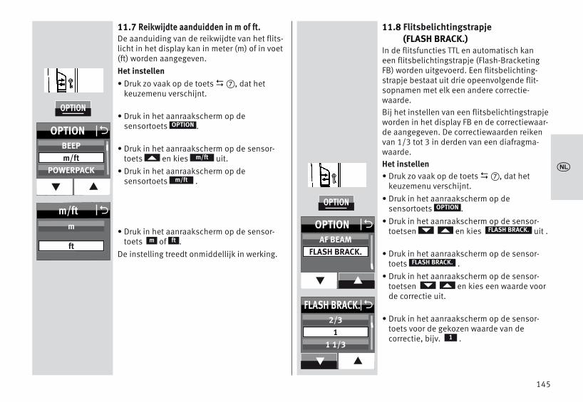
11.7 Reikwijdte aanduidden in m of ft. De aanduiding van de reikwijdte van het flits-licht in het display kan in meter (m) of in voet(ft) worden aangegeven. Het instellen• Druk zo vaak op de toets �, dat het
keuzemenu verschijnt.
• Druk in het aanraakscherm op de sensortoets .
• Druk in het aanraakscherm op de sensor-toets en kies uit.
• Druk in het aanraakscherm op de sensortoets .
• Druk in het aanraakscherm op de sensor-toets of .
De instelling treedt onmiddellijk in werking.
D
OPTION
m/ft
m/ft
ftm
11.8 Flitsbelichtingstrapje(FLASH BRACK.)
In de flitsfuncties TTL en automatisch kaneen flitsbelichtingstrapje (Flash-BracketingFB) worden uitgevoerd. Een flitsbelichting-strapje bestaat uit drie opeenvolgende flit-sopnamen met elk een andere correctie-waarde. Bij het instellen van een flitsbelichtingstrapjeworden in het display FB en de correctiewaar-de aangegeven. De correctiewaarden reikenvan 1/3 tot 3 in derden van een diafragma-waarde.Het instellen• Druk zo vaak op de toets �, dat het
keuzemenu verschijnt.• Druk in het aanraakscherm op de
sensortoets .• Druk in het aanraakscherm op de sensor-
toetsen en kies uit .
• Druk in het aanraakscherm op de sensor-toets .
• Druk in het aanraakscherm op de sensor-toetsen en kies een waarde voorde correctie uit.
• Druk in het aanraakscherm op de sensor-toets voor de gekozen waarde van de correctie, bijv. .
D
OPTION
FLASH BRACK.
FLASH BRACK.
1
145
x
OPTION
m/ft Om
ft
OPTION O
q p
BEEPm/ft
POWERPACK
OPTION
FLASH BRACK. O
q p
2/31
1 1/3
OPTION O
q p
AF BEAMFLASH BRACK.

De instelling treedt onmiddellijk in werking.• De eerste opname wordt zonder correctie
uitgevoerd. In het display verschijnt bovendien ‘FB I’.
• De tweede opname volgt met een minus-correctie . In het display wordt bovendien‘FB II’ aangegeven en daarbij tevens deminus-correctiewaarde (EV).
• De derde opname wordt met een plus-cor-rectie uitgevoerd. In het display wordtbovendien ‘FB III’ aangegeven en daarbijtevens de plus-correctiewaarde (EV).
• Na de derde opname wordt de functie flits-belichtingstrapje automatisch gedeacti-veerd. De aanduiding ‘FB’ in het displaydooft.
Bij het instellen van het flitsbelichtingstrapjewordt de correctiewaarde altijd positief aan-gegeven!Flitsbelichtingstrapje in de TTL-flitsfunctieEen flitsbelichtingstrapje in de TTL-flits-functie kan alleen worden uitgevoerd als decamera het met de hand instellen van eencorrectie op de flitsbelichting op de flitserondersteunt. (zie de gebruiksaanwijzing vanuw camera)! Als dat niet het geval is, wordende drie opnamen zonder correctiewaarde uit-gevoerd!Flitsbelichtingstrapje in de automatisch-flit-senfunctie AVoor het maken van een flitsbelichtingstrapjein de automatisch-flitsenfunctie A is het typecamera van geen betekenis.
11.9 Beep-functie (BEEP)Met de Beep-functie kan de gebruiker zichverschillende functies van het apparaatakoestisch laten melden. Daardoor kan defotograaf zich geheel op zijn onderwerp ende opnamen concentreren en hoeft hij niet teletten op optische statusaanduidingen!De Beep-functie zorgt voor een akoestischsignaal bij het bereiken van de flitsparaat-heid of een bediening op afstand.
Het instellen• Druk zo vaak op de toets �, dat het
keuzemenu verschijnt.
• Druk in het aanraakscherm op de sensortoets .
• Druk in het aanraakscherm op de sensor-toetsen en kies uit.
• Druk in het aanraakscherm op de sensor-toets .
• Druk in het aanraakscherm op de sensor-toets De instelling treedt onmiddellijk in werking.
Na het activeren van de BEEP-functie wordt inhet INFO-menu ' ' aangegeven.
D
OPTION
BEEP
BEEP
On
146
x
OPTION
BEEP OOFF
ON
OPTION O
q p
MOD. LIGHTBEEPm/ft

Akoestische melding na het inschakelen vande flitser:• Een kort (ong. 2 s.) ononderbroken piepje
na het inschakelen geeft de flitsparaatheidaan.
Set Beep-signalen bij de instellingen in deautomatisch-flitsenfunctie:• Een korte piep als alarm treedt op, wanneer
bij de automatisch-flitsenfunctie de dia-fragma- en ISO-instellingen tot het over-schrijden van het regelbereik van het flits-licht zou leiden. Het automatiekdiafragmawordt dan automatisch in de dichtstbij lig-gende, toelaatbare waarde veranderd..
11.10 Vergrendeling / ontgrendelingDe instellingen op de flitser kunnen tegenonbedoeld verstellen worden vergrendeld. Druk voor het vergrendelen, c.q. het ontgren-delen 3 seconden lang op de toets � .In het display worden alle sensortoetsen ineen witte kleur uitgevoerd en zijn dan nietmeer te bedienenAlleen op de INFO-sensortoets kan dan wor-den gedrukt.
11.11 Powerpack aansluiten(accessoire)
Op de flitser kan in de aansluitbus � eenPowerpack (accessoire) worden aangesloten. Voor het aansluiten van het Powerpack heft uen verbindingskabel nodig.Het Powerpack verlengt de bedrijfsduur vande flitser en zorgt voor kortere flitspauzes.
D
147
x
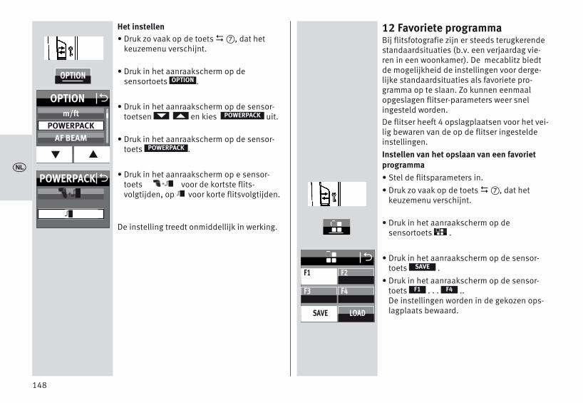
Het instellen• Druk zo vaak op de toets �, dat het
keuzemenu verschijnt.
• Druk in het aanraakscherm op de sensortoets .
• Druk in het aanraakscherm op de sensor-toetsen en kies uit.
• Druk in het aanraakscherm op de sensor-toets .
• Druk in het aanraakscherm op e sensor-toets voor de kortste flits-volgtijden, op voor korte flitsvolgtijden.
De instelling treedt onmiddellijk in werking.
D
OPTION
POWERPACK
POWERPACK
12 Favoriete programmaBij flitsfotografie zijn er steeds terugkerendestandaardsituaties (b.v. een verjaardag vie-ren in een woonkamer). De mecablitz biedtde mogelijkheid de instellingen voor derge-lijke standaardsituaties als favoriete pro-gramma op te slaan. Zo kunnen eenmaalopgeslagen flitser-parameters weer snelingesteld worden.De flitser heeft 4 opslagplaatsen voor het vei-lig bewaren van de op de flitser ingesteldeinstellingen.Instellen van het opslaan van een favorietprogramma• Stel de flitsparameters in.• Druk zo vaak op de toets �, dat het
keuzemenu verschijnt.
• Druk in het aanraakscherm op de sensortoets .
• Druk in het aanraakscherm op de sensor-toets .
• Druk in het aanraakscherm op de sensor-toets . . . ..De instellingen worden in de gekozen ops-lagplaats bewaard.
D
SAVE
F4F1
148
x
F1
F3 F4
SAVE LOAD
F2
O
OPTION
POWERPACK O
OPTION O
q p
m/ftPOWERPACK
AF BEAM

Het instellen voor het laden van een favorietprogramma• Druk zo vaak op de toets �, dat het
keuzemenu verschijnt.
• Druk in het aanraakscherm op de sensortoets .
• Druk in het aanraakscherm op de sensor-toets .
• Druk in het aanraakscherm op de sensor-toets . . . ..De instellingen worden vanuit de gekozenopslagplaats ingeladen.
D
LOAD
F4F1
149
x
F1 GNEV 2/3
F3 F4
SAVE LOAD
F2
O

150
13 Flitstechnieken
13.1 Indirect flitsenDoor indirect te flitsen wordt het onderwerpzachter verlicht en een anders nadrukkelijkeschaduw gemilderd. Bovendien wordt natu-urkundig bepaalde lichtafval van voor- naarachtergrond verminderd.Om indirect te kunnen flitsen kan de reflectorvan de flitser horizontaal en verticaal wordengezwenkt. Reflector zwenken• Druk op de ontgrendelknop en maak de
reflector los en draai hem tegelijkertijdnaar de gewenste positie.
De reflector is alleen in zijn normale positievergrendeld.Ter voorkoming van kleurzwemen in de opna-men moet het reflecterende vlak neutraal vankleur, c.q. wit zijn.Let er bij het zwenken van de reflector op dathij voldoende veruitgezwenkt wordt zodat ergeen rechtstreeks flitslicht uit de reflectormeer op het onderwerp kan vallen. Zwenkdaarom minstens tot de 60° klikstand. Bij gezwenkte kop van de reflector wordtdeze in de zoomstand van 70 mm gestuurd,opdat er geen rechtstreeks strooilicht op hetonderwerp kan vallenDaarbij vindt er ook geen aanduiding van deflitsreikwijdte en de zoomstand van de reflectorplaats.
13.2 Indirect flitsen met een reflectie-kaart
Door indirect te flitsen met de ingebouwdereflectiekaart � kunnen bij personen spits-lichtjes in de ogen worden verkregen:• Zwenk de reflectorkop 90° naar boven. • Trek de reflectiekaart samen met de groot-
hoekdiffusor boven uit de reflectorkopnaar voren.
• Houd de reflectiekaart � vast en schuif degroothoekdiffusor terug in de reflector-kop.
13.3 Dichtbijopnamen / macro-opnamenIn het dichtbijbereik en bij macro-opnamenkan door de parallaxfout tussen flitser enobjectief aan de onderrand van het beeld hetonderwerp afgeschaduwd worden. Om dit tevermijden kan de hoofdreflector met eenhoek van -9° naar beneden wordengezwenkt. Druk daarvoor op de ontgrendel-knop van de reflector en zwenk hem naarbeneden.
Is de hoofdreflector naar beneden gezwenktdan wordt dat in het display aangegeven met„ “ . De hulpreflector wordt hierbij nietondersteund en flitst niet mee.Bij opnamen in het dichtbijbereik moet u erop letten, dat een bepaalde minimumafstandaangehouden moet worden om overbelich-ting te vermijden.
x
+
+
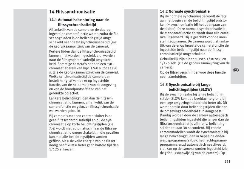
151
14 Flitssynchronisatie
14.1 Automatische sturing naar de flitssynchronisatietijd
Afhankelijk van de camera en de daaropingestelde camerafunctie wordt, zodra de flit-ser opgeladen is de belichtingstijd omge-schakeld naar de flitssynchronisatietijd (ziede gebruiksaanwijzing van de camera).Kortere tijden dan de flitssynchronisatietijdkunnen niet worden ingesteld, c.q. wordennaar de flitssynchronisatietijd omgescha-keld. Sommige camera’s hebben een syn-chronisatiebereik van bijv. 1/60 s. tot 1/250s. (zie de gebruiksaanwijzing van de camera).Welke synchronisatietijd de camera daninstelt hangt af van de er op ingesteldefunctie, van de helderheid van de omgevingen van de brandpuntsafstand van hetgebruikte objectief.Langere belichtingstijden dan de flitssyn-chronisatietijd kunnen, afhankelijk van decamerafunctie en gekozen flitssynchronisatiewel worden gebruikt.Bij camera’s met een centraalsluiter is ergeen flitssynchronisatietijd en bij de syn-chronisatie op korte belichtingstijden (zie7.4) wordt niet automatisch naar de flitssyn-chronisatietijd omgeschakeld. In die gevallenkan met alle belichtingstijden wordengeflitst. Als u de volle energie van de flitsernodig heeft kunt u beter geen kortere tijd dan1/125 s. kiezen.
14.2 Normale synchronisatieBij de normale synchronisatie wordt de flitsaan het begin van de belichtingstijd ontsto-ken (= synchronisatie bij het opengaan vande sluiter). Deze normale synchronisatie isde standaardfunctie en wordt door alle came-ra’s uitgevoerd. Hij is geschikt voor de mee-ste flitsopnamen. De camera wordt, afhanke-lijk van de er op ingestelde camerafunctie deingestelde belichtingstijd naar de flitssyn-chronisatietijd omgeschakeld. Gebruikelijk zijn tijden tussen 1/30 sek. en1/125 sek. (zie de gebruiksaanwijzing van decamera). Op de flitser verschijnt er voor deze functiegeen aanduiding.
14.3 Synchronisatie bij lange belichtingstijden (SLOW)
Bij de synchronisatie bij lange belichting-stijden SLOW komt de beeldachtergrond bijeen lage omgevingshelderheid beter uit. Ditwordt bereikt door belichtingstijden die aande omgevingshelderheid zijn aangepast.Daarbij worden door de camera automatischbelichtingstijden ingesteld die langer dan deflitssynchronisatietijd zijn (bijv. belichting-stijden tot aan 30 seconden). Bij enkelecameramodellen wordt de synchronisatie bijlange belichtingstijden in bepaalde onder-werpsprogramma’s (bijv. het nachtopname-programma enz.) automatisch geactiveerd,c.q. kan op de camera worden ingesteld (ziede gebruiksaanwijzing van de camera). Op
x

de flitser hoeft niets te worden ingesteld ener verschijnt ook gaan aanduiding voor dezefunctie.Het instellen voor de synchronisatie bij langebelichtingstijden SLOW moet op de cameraplaatsvinden (zie de gebruiksaanwijzing vande camera)! Gebruik bij lange belichting-stijden een statief om onscherpte door bewe-gen van de camera te voorkomen!
14.4 Sync-aansluitingDe flitser kan worden geactiveerd via desync-aansluiting in de automatisch flits-functie , manual flitsfunctie en destroboscopisch flitsen.Een mecablitz 64AF-1 op de camera kunnenandere flitser triggeren via een sync-kabel.
Een oude flitser met high-voltage ontste-kingssysteem mag niet worden aangeslotenop de sync-aansluiting.
MA
152
x
+

15 Touch-display instellingen
15.1 Helderheid (BRIGHTNESS)De helderheid van het aanraakscherm kan invijf stappen worden ingesteld.Het instellen• Druk zo vaak op de toets �, dat het
keuzemenu verschijnt.
• Druk in het aanraakscherm op de sensor-toets .
• Druk in het aanraakscherm op de sensor-toets .
• Druk in het aanraakscherm op de sensor-toetsen en kies de gewenste hel-derheid uit. .
• Druk in het aanraakscherm op de sensor-toets van de gekozen helderheid, bijv..
De instelling treedt onmiddellijk in werking.
D
SERVICE
BRIGHTNESS
80
15.2 Rotatie (ROTATION)Bij het zwenken van de flitskop in horizontalerichting kan de beeldschermweergave eve-neens gezwenkt worden. Het instellen• Druk zo vaak op de toets �, dat het
keuzemenu verschijnt.
• Druk in het aanraakscherm op de sensor-toets .
• Druk in het aanraakscherm op de sensor-toets .
• Druk in het aanraakscherm op de sensor-toets .De instelling treedt onmiddellijk in werking.
D
SERVICE
ROTATION
ON
153
x
SERVICE
SERVICE O
BRIGHTNESS
RESET
ROTATION
BRIGHTNESS O
q p
6080
100
SERVICE
SERVICE O
BRIGHTNESS
RESET
ROTATION
ROTATION OOFF
ON

16 Onderhoud en verzorging• Het schoonmaken van het oppervlak van
het beeldscherm moet met een droog,zacht schoonmaakdoekje (bijv. microvezel-doekje) worden gedaan.
• Zouden er echter sterkere verontreinigingenzijn ontstaan, dan kan het schoonmakenvan het oppervlak van het beeldschermmet een slechts licht bevochtigd, zachtdoekje plaats moeten vinden.
Spuit nooit schoonmaakvloeistoffen ophet beeldschermoppervlak ! Wanneerschoonmaakvloeistoffen in de lijst vanhet beeldscherm dringen, worden dezich daar bevindende onderdelen onher-stelbaar beschadigd.
16.1 Update van de firmwareDe firmwareversie (in het voorbeeld V1.0)van de flitser wordt na het inschakelen in hetstartscherm getoond. USB-aansluiting � worden geactualiseerd enbinnen het technische kader aan de functiesvan toekomstige camera“s worden aange-past.Nadere informaties vindt u in het internet opde Metz–homepage www.metz.de
16.2 Het formeren van de flitscondensator
De in de flitser ingebouwde flitscondensatoris onderhevig aan een natuurkundige veran-dering, als het apparaat gedurende een lan-gere tijd niet wordt ingeschakeld. Het is daa-rom noodzakelijk, het apparaat eens perkwartaal gedurende ong. 10 minuten in teschakelen. De voeding moet daarbij zoveelenergie leveren, dat de flitser zeker binnen 1minuut na het inschakelen paraat is.
16.3 Fabrieksinstellingen (RESET)De flitser kan naar de fabrieksinstellingenworden teruggezet.Het instellen• Druk zo vaak op de toets �, dat het
keuzemenu verschijnt.
• Druk in het aanraakscherm op de sensor-toets .
• Druk in het aanraakscherm op de sensor-toets .
• Druk in het aanraakscherm op de sensor-toets .De instelling treedt onmiddellijk in werkingen de flitser wordt teruggezet in de standals bij aflevering.
Firmware-updates van de flitser gelden hier-bij niet!
D
SERVICE
RESET
ON
154
x
SERVICE
SERVICE O
BRIGHTNESS
RESET
ROTATION
RESET OOFF
ON

17 TroubleshootingZou het ooit voorkomen, dat bijv. in het display van de flitser onzin-nige aanduidingen verschijnen of dat de flitser niet functioneertzoals hij op grond van zijn instellingen zou behoren te doen, scha-kel de flitser dan gedurende ong. 10 seconden met de hoofdschake-laar � uit. Controleer of hij correct in de accessoireschoen van decamera zit alsmede de camera-instellingen.Vervang de batterijen, c.q. de accu’s tegen nieuwe, c.q. vers opgela-den accu’s!De flitser zou nu na het inschakelen weer 'normaal' moeten functio-neren. Als dit niet het geval is, ga er dan mee naar uw fotohande-laar.Hieronder zijn enkele problemen opgevoerd, die in de praktijk vanhet flitsen kunnen optreden. Onder elk punt zijn mogelijke oorza-ken, c.q. remedies voor deze problemen aangegeven.In het display verschijnt de reikwijdte niet.• Er heeft geen uitwisseling van gegevens tussen camera en flitser
plaatsgevonden. Tip de ontspanknop op de camera even aan.• De reflector staat niet in de normale stand.• Op de flitser staat de remote-functie ingesteld.De AF-meetflits van de flitser wordt niet geactiveerd.• De flitser is niet paraat.• De camera staat niet in de functie 'AF-S'.• De camera ondersteunt alleen de eigen, interne AF-meetflits.• Sommige cameratypes ondersteunen alleen met de centrale AF-
sensor van de camera de AF-meetflits in de flitser. Als een gede-centraliseerde AF-sensor wordt gekozen, wordt de AF-meetflits inde flitser niet geactiveerd! Activeer de centrale AF-sensor!
• De functie 'AF-BEAM' is uitgeschakeld. Voor het instellen van 'AF-BEAM', zie 11.6.
De stand van de zoomreflector wordt niet automatisch aangepastaan de actuele zoomstand van het objectief.• De camera geeft geen gegevens door naar de flitser.• Er vindt geen uitwisseling van gegevens tussen camera en flitser
plaats. Ontspankop op de camera aantippen!• De camera is uitgerust met een objectief zonder CPU.• De flitser werkt in de manual zoominstelling 'MZoom'.
Schakel om naar autozoom (zie 11.4.3).• De reflector is uit zijn standaard positie gezwenkt.• De groothoekdiffusor is voor de reflector geklapt.• Voor de reflector is een Mecabounce aangebracht.De TTL-flitsfunctie laat zich niet instellen.• Er heeft geen uitwisseling van gegevens tussen camera en flitser
plaatsgevonden. Tip de ontspanknop op de camera aan.• De camera ondersteunt de TTL flitsfunctie niet.De instelling voor met de hand in te stellen correcties op de TTL-flitsbelichting werkt niet.• De camera ondersteunt de met de hand in te stellen correctiesop
de TTL–flitsbelichting op de flitser niet.De automatische omschakeling naar de flitssynchronisatietijdvindt niet plaats.• De camera werkt met een centraalsluiter (de meeste compact-
camera’s). Er hoeft daarbij geen omschakeling naar een flits-synchronisatietijd plaats te vinden.
• De camera werkt met synchronisatie bij korte belichtingstijdenHSS (camerainstelling). Er vindt geen omschakeling naar de flits-synchronisatietijd plaats.
• De camera werkt met een langere belichtingstijd dan de flitssyn-chronisatietijd Afhankelijk van de camerafunctie wordt daarbijniet naar de flitssynchronisatietijd omgeschakeld (zie de gebruik-saanwijzing van de camera).
155
x

156
x
De opname zijn te donker.• Het onderwerp ligt buiten het bereik van de flits. Let op: bij indi-
rect flitsen vermindert de reikwijdte van de flits.• Het onderwerp bevat zeer lichte of reflecterende beelddetails.
Daardoor wordt het meetsysteem van de camera, c.q. van de flit-ser beïnvloed. Stel met de hand een positieve correctie op de flits-belichting van bijv. +1 EV in.
De opnamen zijn te licht .• Bij opnamen in het dichtbijbereik moet u er op letten, dat een
bepaalde minimumafstand moet worden aangehouden om over-belichting te vermijden.

157
x
18 Technische gegevensRichtgetallen bij ISO 100/21°, Zoom 200 mm:in het metersysteem: 64 in het feetsysteem:: 210Flitsfuncties:Standaard-TTL ontblood van meetflits vooraf, TTL met flits vooraf,ADI-meting, manual M, automatisch flitsenfunctie A, Synchronisatiebij korte belichtingstijden HSS, Remote-slaaf, Remote-servo. Automatische instelling van het diafragma bij 100/21°:F 1,4 tot F 64 inclusief tussenliggende waardenMet de hand instelbare deelvermogens:P1/1 . . . P1/ 256 in stappen van een derdeP1/1 . . . P1/256 in synchronisatie bij korte belichtingstijden (HSS)Flitsduur zie Tabel 2 (S. 319)
Kleurtemperatuur: ong. 5600 KLichtgevoeligheid : ISO 6 tot ISO 51200
Synchronisatie: Laagspannings-IGBT-ontstekingAantallen flitsen• ong. 140 met super alkalimangaanbatterijen (1,5V)• ong. 190 met NiMH-accu (1,2V / 2100 mAh)• ong. 290 met lithiumbatterijen (1,5V)• ong. 360 met Metz Power Pack P76
Flitsvolgtijden (min./max.)• 0,1/4,4 met super alkalimangaanbatterijen (1,5V)• 0,1/1,8 met NiMH-accu (1,2V / 2100 mAh)• 0,1/4,2 met lithiumbatterijen (1,5V)• 0,1/1,6 met Metz Power Pack P76
Verlichtingshoek:Reflector vanaf 24 mm (kleinbeeldformaat 24 x 36).met groothoekdiffusor vanaf 12 mm (kleinbeeldformaat 24 x 36).Zwenkbereiken en klikstanden van de reflectoren:Naar boven: -9° 45° 60° 75° 90°Tegen de wijzers van de klok in:60° 90° 120° 150° 180°Richting wijzers van de klok:60° 90° 120°Afmetingen ong. in mm (B x H x D):Ca. 78 x 148 x 112Gewicht :Flitser zonder stroombronnen: ong. 422 gDe levering omvat:Flitser met ingebouwde groothoekdiffusor, Voetie voor flitsers S60,Belt zakje T64, gebruiksaanwijzing,
158
x
19 Bijzondere toebehorenVoor foute werking van en schades aan de mecablitz, veroorzaaktdoor het gebruik van accessoires van andere fabrikanten, zijn wijniet aansprakelijk !• mecabounce Diffuser MBM-03(Bestelnr. 000003902)Met deze diffusor verkrijgt u op de eenvoudigste manier een zachteverlichting.De werking is verbluffend, omdat de foto’s een zacht effect krijgen.De gelaatskleur van personen wordt natuurlijker weergegeven.De flitsreikwijdte wordt ongeveer de helft korter.• Reflexschirm 58-23(Bestelnr. 000058235)Verzacht door zijn zachte, gerichte licht, harde slagschaduwen.• Voetie voor flitsers S60(Bestelnr. 000000607)Voetje om flitsers als slaaf in op te stellen.• Verbindingskabel V58-50(Bestelnr. 000058504)Ook passend op het Powerpack P 7• Powerpack• Easy Softbox ESB 60-60 (Bestelnr. 009016076)
Afmetingen: 60 × 60 cm
Inclusief voor- en achtergrond diffusor, draagtas en met Bowenscompatibele adapter voor het aansluiten aan Metz-studioflitsers TLof BL
• Easy Softbox ESB 40-40 (Bestelnr. 009014047)
Afmetingen: 40 × 40 cm
Inclusief voor- en achtergronddiffusor, draagtas en met Bowenscompatibele adapter voor het aansluiten aan Metz-studioflitsers TLof BL
• Flitserhouder FGH 40-60 (Bestelnr. 009094065)
Adapter tussen compacte flitsersen Easy Softboxen
Hoogte van de flitsschoen verstelbaar
Opsteekbaar op Metz-lampstatieven LS-247 en LS-200
• Mini Softbox SB 30-20 (Bestelnr. 009013023)
Kleur: wit, afmetingen: 30 × 20 cm
• Mini Softbox SB 22-16 (Bestelnr. 009012217)
Kleur: wit, afmetingen: 22 × 16 cm
• Mini Softbox SB 18-15 (Bestelnr. 009011817)
Kleur: wit, afmetingen: 18 × 15 cm
• Mini Octagon Softbox SB 34-34 (Bestelnr. 009023432)
Kleur: wit, afmetingen: Ø 34 cm
• Mini Octagon Softbox SB 20-20 (Bestelnr. 009022029)
Kleur: wit, afmetingen: Ø 20 cm

159
x
• Mini Octagon Softbox SB 15-15 (Bestelnr. 009021516)
Kleur: wit, afmetingen: Ø 15 cm
• Spot-reflectiescherm SD 30-26 W (Bestelnr. 009043021)
Kleur: wit voor neutraal licht / afmetingen: 30 × 26 cm
• Spot-reflectiescherm SD 30-26 S (Bestelnr. 00904303A)
Kleur: zilver voor koel licht / afmetingen: 30 × 26 cm
• Spot-reflectiescherm SD 30-26 G (Bestelnr. 009043048)
Kleur: goud voor warm licht / afmetingen: 30 × 26 cm
Afvoeren van de batterijenBatterijen horen niet bij het huisvuil.S.v.p. de batterijen bij een daarvoor bestemd inzamelpunt afgeven.S.v.p. alleen ontladen batterijen / accu’s afgeven.Batterijen / accu’s zijn in de regel ontladen wanneer het daarvoorgebruikte apparaat– de batterijen na langer gebruik niet meer goed functioneren.Om kortsluiting te voorkomen, moeten de batterijpolen met plak-band worden afgeplakt.Uw Metz-product is ontworpen voor en gebouwd uit hoogwaardigematerialen en componenten die gerecycled kunnen worden en dusgeschikt zijn voor hergebruik.Dit symbool betekent, dat elektrische en elektronische apparatuuraan het einde van zijn levensduur gescheiden van het huisvuil apartmoet worden ingeleverd.
Breng dit apparaat naar een van de plaatselijke verzamel-punten of naar een kringloopwinkel.Help s.v.p. mee, het milieu waarin we leven te beschermen.
Onder voorbehoudvan wijzigingen en vergissingen !

Introduction . . . . . . . . . . . . . . . . . . . . . . . . . . . . . . . . . . . . . . . . . . . 1611 Safety instructions . . . . . . . . . . . . . . . . . . . . . . . . . . . . . . . . . . . . 1622 Dedicated flash functions . . . . . . . . . . . . . . . . . . . . . . . . . . . . . . 1633 Preparing the flash unit for use. . . . . . . . . . . . . . . . . . . . . . . . . . 1643.1 Mounting the flash unit . . . . . . . . . . . . . . . . . . . . . . . . . . . . . . 1643.2 Power supply . . . . . . . . . . . . . . . . . . . . . . . . . . . . . . . . . . . . . . . 1653.3 Switching the flash unit on and off . . . . . . . . . . . . . . . . . . . . . 1663.4 The selection menu. . . . . . . . . . . . . . . . . . . . . . . . . . . . . . . . . . 1663.5 INFO . . . . . . . . . . . . . . . . . . . . . . . . . . . . . . . . . . . . . . . . . . . . . . 1673.6 Auto OFF for the flash unit . . . . . . . . . . . . . . . . . . . . . . . . . . . . 1674 LED displays on the flash unit . . . . . . . . . . . . . . . . . . . . . . . . . . . 1694.1 Flash readiness indication . . . . . . . . . . . . . . . . . . . . . . . . . . . . 1694.2 Correct exposure indication . . . . . . . . . . . . . . . . . . . . . . . . . . . 1695 Information in Display . . . . . . . . . . . . . . . . . . . . . . . . . . . . . . . . . 1695.1 Display of the flash mode. . . . . . . . . . . . . . . . . . . . . . . . . . . . . 1705.2 Range display . . . . . . . . . . . . . . . . . . . . . . . . . . . . . . . . . . . . . . 1706 Displays in the camera viewfinder . . . . . . . . . . . . . . . . . . . . . . . 1717 Flash modes . . . . . . . . . . . . . . . . . . . . . . . . . . . . . . . . . . . . . . . . . 1727.1 TTL flash mode. . . . . . . . . . . . . . . . . . . . . . . . . . . . . . . . . . . . . . 1727.2 Preflash TTL and ADI metering . . . . . . . . . . . . . . . . . . . . . . . . . 1737.3 Manual flash mode . . . . . . . . . . . . . . . . . . . . . . . . . . . . . . . . . . 1737.4 Automatic high-speed synchronisation (HSS) . . . . . . . . . . . . 1747.5 Automatic flash mode. . . . . . . . . . . . . . . . . . . . . . . . . . . . . . . . 1757.6 Strobe flash mode. . . . . . . . . . . . . . . . . . . . . . . . . . . . . . . . . . . 1768 Manual flash exposure correction . . . . . . . . . . . . . . . . . . . . . . . 1789 Special functions . . . . . . . . . . . . . . . . . . . . . . . . . . . . . . . . . . . . . 1799.1 Motor zoom reflector („Zoom“) . . . . . . . . . . . . . . . . . . . . . . . . 179
10 Cordless flash mode. . . . . . . . . . . . . . . . . . . . . . . . . . . . . . . . . . 18110.1 Remote master mode settings . . . . . . . . . . . . . . . . . . . . . . . . 18210.1.1 Remote master mode settings . . . . . . . . . . . . . . . . . . . . . . 18210.1.2 Setting the flash mode on the master flash unit . . . . . . . . 18310.1.3 Partial light output in M-mode settings
on the master flash unit . . . . . . . . . . . . . . . . . . . . . . . . . . . 18310.1.4 Defining the lighting conditions (RATIO) for the flash groups
on the master flash unit . . . . . . . . . . . . . . . . . . . . . . . . . . . . . 18410.1.5 Remote channel settings. . . . . . . . . . . . . . . . . . . . . . . . . . . 18510.2 Remote slave flash mode . . . . . . . . . . . . . . . . . . . . . . . . . . . . 18510.2.1 Remote slave flash mode settings . . . . . . . . . . . . . . . . . . . 18610.2.2 Setting the slave channel . . . . . . . . . . . . . . . . . . . . . . . . . . 18610.2.3 Set slave mode . . . . . . . . . . . . . . . . . . . . . . . . . . . . . . . . . . 18710.2.4 Setting partial light output correction . . . . . . . . . . . . . . . . 18710.2.5 Setting partial light output/exposure correction. . . . . . . . 18810.3 Testing remote flash mode . . . . . . . . . . . . . . . . . . . . . . . . . . . 18810.4 SERVO mode . . . . . . . . . . . . . . . . . . . . . . . . . . . . . . . . . . . . . . 18910.4.1 Setting SERVO flash mode . . . . . . . . . . . . . . . . . . . . . . . . . 18910.4.2 Pre-flash suppression or synchronisation settings . . . . . . 18910.4.3 Servo mode partial light output settings . . . . . . . . . . . . . . 19010.4.4 Learn function . . . . . . . . . . . . . . . . . . . . . . . . . . . . . . . . . . . 19010.4.5 Switching-off SERVO flash mode . . . . . . . . . . . . . . . . . . . . 19111 OPTION menu . . . . . . . . . . . . . . . . . . . . . . . . . . . . . . . . . . . . . . . 19211.1 RAPID mode. . . . . . . . . . . . . . . . . . . . . . . . . . . . . . . . . . . . . . . 19211.2 Secondary reflector (SUB-REFL.) . . . . . . . . . . . . . . . . . . . . . . 19211.3 Modelling light (MOD. LIGHT). . . . . . . . . . . . . . . . . . . . . . . . . 19311.4 Zoom Mode (ZOOM MODE). . . . . . . . . . . . . . . . . . . . . . . . . . . 19311.4.1 Extended Zoom Mode . . . . . . . . . . . . . . . . . . . . . . . . . . . . . 19311.4.2 SPOT zoom mode. . . . . . . . . . . . . . . . . . . . . . . . . . . . . . . . . 194
160
k

IntroductionThank you for choosing a Metz product. We are delighted to welco-me you as a customer. You will of course be impatient to start using the flash unit.However, it is worthwhile reading the operating instructions andlearning how to use the unit correctly.This flash unit is suited for:• Digital Sony reflex cameras with TTL preflash and ADI metering. This flash unit is not suited for other brands of cameras.
Take a look at the diagrams at the end of the manual.
Declaration
Tip, note
Attention - Extremely important safety information!
Proper UseThis flash unit is intended solely for taking pictures of motifs in thephotographic field. It may be operated only with the accessoriesdescribed in this instruction manual or the accessories approved byMetz.The flash unit may not be used for any purpose other than that des-cribed above.
+
11.4.3 STANDARD zoom mode . . . . . . . . . . . . . . . . . . . . . . . . . . . . 19511.5 Shooting format adjustment (ZOOM SIZE) . . . . . . . . . . . . . . 19511.6 AF auxiliary light (AF-BEAM) . . . . . . . . . . . . . . . . . . . . . . . . . . 19611.7 Range display in m or ft . . . . . . . . . . . . . . . . . . . . . . . . . . . . . 19711.8 Flash Bracketing Series (FLASH BRACK.) . . . . . . . . . . . . . . . . 19711.9 Beep function (BEEP) . . . . . . . . . . . . . . . . . . . . . . . . . . . . . . . 19811.10 Locking / unlocking . . . . . . . . . . . . . . . . . . . . . . . . . . . . . . . 19911.11 Connecting a power pack (accessory) . . . . . . . . . . . . . . . . . 19912 Favorite programme . . . . . . . . . . . . . . . . . . . . . . . . . . . . . . . . . . 20013 Flash techniques . . . . . . . . . . . . . . . . . . . . . . . . . . . . . . . . . . . . 20213.1 Bounce flash . . . . . . . . . . . . . . . . . . . . . . . . . . . . . . . . . . . . . . 20213.2 Bounce flash with a reflector card . . . . . . . . . . . . . . . . . . . . . 20213.3 Close-ups / macro shots. . . . . . . . . . . . . . . . . . . . . . . . . . . . . 20214 Flash synchronisation . . . . . . . . . . . . . . . . . . . . . . . . . . . . . . . . 20314.1 Automatic flash sync speed control. . . . . . . . . . . . . . . . . . . . 20314.2 Normal synchronisation . . . . . . . . . . . . . . . . . . . . . . . . . . . . . 20314.3 Slow synchronisation (SLOW) . . . . . . . . . . . . . . . . . . . . . . . . 20314.4 Synch socket . . . . . . . . . . . . . . . . . . . . . . . . . . . . . . . . . . . . . . 20415 Touch display settings. . . . . . . . . . . . . . . . . . . . . . . . . . . . . . . . 20515.1 Brightness . . . . . . . . . . . . . . . . . . . . . . . . . . . . . . . . . . . . . . . . 20515.2 Rotation . . . . . . . . . . . . . . . . . . . . . . . . . . . . . . . . . . . . . . . . . . 20516 Care and maintenance . . . . . . . . . . . . . . . . . . . . . . . . . . . . . . . . 20616.1 Firmware updates . . . . . . . . . . . . . . . . . . . . . . . . . . . . . . . . . . 20616.2 Conditioning the flash capacitor . . . . . . . . . . . . . . . . . . . . . . 20616.3 Reset . . . . . . . . . . . . . . . . . . . . . . . . . . . . . . . . . . . . . . . . . . . . 20617 Troubleshooting . . . . . . . . . . . . . . . . . . . . . . . . . . . . . . . . . . . . . 20718 Technical data. . . . . . . . . . . . . . . . . . . . . . . . . . . . . . . . . . . . . . . 20919 Optional accessories . . . . . . . . . . . . . . . . . . . . . . . . . . . . . . . . . 210
161
k

1 Safety instructionsThe flash unit may in no event be activat-ed in the vicinity of inflammable gases orliquids (petroleum, solvents etc.). RISK OF EXPLOSIONS!Do not flash directly into eyes from a clo-se distance! Direct flashing into the eyesof persons or animals can cause damageto the retina and severe disruption of thevision – up to and including permanentblindness!Never use a flash unit to photograph car,bus, bicycle, motorbike or train driverswhile they are driving. Blinding the drivercan lead to an accident!If the housing has been damaged in sucha way that internal components areexposed, the flash unit may no longer beused. Remove the batteries! Do nottouch any internal components. HIGH VOLTAGE!After repeated flashing, do not touch thediffuser. Risk of burns!Do not dismantle the flash unit! HIGH VOLTAGE! Repairs should only be performed by aut-horised service personnel.
• The flash unit is exclusively designed andauthorised for use in photographic applica-tions.
• Only use the power sources designated andautho-rised in the operating manual!
• Do not open the batteries or short them!
• In no event the batteries be exposed tohigh temperatures like direct sunlight, fireor similar!
• Never throw flat/dead batteries onto a fire!• Do not use any toxic batteries or recharge-
able batteries!• Remove the used batteries immediately
from the device! Chemicals can escapefrom used batteries (so-called “leaks”)resulting in damage to the device!
• Batteries may not be recharged!• Do not expose the flash unit to water drops
and splashes!• Protect your flash unit from heat and high
air humidity! Do not keep it in the glovecompartment of your car!
• Rapid changes in temperature may lead tocondensation. If this occurs, allow time forthe unit to become acclimatized!
• When you activate the flash, there shouldbe no opaque material directly in front of oron the reflector cover (flash window). Theintense energy emissions can otherwiselead to scorching or spotting of the materialand/or the reflector cover.
162
k

• After a series of flashes with full power andshort intervals, a pause of at least 3 minu-tes must be observed after each series of20 flashes! !
• When taking a series of flash shots at fulllight output and with rapid recycling times,and with zoom positions of 35 mm andless, the diffuser heats up, due to the highlevel of thermal energy.
• This flash unit may be used in combinationwith a camera-integrated flash only if theflash can be folded out completely.
2 Dedicated flash functionsDedicated flash functions are flash functionsthat have been specially adapted to a givencamera system. Depending on the type ofcamera, different flash functions are supported.• Flash-ready indication in camera viewfin-
der/camera display.• Automatic flash sync speed control.• TTL flash mode• Manual flash TTL exposure correction• Preflash TTL and ADI metering• Automatic motor zoom control.• 1st or 2nd curtain synchronisation (REAR).• Extended zoom mode.• AF measuring beam control.• Automatic flash range indication.• Automatic HSS short sync for TTL and M • Programmed auto flash mode .• Wireless remote flash mode• Servo mode.• Spot zoom mode.• Extended zoom mode.• Wake-up function for the flash unit.
163
k

It is impossible to describe all camera typesand their individual dedicated flash functi-ons within the scope of these instructions.Therefore, please refer to the flash modedescription in your camera’s operatinginstructions to find out which functions aresupported and which ones have to be setmanually on the camera.
Using lenses not equipped with a CPU (i.e.,lenses without auto focus mode), results incertain functional limitations!
3 Preparing the flash unit for use
3.1 Mounting the flash unitMounting the flash unit on the camera
Turn off the camera and flash before moun-ting or removing.• Remove the protective cap from the unit
base.• Turn the knurled nut � towards the flash
unit housing as far as it will go. The lockingpin in the adapter shoe is now fully retrac-ted into the case.
• Slide the flash unit foot completely into thecamera accessory shoe.
• Turn the knurled nut � towards the camerahousing as far as it will go, clamping theflash unit in place. If the camera does nothave a locking hole, the spring-loaded lok-king pin retracts into the adapter case so asnot to damage the surface.
Removing the flash unit from the camera
Turn off the camera and flash before moun-ting or dismounting.• Turn the knurled nut � towards the flash
unit housing as far as it will go.• Remove the flash unit from the camera’s
accessory shoe.
+
+
+
164
k

3.2 Power supplySuitable batteries/rechargeable batteriesThe flash unit can be operated with any ofthe following batteries:• 4 nickel-metal-hydride batteries 1.2V, type
IEC HR6 (size AA). They have a significantlyhigher capacity than NiCad batteries andare less harmful to the environment, sincethey have no cadmium.
• 4 alkaline-manganese dry cell batteries1.5V, type IEC LR6 (size AA). Maintenance-free power source for moderate powerrequirements.
• 4 lithium batteries 1.5V, type IEC FR6 (sizeAA). Maintenance-free high-capacity powersource with a low self-discharge rate.
• Power Pack with connection cable (specialaccessory).
Please only use the power sources givenabove. If other power sources are used, thereis a risk of damaging the flash unit.
If your flash unit is not going to be used foran extended period of time, remove the bat-teries.
Replacing batteriesThe disposable/rechargeable batteries areempty or used up if the recycling time (timefrom the triggering of a full-power flash, e.g.in the M mode, to the moment the flash-rea-dy indicator lights up again) exceeds 60seconds. In addition, the battery warningappears on the touch display.• Switch off the flash unit. To do this, press
the � button until all displays turn off.
• Slide the battery compartment cover� downwards and fold open.
• Insert the batteries lengthwise as indicatedby the battery symbols provided and closethe battery compartment cover �.
When inserting batteries, ensure that thepolarity is correct and matches the symbolsin the battery compartment. Inserting thebatteries in the wrong direction can destroythe flash unit! Always replace all batteriessimultaneously, and make sure that batteriesare the same brand and have the same capa-city. Flat or dead batteries should not be dis-posed of with ordinary household waste.Help protect the environment, and dispose offlat/dead batteries at the appropriate collec-tion points.
+
165
k

3.3 Switching the flash unit on and off
• Switch on the flash unit with the � button.The start screen appears. The flash unit always switches on after-wards with the mode of operation that wasused last (e.g. manual flash mode M).
The � button flashes red in stand-bymode. To switch off the flash unit, pressthe � button until all displays turn off.
If the flash unit will not be used for an exten-ded period of time, we recommend that youswitch off the flash unit with the � but-ton and remove the power source (disposa-ble/rechargeable batteries).
3.4 The selection menu• Press the � button as often as it takes
for the selection menu to appear.
The selection menu is divided into 6 sensorbuttons:The modes of operation can be set after pressing the button.TTL, chap. 7.1TTL HSS*, chap. 7.4A, chap. 7.5M, chap. 7.3M HSS*, chap. 7.4STROBO, chap. 7.6REMOTE MASTER, chap. 10.1REMOTE SLAVE, chap. 10.2
D
D
MODE
SERVO, chap. 10.4 *) only after data exchange with a camera
The flash parameters can be set after pressing the button.P (partial light output), chap. 7.3, 10.1.3 and 10.4.3EV (exposure correction), chap. 8, 10.2.4ZOOM (reflector setting), chap. 9.1N (Strobe number of flashes), chap. 7.6f (Strobe flash frequency), chap. 7.6F (aperture)ISO (light sensitivity), RATIO (lighting conditions), chap. 10.1.4CTRL (Remote), chap. 10.1CHANNEL (Channel), chap. 10.2.2GROUP (slave group), chap 10.2.3.The displayed flash parameters are depen-dent on the selected flash mode.
The touch display can be configured afterpressing the button, or the flash unitcan be reset to the factory setting.
BRIGHTNESS , chap. 15.1ROTATION (rotate the screen display), chap. 15.2RESET, chap. 16.3
PARAMETER
SERVICE
166
V 1.0
MB 64AF-1digitalSON
MODE
PARAMETER
SERVICE
PARAMETER OP / EVZOOM
Nf (Hz)
FISO
CHANNELRATIO
CONTROL
MODE OETTL
TTL HSSAM
M HSSSTROBO
REMOTE MASTERREMOTE SLAVE
SERVO
SERVICE O
BRIGHTNESS
RESET
ROTATION
k

The options can be set after pressing thebutton.
RAPID (fast recycling times), chap. 11.1
SUB-REFL. (secondary reflector), chap. 11.2ZOOM SIZE (shooting format adjustment),chap. 11.5ZOOM MODE (illumination), chap. 11.4STANDBY (autom., unit switch-off), chap. 3.6MOD.LIGHT (modelling light), chap. 11.3BEEP (acoustic signal), chap. 11.9m / ft (metres / feet), chap. 11.7POWERPACK (external power pack) , chap. 11.11AF BEAM (AF auxiliary light), chap. 11.6
FLASH BRACK. (flash bracketing series , chap. 11.8The displayed flash parameters are depen-dent on the selected flash mode.In the menus shown on the flash unit, allfields that have a black background are confi-gured as sensor buttons that can be pressedfor modifications/changes in the menu.
In the images in the user's guide, only thesensor buttons that must be pressed for set-ting the described function are marked inblack.
OPTION3.5 INFOThe current settings of the flash unit can bedisplayed during operation.• Press the � sensor button on the
touch display. Info appears.- EXT (extended zoom mode) is set, (chap.
11.6.1).- AF OFF (AF auxiliary light) is switched off,
(chap. 11.6).- (MOD.LIGHT) is set,
(chap. 11.3).- (beep function) is set, (chap. 11.9)- (Channel) appears on the display,
chap. 10.1.5, 10.2.2)- The automatic unit switch-off is set for
10 minutes (chap. 3.6).- The temperature display increases after
intensive use.
3.6 Auto OFF for the flash unitThe flash unit is factory-set to automaticallyswitch to standby mode (Auto OFF) 10 minu-tes after• being switched on,• a flash is fired,• the shutter release is actuated,• the camera’s exposure metering system is
switched off. . . . . . switched to stand-by mode, (Auto-OFF) tosave energy and to protect the power sourcefrom unintentional discharging.
i
2CH
167
OPTION
i
k
200
OPTION ORAPID
SUB-REFL. ZOOM SIZEZOOM MODESTANDBY
MOD. LIGHTBEEPm / ft
POWERPACKAF BEAM
FLASH BRACK.

+
The active automatic unit switch-off is shownin the INFO display. The flash ready indicator � and the indica-tors on the LC display disappear. The � button flashes red in stand-bymode.The most recently used operating setting isretained after automatic shutdown and isimmediately restored when the camera isswitched on. The flash unit can be turned on again bypressing the � button, or by tapping onthe shutter release (wake-up function).
In slave-/ servo mode, the automatic cut-offis not activated.
The flash unit should always be turned offusing the main switch � if it is not goingto be used for an extended period!If necessary, the Auto OFF function can be setto occur after 1 minute of inactivity, or can bedeactivated.The flash unit switches off completely about1 hour after its last use. In all operatingmodes, the brightness of the screen is redu-ced by 50 per cent after approx. 10 secondsto save energy. The screen brightness isrestored again whenever a button or a sym-bol on the screen is pressed.
D
D
Setting the automatic unit switch-off• Switch on the flash unit with the � but-
ton. The start screen appears. The flashunit always switches on afterwards with themode of operation that was used last (e.g.manual flash mode M).
• Press the � button as often as it takesfor the selection menu to appear.
• Press the sensor button on thetouch display.
• Press the sensor buttons on thetouch display and select .
• Press the sensor button on thetouch display.
• Tap the sensor button on the touch displayfor the desired time. The setting is adoptedimmediately.
The � button flashes red in stand-bymode.
D
OPTION
STANDBY
STANDBY
D
168
OPTION
OPTION O
q p
ZOOM MODESTANDBY
MOD. LIGHT
STANDBY OOFF
1 min10 min
k
200

4 LED displays on the flash unit
4.1 Flash readiness indicationWhen the flash capacitor on the flash unit ischarged, the � button lights up in green,thus indicating that the flash unit is ready.This means that flash light can be used forthe next shot. Flash readiness is also trans-mitted to the camera and indicated accordin-gly in the camera's viewfinder.If a photograph is taken before flash readi-ness appears, then the flash unit will not betriggered. If the camera has already switchedto flash sync speed, the shot may have thewrong exposure (see 14.1).
4.2 Correct exposure indicationIf the exposure is correct, then button �lights up in red for around 3 seconds if thephotograph has been correctly exposed inflash modes und (see 7.1) ) aswell as automatic mode !If there is no exposure control indication afterthe shot, then the photograph was underex-posed. In that case, you must:- set the next smaller f-stop (e.g. use f-stop 8
instead of 11), or- reduce the distance to the subject or to the
reflection surface (e.g. for indirect flashes),or
- set a higher ISO value on the camera.
D
PTTLHSSPTTLA
Note the maximum flash range indicated onthe display of the flash unit (see 5.2).
5 Information in DisplayThe cameras transmit the settings for ISO,lens focal length (mm) and aperture to theflash unit. It calculates the maximum flash range fromthe settings and their guide number. Flash mode, range, aperture and zoom positi-on of the reflector are displayed in thedisplay of the flash unit.If the flash unit is operated without receivingdata from the camera, then the values set onthe flash unit will be shown.Display illuminationAfter pressing the � button on the flashunit, or after tapping the touch display, thedisplay illumination will be at maximum levelfor approximately 10 sec.
D
169
k

+
5.1 Display of the flash modeThe current flash mode is shown in thedisplay. Depending on the type of camera,different displays are available for the selec-ted TTL flash mode (e.g. and )and the manual flash mode M (see 7.3).
5.2 Range display When using cameras and a lens with CPU,the range is indicated in the display. For this a data exchange must have occurredbetween the camera and flash unit, for exam-ple by tapping the shutter release. The rangecan be displayed either in metres (m) or feet(ft) - see 11.7).
The flash range is not displayed when . . .
- no data is transmitted from the camera.
- when the reflector head is tilted out of itsnormal position (upwards or sideways).
- if the flash unit is working in REMOTEMASTER, REMOTE SLAVE or SERVO mode.
PTTL HSSPTTL
Range display in TTL- and TTL HSS flashmodesIn the TTL flash modes and S;see 7.1) the value for the minimum and themaximum range of the flash unit is displayed.The value indicated relates to subjects with areflection factor of 25%, which applies tomost photographic situations.Strong deviations from this reflection factor,as in the case of highly reflective or poorlyreflective subjects, may affect the flash rangeof the flash unit.The subject should be in the range of 40% to70% of the maximum range. This will give theelectronics sufficient scope for compen-sation.To prevent overexposure, the minimumdistance to the subject shown in the displayshould not be undershot.Adjustment to the photographic situation athand can be achieved by, for example,changing the aperture of the setting on thelens.
TTL HSSTTL
170
5.5 - 56 m M-Zoom 35 m
m
TTL
iEV
5.5 - 56 m M-Zoom 35 m
m
TTL
iEV
k

Range display in manual flash mode In manual flash mode , the distance thatmust be maintained from the subject for cor-rect flash exposure is indicated. Adjustmentto the photographic situation at hand can beachieved by, for example, changing the aper-ture setting on the lens or selecting a manualpartial light output level (see 7.3).Exceeding the display rangeFlash ranges of up to 99 m or 99 ft can beshown in the display.This display range can be exceeded in thecase of high ISO values and large apertureopenings.An arrow or triangle after the distance valueindicates that the display range has beenexceeded.
M 6 Displays in the camera viewfinder
Examples for the camera viewfinder display:Flash symbol is illuminated:The flash unit is ready for use (by somecameras). Flash symbol flashes slowly:Switch on the flash unit.Incorrect exposure guidelines:• overexposure: do not use the flash!• underexposure: switch the flash on or use a
tripod and a longer exposure time.Reasons for incorrect exposure can lay in thevarious exposure and automatic program-mes.For information applicable to the displays inthe viewfinder of your camera model, refer tothe camera’s operating instructions.
171
9.0 mM-Zoom 35 m
m
M
iP1/1
49- 99 m uF 1,4M-
Zoom 200mm
TTL
iEV
k

7 Flash modesDepending on the camera model, the follo-wing flash modes are available:• TTL flash mode ( ), chap. 7.1• Manual flash mode ( ), chap. 7.3• Automatic high-speed synchronisation
(HSS), chap. 7.4• Automatic flash mode ( ), chap. 7.5• Strobe flash mode ( ), chap. 7.6• mode settings, chap. 10.1• flash mode, chap. 10.2• mode, chap. 10.4. The flash mode is set using the touch display.A data transfer between flash unit and came-ra is necessary before setting flash mode
and e.g. by actuating theshutter release.
7.1 TTL flash mode ( )Before shooting, the flash unit fires a seriesof barely visible measuring preflashes. The camera evaluates the reflected preflashlight. Depending on the result of the evalua-tion, the subsequent flash exposure is adap-ted by the camera to suit the given shotsituation (see camera operating instructionsfor further details).If the shot was exposed correctly, the correctexposure indication will illuminate for about3 seconds (see 4.2).
TTLM
A
STROBO
REMOTE MASTER
REMOTE SLAVE
SERVO
M HSSTTL HSS
TTL
Setting the mode of operation• Switch on the flash unit with the �
button.The start screen appears. Thereafter, theflash unit always switches on with themode of operation that was used last (e.g. M flash mode).
• Press the displayed mode of operation onthe touch display as many times as it takesfor the display for selecting the mode ofoperation to appear.
• Press the sensor buttons on thetouch display and select the desired modeof operation.
• Press on the selected mode of operationthat is highlighted in yellow. The setting isadopted immediately.
• Set a suitable mode of operation on thecamera, e.g. P, S, A etc.
• Tap the shutter release to transfer data bet-ween the flash unit and the camera.
172
V 1.0
MB 64AF-1digitalSON
9.0 mM-Zoom 35 m
m
M
iP1/1
MODE O
q p
TTLTTL HSSk

7.2 Preflash TTL and ADI meteringPreflash TTL and ADI metering are digital TTLflash operating modes and refined versionsof the TTL flash operation found in analoguecameras. When taking a shot, an almostimperceptible measurement preflash is trig-gered by the camera prior to the actual expo-sure process. The reflected light of the mea-surement preflash is evaluated by thecamera. Depending on the result of the eva-luation, the subsequent flash exposure isadapted by the camera to suit the given shotsituation (see camera operating instructionsfor further details). In the case of ADI mete-ring, additional distance data from the lens isincorporated into the flash exposure process.The selection and/or setting of the preflashTTL and ADI metering operating modes arecarried out on the camera (see camera opera-ting instructions).The flash unit must be set to the flashoperating mode.
7.3 Manual flash modeIn the manual flash mode M, the flash unitemits the full uncontrolled amount of light ifno partial light output has been selected. Thespecific photographic situation can be takeninto account by adjusting the aperture set-ting or by selecting a suitable manual partiallight setting. The setting area ranges from P 1/1 to P1/256in mode and P1/1 - P1/32 inmode.
TTL
M HSSM
The display shows the distance at which thesubject is correctly lit (see 5.2).Setting the mode of operation• Switch on the flash unit with the �
button.The start screen appears. Thereafter, theflash unit always switches on with themode of operation that was used last .
• Press the sensor button of the displayedmode of operation on the touch display asmany times as it takes for the display forselecting the mode of operation to appear.
• Press the sensor buttons on thetouch display and select .
• Press the sensor button on the touchdisplay.
• Set a suitable mode of operation on thecamera, e.g. .
• Tap the shutter release to transfer data bet-ween the flash unit and the camera.
Various cameras support manual flash modeM only in the camera's M mode (manual).In other camera models, an error messageappears in the display and the release is locked.
M
M
M
173
0.8 - 9.0 m M-Zoom 35 m
m
TTL
iEV
0.8 - 9.0 m M-Zoom 35 m
m
TTL
iEV
9.0 mM-Zoom 35 m
m
M
iP1/1
MODE O
q p
AM
M HSS
k

Manual partial light output levelsPartial light output can be set in manual flashmode .
Setting procedure• Press the sensor button for partial light out-
put on the touch display as many times asit takes for the partial light output displayto appear.
• Press sensor buttons on thetouch display and set the desired partiallight output to 1/1, 1/2, 1/8 . . . 1/256.
• Press the sensor button on the touchdisplay for the selected partial light output.
The setting is immediately effective andautomatically saved.
The distance display is adjusted to the partiallight output automatically (see 5.2).
M
7.4 Automatic high-speed synchroni-sation (HSS)
Various cameras support automatic high-speed synchronisation (see the camera’soperating instructions). This flash modemakes it possible to use a flash unit evenwith shutter speeds that are faster than theflash sync speed. Interesting results may by achieved in thismode when, for example, a wide open aper-ture (e.g., f/2.0) is used to limit the depth offield in portrait shots taken in very brightambient light. The flash unit supports high-speed synchronisation in and flashmode.For physical reasons, however, high-speedsynchronisation significantly reduces thenumber and the maximum flash range. Be sure to note, therefore, the flash range onthe display of the flash unit. High-speed syn-chronisation is activated automatically if ashutter speed faster than the flash syncspeed is set on the camera, whether manual-ly or automatically by the exposure program.Note that in the case of high speed synchro-nisation the guide number of the flash unitalso depends on the shutter speed. The faster the shutter speed, the lower theguide number!High-speed synchronisation is activatedautomatically if a shutter speed faster thanthe flash sync speed is set on the camera,whether manually or automatically by theexposure program.
MTTL
174
k
9.0 mM-Zoom 35 m
m
M
iP1/1
3.1 mM-Zoom 35 m
m
M
iP1/8
P O
q p
1/11/1 - 1/3
P O
q p
1/4 - 2/31/8
1/8 - 1/3

Setting the mode of operation • Switch on the flash unit with the �
button. The start screen appears.Thereafter, the flash unit always switcheson with the mode of operation that wasused last (e.g. TTL flash mode).
• Tap the shutter release to transfer data bet-ween the flash unit and the camera.
• Press the sensor button of the displayedmode of operation on the touch display asmany times as it takes for the display forselecting the mode of operation to appear.
• Press the sensor buttons on thetouch display and select resp.
.
• Press the sensor button on thetouch display.
The setting will take effect immediately.
Second curtain synchronisation (REAR) isautomatically deactivated when the flashunit is set to high-speed synchronisationHSS!
TTL HSSM HSS
TTL HSS
7.5 Automatic flash modeIn the automatic flash mode , the flashunit sensor � measures the light thatreflects back from the subject. The sensor �has a coverage of about 25°, and only mea-sures the light for the time a flash is fired bythe mecablitz. The flash is cut off as soon as sufficient lighthas been emitted for correct exposure. Thesensor � of the mecablitz has to be directedat the subject.Setting the mode of operation• Switch on the flash unit with the �
button.The start screen appears. Thereafter, theflash unit always switches on with themode of operation that was used last .
• Press the sensor button of the displayedmode of operation on the touch display asmany times as it takes for the display forselecting the mode of operation to appear.
• Press the sensor buttons on thetouch display and select .
• Press the sensor button on the touchdisplay.
• Set a suitable mode of operation on thecamera, e.g. .
• Tap the shutter release to transfer data bet-ween the flash unit and the camera.
A
A
A
A
175
9.0 mM-Zoom 35 m
m
M
iP1/1
MODE O
q p
TTL HSSA
M HSS
0.8 - 9.0 m M-Zoom 35 m
m
A
iEV
k
0.8 - 9.0 m M-Zoom 35 m
m
TTL
iEV
9.0 mM-Zoom 35 m
m
TTL HSS
iP1/1
MODE O
q p
TTLTTL HSS
A

7.6 Strobe flash modeThe strobe flash mode is a manual flashmode. It allows several flash exposures to bemade on a single photo, which can be espe-cially interesting for movement studies orspecial effect images. In strobe flash mode,several flashes at a certain flash frequencyare emitted. For this reason, this function isonly possible with a partial light output of1/8 or less.For a strobe exposure, the frequency of theflashes (flashes per second) as well as thenumber of flashes must be selected.Strobe number of flashes (N)In strobe mode, the number of flashes pershot (N) can be selected.The number of flashes can be set from 2 to90.
The maximum possible number of flashes(N) depends on the set partial light output(P).Strobe flash frequency (f)Strobe mode allows you to select the flashfrequency (f ), which indicates the number offlashes per second. The number of flashescan be set from 1 to 100. If you desire short flashes, you can manuallyreduce the partial light output to the lowestvalue of 1/256.
The maximum possible frequency of flashes(f) depends on the set partial light output(P).
Setting the mode of operation• Switch on the flash unit with the �
button.The start screen appears. Thereafter, theflash unit always switches on with themode of operation that was used last .
• Press the sensor button of the displayedmode of operation on the touch display asmany times as it takes for the display forselecting the mode of operation to appear.
• Press the sensor buttons on thetouch display and select .
• Press the sensor button on thetouch display.
• Set a suitable mode of operation on thecamera, e.g. .
• Tap the shutter release to transfer data bet-ween the flash unit and the camera.
STROBO
STROBO
M
176
k+
+
0.8 - 9.0 m M-Zoom 35 m
m
TTL
iEV
MODE O
q p
M HSSSTROBO
REMOTE MASTER
3.1mM-Zoom 35 m
m
STROBO
iP1/8
f(Hz) 5N 5

177
Setting number of flashes (N)• Press the sensor button for the number of
flashes on the touch display.
• Press the sensor buttons on thetouch display and select the desired num-ber of flashes.
The maximum possible number of flashes(N) depends on the set partial light output(P).
• Press the sensor button on the touchdisplay for the desired number of flashes(in the example . The setting will take effect immediately.
4
N
Setting the flash frequency (f(Hz)) • Press the sensor button on the touch
display for the flash frequency .
• Press the sensor buttons on thetouch display and select the desired fre-quency of flashes.
The maximum possible frequency of flashes(f) depends on the set partial light output(P).• Press the sensor button on the touch
display for the desired frequency of flashesin the example . The setting will take effect immediately.
The valid distance to the set parameters isshown on the display. The distance value dis-played can be adjusted to the distance fromthe subject by changing the f-stop or the par-tial light output.The aperture and ISO values are not shownon the display in Strobe flash mode!
The secondary reflector is not supported inthe Stroboscopic flash mode.
f (Hz)
8
f (Hz) O
q p
789
3.1mM-Zoom 35 m
m
STROBO
iP1/16
f(Hz) 10N 4
3.1mM-Zoom 35 m
m
STROBO
iP1/8
f(Hz) 8N 4
k
+
+
+
3.1mM-Zoom 35 m
m
STROBO
iP1/16
f(Hz) 10N 5
N O
q p
345

178
8 Manual flash exposure correction
The auto flash exposure mode of most came-ras is adjusted to a reflection factor of 25%(the average reflection factor of flash sub-jects). A dark background that absorbs much of thelight or a highly reflective bright background(backlit shots, for example) may result in,respectively, underexposure or overexposureof the subject.To offset these effects, the flash exposurecan be adjusted manually for the shot with acorrection value. The extent of the correctiondepends on the contrast between the subjectand background!In A/TTL flash modes, manual flash exposurecorrection factors of from -3 EV (f-stops) to +3EV (f-stops) can be adjusted on the flash unitin one-third increments.Tip:Dark subject against light background: posi-tive correction factor.Light subject against dark background:negative correction factor.Exposure correction by means of alteration ofthe lens aperture setting is impossible, sincethe camera’s automatic exposure programregards the altered aperture setting as thenormal working aperture setting.When setting the correction factor, thedistance shown in the display can change
and be adjusted to the correction factor(depending on the camera model)!Setting procedure• Press the sensor buttons on the touch
display as many times as it takes for thepartial light output selection to appear.
• Press the sensor buttons on thetouch display and set a correction value.
• Press the selected correction value on thetouch display, e.g. .
The setting will take effect immediately. Manual flash exposure correction is only pos-sible in TTL flash mode if the camera sup-ports this function (consult the camera’s ope-rating instructions)!
If the camera does not support this function,the adjusted correction will have no effect.
For some camera models, the manual flashexposure corrections must be adjusted onthe camera. If this is the case, no correctionvalue will appear on the flash unit display.
After the shot, remember to cancel the manu-al flash exposure correction in the camera!
EV
-1
+
k
0.8 - 9.0 m M-Zoom 35 m
m
TTL
iEV
EV O
q p
-1 1/3-1
-2/3
1.1- 12 m M-Zoom 35 m
m
TTL
iEV-1

179
Strongly reflecting objects in the motif canhave a negative impact on the camera’sautomatic exposure. The photograph will beunderexposed. Remove reflecting objects orset a positive correction value.
9 Special functionsDepending on the camera model or cameragroup, various special functions are availa-ble. For this purpose, data exchange must firstoccur between the flash unit and camera toaccess and set the special functions, forexample by tapping the shutter release.The setting must occur immediately afteraccessing the special functions since other-wise the flash unit automatically switchesback to normal flash operation after a fewseconds!
9.1 Motor zoom reflector („Zoom“)The motor zoom reflector of the flash unitcan illuminate lens angles from 24 mm (35 mm format).Thanks to the use of the integrated wide-angle diffuser , the illumination widens to12 mm.
Auto zoomThe zoom position of the reflector is automa-tically adjusted to the lens focal length whenthe flash unit is used with a camera thattransmits the data related to the lens focallength. After the flash unit has been switchedon, „Zoom“ and the current zoom position ofthe reflector are shown in the display.Automatic adjustment occurs for lens focallengths from 24 mm. The automatic adjustment will not be activat-ed if the reflector is swivelled, if the wide-angle diffuser is pulled out, or aMecabounce (accessory) is mounted.If so desired, the position of the reflector canbe manually adjusted in order to achieve par-ticular lighting effects (such as spot effectetc.).Manual zoom modeThe zoom position of the reflector must beadjusted manually to the lens focal lengthwhen used with a camera that doesnít trans-mit the data related to the lens focal length.
In this case auto-zoom mode is not possible!
After switching on the flash unit, „Zoom“appears in the display and the current zoomposition of the reflector appears.
+
+
k

180
Example:You use a zoom lens with a focal length rangeof 35 mm to 105 mm. In this case, you setthe position of the reflector of the flash unitto 35 mm.Resetting to auto-zoom• Touch the shutter release to begin a data
transfer between the flash unit and thecamera.
• Press the � button as often as it takesfor the selection menu to appear.
• Press the sensor button on thetouch display.
• Press the sensor buttons on thetouch display and select .
• Press the sensor button on thetouch display.
• Press the sensor buttons on the touchdisplay and select .
• Press the sensor button on thetouch display.
After around 10 seconds, the operationdisplay appears, or press the � buttonrepeatedly until the operation display appears.
D
PARAMETER
ZOOM
ZOOM
AUTOZOOM
AUTOZOOM
D
Setting procedure• Press the � button as often as it takes
for the selection menu to appear.
• Press the sensor button on thetouch display.
• Press the sensor buttons on thetouch display and select .
• Press the sensor button on thetouch display.
• Press the sensor buttons on thetouch display and select the desired zoomvalue.
• Press the sensor button on the touchdisplay for the desired zoom value The setting will take effect immediately.
The following zoom positions are possible forthe reflector: 24 - 28 - 35 - 50 - 70 - 85 - 105-135-180-200 mm (35 mm format).Tip:If you do not necessarily need the full guidenumber and maximum flash range of theflash unit, you can leave the zoom reflector atthe position for the shortest focal length ofthe zoom lens. This will provide full light coverage of the pic-ture and eliminate the need to continuallyadjust it to the focal length of the lens.
D
PARAMETER
ZOOM
ZOOM
k
PARAMETER
PARAMETER O
q p
P/EVZOOM
F
ZOOM O
q p
7085
105
PARAMETER
PARAMETER O
q p
P/EVZOOM
F
ZOOM
q p
AUTOZOOM24
O

Wide-angle diffuserWith the wide angle diffuser , focal lengthsof 12 mm or more can be illuminated (35 mmformat).Pull the wide-angle diffuser out from thereflector as far as it will go, and then releaseit. The wide-angle diffuser automaticallyfolds downwards. The reflector automaticallymoves to the required position. The distance readings and the zoom valueare corrected to 12 mm on the display panel.The automatic adjustment of the motor-zoomreflector is not activated if the wide-anglediffuser is in use.To insert the wide-angle diffuser , turn itupwards 90° and push it all the way in.mecabounce Diffuser MBM-03If the mecabounce (optional accessories, see19) is fitted to the reflector of the flash unit,the reflector is automatically guided to theposition required. The distance data andzoom factor are corrected to 16 mm.
The automatic adjustment of the motor-zoomreflector is not activated if the mecabounceis in use.The simultaneous use of the wide-angle dif-fuser and the mecabounce is not possible.
10 Cordless flash modeThe flash unit supports the wireless Sonyremote system in the “CTRL” and “CTRL+”modes, depending on the camera systemused. The “CTRL” and “CTRL+” modes areautomatically detected.The remote system consists of a master flashunit on the camera and one or more slaveflash units. The slave flash unit(s) are con-trolled via wireless technology by the reflec-tor of the master flash unit.There are four independent remote channelsto use so that multiple remote systems in thesame room do not interfere with one another.Master and Slave flash units belonging to thesame remote system must be set to the sameremote channel.The slave flash units must be able to receivethe light from the master flash unit with theintegrated sensor for remote mode . Remote flash mode also supports secondcurtain synchronisation.In remote flash mode, the maximum flashrange is not indicated on the flash unit'sdisplay panel.
181
+
k

10.1 Remote master mode settingsThe slave groups RMT and RMT2 are activatedat the factory. The master flash unit (CTRL) and the slavegroups RMT and RMT2 can be activated ordeactivated!If the master flash (CTRL) unit is deactivated,it only controls the slave units and does notcontribute to exposing the shot.10.1.1 Remote master mode settings• Switch on the flash unit with the �
button. The start screen appears.
• Press the sensor button of the displayedmode of operation on the touch display asmany times as it takes for the display forselecting the mode of operation to appear.
• Press the sensor buttons on thetouch display and select .
• Press the sensor button onthe touch display. Remote master mode is set.
Remote master mode CTRL+ is shown in thepicture. The master (CTRL) contributes in thesame light conditions to exposure at the sla-ve flash groups (RMT).
Light conditions can be assigned to master(CTRL) and slave flash group RMT or slaveflash group RMT2 (see 10.1.4).
REMOTE MASTER
REMOTE MASTER
Switch from CTRL to CTRL+• Press the � button as often as it takes
for the selection menu to appear.
• Press the sensor button on thetouch display.
• Press the sensor buttons on thetouch display and select .
• Press the sensor button on thetouch display.
• Press the sensor button on the touchdisplay for the desired mode of operation
or alternatively .
The setting will take effect immediately
Light condition control (ratio) is only possi-ble in CTRL+ mode.
D
PARAMETER
CONTROL
CONTROL
CTRL+CTRL
182
k
0.6- 7.2 m M-Zoom 35 m
m
TTL
iEV
MODE O
q p
STROBOREMOTE MASTER
REMOTE SLAVE
CTRL RMT4 8
REMOTECTRL
TTL
i RATIO
CTRL RMT RMT24 8 1
REMOTECTRL+
TTL
i RATIO
PARAMETER
PARAMETER O
q p
RATIOCONTROL
CTRL/CTRL+ OCTRL
CTRL+
+

10.1.2 Setting the flash mode on the masterflash unit
• Press the sensor button on the touchdisplay for the mode as many times as ittakes for the mode to appear.
• Press the sensor buttons on thetouch display and select the mode of theflash.
• Press the sensor button on the touchdisplay for the desired mode of operation
or alternatively .
The set mode of operation is adoptedimmediately.
MTTL
10.1.3 Partial light output in M-mode settings on the master flash unit
Set the mode to as described in 10.1.2.
• Press the sensor button on the touchdisplay as many times as it takes for themaster selection to appear.
• Press the sensor button on the touchdisplay for the partial light output.
• Press the sensor buttons on thetouch display to set the desired partial lightoutput.
• Press the sensor button of the selected par-tial light output on the touch display.
The setting is adopted automatically.
M
M
P
1/8
183
kCTRL RMT RMT2
4 8 1
REMOTECTRL+
M1/1
i RATIO
CTRL RMT RMT24 8 1
REMOTECTRL+
M1/1
i RATIO
CTRL RMT RMT24 8 1
REMOTECTRL+
M1/8
i RATIO
CTRL RMT RMT24 8 1
REMOTECTRL+
TTL
i RATIO
MASTER O
q p
TTLMEV
P O
q p
1/4 - 2/31/8
1/8 - 1/3
MASTER OTTL
M
P

10.1.4 Defining the lighting conditions(RATIO) for the flash groups on themaster flash unit
The lighting conditions of the remote systemcan be set to achieve particular lightingeffects. The lighting conditions for the master(CTRL) and the groups (RMT, RMT2) are con-trolled exclusively via the master flash unit.Ratio activate / deactivate• Press the � button as often as it takes
for the selection menu to appear.
• Press the sensor button on thetouch display.
• Press the sensor buttons on thetouch display and select .
• Press the sensor button on the touchdisplay.
• Press the or sensor button onthe touch display and switch the RATIOfunction on or off.
D
PARAMETER
RATIO
RATIO
OFFON
Defining the lighting conditions (RATIO• Press the sensor button on the
touch display.
• Press the sensor button on the touchdisplay for which a lighting condition is tobe set, in the example RMT2.
• Press the sensor buttons on thetouch display set the desired lighting con-dition or switch off the lighting contribution(--).
• Press the sensor buttons on the touchdisplay for the desired correction value.
The setting is applied immediately.
RATIO
184
k
CTRL RMT RMT24 8 1
REMOTECTRL+
M1/8
i RATIO
PARAMETER
PARAMETER O
q p
CHANNELRATIO
CONTROL
RTM2 O
q p
48
16
RATIO OOFF
ON
8
1
4
ORATIO
CTRL
RMT
RMT2
CTRL RMT RMT24 8 8
REMOTECTRL+
M1/8
i RATIO

10.1.5 Remote channel settingsThere are four independent remote channelsto use so that multiple remote systems in thesame room do not interfere with one another.Master and Slave flash units belonging to thesame remote system must be set to the sameremote channel.
• Press the � button as often as it takesfor the selection menu to appear.
• Press the sensor button on thetouch display.
• Press the sensor button on thetouch display.
• Press the sensor buttons on thetouch display and select a remote channel,e.g .
• Press the sensor button on the touchdisplay for the desired channel.
The setting will take effect immediately.Press � and check the channel setting.
D
PARAMETER
CHANNEL
CHANNEL 2
i
10.2 Remote slave flash modeThe flash unit supports the wireless remotesystem in slave flash mode and is compatiblewith the Sony system. At the same time, one or more slave flashunits can be remotely controlled from onemaster flash unit on the camera (e.g. meca-blitz 5 64AF-1S digital).A slave flash unit can be assigned to two ofthree possible slave groups (RMT, RMT2). Themaster flash unit can control all of these sla-ve groups simultaneously and at the sametime take the settings for each slave groupinto account.So that multiple remote systems in the sameroom do not interfere with one another, thereare four independent remote channels avai-lable (CH 1, 2, 3 or 4). Master and slave flash units belonging to thesame remote system must be set to the sameremote channel. The slave flash units must be able to receivethe light from the master flash unit with theintegrated sensors for the remote mode .Depending on the camera model, the came-ra’s internal flash unit can also function asmaster flash unit.
185
k
PARAMETER O
q p
ZOOMCHANNEL
RATIO
CHANNEL O
q p
CHANNEL 1CHANNEL 2CHANNEL 3
PARAMETER

10.2.1 Remote slave flash mode settings• Switch on the flash unit with the �
button. The start screen appears.Thereafter, the flash unit always switcheson with the mode of operation that wasused last (e.g. TTL flash mode).
• Press the displayed mode of operation onthe touch display as many times as it takesfor the display for selecting the mode ofoperation to appear.
• Press the sensor buttons on thetouch display and select .
• Press the s ensor button onthe touch display.
Remote slave mode is set.
In addition, the selected slave group (e.g.RMT) and the remote channel (e.g. CH 1) aredisplayed.
REMOTE SLAVE
REMOTE SLAVE
10.2.2 Setting the slave channel• Press the sensor button on the touch display
for the channel group (e.g. ).
The window for selecting the channel andgroup appears.
• Press the sensor buttons on the touch display for the channel .
• Press the sensor buttons on thetouch display and select the desired channel.
• Press the selected channel on the touchdisplay.
The setting will take effect immediately.“CH2” appears on the display.
RMT I CH1
CHANNEL
186
k
0.8- 9.0 m M-Zoom 35 m
m
TTL
iEV
MODE O
q p
REMOTE MASTERREMOTE SLAVE
SERVO
M-Zoom 24
REMOTE
SLAVERMT Ch
2 1
i
mm
P1/1
M-Zoom 24
REMOTE
SLAVERMT Ch
2 2
i
mm
P1/1
M-Zoom 24
REMOTE
SLAVERMT Ch
2 1
i
mm
SLAVE OCHANNEL
GROUP
CHANNEL O
q p
CHANNEL 1CHANNEL 2CHANNEL 3

10.2.3 Set slave mode• Press the sensor button on the touch
display for the partial light output/exposu-re correction (e.g. ). The windowfor the selection appears.
• Press the sensor button on the touchdisplay for the group .
• Press the sensor button on the touchdisplay for the desired group or .
The setting is applied automatically.
RMT I CH1
GROUP
RMT2RMT
10.2.4 Setting partial light output correction• Press the or sensor button on the
touch display for the partial light output.
• Press the sensor button on the touchdisplay for the desired mode of operation
or alternatively .
The setting will take effect immediately.
EVP
MTTL
187
k
M-Zoom 24
REMOTE
SLAVERMT Ch
2
i
mm
P
M-Zoom 24
REMOTE
SLAVERMT Ch
2
i
mm
P1/1
M-Zoom 24
REMOTE
SLAVERMT Ch
2 1
i
mm
SLAVE OCHANNEL
GROUP
GROUP O
RTM2
SLAVE OTTL
M
P
RTM

10.2.5 Setting partial light output/exposurecorrection
• Press the sensor button on the touchdisplay for the partial light output/exposu-re correction (e.g / ) . The windowfor the selection appears.
• Press the sensor button on the touchdisplay for the desired mode of operation
or .
• Press sensor buttons on thetouch display and set the desired partiallight output to 1/1, 1/2, 1/8 or 1/256.
The partial light output is adopted.Once the slave flash units have achievedflash-readiness, the AF measurement flashflashes.
EV1/1
EVP
10.3 Testing remote flash mode• Place the slave flash units in the desired
positions for the shot. Use flash unit mounting foot S60 to set upthe slave flash unit.
• Wait for all of the flash units involved tobecome flash ready. Once the slave flashunits are flash ready, the AF auxiliary ligh� will blink.
• Press the manual firing button � on themaster flash unit to fire a test flash. The slave flash units will respond in succes-sion, according to slave group, with a testflash. If a slave unit fails to fire a test flash,check the settings for remote channel andslave group. Correct the position of the sla-ve flash unit so that it is able to receivelight from the master flash unit via the sen-sor .
The flash mode is transmitted automaticallyby master.When the flash unit functions as master inthe cordless remote system, the activation ofthe modelling light also activates the model-ling light of slave flash units.
188
k
M-Zoom 24
REMOTE
SLAVERMT Ch
2 2
i
mm
P1/1
SLAVE OTTL
M
EV / P
P O
q p
1/4 - 2/31/8
1/8 - 1/3

10.4 SERVO modeSERVO mode is a simple slave mode withoutor with complete pre-flash suppression inwhich the slave flash unit always triggers aflash as soon as the camera flash unit recei-ves a light pulse.In SERVO mode, only manual flash mode ispossible. Manual flash mode is automaticallyactivated after switching to SERVO mode.10.4.1 Setting SERVO flash mode• Press the sensor button of the displayed
mode of operation on the touch display asmany times as it takes for the display forselecting the mode of operation to appear.
• Press the sensor buttons on thetouch display and select .
• Press the sensor button on thetouch display.
The mode of operation is adopted.If desired, partial light output can be set,see 10.4.3.
SERVO
SERVO
10.4.2 Pre-flash suppression or synchronisation settings
• Press the sensor button on the touchdisplay as many times as it takes for thedisplay for selecting the type of synchroni-sation.
• Press the sensor button on the touchdisplay:
synchronisation without pre-flashsynchronisation with pre-flash
The synchronisation of operation is adop-ted.
If the synchronisation set here does not workproperly, then proceed as described in10.4.4.
SYNC
189
k
0.8- 9.0 m M-Zoom 35 m
m
TTL
iEV
MODE O
q p
REMOTE SLAVESERVO
M-Zoom 24
M-Servo SYNC
iP1/1
mm
SYNC O
LEARN
M-Zoom 24
M-Servo SYNC
iP1/1
mm

10.4.3 Servo mode partial light output settings
• Press the sensor button for partial lightoutput on the touch display as many timesas it takes for the partial light outputdisplay to appear.
• Press sensor buttons on thetouch display and set the desired partiallight output to 1/1, 1/2, 1/8 to 1/256 .
• Press the sensor button on the touchdisplay for the selected partial light output
(e.g. 1/16).
The partial light output is adopted.Once the slave flash units have achievedflash-readiness, the AF measurement flashflashes.
Remote channels cannot be set in SERVOmode.The camera flash unit may not work in theremote mode.
P
1/16
10.4.4 Learn functionThe “Learn function” enables individual auto-matic adjustment of the slave flash unit tothe flash technology of the camera’s flashunit. In the process, one or more pre-flashes, e.g.to reduce the “red-eye effect” of the cameraflash unit can be taken into account. The slave flash unit is then fired to coincidewith the main flash that illuminates the actu-al picture.
If the camera’s own flash device provides forautomatic focussing AF measuring flashes,then due to the system characteristics nolearn operation is possible.
If possible, use another camera mode orchange to manual focussing.
190
k
+
+
M-Zoom 35
M-Servo SYNC
iP1/1
mm
M-Zoom 35
M-Servo SYNC
iP1/16
mm
P O
q p
1/8 - 2/31/16
1/16 - 1/3
+

Setting procedure for the learn function The AF pre-flash function of the camera mustbe switched off.• Press the sensor buttons on the
touch display as many times as it takes forthe selection to appear.
• Press the sensor button on the touchdisplay.
• "Learning Mode" is ready to learn.
• Press the release button on the camera sothat the camera’s own flash unit is activated.If the SERVO flash unit has received a lightpulse, then "LEARN OK" appears in thedisplay as confirmation.
The macablitz digital has learned the flash ofthe camera flash unit.
SYNC
Learn
10.4.5 Switching-off SERVO flash mode• Press the displayed mode of operation on
the touch display as many times as it takesfor the display for selecting the mode ofoperation to appear.
• Press the sensor buttons on thetouch display and select the desired modeof operation, e.g .
• Press the sensor button on the touchdisplay for the mode of operation, e.g .
The selected mode of operation is adopted.
TTL
TTL
191
k
M-Zoom 24
M-Servo SYNC
iP1/16
mm
SYNC O
LEARN
M-Zoom 24
M-Servo SYNC
iP1/16
mm
MODE O
q p
TTLA
0.6- 7.5 m M-Zoom 24 m
m
TTL
iEV

11 OPTION menu
11.1 RAPID modeIn flash modes A and TTL, the recycling timesdepend on how much light is needed for theexposure. If the recycling time is too long, theRAPID function can be switched on in the Aand TTL flash modes. The RAPID function isrecommended especially in cases where fastrecycling times are more important and maxi-mum flash output is less important, such asin relatively small spaces. However, the gui-de number is reduced by 1 level, e.g. from aguide number of 36 (at ISO 100 zoom 35) toguide number 25 (at ISO 100 zoom 35).Setting procedure• Press the � button as often as it takes
for the selection menu to appear.• Press the sensor button on the
touch display.• Press the sensor buttons on the
touch display and select .• Press the sensor button on the
touch display.
• Press the or sensor button onthe touch display and switch the RAPIDfunction on or off.
The setting is adopted immediately.After activation of the RAPID function, „ ”appears in the display.
D
OPTION
RAPID
RAPID
OFFON
11.2 Secondary reflector (SUB-REFL.)The secondary reflector is used for frontalbrightening when using a bounce flash if themain reflector is tilted sideways or upwards.If the light from the secondary reflector is toolarge, it can be reduced by half.Setting procedure• Press the � button as often as it takes
for the selection menu to appear.
• Press the sensor button on thetouch display.
• Press the sensor buttons on thetouch display and select .
• Press the sensor button on thetouch display.
• Press the , or sensor but-ton on the touch display and switch thesecondary reflector on or off. The setting isadopted immediately.
Upon switching on the secondary reflector,appears on the display
„ 1/1” or „ 1/2” is displayed in the INFOmenu. 1/1 means full light output, 1/2 means halflight output.
D
OPTION
SUB-REFL.
SUB-REFL.
OFF1/21/1
192
k
OPTION
SUB-REFL. OOFF1/11/2
OPTION O
q p
RAPIDSUB-REFL.ZOOM SIZE
OPTION O
q p
RAPIDSUB-REFL.
OPTION
RAPID OOFF
ON

11.3 Modelling light (MOD. LIGHT)The modelling light is a high-frequency stro-boscopic flash. It creates the impression of asemi-permanent light for a duration of about3 seconds. The modelling light enables theuser to assess light distribution and the for-mation of shadows before taking pictures.The modelling light is triggered with themanual firing button �.Setting procedure• Press the � button as often as it takes
for the selection menu to appear.
• Press the sensor button on thetouch display.
• Press the sensor buttons on thetouch display and select .
• Press the sensor button on thetouch display.
• Press the or sensor button onthe touch display and switch the modellinglight on or off. The setting is adoptedimmediately.
After activation of the modelling light, „” appears in the INFO menu.
D
OPTION
MOD. LIGHT
MOD. LIGHT
OFFON
11.4 Zoom Mode (ZOOM MODE)11.4.1 Extended Zoom ModeIn extended zoom mode the zoom position ofthe reflector is reduced to one level belowthe focal length of the camera lens. Theresulting expanded and broader light covera-ge provides additional dispersed light (reflec-tions) inside rooms so that a softer flash illu-mination is possible.Example:The focal length of the camera lens is 50 mm.The extended zoom mode sets a 35 mmreflector position on the flash unit. However,50 mm continues to be shown on the display.Setting procedure• Press the � button as often as it takes
for the selection menu to appear.• Press the sensor button on the
touch display.
• Press the sensor buttons on thetouch display and select .
• Press the button as often as ittakes for the selection menu to appear.
• Press the sensor button on thetouch display.The setting is adopted immediately.
After activation of extended zoom mode,"EXT" appears in the INFO menu.
D
OPTION
ZOOM MODE
ZOOM MODE
EXTENDED
193
k
MOD. LIGHT OOFF
ON
OPTION O
q p
OPTION
OPTION
q p
MOD. LIGHTBEEP
RAPIDSUB-REFL.
STANDBY
OPTION
ZOOMMODE OExtendedStandard
Spot
OPTION O
q p
ZOOM SIZEZOOM MODE
STANDBY

Depending on the system, the extendedzoom mode is supported for lens focallengths of 28 mm or more (35-mm format).The camera must be equipped with a CPUlens and be able to transfer data on the lensfocal length to the flash unit.11.4.2 SPOT zoom modeIn spot zoom mode, the zoom position of thereflector is increased by one level comparedto the focal length of the camera lens. Theresulting reduced illumination provides centre-weighted illumination or alternativelyshadowy edge lighting.Example:The focal length of the camera lens is 50 mm.The spot zoom mode sets a 70 mm reflectorposition on the flash unit. However, 50 mmcontinues to be shown on the display.
Setting procedure• Press the � button as often as it takes
for the selection menu to appear.
• Press the sensor button on thetouch display.
• Press the sensor buttons on thetouch display and select .
• Press the sensor button on thetouch display.
• Press the sensor button on thetouch display.The setting is adopted immediately.
After activation of spot zoom mode, "SP"appears in the INFO menu.
Depending on the system, the spot zoommode is supported for lens focal lengths of24 - 180 mm or more (35-mm format).The camera must be equipped with a CPUlens and be able to transfer data on the lensfocal length to the flash unit.
D
OPTION
ZOOM MODE
ZOOM MODE
SPOT
194
k
ZOOMMODE OEXTENDEDSTANDARD
SPOT
OPTION
OPTION O
q p
ZOOM SIZEZOOM MODE
STANDBY

11.4.3 STANDARD zoom modeIn standard zoom mode, the zoom position ofthe reflector is adjusted to the focal length ofthe camera lens.Setting procedure• Press the � button as often as it takes
for the selection menu to appear.
• Press the sensor button on thetouch display.
• Press the sensor buttons on thetouch display and select .
• Press the sensor button on thetouch display.
• Press the sensor button on thetouch display. The setting is adopted immediately.
D
OPTION
ZOOM MODE
ZOOM MODE
STANDARD
11.5 Shooting format adjustment (ZOOM SIZE)
Certain types of digital cameras allow thedisplay for the position of the reflector to beadjusted to chip-format (dimensions of therecording module) using the Zoom SizefunctionSetting procedure• Press the � button as often as it takes
for the selection menu to appear.
• Press the sensor button on thetouch display.
• Press the sensor buttons on thetouch display and select .
• Press the sensor button on thetouch display.
• Press the sensor button on thetouch display. The setting is adoptedimmediately.
„ ” appears in the INFO menu after acti-vation of the zoom size function.
„ ” once the zoom size function hasbeen deactivated, the symbol will be deletedfrom the INFO menu.The Zoom Size function cannot be set withcameras which do not support shootingformat adjustment!
D
OPTION
ZOOM SIZE
ZOOM SIZE
ON
195
k
OPTION
OPTION O
q p
SUB-REFL.ZOOM SIZE
ZOOM MODE
ZOOM SIZE OOFF
ON
OPTION
OPTION O
q p
ZOOM SIZEZOOM MODE
STANDBY
ZOOMMODE OEXTENDEDSTANDARD
SPOT

11.6 AF auxiliary light (AF-BEAM)If the AF metering system of a digital AF reflexcamera is unable to focus due to insufficientambient lighting, the camera activates the AFauxiliary light � built into the flash unit. This projects a stripe pattern onto the subjectwhich the camera uses to focus.With the "AF-BEAM" function, the AF auxiliarylight can be switched on or off.The range is approx. 6 m... 9 m (with a stan-dard 1.7/50 mm lens). Parallax error bet-ween the lens and AF auxiliary light � limitsthe close-up range with the AF auxiliary lightto approximately 0.7 m to 1 m.If the automatic AF auxiliary light � is to beactivated by the camera, the "Single-AF (S-AF)"autofocus mode must be set on the camera andthe flash unit must indicate flash readiness.Some camera models support only the came-ra's internal AF auxiliary light. In this case,the automatic AF auxiliary light of the flashunit is not activated (as in the case of com-pact cameras; see the camera's operatinginstructions).Low-speed zoom lenses can significantly cur-tail the range of the AF auxiliary light!
Setting procedure• Press the � button as often as it takes
for the selection menu to appear.
• Press the sensor button on thetouch display.
• Press the sensor buttons on thetouch display and select .
• Press the sensor button on thetouch display.
• Press the or sensor button on thetouch display.
The setting is adopted immediately.
D
OPTION
AF BEAM
AF BEAM
OffOn
196
k
OPTION
OPTION O
q p
POWERPACKAF BEAM
AF BEAM OOFF
ON

11.7 Range display in m or ftThe range indication in the display can eitherbe shown in metres (m) or feet (ft).Setting procedure• Press the � button as often as it takes
for the selection menu to appear.
• Press the sensor button on thetouch display.
• Press the sensor buttons on thetouch display and select .
• Press the sensor button on thetouch display.
• Press the or sensor button on thetouch display.
The setting is adopted immediately.
D
OPTION
m/ft
m/ft
ftm
11.8 Flash Bracketing Series(FLASH BRACK.)
A series of flash exposures (flash-bracketingFB) can be carried out in the TTL and automa-tic flash modes. A flash bracketing seriesconsists of three successive flash shots withdifferent flash exposure correction values.When a flash bracketing series is set, FB andthe correction value appear on the display.The possible correction values range from1/3 to 3 apertures in onethird apertureincrements.Setting procedure• Press the � button as often as it takes
for the selection menu to appear.
• Press the sensor button on thetouch display.
• Press the sensor buttons on thetouch display and select .
• Press the sensor button onthe touch display.
• Press the sensor buttons on thetouch display and select a correction value.
• Press the sensor button on the touchdisplay for the selected correction value,e.g. .
D
OPTION
FLASH BRACK.
FLASH BRACK.
1
197
k
OPTION
m/ft Om
ft
OPTION O
q p
BEEPm/ft
POWERPACK
OPTION
FLASH BRACK. O
q p
2/31
1 1/3
OPTION O
q p
AF BEAMFLASH BRACK.

The setting is adopted immediately.• The first shot is taken without a correction
value. „FB I“ will also appear on thedisplay.
• The second shot is taken with minus correc-tion. „FB II“ and the minus correction value(EV) will also appear on the display.
• The third shot is taken with plus correction.„FB III“ and the plus correction value (EV)will also appear on the display.
• After the third shot, the flash bracketingseries is automatically deleted. „FB“ willdisappear from the display
When the flash bracketing series is set, thecorrection value is always shown as a positi-ve value!!Flash bracketing series in the TTL flash modeA flash bracketing series in the TTL flashmode is only possible if the camera supportsthe setting of a manual flash exposure cor-rection on the flash unit (see camera instruc-tion manual)! Otherwise, the shots are takenwithout a correction value!Flash bracketing in automatic flash mode AThe type of camera is not important for aflash bracketing series in automatic flashmode A.
11.9 Beep function (BEEP)The beep function allows the user to receivean acoustic signal for certain functions of theflash unit. This allows the photographer toconcentrate fully on the subject and takingthe picture, and not have to worry about anyoptical status indicators.The beep function acoustically signals whenthe flash is ready or when an error occurs.Setting procedure• Press the � button as often as it takes
for the selection menu to appear.
• Press the sensor button on thetouch display.
• Press the sensor buttons on thetouch display and select .
• Press the sensor button on thetouch display.
• Press the sensor button on the touchdisplay.The setting is adopted immediately.
„ ” appears in the INFO menu after activati-on of the BEEP function.
D
OPTION
BEEP
BEEP
On
198
k
OPTION
BEEP OOFF
ON
OPTION O
q p
MOD. LIGHTBEEPm/ft

Acoustic signals after the flash unit has beenturned on:• A short (about two seconds) uninterrupted
beep signal after turning the flash on indi-cates that the flash unit is ready.
Set Beep signals when adjusting automaticmode settings:• A short beep signal as an alarm in automa-
tic mode indicates that the aperture andISO settings exceed the permissible lightcontrol range. The auto aperture of themecablitz is then automatically adjusted tothe next permissible value.
11.10 Locking / unlockingThe setting on the flash unit can be lockedagainst unintended changes.To lock or unlock, hold down the �button for approximately 3 seconds.On the screen, all the sensor buttons areshown in white and can no longer be acces-sed.Only the INFO sensor button can be pressed.
11.11 Connecting a power pack (accessory)
A power pack (accessory) can be connectedto the flash unit using port �. You need a connection cable (special acces-sory) to connect the power pack.The power pack extends the operating timeof the flash unit and provides faster flashrecycling times.
D
199
k

Setting procedure• Press the � button as often as it takes
for the selection menu to appear.
• Press the sensor button on thetouch display.
• Press the sensor buttons on thetouch display and select .
• Press the sensor button on thetouch display.
• On the touch display, press thesensor button for a very fast recycling timeor the sensor button for a fast recyclingtime.
The setting is adopted immediately.
D
OPTION
POWERPACK
POWERPACK
12 Favorite programmeIn flash photography there are always recur-ring standard situations (e.g. birthday cele-brations at home, etc.). The ecablitz permitsthe settings for such standard situations tobe stored as a favorite programme so that theselected flash parameters can be instantlyreset.The flash unit has 4 memory locations forsaving the settings made on the flash unit.Procedure for saving a favourite programme• Set the flash unit parameters.• Press the � button as often as it takes
for the selection menu to appear.
• Press the sensor button on the touchdisplay.
• Press the sensor button on thetouch display.
• Press the . . . sensor button onthe touch display.
The settings are saved to the selected memo-ry location.
D
SAVE
F4F1
200
kF1
F3 F4
SAVE LOAD
F2
O
OPTION
POWERPACK O
OPTION O
q p
m/ftPOWERPACK
AF BEAM

Procedure for loading a favourite programme
• Press the � button as often as it takesfor the selection menu to appear.
• Press the sensor button on the touchdisplay.
• Press the sensor button on thetouch display.
• Press the . . . sensor button onthe touch display..The settings are loaded from the selectedmemory location.
D
LOAD
F4F1
201
k
F1 GNEV 2/3
F3 F4
SAVE LOAD
F2
O

202
13 Flash techniques
13.1 Bounce flashBounce flash illuminates the subject moresoftly and reduces dense shadows. It alsoreduces the drop in light from foreground tobackground that occurs for physical reasons.The reflector of the flash unit can be swivel-led horizontally and tilted vertically for boun-ce flash. Tilting the reflector• Press the release button and remove the
reflector from the lock while turning it tothe desired position.
The reflector is locked only in the normalposition .To avoid colour cast in your shots, the reflec-tive surface should be colour-neutral or whi-te.When tilting the reflector vertically, makesure that it is turned through an angle that iswide enough to prevent direct light from fal-ling on the subject. For this reason the reflec-tor should be tilted at least as far as the 60°lock-in position. When the reflector head is tilted, the reflectoris moved to a position of 70 mm in order toprevent the subject from being additionallyilluminated by dispersed light .The range and position of the reflector is notdisplayed.
13.2 Bounce flash with a reflector cardThe use of bounce flash with the integratedreflector card � can bring out highlights inthe eyes of human subjects:• Tilt the reflector head upwards by 90°.• Pull the reflector card � together with the
wideangle diffuser from above out of thereflector head and forwards.
• Hold the reflector card � and push thewide-angle diffuser back into the reflec-tor head.
13.3 Close-ups / macro shotsIn close-ups and macro shots, parallax errorbetween the flash unit and lens may result inshadows on the lower edge of the image. Tocompensate for this, the main reflector canbe tilted downwards by an angle of -9°. To dothis, depress the reflector release button and tilt the reflector downward.
If the main reflector is tilted downwards, „“ is shown on the display to indicate this.The second reflector is not supported anddoes not flash.Certain minimum lighting distances must bemaintained for close-up shots to avoid over-exposure.
k
+
+

203
14 Flash synchronisation
14.1 Automatic flash sync speed controlDepending on the camera model and cameramode, the shutter speed is switched to flashsync speed when flash readiness is reached(see the camera’s operating instructions).Shutter speeds cannot be set faster than theflash sync speed, or they are switched auto-matically to the flash sync speed. Variouscameras have a sync speed range, for exam-ple from 1/60 sec to 1/250 sec (see thecamera’s operating instructions). The syncspeed set by the camera depends on thecamera mode, the ambient light, and thefocal length of the lens used.Shutter speeds slower than the flash syncspeed can be set according to the cameramode and the selected flash synchronisati-on.If a camera with a between-the-lens shutterand high-speed synchronisation (see 7.4) isused, flash sync speed is not controlled auto-matically. As a result, the flash can be usedat all shutter speeds. If you need the full lightoutput of the flash unit, you should notselect a shutter speed that is any faster than1/125 sec.
14.2 Normal synchronisationIn normal synchronisation the flash unit istriggered at the beginning of the shutter time(first curtain synchronisation). Normal syn-chronisation is the standard mode on allcameras. It is suitable for most flash shots.The camera, depending on the mode beingused, is switched to the flash sync speed.Speeds between 1/30 sec. and 1/125 sec.are customary (see the camera’s operatinginstructions).No settings are necessary on the flash unit,nor is there any display for this mode.
14.3 Slow synchronisation (SLOW)A slow exposure (SLOW) gives added promi-nence to the image background at lowerambient light levels. This is achieved by adju-sting the shutter speed to the ambient light.Accordingly, shutter speeds that are slowerthan the flash sync speed (e.g., shutterspeeds up to 30 sec.) are automatically adju-sted by the camera. Slow synchronisation isactivated automatically on some cameramodels in connection with certain cameraprograms (e.g., a night shot program, etc.), orit can be set on the camera (see the camera’soperating instructions). No settings arenecessary on the flash unit, nor is there anydisplay for this mode.Slow synchronisation SLOW is set on thecamera (see camera’s operating instructi-ons)! Use a tripod when shooting with slowshutter speeds to avoid blurred images!
k

14.4 Synch socketThe flash can be triggered in automatic flashmode , in manual flash mode andstrobe flash mode via the sync socket.A mecablitz 64AF-1 on the camera can triggeranother flash via a sync cable.
An old flash unit with high-voltage ignitionsystem may not be connected to the syncsocket.
MA
204
k
+
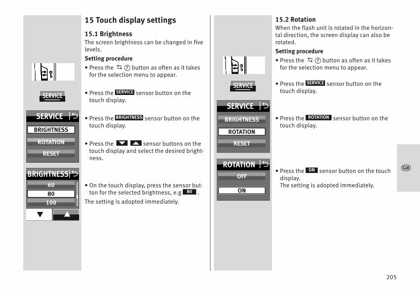
15 Touch display settings
15.1 BrightnessThe screen brightness can be changed in fivelevels.Setting procedure• Press the � button as often as it takes
for the selection menu to appear.
• Press the sensor button on thetouch display.
• Press the sensor button on thetouch display.
• Press the sensor buttons on thetouch display and select the desired bright-ness.
• On the touch display, press the sensor but-ton for the selected brightness, e.g .
The setting is adopted immediately.
D
SERVICE
BRIGHTNESS
80
15.2 RotationWhen the flash unit is rotated in the horizon-tal direction, the screen display can also berotated.Setting procedure• Press the � button as often as it takes
for the selection menu to appear.
• Press the sensor button on thetouch display.
• Press the sensor button on thetouch display.
• Press the sensor button on the touchdisplay.The setting is adopted immediately.
D
SERVICE
ROTATION
ON
205
k
SERVICE
SERVICE O
BRIGHTNESS
RESET
ROTATION
BRIGHTNESS O
q p
6080
100
SERVICE
SERVICE O
BRIGHTNESS
RESET
ROTATION
ROTATION OOFF
ON

16 Care and maintenance• The screen surface should only be cleaned
with a soft, dry cleaning cloth (e.g. microfi-bre cloth).
• If significant soiling nevertheless occurs,the screen surface can be cleaned with aslightly moist soft cloth.
Never spray cleaning fluid on the surfaceof the screen! If cleaning fluid penetratesinto the frame of the screen, the compo-nents there will be damaged beyondrepair.
16.1 Firmware updatesThe firmware version (V.10 in the example) ofthe flash unit is shown in the start screenafter switching on.The flash unit’s firmware can be updatedthrough the USB port � and adjusted to thetechnical requirements of future cameras(Firmware Update).For more information, visit the Metz homepa-ge at www.metz.de.
16.2 Conditioning the flash capacitorThe flash capacitor built into the flash unitundergoes a physical change when thedevice has not been used for a long time.For this reason it is necessary to switch thedevice every three months for approx.10 mins. The power supplies must deliverenough power so that flash standby lights upno later than 1 min after switching on.
16.3 ResetThe flash unit can be reset to the factory set-tings when delivered.Setting procedure• Press the � button as often as it takes
for the selection menu to appear.
• Press the sensor button on thetouch display.
• Press the sensor button on the touchdisplay.
• Press the sensor button on the touchdisplay.All settings are adopted immediately andthe flash unit is reset to its factory settings.
This will not affect the firmware updates forthe flash unit !
D
SERVICE
RESET
ON
206
k
SERVICE
SERVICE O
BRIGHTNESS
RESET
ROTATION
RESET OOFF
ON

17 TroubleshootingShould the flash unit fail to function properly or meaningless con-tent appear on the flash unit display panel, switch the flash unit offwith the main switch � for approximately 10 seconds. Check thecamera settings and make sure the foot of the flash unit is mountedcorrectly in the camera’s accessory shoe.Replace the batteries with new or freshly charged batteries.The flash unit should function normally again once it is switchedback on. If this is not the case, contact your local dealer.Below is a list of some of the problems that may occur when theflash unit is used. For each item, possible causes and remedies forthe problem are listed.No maximum flash range indication appears on the display panel.• There has been no exchange of data between the flash unit and
the camera.Tap the camera’s shutter release.
• The reflector is not in normal position. • The flash unit has been set to remote operation.The AF measuring beam of the flash unit is not activated.• The flash unit is not ready for firing.• The camera is not in „AF-S“ mode.• The camera supports only its own internal AF measuring beam.• Some cameras support the AF measuring beam in the flash unit
only with the camera’s central AF sensor. If a peripheral AF sensoris selected, then the AF measuring beam will not be activated inthe flash unit.Activate the central AF sensor.
• The "AF BEAM" is switched off. Switch on "AF BEAM", see 11.6
The reflector position is not automatically adjusted to the currentzoom position of the lens.• The camera does not transfer data to the flash unit• There is no exchange of data between the flash unit and the camera.
Tap the camera’s shutter release.• The camera is equipped with a lens without CPU.• The flash unit operates in manual zoom mode „MZoom“.
Switch to Auto-Zoom (see 11.4.3).• The reflector is swivelled out of its locked normal position.• The wide-angle diffuser folds out from the reflector.• A Mecabounce is mounted in front of the reflector.The TTL flash mode cannot be set.• Data transfer has not occurred between the flash unit and the
camera.Actuate shutter release.
• The camera does not support TTL flash mode.The setting for manual TTL flash exposure correction has no effect.• The camera does not support manual TTL flash exposure correcti-
on on the flash unit.Automatic switching to the flash sync speed fails to occur.• The camera has a between-the-lens shutter (as do most compact
cameras), Switching to sync speed is therefore unnecessary.• The camera operates with high-speed synchronisation HSS (came-
ra settings). Switching to sync speed does not occur in the pro-cess.
• The camera operates with shutter speeds that are slower than theflash sync speed. Depending on the camera mode, there is noswitch to flash sync speed (see the camera’s operating instructi-ons).
207
k

208
k
The shots are too dark.• The subject is beyond the range of the flash unit.
Note: Using bounce flash reduces the range of the flash unit.• The subject contains very bright or highly reflective areas. The
metering system of the camera or flash unit is deceived as aresult. Set a positive manual flash exposure correction, e.g., +1EV.
The shots are too bright.• In close-up shots, overexposure (shots that are too bright) may
result if the shutter speed is faster than the flash sync speed.

209
k
18 Technical dataMax. guide numbers at ISO 100/21°, zoom 200 mm:In the metric system: 64 In the imperial system: 210Flash modes:TTL (without preflash), preflash TTL, ADI metering, manual M, automatic A, high-speed synchronisation HSS, remote slave, remote servo.automatic aperture setting at ISO 100/21°:F1.4 to F64, including intermediate valuesManual partial light output levels:P1/1 . . . P1/ 256 in one-third increments.P1/1 . . . P1/256 light output, in automatic high-speed synchronisation(HSS)Flash durations: see table 2, page (Page 319)
Colour temperature: Ca. 5600 K
Sensitivity to light: ISO 6 to ISO 51200
Synchronisation: low-voltage ignitionNumber of flashes• 140 with alkaline manganese batteries (1,5V)• 190 with NiMH-batteries (1,2V / 2100 mAh)• 290 with lithium-batteries (1,5V)• 360 witht Metz Power Pack P76
Recycling times (min./max.)• 0,1/4,4 with alkaline manganese batteries (1,5V)• 0,1/1,8 with NiMH-batteries (1,2V / 2100 mAh)• 0,1/4,2 with lithium-batteries (1,5V)• 0,1/1,6 with Metz Power Pack P76
Light coverage:Reflector from 24 mm (35 mm format)Reflector with wide-angle diffuser from 12 mm (35 mm format)Swivelling ranges and locking positions of the reflector:upwards: -9° 45° 60° 75° 90°counter-clockwise: 60° 90° 120° 150° 180°clockwise: 60° 90° 120°Dimensions, approx., in mm (W x H x D):Ca. 78 x 148 x 112Weight :Flash unit without batteries approx. 422 g
Included:Flash unit with integrated wide-angle diffuser, operating instructi-ons, Flash unit mounting foot S60, Belt pouch T64, operatinginstructions.

210
k
19 Optional accessories We accept no liability for malfunctions of or damage to the flash unitcaused by the use of accessories of other manufacturers!• mecabounce Diffuser MBM-03(Order No. 000003902)With this diffuser, soft lighting can be achieved in a very simplemanner. It gives your pictures a marvellous soft appearance. Skintones are captured more faithfully. The maximum working range isreduced by about half in conformity with the loss of light.• Bounce diffuser 58-23(Order No. 000058235)Softens heavy shadows with reflected light.• Flash unit mounting foot S60(Order No. 000000607)Flash unit mounting foot for slave mode.• Connecting cable V58-50(Order No. 000058504)also fits power pack P76• Powerpack• Easy Softbox ESB 60-60 (Order No. 009016076)
Dimensions: 60 × 60 cm
Including front and background diffusers, carrying case andBowens-compatible adapter to connect to a Metz TL or BL studioflash device
• Easy Softbox ESB 40-40 (Order No. 009014047)
Dimensions: 40 × 40 cm
Including front and background diffusers, carrying case andBowens-compatible adapter to connect to a Metz TL or BL studioflash device
• Flash device holder FGH 40-60 (Order No. 009094065)
Adapter for compact flash devices and Easy Softboxes
Adjustable flash foot height
Connects to Metz lighting tripods LS-247 and LS-200
• Mini Softbox SB 30-20 (Order No. 009013023)
Colour: white, Dimensions: 30 × 20 cm
• Mini Softbox SB 22-16 (Order No. 009012217)
Colour: white, Dimensions: 22 × 16 cm
• Mini Softbox SB 18-15 (Order No. 009011817)
Colour: white, Dimensions: 18 × 15 cm
• Mini Octagon Softbox SB 34-34 (Order No. 009023432)
Colour: white, Dimensions: Ø 34 cm
• Mini Octagon Softbox SB 20-20 (Order No. 009022029)
Colour: white, Dimensions: Ø 20 cm

211
k
• Mini Octagon Softbox SB 15-15 (Order No. 009021516)
Colour: white, Dimensions: Ø 15 cm
• Spot bounce diffuser SD 30-26 W (Order No. 009043021)
Colour: white for neutral light / Dimensions: 30 × 26 cm
• Spot bounce diffuser SD 30-26 S (Order No. 00904303A)
Colour: silver for cool light / Dimensions: 30 × 26 cm
• Spot bounce diffuser SD 30-26 G (Order No. 009043048)
Colour: gold for warm light / Dimensions: 30 × 26 cm
Disposal of batteriesDo not dispose of spent batteries with domestic rubbish.Please return spent batteries to collecting points should they existin your country!Please return only fully discharged batteries.Normally, batteries are fully discharged if:- the device they powered switches itself off and indicates "Spent
Batteries".- they no longer function properly after prolonged use.
To ensure short-circuit safety please cover the battery poleswith adhesive tape.
Errors excepted. Subject to changes !

Premessa . . . . . . . . . . . . . . . . . . . . . . . . . . . . . . . . . . . . . . . . . . . . . 2131 Avvertenze per la sicurezza . . . . . . . . . . . . . . . . . . . . . . . . . . . . . 2142 Funzioni flash dedicate . . . . . . . . . . . . . . . . . . . . . . . . . . . . . . . . 2153 Preparazione del flash . . . . . . . . . . . . . . . . . . . . . . . . . . . . . . . . . 2163.1 Montaggio del flash . . . . . . . . . . . . . . . . . . . . . . . . . . . . . . . . . 2163.2 Alimentazione . . . . . . . . . . . . . . . . . . . . . . . . . . . . . . . . . . . . . . 2173.3 Accensione e spegnimento del flash . . . . . . . . . . . . . . . . . . . . 2183.4 Il menu di selezione . . . . . . . . . . . . . . . . . . . . . . . . . . . . . . . . . 2183.5 INFO . . . . . . . . . . . . . . . . . . . . . . . . . . . . . . . . . . . . . . . . . . . . . . 2193.6 Spegnimento automatico dell’apparecchio/Auto - OFF . . . . . 2194 Indicazioni sul flash . . . . . . . . . . . . . . . . . . . . . . . . . . . . . . . . . . . 2214.1 Indicazione flash pronto. . . . . . . . . . . . . . . . . . . . . . . . . . . . . . 2214.2 Indicazione di corretta esposizione. . . . . . . . . . . . . . . . . . . . . 2215 Indicazioni sul display . . . . . . . . . . . . . . . . . . . . . . . . . . . . . . . . . 2215.1 Indicazione della modalità del flash . . . . . . . . . . . . . . . . . . . . 2225.2 Indicazione campo di utilizzo . . . . . . . . . . . . . . . . . . . . . . . . . 2226 Indicazioni sul mirino della camera . . . . . . . . . . . . . . . . . . . . . . 2237 Modalità flash. . . . . . . . . . . . . . . . . . . . . . . . . . . . . . . . . . . . . . . . 2247.1 Modalità TTL . . . . . . . . . . . . . . . . . . . . . . . . . . . . . . . . . . . . . . . 2247.2 Pre-lampo TTL e misurazione ADI . . . . . . . . . . . . . . . . . . . . . . . 2257.3 Modo flash manuale . . . . . . . . . . . . . . . . . . . . . . . . . . . . . . . . . 2257.4Sincronizzazione automatica con tempi corti (HSS) . . . . . . . . 2267.5 Modo flash Automatico . . . . . . . . . . . . . . . . . . . . . . . . . . . . . . 2277.6 Modo flash Stroboscopico . . . . . . . . . . . . . . . . . . . . . . . . . . . . 2288 Correzione manuale d’esposizione flash . . . . . . . . . . . . . . . . . 2309 Funzioni speciali . . . . . . . . . . . . . . . . . . . . . . . . . . . . . . . . . . . . . . 2319.1 Parabola con zoom motorizzato („Zoom“) . . . . . . . . . . . . . . . 231
10 Controllo a distanza wi-fi . . . . . . . . . . . . . . . . . . . . . . . . . . . . . . 23310.1 Funzionamento master remoto . . . . . . . . . . . . . . . . . . . . . . . 23410.1.1 Impostazione del funzionamento master remoto . . . . . . . 23410.1.2 Impostare la modalità sul flash master . . . . . . . . . . . . . . . 23510.1.3 Impostare la potenza ridotta in modalità M sul flash master 23510.1.4 Definire le condizioni di illuminazione (RATIO)
per i gruppi di flash sul flash master . . . . . . . . . . . . . . . . . 23610.1.5 Impostare il canale remoto . . . . . . . . . . . . . . . . . . . . . . . . . 23710.2 Modo con controllo a distanza. . . . . . . . . . . . . . . . . . . . . . . . 23710.2.1 Impostare la modalità slave remota. . . . . . . . . . . . . . . . . . 23810.2.2 Impostare il canale slave . . . . . . . . . . . . . . . . . . . . . . . . . . 23810.2.3 Impostare la modalità slave . . . . . . . . . . . . . . . . . . . . . . . . 23910.2.4 Impostare la potenza ridotta slave. . . . . . . . . . . . . . . . . . . 23910.2.5 Impostare la potenza ridotta/correzione
dell'esposizione slave. . . . . . . . . . . . . . . . . . . . . . . . . . . . . 24010.3 Verifica del modo con controllo a distanza. . . . . . . . . . . . . . 24010.4 Modo SERVO . . . . . . . . . . . . . . . . . . . . . . . . . . . . . . . . . . . . . . 24110.4.1 Impostare la modalità SERVO . . . . . . . . . . . . . . . . . . . . . . . 24110.4.2 Impostare la soppressione pre-lampo e la sincronizzazione 24110.4.3 Impostare la potenza ridotta in modalità servo . . . . . . . . 24210.4.4 Funzione di apprendimento . . . . . . . . . . . . . . . . . . . . . . . . 24210.4.5 Disattivare la modalità flash SERVO. . . . . . . . . . . . . . . . . . 24311 OPTION-Menu . . . . . . . . . . . . . . . . . . . . . . . . . . . . . . . . . . . . . . . 24411.1 Modalità RAPID . . . . . . . . . . . . . . . . . . . . . . . . . . . . . . . . . . . . 24411.2 Parabola ausiliaria (SUB-REFL.) . . . . . . . . . . . . . . . . . . . . . . . 24411.3 Luce pilota (MOD. LIGHT) . . . . . . . . . . . . . . . . . . . . . . . . . . . . 24511.4 Modo zoom (ZOOM MODE). . . . . . . . . . . . . . . . . . . . . . . . . . . 24511.4.1 Modo zoom esteso . . . . . . . . . . . . . . . . . . . . . . . . . . . . . . . 24511.4.2 Modalità zoom spot. . . . . . . . . . . . . . . . . . . . . . . . . . . . . . . 246
212
ö

PremessaGrazie per aver scelto un prodotto Metz. E’ un piacere per noi acco-gliervi tra i nostri clienti.
Sicuramente non vedete l’ora di iniziare ad usare il vostro flash. Vi raccomandiamo tuttavia di leggere le istruzioni per l’uso, che viconsentiranno di usare correttamente l’apparecchio.
Questo lampeggiatore è adatto per:• Camere digitali reflex Sony con pre-lampo TTL e misurazione ADI.Il flash non è adatto per camere di altre marche!
Consultare anche gli schemi al termine delle istruzioni.
Spiegazione
Indicazione, nota
Attenzione – Avvertenze per la sicurezza estremamente impor-tanti!
Uso conformeIl presente dispositivo flash è concepito esclusivamente per essereutilizzato per l’esposizione di soggetti in ambito fotografico. Puòessere impiegato solo con gli accessori descritti nel presentemanuale di istruzioni o con accessori autorizzati da Metz.Il dispositivo flash non può essere utilizzato per scopi diversi rispet-to a quello summenzionato.
+
11.4.3 Modalità zoom STANDARD . . . . . . . . . . . . . . . . . . . . . . . . . 24711.5 Adattamento formato foto (ZOOM SIZE) . . . . . . . . . . . . . . . . 24711.6 Illuminatore ausiliario AF (AF-BEAM) . . . . . . . . . . . . . . . . . . . 24811.7 Indicazione del campo d’utilizzo in m o ft . . . . . . . . . . . . . . 24911.8 Serie di esposizioni flash (FLASH BRACK.) . . . . . . . . . . . . . . 24911.9 Funzione bip (BEEP) . . . . . . . . . . . . . . . . . . . . . . . . . . . . . . . . 25011.10 Blocco / sblocco . . . . . . . . . . . . . . . . . . . . . . . . . . . . . . . . . . 25111.11 Collegare il Power Pack (accessorio) . . . . . . . . . . . . . . . . . . 25112 Programma favorito . . . . . . . . . . . . . . . . . . . . . . . . . . . . . . . . . . 25213 Tecniche lampo. . . . . . . . . . . . . . . . . . . . . . . . . . . . . . . . . . . . . . 25413.1 Lampo riflesso. . . . . . . . . . . . . . . . . . . . . . . . . . . . . . . . . . . . . 25413.2 Lampo riflesso con pannello riflettente . . . . . . . . . . . . . . . . 25413.3 Riprese da vicino/Riprese macro . . . . . . . . . . . . . . . . . . . . . . 25414 Sincronizzazione del lampo . . . . . . . . . . . . . . . . . . . . . . . . . . . 25514.1 Sincronizzazione automatica del lampo . . . . . . . . . . . . . . . . 25514.2 Sincronizzazione normale . . . . . . . . . . . . . . . . . . . . . . . . . . . 25514.3 Sincronizzazione con tempi più lunghi (SLOW) . . . . . . . . . . 25514.4 Presa di sincronizzazione. . . . . . . . . . . . . . . . . . . . . . . . . . . . 25615 Impostazioni del display touch. . . . . . . . . . . . . . . . . . . . . . . . . 25715.1 Luminosità (BRIGHTNESS) . . . . . . . . . . . . . . . . . . . . . . . . . . . 25715.2 Rotazione (ROTATION). . . . . . . . . . . . . . . . . . . . . . . . . . . . . . . 25716 Cura e manutenzione . . . . . . . . . . . . . . . . . . . . . . . . . . . . . . . . . 25816.1 Aggiornamento del software . . . . . . . . . . . . . . . . . . . . . . . . . 25816.2 Formazione del condensatore flash. . . . . . . . . . . . . . . . . . . . 25816.3 Fabbrica iniziale (RESET) . . . . . . . . . . . . . . . . . . . . . . . . . . . . 25817 In caso di anomalie di funzionamento. . . . . . . . . . . . . . . . . . . 25918 Dati tecnici . . . . . . . . . . . . . . . . . . . . . . . . . . . . . . . . . . . . . . . . . 26119 Accessori opzionali . . . . . . . . . . . . . . . . . . . . . . . . . . . . . . . . . . 262
213
ö

1 Avvertenze per la sicurezzaNon attivare il flash in presenza di gas oliquidi in fiammabili (benzina, solventiecc.). PERICOLO DI ESPLOSIONI!Non esporre gli occhi al lampo direttodel flash a distanza ravvicinata! La lucediretta del flash può causare danni allaretina di persone e animali e seri disturbialla vista o addirittura la cecità!Non fotografare mai con il flash automo-bilisti, ciclisti, motociclisti, conducenti diautobus o treni mentre sono alla guida.A causa dell’abbagliamento prodotto dalflash il guidatore potrebbe causare unincidente!Non utilizzare il flash se in seguito aldanneggiamento della scatola di allog-giamento eventuali componenti internirestano scoperti. Rimuovere le batterie!Non toccare i componenti interni. ALTA TENSIONE!Dopo aver utilizzato più volte il flash nontoccare il diffusore. Pericolo di ustioni!Non smontare il flash! ALTA TENSIONE!Per le riparazioni rivolgersi esclusiva-mente a un centro di assistenza autoriz-zato.
• L’utilizzo del flash è previsto e autorizzatosolamente nell’ambito della fotografia.!
• Utilizzare solo le fonti di alimentazioneelettrica con-sentite e descritte nelle istru-zioni per l’uso.!
• Non aprire o cortocircuitare le batterie!• Non esporre le batterie a temperature ele-
vate, ai raggi diretti del sole, al fuoco o afonti di calore simili!
• Non toccare i contatti elettrici del flash!• Non utilizzare batterie o accumulatori
danneggiati!• Estrarre subito dall’apparecchio le batterie
usate! Dalle batterie usate potrebbero fuo-riuscire sostanze chimiche (“perdite”) chepossono danneggiare l’apparecchio!
• Non caricare le batterie!• Non spruzzare e non lasciar gocciolare
acqua sull’apparecchio!• Non esporre l’apparecchio a calore estremo
e ad elevata umidità atmosferica! Non conservarlo per es. nel cassetto porta-oggetti dell’automobile!
• Con improvvisi sbalzi di temperatura puòformarsi uno strato di umidità. Lasciareacclimatizzare l’apparecchio!
214
ö

• Quando il flash viene attivato, non porremateriali impermeabili alla luce davantialla parabola (finestra flash) o a direttocontatto con essa. A causa dell’elevataemissione di energia potrebbero verificarsifenomeni di combustione oppure potrebbe-ro formarsi macchie sul materiale o sullaparabola.
• Quando si scattano fotografie in serie conflash a piena potenza e brevi tempi di rica-rica, lasciar riposare il flash per almeno 3minuti dopo 20 scatti consecutivi!
• Quando si scattano fotografie in serie conflash a piena potenza e brevi tempi di rica-rica, il diffusore si scalda molto a causadell'elevata energia del lampo con posizio-ni zoom da 35 mm e inferiori.
• Questo lampeggiatore può essere impiega-to insieme al flash integrato nella camera,soltanto se questo può essere aperto com-pletamente!
2 Funzioni flash dedicateLe funzioni flash dedicate sono funzioni messe a punto specificatamente per i diversisistemi di camera. Le funzioni del flash supportate dipendono dal tipo di camera.• Indicazione di stato di carica del flash nel
mirino/display della fotocamera.• Controllo automatico del tempo di
sincronizzazione• Controllo flash TTL• Memoria del valore misurato per
l’esposizione del flash• Pre-lampo-TTL e misurazione ADI• Controllo zoom motorizzato automatico.• Sincronizzazione sulla prima o sulla
seconda tendina 2 (REAR).• Modo zoom esteso.• Controllo dell'illuminatore AF.• Indicazione automatica del campo
d'utilizzo del flash.• Sincronizzazione automatica con tempi
corti HSS per TTL et M • Automatismo flash programmato.• Modo flash con controllo a distanza senza fili • Modo Servo.• Modo zoom spot.• Modo zoom esteso.• Funzione wake-up per il flash.
215
ö

In questo manuale non è possibile descriveredettagliatamente le singole funzioni dedicateai rispettivi tipi di fotocamere, pertanto viinvitiamo a consultare le avvertenze riportatenel libretto d’istruzioni della vostra foto-camera, nelle quali sono riportate le funzioniflash supportate e quelle che invece devonoessere impostate!
L’uso di obiettivi senza CPU (ad es. obiettivisenza autofocus) danno luogo in parte alimitazioni!
3 Preparazione del flash
3.1 Montaggio del flashMontaggio del flash sulla camera
Spegnete la camera e il flash con l’inter-ruttore principale!• Rimuovere il cappuccio protettivo dalla
base dell'unità.• Ruotate il dado zigrinato � fino ad arresto
contro il flash. La spina di sicurezza nellabase è ora scomparsa completamente nelcorpo del flash.
• Spingete il flash con la base fino all’arrestonella slitta accessori della camera.
• Ruotate il dado zigrinato � fino ad arrestocontro la camera e fissate il flash. Con foto-camere il cui corpo non possiede il foro peril blocco di sicurezza, il relativo perno, gra-zie al sistema a molla, scompare nel corpodel flash per non rovinare la superficie.
Smontaggio del flash dalla camera
Spegnete la camera e il flash con l’inter-ruttore principale!• Ruotate il dado zigrinato � fino ad arresto
contro il flash.• Estraete il flash dalla slitta accessori della
camera.
+
+
+
216
ö

3.2 AlimentazioneScelta delle pile o delle batterieIl flash può essere alimentato a scelta con:• 4 batterie al nichel metallidruro 1,2 V, tipo
IEC HR6 (AA/Mignon), capacità nettamentesuperiore rispetto alle batterie NiCd e mag-giore compatibilità ambientale, poichéprive di Cd.
• 4 batterie a secco alcaline al manganese1,5 V, tipo IEC LR6 (AA/Mignon), una fontedi energia esente da manutenzione, adattaper un impiego generico.
• 4 batterie al litio 1,5 V, tipo IEC FR6(AA/Mignon), una fonte di energia esenteda manutenzione, ad elevata capacità eautoscarica contenuta.
• Power Pack con cavo di collegamento(accessorio speciale).
Utilizzate solo le sorgenti d’alimentazioneindicate sopra. Se si utilizzano altre sorgentid’alimentazione c’è il rischio di danneggiareil flash.
Se prevedete di non usare il flash per lungotempo, togliete le batterie dall’apparecchio.
Sostituzione delle batterieLe batterie/batterie ricaricabili sono scaricheo consumate se l'intervallo di ricarica (tempofra lo scatto di un flash a piena potenza,p.es. con M, e la riaccensione della spia dicarica del flash) supera i 60 secondi. Inoltresul display touch appare l’avviso di batteriascarica.• Spegnere il flash tenendo premuto il
tasto � finché non scompaiono tutte leindicazioni.
• Spingere in basso e aprire il coperchio delvano batterie � .
• Inserire le batterie in senso longitudinalecosì come indicato dai simboli delle batte-rie e chiudere il coperchio del vano batterie�.
Quando inserite le pile/batterie assicuratevisempre che le polarità (+/-) siano corrette,come indicato dai simboli all’interno delvano batteria. L’inversione delle polarità puòprovocare la rottura dell’apparecchio!Sostituite sempre tutte le batterie con altreequivalenti della stessa marca e della stessacapacità! Non gettate le pile/batterie esauri-te nei rifiuti domestici! Contribuite alla tuteladell’ambiente e portatele nei contenitoriappositi per il riciclaggio!
+
217
ö

3.3 Accensione e spegnimento del flash• Accendere il flash con il tasto � .
Appare la schermata di avvio. Il flash si accende sempre nell’ultimamodalità utilizzata (per es. modalità flashmanuale M).
In modalità standby il tasto � lampeggiadi rosso. Per spegnere il flash tenere premutoil tasto � finché non scompaiono tutte leindicazioni.
Se il flash non viene usato per periodi di tempoprolungati, consigliamo di spegnere il flashcon il tasto � e togliere le sorgenti d’alimentazione (batterie, batterie ricaricabili).
3.4 Il menu di selezione• Continuare a premere il tasto � finché
non compare il menu di selezione.
Il menu di selezione è suddiviso in 6 tasti asensore:Una volta premuto il tasto è possibileimpostare le modalità.TTL, cap. 7.1TTL HSS*, cap. 7.4A, cap. 7.5M, cap. 7.3M HSS*, cap. 7.4STROBO, cap. 7.6REMOTE MASTER, cap. 10.1REMOTE SLAVE, cap. 10.2SERVO, cap. 10.4 *) solo dopo lo scambio di dati con una fotocamera
D
D
MODE
Una volta premuto il tasto è possi-bile impostare i parametri del flash.P (potenza luminosa ridotta), cap. 7.3, 10.1.3 e 10.4.3EV (correzione dell‘esposizione), cap. 8, 10.2.4ZOOM (posizione della parabola), cap. 9.1N (Numero lampi stroboscopio), cap. 7.6f (Frequenza lampi stroboscopio), cap. 7.6F (diaframma)ISO (sensibilità alla luce), RATIO (condizione di illuminazione), cap. 10.1.4CTRL (Remote), cap. 10.1CHANNEL (canale), cap. 10.2.2GROUP (gruppo Slave), siehe 10.2.3.La visualizzazione dei parametri di flashdipende dalla modalità di flash scelta.
Una volta premuto il tasto è possibileconfigurare il display touch o riportare il flashnelle impostazioni iniziali.
BRIGHTNESS (luminosità), vedere 15.1ROTATION (orientamento delle indicazionisullo schermo), vedere 15.2RESET, vedere 16.3
PARAMETER
SERVICE
218
V 1.0
MB 64AF-1digitalSON
MODE
PARAMETER
SERVICE
PARAMETER OP / EVZOOM
Nf (Hz)
FISO
CHANNELRATIO
CONTROL
MODE OETTL
TTL HSSAM
M HSSSTROBO
REMOTE MASTERREMOTE SLAVE
SERVO
SERVICE O
BRIGHTNESS
RESET
ROTATION
ö

Una volta premuto il tasto è possibileimpostare le opzioni.RAPID (tempi rapidi di ricarica), cap. 11.1
SUB-REFL. (parabola ausiliaria), cap. 11.2ZOOM SIZE (adattamento del formato foto),cap. 11.5ZOOM MODE (illuminazione), cap. 11.4STANDBY (spegnimento automatico dell’apparecchio), cap. 3.6MOD.LIGHT (luce pilota), cap. 11.3BEEP (segnale acustico), cap. 11.9m / ft (metri / piedi), vedere 11.7POWERPACK (Power Pack esterno), cap.11.11AF BEAM (illuminatore ausiliario AF),cap. 11.6FLASH BRACK. (serie di esposizioni flash),cap. 11.8La visualizzazione dei parametri di flashdipende dalla modalità di flash scelta.Nelle visualizzazioni del menu, tutti i campicon lo sfondo nero sono tasti con sensoreche devono essere premuti nel menu peressere cambiati/bloccati.
Nelle riproduzioni delle immagini sono contrassegnati in nero sempre e solo i tasticon sensore che devono essere premuti perimpostare la funzione descritta.
OPTION 3.5 INFOLe impostazioni attuali del flash possonoessere visualizzate durante l’uso.• Premere il tasto con sensore � sul
display touch. Appare la scheda informativa 1.
- È impostata la modalità EXT (modalità zoomesteso), (cap. 11.6.1).
- AF OFF (luce ausiliaria AF) è spenta,(vedere 11.6).
- (MOD.LIGHT) impostata, (vedere 11.3).
- È impostata la (funzione Beep) (cap.11.9)
- Compare (canale), (cap. 10.1.5,10.2.2)
- Lo spegnimento automatico dell’apparec-chio è impostato su 10 minuti, (vedere 3.6).
- L’indicatore della temperatura aumentadopo un uso intenso.
3.6 Spegnimento automatico dell’appa-recchio/Auto - OFF
Il flash è impostato di fabbrica in modo taleche circa 10 minuti• dopo l’accensione,• dopo lo scatto del lampo,• dopo aver premuto leggermente il pulsante
di scatto della camera,• dopo lo spegnimento del sistema di misu-
razione dell’esposizione della camera. . . . . . passa in modalità standby (Auto-OFF) per
i
2CH
219
OPTION
i
ö
200
OPTION ORAPID
SUB-REFL. ZOOM SIZEZOOM MODESTANDBY
MOD. LIGHTBEEPm / ft
POWERPACKAF BEAM
FLASH BRACK.

+
risparmiare energia ed evitare che le sorgentid'alimentazione si scarichino inutilmente. La presenza dello spegnimento automaticodell’apparecchio è visualizzata sul displayINFO. L'indicazione dello stato di carica del flash� e le indicazioni sul display LCD si spengo-no.In modalità standby il tasto � lampeggiadi rosso. La modalità d’esercizio impostata per ultimorimane memorizzata dopo lo spegnimentoautomatico e viene immediatamente ripristi-nata alla successiva accensione.Per riaccendere il flash, premere il tasto �o toccare il pulsante di scatto della foto-camera (funzione wake-up).
Nel modo slave/SERVO lo spegnimento auto-matico dell'apparecchio non è attivo.
Se prevedete di non utilizzare il flash perlungo tempo è opportuno spegnere l’appa-recchio sempre con l’interruttoreprincipale � !All’occorrenza lo spegnimento automaticopuò avvenire già dopo 1 minuto oppure puòessere spento. Il flash si spegne dopo ca. 1 ora dall’ultimoutilizzo. In tutte le modalità, dopo circa 10sec. la luminosità dello schermo viene ridot-ta a metà per risparmiare energia. Premendoun tasto o toccando lo schermo viene ripristi-nata la normale luminosità.
D
D
Impostare lo spegnimento automaticodell’apparecchio• Accendere il flash con il tasto �.
Appare la schermata di avvio. Il flash si accende sempre nell’ultimamodalità utilizzata (per es. modalità flashmanuale M).
• Continuare a premere il tasto � finchénon compare il menu di selezione.
• Premere il tasto con sensore suldisplay touch.
• Premere il tasto con sensore suldisplay touch e selezionare .
• Premere il tasto con sensore suldisplay touch.
• Premere il tasto con sensore sul displaytouch per digitare il tempo desiderato.L'impostazione verrà subito applicata.
In modalità standby il tasto � lampeggiadi rosso.
D
OPTION
STANDBY
STANDBY
D
220
OPTION
OPTION O
q p
ZOOM MODESTANDBY
MOD. LIGHT
STANDBY OOFF
1 min10 min
ö
200

4 Indicazioni sul flash
4.1 Indicazione flash prontoQuando il condensatore flash è carico, sulflash si accende la spia di carica del flash�, per indicare che il flash è pronto.Ciò significa che è possibile utilizzare il flashper la fotografia successiva. Lo stato di caricadel flash pronto viene trasmesso anche allafotocamera e viene visualizzato con il simbolo corrispondente nel mirino.Se si scatta una foto prima che nel mirinoappaia l'indicatore di flash pronto, quest'ultimo non parte. In determinate con-dizioni la foto avrà un'esposizione non cor-retta nel caso in cui la fotocamera sia giàpassata al tempo di sincronizzazione delflash (vedere 14.1).
4.2 Indicazione di corretta esposizioneIn caso di corretta esposizione, il tasto �si illumina per ca. 3 secondi di rosso, sel’esposizione della foto era corretta nellemodalità di funzionamento ed; (vedere 7.1) e in modalità Automatico !Se non appare alcuna indicazione di correttaesposizione una volta scattata la foto, ciòsignifica che quest'ultima era sottoesposta. Allora dovete:- impostare il numero di diaframma diretta-
mente inferiore (per es. anziché il livello 8 illivello 11), oppure.
- ridurre la distanza dal soggetto e/o dalla
D
PTTLHSSPTTLA
superficie riflettente (per es. in caso di flashindiretti), oppurer.
- impostare sulla fotocamera un valore ISOsuperiore.
Fate attenzione all'indicazione del campod'utilizzo sul display del flash (vedere 5.2).
5 Indicazioni sul displayLe fotocamere trasmettono al flash i valorirelativi all’ISO, alla distanza focale (mm) eall’apertura del diaframma. Questa adatta inmodo automatico le impostazioni necessa-rie. In funzione di tali valori e del suo numeroguida viene calcolato il massimo campo diutilizzo del flash. La modalità flash, il campo di utilizzo, l’aper-tura del diaframma e la posizione zoom dellaparabola principale vengono visualizzati suldisplay del flash.Se il flash viene usato senza che i dati sianostati trasmessi alla fotocamera, vengonoindicati solo i valori impostati del flash.Illuminazione del displayUna volta premuto il tasto � sul flash odopo aver toccato il display touch, l’illumina-zione del display sarà massima per circa 10sec.
D
221
ö

+
5.1 Indicazione della modalità del flashSul display verrà visualizzata la modalità delflash impostata. A tal proposito sono possi-bili diverse indicazioni relative alla modalitàflash TTL di volta in volta supportata (z.B.
e ) e al modo flash M manuale aseconda del tipo di camera (vedi 7.3).
5.2 Indicazione campo di utilizzoNell'utilizzo di fotocamere e in caso di obiet-tivo CPU comparirà sul display l'indicazionedel campo di utilizzo. Tra fotocamera e flash deve avvenire inoltreuno scambio dati, ad es. toccando legger-mente il pulsante di scatto. Il campo di utiliz-zo può essere visualizzato in metri (m) o infeet (ft) (vedi 11.7).
Non viene indicato il campo di utilizzo . . .
- se non sono stati trasmessi dati alla foto-camera.
- se la testa della parabola viene spostatadalla sua normale posizione (verso l'alto,verso il basso o lateralmente).
- Se il flash lavora in modalità REMOTEMASTER; REMOTE SLAVE o SERVO.
PTTL HSSPTTL
Indicazione campo di utilizzo in modalitàflash TTL-/TTL HSSIn tali modalità ( , ; vedi 7.1) vie-ne visualizzato sul display il valore massimodel campo di utilizzo del flash. l valore visualizzato si riferisce ad un gradodi riflessione del 25% del soggetto.Ciò riguarda la maggior parte delle situazionidi ripresa. Scostamenti elevati del grado diriflessione, ad es. in presenza di soggettimolto o poco riflettenti, possono influenzareil campo di utilizzo del flash.Il soggetto dovrebbe trovarsi fra il 40% e il70% circa della portata massima. Ciò con-sente al sistema elettronico di avere un sufficiente margine di compensazione. Per evitare una sovraesposizione non si dov-rebbe restare a una distanza dal soggettoinferiore a quella minima indicata suldisplay.L’adattamento alle diverse situazioni di ripre-sa è possibile ad es. variando l’apertura deldiaframma sull’obiettivo.
TTL HSSTTL
222
5.5 - 56 m M-Zoom 35 m
m
TTL
iEV
5.5 - 56 m M-Zoom 35 m
m
TTL
iEV
ö

Indicazione del campo di utilizzo del flashnel modo flash manuale Nel modo flash manuale M il display indica ilvalore della distanza da mantenere per unacorretta esposizione. L’adattamento allediverse situazioni di ripresa è possibile ades. modificando l’apertura del diaframmasull’obiettivo oppure selezionando unapotenza ridotta manuale (vedi 7.3).Superamento del campo indicatoSul display vengono visualizzati campi di utilizzo fino a un massimo di 99 m o 99 ft.In presenza di valori ISO elevati e ampieaperture di diaframma è possibile superare ilcampo di valori indicato.Ciò viene indicato con una freccia o con untriangolo dietro al valore della distanza.
M6 Indicazioni sul mirino della
cameraEsempi di indicazioni sul mirino:Il simbolo flash si accende:il flash è pronto (in alcune camere)Il simbolo flash lampeggia lentamente:Accendere il dispositivo flashAlcune nozioni sulla cattiva esposizione:• In caso di sovraesposizione: non usate il
flash!• In caso di sottoesposizione: accendete il
flash oppure utilizzate uno stativo e untempo di esposizione più lungo.
Nei diversi programmi automatici e di esposi-zione possono esserci varie cause di una cat-tiva esposizione.Per quel che riguarda le indicazioni nel miri-no, consultate nelle istruzioni d’uso dellavostra camera ciò che vale per il vostro tipodi camera.
223
9.0 mM-Zoom 35 m
m
M
iP1/1
49- 99 m uF 1,4M-
Zoom 200mm
TTL
iEV
ö

7 Modalità flashA seconda del tipo di fotocamera sono dispo-nibili le seguenti modalità flash:• Modalità TTL ( ), cap. 7.1• Modo flash manuale ( ), cap. 7.3• Sincronizzazione automatica con tempi
corti (HSS), cap. 7.4• Modo flash Automatico ( ), cap. 7.5• Modo flash Stroboscopico ( ),
cap. 7.6• Funzionamento master remoto
, cap. 10.1• Modo con controllo a distanza ,
cap. 10.2• Modo SERVO ( ), cap. 10.4. La modalità di funzionamento del flash vieneimpostata con il display touch. Per impostare la modalità flash et
è necessario che avvenga prima unoscambio di dati fra la fotocamera e il flash,ad es. premendo leggermente il pulsante discatto della fotocamera.
7.1 Modalità TTL ( )Durante lo scatto, il flash emette una serie dipre-lampi di misurazione quasi invisibili pri-ma della vera e propria esposizione. La luce riflessa dei pre-lampi viene valutatadalla fotocamera. In base a questa valuta-zione la fotocamera adatta in modo ottimalela successiva esposizione alla situazione diripresa (vedi le istruzioni d'uso della foto-camera).
TTLM
A
STROBO
REMOTE MASTER
REMOTE SLAVE
SERVO
TTL HSSM HSS
TTL
L'indicazione di corretta esposizione com-pare per ca. 3 secondi se la ripresa è corret-tamente esposta (vedere 4.2).Impostare la modalità • Accendere il flash con il tasto �.
Appare la schermata di avvio.Il flash si accende sempre nell’ultimamodalità utilizzata (per es. modalità flashM).
• Premere sul display touch la modalitàvisualizzata finché non appare quella desiderata.
• Premere il tasto con sensore suldisplay touch e selezionare la modalitàdesiderata.
• Premere sulla modalità con sfondo giallodesiderata. L'impostazione verrà subitoapplicata.
• Impostare sulla fotocamera una modalitàcorrispondente, per es. P, S, A, ecc.
• Premere leggermente il pulsante di scattodella fotocamera per permettere uno scambio dati fra il flash e la camera.
224
V 1.0
MB 64AF-1digitalSON
9.0 mM-Zoom 35 m
m
M
iP1/1
MODE O
q p
TTLTTL HSS
ö

7.2 Pre-lampo TTL e misurazione ADIIl pre-lampo TTL e la misurazione ADI sonomodalità digitali di TTL e rappresentanol’evoluzione del modo flash TTL di camereanalogiche. Nella ripresa il flash emette unaserie di pre-lampi di misurazione quasiimpercettibili prima della vera e propriaesposizione. La luce riflessa dei pre-lampi dimisurazione viene valutata dalla camera. Inbase alla suddetta valutazione la cameraadatta in modo ottimale l’esposizione suc-cessiva alla situazione di ripresa (vedi leistruzioni d’uso della camera). In caso dimisurazione ADI vengono consideratinell’esposizione flash anche i dati relativialla distanza dell’obiettivo. La selezione ol’impostazione dei modi pre-lampo TTL emisurazione ADI avviene nella camera (vedile istruzioni d’uso della camera).Il flash deve essere regolato sul modo flash
.
7.3 Modo flash manualeCon il modo flash manuale M il flash emetteun lampo non dosato a potenza piena, ameno che non sia stata impostata la potenzaridotta. Per adeguarsi alla situazione di ripre-sa è possibile ad es. regolare il diaframmasulla fotocamera o selezionare manualmentela potenza ridotta adeguata. L’intervallo di regolazione si estende da P1/1fino a P1/256 in mode o P1/1 fino aP1/32 in mode . Sul display viene indicata la distanza alla
TTL
MM HSS
quale il soggetto viene ben esposto (vedi5.2).Impostare la modalità • Accendere il flash con il tasto �.
Appare la schermata di avvio.Il flash si accende sempre nell’ultima moda-lità utilizzata .
• Premere sul display touch la modalitàvisualizzata finché non appare quella desiderata.
• Premere il tasto con sensore suldisplay touch e selezionare .
• Premere il tasto con sensore sul displaytouch.
• Impostare sulla fotocamera una modalitàcorrispondente, per es. .
• Premere leggermente il pulsante di scattodella fotocamera per permettere uno scambio dati fra il flash e la camera.
Diversi tipi di fotocamera supportano lamodalità flash manuale M solo se impostatesulla modalità fotocamera M (manuale).In altre modalità di fotocamera apparirà unsegnale di errore sul display e non sarà possibile scattare la foto.
M
M
M
225
0.8 - 9.0 m M-Zoom 35 m
m
TTL
iEV
0.8 - 9.0 m M-Zoom 35 m
m
TTL
iEV
9.0 mM-Zoom 35 m
m
M
iP1/1
MODE O
q p
AM
M HSS
ö

Potenza ridotta manualeIn modalità flash manuale è possibileimpostare la potenza ridotta.
Procedura per l'impostazione• Premere sul display touch il tasto con sen-
sore per la potenza ridotta, finché nonappare il menu di selezione corrispon-dente.
• Premere i tasti con sensore suldisplay touch e impostare la potenza ridotta desiderata 1/1, 1/2, 1/8 . . . 1/256.
• Preparare il tasto con sensore sul displaytouch per la potenza ridotta desiderata.
L'impostazione viene applicata immediata-mente e salvata automaticamente.
L'indicazione della distanza viene automati-camente adeguata alla potenza ridotta (vedere 5.2).
M7.4 Sincronizzazione automatica con
tempi corti (HSS)La sincronizzazione automatica con tempicorti viene supportata da diverse fotocamerevedi il manuale di istruzioni della foto-camera). Questa funzione permette di utiliz-zare il flash con tempi di posa più rapidi diquelli di sincronizzazione.È interessante nei primi piani con luceambiente molto chiara, quando la profonditàdi campo deve essere limitata tramite apertu-re del diaframma relativamente grandi (ades. F 2,0)! Il flash supporta la sincronizzazio-ne con tempi corti nei mode et .Tuttavia per cause naturali con la sincroniz-zazione a tempi corti il numero guida e quin-di anche il campo di utilizzo del flash verran-no in parte considerevolmente limitati! Fateattenzione pertanto all’indicazione del cam-po d’utilizzo sul display del flash. La sincro-nizzazione con tempi corti viene effettuataautomaticamente, quando sulla fotocameraviene impostato manualmente o automatica-mente tramite il programma di esposizioneun tempo di posa inferiore al tempo di sin-cronizzazione del lampo.Ricordatevi che con la sincronizzazione atempi corti il numero guida del flash dipendeanche dal tempo di posa: più è corto il tempo di posa minore sarà ilnumero guida!La sincronizzazione con tempi corti vieneeffettuata automaticamente, quando sulla
MTTL
226
ö
9.0 mM-Zoom 35 m
m
M
iP1/1
3.1 mM-Zoom 35 m
m
M
iP1/8
P O
q p
1/11/1 - 1/3
P O
q p
1/4 - 2/31/8
1/8 - 1/3

fotocamera viene impostato manualmente oautomaticamente tramite il programma diesposizione un tempo di posa inferiore altempo di sincronizzazione del lampo.Impostare la modalità • Accendere il flash con il tasto � .
Appare la schermata di avvio.Il flash si accende sempre nell’ultima modali-tà utilizzata (per es. modalità flash TTL).
• Premere leggermente il pulsante di scattodella fotocamera per permettere uno scambio dati fra il flash e la camera.
• Premere sul display touch la modalitàvisualizzata finché non appare quella desiderata.
• Premere il tasto con sensore suldisplay touch e selezionare risp.
.
• Premere il tasto con sensore suldisplay touch.
L'impostazione verrà subito applicata.
Se sul flash viene attivata la sincronizzazio-ne con tempi corti HSS, la sincronizzazionesulla seconda tendina (REAR) viene automa-ticamente disattivata!
TTL HSSM HSS
TTL HSS
7.5 Modo flash AutomaticoCon il modo flash Automatico il fotosen-sore � del lampeggiatore misura la luceriflessa dal soggetto. Il fotosensore � ha unangolo di rilevazione di circa 25° e procedealla misurazione solamente durante la pro-pria emissione del lampo. Se l’intensità della luce è sufficiente, il siste-ma di esposizione automatica del lampeggia-tore disattiva il flash. Il fotosensore � deveessere rivolto verso soggetto.Impostare la modalità • Accendere il flash con il tasto �.
Appare la schermata di avvio.Il flash si accende sempre nell’ultima moda-lità utilizzata .
• Premere sul display touch la modalitàvisualizzata finché non appare quella desiderata.
• Premere il tasto con sensore suldisplay touch e selezionare .
• Premere il tasto con sensore sul displaytouch.
• Impostare sulla fotocamera una modalitàcorrispondente, per es. .
• Premere leggermente il pulsante di scattodella fotocamera per permettere uno scambio dati fra il flash e la camera.
A
A
A
A
227
9.0 mM-Zoom 35 m
m
M
iP1/1
MODE O
q p
TTL HSSA
M HSS
0.8 - 9.0 m M-Zoom 35 m
m
A
iEV
ö
0.8 - 9.0 m M-Zoom 35 m
m
TTL
iEV
9.0 mM-Zoom 35 m
m
TTL HSS
iP1/1
MODE O
q p
TTLTTL HSS
A

7.6 Modo flash StroboscopicoIl modo flash Stroboscopico è un modomanuale. Con questa funzione è possibilefare diverse esposizioni su una foto unica. Sirivela particolarmente interessante per glistudi di movimento e le riprese d’effetto.Con il modo Stroboscopico vengono emessidiversi flash ad una determinata frequenza.Pertanto, questa funzione può essere utiliz-zata solo se il valore della potenza ridotta èal massimo di 1/8, o con valori inferiori.Per una fotografia scattata in modalità stro-boscopica si devono impostare la frequenzadei flash (flash al secondo) e il numero deiflash.Numero lampi stroboscopio (N)Con il modo flash Stroboscopico è possibileimpostare il numero di lampi (N) per scatto.
Il numero dei lampi è compreso fra 2 e 90 epuò essere regolato in continuo.
Il numero massimo possibile di flash (N)dipende dalla potenza ridotta impostata (P).
Frequenza lampi stroboscopio (f)Con il modo flash Stroboscopico è possibileimpostare la frequenza dei lampi (f ). Taleparametro indica il numero dei lampi persecondo. La frequenza è compresa fra 1 e100 può essere regolata in continuo con pas-si di 1.
Al fine di ottenere durate brevi del lampo èdata la possibilità di impostare la potenzaridotta fino al valore minimo di 1/256.
La frequenza massima possibile di flash (f)dipende dalla potenza ridotta impostata (P).
Impostare la modalità • Accendere il flash con il tasto �.
Appare la schermata di avvio.Il flash si accende sempre nell’ultima moda-lità utilizzata.
• Premere sul display touch la modalitàvisualizzata finché non appare quella desiderata.
• Premere il tasto con sensore suldisplay touch e selezionare .
• Premere il tasto con sensore suldisplay touch.
• Impostare sulla fotocamera una modalitàcorrispondente, per es. .
• Premere leggermente il pulsante di scattodella fotocamera per permettere uno scambio dati fra il flash e la camera.
STROBO
STROBO
M
228
ö
+
+
0.8 - 9.0 m M-Zoom 35 m
m
TTL
iEV
MODE O
q p
M HSSSTROBO
REMOTE MASTER
3.1mM-Zoom 35 m
m
STROBO
iP1/8
f(Hz) 5N 5

229
Impostare la nomero dei flash (N)• Premere il tasto con sensore sul display
touch per il numero dei flash .
• Premere i tasti con sensore suldisplay touch e selezionare il numero diflash desiderato.
Il numero massimo possibile di flash (N)dipende dalla potenza ridotta impostata (P).
• Premere il tasto con sensore sul displaytouch, nell’esempio , per il numerodi flash desiderato. L’impostazione è imme-diatamente attiva.
N
4
Impostare la frequenza dei flash (f(Hz))• Premere il tasto con sensore sul display
touch per la frequenza dei flash .
• Premere il tasto con sensore suldisplay touch e selezionare la frequenza diflash desiderata.
La frequenza massima possibile di flash (f)dipende dalla potenza ridotta impostata (P).
• Premere il tasto con sensore sul displaytouch per la frequenza di flash desiderata,nell’esempio . L’impostazione è immediatamente attiva.
Sul display viene indicata la distanza validaper i parametri impostati. Il valore di distanzaindicato può essere adeguato alla distanzadel soggetto cambiando il valore del diafram-ma o la potenza ridotta.In modalità flash stroboscopico nel displaynon vengono visualizzati il valore ISO e quel-lo relativo al diaframma!
La parabola ausiliaria non è supportata nelmodo flash stroboscopico.
f (Hz)
8
f (Hz) O
q p
789
3.1mM-Zoom 35 m
m
STROBO
iP1/16
f(Hz) 10N 4
3.1mM-Zoom 35 m
m
STROBO
iP1/8
f(Hz) 8N 4 ö
+
+
+
3.1mM-Zoom 35 m
m
STROBO
iP1/16
f(Hz) 10N 5
N O
q p
345
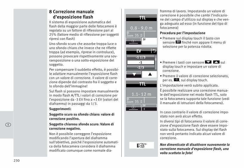
230
8 Correzione manuale d’esposizione flash
Il sistema di esposizione automatica delflash della maggior parte delle fotocamere èregolata su un fattore di riflessione pari al25% (fattore medio di riflessione per soggettiripresi con flash) Uno sfondo scuro che assorbe troppa luce ouno sfondo chiaro che invece che ne riflettetroppa (ad esempio, riprese in controluce),possono provocare rispettivamente una sov-raesposizione o una sotto-esposizione delsoggetto.Per compensare il suddetto effetto, è possibi-le adattare manualmente l’esposizione flashcon un valore di correzione. Il valore di corre-zione dipende dal contrasto fra il soggetto elo sfondo dell’immagine!Sul flash si possono impostare manualmentein modo flash A/TTL i valori di correzione perl’esposizione da -3 EV fino a +3 EV (valori deldiaframma) in passaggi da 1/3.Suggerimenti:Soggetto scuro su sfondo chiaro: valore dicorrezione positivo. Soggetto chiarosu sfondo scuro: Valore dicorrezione negativo.Non è possibile correggere l’esposizionemodificando l’apertura del diaframmasull’obiettivo, poiché l’esposizione automati-ca della fotocamera considera il diaframmamodificato comunque come normale dia-
framma di lavoro. Impostando un valore dicorrezione è possibile che cambi l’indicazio-ne del campo d’utilizzo sul display e che ven-ga adeguato ad esso (in funzione del tipo difotocamera)Procedura per l’impostazione• Premere sul display touch il tasto con
sensore finché non appare il menu di selezione per la potenza ridotta.
• Premere i tasti con sensore suldisplay touch e impostare un valore di correzione.
• Premere il valore di correzione selezionato,per es. , sul display touch.
L'impostazione verrà subito applicata.È possibile realizzare una correzione manua-le dell’esposizione nel modo flash TTL, solose la fotocamera supporta tale funzione (vediil manuale di istruzioni della fotocamera).
In caso contrario il valore di correzione impo-stato non avrà alcun effetto.In diversi tipi di fotocamera il valore di corre-zione d’esposizione flash deve essere impo-stato sulla fotocamera. Sul display del flashnon verrà pertanto indicato alcun valore dicorrezione.
Non dimenticate di disattivare nuovamente lacorrezione manuale d'esposizione flash, unavolta scattata la foto!
EV
-1
+
ö
0.8 - 9.0 m M-Zoom 35 m
m
TTL
iEV
EV O
q p
-1 1/3-1
-2/3
1.1- 12 m M-Zoom 35 m
m
TTL
iEV-1

231
Attenzione: Oggetti fortemente riflettentinell’immagine del soggetto possono distur-bare l’esposizione automatica della foto-camera. La ripresa sarà quindi sottoesposta.Spostate gli oggetti riflettenti o impostate unvalore di correzione positivo.
9 Funzioni specialiIn base al tipo di fotocamera o al gruppo diappartenenza della vostra fotocamera sonodisponibili diverse funzioni speciali. Per richiamare e impostare le funzioni spe-ciali deve pertanto prima esservi stato unoscambio di dati fra la fotocamera e il flash,ad es. premendo leggermente il pulsante discatto della fotocamera.L’impostazione deve essere eseguita imme-diatamente dopo aver richiamato la funzionespeciale, poiché il flash dopo alcuni seconditorna di nuovo automaticamente al normalemodo flash!
9.1 Parabola con zoom motorizzato(„Zoom“)
La parabola con zoom automatico del flashpuò illuminare completamente distanze foca-li a partire da 24 mm (formato piccolo). Grazie all’utilizzo del diffusore grandangola-re è possibile un’illuminazione fino a 12 mm.
Zoom automatico.Quando si utilizza il flash con una foto-camera che trasmette i dati relativi alladistanza focale dell’obiettivo, la posizionezoom della parabola principale si regolaautomaticamente in funzione della distanzafocale. Dopo l’accensione del flash suldisplay verranno visualizzati l’indicazione“Zoom” e l’attuale posizione zoom dellaparabola .L’adattamento automatico avviene perdistanze focali a partire da 24 mm.L’adattamento automatico non avviene se laparabola principale è inclinata, se il diffusoregrandangolare è estratto o se è montatoun Mecabounce (accessori).È possibile spostare a scelta la posizione del-la parabola manualmente per ottenere deter-minati effetti di esposizione (ad es. l’effettospot, ecc.).Modo Zoom manualeIn caso di camere che non trasmettono i datirelativi alla distanza focale dell’obiettivo ènecessario regolare manualmente la posizio-ne zoom della parabola principale in funzio-ne della distanza focale.
In tal caso non è possibile il modo zoomautomatico! Dopo avere acceso il flash sul display compa-riranno l’indicazione „Zoom“ e l’attuale posi-zione zoom della parabola.
+
+ö

232
Esempio:State utilizzando un obiettivo zoom con unintervallo di focali da 35 mm a 105 mm. Inquesto caso posizionate la parabola princi-pale del flash su 35 mm.Ripristino dello zoom automatico• Premete leggermente il pulsante di scatto
della fotocamera per permettere uno scam-bio dati fra il flash e la fotocamera.
• Continuare a premere il tasto � finchénon compare il menu di selezione.
• Premere il tasto con sensore suldisplay touch.
• Premere il tasto con sensore suldisplay touch e selezionare .
• Premere il tasto con sensore suldisplay touch.
• Premere i tasti con sensore sul displaytouch e selezionare .
• Premere i tasti con sensore v sul display touch.
Dopo ca. 10 sec. si passa alla visualizzazionedella modalità oppure, se non accade, premere il tasto � finché non compare.
D
PARAMETER
ZOOM
ZOOM
AUTOZOOM
AUTOZOOM
D
Procedura per l’impostazione• Continuare a premere il tasto � finché
non compare il menu di selezione.
• Premere il tasto con sensore suldisplay touch.
• Premere il tasto con sensore suldisplay touch e selezionare .
• Premere i tasti con sensore sul display touch.
• Premere i tasti con sensore suldisplay touch e selezionare il valore zoomdesiderato.
• Sul display touch premere il tasto con sen-sore per il valore zoom desiderato.L'impostazione verrà subito applicata.
Sono possibili le seguenti posizioni zoom perla parabola: 24 - 28 - 35 - 50 - 70 - 85 - 105-135-180-200 mm (formato piccolo).Suggerimenti:Se utilizzate un obiettivo zoom e non avetesempre necessariamente bisogno del nume-ro guida completo e del campo d’utilizzo delflash, potete lasciare la posizione della para-bola sulla focale iniziale dell’obiettivo zoom.In questo modo si garantisce sempre un’illu-minazione completa della vostra immagine.Eviterete così un continuo adattamento allafocale.
D
PARAMETER
ZOOM
ZOOM
ö
PARAMETER
PARAMETER O
q p
P/EVZOOM
F
ZOOM O
q p
7085
105
PARAMETER
PARAMETER O
q p
P/EVZOOM
F
ZOOM
q p
AUTOZOOM24
O

Diffusore grandangolareGrazie al diffusore grandangolare integra-to è possibile illuminare distanze focali apartire da 12 mm (formato piccolo).Tirate in avanti il diffusore grandangolare dalla parabola fino allo scatto ed estrarlo. Il diffusore grandangolare scatta automa-ticamente verso il basso. La parabola vieneportata automaticamente nella posizionenecessaria. La parabola viene portata automaticamentenella posizione necessaria.L’adattamento automatico della parabola conzoom motorizzato non avviene se si utilizza ildiffusore grandangolare .Per far rientrare il diffusore grandangolare ,piegarlo di 90 gradi verso l’alto e spingerlofino in fondo.mecabounce Diffuser MBM-03Se il mecabounce (accessorio speciale; vedi19) viene montato sulla parabola del flash,quest’ultima si mette automaticamente nellaposizione necessaria. I dati relativi alladistanza e il valore dello zoom vengono cor-retti su 16 mm.
L’adattamento automatico della parabola conzoom motorizzato non avviene se si utilizzaun mecabounce.Non è possibile utilizzare contemporanea-mente diffusore grandangolare e mecaboun-ce.
10 Controllo a distanza wi-fiIl flash supporta il sistema Sony con controlloa distanza senza cavo nelle modalità “CTRL”e “CTRL+”, a seconda del tipo di fotocamerautilizzato. Le modalità “CTRL” e “CTRL+” ven-gono riconosciute in automatico.Questo sistema è composto da un flash con-troller sulla fotocamera e da uno o più flashslave. Il o i flash slave sono comandati adistanza, senza fili, dal flash master.Per fare in modo che più sistemi a distanzanella stessa area non si disturbino a vicenda,sono disponibili quattro canali remoti indi-pendenti. I flash controller e gli slave cheappartengono allo stesso sistema a distanzadevono essere impostati sullo stesso canaleremoto. I flash slave devono poter ricevere la luce delflash principale o master grazie al sensoreintegrato per la funzione remote . La modalità flash con controllo a distanzasupporta anche la sincronizzazione sullaseconda tendina. In modalità controllo a distanza non vi è alcu-na indicazione del campo sul display delflash.
233
+ ö

10.1 Funzionamento master remotoI gruppi slave RMT ed RMT2 sono attivaticome impostazione di fabbrica. Il flash master (CTRL) e i gruppi slave RMT edRMT2 possono essere attivati o disattivati!Se il flash controller (CTRL) è disattivato svol-ge solo una funzione di controllo e non con-tribuisce personalmente all'esposizione conla propria luce!10.1.1 Impostazione del funzionamento
master remoto• Accendere il flash con il tasto �.
Appare la schermata di avvio. • Premere sul display touch la modalità
visualizzata finché non appare quella desiderata.
• Premere il tasto con sensore suldisplay touch e selezionare .
• Premere il tasto con sensoresul display touch. Il funzionamento master remoto è impostato.
Nell'immagine è visualizzato il funzionamen-to master remoto CTRL+. Il master (CTRL) con-tribuisce all'esposizione alle stesse condizio-ni di illuminazione dei gruppi di flash slave(RMT).Al master (CTRL), al gruppo di flash slave RMTe al gruppo di flash slave RMT2 possonoessere assegnate delle condizioni di illumi-nazione (vedere 10.1.4).
REMOTE MASTER
REMOTE MASTER
Passare da CTRL a CTRL+• Continuare a premere il tasto � finché
non compare il menu di selezione.
• Premere il tasto con sensore suldisplay touch.
• Premere i tasti con sensore suldisplay touch e selezionare .
• Premere il tasto con sensore suldisplay touch.
• Premere il tasto con sensore sul displaytouch per la modalità desiderata o
.
L'impostazione verrà subito applicata.
La gestione delle condizioni di illuminazione(Ratio) può avvenire solo in modalità CTRL+.
D
PARAMETER
CONTROL
CONTROL
CTRLCTRL+
234
ö
0.6- 7.2 m M-Zoom 35 m
m
TTL
iEV
MODE O
q p
STROBOREMOTE MASTER
REMOTE SLAVE
CTRL RMT4 8
REMOTECTRL
TTL
i RATIO
CTRL RMT RMT24 8 1
REMOTECTRL+
TTL
i RATIO
PARAMETER
PARAMETER O
q p
RATIOCONTROL
CTRL/CTRL+ OCTRL
CTRL+
+
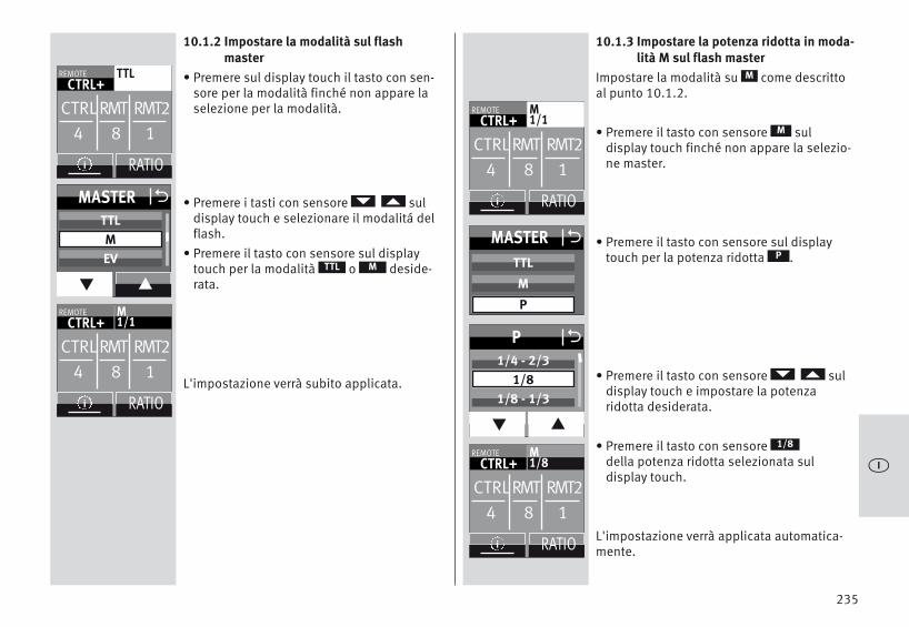
10.1.2 Impostare la modalità sul flashmaster
• Premere sul display touch il tasto con sen-sore per la modalità finché non appare laselezione per la modalità.
• Premere i tasti con sensore suldisplay touch e selezionare il modalitá delflash.
• Premere il tasto con sensore sul displaytouch per la modalità o deside-rata.
L'impostazione verrà subito applicata.
MTTL
10.1.3 Impostare la potenza ridotta in moda-lità M sul flash master
Impostare la modalità su come descrittoal punto 10.1.2.
• Premere il tasto con sensore suldisplay touch finché non appare la selezio-ne master.
• Premere il tasto con sensore sul displaytouch per la potenza ridotta .
• Premere il tasto con sensore suldisplay touch e impostare la potenza ridotta desiderata.
• Premere il tasto con sensoredella potenza ridotta selezionata sul display touch.
L'impostazione verrà applicata automatica-mente.
M
M
P
1/8
235
ö
CTRL RMT RMT24 8 1
REMOTECTRL+
M1/1
i RATIO
CTRL RMT RMT24 8 1
REMOTECTRL+
M1/1
i RATIO
CTRL RMT RMT24 8 1
REMOTECTRL+
M1/8
i RATIO
CTRL RMT RMT24 8 1
REMOTECTRL+
TTL
i RATIO
MASTER O
q p
TTLMEV
P O
q p
1/4 - 2/31/8
1/8 - 1/3
MASTER OTTL
M
P
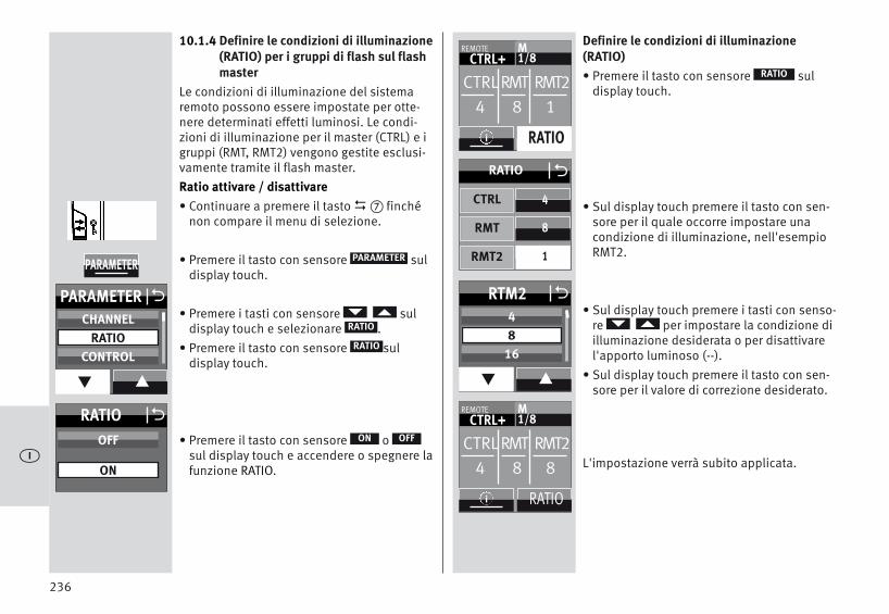
10.1.4 Definire le condizioni di illuminazione(RATIO) per i gruppi di flash sul flashmaster
Le condizioni di illuminazione del sistemaremoto possono essere impostate per otte-nere determinati effetti luminosi. Le condi-zioni di illuminazione per il master (CTRL) e igruppi (RMT, RMT2) vengono gestite esclusi-vamente tramite il flash master.Ratio attivare / disattivare• Continuare a premere il tasto � finché
non compare il menu di selezione.
• Premere il tasto con sensore suldisplay touch.
• Premere i tasti con sensore suldisplay touch e selezionare .
• Premere il tasto con sensore suldisplay touch.
• Premere il tasto con sensore o sul display touch e accendere o spegnere lafunzione RATIO.
D
PARAMETER
RATIO
RATIO
OFFON
Definire le condizioni di illuminazione(RATIO)• Premere il tasto con sensore sul
display touch.
• Sul display touch premere il tasto con sen-sore per il quale occorre impostare unacondizione di illuminazione, nell'esempioRMT2.
• Sul display touch premere i tasti con senso-re per impostare la condizione diilluminazione desiderata o per disattivarel'apporto luminoso (--).
• Sul display touch premere il tasto con sen-sore per il valore di correzione desiderato.
L'impostazione verrà subito applicata.
RATIO
236
ö
CTRL RMT RMT24 8 1
REMOTECTRL+
M1/8
i RATIO
PARAMETER
PARAMETER O
q p
CHANNELRATIO
CONTROL
RTM2 O
q p
48
16
RATIO OOFF
ON
8
1
4
ORATIO
CTRL
RMT
RMT2
CTRL RMT RMT24 8 8
REMOTECTRL+
M1/8
i RATIO

10.1.5 Impostare il canale remotoPer fare in modo che più sistemi a distanzanella stessa area non si disturbino a vicenda,sono disponibili quattro canali remoti indipendenti. I flash controller e gli slave cheappartengono allo stesso sistema a distanzadevono essere impostati sullo stesso canaleremoto.• Continuare a premere il tasto � finché
non compare il menu di selezione.
• Premere il tasto con sensore suldisplay touch.
• Premere il tasto con sensore suldisplay touch.
• Premere i tasti con sensore suldisplay touch e selezionare un canaleremote, ad es .
• Premere il tasto con sensore sul displaytouch per il canale desiderato.
L'impostazione verrà subito applicata.Premere � e controllare l'impostazionedel canale.
D
PARAMETER
CHANNEL
CHANNEL 2
i
10.2 Modo con controllo a distanzaIl flash supporta il sistema remote senzacavo in modo asservito ed è compatibile conil sistema Sony.Così è possibile controllare a distanza senzacavo uno o più flash slave attraverso un flashprincipale fissato sulla fotocamera (ad es.mecablitz 64AF-1S digitale).Il flash slave può essere associato ad uno deidue possibili gruppi (RMT, RMT2). Il flashprincipale può regolare contemporaneamen-te tutti questi gruppi-slave e tener conto inoltre delle singole impostazioni per ognunodi essi.Per fare in modo che più sistemi a distanzanello stesso ambiente non si disturbino avicenda sono disponibili 4 canali remoteindipendenti (CH 1, 2, 3 o 4).Il flash principale e gli slave che appartengo-no allo stesso sistema a distanza devonoessere impostati sullo stesso canale remoto. I flash slave devono poter ricevere la luce delflash principale grazie al sensore integratoper la funzione remote .In funzione del tipo di fotocamera anche ilflash incorporato nella stessa fotocamerapuò servire da flash principale.
237
ö
PARAMETER O
q p
ZOOMCHANNEL
RATIO
CHANNEL O
q p
CHANNEL 1CHANNEL 2CHANNEL 3
PARAMETER

10.2.1 Impostare la modalità slave remota• Accendere il flash con il tasto �.
Appare la schermata di avvio.Il flash si accende sempre nell’ultima modali-tà utilizzata (per es. modalità flash TTL).
• Premere sul display touch la modalitàvisualizzata finché non appare quella desiderata.
• Premere i tasti con sensore suldisplay touch e selezionare .
• Premere i tasti con sensoresul display touch.
Il funzionamento slave remoto è impostato.
Vengono inoltre indicati i gruppi slave sele-zionati (per es. RMT) e il canale remote (peres. CH 1).
REMOTE SLAVE
REMOTE SLAVE
10.2.2 Impostare il canale slave• Premere il tasto con sensore sul display
touch per il gruppo del canale(per es. ).Viene visualizzata la scelta di gruppo ecanale.
• Premere il tasto con sensore sul displaytouch per il canale .
• Premere i tasti con sensore suldisplay touch e selezionare il canale desiderato.
• Premere il canale desiderato sul displaytouch.
L'impostazione verrà subito applicata. Suldisplay compare "CH2".
RMT I CH1
CHANNEL
238
ö
0.8- 9.0 m M-Zoom 35 m
m
TTL
iEV
MODE O
q p
REMOTE MASTERREMOTE SLAVE
SERVO
M-Zoom 24
REMOTE
SLAVERMT Ch
2 1
i
mm
P1/1
M-Zoom 24
REMOTE
SLAVERMT Ch
2 2
i
mm
P1/1
M-Zoom 24
REMOTE
SLAVERMT Ch
2 1
i
mm
SLAVE OCHANNEL
GROUP
CHANNEL O
q p
CHANNEL 1CHANNEL 2CHANNEL 3

10.2.3 Impostare la modalità slave• Premere il tasto con sensore sul display
touch per la potenza ridotta/correzionedell'esposizione (per es. ) . Vienevisualizzata la scelta.
• Premere il tasto con sensore sul displaytouch per il gruppo .
• Premere i tasti con sensore sul displaytouch per il gruppo desiderato o.
L'impostazione verrà applicata automatica-mente.
RMT I CH1
GROUP
RMT2RMT
10.2.4 Impostare la potenza ridotta slave
• Premere il tasto con sensore sul displaytouch per la potenza ridotta o .
• Premere il tasto con sensore sul displaytouch per la modalità desiderata o .
L'impostazione verrà subito applicata.
EVP
MTTL
239
ö
M-Zoom 24
REMOTE
SLAVERMT Ch
2
i
mm
P
M-Zoom 24
REMOTE
SLAVERMT Ch
2
i
mm
P1/1
M-Zoom 24
REMOTE
SLAVERMT Ch
2 1
i
mm
SLAVE OCHANNEL
GROUP
GROUP O
RTM2
SLAVE OTTL
M
P
RTM

10.2.5 Impostare la potenza ridotta/corre-zione dell'esposizione slave
• Premere il tasto con sensore sul displaytouch per la potenza ridotta/correzionedell'esposizione (per es. / ) . Vienevisualizzata la scelta.
• Premere il tasto con sensore sul displaytouch per la modalità desiderata o .
• Premere i tasti con sensore suldisplay touch e impostare la potenza ridotta desiderata 1/1, 1/2, 1/8 o 1/256.
La potenza ridotta viene acquisita.Una volta che tutti i flash slave sono carichi,il flash di misurazione AF lampeggia �.
EV1/1
EVP
10.3 Verifica del modo con controllo a distanza.
• Posizionate il flash slave nel modo deside-rato per la foto successiva. Utilizzate un piedistallo per flash slaveS60.
• Attendete che lo stato di carica di tutti iflash interessati sia pronto. Quando lo sta-to di carica dei flash slave è pronto,la spiadel illuminatore ausiliario AF �.
• Premete lo scatto sul flash principale �emettendo così un flash di prova. I flash slave rispondono con un flash di pro-va ritardato uno dopo l’altro a seconda delgruppo slave a cui appartengono. Se unflash slave non emana un flash di prova,verificate l’impostazione del canale remotee del gruppo-slave. Correggete la posizionedel flash slave permettendogli di captare laluce del flash principale con il sensore .
La modalità flash viene trasmessa automati-camente dal flash principale. Se il flash lavora come flash principale nelsistema con controllo a distanza, con l’emissione della luce pilota verrà emessaanche la luce pilota dei flash slave.
240
ö
M-Zoom 24
REMOTE
SLAVERMT Ch
2 2
i
mm
P1/1
SLAVE OTTL
M
EV / P
P O
q p
1/4 - 2/31/8
1/8 - 1/3
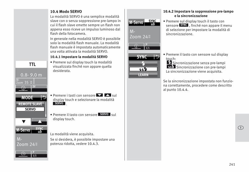
10.4 Modo SERVOLa modalità SERVO è una semplice modalitàslave con o senza soppressione pre-lampo incui il flash slave emette sempre un flash nonappena esso riceve un impulso luminoso dalflash della fotocamera.In generale nella modalità SERVO è possibilesolo la modalità flash manuale. La modalitàflash manuale è impostata automaticamenteuna volta attivata la modalità SERVO.10.4.1 Impostare la modalità SERVO• Premere sul display touch la modalità
visualizzata finché non appare quella desiderata.
• Premere i tasti con sensore suldisplay touch e selezionare la modalità
.
• Premere il tasto con sensore suldisplay touch.
La modalità viene acquisita.Se si desidera, è possibile impostare unapotenza ridotta, vedere 10.4.3.
SERVO
SERVO
10.4.2 Impostare la soppressione pre-lampoe la sincronizzazione
• Premere sul display touch il tasto con sensore , finché non appare il menudi selezione per impostare la modalità disincronizzazione.
• Premere il tasto con sensore sul displaytouch:
Sincronizzazione senza pre-lampiSincronizzazione con pre-lampi
La sincronizzazione viene acquisita.
Se la sincronizzazione impostata non funzio-na correttamente, procedere come descrittoal punto 10.4.4.
SYNC
241
ö
0.8- 9.0 m M-Zoom 35 m
m
TTL
iEV
MODE O
q p
REMOTE SLAVESERVO
M-Zoom 24
M-Servo SYNC
iP1/1
mm
SYNC O
LEARN
M-Zoom 24
M-Servo SYNC
iP1/1
mm

10.4.3 Impostare la potenza ridotta in modalità servo
• Premere sul display touch il tasto con sensore per la potenza ridotta, finchénon appare il menu di selezione corrispon-dente.
• Premere i tasti con sensore suldisplay touch e impostare la potenza ridotta desiderata 1/1, 1/2, 1/8 fino a1/256 .
• Premere il tasto con sensore sul displaytouch per la potenza ridotta desiderata
(per es. 1/16).
La potenza ridotta viene acquisita.Una volta che tutti i flash slave sono carichi,il flash di misurazione AF lampeggia �.
Nella modalità SERVO canali remote nonpossono essere impostati. Il flash della fotocamera non può funzionarein modo remoto.
P
1/16
10.4.4 Funzione di apprendimentoLa “Funzione di apprendimento” consente diadeguare automaticamente, in maniera per-sonalizzata, il flash slave al flash integratonella fotocamera.È possibile includere uno o più prelampi delflash della fotocamera, ad es. per la riduzio-ne dell’effetto “occhi rossi”. Il flash slave scatta nel momento del flashprincipale che determina l’esposizione dellaripresa.
Se il flash della fotocamera emette lampi dimisurazione AF per la messa a fuoco auto-matica, il sistema non consente la funzionedi apprendimento.
Selezionare, se possibile, un’altra modalitào passare alla messa a fuoco manuale.
242
ö
+
+
M-Zoom 35
M-Servo SYNC
iP1/1
mm
M-Zoom 35
M-Servo SYNC
iP1/16
mm
P O
q p
1/8 - 2/31/16
1/16 - 1/3
+

Procedura per l’impostazione della funzionedi apprendimentoLa funzione pre-lampo AF della fotocameradeve essere spenta.• Premere sul display touch il tasto con
sensore , finché non appare il menudi selezione.
• Premere il tasto con sensore sul display touch.
• Il “Learning Mode” (funzione di apprendi-mento) è pronto ad apprendere.
• Azionare il pulsante di scatto della foto-camera in modo tale che il flash della foto-camera scatti.Se il flash SERVO ha ricevuto un impulsoluminoso, sul display appare “LEARN OK”come conferma.
Il macablitz digital ha appreso il lampeggia-mento del flash della fotocamera.
SYNC
Learn
10.4.5 Disattivare la modalità flash SERVO
• Premere sul display touch la modalitàvisualizzata finché non appare quella desiderata.
• Premere il tasto con sensore suldisplay touch e selezionare la modalitàdesiderata, per es .
• Premere il tasto con sensore sul displaytouch per il per la modalità, per es. .
La modalità selezionata viene acquisita.
TTL
TTL
243
ö
M-Zoom 24
M-Servo SYNC
iP1/16
mm
SYNC O
LEARN
M-Zoom 24
M-Servo SYNC
iP1/16
mm
MODE O
q p
TTLA
0.6- 7.5 m M-Zoom 24 m
m
TTL
iEV

11 OPTION-Menu
11.1 Modalità RAPIDNella modalità flash A e TTL i tempi di ricaricadipendono da quanta luce occorre per loscatto. Se il tempo di ricarica è troppo lungo,nella modalità A e TTL è possibile attivare lafunzione RAPID. Si raccomanda la funzioneRAPID soprattutto in quei casi in cui occorro-no più tempi di ricarica rapidi che la massimapotenza, ad es. in ambienti relativamentepiccoli. Il numero guida viene tuttavia ridottodi 1, ad es. dal numero guida 36 (per ISO100 Zoom 35) al numero guida 25 (per ISO100 Zoom 35).Procedura per l’impostazione• Continuare a premere il tasto � finché
non compare il menu di selezione.• Premere il tasto con sensore sul
display touch.• Premere il tasto con sensore sul
display touch e selezionare .• Premere il tasto con sensore sul
display touch.
• Premere il tasto con sensore osul display touch e accendere o spegnere lafunzione RAPID.
L’impostazione verrà subito applicata. Una volta attivata la funzione RAPID, suldisplay verrà visualizzato il simbolo „ ” .
D
OPTION
RAPID
RAPID
OFFON
11.2 Parabola ausiliaria (SUB-REFL.)La parabola ausiliaria serve a rischiararefrontalmente con flash indiretto, quando laparabola principale è spostata lateralmenteo verso l’alto. Se la quantità di luce dellaparabola ausiliare è eccessiva, è possibileridurla della metà.Procedura per l’impostazione• Continuare a premere il tasto � finché
non compare il menu di selezione.
• Premere il tasto con sensore suldisplay touch.
• Premere il tasto con sensore suldisplay touch e selezionare .
• Premere il tasto con sensore suldisplay touch.
• Premere il tasto con sensore oo sul display touch e accendere ospegnere la parabola ausiliaria.L’impostazione verrà subito applicata.
Dopo l’attivazione della parabola ausiliaria,nel display si visualizza .Nel menu INFO si visualizzerà „ 1/1” o „1/2”. 1/1 sta a indicare la piena potenza, mentre1/2 indica la mezza potenza.
D
OPTION
SUB-REFL.
SUB-REFL.
1/21/1OFF
244
ö
OPTION
SUB-REFL. OOFF1/11/2
OPTION O
q p
RAPIDSUB-REFL.ZOOM SIZE
OPTION O
q p
RAPIDSUB-REFL.
OPTION
RAPID OOFF
ON

11.3 Luce pilota (MOD. LIGHT)La luce pilota (ML = Modelling Light) è unflash stroboscopico ad alta frequenza. La suadurata è di ca. 3 secondi, si ha pertanto l’im-pressione di una luce quasi permanente.Grazie ad essa è possibile valutare già primadello scatto della foto la distribuzione dellaluce e la creazione di ombre. La luce pilota viene fatta scattare premendosul tasto per lo scatto �.Procedura per l’impostazione• Continuare a premere il tasto � finché
non compare il menu di selezione.
• Premere il tasto con sensore suldisplay touch.
• Premere il tasto con sensore suldisplay touch e selezionare .
• Premere il tasto con sensore suldisplay touch.
• Premere il tasto con sensore osul display touch e accendere o spegnere laluce pilota. L’impostazione verrà subitoapplicata.
Una volta attivata la luce pilota, nel menuINFO viene visualizzato „ ”.
D
OPTION
MOD. LIGHT
MOD. LIGHT
OFFON
11.4 Modo zoom (ZOOM MODE)11.4.1 Modo zoom estesoNel modo zoom esteso la posizione zoomdella parabola viene ridotta di un gradorispetto alla distanza focale dell’obiettivodella fotocamera. La forte illuminazione chene deriva permette di avere un’ulteriore lucediffusa (riflessioni) in ambienti chiusi e diconseguenza una luce flash più morbida.Esempio:la distanza focale dell’obiettivo nella foto-camera è di 50 mm. Nel modo zoom esteso ilflash regola la parabola principale sulla posi-zione zoom 35 mm. Sul display continuanoad essere indicati 50 mm.Procedura per l’impostazione• Continuare a premere il tasto � finché
non compare il menu di selezione.
• Premere il tasto con sensore suldisplay touch.
• Premere il tasto con sensore suldisplay touch e selezionare .
• Premere il tasto con sensore suldisplay touch.
• Premere il tasto con sensore suldisplay touch. L'impostazione verrà subito applicata.
Dopo aver attivato la funzione zoom estesosul display apparirà la scritta "EXT" nel menuINFO.
D
OPTION
ZOOM MODE
ZOOM MODE
EXTENDED
245
ö
MOD. LIGHT OOFF
ON
OPTION O
q p
OPTION
OPTION
q p
MOD. LIGHTBEEP
RAPIDSUB-REFL.
STANDBY
OPTION
ZOOMMODE OExtendedStandard
Spot
OPTION O
q p
ZOOM SIZEZOOM MODE
STANDBY

Per motivi di sistema la modalità zoom este-so è supportata per focali d'obiettivo a parti-re da 28 mm (formato piccolo).La fotocamera deve essere dotata di obietti-vo CPU e trasmettere i dati per la distanzafocale al flash.11.4.2 Modalità zoom spotNella modalità zoom spot la posizione zoomdella parabola viene aumentata di un gradorispetto alla distanza focale della foto-camera. L’illuminazione ridotta che ne derivapermette di avere una luce con accento sullazona centrale oppure una illuminazione peri-ferica oscurata.Esempio:La distanza focale dell'obiettivo nella foto-camera è di 50 mm. Nella modalità zoomspot il flash regola la parabola sulla posizio-ne zoom 70 mm. Sul display continuano adessere indicati 50 mm.
Procedura per l’impostazione• Continuare a premere il tasto � finché
non compare il menu di selezione.
• Premere il tasto con sensore suldisplay touch.
• Premere il tasto con sensore suldisplay touch e selezionare .
• Premere il tasto con sensore suldisplay touch.
• Premere il tasto con sensore suldisplay touch.L'impostazione verrà subito applicata.
Dopo aver attivato la funzione zoom estesosul display apparirà la scritta "SP" nel menuINFO.Per motivi di sistema la modalità zoom esteso è supportata per focali d'obiettivo apartire da 24 - 180 mm (formato piccolo).
La fotocamera deve essere dotata di obiettivo CPU e trasmettere i dati per ladistanza focale al flash.
D
OPTION
ZOOM MODE
ZOOM MODE
SPOT
246
ö
ZOOMMODE OEXTENDEDSTANDARD
SPOT
OPTION
OPTION O
q p
ZOOM SIZEZOOM MODE
STANDBY

11.4.3 Modalità zoom STANDARDNella modalità zoom standard la posizione dizoom della parabola viene adeguata alladistanza focale della fotocamera.Procedura per l’impostazione• Continuare a premere il tasto � finché
non compare il menu di selezione.
• Premere il tasto con sensore suldisplay touch.
• Premere il tasto con sensore suldisplay touch e selezionare .
• Premere il tasto con sensore suldisplay touch.
• Premere il tasto con sensore suldisplay touch.L'impostazione verrà subito applicata.
D
OPTION
ZOOM MODE
ZOOM MODE
STANDARD
11.5 Adattamento formato foto(ZOOM SIZE)
In alcuni tipi di camere digitali l’indicazionerelativa alla posizione della parabola puòessere adattata con la funzione Zoom Size alformato chip (dimensioni dell’unità di acqui-sizione dell’immagine).Procedura per l’impostazione• Continuare a premere il tasto � finché
non compare il menu di selezione.
• Premere il tasto con sensore suldisplay touch.
• Premere il tasto con sensore suldisplay touch e selezionare .
• Premere il tasto con sensore suldisplay touch.
• Premere il tasto con sensore sul display touch. L'impostazione verrà subitoapplicata.
Dopo aver attivato la funzione zoom size suldisplay apparirà la scritta „ ” nel menuINFO.Dopo aver disattivato la funzione Zoom-Size,l’indicazionec„ ” nel menu INFO scom-pare.In camere che non supportano tale adatta-mento, la funzione Zoom Size non può essereimpostata!
D
OPTION
ZOOM SIZE
ZOOM SIZE
ON
247
ö
OPTION
OPTION O
q p
SUB-REFL.ZOOM SIZE
ZOOM MODE
ZOOM SIZE OOFF
ON
OPTION
OPTION O
q p
ZOOM SIZEZOOM MODE
STANDBY
ZOOMMODE OEXTENDEDSTANDARD
SPOT

11.6 Illuminatore ausiliario AF (AF-BEAM)Se il sistema di misurazione AF di una foto-camera reflex digitale AF non riesce a metterea fuoco a causa della scarsa luminositàdell’ambiente, verrà attivato l’illuminatoreausiliario AF integrato � integrato nel flashdella fotocamera. L’illuminatore proietta unfascio di raggi luminosi sul soggetto la cuiriflessione consente alla fotocamera di ope-rare la messa a fuoco.La funzione “AF-BEAM” permette di spegnereo accendere l’illuminatore ausiliario.La portata è pari a ca. 6m ... 9 m (con obietti-vo standard 1,7/50 mm). A causa della paral-lasse fra obiettivo e illuminatore ausiliario AFm il limite della messa a fuoco ravvicinatacon l’illuminatore ausiliario AF equivale a cir-ca 0,7 m -1 m.Affinché la fotocamera possa attivare l’illumi-natore ausiliario AF m, essa deve essereimpostata sulla modalità autofocus "Single-AF (S-AF)" e sul flash deve essere visualizzatol'indicatore flash pronto.Alcuni tipi di fotocamere supportano solo l’illuminatore ausiliario AF incorporato nellafotocamera. L’illuminatore ausiliario AF delflash non verrà pertanto attivato (ad es. nellefotocamere compatte; vedere il manuale diistruzioni della fotocamera)!
Obiettivi zoom con apertura ridotta del dia-framma iniziale limitano a volte considere-volmente la portata dell’illuminatore ausiliario AF!
Procedura per l’impostazione• Continuare a premere il tasto � finché
non compare il menu di selezione.
• Premere il tasto con sensore suldisplay touch.
• Premere il tasto con sensore suldisplay touch e selezionare .
• Premere il tasto con sensore suldisplay touch.
• Premere il tasto con sensore osul display touch.
L'impostazione verrà subito applicata.
D
OPTION
AF BEAM
AF BEAM
OffOn
248
ö
OPTION
OPTION O
q p
POWERPACKAF BEAM
AF BEAM OOFF
ON

11.7 Indicazione del campo d’utilizzo inm o ft
Il campo di utilizzo può essere visualizzatosul display in metri (m) o in feet (ft).Procedura per l’impostazione• Continuare a premere il tasto � finché
non compare il menu di selezione.
• Premere il tasto con sensore suldisplay touch.
• Premere il tasto con sensore suldisplay touch e selezionare .
• Premere il tasto con sensore suldisplay touch.
• Premere il tasto con sensore o suldisplay touch.
L'impostazione verrà subito applicata.
D
OPTION
m/ft
m/ft
ftm
11.8 Serie di esposizioni flash(FLASH BRACK.)
Nei modi flash i TTL e automatico è possibileeffettuare una serie di esposizioni flash(Flash-Bracketing FB). Una serie di esposizio-ni comprende tre foto consecutive con valoridiversi di correzione dell’esposizione.
Impostando una serie di esposizioni suldisplay verrà visualizzato FB e il valore di cor-rezione. I valori di correzione possibili vannoda 1/3 a 3 di diaframma in gradi da un terzo.
Procedura per l’impostazione• Continuare a premere il tasto � finché
non compare il menu di selezione.
• Premere il tasto con sensore suldisplay touch.
• Premere il tasto con sensore suldisplay touch e selezionare .
• Premere il tasto con sensoresul display touch.
• Premere i tasti con sensore suldisplay touch e selezionare un valore dicorrezione.
• Sul display touch premere il tasto con sen-sore per il valore di correzione desiderato,per es. .
D
OPTION
FLASH BRACK.
FLASH BRACK.
1
249
ö
OPTION
m/ft Om
ft
OPTION O
q p
BEEPm/ft
POWERPACK
OPTION
FLASH BRACK. O
q p
2/31
1 1/3
OPTION O
q p
AF BEAMFLASH BRACK.

L'impostazione verrà subito applicata.• La prima ripresa viene effettuata senza
valore di correzione. Sul display si visualiz-zerà in aggiunta „FBI“.
• La seconda ripresa viene effettuata con cor-rezione negativa. Sul display si visualizzeràin aggiunta „FBII“ e il valore di correzionenegativa (EV).
• La terza ripresa viene effettuata con corre-zione positiva. Sul display si visualizzerà inaggiunta „FBIII“ e il valore di correzionepositiva (EV).
• Dopo la terza ripresa la serie di esposizioniflash viene automaticamente disattivata.Scompare la scritta „FB“ dal display.
Impostando la serie di esposizioni il valore dicorrezioni verrà visualizzato sempre positivo!
Serie di esposizioni flash nel modo flash TTLÈ possibile realizzare una serie di esposizioniflash nel modo TTL solo se la camera supporta l’impostazio-ne di una correzione manuale dell’esposizio-ne nel flash (vedi le istruzioni per l’uso dellacamera)! Altrimenti le foto saranno scattatesenza valore di correzione!Serie di esposizioni nel modo flash automa-tico APer una serie di esposizioni flash nel modoautomatico A il tipo di camera è ininfluente.
11.9 Funzione bip (BEEP)Con la funzione bip l’utente può ottenere dalflash segnali acustici per alcune funzionidell’apparecchio. In questo modo il fotografopuò concentrarsi completamente sul sogget-to e sulla ripresa e non deve guardare altrisegnali di stato visivi!La funzione Beep segnala acusticamente che il flash è pronto o che si è verificato unerrore.Procedura per l’impostazione• Continuare a premere il tasto � finché
non compare il menu di selezione.
• Premere il tasto con sensore suldisplay touch.
• Premere il tasto con sensore suldisplay touch e selezionare .
• Premere il tasto con sensore suldisplay touch.
• Premere il tasto con sensore suldisplay touch. L'impostazione verrà subito applicata.
Dopo aver attivato la funzione BEEP, nelmenu INFO comparirà „ ” .
D
OPTION
BEEP
BEEP
On
250
ö
OPTION
BEEP OOFF
ON
OPTION O
q p
MOD. LIGHTBEEPm/ft

Segnale acustico dopo l’accensione delflash:• Un breve segnale acustico continuo (bip di
circa 2 secondi) dopo l’accensione indicalo stato di lampo pronto dell’apparecchio.
Set Segnali bip nelle impostazioni in modoflash automatico:• Si ha un breve segnale bip di allarme se nel
modo flash automatico l’impostazione didiaframma e ISO porterebbe a superarel’intervallo consentito di regolazione luce.Il diaframma automatico passa automatica-mente al successivo valore ammesso.
11.10 Blocco / sbloccoÈ possibile bloccare l’impostazione sul flashcontro le regolazioni involontarie. Per bloccare e sbloccare, tenere premuto iltasto � per ca. 3 secondi.Sullo schermo tutti i tasti con sensore saran-no rappresentati in bianco e non saranno piùselezionabili.Solo il tasto con sensore INFO potrà esserepremuto.
11.11 Collegare il Power Pack (accessorio)
Alla presa � del dispositivo flash è possibilecollegare un Power Pack (accessorio). Per connettere il Power Pack è necessario uncavo di collegamento (accessorio speciale).Il Power Pack allunga la durata di funziona-mento del flash e accelera i tempi di ricarica.
D
251
ö

Procedura per l’impostazione• Continuare a premere il tasto � finché
non compare il menu di selezione.
• Premere il tasto con sensore suldisplay touch.
• Premere il tasto con sensore suldisplay touch e selezionare .
• Premere il tasto con sensoresul display touch.
• Premere sul display touch il tasto con sen-sore per tempi di ricarica dellamassima rapidità e tempi di ricaricarapidi.
L'impostazione verrà subito applicata.
D
OPTION
POWERPACK
POWERPACK
12 Programma favoritoQuando si fanno fotografie con il flash ci sitrova spesso di fronte alle stesse situazionidi ripresa (ad es. feste di ompleanno nellapropria stanza ecc.). Il mecablitz offre la pos-sibilità di memorizzare le impostazioni delflash come programma favorito. Ciò significache è possibile richiamare con estrema facili-tà i parametri selezionati recedentementesul flash.Il dispositivo flash è dotato di 4 spazi dimemoria per il salvataggio delle impostazio-ni dello stesso.Procedura per l’impostazione del salvatag-gio di un programma preferito• Impostare i parametri del dispositivo flash.• Continuare a premere il tasto � finché
non compare il menu di selezione.
• Premere il tasto con sensore sul displaytouch.
• Premere il tasto con sensore suldisplay touch.
• Premere il tasto con sensore . . .sul display touch.
L’impostazione viene salvata nello spazio dimemoria selezionato.
D
SAVE
F4F1
252
ö
F1
F3 F4
SAVE LOAD
F2
O
OPTION
POWERPACK O
OPTION O
q p
m/ftPOWERPACK
AF BEAM

Procedura per l’impostazione del caricamen-to di un programma preferito• Continuare a premere il tasto � finché
non compare il menu di selezione.
• Premere il tasto con sensore sul displaytouch.
• Premere il tasto con sensore suldisplay touch.
• Premere il tasto con sensore . . .sul display touch.L’impostazione viene caricata dallo spaziodi memoria selezionato.
D
LOAD
F4F1
253
ö
F1 GNEV 2/3
F3 F4
SAVE LOAD
F2
O

254
13 Tecniche lampo
13.1 Lampo riflessoUtilizzando il lampo riflesso la luce sul sog-getto risulta più morbida e le ombre sonomeno dure. Inoltre la naturale caduta di illu-minazione dal primo piano verso lo sfondoviene ridotta.Per utilizzare il lampo riflesso, la paraboladel flash può essere ruotata orizzontalmentee verticalmente. Orientare la parabola• Premere la testa di bloccaggio sganciare
la parabola dal blocco e al contempo ruota-re nella posizione desiderata.
La parabola è bloccata solo nella posizionenormale .Per evitare dominanti di colore nelle riprese,la superficie riflettente dovrebbe avere uncolore neutrale o, meglio, dovrebbe esserbianca.Quando la parabola viene orientata in sensoverticale, è essenziale verificare che sia incli-nata di un angolo sufficientemente ampio inmodo che il soggetto non venga raggiunto daluce diretta. Il riflettore quindi si deve trovarealmeno nella posizione con fermo a 60 gradi.Nel caso in cui la testa della parabola sia incli-nata, la parabola viene regolata su una posi-zione di 70 mm per evitare che il soggetto ven-ga illuminato da un'ulteriore luce diffusa.Non verrà visualizzata nessuna indicazionerelativa al campo di utilizzo e alla posizionedella parabola.
13.2 Lampo riflesso con pannello riflet-tente
Utilizzando il lampo riflesso con pannelloriflettente � integrato, possono crearsi pic-chi di luce negli occhi delle persone:• Inclinate la testa della parabola di 90 gradi
verso l’alto.• Estraete in avanti il pannello riflettente �
insieme al diffusore grandangolare dallatesta della parabola.
• Tenete il pannello riflettente � e reinseriteil diffusore grandangolare nella testadella parabola.
13.3 Riprese da vicino/Riprese macroNei primi piani e nelle riprese macro possonoverificarsi zone d’ombra sul bordo inferioredell’immagine a causa di un errore parallatti-co tra flash e obiettivo. Per compensare taleerrore, la parabola può essere orientata ver-so il basso di -9° premendo la testa di sbloc-caggio della parabola e orientando laparabola verso il basso.
Se la parabola principale è rivolta verso ilbasso, il display mostra la nota „ “. Laparabola secondaria non viene così suppor-tata e non entra in funzione durante il flash.Per le riprese da vicino bisogna manteneredeterminate distanze minime di illuminazio-ne per evitare sovraesposizioni.
ö
+
+

255
14 Sincronizzazione del lampo
14.1 Sincronizzazione automatica dellampo
A seconda del tipo di fotocamera e alle sueimpostazioni, il tempo di posa viene commu-tato sul tempo sincro-flash, una volta che ilflash ha raggiunto lo stato di carica (vedi ilmanuale di istruzioni della fotocamera). Non possono essere impostati tempi di posapiù brevi del tempo sincro-flash oppure essivengono commutati sul tempo sincro-flash.Alcune fotocamere dispongono di un temposincro che va, ad es. da 1/60s a 1/250s (vediil manuale di istruzioni della fotocamera). Iltempo impostato dalla fotocamera dipendedalle impostazioni della fotocamera, dallaluce dell’ambiente e dalla distanza focaledell’obiettivo.Possono essere impiegati tempi di posa piùlunghi del tempo sincro-flash in base alleimpostazioni e alla sincronizzazione flashselezionata.Sulle fotocamere con otturatore centrale esincronizzazione con tempi brevi (vedi 7.4)non avviene alcun controllo automatico deltempo di sincronizzazione. In questo modo èpossibile lavorare con tutti i tempi di posa.Se doveste aver bisogno della potenza pienadel flash, non selezionate tempi di posa piùbrevi di 1/125s.
14.2 Sincronizzazione normaleNella sincronizzazione normale il flash inter-viene all’inizio del tempo di esposizione (sin-cronizzazione sulla prima tendina) La sincro-nizzazione normale è una modalità standarde viene eseguita da tutte le fotocamere. Èadatta alla maggior parte delle riprese conflash. La fotocamera passa al tempo sincrodel lampo in funzione della sua modalità. Generalmente i tempi sono fra 1/30s e1/125s (vedi il manuale di istruzioni dellafotocamera).Sul flash non vi è alcuna impostazione o indi-cazione per tale modo.
14.3 Sincronizzazione con tempi piùlunghi (SLOW)
La sincronizzazione con tempi lunghi consen-te di mettere più in luce lo sfondo in presen-za di scarsa luminosità dell’ambiente. Ciò siottiene adattando i tempi di posa della foto-camera alla luce dell’ambiente. In questocaso la fotocamera imposta automaticamen-te tempi di posa più lunghi del tempo sincro(ad es. tempi di posa fino a 30s) Su alcunefotocamere la sincronizzazione con tempilunghi viene attivata in determinati program-mi della fotocamera ( ad es. programmi ripre-se notturne, ecc.) o può essere impostatasulla fotocamera (vedi il manuale di istruzio-ni della fotocamera). Sul flash non vi è alcu-na impostazione o visualizzazione che indi-chi tale modo.
ö

L’impostazione per la sincronizzazione contempi lunghi SLOW avviene sulla fotocamera(vedi il manuale di istruzioni della foto-camera)! Con tempi di posa lunghi utilizzateun treppiede per evitare che la foto vengamossa!
14.4 Presa di sincronizzazioneIl flash può essere attivato tramite la presa disincronizzazione in modo flash automatico
, modo flash manuale e in modo flashstroboscopico.A mecablitz 64AF-1 sulla fotocamera puòinnescare un altro lampo tramite un cavo disincronizzazione.
Un vecchio flash con sistema di accensionead alta tensione non può essere collegatoalla presa di sincronizzazione.
AA
256
ö
+

15 Impostazioni del display touch
15.1 Luminosità (BRIGHTNESS)La luminosità dello schermo può essere cambiato in cinque posizioni .Procedura per l’impostazione• Continuare a premere il tasto � finché
non compare il menu di selezione.
• Premere il tasto con sensore suldisplay touch.
• Premere il tasto con sensore suldisplay touch.
• Premere i tasti con sensore suldisplay touch e selezionare la luminositàdesiderata.
• Sul display touch premere il tasto con sen-sore della luminosità desiderata, per es.
.L'impostazione verrà subito applicata.
D
SERVICE
BRIGHTNESS
80
15.2 Rotazione (ROTATION)Quando si orienta il flash in orizzontale èpossibile orientare anche le indicazioni sulloschermo.Procedura per l’impostazione• Continuare a premere il tasto � finché
non compare il menu di selezione.
• Premere il tasto con sensore suldisplay touch.
• Premere il tasto con sensore suldisplay touch.
• Premere il tasto con sensore sul display touch.L'impostazione verrà subito applicata.
D
SERVICE
ROTATION
ON
257
ö
SERVICE
SERVICE O
BRIGHTNESS
RESET
ROTATION
BRIGHTNESS O
q p
6080
100
SERVICE
SERVICE O
BRIGHTNESS
RESET
ROTATION
ROTATION OOFF
ON

16 Cura e manutenzione• Pulire la superficie dello schermo con un
panno asciutto e morbido (ad es. panno inmicrofibra).
• In caso di sporco ostinato, per la puliziadella superficie dello schermo è possibileutilizzare un panno morbido solo lievemen-te inumidito.
Non spruzzare in alcun caso detergentiliquidi sulla superficie dello schermo!Qualora il detergente liquido penetrassenella cornice dello schermo, i componen-ti ivi presenti sarebbero danneggiati irri-mediabilmente.
16.1 Aggiornamento del softwareLa versione firmware (nell’esempio V1.0) delflash viene visualizzata dopo aver attivato laschermata iniziale.Il software del flash può essere aggiornatotramite la porta USB � e adeguato in ambitotecnico alle funzioni delle camere più moder-ne (aggiornamento software).Per maggiori informazioni consultate il sitointernet Metz: www.metz.de
16.2 Formazione del condensatore flashIl condensatore incorporato nel flash tende adeformarsi quando il lampeggiatore restainutilizzato per lungo tempo. Per questo ènecessario accendere per circa 10 minutil’apparecchio ogni tre mesi. Se le pile/batte-rie hanno energia sufficiente, la spia di cari-ca del flash impiega non più di un minuto peraccendersi.
16.3 Fabbrica iniziale (RESET)Il flash può essere riportato alle impostazionidi fabbrica iniziali.Procedura per l’impostazione• Continuare a premere il tasto � finché
non compare il menu di selezione.
• Premere il tasto con sensore suldisplay touch.
• Premere il tasto con sensore suldisplay touch.
• Premere il tasto con sensore suldisplay touch.L’impostazione verrà subito applicata e ilflash viene riportato alle impostazioniiniziali.
Questo non riguarda gli aggiornamenti delsoftware del flash!
D
SERVICE
RESET
ON
258
ö
SERVICE
SERVICE O
BRIGHTNESS
RESET
ROTATION
RESET OOFF
ON

17 In caso di anomalie di funzionamentoNel caso in cui il display del flash dovesse per esempio fornire indi-cazioni senza senso o il flash non funzionasse come dovrebbe,spegnete il flash per circa 10 secondi con l’interruttore principale .Controllate che la base del flash sia stata montata correttamentenella slitta portaccessori della camera e verificate le impostazionidella camera.Sostituite le pile/batterie esauste con pile/batterie nuove o ricarica-te!Quando lo riaccendete, il flash dovrebbe funzionare „normalmen-te“. Se così non fosse, rivolgetevi al vostro rivenditore di fiducia.Di seguito sono riportati alcuni errori che potrebbero verificarsi uti-lizzando il flash. Sotto ciascun punto sono riportate le possibili cau-se e soluzioni per risolvere il problema.Sul display non è indicato il campo d’utilizzo.• Non ha avuto luogo lo scambio dati tra flash e fotocamera.
Premere leggermente lo scatto della fotocamera.• La parabola principale non si trova nella posizione normale. • Sul flash è impostato il modo con controllo a distanza.Il flash di misurazione AF del lampeggiatore non si attiva.• Il flash non è carico.• La fotocamera non lavora nel modo „AF-S“.• La fotocamera supporta solo il proprio flash di misurazione AF
incorporato.• Diversi tipi di fotocamere supportano il flash AF del lampeggiatore
solo con il sensore AF centrale della camera. Quando viene sele-zionato un sensore AF decentrato il flash di misurazione AF dellampeggiatore non si attiva! Selezionate il sensore AF centrale!
• La funzione “AF BEAM” è spenta. Per attivare “AF BEAM”, vedere11.6.
La posizione della parabola non viene adeguata automaticamentealla posizione zoom dell’obiettivo.• La camera non trasmette alcun dato al flash.• Tra flash e fotocamera non ha luogo uno scambio di dati. Premere
leggermente lo scatto della fotocamera!• La fotocamera è dotata di obiettivo privo di CPU.• Il flash lavora in modo Zoom manuale “M Zoom”. Regolare su
Zoom automatico (vedi 11.4.3).• La parabola principale è inclinata rispetto alla sua posizione nor-
male bloccata.• Il diffusore grandangolare è inserito davanti alla parabola .• Davanti alla parabola è montato un Mecabounce. Non è possibile impostare il modo flash TTL.• Non vi è stata alcuna trasmissione dati fra il flash e la camera.
Premete leggermente il pulsante di scatto della camera.• La camera non supporta il modo flash TTL.L’impostazione per la compensazione manuale dell’esposizioneTTL non è possibile.• La fotocamera non supporta la compensazione manuale
dell’esposizione TTL sul flash.Non ha luogo la commutazione automatica sul tempo sincro.• La fotocamera ha un otturatore centrale (la maggior parte delle
fotocamere compatte). Pertanto non è necessaria la commutazio-ne sul tempo sincro.
• La camera lavora con la sincronizzazione con tempi corti HSS(impostazioni della camera). A questo punto non avverrà nessunpassaggio sul tempo di sincronizzazione.
• La fotocamera lavora con tempi di posa maggiori rispetto al temposincro. In base al suo modo d’esercizio, la fotocamera non vienecommutata sul tempo sincro (vedi le istruzioni d’uso della foto-camera).
259
ö

260
ö
Le riprese sono troppo scure.• Il soggetto si trova al di fuori del campo d’utilizzo del flash.
Ricordate: con il lampo riflesso si riduce il campo d’utilizzo delflash.
• L’immagine del soggetto contiene parti molto chiare o riflettenti.In questo modo il sistema di misurazione della fotocamera o delflash viene fuorviato. Impostate una compensazione manualedell’esposizione positiva, ad es. +1 EV.
Le riprese sono troppo chiare.• Quando si effettuano riprese da vicino e la durata dell’illuminazio-
ne del flash è inferiore a quella minima tollerata possono verificar-si delle sovraesposizioni (riprese troppo chiare).

261
ö
18 Dati tecniciNumero guida massimo per ISO 100/21°, Zoom 200 mm:in metri: 64 in piedi: 210Modalità di funzionamento del flash:TTL (senza pre-lampo), pre-lampo TTL, misurazione ADI, M manuale, modo flash Automatico, sincronizza-zione con tempi corti HSS, flash con controllo a distanza, modo ser-vo.Regolazione automatica del diaframma con ISO 100/21°:da F1,4 a F64, valori intermedi inclusiLivelli di potenza luminosa ridotta manuale:P1/1 . . . P1/ 256 in passaggi da un terzo.P1/1 . . . P1/256 in sincronizzazione automatica con tempi corti (HSS)Durata del lampo, vedi anche Tabela 2, (Pag. 319)
Temperatura di colore: Ca. 5600 K
Sensibilità alla luce: ISO 6 a ISO 51200
Sincronizzazione: Scarico a basso voltaggio IGBTNumero lampi• 140 con batterie alcline al manganese (1,5V)• 190 con pile ricaricabili NiMH (1,2V / 2100 mAh)• 290 con batteria al litio (1,5V)• 360 con Metz Power Pack P76
Tempi de ricarica. (min./max.)• 0,1/4,4 con batterie alcline al manganese (1,5V)• 0,1/1,8 con pile ricaricabili NiMH (1,2V / 2100 mAh)• 0,1/4,2 con batteria al litio (1,5V)• 0,1/1,6 con Metz Power Pack P76
Illuminazione:Parabola , a partire da 24 mm (formato piccolo 24x36)Parabola con diffusore grandangolare, a partire da 12 mm (formato piccolo 24x36)Orientamento e posizioni della parabola principale:verso l’alto: -9° 45° 60° 75° 90°in senso antiorario:60° 90° 120° 150° 180°in senso orario:60° 90° 120°Dimensioni approssimative in (L x H x P):Ca. 78 x 148 x 112Peso:Ca. 422 g exclusa alimentazioneDotazione standard:Lampeggiatore con diffusore grandangolare incorporato, Base d’appoggio S60, Borsa a cintura T64, istruzioni per l’uso.

262
ö
19 Accessori opzionali l cattivo funzionamento e i danni eventualmente provocati al flashdall’utilizzo di accessori non prodotti dalla Metz non sono copertidalla nostra garanzia!• mecabounce Diffuser MBM-03(art. no. 000003902)Questo diffusore permette di realizzare con estrema semplicitàun’illuminazione tenue. L’effetto che se ne ricava è straordinariopoiché crea un’immagine morbida. Il colore della pelle del visorisulta molto naturale. I valori di portata limite si riducono della metà in funzione alla per-dita di luce.
• Schermo riflettente 58-23(art. no. 000058235)Riflette una luce diffusa per ammorbidire le ombre.• Base d’appoggio S60(art. no. 000000607)Treppiede per flash slave.• Cavo di collegamento V58-50(art. no. 000058504)idoneo anche per Power Pack P76• Powerpack• Easy Softbox ESB 60-60 (art. no. 009016076)
Misure: 60 × 60 cm
Inclusi diffusore frontale e per sfondi, apposita borsa e adattatorecompatibile con Bowens per il collegamento a flash da studio MetzTL o BL
• Easy Softbox ESB 40-40 (art. no. 009014047)
Misure: 40 × 40 cm
Inclusi diffusore frontale e per sfondi, apposita borsa e adattatorecompatibile con Bowens per il collegamento a flash da studio MetzTL o BL
• Blitzgerätehalter FGH 40-60 (art. no. 009094065)
Adattatore fra flash compatti e Easy Softbox
Altezza regolabile della slitta portaflash
Applicabile su stativi portalampada Metz LS-247 ed LS-200
• Mini Softbox SB 30-20 (art. no. 009013023)
Colore: bianco, dimensioni: 30 × 20 cm
• Mini Softbox SB 22-16 (art. no. 009012217)
Colore: bianco, dimensioni: 22 × 16 cm
• Mini Softbox SB 18-15 (art. no. 009011817)
Colore: bianco, dimensioni: 18 × 15 cm
• Mini Octagon Softbox SB 34-34 (art. no. 009023432)
Colore: bianco, dimensioni: Ø 34 cm
• Mini Octagon Softbox SB 20-20 (art. no. 009022029)
Colore: bianco, dimensioni: Ø 20 cm

263
ö
• Mini Octagon Softbox SB 15-15 (art. no. 009021516)
Colore: bianco, dimensioni: Ø 15 cm
• Schermo riflettente spot SD 30-26 W (art. no. 009043021)
Colore: bianco per luce neutra / Dimensioni: 30 × 26 cm
• Schermo riflettente spot SD 30-26 S (art. no. 00904303A)
Colore: argento per luce fredda / Dimensioni 30 × 26 cm
• Schermo riflettente spot SD 30-26 G (art. no. 009043048)
Colore: oro per luce calda / Dimensioni: 30 × 26 cm
Smaltimento delle batterieLe batterie non vanno gettate insieme ai rifiuti domestici.Si prega di utilizzare un sistema di smaltimento adeguato, p. es.portandole al negozio dove le si è acquistate o ad un centro di rac-colta apposito.Si prega di effettuare lo smaltimento soltanto di batterie scariche.Le batterie sono scariche, quando l’apparecchio, alimentato dallestesse,- si spegne e segnala „batteria vuota“- non funziona regolarmente dopo un uso prolungato delle batterie.
Per una protezione contro il cortocircuito si consiglia dicoprire i poli della batteria con del nastro autoadesivo.
Riserva di modifiche e disponibilità di fornitura.

Introducción . . . . . . . . . . . . . . . . . . . . . . . . . . . . . . . . . . . . . . . . . . . 2651 Indicaciones de seguridad. . . . . . . . . . . . . . . . . . . . . . . . . . . . . . 2662 Funciones dedicadas del flash . . . . . . . . . . . . . . . . . . . . . . . . . . 2673 Preparación del flash . . . . . . . . . . . . . . . . . . . . . . . . . . . . . . . . . . 2683.1 Montaje del flash . . . . . . . . . . . . . . . . . . . . . . . . . . . . . . . . . . . 2683.2 Alimentación de energía. . . . . . . . . . . . . . . . . . . . . . . . . . . . . . 2693.3 Conexión y desconexión del flash . . . . . . . . . . . . . . . . . . . . . . 2703.4 El menú de selección . . . . . . . . . . . . . . . . . . . . . . . . . . . . . . . . 2703.5 INFO . . . . . . . . . . . . . . . . . . . . . . . . . . . . . . . . . . . . . . . . . . . . . . 2713.6 Desconexión automática del flash (Auto - Off) . . . . . . . . . . . . 2714 Indicadores LED en el flash . . . . . . . . . . . . . . . . . . . . . . . . . . . . . 2734.1 Indicación de disponibilidad del flash . . . . . . . . . . . . . . . . . . 2734.2 Indicación del control de la exposición . . . . . . . . . . . . . . . . . . 2735 Indicaciones en la pantalla . . . . . . . . . . . . . . . . . . . . . . . . . . . . . 2735.1 Indicación del modo de funcionamiento de flash. . . . . . . . . . 2745.2 Indicación del alcance . . . . . . . . . . . . . . . . . . . . . . . . . . . . . . . 2746 Indicaciones en el visor de la cámara . . . . . . . . . . . . . . . . . . . . 2757 Modos de funcionamiento del flash . . . . . . . . . . . . . . . . . . . . . . 2767.1 Modo de flash TTL . . . . . . . . . . . . . . . . . . . . . . . . . . . . . . . . . . . 2767.2 TTL con predestello y medición ADI . . . . . . . . . . . . . . . . . . . . . 2777.3 Modo de flash manual . . . . . . . . . . . . . . . . . . . . . . . . . . . . . . . 2777.4 Sincronización rápida automática (HSS). . . . . . . . . . . . . . . . . 2787.5 Modo automático . . . . . . . . . . . . . . . . . . . . . . . . . . . . . . . . . . . 2797.6 Modo estroboscópico . . . . . . . . . . . . . . . . . . . . . . . . . . . . . . . . 2808 Corrección manual de la exposición del flash . . . . . . . . . . . . . . 2829 Funciones especiales . . . . . . . . . . . . . . . . . . . . . . . . . . . . . . . . . . 2839.1 Reflector con zoom motorizado („Zoom“) . . . . . . . . . . . . . . . . 283
10 El funcionamiento Remoto. . . . . . . . . . . . . . . . . . . . . . . . . . . . . 28510.1 Funcionamiento maestro remoto. . . . . . . . . . . . . . . . . . . . . . 28610.1.1 Ajustar modo maestro remoto . . . . . . . . . . . . . . . . . . . . . . 28610.1.2 Ajustar modo en flash maestro. . . . . . . . . . . . . . . . . . . . . . 28710.1.3 Ajustar potencia parcial de luz en el modo M
del flash maestro . . . . . . . . . . . . . . . . . . . . . . . . . . . . . . . . . 28710.1.4 Definir condiciones lumínicas (RATIO) para
los grupos de flash del flash maestro . . . . . . . . . . . . . . . . 28810.1.5 Ajustar canal remoto . . . . . . . . . . . . . . . . . . . . . . . . . . . . . . 28910.2 Modo remoto esclavo . . . . . . . . . . . . . . . . . . . . . . . . . . . . . . . 28910.2.1 Ajustar modo de flash esclavo remoto. . . . . . . . . . . . . . . . 29010.2.2 Ajustar canal esclavo. . . . . . . . . . . . . . . . . . . . . . . . . . . . . . 29010.2.3 Ajustar modo de funcionamiento esclavo . . . . . . . . . . . . . 29110.2.4 Ajustar potencia parcial esclava. . . . . . . . . . . . . . . . . . . . . 29110.2.5 Ajustar potencia parcial/compensación de exposición esclava. 29210.3 Comprobación del modo remoto . . . . . . . . . . . . . . . . . . . . . . 29210.4 Modo SERVO . . . . . . . . . . . . . . . . . . . . . . . . . . . . . . . . . . . . . . 29310.4.1 Ajustar modo de funcionamiento SERVO . . . . . . . . . . . . . . 29310.4.2 Ajustar anulación de predestello y sincronización . . . . . . 29310.4.3 Ajustar potencia parcial de luz en modo Servo . . . . . . . . . 29410.4.4 Función de aprendizaje. . . . . . . . . . . . . . . . . . . . . . . . . . . . 29410.4.5 Desactivar modo de flash SERVO . . . . . . . . . . . . . . . . . . . . 29511 OPTION-Menu . . . . . . . . . . . . . . . . . . . . . . . . . . . . . . . . . . . . . . . 29611.1 Modo RAPID. . . . . . . . . . . . . . . . . . . . . . . . . . . . . . . . . . . . . . . 29611.2 Reflector adicional (SUB-REFL.) . . . . . . . . . . . . . . . . . . . . . . . 29611.3 Luz de modelado (MOD. LIGHT) . . . . . . . . . . . . . . . . . . . . . . . 29711.4 Modo Zoom (ZOOM MODE) . . . . . . . . . . . . . . . . . . . . . . . . . . 29711.4.1 Modo de zoom extendido . . . . . . . . . . . . . . . . . . . . . . . . . . 29711.4.2 Modo de zoom SPOT . . . . . . . . . . . . . . . . . . . . . . . . . . . . . . 298
264c

IntroducciónLe agradecemos que se haya decidido por un producto Metz y noscomplace saludarle como usuario de nuestra marca.Como es natural, deseará empezar a utilizar el flash lo antes posi-ble, pero le recomendamos que lea primero estas instrucciones,pues sólo así sabrá cómo manejarlo correctamente.
Este flash es apropiado para:• Cámaras digitales réflex Sony con predestello con TTL y medición
ADI.Este flash no es apropiado para cámaras de otros fabricantes.
Despliegue la doble página con el dibujo al final de las instruccio-nes.
Explicación
Indicación, nota
Atención: nota de seguridad muy importanteUso previstoEste flash está pensado exclusivamente para iluminar motivos entareas fotográficas. Sólo se puede usar con los accesorios descritosen este manual de instrucciones y los autorizados por Metz.El flash no se puede usar para fines distintos a los arriba descritos.
+
11.4.3 Modo de zoom STANDARD . . . . . . . . . . . . . . . . . . . . . . . . . 29911.5 Adaptación del formato de toma (ZOOM SIZE) . . . . . . . . . . . 29911.6 Luz auxiliar AF (AF-BEAM) . . . . . . . . . . . . . . . . . . . . . . . . . . . 30011.7 Indicaciones de alcance en m o ft . . . . . . . . . . . . . . . . . . . . . 30111.8 Horquillado de flash (FLASH BRACK.) . . . . . . . . . . . . . . . . . . 30111.9 Función Beep (BEEP). . . . . . . . . . . . . . . . . . . . . . . . . . . . . . . . 30211.10 Bloqueo/Desbloqueo. . . . . . . . . . . . . . . . . . . . . . . . . . . . . . 30311.11 Conectar el Powerpack (accesorio) . . . . . . . . . . . . . . . . . . . 30312 Programa favorito. . . . . . . . . . . . . . . . . . . . . . . . . . . . . . . . . . . . 30413 Técnicas de destello. . . . . . . . . . . . . . . . . . . . . . . . . . . . . . . . . . 30613.1 Destellos indirectos . . . . . . . . . . . . . . . . . . . . . . . . . . . . . . . . 30613.2 Destellos indirectos con tarjeta reflectante . . . . . . . . . . . . . 30613.3 Primeros planos y macrofotografía . . . . . . . . . . . . . . . . . . . . 30614 Sincronización del flash . . . . . . . . . . . . . . . . . . . . . . . . . . . . . . 30714.1 Control automático de la sincronización del flash . . . . . . . . 30714.2 Sincronización normal . . . . . . . . . . . . . . . . . . . . . . . . . . . . . . 30714.3 Sincronización de velocidad lenta (SLOW) . . . . . . . . . . . . . . 30714.4 Conector de sincronización . . . . . . . . . . . . . . . . . . . . . . . . . . 30815 Configuración de pantalla táctil . . . . . . . . . . . . . . . . . . . . . . . . 30915.1 Brillo (BRIGHTNESS) . . . . . . . . . . . . . . . . . . . . . . . . . . . . . . . . 30915.2 Rotatión (ROTATION) . . . . . . . . . . . . . . . . . . . . . . . . . . . . . . . . 30916 Mantenimiento y cuidadoss . . . . . . . . . . . . . . . . . . . . . . . . . . . 31016.1 Actualización del firmware. . . . . . . . . . . . . . . . . . . . . . . . . . . 31016.2 Formación del condensador de destellos . . . . . . . . . . . . . . . 31016.3 Valores de fábrica (RESET) . . . . . . . . . . . . . . . . . . . . . . . . . . . 31017 Ayuda en caso de problemas. . . . . . . . . . . . . . . . . . . . . . . . . . . 31118 Características técnicas. . . . . . . . . . . . . . . . . . . . . . . . . . . . . . . 31319 Accesorios especiales . . . . . . . . . . . . . . . . . . . . . . . . . . . . . . . . 314
265
c

1 Indicaciones de seguridad¡No disparar el flash en las proximidadesde gases o l’quidos inflamables (gasoli-na, disolventes, etc.)!¡PELIGRO DE EXPLOSION!
¡No disparar un flash en la proximidadinme diata de los ojos! La luz directa delflash sobre los ojos de personas o ani-males puede producir daños en la retinay causar graves deterioros en la visión,incluso la ceguera!¡Nunca fotografiar con flash, durante eldesplazamiento, a conductores de auto-móviles, autobuses, bicicletas, motoci-cletas, o trenes, etc. ¡El conductor sepodr’a deslumbrar y provocar un acci-dente!¡Si la carcasa hubiera recibido daños tangraves que hayan quedado al descubier-to componentes internos, no debe volvera utilizarse nunca el flash. ¡Retire laspilas! No toque ninguna pieza del inte-rior del aparato. ¡ALTA TENSIÓN!¡Después de varios destellos, no se debetocar el reflector. ¡Peligro de quemadu-ras!¡No desmontar el flash! ¡ALTA TENSION!Las reparaciones solamente pueden serefectuadas por un servicio autorizado.
• ¡El flash está previsto y autorizado para suuso exclusivo en el ámbito fotográfico!
• ¡Emplear solamente las fuentes de energíarecomendadas y admitidas en el modo deempleo!
• ¡No abrir ni cortocircuitar las pilas!• ¡No someter las pilas a altas temperaturas,
como los intensivos rayos del sol, fuego osimilares!
• ¡No tirar las pilas o pilas recargables gasta-das al fuego!
• ¡No emplear pilas o pilas recargables defectuosas!
• ¡Retirar inmediatamente las pilas gastadasdel aparato. Las pilas gastadas pueden sol-tar ácido (vaciado) lo que podr’a dañar elaparato!
• ¡Las pilas no se deben recargar!• ¡No exponer el flash al goteo o salpicaduras
de agua!• ¡Proteger el flash contra el calor elevado y
la alta humedad del aire! ¡No guardar elflash en la guantera del automóvil!
• ¡Cuando hay cambios bruscos de tempera-tura, puede aparecer condensación.Esperar a que el equipo se aclimate.!
266c

• ¡Al disparar un destello, no debe encontrar-se ningún material opaco inmediatamentedelante o directamente sobre el reflector(ventanilla). Caso contrario, debido alimpacto de la alta energía, se podrían pro-vocar quemaduras o manchas en el materi-al o en el reflector.
• ¡En series de destellos con plena potencialuminosa y cortos intervalos entre destel-los, después de cada 20 destellos es nece-saria una pausa de, al menos 3 minutos!
• ¡Al tomar series de fotografÌas con flashusando toda la potencia luminosa e inter-valos entre destellos breves, en posicionesdel zoom de 35 mm e inferiores, el difusorse calienta intensamente debido a la eleva-da potencia luminosa!
• ¡El flash sólo se puede utilizar junto con unflash integrado en la cámara si éste se pue-de desplegar por completo!
2 Funciones dedicadas del flashLas funciones dedicadas del flash son lasque se adecuan de manera especial al siste-ma de la cámara. Así, las funciones del flashserán compatibles dependiendo del modelode cámara.• Indicación de disponibilidad del flash en el
visor/pantalla de la cámara• Control automático de la sincronización del
flash• Control de flash TTL• Memoria de valores de medición de
exposición del flash • TTL con predestello y medición ADI• Control automático de zoom motorizado.• Sincronización con la 1ª o la 2ª cortinilla
(REAR).• Modo de zoom extendido.• Control automático de destellos de medición AF.• Indicación automática de alcance del flash.• Sincronización automática HSS de alta
velocidad TTL y M • Programa de flash automático .• Modo remoto inalámbrico• Modo Servo.• Modo de zoom Spot.• Modo de zoom extendido.• Función de despertador del flash.
267
c

En el marco de estas instrucciones no esposible describir detalladamente todos losmodelos de cámara y cada una de susfunciones de flash dedicadas. Por ese moti-vo, es aconsejable consultar las indicacionessobre los modos del flash en el manual deinstrucciones de la cámara para saber quéfunciones son compatibles con su modelo decámara y cuáles deben ajustarse en la propiacámara.Si se utilizan objetivos sin CPU (es decir, sinautofoco), pueden existir ciertas limitacio-nes.
3 Preparación del flash
3.1 Montaje del flashColocar el flash en la cámara
Desconectar la cámara y el flash antes demontarlos o desmontarlos.• Retire la tapa protectora de la base de la
unidad.• Girar la tuerca moleteada � hasta el tope
contra el flash. El pasador de seguridad delpie está totalmente hundido en la carcasa.
• Introducir el flash con el pie de conexiónhasta el tope en la zapata de accesorios dela cámara.
• Girar la tuerca moleteada � hasta el topecontra la carcasa de la cámara y fijar elflash. En aquellas carcasas de cámaras queno dispongan de agujero de seguridad, elpasador de muelle se hunde en la carcasapara no dañar la superficie.
Extraer el flash de la cámara
Desconectar la cámara y el flash antes demontarlos o desmontarlos.• Girar la tuerca moleteada � hasta el tope
contra el flash.• Extraer el flash de la zapata de accesorios
de la cámara.
+
+
+
268c

3.2 Alimentación de energíaSelección de pilas o bateríasEl flash funciona con cualquiera de estasopciones:• 4 baterías de hidruro metálico de níquel de
1,2 V, tipo IEC HR6 (AA/Mignon), con unacapacidad considerablemente más elevadaque las bateríasde NC y más ecológicas, yaque no contienen cadmio.
• 4 pilas secas alcalino-manganesas de 1,5 V, tipo IEC LR6 (AA/ Mignon), que suministran energía sin necesidad de man-tenimiento para rendimientos moderados.
• 4 pilas de litio de 1,5 V, tipo IEC FR6 (AA/Mignon), que suministran energía sin nece-sidad de mantenimiento con una capaci-dad mayor y una menor autodescarga.
• Power Pack con cable de conexión (accesorio especial).
Utilice sólo las fuentes de alimentación indicadas arriba. Si emplea otras fuentes dealimentación, se corre el riesgo de dañar elflash.
Cuando no se vaya a utilizar el flash duranteun periodo prolongado de tiempo, retirar laspilas del aparato.
Cambiar pilasLas pilas o pilas recargables están vacías ogastadas si el intervalo entre destellos (tiem-po desde que se realiza un disparo con plenapotencia luminosa, p. ej. en M, hasta que sevuelve a iluminar el indicador de disponibili-dad del flash) asciende a más de 60 segun-dos. Además aparece la indicación de bate-ría vacía en la pantalla táctil.• Apagar el flash; para ello, mantener pulsa-
da la tecla � hasta que desaparezcantodas las indicaciones.
• Deslizar hacia abajo la tapa del comparti-mento de pilas � y abrir.
• Introducir las pilas o baterías en sentidolongitudinal según los símbolos indicadosy cerrar la tapa del compartimento de pilas�.
Al colocar las pilas o baterías, observar lapolaridad correcta indicada por los símbolosdel compartimento de las pilas. Si se confun-den los polos, el aparato puede quedar inuti-lizable. Sustituir siempre todas las pilas porlas equivalentes del mismo fabricante y lamisma capacidad. Las pilas y baterías usa-das no deben tirarse al cubo de la basura.Contribuyamos a conservar el medioambiente desechándolas en los contenedo-res destinados al efecto!
+
269
c

3.3 Conexión y desconexión del flash• Encender el flash con la tecla � .
Aparece la pantalla inicial. El flash se enciende después siempre conel último modo de funcionamiento usado(p. ej. el modo de flash manual M).
En el modo standby, la tecla � parpadeaen rojo. Para apagar mantener pulsada latecla � hasta que desaparezcan todaslas indicaciones.
Si el flash no se usa durante mucho tiempo,recomendamos: apagar el flash con latecla � y retirar las fuentes de alimenta-ción (pilas, pilas recargables).
3.4 El menú de selección• Pulsar la tecla � hasta que aparezca el
menú de selección.El menú de selección está dividido en 6teclas de sensor:Tras pulsar la tecla , se pueden configurar los modos de funcionamiento.TTL, consultar 7.1TTL HSS*, consultar 7.4A, consultar 7.5M, consultar 7.3M HSS*, consultar 7.4STROBO, consultar 7.6REMOTE MASTER, consultar 10.1REMOTE SLAVE, consultar 10.2SERVO, consultar 10.4 *) sólo tras intercambio de datos con una cámara
D
D
MODE
Tras pulsar la tecla , se pueden configurar los parámetros del flash.P (potencial parcial de luz), consultar 7.3, 10.1.3 y 10.4.3EV (corrección de la exposición), consultar 8, 10.2.4ZOOM (ajuste del reflector), consultar 9.1N (Numero lampi stroboscopio), consultar 7.6f (Frequenza lampi stroboscopio), consultar 7.6F (diafragma)ISO (sensibilidad a la luz), RATIO (condiciones luminicas), consultar 10.1.4CTRL (Remote), consultar 10.1CHANNEL (canal), consultar 10.2.2GROUP (grupo esclavo), consultar 10.2.3.La indicación de los parámetros del flashdepende del modo de funcionamiento delflash elegido.
Tras pulsar la tecla , se puede confi-gurar la pantalla táctil o se puede restaurar elflash al estado de fábrica.
BRIGHTNESS (brillo), consultar 15.1ROTATION (rotar indicación de pantalla), consultar 15.2RESET, consultar 16.3
SERVICE
PARAMETER
270
V 1.0
MB 64AF-1digitalSON
MODE
PARAMETER
SERVICE
PARAMETER OP / EVZOOM
Nf (Hz)
FISO
CHANNELRATIO
CONTROL
MODE OETTL
TTL HSSAM
M HSSSTROBO
REMOTE MASTERREMOTE SLAVE
SERVO
SERVICE O
BRIGHTNESS
RESET
ROTATION
c

Tras pulsar la tecla , se pueden configurar las opciones.RAPID (intervalos rápidos entre destellos),consultar 11.1SUB-REFL. (reflector adicional), consultar 11.2ZOOM SIZE (ajuste de formato de toma), consultar 11.5ZOOM MODE (iluminación), consultar 11.4STANDBY (desconexión autom. del aparato), consultar 3.6MOD.LIGHT (luz de modelado), consultar 11.3BEEP (señal acústica), consultar 11.9m / ft (metros/pies), consultar 11.7POWERPACK (Powerpack externo) , consultar 11.11AF BEAM (luz auxiliar AF), consultar 11.6FLASH BRACK. (horquillado de exposición delflash) consultar 11.8La indicación de los parámetros del flashdepende del modo de funcionamiento delflash elegido.En la presentación del menú, todos los campos en negro se ejecutan como teclas desensor que se deben pulsar para la adapta-ción o regulación en el menú.En la presentación de imágenes, sólo estánmarcadas en negro las teclas de sensor quese deben pulsar para ajustar la función des-crita.
OPTION 3.5 INFOLa configuración actual del flash se puedemostrar durante el funcionamiento.• En la pantalla táctil, pulsar la tecla de
sensor �. Aparecerá la placa informativa 1.
- EXT (funcionamiento de zoom extendido)está configurado, (consultar 11.6.1).
- AF OFF (luz auxiliar AF) está apagada, (consultar 11.6).
- (MOD.LIGHT) está configurada, (consultar 11.3).
- (Función de bip) está configurada, (consultar 11.9)
- (Canal) se mostrará, (consultar 10.1.5, 10.2.2)
- La desconexión automática del aparato estáconfigurada en 10 minutos, (consultar 3.6).
- La indicación de temperatura aumenta trasun uso intensivo.
3.6 Desconexión automática del flash(Auto - Off)
El flash está ajustado de fábrica de maneraque, aprox. 10 minutos-• después de la conexión,• después de disparar el flash,• después de pulsar el disparador de la
cámara,• después de desconectar el sistema fotomé-
trico de la cámara. . . . . . cambia a estado de standby (Auto-OFF)
i
2CH
271
OPTION
i
c
200
OPTION ORAPID
SUB-REFL. ZOOM SIZEZOOM MODESTANDBY
MOD. LIGHTBEEPm / ft
POWERPACKAF BEAM
FLASH BRACK.

+
para ahorrar energía y evitar que las fuentesde alimentación se descarguen de modo nodeseado. La desconexión automática delaparato aparecerá indicada en la pantallaINFO. Desaparecerán entonces la indicaciónde disponibilidad del flash � y otras indica-ciones del visor LCD. En el modo standby, la tecla � parpadeaen rojo. El último ajuste operativo utilizado quedaregistrado tras la desconexión automática yse recupera inmediatamente tras la conexión. El flash se activa de nuevo al pulsar latecla � o el disparador de la cámara (fun-ción Wake-Up).
En los modos de funcionamiento esclavo /SERVO no está activada la desconexión auto-mática.
Cuando no se vaya a utilizar el flash duranteun periodo de tiempo prolongado, debe apa-garse siempre mediante el interruptor géné-ral � !En caso necesario, se puede activar la des-conexión automática un minuto después dela conexión o desactivar esta función.El flash se desconecta por completo aprox. 1 hora después del último uso. En todos losmodos de funcionamiento, transcurridos aproxi-madamente unos 10 segundos el brillo de lapantalla se ajustará a la mitad para ahorrar ener-gía. Cada vez que se pulse una tecla o se toquela pantalla táctil se restablecerá el brillo normal.
D
D
Ajustar desconexión automática del aparato• Encender el flash con la tecla �
Aparece la pantalla inicial.El flash se enciende después siempre conel último modo de funcionamiento usado(p. ej. el modo de flash manual M).
• Pulsar la tecla � hasta que aparezca elmenú de selección.
• En la pantalla táctil, pulsar la tecla de sensor .
• En la pantalla táctil, pulsar las teclas desensor y seleccionar .
• En la pantalla táctil, pulsar la tecla de sensor .
• En la pantalla táctil, seleccionar el tiempodeseado con la tecla de sensor. El ajuste se adopta de forma inmediata.
En el modo standby, la tecla � parpadeaen rojo.
D
OPTION
STANDBY
STANDBY
D
272
OPTION
OPTION O
q p
ZOOM MODESTANDBY
MOD. LIGHT
STANDBY OOFF
1 min10 min
c
200

4 Indicadores LED en el flash
4.1 Indicación de disponibilidad del flashCuando el condensador del flash está cargado, se enciende en el flash la tecla �en verde que indica que está listo para dis-parar.Esto significa que en la próxima toma se puede utilizar el flash. La disponibilidad delflash se transmite a la cámara y en el visor dela cámara aparece también la indicación cor-respondiente.Si se toma una foto antes de que aparezca enel visor la indicación de disponibilidad delflash, éste no se disparará. Según la situaci-ón, la toma queda mal expuesta si la cámaracambió a velocidad de sincronización (con-sultar 14.1).
4.2 Indicación del control de la exposición
Con una exposición adecuada, la tecla �se ilumina en rojo durante unos 3 segundossi la toma se ha expuesto bien en los modosde flash e ; (consultar 7.1) yen el modo automático !Si después de la toma no aparece la indica-ción de control de exposición, esto se debe aque la toma ha quedado subexpuesta. Entonces hay que:- ajustar el siguiente valor más pequeño del
diafragma (p. ej. diafragma 8 en lugar de11), o
D
PTTLHSSPTTLA
- acortar la distancia al motivo o a la super-ficie de reflexión (p. ej. con destellos indirectos); o
- ajustar un valor ISO superior en la cámara.Observe el indicador de alcance en la pantalla del flash (consultar 5.2).
5 Indicaciones en la pantallaLas cámaras transmiten al flash los valoresde ISO, distancia focal (mm) y aper-tura. Elflash realizará automáticamente sus ajustesnecesarios. A partir de dichos valores y de supropio número guía, calculará el alcancemáximo de la luz de flash. En la pantalla del flash se indicarán modo defuncionamiento,alcance, apertura y posiciónde zoom del reflector principal.Cuando esté utilizándose el flash sin que sehayan recibido datos de la cámara, se indi-carán los valores ajustados en el flash.Iluminación de la pantallaTras pulsar la tecla � en el flash o tocar lapantalla táctil, la iluminación de la pantallase ajustará a su nivel de brillo máximo duran-te unos 10 segundos aproximadamente.
D
273
c

+
5.1 Indicación del modo de funciona-miento de flash
En la pantalla se indica el modo de funciona-miento que se ha configurado. A este respec-to, dependiendo del modelo de cámara, sedispone de distintas indicaciones para losmodos TTL compatibles en cada caso(z.B. y ) y para el modo manualde flash M (consultar 7.3).
5.2 Indicación del alcanceCuando se utilizan cámaras y un objetivo conCPU, aparecerá en la pantalla una indicaciónde alcance.Para ello debe haberse producido una trans-misión de datos entre la cámara y el flash, p. ej. pulsando el disparador de la cámara.La indicación de alcance puede efectuarse obien en metros (m) o en pies (feet = ft) (consultar 11.7).
No aparecerá ninguna indicación de alcance . . .
- cuando la cámara no haya transmitidodatos.
- cuando el cabezal del reflector esté abatidosin encontrarse en su posición normal(hacia arriba o hacia un lado).
- cuando el flash funcione en modo REMOTOMAESTRO, REMOTO ESCLAVO o SERVO.
PTTL HSSPTTL
Indicación de alcance en modos de funciona-miento TTL-/TTL HSSEn los modos TTL de funcionamiento delflash ( , ; consultar 7.1), apare-cerá en la pantalla el valor del alcance máxi-mo de la luz del flash. El valor indicado se refiere a un grado dereflexión del motivo del 25%, lo que se pue-de aplicar a la mayor parte de las situacionesde toma.Las desviaciones acentuadas del grado dereflexión, p. ej. con motivos muy reflectanteso muy poco reflectantes, pueden influir en elalcance del flash.Lo ideal es que el motivo se encuentre dentrode un ámbito de aprox. entre 40% y 70% delalcance máximo. Con ello, el sistema electróni-co dispone de margen suficiente para el ajuste. Para evitar la sobreexposición, se debe superar la distancia mínima al motivo que seindica en la pantalla.La adaptación a la situación de la toma sepuede conseguir en cada caso p. ej. modifi-cando el diafragma del objetivo.
TTL HSSTTL
274
5.5 - 56 m M-Zoom 35 m
m
TTL
iEV
5.5 - 56 m M-Zoom 35 m
m
TTL
iEV
c

Indicación de alcance en modo manual En el modo manual M de funcionamiento delflash se indicará en la pantalla el valor dedistancia que debe respetarse para una cor-recta exposición de flash para el motivo.La adaptación a la situación de la toma sepuede conseguir en cada caso p. ej. modifi-cando el diafragma del objetivo o eligiendomanualmente una potencia parcial de luz(consultar 7.3).Superación del margen de indicaciónEn la pantalla aparecen indicados alcancesde hasta 99 m o 99 pies.Con valores ISO altos y aperturas de dia-fragma grandes, se puede sobrepasar el margen de indicación.Esto se indica mediante una flecha o un triángulo detrás del valor de la distancia.
M 6 Indicaciones en el visor de lacámara
Ejemplos de indicaciones en el visor de lacámara:El símbolo de flash se ilumina:El flash está listo para su uso (en algunascámaras). El símbolo de flashparpadea lentamente:Encienda el dispositivo flashReglas básicas sobre errores en la exposición:• En caso de sobreexposición: ¡no disparar el
flash!• En caso de subexposición: conecte el flash,
o bien emplee trípode y un tiempo mayorde exposición.
En los distintos programas de exposición yautomáticos pueden darse diferentes causasde exposiciones defectuosas.Respecto a las indicaciones en el visor de lacámara, leer el manual de instrucciones de lacámara para saber de qué indicaciones dis-pone la suya.
275
9.0 mM-Zoom 35 m
m
M
iP1/1
49- 99 m uF 1,4M-
Zoom 200mm
TTL
iEV
c

7 Modos de funcionamiento del flashSegún el tipo de cámara, están disponibles lossiguientes modos de funcionamiento de flash:• Modo de flash TTL ( ), cap. 7.1• Modo de flash manual ( ), cap. 7.3• Sincronización rápida automática (HSS),
cap. 7.4• Modo automático ( ), cap. 7.5• Modo estroboscópico ( ),
cap. 7.6• Funcionamiento maestro remoto
, cap. 10.1• Modo remoto esclavo ,
cap. 10.2• Modo ), cap. 10.4. El modo de flash se ajusta con la pantallatáctil. Para ajustar los modos de funcionamiento deflash y , es preciso que pre-viamente se produzca una transmisión dedatos entre el flash y la cámara, p. ej. pulsan-do el disparador de la cámara.
7.1 Modo de flash TTL ( )En la toma, antes de la iluminación propia-mente dicha, el flash emite varios predestel-los de medición casi imperceptibles.La luz reflejada de los predestellos de medi-ción es evaluada por la cámara, que, a conti-nuación, adapta la exposición posterior delflash a la situación de la toma (para másdetalles, consultar el manual de instruccio-nes de la cámara).
TTLM
A
STROBO
REMOTE MASTER
REMOTE SLAVE
SERVO
M HSSTTL HSS
TTL
La indicación del control de la exposición seenciende durante unos 3 seg. cuando latoma ha conseguido la exposición correcta(consultar 4.2).Ajustar modo de funcionamiento• Encender el flash con la tecla �
Aparece la pantalla inicial.El flash se enciende después siempre conel último modo de funcionamiento usado(p. ej. el modo de flash manual M).
• En la pantalla táctil, pulsar el modo de fun-cionamiento mostrado hasta que aparezcala selección del modo de funcionamiento.
• En la pantalla táctil, pulsar las teclas desensor y seleccionar el modo defuncionamiento deseado.
• Elegir el modo de funcionamiento en ama-rillo. El ajuste se adopta de forma inmedia-ta.
• En la cámara, ajustar el modo de funciona-miento pertinente, p. ej. P, S, A, etc.
• Pulsar el disparador de la cámara para quese produzca una transmisión de datosentre la cámara y el flash.
276
V 1.0
MB 64AF-1digitalSON
9.0 mM-Zoom 35 m
m
M
iP1/1
MODE O
q p
TTLTTL HSS
c

7.2 TTL con predestello y medición ADILos modos TTL con predestello y la mediciónADI son modos digitales de funcionamientode flash y nuevos desarrollos del modo deflash TTL de las cámaras analógicas. En latoma, antes de la iluminación propiamentedicha, el flash emite un predestello de medi-ción casi imperceptible. El reflejo de ese pre-des-tello es evaluado por la cámara que, acontinuación, adapta la exposición posteriordel flash a la situación de la toma (para másdetalles, consultar manual de instruccionesde la cámara). En la medición ADI, para laexposición del flash se toman además encuenta los datos de distancia del objetivo. Laselección o configuración de los modos defuncionamiento TTL con predestello y medici-ón ADI se realiza en la cámara (consultarmanual de instrucciones de la misma).Es imprescindible que el flash esté activadoen modo .
7.3 Modo de flash manualEn el modo de flash manual M , el flash liberaun destello a plena potencia si no se ajustauna potencia parcial. La adaptación a lasituación de la toma se puede realizar, porejemplo, ajustando el diafragma en la cáma-ra o seleccionando manualmente una poten-cia parcial adecuada. El margen de ajuste va desde P 1/1 hastaP1/256. en modo y P 1/1 hasta P1/32en modo .En la pantalla aparece indicada la distancia a
TTL
MM HSS
la cual el motivo queda iluminado correcta-mente (consultar 5.2).Ajustar modo de funcionamiento • Encender el flash con la tecla �
Aparece la pantalla inicial.El flash se enciende después siempre conel último modo de funcionamiento usado.
• El flash se enciende después siempre conel último modo de funcionamiento usado.
• En la pantalla táctil, pulsar las teclas desensor y seleccionar .
• En la pantalla táctil, pulsar la tecla de sensor .
• En la cámara, ajustar el modo de funciona-miento pertinente, p. ej. .
• Pulsar el disparador de la cámara para quese produzca una transmisión de datosentre la cámara y el flash.
¡Varias cámaras son compatibles con el funcionamiento de flash manual únicamentecuando la cámara se encuentra en modo defuncionamiento M (manual)! ¡En otros modosde funcionamiento de la cámara, apareceráen la pantalla un mensaje de error y se bloqueará el disparo!
M
M
M
277
0.8 - 9.0 m M-Zoom 35 m
m
TTL
iEV
0.8 - 9.0 m M-Zoom 35 m
m
TTL
iEV
9.0 mM-Zoom 35 m
m
M
iP1/1
MODE O
q p
AM
M HSS
c

Potencias parciales manualesEn el modo de flash manual , se puedeajustar una potencia parcial de luz.
Configuración• En la pantalla táctil, pulsar la tecla de
sensor de la potencia parcial de luz hastaque aparezca la selección de potencia parcial de luz.
• En la pantalla táctil, pulsar las teclas desensor y ajustar la potencia parcial de luz 1/1, 1/2, 1/8 . . . 1/256.
• En la pantalla táctil, seleccionar la potenciaparcial de luz con la tecla de sensor.
El ajuste se aplica de forma inmediata y queda guardado automáticamente.
La indicación de distancia se adapta auto-máticamente a la potencia parcial de luz(consultar 5.2).
M7.4 Sincronización rápida automática
(HSS)Algunas cámaras son compatibles con la sin-cronización rápida automática (consultarmanual de instrucciones de la cámara). Coneste modo de flash se puede utilizar un flashincluso con velocidades de obturación másrápidas que la velocidad de sincronización. Este modo es interesante, por ejemplo, conretratos en entornos muy claros cuando debelimitarse la profundidad de campo medianteun diafragma muy abierto (p. ej., F 2,0). El flash es compatible con la sincronizaciónrápida en los modo de flash y .Físicamente, el número guía, y con él elalcance del flash, se reducen mucho debidoa la sincronización rápida. Por ello, debe ten-erse en cuenta la indicación de alcance queaparece en la pantalla del flash. La sincroni-zación rápida se realiza automáticamentecuando en la cámara se ajusta de formamanual o automática una velocidad de obtur-ación más rápida que la velocidad de sincro-nización del flash debido al programa deexposición.Debe recordarse que el número guía del flashdepende también de la velocidad de obturacióncuando se utiliza la sincronización rápida:Cuanto más rápida sea la velocidad de
obturación, más bajo será el número guía.La sincronización rápida se realiza automáti-camente cuando en la cámara se ajusta deforma manual o automática una velocidad de
MTTL
278c
9.0 mM-Zoom 35 m
m
M
iP1/1
3.1 mM-Zoom 35 m
m
M
iP1/8
P O
q p
1/11/1 - 1/3
P O
q p
1/4 - 2/31/8
1/8 - 1/3

obturación más rápida que la velocidad desincronización del flash debido al programade exposición.Ajustar modo de funcionamiento• Encender el flash con la tecla �
Aparece la pantalla inicial.El flash se enciende después siempre conel último modo de funcionamiento usado(p. ej. el modo de flash manual TTL).
• Pulsar el disparador de la cámara para quese produzca una transmisión de datosentre la cámara y el flash.
• En la pantalla táctil, pulsar la tecla de sensor del modo de funcionamientomostrado hasta que aparezca la seleccióndel modo de funcionamiento.
• En la pantalla táctil, pulsar las teclas desensor y seleccionarresp. .
• En la pantalla táctil, pulsar la tecla de sensor .
El ajuste se aplica de forma inmediata.
Cuando se activa en el flash la sincroniza-ción rápida HSS, se desactiva automática-mente la sincronización con la segunda cortinilla (REAR).
TTL HSSM HSS
TTL HSS
7.5 Modo automáticoEn el modo automático , el fotosensor �del flash mide la luz reflejada por el motivo.El fotosensor � tiene un ángulo de mediciónde aprox. 25° y mide únicamente durante eldisparo de luz propia. Si la cantidad de luz es suficiente, el sistemaautomático de exposición del flash corta eldestello. El fotosensor � debe estar dirigidoal motivo.Ajustar modo de funcionamiento • Encender el flash con la tecla �
Aparece la pantalla inicial.El flash se enciende después siempre conel último modo de funcionamiento usado.
• En la pantalla táctil, pulsar la tecla de sen-sor del modo de funcionamiento mostradohasta que aparezca la selección del modode funcionamiento.
• En la pantalla táctil, pulsar las teclas desensor y seleccionar .
• En la pantalla táctil, pulsar la tecla de sensor .
• En la cámara, ajustar el modo de funciona-miento pertinente, p. ej. .
• Pulsar el disparador de la cámara para quese produzca una transmisión de datosentre la cámara y el flash.
A
A
A
A
279
9.0 mM-Zoom 35 m
m
M
iP1/1
MODE O
q p
TTL HSSA
M HSS
0.8 - 9.0 m M-Zoom 35 m
m
A
iEV
c
0.8 - 9.0 m M-Zoom 35 m
m
TTL
iEV
9.0 mM-Zoom 35 m
m
TTL HSS
iP1/1
MODE O
q p
TTLTTL HSS
A
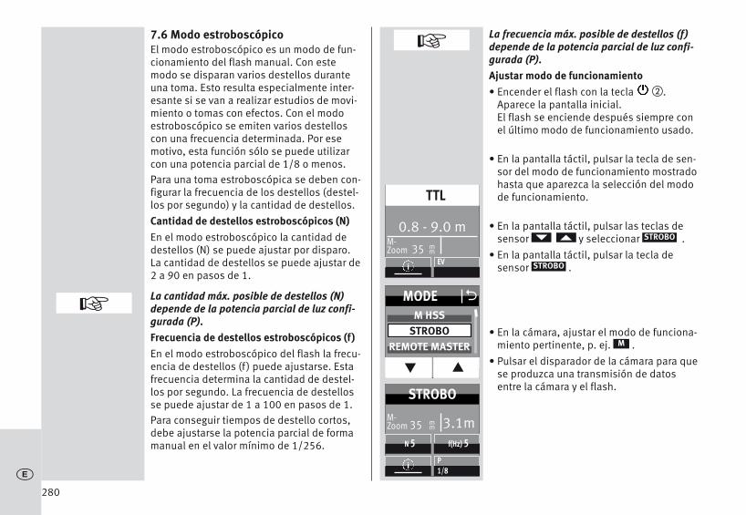
7.6 Modo estroboscópicoEl modo estroboscópico es un modo de fun-cionamiento del flash manual. Con estemodo se disparan varios destellos duranteuna toma. Esto resulta especialmente inter-esante si se van a realizar estudios de movi-miento o tomas con efectos. Con el modoestroboscópico se emiten varios destelloscon una frecuencia determinada. Por esemotivo, esta función sólo se puede utilizarcon una potencia parcial de 1/8 o menos.Para una toma estroboscópica se deben con-figurar la frecuencia de los destellos (destel-los por segundo) y la cantidad de destellos.Cantidad de destellos estroboscópicos (N)En el modo estroboscópico la cantidad dedestellos (N) se puede ajustar por disparo.La cantidad de destellos se puede ajustar de2 a 90 en pasos de 1.
La cantidad máx. posible de destellos (N)depende de la potencia parcial de luz confi-gurada (P).Frecuencia de destellos estroboscópicos (f)En el modo estroboscópico del flash la frecu-encia de destellos (f ) puede ajustarse. Estafrecuencia determina la cantidad de destel-los por segundo. La frecuencia de destellosse puede ajustar de 1 a 100 en pasos de 1. Para conseguir tiempos de destello cortos,debe ajustarse la potencia parcial de formamanual en el valor mínimo de 1/256.
La frecuencia máx. posible de destellos (f)depende de la potencia parcial de luz confi-gurada (P).Ajustar modo de funcionamiento • Encender el flash con la tecla �.
Aparece la pantalla inicial.El flash se enciende después siempre conel último modo de funcionamiento usado.
• En la pantalla táctil, pulsar la tecla de sen-sor del modo de funcionamiento mostradohasta que aparezca la selección del modode funcionamiento.
• En la pantalla táctil, pulsar las teclas desensor y seleccionar .
• En la pantalla táctil, pulsar la tecla de sensor .
• En la cámara, ajustar el modo de funciona-miento pertinente, p. ej. .
• Pulsar el disparador de la cámara para quese produzca una transmisión de datosentre la cámara y el flash.
STROBO
STROBO
M
280c
+
+
0.8 - 9.0 m M-Zoom 35 m
m
TTL
iEV
MODE O
q p
M HSSSTROBO
REMOTE MASTER
3.1mM-Zoom 35 m
m
STROBO
iP1/8
f(Hz) 5N 5

281
Ajustar cantidad de destellos• En la pantalla táctil, pulsar la tecla de sen-
sor para la cantidad de destellos .
• En la pantalla táctil, pulsar las teclas desensor y seleccionar la cantidadde destellos deseada.
La cantidad máx. posible de destellos (N)depende de la potencia parcial de luz confi-gurada (P).• En la pantalla táctil, pulsar la tecla de sen-
sor para la cantidad de destellos deseada,en el ejemplo . El ajuste se aplica de forma inmediata.
4
N
Ajustar frecuencia de destellos (f(Hz)) • En la pantalla táctil, pulsar la tecla de sen-
sor para la frecuencia de destellos .
• En la pantalla táctil, pulsar las teclas desensor y seleccionar la frecuenciade destellos deseada
La frecuencia máx. posible de destellos (f)depende de la potencia parcial de luz confi-gurada (P).• En la pantalla táctil, pulsar la tecla de sen-
sor para la frecuencia de destellos desea-da, en el ejemplo . El ajuste se aplica de forma inmediata.
En la pantalla se muestra la distancia válidapara los parámetros configurados. Al cambiar el valor del diafragma o la poten-cia parcial de luz, se puede adaptar el valorde distancia mostrado en relación con ladistancia al motivo. ¡En el modo de flash estroboscópico no semuestran los valores de diafragma e ISO enla pantalla!
El segundo reflector no es compatible con elmodo estroboscópico.
f (Hz)
8
f (Hz) O
q p
789
3.1mM-Zoom 35 m
m
STROBO
iP1/16
f(Hz) 10N 4
3.1mM-Zoom 35 m
m
STROBO
iP1/8
f(Hz) 8N 4
c
+
+
+
3.1mM-Zoom 35 m
m
STROBO
iP1/16
f(Hz) 10N 5
N O
q p
345

282
8 Corrección manual de la exposición del flash
El sistema automático de flash de la mayoríade las cámaras está diseñado con un gradode reflexión del 25% (grado de reflexiónmedio de los motivos del flash).Un fondo oscuro que absorba mucha luz, oun fondo claro con fuerte reflexión (p. ej.,tomas a contraluz), pueden conducir asobreexposiciones o subexposiciones delmotivo.Para compensar este efecto, la exposicióndel flash se puede adaptar manualmente a latoma mediante un valor de corrección. Lamagnitud de este valor de corrección depen-de del contraste entre el motivo y el fondo dela imagen.En el flash pueden ajustarse manualmenteen los modos A/TTL unos valores de correcci-ón para la exposición del flash de -3 hasta +3valores de diafragma (EV), en tercios de dia-fragma.Sugerencia:Motivo oscuro en fondo de imagen claro:valor de corrección positivo.Motivo claro en fondo de imagen oscuro:valor de corrección negativo.No es posible corregir la exposición modifi-cando el diafragma del objetivo, ya que elsistema automático de flash de la cámaraconsiderará entonces que el diafragma modi-ficado es la apertura normal de diafragma.
Al ajustar un valor de corrección, la indicaci-ón del alcance en la pantalla puede variaradaptándose al valor de corrección (depen-diendo del modelo de cámara).
Configuración• En la pantalla táctil, pulsar la tecla de
sensor hasta que aparezca la selecciónde potencia parcial de luz.
• En la pantalla táctil, pulsar las teclas desensor y ajustar un valor de compensación.
• En la pantalla táctil, seleccionar el valor decompensación seleccionado, p. ej. .
El ajuste se aplica de forma inmediata.Una corrección manual de la exposición delflash en los modos TTL sólo es posible si lacámara cuenta con esta función (consultarmanual de instrucciones de la cámara).
Si la cámara no ofrece esta función, el valorde corrección ajustado no tiene ningún efecto.Con algunos modelos de cámara debe aju-starse el valor de corrección manual de laexposición del flash en la propia cámara. Enla pantalla del flash no aparece el valor decorrección.
Tras la toma, ¡no olvide volver a borrar en lacámara la corrección de la exposición delflash manual!
EV
-1
+c
0.8 - 9.0 m M-Zoom 35 m
m
TTL
iEV
EV O
q p
-1 1/3-1
-2/3
1.1- 12 m M-Zoom 35 m
m
TTL
iEV-1

283
Atención: Los objetos muy reflectantes en laimagen del motivo pueden perturbarel siste-ma de exposición automática de la cámara.En ese caso, la toma quedará subexpuesta.Retire los objetos reflectantes, o bien ajusteun valor de compensación positivo.
9 Funciones especialesSegún el modelo o el grupo de cámara, estándisponibles distintas funciones especiales.Para acceder a las funciones especiales yajustarlas, es preciso, por tanto, que se hayaefectuado previamente una transmisión dedatos entre el flash y la cámara, p. ej. pulsan-do el disparador de la cámara.La configuración tiene que efectuarse inme-diatamente después de acceder a la funciónespecial, pues de lo contrario el flash regresaautomáticamente tras algunos segundos almodo normal de funcionamiento.
9.1 Reflector con zoom motorizado(„Zoom“)
En el flash, el reflector con zoom motorizadoes capaz de iluminar distancias focales deobjetivo a partir de 24 mm (pequeño forma-to). Usando el difusor de gran angular integrado, la iluminación se amplía en12 mm.
Auto-ZoomCuando se emplea el flash con una cámaraque transmite datos de la distancia focal deobjetivo, la posición del zoom del reflector seajusta automáticamente a la distancia focaldel objetivo. Tras conectar el flash, apareceráen la pantalla la indicación “Zoom” y la posi-ción actual de zoom del reflector.El ajuste automático se realiza para distanci-as focales de objetivo a partir de 24 mm.No se efectuará el ajuste automático cuandoesté girado el reflector, cuando esté extraídoel difusor de gran angular o cuando esté-montado un Mecabounce (accesorio).Si se desea, puede ajustarse manualmentela posición del reflector para conseguir deter-minados efectos de iluminación (p. ej. efecto„spot“, etc.).Funcionamiento manual de zoomEn cámaras que no transmiten datos dedistancia focal de objetivo, es necesario aju-star manualmente a dicha distancia la posici-ón de zoom del reflector.
En tal caso, no resulta posible el funciona-miento con auto-zoom!Tras conectar el flash, en la pantalla aparece-rá la indicación „Zoom“ y la posición actualde zoom del reflector.
+
+
c

284
Por ejemplo:Se utiliza un objetivo zoom con una gama dedistancias focales de 35 mm a 105 mm. Eneste ejemplo, se ajusta a 35 mm la posicióndel reflector del flash.Restablecer auto-zoom• Pulsar el disparador de la cámara para que
se produzca la transmisión de datos entreel flash y la cámara.
• Pulsar la tecla � hasta que aparezca elmenú de selección.
• En la pantalla táctil, pulsar la tecla de sensor .
• En la pantalla táctil, pulsar las teclas desensor y seleccionar .
• En la pantalla táctil, pulsar la tecla de sensor .
• En la pantalla táctil, pulsar las teclas desensor y seleccionar .
• En la pantalla táctil, pulsar la tecla de sensor .
Tras unos 10 s se muestra el modo de funcio-namiento, o pulsar la tecla � hasta queaparezca el modo de funcionamiento.
D
PARAMETER
ZOOM
AUTOZOOM
AUTOZOOM
AUTOZOOM
D
Configuración• Pulsar la tecla � hasta que aparezca el
menú de selección.
• En la pantalla táctil, pulsar la tecla de sensor
• En la pantalla táctil, pulsar las teclas desensor y seleccionar .
• En la pantalla táctil, pulsar la tecla de sensor .
• En la pantalla táctil, pulsar las teclas desensor y seleccionar el valor dezoom deseado.
• En la pantalla táctil, pulsar la tecla de sen-sor para ajustar el valor de zoom deseado.El ajuste se aplica de forma inmediata.
Son posibles las siguientes posiciones dezoom para el reflector: 24 - 28 - 35 - 50 - 70 -85 - 105-135-180-200 mm (pequeño forma-to).Sugerencia:Si no siempre son necesarios el máximonúmero guía y alcance del flash, se puededejar la posición del reflector en la distanciafocal inicial del objetivo zoom. Así se garantiza que los márgenes de laimagen estarán siempre totalmente ilumina-dos. De esta manera se evita tener que confi-gurar continuamente la distancia focal delobjetivo.
D
PARAMETER
ZOOM
ZOOM
c
PARAMETER
PARAMETER O
q p
P/EVZOOM
F
ZOOM O
q p
7085
105
PARAMETER
PARAMETER O
q p
P/EVZOOM
F
ZOOM
q p
AUTOZOOM24
O

Difusor de gran angularCon el difusor de gran angular integradose pueden iluminar distancias focales a par-tir de 12 mm (pequeño formato).Extraer y soltar el difusor de gran angular del reflector hacia delante hasta el tope. El difusor de gran angular desciende auto-máticamente. El reflector se coloca automáti-camente en la posición adecuada. En la pantalla aparecen las indicaciones cor-regidas de alcance del flash y valor de zoomajustadas a 12 mm.No se efectuará el ajuste automático del reflec-tor con zoom motorizado cuando se estéempleando el difusor de gran angular .Para plegar el difusor de gran angular ,levantarlo 90º e introducirlo completamente.mecabounce Diffuser MBM-03Cuando el mecabounce (accesorio especial;consultar 19) se halla montado en el reflectordel flash, el reflector se coloca automática-mente en la posición adecuada. Las indica-ciones de alcance del flash y valor de zoomson corregidas ajustándolas a 16 mm.
No se efectuará el ajuste automático delreflector con zoom motorizado cuando seesté empleando un mecabounce.No es posible emplear a la vez el difusor degran angular y el mecabounce.
10 El funcionamiento RemotoEl flash soporta el sistema inalámbrico SonyRemote en los modos de funcionamiento"CTRL" y "CTRL+" según el sistema de cámarausado. Los modos de funcionamiento "CTRL"y "CTRL+" se detectan automáticamente.El sistema remoto se compone de un flashmaestro situado en la cámara y de uno o másflashes esclavos. Los flashes esclavos secontrolan de forma remota y sin cablesmediante el reflector del flash maestro.Con el fin de que no interfieran recípro-camente en una misma estancia varios sistemas remotos, hay disponibles cuatrocanales remotos independientes. Es necesario sintonizar en el mismo canalremoto los flashes remotos y esclavos quepertenezcan al mismo sistema remoto. Es preciso que los flashes esclavos puedanrecibir mediante el sensor integrado para elfuncionamiento remoto la luz del flash maestro. El modo de flash remoto admite también lasincronización a la 2ª cortinilla. En el funcionamiento remoto no se produceninguna indicación de alcance en la pantalladel flash
285
+
c

10.1 Funcionamiento maestro remotoLos grupos esclavos RMT y RMT2 vienen acti-vados de fábrica. El flash maestro (CTRL) y los grupos esclavosRMT y RMT2 se pueden activar o desactivar! Con el flash maestro (CTRL) desactivado, laluz del flash maestro desempeña sólo la fun-ción de control y no contribuye a la exposici-ón de la toma.10.1.1 Ajustar modo maestro remoto• Encender el flash con la tecla �
Aparece la pantalla inicial.• En la pantalla táctil, pulsar la tecla de sen-
sor del modo de funcionamiento mostradohasta que aparezca la selección del modode funcionamiento.
• En la pantalla táctil, pulsar las teclas desensor y seleccionar
.• En la pantalla táctil, pulsar la tecla de
sensor . Se ajusta el modo maestro remoto.
En la imagen aparece el modo maestro remo-to CTRL+. El maestro (CTRL) contribuye a lailuminación con las mismas condicioneslumínicas que los grupos de flash esclavos(RMT).Se puede asignar condiciones lumínicas almaestro (CTRL) y al grupo de flash esclavoRMT o al grupo de flash esclavo RMT2 (con-sultar 10.1.4).
REMOTE MASTER
REMOTE MASTER
Cambiar de CTRL a CTRL+• Pulse la tecla � hasta que aparezca el
menú de selección.
• En la pantalla táctil, pulse la tecla de sen-sor .
• En la pantalla táctil, pulse las teclas desensor y seleccione .
• En la pantalla táctil, pulse la tecla de sen-sor .
• En la pantalla táctil, pulse la tecla de sen-sor del modo de funcionamiento o
deseado.
El ajuste se aplica de forma inmediata.
El control de las condiciones lumínicas(Ratio) sólo es posible en el funcionamientoCTRL+.
D
PARAMETER
CONTROL
CONTROL
CTRLCTRL+
286c
0.6- 7.2 m M-Zoom 35 m
m
TTL
iEV
MODE O
q p
STROBOREMOTE MASTER
REMOTE SLAVE
CTRL RMT4 8
REMOTECTRL
TTL
i RATIO
CTRL RMT RMT24 8 1
REMOTECTRL+
TTL
i RATIO
PARAMETER
PARAMETER O
q p
RATIOCONTROL
CTRL/CTRL+ OCTRL
CTRL+
+

10.1.2 Ajustar modo en flash maestro• En la pantalla táctil, pulse la tecla de sen-
sor para los modos de funcionamientohasta que aparezca la selección para elmodo de funcionamiento.
• En la pantalla táctil, pulsar las teclas desensor y seleccionar el modo deflash..
• En la pantalla táctil, pulsar la tecla de sensor para el modo de funcionamientodeseado o .
El modo de funcionamiento ajustado seadopta de forma inmediata.
MTTL
10.1.3 Ajustar potencia parcial de luz en elmodo M del flash maestro
Ajustar el modo de funcionamiento a des-crito en 10.1.2.
• En la pantalla táctil, pulsar la tecla de sen-sor hasta que aparezca la selecciónmaestro.
• En la pantalla táctil, pulse la tecla de sen-sor para la potencia parcial de luz .
• En la pantalla táctil, pulsar las teclas desensor y ajustar la potencia par-cial de luz deseada.
• En la pantalla táctil, pulsar la tecla de sen-sor de la potencia parcial de luzdeseada.
El ajuste se adopta automáticamente.
M
M
P
1/8
287
c
CTRL RMT RMT24 8 1
REMOTECTRL+
M1/1
i RATIO
CTRL RMT RMT24 8 1
REMOTECTRL+
M1/1
i RATIO
CTRL RMT RMT24 8 1
REMOTECTRL+
M1/8
i RATIO
CTRL RMT RMT24 8 1
REMOTECTRL+
TTL
i RATIO
MASTER O
q p
TTLMEV
P O
q p
1/4 - 2/31/8
1/8 - 1/3
MASTER OTTL
M
P

10.1.4 Definir condiciones lumínicas (RATIO)para los grupos de flash del flashmaestro
Las condiciones lumínicas del sistema remo-to se pueden ajustar para lograr efectos deluz concretos. Las condiciones lumínicaspara el maestro (CTRL) y los grupos (RMT,RMT2) se controlan exclusivamente con elflash maestro.Ratio activar / desactivar• Pulse la tecla � hasta que aparezca el
menú de selección.
• En la pantalla táctil, pulse la tecla de sensor .
• En la pantalla táctil, pulse las teclas desensor y seleccione .
• En la pantalla táctil, pulse la tecla de sensor .
• En la pantalla táctil, pulsar la tecla de sen-sor o y encender o apagar lafunción RATIO.
D
PARAMETER
RATIO
RATIO
OFFON
Definir condiciones lumínicas (RATIO)• En la pantalla táctil, pulse la tecla de
sensor .
• En la pantalla táctil, pulse la tecla de sensor para la cual debe ajustarse unascondiciones lumínicas; en el ejemplo esRMT2.
• En la pantalla táctil, pulse las teclas desensor , ajuste las condicioneslumínicas deseadas o desactive la aporta-ción de luz (--).
• En la pantalla táctil, pulse la tecla de sen-sor para ajustar el valor de compensacióndeseado.
El ajuste se adopta de forma inmediata.
RATIO
288c
CTRL RMT RMT24 8 1
REMOTECTRL+
M1/8
i RATIO
PARAMETER
PARAMETER O
q p
CHANNELRATIO
CONTROL
RTM2 O
q p
48
16
RATIO OOFF
ON
8
1
4
ORATIO
CTRL
RMT
RMT2
CTRL RMT RMT24 8 8
REMOTECTRL+
M1/8
i RATIO

10.1.5 Ajustar canal remotoCon el fin de que no interfieran recíproca-mente en una misma estancia varios sistemas remotos, hay disponibles cuatrocanales remotos independientes. Es necesario sintonizar en el mismo canalremoto los flashes remotos y esclavos quepertenezcan al mismo sistema remoto.• Pulsar la tecla � hasta que aparezca el
menú de selección.
• En la pantalla táctil, pulsar la tecla de sensor .
• En la pantalla táctil, pulsar la tecla de sensor .
• En la pantalla táctil, pulsar las teclas desensor y seleccionar un canalremoto, p. ej. .
• En la pantalla táctil, pulsar la tecla de sensor para el canal deseado.
El ajuste se adopta automáticamente.Pulse � y comprobar la configuracióndel canal .
D
PARA
CHANNEL
CHANNEL 2
i
10.2 Modo remoto esclavoEl flash es compatible con el sistema remotoinalámbrico en modo de flash esclavo, e igu-almente con el sistema Sony. Esto permite controlar a distancia de modo
inalámbrico uno o varios flashes esclavos desde el flash maestro de la cámara(p. ej. mecablitz 64AF-1S digital).Un flash esclavo puede pertenecer a cual-quiera de los dos grupos esclavos (RMT,RMT2). El flash maestro puede controlar almismo tiempo todos estos grupos esclavos,siempre manteniendo los ajustes individua-les aplicados a cada uno de los grupos esclavos por separado.Para que los varios sistemas remotos quepueda haber en la misma habitación no sesolapen, existen cuatro canales remotosindependientes (CH 1, 2, 3 y 4).Los flashes maestro y esclavos del mismosistema remoto deben ajustarse en el mismocanal remoto. Los flashes esclavos deben recibir la luz delflash maestro mediante el fotosensor inte-grado para funcionamiento remoto .Dependiendo del modelo de cámara, el flashinterno de la cámara también puede trabajarcomo flash maestro.
289
c
PARAMETER O
q p
ZOOMCHANNEL
RATIO
CHANNEL O
q p
CHANNEL 1CHANNEL 2CHANNEL 3
PARAMETER

10.2.1 Ajustar modo de flash esclavo remoto• Encender el flash con la tecla �.
Aparece la pantalla inicial.El flash se enciende después siempre conel último modo de funcionamiento usado(p. ej. el modo de flash TTL).
• En la pantalla táctil, pulsar el modo de funcionamiento mostrado hasta que aparezca la selección del modo de funcionamiento.
• En la pantalla táctil, pulsar las teclas desensor y seleccionar
.• En la pantalla táctil, pulsar la tecla de
sensor .
Se ajusta el funcionamiento esclavo remoto.Además aparecerán indicados el grupo esclavo (p. ej. RMT) y el canal remoto (p. ej. CH 1) seleccionados.
REMOTE SLAVE
REMOTE SLAVE
10.2.2 Ajustar canal esclavo• En la pantalla táctil, pulsar la tecla de sen-
sor para el grupo de canales (p. ej). Aparecerá la visualización del canal y elgrupo.
• En la pantalla táctil, pulsar las teclas desensor para el canal .
• En la pantalla táctil, pulsar las teclas desensor y seleccionar el canaldeseado.
• En la pantalla táctil, pulsar el canal seleccionado.
El ajuste se aplica de forma inmediata.En la pantalla se muestra "CH2".
RMT I CH1
CHANNEL
290c
0.8- 9.0 m M-Zoom 35 m
m
TTL
iEV
MODE O
q p
REMOTE MASTERREMOTE SLAVE
SERVO
M-Zoom 24
REMOTE
SLAVERMT Ch
2 1
i
mm
P1/1
M-Zoom 24
REMOTE
SLAVERMT Ch
2 2
i
mm
P1/1
M-Zoom 24
REMOTE
SLAVERMT Ch
2 1
i
mm
SLAVE OCHANNEL
GROUP
CHANNEL O
q p
CHANNEL 1CHANNEL 2CHANNEL 3
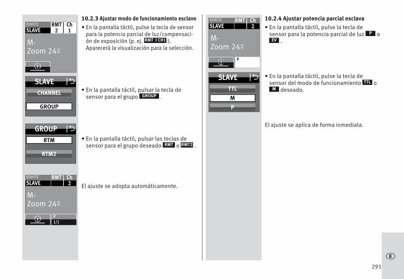
10.2.3 Ajustar modo de funcionamiento esclavo• En la pantalla táctil, pulse la tecla de sensor
para la potencia parcial de luz/compensaci-ón de exposición (p. ej. ).Aparecerá la visualización para la selección.
• En la pantalla táctil, pulsar la tecla de sensor para el grupo .
• En la pantalla táctil, pulsar las teclas desensor para el grupo deseado o .
El ajuste se adopta automáticamente.
RMT I CH1
GROUP
RMT2RMT
10.2.4 Ajustar potencia parcial esclava• En la pantalla táctil, pulse la tecla de
sensor para la potencia parcial de luz o.
• En la pantalla táctil, pulse la tecla de sensor del modo de funcionamiento o
deseado.
El ajuste se aplica de forma inmediata.
PEV
MTTL
291
c
M-Zoom 24
REMOTE
SLAVERMT Ch
2
i
mm
P
M-Zoom 24
REMOTE
SLAVERMT Ch
2
i
mm
P1/1
M-Zoom 24
REMOTE
SLAVERMT Ch
2 1
i
mm
SLAVE OCHANNEL
GROUP
GROUP O
RTM2
SLAVE OTTL
M
P
RTM

10.2.5 Ajustar potencia parcial/compensaci-ón de exposición esclava
• En la pantalla táctil, pulse la tecla de sen-sor para la potencia parcial de luz/compen-sación de exposición (p. ej. / ) .Aparecerá la visualización para la selecci-ón.
• En la pantalla táctil, pulse la tecla de sen-sor del modo de funcionamiento o deseado.
• En la pantalla táctil, pulsar las teclas dey ajustar la potencia parcial de
luz 1/1, 1/2, 1/8 o 1/256.
Se adopta la potencia parcial de luz.Cuando los flashes esclavos estén listos paradisparar, parpadeará el destello de mediciónAF.
EV1/1
EVP
10.3 Comprobación del modo remoto• Colocar los flashes esclavos para la toma.
Para colocar el flash esclavo, emplear unpie de apoyo S60 para flashes.
• Esperar a que se encienda la indicación dedisponibilidad de todos los flashes.Cuando los flashes esclavos están listospara disparar, parpadea la indicación dedisponibilidad y, además, el luz auxiliar AF�.
• Pulsar el disparador � en el flash maestroy hacer una prueba de iluminación. Los flashes esclavos van respondiendo unodetrás de otro con cierto retraso según sugrupo con un disparo de prueba. Si un flashesclavo no emite ningún disparo de prue-ba, comprobar la configuración del canalremoto y el grupo esclavo. Corrija la posici-ón del flash esclavo, de modo que puedarecibir la luz del flash maestro .
El modo de funcionamiento de flash es trans-mitido automáticamente desde el maestro.¡Cuando en el flash maestro está ajustada lafunción de luz de modelado (ML), al disparar-se la luz de modelado se dispara al mismotiempo la de los flashes esclavos!
292c
M-Zoom 24
REMOTE
SLAVERMT Ch
2 2
i
mm
P1/1
SLAVE OTTL
M
EV / P
P O
q p
1/4 - 2/31/8
1/8 - 1/3

10.4 Modo SERVOEl modo SERVO es un modo esclavo simplesin o con anulación de predestello en el queel flash esclavo emite siempre un disparo tanpronto como recibe un impulso lumínico delflash de la cámara.En general, en el modo SERVO sólo es posible el modo de flash manual. El modo deflash manual se ajusta automáticamente unavez puesto en funcionamiento el modo SERVO.10.4.1 Ajustar modo de funcionamiento SERVO• En la pantalla táctil, pulsar la tecla de
sensor para el modo de funcionamientomostrado hasta que aparezca la seleccióndel modo de funcionamiento.
• En la pantalla táctil, pulsar las teclas desensor y seleccionar el modo defuncionamiento .
• En la pantalla táctil, pulsar la tecla de sensor .
Se adopta el modo de funcionamiento.Si se desea, es posible configurar la poten-cial parcial de luz (consultar 10.4.3).
SERVO
SERVO
10.4.2 Ajustar anulación de predestello ysincronización
• En la pantalla táctil, pulsar la tecla de sensor hasta que aparezca la selecci-ón del tipo de sincronización.
• En la pantalla táctil, pulsar la tecla de sensor:
Sincronización sin predestelloSincronización con predestello
Se adopta el sincronización de funciona-miento.
Si la sincronización configurada aquí no fun-ciona bien, proceda entonces como se des-cribe en 10.4.4.
SYNC
293
c
0.8- 9.0 m M-Zoom 35 m
m
TTL
iEV
MODE O
q p
REMOTE SLAVESERVO
M-Zoom 24
M-Servo SYNC
iP1/1
mm
SYNC O
LEARN
M-Zoom 24
M-Servo SYNC
iP1/1
mm
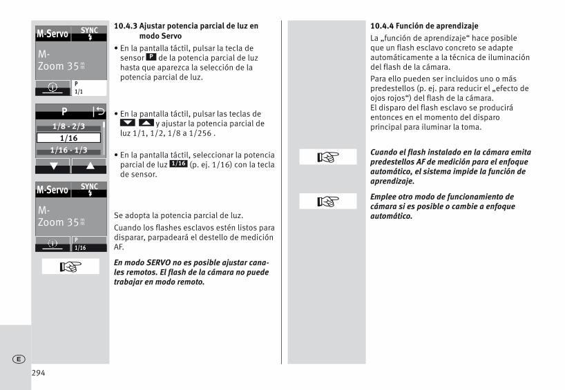
10.4.3 Ajustar potencia parcial de luz enmodo Servo
• En la pantalla táctil, pulsar la tecla de sensor de la potencia parcial de luzhasta que aparezca la selección de lapotencia parcial de luz.
• En la pantalla táctil, pulsar las teclas dey ajustar la potencia parcial de
luz 1/1, 1/2, 1/8 a 1/256 .
• En la pantalla táctil, seleccionar la potenciaparcial de luz (p. ej. 1/16) con la teclade sensor.
Se adopta la potencia parcial de luz.Cuando los flashes esclavos estén listos paradisparar, parpadeará el destello de mediciónAF.
En modo SERVO no es posible ajustar cana-les remotos. El flash de la cámara no puedetrabajar en modo remoto.
P
1/16
10.4.4 Función de aprendizajeLa „función de aprendizaje“ hace posibleque un flash esclavo concreto se adapteautomáticamente a la técnica de iluminacióndel flash de la cámara. Para ello pueden ser incluidos uno o máspredestellos (p. ej. para reducir el „efecto deojos rojos“) del flash de la cámara. El disparo del flash esclavo se produciráentonces en el momento del disparo principal para iluminar la toma.
Cuando el flash instalado en la cámara emitapredestellos AF de medición para el enfoqueautomático, el sistema impide la función deaprendizaje.
Emplee otro modo de funcionamiento decámara si es posible o cambie a enfoqueautomático.
294c
+
+
M-Zoom 35
M-Servo SYNC
iP1/1
mm
M-Zoom 35
M-Servo SYNC
iP1/16
mm
P O
q p
1/8 - 2/31/16
1/16 - 1/3
+

Proceso de ajuste para la función de aprendizaje
La función de predestello AF de la cámaradebe estar apagada.• En la pantalla táctil, pulsar la tecla de
sensor e hasta que aparezca la selección.
• En la pantalla táctil, pulsar la tecla de sensor .
• El "Learning Mode" (modo de aprendizaje)está listo para aprender.
• Pulsar el disparador en la cámara para provocar un disparo del flash de la cámara.
Cuando el flash SERVO haya recibido unimpulso lumínico, aparecerá en la pantalla"LEARN OK" como confirmación.
Ahora el mecablitz3digital ha aprendido qué luz usa el flash de la cámara.
SYNC
Learn
10.4.5 Desactivar modo de flash SERVO
• En la pantalla táctil, pulsar el modo de fun-cionamiento mostrado hasta que aparezcala selección del modo de funcionamiento.
• En la pantalla táctil, pulsar las teclas desensor y seleccionar el modo defuncionamiento deseado, p. ej .
• En la pantalla táctil, pulsar la tecla de sensor para el modo de funcionamiento,p. ej .
Se adopta el modo de funcionamiento seleccionado.
TTL
TTL
295
c
M-Zoom 24
M-Servo SYNC
iP1/16
mm
SYNC O
LEARN
M-Zoom 24
M-Servo SYNC
iP1/16
mm
MODE O
q p
TTLA
0.6- 7.5 m M-Zoom 24 m
m
TTL
iEV

11 OPTION-Menu
11.1 Modo RAPIDEn los modos de funcionamiento de flash A yTTL, los intervalos entre destellos dependende la cantidad de luz necesaria para la toma.Si el intervalo entre destellos tarda demasia-do, se puede activar la función RAPID en elmodo de flash A y TTL. La función RAPID serecomienda sobre todo cuando se dependamás de los intervalos rápidos entre destellosy menos de la potencia del flash máxima, p.ej. en salas relativamente pequeñas. Sinembargo, el número guía se reducirá 1 nivel,p. ej. del número guía 36 (con ISO 100-Zoom 35) al número guía 25 (con ISO 100-Zoom 35).Configuración• Pulsar la tecla � hasta que aparezca el
menú de selección.
• En la pantalla táctil, pulsar la tecla de sensor .
• En la pantalla táctil, pulsar las teclas desensor y seleccionar .
• En la pantalla táctil, pulsar la tecla de sensor .
• En la pantalla táctil, pulsar la tecla de sen-sor o y encender o apagar lafunción RAPID. El ajuste se adopta de forma inmediata.
Una vez activada la función RAPID, en la pan-talla aparecerá la indicación „ ” .
D
OPTION
RAPID
RAPID
OFFON
11.2 Reflector adicional (SUB-REFL.)El reflector adicional sirve para iluminar fron-talmente con destellos indirectos cuando elreflector principal está abatido hacia arriba ohacia un lado. Si la cantidad de luz del reflec-tor adicional es demasiado grande, se puedereducir a la mitad.Configuración• Pulsar la tecla � hasta que aparezca el
menú de selección.
• En la pantalla táctil, pulsar la tecla de sensor .
• En la pantalla táctil, pulsar las teclas desensor y seleccionar .
• En la pantalla táctil, pulsar la tecla de sensor .
• En la pantalla táctil, pulsar la tecla de sen-sor , o y encender o apa-gar el reflector adicional. El ajuste se adop-ta de forma inmediata.
Tras activar el reflector adicional apareceráen la pantalla.
En el menú INFO aparece „ 1/1” o. „ 1/2”.
1/1 es para plena potencia lumínica y 1/2para la mitad de la potencia lumínica.
D
OPTION
SUB-REFL.
SUB-REFL.
OFF1/21/1
296c
OPTION
SUB-REFL. OOFF1/11/2
OPTION O
q p
RAPIDSUB-REFL.ZOOM SIZE
OPTION O
q p
RAPIDSUB-REFL.
OPTION
RAPID OOFF
ON

11.3 Luz de modelado (MOD. LIGHT)La luz de modelado (ML = Modelling Light) esuna secuencia de destellos estroboscópicosa alta frecuencia. Con una duración de aprox.3 segundos, produce la impresión de una ilu-minación casi continua. Con la luz de mode-lado se puede evaluar la distribución de luz yla formación de sombras incluso antes de latoma. La luz de modelado se dispara mediante latecla de disparo manual.Configuración• Pulsar la tecla � hasta que aparezca el
menú de selección.• En la pantalla táctil, pulsar la tecla de
sensor .
• En la pantalla táctil, pulsar las teclas desensor y seleccionar .
• En la pantalla táctil, pulsar la tecla de sensor .
• En la pantalla táctil, pulsar la tecla de sen-sor o y encender o apagar la luzde modelado. El ajuste se adopta de formainmediata.
Tras la activación de la luz de modelado, semuestra en el menú INFO „ ”.
D
OPTION
MOD. LIGHT
MOD. LIGHT
OFFON
11.4 Modo Zoom (ZOOM MODE)11.4.1 Modo de zoom extendidoCon el modo Extended-Zoom se reduce unnivel la posición de zoom del reflector conrespecto a la distancia focal del objetivo dela cámara. La iluminación de superficiesgrandes resultante sirve para lograr una luzdifusa adicional (reflexiones) en recintos cer-rados y, con ello, una iluminación más suavecon la luz del flash.Por ejemplo:La distancia focal del objetivo en la cámaraes de 50 mm. En el modo de zoom extendi-do, el flash controla el reflector ajustándolo ala posición de zoom 35 mm. En la pantallasigue apareciendo 50 mm.Configuración• Pulsar la tecla � hasta que aparezca el
menú de selección.
• En la pantalla táctil, pulsar la tecla de sensor .
• En la pantalla táctil, pulsar las teclas desensor y seleccionar .
• En la pantalla táctil, pulsar la tecla de sensor .
• En la pantalla táctil, pulsar la tecla de sensor . El ajuste se adopta de forma inmediata.
Después de activar el funcionamiento de zoomextendido, en el menú INFO aparece "EXT".
D
OPTION
ZOOM MODE
ZOOM MODE
EXTENDED
297
c
MOD. LIGHT OOFF
ON
OPTION O
q p
OPTION
OPTION
q p
MOD. LIGHTBEEP
RAPIDSUB-REFL.
STANDBY
OPTION
ZOOMMODE OExtendedStandard
Spot
OPTION O
q p
ZOOM SIZEZOOM MODE
STANDBY

Según el sistema, el funcionamiento de zoomextendido se puede utilizar con distanciasfocales de objetivo a partir de 28 mm (forma-to pequeño). La cámara debe tener un objetivo CPU y transmitir al flash los datos dedistancia focal del objetivo.11.4.2 Modo de zoom SPOTCon el modo de zoom Spot se amplía un nivella posición de zoom del reflector con respecto a la distancia focal del objetivo dela cámara. La menor iluminación resultantesirve para lograr una iluminación con realcecentral y una iluminación periférica sombreada.Por ejemplo:La distancia focal del objetivo en la cámaraes de 50 mm. En el funcionamiento de zoomSpot, el flash controla el reflector ajustán-dolo a la posición de zoom 70 mm. En la pantalla sigue apareciendo 50 mm.
Configuración• Pulsar la tecla � hasta que aparezca el
menú de selección.
• En la pantalla táctil, pulsar la tecla de sensor .
• En la pantalla táctil, pulsar las teclas desensor y seleccionar .
• En la pantalla táctil, pulsar la tecla de sensor .
• En la pantalla táctil, pulsar la tecla de sensor . El ajuste se adopta de forma inmediata.
Después de activar el modo de zoom Spot,en el menú INFO aparece "SP". Según el sistema, el modo de zoom Spot sepuede utilizar con distancias focales de obje-tivo a partir de 24 - 180 mm (formato peque-ño).La cámara debe disponer de un objetivo CPUy transmitir al flash los datos de la distanciafocal del objetivo.
D
OPTION
ZOOM MODE
ZOOM MODE
SPOT
298c
ZOOMMODE OEXTENDEDSTANDARD
SPOT
OPTION
OPTION O
q p
ZOOM SIZEZOOM MODE
STANDBY

11.4.3 Modo de zoom STANDARDEn el modo de zoom estándar, se ajusta laposición del zoom del reflector a la distanciafocal del objetivo de la cámara.
Configuración• Pulsar la tecla � hasta que aparezca el
menú de selección.
• En la pantalla táctil, pulsar la tecla de sensor .
• En la pantalla táctil, pulsar las teclas desensor y seleccionar .
• En la pantalla táctil, pulsar la tecla de sensor .
• En la pantalla táctil, pulsar la tecla de sensor . El ajuste se adopta de forma inmediata.
D
OPTION
ZOOM MODE
ZOOM MODE
STANDARD
11.5 Adaptación del formato de toma(ZOOM SIZE)
En algunos modelos de cámaras digitales, laindicación relativa a la posición del reflectorpuede ser adaptada al formato de chip(dimensiones del bloque básico de toma deimagen) utilizando la función grado de zoom.Configuración• Pulsar la tecla � hasta que aparezca el
menú de selección.
• En la pantalla táctil, pulsar la tecla de sensor .
• En la pantalla táctil, pulsar las teclas desensor y seleccionar .
• En la pantalla táctil, pulsar la tecla de sensor .
• En la pantalla táctil, pulsar la tecla de sensor . El ajuste se adopta de formainmediata.
Después de activar la función Zoom Size, enel menú INFO aparece „ ”.Después de desactivar la función Zoom Sizedesaparece la indicación en el menú INFO„ ”.La función grado de zoom no puede configurarse en cámaras que no permitan laadaptación del formato de toma.
D
OPTION
ZOOM SIZE
ZOOM SIZE
ON
299
c
OPTION
OPTION O
q p
SUB-REFL.ZOOM SIZE
ZOOM MODE
ZOOM SIZE OOFF
ON
OPTION
OPTION O
q p
ZOOM SIZEZOOM MODE
STANDBY
ZOOMMODE OEXTENDEDSTANDARD
SPOT

11.6 Luz auxiliar AF (AF-BEAM)Cuando el sistema de medición AF de unacámara réflex AF digital no puede enfocar connitidez debido a una luminosidad ambienteinsuficiente, la cámara activa la luz auxiliarAF integrada � en el flash. Esta proyecta undibujo de franjas sobre el motivo para que lacámara pueda enfocar.Con la función "AF-BEAM", la luz auxiliar AFse puede encender o apagar.El alcance es de aprox. 6 m - 9 m (con objeti-vo estándar 1,7/50 mm). Debido al paralajeentre el objetivo y la luz auxiliar AF del flash,el límite de medición con la luz auxiliar AF esde aprox. 0,7 m a 1 m.Para que la cámara pueda activar la luz auxi-liar AF, debe ajustarse el modo de funciona-miento de enfoque automático "Single-AF (S-AF)" en la cámara y el flash debe mostrarla indicación de disponibilidad.Algunos modelos de cámara son compatiblesúnicamente con la luz auxiliar AF interna dela cámara. La luz auxiliar AF del flash no seactiva en ese caso (p. ej. en cámaras com-pactas; consultar manual de instrucciones dela cámara).Los objetivos zoom con reducida aperturainicial del diafragma limitan bastante la luzauxiliar AF.
Configuración• Pulsar la tecla � hasta que aparezca el
menú de selección.
• En la pantalla táctil, pulsar la tecla de sensor .
• En la pantalla táctil, pulsar las teclas desensor y seleccionar .
• En la pantalla táctil, pulsar la tecla de sensor .
• En la pantalla táctil, pulsar la tecla de sensor o .
El ajuste se adopta de forma inmediata.
D
OPTION
AF BEAM
AF BEAM
OffOn
300c
OPTION
OPTION O
q p
POWERPACKAF BEAM
AF BEAM OOFF
ON

11.7 Indicaciones de alcance en m o ftLa indicación de alcance en la pantalla puedeefectuarse o bien en metros (m) o en pies (ft).Configuración• Pulsar la tecla � hasta que aparezca el
menú de selección.
• En la pantalla táctil, pulsar la tecla de sensor .
• En la pantalla táctil, pulsar las teclas desensor y seleccionar .
• En la pantalla táctil, pulsar la tecla de sensor .
• En la pantalla táctil, pulsar la tecla de sensor o .
El ajuste se adopta de forma inmediata.
D
OPTION
m/ft
m/ft
ftm
11.8 Horquillado de flash(FLASH BRACK.)
En el modo TTL y automático se puede reali-zar un horquillado de flash (Flash Bracketing,FB). Esto consiste en una exposición en seriede tres tomas seguidas con flash a diferentesvalores de corrección del flash.Cuando se ajusta un horquillado de flash, enla pantalla aparece FB y el valor de la correc-ción. Los valores de corrección pueden ir de1/3 hasta 3 diafragmas en pasos de 1/3 dediafragma.Configuración• Pulsar la tecla � hasta que aparezca el
menú de selección.
• En la pantalla táctil, pulsar la tecla de sensor .
• En la pantalla táctil, pulsar las teclas desensor y seleccionar.
• En la pantalla táctil, pulsar la tecla de sensor .
• En la pantalla táctil, pulsar las teclas desensor y seleccionar un valor decompensación.
• En la pantalla táctil, pulsar la tecla de sen-sor para el valor de compensación seleccio-nado, p. ej. .
D
OPTION
FLASH BRACK.
FLASH BRACK.
1
301
c
OPTION
m/ft Om
ft
OPTION O
q p
BEEPm/ft
POWERPACK
OPTION
FLASH BRACK. O
q p
2/31
1 1/3
OPTION O
q p
AF BEAMFLASH BRACK.

El ajuste se adopta de forma inmediata.• La primera toma se realiza sin valor de cor-
rección. En la pantalla aparece „FBI“.• La segunda toma se realiza con la correcci-
ón negativa. En la pantalla aparece „FBII“ yel valor de corrección negativo (EV).
• La tercera toma se realiza con la correcciónpositiva. En la pantalla aparece „FBIII“ y elvalor de corrección positivo (EV).
• Tras la tercera toma, se borra el horquilladodel flash automáticamente. La indicación„FB“ desaparece de la pantalla.
Al ajustar el horquillado, el valor de correcci-ón que aparece siempre espositivo.Horquillado en el modo TTLUn horquillado del flash en el modo TTL sóloes posible cuando la cámara permite ajustaruna corrección manual de la exposición delflash (consultar manual de instrucciones dela cámara). De lo contrario, las tomas serealizan sin valor de corrección.Horquillado del flash en el modo automáticoAPara realizar un horquillado del flash en elmodo automático A el modelo de la cámaracarece de importancia.
11.9 Función Beep (BEEP)Gracias a la función Beep el usuario recibeuna señal acústica con determinadasfunciones del flash. De esta manera, el fotó-grafo puede concentrarse totalmente en elmotivo y la toma sin necesidad de comprobarlas indicaciones de estado visualmente.La función de bip señala con un sonido queel flash está operativo o que hay un fallo defuncionamiento.Configuración• Pulsar la tecla � hasta que aparezca el
menú de selección.
• En la pantalla táctil, pulsar la tecla de sensor .
• En la pantalla táctil, pulsar las teclas desensor y seleccionar .
• En la pantalla táctil, pulsar la tecla de sensor .
• En la pantalla táctil, pulsar la tecla de sensor . El ajuste se adopta de forma inmediata.
Después de activar la función BEEP, en elmenú INFO aparece „ ”.
D
OPTION
BEEP
BEEP
On
302c
OPTION
BEEP OOFF
ON
OPTION O
q p
MOD. LIGHTBEEPm/ft

Aviso acústico al encender el flash:• Al encender el flash, un breve pitido conti-
nuado (aprox. 2 seg.) indica que el flashestá preparado.
Set Pitido al ajustar el modo de flash auto-mático:• Se oye un breve pitido de aviso cuando,
estando seleccionado el modo de funciona-miento automático, se ajusta la apertura yla sensibilidad más allá del margen deregulación de luz. La apertura automáticacambia automáticamente al siguiente valorpermitido.
11.10 Bloqueo/DesbloqueoLa configuración del flash se puede bloquearpara evitar cambios por descuido. Para bloquear y desbloquear la configura-ción, mantener pulsada la tecla � unos 3 segundos.En la pantalla se muestran todas las teclasde sensor en color blanco y éstas ya no sepueden usar más.Sólo se puede pulsar la tecla de sensor INFO.
11.11 Conectar el Powerpack (accesorio)En la toma � del flash se puede conectar unPowerpack (accesorio). Para conectar el Powerpack necesita un cablede conexión (accesorio especial). El Powerpack prolonga la autonomía delflash y reduce el intervalo entre destellos.
D
303
c
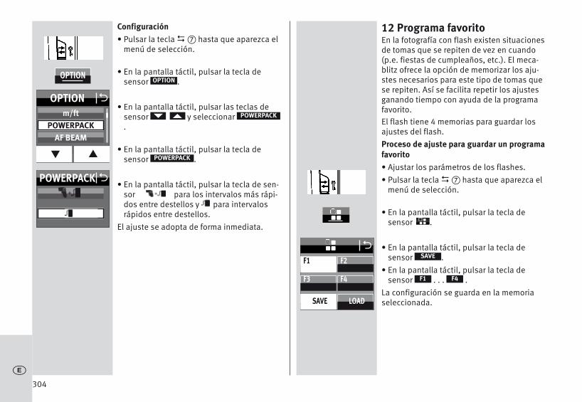
Configuración• Pulsar la tecla � hasta que aparezca el
menú de selección.
• En la pantalla táctil, pulsar la tecla de sensor .
• En la pantalla táctil, pulsar las teclas desensor y seleccionar.
• En la pantalla táctil, pulsar la tecla de sensor .
• En la pantalla táctil, pulsar la tecla de sen-sor para los intervalos más rápi-dos entre destellos y para intervalosrápidos entre destellos.
El ajuste se adopta de forma inmediata.
D
OPTION
POWERPACK
POWERPACK
12 Programa favoritoEn la fotografía con flash existen situacionesde tomas que se repiten de vez en cuando(p.e. fiestas de cumpleaños, etc.). El meca-blitz ofrece la opción de memorizar los aju-stes necesarios para este tipo de tomas quese repiten. Así se facilita repetir los ajustesganando tiempo con ayuda de la programafavorito.El flash tiene 4 memorias para guardar losajustes del flash.Proceso de ajuste para guardar un programafavorito• Ajustar los parámetros de los flashes.• Pulsar la tecla � hasta que aparezca el
menú de selección.
• En la pantalla táctil, pulsar la tecla de sensor .
• En la pantalla táctil, pulsar la tecla de sensor .
• En la pantalla táctil, pulsar la tecla de sensor . . . .
La configuración se guarda en la memoriaseleccionada.
D
SAVE
F4F1
304c
F1
F3 F4
SAVE LOAD
F2
O
OPTION
POWERPACK O
OPTION O
q p
m/ftPOWERPACK
AF BEAM

Proceso de ajuste para cargar un programafavorito• Pulsar la tecla � hasta que aparezca el
menú de selección.
• En la pantalla táctil, pulsar la tecla de sensor .
• En la pantalla táctil, pulsar la tecla de sensor .
• En la pantalla táctil, pulsar la tecla de sensor . . . .La configuración se carga desde la memo-ria seleccionada.
D
LOAD
F4F1
305
c
F1 GNEV 2/3
F3 F4
SAVE LOAD
F2
O

306
13 Técnicas de destello
13.1 Destellos indirectosMediante los destellos indirectos, el motivorecibe una iluminación más suave y se ate-núa la formación pronunciada de sombras.Asimismo, se reduce la diferencia de ilumi-nación, debida a causas físicas, entre el pri-mer plano y el fondo.Para lograr destellos indirectos, el reflectordel flash se puede orientar en horizontal yvertical. Girar reflector• Pulsar el botón de desbloqueo , separar
el reflector del bloqueo y, al mismo tiempo,girar hasta la posición deseada.
El reflector sólo se bloquea en la posiciónnormal.A fin de evitar los tonos de color en lastomas, la superficie de reflexión debe ser deun color neutro o blanca.Al girar el reflector debe hacerse con unángulo suficientemente grande para que nopueda llegar luz directa del reflector al moti-vo. Por lo tanto, girar hasta la posición deretención de 60º como mínimo. Hallándose girado el cabezal del reflector, seactiva en el reflector una posición de 70 mm,con lo que no habrá luz difusa directa ilumi-nando adicionalmente el motivo.No se produce entonces ninguna indicacióndel alcance ni de la posición del reflector.
13.2 Destellos indirectos con tarjetareflectante
Mediante la iluminación indirecta con elflash y una tarjeta reflectante � integradasepueden conseguir luces angulares en losojos de las personas:• Girar el cabezal del reflector 90º hacia arri-
ba.• Sacar la tarjeta reflectante � junto con el
difusor degran angular del cabezal delreflector
• Dejar fuera la tarjeta reflectan � te e intro-ducir eldifusor de gran angular en elcabezal del reflector.
13.3 Primeros planos y macrofotografíaCon fotografía de primeros planos y macrofo-tografía puede aparecer un sombreado en elmargen inferior de la imagen debido al errorde paralaje entre el flash y el objetivo. Paracompensar este error, debe girarse el reflec-tor principal en un ángulo de -7° hacia abajo.Para ello, presionar el botón de desbloqueodel reflector m y girar el reflector hacia abajo.
Si el reflector principal está inclinado haciaabajo, en el visor aparecerá la indicación„ “. En ese caso, el sistema no es compati-ble con el reflector adicional, que no dispa-rará al usarse el flash.Con fotografía de primeros planos deberespetarse la distancia mínima de iluminaci-ón para evitar sobreexposiciones.
c
+
+

307
14 Sincronización del flash
14.1 Control automático de la sincroni-zación del flash
Según el modelo de cámara y el modo defuncionamiento de la misma, al aparecer laindicación de disponibilidad de flash, lavelocidad de obturación se conmuta a lavelocidad de sincronización del flash (con-sultar manual de instrucciones de la cáma-ra).Las velocidades de obturación más rápidasque la velocidad de sincronización del flashno se pueden ajustar o se conmutan automá-ticamente a la velocidad de sincronizacióndel flash. Algunas cámaras disponen de unmargen de sincronización, p. ej. 1/60s hasta1/250s (consultar manual de instruccionesde la cámara). Dependiendo del modo defuncionamiento de la cámara, de la luzambiente y de la distancia focal del objetivoutilizada, la cámara activará una determina-da velocidad de sincronización.Se pueden emplear velocidades de obturaci-ón más lentas que la velocidad de sincroni-zación del flash según el modo de funciona-miento de la cámara y de la sincronizacióndel flash seleccionada.En cámaras con obturador central y con sin-cronización rápida (consultar 7.4) No seencuentra el origen de la referencia.) no serealiza ningún control automático de la sin-cronización del flash. Por lo tanto, se puedeusar el flash con cualquier velocidad de
obturación. Si se necesita disparar el flash aplena potencia, no se debe seleccionar unavelocidad de obturación mayor de 1/125s.
14.2 Sincronización normalEn la sincronización normal, el flash se dis-para al principio del tiempo de obturación(sincronización con la primera cortinilla).Este es el funcionamiento estándar quesiguen todas las cámaras. La sincronizaciónnormal es apropiada para la mayoría de lastomas con flash. La cámara cambia a la velo-cidad de sincronización del flash dependien-do del modo de funcionamiento en que seencuentre. Son normales velocidades entre 1/30s y1/125s (consultar manual de instruccionesde la cámara). En el flash no aparece ninguna indicación enreferencia a este modo.
14.3 Sincronización de velocidad lenta(SLOW)
Con la sincronización de velocidad lentaSLOW, si la luminosidad ambiente es reduci-da, se puede resaltar más el fondo de laimagen. Esto se consigue mediante velocida-des de obturación en la cámara adaptadas ala luz ambiente. Para ello, la cámara utilizaautomáticamente velocidades de obturaciónmás lentas que la velocidad de sincronizaci-ón del flash (p. ej., velocidades de obturaci-ón de hasta 30 seg.). En algunos modelos decámara y con determinados programas (p. ej.
c

programas para fotografía nocturna, etc.), seactiva automáticamente o se puede ajustaren la cámara la sincronización de velocidadlenta (consultar manual de instrucciones dela cámara). Para este modo, no es necesarioningún ajuste en el flash ni aparecen otrasindicaciones en la pantalla.La configuración para la sincronización develocidad lenta SLOW se realiza en la cámara(consultar manual de instrucciones de lamisma). Utilizar un trípode para evitar quelas tomas salgan movidas cuando se utilizanvelocidades de obturación lentas.
14.4 Conector de sincronizaciónEl flash se puede disparar a través del conec-tor de sincronización en el modo automático
, modo de flash manual y en modoestroboscópico.A mecablitz 64AF-1 en la cámara puede dis-parar otro flash a través de un cable de sin-cronización.
Una unidad de flash de edad con sistema deencendido de alta tensión puede no estarconectado a la conector de sincronización
MA
308c
+

15 Configuración de pantalla táctil
15.1 Brillo (BRIGHTNESS)El brillo de la pantalla se puede cambiar encinco niveles.Configuración• Pulsar la tecla � hasta que aparezca el
menú de selección.
• En la pantalla táctil, pulsar la tecla de sensor .
• En la pantalla táctil, pulsar la tecla de sensor .
• En la pantalla táctil, pulsar las teclas desensor y seleccionar el brillodeseado.
• En la pantalla táctil, pulsar la tecla de sen-sor del brillo seleccionado, p. ej. .
El ajuste se adopta de forma inmediata
D
SERVICE
BRIGHTNESS
80
15.2 Rotatión (ROTATION)Al girar el flash en posición horizontal, laindicación de la pantalla también se puedegirar.Configuración• Pulsar la tecla � hasta que aparezca el
menú de selección.
• En la pantalla táctil, pulsar la tecla de sensor .
• En la pantalla táctil, pulsar la tecla de sensor .
• En la pantalla táctil, pulsar la tecla de sensor .El ajuste se adopta de forma inmediata.
D
SERVICE
ROTATION
ON
309
c
SERVICE
SERVICE O
BRIGHTNESS
RESET
ROTATION
BRIGHTNESS O
q p
6080
100
SERVICE
SERVICE O
BRIGHTNESS
RESET
ROTATION
ROTATION OOFF
ON
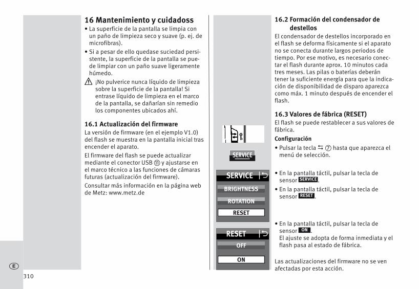
16 Mantenimiento y cuidadoss• La superficie de la pantalla se limpia con
un paño de limpieza seco y suave (p. ej. demicrofibras).
• Si a pesar de ello quedase suciedad persi-stente, la superficie de la pantalla se pue-de limpiar con un paño suave ligeramentehúmedo.
¡No pulverice nunca líquido de limpiezasobre la superficie de la pantalla! Sientrase líquido de limpieza en el marcode la pantalla, se dañarían sin remediolos componentes ubicados ahí.
16.1 Actualización del firmwareLa versión de firmware (en el ejemplo V1.0)del flash se muestra en la pantalla inicial trasencender el aparato.El firmware del flash se puede actualizarmediante el conector USB � y ajustarse enel marco técnico a las funciones de cámarasfuturas (actualización del firmware).Consultar más información en la página webde Metz: www.metz.de
16.2 Formación del condensador dedestellos
El condensador de destellos incorporado enel flash se deforma físicamente si el aparatono se conecta durante largos periodos detiempo. Por ese motivo, es necesario conec-tar el flash durante aprox. 10 minutos cadatres meses. Las pilas o baterías deberántener la suficiente energía para que la indica-ción de disponibilidad de disparo aparezcacomo máx. 1 minuto después de encender elflash.
16.3 Valores de fábrica (RESET)El flash se puede restablecer a sus valores defábrica.Configuración• Pulsar la tecla � hasta que aparezca el
menú de selección.
• En la pantalla táctil, pulsar la tecla de sensor .
• En la pantalla táctil, pulsar la tecla de sensor .
• En la pantalla táctil, pulsar la tecla de sensor .El ajuste se adopta de forma inmediata y elflash pasa al estado de fábrica.
Las actualizaciones del firmware no se venafectadas por esta acción.
D
SERVICE
RESET
ON
310c
SERVICE
SERVICE O
BRIGHTNESS
RESET
ROTATION
RESET OOFF
ON

17 Ayuda en caso de problemasSi alguna vez aparecen en la pantalla, por ejemplo, indicaciones sinsentido o el flash no funciona como es debido, debe apagarsedurante aprox. 10 segundos pulsando el interruptor général .Comprobar que el pie del flash está bien montado en la zapata de lacámara y que los ajustes de la cámara son correctos.Cambiar las pilas o baterías por otras nuevas o recién cargadas.Tras la conexión, el flash debería funcionar „normalmente“. De locontrario, diríjase a un proveedor autorizado.A continuación se describen algunos problemas que pueden apare-cer al utilizar el flash. Debajo de cada punto, se indican las causas ysoluciones para estos problemas.En la pantalla no aparece la indicación del alcance.• No se produce transmisión de datos entre la cámara y el flash.
Pulsar el disparador de la cámara.• El reflector no se encuentra en la posición normal.• En el flash está configurado el modo remoto.El destello de medición AF del flash no se activa.• El flash no está preparado.• La cámara no funciona en el modo „AF-S“.• La cámara sólo es compatible con el destello de medición AF inter-
no.• El destello de medición AF de algunos modelos de cámara sólo es
compatible con el sensor AF central de la cámara. Si se seleccionaun sensor AF descentralizado, el destello de medición AF no seactiva en el flash. Activar el sensor AF central.
• La función "AF BEAM" está apagada. Encender "AF BEAM", consul-tar 11.6.
La posición del reflector no se ajusta automáticamente a la posición real de zoom del objetivo.• La cámara no está transmitiendo datos al flash.• No tiene lugar una transmisión de datos entre el flash y la cámara.
Pulsar el disparador de la cámara.• La cámara está equipada con un objetivo sin CPU.• El flash está funcionando en el modo manual de zoom “MZoom”.
Cambiar a auto-zoom (consultar 11.4.3).• El reflector está girado respecto a su posición normal bloqueada.• El difusor de gran angular está desplegado por delante del reflector.• Está montado un Mecabounce delante del reflector .No se puede configurar el modo TTL de funcionamiento de flash.• No ha habido transmisión de datos entre el flash y la cámara.
Pulsar el disparador de la cámara
• La cámara no es compatible con el modo TTL .
La configuración de la corrección manual de la exposición del flashTTL no tiene ningún efecto.• La cámara no es compatible con la corrección manual de la expo-
sición del flash TTL.No tiene lugar una conmutación automática a la velocidad de sin-cronización del flash.• La cámara tiene un obturador central (como la mayoría de las
cámaras compactas). Por eso, no es necesario cambiar a la veloci-dad de sincronización.
• La cámara está operando con sincronización rápida HSS (configu-ración de cámara). En ese caso, no cambia a la velocidad de sin-cronización.
• La cámara funciona con velocidades de obturación más lentas quela velocidad de sincronización del flash. Dependiendo del modode funcionamiento de la cámara no se pasa a la velocidad de sin-cronización del flash (consultar manual de instrucciones de lacámara).
311
c

312c
La imagen aparece demasiado oscura.• El motivo se encuentra fuera del alcance del flash.
Recordar que con los destellos indirectos se reduce el alcance delflash.
• El motivo contiene partes muy claras o reflectantes. Esto confundeal expo-símetro de la cámara o del flash. Ajustar una correcciónmanual de la exposición del flash positiva, por ejemplo, +1 EV.
La imagen aparece demasiado clara.• En la fotografía de primeros planos pueden producirse sobreexpo-
siciones (tomas demasiado claras) cuando no se alcanza la veloci-dad más rápida del flash.

313
c
18 Características técnicasMáximo número guía con ISO 100/21°, zoom 200 mm:En metros: 64 En pies: 210Tipos de funcionamiento del flash:TTL (sin predestello), TTL con predestello, medición ADI, manual M,Automatiskt blixtläge, sincronización rápida HSS, esclavo remoto,slave remoto.
Ajuste automático del diafragma con ISO 100/21°:F1,4 a F64 incluidos valores intermediosPotencias parciales manuales:P1/1 a P1/ 256 en tercios.P1/1 a P1/256 Sincronización rápida automática (HSS)Duración de destellos ver Tabla 2, (Sida 319)
Temperatura de color: Aprox. 5600 K
Sensibilidad de la película: ISO 6 bis ISO 51200
Sincronización: Encendido de baja tensión IGBTNúmero de destellos• 140 con pilas alcalino-manganesas (1,5V)• 190 con acum. NIMH (1,2V / 2100 mAh)• 290 con pilas de lithio (1,5V)• 360 con Metz Power Pack P76
Tiempo de secuencia de destellos• 0,1/4,4 con pilas alcalino-manganesas (1,5V)• 0,1/1,8 con acum. NIMH (1,2V / 2100 mAh)• 0,1/4,2 con pilas de lithio (1,5V)• 0,1/1,6 con Metz Power Pack P76
Iluminación:Reflector a partir de 24 mm (pequeño formato 24 x 36)Reflector con difusor de gran angular a partir de 12 mm (pequeño formato 24 x 36)Gama de inclinación y posiciones de enclavamiento del reflector:Hacia arriba: -9° 45° 60° 75° 90°En sentido contrario a las agujas del reloj:60° 90° 120° 150° 180°En el sentido de las agujas del reloj:60° 90° 120°Dimensiones aprox. en mm (An x Al x Pr):Ca. 78 x 148 x 112Peso:Aprox. 422 g excluidas fuentes de alimentaciónComponentes suministrados:Flash con difusor de gran angular integrado, Pie de apoyo para flashes S60, Bolsa de cinturón T64, manual de instrucciones.

314c
19 Accesorios especialesMetz no asume ninguna garantía por funcionamientos erróneos odaños en el flash, causados al utilizar accesorios de otros fabrican-tes.• mecabounce Diffuser MBM-03(Nº ref. 000003902)Mediante este difusor se consigue, de forma sencilla, una ilumina-ción suave.El efecto es extraordinario dado que las imágenes adquieren unaspecto delicado. El color de la piel de las personas resulta muynatural. Los alcances límite se reducen aprox. a la mitad según lapérdida de luz.• Paraguas de reflexión 58-23(Nº ref. 000058235)Isminuye las sombras duras dirigiendo una luz suave.• Pie de apoyo para flashes S60(Nº ref. 000000607)Pie de apoyo para flashes en modo de funcionamiento esclavo.• Cable de conexión V58-50(Nº ref. 000058504)compatible también con el Powerpack P76• Powerpack• Easy Softbox ESB 60-60 (Nº ref. 009016076)
Dimensiones: 60 × 60 cm
Con difusor de fondo y primer plano, bolsa de transporte y adapta-dor compatible con Bowens para conectar a los flashes de estudioTL o BL de Metz
• Easy Softbox ESB 40-40 (Nº ref. 009014047)
Dimensiones: 40 × 40 cm
Con difusor de fondo y primer plano, bolsa de transporte y adapta-dor compatible con Bowens para conectar a los flashes de estudioTL o BL de Metz
• Soporte para flash FGH 40-60 (Nº ref. 009094065)
Adaptador entre flashes compactos y Easy Softboxes
Altura ajustable de la zapata
Encajable en trípodes para iluminación LS-247 y LS-200 de Metz
• Mini Softbox SB 30-20 (Nº ref. 009013023)
Color: blanco, dimensiones: 30 × 20 cm
• Mini Softbox SB 22-16 (Nº ref. 009012217)
Color: blanco, dimensiones: 22 × 16 cm
• Mini Softbox SB 18-15 (Nº ref. 009011817)
Color: blanco, dimensiones: 18 × 15 cm
• Mini Octagon Softbox SB 34-34 (Nº ref. 009023432)
Color: blanco, dimensiones: Ø 34 cm
• Mini Octagon Softbox SB 20-20 (Nº ref. 009022029)
Color: blanco, dimensiones: Ø 20 cm

315
c
• Mini Octagon Softbox SB 15-15 (Nº ref. 009021516)
Color: blanco, dimensiones: Ø 15 cm
• Spot Reflexschirm SD 30-26 W (Nº ref. 009043021)
Color: blanco para luz neutral / dimensiones: 30 × 26 cm
• Spot Reflexschirm SD 30-26 S (Nº ref. 00904303A)
Color: plateado para luz fría / dimensiones: 30 × 26 cm
• Spot Reflexschirm SD 30-26 G (Nº ref. 009043048)
Color: dorado para luz cálida / dimensiones: 30 × 26 cm
Eliminación de las bateríasNo se deben tirar las baterías a la basura casera.Para la devolución de sus baterías gastadas, sírvase utilizar uno delos sistemas de reciclaje existente eventualmente en su país.Sírvase devolver unicamente baterías descargadas.Por regla general, las baterías están descargadas cuando el aparatoalimentado por ellas- se apaga y señala „baterías gastadas“- no funciona bien despues de un largo período de uso
de las baterías.Para evitar cortocircuitos, es recomendable cubrir los polosde las baterías con cinta adhesiva.
Con reserva de modificaciones y posibilidades de entrega.

316c

317
c

318
Tabelle 1:Leitzahlen bei maximaler Lichtleistung (P 1/1)Tableau 1:Nombres-guides pour la puissance maximale (P 1/1)Tabel 1:Richtgetallen bij vol vermogen (P 1/1)Table 1:Guide numbers at maximum light output (P 1/1)Tabella 1:Numeri guida a potenza piena (P 1/1)Tabla 1:Números-guía con máxima potencia de luz (P 1/1)
ISO Zoom12 24 28 35 50 70 85 105 135 180 200
6/9° 5,3 7,5 8 9 11 12 13 15 15 16 168/10° 5,9 8,4 9 10 12 13 15 17 17 17 1810/11° 6,6 9,4 10 11 14 14 16 19 19 20 2012/12° 7,4 11 11 13 15 16 18 21 22 22 2316/13° 8,3 12 13 14 17 18 21 24 24 25 2520/14° 9,4 13 14 16 19 20 23 27 27 28 2925/15° 11 15 16 18 22 23 26 30 31 31 3232/16° 12 17 18 20 24 26 29 34 34 35 3640/17° 13 19 20 23 27 29 33 38 38 39 4050/18° 15 21 23 25 30 33 37 42 43 44 4564/19° 17 24 25 29 34 37 41 48 48 49 5180/20° 19 27 29 32 38 41 46 53 54 55 57100/21° 21 30 32 36 43 46 52 60 61 62 64125/22° 24 34 36 40 48 52 58 67 68 70 72160/23° 26 38 40 45 54 58 66 76 77 78 81200/24° 30 42 45 51 61 65 74 85 86 88 91250/25° 33 48 51 57 68 73 83 95 97 98 102320/26° 37 53 57 64 77 82 93 107 109 110 114400/27° 42 60 64 72 86 92 104 120 122 124 128500/28° 47 67 72 81 97 103 117 135 137 139 144650/29° 53 76 81 91 108 116 131 151 154 156 161800/30° 59 85 91 102 122 130 147 170 173 175 1811000/31° 67 95 102 114 137 146 165 190 194 197 2031250/32° 75 107 114 128 153 164 185 214 217 221 2281600/33° 84 120 128 144 172 184 208 240 244 248 2562000/34° 94 135 144 162 193 207 233 269 274 278 2872500/35° 106 151 161 181 217 232 262 302 307 312 3233200/36° 119 170 181 204 243 260 294 339 345 351 3624000/37° 133 190 203 229 273 292 330 381 387 394 4065000/38°150 214 228 257 306 328 371 428 435 442 4566400/39° 168 240 256 288 344 368 416 480 488 496 512

319
Tabelle 2: Blitzleuchtzeiten in den TeillichtleistungsstufenTableau 2:Durée de l’éclair pour les différents niveaux de puissanceTabel 2: Flitsduur en deelvermogensstappenTable 2: Flash durations at the individual partial light output levelsTabella 2: Durata del lampo ai vari livelli di potenza flashTabla 2 Duraciones de destellos en los escalones de potencias parciales de luz
Teillichtleistung Blitzleuchtzeit (s) Blitzleuchtzeit (s)Niveaux de puissance Durée d’éclair (s) Durée d’éclair (s)Deelvermogensstappen Flitsdur (s) Flitsdur (s)Partial light output Flash duration Flash durationLivello di potenza Durata del lampo Durata del lampoPotencia parcial Duración de destello Duración de destello(P=Flash Power) t0,5 in 1/s t0,1 in 1/sP 1/1 1/750 1/180P 1/2 1/750 1/680P 1/4 1/1700 1/1500P 1/8 1/4300 1/3000P 1/16 1/7500 1/4700P 1/32 1/11500 1/7000P 1/64 1/15000 1/9000P 1/128 1/25000 1/12500P 1/256 1/40000 1/18000

320
Tabelle 3: Maximale Leitzahlen im HSS-BetriebTableau 3: Nombres-guides en mode HSSTabel 3: Max. Richtgetallen bij de HSS functieTable 3: Maximum guide numbers at HSS-ModeTabella 3: Potenza piena a numeri guida per il modo HSSTabla 3: Números-guía max. en el funcionamiento HSS
ZOOM12 24 28 35 50 70 85 105 135 180 20011 15 16 18 22 23 26 30 31 31 32HSS

321

322
Ihr Metz-Produkt wurde mit hochwertigen Materialien undKomponenten entworfen und hergestellt, die recycelbarsind und wieder verwendet werden können.Dieses Symbol bedeutet, dass elektrische und elektroni-sche Geräte am Ende ihrer Nutzungsdauer vom Hausmüllgetrennt entsorgt werden müssen.Bitte entsorgen Sie dieses Gerät bei Ihrer örtlichen kom-munalen Sammelstelle oder im Recycling Centre.Bitte helfen Sie mit die Umwelt, in der wir leben, zu erhal-ten.Votre produit Metz a été conçu et fabriqué avec des maté-riaux et composants de haute qualité, susceptibles d'êtrerecyclés et réutilisés.Ce symbole signifie que les appareils électriques et électroniques, lorsqu'ils sont arrivés en fin de vie, doiventêtre éliminés séparément des ordures ménagères.Veuillez rapporter cet appareil à la déchetterie communa-le ou à un centre de recyclage.Vous contribuez ainsi à la préservation de l'environne-ment.Uw Metz-product is ontworpen voor en gebouwd uit hoog-waardige materialen en componenten die gerecycled kunnen worden en dus geschikt zijn voor hergebruik. Dit symbool betekent, dat elektrische en elektronischeapparatuur aan het einde van zijn levensduur gescheidenvan het huisvuil apart moet worden ingeleverd. Breng dit apparaat naar een van de plaatselijke verzamel-punten of naar een kringloopwinkel.Help s.v.p. mee, het milieu waarin we leven te bescher-men.
Your Metz product was developed and manufactured withhigh-quality materials and components which can berecycled and/or re-used.This symbol indicates that electrical and electronic equip-ment must be disposed of separately from normal gar-bage at the end of its operational lifetime.Please dispose of this product by bringing it to your localcollection point or recycling centre for such equipment.This will help to protect the environment in which we alllive.Il vostro prodotto Metz è stato progettato e realizzato con mate-riali e componenti pregiati che possono essere riciclati e riutilizzati.Questo simbolo significa che gli apparecchi elettrici ed elettroni-ci devono essere smaltiti separatamente dai rifiuti domestici alla fine del loro utilizzo.Vi preghiamo di smaltire questo apparecchio negli appositi punti di raccolta locali o nei centri preposti al riciclaggio.Contribuite anche voi a tutelare l’ambiente nel quale viviamo.
Su producto Metz ha sido concebido y fabricado conmateriales y componentes de alta calidad, que puedenser reciclados y reutilizados.Este símbolo significa que los aparatos eléctricos y elec-trónicos, al final de su vida útil, deberán ser separados delos residuos domésticos y reciclados.Rogamos llevar este aparato al punto de recogida de sumunicipio o a un centro de reciclaje.Por favor, contribuya Vd. también en la conservación delambiente en que vivimos.
j
l
x
k
ö
c

323
Hinweis:
Im Rahmen des CE-Zeichens wurde beider EMV-Prüfung die korrekte Belichtungausgewertet.
SCA-Kontakte nicht berühren !In Ausnahmefällen kann eine Berührungzur Beschädigung des Gerätes führen.
j
Remarque:
L’exposition correcte a été évaluée lorsdes essais de CEM dans le cadre de lacertification CE.
Ne pas toucher les contacts du SCA !Il paut arriver que le contact avec lesdoigts provoque la dégradation de l’appareil.
l
Opmerking:
In het kader de CE-markering werd bij deEMV-test de correcte be-lichtingbepaald.
SCA Contacten niet aanraken !In uitzonderlijke gevallen kan aanrakenleiden.
x
Note:
Within the framework of the CE approvalsymbol, correct exposure was evaluatedin the course of the electromagneticcompatibility test.
Do not touch the SCA contacts !In exceptional cases the unit can bedamaged if these contacts are touched.
k
Avvertenza:
Nell’ambito delle prove EMV per il segnoCE è stata valutata la corretta esposizio-ne.
Non toccate mai i contatti SCA !In casi eccezionali il toccare può causaredanni all’apparecchio.
ö
Atención:
El símbolo CE significa una valora ciónda exposición correcta con la pruebaEMV (prueba de tolerancia electroma-gnética).
No tocar los contactos SCA !En algunos casos un contacto puedeproducir daños en el aparato.
c
Technische Änderungen und Irrtümer vorbehalten !Sous réserve de modifications et d’erreus !Onder voorbehoudvan wijzigingen en vergissingen !Errors excepted. Subject to changes !Riserva di modifiche e disponibilità di fornitura.Con reserva de modificaciones y posibilidades de entrega.

Handauslösetaste und BlitzbereitschaftsanzeigeBouton du flash et témoin de disponibilitéOntspanknop voor handbediening en flitsaparaat-aanduiding Manual firing button and flash-ready indicatorTasto emissione manuale del lampo e Indicazione pronto lampoTecla de disparo manual y Indicación de disposición de disparo
�
Anzeige und Auswahl der BlitzbetriebsartAffichage et de sélection le mode flashAanduiding en selectie van de flitsfunctieDisplay and select the flash modeSelezione del display e di modalità flashVisualización y selección de modo de flash
�HauptschalterInterrupteur généralHoofdschakelaarMain switchInterruttore principaleInterruptor principal
�
�
Anzeige und Auswahl der - Teillichtleistung / - Belichtungskorrektur EVAffichage et de sélection de- Puissances partielles / - correction d’exposition EVAanduiding en selectie van - Deelvermogen / - correctie op de flitsbelichting EVDisplay and selection of - Partial light output / - exposure correction EVSelezione del display e di - Potenza ridotta / - correzione dell’esposizione EVVisualización y selección de - Potencias parciales / - compensación de exposición EV
�
Sensor für Remote-Betrieb (hinter Infrarotdurchlässiger Gehäuseschale)Senseur pour mode multi-flash sans fil (derrière la coque transparente aux infrarouges)Sensor voor draadloze afstandbediening (achter de infrarood-doorlatende behuizing)Sensor for cordless remote control (behind a section of the housing that is permeable to infrared light)Sensore per controllo a distanza senza cavi (collocato sul retro del guscio sensibile agli infrarossi)Sensor para control remoto (tras cubierta de carcasa translúcida para infrarrojos)
Belichtungs o.k. Anzeige, Auswahlmenü aufrufen, im Menü ein Schritt zurück, VerriegelungExposition o.k., menu de sélection, menu est un pas en arrière, VerrouilageBelichting o.k.-aanduiding, Keuzemenu oproepen, het menu is een stap terug, VergrendelingExposure ok indicator, call up selection menu, a step back in menu, KeylockIndicazione di corretta esposizione, aprire menu di selezione, menu è un passo indietro, BloccoIndicación de exposición o.k., abrir menú de selección, el menú es un paso atrás, Bloqueo
Info
64AF-1
� �
0.8- 9.0 m
F 5,6M-Zoom 35m
m
A
iEV-1
SynchronbuchsePrise synchroAansluitbus voor flitskabelSync socketPresa sincroClavija sincrona
Anschluss PowerpackPrise pour PowerpackAansluiting PowerpackPowerpack connectionPresa per PowerpackConexión Powerpack

ReflektorkarteCarte-réflecteurReflecterende kaart Reflector cardPannello riflettenteRiflettente integrato
�
Firmwareupdate-BuchseMise à jour du micrologicielUpdaten van de firmwareFirmware updatesAggiornamento del softwareActualización del firmware
�
Entriegelungsknopf HauptreflektorBouton de déverrouillage pour réflecteurOntgrendelingsknop HoofdreflectorUnlocking button for the main reflektorPulsante di sblocco della parabola principaleBotón de desbloqueo del reflector principal
BatteriefachdeckelCouvercle du compartiment des pilesDeksel batterijvakBattery compartment coverCoperchio del vano batteriaTapa del compartimento de pilas
AF-HilfslichtLumière auxiliaire AFAF-hulplichtAF auxiliary lightIl'illuminatore ausiliario AFLuz auxiliar AF
��
FotosensorSenseurLichtmeet-sensorSensorSensore
�
RändelmutterÉcrou moletéKartelmoerKnurled nutDato zigrinatoTuerca moleteada
� ZweitreflektorRéflecteur secondaireHulpreflectorSecondary reflectorParabola ausiliariaReflector adicional
�
WeitwinkelstreuscheibeDiffuseur grand angleGroothoekdiffusorschijfWide-angle diffuserDiffusore grandangolareDifusor gran angular
�
-7°
0°
45°
60°
75°
90°
*PRESS

713 47 0070.A1
j l x k ö cMetz - always first class.
Consumer electronics Photoelectronics Plastics technology
Metz-Werke GmbH & Co KG • Postfach 1267 • 90506 Zirndorf/GermanyTechnische Hotline:+49 (0) 911 – 97 06 172 • www.metz.de • [email protected]