ct -64 terminal system
184
-
Upload
khangminh22 -
Category
Documents
-
view
0 -
download
0
Transcript of ct -64 terminal system


CT -64 TERMINAL SYSTEM
* 64 OR 32 CHARACTERS PER LINE * UPPER AND lower case LETTERS * FULL 8 BIT MEMORY
* 128 CHARACTER ASCII SET * 110/220 Volt 50-60 Hz POWER SUPPLY
* SCROLLING OR PAGE MODE OPERATION
* CONTROL CHARACTER DECODING-32 COMBINATION * PRINTS CONTROL CHARACTERS
* USABLE WITH ANY 8 BIT ASCII COMPUTER * REVERSED BACKGROUND - HIGHLIGHTING
COMPLETE WITH - Chassis and cover, cursor control, 110-1200 Baud ser ial interface and keyboard. Optional
monitor show in photo avai lab le.
Now you can buy it. The terminal that has all the fea tures that people have been asking us to include. The CT-64 has all the functions that you could want in a terminal and they may be operated by either switches, or through a software program.
All cursor movements, home-up and erase, erase to end of line, erase to end of frame, read on, read off, cursor on, cursor off, screen reversal, scro ll, no scroll, sol id cursor, blinking cursor, page se lection and a beeper to warn you of end of page; all are provided for your use in the CT-64.
You may also switch from upper case only teletype style operation to upper -lower case typewriter style operation . You can reverse the field on individual words to highlight them, or you ca n reverse the who le screen.
CT-64 is comp lete with keyboard, power supply seria l interface and case. A matching 9 inch monitor with coordinated covers is also available to make a complete syste m.
CT-64 Terminal Kit
MM-1 Monitor (assembled)
$325.00
$175.00
r----------------------------------____________________________ _ You are right, it's just what I have been asking for.
o Enclose is $325.00 for the CT-64
o Send the MM-1 monitor too. 0 Send Data Oar BAC ____________ # ________ _ Oar MC Ex Date _______ _
NAME
219 W. Rhapsody ADDRESS
San Antonio, Texas 78216 C ITY STATE Z IP
Circle 29 on inqui ry card. Southwest Technical Products Corp. 219 W. Rhapsody, San Antonio, Texas 78216

Meet the most powerful j.lC system available for dedicated work.
Yet it's only $595: Here's the muscle you've been telling us you wanted:
a powerful Cromemco microcomputer in a style and price range ideal for your dedicated computer jobs-ideal for industrial, business, instrumentation and similar applications.
It's the new Cromemco Z-2 Computer System. Here's some of what you get in the Z-2 for only $595:
• The industry's fastest ~P board (Cromemco's highly regarded 4 MHz, 250-nanosecond cycle time board).
• The power and convenience of the well-known Z-80 ~P.
• A power supply you won't believe (+ 8V @ 30A, +18V and -18V @ 15A - ample power for additional peripherals such as floppy disk drives).
• A full-length shielded motherboard with 21 card slots. • Power-on-jump circuitry to begin automatic program
execution when power is turned on. • 5-100 bus. • Standard rack-mount style construction. • All-metal chassis and dust case. • 110- or 220-volt operation.
DEDICATED APPLICATIONS The new Z-2 is specifically designed as a powerful but
economical dedicated computer for systems work. Notice that the front panel is entirely free of controls or switches of any kind. That makes the Z-2 vir-tually tamper-proof. No accidental program changes or surprise mem- - ;. oryerasures.
FASTEST, MOST POWERFUL p.C
Cromemco's mlcrocpm" puters are the fa$(est and most I available.
widely regarded as the standard of the future. So you're in the technical fore with the Z-2.
BROAD SOFTWARE/PERIPHERALS SUPPORT Since the Z-2 uses the Z-80, your present 8080 soft
ware can be used with the Z-2. Also, Cromemco offers broad software support including a monitor, assembler, and a BASIC interpreter.
The Z-2 uses the 5-100 bus which is supported by the peripherals of dozens of manufacturers. Naturally, all Cromemco peripherals such as our 7-channel AID and D/A converter, our well-known BYTESAVER with its built-in PROM programmer, our color graphics interface, etc., will also plug into the 5-100 bus.
LOW, LOW PRICE You'll be impressed with the Z-2's low price, technical
excellence and quality. So see it right away at your computer store-or order directly from the factory.
Z-2 COMPUTER SYSTEM KIT (MODEL Z-2K) (includes 4 MHz ~P card, full-length 21-card-slot motherboard, power supply, one card socket and card-guide set, and front panel; for rack mounting) .............. $595.
Z-2 COMPUTER SYSTEM ASSEMBLED (MODEL Z-2W) (includes the above as well as all 21 sockets and card guides and a cooling fan; for rack mounting) ... $995.

TV DAZZLER
To make your computer more useful-
a wide choice of memory, 1/0, CPU
Your computer's usefulness depends on the capability of its CPU, memories, and I/O interfaces, right?
So here's a broad line of truly useful computer products that lets you do interesting things with your Cromemco Z-1 and Z-2 computers. And with your S-100-compatible AItairs and IMSAls, too.
CPU • Z-80 MICROPROCESSOR CARD. The most advanced ,uP card available. Forms the heart of our Z-1 and Z-2 systems. Also a direct replacement for Altair / IMSAI CPUs. Has 4-MHz clock rate and the power of the Z-80 ,uP chip. Kit (Model ZPUK): $295. Assembled (Model ZPUW): $395.
MEMORIES • 16K RAM. The fastest available. Also has bank-select feature. Kit (Model 16KZ-K): $495. Assembled (Model 16KZ-W): $795. • 4K RAM. Bank-select allows expansion to 8 banks of 64K bytes each. Kit (Model 4KZ-K): $195. Assembled (Model 4KZ-W): $295. • THE BYTESAVER - an 8K capacity PROM card with integral pro-
grammer. Uses high-speed 2708 erasable PROMs. A must for all computers. Will load 8K BASIC into RAM in less than a second. Kit (Model BSK-O): $145. Assembled (Model BSW-O): $245.
• 16K CAPACITY PROM CARD. Capacity for up to 16K of high-speed 2708 erasable PROM. Kit (Model 16KPR-K): $145. Assembled (Model 16KPR-W): $245.
I/O INTERFACES • FAST 7-CHANNEL DIGITALANALOG I/O . Extremely useful board with 7 A/D channels and 7 0/ A channels. Also one 8-bit parallel I/O channel. Kit (Model 0 + 7A-K): $145. Assembled (Model 0 + 7A-W): $245.
• TV DAZZLER. Color graphics interface. Lets you use color TV as fullcolor graphics terminal. Kit (Model CGI-K): $215. Assembled (Model CGI-W): $350. • DIGITAL INTERFACE (OUR NEW TU-ART) . Interfaces with teletype, CRT terminals, line printers, etc. Has not one but two serial//O ports and two 8-bit parallel //0 ports as well as 10 on-board interval timers. Kit
Cromemeo incorpora ed Specialists in computers and peripherals
(Model TRT-K): $195. Assembled (Model TRT-W): $295.
• JOYSTICK. A console that lets you input physical position data with above Model 0 + 7 A/D card. For games, process control, etc. Contains speaker for sound effects. Kit (Model JS-1-K): $65. Assembled (Model JS-1-W): $95.
PROFESSIONAL QUALITY You get first-class quality with
Cromemco. Here are actual quotes from ar
ticles by independent experts: liThe Cromemco boards are absolutely beautiful" ... liThe BYTE5AVER is tremendous" ... "Construction of Cromemco I/O and joystick are outstanding" .. . "Cromemco peripherals ran with no trouble whatsoever."
Everyone agrees. Cromemco is tops.
STORES/MAIL So count on Cromemco. Look
into these Cromemco products at your store. Or order by mail from the factory.
We wish you pleasure and success with your computer.
2432 CHARLESTON RD., MOUNTAIN VIEW, CA 94043 • (415) 964-7400
Circle 41 on inquiry card.

18
46
76
88
100
140
154
30
54
116
4
9
12
16,24,144,158
60
74
85
In I:he Queue
Foreground
DESIGN ING MULTI CHANNEL ANALOG INTERFACES
Hardware-Kraul
INTERFACING THE IBM SELECTRIC KEYBOARD PR INT ER
Periphera ls- Fylstra
COME FLY WITH KIM
Periphera l s-Simpson
SOFTWARE FOR THE ECONOMY FLOPPY D ISK
Systems Software-We lles
ARTIF ICIA L INTELLIGENCE: Part 2, Imp lementation
Software-Wimble
A 6800 SELECTRIC 10 PRINTER PROGRAM
Software-Guzzon
A GUIDE TO BAUDOT MACHINES: Part 3
Constructi on-MeN att
Background
NEWT: A MOB I LE , COGNITIVE ROBOT
Robotics-Hol li s
INTERFACING TO AN ANALOG WORLD: Part 2
Hardware-Carr
INTRODUCTION TO MICROPROGRAMMING
Software-Quek
Nucleus
In Th is BYTE 108 Clubs, Newsletters
The Software Dilemma 126 BYTE's Bits
Letters 150 Desk Top Wonders:
What's New? SR-52 Card BLACKJA CK
Ask BYTE 160 BYTE's Bugs
Technical Forum 180 BOMB
CI ass ified Ads 180 Reader Service
BYTE is published monthly by BYTE Publications Inc, 70 Main St, Peterborou gh NH 03458 . A ddress all mail except sUbscriptions to above address; phone (603) 924-7217. Address all editorial c orrespond ence to the editor at the above address. Unacceptable manuscripts will be returned if accompanied by sufficient first class postage. Not responsibl e for lost manuscripts o r photos. Opinions expressed by the authors are not necessarily those of BYTE. Address all subscriptions, change of address, Form 3579, and fulfillment complaints to BYT E Sub scriPtions, P O Box 361, Arlington MA 02174; phone (617) 646-4329. Second cl ass postage paid at Peterborough NH 03458 and at additional mailing offices. Subscriptions are $12 for one year, $22 for two years, and $32 for three years in the USA and its possessions. Add $ 5. 50 per year for subscriptions to Canada and Mexico. For air delivery to west ern Eur ope, and f o r su rface d elivery worldwide, $25 for a one year subscription o nly. Worldwide air delivery available at additional rates. Please see subscription card. Single copy p rice is $1.50 in the USA and its possessions, $2 in Canada and Mexico, and $3 elsewh ere . Forei gn subscrip tions and sales should be remitted in United States fund s. Printed in United States of A m erica . Entire contents copyright © 1977 by BYTE Publications Inc. All rights reserved.
3
JU NE 1977 ~~TI Volume 2 Number 6
PUBLISHERS Virginia Peschke Manfred Pesch ke ED ITOR IN CHI EF Car l T He l rrters J r PROD UCTI ON MANAGER Jud ith Havey CIRCULATI ON MANAGER Gregory Sp itzfaden ASSISTAN T PUBLIS HER Debra Boudrieau EDITOR Christopher P Morgan CO-OP ED ITOR Raymond Cote PRODUCT ION EDITORS Karen Gregory Nancy Salmon EDITORIA L ASSISTANT Ingrid Nyland PRODUCTION ASSISTANT Chery l Hurd SUBSCRIPTIONS Kimberly Barbour Noreen Bardsley DEALER SALES Ginnie F Boudrieau ADVERTISING El izabeth A lpaugh Debra Boudrieau Virginia Peschke CLU BS, PAPE RBYTES Peter T ravisano TRA FFIC Edmond C Ke l ly Jr Wai Ch iu Li ART Mary Jane Frohlich El len Shamonsky SPECIA L PRODUCTS Susan Pearne Floyd Reh l ing RECEPTIONIST Jacq ueline Earnshaw DRAFTING Lynn Malo Bi ll Morello Stephen Kruse TYPOGRAPHY Custom Marketing Resources Inc Goodway Graphics PHOTOGRAPH Y Ed Crabtree PRINTING The George Banta Company Custom Marketing Resources Inc EDITORIAL CONSULTANT Dan iel Fy lstra ASSOCIATES Wal ter Banks Steve Ciarcia David Fy lstra Portia Isaacson AFFILIATE PUBLISHER Southeast Asian Ed itions John Ban nister FORE IGN DISTR IBUTOR Pan At lantic Computer Systems gmbh Frankfurter Str 78 D6 1 Darmstadt (061 51) 29 29 23

In This Some uses of a microprocessor
involve the connection to the outs ide world through an analog in terface. When foo lin g arou nd with such projects from mu sic generation to robotic control, however, it quickly becomes necessary to have a large number of inexpensive rea l world interfaces. To help point you in the right directions Douglas R Kraul suppli ed an articl e on Designing Multichannel Analog Interfaces.
I n the past, readers have seen some interest ex pressed in the concepts of robot ics, the use of small computers as the bra ins of mobile automated mechanisms. Robots have long been fancied in sc ience fiction literature and cinema, but onl y rarely have peo pl e taken any practical steps towards a "real" robot as opposed to paper romantic isms or stage dummies. One of those rare cases is that provided by Ralph Ho lli s and his assoc iate Dennis Toms, both of whom are physici sts at the University of Colorado, Duane Physical Laboratory, Boulder CO. Ral ph has been pursuing the design of practical robots as an avocation since 1957, and late ly has progressed to the point of a work ing mobile computer system ca ll ed Newt, whose picture provides the theme of this month's cover. Turn to Ralph's articl e, Newt: A Mobile, Cognitive Robot for essential background information on contemporary robot design philosophies .
page 46
Hard copy is a most useful output, but it tends to be somewhat expensive. Dan Fylstra shows one very attractive opt ion in hi s art icle on Interfacing the IBM Selectric Keyboard Printer. Dan purchased a used print mechan ism late in 1976, and sin ce then has successfully in terfaced the device to hi s KIM-1 system. Readers in terested in using these printers (which are ava il ab le in sign ificant numbers on surplu s markets) will find Dan's art icle an essential guide to the art.
How can hard ware be used to accomp li sh the details of Interfacing With an Analog World? Turn to auth or Joseph Carr's second part of a two part series to find out some of the details of basic conversion circuits wh ich use the outputs of sensors and preamplifiers discussed in last month's art icl e.
Much of the software that is availab le on the market today is avail ab le on paper tape so as to be easil y read into your microprocessor. The problem is that most common paper tape readers are so slow that it seems to take forever to read a large program into memory. In the article Come Fly With KIM, Rick Simpson introduces us to a so lu tion to this speed problem: the Fly Reader, whi ch he uses with MOS Technology's KIM-1.
4
Now that you've got the hardware built, how do yo u run it? Ken Welles answers this question in Software for the Economy Floppy Disk. His previous ar ticle (February 1977 BYTE, page 34) descr ibed how to construct an inexpensive floppy disk with minim al hardware. Th is month he provides a se ri es of subrouti nes to run it, wh ich could eas il y be ex panded into a complete floppy disk operating system.
Last month in the f irst part of hi s artic le Artificial Intelligence, An Evolutionary Idea, Michael Wimble intro
duced us to the use of a simulated evo lution technique by which it was possible for a program to alte r itself and reshape its responses as a direct result of an outside stimu lus. This month in Part 2: Implementation , Mr Wimble details how the computer experimenter can implement this type of program on any small computer system .
To many people the concept of assembl y language is that of the fundamental language of the computer next to mac hine langu age . Howeve r, each particular assemb ly language com mand must be broken down into a series of si mpl er command sequences. These commands are known as microinstructions. In h is articl e, An Introduction to Microprogramming, S M Quek describes how the concept of microinstructio ns is a great benefit to the user of a computer, all owi ng the easy change of basic instructions.
I n previous issues Michael McNatt has shown us the avail ab ility of Baudot teleprinters and the ways in which they can be interfaced with your microprocessor. In his concluding articl e, A Guide to Baudot Machines: Part 3, A Teleprinter Test Circuit, he describes a test circuit that can be used for generating Baudot characters for alignment and ad justment purposes.

POWER.
IMSAI Introduces the Megabyte Micro~M
The Megabyte Memory Until today, the largest memory you could fit and address in a single microcomputer CPU was 65K.
Now, IMSAI presents an incredible memory system for micros 16 times more powerful than yesterday's best.
Imagine, a full megabyte of power fro m sixteen 65 K RAM boards.
And , to control all this, the IMSAI Intelligent Memory Manager (IMM), the super control board .
You can write protect bl ocks throughout the full mega byte. Or, map in 16K blocks.
Plus, preset 16 mapping configurations with pro tect for high speed transfer or rapid change. .
All interrupts are fully vectored, and there's an interrupt if an attempt is made to write into protected memory.
There's even a real " time of day" clock.
65K, 32K and 16K RAM Boards Until today, the most memory you could plug ihto a single slo t was 16K.
Now, IMSA I presents memory boards in astonis hing multiples of sixteen : 65 K, 32K and 16K low power, dynamic RAM Bdards. They can be used in any S- IOO bus computer individua lly or in combina tion to form conventional systems up to 65 K bytes.
Every board is fas t. With " hidd en refres h" and no "wa it state."
The Complete Megabyte Microcomputer System T he IMSAI Mega byte Micro™ is only part of the story. The full sys tem can incl ude d ual fl oppy d isks, termin als, plo tters, printers and tape cassettes.
IMSA I also offers th e fi nes t high level and periphera l soft ware available. Paper tape and Tape Cassette 110 and super Disk Operating Systems. Plus, BASIC and Disk BAS IC with more high level languages coming.
Until today, th e microcomputer's potenti al was just something you talked a bout.
Now, you can put it to work. Powerfully. Circle 12 on inquiry ca rd.
GENTLEM EN: I" m power hungry ! o Se nd 65K RAM Board Ki. $25990 Assembled 53899 o Se nd 32K RA M Board Ki. $749 0 Assembled 5 1099 o Send 16K RAM Board Ki. 5449 0 Asse mbled $679 o Send IMM ROM Con. ro l Ki. 5299 0 Assembled S399 o Se nd IMM EROM Conlrol Ki. $4990 Assembled 5699 o Send full Cllla log SI.OO
Check / MO enclosed. Arnt. $ _____ ___ _
Charge my: 0 BAC 0 M IC
# ______ ____ Exp. Dale: _ _ _
Sig. ______________ _
o Send name o r my neares l IMSAI dealer
Nnme _ ______ _______ _
Company __________ Ti.le __
Add ress ____ _________ _
Ci.y ______________ _
S.a .e/ Zip _____________ _
IMSAI Manufacturing Corporation 14860 Wicks Blvd. San Leandro, CA 94577 (415) 483-2093 TWX 910-366-7287


See Sol Systems at your dealer ARIZONA The Byte Shop The Byte Shop OKLAHOMA
Byte Shop Tempe 3400 EI Ca mino Real 5947 Eas t 82nd St . High Technology 813 N. Scottsdale Rd. Santa Cla ra. CA 95051 Indian apo lis. IN 46250 1020 West Wilshire Blvd . Tempe, AZ 85281 The Byte Shop KENTUCKY Oklahoma City, OK 73116
Byte Shop Phoenix 2989 North Main SI. RHODE ISLAND Walnut Creek . CA 94596 The Data Domain
12654 N. 28th Dr. 3028 Hunsinger Lane Computer Power, Inc. Phoenix, AZ 85029 Byte Shop Lou isv ille. KY 40220 M24 Airport Mall 14300 Beach Blvd . Byte Shop Tucson Westminster. CA 92683 MICHIGAN 1800 Post Rd . 2612 E. Broadway Warwick, RI 02886 Tucson , AZ 85716 Recreationa l The Computer Store
Comput er Cente rs of Ann Arbor SOUTH CAROLINA
CALIFORNIA 1324 South Mary Ave. 310 East Washington Byte Shop Sunnyvale. CA 94087 Ann Arbor. MI 48104 2018 Green Street
Bits 'N Bytes Gene ral Comput e r Store Columbia, SC 29205
679 S. State College Blvd. Byte Shop of Tarzana 2011 Livernois Fullerton, CA 92631 18424 Ventura Blvd . Troy. M I 48084
TENNESSEE Tarzana, CA 91356 Microproducts & Systems The Byte Shop
Computer Man of Royal Oak 1514 University Ave. Digital-Deli 2307 E. Center SI. Berkeley, CA 94703 80 West EI Camino Real 1800 W. 14 Mile Rd.
Kingsport, TN 37664 Mounta in View. CA 94040 Royal Oak. MI 48073
The Byte Shop NEW JERSEY TEXAS
2626 Union Ave. COLORADO The Micro Store Campbell, CA 95124
Byte Shop The Comput er Man 634 So. Central Expressway
Byte Shop Computer Store 2040 30th SI. of New Jersey Richardson, TX 75080 SOl Rout e 27 6041 Greenback Lane Boulde r. CO 80301 Ise lin . NJ 08830 Computertex
Citrus Heights. CA 95610 FLORIDA Hoboken Computer Works
2300 Richmond Ave. Computer Center Houston , TX 77098
Byte Shop of Miami No. 20 Hudson Place Interactive Computers 1913 Harbor Blvd. Hoboken. NJ 07030
Costa Mesa, CA 92627 7825 Bird Road 7646 Dashwood Rd. Miami. FL 33155
NEW YORK Houst on. TX 77036 The Byte Shop Microcomputer Systems Inc. Audio Desig n Electro nics 16508 Hawthorne Blvd. 144 So. Da le Mabry Hwy. Byte Shop
Lawndale, CA 90260 Tampa. FL 33609 487 Broadway. Sie. 512 32 11 Fondren
The Byte Shop Sunny Comput er Stores New York . NY 10013 Ho uston, TX 77063
1063 EI Camino Real University Shopping Cent e r The Comput er Corner WASHINGTON Mountain View, CA 94040 1238A S. Dixie Hwy. 200 Hamilt o n Ave.
The Computer Mart Cora l Gables. FL 33146 Wh ite Plains. NY 10601 Byte Shop Computer Store
The Comput e r Mart 14701 N.E. 20th Ave. 624 West Kate lla # 10 Delta Elec tronics Bellev ue. WA 98007 Orange, CA 92667 2000 U.S. Highway 441 East of Long Island
Leesburg, FL 32748 2072 Front Stree t The Retail Computer Store The Byte Shop East Meadow. L. I. NY 11554 410 N.E. 72nd 2227 EI Camino Real GEORG IA The Comput er Man Seattle, WA 98115 Palo Alto, CA 94306
Atlanta Comput er Mart of New York WASHINGTON, D.C. Area Byte Shop 5091-B Buford Hwy. 314 Fifth Ave. Media Reacti ons Inc. 496 South Lake Ave. At lanta. G A 30340 New York. NY 10001 11 303 South Shore Dr. Pasadena, CA 91101
Synchro Sound Emerprises Reston. VA 22090 The Computer Store
iLLI NO IS 193-25 Jamaica Ave.
of San Fra ncisco The Numbers Rac ket Ho lli s. NY 11423 W ISCONSIN 1093 Mission Street 518 East G ree n SI.
The Comput er Shoppe The Milwaukee San Francisco, CA 94103 Champaign. IL 61820
444 Middle Country Rd . Computer Store Byte Shop
itty bitty machine co. Middle Island. NY 11953 6916 W. North Ave. 321 Pacific Ave.
1316 Chicago Ave. Milwaukee. WI 53213 San Francisco, CA 941 11 Evanston. IL 60201 OREGON
illy bitt y machine co. T he Real Oregon CANADA The Computer Room 42 West Rooseve lt Comput er Co. The Computer Place 124H Blossom Hill Rd . Lomba rd. IL 60148 205 West 10th Ave. 186 Queen SI. West San Jose, CA 95123
Eugene. OR 97401 Toronto, Ontario M5V IZI The Byte Shop INDIANA
Byte Shop Comput er Store Trintronics 509 Francisco Blvd. The Data Domain
2033 S. W. 4th Ave. 160 Elgin St. San Rafae l. CA 94901 406 So. College Ave.
Ponland. OR 97201 Place Bell Canada Bloomingto n. IN 47401
Byte Shop Compute r Store Ottawa, Ontario K2P 2C4 The Data Domain
3482 S. W. Cedar Hills Blvd. First Canadian 219 West Columbia
Beaverton. OR 97005 Computer Store Ltd. West Lafayett e. IN 47905 44 Egl inton Ave. West The Data Domain Toronto. Ontario M4R IAI 7027 N. Michigan Rd. Pac ific Computer Store Indianapo lis. IN 46268 4509-11 Rupert St.
Va ncouver, B.C. V5R 214
Processor Technology, 6200B Hollis Street, Emeryville, CA 94608, Phone (415) 652-8080
Circle 24 on inquiry card.

The
Software
Dilemma:
How is it possible to simultaneously make software widely avail abl e (and low priced), yet reward the producers of good software wit h adequate compensation for their efforts?
By Carl Helmers
Conve nt ional wisdom has it th at propri etary software must come at extremely high pri ces, co mmensurate with concentrated wo rk on the part of a small number of dedi cated and th oughtful programmers. Af ter all , thi s wi sdom has it, we'll o nly sell a few cop ies of package X anyway, so wh y not kee p a t ight li d on it and charge as mu ch as possibl e?
Thi s convent ional wisdom has worked we ll in the past , when the typical co mputer syste m might cost upwards of $10,000 or $100, 000. But when th e typical computer system co mes in at a pri ce on the o rd er of $1000, payi ng prices which are of thi s same order of mag nitude fo r software pac kages is not a ve ry likely move o n th e part of the ind ividua l purchaser with hi s or her perso nal budget.
In th e perso nal co mpu ting fi e ld we are parti cipating in a market phenomenon characteri zed by a change from the situation whi ch supports th e con ventional software wisdom, to a new situ ation which has its ow n characteristics. More and more peop le are gett ing in to the swi ng of things with computer use, and th us more and more peopl e have needs whi ch can and should be fill ed by' spec iali zed software prod ucts. Wh ere co mputers are co nce rn ed, when we talk abo ut a 100,000+ perso n acti ve indi vid ual use r market as we do today, we are fo r the fi r'st tim e ta lking about th e pote nt ial fo r mass market ing of software in ways unheard of in the convent ional wisdom of compu ting. Estab li shing a new "conventional wisdom" is clear ly required ; as a step toward that goa l, thi s paper prov ides a survey of the prospects fo r mass marke ting
of software, and a so lutio n of the software dil emm a posed above.
Let's Draw Some Parall els : Woodworking
Li ke many individu als, I dabbl e a bit in th e arts of crafting furniture. Suppose, for exampl e, that I want to build a nice, neat co nte mporary ro ll to p desk for my stud y. As an ind ividu al with limi ted tim e avail abl e for such leisure crafts activity, I'd probabl y want to stMt with an ex isting des ign rather than worki ng out all the detail s myself . In seeking the end produ ct of a f"O lltop desk, I'd be in th e same sit uation (as a wood craftsman) as the ow ner of a computer system desi ring a co mpil er, assembl er, appli -cat ion pf"O du ct or per ipheral. I know in prin ciple that ro lltop des ks ex ist and th at in prin cipl e I coul d des ign then fa bricate one, or use an ex ist ing one as a men tal model with my ow n vari ations. Bu t to save time and possibl e mistakes I might want to fin d so me so urce of a " proven" des ign with deta il ed in fo rm atio n on ac hiev ing th e goal of
This editorial consists of the text of a paper delivered at the First West Coast Computer Faire in April of this year.
a ro ll to p des k. Well , in the world of wood-craft ing, as in the wo rld of photography, the r------------wor' ld of li ve steam model engin es, or th e About those missing wo l"id of back packing, th ere are numerous mailing wra ppers and so urces of information including ready-m ade the May issue: desi gns and techniques. I refer , of course, to A strike at the printing books whi ch are just published produ cts plant w as res ponsib le wi th spec if ic ori entation or th eme. for May BYTE s arri v -
Simil arl y, when I have a co mputer system in g late to subs c rib ers and I know that so me neat language or and fo r M ay and jun e software developm ent too l ex ists, I also issues bein g mailed w ith-know that in pr inciple I co uld write such a out the customary brow n package myse lf using my ow n des ign or wrappers . Th e w rappers ge nera l des ign co ncepts take n from any will be restored as soon
as our printing situation
Continued on page 68 is res tored to norm alcy . •
9

Intel delivers Dlicro ahead of the fast
In 1971, Intel invented the microcomputer and quickly became the world's largest supplier of microcomputers and micro~ computer support products. We still are.
Over the past six years we've in~ vested millions of dollars to make the microcomputer even more useful and more economical.Today there are over 195 Inter microcomputer hardware and software products available to help people like you keep ahead of costs, ahead of the competition and ahead of the fast changing world.
We're now offering seven microc0rr:-puter families. Including the newest high performance 8085 and the single chip 8748 with resident PROM. And 81 LSI peripheral, memory and I/O support circuits to help you cut design time, do more and get to market first. To reduce design time even further, choose one of our SBC80 Single Board Computers or System 80 ,------------,----81-L-::-:S�-pe-ri~ph-e~ral~, m-e-m-or-ya-n--:-d -----, packaged microcomputer
7 microcomputer families
33 software products, users' library with 235 programs
I/O support products
Intellec Development System with 42 options and accessories
2 System 80 packaged microcomputer systems
systems. But a wide selection of
microcomputer components and systems is only half the story. We also provide program~ ming support, including the PLIM high level microcomputer language to help you cut months off those big software develop~ ment jobs. And Intellec® micro~ computer development systems with ICETM in~circuit emulation

cODlputers to keep you changing world.
and symbolic debugging to help reduce system integration and debug time.
Then there's application assistance, training classes and regularly scheduled seminars available worldwide. A users' library with 235 programs and still growing.
Intel's investment protects your investment. Here are a few examples. Our new 8085 microprocessor offers
greatly improved performance over our industry standard 8080, with sub-
stantial cost savings. Yet you use the same software, the same peripheral, memory and
I/O circuits as the 8080. You don't have to go through a new learning experience or re-invest in software to upgrade your system to 8085 performance. And that same kind of protection comes when you invest in an Intel development system. Last year's investment in an Intellec system is preserved even when we introduce a new microcomputer. Our newest 8085 and 8748 microcomputers are now fully supported with development software for your present Intellec system. And you will soon be able to add low cost ICE-85 and ICE-48 incircuit emulation modules.
Let Intel help you stay ahead. Get started now by asking for our new microcomputer product line brochure describing the full line of Intel microcomputer products, systems and software. Use the reader service card or write: Intel Corporation, 3065 Bowers Avenue, Santa Clara, CA 9505l.
inter delivers. Circle 117 on inquiry card.

AN APL LOVER'S STORY
Regarding the two letters by APL enthusiasts in your February 1977 issue, let me lend my voice to this group. While still in high school, I got my first taste of APL from a friend at IBM via a long· distance line to Detroit, and got access to Xerox Sigma 9 APL while a junior in college. Since then I've written a lot of APL code - including a 7 page pattern recognizer program (imagine what that would be in BASIC!) and about five pages of n·dimensional optimization routines, and now I am running IBM 5100 APL where I work. Needless to say, I think APL is the greatest thing since left·hand Turing machines.
I have just bought an ECD MicroMind computer (graphics) system with the explicit intent of buying 32 K of memory when the price comes down, and beg, borrow, buy, or if necessary, write an APL interpreter. (What about Tiny APL, analogous to Tiny BASICs being written now?) Since my co mputer will have graphics capability, I won't be interested in APL ROMs. (Might I suggest mnemonics, eg: $R for APL "rho," $QQ for APL "character quad .") I have used them "without hardly noticing." But in any case, put my vote in for APL, and I would be happy to hear from any APL enthusiasts.
Gregg Williams 3439 Southern, #7
Memphis TN 38111
SOME APL PERIPHERALS QUESTIONS
You can add my name to the list of those who would be interested in an APL character generator chip (Letters, February 1977). Like a lot of people who have used APL, I caugh t the bug, and have been disappointed that there is no software for the 8080 to support APL. Though I suspect it's only a matter of time.
A cost of $20 to $25 for a chip "feels" righ t to me. Th is would require about haif the 500 buyers that Mr Montgomery postulates in his letter. I have a couple of warnings to add, though. First, a full upper and lower case keyboard is desirable, although it's certainly possible to use a spare control key to signal upper case and take care of the translation problem in software. Such keyboards don't seem to be as cheap and available as the surplus upper case ones. Second, I can attest to the fact that using little stickers on the keys to show you where the symbols are leads to a lot of frustration. Better to have keys imprinted with the letters and symbols. What would it cost to have sets of these made up for distribution with the character generators?
I'm convinced that there's a real market for a "small" (not tiny) APL interpreter. Th e word would spread fast to those who have n't had a chance to use it and are putting up with the inade· qu acies of BASIC (mainly the size of source programs) without much complaint.
James C Wilson Ketron Inc
3250 Wing St # 402 San Diego CA 92110
We know of one interpreter which is nearly complete for the TMS-9900, plus
SWTP 6800 OWNERS-WE HAVE A CASSETTE 1/0 FOR YOU!
The CIS-30+ allows you to record and playback data using an ordinary cassette recorder at 30, 60 or 120 Bytes/Sec.! No Hassle! Your terminal connects to the CIS-30+ which plugs into either the Control (MP-C) or Serial (MP-S) Interface of your SWTP 6800 Computer. The CIS-30+ uses the self clocking 'Kansas City'/Biphase Standard. The CIS-30+ is the FASTEST, MOST RELIABLE CASSETTE I/O you can buy for your SWTP 6800 Computer.
PerCom has a Cassette I/O for your computer! Cali or Write for complete specifications
[~Efm()Ml PerCom Data CO.
P.O. Box 40598 • Garland, Texas 75042 • (2141 276-1968
PerCom - 'peripherals for personal computing'
12
several 8080 versions. Watch future BYTEs for some fairly extensive APL information. Articles are now in prepara· tion concerning APL interpreter design, use of APL, etc.
ON AUTOMATED BAROMETERS AND OBTAINING MERCURY
was very interested in Mr Firth's article on weather predictions (Decem· ber 1976 BYTE, page 62), for there have been very few -articles in BYTE on getting a computer to do things other than to play Star Trek . I was especially interested in his idea about getting barometric readings into a computer. Being a chemistry student I ran across an article in the Journal of Chemical Education (October 1976). Although the barometer in the Journal is a little different, it 's basically the same as Mr Firth's.
Also, in Mr Firth's article he mentions that you need a quarter pound of mercury, and many lab supply houses will not sell you mercury for any reason without a com pany's purchase order. Another way of obtaining the mercury , although it may take some time , is to remove the mercury switches from old washing machines. The mercury is not very pure , but it can be cleaned up somewhat by passing it through a pin hole in filter paper. The mercury obtained by this method is good enough to be used in the barometer. This may seem a lot of work to go through, but it sure beats paying $13 for a quarter pound of mercury that you will probabl y use a quarter of.
D Pasken 23 Farview Cir
Camillus NY 13031
Mr Pasken enclosed a Xerox shot of the article he men tions, which can be found on page 670 of the October 7976
Kit - $69.95* Assembled - $89.95*
(manual included) * plus 5% f/shipping
• BANKAMERICARD
TEXAS RESIDENTS ADD 5% SALES TAX

issue of the Journal of Chemi cal Edu ca· tio n. The design is by j ohn T Viola and William E McD erm ott of th e US Air Force Academy. The design, in detail, is a recording manometer. Reference is made to a paper, circa 7953, by H T Svec and D S Gibbs (in Rev Sci In str, 24, 202, 7953). The paper also gives a reference to a source of wire for the measurement: 28 gauge bare nickel ch rome wire cabl e cord manufactured by Consolidated Companies, Ch icago I L.
SOME SR-51 CALCULATOR INTERFACE INFO
I read with interes t Ralph Getsla's (Letters of Jan ua ry 1977 BYTE) requ est for inform atio n o n in te rfaci ng hi s SR-52. My in te rests are sim ilar, o nl y my o u t· look evolves aro un d the use of the S R-5 1 A te rmin al s t rip th at can be seen upo n rem oval of the batte ry pack of th e 5 1. My plan here is to in te rface the 5 1 to the mod if ied TV ty pew riter te rm inal th at I am p resen t ly in th e completion stages of building, I was able, so far, to track th ese lines back to th eir sou rce by th e use o f a ha nd he ld f lash light afte r di sassembl y of the 5 1 (see inte rface di agram) . If I can get any in form atio n on the t wo chips in quest ion I beli eve I would be in busin ess.
William D Lewis 469 Heatherbray Ct San Jose CA 94136
_____ open
28 ...... -------- 15
~U1.26 ---
~ T MC0523 NS·5
11 __ " U1" Piggybacked over
~ (?l 10 __
~ 9--1 • 14
~ 8-.
~ 1--
~ U1-14--28---------- 15
~U2.17---
~ 14 __ TMC0501NL
" U2 "
~ 12--~ ________ ~
~U2.10 __ 1
PS: Could thi s interface be the sam e as the S R-52? I will be w ri t ing T exas Instrum en ts fo r any info rm atio n they will be ab le to give me on th ese dev ices. If no t , I w ill o pera te via th e probe.
Who k nows?
Con ti nued on page 122
• 14
'E '" u
~ :J rr c c o
00 ~ I OJ
~ U
Both the MB-8 2.708 and the MB-3 170.2A EPROM boards offer these features:
• Optional memory-option of 2K or 4K 1702A's, or 8K or 16K 2708's. ' ' t .
• Dip switch selection of addressing and wait cycles. • Reverse voltage protection . • On-board regulators for all voltages. • All sockets included. • Gold-plated contacts.
Contact your local dealer today for complet~ details.
'~~' . A Solid State Music 2102A Walsh Avenue
Santa Clara, CA 95050 (408) 246-2707
The 1702A MB-3 gives you lowest cost
EPROM versatility. $65.00
$105.00 $145.00

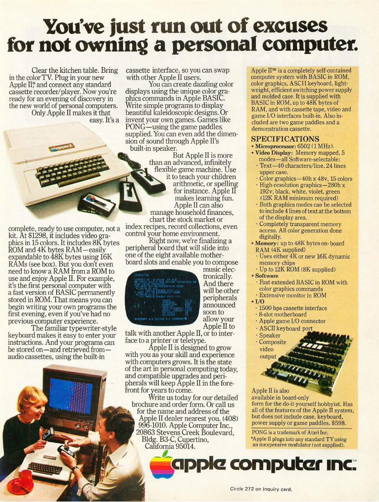
You've just run out of excuses for not owning a personal computer.
Clear the kitchen table. Bring in the colorTV. Plug in your hew . Apple IT'; and connect any standard cassette recorder/player. Now you're ready for an evening of discovery in the new world of personal computers.
Only Apple IT makes it that easy. It's a
complete, ready to use computer, not a kit. At $1298, it includes video graphics in 15 colors. It includes 8K bytes ROM and 4K bytes RAM -easily expandable to 48K bytes using 16K RAMs (see box). But you don't even need to know a RAM from a ROM to use and enjoy Apple II. For example, it's the first personal computer with a fast version of BASIC permanently stored in ROM. That means you can begin writing your own programs the first evening, even if you've had no previous computer experience.
The familiar typewriter-style keyboard makes it easy to enter your instructions. And your programs can be stored on -and retrieved fromaudio cassettes, using the built-in
cassette interface, so you can swap with other Apple IT users.
You can create dazzling color displays using the unique color graphics commands in Apple BASIC. Write simple programs to display beautiful kaleidoscopic designs. Or invent your own games. Games like PONG-using the game paddles. supplied. You can even add the dimension of sound through Apple IT's
built-in speaker. But Apple IT is more
than an advanced, infinitely flexible game machine. Use
it to teach your children arithmetic, or spelling for instance. Apple IT makes learning fun. Apple II can also
manage household finances, chart the stock market or
index recipes, record collections, even control your home environment.
Right now, we're finalizing a peripheral board that will slide into one of the eight available motherboard slots and enable you to compose
music electronically. And there will be other peripherals announced soon to allow your Apple IT to
talk with another Apple IT, or to interface to a printer or teletype.
Apple II is designed to grow with you as your skill and experience with computers grows. It is the state of the art in personal computing today, and compatible upgrades and peripherals will keep Apple IT in the forefront for years to come.
Write us today for our detailed brochure and order form. Or call us
for the name and address of the Apple IT dealer nearest you. (408) 996-1010. Apple Computer Inc. ,
20863 Stevens Creek Boulevard, Bldg. B3-C, Cupertino, California 95014.
Apple IITM is a completely self-contained computer system with BASIC in ROM, color graphics, ASCII keyboard, lightweight, efficient switching power supply and molded case. It is supplied with BASIC in ROM, up to 48K bytes of RAM, and with cassette tape, video and game I/O interfaces built-in. Also included are two game paddles and a demonstration cassette.
SPECIFICATIONS • Microprocessor: 6502 (1 MHz). • Video Display: Memory mapped, 5
modes - all Software-selectable: · Text-40 characters/ line , 24 lines
upper case. · Color graphics-40h x 48v, 15 colors · High-resolution graphics-280h x
192v; black, white, violet, green (12K RAM minimum required)
· Both graphics modes can be selected to include 4 lines of text at the bottom of the display area.
· Completely transparent memory access. All color generation done digitally_
• Memory: up to 48K bytes on- board RAM (4K supplied) · Uses either 4K or new 16K dynamic
memory chips · Up to 12K ROM (8K supplied)
• Software · Fast extended BASIC in ROM with
color graphics commands · Extensive monitor in ROM
• I/O · 1500 bps cassette interface · 8-slot motherboard · Apple game I/O connector · ASCIT keyboard · Speaker · Composite
video output
Apple IT is also available in board-only form for the do-it-yourself hobbyist. Has all of the features of the Apple II system, but does not include case, keyboard, power supply or game paddles. $598.
PONG is a trademark of Atarl Inc. *Apple II plugs into any standard TV using an inexpensive modulator (not supplied).
__ L pplcz computczr Inc:
Circle 272 on inq uiry card .

, ., ..... •
Games are More Fun with Action Inputs
c·:·f : ....
~ I I « . ·''''''1'· ~\
This littl e tru ism can be confirmed by anyone who has implemented and played a space war with joystick control, or used joysticks for direct control of moving systems such as robots or other mechanical marvels. Cromemco, 2432 Charleston Rd, Mountain View CA
Hard Copy That 's Hard to Beat for Speed
The Digital Group, POB 6528, Den· ver CO 80206, has announced what is probably the fastest and widest line width matrix impact printer mechanism and electronics package yet to be marketed to personal computing users. In kit form (kit refers to the e lectronics, not the mechanics), prices for this printer start at $495 . What you get is a fast 120 characters per second 5x7 dot matrix printer which gives 96 characters per lin e at 12 characters per inch pitch, and lin e spacing of six lines per inch .
A New Audio Tape Cassette Driver for the Altair Bus
PerCom Data .Company In c, 4021 Windsor, Garland TX 75042, has just introduced a new vers ion of Harold Mauch's Kansas City standard phase en· coding audio signal interface board, a version wh ich plugs directly into an Altair bus s lot. Harold's design al lo ws phase encoding with redundancy at 300
94043, has sent along this photo of the new model JS-1 joystick conso le adapters for their Alta ir compatib le D+7A 10 board. What you get is two independent game contro l boxes w ith two axis joysticks, four game function buttons, and loudspeaker outputs for aura l effects (such as photon torpedo or phaser sounds). The kit form of the box (in foreground) is ava il ab le for $65 .•
Circle 601 on inquiry card.
Since it is a true impact printer mech anism intended for computer systems use, it will take up to four part forms and shou ld prove most useful to business people for that reason. For the amateur computer person with software deve lopment in mind, the 120 character per second rate means listings of assem· blies and compilations which take one twelfth the t ime of a 10 character per second Teletype, but at a price for th e mechanism and its interface which is lowe r than th e new cost of a T eletyp e ! Other featu res of the OEM m ec hanism se lected by the Digital Group include built·in ribbon reinkers for a total ribbon life of 10,000,000 characters, use of 8.5 in ch (22 cm) wide standal'd roll, fanfold or sheet paper, an 8 bit parallel interface ready to plu g into yo ur computer's output port after yo u wire up the cab le, and th e option of double w id th characters. For those with idle cur iosity, the inking li fe of 10,000,000 characters before replacement of ribbon co rresponds to over 23 hours of f lat-out printing, or 250, 000 lin es with 40 nonblank characters per line .•
Circle 603 on inquiry card.
16
bps (Kansas City standard), 600 bps, 1200 bps and 2400 bps. I n ad d ition to the tape interface function, the CI-812 product also in clud es a compan ion RS-232 terminal interface with data rates from 300 to 9600 bps. The kit price of this board is $89.95, and an assembled vers ion is $ 119.95 .•
Circle 602 on inquiry card.
Inexpensive Wire Wrap Tools
-
OK Machine and Tool Corporat ion, 3455 Conner St, Bronx NY 10475, has come out with a unique produ ct line of wire wrapping tools and accessor ies for the amateur electronics person. These products in clud e manual and battery powered wire wl·t.pp in g tools, precut and stripped wire, wire rolls, du al in lin e package sockets, and wire wrapping "kits." Of particular interest to people on a tight budget is a new lo w in prices for wire wrapping tools which a re powered. The OK BW·630 battery powered wire wrap tool uses standard C size batteries and comes equipped with a b it and sleeve fa I' wrapping AWG 30 wire for only $34.95 (less batteries). This is not a kluge, but a genuine wire wrap gun with positive indexing mech anism to return the bit to a well defin ed position after each wrap, and the usual "anti· backforce" spring loading of the bit to prevent overwrapping. Both of these features are standard items on the industrial wrapping guns which have bee n used for years .•
Circle 604 on inquiry card.

Order your AppleII now. Use this order form to get your Apple II fast. As a special offer for those who order now, we will include free a custom vinyl carrying case (a $50 value). And we will also pay shipping charges to anywhere in the continental United States.
Apple II Price List. RAM Apple II Calif. Residents Apple II Calif .. R~sidentS Complement System Add Board-only Add .
4K $1,298.00 $ 84.37 $ 598.00
8K 1,398.00 90.87 698.00 45.37
12K 1,498.00 97.37 798.00 . . c 51.87
16K 1,698.00 110.37 978:00 'i . 63.57 .
20K 1,778.00 115.57 1,078:00 70.07
24K 1,878.00 122.07 1,17KOO ,
32K 2,158.00 140.27 1,458.QO I Y, 94:7-7
36K 2,258.00 146.77 1,558:00 101.27 .
48K 2,638.00 171.47 1,938.00 . 125.~7.
Memory is offered at a 20 % savings when ordered with the system-or board-as reflected in the prices above.
Additional RAM can be easily added-in at a later date as your needs develop. One set 4K chips (4K bytes) $125 One set 16K chips (16K bytes) $600
Prices and specifications subject to change without notice.
pplC! computczr Inc:' 20863 Stevens Creek Blvd., B3-C Cupertino, California 95014 (408) 996-1010
-~--~---~-----~~~-~ OrderforDl o Please send me an Apple II System
o Board Only with _ K bytes of RAM (4K minimum) at $ ____ _
California Residents add 6.5% tax ________ _ Tot"l $ _______ _
Name _______________ ___
Address _ ______________ _ City ________________ _
State - ____ Zip __________ _ Phone _______________ ___
Shipping Address (if different)
o Cashier's check or money order enclosed.
(Please allow 2 additional weeks for personal checks.)
Please charge to my
o BankArnericard
o VISA o Master Charge Card Number ______________ _
Expiration Date _____________ _
Signature _______________ _
Mail to: Apple Computer Inc., 20863 Stevens Creek Blvd., B3-C, Cupertino, California 95014
~~~-~~~--------~--~ ., Circle 272 on inquiry card.

Designing Multichannel
Douglas R Kraul 4373 Ashwoody Trl Atlanta GA 30319
7
6
:;
ANALOG 4
INPUTS :3
2
0
Analog interfaces to and from the personal computer system can present a difficult dilemma to the small systems user : The analog interface usually is a very expensive propos ition, especia ll y if more than one inpllt and one output are needed. Schemes like that suggested by Roger Frahk (page 70 of the May 7976 issue of BYTE], can greatly reduce hardware complexity, ahd thus cost, since much of the interface burden is left to the software of the computing system. Direct extension of this principle to the case of mUltiple input voltages and multiple output voltages can, however, result in a h ard~are cost that at the least rises linearly with the number of needed outputs and inpu ts. One alternative scheme requires an additional bit of input to the computer and one additional vo ltage
DIGITAL TO ANALOG CONVERTER
ANALOG MULTIPLEXER 10
PORT A 7
6
5
4
:3
2 OUTPUT
INPUT
0 ::;ELECT
OUTPUT DAC
>---~INPUT IO PORT B
I----------~OUTPUT
Agure 7,' Block diagram symbolizing the hardware that is needed for a multiplexed analog to digital converter for eight inputs. The three outputs from 10 port B select the analog channel. The output from the multiplexer is fed to the negative side of a voltage comparator. An analog output from a digital to analog converter is fed to the positive side of the comparator. When the analog value from the converter is greater than the value being tested, the voltage comparator will output a 7. Using successive approximations the input voltage can be determined.
18
comparator for each additional ana log to digital input up to a total of 8. On the output side each additional voltage output leads to an ad ditional 8 bit output port and an additiona l 8 bit digital to analog converter. This resu lts in a situation where a many input, many output analog interface requ ires an inordinate amount of hardware, which means money to the user. (We should not kid ourselves by saying that large numbers of ana log channels are rare ly needed. Many worthy applications, like control of analog music synthesis, automated test faciliti es or control of robots wou Id easily push the number of channels needed beyond the point of no return for the previously suggested schemes of interface.) Thus one must turn to a modified philosophy of interface design in order to meet the necessary goal of a less expensive analog interface.
Fortunately digital techniques prov ide us with a method of soluti on to the problem: time mUltiplexing. Time multiplexing is simply the process by which one device can be made to function as many I ~gica l devices. To the user these virtual devices appear as if they werefiJ ll f ledged dedicated devices. Thus our objective is to find some technique by which one analog to digital. converter and
. one digital to analog converter can be made to function in many seemingly simultaneous conversions.
Basics of Time MUltiplexed Interfaces
The basic . principles are illustrated first for the analog to digital case. Figure 1 illustrates the hardware that allows multiplexed analog to digital conversions. An output port, A, from the computer is used to provide the necessary eight bits to drive the digital to analog converter (DAC). The Qutput of the digital to analog converter is connected to the minus input of the voltage

Analog Interfaces
comparator. The output from the comparator provides an input to the compu ter by way of the most significant bit of an input port to the computer. This structure thus far is identical to the scheme proposed by Roger Frank. The difference is th at the pos itive input to the comparator is no longe r connected directly to the voltage to be converted. Rather the comparator is connected to the voltage to be conve l"ted by way of an analog multipl exe r.
The analog multiplexe r here is perfnl"ming the needed funct ion th at all ows one analog to digital converter to deal with many chann els. A typical applicat ion might Lise <I n 8 to 1 multipl exe r. ThLi s anyone of the eight vo ltage inputs might become the volt" age to be converted if the mul t iplexer se lects it.
The selection is accomplished by a binary code applied to the se lect inp ut of the multipl exe r. In an 8 to 1 device the bin "ry code 0'11 would pick th e input labe led 3. The code which selects the input was set by the computer through an output port. For our 8 to 1 example three bits wou ld be needed, possibly originating from the lower three bits of an 8 bit output por t.
This change results in almost no change in the software that would service the analog to digital conversions. In fact, the only necessary modification is to preload the channel selection word, which chooses the vo ltage tn be converted in the proper output port. Then the analog to digital conversion routine can be called .
Time Multiplexed Digital to Analog Conversion
MUltiplex ing of the analog to d igita l conversion rea lly only so lves half of the analog interface problem. The pro bl em of economically generating multipl e analog out-
puts from th e converter still remains. We can apply the ve rsat il e analog multiplexer to so lve th is prob lem as we ll. (However, there are complications that can mask the simpli city of the method. )
The basic hardware of the multipl exed digita l to analog converter output is shown in bl ock for m in figure 2. Once aga in the sou rce of the digital to ana log converter's word is an 8 bit output port from th e computer. The output is now connected to multiplexed sample and hold circuits. Much li ke th e multiplexer used in the analog to digita l conversion system the multiplexed sample and hold s. connect the output of the digit:!1 to analog conve rter to the desired ana log outpu t which is chosen by the select inputs to the mUltiplexer. The difference between the plain analog multiplexer and
SAMPLE AND HOLD ANALOG CIR CUITRY MULTIPLE XER
7 7
6 6 INPUT
5 5
ANALOG 4 4
OU T PU T S 3 3
2 2
OUTPUT SELECT
0 0
STR OBE
DIG ITAL TO ANALOG CONVERTER
[0 PORT A
1-------t8 ro I-------t~ I-------tu
PORT B
T
'-----------1 OUTPUT
Figure 2: Block diagram of the basic hardware needed for a multiplexed digital to analog converter for eight channels of output. Three bits of output fro m 10 port B select the channel that is to be used. When a strobe is enabled the chosen channel is activated. Each analog channel has a sample and hold circuit which must be updated periodically due to the leakage of the capacitor.
19

INPUT SWITCH HIGH IMPEDANCE
BUFFER
VOLTAGE TO BE HELD
SAMPLE COMMAND
HELD VOLTAGE
Figure 3: Functional schematic of a typical sample and hold circuit. The input switch can be mechanical or electronic. In the case of a multiplexed interface it is an analog switch.
Figure 4: Flowchart of a typical 10 driver for a digital to analog system. This program is called periodically to update the value that is being held by the sample and hold circuitry.
the multiplexed sample and hold is memory. The multiplexed sample and hold has the ability to remember the voltage that was applied to the desired output (for a while).
Before proceeding, some background information on sample and hold circuits in general will prove instructive. A functional schematic of a sample and hold circuit is shown in figure 3. The major components of the sample and hold circuit are an electronic input switch, a memory capacitor and a high impedance buffer. The sample and hold circuit works as follows: The voltage to be remembered is applied to the input. The switch is closed, allowing the voltage to be applied to the capacitor. The switch is then opened and the input voltage can now be changed because the output of the sample and hold now reflects the formally applied voltage. This discussion assumes ideal components. There are a number of error sources. The majority revolve around the memory capacitor.
The remembered voltage is stored as an electric charge in the memory capacitor. Because of this any variation of charge with time, ie: current, causes an error in the remembered voltage. This explains the need for a high input impedance in the buffer amplifier so that it doesn't drain away too much charge. A measure of a sample and hold circuit's ability to retain the voltage to within a certain percentage is its hold time. Another probl em associated with the memory capacitor is acquisition time. This arises from the fact that charge cannot be delivered instantly to the capacitor. A finite amount of time is needed to deliver enough charge to change the capaci tOl' to the new vol tage. Thus we have two design parameters : hold time and acquisition time.
The mUltiplexed design is not much different from the principles outlined above . The sample switch is merely replaced by our friend, the analog multipl exer. The output to be changed is selected, the strobe then enabled (closing the switch) and after the acquIsition time, disabled (opening the switch). The select word and the strobe will
20
possibly originate from the lower four bits, for an 8 output system, of an output port from the computer.
Th is type of interface does represent a burden on the computer. The reason for this burden is the very fini te hold time of the capacitor, No sample and hold circuit can retain its value forever. The time can be increased by using a larger capacitor, but a limit is reached because a larger capacitor leads to longer acquisition times. Thus, the sample and hold device must be updated periodically if the outputs are to remain accurate. This situation is not unlike that of dynamic memories which are effectively two state sample and hold circuits.
Use of the MUltiplexed Digital to Analog System
Obviously this type of interface will require much more computer intervention. The software, though, is not difficult. A possible 10 driver is flowcharted in figure 4. For an 8 output system an 8 entry data file is needed to hold the current output values. Periodically (perhaps cued by the interrupt system) with a period less than the hold time a routine is executed to update the eight outputs. The main loop of this routine consists of the following : The value of the output presently being updated is sent to the digital to analog converter interface. The output is then selected and strobed. This action then repeats until all eight outputs have been updated.
What Time Multiplexing Buys You
For the small systems user minimizing hardware is essential. The potential saving of a time multiplexed analog interface is high. The reason for this in general is the reduced hardware. Another not so apparent reason is the ease of expansion.
The most obvious hardware savings occurs in the digital to analog converter. Th is is because eight channels can be had for the cost of one converter, one 8 to 1 analog multiplexer, eight memory capacitors, eight output buffers, and two output ports. This is contrasted to the eight converters, and the eight output ports from the computer needed by the conven tional brute force approach. On the input side the gain is not as obvious. Here we have replaced eight comparators with one comparator and a multiplexer. Both cases require an output port, an input port and a digital to analog converter. A check of prices reveals , though, that eight comparators cost more than one multiplexer.
The clincher is when one considers updating the system to more than eight chan-

nels. The output channel needs only to increase the number of sample and hold devices which is cheaper by factors of eight. The brute force scheme requ ired one more converter and one more output port per additional channel. Table 1 compares the number of components needed for a conventional and a multiplexed system based on 16 channe ls.
The multip lexed analog to digital conversion process has an even more spectacular success. In the dedicated hardware approach each channel requires one comparator and one bit of input to the computer. The increment for the mUltiplexed approach is on ly one multiplexer per eight additions, and one bit of output. Table 2 compares the needed components, based on 16 channels. Thus overa ll we see that the multip lexed approach offers a multitude of hardware savings.
What Time Multiplexing Costs You
This design technique is typica l of many that trade hardware for software. Obviously since we have taken so much out of the hardware, the software and computer efficiency will degrade. It is perh aps a truism that if the interface is designed in tel li gently these problems can be minimi zed.
Th e ana log to digital interface suffers the least. .The main prob lem here is the amou nt of time spent doing the conversion routine. If fast changing inputs or a multitude of moderate inputs are to be converted then the computer is severe ly loaded. However, many applications only require moderate conversion rates. Foremost of these are interfaces to human operators. Max imum convel'sion rate needed here is around 100 Hz. Typically, this is around 0.001 Hz to 0. '1 Hz. Examples of this are the proportional contro ls in games and operator set parameters . Control signals in electronic music also fall in these categories. Thus this type of interface can work well in many
GLOSSARY
Acquisition Time: The time requ ired for a sample and hold circu it to change from its previous value to its new va lu e within a prescribed tolerance.
Analog Multiplexer: A sol id state dev ice that a ll ows a multitude of connections to be accessed bV a common line . The action is li ke an N position switch .
Comparator : An analog device whose output is logical 1 if the plus input is greater than the minus input and logica l 0 if the situation is reversed.
Digital to Analog Converter (DAC): A device whose output analog signal (current typically) is proportiona l to a digital word at its input .
Component Dedicated Multiplexed
Digital to analog converter 16 1
10 ports 16+16 bits 2 8 to 1 multiplexer 0 2
Table 7: Comparison of the amount of hardware that is needed for the direct method of digital to analog converter versus the multiplexed method of interfacing. The table is constructed for an interface conSisting of 76 channels.
Component Dedicated Multiplexed
Digital to analog converter 1 1
10 ports 3 2 Vol tage comparators 16 1 8 to 1 multiplexers 0 2
Table 2: Comparison of the amount of hardware needed for direct methods of analog to digital interfacing versus the multiplexed method of interfacing. The table is constructed for an interface consisting of 76 channels.
typ ical applications if the rates and the numbers Me not excess ive.
The dig ita l to ana log interface suffers from a simil al' situ ation . Here the main problems are extremely slow changing outputs or large numbers of fast outputs. Here again an analysis of like ly appl ications revea ls that a great number of output signals res ide in the frequency spectrum between 1 Hz and 100 Hz. Samp le and ho ld circuitry can be economicall y designed with hold times in the excess of one second. Also the who le refresh process can be made transparent to the main program if it is done under interrupt control by causing the update routine to be executed at the rate of the fastest output in response to the request of a programmable timer. As with the analog to
High Input Impedance Buffer : A device whose in put draws li tt le current from any other devices connected to it. It is important in a sample and hold circuit since currents cause the voltage he ld in the memory capacitor to discharge.
Hold Time: Amount of t ime that passes before t he output from a sa mple a nd hold c ircuit changes from the origina ll y held value by a prescribed to lerance.
Sample and Hold : Analog memory device which stores a voltage as e lectrica l charge in a capacitor.
Time Multiplex ing : Process of combining several measurements for transmissio n over one signal path. In our case. this s igna l path is the 10 port structu re of a processor .
21

IK
;J; 1000pF
IK
;J; 1000pF
IK IC9 CD405 1 6
4 10
3 IK
7 2
ENABLE 6 6 5 5 C
9
ANALOG I 4 10 B
OUTPUTS 12 3 II I K A
15 2
14 I
130
+15V
~ 3.9K
10pF
OUT
ICI3 LM31B
3pF
lCI2 LM 311
3
10K -15V
2
3
2 .7K
2.2K
I.BK 2 .2 K
4 OUT
15 -VREF
OUTPUT lCII PORT
MCI40BL-B
2 .2K - 15V
IK '>7=---_ ..... __ ..:S;:.:IG::;.N:....:::.B I:..!T-c:> 7 10
~~-4-4 __ ~20NO~_~~~~ PORT
l'lOOOPF
IK L-"-ST.:...:R.:.;O"-'B""E'---_-(:::> 3 SELECT 2 +15V
" l'lOOOPF
SELECT I I PORT 2 10 ~ SELECT 0
..... t-t--""'-!==-='-"-.!::....--c:> 0 + 5 V
IK I lCIO I CD4051
;J;IOOOPF 7 10
3
OUT IC I TO B ENABLE:
CA3130 C ANALOG 4 B 10
INPUTS A II +
100pF
Number Type +5V GND -15V +15 V -5 V
1 to 8 CA3130 7 4 9 CD4051 16. 8 7
10 CD4051 16 8 7 11 MC1408L-8 13 2 12 LM3 11 1 4 8 13 LM31 8 4 8
Figure 5: Schematic of the multiplexed analog to digital and digital to analog interface. The parts were mostly chosen for speed and cost considerations. The integrated circuits are mostly CMOS. All resistances are measured in ohms and all resistors are 7/4 W. Be sure to bypass each power pin with a 0.07 pF capacitor to help eliminate any stray spil?es originating from power surges.
d igital cases this type o f interface works we ll with a moderate number of medium speed o utputs or a multitude of low speed outputs. Note that outputs wh ich can be changed at a rate up to that of the acquis ition time (if only o ne channe l is used) can be had by using fewer channels in the output program loop. Outputs that meet these requ irements are some automatic testing signals, mechanical devices and control signals for electronic music.
22
-15V
To summarize, this type of interface burdens the computer system. Using it wisely for moderate types of signals does lead to a workab le system . Conveniently these types of signals are qu ite preva lent in in terfaces to humans, and many types of equipment.
A Complete Design Example
To illustrate these principles in more concrete terms a complete interface is described in figure 5. The 8 channel interface represents hardware well within the realm of most sma ll systems users. It is optimized for signa ls from 0 .1 Hz to around 100 Hz, though lower and higher rates are possible at the expense of efficiency. This type of interface is useful in interactive games, testing of equipment and electronic music. Parts used are neither exotic nor expensive.
Figure 5 contains the complete circuit. The fo ll owing comments o n component se lection are in order. The digital to analog converter was chosen for cost reasons . However, a lmost any state of the art current output converter can be used. Note that a

mUltiplying converter can provide for scaling of the output by a voltage, possibly from another interface. The LM318 operational amplifier was chosen to be the current to voltage converter to minimize response time of the DAC. As such, only an operational amplifier of similar speed should be substituted unless you cari tolerate slower response. Also care must be taken to isolate the amplifier from stray signals, or it could become unstable and oscillate. The multiplexer chosen for both converters is one of the CMOS variety. I n order to meet the specifications on this device and give an easy design, the voltages of this system are restricted to ± 5 V. This allows for adequate range for most 8 bit applications. 10 V full scale means one bit is 39.1 mY. This can be scaled down if needed.
The sample and hold capacitor was chosen to satisfy the acquisition and hold time requirements. Changing its value can tailor the system to individual needs. Always use polystyrene capacitors since their characteristics are essential to a good interface. I used the new CMOS operational amplifiers for the buffers because of their high impedance and low cost. Notice that they operate on the same power supplies as the analog switches.
The comparator was chosen for its low cost and speed. Similar devices could be substituted. The necessary power suppl ies are ±15 V and ±5 V. The ±15 V could be reduced to ±12 V if convenient.
The software for such an interface is not difficult. Roger Frank's article and figure 4 contain the basics. A complete routine written for an MOS Technology 6502 based system is shown in listing 1.
Summary
A multichannel analog interface can be designed with a minimum of hardware if a
Listing 7 .. Typical program written for a 6502 based system to update eight digital to analog conversion channels. The program sequentially addresses each channel, outputs the desired voltage to be held, disables the channel, and steps to the next channel. This is done once for each time that the program is called. This program could be set up as an interrupt handler which responds to a clock strobing an interrupt line.
Label
UPDATE LOOP
Op
LOX LDA,zpa,X STA TXA STA ORA STA DEX BPL RTS
Data Definitions
Operand
#07 BUF DAC
CONT 04 CONT
LOOP
BUF : A string of output bytes DAC : Address of DAC output port CONT : Address of control port
Commentary
initialize pointer; get next byte for output; output byte; accumul ator :=pointer; select channel and enable sample and hold; turn sample and hold strobe off; turn selected sample and hold off; pointer: =poin ter-l ; if pointer >=0 then go to LOOP ; else return from subroutine;
few software vs hardware trade offs are made. Though the mUltiplexed approach does impose some software burdens, for most appl ications the variat ion of the outputs and inputs is slow enough to make this type of interface transparent under the interrupt system. This type of interface should make many real world applications possible to the limited budgets of most experi men ters.-
BIBLIOGRAPHY
1. Frank, ."Microprocessor Based Analog/Digital Conversion," BYTE magazine, May 1976, pages 70 to 73 .
2. Graeme, Huelsman, Tobey, Operation Ampli· fiers : Design and Application, McGraw· Hill,1971 .
3. Kraul, "Analog I nterfaces for Microprocessor Systems," Electronotes, Newsletter of the Musical Engineering Group, volume 8, number 63; March 1976, pages 11 to 14.
COMPUTER MUSiC WITtt OR WiTttOUT .==-."._...JL-... -TttE COMPUTER EQUALLY TEMPERED DIGITAL m ANALOG l:iiN~ERTER Based on a multiplying prinCiple, the 8780 generates the exact exponential stair-step function required to make the simplest linear r esponse oscil.1ators and filters produce equally tempered musicai intervals. 6 bits of data generate over 5 octaves control voltage. Compatible with P AIA synthesizer modules, easily interfaced to any proces sor with or without hand-shaking logic. #8 780 D/A CONVERTER KIT .. $34.95 (+$1 postage)
THE PAIA HIGH LEVEL LANGUAGE FOR COMPUTER MUSIC DATA ENTRY (We call it a keyboard) An n key roll·over scanning matrix encoder tied to a 3 7 note AGO keyboard provides 6 bits of date and both STRO BE and STROBE control outputs. Input control lines to the encoder include SCAN (starts stops the encoder clock), RESET, START & making the keyboard universally applicable to all computer/processors from the largest to the smallest. #8782 ENCODED KEYBOARD .. $109.95 (+ freight 20 lbs)
WITH A COMPUTER Both the 8780 D/A and the 8782 Encoded Keyboard easily interface any processor prOViding capabilities and control
never before ssible ~~;':~~~=~~L
ELECTROIIICS. IIIC.
DEPT. 6-B 1020 WEST WILSHIRE BLVD.
23
WITHOUT A COMPUTER An infinite hold, DIGITAL Sample & Hold and the heart of an entire system of modules that will be introduced over the next few months including: Memories,
output modules and others.
OKLAHOMA CITY, OK 73116
Circle 265 on inquiry card.

COMPLETE FLOPPY DISK SYSTEM
FOR YOUR ALTAIR/IMSAI $699
That's right, complete. The North Star MICRO -DISK SYSTEMTM uses the Shugart
minifloppy ™ disk drive. The contro ller is an S-100 compatible PC board with on-board PROM for bootstrap load. It can control up to three drives, either with or without interrupts. No DMA is required .
No system is complete without software: we provide the PROM bootstrap, a file-oriented disk operating system (2k bytes), a nd our powerful extended BASI C with sequent ial and random disk file accessing (10k bytes).
Each 5" diameter diskette has 90k data byte capacity. BASIC loads in less than 2 seconds. The drive itse lf can be mounted inside your computer, and use your existing power supply (.9 amp at 5V and 1.6 amp at 12V max). Or, if you prefer, we offer a power supply ($39) and enclosure ($39).
Sound unbelievable? See the North Star MICRO-DISK SYSTEM at your local computer store. For a high-performance BASIC computing system, all you need is an 8080 or Z80 computer, 16k of memory, a terminal, and th e North Star MICRO-DISK SYSTEM. For additional performance, obtain up to a factor of ten increase in BASIC execution speed by also ordering the North Star hardware Floating Point Board (FPB-A). Use of the FPB-A also saves about 1 k of memory by eliminating software arithmetic routines.
Included: North Star controller kit (highest quality PC board and components, sockets for all I C's, and power regulation for one drive), SA-400 drive (assembled and tested), cabling and connectors, 2 diskettes (one containing file DOS and BASI C), complete hardware and software documentation, and U.S. shipping.
MICRO-DISK SYSTEM ... $699 (ASSEMBLED) . . . .. .. $799
ADDITIONAL DRIVES ... $425 ea. DISKETTES ......... . .. $4.50 ea. FPB -A .. . . ...... ... ... $359
(ASSEMBLED) .... . . . $499
Circle 155 on inquiry card.
T o place order, send check, money order or SA or MC card # with expo date and signature. Uncertified checks require 6 weeks processiny. Ca lif. residents add sa les tax .
24
A High Performance Character Display Terminal
Volker-Craig Ltd, 266 Marsland Dr, Waterloo, Ontario CANADA N2J 3Z 1, has introduced a new data terminal in te nded for use in small business systems, timesharing and other small comp u ter end user app lications. The featu res of this terminal in clud e RS232C in terface at rates f rom 110 to 9600 bps, a 1920 character display (24 lines of 80 characters), 12 in ch CRT display, composite video output for extra slave monitors, XY cursor address in g by computer or operator, 64 key ASC II keyboard with tactile feedback and automatic repeat, and an optional separate numeric data entry keypad. Options include upper and lower case ASCII keyboard and display, switched seria l interface, parallel input and output interfaces, and custom keyboard character fo nts suc h as APL or French. The display is the model VC303A, and the price is $15 95 in quantities of one, $995 to distributors and OEM quantity buyers.-
Circle 605 on inquiry card.
Here 's a Product That Counts
E Barry Hil ton, president of Automated Industria l Measurement In c, POB

& A complete language for "8008"'''8080'' systems including source listings, routines, flow charts and more!
New books ... for everyone who's into their own computer. Programs.
Fun. Games. Languages. Excitement.
•• • that's simpler than machine language.
SCientific ELementary BAsic Language for "8008" /"8080" systems. A complete, illustrated program book. Routines . Techniques. Source Listings. Flow Charts. And more. Took several years to develop. Now yours for many years to come. First time that intimate details of higher level language has been offered for such a low price. Only $49! You get 5 Commands: SCR, LIST, RUN, SAVE, LOAD. 14 Statements: REM, LET, IF ... THEN, GOTO, FOR with STEP, END, INPUT, PRINT, NEXT, GOSUB, RETURN and optional DIM. 7 Functions: INT, SGN, ABS, SQR, RND, CHR, TAB. And, it runs in 8K and more. Here's all the data needed to customize a high level language for your system . .. at a fraction of the cost!
Order your copy today! Get $49 started advancing your system! ppd.
SCELBAL SUPPLEMENTS •.• SCELBAL has taken off so fast, .two special supplements had to be printed . First, there's Extended Math Functions: SIN, COS, LOG (BASE E) , EXP (BASE E) and ATN . .. only $5.00 ppd . The second supplement, String Handling Capabilities, includes the numeric functions LEN and ASC. It sells for only $10 ppd.
• •• Cook up mouthwatering programs
for your "8080" or "6800"! Delectable "how to" facts, Random number generators. including descriptions of And more. You even get float-"8080" or "6800" instruction ing point arithmetic routines! sets. How to manipulate Input! output processing for stacks. Flow charts . Source basic I / O programming
listings. General pur- through interrupt processing. pose routines for And so much more, we can't multiple precision list it all here. Scelbi's operation. Program- Software Gourmet Guides ming time delays for and Cookbooks for "8080" real time applications. or "6800". (Specify!)
Order your copies today! $ 995 Start cookin'! Bon Appetite. each ppd.
~~L4XY Microcomputer Outer ~ Space War Games ..•
Captain your own starship on an inter-gallactic journey to adventure. Meet alien ships in realistic combat. Plan a painstaking journey filled with battles, refueling problems, weaponry, warp factors and more-all against your "8008" / "8080" or "6800" computer. Either complete book, written in machine language for 4K memory, is an ongoing, ever-changing interstellar adventure, including source listings, flow charts, routines and much more. Choose your copy today. Blast off to high adventure in outer space!
l,-.!:::::~,:-------,order either GALAXY today! $1495 each ppd •
\, Prices shown for North Am erican custom ers. Master Charge. Postal and Bank Money Orders preferred . Personal checks delay shipping up to 4 weeks. Pricing , spec ificati ons, availability subject to change without notice.
w a •• S 7
Scelbi Books are available in many fine Computer Stores.
1~llm. ~OI'lI>IJ"IR Post Office Box 133 PP STN (O~IIJI •• ~6 .~~. Milford, CT 06460
Circle 26 on inquiry ca rd .
,
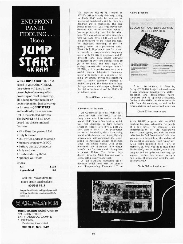
END FRONT PANEL
FIDDLING ... Use a
lUMP STfiitTM
4K itfiM
With a JUMP START 4K RAM board in your Altair/IMSAI, the system will jump to any preset byte of memory after power-up or reset. Never toggle a jump to your monitor or bootstra p agaiq! Just power-up or hit reset-JUMP START a utoma ti ca lly transfers controlto the selec ted address. The JUMP START 4K RAM boa rd has these standard fea tures:
, 4K 450 ns low power RAM
• fully buffe red • DIP switch address selection • memory protect with POC • battery backup connector • fully socketed • disa 5led during INT A • op tional wa it state
Prices: Kit $145 Assembled 190
Call toll-free anytime to place credit card orders:
800/6485311
Prepa id mai l orders shipped pos tPll id ill USA. Ca li[orni a residen ts add 5'!!. sa les tux.
MICROMATION INCORPORATED 524 UNION STREET SAN FRANCISCO, CA. 94133 415/398-0289
Dea ler inquiries invited
CIRCLE NO. 242
125 , Way land MA 0177 8, stop ped by BYTE's offices in ear ly Febru ary, tot ing an Altair 8800 und er hi s arm and an interest ing peripheral which hi s firm has designed and is mark eting. The per ipheral is the AIM-1 005 freq uency meter, demonstrated to U5 moun ted upon a Vector prototypi ng card for the Alta ir bus. (This was a demo nstrat ion setup ; his firm will soon ha ve a $3 0 ca rd with all the connections to th e Altair bus made for piggyback moun t ing of the f requ ency meter o n a permanent bas is.) Wh at thi s $ '178 produ c t does for its user is provid e a programmable f requency meter with 13 bits of prec ision, and 11 d iffe rent t im e base ranges all ow ing meas urem ent over time periods from 10 J.lS to one hour. The input logic has scaling counters with an upp er li mit of 25 MH z, 50 it is possib le to ll1 ake a quite useful general labo ratory frequ ency meter with outputs on a co mpu te r te r· minal by simpl y dr ivin g thi s peripheral with a simple assembly language or BAS IC program. Th e device is interfaced through memory address space, decoding th e high o rd er fo ur bits of the 8080's 16 bit ad dress bu s. -
": ircle 606 on inquiry card.
A Synthesi zer Exampl e . , , .
AI Cy berne ti c Systems, POB 469 '1, Uni vers ity Park NM 88003, has se nt along so me new in formatio n on th eir Model 1000 Sp eech Synth es izer , wh ich was first described in Wirt Atmar's articl e in August 1976 BYTE, page 26. Th e pi cture here is th e produ ct ion vers ion of th is device , wh ich i5 an analog model of the hUll1 an vocal t ract, digita ll y programm ed with comma nd s that co rrespo nd to American English phonemes. Since th e dev ice works wi th coded phonemes, th e max imum inform atio n transfer rate for speech which is req uired is about 50 bp s. The dev ice plu gs direc tly into th e Altair bus and cost is $325 , with deli ve ry from stock.
A signifi cant and inte rest in g bi t of literature which came with th is pi cture was "Programming Example 'I," an
26
A New Brochure
EDUCATION AND DEVELOPMEN MICROCOMPUTER
_UU ___ '"IC._._ .. -.."' ............. QjI.O'OCOO"_..,. .. '.l .u.,.' ....... '.""n." .. Q(""..,... ... "WUI_ .... } .. I.>'U ... 1 '.UC1_.~D .. 1T~UH I~M' '''' .H( NOfUS_ ""Y.IlJo01D".G.'.~..o~~-.()OIO
~,~(" .. tooo."''''...--.t .. .,..,_ ....... :."".""' .. <_.( .. " ..... ""':;.0.
",ote, •• ~.., .. "" ,_ .. ,~ . N .... U~'O ' .. ' r. II<"'>O"''' ...... '.'.''UHR .... U'
",,,,,,,,,,oooOf.'U''''I_.~ __ ~n .. " .. " ..... nl." .... ~.,,_UI.O ' .. , __
........ ... ~.(;~ .... ,0;"1 '"''.''' ''_ ~''''''' .......... a""~v ...... ". , ... It.' ''''.
E & L Instruments, 61 First St, Derby CT 06418, has just rel eased a new 8 page brochure describ ing th e MMD·1 education and development microcomp uter and its opt iona l accessories. Copies of the MMD-J brochure are ava il· ab le from the co mpany, as we ll as its represe ntat ives and author ize d dealers. -
Circle 607 on inquiry card .
Alta ir BASIC program with an 8080 mach ine language subroutin e fo r detai ls at a low leve l. Th e program is an impl ementation of the well · known Lunar Lander game, but with th e Qove l twist that th e "ship's computer" tells you your present height from the su rface of the plallet as you lan d. It will run on any Al ta ir 8800 equipped with 12 K of memory. So, what you do is p lug in the Mod el 1000, read in BAS IC, type in this program and set up its machin e language support routin e, then proceed to use a new mode of interaction with the com puter system .-
Circle 608 on inqu iry card.

The SOROe IQ120 CURSOR CONTROL. Forespace, backspace, up, down, new l ine, return, home, tab, PLUS ABSOLUTE CU RSOR ADDRESSING.
TRANSMISSION MODES. Conversation (half and fu ll Dup lex) PLUS BLOCK MODE - transmit a page at a time.
FIELD PROTECTION . Any part of t he d isp lay can be "protected" to prevent overtyping. Protected f ields are d isp layed at reduced intensity.
EDITING. Clear screen, typeover, absolute cursor addressing, erase to end of page, erase to end of li ne, erase to end of field.
DISPLAY FORMAT. 24 l ines by 80 characters (1,920 characters).
CHARACTER SET. 96 characters tota l. Upper and lower case ASC II .
KEYBOARD. 73 keys includ ing numeric key pad.
REPEAT KEY. 15 cps repeat action.
DATA RATES. Thumbwheel se lectable from 75 to 19,200 baud.
SCREEN. 12 inch rectangular CRT - P4 phosphor.
specialS of the Month North Star Micro Disk w ith power supply and cabinet .. . .. Kit - $699
A sse mbled - $799
IMSAI 1-8080 with TDL ZPU .... .. Kit - $825 A sse mbl ed - $975 .
Digital Systems FDS Disk Drive with CP/M Softwa re (assembled only) . Single - $1,750
Dual - $2 ,350
Mountain Hardware PROROM ..... Kit - $ 145 A ssembled - $210
Vector Graphic 8K RAM .. . .. . ... Ki t - $235 A ssembled - $285
XIMEDIA OFFERS A FULL RANGE OF PRODUCTS FOR THE PERSONAL COMPUTER ENTHUSIAST AND THE SMALL SYSTEM DESIGNER. LET US QUOTE ON ALL YOUR HARDWARE AND SOFTWARE NEEDS.
OUR RETAIL STORE - THE COMPUTERIST t m - IS NOW OPEN IN SAN FRANCISCO. CALL US FOR DIRECTIONS.
27
SPEC/IAL INTRODUCTORY PRICING
Kit $ 995 .00 Assembled $ 1,295.00 (Price includes block m ode, lower case and 24 line options.)
NOW WE'RE TOLL FREE
800-227-4440 (in California, Hawaii, and Alaska, call collect:
415/566-7472)
1290 .24th Avenue, San Francisco, CA 94122 (415) 566-7472
Circle 220 on inquiry card .
COD orders freight col lect. Orders with paymen t shipped prepaid. California residents add 6% sales tax . Pl ease allow 3 weeks for delivery.

The Digital Group adds character(s).
64, to be exact. The Digital Group's computer systems have a lot of character already. Just one quick look at any of our products in their unique custom cabinets confirms that. But we believe it never hurts to add a bit more .
So, the Digital Group has added character in a big way to give an added dimension to the operation of our video-based com-puter systems. We are pleased to announce our new TV readout with a 64-character line . It will give your system a great deal more capability. Give it more character, if you will.
Here are the specifics on the Digital Group TV Readout and Audio Cassette Interface:
1024 Character TV Readout • 64 characters horizontal by 16 lines • 7x9 character matrix (effectively 7x12 due to char
acter shifting) • 1K on-board RAM for buffer storage-requires
no main memory-completely independent • 128 character ASCII
Upper case alpha Lower case alpha with base line extenders (g, j, p, y) Numbers and extended math symbols Greek alphabet
• Software driven cursor-forward and backward • Compatible with most microprocessors; Interfaces
with 1 8-bit parallel output port • limebase may be driven with an external timebase
(may be synchronized to TV camera, TV set, etc. ) • Readout timebase available at connector (can be
used for graphic driver, etc.) • White characters on black, and!or black on white;
software selectable • Pluss into standard dual 22-pin TVC connector on
Digital Group Systems
Improved Audio Cassette Interface: • Reliable FSK recording technique • Uses standard unmodified audio cassette recorder
• Write cassette system uses a digitally synthesized frequency shift system, derived from TV system's master crystal oscillator
• Read cassette system easily aligned using the write system as an alignment aid.
• Runs at 1100 baud (100 characters! second)-loads 16K in 3 minutes
512 TVC to 1024 TVC Upgrade Kit: As always, when the Digital Group extends the capabilities of our systems, it doesn ' t mean obsolescence for any products . We are offering an upgrade kit for present Digital Group system owners who wish to go to the longer line length. This kit uses most of the Ie's from our TVCF readout. No unsoldering is required; all new sockets, capacitors, resistors, PC board and other necessary parts are supplied.
Prices: TVC-64-Full 64-character TV Readout & Audio Cassette interface:
Kit - $140 Assembled - $205
TVC-64UPG-Upgrade kit from TVC-F: Kit - $65
If you already own a Digital Group system, our 64-character line will definitely enhance its operation. If you're just looking, you might want to keep in mind that the Digital Group has a lot of characters.
Write or call now for details on our new 64-character TV readout and all our other exciting products .
( ~ cQll@j01@l ®IT@ill[g) ) box 6528 denver, colorado 80206 (303) 777-7133
Circle 78 on inquiry card.

Peripheral Vision i cts your cOl11puter.
,,-
",. '"'' '\¥~f:~;;:: ' ' ' .,' ,.'
WITH A FULL-SIZ!z. LOW-CO~I IMPACT PRINTER.
Until now, the hobbyist and small businessman have had one major problem in assembling a reasonably price microprocessor system with the capabilities found in the more costly computers. It was impossible to find a high-quality, high-output printer for hard copy needs at an affordable price .
Peripheral Vision has come up with a solution. We are offering a full-size impact printer designed for microprocessors-and it comes
with a mini price. Kit prices start as low as $495 for the printer and interface card. And that won't impact your pocketbook.
Peripheral Vision's printer is loaded with capabilities. Take a look: • It's fast-120 characters per second • 96 characters per line, 12 characters per inch horizontal, 6 lines per inch • Makes up to 4 copies simultaneously • Character set and pitch variable under software control • 5 x 7 character matrix • Ribbon has built-in re-inkers for a life of 10,000,000 characters • Paper can be either a standard 8V2-inch roll , fanfold or cut page • Interfaces to 8-bit parallel ports
Just remember, Peripheral Vision is committed to helping you get along with your computer. The new printer we are offering is another example. It is high quality, low in cost and will definitely impact your system.
Write or call now to find out how to impact your computer.
PO. Box 6267 Denver, Colorado 80206 (303) 777-4292
Circle 194 on inquiry card.

Newt: MAIN IMAGE SENSOR
. f
A Mobile, Cognitive
Robot
POWER CONVERSION '--- SENSORY
TURRET
COMPUTER
-BATTERY ENCLOSURE
Ralph Hollis
AUXILIARY IMAGE SENSOR
MOTIVE SYSTEM ---~ GEAR BOX
WALL FOLLOWER
~t--- (RETRACTED)
DRIVE MODULE
-REAR FEELER
(EXTENDED)
Figure 7: The robot Newt as it will appear when completed. There are three main ,subsystems shown in this diagram which was supplied by the author: motive, manipulator and sensory turret. The entire machine is controlled by an on board microcomputer. The motive power subsystem is built around two precision drive wheels actuated by stepper motors. The manipulator, a simple hand capable of grasping, lifting and rotating, is also actuated by stepper motors and includes various sensors. The sensory turret at the top is a platform which includes a main image sensor, which can be tilted to look straight down or up at a slight al7gle using a stepping motor; other sensors are shown in outline form, and are a subject for future experimentation.
Dept of Physics and Astrophysics Unil1ersity of Colorado
"Forbidden Planet," "Gog," "Silent Running," "Westworld" and others.
Alas, the imaginative stories of the science fiction writers have far outstripped the efforts of the robot engineers. Progress in building real robot devices has been painfully slow over the past several decades, al th ough a few individuals and small groups have produced some very interesting results.
Boulder CO 80309
In the late 1930s, a young man named Rossum began manufacturing industri al robots in a small factory on the outskirts of Prague. This venture was immediately successful and would have virtually guaran tced a second industri al revolution had it not been for a singular tragic circumstance: The robot workers became irrational and revolted. They turned on their masters and burned the factory to the ground.
Fortunately, the preceding scenario is only a work of fiction by the Czechoslovakian writer K Capek. Since Capek's coinage of the word "robot" in hi s 1923 play R U R it has been the subject of a great many works of science fiction, including Isaac Asimov's I, Robot and the movies
30
It is not my purpose here to review these works, but rather to describe a project with which I have been personally involved for some time: the construction of a freely moving robot vehicle which will be capable of interacting with its environment in a rational way, and managing its own survival. i he work is being done by a small group of pw ple in the Du ane Physical Laboratory of the UI,i\ Ci ~ii.y of Colorado. The project is being financed through personal funds, and in this sense qualifies as an "amateur" undertaking.

What are the requirements for such a robot? I t must be able to explore the environment in some orderly manner, measure the attributes of objects and obstacles encountered, classify them according to some scheme, and incorporate them in its evolving internal world model. The world model must have a logical structure which allows modifications to be easily made; it must be compact with respect to memory space, and it must use a c1esign which can be consulteq in some reasonable way. The roLot must be able to manipulate the world model (cognition), derive informed decisions from it, ancl carry out these decisions in physical action to achieve broadly defined goals.
Figure 1 is a general view of the robot as it will appear when completed. Practically speaking, it resembles less a met:;hanical man than, say, a shop type vacuum cleaner. The machine is cylindrical, about 36 cm (14 inches) in diameter and 76 cm (30 inches) in height, weighing approximately 27 kg (60 pounds). All rigid mechanisms lie within the cyl indrical boundary or can be retracted within the boundary !f necessary. This c1esign greatly reduces the number and diversity of senses required . The robot will be fitted with a smooth cylindrical skin (not shown), removable in sections for easy inspection and maintenance. Modular construction is used in the robot wherever possible. There are three main subsystems: motive, manipulator and sensory turret. These are presided over by an 8080 based microcomputer with 8 K bytes of EROM and 24 K bytes of programmable memory. The entire s'ystem is powered by a 6 V, 84 amp-hour storage battery.
How the Robot Gets Around
The robot is given locomotion by two main diametrically opposed drive wheels. A third (unpowered) castoring wheel is located at the rear. This motive geometry has been successfully employed in several other robot vehicles constructed by other groups, and has been in use in the author's robot research since 1957. The vehicle's center of gravity is located well aft due to the placement of the battery and other heavy components, obviating the need for a front wheel. The wheels are constructed of aluminum with neopreme O-ring tires. The main wheels are driven by stepping motors through precision 3: 1 gearing. A ~ingle c;;ommand step rotates a wheel 0.6 degrees, so there is a total of 600 steps per revol ution. If both wheels are moved in the same direction, the vehicle travels forwards or bac~-
wards in a straight line. If the wheels are moved in opposite directions, the vehicle executes a perfect rotation about its vertical axis. By stepping the wheels at different rates, a circular trajectory is ~pproximated having a radius which can range from ~ero to infinity. The hardware and software neCe'?sary to drive the stepping motors are discussed in some detail later in this article, since they have very general application.
The robot navigates principally by open loop dead reckoning. That is, it depends largely on the precise control of the wheels during acceleration, deceleration, and constant speed motion to achieve accurate positioning of the vehicle. The robot's position and azimuth relative to it fixed origin are computed at the end of each motion segment by counting stepping motor increments and using trigonometry. The precision attainable is limited principally by wheel slippage, ' unequal wheel diameters, non planar floors, round-off errors, and step quantization. In practice, all these errors are small for short distance movements.
The robot's excellent open loop performance makes it unnecessary to have continuous closed loop servo systems, such as have been extensively employed in other robots. For example, consider the problem of having a robot view a small object on the floor a short distance i\way, and then go pick up the object. One approach would be to have the robot continuously view the object as it moves towards it, adjusting its motion in a continuous way to converge qn the object and pick it up. In th is approach, a rather crude motive system would suffice, since errors are always nulled. A heavy load, however, is placed on the sensor-computer system. An alternative approach, the one followed here, is to have the robot vi~w the object once, and then compute ex~ctly how to move to the object and pick itup: When the computation is completed, the machine simply carries out the proper motions in a blind fashion. There is a 'greatly reduced strain on the sensor-computer system, at the expense of having to builq rather precise motive machinery. Of CO!JfS~, this approach assumes the relevant environment will remain fixed for the durati~n ~f the task.
In this genera! spirit, by using high precision open loop movements throughQfJt the robot, only intermittent feedback through the senses is ·required to close the control loop. In this way, the overall complexity of the robot c'an be kept at a reasonable level, allowing the rf1q\Jir~d computations to fall within the a,bilities or an on board microc;;omputer.
31

Scanning the Environment with Electronic Senses
The sensory turret (see figure 1) provides a general platform on which to mount various senses, some of which might be quite experimental and temporary in nature. It can pan a full 360 degrees, and a small section containing the main im age sensol· can tilt from approximately 30 degrees above horizontal to 90 degrees below hori zontal. Both of these motions are controlled by stepping motors. Th e main image sensor has a motorized focus control. Th e geometry of the "hand-eye" system allows orthogonal views of objects held in the manipul ato r jaws by using both image sensol-s under conditions of controlled focus and li ghti ng.
Each image sensor is a 32 by 32 element integrated array of photodiodes on a silicon chip measuring approximately 4 mm (0.1 inch) square. The arr-ay acts like a 1024 bit memory. Each element is precharged to a fixed vo ltage; then at some later time the voltage of each element is read out, decreased in proportion to the amount of li ght which has fa ll en on it. Several milliseconds are required to digitize the im age. Up to 16 levels of gray can be discerned, which means that 512 bytes of computer memory are sufficient for a single image. Once the image is obtained, it is anal yzed by appropriate software. The extl-emely small size of these solid state image sensors, and the simplicity of their associated electronics, make them ideal for robot use . Higher resolution devices such as charge coupled sensors and miniature television cameras are avai labl e, but thei Icost and complexity make them un attract ive for such applications. Besides, the amount of data generated wou ld be too unwieldy to handle with a microcomputer.
In addition to the main image sensor, several simple phototr"ansistol- li ght sensors are mounted on the tilting platform of the sensory turret. These enab le the mbot to locate and track point sources of ligh t.
Several other pro posed senses are to be mounted on the turret. These are shown in Ischematic form in figure 1. To the left of the image sensor is shown an ultrasonic ranging transmitter and receiver which should be extremely useful for finding the I·ange to walls at distances as great as 10 meters (33 feet). The idea is to transmit short bursts of 40 kHz sound and measure the time required for an echo to be received in order to compute the distance. Much of th e necessa ry circuitry is available in compact integrated form.
Just to the right of the im age sensor is shown a long wavelength infrared radiation detector with which it might be possible to
32
locate sources of heat such as dogs, cats and humans._
Located on an axis perpendicular to the main image sensor are shown two microphones which form part of a sound location system. The intent is for each sensor to acquire a short sample of sound. The computer then attempts to find a phase re lationship between them, thereby locating the direction of the source.
Many other possible senses can be jmagined; the sensory turret is intended to provide a versatile platform and interface for experimenting with them. For example, using a helium neon laser, or perhaps a compact metal vapor laser, it may be possible to provide an optical range finding system with high resolution if a suitable detector can be found. Eventually it is hoped to provide limited forms of speech synthesis and phrase recognition (using off line electronics with an analog radio link). This wou ld make it possible to give general spoken commands to the robot in contextual surroundings, and have verbal feedback to insure that the commands were being properly interpreted.
Sharing some space with the sensory turret system, and directly below the platform in figure 1, is the necessary power conversion electronics. These modules convert the battery voltage to ±12 V and +5 V (regulated) for use by the electronics, and also house the battery recharging circuitry.
Manipulating Objects in the Environment
The number of tasks which a simple robot can do is greatly increased if it has some sort of hand with which to grasp and manipulate objects in the envimnment. The hum an arm and hand system, with its 27 degrees of freedom, is a marvelously versatile mechanism. Large industri al manipulators are fairly comp li cated and have six or seven degrees of freedom. For practical reasons, the present system is limited to a mere three degrees of freedom which, when combined with the two degrees of freedom of the motive system, should be sufficient for carrying out simple tasks.
The manipulator is able to grasp objects, move up and down along the front of the robot by means of a rack and pinion drive, and to rotate about a hori zontal axis. All three motions ar-e controlled by stepping moto rs. Th e manipulator has a parallelogram geometry which permits the jaw faces to remain parallel regardl ess of theil" separation. This feature simplifies the problem of picking up objects of varying sizes. When not in use, the jaws open wide enough to bring all

parts of the mani pul ator within the cylindrical boundary of the robot, where it is o ut of the way and does not cause problems when the robot turns and mane uvers in tight places.
An auxili ary 32 by 32 element im age sensor with fixed focus lens is mounted directly in the manipul ator assembly, providing a view of whatever object is between the jaws.
In addition to mechan ical force sensors in the jaw faces, there are several infrared LEOs in one face with opposing phototransistors in the other face. These LED phototransistor pai rs defi ne beams of I igh t between the two jaw faces. By scanning the manipul ator up and down, and moving the entire vehicle forwards and backwards, these bea ms enabl e the robot to measure the height and depth of simple objects resting on the floor between the jaw faces, as well as to determine when ob jects are co rrectly positioned for picking up. The widths of objects are measu red directly by coun t ing the number of steppi ng motor pul ses req uired to close the jaws on the object.
A tactile sensor is moun ted o n the front of each jaw to enab le the robot to sense and locate large obstacles such as walls. Th e robot can align itself accurate ly eith er parall el or pNpendicular to the wall, after perfo rming a simpl e sel-ies of maneuvers. This action is conveni ent for many of the tasks the robot might have to carry o ut. For example, a si mple strategy of maneuve rs al lows the robot to "square itself off" fro m a corner in a room, thereby defining a pl-ecise origin for its navigat io nal coordinates_
The tact il e se nsors doub le as electrica l contacts used for plugging into ord in ary wall out lets fOI- the purpose of recharg ing th e robot's battery (more about this late r).
All electrical power and signals to and from the manipulator assembly are sent through folding ribbon cables which are not shown in fig ure 1.
Auxiliary Senses
In addition to the senses mou nted on the man ipul ato r and sensory tUITet asse mblies, there are sevel-al auxi li ary senses illustra ted in figure 1. A pair of retractable fee lers are provided in the rear of the ve hi cle and se rve much the same purpose as the tacti le sensors on the manipul ator jaws. Th ese I-ear feele rs enable the robot to detect and square up from wall s and corners if the manipul ator is occupied with holding some object.
In add ition to the rear fe elers, a pair of retrac tab le wa ll-follower feelers located o n the sid es of the vehicle enab le th e robot to
trave l parallel to a wall by meas uring the distance from itself to the wall. The rear feelers and the wall -follower fee lers are both act ivated by · double co il latching solenoids and contain " microswitches " consisting of movabl e masks and in frared LED-phototransistor pai rs.
For all of the robot's vari ed an d specialized senses we have discussed so far, there is noth ing to prevent the robot from acci denta ll y ru nning at high speed into a wall. To prevent just such a mishap, and to provide a "soft" broad area "sense of to uch," the robot is equipped with a number of proximity detectors, several of which are shown in schemat ic for m in figure 1. These detectors work on a si mpl e, but elegant, principl e. Infral-ed LEOs, amplitud e modulated by a 20 kH z signal, send broad beams of li ght out from the robot. If a wall is nearby, some of this li ght is reflected back into ph ototrans istor senso rs located in the same modul e. The rece ived signal is ampli fied and sent to a phase sens itive detector locked to the outgo ing signal. Th e computer is notified if the signal exceeds some programmab le thl-eshold. Th ese prox imi ty detectors are quite insensitive to ambi ent li ght co ndi tions, not very sensit ive to the co lor or textul-e of th e I-efiecting surface, and have usefu I ranges ex tend i ng from several cen timeters to perh aps one meter. Wi th these detectors, the robot is free to travel at faidy high speed until a wall or other obstac le is encoun tered, and can the n slow down and investigate it with caution.
I t shou ld be ment ioned that all of the senses interact with the processor through a vecto red pri or ity in telTupt system.
Robot Psychology
Up to the pl-esent t ime, th e envi ro nm ent of the robot has been intentio nall y restricted. Th e robot is permitted to roam freely within a large " pl aypen" constructed of plywood. As var ious sensory functions are added, and the robot nea rs co mpl etion, simpl e objects such as blocks of wood, and larger obstac les constructed from pl ywood will be introduced, and restrictions on the envi ro nm ent will be gl-adually re laxed. Whil e this is happen ing, the co mpl ex ity of the softwal-e wi ll great ly increase. It is expected to take several more years of effort before th e robot reaches a form which can be co nsidered "fini shed." Whether the robot will ever be ab le to cope successfu ll y with a "gene ral" environment, such as a typical research laboratory or home living room, is certainl y an open question.
The software wi II be developed as a hi erarchy of modul es. The bottom strata of
33

Photo 7.' The feeding trough. This is a photograph of an ordinary wall outlet with a white concrete block wall as a background. The robot must be able to. seek out and plug into outlets such as this in oreier to periodically replenish its energy supply.
this hierarchy will be occupied by hardware oriented routin es for motor control, interrupt servicing, sensory data acq uisition and the like. These routines will be relegated to EROM, where they will reside as powerful appendages for the higher level software. In the highest reaches of the hierarchy will be the pl anning algorithms: heuristic program· ming which will take into account goals, subgoals, behavior, the structure of priorities, and what may generally be called the "psychology" of the robot.
If the robot is turned loose in a strange room, its immediate behavior will be to begin exploring the room in some systematic way, locating walls and the boundaries of objects with respect to a specific origin. As new features of the environm~nt are encountered, they will be incol"porated into the world model. Particular interest will be shown in the positions and heights of recognizable wall outlets, since these are critical for survival. As the model of the room nears completion, the original intense curiosity will subside, and will be rep laced by an attitude of playfulness. Th e world mod el Jwill be consulted to find out which objects (eg: wooden blocks) are small enough to be manipulated. The robot may choose to group together objects with similar characteristics, build simple structures by stacking blocks and so forth. When tile energy supply nears exhaustion, the robot will interrupt its play, head directly for a convenient wall outlet, plug in, and recharge its battery. The recharging proces,s might take sever'al hours, during which all motors will be turned off, and all but one 4 K byte memory modul e will be powered down. After recharging, the
34
robot will unplug itself and continue on its way. When the robot eventually "tires" of its environment, it will perhaps leave the room, wander down the hallway, and look for other rooms to explore. An interesting experiment would be to observe how long it takes for the mac hine to recognize a room in which it is arbitrarily placed, but has previously explored. In addition to observing general behavior, one can give the robot general tasks to perform, such as picking up all small objects in a cluttered room and pla(:ing them in a box in the corner. (Mothers with small children, take note!)
Many of the computing requirements for the robot will exceed the capabilities of its on board microcomputer. For example, the analysis of complicated scenes viewed by the image sensors can, at present, be done only by a very fast computer with lots of memory. For this reason it is planned to equip the robot with a 'duplex radio telemetry link to a "black box '" wh ich connects with a telephone. The robot will then be able to initiate telephone calls to a large timeshared computer, and be able to communicate with it via the 2400 bps telephone lines . Control routines in the on board microcomputer will invoke large analysis programs stored on permanent disk files attached to the timeshar"ed computer.
A visual scene can be transmitted in less than a second, and the large computer can extract features of interest and send them back to the robot in several seconds. It will also be useful to take advantage of the off line disk files to stor'e lar"ge data bases such as portions of the world model. When the robot has finished its transactions with the

large computer, it simply "hangs up the phone" and goes about its business, per'haps reinitiating the hookup at a later time. It is important to point out here that in no sense is the large computer "in control" of the robot. The robot is simply using the services of the large computer to perform calcu lations that are too involved or too lengthy to do itself, much as you or I would use a computer to solve some problem. Also, it should be noted that if the large timesh ared computer is busy, or if the computations ar'e long, the robot is free to continue with other tasks until the requested analysis can be performed.
This usage of an off line . timeshared computer will permit access to a large amount of general robot planning software written in high level languages by other groups. The telemetry hookup will, as a side benefit, enable the robot to make calls to human researchers (hopefully not in the middle of the night) to report malfunctions or unusual condit ions in the environment by means of coded audio signals. (The robot night watchman?)
Finding Energy Sources
I t may be necessary for the robot to survive for weeks at a time without supervision or interruption of its operation. To do so, it must manage its own energy supply. The battery vo ltage and current are sensed periodically and converted to digital form by a simple software driven analog to digital conversion system. This information, along with the battery's internal temperature (sensed with a thermistor probe), all ows the state of charge to be determined. When this reaches some minimum level, the robot is ob li ged to renew its supp ly of energy by finding a wall outlet and plugging in.
From the outset, it must be said that the robot will depend heavily on preprogrammed strategies to accomplish this task. A standard wall outlet mounted on a white concerete block wall is shown in photo 1. The cover plate is of brushed stain less steel, and the receptacles are made of light colored molded plastic. From a distance of perhaps 10 meters (33 feet), with the turret image sensor focused on infinity, the'outlet appears as a small spot. Any such spot, identifiable by the software as a few dark picture elements surrounded by a light field, is worth further investigation. If several spots are visible, a single one will be se lected for closer examination.
Using the motive system and the se nsOl Y turret in combination, the direction and distance to the spot is then computed by triangulation. After this is done, the robot
Photo 2: Here is an oscilloscope display of the wall outlet shown in photo 7, as viewed by an image sensor. Thel e (jre a total of 7024 picture elements in this sensor, each with 76 levels of gray perceptible to the computer. The picture has 32 columns and 32 rows of elements. The outlet appears as a dark rectangle with a light background. The two receptacles can just be resolved at this range.
Photo 3: As the robot moves closer to the wall outlet, more detailed features of the socl?et become apparent. This is an oscilloscope display of an individual receptacle, as viewed at close range by the image sensor. By applying pattern recognition techniques to images such as this and the image in photo 2, the robot can recognize outlets and determine the exact position and height of the electrical contacts, prior to its final maneuver to plug itself into the wall.
35

74LOO 74LS04
CONTROL {MEMW 3 2
3 .-----IA2
2 r-----1 AI
07
06
05
12
II
10
{
3 4 3 4 DATA ~;IGN BIT)>--+-----1 :><;>---------i
AO
13 0 9
04
03
02
7
6
007
006
005
004
003
002
LEVEL OUTPUTS
AI5 (I/O SELECT)
A3
8080 ADDRESS A2 BUS
AI
AO
74LS04
74L04 (4)
5 6
9 8
II 10
13 12
74LS04 74LOO 9334
p;6,-+-+-+-+-14---1 E
74LS04 (4) 15
5 6
9 ~r8~_-+ ___ 4-~+-~~3~ A2
II
13 12
r--+ ___ -I-_....-/--..::2'-1 AI
r---+--*-----i A 0
6 '------I GI
5 L...+-_____ ~ G2A
4 G28
74LSI38
5 01 001
4 00
7 Y7
Y6 9 10
Y5 II
Y4 12
Y3
Y2
YI
13
14
15 YO
000
CLR
P07
P06
P05
P04
P03
P02
POI
POO
PULSE OUTPUTS
Figure 2: Output decoding logic used to create discrete (level) outputs and pulse outputs. This circuitry connects to an 8080 data bus through memory address space. The outputs are used to drive the various lines of stepper motor interfaces such as those shown in figure 3. Each stepper motor individually uses one discrete level output (for forward or reverse direction contro!) and one pulse output (to initiate one step sequence). Two discrete level outputs are also used to control the running versus standby, or off, status of the motors.
drives to the approx imate position of the spot, and with LED pmximity sensors and the tacti le sensors on the manipulator, it attempts to sense and I" ecognize the ex istence of a wall, which is hopefully associated with the spot" If this is the case, the robot moves out perpendiculal" to the wall for a fixed distance, sets the image sensor focus accordingly, and rescans fOI" the spot which hopefully shou ld now begin to have the shape of a wall outlet from this short range" By a series of small maneUVel"S , the robot positions itself exactly in front of the outlet at a precise distance away" At this time, the manipulator begins a vertical motion until the outlet is centered in the field of view of the aux il iary image sensor" The computer now has a straight on, "in focus view such as that seen in photo 2"
At this point, fairly simple pattern recognizing algorithms are used to ana lyze the shape, size and topology of the image (feature extraction)" These features are compared with known properties of wall outlets. If enough features match within certain ermr bounds, the recognition is successful. (In this respect, it is much easier to attempt to recogni ze a specific object than to try to analyze a general scene.) If the recognition is not successfu l, several more attempts are made at slightly different distances to over-
36
come th e granu larity effects of the sensor. If a recognition is still not successful, the robot heads off to explore other spots. Assuming success at this point, the robot moves in for a high resolution image of a single receptacle (see photo 3) . Again, the image is analyzed, and further recognition tests are made. If everything is okay, the exact height and distance to the electrical contacts are determined, and the manipulator jaws close to the separation appropl"iate to the space between the two contacts . An attempt is now made to plug in, with the computer monitoring the voltage between the two plug prongs on the manipulator. Small searching motions are made until contact is established, whereupon the jaws open sli ght ly to make good electrical connections. The computer then directs the recharging operation until the correct charge is reached. It is expected that the robot will normally be able to go about six hours between rechargi ng operat ions.
Stepping Motor Drives
I n order to execute all of the motions required of it, the robot must have pr"ecise control of the motor"s. This is accomplished by means of the stepping motor drive modules which constitute the interface between the on board computer" and the stepping motors. There is a total of seven

id entical drives : two fo r the mot ive sys tem (one for each wheel), three for the manipul ator (gras p, lift and rota te), and two for the sensory turret (pan and til t).
Figure 2 illustrates the logic used to provid e bo th pulse and discrete (l evel) outputs from th e co mputer. For simpli city , onl y eight pul se outputs and eight di screte outputs Me sh own. The sch eme can be ex panded to many more outputs, with the addition of sui ta bl e logic. Low power TTL provid es the co nnection to the addr·ess, data and control buses of the microprocessor. Lines AO to A3 select one of 16 poss ibl e outputs, with A1 5 act ing as an input output selec t line. Th e sign bit, 0 7. is used to signi fy wheth er a one or a ze ro will be written into the selected di sc rete output line. Gener·at ion of th e negative going outpu t pulses and stro bing of the data are done by th e MEMW pulse. A 9334 addressabl e latch and 74LS138 binar·y to octal decoder provide the outputs to th e system. If desired, one pulse outpu t can be wired to th e CLR lin e of the 9334 latch for simultaneous r·esetting of all the di sc rete outpu ts.
Figure 3 shows an ind ividual ste pp ing motor dr ive circuit which is suffic ient ly sim ple and ge nera l to permit many oth er nonrobot application s wh ere prec ise compu te r cont ro ll ed motion is requi red. Th e circ ui t generates the 4 phase pu lse sequence of high currents necessary to operate a Si o-Sy n TM bifil ar type stepping motor manufactured by th e Superi or El ectri c Company. Inputs to th e steppin g motor cir·cuit are co nn ected as des ired to the discrete and pulse outputs shown in figure 2. Th e fo rward or reverse inpu t (FR) determines whether the moto r sh aft turns clockwi se (FR = 1) or coun te rcl ockwi se (FR = 0) as viewed hom th e shaft end of the motor. The fo rwMd limit input (FL) preve nts th e motor from moving forward s (cl oc kwise) if FL = O. Th e reverse limit input (RL) prevents the moto r from moving bac kward s if RL = O. Th ese inpu ts are generally not controll ed by th e computer, bu t are wi red to si mpl e limit swi tches to prevent excess ive moti on of the moto r in a particular direction. In the case of th e robot, these " reflex inputs" are ind epend ent to allow th e computer to change th e direction of moti on after a mechanical limi t has been reached, and to estab li sh "ze ro po int" settings fo r the various possible motions. The pulse input (P) tri gge rs on a negative go ing transition and causes th e motor to advance one step (1 .8 degrees) in th e direc tion specified by the FR inpu t. Thu s, 200 pul ses on the P input cause th e motor shaft to rota te exactly one revo lu tion. The max imum pul se rate is of the order of several hundred pul ses per second without error, but thi s
de pends strongly on the motor size and th e dr·iven load. Th e clea r input (CLR) , when momenta ril y brought low, rese ts the counting flip fl ops to zero in case it is necessa ry to establ ish a standard shaft pos ition when power is turned on. Th e off inpu t (OFF), wh en brought low, removes all current from th e motor windings, and frees the shaft except fo r a small holding to r·qu e caused by the permanent magnets. If OF F = 0 and standby (SBY) is brought high (SBY = 1), th e shaft positi on is maintained, but at grea tl y redu ced current. The off and standby inputs are cri tica l fo r applica tion in the robot, since they permi t substanti al power sav ings. I n f igure 3, se ries 7400 logic can be substi tuted fo r the 74 L and 74LS se ri es if des ir·ed, bu t at th e ex pense of ex tra power. Res istance va lu es in th e dri ve circuits are ty pica l, and might need to be optimized for a pa rt icular moto r. The diodes in th e emi tte r ci rcui t of the 2N3055s should have a high surge r·ating, and moderate heat sinking for 2N 3055s is advi sed.
Co nnect ions to a Si o-Syn TM stepping motor are shown in f igur·e 4. In the robot, all motors are powe r·ed direc tl y from th e main 6 V batte ry (+MV) . Values fo r the res istance R can var·y hom zero to seve r·a l ohm s and are se lec ted to be co mpatibl e with th e motor' s max imum current rat ing and dynami c characteristics.
Robot Control : Software Aspects
Th e prev ious di scuss ion dea lt with several general and spec ifi c aspects of the robot system and how it is intend ed to operate, once compl eted. Of the three majo r subsystems, motive, manipul ato r and senso ry turr-e t, onl y the mot ive subsystem is fully operational at presen t. Th e others ar·e in vari ous stages of detail ed des ign and construction. Pho to 4 refl ects the cur rent state of construction, whi ch includes sever·al temporary items such as the hand wired computer backpl ane and stepping motor· drive modul es, th e crude "hand" made from shee t metal, and th e ca bl es leading to conventional power sup pli es . Th e 16 kg (35 pound) battery is on boar·d to main tain balance, but no t used, awaiting co mpl etion of th e power co nve rsion electroni cs . Th e open area at th e front of the ro bot will be taken up by th e manipulator assembl y wh en it is compl eted. Th e powe r co nve rsion modul es and the sensory turret will go in pl ace above th e compu te r.
Software for th e robo t is created on th e CDC-6400 co mpu ter using an 8080 cross assembler written in FORTRAN IV by Robert Mi tchell. Objec t code for the 80RO is pun ched on 8 level paper tape by the 6400
37
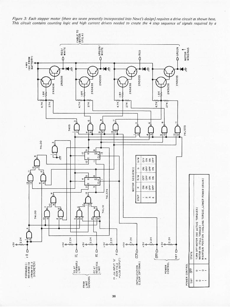
W
00
FO
RW
AR
D::
I fl
EV
ER
SE
=0
(
FR
OM
FIG
. 2
FR
+5
V 2.2
K
OIS
CR
ET
ES
)
74
LO
O
74
LO
O
+5
V ~22K
0=
AT
F
OR
WA
RD
F
L
3
LIM
IT
FR
OM
+
5V
LIM
IT
SE
NS
OR
S
!2.2
K
0=
AT
R
EV
ER
SE
R"
L-
LIM
IT
+ 5
V
74
LI0
~2.2K
PI
_S
E I
NP
UT
V
RO
M
FIG
.2
P
>-U
LSE
OU
TP
UT
)
+5
V
f22
K
INIT
IAL
IZA
TIO
N
CL
RC
C
LE
AR
(O
PT
ION
AL
)
+5
V
l22
K
OF
F
+ 5
V
PO
WE
R
f2
. 2K
C
ON
TR
OL
SB
Y
l
PO
WE
R
CO
NT
RO
L
SB
Y
OF
F
ST
AT
E
0 0
TU
RN
OF
F M
OT
OR
(N
O
AC
TIV
E
TO
RQ
UE
S)
0 M
OT
OR
ON
(F
UL
L T
OR
QU
E)
fLY
7
40
3
10
~9 ~f
O
ONI
(iB
eL
K 13
~B ~
74
LS
74
MO
TO
R
SE
QU
EN
CE
ST
EP
R
R
/W
G
I O
N
OF
F
ON
2 O
N
OF
F
OF
F
3 O
FF
O
N
OF
F
4 O
FF
O
N
ON
I
G/W
J O
FF
ON
I
ON
OF
F
~
~
Illr
-3
11+0
6
10 fCY
0
"
12
74
LS
03
0 M
AIN
TA
IN
PO
SIT
ION
(H
OL
OIN
G T
OR
QU
E, L
OW
ER
PO
WE
R D
RA
IN)
X
4.7
K
27
K
4.7
K
27
K
,---
--J
4.7
K
27
K
14.7
K
27
K
+M
V
(6V
F
RO
M
BA
TT
ER
Y)
IBK~
2N
36
3B
RE
DI
2N
30
55 ~ W
HIT
E
l
IBK~
2 N
36
3B
2N
30
G
RE
EN
I 5
5 ~
WHITE
4 r;
IBK~
-' 2
N3
63
B
~RED
2N
30
55
1
IBK~
2N
36
3B
~GR
EEN
2N
30
55
• r. M
OT
OR
t
WIN
DIN
GS
CA
BL
E T
O
MO
TO
R
(FIG
A)
;!~
~.~
'
" ~
:::;.
V-J
2 '.
-.
r,.,
~9-
" o ~ '"
ES(
ti -
.~
~~
" ...
,
~ ~
~
0 ~ ~
-.
0 ~
..., ------
o-s:.
It:)
'"
-. ...
, "
'" C
l C
l ~
..., Q
..'"
'" :;
:-'"
-. "
'§
.~
,,~
I:::
;;;
:::;
'" '"
'" ~ ~
~!::
:!:.
Q
..'<
::
...,
-. -. ~
~ "
~ Q
~-g
'" ...
, '"
C
l Q..~
'" '"
Q..
Q..
f"-i-
:So
o 8
~ <:
'"
'" ;;.
~ '" ~
",-
s:. '"
Q.. ~
~ '-'
S.
'" ~
~'-
~ ~
~t
-Cl
;;;
~ '"
~
Cl
~ ~
~ ~ .
'" "
'§. ~
.
~ ;
; . ...,
51 '"
'" -g
:::o--
.0
~§
CJ-
:::O
" ~
Cl ~

Slow-Syn TM stepping motor. The inputs to this interface circuit include one level (FR) signal and one pulse signal (P) derived from an output port such as the one shown in figure 2. The forward and reverse limit inputs are used to override commands when a sensor detects that rotation of the motor has reached some mechanical limit of the motor's activity. The power control logic (summarized in the chart) is used to conserve battery power by allowing a "standby" mode for the motor when it is not being actively driven. This standby mode holds the motor shaft positon actively, bl(t uses less current than the full torque state used to move the shaft from step to step. .
system, and is subsequently read into the robot's memory through an ASR33 Teletype. A modest resident monitor program is stored in the first 666 bytes of EROM, which allows dumping and modifying of memory, punching and reading of paper tape, and branching to any memory location. The monitor is essential, because the computer has no conventional "front panel" with switches and lights.
The current robot control program QC
cupies about 1000 bytes ' of programmable memory, not inc luding table areas of variab le size. It provides a method for exercising direct control of the robot for testing purposes. The coding, written by Dennis Toms, is very general, modular and compact. In order to start and stop the stepping motors without error, it is necessary to provide a profile of acceleration and dece leration. This is most conveniently done by using a time-delay table giving the appropriate time intervals between stepping motor pulses. The table is precomputed to yield a uniform acce leration over some time period. It is sufficient to have a single table for all motors. Each motor has associated with it a 14 byte motor status word (MSW) whose format is given in figure 5. The motor nUrylber and motor flag each occupy one byte; the other entries are two bytes (one word) each. The motor number byte is a fixed number which associates the fv1SW with a particul ar motor. The motor f lag byte is a code which gives the current state of the motor (off, on, standby, acce lerating, decelerating, emergency stop, etc) ~ The speed pointer word is an index which points to the current entry in the time delay table. The top speed word specifi es the index to the delay table entry, giving the shortest permissible delay between stepping motor pulses (maximum motor speed). The total steps word specifies the number of steps the motor is to execu teo The acce leration, constant speed and deceleration counters specify the number of steps to be taken in the acceleration, constant speed and deceleration ph ases of the motion, respectively . These counters are decremented appropriately as the motion takes place, so that if necessary, at any time during the motion the state of the motor can be determined by
CABLE FROM MOTOR DRIVE CIRC UIT (FIG. 3 )
GREEN/WHITE
GREEN
RED
RED/WHITE
R WHITE
(SEE TEXT)
R BLACK
Figure 4: Wiring and color code for the Superior Electric Slow-Syn TM bifilar stepping motors. The resistance R should be set (see text) to reflect typical operating characteristics. of the motor's use. The wiring is shown by color designations, and is connected to the drive circuit of figure 3. The ground return to figure 3 can be via the robot's chassis or through an additional circuit in the cabling.
interrupt handling routines. After all bytes of the appropriate MSW have been loaded with proper values, low level software takes over to carry out the motion. A pulse is issued to the selected motor causing it to advance 1.8 degrees. After a delay specified by th e first entry in the de lay table, a second pulse is issued, and the speed pointer is incremented to point to the second va lue in the de lay table, and the acce lerat ion counter is decl·emented . This process continues until the acceleration coun ter reaches zero. When this occurs, the acce leration phase is complete and the 'constan t speed phase is entered. For this phase, the speed pointer is
Figure 5: Format of the
Motor
Motor Status Word (MSW) motor status word. There
is one motor status word allocated to each stepper motor; an interrupt driven process updates and times the operations of the motors. The information includes motor identification, status flags and parameters which specify the details of a cycle of operation consisting of acceleration, constant running speed and deceleration.
Number I Speed Pointer
Top Speed
Total Steps
Acceleration Counter
Constant Speed Counter
Deceleration Counter
39
Motor Flag

Photo 4: The robot Newt as it appears in the current state of construction. The hand wired computer backplane and stepping motor drive modules and sheet metal "hand" and power cables to an external source are all temporary.
- I
held fixed, pointing to the time delay value correspo ndin g to the top speed index, while the constant speed counter is decremented for each step. After the co nstant speed phase is completed, the speed pointer is decremented for each pulse, caus ing the motor to decelerate. The motor fina ll y stops after a number of pulses have been issued eq ualing total steps. The motor is then placed in
40
I
standby condition and this fact is stored in the motor flag byte. If unforeseen conditions arise which make it inadvisable or impossib le to complete the motion as planned, the interrupt software stol'es the appropriate emergency stop code in the motor f lag and the motor is halted. In all but extreme emergency cases requIring instant stopping of a motor running at high speed,

the software can recover the total number of steps actuall y taken, sav ing it for navigati onal pu rposes .
To exe rci se direct co ntro l of th e robot, a simple in terpret ive co mm and system was developed. Th e current ly impl emented command s are listed in tabl e 1. Each command consists of the 1 byte ASCII characte r F, B, L, R, W, V or Q, fo ll owed by a 2 byte argu ment. In th e case of the F, B, L and R command s, th e argument is simpl y th e number of motor steps to be taken (l ess than or eq ual to 215 - 1) . For the W comm and, the argum ent is the waiting tim e in units of 10ths of a second. For th e V comm and , the argument specifies the new max imum speed of the robot in steps per seco nd. For the Q command , the argum ent gives th e 16 bi t add ress of a sequence of command s stored in memory. Of course, many other co mm ands, such as those appropri ate fo r sensory turret and manipul ator motion, will be added to the list of tab le 1. A program of robot activity co nsists of a simpl e sequence of these 3 by te co mmands, one after the other. For example, th e fo ll owing 15 by te sequence (argum ents show n in hexadecim al nota tio n):
F OA10 L OOOB B 0010 W 0066 B 0002
woul d cause the ro bot to move forward 2576 steps (about 1.4 meters), turn left 11 steps (a few degrees), back up fo r 16 steps, stop and wait for 10.2 seconds, and th en back up two steps. All acce lerations and dece lerati ons are taken care of automat icall y by the lower leve l softwat·e .
Commands can be give n to the robot in several different ways (command modes) whi ch are specifi ed in ta ble 2. For th e D mode, the robot simpl y executes the co mmands directly as th ey are ente red on the Telety pe. Afte r each command is give n, it is necessa ry to wait un t il it is carri ed out before entering another command . In the R mode nothing is executed , but each co mmand is recorded in sequence in the memory. The N mode is a combi nation of the D and R modes. It permi ts a sequence of command s to be recorded as they are be ing executed. Th e P mode all ows play bac k of any previ ously recorded sequence. In th is mode, the Teletype cabl e can be disconnected to all ow the robot to roam free ly. If the C mode is specifi ed, th e robot creeps along at a ve ry slow pace und er an F, B, L or R command fo r an ind efini te number of steps. Th e motion is te rmin ated by de-
Table 7: Currently implemented commands. The demonstrations of operation seen in photo 5 were created using an in terpretive sequence including these seven basic commands. The command list is open ended il1 that many additions to the possible operations are expected as the software is developed further.
ASCII Command Code Command Definition
F Move robot f o rward B Move robot backward L Rot ate robot I eft R Rotate robot r ight W Make robot wa it V Set robot max imum speed Q Execute comm and s equ ~ nce
pressing any key on the Telety pe, after whi ch the numbe r of ste ps taken is prin ted out. Th e T mode is a co mbin at ion of th e C and R modes. Th e E, L and 0 modes are " bookkeeping" in nature, and permit erasing, li st in g, and setting the ori gin of a com mand sequence, t·espective ly. DUt-in g th e creation of a program of action fo r the ro bo t (comm and seq uence), any combin ati on of modes can be used as des it-ed. It is easy to th ink of many other useful modes whi ch could be added to th e li st of tabl e 2.
Using the command s li sted in tabl e 1, it has been poss ible to do a number of prelimin ary ex per im ents with the robot whi ch serve to test bo th the hardware and softwa re, and to prove some of the fund amental id eas. For exampl e, one can pl ace wood en alphabet bl ocks on the floor at random, and then program the robot (using the N and T modes) to " pick them up " by trapping them in its temporary "hand ." After putting the blocks and the robot back in their initi al pos it ions, the pl ay back (P) mode can be used to t-e peat the mot ions automatically. One such test, ra ther in the fo rm of a demonstrat ion, is shown in photos 5a to 5g. In the first fra me, photo 5a, the robot is movin g toward s the nea rest bl ock from its
Table 2: Command modes for the robot. The software presently implemented is used to tryout various exercises o f the robot's machinery. Th e software is structured into several command m odes described by this list.
Command Mode
D
R
N
P
C
T
E
L
o
41
Type of Operation
Direct (simplv execute the commands)
Rem ember (record comm ands)
Normal (c ombine D and R)
Pl ay back (run through a comm and sequence)
Creep (directly execute m otions at a turtle's pace)
T each (combine C and R)
Erase
List
Set origin

-"",,,-
(a) (b)
(c) (d)
Photo 5: A program of action executed by the robot. In this sequence, prearranged blocks are pushed to appropriate locations to spell out NEw T, which is the robot's name.
(a) The robot's actions start with its movement from an initial position in the left corner of the playpen toward its first block.
(b) As it closes in on the block, it maneuvers into position to entrap the block. Note that in this prearranged course, the robot is executing a fixed sequence of interpretive commands, and is not yet using visual inputs to find blocks at arbitrary positions.
(c) Arter trapping the block and movirig to the final position, Newt releases the block at its final position.
(d) Here, a second block has been fetched and released next to the first block, and Newt is turning around in order to head for the third block.
, , (e) Now Newt is ready to pick up the third block in the sequence.
(f) After placing the third block and going to the fourth, Newt has picked up this last block.
(g) Finally, the fourth block h;s been placed, completing the spe/ling of Newt's name, which is the end of the programmed sequence of approximately 700 interpretive motion commands.
42

(e)
initial positIOn in the left corner of the pl ay pen. In 5b, it is maneuvering into position for "picking up" the block. In 5c, the block has been picked up, moved and released in a new pos ition. In 5d, a seco nd block has been fetched and placed next to the first block, and the robot is turning aro und and head ing fOI- a third block. In 5e, it is abo ut ready to pick up the third block. In 5f, the th ird block has been placed, and the fourth block is in the " hand." In the final frame 5g, the fourth block has been pl aced, spe lling out NEW T, which is, of course, the robot's name. Appmximately 1003 byte commands were req uired fOI· this seq uence. Th e program can be executed dozens of times without errpr, and the final positions of the blocks and the robot afte r the seq uence is finish ed has a scatte r of a few millimeters (±1/8 in ch) in each direction. Of course, when the mbot is complete with all its senses, it will se ld om have to execute such a lengthy sequence in a completely ope n loo p fashion. Perhaps it can eventuall y do tasks such as search ing for and finding spec ifi c alph abet blocks in a random pile of blocks. This would I·eq uire frequent clos ing of the feedback loops through the visual senses.
As the robot goes thmugh its motions, such as depicted in photos 5a to 5g, it seems to possess an alm ost uncanny grace and precisio n. Small children, when watching it, are frightened at first , but this soon gives way to playful in terest and warm curiosity. Even hardened computer experts are amazed to see a computer driving itself arou nd on wheels!
(f)
(g)
Some Personal Remarks on Building Robots
It wi ll not be possibl e for one pel-son alo ne to write the software for the robot. Th is is fa l· too lal-ge a job. I t is hoped, however, that as the hardware nears comp letion, it will act as a foca l point for many persons wantin g to exper im ent with the robot by wl·iting their· own software. A
43
-""'-
fascinating project would be to create a general "Robot Control Language" which would free each programmer from th e details of th e hardware . What a rich ex peri ence it would be to work together, exchanging id eas in a highly interactive way. Th ere are many tutorial possibilities for computer
SOME TERMINOLOGY
Amp hour: A unit of energy for rating batteries. The battery of NEWT, with its 84 Amp hour capacity, can store enough charge to drive a steady 1 A load for 84 hours, or a 14 A load for six hours. The finite capacity of any practical battery means that any mobile robot must incorporate some programs for seeking electrical outlets and recharging batteries periodically.
Azimuth : As used here, an angle relative to a fixed direction in the horizontal plane.
Cognition: As Webster has it, th is is "the act or process of knowing, including both awareness and judgement." {Webster's New Collegiate Dictionary, 1976 edition.l I n the context of robots and artificial intelligence, this term refers to programmed models which approximate the behavior of natural cognition.
Degrees of freedom: The state of a robot mechanism (or any other system) can be described by specifying the current value of each variable para · meter. Thus, if a robot arm has seven joints, the position of its "hand" might be determined by the angular setting of each joint. Each such independently variable parameter of a system is called a "degree of freedom," so the seven jointed arm would have seven degrees of freedom .
Heuristic: A heuristic computer program is one which starts out with an approximate method of solving of a problem within the context of some goal, and uses feedback from the effects of the solution to improve upon its own performance. Heuristic programming is one of the major contem· porary artificial intelligence techniques, and is a key to developing a cognitive robot.
Manipulator systems: A generic term for any mechanical device which a robot uses to directly manipulate its environment. In the NEWT robot, this is currently (see photos) a simple sheet metal frame which can catch a block and slide it across the floor as the robot moves, with no active grasping; NEWT is intended to eventually have a much more flexible system of manipulation as described in the text . Most industrial robots currently in use consist of manipulators alone, without much in the way of sensory feedback or motive systems ,
Motive systems: A generic term for the mechanisms used to convey the robot around its environment. In the NEWT robot, this refers to the two drive wheels, balancing caster and stepper motors which propel the robot.
Open loop, closed loop: A closed loop system is one which operates with feedback from errors. The feedback is intended to correct for the errors and thus approach the truth; an open loop system ig· nares error signals and operates on the sometimes
44
science classes and beginning students learning about computers. There are problems in psychology, procedural languages, human-to-machin e communication, functioning of parts of the brain ... (Working with robots is certainly one way to ga in a much greater appreciat ion for th e complex-
naive assumption that no errors occur. The terms must be qualified by a reference to the time intervals involved in the system: NEWT, for example, is a closed loop system over long time periods, since it is intended to navigate using feedback from its sensors; however, due to the processing loads associated with sensors, NEWT operates open loop between navigation sightings in a manner analogous to the dead reckoning method of navigation used occasionally by airplane pilots or captains of ships.
Round off errors: In operations such as addition, multiplication or calculating transcendental func· tions, there is often some uncertainty in the least significant part of the result. I n an extended calculation in which these operations are repeated over and over, appreciable round off errors can accumulate. In a digitally controlled vehicle guidance system such as that used for a robot, these numerical errors are a major source of uncertainty in the vehicle position, and are just as important as more obvious sources of error such as step quantization or slippage in the drive mechanism.
Senses: In a robotics context, senses are specialized peripherals which convert information about the environment into signals which can be analyzed by a computer or used directly by the electronics, as in a reflex. Sensory information may be obtained from devices as simple as a microswitch with a "feeler" arm, or as complicated as photoelectric imaging arrays with zoom lenses and painting mechanisms.
Stepping motors : An ordinary electric motor is characterized by continuous motion when energized. A stepping motor uses a different design philosophy to achieve a motor which will move its shaft in small incremental angular steps on com· mand, and will actively maintain its position in between each command. This type of motor is very well adapted to digital control of mechanical systems, and is used by NEWT for all mechanical motions in the robot.
Step quantization : The stepper motors have a finite angular resolution built into their design. This means that any mechanical motion derived from the motor will have a certain minimum step size, so that any attempt to position to a finer tolerance must be approximated.
Trajectory: The path of a moving object is its tra· jectory. In the case of the mobile robot, a trajecectory is planned before motion takes place, given a desired goal position and a world model which covers its course and objects which may be in the way.
World model : A world model is the result of cognition as implemented in robots. Formally, it is an information structure built up in the memory of the robot, based on both initialization and heuristic interaction with the environment.
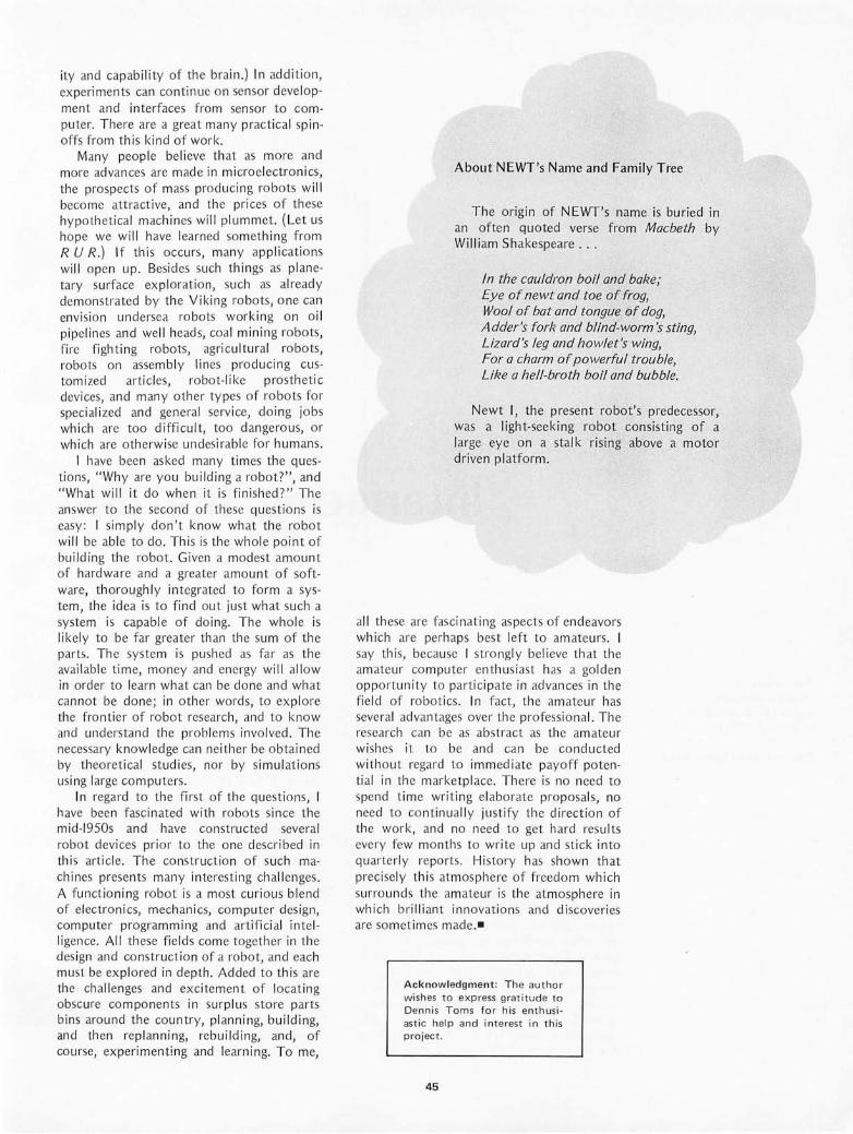
ity and capability of the brai n.) In addi t ion, experiments can continue on sensor development and interfaces fro m sensor to compu ter. There are a great many practical spinoffs from thi s kind of work.
Many peopl e beli eve that as more and mOI'e advances are mad e in mi croelectronics, the prospects of mass produc ing robots will become att ract ive , and the pl'ices of th ese hypothetica l machines will plummet. (Let us hope we will have lea rn ed someth ing from R U R.) If thi s occurs, many ap plications will open up. Besides such things as planeta ry surface exp lorat ion, such as already demonstrated by the Vi king robots , one can envision und ersea robots working on oil pipelines and well heads, coa l mining robots, fi l"e fighting robots, ag l"icultural robots, robots on assembly lines producing customized art icles, wbot-like prosthetic devices, and many other types of robots for specia li zed and genera l se rvice, doing jobs which are too difficult, too dangerous, or which are otherwise undesirab le for humans .
I have been as ked many times the questions, " Wh y are you building a robot?", an d "Wh at will it do when it is fini shed?" Th e answer to the second of these quest ions is easy : I simply don't know what the robot will be ab le to do. Thi s is the whole point of building the robot. Given a modest amount of hardwa re and a greate r amount of software, thoroughly integrated to form a system, the id ea is to find out just what such a system is capable of doing. Th e whole is li ke ly to be far greater than the sum of the parts. Th e system is pushed as far as the avail ab le t ime, money and energy will all ow in order to leam what can be done and what cannot be done; in other words, to ex plore the frontier of robot rese3l"ch, and to know and unde rstand the problems invo lved. The necessary knowledge can neithel' be obta ined by theoretical studi es, nor by simul at ions using large computers.
In regard to the first of the questions, I have been fasc in ated with wbots sin ce the mid-1950s and have constructed severa l robot dev ices prior to the one described in thi s arti cle. Th e construction of such machines presents many interest ing challenges. A functioning robo t is a most cu ri ous blend of electroni cs, mechani cs, computel' design, computer programming and arti fic ial intelli gence. All these field s come together in the design and construction of a wbot, and each must be explo red in depth. Added to this are the challenges and excitement of locati ng obscure components in surplus store parts bins around the country, pl anning, building, and then replanning, rebuilding, and, of course, experimenting and leaming. To me,
About NEWT's Name and Family Tree
The ongll1 of NEWT's name is buried in an often quoted verse from Macbeth by William Sh akespeare . . .
In the cauldron boil and bake; Eye of newt and toe of frog, Wool of bat and tongue of dog, Adder's fork and blind-worm 's sting, Lizard's leg and howlet's wing, For a charm of powerful trouble, Like a hell-broth boil and bubble.
Newt I, the present robot's predecessor, was a light-seeking robot consisting of a large eye on a stal k rising above a motor driven pl atform.
all these are fascinating as pects of endeavors which are perhaps best left to amateurs. I say this, because I strongly believe that the amateur co mputer enthusiast has a go ld en opportunity to participate in advances in th e fi eld of wbot ics. In fact, the amate UI" has several advantages over the profess ional. Th e I"esearch can be as abstract as the amateur wishes it to be and ca n be co ndu cted without regard to immed iate payoff potential in the marketpl ace. Th ere is no need to spend time wr iting elaborate pwposals, no need to continuall y justify the direct ion of the work, and no need to get hard results every few months to write up and stick into quarterly reports . Hi story has shown that precisely this atmos ph ere of freedom which surround s the amate UI" is the atmosph ere in which brilliant innovations and discoveries al"e somet imes mad e.-
Acknowledgment : Th e author wishes to express grat itud e to Den ni s Toms for h is e nthusiastic help and interest in this proiect .
45

Dan Fylstra Hamilton Hall C·23 Harvard Business School Boston MA 02163
Photography by Carole Brock
Photo 7: The complete setup of the IBM Selectric Keyboard Printer, typing under the control of a K I M-} microcomputer with a 4 K memory expansion. The ' Selectric interface described in this article is housed in the equipment case in the center of this photo.
Interfacing the IBM
One of the most desirable forms of computer output is high quality typewritten text suitable for preparing letters, reports and other documentation. A word processing system which speeds up the process of writing and revising text would be a very useful and feasible application for a small microprocessor based system, provided that a suitable hard copy output device can be found at a reasonable price.
An ideal output medium for such a word processing system would be an IBM Selectric office typewriter. Selectrics are moderately expensive when compared to ordinary typewriters {$630 to $830 depending on the options chosen}, but they are Ubiquitous in the office environment, produce very high quality typed output, and can be used to print in many different type styles simply by changin g the ball shaped typing element. Special typeballs are available for printing mathem~tica l symbols and for the APL character set (see "What is APL?", by Mark Arncld , November 1976 BYTE, page 20).
46
Unfortunately, the job of converting a Selectric office typewriter is made somewhat more difficult by the fact that (contrary to popular belief) the Selectric mechanism is entirely mechanical and not electronic in nature. The only use of electric power in an ordinary Selectric is for the motor which turns the drive shaft and various gears and cams. I t is necessary to use solenoids to push levers and "bails" in the base of the mechanism to achieve printing under computer control. Similarly, contact switches must be installed in order to use the keyboard for computer input.
There is another alternative, however. A variety of computer terminals and other devices based on the Selectric mechanism are becoming available on the surplus market, often at a fraction of their original prices. These machines have their own built-in solenoids or other means for mechanical control, and present some sort of electrical or electronic interface to the outside world. The simplest, most commonly available, and of-

Selectric Keyboard Printer
ten the cheapest of these are the Selectric Input/Output Keyboard Printers, Models 73, 731, 735 and others. They were manufactured by IBM, typically for use as 10 devices in other companies' computer systems. As these systems have become obsolete, the Selectric Keyboard Printers have found their way into surplus channels.
As a business school student and experi enced user of computers, I have always wanted ,to build a word processing system around my own home co mputer. Hence I seized a chance to acquire a Model 73 Keyboard Printer for $450 from the Computer Warehouse Store in Boston. (These units were so ld out in a few weeks; I have heard of prices ranging from $250 to $1500 through other channels, but as interest in the uni ts increases, their typical prices are bound to rise.) Armed with a couple of o ld IBM manuals provided by the Computer Warehouse Store, I set out to accomp li sh what I expected would be a stra ightforward interfac ing process.
(Teaching KIM to Type)
Th is art icle is a report of my exper ience, and a detailed description of the interface which I built. Briefly , the interfac ing process, while simple in principle, was not at all straightforward in pract ice. But it was successful, even for such a mechanically inept person and relative novice in electronics as me. For abo ut $50 in parts (including such extravaga nces as a pretty cab inet and a $ 20 IBM con nector to plug into the Selectric's peculiar 50 pin receptacle), and lots of labor, I prod uced the unit shown in photo 1. It's only an interface to the Selectric printer) since I'm content to use my ex isting ASCII keyboard fo r input. It has its limitations, but it works.
This, of course, is hard Iy the last word on Selectric Keyboard Prin ter conversion. As a BYTE reader, I wou ld be delighted to see in format ion on more comprehensive interface designs, as we ll as actua l exper iences with severa l of the units currentl y on the market. Since most of them are so ld on an "as is'; basis, these machines can bring
47

Photo 2: A closeup of the IBM Selectric ball mechanism on its moving carriage within the printer. The Courier 72 ball shown here is one of many balls available with the "Correspondence" coding armnQement.
you a lot of grief {read on}. So it's wise w report on problems, and how you overcame them.
The Selectric Mechanism
To appreciate what the interface must do {and what can go wrong}, it is first necessary to understand basically how the Selectric mechanism works. The typing element is a
Photo 3: This diagram, from the IBM manual number 247-5759-3, shows how the various bails of the mechanism are connected in a typical case. The IBM manuals for the typewriter output unit are valuable reference materials and can be obtained by calling your local IBM office.
48
golfball sized hollow sphere embossed with up to 88 characters, arranged in four horizontal rings of 22 characters each. Photo 2 illustrates the ball in its rest position in the mechanism. All the lower case or unshifted characters appear on the "western hemisphere," the side normally closest to the paper. The upper case characters are in corresponding positions on the back side or "eastern hemisphere." Pressing the shift key causes the whole typeball to rotate 180
0,
thereby allowing the upper case characters to be printed. Hence, the actual typing operation can select any of 44 characters, four half rings of 11 characters each, with five to the left and five to the right of the center or "home" position on each ring. A particular character is selected by causing the typeball to tilt up Or down and rotate right or left; then the ball jumps forward to strike the ribbon and paper. These movements account for the peculiar "dancing" motion seen when the Selectric is typing continuously. The typeball is mounted on a carriage which moves across the page, as opposed to traditional pre-I BM typewriters where the paper carriage moves and the typing mechanism remains stationary.
The actual tilting and rotation of the typeball is accomplished by an incredibly complicated system of latches, pulleys and levers which are driven by six moving "bails," or rods in the base of the machine. Although we need not understand the detailed mechanical linkages, we should appreciate the roles played by these six

INTRODUCING THE COMPLETE CHALLENGER SYSTEM.
OSI~ DREAM MACHINE Is a totally Integrated compllter system.
Imagine a system complete with terminal, CPU , memory, floppy disk, software, and all the little necessities to make it work together immediately. Now imagine this complete system available not only fully assembled , but priced much lower than anyone else's kit. What you are dreaming of is OSI 's "new" Challenger System!
In the configuration shown above, the Challenger includes everything an end user needs for a complete small computer system. All you add is 110 VAC power and a desk to put it on .
This fully-assembled system includes:
HARDWARE: OSI Challenger 65 with 16K RAM , serial interface, system
monitor PROM , and floppy disk bootstrap PROM. OSI Challenger single drive floppy disk formatted for 250K
bytes storage per diskette surface. Stand-alone terminal and Sanyo monitor for 16 lines of 64
characters at 2400 baud (other terminal options are available). And all interconnecting cables!
SOFTWARE: 2 diskettes containing over 100,000 bytes of software in
cluding OSI's powerful Disk Operating System with variable length sectors. 6502 DISK BASED RESIDENT ASSEMBLER/ EDITOR! A totally interactive Assembler/Editor which assembles up to 600 lines a minute and is completely compatible with MOS Technology's Cross Assembler format. This program also contains a powerful disk-based line editor with commands for general text editing. OSI'S EXTENDED MONITOR: A powerful machine language debugging and utilities package including a Disassembler which is format compatible with the Assembler! OSI 6502 8K BASIC FOR DISK BY MICROSOFT: This powerful BASIC has all the features of Altair '" 8K BASIC for the 8080 plus higher speed and disk storage. And it comes complete with a BASIC program library.
DOCUMENTATION AND SUPPORT: We include over 600 pages of hardware, software, program
ming, and operation manuals. The Challenger is based on the well-proven OSI 400 system. The over 2,000 OSI 400s and Challengers now in use assure continuing hardware and software support for this system for years to come!
EXPANDABILlTY: The Challenger System can now be expanded to 192K of
RAM and 16K of I/O and ROM. There are over 13 accessory boards including A/D, D/ A, parallel and serial I/O, cassette interfaces, a dual drive floppy , a video graphics display, several RAM and PROM boards, and multiple-processor configurations.
APPLICATIONS: The Challenger system is complete, fully assembled and
configured so that the Disk Operating System can be booted in immediately on system power-up. Even a relatively inexperienced operator can have a complex BASIC program on-line just seconds after the system is turned on. The ease of use, high reliability , and large library of standard BASIC applications programs make the OSI Challenger System the first practical and affordable small computer system for small business , educational institutions, labs, and the personal computerist.
PRICES: Challenger System , complete as stated above with terminal
and monitor $259900 As above without terminal. Specify RS-232 or 20m a loop
and baud rate $209900
IMPORTANT NOTE: One of the most important features of the Challenger System
is that it is not really "new". OSI has been delivering the basic circuitry of the Challenger since November 1975 and the floppy disk since June 1976. The only thing new is the total integration of the components as a complete, simple to use, fully-assembled, small computer system.
For more free information and the address of the OSI Computer Dealer or representative in your area, write to: OSI; Dept. S; Hiram, Ohio 44234 or enclose $1.00 for the full · OSI catalog which contains kits from $134 and fully assembled computers from $439.
II Ohio Scientific Instruments
11679 Hayden Street, Dept. S, Hiram, Ohio 44234 Circle 40 on inquiry card.
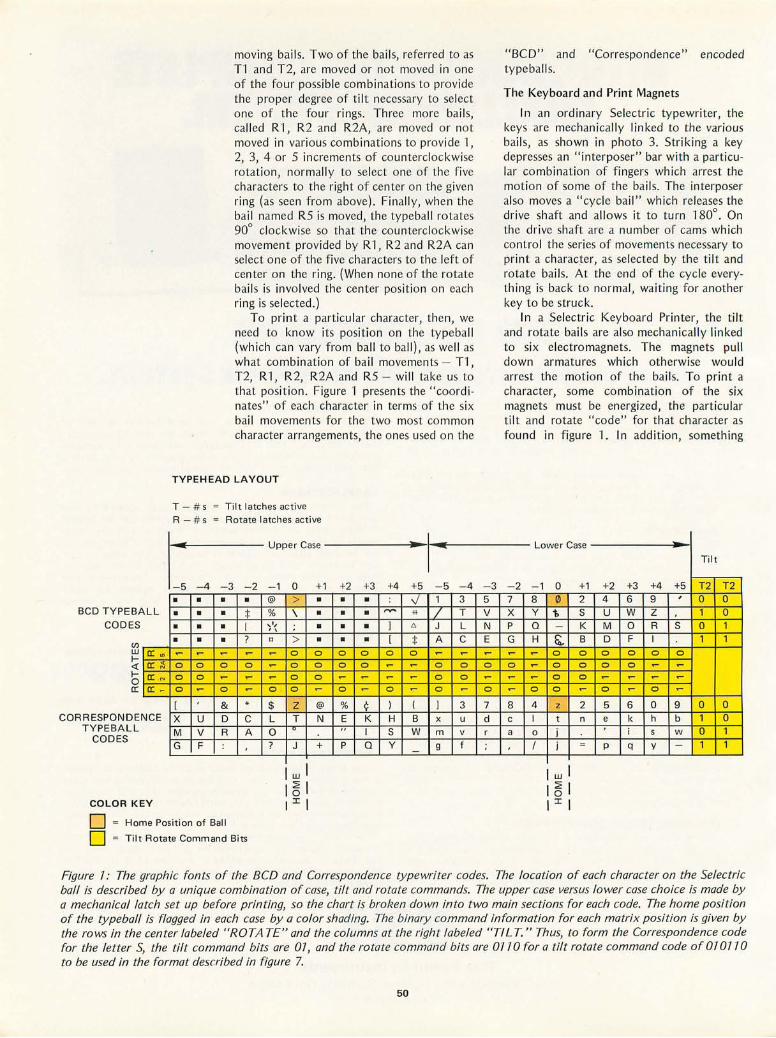
ALL BCD TYPEB CODE S
(Jl
w I« Io a:
CORRESPONDE T YPE BALL
CODES
a: '" a: !-\ a: . N
a: _
NCE
COLOR KEY
movin g bail s. Two of the ba il s, referred to as T1 and T2, are moved or not moved in one of the fo ur possible combinations to prov ide the proper degree of tilt necessary to se lect one of the four rings . Th ree more bail s, call ed R 1, R2 and R2A, are moved or not moved in vari ous co mbinations to prov ide 1, 2, 3, 4 or 5 in crements of co un terclockwise rotation, normall y to se lect one of the f ive characters to the right of center on the give n ring (as seen from above). Finall y, whe n the bail named R5 is moved, the ty peball rotates 90° clockwise so that the coun terclockwise movement prov ided by R 1, R2 and R2A can se lect o ne of the five characters to the left of center on the ring. (When none of the rotate bail s is in vo lved the center pos it ion on each ring is se lected.)
To prin t a parti cul ar character, then, we need to know its position on the typeball (which can vary from ba ll to ball), as well as wh at co mbin ation of bail movements - T1 , T2, R 1, R2, R2A and R5 - wi ll take us to that posit ion. Figure 1 presents the " coord inates" of each character in terms of the six bail movements fo r the two most common character arrangements, the ones used on the
TYPEH EAD LAYOUT
T - # s Til t latc hes active R - # s Ro tate I atches acti ve .. Upper Case · I ~ - 5 - 4 -3 -2 - 1 0 +1 +2 +3 +4 +5 -5 -4
• • • • @ > • • • ..J 1 3
• • • :j: % \ • • • ,..... "' / T
• • • I , ', • '\ • • 1 6 J L
• • • ? !l > • • • [ :j: A C ~ ~ ~ ~ ~ 0 0 0 0 0 0 ~ ~
0 0 0 0 ~ 0 0 0 0 ~ ~ 0 0
0 0 ~ ~ ~ 0 0 ~ ~ ~ ~ 0 0
0 ~ 0 ~ 0 0 ~ 0 ~ 0 ~ 0 ~
[ & * $ Z @ % ¢ ) ( 1 3
X U D C L T N E K H B x u
M V R A 0 0 .. I S W m v
G F : ? J + P Q Y 9 f
o Home Pos iti on of Ball o ; Til t Rotate Comm and Bits
-3 5 V N E ~
0
~
0
7
d r ;
"BC D" and "Correspo ndence" encoded type ball s.
The Keyboard and Print Magnets
I n an ord inary Selectric typewriter, the keys are mechanicall y lin ked to th e various bail s, as shown in photo 3. Stri king a key depresses an " interposer" bar with a part icular co mbination of fingers which arrest the motion of so me of the bail s. The in terposer also moves a "cycle bail " which re leases the drive shaft and all ows it to turn 180°. On the drive shaft are a number of cams which co nt rol the seri es of move ments necessary to print a character, as se lected by the t il t and rotate bai ls. At the end of the cyc le eve rything is back to normal, wa it ing fo r another key to be struck.
In a Selectr ic Keyboard Printer, the til t and rotate bail s are also mechanicall y linked to six electro mag nets. The magnets pull down armatures which otherwise wo uld arrest the mot ion of the ba il s. To prin t a character, some combinati on of the six magnets must be energized, the part icular til t and rotate "code" for that character as fo und in fi gure 1. In add ition, something
- 2 7 X P G ~
0
~
~
8 c a
Lower Case
- 1 8 Y Q
H ~
~
~
0
4 I 0
I
0 ([J
1--
~ 0
0
0
0
z t j j
I w I I ~ I I I I
+1 2 S K
B 0
0
0
~
2 n
-
+2 4
U M D
0
0
~
0
5 e
p
Til t
+3 +4 +5 T2 T2 6 9 , 0 0 W Z 1 0 0 R S 0 1 F I 1 1 0 0 0
0 ~ ~
~ ~ ~
~ 0 ~
6 0 9 0 0 k h b 1 0 i s w 0 1 q y - 1 1
Figure 7.- The graphic fonts of the BCD and Correspondence typewriter codes. The location of each character on the Selectric ball is described by a unique combination of case, tilt and rotate commands. The upper case versus lower case choice is made by a mechanical latch set up before prin ting, so the chart is broken down in to two main sections for each code. The home position of the ty peball is flagged in each case by a color shading. The binary command in fo rmation for each matrix position is given by the rows in the center labeled "ROTA TE" and the columns at the right labeled ''TILT. " Thus, to form the Correspondence code for the letter S, the tilt command bits are 07, and the rotate command bits are 07 70 for a tilt rotate command code of 07 0770 to be used in the format described in figure 7.
50

SATISFY YOUR APPETITE FOR COMPUTER KNOWLEDGE dT~OOKDOOKS Send for the cookbooks and manuals described. Increase your knowledge of minicomputers, microprocessors, computer technology, related computer circuits and peripheral equipment. Be satisfied or your money back.
CMOS Cookbook By Don Lancaster Your complete guide to the understanding and use of Complementary Metal-OxideSilicon integrated circuits. Gives usage rules; power supply design examples ; applications; information on breadboards, testing, tools, and interface. Detailed coverage of logic and more.
416 pages; softbound. No. 21398 $9.95 The Big CMOS Wall Chart 35" x 23" Big, readable wall chart provides essential information on CMOS devices. No. 21399 $2.95
TV Typewriter Cookbook By Don Lancaster Your comprehensive guide to low cost television display of alpha-numeric and graphics data for microprocessor systems, word processin_g, TV titling and video games. Covers configurations, memories, keyboards, techniques and much more . 256 pages; softbound. No. 21313 $9.95
Send your order Today!
Send books and /or wall charts checked below, $ _ _ enclosed'. I understand that, if not completely satisfied, I may return my order within 10 days for a full refund.
D 21351 D 21399 D 21080 D 20969
D 21404 D 20850 D 21313 D 20715
~~
NAME
How To Buy & Use Minicomputers & Microcomputers By William Barden, Jr. This manual gives you the basics of minicomputers and microcomputers. Explains their hardware and software, the peripheral devices available
and various programming languages and techniques. Allows you to decide which system is best for your needs. 240 pages ; softbou nd . No. 21351 $9.95
Computer Dictionary and and Handbook By Charles J . Sippi & Charles P. Sippi At your finger tips you have more than 22,000 definitions, acronyms, and abbreviations dealing with the field of data processing . Also 13 appendices cover a myriad of computer related subjects. 784 pages; hardbound. No. 20850 $19.50
Active-Filler Cookbook By Don Lancaster Dynamic coverage of active filters. What they are and how to use them. Learn to build and apply them to audio equalizers, speech therapy, psychedelic lighting and more. 240 pages; softbound. No. 21168 $14.95
please print
ADDRESS n r-
CITY
STATE ZIP
EJ630
:;; o c: ....
D 21398 D 21035 D 21168 'Inc lude sa les tax where applicable. Canadian prices slightly higher.
®~ Howard W. Sams & Co., Inc. 4300 West 62nd Stree t Indianapolis, Indiana 46206
Circle 282 on inquiry card.
Microcomputer Primer By Mitchell Waite and Michael Pardee Written for the beginner in the computer field. All the basic concepts and characteristics of microcomputers are explored. The easy to understand language prepares you for further study. 224 pages; softbound. No. 21404 $7.95
TIL Cookbook By Donald E. Lancaster You'll discover what Transistor-Transistor Logic is, how it works and how to use it. Discusses practical digital applications. You'll learn to build TIL systems that entertain, test and train. 336 pages; softbound No. 21035 $8.95
Guide to TTL (Wall Chart) 35" x 23" Shows you needed information on TIL devices at a glance. No. 20180 $2.50
IC Op-Amp Cookbook By Walter G. Jung Now one book gives you in-depth exposure to IC op amps. Covers theory and over 250 practical circuit applications. 592 pages; softbound. No.20969 $12.95
RTL Cookbook By Donald E. Lancaster You will learn the how and why of Resistor-Transistor Logic. Obtain useful design information and many digital applications. 240 pages ; softbound. No. 20715 $5.75

Tilt Rotate Bails ---
Drive Shaft ----..;:-..., ~iI"""""",,
Photo 4: A detail of the underside of the Selectric Keyboard Printer with housings removed. The overlay shows several of the key poin ts such as the location of various magnets, the switch contacts and intercon nection receptacle.
Keyboard
Print Magnets 50 Pin Receptacle
must actuate the "cycle bail" to start the printing process. Hence a trip mechan ism is provided which moves the cycle bail whenever any of the armatures is pulled down. However, there is one character on each hemisphere which should be printed when none of the magnets is energ ized, fo r the code 000000. Hence the trip mechanism is connected to a seventh magnet, called "check," which provid es an odd parity function for the other six magnets. I t is energized whenever necessary to ensure that the total nu mber of magnets energized is odd. Thus the check magnet is energized o n the code 000000, and this serves to actuate the . cycl e ba il. (I didn't realize this when building my interface, so I can' t print those two characters yet. Do n't make the same mistake!)
Besides the print mag nets, there are a number of other magnets and armatures inside the Key board Printe r which control special functions such as space, backspace, tab, carriage return, index (ie: advance paper without returning), ribbon shift, and upper and lower case shift. Many of these magnets
52
board Lock
and Lower
Control Magnets
(tab, backspace, index, space, carriage return)
can be seen in photo 4, which exposes the unders ide of the machine and outlines the pos itio ns of many components. The upper and lower case shift magnets are latch ing, and hence they lock the machine into the new case until th e opposite magnet is energized. Note that the operator cannot shi ft the machine back into lower case when t he upper case magnet is latched ! By Murphy's Law this is bound to happen whenever you are testing the interface, but it can be remedied by fooling aro und with the shift cam at the end of the drive shaft.
No e lectric power is provided fo r any of these magnets inside the Keyboard Prin ter, but the coil connections are brought o ut to the 50 pin receptacle at the back of the machine . The magnets are rated for 43 to 53 VDC at 125 to 300 mA, applied for at least 10 ms in order to pull down the armatures and cause the desired act io n.
Switch Contacts
The other major add itio n to the basic
Continued on page 133


Joseph J Carr Bioelectronics Laboratory The George Washington Univ Medical Ctr 901 23rd St NW Washington DC 20037
Interfacing With an
Analog World-Part 2
Last month we discussed transducers and ampl ifiers. These are necessary portions of a signal processing system which result in scaled voltages of, for example, 0 to 10 V corresponding to the original physical parameter being measured. But how can we convert these voltages into numbers inside a computer for computation, and use numbers from computations to control extern al voltages? In this article we'll see how some of ' the more common conversions are accomplished . We'll start with digital to analog conversion, even though this may seem at first glance to be backwards. The reason for starting with the output process is that digital to analog conversion is simplest, and that many analog to digital input conversion techniques require a digital to flnalog conversion as part of the process.
There are several techniques for mak ing a digital to analog converter (often ab breviated DAC). In most cases these converters use some form of binary weighted current or voltage summation th at is controlled by the digital word presented to its inputs. A typical example is the classical R-2R technique which is outlined in figure 1. The active element A 1 is an operational amplifier of unity gain inverting follower configuration. Although an amplifier of the 741 general purpose family will suffice in many experimental situations, it is often better to select one of the more costly premium grade integrated circuit operational amplifiers. We have shown the digital inputs of the circuit in figure 1 as mechanical switches, a configuration wh ich is most useful in a tutorial situation when teaching the concept of the digital to ana log conversion. In practical digital to analog conversion app l ications the switches are electronic, and are
54
controlled by some form of n bit binary data source such as a counter or computer output port.
A precision reference vol tage source is required as well, and for many commercial and industrial system designs this will be a precise 10.000 ... V. The accuracy of the converter is largely dependent upon the precision of the reference voltage. Although any precise voltage regu lator' circuit may be used for the reference, I have found in laboratory instrumentation experience that commercial products such as the REF-01 CJ or REF·01 HJ (for severe applications) work quite well. In a homebrew experimenter's situation, where relaxation of tolerances is quite normal, a simple zener diode reference circuit will often prove quite adequ ate.
Now let's consider the circuit in figure 1 in more detail. What happens when various combinations are presented to the digital input? Suppose that all the inpu t bits are in the low state, which means that they are connected to ground by the electronic or mechanical switches shown. The value of the output voltage is given by the product 11 R. When all bits are groul1ded through the switches, the input current to the amplifier is zero, as can be deduced by tracing, noti ng that there are no nonzero inputs to the amplifier's feedback node. (In practica l circuits, though, there may be some output voltage under these circumstances due to offsets in the operational amplifier itself. These undesirable offsets may be null ed out through an offset adjustment potentiometer arrangement, RNULL in this circuit. See some of the tutorial design books on operational amplifiers for further elaboration of this detaiL)
If the most significant bit of the word is

O.9R
R
2R 2R 2R 2R 2R
SN S3 S2
VCC( +) RNULL
20 K
10K
10K
4-
I3 El=-IIR
VEE (-)
14
10K
OUTPUT
r r-----------. ----..., I RZ + 15V I
.
[
'I" ~":'_'_ I LOW PRECIS ION I ,- EREF EXPERIMENTER'S I I VOLTAGE REFERENCE
I I l' CHOOSE RZ FOR .5V DROP I +----4>-----+-------'--(~ L ______________ ~
set to a logical 1 value, then the output voltage (assuming RG is arbitrari ly set) will be approximate ly one half the reference vo ltage, as can be verified with the operational amplifier gain formu la shown in figure 3 of the first part of this artic le. (The remaining resistors in the R-2R network have no effect in this case since both ends are effectively tied to ground. One end is the real ground at the left, and the other end at the feedback node of the amplifier is its "virtual ground" for the signaL) The analysis of the next most significant bit and the remaining bits of the digital word is a bit more complicated, but the result is what might be expected. The bit control led by 52 in figure 1 wi ll contr ibute one fourth of the reference voltage to the output of A 1; the bit controll ed by 53 will contribute one eighth of the reference voltage. And for switch, or bit, n (where n starts at 1) the contribution wi ll be EREF/(2n).
Let us assume that we have an 8 bit digital to analog converter of the type shown in figure 1. The word at the input terminals is 11001011 and the refere nce vo ltage is precise ly +10.000 VDC. What is the output voltage? The fol lowing calculation, wh ich is easi ly generalized, shows how the value is derived:
EO! = T ( ~~ + ~ + ~ + ~ + ~ ; 7 + ~ + i8 ) EREF V
Frac ti on Based on a DIgital Word Output
= (10/2) + (1 0/4) + (10/32) + (10/128 ) + (10/256) = = 5 + 2.5 + 0.3125 + 0.078 125 + 0.0390625
~ 7.93 V
1 EREF= +IO.OOOVOLTS PICK ONE I
~6G~~~NCE i IH~;;c~o;;--------~--l LABORATORY QUALITY 12 REFERENCE
I L_ I 6
I PRECISION MONOLITHICS
lOOK 5
I REF-OI
IO·TURN TRIM
I n7
I I I I L _____________ -l J4
But use of amplifiers and resistors as shown in figure 1 is hardly optimal in an age of integrated circu its. A number of manufacturers offer convenient low cost 8 bit integrated circuit digital to analog converters that contain almost all of the electronics, except possibly the ERE F supply and the operational amplifier used for output voltage conversion and leve l shift ing. I have used those by DATE L, Analog Devices and Precision Monolithics with good results in laboratory instrumentation . Experimenters and designers wi ll also find the parts in the Motorola MC1408 fami ly, as wel l as several simi lar parts made by 5ignetics, to be quite useful . For my examp les in this article I have selected the Precision Mono lithics DAC-08. I found this product easy to obtain in low quantities (ie : one) through local distributors .
Figure 2 shows the basic circuit for using the DAC-08, along with two vo ltage conversion schemes for its current outputs of pins 2 and 4. The integrated circuit itself ccntains the electronic switches, the resistance ladder, a reference amplifier and the current output buffer that drives pins 2 and 4. Two types of input are required to make
55
Figure 7.' A classical R-2R network digital to analog converter implemented as a circuit diagram with discrete parts and operational amplifiers. The essentials of any digital to analog converter are present: a reference voltage (two alternatives shown), a switched network that creates a binary weighted current controlled by the switches, and buffering and conversion amplifiers to create a voltage output which can drive other circuits.

Figure 2: While the circuit of figure 7 could be constructed, it is usually more convenient to replace it with a monolithic integrated circuit device such as the DAe-08 part by Precision Monolithics, which is used for this illustration. The integrated circuit contains all the components of the R-2R network of switches and buffering amplifiers. It still requires an output conversion circuit (two variations shown) and a reference voltage. Because the R-2R network is an integrated circuit, this form guarantees the highest possible accuracy with none of the extra bother of hand wiring a circuit as in figure 7.
OU TPUT VOLTAGE CONVERSIONS
CONDITION BINARY EOUT CONDITION
BINARY EOU T COD E CODE
FULL SCA LE IIIIIII I I - 9 .96 (+) FULL SCALE III II I II +9.96
HALF SCA LE 100000000 - 5.00 (+)ZERO 10000000 +0.04
ZER O 000000000 0.00 (-)ZERO 0 1 I I I I I I -0.0 4
(-)FULL SCA LE 00000000 - 9.96
RF 5K
FROM FROM DA C'08 DA C-08
4 -- ..... L.....? EOUT 4 --
Rp Vb ' 0", 2 -- 2 --
RN RLS
r;'7 1"/7
NEGATIVE OUTPUT BIPOLAR OUTPUT
4B
this digital to ana log converter do its work. One is the reference current, IREF thru pin 14. This current can be generated by a precision vo ltage reference {see figure 1} and a precision low temperature coefficient resistor in the ideal cases. {Fo r low precision applications, ordinary resistors wi ll work just fine.} For the configuration shown in figure 2 and a reference potential of 10 V, this resistor shou ld be prec ise ly 5000 ohms, a number which is derived fro m the documentation of the DAC-OB.
The second major type of inpu t to the converter is th e B bit digital word that is applied through pins 5 to 12. In the notation of figure 2 and throughout this article, the bits are numbered from 1 {m ost significant} to B {least significant}. Bit 1 of th e DAC-OB package is wired to pin 5, with bits 2 thru B wired to pins 6 thru 12. Th e logic leve ls at the inputs are the usual TTL levels, with a low vo ltage {approximately 0 volts} signifying a logical 0, and a high voltage signifying a logical 1.
One of the outpu t conversion circuits shown in figure 2 is a si mple un ipolar conversion which uses two res istors and no operational amp lifier. With this conversion, the formulas di scussed in figure 1 app ly except for the fact that the voltage is negative with respect to ground. When the input word is binary 00000000, then the output of the converter system is 0.00 V. Half scale {- 5 V output} is given by an input word of binary 10000000, and ful l scale output occurs when the input word' is bin ary
56
4C
11111111 . The output under fu ll sca le condi tions wil l not be 10 V, but approximate ly 9.96 V. This slightly unex pected condi tion is due to the mathematics of the switching network. Evaluating the fo rmul a for the conversion given ea rli er, with a reference of 10 V and a binary 1111 111 '1 digital value, we find:
Eout = lO X {255/256} = 9.96 V
Also shown in f igure 2 is an output circuit which uses an operational ampli fie r as a leve l sh ifter and voltage conversion device. Wired with the components shown, thi s amplifier connec ted to the DAC-OB gives a ga in of 2 and shifts the generation of outpu t leve ls to a symmetric bipolar range of - 9.96 to +9.96 V. Note that it is impossibl e to get an exactly zero vo ltage in this case, since the 256 possible states are sp lit symmetrically about ze ro. If the level sh ifting reference res istor RLS were adju sted slightly off the 5 K value, the vo ltage range of the conversion could be pulled slight ly (ie: 0 .04 V) positive or negative so that a true zero would be possi bl e for one of the binary states. Th ere are other possibili ties for the ou tput conversion circuits and as in any design situation, a little bit of imagin ation always comes in handy . (Readers looking for more examples of typical applications should consult the applications notes of the various manufacturers. Of particular use is the excellent specification sheet and application notes on the Mel408 DA e, published by Motorola . .. CH]

Analog to Digital Conversions
Wi th th e co ncept of a d igital to analog conversion covered, it is now possible to consider th e opposite case: co nve rsi on of measured vo ltages from the sensor preamplifiers into numbers whi ch can be processed and used by a computer. Of th e many techniques which are avai labl e fo r performing analog to digital conversions, we will only consider the deta il s of integration, counter (or ramp) , and successive approximat ion meth ods here. These are the si mpl est and most uni ve rsa l methods.
One of the basic param ete rs to be considered when talking abo ut any ana log to digital convers ions is speed. Thi s is not a major cons id eratio n in the output probl em already discussed, since digital to anal og current output conversions essentiall y take pl ace at th e sw itching speeds of digital logic, and are then limited only by the fin al operational vo ltage output amplifier's response. In the input case, however, some form of approximation cycle which converges upon the digital value is required; as a result, the conversion can be somewh at slower.
Integration Methods
At the slow end of the analog input conversion spectrum is the integrat ion method. This is the type of conversion wh ich is typicall y used in digital panel meters and similar instrumentation. These
ANALOG INPUT
EREF D 0
SI DRI VER
SI R
STAR T ~~-'1-~=-____ +-____ -4
INTEGRATOR
C
CONTROL LOGIC
can be useful in cases where you might mount the digital panel meter or multimeter in a sys tem, both as a readout mechanism and as a measu l'e ment conversion device. Many such in struments offe r parall el digital outpu ts on their rear panels, along with control and strobe lin es. The appeal of this approach often is affected by two characteristics: relatively slow co nversion speeds and bin ary coded decimal (BCD) encoding dil'ectly taken from the displ ays. Th e relat ive ly slow co nversion rates become a prob lem when look ing at sign als other th an "slowly va rying DC levels" of very low frequency sources. Th e cod ing characte l'istics may in fact be optimal for many computational schemes in a computer progl'a m, but it can be a nuisance if one attempts to use such a meter in a binary ori ented hard ware system. The typical "dual slope" integrato r used in th ese digital panel mete r cil-cuits is illustrated in figure 3.
Th e dual slope conversion circuit co nsists of f ive basic sec tion s: an in tegrator, a compa rator, a control logic section, a bin ary counter, and a I-eference current or vol tage source. Th e integrato r consists of an operational ampl ifier connected with a capac itor in a nega tive feedback loop. This capacitor is charged by the operationa l amplifier output voltage. The input to the integrato r is taken from either the analog input or th e reference source. The comparator is made with an operational amplif ier that has an open feedback loop.
COM PARATOR
JL. EOC 1----=---=1"> (END OF CONV ERSION)
OVERFLOW
CLOCK
BINARY COUNTER
v
BINARY OUTPUT
57
Figure 3: Analog to digital conversion by the dual slope integration method is often performed by slow devices such as digital panel meters. This method works through an analog integrator and a counter. The integrator has switch,able inputs. It first integrates the incoming signal for a specified time interval. Then it coun ts the time necessary to linearly discharge the charge just accumulated with a known slope. The result is a count which is proportional to the voltage which drove the integrator during the charging time.
TI
COUNTER MEASURES CHARGE
/

COMPARATOR + ANALOG
INPUT
C -V
START
CLOCK
8 B IT DIGITAL
TO ANALOG
CONVERTER
Figure 4: The ramp or counter method of analog to digital conversion is straightforward: A counter is initially zeroed and then allowed to count upwards until its binary code through a digital to analog conversion creates a voltage greater than or equal to the input voltage.
CONTROL
I BINARY COUNTER
1
L-u
-C> BI
-C> -C> -C>.
EOC (END OF CONVERSION)
NARY OUTPUT
This makes its gain very high . If the two input voltages are not equal, then the operational amplifier output is high or saturated. In this case the comparator is ground referenced and uses just one active input.
When a START command is received the control circuit resets the counter to 00000000, resets the integrator to 0 V output (discharges C), and sets switch Sl to the analog input. The ana log vo ltage creates an input current to the integrator which causes the integrator output to begin charging capacitor C. This means that the output voltage of the integrator begins to rise. As soon as th is voltage rises a few millivolts above ground the comparator output snaps high. The high comparator output causes the control circuit to trigger the counter, which begins counting clock pulses. The counter is all owed to overflow and this outputs an overflow bit. This bit changes the state of switch 51. The graph in figure 3 shows the integrator charging during the interval between START and the overflow of the binary counter (to to t1 ). At time t1 the switch changes the integrator input from the analog signal to a precision reference source. Also, at time t1, the cou nter has overflowed and aga in it has an output of 00000000 (maximum count + 1 is the same as the initial condition). It will, however, continue to increment so long as we have a high comparator output.
The charge accumulated on capacitor C during the f irst time interval is proportional to the average va lue of the analog input voltage between to and t1'
58
Capacitor C is discharged during the next time interval (t1 to t2)' When C is fu ll y · discharged the comparator will see a ground condition on its input and again it will change state to make its output low. This causes the control circui t to stop the counter but does not reset the counter. The binary word at the counter output at the instant it is stopped is proportional to the average va lue of the analog waveform over the interval to to t1' An end of conversion (EOC) signal is generated to let the microprocessor or other system know that the output data is stable, valid and ready for use. The speed I imitations are based on the requirement for an accurate and stable analog integrator, and the need to average the input signal over a long cycle.
Counter (Ramp) Analog to Digital Conversion
A counter or ramp type analog to digital conversion circ ui t is shown in figure 4. Here we find a voltage comparator, a digital to analog converter with voltage output, a binary counter, and necessary digital control logic. Here is how the conversion works:
When the START command is issued by a control system (for example, a computer output port) the control logic resets the binary coun t to 00000000 and enables the clock input to the counter, which begins counting upwards at the clock rate. Since the counter outpu ts set the voltage level out of the digital to analog converter, the DAC generated voltage to the comparator will begin to rise. As long as the analog input voltage is greater than the reference voltage generated by the digital to analog conversion, the state of the comparator output wi ll enable counting via the control logic. However, when the rising reference level finally equals or exceeds the input voltage for the first time, the comparator output state will switch and stop the counter. At this time, the output of the counter can be read by the computer or other system, and represents the value of the analog input voltage. If the counter and digital to analog converter are both eight bits, the number in the counter wi ll represent from 0 (00000000) to 255/256 times the digital to analog converter's reference voltage level. The conversion time of this algorithm is proportional to the voltage being measured.
Both the dual slope integration technique and the counter technique discussed thus far take far too long for many applications. On the order of 2n clock cycles are typically required where n is the number of bits involved . Conversion time becomes critical in an application when the frequency

+5
~
OXIMATION UNIT.,
SUCCESSIVE APPR SHIFT REGISTER OUTPUT lATCH A ND CONTROL lOGIC
START
2.25 TTL ClK
10
9
t
81 A.M.P. 82 AM2502
83
84
85
86
87
88
2 I
I'esponse must be high and a faithful reproduction is required, (For reference, consult textbooks in electr ica l engi neering concerning the "sampling theorem" and Nyquist's criterion that says we must have a sampling rate of at least twice the highest frequency that is to be recognized, if a faithfu l reconstruction of the signal is to be achieved. )
Successive Approximation
In programming and software design, we often find use of a "binary search" stratagem instead of a flat out sequentia l search when trying to speed up the process of finding an item in a table. This same approach is just as app licab le in hardware, whel'e the "successive approxi mation" technique of ana log to digital conversion provides a much higher speed of conversion than the sequential counting methods discussed so far. The successive appmxi, mation technique typically requil'es only n+1 clock cycles to make an n bit conversion, and its hardware is no more comp lex than that of the dual slope or counter methods.
The successive appmximation converter, shown in fig ure 5, consists of a comparator, contro l logic, a shift register with output latches fa I' th is form of convel'sion, and a vo ltage output digital to analog converter.
+15
COMPARATOR
P.M.I RI 39M
CMP-OIC 8V 3
~I'-I"l,
~ 14
13
12
II
6
5
4
3
R2 R3 5K IK
t J 4
-15 3
P.M.!.
f CI DAC 08 .01
16
5 81
6 82
7 83
8 84
9 85
10 86
II 87
12
1 88
When a START command is issued to the converter circuit, it loads a binary 1 va lue into the most significant bit of the shift registel', wh ich in turn sets the most significant bit of the output latch. This sets the output of the digital to ana log converter to half scale. In true binary search strategy, if the input voltage is less than the reference output provided by this half sca le setting, the most significant bit is cleared from the latch on the next clock pulse; otherwise, the most significant bit is left unchanged at the next clock pulse, Then the internal sh ift register of the successive approximat ion register unit is shifted so that its single high leve l bit is opposite the next most significant bit. Again, the output register is modified, this time so that bit 2 is set to 1 for the tria l measurement. This bit has a value of one fourth of the tota l voltage range, which is added to the half I'ange or zero va lu e sti ll latched from the first measurement. At the next clock pulse, if this new tr ial value to the comparator is greater than the input value, the 1 bit is latched in the success ive approximation register; otherwise a 0 bit is inserted at the current position. This process continues with successively less significant bits until the sh ift register over'flows indicating that the last bit has been tested, Some forms of this conversion have control logic to detect an equality condition and
59
~
ANALOG INPUT (O-IOV)
NOTE: NOT All PIN C ONNECTIONS 08. ARE SHOWN FOR DAC'
REFER TO FI GURE 4.
~
~
81NARY OU TPUT ~
-SERIAL OUT PUT
EOC (END OF CONVERSION)
Figure 5: The successive approximation method, here illustrated with a practical Circuit, uses a binary search strategy. The most significant bit is tested first, then the next most significant bit, and so on down the line until all n bits have been tested. If at each stage the contribution of the selected bit causes the trial approximation output from the converter to exceed the input value, the bit will be stored as a zero. After alln bits have been tested, the result is an n bit binary representation of the 1I0/tage of the input.
Continued on page 62
As~~YTE
BRITISH COMMENTARY
As o ne of t he re lati ve ly sm all number o f pe rso nal co m puting ad dic ts in England , I 'm ve ry im p ressed with the ra te at whi ch th e field is grow ing in pop ul ar ity o n the othe r side of the A tlantic. I've been su bsc ribing to BYTE for the past six mo nths and I p rom ise it 's always m ade fasc in ating reading. I wish I knew whe re in thi s co un t ry o ne co uld lay hand s o n any issues befo re last August 's. (H int, any bo dy ?)
Th e advert ise me nts are fasc in at ing, too. A nybo dy co ns id ering purc has ing any sort of syste m is alm ost fo rced to imp ort it fro m the USA. My qu ery is abo u t TV di spl ays that most of these syste ms use. Na tu ra ll y , t hey' re des igned for Ame ri can TV stand a rds, whi ch diffe r from Bri t ish on es. We h ave 625 in ter laced lines pe r fra me, repeating at 25 Hz. Is it, in genera l, poss ible to modify an Am eri can TV di sp lay dev ice to wo rk with a Bri t ish TV ? Or is all t he tim ing gene ra t io n usu all y pe rfo rm ed in· sid e a spec ial chi p? Might I have mo re success if I t ri ed to modify a TV instead? I know rathe r m o re a bo u t T T L logic than abo u t te levisio ns, bu t I' m gam e to lea rn if necessa ry . Otherwise, if th e answer to all th ese qu estions is no , then the temptatio n to com e and live in t he S tates is ' go ing to be alm ost unbea rable . . . .
I look fo rward to every issue of yo u r magazin e; I' m onl y sorry th at I d iscovered it so late. Best w ishes fo r the successful futu re that y ou d ese rve.
Guy A Burkill Corpus Christi College
Cambridge CB2 1 RH ENGLAND
Are there any other British readers who have experienced the problems of interfacing American video generation logic to European television designs? Some firsthand kno wledge of the subtleties to be found would be the best way to answer Guy's query on that subject,
Wi th regard to bacl? issues of BYTE, there are none le ft. However, much of the editorial content is no w available in a book titled Bes t of BYTE edited by David A hI, publisher of Creative Co mputin g. This book con tains reprin ts of numerous articles from the first 76 issues o f BYTE, September 79 75 thru December 7976.·
SACRED BUSES
I am ve ry cu rio us a bou t so mething. Wh at is sac red about t he Alta ir bus as o p posed to othe rs? Would it not be possibl e to ins ta ll a pe riph e ral des igned fo r t he Al ta ir sche me to, for exa mpl e, a
Digita l G ro u p o r Sou th west T echni cal Prod ucts bu s? I am co n fused o n the issue sin ce it seems to me th at , fu nctio nall y , lines mu st cor respond be twee n the syste m s pret ty we ll . Perhaps the answer li es in t he f act th at t he Al tair bu s was based o n th e 8 08 0 processo r, whi ch has so m e uniqu e 10 metho d s. Is tha t the prob lem ? Is it rea ll y a q uest io n of 8080 vers us o th e r processo r co m patib ili ty?, I understand wh y a m anu facturer wou ld wa n t to m ake plug comp a tible ca rds to the A ltair bu s, but why co uldn 't a s im ple co nve rsio n be ava il a bl e for an y p rod uct?
J C C hirigos 1 601 Ke nt ucky N E
Albuquerque NM 8 711 0
Th e main issue is one o f plug-in compatibility. Wh ether you call it th e A Itair bus, or, as used by non-M ITS suppliers, the 5- 700 bus, the key to th e wide availability of the periph erals is nominal compatibility at the hardware level. Even here, there are occasional clashes between various m anufacturers about the definitions of pins no t originally assigned meanings in the Altair de finition of the bus.
A t the detail level, a 700 pin bus surely works, and in principal one could talk to any other similar compu ter at the mem ory and bus in terface level sim ply by simulating all th e signals which would have been present on th e bus in its Altair implementation. This is a quite workable procedure, as demonstrated by many products.
True, the 10 structure of the 8080 is unique, and there are some 8080 specific features of the Altair bus as a result of thi s and other characteristics of the 8080 . But fo r the most part, the particular selection of the lines present on the 100 pin interface of the Altair bus is just a renection of discretionary choices on the part of the des igner(s) of the fir st Altair within the framework of the general des ign o f a microprocessor with 16 address bits and eight clata bit s, •
SOME TERMINOLOGY
I have a proble m . First, le t me give yo u som e id ea o f
m y bac kgro und . I have spen t 15 years in th e com p u te r indu stry as an app li ca tio ns progra mm e r. I am flu en t in BASI C FORTRAN , PL/ I a nd AP l . Now t hat i h ave left th e in d ust ry, I am getting inte res ted in rec rea ti o nal co mpu ti ng.
I have neve r bee n in vo lve d in log ic d es ign or in th e deta il s of ha rd wa re nor do I fee l th at I wa n t to ge t invo lved ~ i th it no w_ I wo ul d not mi nd buil d ing a ki t prov id ed tha t t he instructio ns we re o f the "put ta b A in to slot B" ty pe. However, when I read all the ads and li t era ture fu rn ished by the vario us m anufac tu re rs, I have t he fo ll owi ng pro bl em: Wh at are you all talk ing abo u t ?
I thought I kne w wh at " read only m e mory " was . Now I come across "pro -
Continued on page 67
60
BUY YOUR COMPUCOLOR8001 FROM THESE DEALERS. AHiZONA Phoenix: Phoeni x Byte Shop Wesl
12654 N, 28th Dc, -Iempc: "'cmpe Byte Shop East
813 N. Scottsdale Rd. "Iucson: Byte Shop of 'Ii.lcson
2612 E. Broadway
CALI FOHNIA L...1wndalc: B}1C Shop of Lawndale
16508 1-1awthomc Bl vd. Orange: Computer Man of Los Angeles
625 W. Kate!!a, No. 10 San Diego: The Computer Center
8205 Ronson Hd. San Francisco: The Computer Store
1093 Mission 51. San Jose: Ameo Electronics
4 14 S. Bascom Ave. San Jose: Byte Shop
155 131ossom Hill Rd . Van Nuys: Computer Component s
5848 Sepulveda Blvd.
CONNEC I'ICUT Wi ndsor Locks: The Computer Store
63 S. Main 51.
FLOHIDA Cora l Gables:
' Ihmpn:
GEOHGIA i\t l<mt a:
HAWAII Iionolulu:
ILLINOIS ChamJ'Xlign:
Evanston:
Park Hidv,e:
INDIANA Indinnn polis:
MAHYLJ\ ND Rockvi lle:
Sunny Computer Stores 1238A S. Dixie J-iwy, Microcomputer Systems 144 S. Dale Mabry Hwy.
At lanta Computer ~4art 5091-13 Buford Hwy.
Compaci Computers p.o. Box 1(X)96
'111e Numbers Hacket 518 E. Grcen 51. Illy Bi lly ~ Iachi ne 1316 Chicago Ave. Chi ca~o Computer Store 157 'Inkoll Hd .. l-lw}'. 62
Home Computcl' Shop 1(}147 Chri s Dr.
Computer \Vorkshop. lnc. 5709 Frederick I\\·e.
MASS,\ CHUSET r s Burl ington: The Computer Store
120 Cambridge St.
(602) 942,7300
(602)894- 11 29
(602) 3274579
(2 13)37 1·242 1
(7 141633· 1222
(7 14) 292-5302
('115)43 1·0640
(408)998-2828
(4081226·8383
(2 13)786·74 11
(203)627·0 188
(305) 66 1·6042
(8 131879·430 1
(404) 455·0647
(8081373·275 1
(2 171352·5435
(312)328·6800
(3 12)823·2388
(317)894·33 19
130 11468·1>155
(617) 272-8770
jI,'lICHIGAN "Ii'oy: General Computer Comp.;-lIlY (3 13) 362-0022
MINNESali\ Minncn polis:
MISSOURI Kansas City:
NEW JERSEY Iselin:
NEW YOHK East Meadow:
New York:
0 1-110 Columbus:
2017 Jj vclTlois
Cost Heduction Sen/ices (6 12) 822-2 1 J9 3142 Ilennepin Ave. So.
·~~7cfr.I~~~~I.· !Vlart of long Island (516) 79<1-0510
-'he Computer i\'lal1 (2 12) 279-1048 3 14 5th Ave.
Compulervision (6 14) 228-2477 894 W. Brood St.
SOLInl CAHOIJNA Columbia: Byte Shop (803) 77 1·7824
T EXAS Houston:
Richardson:
WASHINGTON Seatt le:
WISCONSIN Beloit:
Watertown:
2018 Gn:."CIlC 51.
Communications Center 723 1 Fondren '111e Micro Store 634 S. Central Expressway
Ilctail Computer Store 410 NE 72nd SI.
Aus! in Computers 1835 Northgate General Precision Elect ronies 207 RhineS!.
(7 13) 774·9526
(2 14)23 1· 1096
(206) 524·410 1
(608)365·6096
(4 14)26 1·8148
Compucolor Corporation
~ Circle 38 on inquiry card .
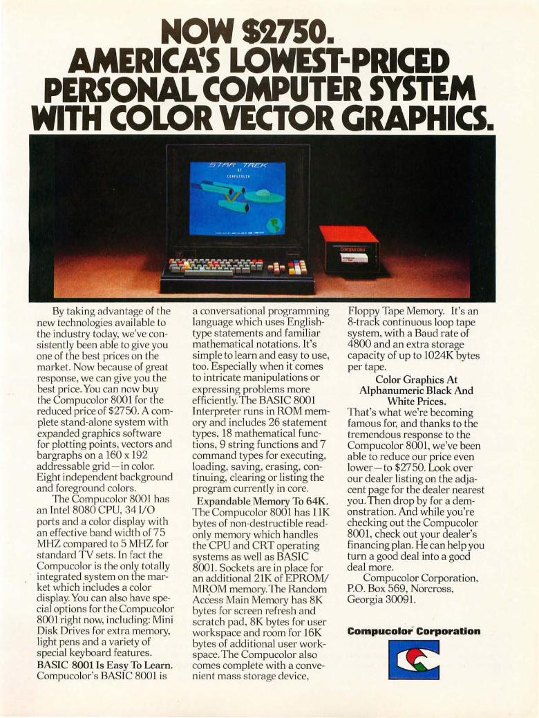
NOWSI750. AMERlCMS LOWEST-PRICED
PERSONAL COMPUTER SYSTEM WITH COLOR VECTOR GRAPHICS.
By taking advantage of the new technologies available to the industry today, we've consistently been able to give you one of the best prices on the market. Now because of great response, we can give you the best price. You can now buy the Compucolor 8001 for the red uced price of $ 2750. A complete stand-alone system with expanded graphics software for plotting points, vectors and bargraphs on a 160 x 192 addressable grid - in color. Eight independent background and foreground colors.
The Compucolor 8001 has an Intel 8080 CPU, 34 I/O ports and a color display with an effective band width of 75 MHZ compared to 5 MHZ for standard TV sets. In fact the Compucolor is the only totally integrated system on the market which includes a color display. You can also have special options for the Compucolor 8001 right now, including: Mini Disk Drives for extra memory, light pens and a variety of special keyboard features. BASIC 8001 Is Easy To Learn. Compucolor's BASIC 8001 is
a conversational programming language which uses Englishtype statements and familiar mathematical notations. It's simple to learn and easy to use, too. Especially when it comes to intricate manipulations or expressing problems more efficiently. The BASIC 8001 Interpreter runs in ROM memory and includes 26 statement types, 18 mathematical functions, 9 string functions and 7 command types for executing, loading, saving, erasing, continuing, clearing or listing the program currently in core. Expandable Memory To 64K.
The Compucolor 8001 has 11K bytes of non-destructible readonly memory which handles the CPU and CRT operating systems as well as BASIC 8001. Sockets are in place for an additional 21K of EPROM/ MROM memory. The Random Acc'ess Main Memory has 8K bytes for screen refresh and scratch pad, 8K bytes for user workspace and room for 16K bytes of additional user workspace. The Compucolor also comes complete with a convenient mass storage device,
Floppy Tape Memory. It's an 8-track continuous loop tape system, with a Baud rate of 4800 and an extra storage capacity of up to 1024K bytes per tape.
Color Graphics At Alphanumeric Black And
White Prices. That's what we're becoming famous for, and thanks to the tremendous response to the Compucolor 8001, we've been able to reduce our price even lower-to $2750. Look over our dealer listing on the adjacent page for the dealer nearest you. Then drop by for a demonstration. And while you're checking out the Compucolor 8001, check out your dealer's financing plan. He can help you turn a good deal into a good deal more.
Compucolor Corporation, PO. Box 569, Norcross, Georgia 30091.
Compucolor" Corporation
m:

Continued from page 59 stop the conversion ahead of overfl ow, but the worst case time is the n+ 1 clock pulses for n bits mentioned earlier. Figure 6 shows the sequence of vo ltages presented to the comparator by a 6 bit success ive app roximation algorithm, as compared to a 6 bit counter conversion algor ithm to show the time savings of this meth od.
63-62 60
58
56
54 52
50
48 46 44 42
40 38 36
34
t 32
VOLTAGE 30 28
26 24
22
20
18 16 14
12
10
8
6 4 2 0
In the circuit of figure 5, the comparator is shown as the Precision Monolithics CMP-01 C device, alth ough faster conversions may be possible if a higher speed Advanced Micro Devices AM686 comparator is used instead. Th e Advanced Mi cro Devices AM2502 integrated circuit, which was des igned for th is successive approxi mations conversion ap plication, conta ins everything needed for the logic described verba ll y above, except the digital to analog converter and th e comparator . Other compani es go even further with in tegration of the input conversion. Prec ision Monolithics, for example, makes an AD-02 circui t which contains all the complete 8 bit analog to digital conversions. It is relatively expensive, but its cost can often be justified by its uti lity and ease of use. It has a respectab le conversion speed and has several input options that can accomodate analog vo ltage ranges of 0 to 5 V, 0 to 10 V, - 2.5 to +2.5 V, - 5 to +5 V, and - '10 to +10 V.
REFER ENCE DAC OUTPUT VOLTAGES
SUCCESS IVE APPROXIMATION METHOD BECOMES READY
IN PUT VOLTAGE
RE FERENCE DAC OUTPUT VOLTAGES
TIME-
Software Approaches ...
As noted earlier, the software of a microprocessor can often implement the algorithms of digital to analog conversion. This is especiall y so with the successive approx imatio,n algorithm, since its inherent speed makes up for some of the slow facts of li fe concerning programmed execution. To rig a software approach to the problem, we need a digital to analog converter attached to an output port, an input comparator which drives one inpu t line, and the software of success ive approximation (or other methods for that matter ). In this case, the successive approximation shift register is variab le in a program, the outpu t latch is an outpu t latch connected to the DAC device, and decisions are made based on the si ngle bit input. A previous articl e in BYTE [see "Microprocessor Based Analog/Digital Conversion," by Roger Frank, page 70 of May 7976 BYTE] discussed both the ra mp (coun ter) and successive approximat ion methods described here, but showed how to implement them in software.
Whether the approach taken is that of pure hardware or software aided designs, adding analog input conversions to a personal' system can expand its capabil ities to cover many interesti ng real world control and measurement problems.-
COUNTER METHOD BE COME S READY
Figure 6: Comparison of the successive approximation method with the ramp method of conversion for a 6 bit value. (Six is chosen for purposes of this illustration.) The successive approximation method takes a mere six cycles of testing to arrive at the best value, where the ramp method has to count up to the number which matches the input and causes the conversion to terminate. The ramp takes'44 cycles here, versus six for the successive approximation method.
62


Personal Computing· & the It's happening at the Dallas Convention Center
Big Plans for "Big D" Innovation and relevance are key words for the 1977 National Computer Conference, the first NCC ever held in the Southwest and the year's largest gathering anywhere of data processing users, computer professionals and computer hobbyists. More than 25,000 people are expected to gather in Dallas for a conference program of more than 100 sessions and the year's largest display of computer hardware, software, systems and services-plus the first National Programming Contest and a series of outstanding Professional Seminars.
Largest Computer Exhibits Ever More than 300 major hardware and software companies will pack 1,143 booths into the Dallas Convention Center's modern 200,000-square-foot main hall- surpassing the all-time exhibit record set at the 1969 Fall Joint Computer Conference in Las Vegas. Additional space for the Personal Computing Fair & Exposition is on the next level for a totally separate exhibit by commercial producers of Personal Computing hardware and software. For. computer professionals and hobbyists with a need to know, the 77NCC offers a unparalleled opportunity to make close-up evaluations and comparisons of the latest in computer hardware and software, systems and service ... with many of the offerings scheduled to be shown for the first time.
Headquarters Hotel Personal Computing headquarters for the 77NCC will be at the Holiday Inn in downtown Dallas. Low-cost housing also will be available at Southern Methodist University. For information about NCC's Deluxe Travel Service, which can take care of all travel and housing reservations for you in one neat package, contact 77NCC, c/o American Federation of Information Processing Societies, Inc., 210 Summit Ave., Montvale, N.J. 07645, 2011391-9810.
r----------------, Registration Information! Fo r reg istrat io n at th e conference:
o Full four-day registration for program, exhibit s, Proceedings $75
o Student registration, as above, w ith out Proceedings $10
o One-day regi strat io n, program and exhibits o nl y $25
o Fo ur-day reg istrati o n, exhibits o nl y $25
DOne-day reg istr·ati on, exhibits only $10
o Proceed ings o nl y: members $30; no n-members $60
o Professional sem in ars, eac h $30
Checks should be payabl e to 1977 Na tional Computer Conference for the exac t amount only. Purchase orde rs will not be acce pt ed.
L ________________ ~

Great Computer Roundup during the 1977 NCC, June 13-16
Personal Computing Fair & Exposition The fast-growing field of Personal Computing will share the national spotlight in June, when the 77NCC will recognize the dynamic growth and promise of the field with the Personal Computing Fair & Exposition. In addition to the commercial exhibits of Personal Computing manufacturers, dynamic displays and demonstrations of non-commercial individual and group-owned projects will be featured at the Dallas Convention Center. The success of other hobbyists can give you new ideas for your own systems, "how-to" tips and dozens of clever solutions to everyone's problems. You might even find a joint-venture partner with a kindred spirit. More than 100 non-commercial small computing systems are expected, featuring hardware and/or software implementations, games, recreation, music, art, amateur radio, scientific, miscellaneous and general applications. Prizes and awards will be given in all categories.
Personal Computing Program Two full days of panel sessions on June 15 and 16 will provide an in-depth look at Personal Computing: Past, Present and Future; The Future of Retail Computer Stores; Hardware of the Computer "Hobby" Market; and Personal Computing Software. Leaders in the Personal Computing movement will appear on each of the panels to let you know the latest developments in the field, point out trends you'll need to be aware of - and answer your questions.
Special Interest Sessions In addition to the panel sessions, special interest groups will be able to gather informally for "how-to" programs on building a kit, debugging software, using assembly language, I/O interfaces, cassettes and disks, software standards and so on, into the night. If the special interest group you want is not organized when you get there, we'll do our best to help you get one started!
National Club Congress Is a national personal computing association needed? If it is, what does it do, how does it do it, and who does it? To find out what's happening-pro and con-club reps from across the nation will gather to exchange ideas and discuss issues related to club activities and programs. Make certain your club sends an official delegate who can speak for you and vote vis-a-vis a national organization, establishment of national hardware/software standards, a national program library and interchange, educational seminars, meetings, ad infinitum.
1977 NATIONAL COMPUTER CONFERENCE Dallas Convention Center • June 13-16

77NCC: The Great Computer Roundup A record-setting roundup of the latest trends and developments in computing and data processing will be offered at the 1977 National Computer Conference, the first ever held in the Southwest. As a vital learning experience for people whose business, professional or personal activities relate to information processing technology and techniques, it will encompass 89 technical program sessions, 11 professional seminars, the largest computer exhibit ever held and many other special events.
Timeliness and pertinence are key elements in the program, which will analyze latest developments and applications in computer science and technology, costeffective computer usage, management concerns and public policy issues. A series of briefings and panel discussion will cover practical, up-to-date information important to effective management and professional development. Throughout, emphasis will be on personal interaction and the exchange of ideas.
Underscoring the importance of NCC as a learning experience, the professional seminars will offer topics from system development and database technology to networking, planning and computer usage. Each will be covered in a comprehensive, one-day mini-course conducted by a nationally recognized authority.
77NCC will pay special attention to the fast-growing field of Personal Computing. Included will be two full days of program sessions, a Personal Computing Fair, a Personal Computing Exposition, a National Club Congress, plus additional activities of particular interest to hobbyists.
Special plenary sessions will feature a keynote address June 13 by Mark Shepherd, Jr., chairman and chief executive of Texas Instruments Inc.; the AFIPS Presidential Address June 14 by Dr. Theodore J. Williams; and a special address June 15 by A. Douglas Murch, senior vice president, Prudential Insurance Company of America.
Other highlights will include a Pioneer Day Program honoring members of the computing group at los Alamos Scientific laboratory; the first NCC National Programming Contest; the annual NCC Computer Science Film Theatre; special tours and an all-conference reception.
Be in Dallas June 13-16, when the 1977 National Computer Conference will offer computer specialist and generalist alike a most outstanding opportunity to attend the year's most complete computer roundup.
1977 NATIONAL COMPUTER CONFERENCE Dall as Convent ion Center • June 13-1 6

altair - IMSAI - S-100 BUS COMPATIBLE
Check these features . • ACCESS TIME - 450ns No wait states • FULLY BUFFERED - for BUS reliabil it y
• LOW POWER CHIPS - for long life and low power drain • MEMORY WRITE PROTECT - Hard ware, 2K segments • POWER REGULATION - 4 Regu lators for re liabili ty • AODRESS SElECT - lK boundari es - Dip. Sw itch • LEO MEMORY SElECT INDICATOR - Visua l Check • LED MEMORY PRDTECT INOICATOR - Visual Check • BATTERY BACKUP PROVISION - Saves memory during power fa ilure • OUTPUT DISABLE - Switch se lectable for transparent loader app licat ion
• p.e. BOARD - Quali ty Gl0 matenal w ith so lder mask both sides and si lkscreen • SOFTWARE - Diagnost ic provided
To Order Name __________________________ _
City __________________________ _
Circl e 248 on inquiry card.
Address State ____________ Zip
I
Price Enclosed is $ Check 0 Money Order 0
• KIT - With IC Socket s • KIT - Wi t hout Socket s
Solder chips direct ly to PCB
$239 $225
Bill my BankAmericard 0 : Master Charge 0 : Card No. Exp. Date ________ Interbank No. _____ _ _
Signa tu re ______________________________________________________________ __
Handling and Postage $2.50. California Residents add 6% sales tax.
• ASSE MBLED -With Sockets ...... $295 FRANKLIN ELECTRIC Co. 733 LAKE FI ELD ROAD • ASSEMBLED - Without Sockets .... $280 FE
Cont inued from page 60
gramm able read only memory" (or worse yet, erasable p rogram mab le ... ). I f i t's read only, how can i t be program mable? What is stat ic memory? Is there any othe r k ind of memory other than "random access memory? "
Is i t possible for yo u to help me ou t of my dilemma? Something between " bi nary numbers are made up of zeros and ones" and "when th e sta t ic EPROM is co nnected to the DMA lI sing a 3P+S 10 modu le."
A I Weiss POB 942
A lleghany CA 95910
Short of the tutorial article which may be inspired by your questions, here are a few notes on terminology and concepts in computer design and implementation.
Random Access Memory: Fo r the purposes of discussing the present state of technology, a random access memory means some sort of reference to semiconductor memory parts (excluding serial access devices such as shift registers) . A magnetic core memory is a form of random access memory, but is not used in modern small computer technology due to various manufacturing and
economic considerations. A read only memory (ROM) is a random access memory part, as is an ordinary programmable memory. The read only memory is distinguished from the fully programmable memory by the fact that it is nonvolatile (the in formation is retained when power is removed) and moderately difficult or impossible to alter once it has been set up with a program.
A commonly used acronym found in technical jargon and advertising is RAM, referring to random volatile programmable semiconductor memories. Since both read only memories and volatile programmable memories are random access devices, this term is misleading and ambiguous. In BYTE's editorial content, we do not use the term RAM intentionally, because of this ambiguity, and refer instead to "programmable" and "read only" memory. Progra mmab le emphasized the volatile, user program oriented nature of parts which are often called RAMs in conventional engineering journals, and read o nly characterizes the nonvolatile, permanent nature of the other type of random access memory part. (Of course, "programmable" is still not an optimal choice, since even read only memories are always programmable in the sense of "program it only once. ")
Stat ic Versus Dyna m ic: In brief, there are two types of volatile programmable memory parts, characterized by the in-
67
WESTLAKE V I L LAGE, CA 9 136 1 18051497-7755
ternal design of the basic memory cell of the circuit. A static memory typically has a cell with sufficient active transistor elements to create a true flip flop memory register. A dynamic memory typically has a smaller memory element size which is achieved by replacing the memory flip flop with a capacitor which stores an electric charge. As a result of this smaller unit bit cell size, at the lim its of technology the largest dynamic parts have historically had about four times as many bits as the largest static memory parts. A t the present time, the largest static memories readily available are 4 K bits per chip, whereas the largest dynamic memories are 76 K bits per chip.
There is a subtlety of design with dynamic memories, however. This is the fact that since the storage elements are capacitive in nature, sensing and support electronics on the chip tend to drain th e charge with time, losing any information stored in the cell. The dynamic memory chips must thus be refreshed periodically, an operation that is commonly performed by cycling through a reference to the low order bits of the address inputs to the chip. Sta tic memory chips have no such refresh requirement, and are often easier to use in prototype, small or homebrew circuitry; the manufacturing economies tend to make dynamic memories the most attractive in larger systems products .•

Continued from page 9
number of existing computer science textbooks. But I'd really like to somehow buy the design in a completely documented form so that like the plan of the hypothetical rolltop desk, I could implement it literally with custom modifications. Tutorial and "how to" plans books for specialized fields such as those mentioned above are widely available already, and at prices well within the range of an individual's budget. They are marketed in large quantities because large numbers of individuals use the information; outlets range from mail order book services to retail stores. Drawing out of this parallel between individualized computing and individualized "anything else," it should be obvious what the solution of the software dilemma is: Publish detailed plans and tutorial information for software, on a scale commensurate with the size of the market. Publishing ideas is an activity which has a long and distinguished history, and yields both personal and financial rewards to those who engage in the practice, as well as real benefits to those who purchase the products. Let's turn now to the application of th is concept to the software designs of the computing world.
68
The Ideal Model of a Published Software Product
When we talk about publishing software at the present state of technology, we are talking about a product which is akin to the detailed design of the rolltop desk mentioned earlier. It is a product which serves as the starting point for the home software craftsman, not a recipe which will fit without thought into every conceivable system. This will change a bit as the systems in the marketplace become more refined, but the nature of the computer as an intellectual amplifier tends to require a certain level of technical familiarity on the part of its user. (This is the element which distinguishes the general purpose computer from the applications oriented dedicated computer such as a 4 function calculator or oven controller.)
I n order to make a software package which is optimally configured for the customer's standard or customized use, there is a certain minimal level of documentation which is required. This level of documentation is not necessari Iy needed by all users all of the time, but is in many respects akin to the reference books for integrated circuits: When a question needs to be answered, it is good to have the information needed to zero

in on the answer. Here is what I consider to be adequate documentation:
• Users' manual textual materials concerning the "standard" uses and limitations of the software. Here is where we find such information as standard 10 patch points, relocation tables, etc.
• Complete object code, preferably machine readable along with machine readable relocation information.
• Complete source listing of the package including source language and generated object code for each statement.
• Program logic manuals and tutorials on the design of the product are an excellent option.
The idea is to include enough information to allow the user to do routine field alterations, including relocation. The idea of a published software product is to compile all this information together in a comprehensive book form, to be sold at prices characteristic of books, as opposed to the past history of software prices for applications and system software packages. The technology of printing covers all the portions of the "complete" package except machine readable code, at least in the minds of most people. However, as we have demonstrated with experiments
69
published in BYTE, printing technology also covers machine readable representations as well.
Varieties of Machine Readable Representations
User convenience demands that a software product be made available in some form of mach ine readable representation. While it is certainly possible to take an object listing in printed form and type it into a processor by hand, this is a long, ted ious and error prone process. To complete the functional definition of "adequate documentation" given above, we need a form of machine readable object code at minimum, along with machine readable relocation information. Fortunately there exist several technologies which can be employed for this purpose, which I'll review here.
ROM Releases
This is the most expensive medium presently available for reproducing software; however, it has utility in the convenience of use provided by built-in software. In terms of practical products, however, this form of software will most frequently show up in manufactured products preloaded at the

factory, rather than user integrated software. A ROM program is d ifficu lt to achieve in a relocatable form, and has a certain permanence which is both its advantage (convenience) and its disadvantage (difficulty or impossibility of patching). This method has been successfu ll y emp loyed in sevel'a l desk top calculator packages in the form of ROM software options, and in such personal computing products as bu il t-in BASIC in terpreters and monitors. For end user markets, this form of software can dispense with all but the user oriented manuals in most purchases, since modification is impossible.
Magnetic Digital Media Releases
As more and more floppy disk products, large and small, come to market, the use of the magnetic diskettes for softwal'e releases is becoming common. Simi lar ly, the Philips and 3M digital tape media with standard digital recording techniques can be considered as veh icles for re lease of machine readable data. However, the price of the media and the costs of dig ita ll y record ing and verifying each copy tend to make this method of delivery limi ted. It 'is used, quite naturally, as the vehicle for de li very of floppy disk operating systems from the
70
manufacturers of drive in terfaces, but the re the wr iting and testing of a diskette fu ll of data fa ll s out of the expected quality assurance tests prior to packing and delivery. The same is true for the other forms of hardware which have related operating system software products that can be recorded.
Paper Tape
This venerable medium has been in existence longer than the modern electron ic computer. No survey of distribution media wou ld be comp lete without mention of it. Very re i iable means ex ist for read ing paper tapes into computers at quite economica l prices, we ll under $100 for the peripheral. As a distribution medium, however, paper tape in my op inion suffers from several disadvantages: It is inconven ient to sto re, bulky, prone to create a messy tangle due to manual handling with inexpensive peripherals. Whether my op in ion is supported in the marketplace is another question altogether.
Audio Media Releases
One of the most useful and practical vehicles for the distr ibu tion of software is likely to be the use of audio recording media. Here we can identify two principal

method s of distribution; recording on tape cassettes or other magnet ic tape aud io media, and recording on the audio eq ui va lent of a read on ly memory, the phonograp h record.
Th e techno logy of record ing on tape resu lts in a product with a fa irly high unit cost for each copy of the in fo rmation. To this mu st be added the cost factors associated with normal pri nti ng of the rest of the documentation. Cassettes, as a record in g method, are a logical choice for custom software, or small volume situati ons, but the hi gh degree of manual labo r associated with each copy argues again st th e practica lity of large production runs in this form.
Th e technology of making phonograph records is, on the other hand, a we ll establi shed mass prod uction technique which can be adapted to the software distribution without much vanatlon from standa rd methods. To illustrate the point and to test the concept, I mad e a test in the spring of 1976 at the suggestio n of Dav id Fylstra, an associate of mine who is also a homebrew record maker. He arranged for the cutting of a test record with th e audio format of my personal monitor program, circa March 1976, to test out this method using a master record cut on stand ard record ing industry equ ipment. Depending upon size an d qu an-
71
tity of pressin g, the costs per record run well und er $1, which is hard to meet with the cassette duplication method.
Machine Readable Printed Media
As a final option, there is the use of machine readab le printed formats for object code and relocation information in the re lease of software products. Th is is a form which was suggested to us at BYTE by Walter Banks of the University of Waterloo, and with which we have been experimenting in the pages of BYTE . In thi s method , an optical reader is used to scan printed materials whi ch have been formatted into a series of bars corresponding to the digital information. Because of constraints in the design of the layo ut and the method of scanning, it is possible to si mplify the scanner designs to th e point where a very inex pensi ve per iph era l is used together with some adaptive software which takes care of the speed tolerant inpu t scan. Th e beauty of this method is th at it "comes fo r free" in so far as actual production costs are concerned. Wh y is th is true? Th e reason is that the 200 to 300 pages of documentat ion needed to support a systems software product with perh aps 12 K bytes of object code require only an addi tio nal five to seven pages of
Circle 151 on inquiry card .

Articles Policy BYTE is continually seek
ing quality manuscripts written by individuals who are applying personal systems, or who have knowledge which will prove useful to our readers. Manuscripts should have double spaced typewritten texts with wide margins. Numbering sequences should be maintained separately for figures, tables, photos and listings. Figures and tables should be provided on separate sheets of paper. Photos 0 f technical subjects should be taken with uniform lighting, sharp focus and should be supplied in the form of clear glossy black and white or color prints (if you do not have access to quality photography, items to be photographed can be shipped to us in many cases). Computer listings should be supplied using the darkest ribbons possible on new (not recycled) blank white computer forms or bond paper. Where possible, we would like authors to supply a short statement about their background and experience.
Articles which are accep ted are typically acknowledged with a binder check 4 to 8 weeks after receipt. Honorariums for articles are based upon the technical quality and SUItability for BYTE's readership and are typically $25 to $50 per typeset magazine page. We recommend that authors record their name and address information redundantly on materials submitted, and that a return envelope with postage be supplied in the event the article is not accepted . •
machine readable bar code copy, hardly affecting the economics of the book at all. These 200 to 300 pages of documen tation are required by the product concept, whether or not there is any other form of machine readable code made available.
Economics of Publishing
With media established, and a product concept outlined, what about addressing the problem of rewarding the producers of software products? Here, as in any area of publishing, the answer is quite simple. The publishing house judges whether the particular software package is in its view a readily marketable product with a certain minimum press run potential. If so, the publisher puts up production capital, where the author puts up intellectual capital in the form of hi s or her work . It is a risk situation in which both parties are mak ing a speculation that readers will purchase the product; as in numerous parallel situations throughout industry, authors and publishers work on an agreed upon split of any rewards from success in the marketplace.
Applied to the software publishing variant of this business, the author's intellectual capital is in the form of the progra m, its source code, its object code, and its documentation ; the publisher'S contribution is the marketing organization, the technical editing of the manuscripts, and the technical detaifs of book preparation. Other th an the specialized content, the method of operation and the details of the arrangement are not much different from publishing any item . Rewards to authors now become a small
amount (in absolute terms) of royalty recovered from orders of magnitude in sales for successful software book products.
Proprietary Products
The problem of protecting and keeping software proprietary is no longer a major "new" issue when publishing of software is contemplated. How many people extensively copy from books? Very few, and if they attempt to make a regular practice of it they would tend to be prosecuted by publishers under copyright law. In publishing software, an implicit or explicit license to copy the copyrighted materials for personal use and modification is part of the bargain; the price is low enough so that if you want your own user documen tation, you buy your own copy of the book (even if you may have been using object code derived from your neighbor's computer). Since the documentation is a necessary component of use, no sales tend to be lost in the long run due to the fact that object code can be swapped around.
Conclusions
What I have endeavored to show is that there is quite some potential for the sale and distribution of software using conventional publishing techniques with modi fications to suit this type of product. By publishing software along with mach ine r.eadable code, we end up with a way to make the products widely available, yet retain the desirability of compensating authors for their efforts in proportion to the success of the product.-
MULTIPLE DATA RATE INTERFACING FOR YOUR CASSETTE AND RS-232 TERMINAL
the CI-812 The Only S-100 Interface You May Ever Need On one card, you get dependable "KCstandard" /biphase encoded cassette interfacing at 30, 60, 120, or 240 bytes per second, and full-duplex RS-232 data exchange at 300- to 9600-baud. Kit, including instruction manual, only $89.95*.
[LlEfUlllM 1 PERCOM DATA COMPANY, INC. 4021 WINDSOR. GARLAND. TE XAS 75042
*Assembled and tested, $119.95. Add 5% for shipping. Texas residents add 5% sales tax. BAC/MC available.
72
PerCom 'peripherals for personal computing

Item No.
8KSC WWC 88 EXT 88 Ext-S 88 Ext-L 88WWC BBUC
----------~ OROER FORM [Write in each box the quantity of each part required ) KI T ASSEMBLED KIT ASSEMBLED KIT ASSEMBLED D 4KROM 0 D 8KSC-Z 0 D 68KSC c=J D 8KSC 0
o wwc D D 68EXT-L D c=J 88 EXT D D 68WWC D o 68EXT-S D D BBUC D
D ASSEMBLY AND OPERATING MANUAL $4.00
NAME ______________ ~~~~~~~-------------------PLEASE PRINT OR TYPE
ADDRESS __________________________________________ __
CITY _____________________ STATE ______ ZIP ____ _
SEND CHECK· MONEY ORDER· COD'S ACCEPTED· CREDIT CARDS
SEALS ELECTRONICS, INC P.O. BOX 11651 KNOXVILLE, TN 37919
_ (O ..... ccOUOO ............ O/IO.OUO ........ U OC .. D
IUIf.l. .. I~ICUO LL.UJUlJ!-dolJ UlJ - ... ",.IIIW
(00" ace"","' ........... 000.0\,1 . "UIII ("U""
MOST ORDERS SHIPPED WITHIN 10WORKING DAYS I_tl"l"""l"'l" ,=!::::~; ' . LlllJ .. "" WW ......... h... .. .... I .. -
[READ ONL Y MEMORY]
• Will accept up to 16 ea. 1702-A or 5203 EProm Providing up to 4096 Nords of non-volatile memory for Boot Loads to Complete Programs.
• Programming Available at Factory for $3.00 per EProm when accom-panied by binary formated tape.
• Each 1702·A has its own Vgg clocked for Low Power Consumption , • Will work with the weakest power supply based S·100 buss computer. • Switched Selected Address in 4K Blocks. • Switch selected wait states so that even the slowest 1702-A can work
in your system. 0-8 wait states. • Solder Masked on both sides of PC Board. • Component Screened on Component Side of PC Board.
Kit Price: • • $119.00 Assembled Price: •• • $179.00
[STATIC MEMORY CARD FOR SWTPC 6800]
.8192 Words of Static Memory • Access Time: 500 nsec. (250 nsec on request) • Memory Chip 91 L02 APC • Battery Standby • Address Selected 8 Ea. SPST Dip Switch • Low Power • All Lines Buffered. • AlllC'swith sockets • Solder Masked on both sides of PC Board.
Kit Price: •• $269.00 Assembled Price: • , .$359.00
[STATIC MEMORY CARD]
• AL TAI~IMSA~and S-100 buss compatible. • Access Time : 250 nsec max. • ZiloQ Speed Compatible up to 4 mhz. • Memory Chip: 2102LHPC or 2102AL-2 • 8attery Standby: >1 .5 to 4 volts< • Address Select : 8 ea. Spst. Dip Switch. • Wait States: None • Current Reg. : Less than 200 ma per 1 K • All Address, Control, and Data out lines fu lly buffered. • All IC's supplied with IC Sockets • Solder Masked on Both Front and Back of P.C. Board .
Kit Price: $295.00 Assembled Price: ••• $395.00
OTHER SEALS ELECTRONIC PARTS AVAILABLE
IIISE~lH~, Description Kit Price Assembled Price
8K Static Memory Card 500 nsec Wire Wrap Card 88 Extender Card Extender Card (Small I SWTPC"OOC~,,"b" "_'" Extender Card (Large' SW1PC 6800ComPtllb'. P' Oduc:n
Wire Wrap Card SWTPC UiOOComPI" bl. P ,Qduel\
Battery Back·Up Card
$269.00 $ 37.50 $ 29.00 $ 19.00 $ 29.00 $ 35.00 $ 55.00
$369.00 $47.50 $ 38.00 $ 25.00 $ 39.00 $ 45.00 $ 68.00 ELECTRONICS, INC.
ORDER DELIVERY: FROM STOCK TO 10 DAYS TELEPHONE # 615 / 693-8655
Circle 236 on inquiry card .

Circle 137 on inquiry card .
More on Using the 8x300
Jon Twichell 303-0 Eagle Hts
Madison WI 53705
A short note concerning your note in the March 1977 issue of BYTE (page 100) on the Signetics 8X300. This processor was designed and sold as the SMS 300 (Scientific Micro Systems, 520 Clyde Av, Mountain View CA 94043). I used SMS's development system in a scientific data acquisition system. Two years ago it was the fastest thing on the market. I was building a two dimensional multichannel analyzer out of a Modcomp II, and used the microcontroller for the address mapping and handshaking. Pure blinding speed was our object, subject to the constrai nt of programmability. The observation is that this is the same criterion for a microprocessor used for emulation.
True, the 8X300 is fast, but by today's standards, not that fast. It is rumored that
SMS is working on an ECl version .... Anyway, if one examines the architecture of the 8X300, one finds two chokes, both fixable. The first is that the microcode is quite vertical, as one would expect with a 16 bit instruction . One can effectively double the speed of the system by simply extending the microcode width by eight bits_ Make your program memory 24 bits wide; use 16 in the normal fashion. The extra eight are used as the address in working storage or 10 space. The 8X300 must use an instruction to load the "memory address register" (IVR REG) and then another instruction to fetch the word at that address; by selecting an address for each instruction (the extra eight bits), most programs halve in size, and double in speed.
The second choke is the time multiplexed 10 bus. I seriously suggest the user extend the microcode and stay away from those
Continued on page 110
PROM: Space for 2K bytes, :1702A. Store bootstrap loaders and monitors .
RAM: 1 K bytes, 2102L1PC, 450 ns, low power. NO NEED TO RELOCATE STACK WHEN ADDING MEMORY. CIRCUITRY: Replaces memory write logic on ALTAIRTM and Imsai front panels . REGULATORS: Two regulators . No need for regulated power supply. JUMP-ON-RESET: PROM program execution starts at any location in memory without interfering with programs in any other portion of memory .
S-100 BUS; + 8 and -16 VDC; PIC BOARD SOLDER MASKED BOTH SIDES WITH PLATED THROUGH HOLES; ALL SOCKETS INCLUDED . OPTIONAL FIRMWARE: 512 byte monitor for use with Tarbell tape interface on 2, 1702A PROMs. PROM/RAM KIT WITHOUT PROMS $ 89 +OPTIONA-SIORev.1or3P+S $129 + OPTION B-2 SIO (MITS) $129 + OPTION C - SIO 2 (IMSAI) $129 + OPTION 0 - Poly Video Interface $159
(Includes Video Driver) California residents please add 6% tax.
IMMEDIATE DELIVERY FROM FACTORY OR YOUR LOCAL COMPUTER STORE
T .M.
t#wIi. i:O=l <:=lAilJ-iC inC.
74

Deal Yoursell • In ...
Allalil tic City, N.J. Aug st 27th-28th
What its all about! Software Development
Micro Computers Hardware Development
Disc Memories Computer Comparisons
Interfacing Program Implementation
AM SAT Computerized Music
Video Terminals Kit Construction
Printers Computer Games
Digital Tapes
• Seminars and Technical talks by leading electronic equipment manufacturers • Major Exhibits from all over the country • Demonstrations in many areas including Home and Personal Computing • Door Prizes, Free Literature and Free Mementos • All this plus Sun and Surf - Fun and Excitement - Relaxation and Leisure
• Personal
C Computing
SPECIAL GROUP RATES FOR CLUBS A.ND ORGANIZATIONS TRAVELING FROM THE WEST COAST AND MID-AMERICA.
CONTACT
Dawn Corrigan (213) 924-8383
Seven Seas Travel 17220 S. Norwalk Blvd. Cerritos. CA. 90701
Write for FREE TRIP-KIT to PERSONAL COMPUTING 77, Rt 1, Box 242, Mays Landing, New Jersey 08330
77 Consumer Trade Fair
EXHIBITION BOOTHS STILL AVAILABLE - CALL (609) 653-1188

Photo 7,' The Teleterminal Corporation Fly Reader for use with the KIM-l microprocessor.
Come Fly With KIM Rick Simpson
Many computer hobby ists start with nothing more than a processor, a small amount of programmable memory, a small onboard moni tor such as M I KBUG or KIM and some front panel sw itch es . Th ose with more fore sight, o r cash, will have a keypad or even a hi ll keyboard fo r data ent ry and processor contro l. But even with a good monitor and a full keyboard and disp lay, loading progra ms is a tedi ous chore at best, and there is an awful feeling when you turn off power, knowing that twenty minutes of typing just evaporated.
The next step in expandin g the system is usually an audi o cassette in terface or a Teletype with paper tape reader and punch for the wealthy or fortunate. Now the tedious rety ping is eliminated and a program, once written and recorded or punched , can be rel oaded in a matter of minutes .
Many peo pl e stop at this poin t. When hand assembly of programs is required, a program of more th an a few hundred bytes is rarely attempted. Bu t as the software gap is slowly fill ed, more and more systems are being implemented with assemblers or
76
MOS Technology Inc Valley Forge Corporate Center 950 Rittenhouse Rd Norristown PA 19401
BASIC interpreters. Mo re memory is purchased to ex pand program mabl e memory from a few hundred bytes to 4 K, 8 K, or more. [One firm now even markets a 64 K board! . .. CHj Once aga in your memory has outrun your ab ility to fill it in a reasonab le t ime.
For instance, usi ng the Teletype paper tape reader or audio cassette interface on the KIM system, a 2 K Tiny BASIC interpreter takes almost ten minutes to load. A 12 K BASIC source program would take an hour. Even a 30 character per second in terface onl y cuts thi s to twenty minutes. The alternat ives seem to be a Tarbell or Suding type high speed cassette system , a 3 M dri ve at 9600 bps or a floppy disk.
The flo ppy dis k certa inl y so lves the sp-eed problem. We can now load 12 K in a few seconds, bu t at a cost of $1,000 to $2,000. The high speed cassette is reasonable in cost, about $200 including the high quality cassette uni t required, but tricky to in terface unl ess a manufactu rer-supplied board or kit is ava il ab le.
Although some magnetic tape units have start, sto p, and search functions under pro-

gram control, most users end up pushing the buttons. No hobbyist magnetic tape cassette unit can read a few (ie: one I ine or so) characters, stop and process the data, and then start and read some more, a real need when running an asse mbl er with the sou rce stored on the tape in a limited resource system.
After this lengthy preambl e, you may have suspected that I have an alternat ive solution in mind, and I do: a high speed paper tape reader , manufactured by the Teleterm inal Corporation, called the Fl y Reader, shown in photo 1. Although a bit more expensive than the high speed cassette system (about $350), it is far faster; reading at 300 characters per second, it can load my Tiny BASIC in twenty seconds, or fill that 12 K of memory in two minutes. It is easy to interface, req uires littl e software, and is extremely reliable. It needs only a single +5 V, 2 A power supply and is operated completely under program control. You can read as little as a single character at a time and can read in either direction; try that on your cassette!
Paper tape has always been the standard mass storage device for minicomputers, until floppy disks came along, and paper tape has been the most universal and inexpensive method of software distribution and interchange in the minicomputer field.
The basic problem is that it is only a reader; how do you punch the tape? There are several answers: Flexowriters and other similar low speed punches are becoming available, as are gobs of older 7 leve l machines . I've also seen higher speed punches, typically 60 characters per second, advertised for under $100. The fact that the punch is slow is not so important; typically you punch a tape once and read it many
PAPER TAPE ©
times. Even if you have no punch , the reader is a useful peri pheral because much software is ava il able already punched.
How it Works
The Fly Reader can read at such a high speed because it transfers 8 bits in parallel and contains only a single moving part: a stepping motor connected to a toothed wheel which engages the sprocket holes in the paper tape. Sensing of the holes in the tape is done by photodetectors rather than the mechani ca l fingers used in a low speed reader. This is a method similar to that used in the manual reader sold by Oliver Audio. Figure 1 shows a block diagram of the unit.
There are five control lines for the unit. All are compatible with standard TTL circuitry. The "load status" line is a logic 1, +5 V, if the reader is not ready because the feed gate is not closed. When tape is inserted and the gate is closed, this signal goes to logic ze ro.
In operation, the reader must be checked by software to see if the "reader ready" signal is at logic 1 to indicate that the reader is ready to read another tape character. The software must then issue a pulse from logic 1 to logic 0 whose width is between 500 ns and 500 MS. This READ pulse will start the reader and drive the reader ready line to logic O. The software then watches the "data strobe" line. When data strobe goes to logic 1, the data can be read from the eight parall el output lines. If the program needs to read another character from tape, it must wait until reader ready goes back to logic 1, issue another read pulse, and wait for another data stro be. Figure 2 shows the flowchart for such software and figure 3 shows the interface timing diagrams.
AMPLIFIER AND SIGNAL CONDITIONING
OUTPUT LINES
Figure 2: Flowchart of the so ftware for reading the paper tape with the Fly Reader.
ISSUE READ PULSE
READ PARALLEL OUTPUT
NO
Figure 7: Block diagram of the Fly Reader. The input is achieved through an incandescent lamp and a photodetector array. The tape is advanced by a stepping motor allowing input of data either forwards or backwards. The reader open sense switch is closed when the paper tape is in the reader.
PHOTODETECTOR ARRAY
[> BTTL
(TO KIM-I PAO TO PAn
TO OTHHEAO SPROCKET DRIVE • WHEEL
f5V
.------,.--DATA STROBE (PB4) READER READY (PB5) READ (PBO)
'---__ ---r--FORWARD. REVERSE (SET TO DEFAULT STATE OF 0 OR I)
READER OPEN ~C>------_' LOAD STATUS LINE SEN SE SWITCH J,
(TO PBI OF KIM-I)
77

SIGNAL
LOAD STATUS
READER READY
READ COMMAND
FORWARD REVERSE
SPROCKET
DATA STROBE
DATA OUTPUTS
DATA TRUE
LOCATION
J3 P7
J3 PB
J3 P6
J3 P5
INTERNAL
J3 P9
J3 PI2 TO PI9
J3 PI2 TO PI9
LOAD READER
READ FORWARD, 2 CHARACTERS
20m. RISE AND FALL TIMES
20m. j DELAY
Figure 3: Timing diagram generated by the software of listing 7. The minimum width of the data strobe is 50 iJ.S except when forced low by a new read command. The crossed out sections in the data true section indicate that the state of the output is unlmown. A read command is issued only when the reader ready line is high.
Other Interface Possibilities (An Advertisement ... )
The interface described here uses most of the avail· able 10 lines on the KIM-1. Systems supporting several 10 devices may wish to interface the Fly Reader through a separate interface chip. The MCS6532 is one such interface chip for adding more 10 to KIM-1 as well as an additional 128 bytes of programmable memory and another interval timer . Two of these chips (with ROMs) are already built into each KIM . Since the 6532 is a MOS rather than TTL device it does not load the KIM-1 address or data buses significantly. The MCS6532 is available for $16 postpaid from National Electro-Sales, 12063 W Jefferson, Culver City CA 90230.
Interfacing to Kim
As described above, the Fly Reader interface requires eight parallel input lines, three input control lines and one or two output control lines. Two output control lines are needed if the forward, reverse function is used; otherwise only one control line is needed. Since KIM -1 has 15 bidirection al 10 lines the interface is very simple. The A data port lines PAO to PA7 are programmed as input lines and connected to the parallel output lines from the Fly Reader. PB5 is connected to the reader ready line, PB1 is connected to the load status line, PBO is connected to the read command line and programmed as .an output line, and PB4 is connected to the data strobe line. A 5 V, 2 A power supply is co nnected to the reader and the interface is complete. When wiring the power connectors, you should make sure that separate power and ground wires are run back to the power supply for both th e motor and logic connections. This will insure that current su rges to the motor during stepping operations do not feed noise pulses into the control logic.
I nterface Details
The fifteen KIM-"I 10 lines are divided
78
READ REVERSE, 3 CHARACTERS
into two ports. Each port has a data direction register and a data register. Writing a 1 to a bit or bits in the data direction register configures the corresponding 10 lines for output, writing a 0 sets them for input. For instance, writing a hexadecimal 02 to the A data direction register configures the P AO I ine for input, PAl for output, and P A2 through PA7 as input lines. Similarly, writing hexadecimal FO to the B data direction register configures PBO through PB3 as input lines and PB4, PB5 and PB7 as output lines. Note that there is no PB6, and PB7 has no output pullup; it is essentially an open collector output. Read ing the A or B data register will show whether the signal at each input line is 1 or 0 and will show whether a o or 1 was previously written to any lines configured as outputs. Writing to a data register will set the appropriate output lines to 1 or 0 and does not affect lines programmed as inputs. Hexadecimal address location 1700 is the A port data direction register, hexadecimal 1702 is the B data direction register, hexadecimal 1701 is the A data register, and hexadecimal 1703 is the B data regi ster.
The KIM Paper Tape Format
The software to drive the reader uses the same paper tape format as that used in the KIM-1 Q (paper tape dump) and L (paper tape load) commands. Thus any paper tape punched on a low speed punch by KIM-1 can be read by the Fly Reader. The KIM-1 paper tape format ignores any characters

Fantastic Software This LIBRARY is a complete do it yourself kit. Knowledge of programmin g not re quired . EASY to read and US E
Written in co m pat ibl e BAS IC im mediately executable in A N Y computer with at least 4K , NO other pe rip herals needed.
.... " BASIC
This Library is the most comprehensive work of its kind to date . There are other software books on the market but they are dedicated to computer games. The intention of this work is to allow the average individual the capability to easily perform useful and productive tasks with a computer. All of the programs contained within this Library have been thoroughly tested and executed on several systems. Included with each program is a description of the program, a list of potential users, instructions for execution and possible limitations that may arise when running it on various systems. Listed in the limitation section is the amount of memory that is required to store and execute the program.
Each program's source code is listed in full detail. These source code listings are not reduced in size but are shown full size for increased readability. Almost every program is self instructing and prompts the user with all required running data. Immediately following the source code listing for most of the programs is a sample executed run of the program.
BASI C
SOFTWARE
• • • . w . •• OWN
The entire Library is 1100 pages long, chocked full of program source code, instructions, conversions, memory requirements, examples and much more. ALL are written in compatible BASIC executable in 4K MITS, SPHERE, IMS, SWTPC, PDP, etc. BASIC compilers available for 8080 & 6800 under $10 elsewhere.
This Library is destined to become one of the reference bibles for the small computer field, due to its versatility and uniqueness and the ease of operation of the programs it contains. These volumes are deductible as a business expense when purchased by a company. Send your remittance for prompt delivery, while supplies last. Volume discounts are available to qualified dealers .
VOLUMEI Bookkeeping Games Pictures . . . _ . . . .. . .... . . . S24 .95
VOLUME II Math & Engineer ing Plotting &. Stat Basic Stateme nt Del . . . . . . . S24.95
VOLUME III Advanced Business Billing Inve ntory PayrOl l . . . . . .. . . .. _ . . . . _ S39.95
VOLUME IV Ge neral Purpose .... _ . . . ... S9.9 5
VOLUME V Experime nter .... _ .... . . . . S9.95
FU T URE ADD IT ION TO THE "BAS IC SO FTWAR E LI BRARY "
V o lume VI (A Complete BUSiness System $49.95) General Ledger System - T axes, Pyrl, W-2's, l nventory, Depr., Financial S tatements, e tc . AVA I LAB L E MID S UMM E R
Available at most computer stores. Add $1.50 per vol ume for postage and hand lIng.
SCIENTIFIC RESEARCH 1712-B FARMINGTON COURT
CROFTON MD 21114
Phone Orders cal l (800) 638-9194 In formation and Mary land Reside n ts Ca ll (301) 72 1-11 48
Circle 282 on inquiry card.

address
lC4F 4000 4001 4004 4007 4009 400B 4000 400F 4011 4014 4015 4018 401B 401D 4020 4023 4025 4028 4029 402B 402E 4030 4033 4036 4037 4039 403A 4030 403F 4041 4044 4046 4048 4049 404B 404D 4050 4053 4055 4057 4059 405C 405F 4062 4064 4066 4068 406B 406E 406F 4072 4074 4076 4078 407B 4070 4080 4083 4085 4087 408A 408B 408E 4091 4094 4097 4099 409A 409D 40AO
hexadecimal code label
START 08 20 57 40 PTR LD 20 6F 40 LOAD C9 3B DO F9 A9 00 85 F7 85 F6 20 8B 40 AA 20 91 1 F 20 8B 40 85 F8 20 91 1 F 20 8B 40 85 FA 20 91 1 F 8A FO 20 91 20 20 CA
OF 8B 40 FA 91 1 F 63 1 F
DO F2 E8
LOADS
LOAD2
20 8B 40 LOAD3 C5 F6 DO 12 20 8B 40 C5 F7 DO 08 8A DO B9 A2 OC 20 31 4C 4F A2 ,., DO F6
LOAD7 1 E LOAD8 lC
A9 01 8D 03 17 80 02 17 AD 02 17 29 02 DO 08 A9 58 20 AO lE 4C 57 40
LOADER
PTRINI
60 OK AD 02 17 GETPTR 29 20 FO F9 A9 00 8D 02 17 A9 01 8D 02 17 AD 02 17 CHECK 29 10 FO F9 AD 00 17 60 20 20 20 20 A5 60 20 20 4C
6F 40 AC IF 6F 40 AC lF F8
PTR8YT
57 40 MAIN 6F 40 LOOP 90 40
op. operand
PTRINI GETPTR $3B $LOAD 00
commentary
$lC4F clear decimal mode; go to PTRINI; go to GETPTR;
} if A not equal to 3B go to LOAD ;
else A:=OO;
EQU CLD JSR JSR CMP BNE LDA STA STA JSR TAX JSR JSR STA JSR JSR STA JSR TXA BEQ JSR STA JSR JSR DEX BNE INX JSR CMP BNE JSR CMP BNE TXA BNE LDX JSR JMP LDX BNE LDA STA STA LDA AND BNE LDA JSR JMP RTS LDA AND BEQ LDA STA LDA STA LDA AND BEQ LDA RTS JSR JSR JSR JSR LDA RTS JSR JSR JMP END
$F7 } $F6 PTRBYT
store checksum;
$1 F91 PTRBYT FB $lF91 PTRBYT FA $lF91
LOAD3 PTRBYT FA,Y $1 F91 $lF63
LOAD2
PTRBYT $F6 LOADER PTRBYT $F7 LOADER
LOAD OC $1 E31 START 11 LOAD8 $01 $1703 $1702 $1702 $02 OK 'X' $lEAO PTRINI
1702 $20 GETPTR $00 $1702 $01 $1702 $1702 $10 CHECK $1700
GETPTR $lFAC GETPTR $lFAC $F8
PTRINI GETPTR LOOP
go to PTR8YT; [get byte count] X: =A; compute checksum; get high address; store high address pointer; compute checksum; get low address pointer; store low address pointer; compute checksum; A :=X; if A:=O go to LOAD3 ; get data ; store data; compute checksum; get next address; X:=X-l; go to LOA02 ; X:=X+l; get data; compare high order checksu,n; if different go to LOADER ; else get data; compare checksum ; if different go to LOADER; else A :=X; if A not equal to 0 go to LOAD ; else X:= location of 'KIM' ; output message; go to START; X:=location of 'ERR KIM' ; go to LOAD8; [initialization routine] A:=8 port address; read flag:=l; A : = B register; determine PB1; if reader ready go to OK; else A: = 'X'; output 'X ' ; go to PTRINI; return ; [subroutine to input one character] get bit from 8 data register ; if not ready go to G ETPTR ;
} else output read pulse;
} turn off read pulse;
} get bit 5 from B data register;
if character not ready go to CH ECK; else get character; return; get character ; pack character; get another character; pack character; A :=2 characters; return; go to PTRINI ; go to G ETPTR ; go to LOOP;
Symbol
CHECK GETPTR LOAD LOADER LOADS LOAD2 LOAD3 LOAD7 LOAD8 LOOP MAIN OK PTRBYT PTRINI PTRLD START
CROSS REFERENCE TABLE
Value
4080 406F 4004 4053 400B 402B 403A 404B 404D 409D 409A 406E 4088 4057 4001 lC4F
Referenced
4085 400440744088 4091 409D 40094049 403F 4046
4037 4029
4055 40AO
4064 4011 401840204028 403A 4041 4001 4068 409A
4050
read until a semicolon is found; the next two characters give the hexadecimal number of bytes on the current line to be punched. This is followed by four characters, two bytes, giving the high order and low order bytes of the starting address for the data to follow. This is fol lowed by the data which KIM-1 software always punches 24 bytes per line, a 2 ch aracter checksum for the line, and a carriage return. The carriage return is followed by six null characters, and a semicolon starts the next line. The last line punched co ntains 0 for the number of bytes, 0 for the add ress bytes and is fo llowed by a four character checksum. When finished reading a paper tape, KIM-1 types 'E RR KI M' if the checksum does not compute (there has been an error in reading the tape) , or just 'KIM' if the tape was read correctly .
Listing 7: The basic software needed to run the Fly Reader with the KIM-7 microprocessor. The software uses the KIM-7 monitor routines and substitutes the GETCH and GETBYT routines with routines GETPTR and PTRBYT. The new subroutine PTRINI properly configures the 10 lines used with the reader. Subroutine PTRINI will output an endless number of 'X' characters until the tape is loaded into the reader. The listing was set prepared from a cross-assembly provided by the author. A symbol table showing the values of the symbols used and where they are referenced follows the assembly and will prove useful when it is necessary to relocate a program at a different starting address.
The software consists of a copy of the KIM-1 monitor routine for reading paper tape modified by removing all calls to the GETCH and GETBYT routines and substituting two new routines, GETPTR and PTRBYT. A new subroutine, PTRINI is ca ll ed at the beginning of the mainline program to properly configure the 10 lines and check that the read head on the Fly Reader is closed. If it is not, KIM-' wi ll type out the character 'X' endless ly until the read head is closed. The software shown in listing 1 occupies 154 bytes starting at hexadecimal location 4000.
The Fly Reader is an excellent way to add a high speed paper tape reader to a microprocessor system. It is easy to interface and requires only a single +5 V supply. As a fast paper tape device it is considerably faster than an audio tape cassette system and offers increased flexib il ity of operation .•
80

THE HOME UTER COMES OF AGE

Beyond state-of-the-art capabilities, handsomely housed in a fine piece of functional furniture.
Noval Incorporated proudly introduces the finest personal computer ever offered, the NOVAl 760 COMPUTER. This fully computational, self-contained hardware and software package offers limitless expansion capabilities. NOVAl's extensive and expanding library of programs presents exclusive opportun ities for educational applications, practical implementations and a world of fun. And you can develop low-cost end user products never before available at the small board leve l.
The NOVAl 760 COMPUTER, in its handsome desk setting will take you wherever your imagination wants to go.
Introducin NOVAL76
the tomputet

-
The Ultimate in Home Computers $2995 includes a fully-assembled, fully-tested personal computer with: • Handsome wood desk,
designed to complement any decor
• Crisp black and white 12" professional display monitor
• Full , easy-to-use Alpha-Numeric Keyboard
• Printer • Extensive graphic capability • Fully remote-control, pro
fessional mag tape system • 8080 Microprocessor
System 16K RAM 3K PROM
• Display control, with additional
1 K Refresh RAM 2K Character generator
RAM 1 K Scratch pad RAM
• 8 built-in I/O ports • Power Supply • System Software on mag
tape, with Interactive Editor/Assembler I/O control for
Printer Displ ay (b lack & white
or optional color) Mag Tape Unit Audio Tone Generator Keyboard Film Reader Paper Tape Reader
Graphics On-line debugging
technique E-PROM burner Copy-verify
• Comprehensive and complete Operating Manual (also available separately)
The NOVAl 760 COMPUTER Instant-Edit feature makes Assembly language interactive AS YOU WRITE IT! The computer corrects errors before they're entered.
And look at these Additional NOVAl Capabilities : • System Software on PROM • BASIC on Mag Tape • BASIC on PROM • Bright color display screen
wh ich converts for TV use • Second display screen • 16K additional RAM • E-PROM Burner • Bus-extender • Film reader • Paper tape reader • Dual hand-held keyboards
for competitive game action and , for the first time on a home computer,
• Basic Graphics! The NOVAl 760 COMPUTER Operating Manual This comprehensive, yet easy-to-understand, Noval Operator 's Manual provides an exciting introduction to the capabilities and possibilities of microprocessor technology. In step-by-step, "how to" fashion , the intriguing inner-workings of the NOVAl 760 COMPUTER are revealed (included with your 760 Computer or available separately for $20.00). Challenging Libraries Available Now Add the excitement of actionpacked competition as your child learns the elements of math with Noval 's extensive TElEMATH library. TElEMATH , a computer audio-videographic instructional system developed by Noval , presents challenging math problems to each of 2 players . The first player responding correctly moves one step closer to victory in this graphic game format.
Our exclusive affiliation with Gremlin Industries, the leader in commercial computer videographic and wall games, offers you the opportunity to play some of the most sophisticated games ever developed at home! With the Gremlin library, your NOVAl 760 COMPUTER becomes a home entertainment center.
The expanding libraries of TElEMATH and Gremlin are available to all NOVAl 760 COMPUTER owners.
The NOVAl 760 COMPUTER. A fully-assembled, fully tested personal computer . .. not a kit!

If you can imagine it, you can achieve it with the NOVAl 760 COMPUTER.
NOl!41L NOVAl INCORPORATED, 8401 Aero Drive, San Diego, California 92123 • 714/277-8700
FOR SALE OR TRADE: Issues 1, 2 and 3 of BYTE for $10 or exchange for May 1976 issue and $5. CPT William T Pace, 5433B Seay St, Fort Polk LA 71459.1318) 537-7198.
FOR SALE: Computers in Laboratory M.edicine. j have several copies of this book which are surplus to a class requi rement. This excellent book is edi ted by Derek Enland er MD and is one of the most up to date and forward looking works on the subject of computeriza tion in nuclear medicine, clinical pathology. anatomic pathology and diagnostic data retrieval. The book was published by Academic Press in 1975·1976 and costs $14. David Johnson, 1473 Pine St, San Francisco CA 94109.
FOR SALE: IBM 2311 compatible disk drive made by Marshall, plus disk pack, $425. Teletype ASR 33 with auto-answer modem, auto-dial, stand. Three MITS 4 K dynamic boards, operating. Signetics 3000 Microprocessor Designer 's Kit. Make offer. Lenny Heath, Bob Turnage, 86 Village Grn, Greenville NC 27834.19191752-7813.
FOR SALE: Two MITS 4MCD memories, one S·4 K update kit, less RAMS. All assembled, all nonfunctional. First cas hi ers check for $145 wkes it all. K K Tatlow, 303 S 4th St, Rockford I L 61108.
FOR SALE: Friden Flexowriter Model 2303 with paper tape punch reader, 7 level, types 100 wpm in upper and lower case, works good, recently serviced, can be converted to ASCII, $150 plus shipping. J E Upchurch, POB 1987, Sebring F L 33870.18131385-2788.
FOR SALE OR TRADE : One Cartrivision video tape recorder, camera and tapes, $650 cash or Altair, IMSA I equivalent with memory . Doug Thurston, POB 1104, Silsbee T X 77656 . (7131 246·3091.
FOR SALE: Altair 8800 computer with 2 MITS 4 K Dynamic memory cards, BB-ACR cassette interface, 88-2S10 serial board, 88·P10 parallel board, 2 expander boards, 8 K BASIC on cassette. Not completely assembled. Original cost was over $1200. Will sell for $750. Bob Majdanski, 214 Coolidge Av, Hasbrouck Heights NJ 07604. 1201 I 288-3742 after 7 PM.
WANTED: BYTE numbers 1, 2,3,8,9 and 10. I wi ll consider any offer, even partial ones. (One issue is better than none.) Send your terms and asking price to me and I'll get in touch with you. Tony Aiuto, 19 Old Fiel d Ln , Lake Success NY 11020.
FOR SALE: Sphere 340 system with 20 K pro· grammabl e memory plus 16 K memory board less memory ch ips, 1 K EPROM system monitor, full SIM board (one cassette and modem!. 80 column line printer with tractor feed, dual fl oppy disk, 9 inch CRT in console, large power supply, 4 K EPROM board 11702AI, no EPROM chips. Software includes assemble r, editor, 10 handl er, mem ory test and disassembler. This system is ideal for program development. Working perfectly, $6500. Wayne Smith, 227 S State St, Salt Lake City UT 84 111 . 1801 I 363-4941.
FOR SALE OR SWAP: One Mohawk Data Systems 1101 keyboard and tape unit. It's in good working cond ition with loads of electron ics and it wo uld even make a nice desk! Will trade for Altair 8800 interface, memory, terminal or best offer of cash. Write G Ryan, Rm 1-15, Off Campus Apts, Potsdam NY 13676 .
FOR SALE: HP-65, including a case, charger, manuals, programming forms, over 100 magnetic cards with tested prerecorded programs, and 40 blank magnetic cards for your new programs. Any of over 140 HP-65 Users' Library programs available for copy ing cost. Remember, the HP-65 is faster than the HP-67; so is better for problems where speed is needed. $300. Delmer D H inrichs , 2116 SE 377th Av, Washougal WA 98671.
FOR SALE: IMSAI 8080 with 22 card mother board , new in box, $645. Also, will assemble and debug it for you for $120 ext ra. SKim, 10190 Vicksburg Dr, Cupertino CA 95014. (4081 996·0537, after 7 PM.
FOR SALE: Two PDp·12s IPDP·8 and Linel; four 4 K 12 bit memory units ; three DF 32 disks , 32000 words 16.7 )JS access time; two PC-12 high speed tape readers, 300 cps; two PC-12 high speed tape punches, 50 cps; two AF01·AM08 analog converter systems; two 10 bus converters; two Teletypes; Dual ·MS and 0S-8 software and a lot of Decus software for the PDP-8, BASIC, FORTRAN and 8 K assemblers. All this for $5,500. I'll sell the units as two or three PDP-12s separately or together . Contact Keith EI kin, Dian avagen 30, 115 43 Stockholm SWEDEN 08/673568.
FOR SALE: Mode l 15 Page Printer - Baudot Teletype suitable to OSI, MITS 680b computers. Excellent working condition, with current source and box of paper. Also, Friden Auxiliary Pun ch -Baudot paper tape punch. Could be modified to ASCII with additional parts, not supp lied. Prob· ably works, not guaranteed, w ith stand and motorized tape take up spool. Make offe rs for either to GAR Trollope, 433 Cherry Ln, Lewiston NY 14092. 17161754·7222.
FOR SALE: M6800 cross assembler . A two pass cross assembler writ ten in FORTRAN IV is available for the M6800 Motorola mi cro. Input is in fixed format. Statements are simi lar to Motorola assembler language, most features of the language bein g supported. Additionally, a system symbol table is supported, enabling symbo li c reference to system addresses and assembly of routines to contiguous memory locations. Send $ 1 for the manual , and $5 for the li st ing or $8 for a paper tape (state if XOFF neededl to GAR Trollope, 433 Cherry Ln, Lewiston NY 14092. 17161 754·7222.
FOR SALE: CDP-1802 microcomputer software, Morse keyboard, 256 bytes, $3. WA6UYV, 4956 Andrea Blvd, Sacramento CA 95842.
FOR SALE: Viatron System 2 1 in working cond ition . Must sell to make room for 8080 system, $300; you pay sh ipping . Jim Williams, 4175 Walnut Ridge Dr, Columbus OH 43224, 16141 889·3836,ldaysl.
TIMESHARING SERVI CES WANTED: Research and advanced degree level programs and routines o f civil and mechanical engineering, or bio-engineering or bio-medical interest. Please send full information and price li st to Donald Becnel, POB 14473 , 8aton Rouge LA 70808.
WANTED: Someone who has or wants to write an 8 K version of BASIC for my COSMAC ELF, as in the Popular Electronics August 1976 construction article. It uses th e RCA CO P 1802 central processor unit. Pl ease send any and all correspondence on this subject to Greg Watson, 9617 Jomar Or, Fairfax VA 22030.
FOR SALE OR TRADE : BYTE issues # 1 thru # 10, $50, or swap for first six issues of 73 magazine or first three issues of CO magazine. Wanted: Fl exowriter with upper and lower case type; will buy or swap for three upper case only machines, one designed for computer interface. Greggory SWails, 5630 Ensenada Way, Riverside CA 92504.
TELEPRINTER: Creed 7B. Seria l input/output device. Swap for KIM-' or simi lar microprocessor. Free delivery. All BYTE back issues, 19 75 and 1976 (excluding numbers 3 and 10), included. T N Artllur, 30 Willingdon Av. Kloof 3600, Natal Republi c of SOUTH AFRICA.
FOR SA LE : Vidar #624 computer clock, 999 days, 23:59 hours, 23:59 minutes and 60 seconds, BCD output (like newl. $200. Also, 1 Brpe (used I $100. FOB, Norwich NY 138 15. (6071 334-4478.
WANTED: BYTE issues. October and November 1975. ( ';:-2, 3), For sale or prefer to trade for the above issues, D ecember 1975. June thru December 1976,1 #4.10,11,12.13,14. 15and 16), David A Eastman, 46 Sable Av, N Dartmouth MA 02747, 16171993·7098.
85
FOR SALE : BYTE # 1 in mint condition (neve r removed from mailing wrapper). Best offer over $20. Steve Saunders, 5400 Ellsworth Av, Pitts· burgh PA 15232.
FOR SALE : MCS 6502 resident assembler. Uses 6530 TIM input and output routines. Can be easily modified to be used in systems not having the TIM chip. Resides in less than 2 K memory (4000-47FF). This software contains a tex t editor (TED) which sets up the source file, and a 2 pass assembler which assembles the source and generates a svmbol table. If an error occurs, an erro r code and line ·number are outputted which pinpoints the error in the source file. Source file and symbol tabl e can be located practically anywhere in memory . Assembled programs can be execu ted via the TED R IRunl command. Hexadecimal listing and operator's manual, $15. Source code and manual, $25. C W Moser, 3239 Linda Dr, Winston-Salem NC 27106.
FOR SALE : M6800 cross assembler written in FORTRAN and set up to run under any system with some minor modifications. Other M6800 programs available. Mid-Michigan Computer Club, T Preston, 15151 Ripple Dr, Linden MI 48451.
KIM-l USERS: Am designing a universal PC board same size as KIM-1 board. Double sided, space for up to 70 16 pin and 1228 pin chips, fou r regulator or power transistor packages with heat sinks. Need ten people to get cost to $30 each. Contact Gerry Houlder, 3832 Stevens Av, Minneapolis MN 55409.
WANTED : The base for the CRT terminal en· closure that was offered by Tri-Tek. Will buy outright or swap for TTL chips or back issues of BYTE. If you have one of these bases for sale, write Larry Ingram, 20 Locust St, Cambridge MA 02138.
AUCTION: Issues 1, 2 and 13 of 8YTE. Good condition. Make your offer of cash or equipment for use with Altair 8800. Bidd ing closes last day of month this is published. Enclose SASE and you will be notified if you are not a successful bidder. Also for sale: DEC PDP-ll regulators 5 V 25 A, $30; 15 V lOA, $20. H S Corbin, 11704 Ibsen Dr, Rockvill e MD 20852.
FOR. SALE : DEC PDP-8E w ith following options: MM8E EJ 8 K core memory, KM8E memory ex ten sion and timeshare control, KC8E programmers console, KP8E power fail detect, KL8E console Teletype control, BE8A omnibus ex pander. Asking $3000. I f interested contact David Kohl, 3002 8edford Av, 8rooklyn NY 11210.12 121952-4420 days.
COMPUTER Paper tape punches and readers, 8 and 5 leve l. IBM 056 Verrfier, ultra high speed pape r tape punch (2400 ppm I, 5 level . PDPSe/ Lab8e software to exchange. 150 item list of ham, computer, test, hi fi, aircraft, photo, and antique gear for sa le or trade. SASE. K2DCY, 11 Squire Hill Rd. N Caldwell NJ 07006.
FOR SALE: Teletype Model 33 KSR. $250. Model 33 ASR, $350. Friden Programatic Fl exowriter Model SPD with tape punch and tape reader, $225. Friden Programati c Fl exowriter Model 2201 with tape punch and tape reader, $325. Send SASE for small list. Ron Turnure, 206 S Highwood Av, Glen Rock NJ 07452.
Readers who have equipment, software or other items to buy, sell or swap should send in a clearly typed notice to that effect_ To be considered for publication, an advertisement should be clearly noncommercial, typed double spaced on plain white paper, and include complete name and address information. These notices are free of charge and will be prin ted one time only on a space available basis. Insertions should be limited to 100 words or less. Notices can be accepted from individuals or bona fide computer users clubs only. We can engage in no correspondence on these and your confirmation of placement is appearance in an issue of BYTE.
Please note that it may take three or four months for an ad to appear in the magazine . •
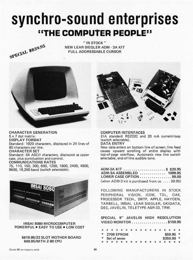
synchro-sound enterprises "THE COMPutER PEOPLE"
" IN STOCK" NEW LEAR SIEGLER ADM - 3A KIT
FULL ADDRESSABLE CURSOR
CHARACTER GENERATION 5 x 7 dot matrix. DISPLAY FORMAT Standard: 1920 characters, displayed in 24 lines of 80 characters per line. CHARACTER SET Standard: 64 ASCII characters, displayed as upper case, plus punctuation and control. COMMUNICATIONS RATES 75, 110, 150, 300, 600, 1200, 1800, 2400, 4800, 9600, 19,200 baud (switch selectable).
IMSAI 8080 MICROCOMPUTER POWERFUL. EASY TO USE. LOW COST
$619.95/22 SLOT MOTHER BOARD 849.95/WITH Z-80 CPU
Circle 96 on inquiry card. 86
COMPUTER INTERFACES EIA standard RS232C and 20 mA current-loop (switch sel ectabl e). DATA ENTRY New data enters on bottom I ine of screen; I ine feed causes upward scrolling of entire display with top-of-page overflow. Automatic new line switch selectable, end-of-line audible tone.
ADM-3A KIT ..................... $ 839.95 ADM-3A ASSEMBLED ............. 1099.95 LOWER CASE OPTION ................ 89.00 (when ADM-3 kit is purchased from us .... 59.95)
FOLLOWING MANUFACTURERS IN STOCK PERIPHERAL VISION, iCOM, TDL, OAE, PROCESSOR TECH., SWTP, APPLE, HAYDEN, TARBELL, IMSAI, LEAR SIEGLER, OKIDATA, DEC, JAVELIN, TELETYPE ASR-33, TRW.
SPECIAL 9" JAVELIN HIGH RESOLUTION VIDEO MONITOR .................. $159.95
* * * * * * * * * * * * * * * * * * 2708 EPROM $59.95 * * Set of seven $350.00 * * * * * * * * * * * * * * * * * *

oeCwriter II
($1099.00) OKIDATA MODEL 110 110CPS DOT MATRIX LINE PRINTER FRICTION FEED* $1099.00 TRACTOR FEED 1229.00 RS 232C SERIAL INTERFACE 250.00
~ ~ ~ ~ ~ ~ ~ ~ ~ ~ ~ ~ ~ ~ ~ ~ ~ ~ ~ ~ ~ ~ ~
: MOST ITEMS IN STOCK FOR SAME DAY : ~ SHIPPING. FULL MODERN REPAIR FA- ~ : CI LlTI ES ON PREMISES-WE SERVICE : ~ WHAT WE SELL. ~ ~ ~ ~ ~ ~ ~ ~ ~ ~ ~ ~ ~ ~ ~ ~ ~ ~ ~ ~ ~ ~ ~ ~
synchro-sound enterprises
193-25 Jamaica Ave. , Jamaica , NY 11423 Phone (212)468-7067
HOURS 9 - 4 DAI LY + SATURDAY BANKAMERICARD MASTER CHARGE
VISIT OUR NEW SHOWROOM WORKING UNITS ON DISPLAY
87
Features $1769.95
132 column printing 30 CPS Full Keyboard Tractor Feed
NEW COMMERCIAL QUALITY KEYBOARD
The Model SS-1 Communications Terminal is a non-contact capacitive keyboard with a guaranteed I ife of over 100,000,000 operations. FEATURES • MOS/LSI Encoder with high reliability and low
power consumption • n Key Roll Over which eliminates operator error
and increases thruput • Hysteresis for tease proof operation • Solid State performance at mechanical switch
prices • Tactile Feedback at the operate point • ASR-33 Array with four mode encoding
KEYBOARD KIT. . . . . . . . . . . . . . . . .. $ 99.95 ENCLOSURE ............ . ..... . ..... 49.95
(WITH NUMERIC CUTOUT) NUMERIC PAD ........... . . . ..... . COMPLETE KIT (with pad) .. . ....... . ASSEMBLED UNIT (with pad) . ... . .. .
34.95 179.95 229.95

Dr Kenneth B Welles General Electric, Nela Park 2623 Fenwick Rd University Heights OH 44118
The two fundamental routines needed for a floppy disk system are: Write a block of data to the disk, and read a block of data from the disk.
Software for the
Economy Floppy Disk
As hobbyists are rapidly finding out, even the most sophisticated hardware is next to useless without the proper software to control it. My previous artic le on the floppy disk dl'ive interface (see February 1977 BYTE, page 34) described a hardware device of the simp lest and, consequently, most software dependent type. Th is month's art icle describes the operation and use of the routines needed fOI' tl"ansferring data between the computer and a disk dl"ive (one of up to eight) connected to the interface.
The two fundamental routines needed for a floppy disk drive system are: Write a block of data to the disk, and read a block of data from the disk. This sounds simpl e in theory but in practice much more information and many operations are needed. How many bytes of data are in the block to be transferred, and which disk drive should the block go to or come from? At which track and sector is the block to be located? How will an error be detected (and if detected what steps should be taken for correction)? These are some of the major questions involved, without even consider ing such specific details as data format, file structure, unrecoverable errors, directory structures, naming and dating conventions, and so on ad futilitum.
A block read or write routine can be divided into four stages:
• Set up for the data transfer • Transfer the actual data to or from the
disk • Error detection • Error correction
88
Th ese stages must, by their definition, occur in the order li sted, and in most disk systems all four stages are included. In some opera" ting systems the error detection and corl'ec" tion stages are ignored during a write operation . While this speeds up transfers by eliminating a reread or verify operation, it means that most wl"ite eITOI"S will be unrecoverable.
Write Set Up
Because this in terface is quite unsophisticated, data to be written onto the disk must be prepared in memOl"Y inexactly the manner that it will appear on the disk. A preamble contain ing 16 bytes of zeroes (128 "0" bits) and a byte boundary synchronization signa l (or sync byte) must precede the data. Before the data is written, the error detection bytes must be ca lcul ated and stored with the data to be written, since there will be no time to calculate them once the write operation has been initiated. This software uses a 16 bit cyclic redundancy check (eRe) word ca lculated from the data bytes by the binary polynomial:
x16+x12+x5+1.
Because they are precalculated, the ermr detection bytes may be put in any position before, within, or after the data. I chose to place them directly after the data . The assemb led block of data to be transfer red (consisting of the preamble, sync byte, data and eRe bytes) is now in the propel' format for transm issio n to the disk, but the disk drive itself is not yet properly set up for the

transfcr. Because the in terface may contro l multipl e drives, th e f il·st act ion of the software is to se lect th e pl"Op er dl·ive and to assure that it is ready. "Ready" means that a diskette is loaded an d I·evo lving, and th e power supplies are working. Next, the CUI·rent ·track locatio n of the data u·ansfer head is determined and co mpared to the des il·cd track. If the desired and CU ITent tracks differ , the software mu st step th e head in or out at the proper rate ( 10 IllS per track) until the co rrect track is reached, and then delay fo r the proper head sett ling t ime (10 ms) before co nt inuing.
If the head is not cUI·rentl y loaded, the software must load the head and all ow t im e for the load ing to be accompli shed (30 ms) .
All that rema in s before initi at io n of th e data t ransfer is to find the sta rting point of the proper sector. Because the t iming is fa irl y cr itica l betwee n finding the secto l· and initiat ing the write ope rat io n, all of the parameters fO I· the wl- ite data loop such as pointers, counters and output co mm ands must be set up ahead of time in the 8080 registe l-s. Th e software now searches .. for the index pulse from th e ind ex ho le of the se lected disk drive and, hav ing found it, begins to co unt sector pulses un t il the desired sector is found_ When the lead ing edge of this sector pulse is sensed, the softwal-c transfers imm ed iate ly to the wr ite routines , using the values prev iously stored in the reg iste rs to speed the initiation of the write ope rat ion. Th is generates the proper timing re lat ionship between the sector pul se and the start of the reco rd ed data.
Write Data Transfer
If N bytes of informat ion (including the cycli c I-edund ancy check) are to be record ed on the disk, the software will actua ll y send out N+33 bytes of data to the interface_ Figure 1 shows that the first 16 bytes (a preamble of ze ro by tes) are recorded to allow the interface to correctly distinguish between data pulses and clock pulses when this data block is read. The seventeenth byte recorded is the sync byte, in this case a binary value of 10000001. This sync byte is used by the Universal Synchronous Rece iver Trans mi tter (USRT) to find the boundaries between bytes dur-ing a read operat io n. Th e next N bytes are the block of data to be recorded, and finally there are 16 bytes as a postscr ipt to assure that no data is destroyed when the disk drive write gate is tu rned off. Because th e only use of this data is to maintain clock sy nchroni zatio n and protect the preceding data, th e contents of the last 16 bytes are not cri t ical, and may overlap data used for some other purpose.
16 BYTES } PREAMBLE
10000001
DATA BLOCK
SY NC BYTE
N DATA AND HOUSEKEEPING BYTES
16 BYTES } POSTSCRIPT
Figure 7: Floppy disl? data transfer blocl? format. The simplicity of this "hard sectored" floppy disl? system requires that a specific format be used for the data. The first 76 bits act as a preamble to enable the interface to distinguish between data pulses and cloc!? pulses. Next comes the sync byte used by the Universal Synchronous Receiver Transmitter (USR T) to find the boundaries between bytes. This is followed by the actual data and, finally, a 76 byte safety region to assure that no data is destroyed when the disl? drive write head is turned off. See also table 2.
Write Error Detection
A fter all N + 33 bytes have been sen t to th e disk thl-ough the interface, th e write gate of the disk drive is turned off and error detect ion may now be performed. Error detection consists of performing a single read operation of the block of data just written . The block of data read in is compared byte by byte to the block of data written. If all N bytes are not the same for both blocks, an error has occurred. This process could be called a "verify " operation.
Write Error Correction
If errOl" co rrectio n is necessary on a write operat io n that fails to verify, it is accomplished by rew ri t ing the same block of data to the same disk , track and sector. After this rewr ite attempt, a verify of the rewritten data is performed an d compared to the co rrect data to determine the success or failure of the error correction operation. If
89
As block sizes increase there are fewer preambles and postscripts on any given track, thus maximizing the usable data bytes per track.

In the very simplest sys
tem each block of data would have some form of error detection ranging
from a single byte of
checksum to a 16 bit cyclic redundancy code or
even a complex Hamming
code.
Table 7: Characteristics of different data block sizes. Smaller data blocks have the advantage of not tying up large blocks of memory (a premium commodity in many small systems). Large data blocks, by comparison, speed up data transfer, require fewer blocks per track, and maximize the number of usable data bytes per track.
the write operation fails four (or some other small integer) times in a row, all hope is abandoned, an error message is printed on the user's console device, and the write routine terminates. Manufacturers' recommendations for action taken at this point are as fo llows: Move to an unused sector and track on the disk in question, and retry the write operation. Ifthe error persists, the disk drive has write circuitry problems; notify the user. If the error is eliminated, then the track and sector where the original error occurred probably has some damage to its oxide coating. In this case, re lin k the data file to reflect the new location of th e data (the track and sector where the second attempt was made), and then record in some table the fact that the origina l track and sector where the write operation failed is an unusable area. But what do you do when the area that failed to write properly is the location of the table where the fai led areas are stored? Th is is why operating systems designers have such a high incidence of insanity . The software in this article ignores the whole issue, the traditional ostrich solution.
Read Set Up
No data preparation need be done on a read operation because the only routines required are disk drive se lect, head load, track seek and sector seek. These are the same routines used by the write operation as described earlier.
Read Data Transfer
The USRT is reset to search for an occurrence of the sync byte within the incoming serial data, and the program is set to wait for the USRT to signal that the sync byte is found. When the sync byte is found, data is brought in from the interface and stored in memory. For a block recorded with N bytes of information as in the write operation, a total of N+1 bytes are read in. The first byte brough t in by the software is the sync byte, accounting for the extra byte transferred.
Data Blocks Usable Bytes Data Bytes Housekeeping Per Track Per Block Per Block Bytes Per Block
1 5127 4096 1031 2 2549 2048 501 4 1260 1024 236 8 615 512 103
16 293 256 37 32 132 128 4
All Formats Store 315,392 Data Bytes Per Disk
90
Read Error Detection
The routine that calculated the 16 bit cycli c redundancy check (CRC) for the write operation is now used to calculate the CRC of the data block just read. The calculated cyc lic redundancy check must match the CRC read in if the data is correct. If these values do not agree, an error has occurred during the read operation.
Read Error Correction
If a single read operation is unsuccessful, two more attempts are made to read the data. If the computed and read-in cyclic redundancy check values sti ll disagree, the disk head is stepped in one track and then out one track, and up to three more read operations are tried. Continued lack of success causes the head to be stepped o ut and then stepped in one track, and three more attempts to read are made. If the error persists after all of th is, then th is software concludes that the data is unrecoverable . The jogging of the head one track in or out is recommended by the manufacturer to re lease any dust particles which may have lodged between the disk and head, and wh ich therefore may be causi ng the read errors.
Block Size
The discussion of the software to this point has referred to the transfer of a "block" of data, but no definition has been made of the size of this block. The disk is divided physically into 32 different sectors by the presence of 32 sector holes. The combination of the rotational speed of the disk (360 rpm), the data rate (250,000 bps), variat ion in the timing of the sector hole detection (± 5001ls), and the necessity for the 16 byte preamble, sync byte and 16 byte postscript on each record determines that if each track holds 32 blocks of data, then each block has 132 usable data bytes. There is no electronic or philosophical reason that the disk must be recorded in a format of 32 data blocks per track, or even that a 32 block track must consist of full size 132 byte blocks. The proper operating system software could quite easily make use of a data format with o nly 16 bytes per block and 11 blocks per track. However, this would make the capacity of each disk less than 30 K bytes, a tenfold reduction in storage capacity . The software presented here can be easi ly modified to allow other block sizes and formats to be used, and the reasons for choosing different block sizes will be presented before attempting to justify the block size used.
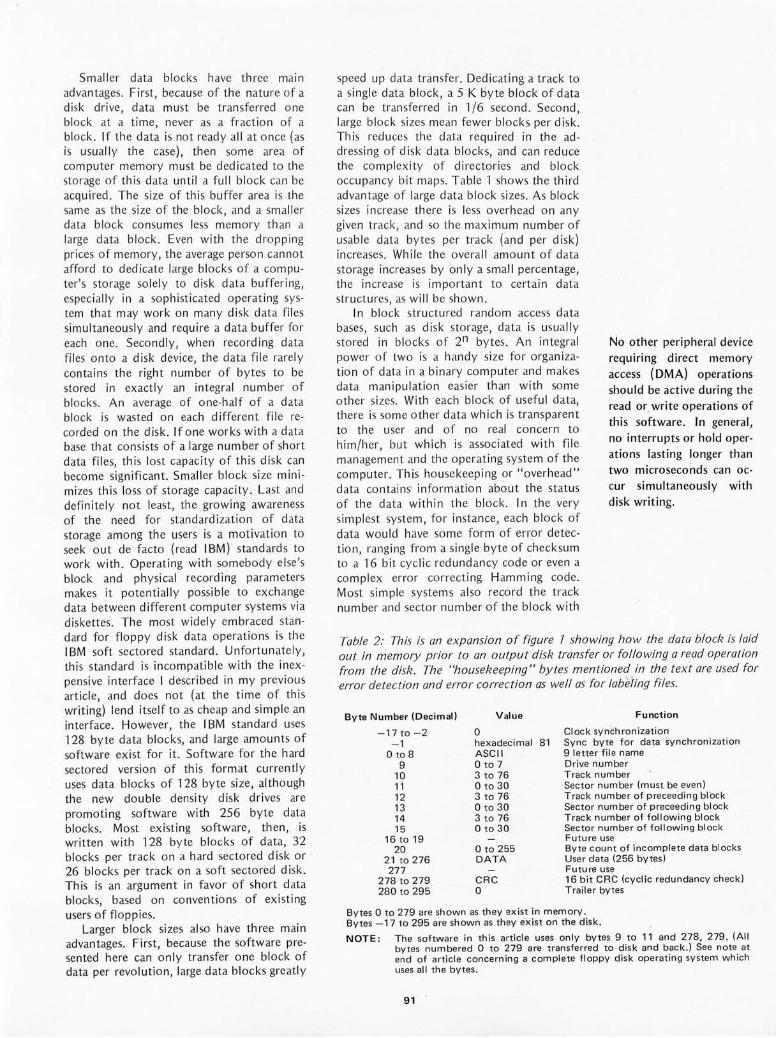
Smaller data blocks have three main advantages. First, because of the nature of a disk drive, data must be transferred one block at a time, never as a fraction of a block. If the data is not ready all at once (as is usuall y the case), then so me area of computer memory mu st be dedicated to the storage of th is data until a full block can be acqu ired . The size of this buffer area is the same as the size of the block, and a small er data block co nsu mes less memory than a large data block. Even with the dropping prices of memory, the average person cannot afford to dedicate large blocks of a computer's sto rage so lely to disk data buffering, especiall y in a sophisticated operat ing system that may work on many disk data files simultaneously and require a data buffer for each one. Secondly, when recording data fi les onto a disk device, the data file rarely contains the right number of bytes to be stored in exact ly an in tegral number of blocks. An average of one-half of a data block is wasted on each differe nt fil e recorded on the di sk. If one works with a data base that consists of a large number of short data files, this lost capacity of this di sk can become significant. Small er block size mini mi zes this loss of storage capacity . Last and definitely not least, the growi ng aware ness of the need for standard ization of data storage among the users is a motivation to seek out de facto (read IBM) stand ard s to work with. Operat ing with somebody else's block and physi cal record i ng parameters makes it potenti all y poss ible to exchange data between different computer systems via diskettes. Th e most widely embraced sta ndard fo r f loppy di sk data operations is the IBM soft sectored standard. Unfortun ate ly, this stand ard is incompatibl e with the inexpensive in te rface I descr ibed in my previous art icle, and does not (at the ti me of this writing) lend itse lf to as cheap and simple an interface. However, the I BM standard uses 128 byte data blocks, and large amoun ts of software exist for it. Software for the hard sectored version of thi s format currently uses data blocks of 128 byte size, although the new double density disk drives are promoti ng software with 256 byte data blocks. Most ex isting software, then, is written with 128 byte blocks of data, 32 blocks per track on a hard sectored disk or 26 blocks per track on a soft sectored disk. This is an arg ument in favor of short data blocks, based on conventions of ex isting users of floppies.
Larger block sizes also have three main advantages. First, because the software presented here can only transfer one bl ock of data per revolution, large data blocks greatly
speed up data transfer. Dedicating a track to a s ingle data block, a 5 K byte block of data can be transferred in 1/6 second. Second, large block sizes mean fewer blocks per disk. This redu ces the data req uired in the ad dressing of disk data blocks, and can reduce th e co mpl ex ity of directori es and block occupancy bit maps. Table 1 shows the third advantage of large data block sizes . As block sizes increase there is less overhead on any give n track, and so the maximum number of usab le data bytes per track (and per di sk) increases. While the overa ll amount of data storage increases by onl y a small percentage, the in crease is important to certa in data structures, as wi ll be shown.
In block structured random access data bases, such as disk sto rage, data is usually sto red in blocks of 2n bytes. An in tegral power of two is a hand y size for organ ization of data in a, binary computer and makes data manipul atio n easier than with some other sizes. With each block of usefu l data, there is some other data which is transparent to the user and of no real concern to him/her, but which is associated with f il e management and the operat ing system of the co mputer. This housekeeping or "overhead" data co ntains' in fo rm at ion about the status of the data within the block . In the very simpl est system, for instance, each block of data would have some for m of er ror detection , ranging from a si ngle byte of checksum to a 16 bit cyc li c red und ancy code or even a comp lex error correcting Hamming code. Most simple systems also record the track number and sector number of the block with
No other peripheral device requiring direct memory access (DMA) operations should be active during the read or write operations of this software. in general, no interrupts or hold operations lasting longer than two microseconds can occur simultaneously with disk writing.
Table 2: This is an expansion of figure 7 showing how the data bloel? is laid out in memory prior to an output disl? transfer or following a read operation from the disk. The "housekeeping" bytes m entioned in the text are used for error detection and error correction as well as for labeiing files.
Byte Number (Decimal)
-17 to - 2 - 1
o to 8 9
10 11 12 13 14 15
16 to 19 20
2 1 t0276 277
278 to 279 280 to 295
Value
o hexadec imal 81 ASCII o to 7 3 to 76 o to 30 3 to 76 o to 30 3 to 76 o to 30
o to 255 DATA
CRC o
Function
Clock syn~hronization Sync byte for data synchronization 9 letter file name Drive n,umbe r T rack number Sector number (must be even) Track number of preceed ing block Sector number of preceeding block Track number of following block Sector number of following block Future use Byte count of incomplete data blocks Use r data (256 bytes) Futu re use 16 bit CRC (cyclic redundancy check ) Trailer bytes
Bytes 0 to 279 are shown as they exist in m emory . Bytes - 17 to 295 are shown as they ex ist on the disk.
NOTE: Th e software in this article uses only bytes 9 to 11 and 278, 279 . (All bytes numbered 0 to 279 are tran sferred to disk and back ,) See note at end of arti c le concerning a complete floppy disk operating system which uses all the bytes .
91

1313013
1313:1.13
1313:1.13 E3 1313:1.:1. F'5 013:1.2 C5 130:1.3 D5 1313:1.4 7E 1313:1.5 23 1313:1.6 E!5 1313:1.7 F5 1313:1.8 212812113 aa:l.B CD!55a0 aB:l.E F:I. Ba:l.F CD2FBB 131322 E:I. 131323 D:I. 131324 C:I. 131325 F:I. 131326 E3 131327 C9
12112128 000A4552 aB2C 524FD2
Ba2F F5 1313313 BE2a 131332 CDa0ee ea35 F:I. 01336 F5 131337 0F 131338 eF 131339 aF eB3A BF ee38 CD43013 ea3E F:I. aa3F 131342
0043 01344 13046 131348 a04A 0a4D 13e4F 1313513 131353 131354
13055 131356 13057 131358 131359 aaSB a05C aa5F 131360 13136:1. 131362
01313:1. 1313132 130,133
eeFa 0aFa
a13Fa a0F:I. aaF2 aaF3 aaF4
aeF0 eeF1. 00F2 a0F3 00F4 aaF5 eeF6
CD4300 C9
F5 E613F C63e FE3A DA4F00 C607 4F CDe"oo F:I. C9
7E B7 C8 F5 E67F 4F CDeeSl3 F:I. F8 23 C35500
THE FOLLOWING IS A GENERAL PURPOSE ERROR TYPEOUT ROUTINE THE YALUE OF CO REFERS TO A USERS ROUT! NE I·'H I CH WPI!S OUT THE ASC 11 VALUE I N THE C REG I STER ONTO THE USERS CONSOLE OUTPUT . ONLY THE A REG ISTER AND FLAGS MAY 8E DESTROYED BY CO.
CO EOU
ORG
; THIS ROUTINE ; IT I S CALLED
CALL DB
; THE RESULT ; ERROR )(
ERTYP : XTHL PUSH PUSH PUSH MOV INX PUSH PUSH LXI CALL POP CALL POP POP POP POP XTHL RET
ERMES : DB
BYTYP : PUSH MVI CALL POP
NMTYP : PUSH RRC RRC RRC RRC CALL POP CALL RET
HEXCHR : PUSH ANI ADI CPI JC ADI
HE X:1. : MOV CALL POP RET
TXWP : f10'·,1 ORA RZ PUSH ANI MOY CALL POP Rrl INX JMP
ER~'RT EQU ERRED EQIJ ERDKNM EQU
:l.aH ; TH I S ROUT! NE MAY BE ORG' D ANYWHERE 1 N MEMORY
TYPES OUT AN ERROR MESSAGE INTERNALLY AS :
ERTYP X
IS THE T'YPING OF :
PSW B ' D A, M H H PSW H, ERMES TXTYP PSW BYTt.,'P H D B PSW
1.3, 1.8, " ERRO '" , ... R" +1.28
PSl.J C, ' ,
CO PSl.J PSW
HEXCHR PSIJ HEXCHR
PSI-J 0FH ' 13 ' " 9 " +1. HE Xi ' A' - ' 9 ' -i C, A CO PSW
A, ~1 A
PSloJ 7 FH LA CO PSIJ
H TXTYP
TO THE USER,
; IF THE DISK FAILS TO I·'RITE, 2 ; IF THE DISK FAILS TO READ,
; IF NO SUCH DISK EX ISTS,
TYPE "ERROR :I." TYPE "ERROR 2" TYPE "ERROR 3"
; THESE ARE THE FLOPPY DR I VE I -0 ROUT I NES :l.9-AUG-76
Ir~PORT EOU eF0H OTPORT EQU eFeH
FDRED EQU INPORT ; DATA FROM THE FLOPP',' FDSTAT EQU I NPORT+1. ; STATUS BITS OF THE FLOPPY SRTSIJE EQU INPORT+2 ; READ THE SRT STATUS WORD SRTRR EOU I NPORT+3 ; I NPUTT ING THIS RESETS THE USRT TO LOOK FDINm EQU INPORT+4 ; KLUGE TO S'T'NCHRON I ZE TO 32 M I CRSECS
FDWRIT EQU OTPORT ; DATA TO BE l,JR I TTEN TO THE FLOPPY SRTTFS El;!U OTPORT+1 ; PORT OF THE DEFAUL T CH ARACTER SRTRSS EQU OTPORT+2 FDOUT EQU OTPORT+3 ; SEND SIGNALS TO THE FLOPPY FDOTIH EQU OTPORT+4 ; S .... 'NC TO 3:2 r1 I CROSECS LOADHD EQU OTPQRT+5 ; THIS COt'1MRNDS LOADS THE HEAD FOR 3: SECONDS HDUNLO EQU OTPORT+6 ; THIS FORCES AN I MNED I ATE HEAD UNLOAD
, ; THESE ARE SIGNALS TO FDOUT ( DIRECT FLOPPY CONTROLS) 131313:1. eee2 01304 FFFB 013139 ea~a
FFEF '
131313:1. eee2 013134
~.JCSEL EQU 1. ; l.=TRACK 0-43", 0=TRACK 44-76 FUREST EQu 2 ; USE TO RESET A FILE UNSAFE CONDITION DIRIr~ EOU 4 ; LOGICAL OF.: FOR IN TRACK D I ROT EQU NOT D I R I r ·~ ; AND FOR OUT TRACK WRTGAT EQU :1SQ ; LOG I CAL OR TO START A WR I TE STEPP EQU 20a ; LOG I CAL OR TO START A STEP PULSE STEP!'1 EQU NOT STEPP ; LOGICAL AND TO STOP THE PULSE
; THESE ARE THE DIRECT STATUS LINES OF THE FLOPPY < IN FDSTAT) TRKZRO EQU 1 UNSAFE EQU 2 FDRDY EQU 4
92
Listing 1,' Floppy disk drive input and output routines. As it stands, this listing is one step short of being a complete operating system, but could be used as a starting pOint for such an operating system, This program will run only on an 8080 with memory having a cycle time of 500 ns or faster; it will not run correctly if any interrupts or direct memory access (DMA) routines lasting longer than 2 J15 occur during program execution. (See part " page 42, February 7977 BYTE, "Software Timing, ")
the rest of the data on that block. When some track and sector is read, the track and sector numbers read must agree with the desired track and sector numbers. If these bytes disagree, then a seek error has occurred. The error detection information and the track and sector numbers are simple housekeeping data that the user need never be concerned with during data transfer. A more complex data base management system may store extensive housekeeping information with each block of data. Information such as forward and reverse linkages (pointers to the succeeding and preceding blocks of data in a fi le), file name, number of valid bytes in a partially fi ll ed data block, date and time of the recording of this block of data, write or read protection, user identification, destroy date - all may be recorded as useful housekeeping data.
If a format of 32 blocks per track, 128 data bytes per block is used, table 1 shows that this leaves only four bytes of data available with each block to record housekeeping data. Going to 16 blocks of 256 data bytes per block, the available housekeeping area increases to 37 bytes per block. 512 data byte blocks gives a substantial 103 bytes of housekeeping on each of eight blocks per track. The routines presented here were written as a first low leve l step toward a fu ll floppy disk operating sytem, and the amount of housekeeping required for the full system necessitated at least the 256 byte block size. The 512 byte block size was ruled out because it consumed buffer space much too quickly, and because a single byte wou ld no longer be sufficient as a buffer data counter.
A DOS Block Format
Tab le 2 shows the layout of the data block for my disk operating system (DOS) as it exists in memory and as it is written to and read from the disk. There are 280 bytes in the block, 256 of which are usab le data bytes, and 24 of which are reserved for housekeeping. Of the housekeeping bytes,

five are not currently defined, and all but bytes 9, 10, 11, 278 and 279 are availab le to the user in the routines listed in this article. As of this writing, a full f loppy disk operating system for my periphera l interface to the 8080 has been completed (see note at end of this article). The format described here is that used by this operating system . In this format, the first nine bytes are designated as the file name, ordered a la DEC as six ASCI I characters of file name and three characters of extension. Having the fi Ie name associated with each block of a file is a great aid in data recovery from crashed systems (a not unheard of occurrence) and in troubleshooting modifications to the operating system (a frequently heard of occurrence). Byte 9 is the number of the device (disk 0 to disk 7) where this fi le was origina ll y recorded. This number does not have to match the number of the device that the fi le is subsequently read from. Bytes 10 and 11 are the numbers of the track and sector where this data block is stored. Valid values are any integer from 0 to 76 for the track, and only even integers from 0 to 30 for the sector. (With 256 byte blocks, we have to use every other sector.) Bytes 12 and ,13 indicate the track and sector of the block of data preceding this one in a lin ked data file. If the current block is the f irst block, and no previous data blocks exist, then bytes 12 and 13 are set to zero. Since track ze ro, sector zero is reserved for the bootstrap copy of the operating system, no li nked file can have th is block ad dress as a legal forward or reverse Ii nkage. Bytes 14 and 15 give the track and sector of the data block fol lowing this block in the linked fi le. If this is the last block, values of 0 and 0 are again used to indicate an invali d linkage (end of f il e).
Because no operating system is ever finished and better ideas are generated as a continuous function of t ime, bytes 16 to 19 are reserved for whatever fu nctions may become desirab le in the future. Byte 20 is used when the last block in a recorded data fi le is not complete ly fi ll ed, indicating the actual number of va lid data bytes stored in the data area. Bytes 21 to 276 inclusive contain the 256 bytes of usable data. The data in these bytes is usually the only data of fina l concern to a program retri eving data from a f il e. Bytes 278 an d 279 are the cyclic redundancy check bytes, least sign ificant byte first. Thi s 16 bit value is calcu lated as detail ed ear lier, from the va lues of bytes 0 to 276 inclusive.
Now, the Software
Listing 1 shows the software which controls the di sk interface and performs the
Listing 7,
13"'08 e0113 1313213
131381 13:lI313 131316 0117 000S
E1300
EOO0 F 3 Ea131 0602 E13133 CS m134 CD15E& E13137 CD6FE0 E013A C:l E00S C8 E00C 135 E130D F203E13 E1310 CD113aa EBB 13:l E1314 C9
E1315 JA65E2 EIl18 CD2BE1. E01B 2:148E2 E01E AF E01F 06103 E132:1 77 E1322 23 E023 135 E024 C221.Ee E1327 3681 E029 2 A66E2 E02C 2243E2 E02F 21.58E2 E1332 COF2E0 E133S EB E1336 2272E3 E039 CDD8E1. E03C CD139E2 E0lF 11.361211. E042 21.48E2 E04S RF E046 Co 3F1 E134S 3A46E2 E048 F6"'A E04D 4F E"'4E CD1.AE2 EOS1 79 E1352 D3F3 E0S4 E6FD E0S6 D3F3 E13S8 D3F4 E05A 7E Ea58 D3F0 EaSD 23 E0SE 18 EaSF 7A E060 83 E06:1 C258E0 E064 lA46E2 E067 . E6F7 E1369 Cl F3 Ea6B 3246E2 E06E C9
E06F CDA3Ee E1372 C0 E1373 2 1.75E3 E1376 1.1.58E2 E079 ~6ee E078 1A E67C BE EB7D C0 E07E 13 E07F 23 EaS0 05 E1381. C278Ee E084 C9
E1385 F3 E886 CDA3E0 E0S9 CB Ea8A CDA3Ei E0SD CDB2E1. E090 CDR3E0 EB93 C8 Ee94 CDB2E1. El397 CDA3E1. Ee9A CDA3:E13 E09D C8 EB9E CD1.0el) E0A:1 0 2 EBA2 C9
EaA3 3: E132 E0A5 3245E2 E0A8 CDB4E0 EaAB C8
continued:
5CTR EI:;:!U INDX EQU HEADLD EQU
; THESE ARE
8 HlH 20H
VARIOUS PARAMETERS SYNCB EQU 8:1H ; TH I SIS THE s'mc S',TE FOR START OF TRACK UIBUF EQU 256 ; LENGTH OF THE 81JFFER X TRA EQU 22 ; E~<TRA BYTES FOR HOUSEKEEP I HG LN25NC EQU LHBUF+XTRA+1. ; DISTANCE OF $'T'NC TO CHECKSur'l DSKLIt" EQU 8 ;UP TO 8 DISK DRIVES ON THIS CONTROLLER
ORG eEe00H ; THIS IS DISCONTIGIJOU5 RAM
GDI.JRT ; 01 r-WI B.2
; DISABLE THE INTERRUPT TO t'lAIUTAIN CRITICAL TIMING ; TR'T' THIS 3 TIt'lES BEFORE GIVING IJP
GDloJR1. : PUSH CALL CALL POP RZ OCR JP CALL 08 RET
B WRT256 CHKI4RT B
8 GDWR1 ERTYP ERI4RT
; FIRST, 14RITE IT ; THEr~ CHECK FOR PROPER WRITE ; RESTORE STACK, DOr,V T CHANGE FLAGS ; SUCCESSFUL WR I TE, RETF.:UN ,·jOW ; A BAD l·IRITE. TR'T' AGAIN ; IF I.>JE STILL HAVE TINE. TR'T' AGAIN ; ELSE , SIGNAL THE ERROR AND QUIT
; TH I S ROUT I "~E ASSUl'lES THAT THE TRACK AND SECTOR TO BE l,JR I TTEN ARE IN TRKWRT ; AND THE DATA I S ALL IN l,JRDAT I,JRT256 : LDA I,JRDEV ; TH I S MUST CotHA I N THE DISK NUMBER!!!
CALL D5KNUt'1 ; PROCESS At·~'T' UN I T NUt'1BER CHA"~GE L X I H. WRTBUF ; CLEAR THE CLOCK SYNC B'T'TES XRA A ; B" F I LLI NG WITH ZEROES t'l\/ I B, iOH ; 1.6 OF THEr1
CLRLOP : t'10'·/ N,A H 8 CLRLOP r'" S","'NCB ; STORE THE s','riC B'T'TE TRKWRT TF.:KI.>HH ; SET UP THE TRACK Ar·jD SECTOR PO I NTS H, I.>IRSNCB J START OF THE CHECK5Ut'1 AREA CHK436
I·JRCHKS ; STORE THE CALCULATED CHECK5Uf1 TRKGET ; GET THE DESIRED TRACK HEDLOD ; LOAD THE HERD D, LNI;3UF+XTRA+ 3:2
W X OCR ·JN2 MVI LHLD SHU ) L X I CALL XCHG SHU,) CALL CALL L X I L~: I
XRA OIJT LDA OR I t'10V CALL r'10'.,.' OUT ANI OUT
H. l,JRTBUF ; BUFFER AREA TO l,JR I TE TO THE 0 I SK
I,JRTLOP : OUT t'10V OUT INX DCX t'10V ORA
A SF.:TTFS ; TRAr'jSt'l I T A FILL CHAR OF ZERO FDBUF ; THE OUT STATUS l.JRTGAT +FUREST ; TURf...! ON THE l,JR I TE GATE C, A ; HOLD THE WR I TE COMMAND INC SCTGET ; GET THE PROPER SECTOR A, C FDOUT ; HUT THE WRITE GATE QUICKL', NOT FIJREST ; TURN OFF FILE UNSAFE RESET FDOUT FDOTIH ; KLUGE AND I.JA I T FOR READY FOR DATA A,M FDWRIT H D A, O E
JNZ 1,IRTLOP LOA FOBUF AN I NOT (·JRTGAT ; TURN OF F THE WR I TE GATE OUT FDOUT ; NOl.>l STA FDBUF ; THIS IS THE PRESENT STATUS RET
; TH I S ROUT I NE PERFOR~lS A REREAC' OF THE SECTOR JUST 14R I TTEN. ; RETURN I S loll TH 2=0 I F A READ FA I L OCCURRED. OR I F A READ D I DW T MATCH ; THE IMt'lEDIATE PREVIOUS WRITE. 2=1. IS A SUUCCESSFUL HRITE CHKWRT : CALL TR',3RD ; TRY 3 T HIES TO READ IT
RN2 ; RETURN \.JI TH z=e O,.~ A BAD ERROR L X I H,RDSNCe ;SET UP A 256 BYTE COMPARE L X I D, HRSNCB r'Wl B, a ; 256 Isry T ALL, BUT IT IS ENOUGH
CHKW1. : LDA}, 0 ; GET WHAT \,JAS WR I TTE r...! CNP t'1 ; COMPARE TO I.>JHAT WAS READ RNZ INX lU X DCR
D H E:
JNZ CHKW1.
; RETURN ON AN ERROR
; UP THE PO IrHERS
RET ; SUCCESSFUL RETURN, Z=1.
; THIS ROUTIr~E TRIES 3: T[t'1E5 TO READ, THEN JOGS IN, AND OUT AND ,AGAIN RED256 : DI ; DISABLE THE INTERRUPT FOR CRI TI CAL TIMING
CALL TRY3RD ; TRY 3: T I r'1ES TO READ THE BLOCK RZ ; IF SUCCESSFUL. THEN RETURN CALL TRAKIN ; JOG IN CALL TRAKOT ; SCRAPE OFF FLIES AND FROGS CALL TRY3:RD i THREE t'10RE RZ CALL TRAKOT ; .]1 GOUT CALL TRAKIN ; SCRAPE OFF DIGITS AND DOGS CALL TR'T'3RD i LAST CHANCE COWBOY RZ i IF FINALLY SUCCESSFUL, THEN RETURN CALL ERT'T'P ; I F NOT , THEN P,'PE OUT THE ERROR D8 ERRED RET
; THI S ROUTINE TRIES TO READ THREE TH1ES, RETURNS 2=1. FLAG TRY3RD : r"v I A, 2 ; ACTUALLY TR'T" 3 T I t'lES
STA REDTR'T" ; HOLD ONTO IT TRGP : CALL REDONC ; TR","' IT .JUST ONCE
R2
93
IF OK ON REA

Listing I, continued:
E0AC 21.4!5E2 EeAF 3'5 E0Be Fa EeB:I. C3A8E0
E0B4 3A4AE2 EBB7 CD2BE:I. E0BA CDD8E:1. EeBD CDB9E2 E0C0 :I.:I.:I.A0:1. EeC3 2:1.75E3 EeC6 lEB:I. EeCB D3F2 E0CA CD:l.AE2 EBCD DBFl EBCF DBF4 EeD:I. DBF0 EeD3 77 EeD4 2 3 E0D5 :l.B EeD6 7A Ee07 8 3 EBD8 C2CFEO E0DB 2:1.75E3 E0DE CDFlEe E13E1. 3A3AE2 EeE4 327 FE3 E0E7 2 A8CE4 E0EA C3EDE<.l
E0EO 7 C EeEE 9 2 EeEF C0 E0F0 7D EeF:I. n E0F2 C9
EeF3 13:1.:1.613:1. EeF6 :1.:1.1313013 EeF9 7E EeFA E5 E0FB CS E0FC AB EeFD 47 E0FE 03F EeFF 0F E:l.ee 0F E:l.e:l. 03F E:l.e2 4F E:l.e3 A8 E1e4 E6F0 E:l.06 AA E1e7 6F E:l.e8 79 E:l.e9 137 E10A E6:1.F E:l.0C AD E:l.eD 6F E:l.0E 78 E:l.eF 137 E11e E6131 £1.1.2 AA E:I.:1.3 AC' E1:I.4 57 E1:I.5 79 E1:1.6 E60F E11a AS E119 SF E:I.:l.A 79 E1:I.B AS E1:1.C 137 E1.1.0 E6E0 E11F AB E:l.2e SF E:l.2:1. C:I. E1.22 E:I. E123 23 E124 0B E:l.25 7 8 E126 8:1. E:1.27 C2F9E0 E12A C9
E:l.2B FEeS E:1.20 F285E1 E:I.3e 2:13AE2 E:I.33 BE E134 ce E:I.3S F 5 E:I.36 E5 E137 3Ees E:I.39 BE E:I.3A FA46E:I. EnD 4E E1.3E 961313 E14B 139 E14:1. 23
L X I OCR RM ,mp
; IF TOO t'1AN',' , THEr~ RETURN Z=~) TRGP ; TR'r' TRY AGAIN. AGAIN
; THIS ROUTINE REDONC : LDA
CALL CALL CALL L X I L X I MVI OUT CALL
TRIES ONL'~ ONCE ( AND I DOW T 8Lm'E IT ATALL> DSKWNT ; THIS MUST CONTAIN THE DISK ~~UMBER~ ~
DSKNur', ; PROCESS ANY Ut.,j I T CHANGE TRKGET ; GET THE TRACK HEDLOD .' LOAD THE HEAD O, LNBUF+XTRA+4 H. RDSNCB ; PO I NT TO THE BUFFER AREA A, SY'IC8 ; PRm'PT THE USRT HITH .IHAT TO EXPECT SRTRSS ; SHOVE IT SCTGET ; GET THE PROPER SECTOR
"I SRTRR ; RESET THE USRT TO LOOK FOR THE SYr.,jCB REDLOP : IN FD I NIH ; SPEC I AL SWIC KLUGE TO HOLD ONTO THE BUe>
FDRED ;UNTIL DATA I S AVAILABLE
'" A H D A,D E REDLOP
IN MOV W X DCX MOV ORR JNZ L X I CALL LDA STA LHLD ,Jr1P
H, RDSNCB CHK436 L STDSK RDDE V RDCHKS COr1PAR
; POI NT TO THE BUFFER AREA
; GET THE 1·IUMBER OF THIS DISK, ; AND STORE IT IN THE READ AREA FOR FUTURE USE ; HL HAS THE CHECKSUt"
; TH I S ROUT I t-lE COI'1PARES HL TO DE COl'lPAR : 1'10',/ A. H
SUB D RNZ MOV SUB RET.
A, L E
; TH I S ROUT I HE DOES A DOUBLE PREe I SE CHECKSlJr'l CHK436 : LXI B. LUBUF+XTRA CHKSUf1 : L X I O. e CHKLOP : f1QV A. 1'1 ; GET THE 8',.'TE TO SUI"
PUSH H PUSH B ; SAVE ALL THE REGS. XRA E I'tOV B. A RRC RRC RRC RRC MOV C, A XRA B ANI 0FeH XRA D MOV LA ('lOY AI C RLC ANI :l.FH XRA L MOV LA t10V A. 8 RLC ANI 1 XRA D XRA L MOV D. A MOV A, C AIH eFH XRA B MO'" E, A MOV AI C XRA B RLC ANI IJE8H )(RA E ~'OV E, A POP B POP H INX H DCX 8 MOV A, B ORA C .JHZ CHKLOF' ; NEXT BYTE I F r~OT '1"ET Dm~E RET
TH I S ROUT U'E I S ENTERED I.JI TH A CorHA HU NO THE NUMBER OF THE DISK DRIVE UNIT ON 'IHICH THE DESIRED OPERATIONS ARE TO BE PERFORMED. ( 9-DSKLIM-i ). IF THE LAST DRIVE USED I·JAS THIS DRIVE. THEN RETURN IS IMMEDIATE. At~D NO ACTION IS TAKEN. IF A NE~J DRIVE IS CALLED. THEN THE HEAD OF THE PRESENT DRIVE IS FORCED TO UNLOAD AND THE CURRENT TRACK r-lUI'1BER ASSOCIATED WITH IT IS STORED. THE NEW DISK' S LAST TRACK IS REr'1EI'1BERED, AND IF VALID. CONTROL IS RETUR,.,ED. ELSE. THE NE1-l 0 I SK I SIN I TEO. AND THE TRACK e I S FOUND.
DSKr·lUM : CP I JP L X I CMP RZ PUSH PUSH 1'1VI C!'1P JM MOV MV I DAD INX
DSKLIM ; 13-7 IS CONDITIONRLL', ACCEPTABLE DSKR:l ; NO SUCH DISK EXISTS!! H, LSTDSK ; POIrHER TO THE LAST DISK N ; NEloJ=OLD?
; IF SO; THEN RETURN NO ACTION P5W ; ELSE, SAVE THE HEEDED DATA H A. DSKL I 1'1 ; LoJAS THE OLD Qt-.lE LEGAL? M OSKN:I. ; I F NOT , DOW T STORE THE OLD TRACK C. M ; C=LAST NUr'18ER B, e B H ; HL=LSTDSK+OLD DISK+1.
94
operat ions described above. There are three main entry points to this softWare: DKINT, GDWRT and RED256. When called, these routines initiali ze a disk drive, write a data block, and read a data block, respectively .
DKINT
DKINT (for DisK IN iTiali ze) is a subroutine called with the accumu lator containing the number (0 thru 7) of the disk drive to be initialized. DKINT causes the selected disk drive to unload its data transfer head, step the head to track zero , and reset the track counter associated with that drive to ze ro . DKINT destroys the contents of all of the 8080 registers, so appropriate precautions should be taken when using it. This rout ine must be used after powering up the processor, and should be used both before disks are removed from the disk drives, and before they are referenced by programs after insertion .
GDWRT
GDWRT (for GooD WRiTe) causes a data block to be written to a specified track and sector on a specified disk. When the GDWRT subroutine is ca ll ed, all of the data relevant to the transfer is assumed to already reside in the 280 byte buffer area from WRFLNM to WRFLNM+279. The number of the disk to be written on (0 thru 7) must be in location WRDEV (which is WRFLNM+9), the track number (0 thru 76) must be in TRKWRT (which is WRFLNM+lO), and the sector number (an even number from 0 to 30) must be in TRKWRT +1 (WRFLNM+11). The data to be stored on the disk may reside anywhere in bytes 0 to 8 and 12 to 277 of the buffer area, but in. the context of my operating system, the 256 bytes from WRFLNM+21 to WRFLNM+276 are spec ificall y reserved for data. G DWRT performs the steps previously described for the write data block operation: generating the preamble, ca lculating the cyclic redundancy check, se lecting the disk and positioning the head , writing the block, verifying the write operation and attempting to rewrite if necessary. Control wil l return to the program which called GDWRT after a delay of from 0.2 to 2 seco nds, depending on the distance that the head had to travel and the occurrence of any write errors. The user need not worry abo ut the timing of the operation; however, no interrupts or hold operations longer than 211s may occur during GDWRT. Specifically, no memory slower than 500 ns response time may be used , and no device using direct memory access (DMA) operations may occur during GDWRT. If such a delay hap pens at the wrong time, the data

will not be properl y recorded, and following data blocks on the same track may even be overwritten and destroyed. Caution must also be observed when using both GDWRT and RED256 from the same program, since the wri te check operation of th e GDWRT routine reads data into the buffer used by the RED256 routine, th ereby destroy ing data previously present in the buffer. GDWRT perfo rms the error detection and correction steps outlined above the returns with the zero flag true whenever the write operat ion was successful . If some write error occurs, the ze ro fl ag will be fa lse (a JNZ instruction will jump). The contents of the 8080 registers are destroyed by GDWRT in either case, and only the Z flag returns with valid inform at ion.
RED256
RED256 (for RE aD a 256 byte block) reads a data block in from a specified disk, track and sector. When RED256 is called, it initiates th e read operation, and ass umes that the disk, track and sector of the data block to be read are stored in the memory locations DSKWNT, TRKWNT and SECWNT, respecti ve ly, with the sa me restrictions on the disk track and sector values as in the GDWRT routine. After being call ed , RED256 will return to the call ing program after a del ay of from 0.1 to 3 seconds. Upon returning, the ze ro flag is set (true) to indic.ate that the data block read in had the pro per cycl ic redundancy check bytes, and that the read operation was successful. The ze ro flag is cleared (false) to indicate that the read fa il ed to pro duce the proper check value even afte r the mUltiple reads an d head jogs described in the read error correct ion section. After a successful read, the block of data read will be present in the 280 byte buffer area from RDFLNM to RDFLNM+279, in the format shown in table 2. Because the buffer area is also used to check for errors during a write operation, as noted previousl y, the data read from the disk by a call to RED256 should be copied into another buffer area if the data is to be kept beyond the time of the next data block read or data block write. None of the 8080 registers are sacred during a call to RED256, and the programmer must take this into account.
The three entry poi nts described , DKINT, GDWRT and RED256, are sufficient for all operatio ns involved in any data base management or operating system which uses the data block format of tab le 2. However, the personal computing enthusiast (by definition never satisfied) may wish to use different data form ats or different disk drives .
Listing 7, continued:
E1.42 3A47E2 E145 77 E146 D3F6 E148 E1 E149 F1 E14A 77 E14B 4F E14C I3F E14D 0F E14E 0F E14F 3246E2 E:1.52 D3F3 E154 DBF1 E156 E604 E153 C285E1 E1SB 09 E15C 23 E15D 7E E15 E 3247E2 E161 FE4D E163 F8
E164 DBF1 E1.66 E604 E168 C234E:1. E16B CDA3E1 E16E CDA3E1 E:1.7 :1. CDA3E:1. E:1.74 CDA3E:1. E177 CDB2E1. E:1.7R DBF:1. E17C E6B:1. E:1.7E C277E1 E1.8 1 3247E2 E184 C9
E18S CD1eBO E:1.88 133 E189 C9
E18A 3EFF E18C 323RE2 E18F 3C H90 F5 E191 CD9CE1 E194 F1 E195 3C E:1.96 FEes E198 C290E1 E1.98 C9
E1.9C CD2BE1. E19F CD64E1 E:1.A2 C9
E:1.A3 2 147 E2 E:1.R6 34 E:1.A7 3A46E2 E:1.AA F604 HAC 3246E2 E:1.AF C3BEE1. E:1.B2 2147E2 E:1.BS 35 E:1.B6 3 A46E2 E1B9 E6FB E1.BB 3246E2 E1BE F61e E1ce D3F3 E1.C2 E6EF E1C4 D3F3 E:1.C6 CDCAE1 E1C9 C9
E1CA e1FFB3 E1CD AF E1CE as E1CF B9 E100 C2CEE1 E1D3 B8 E1.D4 C2CEE:1 E1D7 C9
E108 3A48E2 E1DB FE4D E1DD Fe E:1.DE 2146E2 E1E1 7 E E1E2 E6 FE E1E4 77 E:1.E5 3A4 8E2 E1.E8 DE2C E1.EA F2F1E1. EiED 7E E1EE F601 E1F0 77
E:1.F1 3 A47 E2 E1F4 47 E1F5 3A48E2 E1F8 B8 E1F9 (:8 E1.FA F203E2 E1 FD CD82E1 E2ee C3F1.E1. E203: CDA3E1 E2e6 C3 F1E1
LDA TRAKNO NOV "1. A ; STORE THE OLD CURRE,n TRACK NUMBER
DSKN1. : OUT HDUNLD ; FORCE THE HEAD TO UNLOAD POP H POP PSl·J ; RETRIEVE THE OLD DATA t'lO,,"
"" A ; S TORE THE NEW NUMBER AS THE OLD ONE
r1QV C.A ; BC=NEXT DISK RRC RRC RRC ; R=NEl.JTRACK*32 STA FOBIJF ; CONSIDER THI S THE NEXT DRIVE COMMRND OUT FDOUT ; SET UP AHEAD OF TIME TO OEGLITCH IN FDSTRT ; CHECK THE STATUS OF THIS DISK ANI FORD" ; IS IT LOADED AND USEFUL? JNZ DSKRl ; NO. TELL USER ABOUT I T ~ DRD B It, X H NOV A.M ; THIS IS I'HERE THE DISK ~IAS LEFT STA TRAKNO ; DECLARE IT THE CURRENT cown CPI 77 ; e - 76? Rl'l
GTRK8 : It, mSTAT DSKN2 : ANI FORD,'
,JNZ NODSK CALL TRAKIN CALL TRAKW CALL TRAKW CALL TRAKIU
TRZLP : CALL TRA KO T IN FDSTAT ANI TRKZRO .JHZ TRZLP STA TRAI~NO
NOOSK : RET
DSKR1 : CALL ERT'lP ; DISK NUMBER ) 7 DB ERDK,m RET
UHT : 1'1'.,11 A,255 STA LSTDSK INR A
1t<l1 : PUSH PSIJ CALL DKWT PDP psw INR R CPI DSKLIH JNZ HU:t RET
DK INT : CALL DSKNUM CALL GTRK0 RET
; THESE ROUT I NES f10VE THE TRAW( ; THESE ROUT I NES "lOVE THE .' EAD IN ( TOl'ARDS HUB ) OR OUT < TOI'ARDS C I RCUMFER ; ONE TRACK FOR TRAKI N: LXI
INR LDA ORI STA ,n'lP
EACH CALL9 CALL LASTS 1.0 MILSECS H,TRAK NO ", i COUNT UP ONE TRACK FDBIJF OIRIN FDBIJF TRAKMV
TRAK,OT : L X I H, TRAKNO OCR LDA ANI STA
M ; COUNT Dm·H~ THE TRACK FD8UF DIROT ; CLEAR FOR AN OUT MOVE FDBIjF ; SA ..... E IT
TRAI( MV : OR I OUT ANI OUT CALL RET
STEPP ;SET THE STEP BIT FDOUT ; AND THE START BIT STEPM ;CLEAR STEP BIT FDOUT TENm L ; "A IT TEH "j I LSECS
; THIS ROUTINE IS JUST A SOFnJARE :l0f'lS WAIT TEr~NI L : L X I B,1.7770
XRA A Tf1LP : DCX B
C"lP C JNZ H1LP C"lP B ,JHZ Tf1LP RET
; TH I S ROUT I NE GETS THE DES I RED TRACK ( FOUND I N TRA~oJNT )
TRKG ET : LDA TRK;INT ; GET THE D,ESI RED TRACK NurlBER CPI 77 RP ; ERROR LXI H, FDBUF NOV A. ", AN I NOT I.JCSEL MOV 1" , A LOA TRKI>JNT SB I 54!;! JP TRKGl r'1 0\1 A. 1'1 OR I loJCSEL 1'1OV M. A
TRI(G1. : TGETLP: LDA TRAt( NO; GET THE PRESENT TRACK NU"18ER
MO'" B. A ; B IS I>IHERE WE ARE AT L DA TRKHrH; A I S WHERE loJE I,IANT TO 8E CMP B RZ ; TADA. . WE ARE THERE ,JP INGIr~ ; A> B THEN GO IN CALL TRAKOT; A. ( 8 , THEN OUT J r'1P TGETLP
INGIN : CALL TRAK IN JMP TGETLP
; ,THI S ROUTINE LOADS THE HEAD AND loJAITS 313 MS FOR SETTLING
95

Listing 7, continued:
E2139 D8F1. E20B E62 13 E2eD D3F5 E20F C€1 E2 i C:' C0CAE1 E213 CDC REi £ 21.6 CDCREl £219 C? E21A 08Ft £21(: E';·l(' E21E C.21AE2 E221 :?A·I';..E2 E2~4 E61.E E226 ·1 7 E227 D8Fl £ 229 £';1):;: £228 C~~7E2 £ 2:2£ 05 E22F F::;: E21 1!1 (.· E:Fl £232 E608 £274 CA? '3E2
HEDLOD: H' ANI OUT RHZ ('ALL CALL ':: RLL RET
:::.C TG£T · IN ANI ·JNZ LDA AUI ,'11) \1
''';(,TLP IN Hrll .}HZ DCR RI"
'i.("TL2: III A~U
.1 2
FDSTAT HERDLD LOADHD
TEM'IIL TErmIL TENf'lIL
FOSTAT If'JD~
SeTGET , ~,JA 1 T FOT THE I t-lDE:: PULSE SECloltH . • j ET THE DESIF~ED SECTO!=" 30 8 .. A F(')STAT '=:CTR SCTLP B
FDSTAT sc r r;~
SCTL2 , 1-1A I T FOR EflD OF S ECT(lP PULEE ,JI'IP S CTLP
. HLL THE FOLLOt·Ji N(;i j'l lJ:;·T 8E RAt·,
ALL DATA FILES, LINKEC' OF: COrHIGUOtY5, SHALL HA'· ... E THE FOLL(lI'l lNG ' FORI·tAT :
8','TE (1- ::: E:','TE . .:..
F ILUAH. Ein~ :..~ 8','TE5 ASC II FILE NANE ON EACH BLOCK DE · .... I CE '·WI'lBER, I Gf·JOF:E
:::','TE 113· :11. 8','TE 1 2. 1. ]; 8'T'TE 1.4, 1.'5 8 'lTE ·16-1.9
(:UF'F:ErH TPAGI' ( J;-?6 ). SECTOF: ( 1]-3:13 ; EVEN > OF THIS BLOCI .... TRACK SECTOR OF PRE',.,'IOU5 BLOC .... , 13 . 8 I F THIS I S FIRST ) TRACK ';ECTOR OF FOLLOH I UG BLOCK (e. 8 IF TH I SIS LRST:FUTURE USE
B','TE 28 B','TE C:OUNT OF I Ncor'1PLETE DATA 8LOCY'S 8','TE 21.-276 2~6 ('\ATA E:','TE5 B','TE 278-279 C','CL I C REDUf-lDANC'T' CHECI" B','TES
E23A 13(\ E2]'8 E2 43 0000 E245 130 E2 4 6 eo
L ST(.rSK: 08 C'K TF~~) : [:OS SC;TW<T : Col·1 REDTR',' DB FD8UF ' Cl8
E2 47' eo TPAKNO : OB E248 €H3 TPVHrH (:'8 E249 80 ::.ECI..jNT : 08 E24A 0(1 OSI( l-HH : DB ~_24 E: HPT8UF : OS E258 8 1 I·I~·SHC:B : [:.8
E25(, 46494C4E !·IPFLHr1 ' 0 8 E26~) 4 140455::: E264 54 E2£,5 01)
E266 081313 £268 131:.1':113 E26A 0131313 E26C £ 2713 1) 13 E2C2 E:J72
HRDEV : DE TPI .... I·IF~ T : DB l·tP'· ... LHK e'E:
IoIRCUT : HRCoAT : !,IRCHKS
DE ( '$
DB D$ EQU
E3"7'5 OF.'13 E375 8 1 f"DSW'::: S ' C'8 E3 76 4 6494C4E R(:rFUlI'1 . C'8 E l7A 414 D4558 E37E 54 E 3:7F 0(1 E3:::(; 0(01) E3:82 88&13 E3::: 4 81388 E3:86
E3','B E4:3C 01:;'00 8','T 'T'P I~HJ2F
CHKl·11 E8 7 8 COt'lPA EB ED DKTF:I) E238 OSI"": rlU E '1 2 8 ERt'lES ')028 FDBUF E24':. FORD',' I:!H':H)4 FUPE5 (n302 HC'UNL eOF6 HEXCH 13043: INIT E1:::A LOACH 130F5 OTPOP 1:!1I3F (-t ~'OOE'./ E 37F PEDLO E13 CF RRVU·j E382 5CTNX E243 SRTPS 130F 2 STEPP 138:10 HILP E1CE TRAKO E1.B2 TRKRE E 3:=:0 TR'T' 3 P E13A 3 1·leSEL 13EIOi l>IRDAT E~71
WRT 2 5 E1315 Wp· ... 'UI E2£.:3
F~C'DEV : OB TRKREO : DB RF.'VLNK : DE: f"FI-IU-jK : DB
C'$ F~C'CNT : 08 RDDAT : DS RDCHKs E(!U
ENC' CHV-:4 3 EI3F : CHKHR EI)6F Co I F~ I r·J 0 004 (.,·;KL 1 131313::: DSKR1. E1.:;:5 ERRED 131302 FOHH·J eOF4 FDRED 130FO GD1·JP.:1 E8 0 3 HEACrL 00213 I NDX 0(1.:11:.1 IrWOR 130FO LSTOS E23A PDCHt( E48C R['IFLN E3:76 ~' EDOr-j E~'E:4
SC TGE E2 1.A SCTR ~::HjL;:Ii::
5F.'T5 1·j 138F 2 S','NCB 1)1381 TRAK I E1A1 TRGP E0A::: TPKI·IN E2 4::: TRZLF' E:177 HFHLH E26A '"'PDE ... ·' E26 5 L·JPTBIJ E248 ~nF:A O€11E.
Q
DSKLIt'l o
; '-JUt'lBER OF THE LAST e'l SK TO 8E USED ; UP TO ::: DISK S loJ I TH SEPEPATE TRACKS TO KEEP ; TEI'lPORAF.''T' PI) I HTER TO NEXT SECTOR
.3
.3 » Q
» »
; COUUTER FOF~ 3: ATTEt'1PTES ; 8UFFEF.·E TO THE FD ConTROLS ; CURRENT TRACK i DESIRED TRACK i DESIREO SECTO~' r·~ut'18ER
; DES I RED ['11 SI( UUr>18ER 1.6 ; 1 28 BITS OF 13 S'T'NC ' S THE CLOCK S','NC8 ; SYNC 8','TE GOE5 HEF'E ", FILNAI·,... . "' EX T"' ; HAI'1E OF FILE AS IT APPEARS IN THE DIRECTOR','
o ; ONE OF -1 6 DE' .... I CES OF :16 T'T'PES (1 . 13 ; TRACI( , SECTOF~ THAT THIS lHLL BE I·JRI TTEt-l TO 0, (I ; TRACK, SECTOR OF THE LAST 8LOCI( BEFORE THI S I) , 13 ; TRACK, ';ECTOP OF THE ,·jE:..:T BLOCK RFTER TH I S 4 ; RESEF.'··," E 4 E:','TES F OR E::';PANSION a ; REALL', ' ONL', ' IJSED 8',' THE BYTOT ROUTINES 256 I·JF.: ~.rK8+Lr·1 2Suc
L·JF~CHKS+ :: SWKB ; HERE FALLS THE [f-lPUT S'T'NeB','TE .... F I LNAW } .... EX T' ; SANE AS D I RECTOR',' EtHF.",'
I) ; IHcor·j;';EG1UENTIAL (I. 13 i TH I S l'lUST AGREE \oj I TH THE TF~ACK, S ECTOR DES I RE['I 13, I) ; LAST TRACK SECTOR REAr, 13. 13 i NEXT T RACK SECTO~~ PERC, FOP. TH I S FILE
256
CHt<:" LO E0 F9 CLf':LO E02 1 ('dROT FFF8 DSKN1 E:146 DSY- l·1N E2 4A ERT','P 0131.~1
FDOTH 00F4 FDSTA l~h3F1
GDl·lF.'T E8130 HEOLO E2 139 INlJIr·1 E2133 LN2sr·j ~3117
t-H1T','P 13131';: RDCNT E 3:8A RC",sr·~c E 3:75 REC'TF: E245 SCTL2 E238 SECI-lt-j E2 49 SP.TTF 130F1 TENf'1l E.1CA TRAK f'1 E:18E TRKG :1 E.1F.1 TRKI·1P E266 TX T'y'P 13055 IolRCHK E372 l,lRFLN E25C WRTGA 01308
CHKSU E(::,F6 CO 1301313 C"¥ HH E19C O::.t<N2 E166 ERDKN 00i33: ERI-lRT 131301 FDOUT 00F3 FCoHRI 0eFO GTRK0 E:164 HE: -: :1 004F INI:1 E1913 U ·jBUF 0:10 13 f-lODS K E:184 RDDAT E 388 RED25 E035 RFloILf-l E 3:34 SCTLP E227 SRTRR eJOF 3: STEPl'l FFEF TGETL E:1F1. TRAKN E 24 7 TRKGE E1D::; TRKZR 0130:1 UNsAF 131382 HRCNT E 2713 HRSNC E 258 HRTLO EIJ5:3
96
The following subroutines, which are contained in this software, are useful for such purposes.
WRT256
This subroutine performs all of the write operations: generate preamble, sync byte, cyclic redundancy calculation, head load and seek, and data write. This is all that is done; no verify operation is performed, and the write is o nl y performed once per call of WRT256.
REDONC
This subroutine performs all of the read operations: head load and seek, data read, cyclic redu nd ancy check generation and comparison. Control is returned to the calling program with the Z flag set if the calculated cyclic redundancy check equals the val ue read from the disk. The read is performed only once per call of REOONC, regardless of whether the checking information indicates a proper read or not.
DSKNUM
In a multiple disk drive system, when changing from a read or wri te operation on one disk to a read or write operation on another drive, this routine must be call ed. The number of th e next drive to transfer data to or from must be in the accumu lator (a value of 0 to 7) when DSKNUM is ca ll ed. If the number of the next drive to be used is different from that of the last drive, then DSKNUM will unload the head of the last drive, store the number of the track where the head of the last drive is positioned, enab le the next dri ve, and recall the track where the head of the next drive is positioned. If th e next and last drives are the same, no action is taken,
CHKSUM
This routine is entered with the HL register pair pointing to the first byte of so me block of data whose cyc li c redund ancy check is to be ca lcu lated, The BC register pair contains some number from 1 to 65,536, indicating how many bytes are Llsed in the ca lcul ation . The 16 bit check va lue is returned in the DE register pair. The pro-gram used to calculate this binary nomial is adapted from th e In tel Library (program 80-41).
TRKGET
polyUsers
The desired track, hom 0 to 76, is stored in the byte labeled TRKWNT. When TRKGET is ca ll ed, the selected disk (selec-

ted by DSKNUM above) will move its data transfer head in or out until it is over the desired track. The desired track number is compared to 44, and the proper write current is selected on the WRITE CURRENT SELECT line of the interface . Upon returning from TRKGET, the head is at the pi"Oper track and the required head settling time has transpired. Calling TRKGET when the head is already at the proper track causes an immediate return; this will not significantly slow down the calling program.
TRAKIN
Calling this routine moves the data transfer head of the selected disk inward one track and in crements the track counter. A 10 ms track movement delay occurs before contro l returns to the calling program.
TRAKOT
TRAKOT performs the inverse of TRAKIN by moving the head out one track, decrementing the track counter and delaying 10 ms before returning.
TENMIL
This is a software delay routine which delays 10 ms before returning. Wh en using an 8080 or Z-80 system with a faster cycle time than 2 MHz, the delay loop cou nter shou ld be changed. Because this software will not operate proper ly in memory with a cyc le time longer than 500 ns, no values for slow memory need be give n.
HEDLOD
This routine generates a head load pulse which causes the head of the se lected disk drive to be loaded for at least 3 seconds fo ll owing the ca ll to HEDLOD . If the head was not loaded when HEDLOD was called, a delay of 30 ms occurs before contro l is returned to the calling program. If the head was loaded when HEDLOD was ca lled, then the return is immediate.
SCTGET
SCTGET is called with the desired sector value in the memory location labeled SECWNT. The routine waits for an index pulse to occur on the selected disk drive, and then cou nts the secto r pulses that follow. The first sector pulse following an index pulse is the start of sector 0, and the last pulse preceding an index pulse is the start of sector 31. Control is returned to th e calling program with in 15 to 25 fl S of when the leading edge of the desired sector pulse is fou nd . Only registers A and B are used by this routine, allowing all other registers to be used by the ca lling program.
Conclusion
The software described in thi s article all ows the advanced computer experimenter, who has implemented the economy floppy disk interface, to make good use of his/her floppy disk drive(s) for data storage and retrieval. These ro utin es have been operational for well over one year, an d for the last year, GDWRT, RED256 and DKINT have formed the heart of my 4 K byte (including data buffer areas) 8080 fl oppy di sk operating system. This operating system all ows machine language programs to be stol'ed and retri eved, MITS BASIC programs to be stored and loaded (through the CSA VE and CLOAD rout in es), editing of text files (this art icle and my previous one were written and edited on the disk system) and batch stream processing (by assigning the keyboard input to be taken from a batch stream file on the disk). An unlimited number of files may be open fO I' input 01- output simultaneous ly, requi ring o nl y a 280 byte buffer area for each fi Ie. BAS IC programs can create read write and modify data fi les in ASCII' or binary. All files can be specified with a 9 lette r file name and a disk number.
The rest is up to YOLi. This sytem can give you the extra bit of programming power you've been looking fori.
NOTE: A floppy disk operating system is available for use with the interface described in February 1977 BYTE. The operating system runs in 4 K of 500 ns (or faster) user memory addressed at 0000 hexadecimal.
The operating system is ava ilabl e on a diskette with two bootstrappable copies of F DOS on tracks o and 1, and the source code for the operating system is a lso supplied on the diskette.
Programs supplied on the diskette a llow the user to reconfigure the FDOS to use h is own 10 devices and to store and run any of the users programs by name. The diskette and documentation are available for $40 (Ohio residents add 5.5% tax) from K B Well es, 2623 Fenwick Rd, University Heig hts OH44118.
97
Object Code in Machine Readable Form
The bar code representation of Dr Welles' floppy disk software is expected to be prepared in time for the july issue of BYTE, where it will be printed as a small feature supplementing the information in this month's article.

• • • • Z-so Power for the S-%OO
without getting rid 01
our CPU card~; I{
159.95 asselDbled
OX>
o C> o
piggy back card. This plug - in board enables you to use your existing IMSAI, ALTAIR CPU card
and upgrade your system to a Z - 80.
The card design is such that all you do is pull out your 8080 and 8212 chips, plug in the Board
to the 8080 socket itself and the ribbon cable to the 8212.
A system monitor, on paper tape, is included with the board as well as a 280 Manual and Theory
of Operation Manual.
Dutronics will also supply all additional software at no cost, when it becomes available
The price is $159.95 (assembled) only. OFF THE SHELF.
BYTE OF PHILADELPHIA 1345 W. Lancaster Ave. Bryn Mawr, Penn. 19010 (215) 525-7712
BYTE OF PALO ALTO 2227 El Camino Palo Alto, Ca. 94306 (415) 327- 8080
HOBOKE N COMPUTER WORKS 20 Hudson Place Hoboken, N.J . 07030 (201 420-1644
BYTE OF WESTMINSTER 14300 Beach BLvd. Westminster, Ca. 92683 (714) 894-9131
BYTE OF S/1NTA CLARA 3400 El Camino Real Santa Clara, Ca. 95051 (408) 249-422]
for more information call or write to:
R.H.S. MARKETING 2233 El Camino Real
Palo Alto, California 94306 (415) 321-6639
DEALER INQUIRES INVITED
B of A & MASTERCHARGE ACCEPTED
16384 BYTES for $485.00 assembled (with sockets) : tested - burned-in - guaranteed
A new high in 5100 bus memory cost effectiveness . Fully assembled
{with sockets}, te s ted, burned-in and guaranteed. 4Kx1 dynamic
memory chips {the same ones used by th e ton in IBM compat-
ible memory systems} combined with self contained control
logic, yi eld a memory system with:
• Low power consumption, total board 5 watts.
• Transparent refresh, which means the
memory looks static to the outside world.
• No waiting. In fact, xrdy is not even con
nected to the memory.
• Full DM A capability
• Reliabl e, low level clock and control signals .
. Dynabyte Dynabyte ® brings to th e 5 -100 Bus a s tate of th e art, industrial quality memory syst em.
16K on a singl e board for $485 .00, Guaranteed for 1 year.
BYTE OF PASA DENA 496 So , Lake Ave . Pasadena, Ca. 91109 (213) 684·- 33 11
BYTE OF SAN TA CLARA 3400 El Camino Real San t. a Clara , Ca. 95051 (408) 249 - 4221
BYTE OF WALNUT CREEK 2989 N. Main St. Walnut. Creek , Ca. 94596 (4iS) 933-6252
B )lTE OF SAN Mil TEO 1200 W. IIilfsda Le f5/ vd, S(l.II iIIal eo, Ca. 94403 (1 15) 341-4200
8 }/TE OF IJA LO ;I era 2227 c'L Ca rni n.u Palo II lt.o, Ca. 94306 (4 15) 327- 8080
for more information call or write to:
R.H.S. MARKETING 2233 El Camino Real
Palo Alto, California 94306
{415} 321-6639
DEALER INQUIRES INVITED
B of A & MASTERCHARGE ACCEPTED
Circle 21"9 on inquiry card.

Artificial Intelligence,
Part 2: Implementation
As described last month in part 1, there are five types of mutations that can be performed with the simulated evolution technique. A separate subroutine will be used for each mutation type . Four of the subroutines rely heavily on a subroutine which generates a random nu mber between limits. (For those systems not already possessing random number generators, a box
(FROM FIG. 6) MUTATION I: ADD STATE
[MUTATE SUBROUTINE]
NO
SELECT RANDOM NUMBER OF MUTATIONS
DETERMINE NEW STATE LINKAGE
YES
BUILD NEW STATE
INDICATE SUCCESSFUL MUTATION
(FIG. 71
NO
r------l ISELECT RANDOM I I LINKAGE AND I I REPOINT IT TO I I NEW STATE I L ______ ...J
Figure 7: Mutation type 7, add a state to the model. This routine determines if there is room for another state. If there isn 't enough room the model fails. If there is enough room the routine determines a new state linlwge and then builds the new state. This is a component of the MUTA TE subroutine.
100
Michael Wimble 6026 Underwood Av Cedar Rapids IA 52404
accompanying this article gives an algorithm to produce pseudorandom numbers by the power residue method.)
Figures 1 through 9 are flowcharts of the basic modules which were extracted from a fairly sophisticated system of FORTRAN programs. These are intended to serve as a starting point for the reader in implementing his/her own program. If there is sufficient reader interest, I would be happy to program and publish program listings of implementations for one or more small system processors, in any popular computer language .
The rest of this article then is a description of the modules used to implement a 2 symbol gaming program using the artificial intelligence technique. If more detail is needed I suggest you look first into the book Artificial Intelligence Through Simulated Evolution by L J Fogel, A J Owens and M J Walsh (j ohn Wiley and Sons, New York, 1966) or send questions and a self-addressed stamped envelope to me. Although there are many flowcharts and the technical jargon may seem complex at ti mes, I wish to emphasize that the programming is simple and the technique can be implemented on any personal computing system with sufficient memory .
Mutation '1 - Add a State
Figure "I describes the first mutation type. As shown, the number of states is first compared to some maximum number. Most programs will have a fixed amount of rTjemory allocated for containing the model, and so a check is made to see if any memory is yet available for expanding the model. The 2 symbol version previously discussed can conveniently be implemented using two bytes per state with the maximum number of states being 127. The programmer must determine the internal representation of the model and the amount of memory available and then set a variable to represent the maximum number of states the model can hold .

An Evolutionary Idea
The random number subroutine is called to provide an iteration counter. This counter is the number of randomly selected transitions that will be pointed at the new state. If no transitions were pointed to the new state then it would be an impossible state, ie: it could never be reached and could contribute no value to the model. Next, random transitions are changed to point to the new state which is to be created. Then, the new state is created. Finally ISREM is entered to remove any impossible states from the model.
Mutation 2 - Delete a State
Figure 2 describes the second mutation type. As with mutation type 1, a check is made of the number of states currently in the model. If there is only one state in the model, the mutation fails, since to (:Ielete the state would totally eradicate 'the model. If there is more than one state then the mutation will be able to proceed successfully.
Next, one of the states in the machine is randomly selected to be deleted. The only state that cannot be deleted with this subroutine is the state designated as the first state. To delete this state would result jn the same mutation as mutation type 4 and is thus prohibited to this subroutine.
The actual qeletion is accomplished in a rather roundabout manner. Every transition in the model is checked to see if it refers to the state being deleted. If so, it is repointed to some other random state number. The result of course is the creation of an impossible state, one that cannot be reached and is thus useless to the model. Entering the ISREM routine, as explained in the description 'of mutation type 1, will remove any impossibie states from the model and so effect the actual deletion of the desired sta teo
Mutation 3 - Change a Transition
Figure 3 describes the third mutation type . The model is first checked for having more than one state. If there is only one state, then all transitions must necessarily point to that state, and so no change can be made and the mutation fails. Otherwise a
(FROM FIG. 6)
NO
SELECT RANDOM STATE
REMOVE ALL REFERENCES TO STATE
INDICATE SUCCESSFUL MUTATION
(FIG. 7)
(FROM FIG. 6)
CHOOSE AND REPOINT RANDOM LINKAGE
INDICATE SUCCESSFUL MUTATION
(FIG . 7)
101
MUTATION 2 : DELETE STATE [MUTATE SUBROUTINE]
(FIG. 6)
Figure 2: Mutation type 2, delete a state from the model. This routine checks to make sure that there is more than one state in the model or else it fails. If there is more than one state it deletes all references to a randomly chosen state thereby severing it from the rest of the model. This is a component of the MUTA TE subroutine.
MUTATION 3: RANDOM TRANSITION CHANGE [MUTATE SUBROUTINE]
Figure 3: Mutation type 3, change a transition. This mutation will fail if there is only one state in the model. If there is more than one state a transition will be randomly chosen and repainted to another state from that to which it is presently pointing. This is a component of the MUTA TE subroutine.

A Pseudorandom Number Algorithm
1. Test X, a 16 bit variable. If X is equal to zero, then set X to any number such as the time of day, or some other indeterminate number, and repeat step 1. This defines the initial seed of a pseudorandom sequence.
2. Multiply X by 259 to yield new value for X. Keep only the 16 least significant bits of the result. Increment X by 1.
3. If X is zero go to step 1.
4. Divide X by the input argument but do not destroy original value of X. The remainder of this result is a pseudorandom number between zero and one less than the input argument.
(FROM FIG. 6)
NO
CHANGE FIRST STATE TO ANY OTHER STATE
INDICATE SUCCESSFUL MUTATION
(FIG . 7l
(FROM FIG. 6)
NO
SET FIRST STATE TO SECOND STATE
INOICATE SUCCESSFUL MUTATION
(FIG. 7)
MUTATION 4 : CHANGE INITIAL STATE
[MUTATE SUBROUT INE]
(FIG . 6)
Figure 4: Mutation type 4, change the first state number. This mutation fails if there is only one state in the model. If there is more than one state the first state will be changed to any of the other states. This is a component of the MUTA TE subroutine.
MUTATION 5 ·. ADVANCE I STATE
[MUTATE SUBROUTINE]
Figure 5: Mutation type 5, advance model by one state. This mutation fails if the first state is equal to the second state. If this is not true the first state is set equal to the second state of the model. This is a component of the MUTA TE subroutine.
102
random e lement in the model is chosen and its transi tion pointer is changed to point to some other state. ISREM must be entered at the end of the routine since the changing of a transition may have resulted in the creat ion of an impossible state .
Mutation 4 - Change the First State Number
Figure 4 describes the fourth mutation type. Again, if there is on ly one state in the model, then it must necessarily also be the first state, and the mutation would then fail. Otherwise the first state number is set to any other state in the model. Also it is possible that an impossibl e state was created as the result of this mutation, so ISREM is e ntered to remove such impossible states.
Note that earlier discussion described the fourth mutation type as changing th~ current state number of the machine. The mode l must be driven by history from the first state when performing evolution, and it is seldom possible to work backwards from the current state number to determine the first state number. It is pract ical, therefore, to modify the mutation from change current state number to change first state number . The result of changing the first state number will usu all y end up changing the current state number. '
Mutation 5 - Advance Model by One State
Figure 5 describes the simple but powerful mutation type 5. If the first state number is equal to the second state number of the model, then the mutatio n fa ils. Otherwise the first state number is set to the second sta te number.
Earlier discussion of mutation 5 described it as adva ncing the current state number by one. As with the case of mutation type 4, it is impract ica l to change the current state number directly, so the first state is advanced by one and evo lution routines described later will run the model over its historical recall to result in the current state number actually being adva nced by one state.
Mutation Control
Figure 6 shows the logic involved in controlling the mutation process. A random number is generated and used to select one of the five mutation types to be perfo rmed. Upon return from the mutat ion routine , a check is made for successful mutatio n. If the attempt was unsuccessful, a random selec-

tion is again made until a successfu l mutation is finally made. Finally, the routine OPTIMIZE is used to perform deterministic optimization and to assign a value to the model.
For those who implement this artifici al intelligence game and would like to improve the intelligence forming process, the mutation contro l routine of figure 6 offers the greatest potential for improvement. The mutation se lection process shown is simple and effective, but is essentia ll y a brute force method . One of the first improvements I made to the program was to all ow dynamic altering of the probability of se lecting a mutat ion type . That is, if ADDST A TE was called successful ly and resulted in a model with a higher va lue than before, then the probability of selecting ADDST ATE in the future was increased slight ly. Similarly, if any mutation type was performed successfully and decreased the va lue of the model, then the probability of selecting that mutation type again was made slight ly less. The most soph isticated versions of this artificial intelligence program use the very artificial intelligence process to optimize the se lection of mutation types, thus aiding the evo lution process.
ISREM - Remove Impossible States
Figure 7 describes the subrouti ne that removes impossib le states. An impossible state is any state that cannot be reached . For example, the model:
~f=X has the impossible state Z. An impossible state cannot contribute to the value of a model but can hinder the model. If a model already had the maximum number of states permitted, but five of these states were impossible states, then the ADDST ATE mutation could not be performed until some states were deleted to make room.
The flowchart of figure 7 will not remove all impossible states. For instance, if in the figure above, the current state was changed from X to Z, then X and Y would now be impossible states instead of Z. The subroutine described will only find those states which are impossib le sole ly because they cannot be reached from another state of the current model. In practice, this has never yet failed to eventually find all impossible states.
(CALLED FROM FIG. 9) (FROM FIGURES I TO 5)
RANDOMLY SELECT MUTATION TYPE
(FIGURES I TO 5)
MUTATE SUBROU TINE ENTRY POINT
(FIG. 8)
Figure 6: The MUTA TE subroutine entry point. MUTA TE chooses the type of mutation that will be performed using a pseudorandom number generator. At MUTCHK we check to see if the mutation was a success. If it was not then the MUTA TE routine continues by choosing another mutation. (If at first you don't succeed . . .) If the mutation was a success then the optimization process cleans up the mutation by transforming it to its most usable form before returning control to the main program logic of PREDMUT.
(FROM FIGURES I TO 5)
NO
SET VECTOR TO 0 FLAG STATE I AS REFERENCED
FLAG ALL NONSELF REFERENCES
INTER CHANGE UN REFERENCED STATE WITH LAST STATE
REPLACE REFERENCES TO OLD LAST STATE
103
IMPOSS IBLE STATE REMOVAL
[MUTATE SUBROUTINE]
(FIG. 6)
NUMBER OF STATES
NUMBER OF STATES - I
Figure 7: Routine ISREM removes any impossible states from the model. It performs this by checking all of the transitions to see that all of the states are referenced at least once. If it finds a state that is not referenced it will interchange that state with the last state of the model and delete the last position as valid. This is a housekeeping component of the MUTA TE subroutine.
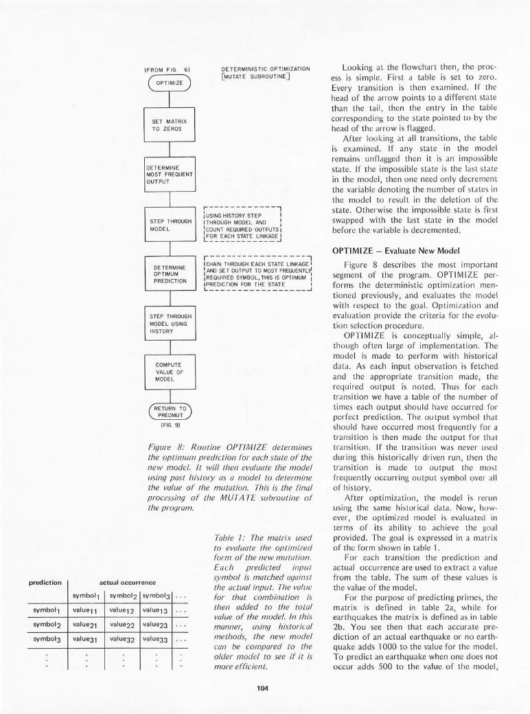
prediction
symbol1
symbol1 value11
symbol2 value21
symbol3 value31
(F ROM FIG . 6)
( OPT IMI ZE
I SET MATRI X T O ZEROS
I DETERMINE MOST FREQUENT
OUTPUT
I STEP THROUGH
MODEL
I DE TERMIN E OPTIMUM PREDICTION
I STEP TH ROUGH
MODEL USING HI STORY
I COMPUTE VALUE OF MODEL
1 RETURN TO
PREDMUT
(FIG. 9)
DETERMINISTIC OP TIMI ZAT ION
[MUTATE SUBROUTINE]
r---- ---- --- ---, : USING HI STORY STEP I ITHROUGH MODEL AND : : COUNT REQUIRED OUTPUTS I I FOR EACH STAT E LINKAGE I L ___ __ _______ ...J
r-----------------, I CHAIN THROUGH EACH STATE LINKAGE I I AND SE T OUTPUT TO MOST FREQUENTLY! : REQUIRED SY MBOL, TH IS IS OPT IMUM : IPREDICT ION FOR T HE STATE I L ___ __ ____ __ ___ _ __ ...J
Figure 8: Routine OPTIMIZE determines the optimum prediction (or each state of the new model. I L will then evaluate the model using past histOlY as a model to determine the value of the mutation. This is the final processing of the MUTATE subroutine of the program.
actual occurrence
Table 7: The matrix used to evaluate the optimized form of the new mutaLion. Ea ch predicted input symbol is matched against the actual input. The value for that combination is then added to the total value of the model. In this manner, using historical methods, the new model can be compared to the older model to see if it is more efficient.
symbol2 symbol3 ...
valu e12 va lue13 ...
va lue22 valu e23 ...
value32 va lu e33 ...
104
Look ing at the fl owchart then, the process is si mpl e. First a table is set to zero. Every transition is th en examined. If the head of the arrow points to a different state than the tail, then the entry in th e table correspond ing to the sta te po inted to by th e head of the arrow is fl agged.
After look ing at all transitions, the tab le is exam ined . If any state in the model remains unfl agged then it is an imposs ibl e state. If the imposs ibl e state is the last sta te in the mode l, then one need on ly decrement the variab le denoting the number of states in the model to resul t in the deletion of the state. Otherwise th e impossib le state is fir st swapped with the last state in the mode l before the vari able is decremented.
OPTIMIZE - Eyaluate New Model
Figure 8 describes the most important segment of the program . OPT lfYll ZE perfOl'ms the deterministic optimizat ion mentioned prev iously, and eva luates the mode l with respect to the goa l. Optimi zation and evaluation provide the criter ia for the evo lution se lect ion proced ure.
OPTI fYll ZE is conceptually si mple, although often large of implementation . The mode l is made to perfOl'm with hi storica l data. As each input o bservation is fetched and the appropriate transition made, the req uired output is noted. Thus for each transit ion we have a tab le of the number of times each outpu t sho uld have occurred fo r perfect prediction . Th e output sy mbo l that should have occurred most frequently for a transition is then made the outpu t fo r that trans iti on. If the transiti on was never used during thi s historicall y driven run , then the transition is made to outpu t the mos t frequent ly occurring outpu t symbol ovel' all of hi sto ry .
After optimizat ion, the model is rerun using the sa me hi stor ical data . Now, however, the optimi zed model is eval uated in terms of its abili ty to ach ieve the goal provided. The goa l is expressed in a matr ix of the form shown in tab le '1.
For each transition the pl-ed ictio n and ac tual OCC UITence are used to extract a va lu e from the table. The sum of these va lu es is the va lu e of the model.
For the purpose of predicting primes, the matri x is defined in table 2a, while for earthquakes the matrix is defined as in ta ble 2b. You see then that each accurate prediction of an actual earthquake or no ea rthquake adds -1000 to the va lue for the model. To predict an earthquake when one does not occur adds 500 to the value of the model,

If lIol1 talk COlUpl1tep •• D1e .peak lIOI1P ~
la.gl1age. 1. MICROPROCESSORS Technology, Architecture and Applications Daniel R. McGlynn This book explains how a microcomputer system is built and used,and also provides a unique survey of the specific models of microprocessors available today. Gives useful actual applications including automotive, telecommunication. low-cost home computers. microprocessor selection criteria. microcomputer system design techniques. a semiconductor technology review. software and the use of development systems.
(0471 58415-2) 1976 207 pp. $11.95
2. MICROPROCESSORS AND MICROCOMPUTERS Branko Soucek Here is a complete. detailed text and introduction to the field beginning with the basics and taking the reader all the way to programming. Some of the book's features include:
· Explanation of digital codes · Simple hexadecimal. assembly. and high
level programming · Logical systems and microcomputer orga
nization • Basics for design and use of microproces
sor-oriented systems. and the replacement of powerful minicomputers with the microchip set.
(047181391-5) 1976 607 pp. $23.00
3. COMPUTER-AIDED EXPERIMENTATION Interfacing to Minicomputers Jules Finkel Providing practical guidance on all major topics needed in interface specification and design. this book shows you how to connect scientific instruments and experiments to computers and to analyze suggested criteria for the selection of system elements. Offers many examples of practical connections and how to overcome problems that are commonIyencountered.
(0471 25884-9) 1975 422 pp. $28.00
Circle 214 on inquirv card.
4. INTRODUCTION TO MICROCOMPUTERS AND MICROPROCESSORS Arpad Barna & Dan I. Porat Presents a concise. basic introduction to microprocessors-what they are. how they work. and how to read the applications literature. You'lI find descriptions of the basic structure of a microprocessor. arithmetic operations and circuits. basic programming techniques. and information on input/output. memory. assemblers. loaders. data structures. and subroutine linkages.
(047105051-2) 1976 108pp. $11 .25
5. MINICOMPUTERS IN DATA PROCESSING AND SIMULATION Branko Soucek Explores basic principles of digital codes and logical systems. concentrating on programming. organization and interfacing . Soucek explains the elements of digital circuit design . the basic instruction set for a minicomputer, and data simulation necessary to design and use your digital systems.
(047181390-7) 1972 467 pp. $24 .50
~ WILEY-INTERSCIENCE a division of John Wi ley & Sons. Inc. 605 Third Avenue . New York . N.Y. 10016 In Canada: 22 Worcester Road . Rexdale. Ontario
6. A PRACTICAL GUIDE TO MINICOMPUTER APPLICATIONS Edited by Fred Coury Bringing together the work of leading experts. this volume provides information and examples of the application of minicomputer techniques. what is actually involved in the application and how to go about the selection and connection process. The five parts include an introduction to minicomputers. peripheral and software considerations, minicomputer selection . general applications and specific application .
(047118051-3) 1972 211 pp. $6.45
7. SCIENTIFIC ANALYSIS ON THE POCKET CALCULATOR JonM.Smith Smith shows. in c lear step-by-step procedures. how to use and apply numerical techniques. approximations. tables. graphs. and flow charts for performing quick accurate calcu lations. all the way to advanced mathematics. Using few derivations and theorems. iI's the best book for getting numerical results for scientific operations from your pocket calculator.
(047179997-1) 1975 380 pp . $13.75
rPi~~~;~~~~~~~YFREUAA~~OO~~~~~---continental US. and Canada.)
Mail to WILEY-INTERSCIENCE PO. Box 092 Somerset. N.J. 08873
o Payment enclosed, plus sales tax. Wiley pays postage / handling. We normally ship within 10 days. If shipment cannot be made within 90 days. payment will be refunded .
o Bill me. 0 Bill firm or institution .
NAME
AFFILIATION
ADDRESS
CITY STATE/ZIP
Prices subjec t to change without notice.
o 1. McGlynn(0471 584 15-2) o 2. Soucek (0 471 81391-5) o 3. Finkel (0 47125884-9) 0 4. Barna / Porat(0471 05051-2) o 5. Soucek (0 471 81390-7) 0 6. Coury(047118051-3) 0 7. Smith(047179997-1)
092 A 8071-57

Figure 9: This is the main control logic of the simulated evolution technique. It first builds a dummy model, predicts an event, and receives the response. It then performs repeated versions and variations of the model looking for the optimum model to predict the correct answers.
(a)
prediction
prime
not prime
NO
NO
BUILD DUMMY
MODEL
MAKE
PREDICTION
GET RESPONSE
PREDICTION
GOOD
i' NO
SAVE ORIGINAL
MODEL
CALL MUTATE (FIG. 6)
MUTATION
BETTER
i' YES
REPLACE ORIGINAL WITH
MUTATION
actual
prime not prime
0
0
MAIN PROGRAM
YES ADVANCE MODEL
ONE STATE
r--------, : REFERENCES : I FIGURES I TO 8.1 i PIECES OF MUTATE I L _______ ...J
NO
YES
106
(b) prediction actual
earthquake no earthquake
earthquake 1000 500
no earthquake 0 1000
Table 2: Two tables which illustrate examples of goals used to evaluate the models using historical data methods. Table 2a shows that when a correct guess of either prime or not prime is made a value of 7 is added to the total value of the state. Table 2b illustrates another manner of weighting answers. A correct answer receives a weight of 7 000. Predicting an earthquake when there isn't one only adds a weight of 500 to the model. Not predicting an earthquake when there is going to be one adds nothing to the model. This is a more subtle form of weighting since it not only allows a good and bad answer but also a not so good answer.
while missing an earthquake prediction adds nothing to the va lue of the model.
PREDMUT - Putting It All Together
Figure 9 shows the mainline logic for the program. The flowchart should be obvious except perhaps for the use of the terms search limit and generation limit.
In order to prevent the evolution procedure from taking hours or days, it is constrained as to how long it can take. Each time an evolution cycle must occur, two variables are set. The search limit variable defines the number of times the parent may be serially mutated when searching for a better offspring. The generation limit variable defines the number of offspring to be generated.
The result is that a fixed number of offspring are generated. Further, each offspring can undergo a maximum series of mutations, since it is seldom that a single mutation results in a better model. To make the program more intelligent, one can increase these limi t constants, but the result is a greater amount of computer time required between responses.
Again, for those adventurous programmers who want to make their programs even smarter, other methods can be employed to determine dynamically how many offspr ing and how many mutations are to be performed. Thel"e are other advanced evol utionary techniques that can also be employed. Interbreeding, majority logic and second order pattern recognition are just a few terms describing the advanced tech-

niques available in computer science literature.
In Conclusion
If yo u have the patience, sit down with a pencil and paper and attempt to perform the process I've just described. Many mathemati· cal books and papers contain random num· ber tables you can use. As a result you should quickly see how this mathematical technique results in the creation of a model of some process. From there it is relatively simple to program.
Do not be afraid to try your own improvements, but do so intelligently as you get a feel for the underlying processes. The process described herein is the basis for many computer versions of this art ificial intelligence technique and has worked with varying degrees of success for a wide variety of goals. I might conclude from personal experi ence: Be careful how and to whom you expose this technique. There are many peo ple who fear computers as they fear anything they don't understand and their enthusiasm for your creation may not match yo urs . With a good enough program model, however, you should be able to predict who these people will be. [Hmm ... our artificial life has defense mechanisms. J.
Circle 136 on inquiry card.
- SOFTWARE---..... All programs include: Complete assembler source listing, sample output, hex dump, sorted symbol table, plus com· plete instructions and thorough documentation. Text Editing System for 6800 . The best! SL68·24 $23.50 NEW Mnemonic Assembler System for 6800. SL68·26 $23.50 NEW Stack Oriented Arithmetic Processor (6800) SL68·25 $ "0.00 NEW 8080 Klingon Capture Space game. SL80·7 $6.50 Special Game Packages Each containing 6 programs:
8080 PD80·1 $19.95. 6502 PD65·1 $19.95. 6800 PD68·1 $16.50
Complete 6800 Software Pack 16 programs. PD68·3 $35.50 Battleship for 6800, like the board game. SL68·22 $8.00 Space Voyage '· TSC's 6800 Star Trek game . SL68·5 $12.00 Micro BASIC Plus The best 6800 "Tiny BASIC' SL68·19 $15.95 Diagnostics for 6800. Very Important! SL68·23 $10.00 Stock Market for 6800 . Lots of fun! SL68·7 $4.25 Complete Catalog of all of our programs. $ .25 Progrilm-of-the-Month-Club ,. Join the hundreds of hobbyists already enjoying this service. No obligation and no tim e valued cards to return. Discounts offered. One year for $2.00 To Order: Include 3% postage, $1.00 handling on orders under $10.00. Indiana residents add 4 % sales tax. Check your dealer!
T5C TECHNICAL SYSTEMS CONSULTANTS BOX 2574 W. LAFAYETTE, INDIANA 47906
The ACT-I sets the standard for Affordable Computer Terminals. The ACT-I is the most economical method of alphanumeric communication at data rates all the way to 19200 baud. The ACT-I video computer terminal manages a 1024 character memory organized as 16 lines of 64 characters chosen from the standard uppercase ASCII set. Receipt of more than 64 characters automaticall scrolls the screen and initiates a new line.
I/O SPECIFICATIONp (now switch selectable)
Data rate: 110, 300, 600, 1200, 2400, 4800, 9600, or 19200 baud
Parity: odd, even or none
The ACT-I comes fully assembled and tested. MICRO-TERM products are available in stock at discriminating computer stores or factory direct (30-45 days). Optional video monitors are available from the factory beginning at $125. Prices FOB St. Louis, MO.
MICRO-TERM INC. Po. BOX 9387 ST. LOUIS. MO 63117
107
StQP bits: 1 or 2
Logic Levels: RS232, TTL, source or sink 20 ma loop
Price: $400 excluding monitor
Optional features: the additional functions of cursor forward, backward, bell, screen roll up and roll down are ava!lable for $50.
CT-ION Circle 77 on inquiry card.
Circle 205 on inquiry card.
THE PROM SETTER WRITE and READ
EPROM 1702A and 2708
• Plugs Directly into your AL TAIRIIMSAI Computer
• Includes Main Module Board and External EPROM Socket Unit
• The EPROM Socket Unit is connected to the Computer through a 25 Pin Connector
• Programming is accomplished by the Computer
• Just Read in the Program to be Written on the EPROM into your Processor and let the Computer do the rest.
• Use Socket Unit to Read EPROM's Contents into your Computer
• Software included
• No External Power Supplies, Your Computer does it a ll
• Programs and Reads Both 1702A and 2708 EPROMS
• Doubles as an Eight Bit Parallel 110
• Manual included
KIT COMPLETE - $165 ASSEMBLED - $275
De livery Less Thon 60 Doys
SZERLIP ENTERPRISES 1414 W. 259th St. - Harbor City California 90710
C(l /if ornio residenls ple(lse odd 6% s(l /es I(lx.
21 START-AT-HOME COMPUTER BUSINESSES
in the shoestring, start-at-home computer business hand book
CONSULTING ePROGR AMMING e SOFTWARE PACKAGES e COM FREELANCE WRITINGeSEMINARseTAPE/DISC CLEANING FIELD SERV I CE e SYSTEMS HOUSES e LEAS I NGeSUPPL I ES PUBLISHINGeTIME BROKERse HARDWARE DISTRIBUTORS SALES AG EN C I ES. HEADHUNT I NG. TEMPORARY SERV ICES USED COMPUTERS . FINDER'S FEES. SCRAP COMPONENTS COMPUTER PROOUCTS AND SERVICES FOR THE HOME
1Ht ~Hn"sT"!NC,
lu,,'.I.' · HOM£ .
\
(:Q",pO:lf:I.1. bu !HneSS I
, t'land!)o{) !O; 1
Plus - - hundreds of id eas on mo o nlighting , going full-time, imag e building, r even u e building, bidding , contracts, marketing, profe ss ional i sm, and much more. No career planning tool 1 ike it eve r pub li s he d. 0 r d ern ow and i f you1re not completely satisfi ed, send it ba ck wi thin 30 days for a fu ll and immediate refund .
• 8~ X II ringbound .11 3 pp .• $12.00
-----------------------D A T A 5 EAR C H 730 WAUKEGAN ROAD· SUITE 108
Incorpora ted DEERFIELD, ILLINOIS 60015
Rush_copies of "The Shoestring Start-At-Home Compute r Business Handbook to me right away -NAME/COMPANY ____________________________ ___
ADDRESS ________________________________ _
CITY /5TATE/Z I P Dc H E C KEN C L 0 S""E-=-D"'D""B""'A:-;-N:7.K'-;A7:M"'"E""R"'"'I C:C-A:-:R:-:D"'D==M7"A"'S T::-:E""'R:-::C"""H7A-=-R-=-G E=--
#
Circle 223 on inquiry card. 108
KIM Users Notes
Owners of KIM microprocessors shou ld look into KIM Users Notes, published monthly by Eric C Rehnke, Apt 207, 7656 Broadview Rd, Parma OH 44134. The subscription rate is $5 for the first six issues.
Alberta Microprocessor
David Lavers, a member of the recently formed Alberta Microcomputer Soci ety, has been in touch. Right now information at this end is a bit sketchy, but you can find out more through their act ing president Dwight K Soloman, c/o The Computer Hobby Shop, 4812 16th St SW, Calgary Alberta CANADA T2T 4J5, (403) 243-6776_
Diablo Professional Users Group -Pleasant Hill CA
Here's a uniqu e idea for a computer club. The word professional in this case in
cludes two categories : the computer novice who is an expert in another field, and the computer expert who can provide answers to the first group. This is an opportunity for budding technical types to get in on the ground floor of microcomputer consulting. The beginners include a wide spectrum of industries and professions. Anyone from the high school leve l up, with several years experience with hardware and/or software, can consider himself or herself an expert.
Meetings are held in the Diablo Valley College library'S large conference room from 8:00 to 9:00 PM on the fourth Wednesday of each month. Diablo Valley College is located near the Willow Pass exit of Freeway 680. For details write or call Bob Hendrickson, Electronics Dept, Diablo Valley College, Pleasant Hill CA 94523, (415) 687-8373.
South Florida Computer Group
The South Florida Computer Group has apparently grown to the status of a major computer club. Meetings are held in both Miami and Ft Lauderda le. Meeting times seem so flexible that it would be best to contact them directly to get their schedule. Their newsletter I/O has improved substantially over the pas~ six months to the point that it is far more than just a review and

listing of club events. Volume 2, number 2 contains an in-depth look at resistors and capacitol' color codes, and a piece on the new "minor loop" chips designed by Texas Instruments to be used with bubble memories.
To contact the South Florida Computer Group, write 1155 NW 14th St, POB 236188, Miami FL 33123, or phone (305) 324-5572.
Looking for Computer Games? Try POPULAR COMPUTING
POPULAR COMPUTING is a monthly compil ation of co mputer ga mes, puzz les and brain twisters. Most of the programs are fairly short, perfect for whiling away a spare afternoon. Among the games is up-to-date information on the micro field and a regul ar feature called "Schwartz on Calculators." To subscribe, write POPULA R COMPUTING, POB 272, Calabasas CA 9'1302. Subscription rate is $20,50 per year, or $17.50 if remittance acco mpanies the order. Add $ 1,50 per year for Canada and Mexico; all other countries, add $3.50 per year. Back issu es are $2.50 each.
The Computer Hobbyist Group -North Texas
The Computel- Hob byist Group of North Texas is the place for computer buffs in the Dallas-Fort Worth area to develop and share an understa nding of the hobby,
Meetings are held regularly at the University of Texas, Arlington, and the University of Texas, Dallas. Contact the Computer Hobbyist Group of North Texas at 2377 Dalworth 157, Grand Prairie TX 75050.
ON LINE - Hardware and Software Exchange
ON LINE is a newsletter strictly limited to classifieds for computer hobbyists. You ' ll find page afte r page of hardware and software ava il ab le to buy, sell or swap. A great place to fi nd a bargain or an odd item.
ON LINE is published eve ry three weeks. Four issues are available for $1,18 for $3.75 and 36 for $7 . For advertising I-ates and other information, get in touch with D H Beetle, publisher, 24695 Santa Cru z Hwy, Los Gatos CA 95030.
Chicago Area Computer Hobbyist Exchange
Look ing through The Register, newsletter of CACHE, I ca me across what may prove to be an interesting series on languages, In the coming months The Register is planning on a series of articles on BASIC, PL/ I, SNOBOL, PASCAL, PILOT,
FORTRAN, LISP, TRAC, CASUAL and FORTH. This should be a step toward cieal-ing up language questions and misconceptions. Write to CACHE at POB 36, Vernon Hills I L 60061 . The Register is available fOl- $10 pel- year.
Washington Amateur Computer Society
The Washington Amateur Computer Society is a growing group of hobbyists in the nat ion's capi to l. Meetings are held on the last Friday of the month in th e second floor conference room of St John's Hall at the Catholic University of America. WACS is interested in exchanging newsletters with other computer groups. Correspondence should be add ressed to Washington Amateur Computer Society, c/o 4201 Massachusetts Av, Washin gton DC 20016.-
109
Conducted by Peter Travisano
BYTE's wide readership gives your club a unique opportunity to reach thousands of hobbyists, If you'd like to help your club develop or maintain a high profile, put us on your mailing list. Information about new clubs is especially welcome. Address your correspondence to Clubs and Newsletters, BYTE Publications In c, Peterborough NH 03458.
Circle 63 on inquiry card,

Your single source for the most advanced S-100 components available:
* Guard your Altair, IMSAI or custom system against program crashes with CONSTANT VOLTAGE POWER SUPPLIES, special 12 and 20-amp models from Parasitic Engineer ing. * INTEGRATED CPU/ FRONT PANEL gives you access to all 8080 registers, I / Os and memory from octal keyboard and digital LEDs ... by Morrow Micro-Stuff.
* WiinderBuss with Noiseguard"'" is the only 20-s10t S-100 bus-board with twoway squelching. * TOTAL I/O BOARD for $120! 3 cassette c hann e ls with control, RS232/TTY port, para ll e l port, memory. * Writ e for specs.
Th~nker Thys
" .. 505 Arlington Berkeley, Ca . 94707
photo - murtc..;y I\:lcr Il ul lcnbcrk BYle Shop Ikrkclcy
STATE OF THE ART
BOTH FORMS
There are two forms of the "state of the art ." One form is the personal growth attained by most professionals who realize they must stay in step, intellectually, with new concepts and new techinques. Too often, a tragedy occurs when the professional neglects the second form, his career development, The fatal mis· take occurs when working in an environment that provides a continuous parallel to industry but neglects to provide the pro· fessional growth that is necessary to insure career development and avoid potential future frustrations. To insulate yourself against this happenstance, check with our professional staff, They will advise you on your career development as it relates to your technical development.
Our areas of special ization are:
Software Development Computer Graphics Data Base Computer Design Simulation and Modeling Telecommunications Hardware/Software Interface
For further information either call or send resume to:
PERRI-WHITE ASSOCIATES 50 FRANKLIN STREET BOSTON, MASS, 02110 (617) 423-1900
PERRI-WHITE & ASSOCIATES, INC. 5373 W. ALABAMA PLACE HOUSTON, TEXAS 77056 (713) 960-0350
Management Consultants Specializing in Data Processing/Systems Engineering
All Replies Held In Strictest Confidence
Circle 281 on inquiry card. 110
Continued from page 74
blasted- IV bytes. They are great if you never want to do anything fancy, but .... With the bus address coming from an extended microcode"one may simply decode a la 8080 and use 8212s as your 10 ports. Also note that for some instructions there are free bits, ideal for adding instructions.
Interrupts will be painful, as the system doesn't have a stack, unless you use one of the aforementioned free bits to implement one (hint, hint).
My reaction to your suggestion about emulation of a 360 is unprintable. I Quite reasonable evaluation . .. CHj I f you must, however, don't do it with the 8X300. Use Motorola's 10800 series. I t's faster (50 ns , YES, 50 ns), and in the end would be less work. See, it's optimized for 360 type systems. Leave the 8X300 for the job it was designed for, a microcontroller.
Wh ich gets around to the point of this letter: As a controller, the 8X300 is unbeatable. You neglected to mention what I consider to be the best feature of the system (after its speed). Every instruction operates on a bit string. You specify the starting bit and the length in bits of the field in the byte that you want the instruction to operate on. One can also do n bit rotates on any reg ister to register instruction. Thus, you can add two registers and rotate right n bits in 250 ns or move bits 5 to 2 from memory to IV byte bits 7 to 4 without affecting th e rest of the bits. This applies to all instructions. Thus, the 4 port kit can easily act as a front end to a busy computer for 8 Telety pes. Or consider a floppy disk . At double density, the bit transfer rate is 500 kHz, or a bit every 2 ps, or a bit every 8 instructions. Actually, as shift registers are so cheap, one might as well use them and free the m icrocontroller for other tasks like fil e handling. I have SMS's floppy disk controller interfaced to my 8080. At $640 it's not cheap, but they do provid e the address and data bus on connectors for "maintenance ." They are rath er tight with the source code in the read only memories, though. It would be nice to have a parallel processing floating point processor when not doing disk transfers, particularly as it is practically free.
In short, th e hobby world should take a long look at this device. But keep in mind that it was designed as a controller, not a computer. Its architecture is optimized as a bit banger, and it does that superbly. As an emulator, it's the pits: Use a 2901 and a 2909, or any of the other bit slices and save yourself a bunch of time, trouble and hassle . Do use the 8X300 as a peripheral controller,

top values, professionalism Computerland stores are exciting, enjoyable places to visit. From the striking decor to the fun and challenge of the ComputerlandTM Game room, you'll find Computerland stores a completely new shopping experience.
You can count on Computerland stores for total professional support whether your needs are those of a computer hobbiest, education, science or business user. The skilled, management· trained staff offers knowledgeable service, expert maintenance, and software guidance.
breadth of products At Computerland stores the emphasis is on quality products. Major brands like Cromemco, DEC, Diablo, IMSAI, Lear Siegler, Polymorphic Systems, TDL and Vector Graphics to name a few.
Every store is completely stocked with tools, books and a broad range of accessories.
Franchise Opportunities available-Contact:
Ed Faber, President Computerland Corp.TM 1922 Republic Ave. San Leandro, CA 94577 (415) 895·9363
Circle 208 on inquiry card.
beginners welcomed Do you want to get started with microcomputers? Are you seeking expert guidance on computers, peripherals, software? The place to visit is your nearest Computerland.
Watch for a Computerland store opening near you soon.
now open: DeHart Street Morristown, NJ 07960
(201) 539·4077 6840 La Cienga Blvd. Inglewood, CA 90302
(213) 776·8080 813 B Lyndon Lane Louisville, KY 40222
(502) 425·8308 104 W. First Street Tustin, CA 92680
(714) 544·0542 24001 Via Fabricante Mission Viejo, CA 92675
(714) 770·0131 22634 Foothill Blvd. Hayward, CA. 94542
(415) 538·8080 Opening Soon: Chicago, ILL. Gaith.ersburg, M D San Diego, CA Buffalo, NY
In February 7977 BYTE, page 732, we published an article by Charles Ho werton, giving the software of a package of utility routines for an 8080 processor. joseph Newcomer of Carnegie-Mellon University sends along this critique of the methods of coding the BA RC routines. It should be noted that within the context of an in terrupt free single process computer, the BA RC routines will work as described. The subtleties occur in cases where in terrup ts are allowed or one desires to put the program into write protected or read only memory regions.
A TOTALLY NEW APPROACH!
floppy di sk co ntm ll er, unibu s to Altair address mapper, DMA IEEE-448 bus interface , data acqui siti on co ntro ll el', etc. If yo u use it for its intended purpose, yo u canno t be anything but deli ghted.
Finall y, a note abo ut Scientific Micro System s. They are th e only company to provide rea ll y co mplete documentation . Their pmdu cts work as adve rtised. They
ga ve me the shirt off their backs in helping with the nuclea r instrumentat io n. It is trul y refreshing to deal with such a co mpany. I urge yo u to drop th em a note as the microcontroller is onl y one of a large group of components they make. All are so pleasant to use, yo u kind of forget about them, whi ch is the hi ghest compliment I know how to give to an Ie.-
A Critique of Self-Modifying Code
Joseph M Newcomer Computer Science Dept
Carnegie-Mellon University
Pittsburgh PA 15213
Mr Howerton's arti cle in the Feb l'uary BYTE wo uld have pel'form ed <I mu ch gl'eater se rvi ce to th e co mmunity of programmers if he had coded it to all ow recursion and pmvid ed a few extra items of documentatio n. After hav ing expended a great dea l of effort and cleve rn ess to fit hi s cod e into 256 bytes, he then comprom ises reli ab ility by hav ing it mod ify itse lf. Th e concept of code mod ifying itself is und oubted ly the wo rst single idea that neo phyte programmers fa ll in love with . Since the most obvious thing in th e world is to take his BARC pac kage anc! put it in a PROM , my fir st cr it ique is that he has
SAVES TIME AND MONEY!
cMefull y made sUI'e that is not poss ibl e! Not o nly is self-modifying code useless in the world of read o nly memory, but experi enced pmgrammers know that code which modifi es itself is inh erentl y harde r to debug.
I sho uld like to offe r the obvious so lu t ion: In stead of storing th e dispatch address in line in th e code, store it o ut of line in th e wl'itab le programmabl e memory . Thu s, one mu st reserve a ce l· ta in number of bytes fa I' this addl"ess. Howeve l", since none of th e rout in es in BARC ca ll o ne another, o nl y one dispatch addl'ess Mea is requ ired . Then one on ly need do a "ca ll indirect " thmugh this addl·ess. Of COUI'se, the 8080 does not have a call indirect in stru ct ion, so o ne has to fake it; use a 3 byte di spatch area, and make the first byte the op code of a J MP
.,
MAKES YOUR JOB EASIER!
A powerful new tool for every serious 8080 user - professional and novice alike . Priceless timesaver for engineers , technicians, and programmers . Saves time and money in the lab, on the production line, or in the field.
PLEASE SEND
NAME
STREET
This convenient pocket size guide (3% by 73/ 4 inches) gives quick and easy access to all vital reference data. No more searching here and there for codes, instructions, or definitions. It's all there - at your finger tips - everything you need to successfully use the 8080A and its replacement -Intel's new 8085 microprocessor. Features cross listing, for rapid assembly and disassembly, of MACHINE CODES and MNEMONICS. Concise description of 8080 and 8085 OPERATIONS, SIGNALS, PINOUTS, and INSTRUCTIONS. Convenient cross conversion of OCTAL, HEXIDECIMAL, DECIMAL, ASCII, and EBCDIC codes. Easy-to-use tables of powers of two, eight, and sixteen ... and much more ... This handsome easy-to-read guide is printed on durable "lifetime" vinyl. Sturdy metal binding insures that your timesaver will provide many years of professional service. $12.95 each (plus postage & Calif. sales tax) - 25% discount for 4 or more. Money Back Guarantee : You must be fully satisfied or simply return the guide within 15 days for full and prompl refund.
URBAN INSTRUMENTS· 4014 CODY ROAD · DEPARTMENT B1 • SHERMAN OAKS, CALIFORNIA 91403
MAIL TODAY OR CALL ORDER DESK (213) 986-6958
8080 timesavers to : CHECK/M.a. ENCLOSED 0 BANKAMERICARD 0 MASTER CHARGE 0
CARD NUMBER
I I GOOD THRU 4 DIGITS ABOVE NAME CITY BAN KAMER ICARD (MASTER CHARGE)
STATE _ __ _ _ __ __ _ ZIP -- _ I I SIGNATURE - -- .~ ________________________________ ___ _________ ____ ___________________________________ J
Circle 270 on inquiry card. 112

inst ruct ion. Thi s is, of course, "mod ifying code," but at least we now have the ability to put the program in read only memory.
writeab le space: GODO JMP !"Om, typica l ca ll :
0'000000'
SHLD GODO+ 'I
CAL L GO DO
Now, as to the issue of insufficient documentation: The fu nctiona l documentation is quite clear, but the crucial p iece of information that I find to be missing is that the rout ines in the BARC package should never be ca ll ed f rom an in terru pt serv ice routine. Th is is because the routines are not reentrant (and my pro posa l of the dispatch vector in p!"Ogrammab le memory does not change thi s); if they are active when an interrupt is taken, and the interrupt service ca ll s th em, the dispatch address will be changed. Consider the fo ll ow ing sequence (events are listed) :
CALL OCHR
CALL DASXR
CA LL DASNT --- - < interrupt>----
CALL XCHR
< return f rom XCHR> -----< return f rom inter ru pt> ---
DASFC: CA LL <something>
<n (t) ::J
n '" M :::l OCIQ ..., (t)
'"
where <somethi ng> is expected to be OCH R but in fact is XCH R. The diffe rence in t ime between th e sett ing of the dispatch add ress and the use of it is (if I counted correctly) 235 mach ine cycles: a very, very long time. Furthermore, this sort of bug is nearly imposs ible to locate at the " lights and switches" leve l because the act of singlestepp ing changes the relative t imings and the error wi ll not occur. Using a debuggi ng system may have the same effect, and if i t is a homebrew debugger which would use BA RC, then it wo uld destroy the very in.formation i t was try ing to analyze. Absolute ly nowher'e in the article coul d I f ind any warnings about thisr Onl y my exper ience was an indicator: Wh enever stat ic data, either code or otherwise, co ntai ns state in fo rmat ion, look fo r cases in which rout ines which use it can be called recu rsive ly. Note that recursion does not have to be explic i t; calling a routi ne fro m in terrupt leve l where the rout ine was active at the t ime the interrupt was taken co nst itutes a recurs ive ca ll .
Less Bread, More Box.
New, complete Breadboarding/Interfacing Station. Only $237.50
We took our economy Breadbox IV kit and did a complete design number on it . .. to add accessories and give you far more hardware for the buck. For example: It plugs directly into your Altair/lmsai buss without special adapters ... Gives you almost 3,000 connections for breadboarding ... Power supplies (+5 & +/ - 15V) built in .. . Available in kit or assembled format. All that for just $237.50 each in kit form .
And to top it off, monitor the buss with LED or 7 segment displays, add an LR -6/K LED indicator outboard - 4 individual LED's with driving circuits ($10.00 each) . And LR-4/K seven segment display outboard with driver/decoder ($19.00 each) .
So bug out to your local computer store now and save substantial bread on this E&L deal. Or write us for the store nearest you . ' Suggested resale price (U.S.A. ).
E&L INSTRUMENTS, INC. 61 First Street. Derby, Conn. 06418 (203) 735-8774 Telex No. 963536
113
, ,
Circ le 56 on inquiry card .

Circle 222 on inquiry card.
PRAMMER by XYBEK
An extraordinary 2k memory board for your Altair-bussed computer
* On -board 1702A PROM programmer
* Space for 1792 bytes of read-only memory (seven 1702A EPROMs)
* 256 bytes of RAM
* Supplied with one 1702A, pre-programmed with stand-alone programming software - no sense switches are used
* Supplied with programming power supply
* PRAMMER's own on-board clock makes it compatible with almost any Altair-bussed system.
* All read and write sequences are generated via an on-board micro-programmed state machine, thus eliminating all one-s hots.
* Complete 1702A programming in 18 seconds
COMPLETE KIT: ................ $209 ($189 through June 14, 1977)
Assembled and tested: . ............. . $289 I mmediate (off-the-shelf) delivery
California residents please add sales tax. Master Charge and BankAmericard accepted .
XYBEK • P.O. Box 4925 • Stanford , CA 94305 Telephone: (408) 296-8188
IBM SELECTRIC TYPEWRITER
INPUT OUTPUT CONVERSION KIT
Easy to install on any IBM Selectric I and II, providing quality hard copy output for all microprocessor devices.
PRICE .... $395 EDITYPER SYSTEMS CORPORATION
A SUBSIDIARY OF TYCOM CORPORATION
Circle 269 on inquiry card. 114
The use of a single dispatch vector does make it possible, with care, to use BA RC from an interrupt routine . Before invok ing any BA RC routines, push the current dispatch address onto the stack; after using BARC, pop it off. If BARC was active, the program has correctly preserved state; if not active, only a few cycles have been lost.
The requirement that the parameter lists be in line also seems to be a bad choice to me; it would be much better to simply store a pointer to the parameter lists, or even better pass a pointer in a register. Since speed was not of the essence and size was, it seems to me that something which reduces the size of the code at the call site would be more desirable. Furthermore, if the addresses or values of the parameters must change, in line parameters force the user to write self-modifying code. Thi s means that the user cannot, after haying developed some neat system, convert it to a PROM region of memory.
A good criterion for evaluating a program is: Can it be put in PROM? If, after separating out the data areas, it cannot be put in PROM, then from my experiences I consider it to be badly written, no matter how useful or amazing its functions may be. Th en ask: Can it be called recursively? If not, do not ca ll it from an interrupt routine if it can ever be called from outside an interrupt routine. And don't forget multilevel priority interrupts, which are very easy to handl e on 8080 architecture. Do not call the routine from outside an interrupt context if it can be called from within one, which is the complementary condition . Note that these are not always obvious errors to detect, since the interrupt ro utine may call something which calls something which eventually calls something else; and one day the "something else" is modified so that it calls one of the nonrecursive routines. The scenario is now set for disaster: Let an interrupt come in at the wrong time and you are set for a long, tedious and probably unrewarding debugging session attempting to locate a source of "random" behavior.
Charles Howerton Replies
In response to the critique of BARC by Mr Newcomer of Carnegie-Mel/on University, I should like to begin by saying that I agree with his comments without equivocation for the environment which he hypothesizes. I also agree that the concept of modifying running code is very "hai/y." However, even Mr Newcomer 's proposed "fix" requires the modification of running code.

The BA RC routines were written for newcomers to the computer programming field. It has been my experience that the greatest problems the beginner has in writing programs are manipulating the registers (hence, the register preservation facilities of BA RC), and writing routines containing .loops which are designed to perform the functions provided by BARe.
In addition, the newcomers to home computing or even industrial or business computing are rarely faced with programming an 8080 or Z-80 which is loaded with interrupt generating hardware. Those of us who work with interrupt driven hardware (and I do) would not use BA RC for the simple reason that we are, presumably, sufficiently talented in programming arts that the creation of routines to perform equivalent functions is trivial.
As for embedding the parameters in line with the code, the one type of code that the average beginner writes well is straight line code with a few conditional jumps where decisions are required. Also, this is a fairly standard practice in large machine operating systems. Relative to the comment, " ... if the addresses or values of the parameters must change .. . ", what is the difference whether they change in a work area or in the in line code? They must still be changed!
BARC was not designed to be called recursively; it was designed to be used as a programming tool by someone who was using straight line code to solve a problem. As for debugging it: it works.
Could BA RC have been written to meet all of Mr Newcomer's criteria? Undoubtedly. However, not nearly as many fun ctions could have been included in the same space.
Charles P Howerton Digital Group Software Systems Inc
POB 1086 Arvada CO 80001 •
Thanks to Charles Howerton For BARC
Thanks for the Howerton article in your February 1977 issue, page 132, "Add Some BARC to Your 8080." Now I can finally get rid of the needless duplication and generally sloppy coding of utility routines in my programs and turn the job over to BARC. What a great time and memory saver!
D M Bell Vice President, Engineering
Handi Kup Company 195 Tamal Vista
Corte Madera CA 94925 •
THE L[]f:1PUTEA A[][jf:1 SMALL COMPUTER SYSTEMS. SOFTWARE. AMATEUR RADIO EQUIPMENT
1455-A So. 1100 E. Salt Lake City. Utah 84105 Phone: 801-466-7911
"WE TAKE THE . . ' "
\\\'~\."t\\\ OUT OF THE f:1~LA[]
One Of The Nations Largest Full-Service Computer Stores.
Over 1600 Square Feet Of Sales And Service Facilities.
WHEN YOU WRITE FOR OUR CATALOGANDENCLOSE$l TO HELP DEFRAY THE COST OF HANDLING AND MAILING, HERE'S WHAT YOU GET:
1. A CERTIFICATE GOOD FOR $2 ON YOUR NEXT PURCHASE . ... .... . ............... ..... .. .. .... . ......... .
2. THE C[]l';1PUTtR R[][]I';1 EASY TO UNDERSTAND CATALOG COVERING ....... .. ..... .. .... . . . ............. . .
IMSAI THE DIGITAL GROUP POL YMORPHIC SYSTEMS SOUTHWEST TECHNICAL PRODUCTS CORPORA nON TECHNICAL DESIGN LABS ETC.
3. THE ~[]I';1PUTtR R[][]I';1 "EASY GUIDE" TO HELP YOU PICK THE RIGHT SYSTEM, PERIPHERALS, COMPONENTS, AND SOFTWARE FOR ....... . .. . ...... . .. . .... . .. . ........ .
THE BEGINNER THE ADVANCED THE EXPERT THE SMALL BUSINESS
4. A CURRENT LISTING OF PRESENTLY AVAILABLE
SOFTWARE PUBLICA nONS PERIPHERALS
5. INFORMATION ON REPAIR SERVICE, LOW COST CUSTOM PROGRAMMING AND OTHER SPECIAL SERVICES.
AT THE C[]l';1PUTtR R[][]I';1 YOUR WRITTEN QUESTIONS ARE HAPPILY RECEIVED AND PROMPTLY ANSWERED ..... .
WE ALSO STOCK A COMPLETE LINE OF AMATEUR RADIO EQUIPMENT
BANKAMERICARD ... . .. ... .. ... . .. . ... . . . .. .. .... MASTERCHARGE
115 Circle 141 on inquiry card.

Introduction to S M Quek Stanford University POB 9647 Stanford CA 94395
Microprogramming
REGISTER FILE
Figure 7: A block diagram with time notations for a sequence of events that might occur in a simple machine instruction such as: Add accumulator to register B. First (7) register B is put into a temporary storage area. Then (2) this storage area and the accumulator are added together by the arithmetic logic unit. The resulting answer (3) is stored in the accumulator or register B.
CENTRAL PROCESSING UNIT
~-----------------1 I I I I I I
CON TROL .... -.,........< I SIGNALS I I
L ___________________ ...1
BUS
Figure 2: Block diagram of the architecture of a typical bus oriented digital computer.
116
What is Microprogramming?
When we consider the operation of a simple machine instruction, like add accumulator to register B on some computer, we often fi nd that there is a sequence of even more e lem entary operations involved, For the example given, we may first have a transfer of data in I'egister B to some temporary register in the ar ithmetic log ic unit. Next, we may then perform an addition operation and finally, retu rn the result of the operation to either the accumulator or reg ister B. Figure 1 illustrates this sequence of operations.
Wilkes, an early pioneer in the field of computer design, called these elementary operations "microoperations." (See refel'ence 1.) By this token, a single mac hine instruction, like the add described above, wou Id consist of a microprogram of these m i crooperations. Microprogramming is, then, the implem enting of control logic for a computer's instruction set through the ordered storage of processor control information.
Microprogrammable Computer Organization
Figure 2 is a simplified block diagram of the architecture of a digital computer. The organization of a microprogrammable computer differs from that of a nonmicroprogrammable computer in the des ign of the control unit. The nonmicroprogrammable

machine uses a hardw ired contro l unit. All contro l I ines are fixed and cannot be changed easily . On the other hand, a mi croprogl-ammab ie machine uses a changeab le microprogl'am in implementing the contl'Ol unit and th 'us by changing the mi croprogram, the machi ne can be l altered within certa in limits of its des ign. Let us now take a look at the contro l unit of a micl'Oprogram mab le computer and figure out how it works,
A typica l microco ntro l un it wo ul d cons ist of a mapper , a microseq uencer, a microco ntl'O l storage and a decoder. The last item, the decodel' unit, is optional and may not be found in some mac hi nes, Th e in tel-con nectio ns between these un its are shown fO l' a typ ica l des ign in figure 3.
In operat ion, a machi ne instru ct ion is fetc hed from main memmy and is sto l-ed in the instruction reg iste l', The mappel' co nvel'ts thi s machi ne instructio n into the stal-t ing add ress of the microprogl-am routi ne whi ch is supposed to execute the in struct ion as a sequence of microope l'at ions, Thi s add l'ess is passed on to the microsequencel' whose job is ' to step through the microprogram, As each micl'O instruct ion is read out, the decodel- tl'ans lates it into co ntro l signa ls fO I- the val' io us contl'o l li nes,
Origina ll y, the mapper was imp lemented us ing a decoder tree made up of d iscrete logic gates, Nowadays, array logic blocks in the fOl'm of read onl y memOl'y and so ca ll ed progl'ammed log ic alTaYs al'e used fO l' th is pu rpose , (It shou ld be noted that programmed logic arrays al'e espec iall y su ited for this task , Read only memo ri es contain many more bits than al-e needed , and are th us more expensive than programmed logic arrays, The array is powerfu l eno ugh to imp lement most functions needed and its lower cost makes it a very attract ive candidate for the mappe r,)
The funct io n of t~e microsequence r is to provide a va lue for the next add ress of an instruct ion in the co ntro l memory. I t can be thought of as hav i ng .a microprogram counter and add it ional log ic to test for cond it ional branches, Th us, in its simp lest fo rm, it co u\Id ju st be a pl-esettab le co unter with assoc i ~ted circui try for perform ing branches and conditiona l tests, However, most commerciall y ava i lab le micro·
CONT ROL STORAGE
(THE MICROPROGRAM)
CON T ROL S IGNALS
SEQU ENC E INFOR MATI ON
CONDITI ON FL AGS
Figure 3: Block diagram of the connections between various parts of a microprogrammed central processor. The typical processor consists of a mapper, a microsequencer, control storage and an optional decoder,
r-
D \ E C
~ - 0 D E
\ \ R
- \ 2 n LI NES
~
- \ n L INES
~ '--- \
CO NTROL SIGNAL S
Figure 4: Typical diode matrix. A binary number is input on n number of lines. It is decoded into 2n number of outputs. These lines are then decoded through the use of a diode matrix. The outputs of the matrix are at the control signals lines.
117

DATA ROUTING
ARITHMETIC LOGIC UNIT MEMORY DATA DATA NEXT USER
Figure 5: Typical microinstruction word format. The instruction allocations are generalized but are found in almost all such data formats. The word format itself can be of any length. The usual length is from 24 to 60 bits although a field width of 700 bits is used by IBM in some applications.
AND SHIFTER 10 SOURCE DESTINATION ADDRESS FUNCTIONS
IF : INSTRUCTION FETCH D:DECODE DF : DATA FETCH
sequencel's (such as the In te l 3001 or AMD 2909) are more sophisticated than this; some (eg: AMD 2909) even to the extent of having a built-in stack for processing microprogram subroutine linkages.
The miclocontrol store is usuall y some kind of read on ly memory. Wilkes envisioned this as a diode matrix such as shown in figure 4. Of course, immense technological advances have been made since Wilkes' time and now the microcontrol store is usually impl emented by read on ly memories, of which the discrete diode matrix can be thought of as the forerunner . In add ition to read only memories, some m icroprogrammabie computers have a form of programmabl e memory as part of their microco ntrol store . This all ows fOl' dynamic changes of microprogramming which lead to an eve n more flexible and powerful machine. With such a configuration, the microprogrammer can easily rewrite, add or de lete portions of the microprogram to su i t the particul ar task at hand .
From a consideration of the microcontrol store, we next pmceed to a discussion of the microinstruction. It is the microin struct ion that forms the control mechanism which causes each data register change. A typical microinstruction word format is shown in figLII:e 5. Generally, there has to be a field to control the arithmetic log ic unit and the shifter, one for memory, and one for 10 control. In addition, another field has to be reserved for information regarding the routing of data. Some kind of sequencing field wh ich specifies the next microprogram address is usually also included. Finall y, to
E : EXECUTE T : TESTS
Figure 6: Timing diagram for the sequence of interpreting an instruction. This process is divided intd five stages: instruction fetch, decode, data fetch, execution and testing. As soon as the testing is finished, the instruction fetch cycle is again encountered to start the next sequence.
118
suit the architecture of a particular machine, there is a field left for user defi nable functions. These vary from machine to machine but would usually includ e conditional tests and branches. From this brief discussion, it should be apparent that there is no fixed width for the microinstruction. I ndeed, it vari es from 16 bits for the Signetics 8X300, chip, to 24 bits fOl' the HP21 MX minicomputer to 100 bits for various models of the I BM360. However, the width of the microprogram wOl'd in most small and medium size co mpu ters ranges from 24 bits to 60 bits.
If the microinstructi on is wide enough, we can allocate a single bit to a single control line. In such a case, the microinstruction is said to be unpacked or ' horizontal. Howevel', if we want to save control memory space, we may want to encode the data so as to compress the wOl'd width. An external decoder can then be used to recover the data. 1:11 is is the packed or vertical format. A machine seldom takes on a fully packed or unpacked format for its microinstruction. Instead, most machines have microinstructions which lie somewhere between the two extremes; some fields are encoded while others are not.
When deciding on the width of th e micrbinstruction , several factors have to be considered. Th e first and most obvious is cost: The wider the microinstruction, the higher its cost. This is so because memory is more expensive th an a decoder. The penalty paid for having a vertical or packed format is a decrease in speed and flexibility . In the case of a horizontal machine, there are separate bits controlling the individual lines. Thus, there can be more para ll elism in the control as more resources can be controlled simultaneously. Howeve r, for this same reason, horizontal mach ines are much harder to program. The microinstruction set of vertical machines resembles the assembly languages of minicomputel's.
Instruction Interpretation
Let us consider the sequence for the interpretatio n of an instruction. In figure 6, we see that the process of interpreting an

IF I 0 I
OF E I T I
I I I I I I
I IIF I 0 I OF E I T I
Figure 7: Timing diagram illustrating the time that is saved when implementing
TIME SAVEOJ l- TIME_
the changes of listing 2. This time saving occurs only when an interrupt or direct memory access request does not have to be processed. If a request does have to be processed, the timing diagram of figure 7 applies to the
instruction can be roughly divided into five stages. The first stage is that of an instruction fetch. The contents of the program counter is sent to the memory address register and a read memory command is initiated. The program counter is now incremented and the microcontrol unit waits until memory is ready with an in struction.
Once memory is ready, the instruction is loaded into the instruction registel-. This completes the first stage. On the time chal-t (figure 6), this corresponds to the segment IF . The mapper decodes this instruction into a microaddress which is passed on to the microsequencer. This is the decode phase, segment D on the time chart. As the microsequencer steps through the control memory, we have contl"Ol signals coming out of the micl"Ocontrol memory. Depending on the instruction, we may need to initiate another memory read to fetch data. Th is would be segment DF. Once this is completed, we can proceed to instruction execution, segment E. Finally, upon completion of execution, a series of tests can be performed. These could include software tests for conditional branch hal-dware or software tests for interrupt, and hardware tests for direct memory access requests. The sequence for an add accumulator to register B (store results in accumulator) and skip if ovel-flow may look like listing 1.
Of course the listing has to be coded into micl"Omachine language form. DMA. SERVICE, INT.SERVICE and INSTRUCTION.FETCH would then be microprogram subroutines to service the various requests. A register, which holds data coming from memory, is assumed to be present. If no buffer register is used , then step lOin the routine should be changed to:
(10) IR:= MEMORY DATA.
This will enable the mapper and load the microsequencer.
Why Microprogramming?
Before microprogramming was developed and firmly incorporated into computer de-
sign, most computer designers had to rely on multiphase "hardwired" logic for their design. Multiphase logic uses multiphase clocks to control the various register to register transfers and other functions . Hence, the designs Me extremely complicated. Once the machine has been hardwired, it becomes virtually impossible to change the instruction set without redoing the design once again, ie: rew iring it.
Microprogramming overcomes these disadvantages and provides a means for obtaining relatively simple and flexible designs. To illustrate , reconsidel- the microprogram for the add instruction . If we look at the time chart of figul'e 6, we see that waiting for
Step Instruction
process ..
Commentary
MAR: =PC memory data counter:= program counter; [read memory 1
2 PC: =PC+ 1 3 [wait for memory 1 ; 4 IR: =MDR 5 TEMP :=REG B 6 ADD,ACC:=RESULTS 7 IF OV=1 THEN PC: =PC+1 8 IF DMA REQ=1 THEN JMP
DMA.SERVICE 9 IF INT REQ=1 THEN JMP
INT.SERVICE 10 JMP INSTRUCTION.FETCH
in crement program counter;
enab le mapper, load microsequencer; disable mapper; add and store results in accumulator; if overflow increment program counter; if direct memory access requested, go to routine; if interrupt requested, go to routine;
fetch next instruction;
Listing 7: A program listing for the sequence: Add accumulator to register B, store results in accumulator and sl?ip if overflow exists. Lines 7 through 4 are the instruction fetch routine. Lines 5 and 6 add register B to the accumulator and stores the result in register B. Line 7 checks for an overflow, and lines 8 through 70 check for interrupt and direct memory access requests. When the program listing is encoded into micromachine language form the DMA.SERVICE, INTSERVICE, and INSTRUCTIONFETCH will become microprogram subroutines to service the Ilarious requests.
Step Instruction
9 MAR :=PC 10 IF INT REQ=1 THEN JMP
INT. SERV ICE 11 JMP INSTRUCTION.FETCH+1
Commentary
read memory; if interrupt requested, go to routine;
ski p fi rst step of instruction fetch;
Listing 2: Revisions of the program of listing 7 which allow a savings of time in the execution of the program. This savings is shown graphically in the timing diagram of figure 7.
119

memory to be ready with an instruction takes up a good pOI-tion of our time. Thus, to speed things, we may want to initiate a read memory instruction before we proceed to the various tests. Accordingly, we rewrite our microprogl'am with the mod ifications starting on line 9 shown in listing 2.
The new time chart obtained with this modification is shown in figure 7. Note that if no direct memory addl'ess requests or interrupts have been requested, th en there is a savings in time. This is because we do not have to wait as long for the instruction fetch: a result of th e earl y initiation of the read memory . If there has been an interrupt or direct memory access request, then no gain in speed would be obtained. Howeve r, since these requests are relatively rare, this new modification would result in an overall increase in speed.
If hardwired logic was used for the control unit, it would be very difficult to make the modification just described. Thus, we see that microprogramming is a very powerful tool in the design of digital computers.-
REFERENCES
1. Wilkes, M V and Stringer, J B, Micropro· gramming and the Design of the Control Cir· cuits in a Digital Computer, Proceedings of the Cambridge Philosophical Society , Part 2, Volume 49, April 1953, pages 230-238.
2. Mick, J R, AM2900 Bipolar Microprocessor Family, Micro 8 Proceedings, September 1975, pages 56-63.
3. Coleman, V and RallapalJi, K, A Versatile Microprogram Sequencer, Micro 8 Proceedings, September 1975, pages 52-55.
4. Intel, "3001 Microprogram Control Unit," data sheets, I ntel Corp, Santa Clara CA.
5. Cook, R Wand Flynn, M J , System Design of a Dynamic Microprocessor, IEEE Transactions on Computers, C-19, 1970, pages 213-222.
6. Stone, H S, editor, Introduction to Computer Architecture, Chapter 10, "I nterpretation, Microprogramming, and the Control of a Com· puter" by Flynn, M J, Science Research Associates Inc, Palo Alto CA, 1975, pages 432-471.
6800 OWNERS UNITE! FREE YOURSELVES FROM THE BONDAGE OF SLOW CASSETTE 1/0.
LOUDLY PROCLAIM YOUR SUPERIORITY OVER YOUR 8080 NEIGHBORS AND THE Z-80 SUBCULTURE. JOIN THE BFD-68 REVOLUTION.
Our Basic Floppy Disc System (BFD-68) must, in all modesty, be called superb. It comes completely assembled with a disc controller that is plug compatible with 'the SWTPC 6800. The cabinet and power supply are capable of handling 3 Shugart Mini-Floppy Drives. One drive is included in the basic system price of $795 and other drives may be added easily at any time for $390. Or, you may save money by ordering a dual or triple drive system initially. The price for the BFD-68-2 is $1169 and for the BFD-68-3 triple drive system $1539.
Remembering that we are prone to understatement, we must say that while the BFD-68 hardware is superb, the software is even better. Our Disc Operating System provides the following advantages over most other systems.
• ANY NUMBER OF FILES MAY BE OPEN (IN USE) AT ONE TIME
• THE NUMBER OF FILES AND SIZE OF FILES IS LIM-ITED ONLY BY THE SIZE OF THE DISC
• MERGING FILES REQUIRE NO EXTRA DISC SPACE
• NO WAITING FOR THE DISC TO RE-PACK
• LONGER DISC LIFE - MORE EVEN DISC WEAR
NEED A FULL SIZE FLOPPY? Our P·38·FF is a plug·in interface card to the ICOM Frugal FloppyT". It includes all the features of the P·38·1 plus one 2708 EPROM containing the ICOM bootstrap software. Just plug the P-38·FF into your SWTPC 6800 and your ICOM into the P·38-FF and you're ready to use the Frugal Floppy and ICOM's 6800 soft· w a re package. Price $299.
Our P·38 is a n 8K EPROM board containing room for 8 2708's. Or, you m ay use it to hold up to 7 2708's plus your Motorola Mikbug or Minibug II ROM . The P·38 addressing is switch select· able to any 8K location . Price $179.
The P·38- 1 contains all the features of the P·38 plus an interface t o the Oliver Paper Tape Reader and our EPROM Programmer. Price $229.
The PS·1 Power Supply Kit provides plus and minus 16 volts required for the P·38 series boards. Also, it allows a wiring mod· ification to be made to the 8 volt supply that will increase its output by one volt. Price $24.95 .
Our M·16 is a 16K single power supply STATIC RAM memory system. Th e M·16 is fully buffered and requires only half the power of a similar size system using low power 2102's. With the M-1 6, you can expand you r system to 48K and still have room left over for one of our EPROM boards. Price $595.
ALL OUR PRODUCTS EXCEPT THE PS·1 ARE COMPLETELY ASSEMBLED. AVAILABLE AT MANY SWTPC DEALERS OR FROM US BY MAIl. BANKAMERICARD AND MASTERCHARGE WELCOME.
SMOKE SIGNAL BROADCASTING P.O. Box 2017, Hollywood, CA 90028
Circle 169 on inquiry card. 120

Your microcomputer is only as good as its memory
Your microcomputer is ... in a manner of speaking ... capable of thinking. The amount
7 £ ----"'--'- -
DISK !liE ORY · ...
of information you can store, combined with the access speed, determines the bottom line capability of your microcomputer. The Midwest Scientific Instruments' FD-8 Floppy
Disk Memory System will enable you to get the most out of your microcomputer ... 6800 or 8080. We have the most complete 6800 disk operating system available today, which interfaces to any microcomputer via a single PIA chip. When used with the MSI FDOS Operating
System ... included with purchase ... the FD-8 gives your microcomputer a level of performance which can only be matched by larger computers.
You can have program save and load with named, variable length, password protected files at three levels: object code files, source code files, and BASIC files.
It has disk routines which can be used easily by
American Microprocessors Equipment & Supply Corp. Chicagoland Airport, P.O. Box 515 Prairie View, Illinois 60069 (312) 634-0076
Microcomputer Systems, Inc . 144 South Dale Mabry Avenue Tampa, Florida 33609 (813) 879-4301
Micro Store 634 South Central Expressway Richardson, Texas 75080 (214) 231-1096
Vanguard Systems Corporation 6812 San Pedro San Antonio, Texas 78216 (512) 828-0553
A-Vid Electronics Company 1655 East 28th Street Long Beach, California 90806 (213) 426-5526
Electronics for Yachting 1525 South East 16th Street Ft. Lauderdale, Florida 33316 (305) 525-3478 TWX 510-955-9484
High Technology 1020 West Wilshire Blvd. Oklahoma City, Oklahoma 73116 (405) 842-2021
Computer Workshop . 174 ifield Road London England SW109AG 01-373-8571
low level assembler language programs as well as high level BASIC programs.
The coresident assembler/editor saves and loads
source files from disk, assembles and stores object
code on disk, and creates assembly listings on a high speed printer.
You get a full ANSI standard BASIC interpreter* with program load and save, from disk as well as tape, with both random and sequential disk data files. BASIC also has multi-I/O port capability under software control.
And all you need do to access any of these functions is type the appropriate commands on your terminal.
The FD-8 is complete, including all power supplies, cabinet, cables, software, manuals, and documentation.
You can order the FD-8 as a kit for $1,150.00, or wired and tested for $1,395.00.
Visit one of our dealers f0r a demonstration, or send for our free Catalog of MSI products.
220 West Cedar. Olathe, Kansas 66061 • 913/764-3273 TWX 910 749 6403 (MSI OlAT)
0000000000000000000000000 o Before I forget ... send me your catalog 0
o Name 0 0 0 0 Address 0 0 0 0 City
0 0 State Zip 0 o ~mD 0000000000000000000000000
°MSI BASIC is an additional $65.00
MSI is a dealer for Southwest Technical Products. Mastercharge & BankAmericard Orders accepted
220 West Cedar • Olathe, Kansas 66061 • 913/764-3273 • TWX 910 749 6403 (MSI OlAT) Circle 119 on inquiry card.

MERLIN is the best ASCII/Graphics board now available for the S-I00 bus ... and at an unbelievable price!
Compare these features to any other video interface: * 160H x l00V resolution bit mapping
graphics * On-board ROM (Monitor/Editor)
option * 40 characters by 20 lines, character
ROM generated (hardware) * Keyboard Interface (with power) * Programmable modes and display
format * Serial I/O port * Low power ... only 600ma at + 8V * Extremely fast (uses DMA) * Comprehensive User Manual
... 200ps * American 60HZ or European 50 HZ
operation.
Designed-in expandability means maximum versitility at minimum cost. Add-on options now available (in kit form) Include: * Super Dense Graphics
(M320-K) ....... ........ .. . $39 * Lower case characters
(LC) .. ...... ............... . $25 * Serial-te-parallel expansion Kit
(MSEK-K) .... . . . .. . . . ....... $45 * 1500 Baud (software) cassette
interface kit (MCAS-K) . .. . ..... $29 n 2K x 8 Mask ROM; graphics,
cassette, & extended editing software (MEl) ....... . . . $35
* 2K x 8 Mask ROM/256 RAM; Monitor Editor Software (MBI) .. $39
The MBI ROM software is designed to allow turnkey operation and sophisticated editing and scrolling.
Ask to see a demonstration of MERLIN at your nearest computer store. Many dealers now stock MERLIN and there is nothing like a hands-on demo for really evaluating a product. We know you'll be sold.
MERLIN Kit with Manual ........ $269 MERLIN, assm'd & tested .. . . . . . . $349 MERLIN User Manual . ...... . . . . $ 10
For fast information, write us direct! MC and BAC accepted.
.... MmlTerm ASSOCiates, mc. II~ Bo . 268 . Becllofd. Mass 01730 (6111648· 1200
Circle 112 on inquiry card.
Continued from page 13
ELIZA INTEREST
John Aurelius' lette r (March 1977 BYTE, page 16) struck a reso nant chord. When I succeed in getti ng my own system, I have plans to implement a version of the ELIZA program. ELIZA was first described by Weize nbaum in the Communications of the A CM (CACM), Volume 9, Number 1, Janu ary 1966, and has subseq uen tly been discussed by Weizenbaum and others too num erous to mention. ELIZA is still ali ve and productive, al tho ugh not necessaril y as a psychotherapist. I am referring to a version of ELIZA implemented by Shapiro and Kwasn y (CAC~ 1975, 78, pages 459 to 462) as an interactive co nsultant for a tim esharing system. ELIZA is a very gen eral program whose specifi c person ality derives f rom a script she is given. Shapiro and Kw asny rea· soned that ELIZA woul d be a su itabl e mec hanism for providing assistance to timesharing users. I t was this app li cation of ELIZA whi ch intri gued me sufficientl y to beg in ex perimenting w i th her. Using their program as a point of departure, I have im plemented my own (somewh at improved, I fee l) version of ELIZA also designed to act as a tim esharing sys tem co nsultant. This program is now free of bugs (I think); however, the scr ipt is no t yet very sophist icated, so a di alogue w ith th e program is not ye t rousing. I woul d be w illing to provide a reaso nabl y we ll documented li sting to anyo ne se riousl y in terested. Before the idly curious drop me a card requesting a copy, I should warn th em that th e program alon e cons ists of 5 00 lines of SNOBOL 4 statem ents and requires 60 K word s (the equ iva lent of approx imatel y 36 0 K bytes) of sto rage to run on th e Honeywe ll 635 computer for whi ch it was writ ten.
Now that everyo ne's enthusiasm has bee n dampened, I should admit that my cho ice of SNOBOL was expediency. ELIZA was ori gin all y written in LISP (also a memory hungry , slow, interpretive language).1 ELIZA requires th e ab ility to search in put text for ce rtain des ired content (pattern III atch in g) and ELI ZA's internal d ata stru ctures are best represen ted as som e form of li st structure. These two att.ributes sugges t that th e IllOSt natural (but not necessaril y most effic ient) choi ce of a prograillm ing l anguage is one that facil i tates one or both of these ends. For illlpl ementing ELIZA on a small Illach in e, I envision a relativel y sma ll co re resident program to maintain th e key li sts and do the pattern m atchin g, wh il e the length y scr ipt is maintained as fil es on a .secondary storage medium. Th ese files would preferab ly be kept as random access files on a relat ivel y fast dev ice such as a floppy . A sequ ential devi ce like cassettes might do, but I fear it would be into lerab ly slow. Unfortunate ly, ELIZA needs to keep a great deal of text at her f ingertips (core res iden t in my SNOBOL program)
122
for matching against input and fo r reconstructing into output. Again, I wou ld glad ly exc hange ideas with any one interested in implementing such a program.
Glen A Taylor Wi sconsin Research and Development Center for
Cognitive Learning University of Wisconsin
1025 W Johnson St Madison WI 53706
COMMENTS ON TURING MACHINES
Jonathan K Millen's Decemb er 197 6 article (page 1"14) on an actual hardware impl ementat ion of a uni versal Turing machine was very interestin g. The re lationship betwee n the Turin g concept of a uni versal m achine (computer) and the capab ilities of "real" cornputers continues to be ignored or misunderstood by m any persons who think th ey know what a computer is. Millen's hardware project may help to enlighten these persons who v iew th e Turing machine world as totall y separate from the "real computer" wor ld.
It m ay be of interest to note th at Konrad Zuse appears to have inves tigated the Turin g m ach ine concept soo n after World War II , hoping to f ind so rn e ideas which could be used to simpli fy the co nstr uct ion of real computers. (My k no w ledge of this activity comes f rom a bri ef private conversation with Zu se at Los Alamos in Jun e 1976.) He did not find any, of course, since we know now from experience th at extremely simple m ac hin es in thei r primitive state are difficult to use in pract ice. Zu se's ear ly wo rk on computers was done w ithout any knowledge of Turing's work, wh il e i t is known that vo n Neumann's input to earl y comp u ters was not ind epe nd en t of such know led ge. (von Neum an n becam e acquainted with Turing whi le Turing was at Princeton in "1937 and 1938 after I:he Turing machine work which was published in England.)
Mill en makes so me statem ents regarding th e Busy Beave r Garne that should be corrected. This ga me was in ve nted by Tib or Rado and is described in th e arti cle " On Non-computable Functions" in th e Bell System Technical Journal, Volum e 4 "1, M ay "1962. Mill en h as t aken the liberty of adding an addition al state to hi s Turing m ac hin es which he counts as a sta te fo r the Busy Beave r Game. Th is adds beh av ior th at effect ive ly elimin ates his rn ac hine example f rom being considered in the gam e. It goes into a nonstop loop instead of halt ing. Th is also distorts the rules of th e game. His 6 co unting "4 state" machine is actuall y a 3 state machine by Rado 's rules.
Millen then gives what he says are known results for 3 thru 7 states when he re all y should be say ing 2 thru 6 states. In any case, the "k no wn" results he mentions are sti ll inco[rect. Th e best results are as follows :

Current Results (1975) Busy Beaver Game
(Millen's Correct Number States :) of States Busy Beaver Score: Determ in ed by:
(3) 2 =4 T Rado (4) 3 = 6 S Lin (5) 4 =13 A Brady (6) 5 ;;. 112 D Ly nn (7) 6 ;;. 117 A Brady f rom
5 state result of D Lynn
7 ;;. 22,961 M Green 8 ;;. 3.(7.3 92 .1 )/ 12 M Green
Whil e the summary I h ave shown here is in the process of being published, most of these resu l ts have been available in the open li terature.
Allen H Br.ady Univ of Nevada
Computing Center POB 9068
Reno NY 89507
AUTHOR JONATHAN MILLEN REPLIES:
I am grateful to Dr Brady for hi s update on the Busy Beaver Game results. The terminal "copy" loop on state 4 of the example program was necessary because my uni ve rsal Turing machine (UTM) has no automatic halt. A copy loop is an adequ ate substitute, because it is recogni zable as such, and it does not change the co ntents of the tape.
Reade rs may be interested in the altern ative Turing machine hardw are real izat io ns described in the fo llowing two refe rences:
1. I Gilbert and J Cohen, "A Simp le H ardware Model of a Turing M achine: Its Educational Use," Proceedings of the ACM Annual Conference, 1972.
2. Wakerly, J F, Logic Design Projects Using Standard Integrated Circui ts, John Wiley and Sons, NY,1976.
Jonathan Millen 66 Main St
Concord MA 01742
FURTHER SYS 8 EXTENSIONS
Readers who have been following the two recent articles in the Janu ary and Febru ary 1977 issues on improvi ng SYS 8 Software Package 1 by Wi ll ard Nico may be interested to know about one o f our products. This produ ct is ca ll ed Software Pac kage 0.5.
This is a program in source code, plus a co mplete manu al , fo r improving SYS 8 Package 1. I n addition to the added comm ands and auto line capabilities discussed by Mr Nico, our program offers: insert, delete, and change stri ng operat ions o n a current line; string operations on a find first occurrence basis; page listi ng mod es; reordering of line numbers; automati c tabbing; optional su ppress io n of line numbers; and more. For the assembler, we add the fo llowing: octal numbers are accepted; a
global sym bol tab le fo r often used symbols; an ASC pseudo op for including real tim e output lines;' output of the symbol tab les; an expandab le tabl e of pseudo ops; and st ill more.
Th e program also ad ds the capability to asse m ble program s in sect ions as they are re ad in from a mass storage device . Th is mean s that program size is no longer limited by the amount of programm able memory avai lab le fo r source code files!
Th e source code transla tes to 1.75 K objec t code bytes. Th e use r edits this in with his existing SYS 8 Software Package 1, conform ing it to the limits of his sys tem. For thi s gem of a program, we charge a mere pittance , a toke n $14.95 .
Larry Weinstein Ob jective De sign Inc.
POB 20456 T all ahassee FL 32304
WINDMILL JOUSTING DEPARTMENT
I 'm just getting started in this fie ld and have enjo yed and benefited from th e past six or seven issues of y our pUblication. I w ill soo n purch ase and (I hope) have running a micro, bo th for personal use and as a fa irl y l arge data base device fo r a three man law office.
What prompts me to write this is the use of such exp ressions as " his/her" and "he or she" which appea r with increas in g regul arity in your magaz ine. Th e ze nith was reached in the February issue.
Let's be fa i r; you are leaving out a lot of reade rs. For examp le, there are certainly corporations and schools whi ch own micros. Surely, the inclusion of onl y the masculine and fem inine gend er mu st ser iou sly offend these neuter users. f Let 's start an " I t" liberation front? J Pl ease, th en, include "it" in such expressions as "Wh eneve r the user finall y gets hi s/her/its machine running .. . . "
Secondly, there no doubt are so me partn erships or associations th at ow n or use micros. Can you im ag in e the chagrin of the members of th ese bodies not to be included in all your pro nouns! This will necessitate your sayi ng: "Whenever the user f inally ge ts his/her/ i ts/their m achine running . . .. It
Don't offend , for God's sake. And to heck with gramm ar or readability.
I am sure, i f you re ally work at i t, yo u cou ld find even more ways to in sure that yo ur articles are hard to read - like,
123
The MERLIN Super Dense add-on kit provides maximum resolution at a minimum cost. In fact , MERLIN with Super Dense has more capabilities than any other S-100 bus video Interface at any price!
Once you've seen 'Super Dense' graphic resolution you'll know there is nothing to compare it to .. . short of spending over $600 . . . and even then you'll not have all of the capabilities of MERLIN with 'Super Dense'.
Super Dense provides true bitmapping . Each and every point on the screen is controlled directly by a bit in memory. (Requires BK of system memory.)
ROM character-graphics looked good for a while; then came MERLIN's 160 by 100 bit mapping graphics; and now ...
320 by 200 blt-mllpplng grllphlcslll If you're looking for a graphic display, MERLIN with Super Dense is the best there is. And if you hadn't considered graphics or thought it was out of your price range, consider what you could do with 320 H by 200V graphics and for only $39 extra.
The Super Dense add-on kit to the popular MERLIN video interface is now available with off-the-shelf delivery.
M320-K, Super Dense Kit . ... . $39 M320-A, Super Dense Assm ... $54
See MERLIN ad on previous page.
For information fast , write direct , or see 'Super Dense' at your nearest computer store.
MC and BAC accepted.
Circle 112 on inquiry card.

Made possible by the designed-in expansion capabilities of the Impressive MERLIN Video Interface.
Aside from general purpose uses, the designers at MiniTerm anticipated Graphics and Graphics games and the problem of control interfacing . The MSEK (MERLIN Serial Expansion Kit) provides:
Three parallel Input ports Three parallel output ports
These can be used for Interfacing joysticks or game controllers or parallel I/O devices. And the price can't be beat! The MSEK mounts inside your keyboard and connects to MERLIN through the keyboard cable.
Also available from MlnlTerm is the first real raster graphics ,"Space War" game for the personal / hobby market.
"Space War" gives the user control of rotation, accelleration, and firing of missiles for two space ships. When used on the MERLIN video interface with 'Super Dense' add-on option (320 x 200) the game provides more excitement than any BASIC version of "Space War" or any of the standard TV games!
A delux version of "Space War" is also available which allows selection of ship dynamics to simulate cars, tanks, boats, etc, and allows the user to draw his own 'ship',
Space War (SPW) , . , , , ' , . , , ' ,$25 Delux Space War (DSPW) , ' , , ,$35
(Add suffix -T for Tarbell tape, or -P for INTEL hex paper tape.)
A complete source listing Is available for an additional $10 for either game.
Write for full description, or better yet, play a few rounds at your local computer store. But be prepared to stay a while, There is likely to be a line and you may become addicted .
MC and BAC accepted.
.... MlnlTerm ASSOCiates, inC. IT~BO'268. Bcdford , Mass . OI730(617)648· 1200
Circle 112 on inquiry card .
"owner/user," fo r example - we have to be accurate, righ t? Or "hobby /perso nal/ recre ation/sm all business" every time to describe (modify) the word "microcomputer." Th at' ll really screw up the read ers and give more money to the authors, too.
Be honest, fo lks; are yo u on so me kind of a cru sade? If not, please drop the abom in al usage of English (even lawyers recogn ize the use of "his/her" and the like is bad) and get on with publishing valuable, concise and readable pieces for the benefit of your poor readers. It the ga ls are offended ' by the use of masculine pronouns, then fine - print 'em all in the feminine gender. Most men cou ldn ' t care less. But stop the foolishness, okay?
W C Welborn J r Caine and Welborn Law Office
2221 W Franklin St Evansville IN 47712
Its, you? Gesundheit!
SOME COMMENTS ON MIKBUG
The following letter reaches readers in two parts. The main body of the letter is found here; the information in one paragraph of the letter is noted in "B YTE's Bugs" on page 760, and is not repeated here.
I was pleased to see john Rathkey's article "A MIKBUG Roadmap . .. " in February 1977 BYTE, page 96. The 10 routines in this ROM are very usefu l and have saved me a lot of programming t im e.
The following comments and add it ions apply to table 1:
1. BADDR alters the contents of both A and B.
2. OUTH L and OUTH R both destroy the contents of A, Thus A must be reloaded if one desires to output both nybb les.
3. INHE X puts a hexadecimal digit in the right nybble of A.
4. OUT4HS outputs the four hexadecimal digits pointed to by X and X +1, then prints a space. X is incremen ted by 2 and the contents of A are lost.
5. OUT 2HS also uses X as a pointer. X is incremented and A is altered.
6. OUTS is omitted from the list . Th is routine prints a space and begins at EDCC.
The routine label led PSTR in li st ing 1 duplicates PDATA 1 in MIKBUG. The only sign ificant difference between the two routines is that PDATA 1 uses the code 0.4 (EOT) to mark the end of the string rather than DO. as used by Rath key.
The ind exed mode jSR command can occasio nal ly be used to save d few bytes of code when using the MIKBUG 10 routines to and from the A register. Simply load the lowest address of the routines you will be using in to X; the
124
desired routines can then all be addressed with the 2 byte indexed mode jSR rather than the 3 byte exte nded mode. Of course, this technique won't help if you want to use the routines that require X as a pointer.
The MIKBUG program uses a block of programmable memory from ADDD to AD49. Since this is usually provided by a 128 by 8 RAM chip, the remaining 53 bytes from AD4A to AD7 F are avai labl e to the user for data or short programs. In addition, space for a stack is provided fram AD14 to AD42. Since many programs won't require such a large stack, some of these bytes can generally be used for other purposes. Th e stack pointer is initiall y set to AD42 and increments downward as more stack bytes are required.
You have a fine magazine; keep up the good work.
D B Brumm dB Engineering
224 Hecla St Lake Linden M I 49945
NOTES ON ARTICLE CONTENTS
I have been reading BYTE for about a year now. I would like to congratu late you on your very interesting journal. However, it disturbs me that yo u continue to publish articles on programming and construction techniques only for the more well known microcomputer chips such as the 80.80. and 680.0.. I contend that artic les on microcomputers based on the 180.2 and the 650.2 would also oe beneficial as they are also in popul ar use.
Leonar:l P Jacobs J r USF # 1570.
Tampa FL 33620.
We've had numerous articles on the 6502, already, starting with a review of the processor in November BYTE 79 75 by Dan Fylstra, and continuing with several about the K IM -7 and its application or modification. In the near future we 'll have David Brader's Komputar, a homebrew 6502 system plan. As for the 7802, or any other processor, what we print to a large exten t depends on what people are doing, since the majority of BYTE articles are unsolicited contributiOI75 from readers actively engaged in experimentation. Based on recent data from readers, authors and manufacturers, there should be a bit of on upswing in 7802 awareness over the next few months.
THE EVOLVING 'LEXICON
A thorough answer to W Buchholz's question [February 7977 BYTE, page 744/ about words that have passed from computer jargon into the general vocabu lary wou ld probably require a master's thesis.
The main reason is that several wholly new dictionaries have cOllle on the US market in the past ten years or

so. Amo ng th em are: American Heritage Dictionary (three ed i t ions). Doubieday Dictionary , Random House Dictionary ( two edi t ions). Seve ral old er .dicti onari es have bee n extensive ly revised; se t in new ty pe, or both : Webster's New World Second College Edition, Merriam-Webster Seventh College Edi t ion, Thorndike-Barnhart Advanced Diction~
ary . And th at 's no t all . T he Oxford English Dictionary has
started work on a 3 volume sup plement that will cove r new word s and mea nings sin ce about 1914. Th e f irst vo lume cam e out in 1972. T he Oxford English D ictionary seems to be do ing a more tho rough jo b on co mputer term s th an on general electroni cs! T he entry for "contro l " in the new Oxford Englis/1 D ictionary supp leme nt qu o tes th e 1948 MIT glossary and th e 1955 glossary of the Br i t ish Standa rds Insti tu te . Bu t the Oxford English Dictionary inex pli ca bl y sk ipped the electroni c use of " emission" as the kind of signa l (AM, FM, T V ) a sta ti on se nds out, al t hough th at word wi th tha t mea nin g has bee n aro und sin ce at leas t 1927.
A lmost the f i rs t thing I did when I got interes ted in mi croco m puters was to buil d my own glossary , sta rt ing wi th the li sts in th e bac k of th e IEEE Dictionary (a nd acq uiring o th er glossari es as I we nt) . So I had a li st I co ul d check aga inst a bra nd new di cti onary (American Heri tage Dictionary, Coll ege Edi ti on of 1969) and a dict ionary whose date of rev ision is known (Webster's New World Dictionary, Second Coll ege Edi t ion of 1970).
A merican Heritage Dictionary sta r ted with a clea n sheet. I t has exce llen t t y pography bu t fewer entries tha n Web ster's New World Dictionary . I t uses large r type, and has very w ide ou te r marg ins on eac h page where th e artwork is pu t. I ts vocabu lary o f co mputer te rms in cludes:
accumulator, address, A LGOL, alphanumeric, analog computer;
base, bit; Boole, George; Boolean algebra;
chip, computer, computer language, converter ("a dev ice that transfor ms inform at ion fro m one co de to another");
data ("Numeri ca l in fo rma tion in a for m sui table for process ing by computer "), data processing, demodulation, digital computer;
flip flop, FO R TRAN; gate ("a circuit ex tensive ly used in
computers that has an output dependen t on some f un ct ion of i ts input");
hardware ("a co m pu ter and the associate d phys ica l equ ipmen t direct ly in vo lved in th e performance of comm u nicat ions or da ta processin g f unc ti ons") ;
information, information theory, input;
machine, machine language, memory, module, Murphy 's Law;
PL / I, printer, print out ( ve rb)' printout (noun ), p r ogram (noun and verb)' programmer;
readout, real time; soft war e, storage.
Webster's New World Dictionary has mo re entr ies and smal ler ty pe. Th e Co llege Ed iti on is i ts number 2 p rodu ct . Some of th e co mputer defin i ti ons are eyebrow ra isers:
accumulator, address (" th e locat ion in a co mputer's storage co mp artment of an item of in format ion, identi fie d by a number o r other cod e"), alphanumeric, analog, analog computer;
bit, Boolean Algebra; computer, console; data proceSSing, decoder, digi tal com
puter; flipflop, FORTRAN ("a digi tal co m
puter language simil ar to alge bra") ;
gate; hardware; information, information theory,
input; language ("a spec ial set of sy mbo ls,
lette rs, numera ls, rul es, etc, used for the t ransmission of in fo rm ati on , as i n a co mputer") , logic (" th e sys temat ized interco nn ectio n of digi ta l sw i tching fun cti ons, circuits, o r dev ices, as in electron ic digi ta l co mpu te rs ");
machine language, memory; printer, printout (noun). program
(nou n and verb, two defin i tion s eac h). programmer and program er (as shi rt t ail s, undefi ned , fo llow ing program);
random access, read ("to o btain [in fo rm ati on] fro m [pun ched card s, t ape, et c ] ; said of a compu ter " ), readout, real time, routine;
software, storage, store, symbolic logic;
throughput, trac!?; word, write (" to record in fo rmati on
in a com puter's memory o r on a tape, etc, fo r use by a co mputer").
Webster's New World Dictionary had a co n tr ibu t in g ed i to r who was then the head of th e Elec troni cs Engin ee ring Department at Carn eg ie- Mell on Uni versi ty . American Heritage Dictionary had no electron ics special is t ide n t i f ied as such on i ts 1969 m as th ead.
I f y ou know someo ne who is majo ring in co mputer and m inor ing in linguisti cs, yo u mi gh t set him o r her on thi s. Th e soo ner i t 's w rapped up thoroughl y, the eas ier i t will be to do thoro ughl y. On e quest ion that should bc exp lo red in any ex haust ive t reatment is wh y ce rtain words we re admi tted to the gcneral vo ca bul ary , and others we re no t , in each edi tio n of each di ct ionary.
C J Mike Fern Jr, WA60WJ 1046 S Westlake # 1
Los An geles CA 90006-
125
They can transform a hobby computer into a professional, useful tool.
But why pay $3()() for one? The MERLIN Video Interface is also a ROM Monitor board . The optional 2K x 8 MBI ROM Monitor/ Editor is available for on Iy $39.
The MERLIN Monitor provides commands for turnkey 8080 or ZOO operation and program debugging and the. Editor is the best there is. Any BASIC or user program is compatible with the MBI software.
And now MiniTerm introduces the ROM / EROM kit so that you can put the rest of your operating system and general purpose routines in ROM for increased ease of use and reliability .
Just Look at these features : -(( Power-on jump to any 1 K block '" Holds eight 2708 EROMs '" Bank select feature -(( S-1()() bus compatible '" Walt state logic -(( Addressable to any 4K block And it's only $89 in kit form!
So write or buy your operating system - then optimize it for your specific needs and put it into ROM where it will always be available and yet changeable when necessary.
MiniTerm will also provide 2708s for $40 and will introduce Its inexpensive 2708 programmer next month .
Once you've had or used a system with good ROM operating software (Monitor, Editor, Relocatable loader) you'll understand why ROM boards are becoming so popular.
But don't spend more for ROM boards with extra goodies when all you need Is a board to hold your ROMs and to provide power-on jump. Buy the MiniTerm ROM / EAROM kit for only $89.
For more information fast , write direct.
MC and BAC accepted.
... MlI1lTerm ASSOCiates , II1C.
IT~ flo. 268 Oedlord. Mau 01130 (617) 64801200
Circle 112 on inquiry card .

IlYlE's Ilits A Phonograph Record in a Computer Magazine?
Bob Jones of Interface Age magazine has informed us of an intri guing new feature included in their May issue: a fle xible plastic phonograph record bound into the magaz ine which contains a 4 K byte BASIC comp il er plus a binary load er and two memory test programs_ The program, written by Robert Uiterwyk for Motorola 6800-based systems, uses the 300 bps Kansas City standard_ The record's appearance marks the first time that such a technique has been used in a magazine to disseminate software. (R eaders may recognize th e record as the type used to promote recordin gs by· mail).
To recover the programs, th e user plays the record on his or her phonograph in the normal manner and feed s the output to an AC-30 or similar cassette interface, the same procedure used fo r data cassettes. Using the "tape out" feature (available on most amplifiers) is probabl y the easiest way to feed the signal to the interface.
Each record is good for about 100
playings; unless they are severe, scratches have no effect on accuracy. An additional benefit of this system is the elimination of t,!pe dropout problems. Bob has promised some 8080 and Z-80 programs for future iss ues. Co ntact Interface Age, POB 1234, Cerritos CA 9070 1. ·
KIM Has a Contest
In a press release from MOS Technology Inc , Richard Simpso n has an nou nced the KIM Software Contest, open to al l KIM own ers and users. The pri zes are:
First pri ze: K I M- 3 8 K memory expans ion board
Second pri ze: KIM ROM-1 Res ident Editor/Assembler ROM Se t
Third pri ze through tenth pri ze: . ' KIM ath Source Listi ng and User
Manual.
All entries must co ntain program documentation and so urce code li st ing (but a hand asse mbled source is a ll ow~d) . All entries become the property of MOS
OUR PROTO-CLlpTM CAN PAY FOR ITSELF THE
1ST TIME YOU USE IT. The reason's as simple as the time you 'll save testing, s ignal tracing or wiring in DIP's. Not to mention the cost of IC 's ruined by accidental shorts. A Proto-Clip is the foolproof, s hort proof way to bri ng up leads from crowded circuit boards. Its patented, molded design and unique gripping teeth free hands for other work. Built to withstand tough dayto-day use, CSC clips are available with or ' without cable for 14-, 16-,and 24-pin DIP 's,
starting at $4.50* For more information, see your dealer or write for
U.S . Pat No. 3 ,914,007 ' Mfr's . sugg . retail
o ur full-line cata log and distributor li st.
44 Kendall Street, Box 1942 New Haven , CT 06509.203-624-3102, TWX: 710-465-1227 West Coast office: Box 7809, San Francisco, CA 94119. 415-421-8872 TWX: 910-372-7992
© 1975, Continental Specialties Corp.
Circle 6 on inquiry card. 126
Technology Inc and wi ll be turned over to the K 1M Users Group for possible publication.
Entri es wil l be judged on the basis of originality and usefulness to the user commu nity. If external hard ware is required, a schematic should be provided. Co mplex programs taking more than 1 K bytes of memory such as high level I .a nguage~, assem biers, cross assemblers, text editors, etc, will be awa rded a duplicate first prize if accompanied by working source tape or cassette. All entries must be received by July 1977. Prizes will be awarded on August 1 1977. Send all entries to KIM Software Contest, MOS Technology, 950 Rittenhouse Rd, Norristown P A 1940l.
This looks like an interesting opportunity for KIM enthusiasts to earn a bit of glory .•
The Following Was Received From American Federation of Information Processing Societies '(AFIPS):
The fast growing field of personal comp uting will be in t he national spotlight this June at the 1977 National Co mputer Co nference in the Dallas Convention Center. Reflecting the dy namic growth and promise of th e personal co mputin g f ield, the 1977 NCC will feature a Personal Com pu ting FiliI', a Personal Computing Ex position, two ful l days of program sess ions, a National Club Congress, as well as special interest sess ions for co mputer hobbyi sts.
Th e Perso nal Computing Fair , scheduled to run throughout the four days of the conference, June 1 3 to 16, wi ll feature operational displays and demonstrations of individually and group owned noncommercial projects. More th an 100 small computi ng systems are expected to be di sp layed featuring hardware and software implementations , games, recreation, music, art, amateur radio, as we ll as scient ific and general applications. Prizes and awards will be presented in recognition of outstandi'lg ach ievem ent. The Person al Comp uting Fair will provide hobbyists with the unique ·opportunity to obtain new id eas for their own systems, solut ions to current problems, and a wealth of "how-to" tips on personal computing.
The conference program wi ll feature an in-depth examination of personal computing on Wednesday and Thursday, June 15 to 16. Two 3 hour panel sessions on Wednesday will examine "Pe rsonal Computing - Past, Present and Future" and " Hard ware for the Computer Hobby Market." Thursday morning will feature a 3 hour panel covering "Personal Computing Software," with the afternoon devoted to the presentation of papers relating to personal com puting, plus a concluding pan el on " Th e Future of Retail Com puter Stores ." Each panel wi ll feature presentations by leading authorities in the personal computing field, and will be designed to
THE COMPUTER SHOP
Calgary, Alberta 351 5 18th St SW
Phone (403) 243-0301
IMSAI, SWTPC, Digital Group, Cromemco, T.D.L. , Lear Siegler ADM-3A, Morrow cassette interfaces, MiniTerm, Polymorphic, Solid State Music, and the Calgary made Interalia 8000 micro. Prices generally US list plus duty, tax & exchange (now 30% altogether). Special: free Morrow serial/parallel/cassette port board incl. PROM boot with every I MSAI 8080 mainframe - first 50 orders mentioning this ad only! Full repair facilities.
CANADA Circle 179 on inquiry card.
-FREE Complete listing of all feature articles appearing in Volume I of BYTESeptember, 1975 thru December 1976. I ndexed for easy reference. Includes all errata.
To get yours, send a $.24 stamped self addressed envelope to:
BYTE Index 70 Main Street
Peterborough N H 03458
LOGIC DESIGN INC
QUALITY Support for those who wish to dig deeply into digital design.
Breadboarding System, textbook on logic design, and complete schematics for an elegant CPU that will run the PDP8 instruction set . . $1095
1321C's ....... .. .. .. $ 87
TTY Interface .... .... $ 20
Memory .... ... ...... $26/k
BOX 3991, UNIV. STATION LARAMIE, WY 82071
(307) 742-7977
Circle 209 on inquiry card .
B"'TESH[]P the affordable computer store
7825 BIRD ROAD (305) 264-2983 DIAL 264-BYTE
OF MIAMI
WE HELP YOU GET YOUR SYSTEM UP AND RUNNING.
The word is getting around ... the Byte Shop OF MIAMI is a remarkable exception to the rule among computer stores. We offer a truly delightful environment supported by
• REAL courtesy • REAL expertise • EXPERT service • GREAT classes
demo systems IMSAI BOBO BYTE·B SWTP MP6B CROMEMCO PROCESSOR TECH
MEMORY EXPANSION COLOR TV GRAPHICS LEAR SIEGLER ADM 3 PAPER TAPE READER
INTERFACES (KITS or ASSEMBLED UNITS)
Opening COMPUTER STORE
#2 IN FORT LAUDERDALE
Circle 271 on inquiry' card.
19" RACK S-100 BUS CARD CAGE
ECT-100 CARD CAGE KIT $ 100 CARD CAGE / MICROCOMPUTERS
ECT·100-8080 KIT $320 ECT·100-Z80 KIT $420
8,192 x 8 BIT STATIC MEMORY EX CEPTI ONA LL Y LOW POWER
8KM M EMOR Y BOARD KIT $295 PB-1 PROTOTYPING BOARD $28 EX T -l00 EX TENDER CARD $24
ELECTRONIC CONTROL TECHNOLOGY
P.O. Bo x 6. Union . New Jersey 07083 (2011 686·8080
Circle 47 on inquiry card.
DISCOUNTS!
IMSAI8080 KIT $599. assembled 750.
I MSAI 8080 w/22 slot MB 645. assembled 795.
RAM 4A-4 125. assembled 225.
MULTIPLE I/O Board (Mia) (both Tarbell and Byte modes one serial, two parallel , one control port) 175.
assembled 275. EX PM (100 pin w/edge conn 6.50
assembled 11 .50 (POLYMORPHIC SYSTEMS) 16x64 CHAR VIDEO BOARD 189.
assembled 229.
Keyboard -63 key fully encoded ASCII, +5v only, positive or negative logic, repeat key, IC sockets. kit $54.
assembled 69.
*write for discount prices on other IMSAI products .
"N.C. residents add 3% state sa les tax
COmPlJTER ElECTROfllCS BOX 339 Cary, N.C. 27511
Circle 253 on inquiry card.

provide atte ndees with the latest information on ne w developments, trends, and the outlook for the future. Ample time wi ll be allotted to answeri ng questions from those in the audience.
Plans are also und er way to bring together various special interest groups in personal computing for a series of informal sessions on such top ics as the building of comp uting kits, debugging software , use of assembly langu age, peripheral interfaces, cassette and disk storage, and software standards. I n add ition, plans are being developed for a "National Club Congress" to enable representatives of clubs from throughout the nation to exchange ideas and discuss issues relating to their activities and programs. Among expected topics will be whether or not a national personal computing association is needed, and if so, how it might be formed. Related topics are expected to include hardware/software standards, a possible national program library interchange, and the establi shment of educational seminars.
In additio n, the 1977 NCC will feature a com mercial exh ibition by equ ipment manufacturers and suppliers of personal computing products and services. The Personal Computing Ex position will be in the North Hall of the
Dallas Convention Ce nter, one level below the main NCC exhibit hall.
Inform atio n on the 1977 NCC may be obtained from AFIPS Headquarters, 210 Summit Av, Montvale NJ 07645, or by ca lling (201) 391-9810. -
A Calgary, Alberta Store ...
The Computer Shop is the name of a new store which se ll s IMSAI, Digital Group, Interalia, Cromemco, LearSeigler, Polymorphic Systems, Southwest Technical Prod ucts, Morrow, MiniTerm and TDL products to central Canadians. The shop sent us a fli er, with a handwr it te n note that the typical prices are USA prices plus about 25%. The store is located at351518th StSW,Calgary, Alberta CANADA T2T 4T9.-
Another Dallas Area Store
KA Electronic Sales, a Dall as distributor of indu stria l e'lectron ic components to both businesses and indi viduals, has opened a computer store at 1220 Majesty Dr in the Brookhollow Industria l Pk, Dallas TX.
The KA Computer Store currently
. ' t, 4 . ~ • S
\ UOI( . '~, ~'fl" O" : : ' /-
Unlimited Number of Steps
-14 Digit Readout \\( \ ' /,'"
INCLUDES FREE . .. "". '\ - 44 page HANDBOOK '
- ONLY $189.00 - Users Group Membership -IN STOCK - Programming Sheets
ARTISANELE~TE~~~J~~s ~~.~rpR~~!~~~ NEW JERSEY 07054
TELEPHONE: (201) 887-7100
Circle 275 on inquiry card. 128
markets central processing units and peripherals by several manufacturers including IMSAI, Southwest Technical Products Corporation, Lear-Siegler Terminal s, Solid-State Music and The Digital Group.
KA also supplies electro ni c components and parts as an industrial and retail distributor, and has a second electronics parts walk-in store located at 1117 S Jupiter, Garland TX.-
How to Get a BASIC Source Listing
Dr Dobb's Journal of Computer Calisthenics & Orthodontia, in its January edition of this year, has published the complete source and object code assembly li st ing of the Lawre nce Livermore Laboratory BASIC interpreter developed by John Dickenson, Jerry Barber, John Teeter and Eugene Fisher. The interpreter is aSK byte program designed to be loaded in PROM or ROM. It includes a f lo at ing point arithm etic package. Dr Dobb 's is located at People's Computer Compa ny, POB 310, Menlo Park CA 94025 . -
Question:
Dr Chuck Adams of the Texas A & M University EE Department posed the following question in a recent phone conversation : "Who invented the D flip flop?" Can a reader supply the answer to this query, for publication in a future issue ?-
Want to Find Out Who's a Professional Computer Scientist?
The 1977 Association for Comp uting Machinery Roster of Members, an alph abetic and geographical cross-listing of the names and addresses of more than 35,000 ACM members as of January 1 1977 is now ava il ab le.
The Roster may be ordered from the ACM Order Department, POB 12105, Church St Station, New York NY 10249. Prices are $7 to members and $25 to nonmembers, prepaid . -
Guide to Buzzwords
"Sherry's Gu id e to Data Communications Bu zzwords" is the nam e of a 24 page booklet of words and de finitions which are commonly used in the data commun ications field. Write for your complementary copy, avai lab le from : Public Rel a tions Dept, Internat ional Communications Corp, 8600 NW 4 '1 st St, Miami FL 33166. -
Survey Sweepsta kes Results ...
In November 1976 BYTE ran a random survey of readers, to gather data for editoria l and marketing purposes about this crazy field . Of approx im ate ly 2100 survey questionn aires mailed, 1448 were returned prior to the deadline of Novem-

ber 15 1976. As an incentive to return the survey, we offered five Life Subscriptions to BYTE, commencing with the expiration of the current subscriptions of the winners. The following five individuals were drawn at random from the returned survey sweepstakes entry blanks (which were kept separate from the actual questionnaires in order to keep the questionnaires anonymous and private).
Arthur H Bazell 50 EI Camino Real Berkeley CA 94705
Allen L Curl Robert S Curl & Assoc 1555 Alum Creek Dr Columbus OH 43209
Dennis A Hewitt POB8747 S Charleston WV 25303
Mark T Marshall 18229 Topham St Reseda CA 91335
Howard Rothman 86-25 Van Wyck Expy Briarwood NY 11435-
Technology Fact Attention S~Lovers ... Another Far-Out Technology
How About Running a Real World Enterprise Instead of a Computer Driven Simulation Game?
A group of aerospace specialists has begun to investigate the prospects for a satellite launch center at the equator. Sponsored by the Sabre Foundation, the group hopes to determine the extent of interest by government and private organizations in an "Earthport" that would be open to peaceful users from every nation.
Equatorial sites offer cost savings for most satellite launches because the earth's spin gives rockets a boost into orbit. Severa l nations now operate equatorial launch sites of varying sizes, but none are international.
"In the past six years, aerospace companies such as Boeing and General Dynamics have explored the possibility of providing commercial launches from the equator," said the director of the study, Mark Frazier. "We plan to work with representatives of private organizations as well as governments to determine what environment would be best suited for them."
The initial stage of the study is intend ed to assess international interest in establishing a "space freeport," and will be completed within the nex t four month s, acco rding to Frazier.
Pro jec t members will then evaluate the economi"c, te chnical, legal and political aspects of establishing an international launch site, culminating
in publication of a report late this year. An international advisory group will review the report before any moves to approach Third World nations about hosting the spaceport.
Total cost of the study is estimated at $50,000, to be provided by contributions from philanthropic, space oriented organizations and individuals.
Although the project is at an early stage, it has drawn support from leading aerospace figures. Among the advisors are Prof Freeman Dyson of the Institute for Advanced Studies, Princeton; Dr Philip K Chapman, a former astronaut; Dr Raymond Bisplinghoff, past NASA associate director and research director; and Dr George Robinson of the Smithsonian Institution.
Three study groups will be responsible for preparation of the final report. The Government Launch Activities Committee will examine ways that governmental organizations could use an equatorial spaceport to their advantage, and the Private Users Committee will investigate opportunities for nongovernmental groups. The Freeport Design Committee, chaired by Stanford freeport specialist Dr Avlin Rabushka, will recommend possible sites and alternative lega l and economic configurations of the site.
Copies of an eight page brochure
describing Earthport are available for $.50 per copy. Suggestions about the project are welcomed by the foundation. For further information, write Mark Frazier, Space Freeport Project, Sabre Foundation, 221 W Carrillo St, Santa Barbara CA 93101_
Project Members (Partial Listing)
Advisory Board: Dr George Robinson, Smithsonian Institution; Dr Philip Chapman, former astronaut; Prof Freeman Dyson, I nstitute for Advanced Studies, Princeton; Pat Gunkel, Hudson Institute; Dr Larry Smarr, Harvard Astrophysics Center; Prof Alvin Rabush ka, Hoover I nstitution, Stanford; Dr Raymond Bisplinghoff, former NASA associate director, NASA research director, and dean of engineering at MIT; Robert Prehoda, consultant.
Study Groups. Government Launch Activities Committee: Arthur M Dula J 0, chairman_ Private Users Committee: Robert W Poole J r, chairman; Raymond L Kendall, program development manager, Motorola Inc; Paul Siegler, president, Earth/Space Inc. Freeport Design Committee: Prof Alvin Rabushk a, chairman; Michael Bader, 'ass istant director, NASAAmes; Jerry Glenn, consultant.
Executive Director: Mark Frazier.-
Make the HAL Connection • 8080A MPU
Software in • Hardware "front 2708 EPROM or panel" on board
2-3624 PROMs • Optional • On board space Accessories:
for : 4K ROM CRT Terminal (2708),2K RAM Board, BASIC in
EPROM, Audio (2102A-4) Cassette Interface,
• TIY Current Loop or 7K RAM Expansion Board / RS-232C serial I/ O (8251) EPROM Programmer. Power Supply.
MCEM-8080 from $375 (2-3624 ROM/1K RAM) or$445 as shown (2708 EPROMI2K RAM)
and solve your lab or OEM computer problems 1. Connect to the 24 lines of Parallel I/ O puter system elements are incorporated in
and ASCII or Baudot Serial I/ O. this fuily assembled, tested single-board 2. Connect to processor bus to add mem- computer. Some unexpected features of
ory expansion board/EPROM program- the HAL MCEM-8080 are: hardware "front mer, I/O devices, or our unique CRT panel" which allows setting a breakpoint Terminal Board. and manual control of the computer; 1K
3 . Connect to our power supply or use ROM Monitor/ Debug Software (with user your own. callable, Intel@compatible I/ O routines)
Lab users and OEM's alike will find solu- which greatly simplifies program develop-tions to their computer problems with the ment; Parallel and Seriall/Oon the board; MCEM-8080 computer. All essential com- and very reasonable prices.
Call or write for further information on the HAL Connection. You'll be glad you did!
I1IJ HAL COMMUNICATIONS CORP. Box 365B 807 E. Green Street, Urbana, III. 61801 Telephone (217) 367-7373
129

The Midwest Affi I iation of Computer Clubs invites you to attend the Second Annual, Midwest Regional Computer Convention and Exposition ....
J U N E 1 0, 11, 12
COMPUTERFEST '77 BOND COURT HOTEL 777 St. Clair,
> Manufacturers' Reps & Exhibits > Roofed Flea Market > Seminars & Tech Sessions > Club Congress > And Prizes, Games, Media Duping, and more ....
Cleveland, Ohio
Still only
&1M}) per ticket
The M.A.C.C. Convention is Where It's At in the Midwestern region. See you there! And if you plan to attend NCC, why not fly with us? Ask for information about the charter flight to Dallas. Drop a line to:
MIDWEST AFFILIATION OF COMPUTER CLUBS P.O. BOX 83, CLEVELAND, OHIO, 44141

----------~-----------------------------~----------,
_ _ Game Playing With Computers by Donald D Spencer, published by Hayden. What does it mean to play games using a computer? Read this book to get an introduction into numerous recreational uses of the computer to program and play mathematical and logical g;lmes. Topics include numerous mathematical problems, casino games, board games, unusual gambling games, and miscellaneous logic games. Numerous BASI C language programs and listiflgs are included to show details. $16.95.
----Scientific Analysis on the Pocket Calculator by Jon M Smith, published by John Wiley & Sons. This book is another in a set of source books for mathematical analysis using the contemporary products of technology. It is oriented to the pocket calculator, yet it will provide you with algorithms and methods useful with any personal computer which implements the scientific and analytical functions found on a good pocket calculator. For a more complete description, see the book review on p~ge 1'20 of the December 1976 BYTE ; or order its 392 pages of detailed tech nical information and review its use for yourself. $13,75.
Send to :
__ Build Your Own Working Robot by David L Heiserman, publ ished by Tab Books. This book will not tell you how to build Robbie, the robot of Forbidden Planet, or a classical android of science fiction. What it will introduce you to is the problems of making a robot mobile device called Buster III, using pre-microprocessor TTL integrated circuits for all logic fu nctions. I t is a must book for background reading, but much of the logic can be extremely simplified using today's microprocessor technology. Use this book as a first look at these problems from which you can build further and more elaborate solutions. Softbound, $5.95.
Check payment method :
_ _ A Dictionary of Microcomputing by Philip E Burton. In the opinion of BYTE's editor, Carl Helmers, "This is one of the best designed and executed dictionaries of computer related terms yet seen on the market. It is of particular relevance to those individuals who want a good general reference to numerous technical terms, broadly covering hardware and software fields as currently practiced," This new hardbound edition is part of the Garland Reference Library of Science and Technology. $12.50.
__ Software Design for Microprocessors. This stand alone guide to microprocessors has been designed by the people at Texas I nstruments to · convey knowledge to the first time user of micropr9cessors. This excellent source book of computer concepts begins with an outline of the basic principles of the general purpose computer, its machine architecture, software, and methods of addressing. I t proceeds to discuss how to build software, what is involved in <;locumenting what you've done once you've done it, the mechanics of programming, and specific examples using the TI TMS-1000, TMS-8080, TMS-9900 and SBP0400 designs. You'll find a thick hardcover textbook filled with over 370 pages of useful information including a comprehensive glossary of microprocessor terminology, among several other detailed appendices. $12.95.
BITS, Inc 70 Main St Peterborough NH 03458
My check is enclosed II --Bill my MC No. ____ _________ _ Exp. date ____ _
i - I = Bill my BAC No . Exp.date _ ___ _
Total for all :books checked Postage, 25 cents per book for books
Grand Total
$ _ - - -
$ _-- $ _---
Name
Address
City
Signature
You may photocopy this paie if you wish to leave your BYTE intact. Please allow six weeks for delivery .
State Zip
---------------------------------------------------Circle 4 on in quiry card.

--------------------------------------------------------------------------------------
___ Digital Computer Fundamentals by Jefferson C Boyce. The way to a world of learn ing is through books. A great place to start, and to return from time to time, is the class ica l textbook. Thi s new book from Pren tice Hall is intended as just that. Topics covered include digital computer operation, basic computer circuits and concepts, Boolean algebra, implementing computer operations in hardware , communicating with the computer and related issues of coding sche mes, detailed discussions of the control section, memory functions, arithmetic and logic functions, input and output functions of a classical computer, a chapter on computer programming and a final summary chapter on the details of a typical minicomputer design interpreted in the light of the more theoretical general concepts in the book. This book is exce llent background in formation for the I iterate and well read hacker. Order yours today. $15.95 hardbound.
Send to :
BITS, Inc 70 Main St Peterborough NH 03458
Total for all books checked Postage, 25 cents per book for books
Grand Total
Adam Osborne's books An Introduction to Microcomputers, Volumes 1 and 2, are a concise compendium of the technical details of microprocessors at the component (engineering) level. These are the source books for the system designer who plans to employ the microprocessor, or the advanced homebrewer who wants a dash of customization not found in commercial products.
~~ Volume 1 is subtit led "Basic Concepts." This is the book which presents a framework of ideas concerning the design and use of small computers implemented with LSI. Topics include definitions of the microcomputer, fundamental concepts of logic and numbering characteristics of instruction sets, etc . $7.50 .
~~ Volume 2 is a much thicker (895
~_ How to Buy and Use Minicomputers and Microcomputers by William Barden. Peopl e have often asked us where to turn to get an introductory book about computers for personal use. One excel lent place to start is How to Buy and Use Minicomputers and Microcomputers, William Barden Jr's instant summary of the small computer revo lution, published by Howard Sams in mid-1976. This is one of the first books of the "general introduction to computers" genre to be pUblished with an emphasis towards the sma li computer and personal computing as it is being practiced these days. the book, written for the novice as well as the exper t , surveys the technical details of th e field in nine chapters and 10 appendices. Thi s book is light (but essential) reading for the experi enced computer person, and worthy of serious, concentrated perusal by the novic~ . $9.95.
Check payment method :
page) detailed volume which t:omplements the information in the first volume. Thi s is the vo lume which fills in many of the details left out of the conceptual treatment in Volume 1. Here you'll find 19 detailed chapters on the engineering and logical spec ifications of products made by 16 different manufacturers, including in many cases reprints from th e man ufactu rers' documentation as well as new materials provided by the author. Published in 1976, it even includes such processors as the MicroNOVA by Data General and the Texas I nstru ments TMS-9900 as well as the 01 der 8 an d 16 bit machines. Organization is by desig'n type, and where parts of severa l manufacturers were intended for a given processor design such as the 8080" these are grouped into a single chapter. $12.50
_~ Computer Power And Human Reason by Joseph Wei zenbaum. This book is one which shou ld be pu rchased or read for several reasons. If you're presently a programmer by trade or ski ll , you'll see a philosophy of computer use and abuse propounded. I t's genuinely interesting, and definitely provocative if you reference the storm of letters, counter letters and counter counter letters which this book produced in the Association for Computing Machin ery's SIGART newsletters during 1976. If you're a novice to the f ield, the tutorial and explanatory chapters of this book, which are aimed at the layman, will serve as an excellent background source which is also eminently readable . This includes an excellent and low level explanation of what an algorithm is, and how computers go about executing effective algorithms. $5.95 softbou nd.
My check is enclosed
. --Bill my Me No. Exp. date 1--'-'1 = Bill my BAC No-. ------------Exp. date -~~-
$ _---
$ _-- $ _-- -
Name
Address
City
Signature
State Zip
You may photocopy this page if you wish to l eave your BYTE intact. Please allow six weeks for delivery.
--------------------------------------------------------------------------------------1 Circle 4 on inquiry card .

Continued from page 52
Selectric mechanism found in the Keyboard Printer is a set of switch contacts which are closed by movement of the ti lt rotate bails and by movement of the cams in variou~ stages of the printing cycl e. These contacts can also be seen in photo 4. Again , no electric power is app lied to these contacts inside the Selec tric, but six of them, called C1 to C6, are wired together thru certain pins in the receptable at the back of the machine (more on this later). For printed output, these contacts can be tes ted to dete rmine when the printing cycle is complete. For keyboard input, there is another set of co ntacts which must be tested at the proper instant in order to capture the code fo r the key just depressed. Other contacts are provided which make it possible to determine whether the machine is currently loc ked in upper or lower case, whether the end of line margin stop has been reached, and so on. According to the documentation, the contacts are rated for 40 rnA at l 0 V (minimum) to 300 rnA at 48 V (max imum).
BCD and Correspondence Machines
At thi s point, I should clear up the mystery surrounding the differences between th e so -ca ll ed "BCD" and "Correspondence" versions of the Se lectri c Keyboard Printer. There are differences in three areas:
'I. The arrangement of characters on the typeba ll that is used .
2. The arrangement of the fingers on the interposers connected to particular keys.
3. The code obtained for key board inpu t at the 50 pin receptac le when a key is pressed.
The Correspondence version is the simpler of the two. All of the office typewriters are built this way, and nearly all the typeballs avail ab le from IBM use the Correspondence arrangement of characters. I n a Correspondence encoded Keyboard Printer, th e tilt and rotate bail contacts are wired directly to the 50 pin receptacl e, and so the code obta ined when a key is pressed is the ac tual tilt rotate code. Note that the tilt rotate code is the same for , say, an upper case A and a lower case a, so the current state of the sh ift contacts must be checked whenever a character is read.
Many Selec tric Keyboard Pi' inters were buil t for use in eq uipment which empl oyed a 6 bit byte and the old BCD (binary-coded decimal) character code, and so IBM dev~ l oped the "BCD" version of the Selec-
tric. In this machine, the tilt and rotate contacts (there are several sets of contacts for each bail) are wired through a maze of diod es and shift contact connections to yie ld a unique 6 bit code for a ll of the essential characters in the BCD set. Hence th e code which reac hes the 50 pin receptacle can be read direc tl y into a 6 bit byte, and the shift contacts themse lves need not be tested, Of course, a 6 bit byte can represent only 64 different characters, and after allowing for the digits and various special characters, there was roo m for only the upper case alphabet ics. In fact, because of the limitations of wiring through diodes and switch contacts, only 48 di stinct codes are ac tually produ ced. Even so, in order to acco mplish this wiring feat, it was necessary to move some of the esse ntial characters to convenient spots on the typeba ll , and hence the interposers with certain fin ger combinations also had to be moved around in order to preserve the usual layout of the keyboard. This is why the characters are a ll mi xed up when you ty pe manually on a BCD machine with a Correspondence typeball. Indeed, just to make eve rything fit together, I BM pu ts on ly the upper case characters on most of th e typeballs intend ed for use with the BCD mach ine. (An exception is the Model 963 typeball which is used in many timesharing termina ls.) But, in fact, the mechani sm is still capable of tilting and rotating to any character position.
Wh at does all this mea l) for the computer hobbyist? If yo u are using the Selectric as a prin ter onl y, it makes no difference whether you have a BCD or a Correspondence mac hine, since in either case you have direct access to the tilt and rotate magnets. By energizing the proper co mbinations of the seven magnets, you can use both BCD and Correspo nd ence typeba ll s with either machine. (My Selectric is a BCD machine and I regu larly use it with a Correspondence encoded Courier 72 typeball .)
If you wallt to use the Selectric keyboard for co mpu ter input (and you want upper and lower case), or if you want to use the machine off line with a variety of Correspond ence encoded typeball s, you are considerably bettel' off with the Correspondence version of the Kcyboard Printer. But, since most of the units ava il ab le through surplu s channels (at leas t at reasonable prices) are BCD mac hines, you may have to settle for one of these. With so me mcchanical and electronic sk ill (and lots of courage), you could convert a BCD machine into a Correspondence version by:
1. I'ea rrangi ng the interposers to match the Correspondence typeball arrangement.
133
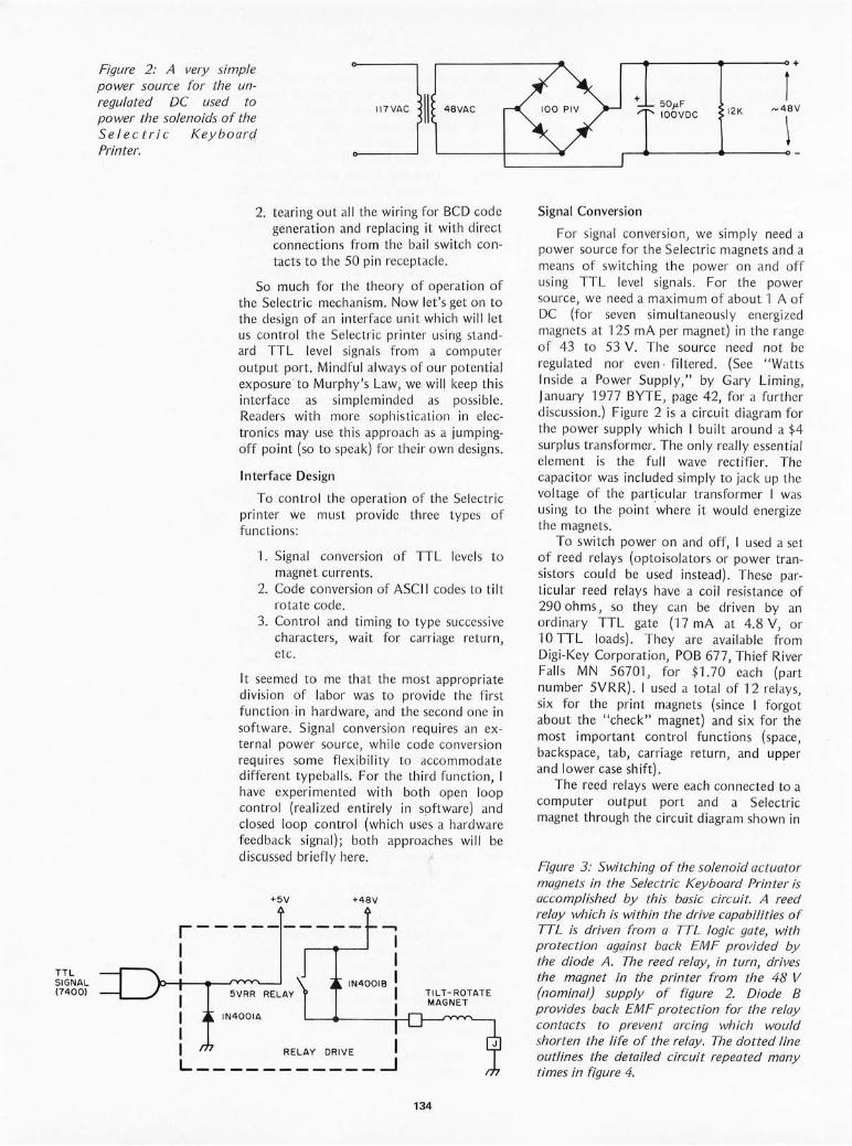
TTL SIGNAL (7400)
Figure 2: A very simple power source for the unregulated DC used to power the solenoids of the Selectric Keyboard Printer.
48VAC
2. tearing out all the wiring for BCD code generation and replacing it with direct connections from the bail switch contacts to the 50 pin receptacle.
So much for the theory of operation of the Selectric mechanism. Now let's get on to the design of an interface unit which will let us control the Selectl"ic printer using standard TTL level signals from a computer output port. Mindful always of our potential exposure to Murphy's Law, we will keep this interface as simpleminded as possible. Readers with more sophistication in electronics may use this approach as a jumpingoff point (so to speak) for their own designs.
Interface Design
To control the operation of the Selectric printer we must provide three types of functions:
1. Signal conversion of TTL levels to magnet currents.
2. Code conversion of ASCII codes to tilt rotate code.
3. Control and timing to type successive characters, wait for carriage return, etc.
It seemed to me that the most appropriate division of labor was to provide the first function in hardware, and the second one in software. Signal conversion requires an external power source, while code conversion requires some flexibility to accommodate different typeballs. For the third function I have experi mented with both open lo~p control (reali zed entirely in software) and closed loop control (which uses a hardware feedback signal); both approaches will be discussed briefly here.
+5V +48V
r---------- ....., I I
5VRR RELAY
IN400lA
IN400lB
I I I I RELAY DRIVE I L ___________ --1
TILT-ROTATE MAGNET
134
r--.--------~------~+
+
Signal Conversion
50)'F IOOVDC 12K
r ~48V
~
For signal conversion, we simply need a power source for the Selectric magnets and a means of switching the power on and off using TTL level signals . For the power source, we need a maximum of about 1 A of DC (for seven simultaneously energi zed magnets at 125 mA per magnet) in the range of 43 to 53 V. The source need not be regulated nor even· filtered. (See "Watts Inside a Power Supply," by Gary Liming, January 1977 BYTE, page 42, for a further discussion.) Figure 2 is a circuit diagram for the power supply which I built around a $4 surplus transformer. The only really essential element is the full wave rectifier. The capacitor was included simply to jack up the voltage of the particular transformer I was using to the point 'where it would energize the magnets.
To switch power on and off, I used a set of reed relays (optoisolators or power transistors could be used instead). These particular reed relays have a coil resistance of 290 ohms, so they can be driven by an ordinary TTL gate (17 mA at 4.8 V, or '\0 TTL loads). They are available from Digi-Key Corporation, POB 677, Thief River Falls MN 56701, for $1.70 each (part number 5VRR). I used a total of 12 relays six for the print magnets (since I forgo~ about the "check" magnet) and six for the most important control functions (space, backspace, tab, can'iage return, and upper and lower case shift).
The reed relays were each connected to a computer output port and a Selectric magnet through the circuit diagram shown in
Figure 3: Switching of the solenoid actuator magnets in the Selectric Keyboard Printer is accomplished by this basic circuit. A reed relay which is within the drive capabilities of TTL is driven from a TTL logic gate, with protection against back EMF provided by the diode A. The reed relay, in tum, dril1es the magnet in {he printer from the 48 V (nominal) supply of figure 2. Diode B provides back EMF protection for the relay contacts to prevent arcing which would shorten the life of the relay. The dotted line outlines the detailed circuit repeated many times in figure 4.

figure 3. Here the 1 N4001 diodes protect the TTL gate and the reed switch from voltage transients in the two coils. Since I needed a standard TTL buffer to provide enough current for each reed relay, and si nce I wanted to eco nom ize on my use of output ports, I used a seventh con trol line to switch between the six print magnets and the six control function magnets. The resulting circu it diagram is shown in figure 4. The lettered squares which terminate the reed switch contact lines refer to pin designations on the Selectric's 50 pin receptacle (see below). Photo 5 shows the physical layout of the compo nents of figure 4 in the interface which I built. Most of the wiring is Vector 51 it n' Wrapped on the other side of the sq uare piece of Vectorboard .
This construction layout is not reco mmended! Allow yourself much more room fo r repairing, repl ac ing or adding co mponents (like a seventh pair of reed relays !) . A length of scrapped telephone cable makes a good co nnection between the interface and the Selectric itself. Also shown in photo 5 is a 50 pin connector which plugs into the
Photo 5: Physical layout of the components of the in terface box which houses the circuit described in this article.
COMPUTER OUTPUT PORT
IC I
7 400
CONTROL DRIVERS
7400'S 6 7400'S PRINT DRI VE RS
TAB
SPACE
BACKSPACE
CARRIAGE RETURN
UPPER CAS E 10
9
13
12
*COPI E S OF THE RELA Y DRI V E CIR CUIT IN FIGURE 3
TI
T2
RI
R2A
Figure 4: Th e complete interface schematic. The 7400 NAND gate logic is used to select either the drivers for the miscellaneous control functions, or the drivers for the print commands. The basic drive circuit of figure 3 is repeated once for each magnet in the printer.
135

Pin Function
A +-- T2 B +-- Check C +-- T1 D +-- R2A E +-- R1 F +-- R2 H +-- R5 J +-- Magnet Common K +-- Keyboard Lock L +-- Tab M +-- Space N +-- Backspace P +-- Carriage Return R +-- Index S +-- Upper Case Sh ift T +-- Lower Case Shift U +-- Red Ribbon Shift V +-- Black Ribbon Shift W --+ C1 N/C X --+ Contact Common a --+ Feedback N/C b --+ Feedback N/O e --+ End of Line N/C f --+ End of Line N/O n --+ C1 N/O r,s,t,u,V,w --+ BCD Bit Lines
Figure 5: The Selectric Keyboard Printer receptacle pin identifications. This receptacle can be purchased as a spare part through an IBM office, The arrows in this table indicate direction of the signal: A left arrow indicates drive to the printer (typically a magnet) from a source in the interface,' a right arrow indicates a sensor contact in the printer.
OFFSET (ASCII CHARACTER)
TABLE BASE POINTER
7F
7E
70
2
receptacle at the back of the Selectric, which I obta ined from iny local I BM branch office for $20 (IBM part number 1167l34). The more important pin designations on th is connector are shown in figure 5.
TILT-ROTATE CODE
I NTER FACE TO SELECTRIC
Figure 6: Table structure for the conversion of ASCII to Selectric coding, The table base pointer identifies the start of the table. There should be one table for each different ball coding scheme employed. The ASCII character value is added to the base address giving an address in the table. A t this address is found the code which is sent to the output port. The logic of sending the code to the output port is given in detail by figure 8.
136
Code Conversion
Assuming that the ASCII code is used for characters inside the computer, the process of code conversion is basically just a simple table lookup: The 7 bit ASCII code is used as an index into a 128 byte table to obtain the 6 bit tilt rotate code. Since the tilt rotate code for a given character may vary depending on the typeball that is used, it should be possible to switch between several -128 byte tables. This is easily done by indexing from a pointer to the base of the table as shown in figure 6.
The main complication in code conversion is the handling of upper and lower case. At any given time the Selectric Keyboard Printer is locked into one case or the other. If the machine is locked in upper case and the next character to be printed is an upper case A, we need only send out the appropriate tilt rotate code. But if the next character is a lower case a, we must energize the lower case shift magnet, wait for the machine to sh ift into lower case, and then send out the tilt rotate code_ This is easi ly accomp li shed by using a seventh bit in the table entry byte for each ASC II character to indicate whether it is to be printed in upper or in lower case.

HEXADECIMAL TABLE OFFSET
41_
76543 2 I 0
IULC I TI 1 T21 RI 1 R2 1R2AI R51 CL I UPPER/ '-TILT-ROTATE CODE----' CON-LOWER FROM FIGURE I TROL CASE LINE
ASCII "A"
61- I I I I I 0 I o I 0 I I I
I I
I
ASCII "0"
00- 10 I 0 1 0 I 0 I I 0 0 o I
ASCII "CR"
09- 10 1 I I 0 I 0 I 0 I 0 0 0 1
ASC II "HT"
The last problem in code conversio n is the handling of control fu nctions such as carriage return, tab, backspace, etc. Fortunately, the ASCI I character set assigns unique 7 bit codes for functions such as these. For example, the ASCII carriage return character (hexadeci mal code OD) can be used for carriage return, and the ASCII horizontal tab (hexadecimal code 09) can be used for the tab func tion. Since in my interface a special control line determines whether the six output ports affect the print magnets or the contro l function magnets, I can use the eighth bit in each table entry byte to set the contro l line appropriate ly. The tab le entr ies for the printab le characters have this bit set to 1, with six bits providing the tilt rotate code; the entri es for the contro l chal-acters have this bit set to 0, with the bit corresponding to the given control function magnet set to 1 and the other five bits set to O. This encod ing is illustrated in fig ure 7.
Once we have this encoding of the information needed for code co nversion, the actual program logic to accomp li sh the conversion is straightforward. A f lowchart of the logic is presented in figure 8, and an
Figure 8: A flowchart giving the logic of a simple open loop driver program which tal?es a given ASCII character, looks up its table entry, and then takes appropriate prin ter actions. As an open loop program, each time delay in this chart (the f':,Ts) is picked to reflect the worst case response time for the action involved. This makes the Selectric type successfully, but does not optimize operation for the maximum speed, since as everyone Imows, the worst case is often not identical with the typical value of a parameter.
Figure 7: The coding scheme for each conversion table entry is given by the general box at the top of this diagram. Bit 7 tells the software whether the mechanism should be in the upper or lower case mode. (The need to shift explicitly in a Selectric is reminiscent of the shift requirements of Baudot Teletypes.) The tilt rotate code contained in bits 6 thm 2 is derived from figure 7 for each character in the table. (For other ball arrangements, a version of figure 7 would need to be generated.) The low order bit of the word is used to indicate to the logic of figure 4 whether a control command (0) or print command (7) is being sent.
SEND CONTROL CODE
WAIT liT SUF FI CIENT TO COMPLETE OPERATION
137
YES
YES
LOOK UP ASCII CHARACTE R IN TABLE
IS IT A CONTROL CHARACTER
?
NO
IS MACHINE
IN UPPER CASE ?
NO
SEND CON TR OL CODE FOR UP SHIFT
WA IT liT SU FFI CIENT TO COMPLET E SHIFT
SEND TILT ROTATE CODE
WAIT li T SUFFIC IENT TO COMPLETE PRINTING
SINGLE CHARACTER PRINT ROUTINE
IS
L OWER MACHINE YES IN LOWER CASE
CASE ?
NO
SEND CONTR OL CODE FOR DOWN SHIFT
WAI T liT SU FFI CIENT TO COMPLETE SHIFT
...-------------., I NOTE : SEND ING A NONZERO I I 7 BIT PATTERN TO THE INTER- I I FACE PORT WILL ENERGIZE ONE I I OR MORE SO LEN OID S, INITIATING: I A MECHANICAL OPERATION. I LS-=-E~I GU~~2N'::"~ ___ ..J

CHARACTER OUTPUT ROUTINE FOR SELECTRIC KEYBOARD PRINTER
OUTCH TAY ASCII cha racte r to index register LOA (TABPT), Y get code byte from table LSR A BCC CTL ROL A BMI LOWER LOX #4 LOY CASE BEQ OK IN C CASE JMP SH IFT
LOWER LOX # 2 LOY CASE BNE OK DEC CASE
SHIFT STX PORT JSR ENERG LOY #60 JSR WAIT
OK STA PORT JSR ENERG LOY # 50 JSR WAIT RTS
CTL ROL A STA PORT JSR ENERG LOY # 120 JSR WAIT RTS
ENERG LOY # 10 JSR WA IT LOY # 0 STY PORT RTS
WAIT LO X # 200 LOOP OE X
BNE LOOP DEY BNE WAIT RTS
Listing J: 6502 assembly language source code of a program which implements the logic of the flowchart in figure 8. This program is a subroutine which will drive the Selectric Keyboard In terface in an open loop mode and is run on a KIM-J system.
test low order bit o means cont rol character test high order bit 1 means lower case character code for upper case shift check current case o means upper case indicate shift to upper case go initi ate sh ift operation code for lower case shift check current case - 1 m ea ns lower case indicate shift to lower case send shift code to port for 10 milliseconds delay for 60 milli seconds until shift operation is done send ti lt rotate to port for 10 milliseconds delay for 50 milliseconds until pri nt operation is done return to ca lling program restore control code send to output port for 10 m ill iseconds delay for 120 milliseconds until control operation is done return to ca lling program set up for 10 millisecond delay loop for that long send Os to output port to turn off magnet current return to ca ll er number times thru inner loop decrement inner loop count loop until count is 0 decrement outer loop count loop until count is 0 return to ca ll er
equ ivalent asse mbl y language program for the MOS Technology 6502 used in my system is shown in li st in g 'I. In this sim ple version of the program, delay loops are used for timing purposes, and sufficient t ime is all owed ei ther to print a character or to complete the worst case control functio n (carriage return ac ross the entire length of the page). Of course, this version of the program wi ll operate the Selectric at far less than its maximum rated speed, and will monopo lize the processor's time whi le waiting for comp letion of each operation. In order to improve on this, we turn next to the subject of contro l and timing.
Contro l and Timing
Now that we have a worki ng Selectric interface, we can turn our attention to two major improvements: driving the Selectric at maximum rated speed, and minimizing use of the processor's time for Selectric contro l.
To drive the Selectr ic at fu ll speed we can adopt an approach of "open loop" contro l or "closed loop" control. Open loop contro l
138
involves keeping track of the carr iage posi tion, margin, tab stops and similar information in software (changing the margin and tab stop information via software interpreted commands), and calculating the delay time necessary for each operation. Closed loop contro l involves testing the Keyboard Printer's switch contacts to determine when each operation has been completed . The worst case delay approach used in the program of li sti ng 1 is a simplified version of open loop contro l. For full speed operation, the closed loop approach is much simpl er and more reliable; so let 's consider it here.
Nearly every mechanical operation opens or closes some set of switch contacts inside the Se lectric. Sets of contacts are wired to the 50 pin receptacle in a variety of ways to reflect operations such as printing, tabbing, backspacing, etc. We will not cons ider all the possible methods of ach ieving feedback control using these contacts, but wi ll outline one particularly simple approach , which rema ins to be tested in my own system. The pin labe led a on the receptacle is wired through a set of normally closed contacts, and the pin b through corresponding normall y open contacts, assoc iated with the set of common contacts co nnected to pin X. Figure 9 shows how these contacts may be debounced to yield a clean TTL level signal (ignoring the nominal voltage ratings for the contacts). Here we use the last half of the 7400 package left over from figure 4. During any printing or contro l function operation, pin a wi ll go from ground to +5 V and back to gro und again, while pin b does the reverse. Hence the feedback line will go from logic 1 to 0 to 1. By sensing this change in software through a loop testing the feedback input port after energizing the magnets, we can close ly control the operation. When the line goes to logic 0, we can tu rn off cu rrent to the magnets, and when it returns to logic 1, we are ready to start the next operation .
The seco nd problem we face in contro l and timing is how to minimize li se of the processor's time for Selectric control. Here, of course, is where the interrupt system comes into play. If we are using the circuit outlined in figure 9 for closed loop co ntro l, we can tie the feedback line to a processor interrupt rather than to a data input port. If we are re lying instead on open loop contro l, we can use a programmable interval timer which is capable of causing an interrupt as an alternative to delay loops. The software to handl e interrupts fro m the Selectric is slightl y comp li cated by the need to shift between upper and lower case prior to typing the next character, but this can be handl ed by ini tiat ing the shift operatio n and
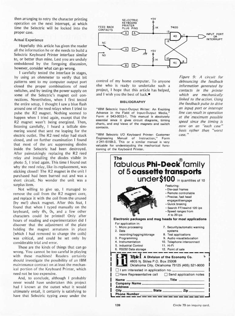
then arranging to retry the character printing operation on the next interrupt, at which time the Selectric will be locked into the proper case.
Actual Experience
Hopefully th is article has given the reader all the informatio n he or she needs to build a Selectric Keyboard Printer interface similar to, or better than mine. Lest you are unduly emboldened by the foregoing discu ss ion, however, consider what can go wrong.
I carefully tested the interface in stages, by using an ohmmeter to verify that bit patterns sent to my co mputer output port closed the proper combinations of reed switches, and by testing the power supply on some of the Selectric's magnet coil connections. Nevertheless, when I first tested the entire setup, I thought I saw a blue flash around one of the reed relays when I tried to pulse the R2 magnet. Noth ing seemed to happen when I tried aga in , except that the R2 magnet wasn 't being energized. Then, li stening carefull y, I heard a telltale simmering sound that sent me leap ing for the electr ic out let. The R2 reed relay had stuck closed, and on further examination I found that most of the arc suppressing diodes inside the Selectric had been destroyed. After painstak ingly repl aci ng the R2 reed relay and installing the diodes visible in photo 5, I tried aga in . This t ime I found out why the reed re lay, like its replacement, was sticking closed! The R2 magnet in the unit I purchased had been burned out and was a short circuit. No wonder the unit was a surplus item.
Not wi lling to give up, I managed to remove the co il from the R2 magnet core, and replace ·it with the coil from the unu sed (by me!) check magnet. After this feat, I fo und that when I typed man uall y on the keyboard, onl y @s, Os, and a few other characters cou ld be printed! Only after hours of reading and exper imentation did I discover that the adju stment of the plate holding the magnet arm atures in place (which I had re moved to change the co il s) was critical, and could be set on ly by considerab le trial and error.
Th ese are the kinds of things that can go wrong. You cannot be too carefu l in playing with these machines! Readers ce rta inl y should investigate the possibility of an IBM main tenance co ntract on at least the mechanica l port ion of the Keyboard Printer, which need not be too expensive.
And, to conclude, although I probably never wo uld have undertaken this project had I known at the outset what it would ultimately entai l, it certainly is satisfyi ng to have that Selectric typing away under the
SELECTRIC KEYBOARD PRINTER
FEED BACK PLUG PINS
~A
+5V
IK 7400
+5V ~~ L ,>-_~~I_K_~L~
INPUT PORT OR
INTERRUPT
control of my home computer. To anyo ne else who is ready to undertake such a project, I hope that this article has helped, and I wish you the best of ruck.-
BIBLIOGRAPHY
"IBM Selectric Input-Output Wri ter: An Exciting Advance in the Field . of Input-Output Media," Form # 543-0033-1. This manual is absolutely essential since it gives circuit diagrams, timing charts, and en9 'views of the magnets · and switch contacts.
·" IBM Selectric I/O Keyboard Printer: Customer Engineering Manual of Instruction, " Form # 241 -5159-3. This or a si milar manual is very valuable for understandi ng the mech anical functioni~g of the Keyboard Printer .
Figure 9: A circuit for debouncing the feedback information generated by contacts in the printer which are mechanically linked to tbe action: Using the feedback pulse to drive an input port or interrupt line can result in operation at the ·maximum possible speed since the timing is now on an "each case " basis rather than "worst case. "
The ® fabulous Phi-Deck family
of 5 cQssette transports . und.er$100 in quantities of 10
Featuring: • Die-cast frames • Remote controllable • Precise, fast head
engage/disengage • Quick braking • Search FF/rewind 120 ips • Speed ranges from
.4 to 20 ips
Electronic packages and mag heads for most applications For application in : 1. Micro processing 7. Security/automatic warning 2. Data systems
recording/logging/storage 8 . Test appli cations 3. Programming 9. AL!dio visual/education 4. Instrumentation 10. Telephone interconnect 5. Industrial Control 11 . Hi-Fi 6. RS232 Data storage 12. Point of sale lEI·mp.l:-;:,::. o;;;;~:.:.;;,::-- - b I 4605 "/ . Stiles P.O . Box 25308
. Oklahoma City, Oklahoma 73125 (405) 521-9000 o I am interested in application no. _______ _
o Have Representative call 0 Send application notes
Name Title _____ _ Company Name ______________ _
Ad9ress _____ ~---------~--City State Zip ___ _
L~~~~~ ____________ ~
139 Circle 79 on inquiry card.

A 6800 Selectric 10 Printer Program
Listing 1: The listing of the Selectric printer interface routine for a 6800 system driving the 10 version of the standard office typewriter. This listing is extracted from two assemblies done using the South west Technical Products Corporation's version of the M6800 self assembler. The first part of the listing is the actual code, and the second part is a table of Selectric correspondence codes which is referenced using ASCII codes as an index into the table which is computed at CONV1.
SWTPC ~-6800 ASSENBLER ENTER PASS : 1P,lS,2P,2L,2T
NAM SELECTRIC 00001
00002
00003
0000 11
00005
00006 0100
'SELEC TRIC DRIVER PROGRA~I FO R SI/TPC 6800 ASSEI·:BLE:r.
OPT S
00007 0100 7E 17cD
00008 0212
OPT on aRC
JMP
ORO
00009 0212 BD 17 F4 JSR
00010 08F7 ORO
00011 081"7 18FF FDB
00012 093D ORO
00013 093D 1900 FDB 0001. 13D6 ORO
00015 13D6 1900 FOB
00016 17CO ORO
00017 17CO c6 FF S1'AR1' LOA B
00018 17CF F7 8000 STA B
00019 17D2 7F 8002 CLR
00020 17D5 c6 O. LDA B
00021 17D7 F7 8001 STA B 00022 170A F7 8003 STA B
00023 17DD c6 81 LOA B
a L
$0100
STAR1'
$0212
S1'ARTl CALL OUTPt:1'(HEW)
$08F7
$18FF MAKE ROOM FOR PATCH
$093D
$1900
$13D6
$1900
$17CD
#$1"1" INn-IALIZE PIA
PIAOUT
PIACHK
Hi04
PI AOUT+l
PIACHK+l
#$81 START ALI/AYS IN LOWEll CA~;r:
00024 17DF F7 8000
00025 17E2 F7 18cA
00026 17E5 FE 181A
S1'A B PIAOUT
S1'. B CASE
LDX COUNTl SETUP TINER FOR SHIFT CYCLE
00027 17E8 PI" 18CB
00028 17E5 so 18c3
STX
JSR
00029 17EE 7F 8000 CLR
00030 17F1 7E 0300 JMP
00031 17F4 84 71" START1 AND A
00032 17F6 FF 18cD STX
00033 171"9 81 10 CMP A
00034 17FB 26 02 BNE
00035 17FD 20 04 BRA
00036 17FF 81 00 CR CMP
COUNTR
TIMER
PIAOUT
$300 001'0 MAIN PRO~I
# $ 7 F RESE1' PARITY
SAVEX SAVE XREO FOR HAIN PROM
1$10 TRAP HmiE-UP
CR
CR1 PRIHT IT AS CR,Ll"
i$OD TRAP CR
00037 1801 26 OB BNE SP
00038 1803 86 8. CR1 LDA A 1'$84
00039 1805 FE 181C
00040 1808 FF 18CB
00041 180B 7E 18BA
00042 180E 81 20 SP
LOX COUNT2 sm'uP TIMER ,'OR 'CR,LF
STX COUNTR
JMP EXl
CMP A #$20 TRAP SPACE
00043 1810 26 05 BNE
00044 1812 86 88 LDA A
00045 1814 7E 18B4 JMP
00046 1817 7E 1880 CONVO J~IP
00047 18 1A 2000
00048 181C 1000
00049 181E 0400
00050 1880
COUNT1 FDB
COUNT2 FOB
COUNT3 FOB
ORO
CONYO
1$88
EX2
CONYRT
$2000
$1000
$0400
$1880
00 PRINT BUT DO NOT RESE~ M~B
0005 1 1880 81 20 CONVRT CMP A #$20 IS IT A PRINTINO CHARACTI:lI?
00052 1882 22 02 BHI CONV1 YES
00053 1884 20 39 BRA EXIT NO
00054 1886 87 1800 CONYl STA A TABLEP+1 CONVERT CODE
140

The following letter and listing J were received from an Italian reader of BYTE, Fulvio Guzzon of Rome. Fulvio purchased the same print mechanism (IBM Model 735 10 type writer) which is de~cribed by Dan Fylstra in his article in this issue. We're treating Fulvio 5" letter as a short article, since its technical content is far above that of the usual letter. The listings photographically reproduced here were typed on pin feed paper using his printer mechanism. The text of his letter was submitted using a text editor with the Selectric 10 m.echanism as its output.
I understand there is some in terest among your readers in using a Selec tric typewl'iter fO!' hard co py. As you can see I have funneled an ed itor program (SWTPC) and an asse mbl er program (SWTPC, too) through a Selec tric typewl- iter. [The original of this note was typed on the Selectric. } I bought the machine on the surplu s market in Boston and it had some problems: I t was stuck in upper case by a bolt screwed on the righ t side of the frame, it had some unrecoverable backlash in the head ro tate mechanism, and many feedback and interlock contacts were mi ss ing or badly damaged. I had the machine serviced here in Rom e (Italy) and at las t, with a new carriage, a new motor (h ere we have 220 V 50 Hz power), and a new set of sh ift magne ts, the printer was ready . I decided to use it on ly as a printer in order to reduce the hardware and software effo rt to a minimum.
On the underside of the machine th ere are seven printing magnets . In tabl e -I I have paired them with the bits from 0 to 6. Seven transistors provide for the interface between the PIA and the printe r.
Th ere are seven more mag nets for the machine commands: space, backspace, tab, carriage return , index (line feed), upper case, and lower case; so seven more transi sto rs are required. Seven output lines from the PIA in slot 0 are sw itched between the two se ts of mag nets by digital logic. Th e various feedback and inter lock contacts were wired in series and filtered for bounce by a co ndenser and a software loop. Th e co nversion tabl e shown in the assemb ly li st ing provides for the characte rs used on the so call ed "Correspondence" balls. As I later found out, there are minor variations between the ball s of th is ser ies.
The MSB in the table is set when the character to be printed is on the upper case half of the ba ll. (The upper or lower case of ASC II code bears no re lation to the upper or lower sid e of Selectric go lf ball s). The MSB of th e output byte to the printer
Listing J, continued:
00055 1889 F'E 1 8cF LOX TABLEP
00056 1 88c A6 00 LOA A o , x
00057 1 88E 26 02 BNE CASECK I q IT AVAILABLE SOflEWHERC 011
00058 " ~'HE BALL?
00059 1 890 20 20 BRA EXIT NO,RETURN
00060 18 92 2A 04 CASECK BPL CASELW MSB CLEAR?
00061 189 4 c6 CO LOA ~ lico liO ,CHECK I F PRI)lTEP. IS I II UC
00062 1 896 20 02 BRA SKIP
00063 1 898 C6 81 CASELW LOA B 1$81 YES.CHECK IF' PRINTER IS III LC
00064 1 89A Fl 1 8cA SKIP CMP B CASE NEW CHAR. SAllE IjALFBALL
00065 " AS THE PREVIOUS ONE?
00066 1890 27 1 3 BEQ PRIN1'1 YES GO AND PRINT no
00067 1 89F F7 8000 STA B PIAOUT NO, ROTATE BALL 180 DEGRCES
00068 1 8A2 F7 1 8cA STA B
00069 18A5 FE lSlA LOX
00070 1 8A8 FF 1 8cB STX
000 71 18AB 80 ),6 BSH
00072 18AD 7F 8000 CLR
00073 1 8BO 80 11 BSR
00074 18B2 8~ 7F PR INTI AND A
00 075 18B4 FE 1 81E EX2 LOX
00 07 6 18B7 FF 18cB STX
00077 18BA B7 8000 EX1 STA A
00078 18BD 80 12 BSR
00079 18BF ,-E 1 8CD EXIT LOX
00080 18c 2 39 RTS
00081 18c3 FE 18cB TI MER LOX
00082 18c6 09 LOOP DEX
00083 18C7 26 FD BNE
00084 18C9 39 RTS
00085 8000
00086 8002
00087 1 8C A 00
00088 18cB 0000
00089 18co 0000
00090 18CF 1800
0009 1 1801 80 FO
00092 1803 c6 01
00093 1805 F5 8002
00094 1808 27 F7
00095 1 80A 71' 8000
PIAOUT EQU
PIACHK EQU
CASE FCB
COUNTR FOB
SAVEX FOB
TABLEP FOB
WAITI BSP.
LOA B
BIT B
BEQ
CLR
00096 1800 80 E4 WAIT2 BSR
00097 18DF F5 8002 BIT B
00098 18E2 26 F'9 BNE
00099 1 8E4 39 RTS
00100 18E8 ORG
00 1 0 1 "TO NEXT PAGE
CASE
COUNTI
COUNTR
THIER
PIAOUT
TIMER
#$7F
COUNT3
COUNTR
PIAOUT
WAITI
SAVEX
COUNTR
LOOP
$8000
$8002
$1800
1'IMER
#l
PIACHK
WAITI
PIAOUT
THIER
PIACHK
WAU'2
$18E8
0010 2 18E8 Cl
00103 18E9 20
FCB $Cl
18EA 20 1 8EB 20
1 8EC 20 18ED 20
00104 18EE FFFF
00105 18FO C2
00106 18Fl 20
18F2 20
18F3 20
1 8F~ 20
1 8F5 20
00107 18F6 FFF.!'
141
FCC 5.
FOB $FFFF
FCB $C2
FC C 5.
FOB $FFFF
AND RECO RD IT
SICT!;P TUlER FOR SH I FT CYCLE
RESET CASE BIT AND
SE1'UP TH IER FOR PRINT CYCLE
NOW PRINT
RES1'ORE X REG
GO AND FEr'CH NEXT CHARACTLR
SE~UP HASK
PRIN1' CYCLE S1'ARTED?
NO
YES ON 1:'I"' S WAY
READY FOR A NEW ONE?
NO
YESI
SHIFT START OF SYMBOL TAlJLE
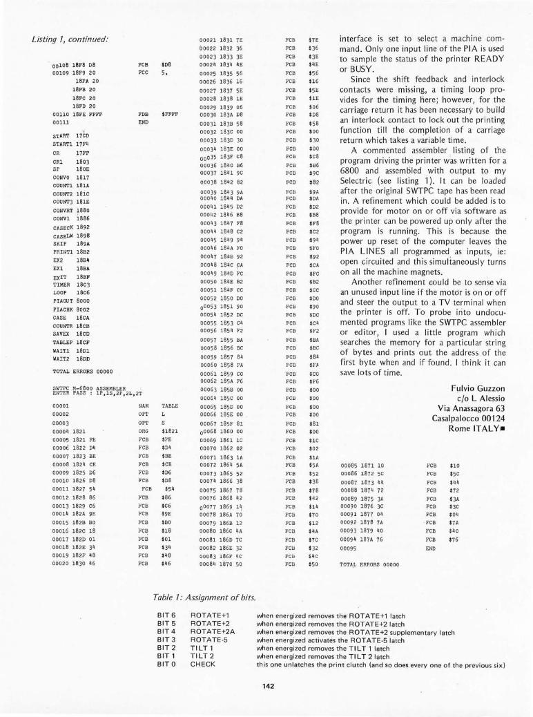
Listing 7, continued:
, 0010S lSFS os
00109 lSF9 20
lSFA 20
lSFB 20
18FC 20
18FO 20
00110 18FE FFFF
00111
START 17(;0
STARTl 17Fq
CR 17FF
CRl 1803 SP 180E
CONYO 1817
COUNTl 181A
CO UNT2 181C
COU NT3 181E
CONVRT 1880
CONYl i886
CASECK 1892
CASELW 1898
SK IP 189A
PRINTl 1 8B2
EX2 18Bq
EX l 18BA
EXIT 18BF TIMER 18c3
LOOP 18c6
PIAOUT 8000
PIACHK 8002
CASE 18c A
COUNTR 18cB
SAVEX 18cD
TABLEP 18CF
WAITl 18Dl
WAIT2 180D
TOTAL ERRORS 00000
FCB
FC C
FDB
END
$08
5,
$FFFF
SWTPC M-6800 ASSEMBLER ENTER PASS : IP ,lS , 2P , 2L, 2T
0000 1
00002
00003
ooooq 1821
00005 1821 FE
00006 1822 D4
00007 1823 BE
00008 1824 CE
00009 lS 25 06
000 10 1826 08
00011 1827 54
00012 1828 86
0001 3 1829 c6
000 14 182A 9E
000 15 182B BO
000 16 182C 1 8
00017 1 82D 01
00018 182E 34
000 1 9 182F 48
00020 1830 46
NAN
OPT
OP~'
ORa
,'CB
FCB
TABLE
L
S
$1821
$,'E
$04
FCB $BE
FCB iCE
FCB $06
FCB $08
FCB $54
FCB $86
FCB $C6
FCB $9E
FCB $BO
FCB $18
FCB $0 1
FCB $34 FCB
FCB
0002 1 1831 7E
00022 1832 36
00023 1833 3E 00024 1834 4E
0002 5 1835 56
00026 1836 16
00027 1837 5E
00028 1838 lE
00029 18 39 06 00030 183A 08
00031 1 83B 58
000 32 183C 00
00033 1830 30
00034 183E 00
00035 183F CS
000 36 1840 B6 00037 1841 9C
00038 184 2 82
00039 1843 9A 000 1/0 1844 OA
000q 1 lSq 5 02
00042 18q6 B8
00043 1847 F8
00044 1848 C2
00045 1 849 94
00046 184A FO
00047 184B 92
00048 184C CA , 00049 1840 ,'C
000 50 1 84E B2
00051 1 84F CC
00052 1850 00
00053 1851 90
0005'/ l S52 OC
00055 l S53 C4 00056 lS 54 F2
00057 l S55 BA
00058 1856 BC
00059 1857 84
00060 1858 FA
00061 1859 CO 00062 185A F6
00063 185B 00
00064 185c 00
000 65 1850 00 00066 185E 00
00067 185F 81
00068 1860 00
00069 186 1 l C
00070 1862 02
00071 1863 lA 00072 1 86q 5A
00073 1865 52 00074 1866 38
00075 1867 78 00076 1868 42
00077 1869 1 ~
0007S 186A 70
0007 9 186B 12
00080 l S6C 4A
OOOSl lS 60 7C
00082 1 86E 32
00083 186F 4C
0008 11 1870 50
Table 7: Assignment of bits.
BIT6 BIT 5 BIT4 BIT 3 BIT 2 BIT 1 BITO
ROTATE+l ROTATE+2 ROTATE+2A ROTATE·5 TILT 1 TILT2 CHECK
FCE $7E
FCB $36
FCB $3E ,'CB $4 E
FCIl $56
FCB $16
FCB $5E
FCB $1E
FCB $06 FCB $08
FCB $58
FCB $0 0
FCB $30
FCB $00
FCB $CS
FCB $B6
FCB $9C
FCB $ 82
FCIl $9A FCB $OA
FCB $02
FCB $B8
FCB $FS
FCB $C 2
FCB $94
,'CB $FO
FCB $92
FCB $CA
FC B $FC
FCB $B2
FCB iCC
FCB $00
FCB $90
FCIl $OC
F'CB $C4
FCB $F2
F'CB $BA
FCB $BC
I,'CB $84
FCB $Fft
' FCB $CO
FCB $F6
FCB
FCB
FCB FCB
FCB
FCB
FCB
FCB
FCB FCB
FCB
FCB
Fcll
FCB
FCB
FCB
FCB
FCB
FCB
FCB
FC B
FCB
$00
$00
$00
$00
$81
$00
$ l C
$02
$lA $5A
$52 $38
$78 $42
$14
$70
$12
$4A
$7C
$32
$4C
$50
interface is set to select a machine command. Only one input line of the PIA is used to sample the status of the printer READY or BUSY.
Since the shift feedback and interlock contacts were missing, a timing loop provides for the timing here; however, for the carriage return it has been necessary to bu ild an interlock contact to lock out the printing function till the completion of a carriage return which takes a vari able time.
A commented assembler , listing of the program driving th e printer was written for a 6800 and assembled with output to my Selectric (see listing i). I t can be loaded after the original SWTPC tape has been read in. A refinement which could be added is to prov ide for motor on or off via software as the printer can be powered up only after the program is running. Th is is because the power up reset of the computer leaves the PIA LINES all programmed as inp,uts, ie: open circuited and this simultaneously turns on all the mach ine magnets .
Another refinement £Quid be to sense via an unused input line if the motor is o n or off and steer the output to a TV terminal when the printer is off, To probe into undocu mented programs like the SWTPC assembler or editor, I used a little program which searches the memory for a particul ar string of bytes and prints out the address of the first byte wh en and if found. I think it can save lots of time.
00085 1 871 10
00086 1 872 5C
00087 1873 q4
00088 1874 72
00089 1 875 3A 00090 1876 3C
0009 1 1 877 04
00092 1878 7A
00093 1 879 40
00094 1 S7A 76
00095
TOTAL ERRORS 00000
Fulvio Guzzon c/o L Alessio
Via Anassagora 63 Casalpalocco 00124
Rome ITAL YI-
FCB
FCB
FCB
FCB
FCB FCB
FCB
' FCB
FCB
FCB
ENO
$10
$5C
$44
$72
$ 3A
$3C
$04
$7A
$40
$76 '
when energized removes the ROT ATE+l latch when energi zed removes the ROTATE+2 latch when energized remOlles the ROTATE+2 supplementary latch when energized activates the ROT A TE-5 'latch when energized removes the TI L T 1 latch when energized removes the TI L T 2 latch this one unlatches the print clutch (and so does everyone of the previous six )
142
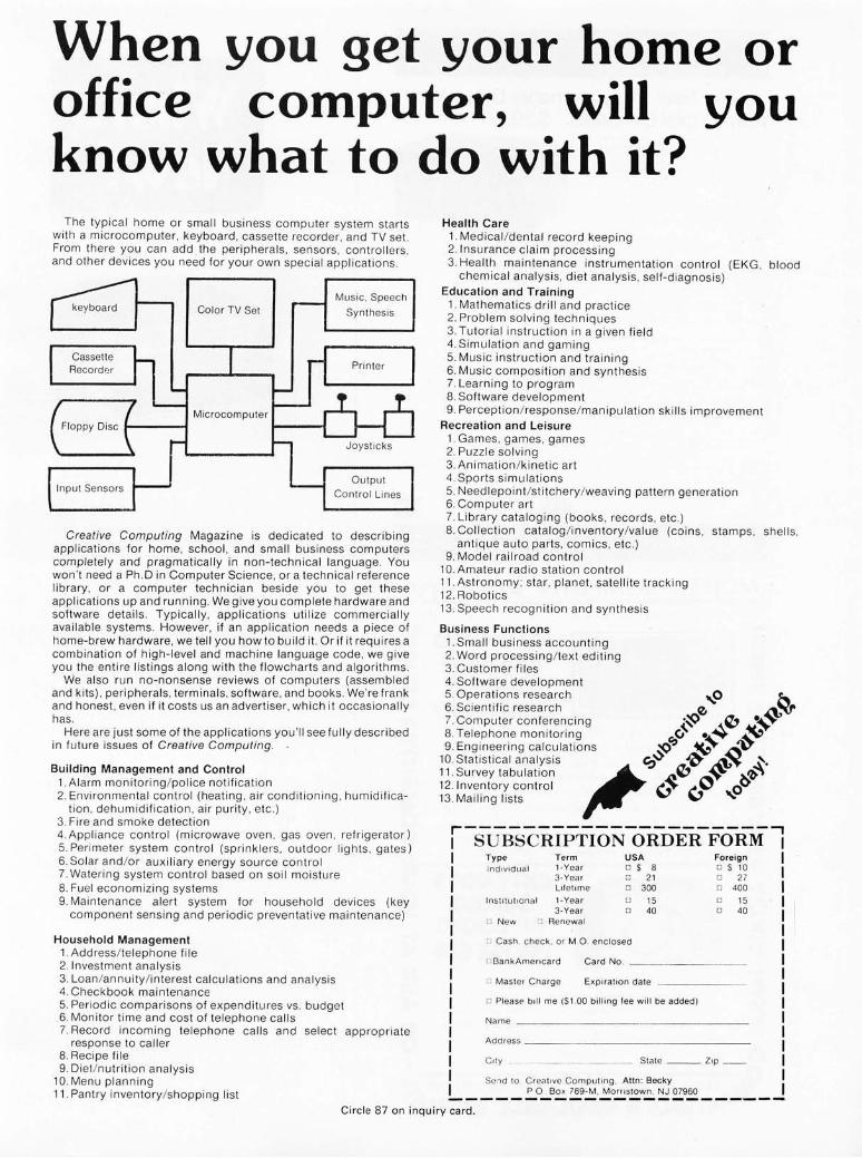
When you get your home or office computer, will you know what to do with it?
The typical home or small business computer system starts with a microcomputer, keyboard, cassette recorder . and TV set. From there you can add the peripherals. sensors. controllers. and other devices you need for your own special applications.
Color TV Set
Microcomputer
Input Sensors
I--~
Music. Speech
Synthesis
Output
Control Li nes
Creative Computing Magazine is dedicated to describing applications for home, school, and small business computers completely and pragmatically in non-technical language. You won't need a Ph .D in Computer Science, or a technical reference library, or a computer technician beside you to get these applications up and running. We give you complete hardware and software details. Typically , applications utilize commercially available systems. However, if an application needs a piece of home-brew hardware, we tell you how to build it. Or if it requires a combination of high-level and machine language code , we give you the entire listings along with the flowcharts and algorithms.
We also run no-nonsense reviews of computers (assembled and kits), peripherals, term inals , software, and books . We're frank and honest , even if it costs us an advert iser, which it occasionally has.
Here are just some of the applications you 'll see fully described in future issues of Creative Computing.
Building Management and Control 1. Alarm monitoring/police notification 2. Environmental contro l (heating, air conditioning. humidifi ca-
tion, dehumidification, air purity , etc.) 3. Fire and smoke detection 4. Appliance control (microwave oven, gas oven. refrigerator) 5. Perimeter system control (sprinklers , outdoor lights , gates) 6. Solar and/ or auxiliary energy source control 7. Water in g system contro l based on soil moisture 8. Fuel economizing systems 9. Maintenance alert system for household devices (key
component sensing and periodic preventative maintenance)
Household Management 1. Address / telephone file 2.lnvestment analysis 3. Loan/ annuity/ interest calcu lati ons and analysis 4. Checkbook maintenance 5. Periodic comparisons of expenditures vs. budget 6. Monitor time and cost of telephone calls 7. Record incoming telephone ca ll s and select appropriate
response to caller 8. Recipe file 9. Diet/nutrition analysis
10. Menu planning 11 . Pantry inventory/shopping li st
Health Care 1. Medical / dental record keeping 2. Insurance c laim processing 3. Health maintenance instrumentation control (EKG . blood
chemica l ana lys is, diet analysis , se lf-d iagnosis) Education and Training
1. Mathematics drill and practice 2. Problem solving techniques 3. Tutoria l instruction in a given field 4. Simu lation and gaming 5. Music instruction and training 6. Music composition and synthesis 7. Learning to program 8. Software deve lopment 9. Perception / response / manipulation ski ll s improvement
Recreation and Leisure 1. Games , games, games 2. Puzzle solving 3. Animation / kinetic art 4. Sports simu lations 5. Needlepoin t/s titchery /weaving pattern generation 6. Computer art 7. Library cataloging (books, records , etc .) 8. Collection cata log / inventory/ value (coins. stamps. shell s.
antique auto parts. comics, etc.) 9. Model railroad control
10.Amateur radio station contro l 11 . Astronomy; star, planet, satellite tracking 12. Robotics 13. Speech recognition and synthesis
Business Functions 1. Small business accounting 2. Word processing / text edit ing 3. Customer files 4. Software development 5. Operations research ,. ..... 0 ~ 6. Scientific research '" ~":r(r 7. Computer conferencing ;,.:$> ..... 'b ~~~~ 8. Telephone monitoring ~CJ ~~ _ ...... ,.,., 9. Engineering ca lculations § ~ ~t.T
10. Statistical analysis ,~ i'f~ ~~ ~~. 11. Survey tabulation J:.'V ~. ~'>' 12. lnventory contro l \,) ... ,...~ ..... 0 13. Mailing li sts V
.---------------------. SUBSCRIPTION ORDER FORM Type Term USA IndlvlduCtI 1-Year o $ 8
3-Yea r 0 21 Lifetime 0 300
In s titutional 1-Year 0 15 3-Year 0 40
o New ~ Renewal
:J Cash . c heck, or M O . enclosed
Foreign o SlO o 27 o 400
o 15 o 40
OBankAmencard Card No. _~~~~~~~_
o Master Cha rg e EXpiration date ~~~~~~_
o Please bill me ($1 .00 billing fee will be added)
Name _~~~~~~~~ __ ~~~~~~_
Address _~~~ __ ~~_~~_~~~~_
Siale ~ __ Z,p __
Se:ld to Creat ive Comput ing. Attn: Becky POBox 789-M. MomslOwn. NJ 07960
Circle 87 on inquiry card.

"E III U
~ :l cr C
c o
M (!) N
'" ~ U
"E '" U
~ :l cr C
C o
The New Programmable Clock Kit from Digital Concepts. $29.95 SYST EM 5000 i~ the programmable clock kit that makel kiHllIild ;n9 a nel'! experience. The ~y~[em has been de~igned [0 met! a var ie ly 01 particular requircmcilu and talles. and programming lechniQlJclare used [oereate a WIly individualiled timepiece. Numerous functions and fea tures are provitled lor maximum !lex;· bilityand addp tability,and any or all can be used \0 consl ruc\ many
diHef~" [ lYlle\of time-keeping and t imingde.iccs.
SYSTE M 5000 i~ nol a simple lEO l ime of day clock. but a full featu re digital timing Wllem. Programming is accomplished by co""ec!;ng the apflrop rialc jumpers andswi lches 10 produce Ihe desircd system con liguralion. Complete assembly anti pmg.ar,, · "lingmanualsaruinciuded.
SYSTEM 5000 has a fluorescent readout panel wi t h lour 0.5" numerals ,hat hrigh ten and dim automatica lly according to the ambient lighl This unique digital diwlay provides OPtimum rcatl abiti!yJIall times lrom almon any viewing angle.
SYSTEM 5000 can be huilt as a d~~k clock, alarm clock, calendar clock. 0' all 01 th~se in one lull·lcature timepiecc _ The Dupl icate TimQ Rcui'ter can monitor elapscrltimc o r anuther Timo Zone such as GMT, A len minute "to" reminder capability is indl1ded 10' Radio Stal ion U~ . A ql1arll time bare is available lor hinh precision,
nah rl rty and unin lerruplOO OperallOll if IheACline sho"l( lfail.
SYSTEM 5000 ca n automatically corllrol AC or DC acccsso';cs up
10 700 Watts by adding the optional le lay . Pluy in your radio or ste,eo to cons tr uct a lull· lunction dock radio Ihat puts '1' ('" 10 slc~p withgentie music and wakes YOU'O mmic, a tone, Of bOlh The system will also control TV's. small appliances , '" olher accessorres.
SYSTEM 5000 can he used 10 tonll IuCI timNs lor J v,~riety 01 aPllli cmions. llilidealforautolllalicploccSltimers alltlcUI\t'ol lcrs in I JbmJ t orie~, workshops, Jnd l'nuin~er1ng facilitie s.
SYSTEM 5000 includes all COIllPon~rlls, speaker, 11'.10 t ime ~C!1ing swilches, andcomprehensivc imuuttionandpIogramrninglllJl1ual s Ca~e & sw rt ches lor progr am"''''!1 add" ionallunCliom a,e 1101
included tlllt availahleasopl,ons, $29,95
,------------ FE ATUR ES AND SPECIFICATIONS -------------,
Timekeeping Functionl
T,mt:of D~V Regrs{Cr • O"pircaleTime Regillc' • Tf\'~ 24 Hour Alarm • DUI)I,f:d le 2J Hour Alarm • 10 MinuteSnoore on Alarrns • T,ue Four Year Ciilend'll
One HOl" DownCounle,
RELAY OPT ION - $4.00
Dilplay
• [l,i!lhI4·Digil Fluorcsccml'Jnel • ALI10malic Brigh tncss Circuil • 12m 24 Hour Display Format • PJI.l amlPowcr Failurelndrcation • I I,ll Acti.i ty Indicato,
Power-On Clear • Direct D,ive Elim;natesall RF I
General
FOlwardur RevefScTrlllc Selting Rele t and Count Inhih;t ConIL!)ls
• Seconds Display • S,ngle 9 Volt Battery Bac~"p
100 Watt Relay Optional 500,60 HI, 117V ac, 3Wattl
• 1 . 5" H , ~ 4"W . ~ 4"D
SWITCH OPT ION - 53.75 inCludes 700W3U relay and all in te,lacccornponenH.Wrll cOlllrol ACo' DC accessorres such asappiiancci. ste,cos,elt
COnla,n\ 4 hlack SPST 1"'lhlll, l1 Unl, 2 black OPOT tJu.,hl",!tonl , Jmi2t>lackSPST.,lidclw,tthcl. P,oyrJrnSii llmajo ,fcalL,fes
QUARTZ T IM E BASE OPTION - 56.95 Gene,atu precile 60 Hl , iouffer ed ou lPUI ",ith ~xcp.ptiOrlal stah rlilV. relioliJlI,ly, ami accuracy . Dllect rn t ~,I.lr.e 10 Synem 5000 anti rno~1 0111J'! ClOCkS. Incl"des Q,'artl Crv ~tal, IC Di",der. tr immel, COIll PilCt G· IO iJ(),orrt. all necessary componenl~, illSlructionl . .llld in~t~lli' t i() n
dlleclions,
ORDER TH IS EXC ITI NG KIT TODAY AND PUT
ELECTRON IC TIMEKEEPING TO WORK FOR YOU !
CASE OPTION - $11 ,00 This\ 'elu~c, hand Iin'llt cd solid walnUI t3{S " )calJine l fo rrnsJn 'dualho\lsinglorlhecomplclcd system.lncll1delrearpaneland Slarrr iard blue facepl ate ; e~tra facelJla!el (hlue 01 !lleen l olIe 51.00 ea . Cahinet dime'llions - 5',"" 50/,' ~ 3".
Send your checko! moncyo,der today
III fo,fastd~I'vNyAdd5'!" I Olo t alo'dC ' -I· 1i ~ IAIIUI{lA!
t u cove r sh,pp<rl~n1l<j'IlIUlance.N.J __
res,denllmlLl t aho add 5 '~ sJles t JM ,
l ~ d' ./: I /: DIgItal Concepts Corporation • 245 Route 46 alfq '9' a concep 5 SaddleBrook,NewJersey07662· (201)8457101
MULLEN COMPUTER BOARDS BOX 6214, HAYWARD, CA 94545 ((.iV~
""~. I ... /OPIO '· ...
i ISOWOR -III CONTROL ~ .. IQMD $n7 ell II 8 fast reed relays respond to an 8 bit word: Feed II _I the relay associated with its bit a "1" and it closes, give it I
a "0" and it opens. Also, 8 opto·isolators accept an 8 bit
word from the outside world and send it to your com·
111= puter for handshaking or further control purposes. I Especially suited for model railroad, burglar alarm,
audio switching, ham rodio, music synthesizer, and auto· ~ mated display applications, this board goes wherever 0 .,. you need a general purpose 1/ 0 switching gizmo. • • • EXTENDEI i ~ IOAID ~ t WI LOGIC L-
• PI08E$3S ~ ""--_ K _ Whether for troubleshooting or analysis at some point C4 lit you'll need an extender board. Ours offers a built - in logic C ~ probe, special edge connector that allows clip lead probing, • - jumper links in all supply lines, a non-skid probe. plus 0 S good instructions and a realistic price. I
~~ Boards are kit form only. Cal res add tax, ~ "'ATIILE • AVAILABLE IV M'"
A Full Size Floppy Disk with Altair Interface
Peripheral Vision, POB 6267, Denver CO 80206, has an nounced this f ull si ze floppy disk for the Altair bus. Prices start at $750 for the interface card kit and one assembl ed and tested dri ve. A 24 V at 2 A power suppl y is also avail· able in kit form for $45 or assemb led for $65; and a cabinet is offered for an additional $85 . The Periph era l Vision floppy disk interface card supports eight drives and according to the press release, stores over 300,000 bytes per f loppy . A bootstrap EROM is in clud ed to make systern start·u p auto rnatic.
Th e f lopp y is completely AI ta il' bus compatible, and interface cabling is in· cluded , The Peripheral Vision f loppy disk drive itself is rn anu fac tured by I nnovex, and comes assernb led and tested. A disk operating systern with file management syste m is in clud ed on a floppy disk cartridge .•
Circle 615 on inquiry card.
New Technology for the 9900 Family
Texas Instrum ents Inc has in troduced a new version of the 9900 architecture in the form of this SBP 9900, wh ich uses integrated injection lo gic (called 12 L in mu ch of the eng in eeri ng and design literatu re) . The key features of this new product are in the subtleties of usin g th e

ch ip at a hardware level (software is id en tical to the previous TMS 9900 a nd Texas Instruments' 990 lin e of miniCompu ters which use this arch itectu re). For t he hardware designer or homebrew hacker, this new premium versio n of the desig n gives a wide (-55°C to + 125°C) operatio nal temperature range, infinitely variab le clock rates from DC to 3 MHz (power co nsumpti on leve ls va ry with the ra te) a nd TTL co mp atibili ty with wid e to lerances on power supply voltages . This is, however, a premium device intended for applications whic h require ru gged ness. The ceram ic packaged SBP 9900 starts at a $386 price in 100 piece quant ities . Reader inquires shou ld be d irected to T exas Instruments In c, Inquiry Answering Service, POB 5012, MIS 308 (attn: SBP 9900), Dall as TX 75222. _
Circle 616 on inquiry card.
A Rugged l-80 Prod uct
Cromemco h as se n t along this press re lease p icture of the new l-2 processo r wh ich is th e latest p rodu ct of th e ir labo rato ry. This processo r uses the ir l-80 processor board wh ich acco rdin g to the company is avai lab le in a fas t 4 MHz ve rsion. Coup led with Cromemco's oth e r periph era ls whi ch a lso work at this spee d, in princ ipl e th is one has one of the fastest processors yet avai lab le in a commercia l product. The bas ic box conta ins the processor card, a moth er bo ard with 21 card slo ts fo r Alta ir com patibl e cards , and a heavy duty power supp ly in tended to suffice for a ll system nee ds in clu d in g floppy di s k drives . Naturall y, in addition to the $59 5 kit ve rsion of th is processor, you'll want to have some ded icated monitor ROM and extra periphera ls, but th e pr ice makes it a n attractive way to s tart buildin g a system. Cromemco h as software of a monitor, assemb ler, and a BAS IC w ith processor contro l extens io ns. Th e f irm a lso makes num erous perip he ral s in c lu ding digita l to analog interface cards, ROM memory cards a nd a co lor graphic product. Cromemco is located at 2432 Char leston Rd, Mountain View CA 94043. -
Circle 617 on inquiry card.
A 16 K Byte Memory Board
RHS Marketing, 2233 EI Cam in o
Circle 278 on inquiry card .
IMSAI 8080 kit
$ WITH 22 SLOT COER BOARD 575 plus $10.00 shipping
Bk blank RAM board Featuring
oFULL BUFFERING ON ALL DATA, AND ADDRESS LINES oMEMORY PROTECT/UNPROTECT
for 2102 type memory 0 SELECTABLE WAIT STATES $25.00 oDIP SWITCH ADDRESSING
SPECIAL LIMITED QUANTITY
SUPERIOR TRP-125 PAPERTAPE READER (125 cps) $275.00 FACIT4070PAPERTAPE PUNCH (125 cps) $350.00
Complete with all documentation, including field service manuals and schematics .
WAND READER $75.00 Reads PAPERBYTE~r any 2- or 3-color bar code. Pen is fiber-optic. which plugs into
analog decoding board . All documentation is included.
La IC~O(O OU~IO POBOX91 ITHACA, N.Y. 14850
Please call (607) 273-3271 for technical assistance and to order. BankAmericard and Master Charge orders welcomed.
145 Circle 71 o n in quiry card .

1: '" u
C ::J 0-c c o
N
Why Wait?
The Tarbell Cassette Interface • Plugs directly into your IMSAI or ALTAIR ·
• Fastest transfer rate: 187 (standard) to 540 bytes/second
• Extremely Reliable - Phase encoded (self-clocking)
• 4 Extra Status Lines, 4 Extra Control Lines
• 37-page manual included
• Device Code Selectable by DIP-switch
• Capable of Generating Kansas City tapes also
• No modification required on audio cassette recorder
• Complete kit $120, Assembled $175, Manual $4
TARBELL ELECTRONICS 20620 S. Leapwood Ave., Suite P, Carson, Ca. 90746
(213) 538-4251 Cali forn ia res idents please add 6% sales tax
' ALTAIR is a trademarklt radename of MITS, INC.
BUILD THE CRATE!
THE S-100 CARDFRAME THAT YOU CAN BUILD FOR LESS THAN $150
COM PLETE PLANS. INFO ON TOO LS, PARTS, SO URCES, ETC.
ORDER THE CRATE BOOK . . . . .. .. . .. . . . . . . . .. . . $19.95
ENCOUNTER! FOR GAM E LOV ERS. RE ALTI ME GAMEBOA RD WARFARE ON A VDM. NO TAKING TURNS. JUST ACTI ON , STRATEGY, AND LOGISTICS.
8080 CODE ON P-TAPE + SOURCE, RULES .. . . . . $16.95
USE SYS a/SOFT PKG 1? AUTO- LI NE ENTRY, STRI NG EDIT, AUTO TABS. OCTAL NBRS. MUL T. SECTION ASSEMBLIES, MORE ADDED BY OU R PROGRAM.
SOURCE ONLY. SPKG. 5 . . . . .. .... ... . ... .. . .... $14.95
OBJECTIVE DESIGN, INC. P,O. BOX 20325, TALLAHASSEE, FL. 32304
Circle 260 on inqu iry card. 146
Rea l, Palo Alto CA 94306, se nds this picture of a new A ltair compat ib le, assemb led and tested 16 K byte memory board with a price of $485 or $30 per insta ll ed 1024 by tes . The boa rd contains its own refresh co n tro l log ic and uses 4 K dynam ic memory ch ips w ith a tota l board power co nsumption of 5 W. Externa l to the board, this product looks like a static memory board and has no wa it states si nce the refresh is t ransparen t. T he number of personal computers with a saturated 64 K memory address space is like ly to go u p as more and more products such as th is reac h the market. -
Ci rcle 618 o n in q u iry card.
Contro lli ng T hose Necessary Bell s, Wh ist les and Other Good ies
Comptek has des igned and manu fac tured t his in teresting ~rray of com ponen ts with t he needs of the rea l world interface in mind . The hea rt of th e co ntrol se tup is of course a ty pica l m icrocomputer, a n Altai r bu s compat ibl e mach ine into wh ich the m ain "contro l logic interface" board plugs. Out of the board co mes a ribbo n cab le to a 0 B-25 co nnector at th e back ed ge of the cab ine t. T he DB-25 is in turn the rec ipien t of a cab le wh ich goes to yo u r remote power un it, the box shown in this picture. Th is box , whic h is one of ma ny whic h may be dri ve n f rom o ne contro l log ic in te rface boa rd , conta ins the opt icall y isolated 400 W cont rol ler for 110 VAC. The cos ts of thi s in terface in kit form are $189 fo r a '16 channe l

PC32 16 control logic interface card , plli~ $39.50 for each PC3202 400 W power control unit kit. Other options includ e fully assemb led versions at higher prices and a 32 chann el PC3232 coritrol logic interface card . A product like thi s is needed when yo u want to have your co rn puter drive 11 b VAC appliances, li ghting circuits and other household electrical loads. Comptek is located at POB 516, La Canada CA 91011.-
Ci rc le 619 on inquiry card .
Morrow Ta pe Interface
Morrow's Micro Stuff, POB 6 194, Albany CA 94706, has introduced this Alta ir bus plu g-in unit which generates and reads data on up to three channels of audio recording in the Kansas City standard of record in g, at 300 bps. Also thrown into the board is a seria l port to allow com munj cat io n with a Teletype with reader co ntrol, as well as a ny RS·232 se ri al device. Also in cluded is an 8 bit paral le l board fo r use with para llel in terfaced peripherals such as keyboards or tape readers. A ROM on the board holds 512 bytes of programming for the cassette interface, UART simulation, and transfer to or from you r 808 0 's memory or the 512 byte programmable memory regio n o n the board. This boa rd is ava il ab le in kit for m fo r $120 o r assem· bled and tested at $165 with wa rran ty. The product is marketed by mai l or through comp uter stores.-
Circl e 620 on inquiry card .
Matrox Video Display with External Sync Capability
One fasc in ati ng possibility for the use o f small co mpu ters is in comb ination with stand a rd video signa ls for va ri o us pu rposes. (An exa mpl e might be display of product feature data along with digital messages in a merchandisin g situ at ion such as a dep artment store.)
Circle 127 on inquiry card.
~ Boards DO Something ~-1
. I ~ 'i ~ ' ... ' ~ · If: r '.:1. II .1· t
CL2400 Real Time Clock
·r:,'!.'", ' I i "i I ._."'" "_ -=-.:J S98-Kit S135-Assembled
If your system needs to know what time it is, our CL2400 is the board for you. The present time in hours , minutes , and second s is always available for input, and is continuously updated by the highly accurate 60 Hz power line frequency . Need periodic interrupts? The CL2400 can do that , too , at any of 6 rates . Reference manual with BASIC and assembly language software examples included .
PC3200 Power Control System
PC3232 S299-Kit PC3216 S189-Kit . PC3202 S39.50-Kit
S360-Assm. S240-Assm. S52-Assm .
" your system needs on/ofr' control of lights, motors, appliances, etc., our PC3200 System components are for you. Control boards allow one I /O port to control 32 (PC3232) or 16 (PC3216) external Power Control Units , such as the PC3202 which controls 120 VAC loads to 400 Watts. Optically isolated , low voltage , current-limited control lines are standard in this growing product line .
c n rnntek... ---.I P.O. Box 516
La Canada, CA 91011 (213) 790-7957 " Real World Electronics "
16 KSTATIC RAM For ALTAIR / IMSAI / POLY 88
$459 KIT ASSEMBLED $529
• USES 4K STATIC RAMS - NO REFRESH • VERY LOW POWER - LESS THAN 1 AMP • zao FAST - 200ns ACCESS TIME • PROVISION FOR BATTERY BACKUP • LOW PROFILE SOCKETS FOR ALL CHIPS • EACH 4KADDRESSABLE TO ANY 4K SLOT • HARDWARE/SOFTWARE MEMORY PROTECT
FOR EACH 4K • SPECIAL PAGING OPTION ALLOWS UP TO
1 MEGABYTE ADDRESSABLE MEMORY • LOWCOST CONSTRUCTION MANUAL . .. .. .. .. ... . .... ...... $1 .75 PAGING OPTION . . . . .. .. ........ . . . ............. $9.00 QUANTITY DISCOUNT . .. ............. 5 BOARDS - 5%
147
10 OR MORE -10% DEALER INQUIRIES INVITED
OMNI SYSTEMS INC. P.o. BOX 7536, UNIV. STATION
PROVO, UTAH 84602
READER SERVICE NO. 198

Circle 143 on inquiry card .
Your Mail Order Computer Shop .•.
IMSAI8080 kit with 22 slots (limited quantity) . . .. .. $645.00 TDL Z·80 ZPU (the one with full software available now) 242.00 Edge Connectors and guides for I MSAI each. . . ...... 4.25 Edge Connectors and guides for IMSAI10 for ... .... 40.00 Vector Graphic 8k RAM kit with 500 ns chips . . .... 225.00 Seals 8k RAM kit with 250 ns chips ..... .. .... .. .... 260.00 North Star complete M icro·Disk System kit . . ..... . . 599.00
WETAKE MASTER CHARG E OR BANKAMERICARD
For phone and mail orders ... (Add 4% of TOTAL ORDER for service charge) -BANKAM£RICARO ...
TERMS: Shipping charges - $10. per CPU or large units, $1 .50 per kit , $2 . minimum per order.
Prov ided stock is avai lable, we wi.l l ship immediate:y for payment by cashiers check or money order. Allow 3 weeks for personal checks to clear. New York State res idents add appropriate sales tax.
PRICES SUBJECT TO CHANGE WITHOUT NOTICE.
Forthe best prices available on: IMSAI • TDL • NORTH STAR • POLYMORPHIC
TARBELL • SEALS ELECTRONICS
CALL: (315) 637·6208 WRITE: P.O. Box 71 • Fayetteville, N.Y. 13066
Teach your DUMB TERMINAL to display lower case!
ADM-3 Lower Case Kit by Northern Valley Systems
• Add Lower Case character display to your ADM·3 or ADM·3ACRT
• Installs in under 10 minutes with NO MODIFICATIONS to PC board .
• Custom programmed character generator ROM included.
• Save $70 off Lear Seigler Kit price· yet get the same results.
Price: $27.50, 25% deposit required on all COD's . Non· COD orders sent Postpaid . Dealer Inqu iries Invited.
Send to: Northern Valley Systems, P.O. Box 687, Englewood, N .J . 07631
Enclosed find $ for ___ ____ units. (N .J. Res iden ts add Sa les Tax .)
MC/BAC # Expires ___ _ _
Signature: Interbank #
Name
Street
City , State Zip ____ _
Circle 280 on inqui ry card . 148
Matrox Electronic Systems, POB 56, A hun t s i c Sta, Montrea l , Quebec CANADA H3L 3N5, has just announced the new member of its v ideo RAM famil y of devices. Thjs is the MTX·1 632S L, shown here in front of a teleyision dri ven by a mi'xed signal g~n ~rated from another video source and tlie :character generator. Sin ce the hor i· zontal and ve rtical sy nchroni za tion ca n be slave d to the external sou rce, such as the stand ard televis ion video picture in this case, i t is possible to co mbine the displ ays. Th e app lication of this $2 25 module (lowe r prices in larger quan tities) provides ample opportunities for th e imagination .•
Circle 621 on inquiry card.
Ruggedized Power Supplies
Ca lex Manufacturing COll1pan y Inc, 33 05 Vince nt Rd, Pleasant Hill CA 945 23, has co me out with this sealed power suppl y bl ack box which is des igned for use with small ded icated micro processor systems using the 8080. The suppl y transforms an AC input at 110 V (or several other voltages) into +12 V at 225 mA, - 5 V at 20 mA, and +5 V at 1.25 A. Th ese vo l tages are sufficient to run a typical 8080 sys tem with 8080, 8024, 8228, two 2708s and several programm able memory parts with about 500 mA of TTL logic power left over on the +5 V lin es .•
Circl e 622 on inquiry card.
A Splice in Time Saves Nine ?
Master Digital Corporation, 1308· F Logan Av, Costa Mesa CA 92626, has come out wi th this $60 tape sp lic ing ji g which can be had with var ious options for tapes f rom 5 to 8 channel wid lhs. Th e co mpany also makes pressure se nsi· t ive my lar tape patches in lengths from one to 12 inches, opaque or clear.-
Circl e 623 on inquiry card.
N k ed PERSONAL ew I COMPUTING EXPO COMES TO NEW YORK FOR BIG BUSINESS
tb It's a brand new show in the world 's biggest economic center on e specifically for manufacturers and buyers who are into personal computing. For the first time, this booming field will have a New York Coliseum showcase in the major population center in the
111 k' east. It is planned as the largest public show of its type in the world
oe that will attract enthusiastic buyers from a multi-state area .
WHY NEW YORK? • New York is the economic nerve center of the world . It also is
But watch out he means business
\ . !
the world's communications focal point , the one place that will put personal computing in a Significant spotlight. New York is surrounded in depth by people who work in the computer field, by computer learning centers, universities, personal computing clubs , and thousands of others whose lives are affected by computers.
From this vast potential , Personal Computing Expo will draw the hard-core hobbyist, the interested student, and , because of a highly-publicized program of introductory seminars , those who are attracted and fascinated by computing but have not had expo-sure to the ways and means of becoming personally involved.
SHOW MANAGEMENT Personal Computing Expo is being produced by H.A. Bruno &
Associates, Inc. , a firm in the exposition and promotion fields since 1923. Highly skilled in the production and promotion of consumer and trade shows, the company currently promotes the American Energy Expo , the National Boat Show, Auto Expo/ New York. Promotion assistance also is currently rendered to the National Computer Conference and the Triennial IFIPS Congress in Toronto .
The show producer has promoted successful shows in the New York Coliseum every year since the bUilding opened in 1957 . Staff personnel are thoroughly familiar with the building , its services, management and labor.
EXCITING SEMINARS FROM "BYTE" MAGAZINE
Personal Computing Expo is endorsed by "Byte" magazine , whose staff is developing an exciting series of seminars and lectures for the exposition .
Visitors to the show will be able to attend these meetings free of charge. They will hear from lecturers such as Louis E. Frenzel and Carl L. Holder. More importantly, visitors will be able to attend meetings aimed at their proficiency levels , from beginner through intermediate and advanced personal computing .
FOR DETAILED INFORMATION CONTACT: RALPH IANUZZI , Show Manager H.A. BRUNO & ASSOCIATES , INC.
", I t 78 E. 56th Street ~ . New York , N.Y. 10022 ~ :~ (212) 753-4920
'~C:l~~_ ~:1 Encio",eci by BYTE Maga,ine
OCTOBER 28, 29, 30, 1977
peE PERSONAL COMPUTING EXPO • NEW YORK COLISEUM

location Code Key
000 01 1 001 51 SBR 002 32 SIN 003 42 STO 004 00 0 005 03 3 006 02 2 007 51 SBR OOB 32 SIN 009 01 1 010 51 SBR 011 32 SIN 012 41 GTO 013 12 CB 014 46 *LBL 015 32 SIN 016 42 STO 017 00 0 018 00 0 019 22 INV 020 57 *fix 021 43 RCL 022 09 9 023 09 9 024 40 *X2 025 52 EE 026 00 0 027 09 9 028 22 INV 029 52 EE 030 42 STO 031 09 9 032 09 9 033 75 034 53 ( 035 42 STO 036 55 0/0 037 01 1 038 03 3 039 75 040 93 041 05 5' 042 54 ) 043 57 *fix 044 00 0 045 52 EE 046 22 INV 047 52 EE 048 65 X 049 01 1 050 03 3 051 85 + 052 02 2 053 75 054 42 STO 055 00 0 056 05 5 057 01 1 058 01 1 059 95 060 90 *i f z 061 33 COS 062 22 INV 063 80 * if p 064 34 TAN 065 01 1 066 00 0 067 41 GTO 068 65 X 069 46 *LBL 070 33 COS 071 36 *IND 072 43 RCL 073 00 0 074 00 0 075 75 076 01 077 01 078 95 079 22 INV 080 80 *if p 081 34 TAN 082 01 1
}-}-r-}-}-
}
} } }
Commentary Listing 7.
Deal card to dealer [)BS~ T()~ W()"~B~S
_. -Store as face down card .
Deal card to player. SR-52 Card Deal card to dealer.
Jump around subroutine
Begin "Deal Card" subroutine
BLACKJACK
Generate random number in R99
Convert random number to a card value.
Store card value
Is card; 11 [ACE]? If so then go to COS
Is card in range 2 to 10? If so then go to TAN.
Force card value of 10 if outside legi mate range
Blackjack Logic: Would hand go over 2, if ace counted as 11?
If so then ACE; 1 else ACE; 11
150
Michael J Garvey, vice president and systems consultant with General Computer Services Corporation, 2308 Central Av, Middletown OH 45042, sends in a game program for the SR-52, which was accompanied by this note:
I appreciate your article in your December issue on the "buried gold" in
Operating Procedure For "SR·52 Card BLACKJACK":
1. Load the program card, both sides, after it has been prepared.
2. Prime the random number generator with a 9 or 1 0 digit number as its seed . A good choice of a priming number is the current time of day (24 hour clock), followed by the date. This gives 10 digits total in the format.
Enter: hhmmyymmdd Then press: STO, 9, 9
3. Enter the amount of your bet and start the game:
Enter: bet amount Then press: A
4. Outcome: If the display flashes, then the game is over. The
display shows the total of dealer and player hands.
Press : CE to stop flashing . Then press: RCL, 9, 8 to read out the
cumulative score if desired. Go to Step 3 to restart game.
If the display is not flashing, the dealer's face down card is not shown.
5. Player options: To take a "hit,"
Press B Then 90 to step 4.
To "stand," Press C Then go to step 4 .
To "double down" (if player's hand is 10 or 11 and not in iti al deal).
Press D Then go to step 4.
Notes on operation of the game:
The player always wins at 21. House always draws to 16 or lower, stands on
17 or higher. On a "push" (both hands equal) neither side
wins unless player has 21 .
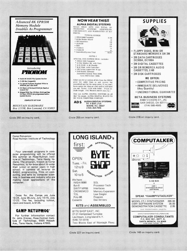
.
Advanced 8K EPROM Memory Module Doubles As Programmer
Introducing
PIfDM»I • Holds BK BA.SIC Plus System .Hollitor
• 5-100 Bils Co",patible
• No S~c;'1 SOftUM1r Reqllirrd-Write to EPROM. )II.t Lilte RAM
• j 11 Bytn of ON-boord RA.." for Sudt or Scrrltcb Pad
• SbWd With O"e l'frByte RAM IIIId Ow Jl1-Byu EPROM prr-pro"..",,,.edVlitb. Syttnff Mo" ito,
COMPLETE KIT SI64
MOUNTAIN HA RDWARE Box 1133B, Ben Lomond, CA 95005
Circle 250 on inquiry card.
Camp Retupmoc Rose-Hulman Institute of Technology
Four one-week programs in computer programming will be offered this summer at Rose-Hulman I nstitute of Technology, Terre Haute, I ndiana , The program, known as Camp Retupmoc, is for boys about to enter their junior or senior years in high school; it consists of lectures on BASIC programming, films on computing, and talks by computer scientists in business and industry who are making novel applications of the computer.
Dates for the Camps are June 19-24, June 26-July, July 10-15, July 17-22. The fee , including tuition, room and board, is $125.
For further information contact Dr. John Kinney, Rose-Hulman Institute of Technology, 5500 Wabash Ave., Terre Haute, Indiana 47803.
NOW HEAR THIS!! ALPHA DIGITAL SYSTEMS
SEI.LS IMSAI K ITS AND TOTAL I N. TE ~ RA :!'W SY STEM S ASS EMBLED . ~:: ~(:.:. Il . O UT . AND IVAHHANTED AT KIT
T YP ICAL SYST EM ... 1I\15 AI H080 Computer .. 22 Slo! Mothe r Bo;u"d .. A JJ Connc(' (ors .. ", K i{ ;\ j\:l • ~IIU
.. :1 Cable i\
.. I C.a ble 1\1
S ()~ )!I
:J4 12
.. Assembled Sys tem Tot al ~
ALPHA J
SPECIAL ])OS S YSTE J\'l J)I~AL !i ncludes) .. II\tSAI HOHO Compute r • 22 Slot Mother Bd . with COll I! • 16 K HAl\'1 (4 4K Boards f · 90 K Dis k (with Controll e r f • DECwriter typewriter :10 cps ... DOS-BASIC Software
Assembl ed Sys te m Total $3995 ( Less DECwrit c r f $2495.
Se lect an y kit or sys tem of kit s frolll the IMSA I price li s t. order from us and rece ive the a ssemb l e~l unit for the same price. If you don't have a pnce list , drop us a li ne a nd we will send you one . T erms: Ca s h wi th Orde r · Prices include frei g ht. ( N C. Res iden ts Add 4"'; Sales Tax)
1I0w can ALPHA DIGITAL SYSTEMS do a ll tius'! Its simple. ALPHA DIGITAL WANTS T O BE YOU H COMPUTER COMPANY .
ADS ALPHA DIGITAL SYSTEMS RT. 4 BOX 171A BOONE, N.C. 28607 (704) 264·7946
Circle 255 on inquiry card.
LONG ISLAND'S fi rst:
OPEN Tues . - Fri.
12to 9 Sat.
10 to 5
We have. IM SAI 8080 Byt-8 SWTP MP68 CROMEMCO TDL Poly-88
Cassetts
SOL Processor Tech Interfaces Memory Expansion Lear Sieg ler Floppies Dec Writers
KITS and ASSEMBLED
BYTE SHOP EAST, INC. 27-21 Hempstead Tu rnpike Levittown, Long Island N.Y. (5161731 -811 6 Two Blocks East of Wan tagh Pkwy.
Circle 227 on inquiry card . I
• FLOPPY DISKS, MINI OR STANDARD MEMOREX OR 3M
• 3M DATA CARTRIDGES DC300A, DCl OOA
• 3M DIGITAL CASSETTES • 3M OR MEMOREX AUDIO
CASSETTES, C-60 3M DISK CARTRIDGES
WE OFFER:
• COMPETITIVE PRICING • IMMEDIATE DELIVERIES
(Any Quantity)
• UNCONDITIONAL GUARANTEE
BETA BUSINESS SYSTEMS 8369 V ICK ER S ST., #G
~ SAN DIEGO, CA 92111~ Iiiiiiiii (714) 565-4505 _
Circle 276 on inquiry card.
S-100 BUS
SPEAK "KAAMPYUTAOLKER"
MODEL CT-1 SYNTHESIZER CSR1 SOFTWARE SYSTEM DEMONSTRATION CASSETTE
CALIF RES IDEN I S ADO 6 °~ SAl ES-TA X
395. 00 35.00
2.95
WRITE FOR IN FORMATIVE LITERA TURE
COMPUTALKER CONSULTANTS P.o . BOX 1951, DEPT. B,
SANTA MONICA, CA 90406 ci rcle reader number 140
Circle 140 on inquiry card .
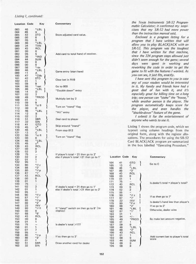
Listing 7, continued:
location Code
083 46 084 65 085 42 086 00 087 05 088 46 089 34 090 43 091 00 092 05 093 36 094 44 095 00 096 00 097 56 098 46 099 11 100 47 101 42 102 01 103 09 104 86 105 46 106 14 107 02 108 49 109 01 110 09 111 50 112 00 113 46 114 12 115 02 116 51 117 32 118 41 119 45 120 46 121 13 122 50 123 00 124 46 125 45 126 43 127 00 128 02 129 75 130 02 131 01 132 95 133 90 134 88 135 80 136 87 137 43 138 00 139 01 140 75 141 02 142 01 143 95 144 90 145 87 146 80 147 88 148 22 149 60 150 00 151 68 152 43 153 00 154 01 155 75 156 01 157 07 158 95 159 80 160 89 161 01 162 51 163 32
Key
~LBL I STO o 5 * LBL TAN RCL o 5 * IND SUM o o * rtn
~LBL }
* CMs } STO 1 9 * rset
;LBL }
iPROD
}
*st fl o * LBL B 2 SBR SIN GTO yX * LBL C *st fl o * LBL yX RCL o 2
2 1
* if z * 2' * if p * 1' RCL o 1
2 1
*i f z * 1' *i f p *2' INV * if fl o *8 ' RCL o 1
1 7
* it P * 3' 1 SBR SIN
}
I } } }
I
}
}
Commentary
Store adjusted card val ue.
Add card to total hand of receiver.
Game entry (start here)
Clear bet in R19
Go to 000
" Double down" entry
Multiply bet by 2
Turn on "stand" flag
"Hit" entry
Deal card to player
Skip around "stand"
From step 012
Turn on " stand" flag
If player's total = 21 then go to 2' else if player's total > 21 t hen go to l '
If dealer's total = 21 then go to l ' else if dealer's total > 21 then go to 2'
If "stand" switch on then go to 8' [to display]
Is dealer's total ;;' 17?
If so then go to 3'
Draw another card for dealer
152
the Texas Instruments SR-52 Programmable Calculator; it confirmed my suspicions that my SR-52 had more power than the instruction manual said.
Enclosed is a program listing for a program that I have written that wi/! allow you to play BLACKJACK with an SR-52. This program was the toughest that I have written for that machine, since the 224 program steps allowed just didn't seem enough for the game; several days were spent in working and reworking the code in order to get the game to fit with the features I wanted. As you can see, it just fits, exactly.
I have sent this program to you in case any of your readers would be interested in it. My family and friends have had a great deal of fun with it, and it's especially great for killing time on a long trip; one person can "stake" the "house," while another person is the player. The program automatically keeps score for the player, and even handles the "double-down" feature of the game.
I submit it for the entertainment of anyone who wants to use it.
Listing 1 shows the program code, which we typeset using column headings from the original form, along with the register allocations. The procedures for using the SR-S2 Card BLACKJACK program are summarized in the box labe lled "Operating Procedure."
Location Code Key Commentary
164 165 166 167 168 169 170 171 172 173 174 175 176 177 178 179 180 181 182 183 184 185 186 187 188 189 190 191 192 193 194 195
41 13 46 89 43 00 01 75 43 00 02 95 90 67 22 80 88 46 87 01 94 49 01 09 46 88 43 01 09 44 09 08
GTO C * LBL * 3' RCl o 1
RCL o 2
* if z * 7' INV * if p * 2' * LBL * 1'
}
1/- } iPROD
* LBL ) *2 ' RCL 1 9 SUM 9 8
Go to C
Is dealer's total = player's total?
If so then go to 7'
Is dealer's hand less than player's
If so go to 2'
Otherwise, dealer wins
So make bet amount negative.
Add current bet to player's total score

Listing 7, continued:
Location Code Key
196 46 *LBL 197 67 *7 ' 198 43 RCL 199 00 0 200 03 3 201 85 + 202 85 + 203 46 * LBL 204 68 *8 ' 205 57 *fix 206 02 2 207 43 RCL 208 00 0 209 01 1 210 75 211 43 RCL 212 00 0 213 03 3 214 85 + 215 43 RCL 216 00 0 217 02 2 218 55 0 / 0 219 01 1 220 00 0 221 00 0 222 95 223 81 HLT
} Commentary
Game over, so display end game
Display dealer hand as integer, player as decimal, and await next round.
Register Utilization:
The SR-52.
ALLOCATIONS FOR SR-52 CARD BLACKJACK: 00 pointer for subroutine parameter
User accessible labels:
A B C
Start game Hit Stand
D Double
Flag Usage:
o ~ "stand" fl ag
Spring into Season with a BYTE T-shirt
01 02 03 05 98 99 19
dealer count player count facedown current card winnings random number output cu rrent bet •
At lastl No more wardrobe crises! BYTE T-shirts are herel Now you have the perfect garb for computer club meetings, Altair Conventions, playing Shooting Stars and computer chess. (A pair of trousers from your own closet is suggested as an addition to the BYTE T-shirt. BITS can't do everything for you .)
BYTE T-shirts are of top quality 100% cotton or cotton-polyester. The original design, by. artist Judy Lee Rehling, is silk screened in red on white shirts with blue trim on collars and sleeves, or on blue heather shirts.
The $5.50 price includes postage and handling.
BITS, Inc. 70 Main St. Peterborough NH 03458
Please send me __ extra large __ blue heather
__ large __ white with blue trim and
__ medium
__ small
Total enclosed $. _____ _
red letters
T-shirts @ $5.50 each (includes
postage and handling)
Bill MasterCharge No._____ Exp. Oate' _______ _
Bill BankAmericard No. _____ Exp. Oate· _______ _ Name' _ _______________________ __
Address _______________________ _
City _____________ ..:lState' _______ .LZip, ___ _
Signature' _______________________ _
All orders must be prepaid Prices shown are subject to change without notice .
153 Circle 213 on inquiry card.

A Guide to Baudot Machines:
Michael S McNatt 4658 E 57 St Tulsa OK 74135
Part 3, A Teleprinter Test Circuit
Now that you've found out what type of Baudot teleprinters are available on the surplus market, and where to go to get information on how to interface them to your microprocessor, it might be convenient to build a test box to check the working condition of your new acquisition. What follows is a circuit for just such a test box which can be used to provide the 60 mA current loop required by the Baudot machine. Circuits are also included in the box to generate signals which can verify correct machine function. Although not as handy as the test box, a Baudot keyboard may be used to test a page printer of the same speed. The test box has variable control of data rate for testing all Baudot teleprinters. The test box circuits supply the following functions:
1. Standard RY test signals, ei ther continuously or at two second intervals, for mechanical alignment purposes. These signals result in a maximum amount of slipping and sliding of adjacent gears and parts with in the machine, conditions which are also most likely to cause malfunctions to
LOOP 1---------+1 HIGH VOLTAGE SUPPLY CURRENT SWITCH
LOW VOLTAGE SUPPLY
TO CMOS
TTL PROCESSOR INTERFACE
CONTROL
J
I '~ ______ ~
154
surface. The two second interval used with the RY test prevents a rather large waste of paper or tape during a long test.
2. Individual Baudot characters at two second intervals. Five bit-switche c
select the particular character desired (see table 1 in part 1 of this article for bit codes). One use of this function is to check variou s mach ines to see wh ich keys are actually installed for selected bit combinations. For example, there are at least three different "figures" code assignments. Another use is in troubleshooting, for instance when the wrong character is appearing on the printer or punch in response to a processor output command. The test box can be quickly switched from "CPU" to local "char" mode to verify that the source of the problem is or is not the machine itself.
Also included in the test box is circuitry to accept serial TTL or CMOS level Baudot coded output from the processor or hardware code converter. The "MODE" switch
Figure 7: Block diagram of a Baudot machine test box allowing the generation of continuous or intermittent 'R Y' test Signals, or individual Baudot characters.

J" • '-, ~ ~ . ,.
." . . . .. • • • • • • ., . . . . .. ..... .. . . . . • • • t: .. • • •
t • •
• • • ., . . . . · . .. . . • • • .... ...
jJ . ...... . · . . . ,. • • •
•
selects between processor input, RY test signals, and the individual character generator.
The absolute minimum amount of hardware one can get by with when setting up a Baudot machine is a high voltage loop supp ly. Some machines, Model 28s and
"Kleinschm id ts, for examp le, come equipped with this supply; unfortunately, my Model 15 RO page printer didn 't. It may be a good idea to borrow or build a test box anyway. When trying to determine the operating condition of a prospective Baudot machine, taking along a simple loop supply can enab le at least a very minimal check of the printer mechanism. When purchasing my 15, the seller, a ham, used h is own supp ly to demonstrate successfu l clutch actio n, then opened and closed the loop by rubbing the connections, causing random characters to be printed. Obviously, a better check would have been with a test box or a speed compatible Baudot keyboard. However, the
• • • .. c. •
« \I e « •• ., l
.. • • • ' .to 0 • • • " .. + • ~._"~ .. • • • • • .,~ • • • .. .. f
O~ ••• ". ~ . .. "" • ~t • " " It • • • • • 0 • • • • • • • ..
demonstration, in this case, was tota ll y satisfactory because of the price, $30!
Theory of Operation
A complete schematic of the Baudot machine test box is shown in figure 2. Many of the parts used were se lected solely because they were immediately ava ilabl e from the proverbial junk box. (I think there are companies which wou ld envy some of the so-ca ll ed "junk boxes" I've seen belonging to hams and computer phreaks . . . ) For instance, the transformer shown was the only one usable that cam e out of a thorough purging of not only my junk box but that of a fellow designer. Actually any transformer secondary from 110 V to 300 V AC may be used, as long as adequate series power resistors are included to result in a short circuit current of 65 to 70 mAo Telegraph loops, such as Western Union, usually work at 260 V. Use of the higher vo ltages, around 200 VDC, although requ iring more power to
155
Photo 7: A sample layout of the Baudot test box. Note the eight diodes plugged into the 76 pin IC socket at the lower right of the picture. These diodes are being used in replacement of IC7 in the circuit of figure 2.
Ph oto courtesy of Don Clum

~
(11 en
29
0V
6.3
V
+V
TI
DA
TA
CLO
CK
(3
0T
O 2
00
Hz
,:::
:60
Hz
FOR
60
WP
M)
\ I PO
WE
R ~
l~ 4
01
3 t 4
ON
T
.lfLF
R
ES
ET
IN9
14
S
IM
2 S
EC
ON
D R
Y'S
R
Y
CO
NT
RO
L
S T o P B
I T
" 1 ~NERIAL
O-I
OO
mA
DA
TA
B
ITS
PA
RA
LL
EL
S
ER
IAL
CO
NT
RO
L
9
'-.,
-__
-+_
-"-l
3IC
K
01
2
I'
40
13
~
SE
T
6 IC
6
40
13
--
--l
\""'
2-S
EC
ON
D
CLO
CK
,10
II
40
13
,4
'f
11
40
13
I I
I
CO
NT
INU
OU
S R
Y
CL
UT
CH
10
N
OT
CO
NN
EC
TE
D
40
01
4
07
5
J6
IC5
4
02
1
+
S B
IT S
HIF
T
RE
GIS
TE
R N
OT
E-
47
0
+V
22
K
SE
RIA
L D
AT
A
FR
OM
PR
OC
ES
SO
R
QS
j-2
.
CH
AR
AC
TE
R
GE
NE
RA
TO
R
10K
IN
91
4
PR
OC
ES
SO
R
MO
DE
SW
ITC
H
RY
G
EN
ER
AT
OR
+V
RI
1M
2N
22
22
-
MA
RK
/ \
HI
LO
" +V
SP
AR
E I
C
SE
CT
ION
S W
ITH
UN
US
ED
IN
PU
TS
CO
NN
EC
TE
D T
O
GR
OU
ND
..-/
110
I I
I I
ST
AR
T
SIT
R
ST
OP
S
TA
RT
B
IT
BIT
Y
ST
OP
B
IT
1 ~ 1 1 ~
if-ET
C
(
0 2
3 4
CO
UN
TE
R S
TA
TE
5
PO
WE
R
CO
NN
EC
TIO
NS
IIC
NO
. P
IN N
O.
CO
NN
EC
TIO
N
I 14
+
9V
7 G
ND
2 14
+
9V
2 7
GN
D
3 14
+
9V
3 7
GN
D
4 14
+
9V
4 7
GN
D
6 14
+
9V
6 7
GN
D
7 14
+
9V
7 7
GN
D
6 7
8 9
10
" 12
13
15
o
2
TlM
lliG
DIA
GR
AM
TR
UT
H
TA
BL
E
ILL
US
TR
AT
ING
SE~UENCE O
F C
OU
NT
ER
ST
AT
ES
;
ST
AT
E
D
C
B
A
0 0
0 0
0 I
0 0
0 I)
A
RE
SE
T,
2 0
0 I
o C
LO
CK
S
B
3 0
0 I
I 4
0 I
0 0
5 0
I 0
I
6 0
I I
0
7 0
I I
I
B
I 0
0 0
9 I
0 0
10
I 0
I 0
" I
0 I
I
12
I I
0 0
13
I I
0 I)
A
SE
T,
14
I
I I
o N
O
CL
OC
K
15
I I
I I
TO
8
3

Figure 2: A Baudot machine test box and interface. This circuit generates 5 level Baudot code to be used in testing the working condition of a Baudot teleprinter. All resistances are measured in ohms, and unless otherwise marked are 7 /4W and ±-70% accuracy. The circuit allows either continuous R Y test strings or intermittent 2 second test strings. The R Y test string causes the most movement of gears and will show any difficulties in operation quicker than other test string combinations. All unused inputs of any CMOS integrated circuit must be grounded.
be wasted in the series resistors, results in a faster response in the printer selector magnets, which is especially important at the higher speeds such as 100 words per minute. Do not put the standard transient suppression diode across the coils because selector magnet release will be slowed down.
Since CMOS logic elements are used, the low voltage secondary winding can be of any voltage which will result in from 5 to 12 VDC for the +V supply. The series resistor capacitor network across high voltage transistor 01 is used to suppress the voltage transient occurring in the magnet coils when 01 is turned off. A low logic state at IC4, pin 10, resu lts in a mark or clutch state, since this will switch 02 and thus 01 on, causing loop current to flow. Resistor R 1 tied to +V insures that the machine will remain in the mark state while changing the MODE switch.
Th e data clock and the 2 second interval clock, IC3 and IC4, are standard CMOS osc illators. I n substituting CMOS, try to avoid 4049 inverters in these osc ill ato rs. The character generator is formed by 8 bit shift register IC5, which is parallel loaded with the 5 Baudot data bits, a start bit, pin 15, and a stop bit, pin 7. The remaining bit, pin 1, is tied high. Characters are ge nerated every 2 seconds when the load control, pin 9, is pulled high for one half period of the data clock. Flip flop IC6 synchronizes the load pulses from the slow interva l clock with the much faster data clock. Note that serial input IC5, pin 11, is tied hi gh. This provides marking 1 s to be introd uced into the shift register after the parallel loaded Baudot bits have been shifted out.
The RY generator is essentially a CMOS version of an RTL circuit published in Ham Radio magazine, Mal-eh 1971 , pages 23 to 29. Briefly, IC1 and IC2 form a four bit, labe led A through D on schematic, binary counter which skips two states when counting from 0 to 15. The RY pattern thus generated is shown in the timing diagram of figure 2. Referring to the schematic, counter state 1, DCBA = 0001, causes flip flop A to be reset, thus clocking flip flop B. This occurs when IC1, pin 2, goes hi gh, causing the reset pulse at IC3, pin 4. Counter state 14, DCBA = 1110, causes fl i P flop A to
be set, with no clocking of flip flop B. This occurs when IC1, pin 1, goes high, causing the set pulse at IC3, pin 10.
The RY control is a three position SPDT minitoggle sw itch with the center position off. A neat feature of this circuit is that no matter when the RY control is switched from one position to another, complete RYs are always generated_
Miscellaneous Notes
• I used six lN914 diodes and two resistors in place of IC7, hence the 16 pin socket was used as a diode holder, (see photo 1). The 4075s are more convenient, but the diodes were in the junk box at the time. If diodes are used, connect three of the anodes in pl ace of IC7, pins 1, 2, 8, and the cathodes in place of IC7, pin 9, and tie a 1 M resistor to ground at this point. Ditto to replace the second gate.
• To avo id the self-smoke or reach for the sky mode, all unused CMOS inputs must be grou nded or tied to +V.
• Obviously the test box can be as simple or complex as one desires_ The minimum configuration would probably be two Eveready No. 416 67.5 V batteries and a resistor in series, using the "spal-k ing" method to ge nerate random characters!
• Seriously, the RY generator is mandatory, with the character generator and 2 second timer as options_ Of course a more soph isticated Baudot test box would have an 8080A, a 1702A, an 8251, and maybe some hexadecimal ch al-acte r readouts .. .
Summary
An old surpl us Baudot code telepri nter is the most inexpensive hardcopy peripheral available to the computer hobbyist today_ Th is seri es of articles has presen ted approaches to acqu iring, using and testing these units, as well as sources of refere nce material and intel-facing hardware and software. It is hoped that the inform at ion provided will greatly ease the acqu isition and interfaci ng tasks facing the hobby ist who owns or is pl anning to own one of these practicall y indestructible · mach ines.-
157
:::.>
GNA T 3M Drive
This new GNAT MC-200 data storage system wi ll make an in terest ing optio n for many users. This is an RS- 232 interfaced ser ia l dev ice which plu gs into a sta ndard DB-25 connector often used
• .\.§tlAL~·"" " i MC - 2 00
with RS-232. It gives the user a serial storage capability on 3M DCD-1 00 cartridges. Optional parall el 10 is also avail able.
The unit has sufficient inte lligence built in to recogni ze various comman d sequences inc lu ding start write, sta rt read, stop wri te, stop read, rewind, etc. All th ese seq uences are du pl icated by ha rdware switches o n the front panel for manu al control as wel l. The data rate for the device, which looks logically li ke any RS-232 serial terminal, can be set by a switch at rates from 75 to 9600 bps. Options ava il ab le include paralle l in ter-
The Ultimate in Terminal Printers
The ultimate in termina l pr in ting mechanisms is that provided by the Diablo HyT y pe 1\ printers a nd simil ar high-speed, high quality im pact mech-
face, fil e sea rch capabil ity, dua l dr ives, etc. Th e pr ice of th is sys tem is $ 1930, and its mix of features shou ld prove qu ite useful for those who want a f il e storage syste m with the minimum of interface complex ity.
GNAT is located at 7895 Co nvoy Ct, Unit 6, San Diego CA 92111, and de livery is quoted as from stock to 60 days A RO .•
Circle 613 on inquiry card.
An I nteresting Test fixture
AP Produ cts, POB 110, 72 Corwin Dr, Pain esv ille OH 44077, has in troduced this interesting new fixture for use in test in g integrated circui t assemblies. Called the "logical Connectio n," this is a preassembled ribbon
anisms. These mech anisms give print quality (with carbon ribbons) good enough to photocopy and reproduce, yet at character printing rates of u p to 45 characte rs per second. Appli ed Com· puter Systems, 248 Sobrante Way, Sunnyvale CA 94086, has take n the Diablo mechan ism and placed it into this attract ive package along with a microprocessor and numerous options. The res ult is a hard copy or iented microco mputer with p ri ces start ing at $4500 and options in clu d in g f loppy d isks, memory to 64 K, p lotti ng, sort and merge capability, down loading of programs over commun ications lines to large systems, and user programmability of th e built-in microprocessor. Comm u nicatio n speeds of 600, 1200, 2400 and 4800 bps are supported, and the standard memory s ize is 4 K bytes. Keyboards customized for APl, ASCII and IBM 2741 compatib ility are ava ilabl e . •
Circle 61 2 on inquiry card.
cable attached to an IC test cli p at one end, and a f lat cable socket co nn ector at the other. The length of the ribbon cable can be chosen by the purchase ri the examp le here is of course rather short to illustrate the id ea . •
Circle 614 on inquiry card.
MVM 1024 MICROPROCESSOR VIDEO MODULE
Circ le 201 on in qu iry card.
* Sixteen 64 -character lines, upper !Iower case 128 character font .
* Software -controllable reverse video characters.
* Full read and write capability for both cursor position and character code.
* Interfaces to any microprocessor : 8080, 6800, 6502, etc.
* Scrolling, line/character insert/delete, etc. easily done with software.
THE SOPHISTICATED VIDEO MODULE $ 225 FOR THE ADVANCED EXPERIMENTER ASSEMBLED AND TESTED Write or call for complete literature.
~·'~El..ECTRONIC·ideDESlGHINC' ----W'-'I.::7 1700 NIAGARA STREET BUFFALO , N.Y. 14207
716 875 - 7070
158

THE COMPUTER CORNER
Lower Hudson Vall ey Southern Connecticut
-IMSA18080 -POL Y-88 -Teletype supplies - Full line of magazines
- Processor Tech - Computer Book Service - Magnetic tapes & disks - Brai n Games & Puzzles
THE COMPUTER CORNER White Plains Mall
200 Hamilton Avenue White Plains, N. Y. 10601
Tel: (914) 949-DATA
Hours: 10-6 Daily & Saturday
10-9 Thursday
Circle 161 on inqu iry card.
COMPUTER MART
OF
NEW HAMPSHIRE
DEALERS FOR
TDL ICOM IMSAI
DIGITAL GROUP
SOFTWARE INCLUDES:
8K BASIC EXT. BASIC TEXT EDITOR DISK BASIC
WORD PROCESSOR MACRO-ASSEMBLER
170 MAIN STREET NASHUA (603) 883-2386
Circle 176 on inquiry card .
MPRES! your computer.
Monitor up to 256 points under software control.
Each MPRES card monitors eights points and plugs into the XPRES bus.
Call us. We're the interface people.
CRC ENGINEERING, INC. P.O. BOX 6263 BELLEVUE, WA 98007 (206) 885- 7038
Circle 202 on inquiry ca rd.
the mic rocompute r
an introduction to
reality
now in canada:
imsai
processor
crom e mco
tdl
a nd more
Th e Computer Pl ace 186 Queen St. W Toronto M5V l Z l 416- 598-0260
Focus Sci enti fi c 160 Elgin St. Ottawa K2P 2C4 613-236-7767
Ci rcle 156 on inquiry card.
P o W E R
SURPLUS
CONTROL DATA
s U P P L
:=!!!!!~~~!!!!!'-._.:Il Y
BARGAIN
+ SV @ 7A - 12V @ 2A +12V @ 2.SA +180 V @ 1S0 rna +30V @ 200ma (unregulated) -6.2V @ 25ma (no adj. pot)
B ra nd new. made by CDC fo r mic ro processor termi nals. 110 VAC in . regu lated and ad justab le DC outputs . Overvoltage pro tected +S. -12 . Power status signal. Fan. Schematic . Orig inal l ist $600+. From stock. UPS pa id, custom foam box, guaran teed.
$50,00
ELE CTRAVALUE INDUSTRIAL BOX 464
Cedar Knoll s, NJ 07927 (201) 267-1 11 7
Circle 247 on inquiry card .
WE NEED PEOPLE WHO ENJOY COMPUTERS
We're a small custom software house doing state-of-the-art things with large online scientific data bases. Not with packages - our systems are too sophisticated . fo r that. You would develop systems for real-world use, in intellectua lly challenging applications. Mostly Fortran for I BM/370, D EC-l 0 , Univac 11 OO-series. We offer the usual benefits (a bit better than most) , comfortable offices, and company-paid coffee. Send your resume (in confidence), sal ary requirements, to
Dr. R. Gary Marquart Fein-Marquart Associates, Inc.
7215 York Road Baltimore, Maryland 21.212
Circle 257 on inquiry card.

An I nteresting New Product for People Wanting Complete Systems
Frank Laczko, president of TLF, POB 2298, Littleton CO 80161, called us early in February to announce his new brainchild, the Data 12 computer, shown here. This machine is an example of a completely in teg rated system oriented to a terminal user. Its architecture is that of the Digital Equipment
A New Variation on Solderless Prototypi ng Boards
Conti nental Sp e. cialties, 44 Kendall St, POB 1942, New Haven CT 06509, has announ ced an interesting new variation on the solderless breadboard co ncept: modul ar uni ts with a set of interlocking edges so tilat they can be built up into multiboard arrays that are rigidly held together .•
Circle 609 on inquiry card.
Corporation's PDP-8E, using the Intersil IM61 00 microprocessor.
The $1695 price tag of this processor with its built-in tape drive gets a PDP-8 like computer with 4096 12 bit words of user memory, serial terminal interface, tape controller with one drive built in , and a tape operating system that includes both an unattended batch mode of operation and real time task scheduling capab ili ty. The random access tape cassette drive uses a preformatted digital cassette that has an average access time quoted by tile TLF press release as less than 25 seconds, with bidirectional search speeds of 100 in ches per second. The tape hold s a maximum of 262,144 words in 128 word blocks. The software supplied with the system is completely
A Portable Display Terminal
The Micon KDM/1 is manufac tured by Micon Industries, 252 Oak St, Oakland CA 94607. The terminal is a se lf -contai ned keyboard with 32 character alph anumeri c LED display, ava il ab le for $400 mail order. The product is ava ilabl e in eigh t different colors. I t is also available in many fine co mputer stores. Options include acoust ic cou pl er, digital cassette tape storage and addition al memory capacity to 1920 characters .•
Circle 610 on inquiry card .
oriented to an interactive keyboard , and it includes an "invisible" system executive that handles all 10 scheduling, buffering and' vectoring. The operating system, modeled afte r DEC's 05-8, is written with an eye towards device independen ce in the same fash ion as larger computers. Th e system software manages named file s for mass storage control, and also includ es the usual tex t editor for program preparation, a symbolic assemb ler , dissassembler and load ers. Th'e system is marketed with a BASIC compiler which includ es multisegment program linkage conventions, large multidimensional arrays, string handling, and multiline user defined functions. User memory can be expanded to 32 K words, and add itional peripherals are also avai lab le .•
Circle 611 on inquiry card.
Oops · ... Some Phi-Deck Updates to Freeman 's Article
have read an article publish ed in the March 1977 issu e of BYTE . Th e article, "Cassette Transports for the 'Roll Your Own' Hobbyist," had some errors in it concerning the PhiDeck cassette transports. These errors are appa rentl y due to the normal time lags involved between the occurrence of a development and the time consumed to communicate the event.
Areas I wou ld like to bring to your attention are:
Solenoid Operation Phi-Deck uses a 4 motor des ign for
all co ntrol functions. No solenoids are used, thus eliminating the power con -
INTERNATIONAL DATA SYSTEMS, INC. 400 North Washinglon Street. Suite 200 Falls Church, Virginia 22046 USA Telephone (703) 536-7373
S100 Bus: Cards (ALTAIRIIMSAI Compatible)
88-SPM Clock Module
88-UFC Frequency Counter Module
88-MODEM Originate! Answer MODEM
GENERAL PURPOSE PERIPHERALS
MCTK Morse Code Trainer!Keyer
TSM Temperature Sensing Module
DAC8 Eight Bit Dig ital to Analog Converter
Your compuler keeps time 01 day· regardless of whal program it is executing. Applications include event logging, data entry, ham radio, etc.
Measure frequencies up 10 600 MHz. Computer can monitor multiple frequencies such as transmit and receive frequency.
Use your computer to ca ll other computer systems such as targe timesharing systems. Also allows other computer terminals to "dial-up" your computer.
Hardware/Software package which a llows you r computer to teach Morse Code, key your transmitter, and send prestored messages.
Use it to measure inside and /or outside temperature for computerized climate control systems, etc.
Requires one eight bit output port. Use it to produce computer music.
KIT PRICE
$96.00
$149.00
$199.00
$29 .00
$24 .00
$19.00
Terms: Payment wtth order. Shipment prepaid. Delivery Is stock tei 30 days. Write or call lor detailed product brochures.
Circle 204 on inquiry card . 160

Floating Point
Software
for the 8080 PACKAGE I NCLUDES MANUAL , OBJ ECT CODE ON PAPER TAPE , AND cm~PLETE ANNOTATED SOURCE LI ST ING.
RCUT I NES PERFORM , Add , subtrac t , mu l t i p l y , and d i v i de load and s t o re f I oat i n9 po i nt accumu I ata r Format conver s i on Squa re root Si ne and cos i ne Natur a l loga ri thm and exponent i a l Arc tangent Hyper bo l ic s i ne and cos i ne Logar j t hm base t en
OTHER FEATURES , Compat i b Ie with any 8080 mi cr ocomp ut e r Requi r es l ess t han 2K bytes progr am store Hi gh speed- - wor st case mu l tip l y 2 . 5 msec . Accurate to six dec ima l d i g i t s lmt' cost ( source tape a va i l abl e separate l y)
SEND $10 TO,
BOOT HASH I ZUI.IE P . O. BOX 447 1·1AYNARD, MASS . 0 1754
Circle 262 on inquiry card.
Cor1PUTER CLUBS
PROFESS IONALS-M1ATEURS
BUS I NESSr~EiH1OBBY I STS ORGANIZE (5-20 PEOPLE) AN D BUY A FULL TELEPROC ES SING SYSTEM (Z-BO I~I CROCOt~PUTER, CUSTOM BOARDS, DUAL FLOPPY). THEN BUY SINGLY REMOTE OR IN-HOUSE VIDEO TERMINALS (WE SEL L THESE 100!). ADD MVT' s BOSSYS TEM/ 1 SOFTWARE AND YOU HAVE A "DEDICATED" COI~PUTE R FOR 5-20 USERS.
USING OUR MULTI-USER BASIC INTERPRETER YOU ARE NOW READY FOR EASY REMOTE PROGRAM~~ING, PROCESSING, GAI1ES, ETC . FOR A COt1PLETE SYS TEM (TESTED AND BURNED-IN WITH SOFTWARE, TERMINALS AND PERIPHERALS) THE PRICE FOR 10 PEOPLE IS LESS THAN $1900 PER PERSON .
WRITE NOW FOR FURTHER DETAILS ON THIS NEW AND EXCITING DIMENSION IN PERSONAL COMPUTING.
MVT MICROCOMPUTER SYSTE MS, INC . P.O. BOX 62
AGOURA, CALIFORN IA 91301
Circle 264 on inquiry card.
Circle 261 on inquiry card.
Pictured above is the new OP-80A High Speed Paper Tape Reader from OAE . This un it has no moving parts , wi ll read punched tape as fast as you can pull it through (0·5.000 c.p .s .), and costs only $74.50 KIT, $95 .00 ASSEMBLED & TESTED. It includes a precision optica l sensor ar· ray. high speed data buffers , a nd all required handshake logic to interface wi th any uP para lle l I/O port .
To order. send check or money order (include $2 .50 shipping/ handling) to Oliver Audio E ng ine ering . 7330 Laur e l Can yon Blvd . . No . Ho ll y· wood . CA 91605 . or ca ll our 24 hr . M/ C-B/ A orde r li ne (213) 874·6463 .
Circle 64 on inquiry card:
THE BETTER BUG TRAP
The Better Bug T rap is an Altair/ I MSAI plug-compatible board that extends system ca pabilities to facilitate software de bugging and real-time processing. Capabilities include interval timer, real-time clock, watchdog time r, processor slowdown, and clock with variable rates. Four hardware breakpoint addresses allow you to stop processing or generate an interrupt at a breakpoint without modifying existing software. The board services its interrupt with a CALL instruction to ANY memory address you choose. All capabil ities may be set by software or front panel. Write for free I iteratu reo $180 assembled, t ested , complete documentation, software.
MICRONICS, INC. PO Box 3514, Greenville, N.C. 27834
919 - 758 - 7757
Circle 196 on inquiry card .
SIX PORT I/O CONTROLLER • Program Control of Ports • S100 Buss Compatible • Para llel I/O • Single Printed Circuit Board
VIDEO SYSTEM • 30 x 64 Di sp lay - 1920 Ch ar. • 120 Ch aracter Buffe r • 1 Ilsec Read /Write Time • Extensive Software Provided • D isplay Attribute Control s Are
All Programmable
Available in Kits or Assembled BankAmericard and Master Charge
Accepted
Dealer or Club Discounts Available
lOR Box 28823 Dallas, Texas 75228
Circle 268 on inquiry card .

Circle 83 on inquiry card.
®
COMPLn"ER MART
A NEW YEAR, A NEW LOGO, A NEW STORE!
Last year we opened the first computer store on the East Coast. This year we move out of the Hobby Store and into our new Real Systems Showroom and Store. The largest display of up-and-running computer equipment. The same friendly help and advice. Plus-all the bits and pieces you can't find elsewhere ! Plain and Fancy Software too! ~
<t ~O~ ~e~ tf:,t.." ~G \. ~'\.O'
\~ O~ \~~ u.~O 9~~
~"Q over $10.00 BallkAmericard
and Master Charge accepted Stan Veit -Storekeeper. COMPUTER MART OF NEW YORK INC. 11 8 MADISON AVE. (ENTER ON 30th ST.) 212-686-7923.
sumption associated with maintaining a so lenoid in the active state.
Die Cast Chassis All Phi-Dec k models now utilize
a precise die cast chassis. Triple I no longer uses the sheet metal fr ames.
AC Phi-Deck Model s Triple I is anno un cing two new
Phi -Deck transports wh ich will give us a total of five models. Both of the ne w mode ls will use an AC ca pstan motor.
New Pricing Ph i-Deck Mod els 1 and 2 are now
built with t he die cas t chassis. This and other factors have increased the price of these mode ls to $124 in quantities of 1 to 9. The price is higher , but you can now get a precise die cast chassis fo r und er the $169 mentioned.
If you co uld update your audi ence abo ut the above cor rections to the arti cle, it wo uld be greatly apprec iated .
Jack Morrow Applications Engineer ing Technician
Triple I POB 25308
Oklahoma City OK 73125
My fault. In editing, I should have correlated later Phi-Deck literature with the article, which was written in the Sum m er of 7976 .. . CH.
PAPERBYTES Design and Implementation 01 a Microprocessor Sell Assembler Tiny Assembler 6800 -
No. 700 $7
.I.IIIY'II Tiny Assembler 6800
Design and Implementation of a Microprocessor Self Assembler
by Jack Emmerichs
Send today to :
BYTE Interface Technical Services, Inc.
70 Main St
Peterborough NH 03458
Dealer inquiries invited
All orders must be prepaid.
Originally described in the April and May 1977 BYTE, PAPER BYTES is now offering J ack Emmerichs' Tiny Assembler 6800. This book contains the complete Tiny Assembler source listing plus object code in c ross assembly format (space restrictions prevented p rinting of this material in BYTE). A bar code version of Tiny Assembler is included for convenience, as well as reprints of J ack 's two articles and add itional user manual materia ls . Tiny Assembler will run on any machine with MI KBUG and 4 K of memory starting at address 0000, and is an excellent tool for the interactive development of function al blocks fo r a large structured program. Add it to your 6800 system and you'll have a valuable programming aid which can free you from the drudgery of machine language. The best part is the price : only $7. Order yours today!
---------------------------. Name
Address
City State Zip
PAPER BYTES Price of Book $ _-- -Tiny Assembler 6800
Postage , 35 cents $ ___ __ _
Total $ _ ____ _
o Chec k end osed
[1.1 0 Bill MC # _ _ ____ _____ Exp . Date _ ______ _
[ .. ",,~ ' 0 Bill BA # Exp. Date _______ _ -. Signatu re
In unusual cases, processing may exceed 30 days. No . 700 You may photocop y this page if you wish to leave your BYTE intact.
----------------.;.---------------------------Ci rcle 4 on inquiry card. 162

CANADIANS! Eliminate the Customs Hassles. Save Money and get Canadian Warranties on IMSAI and S-100
compatible products.
IMSAI 8080 KIT $ 838.00 ASS . $1163.00
(Can. Duty & Fed. Tax Included) .
AUTHORIZED DEALER
Send $1 :00 for complete IMSAI
Catalog. We will develop complete applica
tion systems. Contact us for further information.
Rotundra A Cybernetics ~ Box 1448, Calgary, Alta. T2P 2H9
Phone (403) 283-8076 TWX 610-821-1883
Circle 234 on inquiry card.
South Florida Across from the University of Miami
Uni ve rsity Shopping Center
~1 238A South Dix ie Highway
Coral Gab les, F L 33 146
g g (305) 661 -6042 C
"-'"
S UNNY C OMPUTER S TORE S. I NC
South Fl orida's First Computer Store
We Carry ' -I MSA I , COM PUCOLOR, V ECTOR, SOUTHWEST, C.S.C., CROMEMCO
VECTOR GR APHIC , SEALS - Books , Magazines, Newspapers - Sockets, Ie's , Printers
- Digital Cassette Equipment - Debugging Equipment
We offer Classes, Fr iend ly A dvice and Service Hours: Monday - 12 Noon to 9 P.M.
Tuesday through Saturday -10 A. M . to 6 P.M.
Circle 164 on inquiry card ,
WIRE WRAP Cut & Strilmed .=30 Wire Gold Wire Wrap &Y.:kets
in Red, Ye llow, Bluc or Orange Hiyh Qu~l ily Closed Entry Type
1024 '00 '00 8 " . ., JG
3· " 2.60 4.71 " .,. .37 .365 3,,' .86 2.81 5.12 " ." ." 39 ,. 90 3.00 5.52 " 70 65 60 4 \!' '' " 3.1 1 5.93 " .. 30 1.20 '" ,. .98 3.42 6. J~ " .90 85 80 5).>" 1.02 3.63 6.75 28 1.30 1.20 1.05 6· "'6 3.83 7.16 " "60 1.50 1.30
" ." " 00 250 II . Aolh $4.00 101$30 1m,. 1
HOBeY WRAP TOOL Hand WrOlI) UnWrap & Strip Tool
S5.95 with $2 fre!'! wire.
WealsoSlOck : • WrreWrap Boards . 7400 & 74LSOO IC's • Processor Support Chips
call or Wri te lor catalog (2 13) 797·4002 or 797·4007
Orders under $10 or COO"s add $1.00; o ther orders shipped UPS ppd. BilnkAmericard .md Master Charge.
Page Dlglt~~lectronlcs
1701 East Orange Grove Blvd Pasadena, CalUornla 91104
Circle 273 on inquiry card .
The Best t;)f BYTE, Volume I
Send now to:
BYTE Interface Technical Services, Inc, 70 Main St Peterborough NH 03458
The volume we have all been waiting for! The answer to those unavailable early issues of BYTE. Best of BYTE, edited by Carl Helmers Jr and David Ahl. This 384 page book is packed with a majority of material from the first 12 issues, I ncluded are 146 pages devoted to "Hardware" and how-to articles ranging from TV displays to joysticks to cassette interfaces, along with a section devoted to kit building which describes seven major kits, "Software and Applications" is the other side of the coin: on-line debuggers to games to a complete small business accounting system is included in this 125 page section. A section on "Theory" examines the how and why behind the circuits and pr'ograms, "Opinion" closes the book with a look ahead, as to where this new hobby is heading, It is now avaiiable through BITS I nc for only $11,95 and 35 cents postage.
1---------------------------· I Name
Address
City State Zip
Price of Book $ ____ _
The Best of BYTE, Volume 1 Postage, 35 cents $ _ ____ _
Total $ _____ _
o Check enclosed '.liI 0 Bill MC # ___________ Exp. Date _ ______ _
II'~ 0 Bill BA # Exp. Date _______ _
Signature
~~~sual ~~,~~ssin~~~~e~3~days.:.... __ A~~~~~~repaid.:J
You may photocopy th,S page if you wish to leave your BYTE intact.
Circle 4 on inquiry card.

Advanced Microcomputer Products Presents
Prototype Design Equipment
., . --.--.--.-•••• ••• ~ ... "",, '_'''._ ' ''' _' _'''C'''''' .''''''''''' . .. -", ,,_,,,, ,~,,,._~_,,,,,,,,,,.,,,,.,,, . ......... , ... ..... " "" ........ , ... _ _ _ 10. ,TTLJon .. c ..... , ...... _ ... _" . ...... c ... , •• _ .. _ !.P·,_ " .. .. _ ... , _ ... .. ,.. .......... ~ ...... T ..... " • ..-,UU •• ", "'''''' -''' ''' ""","'''''''''1 ... . ' "' " '' P 'JI" ~ . ...... , ,.~" ....... " f ." .... """,. u _ _ . ......... " ......... .. "" • . ...-.,.. .V'I1 ....... Y\ _ ... .. ,·III .. Kt .. ~ ... ""V ....... """ ... ...... , .... ..
Now inuock tol . ~M Microp,oeenor P,otOI VP.ng ~l~~ NEW SOCKETS & BUS STR IPS
[.po'i ..... n'.' 600 . $10.95 .6 <PK.ng 10' mk."".oc .. __ 1", •• _. ~E,.:~:J~;,~ .. ~~ .... fJ.r.==:·;:.,;,=:.E:~,
£'po",,.,.n,ol lOG $ 9.95 3''*''''II'Ofm.croprO<'''''' opp'oa , iot> .
f~::::O ... · .. ' .. ---oo .. - .,10.00
WE "fl~ A FUll ti NE esc DISf fll UVTOR wE CII.N SUl'Pl v AN Y PROQUCT OUT OF THE esc CATA LOGUe
~ '.1 .
1. EVK 99 co.""~ l oIl"""~ Q ~I ' Ot. III PCB ,0;, •• ,
II I 68OOBI>UCPu I I I 6850 ACIA IA"nch.",."" , C ..... m~n.c." ",. h'W!.c:~ ~ .. , .. I (l168]QP'A'P •• ,,,,,,,. , I 'nlCfl.c:eAdoo,.d 1'1 6830 ROM S .. II' .... ""'" p, .... , ..... L'~,.'" 111683, lSI( ROM 141 S810 IRA'" I II ~" ' '''9M"" ... ' I. 'n''".c ''",.,
I,,'mlll ........ ' 1 .. 11 . e . ".-.lW "'"."'.1<l,t" ..... IC,..,,,.rq .. ,,eo ISH Ph".,,1
2. UN IV ERSAL KLUGE BOARD $9S.00 Comll'"'''' com ~,."b" '" '''_ (I/O< w""", Tn " ",,",d .11 .... ·, ,~" .. ,." 10 .. I<, "'" A1d,,,,,,.01,,,,nh.d • • ,, •• Ilh .. ~OOhol ••. ~"ld,94 ISp,nIC·' o<"Ih ... ,\< ,
SPECIALS ... NEW PRODUCTS ~ • 6. 9 ··01 "' .... , . .. " ... , §Q",n I :xl,,,n" .. ut>l • . 1 ~SI>,n Asn'
3. ;-;;;';YTE RAM BOARD $77 .95 ,60: . 8 0180: . 16 " • .,.,. ... ""., \.Iv , 110", ,,, ' I ~O'·''''''.od'I>'''o'I<''''
15452 8T26B 74LS IJ8 11097 74166 14 161 741HC M110026CN 148B
10/2.50 215.00 1.49 .90 .80 .49
1012.50 J .95 1.29 1.29
F4102Baud flar e Ge.. . 15.95 8214I'.,u",y 1111. 11 .95
4 . ;~T MOTHER BO ARD $29 .95 Z80C PU 49. 95 Z80388 1 P IC 9.95
5. EXT ENDE R BOARD $46 .50 Z80 3882 CPC 9 .95
PO 372 FloPI'Y Cont,oLle l 55.00 FD'~" .... ~ """. "I ... ~ .1.00,~ "'c,'d C",", c ..... ,qu .... ",. PO 37 1 M~!I . T ~I>U Conllolier 49.95 ::':. ~:;,~~:~.:;,: :':::-nI ",crud"'9 < .... n~ 110 _ " "'.,, II ¥"" ... ." 1489
APP NOle1 fo. 372FloPl'Y 6 .95 Gt A Y5 3550 ,, % D . ~., DVM 29.95 GI AY5 3600 K ~yho~rrl Encodel 14 .95 Intc.s,18038CC Wa.e Gell . 3.50 AV3507 DVM Ch'll 12.95 R03 2513 UlIpe,Cale 9 .95 RD3 25 1 3 l owcr~atc 10 .95
..,. I C MARKET PLACE "'" --- TM S4060 Nl ·24K RAM 3.95
,~ ,,, " t MJOllO ' S
lM)OIC N 4 5 1."'301" I ,,,, l "' l04'; 120 l "' )Ib" 8~
~:~ .. '~~ l"'30/CN J~
" 1."'308" l "' lOI:ICN 1 00 l ''' 309'' 110 l MJO'lIl I ]~
~~~:~N ::~ lMJIIH '10 t",llICN " l MJI71t 1 9~ lM1IMIt 150 lMl1l1CN 1!>tI
I. MJI9/1 : ~~
lM]]OO:!>1 I." l MJ]OIl.] I 4~ lM];>OO: I~
l MlXl I ~ I I ~ lMl:xll ~, "~
~~~::~] :;~ (M];>0 118 I''. lM]J7~ ~ 9 ')'~ l "'124'" I~!> lMl l9N I!>~
l Ml-'OIl~ I~ lM~01l8 . 95 lMlotOIl" .9'!> l MlotOIl 1~ I !l'~ l M1400: I ~ .9'. l MJ.400:]4 I !l'~ I . M J<~ICN 65 l M1ION 165 l M1100t 165
~:~~~~ ~ ~ (MlIIIJ"j Il!l lM JIIOCN 1 O'~
* LINEAR
lMJalN 119 I. M3!l1N 119 l M555CN ~B I.M5S6(N 1]0
~~~N :~ lM~5H
I,M10.)CN I.M10'111 lM109N lMlIOfoI lM111N lM71111 ~MnJN
lM12JI I I,M12SI; lM1]]N lM1J1CH lMll!1N
'" " " " ,. " " " " '" ' .00
'" ", I.M141CII .:15 lM141CN I4 J9 l M141 CO 4~
I.M141H 1S ~M741N
1.""4811 " H H
* 7400TTL
,,HOIN ,~'"
II 7"5101 " " " " " " "
l' 7"6101 " , .... 1N
HOlN 18 '"IN 7~N 19 HSON 140SN lO 74S1N , ... " H 01 N 2!0 lol.08N ~I U09N 2 1 H1DN 21
~::~ :~1 H 1JN .:.:
." Hl1N l6 1410N 19 H11N l&
~:~ ~ '.16N 15 141 m J!o 1418N ... 14~ 21 1~]lN ] 1
1UJN ~
" ' "ON 2 1 1«lN Sl Q!;
'"IN 6t HUN 6; , ..... N ,, !to
" ;: ~ " ., " H8lN 95
148JN 95 141SH 19 ' 14i6N 78 ,.89N SIll 14_ &0 14'JIN 10 149lN S9 149lN 1i HIWoI 19 '.i!>H 19 ,.1I6H 19 14\11101 SJ 1~ 141(IOH S i l O 1.'04H ~J 74105H 51 14101101 II H109H Jl 74nlN l~
J.I21H J.U1N &0 '.1l!1N 19 14116H 19 '.112N 10 14.4 1H 811
~:~:~~ SI ~~ 7. , 411N $119 ,.1SON SI15 1.I~lN !wi '.,SlN 98 '.'$4H SI . I§ '.'56N 115 '. '!>6N 95 1.,51H 115 '.16ON 99 '.161H 9!1 '.1&7N 99 '.1'-lN 99
" 14'6!>N 99 ' .16ON SI lO ,.110N $.4 lO 141J1NS1615 ' 411JN SI_O ' " UN SI ~ , .17SN $1 15 14 116N 19
" ' '' ION 19 ,.,I'N HI!> 7.'I7N 79
SlID
H lasN $1.10 14190101 S1.]O 14191 101 $1 .30 lHUN SlID 74193N St.IO 141i4N 9'5 1.195101 9'5
~::~ : 11. ItlN S1 45 7. '99N S1.8S 14~1N SI .45 1UliN SI.IO II09lN 49 ~ .~9 -- " .-. ." 8O'J1N 99
""'" " lS ISON SI10 15015OH SlIO 150151N .§9 J5oIS1 N .59 154S]N 154!j.otN J5491N 150191N 1501 9JH 1501!MH
100 PIECES MIX TAKE 10% DISCOUNT 1000 PIECES MIX TAK E 15% DISCOUNT
L"' 14~8C N 1 .... '496"1 l"" IIIN L"' ;>90 I N lMJII6!>N lM]900N
lM1!o20 l""514N lMl!>15N lM1S300N lM1S1!>N
"' " 1 9!.
'" " " '" ]1!>
'" ,~
* CMOS
MK40964K RAM 3 .95 16026 UAR T 5 .50 1883 UAR T 6.50
'l ~l]4 3S0 AY5 101 3A UART C. .5 0 5 10 1C·E I K CMOS RAM 6 .95
29.95 WD 1941 Dual Baud Gen 9 .95
sC'SO lT 2 ~ 0 SG 'S01N ] . 0
~!~~, ::~ WD 16118 Awos
RC.'95f 695 WD 177 1 F lo!'!'y O,~c Coni. 74.95 6330·1 256 BII DC P' om 2 .95 633 1· 1 256 B" TS PfOrn 2 .95 6300·1 I K OC I'.om 3 .50
HClfS8CN II~
nC IS!.6CN 9-9
:~~~~~~ ]~ RC.'36f) 1 90 63011lK TSI'IOtn 350 RC~S~N 9!1 630 5· 1 2K OC P, m" 9 .95 RC4IS ICN 6S0 6306·1 2K TS P.om 9 .95
6340·1 4K OC PlOm 18.95 6341 ·1 4K TS P,urn 18 .95 6352· 1 4K OC Prom 18 .95
~g:rir ~~ ~E~~! : .:~ ~~:m .~ ~ __ .. 6.;.J5,;J •. '.'.K .TS.P,;" .. "' ___ . ' .. B,;,.9!' .. ' __ .....
CU.()OG 1 1~ C/l '07\l 199 r.o . oa7 J~ F, o ," I;lltt DJVld G,lfurn lm '\ furrn~ oI y ur
gg:= I ~~ ~g:m! ~ ~g:~:;, :;~ :~~:I~ :n~~;,;),I::~'~~:~~:::~j~,::)~'~~~:~C,:I" CU'OlO .11 (040)!' 119 CO'~III 7'S :I Sn~ I) " only $99.50 CO'OI! 711 CO'040, 10 CO'~10 '4'1 M,croCOOlIIUle. Al!llioC ~ IOO" l-\,nulllOok CO'017 78 CO.o-t7 .4S CI,.~n ~~ ontv $7 .95
~g:~:~ I ~~ ~g:~ ::~ ~g:~~ ~ ~ lal ' s 8080 M,~ro".ocellor Syllcm 101 .• h uok
~g:g : : I ~~ ~g:~ ~: ~g:~~~: ~ ~:~,::I~~~ ~:~:::~;:0:;::~;:;:dO~,1~~: {::~::I::~~~~CIS . ~g:~:~;~ ~g:~ ~~ ~g:;::~ 1 ~ ... _______________ •
~g:~;~ : ~~ ~g:~: ~ ~g:~~ 1 ~~ In l lli MCS8 U\CfI Manu;!1 5 .00 C040' 1 I K~ C04010 99 C04~8' 195 Inl l' l MCSI\ Utcn Manu al 5 .00
~g:g~: 1 ~ ~g:~;~ ~~ ~?!!>8!o 7 .~ ~::~::::~:: ~:::: ~a~~::'~,,,I ,,., 1 ~:~~
C040~ ;>~' I'~O'~";'~ ";_'j"~' l"I"I'f--:~:]~~~::::~--l
DIVIDERS
Sl'1t(;1~11 7000 S\'ij(; lbU 1200
sP8610H 11!.O Sl'1IG1188!.O ~(I!;n8 6!tO S~(I(;lOI1 ]000 SI'Rfil l1l I ~ 00 SI'Hr. J~ 11 . 000 1;J'R6l4 11 3~ 00 sPlI6l~1I ]I !~I
~:~~~ ~~~
", m
SP_OII 670 ~SIl(AUI I ~n SI'_1" 11t.0
~:~~ : : 1~~: SPIIGoUU HOO Sl'8fi!>01l ]~ 00 Sl'86!>I" 18!>4 Sl'8fi~2U 1100
A L TA IR / IMSA I COMI'AT IBLE 8K MEMORY
Q", ncw b.am bu,,,d cornclculIlll io: lcw,rh 21 l02·1 flIeOlOfY ch'I'1 f500",1 :.nd locke ll . AI1.ldd .en co"troI 3 ,,"d~t :oo,,' ImCI h.ll y hutie ,,!Ii .
5198.00 COMPLETE II YOU d e",e 9 1l02AI'C PIC.lId .001d S!l .!l5
6S00 STARTER SE T " .. I • •• K",. ' , \t;H OO ' "'' , .... ", " HOlM, .. , C~'J
"! I.H~'.\(':' ~, ,1l.I.'rO,'III ·."
SOSOA STARTER SET
$MUOIJ I( HOJhfl ll", .. ,(.f·u
III 11111.01'.". PI 11.'1·\ ",. , ,I! 11/.'11 ~,,,,.,, •• • H,,,,,II.·.
,: ~ , .' 10;' ""'.1,
All s111 ~rnell1s I lrst class or UPS III U S. o r add 58"
lor sl"1111111g and handfll l? MtlllillUrn o rder S 10 .00 Calrfollua AesldellU acid 6% ta x Foreign add B·b.
~ * aND""
P. O. BOX 17329 NE'" C,,1"CO ~ {)I\1PUTER IRVtNE. CALifORNIA 92713 O"OE" ~OU" ~s PHONE 171419663665
Circle 75 on inquiry card.
WIREWRAP SOCKETS - GOLD 14 Pin WW 1 level .30 14 Pin WW 2 1evcl .33 14 Pin WW 3 level .37 16 Pin WW 1 Icvel .31 16 Pin WW 2 leye l .34 16 P in WW 3 1cI/ei .38 18 Pin WW 3 level .60 24 Pin WW llevcl .70 24 Pin ww 2 1cvc l .75 24 Pin WW 3 levcl .85 40 Pin WW 3 level 1.25
EDGE CARD CONNECTOR S IMSA 1 S100 WW .250" Ro w Spacing IMSA 1 S100 ST .250" Row Spitting Allair 5100 WW Wire Wrap Altair S100 5T Solderl ail
$5.00 5.00 5.50 5.25
D-SUBMIN CONNECTORS RS ·23225 Pin Male Pa rt No. DB25P S3.50 RS·23225 Pin Female Part No. DB25S. 3.95 RS ·232 Plastic H ood for abolle .75
Frequency
1 .000 MH z 2.000 MHz 2.097162MHz 4.000 MHz 5.000 MHz 6.000 MH z 10.000 MH z
HC6/H C33 HC6 / H C33 HeG HC 1S He l S HelS HC 1S
Price
4 .95 5.85 6.95 4.95 4.95 4.95 4.95
Frequency
13 .000 MHz 14.3 18 18 M H z 18.000 MHz 20.000 MHz 32.000 MHz lOOKe 3579.45 Kc 2 .4576M HI
icExar
Ca~e Pdt.:
HC18 4.95 HelS 4.95 He 18 4 .95 He1S 4 .95 He 1S 4.95 Hen 12.95 He 1S 4.95
5.95
.. T1M INGCIRCUIIS * * COMMUNICATION CIRCU ITS "
XA5S5C1' )(A~~P 0...0 ~~~ I ,,, ... XR25S6(1' 0.. .. I """'1C.,~"
XR12'OCI' "'''''''' ''''- ' '_ XR32Of'
g.o lCRI48B 11S lCA14 89
!.~ XR2208
* PflASE LO CKED LOO~S * * Sl{ A[ OOECOOERS *
'" '" n,
Xfl221 1CP I S~!"''''''''''''''''''''_' S.!I~ Klt l l loP '''' ~'' '' '''''''''''"'"'"o· lOO Xll5111CI' 1,10 XR I310EI' 'M~, ... "f)o....,. .... " ", 100 XII2SS67CI'I .... 0',....,.. 1.80 lCH1800 J.OO
* fUNCt.ON Cl:N(RA10IlS * lClI1106(I' _ ... ,."'<'_, ..... r .. ,_",". lCR2201CP c . .... "C .... ,. o,, __ , 0",".".
* OPrRATIONA~ AMI'LIFI(IIS * ::!;~I' ~;~:"~~~~:';' XR.,)6C1' lCR ' 202[1' •• 09' . .......... 0...,0.. .. _
!"..1S 1.1!>
, ... '" us n,
2708 PRIME ONLY $49.95 Build Your Own MON I TOR
Now in Stock - NEW
M3000 - 100 12·inch display modul e M2000 - 155 9-inch display module • Add S10.00 Shipping
S229.00 S208.00
MOTORO LA Exorci,er. MEK6800DI and MEK6800D2 Compatible Modules
9601 16 Slot mother board· Inc. Conn . S175.00 9602 16 Slot card cage 19" rack mount S 72.00 9610 Utility Prototyping Board S 36.00 96i5 4K Eprom Module 11702A) 5350.00 9620 Parallel 1/0 Module 5375.00 9626 8K Static Ram Modu le 5350.00 96508 Channel Duplex Ansyn I/O $390.00
All assembled and tes ted . No t Kits
* IC SOCKETS ,,,,,,1',,,,,,.· 111' •• , 11 I·I"" '/!! 10;1'.".'.' 1111'"".
lfvAR1ABL E RESISTOR S
C~'~r,~,:~,I,~:~,~~, M~" ~ I .. "I."I It" .. " ... ,e" II.' ....
M""."I .. "I ~j>C' ~'.' ".I,~." ."", ,,,,,,
".~ .04S..,,,h
l:r" " .tI ,." ' I!~~ N.\ vSIl!JOJ .... ( w.w !>O~ j ~I !t5 04'''''h Ol .. ch
o~."''' 11N4 N,WSII!>OJ II I!>JCJ!>O" S' 11 9~
~ C~2~;~~AE_M~yIL ~~ ROTARY SWITCH
II!>nOIl!.(HOOtI,I .·,,] IOOVI>C
• COUNt II DUll l ~lIll N~~ I OI !, ],4117'..oVAC O,,'yS.t~ ..
• U'~S"" <:" ........ ~ • ••• ~" ••• ""., 11.-.

Circl e 168 on inquiry card .
TTL SPECIALS RF DEVICES 8038 ... ......•.. . . ..... . . . . $3.25 _MPSA14 .... .. ..... . .... .... ... 90
74H 10 Dual 4 I nput Buffer ...... . ... .. .... .. . . ... . . .. $ .20 2N3375 3W 400 MHz ..... . . . . ... . .. $5.50 2N3055 ... . ....... ... . . ... . . . .. 99 7490 Decade Counter .......... .. ... ... . . ... . . . ... .. . .. .49 74S175 Quad Flip ·Flop with clea r ... . .. . .. .. .. ....... .. . .. 99 74283 4 Bit Binary Adder ... ... . ... . ... . .. .. . .. .. ....... 99
2N3866 lW 400 MH z . . ....... .... ... 1.15 2N5589 3W 175 MHz . ........ ... . ... 4.75 2N5590 lOW 175 MHz .............. . 7.80 2N5591 25W 175 MHz ..... ... ... . .. 10.95
MPF102 FET . .. . . .. . .. . . . . . . ... . 55 2N3904 or 2N3906 ... ..... .... ... 25 2N5496 or 2N6108 . ......... ..... 70 MJE340 (2N5655) ...... . .... .. . 1.10
2Y," round speaker. 8 Ohms .. ... ....... .. .. . . ..... .. . . ... 1.00 2%" round speaker. 100 Ohms . ..... .... ... .. .. . . .. . ..... . 1.1 0 Speco miniature replacement speakers from 1" to 3'!. ... SASE for list.
2SC517 . ..... ............. . ...... . 3.95 2SCl226 ....... ... ...... ..... ..... 1.25 2N6080 4W 175 MHz . . .. . ... ........ 5.40 2N608115W175MHz .... ......... .. 8.45
40673 RCA FET ....... . .... ... 1.55 741 or 70914 Pin DiP .... .. .. ..... 25 555 Timer ..... .. .. . ... . ........ 75 556 Dual 555 . ........ . . ... .... 1.75
Brand New GE Stereo Tape Amplifier Board with all components 4 Watts 12 V ac supply lim ited ........... ... . . .. . . .. ..... . . 3.50 Mono Amplifier Board 1 control . ... .. . . . . ... . . . ........ . . 2.25 6 foot black or brown zip cord and plug .... . . . .... ... .. .. . . . . 35 RG174 50 ' coil .. . . .. .... . . ...... . .. .. " . . . . . . . .. .. .. .. 4.50 2'!. " round speaker. 8 Ohms ...... ........ . .. . .. .. . ...... . .. 75 VH F Ferrite Beads . . . ... ....... .. . . .... . ..... . .. . . 15 for 1.00 Ham & CB Slide Mounts with lock & coax connectors ........ . . 8.95 2 Amp Bridge Rectifier. 200 Volt .. . . . ..... . ..... ...... ..... 50 2 Amp Bridge Rectif ier. 600 Volt ... . .. . ... . ..... . . . ... . .. 1.25 3 Amp Bridge Rectifier. 200 Volt ...... .. . .. . . .. .. .. . . ...... 85 Gould AA 500 mA Nicads .. .... . .. .. . . .. ..... . . . ... . ... . 1.69
2N6082 25W 175 MHz . . . .... . ...... 10.95 2N6083 30W 175 MHz . ..... .. ...... 12.30 2N6084 40W 175 MHz . ........ ..... 16.30 2SC 1306 ... .. ... . .. . ...... . ....... 4.30 2SC 1307 ..... .. .. . .. .. .. ... .. ..... 5.25 2N2876 . . .. . . . . .' " '.' . .. . .. .. special 10.95
ZENERS 1 N746 to 1 N759 .. . . .. .. 400 Mw ... ea .. 25 1 N4728 to 1 N4764 .. 1 watt ......... ... 28 1 N5333 to 1 N5378 . . 5 watt .... . . . ... 2.10 1 N2970 to 1 N3005 .. 10 watt .. .. ... . . 2.40 1 N3305 to 1 N3340 .. 50 watt ... . ..... 4.75
200 Volt 25 Amp Bridge ... .. ... . 1.50 lN914·1N4148 .. . . . ....... 15 for .99 lN34·1N60·1N64 ... . .. . .. . 10 for .99 CA 3028 Oil. Amp . . ... . . . . .... 1.50 4060 CMOS . . ... . ... ... . .. .... 2.00 LM309K Volt Reg ... . . . . .. ... . . 1.10 MJ3055 ...... . ... . . . ... ... . . . 2.20 5313 Clock Chip . .. ... .... .. . .. 3.95 5314 Clo ck Ch ip .. . .. . . .. . ..... 4.50 5316 Clock Chip .... . ... ..... .. 4.95 2N6103 .... . .......... .. . . ... . . 89 LM309 or 741 Min DIP Dp Amp .... .45 LM741 CE T05 Dp Amp , .. . .. ..... 45 14 or 16 Pin IC Sockets ..... . . .... . 30
2 Amp 1000 volt rectifier .... ... .. . .. . . . . . . . .. .... . . 10 for 1.00 LM 72314 pin Voltage Reg .. . .. . . ....... . .......... . . . ... .49
.001 Pacer Cap. 192Pl0292 200 WVDC .. 18 12.8 kHz Crystal in TO 5 Can .... . . . 4.95
Sl ide Pots Tapered 1 K or 15 K . $ .50 Insulators ... . .. .. .. . ..... ,45
2N918 ............. 95 2 N2218 ... . . . . . ... .45
........ . . 2.25 2N3773 .. .. .. .... 4.95 A LUcLl,U L,UIVIt"'U I cR CENl t:H NUW UJ-ItN
2N2219A .......... .40 2N2222A ... . .. .... JO 2N2369 ....... . . . .. 20 2N2483 .... . .. . . . . J4 2N2484 ..... . ... . . .45 2N2905 .....•...... 35 2N2907 . .. .. . . ..... 25 2N2926G ..... ..... .24 2N2926Y . .. . .. ... .. 24 2N3053 ...... . ... . 50 2N3390 ... . . ..... . 15 2N3439 .....•.... 1.59 2N3440 ............ 60 2N3512 .. .. ...... 1.15 2N3553 ...... ... . 1.40 2N3565 . .. .... .. . . . 22 2N3584 .....•..... . 30 2N3638A .... ... . . . . 37 2N3646 .... . ...... 17 2N3713 .... . ... . . lJ5 2N3725A ..... .... 1.80 2N3771 . ... . . .. .. 250
Kits, Books, Boards, Magazines. Special 2102L1 8 for $17.50: 8080A CPU Chip $29.95. We stock OK Battery Operated Wire Tool $34.95, OK Hand Wire Wrapped Tool $5.95 . 7400 ICs CMOS, Timers PLL's IC Sockets. All kinds of transistors, rectifiers and diodes. Plus other electronic parts.
HOURS: MONDAY TO SATURDAY, 9:30-5:00 OPEN WEDNESDAY UNTIL 9 PM (516) 378-4555.
We quote on any device at any quantity. Add 5% for shipping. Minimum order $6.00. Out of USA send certified check or money order, include shipping costs.
2N3859 ..... . . ..... 29 2N3903 ... .. .. . . . .. 20 2N3905 . ... . ... ... . 25 2N3924 .. . ..... .. 1.80 2N3926 ... . .. .... 6.30 2N4041 .......... 7.80 2N4249 .... . . ..... .25 2N4401 ...... . . .... 25 2N4402 . . .. . ... . . . .25 2N4403 . . .. . ... ... . 25 2N4409 ............ 19 2N4427 .... . . .. .. 1.35 2N4429 . . . .. ..... 7.65 2N4888 . . . . .... . ... 50 2N5016 . ........ 17.60 2N5090 .. . . .. .. .. 7.50 2N5129 .. .. .. . . ' .. . .40 2N5179 .. ..... . . .. . 90 2N5641 .... .... . . 5,40 2N5642 . ... . . . .. 10.25
SpeCial 50 Foot Spool =30 wire wrap $198. White. blue, red or yellow. NATIONAL 8080A SPECIAL $19 .95 2N5643 ... . . . . . . 14.35
STOPWATCH KIT Operates on a 9 Volt battery. Includes Crystal. Switches, 7205 MOS Chip & LED Displays and Board ... .... $29.95 STOPWATCH HAND CASE for above . .... . ... ... ... . . .. 3.95 CLOCK CABINETS Beautiful
2N5913 . .... . .... 110
Mobile Mounting Bracket . KIT ONLY $29.95 Three or more kits 27.95 Wired and Tested 39.95 Power Peck for use on AC 2.95 NOW NEW IMPROVED DIGI ·, TAL ALARM CLOCK KIT Ho urs
wood simulated walnut grain $3.95 • Minutes' Seconds displayed on
Pl ex iglass in Blue . Whi te, Black or si x BIG 0 .5 Fairchild 7 Segment
Build the W7BBX Programmable Keyer (Ham Radio April 1976) We can supply the four PC boards and a Comprehensive Construction Manual all fo r only $29 .95
Smoked . . $2.95 Display LEOS 12·ho ur f ormat
SIX DIGIT AUTO OR BOAT 24·ho ur ala rm with snooze f ea· DIGITAL CLOCK KIT Has a ture , plus elasped t ime indicator
beautiful Charcoal Grey moulded and freeze feature . Eigh t pages o f
high temperature plastic case with pictorials and instructions . NEW '
Wri te for our catalog featuring other Kits including the ha rd to get Keyer switching tran sistor 2N4888 as well as other Keyer parts and boards.
Clubs contact us for quantity discounts on any of our kits.
We have Wire Wrap Sockets and Wire Wrap Wire - 50 feet 51.98,
chrome rim . Dimensions are 1 ~" o n -board power transf ormer high x 4" wide x 4 %" deep.
Large 0.4 LEOs d isplay hours, m inutes and seconds. Works on 12 Vol t AC or DC as well as automatic switching to a 9 Volt battery for power failures. Battery (not sup· plied) fits in case . Provision for blanking display LEOs for out of 'car or boat use. Adjustable Crysta l T ime Base included, as well as
and circui try for opti onal time base . . . . . $ 19 .99 60 Cyc le time base kit for de use in automobi le o r for battery operat ion . . . $4 .95 12 OR 24 HOUR CLOCK KIT . Comes with Big 0 .5 Seven Segment LEOs. Uses National 5314 Clock Chip. Fits our Walnut Grain or Ple xiglas Cab inet s. ON Y $18.95
2281A BABYLON TURNPIKE, MERRICK NY 11566 516-378-4555
A2

CAliFoRNiA INduSTRiAL Post Office Box 3097 B • Torrance. California 90503
DB25P
;::,y...J~UNIVAC KEYBOARD
The famous Sperry Univac 1710 Hollerith keyboard assembly is now available from California Industrial for only $24.88 The ideal computer input dE!vice for accountants and mathematicians. The numeric keys are placed on the lower three rows to resemble a ten key adding machine. This format allows one handed numeric data entry. Original cost was $385. Used but guaranteed in excellent condition . Complete with documentation.
Ed RS-232
male plug & hood ~:;~_!JI II III I "';'00 PIN
IMSAI/ALTAIR $1150 63 key ~:,:,: ,: ,¥;'\;, : ,: ,: ,: ,? _S3_.95_ Edge Connector • KEYBOARD
10 c..:.::::::::::::} 01 DB 255 female
"""'" S3~5 Altai r, Imsai compatible gold plated . dual 50 (.1 25 centers) three lier wire wrap edge conneclor. 3 lor $13.50
.09 7476 .39
.19 7479 ' .99
.19 7480 .79
.19 7482 .99
.19 7483 .99
.19 7485 .99
.19 7486 .<9
.19 7486 3.40
.25 7489 2.79
.25 7490 .<9
.25 7491 .99
.19 7492 .49
.25 7493 .49
.35 7494 .79
.49 7495 .79
.79 7496 .79
.39 7497 ' .99
.39 74100 1. 19
.19 74107 .39
.49 74109 .49
.39 74110 1.19
.39 74116 1.99
.39 7412{) 1.19
.39 74121 .39
.49 74122 .39
.39 74123 .69
.25 74125 .59
.39 74126 .59
74164 74165 74166 74167 74170 74173 74174 74175 74176 74177 74180 74181 74282 74184 74185 74186 74190 74191 74192 74193 74194 74195 74 196 74197 74198 74199 74273 74290 74366 74390 74939 74490
CALCULATOR KEYBOARD
Ideal for keyless entry systems. burglar alarms. Touch Tone or heltadecimal comp:.Jter input code.
4049 .79 MEMORY 4OSO .79 4051 1.99 4052 1.49 1702 9.95 ' 053 2.19 '060 3.19 82523 2.95
'1166 1.19 825123 2.95 '069 .49 2102 1.19 4071 .49 2102·1 1.89 4077 .79 21102 1.99 4081 .49
CP U's CLOCK 's
1.99 JOOH ~ 340T ·24 CMOS
.79 JOiH .39 'SON
41I0Il .25 301CN .39 l51CN '001 .25 J01H 1.29 370H '001 15 J04H 1.29 370N '006 1.99 305" .99 373N '001 .25 J07H .49 377N 4008 1.49 307CN .39 J80N 411119 .69 JOSH .99 " 'N 4010 .69 JOSeN .99 Ja1N 4011 25 J09H 1.09 NE555v 4012 .25 J09' .99 NE556 4013 .49 310H 1.19 NE565H
Uncoded computer keyboard . Contains: 63 reliable gold pia led SPST SWi tches. ASCII Kit: components and printed CUCUII board. $35.00 addllJonal.
ThiS joystick feature lour 100K potentiometers, thai va ry resistance proportional to the angle 01 tho Slick. Perfect for television games, quad stereo and radio controlled aireral! .
ELE~TROLYTICS ea. 10 50
4S00 / S0 • • SU9 13S 1)9
1000/ 15 •. S.55 ~9 .45 <lXlal
SPOT MINIATURE TOGGLE SWITCH
S.98 ... ~. > .,:1,V ~ -: /
OPDT ~ ROC KER SWITCH
.1 disc .01 disc
S.12 .10 .08 h d .06 .05 .04 P otocon uctor
~ Cells
~ l!tm ~ ~ 3f.r~98 .39 74128 .49 .39 1<1132 .99 4014 1.49 310eN 1.19 NE565N .39 74136 .89 4015 1.39 311H .99 NE566N .39 74141 .99 4016 .69 311 N .99 703CN
4017 1.29 312H 1.99 100H
[[JJI 10 ohm t. 100 K I
I~~~~~~~~~ .. .B9 74145 .99 .59 74147 2.49 4018 1.69 318H .79 74148 1.99 4019 1.79 318eN .89 74150 1.19 4020 1.39 31geN .99 741S1 .99 4021 1.49 J20K·5 .99 74153 .89 4022 115 J20K-12 .99 74154 .99 4013 15 320K·15 .25 74155 99 4024 1.19 320T-5 .25 74156 1.29 "'25 .25 320T-8 .25 741S7 .99 4027 .69 320T-12 .25 74159 1.99 4028 1.25 32QT·18 .15 74160 1.19 4019 1.99 3lO!·24 .25 74161 .99 '030 .69 324N .39 74162 1.49 4032 .49 339N .39 74163 .99 4033 1.99 340K·S .35 '035 1.69 340K·8 .49 '040 1.99 340K-12
.041 1.49 340K· 15 411" 1.'19 340K·18 '043 1.49 340K-24 .04. 1.'19 340T-5 4046 2.'19 340T·12 4047 2.49 340T·15
1.79 I09N 1.49 710N 1.29 711H 1.39 711N 1.39 723H 1.39 723N 1.75 725H 1.75 133N MJ30SS 1.7S 133N 1.75 739N 2N3904 1.75 741N 1.79 747N 2N3906 1.69 748H 1.95 748N
Diodes 1.95 1414N 1.95 1458 1.95 1496N 1025100 1.95 2111N 1N4002 100 •.• 08.06.05 1.95 290IN 1.79 JOG5N 1N400S 600 •.. 10 .08.07 1.79 3900N 1.79 3909N 1N4148 signal .07.05.04
Wire wup u . 25 50
37< 36 35 38 37 36
Solder ea. 25 50
17< 16 15
20 19 18 21 20 19
99 93 85 36 35 34 169 1SS 139 63 60 58
KYNAR~m
COMPUTER WAREHOUSE STORE __ ____
DEPT : B. 584 COMMONWEALTH AVENUE.eOSTON , MA.02215. 617- 26 1- 2701.VI SIT US: 9- 9 \~EE KDAYS; 9-6 SATU RDAYS
ONE DAY SHIPMENT
HAZELTINE 1000 $795 VIDEO DISPLAY TERMINAL + SHIPPING' 35 12 LINES x 80 CHAR., TTY COMPATIBLE , 5 x 7 DOT MATRI X, 525 LINE RASTER . BUILT & TESTED; PLUG & GO
~
LLanASR 33 is and MORE! OLIVETTI TE318 - BAC K IN STOCK!
RS232 INTERFACE , QUIET OPERATION 10 CPS , PRINTER, BUILT- IN PAPER. TAPE READER/PUNCH, ELECTRIC TYPEWRITER KEYBOARD WITH ADDITIONAL 10 KEY NUMERIC PAD, YOUR CHOICE OF FRICTION
7!> OR SPROCKET FEED, LIGHTED PLATEN AREA FOR EASY READING, STANDARD PAPER AND
+ SH I PP I NG 165 1 b TAPE, SUPPORTED BY OLI VETT I
TECHTRAN 4100 ••••••• $595s~I ~~~N G TAPE CASSETTE DRIVE. CAN RUN DIRECTLY FROM TERMINAL INDEPENDENT OF CPU. FULL EDIT CAPABILITY ,
KDI ADTROL AR-21 ••• $95 S ~I ;~ ~N G ELECTRO OPTICAL PAPER TAPE READER WITH 110V PS , STE PPER MOTOR, 250 CHAR/SEC, FAN IN TABLE TOP HOUSING
IBM 731 I/O WRITER $750 s~l n~N G 8t "PLATEN,PINFD,EBCDIC,U/L CASE , DUAL CLR RIBBON,115V
CWS U-BUI -IT SYSTEM $599 + $35 SHIPPING
MPU, CRT TERMINAL & AUDIO CASSETTE AT A
CK BOTTOM PRICE!
, 512 x 8 ROM GREEN PHOSPHOR VIDEO MONITOR; 12" RASTER SCAN SWTPC 1024 ; 32 CHAR. x 16 LNS, ASCI I KEYBOARD SWTPC AC-30 AUDIO CASSETTE INTERFACE *OTHER PACKAGE PLANS - SEND FOR OUR CATALOG
TO ORDER EQUIPMENT
I . ENCLOSE CHECK FOR FULL PRICE PLUS SHIPPING CHARGES (KITS - ADD $5 IF UNDER $100; $10 IF OVER) (FOREIGN RATES HIGHER) BANKAMERICARD & MASTERCHARGE ACCEPTED -SEND CARD NUMBER, EXPIRATION DATE , INTERBANK #
2. CLEARLY IDENTIFY SHIPPING ADDRESS 3.DESCRIBE ITEM BY MODEL NUMBER
ALL MERCHANDISE WARRANTEED
A MUST FOR PERSONAL COMPUTING SEND $1 FOR OUR CATALOG
THE ONLY ONE OF ITS KIND! FULL DETAILS ON OUR COMPLETE LINE OF KITS & UNITS, REVIEWS OF OVER 150 BOOKS, LI STS OF NEW & SURPLUS PARTS & "ALL ABOUT HOBBY MICROCOMPUTERS" - AN INTRODUCTION TO PERSONAL COMPUTING . Circl e 138 on in qui ry card .
SAVE UP TO OFF KIT PRICE WHEN A PERIPHERAL IS PURCHASED AT THE SAM E TIME . ($200 MA XIMUM DI SCOUNT)
PERIP HERA L PRIC E OV ER $900.200/0 0F F KIT
PE RI PHERAL PRI CE OVER $250 • 100/0 OFF KIT
PERIPHERA L PRI CE OVER $95. 50/0 0F F KIT
GREEN PHOSPHOR $150 +25
VIDEO MONITOR SHI PP ING STANDARD IV P TO P COMPOSITE VIDEO INPUT , 16MHz BAND WIDTH, RASTER SCAN 12x12x13" WITH POWER SUPPLY, VIDEO AMPLIFIER , DRIVING CIRCUITRY VENTILATION MUFFIN FANS , 7x9" HORIZONTAL VIEWING CAPABLE OF 24 LINES x 80 .CHAR ., ANTIGLARE k" ETCHED GRADIENT DENSITY FACE PLATE, P39 GREEN PHOSPHOR , ON/OFF BRIGHTNESS CONTROLS, 115Vac , 60 W ... TRULY A COMMERCIAL UNIT BUILT TO WORK IN A DEMANDING ENVIRONMENT .
DATAPOINT 3300-200 THERMAL PRINTER $375 +$25 SHIPPING PARALLEL PRINTER WITH ADDITIONAL CIRCUIT BOARDS TO PROVIDE SERIAL INTERFACE , PRINTS UP TO 30 CPS, 100Vac PS USES WIDELY AVAILABLE NCR PAPER, 96 CH, ASCI I, 80 COL, CRT COMPATIBLE 5x7 DOT MATRI X SOLID STATE WITH LESS THAN 25 MOVING PARTS .
DATAPOINT 2200-200 $395 s~~ ~~I~~ CONSOLE PRINTER BOTH UNIVAC & SINGER BUILT THESE PRINTER MECHANISMS WHICH OPERATE AT 30 CPS FROM A ROTATING WHEEL . 65 CHAR . USES STANDARD FORM FEED PAPER, PINWHE IS INTERCHANGEAB~E .
UNIVAE 0769-06 PRINTER MECHANISM ONLY INCLUDES MOTOR/PRINT WHEEL . .. $195 +S~IPprNG
K I T S * HIGHLIGHTS FRO~1 OUR * WIDE SELECTION
IMSAI 8080 MICROKITS LEAR SIEGLER ADM-3A
8080A KIT 5 SLOT .. .. .. ........ .. ~699 .••.• _. . WI Cursor Control 8080A KIT 22 SLOT .. .. .. ......... 75 1 i" . 01 2" CRT 4K MEMORY KIT .............. .. ... 139 \ . ;... ~ . 24 LN x 80 CHAR
SERI AL I /O KIT .................. 125 '" 0 20 rnA LOOP 875 Pl c-8 PRIOR ITY I NTERRUPT .. .. .. .. 125 \. ~ o RS232 $
~ ~~7- ~ -~ :~ . ~~ ~ ::::::::::::: : :::: 1 ~~ SCA P KIT ............. .. $99 CABLE A KIT ..................... 18 FROM NATI ONA L SEMICO ND UCT OR STANDARD I NPUT/OUT I NTERFACES, KEYBOARD K I T ... . . ...... 95
'lANUALS, SOCKET SETS * BUILT UNITS * VI KIN G 100 PIN , HEAVY DUTY ..... S3.00 ICOM MICROFLOPPIES
SWTPC 6800 .... .. ..... $395 PLUG CQM'PAT I BLE FOR, $1095 _512 BY TES of ROM - SERIAL INTE RFACE $100 BUS . . . FDZ4 1 ! . .••• eRS232 o r 20 rnA - 4K of RAM SI NGLE DR I VE FD2402 .••.. . $ ·649
4K HEMORV .. .. .............. .. .. . $100 I c~~ 3~ : ~P~ ~ ~ ~~ L. . . . ... S I 195 MPA ..... .. .... 145 MPB .... .. .... 40 FF36-2 DUAL FRUGA L ..... 1395 MPC .... .. ..... 40 MPD .... .. .. .. 35 360 - 58 BL T ; INTFC 8080. 300 MPE .... .. ... 14.95 MPF .......... 30 5 1 7 1 POWER SUPP L Y ... 250 MPM .. ......... 65 MPMx...... ... 35 FD360- 2- 5 DUAL SYSTEM . . . 3000
~;~: : : : :::::::;~ ~;;b : :::::::idg KIM-I 6502 .. . .•.. •. . . .... S 2;5
MPMb ........ 14 .5D KKII MM=32 84KK .... .•.•.•..•. .• : : :::::. ~~~ MPCb, MPSb, MPLb, EACH . ......... 9 . 50 CONNECTOR SETS HPU/ HEM .......... 2.50 MAN UA LS PACKAG E... . .. 15 CONNECTOR SETS I NTERfACE......... 2 TARB ELL AUD I O CASSE TT E KIT 120
4KBA .... ..... . 5 GT6 1 ......... 99 INTERSIL INTERCEPT JR $28 1 AC30 AUD I 0 I NTE RFACE. .. ........ 79.50 . PP40 .PRINTE R ............ .. ...... 250 12K RAM .. . ..•• . ••.. · · •· 4 1 ~5 CT 1024 TERMI NAL KIT ............ 275 ROM/ PROM BOARD .... .. .. . 7 . 5
YOU ADD MEMORY CH I PS CTP .... ... .. 15.50 CTS ........ · 39.95 SER I A L 110 ... . .... . ... . 81.50
ALL SI.'TPC UNITS ARE KITS AU DI O V I SUA L BOARD .... . 125 SHOKE SI GNAL BROADC AS T 16K RAM 595

SPECIAL OFFER 100 STEPS
PROGRAMMABLE SCIENTIST
#4525
REG. $89.95
$ 95
· RPN logic with "built-in" hierarchy for increased accuracy and speed in calculating sequences involving arithmetic, trigonometric, logarithmic, power or exponential functions .. A rollable 4-level stack lets you review or use intermediate solutions. . Eightdigit plus 2-digit exponent LED display with fullfloating decimal system. . Scientific notation for increased mathematical capacity. . Sine, cosine, tangent and inverse trigonometric functions. . Common and natural logarithms and antilogarithms. · Instant automatic calculation of powers and roots. · Single-key square root calculations .. Single-key Pi entry .. Separate storage mem()ry. Square, square root and reciprocal calculations. Change sign and register exchange keys. . MOS/LSI solid-state circuitry .. Includes 3 AA rechargable NiCad batteries.
MANUFACTURED IN USA BY BY NATIONAL SEMICONDUcrOR
ONE YEAR UNLIMITED WARRANTY 10 DAYS MONEY BACK GUARANTEE
~odel #4525 @38.95 __ ~odel #[email protected] __
-------.AC [email protected] __ _ _ Case(s) @2.95 _ _
_ _ Calc. [email protected] __ Cal. Res. add 6% tax _ _
Total __
ALSO AVAIlABLE MODEL #4520 With the same features as above but without programming capability @ $28.88. Accessories same price as above. Ci rc le 157 on inqu iry card.
SAME DAY SERVICE IF PAID BY CASHIER'S CHECK, MONEY ORDER OR CHARGE CARD.
$58.00 This 63 key ASC II Encoded Keyboard kit was designed and manufactured by Electronics Warehouse Inc. Features: Single 5 volt D.C. supply, utilizing only TIL Logic elements (no MOS devices to blow) . TIL drive capability (each of the eight bits of ASC II output will drive the equivalent of ten standard TIL inputs without external buffer drivers). de-bouncing, upper and lower case fully ASC II , 8 bit parallel. In addition to the alpha-numeric and symbol keys available on a regular keyboard, the following keys are utilized : Escape, back-space , tab, line-feed, delete, contro\. shift-lock, shift (2 keys). return . All 128 ASC II characters are generated . Kit includes: 63 key keyboard, P.C. board , all required components and assembly manual with ASC II code list. Optional: Parity bit - add 50q; • Enclosure - $25.00 • Serial output - add $2 .00· 18 Pin edge connector - $2.00 • Sockets - $4.00 Note: If you already have this teletype keyboard you can have the kit without it for $39.00. Dealer in uiries invited .
FROM CONCORD
THE FIRST FULL FFA TURE
LSIDMMKIT INTRODUCTORY PRICE:
Reg Suggested Retail $149.00
. AUTO RANGING MEASUREMENT RANGES:
AUTO POlARilY Voltage (AC& DC) 1 MV - 1000V Current: lAC & DC) 10 }JA - 1 A
. AUTO ZERO RE SISTANCE 1 0 - 10 MO Basic D.C. Accuracy, bette r than
3 Large Digits (1/2") 0 1%:!: 1 Digit Power: 4 AA batter ies I Recharg-
Rechargable able batteries op tional)
NI-CAD BATTERIES: $6.00 • AC CHARGER: $4.95 • ENCLOSURE: $12.95 • TEST LEADS: $1.95 • SHUNT KIT FOR 3 CURRENT RANGES: $4.75. SOCKETS $2.50
ORDERING INFORMATION SHIPPING AND HANDLING - $3.00 + 50C; Insurance
California residents add 6% sales tax
ELECTRONICS WAREHOUSE Inc. 1603 AVIATION BLVD. Dept. B REDONDO BEACH, CA. 90278
TEl. (213) 376-8005 WRITE FOR FREE CATALOG
You are invited to visit our store at the above address
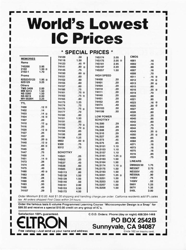
... --------------------- - ., I World's Lowest I
I I I Ie Prices
I I I I I I * SPECIAL PRICES * I
74109 .30 745174 2.05 CM05 I I MEMORIE5 74116 1.50 745175 2.05 -x- 4001 .16
Rams 74123 .45 * 745181 2.95 4002 .16 I I 745200 2.95 74141 .80 * 745197 2.20 4006 .90 2102 1.50 * 74145 .75 745257 1.50 4007 .16 I I 2102-1 1.70 74150 .60 * 4008 .70 Proms 74151 .60 HIGH 5PEED 4011 .16 * I I 82523/5123 1.95 * 74152 .90 74HOO .20 4012 .16 * 825129 3.25 74155 .60 74H01 .20 4013 .30 * I I Others 74157 .60 74H04 .20 4015 .80 TM53409 2.00 74160 .75 74H10 .20 4016 .35 * I I MM 5013 1.50
74161 .75 * 74H11 .20 4019 .70 N55260 1.50 N58619 2.00 74163 .75 * 74H40 .20 4020 .90
I I MH 0026H 3.25 74165 .80 74H51 .20 4021 .95
TTL 74173 1.25 74H52 .20 4023 .16 * I I 74174 .75 74H74 .40 4025 .20 "* 7400 .12 * 74175 .75 * 74H103 .50 4027 .40
I 7402 .14
74177 .70 74H106 .50 4028 .60 I 7403 .14 * 74180 .80 4030 .35 7404 .16 * LOW POWER I I 74181 1.50 SCHOTTKY 4040 .95 7407 .20
74191 .85 4042 .60
I 7410 .12 * 74192 .70 * 74L500 .29
4043 .75 I 7416 .25 74193 .70 * 74L502 .29 4044 .70
I 7420 .12 * 74194 .85 74L508 .29 4049 .35 * I 7427 .25
74195 .68 74L510 .29 4050 .35 * 7437 .20 74198 1.25 74L527 .30 4066 .65 I I 7438 .20 * 9602 .50 * 74L573 .45 4068 .35
7440 .12 * 9300 .75 74L575 .65 4071 .16 I I 7441 .65 * 9312 .70 74L5151 1.10 4073 .16 7445 .60 74L5153 1.10 4075 .16 I I 7447 .75 5CHOTTKY 74L5157 1.10 4516 .85 7450 .14 74501 .25 74L5161 1.25 * 4528 .75 I I 7451 .14 * 74502 .25 74L5163 1.50 7473 .28 74L5164 1.50 LlNEAR5
74537 .40
I I 7474 .28 74538 .60 74L5174 1.10 * DM8820/30 1.75 7475 .40 74585 2.00 74L5175 1.50 NE536T 2.75
I I 7480 .40 * 745113 .80 74L5193 1.50 NE555V .43 7483 .68 745138 1.50 74L5221 1.25 * NE556A .90
I 7486 .28 745139 1.50 74L5251 1.50 1456V .75 I 7490 .45 745140 .50 74L5253 1.50 1458V .52
I 7493 .50 745151 2.00 74L5257 1.50 566V 1.25 I 7495 .49 745153 2.50 74L5258 1.50 567V 1.35
I 74107 .29 745172 4.50 540L 2.00 I I Order Minimum $10.00. Add $1 .00 shippmg and handling charge per order. California residents add 6% sales I tax . All orders shipped First Class within 24 hours .
I Order the famous lasis 6 volume Programmed Learning Course "Microcomputer Design is a Snap" for I $99.50 and receive a special $10.00 credit on any group of IC ' s.
I I Satisfaction 100% guaranteed. C .O.D. Orders: Phone (day or night) 408/354-1448
I ELTRON PO BOX 2542B I I Sunnyvale, CA 94087 I L Free catalog-Just send us your name and address Circle 102 on inqu iry card. J ----------------------

A New Generation of Computer Kits When we started catering to the computer hobby ist back in '73, some people thought we were going to go out of business; now
it' s 1977, and because of the popularity of our computer kits we are agai n expanding the line. Note particularly the new 8K ECONORAM 11 1m : first the price, which is extremely low; next the unique configuration that extends its usefulness. Our Motherboard represents another tremendous va lue made possib le because of our large parts business. We're also distributing products from both George Morrow and Mullen Computer Boards---we think they are exceptionall y good and represent cost effectiveness equal to our line of kits.
From parts to peripherals, we are your one-stop , mail order computer store .
8Kx8 ECONORAM Ir·M 4Kx8 EconoramTM.~~ Unique ly configured as 2 separate 4K x 8 b l ocks (with fu lly independent
protect and address decoding to increase flexibilit y) J OUT ECONORM-l II1M
features full buffering, guaranteed 450 TIS or faster speed (use 1 wa it s tate with Z- SO; necessary l ogic included on board) J plated-through, double-sided epoxy g l ass board with go l d edge fingers, low profile sockets, on board regulation, and 3 state out puts that can drive the Altair/IMSAI 5- 100 buss or any bidirectional buss.
We use proven , reliable technology. like stat i c 21021..-1 low power lK RAMs , and low power Schottky res wh ich keep current consumption to an absolute minimum. And there' 5 more .. . to see for $ your se lf, send $1 to cover cost s and we'll send you our ECONORAM lIT" Logic Print/Documention . 163.84
!t~ per bi t I
MOTHERBOARD 80 Use with the IMSAI microcomputer as an add -on with room for 10 peri
pheral s, or for starting an 11 slot stand-alone system . Comes with 10 edge connectors---lots of places would charge you the cost of ouT""Motherboard for these alone. Active, regulated terminations, included on board, minimize the crosstalk, noi se, overshoot, and ringing you can find on improper ly terminated busses. And of course, we use an epoxy glass board, with bypass caps and heavy power traces i ncluded. Get yourself one of these, a Morrow Sigma -l OO Front Panel, some ECONORAM II boards and a power s upply, and you' re well on your way to a powerful system at a really good pr i ce.
Sigma 100 Front Panel last, a machine where you can examine , alter I and
moni tor every function of t he CPU/front panel and its operation in rea l time. Edit or modi fy your program while you run it ... think of what this means in terms of extra productivity, reduced frustration. and greater speed.
The 5 I G~lA - 100 ~ti n icomputer CPU Board (with integra l front panel) gives you this control ... run your program, or step it at any rate from 1 to 1000 steps per minute. You can stop the machine to examine and a lter processor registers, memory locations. and I/O devices---there is special firmware to keep the CPU from going to s l eep. You can also monitor all of t he above during execution of a program as well . Everything i s front panel controlled by your fingertip s $ 250 through a 12 pad keyboard; oc t al data r eads out on 7 segment readout s . OOCUMENTATION: $5 .
Morrow I/O Board I f you think I/O boards don't offer enough fea
tures ... we agree. This one handle s 3 cassette machines, a modem or tel etype, and video tenninal or ot her RS-232 device . .. and incl udes a general purpose 8 bit port for an ASCI I keyboard, tape reader , or the li ke. Contains ~ Kbyte of onboard RA~l and !.:z Kbyte of onboard Rml to give this peripheral the requi red smarts; data buffers handle the interface between the I /O board and your 5-100 buss micro or minicomputer . Want to know more of this ver satile board? Our complete 120 documentation . many pages of useful infor mation, is availab l e for $5.
I f you want the best combi nation of va lue and economy, l ook at ECONORAM TM. We don't just claim low power: we guarant ee current consumption under 750 mA, with the typical board falling between 600 and 650 rnA. Fully compatible with the 5-100 buss; full buffering gives clean and unambiguous data transfer; and speed is guaranteed 450 ns or faster. We didn I t cut corners on the kit either, with low profile soc kets, dipswitch addres~ selector , low power Schottky SUppOTt res, and a high quality circuit board .
Al so avai l able assembled , tested, and $100 warranted for one year for $130 .
Sma System Power Supply Finally, a quality, cos t-effective supply for small sys
terns . Gives you a full 4 Amps at 5 Volts I \<I'i th crowbar overvoltage protection, along with half an Amp of +12 and half an Amp of -12 .. . and an additiona l 10 mA supply, ad-justable over 5 to 10V for biasing required by some CP Us. $ 4 Al though intended to be used wi th computer systems, it's 5 also a dandy little bench supply for digital experiments .
Mullen Extender Board 35 Almost every S- l OO buss comput owner
will at some point need an extender board, and there are many good reasons to choose this one. Like the integral logic probe ... the specia ll y designed edge connector that allows use of clip lead probing and iden fifies pin numbers ... the jumpe r links tha t allow easy current measurement ... the non-skid probe ... the quality board ... and the instructions , which are c l ear and very comp l ete . Save yourse lf troubleshooting time md trouble with 1.
Mullen Opto-isolcnor B d $117 8 fast reed relays respond to an 8 bit oar word:----reed the relay associated with its
bit a "I" and it closes, give it a "0" and it opens. Also, 8 opto-isolators accept an 8 bit word from the outside world and send it to your comput er for handshakin g or further control purposes. Use it when you need a general purpose I/O swi t ching gizmo - model railroad, security
ems, audio swi , and so on.
Vector 8800V Prototype Board $19.95
Same size as typical Altair card . but useful for any prototyping work. Accepts virtually any size I C package, ha s a power and ground plane, room for 4 regu l ators (with I heat sink provided) ... implement your own memory boards. I/O boards , and other circuits.
PARTS FND359.4" READOUT Common cathode, 7 t.:::) segment display. I I FIFTY CENTS EACH I
FND503/510 .5" READOUTS -FNDSlO Com anode , I
100 PIN EDGE CON S-100-1 40ST : NEW! So l dertail type, .140" spacing--same as Altair motherboards.
10 4. 00 actua~ze . 00
FNDS03 Com cathode ,-
95~ each _, 101 . 50 actual
5 -100WW: 3 leve l, go l d plated wrap pos t s; . 250" pin spacing fits IMSAI motherboards .
S-lOOST : Same as above but so l dertail . - same-
TERJoIS: Add 50¢ to orders under $10 . Pl ease allOW®®lID0®OO~ 5% for shipping; any excess refunded. Street ad-dress MUST be included for COD orders. Pl ace Bank- 0 DoD Americard'" and Mastercharge® orders ($15 minimum) by calling (415) 562 - 0636, 24 hours. California residents please add sales tax . BILL GODBOUT ELECTRONICS
BOX 2355, OAKLAND AIRPORT, CA 94614
FREE FLYER: Give us the word and we'll send you a copy of our flyer, which describes our complete line of product s in greater detail. In addition to our computer oriented line , we carry many items relating to electr onic mus i c as well as a complet e line of semiconducto rs and components .
Circle 9 on inquiry card.

MICROCOMPUTER 'ml S ~
II - J 024 ·5 11 2SI, )( ~ fI i t 70 ns OC 4. 2S 1702,\ lSt. x 8 IIi I I u s 1S I:r o1 s;lb l l' S . OO 1702,\ 1. l!ib oX II !Ii t I us TS Er as Lo I'w r 7. on 1704 512 )( S ili t J50 ns TS Eras:l b l l' 30 . 00 2708 IU14 II II lI i t HO.n,; TS l : ra .~.1b]c .• 5.00 SZ03AQ l!ib l l! fli t I us TS trasah)(' 9.00 5204,\Q 5 11 x A lIit I us TS Er;l sa hll' 12 . no 11).1 76 11 · 5 ISb J( J )Ii t 00 ns IS J.lS HilS 7 256 x J IIi I uS ns T'i !l.on 74nS 7 Hb J( ~ fill ()S n:< OC 9 . no 821238 32)( 8 flit 50 CIS DC 4 . 00 82il191! lSb It ~ fli t sn ns TS J . ZS S2nS Jl \ 8 lIit 50 I\~ OC J.50
WAVEFORM GF.NERJ,TOR
8038 101(402 4 SOb
VCO Dual VCO veo- Func! ion
lS13 .'ix7 5 l int' Oll l .tO Upp!.'r' MCbS 7 ] 7..:9 7 I inc IJ~ ] · l 013421 (Sil: nl't I csl
SH IFT RJ:C1STF.RS ~
I J OJ,\ N J 024 )( I B 11 5 ~ur! Z sOS/.: 512){ I Ii i t 5 ~DI:
~L"'S06 1 00 " I Bit lS09t.: 50)( 2 Bit HUB 32 x b lIi t lSlJ\' ]OH x I Hit 1M53002 SO l 2 Ilit TMS3112 12 x 6 lIit MMS05B ]024 x b lIit
~I I 5(: OT II ER CO MI'ONE:{f S
,STATIC
I . 5 ~nj: 2. 0 ~tJ]:
1.5 Mil: I . 0 ,~D I z 2. 0 ~tJI:
I . 5 ~nl z IH pill).
,'1HOO2SC~
NII00 !6C ... .'lUlO N8Tl6 N8T97 0~18(j!J8
1488
[lu ;Ji 1.0 10, Cost ~IOS C lo c~ Drll~'1
5 ~\J I: 11\1:11 ,~\OS C I Ol' ~ II r I I'l' r
lUg 0 ·)2 11 7,\ C' 34 U ~ p . 3~OIl,' 1' · 4201 M."l ·S320 ~·5 1b9
O~I · 8 I 30 ml ' S131 llM · 88H U~t · 8833 [)~1 ·88.H
III - [)j f ee t i Oll a I Oll~' Shill Quad hu s Dril'l'r/Rl'c('i ... ('r T r I S t ;It{' Il(' x lIuffer T n SUi tt' Hex lllvcrto:'r I<S!)Z QuaJ Lino:' UrI\,cr RS! .U Quad LIllo:' Rec(,I\' ('r QuaJ N,\,"'U t o ~lOS DrIvel to HI t I.:Jlch I ! n ~ nil' P('I:lV T I'l S tall' Hl'X ~)O S <;"II~{, ,\mi, CI uc~ r.ener at o r T V Camera "yn\' CerH'r:lt or O~c !ll;ll or Pn' · Sell,·r Ten IIi t Comparator b HI t Comp:Jf,1I 0r J I npul A~1l .\:,\.\"]\ 1 r I 'lUI I l' \}uau Tri SI ;).1\' Tr.1n~l"(' i I'l' r ('11'111' I QU;ld T r l S t :lt ~' Tr:lII ~l' {,I\'cr (In>,)
U A I< T S
AY5 · 10 1 l (T RI60 ZA) 3n Kit:
4.50 2,7S 2 . 00
h ,75 I ~. 00 5.00
. .,un
.Lon
, H ~)
1.011 3.95 2.0() I.nn .L95 2.00
1 . 7:, 3 . 11 0 .I,HO 'i, ~ 5 11 5 I.II {I 1,% I . ~ 1 ;, 2.511 ';' 95 I>."S 4 . ~I;,
1', 00 :.1)0 2.25 1.1111 ~ , 511 2. ~O :.;'11
6 .9 5
L: .r, u. 'S
8008· 1 8080 8080A :80 fB
8 hi I CPU [ml' r ol'(.'u SUU8 Super 8008 CPt! (.'8S0) CI'U (.\1150)
Su p port Dey icC's
18,75 ZZ.US 2 4 , ~I 5 39.95 29,95
385 1 I'rol:ram SIOr:I}!C Un i t ( ]:·8 19,95 3853 SIal I C ~kmorr Inlo:'rf:ic(' ( F · I 19,95 388 1 Pi! ra 1 [0:' I l in fo nl ro II 0:'1 {·RU) I ~I. 9S 3882 Count('r Time T (' )f r uit {·8nl 1 9. ~1 5
8212 !I ' lIi I l In Po rt ~ .:5
8214 PriOri lylnl('rrul'l Cont r o l I': .95 82lb hi ·n l ro:'n iona I i\u ~ J!rlH f 5. Z~ 822~ ( l ock, (;(' Il('r:JlOr f, !lrl\'l'r 1J , IlII 11228 SyS\o:'m Contro l l,'r L Jlu ,; I1 r ivcr ') . 25 825l I' r 0r.r:l mm;, b l (' fommunlc;11101l Inl 1:, 00 11255 I'ro);ramm:lhl(' I'o:'rlpher:!l I nt('rfaL·e l l .lI(i 112S7 I'roJl.r ])irL' ~' 1 ,\ il'm '\<:(l'~ ~ Control ~2"951
11 0.) 102,1 ., .! I U7,\ .111 9 10 2 1 11 7 11 ~W'h
210 7 R · 4 J()'II, .'IU 711·6411% ~ (HiliI' · (0 I II !.l ~ IISO .\L 411'11O),
.'t\I,)1bl In :4 x ,LL"l;:'~ h l 204 II , .~J.\ 15 ~ 7 II ,I 1I9h ~
~1,~1 5280 4W'h,
~ I loll 2 • I ,11.01 11111/\ : 1111 2 10= ~ III =. I 2 11)\ · 4 ~ I I !-\ . . 1 ~ ;:'11 1 i\ ,In ; " I (",~'l
102·1 ,,, Z5h
jl I t ;lIf/ tI ~
hit \1111 II' !I I I ~nn 1\'0 !lIt :;0 Il " 11I1 .\ 511 Ih
II I I ~UII II " III t \110 n~
1111 400 rh n I I ,105 f1 ~
IIr l =IIO lh II I I ~ Oll Il~
1.50 I>,OU
tJ.SO ;,, \HI 1 ,50 ~, "5 .I.un .-.,on ;.Il!!
( I S pIn) 1.110 ( = ~ [l ill) f,. nu
1\1 \ SUII 11' I ;; 2.IIP 2 .11 11 1.11 0
JIll I In II ' or ]" <.i
[1 1\ H II
llh I u~
JI ll SI1I1 n .. [11\ 1 ;:'11 fl.
fi ll 1 ;0 II ..
I Ih
I'" •• 11(1
T" 1 . 511 1'1 I , "~ 1'1 1 III l' I II I I . I ~ J" { Ill 1" nI 2 .1 5
I , J 5 II I 1 ,~Il II" or : , !ts
,,1111 1 . 7 :
.11() "
11 11 ',(1(\ " ... 7 J ;o\~1l1 ~ , I I. n 2 \ i' 4H~ »]225
511 II" 1-;
" Of" ~ I 1\ 1 I hI) :, .:'11 ~(I
511 PC S 5 ~I ~I 1\ I I ~(j 1\" I";
1'1 FO
64 oX ,I !l I t I. 11 ,~1J I : h. -S
Digital Clock Module FI.ATLJR [ S
' ~ . J I J: II 0, S J i s l' 1 :. )' · Compl"ll' ,TH·,'J s o nl,·
Ir,'ll "forml'r (, S"lt(]\o:' S " C lod, 1/ :,,11 11 '\\.trm "1 1 tlr r. t,lIl1: " I'O"l'/' I.IIlun' II\lh,· .lIor " Il> r .. ..:1 lIrll' '' ' ~() RI ' I
'\)'I'!.JC,\TI()S S ' C "h'~ r :ld io I Im,' r ~ • lie s l (I o~' l s • In,,1 TUml'1l1 l'~nl'l c I lh' ~ S
.... 1 ,~J to ]) I S I' !.,\) ~ I t
MA 1002 A $10.95
~ I ~I S -; I, ,I
: FAST·SH
Ii! 0 9 ~ : SLOW SET
o Of /ll$pl.ly 0
• 1l1',·r,'l l· ... 0 11 \ll! \' JI( '
• 0 .. ," I! r.' ~·11 .) I 'p l:l ~' " l"I ~'n,~1 I L~" h~ ~l'
f,SI! I'f I'ARK 1. 1(;11'1", 1\,\ lTt:R\ P,\SII LA~1PS
IG,\11 I n."
• 1i1 " 1')" )' ,' o JO I' fl ll o:'f .1l>l (' 10 I, I Lit· . ~ n·,·11 t, "o:'!! 0 "
• I. oc ~ OU I o f tI m' "' \'1 .. hen ,11'1, 1 .• " I ... "nn"
,\!'I'LI \,\110;-'''' • III JiI" h :llll l), ! ('I( ~ " • R,, \' n'.1 I 1011 1'('h l ..: I ('" • ,\ L r c r " r 11 ~I:o r Illl' .. I " .. ), ... " 1'01'1 ,1]' 1,' h:>ll <' r'l"
OI ' I' T" II'<lII1"lr"",\'n"
TIM E BASE CHIP I" "l.I .~I' Ih..: J IIII' ld"1
MA 1003 $24.95
~ . !I II
CLOCK CHIPS
FEATURE S • K\lSJI II C I 0\' ~ ( II I I' ° :-,oc .. d s o n I)' C:I SC ~
I Z \' AC ~ !OO mn " Bl nnklnt: co n tr ol · A~I 1'!oJ Opt ion "H hr C nl'~h i I i' ~ • ~9 ml nUl eli mo:'r "I'owo:' r Falluro:' indi c ,lIor ' l ~ hI" c I O( l rau io
S I XI~, CLOD, KIT
$12.95 Tr:nbf<J rm\'r I I fl· I ~ V II r lU IlTl"
Sl, sn
CONNECTORS nu~ I . I SO II h Go l J lJ,, ~ I . J So h I. r.o l d lIu~J . 1 5b So ld"r C;O Ld [!lui . US So ldn Go ld
." ." 2.2S
"1)01
I [II): II " /111]1 " ".~ I: I .'~ II I 51 I f 1J (lIl:
~ (I I J.: I I ,\ I ,'f'" "!ln u :l', I: / .! J :'~I mill I ,ml' ! , Sll/loll II: . ,\.'1 1['11
I:" ~ III ~l' Ira r .<:l· [I, - r 1:0' I ~ I : ~ \,(\' 11:_, , ~I mIn I, 1'1<' r , ,\ ,~ I fI ' ~I
.I / fo d I ~ I ! , .1:011' ""lII"'r,
I, ,11I:i l \ ' :I I"'''[I'r , "[" 1m, I! /: I Il,
JADE CO. OFFERS
THE ITEMS SHOWN IN THIS AD FOR IMMEDIATE SHIPMENT FROM STOCK. IN ADDITION WE STOCK OVER 4,000 OTHER ITEMS. INCLUDING:
1. All Standard, Hi-Speed, Low Power, Schottky TTL Product
2. All Linear Devices
3. Transistors-Diodes
4. Clock Kits & Modules
5. Vectors & AP Products
6. Rlilsis!ors-Capacitors
7. Video Games & Chips
8. PROM . Setters [E-Prom)
9. Wire & Wire Wrap Tools
SPECIAL OF THE MONTH
2708 E-PROM Price $35.00 ea.
-BAN KAMER ICARD
M&+:II:M
74LSOO CMOS Low Power
741.500 741.502 74 L503 74 L504 741.505 74L$08 7<1 LS I () 74 LS I I 74 LS 12 74 1.520 74 LS21 741.530 74 L532 741.537 7<1 LS4 2 74 LS5 1 741.573 74LS74 741.576 7,11.578 74l.SBS 74 LS86 74 1. 595 74LS] 07 741.5 I 09 74 1.S1 12 74L5113 74 L5122 74 LSl39 74 LSI 5 I 74 LS I 53 74 LSI 55 7H,SI57 741.5 1 bl 7,1 1. 5 169 74 1. S I 74 74LS175 74LSl9 1 74 L5 192 74 1.5 193 74 LS I 96 74 LS24B 74LS251 74 L5266 74 L5363 H i.Sl67 HI. S16S
7 4 L5386
SchOl1 k)'
.40
.40
.40
. 4 0 ,40 .40 .40 . 4 0 .50 .40 ,40 ,4(]
.40
.50
.90
.40
.60
.65
.60
.80 ,00 .55 . QO .55 .60 .60 .60 .60
1 ,30 1 .50 I. 60 1.6U l. 30 1 ,50 2 00 1. 25 1,30 ' 2 . 45 1 . 95 2,45
.60
.35 00
.75
.70
: : ~ .75
~I':~ II '," 11\\1' 1101: 1" \\ Ir1\J 1(11, JO \~
I' \ J " Jlql
11\11,
11' 1 '
I~",d ! ' I"p,,' ... nR r..H.· J O 1\" I \ I "I'u, .. 11M I:", ~ f In,' ," ! S I)'O:IJ .' . I nl'u l ~ r'R I:a.,' t ~.., I 4 I "I''' ' "' Il~ I:" ,.' " ~ I "I:" ~1'1 r I r II" 1'1" . 'I. ~" IH IIi I "I. ~ h, f\ R('~, q ,., I. l ~ 11",,11'0 ,"1' I'.," . lov.'rtn :, 4 · 11" lul[ ,\,1.1.·, Ik' H"ff ,' r I",' ,'r,,, , 11 ... R"CI,·rl'on,·"rt(" '1u,'d , 1"l'u, ~ ,\\II Ca l< I ~ I : ' I 4 1111'''' \ ,\\1' <:.'1,'
-" " . : S
I~,,, 1 I '"f'~ II 1 I 'I ' r) "f' . 1>" ~ II I' ~ " ~hd l II~C"!'" I.:, 1)".11 J 1\ , t " I,\I, ~ ~h, fl IIr~ 1.: S
'It~~~.I '~\'~::~! ~ ~ ~ 'I; '::'~ d~~' I I I I . ~'~ I., ... J<, II, \founl.., 1 . : \ ''1 ' ,HI "I' n~ ,<, 1" ,' 1 Ca n ' " {l
, ,1 M" lI ,n",' ''','''In ~ II" ~ I , "h ,ft R('" ,q~, n.: I"l l"o ,,,".·, II" "ldrr Jr'rll' '\ Inru, ... 10.;10 (", It· " ".,~o' ~ '1'1' 10' rOlin, r,
I . :, I . : , I . : ; . , ~
1 .l1n Jrl],I,' \ 1"1"" \r'w r..ll c ,; 11,' . ,HI<' 1" 1 ' / 1'1' - ~ " r n" ll,ul : . :' Ih,." I ~ I I 'I' I ll' I' lin. ' 0 11,· .. . 11, . ",· ' .,1 II<- , I lilt HI", / "!"!I 1I1' / !!\ rTR
l.'u".II . ,- I" < II'I·IlWr."I.,
'" 1. :<' I . ~"
1 ri 1'1 " ~ ' " I ," ,Id.ln 1 rl" I 1. t," 1\, .... . , ,11' 1" " 11'11' " ~ I' ~ o1u t ~ I II :. ror' 1\ k, t II" ",,' , ,,01 II" ~ R,'~ I" I,', ,\, ,0 I lilt t; hd l RI'e, ' "'' l . hO
:~'~~;' ~ I::,,~;~~. ;\::::~;I.:~"~I : : ~:: '.'"."ll r"",Cn'"plI,,,r,,, I.J' '1" ,',1 I ., 1.-1, I • ,~ " "",1 \ ~ , . ., '" "'\~ 11/ ... 1., I .:h \.:n " ".,J \ ~1.d,' \ 1\1' ~ f" !..11 ch 1.:, I'h,' '.. I ",' ~ .' . J I onp I . Q S '~", n/,\ ' I . ,I ' I, ' '!lld' i :.SO Hr .II,,' \·r!", / H,,(f r, . \ If<' . , ,," In, .. ",,, ,: lIuf f,' r .-S ~ I"h :" ",(' I ,In ,II ''~ 'lull I r I~.c r I I ~ 1' , I I f1,~"n .. I An.'! o ~ ) " . I . I n 1" " 1<' : \ I " ",n('] "'''ph 1 . \ 11
Pins
. , 10
" " 10
II ~ I~~" lI,na," C lf f ll ~( .\ . 2~ :H > J ~ talL' RAM 1. 0(l 1 ~ I \ lola ~n" ud .. Cn" r' r ' l or ~. ~n '),,~,I K'!.' I ~r.' 1 ~~ ~S
rl~;n~~;,~~~~I: r.al.. : !~ 'lLl"d r,,' 1 OM CHC .n nllatl! Inp il l IlII r.ale .. H II ll al ( InPUl nR GH~ . H Tnple.l Inpul A)iD Gale . n Trol'l .. 1 Inpil ' (lll G.te .U Qu~d D Type IIrg n l ~r l. 8~ ~ . I nPUl NOli r.. Ie , 13 Quad 2 Input AND Gale .38 Dual "I"put ",)iD GHe .l~ Quad ,·1 SA ND SCh_l ,t Tr'UH .1~ Dua I lie 1 r , M / II .. ~ .. I JoI S JoIu I I i Z • ~O Drcadr Co ""ler 1 , 7S
R,nan' Counter I\r f ad~ roun l r' ~lnH" (.,UnH" II~. II rt I]' rt "p
L.H L.H I. H I .n
{~ u~J I' f I If" n o r' l. bn 1· /1>, ""1\' <;kl (I R,,~,q~ r l.BO Irlf')(' r,alr H ~ " o~rd 11,·, Inl' ~r1<' r / ~uffrr 1 . 1~
lin 11" rr " laIr Ruff~r I . I ~ I'u~ I I 'r ... "d.Ii'1 r ,\nl 1;.1I~ . 'r
~:;~~l1~:~~~:;· ;I~:~~f:"''' : : ~~ RI'II 10 1 ,~~ l. "I .· lo/fl~.· Jr/I\, :. lin R Clt"nnrl .1 . 1.1 , .. 1"" '0' I. <.n
I . ", J{! ~ I I nt· .I~,,,J .. , (hI) J /ln l ,n,·Jao.),· r (10) II",,, '" ul' / do~n counlcr I . " S U"" I ~( ~ I' , ,:11, r t;h, f l IIr~ ._. Sll ll,,~ I J ~'I IIC,· .,d~ (n,," I '" I . ro" I ~'I '\~I' /f\ ~ ~"l c,' lor 911 1'",11 J · ~" ~Ji I" an rounl .. , 1.1>5 , I ~ 1 " lr I " '",, .. n ... ' flll"ldn I . :S ~n ' 111\, .. 1" ~ , \ rOU nl.'r I . - ~ ~nl R:tl r 'lttll lpl,,·, 1.00 \1",01 ~'" n '' ' 1.., 1>1" 'Il! ,' 1>, I. - S
SOCKETS I C SOOETS
De sc ripI ion Price
Lo Pro Tin Trans istor Ie 10) Gold Lo Pro' Tin ""j rc lI' r ap Gold Lo Pro Tin Standa r d I' C Tin Wi rc Wr ap Tin
" " " " " Ilu,l l . 1! SSo IJl'T Gol J [.'>0 Rol l !I" ~,, r.uq Ha l ~~ t ypc .. / ('dl:" c J 'p (c ,"ar.· ~ ,"~h' (sold",)
S.IIO ~. SO
11I1l .!S
~' $11 !f'~'"" ...
Electronics for the Hobbiest and Experimenter
16 10 18 n .' 24
1.0 Pro Tin Lo Pro Ope n Frame Tin
.20
.15
.15
.'0
.15
. 30
. '0
.15
.50
. 95
. 50
.85
. 40
.60
.95
. SO J.4S
SlIB!oI IS I 'TURf:
So l d~ r I )'pe (lS 'S ) (F'c"~J "l So lder typ" (!S·n ( ~!~Lo:'l
lola 1<' ~ (''' ill" (!5 ' r t 2 S ·SI cach
.L90 3.S 0 lo.SU 1 ,50
5351 WEST 144th STREET LAWNDALE, CALIFORNIA 90260
(213) 679·3313 Circle 215 on inquiry card .
24 28 28 28 40 40
Wi r e Wr a o Ti n Standilfd I' ( Tin I'r'irc Wrap Tin Lo Pro (Open F r ame) Sta n dard P ( Tin Wi re ""r ap Tin l. o Pro (Open Frame) 'il'i r c Wrap Tin
Tin
Tin

CRYSTALS 1--p~I ]- -THESE FREQUENCIES ONLY I ~ L Frequency Case/Style r ce
CY1A 1.000 MHz HC33/U S5.95 CY2A 2.000 MHz HC331U 55.95 CY3A 4.000 MHz HC181U 54.95 CY7A 5.000 MHz HC181U 5' .95 CY12A 10.000 MHz HC181U S4.95 CY14A 14.31818 MHz HC18U 54 .95 CY19A 18.000 MHz HC18/U 54.95 CY22A 20 .000 MHz HC18/U 54.95 CY30B 32.000 MHz HC18/U 54 .95
XR-2206KB Kil 527 .00 Special XR-2206KA Kil 517.00
WAVEFORM GENERATORS
XR ·205 S6.40 XR·2206CP 4.49 XR·2207CP 3.85
STEREO OECOOERS XR ·1310CP S3 .20 XR·1310EP 3,20 XR·1600P 3.20 XR·2567 2.99
EXAR MISCELLANEOUS
XR·22IICP S6.i0 xR'~IJ6 99 XR·I'16B 3.B5 XR ·14BB 5.60 XR·14B9 4.60 XR·220B 5,20
TIMERS XR·555CP S 39 XR·320P 1.55 XR·556CP 185 XR·2556CP 3.20 XR·2240CP 3.25 PHASE LOCK£O l OOPS XR·210 5.20 XR·215 6.60 XR·567CP 1.95 XR·567CT 1.70
MICROPROCESSOR C 8080A CPU S19.95 8228 Syslem Conl roller - Bus Driver $10 .95 8212 8 Bil lnpul/Oulpul 4.95 MC6800L 8 Bil MPU 35.00 82 14 Priority Interrupt Contro l 15.95 MC6820L Periph. Interface Adapler 15.00 8216 Bi-Directional Bus Driver 6.95 MC6810AP1128 x 8 Sialic RAM 6.00 . 8224 Clock Generator /Driver 10.95 MC6830L7 1024 x 8 Bil ROM 18.00 CDP1802 - with user manual 39.95 Z80 CPU 49.95
CPU'S RA M'S Super S008 2~ 95 1101 25611 SIaliC S
2504 2518 2519 252~ 2525 252i 2529 2532 2533 334 1 J.llS6iO
SuperaD08 Hl.%
SR 'S 1024 DynamiC 53.95 Hex 32 Bil 700 Hf~ ~O SiT ao 512 DynamiC 2.49 1 02 ~ OynamlC 600 Dual 256 BIT 395 Dual 51 2 BIT ~ 00 aua~ 80 SIT 395 102~ SIaliC SpeaalS 95 Fllo 695 16 x ~ Reg 395
UART'S
2101 2102 210715280 211 1 ; J89 8101 811 1 8599 91L02 ; 4200 93·121
II.1M5262
1/021> 5203 82S23 825 173
256 ~ ,I Stallc 102·) ~ 1 St~I I C 1.75 J09S. 1 D,'narTl lc 4.95 256 ~ ~ StaliC 6.95 t[ix·1 Slatlc 2,19 250 \4 Sial iC 6.95 256 \ ~ SIalic 6.95 10)': SIalic '" 1024 , 1 SialiC 2.25 256 .1 Static 6 95 2f,6 . 1 SI ~ I Ir. 195 2Kxl Dlrnamlc 2 10r1.00,
PROMS 20·18 Faml}S 59.95 2\).18 Famo~ 1495 32 ).3 ODCIIC 5,00 3216
<D limeband ". -i\ lraoemJr~o. I'J"CI'tI<l Camera H,\tt ITlWu"",., t Co'llOt,lt lOn
Digital Alarm Clocks
C·SOO • I~orr Case C·500B · Ebony Case
S16.95
. 2J·nouralarm • Doze8utton . IQOooSollC Slale • LargeRwLellOlsplay
( 8" I1I!1I1)
• AMIPM Indll:al0r • Seconds display at tOllcn
olbut\on • Power tallu re Indlcalol • One year lactoryw311anty
C·BZll WoolIgralnCase
S19 .9S
DIGITAL AUTO INSTRUMENT SEVEN DIFFERENT INSTRUMENTS!
MEETS OR EXCEEDS ORIG INAL AUTOMOTIVE SPECS.
Please specify whICh one 01 rtle seven models you want when ordering -Ihese do not all come In one umt.
Each model must be bough! separately.
TACHOMETER 4 ~.~~~~HMETER" 1 0-9900 RPM
CONNECTORS 4. ',,'CYOlm""'il 5 OIL PRESSURE
~~=~~=~~;:;;:;:;:;:::==:Jii lb WATER TEMP. _ o-eo PSI PRINTED CIRCUIT EDGE-CARD ~~;~ 10Q·2SO"F OIL TEMP
.156 Spacing-lin-Double Read-Out FUEL LE VEL 6 200_350° F
Bifurcated Contacts - Fits .054 to .070 p,e. Cards 1---------===-::-:===~==:--------_t3 ~~~~~t:,g,~dlcal01 7 ~~~~AF;O~~,~:~OA
30KBaud 55.95
RUM'S Char Gen S995 Char Gen 10.95
7 ~S28i IOl·1
6330 ·' 256 6331 ·1 256
15/30 PINS (So lder Eyelel) S1.95 4Y385001 519.95 SPECIAL REQUESTED ITEMS 18/36 PINS (Soldel Eyelet) $2.49 ~~~~~~~ (744 16) ~ . ;~ Eg:~~ 2~ :~ ~~~~ 22/44 PINS (Solder Eyele t) S2 .95 MC14583 3.50 C04510 11.50 MC14OSL7
BRIGHT YElLOW ORANGE .3" LED DISPLA Y!
50 /100 (.100 Spacing) PI NS (So lder Eyele t) $6.95 ~g;;;;2 ':;~ MCM6571 'i:~ ;~, :oi;:;" KIT: 549.95
25 PIN-D SUBMINATURE ~~w~~~m~~~~~~~~~~~~~~~'F~~50~9~~~.~~~~~~~~~~~~~~~~~~~~~U DB25P DB25S
PL UG S3 .25 I 559.95 SOCKET $4 .95 -I 3112 DIGIT DVM
? This 0·2 VOC .05 per cent digital vollmeter features the Motorola 3V2 digit DVM chip sel. II has a .4" LED display and operates from a single + 5V power supply. The !lnit is provided complete with an in jection mol dedblack plastic case complete with Bezel. An optional power supply is available which tits into the same case as the Q·2V DVM allowing 117 VAC operation .
WEEKS DELIVERY
Featured on February's Front Cover of Popular Electronics
logic Analyzer Kit
• Analyzes any type of digital system • Checks data ra tes in excess of 8 mill ion
words per second
• Trouble shoal TIL. CMOS. OTL. RTL. Schottky and MOS families
MODEl 100A
$189.00/Kit
• Bugl1160l{lll LED Display • Times to 59 mlnules 59.59 secontls • Cryslal Controlled Time Base • TnreeSlopwatct\es In One
Times SingleEvent -Split & l aylor . Slze4.5"x2.1S" x .90"(4V,ounces) • Uses 3 Penlile Cells
KitAssembled -Heavy Duly Carry Case $5.95
$49.95 : ~:~~K:s1~~~g;~r~~I~~s~:::~d8 ~;g~~;ide $14.95 CRT, oclal or hexadeclmal lormal
• Tests circu its under actual operating
R WIRING PENCIL conditions VCClor Wiling Pencil P173 conSlSlS 01 a IWHll1cl1l ICJttlerwel{j11l (undc! one Olll l ce~ • Easy to assemble - comes with
~ooo~:~:c~!:~ou~~~~~ogn~I~~ ~e~~:r~~ ;~~~II:~;I~ ~1~(s~a :I~~ o~:la ~:~~'~~nn~~~naea r;Pl a~~~~;~ I-...;.W ... h ... iCh ...... in ... cl ... ud ... es ...... 80;..:;,;,:.;;;;.;.;; ... 1 ;,;,;,;,,;;.;;;;:,;;;;,.;;:;,;;; ...... ...;. ___________ 1 Vectorbord' ConnecltOns belween lIlewr3ppellwlleano component teads pads (I! lermmals are mollie by sOlaermQ . Complele With 250 F1 01 fell Wl r~
REPLACEMENT WIRE - 80B81NS FOR WIRING PENCIL W36·3·A·Pkg. 3 250 It , 36 AWG GREEN S2.40 W36-3·8-Pkg. 3 250 Ii 36 AWG RED $2. 40 W36-3·C-Pkg . 3 250 Ii . 36 AWG CLEAR 52 .40 W36-3-0-Pkg. 3 250 Ii . 36 AWG BLUE 52.40
1/16 VECTOR BOARD 0.1" Hole Sp3cino P·Pat1em
ParI No l W
PliENOLIC 6~P~~ 06ZX~ XP ~ 50 650 l i2 1 5·1 169P.;.102xxxP 450 1700 3 69 332
EPOXY 64P4~ 062 .150 ' .50 2.07 '"' GU.SS 8~P44 062 450 8SO 2S6 231 t69P,:4 062 J,50 17,00 5,04 ·1 ~ 3 169P64 062 850 l i DO 9.23 826
EPOxY GlASS 169P.14062Cl '150 1700 680 612 .,. HEAT SINKS III 205-CB Bef)'llium Copper Heal Sink Wllh Black Fin.sh lor 10·5
• , ·0 • ABCDEF • Return Key • Optional Key (Period)
• - Key
BUGBOOK C!J)
Continuing Education Serie5
BUGBOOK I & 11 -Basic concepls 01 TIL Log ic - over 90 experimenls S17.00 /sel
BUGBOOK lIa - Inlroduces UART - recommended for RTIY enlhusiast 55. DO/book
8UGBOOK III - Explores 8080 chip - inlroduces Mark 80 Microcompuler SI5 .00/book
555 TIMER APPLICATIONS SOURCEBOOK WITH EXPERIMENTS - over 100 design lechniQues S6.95 /book
CMOS-M-OESIGNERS PRIMER AND HANDBOOK
Other CS Proto Bo ards
PB100 - 4.5" x 6" S 19.95 P8101 - 5.8" x 4.5" 29.95 PB102 - 7" x 4.5" 39.95 PB103 - 9" x 6" 59.95 PB104 - 9.5" x 8" 79.95 PB203 - 9.75 x 6V, x 2¥. 75.00 PB203A - 9.75 x 6'12 x 2¥, 120.00 (Includes power supply)
i Monitor lill. nlor CMOS Devices
- Function Generator
69.95 - RC Bridge
<-i
. ' i '" ! Tile JE 7QO IS a IOwCOSI IIIQllal clock. Du! Isaveryt\lghQuJlttyunil Theuntl !ca· tures a slnJul~!e~ wainul case .... ' Ih !II ' menSlOns 016' ~ 21 .. . ~ I 1\ ulIli!cs a MAN 72 11Ighbuglllncssrcal!01l!. andlhe
-..::.~ "" ~ ""~
""5""rofT.95
115 VAC
.. :: .: :~ .. :~ DIGITAL CLOCK KIT - 3Y2 INCH DIGITS 4 DIGIT KIT $49.95 6 DIGIT KIT $69.95
4 DIGIT ASSEMBLED $59.95 6 DIGIT ASSEMBLED $79 .95
I------ ---...J'------____ .L.. __ .::.:: .... __ ..... This clock fea tu res big3'h" high digits for viewing in otfices,a ud ilo riums,
t------------::-~~~--::::--i ~i.~C~ ~~oo l es ~~c;O etc. Each digit is formed by 31 bright 0.2" LED's. The clock operates from OT.598 bus slri~ 2:50 11 7 VAG, has either 12 or 24 hr. operation. The 6 digit version is 27" .II
.... ~ " -. ~ .. ~.~~ ., ~ SUits mosl2Dohca!lOIl ~
I ' • < , ~ .. .. ,-- . . ..... -.. $19.95 H00165 16 LINE TO FOUR BIT PARALLEL KEYBOARD ENCODER S7.!JS
JOYSTICK These joysticks feature fou r * potent iometers. that vary rasistance propo rtional to Ihe angle of the stick. Siurdymetal construction with pla st icS componentsonlyatlhemova· blejoinl.Perfectforeleclronic
games and inslrumentation .
Special *5K Pots $4.95 *100K Pots $7.95
01·475 410 10,00 31h"x 11h" and th e 4 digit is 18" x 31h" x l 1h". Kits come complete wiih OT ·47B bus stop 2,25 aU components , case and transfo rmer. OT ·35S 350 B.50 Specify 12 or 24 Hour When OrcSerlnll QT·35B bus SinD 2.00 OT-1BS 180 4.75 OT·12S 120 3.75 OT·8S 80 3.25 OT·7S 70 3.00
JE803 PROBE -r--",", ,,---...- ....J
~-':"" . t-.,- ! -

SN7401N .16 St/7460N .22 SN74154tl 1.00 SN7402N .21 SN7470N .45 SN74155N .99 SN7403N . 16 St17472N .39 SN74156N .99 SN7404N .18 SN7473N .37 5N74157N .99 5N7405N 24 5N7474 N .32 SN741 60N 1.25 SN7406N .20 SN7475N' 50 5N74 161N .99 SN7407N .29 SN7476N' .32 SN74 163N .99 5N7408N .25 SN7479N 5.00 St1741D4 N 1.10 SN7409tl .25 SN7480N .50 SN74165N 1.1 0 SN7410N .18 SN748ZN .98 SN74166N 1.25 SN74 11 tl .30 SN7483N 70 SN74167N 5.50 SN7412N . 3~ SN7485N .89 SN74170N 2.10 St1741 3N 45 SN74B6N .39 SN74172N 8.95 SN7414 N .70 SN7488N 3.50 SN7417JtJ 1.50 SN741@ 35 SN7489N 2.49 SN741 74N 1.25 SN74 17N .35 SN7490N .45 SN74175N .99 SN7420N 21 SN7491N .75 SN74176N 90 SN7421N .33 SN7492N .49 SN74 177N .90 SN7422N A9 SN7493N .49 SN74 1BON 99 SN742Jtl 37 Stm94N .79 SN741 81 N 2.019 SN7425N .29 SN7495N .79 SN741 82N .95 SN7426N 29 SN7496N .89 SN74184N 1.95 SN7427N .37 SN7497N 4.00 SN74 185N 2.20 SN7429N .42 SN74100N 1.00 SN74 166N 15.00 SN7430N .26 SN74 107N 39 SN74187N 6.00 SN7432rl 31 SN741 21 N' .39 SN74188N 3.95 SNl43m .27 SN74122N .39 SN74 190N 1.19 SN7438N 27 SN74123tl .50 St/74191 N 1.25 SN7439N 25 SN74 125N 60 SN74192N .89 SIIWOIl .15 SN74 126N 60 SN74193tl .89 SIH441N .89 SN74132N 1.09 SN74194N 1.25 SI1744211 59 SN74136N 95 SN74195N .75 SNl443N 75 SN741 4H1 1.1 5 SN74196N 1.25 SN7444N 75 SN74 142N 4.00 SN7419711 .75 SN7445N 75 SN74 143N 4.50 SN7419BN 1.75 SN7446N .81 SN74 144N 4.50 SN74 199N 1.75 SN7447t. .69 SN74145N 1.15 SN74200N 5.59 SNW8N 79 SN7414nJ 2.35 SN74279N .90 SN7450N .26 SI/74148N 2.00 SN74251N 1.79 SN745H1 .27 SN74150N 1.00 SN74284 N 6.00 SN7453N .27 SN74151N .79 SN74285N 5.00 SN7454N 20 SN74153N 89 SN74367N .75
MANY OTHERS AVAILABLE ON REQUEST 20% Discount fo r 100 Combined 7400's
CD~OOO CO~OOI CD4oo2 CO~006 C04007 CD4009 CD-1010 CD4011 CO~012
CO~013 C04016 CO~017 CD~019
C04020 CD4022 CD4023 CD4024 C04025 C04027 CO~028 CD4029
: CO~030
25 25 25
2.SO .25 .59 59
.25
.25 ~7
56 '35
55
'" 1.25 25
' 50 25 69
165 290
65
, 8 LM301li .35 l M301CN 35 LM302H 75 LM304H 1.00 LM305H 95 LM307Ctl .35 LM308H 1.00 LM308CN 1.00 LM309H 1.10 LM309K .99 LM310CN 1.15 LM31 1H .90 LM31\N .90 LM31BCN 1.50 LM319N 1.30 LM320K·5 1.35 LM320K·5.2 1.35 LM320K·12 1.35 LM320K-15 1.35 LM320T-5 1.75 LM320r.5.2 1.75 LM320T'8 1.75 LM320T-12 1.75 LM320T·15 1.75 LM320T·18 1.75 LM320T'24 1.75 LM323K-5 9.95 LM324N LBO LM339N 1.70 LM340K-5 1.95 LM340K·6 1.95 LM340K·8 1.95 LM340K·12 1.95 LMJ..IOK·15 1.95 LM340K ·18 1.95 LM340K·24 1.95 LM340T-5 1.75 LM340T·6 1.75 LM340T·8 1.75 LM340T-12 1.75 LM340T ·15 1.75 LM34DT·18 1.75 LM3~OT-24 1.75 LM350N 1.00 LM351Ctl .65
CMOS i<!CO~1J .75 7~Cl0N .65
CO~035 1.85 74C20N 65 CD4040 2 45 74C30N 65 CD4042 1.90 74C42N 2 15 CO '10 4,1 1.50 74C73N 1.50 C04046 2.51 74C74 1.15 C04047 2.75 74C90N 3.00 CD4049 79 74C95N 2.00 coa050 .79 74C l0m 1.25 COA051 2.9S 74C151 290 CO~053 295 74C15~ ~ . OO CD4060 325 74C157 2.15 C04066 175 74C160 3.25 C04069 .45 74C 161 3. 25 CD407 1 45 74C 16J 3.00 CoA081 45 74C164 3.25 C04511 2.50 74C173 2.60 CD~518 250 i4C193 2.75 MC1~566 300 7~C195 2 75 7~COON .39 MC404;: 4.50 7~C02N .55 MC14015 .56
LM1351N 1.65 l M141 4N 1.75 LINEAR
78MG 1.75 LM1 458C .65 LM370N 1.1.5 LM 1496N .95 lM373N 3.25 LM 1556V 1.B5 lM377N 4.00 LM211 HI 1.95 lM380N 1.39 LM2901N 2.95 LM380CII 1.05 LM3065N 69 LM38111 1.79 LM3900N .55 l M3B2N 1.79 LM3905N .60 NE501K 8.00 LM3909 1.25 NE510A 6.00 LM5556N I.B5 NE531H 3.00 MC555BV 1.00 NE536T 6.00 LM7525N .90 NE540L 6.00 l M7535N 1.25 NE550N .79 80386 4.95 NE555V 39 LM75450 .49 NE560B 5.00 75451CN .39 tJE55 18 5.00 75452CN 39 NE5628 5.00 75453CN 39 NE565H 1.25 75454CN 39 NE565N 1.75 75491 CN .79 NE565CN 1.25 75492CN .89 NE567H 1.95 75494CN .89 NE567V 1.50 RCA LIN EAR LM703CN . ~5 CAJ013 2.15 LM709H .29 CA3023 2.56 LM709N .29 CAJ035 2.48 LM710N .79 CAJ039 1.35 LM 711N .39 CAJ046 1.30 LM723H .55 CAJ059 3.25 lM723H .55 CAJ060 3.25 LM733N 1.00 CAJ080 .B5 LM739N 1.00 CAJ081 2.00 UA741CH .35 CAJ08Z 2.00 LM741C11 .35 CAJOB3 1.60 LM741 · 14N .39 CAJ086 .85 LM747H .79 CAJOB9 3.75 lM747N .79 CAJ091 10.20 LM748H .39 CA3102 2.95 LM74BN .39 CAJ 123 2.15 LM1303N .90 CAJ 130 1.39 U,11304tl 1.19 CA3 140 1.25 LM1305N 1.40 CA3600 1.75 LM130711 85 RC4 194 5.95 Lt.l 1310N 2.95 RC4195 3.25
~ 74LSOO TT L ;:L~~~9 1.95 '55
29 35 35 29
" 69 l iS
29 39
·:9 74lS153 69 74LS157 49 7;ILS162
1 75 i·llSl63 2 ·:9 i~LS16~
·:9 74L5t75 1(5 74LS181 1 25 i4lS190 1 25 74lS191
'" "5 225 225 '95 1.95 369 285 285
T201Black Bracelel 519.95 LED
Timeband" by FRIROIIIO - Watches
Men 's & Ladies
• So lid State • Displays !lour, minute,
second , month & day
• Snap-out battery
TC441 Wh ilew{slrap 529.95 TC440 Yellow wlslrap 534.95
LCD
WIRE WRAP CENTER HOBBY-WRAP TOOL-BW-630
_, Battery Operaled (Size C) " '.' • Weighs ONLY 11 Ounces
''" • Wraps 30 AWG Wire onto Siandard DIP Sockets (.025 inch)
$34.95 ' Compl,te with buill -in bil and sleeve
~ ballcfles nOl Included)
,~ ~
replacement WIRE-WRAP KIT -- WK-2-W _,_ , • Free set of replacement WRAP • STRIP • UNWRAP \""~~~ \ ;
batte ries • Tool for 30 AWG Wire \p: \ \ ". • Choose LED or LCD • Ro ll of 50 ft. While or Bl ue 30 AWG Wire \' ~ l\ ."
styles • 50 pes. each 1", 2" . 3" & 4" lenglhs - \ " pre-stripped wire. ", ~ \, T237Wlll1ew/bracelel529.9S ~
T236 Ye llow w/bracelel 534 .95 • One year factory T311 While w/slrap 534 .95 $1.1.95 \ ff!1i ... r. -- -~
1~~~;;LE~O~~~~::;i:w~a:r r:a:n:ty~-:::~::::::~T3~1D;Y;" ;'"W;W;r;"'~'P~~S3;'·~9S:II ___ ~ ______ ~~ ______________________ '1
• ~_? WIRE WRAP TOOL WSU -30 125'·dia. ': •• 1:=== .190·' dia . ...,.-.. WRAP. STRIP. UNWRAP - S5.95
Red 10lSl ~ XCIII 10151 XC209 XC209 XC209 XC209
G"" 41" XC, ,, 41S' WIRE WRAP WIRE __ 30 AWG ~~:,~': ~j~; DISCRETE LEOS :~ : :: :;;: 25ft min 51.25 50ft 51.95 100ft.52.95 1000ft 51500
.200 " dia .185" dla . .200' dla. SPECIFY C'OLOR - White - Yellow - Red - Green - Blue - Black XC22 Red 10lS1 XC525 Red 51S1 XC555 Red 10lSl XC22 Green 4/S1 XC525 Green 4iS l XC556 Green 4/S1 XC22 Yellow ,liS 1 XC526 Yellow 4151 XC556 Yel low 4/S1 = _ ~ _ _ ~ _ _ m
SSL·22 fH 4151 XC525 Clear 41S1 XC556 Clear 71S1
SPECIAL ' - XC556 Red 100/S8.00 1000/S60.00 - SPECIAL ' Oli07 .. DISPLAY LEOS ., "LB"
TYPE POLARITY Mf,N t Common Anode MAN 2 5 ~ 7 001 Malf1x MAN 3 Common Calhode MAN oj Common Cathode MAN 7 Common Anode liMN 7G Common Anode·green MAN 7Y Common i'HlmJe·yeMow MAN 52 Common Anodc·grwn MAN 6,1 r:onunonAnode·red MAN 74 Common Call1 0rl e MAN 82 Common Anode'ye llow MAN 84 Common Calhode·~ellow 1I1f1f1J620 Common Anode·onnge
HT 270295 JOO .195 12531100 18,195 300 1 25 300 1 95 300195 300 99 400 99 3001.50 300 .99 300 99 300 1 i5
TYPE MAN 3640 M,\N4 710 Dl701 DL704 oLlOr r,MN ~740 Ol74 1 Ol 7-17 Ol750 Ol 338 FN070 FN0503 HlD50i
POLAR ITY Common Col l1\Ode,olange COmll lollAllorlc· flcd C)mmonAno!le'red !:
Colnmon Catno!le CJnnnonAnode C)mmonAnodc·Red CornrnonAnode COl1l1110nlmorte CornlllonCatilodc COl1l1nonCiltilodc CornrnOl1 C~1tl o de ComrnonCathodc COllllllonAnorle
tiT ~OO 1.75 ;100 1 95 300 99 JOO 99 JOO 99 400 .99
.600 1.50 6002.25 6002 49
. 110 50 250 75 500 1.00 500 1.00
~~~:g:; ATARI GAME BOARDS HP 5082-7300 Multi -Oigit Series 80ARD A _ 8'/1 " ~ 16" • Vs" HI. • Common Cathode • Dip Package
Over 60 caw reusable IC 's S6 .95 ea . • 3 to 5 volts @5 mils per segment Misc. lransiSlors . Rcsislors . ONLY 500 EA. • 7 segment Monolith ic • Red Display Diodcs.Caps.Crys13Is,Swilch . elc AVAll.ABlE
W'-} -";-:.J ' 2 Di git $.79
DELUXE 80ARD B_ !H'!"x 18 ' S9_95 ea. J ~, 3 Di git .89 Over 100 each reusable lC'S ONLY 500 EA _ _ _ 4 Di git .99
MI SC. Tramst()lS. Reslslors. AV AILABLE II." , 5 0igil 1.19 DIOdes. Caps, Crystals. SWllches. LEOS. fI e
SPill 14 pin 16Din 18 Dm 22pln
14prn 15pln 18 Pin 24 pl~
8pln 14 pm 16 pin 18pln
10 pln 14pln 15pln 18 pil i
1·24 5.17 .20 .n 29 37
S27 3D 35 .,19
S.30 35 38 52
545 39 43 75
IC SOLDERTAIL LOW PR OFILE (TIll) SOCKETS 25.4950. 100 . 1·24 .16 15 ~·24 PIIIS. 38 . 19 18 28 11111 ,15 .21 20 "'""- I I 36pIfI 60 28 27 40ptll 63 36 35 SOLDERTAIL STANOARD (TIN) 25 27 32
. ~ 5
27 32 35 .:7
" 38
" 68
" __ 28 prn
25 35 [) In 30 . I .10 pin
." SOLDERTAIL STANOARO ( G ~LO )
" _ 24prn 29 28 pin 32 36 pin 4) ~ O Dill
WIRE WRAP SOCKETS (GOLO) LEVEL # 3 37 ,,_ " pm 37 28 pm oil 36 pl(I 62 ,10 pili
s" '" 1.59
S 7D
' " 175 '75
51.05 '40 1 5' \.75
25·,\9 37
" 59
" 90
'" '"
" '00
'" '" 95
"S U 5 ' 55
50·100 36 43 58
" " 'IS
1.30
57 90
"6 145
85
' " 130 1.40
50 PCS. RESISTOR ASSORTMENTS $1.75 PER ASST. ASST. 1
ASST. 2
ASST . 3
ASS T_ 4
ASS T. 5
ASS T. G
1001iM 12 OHM 15 OHM 18 OHM 22 OHM S . 27_ D ___ U _ ~_
68 OHM 82 OHM 100 OHM 1200 riM 150 OHM 5 ea . 180 OHM 220 OH M 270 OHM 330 OHM 390 OHM
HO OHM 560 OHM 580 OHM 820 OHM IK Sea 1 2K 15K 18K 2.2K 27K
3" Sea S2l(
,2< S ea. 56K
150K Sea. 390K
39' ' OK
2iK 66'
180K ~70K
n, '2<
33K
52' 2l0K 550K
5 6K ISK -,
100r,
liOK 580K
68' ' 8K ~ j"l(
120K
330K 82CK
114 WAn 5% 50PCS.
114 WAn 5% 50PCS .
1/4 WAn 5% 50PCS.
1/4 WAn 5% 50PCS.
114 WAn 5% 50PCS
1/4 WAn 5% SOPCS.
I
<D
i ~,\
II ,I
CUTTER CRIMPER TOOL (CS-8) • Plier Nose (serrated-jaw) • Scissors Action Cutting • 6 Boll Cullers (4 -40. 5-40, 6-32. B-32,
10-32, 10-24) • Crimp Sta ti ons (7mm Auto - 22-20 to
12-XO eleel.) • " Up-Fron t" Wi re Cutting • Scissors Action Stripping (No. 22-20 to No. 10) • Crimp Stations - insu lated (2w-20 to
12-10 , leel.) Actual Size - BV, ' length $8.50
Permacel Electrical Tape • ¥I"(wide) X 66 It. (long) • All wealher . Not import
51.25 per roll- S9.95 per 10 roll package
ZENERS - DIODES - RECTIFIERS TYPE VOLTS W PRI CE TYPE VOLTS W PRI CE lN746 3.3 400mm 4/1. 00 lN4005 500 PlY 1 AMP 10/1.00 lN751A 5.1 400m 4/1.00 1/J4006 800 PIV 1 AMP 10/1.00 lN752 5.6 400m 4/1.00 lN4007 1000 PIV 1 AMP 10/1.00 lN753 6.2 400m 411.00 lN3S00 50 200m 6/1.00 lN754 6.8 400m 4/1.00 lN4 148 75 10m 1511.00 lN959 8.2 400m 8/1.00 lN4154 35 10m 12/1. 00 lN955B 15 400m 411.00 Hl4305 75 25m 20/1.00 lN5232 5.6 500m 28 lN4734 5.5 lw 28 lN5234 6.2 500m 28 l N4735 6.2 lw 28 l N5235 6.8 500m 28 lN4736 6.8 lw 28 lN5236 7.5 500m 28 l N4738 8.2 28 lN456 25 40m 611.00 lN4742 12 lw 28 l N458 150 7m 6/1.00 lN4744 15 lw 28 lN485A 180 10m 611. 00 lN1183 50 PIV 35 AMP 1.60 lN4001 50 PlY 1 AMP 12/1.00 l N1184 100 PIV 35 AMP 1.70 lN4002 100 PIV 1 AMP 1211.00 lN1185 150 PlY 35 AMP 1.50 1N4003 200 PIV 1 AMP 12/1.00 l N11 85 200 PlY 35 AMP I.BO lN4004 400 PIV 1 AMP 1211.00 lN11 8B 400 PlY 35 AMP 3.00
SCR AND FW BRIDGE RECTIFIERS C36D 15A@ 400V SCR 51.95 C3BM 35A@200V SCR 1.95 2N232B 1.6A @200V SCR .50 MoA 980,1 12A @50V FW 8RlDGE REC. 1.95 MoA 980·3 12A @ lO0V FW BRIDGE REC 1.95
lOp! 22pl 47p!
lOOp! 220pf 470 p!
00l mf .0022 0047mf 01m!
.1I35Y
TRANSISTORS
10-4950-100 .04 .035 .04 .035 0..\ 035 .05 .0..\ .05 .04 .09 .075
DB .13 .17 .n
.21
" " 23 25
HLSOO 74lS02 74lS03 74lS().1 7~LS05 7~LS08 7 ~ lS10
i4L513 7 ~ lS14 74LS20 74lS26 74lS27 74LS2B 74LS30 74l5J2 i ·IL S40 7~LS51 7~ LS55
7~ LS73
" " "
74LS7~
7,llS75 7~LS76
i 4LS83 i ~L585 i4LS86 i 4LS9Q 74lS92 74lS93 7~lS95
7~LS96
74LS107 74L5t09 i4lS11 2 7~LS132 74lS136 i4LS138
1 95 i~ LSI9:!
1 89 7.l lS 193 ~:~ 1M 1 2M 15M IBM 22M 1 89 ASST _ 7 5 ea . 2. 7M 33M 39M ., 7M 5 6~ 1/4 WAn 5% 50PCS.
. 15/35V .22/35Y .33135V .47135V .68/35V
1. 0/35V " .40 59 74lS194
39 39 29 29 .:g
59 i4LS195 59 7·:lS257 , 89 ASST. 8R Includes Res istor Assortments 1-7 (350 PCS .) $10.95 ea.
1 ~; I--S5":. 0;:0::;M::'l n:':l m":u:';m':'0~nI;:er'::-::'::':u:':;.s::. ':'Fu:;;nd'::',::o'::nl:';', ':';:;::'::':';;s.~ec;'s;;'h:;:ee";I'--;"2~S';';' -;';;';s";, n;';d;';3s",";s"'I.':'m';;.';'lo';;r ";,9;"77"'A;';C;;'.I;". I:"'o,-I 125 7·:LS260
3 ~~ California Resldenls - Add 6% Sales Tal Dea ler Discount Avail able - Request Pricing
~~~~J--BineS -59 7~LS279
189 7·:LS570
CLOCK CHIPS MM53D9 6 Digit. BCD OulpulS. Reset PIN. SH~ MM5311 6 Digil. BCD Oulpuls. 12 or 24 Hcur 4.95 MM 5312 4 Dlgl1. BCD Outpuls, 1 PPS Outpul 4.95 ; MM5314 6 Digit , 12 or 24 Hour . SOar 60Hz 4.95 MMS316 4 olgl1. !.lalm. 1 Pps Oulput 6.95 MM5318 V,lIeo Ctock ChiP, For Use Willl (MM5841 - S9.95) 9.9!j CT7001 6 Olgl1. CJlendar . Alarm . 12 or 2~ Hour 5.95
7400 p, - . 'i2.to~e:r~p~~n~~~£~/~400 lCS $2 .95 CN1(' ~ .,, ·out & Description 01 4000 Series IC S $2.9 5
.. Jtlr Pin ·oul & F unction(l l Desc ript ion 52.95 ALL THR EE H AN D BOOKS S6.95
ELECTRONICS ,+o~~ ~ ~ 1021-A HOWARD AVE .. SAN CARLO S, CA. 94070
PHONE ORDER S WELCOME - 1415} 592-8097 All Advert ised Prices Good Thru June
Circ le 15 on in q uiry card .

comDuter disDlay- terminal This display terminal has an integral controller, B/W cathode ray tube and keyboard. The system has a serial I/O interface for communication and an I/O interface for a printer
DISPLAY (P/N 4802-1095·501) FEATURES:
.17" B/W CRT
.41 lines of data
.52 characters per line • Characters are generated by a diode matrix "graphic"
technique .21 special push-buttons wired for a program call up
• Brightness Control • Self-contained power supply
KEYBOARD (P/N 4802-1115-501) FEATURES:
• Reed switch technology .54 data keys .28 special keys detachable with cable
LOGIC UNIT (P/ N 4802-1157-502) FEATURES : .1024 by 6 bit core memory
• Printer I/ O interface • Communication I/O interface
POWE R: 115V, 50/60 Hz, 500 Watts
WEIGHT : 210 Ibs. (including logic unit, keyboard, display and cables.)
FOB LYNN MASS (you pay shipping) Check with order please.
SPECTRA FLAT TWIST 50 conductor, 28 gauge, 7 strands/ conductor made by Spectra. Two conductors are paired & twisted and the flat ribbon made up of 25 pairs to give total of 50 conductor. May be peeled off in pairs if desired. Made twisted to cut down on "cross talk." Ideal for sandwichinq PC boards allowing flexibility and working on both sides of the boards. Cost originally $13.00/ft SP-324-A $1.00/ft. 10 ft/$9.00
SP-234-A $1.00 ft 50 condo 10 ft/$9.00 SP-234-B .90 ft 32 condo 10 ft/$8 .00
In tall TO-5 can DPDT, 24 volts. Brand new. cost $16.00 each
SP-134 $3.00 each 2/$5.00
TINY SWITCH TELEDYNE
$180.00 External logic & power pack not shown. "AS IS" 4 way cursor control, graphics display.
The story: These are unused terminals made for airport ticketing & seat assignment. After several years of storage they require tinkering to make operable. We have some hints printed such as cleaning PC fingers. One of our customers has th is tied into his K I M-l, another has his running with his IMSAI. We have data on this. Should be useable on most common computers. A hell of a deal and all for a paltry $180.00- Don't be left out as many were on our past VIATRON deal. Sold "as is" all sales final. .
WITH COMPLETE DOCUMENTATION
WIRE WRAP WIRE TEFZEL blue #30 Reg. price $13 .28/100 ft . Our price 100 ft $2 .00; 500 ft $7.50.
MULTI COLORED SPECTRA WIRE
Footage 10' 50' 100' 8 Condo #24 $2.50 9 .00 15.00
12 22 3 .00 11.00 18.00 14 22 3.50 13.00 21.00 29 22 7.50 28.00 45.00
Great savings as these are about 1/4 book prices. All fresh & new.
Precision 16 pin DIP network as shown. Each resistor 1 K. For pull-up/pull -down interface networks. Value over $1.00 each; New, CTS or Beckman
SP-320 pack of 6 $1.00
Please add shipping cost on above. Minimum order $10
FREE CATALOG SP-9 NOW READY P.O. Box 62, E.Lynn, Massachusetts 01904
174
KITS BY ~ CtfHccrn
4KxB Static Memories MB-l MK-8 board, 1 usec 2102 o r eq . PC Board $22 (Not for S-100 Buss)
MB-4 Improved MB-2 designed for 8K "piggy-back" without cutting traces. PC Board ............... $30 Kit 4K .5 usec .... $129.95 Kit 8K .5 usec .... $199 .
MB-31702A's Eroms, Altair 8800 '& Imsai 8080 compatible switched address & wait cycles. 2K may be expanded to 4K. Kit less Proms .... $65 2K Kit.. .. $105 4K Kit.. .. $145
MB-6 PC Board . " .$35 MB-6A BKxB Switched address and wait assignments. Memory protection is switchable for 256,512, 1 K, 2K, 4K and 8K. 91 L02A .5usec rams. Altair 8800& Imsai compatible. With battery power option. Kit , . ,.5250 Auembled & tested ,. , """ ' ,. ,5290
VO Board. V()'2 1/0 for 8800, 2 ports, committed pads for 3 more, other pads for Et;lOMS UART, etc. Kit.. .. $55 PC Board only ....................... $25
64 x 16 VIDEO BOARD Altair plug compatible display 32 x 16 or 64 x 16 switch selectable Composite and paral lel video ports, upper and lower case with software. Kit ..... $179.95 PC Board . . .... $35
SP-l Synthesizer Board Computer controlled wave form s 9 octaves 1 vrms V2% distortion includes high level music langauge. Kit .. $250
Altair Compatible mother board . Room for 15 connec-tors II" x l1W' (w/o connectors) .... $45 With 15 connectors . . .... $105
Altllr Extender Board (w/o connectors) . . .. $9.00 With wl w connecto r . . ........... $13.50
100 Pin spec WW or Sotdertail both fit Imsai or SSM Mother Board $5.00 each 101$44 .
1702A EROM programming send hex list
AY5-1013 UART 2513 Pr ime spec. upper or lower case 8080A prime CPU 8212 prime latch buffer 8224 prime clock gen 8228 prime sys controller
82S06 2.00 82S126 82S07 2.00 82S129 82S11 2.00 82S130 82S12 2.00 82S131 82S17 2.00 74S206 82&23 2.50 74S412 82S123 3.00
3.50 74C200 3.50 8573 3.95 8574 3.95 8575 2.10 8576 4.00 8577
8578
$ 8.00 5.00 6.95
11 .00 25.00 4.00 500 8.90
5.50 4.50 5.50 4.50 4.50 3.50 4.00
Kits byWALCON (AVAILABLE MID-MAY)
MM-l 8Kx8 Ram Board First fully buffered 8K ram board . Addresses and data are full y buffered . Low power rams used. Protec t is reset with a sing le switch. Documentation is avai lable for $5 wh ich is refunded at time of purchase of board or kit. MM-l Kit .... $245
..... 295 Assembled PC Board only. . .. ......... . 30
* 2102AL-4 FULL SPEED MEMORY (500nl) * * Nearly V3 less power consumption of even a *
21 L02A PRIME FROM NEC
* 52,00 EACH 64 - 51.70
7400 .16 7401 .16 7402 .21 7403 .16 7404 .18 7405 .24 7406 .20 7407 .29 7408 .25 ]409 .25 7410 .18 7411 .30 7413 .45 7414 .70 7416 .35 7417 .35 7420 .20 7423 .37 7425 .30 7426 .30 7427 .35 7430 .25 7432 .30 7437 .27 7438 .27 7440 .15 7441 .85 7442 .60 7443 .75 7444 .75 7445 .75 7446 .80 7447 .70 7448 .80 7450 .25 7451 .25 7453 .25 7454 .20 7460 .20
7470 7472 7473 7474 7475 7476 7480 7483 7485 7486 7489 7490 7491 7492 7493 7494 7495 7496 74100 74107 74 109 74 121 74 122 74123 74 125 74 126 74132 74 141 74145 74147 74148 74150 74151 74 153 74154 74155 74156 74157 74160
32 FOR 51,80 EACH * 128 FOR 51.60 EACH
.45 74161 1.00
.40 74162 1.50
.35 74163 1.00
.35 74164 1.10
.50 74165 1.10
.30 74166 1.25
.50 74170 2.10
.70 74173 1.50
.90 74174 1.95
.40 74175 .95 2.00 74176 .90
.45 74177 .90
.75 74179 .90
.50 74180 .90
.50 74181 2.50
.80 74182 .95
.75 74184 1.95
.90 74185 2.20 1.00 74190 1.15
.40 74191 1.25
.90 74192 .90 40 74193 .90 .50 74194 1.25 .70 74195 .75 .60 74196 1.25 .60 74 197 .90
1.00 74198 1.75 1.15 74199 1.75 115 74200 4.95 2.35 74251 1.75 2.00 72284 4.95 1.00 74285 4.95 .80 74365 .90 .90 74367 .75
1.00 74368 .90 1.00 MH0025 2.50 1.00 MH0026 2.95 1.00 95H90 9.95 1.25
iMM5309---8~OO-2501B-- - -$1~25 -110~ - -- - -.4"0- -7~LSOO----- ~40 - -74LOO ---2S-74L7S- - ~901 I MM5312 4.00 2503V 2.00 1103 1.25 74LSOI .50 74LOI .25 74L85 1.40 1
: MM5313 4.00 2504V 2.00 2101 4.50 74LS02 .40 74L02 .25 74L86 .75! I MM5320 4.952505KN 2.00 2112 4.50 74LS03 .40 74L03 .25 74L89 3.50 1 I MM5554 1.90 2507V 1.25 2602 1.60 74LS04 .45 74L04 .30 74L90 1.50 I MM5556 2.50 2509A 2.00 4002-1 7.50 74LS05 .45 74L05 .40 74L91 1.50 : MM5055 1.90 2510A 2.00 4002-2 7.50 74LSlO .40 74L06 .30 74L93 1.70 I DM8836 .60 2511A 2.80 MM5262 1.00 74LS1 1 .50 74L08 .40 74L95 1.70 I DM8837 1.50 2517V 1.25 7489 2.00 74LS12 .55 74L09 .40 74L98 2.80 : 8OG95 1.10 2518B 1.50 74200 4.95 74LS20 .40 74Ll0 .30 741123 1.50 I 80C97 1.00 2519B 2.80 74S89 3.50 74LS22 .45 74L20 .35 741154 2.00 : 8Ol97 1.50 2521V 1.50 74C89 3.50 74LS27 .45 74L26 .40 74L 164 2.50 I 81 L22 1.50 2522V 2.00 74L89 3.50 74LS30 .40 74L30 .40 741165 2.50 I 81L23 1.90 2525V 2.80 8T80 2.50 74LS42 1.50 74L32 .45 741192 1.25 I 81 L51 2.50 2527V 2.80 8T97 2.00 74LS55 .40 74L42 1.50 741193 1.20 I 85L52 2.50 2528V 2.80 INTEL 74LS73 .65 74L51 .35 MC4044 2.25 : 85163 1.25 2529V 2.80 8216 4.95 74LS74 .65 74154 .45 N8263 3.50 I 86170 1.50 2532B 2.80 8214 8.30 74LS76 .65 74L55 .35 N8826 2.50 I 86L75 1.90 2533V 2.80 8251 14.50 74LS151 1.55 75L71 .30 DM8131 2.50 : 86L99 3.50 91 L02APC 2.55 8255 14.50 74LS174 2.20 74L73 .55 8T16 2.00 I 86112 .80 32 ea. 2.40 1488 1.50 74LS175 1.95 74174 .55 8T20 2.00 I 8T13 2.50 64 ea 2.25 1489 1.50 74LS192 2.85 74L75 1.20 8Tl0 2.00 L __________________________ ---- - -------- --------- - ------------~
~D~@~ 419 Portofino Drive
San Carlos, California 94070 PI ...... Hnd lor ,Iotor, Ie and kH lIot
For large orders please send money order or cashier's check to avoid delays in waiting Ir checks to clear. Check or money order only. California residents add 6% tax. All orders postpaid in U.S. All devices tested prior to sale. Money back 30 day guarantee. Sorry we cannot accept returned ICs that have been soldered to . $10 minimum order. Prices subject to change without notice.
Circle 57 on inquiry card .
The Proko Paper Tape Reader A fully TIL buffered optical tape reader for reading 8-level paper lape. It's compatible with nearly all parallel input ports and has both positive and negative strobe outputs . The power (+5V @ 20ma) is derived from your 1/0 board ... just supply a light source (study lamp), grab the tape and pull! PTR-II Kit 554,00 Assembled 568,00
Now, Idd m ... storage to your micro with the North Star floppy disk system. Comes with cables, S-100 controller with bootstrap rom, and powerful extended basic. (Basic supports sequential and random access disk files.) North Star Disk Kit ... ..... ................ . ... $699 IMSAI 8080 Kit with 22 .Iots .... . _ ............ .$650
SPECIAL DEAL: IMSAI WITH DISK $1325
SPECIAL DEAL No_ 2 IMSAI 8080 with 22-SLOT MB
UPGRADED WITH Z-80 CPU $75000
POWER TRANSFORMER
~ FOR ALTAIR<® TYPE BUSS Designed to deliver +18VDC @ 2A and 5VDC @ 22A with proper bridges and fil-
, tering .
2950 each NEW FROM IMSAI
32K RAM CARDS for 5-100 Buss
Full Speed - Low, Low Power
$72500
~'.j;
' V ; \ , ~ , L. - .,
l /f~ J .. ' •• 1
D-CONNECTORS 25-Pin
Blmboards for Prokotyplng
$1350 each 4 for $4400
Male $300
Female $400
Pair $650
proko . . '_ tron'ICs
439 marsh street " san luis obispo, california 93401 805/544/5441 .
Delivery: Siock 10 45 days !rom receipl 01 oreter . We pay all U.P.S. sh ipp ing on U.S. orders. Check or money oraer accepted . No P .O.s except by above terms. Cali fornia residents add 6% tax. Prices subject to change without notice. •

New Component Values
PRIME, NEW 270a1K x a EPROM
PRIME, NEW 2716 2K x a EPROM
$ 47.95 $77.95
ZI LOG z-ao's $47.95
91l02C's , 300ns low-power - $ 1.89
PROTOTYPE BOARDS
Prototype boards for the S-100 bus are available from many others -but only MINI MICRO MART supplies four different types. Two are wire-wrap versions and two are general-purpose DIP, for either ww or point-to-point wiring. All boards come with a 5V regulator and a heat sink. The two "bus" versions are unique and have circuitry etched on for buffering and address decoding, and include the decoders and necessary tri-state buffers. (Illustrated above is the general-purpose DIP version, MODEL 01 -2115.l
01-2115 General-purpose DIP Prototype Board $18.95
01-2116 Wire-wrap Prototype Board ....... $19.95
01 -2136 Gen.-purpose DIP Bus Interface Bd ... $ 29.95
01-2112 Wire-wrap Bus Interface Board ..... $30.95
AUDIO CASSETTE I·NTERFACE
This simple board can be used with any minicomputer or TV terminal that uses a UART with a 16X baud-rate clock. Designed for the St. Louis BYTE standard, it also provides for a tone/no-tone and a H ITS interface . Available in kit form, order as -
51-2166 Audio Cassette Interface ......... $ 24.95
Surplus Bargains
" .'
POWER SUPPLY
Surplus power supply (made by Milwaukee Electronics) removed from used Mohawk Data equipment, excellent condition .... . 'Sorry we can't give full details at press time, but we're sure that it will supply all the +5 you ' ll ever need as well as other voltages. 'Has all the good things - such as over-voltage protection. We hope to have schematics to ship with these units. Limited supply. A REAL VALUEI Order as-
42-5005 Power Supply . . . . . . . . . . . . . . . . $ 24.95
TELETYPES MINI MICRO MART has one of the largest selections of used , reconditioned, and rebuilt Teletypes in the U.S. -
RO-33's (printer only) ............. $395 to $595
KSR-33's (keyboard & printed ........ $495 to $695
ASR-33's (prntr.,keybd.,reader & punch). $695 to $895
Model 35 RO's, KSR 's and ASR 's also available.
SURPLUS PERIPHERALS We have a tremendous inventory of used and like-new computer peripherals which we have rescued from large computer systems. Among them are : Delta video terminals, Hazeltine 1000 video terminals, Univac 30 CPS serial printers, Singer 30 CPS serial printers, 9-track digital reel-to-reel recorders, used commercial minicomputers and intelligent terminals .
Also available are a wide variety of transformers, power-supply kits, and surplus power supplies.
Send stamped, self-addressed envelope for details on any advertised items or for a copy of our catalog.
Add $2 for handling, shipping & insurance for each item ordered.
1618 James Street, Syracuse, N. Y. 13203, Phone : (315) 422-4467
Circl e 279 on inquiry card.
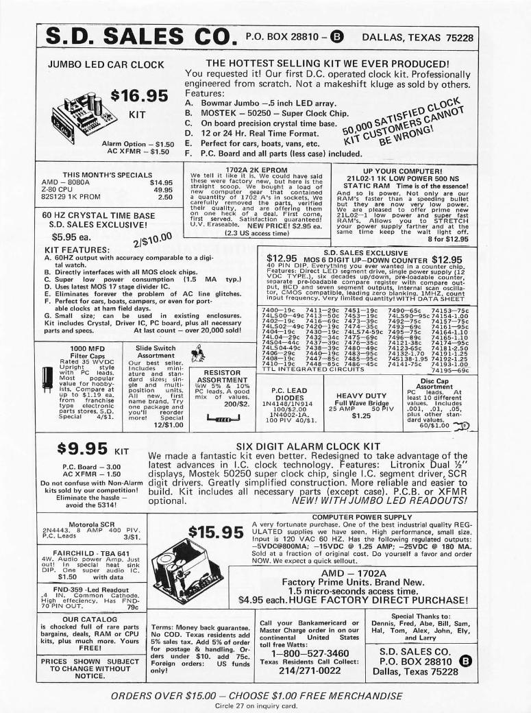
S D SALES CO P.O.BOX28810-0 • • • DALLAS, TEXAS 75228
JUMBO LED CAR CLOCK
~16.95
~~ ::,m 0::: -$150 AC XFMR - $1.50
THIS MONTH'S SPECIALS AMD - 8080A $14.95 Z-80 CPU 49.95 82S129 1 K PROM 2.50
60 HZ CRYSTAL TIME BASE S.D. SALES EXCLUSIVE!
$5.95 ea. 2/$'\0.00 KIT FEATURES:
THE HOTTEST SELLING KIT WE EVER PRODUCED! You requested it! Our first D.C. operated clock kit. Professionally engineered from scratch. Not a makeshift kluge as sold by others. Features: A. Bowmar Jumbo -.5 inch LED array. C\..OC\<" B. MOSTEK - 50250 - Super Clock Chip. 1'\S~\t.O CP.NN01' CD'. On board precision crystal time base. r::.O,OOC~ ~~~~~O~~G\
12or24Hr.ReaITimeFormat. ~ V;:, \ ""p ''" E. Perfect for cars, boats, vans, etc. \<..\1' £,t. F. P.C. Board and all parts (less case) included.
1702A 2K EPROM We tell it like it is. We could have said these were factory new, but here Is the straight scoop. We bought a load of new computer gear that contained a quantity of 1702 A's in sockets. We carefully removed the parts, verified their quality, and are offering them on one heck of a deal. First come, first served. Satisfaction guaranteed! U.V . Eraseable. NEW PRICE! $2.95 ea.
(2.3 US access time)
UP YOUR COMPUTER! 21 L02-1 1 K LOW POWER 500 NS
STATIC RAM Time is of the essence! And so Is power. Not only are our RAM's faster than a speeding bullet but they are now very low power. We are pleased to offer prime new 21L02-1 low power and super fast RAM's. Allows you to STRETCH your power supply farther and at the same time keep the wait light off.
8 for $12.95
A. 60HZ output with accuracy comparable to a digi-S.D. SALES EXCLUSIVE
$12.95 MOS 6 DIGIT UP-DOWN COUNTER $12.95 tal watch.
B. Directly interfaces with all MOS clock chips. C. Super low power consumption (1.5 MA typ.) D. Uses latest MOS 17 stage divider IC. E. Eliminates forever the problem of AC line glitches. F. Perfect for cars, boats, campers, or even for port-
able clocks at ham field days. G. Small size; can be used in existing enclosures. Kit includes Crystal, Driver IC, PC board, plus all necessary parts and specs. At last count - over 20,000 sold!
1000 MFD Filter Caps
Rated 35 WVDC Upright style with PC leads. Most popular value for hobbyists. Compare at up to $1.19 ea. from franchise type electronic parts stores. S.D. Special 4/$1.
Slide Switch Assortment
Our best seller. I ncludes miniature and standard sizesj single and multiposition units. All new, first name brand. Try one package and you'll reorder more! 5 pecial
12/$1.00
RESISTOR ASSORTMENT
l/.W 5% & 10% PC leads. A good mix of values.
200/$2.
40 PI N 01 P. Everything you ever wanted in a counter chip. Features: Direct LED segment drive, single power supply (12 VDC TYPE.), six decades up/down', pre-Ioadable counter, separate pre-Ioadable compare register with compare out. put, BCD and seven segment outputs, internal scan oscillator, CMOS compatible, leading zero blanking. 1MHZ. count input frequency. Very limited quantity! WITH DATA SHEET
7400-19c 7411-29c 7451-19c 74LS00-49c 7413-50c 7453-19c 7402-19c 7416-69c 7473-39c 74LS02-49c 7420-19c 7474-35c 7404-19c 7430-19c 74LS 74-59c 74L04-29c 7432-34c 7475-69c 74S04- 44c 7437-39c 7476-35c 74LS04-49c 7438-39c 7480-49c 7406-29c 7440-19c 7483-95c 7408-19c 7447-85c 7485-95c 7410-19c 7448- 85c 7486-45c TTL INTEGRATED CIRCUITS
7490-65c 74153-75c 74LS90-95c 74154-1.00 7492-75c 74157-75c 7493-69c 74161-95c 7495-75c 74164-1.10 7496-89c 74165-1.10 74121-38c 74174-95c 74123·65c 74181-2.50 74132-1.70 74191·1.25 745138-1.95 74192-1.25 74141-75c J4193-1.QQ..
74195-69c
Disc Cap Assortment
P.C. LEAD DIODES
1N4148/1N914 100/$2 .00
1N4002-1A. 100PIV 40/$1.
HEAVY DUTY Full Wave Bridge
PC leads. At least 10 different values. Includes .001, .01, .05, plus other standard values. ~
25 AMP 50 PIV $1.25
60/$1.00 • , c_
$9.95 KIT SIX DIGIT ALARM CLOCK KIT
P.C. Board - 3.00 AC XFMR - 1.50
Do not confuse with Non-Alarm kits sold by our competition!
Eliminate the hassle -avoid the 5314!
Motorola SC R 2N4443. 8 AMP 400 PIV. P.C. Leads 3/$1.
FAIRCHILD - TBA 641 4W. Audio power Amp. Just out! I n special heat sink DIP. One su per audio IC.
$1.50 with data
FND-359 -Led Readout .4 IN. Common Cathode. High effeciency. Has FN D· 70 PIN OUT. 79c
OUR CATALOG is chocked full of rare parts bargains. deals, RAM or CPU kits. plus much more. Yours
FREE!
PRICES SHOWN SUBJECT TO CHANGE WITHOUT
NOTICE.
We made a fantastic kit even better. Redesigned to take advantage of the latest advances in I.C. clock technology. Features: Litronix Dual %" displays, Mostek 50250 super clock chip, single I.C. segment driver, SCR digit drivers. Greatly simplified construction. More reliable and easier to build. Kit includes all necessary parts (except case). P.C.B. or XFM R optional. NEW! WITH JUMBO LED READOUTS!
$15.95
:'.
COMPUTER POWER SUPPLY A very fortunate purchase. One of the best industrial quality R EGULATED supplies we have seen . High performance, small size. Input is 120 VAC 60 HZ . Has the following regulated outputs: -5VDC@800MA; -15VDC @ 1.25 AMP; -25VDC @ 180 MA. Sold at a fraction of original cost. Do yourself a favor and order NOW. We expect a quick sellout.
AMD - 1702A Factory Prime Units. Brand New.
1.5 micro-seconds access time. $4.95 each. HUGE FACTORY DIRECT PURCHASE!
Terms: Money back guarantee. No COD. Texas residents add 5% sales tax. Add 5% of order for postage & handling. Orders under $10. add 75c. Foreign orders: US funds only!
Call your Bankamericard or Master Charge order in on our continental United States toll free Watts:
1-800-527 -3460 Texas Residents Call Collect:
214/271-0022
Special Thanks to: Dennis, Fred, Abe, Bill, Sam, Hal, Tom, Alex, John, Ely,
and Larry
S.D. SALES CO. ~ P.O. BOX 28810 ~
Dallas, Texas 75228
ORDERS OVER $15.00 - CHOOSE $1.00 FREE MERCHANDISE Circle 27 on inquiry card.
This power supply kit features a high frequency torroid transformer with switching transistors in order to save space and weight. 115V 60 cycle primary. The outputs wi th local regulators are 5V to 10A, in one amp increments, - 5V at 1A, ± 12V at 1A regulators supplied 6 340T·5 supplied.
UNIVERSAL 4K MEMORY BOARD KIT $745 0
F8 EVALUATION BOARD KIT TH EXPANSION CAPABILITIES
This memory board kit can be used with most microcomputers. Some of the outstanding features are:
32·2102·1 static RAM 's, 16 address lines, 8 data lines in , 8 data lines out, all buffered. On· board decoding for any 4 of 64 pages, standard 44 pin, .156" buss.
$29 .50 .. S 1 95
. S 995
. S 350 S 1.39 S 6 .95
5202A UV PROM S 6.95 MMS203 uv PROM. .. S 6 .95 1702A UV PBOM ... S 6 .95 520t1 ·4K PROM . . . SIO 95 AY·5·1013UART ......... .... S 6.95 M fN tATUAE MULTI .TURN TRIM~' 100,500, 2K,SK.l0K,25K. 50K.l00K.200K 1 Meg. S. 75 eac h .3/S2.aO MULTI .TunN T R IM POTS Sundar 10 Bourns 30 10 style 3I1G"x5/S"x l · 1/4" ; 50,100, 1 K, 10K, SOK o hms $1 .50 CiS. 3/5<1 .00 LIGHT ACT IV A T ED seR's TO·18, 2aQv 1 A. S 1.75
TRANSISTOR SPECIALS 2N3585 NI'N $, TO-66 . . S .95 2N3772 NPN 5. TO·3 S 1.GO 2N456I\PNPGE . . 5 .75 2N"90a PN P 51 TO·] . . . . S 1.00 2N6056 NPN 5, TO ·3 Dalllll!Jton . S 1.70 2N5086 PNP 51 TO-92 4 /5 1.00 2N4898 PNP TO·66 ., . . . 5 .60 2N404 PNP GE TO·S 5/5 1.00 2N39 19 NPN 5 . TO·3 RF ..... 5 1.50 MPSA 13 NPN S. TO·92 3/5 1,00 2N3767 NPN Si TO·66 . 5 .70 2N2222 NPN Si TO·IS . 5 /5 1.00 2N3055 NPN SI TO·3 . 5 .80 2N3904 NPN 5 . TO-92 5 /$ 1.00 2N3906 PNP 51 TO·9 2 . . .. 5/$ 1.00 2N5296 NPN Si TO·220 . . $ .50 2N6 109 PNP SI TO·220. . . S .55 2N3638 PNP S. TO-5 . 5/ 5 1.00 2N651 7 NPN TO·92 S • .. . . .. . 3/ $ 1.00
CIMOS (DIODE CLAMPED) 74C02 - .22 4015 - .95 4029 I 10 74C l 0- .22 40 16 - AD 4030 .22 74C 19 3 1.50 4017 - 1.05 4033- 1.50 4001 - .22 4018 - 1.00 4035 - 1. 1 0 4002 - .22 4019 ~ .25 4042 78 4006- 1.20 4020 1.05 4046 - 2.25 4007 - .22 4022 .95 4047 2.00 4009- .4 2 <1023 .22 4049 40 40 10- A2 4024 - .75 4050 .40 401 1- .22 4025 .22 4055 1 50 4012 - .22 4026 1. 25 4066- 8 0 4013- 040 4027 - .40 4071 .22
LED READOUTS
2N 3820 P FET .... 5 .'1 5 2N5457NF ET . . . . .. 5 .4 5 2N2646. . . .. $ .45 ER 900 TR IGG ER D IODES 4/ $1 .00 2N 6028 flROG . UJT . S .6 5 8 PIN DI P SOCKET S . S .24 14 PIN DIP SOCKETS S .25 16 PIN D I P SOCKET S . S .28 18 PIN DIP SOCK ET S . S .30 24 PIN Off> SOCK ET S $ .'10 28 PIN D IP SOCKETS S .50 40 PIN D IP SOCKETS . . . . . $ .60
VE RIPAX PC BOAR D This 110w/l IS il 1/16" s tn ! ll~ sided P.1PC/ epox y llo<J rd. 4 '~· "lim." · DR I LLED ilnd ETC H ED w hich w ill ho ld up to 21 slflUlc 14 p i ll IC's 0 1 8, 16, 01' l SI D IP 1C"5 with busses lor POW!!I sllpply cunnec tol. . ... . . . $4 .00 MV 5G9 1 YE llOW·G RE EN
BIPOLAR LED . . . . .... $1.25 FP 100 PHOT O TRANS . . . . . . $ .!i0 Rc D . YE llOW OR GREEN
L ARGE L ED 's 1 L·5 (MCT ·2) .... MO L EX PIN S ..
. 5 .75 100/51.00
1000/S8 .00 10 WATT ZENERS 3.9, 4.7,5.6, 8.2,
12, 15,18,22.100, 150 or 200V . ea. $ .60 , WATT ZENEAS 4. 7, 5 .6,
18 o r 22 V ..... .... . .. ca. $ .25 MC6860 MODEM CH IP 59.95
J .:..80_ 8.50 .3Jl __ .45 1.1 0
2.30 10.50 2 .75- 12,50
SILICON SOLAR CELLS 2%" diameter
.4V al 500 rna. $4.00 / .2V al 200 mils $2.00 REGULATORS
S .95 S .50 $ .60 $1.40
340K·5,12. 15 or 24 V. .... $1.25
340T·5, 6. 8, 12 15,18 or 24 V5 1. I O
78 MGS ..... 51.35 79 MGS ... 5 1.35
A fantastic bargain for only with the fol/owing features: • 20 ma or RS 232 interface • 64K addressing range • Program control timers • 1 K of on·board static
memory • Built in clock generator
NATIONAL MOS DEVICES ~,lM 1 40 2 1./5 MM I403 - 1.75 MM 1404 - 1. !5 MM50 13 - 2.50 MM50 16 - 2.50 MMS555- 4 .75 MM50 17- 2.70 MM5556- 4 .75 MM!.i055- 2.25 MM521O - 1.95 MM5056- 2.25 MM5260 1.75
TIL IC SERIES 7400 - .15 7445 - .70 74 15 1 . 70 7401 - .15 7446- . 70 74153 .65 7402 - . 15 7447 - 70 74 154 1. 10 7403 - . 15 7448 - .70 74155 . 70 7404 - .20 7450 - .20 74 157 . 70 7405 - .20 7472 - .33 7416 1 .85 7406- .25 7473 - .35 74163 .80 7407 - .25 7474 - .35 74 16-1 .95 7408- .25 74 75 - .49 74165 - 1.0 5 7409 - .21 7476- .35 74173 - 1.40 741 0 - . 15 7480 - .35 74 174 - .95 74 11 - .20 7483- .70 74 175 .9 2 74 12- .20 7485- .BB 74 176 .75 7413- .45 7486 - .30 74 177 - . 79 7414 - .70 7489 1.85 74180 . 70 741 6- .25 7490- ,45 74 18 1- 2. 10 7417 - .25 7491 - . 70 74190- 1. 20 7420 - .20 7492 - .50 7419 1- 1.20 7425 - .2B 7493- 45 741 92 - .85 7426- .25 7494 - . 70 74193- .85 7427 - 30 7495 - .70 74 194 - .85 7430 - .20 7496 - .70 74 195 . 75 " 432 - 25 74 107 - .32 74 196 .BB 7437 - .25 7412 1- .38 74257 1.25 7438 - 25 741 23 - .65 74 279 .90 7440 - . 16 74 125 - 040 753 24 - 1.75 744 1- 85 74126 - AO 75491 - .65 7442 - 52 74 132 - .82 75492 - 6 5
M I NI ATURE DIP SWITCHES CTS·20G·4 Four SPST sW llches
In o nc rIlm.d .p pac ka!!e . S1.75 CTS·20GB EI!)lu SPST sWi tches In a 16
pm DIP p<tckage. $1.95
Circle 59 on inquiry card .
• 64 Byte register • Built·in priority interrupts • Documentation • Uses Fairbug PSU
400 600 1.20 1.75 4 .0(]
SANKEN AUDIO POWER AMPS S.1010 G 10WATTS . . S 7.95 S.1020G20WATTS .. . S 15.95 Si 1050 G 50 WAT TS . . ..... S27.95 ceo 110 LIN EA R 256 XI BIT SELF SCANN I f\iG CHARGED COUPL ED DEV ICE
CCD 20 1
74 LSOO - .25 LM 101 - .75 74LS02 - .25 LM 301/748 - .31 74lS04 - .29 LM 307 - .30 74 l S08 - .25 LM 308 - .95 74 L SI0 - .25 lM 3 11 - .95 74LS I I - .25 lM 319 - .95 74LS20 - .25 lM 324 - 1.05 74LS21 - .25 LM 339 - 1. 10 74LS22 - .25 LM 370 - 1. 15 74LS27 - .29 LM 377 - 2.50 74LS30 - .25 l M 380 - .95 74LS32 - .37 LM 381 - 1.25 74LS37 - .37 LM 382 - 1.25 74LS38 - .37 lM 537 - 2.50 74LS74 - A9 lM 553 - 2.50 74LS90 - .95 lM 555 - A4 74lS 132 - 1. 10 lM 556 - .8!) 74 lS138 - 1.40 560 - 2.00 74LSI39 - 1.40 562 - 2.00 74LS155 - 1.40 565 - 1.10 ?4LS157 - 1.20 703 - .90 74 l S160 - 1. 75 709 - .25 74 l S162 - 1.7S 7 10 - .35 74lS 163 - 1.75 711 - .35 74lS 175 - 1.35 74 1 C or V - .3 1 74lS 193 - 1.80 747 .65 74lS258 - 1.45 1310 - 2.50 74lS367 - . 75 1456 - .95 74lS368 - .75 1458 - .60
CA 3046 - .75 CA 3047 - .95 3900 - A9 8038 - 3.90

• -DIP PLUGS AND COVERS Use fo r mounting diodes, resistors, iumpers, etc. Gold p la ted po rts for lo ng wear.
8 pin 14 pin 16 pin 24 pin 40 pin
1-24 .46 .48 .56 .79
51. 23
PL UGS 25-49
.39
.40
.47
.72 $1. 08
50-99 .32 .34 .38 .65 .93
COV ERS 1-2425-99 . 10 .09 . 10 .09 . 10 .09 . 15 . 13 . 25 .22
Q}OO[fillJDll 5ayg
Be sure to ge t the la test editi on of the TRI-TE K fl ye r . Packed w;th good news o n the la test components
I! " I ! !I " " I ! I! !I
MCM6571A is an 8192 -Bit Ho r izonta l - Scnn (Row se l ect) c hst'scter gene r ator with shifted characters. It contains 128 cha racters in a 7X9 mat r ix , and has capability of shif t ing certain charac t e rs that ally extend below the baseline, such as J,y,g,p and q. A 7 -bit address code is used to ' select one of the cha racters. Features :
.Static operation
.TTL compatability
. CMOS compatability (5V)
.Shifted cha r acte r compatabili t y
. I nclud es Greek alphabe t
.Maximum access time =500n5 (See article in March 177 iss ue of 73 Magazine fo r applications i ncluding 'IV - Computer interface) MC>!6571A .. . . .. ......... . .. ....... . .......... $9.95 Specs •••.. . ...•.••••..• . •• . • .. • .••.• . .•.•••• $1.00
MM5320 TV SYNC G ENE RATOR I.C. Genera te a ll the sync pul ses necessary fo r came ro or video te rmina ls . Use with MCM657 1A in the TV- Compute r inte r-face. MM5320N . . .. .. .... .. . . ...... . ..... .. . . 518.80
C30- 1 400V, 25A Stud SCR ............. .. .. . .. S2.25 SC45E 5OOV, l OA Stud Tdac ........ .. .. .. . ... . 51. 59 Insu la ted Stud 400V, l OA TRIAC assemb ly with built- in
1' •• - •••• -l1li.-16..-.-.-.•• � d;ac. TRI-1 33 ....... ... ... .... . .. .. .. ........ $1.85
DIP PLUG INT ERCO NN ECTS ~~~~K~t ~:,~~R!"~~!hR~~~~~RadjU'table regu l a tor . Ideal fo r use from board to board, remote sw itc hes , in tes t Same simp le circuitry as the popular 78GKC. Needs
Tl P- 30 4OV, I amp PN P Plastk .. . . .. ... . .. . ..... 50~ Tl P-33 4OV, 10Amp NPN Plast;c ........... ..... S1. OO
equ ipment, lanip panels , e tc. Mode from go ld pl ated only two ex ternal resist o rs to program to any volt -connectors, co lor coded ri bbon cob le; mo lded pl ugs . age between +5 and 30V @ SA output . LM18l5 ADA PTI VE SENSE AM P IP. Very fl ex ib le ond durab le. 78HGKC ..... . . . ..... . ... .. • . .•• . . •..... . .... $13.95 Used wi th motor contro l to adopt to variab le input and I
To order , make up part nu mber from characteristic a nd find Spec . .. . ... . ... .. .. ..... . . . . . ....... . .. . .... .30 levels. Applicat ions include ze ro crossing switch, motor price in chart. For instance: S-1 4P-1 8 is si ng le e nded 14 pin ................ __ ••••• 1 contro l, tachome te rs , motor testi ng. . interconnect 18 inches in le ng th. Price is Sl.72. D-24P- 06 LM18 15N . . . . .. .. . .. .. .. ... . . .... . ... .. .. .... . . S5 . 72 is double ended 24 pin, 6 inches in le ngth . Pri ce is $4 . 55. NEW BOOK Specs • . • • •• • .. •. • • . . •••• • . . ••..• • •• •• • • . •.•• • . 30C; Quantity pricing is ava ilab le.
PRICE CHARTS SING LE END No Of Pi ns
12" Length
6" 18" 24" 36" 48" 14P • . • • • • 13 1 1. 62 1:72 1.83 2-:05 2. 26 16P •••••• 1. 64 1.76 1. 87 1.99 2. 21 2,44 24P •••••• 2.49 2.69 2.88 3.08 3 . 48 3 . 87
DQUBLE END 14P ••••• • 2.76 2 .87 2.97 3. 08 3 .30 3 . 51 16P ••• • • • 3 . 01 3 .1 3 3.24 3.36 3 . 58 3 . 81 24 P ••• •• • 4.55 4 .75 4.94 5. 14 5.54 5 . 93
PRESTRIPPED WIR E WRAP WIRE Highest q ua l ity 30 go , Ky nor insu lated sil ve r p la ted wire fo r wrapping. Stripped I " o n bo th ends. Indico ted le ng ths ore lengths of insulated porti on. Pocked 100 per stu rdy p lastic viol or 1000 per po ly bog. Compare our prices ! ! ! . Ava ilab le in Block, Red, Ye llow and Green . State color desi red
Leng th Price per tube of 100 I" 51.48 (WV/30VC- 1) 2" $1.60 (WW30VC- 2) 4" SI .85 (WW30VC- 4) 6" 52 . 20 (WW30VC-6)
Pri ce per bog of 1000 Sl1 .84 (#WW30BK-1) SI2.80 (#WW30B K-21 SI4.80 (#WW30BK-4) $17.60 (NWW30BK- 6)
Dea ler InQuiry Inv ited 100ft. ro ll . .•.•• . . 53.45 10 ro ll s, mixedco lors •. $24.00 500 ft. roll .• . . •.•. 59 . 95 4 ro ll s , mixed co lors • . S35 . 82 1, 000 ft. ro ll ..•. . $17.85 4 ro lls , mi xed colors . . S64 . 26 WIRE WRAP I.C . SOCK ETS, 3 LEV EL GO LD 14 pi n 38<; eo, 10 for $3.60 16 pin 42<; eo, 10 fo r SJ.90
NEW BOOK FROM NATIONA L 1 N5393 200V, 1.5A D;ode . Sturdy replace;"ent for MOS l SI. Giant data book fi l led wi th spec and a pps 1 N4003 ot a good savings • .••.•••••••••••. • • • 15/S1 o n larae sca le MOS ci rcu its from Notiona l Sem iconductor 1 ••••• _ •• _ •••••••• _ ••• Co rpor~ tion . Pri ce includes shipping in U . S . onl y ... S4 . 25 DATA BOOKS BY G. E.
I~O~u~t~s ;~d!. ~U!.~S~.~0~d~d~~ ... filor~2~I~bS~.~~~~~~ ... Opto El ectronics Manua l. Filled with spec a nd a ppli ca ti ons on a wide va ri e ty of Opto devices including many new ISO-
~• r • .:-· .. ·"--1 la tors and couplers . G .E . Opto Manua l . . .. ... . . 54.25 _- .... ~ Semiconductor Da ta Book. A g ia nt book of dato , cross __ _ references, app li ca tions on G . E. devices from tra nsistors
=""" .... "" ,,.... and d;odes to SCRs, Tdocs ond power modul es . Over 1400 BIG pages. Nea rl y 5 Ibs of book! ! ! G.E. Semi Conductor Do to Book . ......... . .... Sl1 .95 Fo reign orders add postage for 5 Ibs (2.3KG)
tlli!ilii!i~ .. ~~~ ...... - .. - .. - .. -iii ..... 1 Power Transis tor Use rs Handbook. For anyone using power Fast transistors and you wa nt to know how to mount o n hea t 11 5V VR 100mA If. Reve rse recovery ti me is less thon sink, dera te o r just genera ll y app ly the m rig ht, thi s is the 20 nS at lOOmA fo rwardl 6 pf cop. Some size as book. G. E. Power Trans istor Users Book •• • • . •. ,$3 . 95 1 N914, I N4148. D600 .. .. . .. . . .. ..... . 20/S1
TO - 5 Heat S;nk. TH ERMALLOY 2211 B 2-p;ece black a nodized for max imum heat diss ipa tion. HS22 11 B. 5/$1
6.8V, 50Wott Zener . "-"ode by t-Aotorolo in TO- 3 case . Gold p lated. • .. • . •. •• . . . .• . •. • 0 • •••• $1. 00
15V. 51.' 57. Zener. IN5352B axial l ead zener is just right for those HOS vo lta ge supplies . . •...•.•• 3/ $1
General PlIrpose NPN Switch. /12501-1 2 NPN switch in TO - 18 metal trans istor similar to 2N2847. 112501 -l2 ..... . ... . •.. .. • .......•.....• . •. . . 12/$1. 00
2N4234, 40\', 3A PNP switch, TO - S ••.••••••••• SOC 2N2905, 40V •. 6A PNP Switch /Amp . TO-5 ..... . 5/$1.00 2N2147, SOV Gemwnlwn TO - 3 .. . ..•........•. . . $ 1.00
sov. 45Amp Fast Recovery Diode. Similar to IN3909 s tud mount. Reverse recovery at 1 Amp= .SuS . ..........• •.• •.•.•... • . • . . .•.... $2.00
"COOK BOOKS" The famous Howard Sams "Cook Book" se ri es te ll s you who t a nd how in a brood ra nge of sub jects. Probab ly the most wide ly referenced works in thei r fie lds . Pr.ices q uoted inc lude sh ipping (U .S . onl y) TTL Cookbook ....... . ... . . . 328 pages .. ...... S9 . 95 AcHve Hlter Cookbook .. .... 223 pages .. .. . .. S15.95 CMOS Cookbook . ....... . .. 402 pages .. ...... S10 . 95 IC OP AM P Cookbook ....... 579 poges ....... . S14.25 J V Typewrite r Cookbook . . .. . 250 pages .. . . . .•• $10 . 95
14411 BIT RATE G ENE RATOR. chi p for genera ti ng se le ctable frequenc ies for
dato communications suc h as TT Y, pr inte rs, CRT 5
m; c"o~"o,:e",ors . Generates 14 d iffe re nt standa rd b it wh ic h are multipli ed under externa l contro l to l X,
16X or 64X ini tia l va lue. Opera tes from sing le +5 t supp ly. MC I44 Il .... . . .. .. ...... .. ... . .. Sil . t •••••• IIIIIII~~ .. IIII-•••••••• 1 4 pages of da ta . ..... . .. .. . . .. . ..... .. .. .. . . . . ... . •
SIGNETICS 8000 SERIES TTL LOGIC Crysta l for the ob<:':.e ..... ........ ..... :..:..: . .. . . . . $4 .
~ These quality uni.t s are faster and have greater fan-
. , alit capabili.ty than sta ndard TTL. From a giant fac -tory change - over YOll get rea 1 ba rgain prices. All : ~!~I~~it~~OR~~~e~:1 ~.~~~i~ ;n~ ~~~ mV
. :~~ _~~~s=h~:~ered. but we provide B reference nnd : ~:,;~~~o~v~~:nS/$ - ~ ';, N8880A ... Qulld - 2 input NAND gate ........... 8/$1.00 • Auto·Polar iWolndAulo-Zero
HIG H CURRE N T STUD DIOD ES '* N8822A ... Dual J - K mnsterlslave F/F . . . . . . . . 4/$1.00 : ~:~~~a~~S~I.~:r~~~~~~~:rl~~~_Dr ive~Onelow Power 131 200V , 25A . . .. ............. . . .. .. . .. . ....... $ .85 N8885A ... Quad 2 - inpllt NOR gatc . • .. • . . .• . . . 8/$l.OO Schot1kv l oad
135 400V , 25A .. .. . .. . ... . .. .. ..... .. . .. . ... . . .. SI. 00 N8890A ... Hex Inve rte r ......... ... ......... 6/$1. 00 : ~~: ~~~~t: itoSnVs~I~~I~~~~.~rm;~\e::;~aT~c~5 .0 v
138 600V, 25A ..• . •• .• .••.•.••.•.••• • • . ••••• . . •• Sl . 55 11-"8. 2.0.2A • .• .•.• 10. b.1.t .'.'O.". t. y.p.e. r ••• g.1'. t.".r ...... ... ......... . $. 1 •.• 25.~1 • Wide SupplV Rangil: lI.g., !:4.5 V 10 .! B.O V 3289 200V, l OOA .... ; ........... ... .............. $5.85 MC I4433 SING LE CHIP 3l DIG IT AI D
following items a r e avaUable in l a r ge quantities Sing le chip comb ines linear a nd CMOS d ig ital to b ri ng you
14. ~r N;~n~~~~~~r~~ ~:~~!~~.:~. ~~~~~~~ : .. 10/$1 the s imp les t ye t DVM opproach . Requi ri ng on ly 4 ex te rnal IN753A . . 6.2V , 5%, ~w Zener . .. . ...••....••.. 5/$1 pass ive ports , thi s subsys tem gi ves you: Auto po la rity , a uto Cl 06F2 .. 50V , 4A SCR w/socket ......... . ••... 3/$1 zero , sing le vo ltage re ference, 8 m\Vopera tion, overrange , IN967B .. 18V. 5% , W Zene r ..••.••......• .. .• 5/$1 unde rra nge signa ls, 25 conve rs ions pe r second a nd .05% ± 42501 - 1 Quad Hi speed NPN transistor in 14 pin DIP 1 count accuracy ! 100 uV reso lution . 24 Pin DIP.
tQ I - tEk, Inc. 6522 no~th 43~O ave nue. c;lenOal€, a~lzona" 85301
phon€ 602 - 931 ' 6949
Similar to Motorol a MPQ3303 .. ..... 5/$1 MCI4433P ... .. .. . ... w; th .... .......... . SI9.55
We pay su rface shippi ng on all orde rs ove r S10 US, $15 fore ign in US funds. Please odd ex tra for firs t c loss or a ir mo il . Excess will be refu nded. O rders under $10, odd $1 ha nd ling . Please add 50C; insura nce . Moster cha rge a nd Bonk America co rds welcome, (S20 minimum). Te le phone orders may be placed l OAM to 5,30PM da ;] y, Man th ru Fd . Call 602- 931 - 452B. Check reoder se rvice ca rd or send stomp fo r our la test flye rs pocked wi th new a nd surpl us e lec troni c compone nts .
•
• • Circ le 32 o n inq u iry card.

To get further information on the products advertised in BYTE, fill out the reader service card with your name and address. Then circle the appropriate numbers for the advertisers you select from this list. Add a 9 cent stamp to the card , then drop it in the mail. Not only do you gain information, but our advertisers are encouraged to use the marketplace provided by BYTE. This helps us bring you a bigger BYTE.
Reader Reader Reader Service Page Service Page Service Page
Number Number Number Number Number Number
75 Advanced Microcomputer 164 157 Electron ic Warehouse 168 260 Objective Design Inc 146
168 Aldelco 165 247 El ectrava lue 159 40 Oh io Scientific Instruments 49
255 Alpha Digital Systems 151 102 El tron 169 64 Ol iver Audio Engineering 161
272 Apple Computer 14, 15, 17 257 Fein·Marquart 159 198 Omni 147
275 Artisan Computer 128 248 Franklin Electric 67 PC 77 At lantic City 75
276 Beta Business Systems 151 9 Godbout Electronics 170 273 Page Digital Electron ics 163 4 Bits Inc 131 , 132, 162, 163 HAL Communications 129 265 Paia Electronics Inc 23
Byte Index 127 262 Hashi zume Burt 161 63 Parasitic 109, 110 227 Byte Shop East 1 51 151 Heath Co 68, 69, 70, 71 PerCom Data 12, 72 271 Byte Shop of Miami 127 12 IMSAI5 194 Peripheral Vi sion 29 200 California Industrial 166 117 Intel 10,11 281 Perri·White 110
* Camp Retupmoc 151 204 Internationa l Data Systems 160 Personal Computing Expo 149
127 Comptek 147 268 lOR 161 PolyMorphic Systems C III 38 Compucolor 60,61 278 Ithaca Audio 145 213 Prime Radix 153
140 Computal ker 151 215 Jade Company 171 24 Processor Technology 6, 7, 8 161 Computer Corner 159 15 James 172, 173 219 RHS Marketing 98, 99 253 Computer Electronics 127 214 Joh n Wiley & Sons 105 201 Riverside Electronic 158 143 Computer Enterprises 148 209 Logic Des ign 127 234 Rotundra Cybernetics 163 176 Computer Mart N H 159 MACC 130 27 SO Sales 177 83 Computer Mart NY 162 18 Meshna 174 282 Sams Howard W 51
156 Computer Place 1 59 261 Micro Computers 161 26 Sce lbi 25 141 Computer Room 115 77 Micro·Term 107 73 Scientif ic Research 79 208 Computer Shack 111 242 Micromation 26 236 SEALS 73 179 Computer Shop (Canada) 127 196 Micronics 161 169 Smoke Signal Broadcasting 120 138 Computer Warehouse Store 167 119 Midwestern Scientific I nst 121 59 Solid State Sales 178
6 Continental Specialties 126 57 Mikos 175 29 Southwest Technical Products CII 202 CRC Engineering 159 279 Mini Micro Mart 176 164 Sunny Computer Stores 163
87 Creative Computing 143 112 MiniTerm 122, 123 , 124, 125 96 Synchro·Sound Enterprises 86, 87 41 Cromemco 1 , 2 MITS CIV 205 Szerlip Enterprises 108
178 Cybercom 13 250 Mountain Hardware 151 121 Tarbe ll Electron ics 146 223 Data Search 108 71 mp i 145 82 Techn ical Design Labs 53
78 Digital Group 28 171 Mullen 144 136 Techn ical Systems Consultants 107 263 Digital Concepts 144 264 MVT Microcomputer Systems 161 32 Tri ·Tek Inc 179
56 E& L Instruments 113 NCC 63, 64, 65, 66 270 Urban Instruments 11 2 79 Economy Company 139 155 North Star Computers 24 13 7 Vector Graphic Inc 74
269 Edityper Systems Corp 114 280 Northern Vall ey Systems 148 220 Xi media 27 47 Electronic Control Tech 127 277 Nov~ 81,82,83,84 222 Xybek114
* Reader service inquiries not solicited. Correspond directly with company.
On BOMB Card, Article No. ARTICLE
Kraul : Designing Multichannel Analog Interfaces 2 Hollis: Newt: A Mobile, Cognitive Robot 3 Fylstra: Interfacing the IBM Selectric Keyboard Printer 4 Carr: Interfacing to an Analog World : Part 2 5 Simpson : Come Fly with KIM 6 Welles: Software for the Economy Floppy Disk 7 Wimble: Artificial Intelligence: Part 2 , Implementation 8 Ouek : Introduction to Microprogramming 9 Guzzon: A 6800 Selectric 10 Printer Program
10 McNatt: A Guide to Baudot Machines : Part 3
180
PAGE
18 30 46 54 76 88
100 116 140 154
The Bomb of March
Th e BOMB of March has fa ll en . In the tabu lation of the stacks of cards returned with article eva luations, Jack Breimeir and Ira Rampil came out first, and receive the $100 prize for the ir articl e "The Digita l Cassette Subsystem, Part 2." Second prize win ner in the tally came up as a tie between Steve Ciarcia's " Try This Computer on for Size" and Thomas R Buschbach's "An I nexpensive Joystick In terface." Steve and Thomas wil l each receive a $50 bonus check.-

The LY88 Microcomputer S em
PolyMorphic Systems now offers the complete, assembled, personal computer system-the POLY 88 System 16. A full 16K system with high speed video display, alphanumeric keyboard, and cassette program storage. A BASIC software package providing the most advanced features available in the personal computing market. Features like PLOT and TIME, which utilize our video graphics and real-time clock. Others like VERIFY, so that you know your tape is good before you load another. Or input type-ahead so you can tell your program to run while the tape is still loading (it stores up to 64 characters of commands or question responses to be executed). All these plus a complete package of scientific functions, formatting options, and string capabilities. With the POLY 88 System 16 you can amaze your timesharing friends the very first night!
Polymorphic Systems 11K BASIC - Size: 11 K bytes.
Scientific Functions: Sine, cosine, log, exponential , square root , random number, x to the y power. Formatted Output. Multi-line Function Definition. String Manipulation and String Functions. Real-Time Clock. PolntPlotting on Video Display. Array dimensions limited by memory • Cassette Save and Load of Named Programs. Multiple Statements per Line. Renumber. Memory Load and Store • 8080 Input and Output. If Then Else. Input type-ahead.
Commands: RUN, LIST, SCR, CLEAR, REN, CONTINUE
Statements: LET, IF, THEN, ELSE, FOR, NEXT, GOTO, ON, EXIT, STOP, END, REM, READ, DATA, RESTORE, INPUT, GOSUB, RETURN, PRINT, POKE, OUT.
Built In Functions: FREE, ABS, SGN, INT, LEN, CHR$, VAL, STR$, ASC, SIN, COS, RND, LOG, TIME, WAIT, EXP, SORT, CALL, PEEK, INP, PLOT.
Systems Available. The POLY 88 is available in either kit or assembled form . It is suggested that kits be attempted only be persons familiar with digital circuitry.
System 2: is a kit consisting of the POLY 88 chassis, CPU, video circuit card , and cassette interface. ReqL'ires keyboard, TV monitor , and cassette recorder for operation . $735
System 16: consists of an assembled and tested System 2 with 16K of memory, keyboard, TV monitor, cassette recorder, 11 K BASIC and Assembler on cassette tapes. $2250. System 0: The circuit cards an S-1 00 mainframe owner needs to be compatible with the POLY 88 software library. System 0 consists of the central processor card with monitor ROM, the video circuit card, and cassette interface, all in kit form . $525.
Prices and specifications are subject to change without notice. California residents add 6% sales tax.
460 Ward Drive Santa Barbara. Ca. 93111 (805) 967-2351
PolyMorphic Systems
POLY 88 PolyMorphiC
Syslems

Now you can buy an Altair8800b or an Altair 680b computer right off the shelf. Altair plug-in
boards, peripherals, software and manuals
are also available. Check the list below
for the MITS dealer in your area.
ALTAIR COM PUTER CE N TE R 4941 East 29th SI TU C SON, AZ 85711 1602)·748·7363
COMPUTE R KITS 1044 Un iversity A ve B E R K E LEY, CA 94710 1415 1· 8 45 · 5300
T HE COMPUTE R STORE 820 Broaaway SANTA MONICA. CA 90401 12 13 1· 4 5 1·0 713
GATEWAY ELEC TRONI CS. INC OF COLORADO 2839 W 44th Ave DENVER, CO 80211 1303)·4 58·544 4
THE CO M PU TER STORE. IN C ( H a rtford area) 63 South Mam Street WINDSOR LOCKS , CT 06096 12031·627·0188
MAR S H DATA SYS TE M S 5 4 05 B Sou thern Com fort Bl vd TAMPA, FL 33614 181 3 )·88 6 · 9890
THE CO MPUTER SYS TE M CE N TER 3330 Piedmont Roa d ATLANTA , GA 30305 14 0 4 1·2 3 1·1691
C HICAGO COM PU TE R STORE 5 17 Talco !1 Ad PARK RIDGE , IL 60068 13 12)·82 3 · 2388
TH E CO M P UTER STORE L1F ANN AR 8 0R 3 1 0 Ea st Wa s hing ton S t reet ANN ARBOR, MI 48104 13 131·995·7616
TH E COMPU T ER R OOM 3938 Beau O ' Rue Drive EAGAN, MN 55122 16 121· 4 52·2567
GATEWAY ELECTRONICS. INC 8 1 23·25 Page Blvd ST. LOUIS , MO 63130 1314)· 427·611 6
ALTA IR COMPUTER CE NTER 61 1 N 2 7th S t S uit e 9 LINCOLN , NB 68503 1402) 474·2800
COMPUTER SHACK 3 1 20 San M ateo N E ALBUQUERQUE , NM 87110 15051·883·8282.883·8283
THE CO MPUTER STORE 269 Os b orne Rond ALBANY, NY 1221' (5 18)- 4 59-6 14 0
THE COMPUTER STORE OF NEW YO RK 55 West 391h Street NEW Y ORK , NY 10018 1212 1· 221 ·1404
COMPUTER STO R ES OF CA R O LINA, INC 1808 E . Independence B lvd CHARLOTTE, N.C . 28205 1704)·33 4 · 0242
ALTAIR COMPUTER CE NTE R 5252 North Dixie D rive DAYTON , OHIO 45414 1513 )· 433 ·8460
ALTAIR COMPUTER CE NTER 110 The Annex 5345 East Forty Firs t S t T U LSA , OK 74135 19 18)·664· 4 564
ALTA IR CO MPUTER CE NTER 8105 SW Nimbus Ave BEAVERTON , OR 97005 ~503)-644 - 2314
ALTA IR COMPUTER CE NTER 5750 Blntldf Driv e Slll t e 206 HOUSTON, TX 77036 1713 1·7 80·8981
COMPUTERS·TO·GO 4 503 West Broad 5 1 RICHMOND, VA 23230 1804 1·355·5773
MICAOSYSTE M S !Washlnglon , 0 C) 6605A 8ac kllck A d SPRINGFIELD, VA 22150 1703)·5 69·11 10
THE CO MPUTE R STORE SUIte 5 Municipal Pa rkmg Build ing CHARLESTON , W . VA . 25301 13 0 4 )· 345·1360