Melting Point M-565 Operation Manual
62
Melting Point M-565 Operation Manual 093256G en
-
Upload
khangminh22 -
Category
Documents
-
view
5 -
download
0
Transcript of Melting Point M-565 Operation Manual

Melting Point M-565Operation Manual
093256G en

ImprintProduct Identification: Operation Manual (Original), Melting Point M-565
093256G en
Publication date: 07.2018
BÜCHI Labortechnik AG Meierseggstrasse 40 Postfach CH-9230 Flawil 1
E-Mail: [email protected]
BUCHI reserves the right to make changes to the manual as deemed necessary in the light of experience; espe-cially in respect to structure, illustrations and technical detail.
This manual is copyright. Information from it may not be reproduced, distributed, or used for competitive purpos-es, nor made available to third parties. The manufacture of any component with the aid of this manual without prior written agreement is also prohibited.

Table of contents
3 Melting Point M-565 Operation Manual, Version G
Table of contents
1 About this manual . . . . . . . . . . . . . . . . . . . . . . . . . . . . . . . . . . . . . . . 51.1 Reference documents . . . . . . . . . . . . . . . . . . . . . . . . . . . . . . . . . . 51.2 Abbreviations . . . . . . . . . . . . . . . . . . . . . . . . . . . . . . . . . . . . . . 5
2 Safety . . . . . . . . . . . . . . . . . . . . . . . . . . . . . . . . . . . . . . . . . . . . . . 62.1 User qualification . . . . . . . . . . . . . . . . . . . . . . . . . . . . . . . . . . . . 62.2 Proper use . . . . . . . . . . . . . . . . . . . . . . . . . . . . . . . . . . . . . . . 62.3 Improper use . . . . . . . . . . . . . . . . . . . . . . . . . . . . . . . . . . . . . . 62.4 Warning notices used in this manual . . . . . . . . . . . . . . . . . . . . . . . . . . 72.5 Product safety. . . . . . . . . . . . . . . . . . . . . . . . . . . . . . . . . . . . . . 72.5.1 Instrument-related hazards . . . . . . . . . . . . . . . . . . . . . . . . . . . . . . . 72.5.2 Other hazards . . . . . . . . . . . . . . . . . . . . . . . . . . . . . . . . . . . . . . 72.5.3 Safety measures . . . . . . . . . . . . . . . . . . . . . . . . . . . . . . . . . . . . 82.5.4 Safety elements . . . . . . . . . . . . . . . . . . . . . . . . . . . . . . . . . . . . . 82.6 General safety rules . . . . . . . . . . . . . . . . . . . . . . . . . . . . . . . . . . . 8
3 Technical data . . . . . . . . . . . . . . . . . . . . . . . . . . . . . . . . . . . . . . . . . 93.1 Scope of delivery . . . . . . . . . . . . . . . . . . . . . . . . . . . . . . . . . . . . 93.1.1 Standard accessories . . . . . . . . . . . . . . . . . . . . . . . . . . . . . . . . . . 93.1.2 Optional accessories . . . . . . . . . . . . . . . . . . . . . . . . . . . . . . . . . 113.2 Technical data overview . . . . . . . . . . . . . . . . . . . . . . . . . . . . . . . . 143.3 Materials used. . . . . . . . . . . . . . . . . . . . . . . . . . . . . . . . . . . . . 15
4 Description of function . . . . . . . . . . . . . . . . . . . . . . . . . . . . . . . . . . . 164.1 Functional principle . . . . . . . . . . . . . . . . . . . . . . . . . . . . . . . . . . 164.1.1 Pharmacopoeia and thermodynamic melting points . . . . . . . . . . . . . . . . . . 174.1.2 Boiling points . . . . . . . . . . . . . . . . . . . . . . . . . . . . . . . . . . . . . 184.2 Controls and connections . . . . . . . . . . . . . . . . . . . . . . . . . . . . . . . 19
5 Putting into operation . . . . . . . . . . . . . . . . . . . . . . . . . . . . . . . . . . . . 205.1 Installation site. . . . . . . . . . . . . . . . . . . . . . . . . . . . . . . . . . . . . 205.2 Commissioning . . . . . . . . . . . . . . . . . . . . . . . . . . . . . . . . . . . . 205.2.1 Unpacking and installation. . . . . . . . . . . . . . . . . . . . . . . . . . . . . . . 205.2.2 Connecting to a PC with MeltingPoint Monitor software . . . . . . . . . . . . . . . . 225.2.3 Power connection . . . . . . . . . . . . . . . . . . . . . . . . . . . . . . . . . . . 225.2.4 Calibration. . . . . . . . . . . . . . . . . . . . . . . . . . . . . . . . . . . . . . . 22
Read this manual carefully before installing and running your system; take particular note of the safety precautions in section 2. Keep the manual in the immediate vicinity of the instrument, so that it can be consulted at any time.No technical modifications may be made to the instrument without the prior written agreement of BUCHI. Unauthorized modifications may affect system safety or result in accidents. This manual is copyrighted. Information from it may not be reproduced, distributed, or used for competitive purposes, nor made available to third parties. The manufacture of any component with the aid of this manual without prior written agreement is also prohibited.The English manual is the original language version and serves as basis for all translationsinto other languages . Other language versions can be downloaded at www .buchi .com .

Table of contents
4 Melting Point M-565 Operation Manual, Version G
6 Operation . . . . . . . . . . . . . . . . . . . . . . . . . . . . . . . . . . . . . . . . . . 236.1 Basic operating principles . . . . . . . . . . . . . . . . . . . . . . . . . . . . . . . 236.1.1 Display during idle . . . . . . . . . . . . . . . . . . . . . . . . . . . . . . . . . . . 236.1.2 Display during a process or in menus . . . . . . . . . . . . . . . . . . . . . . . . . 246.1.3 Entering text. . . . . . . . . . . . . . . . . . . . . . . . . . . . . . . . . . . . . . 256.1.4 Using the external keyboard. . . . . . . . . . . . . . . . . . . . . . . . . . . . . . 266.2 Melting point determination . . . . . . . . . . . . . . . . . . . . . . . . . . . . . . 266.2.1 Sample preparation . . . . . . . . . . . . . . . . . . . . . . . . . . . . . . . . . . 266.2.2 Determination without pre-registered melting point method . . . . . . . . . . . . . . 276.2.3 Creating a method . . . . . . . . . . . . . . . . . . . . . . . . . . . . . . . . . . 306.2.4 Using and handling methods . . . . . . . . . . . . . . . . . . . . . . . . . . . . . 306.2.5 Adjusting parameters during a determination . . . . . . . . . . . . . . . . . . . . . 316.2.6 Printout . . . . . . . . . . . . . . . . . . . . . . . . . . . . . . . . . . . . . . . . 316.2.7 Melting result . . . . . . . . . . . . . . . . . . . . . . . . . . . . . . . . . . . . . 326.3 Boiling point . . . . . . . . . . . . . . . . . . . . . . . . . . . . . . . . . . . . . . 386.3.1 Sample preparation . . . . . . . . . . . . . . . . . . . . . . . . . . . . . . . . . . 386.3.2 Determination without pre-registered boiling point method . . . . . . . . . . . . . . 386.3.3 Creating a method . . . . . . . . . . . . . . . . . . . . . . . . . . . . . . . . . . 406.3.4 Adjusting parameters during a determination . . . . . . . . . . . . . . . . . . . . . 406.3.5 Printout . . . . . . . . . . . . . . . . . . . . . . . . . . . . . . . . . . . . . . . . 416.4 Calibration. . . . . . . . . . . . . . . . . . . . . . . . . . . . . . . . . . . . . . . 426.4.1 Calibration principle . . . . . . . . . . . . . . . . . . . . . . . . . . . . . . . . . . 426.4.2 Calibration procedure . . . . . . . . . . . . . . . . . . . . . . . . . . . . . . . . . 436.4.3 Printout . . . . . . . . . . . . . . . . . . . . . . . . . . . . . . . . . . . . . . . . 456.4.4 Verification. . . . . . . . . . . . . . . . . . . . . . . . . . . . . . . . . . . . . . . 466.5 Settings, SysInfo, Test . . . . . . . . . . . . . . . . . . . . . . . . . . . . . . . . . 466.5.1 Test protocol . . . . . . . . . . . . . . . . . . . . . . . . . . . . . . . . . . . . . 496.5.2 SysInfo protocol . . . . . . . . . . . . . . . . . . . . . . . . . . . . . . . . . . . . 506.6. User Managment . . . . . . . . . . . . . . . . . . . . . . . . . . . . . . . . . . . 526.7 XML to PC data export . . . . . . . . . . . . . . . . . . . . . . . . . . . . . . . . 52
7 Maintenance . . . . . . . . . . . . . . . . . . . . . . . . . . . . . . . . . . . . . . . . . 537.1 Housing . . . . . . . . . . . . . . . . . . . . . . . . . . . . . . . . . . . . . . . . 537.2 Glass window . . . . . . . . . . . . . . . . . . . . . . . . . . . . . . . . . . . . . 537.3 Upkeep . . . . . . . . . . . . . . . . . . . . . . . . . . . . . . . . . . . . . . . . 537.4 Cleaning the heating block . . . . . . . . . . . . . . . . . . . . . . . . . . . . . . 54
8 Troubleshooting . . . . . . . . . . . . . . . . . . . . . . . . . . . . . . . . . . . . . . . 558.1 Malfunctions and their remedy. . . . . . . . . . . . . . . . . . . . . . . . . . . . . 558.1.1 Setting the printer baud rate. . . . . . . . . . . . . . . . . . . . . . . . . . . . . . 578.2 Customer service . . . . . . . . . . . . . . . . . . . . . . . . . . . . . . . . . . . 57
9 Shutdown, storage, transport, and disposal . . . . . . . . . . . . . . . . . . . . . . . 589.1 Storage and transport . . . . . . . . . . . . . . . . . . . . . . . . . . . . . . . . . 589.2 Disposal . . . . . . . . . . . . . . . . . . . . . . . . . . . . . . . . . . . . . . . . 58
10 Spare parts . . . . . . . . . . . . . . . . . . . . . . . . . . . . . . . . . . . . . . . . . . 5911 Declarations and requirements . . . . . . . . . . . . . . . . . . . . . . . . . . . . . . . 60
11.1 FCC requirements (for USA and Canada) . . . . . . . . . . . . . . . . . . . . . . . 60
1 About this manual
5 Melting Point M-565 Operation Manual, Version G
1 About this manual
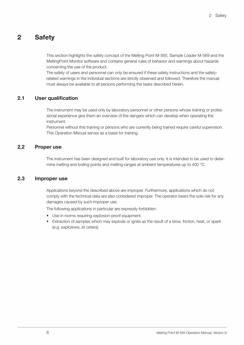
This manual describes the Melting Point M-565 and provides all the information required for the safe operation and to maintain it in good working order.It is addressed in particular to laboratory personnel and operators.
NOTEThe symbols pertaining to safety (WARNINGS and ATTENTIONS) are explained in section 2.
1 .1 Reference documents
For more information regarding melting point, refer to the corresponding literature:
• The Laboratory Assistant 94187• Melting Point M-560, Operating Manual numbers 93251–93255• Melting Point M-565, Operating Manual numbers 93256–93260
1 .2 Abbreviations
Chemicals:
PTFE PolytetrafluoroethylenePP PolypropylenePE PolyethyleneEPDM Ethylene-propylene-diene rubberPOM PolyoxymethylenPUR Polyurethane
Miscellaneous:
mp Melting pointbp Boiling pointpharm. Pharmacopoeiatherm. ThermodynamicL Sample leftC Sample centerR Sample right
2 Safety
6 Melting Point M-565 Operation Manual, Version G
2 Safety
This section highlights the safety concept of the Melting Point M-565, Sample Loader M-569 and the MeltingPoint Monitor software and contains general rules of behavior and warnings about hazards concerning the use of the product.The safety of users and personnel can only be ensured if these safety instructions and the safety- related warnings in the individual sections are strictly observed and followed. Therefore the manual must always be available to all persons performing the tasks described herein.
2 .1 User qualification
The instrument may be used only by laboratory personnel or other persons whose training or profes-sional experience give them an overview of the dangers which can develop when operating the instrument.Personnel without this training or persons who are currently being trained require careful supervision. This Operation Manual serves as a basis for training.
2 .2 Proper use
The instrument has been designed and built for laboratory use only. It is intended to be used to deter-mine melting and boiling points and melting ranges at ambient temperatures up to 400 °C.
2 .3 Improper use
Applications beyond the described above are improper. Furthermore, applications which do not comply with the technical data are also considered improper. The operator bears the sole risk for any damages caused by such improper use.
The following applications in particular are expressly forbidden:
• Use in rooms requiring explosion-proof equipment.• Extraction of samples which may explode or ignite as the result of a blow, friction, heat, or spark
(e.g. explosives, et cetera).

2 Safety
7 Melting Point M-565 Operation Manual, Version G
2 .4 Warning notices used in this manual
WARNINGGenerally, the triangular warning symbol indicates the possibility of personal injury or even loss of life if the instructions are not followed.
WARNINGHot surface.
WARNINGElectrical hazard.
WARNINGBiohazard.
ATTENTIONThe “read this” symbol for ATTENTION indicates that equipment damage, malfunctions, or incorrect processes may result if the instructions are not followed.
NOTEUseful tips to facilitate operation of the instrument.
2 .5 Product safety
The Melting Point M-565, Sample Loader M-569, and the MeltingPoint Monitor software are designed and built in accordance with current state-of-the-art technology. However, risks to users, property, and the environment can arise when the instrument is used carelessly or improperly.
The manufacturer has determined residual dangers emanating from the instrument
• if the instrument is operated by insufficiently trained personnel.• if the instrument is not operated properly.
Appropriate warnings in this manual serve to alert the user to these residual dangers.
2 .5 .1 Instrument-related hazards
Pay attention to the following safety notices:
WARNINGPotentially hot surfaces during operation, especially the heating oven (up to 400 °C).
• Always be aware of the danger of being burned.
2 .5 .2 Other hazards
WARNINGCertain solvents within or in the vicinity of the Melting Point M-565 can form peroxides and/or are highly inflammable.
• Always be aware of the explosion risk when working with hazardous substances or with substances of unknown composition.
• Always use the instrument in an adequately ventilated work area.
2 Safety
8 Melting Point M-565 Operation Manual, Version G
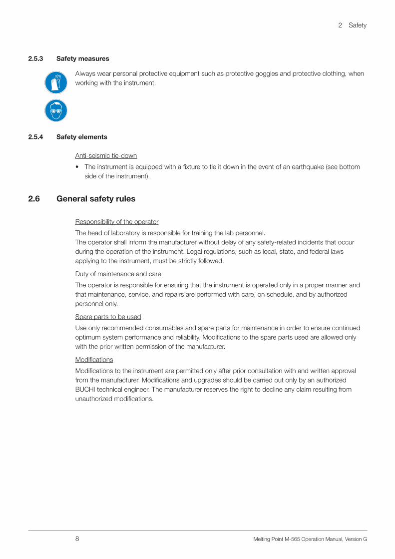
2 .5 .3 Safety measures
Always wear personal protective equipment such as protective goggles and protective clothing, when working with the instrument.
2 .5 .4 Safety elements
Anti-seismic tie-down
• The instrument is equipped with a fixture to tie it down in the event of an earthquake (see bottom side of the instrument).
2 .6 General safety rules
Responsibility of the operator
The head of laboratory is responsible for training the lab personnel.The operator shall inform the manufacturer without delay of any safety-related incidents that occur during the operation of the instrument. Legal regulations, such as local, state, and federal laws applying to the instrument, must be strictly followed.
Duty of maintenance and care
The operator is responsible for ensuring that the instrument is operated only in a proper manner and that maintenance, service, and repairs are performed with care, on schedule, and by authorized personnel only.
Spare parts to be used
Use only recommended consumables and spare parts for maintenance in order to ensure continued optimum system performance and reliability. Modifications to the spare parts used are allowed only with the prior written permission of the manufacturer.
Modifications
Modifications to the instrument are permitted only after prior consultation with and written approval from the manufacturer. Modifications and upgrades should be carried out only by an authorized BUCHI technical engineer. The manufacturer reserves the right to decline any claim resulting from unauthorized modifications.

3 Technical data
9 Melting Point M-565 Operation Manual, Version G
3 Technical data
This section introduces the reader to the Melting Point M-565 and its main components. It contains technical data, requirements, and performance data.
3 .1 Scope of delivery
Check the scope of delivery according to the order number.
NOTEFor detailed information on the listed products, see www.buchi.com or contact your local dealer.
3 .1 .1 Standard accessories
Table 3-1: Standard accessories
Product Order number
Melting Point M-565 11058004
Calibration set M-560 / M-565 (4 substances; 4-nitrotoluene, diphenyl acetic acid, caffeine, potassium nitrate)
11055018
Melting point capillaries, 100 units 017808

3 Technical data
10 Melting Point M-565 Operation Manual, Version G
Table 3-1: Standard accessories (cont.)
Product Order number
Sample holder 11055014
Cleaning tool 051978
A
A
B BA) Boiling point tubes, 10 units 019697
B) Boiling point capillaries, 10 units 051850
User management activation code 11066387
Protective cover 051935
Compaction wire 036721
CD Demo Melting Point Monitor 051983
USB cable, 2.0 m 11055310
Operation Manual:
English 93256
German 93257
French 93258
Italian 93259
Spanish 93260

3 Technical data
11 Melting Point M-565 Operation Manual, Version G
3 .1 .2 Optional accessories
Table 3-2: Optional accessories
Product Order number
MeltingPoint Monitor software with license
11055332
Sample Loader M-569 051997
Verification set M-560 / M-565 (3 substances; benzil, p-anisic acid, phenolphthalein)
11055019
Melting point capillaries, 1000 units 001759
Mortar and pestle, agate 041867
3 Technical data
12 Melting Point M-565 Operation Manual, Version G
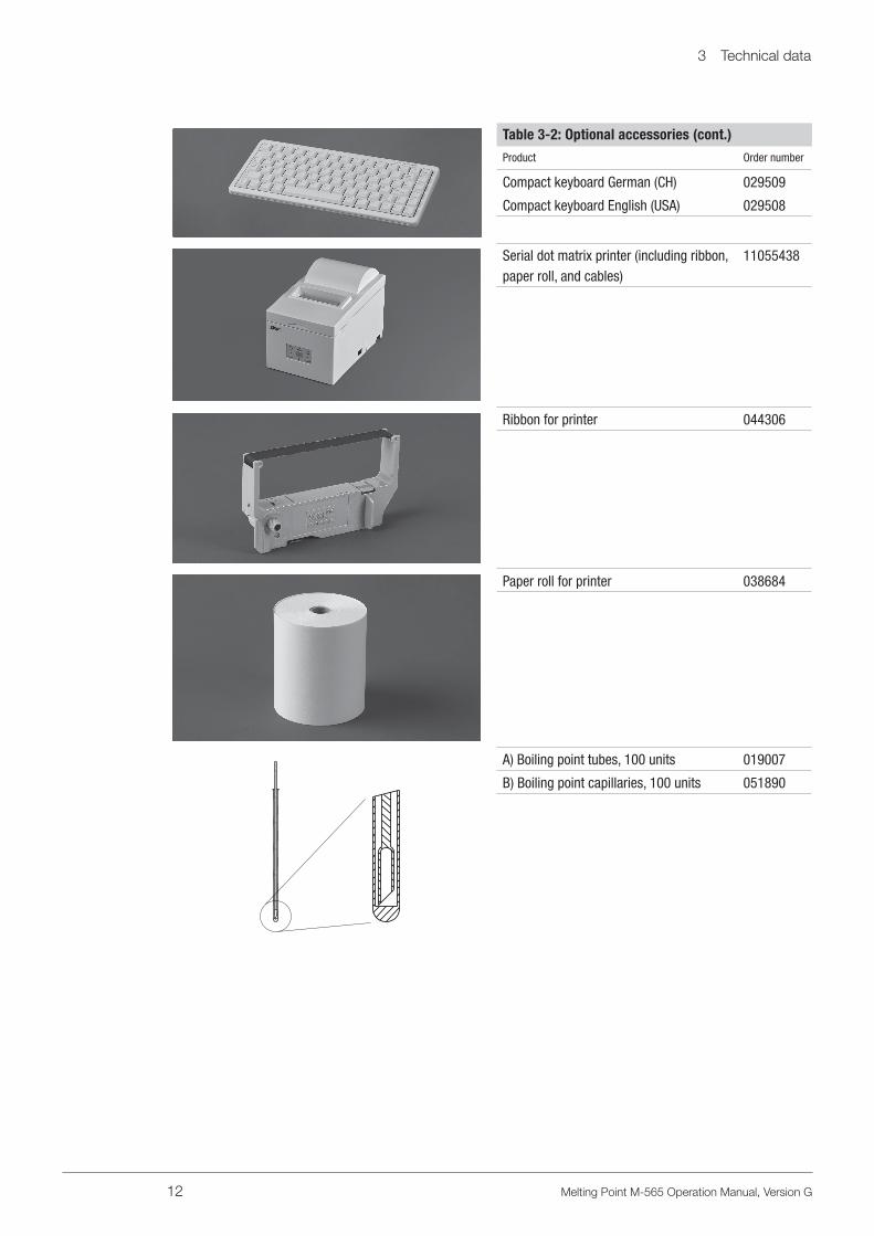
Table 3-2: Optional accessories (cont.)
Product Order number
Compact keyboard German (CH) 029509
Compact keyboard English (USA) 029508
Serial dot matrix printer (including ribbon, paper roll, and cables)
11055438
Ribbon for printer 044306
Paper roll for printer 038684
A) Boiling point tubes, 100 units 019007
B) Boiling point capillaries, 100 units 051890

3 Technical data
13 Melting Point M-565 Operation Manual, Version G
Table 3-2: Optional accessories (cont.)
Product Order number
IQ/OQ: After installation OQ: For repeat use
For further information please contact your local affiliate or distributor.
IQ/OQ M-565 English 11055 004
OQ M-565 English 11055 009

3 Technical data
14 Melting Point M-565 Operation Manual, Version G
3 .2 Technical data overview
Table 3-3: Technical data of the Melting Point M-565
Melting Point M-565
Manual melting point determination √
Manual boiling point determination √
Automatic melting point determination √
Automatic boiling point determination √
Homogeneous sample loading –
Positions for melting capillaries 3
Positions for boiling capillaries 1
Precision magnifying lens √
Magnification of lens 2.5×
Digital camera √
Video function √
Magnification, display 6 x
Display Colour, TFT, 320×240, 3.5˝
Determination temperature range Ambient + 10 °C to 400 °C
Temperature resolution 0.1 °C
Accuracy melting point at 0.5 °C/min ± 0.2 °C
Repeatability melting point at 0.5 °C/min ± 0.1 °C
Accuracy boiling point at 1.0 °C/min up to 400 °C
± 0,5 °C
Repeatability boiling point at 1.0 °C/min ± 0.3 °C
Temperature gradients, °C/min 0.1, 0.2, 0.5, 1, 1.5, 2, 2.5, 3, 5, 10, 20
Heat-up time (50 °C–350 °C) at 25 °C ~ 4 min
Cool-down time (350 °C–50 °C) at 25 °C ~ 13 min
Electrical supply 100–240 V (±10%), 50–60 Hz
Power consumption 150 W
Contact termination L, N, PE
Video run time 350 min at 1 °C/min, 700 min at 0.5 °C/min
Approval CE, CSA, UL
Dimensions (W×H×D), mm 190×200×370
Weight, kg 4.5
Environmental conditions For indoor use only
Temperature 5–40 °C
Altitude up to 2000 m a.s.l.
Humidity Maximum relative humidity 80% for temperatures up to 31 °C, decreasing linearly to 50% relative humidity at 40 °C
Over voltage category II
Degree of protection IP 20
Pollution degree 2
Storable methods for melting point 50
Storable methods for boiling point 50

3 Technical data
15 Melting Point M-565 Operation Manual, Version G
Table 3-3: Technical data of the Melting Point M-565 (cont.)
Melting Point M-565
Compliant with Pharmacopeia methods PH. EUR., USP and JP
NOTETemperature measuring accuracy refers to pharmacopoeia melting point.
3 .3 Materials used
Table 3-4: Materials used
Component Material designation
Print holder PA
Heating block Aluminium
Lenses Glass
Axial fan Aluminium
Housing PU, stainless steel, glass
Cover POM, ceramic, aluminium, stainless steel
4 Description of function
16 Melting Point M-565 Operation Manual, Version G
4 Description of function
This section explains the basic principle of the Melting Point M-565 and provides a functional descrip-tion of the assemblies.
4 .1 Functional principle
The Melting Point M-565 is an instrument for automatic and visual (manual) determination of melting point, melting range, and boiling point at ambient temperatures +10 °C up to 400 °C. The melting point of three samples can be determined at the same time. The boiling point can be determined for one sample. Samples can be observed through the lens or on the color display.
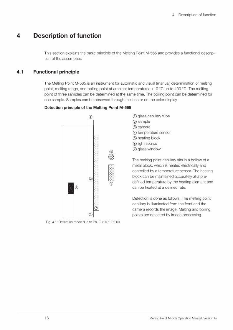
Detection principle of the Melting Point M-565
e
a
b
cd
f
g
a glass capillary tubeb samplec camerad temperature sensore heating blockf light sourceg glass window
The melting point capillary sits in a hollow of a metal block, which is heated electrically and controlled by a temperature sensor. The heating block can be maintained accurately at a pre-defined temperature by the heating element and can be heated at a defined rate.
Detection is done as follows: The melting point capillary is illuminated from the front and the camera records the image. Melting and boiling points are detected by image processing.
Fig. 4.1: Reflection mode due to Ph. Eur. 6.1 2.2.60.

4 Description of function
17 Melting Point M-565 Operation Manual, Version G
4 .1 .1 Pharmacopoeia and thermodynamic melting points
The melting process of a substance does not take place instantaneously - it requires a finite amount of time. The melting process begins at the point where the first particles of the substance turn into the liquid state (thermodynamic melting point). The end of the melt is reached when the last solid particles have gone over into the liquid phase (pharmacopoeia melting point).During the entire melting process of a pure compound, the temperature of the pure substance remains constant while heat is constantly transferred from the heating block to the sample.For pure substances the thermodynamic melting point can be approached by multiplying the ther-modynamic correction factor by the square root of the gradient and subtracting the result from the pharmacopoeia melting point.
temperature
Steep gradient Flat gradient
thermodynamic correction
all molten: moment of detection
oven temperature
oven temperature
sample temperature
sample temperature thermodynamic
correction
temperature at moment of detection
melting temperature
melting temperature
temperature at moment of detection
timetime
temperature
melting start
Fig. 4.2: The amount of thermodynamic correction depends on the gradient selected: The smaller the gradient, the less the correction required.
mp[thermodyn.] = mp[pharma.]–(k × gradient)
k = thermodynamic factor

4 Description of function
18 Melting Point M-565 Operation Manual, Version G
4 .1 .2 Boiling points
The boiling point is determined by the “Siwoloboff” method.
The Melting Point M-565 can be used to determine the boiling point of a small amount of liquid. The heating block has one insert avail-able for boiling point tubes (outside left). The moment of boiling is determined automatically or visually.
Detection is done as follows:The beam of light illuminates the boiling point tube from the front, and the camera records the image.
Fig. 4.3: Boiling point
The process for boiling point determination is analogous to that for determining a melting point:
• The start temperature is set 5 to 10 °C lower than the expected boiling point.• The sample is put into the heating block as soon as the start temperature is reached.• A delay time allows the equilibrium between sample oven temperature and sample temperature.
During this delay time some air bubbles turns out of the boiling point capillary.• Starting from the start temperature, the sample is heated at a temperature gradient of 1 °C/min.• As the temperature rises, bubbles of gas rise slowly and regularly from the immersed end of the
boiling point capillary.• The boiling point of the liquid has been reached when the flow of steam bubbles reaches a
frequency of 0.6 Hz [Hertz].
The instrument records the curve and displays the result. At the beginning of the measurement, the current pressure has to be entered to obtain correct results. The system detects the boiling tempera-
ture. The boiling point is calculated and corrected for current pressure.

4 Description of function
19 Melting Point M-565 Operation Manual, Version G
4 .2 Controls and connections
ab
c d e
f
a Power switch; turns the instrument on/offb Start; starts processc Stop; stops process, starts/stops ventilation,
returns to idle screend 3 Select and Set buttonse Rotary knob for navigation in the menu and
for select charactersf Display
Fig. 4.4: Front view
RS232
PS/2
USB
b
c
d
e
a
f
a Mains plugb PS/2 connection for keyboardc RS 232 connection for serial printerd USB connection to the PC if software Melting
Point Monitor is used, needed for servicee Housing cooling fanf Heating block cooling fan
Fig. 4.5: Rear view

5 Putting into operation
20 Melting Point M-565 Operation Manual, Version G
5 Putting into operation
This section describes the installation of the Melting Point M-565 and gives instructions for initial start-up.
NOTEInspect the instrument for damage during unpacking. If necessary, prepare a status report imme-diately to inform the postal company, railway company, or transport company. Keep the original packaging for future transport.
5 .1 Installation site
Place the instrument on a stable, horizontal surface adequate for the maximum product dimensions. It is advisable to place the instrument in a fume hood due to the fact that it will be used to measure chemical substances. For safety reasons and to ensure sufficient cooling in the electronic compart-ment, of the unit must be placed at least 30 cm away from rear walls or other objects. No containers, chemicals, or other appliances should be placed behind the unit.
NOTEDo not expose the instrument to direct sunlight or very high illumination. This could influence the automatic detection process.
General hazards arise from:
• Mixtures of unknown composition or contaminations• Combustible gases or solvent vapors in the immediate vicinity of the unit• Damaged glass components• Insufficient distance from back of the unit to the wall• Burning by touching hot parts of the heater
5 .2 Commissioning
5 .2 .1 Unpacking and installation
• Unpack the instrument and place it on a table. Remove the packing, and make sure that the following parts are installed:
5 Putting into operation
21 Melting Point M-565 Operation Manual, Version G
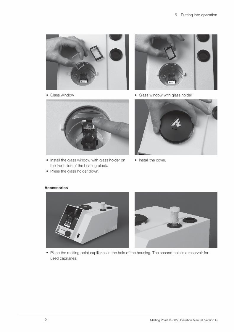
• Glass window • Glass window with glass holder
• Install the glass window with glass holder on the front side of the heating block.
• Press the glass holder down.
• Install the cover.
Accessories
• Place the melting point capillaries in the hole of the housing. The second hole is a reservoir for used capillaries.
5 Putting into operation
22 Melting Point M-565 Operation Manual, Version G
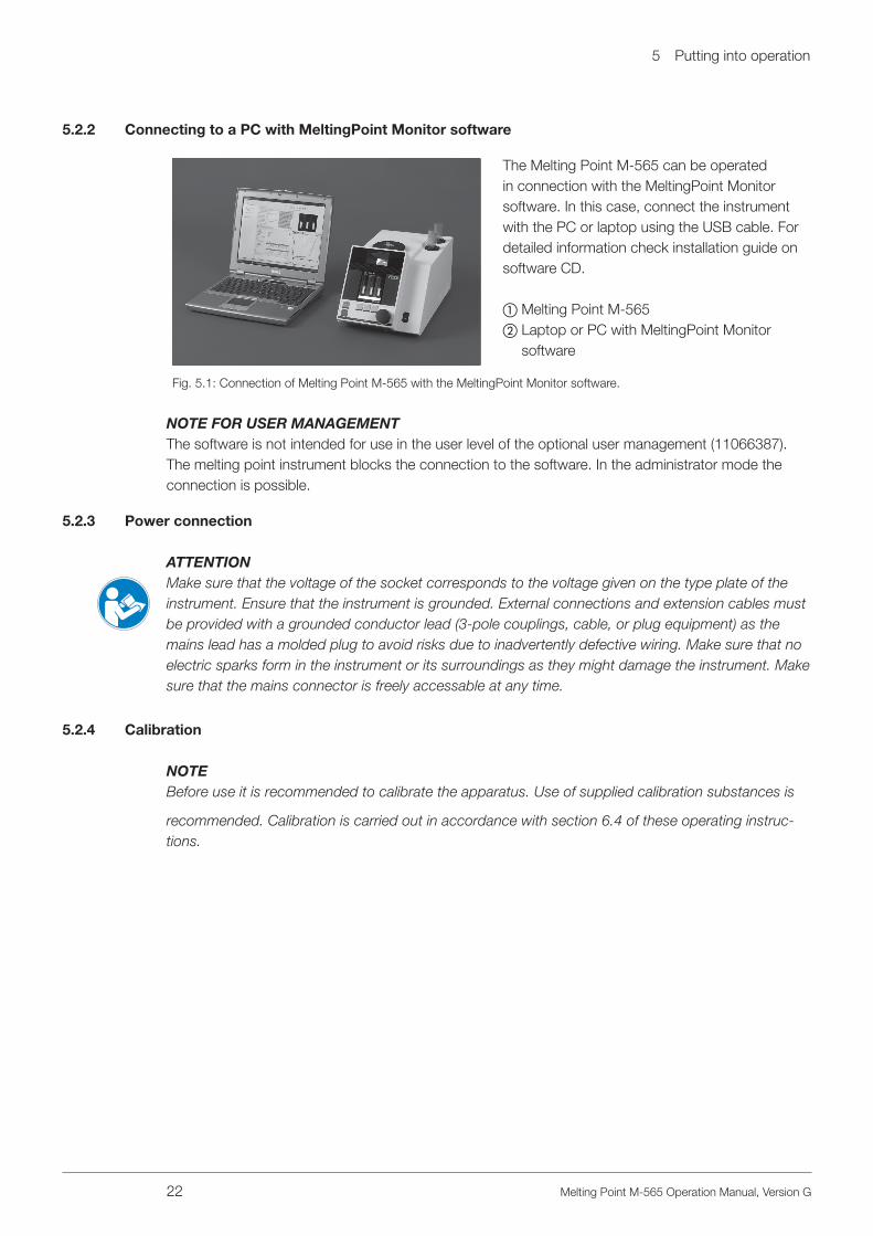
5 .2 .2 Connecting to a PC with MeltingPoint Monitor software
The Melting Point M-565 can be operated in connection with the MeltingPoint Monitor software. In this case, connect the instrument with the PC or laptop using the USB cable. For detailed information check installation guide on software CD.
a Melting Point M-565b Laptop or PC with MeltingPoint Monitor
software
Fig. 5.1: Connection of Melting Point M-565 with the MeltingPoint Monitor software.
NOTE FOR USER MANAGEMENTThe software is not intended for use in the user level of the optional user management (11066387).The melting point instrument blocks the connection to the software. In the administrator mode theconnection is possible.
5 .2 .3 Power connection
ATTENTIONMake sure that the voltage of the socket corresponds to the voltage given on the type plate of the instrument. Ensure that the instrument is grounded. External connections and extension cables must be provided with a grounded conductor lead (3-pole couplings, cable, or plug equipment) as the mains lead has a molded plug to avoid risks due to inadvertently defective wiring. Make sure that no electric sparks form in the instrument or its surroundings as they might damage the instrument. Make sure that the mains connector is freely accessable at any time.
5 .2 .4 Calibration
NOTEBefore use it is recommended to calibrate the apparatus. Use of supplied calibration substances is
recommended. Calibration is carried out in accordance with section 6.4 of these operating instruc-tions.
6 Operation
23 Melting Point M-565 Operation Manual, Version G
6 Operation
This section explains the operating elements and possible operating modes. It gives instructions on how to operate the Melting Point M-565 properly and safely.
ATTENTIONBefore use it is recommended to calibrate the apparatus. Use supplied calibration substances only. The calibration mode is described in section [6.4 Calibration].
6 .1 Basic operating principles
WARNINGThe heating oven can reach temperatures up to 400 °C.
6 .1 .1 Display during idle
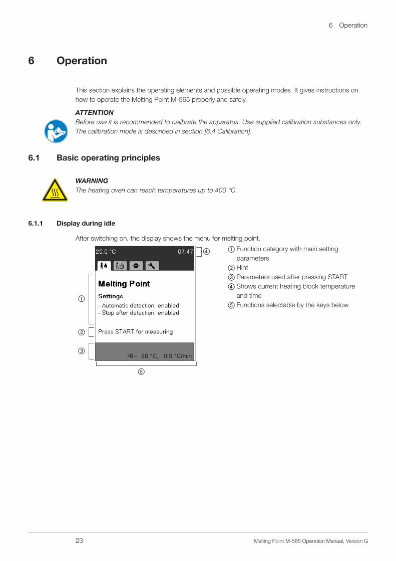
After switching on, the display shows the menu for melting point.
a
b
c
d
e
a Function category with main setting parameters
b Hintc Parameters used after pressing STARTd Shows current heating block temperature
and timee Functions selectable by the keys below

6 Operation
24 Melting Point M-565 Operation Manual, Version G
Different menus can be accessed by turning the rotary knob. Each menu has its own symbol. These idle screens are the starting points for all actions. The corresponding symbol is displayed during all processes.
Melting Point Boiling Point
Calibration Tools
6 .1 .2 Display during a process or in menus
a
b
c
a Shows where you are and gives hints and instructions.
b Working area shows:• items to select• samples during measurement• specific information in connection with
the current menuc Functions selectable by the keys below.

6 Operation
25 Melting Point M-565 Operation Manual, Version G
Screen during melting point determination
Settings menu
Result indication (numeric result)
Result indication (replay)
6 .1 .3 Entering text
Text can be entered by using the rotary knob or an external keyboard.
Rotary knob:• Turn the rotary knob to select a character
and press Enter. Press Save after entering all characters.

6 Operation
26 Melting Point M-565 Operation Manual, Version G
6 .1 .4 Using the external keyboard
NOTEThe instrument can be operated using an external keyboard.
For the softkeys, the following keys of the external keyboard are assigned:
• ENTER = right softkey• Alt = center softkey• Esc = left softkey• In the method menu: To navigate quickly to a method name press the initial letter.
6 .2 Melting point determination
NOTEFor exact melting point determination, use original capillaries from BUCHI only. If other capillaries are used, the results can be wrong. Use the following items:
Product Order number
Melting point capillaries, 100 units 017808
Melting point capillaries, 1000 units 001759
Fig. 6.1: Melting point capillaries
6 .2 .1 Sample preparation
NOTEUse only capillaries from BUCHI. They are precise and adequate for this kind of operation. Other capillaries have other dimensions and wall thicknesses. Using others may result in results that are incorrect.
Each sample has to be prepared.The following methods to compact the samples are recommended:• Using the Sample Loader M-569• Knocking the capillaries on a hard surface.
NOTESample preparation by letting the capillaries fall through a tube is not advised, because cross contamination may occur.

6 Operation
27 Melting Point M-565 Operation Manual, Version G
Preparation of the samples:
• The samples being investigated must be fully dry, homogenous, and in powdered form. Moist samples must be dried first (the pharmacopoeias prescribe that the substance needs to be dried in a vacuum for 24 hours over silica gel R). Coarse crystalline samples and non-homogeneous samples are finely ground in a mortar.
• To fill the capillary tubes with the sample, the open ends of the tubes are pressed into the substance. The substance is moved to the bottom of the tubes by repeatedly pounding the tubes against a hard base.
• Enough substance must be filled into the glass capillary to form a compact column 4 to 6 mm in height. (A height of 4–5 mm is recommended for precision measurements.) To ensure compa-rable results, it is important to fill all three capillary tubes to the same height and to compact the substance well in the tubes using the Sample Loader M-569.
6 .2 .2 Determination without pre-registered melting point method
• Choose the menu for melting point determination.• Make sure that all samples are removed.• Press START to start the determination process immediately with the last parameters used.
NOTEIf the current parameters do not meet your needs, press Edit and set start temperature, stop temper-ature, and temperature gradient.
a b c
d
a Start temperatureb Stop temperaturec Temperature gradientd Edit
• To adjust the desired melting parameters, press Edit.
• Chose start temperature with the rotary knob, and press Next.
• Chose stop temperature with the rotary knob, and press Next.
• Chose temperature gradient with the rotary knob, and press Save.
6 Operation
28 Melting Point M-565 Operation Manual, Version G
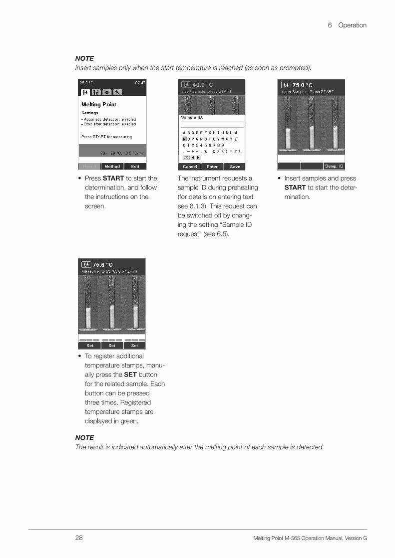
NOTEInsert samples only when the start temperature is reached (as soon as prompted).
• Press START to start the determination, and follow the instructions on the screen.
The instrument requests a sample ID during preheating (for details on entering text see 6.1.3). This request can be switched off by chang-ing the setting “Sample ID request” (see 6.5).
• Insert samples and press START to start the deter-mination.
• To register additional temperature stamps, manu-ally press the SET button for the related sample. Each button can be pressed three times. Registered temperature stamps are displayed in green.
NOTEThe result is indicated automatically after the melting point of each sample is detected.

6 Operation
29 Melting Point M-565 Operation Manual, Version G
• To run through the results, turn the rotary knob up and down.
• To replay the recorded melting process, press Replay.
• Press End or STOP to return to the idle screen.
• Press START to measure again with the identical measuring parameters.
• The result is printed out automatically if a printer is connected.
• Back: Turns back to the result menu.
• Sample: Switches between sample left, middle, and right.
• Play: Replays recorded video automatically.
• Rotary knob: Changes temperature value and its corresponding picture of the sample.
• Changes replay speed of video using rotary knob.
• Stop: Stops replay mode.
NOTEThe last result is stored in the device until a new measurement is started or the instrument is switched off.
• After turning back to idle, the last result can be checked again by pressing Result.

6 Operation
30 Melting Point M-565 Operation Manual, Version G
6 .2 .3 Creating a method
Instead of entering and using the parameters directly from the idle screen, it is also possible to store parameter sets as methods.
• To enter the method menu, press Method.
• To create a new method, press Options New then OK.
• Enter a method name. To finish press Save.
• Adjust a parameter and press Next. Then Save.
NOTE FOR USER MANAGEMENTCreating a method is not possible when operating the instrument in the user level.
6 .2 .4 Using and handling methods

6 Operation
31 Melting Point M-565 Operation Manual, Version G
• Turn the rotary knob to select a method.
• Press START to start the determination.
• Use Edit to adjust method parameters.
• Press the Options key to get further functions:
• New: Creates a new method.• Delete: Deletes the
method.• Rename: Changes the
method name.
NOTE FOR USER MANAGEMENTMethods can only be started in the user level. All other actions are not possible.
6 .2 .5 Adjusting parameters during a determination
NOTEMeasuring parameters can be modified during preheating or a determination. This function is possible only if enabled by the setting “Param. adj. during meas.” (see 6.5).
a
• Turn the rotary knob to display the current param-eter set.
• Adjust the parameters by pressing Edit. Adjusting the parameters does not affect the saved method.
If the temperature gradient is changed during a mea-surement, the result shows CHANGED (a) for the tem-perature gradient.
6 .2 .6 Printout
NOTEThe result is printed out automatically if a printer is connected and automatic printing is configured in the settings menu.
6 Operation
32 Melting Point M-565 Operation Manual, Version G
6 .2 .7 Melting result
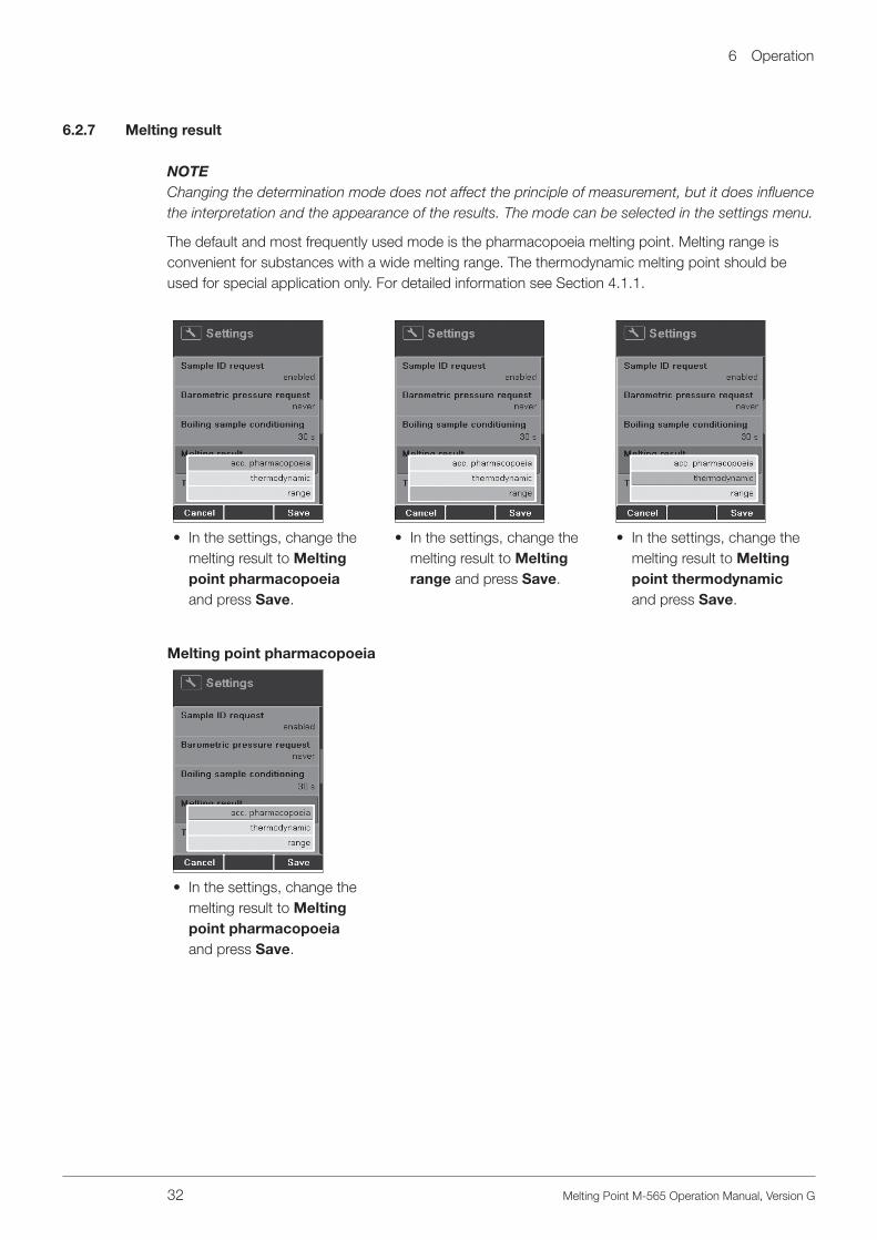
NOTEChanging the determination mode does not affect the principle of measurement, but it does influence the interpretation and the appearance of the results. The mode can be selected in the settings menu.
The default and most frequently used mode is the pharmacopoeia melting point. Melting range is convenient for substances with a wide melting range. The thermodynamic melting point should be used for special application only. For detailed information see Section 4.1.1.
• In the settings, change the melting result to Melting point pharmacopoeia and press Save.
• In the settings, change the melting result to Melting range and press Save.
• In the settings, change the melting result to Melting point thermodynamic and press Save.
Melting point pharmacopoeia
• In the settings, change the melting result to Melting point pharmacopoeia and press Save.

6 Operation
33 Melting Point M-565 Operation Manual, Version G
a
b
c
d
e
f
g
h
i
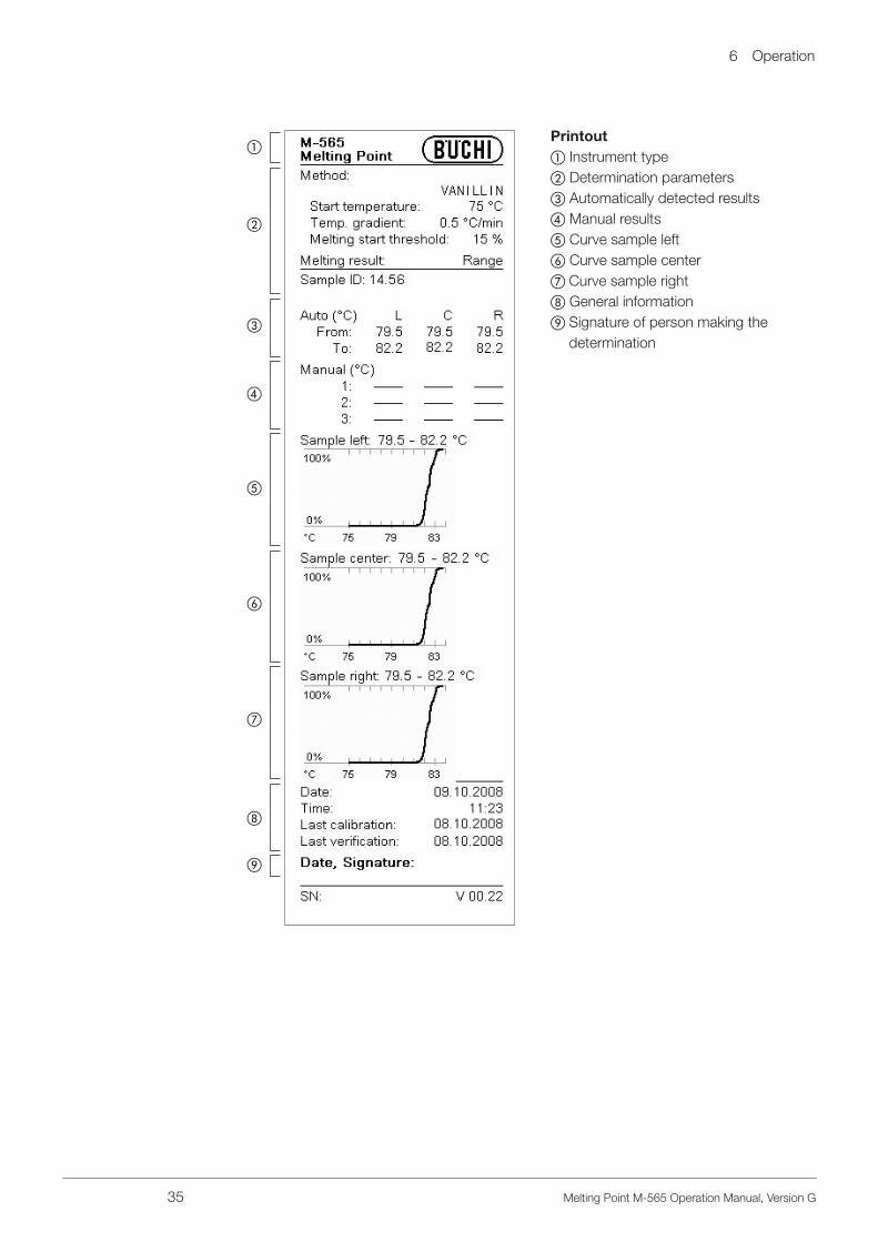
Printouta Instrument typeb Determination parametersc Automatically detected resultsd Manual resultse Curve sample leftf Curve sample centerg Curve sample righth General informationi Signature of person making the
determination
NOTEThe Average is calculated on the basis of the temperature values with two positions after the decimal point. Thus, the value indicated for the Average might deviate from the value you calculate on the basis of the temperature values on the printout, as there is just one position after the decimal point.

6 Operation
34 Melting Point M-565 Operation Manual, Version G
6 .2 .7 .2 Melting range
• In the settings, change the melting result to Melting range and press Save.
An additional parameter is shown. The default value is set to 15%. This value can be used for most of substances.
Threshold: This value is needed only for melting range determination. The default value is set to 15%. This value can be used for 80% of sub-stances. • If the beginning of the
melting range differs from that observed, increase or decrease this value.
The result mode shows a range for each sample: XX.X–XX.X °C
In the replay mode, the melt-ing range is shown in gray backlit.
6 Operation
35 Melting Point M-565 Operation Manual, Version G
a
b
c
d
e
f
g
h
i
Printouta Instrument typeb Determination parametersc Automatically detected resultsd Manual resultse Curve sample leftf Curve sample centerg Curve sample righth General informationi Signature of person making the
determination

6 Operation
36 Melting Point M-565 Operation Manual, Version G
6 .2 .7 .3 Melting point thermodynamic
• In the settings, change the melting result to Melting point thermodynamic and press Save.
Experimental measurements have shown that in most cas-es a good approximation to the factor for thermodynamic correction of the BUCHI Melt-ing Point M-565 is a value of ~1.5.
Empirical calculation for thermodynamic correction is recommended when more ac-curate results are required for specific substances.
In order to obtain a thermodynamic melting point result within the accuracy of the unit, the following steps are advised:
• Perform complete automatic pharmacopoeia melting point determinations on your sample at three different temperature ramping rates: 0.2, 0.5, 1.0 °C/min.
• Plot the resulting melting points versus the square root of their corresponding temperature ramping rate (mp pharmacopoeia vs. gradient )–a linear dependence should be observed.
• The slope is the thermodynamic correction factor. Enter this value in the setting 6.6 “Thermody-namic correction.”
An example of this calculation procedure is shown below:
Gradient, r [°C/min] Melting Point [°C]
0.2 236.1
0.5 236.5
1.0 236.9
236.9236.8
236.7236.6
236.5236.4
236.3236.2
236.1236.0
0 0.2 0.4 0.6 0.8 1 1.2
gradient
mp pharmacopoeia vs. gradient
y = 1.2684 x + 235.52
“Melting point temperature vs. gradient” for a caffeine sample melted at 0.2, 0.5, and 1.0 °C/min. The slope of the straight line, factor for thermodynamic correction = 1.3, is programmed into the setting of instrument for this compound.
Fig. 6.2: “Melting point temperature vs. gradient ”

6 Operation
37 Melting Point M-565 Operation Manual, Version G
a
b
c
d
e
f
g
h
i
d
Printouta Instrument typeb Determination parametersc Correction factor for thermodynamic
determinationd Automatically detected resultse Manual resultsf Curve sample leftg Curve sample centerh Curve sample righti General informationj Signature of person making the deter-
mination
NOTEThe Average is calculated on the basis of the temperature values with two positions after the decimal point. Thus, the value indicated for the Average might deviate from the value you calculate on the basis of the temperature values on the printout, as there is just one position after the decimal point.

6 Operation
38 Melting Point M-565 Operation Manual, Version G
6 .3 Boiling point
NOTEFor exact boiling point determination, use boiling point tubes and capillaries from BUCHI only. If other glass parts are used, incorrect or no results can be obtained. Use the following items:
A
A
B BProduct Order number
A) Boiling point tubes, 10 units 019697
A) Boiling point tubes, 100 units 019007
B) Boiling point capillaries, 10 units 051850
B) Boiling point capillaries, 100 units 051890
Fig. 6.3: Boiling point tube and capillary
6 .3 .1 Sample preparation
In preparation, the boiling point tubes are filled with 5 to 10 mm of liquid sample. We recommend using a syringe for simple filling. Insert a boiling point capillary into the boiling point tube with its open/thick end down. Put the sample immediately into the heating block.
6 .3 .2 Determination without pre-registered boiling point method
• Choose the menu for boiling point determination.• Make sure that all samples are removed.• Press START to begin the determination process immediately with the last parameters used. They
are always saved in the instrument and are indicated in the green field in the lower part of the screen.
If the current parameters do not meet your needs, press Edit and set the start temperature, stop temperature, and temperature gradient.
a b c
d
a Start temperatureb Stop temperaturec Temperature gradientd Edit
• To adjust the boiling parameters, press Edit.

6 Operation
39 Melting Point M-565 Operation Manual, Version G
• Use the rotary knob to choose the start tempera-ture and press Next.
• Use the rotary knob to choose the stop tempera-ture and press Next.
• Use the rotary knob to chose the temperature gradient and press Save.
NOTEInsert sample only when the instrument has reached the start temperature.
• Press START to start the determination, and follow the instructions on the screen.
The instrument requests a sample ID during preheating (for details on entering text see 6.1.3). This request can be switched off by chang-ing the setting “Sample ID request” (see 6.5).
• Bar P: Enter the current barometric pressure.
• This request can be switched off by changing the setting “Barometric pressure request” (see 6.5).
• Insert sample and press START to start the deter-mination.
6 Operation
40 Melting Point M-565 Operation Manual, Version G
73.2 76.4
73.4 76.6
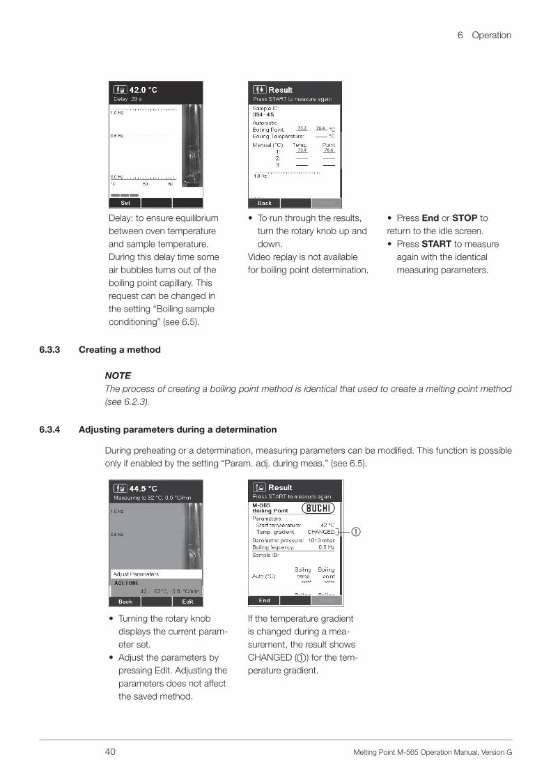
Delay: to ensure equilibrium between oven temperature and sample temperature. During this delay time some air bubbles turns out of the boiling point capillary. This request can be changed in the setting “Boiling sample conditioning” (see 6.5).
• To run through the results, turn the rotary knob up and down.
Video replay is not available for boiling point determination.
• Press End or STOP to return to the idle screen.• Press START to measure
again with the identical measuring parameters.
6 .3 .3 Creating a method
NOTEThe process of creating a boiling point method is identical that used to create a melting point method (see 6.2.3).
6 .3 .4 Adjusting parameters during a determination
During preheating or a determination, measuring parameters can be modified. This function is possible only if enabled by the setting “Param. adj. during meas.” (see 6.5).
a
• Turning the rotary knob displays the current param-eter set.
• Adjust the parameters by pressing Edit. Adjusting the parameters does not affect the saved method.
If the temperature gradient is changed during a mea-surement, the result shows CHANGED (a) for the tem-perature gradient.

6 Operation
41 Melting Point M-565 Operation Manual, Version G
When a measurement is done, the last method parameters are always retained in the instrument. To start the same method, just press START.
NOTEResults are stored in memory until a new measurement is started or the instrument is switched off.
6 .3 .5 Printout
a
b
c
d
e
f
Printouta Instrument typeb Determination parametersc Automatically detected resultsd Manual resultse General informationf Signature of person making the de-
termination
Boiling temp. = Temperature sample boiled.
Boiling point = Boiling temp. corrected according entered baro-metric pressure. If a barometric pressure of 1013 mbar is entered boiling temperature and boiling point results are equal.
6 Operation
42 Melting Point M-565 Operation Manual, Version G
6 .4 Calibration
NOTEBUCHI recommends calibrating each new instrument after installation. Furthermore it is recom-mended that the instrument be recalibrated every year.
Two calibration modes are available: with BUCHI substances and user defined substances
6 .4 .1 Calibration principle
NOTEThe instrument is calibrated using melting point standards. The calibration is valid for boiling points
as well. The calibration procedure is recommended to be performed with the BUCHI calibration
substances, in the BUCHI calibration set mode.
Use the calibration set (11055018). This calibration set contains the melting point standards listed below. Each standard is shipped with a certificate of analysis and an MSDS (material safety data sheet).
The calibration set contains the following substances:
• 4-Nitrotoluene: approx. 52 °C• Diphenyl acetic acid: approx. 148 °C• Caffeine: approx. 237 °C• Potassium nitrate: approx. 335 °C
From each substance, a minimum of 6 have to fulfill a standard deviation of less than +/- 0.2 °C. Otherwise the instrument will not move on to the next substance. The maximum number of samples for each substance to reach the deviation of +/- 0.2 °C is limited to 12 samples. The instrument auto-matically chooses the best 6 results from the determinations performed.After a successful calibration is done, it may be checked using the verification set (11055019). Each standard of the set contains a certificate of analysis and the MSDS.
The verification set contains the following substances:
• Benzil: approx. 94 °C• p-Anisic acid: approx. 182 °C• Phenolphthalein: approx. 261 °C
NOTE FOR USER MANAGEMENTThe calibration procedure can only be performed in the administrator level.

6 Operation
43 Melting Point M-565 Operation Manual, Version G
6 .4 .2 Calibration procedureTo start calibration, turn the rotary knob to Calibration. With the select button the calibration principlecan be chosen. Press START and follow the instruction on display.BUCHI calibration set:
The instrument automatically heats to the start temperature of the first substance. In the meantime, prepare at least 6 samples of the given sub-stance. For this process, follow section 6.2.1.
• Choose the correct phar-macopoeia melting point value with the rotary knob. The pharmacopoeia melting point is written on the certificate of analysis. Press Save.
Follow the instructions on the display. After each run, the current result is indicated.• Press START to perform
the next measurement.
After 6 results are obtained within a standard deviation of +/- 0.2 °C, the process moves on to the next substance. The process is identical for the other substances.
As soon as a complete calibration is obtained, the new calibration date is saved automatically. • Press OK. All results
obtained are displayed.
• The rotary knob can be used to display all the results of the calibration.
• The Print key is used to print out the data.
• Back exits this menu.
The calibration date is now saved and indicated on the idle screen.
6 Operation
44 Melting Point M-565 Operation Manual, Version G
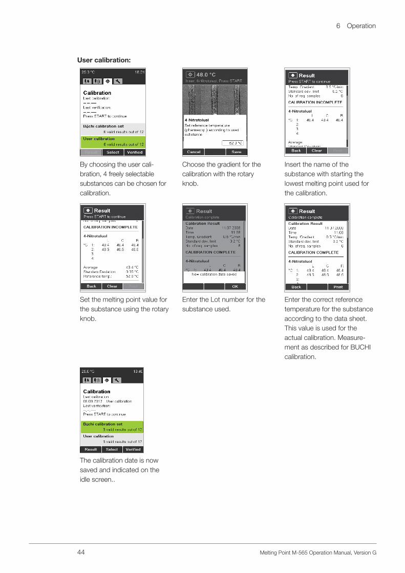
User calibration:
By choosing the user cali-bration, 4 freely selectable substances can be chosen for calibration.
Choose the gradient for the calibration with the rotary knob.
Insert the name of the substance with starting the lowest melting point used forthe calibration.
Set the melting point value forthe substance using the rotaryknob.
Enter the Lot number for thesubstance used.
Enter the correct referencetemperature for the substanceaccording to the data sheet.This value is used for theactual calibration. Measure-ment as described for BUCHIcalibration.
The calibration date is nowsaved and indicated on theidle screen..

6 Operation
45 Melting Point M-565 Operation Manual, Version G
6 .4 .3 Printout
a
b
c
d
e
g
f
h
Printouta Instrument typeb General information regarding
calibrationc Results 4-nitrotoluened Results diphenylacetic acide Results caffeinef Results potassium nitrateg General informationh Signature of person making the
calibration
NOTEThe Average is calculated on the basis of the temperature values with two positions after the decimal point. Thus, the value indicated for the Average might deviate from the value you calculate on the basis of the temperature values on the printout, as there is just one position after the decimal point.

6 Operation
46 Melting Point M-565 Operation Manual, Version G
6 .4 .4 Verification
To verify the calibration, proceed as follows:• Measure all standards (BUCHI recommends using the verification set (11055019) but it is also
possible to use your internal standards.
NOTEThe verification is not a guided process.
• When all measuring results were within the required tolerances, click on Verified. The following screen appears:
• Enter the following password: VER. The current date is now indicated under “Last verification”.
NOTE FOR USER MANAGEMENTCan only be accessed in the administrator level.
6 .5 Settings, SysInfo, Test
Test: Functional test of the instrument. To per-form the test of several functions follow carefully the instuction on the screen. If a function test shows not ok, please contact the customer service. The Test protocol is described in sec-tion 6.5.1.SysInfo: Instrument gives information regarding settings and connected devices.Settings: This menu can be used to change parameters. The SysInfo protocol is described in section 6.5.2.
NOTE FOR USER MANAGEMENTCan only be accessed in the administrator level.

6 Operation
47 Melting Point M-565 Operation Manual, Version G
• Press the Test button to enter the functional test, and follow the instructions.
• Press the SysInfo button to open the system infor-mation menu.
Printout is possible if a printer is connected.
• Press the Settings button to enter the settings menu.
Table 6-1: Setting parameters
Language English, German, French, Italian, Spanish, Japanese, Chinese
Stop after detection disabled, enabled: If the instrument finds a melting point or boiling point for every detected sample, measurement stops automatically.
Param. adj. during meas. disabled, enabled: Whether or not it is possible to change parameters (start temperature, stop temperature, and temperature gradient) during a determination.
Result printout automatically disabled, enabled: After a measurement is finished, results will be printed automatically.
Result graph indication disabled, enabled: Each result contained is shown with a graphic.
Calibration interval 0–36 months: default 12 months. BUCHI recommends calibration or verification after 12 months using the calibration set and the verifica-tion set.
Sample ID request enabled: After the start of determination, the sample ID window is displayed.
disabled: The sample ID window is not automatically displayed. In combination with the MeltingPoint Monitor software, it is advisable to turn this feature off.
Barometric pressure request Has impact only on boiling point determination.
never: No pop-up screen is shown.
daily: Enter current barometric pressure once a day.
always: Enter current barometric pressure every time the instrument heats up to the start temperature for boiling point determination.
Boiling sample conditioning 0–600 s: The default value is set to 60 seconds. This is needed to ensure a temperature equilibrium between heating block and liquid in the boiling point tube. If this value is set too low, the result can be incorrect or no automatic boiling point detection.
Melting result acc. pharmacopoeia
thermodynamic
range
6 Operation
48 Melting Point M-565 Operation Manual, Version G
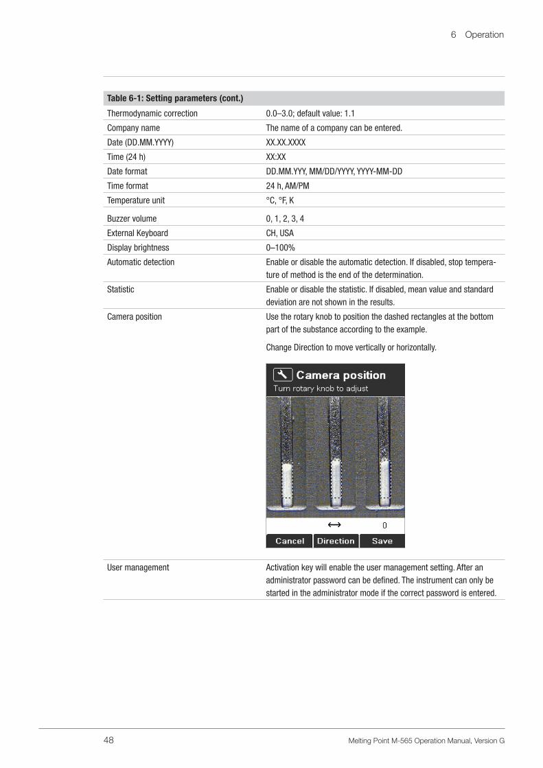
Table 6-1: Setting parameters (cont.)
Thermodynamic correction 0.0–3.0; default value: 1.1
Company name The name of a company can be entered.
Date (DD.MM.YYYY) XX.XX.XXXX
Time (24 h) XX:XX
Date format DD.MM.YYY, MM/DD/YYYY, YYYY-MM-DD
Time format 24 h, AM/PM
Temperature unit °C, °F, K
Buzzer volume 0, 1, 2, 3, 4
External Keyboard CH, USA
Display brightness 0–100%
Automatic detection Enable or disable the automatic detection. If disabled, stop tempera-ture of method is the end of the determination.
Statistic Enable or disable the statistic. If disabled, mean value and standard deviation are not shown in the results.
Camera position Use the rotary knob to position the dashed rectangles at the bottom part of the substance according to the example.
Change Direction to move vertically or horizontally.
User management Activation key will enable the user management setting. After an administrator password can be defined. The instrument can only be started in the administrator mode if the correct password is entered.

6 Operation
49 Melting Point M-565 Operation Manual, Version G
6 .5 .1 Test protocol
a
b
c
a Power supply voltageb Values for sample brightnessc Signature of person carrying out the test

6 Operation
50 Melting Point M-565 Operation Manual, Version G
6 .5 .2 SysInfo protocol
a
a Setting parameters

6 Operation
51 Melting Point M-565 Operation Manual, Version G
b
c
d
e
f
b Correction values for calibrationc Camera position valuesd Color values (Factory default settings)e Date of the factory testsf Signature of the person who performed the test
6 Operation
52 Melting Point M-565 Operation Manual, Version G
6 .6 User management
An optional user management (11066387) is available to provide regulatory compliance. A serial number dependent activation code has to be entered in the settings menu. After entering the activa-tion code, a password to enter the administrator level can be defined.With the user management a password identification is requested when switching on the instrument.• If the password is successfully entered, the user gets access to the administrator level.• Without password identification or the wrong password the user has limited access to the instru-
ment functionalities.
Administrator level
1. Full access to the instrument functionalities2. Access to the Service menu3. Possibility to change the password4. Connection to MeltingPoint Monitor Software possibleUser level
1. Possibility to choose between melting point and boiling point2. Access to the following parameters: start temperature, heating rate and end temperature3. Selection of methods, but no editing and deleting4. No access to: changing of date and time, calibration data and calibration menu.5. No connection to: MeltingPoint Monitor Software
The user management setting for the password protection can be undone by deleting the password inthe administrator mode and leaving the field blank. The user management setting can be reactivatedwith the activation key.
The activation key is only valid in the year of purchase.For later activation please contact: [email protected]
6 .7 XML to PC data export
If no printer is connected to the MeltingPoint device, data can be sent to a PC by pushing the“XML2PC” button. The raw data is transmitted through the serial interface and can be received by thePC with the following settings:
Table 6-7: PC settings
Baud rate: 19200
Parity: No
Data bit: 8
Stop bit: 1
No PC software is supplied to receive the XML data.Picking up the data is the customers responsibility.

7 Maintenance
53 Melting Point M-565 Operation Manual, Version G
7 Maintenance
This section provides instructions on all maintenance work to be performed to keep the instrument in good working condition.
WARNINGAll maintenance and repair work requiring the opening or removal of the instrument housing must be carried out by trained personnel and only with the tools provided for this purpose.
WARNINGElectrical hazard:
• Prior to any maintenance work on the instrument, switch off the power supply.
ATTENTIONUse only genuine BUCHI consumables and spare parts for any maintenance and repair work in order to assure continued system performance and reliability. Any modifications to the spare parts used should be carried out only with the prior written permission of the manufacturer.
7 .1 Housing
Check the housing of your melting point instrument for defects (controls, plugs). The housing is coated with paint and should be cleaned only with a rag moistened in a soapy solution.Remove the glass window from the heating block periodically and wipe it clean with alcohol or acetone. Replace the window with a new one if it will not come completely clean.
ATTENTIONNever use any halogenated solvents, acetone, or similar chemicals, because such cleaning agents may damage the instrument.
7 .2 Glass window
Remove the glass window from the heating block periodically and wipe it clean with alcohol or acetone. Replace the window with a new one if it will not come completely clean.
7 .3 Upkeep
The upkeep of the unit is mainly limited to:
• Periodic calibration of the temperature.
7 Maintenance
54 Melting Point M-565 Operation Manual, Version G
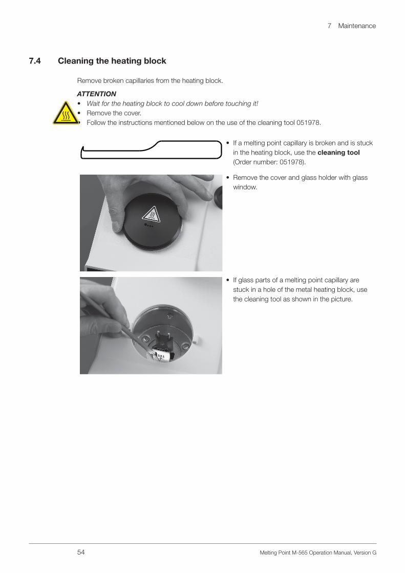
7 .4 Cleaning the heating block
Remove broken capillaries from the heating block.
ATTENTION• Wait for the heating block to cool down before touching it!• Remove the cover.• Follow the instructions mentioned below on the use of the cleaning tool 051978.
• If a melting point capillary is broken and is stuck in the heating block, use the cleaning tool (Order number: 051978).
• Remove the cover and glass holder with glass window.
• If glass parts of a melting point capillary are stuck in a hole of the metal heating block, use the cleaning tool as shown in the picture.

8 Troubleshooting
55 Melting Point M-565 Operation Manual, Version G
8 Troubleshooting
The following section describes how to resume operation of the instrument in the event of any minor problem. It lists some possible occurrences, their probable cause, and suggests how to remedy the problem. The troubleshooting table below lists possible instrument malfunctions and errors and describes courses of action that can be used by operators to correct some of those problems. The appropriate course of action is listed in the column “Remedy”.More complicated malfunctions or errors are usually handled by a BUCHI technical engineer who has access to the official service manuals. In this case, please contact your local BUCHI customer service agent.
8 .1 Malfunctions and their remedy
Table 8-1: General malfunctions and their remedyMalfunction Possible cause Remedy
Instrument does not work Main switch off Switch on mains switch
Instrument is not connected to mains supply
Check mains connection
No or unreadable printout Not activated in the settings Activate automatic printout in the settings
Bad cable connection Check cable connection
Printer switched OFF Switch ON printer
No paper Replace paper roll
Baud rate settings of printer faulty See section 8.1.1
No melting curve is shown Not activated in the settings Activate graphic in the settings
No automatic detection of samples Manually register the melting point/boiling point
Measuring finished before detecting a result for all samples
Turn off in the settings “Stop after detection” and check stop tempera-ture.
In the automatic melting point deter-mination, no value and no melting curve are determined
Sample is unstable, it decomposes, turns brown, or melts non-uniformly
The temperature parameters have been entered incorrectly and the sample does not melt at all
Automatic detection is disabled
e.g. select higher maximum point
Enable the Automatic detection in the Settings
Sometimes no results or only 1 or 2 results instead of 3 results
START button was pressed before insertion of all sample capillaries
Put all sample capillaries in the oven first, then press the START button.Do not move the sample capillaries again.
Unexpected results Sample-specific preparations:
Sample is not dry or is contaminated by another substance
Sample should be dried before use

8 Troubleshooting
56 Melting Point M-565 Operation Manual, Version G
Table 8-1: General malfunctions and their remedyMalfunction Possible cause Remedy
Sample decomposes during the melting process (formation of bubbles, sample turns brown, etc.)
Apparatus parameters:
Apparatus is not or is poorly cali-brated
Regular calibration of apparatus with BUCHI calibrating substances
Method “According to pharmaco-poeia” or “thermodynamic melting point determination” is incorrectly selected
Alter the corresponding parameters
No results Setting point is too close to the melting point
Select setting point 5–10 °C below melting point
No statistic Setting parameter Statistic is disabled
Enable the Statistic in the Settings
Instrument does not heat Heating defective Contact BUCHI customer service.
Table 8-2: Malfunctions with Melting Point Monitor software
Malfunction Possible cause Remedy
No USB connection USB cable is not connected or defec-tive.
Check USB connection, replace if necessary.
Driver not found Device connected for the first time. Install recommended driver.
Table 8-3: Warning messages
Warning number Possible cause Remedy
Warning 01 Calibration outdated. Calibrate or verify device.
Warning 02 Housing temperature too high. Cool down device and check clearance of vent holes and fans. Check ambient temperature.
Warning 03 Device not calibrated. Calibrate device.
Table 8–4: Error messages
Error number Possible cause Remedy
Error 01 Memory data loss, all data are reset. Calibrate device. In case of recurrence contact customer service.
Error 02 Automatic restart, firmware problem possible. In case of recurrence contact customer service.
Error 03 Board temperature sensor defective. Contact customer service.
Error 04 Temperature sensor defective. Contact customer service.
Error 05 Heating defective. Contact customer service.
Error 06 Cooling fan defective. Contact customer service.
Error 07 Housing fan defective. Contact customer service.
Error 08 Camera defective, communication loss. Contact customer service.
Error 09 24 V fuse defective. Contact customer service.
Error 10 24 V input voltage missing. Contact customer service.

8 Troubleshooting
57 Melting Point M-565 Operation Manual, Version G
Table 8–4: Error messages
Error number Possible cause Remedy
Error 11 Internal clock, power loss. Contact customer service.
Error 13 5V input voltage missing Contact customer service.
NOTEIf several errors are pending, the one with the highest priority will be displayed.
8 .1 .1 Setting the printer baud rate
• Open compartment on the bottom of the printer.
• The following setting should be selected. 1,2,3,4,5,7,8,9,10 = ON 6 = OFF
8 .2 Customer service
Only authorized service personnel are allowed to perform repair work on the instrument. They have comprehensive technical training and knowledge of possible dangers that might arise from the instru-ment.Contacts for official BUCHI customer service offices are available on the BUCHI website at: www.buchi.com. If malfunctions occur on your instrument or you have technical questions or applica-tion problems, please contact one of these offices.
Customer Service offers the following:
• Spare part delivery• Repairs• Technical advice

9 Shutdown, storage, transport and disposal
58 Melting Point M-565 Operation Manual, Version G
9 Shutdown, storage, transport, and disposal
This section provides instructions on how to shut down the instrument, how to pack it for storage or transport, and specifies the storage and shipping conditions.
9 .1 Storage and transport
WARNINGBiohazard:
• Remove all dangerous substances from the instrument, and clean it thoroughly.• Store and transport the instrument in its original packaging.
WARNINGElectrical hazard:
• Always remove the power cord from the socket first to avoid having live cables in the laboratory.
9 .2 Disposal
To dispose of the instrument in an environmentally friendly manner, a list of materials is given in section 3.3, please ensure that the components are separated and recycled correctly. Please follow current regional and local laws concerning disposal.

10 Spare parts
59 Melting Point M-565 Operation Manual, Version G
10 Spare parts
This section lists spare parts, accessories, and optional extras, including all of the relevant order information for ordering from BUCHI. Always state the product designation and part number when ordering any spare parts.To ensure optimum system performance and reliability, use only genuine BUCHI consumables and spare parts for maintenance and repair. Prior written permission of the manufacturer should be obtained before any modifications are made to the spare parts used.
051900
051848
051847
051849
11055017
Fig. 10.1: Spare parts
Table 10-1: Spare parts
Product Order number Product Order number
Cover 051900 Ring 051848
Glass holder 051847 Rotary knob 11055017
Glass window 051849

11 Declarations and requirements
60 Melting Point M-565 Operation Manual, Version G
11 Declarations and requirements
11 .1 FCC requirements (for USA and Canada)
English:
This equipment has been tested and found to comply with the limits for a Class A digital device, pursuant to both Part 15 of the FCC Rules and the radio interference regulations of the Canadian Department of Communications. These limits are designed to provide reasonable protection against harmful interference when the equipment is operated in a commercial environment.This equipment generates, uses, and can radiate radio frequency energy and, if not installed and used in accordance with the instruction manual, may cause harmful interference to radio communications. Operation of this equipment in a residential area is likely to cause harmful interference, in which case users will be required to correct the interference at their own expense.
Français:
Cet appareil a été testé et s’est avéré conforme aux limites prévues pour les appareils numériques de classe A et à la partie 15 des réglementations FCC ainsi qu’à la réglementation des interférences radio du Canadian Department of Communications. Ces limites sont destinées à fournir une protec-tion adéquate contre les interférences néfastes lorsque l’appareil est utilisé dans un environnement commercial.Cet appareil génère, utilise et peut irradier une énergie à fréquence radioélectrique, il est en outre susceptible d’engendrer des interférences avec les communications radio, s’il n’est pas installé et utilisé conformément aux instructions du mode d’emploi. L’utilisation de cet appareil dans les zones résidentielles peut causer des interférences néfastes, auquel cas l’exploitant sera amené à prendre les dispositions utiles pour palier aux interférences à ses propres frais.

11 Declarations and requirements
61 Melting Point M-565 Operation Manual, Version G
Quality in your hands
BUCHI Affiliates:
We are represented by more than 100 distribution partners worldwide. Find your local representative at: www.buchi.com
BUCHI Support Centers:
Europe
Switzerland/Austria
BÜCHI Labortechnik AGCH – 9230 Flawil T +41 71 394 63 63F +41 71 394 64 [email protected]
Benelux
BÜCHI Labortechnik GmbHBranch Offi ce Benelux NL – 3342 GT Hendrik-Ido-Ambacht T +31 78 684 94 29F +31 78 684 94 30 [email protected]/bx-en
France
BUCHI SarlFR – 94656 Rungis CedexT +33 1 56 70 62 50F +33 1 46 86 00 [email protected]/fr-fr
Germany
BÜCHI Labortechnik GmbHDE – 45127 EssenT +800 414 0 414 0 (Toll Free)T +49 201 747 49 0F +49 201 747 49 20 [email protected]/de-de
Italy
BUCHI Italia s.r.l.IT – 20010 Cornaredo (MI)T +39 02 824 50 11F +39 02 575 12 [email protected]/it-it
Russia
BUCHI Russia/CISRussia 127287 MoscowT +7 495 36 36 [email protected]/ru-ru
United Kingdom
BUCHI UK Ltd.GB – Oldham OL9 9QLT +44 161 633 1000F +44 161 633 [email protected]/gb-en
Germany
BÜCHI NIR-OnlineDE – 69190 Walldorf T +49 6227 73 26 60F +49 6227 73 26 [email protected]
China
BUCHI ChinaCN – 200233 ShanghaiT +86 21 6280 3366F +86 21 5230 [email protected]/cn-zh
India
BUCHI India Private Ltd.IN – Mumbai 400 055 T +91 22 667 75400F +91 22 667 [email protected] www.buchi.com/in-en
Indonesia
PT. BUCHI IndonesiaID – Tangerang 15321T +62 21 537 62 16F +62 21 537 62 [email protected]/id-in
Japan
Nihon BUCHI K.K. JP – Tokyo 110-0008 T +81 3 3821 4777F +81 3 3821 [email protected]/jp-ja
Korea
BUCHI Korea Inc.KR – Seoul 153-782T +82 2 6718 7500F +82 2 6718 [email protected]/kr-ko
Malaysia
BUCHI Malaysia Sdn. Bhd. MY – 47301 Petaling Jaya, SelangorT +60 3 7832 0310F +60 3 7832 [email protected]/my-en
Singapore
BUCHI Singapore Pte. Ltd. SG – Singapore 609919T +65 6565 1175F +65 6566 [email protected]/sg-en
Thailand
BUCHI (Thailand) Ltd. TH – Bangkok 10600T +66 2 862 08 51F +66 2 862 08 [email protected]/th-th
Asia
America
Brazil
BUCHI Brasil Ltda.BR – Valinhos SP 13271-200T +55 19 3849 1201 F +55 19 3849 [email protected]/br-pt
USA/Canada
BUCHI CorporationUS – New Castle, DE 19720T +1 877 692 8244 (Toll Free)T +1 302 652 3000F +1 302 652 [email protected]/us-en
South East Asia
BUCHI (Thailand) Ltd.TH-Bangkok 10600T +66 2 862 08 51F +66 2 862 08 [email protected]/th-th
Middle East
BÜCHI Labortechnik AGUAE – Dubai T +971 4 313 2860F +971 4 313 [email protected]
Latin America
BUCHI Latinoamérica S. de R.L. de C.V.MX – Mexico CityT +52 55 9001 5386 [email protected]/es-es