OXYGEN-SOLID FUEL COMBUSTION IN GLASS MELTING ...
14
Oxygen-Solid Fuel Combustion in Glass Melting Furnaces Dr. Mark D. D’Agostini, Dr. Jinghong Wang, Mr. Juping Zhao Air Products and Chemicals, Inc.
-
Upload
khangminh22 -
Category
Documents
-
view
1 -
download
0
Transcript of OXYGEN-SOLID FUEL COMBUSTION IN GLASS MELTING ...

Oxygen-Solid Fuel Combustion in Glass Melting Furnaces
Dr. Mark D. D’Agostini, Dr. Jinghong Wang, Mr. Juping Zhao Air Products and Chemicals, Inc.

Presented during the 76th Conference on Glass Problems, held November 2-5, 2015 in Columbus, Ohio and republished with permission of The American Ceramic Society (www.ceramics.org).
2

Presented during the 76th Conference on Glass Problems, held November 2-5, 2015 in Columbus, Ohio and republished with permission of The American Ceramic Society (www.ceramics.org).
3
Abstract With prices of conventional fossil fuels such as natural gas and fuel oil projected to remain relatively high in
several regions of the world while the global demand for glass production is comparatively low, many glass
manufacturers, particularly in Asia and Latin America, are viewing petroleum coke (petcoke) and, secondarily,
coal as potentially viable, low-cost, alternative fuels. There are, however, certain challenges and risks
associated with solid fuel utilization for glass melting that need to be understood prior to commercial
adaptation. And while petcoke / coal combustion may not be an acceptable choice in every case, Air Products’
experience and know-how suggest that enhancement of solid fuel combustion with oxygen will broaden its
successful adaptation in glass melting applications relative to the use of air-fuel combustion. This paper
explains the challenges and risks of petcoke and coal combustion for glass melting, and via laboratory and field
data, highlights the benefit that oxygen enrichment can bring.
Properties of Petcoke and Coal Petcoke is a solid, essentially carbonaceous, by-product of crude oil refining. As such, it is not surprising that
petcoke chemical properties are quite similar to heavy fuel oil (HFO). This is illustrated in Tables I and II, where
relevant property ranges are shown for the two types of fuel. Although properties vary substantially with the
crude oil source and refinement method, it is evident that, apart from marginally higher sulfur and ash content,
(fuel grade) petcoke and heavy fuel oil are, chemically, very similar. Moreover, comparison of petcoke with
bituminous coal (Table II) reveals that petcoke generally has much lower volatile matter content and ash
content. The low ash content makes petcoke more attractive for glass melting than coal, since it reduces the
risk of ash mineral-related glass contamination and defects, and also lowers particulate emissions. However, as
subsequently explained, the low volatile matter represents a principal challenge in the effective utilization of
petcoke for glass melting.
Table I
Major Constituents of Typical Fuel Grade Petcoke and Heavy Fuel Oil
(wt%, dry basis)
Constituent Fuel Grade Petcoke Heavy Fuel Oil
Carbon 85 - 90 83 - 88
Hydrogen 3 - 6 10.5 – 11.0
Nitrogen 0.1 – 2.0 0.15 – 0.40
Oxygen 0 – 1 0.35 – 0.40
Sulfur 4 – 7 2 – 4
Ash 0.1 – 0.5 0.04 – 0.20
Moisture 0.5 – 10 0.3
Presented during the 76th Conference on Glass Problems, held November 2-5, 2015 in Columbus, Ohio and republished with permission of The American Ceramic Society (www.ceramics.org).
4
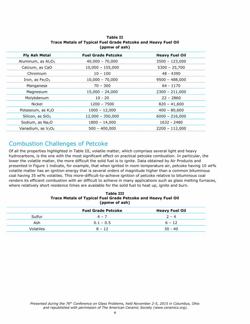
Table II
Trace Metals of Typical Fuel Grade Petcoke and Heavy Fuel Oil
(ppmw of ash)
Fly Ash Metal Fuel Grade Petcoke Heavy Fuel Oil
Aluminum, as Al2O3 40,000 – 70,000 3500 – 123,000
Calcium, as CaO 10,000 – 155,000 5300 – 25,700
Chromium 10 – 100 48 - 4390
Iron, as Fe2O3 10,000 – 70,000 9500 – 488,000
Manganese 70 – 300 64 - 1170
Magnesium 15,000 – 24,000 2300 – 211,000
Molybdenum 10 - 20 22 – 2860
Nickel 1200 – 7500 820 – 41,600
Potassium, as K2O 1000 – 12,000 400 – 80,600
Silicon, as SiO2 12,000 – 350,000 6000 – 216,000
Sodium, as Na2O 1800 – 14,000 1632 - 2480
Vanadium, as V2O5 500 – 400,000 2200 – 112,000
Combustion Challenges of Petcoke Of all the properties highlighted in Table III, volatile matter, which comprises several light and heavy
hydrocarbons, is the one with the most significant effect on practical petcoke combustion. In particular, the
lower the volatile matter, the more difficult the solid fuel is to ignite. Data obtained by Air Products and
presented in Figure 1 indicate, for example, that when ignited in room temperature air, petcoke having 10 wt%
volatile matter has an ignition energy that is several orders of magnitude higher than a common bituminous
coal having 35 wt% volatiles. This more-difficult-to-achieve ignition of petcoke relative to bituminous coal
renders its efficient combustion with air difficult to achieve in many applications such as glass melting furnaces,
where relatively short residence times are available for the solid fuel to heat up, ignite and burn.
Table III
Trace Metals of Typical Fuel Grade Petcoke and Heavy Fuel Oil (ppmw of ash)
Fuel Grade Petcoke Heavy Fuel Oil
Sulfur 4 – 7 2 – 4
Ash 0.1 – 0.5 6 – 12
Volatiles 8 – 12 30 - 40

Presented during the 76th Conference on Glass Problems, held November 2-5, 2015 in Columbus, Ohio and republished with permission of The American Ceramic Society (www.ceramics.org).
5
The most commonly applied
remedial measure for addressing
combustion residence time
limitations is fine pulverization
of the fuel. In coal combustion,
for example, it is generally
accepted that grind sizes of the
order of 70 wt% or greater of
the solid fuel passing through a
200 mesh screen (aperture size
of approximately 75 microns)
are required for efficient
combustion with entrained-flow
burners. Fine pulverization is
indeed essential in applications
having limited residence time, of
which glass melting is one, yet
industry experience suggests
that fine pulverization alone is
generally not sufficient,
particularly in the case of
petcoke. This is because while
combustion rates are increased
for finer particles (due to more
abundant surface area), the
added surface area has little
effect on ignition energy1.
However, as seen in Figure 1, when the aforementioned petcoke and bituminous coal ignition energy data are
extended to include the effect of oxygen enrichment on the ignition atmosphere, a dramatic reduction in ignition
energy is thereby obtained. And although an oxygen atmosphere of 50 mol% (balance N2) is needed to lower the
petcoke ignition energy to that of the air-bituminous coal mixture, much lower levels of oxygen enrichment,
properly applied, can have a substantial beneficial effect on combustion kinetics.
To illustrate this point for an application with commercial relevance to glass melting, several industrial-scale solid
fuel injection nozzles were tested in Air Products Clean Energy Laboratory (CEL), a pilot-scale, multi-fuel facility
capable of firing rates up to 20 MMBtu/hr.
Key results obtained during the
development are highlighted in Figures 2
and 3. The photos in Figure 2, were taken
in the CEL for two different simulations of
oxygen enhanced combustion of an air-
petcoke stream. Both scenarios represent
identical conditions in firing rate,
transportation air flow rate and overall
flame stoichiometry, but differ as to the
manner in which oxygen is introduced into
the flame. In photo A, transportation air
alone, amounting to approximately 10%
of the total stoichiometric requirement,
conveys the petcoke into a furnace, while
the balance of oxygen required for
complete combustion is lanced in a parallel stream immediately beneath the injector. By contrast, photo B shows
1
10
100
1000
10000
100000
20% 30% 40% 50% 60% 70%
Ign
itio
n E
ne
rgy
(mJ)
Vol% Oxygen (balance N2)
Petroleum Coke (10% VM)
Bituminous Coal (35% VM)
1
10
100
1000
10000
100000
20% 30% 40% 50% 60% 70%
Ign
itio
n E
ne
rgy
(mJ)
Vol% Oxygen (balance N2)
Petroleum Coke (10% VM)
Bituminous Coal (35% VM)
Figure 1.
Ignition energy vs oxygen concentration
for typical petcoke and bituminous coal.
Figure 2. Photos of petcoke flame.
A (left): Air-petcoke flame with oxygen staging.
B (right): Oxygen-enriched air-petcoke flame using SF Port Injector.
Presented during the 76th Conference on Glass Problems, held November 2-5, 2015 in Columbus, Ohio and republished with permission of The American Ceramic Society (www.ceramics.org).
6
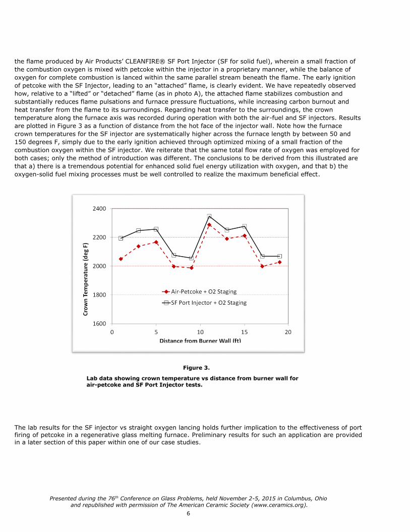
the flame produced by Air Products’ CLEANFIRE® SF Port Injector (SF for solid fuel), wherein a small fraction of
the combustion oxygen is mixed with petcoke within the injector in a proprietary manner, while the balance of
oxygen for complete combustion is lanced within the same parallel stream beneath the flame. The early ignition
of petcoke with the SF Injector, leading to an “attached” flame, is clearly evident. We have repeatedly observed
how, relative to a “lifted” or “detached” flame (as in photo A), the attached flame stabilizes combustion and
substantially reduces flame pulsations and furnace pressure fluctuations, while increasing carbon burnout and
heat transfer from the flame to its surroundings. Regarding heat transfer to the surroundings, the crown
temperature along the furnace axis was recorded during operation with both the air-fuel and SF injectors. Results
are plotted in Figure 3 as a function of distance from the hot face of the injector wall. Note how the furnace
crown temperatures for the SF injector are systematically higher across the furnace length by between 50 and
150 degrees F, simply due to the early ignition achieved through optimized mixing of a small fraction of the
combustion oxygen within the SF injector. We reiterate that the same total flow rate of oxygen was employed for
both cases; only the method of introduction was different. The conclusions to be derived from this illustrated are
that a) there is a tremendous potential for enhanced solid fuel energy utilization with oxygen, and that b) the
oxygen-solid fuel mixing processes must be well controlled to realize the maximum beneficial effect.
The lab results for the SF injector vs straight oxygen lancing holds further implication to the effectiveness of port firing of petcoke in a regenerative glass melting furnace. Preliminary results for such an application are provided in a later section of this paper within one of our case studies.
Figure 3.
Lab data showing crown temperature vs distance from burner wall for air-petcoke and SF Port Injector tests.
Presented during the 76th Conference on Glass Problems, held November 2-5, 2015 in Columbus, Ohio and republished with permission of The American Ceramic Society (www.ceramics.org).
7
Importance of Solid Fuel Chemistry
Ash from both petcoke and coal contain numerous metals and minerals that have the potential to influence glass
quality, color and refractory life. Among these are refractory oxides such as alumina, calcium oxide (lime) and
magnesia; metals including sulfur, vanadium and nickel, and naturally carbon, which in and of itself is a strong
reducing agent. Non silica-based refractory elements, for example, is known to lead to stones and knots in glass,
while inclusions of nickel sulfide, NiS, have been implicated in relation to spontaneous breakage in flat, tempered
glass 2. As such, it is obviously a concern with petcoke firing in float furnaces in particular. Nickel can also impart
a color to the glass that varies with the composition of the glass matrix.
Vanadium is a trace metal that is known to react with other commonly occurring ash metals such as nickel, iron
and sodium to form high melting point compounds. Silica, alumina and calcium have also been found to adhere to
these compounds (once deposited) as separate species3. The deposited vanadium compounds, particularly
vanadium pentoxide, V2O5, and salts such as the various sodium – vanadium compounds, have substantial
potential to attack refractory and foul regenerator flow passages. V2O5 is a known catalyst with peak activity in
the range of 950 – 1300 degrees F 4 and a melting point of approximately 1150 degrees F. Accordingly, in
regenerative glass furnaces, deposition and corrosive attack induced by vanadium is particularly prone to occur in
regenerators. Finally, vanadium ions in a highly oxidized state are known to affect glass color, typically by
imparting either a greenish or brownish tint 5.
A key concern of sulfur in solid fuel is that, via reaction with alkali metals it forms alkali sulfates which can attack
and weaken refractory structures 6. For example, sodium sulfate, Na2SO4, which melts at 1623 degrees F is can
penetrate and lead to progressive deterioration of alumina-silicate refractories. Of further concern are emissions
of sulfur dioxide (SO2), which is a principle contributor to acid rain, and sulfur trioxide (SO3) which combines with
water vapor to form sulfuric acid, H2SO4. The acid then condenses from flue gas in the cold end of the flue gas
ductwork, while also forming a condensate mist that can add a visible bluish tint to the furnace exhaust plume.
Flue gas scrubbers may be required depending upon regional emissions regulations.
For petcoke in particular, carbon can be the most abundant element in fly ash, and its strongly reducing nature
can effect glass redox state 7. Our experience is that poor petcoke combustion can in practice lead to ash that
contains over 90% carbon by weight. Apart from reducing fuel efficiency, which is naturally undesirable, high
unburned carbon-in-ash levels produce larger, heavier fly ash particles which are more prone to find their way
into both the glass melt and regenerator checker packs. Since, the above mentioned minerals and metals are
also constituents of the fly ash, poor combustion will dramatically increase the any deleterious effect of these
aforementioned species.
Based on these perspectives, it is clear that the benefits of oxygen enrichment in solid fuel combustion extend
beyond fuel efficiency and into the realm of capital and maintenance costs and glass quality.

Presented during the 76th Conference on Glass Problems, held November 2-5, 2015 in Columbus, Ohio and republished with permission of The American Ceramic Society (www.ceramics.org).
8
Material Handling
Combustion systems firing solid fuels can be categorized as directly or indirectly fired. Directly fired systems are
those in which coarse fuel is metered and introduced into a grinding mill which, after completion of the grinding
process, delivers the pulverized fuel with conveying air into one or more transport lines that carry fuel into the
burners. The indirect firing system differs from this in that the pulverization step is decoupled from the transport
of the fuel to the burner. The decoupling occurs by short or long term storage of the pulverized fuel in a bin,
hopper or other storage container. The indirect firing system is generally preferred for glass melting for at least
the following two reasons:
1. For an indirectly fired system, interruptions in the grinding process, which are not uncommon, will not cause
an interruption in the fuel being delivered to the furnace.
2. Pulverizers generally require more cool air than is strictly required for lean phase particle transport. Hence,
burners in indirectly fired systems are generally smaller, and combustion is less diluted with cool transport air
than for directly fired
systems.
It is further important to
mention that due to its low
volatility, long-term storage
of pulverized petcoke is
generally not plagued by self-
heating and spontaneous
combustion. Thus, whether
or not the pulverization
process is carried out onsite
or at remote location, storage
of the pulverized petcoke
onsite is a safe and viable
option.
Assuming the indirectly fired
system is used, the basic
material handling equipment
package consists of a storage
hopper, dust collection
system, injector vessel,
metering device and transport air
blower. One common
configuration illustrating the
packaging of this equipment, along with auxiliary piping hardware is presented in Figure 4. (Note that while dust
collection in the vicinity of the material handling system is strongly recommended, it is omitted from Figure 4 for
the sake of brevity.) Many specific design variations are possible within the basic framework of this system.
Perhaps the most critical of these relates to the maximum transportation air pressure required at the point of
injection of solid fuel into the transportation air line. This is due to the cascading effect that pressure at this initial
injection point has upon critical design and operating factors such as air blower / compressor cost and power
requirement, material flow stability, dust control, injector vessel design and the need for a pressure isolation
vessel. Concerning this latter point, Figure 4 depicts a so-called lock vessel, labeled as optional, which is frequently
used for systems where a large pressure increase across the charging screw would otherwise be required. This
Figure 4.
Typical material handling and transportation
system for indirect firing.

Presented during the 76th Conference on Glass Problems, held November 2-5, 2015 in Columbus, Ohio and republished with permission of The American Ceramic Society (www.ceramics.org).
9
arrangement provides a buffer between the atmospheric pressure hopper and higher pressure injector vessel,
facilitating smooth and continuous material feeding across the charging screw.
In so far as it is highly desirable to maintain the lowest pressure possible at the point of discharge from the
charging screw to the transportation line, selection of the transportation air flow rate and transport line size are
of considerable importance. Transportation line velocities of between 15 and 30 m/sec are typically acceptable;
depending upon particle size, shape and density. Velocity below 15 m/sec can lead to particle drop out and line
plugging, while velocity above 30 m/sec will substantially increase both pressure drop and line erosion
phenomena. Simultaneously, fuel to transportation air mass flow rate ratios between nominally 1 and 10 are
generally preferred for glass melting. A ratio lower than 1 can be too lean for combustion applications, and may
promote combustion instabilities, while also diluting the balance of oxidizer mixed at the burner, which will
generally be either be hot air or oxygen. Conversely, fuel to transportation air ratios significantly above 10 can
bring the onset of unsteady, chugging flow and higher pressure drop associated with dense phase transport. It is
emphasized that the stated design ranges for the transportation line are intended for estimation only, and a more
precise assessment should include the flow characteristics of the solid fuel particulate as well as details of the
transportation line layout.
Concerning integration of the solid fuel handling system with the furnace, the most significant factor is whether
or not the glass furnace is of the regenerative type. The regenerative furnace requires periodic side-to-side
switching of the fuel delivery. This can generally be accomplished with either a) side-to-side redundancy in the
delivery system where only one side delivers petcoke at a given time while the other introduces purge air flow; or
b) a single feed system with a switching mechanism coupled to recirculation lines that enable fuel and purge air
to be diverted as needed for left or right side firing. While the redundant system (a) requires a higher initial
capital cost, it is likely to afford smoother operation during transients, plus less piping complexity and simpler
balancing of petcoke flow to each burner. The merits and drawbacks of both systems should be assessed for the
particular glass melting application. In this regard, it should be mentioned that non-regenerative furnaces, such
as occurs with oxy-fuel, offer the advantage of continuous petcoke delivery to the burners, which will lead to
more stable combustion and process conditions than can be achieved in regenerator-based systems.
An additional key factor in material handling system design is whether or not dedicated feeders are used for each
burner versus a single feeder with one or more discharge splitters for solid fuel delivery to two or more burners.
This, however, requires that burners have been identified by furnace zone that can operate at nominally the
same firing rate. Whether or not this level of precision and constraint are acceptable for glass furnace process
control needs to be evaluated on a case-by-case basis. A practical example is in regenerative furnaces where fuel
delivery to a given port is likely to come from a single feeder and is subsequently split to two or three fuel
injectors, depending upon the port firing configuration. It is our experience that evenly splitting a solid fuel
delivery header into 3 outlet streams is much more challenging than when only a two-way split is required. Either
way, it is crucial to include flow balancing devices such as adjustable/removable orifices or riffles that can be
“tuned” during operation to achieve a desired uniformity in flame appearance. We have also found oxygen
enrichment at the injector level to be an effective tool in assisting to mitigate the effects of solid fuel flow
imbalance on flame appearance and heat release. An example of this is provided in the Case Studies.
Case Studies of Glass Melting with Oxygen-Enriched Solid Fuel Combustion
The following several case studies are intended to briefly highlight a cross-section of key results of our recent
experience in oxy-solid fuel combustion for glass melting.
Case 1: Dark Specialty Glass Production using Combination of Oxy-Petcoke and Oxy-Natural Gas Firing
This application utilizes two SF oxy-petcoke burners at the batch end of the nominal 42 tpd cross-fired melter,
while the remainder of the furnace comprises 8 Mini HRi™ oxy-gas flat flame burners. Individual feed systems
driven by relatively low pressure transportation air blowers deliver the petcoke independently to the two solid fuel
burners. The SF burners produce a stable, highly luminous and adjustable-length round solid fuel flame, with
back-up gas or oil lances available for rapid fuel-switching between petcoke and other fossil fuels, as dictated for

Presented during the 76th Conference on Glass Problems, held November 2-5, 2015 in Columbus, Ohio and republished with permission of The American Ceramic Society (www.ceramics.org).
10
example by fuel price volatility and/or temporary interruption to the fuel supply. A photo of one of the SF oxy-
petcoke flames in this furnace is presented in Figure 5. Note: The SF burners differ from the previously
mentioned SF injectors in that the burners are designed for stoichiometric oxy-fuel combustion, while the
injectors utilize only a small fraction of the oxygen required for combustion.
Initial results of the switch
from full oxy-gas to oxy-
gas/petcoke have been
favorable. Specifically, bottom
temperature beneath the
oxy/petcoke burners increased
by 10 deg C, and glass quality
improved. The fuel-switching
experience was not, however,
without its challenges, as
there were several
interruptions in the petcoke
pneumatic delivery system
early in the project caused by
stray material in the fuel
supply that required rapid and
immediate removal of the SF
burner’s solid fuel nozzles and
immediate replacement with
backup oxy-natural gas
lances. Overall, the customer
is very satisfied with the operation, which has been ongoing for nearly two years, and plans to convert several
additional burners to oxy-petcoke in the near future.
Case 2: Dark Specialty Glass Production using Combination of Oxy-Petcoke and Oxy-Fuel Oil Firing
Similar to Case 1, Case 2 is a dark specialty glass produced in a cross-fired oxy-fuel tank with 8 SF burners. Pull
rate is nominally 50 tpd. Half of the burners are currently firing petcoke in the melting end of the tank, while the
other half are firing heavy fuel oil in the fining end using s Gen1-SF backup oil nozzles. The customer reports that
glass quality is as good now as with 100% oxy-oil operation, and plans to eventually convert to 100% oxy-
petcoke.
Case 3: Clear Specialty Glass Production using Oxy-
Petcoke/Coal Firing
This case involves a small, single-burner 15 tpd melting
furnace previously fired with synthetic fuel gas. Notably,
the furnace provides very little residence time to achieve
complete combustion in comparison to a typical glass
melting furnace. Conversion was initially to a single
Cleanfire SF burner firing petcoke, but the customer was
not satisfied with the color of the product (see Figure 6).
Subsequently the customer switched from petcoke to
coal and the color problem was resolved. Two factors
were identified as being linked to the color problem; high
vanadium content and poor combustion. Regarding
vanadium content, Table IV summarizes key
constituents found in the petcoke from Cases 1 and 3, as
well as the coal from Case 3. Note that the magnitude of vanadium, a known coloring agent, in the petcoke from
Case 3 was over 10 times higher than either the petcoke from Case 1 or the coal from Case 3.
Figure 5. Photo of SF Oxy-Petcoke flame in glass melting furnace (Case 1).
Figure 6. Photo of glass product produced with
syngas firing (left) and petcoke firing having high
vanadium content and poor combustion (right).

Presented during the 76th Conference on Glass Problems, held November 2-5, 2015 in Columbus, Ohio and republished with permission of The American Ceramic Society (www.ceramics.org).
11
Table IV
Values represent % of parent fuel
Element Case 1: Petcoke Case 3: Petcoke Case 3: Coal
Vanadium .018% .190% .012%
Iron Not Sampled .110% .096%
Nickel .0055% .090% .035%
Ash .45% 1.19% 13.1%
Volatiles 10.7% 15% 29%
Combustion problems reported with the petcoke in Case 3 were traced back to a transportation air flow rate that
was 2-3 times higher than recommended by Air Products. As such, ignition delay of the petcoke was unavoidable,
resulting in significant unburned carbon. Hence, as previously suggested, it is clear that much of the ash-bound
vanadium and carbon migrated to the glass melt where it led to redox changes and color contamination of the
glass product. It is interesting that, despite the much higher ash content of the coal, the higher coal volatility
nevertheless resulted in minimal ignition delay, good combustion and, hence, acceptable glass quality. While it
was not possible to differentiate the relative effects on product color of vanadium content versus combustion
quality, results from this case affirms the need for attention to be given to ash composition, and further
underscores the importance of achieving good combustion.
Case 4: Clear Container Glass Production in a Regenerative Air-Fuel Furnace using Oxygen-Enriched Air Firing of
Petcoke
This final case is a 200 tpd regenerative end port furnace producing clear container glass. The customer desired
to replace heavy fuel oil with petcoke as the principal fuel, while oxy-natural gas boost was also supplied with
Cleanfire Advanced Boost burners. We proposed using oxygen-enriched SF Port Injector technology instead of the
combination of air-petcoke injectors plus oxygen lancing, as originally planned by the customer. The first step of
this project was thus to compare the two approaches to petcoke combustion. Results are summarized in the
photographs of Figure 7.
The photo on the left features three SF injectors, while that on the right shows three air-petcoke lances plus
adjacent oxygen lancing. Firing rate and total oxygen enrichment is nominally the same for the two cases. The
Figure 7. Photos of SF Port Injectors with integral oxygen mixing (left) and air-petcoke injector plus
oxygen staging (right) in an end-port regenerative container glass furnace

Presented during the 76th Conference on Glass Problems, held November 2-5, 2015 in Columbus, Ohio and republished with permission of The American Ceramic Society (www.ceramics.org).
12
photos, taken with the same furnace camera, clearly demonstrate that the flames produced by the SF injectors
were longer, broader and more luminous than those produced with air-fuel injectors plus O2 lancing. Moreover,
close examination of these photos show that while three distinct flames are apparent for the SF injectors, only
two can be discerned for the air-fuel lances. The issue here is that a single feeding system with splitting devices
was used to supply all three under-port lances on each side of the furnace. However, the fuel split was plagued
with imbalances which manifested itself principally in fuel deficiency to the outermost injectors. The fact that the
outermost flame is visible, albeit relatively small, for the oxygen-enriched Port injectors, but not readily visible
for the air-fuel injectors is, we believe, the result of the oxygen-fuel mixing facilitated by the Port injectors that
helped to for the detrimental effects caused by the fuel imbalance. Based on these results the customer chose to
move forward using the Port injectors. Note that no negative effects on glass quality have occurred, and while
furnace generated NOx has increased somewhat, NOx emissions exiting the SCR system remained the same as
they were with air-heavy oil firing. Two key takeaways from this case are that the controlled oxy-fuel mixing
occurring within the Port injectors produces a superior flame to the combination of air-fuel injection plus oxygen
lancing, and that even splitting of solid fuel streams in pneumatic conveying is inherently challenging and would
certainly benefit from strategic placement of balancing devices, as previously suggested.
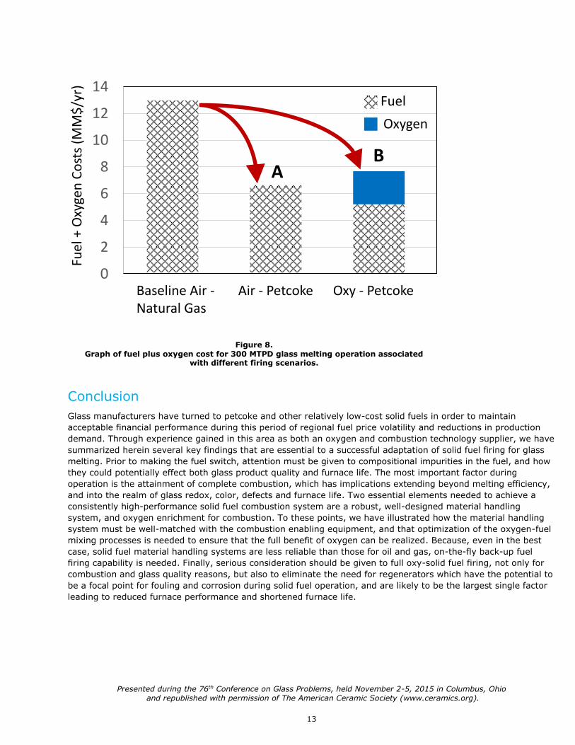
Economic Considerations
The economic viability of converting of a glass melting furnace from oil or gas to petcoke, as well as that of its
ongoing operation, depends upon factors such as the cost of fuel, combustion system efficiency, glass quality and
cost/frequency of a furnace rebuild. While not enough data exist to carry out a comprehensive cost study, we
propose to compare differential operating costs from a base-case of air-natural gas firing in a regenerative
furnace to petcoke firing in either another regenerative air-fuel system (Option A), or employing 100% oxy-
petcoke operation (Option B). Key assumptions for the analysis are that:
1. Natural gas price is $18/MMBtu
2. Petcoke price is $9/MMBtu (pulverized and delivered)
3. Oxygen price is $60/MT
4. Pull rate of glass is 300 MTPD
5. Switching from natural gas to petcoke involves no change in fuel efficiency
6. Switching from air/fuel to oxy/fuel increases fuel efficiency by 20%
Results of the analysis, which reduce to a comparison of annualized fuel and oxygen costs, are summarized in
Figure 8 (next page), adapted from Goruney et al 8. Note that both petcoke Options A (air-fuel) and B (oxy-fuel)
lead to a substantial reduction in fuel cost from the base air-natural gas firing case; from an air-natural gas
baseline of $13MM/yr to $6.4MM/yr for Option A and $5MM/yr for Option B. However, the addition of oxygen in
Option B adds $2.8MM/yr of oxygen cost, resulting in an apparent net operating cost increase relative to Option A
of approximately $1.4MM/yr, or approximately $12.80/MT of pulled glass. The question then becomes whether or
not the higher operating cost with oxygen is offset by benefits related to lower capital cost, longer furnace
campaigns and superior glass quality control due improved combustion efficiency and stability. Regarding capital
costs, a recent study suggests that, relative to a regenerative air-fuel furnace, oxy-fuel capital costs are lower by
30-40% 9. Moreover, our discussions with glass manufacturers having experience with air-fuel petcoke
combustion confirms combustion quality problems and suggests that furnace rebuilds as frequently as every 2 to
3 years is not uncommon. When we contrast this with the nearly two year successful run as documented herein
in Case 1, we believe there is a very persuasive case to be made that oxygen is a vital ingredient in the mix of
factors needed for cost-effective glass melting with petcoke.
Presented during the 76th Conference on Glass Problems, held November 2-5, 2015 in Columbus, Ohio and republished with permission of The American Ceramic Society (www.ceramics.org).
13
Conclusion
Glass manufacturers have turned to petcoke and other relatively low-cost solid fuels in order to maintain
acceptable financial performance during this period of regional fuel price volatility and reductions in production
demand. Through experience gained in this area as both an oxygen and combustion technology supplier, we have
summarized herein several key findings that are essential to a successful adaptation of solid fuel firing for glass
melting. Prior to making the fuel switch, attention must be given to compositional impurities in the fuel, and how
they could potentially effect both glass product quality and furnace life. The most important factor during
operation is the attainment of complete combustion, which has implications extending beyond melting efficiency,
and into the realm of glass redox, color, defects and furnace life. Two essential elements needed to achieve a
consistently high-performance solid fuel combustion system are a robust, well-designed material handling
system, and oxygen enrichment for combustion. To these points, we have illustrated how the material handling
system must be well-matched with the combustion enabling equipment, and that optimization of the oxygen-fuel
mixing processes is needed to ensure that the full benefit of oxygen can be realized. Because, even in the best
case, solid fuel material handling systems are less reliable than those for oil and gas, on-the-fly back-up fuel
firing capability is needed. Finally, serious consideration should be given to full oxy-solid fuel firing, not only for
combustion and glass quality reasons, but also to eliminate the need for regenerators which have the potential to
be a focal point for fouling and corrosion during solid fuel operation, and are likely to be the largest single factor
leading to reduced furnace performance and shortened furnace life.
Figure 8. Graph of fuel plus oxygen cost for 300 MTPD glass melting operation associated
with different firing scenarios.
0
2
4
6
8
10
12
14
Baseline Air -Natural Gas
Air - Petcoke Oxy - Petcoke
Fuel
+ O
xyge
n C
ost
s (M
M$
/yr)
AB
Fuel
Oxygen

© Air Products and Chemicals, Inc., 2015 337-15-006-US
References
1. Man, C. K., and Gibbins, J. R., “Factors Affecting Coal Particle Ignition Under Oxyfuel Combustion
Atmospheres”, Fuel, Volume 90, Issue 1, pp. 294-394, January, 2011.
2. “Spontaneous Breakage of Fully Tempered Glass”, Eckelt Glas, GmbH, Edition 01.2003 (2005).
3. Ito, T., et al, “Long-Term Stable Operation of Petroleum-Coke-Fired Boiler Retrofitted from Existing Oil
Firing”, Proceedings of the Engineering Foundation Conference on Inorganic Transformation and Ash
Deposition During Combustion, pp. 895-914, 1991.
4. Walsh, P. M., Mormile, D. J., and Piper, B. F., “Sulfur Trioxide Formation in the Presence of Residual Oil
Ash Deposits in an Electric Utility Boiler”, pp. 294-300.
5. “Integrated Pollution Convention and Control”, Reference Document on Best Available Techniques in the
Glass Industry, Prepared by the European Commission, December 2001
6. Lewandowski, D., “Design of Thermal Oxidation Systems for Volatile Organic Compounds”, CRC Press,
2000.
7. IMI-NFG Course on Processing in Glass, Lecture 2, Melting and Fining Processes in Industrial Glass
Furnaces, Celsian Glass and Solar, presented at Lehigh University, Spring 2015.
8. Goruney, T., et al., “Alternative Fuels for Glass Melting”, Glass International, October 2013.
9. Worrell, E, et al., “Energy Efficiency Improvement and Cost Saving Opportunities for the Glass Industry”,
an ENERGY STAR® Guide for Energy and Plant Managers, sponsored by the US EPA, March 2008.
*CLEANFIRE is a registered trademark of Air Products and Chemicals, Inc.
tell me more For more information, please contact us at:
Air Products
7201 Hamilton Boulevard
Allentown, PA 18195-1501
Tel 800-654-4567 or 610-706-4730
Air Products Asia
2F, 21 Chung Shan N. Road, Sec. 2
Taipei 10450
Taiwan
T +886 2 2521 4161
Air Products PLC
Hersham Place Technology Park
Molesey Road
Walton-on-Thames
Surrey KT12 4RZ
UK
T +44(0)800 389 0202
airproducts.com/glass