GEHL R165 Operators Manual - Rentalex
206
R135 R135 (EU) R135 X-Series R150 R150 (EU) R150 X-Series R165 R165 (EU) R165 X-Series Skid-Steer Loaders Operator’s Manual Form No. 50940193 DP0415 English Revision D
-
Upload
khangminh22 -
Category
Documents
-
view
0 -
download
0
Transcript of GEHL R165 Operators Manual - Rentalex

R135R135 (EU)R135 X-SeriesR150R150 (EU)R150 X-SeriesR165R165 (EU)R165 X-SeriesSkid-Steer Loaders
Ope
rato
r’s
Man
ual
Form No.50940193DP0415English
Revision D

GEHL COMPANY WARRANTY
GEHL COMPANY, hereinafter referred to as Gehl, warrants new Gehl equipment to the Original Retail Purchaser to be free from defects in material and workmanship for a period of twelve (12) months from the Warranty Start Date.
GEHL WARRANTY SERVICE INCLUDES: Genuine Gehl parts and labor costs required to repair or replace equipment at the selling dealer’s business location. GEHL MAKES NO REPRESENTATIONS OR WARRANTIES OF ANY KIND, EXPRESS OR IMPLIED (INCLUDING THE IMPLIED WARRANTIES OF MERCHANTABILITY AND FITNESS FOR PARTICULAR PURPOSE), EXCEPT AS EXPRESSLY STATED IN THIS WARRANTY STATEMENT.
ANY OF THESE LIMITATIONS EXCLUDED BY LOCAL LAW SHALL BE DEEMED DELETED FROM THIS WARRANTY; ALL OTHER TERMS WILL CONTINUE TO APPLY.
SOME STATES DO NOT PERMIT THE EXCLUSION OR LIMITATION OF THESE WARRANTIES AND YOU MAY HAVE GREATER RIGHTS UNDER YOUR STATE LAW.
GEHL WARRANTY DOES NOT INCLUDE:
1. Transportation to selling dealer’s business location or, at the option of the Original Retail Purchaser, the cost of a service call.
2. Used equipment.
3. Components covered by their own non-Gehl warranties, such as tires, batteries, trade accessories and engines.
4. Normal maintenance service and expendable, high-wear items.
5. Repairs or adjustments caused by: improper use; failure to follow recommended maintenance procedures; use of unauthorized attachments; accident or other casualty.
6. Liability for incidental or consequential damages of any type, including, but not limited to lost profits or expenses of acquiring replacement equipment.
No agent, employee or representative of Gehl has any authority to bind Gehl to any warranty except as specifically set forth herein. 204927/AP0407
Gehl®, All-Tach®, and Power-A-Tach®, are registered trademarks of Manitou Americas, Inc.

Introduction . . . . . . . . . . . . . . . . . . . . . . . . . . . . . . . . . . . . 1Safety . . . . . . . . . . . . . . . . . . . . . . . . . . . . . . . . . . . . . . . 13Safety Equipment . . . . . . . . . . . . . . . . . . . . . . . . . . . . . . 39Indicators and Controls . . . . . . . . . . . . . . . . . . . . . . . . . . 47Operation . . . . . . . . . . . . . . . . . . . . . . . . . . . . . . . . . . . . 81Maintenance . . . . . . . . . . . . . . . . . . . . . . . . . . . . . . . . . 121Troubleshooting . . . . . . . . . . . . . . . . . . . . . . . . . . . . . . 159Specifications . . . . . . . . . . . . . . . . . . . . . . . . . . . . . . . . 183Index . . . . . . . . . . . . . . . . . . . . . . . . . . . . . . . . . . . . . . . 197
R135, R150, R165 Skid-Steer Loader Operator’s Manual
TABLE OF CONTENTS
LOADER INFORMATION
Purchased from
Date of Purchase
Loader Model Number
Loader Serial Number
Engine Serial Number

EC DECLARATION OF CONFORMITY
1. Manufacturer: Manitou Americas, Inc.
2. Address: One Gehl WayWest Bend, WI 53095-0179 U.S.A.
3. Technical Construction File Location:Manitou Interface and Logistics EuropeRue Des Andains 2PERWEZ, 1360Belgium
4. Authorized Representative: Manitou Interface and Logistics Europe
5. Address: Rue Des Andains 2PERWEZ, 1360Belgium
6. We hereby declare that the model(s) listed below conforms to EC Directives: 2004/108/EC (EMC), 97/23/EC (Pressure Equipment), 2006/42/EC (Machinery) and 2000/14/EC (Noise Emission), as amended by 2005/88/EC.
7. In accordance with EN/ISO Standards:EN ISO 3450:1996, ISO 6165
8. Category: EARTH-MOVING MACHINERY/LOADERS/COMPACT
9. Models: R135, R150, R165
10. Directive/Conformity Assessment Procedure/Notified Body:
2004/108/EC Type-test Self-certification97/23/EC Self-certification ----------2006/42/EC Self-certification ----------2000/14/EC Annex VIII – Full
Quality Assurance
TÜV Industrie Service GmbH – TÜV SÜD GroupWestendst. 199, D-80686 München GERMANY

CHAPTER 1INTRODUCTION
Safety Symbol and Signal Words
Manitou Americas, in cooperation with the Society of Automotive Engineers, has adopted this:
Safety Alert Symbol
This symbol identifies potential safety hazards, which, if not properly avoided, could result in injury. When you see this symbol in this manual or on the machine, you are reminded to BE ALERT! Your personal safety is involved!
Signal Words
The word “DANGER” indicates an imminently hazardous situation, that, if not avoided, will result
in serious injury or death.
The word “WARNING” indicates a potentially hazardous situation that, if not avoided, could
result in serious injury or death.
The word “CAUTION” indicates a potentially hazardous situation that, if not avoided, may result
in minor or moderate injury.
Important: The word “IMPORTANT” indicates situations that can result in possible damage to the machine.
Note: The word “NOTE” indicates special or particularly useful information.
Contents and Use of this Manual
This Operator’s Manual provides information about the safe and proper operation and maintenance for the machine. Major points of safe operation and maintenance are detailed in the Safety section of this manual, starting on page 13.
This manual also includes general troubleshooting and specification information about the machine.
DANGER
WARNING
CAUTION
1 50940193/DP0415

Follow the instructions in the Operator’s Manual Safety, Operation and Maintenance chapters, concerning accident prevention regulations, safety and occupational regulations, and machine and traffic regulations. Manitou Americas is not liable for injury or damage resulting from the failure to follow these regulations.
Improper operation, inspection and maintenance of the machine can cause injury or death. Read and
understand the contents of this manual COMPLETELY and become familiar with the machine before operating it.
It is the owner’s or employer’s responsibility to fully instruct each operator in the proper and safe operation and maintenance of the machine.
A storage location is provided inside the operator’s compartment for storing this Operator’s Manual. After using this manual, return it to the storage location.
This manual is considered a permanent part of the machine and should be with the machine at all times. If the machine is resold, include this operator’s manual as part of the sale.
Replace this manual promptly if it becomes damaged, lost or stolen.
Some illustrations and photos in this manual may show doors, guards and shields open or removed for informational purposes only. BE SURE all doors, guards and shields are in their proper operating positions BEFORE starting the engine to operate the machine.
Because of ongoing product improvements, information included in this manual may not exactly match the machine. Manitou Americas reserves the right to modify and improve products at any time without notice or obligation.
CAUTION
2 50940193/DP0415
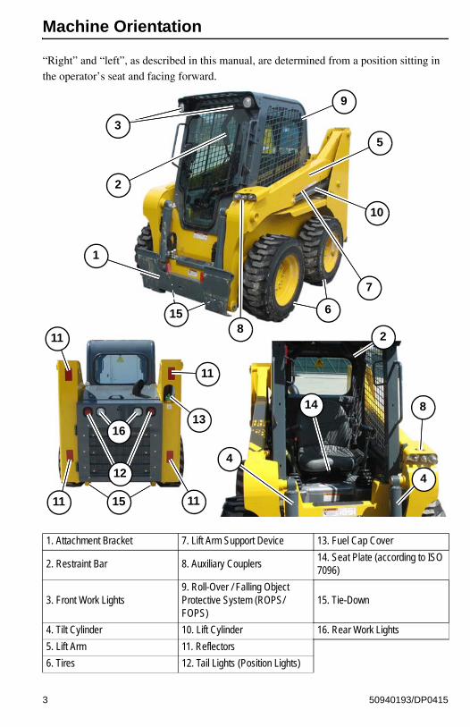
Machine Orientation
“Right” and “left”, as described in this manual, are determined from a position sitting in the operator’s seat and facing forward.
1. Attachment Bracket 7. Lift Arm Support Device 13. Fuel Cap Cover
2. Restraint Bar 8. Auxiliary Couplers14. Seat Plate (according to ISO 7096)
3. Front Work Lights9. Roll-Over / Falling Object Protective System (ROPS/FOPS)
15. Tie-Down
4. Tilt Cylinder 10. Lift Cylinder 16. Rear Work Lights
5. Lift Arm 11. Reflectors
6. Tires 12. Tail Lights (Position Lights)
1
2
2
4
5
6
8
412
1314
3
7
8
9
10
15
15
11
11
1111
16
3 50940193/DP0415

Proper Machine Use
Improper use of the machine can result in property damage, injury or death.
The machine is designed only for moving earth, coarse gravel or ballast and rubble. Use with approved attachments is also allowed – See “Fields of Application” on page 6. Use in any other way is considered as contrary to the intended use. Compliance with, and strict adherence to, the conditions of operation, service and repair as specified by the manufacturer, also constitute essential elements of the intended use.
The machine was designed and built according to the best available technology and approved safety regulations in the countries where it is sold. It is impossible, however, to completely safeguard against abusive, improper use. The operator must always consider potential safety risks and hazards during operation. Accident prevention regulations, all other generally recognized regulations on safety and occupational medicine, and all road traffic regulations must be observed at all times.
The machine must be maintained in proper operating condition. Any damaged or malfunctioning parts must be repaired or replaced immediately.
Do not make any unauthorized modifications to the machine. Unauthorized modifications made to the machine may relieve the manufacture of liability for any resulting damage or injury.
Service and Registration
When ordering service parts, provide complete information about the part and the quantity required. Also, provide the model and serial numbers of the machine. For your safety and continued proper operation, use only genuine service parts. Record the model and serial numbers in the spaces on page 5 for quick reference.
WARNING
4 50940193/DP0415

Model and Serial Numbers
Machine Model Number
____________________________________
Machine Serial Number
____________________________________
Engine Model Number
____________________________________
Engine Serial Number
____________________________________
5 50940193/DP0415

Fields of Application
Note: Refer to “Payloads/Capacities” on page 186 for specific bucket rated payload capacities.
The attachments determine how the machine is used.
Contact CEA Attachments at: http://www.ceattachments.com/ContactUs.aspx for
information about available attachments approved for use with the machine.
Contact your CEA Attachments (http://www.ceattachments.com/ContactUs.aspx) before using attachments or equipment not approved by Manitou Americas. Use of non-approved attachments or unauthorized modifications is prohibited.
Using AttachmentsRead all documentation provided with attachments to learn how to safely operate and maintain them.
Do not use the machine for any applications or purposes other than those described in this manual or manuals supplied with attachments. See the following “Fields of Application” table for information about approved attachments and their uses. Contact your dealer before using attachments or equipment not approved by Manitou Americas. Use of non-approved attachments or unauthorized modifications is prohibited.
WARNING
6 50940193/DP0415

Table 1: Fields of Application
Model Attachment Width Height Depth Capacity
R135
Dirt / Construction Bucket
1372 mm(54 in.)
506 mm(19.9 in.)
808 mm(31.8 in.)
0.28 m3
(9.8 ft.3)
1524 mm(60 in.)
505 mm(19.9 in.)
983 mm(38.7 in.)
0.31 m3
(11.0 ft.3)
1562 mm(61.5 in.)
505 mm(19.9 in.)
983 mm(38.7 in.)
0.32 m3
(11.3 ft.3)
Dirt / Construction Bucket w/Spillguard
1562 mm(61.5 in.)
612 mm(24.1 in.)
808 mm(31.8 in.)
0.40 m3
(14.1 ft.3)
Light Material Bucket
1372 mm(54 in.)
597 mm(23.5 in.)
983 mm(38.7 in.)
0.43 m3
(15.0 ft.3)
1524 mm(60 in.)
597 mm(23.5 in.)
983 mm(38.7 in.)
0.48 m3
(16.9 ft.3)
1676 mm(66 in.)
597 mm(23.5 in.)
1021 mm(40.2 in.)
0.54 m3
(19.0 ft.3)
Pallet ForksN/A N/A
1067 mm(42 in.)
N/A
N/A N/A1219 mm(48 in.)
N/A
R150
Dirt / Construction Bucket
1524 mm(60 in.)
505 mm(19.9 in.)
983 mm(38.7 in.)
0.31 m3
(11.0 ft.3)
1562 mm(61.5 in.)
505 mm(19.9 in.)
983 mm(38.7 in.)
0.32 m3
(11.3 ft.3)
Dirt / Construction Bucket w/Spillguard
1562 mm(61.5 in.)
612 mm(24.1 in.)
808 mm(31.8 in.)
0.40 m3
(14.1 ft.3)
Light Material Bucket
1524 mm(60 in.)
597 mm(23.5 in.)
983 mm(38.7 in.)
0.48 m3
(16.9 ft.3)
1676 mm(66 in.)
597 mm(23.5 in.)
1021 mm(40.2 in.)
0.54 m3
(19.0 ft.3)
Pallet ForksN/A N/A
1067 mm(42 in.)
N/A
N/A N/A1219 mm(48 in.)
N/A
7 50940193/DP0415

R165
Dirt / Construction Bucket
1524 mm(60 in.)
505 mm(19.9 in.)
983 mm(38.7 in.)
0.31 m3
(11.0 ft.3)
1562 mm(61.5 in.)
505 mm(19.9 in.)
983 mm(38.7 in.)
0.32 m3
(11.3 ft.3)
1778 mm(70 in.)
531 mm(20.9 in.)
902 mm(35.5 in.)
0.46 m3
(16.1 ft.3)
Dirt / Construction Bucket w/Spillguard
1562 mm(61.5 in.)
612 mm(24.1 in.)
808 mm(31.8 in.)
0.40 m3
(14.1 ft.3)
1778 mm(70 in.)
660 mm(26.0 in.)
965 mm(38.0 in.)
0.59 m3
(20.9 ft.3)
Light Material Bucket
1676 mm(66 in.)
597 mm(23.5 in.)
1021 mm(40.2 in.)
0.54 m3
(19.0 ft.3)
1778 mm(70 in.)
600 mm(23.6 in.)
1021 mm(40.2 in.)
0.57 m3
(20.3 ft.3)
Grading / Low Profile Bucket
1778 mm(70 in.)
541 mm(21.3 in.)
1062 mm(41.8 in.)
0.55 m3
(19.4 ft.3)
Pallet ForksN/A N/A
1067 mm(42 in.)
N/A
N/A N/A1219 mm(48 in.)
N/A
Table 1: Fields of Application
Model Attachment Width Height Depth Capacity
8 50940193/DP0415

Vibration Information
Compact construction equipment is generally used in harsh environments. This type of usage can expose an operator to uncomfortable levels of vibration. It is useful to understand exposure to vibration levels when operating compact equipment and what can be done to reduce vibration exposure. As a result, equipment operation can be more efficient, productive and safe.
An operator’s exposure to vibration occurs in two ways:
• Whole-Body Vibration (WBV).• Hand-Arm Vibration (HAV).
WBV issues are primarily addressed in this manual, because evaluations have shown that operation of mobile compact construction equipment on worksites typically results in
HAV levels less than the allowed exposure limit of 2.5 m/s2. Member States of the European Union must comply with the Physical Agents (vibration) Directive, 2002/44/EC.
Effective control of vibration exposure for an operator involves more than just vibration levels on the machine. The worksite, how the machine is used, and proper training all play important roles in reducing vibration exposure.
Vibration exposure results from:
• Worksite conditions.• How the machine is operated.• The machine characteristics.
Common causes of high WBV levels:
• Using a machine that is improper for the task.• Worksite with potholes, ruts and debris.• Improper operating techniques, such as driving too fast.• Incorrect adjustment of the seat and controls.• Other physical activities while using the machine.
Vibration Measurement and Actions
The vibration directive places the responsibility for compliance on employers. Actions that should be followed by employers include:
• Assess the levels of vibration exposure.• Determine from this assessment if operators will be exposed to vibration levels
above the limits stated in the directive.• Take appropriate actions to reduce operator’s exposure to vibration.• Provide operators with information and training to reduce their exposure to vibra-
tion.• Keep good records and update operations and training on a regular basis.
9 50940193/DP0415

If the assessment concludes that vibration level exposure is too high, one or more of the following actions may be necessary:
1. Train operators:• Perform operations (accelerating, steering, braking, etc.) in a smooth manner.• Adjust the controls, mirrors and seat suspension for comfortable operation. Do not
make adjustments when the machine is in use.• Travel across the smoothest parts of the worksite and avoid ruts and potholes.
2. Choose proper equipment for the job:
• Use machines with the proper power and capacity.• Select machines with good suspension seats.• Look for controls that are easy to use.• Ensure good visibility from the operator’s position.
3. Maintain the worksite:
• Smooth ruts and fill potholes in traffic areas whenever possible.• Clean up debris frequently.• Vary traffic patterns to avoid exposure to rough terrain.
4. Maintain equipment. Check that seat suspension and all controls work smoothly and properly.
Vibration Levels
See “Vibration Levels” on page 191 for a table listing typical whole-body vibration levels for the machine.
10 50940193/DP0415

Fire Extinguisher Location
An installation location for a fire extinguisher is shown in Figure 1.
Important: Installation of a fire extinguisher according to DIN-EN 3 must be performed by an authorized dealer.
Note: A fire extinguisher is neither included as standard equipment nor available as an option from Manitou Americas, Inc.
Important: Inspect the fire extinguisher at regular intervals as recommended by the fire extinguisher equipment manufacturer.
Manufacturer Information
Products described in this manual are manufactured by Manitou Americas, Inc.
Note: Not all models and options described in this manual are available in all areas.
Figure 1 – Fire Extinguisher Location
11 50940193/DP0415

Indicator and Operation Symbols
Safety Hazard Parking Brake High-Speed Float Hydraglide™ Pre-Heat
Fasten Seat Belt Charging FaultIntake
RestrictionHydraulic Oil Filter Warning
Hydraulic Oil Temp Warning
Elevated EGT Temp
DPF Regen Accept
DPF Regen Inhibited
Regen Maintenance
DPF Regen Engine OilOil Pressure
Warning
Engine Stop Engine Start Engine RunEngine
Malfunction Shutdown
Coolant Temp Warning
Self-Leveling
Hitch Lock Hitch UnlockWindshield
WasherRear Washer Safety Hazard Safety Hazard
Windshield Wiper
Rear Wiper Fan Heater HeaterRead Operator’s
Manual
Horn Engine Oil Filter Work Light Diesel Fuel Fuel Filter Fuel Level
Chaincase OilGrease
Lubrication PointFast Slow
Hydraulic System
Beacon
Lock Unlock Service Hours Lift Point Tie-Down Engine Power
STOP
%
12 50940193/DP0415

CHAPTER 2SAFETY
This safety alert symbol means ATTENTION! ALWAYS BE ALERT! YOUR SAFETY IS INVOLVED! This symbol is used throughout this operator’s manual and on the decals on the
machine.
The word “DANGER” indicates an imminently hazardous situation, that, if not avoided, will result
in serious injury or death.
The word “WARNING” indicates a potentially hazardous situation that, if not avoided, could
result in serious injury or death.
The word “CAUTION” indicates a potentially hazardous situation that, if not avoided, may result
in minor or moderate injury.
Before operating the machine, read and study the safety information in this manual. Be sure that everyone who operates or works with the machine is familiar with the safety precautions. It is essential to have competent and careful operators, who are not physically or mentally impaired, and are thoroughly trained in the safe operation of the machine and the handling of loads. It is recommended that the operator be capable of obtaining a valid motor vehicle operator’s license.
The use of the machine is subject to certain hazards that cannot be eliminated by mechanical means, but only by exercising intelligence, care and common sense. Such hazards include, hillside operation, overloading, instability of the load, poor maintenance and using the machine for a purpose for which it is not intended or designed.
Manitou Americas always takes operator’s safety into consideration during the design process. Guards and shields are provided, which protect the operator and bystanders from moving parts and other hazards. Operators must be alert, however, because some areas cannot be guarded or shielded without preventing or interfering with proper operation. This Operator’s Manual, and decals on the machine, warn of additional hazards, and these warnings should be read and observed closely.
Replace a lost or damaged Operator’s Manual. Always store this operator’s manual in the storage compartment provided for it.
Do not use the machine for any application or purpose other than those described in this manual, or in manuals supplied with any attachments used with the machine.
Some photographs in this manual may show doors, guards or shields open or removed for illustrative purposes only. Be sure that all doors, guards and shields are in their proper operating positions before starting the engine to operate the machine.
DANGER
WARNING
CAUTION
13 50940193/DP0415
Different applications may require optional safety equipment, such as a back-up alarm, mirror, strobe light or an impact-resistant front door. Be sure you know the job site hazards and equip the machine as needed.
Remember that some risks to your health may not be immediately apparent. Exhaust gases and noise pollution may not be visible, but these hazards can cause permanent injuries.
Work crew members should observe and monitor terrain and soil conditions at the worksite, along with traffic, weather-related hazards and any above- or below-ground obstacles and hazards.
The operator must ALWAYS be conscious of the working environment. Operator actions, the environmental conditions and the job being preformed require the full attention of the operator so safety precautions can be taken.
Mandatory Safety Shutdown Procedure
Before cleaning, adjusting, lubricating or servicing the machine, or leaving it unattended:
1. Move the drive controls to their neutral position.
2. Lower the lift arm and attachment completely. If the lift arm must be left in the raised position, BE SURE to properly engage the lift arm support device. See “Lift Arm Support” on page 44.
3. Move the lift/tilt and auxiliary hydraulic controls to their neutral positions.
4. Move the throttle to the low idle position. Allow the engine to idle for five minutes if the engine was operated under full load.
5. Apply the parking brake and lock out work hydraulics by raising the operator restraint bar.
6. Shut off the engine and remove the key.
7. Before exiting, move the lift/tilt control(s) to verify that the controls do not cause movement of the lift arm and hitch.
8. On machines equipped with the optional battery disconnect switch, always turn the switch to the “OFF” position when parking the machine inside an enclosure.
Safety Reminders
Before Starting
• To ensure safe operation, replace damaged or worn-out parts with genuine, original service parts. For example, using incorrect fasteners could lead to a condition in which the safety of critical assemblies is dangerously compromised.
14 50940193/DP0415

• The machine is designed and intended for use only with Manitou attachments or Man-itou-approved attachments. To avoid possible personal injury, equipment damage and/or performance problems, use only approved attachments that are within the operating capacity of the machine. Contact your dealer or Manitou Americas for information about attachment approval and compatibility with specific machine models. Manitou Americas cannot be responsible if the machine is used with non-approved attach-ments.
• Read the operator’s manual provided with each attachment before using it.
• Optional kits are available through your dealer. Because Manitou cannot anticipate, identify and test all of the attachments owners may want to install on their machines, please contact Manitou Americas, Inc. for information on approval of attachments, and their compatibility with optional kits.
• Remove all trash and debris from the machine each day, especially from within the engine compartment, to minimize the risk of fire.
• Always face the machine and use the hand-holds and steps when getting on and off the machine. Do not jump off the machine.
• Keep the operator’s area, steps and hand-holds free of oil, dirt, ice and unsecured objects.
• Never use ether starting aids. Engine pre-heating is used for cold weather starting. Engine preheating can cause ether or other starting fluid to detonate, causing injury or damage.
• Always perform a daily inspection of the machine before using it. Walk around the machine and look for damage, loose or missing parts, leaks, etc. Repair as required before using the machine.
• Wear safety goggles and head protection while operating the machine. The operator must wear protective clothing when appropriate.
• Adjust the seat to allow full actuation of the controls. Never adjust the seat during machine operation. After adjustments, make sure the seat is securely locked in place before using the machine.
• Before working on or with the machine, remove jewelry and tie back long hair. Do not wear loose-fitting garments, such as, scarves, ties, unzipped jackets, etc., which could become caught in the moving parts of the machine and cause injury.
• If a lighting system is installed, check its operation before working in darkness.
• Always keep windows, lights and mirrors clean. Poor visibility can cause accidents.
• Warn all nearby personnel before starting the machine.
• Below-ground hazards also include water mains, tunnels and buried foundations. Know what is underneath the worksite before starting to dig. Contact the North Amer-ican One-Call Referral System at 8-1-1 in the U.S., or 1-888-258-0808 in the U.S and Canada, for the local “Digger's Hotline” number or the proper local authorities for util-ity line locations. Accidental contact/rupture with/of any electrically charged conduc-tor or gas line can result in electrocution or an explosion.
15 50940193/DP0415

• Machine stability is affected by:
• The load being carried.
• Height of the load.
• Machine speed.
• Abrupt control movements.
• Driving over uneven terrain.
DISREGARDING ANY OF THESE FACTORS CAN CAUSE THE MACHINE TO TIP, WHICH COULD THROW THE OPERATOR OUT OF THE SEAT OR MACHINE, AND COULD RESULT IN DEATH OR SERIOUS INJURY. Because of this, ALWAYS operate the machine with the seat belt fastened and the restraint bar lowered. Do not exceed the machine’s Rated Operating Capacity. See “Payloads/Capacities” on page 186. Carry the load low. Move the controls smoothly and gradu-ally, and operate at speeds appropriate for the conditions.
• Exhaust fumes can kill. Do not operate the machine in an enclosed area unless there is adequate ventilation. Internal combustion engines deplete the oxygen supply within enclosed spaces and may create a serious hazard. Operators should also be aware of any open windows, doors or duct work into which exhaust gases may be carried, exposing others to danger.
• When parking the machine and before leaving the seat, check the restraint bar for proper operation. The restraint bar, when raised, deactivates the lift/tilt controls, auxil-iary hydraulics, and applies the parking brake.
Additional Safety Equipment
• Certain operations require use of additional safety equipment. Install additional safety equipment if conditions require – for example, when using a hydraulic breaker, a poly-carbonate front window may be required.
• Never attempt to alter or modify the ROPS/FOPS or any other protective structure, by drilling holes, welding or re-locating fasteners. Any serious impact or damage to the system requires a complete integrity re-evaluation, and the replacement of the system may be necessary.
• Laminated glass or polycarbonate protection for the front, side or rear windows may also be required depending upon particular work conditions.
• Contact your dealer for available safety guards if there is any risk of objects striking the operator’s cab.
During Operation
• ALWAYS fasten the seat belt securely and properly. Never operate the machine with-out the seat belt fastened around the operator.
• Only start the engine and only operate the controls while seated in the operator’s seat.
• Always keep hands and feet inside the operator’s compartment while operating the machine.
16 50940193/DP0415

• Operator visibility is limited in certain areas; ROPS/FOPS posts, attachments, the lift arm, items in the cab, etc., can obstruct the operator's view and could mask hazards or people in the area around the machine. It is very important the operator is aware of these masked visibility areas before operating the machine, especially on busy work-sites.
To reduce the hazards posed by masked visibility areas:
• Use caution when raising or lowering attachments; masked visibility areas can change dramatically when attachments and/or the lift arm is moved.
• Look around the machine before operating. Objects near the machine and close to the ground can be difficult to see from the operator’s position.
• Always look in the direction of travel, including reverse. A back-up alarm is not a substitute for looking behind you when operating the machine in reverse.
• Keep bystanders out of, and away from, the work area.
• Keep the lift arm as low as possible while traveling.
• Use a signal person if you cannot see the entire work area clearly, in high traffic areas, and whenever the operator’s view is not clear.
• Stay alert for people moving through the work area. When loading a truck, the opera-tor should always know where the driver is.
• Be aware of overhead obstacles. Any object near the lift arm could represent a poten-tial hazard, or cause the operator to react suddenly and cause an accident. Use a spotter or signal person when working near bridges, phone lines, worksite scaffolds, or other obstructions.
• Check indicators and displays for normal conditions after starting the engine. Check the operation of the controls. Listen for unusual sounds and remain alert for other potentially hazardous conditions.
• Control the machine cautiously and gradually until fully familiar with all the controls and handling.
• New operators must learn to operate the machine in an open area away from bystand-ers. Practice with the controls until the machine can be operated safely and efficiently.
• Stop the engine and place the controls in the lock-out position before mounting attach-ments. Check that attachments are securely fastened and locked — with the hitch lock-ing pins passing all the way through the attachment — on the lift arm before working.
• Be aware that attachments affect the handling and balance of the machine. Adjust the operation of the machine as necessary when using attachments.
• Do not overload the machine. See “Payloads/Capacities” on page 186 for the load lim-its.
• Do not raise or drop a loaded bucket or attachment suddenly. Abrupt movements under load can cause serious instability.
• Never activate the float function with the bucket or attachment loaded or raised, because this will cause the lift arm to drop.
• Do not raise the restraint bar while traveling. Raising the restraint bar abruptly applies the parking brake, which can cause the machine to tip forward.
17 50940193/DP0415

• Do not drive into materials at high speeds to avoid being thrown forward and injured.
• Do not use the machine to lift or transport people. Never carry riders. Do not allow others to ride on the machine or attachments.
• Use extra care on loose ground. Working heavy loads over loose, soft ground or uneven terrain can cause dangerous side-load conditions and possible tip-over and injury. Traveling with a suspended load or an unbalanced load can also be hazardous.
• Stay away from the edges of loading docks, ramps, ditches, excavations, retaining walls, overhangs, trenches and other weak support surfaces.
• When near an excavation or ditch, be sure the surrounding ground has adequate strength to support the combined weight of the machine and load.
• When operating on inclines or ramps, always travel with the heavier end of the machine toward the top of the incline for additional stability.
• Never travel over obstacles or slopes that will cause the machine to tilt severely. Travel around any slope or obstacle that would cause the machine to tilt greater than 10°.
• Avoid steeps slopes. Do not make sharp turns on slopes. Drive up and down slopes, not across them. Drive slowly on slopes. Keep the heavy end of the machine pointed uphill.
• Avoid sharp turns and high speeds while carrying loads, especially on slopes. The sta-bility of the machine is reduced during sharp turns, and the load may shift, greatly increasing the possibility of an overturn.
• Do not turn the machine when lifting loads. As loads are lifted, stability decreases, which can increase the possibility of a rollover.
• Avoid slowing suddenly while carrying a load. Sudden slowing can cause the load to fall off the attachment, or cause the machine to tip over.
• Do not turn off the ignition keyswitch while traveling. Turning off the ignition will cause sudden braking, which may cause the machine to tip.
• Reduce speed before shifting from high to low travel speed. Down-shifting from high- to low-speed drive while traveling at high speed may cause the machine to tip and can cause injury, loss of control and damage to the machine.
• If the machine becomes unstable and starts to tip, keep the seat belt fastened, hold on firmly and brace yourself. Keep hands and feet inside the operator’s compartment. Lean away from the point of impact and stay with the machine. If tipping occurs, DO NOT jump from the machine. The machine is equipped with rollover protection, which can only protect the operator while in the operator’s seat. Trying to escape from a tipping machine can result in death or serious personal injury.
• If temperatures are changing, be cautious of dark and wet patches when working or traveling over frozen ground.
• In cold weather, avoid sudden travel movements and stay away from even slight slopes. The machine can slide sideways on icy slopes.
• Snow accumulation can hide potential hazards. Use care while operating and while using the machine to clear snow.
18 50940193/DP0415

• Never allow anyone under a raised lift arm. Lowering the lift arm or a falling load can result in death or serious personal injury.
• Slow down the work cycle and use slower travel speeds in congested or populated areas. Use commonly understood signals so other members of the work crew can warn the operator to slow or halt work in a potentially hazardous situation.
• Do not use the machine in an environment where the hot muffler could present a fire hazard, such as hay or straw storage facilities.
• Exposed hydraulic hoses could react with explosive force if struck by falling or over-head items. NEVER allow hoses to be hit, bent or interfered with during operation. Extra guards may be required. Replace any damaged hoses immediately.
• If the machine becomes damaged or malfunctions, stop the machine immediately and lock and tag it. Repair the damage or malfunction before using the machine again.
• NEVER start the engine if there is any indication that maintenance or service work is in progress, or if a warning tag is attached to the controls.
• Do not place limbs near moving parts. Severing of body parts can result.
• If unable to exit out the front of the cab, remove the rear window by pulling the emer-gency rear window release triangle until the window seal is pulled out of the window frame, then push the window out of the frame.
Applications with Load-Handling Devices
• Specific procedures are required, when using load-handling devices (e.g., slings, chains, etc.) for transporting and placing loads. For example, assistance from other people is needed when lifting and lowering pipes, culverts or containers:
• The machine may only be used with load-handling devices if the necessary safety devices are in place and functional.
• The load must be secured to prevent it from moving, slipping or falling.
• Persons guiding the load must stay in visual contact with the operator.
• The operator must guide the load to the ground as soon as possible and avoid any rotating or swinging movements.
• The machine may be moved with a raised load only if the path of the machine is level.
• Persons attaching or securing loads may only approach the machine from the side, after the operator has given permission. The operator may only give permission after the machine and the attachment are stationary.
• Do NOT use any lifting attachments (slings, chains) that are damaged or of inade-quate rated capacity.
19 50940193/DP0415

Parking the Machine
• Never leave the operator's seat without lowering the lift arm/attachment flat on the ground or engaging the lift arm support device(s), and then stopping the engine and removing the ignition key.
• When shutting the machine down for the day, plan ahead so the machine will be on a firm, level surface away from traffic and away from high walls, cliff edges and any area of potential water accumulation or runoff. Lower the attachment and lift arm to the ground. There should be no possibility of unintended or accidental machine move-ment.
• If the machine must be parked on a slope, park across the slope and chock the wheels to prevent movement.
• To avoid collisions when parking on streets, use barriers, caution signs, lights, etc., so the machine can be easily seen at night.
• After the machine has been parked properly, shut the machine down according to the “Mandatory Safety Shutdown Procedure” on page 14.
Electrical Energy
• ALWAYS maintain a safe distance from electric power lines and avoid contact with any electrically charged conductor or gas line. Accidental contact or rupture can result in electrocution or an explosion. Contact the North American One-Call Referral Sys-tem at 8-1-1 in the U.S., or 1-888-258-0808 in the U.S and Canada, for the local “Dig-ger's Hotline” number or the proper local authorities for utility line locations BEFORE starting to dig!
• Before working near power lines (either above ground or buried cable-type), always contact the power utility and establish a safety plan with them.
• Depending upon the voltage in the power line and atmospheric conditions, strong elec-tric shocks can occur if the bucket is closer than 3 m (10 ft.) from the power line. Higher voltages and rainy weather can further increase the safe operating distance.
• If the machine comes into contact with a live wire:
• Do not leave the machine.• If possible, drive the machine out of the danger area.• Warn others not to approach or touch the machine.• Have the live wire de-energized.• Do not leave the machine until the wire has been safely de-energized.
• Work on the machine’s electrical system must be performed only by trained techni-cians.
• Inspect and check the machine’s electrical equipment at regular intervals. Problems found, such as loose connections or scorched cables, much be repaired before using the machine.
• Only use proper, original equipment fuses/circuit breakers with the specified current rating. Turn off the machine immediately if there is any indication of a problem with the electrical system.
20 50940193/DP0415

Maintenance
• Only trained and authorized personnel, with a full awareness of safe procedures, should be allowed to operate or perform maintenance or service on the machine.
• Use warning tag/control lockout procedures during service. Alert others that service or maintenance is in progress by tagging the operator’s controls — and other machine areas if required — with a warning notice.
• Never attempt to bypass the ignition keyswitch to start the engine. Use only the jump-starting procedure described in this manual. See “Jump-starting” on page 90.
• Never use your hands to search for hydraulic fluid leaks. Instead, use a piece of paper or cardboard. Escaping fluid under pressure can be invisible and can penetrate the skin and cause serious injury. If any fluid is injected into your skin, see a doctor at once. Injected fluid must be surgically removed by a doctor or gangrene may result.
• Do not attempt to loosen or disconnect any hydraulic lines, hoses, fittings, covers or caps without first relieving hydraulic circuit pressure. Relieve hydraulic pressure by performing the “Mandatory Safety Shutdown Procedure” on page 16 and slowly loos-ening the hydraulic reservoir filler cap. Be careful not to touch any hydraulic compo-nents that have been in recent operation. Failure to heed this warning could result in severe burns.
• Do not attempt to remove the radiator cap after the engine has reached operating tem-perature or if it is overheated. At operating temperatures, engine coolant is extremely hot and under pressure. Always wait for the engine to cool before attempting to relieve pressure and remove the radiator cap. Failure to heed this warning could result in severe burns.
• Do not work on hot engines, cooling systems or hydraulic systems. Wait for the engine to cool. When engine lube oil, gearbox lubricant or other fluids require changing, wait for fluid temperatures to decrease to a moderate level before removing drain plugs.
Note: Temperatures below 49°C (120°F) will reduce the chances of scalding exposed skin while allowing the fluid to drain quickly and completely. Do not let the fluid fully cool, because drain time will be substantially increased.
• Do not run the engine if repairs are being performed alone. There should always be at least 2 people present if the engine must be run during service. Both persons must maintain visual contact with each other. Keep a safe distance away from all rotating and moving parts.
• Always wear safety glasses with side shields when striking metal against metal. In addition, it is recommended that a softer (chip-resistant) material be used to cushion the blow. Flying metal debris can cause serious injury to the eyes or other parts of the body.
• If the lift arm is raised, do not allow anyone underneath it and/or do not exit the machine unless the lift arm support is properly applied. See “Lift Arm Support” on page 44. Disconnecting or loosening any hydraulic line, hose, fitting or component, parts failure, and venting hydraulic pressure all can cause the lift arm to drop.
21 50940193/DP0415

• Use solid support blocking. Never rely on jacks or other inadequate supports when maintenance work is being done. Never work under any equipment supported only by jacks.
• Do not use the lift or tilt hydraulics to lift or support the machine for maintenance or service.
• At least 2 people must be present if the engine must be run during service. Both per-sons must maintain visual contact with each other. Keep a safe distance away from all rotating and moving parts.
• Safety-critical parts must be periodically replaced. Replace the following potentially flammable components as soon as they begin to show signs of deterioration:
• Fuel system flexible hoses and the fuel filler cap.• Hydraulic system hoses, especially the pump outlet lines. Replace hydraulic hoses
every 6 years from the date of manufacture, even if they do not appear damaged. The date of manufacture (month or quarter and year) is indicated on the hydraulic hoses. See “Hydraulic Hose Maintenance” on page 146.
• Do not modify the ROPS/FOPS unless instructed to do so in installation instructions. Modifications such as welding, drilling, cutting or relocating fasteners, can weaken the structure and reduce the protection it provides. A damaged ROPS/FOPS cannot be repaired – it must be replaced.
• Unauthorized modifications to the machine can cause injury or death. Never make unauthorized modifications to any part of the machine. Any modification made with-out authorization from Manitou Americas could create a safety hazard, for which the machine owner would be responsible.
• Keep mounting brackets and hose and cable routing straps tight. Hose routings should have gradual bends.
• After cleaning the machine, examine all fuel, lubricant and hydraulic oil lines for leaks, chafe marks and damage. Tighten any loose connections and repair or replace parts as necessary.
• Always use the proper tools while working on the machine. Inappropriate tools could break or slip, causing injury, or they may not adequately perform intended functions.
• Hydraulic line and hoses must be routed and fitted properly. Make sure no connections are interchanged.
• Do not use the machine when maintenance is scheduled to be performed. Postponing maintenance can result in a serious reduction of the service life of the machine, more serious and costly equipment failures, and contribute to unsafe operating conditions.
• When handling oil, grease and other chemical substances, follow the product-related safety requirements Material Safety Data Sheet (MSDS) carefully to prevent burning or scalding.
• If the Information Center Electronic Display is broken, avoid contact with any leaking LCD fluid. Wipe any LCD fluid off of skin with a cloth and wash the area with mild soap and water. Thoroughly rinse LCD fluid from eyes with clean water for several minutes and seek medical assistance. If LCD fluid is swallowed, rinse mouth thor-oughly with clean water, then drink a substantial volume of water and induce vomiting and seek medical assistance.
22 50940193/DP0415

23 50940193/DP0415
• Keep fuel and other fluid reservoir caps tight. Do not start the engine until caps have been secured.
Battery Hazards
• Sparks and open flames can set off explosive battery gas from incidental contact or static discharge. Turn off the engine and all switches when working on batteries. Keep battery terminals tight. Contact between a loose cable clamp and a terminal post can create an explosive spark.
• Before performing electrical service or electrical welding on the machine, disconnect the negative battery cable from the negative battery terminal.
• When disconnecting cables from the battery terminals, remove the cable connected to the negative terminal first. When installing a battery, connect the positive terminal cable first.
• When using jumper cables, connect the positive cable first. The final negative cable connection, at the metal frame of the machine being charged or jump-started, should be as far away from the battery as possible. When removing the jumper cables, discon-nect the negative cable from the metal frame first.
• When jump-starting from another machine, do not allow the machines to touch. Wear safety glasses or goggles while battery connections are made.
• Do not jump-start the machine if it has a frozen battery because battery could explode. Thaw a frozen battery before charging it or attaching jumper cables.
• Flush eyes with water for 10-15 minutes if battery acid is splashed in the face. Anyone swallowing battery acid must have immediate medical aid.
• On machines equipped with the optional battery disconnect switch, always turn the switch to the “OFF” position when parking the machine inside an enclosure.
Fire Hazards
• The machine has several components that operate at high temperature under normal operating conditions, primarily the engine and exhaust systems. Also, the electrical system, if not properly maintained or if damaged, can arc or produce sparks. These conditions make it extremely important to avoid circumstances where explosive dust or gases can be ignited by arcs, sparks or heat.
• It is recommended that a 2.27 kg (5 lb.) or larger, multi-purpose “A/B/C” fire extin-guisher be mounted in the operator’s compartment. Check the fire extinguisher period-ically and be sure that work crew members are trained in its use.
• Add fuel, oil, antifreeze and hydraulic fluid to the machine only in a well ventilated area. The machine must be parked with controls, lights and switches turned off. The engine must be turned off before refueling or performing service checks.
• Do not smoke while filling the fuel tank, while working on the fuel or hydraulic sys-tems, or while working around the battery.

• Static electricity can produce dangerous sparks at the fuel-filling nozzle. Do not wear polyester, or polyester-blend clothing while fueling. Before fueling, touch the metal surface of the machine away from the fuel fill to dissipate any built-up static electric-ity. Do not re-enter the machine but stay near the fuel filling point during refueling to minimize the build-up of static electricity. Do not use cell phones while fueling. Make sure the static line is connected from the machine to the fuel truck before fueling begins.
• Ultra-Low Sulfur Diesel (ULSD) poses a greater static ignition hazard than earlier die-sel formulations. Avoid death or serious injury from fire or explosion; consult with your fuel or fuel system supplier to ensure the entire fuel delivery system is in compli-ance with fueling standards for proper grounding and bonding practices.
• Always immediately replace the fuel filler cap after refueling.
• Take care to avoid spilling combustible fluids, such as oil or fuel, on a hot engine. Oil from leaks can ignite on hot components. Repair any damaged or leaking components before using the machine.
Crystalline Silica ExposureExposure to crystalline silica (found in sand, soil and rocks) has been associated with silicosis, a debilitating and often fatal lung disease. A Hazard Review (Pub. No. 2002-129) by the U.S. National Institute for Occupational Safety and Health (NIOSH) indicates a significant risk of chronic silicosis for workers exposed to inhaled crystalline silica over a working lifetime. NIOSH recommends an exposure limit of 0.05 mg/m3 as a time-weighted average for up to a 10-hr. workday during a 40-hr. workweek. NIOSH also recommends substituting less hazardous materials when feasible, using respiratory protection and regular medical examinations for exposed workers.
Transporting the MachineObey federal, state and local over-the-road regulations. Check restrictions regarding weight, height, width and length of a load. The hauling vehicle, trailer and load must all be in compliance with applicable regulations. See “Loading and Transporting the Machine on a Transport Vehicle” on page 113.
Lifting the Machine with a CraneOnly lift the machine according to the following guidelines:
• Do not lift the machine without an approved lift kit installed. Contact your dealer for available lift kits for the machine.
• The crane and rigging equipment must have sufficient capacity. See “Weights” on page 185.
• Secure the machine against unintentional movement. Use taglines as needed.• Do not lift the machine with persons on or in the machine.• Any person guiding the crane operator must be within sight or sound of the crane
operator.• Lift the machine only with the standard bucket installed, with the bucket empty and
in the transport position.• Persons must stay clear of, and out from under, the machine when it is lifted.
24 50940193/DP0415
• Fasten the rigging equipment so the machine is level when it is lifted.• Attach the rigging equipment only at the lift points on the properly attached lift kit.
Lift the machine according to “Lifting the Machine Using a Crane or Hoist” on page 115.
Loading and Transporting the Machine
• Load and transport the machine according to “Loading and Transporting the Machine on a Transport Vehicle” on page 113.
• The transport vehicle must support the weight, and accommodate the height, width and length of the machine. See “Dimensions” on page 192 and see “Weights” on page 185.
• Remove any dirt, snow or ice from the loading ramps and transport platform, to pre-vent slipping.
• Secure the machine to the transport vehicle according to “Loading and Transporting the Machine on a Transport Vehicle” on page 113 to prevent unintentional movement.
Safety Decals
The machine has decals that provide safety information and precautions around the machine. These decals must be kept legible. If missing or illegible, they must be replaced promptly. Replacements can be obtained from your dealer. If there is a decal on a part that is replaced, be sure that the decal is applied to the replacement part.
New Decal ApplicationSurfaces must be free of dirt, dust, grease and foreign material before applying the decal. Remove the smaller portion of the decal backing paper and apply the exposed adhesive to the clean surface, maintaining proper position and alignment. Peel the rest of the backing paper and apply hand pressure to smooth out the decal surface. Refer to the following pages for proper decal location.
25 50940193/DP0415

ANSI-Style Safety and Information Decals
Figure 2 – ANSI-Style Safety and Information Decal Locations
B
RIGHT LEFT
TOPFRONT
OPERATOR’S POSITION
D
TP
DO
N
D Q D
A
E
C
K
H
GJ
I
M
L
R
F
S
26 50940193/DP0415

Note: Refer to Figure 2 on page 26 for decal locations.
B
Located on the inside of the right lift arm pillar.
WARNING: AVOID INJURY OR DEATH
• Keep safety devices working.
• Jump start per Operator’s Manual procedure.
• Clean debris from engine compartment daily to avoid fire. Keep fire extinguisher nearby.
• Do not use hands to find hydraulic leaks. Escaping oil under pressure can be invisible and penetrate skin.
• Allow radiator to cool before removing cap. Loosen cap slowly to avoid burns.
• Keep guards, screens and windows in place.
• Do not smoke while fueling or servicing machine.
CLocated next to the fuel filler neck.
USE PROPER DIESEL FUEL ONLY!
AVOID INJURY OR DEATH
Keep out from under work tool, unless lift arm is supported.
No riders! Never use work tools as work platform.
137655
DANGER
A Located on the front panel below the door, behind the attachment hitch.
DANGER: AVOID INJURY OR DEATH
• Keep out from under work tool, unless lift arm is supported.
• No riders! Never use work tool as work platform.
D Located on the bottom of the side panels behind the rear wheels (both sides), and on the bottom outside corners of the front panel (both sides).
Tie-down point. Only use tie-down points indicated on loader when transporting loader.
E Located near the fuel filler neck.
IMPORTANT: DIESEL FUEL REQUIREMENTS
• Use only Ultra-Low Sulfur Diesel (ULSD) fuel.
• Use of diesel fuel with more than 15 PPM of sulfur will damage the engine.
See “Fluid Capacities/Lubricants” on page 183
27 50940193/DP0415

Note: Refer to Figure 2 on page 26 for decal locations.
WARNINGF
Located on the side of the ROPS/FOPS.
WARNING: Crush Hazard
• Be sure lock mechanism is securely engaged before working under ROPS/FOPS. Read instructions for use in Operator’s Manual.
G USE PROPER HYDRAULIC FLUID ONLY!
Located near the hydraulic fluid reservoir filler neck.
WARNINGLocated inside the engine compartment.
WARNING: ROTATING FAN
• Keep hands out or stop engine.
H
WARNING
DANGER Located on the left door pillar, facing the operator.
DANGER: AVOID INJURY OR DEATH
• Keep hands, feet and body inside cab when operating
• Keep out from under lift arm unless lift arm is supported
• Always follow “Mandatory Safety Shutdown Procedure”
WARNING: AVOID OVERTURN
• Carry load low; Wear seat belt
• Do not exceed Rated Operating Load.
• Avoid steep slopes and high speed turns
• Travel up and down slopes with heavy end uphill
I
Located inside the engine compartment.
IMPORTANT
• Do not use ether or other starting fluids to start this engine — warranty may be voided.
J
28 50940193/DP0415

Note: Refer to Figure 2 on page 26 for decal locations.
WARNINGLocated inside the engine compartment.
WARNING: HOT SURFACE
• Do not touch hot engine or hydraulic system parts.
K
STOP
P
WARNING
1
3
2
4
137683
Always follow "MandatorySafety Shutdown Procedure."
AVOID INJURY OR DEATH
1. Lower equipment to ground.
2. Reduce throttle, stop engine.
3. Apply park brake; remove key.
4. Check safety interlocks.
L
WARNING: AVOID INJURY OR DEATH
Always follow “Mandatory Safety Shutdown Procedure.”
1) Lower equipment to ground.
2) Reduce throttle, stop engine.
3) Apply brake; remove key.
4) Check safety interlocks.
Located on the right door pillar, facing the operator.
WARNING WARNING: AVOID INJURY OR DEATH
• Maintain 3-point contact during entry and exit
• Inspect work area; avoid all hazards
• Look in the direction of travel; Keep children and bystanders away
• Start and operate machine only from the operator’s seat
• Never carry riders; Do not lift personnel in bucket.
• Operate only in well-ventilated area
• Keep away from electric power lines, avoid contact
• Do not wear loose clothing while operating or servicing machine
• Wear any needed Personal Protective Equipment
M Located on the left door pillar, facing the operator.
29 50940193/DP0415
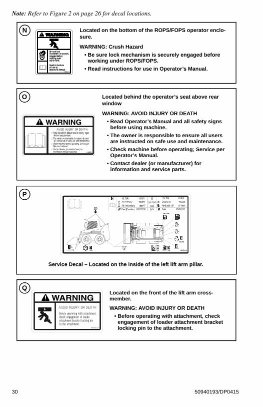
Note: Refer to Figure 2 on page 26 for decal locations.
Located on the bottom of the ROPS/FOPS operator enclo-sure.
WARNING: Crush Hazard
• Be sure lock mechanism is securely engaged before working under ROPS/FOPS.
• Read instructions for use in Operator’s Manual.
N
WARNING
Located behind the operator’s seat above rear window
WARNING: AVOID INJURY OR DEATH
• Read Operator’s Manual and all safety signs before using machine.
• The owner is responsible to ensure all users are instructed on safe use and maintenance.
• Check machine before operating; Service per Operator’s Manual.
• Contact dealer (or manufacturer) for information and service parts.
O
Service Decal – Located on the inside of the left lift arm pillar.
P
WARNINGLocated on the front of the lift arm cross-member.
WARNING: AVOID INJURY OR DEATH
• Before operating with attachment, check engagement of loader attachment bracket locking pin to the attachment.
Q
30 50940193/DP0415

Note: Refer to Figure 2 on page 26 for decal locations.
Hose removal or coponent failure can cause lift arm to drop.Always use lift arm support device when leaving lift arm raised for service.
137637DANGERT
Located on the left lift arm near the lift arm support.
DANGER
• Hose removal or component failure can cause lift arm to drop. Always use lift arm support device when leaving lift arm raised for service.
Located on attachment bracket (power hitch only)
R
50354137
Located on attachment bracket (manual hitch only)
S
31 50940193/DP0415

ISO-Style (Used Internationally)Safety and Information Decals
Figure 3 – ISO-Style (Used Internationally)Safety and Information Decal Locations
B
RIGHT LEFT
TOPFRONT
OPERATOR’S POSITION
D
TP
DO
N
D Q D
A
EC
K
H
G
L
I
J
R
F
S
M
32 50940193/DP0415
Note: Refer to Figure 2 on page 26 for decal locations.
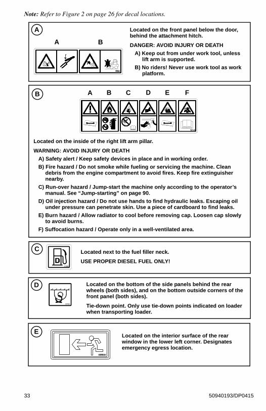
B
Located on the inside of the right lift arm pillar.
WARNING: AVOID INJURY OR DEATH
A) Safety alert / Keep safety devices in place and in working order.
B) Fire hazard / Do not smoke while fueling or servicing the machine. Clean debris from the engine compartment to avoid fires. Keep fire extinguisher nearby.
C) Run-over hazard / Jump-start the machine only according to the operator’s manual. See “Jump-starting” on page 90.
D) Oil injection hazard / Do not use hands to find hydraulic leaks. Escaping oil under pressure can penetrate skin. Use a piece of cardboard to find leaks.
E) Burn hazard / Allow radiator to cool before removing cap. Loosen cap slowly to avoid burns.
F) Suffocation hazard / Operate only in a well-ventilated area.
A B C D E F
C Located next to the fuel filler neck.
USE PROPER DIESEL FUEL ONLY!
A Located on the front panel below the door, behind the attachment hitch.
DANGER: AVOID INJURY OR DEATH
A) Keep out from under work tool, unless lift arm is supported.
B) No riders! Never use work tool as work platform.
A B
D Located on the bottom of the side panels behind the rear wheels (both sides), and on the bottom outside corners of the front panel (both sides).
Tie-down point. Only use tie-down points indicated on loader when transporting loader.
ELocated on the interior surface of the rear window in the lower left corner. Designates emergency egress location.
33 50940193/DP0415

Note: Refer to Figure 2 on page 26 for decal locations.
F Located on the side of the ROPS/FOPS.
WARNING: Crush Hazard
• Be sure lock mechanism is securely engaged before working under ROPS/FOPS. Read instructions for use in Operator’s Manual.
G USE PROPER HYDRAULIC FLUID ONLY!
Located near the hydraulic fluid reservoir filler neck.
Located inside the engine compartment.
WARNING: ROTATING FAN
• Keep hands out or stop engine.
H
Located on the left door pillar, facing the operator.
DANGER: AVOID INJURY OR DEATH
WARNING: AVOID OVERTURN
A) Forward tip hazard: Carry load low, do not exceed Rated Operating Load.
B) Fasten seat belt.
C) Side tip hazard: Avoid steep slopes and high-speed turns. Travel up and down slopes with heavy end uphill.
D) Crush hazard: Keep out from under lift arm unless lift arm is supported. Keep hands, feet and body inside cab when operating.
I
A
B
C
D
34 50940193/DP0415

Note: Refer to Figure 2 on page 26 for decal locations.
Located inside the engine compartment.
WARNING: HOT SURFACE
• Do not touch hot engine or hydraulic system parts.
K
L
WARNING: AVOID INJURY OR DEATH
Always follow “Mandatory Safety Shutdown Procedure.”
1) Lower equipment to ground.
2) Reduce throttle, stop engine.
3) Apply brake; remove key.
4) Check safety interlocks.
Located on the left door pillar, facing the operator.
Located on the right door pillar, facing the operator.
DANGER: AVOID INJURY OR DEATH
A) Crush hazard: Keep out from under lift arm unless lift arm is supported.
B) Crush hazard: Hose removal or component failure can cause lift arm to drop. Always use lift arm support device when leaving lift arm raised for service.
C) Side tip hazard: Avoid steep slopes and high-speed turns. Travel up and down slopes with heavy end uphill.
D) Crush hazard: Keep hands, feet and body inside cab when operating.
J
A
B
C
D
35 50940193/DP0415

Note: Refer to Figure 2 on page 26 for decal locations.
Located on the bottom of the ROPS/FOPS operator enclo-sure.
WARNING: Crush Hazard
• Be sure lock mechanism is securely engaged before working under ROPS/FOPS.
• Read instructions for use in Operator’s Manual.
N
Located behind the operator’s seat above rear window
WARNING: AVOID INJURY OR DEATH
• Read Operator’s Manual and all safety signs before using machine.
• The owner is responsible to ensure all users are instructed on safe use and maintenance.
• Check machine before operating; Service per Operator’s Manual.
• Contact dealer (or manufacturer) for information and service parts.
O
Service Decal – Located on the inside of the left lift arm pillar.
P
SAFETY ALERT
A) Check machine before operation according to Operational Checks starting on page 81. Contact dealer (or manufacturer) for information and service parts.
B) Maintain 3-point contact during entry and exit.
C) Inspect work area. Avoid all hazards. Look in direction of travel. Keep children and bystanders away.
D) Start and operate machine only from the operator’s position with the seatbelt fastened.
E) Keep away from power lines; avoid contact.
F) Wear any needed Personal Protective Equipment. Do not wear loose clothing while operating or servicing machine.
M Located on the left door pillar, facing the operator.
A
C
E
B
D
F
36 50940193/DP0415
Note: Refer to Figure 2 on page 26 for decal locations.
T
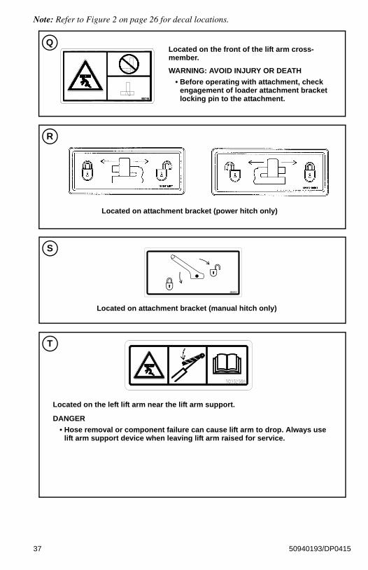
Located on the left lift arm near the lift arm support.
DANGER
• Hose removal or component failure can cause lift arm to drop. Always use lift arm support device when leaving lift arm raised for service.
Located on attachment bracket (power hitch only)
R
50354137
Located on attachment bracket (manual hitch only)
S
Located on the front of the lift arm cross-member.
WARNING: AVOID INJURY OR DEATH
• Before operating with attachment, check engagement of loader attachment bracket locking pin to the attachment.
Q
37 50940193/DP0415

Product and Component Plate Locations
Product and Component Plates
1. Operator protective system plate: with, e.g., model, certification and operator protective system serial number.
2. Seat plate according to ISO 7096
3. Product plate: with Product Identification Number and, e.g., model/type designation.
4. Engine plate: with, e.g., type designation, product and serial numbers.
5. Component plate hydrostatic pump: with, e.g., product and serial numbers.
6. Component plate drive motor: with, e.g., product and serial numbers.
1
2
6 4
6 5 3
38 50940193/DP0415

CHAPTER 3SAFETY EQUIPMENT
Become familiar with all safety devices on the machine before starting. Know how to stop the
machine before starting it. The machine is designed and intended to be used only with Manitou Americas-approved attachments or accessories. Manitou Americas cannot be responsible for operator safety if the machine is used with unapproved attachments.
Guards and Shields
Guards and shields are provided on the machine, wherever possible without effecting machine operation, to protect against potential hazards. In many places, safety decals are also provided to warn of potential hazards and/or to display special operating procedures.
Read and thoroughly understand all safety decals before operating the machine. Do not operate the
machine unless all factory-installed guards and shields are properly installed and secured in place.
Operator’s Position
Operator’s SeatNever adjust the seat during
machine operation. Adjust the seat only when the machine is stopped and the restraint bar is in the raised position. After adjustments, make sure the seat is securely locked in place before using the machine.
Horizontal adjustment: The seat is mounted on rails to allow forward and back horizontal position adjustment.
Use lever (A, Figure 4) to move the seat forward or back as desired. Release handle (A) when the seat is in the desired position. Make sure the seat is locked in position after adjusting.
WARNING
WARNING
WARNING
Figure 4 – Operator’s Seat Horizontal Adjustment
A
39 50940193/DP0415

Seat suspension
Seat suspension can be adjusted as necessary to compensate for the drivers weight and preferred seat suspension stiffness.
Mechanical suspension: While sitting in the operator’s seat, rotate knob (Z, Figure 5) as necessary to adjust seat suspension so weight indicator (X) is set to the approximate weight of the operator.
Air Suspension (option): Use knob (V) to adjust air suspension as desired.
Seat Belt
Always fasten the seat belt
before operating the machine and keep it fastened during machine operation.
Repair or replace any damaged seat belt and clasp parts before operating the machine. Do not operate the machine if the seat belt is not fastened and working properly. After an accident, the seat belt strap is stretched and must be replaced with a new strap installed by an authorized dealer.
Important: Keep seat belt(s) clean. Use only soap and water to wash seat belt(s); cleaning solvents can damage the seat belt(s).
Fastening/Unfastening the Seat Belt
Remove hard, edged or fragile objects from your pockets or clothes that might lie between the seat belt and your body.
Fasten the seat belt around your hips and waist and insert tongue (F, Figure 6) into clasp (G) until it clicks securely in place. Slack in the seat belt should automatically retract into seat belt spool (H).
Make sure the seat belt is not twisted when it is fastened, and that it is fastened over the hips and not the stomach.
Unfasten the seat belt by pressing button (I).
If the seat belt spool does not retract the slack in the seat belt, have it serviced immediately. Repair
or replace any damaged seat belt and lock parts before operating the machine.
Figure 5 – Operator’s Seat Suspension Adjustment
ZX
V
WARNING
Figure 6 – Seat Belt / Upper Torso Restraint
I
G
H
F
J
WARNING
40 50940193/DP0415

Upper Torso Restraint (Option)
Always wear the upper-torso restraint (J, Figure 6) when operating in high speed.
The seat belt should always be fastened during operation.
Important: Inspect the seat belt(s) for damage before use, and replace if damaged. Keep seat belt(s) clean. Use only soap and water to wash seat belt(s). Cleaning solvents can cause damage to seat belt(s).
Operator Restraint BarLower operator restraint bar (C, Figure 7) after entering the operator’s compartment and sitting in the seat. The restraint bar is securely anchored to the ROPS/FOPS. The operator must be seated with the restraint bar in its lowered position to start or operate the machine.
The position of the restraint bar in the lowered position can be adjusted. To adjust:
Loosen jam nut (D, Figure 8), and rotate rubber stop (E) in or out to the desired position. Tighten jam nut (D) to lock rubber stop (E) in position.
Important: Make sure rubber stops (E) are adjusted evenly.
Never electrically or mechanically defeat the operator restraint bar or seat switch.
WARNING
Figure 7 – Operator Restraint Bar
C
Figure 8 – Restraint Bar Low-ered Position Adjustment
D
E
WARNING
41 50940193/DP0415

Safety Interlock System (Hydraloc™)
NEVER attempt to bypass or defeat the safety interlock system. Serious personal injury or death
could result.
The Hydraloc™ safety interlock system provides for operator safety. The interlock system:
• Prevents the engine from starting unless the operator is sitting in the operator’s seat with the restraint bar lowered.
• Disables the lift arm, auxiliary hydraulics, attachment tilt and wheel drive hydraulics if the restraint bar is raised, the ignition keyswitch is turned off or the operator’s seat is not occupied.
Note: The auxiliary hydraulic circuit can be detented in the “on” position for continuous operation with the restraint bar raised and operator out of the seat. See“Auxiliary Hydraulic System” on page 79.
Safety Interlock System TestEach time before using the machine, check the safety interlock system daily for proper operation:
Seat Switch Test
With the engine off and the restraint bar lowered, unfasten the seat belt, and lift your weight off the seat. Try to start the engine. If the engine starts, turn off the engine, troubleshoot and correct the problem. Contact your dealer if necessary.
Restraint Bar Test
With the engine running, raise the restraint bar. Test each of the controls. The lift arm, hitch and drive should move only slightly. If there is any significant movement, troubleshoot and correct the problem immediately. Contact your dealer if necessary.
WARNING
42 50940193/DP0415

Parking Brake
The machine is equipped with a spring-applied, hydraulically-released parking brake. The parking brake is automatically applied when the restraint bar is lifted, the operator’s seat is not occupied, or the engine is shut off. The brake can also be applied manually by pressing button (K, Figure 9) on the control keypad on the right door pillar.
Button (K) are illuminated when the ignition keyswitch is in the ON/RUN position and the parking brake is applied.
ROPS/FOPS
The ROPS/FOPS (Roll-Over/Falling Object Protective Structure) is designed to protect the operator from falling objects and during a tip-over accident, if the operator is secured inside the operator’s compartment by the seat belt and restraint bar.
Never operate the loader with the ROPS/FOPS raised or removed.
Rear Window Emergency Exit
To use the emergency exit function, pull on yellow warning tag (M, Figure 10) at the top of the window and remove the seal. Push or kick out the window to allow exit from the machine.
to reinstall the window, see your local automotive glass specialist.
Figure 9 – Parking Brake Button
K
WARNING
Figure 10 – Rear Window Emer-gency Exit
M
43 50940193/DP0415

Lift Arm Support
The lift arm support prevents the raised lift arm from lowering unexpectedly. The lift arm support must be applied whenever the lift arm is left in the raised position.
A falling lift arm could result in severe injury or death. Never allow anyone under a raised lift arm
without the lift arm support applied.
If the lift arm must be left in the raised position, BE SURE to properly apply the lift arm support.
The operator must not leave the operator's position if the lift arm is in the raised position unless the lift arm support is properly applied.
Applying and disengaging the lift arm support requires two people – one person inside the machine and another person outside the machine to apply and/or disengage the support device.
The lift arm support must be kept in proper operating condition at all times.
Important: A second person on the outside of the machine is required to assist with applying the lift arm support.
Engage Lift Arm Support
1. Empty and remove the attachment (See “Connecting Attachments” on page 96).
2. Bring the machine to a complete stop on a level surface.
3. Lower the lift arm fully.
4. Stop the engine.
5. Have an assistant remove the lift arm support from its storage location on the left side of the machine. Remove lynchpin (S, Figure 11) holding lift arm support (T) up against the lift arm. Allow lift arm support (T) device to pivot down into contact with the lift cylinder.
6. Restart the engine.
WARNING
Figure 11 – Lift Arm Support Stor-age Lynchpin Removal
S
T
44 50940193/DP0415

7. Use the lift control to raise the lift arm until lift arm support (T, Figure 12) drops over the end of the lift cylinder and around the cylinder rod.
8. Slowly lower the lift arm until the free end of the support device contacts the top end of the lift cylinder (U).
9. Check the support device to ensure it is secure against the cylinder end.
10. Stop the engine.
11. Move the lift control to verify the control does not cause the lift arm to move.
12. Unfasten the seat belt, remove the ignition key and take it with you. Exit the machine using the hand-holds.
Disengage Lift Arm Support
The safest method of installing and removing the lift arm support device requires two people – one
person inside the loader and another person outside the loader to disengage the support device.
1. Start the engine.
2. Raise the lift arm fully.
3. Stop the engine.
4. Verify that the lift arm is being held in the raised position by the safety interlock system.
Important: With the key switch OFF and the solenoid valve working properly, the lift arm will stay raised when the lift control is moved to lower the lift arm. If the valve does not hold the lift am and it begins to lower do not leave the operator’s compartment. Instead, lower the lift arm against the lift arm support and exit the machine. Then, contact your dealer immediately to determine why the lift arm lowers while the key switch is OFF.
5. Have an assistant raise lift arm support (T, Figure 13) until it contacts the lift arm. Reinstall lynchpin (S) through post (V) on the lift arm to secure lift arm support (T) in the storage position.
6. Fold lynchpin ring (W) over post (V) to lock lynchpin in place.
Figure 12 – Lift Arm Support Engaged
T U
WARNING
Figure 13 – Lift Arm Support Stor-age Position
S
T
V
W
45 50940193/DP0415

To prevent damage to the lift cylinder, do not lower lift arm until the lift arm support is secured in the
storage position.
Battery Disconnect Switch (Option)
The optional battery disconnect switch is located in the engine compartment. Turning the switch to the OFF position disconnects the battery from the electrical system.
On machines equipped with the optional battery disconnect switch, always turn the switch to the
“OFF” position when parking the machine inside an enclosure.
CAUTION
Figure 14 – Battery Discon-nect Switch
CAUTION
46 50940193/DP0415

CHAPTER 4INDICATORS AND CONTROLS
Become familiar with all controls before operating the machine. Know how to stop the machine before
starting it. The machine is designed and intended to be used only with Manitou-approved attachments or accessories. Manitou cannot be responsible for operator safety if the machine is used with unapproved attachments.
A. Accessory Keypad (page 51) F. HVAC Vent Nozzle K. Right Hand Control (page 67)
B. Ignition Keyswitch (page 59) G. Cup Holder L. Operator’s Seat (page 39)
C. Information Center Electronic Display (page 53)
H. Foot Controls (page 67)M. Optional Lights/Lockout Keypad (page 52)
D. Control Keypad (page 48) I. Throttle Control (page 60)
E. Electrical Accessory Socket J. Left Hand Control (page 67)
WARNING
ok
Figure 15 – Controls (Hand/Foot Control Option Shown)
A
J
F
G H
I
F
E
D
C
B
K
G
L
M
47 50940193/DP0415

Control Keypad
Control Keypad Indicators
Note: Control panel indicators are visible only when the indicator lamps are activated.
Table 2: Control Keypad Indicators
Indicator Description Details
High-Speed Travel Range Indicator
Indicates high-speed travel range is activated.
Lift Arm Float Indicator Indicates lift arm float is activated.
Hydraglide™ Indicator Indicates HydraglideTM lift arm cushion is activated.
Engine Pre-heat IndicatorIs lit when ignition keyswitch is in the ON/RUN position and engine pre-heat is required; goes out when engine pre-heat is complete.
Seat Belt Reminder IndicatorIs lit when ignition is turned on as a reminder to lower the operator restraint bar and fasten the seat belt.
Battery Voltage Warning Indicator
Indicates battery charging system malfunction. During normal operation this indicator should be OFF.
Figure 16 – Control Keypad Indicators
48 50940193/DP0415

Engine Air Filter Restriction Indicator
Indicates engine air filter requires service. See “Engine Air Cleaner” on page 139. During normal operation this indicator should be OFF.
Hydraulic Oil Filter Warning Indicator
Indicates hydraulic oil filter requires service. See“Changing Hydraulic Oil Filter” on page 144. During normal operation this indicator should be OFF.
Hydraulic Oil Temperature Warning Indicator
Indicates hydraulic temperature is too high. During normal operation this indicator should be OFF.
Engine Malfunction IndicatorIs lit when the engine electronic control unit (ECU) has detected an error condition. Refer to “Engine Diagnostic Trouble Codes (DTC)” on page 171.
Coolant Temperature Warning Indicator
Indicates coolant temperature is too high.
During normal operation this indicator should be OFF.
Engine Oil Pressure Warning Indicator
Indicates engine oil pressure is too low.
During normal operation this indicator should be OFF. IMPORTANT! Immediately shut down the engine if this indicator is lit. Correct the problem before restarting the engine.
Table 2: Control Keypad Indicators
Indicator Description Details
49 50940193/DP0415

Control Keypad Buttons
Table 3: Control Panel Buttons
Button Description Function
Parking Brake Engages / disengages parking brake.
Beacon / Position / Work LightsActivates optional beacon, position, and/or work lights. See “Beacon/Position/Work Lights” on page 74.
Self-Leveling CancelCancels self-leveling function. LED above button is on when self leveling is off.
Power-A-Tach® System Hitch Lock
Press and hold to lock attachments onto optional
Power-A-Tach® System Hitch.
Power-A-Tach® System Hitch Unlock
Press and hold to unlock attachments onto the optional
Power-A-Tach® System Hitch to allow attachment removal.
Figure 17 – Control Keypad Buttons
50 50940193/DP0415

Accessory Keypad Indicators/Buttons
Table 4: Accessory Keypad Buttons
Button Description Function
HVAC ButtonTurns cab heat/cool on/off. Low, medium and high settings are available. See “HVAC (Option)” on page 74.
HVAC Blower Fan ButtonTurns cab HVAC blower fan on/off. Low, medium and high settings are available. See “HVAC (Option)” on page 74.
Windshield Wiper ButtonTurns windshield wiper on/off. Slow, medium and fast settings are available. See “Windshield Wiper/Washer” on page 75.
Windshield Washer ButtonActivates windshield washer. See “Windshield Wiper/Washer” on page 75.
Rear Window Wiper ButtonTurns rear window wiper on/off. Slow, medium and fast settings are available. See “Windshield Wiper/Washer” on page 75.
Rear Window Washer ButtonActivates rear window washer. See “Windshield Wiper/Washer” on page 75.
Figure 18 – Accessory Keypad Indicators/Buttons
Heat Indicator: is lit when cab
heat is activated
51 50940193/DP0415

Optional Lights/Lockout Keypad Indicators/Buttons
Table 5: Optional Road Lights/Lockout Keypad Buttons
Button Description Function
Beacon / Position / Work Lights Button
Operates optional road lights, and works with main control keypad to control the beacon and position lights. If all lights are off, one press activates the beacon and all position lights; a second press additionally turns on the road lights. If the work lights are on, pressing this button turns off the work light and turns on the road lights.
If the road lights are on, all lights turn off if this button is pressed.
High-Beam Button Activates optional road lights high-beam.
Hazard Lights ButtonActivates optional flashing road hazard lights. Operates even if the ignition switch is off.
Hydraulics Lock-out Button
Activates optional lift and tilt hydraulics lock-out. Used when driving the machine on roadways. See “Transport Hydraulics Lock-out (Option)” on page 93.
Left Directional Button
Activates optional flashing road lights left directional indicator.
Right Directional Button
Activates optional flashing road lights right directional indicator.
Figure 19 – Road Lights/Lockout Keypad Indicators/Buttons
52 50940193/DP0415

Information Center Electronic Display
The information center electronic display is located on the right door pillar. It provides the following functionality:
• Displays operational status such as engine fuel tank level, engine RPM, coolant tem-perature, service hours and system voltage.
• Displays error fault codes and input/output diagnostic data.
• Configures displays settings.
M. Navigation Rocker Button – Used for general screen navigation and other various functions, depending upon screen and context.
P. Increase Brightness/Return Button – Used for different functions depending upon screen and context:
• Used to increase display brightness.
Corresponds to the symbol on the display screen.
• Used to return to previous screen. Corresponds
to the symbol on the display screen.
N. OK Button – Used for various functions, depending upon screen and context.
Q. Decrease Brightness Button – Used to decrease display brightness. Corresponds to the
symbol on the display screen.
ok
Figure 20 – Information Center Electronic Display
M
O P Q N R
53 50940193/DP0415

If the LCD is broken, care must be taken with any leaking fluid. If LCD fluid gets onto your skin, wipe
with a cloth and wash the area with mild soap and water. If LCD fluid gets into your eyes, thoroughly rinse your eyes with clean water for several minutes and seek medical assistance. If LCD fluid is swallowed, rinse your mouth thoroughly with clean water, then drink a substantial volume of water and induce vomiting. Then seek medical assistance.
Information Center Electronic Display SymbolsThe following table describes symbols used in the information center electronic display.
Note: Values may not display for all parameters, depending upon installed options and equipment.
O. Regen/Return Button – Used for different functions depending upon screen and context:
• Switches to the Regen display mode if the symbol is displayed on the screen. Also initiates DPF regeneration if all appropriate conditions are met.
• Used to return to previous screen. Corresponds
to the symbol on the display screen.
R. Regen Inhibit Button (DPF models) – Press for 5 seconds to inhibit DPF reset regeneration.
Displays the symbol.
Table 6: Symbols Descriptions
Symbol Description Symbol Description
Engine crankshaft revolutions per minute.
Real-time fuel consumption rate. Displayed in gallons/hour (SAE) or liters/hour (METRIC).
Accumulated operation time. Time is displayed in hours, and accumulates when the engine is running.
Display brightness increase. Press button (P, Figure 20) when this symbol is displayed to increase screen brightness.
Battery charging circuit voltage.
Display brightness decrease. Press button (Q, Figure 20) when this symbol is displayed to decrease screen brightness.
Fuel level in fuel tank.
Return to previous. Press button (O, Figure 20) when this symbol is displayed to return to the previous screen.
Coolant temperature.
Diesel Particulate Filter (DPF) regeneration (DPF Models). See “Diesel Particulate Filter (DPF) Regeneration Procedures (DPF Models)” on page 116.
WARNING
n/min
54 50940193/DP0415

Percentage of engine power based on load.
Diesel Particulate Filter (DPF) regeneration inhibit (DPF Models). See “Diesel Particulate Filter (DPF) Regeneration Procedures (DPF Models)” on page 116.
Note: Strike-through line through the symbol is displayed in red when DPF regeneration is inhibited.
Ambient engine compartment temperature.
Diesel Particulate Filter (DPF) regeneration in-progress (elevated temperature). See “Diesel Particulate Filter (DPF) Regeneration Procedures (DPF Models)” on page 116.
Table 6: Symbols Descriptions
Symbol Description Symbol Description
%
55 50940193/DP0415

Information Center Electronic Display Screens
Note: Values may not display for all parameters, depending upon installed options and equipment.
Table 7: Status, Maintenance and Error Code Screens
Display Mode Description
Status Screens
Dual Gauge Display
A. Fuel level.
B. Engine coolant temperature.
C. Accumulated operation time.Note: Time is displayed in hours, and accumulates
when the engine is running.
D. Amber error condition warning. Causes DM1/DM2 errors screen(s) to display. See page 58.
E. Red critical error warning. Causes DM1/DM2 errors screen(s) to display. See page 58.
F. Engine coolant temperature amber warning region. Indicates elevated coolant temperature.
G. Engine coolant temperature red stop warning region. Indicates serious coolant overheating condition.
Note: Running the engine in an overheated condition can damage the engine.
H. Fuel level amber warning region. Indicates low fuel level.
I. Fuel level red stop region. Indicates almost empty fuel tank.
Quad Gauge Display
Displays four different status parameters simultaneously. To change the displayed parameters, press and hold the ok button (N, Figure 20) until orange bar (T) displays. Press the left/right side of navigation rocker button (M, Figure 20) to select the parameter and press the top/bottom of navigation rocker button to change the selected parameter. Press the ok button again to dismiss orange bar (T).
F
1234.5
CE
H
A D FG
B
ECHI
1234.5
12.5 28.0
1000n/min
T
56 50940193/DP0415

Single Gauge Display
Displays single real time operating parameters. Switch between parameters using the navigation button (M, Figure 20). Used for various functions, depending upon screen and context.
Regeneration Screens (DPF Models)
These screens are associated with Diesel Particulate Filter (DPF) regeneration procedures and maintenance. See “Diesel Particulate Filter (DPF) Regeneration Procedures (DPF Models)” on page 116.
Secondary Screens
All Secondary Screens
Secondary screens are accessed by holding down the ok button (N, Figure 20) for 10 seconds while the Dual Gauge Display screen is displayed. Press the left/right side of navigation rocker button (M, Figure 20) to switch between secondary screens.
Revision Screen
Displays information center electronic display software information.
Table 7: Status, Maintenance and Error Code Screens
Display Mode Description
2121234.5
n/min
22 %
REVISIONSDISPLAY
04 14 2014MCU
MAIN KEYPADABCDEFG
ROAD LIGHTS KEYPAD
HEATER/WIPER KEYPADABCDE
************
************
57 50940193/DP0415

Units Screen
Press the top/bottom of navigation rocker button (M, Figure 20) to switch between SAE or metric units for values displayed in screens.
Language Screen
The press the top/bottom of navigation rocker button (M, Figure 20) to switch between English or Spanish language for values displayed in screens.
DM1 Screen
Displays engine, drive system, control, and safety system error code message information. Number of available messages is displayed at the top left of the screen (T). Use buttons (P and Q, Figure 20) to scroll through the messages. See “Engine Diagnostic Trouble Codes (DTC)” on page 171 for specific error code details.
DM2 Screen
Continuation of error code message display along with DM1 Screen. Number of available messages is displayed at the top left of the screen (T). Use buttons (P and Q, Figure 20) to scroll through the messages. See “Engine Diagnostic Trouble Codes (DTC)” on page 171 for specific error code details.
Table 7: Status, Maintenance and Error Code Screens
Display Mode Description
UNITS
SAE
LANGUAGE
ENGLISH
DM1
SPN: 00 of 0
FMI: 0OCI: 0
T
DM2
SPN: 00 of 0
FMI: 0OCI: 0
T
58 50940193/DP0415

Controls
Ignition KeyswitchThe Ignition keyswitch is located near the top of the right door pillar. Ignition keyswitch positions are:
• OFF Position : With the key turned fully counterclockwise, power from the electrical system is disconnected from the controls and instruments. This is the only position from which the key can be inserted or removed.
• ON/RUN Position : With the key turned one position clockwise from the OFF position, electrical power is supplied to all controls and instruments.
• START Position : With the key turned and held fully clockwise, the electric starter engages. Release the key to ON/RUN position when the engine starts.
Input Status
Displays input information from electronic control modules, showing real-time machine component/control state. Status colors indicate the following:
• Green – Active
• Black – Inactive
Output Status
Displays output information from electronic control modules, showing real-time feedback state of machine components. Status colors indicate the following:
• Green – Active
• Black – Inactive.
• Yellow – Standby or Not Applicable
• Red – Short Circuit
Table 7: Status, Maintenance and Error Code Screens
Display Mode Description
DIAGNOSTICS INPUTSFloat
Hydro GlideHigh GearAux Detent
Air Filter Clog
AlternatorKP Ingnition RunKP Ignition StartKP Seat Switch
KP Restraint BarHyd Filter ClogHigh Hyd Temp
Engine Pressure
DIAGNOSTICS OUTPUTSHigh GearSelf Level
Hydro GlideFuel PumpGlow Plug
FloatMarker Lts
Rear Work LtsFront Work LtsKP Beacon Lts
KP Dome LtDisable Park Brake
Tilt/Lift
StarterAll Tach Lock
All Tach Unlock
Figure 21 – Ignition Keyswitch
STOP
59 50940193/DP0415

Throttle ControlsOn machines equipped with throttle knob (Q, Figure 22), engine speed is controlled with throttle knob and optional foot throttle (P, Figure 24), if installed.
Throttle knob (Q) is the primary throttle control. The throttle is set with the knob to the desired idle/run position.
On machines equipped with throttle lever (T, Figure 22), engine speed is controlled with throttle lever and optional foot throttle (P, Figure 24), if installed.
Throttle knob (T) is the primary throttle control. The throttle is set with the lever to the desired idle/run position.
On machines equipped with optional throttle pedal (P, Figure 24), the pedal can be used to increase engine speed whenever additional power is required. When the optional pedal is released, the engine returns to the speed set by throttle knob (Q, Figure 22).
Figure 22 – Throttle Knob
Q
Figure 23 – Throttle Lever
T
Figure 24 – Throttle Pedal
P
60 50940193/DP0415

Travel Drive, Lift and Tilt ControlsSkid-Steer loaders are equipped with one of three control systems:
• T-Bar Controls: see “T-Bar Controls” on page 61.
• Joystick Controls: see “Joystick Controls” on page 64.
• Hand and Foot Controls: see “Hand and Foot Controls” on page 67.
T-Bar Controls
On T-bar-equipped machines, the left T-bar controls the travel drive, and the right T-bar controls the attachment lift and tilt.
Table 8: T-Bar Controls
Ref. Control Description
A Left T-BarControls drive forward, reverse, turn, and speed. See “Drive Control (Left T-Bar)” on page 62.
B Right T-BarControls lift arm raise/lower, float, and attachment tilt. See “Lift/Tilt Control (Right T-Bar)” on page 63.
C Two-Speed Selection ButtonToggles between high- and low-speed travel modes. See “Two-Speed Drive (Option)” on page 69.
D Horn Button Activates horn.
E Hydraglide™ ButtonActivates Hydraglide™. See “Hydraglide™ Ride Control System (Option)” on page 73.
F INACTIVE Button is inactive on T-Bar Controls.
GAuxiliary Hydraulics Rocker Switch
Controls auxiliary hydraulics flow direction and amount. See “Auxiliary Hydraulic System” on page 79.
HAuxiliary Hydraulics Continuous Flow Latch Trigger
Works with Auxiliary Hydraulics Rocker Switch to latch/unlatch auxiliary hydraulics continuous flow. See “Auxiliary Hydraulic System” on page 79.
Figure 25 – T-Bar Hand Controls
D
C G E
FH
Left T-Bar Right T-Bar
BA
61 50940193/DP0415

On machines equipped with T-bar controls, the left T-bar controls the drive, and the right T-bar controls the lift/tilt.
Drive Control (Left T-Bar)
Forward, reverse, travel speed and turning maneuvers are controlled using the left T-bar (Figure 26):
A. To go forward, push the left T-bar forward.
B. To go in reverse, pull the left T-bar rearward.
C. To turn right, twist the control clockwise.
D. To turn left, twist the control counter-clockwise.
For gradual turns, twist the T-bar slightly; for sharp turns, twist the T-bar further.
Turns while moving forward or in reverse can be made by twisting the T-bar while also pushing it forward or pulling it back.
Moving the T-bar farther from neutral increases the speed steadily to the maximum travel speed.
Note: Tractive effort decreases as speed increases. To get maximum tractive effort, move the T-bar only slightly away from the neutral position.
Note: The engine will stall if the control is moved too far forward when loading the bucket.
Be sure the controls are in neutral before starting the engine. Operate the controls gradually and
smoothly. Excessive speed and quick control movements without regard for conditions and circumstances are hazardous and could cause an accident.
Figure 26 – Drive Control (Left T-Bar)
B
AD
C
WARNING
62 50940193/DP0415

Lift/Tilt Control (Right T-Bar)
Lift arm raise and lower, and attachment tilt are controlled using the right T-bar (Figure 27):
A. To lower the lift arm, push the right T-bar straight forward.
B. To raise the lift arm, pull the right T-bar straight rearward.
C. To tilt the attachment forward and down, twist the right T-bar clockwise.
D. To tilt the attachment up and back, twist the right T-bar counter-clockwise.
The lift arm can be tilted while raising or lowering by twisting the T-bar while also pushing it forward or pulling it back.
Note: The speed of the lift/tilt motion is proportional to the amount of T-bar movement and engine speed.
Figure 27 – Lift/Tilt Control (Right T-Bar)
C
DB
A
63 50940193/DP0415

Joystick Controls
On joystick-equipped machines, the left joystick controls the travel drive, and the right joystick controls the attachment lift and tilt.
Table 9: Joystick Controls
Ref. Control Description
A Left JoystickControls drive forward, reverse, turn, and speed. See “Drive Control (Left Joystick)” on page 65.
B Right JoystickControls lift arm raise/lower, float, and attachment tilt. See “Lift/Tilt Control (Right Joystick)” on page 65.
C Two-Speed Selection ButtonToggles between high- and low-speed travel modes. See “Two-Speed Drive (Option)” on page 69.
D Horn Button Activates horn.
E Hydraglide™ ButtonActivates Hydraglide™. See “Hydraglide™ Ride Control System (Option)” on page 73.
F Float Button Activates Float. See “Lift Arm Float” on page 71.
GAuxiliary Hydraulics Rocker Switch
Controls auxiliary hydraulics flow direction and amount. See “Auxiliary Hydraulic System” on page 79.
HAuxiliary Hydraulics Continuous Flow Latch Trigger
Works with Auxiliary Hydraulics Rocker Switch to latch/unlatch auxiliary hydraulics continuous flow. See “Auxiliary Hydraulic System” on page 79.
Figure 28 – Joystick Hand Controls
Left Joystick Right Joystick
A
DC
G
F
B
H
E
64 50940193/DP0415

Drive Control (Left Joystick)
Forward, reverse, travel speed and turning maneuvers are controlled using the left joystick (Figure 29):
A. To go forward, push the left joystick forward.
B. To go in reverse, pull the left joystick rearward.
C. To turn right, push the left joystick to the right.
D. To turn left, push the left joystick to the left.
E. To go forward and to the right, push the left joystick forward and to the right.
F. To go rearward and to the right, pull the left joystick rearward and to the right.
G. To go forward and to the left, push the left joystick forward and to the left.
H. To go rearward and to the left, pull the left joystick rearward and to the left.
Be sure the joystick controls are in neutral before starting the engine. Operate the controls gradually
and smoothly. Excessive speed and quick control movements without regard for conditions and circumstances are hazardous and could result in loss of control and cause an accident.
Moving the joystick farther from neutral increases the speed steadily to the maximum travel speed. Tractive effort decreases as speed increases. For maximum tractive effort, move the joystick only slightly away from the neutral position. The engine may stall if the control is moved too far forward when loading the bucket.
Lift/Tilt Control (Right Joystick)
Lift arm raise and lower, and attachment tilt are controlled using the right joystick (Figure 30):
A. To lower the lift arm, push the right joystick straight forward.
B. To raise the lift arm, pull the right joystick straight back.
C. To tilt the attachment forward and down, move the right joystick to the right.
D. To tilt the attachment up and back, move the right joystick to the left.
Figure 29 – Drive Control (Left Joy-stick)
B
D A
C
WARNING
Figure 30 – Lift/Tilt Control (Right Joystick)
A
B
C
D
65 50940193/DP0415

E. To lower the lift arm while tilting the attachment forward and down, move the right joystick forward and to the right.
F. To lower the lift arm while tilting the attachment up and back, move the right joystick forward and to the left.
G. To raise the lift arm while tilting the attachment forward and down move the right joystick rearward and to the right.
H. To raise the lift arm while tilting the attachment up and back, move the right joystick rearward and to the left.
Note: The speed of the lift/tilt motion is directly proportional to the amount of joystick movement and engine speed.
66 50940193/DP0415

Hand and Foot Controls
On hand and fool controlled-equipped machines, the hand controls are used to control the travel drive, and the foot controls are used to control the attachment lift and tilt.
Table 10: Hand and Foot Controls
Ref. Control Description
A Left Hand ControlControls travel drive forward, reverse, turn, and speed. See “Drive Control (Hand Controls)” on page 68.
B Right Hand ControlControls travel drive forward, reverse, turn, and speed. See “Drive Control (Hand Controls)” on page 68.
C Two-Speed Selection ButtonToggles between high- and low-speed travel modes. See “Two-Speed Drive (Option)” on page 69.
D Horn Button Activates horn.
E Hydraglide™ ButtonActivates Hydraglide™. See “Hydraglide™ Ride Control System (Option)” on page 73.
F INACTIVE Button is inactive on Hand and Foot Controls.
Figure 31 – Hand and Foot Controls
Left Hand Control Right Hand Control
Foot Controls
D
C
A
G
F
E
B
I J
H
67 50940193/DP0415

Drive Control (Hand Controls)
Forward, reverse, travel speed and turning maneuvers are controlled using the hand controls (Figure 32):
A. To go forward, push both hand controls forward.
B. To go in reverse, pull both hand controls rearward.
C. To turn right, push the left hand control farther forward than the right.
D. To turn left, push the right hand control farther forward than the left.
E. To spin turn clockwise, push the left hand control forward and pull the right hand control rearward.
F. To spin turn counter-clockwise, push the right hand control forward and pull the left hand control rearward.
Be sure the controls are
in neutral before starting the engine. Operate the controls gradually and smoothly. Excessive speed and quick control movements without regard for conditions and circumstances are hazardous and could cause an accident.
GAuxiliary Hydraulics Rocker Switch
Controls auxiliary hydraulics flow direction and amount. See “Auxiliary Hydraulic System” on page 79.
HAuxiliary Hydraulics Continuous Flow Latch Trigger
Works with Auxiliary Hydraulics Rocker Switch to latch/unlatch auxiliary hydraulics continuous flow. See “Auxiliary Hydraulic System” on page 79.
I Left Foot ControlControl lift arm raise and lower. See “Lift/Tilt Control (Foot Controls)” on page 69.
J Right Foot ControlControls attachment tilt. See “Lift/Tilt Control (Foot Controls)” on page 69.
Table 10: Hand and Foot Controls
Ref. Control Description
Figure 32 – Drive Control (Hand Controls)
Left Hand Control
Right Hand Control
A
A
B
B
C
D
E
E
F
F
WARNING
68 50940193/DP0415

Moving the hand controls farther from neutral increases the speed steadily to the maximum travel speed. Tractive effort decreases as wheel speed increases. For maximum tractive effort, move the hand controls only slightly away from the neutral positions. The engine will stall if the hand controls are moved too far forward when loading the bucket.
Lift/Tilt Control (Foot Controls)
Lift arm raise and lower, and attachment tilt are controlled using the foot controls (Figure 33):
A. To lower the lift arm, push the front of the left foot pedal down.
B. To raise the lift arm, push the back of the left foot pedal down.
C. To tilt the attachment forward and down, push the front of the right foot pedal down.
D. To tilt the attachment up and back, push the back of the right foot pedal down.
Note: The speed of the lift/tilt motion is directly proportional to the amount of pedal movement and engine speed.
Two-Speed Drive (Option)
Model R165 machines equipped with the two-speed drive options have two travel speed ranges:
• Low-speed range: 0 - 12,6 km/h (7.8 mph).
• High-speed range: 0 - 19,3 km/h (12.0 mph).
Note: Speed varies slightly with tire size.
Note: See “Travel Speeds” on page 190 for speed ranges for all models and configurations.
Reduce speed before shifting from two-speed to single-speed drive. Down-shifting from high speed
to low speed drive while traveling at high speed may cause the machine to tip and can cause injury, loss of control and damage to the machine.
Figure 33 – Lift/Tilt Control (Foot Controls)
A
B
C
D
WARNING
69 50940193/DP0415
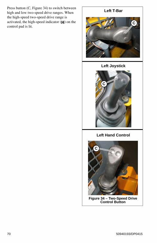
Press button (C, Figure 34) to switch between high and low two-speed drive ranges. When the high-speed two-speed drive range is activated, the high-speed indicator ( ) on the control pad is lit.
Figure 34 – Two-Speed Drive Control Button
Left T-Bar
C
C
Left Joystick
C
Left Hand Control
70 50940193/DP0415

Lift Arm Float
Make sure the attachment is lowered to the ground before activating the lift arm float. Activating float
with the lift arm raised will cause the lift arm and attachment to fall to the ground, which can cause severe injury or death.
.The float mode can be used
where the engine has stopped, is unable to be started, and lowering the lift arm is necessary to allow the operator to exit the loader.
Float allows the lowered lift arm to follow the ground contour while traveling over changing ground conditions.
To activate lift arm float:On T-Bar Controls
1. Lower the attachment to the ground.
2. Push Right T-Bar (B) all the way forward (Figure 27) into the detent (“float”) position. This position allows the lowered lift arm to “float” while traveling over changing ground conditions.
3. To remove lift arm from the detent (“float”) position, pull the Right T-Bar (B) out of the detent position. This returns the lift arm to normal operation.
On Joystick Controls
1. Lower the attachment to the ground.
2. Press button (A, Figure 35) to activate float:
• Press button (A) momentarily to apply float momentarily.
• Press and hold button (A) for 5 seconds to activate continuous float. Press button (A) again to deactivate continuous float.
The float indicator ( ) on the control pad is lit when float is activated on Joystick Control types.
On Hand and Foot Controls
1. Lower the attachment to the ground
WARNING
WARNING
Figure 35 – Lift Arm Float Control
Right T-Bar
B
Right Joystick
A
A
B
71 50940193/DP0415

2. To place the lift arm in the detent (“float”) position, use your toes to push the left pedal all the way down (A) into the detent. This position allows the lowered lift arm to “float” while traveling over changing ground conditions.
3. To remove lift arm from the detent (“float”) position, use your heel to push the left pedal down (B) out of the detent position. This returns the lift arm to normal operation.
72 50940193/DP0415

Hydraglide™ Ride Control System (Option)
When Hydraglide™ ride control is activated, the lift arm may drop slightly without a load, or several
inches with a heavy load.
Do not use Hydraglide™ when using pallet forks.
Hydraglide™ cushions lift arm loads during transport. It provides a smoother ride over uneven surfaces.
Press button (E, Figure 36) to activate Hydraglide™ ride control. Press button (E) again to deactivate.
When Hydraglide™ is activated, the Hydraglide™ indicator ( ) on the control pad is lit.
Note: Hydraglide™ is automatically deactivated when the machine is shut off.
Important: Do not use Hydraglide™ when digging. Precise control of the digging operation is difficult when Hydraglide™ is activated.
Activate Hydraglide™ when driving on public roads, for lighter loads, and for light off-road transport. Deactivate Hydraglide™ when working with heavy loads, such as when picking up excavated material.
WARNING
WARNING
Figure 36 – Hydraglide™ Control Button
Right T-Bar
E
Right Joystick
E
Right Hand Control
E
73 50940193/DP0415

Beacon/Position/Work Lights
The optional beacon, the rear red position lights. and the front and rear work lights are all operated using button (Z).
Note: The rear work lights and red position lights are located at the top of the rear door. The front work lights are located at the top front corners of the ROPS/FOPS.
The beacon/position/work lights control button is located on the control keypad.
• Beacon and Position Lights: Press button (Z) once to activate the beacon and the rear red position lights. LED (Y) is lit when the beacon and the red position lights are on.
• Beacon, Position and Front Work Lights: Press button (Z) twice to activate the bea-con, the rear red position lights and the front work lights. LED (U) is lit when the bea-con, the position lights, and the front work lights are on.
Note: If the optional road lights are installed, this turns on both front and rear work lights. Also, if the roads lights are on, they toggle off when the work lights turn on
• Beacon, Position, and Front and Rear Work Lights: Press button (Z) three times to activate the beacon, the rear red position lights, and the front and rear work lights. Both LEDs (Y and U) is lit when the beacon, the red position lights, and the front and rear work lights are on.
Note: If the optional road lights are installed, this turns off all lights.
• Off: Press button (Z) a fourth time to turn off the beacon, the red position lights and the work lights. Both LEDs (Y and U) are off when the beacon and all lights are off.
HVAC (Option)
Machines with optional heat/cool have two control buttons on the accessory keypad on the left door pillar for controlling the heater fan and heater temperature.
A. Cab Heat/Cool: Controls cab heat/cool. Press button as desired to set cab heat/cool; subsequent pressings increase heat from low to high. LEDs above the button are lit according to the low, medium and high heat settings.
NOTE: Cab heat/cool requires fan to be activated by pressing button (B).
B. Fan Speed: Controls cab air circulation fan. Press button (B) once for low setting, twice for medium, and three times for high. LEDs above the button are lit according to the low, medium and high fan settings. Press button (A) a forth time to deactivate air circulation fan.
Figure 37 – Beacon/Posi-tion/Work Lights Button
T U
Z
Figure 38 – Heater/Fan Buttons
A B
74 50940193/DP0415

Windshield Wiper/Washer
All skid loaders are equipped with a wiper and washer on the rear window, machines equipped with a cab door are equipped with an additional wiper and washer on the front windshield.
A. Windshield Wiper: Controls the front windshield wiper on machines equipped with a cab door. Press button (A) once for continuous setting, twice for 3 second delay, and three times for 6 second delay. LEDs above the button are lit according to the selected setting. Press button (A) a forth time to deactivate the front windshield wiper.
B. Rear Window Wiper (EU only): Controls the back window wiper. Press button (B) once for continuous setting, twice for 3 second delay, and three times for 6 second delay. LEDs above the button are lit according to the selected setting. Press button (B) a fourth time to deactivate the rear window wiper.
C. Windshield Washer: Push and hold button (C) to activate the windshield washer spray and wiper. Release the button to stop the spray; wiper continues for 5 seconds.
D. Rear Window Washer (EU only): Push and hold button (C) to activate the rear window washer spray and wiper. Release the button to stop the spray; wiper continues for 5 seconds.
Dome Light
The dome light is located on the right side of the ROPS/FOPS headliner.
When the ignition is off, if the dome light is centered, the light is activated by either sitting in the operator’s seat or by pressing certain buttons on the control keypad.
Note: The light will deactivate after approximately 10 seconds, if the ignition is turned on, or if the light is rotated by pressing to either side (T, Figure 40).
Figure 39 – Windshield Wiper/Washer Buttons
A C
B D
Figure 40 – Dome Light
T T
75 50940193/DP0415

When the ignition is on, the light is activated by rotating it to either side (T, Figure 40); the light is deactivated by rotating it to the center.
If the light is centered, the light will activate when the ignition is turned off.
Note: The light will deactivate after approximately 10 seconds, if the ignition is turned on, or if the light is rotated by pressing on either side (T, Figure 40) of the light.
Accessory Plug
The 12V accessory plug (C, Figure 41) is located at the bottom of the right door pillar.
Battery Disconnect Switch (Option)
The optional battery disconnect switch (D, Figure 42) is located inside the engine compartment. Turn the switch to the OFF position to disconnect the battery from the electrical system.
Figure 41 – Accessory Plug
C
Figure 42 – Battery Discon-nect Switch
D
76 50940193/DP0415

Attachment Mounting
The machine is equipped with either the standard manual All-Tach® hitch or optional Power-A-Tach® system hitch for mounting a bucket or other attachments.
All-Tach® HitchA manual latch lever (E, Figure 43) engages the latch pins, which lock the attachment onto the hitch. While standing outside the machine, rotate the lever all the way to the right (as viewed while facing back at the machine from the front) to engage the locking pins to lock the attachment onto the hitch. Rotate the lever all the way to the left to disengage the locking pins. Refer to “Connecting Attachments” on page 96 for more information.
To prevent unexpected release of the attachment from the hitch, be sure the locking lever is rotated
all the way to the right (as viewed while facing back at the machine from the front) and the locking pins (F, Figure 44) extend down through the attachment frame.
Locking pins (F) must be fully extended through the holes in the attachment frame before using the attachment. The attachment could fall off if it is not locked on the hitch and cause serious injury or death.
Figure 43 – All-Tach® Hitch
E
WARNING
Figure 44 – Hitch Locking Pins
F
77 50940193/DP0415

Power-A-Tach® SystemButtons (G and H, Figure 45) on the control keypad are used to operate the Power-A-
Tach® System hitch. Refer to “Connecting Attachments” on page 96 for more information.
Note: The Power-A-Tach® system hitch will not operate if the parking brake is engaged and/or the operator restraint bar is in the raised position.
To retract the hitch pins to the unlocked position:
With the machine running, and the parking brake disengaged, press and hold the Power-A-Tach® unlock button (H, Figure 45) on the control keypad until flags (P, Figure 46) move as far as they can to the center of the hitch.
To extend the hitch pins to the locked position:
With the machine running, and the parking brake disengaged, press and hold the Power-A-Tach® lock button (G, Figure 45) on the control keypad until flags (Q, Figure 46) move as far as they can to the outside of the hitch.
To prevent unexpected release of the attachment from the hitch, be sure the latch pins are secure by
verifying that the pin flags (Q, Figure 46) have moved fully to the outside of the hitch and the locking pins (F, Figure 47) extend down through the attachment frame.
Figure 45 – Power-A-Tach® Con-trol Buttons
G H
Figure 46 – Power-A-Tach® Hitch
Unlocked
Locked
P
Q
WARNING
78 50940193/DP0415

Locking pins (F) must be fully extended through the holes in the attachment frame before using the attachment. The attachment could fall off if it is not locked on the hitch and cause serious injury or death.
Auxiliary Hydraulic System
Auxiliary hydraulics are used with attachments requiring hydraulic power.
Always be sure the auxiliary hydraulic control is in neutral before starting the loader or disconnecting
the auxiliary hydraulic couplers.
Auxiliary Hydraulic CouplersAuxiliary hydraulic couplers (Figure 48) are located on top of the lift arm on the left side.
Note: Cover (G) is not present on all machines.
Figure 47 – Hitch Locking Pins
F
WARNING
Figure 48 – Auxiliary Hydrau-lics Couplers
G
79 50940193/DP0415

Auxiliary Hydraulics ControlRocker switch (F, Figure 49) controls the direction and amount of auxiliary hydraulics flow.
Auxiliary hydraulics control is proportional: the farther switch (F) is moved from center, the higher the flow through the auxiliary circuit. Flow direction is reversed when rocker switch (F) is moved in the opposite direction.
To latch continuous auxiliary hydraulic flow, hold rocker switch (F) fully on in either direction and push and hold trigger button (G) for five seconds. When the rocker switch and trigger are released, continuous flow should be enabled.
Note: Continuous flow amount is controlled using engine speed.
To cancel continuous flow, either push trigger button (G) or move rocker switch (F) in either direction.
Figure 49 – Auxiliary Hydraulics Control Rocker Switch
Right T-Bar
F
Right Joystick
F
Right Hand Control
F
G
G
G
80 50940193/DP0415

CHAPTER 5OPERATION
Before Starting the Engine
Before starting the engine and operating the machine:
• Review and comply with all safety recommendations in the Safety chapter of this manual.
• Know how to stop the machine before starting it.
• Fasten and properly adjust the seat belt(s) and lower the operator restraint bar.
Before starting the engine and running the loader, refer to “Safety Equipment” starting on page 39 and “Indicators and Controls” starting on page 47. Become familiar with the safe operation of the machine and the various operating controls, indicators and safety devices on the machine.
Operational Checks
Pre-Start Checks
Complete the following checks before starting the engine and using the machine. Correct/repair any problems before using the machine.
Table 11: Pre-Start Checks
Check Refer To:
Fuel tank filled? “Adding Fuel” on page 135.
Engine oil level correct? “Checking Engine Oil Level” on page 133.
Hydraulic system oil level correct? “Checking Hydraulic Oil Level” on page 143.
Engine coolant level correct? “Checking Coolant Level” on page 141.
Windshield washer reservoir filled? “Windshield Washer Reservoir” on page 154.
Grease fittings properly lubricated? “General Lubrication” on page 128.
V-belt condition good/tension adjustment correct?
“V-Belt Maintenance” on page 140.
Tires properly inflated/tire condition good? “Tires” on page 149.
Lights, signals, indicators, warning lights, indicators and horn operating properly?
“Control Keypad” on page 48, “Controls” on page 59.
Windows, lights and steps clean?
Attachment securely fastened to hitch? “Connecting Attachments” on page 96.
WARNING
81 50940193/DP0415

Checks During Operation
Complete the following checks after starting the engine and during operation.
Overall machine condition (including attachments) for bends, cracks, broken, loose or missing parts, etc.
Engine cover securely closed and latched?
Rags, tools, debris and other loose objects removed? (check especially after maintenance)
Approved warning triangle, hazard warning light and first aid kit in the machine?
Perform safety interlock system test See “Safety Interlock System Test” on page 42.
Seat position correctly adjusted? “Operator’s Seat” on page 39.
Seat belt fastened? “Seat Belt” on page 40.
Table 12: Checks During Operation
Check Refer To:
After Starting the Engine/During Operation
Engine oil pressure and charge indicator lights not on?
“Control Keypad” on page 48.
Parking brake released after starting engine and before operating machine?
Coolant temperature indicator light not on? “Control Keypad” on page 48.
Perform restraint bar safety interlock system test.
See “Restraint Bar Test” on page 42.
Steering operating properly? “Controls” on page 59.
Engine exhaust excessively smoky?
Anyone hazardously close to the machine?
When Driving on Public Roads
Attachments in transport position? “Attachment Transport Position” on page 94.
Table 11: Pre-Start Checks
Check Refer To:
82 50940193/DP0415

Cab Entry and Exit
Use only steps (A,
Figure 50) and handles (B) on the machine when entering/exiting. Keep the steps and the handles clean to ensure a secure hold at all times. Never use the controls as hand holds. Remove dirt (oil, grease, earth, snow and ice) from handles (B), steps (A) and your shoes before entering the cab.
Always face the machine when entering/exiting. When entering/exiting the cab.
Do not jump on or off the machine. Never climb onto or exit a moving machine.
Opening/Closing the Cab Door (Option)
Operate the door latch outside the cab using button (C, Figure 51) on the exterior door handle.
Lock/unlock the door using the ignition key in the key slot in button (C).
WARNING
Figure 50 – Cab Entry/Exit Han-dles/Steps
B
A
Figure 51 – Cab Exterior Door Han-dle
C
83 50940193/DP0415

Operate the door latch inside the cab using lever (D, Figure 52) located along the interior door frame.
Important: If the door is removed for any reason, make sure to re-connect the door electrical connection (E, Figure 53) when the door is replaced.
Operating the machine with the door electrical connection (E) disconnected can result in damage
to the machine not covered under warranty.
Figure 52 – Cab Interior Door Han-dle
D
Figure 53 – Cab Door Electrical Connection
E
CAUTION
84 50940193/DP0415

Starting the Engine
Be familiar with the “Mandatory Safety Shutdown Procedure” on page 14 before starting the
machine. Always perform this procedure before exiting the machine.
Note: The machine cannot be push- or tow-started. Attempting to push/tow start the machine may damage the drive systems of both the machine and the push/tow vehicle.
Do not use starting fluid (ether). An explosion can result, which can cause engine damage, injury or
death.
1. If the machine is equipped with the optional battery disconnect switch, check that switch is the “ON” position. See “Battery Disconnect Switch (Option)” on page 76.
2. Carefully step up onto the back of the bucket or attachment and grasp the hand-holds. enter the operator’s compartment and sit in the operator’s seat. Adjust the seat as required. See “Operator’s Seat” on page 39.
All controls must be within easy reach. The operator must be able to move all controls through
the complete range of motion.
3. Close the door, if so equipped. Perform the seat switch safety interlock test on page 42.
4. Fasten the seat belt(s). See “Fastening/Unfastening the Seat Belt” on page 40.
Always fasten the seat belt before operating the machine. Repair or replace any damaged seat belt
and lock parts before operation.
5. Lower the operator restraint bar.
Important: The operator restraint bar must be lowered before the engine can be started.
6. Place the lift/tilt, drive and auxiliary hydraulic controls into the neutral position.
7. Make sure no persons are hazardously close to the machine.
8. Turn the ignition key one detent clockwise to the ON/RUN position. If the engine is cold, the pre-heat ( ) indicator activates. For information about starting in colder ambient temperatures, see “Cold-Starting” on page 86.
9. When the pre-heat ( ) indicator goes out, turn the ignition key all the way clockwise to the START position to engage the starter.
WARNING
WARNING
CAUTION
WARNING
Figure 54 – Ignition Keyswitch
85 50940193/DP0415

Important: The recommended limit of continuous starter engagement is 15 seconds, and the starter must never be energized for more than 30 seconds. If the starter is energized for 20-30 seconds, the ignition should be turned off for one minute or longer. To protect the starter (DPF Models), the E-ECU system turns off the starter circuit if it is energized for 30 seconds or longer. The starter will remain de-energized for 30 seconds more before the loader can be restarted.
Important: If the engine fails to start within 15 seconds, turn the key all the way counter-clockwise to the OFF position and check for engine error codes on the information center display (page 53). Allow the starter to cool for 20 seconds and repeat steps 8 and 9.
Cold-StartingIf operating in temperatures below 32°F (0°C), the following are recommended:
• Replace the engine oil with the proper viscosity oil according to the engine opera-tor’s manual.
• Make sure the battery is fully charged.
• Install an optional block heater on the engine. A block heater is recommended for starting in temperatures below 20°F (-7°C). Contact your dealer for engine heater options.
Run the engine at 1800 rpm with no load for 5 minutes to warm the engine and hydraulic fluid to operating temperature before operating the loader.
Note: Depending upon coolant temperature, 50° F (10° C) or below, the low idle engine speed is automatically increased during a five minute warm-up period or until the coolant reaches a specified temperature.
Important: In ambient temperatures below -10° C (14° F), an engine block heater is recommended and is required below temperatures below -15° C (5° F) to reduce starter load and aid engine warm up. Starting the machine at these temperatures without a block heater will result in multiple glow/crank cycles or possible extended cranking time approaching 20 seconds.
86 50940193/DP0415

After Starting
1. Check that the charge ( ) and oil pressure ( ) indicators go out after the engine starts.
Important: If the charge ( ) and/or the engine oil pressure ( ) indicators do not go out when the engine is running, shut down the engine immediately and correct the problem. Damage to the engine may result if engine is run and the problem is not corrected.
2. Press the parking brake button on the control keypad to release the parking brake.
Note: The parking brake ( ) indicator on the control keypad is lit when the parking brake is engaged.
3. Perform restraint bar safety interlock system test on page 42.
4. Check for proper steering operation.
5. Check for excessively smoky exhaust (“Engine Troubleshooting” on page 159):
• Black smoke indicates poor and/or incomplete diesel fuel combustion.
• Blue smoke indicates engine oil combustion.
• White smoke indicates incomplete diesel combustion and/or coolant in the com-bustion chamber. Watch for persons hazardously close to the machine after starting and during machine operation.
Important: Do not run the engine at full throttle until it reaches operating temperature, or damage to the engine can result. Perform the following warm up procedure after starting before using the machine.
Important: Do not run the engine at high speed (above 20% of full throttle) for extended periods when the machine is not under load. Damage to the engine can result.
Figure 55 – Parking Brake Button
87 50940193/DP0415

Warm Up
Do not operate the machine until the hydraulic system reaches operating temperature. When cold,
hydraulic response is slow and can be unpredictable, presenting an unsafe condition. Damage to the machine can also result.
1. After starting, allow the engine to run at low idle with no load for a minimum of 5 minutes without operating the drive, lift, tilt or auxiliary functions.
2. Run the engine at 1800 rpm with no load for 5 minutes.
3. Raise the lift arm so the attachment is off the ground.
4. Extend and retract each of the cylinders several times with no load.
5. Travel slowly forward and backward several times.
6. In cold weather, tilt the attachment all the way forward and keep it there for 20-25 seconds. Repeat this step until the attachment tilt speed is normal.
Run-In Period
The performance and service life of the machine is heavily dependent on using the machine carefully during its first 100 operating hours.
• Do not operate the machine at the maximum rated operating capacity.
• Do not run the engine at a high speed for extended periods of time.
• Increase the load gradually while varying the engine speed.
• Follow the maintenance schedule. See “Maintenance Schedules” on page 123.
Stopping the Machine
When stopping the machine, perform the “Mandatory Safety Shutdown Procedure” on page 14. Raise the operator restraint bar, unfasten the seat belt(s) and grasp the hand-holds while climbing out of the operator’s compartment.
Important: Do not stop the engine at full throttle. Damage to the engine can result.
Note: The machine is equipped with a spring-applied automatic parking brake. The parking brake is applied when the operator restraint bar is lifted, the operator’s leaves the operator’s seat, the engine is shut off, or the parking brake switch is actuated.
Engine Stalling
If the engine should stall for any reason during operation, always turn the ignition keyswitch all
the way counter-clockwise to the OFF position and place the lift/tilt, drive and auxiliary hydraulic controls into the neutral positions before re-starting the engine according to “Starting the Engine” on page 85.
WARNING
WARNING
88 50940193/DP0415

Parking the Machine
Park the loader away from traffic on firm, level ground. If this is not possible, park the loader across the incline and block the tires to prevent movement.
After performing the “Mandatory Safety Shutdown Procedure” on page 14, perform the following:
• Check for coolant, fuel and/or oil leaks. Inspect all hoses, working components, covers and chassis for damage or advanced wear. Check for loose or missing parts. Repair or replace damaged, leaking, worn or otherwise compromised components before start-ing the machine again.
• Fill the fuel tank. See “Fluid Capacities/Lubricants” on page 183 for proper fuel speci-fications.
• Remove any dirt and/or debris from the engine compartment.
• Remove any mud/dirt from the chassis. Clean any dirt or water from the cylinder rod surfaces to prevent corrosion and protect the cylinder seals.
• If parking the machine for an extended period, lock the cab door (if so equipped) and the engine compartment. Take the keys with you.
Brake Release Operation (Option)
The machine may have, as an option, a brake release system installed. The brake release system releases the parking brake, allowing the machine to be towed for short distances.
Before utilizing the brake release, be sure to secure the machine with wheel chocks or tow
lines. Verify the travel path of the machine is clear of personnel before operating the brake release system.
1. Locate the brake release jack (Z, Figure 56) and handle. Depending on your particular model, it may be necessary to remove covers and/or open the rear door of the machine.
2. Position the brake release receiver (Y) and insert the jack handle.
3. Push down and hold the plunger (Z) against the brake release.
4. Jack the brake release to build pressure. As pressure builds, plunger (X) stays down and no longer needs to be held.
5. Continue to jack the brake release until jacking resistance no longer increases.
Note: The brake release has a pressure relief which prevents damage to the travel motors.
WARNING
Figure 56 – Parking Brake Release Option
Y X
Z
89 50940193/DP0415

6. Tow the machine for short distances only, such as towing it onto a trailer. Depending on the internal leakage rate of the travel motors, the machine may roll easily with the brake release activated, or the tires may skid until the oil is forced from the motors.
7. Reset the parking brake by pulling up on plunger (X) or starting the machine.
Jump-starting
If the battery is discharged or does not have enough power to start the engine, jump-start the engine as follows:
Two people are required for safe jump-starting. An additional person is required to remove the jumper
cables with the operator remaining in the operator's seat once the engine is running. Start the engine from the operator’s seat with all controls in “neutral.”
NEVER make jumper cable connections directly to the starter solenoid of either engine.
To reduce the risk of a short circuit, keep metal parts on your clothing and metal jewelry away from the battery.
Do not jump-start a frozen battery, or it may explode. A discharged battery can freeze at 14°F (10°C).
Wear safety glasses and avoid leaning over the batteries while jump-starting.
To avoid personal injury, closely follow the procedure, step-by-step.
Important: The external power source must deliver 12 volts, DC. Supply voltages higher than 12V can damage the electrical systems of both machines. Only use jumper cables that are in good condition.
Important: The booster battery must have a voltage of 12-volts.
WARNING
90 50940193/DP0415

1. Turn the ignition keyswitches of both machines to the OFF position. Be sure the controls in both machines are in the neutral position and the machines are NOT touching each other. If the machine with the booster battery has a drive transmission, place the transmission into neutral and apply the parking brake.
2. Open the engine compartment to provide access to the discharged battery (Figure 57). If the machine is equipped with a battery disconnect switch (see “Battery Disconnect Switch (Option)” on page 76), be sure the switch is in the ON position.
3. Route the jumper cables so that they cannot catch on any moving objects or components and connect the positive jumper cable to the positive (+) terminal (A, Figure 58) on the discharged battery.
Important: Prevent the other positive jumper cable clamp from touching any metal other than the positive (+) remote battery terminal.
4. Connect the other end of the positive jumper cable to the positive (+) terminal (B) on the booster battery.
5. Connect the negative jumper cable to the negative (-) terminal (C) on the booster battery.
6. Connect the other end of the negative (-) jumper cable to an unpainted frame surface (D) inside the engine compartment of the machine with the discharge battery. Connect the cable as far as possible away from the battery.
Important: Prevent the other negative jumper cable clamp from touching any metal other than the frame of the machine with the discharged battery.
Figure 57 – Battery Locations
12 V
12 V
Figure 58 – Booster Battery Connection
Discharged Battery
Booster Battery
D
A
B C
91 50940193/DP0415

Do not connect the other end of the negative jumper cable clamp to the negative terminal (-) on
the discharged battery. Gas emerging from the battery may ignite if sparks are formed.
7. Start the machine with the discharged battery. See “Starting the Engine” on page 85. If the engine does not start immediately, stop cranking after 10 seconds and repeat starting procedure after approximately 30 seconds.
Note: Alternately, a third person can start the machine with the booster battery, to avoid excessive drain on the booster battery.
8. Once the machine with the discharged battery is running, disconnect the jumper cables in reverse order of connection. Be careful not to short the jumper cables together when disconnecting.
9. Run the machine for at least 30 minutes to re-charge the battery.
Travel Drive Operation
Refer to travel drive control information starting on page 61.
Never allow anyone to enter the machine travel path and/or inside the turning radius of the
machine. Signal your intention to move by sounding the horn.
Traveling should be performed with the attachment in transport position. See “Attachment Transport Position” on page 94.
Avoid sudden stops, starts or turns. Do not raise the arm rests/safety bars while traveling. Raising the arm rests/safety bars will apply the parking brake abruptly. Loss of control could result.
Do not turn the ignition keyswitch to the OFF position while traveling. Sudden braking will occur and loss of control could result.
Always check and look behind you before and while traveling in reverse. Traveling in reverse without checking and looking could result in collision with a person or obstacle.
Remove obstacles in the machine’s path before traveling with a load.
Two-Speed Drive (Option)Machines equipped with the two-speed drive have two (high and low) travel speed ranges. See “Two-Speed Drive (Option)” on page 69 for two-speed drive control information.
Reduce speed before shifting from two-speed to single-speed drive. Down-shifting from two- to
single-speed drive while traveling at high speed may cause the machine to tip and can cause injury, loss of control and damage to the machine.
WARNING
WARNING
WARNING
92 50940193/DP0415

Driving on an InclineWhen traveling on an incline, travel with the heavy end pointing uphill.
Driving over Rough Terrain When traveling over rough terrain, activate the Hydraglide™ ride control system and drive slowly with the bucket lowered in the transport position (“Attachment Transport Position” on page 94). See “Hydraglide™ Ride Control System (Option)” on page 73 for details about activating Hydraglide™.
Transport on Public Roads
Refer to “Loading and Transporting the Machine on a Transport Vehicle” on page 113 if it is necessary to transport the machine a long distance. For short distance travel on public roads, attach an SMV (Slow-Moving Vehicle) emblem (purchased locally) to the back of the machine. For highway operation, install the optional flashing beacon.
Important: Follow the applicable legal regulations of the country and locality where the machine is used. Only the attachments listed in the operation license or vehicle papers are admissible for driving on public roads.
Transport Hydraulics Lock-out (Option)When driving the machine on public roads activate the transport hydraulics lock-out on machines equipped with this option.
Postion the lift arm in the transport postion and press the hydraulics lock-out button (A) to deactivate the attachment lift and tilt hydraulics and prevent inadvertent lift arm movement. Pressing the button again will toggle hydraulic function back on.
Note: Attachment tilt and lift hydraulics are deactivated when LED (B) is lit.
Figure 59 – Hydraulics Lock-out Option Button
B
A
93 50940193/DP0415

Lift Arm Operation
Refer to lift and tilt control information starting on page 61.
Do not lift loads exceeding rated operating capacity. See “Payloads/Capacities” on page 186.
The float mode can be used where the engine has stopped, is unable to be started, and lowering the
lift arm is necessary to allow the operator to exit the loader. See “Lift Arm Float” on page 71.
Attachment Transport Position
Always carry loads in transport position to minimize the possibility of tipping or rollover
accidents and unstable balance conditions that can cause loss of control.
Carry materials 200-300 mm (8-12”) above the ground (A, Figure 60), and adjust as necessary to clear obstacles. Generally, carry the load as low as safely possible. Tilt buckets back, as shown in Figure 60, to prevent spilling material.
Lift Arm Float
Make sure the bucket is lowered to the ground before activating the lift arm float. Activating float
with an attachment raised will cause the lift arm to fall to the ground, which can cause severe injury or death.
Do not drive the loader forward with the lift arm float activated. Damage to the machine and/or loss of control can result.
WARNING
WARNING
WARNING
Figure 60 – Transport Position
A
WARNING
94 50940193/DP0415

Float allows the lowered lift arm to follow the ground contour while traveling over changing ground conditions. It is useful when grading surfaces while driving the machine in reverse.
Note: Lift arm float is not effective if the lift arm is lowered against the loader frame.
See “Lift Arm Float” on page 71 for details about the lift arm float control.
Hydraglide™ Ride Control System (Option)Hydraglide™ cushions lift arm loads during transport. It provides a smoother ride over uneven surfaces.
When ride control is activated, the lift arm may drop slightly without a load, or several inches with
a heavy load.
Do not use Hydraglide™ when using pallet forks.
Important: Do not use Hydraglide™ when digging. Precise control of the digging operation is difficult with the Hydraglide™ option activated.
Note: Hydraglide™ is not effective if the lift arm is lowered against the loader frame.
See “Hydraglide™ Ride Control System (Option)” on page 73 for details about Hydraglide™ control.
WARNING
WARNING
95 50940193/DP0415

Changing Attachments
To prevent unexpected release of the attachment from the hitch, make sure the attachment is fully
locked onto the hitch before using the attachment. On manual All-Tach® hitches, rotate the latch levers fully. On Power-A-Tach® hitches, verify that the pin flags are all the way to the outside of the hitch.
Always verify that the locking pins on the hitch are fully engaged down through the holes in the attachment frame before using the attachment. The attachment could fall off if it is not locked on the hitch and could cause serious injury or death.
Connecting Attachments
1. In an open, level area, place the attachment lock into the unlocked position (Figure 61):
• All-Tach® system manual hitch: Move hitch lock lever (G) all the way to the right.
• Power-A-Tach® system quick attach hitch: Press the Power-A-Tach® sys-tem unlock button (I) on the control keypad until safety flags (H) have moved all the way in.
2. Tilt the attachment plate forward and drive the machine straight forward toward the back of the attachment
3. Lower the lift arm so tabs (J) on the top of the attachment plate are aligned just under the hooks on the back of the attachment.
4. Tilt the attachment plate back until tabs (J) on the top of the attachment plate are engaged against the hooks on the back of the attachment.
5. Raise the lift arm slightly until the attachment is hanging from the hooks on the back of the attachment and tabs (J) are firmly inserted into the hooks. Tilt the attachment plate back, if necessary, so the back of the attachment is resting flat against the attachment plate.
WARNING
Manual Attachment Hitch In Unlocked Condition
Power-A-Tach® System Quick Attach Hitch In Unlocked Condi-
tion
Figure 61 – Attachment Hitch Unlocked
G
I
H
J
J
J J
96 50940193/DP0415

6. Place the attachment lock into the locked position (Figure 62):
• All-Tach® system manual hitch: Perform the “Mandatory Safety Shut-down Procedure” on page 14 and move hitch lock lever all the way to the left (G).
• Power-A-Tach® system quick attach hitch: Press the Power-A-Tach® sys-tem lock button (N) on the control key-pad until safety flags (H) have moved all the way out.
7. Make sure the locking pins (F, Figure 63) are fully engaged down through the holes in the attachment.
To prevent unexpected release of the attachment from the hitch, be sure the locking lever is rotated
all the way to the right (as viewed while facing back at the machine from the front) and the locking pins (F, Figure 63) extend down through the attachment frame.
Locking pins (F) must be fully extended down through the holes in the attachment frame before using the attachment. The attachment could fall off if it is not locked on the hitch and cause serious injury or death.
Important: To check that the attachment is properly installed, tilt the attachment forward slightly, and apply downward pressure to the attachment before using it.
Manual Attachment Hitch In Locked Condition
Power-A-Tach® System Quick Attach Hitch In Locked Condition
Figure 62 – Attachment Hitch Locked
G
N
H
WARNING
Figure 63 – Hitch Locking Pins
F
97 50940193/DP0415

Disconnecting Attachments
Position the attachment so that after disconnecting, the attachment will stand safely and
not tip over. Serious injury can occur if an attachment tips over onto a person.
1. Empty the attachment and drive to an open, level area to disconnect the attachment.
2. Lower the attachment to the ground.
3. Place the attachment lock into the unlocked position (Figure 64):
• All-Tach® system manual hitch: Move hitch lock lever (G) all the way to the right.
• Power-A-Tach® system quick attach hitch: Press the Power-A-Tach® sys-tem unlock button (I) on the control keypad until safety flags (H) have moved all the way in.
4. Lower the lift arm until tabs (J) on top of the attachment plate disengage out of hooks (K) on the back of the attachment.
5. Look behind you for bystanders and obstacles. Drive straight back in reverse away from the attachment.
WARNING
Manual Attachment Hitch In Unlocked Condition
Power-A-Tach® System Quick Attach Hitch In Unlocked Condi-
tion
Figure 64 – Attachment Hitch Unlocked
G
I
H
J
J
J J
98 50940193/DP0415

Connecting Auxiliary Hydraulic Couplings
Important: Connect hydraulically-powered attachment hoses to the auxiliary circuits after the attachment is secured to the hitch.
Disconnect hydraulically-powered attachment hoses from the auxiliary circuits before removing the attachment from the hitch.
1. Empty the attachment and lower it to the ground.
2. Shut off the engine. With the ignition on, but the engine off, move the auxiliary hydraulics control rocker switch (F, Figure 65) on the right T-bar, joystick or hand control back and forth to relieve pressure in the auxiliary hydraulics circuit.
3. Turn off the ignition. Remove the ignition key and take it with you.
4. Raise the safety bars/arm rests and exit the machine using the hand holds.
5. Clean the hydraulic connections on the hoses and the connections.
6. Relieve any residual pressure remaining in the auxiliary hydraulics circuit by pushing the attachment coupler firmly into the auxiliary coupler (Figure 66).
Route the hydraulic hoses
so they do not get pinched when the attachment is tilted forward and back. Damaged or burst hydraulic hoses could result.
7. Continue to push the hose connections firmly onto the auxiliary hydraulic connections until they snap into place.
Note: Pressure build-up caused by heat in hydraulic attachments left in direct sunlight can make it difficult to connect the quick-couplers to the fittings on the attachment.
Note: The auxiliary hydraulic couplers are located on the left lift arm. When the auxiliary control switch is activated in either direction, the inside and outside couplers can be “pressure” or “return”, depending on which direction the switch is activated. The smaller center coupler is for the case drain.
Important: Always check hydraulic function of the attachment before use, to make sure the hydraulic hoses have not been installed in reverse.
Figure 65 – Auxiliary Hydraulics Control Rocker Switch
F
CAUTION
Figure 66 – Auxiliary Hydraulics Couplers
99 50940193/DP0415

Disconnecting Auxiliary Hydraulic Couplings
1. Empty the attachment and lower it to the ground.
2. Shut off the engine, but do not turn off the ignition. Move the auxiliary hydraulics control rocker switch (F, Figure 67) on the right T-bar, joystick or hand control back and forth to relieve pressure in the auxiliary hydraulics circuit.
3. Turn off the ignition. Remove the ignition key and take it with you.
4. Raise the safety bars/arm rests and exit the machine using the hand holds.
5. Push on the hose connection locking rings until the hose connections release.
Figure 67 – Auxiliary Hydraulics Control Rocker Switch
F
100 50940193/DP0415

Self-Leveling (Option)
Self-leveling automatically keeps the tilt angle of the attachment constant, relative to the ground plane, when the lift arm is raised (A, Figure 68). This feature is especially useful when using pallet forks.
Important: Self-leveling operates only when the lift arm is raised: when the lift arm is lowered (B), self-leveling is not activated.
Note: Self-leveling is activated by default. To deactivate self-leveling, see “Self-Leveling Cancel” on page 102.
Figure 68 – Self-Leveling Operation
Self-LevelingOperates When Lift
Arm is Raised
A
Self-Leveling DoesNot Operate When
Lift Arm is Lowered
A
A
B
B
B
101 50940193/DP0415

Self-Leveling CancelThe self-leveling cancel option allows deactivation of the self-leveling feature when equipped with this option.
To deactivate self-leveling, press the self-level cancel button (E, Figure 69) on the control pad. To restore self-leveling, press button (E) again.
Note: If equipped with this option, self-leveling is activated by default. If the engine is shut off, self-leveling defaults to the activated condition.
Note: Indicator (F) above button (E) is lit when the self-leveling cancel option is on and the self-leveling feature is deactivated. This indicator will light if the unit does not have this installed option.
Using Buckets
Read the “Safety” section in this manual, starting on page 13, before working with a bucket. Pay
special attention to the “During Operation” information, starting on page 16. Always follow the information included in the “Safety” section. Serious injury or death can occur if the safety information is not followed.
Always maintain a safe distance from electric power lines and avoid contact with any electrically charged conductor or gas line. Accidental contact or rupture can result in electrocution or an explosion. Contact the “Call Before You Dig” referral system at 8-1-1 in the U.S., or 888-258-0808 in the U.S. and Canada or proper local authorities for utility line locations before starting to dig.
Make sure the bucket is securely attached to the hitch before starting work. See “Connecting Attachments” on page 96.
Avoid tilting a bucket back when the lift arm is fully raised. Material may fall over the rear of the bucket and onto the operator. If necessary, fit the rear of the bucket with a guard to prevent material from falling out of the back of the bucket.
Figure 69 – Self-Leveling Can-cel Button
F
E
WARNING
102 50940193/DP0415

Always carry the loaded bucket with the lift arm in the transport position. See “Attachment Transport Position” on page 94. For additional stability when operating on inclines, always travel with the heavier end of the loader toward the top of the incline.
Make sure you have a good view of the material you are digging, and of the area you will be working in.
Use extreme care when digging around foundations or walls. Never remove material that might compromise a wall or foundation.
Never push the “float” button with the bucket or attachment raised, because this will cause the lift arm to fall.
Follow the recommendations in “Fields of Application” on page 6.
Digging with a Bucket
1. (Figure 70) Approach the digging site with the lift arm slightly raised. Tilt the bucket forward until the cutting edge contacts the ground.
2. Tilt the cutting edge of the bucket down at an angle appropriate for ground hardness.
3. Drive forward slowly, digging into the ground with the cutting edge of the bucket and gradually lower the lift arm.
4. When the bucket is full, raise the bucket and tilt it back and back away from the material.
Always carry the loaded bucket with the lift arm in the transport position. See “Attachment Transport
Position” on page 94. For additional stability when operating on inclines, always travel with the heavier end of the loader toward the top of the incline.
CAUTION
Figure 70 – Digging
1 2
3 4
WARNING
103 50940193/DP0415
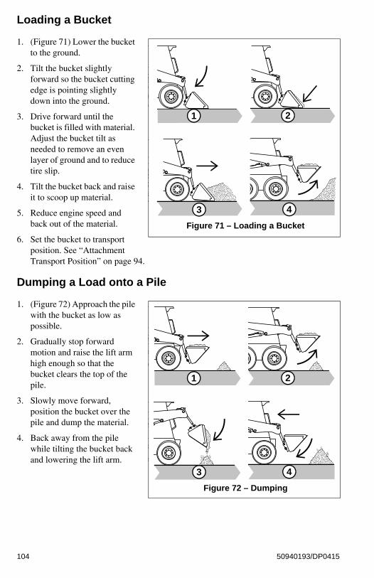
Loading a Bucket
1. (Figure 71) Lower the bucket to the ground.
2. Tilt the bucket slightly forward so the bucket cutting edge is pointing slightly down into the ground.
3. Drive forward until the bucket is filled with material. Adjust the bucket tilt as needed to remove an even layer of ground and to reduce tire slip.
4. Tilt the bucket back and raise it to scoop up material.
5. Reduce engine speed and back out of the material.
6. Set the bucket to transport position. See “Attachment Transport Position” on page 94.
Dumping a Load onto a Pile
1. (Figure 72) Approach the pile with the bucket as low as possible.
2. Gradually stop forward motion and raise the lift arm high enough so that the bucket clears the top of the pile.
3. Slowly move forward, position the bucket over the pile and dump the material.
4. Back away from the pile while tilting the bucket back and lowering the lift arm.
Figure 71 – Loading a Bucket
1 2
3 4
Figure 72 – Dumping
1 2
3 4
104 50940193/DP0415
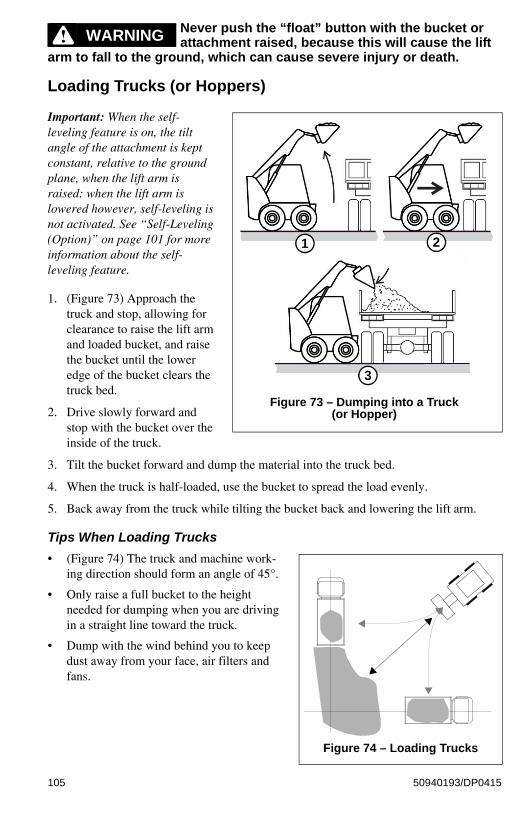
Never push the “float” button with the bucket or attachment raised, because this will cause the lift
arm to fall to the ground, which can cause severe injury or death.
Loading Trucks (or Hoppers)
Important: When the self-leveling feature is on, the tilt angle of the attachment is kept constant, relative to the ground plane, when the lift arm is raised: when the lift arm is lowered however, self-leveling is not activated. See “Self-Leveling (Option)” on page 101 for more information about the self-leveling feature.
1. (Figure 73) Approach the truck and stop, allowing for clearance to raise the lift arm and loaded bucket, and raise the bucket until the lower edge of the bucket clears the truck bed.
2. Drive slowly forward and stop with the bucket over the inside of the truck.
3. Tilt the bucket forward and dump the material into the truck bed.
4. When the truck is half-loaded, use the bucket to spread the load evenly.
5. Back away from the truck while tilting the bucket back and lowering the lift arm.
Tips When Loading Trucks
• (Figure 74) The truck and machine work-ing direction should form an angle of 45°.
• Only raise a full bucket to the height needed for dumping when you are driving in a straight line toward the truck.
• Dump with the wind behind you to keep dust away from your face, air filters and fans.
WARNING
Figure 73 – Dumping into a Truck (or Hopper)
1 2
3
Figure 74 – Loading Trucks
105 50940193/DP0415
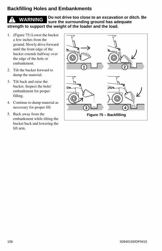
Backfilling Holes and Embankments
Do not drive too close to an excavation or ditch. Be sure the surrounding ground has adequate
strength to support the weight of the loader and the load.
1. (Figure 75) Lower the bucket a few inches from the ground. Slowly drive forward until the front edge of the bucket extends halfway over the edge of the hole or embankment.
2. Tilt the bucket forward to dump the material.
3. Tilt back and raise the bucket. Inspect the hole/embankment for proper filling.
4. Continue to dump material as necessary for proper fill.
5. Back away from the embankment while tilting the bucket back and lowering the lift arm.
WARNING
Figure 75 – Backfilling
1 2
3 4
106 50940193/DP0415

Scraping with a Bucket
Important: Always scrape in the forward direction.
1. (Figure 27) Lower the lift arm down against the loader frame.
2. Tilt the bucket forward until the cutting edge is at a slight angle to the surface being scraped.
3. Travel slowly forward. Material can flow over the cutting edge and collect inside the bucket.
4. Tilt the bucket back and raise it to scoop up material.
Grading
Grading Without Float
1. (Figure 77) Raise the bucket slightly and tilt it forward.
2. Release material from the bucket while traveling forward.
3. Tilt the bucket forward and adjust the lift arm height until the cutting edge is slightly above the ground.
4. Drive in reverse, smoothing the material released in step 2 with the front edge of the bucket.
Check that the work area is clear of people and obstacles. Always look in the direction of travel.
Figure 76 – Scraping
1 2
3 4
Figure 77 – Grading without Float
1 2
3 4
WARNING
107 50940193/DP0415

Grading Using Float
Make sure the bucket is lowered to the ground before activating the lift arm float. Activating float
with an attachment raised will cause it to fall to the ground, which can cause severe injury or death.
Do not drive the loader forward with the lift arm float activated. Damage to the machine and/or loss of control can result.
1. (Figure 78) Lower the bucket to the ground.
2. Activate the lift arm float. See “Lift Arm Float” on page 94 for information about the float feature.
3. Tilt the bucket forward so it stands on the cutting edge at a 30°-45° degree angle to the surface being leveled.
4. Drive in reverse, dragging the floating bucket. Adjust the tilt angle of the bucket while driving in reverse to control the spread of the material.
Check that the work area is clear of people and obstacles. Always look in the direction of travel.
WARNING
Figure 78 – Grading Using Float
1 2
3 4
WARNING
108 50940193/DP0415

Using Pallet Forks
Safety Instructions When Working with Pallet Forks
Read the “Safety” section in this manual, starting on page 13, before working with pallet forks. Pay
special attention to the “During Operation” information, starting on page 16.
Follow all instructions in the Operator's Manual provided with the pallet forks.
Always follow the information included in the “Safety” sections. Serious injury or death can occur if the safety information is not followed.
Always approach the load from a straight-ahead position. Position the fork arms underneath the pallet, as far as they will go, so the load is distributed as closely as possible to the fork frame. Position the fork arms as far apart as possible. Load both fork arms evenly.
Lift, transport and unload loads only on firm and level ground with sufficient load-bearing capacity.
Always transport the load close to the ground as is safely possible. Observe minimum ground clearance.
Use pallet forks for material handling and/or material transport only.
Never lift a load using only one fork arm.
Make sure the fork arms are safely locked onto the fork frame before use.
Do not lift unstable material, or material that is not properly secured on the fork arms.
Never leave a machine with the forks raised or a load unattended. Make sure all persons stay clear of suspended loads.
DO NOT exceed pallet fork load center and/or lifting capacity. See “Payloads/Capacities” on page 186.
Do not use high travel speed range when using pallet forks.
DO NOT use standard fork arms as reverse (inverted) forks.
Never allow a load to get closer than 6 m (20 ft.) to overhead electrical lines.
WARNING
109 50940193/DP0415

DO NOT push, pull or shove the fork arms, or move them in at a slanting angle; the resulting lateral forces can damage the fork arms.
DO NOT pull loads off the fork arms, or allow loads to fall onto the forks arms.
DO NOT tilt the pallet forks to raise loads.
DO NOT lift or transport molten material with pallet forks.
Repair work on fork arms must be performed only by authorized personnel.
Always keep pallet fork arms clean.
Secure loads as directed in the pallet fork Operator's Manual to prevent the loads from falling.
Never modify pallet fork arms.
Do not lift or transport persons on the pallet forks.
Do not drive on public roads with pallet forks installed on the machine.
Do not stack loads which are not properly packaged or have damaged pallets/stacking containers. Do not stack loads on top of loads, which may have shifted.
Always tilt pallet forks back slightly during transport to help retain the load.
Do not use bent, cracked, or otherwise damaged fork arms/pallet forks.
Always inspect pallet forks each time before using. Refer to the pallet fork manufacturer’s documentation and/or contact the pallet fork manufacturer for information regarding safe pallet fork condition criteria:
• Check the fork arm locks for proper function and/or damage. Do not use pallet forks with damaged locks or locks that do not function properly.
• Visually check the fork arm hooks and/or bends for cracks and/or deformations. Do not use fork arms that are cracked and/or have deformations that make the fork arms unsafe.
• Do not use fork arms that have bends or blades that have more than 10% of the original material worn away.
• Check the fork arms blades and tips for deformations or holes.
110 50940193/DP0415

Transporting Loads Using Pallet Forks
Important: When the self-leveling feature is on, the tilt angle of the attachment is kept constant, relative to the ground plane, when the lift arm is raised. When the lift arm is lowered however, self-leveling is not activated. Refer to “Self-Leveling (Option)” on page 101 for more information about the self-leveling feature.
Loading Pallet Forks
1. Stop the machine immediately in front of the material.
2. Position the fork arms parallel to the ground.
3. Make sure the fork arms are adjusted as far apart as possible, as allowed by the load, and are both the same distance away from the center-line of the load.
4. Adjust the height of the fork arms to fit the lifting area at the bottom of the pallet.
5. Drive slowly and carefully forward until the fork frame contacts the material.
6. Make sure the pallet is evenly and safely positioned on the pallet fork arms.
Lifting Loads Using Pallet Forks
7. Apply the parking brake.
8. Slowly raise the pallet forks. Do not raise the pallet forks any higher than required. Make sure to not exceed pallet fork load center and/or lifting capacity.
9. Lower the load immediately if you are unsure of the load, the equipment, or in case of any unsafe circumstances.
10. Tilt the pallet fork frame back slightly, to help retain the load.
Transporting Load Using Pallet Forks
11. Make sure the area around and behind the machine is clear of bystanders and obstacles.
12. Slowly and carefully drive in reverse and lower the pallet forks to transport position (“Attachment Transport Position” on page 94), when it is safe to do so.
13. Carry the load as low as safely possible during transport. Observe minimum ground clearance. Refer to “Attachment Transport Position” on page 94.
14. Drive slowly and carefully forward straight toward the place where the load will be set down.
Setting Down Loads Using Pallet Forks
Note: If the load will be placed on top of stacked material, make sure to align the load in the center of the stack.
Do not stack loads which are not properly packaged or have damaged pallets/stacking
containers. Do not stack loads, or on top of loads, which have shifted.
WARNING
111 50940193/DP0415

15. Raise the pallet forks slightly above where the load will be placed.
16. Tilt the pallet forks as needed to level the fork arms.
17. Carefully drive slowly forward until the load is positioned precisely above where the load will be placed. Use care when aligning the load with a stack.
18. Slowly and carefully lower the lift arm until the load is placed.
19. Make sure the fork arms are no longer bearing weight and are free to be retracted.
20. Make sure the area around and behind the machine is clear of bystanders and obstacles.
21. Slowly and carefully drive in reverse away from the placed load until the lift arm can be lowered to transport position. See “Attachment Transport Position” on page 94.
22. Slightly tilt the pallet fork frame backwards.
112 50940193/DP0415
Loading and Transporting the Machine on a Transport Vehicle
Park the transport vehicle on a level surface. Be sure the vehicle and its ramps have the weight and
size capacity to support the skid loader. Make sure the driver of the transport vehicle knows the overall height, width and weight of the vehicle, including the loaded skid loader, before starting transport. See “Weights” on page 185.
Make sure the load does not fall short of the minimum axle load of the steering axle, otherwise the transport vehicle’s steering could be seriously affected.
Make sure the transport surface and the loading ramps are clear of debris and slippery material that may reduce traction.
Secure the loading ramps to the transport vehicle before loading. Position the loading ramps at the shallowest possible angle. Do not exceed an angle of 15°. Only use ramps with anti-skid surfaces. Move the skid loader on and off the vehicle ramp slowly and carefully.
Position the skid loader at the lowest possible position on the transport platform, with the center of gravity of the load over the centerline of the transport vehicle. Distribute partial loads to ensure an even load across the axles of the transport vehicle.
Secure the machine properly so it cannot move during transport. Consider all possible transport conditions such as: heavy braking, evasive maneuvers, and uneven or rough roadways. Always use the proper tie-down points when using straps and chains. See “Machine Orientation” on page 3.
Failure to follow these instructions could result in an overturn accident.
Important: Observe all local regulations governing the loading and transporting of equipment (Reference: U.S. Federal Motor Carrier Safety Regulations, Section 392). Ensure that the hauling vehicle meets all safety requirements before loading the skid-steer loader.
1. Park the transport vehicle on a level surface. Block the front and rear tires on the transport vehicle.
2. Before starting, check the loader engine oil. The oil level must be at the “Full” mark on the dipstick. Add oil if needed. See “Checking Engine Oil Level” on page 133.
Important: When loading and driving on ramps, the engine can be damaged if the engine oil level is too low.
3. Start the skid loader and raise the hitch plate/attachment enough so that it will not touch the loading ramps.
WARNING
113 50940193/DP0415

4. Slowly and carefully drive the skid loader in reverse up the ramp onto the transport vehicle.
Important: Do not adjust travel direction while traveling on the ramps. Instead, drive down off of the ramps, and re-align the machine with the ramps.
5. Position the skid loader at the lowest possible position on the transport platform, with the center of gravity of the load over centerline of the transport vehicle.
6. Lower the hitch plate/attachment to the transport platform, turn off the engine and remove the key.
7. Raise the operator restraint bar to lock out the hydraulic functions. If applicable, close the cab door and lock it. Do not allow anyone to stay in the cab.
8. Fasten the loader to the hauling vehicle at the points indicated by the tie-down decals (Figure 79).
9. Place blocks in front and behind wheels to prevent movement.
10. Measure the clearance height of the skid loader and transport vehicle. Post the clearance height in the cab of the transport vehicle.
Note: Before transporting the machine through heavy rain, close off the exhaust pipe with a cap or suitable adhesive tape.
Towing
Towing the machine is not recommended as a means of transportation.
Note: The machine may be equipped with an optional brake release. Refer to “Brake Release Operation (Option)” on page 89 for more information.
Use the tie-down/retrieval point in situations where lifting the machine is not possible and the overall distance the machine must be moved is less than 100 feet (30.5 m). Retrieve/tow the machine at 6 mph (10 kph) or less.
Connect the towline to both tie-down/retrieval points at the front or the rear of the loader. Use of only a single retrieval point or connection the twoline to any point on the machine other than a designated tie-down/retrieval location could result in loader damage.
Important: Towline capacity must be at least 1.5 times the gross weight of the machine. Towline length cannot allow the maximum towing angle to exceed 20°.
Note: Tow the machine for short distances only, such as towing it onto a trailer.
Figure 79 – Tie-Down Point Identifier
WARNINGWARNING
114 50940193/DP0415

Lifting the Machine Using a Crane or Hoist
Note: Single-point and four-point lift kits are available for lifting the machine. Contact you dealer for more information.
Contact your dealer for available lift kits for the machine. Do not lift the machine without an
approved lift kit installed.
Before lifting, check the lift kit for proper installation. Securely fasten the lifting gear to the machine at the designated lift points.
When using any lift kit, follow the directions included with the lift kit.
Never allow riders in the operator’s compartment while the loader is lifted.
Keep clear of suspended loads. Keep everyone a safe distance away from the loader while it is lifted.
The machine may only be crane-lifted with an empty bucket, empty pallet forks, or with no attachment. Never lift the machine with any other attachment installed. Never lift the machine with a load in the bucket or on the pallet forks.
Lift equipment used and its installation is the responsibility of the party conducting the lift. All rigging MUST comply with applicable regulations and guidelines.
1. If a bucket is attached, make sure it is emptied. If pallet forks are attached, remove any load from the pallet forks.
2. Raise the arm rests/safety bars to apply the parking brake and lock out the hydraulic functions.
3. Turn off the engine and remove the ignition key. Close the doors and the engine cover. Do not allow anyone to stay in the cab.
4. Using suitable lift equipment, hook into the lift kit lifting points. Adjust the length of the slings or chains so the machine is level when lifted.
Note: The machine may be slightly off level (10 degrees max.) when lifted.
5. Center the hoist over the ROPS/FOPS. To prevent shock loading of the equipment and excessive swinging, slowly lift the loader off the ground. Perform all movements slowly and gradually. As needed, use a tag line to help position the loader and keep it from swinging.
WARNING
115 50940193/DP0415

Diesel Particulate Filter (DPF) Regeneration Procedures (DPF Models)
The Diesel Particulate Filter (DPF) treats exhaust emissions in compliance with Tier 4 emission standards. The DPF filter relies on high exhaust temperatures. Periodic DPF maintenance (regeneration) is required, dependent upon machine operation load / temperature.
Note: Machines operated primarily at high loads and operating temperatures require less frequent DPF maintenance. Extended periods of engine idling rapidly increases DPF soot levels, requiring more frequent regeneration operations.
There are 3 modes of DPF regeneration:
• Passive / Assist Regeneration: Occurs automatically without operator input. Passive/assist regeneration does not affect machine operation.
• Reset Regeneration: Occurs automatically, but can be inhibited by the operator. Increases exhaust gas temperatures. Reset regeneration occurs approximately every 100 hours of operation. See “Reset Regeneration” on page 117.
Note: Reset regeneration effectiveness is improved if the machine is operated at mid- to high-throttle settings when reset regeneration mode is in progress.
• Stationary Regeneration: Requires operator action to initiate and takes approxi-mately 25-30 minutes to complete. See “Stationary Regeneration” on page 118.
Important: The machine cannot be operated and must be parked in a well-ventilated area away from flammable materials when stationary regeneration is in progress.
There is a possibility of carbon monoxide poisoning if stationary regeneration occurs in an
enclosed space. Always perform stationary regeneration in a well-ventilated area.
During regeneration, there will be high exhaust gas temperatures, even at low load. Stay clear of the
DPF during regeneration.
WARNING
WARNING
116 50940193/DP0415

Reset Regeneration
Important: Reset regeneration can be prevented from occurring. See “Reset Regeneration Inhibit” on page 117.
Reset regeneration occurs automatically (unless inhibited) approximately every 100 hours of operation.
Note: Reset regeneration effectiveness is improved if the machine is operated at mid- to high-throttle settings while regeneration is in progress.
When reset regeneration occurs, the DPF in-progress (elevated temperature) symbol
(K, Figure 80) displays on the screen.
Reset Regeneration Inhibit
DPF regeneration inhibit prevents reset regeneration from occurring.
Permanently inhibiting regeneration is not recommended, as this will eventually cause
significant reduction in engine power and will force premature DPF soot filter replacement.
To temporarily inhibit reset regeneration, hold down button (U, Figure 81) until the strikethrough in the Reset Regeneration symbol (W) turns to red.
Note: DPF in-progress (elevated temperature) symbol (K, Figure 80) will not be displayed when reset regeneration is inhibited.
1234.5Figure 80 – Reset Regeneration
In-Progress
K
CAUTION
ok
Figure 81 – Reset Regeneration Inhibit Button
U W
117 50940193/DP0415

Stationary RegenerationStationary regeneration may be periodically required to reduce DPF soot build-up. The frequency of stationary regeneration is dependent upon machine operation and engine load.
The machine cannot be used during stationary regeneration and cannot be moved without interrupting the stationary regeneration process.
When stationary regeneration needs to be performed, the regeneration request screen (Figure 82) displays on the information center electronic display.
Note: The stationary regeneration request screen can be temporarily dismissed by pressing the reset regeneration inhibit button (U, Figure 81) for 3 seconds. Until the previous screen displays. The stationary regeneration request screen will return 1 minute after being dismissed, for as long as the request remains active.
Important: Perform stationary regeneration as soon as possible when the stationary regeneration request screen displays. Postponing stationary regeneration for extended periods will cause significant reduction in engine power and will force premature DPF filter core replacement.
To proceed with stationary regeneration (Figure 83):
1. Park the machine in a safe, well-ventilated location away from flammable materials.
2. The following conditions need to be met before stationary regeneration continues:
A. Press the button on the control keypad (page 48) or lift the operator restraint bar to apply the parking brake. A checkmark is displayed next to the parking brake symbol (A).
B. When engine coolant has reached operating temperature (above 140° F / 60° C, a checkmark is displayed next to the coolant temperature symbol (B).
C. Place throttle controls to the lowest speed setting. A checkmark is displayed next to the engine RPM symbol when the engine is running at low idle.
n/min
Figure 82 – Stationary Regenera-tion Request Screen
n/min
ok
Figure 83 – Stationary Regenera-tion
A
B
C
Z
118 50940193/DP0415

3. When all three checkmarks (A, B & C) are displayed on the Stationary Regeneration screen, press and hold the button (Z) until the Stationary Regeneration In-Progress screen displays (Figure 84)
Note: Stationary regeneration can be interrupted at any time by releasing the parking brake, advancing the throttle, or stopping the engine. Stationary regeneration must start again from the beginning if it is interrupted.
Stationary regeneration completion percentage is displayed as during the stationary regeneration progresses. Progress percentage disappears when stationary regeneration completes.
Note: Stationary regeneration takes approximately 25-30 minutes.
It is not necessary to stay in the machine during stationary regeneration. Keep the machine under
observation while regeneration is in progress in case of malfunction. Keep bystanders away from the machine while regeneration is in progress.
Forcing Stationary RegenerationStationary regeneration can be performed at any time after 50 operating hours following the previous stationary regeneration.
To perform stationary regeneration on-demand:
Press button (Y, Figure 85) associated with the DPF regeneration symbol (X), until the regeneration screen displays. Refer to “Stationary Regeneration” on page 118 to proceed with stationary regeneration.
22 %
Figure 84 – Stationary Regenera-tion In-Progress Screen
CAUTION
ok
Figure 85 – Forcing Stationary Regeneration
Y
X
119 50940193/DP0415

DPF MaintenanceDPF soot filter replacement is required when the DPF (Diesel Particulate Filter) Service Screen (Figure 86) displays.
Note: Contact your dealer when the DPF Service screen displays.
Figure 86 – Stationary Regenera-tion In-Progress Screen
120 50940193/DP0415

CHAPTER 6MAINTENANCE
Read and understand the “Safety” Chapter in this manual, starting on page 15, before servicing the
machine. Follow all applicable warnings and instructions. Check for correct function after performing maintenance. Failure to follow instructions can result in injury or death.
BEFORE performing any maintenance, perform the “Mandatory Safety Shutdown Procedure” on page 14.
Fluid leaks from hydraulic hoses or pressurized components can be difficult to see, but pressurized oil can have enough force to pierce the skin and cause serious injury. Always use a piece of wood or cardboard to check for suspected hydraulic leaks. Never use your hands. Obtain immediate medical attention if pressurized oil pierces the skin. Failure to obtain prompt medical assistance could result in gangrene or other serious damage to tissue.
Do not smoke or allow any open flames in the area while checking or servicing the hydraulic, battery and fuel systems because all contain highly flammable liquids or explosive gases, which can cause an explosion or fire if ignited.
Wear a face shield when disassembling spring-loaded components or working with battery acid. Always wear eye protection to protect eyes from electric arcs from shorts, fluids under pressure, and flying debris or loose material. Wear a helmet or goggles with special lenses when welding or cutting with a torch.
When working beneath a raised machine, always use blocks, jack-stands or other rigid and stable supports. Wear appropriate protective clothing, gloves and shoes. Keep feet, clothing, hands and hair away from moving parts.
Always apply the lift arm support when maintenance work requires the lift arm in the raised position. See “Lift Arm Support” on page 44.
WARNING
121 50940193/DP0415

NEVER weld on the machine without consulting the manufacturer. Special metals may be used,
which require special welding techniques or parts may be designed so that they should not be welded. NEVER cut or weld on fuel lines or tanks.
If repair welding is ever required, remove the positive (+) battery terminal connection before starting to weld. Be sure to attach the negative ground (-) cable from the welder as close as possible to the area to be repaired.
Allow only trained and authorized personnel, with full knowledge of safe procedures, to perform maintenance on the machine.
If any guards, shields and covers were removed during maintenance, BE SURE to replace them in their original positions BEFORE starting the machine.
Do not use the machine when maintenance is due. Postponed maintenance can result in a serious
reduction of the service life of the machine, costly equipment failures, and contribute to unsafe operating conditions.
Do not perform maintenance or service not included in this manual. Maintenance and service not included in this manual should be performed only by an authorized repair shop.
Proper care and maintenance improves machine operational readiness and service life.
Perform maintenance as indicated in “Maintenance Schedules” on page 123, or earlier if required by conditions.
The “Maintenance Schedules” on page 123 were developed to match maintenance information in this manual. Detailed information about each maintenance procedure is located later in this chapter.
Note: Refer to the hour meter in the information center electronic display to determine maintenance interval timing. See “Information Center Electronic Display Screens” on page 56.
Log all maintenance when it is performed in the “Maintenance Log” on page 125. Recording 10-hour or daily service intervals is impractical and is not recommended.
Important: Under severe operating conditions, more frequent service than the recommended intervals may be required.
WARNING
CAUTION
122 50940193/DP0415

Maintenance Schedules
Table 13: Inspection, Checks and Cleaning
Service ProcedureMaximum Interval
10 Hours(or Daily)
250 Hours500 Hours
(or Annually)
Remove foreign material (page 129). X
Check engine air cleaner restriction indicator (page 139).
X
Check for loose or missing parts; repair/replace if necessary.
X
Check engine oil level and condition (page 133). X
Check fuel level and fill if necessary (page 135). X
Check hydraulic oil level and condition (page 133). X
Check coolant level and condition (page 133). X
Check cooling system for dirt and debris (page 141). X
Check water separator; drain water, if present (page 136).
X
Check windshield washer system and wiper blade, if applicable (page 154).
X
Check tire pressures (page 149). X
Check bucket cutting edge (page 148). X
Test safety interlock system (page 42). X
Check hydraulic cylinder piston rods for damage/wear; clean if necessary.
X
Check ROPS/FOPS structure – all fasteners must be installed and tightly secured.
X
Check hydraulic hoses and tubes for cracks and/or debris (page 142).
X
Grease hitch, hitch-related cylinder pivots and latch pins (page 128).
X
Grease lift arm pins (page 128). X
Check wheel fastener torque (page 149). Xa
a. Check wheel fastener torque before initial operation and every two hours until the wheel mounting hardware torque stabilizes. Check wheel nut torque every 250 hours thereafter. See “Wheel Nuts” on page 149.
X
Check oil level in chaincases (page 147). X
Check drive chain tension (page 148). X
Check alternator/fan belt tension and condition (page 140).
X
Check battery (page 153). X
Check engine mounting hardware (page 133). X
123 50940193/DP0415

Table 14: Leakage Check
Service ProcedureMaximum Interval
10 Hours(or Daily)
250 Hours500 Hours
(or Annually)
Check engine for oil/coolant leaks. X
Check cooling system for leaks. X
Check hydraulic system for leaks. X
Table 15: Lubrication and Filter Changes
Service Procedure
Maximum Interval
10 Hours(or Daily)
50 Hours (or every week)
250 Hours (or every 6
months)
500 Hours(or Annually)
Lubricate grease fittings according to lubrication diagram (page 128).
X
Change hydraulic oil filter (page 145). Xa
a. After first 50 hours of operation; every 250 hours thereafter.
X
Change engine oil and filter (page 133). Xb
b. After first 50 hours of operation; every 250 hours thereafter.
X
Change cab air filter, if applicable (page 144). Xc
c. Replace if needed.
X
Lubricate all levers, cables and hinges. X
Change outer air cleaner filter element. Check and change inner air cleaner element if necessary (page 139).
Xc
Change chaincase oil (page 147). X
Change hydraulic oil(page 145). X
Change coolant (page 141). X
Table 16: Functional Check
Service ProcedureMaximum Interval
10 Hours(or Daily)
250 Hours500 Hours
(or Annually)
Check seat belt (page 129). X
Check service and parking brake function. X
Check joystick operation. X
Check windshield wipers, if applicable. X
Check control switches/buttons, indicators and audible warning devices.
X
Check lighting systems. X
124 50940193/DP0415

Maintenance Log
Log maintenance when it is performed in the following table.
Table 17: Maintenance Log
Date Hours Maintenance Procedure
125 50940193/DP0415

Table 17: Maintenance Log
Date Hours Maintenance Procedure
126 50940193/DP0415

Table 17: Maintenance Log
Date Hours Maintenance Procedure
127 50940193/DP0415

General Lubrication
Important: Use of lubricants not corresponding to manufacturer recommendations may invalidate warranty claims. Always dispose of waste lubrication oils and hydraulic fluids according to environmental laws or take to a recycling center for proper disposal. DO NOT pour fluids onto the ground or down a drain.
See “Fluid Capacities/Lubricants” on page 183 for proper grease specifications. Wipe dirt from the fittings before and after applying grease to prevent contamination. Replace any missing or damaged fittings. Avoid excessive greasing to minimize dirt build-up.
A. Front lift cylinder grease fittings (2).
B. Top lift arm grease fittings (2).
C. Back lift cylinder grease fittings (2).
D. Attachment hitch pivot points (2) – NOTE: Lubricate (D) from inside of pin.
E. Bottom tilt cylinder grease fittings (2).
Lubricate Daily or After Every 10 Hours of Operation
C
B
E
D
A
128 50940193/DP0415

Removing Foreign Material
Remove dirt and other foreign matter from the following areas daily before operating the machine:
• Around the lift cylinders.
• At the front of the machine.
• On the attachment hitch, especially around the tilt cylinder.
• Around hydraulic oil reservoir breather.
• In the engine compartment.
• In the operator’s compartment.
Important: Build-up of foreign materials in these areas can interfere with machine operation, cause component damage or become a fire hazard.
Tilting the ROPS/FOPS
Never operate the machine with the ROPS/FOPS in the raised position or removed. Be sure to reinstall
the anchor bolts, washers and locknuts before using the machine. Torque to 43 Nm (32 lb-ft).
Always close the cab door before tilting the ROPS/FOPS. Stay clear from underneath the ROPS/FOPS as it is tilted.
Be sure the lock is securely engaged when the ROPS/FOPS is raised. Properly support the ROPS/FOPS when unlatching the lock mechanism and lowering the ROPS/FOPS.
Raising the ROPS/FOPS
1. Perform the “Mandatory Safety Shutdown Procedure” on page 14.
2. Remove hardware (A, Figure 87) at the front of the ROPS/FOPS.
WARNING
Figure 87 – ROPS/FOPS Anchor Hardware
A
129 50940193/DP0415
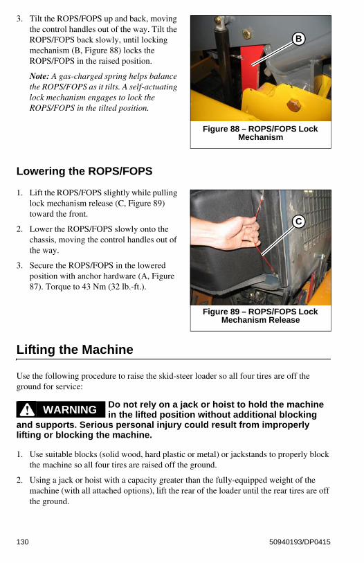
3. Tilt the ROPS/FOPS up and back, moving the control handles out of the way. Tilt the ROPS/FOPS back slowly, until locking mechanism (B, Figure 88) locks the ROPS/FOPS in the raised position.
Note: A gas-charged spring helps balance the ROPS/FOPS as it tilts. A self-actuating lock mechanism engages to lock the ROPS/FOPS in the tilted position.
Lowering the ROPS/FOPS
1. Lift the ROPS/FOPS slightly while pulling lock mechanism release (C, Figure 89) toward the front.
2. Lower the ROPS/FOPS slowly onto the chassis, moving the control handles out of the way.
3. Secure the ROPS/FOPS in the lowered position with anchor hardware (A, Figure 87). Torque to 43 Nm (32 lb.-ft.).
Lifting the Machine
Use the following procedure to raise the skid-steer loader so all four tires are off the ground for service:
Do not rely on a jack or hoist to hold the machine in the lifted position without additional blocking
and supports. Serious personal injury could result from improperly lifting or blocking the machine.
1. Use suitable blocks (solid wood, hard plastic or metal) or jackstands to properly block the machine so all four tires are raised off the ground.
2. Using a jack or hoist with a capacity greater than the fully-equipped weight of the machine (with all attached options), lift the rear of the loader until the rear tires are off the ground.
Figure 88 – ROPS/FOPS Lock Mechanism
B
Figure 89 – ROPS/FOPS Lock Mechanism Release
C
WARNING
130 50940193/DP0415

Important: Be sure the lifting apparatus is of sufficient capacity for the weight of the machine. Refer to “Weights” on page 93. If lifting the machine, refer to “Lifting the Machine Using a Crane or Hoist” on page 115.
3. Stack blocks or place jackstands under the flat part of the loader chassis. Blocks should run parallel with, but not touch, the rear tires.
4. Slowly lower the machine until it rests on the blocks/jackstands. If the tires still touch the ground, raise the machine, add more blocks or raise the jackstands and lower the machine onto the blocks.
5. Repeat this procedure for the front tires. When complete, all four tires will be off the ground so they can be removed.
Lowering the Machine
1. Using a jack or hoist, raise the front of the machine until it no longer rests on the front blocks or jackstands.
2. Carefully remove the blocking under the front of the machine.
3. Slowly lower the machine until the front tires are resting on the ground.
4. Repeat this procedure for the rear tires. When complete, all four tires will be on the ground with the blocks removed from under the machine.
Figure 90 – Lifting Machine
131 50940193/DP0415

Engine Maintenance
Engine Access
1. Lift the engine cover and pull the rear door latch (Z, Figure 91) up.
2. Carefully swing open the rear door.
Note: Rear door prop (Y) near the top hinge pin of the door is used to secure the door open.
3. Additionally, the radiator swings out, providing greater access to the engine:
a. Pull down on spring pin lock (C, Figure 92) to release pin (D). Lift pin (D) out of the bracket.
b. Swing the radiator outward.
c. When engine maintenance is complete, return the radiator back to the closed position and secure it in place with pin (D). Lock pin (D) in the bracket with spring pin lock (C).
Figure 91 – Engine Compart-ment Access
Z
Y
Figure 92 – Radiator Latch
C
D
132 50940193/DP0415

Engine Mounting Hardware InspectionPerform the Mandatory Safety Shutdown Procedure. Allow hot engine and hydraulic system
components to cool before servicing.
All bolts that secure the engine mounting brackets to the engine and the loader frame should be checked and re-tightened as necessary.
Checking Engine Oil LevelCheck the engine oil level daily before starting the machine, or after every 10 hours of use.
1. Park the machine on a level surface.
2. Perform “Mandatory Safety Shutdown Procedure” on page 14.
3. Wait until the engine has cooled.
4. Open the engine access cover and rear door.
5. Twist engine oil dipstick (E, Figure 93) counterclockwise to unlatch it. Remove the dipstick from the engine.
6. Wipe the dipstick with a clean cloth and replace it in the engine. Push it in until it is fully inserted.
7. Remove the dipstick again. The oil level should be within the “Add” (G) and “Full” (H) markings.
8. If the oil level is below the “Add” marking:
a. Clean the area around the oil fill cap (F) with a clean cloth.
b. Remove fill cap (F).
c. Add oil through the fill cap opening until the level reaches the “Full” mark.
d. Replace and tighten fill cap (F).
Important: Do not over-fill the engine with oil; engine damage could result.
Changing Engine Oil and FilterRefer to the “Maintenance Schedules” on page 123 for the service interval for replacing the engine oil and filter.
Important: For new units, the initial oil change should be after the first 50 hours.
1. Park the machine on a level surface.
WARNING
Figure 93 – Engine OIl Dipstick and Fill Cap
EF
G H
133 50940193/DP0415

2. Perform “Mandatory Safety Shutdown Procedure” on page 14.
3. Wait until the engine has cooled, but is not completely cold.
Note: Oil drains faster and more completely when warm.
4. All machines except model R165: Remove the rear belly pan to access engine oil drain plug (X, Figure 94).
5. Position a waste oil collection container under the engine oil drain plug to catch draining oil.
Note: On model R165 machines, engine oil drain plug (A, Figure 95) is located inside the left rear wheel well, on the outside of the chassis behind the left rear wheel.
Important: Dispose waste engine oil according to environmental laws, or take to a recycling center for proper disposal. DO NOT pour waste engine oil onto the ground or down a drain.
6. Remove drain plug (X) or (A) and allow engine oil to drain into the waste oil collection container.
7. Remove oil filter (W, Figure 96), using a filter wrench if necessary. Carefully clean the filter head mounting surface with a clean cloth.
8. Put clean oil on the new oil filter gasket. Install the filter and tighten 3/4 of a turn past the point where the gasket contacts the filter head.
9. Reinstall and tighten the drain plug.
Figure 94 – Engine Oil Drain Plug
X
Figure 95 – Model R165 Remote Engine Oil Drain Plug
Location
A
Figure 96 – Engine Oil Filter
W
134 50940193/DP0415

10. Clean the area around oil fill cap (E, Figure 93). Remove oil fill cap (E) and add the recommended type and amount of oil. See “Fluid Capacities/Lubricants” on page 183. Replace and tighten oil fill cap (E) after the oil is added.
Note: Oil capacity listed is approximate. Always verify proper oil level with the engine oil dipstick.
Important: Do not over-fill the engine with oil; engine damage could result.
11. Start the engine and let it run for several minutes at low idle. Watch for leaks at the oil filter and drain plug. Stop the engine and wait for it to cool.
12. Check the oil level. Add oil if necessary until the oil level is at the “Full” mark (H, Figure 93) on the dipstick.
Fuel System Maintenance
Diesel fuel is flammable. Keep the machine away from open flames. Do not smoke when refueling or
when working on the engine. Stop the engine before fueling.
Wear eye protection. The fuel system is under pressure and fuel could spray out when removing any fuel system component.
Wipe up spills immediately. NEVER use a shop rag to catch draining/leaking fuel. Vapors from the rag are flammable and explosive.
Failure to follow these instructions can cause fire and result in injury or death.
Use only proper types and grades of diesel fuel (See “Fluid Capacities/Lubricants” on page 183).
Note: The fuel tank is filled at the factory with United States off-road grade diesel fuel, which is dyed red for identification. It may take several fillings of the fuel tank before the red dye is purged from the fuel system.
Adding Fuel
Static electricity can produce dangerous sparks at the fuel-filling nozzle. Do not wear polyester, or
polyester-blend clothing while fueling. Before fueling, touch the metal surface of the machine away from the fuel fill to dissipate any built-up static electricity. Do not re-enter the machine but stay near the fuel filling point during refueling to minimize the build-up of static electricity. Do not use cell phones while fueling. Make sure the static line is connected from the machine to the fuel truck before fueling begins.
WARNING
CAUTION
WARNING
135 50940193/DP0415

Ultra-Low Sulfur Diesel (ULSD) poses a greater static ignition hazard than earlier diesel formulations. Avoid death or serious injury from fire or explosion; consult with your fuel or fuel system supplier to ensure the entire fuel delivery system is in compliance with fueling standards for proper grounding and bonding practices.
1. Perform the “Mandatory Safety Shutdown Procedure” on page 14.
2. Lift the engine cover.
3. Using the ignition key to unlock fuel cap (F, Figure 97) and remove the fuel cap from the fuel filler neck.
Note: On Model R135, fuel cap (F) is located under the engine cover.
4. Fill the fuel tank by adding fuel through the fuel filler neck opening.
Important: See “Fluid Capacities/Lubricants” on page 183 and the engine operation manual for proper fuels. Use of improper fuels can cause engine damage.
5. When the fuel tank is full, replace and lock fuel cap (F) in the fuel filler neck opening.
Important: To provide for proper fuel system venting, do not top off the fuel tank.
Water Separator Maintenance
NEVER service the fuel system while smoking, while near an open flame, or if the engine is hot.
Important: Water in the fuel system can cause severe engine damage. Drain water from the fuel filter/water separator whenever water is present.
Inspect the water separator daily, or every day before using the machine.
1. Perform the “Mandatory Safety Shutdown Procedure” on page 14.
2. Wait until the engine has cooled.
Figure 97 – Fuel Filler Cap
F
WARNING
136 50940193/DP0415
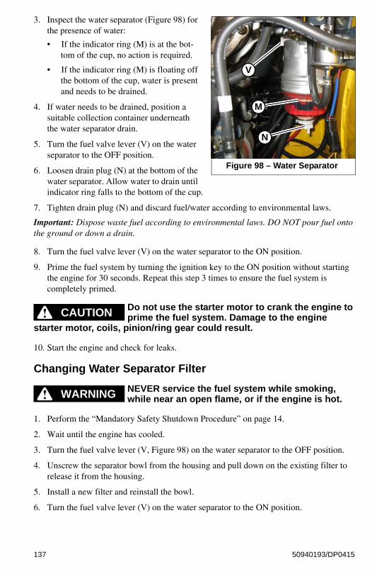
3. Inspect the water separator (Figure 98) for the presence of water:
• If the indicator ring (M) is at the bot-tom of the cup, no action is required.
• If the indicator ring (M) is floating off the bottom of the cup, water is present and needs to be drained.
4. If water needs to be drained, position a suitable collection container underneath the water separator drain.
5. Turn the fuel valve lever (V) on the water separator to the OFF position.
6. Loosen drain plug (N) at the bottom of the water separator. Allow water to drain until indicator ring falls to the bottom of the cup.
7. Tighten drain plug (N) and discard fuel/water according to environmental laws.
Important: Dispose waste fuel according to environmental laws. DO NOT pour fuel onto the ground or down a drain.
8. Turn the fuel valve lever (V) on the water separator to the ON position.
9. Prime the fuel system by turning the ignition key to the ON position without starting the engine for 30 seconds. Repeat this step 3 times to ensure the fuel system is completely primed.
Do not use the starter motor to crank the engine to prime the fuel system. Damage to the engine
starter motor, coils, pinion/ring gear could result.
10. Start the engine and check for leaks.
Changing Water Separator Filter
NEVER service the fuel system while smoking, while near an open flame, or if the engine is hot.
1. Perform the “Mandatory Safety Shutdown Procedure” on page 14.
2. Wait until the engine has cooled.
3. Turn the fuel valve lever (V, Figure 98) on the water separator to the OFF position.
4. Unscrew the separator bowl from the housing and pull down on the existing filter to release it from the housing.
5. Install a new filter and reinstall the bowl.
6. Turn the fuel valve lever (V) on the water separator to the ON position.
Figure 98 – Water Separator
V
M
N
CAUTION
WARNING
137 50940193/DP0415

7. Prime the fuel system by turning the ignition key to the ON position without starting the engine for 30 seconds. Repeat this step 3 times to ensure the fuel system is completely primed.
Do not use the starter motor to crank the engine to prime the fuel system. Damage to the engine
starter motor, coils, pinion/ring gear could result.
8. Start the engine and check for leaks.
Changing Fuel Filter
NEVER service the fuel system while smoking, while near an open flame, or if the engine is hot.
Important: Change the fuel filter every 250 hours of operation.
1. Perform the “Mandatory Safety Shutdown Procedure” on page 14.
2. Wait until the engine has cooled.
3. Turn fuel valve lever (V, Figure 99) on the water separator to the OFF position.
4. Remove the fuel filter (W, Figure 100), using a filter wrench if necessary. Carefully clean the filter head mounting surface with a clean cloth.
5. Apply a coating of clean diesel fuel on the new fuel filter gasket. Install the filter and tighten 3/4 rotation past the point where the gasket contacts the filter head.
6. Turn fuel valve (V, Figure 99) on the water separator to the ON position.
7. Prime the fuel system by turning the ignition key to the ON position without starting the engine for 30 seconds. Repeat this step 3 times to ensure the fuel system is completely primed.
CAUTION
WARNING
Figure 99 – Water Separator
V
Figure 100 – Fuel Filter
W
138 50940193/DP0415

Do not use the starter motor to crank the engine to prime the fuel system. Damage to the engine
starter motor, coils, pinion/ring gear could result.
8. Start the engine and check for leaks.
Engine Air Cleaner
Important: Failure to follow proper air filter servicing instructions could result in catastrophic engine damage.
Do not operate the engine without the air cleaner components installed or damage to the engine could occur.
Check the air cleaner intake hose and clamps, and the mounting bracket hardware daily to be sure they are properly tightened.
Check, and if necessary replace, the engine air filter after every 250 hours of use, or every 6 months, or if the filter is damaged, oil- or soot-laden.
Be sure the air cleaner intake hose, clamps and mounting bracket hardware are properly tightened.
Changing Air Filter Elements
1. Perform the “Mandatory Safety Shutdown Procedure” on page 14.
2. Wait until the engine has cooled.
3. Unlatch clamps (J, Figure 101) on the air cleaner housing and remove the air filter cover (L).
4. Clean debris from inside the air cleaner housing and air filter cover.
5. Carefully remove the outer filter element (G).
6. Clean dirt from inside the air filter housing (M).
Important: To prevent debris from entering the engine intake manifold, do not remove inner filter element (H) while cleaning the inside of the housing.
7. Remove inner filter element (H) only if it needs replacement.
CAUTION
Figure 101 – Engine Air Cleaner
J
L
G
H
M
139 50940193/DP0415

8. Check the inside of the housing for damage.
9. If applicable, install a new inner filter element (H). Make sure the sealing surfaces are clean and the new element is properly seated.
10. Install a new outer filter element (G). Make sure the sealing surfaces are clean and the new element is properly seated.
11. Replace air filter cover (L). Latch clamps (J). Make sure the cover is tightly secured and is seated properly in the housing.
12. Check the air cleaner intake hose, clamps and mounting bracket hardware are properly secured and tightened.
DPF Service (DPF Models)
DPF soot filter replacement is required when the DPF (Diesel Particulate Filter) Service Screen (Figure 102) displays.
Note: Contact your dealer when the DPF Service screen displays.
V-Belt Maintenance
1. Perform the “Mandatory Safety Shutdown Procedure” on page 14.
2. Wait until the engine has cooled.
3. Inspect V-belt (F, Figure 103) for damage. If damaged, have belts replaced by an authorized repair shop.
4. Press on V-belt (F) mid-way between pulleys to check deflection. The belt should not deflect more than 8 mm (5/16 in.).
5. If deflection is more than 8 mm (5/16 in.): Loosen adjustment bolt (G) and rotate alternator (E) outward until V-belt tension is correct. Tighten bolt (G) and re-check V-belt tension.
Figure 102 – Stationary Regenera-tion In-Progress Screen
Figure 103 – V-Belt
G
F
E
140 50940193/DP0415

Cooling System
Important: Check the cooling system every day to prevent overheating, loss of performance or engine damage.
Checking Coolant Level
1. Park the machine on a level surface.
2. Perform the “Mandatory Safety Shutdown Procedure” on page 14.
3. Wait until the engine has cooled.
Do not remove radiator cap when the coolant is hot. Serious burns could result.
4. Check the coolant level in the expansion reservoir (R, Figure 104). Coolant level must be between the full (T) and low (S) marks on the expansion reservoir. Add coolant to the expansion reservoir as required.
Important: The coolant system is specifically designed for coolant level top-off only through the expansion reservoir. Do not add coolant directly to the radiator.
Note: Use a low-silicate ethylene glycol-based coolant, mixed with quality water and supplemental coolant additives (SCAs) suitable for heavy-duty diesel engines. See “Fluid Capacities/Lubricants” on page 183, “Coolant Compound Mixtures” on page 189 and the engine operation manual for additional information.
Cleaning Radiator FinsThe radiator fins can become blocked during use which will lead to reduced cooling function and engine overheating. Clean the radiator cooling fins after every 250 hours or 6 months of operation, whichever occurs first.
1. Perform the “Mandatory Safety Shutdown Procedure” on page 14.
2. Wait until the engine has cooled.
3. Open the rear door. Lift the engine cover.
4. Clean the radiator fins by blowing air/water through the fins from the rear of the radiator, toward the engine.
Important: Use caution! High pressure air/water can damage radiator fins.
WARNING
Figure 104 – Coolant Expansion Reservoir
R
T
S
141 50940193/DP0415

Draining/Flushing Cooling System
1. Perform the “Mandatory Safety Shutdown Procedure” on page 14.
2. Wait until the engine has cooled.
Do not remove radiator cap
when the coolant is hot. Serious burns could result.
3. Slowly loosen radiator cap (P, Figure 105) and allow pressure to escape. Remove cap.
4. Position a suitable collection container, with a minimum capacity of 19 L (4 gals.) underneath the radiator.
5. Remove radiator drain plug (X, Figure 106) underneath the radiator and allow the coolant to drain into the container.
Important: Dispose waste coolant according to environmental laws. DO NOT pour coolant onto the ground or down a drain.
6. Replace the drain plug (X) and tighten securely.
7. Fill the radiator with coolant.
Note: Use a low-silicate ethylene glycol-based coolant, mixed with clean water and supplemental coolant additives (SCAs) suitable for heavy-duty diesel engines. See “Fluid Capacities/Lubricants” on page 183, “Coolant Compound Mixtures” on page 189 and the engine operation manual for additional information.
8. Reinstall radiator cap and tighten securely.
9. Start and run the engine until it reaches operating temperature.
10. Check the coolant level according to “Checking Coolant Level” on page 141.
Hydraulic System
Never use your hands to search for hydraulic fluid leaks; use a piece of paper or cardboard to find
leaks. Escaping fluid under pressure can be invisible and can penetrate the skin, causing serious injury. If any fluid is injected into your skin, see a doctor at once. Injected fluid MUST be surgically removed, or gangrene may result.
WARNING
Figure 105 – Radiator Cap
P
Figure 106 – Radiator Drain
X
WARNING
142 50940193/DP0415

Checking Hydraulic Oil LevelCheck the hydraulic oil level daily before starting the machine, or after every ten hours of use.
1. Perform the “Mandatory Safety Shutdown Procedure” on page 14.
2. Wait until the engine has cooled.
3. Open the engine compartment according to “Engine Access” on page 132.
4. Check the level of the hydraulic oil:
• Models R150/R165: Locate sight gauge (Y, Figure 107) in the left engine compartment wall. The oil level should be in the middle (A) of the sight gauge.
• Model R135: Remove the hydraulic tank filler/dipstick cap (H).
Important: Slowly remove the hydraulic oil fill cap (H). Allow the pressure to escape before completely removing the cap.
Wipe dipstick (X) with a clean cloth and replace it in the filler neck. Push it in until cap (H) is fully seated.
Remove the dipstick again. The oil level should be at the (F) mark.
Figure 107 – Hydraulic Oil Level
AY
Models R150/R165
Models R135
X
F
H
143 50940193/DP0415

5. If the hydraulic oil level is low, remove the hydraulic tank filler cap (H, Figure 108), located in the left engine compartment wall.
Important: Slowly remove the hydraulic oil fill cap (H). Allow the pressure to escape before completely removing the cap.
6. Add hydraulic fluid if required. See “Fluid Capacities/Lubricants” on page 183 for proper hydraulic oil grade and type.
Important: Do not mix different types/grades of hydraulic fluids.
7. Reinstall hydraulic tank filler cap (H) and tighten securely.
Changing Hydraulic Oil Filter
1. Perform the “Mandatory Safety Shutdown Procedure” on page 14.
2. Wait until the engine has cooled.
3. Open the engine compartment according to “Engine Access” on page 132.
4. Place oil pan under the machine to catch the oil.
5. Unscrew and remove hydraulic oil filter (L, Figure 109).
6. Clean the surface of the filter housing where the element seal contacts the housing. Put clean oil on the rubber gasket of the new filter (L).
7. Install and tighten the filter (L) 3/4 of a rotation past the point where the gasket contacts the filter head.
Figure 108 – Hydraulic Oil Fill
H
Figure 109 – Hydraulic Oil Filter
L
144 50940193/DP0415

Changing Hydraulic OilThe hydraulic oil must be replaced if it becomes contaminated, after major repairs, and after 1000 hours or one year of use.
1. Perform the “Mandatory Safety Shutdown Procedure” on page 14.
2. Wait until the engine has cooled.
3. Open the engine compartment according to “Engine Access” on page 132.
4. Slowly loosen hydraulic oil filler cap (H, Figure 108).
5. Position a waste oil collection container with a capacity of at least 60 L (16 gals.) underneath the hydraulic oil reservoir.
Note: The hydraulic reservoir drain plug is accessed from underneath the machine at the left rear corner.
6. Remove the hydraulic reservoir drain plug (O, Figure 110) and allow the oil to drain completely.
Important: Always dispose of hydraulic oil according to environmental laws or take to a recycling center for proper disposal. DO NOT pour onto the ground or down a drain.
7. Unscrew and remove the hydraulic oil filter (L, Figure 109).
8. Clean the surface of the filter housing where the element seal contacts the housing. Put clean oil on the rubber gasket of the new filter (L, Figure 109).
9. Install and tighten the filter (L, Figure 109) 3/4 of a rotation past the point where the gasket contacts the filter head.
10. Reinstall and tighten drain plug (O, Figure 110).
11. Remove hydraulic oil filler cap (H, Figure 108) and fill the hydraulic oil reservoir until the oil level is correct (Y, Figure 107).
Important: See “Fluid Capacities/Lubricants” on page 183 for proper hydraulic oil grade and type. Hydraulic oil capacity listed is approximate. Always verify proper oil level. See to “Checking Engine Oil Level” on page 133.
12. Start the engine and operate the drive, lift and tilt controls.
13. Stop the engine and check for leaks at the filter and reservoir drain plug.
14. Check the fluid level and add fluid if needed.
Figure 110 – Hydraulic Oil Drain Plug
O
145 50940193/DP0415

Hydraulic Hose Maintenance
Hydraulic hoses and connections must be inspected by a trained technician before the first
use of the machine, and at least annually thereafter, for leaks and/or damage.
Leakages and damaged pressure hose/lines must be immediately repaired or replaced by an authorized service center.
Never use your hands to check for suspected hydraulic leaks. Always use a piece of wood or cardboard.
Leaks from hydraulic hoses or pressurized components can be difficult to see, but pressurized oil can have enough force to pierce the skin and cause serious injury.
Obtain immediate medical attention if pressurized oil pierces the skin. Failure to obtain prompt medical assistance could result in gangrene or other serious damage to tissue.
Always relieve hydraulic system pressure before performing any maintenance on the machine. Do not tighten leaking connections when the hydraulic system is under pressure.
Never weld or solder damaged or leaking pressure lines and/or screw connections. Always replace damaged hydraulic components.
Hydraulic hoses must be replaced every six years from the date of manufacture, even if they do not appear damaged. The date of manufacture (month or quarter and year) is indicated on hydraulic hoses. See Figure 111.
WARNING
Figure 111 – Hydraulic Hose Manufacture Date
1 Q/05
146 50940193/DP0415

Chaincases
The chaincase contains the drive sprockets and drive chains. There are two plugs in each chaincase. One is to drain the oil and the other is to check the oil level. Refer to the “Maintenance Schedules” on page 123 for change intervals. See “Fluid Capacities/Lubricants” on page 183 for information on recommended type and amount of oil.
Drive MotorsThe travel drive motors do not require periodic lubrication oil changes because they are lubricated by the oil in the hydraulic system.
Checking and Adding Chaincase Oil
1. Park the machine on a level surface.
2. Perform the “Mandatory Safety Shutdown Procedure” on page 14.
3. Remove check/fill plug (S, Figure 112) from each chaincase housing. If the oil can be reached with the tip of your finger, the oil level is adequate.
4. If the level is low, add oil through the check plug until the oil level reaches the edge of the hole. Reinstall the check/fill (S) plug.
Changing Chaincase Oil
1. Raise the rear of the machine to aid in draining the chaincases.
2. Remove drain plugs (T, Figure 113) on both chaincases and drain the oil into a suitable container(s).
Note: Drain plugs (T) are located inside the tie-down brackets at the bottom front of the machine.
3. Reinstall and tighten drain plugs (T).
4. Refill the chaincases according to “Checking and Adding Chaincase Oil” on page 147.
Figure 112 – Chaincase Fill/Check Plugs
S
Figure 113 – Chaincase Drain Plugs
T
147 50940193/DP0415

Drive Chain TensionDrive chains are located in the chaincase on each side of the machine. See “Maintenance Schedules” on page 123 for chain tension check interval.
Checking Chain Tension
1. Raise the loader according to the “Lifting the Machine” on page 130.
2. Rotate each tire by hand. The proper amount of chain defection should be 3-25 mm (1/8-1 in.) forward and rearward tire movement. If the chain defection is more than 25 mm (1 in.) or less than 3 mm (1/8 in.) in either direction, the chains should be adjusted.
Adjusting Chain Tension
1. Raise the loader according to the “Lifting the Machine” on page 130.
2. Remove the wheel from the axle to be adjusted.
3. Loosen (but DO NOT remove) the bolts holding the axle to the chaincase.
4. Front Chain Tension – To tighten the front chain, move the front axle assembly toward the front of the loader. To loosen the chain, move the front axle assembly toward the rear of the loader. Rear Chain Tension – To tighten the rear chain, move the rear axle assembly rearward. To loosen the chain, move the rear axle assembly toward the front of the loader.
5. After proper tension is achieved, tighten the bolts.
Important: Be careful not to over-tighten the drive chains. Over-tightening will cause premature drive chain and axle sprocket wear.
6. Reinstall the wheel.
7. Repeat this procedure for any other axle requiring adjustment.
8. Lower the loader according to the “Lowering the Machine” on page 131.
Seat and Restraint Bar Switches
Electrical switches in the seat and restraint bar must be closed (operator sitting in the seat and restraint bar lowered) and the auxiliary hydraulics must be in neutral to complete the circuit and start the engine.
Bucket Cutting Edge
The bucket cutting edge should be replaced when it is worn to within 25 mm (1 in.) of the bucket body.
148 50940193/DP0415

Wheel Nuts
Wheel nut torque must be checked before initial operation and every two hours until the wheel mounting hardware torque stabilizes at the following recommended settings:
• Model R135: 161-175 Nm (120-130 lb.-ft)
• Models R150/165: 244 Nm (180 lb.-ft)
Check wheel nut torque every 250 hours thereafter.
When tires are removed and replaced, this procedure must be repeated.
Tires
Rear tires usually wear faster than the front ones. To keep tire wear even, rotate the tires from front to rear and rear to front.
It is important to keep the same size tire on each side of the loader to prevent excessive wear on tires or other damage. If different sizes are used, each tire will be turning at different speeds, causing excessive wear.
The tread bar of all tires must face the same direction.
Mounting Tires
Servicing tires can be dangerous. When possible, trained personnel should service and mount tires.
To avoid possible death or serious injury, follow the safety precautions below.
Important: The tread bars of all tires should point the same direction.
• Be sure the rim is clean and free of rust.
• Lubricate the tire beads and rim flanges with a soap solution. Do not use oil or grease.
• Use a clip-on tire chuck with remote hose and gauge, allowing you to stand clear while inflating the tire. Do not place your fingers on the tire bead or rim during inflation.
• Never inflate beyond 240 kPa (35 psi) to seat the beads. If the beads have not seated by the time the pressure reaches 240 kPa (35 psi), deflate the assembly, reposition the tire on the rim, lubricate both parts and re-inflate. Inflation pressure beyond 240 kPa (35 psi) with unseated beads may break the bead or rim with explosive force sufficient to cause death or serious injury.
• After seating the beads, adjust the inflation pressure to the recommended operating pressure.
• Do not weld, braze or otherwise attempt to repair and use a damaged rim.
WARNING
149 50940193/DP0415

Checking Tire Pressure
Correct tire pressure should be maintained for all tires to enhance operating stability and extend tire life. Refer to the above chart for the proper inflation pressure.
When installing tires, be sure they are the same size and style on each side of the loader. Always replace tires with the same size as the original equipment.
Electrical System
Inspect and check the machine’s electrical equipment at regular intervals. Defects, such as
loose connections or scorched cables much be repaired before using the machine.
Only use proper, original equipment fuses with the specified current rating. Turn off the machine immediately if there are any problems with the electrical system.
Work on the machine’s electrical system must be performed only by a trained technician.
Table 18: Tire Inflation Pressures
Tire SizeInflation Pressure
psi kPa
10.00 x 16.5 10-Ply Severe Duty 65 450
10.00 x 16.5 8-Ply Flotation 60 414
12.00 x 16.5 10-Ply Flotation 65 450
27 x 10.50 x 15 8-Ply 65 450
WARNING
150 50940193/DP0415

Fuses, Relays and DiodesImportant: Blown fuses indicate electrical system malfunctions. Determine what caused the fuse to blow and repair the problem before replacing the fuse.
The fuse, relay and diode boxes are located in the engine compartment, just behind the cab, on the right side of the machine.
.
Table 19: Relay Locations (Figure 115)
Relay Circuit Relay Circuit
A High-speed cab blower fan relay B Horn relay
C Medium-speed cab blower fan relay D Exhaust Gas Recirculation (EGR) relay
E Low-speed cab blower fan relay
Figure 114 – Fuse, Relay and Diode Boxes Location
Fig. 115
Fig. 116
Figure 115 – Relays/Fuses/Diodes Box Map
A
C
E
F
GJ
KP
Q
B
D
HI
LM
N
O
A
C
E
G
FK
J
QP
B
D
H
IL
MN
O
151 50940193/DP0415

Table 20: Fuse Locations (Figure 115)
Fuse
Rated Current /
Resistance (A / Ω)
Circuit Fuse
Rated Current /
Resistance (A / Ω)
Circuit
F 20A Control Keypad G 20A Windshield wiper, Door
H 20A Cab blower fan I 20AElectronic Control Unit (ECU) Note: if required
J 5A Dome light, Radio K 10A Horn, Alarm
L 20AExhaust Gas Recirculation (EGR)
M 20AOperator’s seat switch/optional air suspension
N 3A Electronic display LCD O 5A Hand control buttons
Table 21: Diode Locations (Figure 115)
Diode Circuit Diode Circuit
P Ignition Q EGR Valve (Tier 4)
Table 22: Maxi Fuse Locations (Figure 116)
Fuse
Rated Current /
Resistance (A / Ω)
Circuit Fuse
Rated Current /
Resistance (A / Ω)
Circuit
R 50A Cab heat, Wiper S 80A Glow Plugs
T 60A Starter U 20A Ignition, Accessories
V 50AMicro Controller Unit (MCU)
W 30A Road lights
Figure 116 – Maxi Fuse Box Map
R
T
V
S
U
W
R
T
V
S
U
W
152 50940193/DP0415

.Battery
Before servicing the battery or electrical system, be sure the battery disconnect switch (if equipped)
is in the OFF position. If not equipped with a disconnect switch, disconnect the ground (-) terminal from battery.
The battery on the loader is a 12-volt, wet-cell battery. To access the battery, remove front floor panel.
The battery top must be kept clean. Clean it with an alkaline solution (ammonia or baking soda and water). After foaming has stopped, flush the battery top with clean water. If the terminals and cable connection clamps are corroded or have a build-up, disconnect the cables and clean the terminals and clamps with the same alkaline solution.
Explosive gas is produced while a battery is in use or being charged. Keep flames or sparks away
from the battery area. ALWAYS charge the battery in a well-ventilated area.
Never lay a metal object on top of a battery, because a short circuit can result.
Whenever the battery is removed, be sure to disconnect the negative (-) battery terminal connection first.
Battery acid is harmful on contact with skin or fabrics. If acid spills, follow these first-aid tips:
1. Immediately remove any clothing on which acid spills.
2. If acid contacts the skin, rinse the affected area with running water for 10 to 15 minutes.
3. If acid contacts the eyes, flood the eyes with running water for 10 to 15 minutes. See a doctor at once. Never use any medication or eye drops unless prescribed by the doctor.
4. To neutralize acid spilled on the floor, use one of the following mixtures:
a. 0.5 kg (1 lb.) of baking soda in 4 L (1 gal.) of water.
b. 0.5 L (1 pt.) of household ammonia in 4 L (1 gal.) of water.
WARNING
WARNING
153 50940193/DP0415

Windshield Washer Reservoir
The windshield washer reservoir (E, Figure 117) is located inside the engine compartment. Check the windshield washer reservoir level daily before starting the machine and fill if necessary.
Important: Fill the windshield washer fluid reservoir with clean tap water or windshield washer fluid only. If using tap water, add a cleaning agent if required and/or antifreeze in cold weather.
Long-Term Storage
If storing the machine for a long period (longer than 2 months), perform the procedures in this section.
Before Storage
1. Wash the entire machine. Treat vinyl surfaces in the operator’s compartment with a vinyl protectant.
2. Perform all steps for long-term engine storage according to the engine operation manual.
3. Check tire pressure; adjust to correct pressure, if necessary. See “Tires” on page 149.
4. Lubricate all grease fittings. See “General Lubrication” on page 128.
5. Check all fluid levels and top-off as necessary.
6. Add a fuel stabilizer to the fuel system according to the fuel supplier’s recommendations.
7. If the machine is so equipped, turn the battery disconnect switch to the off position. See “Battery Disconnect Switch (Option)” on page 76.
8. Remove and fully charge the battery. Store the battery in a cool, dry location.
9. If the machine will not be operated for a month or longer, apply grease to all exposed hydraulic cylinder rod areas or retract all cylinders so rod exposure is minimized. Apply grease to any remaining rod areas.
10. Protect against extreme weather conditions such as moisture, sunlight and temperature. Fill the engine coolant system with the proper mix of antifreeze and water as required for expected temperatures according to “Coolant Compound Mixtures” on page 189.
Important: Contact your dealer for additional storage preparation information if the machine will be stored in an environment where temperatures could range below -42°C (-44°F), and/or above 49°C (120°F).
Figure 117 – Windshield Washer Reservoir Fill
E
154 50940193/DP0415

After Storage
1. Replace and re-connect the battery.
2. If the machine is so equipped, turn the battery disconnect switch to the on position. See “Battery Disconnect Switch (Option)” on page 76.
3. Check tire pressure; adjust to correct pressure, if necessary. See “Tires” on page 149.
4. Perform all steps for returning the engine to service according to long-term engine storage section in the engine operation manual.
5. Check V-belt tension. See “V-Belt Maintenance” on page 140.
6. Check all fluid levels and top-off as necessary.
7. Start the engine. Observe all indicators. If all indicators are functioning properly and reading normally, move the machine outside.
8. When outside, park the machine and let the engine idle for at least 5 minutes.
9. Shut off the engine and walk around machine. Make a visual inspection looking for evidence of leaks.
155 50940193/DP0415

Final Shutdown / Decommissioning
Important: Dispose of all materials properly. Used oils/fluids are environmental contaminants and may only be disposed of at approved collection facilities. Never drain any oils/fluids onto the ground, dispose of in municipal waste collection containers, or in metropolitan sewer systems or landfills. Check state and local regulations for other material disposal requirements.
If the machine will no longer be used as intended, shutdown, decommission and dispose of it according to the valid regulations.
Before Disposal
1. Shut down the machine according to valid regulations regarding proper shutdown.
2. Park the machine on level, dry ground. Ensure the surface can support the weight of the machine. Ensure the location is protected against access by unauthorized persons.
3. Move the throttle to the low-idle position and allow the engine to cool for approximately 2 minutes.
4. Shut off the engine.
5. Move the lift/tilt and if equipped, the Power-A-Tach® quick attach control(s) to verify that the controls do not cause movement of the lift arm or hitch.
6. Raise the arm rests/safety bars to apply the parking brake and lock out the hydraulic controls.
7. Switch off all electrical switches.
8. Unfasten the seat belt, remove the ignition key and take it with you.
9. Ensure the machine poses no dangers in the place where it is standing.
10. Ensure the machine cannot be operated after shutdown until further disposal.
11. Ensure no environmentally hazardous materials, fluids and/or fuel can escape the machine.
12. Specifically check for leaks from the engine, the hydraulic system and the coolant system.
13. Remove any dirt and/or debris from the engine compartment, the chassis and the cylinder rod surfaces.
14. Remove the battery.
15. Lock the cab door, the storage compartment, the battery and hydraulic filler compartments and the engine compartment. Remove the key(s) and take it/them with you.
156 50940193/DP0415

Machine DisposalMake sure all materials are disposed of in an ecologically sound manner.
Recycle the machine in accordance with the current state of the art at the time of recycling. Observe all accident prevention regulations.
Dispose of all parts at the at the recycling sites specific to the material of the part. Take care to separate different materials for recycling.
Dealer Services
Service of the following components require special tools, skill and knowledge are not part of normal maintenance and are not included in this manual. Service of these components should only be performed by an authorized dealer:
• Engine service not included in this manual:
• Hydrostatic components.
• Hydraulic system pumps.
• Valves.
• Cylinders.
• Electrical components (other than the battery, relays and fuses).
157 50940193/DP0415

NOTES
158 50940193/DP0415

CHAPTER 7TROUBLESHOOTING
Engine Troubleshooting
Table 23: Engine Troubleshooting
Problem Possible Cause Corrective Action
Engine does not turn over
Blown fuse.Check circuit and replace fuse. See “Fuses, Relays and Diodes” on page 151.
Dead battery.Charge or replace battery—see “Jump-starting” on page 90.
Battery disconnect switch in open position or malfunctioning.
Place battery disconnect switch into closed position— Repair or replace if necessary.
Starter malfunction. Contact dealer.
Operator not in operator’s seat.Operator’s seat must be occupied. for the engine to start.
Malfunctioning seat/restraint bar/door switch.
Replace seat/restraint bar/door switch.
Cab door open (if equipped). Close cab door.
Engine electronics logic error. Contact dealer.
Engine fault code(s) displayed. Identify problem and correct.
159 50940193/DP0415

Engine turns over but will not start
Engine cranking speed too slow.
Check battery and charge/replace as necessary—tighten battery terminals.
In cold temperatures, pre-warm the engine.
Fuel tank empty. Fill tank and vent fuel system if necessary.
Fuel filter plugged or restricted. Change fuel filter.
Fuel paraffin separation in winter.
Use winter grade diesel fuel.
Fuel line leak.Tighten all threaded connections and clamps; replace fuel line as necessary.
Fuel shut-off solenoid not energizing. (interim Tier 4 engines only)
Check electrical connections/voltage to shut-off solenoid.
Fuel filter restricted/fuel hose restriction.
Replace filter/check for pinched fuel hose.
Fuel pump malfunction. Contact dealer.
Water in fuel filter. Purge water from filter.
Fuel valve on water separator in the OFF position.
Turn the valve to the ON position.
Engine fault code(s) displayed. Identify problem and correct.
Engine too cold/ambient temperature too low.
Pre-heating module malfunction; check connection and voltage and charge/replace as necessary. Install block heater.
Engine overheating
Crankcase oil level incorrect.Adjust oil level—see “Fluid Capacities/Lubricants” on page 183 for proper oil grade.
Cooling air circulation restricted.
With engine off, remove restriction.
Fan shroud improperly positioned.
With engine off, reposition shroud/contact dealer.
Improper oil grade or oil excessively dirty.
Change engine oil—see “Fluid Capacities/Lubricants” on page 183 for proper oil grade.
Exhaust restricted. Allow exhaust to cool; remove restriction.
Air filter restricted. Replace filter(s).
Low coolant level.Top off coolant. See “Fluid Capacities/Lubricants” on page 183 for proper coolant mixture.
Loose fan belt. Tighten fan belt.
Dirty/restricted radiator. Clean radiator.
Thermostat malfunction. Replace thermostat.
Table 23: Engine Troubleshooting
Problem Possible Cause Corrective Action
160 50940193/DP0415

Exhaust excessively smoky
Black smoke
Black smoke indicates poor and incomplete diesel fuel combustion, which could be caused by:
• Incorrect timing.• Dirty or worn injectors.• Incorrect valve clearance.• Incorrect air/fuel ratio.• Low cylinder compression.• Dirty air cleaner.• Restricted induction system.• Faulty engine tuning.• Poor quality fuel.• Carbon build-up in combustion and exhaust
spaces.• Cool operating temperatures.
Blue smoke
Blue smoke indicates engine oil combustion, which could be caused by:
• Worn valve guides or seals.• Wear in cylinders, piston rings, ring grooves,
etc.• Cylinder glaze.• Sticking piston ring.• Incorrect engine oil grade.• Fuel dilution in engine oil.
White smoke
White smoke indicates incomplete diesel combustion, or coolant in the combustion chamber, which could be caused by:
• Faulty or damaged injectors.• Incorrect injection timing.• Low cylinder compression.• Faulty head gaskets.• Cracked cylinder heads/blocks.
Table 23: Engine Troubleshooting
Problem Possible Cause Corrective Action
161 50940193/DP0415

Indicator Lamp Troubleshooting
Table 24: Indicator Lamp Troubleshooting
Indicator Icon Indicator Activated Possible Cause Corrective Action
Engine oil pressure
Engine oil pressure too low.
Stop engine immediately; check oil level and top off oil if necessary; check oil pump.
Engine oil level too low.
Top off oil. See “Fluid Capacities/Lubricants” on page 183 for proper oil grade.
Oil pump malfunction. Contact dealer.
Hydraulic oil temperature
Oil temperature is too hot.
Check cooling system for debris in radiator.
Check hydraulic oil level. See “Checking Hydraulic Oil Level” on page 143.
Drive system continuously overloaded.
Improve operation procedure.
Lift/tilt or auxiliary system continuously overloaded.
Improve operation procedure.
Drive motor(s) or hydrostatic pump(s) internal damage/leakage.
Contact dealer.
Hydraulic oil filter restricted.
Replace filter.
Radiator/cooler restricted. Clean radiator/cooler.
Hydraulic oil filterHydraulic oil filter service required.
Replace hydraulic oil and filter. See “Hydraulic System” on page 142NOTE: During cold start in cold temperatures, this indicator may be activated until hydraulic oil warms to operating temperature.
Coolant temperature
Coolant level too low.
Top off coolant. See “Coolant Compound Mixtures” on page 189 for proper coolant mixture.
Air filter plugged.Replace air filter(s). See “Changing Air Filter Elements” on page 139.
Coolant leak.Repair cooling system and top-off coolant.
162 50940193/DP0415

Seal and Hose Troubleshooting
Hydraulic System Troubleshooting
Battery voltageAlternator not charging properly.
Adjust V-belt tension.
Repair/replace alternator.
Engine air filter restrictionAir filter dirty/restricted.
Replace air filter(s). See “Changing Air Filter Elements” on page 139.
Blockage in air filter housing.
Remove blockage.
Table 25: Seal and Hose Troubleshooting
Problem Possible Cause Corrective Action
Oil, coolant or fuel leakage
Loose hose connection(s). Tighten hose connections.
Damaged seals or hoses. Change seals/hoses as necessary.
Hydraulic fluid leakage
Loose fittings. Tighten hydraulic connections.
Seals, hoses or lines damaged.Repair/replace seals, hoses or lines as necessary.
Table 26: Hydraulic System Troubleshooting
Problem Possible Cause Corrective Action
Lift/tilt and drive controls fail to respond
Restraint bar raised. Lower restraint bar.
Solenoid valve malfunctioning.Check electrical connections to pilot solenoid. Repair/replace as necessary.
Hydraulic oil viscosity too heavy.
Replace existing oil with proper viscosity oil. See “Fluid Capacities/Lubricants” on page 183.
Allow longer warm-up.
Hydraulic oil level low.
Check oil level; Top off if necessary. See “Fluid Capacities/Lubricants” on page 183 for proper oil grade.
Check for external leaks; repair/replace as necessary.
Hydraulic oil viscosity too heavy.
Replace existing oil with proper viscosity oil. See “Fluid Capacities/Lubricants” on page 183.
Allow longer warm-up.
Drive coupling failure. Repair/replace coupling.
Table 24: Indicator Lamp Troubleshooting
Indicator Icon Indicator Activated Possible Cause Corrective Action
163 50940193/DP0415

Sluggish hydraulic system performance
Low hydraulic fluid level. Top off hydraulic fluid.
Hydraulic oil viscosity too heavy.
Replace existing oil with proper viscosity oil. See “Fluid Capacities/Lubricants” on page 183.
Allow longer warm-up.
Engine to pump coupling or hydraulic pump damaged.
Contact dealer.
Pressure limiting valves set too low or damaged.
Hydraulic cylinder damaged.
Control valves damaged.
Oil leaking past cylinder/motor seals (internal or external).
Oil leaking past spools in control valve.
Low engine speed. Increase engine speed.
Engine running rough.
Poor fuel quality or incorrect grade. See “Fluid Capacities/Lubricants” on page 183 for proper fuel grade.
Restricted fuel filter/fuel system. Replace fuel filter; remove restriction. See “Changing Fuel Filter” on page 138.
Dirty/restricted air filter(s). Replace filter(s).
Air in hydraulic system.
Cycle lift and tilt cylinders to maximum stroke and maintain pressure for short time to clear air from the hydraulic system. Also check for low oil level in reservoir; top off as necessary.
Worn hydraulic pump. Contact dealer.
Control linkage malfunction. Adjust/repair linkage for full spool travel.
Solenoid valve malfunction.Check solenoid electrical connections; repair as necessary.
Hydraulic system overheating
Hydraulic oil cooler restricted.Clean hydraulic oil cooler. See “Cleaning Radiator Fins” on page 141.
Low hydraulic oil level.Top off hydraulic oil. See “Checking Hydraulic Oil Level” on page 143. See “Fluid Capacities/Lubricants” on page 183 for proper oil grade.
Hydraulic system overloaded. Reduce load.
Table 26: Hydraulic System Troubleshooting
Problem Possible Cause Corrective Action
164 50940193/DP0415

Attachment tilts down with tilt control in neutral
Oil leaking past tilt cylinder seals (internal or external).
Contact dealer.Oil leaking past lift spool in control valve.
Self-leveling valve malfunction.
Leaking hydraulic hoses, tubes or fittings between control valve and cylinders.
Repair as required.
Attachment does not self-level when lift arm is raised
Self-leveling valve malfunction. Contact dealer.
Self-leveling is deactivated.Activate self-leveling. See “Self-Leveling Cancel” on page 102.
Lift arms move down with lift control in neutral
Oil leaking past lift cylinders seals (internal or external).
Contact dealer.Oil leaking past lift spool in control valve.
Self-leveling valve malfunctioning.
Leaking hydraulic hoses, tubes or fittings between control valve and cylinders.
Repair as required.
Lift arm does not raise/lower
Lift spool in control valve not actuated or leaking.
Contact dealer.Hydraulic oil leaking past cylinder piston seals.
Lift arm support engaged. Release lift arm support.
Lift solenoid valve malfunction.Check solenoid electrical connections; repair as necessary.
Restraint bar not lowered. Lower restraint bar.
Seat or restraint bar switch malfunction.
Check switch electrical connections; repair as necessary.
Lift and/or tilt functions inconsistent/jerky
Air in hydraulic system.
Cycle lift and tilt cylinders to maximum stroke and maintain pressure for short time to clear air from the hydraulic system. Also check for low oil level in reservoir; see “Checking Hydraulic Oil Level” on page 143. Top off as necessary.
Low hydraulic oil level.Top off hydraulic oil. See “Checking Hydraulic Oil Level” on page 143. See “Fluid Capacities/Lubricants” on page 183 for proper oil grade.
Cylinder(s) malfunction. Contact dealer.
Seat or restraint bar switch malfunction.
Check electrical connections to switches. Repair as required.
Table 26: Hydraulic System Troubleshooting
Problem Possible Cause Corrective Action
165 50940193/DP0415
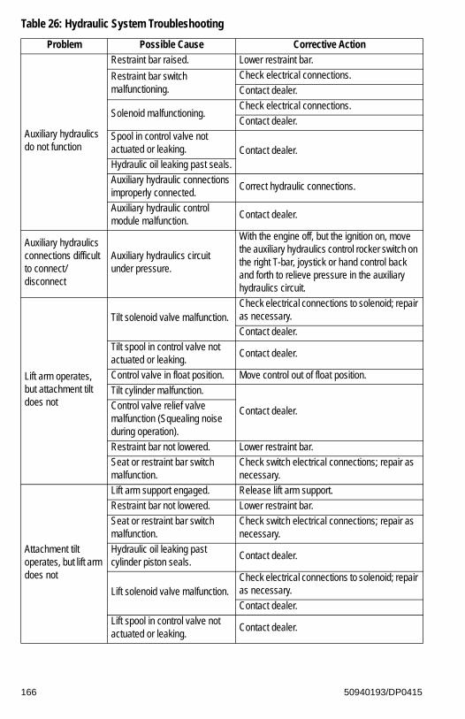
Auxiliary hydraulics do not function
Restraint bar raised. Lower restraint bar.
Restraint bar switch malfunctioning.
Check electrical connections.
Contact dealer.
Solenoid malfunctioning.Check electrical connections.
Contact dealer.
Spool in control valve not actuated or leaking. Contact dealer.Hydraulic oil leaking past seals.
Auxiliary hydraulic connections improperly connected.
Correct hydraulic connections.
Auxiliary hydraulic control module malfunction.
Contact dealer.
Auxiliary hydraulics connections difficult to connect/disconnect
Auxiliary hydraulics circuit under pressure.
With the engine off, but the ignition on, move the auxiliary hydraulics control rocker switch on the right T-bar, joystick or hand control back and forth to relieve pressure in the auxiliary hydraulics circuit.
Lift arm operates, but attachment tilt does not
Tilt solenoid valve malfunction.Check electrical connections to solenoid; repair as necessary.
Contact dealer.
Tilt spool in control valve not actuated or leaking.
Contact dealer.
Control valve in float position. Move control out of float position.
Tilt cylinder malfunction.
Contact dealer.Control valve relief valve malfunction (Squealing noise during operation).
Restraint bar not lowered. Lower restraint bar.
Seat or restraint bar switch malfunction.
Check switch electrical connections; repair as necessary.
Attachment tilt operates, but lift arm does not
Lift arm support engaged. Release lift arm support.
Restraint bar not lowered. Lower restraint bar.
Seat or restraint bar switch malfunction.
Check switch electrical connections; repair as necessary.
Hydraulic oil leaking past cylinder piston seals.
Contact dealer.
Lift solenoid valve malfunction.Check electrical connections to solenoid; repair as necessary.
Contact dealer.
Lift spool in control valve not actuated or leaking.
Contact dealer.
Table 26: Hydraulic System Troubleshooting
Problem Possible Cause Corrective Action
166 50940193/DP0415

Hydrostatic Drive System Troubleshooting
Table 27: Hydrostatic Drive System Troubleshooting
Problem Possible Cause Corrective Action
Travel drive does not operate in either direction
Parking brake is applied. Release parking brake.
Low hydraulic oil level.Top off hydraulic oil. See “Checking Hydraulic Oil Level” on page 143. See “Fluid Capacities/Lubricants” on page 183 for proper oil grade.
Low or no charge pressure.Contact dealer.Hydrostatic pump(s) relief valve
malfunction.
Restraint bar not lowered. Lower restraint bar.
Seat or restraint bar switch malfunction.
Check switch electrical connections; repair as necessary.
Right side drive doesn’t operate in either direction; left side operates normally
Rear hydrostatic pump relief valve malfunction.
Contact dealer.
Rear hydrostatic pump control rod linkage malfunction.
Check linkage connection at control levers and neutral centering mechanisms. Adjust/repair as necessary. Contact dealer.
Right side drive doesn’t operate in one direction
Rear hydrostatic pump relief valve malfunction.
Contact dealer.Rear hydrostatic pump malfunction.
Left side drive doesn’t operate in either direction; right side operates normally
Front hydrostatic pump relief valve malfunction.
Contact dealer.
Linkage front hydrostatic pump control rod linkage malfunction.
Check linkage connection at control levers and neutral centering mechanisms. Adjust/repair as necessary. Contact dealer.
Left side drive doesn’t operate in one direction
Front hydrostatic pump relief valve malfunction.
Contact dealer.Front hydrostatic pump malfunction.
Travel drive system noisy
Hydraulic oil viscosity too heavy.
Replace existing oil with proper viscosity oil. See “Fluid Capacities/Lubricants” on page 183.
Allow longer warm-up.
Low hydraulic oil level.Top off hydraulic oil. See “Checking Hydraulic Oil Level” on page 143. See “Fluid Capacities/Lubricants” on page 183 for proper oil grade.
Air in hydraulic system.
Cycle lift and tilt cylinders to maximum stroke and maintain pressure for short time to clear air from system. Also check for low oil level in reservoir; top off as necessary.
Drive motor(s) or hydrostatic pump(s) internal damage/ leakage.
Contact dealer.
167 50940193/DP0415

Sluggish travel drive acceleration
Low hydraulic oil level.Top off hydraulic oil. See “Checking Hydraulic Oil Level” on page 143. See “Fluid Capacities/Lubricants” on page 183 for proper oil grade.
Low hydrostatic system charge pressure.
Contact dealer.Drive motor or hydrostatic pump internal damage/ leakage.
Air in hydraulic system.
Cycle lift and tilt cylinders to maximum stroke and maintain pressure for short time to clear air from system. Also check for low oil level in reservoir; top off as necessary.
Travel drive overheating
Drive system continuously overloaded.
Improve operation procedure.Lift/tilt or auxiliary system continuously overloaded.
Drive motor(s) or hydrostatic pump(s) internal damage/ leakage.
Contact dealer.
Low hydraulic oil level.Top off hydraulic oil. See “Checking Hydraulic Oil Level” on page 143. See “Fluid Capacities/Lubricants” on page 183 for proper oil grade.
Oil cooler fins restricted. Clean oil cooler fins.
Hydraulic oil filter restricted.Clean hydraulic oil cooler. See “Cleaning Radiator Fins” on page 141.
Right side drive doesn’t operate in either direction. Left side operates normally.
Rear hydrostatic pump relief valve malfunction.
Contact dealer.Rear hydrostatic pump control rod linkage malfunction.
Right side drive doesn’t operate in one direction.
Rear hydrostatic pump relief valve malfunction.
Contact dealer.Rear hydrostatic pump malfunction.
Left side drive doesn’t operate in either direction. Right side operates normally.
Front hydrostatic pump relief valve malfunction.
Contact dealer.Linkage front hydrostatic pump control rod linkage malfunction.
Left side drive doesn’t operate in one direction.
Front hydrostatic pump relief valve malfunction.
Contact dealer.Front hydrostatic pump malfunction.
Table 27: Hydrostatic Drive System Troubleshooting
Problem Possible Cause Corrective Action
168 50940193/DP0415

Electrical Troubleshooting
Table 28: Electrical Troubleshooting
Problem Possible Cause Corrective Action
Electrical system does not function
Battery disconnect switch is in OFF position.
Turn battery disconnect switch to the ON position. See “Battery Disconnect Switch (Option)” on page 76.
Battery terminals or cables loose or corroded.
Clean battery terminals and cables and retighten.
Battery malfunction.Test battery. Recharge/replace as necessary.
Blown main fuse.Correct over-current problem and replace main fuse. See “Fuses, Relays and Diodes” on page 151.
Main wiring harness connectors at rear of ROPS/FOPS not properly plugged in.
Check main harness connectors. Reconnect/repair as needed.
Control pad and information center display do not activate with ignition keyswitch in the ON/RUN position
Blown fuse.Check circuit and replace fuse. See “Fuses, Relays and Diodes” on page 151.
Battery terminals/cables loose/corroded.
Clean battery terminals and cables and tighten.
Main wiring harness connectors at rear of ROPS/FOPS not properly plugged in.
Check main harness connectors. Reconnect/repair as needed.
Starter does not engage when ignition keyswitch turned to the START position
Poor electrical connections in start circuit.
Check connections repair as necessary.
Battery terminals/cables loose/corroded.
Clean battery terminals and cables and tighten.
Starter relay malfunction.Test relay; replace if necessary. Contact dealer.
Battery discharged/malfunctioning.
Test battery. Recharge/replace if necessary.
Starter solenoid malfunction. Contact dealer.
Starter or pinion malfunctioning.
Repair/replace as needed.
Ignition wiring, seat switch, restraint bar switch, etc. loose or disconnected.
Check wiring for poor connections, broken leads; repair wiring or connection.
Restraint bar raised. Lower restraint bar.
Engine fault code(s). Contact dealer.
169 50940193/DP0415

Fuel gauge inoperative
Fuel level sender malfunction. Replace fuel level sender.
Loose wiring/terminal connections.
Check wiring connections.
Blown fuse.Check circuit and replace fuse. See “Fuses, Relays and Diodes” on page 151.
Fuel gage malfunction. Replace gauge.
Coolant temperature gauge inoperative
Temperature sender malfunction.
Replace temperature sender.
Loose wiring/terminal connections.
Check wiring connections.
Blown fuse.Check circuit and replace fuse. See “Fuses, Relays and Diodes” on page 151.
Coolant temperature gage malfunction.
Replace gauge.
Hour meter inoperative
Loose wiring/terminal connections.
Check wiring/connections.
Alternator malfunction. Repair/replace alternator.
Hour meter malfunction. Replace information center electronic display.
Work/road lights inoperative
Single light not working— light bulb burned out, faulty wiring.
Check and replace light bulb as needed, check wiring connections.
No lights—blown fuse.Check circuit and replace fuse. See “Fuses, Relays and Diodes” on page 151.
Light switch malfunction, poor ground or other wiring connection.
Check ground/wire connections, replace light switch.
Lift/tilt and/or drive lock solenoid malfunction
Solenoid wiring disconnected or faulty.
Check circuit; repair as necessary.
Seat or restraint bar switch malfunction.
Contact dealer.Solenoid valve coil malfunction.
Instrument panel hydraulic solenoid relay malfunction.
Table 28: Electrical Troubleshooting
Problem Possible Cause Corrective Action
170 50940193/DP0415

Error Codes
The tables in this section describe error codes which may be reported on the information center electronic display screens DM1 and DM2. More than one error can be reported at one time and may be display on more than one screen. See page 58.
Engine Diagnostic Trouble Codes (DTC)
Table 29: Yanmar Engine Diagnostic Trouble Codes (DTC)
DTC Error Item
SPN FMI P-Code Part State
28
0 P1126 Acceleration Sensor 3Sensor failure (foot pedal in open position)
1 P1125 Acceleration Sensor 3Sensor failure (foot pedal in closed position)
2 P0224 Acceleration Sensor 3 Intermittent fault
3 P0223 Acceleration Sensor 2 Acceleration sensor 2 fault (high voltage)
4 P0222 Acceleration Sensor 2 Acceleration sensor 2 fault (low voltage)
29
0 P1226Accelerator Pedal Position Sensor "B"
Above normal operation range
1 P1225Accelerator Pedal Position Sensor "B"
Below normal operation range
3P0227 Acceleration Sensor 3 Acceleration sensor 3 fault (high voltage)
P0228 Acceleration Sensor 3 Acceleration sensor 3 fault (high voltage)
8P1127 Acceleration Sensor 3 Sensor failure (pulse communication)
P1227Accelerator Pedal Position Sensor "B”
Communication fault
15 P1228Accelerator Pedal Position Sensor "B"
Not available
513 P02E9
Intake Throttle Opening Sensor
Intake throttle opening sensor fault (high voltage)
4 P02E8Intake Throttle Opening Sensor
Intake throttle opening sensor fault (low voltage)
91
2 P0124 Acceleration Sensor 1 Intermittent Fault
3 P0123 Acceleration Sensor 1 Acceleration sensor 1 fault (high voltage)
4 P0122 Acceleration Sensor 1 Acceleration sensor 1 fault (low voltage)
1001 P1198 Oil Pressure Switch Low oil pressure fault alarm
4 P1192 Oil Pressure Switch Oil pressure switch open circuit
102
3 P0238EGR Low Pressure Side Sensor
EGR low pressure side sensor fault (high voltage)
4 P0237EGR Low Pressure Side Sensor
EGR low pressure side sensor fault (low voltage)
13 P0236EGR Low Pressure Side Sensor
Abnormal learning value
171 50940193/DP0415

1053 P040D
Intake Air Temperature Sensor
Intake air temperature sensor fault (high voltage)
4 P040CIntake Air Temperature Sensor
Intake air temperature sensor fault (low voltage)
108
2 P2230 Barometric Pressure Sensor Intermittent fault
3 P2229Atmospheric Pressure Sensor
Atmospheric pressure sensor fault (high voltage)
4 P2228Atmospheric Pressure Sensor
Atmospheric pressure sensor fault (low voltage)
10 P1231Atmospheric Pressure Sensor
Atmospheric pressure sensor characteristic fault
110
0 P0217Cooling Water Temperature Sensor
Cooling water temperature sensor temperature abnormally high (overheat)
2 P0119Cooling Water Temperature Sensor
Intermittent fault
3 P0118Cooling Water Temperature Sensor
Cooling water temperature sensor fault (high voltage)
4 P0117Cooling Water Temperature Sensor
Cooling water temperature sensor fault (low voltage)
157
0 P0088 Abnormal Rail Pressure Actual rail pressure rise error
3 P0193 Rail Pressure Sensor Rail pressure sensor (high voltage)
4 P0192 Rail Pressure Sensor Rail pressure sensor (low voltage)
15 P0093 Abnormal Rail PressureRail pressure deviation error during the actual rail pressure rise
16 P000FPLV (Common Rail Pressure Limit Value)
PLV open valve
18 P0094 Abnormal Rail PressureRail pressure deviation error during the actual rail pressure drop
1580 P0563 System Voltage Too high
1 P0562 System Voltage Too low
1671 P1568 Charge Switch Charge alarm
5 P1562 Charge Switch Charge switch open circuit
1723 P0113
New Air Temperature Sensor
New air temperature sensor fault (high voltage)
4 P0112New Air Temperature Sensor
New air temperature sensor fault (low voltage)
1733 P0546
Exhaust Air Temperature Sensor
Exhaust air temperature sensor fault (high voltage)
4 P0545Exhaust Air Temperature Sensor
Exhaust air temperature sensor fault (high voltage)
Table 29: Yanmar Engine Diagnostic Trouble Codes (DTC)
DTC Error Item
SPN FMI P-Code Part State
172 50940193/DP0415

174
0 P0168 Fuel Temperature SensorFuel temperature sensor temperature abnormally high
3 P0183 Fuel Temperature SensorFuel temperature sensor fault (high voltage)
4 P0182 Fuel Temperature SensorFuel temperature sensor fault (low voltage)
190 16 P0219 Overspeed Overspeed
23713 U3002 CAN 2 VI (CAN message) reception data fault
31 U0168 CAN 2VI (CAN message) reception time-out error
4123 P041D
EGR Gas Temperature Sensor
EGR gas temperature sensor fault (high voltage)
4 P041CEGR Gas Temperature Sensor
EGR gas temperature sensor fault (low voltage)
6282
P1605 ECU Internal FaultFlashROM checksum error (data sheet 1)
P1606 ECU Internal FaultFlashROM checksum error (data sheet 2)
12 P0605 ECU Internal MalfunctionFlashROM checksum error (main software)
6302 P1601 ECU Internal Fault EEPROM error
12 P0601 EEPROM EEPROM memory deletion error
633
3 P0629 SCV (MPROP) SCV (MPROP) high side VB short-circuit
5 P0627 SCV (MPROP) SCV (MPROP) open circuit
6 P1642 SCV (MPROP)SCV (MPROP) high side GND short-circuit
638
2 P1214 Engine Malfunction
3 P1213Engine Fuel Rack Position Actuator
Shorted to high source
4 P1212Engine Fuel Rack Position Actuator
Shorted to low source
7 P1211Engine Fuel Rack Position Actuator
Mechanical malfunction
639 12 U0001 High Speed CAN Communication fault
651
3 P1271Injector 1 (Cylinder Number 4)
Injector 1 short-circuit
5 P0204Injector 1 (Cylinder Number 4)
Injector 1 open circuit (inherent location of the injector)
6 P0271Injector 1 (Cylinder Number 4)
Injector 1 coil short-circuit
11 P0272Injector 1 (Cylinder Number 4)
Injector 1 unclassified
Table 29: Yanmar Engine Diagnostic Trouble Codes (DTC)
DTC Error Item
SPN FMI P-Code Part State
173 50940193/DP0415

652
3P1262
Injector 1 (Cylinder Number 3)
Injector 1 short circuit
P1268Injector 4 (Cylinder Number 3)
Injector 4 short-circuit
5P0203
Injector 1 (Cylinder Number 3))
Injector 1 open circuit (inherent location of the Injector)
P0203Injector 4 (Cylinder Number 3)
Injector 4 open circuit (inherent location of the injector)
6P0268
Injector 1 (Cylinder Number 3)
Injector 1 coil short circuit
P0268Injector 4 (Cylinder Number 3)
Injector 4 coil short-circuit
11P1263
Injector 1 (Cylinder Number 3)
Injector 1 unclassified
P1269Injector 4 (Cylinder Number 3)
Injector 4 unclassified
653
3 P1265Injector 2 (Cylinder Number 2)
Injector 2 short-circuit
5 P0202Injector 2 (Cylinder Number 2)
Injector 2 open circuit (inherent location of the injector)
6 P0265Injector 2 (Cylinder Number 2)
Injector 2 coil short-circuit
11 P1266Injector 2 (Cylinder Number 2)
Injector 2 unclassified
654
3 P1262Injector 3 (Cylinder Number 1)
Injector 3 short-circuit
5 P0201Injector 3 (Cylinder Number 1)
Injector 3 open circuit (inherent location of the injector)
6 P0262Injector 3 (Cylinder Number 1)
Injector 3 coil short-circuit
11 P1263Injector 3 (Cylinder Number 1)
Injector 3 unclassified
1078 4 P0340Fuel Injection Pump Speed Sensor
Shorted to low source
1079
2 P1644 Sensor 5V Intermittent fault
3 P0643 Sensor 5V Shorted to high source
4 P0642 Sensor 5V Shorted to low source
Table 29: Yanmar Engine Diagnostic Trouble Codes (DTC)
DTC Error Item
SPN FMI P-Code Part State
174 50940193/DP0415

1136
0 P0634 ECU Internal Temperature Too high
2 P1664ECU Internal Temperature Sensor
Intermittent fault
3 P0669ECU Internal Temperature Sensor
Shorted to high source
4 P0668ECU Internal Temperature Sensor
Shorted to low source
1202 2 U423 Immobilizer System fault
1209
3 P0473EGR High Pressure Side Sensor
EGR low pressure side sensor fault (high voltage)
4 P0472EGR High Pressure Side Sensor
EGR low pressure side sensor fault (low voltage)
13 P0471EGR High Pressure Side Sensor
Abnormal learning value
12103 P1203
Engine Fuel Rack Position Sensor
Shorted to high source
4 P1202Engine Fuel Rack Position Sensor
Shorted to low source
1485
2 P068A Main RelayPower off without main relay self-holding / Main relay early opening
4 P0686 ECU Main Relay Shorted to low source
7 P068B Main Relay Main relay contact stuck
2791
0 P0404 EGR Valve EGR over-voltage malfunction
1 P1404 EGR Valve EGR low voltage malfunction
7 P1409 EGR Valve EGR feedback malfunction
9 U0401 EGR Valve EGR ECM data fault
12 P0403 EGR ValveOpen circuit between the EGR motor coils
2797 6 P1146 Injector (Common)Injector drive circuit (bank 1) short-circuit (common circuit for number 1, number 4)
2798 6 P1149 Injector (Common)Injector drive circuit (bank 2) short-circuit (common circuit for number 2, number 3)
2950
3 P1658 Intake Throttle Drive CircuitPower short-circuit of throttle valve drive H bridge output 1
4 P1659 Intake Throttle Drive CircuitGND short-circuit of throttle valve drive H bridge output 1
5 P0660 Intake Throttle Drive CircuitNo-load of throttle valve drive H bridge circuit
6 P1660 Intake Throttle Drive CircuitOverload on the drive H bridge circuit of the throttle valve
Table 29: Yanmar Engine Diagnostic Trouble Codes (DTC)
DTC Error Item
SPN FMI P-Code Part State
175 50940193/DP0415

29513 P1661 Intake Throttle Drive Circuit
VB power short-circuit of throttle valve drive H bridge output 2
4 P1662 Intake Throttle Drive CircuitGND short-circuit of throttle valve drive H bridge output 2
3242
0 P1436DPF Inlet Temperature Sensor
DPF inlet temperature sensor temperature abnormally high
3 P1428DPF Inlet Temperature Sensor
DPF inlet temperature sensor fault (high voltage)
4 P1427DPF Inlet Temperature Sensor
DPF inlet temperature sensor fault (low voltage)
3250
0 P1426DPF Intermediate Temperature Sensor
DPF intermediate temperature sensor temperature abnormally high (post-injection failure)
1 P0420DPF Intermediate Temperature Sensor
DPF intermediate temperature sensor temperature abnormally low
3 P1434DPF Intermediate Temperature Sensor
DPF intermediate temperature sensor fault (high voltage)
4 P1435DPF Intermediate Temperature Sensor
DPF intermediate temperature sensor fault (low voltage)
3251
0 P2452DPF Differential Pressure Sensor
DPF differential pressure sensor differential pressure abnormally high
3 P2455DPF Differential Pressure Sensor
DPF differential pressure sensor fault (high voltage)
4 P2454DPF Differential Pressure Sensor
DPF differential pressure sensor fault (low voltage)
13 P2453DPF Differential Pressure Sensor
Abnormal learning value
36093 P1455 DPF High Pressure Sensor
DPF high pressure side sensor fault (high voltage)
4 P1454 DPF High Pressure SensorDPF high pressure side sensor fault (low voltage)
3719
0 P1424 DPF OP Interface Backup mode
7 P1446 DPF OP Interface Recovery regeneration prohibition
9 P1445 DPF OP Interface Recovery regeneration failure
16 P1421 DPF OP Interface Stationary regeneration standby
37200 P1420 DPF OP Interface Ash cleaning request 2
16 P242F DPF OP Interface Ash cleaning request 1
4257 12 P0611 Injector (Common) Injector drive IC error
37251 16 P1437 DPFMaintenance (maintenance not performed for a given period of time)
Table 29: Yanmar Engine Diagnostic Trouble Codes (DTC)
DTC Error Item
SPN FMI P-Code Part State
176 50940193/DP0415

522241
2 P1224Engine Fuel Rack Actuator Relay
Intermittent fault
3 P1223Engine Fuel Rack Actuator Relay
Circuit fault B
4 P1222Engine Fuel Rack Actuator Relay
Circuit fault A
7 P1221 Reserved N/A
522242
2 P1244 Cold Start Device Intermittent fault
3 P1243 Cold Start Device Circuit fault B
4 P1242 Cold Start Device Circuit fault A
522243
2 P1234 Air Heater Relay Intermittent fault
3 P1233 Air Heater Relay Circuit fault B
4 P1232 Air Heater Relay Circuit fault A
5 P0543 Start Auxiliary Relay Start auxiliary relay interrupted
6 P0541 Start Auxiliary Relay Start auxiliary relay GDN interrupted
5222513 P1403 EGR Stepping Motor "A" Circuit fault B
4 P1402 EGR Stepping Motor "A" Circuit fault A
5222523 P1413 EGR Stepping Motor "B" Circuit fault B
4 P1412 EGR Stepping Motor "B" Circuit fault A
5222533 P1423 EGR Stepping Motor "C" Circuit fault B
4 P1422 EGR Stepping Motor "C" Circuit fault A
5222543 P1433 EGR Stepping Motor "D" Circuit fault B
4 P1432 EGR Stepping Motor "D" Circuit fault A
522314 0 P1217Engine Coolant Temperature
Abnormal temperature
522323 0 P1101 Air Cleaner Switch Air cleaner clogged alarm
522329 0 P1151 Oil/Water Separator switch Oil/water separator alarm
5224002 P0336 Crank Sensor Crank signal malfunction
5 P0037 Crank Sensor No crank signal
522401
2 P0341 Cam Sensor Cam signal malfunction
5 P0342 Cam Sensor No cam signal
7 P1341 Cam Sensor Angle offset failure
522402 4 P1340 Aux Speed Sensor Shorted to low source
522567 12 U1401 EGR EGR target value out of range
5225713 P1641 SCV (MPROP) SCV (MPROP) low side VB short-circuit
6 P1643 SCV (MPROP)SCV (MPROP) low side GND short-circuit
Table 29: Yanmar Engine Diagnostic Trouble Codes (DTC)
DTC Error Item
SPN FMI P-Code Part State
177 50940193/DP0415

5225726 P062A SCV (MPROP)
High-pressure pump drive circuit (drive current [high level])
11 P1645 SCV (MPROP)High-pressure pump drive circuit (pump overload error)
522573 0 P2463 DPF Over-accumulation (method C)
522574 0 P1463 DPF Over-accumulation (method P)
522575 7 P2458 DPFRegeneration defect (stationary regeneration failure)
522576 12 P160E EEPROM EEPROM memory read error
522577 11 P2459 DPFRegeneration defect (stationary regeneration not performed)
522578 12 P160F EEPROM EEPROM memory write error
522579 12 P1405 EGRShort-circuit between the EGR motor coils
522580 12 P0488 EGR EGR position sensor malfunction
522581 7 P148A EGR EGR stuck open valve malfunction
522582 7 P049D EGR EGR initialization malfunction
522583 1 P1410 EGREGR high temperature thermistor malfunction
522584 1 P1411 EGREGR low temperature thermistor malfunction
522585 12 P1613 ECU Internal Malfunction CY146 SPE/SPI communication error
522588 12 P1608 ECU Internal Malfunction Excessive supply 1 voltage error
522589 12 P1617 ECU Internal MalfunctionDropped/Insufficient supply 1 voltage error
522590 12 P1609 ECU Internal Malfunction Sensor supply voltage error 1
522591 12 P1618 ECU Internal Malfunction Sensor supply voltage error 2
522592 12 P1619 ECU Internal Malfunction Sensor supply voltage error 3
522593 12 P1624 ECU Internal Malfunction Power for sensor SRC low error
522594 3 P160A ECU Internal Malfunction Actuator drive circuit 1 VB short-circuit
522595 3 P1625 ECU Internal Malfunction Actuator drive circuit 2 VB short-circuit
522596 9 U0292 CAN 2TSC1 (CAN message) reception time out (SA1)
522597 9 U1301 CAN 2TSC1 (CAN message) reception time out (SA2)
522598 11 P160B ECU Internal Malfunction SW reset (recovery) execution 1
5225999 U1292 CAN 2
Y_ECR1 (CAN message) reception time out error
11 P1636 ECU Internal Malfunction SW reset (recovery) execution 2
Table 29: Yanmar Engine Diagnostic Trouble Codes (DTC)
DTC Error Item
SPN FMI P-Code Part State
178 50940193/DP0415

5226009 U1293 CAN 2
Y_EC (CAN message) reception time out error
11 P1637 ECU Internal Malfunction SW reset (recovery) execution 3
5226019 U1294 CAN 2
Y_RSS (CAN message) reception time out error
12 P160D ECU Internal MalfunctionWDA/ABE shut off due to dropped voltage
522602 12 P1639 ECU Internal MalfunctionWDA/ABE shut off due to excessive voltage
5226039 U1296 CAN 2 VH (CAN message) reception time out
12 P1640 ECU Internal MalfunctionWDA/ABE shut off due to unknown cause
522605 9 U1298 CAN 2Y_ECM3 (CAN message) reception time out
522609 9 U1300 CAN 2Y_ETCP1 (CAN message) reception time out
5226109 U101B CAN 1
CAN1 (for EGR): Reception time out error
19 U040C EGRCAN1 (for EGR): Reception data length error
522611 9 U1107 CAN1 / Exhaust ThrottleExhaust throttle (CAN message from the exhaust throttle time out)
522617 12 U1401 EGR Valve EGR target value out of range
522618 9 U1302 CAN 2EBC1 (CAN message) Reception time out error
522619 9 U1303 CAN 2Y_DPFIF (CAN message) reception time out
522623 7 P1647 Acceleration Sensor 1/2 Dual accelerator sensor (open position)
522624 7 P1646 Acceleration Sensor 1/2 Dual accelerator sensor (closed position)
522727
12 P1610 ECU Internal Fault Sub-CPU error A
12 P1611 ECU Internal Fault Sub-CPU error B
12 P1612 ECU Internal Fault Sub-CPU error C
522728 12 P1620 ECU Internal Fault Engine map data version error
5227308 U1167 Immobilizer Pulse communication fault
12 U0167 Immobilizer Communication fault
522744 4 P1626 ECU Internal Malfunction Actuator drive circuit 1 GND short-circuit
522746 12 P1438 Exhaust Throttle Voltage fault
522747 12 P1439 Exhaust Throttle Motor fault
522748 12 P1440 Exhaust Throttle Sensor system fault
522749 12 P1441 Exhaust Throttle MPU fault
522750 12 P1442 Exhaust Throttle PCB fault
Table 29: Yanmar Engine Diagnostic Trouble Codes (DTC)
DTC Error Item
SPN FMI P-Code Part State
179 50940193/DP0415

522751 19 P1443 Exhaust Throttle CAN fault
522994
4 P1633 ECU Internal Malfunction Actuator drive circuit 2 GND short-circuit
12 P1607 ECU Internal Malfunction WDA/ABE communication error
12 P1615 ECU Internal Malfunction CY320 SPI communication error
12 P1616 ECU Internal Malfunction MSC communication error of R2S2
523249 5 P0008 Cam Sensor No signal from both sensors
523460 7 P1670Rail Pressure Control/Sensor
Rail pressure fault (operation time error during RPS limp mode)
523462 13 P1648 Injector (Correction Value)IQA corrected injection amount for injector 1
523463 13 P1649 Injector (Correction Value)IQA corrected injection amount for injector 2
523464 13 P1650 Injector (Correction Value)IQA corrected injection amount for injector 3
523465 13 P1651 Injector (Correction Value)IQA corrected injection amount for injector 4
523468 9 P1665PLV (Common Rail Pressure Limit Value); Rail Pressure Sensor
Rail pressure fault (controlled rail pressure error after PLV valve opening)
523469 0 P1666 Rail Pressure SensorRail pressure fault (PLV opening timing error)
523470 0 P1667 Rail Pressure SensorRail pressure fault (PLV opening timing error)
523471 6 P1467 ECU Internal Malfunction Actuator drive circuit 3 GND short-circuit
523473 12 P1469 ECU Internal Malfunction AD converter fault 1
523474 12 P1470 ECU Internal Malfunction AD converter fault 2
523475 12 P1471 ECU Internal Malfunction External monitoring IC and CPU fault 1
523476 12 P1472 ECU Internal Malfunction External monitoring IC and CPU fault 2
523477 12 P1473 ECU Internal Malfunction ROM fault
523478 12 P1474 ECU Internal Malfunction Shutoff path fault 1
523479 12 P1475 ECU Internal Malfunction Shutoff path fault 2
523480 12 P1476 ECU Internal Malfunction Shutoff path fault 3
523481 12 P1477 ECU Internal Malfunction Shutoff path fault 4
523482 12 P1478 ECU Internal Malfunction Shutoff path fault 5
523483 12 P1479 ECU Internal Malfunction Shutoff path fault 6
523484 12 P1480 ECU Internal Malfunction Shutoff path fault 7
523485 12 P1481 ECU Internal Malfunction Shutoff path fault 8
523486 12 P1482 ECU Internal Malfunction Shutoff path fault 9
523487 12 P1483 ECU Internal Malfunction Shutoff path fault 10
523488 0 P1484 ECU Internal Malfunction Recognition error of engine speed
Table 29: Yanmar Engine Diagnostic Trouble Codes (DTC)
DTC Error Item
SPN FMI P-Code Part State
180 50940193/DP0415

523489 0 P1668PLV (Common Rail Pressure Limit Value); Rail Pressure Sensor
Rail pressure fault (the actual rail pressure is too high during PRV limp mode)
543491 0 P1669Rail Pressure Control/Sensor
Rail pressure fault (injector B/F temp error during PLV4 limp home)
Table 29: Yanmar Engine Diagnostic Trouble Codes (DTC)
DTC Error Item
SPN FMI P-Code Part State
181 50940193/DP0415

182 50940193/DP0415
NOTES

CHAPTER 8SPECIFICATIONS
Fluid Capacities/Lubricants
Table 30: Fluid Capacities/Lubricants
Component/Application
Type R135 R150 R165
Engine Oil (with filter)
Refer to the Engine Operator’s Manual for specific engine oil
recommendations.
Service Classification: API-CJ-4 SM
6.7 L (7.1 qts) (w/out filter) 9.5 L (10 qts)
Hydraulic Oil Tank
Petro Canada HVI60, Mobil DTE 15M or equivalent, which contain anti-rust, anti-foam and
anti-oxidation additives, and conforms to ISO VG46.
HVLPD 46 (HYD0530)
Biodegradable oil: AVILUB Syntofluid
46; PANOLIN HLP Synth 46
37.9 L (10 gal.) 41.6 L (11 gal.)
Hydraulic System – Total
53.0 L (14 gal.) 56.8 L (15 gal.)
Grease Fittings, Lift Arm
Lithium-saponified, brand-name multi-purpose grease
MPG-AAs Required
Battery Terminals
SP-B acid-proof grease As Required
-22 -13 -4 5 14 32°F 41 50 59 68 77 86
-30 -25 -20 -15 -10 0°C
23
-5 5 10 15 20 25 30
5W - 305W - 40
10W - 3010W - 40
5W - 40
183 50940193/DP0415

Diesel Fuel Tank
DPF Models:
ULSDa ultra-low sulfur only, below 15 PPM.
ASTM D975 with biodiesel content limited to 5% of DIN EN14214 type (no additives
allowed!)
62.5 L (16.5 gal.)Non-DPF Models:
ASTM D975-94 (no additives allowed!)
DIN EN14214 Biodiesel (no additives allowed!)
LSD or ULSDa low sulfur or ultra-low sulfur, below 500
PPM. Up to 5% (B5) mixture of BioDiesel allowed
Engine Coolant
Long life coolant ASTM D4985, D6210 (United States) SAE
J814C, J1941, J1034 or J2036 (international)
(See “Coolant Compound Mixtures” on page 189)
9.5 L (2.5 gal.) 14.4 L (3.8 gal.)
Radiator Cap Pressure
N/A 1.10 bar (16 psi)
Chaincase (each)
SAE grade 10W-30 motor oil 7.1 L (7.5 qts.) 9.5 L (10 qts.)
Motor Gearbox Drive motor mechanism lubricated by hydraulic system oil.
a. Ultra-Low Sulfur Diesel (ULSD) fuel lubricity must have a maximum scar diameter of 0.45 mm, as measured by ASTM D6079 or ISO 12156-1, or a minimum of 3100 grams as measured by ASTM D6078. Contact your fuel supplier for details. Specification 1-D S15 or 2-D S15, ASTM D975.
Table 30: Fluid Capacities/Lubricants
Component/Application
Type R135 R150 R165
184 50940193/DP0415

Weights
Table 31: Weights
R135 R150 R165
Operating Weight (without counterweight)2327 kg
(5130 lbs.)2690 kg
(5930 lbs.)2796 kg
(6165 lbs.)
Operating Weight (with counterweight)2424 kg
(5345 lbs.)2783 kg
(6135 lbs.)2887 kg
(6365 lbs.)
Shipping Weight (without counterweight)a
a. Without operator and bucket; with 10% fuel.
2073 kg(4570 lbs.)
2422 kg(5340 lbs.)
2529 kg(5575 lbs.)
Shipping Weight (with counterweight)2170 kg
(4785 lbs.)2515 kg
(5545 lbs.)2619 kg
(5775 lbs.)
185 50940193/DP0415

Payloads/Capacities
Note: Refer to “Common Materials and Densities” on page 195 for selecting the appropriate bucket.
Table 32: Payloads/Capacities (General)
R135 R150 R165
Rated Operating Load(w/o Counterweight)
612 kg (1350 lbs.) 680 kg (1500 lbs.) 748 kg (1650 lbs.)
Rated Operating Load(with Counterweight)
680 kg (1500 lbs.) 748 kg (1650 lbs.) 816.5 kg (1800 lbs.)
SAE Tipping Load(w/o Counterweight)
1225 kg (2700 lbs.) 1373 kg (3027 lbs.) 1486 kg (3275 lbs.)
SAE Tipping Load(with Counterweight
1358 kg (2994 lbs.) 1506 kg (3320 lbs.) 1629 kg (3591 lbs.)
SAE Breakout Force – Tilt(w/o Counterweight)
1320 kg (2910 lbs.) 2059 kg (4540 lbs.) 2082 kg (4591 lbs.)
SAE Breakout Force – Lift
(w/o Counterweight)1346 kg (2967 lbs.) 1538kg (3391 lbs.) 1636 kg (3607 lbs.)
Table 33: Payloads/Capacities (Dirt/Construction Buckets) w/out Counterweight
WeightR135
RatingR150
RatingR165
Rating
1372 mm/0.28 m3
(54 in./9.8 ft.3)
131 kg(288 lbs)
612 kg(1350 lbs.)
N/A N/A
1524 mm/0.31 m3
(60 in./11.0 ft.3)
139 kg(306 lbs)
600 kg(1323 lbs.)
695 kg(1533 lbs.)
738 kg(1627 lbs.)
1562 mm/0.32 m3
(61.5 in./11.3 ft.3)
140 kg(309 lbs)
604 kg(1331 lbs.)
687 kg(1514 lbs.)
743 kg(1638 lbs.)
1778 mm/0.46 m3
(70 in./16.1 ft.3)
214 kg(471 lbs)
N/A N/A688 kg
(1517 lbs.)
Table 34: Payloads/Capacities (Construction Bucket with Spill Guard) w/out Counterweight
WeightR135
RatingR150
RatingR165
Rating
1562 mm/0.40 m3
(61.5 in./14.1 ft.3)
182 kg(415 lbs)
671 kg(1479 lbs.)
757 kg(1670 lbs.)
812 kg(1790 lbs.)
1778 mm/0.59 m3
(70 in./20.9 ft.3)
152 kg(334 lbs)
N/A N/A759 kg
(1674 lbs.)
186 50940193/DP0415

Table 35: Low Profile/Grading Buckets w/out Counterweight
WeightR135
RatingR150
RatingR165
Rating
1778 mm/0.55 m3
(70 in./19.4 ft.3)
228 kg(527 lbs.)
N/A N/A609 kg
(1343 lbs.)
Table 36: Utility (Light Material) Buckets
WeightR135
RatingR150
RatingR165
Rating
1372 mm/0.43 m3
(54 in./15.1 ft.3)
177 kg(390 lbs)
559 kg
(1233 lbs.)aN/A N/A
1524 mm/0.48 m3
(60 in./16.9 ft.3)
187 kg(412 lbs)
554 kg(1222 lbs.)
631 kg(1392 lbs.)
N/A
1676 mm/0.54 m3
(66 in./19.0 ft.3)
203 kg(476 lbs)
538 kg(1186 lbs.)
606 kg(1336 lbs.)
656 kg(1446 lbs.)
1778 mm/0.57 m3
(70 in./20.3 ft.3)
228 kg(502 lbs)
N/A N/A651 kg
(1436 lbs.)
a. Can be used on R135 with 8.50 or 10.50 tires, but will provide zero (0) heel clearance
Table 37: Pallet Forks
R135 R150 R165
SAE Tipping Load (w/o Counterweight) 406 mm (16 in) (en 474-3)
418 kg (922 lbs.) 490 kg (1080 lbs.) 526 kg (1159 lbs.)
SAE Tipping Load (w/o Counterweight) 508 mm (20 in) (en 474-3)
384 kg (847 lbs.) 457 kg (1008 lbs.) 492 kg (1084 lbs.)
SAE Tipping Load (w/o Counterweight) 610 mm (24 in) (en 474-3)
362 kg (797 lbs.) 428 kg (944 lbs.) 458 kg (1010 lbs.)
187 50940193/DP0415

Engine
Table 38: Engine
R135 R150 R165
Engine Make/ModelYanmar 4TNV88C-KMS (DPF Models)
Yanmar 4TNV98C-NMS2 (DPF Models)
Yanmar 4TNV88-BKMSR2 (Non-DPF Models)4TNV98-ZNMS3R (Non-DPF Models)
Design In-line 4 cylinder, 4-stroke diesel, naturally aspirated
Displacement 2.19 L (133.6 in3) 3.3 L (201.4 in3)
Bore and Stroke 88 × 90 mm 98 × 110 mm
Gross Power 34.5 kW (46.3 HP) @ 2800 RPM52 kW (69.9 HP) @
2800 RPM
Net Power 33 kW (44.5 HP) @ 2800 RPM51 kW (68.4 HP) @
2800 RPM
Peak Torque 146 Nm (107.8 ft-lbs) @ 1820 RPM241 Nm
(178 ft-lbs) @1625 RPM
Low/High Idle 1100 / 2830 RPM 1100 / 2530 RPM
Fuel Injection System Direct injection with common rail injection system
Fuel Delivery High-pressure common rail
Fuel Shut-off On individual injectors
Fuel Filtering In-line filter cartridge with water trap and replaceable element
Firing Order 1-3-4-2-1 (from flywheel end)
Normal Starting Aid Glow plugs
Cold Starting Aid (Optional) Engine block / Oil pan heater
Lubrication Forced lubrication with trochoid pump
Crankcase Ventilation Closed
Max. Inclined Angle (engine still supplied with oil)
30° in all directions
Cooling System Water/ethylene glycol
Permissible Coolant Temperature 110°C (230°F)
Thermostat Rating 82° C (180°F) cracking / 95° C (203°F) full open
Fan Type / Ratio Pusher / 1:1 Pusher / 0.867:1
Exhaust Emission Compliance Tier 4
Electric Starter Motor Power 12 VDC - 2.3 kW (3.1 HP)12 VDC - 3.0 kW
(4.0 HP)
Alternator Voltage / Amperage 12-14VDC / 100 A
Operating Range– Ambient
Temperaturea
a. Operation above temperature range may result in overheating; operation below temperature range may result in hard-starting. Contact your dealer before operating the machine outside temperature range.
-15°C (+5°F) – +45°C (+113°F)
188 50940193/DP0415

Coolant Compound Mixtures
Hydraulics
Table 39: Coolant Compound Mixtures
Outside Temperature Water Anti-corrosion agent Antifreeze
Up to °F (°C) % by volume in³/gal (cm³/L) % by Volume % by Volume
39 (4) 99
2.6 (10) 1
–
14 (-10) 79 20
-4 (-20) 65 34
-13 (-25) 59 40
-22 (-30) 55 45
-44 (-42) 50 50
Table 40: Hydraulics
R135 R150 R165
Main Hydraulic System Pressure 207 bar (3000 psi)
Auxiliary System Standard-Flow @ Pressure @ Speed
60.5 L/min (16.0 gpm) @ 179.3 bar (2600 psi) @ 2830
RPM
62 L/min (16.4 gpm) @ 167.4 bar (2428 psi) @ 2830 RPM
71 L/min (18.75 gpm) @ 169.1 bar (2452 psi) @ 2530
RPM
Auxiliary System Standard-Flow – Maximum Flow
64.4 L/min (17.0 gpm)71.4 L/min(18.9 gpm)
Auxiliary System Standard-Flow – Relief Valve Opening Pressure
206.8 bar (3000 psi)
Cylinder Type Double-acting
Lift – SAE Raising Time 3.71 secs. 4.42 secs. 3.82 secs.
Lift – SAE Lowering Time 2.32 secs. 2.88 secs. 2.61 secs.
Tilt – SAE Dumping Time 0.88 secs. 2.70 secs. 1.30 secs.
Dumping Time Stop-to-Stop 1.91 secs. 2.83 secs. 2.40 secs.
Tilt – SAE Rollback Time 1.03 secs. 1.60 secs. 1.30 secs.
Tilt – Rollback Time Stop-to-Stop 1.40 secs. 2.03 secs. 1.80 secs.
189 50940193/DP0415

Travel Speeds
Electrical System
Sound Levels
Table 41: Travel Speeds
R135 R150 R165
Low Speed Range (One-Speed)0 - 12.9 km/h
(8.0 mph)0 - 11.9 km/h
(7.4 mph)0 - 12.2 km/h
(7.6 mph)
Low Speed Range (Two-Speed Option)
N/A N/A0 - 12.6 km/h
(7.8 mph)
High Speed Range (Two-Speed Option)
N/A N/A0 - 19.5 km/h(12.1 mph)
Table 42: Electrical System
R135 R150 R165
Glow Plug (Engine Pre-heat)
Auto with glow lamp
Electrical System Voltage 12.6 V
Alternator 100 Amp
Battery
Type Maintenance-free
Volts 12 V
Group Size 34 31
Cold Cranking Amps @ Temperature
950 CCA @ -18°C (0°F)
950 CCA @ -18°C (0°F)
Minimum Reserve Capacity 115 minutes minimum 170 minutes minimum
Table 43: Sound Power/Pressure Levelsa
a. With sound attenuation package. R165 with Tier 4 engine; R135/R150 with interim Tier 4 engine.
Sound Power Level (Environmental) 101 dB(A)
Sound Pressure Level (Operator Ear) 85 dB(A)
190 50940193/DP0415

Vibration Levels
Table 44: Whole-Body and Hand-Arm Vibration Levelsa
a. Whole-Body Vibration levels in accordance with ISO 2631-1. Hand-Arm Vibration levels in accordance with ISO 5349-1.
Model R165Whole Body Vibration Values
Seat Option Vibration m/s2 Uncertainty m/s2
Standard Non-Suspension 1.05 0.5
Mechanical Suspension 0.96 0.5
Air Ride Suspension 0.97 0.5
Hand-Arm Vibration Values
Control Option Vibration m/s2 Uncertainty m/s2
Hand/Foot 1.13 0.6
T-Bar 1.53 0.8
Pilot 1.27 0.6
Model R150Whole Body Vibration Values
Seat Option Vibration m/s2 Uncertainty m/s2
Standard Non-Suspension 0.80 0.4
Mechanical Suspension 0.68 0.3
Air Ride Suspension 0.73 0.4
Hand-Arm Vibration Values
Control Option Vibration m/s2 Uncertainty m/s2
Hand/Foot 1.60 0.8
T-Bar 1.30 0.7
Model R135Whole Body Vibration Values
Seat Option Vibration m/s2 Uncertainty m/s2
Standard Non-Suspension 0.90 0.5
Mechanical Suspension 0.81 0.4
Air Ride Suspension 0.75 0.4
Hand-Arm Vibration Values
Control Option Vibration m/s2 Uncertainty m/s2
Hand/Foot 1.90 1
T-Bar 1.77 0.9
191 50940193/DP0415
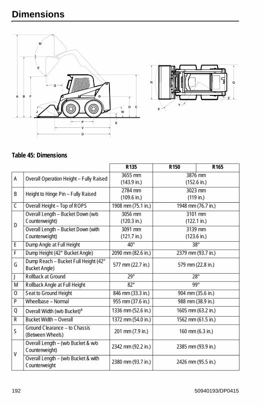
Dimensions
Table 45: Dimensions
R135 R150 R165
A Overall Operation Height – Fully Raised3655 mm(143.9 in.)
3876 mm(152.6 in.)
B Height to Hinge Pin – Fully Raised2784 mm(109.6 in.)
3023 mm(119 in.)
C Overall Height – Top of ROPS 1908 mm (75.1 in.) 1948 mm (76.7 in.)
D
Overall Length – Bucket Down (w/o Counterweight)
3056 mm(120.3 in.)
3101 mm(122.1 in.)
Overall Length – Bucket Down (with Counterweight)
3091 mm(121.7 in.)
3139 mm(123.6 in.)
E Dump Angle at Full Height 40° 38°
F Dump Height (42° Bucket Angle) 2090 mm (82.6 in.) 2379 mm (93.7 in.)
GDump Reach – Bucket Full Height (42° Bucket Angle)
577 mm (22.7 in.) 579 mm (22.8 in.)
J Rollback at Ground 29° 28°
M Rollback Angle at Full Height 82° 99°
O Seat to Ground Height 846 mm (33.3 in.) 904 mm (35.6 in.)
P Wheelbase – Normal 955 mm (37.6 in.) 988 mm (38.9 in.)
Q Overall Width (w/o Bucket)a 1336 mm (52.6 in.) 1605 mm (63.2 in.)
R Bucket Width – Overall 1372 mm (54.0 in.) 1562 mm (61.5 in.)
SGround Clearance – to Chassis (Between Wheels)
201 mm (7.9 in.) 160 mm (6.3 in.)
V
Overall Length – (w/o Bucket & w/o Counterweight)
2342 mm (92.2 in.) 2385 mm (93.9 in.)
Overall Length – (w/o Bucket & with Counterweight
2380 mm (93.7 in.) 2426 mm (95.5 in.)
A B F
J
M
E
G
P
V
D
S
W
O C
R Q
Z
YX
192 50940193/DP0415

Features
WDeparture Angle (w/o Counterweight) 25° 21°
Departure Angle (with Counterweight) 21° 19°
X Clearance Circle – Front (with Bucket) 1842 mm (72.5 in.) 1869 mm (73.6 in.)
Y Clearance Circle – Front (w/o Bucket) 1120 mm (44.1 in.) 1130 mm (45.4 in.)
Z
Clearance Circle – Rear (w/o Counterweight)
1372 mm (54.0 in.) 1466 mm (57.7 in.)
Clearance Circle – Rear (with Counterweight)
1417 mm (55.8 in.) 1519 mm (59.8 in.)
a. Overall width (Q) is dependent upon amount of wheel offset.
Table 46: Standard Features
Indicator and Warning Lamp Display Pre-Heat Starting Assist
Hydraulic Oil Temperature Indicator Lamp Lift Arm Support Device
Battery Charge Indicator LampDual Front and Rear Halogen Work Lights and Dual Tail Lights
Seat Belt IndicatorBi-directional Auxiliary Hydraulics with Flat-Faced Couplers
Choice of three control types:
• Pilot-Controlled Hydrostatic Drive (Hand/Foot)• Pilot-Controlled Hydrostatic Drive (Dual
Joysticka)• Servo-Controlled Hydrostatic Drive (T-Bar)
All-Tach® Attachment Mounting System: Single-Lever (manual)
Hand Throttle Engine Auto-Shutdown System
Foot Throttle (Dual Joystick and T-Bar)b Emergency Exit Rear Window
Operator Restraint Bar Hydrostatic Drive – Servo
ROPS/FOPS (ISO 3471, ISO 3449 Level II) Acoustical Cab Material and Headliner
Skid Plate for Clean Out Electric (Battery) Disconnect Switchc
Hydraloc™ System – Brakes and Interlock for Starter, Lift Cylinders, Tilt Cylinders, Auxiliary Hydraulics, Wheel Drives
Horn
Anti-Vandalism Rear Grille Float Control
Self-Leveling Lift Action with cancel button Interior Dome Light
Dual-Element Air Cleaner with Indicator 3-Spool Open Center Control Valve
12 VDC Power Socket Swing-out Radiator
Hydrostatic Dynamic Braking Parking / Emergency Brake
Auto / Manual Brake Control DPF (Diesel Particulate Filter) Technology
Remote Engine Oil Filter Proportionate Auxiliary Hydraulic Control
Table 45: Dimensions
R135 R150 R165
193 50940193/DP0415

Connect Under Pressure Auxiliary CouplersDual Lift / Tilt Cylinders with Induction Hardened Chrome Plated Cylinder Rods
Independent Hydraulic Reservoir with Cooler Cup Holder / Storage Tray
Deluxe High-Back, Cushion Seat Zero Maintenance Axles
a. Available only on Model R165.b. Not available with hand/foot controls.c. EU machines only
Table 47: Optional Features
Self-Leveling Lift Action with cancel button Engine Block Heater
3-inch Wide Seat Belt (Where Required by State Law)
Four- and Single-Point Lift System Kits
Upper-torso Restraint (Required with Two-Speed Drive) Two-Speed Drivea
a. Model R165 only.
Sliding Side Windows Lift Kit - Single Point Lift System
Rear-View Mirror Hydraglide™ Ride Control System (T-Bar)b
b. Not available on Model R135.
Front Door with WiperOperator’s Compartment Heater/Defroster with Filters
Impact-Resistant Front Door WindowPower-A-Tach® System Hydraulic-Powered Quick-Attach
Audible Back-Up Alarm Adjustable Air or Mechanical Suspension Seats
Strobe Light Bucket Bolt-On Cutting Edge Kits
Electric (Battery) Disconnect Switchc
c. Standard on EU Machines
Two-Speed Drive (Model R165 only)
Radio System Counterweight
Mechanical / Air Suspension Seat Cab Enclosure
Table 46: Standard Features
194 50940193/DP0415

Common Materials and Densities
Note: The densities listed are average values and intended only as a guide for bucket selection. For a material that is not in the table, obtain its density value before selecting the appropriate bucket.
Table 48: Common Materials and Densities
MaterialDensity
lbs./ft.3 kg/m3
Ashes 35-50 560-800
Brick-common 112 1792
Cement 110 1760
Charcoal 23 368
Clay, wet-dry 80-100 1280-1600
Coal 3 53-6 848-1008
Concrete 115 1840
Cinders 50 800
Coal-anthracite 94 1504
Coke 30 480
Earth-dry loam 70-90 1121-1442
Earth-wet loam 80-100 1281-1602
Granite 93-111 1488-1776
Gravel-dry 100 1602
Gravel-wet 120 1922
Gypsum-crushed 115 1840
Iron ore 145 2320
Lime 60 960
Lime stone 90 1440
Manure-liquid 65 1040
Manure-solid 45 720
Peat-solid 47 752
Phosphate-granular 90 1440
Potash 68 1088
Quartz-granular 110 1760
Salt-dry 100 1602
Salt-rock-solid 135 2160
Sand-dry 108 1728
Sand-wet 125 2000
Sand-foundry 95 1520
Shale-crushed 90 1440
Slag-crushed 70 1120
Snow 15-50 240-800
Taconite 107 1712
195 50940193/DP0415

NOTES
196 50940193/DP0415

INDEX
AAccessory Keypad . . . . . . . . . . . . 51
Accessory Plug . . . . . . . . . . . . . . 76
Attachment Hitch . . . . . . . . . . 77, 78
Attachment Mounting . . . . . . . . . . 77
Attachment Transport Position . . . 94
Attachments
Changing . . . . . . . . . . . . . 95, 96
Using Buckets . . . . . . . . . . . 102
Auxiliary Hydraulic System . . . . . . 79
Auxiliary Hydraulic Couplers . 79
Connecting Couplings . . . . . . 99
Disconnecting Couplings . . . 100
Auxiliary Hydraulics System
Auxiliary Hydraulics Control . . 80
BBattery Disconnect Switch . . . 46, 76
Beacon . . . . . . . . . . . . . . . . . . . . . 74
Brake Release Option . . . . . . . . . 89
Bucket
Cutting Edge . . . . . . . . . . . . . 148
Buckets . . . . . . . . . . . . . . . . . . . 102
Backfilling . . . . . . . . . . . . . . . 106
Cutting Edge . . . . . . . . . . . . . 148
Digging with a Bucket . . . . . . 103
Dumping a Load onto a Pile . 104
Grading . . . . . . . . . . . . . . . . . 107
Loading a Bucket . . . . . . . . . 104
Scraping . . . . . . . . . . . . . . . . 107
CCab Door Electrical Connection . . 84
Cab Entry and Exit . . . . . . . . . . . . 83
Cab Heat/Cool . . . . . . . . . . . . . . . 74
Chaincase
Drive Chain Tension . . . . . . . 148
Maintenance . . . . . . . . . . . . . 147
Oil Maintenance . . . . . . . . . . 147
Changing Attachments . . . . . . . . . 96
Connection Attachments . . . . . . . 96
Control Keypad . . . . . . . . . . . . . . 48
Controls . . . . . . . . . . . . . . . . . 47, 59
Hand and Foot Controls . . . . . 67
Joystick Controls . . . . . . . . . . 64
T-Bar Controls . . . . . . . . . . . . 61
Throttle Controls . . . . . . . . . . 60
DDealer Services . . . . . . . . . . . . . 157
Dome Light . . . . . . . . . . . . . . . . . 75
DPF Regeneration Procedures . 116
DPF Maintenance . . . . 120, 140
Forcing Stationary
Regeneration . . . . . . . . . . . 119
Reset Regeneration . . . . . . . 117
Reset Regeneration Inhibit . 117
Stationary Regeneration . . . 118
Drive Motor Maintenance . . . . . . 147
EElectrical System . . . . . . . . . . . . 150
Battery . . . . . . . . . . . . . . . . . 153
Fuses, Relays and Diodes . . 151
Electronic Display . . . . . . . . . . . . 53
Emergency Exit/Rear Window . . . 43
Engine
Changing Oil . . . . . . . . . . . . 133
Changing Oil Filter . . . . . . . . 133
Cooling System . . . . . . . . . . 141
Maintenance . . . . . . . . . . . . 132
Oil Level Check . . . . . . . . . . 133
Engine Stalling . . . . . . . . . . . . . . . 88
FFields of Application . . . . . . . . . . . 6
Final Shutdown /
Decommissioning . . . . . . . . . . 156
Fire Extinguisher Location . . . . . . 11
Float/Lift Arm . . . . . . . . . . . . . . . . 71
Fuel System
50940193/DP0415 197

Adding Fuel . . . . . . . . . . . . . 135
Maintenance . . . . . . . . . . . . 135
Water Separator . . . . . . . . . . 136
Fuses . . . . . . . . . . . . . . . . . . . . . 151
GGeneral Information . . . . . . . 81, 121
Grading . . . . . . . . . . . . . . . . . . . 107
HHVAC . . . . . . . . . . . . . . . . . . . . . . 74
Hydraulic Hose Maintenance . . . 146
Hydraulic System
Checking Oil Level . . . . . . . . 143
Hose Maintenance . . . . . . . . 146
Maintenance . . . . . . . . . . . . 142
Oil Changing . . . . . . . . . . . . 145
Oil Filter . . . . . . . . . . . . . . . . 144
IIgnition Keyswitch . . . . . . . . . . . . 59
Indicator/Operation Symbol . . . . . 12
Indicators . . . . . . . . . . . . . . . . . . . 47
Information Center Electronic Display 53
Introduction . . . . . . . . . . . . . . . . . . 1
JJump-starting . . . . . . . . . . . . . . . . 90
LLift Arm . . . . . . . . . . . . . . . . . . . . 94
Lift Arm Support . . . . . . . . . . . 44
Lift Arm Float . . . . . . . . . . . . . 71, 94
Lifting the Machine . . . . . . 115, 130
Lights
Beacon . . . . . . . . . . . . . . . . . . 74
Position . . . . . . . . . . . . . . . . . 74
Work . . . . . . . . . . . . . . . . . . . 74
Lights/Lockout Keypad . . . . . . . . 52
Lubrication . . . . . . . . . . . . . . . . . 128
MMachine Disposal . . . . . . . . . . . 157
Machine Orientation . . . . . . . . . . . 3
Maintenance . . . . . . . . . . . . . . . 121
Chaincase . . . . . . . . . . . . . . .147
Chaincases . . . . . . . . . . . . . .147
Cooling System . . . . . . . . . . .141
Draining/Flushing . . . 142Engine . . . . . . . . . . . . . . . . . .132
Fuel System . . . . . . . . . . . . .135
Hydraulic System . . . . . . . . .142
V-Belt . . . . . . . . . . . . . . . . . . .140
Maintenance Log . . . . . . . . . . . . .125
Maintenance Schedules . . . . . . .123
Manual Contents and Use . . . . . . . .1Manufacturer Information . . . . . . .11
Model Identification . . . . . . . . . . . . .3
Model Numbers . . . . . . . . . . . . . . . .5O
Operation . . . . . . . . . . . . . . . . . . .81
Before Starting . . . . . . . . . . . .81
Checks During Operation . . . .82
Driving on an Incline/slope . . .93
Driving over Rough Terrain . . .93
Engine Starting . . . . . . . . . . . .85
After Starting . . . . . . . 87Cold-Starting . . . . . . . 86Jump-starting . . . . . . 90Pre-Start Checks . . . 81
Grading . . . . . . . . . . . . . . . . .107
Lift Arm . . . . . . . . . . . . . . . . . .94
Lift Arm Float . . . . . . . . . . 71, 94
Operational Checks . . . . . . . . .81
Pallet Forks . . . . . . . . . . . . . .109
Ride Control System . . . . . . . .95
Run-In Period . . . . . . . . . . . . .88
Self-Leveling . . . . . . . . . . . . .101
Stalling . . . . . . . . . . . . . . . . . . .88
Stopping the Machine . . . . . . .88
Transport on Public Roads . . .93
Travel Drive . . . . . . . . . . . . . . .92
Using Buckets . . . . . . . . . . . .102
Using Pallet Forks . . . . . . . . .109
Warm Up . . . . . . . . . . . . . . . . .88
Operator Restraint Bar . . . . . . . . .41
Operator’s Manual Overview . . . . . .1
198 50940193/DP0415

Operator’s Position . . . . . . . . . . . . 39
Operator’s Seat . . . . . . . . . . . . . . 39
Seat Suspension . . . . . . . . . . 40
PPallet Forks . . . . . . . . . . . . . . . . 109
Transporting Loads . . . . . . . 111
Parking Brake . . . . . . . . . . . . . . . . 43
Parking the Machine . . . . . . . . . . 89
Position Lights . . . . . . . . . . . . . . . 74
Product and Component Plate
Locations . . . . . . . . . . . . . . . . . . 38
RRegistration, Machine . . . . . . . . . . 4
Relays . . . . . . . . . . . . . . . . . . . . 151
Ride Control System . . . . . . . 73, 95
Road Lights . . . . . . . . . . . . . . . . 170
ROPS/FOPS . . . . . . . . . . . . . . . . 43
ROPS/FOPS, Tilting . . . . . . . . . . 129
Run-In Period . . . . . . . . . . . . . . . . 88
SSafety . . . . . . . . . . . . . . . . . . . . . . 13
Additional Safety Equipment . 16
Applications with
Load-Handling Devices . . . . 19
Battery Hazards . . . . . . . . . . . 23
Before Starting . . . . . . . . . . . . 14
Crystalline Silica Exposure . . . 24
During Operation . . . . . . . . . . 16
Electrical Energy . . . . . . . . . . 20
Fire Hazards . . . . . . . . . . . . . . 23
Guards and Shields . . . . . . . . 39
Lift Arm Support . . . . . . . . . . . 44
Lifting the Machine with a
Crane . . . . . . . . . . . . . . . . . . 24
Loading and Transporting the
Machine . . . . . . . . . . . . . . . . 25
Maintenance . . . . . . . . . . . . . . 21
Mandatory Safety Shutdown
Procedure . . . . . . . . . . . . . . . 14
Pallet Forks . . . . . . . . . . . . . 109
Proper Machine Use . . . . . . . . . 4
Rear Window Emergency
Exit . . . . . . . . . . . . . . . . . . . . 43
Safety Alert Symbol . . . . . . 1, 13
Safety Decals . . . . . . . . . . . . . 25
ANSI-Style Safety Decals . . . . . . . . . . . 26ISO-Style Safety Decals . . . . . . . . . . . 32
Safety Equipment . . . . . . . . . . 39
Safety Interlock System . . . . . 42
Safety Signal Words . . . . . 1, 13
Transporting the Machine . . . 24
Safety Seat and Restraint Bar
Switches . . . . . . . . . . . . . . . . . 148
Seat . . . . . . . . . . . . . . . . . . . . . . . 39
Seat Belt . . . . . . . . . . . . . . . . . . . 40
Upper Torso Restraint . . . . . . 41
Self-Leveling . . . . . . . . . . . . . . . 101
Self-Leveling Cancel . . . . . . 102
Serial Numbers . . . . . . . . . . . . . . . 5
Specifications . . . . . . . . . . . . . . 183
Coolant Compound
Mixtures . . . . . . . . . . . . . . . 189
Electrical System . . . . . . . . . 190
Engine . . . . . . . . . . . . . . . . . 188
Fluid Capacities/
Lubricants . . . . . . . . . . . . . 183
Hydraulics . . . . . . . . . . . . . . 189
Payloads/Capacities . . . . . . 186
Sound Levels . . . . . . . . . . . . 190
Travel Speeds . . . . . . . . . . . 190
Vibration Levels . . . . . . . . . . 191
Weights . . . . . . . . . . . . . . . . 185
Stalling . . . . . . . . . . . . . . . . . . . . . 88
Starting the Engine . . . . . . . . . . . 85
Storage, Long-Term . . . . . . . . . 154
TTire Maintenance . . . . . . . . . . . . 149
Torque Specifications . . . . . . . . 201
Towing . . . . . . . . . . . . . . . . . . . . 114
Transport Hydraulics Lock-out . . . 93
Transporting the Machine . . . . . 113
50940193/DP0415 199

Troubleshooting . . . . . . . . . . . . . 159
Drive System . . . . . . . . . . . . 167
Electrical . . . . . . . . . . . . . . . 169
Engine Diagnostic Trouble
Codes (DTC) . . . . . . . . . . . 171
Error Codes . . . . . . . . . . . . . 171
Hydraulic System . . . . . . . . . 163
Seal and Hose . . . . . . . . . . . 163
Two-Speed Drive . . . . . . . . . . 69, 92
UUpper Torso Restraint . . . . . . . . . 41
VV-Belt Maintenance . . . . . . . . . . 140
Vibration Information . . . . . . . 9, 191
WWheel Nuts . . . . . . . . . . . . . . . . 149
Windshield Washer . . . . . . . . . . 154
Windshield Wiper/Washer . . . . . . 75
Work Lights . . . . . . . . . . . . . . . . . 74
200 50940193/DP0415

50940193/DP0415 201
Torque Specifications
Note: Use these torque values when tightening hardware (excluding:locknuts and self-tapping, thread forming and sheet metal screws) unlessspecified otherwise.
*All Torque Values are in ft-lbs. except those marked with an *, which are in-lbs. For metric torque value (N·m), multiply ft-lbs. value by 1.355 or the in-lbs. value by 0.113.
UNIFIEDNATIONALTHREAD
GRADE 2 GRADE 5 GRADE 8
DRY LUBED DRY LUBED DRY LUBED
8-328-36
10-2410-32
19*20*27*31*
14*15*21*23*
30*31*43*49*
22*23*32*36*
41*43*60*68*
31*32*45*51*
1/4-201/4-28
5/16-185/16-24
66*76*1112
50*56*99
9101719
75*86*1314
12142525
9101820
3/8-163/8-24
7/16-147/16-20
20233236
15172427
30355055
23253540
45507080
35355560
1/2-131/2-20
9/16-129/16-18
50557080
35405560
7590110120
55658090
110120150170
8090110130
5/8-115/8-183/4-103/4-16
100110175200
7585
130150
150180260300
110130200220
220240380420
170180280320
7/8-97/8-14
1-81-12
170180250270
125140190210
430470640710
320360480530
600660900
1000
460500680740
METRICCOARSETHREAD
GRADE 8.8 GRADE 10.9 GRADE 12.9
DRY LUBED DRY LUBED DRY LUBED
M6-1M8-1.25M10-1.5
819
37.5
61428
112753
82039
13.532.564
102447
M12-1.75M14-2M16-2
65103.5158.5
4876.5117.5
91.5145.5223.5
67.5108
165.5
111.5176.5271
82131200

© 2015 MANITOU AMERICAS, INC.50940193/DP0415 All Rights Reserved. PRINTED IN U.S.A.
WARNING
THIS OPERATOR’S MANUAL IS PROVIDED FOR OPERATOR USE
DO NOT REMOVE FROM THIS MACHINE
Do not start, operate or work on this machine until you care-fully read and thoroughly understand the contents of thisOperator’s Manual.
Failure to follow safety, operating and maintenance instruc-tions can result in serious injury to the operator or bystand-ers, poor operation, and costly breakdowns.
If you have any questions on proper operation, adjustment ormaintenance of this machine, contact your dealer or the GehlCompany Service Department before starting or continuingoperation.
Manitou Americas, Inc., One Gehl Way, P.O. Box 179, West Bend, WI 53095-0179 U.S.A.www.gehl.com/
California Proposition 65 WarningsDiesel engine exhaust and some of its constituents are known to the State of Californiato cause cancer and birth defects or other reproductive harm.Battery posts, terminals and related accessories contain lead and lead compounds,chemicals known to the State of California to cause cancer and birth defects or otherreproductive harm. Wash hands after handling battery.
®