Operators Manual - Fluke Calibration
248
August 2013 Rev. 1, 6/15 © 2013-2015 Fluke Corporation. All rights reserved. Specifications are subject to change without notice. All product names are trademarks of their respective companies. 5730A Multifunction Calibrator Operators Manual
-
Upload
khangminh22 -
Category
Documents
-
view
2 -
download
0
Transcript of Operators Manual - Fluke Calibration

August 2013 Rev. 1, 6/15 © 2013-2015 Fluke Corporation. All rights reserved. Specifications are subject to change without notice. All product names are trademarks of their respective companies.
5730A Multifunction Calibrator
Operators Manual

LIMITED WARRANTY AND LIMITATION OF LIABILITY
Each Fluke product is warranted to be free from defects in material and workmanship under normal use and service. The warranty period is one year and begins on the date of shipment. Parts, product repairs, and services are warranted for 90 days. This warranty extends only to the original buyer or end-user customer of a Fluke authorized reseller, and does not apply to fuses, disposable batteries, or to any product which, in Fluke's opinion, has been misused, altered, neglected, contaminated, or damaged by accident or abnormal conditions of operation or handling. Fluke warrants that software will operate substantially in accordance with its functional specifications for 90 days and that it has been properly recorded on non-defective media. Fluke does not warrant that software will be error free or operate without interruption.
Fluke authorized resellers shall extend this warranty on new and unused products to end-user customers only but have no authority to extend a greater or different warranty on behalf of Fluke. Warranty support is available only if product is purchased through a Fluke authorized sales outlet or Buyer has paid the applicable international price. Fluke reserves the right to invoice Buyer for importation costs of repair/replacement parts when product purchased in one country is submitted for repair in another country.
Fluke's warranty obligation is limited, at Fluke's option, to refund of the purchase price, free of charge repair, or replacement of a defective product which is returned to a Fluke authorized service center within the warranty period.
To obtain warranty service, contact your nearest Fluke authorized service center to obtain return authorization information, then send the product to that service center, with a description of the difficulty, postage and insurance prepaid (FOB Destination). Fluke assumes no risk for damage in transit. Following warranty repair, the product will be returned to Buyer, transportation prepaid (FOB Destination). If Fluke determines that failure was caused by neglect, misuse, contamination, alteration, accident, or abnormal condition of operation or handling, including overvoltage failures caused by use outside the product’s specified rating, or normal wear and tear of mechanical components, Fluke will provide an estimate of repair costs and obtain authorization before commencing the work. Following repair, the product will be returned to the Buyer transportation prepaid and the Buyer will be billed for the repair and return transportation charges (FOB Shipping Point).
THIS WARRANTY IS BUYER'S SOLE AND EXCLUSIVE REMEDY AND IS IN LIEU OF ALL OTHER WARRANTIES, EXPRESS OR IMPLIED, INCLUDING BUT NOT LIMITED TO ANY IMPLIED WARRANTY OF MERCHANTABILITY OR FITNESS FOR A PARTICULAR PURPOSE. FLUKE SHALL NOT BE LIABLE FOR ANY SPECIAL, INDIRECT, INCIDENTAL, OR CONSEQUENTIAL DAMAGES OR LOSSES, INCLUDING LOSS OF DATA, ARISING FROM ANY CAUSE OR THEORY.
Since some countries or states do not allow limitation of the term of an implied warranty, or exclusion or limitation of incidental or consequential damages, the limitations and exclusions of this warranty may not apply to every buyer. If any provision of this Warranty is held invalid or unenforceable by a court or other decision-maker of competent jurisdiction, such holding will not affect the validity or enforceability of any other provision.
Fluke Corporation P.O. Box 9090 Everett, WA 98206-9090 U.S.A.
Fluke Europe B.V. P.O. Box 1186 5602 BD Eindhoven The Netherlands
11/99

OPERATOR SAFETY SUMMARY
WARNING
HIGH VOLTAGE
is used in the operation of this equipment
LETHAL VOLTAGE may be present on the terminals, observe all safety precautions!
To prevent electrical shock hazard, the operator should not electrically contact the output HI or sense HI terminals or circuits connected to these terminals. During operation, lethal voltages of up to 1100 V ac or dc may be present on these terminals.
When the nature of the operation permits, keep one hand away from equipment to reduce the hazard of current flowing through vital organs of the body.

v
Table of Contents
Chapter Title Page
1 Introduction and Specification ........................................................... 1-1
Introduction ........................................................................................................ 1-1 Safety Information ............................................................................................. 1-3 Symbols ............................................................................................................. 1-4 How to Contact Fluke Calibration ..................................................................... 1-5 Instruction Manuals ........................................................................................... 1-5 Wideband AC Voltage Module (Option 5730A/03 or 5730A/05)..................... 1-6 Auxiliary Amplifiers .......................................................................................... 1-6
5725A Amplifier ........................................................................................... 1-7 52120A Amplifier ......................................................................................... 1-7
Support Equipment and Services ....................................................................... 1-7 732B Direct Voltage Reference Standard ..................................................... 1-8 732B-200 Direct Volt Maintenance Program (USA Only) ........................... 1-8 742A Series Resistance Standards ................................................................. 1-8 Wideband AC Module (Option 5730A/03 or 5730A/05) Calibration Support ....................................................................................... 1-8
The Components of the Calibrator ..................................................................... 1-9 Specifications ..................................................................................................... 1-9
Specification Confidence Levels ................................................................... 1-9 Use of Absolute and Relative Accuracy Specifications ................................ 1-10 Use of Secondary Performance Specifications .............................................. 1-10
General Specifications ....................................................................................... 1-11 Electrical Specifications .................................................................................... 1-13
AC Voltage Specifications ............................................................................ 1-14 Resistance Specifications .............................................................................. 1-20 DC Current Specifications ............................................................................. 1-23 AC Current Specifications ............................................................................. 1-24 Wideband AC Voltage (Option 5730A/03 and 5730A/05) Specifications (99 % Confidence Level) ....................................................... 1-27 52120A Specifications when Operated with the 5730A ................................ 1-28 52120A Electrical Performance Limits ......................................................... 1-28 Operated within 5730A Control Loop (all current ranges) ........................... 1-29
Coverage factor k=2.58 (99 % confidence level) ...................................... 1-29 Coverage factor k=2.00 (95 % confidence level) ...................................... 1-29

5730A Operators Manual
vi
52120A/COIL 3 kA 25-Turn Coil ................................................................. 1-30 52120A/COIL 6 kA 50-Turn Coil ................................................................. 1-31
2 Installation ........................................................................................... 2-1
Introduction ........................................................................................................ 2-1 Unpack and Inspect the Calibrator ..................................................................... 2-1 Placement and Rack Mounting .......................................................................... 2-2 Cooling Considerations ...................................................................................... 2-2 Mains Voltage Selection .................................................................................... 2-3 Connect to Mains Power .................................................................................... 2-4 Connect a 5725A Amplifier ............................................................................... 2-4 Connect a 52120A Amplifier ............................................................................. 2-4
3 Features ............................................................................................... 3-1
Introduction ........................................................................................................ 3-1 Front-Panel Features .......................................................................................... 3-1 Rear-Panel Features ........................................................................................... 3-5
4 Front-Panel Operation ........................................................................ 4-1
Introduction ........................................................................................................ 4-1 Turn on the Calibrator ........................................................................................ 4-2 Warmup ............................................................................................................. 4-2 Product Use ........................................................................................................ 4-2 Reset the Calibrator ........................................................................................... 4-3 Operate and Standby Modes .............................................................................. 4-3 Connect the Calibrator to a UUT ....................................................................... 4-4
Recommended Cable and Connector Types .................................................. 4-4 When to Use External Sensing ...................................................................... 4-6 When to Use the External Voltage Guard ..................................................... 4-6 Four-Wire Vs. Two-Wire Resistance Connections ....................................... 4-6 Cable Connection Instructions....................................................................... 4-7
Set the Output .................................................................................................... 4-14 DC Voltage Output ........................................................................................ 4-16 AC Voltage Output ........................................................................................ 4-17 DC Current Output ........................................................................................ 4-19 AC Current Output ........................................................................................ 4-21 Resistance Output .......................................................................................... 4-23 Wideband AC Voltage Output (Option 5730A/03 or 5730A/05) ................. 4-26
Variable Phase Output ....................................................................................... 4-28 Phase Locking to an External Signal ................................................................. 4-29 Auxiliary Amplifier Use .................................................................................... 4-30
5725A Amplifier Output ............................................................................... 4-31 52120A Transconductance Amplifier Output ............................................... 4-32
Error Mode Operation ........................................................................................ 4-32 Error Mode Overview .................................................................................... 4-33
Enter Error Mode ...................................................................................... 4-33 Exit Error Mode ........................................................................................ 4-33 Use Error Mode ......................................................................................... 4-34
Read the UUT Error: AC and DC Voltage and Current Output .................... 4-34 Read the UUT Error: Resistance Output ....................................................... 4-35
Introduction to Offset, Scale, and Linearity Errors ............................................ 4-35 Offset Error .................................................................................................... 4-36 Scale Error ..................................................................................................... 4-36 Linearity Error ............................................................................................... 4-37

Contents (continued)
vii
Combine the Error Types .............................................................................. 4-38 Program an Offset .............................................................................................. 4-39 Program a Scale Factor ...................................................................................... 4-40 Linearity Check with Offset and Scale .............................................................. 4-41 Set up the Calibrator .......................................................................................... 4-45
Setup Menu .................................................................................................... 4-45 Setup Menu Rules .......................................................................................... 4-46 Menu Description .......................................................................................... 4-47 Touchscreen Selections ................................................................................. 4-47
Instrument Setup ................................................................................................ 4-51 Uncertainty Information Menu ...................................................................... 4-52 Set Output Limits .......................................................................................... 4-53 Select Boost Amplifiers ................................................................................. 4-54 Error Reference ............................................................................................. 4-54
Instrument Settings ............................................................................................ 4-56 Set the Internal Clock/Calendar ..................................................................... 4-56 Language ....................................................................................................... 4-57 Display Brightness ......................................................................................... 4-57 About This Instrument ................................................................................... 4-57
5 Remote Interface Setup ...................................................................... 5-1
GPIB (IEEE-488) Interface................................................................................ 5-2 Use the IEEE-488 Port for Remote Control .................................................. 5-2 IEEE-488 Bus Restrictions ............................................................................ 5-2 Bus Setup Procedure ...................................................................................... 5-2 IEEE-488 Interface Configuration ................................................................. 5-3 Bus Communication Overview ..................................................................... 5-3
RS-232 Serial Interface ...................................................................................... 5-4 Use the RS-232 Port for Remote Control ...................................................... 5-4 RS-232 Interface Specifications .................................................................... 5-4 Set Up and Connect the Serial Interface ........................................................ 5-5 Serial Remote Control Setup Procedure ........................................................ 5-6 Exceptions for Serial Remote Control ........................................................... 5-6
Ethernet Interface ............................................................................................... 5-7 Set Up and Connect the Ethernet Interface ................................................... 5-7 Set the IP Address ......................................................................................... 5-7 Select the Dynamic Host Configuration Protocol (DHCP) ........................... 5-7 Set a Static Internet Address .......................................................................... 5-8 Configure the General Network Socket Port ................................................. 5-8 Configure the LAN Default Gateway ............................................................ 5-9 Set the LAN Subnet Mask ............................................................................. 5-9 Read the MAC Address ................................................................................. 5-9
Establish an Ethernet Connection ...................................................................... 5-10 Terminate an Ethernet Connection ................................................................ 5-10 Use of Ethernet Remote Control ................................................................... 5-10
Use of USB 2.0 Remote Control ........................................................................ 5-11
6 Remote Commands and Syntax......................................................... 6-1
Introduction ........................................................................................................ 6-1 Parameter Syntax Rules ................................................................................. 6-1 Extra Space Characters .................................................................................. 6-2 Terminators.................................................................................................... 6-2 Incoming Character Processing ..................................................................... 6-3 Response Message Syntax ............................................................................. 6-3
5730A Operators Manual
viii
Input Buffer Operation ....................................................................................... 6-3 Commands ......................................................................................................... 6-4
Multiple Commands ...................................................................................... 6-4 Coupled Commands ...................................................................................... 6-4 Sequential and Overlapped Commands ......................................................... 6-5 Commands Ignored When Not in Remote .................................................... 6-5 Commands that Require the Calibration Security Passcode .......................... 6-5 Long Term Commands .................................................................................. 6-5 Definition: Queries and Commands .............................................................. 6-6 Functional Elements of Commands ............................................................... 6-6 Interface Messages (IEEE-488 Only) ............................................................ 6-8 Use of *OPC?, *OPC, and *WAI.................................................................. 6-10
Local-to-Remote State Transitions .................................................................... 6-48 Check the Calibrator Status ............................................................................... 6-50
Status Byte Register ...................................................................................... 6-52 Service Request Line (SRQ) ..................................................................... 6-52 Service Request Enable Register............................................................... 6-52 Load the SRE ............................................................................................ 6-52
Event Status Register ..................................................................................... 6-53 Bit Assignments for the ESR and ESE ...................................................... 6-53 Read the ESR and ESE ............................................................................. 6-54 Load the ESE............................................................................................. 6-54
Instrument Status Register ............................................................................. 6-54 Instrument Status Change Register ................................................................ 6-54 Instrument Status Change Enable Register ................................................... 6-54
Bit Assignments for the ISR, ISCR, and ISCE ......................................... 6-54 Read the ISR, ISCR, or ISCE .................................................................... 6-55 Load the ISCE ........................................................................................... 6-55
Fault Queue ................................................................................................... 6-55
7 Operator Maintenance and Calibration ............................................. 7-1
Introduction ........................................................................................................ 7-1 Fuse Replacement .............................................................................................. 7-1 Clean the Air Filter ............................................................................................ 7-3 Clean the Exterior .............................................................................................. 7-4 User-Replaceable Parts ...................................................................................... 7-4 5730A Calibration .............................................................................................. 7-6
The Artifact Calibration Process ................................................................... 7-6 Establish Traceability .................................................................................... 7-7 Calibration Reports ........................................................................................ 7-7 Range Adjustment ......................................................................................... 7-7
DC Zeros ............................................................................................................ 7-7 Run DC Zeros ................................................................................................ 7-7 DC Zeros Reminder ....................................................................................... 7-8
Calibration ......................................................................................................... 7-8 Calibration Security Passcode ....................................................................... 7-9 Artifact Calibration ........................................................................................ 7-9 When to Adjust Calibrator Accuracy ............................................................ 7-10 Calibration Procedure .................................................................................... 7-10
Range Adjustment .............................................................................................. 7-13 Calibrate the Wideband AC Module (Option 5730A/03 or 5730A/05) ............. 7-17 Wideband Flatness Calibration Procedure ......................................................... 7-18 Calibration Check .............................................................................................. 7-20 Develop a Performance History ......................................................................... 7-21 Save Calibration Reports ................................................................................... 7-21

Contents (continued)
ix
Calibration Shift Results ................................................................................ 7-22 Calibration Check Shift Results .................................................................... 7-23 Raw Data Results .......................................................................................... 7-23
8 Options and Accessories ................................................................... 8-1
Introduction ........................................................................................................ 8-1 Wideband AC Voltage Module (Option 5730A/03 or 5730A/05)..................... 8-1 Accessories ........................................................................................................ 8-1
Low Thermal EMF Test Leads ...................................................................... 8-2 Rack Mount Kits ............................................................................................ 8-3 Shielded IEEE-488 Interface Cables (Y8021 and Y8022) ............................ 8-3 DC Voltage Reference Standard (732B) ....................................................... 8-3 1 Ω and 10 kΩ Resistance Standards (742A-1 and 742A-10k) ..................... 8-3 5725A Amplifier ........................................................................................... 8-4 52120A Amplifier ......................................................................................... 8-4
Appendices
A Fault Codes .................................................................................................. A-1 B ASCII and IEEE-488 Bus Codes ................................................................. B-1 C Glossary ....................................................................................................... C-1

5730A Operators Manual
x

xi
List of Tables
Table Title Page
1-1. Symbols .................................................................................................................. 1-4 1-2. Auxiliary Amplifier Data ....................................................................................... 1-6 2-1. Standard Equipment ............................................................................................... 2-2 2-2. Line Power Cord Types Available from Fluke Calibration ................................... 2-3 3-1. Front-Panel Features .............................................................................................. 3-2 3-2. Rear-Panel Features ............................................................................................... 3-5 4-1. Auxiliary Amplifier Data ....................................................................................... 4-5 4-2. UUT Connection Figures ....................................................................................... 4-7 4-3. Sections of the Display ........................................................................................... 4-14 4-4. Keys that Exit Error Mode ..................................................................................... 4-33 5-1. Supported IEEE-488 Interface Function Subsets ................................................... 5-3 5-2. RS-232 Interface Parameter Choices ..................................................................... 5-4 6-1. Functional Elements of Commands ....................................................................... 6-7 6-2. Interface Messages Accepted by the Calibrator ..................................................... 6-8 6-3. Interface Messages Sent by the Calibrator ............................................................. 6-9 6-4. Command Summary by Function .......................................................................... 6-11 6-5. Commands .............................................................................................................. 6-16 6-6. Serial Remote Control Commands ......................................................................... 6-47 6-7. Range Identifiers for Remote Commands .............................................................. 6-47 6-8. Operating State Transitions .................................................................................... 6-49 6-9. Status Register Summary ....................................................................................... 6-50 7-1. Replacement Fuses ................................................................................................. 7-1 7-2. User-Replaceable Parts .......................................................................................... 7-4 7-3. Standards for Calibration ....................................................................................... 7-10 8-1. Accessories ............................................................................................................. 8-2

5730A Operators Manual
xii

xiii
List of Figures
Figure Title Page
2-1. Available Mains Power Cord Types ...................................................................... 2-3 2-2. Line Power Label and Switch Location ................................................................. 2-4 3-1. Front-Panel Features .............................................................................................. 3-1 3-2. Rear-Panel Features ............................................................................................... 3-5 4-1. UUT Connections: DC Voltage, AC Voltage ≤10 kHz ......................................... 4-8 4-2. UUT Connections: AC Voltage >10 kHz .............................................................. 4-9 4-3. UUT Connections: AC Current ≤2A ...................................................................... 4-10 4-4. UUT Connections: Resistance ............................................................................... 4-11 4-5. UUT Wideband AC Voltage Output (5730A/03 Option) ...................................... 4-13 4-6. UUT Connections: 5725A Amplified Current Output ........................................... 4-13 4-7. Offset Error ............................................................................................................ 4-36 4-8. Scale Error .............................................................................................................. 4-37 4-9. Linearity Error ........................................................................................................ 4-38 4-10. Meter Response vs. Stimulus ................................................................................. 4-41 6-1. Overview of Status Data Structure ......................................................................... 6-51 7-1. Access the Fuse ...................................................................................................... 7-2 7-2. Air Filter Access .................................................................................................... 7-3 7-3. Replaceable Parts ................................................................................................... 7-5 7-4. 732B External Calibration Connections ................................................................. 7-11 7-5. 742A-1 and 742A-10k External Calibration Connections ..................................... 7-12 7-6. 220 V DC Range Calibration Connections ............................................................ 7-16 7-7. Wideband Module Calibration Connection ............................................................ 7-17 7-8. Wideband Flatness Calibration Connections ......................................................... 7-18

5730A Operators Manual
xiv
1-1
Chapter 1 Introduction and Specification
Introduction The Fluke Calibration 5730A Calibrator (the “Calibrator” or the “Product”) can calibrate a wide variety of electrical measurement instruments. The 5730A Calibrator maintains a high accuracy over a wide ambient temperature range. This accuracy lets the Calibrator test instruments in any environment, and eliminates the restrictions to calibrate only in a temperature-controlled standards laboratory. The Calibrator can calibrate precision multimeters that measure ac or dc voltage, ac or dc current, and resistance. The Calibrator also is available with a Wideband AC Voltage option which extends this workload to include RF voltmeters.
Specifications are provided at the end of this chapter. The 5730A Calibrator is a fully-programmable precision source of:
• DC voltage to 1100 V
• AC voltage to 1100 V, with output available from 10 Hz to 1.2 MHz
• AC and DC current to 2.2 A, with output available from 10 Hz to 10 kHz
• Resistance in values from 1 Ω to 100 MΩ, plus a short
• Optional wideband ac voltage from 300 μV to 3.5 V into 50 Ω (-57 dBm to +24 dBm), 10 Hz to 30 MHz (5730A/03) or 50 MHz (5730A/05)
Features of the 5730A Calibrator include:
• Internal environmentally-controlled references that let the Calibrator maintain full performance over a wide ambient temperature range.
• Automatic meter error calculation obtained through the use of a simple output adjust knob.
• Keys that multiply and divide the output value by 10. This simplifies work on meters with calibration points at decade multiples of a fraction of full-scale.
• Programmable entry limits used to restrict the levels that can be entered into the Calibrator. This prevents access to levels that may be harmful to equipment or personnel.

5730A Operators Manual
1-2
• Continuous display of Calibrator specifications at the selected operation point, calibration interval, and specification confidence level.
• An auxiliary current binding post to calibrate meters with separate current inputs without the need to move cables.
• Real-time clock and calendar for date stamping reports and reminders issued to perform the dc zeros calibration procedure within the required interval.
• Offset and scaling modes that simplify linearity tests of multimeters.
• Variable phase reference signal output and phase-lock input.
• Interface for the Fluke Calibration 5725A Amplifier.
• Interface for the Fluke Calibration 52120A Amplifier.
• Standard IEEE-488 (GPIB) interface, that complies with ANSI/IEEE Standards 488.1-1987 and 488.2-1987.
• EIA/TIA-574 Standard RS-232 serial data interface for remote control of the Calibrator.
• Universal Serial Bus (USB) 2.0 high-speed interface device port for remote control of the Calibrator.
• Integrated 10/100/1000BASE-T Ethernet port for network connection remote control of the Calibrator.
• Extensive internal self-testing and diagnostics of analog and digital functions
• USB Host port to save calibration reports to a flash drive.
• Visual Connection Management output terminals illuminate to help show correct cable connection configurations.
• Soft Power - automatic selection of line voltage/frequency.
• LCD Color VGA display with touch panel overlay.
• A traceable calibration procedure for all modes and ranges that requires only 10 V, 1 Ω, and 10 kΩ external standards, with only occasional independent verification.
• Automated calibration check that provides added confidence between calibration recalls, and data that can be used to document and characterize Calibrator performance between calibration recalls.

Introduction and Specification Safety Information 1
1-3
Safety Information A Warning identifies conditions and procedures that are dangerous to the user. A Caution identifies conditions and procedures that can cause damage to the Product or the equipment under test.
Warnings To prevent possible electrical shock, fire, or personal injury:
• Read all safety information before you use the Product.
• Carefully read all instructions.
• Do not use the Product around explosive gas, vapor, or in damp or wet environments.
• Use this Product indoors only.
• Do not put the Product where access to the mains power cord is blocked.
• Use only the mains power cord and connector approved for the voltage and plug configuration in your country and rated for the Product.
• Replace the mains power cord if the insulation is damaged or if the insulation shows signs of wear.
• Make sure the ground conductor in the mains power cord is connected to a protective earth ground. Disruption of the protective earth could put voltage on the chassis that could cause death.
• Do not use an extension cord or adapter plug.
• Do not operate the Product with covers removed or the case open. Hazardous voltage exposure is possible.
• Do not use the Product if it operates incorrectly.
• Do not connect to live output terminals. The Product can supply voltages that can cause death. Standby mode is not sufficient to prevent electrical shock.
• Do not apply more than the rated voltage, between the terminals or between each terminal and earth ground.
• Use only cables with correct voltage ratings.

5730A Operators Manual
1-4
• Do not touch exposed metal on banana plugs, they can have voltages that could cause death.
• Do not touch voltages >30 V ac rms, 42 V ac peak, or 60 V dc.
• Use the Product only as specified, or the protection supplied by the Product can be compromised.
• Use only specified replacement fuses.
• Have an approved technician repair the Product.
Symbols The symbols shown in Table 1-1 can be found in this manual or on the Calibrator.
Table 1-1. Symbols
Symbol Definition Symbol Definition
WARNING. RISK OF DANGER. WARNING. HAZARDOUS VOLTAGE. Risk of electric shock.
This product complies with the WEEE Directive marking requirements. The affixed label indicates that you must not discard this electrical/electronic product in domestic household waste. Product Category: With reference to the equipment types in the WEEE Directive Annex I, this product is classed as category 9 "Monitoring and Control Instrumentation" product. Do not dispose of this product as unsorted municipal waste.
Conforms to European Union directives.
Certified by CSA Group to North American safety standards.
Conforms to relevant Australian EMC standards.
Conforms to relevant South Korean EMC Standards.

Introduction and Specification How to Contact Fluke Calibration 1
1-5
How to Contact Fluke Calibration To contact Fluke Calibration, call one of the following telephone numbers:
• Technical Support USA: 1-877-355-3225
• Calibration/Repair USA: 1-877-355-3225
• Canada: 1-800-36-FLUKE (1-800-363-5853)
• Europe: +31-40-2675-200
• Japan: +81-3-6714-3114
• Singapore: +65-6799-5566
• China: +86-400-810-3435
• Brazil: +55-11-3759-7600
• Anywhere in the world: +1-425-446-6110
To see product information or download manuals and the latest manual supplements, visit Fluke Calibration’s website at www.flukecal.com.
To register your product, visit http://flukecal.com/register-product.
Instruction Manuals The 5730A Calibrator ships with:
• 5730A Getting Started
• 5730A Operators Manual (provided on CD-ROM or a printed copy is available for purchase through the Fluke Calibration Service Department)
To order, refer to the Fluke Calibration Catalog or contact a Fluke Calibration sales representative. See “How to Contact Fluke Calibration”.
This manual provides complete information to install and operate the 5730A Calibrator from the front panel or with remote commands. It also provides a glossary of calibration-related terms as well as general items such as specifications and error code information.

5730A Operators Manual
1-6
Wideband AC Voltage Module (Option 5730A/03 or 5730A/05)
The Wideband AC Voltage Module (Option 5730A/03 or 5730A/05) can be installed in the 5730A Calibrator. The module is a high-accuracy, low-noise, extremely flat ac voltage source to calibrate RF voltmeters, with a frequency range of 10 Hz to 30 MHz (5730A/03) or 50 MHz (5730A/05). Output is in seven ranges from 300 μV (-57 dBm) to 3.5 V (+24 dBm) through a Type-N coaxial connector into a 50 Ω load. The output level is selected in volts or dBm through either the front panel controls or under remote control.
The wideband module also functions with the Calibrator output adjust controls that display the error of a wideband meter in either percentage of output or in decibels.
Included with the wideband module is a Type-N output cable, a 50 Ω terminator, an N(f) to BNC(m) adapter, and a BNC(f) to double banana plug adapter. The wideband module is calibrated to the end of its standard-equipment output cable.
Auxiliary Amplifiers The Fluke Calibration Model 5725A and 52120A amplifiers are available to extend the high voltage performance and current range of the 5730A Calibrator.
Interface connectors on the Calibrator rear panel accept cables to directly operate a 5725A and/or 52120A. Multiple amplifiers can be connected to the Calibrator at the same time, but only one output can be active at a time. Once the amplifiers are connected and configured in the Product Setup Menu, amplifier operation is controlled by the Calibrator.
A maximum of three 52120As can be connected to provide a maximum of 360 A rms ac or 300 A dc current when their outputs are connected in parallel.
See Chapter 4 for instructions to operate both amplifiers. The general specifications at the end of this chapter include specifications to operate the 5730A Calibrator with both amplifiers. For other amplifier specifications, refer to their instruction manuals. Table 1-2 summarizes the extended capabilities offered by the 5725A and 52120A. Brief descriptions of the extended capabilities follow.
Table 1-2. Auxiliary Amplifier Data
Model Mode Range
5725A Amplifier
AC Volts
20 V rms to 1100 V rms up to 70 mA, 40 Hz to 30 kHz (50 mA < 5 kHz)
220 V rms to 750 V rms up to 70 mA, 30 kHz to 100 kHz
DC Amps 0 A to ±11 A
AC Amps 1 A rms to 11 A rms, 40 Hz to 10 kHz
52120A Transconductance Amplifier [1]
DC Amps 0 A to ±100 A
AC Amps 0.2 A rms to 120 A rms, 10 Hz to 10 kHz
[1] Up to three 52120As may be connected, providing a total current of up to 300 A dc or 360 A rms.

Introduction and Specification Support Equipment and Services 1
1-7
5725A Amplifier The Fluke Calibration 5725A Amplifier is an external unit that operates under calibrator control. It extends ac voltage drive capabilities and both ac and dc current output range. The amplifier adds these capabilities to the 1100 V ac range of the 5730A Calibrator with no compromise in accuracy:
• Frequency limits at higher voltage increase to 100 kHz at 750 V, 30 kHz at 1100 V.
• Load limit increases to 70 mA for frequencies above 5 kHz.
• Capacitive drive increases to 1000 pF, subject to the maximum output current.
A separate set of binding posts on the front panel of the 5725A supplies extended-range ac and dc current outputs. Since most meters have a separate input terminal for the high-current ranges, this eliminates the need to change cables during a procedure. The 5725A can also be configured to source all current (both standard calibrator-generated current and its own current) through the 5725A binding posts.
52120A Amplifier The Fluke Calibration 52120A Transconductance Amplifier is an external unit that operates under calibrator control to extend the ac and dc current output range of the 5730A Calibrator. A maximum of three 52120A amplifiers can be connected, as much as tripling the current output available. The 52120A amplifier can:
• Accept full scale dc or ac inputs of 2 volts or 200 mA from any calibrator, signal generator or power supply
• Deliver proportional output current in ranges of 2 A, 20 A or 120 A at frequencies to 10 kHz
• Offer enhanced accuracy to 140 ppm when used in closed-loop mode with a 6105A Electrical Power Standard
• Operate in parallel with one or two other 52120As to deliver 240 A or 360 A
• Source current with compliance voltage of 4.5 V rms or 6.4 V peak
• Drive inductive loads to 1 mH
• Drive optional current coils to deliver test currents of 3000 A or 6000 A
Support Equipment and Services Fluke Calibration supports calibration requirements with precision, high-quality equipment and a wide range of services. Depending on the calibration needs, location, and capabilities, the 5730A Calibrator can be supported independently or with Fluke Calibration services for part, or all support needs. The subsequent paragraphs describe the support equipment and services offered by Fluke Calibration for the Calibrator. For specifications and ordering instructions for this support equipment and other Fluke Calibration instruments, refer to the Fluke Calibration catalog, or contact a representative at a Fluke Calibration Sales and Service Center. See “How to Contact Fluke Calibration”.
5730A Operators Manual
1-8
732B Direct Voltage Reference Standard The Fluke Calibration 732B is a rugged, easily transported solid state direct voltage reference standard with a highly predictable 10 V output. The 732B can be short-circuited, even for extended periods of time, without damage or loss of stability. It maintains full specified stability over a temperature span of 18 °C to 28 °C.
The 5730A Calibrator uses a 10 V reference standard such as the Fluke Calibration 732B in its semi-automated calibration procedure to establish external voltage traceability. Chapter 7 describes this procedure.
732B-200 Direct Volt Maintenance Program (USA Only) The Fluke Calibration 732B-200 Direct Volt Maintenance Program provides laboratories with NIST-traceable 10 V calibration uncertainty as low as 0.6 parts per million (ppm).
The program maintains the 732B that is kept in the laboratory. To do this:
1. Fluke Calibration sends a calibrated Fluke Calibration-owned 732B standard, together with all-necessary connection cables and instructions for comparison with a customer 10 V reference standard.
2. The customer takes a series of readings over five days, and returns the results to the Fluke Calibration Standards Laboratory.
3. The Fluke Calibration Standards Laboratory assigns a value to the customer 10 V standard relative to the NIST legal volt and sends a report of calibration.
742A Series Resistance Standards The 5730A Calibrator uses 1 Ω and 10 kΩ resistor standards such as the 742A Series in its semi-automated calibration procedure to establish external traceability of resistance and current. Chapter 7 describes this procedure.
The 742A Resistance Standards are constructed of arrays of Fluke Calibration wirewound precision resistors and are ideally suited as support standards for the Calibrator. Stability of the resistance transfer standards and their temperature coefficients make them ideal for easy transport to the Calibrator work environment.
Wideband AC Module (Option 5730A/03 or 5730A/05) Calibration Support The Wideband AC Module (Option 5730A/03 or 5730A/05) requires two kinds of calibration: gain and flatness. Gain constants are checked and recalibrated as part of the normal 5730A Calibrator semi-automated calibration process.
Since frequency flatness is determined by such stable parameters as circuit geometry and dielectric constants, flatness of the Wideband AC Module has excellent long-term stability. This stability gives the Wideband AC Module a two-year calibration cycle for flatness calibration. Flatness calibration is required only infrequently, and can be done when the Calibrator is returned to a standards laboratory for periodic verification. Chapter 7 of this manual contains the wideband gain and flatness calibration procedures.

Introduction and Specification The Components of the Calibrator 1
1-9
The Components of the Calibrator The 5730A Calibrator is configured internally as an automated calibration system, with process controls and consistent procedures. Internal microprocessors control all functions and monitor performance with the use of a switching matrix to route signals between modules. Complete automatic internal diagnostics, both analog and digital, confirm operational integrity.
Reference amplifiers maintain dc accuracy and stability. Reference amplifiers have the lowest noise and best stability. Reference amplifiers in the Calibrator go through special selection processes that include long-term aging to ensure high reliability and performance well within specifications.
The Calibrator achieves its exceptional ac voltage accuracy by the use of a patented Fluke Calibration rms sensor to make real-time ac/dc comparison measurements. The Fluke Calibration rms sensor is similar in principle to the traditional thermal voltage converter, but has a shorter time constant, virtually no reversal error, higher signal-to-noise ratio, and better frequency response. In the Calibrator, one Fluke Calibration rms sensor serves as an ac/dc or ac/ac transfer standard to develop gain and flatness correction constants during calibration. The second Fluke Calibration rms sensor continuously monitors and corrects output voltage during operation.
A patented 26-bit digital-to-analog converter (DAC) lets the Calibrator precisely vary its output. This is a pulse-width-modulated DAC with linearity typically better than 0.2 ppm of full scale. As with the other internal functions, the linearity of the DAC is automatically checked during calibration and analog diagnostics.
Specifications The 5730A Calibrator is verified and calibrated at the factory prior to shipment to ensure it meets the accuracy standards necessary for all certified calibration laboratories. By calibrating to the specifications in this chapter, the high-performance level can be maintained throughout the life of the Calibrator.
Specifications are valid after a warm-up period of twice the time the Calibrator has been turned off, up to a maximum of 30 minutes. For example, if the Calibrator has been turned off for five minutes, the warm-up period is 10 minutes.
Specification Confidence Levels 5730A Calibrator performance level is ensured by regular calibration to the primary performance specifications. These specifications are provided at both the 99 % and 95 % confidence levels. Calibration at the 99 % confidence level is guaranteed by calibration at Fluke Calibration and Fluke Calibration Service Centers. For information on selecting the confidence level, refer to Chapter 4.
The tables in this chapter provide specifications at both the 95 % and 99 % confidence levels for the Calibrators. Included with these tables are operating specifications for use of the Calibrator with the Wideband AC Module (Option 5730A/03) and the 5725A and 52120A Amplifiers.

5730A Operators Manual
1-10
Use of Absolute and Relative Accuracy Specifications To evaluate the 5730A Calibrator coverage of the calibration workload, use the Absolute Accuracy specifications. Absolute accuracy includes stability, temperature coefficient, linearity, line and load regulation, and the traceability to external standards. It is not necessary to add anything to absolute accuracy to determine the ratios between the Calibrator specifications and the tolerance requirements of the calibration workload.
Relative accuracy specifications are provided for enhanced accuracy applications. These specifications apply when range constants are adjusted (see “Range Adjustment” in Chapter 7). To calculate absolute accuracy, combine the uncertainties of the external standards and techniques with relative accuracy.
The accuracy specifications can be used to determine the component of instrumental uncertainty for a particular measurement condition at time of use. When the Calibrator is correctly calibrated, the specifications may be applied to subsequent uncertainty analyses as a Type B evaluation of measurement uncertainty. This is estimated as a normal distribution with a coverage factor of K=2.58. Instrumental measurement uncertainty is one of many contributors that must be considered in a thorough uncertainty analysis.
Use of Secondary Performance Specifications Secondary performance specifications and operating characteristics are included in uncertainty specifications. They are provided for special calibration requirements such as stability or linearity tests.
Introduction and Specification General Specifications 1
1-11
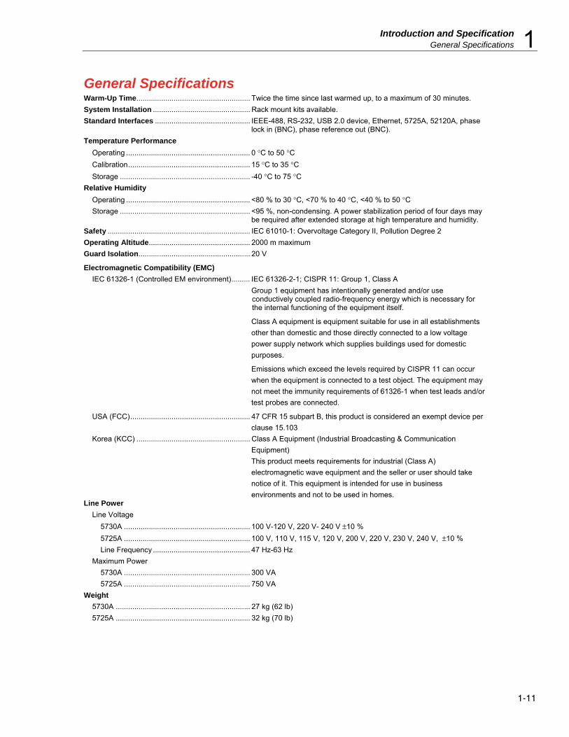
General Specifications Warm-Up Time ....................................................... Twice the time since last warmed up, to a maximum of 30 minutes.
System Installation ............................................... Rack mount kits available.
Standard Interfaces .............................................. IEEE-488, RS-232, USB 2.0 device, Ethernet, 5725A, 52120A, phase lock in (BNC), phase reference out (BNC).
Temperature Performance
Operating ............................................................ 0 °C to 50 °C
Calibration ........................................................... 15 °C to 35 °C
Storage ............................................................... -40 °C to 75 °C
Relative Humidity
Operating ............................................................ <80 % to 30 °C, <70 % to 40 °C, <40 % to 50 °C
Storage ............................................................... <95 %, non-condensing. A power stabilization period of four days may be required after extended storage at high temperature and humidity.
Safety ..................................................................... IEC 61010-1: Overvoltage Category II, Pollution Degree 2
Operating Altitude ................................................. 2000 m maximum
Guard Isolation ...................................................... 20 V
Electromagnetic Compatibility (EMC)
IEC 61326-1 (Controlled EM environment) ......... IEC 61326-2-1; CISPR 11: Group 1, Class A
Group 1 equipment has intentionally generated and/or use conductively coupled radio-frequency energy which is necessary for the internal functioning of the equipment itself.
Class A equipment is equipment suitable for use in all establishments
other than domestic and those directly connected to a low voltage
power supply network which supplies buildings used for domestic
purposes.
Emissions which exceed the levels required by CISPR 11 can occur
when the equipment is connected to a test object. The equipment may
not meet the immunity requirements of 61326-1 when test leads and/or
test probes are connected.
USA (FCC) .......................................................... 47 CFR 15 subpart B, this product is considered an exempt device per
clause 15.103
Korea (KCC) ....................................................... Class A Equipment (Industrial Broadcasting & Communication
Equipment)
This product meets requirements for industrial (Class A)
electromagnetic wave equipment and the seller or user should take
notice of it. This equipment is intended for use in business
environments and not to be used in homes. Line Power
Line Voltage
5730A ............................................................. 100 V-120 V, 220 V- 240 V ±10 %
5725A ............................................................. 100 V, 110 V, 115 V, 120 V, 200 V, 220 V, 230 V, 240 V, ±10 %
Line Frequency ............................................... 47 Hz-63 Hz
Maximum Power
5730A ............................................................. 300 VA
5725A ............................................................. 750 VA
Weight
5730A ................................................................. 27 kg (62 lb)
5725A ................................................................. 32 kg (70 lb)
5730A Operators Manual
1-12
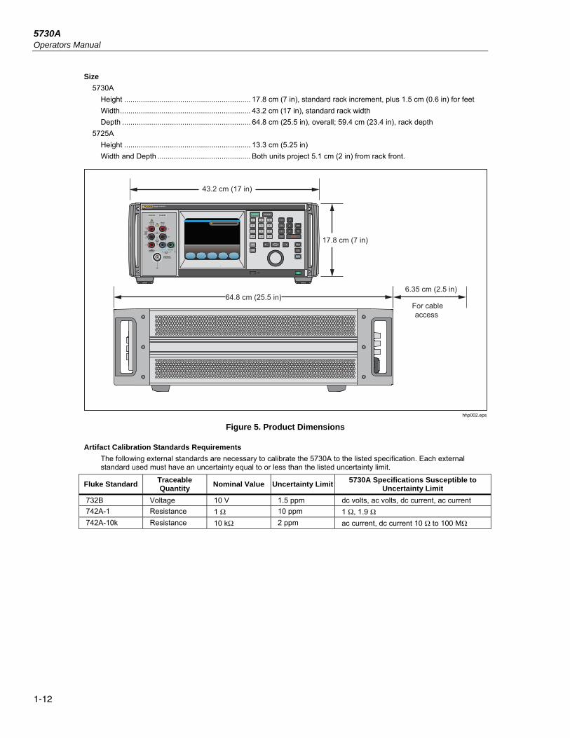
Size
5730A
Height ............................................................. 17.8 cm (7 in), standard rack increment, plus 1.5 cm (0.6 in) for feet
Width ............................................................... 43.2 cm (17 in), standard rack width
Depth .............................................................. 64.8 cm (25.5 in), overall; 59.4 cm (23.4 in), rack depth
5725A
Height ............................................................. 13.3 cm (5.25 in)
Width and Depth ............................................. Both units project 5.1 cm (2 in) from rack front.
43.2 cm (17 in)
17.8 cm (7 in)
64.8 cm (25.5 in)6.35 cm (2.5 in)
For cableaccess
hhp002.eps
Figure 5. Product Dimensions
Artifact Calibration Standards Requirements
The following external standards are necessary to calibrate the 5730A to the listed specification. Each external standard used must have an uncertainty equal to or less than the listed uncertainty limit.
Fluke Standard Traceable Quantity
Nominal Value Uncertainty Limit 5730A Specifications Susceptible to
Uncertainty Limit
732B Voltage 10 V 1.5 ppm dc volts, ac volts, dc current, ac current
742A-1 Resistance 1 Ω 10 ppm 1 Ω, 1.9 Ω
742A-10k Resistance 10 kΩ 2 ppm ac current, dc current 10 Ω to 100 MΩ

Introduction and Specification Electrical Specifications 1
1-13
Electrical Specifications The product specifications describe the Absolute Instrumental Uncertainty of the Product. The product specifications include stability, temperature, and humidity; within specified limits, linearity, line and load regulation, and the reference standard measurement uncertainty. The product specifications are provided at a 99 %, k=2.58, normally distributed and a 95 %, k=2, normally distributed level of confidence. Fluke Calibration guarantees product performance to the 99 % level of confidence.
The relative specifications are provided for enhanced accuracy applications. The specifications apply when range constants are adjusted (see "Range Calibration"). To Calculate an enhanced absolute specification from the relative accuracy specification, it is necessary to combine the uncertainty of your external standards with the pertinent relative specifications.
Specifications are valid after allowing a warm-up period of 30 minutes, or twice the time the Product has been turned off. DC Voltage Specifications
5730A DC Voltage Specifications
Range Resolution
Absolute / ±5 °C from calibration temperature Relative ±1 °C
24 Hours 90 Days 180 Days 1 Year 24 Hours 90 Days
±(ppm output [1] + μV)
99 % Confidence Level
220 mV 10 nV 5 + 0.5 7 + 0.5 8 + 0.5 9 + 0.5 2 + 0.4 2.5 + 0.4
2.2 V 100 nV 3.5 + 0.8 4 + 0.8 4.5 + 0.8 6 + 0.8 2 + 0.8 2.5 + 0.8
11 V 1 μV 2.5 + 3 3 + 3 3.5 + 3 4 + 3 1 + 3 1.5 + 3
22 V 1 μV 2.5 + 5 3 + 5 3.5 + 5 4 + 5 1 + 5 1.5 + 5
220 V 10 μV 3.5 + 50 4 + 50 5 + 50 6 + 50 2 + 50 2.5 + 50
1100 V 100 μV 5 + 500 6 + 500 7 + 500 8 + 500 2.5 + 400 3 + 400
95 % Confidence Level
220 mV 10 nV 4 + 0.4 6 + 0.4 6.5 + 0.4 7.5 + 0.4 1.6 + 0.4 2 + 0.4
2.2 V 100 nV 3 + 0.7 3.5 + 0.7 4 + 0.7 5 + 0.7 1.6 + 0.7 2 + 0.7
11 V 1 μV 2 + 2.5 2.5 + 2.5 3 + 2.5 3.5 + 2.5 0.8 + 2.5 1.2 + 2.5
22 V 1 μV 2 + 4 2.5 + 4 3 + 4 3.5 + 4 0.8 + 4 1.2 + 4
220 V 10 μV 3 + 40 3.5 + 40 4 + 40 5 + 40 1.6 + 40 2 + 40
1100 V 100 μV 4 + 400 4.5 + 400 6 + 400 6.5 + 400 2 + 400 2.4 + 400
Notes:
Perform the DC Zero calibration every 30 days. In addition, perform the DC Zero calibration after powering up the unit the first time after unpacking following a shipment or if exposed to an environmental change of greater than 5 °C.
1. For radiated EMI fields >400 MHz and <500 MHz, add 1 ppm.
DC Voltage Secondary Performance Specifications and Operating Characteristics
Range Stability [1] ±1 °C
24 Hours
Temperature Coefficient Adder [2]
Linearity ±1 °C
Noise
10 - 40 °C 0 - 10 °C and
40 - 50 °C
Bandwidth 0.1 - 10 Hz
pk-pk
Bandwidth 10 - 10 kHz
RMS
±(ppm output + μV) ±(ppm output + μV) / °C ±(ppm output + μV) μV
220 mV 2.2 V 11 V 22 V 220 V 1100 V
0.3 + 0.3 0.3 + 1
0.3 + 2.5 0.4 + 5
0.5 + 40 0.5 + 200
0.4 + 0.1 0.3 + 0.1
0.15 + 0.2 0.2 + 0.4 0.3 + 5
0.5 + 10
1.5 + 0.5 1.5 + 2 1 + 1.5 1.5 + 3
1.5 + 40 3 + 200
1 + 0.2 1 + 0.6 0.3 + 2 0.3 + 4 1 + 40
1 + 200
0.15 + 0.1 0.15 + 0.4 0.15 + 2 0.15 + 4
0.15 + 60 0.15 + 300
5 15 50 50
150 500
Notes:
1. Stability specifications are included in the absolute specification values in the primary specification tables.
2. Temperature coefficient is an adder to accuracy specifications that does not apply unless operating more than ±5 °C from calibration temperature.

5730A Operators Manual
1-14
Minimum Output .................................................. 0 V for all ranges, except 100 V for 1100 V range
Maximum Load ..................................................... 50 mA for 2.2 V through 220 V ranges; 20 mA for 1100 V range; 50 Ω output impedance on 220 mV range; all ranges <1000 pF, >25 Ω
Load Regulation ................................................... <(0.2 ppm of output + 0.1 ppm of range), full load to no load
Line Regulation .................................................... <0.1 ppm change, ±10 % of selected nominal line
Settling Time ........................................................ 3 seconds to full specification; + 1 second for range or polarity change; + 1 second for 1100 V range
Overshoot ............................................................. <5 %
Common Mode Rejection .................................... 140 dB, DC to 400 Hz
Remote Sensing .................................................. Available 0 V to ±1100 V, on 2.2 V through 1100 V ranges
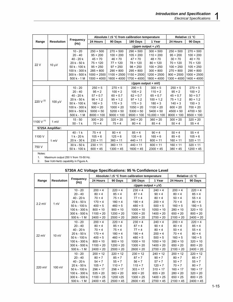
AC Voltage Specifications 5730A AC Voltage Specifications: 99 % Confidence Level
Range Resolution Frequency
(Hz)
Absolute / ±5 °C from calibration temperature Relative ±1 °C
24 Hours 90 Days 180 Days 1 Year 24 Hours 90 Days
±(ppm output + μV)
2.2 mV 1 nV
10 - 20 20 - 40
40 - 20 k 20 k - 50 k
50 k - 100 k 100 k - 300 k 300 k - 500 k 500 k - 1 M
250 + 5 100 + 5 85 + 5
220 + 5 500 + 6
1000 + 12 1400 + 25 2900 + 25
270 + 5 105 + 5 90 + 5
230 + 5 540 + 6
1200 + 12 1500 + 25 3100 + 25
290 + 5 110 + 5 95 + 5
240 + 5 570 + 6
1250 + 12 1600 + 25 3250 + 25
300 + 5 115 + 5 100 + 5 250 + 5 600 + 6
1300 + 12 1700 + 25 3400 + 25
250 + 5 100 + 5 60 + 5 85 + 5
200 + 6 350 + 12 800 + 25
2700 + 25
270 + 5 105 + 5 65 + 5 95 + 5
220 + 6 400 + 12
1000 + 25 3000 + 25
22 mV 10 nV
10 - 20 20 - 40
40 - 20 k 20 k - 50 k
50 k - 100 k 100 k - 300 k 300 k - 500 k 500 k - 1 M
250 + 5 100 + 5 85 + 5
220 + 5 500 + 6
1000 + 12 1400 + 25 2900 + 25
270 + 5 105 + 5 90 + 5
230 + 5 540 + 6
1200 + 12 1500 + 25 3100 + 25
290 + 5 110 + 5 95 + 5
240 + 5 570 + 6
1250 + 12 1600 + 25 3250 + 25
300 + 5 115 + 5 100 + 5 250 + 5 600 + 6
1300 + 12 1700 + 25 3400 + 25
250 + 5 100 + 5 60 + 5 85 + 5
200 + 6 350 + 12 800 + 25
2700 + 25
270 + 5 105 + 5 65 + 5 95 + 5
220 + 6 400 + 12
1000 + 25 3000 + 25
220 mV 100 nV
10 - 20 20 - 40
40 - 20 k 20 k - 50 k
50 k - 100 k 100 k - 300 k 300 k - 500 k 500 k - 1 M
250 + 15 100 + 8 65 + 8
135 + 8 370 + 20 650 + 25
1400 + 30 2700 + 60
270 + 15 105 + 8 66 + 8
140 + 8 380 + 20 700 + 25
1500 + 30 2900 + 60
290 + 15 110 + 8 67 + 8
145 + 8 390 + 20 750 + 25
1600 + 30 3100 + 60
300 + 15 115 + 8 70 + 8
150 + 8 400 + 20 800 + 25
1700 + 30 3300 + 60
250 + 15 100 + 8 60 + 8 85 + 8
200 + 20 350 + 25 800 + 30
2600 + 60
270 + 15 105 + 8 65 + 8 95 + 8
220 + 20 400 + 25
1000 + 30 2800 + 60
2.2 V 1 μV
10 - 20 20 - 40
40 - 20 k 20 k - 50 k
50 k - 100 k 100 k - 300 k 300 k - 500 k 500 k - 1 M
250 + 50 95 + 20 45 + 10 75 + 12 95 + 40
350 + 100 1000 + 250 1600 + 400
270 + 50 100 + 20 46 + 10 77 + 12 97 + 40
370 + 100 1100 + 250 1800 + 400
290 + 50 105 + 20 47 + 10 78 + 12 98 + 40
380 + 100 1150 + 250 1900 + 400
300 + 50 110 + 20 48 + 10 80 + 12
100 + 40 400 + 100
1200 + 250 2000 + 400
250 + 50 95 + 20 30 + 10 70 + 12
100 + 40 270 + 100 900 + 250
1200 + 400
270 + 50 100 + 20 40 + 10 75 + 12
105 + 40 290 + 100
1000 + 250 1300 + 400
Introduction and Specification Electrical Specifications 1
1-15
Range Resolution Frequency
(Hz)
Absolute / ±5 °C from calibration temperature Relative ±1 °C
24 Hours 90 Days 180 Days 1 Year 24 Hours 90 Days
±(ppm output + μV)
22 V 10 μV
10 - 20 20 - 40
40 - 20 k 20 k - 50 k
50 k - 100 k 100 k - 300 k 300 k - 500 k 500 k - 1 M
250 + 500 95 + 200 45 + 70
75 + 120 95 + 250
285 + 800 1000 + 2500 1500 + 4000
270 + 500 100 + 200
46 + 70 77 + 120 97 + 250
290 + 800 1100 + 2500 1600 + 4000
290 + 500 105 + 200
47 + 70 78 + 120 98 + 250
295 + 800 1150 + 2500 1700 + 4000
300 + 500 110 + 200
48 + 70 80 + 120
100 + 250 300 + 800
1200 + 2500 1800 + 4000
250 + 500 95 + 200 30 + 70
70 + 120 100 + 250 270 + 800
900 + 2500 1300 + 4000
270 + 500 100 + 200
40 + 70 75 + 120
105 + 250 290 + 800
1000 + 2500 1400 + 4000
±(ppm output + mV)
220 V [2] 100 μV
10 - 20 20 - 40
40 - 20 k 20 k - 50 k
50 k - 100 k 100 k - 300 k 300 k - 500 k 500 k - 1 M
250 + 5 95 + 2
57 + 0.7 90 + 1.2 160 + 3
900 + 20 5000 + 50
8000 + 100
270 + 5 100 + 2 60 + 0.7 95 + 1.2 170 + 3
1000 + 20 5200 + 50
9000 + 100
290 + 5 105 + 2 62 + 0.7 97 + 1.2 175 + 3
1050 + 20 5300 + 50
9500 + 100
300 + 5 110 + 2 65 + 0.7
100 + 1.2 180 + 3
1100 + 20 5400 + 50
10,000 + 100
250 + 5 95 + 2
45 + 0.7 75 + 1.2 140 + 3
600 + 20 4500 + 50
8000 + 100
270 + 5 100 + 2 50 + 0.7 80 + 1.2 150 + 3
700 + 20 4700 + 50
8500 + 100
1100 V [1] 1 mV 15 - 50 50 - 1 k
300 + 20 70 + 4
320 + 20 75 + 4
340 + 20 80 + 4
360 + 20 85 + 4
300 + 20 50 + 4
320 + 20 55 + 4
5725A Amplifier:
1100 V 1 mV
40 - 1 k 1 k - 20 k
20 k - 30 k
75 + 4 105 + 6
230 + 11
80 + 4 125 + 6
360 + 11
85 + 4 135 + 6
440 + 11
90 + 4 165 + 6
600 + 11
50 + 4 85 + 6
160 + 11
55 + 4 105 + 6
320 + 11
750 V 30 k - 50 k
50 k - 100 k 230 + 11 600 + 45
360 + 11 1300 + 45
440 + 11 1600 + 45
600 + 11 2300 + 45
160 + 11 380 + 45
320 + 11 1200 + 45
Notes:
1. Maximum output 250 V from 15-50 Hz.
2. See Volt-Hertz capability in Figure A.
5730A AC Voltage Specifications: 95 % Confidence Level
Range Resolution Frequency
(Hz)
Absolute / ±5 °C from calibration temperature Relative ±1 °C
24 Hours 90 Days 180 Days 1 Year 24 Hours 90 Days
±(ppm output + μV)
2.2 mV 1 nV
10 - 20 20 - 40
40 - 20 k 20 k - 50 k
50 k - 100 k 100 k - 300 k 300 k - 500 k 500 k - 1 M
200 + 4 80 + 4 70 + 4
170 + 4 400 + 5
800 + 10 1100 + 20 2400 + 20
220 + 4 85 + 4 75 + 4
180 + 4 460 + 5
900 + 10 1200 + 20 2500 + 20
230 + 4 87 + 4 77 + 4
190 + 4 480 + 5
1000 + 10 1300 + 20 2600 + 20
240 + 4 90 + 4 80 + 4
200 + 4 500 + 5
1050 + 10 1400 + 20 2700 + 20
200 + 4 80 + 4 50 + 4 70 + 4
160 + 5 280 + 10 650 + 20
2100 + 20
220 + 4 85 + 4 55 + 4 80 + 4
180 + 5 320 + 10 800 + 20
2400 + 20
22 mV 10 nV
10 - 20 20 - 40
40 - 20 k 20 k - 50 k
50 k - 100 k 100 k - 300 k 300 k - 500 k 500 k - 1 M
200 + 4 80 + 4 70 + 4
170 + 4 400 + 5
800 + 10 1100 + 20 2400 + 20
220 + 4 85 + 4 75 + 4
180 + 4 460 + 5
900 + 10 1200 + 20 2500 + 20
230 + 4 87 + 4 77 + 4
190 + 4 480 + 5
1000 + 10 1300 + 20 2600 + 20
240 + 4 90 + 4 80 + 4
200 + 4 500 + 5
1050 + 10 1400 + 20 2700 + 20
200 + 4 80 + 4 50 + 4 70 + 4
160 + 5 280 + 10 650 + 20
2100 + 20
220 + 4 85 + 4 55 + 4 80 + 4
180 + 5 320 + 10 800 + 20
2400 + 20
220 mV 100 nV
10 - 20 20 - 40
40 - 20 k 20 k - 50 k
50 k - 100 k 100 k - 300 k 300 k - 500 k 500 k - 1 M
200 + 12 80 + 7 54 + 7
105 + 7 296 + 17 535 + 20
1100 + 25 2400 + 45
220 + 12 85 + 7 55 + 7
110 + 7 298 + 17 583 + 20 1200 +25 2500 + 45
230 + 12 87 + 7 56 + 7
115 + 7 303 + 17 600 + 20
1300 + 25 2600 + 45
240 + 12 90 + 7 57 + 7
120 + 7 310 + 17 655 + 20
1400 + 25 2700 + 45
200 + 12 80 + 7 50 + 7 70 + 7
160 + 17 280 + 20 650 + 25
2100 + 45
220 + 12 85 + 7 55 + 7 80 + 7
180 + 17 320 + 20 800 + 25
2400 + 45

5730A Operators Manual
1-16
Range Resolution Frequency
(Hz)
Absolute / ±5 °C from calibration temperature Accuracy ±1 °C
24 Hours 90 Days 180 Days 1 Year 24 Hours 90 Days
±(ppm output + μV)
±(ppm output + mV)
2.2 V 1 μV
10 - 20 20 - 40
40 - 20 k 20 k - 50 k
50 k - 100 k 100 k - 300 k 300 k - 500 k 500 k - 1 M
200 + 40 75 + 15 37 + 8
61 + 10 79 + 30
276 + 80 800 + 200
1300 + 300
220 + 40 80 + 15 39 + 8
63 + 10 81 + 30
300 + 80 900 + 200
1500 + 300
230 + 40 85 + 15 40 + 8
65 + 10 82 + 30
314 + 80 950 + 200
1600 + 300
240 + 40 90 + 15 42 + 8
67 + 10 85 + 30
336 + 80 1000 + 200 1700 + 300
200 + 40 75 + 15 25 + 8
55 + 10 80 + 30
230 + 80 700 + 200
1000 + 300
220 + 40 80 + 15 35 + 8
60 + 10 85 + 30
250 + 80 800 + 200
1100 + 300
22 V 10 μV
10 - 20 20 - 40 40 - 20k 20k - 50k
50k - 100k 100k - 300k 300k - 500k 500k - 1M
200 + 400 75 + 150 37 + 50
61 + 100 78 + 200
238 + 600 800 + 2000
1200 + 3200
220 + 400 80 + 150 39 + 50
63 + 100 80 + 200
243 + 600 900 + 2000
1300 + 3200
230 + 400 85 + 150 40 + 50
65 + 100 81 + 200
249 + 600 900 + 2000
1400 + 3200
240 + 400 90 + 150 42 + 50
67 + 100 83 + 200
254 + 600 1000 + 2000 1500 + 3200
200 + 400 75 + 150 25 + 50
55 + 100 80 + 200
250 + 600 700 + 2000
1100 + 3200
220 + 400 80 + 150 35 + 50
60 + 100 85 + 200
270 + 600 800 + 2000
1200 + 3200
220 V [2] 100 μV
10 - 20 20 - 40
40 - 20 k 20 k - 50 k
50 k - 100 k 100 k - 300 k 300 k - 500 k 500 k - 1 M
200 +4 75 + 1.5 45 + 0.6 70 + 1
120 + 2.5 700 + 16
4000 + 40 6000 + 80
220 + 4 80 + 1.5 47 + 0.6 75 + 1
130 + 2.5 800 + 16
4200 + 40 7000 + 80
230 + 4 85 + 1.5 50 + 0.6 77 + 1
140 + 2.5 850 + 16
4300 + 40 7500 + 80
240 + 4 90 + 1.5 52 + 0.6 80 + 1
150 + 2.5 900 + 16
4400 + 40 8000 + 80
200 + 4 75 + 1.5 35 + 0.6 60 + 1
110 + 2.5 500 + 16
3600 + 40 6500 + 80
220 + 4 80 + 1.5 40 + 0.6 65 + 1
120 + 2.5 600 + 16
3800 + 40 7000 + 80
1100 V [1] 1 mV 15 - 50 50 - 1 k
240 + 16 55 + 3.5
260 + 16 60 + 3.5
280 + 16 65 + 3.5
300 + 16 70 + 3.5
240 + 16 40 + 3.5
260 + 16 45 + 3.5
5725A Amplifier:
1100 V 1 mV
40 - 1 k 1 k - 20 k
20 k - 30 k
75 + 4 105 + 6
230 + 11
80 + 4 125 + 6
360 + 11
85 + 4 135 + 6
440 + 11
90 + 4 165 + 6
600 + 11
50 + 4 85 + 6
160 + 11
55 + 4 105 + 6
320 + 11
750 V 30 k - 50 k
50 k - 100 k 230 + 11 600 + 45
360 + 11 1300 + 45
440 + 11 1600 + 45
600 + 11 2300 + 45
160 + 11 380 + 45
320 + 11 1200 + 45
Notes:
1. Maximum output 250 V from 15-50 Hz.
2. See Volt-Hertz capability in Figure A.

Introduction and Specification Electrical Specifications 1
1-17
AC Voltage Secondary Performance Specifications and Operating Characteristics
Range Frequency
(Hz)
Stability ±1 °C [1] 24 Hours
Temperature Coefficient
Output Impedance (Ω)
Maximum Distortion
Bandwidth 10 Hz-10 MHz
10 - 40 °C 0 - 10 °C and
40 - 50 °C
±μV ±μV / °C ±(% output + μV)
2.2 mV
10 - 20 20 - 40
40 - 20 k 20 k - 50 k
50 k - 100 k 100 k - 300 k 300 k - 500 k 500 k - 1 M
5 5 2 2 3 3 5 5
0.05 0.05 0.05 0.1 0.2 0.3 0.4 0.5
0.05 0.05 0.05 0.1 0.2 0.3 0.4 0.5
50
0.05 + 10 0.035 + 10 0.035 + 10 0.035 + 10 0.035 + 30
0.3 + 30 0.3 + 30 2 + 50
22 mV
10 - 20 20 - 40
40 - 20 k 20 k - 50 k
50 k - 100 k 100 k - 300 k 300 k - 500 k 500 k - 1 M
5 5 2 2 3 5
10 15
0.2 0.2 0.2 0.4 0.5 0.6 1 1
0.3 0.3 0.3 0.5 0.5 0.6 1 1
50
0.05 + 11 0.035 + 11 0.035 + 11 0.035 + 11 0.035 + 30
0.3 + 30 0.3 + 30 2 + 30
±(ppm output + μV) ±(ppm output μV) / °C
220 mV
10 - 20 20 - 40
40 - 20 k 20 k - 50 k
50 k - 100 k 100 k - 300 k 300 k - 500 k 500 k - 1 M
150 + 20 80 + 15 12 + 2 10 + 2 10 + 2 20 + 4
100 + 10 200 + 20
2 + 1 2 + 1 2 + 1
15 + 2 15 + 4 80 + 5 80 + 5 80 + 5
2 + 1 2 + 1 2 + 1
15 + 2 15 + 4 80 + 5 80 + 5 80 + 5
50
0.05 + 16 0.035 + 16 0.035 + 16 0.035 + 16 0.035 + 30
0.3 + 30 0.3 + 30 1 + 30
Load Regulation ±(ppm output + μV)
2.2 V
10 - 20 20 - 40
40 - 20 k 20 k - 50 k
50 k - 100 k 100 k - 300 k 300 k - 500 k 500 k - 1 M
150 + 20 80 + 15 12 + 4 15 + 5 15 + 5
30 + 10 70 + 20
150 + 50
50 + 10 15 + 5 2 + 1
10 + 2 10 + 4
80 + 15 80 + 40
80 + 100
50 + 10 15 + 5 5 + 2
15 + 4 20 + 4
80 + 15 80 + 40
80 + 100
10 + 2 10 + 2 10 + 4
30 + 10 120 + 16 300 ppm 600 ppm
1200 ppm
0.05 + 80 0.035 + 80 0.035 + 80 0.035 + 80
0.035 + 110 0.3 + 110 0.5 + 110 1 + 110
22 V
10 - 20 20 - 40
40 - 20 k 20 k - 50 k
50 k - 100 k 100 k - 300 k 300 k - 500 k 500 k - 1 M
150 + 20 80 + 15 12 + 8
15 + 10 15 + 10 30 + 15
70 + 100 150 + 100
50 + 100 15 + 30 2 + 10
10 + 20 10 + 40
80 + 150 80 + 300 80 + 500
50 + 100 15 + 40 4 + 15
20 + 20 20 + 40
80 + 150 80 + 300 80 + 500
10 + 20 10 + 20 10 + 30 30 + 50 80 + 80
100 + 700 200 + 1100 600 + 3000
0.05 + 700 0.035 + 700 0.035 + 700 0.035 + 700 0.05 + 800 0.3 + 800 0.3 + 800 2 + 800
220 V
10 - 20 20 - 40
40 - 20 k 20 k - 50 k
50 k - 100 k 100 k - 300 k 300 k - 500 k 500 k - 1 M
150 + 200 80 + 150 12 + 80
15 + 100 15 + 100 30 + 400
100 + 10,000 200 + 20,000
50 + 1000 15 + 300
2 + 80 10 + 100 10 + 500 80 + 600 80 + 800
80 + 1000
50 + 1000 15 + 300
4 + 80 20 + 100 20 + 500 80 + 600 80 + 800
80 + 1000
10 + 200 10 + 200 10 + 300 30 + .600
80 + 3,000 250 + 25,000 500 + 50,000
1000 + 110,000
0.05 + 10,000 0.05 + 10,000 0.05 + 10,000 0.05 + 10,000 0.2 + 50,000 1.5 + 50,000 1.5 + 50,000
3.5 + 100,000 ±(ppm output + mV) ±(ppm output) / °C ±(ppm output + mV) ±(% output)
1100 V 15 - 50 50 - 1 k
150 + 0.5 20 + 0.5
50 2
50 5
10 + 2 10 + 1
0.15 0.07
5730A Operators Manual
1-18
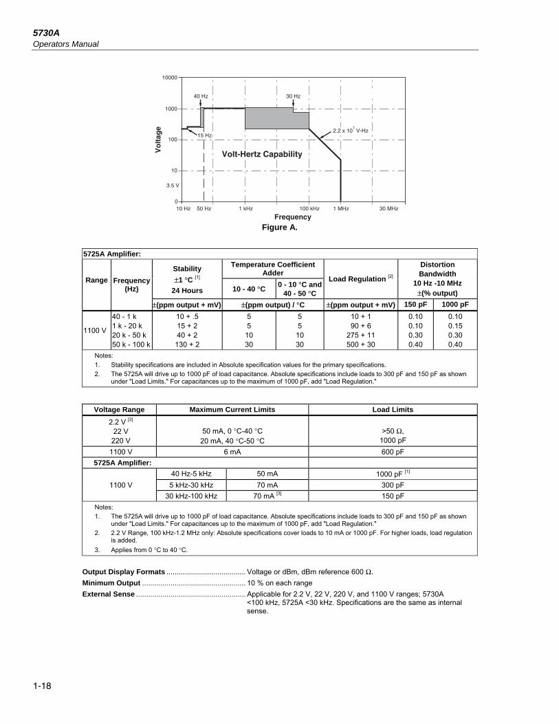
1000
100
10
0
3.5 V
10000
50 Hz10 Hz 1 kHz 100 kHz 1 MHz 30 MHz
Vo
ltag
e
Frequency
40 Hz 30 Hz
2.2 x 10⁷ V-Hz
15 Hz
Volt-Hertz Capability
Figure A.
5725A Amplifier:
Range
Frequency (Hz)
Stability
±1 °C [1]
24 Hours
Temperature Coefficient Adder
Load Regulation [2]
Distortion Bandwidth
10 Hz -10 MHz ±(% output)
10 - 40 °C 0 - 10 °C and
40 - 50 °C
±(ppm output + mV) ±(ppm output) / °C ±(ppm output + mV) 150 pF 1000 pF
1100 V
40 - 1 k 1 k - 20 k 20 k - 50 k 50 k - 100 k
10 + .5 15 + 2 40 + 2
130 + 2
5 5
10 30
5 5
10 30
10 + 1 90 + 6
275 + 11 500 + 30
0.10 0.10 0.30 0.40
0.10 0.15 0.30 0.40
Notes:
1. Stability specifications are included in Absolute specification values for the primary specifications.
2. The 5725A will drive up to 1000 pF of load capacitance. Absolute specifications include loads to 300 pF and 150 pF as shown under "Load Limits." For capacitances up to the maximum of 1000 pF, add "Load Regulation."
Voltage Range Maximum Current Limits Load Limits
2.2 V [2] 22 V
220 V
50 mA, 0 °C-40 °C
20 mA, 40 °C-50 °C
>50 Ω,
1000 pF
1100 V 6 mA 600 pF
5725A Amplifier:
40 Hz-5 kHz 50 mA 1000 pF [1]
1100 V 5 kHz-30 kHz 70 mA 300 pF
30 kHz-100 kHz 70 mA [3] 150 pF
Notes:
1. The 5725A will drive up to 1000 pF of load capacitance. Absolute specifications include loads to 300 pF and 150 pF as shown under "Load Limits." For capacitances up to the maximum of 1000 pF, add "Load Regulation."
2. 2.2 V Range, 100 kHz-1.2 MHz only: Absolute specifications cover loads to 10 mA or 1000 pF. For higher loads, load regulation is added.
3. Applies from 0 °C to 40 °C.
Output Display Formats ....................................... Voltage or dBm, dBm reference 600 Ω.
Minimum Output ................................................... 10 % on each range
External Sense ...................................................... Applicable for 2.2 V, 22 V, 220 V, and 1100 V ranges; 5730A <100 kHz, 5725A <30 kHz. Specifications are the same as internal sense.

Introduction and Specification Electrical Specifications 1
1-19
Settling Time to Published Specifications Frequency (Hz) Settling Time (seconds)
10-120 7
>120 5
Notes:
Plus 1 second for amplitude or frequency range change
Plus 2 seconds for 5730A 1100 V range
Plus 4 seconds for 5725A 1100 V range
Overshoot .............................................................. <10 %
Common Mode Rejection ....................................... 140 dB, dc to 400 Hz
Frequency
Ranges (Hz) ........................................................ 10.000 - 119.99
0.1200 k - 1.1999 k
1.200 k - 11.999 k
12.00 k - 119.99 k
120.0 k - 1.1999 M
Absolute Specification ........................................ ±0.0025 %
Resolution ........................................................... 11.999 counts
Phase Lock (Selectable Rear Panel BNC Input)
Phase Specification (except 1100 V range) ........ >30 Hz: ±1 ° + 0.05 °/kHz), <30 Hz: ±3 ° Input Voltage ....................................................... 1 V to 10 V rms sine wave (do not exceed 1 V for mV ranges)
Frequency Range ............................................... 10 Hz to 1.1999 MHz
Lock Range ......................................................... ±2 % of frequency
Lock-In Time ....................................................... Larger of 10/frequency or 10 msec
Phase Reference (Selectable Rear Panel BNC Output)
Range ................................................................. ±180 ° Phase Absolute Specification ............................. (except 1100 V range) ±1 ° at quadrature points (0 °, ±90 °, ±180 °)
elsewhere ±2 ° Stability ............................................................... ±0.1 ° Resolution ........................................................... 1 ° Output Level ....................................................... 2.5 V rms ±0.2 V
Frequency Range ............................................... 50 Hz to 1 kHz, usable 10 Hz to 1.1999 MHz

5730A Operators Manual
1-20
Resistance Specifications
5730A Resistance Specifications
Nominal Value (Ω)
Absolute Specification of Characterized Value ±5 °C from calibration temperature [1]
Relative ±1 °C
24 Hours 90 Days 180 Days 1 Year 24 Hours 90 Days
±ppm
99 % Confidence Level
0 1
1.9 10 19
100 190 1 k
1.9 k 10 k 19 k
100 k 190 k 1 M
1.9 M 10 M 19 M
100 M
50 μΩ 85 85 23 23 10 10 7 7 6 6 7 8
13 15 33 43
100
50 μΩ 95 95 25 25 11 11 7.2 7.2 7 7 8
10 14 17 37 47
110
50 μΩ 100 100 26 26
11.5 11.5 7.5 7.5 7.5 7.5 9
11 14.5 19 40 50
115
50 μΩ 110 110 27 27 12 12 8 8 8 8
10 12 15 21 46 55
120
50 μΩ 32 25 5 4 2 2 2 2 2 2 2 2
2.5 3
10 20 50
50 μΩ 40 33 8 7 4 4 3 3 3 3 3 3 5 6
14 24 60
95 % Confidence Level
0 1
1.9 10 19
100 190 1 k
1.9 k 10 k 19 k
100 k 190 k 1 M
1.9 M 10 M 19 M
100 M
40 μΩ 70 70 20 20 8 8
5.5 5.5 5 5
5.5 6
10 12 27 35 85
40 μΩ 80 80 21 21 9 9
5.7 5.7 5.5 5.5 7.5 7
11 13.5 31 39 95
40 μΩ 85 85 22 22 9.5 9.5 6 6 6 6 8 8
12 15 34 42
100
40 μΩ 95 95 23 23 10 10 6.5 6.5 6.5 6.5 8.5
8.5 13 18 40 47
100
40 μΩ 27 20 4
3.5 1.6 1.6 1.6 1.6 1.6 1.6 1.6 1.6 2
2.5 8
16 40
40 μΩ 35 26 7 6
3.5 3.5 2.5 2.5 2.5 2.5 2.5 2.5 4 4
12 20 50
Note:
1. Specifications apply to displayed value. 4-wire connections, except 100 MΩ.

Introduction and Specification Electrical Specifications 1
1-21
Resistance Secondary Performance Specifications and Operating Characteristics
Nominal Value
(Ω)
Stability ±1 °C [1]
24 Hours
Temperature Coefficient Adder [2]
Full Spec Load Range [3]
IL - IU (mA)
Maximum Peak
Current IMAX
(mA)
Maximum Difference of Characterized
to Nominal Value
Two-Wire Adder Active
Compensation [4]
10 - 40 °C 0 - 10 °C
and 40 - 50 °C
Lead Resistance
±ppm 0.1 Ω 1 Ω
±ppm ±ppm/°C ±mΩ
0 ⎯ ⎯ ⎯ 8 - 500 500 ⎯ 2 + mIμV 4
4 + mIμV 4
1 32 4 5 8 - 100 700 500 2 + mIμV 4
4 + mIμV 4
1.9 25 6 7 8 - 100 500 500 2 + mIμV 4
4 + mIμV 4
10 5 2 3 8 - 11 220 300 2 + mIμV 4
4 + mIμV 4
19 4 2 3 8 - 11 160 300 2 + mIμV 4
4 + mIμV 4
100 2 2 3 8 - 11 70 150 2 + mIμV 4
4 + mIμV 4
190 2 2 3 8 - 11 50 150 2 + mIμV 4
4 + mIμV 4
1 k 2 2 3 1 - 2 22 150 10 15
1.9 k 2 2 3 1 - 1.5 16 150 10 15
10 k 2 2 3 100 - 500 μA 7 150 50 60
19 k 2 2 3 50 - 250 μA 5 150 100 120
100 k 2 2 3 10 - 100 μA 1 150 Im= Current produced by
Ohmmeter (A)
190 k 2 2 3 5 - 100 μA 500 μA 150
1 M 2.5 2.5 6 5 - 20 μA 100 μA 200
1.9 M 3.5 3 10 2.5 - 10 μA 50 μA 200
10 M 10 5 20 0.5 - 2 μA 10 μA 300
19 M 20 8 40 0.25 - 1 μA 5 μA 300
100 M 50 12 100 50 - 200 nA 1 μA 500
Notes:
1. Stability specifications are included in the Absolute specification values in the primary specification tables.
2. Temperature coefficient is an adder to Absolute specifications that does not apply unless operated more than 5 °C from calibration temperature, or calibrated outside the range 19 °C to 24 °C. Two examples:
- Calibrate at 20 °C: Temperature coefficient adder is not required unless operated below 15 °C or above 25 °C.
- Calibrate at 26 °C: Add 2 °C temperature coefficient adder. Additional temperature coefficient adder is not required unless operated below 21 °C or above 31 °C.
3. Refer to current derating factors table for loads outside of this range.
4. Active two-wire compensation may be selected for values less than 100 kΩ, with either the front panel or the meter input terminals as reference plane. Active compensation is limited to 11 mA load, and to 2 V burden. Two-wire compensation can be used only with Ω-meters that source continuous (not pulsed) dc current.

5730A Operators Manual
1-22
Current Derating Factors
Nominal Value (Ω)
Value of Derating Factor K for Over or Under Current
Two-Wire Comp I < IL
[1] Four-Wire
I < IL [1] Four-Wire
IU < I < IMAX [2]
SHORT
1
1.9
10
19
100
190
1 k
1.9 k
10 k
19 k
100 k
190 k
1 M
1.9 M
10 M
19 M
100 M
4.4
4.4
4.4
4.4
4.4
4.4
4.4
4.4
4.4
5000
5000
⎯
⎯
⎯
⎯
⎯
⎯
0.3
300
160
30
16
3.5
2.5
0.4
0.4
50
50
7.5
4.0
1.0
0.53
0.2
0.53
0.1
⎯
4 x10⁻⁵
1.5 x 10⁻⁴
1.6 x 10⁻³
3 x 10⁻³
1 x 10⁻²
1.9 x 10⁻²
0.1
0.19
2.0
3.8
2 x 10⁻⁵
3.8 x 10⁻⁵
1.5 x 10⁻⁴
2.9 x 10⁻⁴
1 x 10⁻³
1.9 x 10⁻³
⎯
Notes:
1. For I < I L, errors occur due to thermally generated voltages within the 5730A. Use the following equation to determine the error, and add this error to the corresponding specifications.
Error = K(I L - I)/( I L x I)
Where: Error is in mΩ for all two-wire comp values and four-wire short, and in ppm for the remaining four-wire values.
K is the constant from the above table; I and IL are expressed in mA for short to 1.9 kΩ; I and IL are expressed in μA for 10 kΩ to 100 MΩ
2. For IU < I < IMAX errors occur due to self-heating of the resistors in the calibrator. Use the following equation to determine the error in ppm and add this error to the corresponding specifications.
Error in ppm = K(I2-IU2)
Where: K is the constant from the above table; I and IU are expressed in mA for short to 19 kΩ; I and IU are expressed in μA for 100 kΩ to 100 MΩ

Introduction and Specification Electrical Specifications 1
1-23
DC Current Specifications
5730A DC Current Specifications
Range Resolution
Absolute / ±5 °C from calibration temperature Relative ±1 °C
24 Hours 90 Days 180 Days 1 Year 24 Hours 90 Days
nA ±(ppm output + nA)
99 % Confidence Level
220 μA 2.2 mA 22 mA
0.1 1
10
40 + 7 30 + 8
30 + 50
42 + 7 35 + 8
35 + 50
45 + 7 37 + 8
37 + 50
50 + 7 40 + 8
40 + 50
24 + 2 24 + 5
24 + 50
26 + 2 26 + 5
26 + 50
μA ±(ppm output + μA)
220 mA [1] 2.2 A [1]
0.1 1
40 + 0.8 60 + 15
45 + 0.8 70 + 15
47 + 0.8 80 + 15
50 + 0.8 90 + 15
26 + 0.3 40 + 7
30 + 0.3 45 + 7
5725A Amplifier:
11 A 10 330 + 470 340 + 480 350 + 480 360 + 480 100 + 130 110 + 130
95 % Confidence Level
nA ±(ppm output + nA)
220 μA 2.2 mA 22 mA
0.1 1
10
32 + 6 25 + 7
25 + 40
35 + 6 30 + 7
30 + 40
37 + 6 33 + 7
33 + 40
40 + 6 35 + 7
35 + 40
20 + 1.6 20 + 4
20 + 40
22 + 1.6 22 + 4
22 + 40
μA ±(ppm output + μA)
220 mA [1] 2.2 A [1]
0.1 1
35 + 0.7 50 + 12
40 + 0.7 60 + 12
42 + 0.7 70 + 12
45 + 0.7 80 + 12
22 + 0.25 32 + 6
25 + 0.25 40 + 6
5725A Amplifier:
11 A 10 330 + 470 340 + 480 350 + 480 360 + 480 100 + 130 110 + 130
Note:
Maximum output from the calibrator’s terminals is 2.2 A. Specifications for 220 μA and 2.2 mA ranges are increased by a factor of 1.3 when supplied through 5725A terminals.
Specifications are otherwise identical for all output locations.
1. Add to specifications:
±200 x I2 ppm for >100 mA on 220 mA range ±10 x I2 ppm for >1 A on 2.2 A range

5730A Operators Manual
1-24
DC Current Secondary Performance Specifications and Operating Characteristics
Range
Stability ±1 °C [1]
24 Hours
Temperature Coefficient [2]
Compliance Limits
Burden Voltage Adder [3] (±nA/V)
Maximum Load for
Published Specification
[4] (Ω)
Noise
10 - 40 °C 0 - 10 °C
and 40 - 50 °C
Bandwidth 0.1-10 Hz
Bandwidth 10 Hz-10 kHz
pk-pk RMS
±(ppm output + nA)
±(ppm output + nA) / °C
ppm output + nA
nA
220 μA 2.2 mA 22 mA 220 mA 2.2 A
5 + 1 5 + 5
5 + 50 8 + 300 9 + 7 μA
1 + 0.40 1 + 2
1 + 20 1 + 200
1 + 2.5 μA
3 + 1 3 + 10
3 + 100 3 + 1 μA
3 + 10 μA
10 10 10 10 3 [5]
0.2 0.2 10
100 2 μA
20k 2k
200 20 2
6 + .9 6 + 5
6 + 50 9 + 300
12 + 1.5 μA
10 10 50
500 20 μA
5725A ±(ppm
output + μA) ±(ppm output + μA)/
°C
ppm output +
μA μA
11 A 25 + 100 20 + 75 30 + 120 4 0 4 15 + 70 175
Notes:
Maximum output from the calibrator’s terminals is 2.2 A. Specifications for 220 μA and 2.2 mA ranges are increased by a factor of 1.3 when supplied through 5725A terminals.
1. Stability specifications are included in the Absolute specification values for the primary specifications.
2. Temperature coefficient is an adder to Absolute specifications. It does not apply unless operating more than ±5 °C from calibration temperature.
3. Burden voltage adder is an adder to Absolute specifications that does not apply unless burden voltage is greater than 0.5 V.
4. For higher loads, multiply Absolute specification by: ionspecificat publishedfor load maximum
load actualx 0.11 +
5. The calibrator’s compliance limit is 2 V for outputs from 1 A to 2.2 A. 5725A Amplifier may be used in range-lock mode down to 0 A.
Minimum Output .................................................. 0 for all ranges, including 5725A.
Settling Time ........................................................ 1 second for μA and mA ranges; 3 seconds for 2.2 A range; 6 seconds for 11 range; + 1 second for range or polarity change
Overshoot ............................................................. <5 %
AC Current Specifications
5730A AC Current Specifications: 99 % Confidence Level
Range Resolution Frequency
(Hz)
Absolute / ±5 °C from calibration temperature Relative ±1 °C
24 Hours 90 Days 180 Days 1 Year 24 Hours 90 Days
±(ppm output + nA)
220 μA 1 nA
10 - 20 20 - 40 40 - 1 k 1 k - 5 k
5 k - 10 k
260 + 20 170 + 12 115 + 10 300 + 15
1000 + 80
280 + 20 180 + 12 117 + 10 320 + 15
1100 + 80
290 + 20 190 + 12 118 + 10 340 + 15
1200 + 80
300 + 20 200 + 12 120 + 10 350 + 15
1300 + 80
260 + 20 130 + 12 100 + 10 250 + 15 900 + 80
280 + 20 150 + 12 110 + 10 280 + 15
1000 + 80
2.2 mA 10 nA
10 - 20 20 - 40 40 - 1 k 1 k - 5 k
5 k - 10 k
260 + 50 170 + 40 115 + 40
210 + 130 1000 + 800
280 + 50 180 + 40 117 + 40
220 + 130 1100 + 800
290 + 50 190 + 40 118 + 40
230 + 130 1200 + 800
300 + 50 200 + 40 120 + 40
240 + 130 1300 + 800
260 + 50 130 + 40 100 + 40
190 + 130 900 + 800
280 + 50 150 + 40 110 + 40
220 + 130 1000 + 800
22 mA 100 nA
10 - 20 20 - 40 40 - 1 k 1 k - 5 k
5 k - 10 k
260 + 500 170 + 400 115 + 400 210 + 700
1000 + 6000
280 + 500 180 + 400 117 + 400 220 + 700
1100 + 6000
290 + 500 190 + 400 118 + 400 230 + 700
1200 + 6000
300 + 500 200 + 400 120 + 400 240 + 700
1300 + 6000
260 + 500 130 + 400 100 + 400 190 + 700
900 + 6000
280 + 500 150 + 400 110 + 400 220 + 700
1000 + 6000

Introduction and Specification Electrical Specifications 1
1-25
Range Resolution Frequency
(Hz)
Absolute / ±5 °C from calibration temperature Relative ±1 °C
24 Hours 90 Days 180 Days 1 Year 24 Hours 90 Days
±(ppm output + nA)
220 mA 1 μA
10 - 20 20 - 40 40 - 1 k 1 k - 5 k
5 k - 10 k
260 + 5 170 + 4 115 + 3 210 + 4
1000 + 12
280 + 5 180 + 4 117 + 3 220 + 4
1100 + 12
290 + 5 190 + 4 118 + 3 230 + 4
1200 + 12
300 + 5 200 + 4 120 + 3 240 + 4
1300 + 12
260 + 5 130 + 4 100 + 3 190 + 4
900 + 12
280 + 5 150 + 4 110 + 3 220 + 4
1000 + 12
2.2 A 10 μA 20 - 1 k 1 k - 5 k
5 k - 10 k
270 + 40 440 + 100
6000 + 200
280 + 40 460 + 100
7000 + 200
290 + 40 480 + 100
7500 + 200
300 + 40 500 + 100
8000 + 200
260 + 40 420 + 100
6000 + 200
280 + 40 440 + 100
7000 + 200
5725A Amplifier:
11 A 100 μA 40 - 1 k 1 k - 5 k
5 k - 10 k
370 + 170 800 + 380
3000 + 750
400 + 170 850 + 380
3300 + 750
440 + 170 900 + 380
3500 + 750
460 + 170 950 + 380
3600 + 750
300 + 170 700 + 380
2800 + 750
330 + 170 800 + 380
3200 + 750
Note:
Maximum output from the calibrator’s terminals is 2.2 A. Specifications for 220 μA and 2.2 mA ranges are increased by a factor of 1.3 plus 2 μA when supplied through 5725A terminals.
5730A AC Current Specifications: 95 % Confidence Level
Range Resolution Frequency
(Hz)
Absolute / ±5 °C from calibration temperature Relative ±1 °C
24 Hours 90 Days 180 Days 1 Year 24 Hours 90 Days
±(ppm output + nA)
220 μA 1 nA
10 - 20 20 - 40 40 - 1 k 1 k - 5 k
5 k - 10 k
210 + 16 130 + 10
96 + 8 240 + 12 800 + 65
230 + 16 140 + 10
99 + 8 250 + 12 900 + 65
240 + 16 150 + 10 101 + 8
270 + 12 1000 + 65
250 + 16 160 + 10 103 + 8
280 + 12 1100 + 65
210 + 16 110 + 10
80 + 8 200 + 12 700 + 65
230 + 16 130 + 10
90 + 8 230 + 12 800 + 65
2.2 mA 10 nA
10 - 20 20 - 40 40 - 1 k 1 k - 5 k
5 k - 10 k
210 + 40 130 + 35 96 + 35
170 + 110 800 + 650
230 + 40 140 + 35 99 + 35
180 + 110 900 + 650
240 + 40 150 + 35 101 + 35
190 + 110 1000 + 650
250 + 40 160 + 35 103 + 35
200 + 110 1100 + 650
210 + 40 110 + 35 80 + 35
160 + 110 700 + 650
230 + 40 130 + 35 90 + 35
170 + 110 800 + 650
22 mA 100 nA
10 - 20 20 - 40 40 - 1 k 1 k - 5 k
5 k - 10 k
210 + 400 130 + 350 96 + 350
170 + 550 800 + 5000
230 + 400 140 + 350 99 + 350
180 + 550 900 + 5000
240 + 400 150 + 350 101 + 350 190 + 550
1000 + 5000
250 + 400 160 + 350 103 + 350 200 + 550
1100 + 5000
210 + 400 110 + 350 80 + 350
160 + 550 700 + 5000
230 + 400 130 + 350 90 + 350
170 + 550 800 + 5000
±(ppm output + μA)
220 mA 1 μA
10 - 20 20 - 40 40 - 1 k 1 k - 5 k
5 k - 10 k
210 + 4 130 + 3.5 96 + 2.5
170 + 3.5 800 + 10
230 + 4 140 + 3.5 99 + 2.5
180 + 3.5 900 + 10
240 + 4 150 + 3.5 101 + 2.5 190 + 3.5 1000 + 10
250 + 4 160 + 3.5 103 + 2.5 200 + 3.5 1100 + 10
210 + 4 110 + 3.5 80 + 2.5
160 + 3.5 700 + 10
230 + 4 130 + 3.5 90 + 2.5
170 + 3.5 800 + 10
2.2 A 10 μA
20 - 1 k 1 k - 5 k
5 k - 10 k
214 + 35 350 + 80
5000 + 160
224 + 35 390 + 80
6000 + 160
234 + 35 420 + 80
6500 + 160
244 + 35 450 + 80
7000 + 160
200 + 35 300 + 80
5000 + 160
230 + 35 350 + 80 6000 +
160
5725A Amplifier:
11 A 100 μA
40 - 1 k 1 k - 5 k
5 k - 10 k
370 + 170 800 + 380
3000 + 750
400 + 170 850 + 380
3300 + 750
440 + 170 900 + 380
3500 + 750
460 + 170 950 + 380
3600 + 750
300 + 170 700 + 380
2800 + 750
330 + 170 800 + 38 3200 +
750
Note:
Maximum output from the calibrator’s terminals is 2.2 A. Specifications for 220 μA and 2.2 mA ranges are increased by 1.3 plus 2 μA when supplied through 5725A terminals.

5730A Operators Manual
1-26
AC Current Secondary Performance Specifications and Operating Characteristics
Range Frequency
(Hz)
Stability ±1 °C [1] 24 Hours
Temperature Coefficient [2]
Compliance Limits (V rms)
Maximum Resistive
Load For
Published Specification
[3] (Ω)
Noise and Distortion
(Bandwidth 10 Hz - 50 kHz <0.5V Burden)
10 - 40 °C 0 - 10 °C and
40 - 50 °C
±(ppm output + nA)
±(ppm output + nA)/ °C ±(% output + μA)
220 μA
10 - 20 20 - 40 40 - 1 k 1 k - 5 k
5 k - 10 k
150 + 5 80 + 5 30 + 3
50 + 20 400 + 100
50 + 5 20 + 5 4 + 0.5 10 + 1
20 + 100
50 + 5 20 + 5
10 + 0.5 20 + 1
20 + 100
7 2 k
0.05 + 0.1 0.05 + 0.1 0.05 + 0.1 0.25 + 0.5 00.5 + 1
2.2 mA
10 - 20 20 - 40 40 - 1 k 1 k - 5 k
5 k - 10 k
150 + 5 80 + 5 30 + 3
50 + 20 400 + 100
50 + 5 20 + 4 4 + 1
10 + 100 50 + 400
50 + 5 20 + 4 10 + 2
20 + 100 50 + 400
7 800
0.05 + 0.1 0.05 + 0.1 0.05 + 0.1 0.25 + 0.5 00.5 + 1
22 mA
10 - 20 20 - 40 40 - 1 k 1 k - 5 k
5 k - 10 k
150 + 50 80 + 50 30 + 30
50 + 500 400 + 1000
50 + 10 20 + 10 4 + 10
10 + 500 50 + 1000
50 + 10 20 + 10 10 + 20
20 + 400 50 + 1000
7 80
0.05 + 0.1 0.05 + 0.1 0.05 + 0.1 0.25 + 0.5 00.5 + 1
Hz
±(ppm output + μA)
±(ppm output + μA)/°C
220 mA
10 - 20 20 - 40 40 - 1 k 1 k - 5 k
5 k - 10 k
150 + 0.5 80 + 0.5 30 + 0.3 50 + 3
400 + 5
50 + 0.05 20 + 0.05
4 + 0.1 10 + 2 50 + 5
50 + 0.05 20 + 0.05 10 + 0.1 20 + 2 50 + 5
7 8
0.05 + 10 0.05 + 10 0.05 + 10 0.25 + 50
00.5 + 100
2.2 A 20 - 1 k 1 k - 5 k
5 k - 10 k
50 + 5 80 + 20
800 + 50
4 + 1 10 + 5
50 + 10
10 + 1 20 + 5
50 + 10 1.4 [4] 0.8
0.5 + 100 0.3 + 500 1 + 1 mA
5725A Amplifier: ±(% output)
11 A 40 - 1 k 1 k - 5 k
5 k - 10 k
75 + 100 100 + 150 200 + 300
20 + 75 40 + 75
100 + 75
30 + 75 50 + 75
100 + 75 3 3
0.05 [5] 0.12 [5] 0.5 [5]
Notes:
Maximum output from 5730A terminals is 2.2 A. Specifications for 220 μA and 2.2 mA ranges are increased by a factor of 1.3, plus 2 μA when supplied through 5725A terminals. Specifications are otherwise identical for all output locations.
1. Stability specifications are included in the Absolute values for the primary specifications.
2. Temperature coefficient is an adder to specifications that does not apply unless operating more than ±5 °C from calibration temperature.
3. For larger resistive loads multiply accuracy specifications by: (ionspecificat publishedfor load maximum
load actual)
2
4. 1.5 V compliance limit above 1 A. 5725A Amplifier may be used in range-lock mode down to 1 A.
5. For resistive loads within rated compliance voltage limits.

Introduction and Specification Electrical Specifications 1
1-27
Minimum Output .................................................... 9 μA for 220 μA range, 10 % on all other ranges. 1 A minimum for
5725A.
Inductive Load Limits ........................................... 400 μH (5730A, or 5725A). 20 μH for 5730A output >1 A.
Power Factors ........................................................ 5730A, 0.9 to 1; 5725A, 0.1 to 1. Subject to compliance voltage limits.
Frequency Range (Hz) .......................................................... 10.000 - 11.999, 12.00 - 119.99, 120.0 - 1199.9, 1.200 k - 10.000 k
Specification .................................................. ±0.01 % of output Resolution ..................................................... 11,999 counts
Settling Time ...................................................... 5 seconds for 5730A ranges; 6 seconds for 5725A 11 A range; +1 second for amplitude or frequency range change.
Overshoot .......................................................... <10 %
Wideband AC Voltage (Option 5730A/03 and 5730A/05) Specifications (99 % Confidence Level)
Specifications apply to the end of the cable and 50 Ω termination used for calibration.
Range
Resolution
Absolute / ±5 °C from calibration temperature 30 Hz - 500 kHz
Volts dBm 24 Hours 90 Days 180 Days 1 Year
±(% output + μV)
1.1 mV -46 10 nV 0.4 + 0.4 0.5 + 0.4 0.6 + 0.4 0.8 + 2
3.3 mV -37 10 nV 0.4 + 1 0.45 + 1 0.5 + 1 0.7 + 3
11 mV -26 100 nV 0.2 + 4 0.35 + 4 0.5 + 4 0.7 + 8
33 mV -17 100 nV 0.2 + 10 0.3 + 10 0.45 + 10 0.6 + 16
110 mV -6.2 1 μV 0.2 + 40 0.3 + 40 0.45 + 40 0.6 + 40
330 mV +3.4 1 μV 0.2 + 100 0.25 + 100 0.35 + 100 0.5 + 100
1.1 V +14 10 μV 0.2 + 400 0.25 + 400 0.35 + 400 0.5 + 400
3.5 V +24 10 μV 0.15 + 500 0.2 + 500 0.3 + 500 0.4 + 500
Frequency (Hz)
Frequency Resolution
(Hz)
Amplitude Flatness, 1 kHz Reference Voltage Range Temperature
Coefficient ±ppm/°C
Settling Time To Published Specification
(Seconds)
Harmonic Distortion
(dB) 1.1 mV 3.3 mV >3.3 mV
±(% output + floor indicated)
10 - 30 0.01 0.3 0.3 0.3 100 7 -40
30 - 119.99 0.01 0.1 0.1 0.1 100 7 -40
120 - 1.1999 k 0.1 0.1 0.1 0.1 100 5 -40
1.2 k - 11.999 k 1 0.1 0.1 0.1 100 5 -40
12 k - 119.99 k 10 0.1 0.1 0.1 100 5 -40
120 k - 1.1999 M 100 0.2 + 3 μV 0.1 + 3 μV 0.1 + 3 μV 100 5 -40
1.2 M - 2 M [1] 1 k 0.2 + 3 μV 0.1 + 3 μV 0.1 + 3 μV 100 0.5 -40
2 M - 11.9 M 1 k 0.4 + 3 μV 0.3 + 3 μV 0.2 + 3 μV 100 0.5 -40
12 M - 20 M 10 k 0.6 + 3 μV 0.5 + 3 μV 0.4 + 3 μV 150 0.5 -34
20 M - 30 M 10 k 1.5 + 15 μV 1.5 + 3 μV 1 + 3 μV 300 0.5 -34
30 M - 50 M [2] 10 k 3.0 + 15 μV 3.0 + 3 μV 2.0 + 3 μV 600 0.5 -34
Note:
1. For output voltages <50 % of full range in the 33 mV, 110 mV, 330 mV, 1.1 V , and 3.5 V ranges, add 0.1 % to the amplitude flatness specification.
Additional Operating Information: dBm reference = 50 Ω
Range boundaries are at voltage points, dBm levels are approximate.
dBm = 10 log (mW 1
Power) ; 0.22361 V across 50 Ω = 1 mW or 0 dBm
2. Applies to Option 5730A/05 only.

5730A Operators Manual
1-28
Minimum Output ................................................... 300 μV (-57 dBm)
VSWR at Output Terminal .................................... <1.1 Typical
Frequency Specification ...................................... ±0.01 % of output
Frequency Resolution .......................................... 11,999 counts to 1.1999 MHz, 10799 counts to 11.999 MHz, 3800 counts to 50 MHz
Overload Protection .............................................. A short circuit on the wideband output will not result in damage. After settling time, normal operation is restored upon removal.
52120A Specifications when Operated with the 5730A Line Power
Voltage range ..................................................... 100 V to 240 V
Frequency ........................................................... 47 to 63 Hz
Voltage variations ............................................... ±10 % about line voltage
Power consumption ............................................ <1500 VA
Dimensions (HxWxL)
With feet .............................................................. 192 mm x 432 mm x 645 mm (7.6 in x 17.0 in x 25.5 in)
Without feet ......................................................... 178 mm x 432 mm x 645 mm (7.0 in x 17.0 in x 25.5 in)
Weight .................................................................... 25 kg (54 lb)
Temperature
Operating ............................................................ 5 °C to 35 °C (41 °F to 95 °F)
Calibration (tcal) .................................................. 16 °C to 30 °C (61 °F to 86 °F)
Storage ............................................................... 0 °C to 50 °C (32 °F to 122 °F)
Transit ................................................................. -20 °C to +60 °C (-4 °F to +140 °F) <100 hours
Warmup Time ........................................................ Twice the time since last warmed up, to a maximum of 1 hour.
Humidity (non-condensing)
Operating ............................................................ <80 %, 5 °C to 31 °C (41 °F to 88 °F) ramping linearly down to 50 % at 35 °C (95 °F)
Storage ............................................................... <95 %, 0 to 50 °C (32 °F to 122 °F)
Altitude
Operating ............................................................ 2,500 m (8,200 ft) maximum
Non-Operating .................................................... 12,000 m (39,400 ft) maximum
Shock and Vibration ............................................. MIL-PRF-28800F Class 3
Safety ..................................................................... EN/IEC 61010-1, 300 V CAT II, Pollution Degree 2
Electromagnetic Environment ............................. IEC 61326-1, Industrial
Electromagnetic Compatibility ............................ FCC Rules part 15 sub part B
Applies to use in Korea only. Class A Equipment (Industrial Broadcasting & Communication Equipment) [1]
[1] This product meets requirements for industrial (Class A) electromagnetic wave equipment and the seller or user should take notice of it. This equipment is intended for use in business environments and is not to be used in homes.
Indoor use only ..................................................... IP20
52120A Electrical Performance Limits Voltage compliance developed across inductive loads may prevent range maximum current output being achieved at higher frequencies. The appropriate maximum frequency (Fmax) for a given load inductance and current is given by:
Fmax = 4.5 I = Current
2•π•I•L L = Total inductance
The maximum frequency calculated with this equation is only approximate. Series resistance and parallel capacitance also affect the maximum achievable frequency.
Input Common Mode Rejection ........................... 80 dB @ DC decreasing linearly to 40 dB at 10 kHz
Input Impedance
Voltage input ....................................................... >1 MΩ
Current input ....................................................... 10 Ω

Introduction and Specification Electrical Specifications 1
1-29
Maximum Output Compliance Voltage ............... 4.5 V rms (6.4 V pk), 6.4 V dc. 120 A range maximum compliance voltage decreases from 4.5 V at 1 kHz to about 3 V at 10 kHz
DC Offset ............................................................... Magnetic remanence that follows abrupt changes in output current level may cause small changes to DC current offset. It is good practice to correct for offsets in DC measurements and techniques such as DC reversal measurement will result in best accuracy.
Operated within 5730A Control Loop (all current ranges) The current specification of the 52120A, when controlled by a single 5730A, applies to the parallel output of up to three 52120As connected as slaves.
Coverage factor k=2.58 (99 % confidence level)
Current Specification
Frequency
1-year, tcal [1]
±5 °C ±(% of output + % of range)
5730A
% of output % of range
DC 0.015 0.010
10 Hz to 850 Hz 0.011 0.003
850 Hz to 6 kHz 0.052 0.005
6 kHz to 10 kHz See Operated Stand Alone current specification table in the 52120A Users Manual.
Notes:
1. tcal is the temperature at which calibration adjustment took place.
Maximum inductance for stability LCOMP OFF is 100 μH. Maximum inductance for stability LCOMP ON is 400 μH for 2 A and 20 A ranges. 100 μH on the 120 A range.
With LCOMP ON, the output is limited to 7.2e3 A-Hz. For example, a 100 A output is limited to 72 Hz.
Coverage factor k=2.00 (95 % confidence level)
Current Specification
Frequency
1-year, tcal [1]
±5 °C ±(% of output + % of range)
5730A
% of output % of range
DC 0.012 0.008
10 Hz to 850 Hz 0.009 0.002
850 Hz to 6 kHz 0.040 0.004
6 kHz to 10 kHz See Operated Stand Alone current specification table in the 52120A Users Manual.
Notes:
1. tcal is the temperature at which calibration adjustment took place.
Maximum inductance for stability LCOMP OFF is 100 μH. Maximum inductance for stability LCOMP ON is 400 μH for 2 A and 20 A ranges. 100 μH on the 120 A range.
With LCOMP ON, the output is limited to 7.2e3 A-Hz. For example, a 100 A output is limited to 72 Hz.

5730A Operators Manual
1-30
Maximum Distortion and Noise
Frequency Distortion
[1]
Noise 16 Hz to 10 MHz LCOMP OFF LCOMP ON
dBc Current dBc Current
2 Amp Range
16 Hz to 850 Hz -76 42 μA -70 83 μA -60 dB
850 Hz to 6 kHz -52 662 μA -46 1.3 mA -60 dB
6 kHz to 10 kHz [2]
-40 2.6 mA -35 4.7 mA -60 dB
20 Amp Range
16 Hz to 850 Hz -76 418 μA -60 2.6 mA -70 dB
850 Hz to 6 kHz -52 6.6 mA -42 20.9 mA -70 dB
6 kHz to 10 kHz [2]
-40 26.4 mA -35 46.9 mA -70 dB
120 Amp Range
16 Hz to 850 Hz -76 2.5 mA -60 15.8 mA -70 dB
850 Hz to 6 kHz -52 39.7 mA -42 125.7 mA -70 dB
6 kHz to 10 kHz [2]
-40 158.2 ma -35 281.3 mA -70 dB
Notes:
1. Use dB or Current. Whichever is larger.
2. Interharmonics only above 6 kHz.
52120A/COIL 3 kA 25-Turn Coil Number of Turns ................................................... 25
Minimum internal jaw dimension to clear wires 26 mm (width) x 36 mm (length)
Maximum Input Current ........................................ 120 A continuous with built-in 12 V fan on
Maximum Voltage ................................................. 4.5 V rms
Specification
Input Current [1]
Frequency Effective Current
Amp-turns
52120A + Coil Specification [2]
±(% of Amp-turns + % of 52120A range)
% of Amp-turns % of 52120A Range
0 A to 100 A DC 0 to 2500 0.7 % 0.7 %
0 A to 120 A 10 Hz to 65 Hz 0 to 3000 0.7 % 0.7 %
0 A to 120 A 65 Hz to 300 Hz 0 to 3000 0.7 % 0.7 %
0 A to 40 A 300 Hz to 1 kHz 0 to 1000 0.7 % 0.7 %
0 A to 12 A 1 kHz to 3 kHz 0 to 300 0.8 % 1.0 %
0 A to 3 A 3 kHz to 6 kHz 0 to 75 1.5 % 1.0 %
0 A to 1 A 6 kHz to 10 kHz 0 to 25 5.0 % 1.0 %
Notes:
1. The inductance and mutual inductance of the 25 turn coil and clamp that is measured causes a frequency dependent compliance voltage across the coil. The length and configuration of the cables that connect the current to the coil also have an effect. Maximum input current is 120 A input at approximately 100 Hz. Maximum current input decreases to approximately 0.8 A at 10 kHz.
2. Includes coil/clamp interaction.

Introduction and Specification Electrical Specifications 1
1-31
52120A/COIL 6 kA 50-Turn Coil Number of Turns ................................................... 50
Minimum Flexible Probe Length .......................... 500 mm
Maximum Input Current ........................................ 120 A continuous with built-in 12 V fan on
Maximum Voltage ................................................. 4.5 V rms
Specification
Input Current [1]
Frequency Effective Current
Amp-turns
52120A + Coil Specification [2]
±(% of Amp-turns + % of 52120A range)
% of Amp-turns % of 52120A Range
0 A to 100 A DC 0 to 5000 0.7 % 0.7 %
0 A to 120 A 10 Hz to 65 Hz 0 to 6000 0.7 % 0.7 %
0 A to 120 A 65 Hz to 300 Hz 0 to 6000 0.7 % 0.7 %
0 A to 120 A 300 Hz to 1 kHz 0 to 6000 0.7 % 0.7 %
0 A to 120 A 1 kHz to 3 kHz 0 to 6000 0.8 % 1.0 %
0 A to 25 A 3 kHz to 6 kHz 0 to 1250 1.5 % 1.0 %
0 A to 13 A 6 kHz to 10 kHz 0 to 650 5.0 % 1.0 %
Notes:
1. The inductance and mutual inductance of the 50 turn coil causes a frequency dependent compliance voltage across the coil. Maximum frequency for 120 A input current is approximately 600 Hz. Maximum current input decreases to approximately 13 A at 10 kHz.
2. Includes coil/probe interaction.
Note
The specifications for these coils are at 99 % confidence level and are the combined specification of the coil and a 52120A. If the coils are used with other current sources the calibration specification of the coils alone is 0.65 % (99 % confidence level) from 0 Hz to 10 kHz.
Operating Limits
Output Current Range
2 A 20 A 120 A
Current Output (Max.) 2 A rms 20 A rms 120 A rms
Current Input
Input Current (Max.) 200 mA rms 200 mA rms 120 mA rms
Current gain 10 100 1,000
Voltage Input
Input Voltage (Max.) 2 V rms 2 V rms 1.2 V rms
Transconductance 1 Siemen 10 Siemens 100 Siemens
120 A Range Current/Frequency Limits Frequency Maximum Output Current Maximum Current Input Maximum Voltage Input
DC ±100 A ±100 mA ±1.0 V
<10 Hz 100 A pk (70 A rms) 100 mA pk (70 mA rms) 1.0 V pk (0.7 V rms)
10 Hz to 10 kHz 170 A pk (120 A rms) 170 mA pk (120 mA rms) 1.7 V pk (1.2 V rms)
Note:
The 2 A and 20 A ranges operate at full output current from DC to 10 kHz.
Output Isolation Frequency Maximum Voltage Signal Applied to any Output Current Terminal with respect to Earth
DC to 850 Hz 600 V rms, 850 V pk, limited 2 A rms, no transient overvoltages
850 Hz to 3 kHz 100 V rms, 142 V pk, limited 2 A rms, no transient overvoltages
3 kHz to 10 kHz 33 V rms, 47 V pk, limited 2 A rms, no transient overvoltages

5730A Operators Manual
1-32
2-1
Chapter 2 Installation
Introduction Warning
The Product can supply lethal voltages to the binding posts. Read this chapter before you use the Product.
This chapter has instructions to unpack and install the 5730A Calibrator. The procedures for line voltage selection and connection to mains power are provided here.
Instructions for cable connections, other than line power connection, can be found in these chapters of the manual:
• UUT (Unit Under Test) connections: Chapter 4
• Remote interface connection (IEEE-488/RS-232/USB/LAN): Chapter 5
• Option 5730/03 and 5730/05 Wideband AC Module connection: Chapter 4
• Auxiliary amplifier connections: Chapter 4
Unpack and Inspect the Calibrator The 5730A Calibrator ships in a container that prevents shipping damage. Inspect the Calibrator carefully for damage, and immediately report any damage to the shipper. Instructions for inspection and claims are included in the shipping container.
When the Calibrator is unpacked, check for all the standard equipment listed in Table 2-1 and check the shipping order for additional items ordered. See Chapter 8 for information about options and accessories. Report any shortage to the place of purchase or to the nearest Fluke Calibration Service Center. See “How to Contact Fluke Calibration” if necessary. If performance tests are necessary for your acceptance procedure, they can be found in Chapter 7.

5730A Operators Manual
2-2
If it is necessary to reship the Calibrator, use the original container. A new container can be ordered from Fluke Calibration. See “How to Contact Fluke Calibration” if necessary.
Table 2-1. Standard Equipment
Item Model or Part Number
Calibrator 5730A
Mains Power Cord See Table 2-2 and Figure 2-1
5730A Getting Started 4290571
5730A Manual CD (Containing the Operators Manual)
4290580
Certificate of Calibration No part number
Placement and Rack Mounting Put the 5730A Calibrator on top of a bench or mount in a standard-width, 24-inch (61-cm) deep equipment rack. For bench-top use, the Calibrator has non-slipping, non-marring feet. To mount the Calibrator in an equipment rack, use the Rack Mount Kit (Model Y5737) or the Rack Ear Kit (Model Y5738). Instructions are included with the kit.
Warnings To prevent possible electrical shock, fire, or personal injury, do not restrict access to the Calibrator mains power cord. The mains power cord is the mains disconnecting device. If access to the power cord is inhibited by rack mounting, a properly-rated accessible mains disconnecting switch must be provided within reach as part of the installation.
Cooling Considerations Caution
Damage caused by overheating can occur if the area around the air intake is restricted, the intake air is too warm, or the air filter becomes clogged.
Adhere to these rules to lengthen the life of the 5730A Calibrator and enhance its performance:
• The area around the air filter must be at least 3 inches from nearby walls or rack enclosures.
• The exhaust perforations on the sides of the Calibrator must be clear of obstructions.
• The air that enters the Calibrator must be room temperature. Make sure that exhaust from another instrument is not directed into the fan inlet.
• Clean the air filter every 30 days or more frequently if the Calibrator is operated in a dusty environment. Instructions for cleaning the air filter are in Chapter 7.

Installation Mains Voltage Selection 2
2-3
Mains Voltage Selection The 5730A Calibrator automatically detects the main line voltage when the soft power switch is pushed and configures itself to work at that voltage level. Nominal mains voltages ranging from 100 Vrms -120 Vrms and from 220 Vrms -240 Vrms ( ±10 %) are acceptable, with frequencies from 47 Hz to 63 Hz.
Warnings To prevent possible electrical shock, fire, or personal injury, the mains fuse must be selected to match the input voltage. While the product automatically detects the mains line voltage, the fuse must be manually selected. See Table 7-1 for replacement fuses.
The Calibrator comes with the appropriate line power plug for the country of purchase. If a different type is necessary, refer to Table 2-2 and Figure 2-1. They list and show the mains line power plug types available from Fluke Calibration.
Table 2-2. Line Power Cord Types Available from Fluke Calibration
Type Fluke Option Number
North America LC-1
Universal Euro LC-3
United Kingdom LC-4
Switzerland LC-5
Australia LC-6
South Africa LC-7
Brazil LC-42
Universal EuroNorth American/Japan United Kingdom
Australia/China
Swiss
South Africa Brazil
LC-1 LC-3LC-4 LC-5
LC-6 LC-7 LC-42
hhp004.eps
Figure 2-1. Available Mains Power Cord Types

5730A Operators Manual
2-4
hhp005.eps
Figure 2-2. Line Power Label and Switch Location
Connect to Mains Power Warning
To prevent shock hazard, connect the factory-supplied three-conductor mains power cord to a properly-grounded power outlet. Do not use a two-conductor adapter or extension cord, as it will break the protective ground connection. If a two-conductor mains power cord must be used, a protective grounding wire must be connected between the ground terminal and earth ground before you connect the mains power cord or operate the Product.
Connect a 5725A Amplifier The 5730A Calibrator provides an interface connector for the Fluke 5725A Amplifier. Designate the active amplifier for voltage and current boost in the Setup Menu, as detailed in Chapter 4. Refer to the 5725A Instruction Manual for the installation procedure.
Connect a 52120A Amplifier The 5730A Calibrator provides an interface connector for the Fluke 52120A Transconductance Amplifier. Designate the active amplifier for current boost in a Setup Menu, as detailed in Chapter 4. Refer to the 52120A Users Manual for the installation procedure.

3-1
Chapter 3 Features
Introduction This chapter is a reference for the functions and locations of the front and rear panel features. It also provides descriptions of each feature. Read this information before the 5730A Calibrator is used. Front-panel operation instructions for the Calibrator are in Chapter 4. Remote operation instructions are in Chapter 6.
Front-Panel Features Front-panel features (including all controls, displays, indicators, and terminals) are shown in Figure 3-1. Each front-panel feature is briefly described in Table 3-1.
54
14
6
12 11
3
7
16
1 2
8
915 13
19 1718
2120
10
hhp006.eps
Figure 3-1. Front-Panel Features

5730A Operators Manual
3-2
Table 3-1. Front-Panel Features
Item Description
The color touch-sensitive display shows the output amplitude, frequency, and other active conditions and messages. The display provides controls not available with the keys alone. The Calibrator interface is made up of multiple menus, described in Chapter 4.
Numbered keys to enter the output amplitude, frequency, and other data such as the time and date. To enter a value, push the digits of the output value, a multiplier key (if necessary), and an output function key. Then push .For example, for an output of 20 mV, push .
activates the programmed output.
deactivates the programmed output. The output automatically changes to STANDBY if:
• is pushed
• The output voltage is changed from <22 V to >22 V
• The output location changes
• The output function changes. An exception to this is that the output stays operational when functions are changed between ac and dc voltage.
Multiplier keys to select output value multipliers. For example, if is entered, the Calibrator output value is 33 mV. The multiplier keys are:
micro (10-6)
milli (10-3)
kilo (103)
mega (106)
Output function keys. The output functions are:
Decibels relative to 1 mW
Voltage
Current
Resistance
Frequency
When Hz is entered, the Calibrator automatically switches to ac. When a new signed (+ or -) output value is entered without specifying Hz, the Calibrator automatically switches back to dc.
Backspace (Bksp) key. As a new output value is entered, use this key to delete the last key entry.
The CE (Clear Entry) key clears a value entry in progress.
The Reset key returns the Calibrator to its initial power-up state.
Power button. Push the lighted power button to turn on or off the Calibrator.
The ENTER key changes the output value just keyed in with the numerical, multiplier, and output function keys explained above.

Features Front-Panel Features 3
3-3
Table 3-1. Front-Panel Features (cont.)
Item Description
Turn the Edit knob to the right to increase the output value of the active-edit digit. Turn the Edit knob to the left to decrease the output value of the active-edit digit.
Error mode / edit keys
moves the active-edit digit one decimal place to the left.
switches the active-edit field between the amplitude and frequency.
moves the active-edit digit one decimal place to the right.
Front USB port. Calibration report data can be saved to a flash drive inserted into this port. The Calibration report process is explained in Chapter 7.
Multiplier keys
- multiplies the present output by 10.
- divides the present output by 10.
Invert output key. If the output function is dc voltage, current, ac voltage entered in dBm, or a wideband output entered in dBm, push to toggle the polarity of the output. If the output function is ac voltage or current, push to change the output to dc.
GROUND
Binding Post
If the Calibrator is the location of the ground reference point in a system, the GROUND binding post can be used to connect other instruments to earth ground. The chassis is normally connected to earth ground through the three-conductor line cord instead of through the earth ground binding post. Refer to "Cable Connection Instructions" in Chapter 4 for details. Included with the Calibrator is a brass strap that connects GROUND to V GUARD.
V GUARD
Binding Post[1]
The V GUARD binding post provides an external connection point for the internal voltage guard. For a UUT with floating (ungrounded) inputs, the V GUARD should be connected to LO internally (External Guard OFF). For a UUT with a grounded input, the V GUARD must be externally connected to the grounded UUT input (External Guard on). The maximum allowable potential between the V GUARD connector and chassis ground is 20 V peak. Refer to "When to use the External Voltage Guard" and "Cable Connection Instructions" in Chapter 4 for details.
WIDEBAND Connector[1]
The WIDEBAND connector is a Type "N" connector that provides a connection point for output from the Option 5730A/03 or 5730/05 Wideband AC Module. Wideband output specifications are stated for output levels present at the end of its 3-foot 50 Ω coaxial cable terminated into a 50 Ω purely resistive load. The connector shell is connected to chassis ground. Refer to Chapter 4 for connecting and operating instructions for the wideband module.

5730A Operators Manual
3-4
Table 3-1. Front-Panel Features (cont.)
Item Description
OUTPUT
Binding Posts[1]
Connection points for ac and dc current and voltage output, and resistance. The function of each OUTPUT binding post is defined below:
LO
The common binding post for all output functions including 5725A amplified voltage output, but not Option 5730A/03 or 5730/05 Wideband AC or other auxiliary amplifier output.
HI
The active binding post for all output functions including 5725A amplified voltage output, but not Option 5730A/03 or 5730/05 Wideband AC or other auxiliary amplifier output.
AUX CURRENT OUTPUT
An optional active binding post for current. It is convenient to use the AUX CURRENT OUTPUT binding post when calibrating a UUT with a separate current input terminal. Refer to "Connect the Calibrator to the UUT" in Chapter 4 for instructions for use of this binding post.
SENSE Binding
Posts[1]
The SENSE binding post is used with resistance and voltage functions for sensing at the UUT after the external sense has been selected by the touch of External Sense or by remote command.
External sensing should be used in the dc voltage function when the UUT draws enough current to produce a significant voltage drop in the cables, and in the resistance function when the UUT has a four-wire ohms input and the Calibrator is set to 100 kΩ or less. External sensing can also be used in the two-wire ohms function to allow the two-wire compensation circuitry to the UUT terminals. Refer to "When to use External Sensing," "Four-Wire Vs. Two-Wire Resistance Connections," and "Cable Connection Instructions" in Chapter 4 for external sensing instructions and illustrations of SENSE connections.
[1] Visual Connection Management Terminals. The appropriate terminals light up in green when is pushed, whether in STANDBY or OPERATE. The terminals offer visual guidance for cable connections for specific functions, protect the user by indicating which terminals are active, and protecting the calibrator from damage from incorrect connections.

Features Rear-Panel Features 3
3-5
Rear-Panel Features Rear-panel features (including all terminals, sockets, and connectors) are shown in Figure 3-2. Each rear-panel feature is briefly described in Table 3-2.
1
1311109
3 52
76 8 12
4
hhp009.eps
Figure 3-2. Rear-Panel Features
Table 3-2. Rear-Panel Features
Item Description
Fan Filter
The filter covers the air intake to keep dust and debris out of chassis. Fans inside the Calibrator provide a constant cooling air flow throughout the chassis. Circuitry inside the Calibrator monitors correct operation of the internal fans.
52120A
Transconductance Amplifier Connector
Provides the analog and digital interface for the Fluke 52120A Transconductance Amplifier. After the 52120A is connected to the 52120A AMPLIFIER connector, control the 52120A from the Calibrator front panel or by remote commands. Refer to "Auxiliary Amplifier Use" in Chapter 4 for details.
5725A Amplifier
Connector
Provides the analog and digital interface for the Fluke 5725A Amplifier. After the 5725A is connected to the 5725A AMPLIFIER connector, control the 5725A from the Calibrator front panel or by remote commands. Refer to "Auxiliary Amplifier Use" in Chapter 4 for details.
VARIABLE PHASE
OUT BNC Connector
Provides access to a variable-phase nominal 2.5 V rms sine-wave signal, intended for a 3 kΩ load. The phase of this signal can be adjusted with the arrow keys and rotary knob (or by remote commands) to lead or lag the main Calibrator output signal by up to 180 degrees. The connector shell is not connected directly to chassis ground. It is connected internally to the OUTPUT LO binding post. The maximum allowable potential between the connector shell and chassis ground is 20 V peak. Refer to "Variable Phase Output" in Chapter 4 for details.

5730A Operators Manual
3-6
Table 3-2. Rear-Panel Features (cont.)
Item Description
PHASE LOCK IN
BNC Connector
Provides the input for an external signal onto which the Calibrator can be phase locked. (1 V rms to 10 V rms, 10 kΩ input impedance.) The connector shell is not connected directly to chassis ground. It is connected internally to the OUTPUT LO binding post. The maximum allowable potential between the connector shell and chassis ground is 20 V peak. Refer to "Phase Locking to an External Signal," in Chapter 4 for details.
AC PWR INPUT
Connector
A grounded male three-prong connector that accepts the mains power cord.
Master ON/OFF Switch
This switch must be in the ON (I) position before the soft power button on the front panel will function.
F1 Fuse Holder
Line power fuse. Refer to "Fuse Replacement" in Chapter 7 for fuse rating information and the fuse replacement procedure.
Chassis Ground
Binding Post
A binding post that is internally grounded to the chassis. If the Calibrator is the location of the ground reference point in a system, this binding post can be used for connecting other instruments to earth ground. (The chassis is normally connected to earth ground through the three-conductor line cord instead of through the earth ground binding post.) Refer to "Connect the Calibrator to the UUT" in Chapter 4 for details.
Rear USB Port
USB port for remote control of the Calibrator. Chapter 5 describes how to connect to the USB interface. Refer Chapter 6 for remote programming instructions.
RS 232 Connector
A male (DTE) serial port connector for remote control of the Calibrator. Chapter 5 describes proper cabling and how to set up the Serial interface and connect to it. Refer to Chapter 6 for remote programming instructions.
Ethernet Connector
100 Base/T Ethernet connector for remote control of the Calibrator. Chapter 5 describes proper cabling, how to set up the interface, and how to transmit data from the Calibrator. Chapter 5 also describes how to use the Ethernet interface for remote control.
IEEE-488 Connector
A standard interface connector for operating the Calibrator in remote control as a Talker or Listener on the IEEE-488 Bus. Refer to Chapter 5 for bus connection. Refer to Chapter 6 for remote programming instructions.

4-1
Chapter 4 Front-Panel Operation
Introduction This chapter provides instructions to operate the 5730A Calibrator from the front panel and how to set up the Calibrator. Remote interface setups are explained in Chapter 5. Descriptions and instructions to program offsets, scale factors, and linearity checks are also provided.
Before the procedures in this chapter are started, become familiar with the front-panel controls, displays, and terminals that are identified and described in Chapter 3. Once familiar with the front panel, be sure to warm up the Calibrator in accordance with the instructions in the “Warmup” section. Also run the dc zeros process as explained in the “Run DC Zeros” section of Chapter 7. For information on remote commands used to operate the Calibrator, refer to Chapter 6.
Warning The Product is capable of supplying lethal voltages. Do not make connections to the output terminals when any voltage is present. Placing the Product in standby may not be enough to prevent shock hazard, since the key could be pushed accidentally. Push and verify that standby is illuminated before making connections to the output terminals.
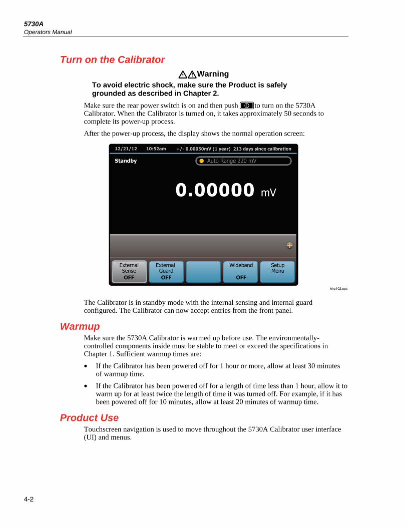
5730A Operators Manual
4-2
Turn on the Calibrator Warning
To avoid electric shock, make sure the Product is safely grounded as described in Chapter 2.
Make sure the rear power switch is on and then push to turn on the 5730A Calibrator. When the Calibrator is turned on, it takes approximately 50 seconds to complete its power-up process.
After the power-up process, the display shows the normal operation screen:
+/- 0.00050mV (1 year) 213 days since calibration12/21/12 10:52am
ExternalSenseOFF
External GuardOFF
Wideband
OFF
SetupMenu
Standby
mV0.00000
Auto Range 220 mV
hhp102.eps
The Calibrator is in standby mode with the internal sensing and internal guard configured. The Calibrator can now accept entries from the front panel.
Warmup Make sure the 5730A Calibrator is warmed up before use. The environmentally-controlled components inside must be stable to meet or exceed the specifications in Chapter 1. Sufficient warmup times are:
• If the Calibrator has been powered off for 1 hour or more, allow at least 30 minutes of warmup time.
• If the Calibrator has been powered off for a length of time less than 1 hour, allow it to warm up for at least twice the length of time it was turned off. For example, if it has been powered off for 10 minutes, allow at least 20 minutes of warmup time.
Product Use Touchscreen navigation is used to move throughout the 5730A Calibrator user interface (UI) and menus.

Front-Panel Operation Reset the Calibrator 4
4-3
Reset the Calibrator At any time during front-panel operation, return the Calibrator to the power-up state with . When is pushed, it:
• Returns the Calibrator to the power-up state: 0 mV dc, standby, internal guard, and internal sense.
• Clears the stored values for limits, offset, scale, and error mode reference.
• Secures the Calibrator if the passcode had been entered.
Operate and Standby Modes When the OPERATE light above the output terminals is illuminated, the output value and function shown on the display are active at the selected terminals. “Operate” also shows on the display.
When the STANDBY light above the output terminals is lit, all 5730A Calibrator binding posts except GROUND are open-circuited. “Standby” also appears on the display in this case.
Visual Connection Management output terminals illuminate in green to indicate which terminals are active and provide guidance to ensure the proper connection of cables for each function.
Push to put the Calibrator into the OPERATE state. Push to put the Calibrator in the STANDBY state.
If any of the subsequent events occur during operation, the Calibrator automatically switches to standby mode:
• The key is pushed.
• A voltage ≥22 V is selected when the previous output voltage was <22 V.
• The output location is changed, for example by selecting an amplifier. The exception is when the 5725A is selected for ac voltage or current, provided the Calibrator current output location is set to “5725A.”
• The output function is changed from one function to another.

5730A Operators Manual
4-4
Connect the Calibrator to a UUT Warning
The Product can supply lethal voltages. Do not make connections to the output terminals when any voltage is present. Placing the Product in standby may not be enough to prevent shock hazard, since could be pushed accidentally. Push and make sure that standby is illuminated before making connections to the output terminals.
The binding posts labeled OUTPUT HI, OUTPUT LO, and AUX CURRENT OUTPUT deliver voltage, fixed resistance, and current to the UUT (Unit Under Test). The Type “N” connector on the front panel labeled WIDEBAND delivers the output signal from the optional 5730A/03 or 5730A/05 Wideband AC Module.
Depending on the output function, output amplitude, and input configuration of the UUT or meter, connection to the SENSE binding posts, the GUARD binding post, and the GROUND binding post may also be necessary or recommended. The text in this chapter explains how and when to use these binding posts.
Recommended Cable and Connector Types Cables can be connected to the binding posts with banana jacks, terminal lugs, or stripped insulated wire. To avoid errors induced by thermal voltages (thermal emfs), use connectors and conductors made of copper or materials that generate small thermal emfs when joined to copper. Avoid the use of nickel-plated connectors. Optimum results can be obtained with the 5730A-7003 Low Thermal EMF Test Leads.
Cable requirements depend on the output function, amplitude, and frequency. Table 4-1 gives specific cable recommendations for all applications.

Front-Panel Operation Connect the Calibrator to a UUT 4
4-5
Caution
To ensure the Product is not damaged, use only cables with correct voltage ratings.
Table 4-1. Auxiliary Amplifier Data
Output Function Cable Recommendations
DC voltage
AC voltage ≤10 kHz
AC current ≤2 A, ≤10 kHz
DC current ≤2 A
Resistance
Low Thermal EMF Test Leads[1] 5730A-7002 (banana plugs) or 5730A-7003 (spade lugs)
(If external sensing is necessary, use a twisted shielded pair.)
AC voltage >10 kHz
SENSE/GUARD: Triaxial cable or Twinax (e.g., Alpha 2829/2), OUTPUT: Coaxial
Or: SENSE: Coaxial, OUTPUT: Coaxial GUARD Lead: Separate wire
AC current with guard Triaxial cable
Wideband AC
3-foot (1 m) 50 Ω coaxial cable with type “N” male connectors supplied with the option. A 50 Ω feedthrough terminator is also supplied for connecting to meters with an impedance >50 Ω.
Voltage-boosted output, 5725A
Low Thermal EMF Test Leads [Note 1] 5730A-7002 (banana plugs) or 5730A-7003 (spade lugs)
(Output is at the Calibrator front panel.)
Current-boosted output, 5725A 16-gauge or heavier twisted pair insulated wire, as short as possible to minimize resistance and inductance. (Output is at the amplifier terminals.)
Current-boosted output, 52120A Refer to the 52120A manual for cable requirements.
[1] Spade lugs provide a slightly better thermal EMF performance. However, some UUTs have repressed banana connectors that cannot accommodate spade lugs.

5730A Operators Manual
4-6
When to Use External Sensing External sensing is normally necessary only when calibrating a device that draws enough current to produce a significant voltage drop in the cables. An example of such a case is with the use of the Calibrator as an external dc voltage reference for an ac/dc transfer standard. In this example, the Calibrator is sourcing 1 V dc into a Fluke 540B AC/DC Transfer Standard. The 180 Ω input impedance results in a current flow of approximately 5 mA. The Calibrator 90-day uncertainty at 1 V is specified to be ±(6 ppm +1.2 μV) or ±7.2 µV. Cumulative lead and contact resistances of as little as 2 mΩ would cause a voltage drop greater than the total uncertainty of the Calibrator. External sensing eliminates this error.
The normal power-up state of the Calibrator is external sensing off, with an internal connection between the SENSE and OUTPUT automatically made. This is the state when the External Sense selection says OFF.
When to Use the External Voltage Guard The voltage guard protects the analog circuitry by placing an electrical shield between the primary and secondary of the ac line power transformer. An optical cable transmits control information from the 5730A Calibrator microprocessor to analog circuits. The voltage guard provides a low-impedance path for common-mode noise and ground loop currents.
The voltage guard is usually internally connected to the OUTPUT LO terminal. This is the normal power-up state of the Calibrator, and the connection is automatically made when the external guard is not selected. This is the state when the External Guard selection says OFF.
If calibrating a UUT with a grounded low or common input terminal, an external connection to the V GUARD is necessary. The Calibrator voltage guard must be grounded at the UUT.
Note
To prevent ground loops, there must be only one ground connection in the system, so all ground connections should be made at the UUT. To maintain one ground point, make sure the grounding strap between the GUARD and GROUND binding posts is disconnected. See Table 3-1, items 17 and 18.
Four-Wire Vs. Two-Wire Resistance Connections Figure 4-4 shows four different ways to connect to a UUT for resistance calibration. Figure 4-4A shows a UUT with four-wire sensing. For such meters, always take advantage of the four-wire sensing capability and use external sensing to get the highest accuracy. Four-wire sensing is available for all resistance values except 100 MΩ.
For calibrating a meter with only a two-wire resistance mode such as a typical handheld DMM, refer to Figures 4-4B through 4-4D. For resistances of 19 kΩ or lower in two-wire mode, compensation circuitry inside the 5730A Calibrator is available to remove errors introduced by resistance in the path between the front panel terminals and the precision resistor. Depending on how the meter is connected, two-wire compensation referenced at the UUT terminals (Figure 4-4C) or at the ends of the UUT test leads (Figure 4-4D) can be used. See “Resistance Output” for information on turning on and off two-wire compensation circuitry.
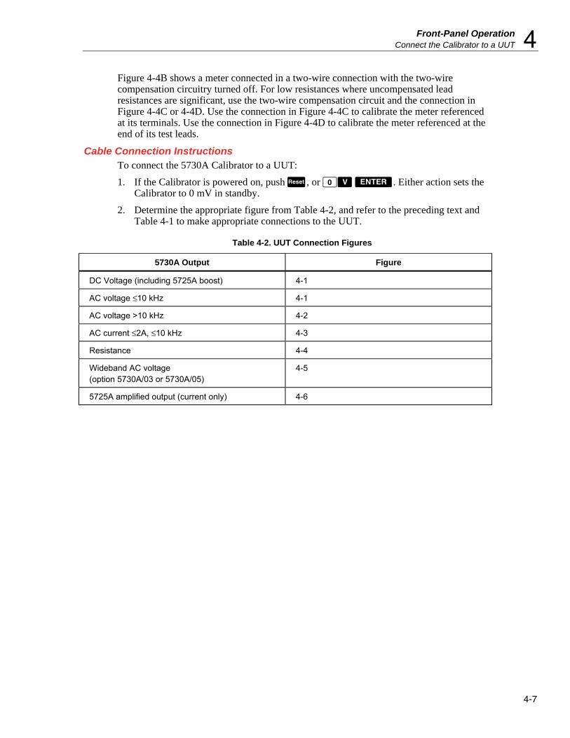
Front-Panel Operation Connect the Calibrator to a UUT 4
4-7
Figure 4-4B shows a meter connected in a two-wire connection with the two-wire compensation circuitry turned off. For low resistances where uncompensated lead resistances are significant, use the two-wire compensation circuit and the connection in Figure 4-4C or 4-4D. Use the connection in Figure 4-4C to calibrate the meter referenced at its terminals. Use the connection in Figure 4-4D to calibrate the meter referenced at the end of its test leads.
Cable Connection Instructions To connect the 5730A Calibrator to a UUT:
1. If the Calibrator is powered on, push , or . Either action sets the Calibrator to 0 mV in standby.
2. Determine the appropriate figure from Table 4-2, and refer to the preceding text and Table 4-1 to make appropriate connections to the UUT.
Table 4-2. UUT Connection Figures
5730A Output Figure
DC Voltage (including 5725A boost) 4-1
AC voltage ≤10 kHz 4-1
AC voltage >10 kHz 4-2
AC current ≤2A, ≤10 kHz 4-3
Resistance 4-4
Wideband AC voltage (option 5730A/03 or 5730A/05)
4-5
5725A amplified output (current only) 4-6

5730A Operators Manual
4-8
INPUTSENSE
Ω4-WIRE
HI
LO
A
HI
LO
GUARD
INPUT
DC
LO
AC
HI LO
Shielded Twisted Pair
Shielded Twisted Pair
UUT Calibrator
UUT
UUT
Calibrator
Calibrator
ExternalSenseOFF
External GuardOFF
ExternalSenseON
External GuardON
ExternalSenseOFF
External GuardON
A
B
C
hhp011.eps
Figure 4-1. UUT Connections: DC Voltage, AC Voltage ≤10 kHz

Front-Panel Operation Connect the Calibrator to a UUT 4
4-9
UUT
UUT Calibrator
Calibrator
Note:Keep the SENSE leads as short as possible.
Be careful not to exceed the capacitive load limit of 1000 pF up to 220 V, 600 pF 220 V to 1100 V. (1000 pF with 5725A Amplifier.)
INPUTSENSE
4-WIREW
HI
LO
A
HI
LO
GUARD
INPUTSENSE
4-WIREW
HI
LO
A
HI
LO
GUARD
Triaxial Cable
Triaxial Cable
Triaxial Cable
ExternalSenseON
External GuardOFF
ExternalSenseOFF
External GuardOFF
A
B
hhp012.eps
Figure 4-2. UUT Connections: AC Voltage >10 kHz

5730A Operators Manual
4-10
INPUTSENSE
4-WIREW
HI
LO
A
HI
LO
GUARD
UUT Calibrator(Front)
ExternalSenseOFF
External GuardOFF
hhp013.eps
Figure 4-3. UUT Connections: AC Current ≤2A

Front-Panel Operation Connect the Calibrator to a UUT 4
4-11
INPUT SENSEΩ4-WIRE
HI
LO
A
HI
LO
GUARD
SENSE
SENSE
SOURCE
SOURCE 2-WIRECOMPOFF
UUT Calibrator
Calibrator
ExternalSense
ON
External GuardOFF
2-WIRECOMPOFF
ExternalSenseOFF
External GuardOFF
UUT
NC
A
BUUT
UUT
Calibrator
Calibrator
hhp014.eps
Figure 4-4. UUT Connections: Resistance

5730A Operators Manual
4-12
UUT
COMP
COMP
Calibrator
UUT
COMP
COMP
Calibrator
UUT Calibrator
CalibratorUUT
Caution:Use connections with exposed plug tips for the ohms function only.
NC
NC
NC
C
D
2-WIRECOMP
ON
ExternalSense
ON
External GuardOFF
2-WIRECOMP
ON
ExternalSenseOFF
External GuardOFF
hhp015.eps
Figure 4-4. UUT Connections: Resistance (cont.)

Front-Panel Operation Connect the Calibrator to a UUT 4
4-13
5730A
NOTE
For wideband meters with higher than 50 Ω input impedence, use the 50 Ω feedthrough terminator at the meter connection end. For all wideband applications, take care to achieve a good 50 Ω impedence match (use cable and connectors with a characteristic input impedence of 50 Ω).
50 Ω Feedthrough Terminator supplied with the 5730A/03 option
Cable supplied withthe 5730A/03
or 5730/05 option
hhp016.eps
Figure 4-5. UUT Wideband AC Voltage Output (5730A/03 Option)
UUT
HI
LO
5725A
hhp017.eps
Figure 4-6. UUT Connections: 5725A Amplified Current Output
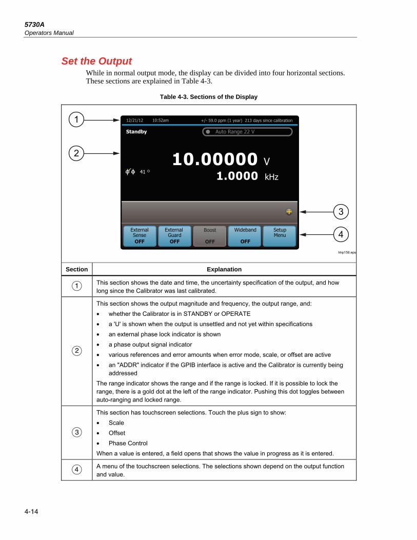
5730A Operators Manual
4-14
Set the Output While in normal output mode, the display can be divided into four horizontal sections. These sections are explained in Table 4-3.
Table 4-3. Sections of the Display
+/- 59.0 ppm (1 year) 213 days since calibration12/21/12 10:52am
ExternalSenseOFF
External GuardOFF
Boost
OFF
Wideband
OFF
SetupMenu
Standby
VkHz1.0000
10.00000
Auto Range 22 V
ExternalSenseOFF
External GuardOFF
Wideband
OFF
SetupMenu
41
1
2
3
4
hhp158.eps
Section Explanation
This section shows the date and time, the uncertainty specification of the output, and how long since the Calibrator was last calibrated.
This section shows the output magnitude and frequency, the output range, and:
• whether the Calibrator is in STANDBY or OPERATE
• a 'U' is shown when the output is unsettled and not yet within specifications
• an external phase lock indicator is shown
• a phase output signal indicator
• various references and error amounts when error mode, scale, or offset are active
• an "ADDR" indicator if the GPIB interface is active and the Calibrator is currently being addressed
The range indicator shows the range and if the range is locked. If it is possible to lock the range, there is a gold dot at the left of the range indicator. Pushing this dot toggles between auto-ranging and locked range.
This section has touchscreen selections. Touch the plus sign to show:
• Scale
• Offset
• Phase Control
When a value is entered, a field opens that shows the value in progress as it is entered.
A menu of the touchscreen selections. The selections shown depend on the output function and value.

Front-Panel Operation Set the Output 4
4-15
For the selections with indicators, the value shown is the value now in effect. For example, if the External Guard selections says OFF, then external guard is off and touching the selection will turn it on.
To set the output, push this key sequence to select an output function and amplitude:
[numeric keys] , [multiplier], [function] , ,
For example, to set the output to 10 mV dc, push:
To set an ac output, push these additional keys:
[numeric keys] , [multiplier] , ,
For example, to change the present 10 mV dc to 10 mV ac at 1.8 kHz, push:
To change the output back to dc, push:
or
The subsequent step-by-step procedures explain how to set an output and how to use the features available for each output function:
• DC voltage
• AC voltage
• DC current
• AC current
• Resistance
• Wideband ac voltage (5730A/03 or 5730A/05 Option)
• Variable phase
• Boost operation (with an auxiliary amplifier)

5730A Operators Manual
4-16
DC Voltage Output To set a dc voltage output:
1. Make sure the Calibrator is in standby (STANDBY annunciator lit). Push if necessary.
2. If the UUT is not connected, connect it now as described in this chapter under “Connect the Calibrator to a UUT.”
3. Set the UUT to measure dc voltage on the necessary range.
4. Enter a voltage value with the numeric keypad.
5. To change the polarity of the entry, push .
6. Push , , or if necessary.
7. Push .
8. The display now shows the amplitude of the entry. If an entry error is made, push to clear the display, and then reenter the value. If the most recent digit entered is in error, push to clear that digit. The display shown below assumes an entry of 10 mV.
+/- 0.00050mV (1 year) 213 days since calibration3/14/2013 10:52am
External GuardOFF
Wideband
OFF
SetupMenu
Standby
mV0.00000
Auto Range 220 mV
10mV
ExternalSenseOFF
hhp113.eps
9. Push . The Calibrator clears the entry from the entry bar toward the bottom and shows in the larger area above. No voltage is available at the output terminals until is pushed.
10. Push to activate the Calibrator output. The UUT will respond to the applied voltage.
In dc voltage output mode, the selections available at the bottom are:
• External Sense
• External Guard
• Wideband
• Setup Menu
In addition, the Offset and Scale functions are available. The output range can be locked in dc volts.
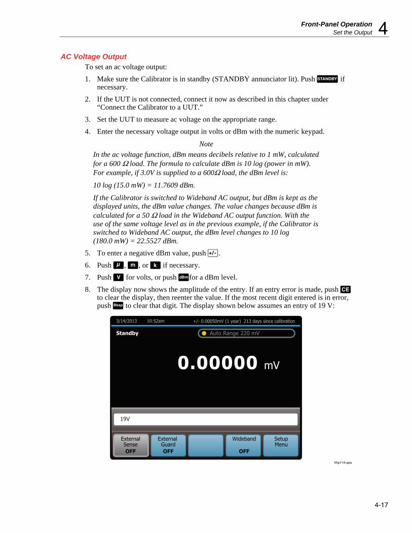
Front-Panel Operation Set the Output 4
4-17
AC Voltage Output To set an ac voltage output:
1. Make sure the Calibrator is in standby (STANDBY annunciator lit). Push if necessary.
2. If the UUT is not connected, connect it now as described in this chapter under “Connect the Calibrator to a UUT.”
3. Set the UUT to measure ac voltage on the appropriate range.
4. Enter the necessary voltage output in volts or dBm with the numeric keypad.
Note
In the ac voltage function, dBm means decibels relative to 1 mW, calculated for a 600 Ω load. The formula to calculate dBm is 10 log (power in mW). For example, if 3.0V is supplied to a 600Ω load, the dBm level is:
10 log (15.0 mW) = 11.7609 dBm.
If the Calibrator is switched to Wideband AC output, but dBm is kept as the displayed units, the dBm value changes. The value changes because dBm is calculated for a 50 Ω load in the Wideband AC output function. With the use of the same voltage level as in the previous example, if the Calibrator is switched to Wideband AC output, the dBm level changes to 10 log (180.0 mW) = 22.5527 dBm.
5. To enter a negative dBm value, push .
6. Push , , or if necessary.
7. Push for volts, or push for a dBm level.
8. The display now shows the amplitude of the entry. If an entry error is made, push to clear the display, then reenter the value. If the most recent digit entered is in error, push to clear that digit. The display shown below assumes an entry of 19 V:
+/- 0.00050mV (1 year) 213 days since calibration3/14/2013 10:52am
External GuardOFF
Wideband
OFF
SetupMenu
Standby
mV0.00000
Auto Range 220 mV
19V
ExternalSenseOFF
hhp114.eps

5730A Operators Manual
4-18
9. Enter a frequency with the numeric keypad followed by or if necessary. The display now shows the amplitude and frequency of the entry. If an entry error is made, use to clear the most recently entered digit, or push to clear the display. Reenter the value. The display shown below assumes an entry of 2.8 kHz.
+/- 0.00050mV (1 year) 213 days since calibration3/14/2013 10:52am
External GuardOFF
Wideband
OFF
SetupMenu
Standby
mV0.00000
Auto Range 220 mV
19V 2.8kHz
ExternalSenseOFF
hhp115.eps
10. Push . The Calibrator clears the entry from the entry bar toward the bottom and shows in the larger area above. No voltage is available at the output terminals until is pushed.
11. Push to activate the Calibrator output. The UUT will now respond to the applied voltage.
In AC voltage output, the selections available at the bottom are:
• External Sense
• External Guard
• Boost
• Wideband
• Setup Menu
In addition, the Phase Control and Scale functions are available. The output range is always automatically chosen and cannot be locked in ac volts.
Note
The Calibrator stays in the ac function after a non-zero frequency is entered. To change back to dc, enter a frequency of 0 Hz or a signed voltage.

Front-Panel Operation Set the Output 4
4-19
DC Current Output To set a dc current output:
1. Make sure the Calibrator is in standby (STANDBY annunciator lit). Push if necessary.
2. If the UUT is not connected, connect it now as described earlier in this chapter under “Connect the Calibrator to a UUT.”
3. Set the UUT to measure dc current in the appropriate range.
4. Enter a current value with the numeric keypad.
5. To change the polarity of the entry, push .
6. Push or if necessary.
7. Push .
8. The display now shows the amplitude of the entry. If an entry error is made, push to clear the display, then reenter the value. If the most recent digit entered is in error, push to clear that digit. The illustration of the display below assumes an entry of 30 mA:
+/- 0.00050mV (1 year) 213 days since calibration3/14/2013 10:52am
ExternalSenseOFF
External GuardOFF
Wideband
OFF
SetupMenu
Standby
mV0.00000
Auto Range 220 mV
30mA
ExternalSenseOFF
hhp117.eps
9. Push . The Calibrator clears the entry from the entry bar toward the bottom and shows in the larger area above. No current is available at the output terminals until is pushed.
10. Push to activate the Calibrator output. The UUT will now respond to the applied current.

5730A Operators Manual
4-20
In dc current output, the selections available at the bottom are:
• Current Output
• External Guard
• Boost
• Wideband
• Setup Menu
In addition, the Offset and Scale functions are available. The output range can be locked in dc current.
Current Output selects one of three locations for non-boosted (current sourced by the Calibrator, for example) current output:
• OUTPUT binding post (NORMAL, which is the OUTPUT HI binding post, also the default setting)
• AUX, which is the AUX CURRENT OUTPUT binding post
• 5725A which is the 5725A Amplifier binding posts. (The 5725A must be turned on, but not necessarily activated.)
Non-boosted current from the Calibrator is not available at the 52120A amplifier binding posts.

Front-Panel Operation Set the Output 4
4-21
AC Current Output To set an ac current output:
1. Make sure the Calibrator is in standby (STANDBY annunciator lit). Push if necessary.
2. If the UUT is not connected, connect it now as described earlier in this chapter under “Connect the Calibrator to a UUT.”
3. Set the UUT to measure ac current on the appropriate range.
4. Enter a current magnitude with the numeric keypad.
5. Push or if necessary.
6. Push .
7. The display now shows the amplitude of the entry. If an entry error is made, push to clear the display, then reenter the value. If the most recent digit entered is in error, push to clear that digit. The illustration of the display below assumes an entry of 125 mA:
+/- 0.00050mV (1 year) 213 days since calibration3/14/2013 10:52am
ExternalSenseOFF
External GuardOFF
Wideband
OFF
SetupMenu
Operate
mV0.00000
Auto Range 220 mV
125mA
ExternalSenseOFF
hhp119.eps

5730A Operators Manual
4-22
8. Enter a frequency with the numeric keypad (followed by if necessary). The display now shows the amplitude and frequency of the entry. If an entry error is made, push to clear the display, then reenter the value. If the most recent digit entered is in error, push to clear that digit. The display below assumes an entry of 2.5 kHz:
+/- 0.00050mV (1 year) 213 days since calibration3/14/2013 10:52am
ExternalSenseOFF
External GuardOFF
Wideband
OFF
SetupMenu
Operate
mV0.00000
Auto Range 220 mV
125mA 2.5kHz
ExternalSenseOFF
hhp120.eps
9. Push . The Calibrator clears the entry from the entry bar near the bottom and shows in the larger area above. No current is available at the output terminals until is pushed.
10. Push to activate the Calibrator output. The UUT will now respond to the applied current.
In AC current output, the selections available at the bottom are:
• Current Output
• External Guard
• Boost
• Wideband
• Setup Menu
In addition, the Phase Control and Scale functions are available. The output range is always automatically chosen and cannot be locked in ac current.
Note
The Calibrator stays in the ac function after a non-zero frequency is entered. To change back to dc, enter a frequency of 0 Hz or push and then .

Front-Panel Operation Set the Output 4
4-23
The Current Output item selects one of three locations for non-boosted (current sourced by the Calibrator, for example) current output:
• OUTPUT binding post (NORMAL, which is the OUTPUT HI binding post, also the default setting)
• AUX, which is the AUX CURRENT OUTPUT binding post
• Boost which is the 5725A Amplifier binding posts. (The 5725A must be turned on, but not necessarily activated.)
Non-boosted current from the Calibrator is not available at the 52120A amplifier binding posts.
Resistance Output In the resistance function, the Calibrator supplies a choice of 18 standard resistance values or a short at the output terminals. The values available are:
0 Ω
1.0 Ω
1.9 Ω
10 Ω
19 Ω
100 Ω
190 Ω
1.0 kΩ
1.9 kΩ
10 kΩ
19 kΩ
100 kΩ
190 kΩ
1.0 MΩ
1.9 MΩ
10 MΩ
19 MΩ
100 MΩ
To select a resistance output:
1. Make sure the Calibrator is in standby (STANDBY annunciator lit). Push if necessary.
2. If the UUT is not connected, connect it now as described previously in this chapter under “Connect the Calibrator to a UUT.”
3. Set the UUT to read resistance on the appropriate range.
4. Push the numeric keys of the nominal resistance, or touch “Ω Value Table” to show a list of the selectable resistance values as shown below.
+/- 3% (1 year) 213 days since calibration12/21/12 10:52am
Operate
Ω0.9995662
Nominal Value 1Ω
Touch a value to select.
0 1.0 10 100 1.0k 10k 100k 1.0M 10M 100M 1.9 19 190 1.9k 19k 190k 1.9M 19M
hhp225.eps

5730A Operators Manual
4-24
If the “Ω Value Table” selection is used, touch the desired resistance value and to select it. To exit the menu, touch the “x” on the top right of the table.
5. Push or if necessary.
6. Push .
7. Push . If a resistance value that is unavailable (as in the subsequent example of 490 Ω) is entered, the display prompts to try again.
+/- 0.00050mV (1 year) 213 days since calibration12/21/12 10:52am
ExternalSenseOFF
External GuardOFF
Wideband
OFF
SetupMenu
Standby
mV0.00000
Auto Range 220 mV
ExternalSenseOFF
Error 820: Calibrator Cannot Source That Value.
OK
hhp123.eps
8. After a valid resistance is specified and is pushed, the Calibrator clears the entry from the entry bar near the bottom and shows in the larger area above.
9. Push . This resistance is now available at the output terminals.
dBmkHz1.0000
42.00000
+/- 10.0 ppm (1 year) 213 days since calibration3/15/2013 10:52am
ExternalSenseOFF
External GuardOFF
2 WireCompON
Wideband
OFF
SetupMenu
Standby
kΩ
Expected Value 1.9 kΩ
1.9000096
ExternalSenseOFF
hhp124.eps

Front-Panel Operation Set the Output 4
4-25
In resistance output, the selections available at the bottom are:
• External Sense
• External Guard
• 2-wire Compensation
• Wideband
• Setup Menu
In the resistance function, two features are available to enhance accuracy: four-wire sensing and two-wire compensation. Two-wire compensation works with either a two-wire connection or a four-wire connection to a two-wire ohmmeter. A full explanation follows:
Four-wire connection is available for all resistance values except 100 MΩ.To activate four-wire resistance, turn External Sense on. (Figure 4-4A shows the four-wire connection.)
For calibrating a meter with a two-wire resistance mode such as a typical handheld digital multimeter (DMM), refer to Figures 4-4B through 4-4D. For resistances of 19 kΩ or lower in two-wire mode, compensation circuitry inside the Calibrator is available to remove errors introduced by resistance in the path between the front panel terminals and the precision resistor. The 2-wire Compensation item is shown at the bottom of the display when resistances of 19 kΩ or lower are selected. This selection lets the compensation circuitry be disabled and enabled.
Depending on how the meter is connected, two-wire compensation referenced at the UUT terminals (Figure 4-4C) or at the Calibrator terminals (Figure 4-4D) can be used.
Figure 4-4B shows a meter connected in a two-wire connection with the two-wire compensation circuitry turned off. Use this configuration only if lead resistances are insignificant. For a two-wire connection, turn External Sense off.
For resistances where uncompensated lead resistances are significant, use the two-wire compensation circuit and the connection in Figure 4-4C or 4-4D. Use the connection in Figure 4-4C to calibrate the meter referenced at its terminals. Use the connection in Figure 4-4D to calibrate the meter referenced at the ends of its test leads.

5730A Operators Manual
4-26
Wideband AC Voltage Output (Option 5730A/03 or 5730A/05) To set an output from the Wideband AC Module (Option 5730A/03 or 5730A/05), proceed from or the power-up state as follows:
1. Make sure the Calibrator is in standby (STANDBY annunciator lit). Push if necessary.
2. If the UUT is not connected, connect it now as described previously in this chapter under “Connect the Calibrator to a UUT.”
3. Set the UUT to read ac voltage on the appropriate range.
4. Touch Wideband.
5. With the numeric keypad, enter the necessary output amplitude, expressed as voltage or a dBm level.
Note
In the Wideband AC function, dBm means decibels relative to 1 mW, calculated for a 50 Ω load. The formula to calculate dBm is 10 log (power in mW). For example, if 3.0 V is supplied to a 50 Ω load, the dBm level is:
10 log (180.0 mW) = 22.5527 dBm
If the Calibrator is switched to standard ac output, but dBm is kept as the displayed units, the dBm value changes. The value changes because dBm is calculated for a 600 Ω load in the standard ac output function. With the same voltage level as in the previous example, if the Calibrator is switched to standard ac output, the dBm level changes to:
10 log (15.0 mW) = 11.7609 dBm.
6. To enter a negative dBm value, push .
7. Push or if necessary.
8. Push for volts or for volts expressed as dBm.

Front-Panel Operation Set the Output 4
4-27
9. The display now shows the amplitude of the entry. If an entry error is made, push to clear the display, then reenter the value. If the most recent digit entered is in error, push to clear that digit. The illustration of the display below assumes an entry of 20 dBm:
dBmkHz1.0000
42.00000
+/- 1.37 % (1 year) 213 days since calibration4/14/2013 13:40
SetupMenu
Standby
μVkHz1.0000
Auto Range 1.1 mV
350.00
Wideband
ON
20dBm
hhp125.eps
10. With the numeric keypad, enter a frequency, followed by or if necessary. The display now shows the amplitude and frequency of the entry. If an entry error is made, push to clear the display, then reenter the value. If the most recent digit entered is in error, push to clear that digit. The display shown below assumes an entry of 21 MHz:
dBmkHz1.0000
42.00000
+/- 1.37 % (1 year) 213 days since calibration4/18/2013 13:40
SetupMenu
Standby
μVkHz1.0000
Auto Range 1.1 mV
350.00
Wideband
ON
20dBm 21MHz
hhp126.eps
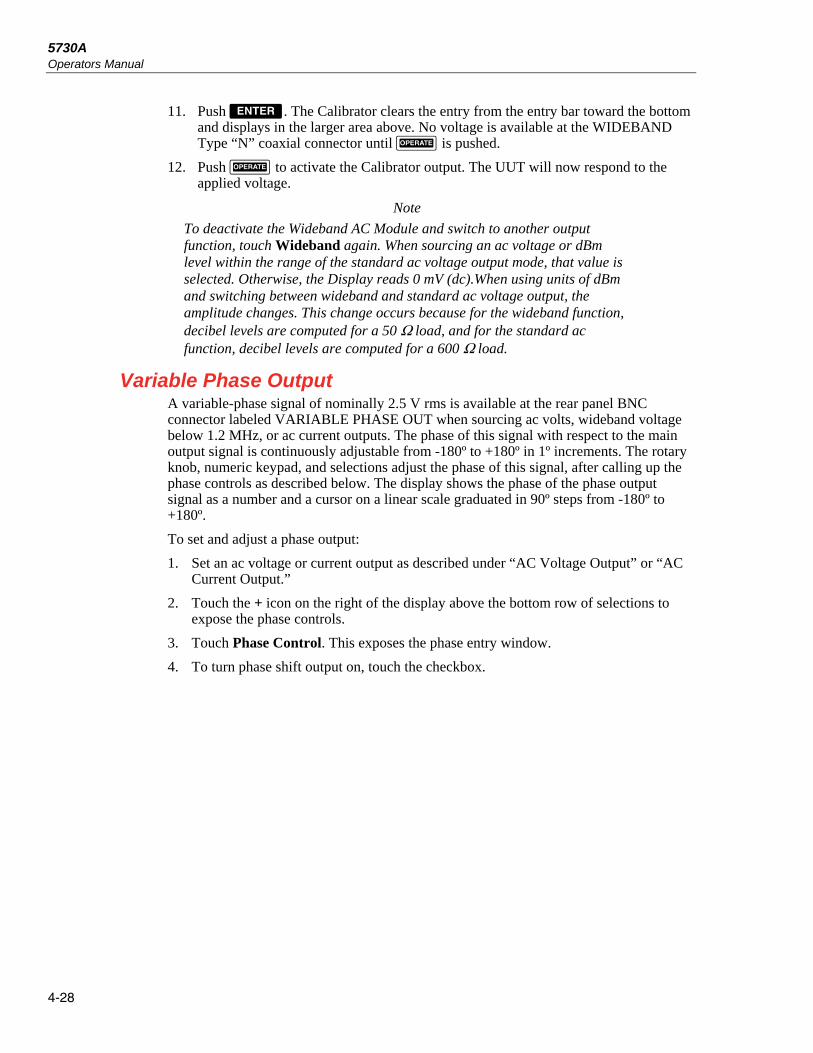
5730A Operators Manual
4-28
11. Push . The Calibrator clears the entry from the entry bar toward the bottom and displays in the larger area above. No voltage is available at the WIDEBAND Type “N” coaxial connector until is pushed.
12. Push to activate the Calibrator output. The UUT will now respond to the applied voltage.
Note
To deactivate the Wideband AC Module and switch to another output function, touch Wideband again. When sourcing an ac voltage or dBm level within the range of the standard ac voltage output mode, that value is selected. Otherwise, the Display reads 0 mV (dc).When using units of dBm and switching between wideband and standard ac voltage output, the amplitude changes. This change occurs because for the wideband function, decibel levels are computed for a 50 Ω load, and for the standard ac function, decibel levels are computed for a 600 Ω load.
Variable Phase Output A variable-phase signal of nominally 2.5 V rms is available at the rear panel BNC connector labeled VARIABLE PHASE OUT when sourcing ac volts, wideband voltage below 1.2 MHz, or ac current outputs. The phase of this signal with respect to the main output signal is continuously adjustable from -180º to +180º in 1º increments. The rotary knob, numeric keypad, and selections adjust the phase of this signal, after calling up the phase controls as described below. The display shows the phase of the phase output signal as a number and a cursor on a linear scale graduated in 90º steps from -180º to +180º.
To set and adjust a phase output:
1. Set an ac voltage or current output as described under “AC Voltage Output” or “AC Current Output.”
2. Touch the + icon on the right of the display above the bottom row of selections to expose the phase controls.
3. Touch Phase Control. This exposes the phase entry window.
4. To turn phase shift output on, touch the checkbox.

Front-Panel Operation Phase Locking to an External Signal 4
4-29
5. The phase can now be changed by entering a value with the numeric keypad, turning the knob, or touching a point on the phase scale.
Current output
NORMAL
External GuardOFF
Boost
ON
Wideband
OFF
Setupmenu
Scale Phase Control
90°
-180 -90 0 90 180
+/- 62.0 ppm (1 year) 213 days since calibration3/14/2013 10:52am
ExternalSenseOFF
External GuardOFF
Boost
OFF
Wideband
OFF
Setupmenu
Standby
VkHz1.0000
1.000000
Auto Range 2.2 V
External
OFF
ADDR
0°
Phase LockInternal Phase Output:
Adjust phase manually using the knob
°0
-180 -90 0 90 180
hhp127.eps
6. To turn phase shift off, touch the checkbox again. To enter a new amplitude leaving the phase shift as is, touch the X icon (where the + was) to collapse the phase control window before the new amplitude is entered.
Phase Locking to an External Signal The phase-lock feature locks the Calibrator main output signal in phase with an external signal (1 V rms to 10 V rms at 10 Hz to 1.2 MHz) applied to the rear panel PHASE LOCK IN BNC connector. This feature can be used with ac volts, wideband voltage, or current outputs, and combine it with variable phase output. The phase lock control is in the window with the phase output controls. To lock onto an external signal:
1. With the external signal source turned off, connect a coaxial cable between the external signal source and the rear panel PHASE LOCK IN BNC connector.
Note
When PHASE LOCK IN is used, make sure the phase lock source is floating relative to the Calibrator output. Ground loops that can occur if the two devices are not isolated can cause amplitude errors in the Calibrator output. These errors may be particularly significant in the millivolt ranges.
2. Set an ac voltage or current output as described under “AC Voltage Output” or “AC Current Output”.
3. Turn on the external signal source.
4. Set the Calibrator frequency to within 2 % of the external source frequency.
5. Touch the + icon on the right of the display above the bottom row of selections to expose the phase controls.
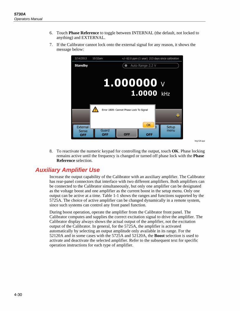
5730A Operators Manual
4-30
6. Touch Phase Reference to toggle between INTERNAL (the default, not locked to anything) and EXTERNAL.
7. If the Calibrator cannot lock onto the external signal for any reason, it shows the message below:
Current output
NORMAL
External GuardOFF
Boost
ON
Wideband
OFF
Setupmenu
Scale Phase Control
90°
-180 -90 0 90 180
+/- 62.0 ppm (1 year) 213 days since calibration3/14/2013 10:52am
External SenseOFF
External GuardOFF
Boost
OFF
Wideband
OFF
Setupmenu
Standby
VkHz1.0000
1.000000
Auto Range 2.2 V
External
OFF
Error 1809: Cannot Phase Lock To Signal
OK
hhp129.eps
8. To reactivate the numeric keypad for controlling the output, touch OK. Phase locking remains active until the frequency is changed or turned off phase lock with the Phase Reference selection.
Auxiliary Amplifier Use Increase the output capability of the Calibrator with an auxiliary amplifier. The Calibrator has rear-panel connectors that interface with two different amplifiers. Both amplifiers can be connected to the Calibrator simultaneously, but only one amplifier can be designated as the voltage boost and one amplifier as the current boost in the setup menu. Only one output can be active at a time. Table 1-1 shows the ranges and functions supported by the 5725A. The choice of active amplifier can be changed dynamically in a remote system, since such systems can control any front panel function.
During boost operation, operate the amplifier from the Calibrator front panel. The Calibrator computes and supplies the correct excitation signal to drive the amplifier. The Calibrator display always shows the actual output of the amplifier, not the excitation output of the Calibrator. In general, for the 5725A, the amplifier is activated automatically by selecting an output amplitude only available in its range. For the 52120A and in some cases with the 5725A and 52120A, the Boost selection is used to activate and deactivate the selected amplifier. Refer to the subsequent text for specific operation instructions for each type of amplifier.

Front-Panel Operation Auxiliary Amplifier Use 4
4-31
5725A Amplifier Output
Warning Boosted voltage operation produces high voltage at higher current levels than normally available from the Product. During boosted voltage operation, the potential risk of injury or fatal accident is greater than during normal operation.
Note
Refer to the 5725A Instruction Manual for setup and installation instructions.
The 5725A Amplifier boosts ac voltage and both ac and dc current. To set a boosted output from the 5725A Amplifier:
1. If not already installed, install the 5725A as described in the 5725A Instruction Manual.
2. If the “Boost Amp Types” setting in the Setup Menu has been changed from the default, select the 5725A for boost operation as described at the beginning of this chapter.
3. Make sure the Calibrator and 5725A are in standby (STANDBY annunciator lit). Push if necessary.
4. If the UUT is not connected, connect it now as described earlier in this chapter under “Connect the Calibrator to a UUT.” Note that for boosted current, connect to the 5725A binding posts, and for boosted voltage, connect to the Calibrator binding posts.
5. Set the UUT to read the appropriate quantity.
6. Enter the necessary output value as described under “Setting the Output.” Current entries beyond the standard range of the Calibrator automatically select the amplifier. Voltage entries in the 220 V-1100 V range automatically select the amplifier. Note that the 5725A takes over the 1100 V range of the Calibrator.
7. Boosted voltage output is available at the front panel of the Calibrator. Boosted current output is available at the front panel of the 5725A Amplifier. When the 5725A binding posts are selected, the Current Output selection indicates the output location. If the entry has caused a change of output location, must be pushed to activate the amplifier.
8. When the range is set to “AUTO”, the amplifier is automatically disabled whenever a current level within the range of the Calibrator is set. Locking the range turns off this auto disable, so the amplifier can be used at lower current levels.
Note
The 5725A can source a current below 2.2 A to take advantage of the amplifier higher compliance voltage of the amplifier. To do so, lock onto the 11 A range when the Calibrator is set for over 2.2 A, or set the lower current and touch Boost to turn on the amplifier.
9. To deactivate the amplifier, touch Boost again.

5730A Operators Manual
4-32
52120A Transconductance Amplifier Output The 52120A Amplifier boosts ac and dc current. A maximum of three 52120A amplifiers may be connected together to the Calibrator. When their outputs are connected in parallel, they produce two (for two 52120As) or three (for three 52120As) times the current output, providing up to 300 A of dc current and 360 A rms ac current.
To set a boosted output with the 52120A Amplifier:
1. Install the 52120A as described in the 52120A Users Manual.
2. If the “Boost Amp Types” setting in the Setup Menu has been changed from the default, select the 52120A for current boost as described at the beginning of this chapter.
3. Make sure the Calibrator and 52120A are in standby (STANDBY annunciator lit). Push if necessary.
4. If the UUT is not connected, connect it now as described earlier in this chapter under “Connect the Calibrator to a UUT.” For boosted current, connect to the 52120A binding posts.
5. Set the UUT to read the appropriate quantity.
6. Enter the necessary output value as described under “Set the Output.” Current entries beyond the standard range of the Calibrator automatically select the amplifier.
7. To deactivate the amplifier, touch Boost again.
Error Mode Operation The output adjustment controls (arrow keys and the rotary knob) are used to adjust the output of the Calibrator incrementally (except in the resistance function). As this happens, the Calibrator computes and shows the difference between the adjusted output and the reference level in ±% or ±ppm (parts per million). The reference level is the original output setting before it was adjusted. When this capability is used to adjust the output until the UUT reads correctly, the displayed difference is the UUT error for that output setting. The error is shown in ±% unless it is ±20 ppm or less.
For example, if the Calibrator is set to output 10.00000 V, and the UUT reads high. To determine the error, use the output adjustment controls to adjust the Calibrator until the UUT reads 10.0000 V. If, for example, the Calibrator display now reads 9.993900, the Calibrator calculates and shows a UUT error of +0.0610 % on the display.
The Calibrator uses this formula to calculate the UUT error:
Error= (Reference) - (Final Output)
X 100 % (Reference)
The rotary knob is also a convenient way to change the frequency during ac voltage tests. To adjust frequency in error mode, for example, when meter flatness is tested, push . The 10 Hz digit of the frequency line is highlighted. Push twice. When the knob is turned, the output frequency increases or decreases 1 kHz per knob click.

Front-Panel Operation Error Mode Operation 4
4-33
Error Mode Overview This section explains how to use Error Mode in general. After the overview, a step-by-step procedure explains how to use this mode to read UUT error for each Calibrator output function.
Enter Error Mode To start Error Mode, turn the rotary knob, push an arrow key, or push . When error mode is entered, the starting value is the reference from which errors are computed. A new reference is established when you exit and then reenter error mode.
Exit Error Mode Table 4-4 lists the actions that cause the Calibrator to exit error mode.
Table 4-4. Keys that Exit Error Mode
Key or Selection Action
Returns to the previous reference value.
+ Establishes a new reference.
A new keypad entry + Establishes a new reference.
New Ref Selection Establishes the present output as a new reference.
Establishes a new reference that is equal to ten times the previous reference value.
Establishes a new reference that is equal to one tenth of the previous reference value.
Offset Selection Identifies the present output as a zero-scale endpoint for scaling and establishes 0.0 as the new reference.
Scale Selection Identifies the present output as a full-scale endpoint for scaling and causes the display to show scale error.
Returns to the power-up state.
Setup Menu Selection Opens the Setup menu.
Note
The Scale and Offset selections are revealed by touching the + icon on the right of the display above the bottom row of selections. The New Ref selection appears with the Scale and Offset selections once error mode is entered.

5730A Operators Manual
4-34
Use Error Mode When error mode is entered from any output function except resistance, the least significant digit on the Display is highlighted. Push to enter error mode and select the frequency line for adjustment first (but only if the frequency is not zero).
When the rotary knob is turned, the highlighted digit increments or decrements. Turn the knob clockwise to make the number more positive. Turn the knob counterclockwise to make the number more negative. As a digit is incremented past 9 or a digit is decremented past 0, the adjacent digit is carried. and select digits to the right and left, and selects the upper line (amplitude) and lower line (frequency).
If the output is adjusted beyond the capability of the Calibrator, the Calibrator beeps and does not allow the change.
Push and to quickly verify the accuracy of different ranges of a UUT. When in error mode and these keys are pushed, the Calibrator output and the new reference are set to 10 times or 1/10 the previous reference value.
In the resistance output function, the edit controls show the UUT error in a similar way, except the output of the Calibrator does not change as the knob is turned. Instead, a reading on the display changes that can be matched to the reading on the UUT. As the reading is changed, the Calibrator computes and displays UUT error.
Read the UUT Error: AC and DC Voltage and Current Output To read the error of the UUT in the ac and dc voltage and current output functions:
1. Set the necessary calibration voltage or current, as previously described under “Set the Output.”
2. Use the output adjustment controls as necessary to get a reading on the UUT equal to the original entry on the 5730A Calibrator. To increment or decrement a higher-order digit, push . As the reference value is approached, work progressively back towards the least-significant digit on the Calibrator display as necessary by pushing . It is only necessary to go one digit past the least significant digit of the UUT. Digits below that are beyond the resolution of the UUT. The UUT error is shown on the display. This example assumes that the Calibrator is in the dc voltage function:
dBmkHz1.0000
42.00000
+/- 4.3 ppm (1 year) 213 days since calibration3/14/13 10:52am
ExternalSenseOFF
External GuardOFF
Boost
ON
Wideband
OFF
SetupMenu
Standby
Reference10.000000V
Error = +0.20 ppm
V
Auto Range 11 V
9.999998
hhp132.eps

Front-Panel Operation Introduction to Offset, Scale, and Linearity Errors 4
4-35
Read the UUT Error: Resistance Output To read the error of the UUT in the resistance function:
1. Set the necessary resistance output as described under “Set the Output.”
2. Use the output adjustment controls as necessary to achieve a reading on the display (illustrated below) equal to the reading on the UUT. To adjust a higher-order digit, push . As the reference value is approached, work progressively back towards the least-significant digit on the 5730A Calibrator display as necessary by pushing . It is only necessary to go one digit past the least significant digit of the UUT.
dBmkHz1.0000
42.00000
+/- 10.0 ppm (1 year) 213 days since calibration3/15/2013 10:52am
ExternalSenseOFF
External GuardOFF
2 WireCompON
Wideband
OFF
SetupMenu
Standby
Error = +5.79ppm
kΩ
Nominal Value 1.9 kΩ
1.9000096Reading1.9000206
hhp133.eps
Introduction to Offset, Scale, and Linearity Errors The performance of a DMM or meter can be plotted as a graph of input stimulus and meter reading. For a perfect meter, the graph of the input stimulus would exactly match the graph of the reading.
The 5730A Calibrator measures and shows three types of UUT errors:
• Offset Error
• Scale Error
• Linearity Error

5730A Operators Manual
4-36
Offset Error Offset error can be measured directly by finding the Calibrator output that causes a meter reading of 0 V. This error is called an offset because it reflects a fixed error that is present in all meter output readings. For example, if a meter reads 0 V when -1.3 mV is applied, the meter has an offset error of +1.3 mV. Figure 4-7 illustrates this example.
CalibratorSetting
0
-1.3 mV
Meter ReadingOffsetError =
+1.3 mV
hhp052.eps
Figure 4-7. Offset Error
Scale Error Scale error, sometimes referred to as gain error, occurs when the slope of the meter response curve deviates from one. A meter with only scale error (no offset or linearity error), will read 0 V when 0 V is applied, but will read a value other than 10 V when 10 V is applied. For example, if a meter reads 19.900 V when 19.903 V is applied, the meter has a scale error of -3 mV. To isolate scale error, offset error must first be subtracted. Scale error is then simply the error measured near the full-scale endpoint, or:
Scale Error= (Reference full scale) - (Adjusted Calibrator Setting)
(Reference full Scale)
Where “Adjusted calibrator setting” is the adjusted output (using the knob) that results in the UUT correctly reading “nominal full-scale.” Select a point just down from the UUT full-scale endpoint for nominal full-scale. This keeps the UUT from ranging while adjustments are made. For example, use 19.9 V as the nominal full-scale for a UUT that ranges at 20 V.

Front-Panel Operation Introduction to Offset, Scale, and Linearity Errors 4
4-37
The example in Figure 4-8 assumes no offset error. The formula for scale error yields:
Scale Error= 19.9 -19.903
= -0.000151= -0.0151 % 19.9
Calibrator Setting
0Meter Reading
19.903 V19.9 V
ScaleError =-3 mV
19.9 V
Ideal
Actual
hhp018.eps
Figure 4-8. Scale Error
Linearity Error Linearity error occurs when the response curve of a meter deviates from a straight line. This type of error is measured by fixing zero and near-full-scale endpoints on the response curve, drawing a line through the points, then measuring how far the meter response deviates from the straight line at various points. The error value is computed relative to the selected full-scale point. The formula for linearity error is:
Linearity Error= (Nominal setting) – (Adjusted 5730A Setting)
(Nominal Full Scale)
Where the “nominal setting” is calculated by subtracting the offset error and a proportional part of the scale error.
5730A Operators Manual
4-38
Figure 4-9 illustrates linearity error with both offset and scale errors assumed to be zero. The formula for linearity error yields:
Linearity Error= (10.0 – 9.993)
= 0.000352 = +0.0352 % 19.9
Calibrator Setting
0
Meter Reading
19.900 V
LinearityError =+7 mV
19.900 V
Linear Response
ActualResponse
10.000 V
9.993 V
10.000 V
hhp019.eps
Figure 4-9. Linearity Error
Combine the Error Types The actual error of a meter is the combination of all three types of errors. The Calibrator uses the Scale and Offset selections to separately show all three types of errors directly, without any calculation.

Front-Panel Operation Program an Offset 4
4-39
Program an Offset The Offset selection can be used when in the dc voltage or current function any time it is necessary to offset the 5730A Calibrator output by a fixed amount. The Offset selection is shown by touching the + icon on the right of the display above the bottom row of selections. After an offset is established, it is subtracted from all later keyboard entries to compensate for a UUT offset error. Touch Offset again to turn off this offset. Both the offset value and the keypad-entered reference value are shown on the display, along with the true output value.
The Offset selection may be used to establish a zero-scale endpoint, this can then be used with the Scale selection to check the linearity of a UUT. (See the example under “Linearity Checking With Offset and Scale.”)
To program an offset:
1. Set the Calibrator to output 0 mV dc. The easiest way to do this is to push , then push .
2. Adjust the Calibrator output with the rotary knob (and arrow keys if necessary) until the UUT reads 0 V.
3. Touch Offset. This stores the output value as the offset value.
The Calibrator output value is now 0 V minus the offset value, in this example, the 1.3 mV output value is shown on the largest font on the Display. The Calibrator reference value is set to 0 V. The reference and offset values are shown on the display as seen below:
dBmkHz1.0000
42.00000
+/- 3% (1 year) 213 days since calibration12/21/12 10:52am
ExternalSenseOFF
External GuardOFF
Wideband
OFF
SetupMenu
Standby
mV
Auto Range 220 mV
- 1.3000
OffsetScale
ExternalSenseOFF
Reference0.00000 mV
Offset1.30000 mV
hhp134.eps
If a new value is entered, the offset value is subtracted from the new value to create the new output. The newly entered value becomes the new reference value shown on the display. For example, if 1 V is entered, the displayed true value is +0.99870000 V and the displayed reference is 1.0000000 V. The offset remains in effect until Offset is touched again, a different output function is selected, Setup Menu is touched, or or are pushed.
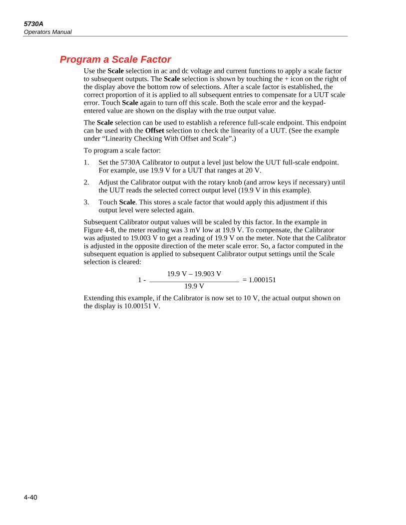
5730A Operators Manual
4-40
Program a Scale Factor Use the Scale selection in ac and dc voltage and current functions to apply a scale factor to subsequent outputs. The Scale selection is shown by touching the + icon on the right of the display above the bottom row of selections. After a scale factor is established, the correct proportion of it is applied to all subsequent entries to compensate for a UUT scale error. Touch Scale again to turn off this scale. Both the scale error and the keypad-entered value are shown on the display with the true output value.
The Scale selection can be used to establish a reference full-scale endpoint. This endpoint can be used with the Offset selection to check the linearity of a UUT. (See the example under “Linearity Checking With Offset and Scale”.)
To program a scale factor:
1. Set the 5730A Calibrator to output a level just below the UUT full-scale endpoint. For example, use 19.9 V for a UUT that ranges at 20 V.
2. Adjust the Calibrator output with the rotary knob (and arrow keys if necessary) until the UUT reads the selected correct output level (19.9 V in this example).
3. Touch Scale. This stores a scale factor that would apply this adjustment if this output level were selected again.
Subsequent Calibrator output values will be scaled by this factor. In the example in Figure 4-8, the meter reading was 3 mV low at 19.9 V. To compensate, the Calibrator was adjusted to 19.003 V to get a reading of 19.9 V on the meter. Note that the Calibrator is adjusted in the opposite direction of the meter scale error. So, a factor computed in the subsequent equation is applied to subsequent Calibrator output settings until the Scale selection is cleared:
1 - 19.9 V – 19.903 V
= 1.000151 19.9 V
Extending this example, if the Calibrator is now set to 10 V, the actual output shown on the display is 10.00151 V.

Front-Panel Operation Linearity Check with Offset and Scale 4
4-41
Linearity Check with Offset and Scale With the 5730A Calibrator offset and scaling features, a UUT offset and scale errors can be removed to isolate and display linearity error. The subsequent procedure is an example that uses the Offset and Scale selection to determine both scale and linearity error of a 4 1/2-digit DMM. In this example, the DMM is set to the 20 V dc range, and the Calibrator is connected to the DMM. Figure 4-10 illustrates all three types of errors that are detected by the Calibrator. The numbers in the graph correspond to the conditions encountered in the example.
Calibrator Voltage
0
-1.3 mV Meter Reading
Offset Error =+1.3 mV
10.000 10.007 19.900
19.9017
19.8987
10.000208
9.993208
LinearResponse
Actual MeterResponse
LinearityError
Scale Error 19.9000
IdealResponse
hhp020.eps
Figure 4-10. Meter Response vs. Stimulus
1. Set the Calibrator to 0 mV in standby. 2. Use the output adjustment controls (the rotary knob and ) to adjust the
Calibrator output for a reading of 0 V on the DMM. The displays shows:
dBmkHz1.0000
42.00000
+/- 3% (1 year) 213 days since calibration12/21/12 10:52am
ExternalSenseOFF
External GuardOFF
Wideband
OFF
SetupMenu
Standby
Error> +999.9999%
mV
Auto Range 220 mV
- 1.30000
ExternalSenseOFF
Reference0.00000 mV
hhp136.eps

5730A Operators Manual
4-42
Note
The message “Error >+999.9999%” occurs because in this case the reference voltage is 0.
3. Touch Offset to identify this as the DMM zero-scale endpoint. The display changes to:
dBmkHz1.0000
42.00000
+/- 3% (1 year) 213 days since calibration12/21/12 10:52am
ExternalSenseOFF
External GuardOFF
Wideband
OFF
SetupMenu
Standby
mV
Auto Range 220 mV
- 1.3000
OffsetScale
ExternalSenseOFF
Reference0.00000 mV
Offset1.30000 mV
hhp137.eps
4. Use the numeric keypad to set the Calibrator to a point near the end of the DMM range. (This example uses 19.9 V.) The displays change to:
dBmkHz1.0000
42.00000
+/- 4.3 ppm (1 year) 213 days since calibration4/18/2013 14:33
ExternalSenseOFF
External GuardOFF
Wideband
OFF
SetupMenu
Standby
V
Auto Range 22 V
19.898700
OffsetScale
ExternalSenseOFF
Reference19.9 V
Offset0.001300 V
hhp138.eps
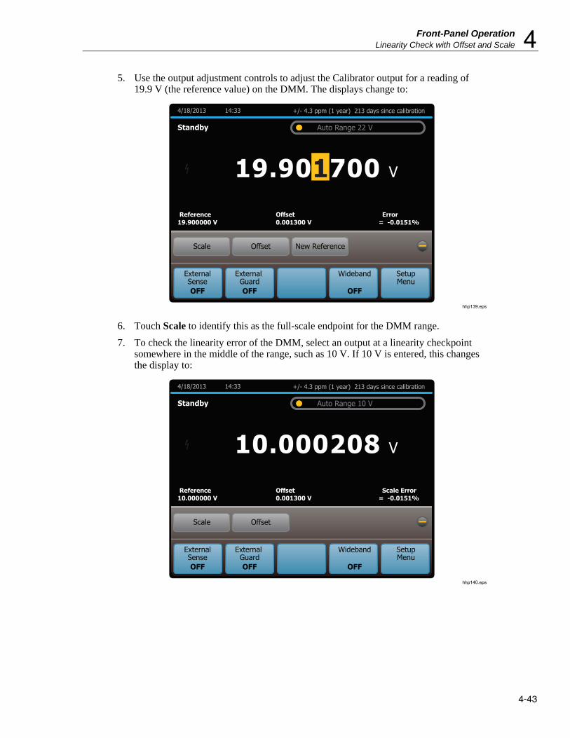
Front-Panel Operation Linearity Check with Offset and Scale 4
4-43
5. Use the output adjustment controls to adjust the Calibrator output for a reading of 19.9 V (the reference value) on the DMM. The displays change to:
dBmkHz1.0000
42.00000
+/- 4.3 ppm (1 year) 213 days since calibration4/18/2013 14:33
ExternalSenseOFF
External GuardOFF
Wideband
OFF
SetupMenu
Standby
V
Auto Range 22 V
19.901700
OffsetScale
Reference19.900000 V
Offset0.001300 V
Error= -0.0151%
New Reference
hhp139.eps
6. Touch Scale to identify this as the full-scale endpoint for the DMM range.
7. To check the linearity error of the DMM, select an output at a linearity checkpoint somewhere in the middle of the range, such as 10 V. If 10 V is entered, this changes the display to:
dBmkHz1.0000
42.00000
+/- 4.3 ppm (1 year) 213 days since calibration4/18/2013 14:33
ExternalSenseOFF
External GuardOFF
Wideband
OFF
SetupMenu
Standby
V
Auto Range 10 V
10.000208
OffsetScale
Reference10.000000 V
Offset0.001300 V
Scale Error= -0.0151%
hhp140.eps

5730A Operators Manual
4-44
The 10.000208 V output setting is calculated by the Calibrator with the subsequent equation:
1 - 19.9 V – 19.903 V
= 1.0001508 19.9 V
This is applied to 10 V to yields:
10 V x 1.0001508 = 10.001508 V
The 1.3 mV zero offset is then subtracted:
10.001508 V − 0.0013 V = 10.000208 V
8. Use the output adjustment controls to adjust the Calibrator output for a reading of 10.0 V (the reference value) on the DMM. The displays change to:
dBmkHz1.0000
42.00000
+/- 4.3 ppm (1 year) 213 days since calibration4/18/2013 14:33
ExternalSenseOFF
External GuardOFF
Wideband
OFF
SetupMenu
Standby
V
Auto Range 11 V
9.993208
OffsetScale
Reference10.000000 V
Offset0.001300 V
Linearity Error= +0.0352%
New Reference
hhp141.eps
The display now shows that the DMM scale error at 19.9 V is -0.0151 %, and the DMM linearity error at 10 V is +0.0352 %.

Front-Panel Operation Set up the Calibrator 4
4-45
Set up the Calibrator The remaining sections of this chapter explain how to set up the Calibrator.
Setup Menu The Setup Menu grants access to various operations and changeable Calibrator parameters. Once a parameter is set, it is saved in memory until it is changed. Any changes are saved during power-off periods.
When Setup Menu is touched from the normal operation screen, the display shows the Setup Menu:
CalibrationDC ZeroArtifact CalibrationCalibration CheckWideband Gain CalibrationWideband Flatness CalibrationChange Calibration PasswordRange AdjustmentGenerate Report
Instrument SettingDate/Time FormatLanguageDisplaySelf Test & Diagnotics
DiagnosticsKey, Knob, and Bell Tests
Instrument SetupRemote PortUncertainty InformationOutput LimitsSourcing HardwareError Reference
Exit
About this Instrument
Setup Menu
hhp104.eps
The subsequent list briefly describes the submenus available from the Setup Menu.
• Calibration- The items in this submenu are used to activate calibration to external standards, Calibration Check, DC Zeros, and to verify or adjust the 5730A Calibrator calibration to its specifications. The Calibration submenu and process is explained in greater detail in Chapter 7.
• Self Test & Diagnostics- Use this submenu to do automatic internal self-diagnostics on various features of the Calibrator. Once started, the self-diagnostic cannot be interrupted. The Calibrator must be completely warmed up to run the self-diagnostics or the process will timeout and prompt to let the Calibrator warm up.
The submenu also has a Key, Knob, and Bell Test that can be run from this point. The key and knob test take input from the front-panel keys and rotary knob and return visual identifiers that the key being pushed returns what it should. For example, if is pushed, “Enter” is returned in the blank field of the submenu. When Run Bell Test is pushed, an internal bell will sound.

5730A Operators Manual
4-46
• Instrument Setup- Use this menu to:
• Choose and configure remote interfaces (see Chapter 5).
• Set parameters to compute output uncertainty.
• Impose limits on the Calibrator output for safety and external equipment protection.
• Select boost amplifiers for voltage and current outputs.
• Enable or disable the ability to turn on or off ac transfers (real-time measurements and adjustments of the value after the output is settled).
• Choose the error reference value (nominal or true value) used to compute unit under test (UUT) errors.
The Instrument Setup submenu is explained in greater detail later in this chapter.
• Instrument Settings- Use this menu to:
• Set the date and time as well as its format.
• Select the user interface language.
• Control the display brightness
The Instrument Settings menu is explained in greater detail later in this chapter.
• About this Instrument- This shows hardware configuration and software version information for the Calibrator. Nothing can be changed from this section.
Setup Menu Rules Each menu has a path shown at the top of the display that shows the current location in the menu structure. This gives access to the menus used to get the present point. For example, if Setup Menu is touched from the normal operation screen, the top of the Setup Menu shows:
Setup Menu
This type of symbol designates the top-level of the menu structure. For this manual, menu paths are shown as in the subsequent example to reach the Remote Port menu:
Setup Menu>Instrument Setup>Remote Port
This example shows the path to this Remote Port section of the menu structure:
Setup Menu was the start point, then Instrument Setup was touched, and finally Remote Port was touched to get to the Remote Port menu.
Conversely, from the Remote Port menu, touch Instrument Setup to go up one level, Setup Menu to go up two levels.
An Exit or Cancel selection in the lower right of the display closes the menus or stops a process. The 5730A Calibrator then returns to the normal operation screen.

Front-Panel Operation Set up the Calibrator 4
4-47
Menu Description A menu item that leads to a submenu with multiple selections has a black and amber title bar on top followed by a list of the items in the submenu. The Instrument Setup menu is shown in this example:
Instrument SetupRemote PortUncertainty InformationOutput LimitsSourcing Hardware
To get to the submenus, touch anywhere in the menu shown.
Touchscreen Selections When applicable, settings controlled by touchscreen selections are shown in this manner:
Remote Port RS-232Setup
Exit
InstrumentSettings
Stop Bits 1
Port Stall XON
Restore Factory Defaults
Parity None
Data Bits 8
EOL CRLF
Remote IF Terminal
EOF 012 000
Baud 9600
Setup Menu
hhp149.eps
Each of the touchscreen selections shown above change a parameter or reveal more changeable parameters.

5730A Operators Manual
4-48
Some selections do not have submenus beneath them or do not include changeable items. For example, in the display below, the About this Instrument selection has no changeable items.
CalibrationDC ZeroArtifact CalibrationCalibration CheckWideband Gain CalibrationWideband Flatness CalibrationChange Calibration PasswordRange AdjustmentGenerate Report
Instrument SettingDate/Time FormatLanguageDisplaySelf Test & Diagnotics
DiagnosticsKey, Knob, and Bell Tests
Instrument SetupRemote PortUncertainty InformationOutput LimitsSourcing HardwareError Reference
Exit
About this Instrument
Setup Menu
hhp104.eps
About this Instrument opens a page to show non-editable information about the Calibrator hardware and software.
Software InformationMain SW Version: v1.00
Inguard SW Version: B
Serial Number: 0000000
Hardware InformationInstalled Hardware Assemblies
Setup Menu About thisInstrument
Exit
hhp156.eps

Front-Panel Operation Set up the Calibrator 4
4-49
There are selections without a submenu listed beneath them that are used to start processes. For example, the Run DC Zero selection from the Calibration menu starts the DC Zero process (see Chapter 7).
Exit
Calibration
Run DC Zero 3/04/2013
Run Artifact Cal 3/04/2013
Setup Menu
Run Calibration Check
Run Wb Gain Cal 8/29/2013
Run Wb Flatness Cal 8/29/2013
Change Calibration Passcode Temperature ˚C 23.0
Restore Factory Defaults
Generate ReportCalibration ShiftsCheck ShiftsRaw Data
Range AdjustmentDCACResistance
hhp173.eps
There are several types of selections that are used for settings. In general, these selections show what is being set in white, and the value that it is currently set to is in amber. See the Temperature °C selection in the screen above.
Touchscreen selections with two possible values look like the Confidence Level selection shown in the screen below. Touch Confidence Level to change the value from 99% to 95%. Touch it again to change the value back to 99%.
Calibration Interval 1 Year Confidence Level
InstrumentSetup
UncertaintyInformationSetup Menu
Exit
99%
hhp107.eps

5730A Operators Manual
4-50
Touchscreen selections with several possible values look like the Calibration Interval item shown in the screen above. Touch the selection to open another menu with a selection for each possible choice as shown below.
UncertaintyInformation
Setup Menu Instrument Setup
24 Hours
90 Days
180 Days
Calibration Interval
Cancel
1 Year
hhp152.eps
Touch a value to select it or touch Cancel to abort the value change.
Touchscreen selections with many possible values look like the Port selection in the Ethernet Setup menu shown here:
Exit
EthernetSetup
DHCP OFF
Remote IF Terminal
Restore Factory Defaults
Remote PortInstrumentSetupSetup Menu
IP Address 129.196.136.119
Gateway 129.196.136.001
Subnet 255.255.254.000
Static IP Settings:
IP Address 129.196.136.119
Gateway 129.196.136.001
MAC Address 00:80:40:00:32:90
EOL CRLF
Port
hhp153.eps
To change the value, touch the present value and then enter a new value with the numeric keypad.
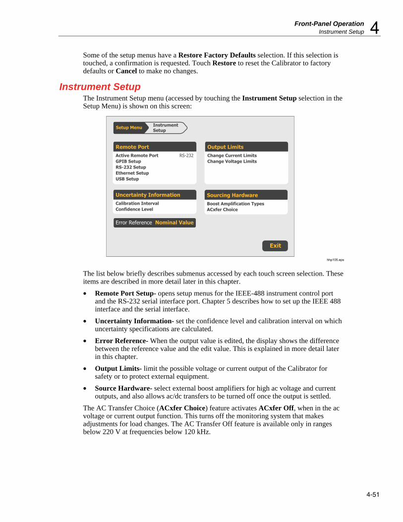
Front-Panel Operation Instrument Setup 4
4-51
Some of the setup menus have a Restore Factory Defaults selection. If this selection is touched, a confirmation is requested. Touch Restore to reset the Calibrator to factory defaults or Cancel to make no changes.
Instrument Setup The Instrument Setup menu (accessed by touching the Instrument Setup selection in the Setup Menu) is shown on this screen:
Remote PortActive Remote Port RS-232GPIB SetupRS-232 SetupEthernet SetupUSB Setup
Uncertainty InformationCalibration IntervalConfidence Level
Sourcing HardwareBoost Amplification TypesACxfer Choice
Output LimitsChange Current LimitsChange Voltage Limits
Setup Menu InstrumentSetup
Exit
Error Reference Nominal Value
hhp105.eps
The list below briefly describes submenus accessed by each touch screen selection. These items are described in more detail later in this chapter.
• Remote Port Setup- opens setup menus for the IEEE-488 instrument control port and the RS-232 serial interface port. Chapter 5 describes how to set up the IEEE 488 interface and the serial interface.
• Uncertainty Information- set the confidence level and calibration interval on which uncertainty specifications are calculated.
• Error Reference- When the output value is edited, the display shows the difference between the reference value and the edit value. This is explained in more detail later in this chapter.
• Output Limits- limit the possible voltage or current output of the Calibrator for safety or to protect external equipment.
• Source Hardware- select external boost amplifiers for high ac voltage and current outputs, and also allows ac/dc transfers to be turned off once the output is settled.
The AC Transfer Choice (ACxfer Choice) feature activates ACxfer Off, when in the ac voltage or current output function. This turns off the monitoring system that makes adjustments for load changes. The AC Transfer Off feature is available only in ranges below 220 V at frequencies below 120 kHz.
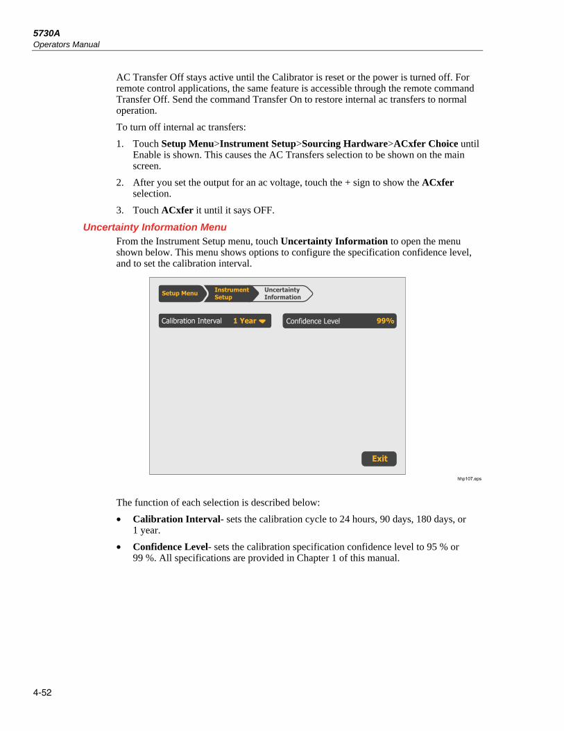
5730A Operators Manual
4-52
AC Transfer Off stays active until the Calibrator is reset or the power is turned off. For remote control applications, the same feature is accessible through the remote command Transfer Off. Send the command Transfer On to restore internal ac transfers to normal operation.
To turn off internal ac transfers:
1. Touch Setup Menu>Instrument Setup>Sourcing Hardware>ACxfer Choice until Enable is shown. This causes the AC Transfers selection to be shown on the main screen.
2. After you set the output for an ac voltage, touch the + sign to show the ACxfer selection.
3. Touch ACxfer it until it says OFF.
Uncertainty Information Menu From the Instrument Setup menu, touch Uncertainty Information to open the menu shown below. This menu shows options to configure the specification confidence level, and to set the calibration interval.
Calibration Interval 1 Year Confidence Level
InstrumentSetup
UncertaintyInformationSetup Menu
Exit
99%
hhp107.eps
The function of each selection is described below:
• Calibration Interval- sets the calibration cycle to 24 hours, 90 days, 180 days, or 1 year.
• Confidence Level- sets the calibration specification confidence level to 95 % or 99 %. All specifications are provided in Chapter 1 of this manual.

Front-Panel Operation Instrument Setup 4
4-53
Set Output Limits An output limit feature is available to help prevent accidental damage to a UUT from overcurrent or overvoltage conditions. The maximum positive and negative allowable voltage or current output can be preset with this feature. Entry limits that are set prevent any input greater than the limit from being activated by entry through the front-panel keys or the output adjustment controls. Positive limits for voltage and current set the limits for ac voltage and current. Default entry limits after power-up or is pushed are the specified maximum and minimum for each output function.
Note
The output limits are not saved when the Calibrator is powered down.
To set voltage and current entry limits:
1. Touch Setup Menu>Instrument Setup>Output Limits. This menu is shown:
Output Limits
Exit
InstrumentSettings
Upper Limit +1100.0000
Lower Limit -1100.0000
Upper Limit +360.0000
Lower Limit -360.0000
Setup Menu
Voltage Current
hhp143.eps
2. There is a selection for each of the four limits: maximum positive voltage and current and negative voltage and current. Select the limit to change by touching the corresponding selection.
3. Use the numeric keys to enter the necessary voltage limit and , , or if necessary, followed by .
Note
The upper voltage limit sets the limits for both dc and ac voltage. The upper current limit sets the limits for both dc and ac current.

5730A Operators Manual
4-54
Select Boost Amplifiers If an auxiliary amplifier other than the 5725A will be used, one amplifier can be identified for current boost and one amplifier can be identified for voltage boost. Model 5725A is the factory default for both voltage and current boost. To select other amplifiers:
1. Touch Setup Menu>Instrument Setup>Boost Amp Types.
(If the Setup Menu is not shown, push first).
The display changes to:
Voltage 5725
InstrumentSetup
SourcingHardwareSetup Menu
Boost Amp Types
Exit
Current 5725
ACxfer ON
hhp111.eps
2. Touch Current to scroll the highlighted label until it shows 5725 or 52120.
3. To go to normal operation, touch Exit.
Error Reference When the output value is edited, the display shows the difference between the reference value (the value originally entered) and the edit value (the value shown on the display), displaying error difference in parts per million (ppm) or percent (%).
For example, an edited difference of 0.00030 volts for an output of 10.00000 V represents 0.00030/10.00000=0.000030, or 30 parts per million. The sign is negative (-30.0 ppm) because the output necessary to display 10.00000 at the UUT shows the UUT is reading below the output value. When the reference is negative, the error sign is relative to the magnitude. For example, if the reference is -10.00000 V and the display is -10.00030, the error is -30 ppm or -0.0030 %.
The 5730A Calibrator has two methods of scaling the UUT error. The first method, called the “nominal” method is used in the Fluke Calibration 5700A, 5720A, 5502A, and 5522A calibrators.

Front-Panel Operation Instrument Setup 4
4-55
The second method is called “true value”. Both methods can be used in this Calibrator. The nominal method of error calculation uses the formula:
reference value – edit value
reference value
The nominal method is useful to check the error of the Calibrator itself, when its performance is verified against a more accurate measuring device.
The true value method of error calculation uses the formula:
Reference value – edit value
edit value
With either the nominal or true value method, small changes in output value result in a calculated error that is the same. In the example above, the display will show the error as -30.0 ppm.
The true value method is useful for large changes in output value. For example, if 10.0000 V is applied to an analog meter, and then the Calibrator output is adjusted to 11.0000 V so that the analog meter now reads exactly 10 V, the true value method will show:
nominal= +10.0000 V
rel err= -9.0909 %
-9.0909 % represents the relative error of the analog meter when compared to the true value (11.0000 V in this case).
To select the UUT error calculation method:
1. Touch Setup>Instrument Setup.
2. Touch Error Reference until it shows the desired choice. The choices are "Nominal Value" or "True Value."
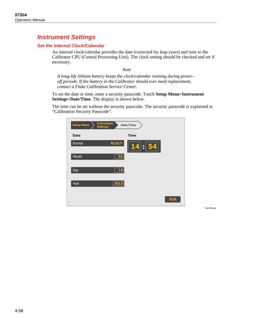
5730A Operators Manual
4-56
Instrument Settings Set the Internal Clock/Calendar
An internal clock/calendar provides the date (corrected for leap years) and time to the Calibrator CPU (Central Processing Unit). The clock setting should be checked and set if necessary.
Note
A long-life lithium battery keeps the clock/calendar running during power-off periods. If the battery in the Calibrator should ever need replacement, contact a Fluke Calibration Service Center.
To set the date or time, enter a security passcode. Touch Setup Menu>Instrument Settings>Date/Time. The display is shown below.
The time can be set without the security passcode. The security passcode is explained in “Calibration Security Passcode”.
Exit
InstrumentSettings Date/Time
Month 03
Day 14
14
Date Time
Year 2013
54:Format M/D/Y
Setup Menu
hhp108.eps

Front-Panel Operation Instrument Settings 4
4-57
Language To select the display language used for the 5730A Calibrator UI:
1. Touch Setup Menu>Instrument Settings>Language.
2. Touch the necessary language from the screen. The choices are:
• English
• French
• Spanish
• Simplified Chinese
• Japanese
• German
• Portuguese
• Russian
• Korean
Note
The new language does not take effect until the Calibrator is powered down and back up again. Push on the front panel.
Display Brightness To adjust the brightness of the display:
1. Touch Setup Menu>Instrument Settings>Display.
2. Touch the field in the Brightness selection and enter the necessary value with the numeric keypad. Note that with brightness setting of 0 %, the display is still visible.
About This Instrument About this Instrument in the setup menu gives access to this information:
• Installed internal operating software revision letters.
• Whether the Wideband AC Module (Option 5730A/03 or 5730A/05) is installed.
• Which auxiliary amplifiers are attached, if any.
To view this information, touch Setup Menu>About This Instrument.
Much of the information is summarized in this menu. Touch Software Information to get more detail about the installed firmware. Touch Hardware Information to get more detail about installed assemblies and attached auxiliary amplifiers.

5730A Operators Manual
4-58

5-1
Chapter 5 Remote Interface Setup
Introduction The 5730A Calibrator can operate under remote control of an instrument controller, computer, or terminal, as well as under direct local control from the front panel. Remote control can be interactive, with the user controlling each step from a terminal, or can be set up to run automatically, taking commands from a computer within an automated system. This chapter explains how to connect, configure, and operate the Calibrator in remote mode.
The remote programmer uses a language of commands called “device-dependent commands” to duplicate the functions of the front panel controls.
The Calibrator has four remote interfaces: IEEE-488, RS-232 Serial, 100-baseT Ethernet, and USB 2.0. Only one interface may be used at a time. The interface is selected in the Remote Setup menu as described below.
Note
5700A/5720A Series II remote programs can be used to operate the 5730A.
Warning The Product can produce voltages up to 1100V rms and must be programmed with caution to prevent hazardous voltages from being produced without sufficient warning to the operator.
Programs should be written carefully and tested extensively to ensure safe operation of the Product. Fluke Calibration recommends to include error-catching routines in your programs to ensure that the Product performs as intended. By setting the Service Request Enable register (SRE), described in Chapter 6, the Product can be programmed to cause an SRQ when an error is detected.

5730A Operators Manual
5-2
GPIB (IEEE-488) Interface Use the IEEE-488 Port for Remote Control
The 5730A Calibrator is fully programmable for use on the IEEE Standard 488.1 interface bus (IEEE-488 bus). The interface is also designed in compliance with supplemental standard IEEE-488.2. Devices connected to the bus in a system are designated as talkers, listeners, talker/listeners, or controllers. Under the remote control of an instrument controller, the Calibrator operates exclusively as a talker/listener on the IEEE-488 bus.
IEEE-488 Bus Restrictions The subsequent restrictions apply to all IEEE-488 systems:
1. A maximum of 15 devices can be connected in a single IEEE-488 bus system.
2. The maximum length of IEEE-488 cable used in one IEEE-488 system is either 2 m (6.56 ft) times the number of devices in the system, or 20 m (65.61 ft), whichever is less.
Bus Setup Procedure To set up the 5730A Calibrator on the IEEE-488 bus, only a choice of address and the connection to a controller is necessary. To set up the bus:
1. With the Calibrator off, attach the IEEE-488 cable to the rear panel IEEE-488 connector. Fluke shielded cables Y8021 (1m), Y8022 (2m), or Y8023 (4m), are recommended.
2. Push to turn on the Calibrator.
3. Touch Setup Menu>Instrument Setup>Remote Port.
4. The IEEE-488 bus address for the Calibrator is shown in the GPIB Setup region. To change it, touch the editable field and enter a new address with the numerical keys.
5. If the Active Remote Port is not GPIB, touch Active Remote Port and then touch GPIB.
6. Touch Exit to exit the Setup Menu.

Remote Interface Setup GPIB (IEEE-488) Interface 5
5-3
IEEE-488 Interface Configuration The 5730A Calibrator IEEE-488 interface supports the IEEE-488 interface function subsets listed in Table 5-1.
Table 5-1. Supported IEEE-488 Interface Function Subsets
Interface Function Description
SH1 Complete source handshake capability
AH1 Complete acceptor handshake capability
T6 Basic talker; serial poll; no talk-only mode; unaddress if MLA
TEO No extended talker capabilities
L4 Basic listener operation; no listen-only mode; unaddress if MTA
LEO No extended listener capabilities
SR1 Full service request capability with ability to bit-mask SRQ
RL1 Full remoter/local capability including local lockout
PPO No parallel poll capability
DC1 Device clear capability
DT0 No device trigger capability
C0 No bus control capability
Bus Communication Overview Communication between the controller and the 5730A Calibrator takes place with commands established by IEEE-488 standards and commands specifically related to the Calibrator. The commands in Tables 6-4, 6-5, and 6-6 are all the remote commands, both common and device-dependent.
Definitions of the different types of messages used on the IEEE-488 bus follow:
• Device-dependent commands are messages used to transfer information directly between the 5730A Calibrator and the IEEE-488 controller. Some commands cause an action to take place in the Calibrator. Others, called queries in the IEEE standards, ask for information, and always generate a response message from the Calibrator. While message format is governed by IEEE-488 standards, messages themselves can be unique to the Calibrator. For example, device-dependent commands are used to set the output mode and amplitude, and to switch from standby to operate.
• Common commands defined by IEEE standards are used for functions common to most bus devices. Examples include the command to reset a device (*RST) and the query for device identification (*IDN?). Common commands and queries can be identified easily because they all begin with an asterisk (*).
• Interface messages defined by IEEE standards have their own control lines, and others are sent over the data lines by first asserting the control line ATN (Attention). An important thing to note about interface messages is that unlike device-dependent and common commands, interface messages are not sent literally (For example, when a device-dependent query is sent to the Calibrator, the controller automatically sends the interface message MTA (My Talk Address).

5730A Operators Manual
5-4
RS-232 Serial Interface Use the RS-232 Port for Remote Control
This procedure is intended for those who use the 5730A Calibrator serial interface for remote control from a terminal or computer with a serial interface.
This section describes how to set up the RS-232 interface for remote control with protocol similar to IEEE-488. This chapter provides all details on data transmission.
The RS-232 interface is designed in accordance with EIA (Electronic Industries Association) standard RS-232.
RS-232 Interface Specifications The RS-232 interface is configured as DTE (Data Terminal Equipment). A null-modem cable with two female 9-pin subminiature D connectors must be used to connect the 5730A Calibrator to other DTE (Data Terminal Equipment) such as a typical computer serial interface. Recommended cable is a Fluke RS43.
The choices available and the defaults for all programmable interface parameters for the Calibrator are shown in Table 5-2.
Table 5-2. RS-232 Interface Parameter Choices
Parameter Choices Default Setting
Data Bits 7 or 8 8
Stop Bits 1 or 2 1
Flow Control Ctrl S/Ctrl Q, (XON/XOFF), RTS, or none Ctrl S/ Ctrl Q
Parity Checking Odd, even, or none None
Baud Rate 9600, 19200, 38400, 57600, or 115200 9600
EOL (End of Line) CR, LF, or CR LF CR LF
EOF (End of File) Any two ASCII characters No characters

Remote Interface Setup RS-232 Serial Interface 5
5-5
Set Up and Connect the Serial Interface Refer to the specifications for the peripheral device, and proceed as follows to set up the serial interface for the application:
1. With the 5730A Calibrator power off, connect a 9-pin D subminiature RS-232 null-modem cable such as Fluke accessory RS43 to the rear panel RS-232 connector and to the peripheral device.
2. Push to turn on the Calibrator.
3. Touch Setup Menu>Instrument Setup>Remote Port Setup>RS-232 Port Setup.
The display changes to:
Remote Port RS-232Setup
Exit
InstrumentSettings
Stop Bits 1
Port Stall XON
Restore Factory Defaults
Parity None
Data Bits 8
EOL CRLF
Remote IF Terminal
EOF 012 000
Baud 9600
Setup Menu
hhp149.eps
4. Touch Data Bits to set the number of data bits.
5. Touch Stop Bits to set the number of stop bits.
6. Touch Stall to select a method of stall control.
7. Touch Parity to select the parity mode.
8. Touch Baud to set the baud rate.
9. Touch EOL to set the EOL (End Of Line) character to CR, LF, or the string CR LF.
10. This step needs to be done only if setting up the interface for remote control of the Calibrator. Touch one of the selections under Remote IF to set the label to “Terminal” or “Computer.”
“Terminal” sets the remote port to expect a human operator to be using a terminal attached to the RS-232 port to control the Calibrator. This setting has the same effect as specifying TERM in the SP_SET or REM_MODE remote command parameter string.
“Computer” sets the remote port to expect a computer to be controlling the Calibrator over the RS-232 port. This setting has the same effect as specifying “COMP” in the SP_SET or REM_MODE remote command parameter string.

5730A Operators Manual
5-6
11. To designate a character or character string as the EOF (End Of File) character, touch EOF.
12. Enter the decimal code of the ASCII character(s) designated as EOF. (Appendix B contains a table of ASCII codes.) Verify that the selection is correct as shown on the display.
13. To exit the setup menus, touch Exit.
Serial Remote Control Setup Procedure 1. Turn on the 5730A Calibrator.
2. Touch Setup Menu>Instrument Setup>Remote Port.
3. The RS-232 setup details are shown in the RS-232 Setup region. To change any of these, select the region. See section “Set up and Connect the Serial Interface” section for more.
4. If the Active Remote Port is not RS-232, touch Active Remote>RS-232.
5. Touch Exit to exit the Setup Menu.
Exceptions for Serial Remote Control When the RS-232 port is used to remotely control the 5730A Calibrator, either interactively with a terminal or under computer control, operation is the same as with an IEEE-488 controller connected to the IEEE-488 port for control. These are exceptions:
1. Control/C does the same function as DCL (Device Clear) or SDC (Selected Device Clear).
2. The EOL (End of Line) input terminator is Carriage Return (Control/M) or Line Feed (Control/L). All output lines are terminated by the terminator programmed in a setup menu, or set with the remote command SP_SET. This setting applies to all lines, including those with the *PUD command (see number 4).
3. Control/R echoes to the port a Carriage Return, a Line Feed, and any uncompleted remote command entered. This shows a copy of whatever has been entered since the last command.
4. For the *PUD (Protected User Data) Command, that stores characters for later recall, the serial remote interface does not store the subsequent characters: Control/C, Line Feed (Control/J), Carriage Return (Control/M), Control/R, Control/S (XOFF), Control/Q (XON). These characters are processed as described above. They cannot be a part of the *PUD command. The *PUD command terminates with Line Feed or Carriage Return, the same as all other serial remote commands.
5. There is no SRQ capability when serial remote control is used. The status registers still behave as described in this section, but the Calibrator serial interface does not have a way to perform the SRQ function.
6. There are three special commands available only for serial/Ethernet/USB remote control. These are described in Table 6-6.

Remote Interface Setup Ethernet Interface 5
5-7
Ethernet Interface The subsequent sections describe how to use an Ethernet interface with the Calibrator.
Set Up and Connect the Ethernet Interface Refer to the specifications for the LAN network, and proceed as follows to set up the Ethernet interface for the application:
Touch Setup Menu>Instrument Setup>Remote Port Setup>Ethernet Setup to get to the Ethernet Setup menu.
When addressing some LAN addresses, computers will often interpret zeros in the IP address as OCTAL values. As an example, if the IP address is configured from the front panel as 129.196.017.023 and then a connection to the 5730A Calibrator is attempted, connect with the IP address 129.196.17.23. Attempts to establish a connection to 129.196.017.023 may result in a connection request to 129.196.15.19.
Set the IP Address An internet (IP) address is necessary for all internet and TCP/IP communications. If DHCP is enabled, the 5730A Calibrator will use the dynamic address supplied by the DHCP server. If the DHCP server fails to supply the address, the IP address will be shown as "0.0.0.0".
Select the Dynamic Host Configuration Protocol (DHCP) Dynamic Host Configuration Protocol (DHCP) is a client-server protocol that eliminates the manual set up of permanent/static IP addresses. The DHCP server provides configuration parameters (dynamic IP address, subnet mask, and default gateway IP addresses) that are necessary for a client to participate in an IP network.
DHCP is the easiest way to configure the 5730A Calibrator for remote communication through the LAN interface. DHCP is enabled by default when the Calibrator is shipped from the factory. When connected to a network, and the LAN port is enabled, the Calibrator attempts to retrieve the parameters from a DHCP server necessary for communications.
To disable or enable DHCP on the Calibrator, from the LAN menu, touch DHCP. If DHCP is already enabled, ON is shown on the selection label.
To use DHCP addressing:
1. Connect a LAN cable from a hub to the LAN port on the back of the Calibrator.
2. Touch Setup Menu>Instrument Setup>Remote Port>Ethernet Setup to get to the Ethernet Setup menu.
3. Select DHCP.
4. Push to turn off the Calibrator.
5. Push to turn on the Calibrator.
From the Ethernet Setup menu, the dynamic IP address assigned to the Calibrator can be checked.
5730A Operators Manual
5-8
Set a Static Internet Address The 5730A Calibrator comes from the factory with 169.254.001.001 in the static IP address register.
Note
If the Calibrator is to be used on a corporate LAN and DHCP is not used, contact the network administrator for a static IP address to be used exclusively by the Calibrator. DHCP must be disabled to set a static IP address.
To change the Calibrator static IP Address:
1. Touch Setup Menu>Instrument Setup>Remote Port>Ethernet Setup to get to the Ethernet Setup menu.
2. Touch IP Address.
3. Use the numeric keypad to enter the IP address and then push .
If a mistake is made when the IP address is entered, must be pushed.
Note
The IP address is stored in non-volatile memory, and does not change when power is removed and reapplied to the Calibrator or when the Calibrator receives an *RST command.
Configure the General Network Socket Port In order to communicate with each other, a client computer and the 5730A Calibrator must use the same socket port number. The default port is 3490. Typically, the default port does not need to be changed. If the socket port must be changed, enter the Socket Port number supplied by the network administrator.
To change the Socket Port number:
1. Touch Setup Menu>Instrument Setup>Remote Port>Ethernet Setup to get to the Ethernet Setup menu.
2. Touch PORT.
3. Use the numeric keypad to enter a new port number.
4. Push . The port number must be between 1024 to 65535.
If a mistake is made when the socket port is entered, push and go back to step 2 to enter the port number again.
Note
The Network Socket Port Number is stored in non-volatile memory.

Remote Interface Setup Ethernet Interface 5
5-9
Configure the LAN Default Gateway The default gateway IP address is the IP address of a gateway (router) attached to the same network as the device. When the 5730A Calibrator detects that a client computer is not on the same network (using the network number), the data is sent through the gateway to reach the host computer.
The default for the Calibrator is “0” (no gateway, and subnetting is not being used).
To set the LAN Default Gateway address:
1. Touch Setup Menu>Instrument Setup>Remote Port>Ethernet Setup to get to the Ethernet Setup menu.
2. Touch Gateway.
3. Use the numeric keypad to enter the gateway address and then push .
If a mistake is made when the gateway address is entered, push and go back to step 4 to enter the port number again.
Set the LAN Subnet Mask If communication between the client computer and the 5730A Calibrator passes through a router or gateway, and DHCP is disabled, it is necessary to set the subnet mask and default gateway address on both the client computer and the Calibrator. Get the correct subnet mask and gateway address from the network administrator.
The LAN Subnet Mask is a 32-bit number. This number is represented as four 3-digit segment numbers on the front-panel display. The default subnet mask set at the factory is 255.255.254.0.
To change the Calibrator subnet mask:
1. Touch Setup Menu>Instrument Setup>Remote Port>Ethernet Setup to get to the Ethernet Setup menu.
2. Touch Subnet.
3. Use the numeric keypad to enter the subnet mask and then push .
If a mistake is made when the subnet mask is entered, push and go back to step 3 to enter the address again.
Read the MAC Address The MAC Address is set at the factory and cannot be changed. The MAC address can be read from the Ethernet Setup menu. The MAC address can also be accessed with a remote connection that uses the MACADDR? remote command.

5730A Operators Manual
5-10
Establish an Ethernet Connection Telnet is the easiest method of establishing an Ethernet connection with the 5730A Calibrator. Telnet is a client-server protocol, based on TCP. The Telnet Protocol provides a fairly general, bi-directional, eight-bit byte oriented communications method. Telnet is available on all UNIX servers and on most PCs.
Telnet clients typically connect to hosts on socket port 23. The LAN connection to the Calibrator must be established with the specified Network Socket Port. See the “Configure the General Network Socket Port” section. When the remote interface port is changed to LAN from the Calibrator front panel, a LAN server is initiated in the Calibrator that listens for client connections on the socket port at the specified IP address.
To establish a LAN connection to the Calibrator from a computer with either UNIX, LINUX, or MS-DOS command prompts, do the subsequent procedure:
1. Touch Setup Menu>Instrument Setup>Remote Port>Ethernet Setup to get to the Ethernet Setup menu.
2. Change the remote interface port to Ethernet.
3. At the command prompt on the client computer, enter:
telnet <IP Address> <Socket Port>
As an example, if the IP address is known to be 129.196.136.131 and the Socket Port is set to 3490, at a command prompt from any client computer, enter:
telnet 129.196.136.131 3490
Once the internal LAN server connects with the client computer, the LAN server will reject any other connection attempts by other computers/clients and will “tunnel” a channel to the connected computer. This prevents multiple computers from trying to control the Calibrator.
Terminate an Ethernet Connection To terminate the Ethernet connection, the Telnet session must be terminated on the client computer. Switching remote control ports will also terminate the Telnet session.
It may be necessary to terminate the Telnet session on the client computer but maintain the current LAN remote interface port selection. Client Telnet session termination can vary from computer to computer. Typically, terminating the shell (or command window in DOS) will terminate the Telnet session. When the client terminates the Telnet session, the LAN server in the Calibrator goes back into listen mode waiting for a new client to make a LAN connection request.
Use of Ethernet Remote Control When the Ethernet port is used to remotely control the 5730A Calibrator, either interactively with a terminal or under computer control, operation is the same as with an RS-232 controller connected to the RS-232 port for control.

Remote Interface Setup Use of USB 2.0 Remote Control 5
5-11
Use of USB 2.0 Remote Control 1. Touch Setup Menu>Instrument Setup>Remote Port.
2. If the Active Remote Port is not USB, touch Active Remote Port.
3. Touch USB.
4. Touch Exit to exit the Setup Menu.
When the USB port is used to remotely control the 5730A Calibrator, either interactively with a terminal or under computer control, operation is the same as with an RS-232 controller connected to the RS-232 port for control.
When USB remote operation is used, connect to the Calibrator with a virtual communication port on the computer and a terminal program such as PuTTY or HyperTerminal. When the USB remote control cable is disconnected, make sure to close the terminal program on the computer. This properly terminates the virtual communication port session in the computer. When the USB remote control cable is connected, open the virtual communication port on the computer from within the terminal program.

5730A Operators Manual
5-12

6-1
Chapter 6 Remote Commands and Syntax
Introduction The syntax rules in this chapter apply to all the remote commands. A command consists of a word by itself or a word followed by one or more parameters. The rules for parameter syntax are provided first (including proper usage of units and multipliers), followed by the rules for extra spaces, then followed by the rules for terminator usage. A description of how the 5730A Calibrator processes incoming characters provides the basis for answering other possible questions about syntax. Information about syntax of response messages is also given.
Parameter Syntax Rules Many of the remote commands require parameters, which must be used properly to prevent command errors. When a command error occurs, bit CME (5) in the Event Status Enable Register (ESE) goes to 1. General rules for parameter usage are:
1. When a command has more than one parameter, the parameters must be separated by commas. For example: “OUT 1 V, 100 HZ.”
2. Numeric parameters may have up to 255 significant figures and their exponents may range from -32000 to +32000. The useful range for 5730A Calibrator programming is ± 2.2 E-308 to ± 1.8 E308.
3. Including too many parameters causes a command error.
4. Null parameters cause a command error (for example, the adjacent commas in “CLOCK 133700, , 071787”).
5. Expressions, for example “(4+2*13)”, are not allowed as parameters.
Units accepted in command parameters and used in responses are:
• HZ (frequency, hertz)
• MHZ (frequency, megahertz)
• V (voltage, volts)
• A (current, amperes)
• OHM (resistance, ohms)
• MOHM (resistance, megohms)

5730A Operators Manual
6-2
• DB (decibels)
• DBM (decibels referenced to 1 milliwatt for ac voltage amplitude)
• PCT (percent)
• PPM (parts per million)
Multipliers accepted in command parameters are:
• MA (mega, or unit x 1,000,000)
• K (kilo, or unit x 1,000)
• M (milli, or unit /1,000, except MOHM and MHZ)
• U (micro, or unit /1,000,000)
Some examples of allowed unit and multiplier combinations are:
• “MOHM” and “MAOHM” are both interpreted as megohms
• “MHZ”and “MAHZ” are both interpreted as megahertz
• “MV” is interpreted as millivolts
• “MAV” is interpreted as megavolts
• “MA” is interpreted as milliamperes
Extra Space Characters Tables 6-5 and 6-6 and the remote program examples at the end of this chapter show commands and their parameters separated by spaces. One space after a command is necessary. All other spaces are optional. They are shown for clarity in the manual and may be left in or omitted as desired. Extra spaces can be inserted between parameters as desired. Extra spaces within a parameter are generally not allowed, except for between a number and its associated multiplier or unit.
Example: Explanation:
“OUT 188.3 MA, 442 HZ” Equivalent to “OUT 188.3MA,442HZ”
“OUT - 110.041 V” Invalid, no space allowed in a number
“OUT -110.041 V” Correct form for above
Table 6-5 contains examples for commands whose parameters are not self-explanatory.
Terminators To signal the end of a response sent to the controller, the 5730A Calibrator sends a “terminator.” For response message terminators, the Calibrator sends the ASCII character Line Feed with the EOI control line held high. The subsequent characters are recognized by the Calibrator as terminators when encountered in incoming data:
• ASCII LF character
• Any ASCII character sent with the EOI control line true

Remote Commands and Syntax Input Buffer Operation 6
6-3
Incoming Character Processing The 5730A Calibrator processes all incoming data as follows (except the 8-bit data byte portion of the *PUD parameter):
1. An eighth bit (DIO8) is ignored.
2. All data is taken as 7-bit ASCII.
3. Lower-case or upper-case characters are accepted.
4. ASCII characters whose decimal equivalent is less than 32 (Space) are discarded, except for characters 10 (LF) and 13 (CR) and in the *PUD command argument. *PUD allows all characters in its argument and terminates in a special way.
Response Message Syntax In Table 6-5, responses from the 5730A Calibrator are described wherever appropriate. In order to know whether to read in an integer, a floating-point number, or character string, the first entry is (Integer), (Floating), or (String).
Note
The responses described in the command tables are correct for IEEE-488 remote control, and for serial/Ethernet/USB remote control in COMPUTER mode. TERMINAL mode (in serial/Ethernet/USB remote control), responses contain more descriptive text intended for an operator using a terminal interactively.
Integers for most controllers or computers are decimal numbers in the range -32768 to 32767. Response elements of this type are labeled as “integer” in the command tables. Floating-point numbers may be in exponential form, for example “1.15E-12”. String responses may be any ASCII printing characters. A special case of string response is in the CAL_CLST?, CAL_SHIFT?, CAL_SLST?, CAL_RPT?, ECHO?, EXPLAIN?, RPT_STR?, *OPT?, and *STATE? commands. Those strings include leading and trailing quotation marks. (See Table 5-2 for details.)
Input Buffer Operation As the 5730A Calibrator receives each data byte from the controller, it places the bytes in a portion of memory called the input buffer. The input buffer holds up to 128 data bytes and operates in a first in, first out fashion.
The Calibrator treats the EOI IEEE-488 control line as a separate data byte and inserts it into the input buffer if it is encountered as part of a message terminator.
Input buffer operation is transparent to the program running on the controller. If the controller sends commands faster than the Calibrator can process them, the input buffer fills to capacity. When the input buffer is full, the Calibrator holds off the IEEE-488 bus with the NRFD (Not Ready For Data) handshake line. When the Calibrator has processed a data byte from the full input buffer, it then completes the handshake, allowing the controller to send another data byte.
The Calibrator clears the input buffer on power-up and on receiving the DCL (Device Clear) or SDC (Selected Device Clear) messages from the controller.
Under RS-232C serial port remote control that uses Control/S (XOFF) protocol, the Calibrator issues a Control/S (XOFF) when the input buffer becomes 80 % full. The Calibrator issues a Control/Q (XON) when it has read enough of the input buffer so that it is less than 40 % full. When RTS (Request to Send) protocol is used, the serial interface retracts and asserts RTS in response to same conditions as for XON/XOFF protocol.

5730A Operators Manual
6-4
Commands Table 6-4 summarizes the commands by function. Table 6-5 provides protocol details of the remote commands. Table 6-6 provides protocol details of the three special commands available for serial remote control only. The commands duplicate almost all activities that can be initiated from the front panel in local operation. Separate headings for each command in the tables provide the parameters and responses (if any), and an example for cases in which the parameters are not self-explanatory.
Multiple Commands Controllers may send commands all at once, or one at a time. To set the output to 100 mV dc and then place the 5730A Calibrator into operate, two separate commands may be used:
OUT 100 MV <CR/LF>
OPER <CR/LF>
Or enter it as a compound command on a single line:
OUT 100 MV; OPER <CR/LF>
Coupled Commands When a compound command follows another command, there is a possibility that a fault can occur because of the action of the first command. Such commands are called coupled commands. An example of coupled commands that cause a fault is:
“OUT 1V, 1 MHZ”
followed by the compound command:
“OUT 100V” ; OUT 100 HZ.”
The second command causes a fault because when the 5730A Calibrator encounters “OUT 100V”, it is interpreted as 100V, 1 MHz, which is out of range of the Calibrator. If only the second compound command was sent, there would have been no fault and the Calibrator would be set to 100 V at 100 Hz.
Another example is:
“OUT 1V ; RANGELCK ON”
followed by:
“OUT 10V ; RANGELCK OFF.”
In this case, when the Calibrator interprets the first half of the second command, it causes an error since the previous command locked the range on 2.2 V.
Any command that affects the state of the output is a coupled command, for example order-dependent. These commands include all the following: *RST, BOOST, BTYPE, CAL_CHK, CAL_REF, CAL_STORE, CAL_ZERO, CUR_POST, DIAG, EXTGUARD, EXTSENSE, FORMAT, INCR, LIMIT, MULT, NEWREF, OFFSET, OPER, OUT, PHASE, PHASELCK, PHASESFT, RANGELCK, RCOMP, REMOTE, LOCAL, LOCKOUT, SCALE, STBY, WBAND, CAL_RNG. Make sure to use appropriate sequences when these commands are used.

Remote Commands and Syntax Commands 6
6-5
Sequential and Overlapped Commands Commands executed immediately as they are encountered in the data stream are called sequential commands. Commands that begin execution, but are completed some time later are called overlapped commands, because they can be overlapped by later commands. Headings under each command description in Tables 6-5 and 6-6 define whether the command is sequential or overlapped. Because the 5730A Calibrator queues and executes overlapped commands in a multitasking way, *OPC, *OPC?, and *WAI are useful to detect completion of overlapped commands. (See the full descriptions of *OPC, *OPC?, and *WAI in Table 6-5 for more information.)
Commands Ignored When Not in Remote The 5730A Calibrator can receive and execute most commands in either local or remote state. Commands that change the state of the Calibrator are prevented from executing unless the Calibrator is in the remote state. At the end of each command description in Tables 6-5 and 6-6 it is noted if the command is ignored if the Calibrator is not in the remote state. When the command description says, “ignored when not in remote,” it means that if sent to the Calibrator in the local state, the command will not work, and logs a fault into the fault queue. (Or it returns the fault message if in serial remote terminal mode.)
To put the Calibrator in remote, send the REMOTE command (described in Table 6-6) to the Calibrator. Refer to “Remote/Local State Transitions” for more information.
Commands that Require the Calibration Security Passcode The subsequent commands do not work unless preceded by the CAL_SECURE OFF, <passcode>, CLOCK, CAL_STORE, CAL_RNG STORE, CAL_WBFLAT STORE, CAL_WBGAIN STORE, *PUD, and RPT_STR. Attempting to use any of these commands without doing so logs a fault into the fault queue. (Or it returns the fault message if in remote terminal mode.)
Long Term Commands Remote commands that take a relatively long time to execute are identified as such in Table 6-5, which follows the command summary in Table 6-4. If a command that produces a change in 5730A Calibrator state (for example any “OPER” command) is received during the execution of a long-term command, for example, CAL_CHK, the command is ignored and a device-dependent fault occurs. (Bit 3 in the Event Status Register is set to 1 if enabled, and the fault code for the fault is available to be read from the fault queue. See the FAULT? and EXPLAIN? commands for more information.)
5730A Operators Manual
6-6
Definition: Queries and Commands Messages directed to the 5730A Calibrator fall naturally into two categories: commands and queries. Commands instruct the Calibrator to do something or to set a value and no response is expected. Queries generally ask only for information from the Calibrator and a response is always expected. Some queries also require the Calibrator to take action. For example, the *TST? query has the Calibrator do a self test, then send the result to the controller. A query always ends with a question mark. A command never ends with a question mark. Tables 6-5 and 6-6 do not separate commands and queries. They are all called commands and are presented together in one alphabetical list.
All query responses are generated instantly on receipt of the query. Queries generate their output when the Calibrator executes the query rather than when the controller attempts to read the response. The Calibrator generates the requested message and places it in an area of memory called the output buffer. When the controller addresses the Calibrator as a talker, the contents of the output buffer are transmitted to the controller.
Some messages have both query and command forms (for example, *PUD and *PUD?). In such cases, the command generally sets the value of a parameter and the query generally returns the most recent value of the parameter. Some messages are queries only (for example, *IDN?). Some messages are commands only (for example, *RST).
Functional Elements of Commands Table 6-1 lists the functional elements of commands described by the IEEE-488.2 standard that are used by the 5730A Calibrator. This table is for those who have a copy of the standard and want to use it to pursue additional information. The standard provides full definitions and syntax diagrams for each element.

Remote Commands and Syntax Commands 6
6-7
Table 6-1. Functional Elements of Commands
Element Function
PROGRAM MESSAGE A sequence of zero or more PROGRAM MESSAGE UNIT elements, each of which is separated by a PROGRAM MESSAGE UNIT SEPARATOR element
PROGRAM MESSAGE UNIT A command, programming data, or query received by the device.
COMMAND MESSAGE UNIT A command or programming data received by the device.
QUERY MESSAGE UNIT A query sent from the controller to the device.
PROGRAM DATA Any of the six available program data types.
PROGRAM MESSAGE UNIT SEPARATOR
Separates the PROGRAM MESSAGE UNIT elements that comprise a PROGRAM MESSAGE.
PROGRAM HEADER SEPARATOR Separates the header from the PROGRAM DATA.
PROGRAM DATA SEPARATOR Separates PROGRAM DATA ELEMENTS listed under one header.
PROGRAM MESSAGE TERMINATOR Terminates a PROGRAM MESSAGE.
COMMAND PROGRAM HEADER Specifies a function or operation. Used with any associated PROGRAM DATA ELEMENTS.
QUERY PROGRAM HEADER Similar to a COMMAND PROGRAM HEADER except that is contains a query indicator (?) since a response form the device is expected.
CHARACTER PROGRAM DATA A data type suitable for sending short mnemonic data, generally used where a numeric data type is not suitable.
DECIMAL NUMERIC PROGRAM DATA A data type suitable for sending decimal integers of decimal fractions, with or without exponents.
NON-DECIMAL NUMERIC PROGRAM DATA
A data type suitable for sending integer numeric representations in base 16, 8, or 2.
SUFFIX PROGRAM DATA An optional field that follows DECIAML NUMERIC PROGRAM DATA, and is used to indicate associated multipliers and units.
STRING PROGRAM DATA A data type suitable for sending 7-bit ASCII character strings where the content needs to be hidden (by delimiters).
ARBITRARY BLOCK PROGRAM DATA A data type suitable for sending blocks of arbitrary 8-bit information. Block size is limited to 1024 bytes.

5730A Operators Manual
6-8
Interface Messages (IEEE-488 Only) Interface messages manage traffic on the bus. Device addressing and clearing, data handshaking, and commands to place status bytes on the bus are all directed by interface messages. Some of the interface messages occur as state transitions of dedicated control lines. The rest of the interface messages are sent over the data lines with the ATN signal true. All device-dependent and common commands are sent over the data lines with the ATN signal false.
IEEE-488 standards define interface messages. Table 6-2 lists the interface messages that the 5730A Calibrator accepts. Table 6-3 lists the interface messages that the 5730A Calibrator sends. The mnemonics listed in the tables are not sent as literal statements as commands are. In this way they are different from device-dependent and common commands.
Interface messages are handled automatically in most cases. For example, handshake messages DAV, DAC, and RFD automatically occur under the direction of an instrument interface itself as each byte is sent over the bus.
Table 6-2. Interface Messages Accepted by the Calibrator
Mnemonic Name Function
ATN Attention
A control line used to notify all instruments on the bus that the next data bytes are an interface message. If ATN is low, these data bytes are interpreted as device-dependent or common commands, addressed to a specific instrument.
DAC Data Accepted
Sets the handshake signal line NDAC low.
DAV Data Valid Asserts the handshake signal line DAV.
DCL Device Clear Clears the input/output buffers.
END End A message that appears when the controller asserts the EOI signal line before sending a byte.
GTL Go To Local Transfers control of the Calibrator from one of the remote states to one of the local states (See Table 6-8.)
LLO Local Lockout
Transfers remote/local control of the Calibrator. (See Table 6-8.)
IFC Interface Clear
A control line that sets the interface to a quiescent state.
MLA My Listen Address
Addresses a specific device on the bus as a listener. The controller sends MLA automatically whenever it directs a device-dependent or common query to a specific instrument.

Remote Commands and Syntax Commands 6
6-9
Table 6-2. Interface Messages Accepted by the Calibrator (cont.)
Mnemonic Name Function
MTA My Talk Address
Addresses a specific device on the bus as a talker. The controller sends MTA automatically whenever it directs a device-dependent or common query to a specific instrument.
REN Remote Enable
Transfers remote/local control of the Calibrator. (See Table 6-8.)
RFD Ready For Data
Set the handshake signal line NRFD low.
SDC Selected Device Clear
Identical to DCL, but only operates when the Calibrator is addressed as a listener.
SPD Serial Poll Disable
Cancels a Serial Poll Enable.
SPE Serial Poll Enable
Causes the Calibrator to return a Status Byte to the next command that address it as a listener, no matter what the command is.
UNL Unlisten “Unaddresses” a specific device on the bus as a listener. The controller send UNL automatically after the device has successfully received a device-dependent or common command.
UNT Untalk “Unaddresses” a specific device on the bus as a talker. The controller sends UNT automatically after it receives the response from a device-dependent or common query.
Table 6-3. Interface Messages Sent by the Calibrator
Mnemonic Name Function
END End A message that appears when the Calibrator asserts the EOI control line, which happens when the Calibrator transmits the ASCII character LF for its termination sequence or terminator.
DAC Data Accepted
Sets the handshake signal line NDAC low.
DAV Data Valid Asserts the handshake signal line DAV.
RFD Ready For Data
Sets the handshake signal line NRFD low.
SRQ Service Request
A control line that can be asserted by any device on the bus to indicate that it requires attention. For details, see “Check the Calibrator Status.”
STB Status Byte The response sent to a serial poll (SPE) by the Calibrator.

5730A Operators Manual
6-10
Use of *OPC?, *OPC, and *WAI The *OPC?, *OPC, and *WAI commands are used to maintain control of the order of execution of commands that could otherwise be passed up by subsequent commands.
If an OUT command had been sent, check if the output has settled by sending the query *OPC?. As soon as the OUT command has completed (output settled), a 1 is shown in the output buffer. Always follow a *OPC? command with a read command. The read command causes program execution to pause until the addressed instrument responds.
The *OPC command is similar in operation to the *OPC? query, except that it sets bit 0 (OPC for “Operation Complete”) in the Event Status Register to 1 rather than sending a “1” to the output buffer. One simple use for *OPC is to include it in a program in order for it to generate an SRQ (Service Request). Then an SRQ handler written into the program can detect the operation complete condition and respond appropriately. *OPC can be used similarly to *OPC?, except the program must read the ESR to detect the completion of all operations.
The *WAI command causes the 5730A Calibrator to wait until any prior commands have been completed before continuing on to the next command, and takes no other action. *WAI is a convenient way to halt operation until the command or commands preceding it have completed.
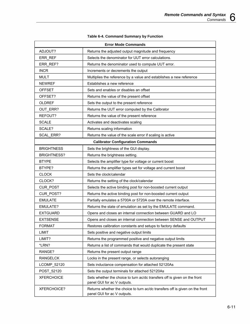
Remote Commands and Syntax Commands 6
6-11
Table 6-4. Command Summary by Function
Error Mode Commands
ADJOUT? Returns the adjusted output magnitude and frequency
ERR_REF Selects the denominator for UUT error calculations.
ERR_REF? Returns the denominator used to compute UUT error.
INCR Increments or decrements the output
MULT Multiplies the reference by a value and establishes a new reference
NEWREF Establishes a new reference
OFFSET Sets and enables or disables an offset
OFFSET? Returns the value of the present offset
OLDREF Sets the output to the present reference
OUT_ERR? Returns the UUT error computed by the Calibrator
REFOUT? Returns the value of the present reference
SCALE Activates and deactivates scaling
SCALE? Returns scaling information
SCAL_ERR? Returns the value of the scale error if scaling is active
Calibrator Configuration Commands
BRIGHTNESS Sets the brightness of the GUI display.
BRIGHTNESS? Returns the brightness setting.
BTYPE Selects the amplifier type for voltage or current boost
BTYPE? Returns the amplifier types set for voltage and current boost
CLOCK Sets the clock/calendar
CLOCK? Returns the setting of the clock/calendar
CUR_POST Selects the active binding post for non-boosted current output
CUR_POST? Returns the active binding post for non-boosted current output
EMULATE Partially emulates a 5700A or 5720A over the remote interface.
EMULATE? Returns the state of emulation as set by the EMULATE command.
EXTGUARD Opens and closes an internal connection between GUARD and LO
EXTSENSE Opens and closes an internal connection between SENSE and OUTPUT
FORMAT Restores calibration constants and setups to factory defaults
LIMIT Sets positive and negative output limits
LIMIT? Returns the programmed positive and negative output limits
*LRN? Returns a list of commands that would duplicate the present state
RANGE? Returns the present output range
RANGELCK Locks in the present range, or selects autoranging
LCOMP_52120 Sets inductance compensation for attached 52120As
POST_52120 Sets the output terminals for attached 52120As
XFERCHOICE Sets whether the choice to turn ac/dc transfers off is given on the front panel GUI for ac V outputs.
XFERCHOICE? Returns whether the choice to turn ac/dc transfers off is given on the front panel GUI for ac V outputs.

5730A Operators Manual
6-12
Table 6-4. Command Summary by Function (cont.)
Output Commands
BOOST Activates or deactivates an auxiliary amplifier
DBMOUT? Returns the output amplitude and frequency, but in dBm if ac V
OPER Activates the Calibrator output if it is in standby
OUT Sets the output and establishes a new reference for error mode
OUT? Returns the output amplitude and frequency
PHASE Sets the phase shift of the phase output signal
PHASE? Returns the phase shift of the phase output signal
PHASELCK Activates or deactivates phase locking to an external signal
PHASESFT Activates or deactivates variable phase output
RCOMP Activates or deactivates two-wire compensation circuitry
STBY Puts the Calibrator in standby
VOUT? Returns the output amplitude in volts if the active units are dBm
WBAND Activates or deactivates the Wideband AC Module (Option 5730A/03 or 5730A/05)
XFER Turns ac/dc transfers off (or on) after output has settled.
XFER? Returns whether ac/dc transfers after settling are turned on.
Overall Functions
*CLS Clear- clears status registers, any service request, and flags
ECHO? Echoes a string to the remote port
*OPC Sets bit 0 in the ESR to 1 when pending remote operations are complete
*OPC? Returns a "1" when all pending remote operations are complete
*PUD Stores a string of user-selected characters in nonvolatile memory
*PUD? Returns the contents of the PUD memory
RPT_STR Loads the user report string
RPT_STR? Returns the user report string
*RST Reset-sets the Calibrator to its default power-up state
*WAI Halts remote program execution until all pending remote operations are complete

Remote Commands and Syntax Commands 6
6-13
Table 6-4. Command Summary by Function (cont.)
Remote Interface Parameter Setting Commands
SP_EOF Sets the End-Of-File (EOF) string
SP_EOF? Returns the End-Of-File (EOF) string
SP_SET Sets baud, terminal or computer mode, stall method, data bits, stop bits, parity, and End-Of-Line (EOL) string
SP_SET? Returns baud rate, terminal or computer mode, stall method, data bits, stop bits, parity, and End-Of-Line (EOL) string
ADDR Set GPIB address
ADDR? Returns the GPIB address
DHCP Turns on/off DHCP
DHCP? Returns the state of the DHCP setting
ENETPORT Sets Ethernet port
ENETPORT? Returns the Ethernet port setting.
EOL Sets EOL for given port
EOL? Gets EOL for given port
GWADDR Sets gateway address
GWADDR? Returns the gateway address.
IPADDR Sets IP address
IPADDR? Returns the IP address
MACADDR? Gets MAC address
REM_MODE Sets computer/terminal mode for given port
REM_MODE? Gets computer/terminal mode for given port
SUBNETMASK Sets subnet mask
SUBNETMASK? Returns the subnet mask

5730A Operators Manual
6-14
Table 6-4. Command Summary by Function (cont.)
Calibration, Testing, and Diagnostics Commands for the Calibrator
CAL_ADJ Does the internal portion of calibration
CAL_CHK Starts calibration check
CAL_CLST? Returns a group of calibration constant names and their values
CAL_CONF Sets the calibration specifications to a confidence level of either 95 % or 99 %
CAL_CONF? Returns the current calibration confidence level
CAL_CONST? Returns the value of a particular constant
CAL_COUNT? Number of times the Calibrator has been unsecured
CAL_DATE? Returns the date of the most recent calibration
CAL_DAYS? Returns the days elapsed since last calibration recall
CAL_INTV Sets the calibration interval
CAL_INTV? Returns the calibration interval
CAL_PASSWD Change the calibration passcode
CAL_REF Does a calibration procedure with a 1 Ω, 10 kΩ, or 10 V standard
CAL_RCSV? Returns a comma-separated-value format report similar to what is saved on a USB flash drive
CAL_RNG Starts a self-calibration procedure of a range
CAL_RPT? Returns a formatted calibration report
CAL_SECURE Locks/unlocks calibration security
CAL_SECURE? Gets lock state of calibration security
CAL_SHIFT? Returns the shift of a range due to a calibration action
CAL_SLST? Returns the shifts of a group of ranges
CAL_STORE Stores new calibration constants in nonvolatile memory
CAL_TEMP Sets the temperature for calibration
CAL_TEMP? Returns the calibration temperature last specified
CAL_USB Saves the calibration report to a USB flash drive
CAL_WBFLAT Does Wideband AC Module (Option 5730A/03 or 5730A/05) flatness calibration
CAL_WBGAIN Does Wideband AC Module (Option 5730A/03 or 5730A/05) gain calibration
CAL_ZERO Does internal zeros calibration
DIAG Runs self-diagnostics

Remote Commands and Syntax Commands 6
6-15
Table 6-4. Command Summary by Function (cont.)
Calibration, Testing, and Diagnostics Commands for the Calibrator (cont.)
DIAGFLT Sets the Calibrator response to faults in remote diagnostics
DIAGFLT? Returns the Calibrator response to faults in remote diagnostics
OHMSREF? Returned calculated resistance reference (Main software revision H and after)
*TST? Checks the nonvolatile storage area (calibration constants and instrument settings).
Serial/USB/Ethernet Only Remote Commands
LOCAL Puts the Calibrator into the local state
LOCKOUT Puts the Calibrator into the local lockout state
REMOTE Puts the Calibrator into remote state
Status Commands
*ESE Loads the Event Status Enable register
*ESE? Reads the Event Status Enable register
*ESR? Reads and clears the Event Status Register
EXPLAIN Decodes a fault code by returning a brief description
FAULT? Returns the most recent fault code from the fault queue
*IDN? Returns Calibrator identification information
ID52120? Returns the number of 52120s connected and their serial numbers
ISCE Loads the Instrument Status Change Enable register
ISCE? Reads the Instrument Status Change Enable register
ISCR? Reads and clears the Instrument Status Change Register
ISR? Reads and clears the Instrument Status Register
ONTIME? Returns the number of minutes since power-up this session
*OPT? Returns a list of installed modules and attached amplifiers
*SRE Loads the Service Request Enable register
*SRE? Reads the Service Request Enable register
STATE? Returns the long-term state of the Calibrator
*STB? Returns the status byte
UNCERT? Returns the calculated absolute uncertainty of the output

5730A Operators Manual
6-16
Table 6-5. Commands
ADDR
Description Sequential command. Ignored if not in remote. Sets the GPIB interface bus address.
Parameter Bus address
Example ADDR 4
Sets the GPIB interface bus address to 4
ADDR ?
Description Sequential command. Gets the GPIB interface bus address.
Parameter None
Response Integer
Example ADDR?
Returns 4 if the gpib interface bus address is set to 4
ADJOUT?
Description
Sequential Command.
Returns the adjusted output magnitude and frequency. The adjusted output magnitude is the output after modification by the front panel knob or the INCR remote command. In all output functions but resistance, ADJOUT? behaves exactly like OUT?. In the resistance function, OUT? returns the actual Calibrator output, which cannot be adjusted, and ADJOUT? returns what would be the reading on the Display in direct operation. The frequency is always the present output frequency.
Parameter None
Response
(Float) Output amplitude
(String) Units (V, DBM, A, or OHM)
(Float) Frequency (0 if dc or ohms)
Example
1.256983E+01,V,0 (12.56983V)
1.883E-01,A,4.42E+02 (188.3 mA, 442 Hz)
1.9E+06,OHM,0 (1.9 MΩ)
BOOST
Description Overlapped Command, ignored if not in remote.
Activates and deactivates an accessory amplifier.
Parameter ON Activates the appropriate amplifier for the type of output)
OFF Deactivates the active amplifier
Example
BOOST ON
Activates the appropriate amplifier if the last OUT command selected an output supported by the attached amplifier.

Remote Commands and Syntax Commands 6
6-17
Table 6-5. Commands (cont.)
BRIGHTNESS
Description Sets the brightness of the GUI display.
Parameter Integer, 0 to 100, where 0 is dimmest and 100 is brightest.
Example BRIGHTNESS 50 Sets the display to half brightness (the default value).
BRIGHTNESS?
Description Returns the brightness setting.
BTYPE
Description
Sequential command, ignored if not in remote. Selects the accessory amplifiers for current and voltage boost. If the BOOST command is active when BTYPE is received, BTYPE does not take effect until the next time the BOOST command is received. The setting of BTYPE remains even after the power is turned off.
Parameter
One of the subsequent: VB5725 (Selects the 5725A for voltage boost) IB5725 (Selects the 5725A for current boost) IB52120 (Selects the 52120A for current boost)
Example BTYPE IB5725 Selects Model 5725A as the current amplifier.
BTYPE?
Description Sequential command. Returns the model numbers of auxiliary amplifiers selected for voltage and current boost. Returns IB52120 if Model 52120A is selected for current boost.
Parameter None
Response (String, string) VB<model number>,IB<model number>; VBNONE is also available to prevent the Calibrator from automatically switching to a connected 5725A.
Example BTYPE? Returns: "VB5725,IB5725" if Model 5725A is selected for voltage boost and Model 5725A is selected for current boost.
CAL_ADJ
Description Overlapped long-term command, ignored if not in remote. Does the internal calibration. This command should be sent after the last CAL_REF command in the sequence of calibration. (See CAL_REF for an example.)
Parameter None
CAL_CHK
Description Overlapped long-term command, ignored if not in remote. Starts calibration check. Results are available via the CAL_SLST? or CAL_SHIFT? commands.
Parameter None

5730A Operators Manual
6-18
Table 6-5. Commands (cont.)
CAL_CLST?
Description Sequential command. Returns a list of names values of a particular group of calibration constants.
Parameter CAL (Returns active calibration constants) CHECK (Returns calibration check constants) PREV (Returns previous calibration constants)
Response
(String) "<EOL> <total number of constants> <EOL> <name> <value> <EOL> <name> <value> <EOL> (cont) "
Example
CAL_CLST?, CAL Could return: " 424 D3P, 3.9817876E+02 (Continues for about 400 pairs of names and values.) “
CAL_CONF
Description Sequential command. Sets the calibration specifications to a confidence level of either 99% or 95%.
Parameter CONF95 or CONF99: Sets 95% or 99% specifications.
CAL_CONF?
Description Sequential command. Returns the current calibration confidence level.
Parameter None Response CONF95 (indicates 95% specifications)a or CONF99 (indicates 99% specifications)
CAL_CONST?
Description Sequential command. Returns the value of a particular calibration constant from a particular group of constants.
Parameter
1. CAL (From active calibration constants) CHECK (From calibration check constants) PREV (From previous calibration constants)
2. Symbolic name of the calibration constant desired (see Appendix D). Response (Float) The value of the constant
Example CAL_CONST? CHECK, KV6 Could return: 6.5000010E+00
CAL_COUNT?
Description Sequential command. Returns the number of calibration constants that have been saved at the end of a calibration procedure (except for DC Zeros)
Response integer Parameter None Example
CAL_COUNT? Returns 34 if calibration constants have been saved 34 times.

Remote Commands and Syntax Commands 6
6-19
Table 6-5. Commands (cont.)
CAL_DATE?
Description Sequential command. Returns the date of the most recent calibration of the specified type.
Parameter
B5725 (Last 5725A Amplifier calibration) CAL (Last calibration of the Calibrator) WBFLAT (Last wideband flatness calibration) WBGAIN (Last wideband gain calibration) ZERO (Last dc V zero calibration)
Response (Integer) Date as MMDDYY, DDMMYY, or YYMMDD depending on the setting of DATEFMT.
CAL_DAYS?
Description Sequential command. Returns the number of days elapsed since the last calibration activity of the specified type.
Parameter
B5725 (Last 5725A Amplifier calibration) CAL (Last calibration of the Calibrator) WBFLAT (Last wideband flatness calibration) WBGAIN (Last wideband gain calibration) ZERO (Last dc V zero calibration)
Response (Integer) Number of elapsed days
CAL_INTV
Description
Sequential command, ignored if not in remote.
Sets the calibration interval for main output calibration. This value is saved in nonvolatile memory and used for calculating the Calibrator output uncertainty.
Parameter 1, 90, 180, or 365- the number of days in the calibration cycle.
CAL_INTV?
Description Sequential command.
Returns the calibration interval for main output calibration.
Parameter None
Response (Integer) 1, 90, 180, or 365- the number of days in the calibration cycle.
CAL_PASSWD
Description Sequential command. Ignored if not in remote. Sets security password. The Calibrator secure state must be set to off or an execution fault results.
Parameter 1. current security passcode (quoted string consisting of up to 8 decimal digits).
2. new security passcode (quoted string consisting of up to 8 decimal digits).
Example CAL_PASSWD "5730", "12345"
Sets the security passcode to 12345.
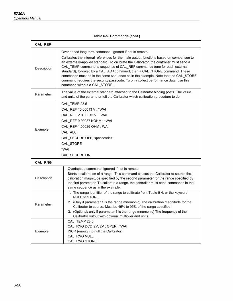
5730A Operators Manual
6-20
Table 6-5. Commands (cont.)
CAL_REF
Description
Overlapped long-term command, ignored if not in remote.
Calibrates the internal references for the main output functions based on comparison to an externally-applied standard. To calibrate the Calibrator, the controller must send a CAL_TEMP command, a sequence of CAL_REF commands (one for each external standard), followed by a CAL_ADJ command, then a CAL_STORE command. These commands must be in the same sequence as in the example. Note that the CAL_STORE command requires the security passcode. To only collect performance data, use this command without a CAL_STORE.
Parameter The value of the external standard attached to the Calibrator binding posts. The value and units of the parameter tell the Calibrator which calibration procedure to do.
Example
CAL_TEMP 23.5
CAL_REF 10.00013 V ; *WAI
CAL_REF -10.00013 V ; *WAI
CAL_REF 9.99987 KOHM ; *WAI
CAL_REF 1.00026 OHM ; WAI
CAL_ADJ
CAL_SECURE OFF, <passcode>
CAL_STORE
*WAI
CAL_SECURE ON
CAL_RNG
Description
Overlapped command, ignored if not in remote.
Starts a calibration of a range. This command causes the Calibrator to source the calibration magnitude specified by the second parameter for the range specified by the first parameter. To calibrate a range, the controller must send commands in the same sequence as in the example.
Parameter
1. The range identifier of the range to calibrate from Table 5-4, or the keyword NULL or STORE.
2. (Only if parameter 1 is the range mnemonic) The calibration magnitude for the Calibrator to source. Must be 45% to 95% of the range specified.
3. (Optional; only if parameter 1 is the range mnemonic) The frequency of the Calibrator output with optional multiplier and units.
Example
CAL_TEMP 23.5
CAL_RNG DC2_2V, 2V ; OPER ; *WAI
INCR (enough to null the Calibrator)
CAL_RNG NULL
CAL_RNG STORE

Remote Commands and Syntax Commands 6
6-21
Table 6-5. Commands (cont.)
CAL_RPT?
Description Sequential command.
Returns a report for a specified calibration activity (see Chapter 6 for format details).
Parameter
CAL (Output change report for calibration)
CHECK (Output change report for calibration check)
RAW (A list of all calibration constants)
Response
(String)
"<EOL>
<formatted report>
"
CAL_RCSV?
Description Sequential command.
Returns a report in CSV format for a specified calibration activity (see Chapter 6 for format details).
Parameter
CAL (Output change report for calibration)
CHECK (Output change report for calibration check)
RAW (A list of all calibration constants)
Response
(String)
"<EOL>
<formatted report>
"
CAL_SECURE
Description
Sequential command. Ignored if not in remote. Lock/unlocks the calibration security by use of a passcode. The passcode is entered as a quoted string of decimal digits. (eg "12345"). To secure the Calibrator, no passcode is necessary. If an incorrect password is entered, the Calibrator will automatically be resecured if it was unsecured.
Parameter 1. ON/OFF 2. <passcode>
Example CAL_SECURE OFF, "12345" Unsecures the Calibrator.
Example CAL_SECURE ON Secures the Calibrator.
CAL_SECURE?
Description Sequential command. Returns the current security state of the Calibrator.
Parameter None
Response String
Example CAL_SECURE? Returns ON if the Calibrator is secured.

5730A Operators Manual
6-22
Table 6-5. Commands (cont.)
CAL_SHIFT?
Description Sequential command. Returns a particular set of output shifts from a particular range.
Parameter CAL (Output changes due to calibration check) CHECK (All output changes due to calibration check) Range identifier from Table 5-4
Response
(String) "<EOL> range name>,<# points><EOL> <mag 1>,<freq 1>,<offset 1>,<ashift 1>,<rshift 1><sshift 1>,<spec 1><EOL> . . . <mag n>,<freq n>,<offset n>,<ashift n>,<rshift 1>,<sshift n>,<spec n><EOL> " Where: <range name> = Range identifier from Table 5-4 <# points> = (Integer) Number of points for the range <mag n> = (Float) Magnitude for point n in range units <freq n> = (Float) Frequency for point n in Hz <offset n> = (Float) Zero shift for point n in range units <ashift n> = (Float) Absolute shift for point n in range units <rshift n> = (Float) Relative shift for point n (ppm) <sshift n> = (Float) % of spec shift for point n <spec n> = Calibrator specification for point n in ppm Range units are the appropriate units for the range, for example, for all DC V ranges, range units are V.
Example
CAL_SHIFT? CAL, DC220MV could return: " DC220MV,2 2.20E-1,0.00E+00,1.76E-07,1.97E-07,8.98E-01,7.10E+00,1.26E+01 -2.20E-1,0.00E+00,1.58E-07,1.38E-07,6.26E-01,4.95E+00,1.26E+01 "

Remote Commands and Syntax Commands 6
6-23
Table 6-5. Commands (cont.)
CAL_SLST?
Description Sequential command.
Returns a group of calibration constant shifts due to a calibration activity.
Parameter CAL (All output changes due to calibration) CHECK (All output changes due to calibration check)
Response
(String) "<EOL>
<range name>,<# points><EOL>
<mag 1>,<freq 1>,<offset 1>,<ashift 1>,<rshift 1><sshift 1>,<spec 1><EOL> . . .
<mag n>,<freq n>,<offset n>,<ashift n>,<rshift 1>,<sshift n>,<spec n><EOL> "
Where:
<range name> = Range identifier from Table 5-4
<# points> = (Integer) Number of points for the range
<mag n> = (Float) Magnitude for point n in range units
<freq n> = (Float) Frequency for point n in Hz
<offset n> = (Float) Zero shift for point n in range units
<ashift n> = (Float) Absolute shift for point n in range units
<rshift n> = (Float) Relative shift for point n (ppm)
<sshift n> = (Float) % of spec shift for point n
<spec n> = Calibrator specification for point n in ppm
Range units are the appropriate units for the range, for example, for all DC V ranges, range units are V.
Example
CAL_SLST? CAL could return:
“
49
DC220MV,2
2.20E-1,0.00E+00,1.76E-07,1.97E-07,8.98E-01,7.10E+00,1.26E+01
-2.20E-1,0.00E+00,1.58E-07,1.38E-07,6.26E-01,4.95E+00,1.26E+01
DC2_2V,2
(cont)
"
CAL_STORE
Description
Sequential command, ignored if not in remote.
Stores all new calibration constants in nonvolatile memory. Use this command to save the results of a CAL_ADJ command after completely finished with calibration via remote control. The Calibrator secure state must be set to off or an execution fault results.
Parameter None

5730A Operators Manual
6-24
Table 6-5. Commands (cont.)
CAL_TEMP
Description
Sequential command, ignored if not in remote.
Sets the temperature for calibration. This should be done before sending CAL_REF, CAL_WBFLAT, CAL_WBGAIN, or CAL_CHK commands. Once set, the temperature is used for all calibration activities until it is changed. If the temperature is not set before a calibration activity, the Calibrator uses a default of 23.0 °C.
Parameter Temperature in degrees C.
CAL_TEMP?
Description Sequential command.
Returns the previous ambient temperature setting used for a particular calibration procedure.
Parameter B5725, CAL, WBFLAT, WBGAIN, or CHECK
Response (Float) Temperature in degrees C.
CAL_USB
Description
Overlapped command. Saves a calibration report to a USB thumb drive connected to the front panel USB host port.
Parameter
CAL (Output change report for calibration)
CHECK (Output change report for calibration check)
RAW (A list of all calibration constants)
Example CAL_USB RAW
CAL_WBFLAT
Description
Overlapped command, ignored if not in remote.
Does Wideband AC Module (Option 5730/03 or 5730A/05) flatness calibration. There are two different calibration procedures for the wideband module- gain and flatness. Wideband gain is to be done at every calibration cycle. Wideband flatness is needed only during full verification, recommended every two years. For reference, the manual procedure for wideband flatness calibration is in Chapter 7.
After sending a CAL_WBFLAT START command, the controller must adjust the Calibrator output with the INCR command until it matches the calibration voltage, then inform the Calibrator of the fact by sending a CAL_WBFLAT NULL command. A series of points to test is selected automatically by the software. After each CAL_WBFLAT NULL command, determine the calibration setting by sending an OUT? command.
Parameter
START (Starts flatness calibration, sources the first point)
NULL (Calculates flatness constant, sources the next point)
STORE (Stores wideband flatness constants into non-volatile memory)
Example
CAL_TEMP 24.6
CAL_WBFLAT START
(Connect to external standard as in Chapter 7)
OPER
INCR (Enough to get the Calibrator output correct)
CAL_WBFLAT NULL
(Repeat the preceding two commands for each calibration point. CAL_NULL automatically sources the next calibration point. When OUT? returns 0,V,0, all points have been calibrated.)
CAL_WBFLAT STORE

Remote Commands and Syntax Commands 6
6-25
Table 6-5. Commands (cont.)
CAL_WBGAIN
Description
Overlapped long-term command, ignored if not in remote.
Does Wideband AC Module (Option 5730/03 or 5730A/05) gain calibration. There are two different calibration procedures for the wideband module: gain and flatness. Wideband gain is to be done at every calibration cycle. Wideband flatness is needed only during full verification (recommended every two years). For reference, the manual procedure for wideband gain calibration is in Chapter 7.
To calibrate wideband gain in remote, the wideband output cable must be connected to the Calibrator SENSE binding posts as described in Chapter 7, then the controller must send commands in the same sequence as in the example. For positive gain, the center conductor is connected to SENSE HI. For negative gain, the center conductor is connected to SENSE LO.
Parameter
PGAIN (Calibrates wideband positive gain)
NGAIN (Calibrates wideband negative gain)
STORE (Stores wideband constants into non-volatile memory)
Example
CAL_TEMP 23.5
CAL_WBGAIN PGAIN (Calibrates positive gain)
(Reverse the SENSE connection now)
CAL_WBGAIN NGAIN (Calibrates negative gain)
CAL_WBGAIN STORE
CAL_ZERO
Description
Overlapped long-term command, ignored if not in remote.
Does internal zeros calibration. This removes offsets on the 2.2V dc range. It takes about 2-1/2 minutes, plus 30 seconds if teamed with 5725A, and does not require a change to the Calibrator security state.
Parameter None
CLOCK
Description
Sequential command, ignored if not in remote.
Sets the clock/calendar. The Calibrator security state must be set to off or an execution fault results.
Parameter
1. Time in 24-hour format as HHMMSS
2. Date as MMDDYY, DDMMYY, or YYMMDD depending on the setting the DATEFMT.
Example CLOCK 133700, 071712 (Sets the clock/calendar to 1:37 p.m., July 17, 2012.)
CLOCK 080000, 101012 (Sets the clock/calendar to 8:00 a.m., October 10, 2012.)
CLOCK?
Description Sequential command.
Returns the setting of the clock/calendar.
Parameter None
Response
1. (Integer) Time in 24-hour format as HHMMSS.
2. (Integer) Date as MMDDYY, DDMMYY, or YYMMDD depending on the setting of DATEFMT.
Example
CLOCK?
Returns:
"150000,090112" if the clock/calendar is set to 3 p.m., September 1, 2012.
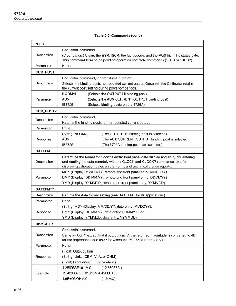
5730A Operators Manual
6-26
Table 6-5. Commands (cont.)
*CLS
Description
Sequential command.
(Clear status.) Clears the ESR, ISCR, the fault queue, and the RQS bit in the status byte. This command terminates pending operation complete commands (*OPC or *OPC?).
Parameter None
CUR_POST
Description
Sequential command, ignored if not in remote.
Selects the binding posts non-boosted current output. Once set, the Calibrator retains the current post setting during power-off periods.
Parameter
NORMAL (Selects the OUTPUT HI binding post)
AUX (Selects the AUX CURRENT OUTPUT binding post)
IB5725 (Selects binding posts on the 5725A)
CUR_POST?
Description Sequential command.
Returns the binding posts for non-boosted current output.
Parameter None
Response
(String) NORMAL (The OUTPUT HI binding post is selected)
AUX (The AUX CURRENT OUTPUT binding post is selected)
IB5725 (The 5725A binding posts are selected)
DATEFMT
Description Determine the format for clock/calendar front panel date display and entry, for entering and reading the date remotely with the CLOCK and CLOCK? commands, and for displaying calibration dates on the front panel and in calibration reports.
Parameter
MDY (Display: MM/DD/YY, remote and front panel entry: MMDDYY)
DMY (Display: DD.MM.YY, remote and front panel entry: DDMMYY)
YMD (Display: YYMMDD, remote and front panel entry: YYMMDD)
DATEFMT?
Description Returns the date format setting (see DATEFMT for its applications).
Parameter None
Response
(String) MDY (Display: MM/DD/YY, date entry: MMDDYY),
DMY (Display: DD.MM.YY, date entry: DDMMYY), or
YMD (Display: YYMMDD, date entry: YYMMDD)
DBMOUT?
Description
Sequential command.
Same as OUT? except that if output is ac V, the returned magnitude is converted to dBm for the appropriate load (50Ω for wideband, 600 Ω standard ac V).
Parameter None
Response
(Float) Output value
(String) Units (DBM, V, A, or OHM)
(Float) Frequency (0 if dc or ohms)
Example
1.256983E+01,V,0 (12.56983 V)
+2.4203670E+01,DBM,4.4200E+02
1.9E+06,OHM,0 (1.9 MΩ)

Remote Commands and Syntax Commands 6
6-27
Table 6-5. Commands (cont.)
DHCP
Description Sequential command. Ignored if not in remote. Enables/disables DHCP (Dynamic Host Configuration Protocol) for LAN operation.
Parameter ON (enables DHCP operation)
OFF (disables DHCP operation)
DHCP?
Description Sequential command. Returns the current state of the DHCP configuration.
Parameter None
Response String
Example DHCP?
Returns ON if DHCP is enabled.
DIAG
Description
Overlapped long-term command, ignored if not in remote.
Runs a self-diagnostics routine. If any faults are detected, they are logged into the fault queue where they can be read by the FAULT? query. The response to faults that occur during remote-controlled diagnostics depends by the setting of the DIAGFLT command.
Parameter
ALL (Runs all diagnostics routines)
D5700 (Runs all Calibrator diagnostics)
DV5725 (Runs 5725A voltage diagnostics)
DI5725 (Runs 5725A current diagnostics)
CONT (Continues execution of diagnostics)
ABORT (Terminates execution of diagnostics)
DIAGFLT
Description
Sequential command, ignored if not in remote.
Determines the response to faults that occur during remote-controlled diagnostics. In all cases the fault encountered is logged into the fault queue before the Calibrator takes any action as set by this command. The settings of this command are saved in nonvolatile memory. The default is ABORT.
Parameter
HALT (Halts and waits for DIAG CONT or DIAG ABORT)
ABORT (Terminates diagnostics)
CONT (Diagnostics continues to completion, logging any more faults as encountered)
DIAGFLT?
Description Sequential command.
Returns the setting of DIAGFLT.
Parameter None
Response (String) HALT, ABORT, or CONT
ECHO?
Description Sequential command.
Echoes a string back to the remote interface port. Upper or lower case remains intact in this command.
Parameter Any string
Response (String including delimiting quotation marks)
Example
ECHO "123abc456"
Returns:
"123abc456"
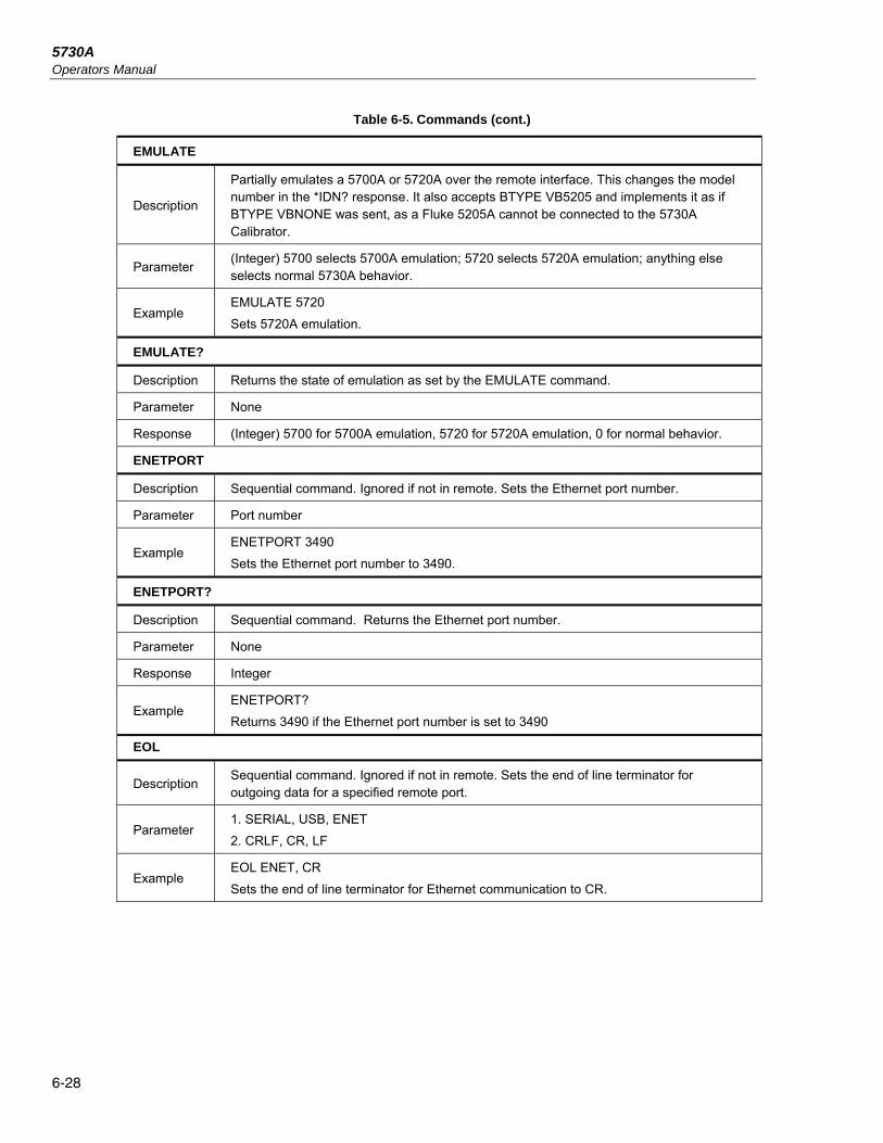
5730A Operators Manual
6-28
Table 6-5. Commands (cont.)
EMULATE
Description
Partially emulates a 5700A or 5720A over the remote interface. This changes the model number in the *IDN? response. It also accepts BTYPE VB5205 and implements it as if BTYPE VBNONE was sent, as a Fluke 5205A cannot be connected to the 5730A Calibrator.
Parameter (Integer) 5700 selects 5700A emulation; 5720 selects 5720A emulation; anything else selects normal 5730A behavior.
Example EMULATE 5720
Sets 5720A emulation.
EMULATE?
Description Returns the state of emulation as set by the EMULATE command.
Parameter None
Response (Integer) 5700 for 5700A emulation, 5720 for 5720A emulation, 0 for normal behavior.
ENETPORT
Description Sequential command. Ignored if not in remote. Sets the Ethernet port number.
Parameter Port number
Example ENETPORT 3490
Sets the Ethernet port number to 3490.
ENETPORT?
Description Sequential command. Returns the Ethernet port number.
Parameter None
Response Integer
Example ENETPORT?
Returns 3490 if the Ethernet port number is set to 3490
EOL
Description Sequential command. Ignored if not in remote. Sets the end of line terminator for outgoing data for a specified remote port.
Parameter 1. SERIAL, USB, ENET
2. CRLF, CR, LF
Example EOL ENET, CR
Sets the end of line terminator for Ethernet communication to CR.

Remote Commands and Syntax Commands 6
6-29
Table 6-5. Commands (cont.)
EOL?
Description Sequential command. Returns the end of line terminator for outgoing data for a specified remote port.
Parameter 1. SERIAL, USB, ENET
Response String
Example EOL? SERIAL
Returns CRLF if the serial end of line terminator is set to CRLF.
ERR_REF
Description Selects the denominator for UUT error calculations.
Parameter NOMINAL to use the original reference, TRUVAL to use the edited value.
Example ERR_REF TRUVAL
ERR_REF?
Description Selects the denominator for UUT error calculations.
Parameter None
Example ERR_REF?
Returns TRUVAL if the edited value is the denominator.
*ESE
Description Sequential command.
Loads a byte into the Event Status Enable Register, described under "Check the Calibrator Status."
Parameter The decimal equivalent of the binary number to load into the register (0-255 only).
Example *ESE 140
Enables bits 2 (QYE), 3 (DDE), and 7 (PON), and disables all the other bits. (See "Check the Calibrator Status" for details.)
*ESE?
Description
Sequential command.
Returns the byte from the Event Status Enable register, described under "Check the Calibrator Status."
Parameter None
Response (Integer) Decimal equivalent of the register byte.
Example
*ESE?
Returns: "140" if bits 2 (QYE), 3 (DDE), and 7 (PON) are enabled (1) and the rest of the bits are disabled (0). (See "Check the Calibrator Status" for details.)

5730A Operators Manual
6-30
Table 6-5. Commands (cont.)
*ESR?
Description
Sequential command.
Returns the byte from the Event Status Register and clears the register. The ESR is described under "Check the Calibrator Status."
Parameter None
Response (Integer) Decimal equivalent of the register byte.
Example
*ESR?
Returns: "140" if bits 2 (QYE), 3 (DDE), and 7 (PON) are set (1) and the rest of the bits are reset (0). (See "Check the Calibrator Status" for details.)
EXPLAIN?
Description
Sequential command.
Explains a fault code. This command returns a string that explains the fault code furnished as the parameter. The fault code (same as the parameter) is originally obtained by sending the FAULT? query.
Parameter The fault code (an integer).
Response (String) An explanation of the fault code.
Example
EXPLAIN? 224
Returns:
Output Tripped To Standby
EXTGUARD
Description
Overlapped command, ignored if not in remote.
Sets the Calibrator to internal or external guard. (The same as pushing EX GRD in local operation.) The default is internal guard.
Parameter ON (Sets the Calibrator to external guard)
OFF (Sets the Calibrator to internal guard)
EXTSENSE
Description
Overlapped command, ignored if not in remote.
Selects internal or external sensing. (The same as pushing EX SNS in local operation.) The default if internal sensing.
Parameter ON (Sets the Calibrator to external sensing)
OFF (Sets the Calibrator to internal sensing)
FAULT?
Description
Sequential command.
Returns the earliest fault code contained in the Calibrator fault queue. After the fault code is received, use the EXPLAIN? command to find out the meaning of the fault code. A table of fault codes is also included in Appendix A of this manual.
A zero value is returned if there are no faults, so to read the entire contents of the fault queue, repeat FAULT? until the response is "0."
Parameter None
Response (Integer) The fault code

Remote Commands and Syntax Commands 6
6-31
Table 6-5. Commands (cont.)
FORMAT
Description
Sequential command, ignored if not in remote.
Use with extreme care. Restores the contents of the non-volatile memory to factory defaults. The non-volatile memory holds calibration constants and setup parameters. All calibration data is lost permanently. The Calibrator security state must be set to OFF: or an execution fault occurs.
Parameter
ALL (Replaces the whole contents with defaults)
B5725 (Replaces 5725A calibration constants with defaults)
CAL (Replaces all calibration constants with defaults)
RNG (Replaces range calibration constants with defaults)
SETUP (Replaces setup parameters with defaults)
GWADDR
Description Sequential command. Ignored if not in remote. Sets Ethernet gateway address for LAN communication when NOT in DHCP mode.
Parameter Gateway address (quoted string consisting of 4 decimal values bound between 0-255 separated by periods).
Example GWADDR "129.196.136.1"
Sets the Etherent gateway address to 129.196.136.1
GWADDR?
Description Sequential command. Returns Ethernet gateway address for LAN communication when NOT in DHCP mode. When in DHCP mode, the response will be default.
Parameter None
Response String
Example
GWADDR?
Returns 129.196.136.1 if the gateway address is set to 129.196.136.1 and DHCP is not enabled. Returns default if DHCP is enabled.
ID52120? (returns the number of 52120s connected and their serial numbers)
Description Sequential command. Returns the number of 52120s connected and their serial numbers.
Parameter None
Response One or more integers
Example
ID52120?
Returns 0 if no 52120As are connected. Returns 2, 7346432, 8883213 if two 52120A's are connected with the indicated serial numbers.

5730A Operators Manual
6-32
Table 6-5. Commands (cont.)
*IDN?
Description
Sequential command.
Returns Calibrator model number and firmware version letters for the main, inguard, and if attached, the 5725A Amplifier CPU.
Parameter None
Response
(String, string, 0, string)
A message containing four fields separated by commas, as follows:
Fluke
5730A
Serial number
Three firmware versions: one each for the Main CPU, the Inguard CPU, and the Boost CPU. Each version is separated by a plus (+). If no amplifier is attached then its position (third character) contains an asterisk (*).
Example FLUKE,5730A,5248000,1.0+B+*
INCR
Description
Overlapped command, ignored if not in remote.
Increments the output amplitude and enters error mode, the same as with the output adjustment knob in local operation.
Parameter Increment step size, positive for incremental step, negative for decremental step. Units (optional) specify magnitude or frequency.
Example INCR -.00001 Enters error mode and decrements the output by .00001.
INCR 1 Hz Enters error mode and increments the frequency by 1 Hz.
IPADDR
Description Sequential command. Ignored if not in remote. Sets IP address for LAN communication when NOT in DHCP mode and with static IP addressing.
Parameter IP address (quoted string consisting of 4 decimal values bound between 0-255 separated by periods).
Example IPADDR "129.196.136.119"
Sets the Ethernet IP static address to 129.196.136.119
IPADDR ?
Description Sequential command. Returns IP address for LAN communication. When DHCP is enabled, this address will be the address allocated by the DNS server. When DHCP is disabled, this address will be the entered value of the static IP address.
Parameter None
Response String
Example
IPADDR?
May return 129.196.137.45 if DHCP is enabled and the DNS server has allocated the device this address or 129.196.136.119 and DHCP is disabled and the static address has been previously set to this address.

Remote Commands and Syntax Commands 6
6-33
Table 6-5. Commands (cont.)
ISCE
Description
Sequential command.
Loads a byte into the Instrument Status Change Enable register described under "Check the Calibrator Status."
Parameter The decimal equivalent of the binary number to load into the register.
Example
ISCE 56
Enables bits 3 (BOOST), 4 (RCOMP), and 5 (RLOCK) in the Service Request Enable register.
ISCE?
Description
Sequential command.
Returns the byte from the Instrument Status Change Enable register, described under "Check the Calibrator Status."
Parameter None
Response The decimal equivalent of the register contents byte.
Example
ISCE?
Returns: "4" if bit 3 (BOOST) is enabled (1) and the rest of the bits are disabled (0). (See "Check the Calibrator Status" for details.)
ISCR?
Description
Sequential command.
Returns and clears the byte from the Instrument Status Change Register, described under "Check the Calibrator Status."
Parameter None
Response The decimal equivalent of the register contents byte.
Example
ISCR?
Returns: "8" if bit 3 (BOOST) is set (1) and the rest of the bits are reset (0). (See "Check the Calibrator Status" for details.)
ISR?
Description
Sequential command.
Returns and clears the byte from the Instrument Status Register, described under "Check the Calibrator Status."
Parameter None
Response The decimal equivalent of the register contents byte.
Example
ISR?
Returns: "16" if bit 4 (RLOCK) is set (1) and the rest of the bits are reset (0). (See "Check the Calibrator Status" for details.)
LCOMP_52120
Description Overlapped command,. Ignored if not in remote. Sets inductance compensation for attached 52120As.
Parameter ON (enables LCOMP for all attached 52120s)
OFF (disables LCOMP for all attached 52120s)

5730A Operators Manual
6-34
Table 6-5. Commands (cont.)
LCOMP_52120?
Description Sequential command. Returns the current state of inductance compensation for attached 52120As.
Parameter None
Response String
Example LCOMP_52120?
Returns ON if LCOMP is enabled.
LIMIT
Description
Sequential command, ignored if not in remote.
Sets the maximum permissible output magnitudes, negative and positive. Both parameters must be present, and the units must be none, volts, or amps. The units must not conflict. If no units are specified, V is assumed.
Parameter 1. Positive limit value with optional multiplier and optional unit.
2. Negative limit value with optional multiplier and optional unit.
Example LIMIT 1.8 A, -1.2 A
Sets the limit for ac and positive dc current to 1.8 A, and negative dc current to -1.2 A.
LIMIT?
Description Sequential command.
Returns the programmed output magnitude limits for voltage and current.
Response
(Float, float, float, float)
1. Positive voltage limit value
2. Negative voltage limit value
3. Positive current limit value
4. Negative current limit value
Example
LIMIT?
Returns: +2.2000000E+02,-1.0000000E+02,
+1.8000000E+00,-1.2000000E+00if the programmed voltage range is -100 V to 220 V, and the programmed current range is -1.2 A to 1.8 A.
*LRN?
Description
Sequential command.
Provides the current setting of the Calibrator. The response to this command is a string that recreates the state of the subsequent settings when returned to the Calibrator:
Output value Whether the wideband AC Module is on Phase lock
Operate/standby Whether an auxiliary amplifier is on Phase shift
Guard Range lock Offset
Sense Two-wire compensation Scale
Output limits
Parameter None
Response (String) A string that enables the settings that were set at the time of the *LRN? command.
Example
SETMFC '00000000000024400000000000408F40000000000000244000000000000024400000000000000000000000000030914000000000003091C0000000000080764000000000008076C000000000000000000000000000000000000000000000000000000000000000000B000158010000000E080000'

Remote Commands and Syntax Commands 6
6-35
Table 6-5. Commands (cont.)
MACADDR?
Description Sequential command. Returns MAC/HW address for LAN communication. The MAC address is a unique assigned value and cannot be changed.
Parameter None
Response String
Example
MACADDR?
Returns six groups of hexadecimal numbers separated by colons (for example, 01:23:45:67:89:ab)
MULT
Description
Overlapped command, ignored if not in remote.
Multiplies the reference magnitude by the parameter and changes the output to the new value. The reference magnitude is the present output in direct operation, and the reference in error mode.
Parameter Floating-point number to act as a multiplier
Example If the output is 10 V with error mode off and the command is sent, "MULT 1.9", the output changes to 19 V.
NEWREF
Description
Sequential command, ignored if not in remote.
Sets reference value to be the present output value. (The same as touching the New Reference selection in local operation.)
Parameter None
OFFSET
Description Sequential command, ignored if not in remote.
Enables and disables an offset for the output value. Effective immediately when enabled.
Parameter ON or OFF
OFFSET?
Description Sequential command.
Returns the offset value if the offset is enabled, otherwise, returns the number 0.0.
Parameter None
Response 1. (Float) Offset value or 0.0 if no offset is active
2. (Float) Offset units
Example OFFSET?
Returns: "5.05000E-03,V" if an offset of 5.05 mV is active.
OHMSREF?
Description Return calculated resistance reference as shown in calibration report (average actual-to-nominal ratio of the 100 ohm to 190 kohm resistors).
Parameter
CAL (From active calibration constants)
CHECK (From calibration check constants)
PREV (From previous calibration constants)
Response (Float) The resistance reference value.
Example OHMSREF? CHECK 1.000021902360723E+00

5730A Operators Manual
6-36
Table 6-5. Commands (cont.)
OLDREF
Description
Overlapped command, ignored if not in remote.
Sets the Calibrator output to the previously-programmed reference value. (The same as pushing the in local operation.)
Parameter None
ONTIME?
Description Sequential command.
Returns the time in minutes since the Calibrator was turned on.
Parameter None
Response (Integer) Number of minutes since power-up this session.
*OPC
Description
Sequential command.
Sets bit 0 (OPC for "Operation Complete") in the Event Status Register to 1 when all pending device operations are complete.
Parameter None
Response Sets bit 0 (OPC for "Operation Complete") in the Event Status Register to 1 when all pending device operations are complete.
Example After sending an OUT command, check if the output has settled by sending *OPC. As soon as the output has settled, a pending *OPC command sets bit 0 (OPC for "Operation Complete") in the Event Status Register to 1. The command to read the ESR is *ESR?.
*OPC?
Description
Sequential command.
Causes program execution to pause until all operations are complete; returns a 1 upon completion of these operations. (See also *WAI.)
Parameter None
Response (Integer) "1" after all operations are complete.
Example If an OUT command had been sent, check if the output has settled by sending *OPC or *OPC?. As soon as the OUT command has completed (output settled), a pending *OPC command places a "1" in the output buffer to be read by the controller.
OPER
Description
Overlapped command, ignored if not in remote.
Activates the Calibrator output if in standby. OPER is inhibited for outputs 22V and over, if there are faults in the fault queue (see "Fault Queue").
Parameter None

Remote Commands and Syntax Commands 6
6-37
Table 6-5. Commands (cont.)
*OPT?
Description
Sequential command.
Returns a list of analog modules installed in the Calibrator, including any auxiliary amplifiers that are attached.
Parameter None
Response (Series of strings) A list of the modules and auxiliary amplifiers, separated by commas.
Example "5725A Attached","52120 Attached"
OUT
Description
Overlapped command, ignored if not in remote.
Sets the output of the Calibrator and establishes a new reference point for shifting the output to determine UUT error. If only one parameter is supplied, the Calibrator makes the minimum change needed to comply with the requested output. For example, if the Calibrator setting is 1 V, 100 Hz and "OUT 2V" is sent, the setting changes to 2 V, 100 Hz.
Parameter
1. (Optional) Output amplitude with optional multiplier and unit. (At least one parameter must be sent.)
2. (Optional) Output frequency with optional multiplier and unit. (At least one parameter must be sent.)
Example
OUT -15.2 V (-15.2 V; frequency unchanged)
OUT 188.3 MA, 442 HZ (188.3 mA, 442 Hz)
OUT 1.9 MOHM (1.9 MΩ)
OUT 100 HZ (Sets the frequency only)
OUT?
Description Sequential command
Returns the Calibrator output amplitude and frequency (does not include multipliers).
Parameter None
Response
1. (Float) Output amplitude
2. (String) Units (V, DBM, A, or OHM)
3. (Float) Frequency (0 if dc or ohms)
Example
1.256983E+01,V,0 (12.56983 V)
1.883E-01,A,4.42E+02 (188.3 mA, 442 Hz)
1.9E+06,OHM,0 (1.9 MΩ)
OUT_ERR?
Description
Sequential command.
Returns the UUT error computed by the Calibrator after the INCR command is used to shift the output.
Parameter None
Response 1. (Float) UUT error magnitude
2. (String) units for the above number (PPM, PCT, or DB)
PHASE
Description Overlapped command, ignored if not in remote.
Sets the phase output signal to lead or lag the main output signal by up to 180 degrees.
Parameter Phase in degrees (-359 to 359, fractions ignored)

5730A Operators Manual
6-38
Table 6-5. Commands (cont.)
PHASE?
Description
Sequential command.
Returns the phase angle of the variable phase output signal, with respect to the main output signal.
Parameter None
Response (Integer) Phase in degrees (0 to 180,-179 to 0, 0 if the output is not ac)
PHASELCK
Description Overlapped command, ignored if not in remote. Enables or disables external phase locking, when the Calibrator is supplying an ac voltage.
Parameter ON (Activates phase locking) OFF (Deactivates phase locking)
PHASESFT
Description Overlapped command, ignored if not in remote. Enables or disables the variable phase output, when the Calibrator is supplying an ac voltage.
Parameter ON (Activates variable phase output) OFF (Deactivates variable phase output)
POST_52120
Description Sequential command. Ignored if not in remote. Sets the output terminals for all attached 52120As.
Parameter 1. LO52120, HI52120
Example POST_52120 LO52120
Selects the low current output terminals for all attached 52120As.
POST_52120?
Description Sequential command. Returns the selected output terminals for all attached 52120As.
Parameter None
Response String
Example POST_52120?
Returns HI52120 if the high current output terminals are selected for all attached 52120As.
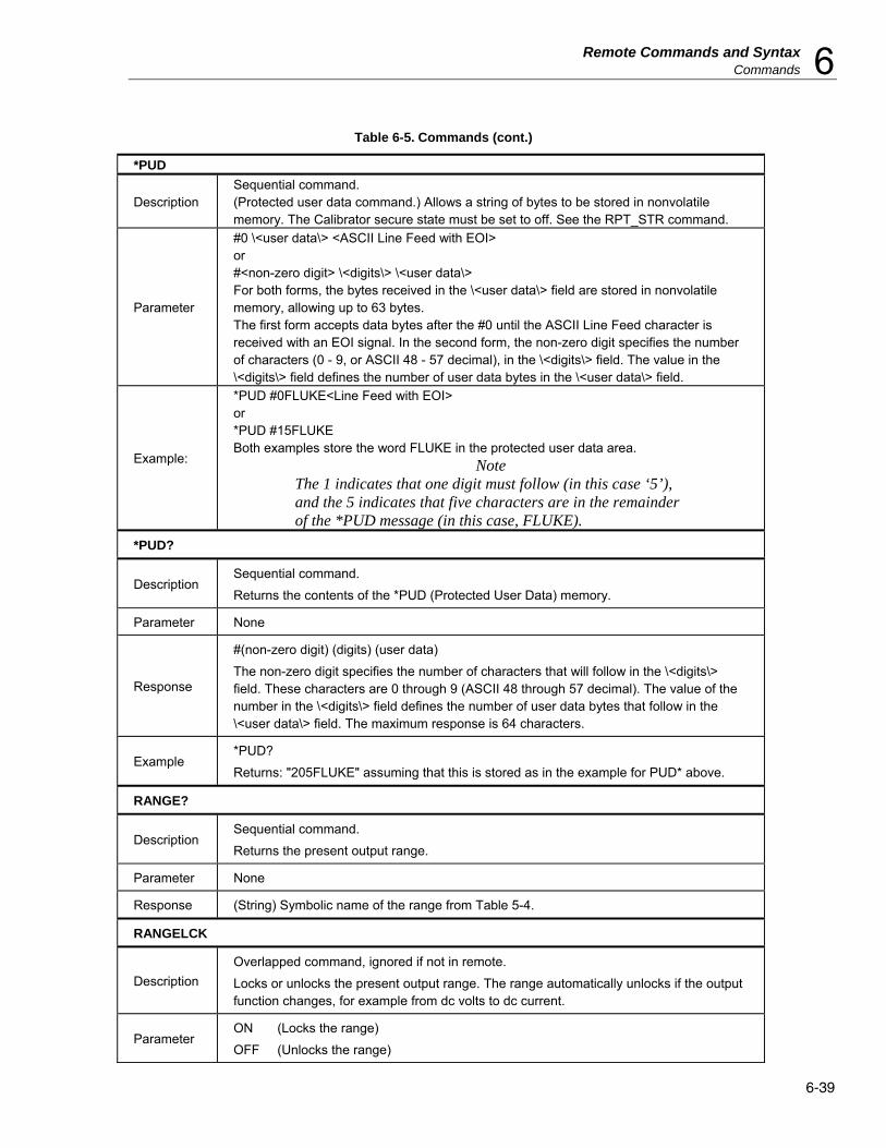
Remote Commands and Syntax Commands 6
6-39
Table 6-5. Commands (cont.)
*PUD
Description Sequential command. (Protected user data command.) Allows a string of bytes to be stored in nonvolatile memory. The Calibrator secure state must be set to off. See the RPT_STR command.
Parameter
#0 \<user data\> <ASCII Line Feed with EOI> or #<non-zero digit> \<digits\> \<user data\> For both forms, the bytes received in the \<user data\> field are stored in nonvolatile memory, allowing up to 63 bytes. The first form accepts data bytes after the #0 until the ASCII Line Feed character is received with an EOI signal. In the second form, the non-zero digit specifies the number of characters (0 - 9, or ASCII 48 - 57 decimal), in the \<digits\> field. The value in the \<digits\> field defines the number of user data bytes in the \<user data\> field.
Example:
*PUD #0FLUKE<Line Feed with EOI> or *PUD #15FLUKE Both examples store the word FLUKE in the protected user data area.
Note The 1 indicates that one digit must follow (in this case ‘5’), and the 5 indicates that five characters are in the remainder of the *PUD message (in this case, FLUKE).
*PUD?
Description Sequential command.
Returns the contents of the *PUD (Protected User Data) memory.
Parameter None
Response
#(non-zero digit) (digits) (user data)
The non-zero digit specifies the number of characters that will follow in the \<digits\> field. These characters are 0 through 9 (ASCII 48 through 57 decimal). The value of the number in the \<digits\> field defines the number of user data bytes that follow in the \<user data\> field. The maximum response is 64 characters.
Example *PUD?
Returns: "205FLUKE" assuming that this is stored as in the example for PUD* above.
RANGE?
Description Sequential command.
Returns the present output range.
Parameter None
Response (String) Symbolic name of the range from Table 5-4.
RANGELCK
Description
Overlapped command, ignored if not in remote.
Locks or unlocks the present output range. The range automatically unlocks if the output function changes, for example from dc volts to dc current.
Parameter ON (Locks the range)
OFF (Unlocks the range)

5730A Operators Manual
6-40
Table 6-5. Commands (cont.)
RCOMP
Description
Overlapped command, ignored if not in remote.
While a resistance output 19 kΩ or lower is selected, RCOMP activates or deactivates two-wire ohms compensation circuitry.
Parameter ON (Turns on the two-wire compensation circuitry)
OFF (Turns off the two-wire compensation circuitry)
REFOUT?
Description
Sequential command.
Returns the value of the reference, which is the output value of the Calibrator the last time a new reference was established with an OUT, NEW_REF, or MULT.
Parameter None
Response
1. (Float) Output amplitude
2. (String) Units (V, A, OHM, or DBM)
3. (String) Frequency (0 if dc)
REM_MODE
Description Sequential command. Ignored if not in remote. Sets the response type for a specified remote port.
Parameter 1. SERIAL, USB, ENET
2. COMP,TERM
Example
REM_MODE SERIAL, COMP
Sets the response type for serial communication to COMPUTER
REM_MODE ENET, TERM
Sets the response type for Ethernet communication to TERMINAL.
REM_MODE?
Description Sequential command. Returns the response type for a specified remote port.
Parameter 1. SERIAL, USB, ENET
Response String
Example REM_MODE? SERIAL
Returns TERM if the serial response type has been set to TERMINAL mode
RPT_STR
Description
Sequential command.
Loads the user report string. The user report string can be read on the Display in local operation, and appears on calibration reports. The Calibrator secure state must be set to off.
Parameter String of up to 40 characters
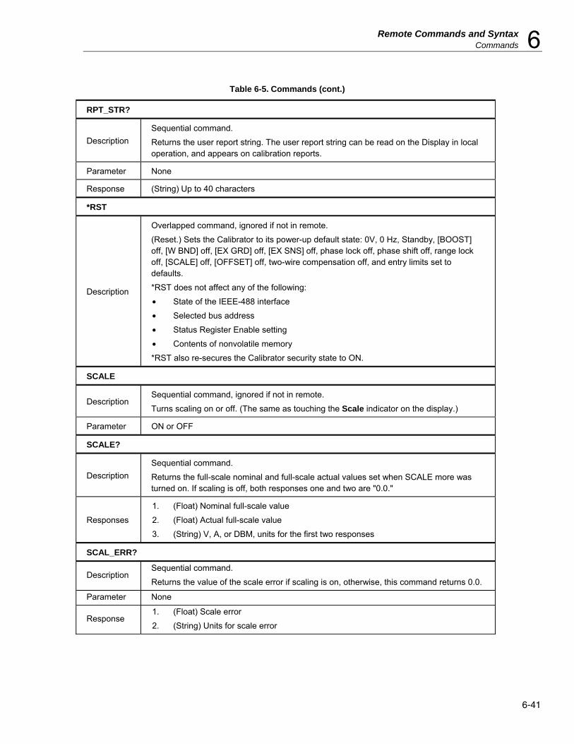
Remote Commands and Syntax Commands 6
6-41
Table 6-5. Commands (cont.)
RPT_STR?
Description
Sequential command.
Returns the user report string. The user report string can be read on the Display in local operation, and appears on calibration reports.
Parameter None
Response (String) Up to 40 characters
*RST
Description
Overlapped command, ignored if not in remote.
(Reset.) Sets the Calibrator to its power-up default state: 0V, 0 Hz, Standby, [BOOST] off, [W BND] off, [EX GRD] off, [EX SNS] off, phase lock off, phase shift off, range lock off, [SCALE] off, [OFFSET] off, two-wire compensation off, and entry limits set to defaults.
*RST does not affect any of the following:
• State of the IEEE-488 interface
• Selected bus address
• Status Register Enable setting
• Contents of nonvolatile memory
*RST also re-secures the Calibrator security state to ON.
SCALE
Description Sequential command, ignored if not in remote.
Turns scaling on or off. (The same as touching the Scale indicator on the display.)
Parameter ON or OFF
SCALE?
Description
Sequential command.
Returns the full-scale nominal and full-scale actual values set when SCALE more was turned on. If scaling is off, both responses one and two are "0.0."
Responses
1. (Float) Nominal full-scale value
2. (Float) Actual full-scale value
3. (String) V, A, or DBM, units for the first two responses
SCAL_ERR?
Description Sequential command.
Returns the value of the scale error if scaling is on, otherwise, this command returns 0.0.
Parameter None
Response 1. (Float) Scale error
2. (String) Units for scale error
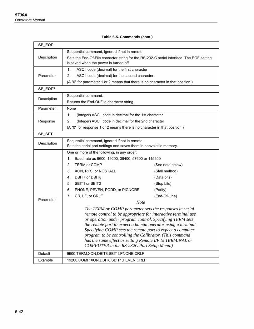
5730A Operators Manual
6-42
Table 6-5. Commands (cont.)
SP_EOF
Description
Sequential command, ignored if not in remote.
Sets the End-Of-File character string for the RS-232-C serial interface. The EOF setting is saved when the power is turned off.
Parameter
1. ASCII code (decimal) for the first character
2. ASCII code (decimal) for the second character
(A "0" for parameter 1 or 2 means that there is no character in that position.)
SP_EOF?
Description Sequential command.
Returns the End-Of-File character string.
Parameter None
Response
1. (Integer) ASCII code in decimal for the 1st character
2. (Integer) ASCII code in decimal for the 2nd character
(A "0" for response 1 or 2 means there is no character in that position.)
SP_SET
Description Sequential command, ignored if not in remote. Sets the serial port settings and saves them in nonvolatile memory.
Parameter
One or more of the following, in any order:
1. Baud rate as 9600, 19200, 38400, 57600 or 115200
2. TERM or COMP (See note below)
3. XON, RTS, or NOSTALL (Stall method)
4. DBIT7 or DBIT8 (Data bits)
5. SBIT1 or SBIT2 (Stop bits)
6. PNONE, PEVEN, PODD, or PIGNORE (Parity)
7. CR, LF, or CRLF (End-Of-Line)
Note
The TERM or COMP parameter sets the responses in serial remote control to be appropriate for interactive terminal use or operation under program control. Specifying TERM sets the remote port to expect a human operator using a terminal. Specifying COMP sets the remote port to expect a computer program to be controlling the Calibrator. (This command has the same effect as setting Remote I/F to TERMINAL or COMPUTER in the RS-232C Port Setup Menu.)
Default 9600,TERM,XON,DBIT8,SBIT1,PNONE,CRLF
Example 19200,COMP,XON,DBIT8,SBIT1,PEVEN,CRLF

Remote Commands and Syntax Commands 6
6-43
Table 6-5. Commands (cont.)
SP_SET?
Description Sequential command.
Returns the serial port settings contained in nonvolatile memory.
Response
1. (Integer) One of these baud rates: 9600, 19200, 38400, 57600 or 115200
2. (String) TERM or COMP (Response type)
3. (String) XON, RTS, or NOSTALL (Stall method)
4. (String) DBIT7 or DBIT8 (Data bits)
5. (String) SBIT1 or SBIT2 (Stop bits)
6. (String) PNONE, PEVEN, PODD, or PIGNORE (Parity)
7. (String) CR, LF, or CRLF (End-Of-Line)
Example 9600,TERM,XON,DBIT8,SBIT1,PNONE,CRLF
*SRE
Description
Sequential command.
Loads a byte into the Service Request Enable register (SRE), described under "Check the Calibrator Status."
Parameter The decimal equivalent of the binary number to load into the register.
Example *SRE 56
Enables bits 3 (EAV), 4 (MAV), and 5 (ESB) in the Service Request Enable register.
*SRE?
Description
Sequential command.
Returns the byte from the Service Request Enable register, described under "Check the Calibrator Status."
Parameter None
Response (Integer) The decimal equivalent of the register byte.
Example
*SRE?
Returns: "56" if bits 3 (EAV), 4 (MAV), and 5 (ESB) are enabled (1) and the rest of the bits are disabled (0). (See "Check the Calibrator Status" for details.)

5730A Operators Manual
6-44
Table 6-5. Commands (cont.)
STATE?
Description Sequential command.
Returns the long-term state of the Calibrator.
Parameter None
Response
1. (Integer) Gross state, with the subsequent responses:
0 Operating 10 Calibration, wideband positive gain
1 Self diagnostics 11 Calibration, wideband negative gain
2 Self diagnostics halted by a fault 12 Wideband flatness calibration, adjustment
3 Calibration check 13 Wideband flatness calibration, reference point
4 DC zeros calibration 14 Range calibration
5 Calibration, +dc reference 15 5725A voltage diagnostics
6 Calibration, -dc reference 16 5725A current troubleshooting
7 Calibration, 1 Ω reference 17 Reserved
8 Calibration, 10 kΩ reference 18 Reserved
9 Calibration, internal adjustment 19 Analog output tripped to dormant
2. (String) Substate: 20. Starting up
If operating, self-calibrating, diagnosing, or testing, returns a descriptive string of the activity underway.
*STB?
Description Sequential command.
Returns the status byte. The status byte is described under "Status Information."
Parameter None
Response (Integer) Decimal equivalent of the status byte.
Example *STB?
Returns: "72" if bits 3 (EAV) and 6 (MSS) are set (1) and the rest of the bits are reset (0).
STBY
Description Overlapped command, ignored if not in remote.
Puts the Calibrator in standby.
Parameter None
SUBNETMASK
Description Sequential command. Ignored if not in remote. Sets Ethernet subnet mask for LAN communication when NOT in DHCP mode.
Parameter Subnet mask (quoted string consisting of 4 decimal values bound between 0-255 separated by periods).
Example SUBNETMASK "255.255.254.0"
Sets the Ethernet subnet mask to 255.255.254.0

Remote Commands and Syntax Commands 6
6-45
Table 6-5. Commands (cont.)
SUBNETMASK?
Description Sequential command. Returns Ethernet subnet mask for LAN communication.
Parameter None
Response String
Example SUBNETMASK?
Returns 255.255.254.0 if the subnet mask was previously set to this value.
*TST?
Description
Sequential command, ignored if not in remote.
Initiates a series of self-tests, then returns a "0" for pass or a "1" for fail. If any faults are detected, they are logged into the fault queue where they can be read by the FAULT? query.
Parameter None
Response (Integer) 0 (for Pass) or 1 (for Fail)
UNCERT?
Description
Sequential command.
Returns the calculated maximum uncertainty of the Calibrator output according to the selected calibration interval.
Parameter None
Response
1. (Float) Uncertainty of the Calibrator output (-1.0 if no specification is available)
2. (String Units for response 1 (PPM, PCT, V, A, OHM, etc.)
3. (Integer) The specification interval in days.
VOUT?
Description Sequential command.
Returns the output amplitude expressed in volts if the currently selected units are dBm.
Parameter None
Response
1. (Float) Output amplitude
2. (String) V, A, OHM, units for response 1
3. (Float) Frequency
Example Assuming a value of 10 dBm, 10 kHz is currently active on the main output terminals, VOUT? returns: "2.4494897E+00,V,1.0000E+04"

5730A Operators Manual
6-46
Table 6-5. Commands (cont.)
*WAI
Description
Sequential command.
(Wait-to-Continue.) This command prevents further remote commands from being executed until all previous remote commands have been executed. (See also *OPC.)
Parameter None
Example
If an OUT command had been sent, it can cause the Calibrator to wait until the output has settled before continuing on to the next command by following OUT with a *WAI command. This is useful because OUT is an overlapped command, which means the Calibrator would normally go on to process other commands before completing the OUT command.
WBAND
Description
Overlapped command, ignored if not in remote.
Activates or deactivates output from the Wideband AC Module (Option 5730A/03). This has the same action as touching the wideband selection from the front panel during local operation.
Parameter ON or OFF
XFER
Description Turns ac/dc transfers off (or on) after output has settled.
Parameter OFF or ON
Example XFER OFF turns transfers off (ON is the default)
XFER?
Description Returns whether ac/dc transfers after settling are turned on.
Parameter None
Example ON or OFF
XFERCHOICE
Description Sets whether the choice to turn ac/dc transfers off is given on the front panel GUI for ac V outputs.
Parameter ON or OFF
Example: XFERCHOICE OFF omits the choice from the front panel (this is the default setting).
XFERCHOICE?
Description Returns whether the choice to turn ac/dc transfers off is given on the front panel GUI for ac V outputs.
Parameter None
Response ON or OFF

Remote Commands and Syntax Commands 6
6-47
Table 6-6. Serial Remote Control Commands
LOCAL
Description
Sequential command.
Enables the local state. This command duplicates the IEEE-488-GTL (Go to Local) message.
Parameter None
LOCKOUT
Description
Sequential command.
Enables the local lockout state. This command duplicates the IEEE-488 LLO (Local Lookout) message.
Parameter None
REMOTE
Description
Sequential command.
Enables the remote state. This command duplicates the IEEE-488 REN (Remote Enable) message.
Parameter None
Table 6-7. Range Identifiers for Remote Commands
Function Ranges
DC Voltage DC220MV
DC1100V DC2_2V DC11V DC22V DC220V
DC Current DC220UA
DC5725A
DC2_2MA
DC52120A_2A
DC22MA
DC52120A_20A
DC220MA
DC52120A_100A DC2_2A
AC Voltage AC2_2MV
AC220V
AC22MV
AC1100V
AC220MV
AC5725A AC2_2V AC22V
AC Current AC220UA
AC5725A
AC2_2MA
AC52120A_2A
AC22MA
AC52120A_20A
AC220MA
AC52120A_120A AC2_2A
Resistance
OHM0
OHM100
OHM19K
OHM10M
OHM1
OHM190
OHM100K
OHM19M
OHM1_9
OHM1K
OHM190K
OHM100M
OHM10
OHM1_9K
OHM1M
OHM19
OHM10K
OHM1_9M
Wideband WB1_1MV
WB330MV
WB3_3MV
WB1_1V
WB11MV
WB3_5V WB33MV WB110MV

5730A Operators Manual
6-48
Local-to-Remote State Transitions The 5730A Calibrator can be operated either locally from the front panel, or remotely with remote control commands. In addition to front panel and remote control operation, the controller can be placed in a local lockout condition at any time by remote command. When combined, the local, remote, and lockout conditions yield four possible operating states:
• Local (Front-Panel Operation)
The Calibrator responds to local and remote commands, but only remote commands that do not affect the state of the Calibrator are allowed to execute. For example, OUT? returns the value of the Calibrator output setting and is executable in the local state. OUT sets the output to another value but cannot be executed in local state.
• Local with Lockout
Local with lockout is identical to local, except the Calibrator will go into the remote with lockout state instead of the remote state when it receives a remote command. The local with lockout state is entered by executing the LOCKOUT statement from an IEEE-488 controller, or by sending the LOCKOUT command from a RS-232C/UCB/Ethernet controller.
• Remote
When the Remote Enable (REN) line is asserted and the controller addresses the Calibrator as a listener, it enters the remote state. These conditions are met, for example, when a GPIB controller executes the statement “OUT 10 V, 1khz;OPER”. In the remote state, display changes to:
+/- 59.0 ppm (1 year) 213 days since calibration12/21/12 10:52am
ExternalSenseOFF
External GuardOFF
Boost
OFF
Wideband
OFF
SetupMenu
Operate
VkHz1.0000
10.00000
Auto Range 22 V
Local Control Operating under REMOTE control.
hhp150.eps
Front panel operation is restricted to use of the power switch and the Local Control selection. Touch Local Control or send the GTL (Go To Local) interface message to return the Calibrator to the local state. (One way to send the GTL interface message in some controllers is by executing the LOCAL statement.)

Remote Commands and Syntax Local-to-Remote State Transitions 6
6-49
• Remote with Lockout
The remote with lockout state can be entered from remote or local with lockout, but not directly from local. Remote with lockout is similar to the remote state, but restricted: the Local Control is not shown on the display. To return the Calibrator to the local with lockout state, the GPIB controller sends GTL. (With some IEEE-488 controllers, this can be done manually by executing a WBYTE statement.) To return the Calibrator to the local state, the GPIB controller unasserts the REN control line. When the Calibrator is in remote with lockout, the display appears as follows:
+/- 59.0 ppm (1 year) 213 days since calibration12/21/12 10:52am
ExternalSenseOFF
External GuardOFF
Boost
OFF
Wideband
OFF
SetupMenu
Operate
VkHz1.0000
10.00000
Auto Range 22 V
Operating under REMOTE control.
hhp151.eps
Table 6-8 summarizes the possible Remote/Local state transitions.
Table 6-8. Operating State Transitions
From To Use Typical GPIB
Command
Local Remote MAL + REN REMOTE
Local/Lockout LLO + REN LOCKOUT
Remote Local
GTL or LOCAL CONTROL selection
LOCAL
Remote/Lockout LLO + REN LOCKOUT
Local/Lockout Remote/Lockout MLA + REN REMOTE or any Calibrator command
Remote/Lockout Local REN not LOCAL
Local/Lockout GTL Manually using WBYTE
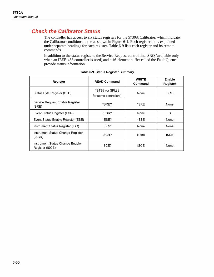
5730A Operators Manual
6-50
Check the Calibrator Status The controller has access to six status registers for the 5730A Calibrator, which indicate the Calibrator conditions in the as shown in Figure 6-1. Each register bit is explained under separate headings for each register. Table 6-9 lists each register and its remote commands.
In addition to the status registers, the Service Request control line, SRQ (available only when an IEEE-488 controller is used) and a 16-element buffer called the Fault Queue provide status information.
Table 6-9. Status Register Summary
Register READ Command WRITE
Command Enable
Register
Status Byte Register (STB) *STB? (or SPL( )
for some controllers) None SRE
Service Request Enable Register (SRE)
*SRE? *SRE None
Event Status Register (ESR) *ESR? None ESE
Event Status Enable Register (ESE) *ESE? *ESE None
Instrument Status Register (ISR) ISR? None None
Instrument Status Change Register (ISCR)
ISCR? None ISCE
Instrument Status Change Enable Register (ISCE)
ISCE? ISCE None

Remote Commands and Syntax Check the Calibrator Status 6
6-51
01234567
01234567
&
& && &
&&
&
Event StatusRegisterRead using *ESR?
Event StatusEnable RegisterRead using *ESE?Write using *ESE
Instrument StatusChange Enable RegisterRead using ISCE?Write using ISCE
Instrument StatusChange RegisterRead using ISCR?
Instrument StatusRegisterRead using ISR?
Event Request Enable RegisterRead using *SRE?Write using *SRE?
Read using *STB?
Read by Serial Poll
Status Byte Register
Output Buffer
Fault Queue
01
0123457
& && &
&&
&
Logi
cal O
R
Logi
cal O
R
ESB MAV EAV ISCB
&
&&
&
&&
&
AC XFER
PON0 CME
EXEDDE
QYE0 OPC
SETTLED
REMOTE
WBNDSCALE
OFFSET
PLOCK
PSHIFT
RLOCK
RCOMP
BOOST
EXSENS
EXGARD
OPER0
&&
&&
&&
&&
&
9101112131415 8 7 6 5 4 3 2 1 0
Bit Change from 0 1 or 1 0
1014
9101112131415 8 7 6 5 4 3 2 1 0
MSS6
RQS
7
911121315 8 7 6 5 4 3 2 1 0
Service RequestGeneration
SRQ onIEEE-488 Bus
DataAvailable?
FaultAvailable?
Logi
cal O
R
DC Zero C
al
hhp050.eps
Figure 6-1. Overview of Status Data Structure

5730A Operators Manual
6-52
Status Byte Register The most important and frequently used register is the Status Byte Register, which is how the 5730A Calibrator responds to a serial poll. This byte is cleared (set to 0) when the power is turned on. A serial poll cannot be done if the RS-232C/USB/Ethernet port is used as the remote control interface. Instead, the *STB? command can be sent to get the same information. Its bits are defined as follows (bits 7, 1, and 0 are always 0):
7 6 5 4 3 2 1 0
0 RQS ESB MAV EAV ISCB 0 0
MSS
RQS Requesting Service. The RQS bit is set to 1 whenever bits ESB , MAV, EAV, or
ISCB change from 0 to 1 and are enabled (1) in the SRE. When RQS is 1, the Calibrator asserts the SRQ control line on the IEEE-488 interface. A serial poll can be done to read this bit to see if the Calibrator is the source of an SRQ.
MSS Master Summary Status. Set to 1 whenever bits ESB, MAV, EAV, or ISCB are 1 and enabled (1) in the SRE. This bit can be read with the *STB? command in RS-232C/USB/Ethernet remote control in place of doing a serial poll.
ESB Set to 1 when one or more enabled ESR bits are 1.
MAV Message Available. The MAV bit is set to 1 whenever data is available in the Calibrator IEEE-488 interface output buffer.
EAV Error (fault) available. A fault has occurred and a fault code is available through the FAULT? query.
ISCB One or more enabled ISCR bits are 1.
Service Request Line (SRQ) Service Request (SRQ) is an IEEE-488.1 bus control line that the Calibrator asserts to notify the controller that it requires some type of service. Many instruments can be on the bus, but they all share a single SRQ line. To determine which instrument set SRQ, the Controller normally does a serial poll of each instrument. The Calibrator asserts SRQ whenever the RQS bit in its Status Byte Register is 1. This bit informs the controller that the Calibrator was the source of the SRQ.
The Calibrator clears SRQ and RQS when the controller does a serial poll of the Calibrator IEEE-488 interface, sends *CLS, or when the MSS bit is cleared. The MSS bit is cleared only when ESB, MAV, EAV, and ISCB are 0, or they are disabled by their associated enable bits in the SRE register being set to 0.
Service Request Enable Register The Service Request Enable Register (SRE) enables or masks the bits of the Status Byte Register. The SRE is cleared at power up. Refer to “Status Byte Register” for the bit functions.
Load the SRE By resetting (to 0) the bits in the SRE, associated bits in the Status Byte Register can masked (disabled). Bits set to 1 enable the associated bit in the Status Byte Register.
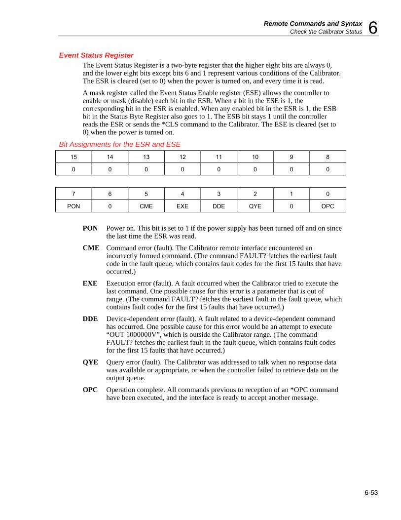
Remote Commands and Syntax Check the Calibrator Status 6
6-53
Event Status Register The Event Status Register is a two-byte register that the higher eight bits are always 0, and the lower eight bits except bits 6 and 1 represent various conditions of the Calibrator. The ESR is cleared (set to 0) when the power is turned on, and every time it is read.
A mask register called the Event Status Enable register (ESE) allows the controller to enable or mask (disable) each bit in the ESR. When a bit in the ESE is 1, the corresponding bit in the ESR is enabled. When any enabled bit in the ESR is 1, the ESB bit in the Status Byte Register also goes to 1. The ESB bit stays 1 until the controller reads the ESR or sends the *CLS command to the Calibrator. The ESE is cleared (set to 0) when the power is turned on.
Bit Assignments for the ESR and ESE
15 14 13 12 11 10 9 8
0 0 0 0 0 0 0 0
7 6 5 4 3 2 1 0
PON 0 CME EXE DDE QYE 0 OPC
PON Power on. This bit is set to 1 if the power supply has been turned off and on since the last time the ESR was read.
CME Command error (fault). The Calibrator remote interface encountered an incorrectly formed command. (The command FAULT? fetches the earliest fault code in the fault queue, which contains fault codes for the first 15 faults that have occurred.)
EXE Execution error (fault). A fault occurred when the Calibrator tried to execute the last command. One possible cause for this error is a parameter that is out of range. (The command FAULT? fetches the earliest fault in the fault queue, which contains fault codes for the first 15 faults that have occurred.)
DDE Device-dependent error (fault). A fault related to a device-dependent command has occurred. One possible cause for this error would be an attempt to execute “OUT 1000000V”, which is outside the Calibrator range. (The command FAULT? fetches the earliest fault in the fault queue, which contains fault codes for the first 15 faults that have occurred.)
QYE Query error (fault). The Calibrator was addressed to talk when no response data was available or appropriate, or when the controller failed to retrieve data on the output queue.
OPC Operation complete. All commands previous to reception of an *OPC command have been executed, and the interface is ready to accept another message.

5730A Operators Manual
6-54
Read the ESR and ESE To read the contents of the ESR, send the remote command, *ESR?. The ESR is cleared (set to 0) every time it is read. To read the contents of the ESE, send the remote command, *ESE?. The ESE is not cleared when it is read. When either register is read, the Calibrator responds by sending a decimal number that represents bits 0 through 15.
Load the ESE Resetting the bits in the ESE can mask (disable) the associated bits in the ESR. For example, to prevent the occurrence of a command fault from causing bit 5 (ESB) in the Status Byte Register to go to 1, bit 5 in the ESE register can be reset to 0.
Instrument Status Register The Instrument Status Register (ISR) gives the controller access to the state of the Calibrator, including some of the information presented to the operator on the display and the display annunciators during local operation.
Instrument Status Change Register The Instrument Status Change Register (ISCR) indicates which ISR bits have changed status (from 0 to 1 or from 1 to 0) since the ISCR was last read. The ISCR is cleared (set to 0) when the Calibrator is turned on, and every time it is read.
Instrument Status Change Enable Register The Instrument Status Change Enable Register (ISCE) is a mask register for the ISCR. If a bit in the ISCE is enabled (set to 1) and the corresponding bit in the ISCR goes to 1, the ISCB bit in the Status Byte is set to 1. If all bits in the ISCE are disabled (set to 0), the ISCB bit in the Status Byte never goes to 1. The ISCE is cleared on power-up.
Bit Assignments for the ISR, ISCR, and ISCE
15 14 13 12 11 10 9 8
0 AC XFER ZERO CAL
SETTLED REMOTE WBND SCALE OFFSET
7 6 5 4 3 2 1 0
PLOCK PSHFT RLOCK RCOMP BOOST EXSENS EXGARD OPER

Remote Commands and Syntax Check the Calibrator Status 6
6-55
ZERO CAL When 1, DC Zero Cal is necessary.
ACXFER When 1, ac/dc transfer is active.
SETTLED When 1, the output has stabilized to within specification.
REMOTE When 1, the Calibrator is under remote control.
WBND When 1, the wideband is active.
SCALE When 1, scaling is active.
OFFSET When 1, an offset is active.
PLOCK When 1, the Calibrator output is phase locked to an external source.
PSHFT When 1, variable phase output is active.
RLOCK When 1, the Calibrator output range is locked.
RCOMP When 1, two-wired compensation is active when in resistance mode.
BOOST When 1, an auxiliary amplifier is active.
EXSENS When 1, external sensing is selected.
EXGARD When 1, external voltage guard is selected.
OPER When 1, the Calibrator is operating, When 0, it is in standby.
Read the ISR, ISCR, or ISCE To read the contents of the ISR, send the remote command, ISR?. In a similar fashion, to read the contents of the ISCR, send ISCR?, and to read the contents of the ISCE, send ISCE?. The Calibrator returns a decimal number representing bits 0 through 15. Each time the ISCR is read, its contents are zeroed.
Load the ISCE By resetting the bits in the ISCE, the associated bits in the ISCR can be masked (disabled). For example, to cause an SRQ interrupt when an attached 5725A Amplifier turns on, bit 3 (BOOST) in the ISCE register must be 1. (The ISCB bit must also be enabled in the SRE.)
Fault Queue When a command fault, execution fault, or device-dependent fault occurs, its fault code is placed in the fault queue where it can be read by the FAULT? command. All fault codes are defined in Appendix A of this manual. Another way to decode a fault code is to send the command, EXPLAIN?, which returns a description of a fault code. Reading the first fault with the FAULT? command removes that fault from the queue. A response of 0 means the fault queue is empty.
The fault queue contains up to 16 entries. If many faults occur, only the first 15 faults are kept in the queue. A 16th entry in the queue is always a "fault queue overflow". fault, and all later faults are discarded until the queue is at least partially read. The first faults are kept, because if many faults occur before the user can acknowledge and read them, the earliest faults are the most likely to point to the problem. The later faults are usually repetitions or consequences of the original problem.
The OPER command is inhibited for outputs of 22 V or greater whenever there is a fault in the fault queue. The OPER command remains inhibited until either the fault queue or the ESR is cleared.
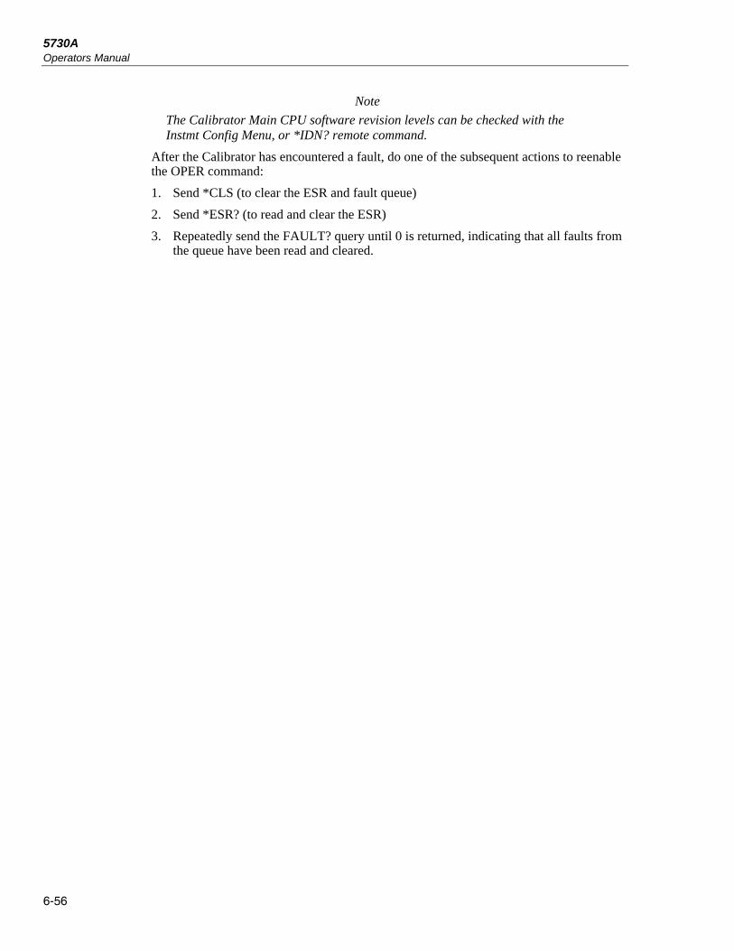
5730A Operators Manual
6-56
Note
The Calibrator Main CPU software revision levels can be checked with the Instmt Config Menu, or *IDN? remote command.
After the Calibrator has encountered a fault, do one of the subsequent actions to reenable the OPER command:
1. Send *CLS (to clear the ESR and fault queue)
2. Send *ESR? (to read and clear the ESR)
3. Repeatedly send the FAULT? query until 0 is returned, indicating that all faults from the queue have been read and cleared.

7-1
Chapter 7 Operator Maintenance and Calibration
Introduction This chapter explains how to do the routine maintenance and calibration tasks necessary to keep the 5730A Calibrator in optimal operating condition. For intensive maintenance tasks such as troubleshooting or repair, contact a Fluke Calibration Service Center. See “How to Contact Fluke Calibration” in Chapter 1.
Fuse Replacement Access the fuse from the rear panel. The fuse rating label below the fuse holder shows the correct replacement fuse ratings for each operating voltage.
Warning To prevent possible electrical shock, fire, or personal injury:
• Turn the Product off and remove the mains power cord. Stop for two minutes to let the power assemblies discharge before you open the fuse door.
• Replace a blown fuse with exact replacement only for continued protection against arc flash.
• Use only specified replacement fuses, see Table 7-1.
To access the fuse, refer to Figure 7-1:
1. Disconnect the mains power cord.
2. With a standard screwdriver, release the fuse holder door.
3. Pull out the fuse holder.
4. If necessary, replace the fuse.
5. Reinsert the fuse holder.
6. Close the fuse holder door.
Table 7-1. Replacement Fuses
Line Voltage Range Fuse Description Fluke Part Number
100 V – 120 V T 3 A 250 V 109280
220 V – 240 V T 1.5 A 250 V 109231

5730A Operators Manual
7-2
115V
115V
115V
115V2
30V
PRSR
12
34
hhp003.eps
Figure 7-1. Access the Fuse

Operator Maintenance and Calibration Clean the Air Filter 7
7-3
Clean the Air Filter Caution
Damage caused by overheating can occur if the area around the fan is restricted, the intake air is too warm, or the air filter becomes clogged.
To prevent Product damage, make sure that the filter is completely dry before reinstallation.
The air filter must be removed and cleaned at least every 30 days, or more frequently if the Calibrator is operated in a dusty environment. The air filter is accessible from the rear panel of the Calibrator.
To clean the air filter, refer to Figure 7-2:
1. Disconnect line power.
2. Unscrew the knurled screw at the top of the air filter and pull the filter retainer downwards (it is hinged at the bottom) to remove the filter.
3. Clean the filter by washing it in soapy water. Rinse and dry it thoroughly.
4. Reinstall the filter and the knurled screw.
hhp026.eps
Figure 7-2. Air Filter Access

5730A Operators Manual
7-4
Clean the Exterior To keep the 5730A Calibrator looking new, clean the case, front panel keys, and display with a soft cloth slightly dampened with either water or a non-abrasive mild cleaning solution that is not harmful to plastics.
Caution
Do not use aromatic hydrocarbons or chlorinated solvents for cleaning. They can damage the plastic materials used in the Product.
User-Replaceable Parts User-replaceable parts are listed in Table 7-2 and shown in Figure 7-3. For more information about these items contact a Fluke Calibration representative. See the “Contact Fluke Calibration” section of this manual.
Table 7-2. User-Replaceable Parts
Item Number
Description Part
Number
Top Cover 4104376
Handle 4104383
Side Extrusion 3468705
Insert Extrusion 4104451
Bottom Cover 4219600
USB Decal 4219557
Input Decal 4219569
Encoder Knob 4222803
5730A Decal 4233853
Air Filter 813493
Fuse (100 V – 120 V, T 3 A 250 V) 109280
Fuse (220 V – 240 V, T 3 A 250 V) 109231
Not Shown 5730A Manuals CD 4290581
Not Shown 5730A Getting Started Manual 4290571

Operator Maintenance and Calibration User-Replaceable Parts 7
7-5
115V
11
10
4
5
6
7
8
9
3
2
1
hhp224.eps
Figure 7-3. Replaceable Parts

5730A Operators Manual
7-6
5730A Calibration The 5730A Calibrator makes use of internal check standards and measurement systems. As a result, it can be completely calibrated in place to full specifications with a small number of convenient, portable, environmentally-tolerant standards available from Fluke Calibration. This procedure is traceable to military standard requirements.
When manufactured, each Product is calibrated and thoroughly verified with process metrology and calibration standards traceable to the International System of units (SI) through well-recognized national metrology institutes. A certificate of calibration that is accredited to ISO 17025 is included.
The calibration verification procedure is recommended every 2 years or as required by established policies. This procedure involves no adjustments. It ensures internal processes are in control, and establishes parallel external traceability paths for internal functions such as ac transfers that are never adjusted or corrected.
The Artifact Calibration Process Calibration requires only three external standards or artifacts: 10 V, 1 Ω, and 10 kΩ. Environmentally-controlled internal check standards provide the primary reference points. A stored table of calibration constants defines additional reference points for controlling the output. Traceable calibration and adjustment to the specified level of performance is accomplished in a semi-automated process that revises this table.
When finished with artifact calibration, but before the new constants are saved, the 5730A Calibrator presents the proposed adjustments as +/- ppm of range and percentage change in specification for each range and function. A list of changes can be sent to the computer through the serial port, USB device port, Ethernet port, or the IEEE-488 port using the remote command: CAL_RPT? CHECK. Also on completion of calibration, the Calibrator shows the largest proposed change.
Calibration can be completed as far as deriving and printing the proposed adjustments without entering the calibration protection passcode. To save the changes in non-volatile memory to adjust future outputs from the Calibrator, the passcode must be entered from the front panel or with a remote command. The passcode entry menu is shown on the display when necessary.

Operator Maintenance and Calibration DC Zeros 7
7-7
Establish Traceability Traceability to national standards is established as follows:
• Except for the internal ac/dc transfer standard, the internal check standards are directly calibrated by traceable external standards every time the Calibrator is calibrated.
• The internal ac/dc transfer standard is never adjusted, so its traceability is not disturbed by calibration. Infrequent verification is done in the traditional way, by comparing selected ac voltage outputs with an external dc voltage standard through an external ac/dc transfer standard. Fluke Calibration recommends this to be done every two years or as determined by the policy of your organization.
• Infrequent independent verification is also done on stable parameters, such as frequency flatness, determined more by circuit geometry and dielectric constants than time.
Calibration Reports The 5730A Calibrator stores two sets of calibration constants: the set currently in use and the old set from the previous calibration. This gives the Calibrator the ability at any time to produce a calibration report of the differences between the present settings and the settings that were in effect before the last calibration. The report shows shifts in various output values from before to after the most recent calibration for each range and function in +/- ppm of range and in percentage of specification limit. The report can be saved to a USB drive or retrieve it from a host computer through either the RS-232, USB device port, Ethernet port, or IEEE-488 interface.
Range Adjustment After calibration, further fine adjustments can be made to each range. Range adjustments are optional and they are not necessary to meet total uncertainty specifications. However, they can help to align the Calibrator closer to in-house standards.
Before range calibration is done, first do the Artifact Calibration as described later in this chapter. This is to calibrate the ranges that will not be adjusted. It also performs an initial adjustment for each range, and supplies flatness corrections for ac functions.
DC Zeros DC Zeros is a quick, automatic process that corrects offset errors that increase with time on several output ranges. If a 5725A Amplifier is attached, it also zeros the 11 A dc range. This process takes approximately 2 ½ minutes (plus an additional 30 seconds for the 5725A).
Run DC Zeros To execute dc zeros, from the normal operation screen:
1. Touch Setup Menu to show the Setup Menu. See the “Setup Menu” section of Chapter 4.
2. Touch the Calibration menu.

5730A Operators Manual
7-8
3. Touch Run DC Zero to start the dc zeros routine. The status of the dc zero calibration is shown as the Calibrator progresses through a series of steps. When completed, the Calibrator shows “Calibration complete”.
Note
If the Calibrator is not warmed up, the display prompts to continue or cancel the DC Zeros function.
4. Touch Close to proceed with Calibrator use.
DC Zeros Reminder Specifications require that dc zeros be run at least every 30 days. If 30 days passes and dc zeros is not done, the display prompts to run the process.
To override the message and run dc zeros at a more convenient time, touch Cancel. To run dc zero at this time, touch OK.
Note
If this message shows after powering on the Calibrator, let the Calibrator warm up before running dc zeros. Otherwise an error message shows that indicates that the Calibrator is not warmed up. To ensure the best performance, the warmup should be completed.
Calibration This section provides procedures to calibrate the Calibrator to external standards, adjust the range if necessary, and for do a calibration check.
In order to maintain traceability, these requirements must be met:
• Calibration to external standards must be completed at the start of the calibration cycle.
• Performance verification must be completed every two years.
Calibration Check and range calibration are optional procedures that are provided to enhance the accuracy if needed for special requirements. See “Calibration Check”.

Operator Maintenance and Calibration Calibration 7
7-9
Calibration Security Passcode The integrity of Calibrator calibration is protected by a security passcode that must be entered before new calibration constants can be saved to non-volatile memory. This passcode replaces the hardware calibration switches found on older calibrators such as the Fluke 5720A. As with the 5720A, the passcode also protects the ability to set the date for the internal real-time clock.
If the passcode has not been entered, the Calibrator is secured. Once the passcode is entered, it is unsecured. The Calibrator secures itself when it is reset or when the setup menus are closed. The Calibrator can be unsecured at any time over the remote interface with the CAL_SECURE command and by entering the passcode. The front panel prompts for the passcode to unsecure the Calibrator before it can accept new values to be eventually secured.
The passcode contains 1 to 8 decimal digits. The Calibrator is shipped with the passcode set to "5730". To change the passcode, touch Setup Menu>Calibration>Change Calibration Passcode. The Calibrator prompts for the current passcode and then the new passcode. The passcode can also be changed over the remote interface with the CAL_PASSWD command.
If the passcode for a particular Calibrator is lost, contact Fluke Customer Support. See “How to Contact Fluke Calibration” in Chapter 1.
Artifact Calibration The 5730A Calibrator must be calibrated to external standards at the beginning of the calibration cycle. The length of the cycle (24 hours, 90 days, 180 days, or one year) is selected in a Setup Menu described in Chapter 4.
To calibrate the Calibrator, apply three portable standards to the output binding posts:
1. 10 V dc voltage standard
2. 1 Ω resistance standard
3. 10 kΩ resistance standard
These standards are recommended:
• Model 732A or 732B DC Reference Standard
• Model 742A-1 1Ω Resistance Standard
• Model 742A-10k 10Ω Resistance Standard
Use 5440A-7003 (spade lugs) Low Thermal Leads for all connections:
Both the Calibrator and the recommended external standards have the ability to internally control (or compensate for) ambient temperature variations. Therefore, it is unnecessary to keep the Calibrator in tightly-controlled temperatures during calibration. During the calibration procedure, the Calibrator prompts for the ambient temperature, and includes this information in specification readouts and output shift reports.
Note
5440A-7002 and 5440A-7003 Low Thermal Lead sets include a third cable specifically designed for completing Artifact Calibration. The 5730A-7002 and 5730A-7003 Low Thermal Lead sets do not include the third cable for connection between reference standards.

5730A Operators Manual
7-10
When to Adjust Calibrator Accuracy Table 7-3 lists each external uncertainty limit of the standards, and the Calibrator accuracy specifications that must be adjusted accordingly if that limit is exceeded.
As long as the external standards have the uncertainties listed in Table 7-3, when performing artifact calibration, it is not necessary to adjust the Calibrator absolute accuracy specifications in Chapter 1. However, if uncertainty of the in-house standard exceeds the value in the table, some of the absolute accuracy specifications of the Calibrator must be adjusted by the algebraic difference between the standard uncertainty and the uncertainty limit listed in the Table 7-3. For example, if the dc voltage standard has an uncertainty of ±2.5 ppm, then the absolute uncertainty specifications listed in the Electrical Specifications tables above for dc volts, ac, volts, dc current, and ac current. must all be increased by ±1 ppm.
Table 7-3. Standards for Calibration
Fluke Standard
Traceable Quantity
Nominal Value
Uncertainty Limit
Specifications susceptible to Uncertainty Limit
732B Voltage 10 V 1.5 ppm dc volts, ac volts, dc current, ac current
742A-1 Resistance 1 Ω 10 ppm 1 Ω, 1.9 Ω
742A-10k Resistance 10 kΩ 2 ppm ac current, dc current 10 Ω to 100 MΩ
Calibration Procedure Before this procedure is started, make sure the 5730A Calibrator is powered on and has completed the appropriate warm-up period.
Follow this procedure to calibrate the main output functions:
1. Touch Setup Menu>Calibration. The calibration menu is shown.
2. If necessary, touch Temperature and enter the correct temperature (in degrees Celsius) to update the ambient temperature.
3. Touch Run Artifact Cal to begin the procedure. The Calibrator prompts the user to see the manual for the correct connections.
4. Connect the 732B to the Calibrator as shown in Figure 7-4.

Operator Maintenance and Calibration Calibration 7
7-11
Calibrator
732B DC STANDARD
AC PWR IN CAL CHARGE LOW BAT
10V 1.018V CHASSIS
GUARD1.018V COM10V COM
SERIAL NUMBER
hhp027.eps
Figure 7-4. 732B External Calibration Connections
5. Enter the value of the 732B 10V output. The true value is the value printed on the calibration sticker or the standard.
6. If the entered value is not between 9 V and 11 V, an error message is shown. The process can be started over from this point with a calibrated 732B. Push to start the calibration procedure. As the 5730A Calibrator does self-calibration, it will indicate what is happening on the display.
When the 6.5 V and 13 V references have been characterized, the display prompts the user to accept or reject the changes that are about to be made to the calibration constants.
7. To reject the changes, touch Cancel. Otherwise, touch Continue to accept and save the changes, and to continue with calibration.
8. Reverse the HI and LO connections at the 732B terminals, and push Continue to continue the calibration process.
9. After this part of the calibration procedure is complete, the Calibrator shows the reference shifts and prompts to continue. Touch Continue. See the manual for the correct connections, as prompted by the Calibrator, and enter the first calibration value.
10. Connect the Calibrator to the 10 kΩ standard as shown in Figure 7-5 and enter the value of the standard. If the standard is not between 9 kΩ and 11 kΩ, an error message is shown. Start over from this point with a different standard. Push again to continue.
11. When the internal 10 kΩ reference has been characterized, accept or reject the changes that are about to be made to the calibration constant. To reject the changes, touch Cancel. Otherwise, touch Continue to accept and save the changes. This lets the calibration process continue.

5730A Operators Manual
7-12
Resistance Standard Calibrator
hhp028.eps
Figure 7-5. 742A-1 and 742A-10k External Calibration Connections
12. Disconnect the 10 kΩ standard, and connect the Calibrator to the 1 Ω standard. Enter the value of the 1 Ω standard. If the standard is not between 0.9 Ω and 1.1 Ω, an error message appears, and the user can start over from this point with another standard.
13. Push Continue to continue calibration.
When the internal 1 Ω reference has been characterized, a message is shown similar to previous messages. Accept or reject the changes that are about to be made to the calibration constant.
14. To reject the changes, touch Cancel. Otherwise, touch Save to accept and save the changes, and let the Calibrator complete the internal calibration steps.
15. Once the internal steps have completed, a screen similar to this is shown:
Setup Menu Calibration
Artifact Calibration
Calibration CompleteThe largest change was 30% of spec.
22VDC
Would you like to save changes?
DiscardSave
hhp215.eps

Operator Maintenance and Calibration Range Adjustment 7
7-13
16. If the largest shift is acceptable, touch Save to save the results, thus adjusting the Calibrator. If the security passcode has not already been entered, the Calibrator will prompt to do so before the results are saved. Touch Discard to discard the results from the calibration.
Range Adjustment Once calibration is complete, it may be necessary to make further adjustments to the range. Range adjustment is accomplished by adjusting a range constant, which is an additional gain multiplier. Although range calibration is not needed in order to meet total uncertainty specifications, they are useful for tuning the 5730A Calibrator so that its values are closer to in-house standards.
Use an in-house laboratory standard to adjust the range constants. The subsequent procedure for adjusting the range constants is designed for laboratory standard values that are between 45 % and 95 % of the range’s full-scale value.
Once the range constant is adjusted, the new constant remains active until the next calibration, at which time all range constant multipliers are restored to 1. All range adjustments can be erased by selecting Restore Factory Defaults from the Calibration Menu.
Before the subsequent procedure is started, make sure the equipment necessary including in-house laboratory standards where necessary, are on hand.
The subsequent example procedure adjusts the 220 V dc range constant with the listed equipment:
• 732B DC reference standard
• 752A Reference Divider
• Null Detector: Fluke Calibration 8508A 8.5 Digit Reference Multimeter
• Low Thermal Test Leads: 5440A-7003 (spade lugs)
Note
5440A-7002 and 5440A-7003 Low Thermal Lead sets include a third cable specifically designed for completing Artifact Calibration. The 5730A-7002 and 5730A-7003 Low Thermal Lead sets do not include the third cable for connection between reference standards.
Proceed as follows to adjust the 220 V dc range constant (the procedure is similar for all ranges). The calibration to external standards must be completed before this procedure is done.

5730A Operators Manual
7-14
1. Touch Setup Menu>Calibration>Range Adjustment to bring up the Range Adjustment menu shown below:
RangeAdjustment
Exit
DCI
ACV
ACI
DCV
Base 19 Values
Resistance
Base 10 Values
Setup Menu Calibration
hhp189.eps
2. Touch DCV to show the next menu shown below:
Range Adjustment
Setup Menu Calibration
220 mV 1100 V
2.2 V
11 V
DC V Range Calibration
Cancel
22 V
220 V
hhp190.eps
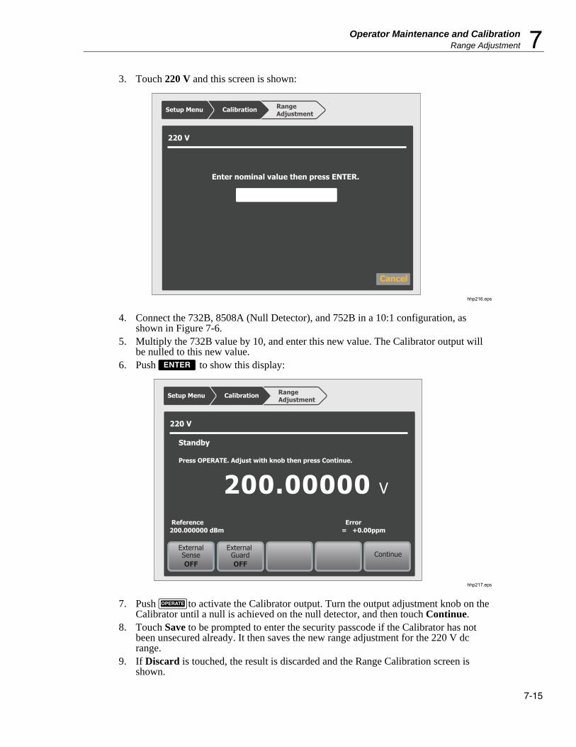
Operator Maintenance and Calibration Range Adjustment 7
7-15
3. Touch 220 V and this screen is shown:
220 V
Enter nominal value then press ENTER.
Cancel
Range Adjustment
Setup Menu Calibration
hhp216.eps
4. Connect the 732B, 8508A (Null Detector), and 752B in a 10:1 configuration, as shown in Figure 7-6.
5. Multiply the 732B value by 10, and enter this new value. The Calibrator output will be nulled to this new value.
6. Push to show this display:
220 V
Range Adjustment
Setup Menu Calibration
ExternalSenseOFF
External GuardOFF
Continue
V200.00000
ExternalSenseOFF
Reference200.000000 dBm
Error = +0.00ppm
Standby
Press OPERATE. Adjust with knob then press Continue.
hhp217.eps
7. Push to activate the Calibrator output. Turn the output adjustment knob on the Calibrator until a null is achieved on the null detector, and then touch Continue.
8. Touch Save to be prompted to enter the security passcode if the Calibrator has not been unsecured already. It then saves the new range adjustment for the 220 V dc range.
9. If Discard is touched, the result is discarded and the Range Calibration screen is shown.

5730A Operators Manual
7-16
Calibrator
HI
HI
HI
LO
LO
LOOUTPUT
HI LO
GND GRD
752A Voltage Divider Standard
INPUT
REFERENCESTANDARD
NULLDETECTOR
732B VoltageReference Standard
732B DC STANDARD
AC PWR IN CAL CHARGE LOW BAT
10V 1.018V CHASSIS
GUARD1.018V COM10V COM
SERIAL NUMBER
ExternalSenseOFF
External GuardOFF
Null Detector
NC
hhp029.eps
Figure 7-6. 220 V DC Range Calibration Connections
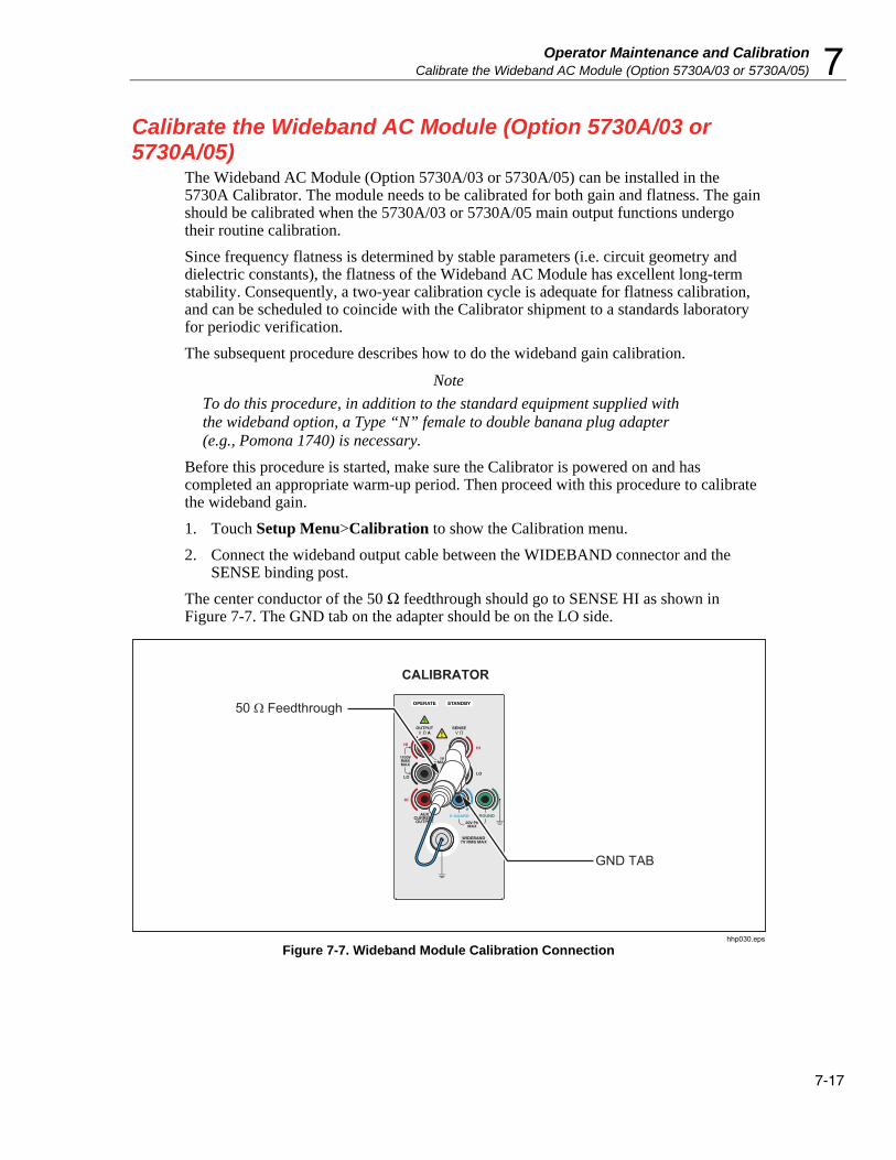
Operator Maintenance and Calibration Calibrate the Wideband AC Module (Option 5730A/03 or 5730A/05) 7
7-17
Calibrate the Wideband AC Module (Option 5730A/03 or 5730A/05)
The Wideband AC Module (Option 5730A/03 or 5730A/05) can be installed in the 5730A Calibrator. The module needs to be calibrated for both gain and flatness. The gain should be calibrated when the 5730A/03 or 5730A/05 main output functions undergo their routine calibration.
Since frequency flatness is determined by stable parameters (i.e. circuit geometry and dielectric constants), the flatness of the Wideband AC Module has excellent long-term stability. Consequently, a two-year calibration cycle is adequate for flatness calibration, and can be scheduled to coincide with the Calibrator shipment to a standards laboratory for periodic verification.
The subsequent procedure describes how to do the wideband gain calibration.
Note
To do this procedure, in addition to the standard equipment supplied with the wideband option, a Type “N” female to double banana plug adapter (e.g., Pomona 1740) is necessary.
Before this procedure is started, make sure the Calibrator is powered on and has completed an appropriate warm-up period. Then proceed with this procedure to calibrate the wideband gain.
1. Touch Setup Menu>Calibration to show the Calibration menu.
2. Connect the wideband output cable between the WIDEBAND connector and the SENSE binding post.
The center conductor of the 50 Ω feedthrough should go to SENSE HI as shown in Figure 7-7. The GND tab on the adapter should be on the LO side.
CALIBRATOR
GND TAB
50 Ω Feedthrough
hhp030.eps
Figure 7-7. Wideband Module Calibration Connection

5730A Operators Manual
7-18
3. Touch Run Wb Gain Cal to begin calibration. The screen prompts the user to check the manual for the correct connections.
4. As the wideband calibration proceeds, messages are shown on the display identifying all processes as they are encountered. When positive gains calibration is complete, a message is shown to refer to the manual for negative gains connections.
5. Reverse the dual-banana connector so that the center connector is connected to LO.
6. Push . The display shows progress through the procedure in the same fashion as for artifact calibration. At the end of the procedure, the Calibrator gives the option to save or discard the results.
7. Touch Save to store the new calibration constants.
8. The Calibrator prompts for the security passcode if it has not already been entered. Enter the security passcode if it has not yet been entered.
Touch Discard to delete the results of the calibration. In both cases, the calibration screen is shown after the results are saved or deleted.
Wideband Flatness Calibration Procedure This calibration procedure and the full verification of the 5730A Calibrator should be done every 2 years.
For flatness calibration:
1. Touch Setup Menu>Calibration. If the ambient temperature has changed from the displayed value, update it.
2. Touch Run Wb Flatness Cal.
3. Connect the equipment as shown in Figure 7-8.
5790A
Wideband Input
5730A
WidebandOutput
WidebandOutput Cable
hhp313.eps
Figure 7-8. Wideband Flatness Calibration Connections
4. Touch Continue.
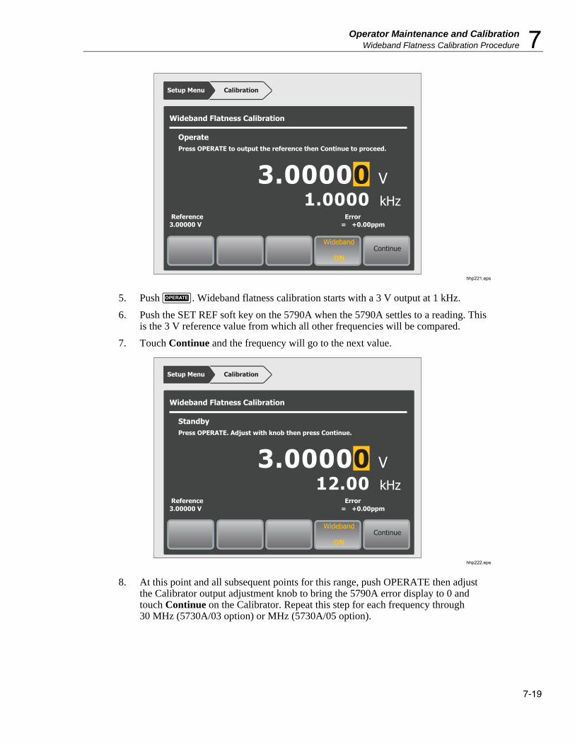
Operator Maintenance and Calibration Wideband Flatness Calibration Procedure 7
7-19
Wideband Flatness Calibration
Setup Menu Calibration
ExternalSenseOFF
Wideband
ONContinue
V
Reference3.00000 V
Error = +0.00ppm
OperatePress OPERATE to output the reference then Continue to proceed.
3.00000kHz1.0000
hhp221.eps
5. Push . Wideband flatness calibration starts with a 3 V output at 1 kHz.
6. Push the SET REF soft key on the 5790A when the 5790A settles to a reading. This is the 3 V reference value from which all other frequencies will be compared.
7. Touch Continue and the frequency will go to the next value.
Wideband Flatness Calibration
Setup Menu Calibration
ExternalSenseOFF
Wideband
ONContinue
V
Reference3.00000 V
Error = +0.00ppm
StandbyPress OPERATE. Adjust with knob then press Continue.
3.00000kHz12.00
hhp222.eps
8. At this point and all subsequent points for this range, push OPERATE then adjust the Calibrator output adjustment knob to bring the 5790A error display to 0 and touch Continue on the Calibrator. Repeat this step for each frequency through 30 MHz (5730A/03 option) or MHz (5730A/05 option).

5730A Operators Manual
7-20
9. The Calibrator wideband output changes to 1 V at 1 kHz. When it has, push the CLEAR REF WBND soft key on the 5790A.
10. Repeat steps 7 to 10 for the 1 V, 300 mV, 100 mV, 30 mV, and 10 mV ranges.
11. Once the calibration procedure completes, save or discard the results in the same way as at the end of artifact calibration and wideband gain calibration.
12. Touch Save to store the new calibration constants.
13. The Calibrator prompts for the security passcode if it has not already been entered.
14. Touch Discard to delete the results of the calibration. In both cases, the calibration screen is shown after the Calibrator saves or deletes the results.
Calibration Check A calibration check is similar to artifact calibration, with the primary differences being that no changes are made to the stored constants, and the internal check standards are used as the reference points. A calibration check produces a report similar to the normal calibration report, and shows output shifts that would result from using the results of the calibration check.
This procedure can be performed from an external computer, and can be set to run automatically, with no assistance (there is no need to enter the security passcode, since no constants are changed).
Use calibration check at any time to confirm the integrity of the 5730A Calibrator without connecting external standards. The calibration check is also useful for collecting a performance history.
Before this procedure is started, make sure the Calibrator is powered on and has completed the appropriate warm-up period. Then follow this procedure to check the calibration.
1. Touch the Setup Menu>Calibration to bring up the Calibration menu.
2. Touch Run Calibration Check to begin the procedure.
3. As the calibration check proceeds, the display indicates the current process of the calibration check. When the check is complete, the largest shift that is detected appears on the display. The Calibrator tells when calibration is complete.
4. Touch Continue to return to the Calibration menu. A report of the output shifts can be saved from this menu.

Operator Maintenance and Calibration Develop a Performance History 7
7-21
Develop a Performance History A Fluke Calibration specification is a set of performance limits that all products must meet. To maintain consistent quality, Fluke calibrators are specified with enough margin to include temperature, line, and load extremes, plus additional margin for production. This means that a typical Calibrator in a typical environment operates inside 50 % of specification limits. For some exacting applications, it can be helpful to know just how accurately a particular Calibrator operates. The proper way to do this is to accumulate a performance history by calibrating regularly and recording results on a control chart.
Calibrating regularly and recording the results on a control chart is tedious and requires a large array of equipment. The Calibrator calibration check feature is an alternative with some distinct advantages:
• Calibrated check standards are already programmed into the unit. External standards are not necessary.
• The process is consistent and automatic and it does not require operator assistance.
Each calibration check produces a new set of data points for accumulating a historical record. When this process is externally automated, significant history can be accumulated much faster than with a manual calibration.
Save Calibration Reports Calibration reports can be created and exported to a USB flash drive from the Calibrator Calibration Report menu. The subsequent sections describe the reports.
To save a calibration report:
1. Put a flash drive into the front USB port.
2. Go to Setup Menu>Calibration>Generate Report.
3. Select one of the three reports:
• Save Calibration Shifts
• Save Check Shifts
• Save Raw Data
Once an item is selected, the report is loaded to a USB flash drive. The report is in comma separated value (CSV) format and is capable of being imported into a spreadsheet program such as Microsoft Excel.
4. Open or print the file from the PC.
5730A Operators Manual
7-22
Calibration Shift Results The Calibration Shift report presents all adjustments made to stored zero-offset and gain constants, as a result of any drift detected at the most recent calibration. This report is available and valid at any time.
The report contains this information:
• Heading containing the date and time the report was saved, the user report string, and the installed version of the Calibrator software.
• Modules present (installed or attached) including any attached amplifiers
• Most recent calibration dates and temperatures
• Values of externally-calibrated internal references including the resistance reference, which is the average of the actual-to-nominal ratios of the 100 Ω, 190 Ω, 1 kΩ, 1.9 kΩ, 10 kΩ, 19 kΩ, 100 kΩ, and 190 kΩ resistors.
• DC voltage output shifts for each range
• AC voltage output shifts for each range. A gain shift for all frequencies is shown along with shifts at selected frequencies for each range.
• Current output shifts for each range (ac and dc)
• Resistance shifts for each value
• 5725A Amplifier output shifts (if attached)
• Wideband AC Module (Option 5730A/03 or 5730A/05) output shifts (if installed)
The shifts of references and outputs are given both as absolute shifts in V, A, or ohms, and also (for non-zero magnitudes) as shifts relative to the previous value, in parts per million (ppm) or percent (%).
The specified accuracy for the output is also shown, and the ratio of the shift to that accuracy in percent.
The Calibration Shift report file name is CSyymmdd.CSV, where yymmdd is the date today. For example, a calibration shift report compiled on October 28, 2013 would be saved to CS131028.CSV.

Operator Maintenance and Calibration Save Calibration Reports 7
7-23
Calibration Check Shift Results The Calibration Check report presents changes in the magnitude of self-correction generated by calibration check. Calibration check uses internal standards rather than external standards as the basis for comparison, and does not make permanent changes to calibration constants. This report is available only after a calibration check has been performed and until the Calibrator is reset. The report contains the subsequent information, and is shown below:
• Heading that shows the date and time the report was saved and user report string
• Modules present (installed or attached)
• Most recent calibration dates and temperatures
• Values of externally-calibrated internal references
• DC voltage output shifts for each range
• AC voltage output shifts for each range
• AC and dc current output shifts for each range
• Resistance shifts for each value
• 5725A Boost Amplifier output shifts (if attached). The calibration report file name is CKyymmdd.CSV, where yymmdd is the date today.
Raw Data Results This report gives the values for the internally stored correction factors (calibration constants), and is useful primarily for our service centers.

5730A Operators Manual
7-24
8-1
Chapter 8 Options and Accessories
Introduction This chapter describes options and accessories available to enhance the capabilities of the 5730A Calibrator. Chapter 4 contains instructions for operation of the Calibrator with the options and accessories described here. To order options or accessories, call or write to a Fluke Calibration Service Center.
Wideband AC Voltage Module (Option 5730A/03 or 5730A/05)
The Wideband AC Voltage Module (Option 5730A/03 or 5730A/05) is used to calibrate RF voltmeters, and can be installed in the Calibrator. The Module frequencies range from 10 Hz to 30 MHz (5730A/03) or 50 MHz (5730A/05). It is a highly accurate, low-noise, ac voltage source that maintains excellent flatness. The module sources its output through a coaxial connector into a 50 Ω load, and this output can be from within any of seven ranges of values, from 300 µV (-57 dBm) to 3.5 V (+24 dBm), selected in either volts or dBm.
The wideband module also functions with the Calibrator edit controls. This will let the display show the error of a wideband meter in percentage of output or decibels.
Accessories Included with the wideband module are a Type “N” output cable, 50 Ω terminator, an N(f) to BNC(m) adapter, and a BNC(f) to double banana plug adapter. The wideband module is calibrated to the end of its standard equipment output cable.

5730A Operators Manual
8-2
Table 8-1 summarizes the accessories available for the Calibrator. After the table is a brief description of each accessory.
Table 8-1. Accessories
Model Description
732B DC Voltage Reference Standard
742A-1 1 Ω Resistance Transfer Standard
742A-10k 10 kΩ Resistance Transfer Standard
5440A-7003 Low Thermal EMF Test Lead Set with Spade Lugs.
Two 4 ft. (122 cm) cables and One 2 ft. (61 cm) cable.
5440A-7002 Low Thermal Test Lead cables with banana plugs.
5730A-7002 Low Thermal Test Lead cables with banana plugs.
5730A-7003 Low Thermal Test Lead cables with spade lugs.
Y8021 IEEE-488 Shielded Interface Cable, 1 Meter
Y8022 IEEE-488 Shielded Interface Cable, 2 Meters
Y5737 24 in (61 cm) Rack Mount Kit
Y5735 24 in (61 cm) Rack Mount Kit for 5725A
Y5738 Rack Ear Kit
5730A/03 30 MHz Wideband AC Voltage option
5730A/05 50 MHz Wideband AC Voltage option
Low Thermal EMF Test Leads Four types of low thermal test leads are available. These cables are designed to exhibit low thermal emfs. The available types are:
• Model 5440A-7002. Low Thermal Test Lead cables with banana plugs.
Set includes one 4 ft. (122 cm) cable and two 2 ft. (61 cm) cables. Each cable includes two conductors and a shield lead.
• Model 5440A-7003. Low Thermal Test Lead cables with spade lugs.
Set includes one 4 ft. (122 cm) cables and two 2 ft. (61 cm) cable. Each cable includes two conductors and a shield lead. Shield lead has a banana plug connector.
• Model 5730A-7002. Low Thermal Test Lead cables with banana plugs. Set includes two 4 ft. (122 cm) cables. Each cable includes two conductors and a shield lead.
• Model 5730A-7003. Low Thermal Test Lead cables with spade lugs. Set includes two 4 ft. (122 cm) cables. Each cable includes two conductors and a shield lead. Shield lead has a banana connector.

Options and Accessories Accessories 8
8-3
Rack Mount Kits The rack mount kits provide all the hardware necessary to mount the Calibrator and the 5725A Amplifier on slides in a 24 inch (61 cm) equipment rack. Model Y5737 is for the 5730A and Model Y5735 is for the 5725A. The Y5738 includes the Rack Ears and fasteners without the slide rack mount. Instructions are included with each kit.
Shielded IEEE-488 Interface Cables (Y8021 and Y8022) Shielded IEEE-488 cables are available in two lengths (see Table 8-1). The cables attach the Calibrator to any other IEEE-488 device. Each cable has double 24-pin connectors at both ends to allow stacking. Metric threaded mounting screws are provided with each connector. Figure 5-1 in Chapter 5 shows the pinout for the IEEE-488 connector.
DC Voltage Reference Standard (732B) The Fluke 732B is a rugged, easily transported solid state direct voltage reference standard with a highly predictable 10 V output. This predictability allows the Fluke Standards Laboratory, as well as many Fluke customers, to completely eliminate fragile, saturated standard cells. Many laboratories that maintain standard cells use the 732B as a transportable voltage standard, eliminating the need to transport their standard cells. The 732B can be short circuited, even for extended periods of time, without damage or loss of stability. The 732B maintains full specified stability over a temperature span of 18 ºC to 28 ºC.
The Calibrator uses a 10 V reference standard such as the Fluke 732B in an automated menu-prompted procedure to establish voltage traceability. Chapter 7 describes this procedure.
1 Ω and 10 kΩ Resistance Standards (742A-1 and 742A-10k) The 742A Series Standard Resistors are available in values of 1 Ω and 10 kΩ to support the Calibrator. Constructed of arrays of Fluke wirewound precision resistors, these standards are ideally suited as support standards for the Calibrator. Stability of the resistance transfer standards and their temperature coefficient make them ideal for easy transport to and operation in the Calibrator working environment.
The Calibrator uses 1 Ω and 10 kΩ resistor standards such as the 742A Series in its automated calibration procedure to establish external traceability. Chapter 7 describes this procedure.

5730A Operators Manual
8-4
5725A Amplifier The Fluke 5725A Amplifier is an external unit that operates under Calibrator control to extend ac voltage drive capabilities and both ac and dc current output range. The amplifier adds the following capabilities to the Calibrator 1100 V ac range with no compromise in accuracy:
• Frequency limits at higher voltage increase to 100 kHz at 750 V, 30 kHz at 1100V.
• Load limit increases to 70 mA for frequencies above 5 kHz.
• Capacitive drive increases to 1000 pF, subject to the maximum output current.
A separate set of binding posts on the front panel of the 5725A supplies extended-range ac and dc current outputs. Since most meters have a separate input terminal for the high current ranges, this eliminates the need to change cables during a procedure. A Calibrator paired with a 5725A can also be configured to source all current (both standard Calibrator-generated outputs and its own outputs) through the 5725A binding posts.
An interface connector on the Calibrator rear panel accepts the cable to directly operate a 5725A. Once the amplifier has been connected and the 5725A has been configured in a setup menu, operation is controlled by the Calibrator.
Chapter 4 provides instructions for operating the 5725A amplifier. The general specifications at the end of Chapter 1 include specifications for operating the 5730A Calibrator with the 5725A. For other amplifier specifications, refer to their instruction manuals. Table 1-1 summarizes the extended capabilities offered by each amplifier. Brief descriptions of the extended capabilities follow.
52120A Amplifier The 52120A is available to extend the current range of the Calibrator.
An interface connector on the Calibrator rear panel accepts the cable to directly operate one or more 52120As in slave mode.
See Chapter 4 for operation instructions for the 52120A Transconductance Amplifier. The general specifications at the end of Chapter 1 include specifications for operating the Calibrator with one or more 52120As.

A-1
Appendix A Fault Codes
0-Level Faults: Firmware Updater
1 Backup directory not specified in AuxInfo
2 Backup filename not specified in AuxInfo
3 Destination directory not specified in AuxInfo
4 Destination filename not specified in AuxInfo
5 Error extracting required file transfer data from AuxInfo
6 Error retrieving parameter value from AuxInfo
7 Error retrieving section name from AuxInfo
8 Interim directory not specified in AuxInfo
9 Interim filename not specified in AuxInfo
10 Error reading AuxInfo file
11 Source directory on USB device not specified in AuxInfo
12 Source filename on USB device not specified in AuxInfo
13 Cannot build a list of sequences to be executed
14 Backup directory not specified in AuxInfo (config/cal)
15 Backup file not specified in AuxInfo (config/cal)
16 Destination directory not specified in AuxInfo (config/cal)
17 Destination file not specified in AuxInfo (config/cal)
18 Source directory not specified in AuxInfo (config/cal)
19 Source file not specified in AuxInfo(config/cal)
20 Error setting mode of new file
21 Timestamp too long in AuxInfo
22 Cannot close updated file (config/cal)
23 Destination file does not exist (config/cal)

5730A Operators Manual
A-2
24 Cannot get required AuxInfo parameters (config/cal)
25 Cannot open new file (config/cal)
26 Failed to read the existing (destination) file (config/cal)
27 Failed to read the new (source) file (config/cal)
28 Cannot remove existing backup file (config/cal)
29 Cannot rename existing file to backup file (config/cal)
30 Source file does not exist (config/cal)
31 Invalid timestamp. Cannot convert to epoch time
32 Kernel Datapath1 not specified in AuxInfo
33 Kernel Datapath2 not specified in AuxInfo
34 Kernel Device not specified in AuxInfo
35 Kernel Erase Command not specified in AuxInfo
36 Cannot extract Kernel update data from AuxInfo
37 Kernel Offset not specified in AuxInfo
38 Kernel Read Command not specified in AuxInfo
39 Kernel Write Command not specified in AuxInfo
40 Kernel Device failed to close
41 Kernel Device failed to return info about device status
42 Kernel Device failed to open
43 Kernel Device failed to return status (error not used).
44 Unable to determine the size of the Kernel image file
45 Invalid offset in Kernel image section
46 Unable to extract command1 from AuxInfo for FrontPanel_Part3
47 Unable to extract command2 from AuxInfo for FrontPanel_Part3
48 Error creating interim directory
49 MD5 hash of downloaded file does not agree with AuxInfo
50 Error mounting USB device
51 File to be downloaded does not exist on USB device
52 USB device not plugged in
53 Error deleting previous backup file
54 Error renaming installed file to backup
55 Error moving download file to destination directory
56 Remove file operation not specified in AuxInfo
57 Remove file operation failed
58 Error copying file from USB device to interim directory

Appendices Fault Codes A
A-3
59 File on USB device is older than installed file
60 File on USB device same as installed file (per timestamp)
61 Error unmounting USB device
62 Cannot extract ver # from line 1 of src file (config/cal)
63 Cannot extract ver # from line 1 of dest file (config/cal)
64 Kernel Datapath1 MD5 hash failed
65 Kernel Datapath2 (readback) MD5 hash failed
100-Level Faults: System
100 Low airflow
101 Cannot modify file property
102 Update execution error
103 Cannot open gpio PORT_A
200-Level Faults: 5725 Boost
200 5725 No Error
201 5725 Self-Test ROM Failure
202 5725 Self-Test RAM Failure
203 5725 Self-Test EEPROM Failure
204 5725 Self-Test Data Bus Failure
205 5725 Self-Test CLAMPS Circuit Failure
206 5725 Self-Test HVCLR Circuit Failure
207 5725 Self-Test DAC Failure
208 5725 Self-Test Watchdog Timer Failure
209 5725 Current Heatsink Too Hot
210 Output Tripped To Standby
211 5725 Current Compliance Voltage Too High
212 5725 Current Compliance Voltage Too High
213 5725 +400 V Supply Did Not Shut Off
214 5725 -400 V Supply Did Not Shut Off
215 5725 Voltage Heatsink Too Hot
216 5725 Voltage Heatsink Too Hot
217 5725 +400 V Supply Too Small
218 5725 +400 V Supply Too Large
219 5725 -400 V Supply Too Large

5730A Operators Manual
A-4
220 5725 -400 V Supply Too Small
221 5725 +400 V Supply Current Too High
222 Output Tripped To Standby
223 5725 -400 V Supply Current Too High
224 Output Tripped To Standby
225 5725 Fan Not Working
226 5725 CLAMPS Fault
227 Output Tripped To Standby
228 5725 Software TRAP
229 5725 Cable Was Off
230 5725 RESET (power-up or watchdog timer)
231 5725 Guard-Crossing Timeout
232 5725 Illegal/Unexecutable Command
233 5725 Non-Maskable Interrupt Occurred
234 5725 HVCLEAR Circuit Activated
235 Output Tripped To Standby
400-Level Faults: Calibration Constant
400 Bad Cal Constant ID
500-Level Faults: Configuration Finder
500 Bad Mode To CNFmodeRanges
501 Configuration Table Overflow
502 Bad Amplifier Type Selection
503 Bad Flat Constant Type Selection
504 Guard Crossing Error While Polling Assemblies
505 5725 Guard Crossing would not Start
700-Level Faults: Error Handling
700 Error Queue Overflow
701 Bad ERR Channel

Appendices Fault Codes A
A-5
800-Level Faults: Executive
800 Wideband Module Needed
801 Amplifier Not Selected or Connected
802 Amplifier Must Remain On For This Output
803 Over Limits Of Locked Range
804 Under Limits Of Locked Range
806 Invalid Date
807 Invalid Time
808 DC dBm Not Allowed
809 Ext Ref Value Out Of Range
810 Bad Edit Digit Movement
811 Not Wideband Units
812 Cannot Set Frequency With Ohms
813 Bad Units
814 Wrong Polarity For Limit
815 Outside Entry Limits
816 Magnitude Too Large For Calibrator
817 Magnitude Too Small For Calibrator
818 Frequency Too Large For Calibrator
819 Frequency Too Small For Calibrator
820 Calibrator Cannot Source That Value
821 V Limit Outside Calibrator Ability
822 I Limit Outside Calibrator Ability
823 Cannot Adjust Frequency To <= 0 Hz
824 Offset Not Allowed Now
825 Scale Not Allowed Now
826 Ohms Reading Set Too High
827 Ohms Reading Set Too Low
828 Cannot Use External Sense Now
829 Cannot Use Phase Shift Now
830 Cannot Use Phase Lock Now
831 Cannot Use 2-Wire Comp Now
832 Could not Do Default Wideband Output
833 Bad Selector For Set/Get Item
834 Cannot Boost This Output Mode

5730A Operators Manual
A-6
835 Cannot Use Ext Sense On Selected Range
836 Cannot Use 2-Wire Comp On Selected Range
837 Cannot Lock This Range
838 Cannot Set Clock, Cal Is Secured
839 Cannot Fmt EEPROM, Cal Is Secured
840 Illegal Output Post For Current
841 No Boost Available For Selected Output
842 Not A Valid Wideband Flatness Point
843 Wideband Flatness Cal Is Not Active
844 Report String Too Long
845 Cannot Store, Cal Is Secured
846 Range Calibration Is Not Active
847 Magnitude Too High For Range Cal
848 Magnitude Too Low For Range Cal
849 Invalid Calibrator Setup Block
850 Cannot Format, 5725 Switch In NORMAL
851 Cannot Store, 5725 Switch In NORMAL
852 Calibration Steps Out Of Order
853 Cannot Use External Guard Now
854 Cannot Use Ext Guard On Selected Range
855 Cannot Set String, Cal Is Secured
856 Present Output Exceeds Selected Limit
857 Bad Selector For Reference Calibration
858 Cannot Change Range Now
859 Hardware Not Installed For This Range
860 Cannot Use Amplifier For This Output
861 5725 Cannot Ext Sense At That Frequency
862 Change To HI Outputs For 120 A Range
1000-Level Faults: 5725 Communication Receive
1000 Could not ACK Packet From 5725
1001 Illegal 5725 Receive Task State
1002 Bad Receive Packet Number From 5725
1003 Bad Control Byte From 5725

Appendices Fault Codes A
A-7
1100-Level Faults: 5725 Communication Transmit
1100 Multiple Timeouts Sending To 5725
1101 5725 RQR Loop
1102 Unexpected NSA From 5725
1103 Bad Packet Number In ACK From 5725
1104 Bad Control Byte From 5725 Receive Task
1105 Illegal 5725 Transmit Task State
1106 5725 Indefinite ACKWAIT Holdoff
1200-Level Faults: 5725 Communication Utility
1200 Serial Write Failure To 5725
1201 Packet Too Large For 5725
1300-Level Faults: Output Monitor
1301 Output Tripped To Standby
1302 Output Tripped To Standby
1303 DC Zero Is Needed (Every 30 Days)
1400-Level Faults: Software Timer
1400 Cannot Install MTtick()
1401 Bad Timer Selector
1500-Level Faults: Guard Crossing Receive
1500 Could not ACK Packet From Inguard
1501 Illegal Inguard Receive Task State
1502 Bad Receive Packet Number From Inguard
1503 Bad Control Byte From Inguard

5730A Operators Manual
A-8
1600-Level Faults: Guard Crossing Transmit
1600 Multiple Timeouts Sending To Inguard
1601 Inguard Request Reset Loop
1602 Unexpected NSA From Inguard
1603 Bad Packet Number In ACK From Inguard
1604 Bad Control Byte From Inguard Rcv Task
1605 Illegal Inguard Transmit Task State
1606 Inguard Indefinite ACKWAIT Holdoff
1700-Level Faults: Guard Crossing Utility
1700 Serial Write Failure To Inguard
1701 Packet Too Large For Inguard
1800-Level Faults: Normal Output Operations
1800 DORMANT To OPERATE
1801 Bad Transition Type
1802 Bad Boolean Selector
1803 NRMrngStby Encountered Error
1804 DCV Called For Non-DCV Range
1805 ACV Called For Non-ACV Range
1806 Bad ACV Frequency Range
1807 Hi Res Frequency Too High
1808 ACV Amplitude Correction Failure
1809 Cannot Phase Lock To Signal
1810 Bad Phase Quadrant
1811 Current Called for Non-Current Range
1812 Ohms Called for Non-Ohms Range
1813 Cannot Phase Lock, Output Not AC
1814 Cannot Phase Shift, Output Not AC
1815 Bad Wide Band Range
1816 Frequency Too High Even For Wide Band
1817 Illegal Current Output Location
1818 Output Current Out Of Tolerance
1819 Current Compliance Voltage Exceeded
1820 2-Wire Compensation Current Exceeded

Appendices Fault Codes A
A-9
1821 NRMbstcur Passed Bad Range
1826 5725 No Longer Connected
1827 14-Bit DAC Scaling Found Zero Output
1900-Level Faults: Non-volatile
1900 Repaired Missing Or Corrupted NV Files
1903 Unknown Nonvolatile Constant Selector
1905 Could Not Write Byte To 5725 EEPROM
1906 Checksum Error Reading 5725 EEPROM
2000-Level Faults: Analog Operations Manager
2000 Bad Command Code
2001 Bad Signal
2002 Long Term Command In Progress
2003 Guard Crossing Protocol Failed To Start
2004 Fatal Fault, Output Tripped
2200-Level Faults: Remote Interface
2200 Unknown Command
2201 Invalid Number Of Parameters
2202 Invalid Cal Constant Name
2203 Invalid Keyword
2204 Invalid Range
2205 Invalid Parameter Type
2206 Invalid Parameter Unit
2207 Invalid Parameter Value
2208 IEEE488.2 I/O DEADLOCK
2210 IEEE488.2 INTERRUPTED Query
2211 Not Allowed From GPIB Interface
2212 Not Allowed From Serial Interface
2213 Remote Only
2214 Invalid Syntax
2215 IEEE488.2 UNTERMINATED Command
2216 Symbol Table Overflow
2218 Invalid Binary Number

5730A Operators Manual
A-10
2219 Invalid Binary Block
2220 Invalid Character
2221 Invalid Decimal Number
2222 Invalid Hexadecimal Block
2223 Invalid Hexadecimal Number
2224 Too Many Parameters
2225 Invalid Octal Number
2226 Too Many Characters
2227 Invalid String
2228 Invalid Register Address
2229 Invalid Cal Constant Name
2230 Remote Serial Port Dead
2231 IEEE488.2 Query After Indef Response
2232 OPER Not Allowed While Fault Pending
2300-Level Faults: Report Generation
2300 Unknown Report Requested
2301 Unknown Report Device Requested
2302 Serial Port Timeout
2303 Could not find USB drive
2304 Could not open report file on USB drive
2400-Level Faults: Real Time Clock
2400 Could not read time and date.
2401 Could not set time and date.
2500-Level Faults: Self Calibration
2500 Invalid Cal Procedure Number
2501 Could not Ext Cal Gain
2502 Could not Ext Cal Ref
2503 Could not Ext Cal Neg
2504 Could not Cal Ratio
2505 Could not Cal Pos 11 V or 22 V DC Zero
2506 Could not Cal Neg 11 V or 22 V DC Zero
2507 Could not Cal Pos 11 V or 22 V DC Gain
2508 Could not Cal 6.5 V or 13 V Buf Ref
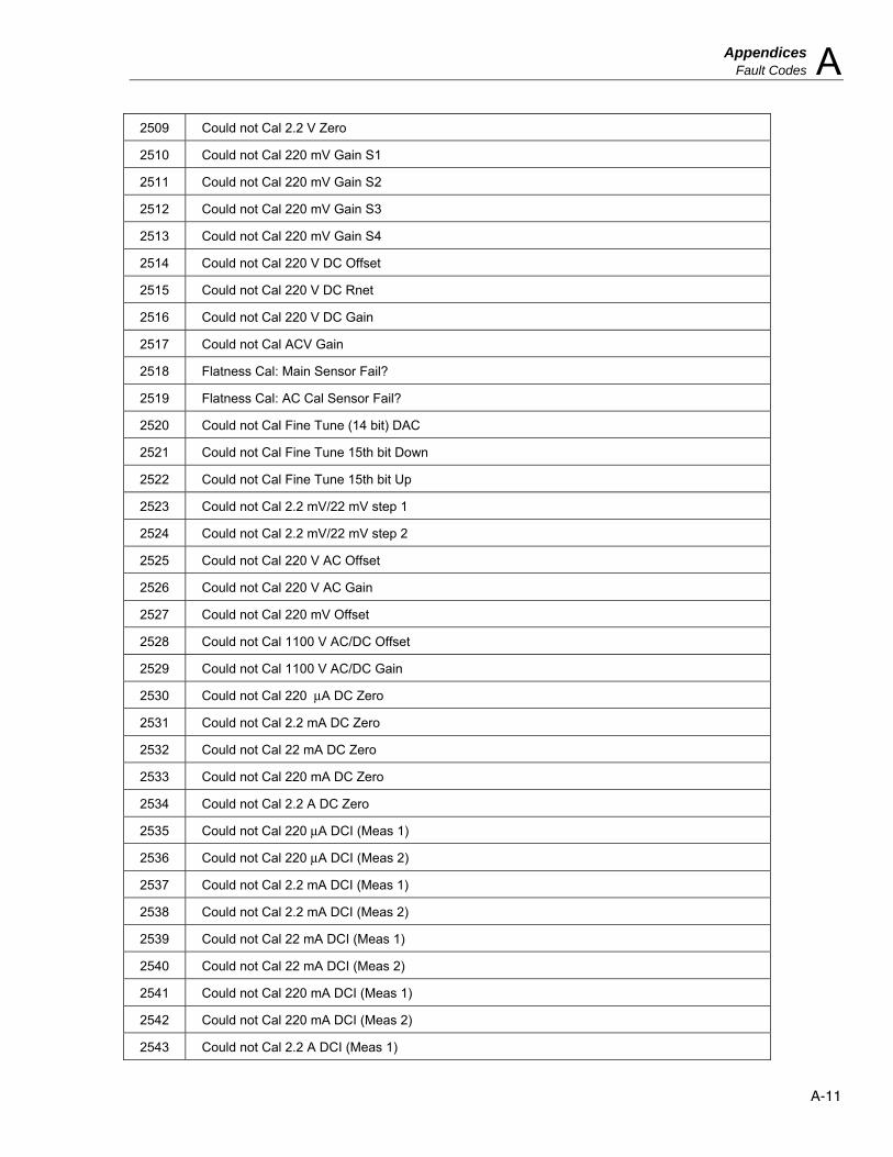
Appendices Fault Codes A
A-11
2509 Could not Cal 2.2 V Zero
2510 Could not Cal 220 mV Gain S1
2511 Could not Cal 220 mV Gain S2
2512 Could not Cal 220 mV Gain S3
2513 Could not Cal 220 mV Gain S4
2514 Could not Cal 220 V DC Offset
2515 Could not Cal 220 V DC Rnet
2516 Could not Cal 220 V DC Gain
2517 Could not Cal ACV Gain
2518 Flatness Cal: Main Sensor Fail?
2519 Flatness Cal: AC Cal Sensor Fail?
2520 Could not Cal Fine Tune (14 bit) DAC
2521 Could not Cal Fine Tune 15th bit Down
2522 Could not Cal Fine Tune 15th bit Up
2523 Could not Cal 2.2 mV/22 mV step 1
2524 Could not Cal 2.2 mV/22 mV step 2
2525 Could not Cal 220 V AC Offset
2526 Could not Cal 220 V AC Gain
2527 Could not Cal 220 mV Offset
2528 Could not Cal 1100 V AC/DC Offset
2529 Could not Cal 1100 V AC/DC Gain
2530 Could not Cal 220 μA DC Zero
2531 Could not Cal 2.2 mA DC Zero
2532 Could not Cal 22 mA DC Zero
2533 Could not Cal 220 mA DC Zero
2534 Could not Cal 2.2 A DC Zero
2535 Could not Cal 220 μA DCI (Meas 1)
2536 Could not Cal 220 μA DCI (Meas 2)
2537 Could not Cal 2.2 mA DCI (Meas 1)
2538 Could not Cal 2.2 mA DCI (Meas 2)
2539 Could not Cal 22 mA DCI (Meas 1)
2540 Could not Cal 22 mA DCI (Meas 2)
2541 Could not Cal 220 mA DCI (Meas 1)
2542 Could not Cal 220 mA DCI (Meas 2)
2543 Could not Cal 2.2 A DCI (Meas 1)

5730A Operators Manual
A-12
2544 Could not Cal 2.2 A DCI (Meas 2)
2545 Could not Ext Cal 10 KΩ Std (Meas 1)
2546 Could not Ext Cal 10 KΩ Std (Meas 2)
2547 Could not Ext Cal 10 KΩ Std (Meas 3)
2548 Could not Cal 10 KΩ (Meas 1)
2549 Could not Cal 10 KΩ (Meas 2)
2550 Could not Cal 10 KΩ (Meas 3)
2551 Could not Cal 19 KΩ (Meas 1)
2552 Could not Cal 19 KΩ (Meas 2)
2553 Could not Cal 19 KΩ (Meas 3)
2554 Could not Cal 100 KΩ (Meas 1)
2555 Could not Cal 100 KΩ (Meas 2)
2556 Could not Cal 190 KΩ (Meas 1)
2557 Could not Cal 190KΩ (Meas 2)
2558 Could not Cal 1 MΩ (Meas 1)
2559 Could not Cal 1 MΩ (Meas 2)
2560 Could not Cal 1.9 MΩ (Meas 1)
2561 Could not Cal 1.9 MΩ (Meas 2)
2562 Could not Cal 10 MΩ (Meas 1)
2563 Could not Cal 10 MΩ (Meas 2)
2564 Could not Cal 19 MΩ (Meas 1)
2565 Could not Cal 19 MΩ (Meas 2)
2566 Could not Cal 100 MΩ (Meas 1)
2567 Could not Cal 1 KΩ (Meas 1)
2568 Could not Cal 1 KΩ (Meas 2)
2569 Could not Cal 1.9 KΩ (Meas 1)
2570 Could not Cal 1.9 KΩ (Meas 2)
2571 Could not Cal 100 Ω (Meas 1)
2572 Could not Cal 100 Ω (Meas 2)
2573 Could not Cal 190 Ω (Meas 1)
2574 Could not Cal 190 Ω (Meas 2)
2575 Could not Cal Ohms Divider (Meas 1)
2576 Could not Cal Ohms Divider (Meas 2)
2577 Could not Cal 10 Ω Ω (Meas 1)
2578 Could not Cal 10 Ω (Meas 2)
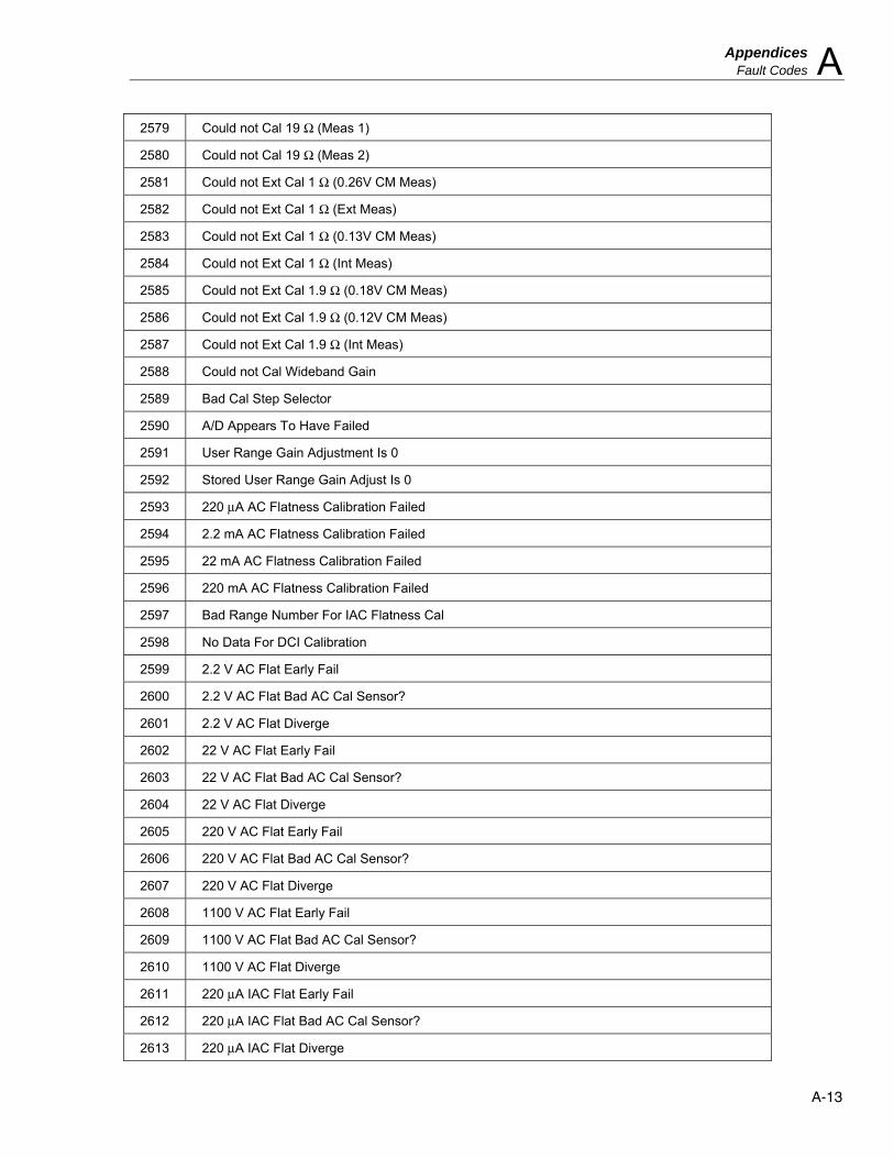
Appendices Fault Codes A
A-13
2579 Could not Cal 19 Ω (Meas 1)
2580 Could not Cal 19 Ω (Meas 2)
2581 Could not Ext Cal 1 Ω (0.26V CM Meas)
2582 Could not Ext Cal 1 Ω (Ext Meas)
2583 Could not Ext Cal 1 Ω (0.13V CM Meas)
2584 Could not Ext Cal 1 Ω (Int Meas)
2585 Could not Ext Cal 1.9 Ω (0.18V CM Meas)
2586 Could not Ext Cal 1.9 Ω (0.12V CM Meas)
2587 Could not Ext Cal 1.9 Ω (Int Meas)
2588 Could not Cal Wideband Gain
2589 Bad Cal Step Selector
2590 A/D Appears To Have Failed
2591 User Range Gain Adjustment Is 0
2592 Stored User Range Gain Adjust Is 0
2593 220 μA AC Flatness Calibration Failed
2594 2.2 mA AC Flatness Calibration Failed
2595 22 mA AC Flatness Calibration Failed
2596 220 mA AC Flatness Calibration Failed
2597 Bad Range Number For IAC Flatness Cal
2598 No Data For DCI Calibration
2599 2.2 V AC Flat Early Fail
2600 2.2 V AC Flat Bad AC Cal Sensor?
2601 2.2 V AC Flat Diverge
2602 22 V AC Flat Early Fail
2603 22 V AC Flat Bad AC Cal Sensor?
2604 22 V AC Flat Diverge
2605 220 V AC Flat Early Fail
2606 220 V AC Flat Bad AC Cal Sensor?
2607 220 V AC Flat Diverge
2608 1100 V AC Flat Early Fail
2609 1100 V AC Flat Bad AC Cal Sensor?
2610 1100 V AC Flat Diverge
2611 220 μA IAC Flat Early Fail
2612 220 μA IAC Flat Bad AC Cal Sensor?
2613 220 μA IAC Flat Diverge

5730A Operators Manual
A-14
2614 2.2 mA IAC Flat Early Fail
2615 2.2 mA IAC Flat Bad AC Cal Sensor?
2616 2.2 mA IAC Flat Diverge
2617 22 mA IAC Flat Early Fail
2618 22 mA IAC Flat Bad AC Cal Sensor?
2619 22 mA IAC Flat Diverge
2620 220 mA IAC Flat Early Fail
2621 220 mA IAC Flat Bad AC Cal Sensor?
2622 220 mA IAC Flat Diverge
2623 2.2 A IAC Flat Early Fail
2624 2.2 A IAC Flat Bad AC Cal Sensor?
2625 2.2 A IAC Flat Diverge
2626 Illegal Ohms Null Function State
2627 Unknown Source Divider Identifier
2628 No Data For Ohms Calibration
2629 Illegal Ohms Calibration Config
2630 Illegal Number Of Ohms Cal Points
2631 5725 Shunt 0 A Meas Fail
2632 5725 Shunt 1.3 A Meas Fail
2633 5725 Current Amplifier Zero Meas Fail
2634 5725 Current Amplifier Gain Meas Fail
2635 Wideband Thermal Sensor Cal Diverge
2636 Wideband Sensor Amp Offset Too Big
2637 Wideband Ext Cal Point Bad Const ID
2638 5725 ACV Sense Amp Offset Diverge
2639 5725 ACV Sense Amp Gain Diverge
2640 5725 ACV Flatness Ref Freq Failure
2641 5725 ACV Flatness Cal Freq Failure
2642 External V Reference Value Out Of Range
2643 5725 Diagnostic DAC Cal did not Converge
2645 52120A Source Range Gain Diverge
2646 DAC Appears To Not Meet Linearity Spec
2647 ACV Buffer Offset Too Large
2648 5725 ACV Flat Test Cap Too Large
2649 5725 ACV Flat Test Cap Too Large

Appendices Fault Codes A
A-15
2650 Could not Cal 100 M Ω (Meas 2)
2651 Invalid Security Passcode
2652 Passcode Be 1 to 8 Digits
2700-Level Faults: Self Diagnostics (Current)
2700 A7: 8255 Control Word
2701 A7: 8255 Port A Fault
2702 A7: 8255 Port B Fault
2703 A7: 8255 Port C Fault
2705 A7: Oven Regulation Fault
2706 A7: Current Compliance Fault
2707 A7: Hardware Initialization Fault
2709 A7: Current Magnitude Fault
2710 A7: Dummy Load Current Fault
2711 Assembly A7 Is Not Responding
2712 A7: Hi-Res Clock Fault
2713 A7: Hi-Res Loop Fault In 100HZ Range
2714 A7: Hi-Res Loop Fault In 1KHZ Range
2715 A7: Hi-Res Loop Fault In 10KHZ Range
2716 A7: Hi-Res Loop Fault In 100KHZ Range
2717 A7: Hi-Res Loop Fault In 1MHZ Range
2718 Fault In Setting Up AC For Diagnostics
2719 A7: 8255 Was Reset
2800-Level Faults: Self Diagnostics (DAC)
2800 A11: 8255 Control Word
2801 A11: 8255 Port A Wires
2802 A11: 8255 Port B Data Bus
2803 A11: 82C54 Status Words
2804 A11: DAC Heaters Not Regulated
2805 Calibrator Not Warmed Up
2806 A11: ADC Amp Output Noise
2807 A11: ADC Amp Output Offset
2808 A11: ADC Amp Gain Error
2809 A11: DAC Monitoring Fault

5730A Operators Manual
A-16
2810 A11: +11 V DC Range Fault
2811 A11: -11 V DC Range Fault
2812 A11: +22 V DC Range Fault
2813 A11: -22 V DC Range Fault
2814 A11: 6.5 V Buffered Reference Fault
2815 A11: 6.5 V Reference Fault
2816 A11: 13 V Buffered Reference Fault
2817 A11: 13 V Reference Fault
2818 Assembly A11 Missing
2819 A11: 8255 Was Reset
2820 A11: Fine Adjust Channel Fault
2821 A8/A11: +11/22 V DC Zero Estimate Fault
2822 A8/A11: -11/22 V DC Zero Estimate Fault
2823 A11: Could not Estimate +11 V Or 22 V Gain
2824 A11: Could not Estimate 6.5 V Or 13 V Ref
2825 A11: Could not Est 6.5 V Or 13 V Buf Ref
2826 A11: A/D Overload Fault
3100-Level Faults: Self Diagnostics (High Voltage)
3100 A14: 8255 Control Word
3101 A14: 8255 Port A Fault
3102 A14: 8255 Port B Fault
3103 A14: 8255 Port C Fault
3104 A15: HV Oven Regulation Fault
3105 A15: HV I Oven Regulation Fault
3106 A15: DC HV Amp Noise Fault
3107 A15: DC HV Amp Offset Fault
3108 A15: DC HV Amp Gain Fault
3109 A15: HV +DC Preamplifier Fault
3110 A15: HV +DC Series Pass & Current Fault
3111 A15: HV +DC High Voltage Output Fault
3112 A15: HV +DC Ref/Error Amplitude Fault
3113 A15: HV -DC Preamplifier Fault
3114 A15: HV -DC Series Pass & Current Fault
3115 A15: HV -DC High Voltage output Fault

Appendices Fault Codes A
A-17
3116 A15: HV -DC Reference/Error Amp Fault
3117 A14/A15: HV +DC Current Error Amp Fault
3118 A14/A15: HV -DC Current Error Amp Fault
3119 A14/A15: HV +DC Current Abs. Value
3120 A14/A15: HV -DC Current Abs. Value
3122 A14/A15: HV AC 1 KHZ, Preamp Fault (lo)
3123 A14/A15: HV AC 1 KHZ, Preamp Fault (mid)
3124 A14/A15: HV AC 1 KHZ, Preamp Fault (hi)
3125 A14/A15: HV AC 100 HZ, Preamp Fault (lo)
3126 A14/A15: HV AC 100 HZ, Preamp Fault
3127 A14/A15: HV AC 100 HZ, Preamp Fault (hi)
3128 A14/A15: HV AC 1 KHZ, Output Fault (lo)
3129 A14/A15: HV AC 1 KHZ, Output Fault (mid)
3130 A14/A15: HV AC 1 KHZ, Output Fault (hi)
3131 A14/A15: HV AC 100 HZ, Output Fault (lo)
3132 A14/A15: HV AC 100 HZ, Output Fault (mid)
3133 A14/A15: HV AC 100 HZ, Output Fault (hi)
3135 Assembly A14 Not Responding
3136 A14: 8255 Was Reset
3137 A14/A15/A16: 2.2 A AC Range Mag. Fault
3138 A14/A15/A16: 2.2 A AC Range Compliance
3139 A14/A15/A16: 2.2 A AC Range Amplitude
3140 A14/A15/A16: 2.2 A AC Range Abs. Value
3141 A14/A15/A16: 2.2 A DC Range Dummy Load
3142 A14/A15/A16: 2.2 A DC Range Compliance
3143 A14/A15/A16: 2.2 A DC Range Magnitude
3200-Level Faults: Self Diagnostics (Misc)
3200 Assemblies Missing
3201 Unknown Diagnostic Test
3202 5725 ACV Sense Amp Fault
3203 5725 ACV Standby 5725 Fault
3204 5725 ACV Operate 5725 Fault
3205 5725 ACV Cal Sensor Test Died
3206 5725 ACV Cal Sensor Fault

5730A Operators Manual
A-18
3207 5725 ACV VLF (100 Hz) will not Converge
3208 5725 ACV LF (1 kHz) will not Converge
3209 5725 ACV MF (10 kHz) will not Converge
3210 5725 ACV HF (100 kHz) will not Converge
3211 5725 Current Path To Shunt Open
3212 5725 Shunt Sense Open
3213 5725 Shunt Measurement Out Of Tolerance
3214 5725 Current Amplifier Offset Too Large
3215 5725 Current Drive Path Open
3216 5725 Current Error Amplifier Failure
3217 5725 Amplifer Not Connected
3300-Level Faults: Self Diagnostics (Ohms)
3300 A9: 8255 Control Word
3301 A9: 8255 Port A Fault
3302 A9: 8255 Port B Fault
3303 A9: 8255 Port C Fault
3304 A9: 10 V Source Fault
3305 A9: 5 V Source Fault
3306 A9: 2 V Source Fault
3308 A9: Diff Amp Offset Fault
3309 A9: Diff Amp Gain Fault
3310 A9: Diff Amp Noise Fault
3311 A9/A10: Ohms 10:1 Divider Fault
3312 A9/A10: Ohms 1:1 Divider Fault
3313 A9/A10: 10 KΩ Diagnostic Fault
3314 A9/A10: 19 KΩ Cal Diag Fault
3315 A9/A10: 10 Ω Cal Diag Fault
3316 A9/A10: 19 Ω Cal Diag Fault
3317 A9/A10: 100 KΩ Ratio Fault
3318 A9/A10: 190 KΩ Ratio Fault
3319 A9/A10: 1 MΩ Ratio Fault
3320 A9/A10: 1.9 MΩ Ratio Fault
3321 A9/A10: 10 MΩ Ratio Fault
3322 A9/A10: 19 MΩ Ratio Fault 1
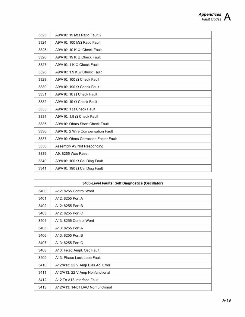
Appendices Fault Codes A
A-19
3323 A9/A10: 19 MΩ Ratio Fault 2
3324 A9/A10: 100 MΩ Ratio Fault
3325 A9/A10: 10 K Ω Check Fault
3326 A9/A10: 19 K Ω Check Fault
3327 A9/A10: 1 K Ω Check Fault
3328 A9/A10: 1.9 K Ω Check Fault
3329 A9/A10: 100 Ω Check Fault
3330 A9/A10: 190 Ω Check Fault
3331 A9/A10: 10 Ω Check Fault
3332 A9/A10: 19 Ω Check Fault
3333 A9/A10: 1 Ω Check Fault
3334 A9/A10: 1.9 Ω Check Fault
3335 A9/A10: Ohms Short Check Fault
3336 A9/A10: 2 Wire Compensation Fault
3337 A9/A10: Ohms Correction Factor Fault
3338 Assembly A9 Not Responding
3339 A9: 8255 Was Reset
3340 A9/A10: 100 Ω Cal Diag Fault
3341 A9/A10: 190 Ω Cal Diag Fault
3400-Level Faults: Self Diagnostics (Oscillator)
3400 A12: 8255 Control Word
3401 A12: 8255 Port A
3402 A12: 8255 Port B
3403 A12: 8255 Port C
3404 A13: 8255 Control Word
3405 A13: 8255 Port A
3406 A13: 8255 Port B
3407 A13: 8255 Port C
3408 A13: Fixed Ampl. Osc Fault
3409 A13: Phase Lock Loop Fault
3410 A12/A13: 22 V Amp Bias Adj Error
3411 A12/A13: 22 V Amp Nonfunctional
3412 A12 To A13 Interface Fault
3413 A12/A13: 14-bit DAC Nonfunctional

5730A Operators Manual
A-20
3414 A12/A13: Nonlinear Control Loop 2Vrng
3415 A12/A13: nonlinear Control Loop 20Vrng
3416 A12/A13: DAC 15th Bit Fault
3417 A12: DC Sensor Buffer Fault
3418 A12: Sensor Loop/Sq. Root Amp Fault
3419 A12: AC Sensor Buff (2V Range)
3420 A12: AC Sensor Buff (20V Range)
3421 A12: AC Cal Sensor (2V Range)
3422 A12: AC Cal Sensor (20V Range)
3423 Assembly A12 Missing
3424 Assembly A13 Missing
3425 Assembly A12 Or A13 Not Responding
3426 A12: 8255 Was Reset
3427 A13: 8255 Was Reset
3500-Level Faults: Self Diagnostics (Power Amp)
3500 A16: 8255 Control Word
3501 A16: 8255 Port A
3502 A16: 8255 Port B
3503 A16: 8255 Port C
3507 A16: PA Supplies Are Off
3508 A16/A14: 220 V AC Range Output Fault
3509 A16: Amplifier Loop Not Regulated
3510 A16: 220 V Amp Fault
3511 A16: Incorrect PA Input
3520 A16: PA Oven Regulation Fault
3521 Assembly A16 Is Not Responding
3524 A16: Power Amp Is Too Hot
3525 220 V DC Initialization Fault
3526 220 V AC Initialization Fault
3527 A16: Power Amp DC Cal Network Zero Fault
3528 A16: Power Amp DC Cal Network Gain Fault
3529 A16: Pwr Amp 220V Range Attenuator Fault
3530 A16: 8255 Was Reset

Appendices Fault Codes A
A-21
3600-Level Faults: Self Diagnostics (Power Supplies)
3600 +17S Supply Fault
3601 -17S Supply Fault
3602 +15S Supply Fault
3603 -15S Supply Fault
3604 +42S Supply Fault
3605 -42S Supply Fault
3606 LH COM Ground Fault
3607 -5LH Supply Fault
3608 5RLH Supply Fault
3609 8RLH Supply Fault
3610 +PA Supply Fault
3611 -PA Supply Fault
3612 +15 OSC Supply Fault
3613 -15 OSC Supply Fault
3614 OSC COM Ground Fault
3615 S COM Ground Fault
3700-Level Faults: Self Diagnostics (Rear I/O)
3700 A21: 8255 Control Word
3701 A21: 8255 Port A Fault
3702 A21: 8255 Port B Fault
3703 A21: 8255 Port C Fault
3704 Assembly A21 Not Responding
3705 A21: Rear Panel Data Bus Fault
3708 A21: 8255 Was Reset
3800-Level Faults: Self Diagnostics (Switch Matrix)
3800 A8: 8255 Control Word
3801 A8: 8255 Port A Fault
3802 A8: 8255 Port B Fault
3803 A8: 8255 Port C Fault
3804 A8: Zero Amp Lo Noise Fault
3805 A8: Zero Amp Lo Offset
3806 A8: Zero Amp Lo Gain Fault
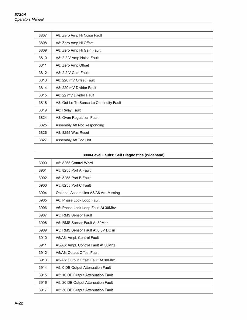
5730A Operators Manual
A-22
3807 A8: Zero Amp Hi Noise Fault
3808 A8: Zero Amp Hi Offset
3809 A8: Zero Amp Hi Gain Fault
3810 A8: 2.2 V Amp Noise Fault
3811 A8: Zero Amp Offset
3812 A8: 2.2 V Gain Fault
3813 A8: 220 mV Offset Fault
3814 A8: 220 mV Divider Fault
3815 A8: 22 mV Divider Fault
3818 A8: Out Lo To Sense Lo Continuity Fault
3819 A8: Relay Fault
3824 A8: Oven Regulation Fault
3825 Assembly A8 Not Responding
3826 A8: 8255 Was Reset
3827 Assembly A8 Too Hot
3900-Level Faults: Self Diagnostics (Wideband)
3900 A5: 8255 Control Word
3901 A5: 8255 Port A Fault
3902 A5: 8255 Port B Fault
3903 A5: 8255 Port C Fault
3904 Optional Assemblies A5/A6 Are Missing
3905 A6: Phase Lock Loop Fault
3906 A6: Phase Lock Loop Fault At 30Mhz
3907 A5: RMS Sensor Fault
3908 A5: RMS Sensor Fault At 30Mhz
3909 A5: RMS Sensor Fault At 6.5V DC in
3910 A5/A6: Ampl. Control Fault
3911 A5/A6: Ampl. Control Fault At 30Mhz
3912 A5/A6: Output Offset Fault
3913 A5/A6: Output Offset Fault At 30Mhz
3914 A5: 0 DB Output Attenuation Fault
3915 A5: 10 DB Output Attenuation Fault
3916 A5: 20 DB Output Attenuation Fault
3917 A5: 30 DB Output Attenuation Fault
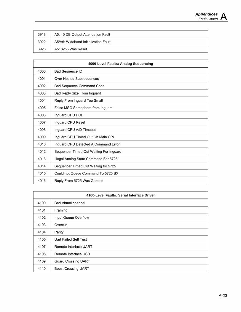
Appendices Fault Codes A
A-23
3918 A5: 40 DB Output Attenuation Fault
3922 A5/A6: Wideband Initialization Fault
3923 A5: 8255 Was Reset
4000-Level Faults: Analog Sequencing
4000 Bad Sequence ID
4001 Over Nested Subsequences
4002 Bad Sequence Command Code
4003 Bad Reply Size From Inguard
4004 Reply From Inguard Too Small
4005 False MSG Semaphore from Inguard
4006 Inguard CPU POP
4007 Inguard CPU Reset
4008 Inguard CPU A/D Timeout
4009 Inguard CPU Timed Out On Main CPU
4010 Inguard CPU Detected A Command Error
4012 Sequencer Timed Out Waiting For Inguard
4013 Illegal Analog State Command For 5725
4014 Sequencer Timed Out Waiting for 5725
4015 Could not Queue Command To 5725 BX
4016 Reply From 5725 Was Garbled
4100-Level Faults: Serial Interface Driver
4100 Bad Virtual channel
4101 Framing
4102 Input Queue Overflow
4103 Overrun
4104 Parity
4105 Uart Failed Self Test
4107 Remote Interface UART
4108 Remote Interface USB
4109 Guard Crossing UART
4110 Boost Crossing UART
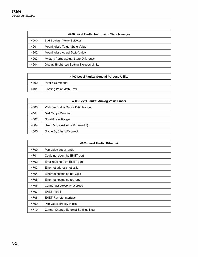
5730A Operators Manual
A-24
4200-Level Faults: Instrument State Manager
4200 Bad Boolean Value Selector
4201 Meaningless Target State Value
4202 Meaningless Actual State Value
4203 Mystery Target/Actual State Difference
4204 Display Brightness Setting Exceeds Limits
4400-Level Faults: General Purpose Utility
4400 Invalid Command
4401 Floating Point Math Error
4500-Level Faults: Analog Value Finder
4500 VFdcDac Value Out Of DAC Range
4501 Bad Range Selector
4502 Non-Vfinder Range
4504 User Range Adjust of 0 (I used 1)
4505 Divide By 0 In (VF)correct
4700-Level Faults: Ethernet
4700 Port value out of range
4701 Could not open the ENET port
4702 Error reading from ENET port
4703 Ethernet address not valid
4704 Ethernet hostname not valid
4705 Ethernet hostname too long
4706 Cannot get DHCP IP address
4707 ENET Port 1
4708 ENET Remote Interface
4709 Port value already in use
4710 Cannot Change Ethernet Settings Now
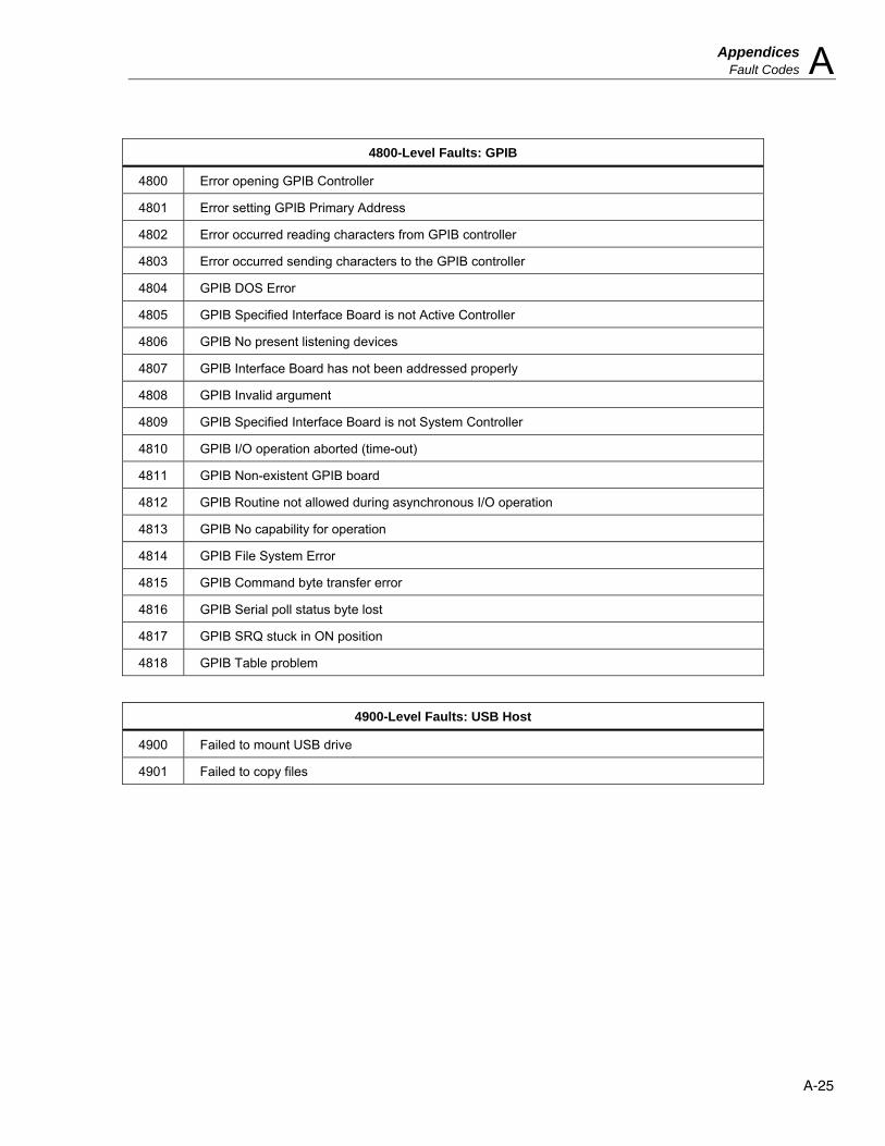
Appendices Fault Codes A
A-25
4800-Level Faults: GPIB
4800 Error opening GPIB Controller
4801 Error setting GPIB Primary Address
4802 Error occurred reading characters from GPIB controller
4803 Error occurred sending characters to the GPIB controller
4804 GPIB DOS Error
4805 GPIB Specified Interface Board is not Active Controller
4806 GPIB No present listening devices
4807 GPIB Interface Board has not been addressed properly
4808 GPIB Invalid argument
4809 GPIB Specified Interface Board is not System Controller
4810 GPIB I/O operation aborted (time-out)
4811 GPIB Non-existent GPIB board
4812 GPIB Routine not allowed during asynchronous I/O operation
4813 GPIB No capability for operation
4814 GPIB File System Error
4815 GPIB Command byte transfer error
4816 GPIB Serial poll status byte lost
4817 GPIB SRQ stuck in ON position
4818 GPIB Table problem
4900-Level Faults: USB Host
4900 Failed to mount USB drive
4901 Failed to copy files

5730A Operators Manual
A-26
5000-Level Faults: 52120A Boost System
5000 Error while reading 52120A cal store
5001 Expected a 52120A but it was gone
5002 52120A cal store corrupted
5003 Value out of range of 52120A
5004 Unknown error reported by 52120A
5005 52120A added or removed
5006 52120A forceably turned off
5007 52120A detected over compliance
5008 52120A detected over range
5009 52120A detected over temperature
65535 Unknown

B-1
Appendix B ASCII and IEEE-488 Bus Codes

5730A Operators Manual
B-2
0123
4567
89
1011
12131415
16171819
20212223
24252627
28293031
32333435
36373839
40414243
44454647
48495051
52535455
56575859
60616263
000001002003
004005006007
010011012013
014015016017
020021022023
024025026027
030031032033
034035036037
040041042043
044045046047
050051052053
054055056057
060061062063
064065066067
070071072073
074075076077
00010203
04050607
08090A0B
0C0D0E0F
10111213
14151617
18191A1B
1C1D1E1F
20212223
24252627
28292A2B
2C2D2E2F
30313233
34353637
38393A3B
3C3D3E3F
0000
0000
0000
0000
0000
0000
0000
0000
0000
0000
0000
0000
0000
0000
0000
0000
0000
0000
0000
0000
0000
0000
0000
0000
0000
0000
0000
0000
0000
0000
0000
0000
0000
0000
0000
0000
0000
0000
0000
0000
1111
1111
1111
1111
1111
1111
1111
1111
0000
0000
0000
0000
1111
1111
1111
1111
1111
1111
1111
1111
0000
0000
1111
1111
0000
0000
1111
1111
0000
0000
1111
1111
0000
0000
1111
1111
0000
1111
0000
1111
0000
1111
0000
1111
0000
1111
0000
1111
0000
1111
0000
1111
0011
0011
0011
0011
0011
0011
0011
0011
0011
0011
0011
0011
0011
0011
0011
0011
0101
0101
0101
0101
0101
0101
0101
0101
0101
0101
0101
0101
0101
0101
0101
0101
ASCIICHAR. DECIMAL OCTAL HEX BINARY
7654 3210DEV.NO.
MESSAGEATN=TRUE
0123
4567
89
1011
12131415
16171819
20212223
24252627
282930
1111
1111
1111
1111
MLAMLAMLAMLA
MLAMLAMLAMLA
MLAMLAMLAMLA
MLAMLAMLAMLA
MLAMLAMLAMLA
MLAMLAMLAMLA
MLAMLAMLAMLA
MLAMLAMLAUNL
64656667
68697071
72737475
76777879
80818283
84858687
88899091
92939495
96979899
100101102103
104105106107
108109110111
112113114115
116117118119
120121122123
124125126127
ASCIICHAR. DECIMAL OCTAL HEX BINARY
7654 3210DEV.NO.
MESSAGEATN=TRUE
100101102103
104105106107
110111112113
114115116117
120121122123
124125126127
130131132133
134135136137
140141142143
144145146147
150151152153
154155156157
160161162163
164165166167
170171172173
174175176177
40414243
44454647
48494A4B
4C4D4E4F
50515253
54555657
58595A5B
5C5D5E5F
60616263
64656667
68696A6B
6C6D6E6F
70717273
74757677
78797A7B
7C7D7E7F
0000
0000
0000
0000
0000
0000
0000
0000
0000
0000
0000
0000
0000
0000
0000
0000
1111
1111
1111
1111
1111
1111
1111
1111
1111
1111
1111
1111
1111
1111
1111
1111
0000
0000
0000
0000
0000
0000
0000
0000
1111
1111
1111
1111
1111
1111
1111
1111
0000
0000
0000
0000
1111
1111
1111
1111
0000
0000
1111
1111
0000
0000
1111
1111
0000
0000
1111
1111
0000
0000
1111
1111
0000
1111
0000
1111
0000
1111
0000
1111
0000
1111
0000
1111
0000
1111
0000
1111
0011
0011
0011
0011
0011
0011
0011
0011
0011
0011
0011
0011
0011
0011
0011
0011
0101
0101
0101
0101
0101
0101
0101
0101
0101
0101
0101
0101
0101
0101
0101
0101
0123
4567
89
1011
12131415
16171819
20212223
24252627
282930
0123
4567
89
1011
12131415
16171819
20212223
24252627
282930
MTAMTAMTAMTA
MTAMTAMTAMTA
MTAMTAMTAMTA
MTAMTAMTAMTA
MTAMTAMTAMTA
MTAMTAMTAMTA
MTAMTAMTAMTA
MTAMTAMTAUNT
MSAMSAMSAMSA
MSAMSAMSAMSA
MSAMSAMSAMSA
MSAMSAMSAMSA
MSAMSAMSAMSA
MSAMSAMSAMSA
MSAMSAMSAMSA
MSAMSAMSAUNS
NULSQHSTXETX
EOTENQACHBELL
BSHTLFVT
FFCRSOSI
DLEDC1DC2DC3
DC4NAKSYNETB
CANEMSUBESC
FSGSRSUS
SPACE!
"#
$%&
'()
*+,_./
0123
4567
89:;
<=>?
@ABC
DEFG
HIJK
LMNO
PQRS
TUVW
XYZ[
\]^_
abc
defg
hijk
lmno
pqrs
tuvw
xyz{
|}~
,
LISTEN
ADDRESSES
0000
0000
0000
0000
GTL
SDCPPC
GETTCT
LLO
DCLPPU
SPESPD
UNIVERSAL
COMMANDS
SECONDARY
ADDRESSES
TALK
ADDRESSES
ADDRESSED
COMMANDS
1111
1111
1111
1111
FB-01.eps

C-1
Appendix C Glossary
adc (analog-to-digital converter) A device or circuit that converts an analog voltage to digital signals.
absolute accuracy Accuracy specifications that include the error contributions made by all equipment and standards used to calibrate the instrument. Absolute accuracy is the number to compare with the UUT for determining test specification ratio.
assert To cause a digital signal line to go into a logic true state.
af (audio frequency) The frequency range of human hearing; normally 15 Hz - 20,000 Hz.
artifact standard An object that produces or embodies a physical quantity to be standardized, for example a Fluke 732B dc Voltage Reference Standard.
base units Units in the SI system that are dimensionally independent. All other units are derived from base units. The only base unit in electricity is the ampere.
buffer Refers to either an area of digital memory for temporary storage of data, or an amplifier stage before the final amplifier.
burden voltage The maximum sustainable voltage across the terminals of a load.
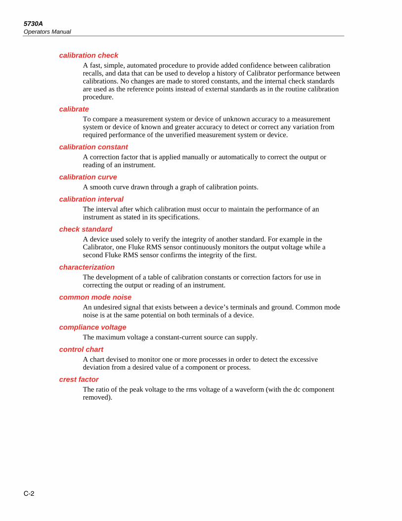
5730A Operators Manual
C-2
calibration check A fast, simple, automated procedure to provide added confidence between calibration recalls, and data that can be used to develop a history of Calibrator performance between calibrations. No changes are made to stored constants, and the internal check standards are used as the reference points instead of external standards as in the routine calibration procedure.
calibrate To compare a measurement system or device of unknown accuracy to a measurement system or device of known and greater accuracy to detect or correct any variation from required performance of the unverified measurement system or device.
calibration constant A correction factor that is applied manually or automatically to correct the output or reading of an instrument.
calibration curve A smooth curve drawn through a graph of calibration points.
calibration interval The interval after which calibration must occur to maintain the performance of an instrument as stated in its specifications.
check standard A device used solely to verify the integrity of another standard. For example in the Calibrator, one Fluke RMS sensor continuously monitors the output voltage while a second Fluke RMS sensor confirms the integrity of the first.
characterization The development of a table of calibration constants or correction factors for use in correcting the output or reading of an instrument.
common mode noise An undesired signal that exists between a device’s terminals and ground. Common mode noise is at the same potential on both terminals of a device.
compliance voltage The maximum voltage a constant-current source can supply.
control chart A chart devised to monitor one or more processes in order to detect the excessive deviation from a desired value of a component or process.
crest factor The ratio of the peak voltage to the rms voltage of a waveform (with the dc component removed).

Appendices Glossary C
C-3
current guard A generator that drives the inner shield of a triaxial cable with a signal of the same amplitude and phase as a Calibrator’s ac current output signal on the center conductor. The current guard shields the Calibrator’s output signal from a capacitive leakage path to ground.
DAC (digital-to-analog converter) A device or circuit that converts a digital waveform to an analog voltage.
dBm Power level expressed as decibels above or below 1 mW.
derived units Units in the SI system that are derived from base units. Volts, ohms, and watts are derived from amperes and other base and derived units.
distortion Undesired changes in the waveform of a signal. Harmonic distortion disturbs the original relationship between a frequency and other frequencies naturally related to it. Intermodulation distortion (imp) introduces new frequencies by the mixing of two or more original frequencies. Other forms of distortion are phase distortion and transient distortion.
errors The different types of errors described in this glossary are: offset error, linearity error, random error, scale error, systematic errors, and transfer error. Each of these are defined in this glossary.
flatness A measure of the variation of the actual output an ac voltage source at different frequency points when set to the same nominal output level. A flat voltage source exhibits very little error throughout its frequency range.
floor The part of the uncertainty specification of an instrument that is typically a fixed offset plus noise. Floor can be expressed as units such as microvolts or counts of the least significant digit. For the Calibrator, the floor specification is combined with fixed range errors in one term.
full scale The maximum reading of a range of a meter, analog-to-digital converter, or other measurement device, or the maximum attainable output on a range of a calibrator.
gain error Same as scale error. Scale or gain error results when the slope of the meter’s response curve is not exactly 1. A meter with only gain error (no offset or linearity error), will read 0V with 0V applied, but something other than 10V with 10V applied.
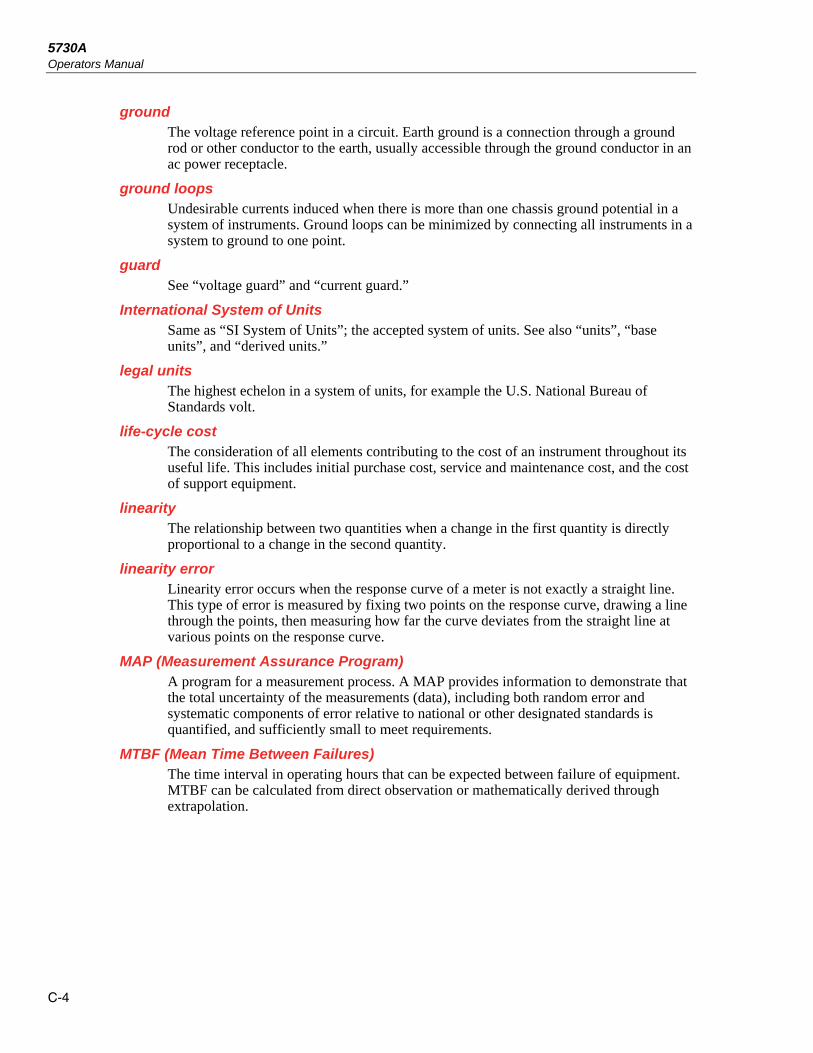
5730A Operators Manual
C-4
ground The voltage reference point in a circuit. Earth ground is a connection through a ground rod or other conductor to the earth, usually accessible through the ground conductor in an ac power receptacle.
ground loops Undesirable currents induced when there is more than one chassis ground potential in a system of instruments. Ground loops can be minimized by connecting all instruments in a system to ground to one point.
guard See “voltage guard” and “current guard.”
International System of Units Same as “SI System of Units”; the accepted system of units. See also “units”, “base units”, and “derived units.”
legal units The highest echelon in a system of units, for example the U.S. National Bureau of Standards volt.
life-cycle cost The consideration of all elements contributing to the cost of an instrument throughout its useful life. This includes initial purchase cost, service and maintenance cost, and the cost of support equipment.
linearity The relationship between two quantities when a change in the first quantity is directly proportional to a change in the second quantity.
linearity error Linearity error occurs when the response curve of a meter is not exactly a straight line. This type of error is measured by fixing two points on the response curve, drawing a line through the points, then measuring how far the curve deviates from the straight line at various points on the response curve.
MAP (Measurement Assurance Program) A program for a measurement process. A MAP provides information to demonstrate that the total uncertainty of the measurements (data), including both random error and systematic components of error relative to national or other designated standards is quantified, and sufficiently small to meet requirements.
MTBF (Mean Time Between Failures) The time interval in operating hours that can be expected between failure of equipment. MTBF can be calculated from direct observation or mathematically derived through extrapolation.
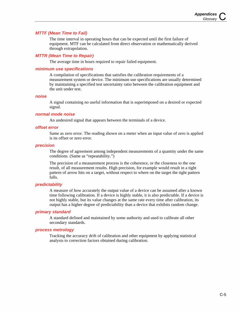
Appendices Glossary C
C-5
MTTF (Mean Time to Fail) The time interval in operating hours that can be expected until the first failure of equipment. MTF can be calculated from direct observation or mathematically derived through extrapolation.
MTTR (Mean Time to Repair) The average time in hours required to repair failed equipment.
minimum use specifications A compilation of specifications that satisfies the calibration requirements of a measurement system or device. The minimum use specifications are usually determined by maintaining a specified test uncertainty ratio between the calibration equipment and the unit under test.
noise A signal containing no useful information that is superimposed on a desired or expected signal.
normal mode noise An undesired signal that appears between the terminals of a device.
offset error Same as zero error. The reading shown on a meter when an input value of zero is applied is its offset or zero error.
precision The degree of agreement among independent measurements of a quantity under the same conditions. (Same as “repeatability.”)
The precision of a measurement process is the coherence, or the closeness to the one result, of all measurement results. High precision, for example would result in a tight pattern of arrow hits on a target, without respect to where on the target the tight pattern falls.
predictability A measure of how accurately the output value of a device can be assumed after a known time following calibration. If a device is highly stable, it is also predictable. If a device is not highly stable, but its value changes at the same rate every time after calibration, its output has a higher degree of predictability than a device that exhibits random change.
primary standard A standard defined and maintained by some authority and used to calibrate all other secondary standards.
process metrology Tracking the accuracy drift of calibration and other equipment by applying statistical analysis to correction factors obtained during calibration.

5730A Operators Manual
C-6
random error Any error which varies in an unpredictable manner in absolute value and in sign when measurements of the same value of a quantity are made under effectively identical conditions.
range The stated upper end of a measurement device’s span. Usually, however, a measurement device can measure quantities for a specified percentage overrange. (The absolute span including overrange capability is called “scale.”) In the Calibrator, however, range and scale are identical.
range calibration An optional calibration procedure available to the enhance the Calibrator specifications by nulling the output to an external standard.
reference amplifier DC voltage references developed for the Calibrator. These are 6.5V hybrid devices consisting of a zener diode and a transistor on a heated substrate. These reference amplifiers exhibit extremely low uncertainty and drift, and are superior to zener diode or temperature-compensated zener diode voltage references.
reference standard The highest-echelon standard in a laboratory; the standard that is used to maintain working standards that are used in routine calibration and comparison procedures.
relative accuracy Calibrator accuracy specifications that exclude the effects of external dividers and standards, for use when range constants are adjusted. Relative uncertainty includes only the stability, temperature coefficient, noise, and linearity specifications of the Calibrator itself.
reliability A measure of the “uptime” of an instrument.
repeatability The degree of agreement among independent measurements of a quantity under the same conditions. (Same as “precision.”)
resistance A property of a conductor that determines the amount of current that will flow when a given amount of voltage exists across the conductor. Resistance is measured in ohms. One ohm is the resistance through which one volt of potential will cause one ampere of current to flow.
resolution The smallest change in quantity that can be detected by a measurement system or device. For a given parameter, resolution is the smallest increment that can be measured, generated or displayed.

Appendices Glossary C
C-7
rf (radio frequency) The frequency range of radio waves; ranging from 150 kHz up to the infrared range.
rms (root-mean-square) The value assigned to an ac voltage or current that results in the same power dissipation in a resistance as a dc current or voltage of the same value.
rms sensor A device that converts ac voltage to dc voltage with great accuracy. RMS sensors operate by measuring the heat generated by a voltage through a known resistance (for example, power); therefore, they sense true rms voltage.
scale The absolute span of the reading range of a measurement device including overrange capability.
scale error Same as gain error. Scale or gain error results when the slope of the meter’s response curve is not exactly 1. A meter with only scale error (no offset or linearity error), will read 0 V with 0 V applied, but something other than 10 V with 10 V applied.
secondary standard A standard maintained by comparison against a primary standard.
sensitivity The degree of response of a measuring device to the change in input quantity, or a figure of merit that expresses the ability of a measurement system or device to respond to an input quantity.
shield A grounded covering device designed to protect a circuit or cable from electromagnetic interference.
SI System of Units The accepted International System of Units. See also “units”, “base units”, and “derived units.”
stability A measure of the freedom from drift in value over time and over changes in other variables such as temperature. Note that stability is not the same as uncertainty.
5730A Operators Manual
C-8
standard A device that is used as an exact value for reference and comparison.
standard cell A primary cell that serves as a standard of voltage. The term “standard cell” often refers to a “Weston normal cell”, which is a wet cell with a mercury anode, a cadmium mercury amalgam cathode, and a cadmium sulfate solution as the electrolyte.
systematic errors Errors in repeated measurement results that remain constant or vary in a predictable way.
temperature coefficient A factor per °C deviation from a nominal value or range that the uncertainty of an instrument increases. This specification is necessary to account for the thermal coefficients in a calibrator’s analog circuitry.
test uncertainty ratio The numerical ratio of the uncertainty of the measurement system or device being calibrated to the uncertainty of the measurement system or device used as the Calibrator. (Also called “test accuracy ratio.”)
thermal emf The voltage generated when two dissimilar metals joined together are heated.
traceability The ability to relate individual measurement results to national standards or nationally accepted measurement systems through an unbroken chain of comparisons, for example, a calibration “audit trail.”
Measurements, measurement systems or devices have traceability to the designated standards if and only if scientifically rigorous evidence is produced on a continuing basis to show that the measurement process is producing measurement results for which the total measurement uncertainty relative to national or other designated standards is qualified.
transfer error The sum of all new errors induced during the process of comparing one quantity against another.
transfer standard Any working standard used to compare a measurement process, system or device at one location or level with another measurement process, system, or device at another location or level.
transport standard A transfer standard that is rugged enough to allow shipment by common carrier to another location.

Appendices Glossary C
C-9
true value Also called legal value, the accepted, consensus, (for example, the correct value of the quantity being measured).
uncertainty The maximum difference between the accepted, consensus, or true value and the measured value of a quantity. Uncertainty is normally expressed in units of ppm (parts per million) or as a percentage. (Accuracy is the same as 1 - % uncertainty.)
units Symbols or names that define the measured quantities. Examples of units are: V, mV, A, kW, and dBm. See also “SI System of Units.”
volt The unit of emf (electromotive force) or electrical potential in the SI system of units. One volt is the difference of electrical potential between two points on a conductor carrying one ampere of current, when the power being dissipated between these two points is equal to one watt.
watt The unit of power in the SI system of units. One watt is the power required to do work at the rate of one joule/second. In terms of volts and ohms, one watt is the power dissipated by one ampere flowing through a 1Ω load.
wideband AC voltage at frequencies up to and including the radio frequency spectrum.
verification Checking the functional performance and uncertainty of an instrument or standard without making adjustments to it or changing its calibration constants.
voltage guard A floating shield around voltage measurement circuitry inside an instrument. The voltage guard provides a low-impedance path to ground for common-mode noise and ground currents, thereby eliminating errors introduced by such interference.
working standard A standard that is used in routine calibration and comparison procedures in the laboratory, and is maintained by comparison to reference standards.
zero error Same as offset error. The reading shown on a meter when an input value of zero is applied is its zero or offset error.

5730A Operators Manual
C-10