5080A/MEG - Fluke Calibration
28
September 2010 © 2010 Fluke Corporation. All rights reserved. Printed in USA. Specifications are subject to change without notice. All product names are trademarks of their respective companies. 5080A/MEG Megohm Option Users Manual
-
Upload
khangminh22 -
Category
Documents
-
view
1 -
download
0
Transcript of 5080A/MEG - Fluke Calibration

September 2010 © 2010 Fluke Corporation. All rights reserved. Printed in USA. Specifications are subject to change without notice. All product names are trademarks of their respective companies.
5080A/MEG Megohm Option
Users Manual

LIMITED WARRANTY AND LIMITATION OF LIABILITY
Each Fluke product is warranted to be free from defects in material and workmanship under normal use and service. The warranty period is one year and begins on the date of shipment. Parts, product repairs, and services are warranted for 90 days. This warranty extends only to the original buyer or end-user customer of a Fluke authorized reseller, and does not apply to fuses, disposable batteries, or to any product which, in Fluke's opinion, has been misused, altered, neglected, contaminated, or damaged by accident or abnormal conditions of operation or handling. Fluke warrants that software will operate substantially in accordance with its functional specifications for 90 days and that it has been properly recorded on non-defective media. Fluke does not warrant that software will be error free or operate without interruption.
Fluke authorized resellers shall extend this warranty on new and unused products to end-user customers only but have no authority to extend a greater or different warranty on behalf of Fluke. Warranty support is available only if product is purchased through a Fluke authorized sales outlet or Buyer has paid the applicable international price. Fluke reserves the right to invoice Buyer for importation costs of repair/replacement parts when product purchased in one country is submitted for repair in another country.
Fluke's warranty obligation is limited, at Fluke's option, to refund of the purchase price, free of charge repair, or replacement of a defective product which is returned to a Fluke authorized service center within the warranty period.
To obtain warranty service, contact your nearest Fluke authorized service center to obtain return authorization information, then send the product to that service center, with a description of the difficulty, postage and insurance prepaid (FOB Destination). Fluke assumes no risk for damage in transit. Following warranty repair, the product will be returned to Buyer, transportation prepaid (FOB Destination). If Fluke determines that failure was caused by neglect, misuse, contamination, alteration, accident, or abnormal condition of operation or handling, including overvoltage failures caused by use outside the product’s specified rating, or normal wear and tear of mechanical components, Fluke will provide an estimate of repair costs and obtain authorization before commencing the work. Following repair, the product will be returned to the Buyer transportation prepaid and the Buyer will be billed for the repair and return transportation charges (FOB Shipping Point).
THIS WARRANTY IS BUYER'S SOLE AND EXCLUSIVE REMEDY AND IS IN LIEU OF ALL OTHER WARRANTIES, EXPRESS OR IMPLIED, INCLUDING BUT NOT LIMITED TO ANY IMPLIED WARRANTY OF MERCHANTABILITY OR FITNESS FOR A PARTICULAR PURPOSE. FLUKE SHALL NOT BE LIABLE FOR ANY SPECIAL, INDIRECT, INCIDENTAL, OR CONSEQUENTIAL DAMAGES OR LOSSES, INCLUDING LOSS OF DATA, ARISING FROM ANY CAUSE OR THEORY.
Since some countries or states do not allow limitation of the term of an implied warranty, or exclusion or limitation of incidental or consequential damages, the limitations and exclusions of this warranty may not apply to every buyer. If any provision of this Warranty is held invalid or unenforceable by a court or other decision-maker of competent jurisdiction, such holding will not affect the validity or enforceability of any other provision.
Fluke Corporation P.O. Box 9090 Everett, WA 98206-9090 U.S.A.
Fluke Europe B.V. P.O. Box 1186 5602 BD Eindhoven The Netherlands
11/99

i
Table of Contents
Title Page
Introduction........................................................................................................ 1 General Specifications ....................................................................................... 1 Detailed Specifications ...................................................................................... 2
Low Resistance Source.................................................................................. 2 High Resistance Source................................................................................. 3 18.24 GΩ Single-Value Output ..................................................................... 3 Short Mode for Megohm Meters ................................................................... 3
How to Prepare the Calibrator for Operation..................................................... 4 How to Calibrate Instruments ............................................................................ 4
How to Set the High Resistance Source Output ............................................ 4 How to Set the Short Mode Output ............................................................... 5 How to Set the Single Output Value ............................................................. 6 How to Set the High Resistance Source Output with Multiplier................... 6
How to Determine R1 and R2 Values of the Multiplier............................ 6 How to Enter the Multiplier Variables into the Calibrator........................ 6 How to Set the High Resistance Output.................................................... 7
How to Set the Low Resistance Source Output............................................. 8 Applications ....................................................................................................... 9
How to Calibrate Continuity Testers ............................................................. 9 How to Calibrate Insulation Testers .............................................................. 10 How to Calibrate Insulation Testers with the Resistance Multiplier ............. 13
Remote Commands and Queries........................................................................ 15 MEGOHM Verification Tests............................................................................ 17

5080A/MEG Users Manual
ii

iii
List of Tables
Table Title Page
1. Overlapped and Coupled Commands..................................................................... 16 2. Megohm Option LVR Verification Points ............................................................. 17 3. Megohm Option Short Verification Points ............................................................ 17 4. Megohm Option HVR Verification Points............................................................. 18 5. Megohm Option S18G Verification Points ............................................................ 19

5080A/MEG Users Manual
iv

v
List of Figures
Figure Title Page
1. Simplified High Resistance Source Schematic ...................................................... 5 2. Multiplier to Calibrator Connections ..................................................................... 8 3. Resistance Calibration UUT Connections.............................................................. 10 4. Calibrating Insulation Resistance of an Insulation Tester...................................... 11 5. Calibrating Insulation Resistance of a Handheld Insulation Tester ....................... 11 6. Calibrating Insulation Resistance of a Portable Tester .......................................... 12 7. Calibrating Insulation Resistance of an Electrical Safety Analyzer....................... 12 8. Calibrating a Megohm Meter ................................................................................. 13 9. Connections to Bench Tester with a Resistance Multiplier Adapter...................... 14 10. Connections to 1550B with a Resistance Multiplier Adapter ................................ 15

5080A/MEG Users Manual
vi

1
Introduction The Megohm Calibration Option (the Megohm Option) provides functions that help you maintain some electrical safety testers, such as megohm meters/insulation testers. Some examples of these testers are:
• Megohm meters/Insulation testers • Ground bond testers • Loop testers • Appliance testers • Electrical installation testers • Earth resistance meters
When this Megohm Option is installed in the 5080A Calibrator (the Calibrator), high and low resistance values and some high power low value resistances can be sourced at the Megohm Option terminals.
General Specifications All specifications are valid after a warm-up period of 30 minutes, or twice the time since last warmed up, to a maximum of 30 minutes. For example, if the 5080A has been turned off for 5 minutes, the warm-up period is 10 minutes.
Specifications include stability, temperature coefficient, linearity, line and local regulation, and the traceability of the external standards used for calibration. It is not necessary to add anything to determine the total specification for the temperature range indicated.
Specification Confidence Level........................... 99 %
Warmup Time ........................................................ Twice the time since last warmed up, to a maximum of 30 minutes.
Temperature
Operating ............................................................ 0 °C to 50 °C
Calibration (tcal).................................................. 15 °C to 35 °C
Storage ............................................................... -20 °C to +70 °C
Temperature Coefficient....................................... Temperature coefficient for temperatures outside tcal ±5 °C is 10 % of the stated specification per °C for temperatures in the range of 0 °C to 35 °C. Above 35 °C, the temperature coefficient is 20 % of the stated specification per °C.
Relative Humidity
Operating ............................................................ <80 % to 30 °C, <70 % to 40 °C, <40 % to 50 °C.
Storage ............................................................... <95 %, non-condensing
Altitude
Operating ............................................................ 2,000 m (6,500 ft) maximum
Non-operating ..................................................... 12,200 m (40,000 ft) maximum

5080A/MEG Users Manual
2
Detailed Specifications Low Resistance Source Range ..................................................................... 1 Ω to 5.9 kΩ
Test Voltage Measurement
Resolution........................................................... 0.1 V
Specification ....................................................... ±(1.2 % of input ±0.2 V)
Settling Time ......................................................... 1 second for input deviations of <5 %
Test Current Measurement Specification ........... ±((1.2 % + RS %) of input ±0.2 V/R) A, where RS is the resistance specification, and R is the resistance
Specification of Characterized Value tcal ±5 °C, ±(% of value) Nominal Value
Maximum Continuous
Test Current [1]
Maximum Deviation from Nominal Value
(± ±(% of value) 90 days 1 year
1 Ω 700 mA 20 % 1.10 % 1.10 %
1.8 Ω 610 mA 10 % 0.78 % 0.78 %
3.7 Ω 550 mA 7 % 0.57 % 0.57 %
5.9 Ω 510 mA 7 % 0.49 % 0.49 %
10 Ω 440 mA 5 % 0.45 % 0.45 %
18 Ω 330 mA 5 % 0.42 % 0.42 %
37 Ω 230 mA 5 % 0.41 % 0.41 %
59 Ω 170 mA 5 % 0.48 % 0.48 %
100 Ω 140 mA 5 % 0.45 % 0.45 %
180 Ω 105 mA 5 % 0.42 % 0.42 %
370 Ω 73 mA 5 % 0.41 % 0.41 %
590 Ω 53 mA 5 % 0.34 % 0.34 %
1 kΩ 44 mA 5 % 0.30 % 0.30 %
1.8 kΩ 30 mA 5 % 0.22 % 0.22 %
3.7 kΩ 15 mA 5 % 0.14 % 0.14 %
5.9 kΩ 9 mA 5 % 0.10 % 0.10 %
[1] Exceeding the maximum current limits will cause the Calibrator to disconnect the output terminals and display an error message.

Megohm Option Detailed Specifications
3
High Resistance Source Range ..................................................................... 10 kΩ to 10.05 GΩ
Resolution ............................................................. 4 digits (continuously variable for 10 kΩ to 10.05 GΩ
Test Voltage Measurement
Range ................................................................. 0 to 1575 V peak
Resolution........................................................... 1 V
Specification ....................................................... ±(3.0 % of input ±5 V)
Settling Time ......................................................... 2 seconds for input deviations of <5 %
Test Current Measurement Specification ........... ±(3.0 % + RS %) of input ±5 V/R A, where RS is the resistance specification, and R is the resistance
Specification and Maximum Ratings Specification (tcal ±5 °C, ± of output)
Range Resolution Maximum Voltage [1]
90 days 1 year
10.00 to 19.99 kΩ 10 Ω 140 V 0.20% 0.20 %
20.00 to 39.99 kΩ 10 Ω 200 V 0.20 % 0.20 %
40.00 to 99.99 kΩ 10 Ω 400 V 0.20 % 0.20 %
100.0 to 499.9 kΩ 100 Ω 800 V 0.20 % 0.20 %
500.0 to 999.9 kΩ 100 Ω 1100 V 0.20 % 0.20 %
1.000 to 9.999 MΩ 1 kΩ 1575 V 0.30 % 0.30 %
10.00 to 99.99 MΩ 10 kΩ 1575 V 0.50 % 0.50 %
100.0 to 999.9 MΩ 100 kΩ 1575 V 0.50 % 0.50 %
1.000 to 10.050 GΩ 1 MΩ 1575 V 1.00 % 1.00 %
[1] Exceeding the maximum voltage limits will cause the Calibrator to disconnect the output terminals and display an error message.
18.24 GΩ Single-Value Output Range ..................................................................... 18.24 GΩ single output
Test Voltage Measurement
Range ................................................................. 0 to 1575 V peak
Resolution........................................................... 1 V
Specification ....................................................... ±(3.0 % of input ±5 V)
Settling Time ......................................................... 2 seconds for input deviations of <5 %
Test Current Measurement Specification ........... ±(3.1 % of input ±1 nA)
Specification and Maximum Ratings
Nominal Value Maximum Voltage [1]
Maximum Deviation from Nominal Value
Specification, 1 year, tcal ±5 °C, ±(% of output)
18.24 GΩ 1575 V ±5 % 3.0 %
[1] Exceeding the maximum voltage limits will cause the Calibrator to disconnect the output terminals and display an error message.
Short Mode for Megohm Meters Nominal Resistance.............................................. <100 Ω
Test Current Measurement
Range ................................................................. 100 mA DC peak
Resolution........................................................... 0.1 mA
Specification ....................................................... ±(1.8 % of input ±3.4 mA)
Settling Time ......................................................... 1 second for input deviation of <5 %
Test Voltage Measurement Specification ........... ±(1.2 % of input ±0.2 V)
Note
Exceeding the maximum current limits will cause the Calibrator to disconnect the output terminals and display an error message.

5080A/MEG Users Manual
4
How to Prepare the Calibrator for Operation Refer to the 5080A Operators Manual for calibrator warm-up times.
How to Calibrate Instruments To activate or deactivate the Megohm Option, push d. An indicator on the button illuminates when the Megohm Option is active. If the Megohm Option is not installed in the Calibrator, an error message is displayed when d is pushed.
The Megohm Option has the following modes:
• High Resistance Source (HVR) • Short Mode (for Megohm Meters) • Low Resistance Source (LVR) • 18.24 GΩ (single value) • High Resistance Source x 1000 (MULTI)
The resistance for all five functions is sourced across the MEGOHM HI and LO terminals of the Calibrator. The LO terminal can be either floating or grounded. When grounded, the LO terminal is connected to earth ground through the ground in the AC power input module through an internal relay. Refer to the “When to Use EARTH” section of the 5080A Operators Manual for details about this feature. When floating, the LO terminal is connected to the earth ground through the protection parts. The voltage between the LO terminal and the earth ground should not be over 20 volts. Voltages higher than 20 volts will cause a measurement error due to the leakage current.
How to Set the High Resistance Source Output To source a high resistance with the Megohm Option:
1. If not already active, push d.
2. Push the softkey labeled MODE until hvr appears above the right-most Calibrator softkey.
3. Type a value through the keypad or turn the rotary knob to set the resistance at the MEGOHM terminals.
Note
The 3-wire mode is sometimes necessary to improve calibration stability. This is especially true for resistances over 100 MΩ. The third terminal is usually connected to the guard or ground terminal on the UUT. If the UUT is equipped with a ground (GND) terminal, it should be connected to AUX EARTH GROUND terminal on the Calibrator’s rear panel.
4. Connect the UUT’s terminals to the Calibrator’s MEGOHM terminals.
5. After confirming the settings and connections are correct, push O to connect the UUT to the selected resistance. See Figure 1 for simplified schematic of this connection.

Megohm Option How to Calibrate Instruments
5
R
OUTPUT V, HIΩ, mA~
HI LO
ehq011.eps
Figure 1. Simplified High Resistance Source Schematic
While connected to the UUT, the Calibrator monitors the voltage across the resistance (MEAS V) as well as the current through it (MEAS A). If the voltage across the resistance exceeds acceptable limits (LIMIT V), the Calibrator disconnects the output terminals and displays an error message.
gjk001.eps
With the Calibrator in Operate mode, the resistance across the MEGOHM terminals can be changed through the keypad or the rotary knob.
6. Push Y to put the Megohm function in standby and disconnect the UUT from the resistance. The MEAS V and MEAS A values change to “-----” when the Calibrator is in standby mode.
How to Set the Short Mode Output The Short Mode shorts the Calibrator’s MEGOHM terminals to test a UUT’s maximum test current.
To set the Megohm Option to Short Mode:
1. If not already active, push d.
2. Push the softkey labeled MODE until short appears above the right-most Calibrator softkey.
3. Connect the UUT’s terminals to the Calibrator’s terminals.
4. Push O to connect the UUT to the short.
While connected to the UUT, the Calibrator monitors the voltage appearing across the short (MEAS V) as well as the current through it (MEAS A). If the current through the short exceeds acceptable limits (LIMIT A), the Calibrator disconnects the output terminals and displays an error message.
gjk002.eps
5. Push Y to put the Megohm function in standby and disconnect the UUT from the

5080A/MEG Users Manual
6
short. The MEAS V and MEAS A values change to “-----” when the Calibrator is in standby mode.
How to Set the Single Output Value The Single Output Value mode places a resistance of 18.24 GΩ across the MEGOHM terminals.
To set the Megohm Option to the Single Output Value:
1. If not already active, push d.
2. Push the softkey labeled MODE until 18G appears above the right-most Calibrator softkey.
3. Connect the UUT’s terminals to the Calibrator’s terminals.
4. Push O to connect the UUT to the resistance.
While connected to the UUT, the Calibrator monitors the voltage appearing across the resistance (MEAS V) as well as the current through it (MEAS A). If the voltage across the resistance exceeds acceptable limits (LIMIT V), the Calibrator disconnects the output terminals and displays an error message.
gjk003.eps
5. Push Y to put the Megohm function in standby and disconnect the UUT from the resistance. The MEAS V and MEAS A values change to “-----” when the Calibrator is in standby mode.
How to Set the High Resistance Source Output with Multiplier The Fluke 5320A High Resistance Multiplier extends the Calibrator’s high resistance range to 10 TΩ. Before you use the resistance multiplier, the multipliers characteristic resistance values must be typed in to the Calibrator to calculate the correct resistance at the resistance multipliers input terminals.
How to Determine R1 and R2 Values of the Multiplier To determine the correct R1 and R2 values for the multiplier:
1. With a Fluke 8508A Reference Multimeter or equivalent, set the meter to 2 GΩ range.
2. Connect the 2W HI meter input to the HI jack (HI Ω Multiplier) on the back of the HV Adapter/R Multiplier.
3. Connect the 2W LO meter input to the Input HI jack on the front of the HV Adapter/R Multiplier.
4. Record the measurement on the meter as R1.
5. Set the meter to the 2 MΩ range.
6. Move the lead connected to the 2W LO input of the meter from the Input HI jack to the COM/GUARD jack on the front of the HV Adapter/R Multiplier.
7. Record the measurement on the meter as R2.

Megohm Option How to Calibrate Instruments
7
Note
The Resistance Multiplier can only be used with insulation testers that have a third terminal, commonly called the Guard terminal.
1. If not already active, push d.
2. Push the softkey labeled MODE until multi appears above the right-most Calibrator softkey.
Note
The minimum resistance value available in the multiplier mode is 350 MΩ.
There are two multiplier calibration constants the Calibrator uses to calculate output resistance to the resistance multiplier: R1 and R2. The current R1 and R2 values are shown in the multiplier mode window.
gjk004.eps
If the values shown under the R1 and R2 are not correct:
1. Push S.
2. Next, push the softkey labeled INSTMT SETUP.
3. Next, push the softkey labeled OUTPUT SETUP.
4. Next, push the softkey labeled SET MULTI.
5. Depending on which variable to set, push the softkey labeled R1, R2, or Rs.
6. Enter the variable value through the Calibrator keypad and push E.
Repeat steps 5 and 6 for each variable you want to change.
Note
Rs sets the input resistance of the sense terminal of the UUT. For optimum performance, the factory default setting for Rs is 0 ohms.
To return to the multi menu, push P multiple times until you reach the display.
Store or discard the changes after you change the setup parameters.
How to Set the High Resistance Output To set the Megohm Option to the Multiplier mode:
1. If not already active, push d.
2. Push the softkey labeled MODE until multi appears above the right-most Calibrator softkey.
3. Connect the multiplier to the Calibrator as shown in Figure 2.

5080A/MEG Users Manual
8
Fluke 5080A
Fluke 5320A kVDivider/R Multiplier
Back
To AuxEarth GroundRear Panel
gjk015.eps
Figure 2. Multiplier to Calibrator Connections
4. Connect the UUT’s terminals to the Multiplier’s input terminals.
5. Through the Calibrator keypad, type in the High Resistance Output value or the rotary knob until the value appears in the display.
6. Push O to connect the UUT to the resistance.
With the Calibrator in Operate mode, the resistance across the multiplier terminals can be changed through the keypad or the rotary knob.
7. Push Y to put the Megohm function in standby and disconnect the UUT from the resistance.
How to Set the Low Resistance Source Output The Low Resistance Source Output mode places one of a number of discrete resistances across the MEGOHM terminals. See the Low Resistance Source uncertainty and maximum ratings table in the specifications section for the list of selectable resistances.
To set the Megohm Option to the Low Resistance Source mode:
1. If not already active, push d.
2. Push the softkey labeled MODE until lvr appears above the right-most Calibrator softkey.
3. Connect the UUT’s terminals to the Calibrator’s MEGOHM terminals.
4. Type in one of the discrete resistance values through the Calibrator’s keypad.
Note
To review the list of valid resistance values, push the softkey labeled LIST VALUE. Once you decide on a resistance value, push P to return to the lvr menu and type in the value.
5. Push O to connect the UUT to the resistance.

Megohm Option Applications
9
While connected to the UUT, the Calibrator monitors the voltage appearing across the resistance (MEAS V) as well as the current through it (MEAS A). If the current across the resistance exceeds acceptable limits (LIMIT A), the Calibrator disconnects the output terminals and displays an error message.
gjk006.eps
Note
The allowed resistance values are discrete values and therefore the rotary knob can not be used to change the resistance value at the MEGOHM terminals.
6. Push Y to put the Megohm function in standby and disconnect the UUT from the resistance. The MEAS V and MEAS A values change to “-----” when the Calibrator is in standby mode.
Note
To show the UUT error using the rotary knob, refer to the Editing and Error Output Settings section in Chapter 4 of the 5080A Operators Manual.
Applications This section shows several typical applications of the Megohm Calibration Option to help better understand how to use the Megohm Option.
How to Calibrate Continuity Testers Continuity is a low-ohms function typically found on most electrical testers. Insulation testers and installation testers are two instruments that use a low-ohms function.
To perform a 2-wire resistance calibration:
1. Push d.
2. Push the softkey labeled MODE until lvr appears above the right-most Calibrator softkey.
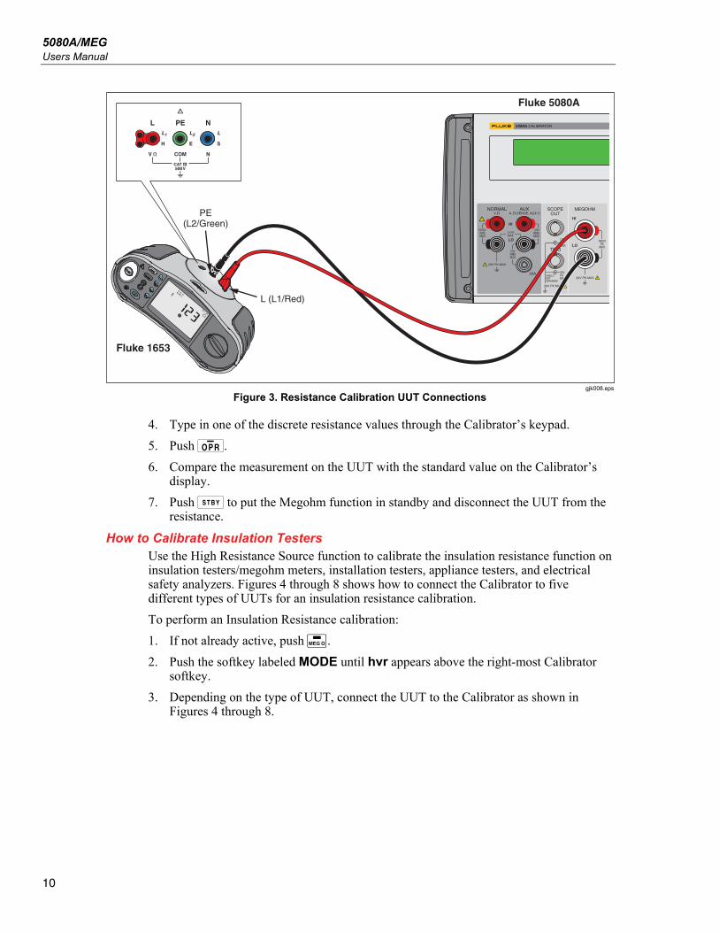
3. Connect the UUT to the Calibrator as shown in Figure 3.
5080A/MEG Users Manual
10
Fluke 1653
L (L1/Red)
Fluke 5080A
PE(L2/Green)
gjk008.eps
Figure 3. Resistance Calibration UUT Connections
4. Type in one of the discrete resistance values through the Calibrator’s keypad.
5. Push O.
6. Compare the measurement on the UUT with the standard value on the Calibrator’s display.
7. Push Y to put the Megohm function in standby and disconnect the UUT from the resistance.
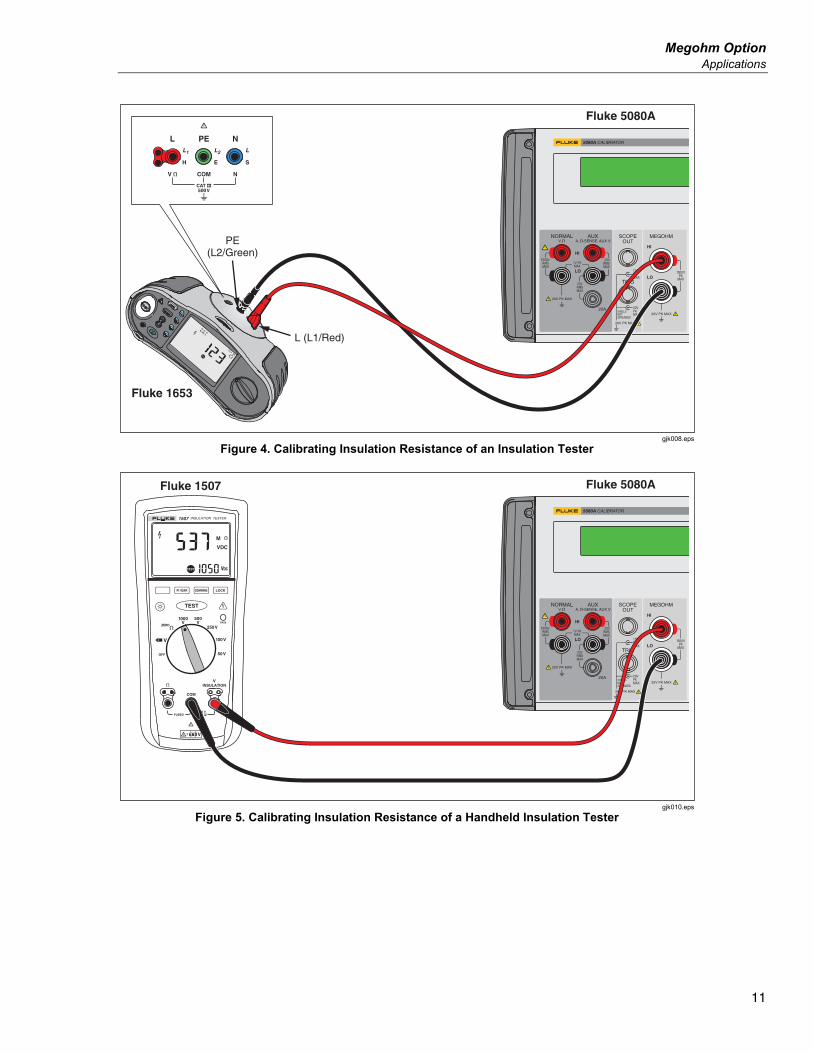
How to Calibrate Insulation Testers Use the High Resistance Source function to calibrate the insulation resistance function on insulation testers/megohm meters, installation testers, appliance testers, and electrical safety analyzers. Figures 4 through 8 shows how to connect the Calibrator to five different types of UUTs for an insulation resistance calibration.
To perform an Insulation Resistance calibration:
1. If not already active, push d.
2. Push the softkey labeled MODE until hvr appears above the right-most Calibrator softkey.
3. Depending on the type of UUT, connect the UUT to the Calibrator as shown in Figures 4 through 8.
Megohm Option Applications
11
Fluke 1653
L (L1/Red)
Fluke 5080A
PE(L2/Green)
gjk008.eps
Figure 4. Calibrating Insulation Resistance of an Insulation Tester
INSULATION TESTER1507
Fluke 1507 Fluke 5080A
gjk010.eps
Figure 5. Calibrating Insulation Resistance of a Handheld Insulation Tester

5080A/MEG Users Manual
12
6500 APPLIANCE TESTER
Fluke 6500
Fluke 5080A
gjk011.eps
Figure 6. Calibrating Insulation Resistance of a Portable Tester
Kikusui 7200
Fluke 5080A
gjk012.eps
Figure 7. Calibrating Insulation Resistance of an Electrical Safety Analyzer

Megohm Option Applications
13
FUNCTION
ON/OFF
UPSCROLL
IRDAPORT
DOWNENTER
TEST
Fluke 1550B
Fluke 5080A
To AuxEarth GroundRear Panel
gjk014.eps
Figure 8. Calibrating a Megohm Meter
Note
To avoid ground loops and noise, use only one earth ground-to-LO terminal connection in the system. Verify the EARTH annunciator is off, when the guard or the ground terminal of the UUT is connected to the AUX EARTH GROUND terminal on the rear-panel of the Calibrator.
4. Type in a value through the keypad or turn the rotary knob to set the resistance at the MEGOHM terminals.
5. Set the test voltage on the UUT.
6. Push O.
7. Push the UUT’s start or test button to activate the measurement.
The standard resistor is now applied to the output terminals. The test voltage and current generated by the UUT is measured by the Calibrator and shows in the display. Compare the measurement on the UUT with the standard value shown in the display of the Calibrator.
8. Stop the test by releasing the appropriate UUT test button.
9. Push Y to disconnect the UUT from the Calibrator.
How to Calibrate Insulation Testers with the Resistance Multiplier
Note
For some megohmmeters, when you use the resistance multiplier adapter the HI terminal on the Calibrator must be attached to the LO terminal on the Multiplier. The LO terminal on the Calibrator must be attached to the HI terminal on the Multiplier. Earth must be activated when you swap HI and LO lead positions in the high ohms resistance function.

5080A/MEG Users Manual
14
The Resistance Multiplier can only be used with megohm meters that have a third terminal, commonly called the Guard terminal.
Note
To avoid ground loops and noise, use only one earth ground-to-LO terminal connection in the system. Verify the EARTH annunciator is off, when the guard or the ground terminal of the UUT is connected to the AUX EARTH GROUND terminal on the rear-panel of the Calibrator.
To make an Insulation Resistance calibration with the Resistance Multiplier:
1. If not already active, push d.
2. Push the softkey labeled MODE until multi appears above the right-most Calibrator softkey.
3. Depending on the type of UUT, connect the UUT to the Calibrator as shown in Figures 0-9 and 0-10.
Fluke 5320A kV Divider/R Multiplier
Front Back
Fluke 5080A
To AuxEarth GroundRear Panel
gjk013.eps
Figure 9. Connections to Bench Tester with a Resistance Multiplier Adapter

Megohm Option Remote Commands and Queries
15
FUNCTION
ON/OFF
UPSCROLL
IRDAPORT
DOWNENTER
TEST
Fluke 1550B
Fluke 5320A kV Divider/R Multiplier
Front Back
Fluke 5080A
To AuxEarth GroundRear Panel
gjk014.eps
Figure 10. Connections to 1550B with a Resistance Multiplier Adapter
4. Type in the High Resistance Output value through the Calibrator keypad or turn the rotary knob until the value shows in the display.
5. Set the test voltage on the UUT.
6. Push O to connect the UUT to the resistance.
7. Push the UUT’s start or test button to activate the measurement.
The standard resistor is now applied to the output terminals. Compare the measurement on the UUT with the standard value shown in the display of the Calibrator.
8. Stop the test by releasing the appropriate UUT test button.
9. Push Y to disconnect the UUT from the Calibrator.
Remote Commands and Queries This section describes commands and queries that are used for the Megohm Option. Each command falls into one or more command categories: Sequential, Overlapped, or Coupled.
Sequential Commands – Commands executed immediately as they are encountered in the data stream are called sequential commands. For more information, see “Sequential Commands” in Chapter 5 of the 5080A Operators Manual.

5080A/MEG Users Manual
16
Overlapped Commands – Commands that require additional time to execute are called overlapped commands because they can overlap the next command before completing execution. To be sure an overlapped command is not interrupted during execution, use the *OPC, *OPC?, and *WAI commands to detect command completion. See Table 6-8 for all the commands that are classified as overlapped. For more information, see “Overlapped Commands” in Chapter 5 of the 5080A Operators Manual.
Coupled Commands – These are called coupled commands (examples: CUR_POST and OUT) because they “couple” in a compound command sequence. Care must be taken to be sure the action of one command does not disable the action of a second command and thereby cause a fault. See Table 6-8 for all the commands that are classified as coupled. For more information, see “Coupled Commands” in Chapter 5 of the 5080A Operators Manual.
Table 1. Overlapped and Coupled Commands
Command Overlapped Coupled
MEGO(?) Yes No
MGSETUP(?) No No
MGMEAS? No No
MEGO(?) <value > Description Programs the 5080A to use the Megohm Option, if installed.
Parameters <value> = OFF Turns the Megohm option off. Programs 0 V, 0 Hz output at the NORMAL terminals.
HVR Sets High Voltage Resistance mode.
SHORT Sets Short Circuit mode.
S18G Sets Single Output Value mode.
MULTI Sets Multiplier mode.
LVR Sets Low Voltage Resistance mode.
Example MEGO HVR Sets the Megohm option to High Voltage Resistance mode.
Query MEGO? Returns the mode of the Megohm option (OFF, HVR, SHORT, S18G, MULTI, or LVR).
MGSETUP(?) <value > Description Sets the parameters for the multiplier in the Megohm option.
Parameters <value> = R2 Value, R1 Value, Rs Value Example MGSETUP 300.0 KOHM, 300.0 MOHM, 0.0 MOHM
Sets R2 to 300.0 kΩ, R1 to 300.0 MΩ, Rs to 0.0 Ω
Query MGSETUP? Returns the programmed parameters for the Megohm option.
Returns 3.000e+05, 3.000e+08, 0.000e+00
MGMEAS? Description Returns the measured values of the MegOhm option.
Query MGMEAS? Returns 1000, 0.100E-3. That is 1000 V for MEAS V, and 0.1 mA for MEAS A.

Megohm Option MEGOHM Verification Tests
17
MEGOHM Verification Tests Before the Megohm Option leaves the Fluke factory, it is verified to meet its specifications. The verification test points provided in Tables 2 through 5 are to be used as a guide when re-verification is desired. There is no built-in factor for measurement uncertainty.
Note
Verification should be performed by qualified metrology personnel who have access to a properly equipped standards laboratory to test calibration equipment of this level of accuracy.
Table 2. Megohm Option LVR Verification Points
Reading Nominal Value Tolerance
Min. Max.
Max. Deviation from Characterized Value
1 Ω 0.2 Ω 800.00 mΩ 1.2 Ω ±0.011 Ω
1.8 Ω 0.18 Ω 1.62 Ω 1.98 Ω ±0.014 Ω
3.7 Ω 0.259 Ω 3.441 Ω 3.959 Ω ±0.021 Ω
5.9 Ω 0.413 Ω 5.487 Ω 6.313 Ω ±0.029 Ω
10 Ω 0.5 Ω 9.5 Ω 10.50 Ω ±0.45 Ω
18 Ω 0.9 Ω 17.1 Ω 18.90 Ω ±0.075 Ω
37 Ω 1.85 Ω 35.15 Ω 38.85 Ω ±0.150 Ω
59 Ω 2.95 Ω 56.05 Ω 61.95 Ω ±0.28 Ω
100 Ω 5 Ω 95 Ω 105 Ω ±0.45 Ω
180 Ω 9 Ω 171 Ω 189 Ω ±0.75 Ω
370 Ω 18.5 Ω 351.5 Ω 388.5 Ω ±1.5 Ω
590 Ω 29.5 Ω 560.5 Ω 619.5 Ω ±2.0 Ω
1 kΩ 50 Ω 950 Ω 1.05 kΩ ±3.0 Ω
1.8 kΩ 90 Ω 1.71 kΩ 1.89 kΩ ±4.0 Ω
3.7 kΩ 185 Ω 3.515 kΩ 3.885 kΩ ±5.0 Ω
5.9 kΩ 295 Ω 5.605 kΩ 6.195 kΩ ±6.0 Ω
Table 3. Megohm Option Short Verification Points
Reading Nominal Value
Min. Max.
59.00 Ω 0.00 Ω 100 Ω

5080A/MEG Users Manual
18
Table 4. Megohm Option HVR Verification Points
Reading Nominal Value Tolerance
Min. Max.
10.00 kΩ 20.0 Ω 9.98 kΩ 10.02 kΩ
11.55 kΩ 23.1 Ω 11.5269 kΩ 11.5731 kΩ
21.00 kΩ 42.0 Ω 20.958 kΩ 21.042 kΩ
42.00 kΩ 84.0 Ω 41.916 kΩ 42.084 kΩ
80.85 kΩ 161.7 Ω 80.6883 kΩ 81.0117 kΩ
100.0 kΩ 200.0 Ω 99.8000 kΩ 100.2000 kΩ
150.2 kΩ 300.4 Ω 149.8996 kΩ 150.5004 kΩ
288.2 kΩ 576.4 Ω 287.9236 kΩ 288.7764 kΩ
499.9 kΩ 999.8 Ω 498.9002 kΩ 500.8998 kΩ
535.5 kΩ 1.0710 Ω 534.4290 kΩ 536.5710 kΩ
999.9 kΩ 1.9998 Ω 997.9002 kΩ 1.0019 MΩ
1.000 MΩ 2.000 kΩ 998.0000 kΩ 1.0020 MΩ
1.029 MΩ 3.087 kΩ 1.0259 MΩ 1.0321 MΩ
1.920 MΩ 5.760 kΩ 1.9142 MΩ 1.9258 MΩ
3.660 MΩ 10.980 kΩ 3.6490 MΩ 3.6710 MΩ
6.980 MΩ 20.940 kΩ 6.9591 MΩ 7.0009 MΩ
9.999 MΩ 29.997 kΩ 9.969 MΩ 10.029 MΩ
10.00 GΩ 30.00 kΩ 9.970 MΩ 10.030 MΩ
10.24 GΩ 51.20 kΩ 10.1888 MΩ 10.2912 MΩ
20.98 GΩ 104.90 kΩ 20.8751 MΩ 21.0849 MΩ
39.19 GΩ 195.95 kΩ 38.9941 MΩ 39.3860 MΩ
76.55 GΩ 382.75 kΩ 76.1673 MΩ 76.9328 MΩ
99.99 GΩ 499.95 kΩ 99.4901 MΩ 100.4900 MΩ
100.0 GΩ 500.00 kΩ 99.500 MΩ 100.500 MΩ
138.6 GΩ 693.00 kΩ 137.907 MΩ 139.293 MΩ
148.9 GΩ 744.50 kΩ 148.1555 MΩ 149.6445 MΩ
289.6 GΩ 1.4480 MΩ 288.152 MΩ 291.048 MΩ
559.6 GΩ 2.7980 MΩ 556.802 MΩ 562.398 MΩ
999.9 GΩ 4.9995 MΩ 994.9005 MΩ 1.0049 GΩ
1.000 TΩ 5.0000 MΩ 995.0000 MΩ 1.0050 GΩ
1.060 TΩ 10.600 MΩ 1.0494 GΩ 1.0706 GΩ
2.000 TΩ 20.000 MΩ 1.9800 GΩ 2.0200 GΩ

Megohm Option MEGOHM Verification Tests
19
Table . Megohm Option HVR Verification Points (cont.)
Reading Nominal Value Tolerance
Min. Max.
3.920 TΩ 39.200 MΩ 3.8808 GΩ 3.9592 GΩ
5.000 TΩ 50.000 MΩ 4.9500 GΩ 5.0500 GΩ
5.370 TΩ 53.700 MΩ 5.3163 GΩ 5.4237 GΩ
7.000 TΩ 70.000 MΩ 6.9300 GΩ 7.0700 GΩ
7.210 TΩ 72.100 MΩ 7.1379 GΩ 7.2821 GΩ
10.000 TΩ 100.000 MΩ 9.9000 GΩ 10.1000 GΩ
Table 5. Megohm Option S18G Verification Points
Reading Nominal Value Tolerance
Min. Max.
18.24 GΩ 547.2 MΩ 17.6928 GΩ 18.7872 GΩ

5080A/MEG Users Manual
20