7312 Users Guide 5B2307.vp - Fluke Calibration
77
7312 Triple Point of Water Maintenance Bath User’s Guide March 2013 © 2013 Fluke Corporation. All rights reserved. Specifications are subject to change without notice. All product names are trademarks of their respective companies.
-
Upload
khangminh22 -
Category
Documents
-
view
0 -
download
0
Transcript of 7312 Users Guide 5B2307.vp - Fluke Calibration
7312Triple Point of Water Maintenance Bath
User’s Guide
March 2013© 2013 Fluke Corporation. All rights reserved. Specifications are subject to change without notice. All product names are trademarks of their respective companies.


6.3 Comparison Calibration . . . . . . . . . . . . . . . . . . . . . . . 27
6.4 Calibration of Multiple Probes . . . . . . . . . . . . . . . . . . . 27
7 Parts and Controls . . . . . . . . . . . . . . . . . . . . . . . . 297.1 Front Panel . . . . . . . . . . . . . . . . . . . . . . . . . . . . . 29
7.2 Bath Tank and Lid . . . . . . . . . . . . . . . . . . . . . . . . . . 30
7.3 Back Panel. . . . . . . . . . . . . . . . . . . . . . . . . . . . . . 30
8 General Operation . . . . . . . . . . . . . . . . . . . . . . . . 318.1 Heat Transfer Fluid . . . . . . . . . . . . . . . . . . . . . . . . . 31
8.1.1 Temperature Range . . . . . . . . . . . . . . . . . . . . . . . . . . . . . . . 318.1.2 Viscosity. . . . . . . . . . . . . . . . . . . . . . . . . . . . . . . . . . . . . 318.1.3 Specific Heat . . . . . . . . . . . . . . . . . . . . . . . . . . . . . . . . . . 318.1.4 Thermal Conductivity . . . . . . . . . . . . . . . . . . . . . . . . . . . . . . 328.1.5 Thermal Expansion . . . . . . . . . . . . . . . . . . . . . . . . . . . . . . . 328.1.6 Electrical Resistivity . . . . . . . . . . . . . . . . . . . . . . . . . . . . . . 338.1.7 Fluid Lifetime . . . . . . . . . . . . . . . . . . . . . . . . . . . . . . . . . . 338.1.8 Safety . . . . . . . . . . . . . . . . . . . . . . . . . . . . . . . . . . . . . . 338.1.9 Cost . . . . . . . . . . . . . . . . . . . . . . . . . . . . . . . . . . . . . . . 348.1.10 Commonly Used Fluids . . . . . . . . . . . . . . . . . . . . . . . . . . . . . 34
8.1.10.1 Water . . . . . . . . . . . . . . . . . . . . . . . . . . . . . . . . . . . . . . . . . . 348.1.10.2 Ethylene Glycol . . . . . . . . . . . . . . . . . . . . . . . . . . . . . . . . . . . . . 348.1.10.3 Mineral Oil . . . . . . . . . . . . . . . . . . . . . . . . . . . . . . . . . . . . . . . 348.1.10.4 Silicone Oil . . . . . . . . . . . . . . . . . . . . . . . . . . . . . . . . . . . . . . . 34
8.1.11 Fluid Characteristics Charts. . . . . . . . . . . . . . . . . . . . . . . . . . . 358.1.11.1 Limitations and Disclaimer . . . . . . . . . . . . . . . . . . . . . . . . . . . . . . . 358.1.11.2 About the Graph . . . . . . . . . . . . . . . . . . . . . . . . . . . . . . . . . . . . 35
8.2 Stirring . . . . . . . . . . . . . . . . . . . . . . . . . . . . . . . 37
8.3 Power . . . . . . . . . . . . . . . . . . . . . . . . . . . . . . . . 38
8.4 Heater . . . . . . . . . . . . . . . . . . . . . . . . . . . . . . . . 38
8.5 Temperature Controller . . . . . . . . . . . . . . . . . . . . . . . 38
8.6 Refrigeration . . . . . . . . . . . . . . . . . . . . . . . . . . . . 39
9 Controller Operation . . . . . . . . . . . . . . . . . . . . . . . 419.1 Bath Temperature . . . . . . . . . . . . . . . . . . . . . . . . . . 41
9.2 Reset Cutout . . . . . . . . . . . . . . . . . . . . . . . . . . . . . 41
9.3 Temperature Set-point . . . . . . . . . . . . . . . . . . . . . . . . 439.3.1 Programmable Set-points . . . . . . . . . . . . . . . . . . . . . . . . . . . . 439.3.2 Set-point Value . . . . . . . . . . . . . . . . . . . . . . . . . . . . . . . . . 449.3.3 Set-point Vernier . . . . . . . . . . . . . . . . . . . . . . . . . . . . . . . . 44
9.4 Temperature Scale Units . . . . . . . . . . . . . . . . . . . . . . 45
9.5 Secondary Menu. . . . . . . . . . . . . . . . . . . . . . . . . . . 46
9.6 Heater Power . . . . . . . . . . . . . . . . . . . . . . . . . . . . 46
9.7 Proportional Band . . . . . . . . . . . . . . . . . . . . . . . . . . 46
ii

9.8 Cutout . . . . . . . . . . . . . . . . . . . . . . . . . . . . . . . . 49
9.9 Controller Configuration . . . . . . . . . . . . . . . . . . . . . . 50
9.10 Probe Parameters . . . . . . . . . . . . . . . . . . . . . . . . . . 509.10.1 D0 . . . . . . . . . . . . . . . . . . . . . . . . . . . . . . . . . . . . . . . . 509.10.2 DG. . . . . . . . . . . . . . . . . . . . . . . . . . . . . . . . . . . . . . . . 50
9.11 Operating Parameters . . . . . . . . . . . . . . . . . . . . . . . . 509.11.1 Cutout Reset Mode . . . . . . . . . . . . . . . . . . . . . . . . . . . . . . . 519.11.2 Triple Point of Water Cutout . . . . . . . . . . . . . . . . . . . . . . . . . . 51
9.12 Serial Interface Parameters . . . . . . . . . . . . . . . . . . . . . 529.12.1 BAUD Rate . . . . . . . . . . . . . . . . . . . . . . . . . . . . . . . . . . . 529.12.2 Sample Period. . . . . . . . . . . . . . . . . . . . . . . . . . . . . . . . . . 539.12.3 Duplex Mode . . . . . . . . . . . . . . . . . . . . . . . . . . . . . . . . . . 539.12.4 Linefeed . . . . . . . . . . . . . . . . . . . . . . . . . . . . . . . . . . . . . 53
9.13 IEEE-488 Parameters . . . . . . . . . . . . . . . . . . . . . . . . 549.13.1 IEEE-488 Address . . . . . . . . . . . . . . . . . . . . . . . . . . . . . . . 549.13.2 Transmission Termination . . . . . . . . . . . . . . . . . . . . . . . . . . . 54
9.14 Calibration Parameters . . . . . . . . . . . . . . . . . . . . . . . 559.14.1 CTO . . . . . . . . . . . . . . . . . . . . . . . . . . . . . . . . . . . . . . . 559.14.2 H and L . . . . . . . . . . . . . . . . . . . . . . . . . . . . . . . . . . . . . 55
10 Digital Communication Interface . . . . . . . . . . . . . . . . 5710.1 Serial Communications . . . . . . . . . . . . . . . . . . . . . . . 57
10.1.1 Wiring . . . . . . . . . . . . . . . . . . . . . . . . . . . . . . . . . . . . . . 5710.1.2 Setup . . . . . . . . . . . . . . . . . . . . . . . . . . . . . . . . . . . . . . 58
10.1.2.1 BAUD Rate . . . . . . . . . . . . . . . . . . . . . . . . . . . . . . . . . . . . . . . 5810.1.2.2 Sample Period. . . . . . . . . . . . . . . . . . . . . . . . . . . . . . . . . . . . . . 5910.1.2.3 Duplex Mode . . . . . . . . . . . . . . . . . . . . . . . . . . . . . . . . . . . . . . 5910.1.2.4 Linefeed . . . . . . . . . . . . . . . . . . . . . . . . . . . . . . . . . . . . . . . . . 59
10.1.3 Serial Operation . . . . . . . . . . . . . . . . . . . . . . . . . . . . . . . . . 59
10.2 IEEE-488 Communication (optional) . . . . . . . . . . . . . . . . 5910.2.1 Setup . . . . . . . . . . . . . . . . . . . . . . . . . . . . . . . . . . . . . . 60
10.2.1.1 IEEE-488 Address . . . . . . . . . . . . . . . . . . . . . . . . . . . . . . . . . . . 6010.2.1.2 Transmission Termination . . . . . . . . . . . . . . . . . . . . . . . . . . . . . . . 60
10.2.2 IEEE-488 Operation . . . . . . . . . . . . . . . . . . . . . . . . . . . . . . 60
10.3 Interface Commands . . . . . . . . . . . . . . . . . . . . . . . . 60
10.4 Power Control Functions . . . . . . . . . . . . . . . . . . . . . . 63
11 Calibration Procedure . . . . . . . . . . . . . . . . . . . . . . 6511.1 Calibration Points—2 Point Calibration. . . . . . . . . . . . . . . 65
11.2 Measuring the Set-point Error. . . . . . . . . . . . . . . . . . . . 65
11.3 Computing DO and DG . . . . . . . . . . . . . . . . . . . . . . . 65
11.4 Calibration Example. . . . . . . . . . . . . . . . . . . . . . . . . 66
11.5 Single Point Calibration . . . . . . . . . . . . . . . . . . . . . . . 66
11.6 Measuring the Set-point Error. . . . . . . . . . . . . . . . . . . . 67
iii
11.7 Computing D0. . . . . . . . . . . . . . . . . . . . . . . . . . . . 68
11.8 Calibrating the Triple Point of Water Cutout . . . . . . . . . . . . 68
12 Charging Instructions . . . . . . . . . . . . . . . . . . . . . . 7112.1 Leak Testing . . . . . . . . . . . . . . . . . . . . . . . . . . . . . 71
12.2 Evacuation. . . . . . . . . . . . . . . . . . . . . . . . . . . . . . 71
12.3 Charging. . . . . . . . . . . . . . . . . . . . . . . . . . . . . . . 71
13 Maintenance . . . . . . . . . . . . . . . . . . . . . . . . . . . 73
14 Troubleshooting. . . . . . . . . . . . . . . . . . . . . . . . . . 7514.1 Troubleshooting . . . . . . . . . . . . . . . . . . . . . . . . . . . 75
14.2 Comments . . . . . . . . . . . . . . . . . . . . . . . . . . . . . . 7814.2.1 EMC Directive . . . . . . . . . . . . . . . . . . . . . . . . . . . . . . . . . 7814.2.2 Low Voltage Directive (Safety) . . . . . . . . . . . . . . . . . . . . . . . . . 78
iv

v
Figures and Tables
Figure 1 Drain Valve Installation—IMPORTANT: Do Not Over Tighten.Follow the installation instructions above. . . . . . . . . . . . . . . . . 18
Figure 2 Details of the Access Cover and Cell Racks . . . . . . . . . . . . . . . 23Figure 3 Fluid Level . . . . . . . . . . . . . . . . . . . . . . . . . . . . . . . . 25Figure 4 Location of Handles for NBS Design Cells . . . . . . . . . . . . . . . 26Figure 5 Front Controller Panel . . . . . . . . . . . . . . . . . . . . . . . . . . 29Figure 6 Chart of Various Bath Fluids and Their Properties . . . . . . . . . . . 37Figure 7 Controller Operation Flowchart . . . . . . . . . . . . . . . . . . . . . 42Figure 8 Bath Temperature Fluctuation at Various Proportional Band Settings . . 47Figure 9 Serial Communications Cable Wiring . . . . . . . . . . . . . . . . . . 58Figure 10 Sample Calibration Computations . . . . . . . . . . . . . . . . . . . . 67

vi
Tables
Table 1 International Electrical Symbols . . . . . . . . . . . . . . . . . . . . . 1Table 2 Table of Various Bath Fluids and Their Properties. . . . . . . . . . . . 36Table 3 Proportional Band - Fluid Table . . . . . . . . . . . . . . . . . . . . . 48Table 4 Interface Command Summary. . . . . . . . . . . . . . . . . . . . . . . 61Table 4 Interface Command Summary continued . . . . . . . . . . . . . . . . 62

1 Before You Start
1.1 Symbols UsedTable 1 lists the International Electrical Symbols. Some or all of these symbolsmay be used on the instrument or in this manual.
Symbol Description
AC (Alternating Current)
AC-DC
Battery
CE Complies with European Union Directives
DC
Double Insulated
Electric Shock
Fuse
PE Ground
Hot Surface (Burn Hazard)
Read the User’s Manual (Important Information)
Off
On
1
1 Before You StartSymbols Used
Table 1 International Electrical Symbols

Symbol Description
Canadian Standards Association
OVERVOLTAGE (Installation) CATEGORY II, Pollution Degree 2 per IEC1010-1 re-fers to the level of Impulse Withstand Voltage protection provided. Equipment ofOVERVOLTAGE CATEGORY II is energy-consuming equipment to be supplied fromthe fixed installation. Examples include household, office, and laboratory appliances.
C-TIC Australian EMC Mark
The European Waste Electrical and Electronic Equipment (WEEE) Directive(2002/96/EC) mark.
1.2 Safety InformationUse this instrument only as specified in this manual. Otherwise, the protectionprovided by the instrument may be impaired.
The following definitions apply to the terms “Warning” and “Caution”.
• “WARNING” identifies conditions and actions that may pose hazards tothe user.
• “CAUTION” identifies conditions and actions that may damage the in-strument being used.
1.2.1 WARNINGSTo avoid possible electric shock or personal injury, follow these guidelines.
GENERAL
• DO NOT use the instrument for any application other than calibrationwork. The instrument was designed for temperature calibration. Any otheruse of the unit may cause unknown hazards to the user.
• DO NOT use the unit in environments other than those listed in the user’sguide.
• DO NOT overfill the bath. Overflowing extremely cold or hot fluid maybe harmful to the operator. See Section 5.3, Bath Preparation and Filling,for specific instructions.
• Follow all safety guidelines listed in the user’s manual.
• Calibration Equipment should only be used by Trained Personnel.
• If this equipment is used in a manner not specified by the manufacturer,the protection provided by the equipment may be impaired.
• Before initial use, or after transport, or after storage in humid or semi-hu-mid environments, or anytime the instrument has not been energized formore than 10 days, the instrument needs to be energized for a "dry-out"
7312 TPW Maintenance Bath
User’s Guide
2

period of 2 hours before it can be assumed to meet all of the safety re-quirements of the IEC 1010-1. If the product is wet or has been in a wetenvironment, take necessary measures to remove moisture prior to apply-ing power such as storage in a low humidity temperature chamber operat-ing at 50 degree centigrade for 4 hours or more.
• DO NOT operate high temperature baths (500°C) near flammable materi-als. Extreme temperatures could ignite the flammable material.
• Overhead clearance is required. Do not place the instrument under a cabi-net or other structure. Always leave enough clearance to allow for safeand easy insertion and removal of probes.
• The instrument is intended for indoor use only.
BURN HAZARD
• Extremely cold temperatures may be present in this equipment. Freezerburns and frostbite may result if personnel fail to observe safety precau-tions.
• High temperatures may be present in this equipment. Fires and severeburns may result if personnel fail to observe safety precautions.
ELECTRICAL HAZARD
• These guidelines must be followed to ensure that the safety mechanismsin this instrument will operate properly. This instrument must be pluggedinto a 115 VAC, 60Hz (230 VAC, 50Hz optional), AC only electric outlet.The power cord of the instrument is equipped with a three-prongedgrounding plug for your protection against electrical shock hazards. Itmust be plugged directly into a properly grounded three-prong receptacle.The receptacle must be installed in accordance with local codes and ordi-nances. Consult a qualified electrician. DO NOT use an extension cord oradapter plug.
• DO use a ground fault interrupt device. This unit contains a liquid. Aground fault device is advised in case liquid is present in the electricalsystem and could cause an electrical shock.
• Always replace the power cord with an approved cord of the correct rat-ing and type. If you have questions, contact a Hart Scientific AuthorizedService Center (see Section 1.3).
• High voltage is used in the operation of this equipment. Severe injury ordeath may result if personnel fail to observe the safety precautions. Beforeworking inside the equipment, turn off the power and disconnect thepower cord.
BATH FLUIDS
• Fluids used in this unit may produce noxious or toxic fumes under certaincircumstances. Consult the fluid manufacturer’s MSDS (Material SafetyData Sheet). Proper ventilation and safety precautions must be observed.
3
1 Before You StartSafety Information

• The instrument is equipped with a soft cutout (user settable firmware) anda hard cutout (set at the factory). Check the flash point, boiling point, orother fluid characteristic applicable to the circumstances of the unit opera-tion. Ensure that the soft cutout is adjusted to the fluid characteristics ofthe application. As a guideline, the soft cutout should be set 10°C to 15°Cbelow the flash point of the bath fluid. See Section 8.1, Heat TransferFluid, for specific information on bath fluids and Section 9.8, Cutout.
1.2.2 CAUTIONSTo avoid possible damage to the instrument, follow these guidelines.
• THE DRAIN VALVE MUST BE INSTALLED ON THE BACK OFTHE BATH BEFORE ATTEMPTING TO FILL THE TANK WITHFLUID. See Section 5.3, page 17 for drain installation instructions.
• Always operate this instrument at room temperature between 41°F and122°F (5°C to 50°C). Allow sufficient air circulation by leaving at least 6inches (15 cm) of clearance around the instrument.
• DO NOT overfill the bath. Overflowing liquid may damage the electricalsystem. Be sure to allow for thermal expansion of the fluid as the bathtemperature increases. See Section 5.3, Bath Preparation and Filling, forspecific instructions.
• Read Section 7, Bath Use, before placing the unit into service.
• DO NOT change the values of the bath calibration constants from the fac-tory set values. The correct setting of these parameters is important to thesafety and proper operation of the unit.
• The refrigeration may be damaged or the lifetime shortened if theset-point temperature is set above 60°C for more than one hour with therefrigeration manually on. Ensure that the refrigeration is off when theunit is used above 60°C.
• The Factory Reset Sequence should be performed only by authorizedpersonnel if no other action is successful in correcting a malfunction. Youmust have a copy of the most recent Report of Test to restore the test pa-rameters.
• DO NOT operate this instrument in an excessively wet, oily, dusty, ordirty environment.
• The unit is a precision instrument. Although it has been designed for opti-mum durability and trouble free operation, it must be handled with care.Position the unit before the tank is filled with fluid. Use the handles pro-vided to move the unit. Due to the weight of the compressor, it may re-quire two people to safely move the bath. If two people are used, placeone person in the front and one person in the back of the unit, carefullyslide hands under the unit and lift in unison. The area containing the com-pressor will be heavier than the rest of the unit. Do not move a unit filledwith fluid.
7312 TPW Maintenance Bath
User’s Guide
4

• Most probes have handle temperature limits. Be sure that the probe handletemperature limit is not exceeded in the air above the instrument.
• The instrument and any thermometer probes used with it are sensitive in-struments that can be easily damaged. Always handle these devices withcare. Do not allow them to be dropped, struck, stressed, or overheated.
COLD BATHS
• Refrigerated baths require that the condensing coil be cleaned periodi-cally. Accumulation of dust and dirt on the condenser will result in pre-mature failure of the compressor.
• This bath has been equipped with a brownout and over voltage protectiondevice as a safety feature to protect the system components.
• Mode of Operation: This bath needs to be plugged into the line voltagefor at least 2 minutes before operation. This is only necessary for the firsttime that the bath is energized or when it is moved from one location toanother. Turning the bath ON or OFF does not trigger the delay.
• If a High/Low voltage condition exists for longer than 5 seconds, the bathde-energizes. An amber indicator on the back panel lights when this con-dition exists.
• Re-energization is automatic upon correction of the fault condition and af-ter a delay cycle of about 2 minutes. If a fault condition exists upon appli-cation of power, the bath will not energize.
• Under and Over Voltage Protection at 115 VAC
♦ Voltage Cutout: ±12.5% (101 - 129 VAC)
♦ Voltage Cut In: ±7.5% (106 - 124 VAC)
• Under and Over Voltage Protection at 230 VAC
♦ Voltage Cutout: ±12.5% (203 - 257 VAC)
♦ Voltage Cut In: ±7.5% (213 - 247 VAC)
1.3 Authorized Service CentersPlease contact one of the following authorized Service Centers to coordinateservice on your Hart product:
Fluke Corporation, Hart Scientific Division
799 E. Utah Valley Drive
American Fork, UT 84003-9775
USA
Phone: +1.801.763.1600
Telefax: +1.801.763.1010
5
1 Before You StartAuthorized Service Centers

E-mail: [email protected]
Fluke Nederland B.V.
Customer Support Services
Science Park Eindhoven 5108
5692 EC Son
NETHERLANDS
Phone: +31-402-675300
Telefax: +31-402-675321
E-mail: [email protected]
Fluke Int'l Corporation
Service Center - Instrimpex
Room 2301 Sciteck Tower
22 Jianguomenwai Dajie
Chao Yang District
Beijing 100004, PRC
CHINA
Phone: +86-10-6-512-3436
Telefax: +86-10-6-512-3437
E-mail: [email protected]
Fluke South East Asia Pte Ltd.
Fluke ASEAN Regional Office
Service Center
60 Alexandra Terrace #03-16
The Comtech (Lobby D)
118502
SINGAPORE
Phone: +65 6799-5588
Telefax: +65 6799-5588
E-mail: [email protected]
When contacting these Service Centers for support, please have the followinginformation available:
• Model Number
7312 TPW Maintenance Bath
User’s Guide
6

• Serial Number
• Voltage
• Complete description of the problem
7
1 Before You StartAuthorized Service Centers

2 Introduction
The Hart Scientific Model 7312 is a floor standing constant temperature bath.This bath is useful in maintaining up to two triple point of water cells, perform-ing temperature calibration, and other applications requiring stable tempera-tures. An innovative state of the art solid-state temperature controller has beenincorporated which maintains the bath temperature with extreme stability. Thetemperature controller uses a micro controller to execute the many operatingfunctions.
User interface is provided by the 8-digit LED display and four key-switches.Digital remote communications is standard with an RS-232 serial interface andoptional with an IEEE-488 interface.
Temperature cutouts protect triple point of water cells from freezing or hightemperatures due to system failure. Separate circuits cut off heating or refriger-ation independent of the temperature controller.
This bath was designed to be compact and low cost without compromising per-formance. The bath operates over a wide temperature range from –5°C to110°C. The refrigeration permits sub-ambient temperature control.
9
2 Introduction

3 Specifications and EnvironmentConditions
3.1 Specifications
Range –5°C to 110°C
Stability ±0.001°C at 0°C (alcohol-water mix)±0.004°C at 30°C (alcohol-water mix)
Uniformity ±0.003°C at 0°C (alcohol-water mix)±0.006°C at 30°C (alcohol-water mix)
TPW Duration Six weeks, typical (assumes correctly formed ice mantle)
Set-Point Accuracy ±0.05°C at 0°C
Set-Point Repeatability ±0.01°C
Display Resolution ±0.01°C
Set-Point Resolution ±0.002°C; 0.00003°C in high-resolution mode
Access Opening 4.75” x 3.8”(121 x 97 mm)
Immersion Depth 19.5” (496 mm)
Volume 5 gallons (19 liters)
Power 115 VAC (±10%), 60 Hz or230 VAC (±10%), 50 Hz
Size 12” W x 24.5” W x 32.25” H (305 x 622 x 819 mm)
Weight 75 lb. (34 kg)
Automation Package Interface-it software and an RS-232 computer interface are availablefor setting the bath temperature via an external computer. ForIEEE-488, add 2001-IEEE to the automation package.
Safety OVERVOLTAGE (Installation) CATEGORY II, Pollution Degree 2 perIEC1010-1
3.2 Environmental ConditionsAlthough the instrument has been designed for optimum durability and trou-ble-free operation, it must be handled with care. The instrument should not beoperated in an excessively dusty or dirty environment. Maintenance and clean-ing recommendations can be found in the Maintenance section of this manual.
The instrument operates safely under the following conditions:
• temperature range: 5-35°C (41-95°F)
• ambient relative humidity: maximum 80% for temperature <31°C, de-creasing linearly to 50% at 40°C
• pressure: 75kPa – 106kPa
11
3 Specifications and Environment ConditionsSpecifications


4 Quick Start
CAUTION: Read Section 6 entitled BATH USE before placing the bath inservice.
This chapter gives a brief summary of the steps required to set up and operatethe bath. This should be used as a general overview and reference and not as asubstitute for the remainder of the manual. Please read Section 6, Installation,through Section 9, General Operation, carefully before operating the bath.
4.1 UnpackingUnpack the bath carefully and inspect it for any damage that may have oc-curred during shipment. If there is shipping damage, notify the carrier immedi-ately. Verify that all components are present:
• 7312 Bath
• Access Hole Cover and Components.
• Triple Point of Water Support Racks and Adapters.
• User’s Guide
• Report of Test
• Drain Valve
If you are missing any item, please call an Authorized Service Center forassistance.
4.2 Set Up
CAUTION: The drain valve must be installed on the back of the bath be-fore attempting to fill the tank with fluid. See Section 5.3, on page 17 fordrain installation instructions.
WARNING: The instrument is equipped with a soft cutout (user settablefirmware) and a hard cutout (set at the factory). Check the flash point,boiling point, or other fluid characteristic applicable to the circumstancesof the unit operation. Ensure that the soft cutout is adjusted to the fluidcharacteristics of the application. As a guideline, the soft cutout should beset 10°C to 15°C below the flash point of the bath fluid. See Section 8.1,Heat Transfer Fluid, for specific information on bath fluids and Section9.8, Cutout.
Set up of the bath requires careful unpacking and placement of the bath, fillingthe bath with fluid, and connecting power. Consult Section 6, Installation, for
13
4 Quick StartUnpacking

detailed instructions for proper installation of the bath. Be sure to place thebath in a safe, clean and level location.
Fill the bath tank with an appropriate liquid. For operation at moderate bathtemperatures, clean distilled water works well above 0°C and below 70°C.Carefully pour the fluid into the bath tank through the large rectangular accesshole above the tank avoiding spilling any fluid. The fluid must not exceed aheight of 12.7-20.3 mm (0.5-0.8 inches) below the bottom of the lid (NOT theaccess cover).
4.3 PowerPlug the bath power cord into a mains outlet of the proper voltage, frequencyand current capability. Refer to Section 3.1, Specifications, for power details.Refer to and read the caution at the front of the manual concerning brownoutand over voltage protection. Check the back panel label for the correct voltageand frequency prior to energizing the unit. Turn the bath on using the frontpanel “POWER” switch. The baths turns on and begins to heat or cool to reachthe previously programmed temperature set-point. The front panel LED displayindicates the actual bath temperature. Set the cooling switch to “OFF” for tem-perature above approximately 45°C. Set the switch to “ON” for lowertemperatures.
4.4 Setting the TemperatureIn the following discussion and throughout this manual a solid box around theword SET, UP, DOWN, or EXIT. Indicates the panel button to press while thedotted box indicates the display reading on the front panel. Explanation of thebutton function or display reading is written at the right.
To view or set the bath temperature set-point proceed as follows. The frontpanel LED display normally shows the actual bath temperature.
24.68 C Bath temperature display
When the “SET” button is pressed the display shows the set-point memory thatis currently being used and its value. Eight set-point memories are available.
S Access set-point selection.
Set-point 1, 25.0°C currently used
Press the “SET” button to select this memory and access the set-point value.
S Access set-point value
C 25.00 Current value of set-point 1, 25.00°C
Press the “UP” or “DOWN” button to change the set-point value.
7312 TPW Maintenance Bath
User’s Guide
14

U Increment display
C 30.00 New set-point value
Press the “SET” button to accept the new value and to display the vernier value.The bath begins heating or cooling to the new set-point.
S Store new set-point, access vernier
0.00000 Current vernier value
Press the “EXIT” button and the bath temperature is displayed again.
E Return to the temperature display
24.73 C Bath temperature display
The bath heats or cools until it reaches the new set-point temperature. Turn offthe cooling to reach and control at higher temperatures.
When setting the set-point temperature be careful not to exceed the temperaturelimit of the bath fluid. The over-temperature cutout should be correctly set foradded safety. See Section 9.8, Cutout.
To obtain optimum control stability adjust the proportional band as discussed inSection 9.7, Proportional Band.
15
4 Quick StartSetting the Temperature

5 Installation
CAUTION: Read Section 6 entitled BATH USE before placing the bathinto service.
5.1 Bath EnvironmentThe Model 7312 Bath is a precision instrument, which should be located in anappropriate environment. The location should be free of drafts, extreme temper-atures and temperature changes, dirt, etc. The surface where the bath is placedmust be level. Allow plenty of space around the bath for air circulation.
The top surface of the bath may become hot at high temperatures. Beware ofthe danger of accidental fluid spills.
A fume hood should be used to remove any vapors given off by hot bath fluid.
5.2 “Dry-out” PeriodBefore initial use, after transport, and any time the instrument has not been en-ergized for more than 10 days, the bath needs to be energized for a “dry-out”period of 1-2 hours before it can be assumed to meet all of the safety require-ments of the IEC 1010-1.
5.3 Bath Preparation and Filling
CAUTION: Before filling the tank with fluid the drain valve must be in-stalled onto the pipe fitting at the back of the bath.
5.3.1 Drain Valve Installation InstructionsThe drain valve attaches to the swage fitting located on the lower backside ofthe bath. (See Figure 1.)
1. Place the valve onto the drain fitting and hand tighten in place by turningthe hex nut (attached to the bath) counter clockwise while holding thevalve stationary.
2. Using open-end wrenches, hold the valve in place and tighten the hexnub one quarter turn from the hand tightened position above.
The valve should be secured in place at this point. If not, repeat step number 2being careful not to over tighten the assembly.
17
5 InstallationBath Environment

Ensure the valve handle is in the closed position before attempting to add fluidto the tank.
5.3.2 Filling With FluidThe Model 7312 Bath is not provided with a fluid. Various fluids are availablefrom Hart Scientific and other sources. Depending on the desired temperaturerange, any of the following fluids, as well as others, may be used in the bath:
• Water
• Ethylene glycol/water
• Mineral oil
• Silicone oil
Fluids are discussed in detail in Section 9.1, Heat Transfer Fluid.
Remove any access hole cover from the bath and check the tank for foreignmatter (dirt, remnant packing materials, etc.).
Fill the bath with clean unpolluted fluid. Fill the bath carefully through thelarge rectangular access hole to a level that allows for stirring and thermal ex-pansion. Section 9.1.5, Thermal Expansion, explains fluid expansion. DO NOTturn on the bath without fluid in the tank. Maximum and minimum fill levelsare dependent on the application whether it is used for TPW cells or compari-son calibration. Carefully monitor the bath fluid level as the bath temperaturerises to prevent overflow or splashing. Remove excess hot fluid if necessarywith caution.
7312 TPW Maintenance Bath
User’s Guide
18
Back of bath
Valve bodyHex Nut
Figure 1 Drain Valve Installation—IMPORTANT: Do Not OverTighten. Follow the installation instructions above.

5.4 PowerWith the bath power switch off, plug the bath into an AC mains outlet of theappropriate voltage, frequency, and current capacity. Refer to Section 3.1,Specifications, for power details. Refer to and read the caution at the front ofthe manual concerning brownout and over voltage protection. Check the backpanel label for the correct voltage and frequency prior to energizing the unit.
19
5 InstallationPower

6 Bath Use
CAUTION: Read this section entitled BATH USE before placing the bathin service.
The information in this section is for general information only. It is not de-signed to be the basis for calibration laboratory procedures. Each laboratoryneeds to write their specific procedures. Some of the information in this textmay not apply to the specific bath you have purchased.
6.1 GeneralBe sure to select the correct fluid for the temperature range of the calibration.Bath fluids should be selected to operate safely with adequate thermal proper-ties to meet the application requirements. Also, be aware that fluids expandwhen heated and could overflow the bath if not watched. Refer to General Op-eration, Section 9, for information specific to fluid selection and to the MSDSsheet specific to the fluid selected. Generally, baths are set to one temperatureand used to calibrate probes only at that single temperature. This means that thetype of bath fluid does not have to change. Additionally, the bath can be left en-ergized reducing the stress on the system.
The bath generates extreme temperatures. Precautions must be taken to preventpersonal injury or damage to objects. Probes may be extremely hot or coldwhen removed from the bath. Cautiously handle probes to prevent personal in-jury. Carefully place probes on a heat/cold resistant surface or rack until theyare at room temperature. It is advisable to wipe the probe with a clean soft clothor paper towel before inserting it into another bath. This prevents the mixing offluids from one bath to another. If the probe has been calibrated in liquid salt,carefully wash the probe in warm water and dry completely before transferringit to another fluid. Always be sure that the probe is completely dry before in-serting it into a hot fluid. Some of the high temperature fluids react violently towater or other liquid mediums. Be aware that cleaning the probe can be danger-ous if the probe has not cooled to room temperature. Additionally, high temper-ature fluids may ignite the paper towels if the probe has not been cooled.
For optimum accuracy and stability, allow the bath adequate stabilization timeafter reaching the set-point temperature.
6.2 Triple Point of Water Cell Maintenance
6.2.1 Bath Preparation
The bath fluid to maintain the TPW cell must be able to operate near 0°C with-out freezing. Water alone can freeze. Water with about 10% ethanol is a goodfluid for this application. It retains most of the excellent temperature controlproperties of water while reducing the freezing point to a useable level. The
21
6 Bath UseGeneral

mixture is also inexpensive and not flammable. Pure denatured ethanol or otheralcohols may be used directly but they can pose a fire hazard. Ethylene glycolis not recommended because it leaves a sticky residue requiring cleaning of thethermometers immersed into it.
Be sure the over-temperature and the water triple point cutouts are properly set.See Sections 10.8 and 10.11.2.
6.2.2 Setting the Bath Temperature
The actual bath temperature must be from 0.007 to 0.008°C. Use an accuratethermometer capable of reading to three decimal places to set the temperature.While the bath may be calibrated to an extent (see Section 12), the set-point ac-curacy by itself is not sufficient. Check the reference thermometer against theTPW to assure accuracy of the temperature setting. The resolution of the digitaltemperature setting is to 0.002 °C. The set-point vernier feature of the tempera-ture controller (see Section 10.3.3) is helpful here. The temperature of the bathneeds to be checked occasionally over the first hour to ensure that control at therequired temperature is established. Check the bath temperature occasionallyover a few weeks to verify that it has not drifted as well.
The condition of the ice mantle must be monitored regularly. If the mantleseems to be growing, increase the temperature. Likewise, if the ice mantleseems to be melting back, lower the temperature.
6.2.3 Adjusting the TPW Cell RackThe 7312 bath is provided with two adjustable racks that provide stable loca-tion for the cells. See Figure 2. Remove the racks by reaching in and withdraw-ing them. The stainless steel baffles on the left and right sides of the tank act asguides or tracks to locate and retain each rack. A TPW rack consists of supportrods, a bottom plate and a top plate. The support plates are positioned on thesupport rods with set screws. Each plate is individually adjusted in order to ad-just cell depth and to adjust cell fit. Start by adjusting the bottom plates untilthe cell is at the proper height. Rubber grommets protect the cell surfaces fromdirect contact with the metal. The top plate is sufficiently large for the Hart Sci-entific Model 5901 cell. Adapters are provided for each rack to fit the HartTPW cells and most other commercially available cells. Other adapters areavailable upon request.
6.2.4 Fluid LevelThe bath fluid level may be adjusted as desired for the cells. Typically the fluidlevel for the Hart Scientific Model 5901 cell is below the funnel but above thetop end bell of the cell. The Hart Scientific Model 5901A cell fluid level maybe just under or just over the opening. Use the adjustability of the racks to com-pensate for different cell designs. See the Figure 3. The handles of the NBSstyle cells (Hart Model 5901A) are as shown in Figure 4.
7312 TPW Maintenance Bath
User’s Guide
22

23
6 Bath UseTriple Point of Water Cell Maintenance
Guide Location
AdjustingSet Screws
TPW Cells
Baffle
Guide Location
Support Rods
Bottom Plate
Top Plate
Adapter
RemovableGuide Tubes
Access Cover
Rubber Shock GuidesThermometer Precooling Holes
RubberGrommet
Figure 2 Details of the Access Cover and Cell Racks

Adjusting the fluid level so that the top bell is exposed permits added heat inputto the cell causing the top of the ice mantle to melt. Careful adjustment can ad-equately maintain the cell while reducing the ice bridging at the top of the cell.
The fluid and fluid level should be regularly checked. If a second cell is addedor removed for a prolonged period adjust the fluid level appropriately. Keep thefluid clean. Verify that there is no ice formation on the sides in the lower half ofthe tank. Formation of ice indicates insufficient alcohol in the water.
6.2.5 Features of the Bath Access CoverThe bath access cover fits over the opening of the bath providing a barrieragainst the ambient temperature while providing holes for immersion of ther-mometers. Remove the cover to maintain the cells and bath fluid. Normally thecover must be on. See Figure 2.
The four wells toward the rear of the cover are used for pre-cooling thermome-ters of typical SPRT size and smaller diameter. Pre-cool each thermometer tothe bath temperature in order to prevent melting the ice mantle in the TPW cell.Melting the mantle reduces its lifetime requiring it to be refrozen sooner. Eachwell has a rubber shock guide at the top to help reduce shock (strain) to the del-icate platinum sensor in an SPRT. Underneath the cover, a guide tube helps toprevent the thermometer from contacting internal parts. If the thermometer islonger than 20 inches, the user must retain it to prevent it from striking thebottom.
The two wells in the front permit thermometers to gain access to the TPW cells.They also feature the rubber shock guide and guide tube. The shock guide andguide tube are removable as an assembly to permit shorter thermometers to bemore fully immersed into the cell.
6.2.6 Maintenance of the TPW CellThe TPW cells may be maintained for days to months depending upon care andmaintenance and usage of the cell. The following steps are typical.
1. Set up the bath and cells as described above.
2. Pre-cool the cell to the bath temperature prior to freezing the mantle.
3. Freeze the cell according to the manufacturers instructions.
4. Fill the reentrant tube of the cell with chilled bath fluid to a level suffi-cient to reach the cells water level when a thermometer is inserted.
5. Insert the cell carefully into the bath. Be certain that bottom of the cell isseated on the bottom plate grommet.
6. Verify the bath fluid level is adequate.
The cell may be held in the bath for many weeks if the daily maintenance isproperly kept up. The daily maintenance consists of the following:
7312 TPW Maintenance Bath
User’s Guide
24

25
6 Bath UseTriple Point of Water Cell Maintenance
Fluid Levelin Bath
Figure 3 Fluid Level

• Check for ice bridging every 1 to 3 days as required. Ice bridging is iceforming at the top surface of the water in the cell that bridges from thereentrant tube to the outer glass wall. Ice bridging can cause a cell to bebroken. It must be melted back regularly.
CAUTION: Wipe bath fluid off the cell as it is removed to prevent fluidfrom running onto the bath controller.
• Check the ice mantle to see if it is free from the reentrant tube perhapsseveral times a day depending upon use. This freedom of movementmeans that there is a thin layer of water all around the reentrant tube. If itis not free to move, small errors result in the acquired temperature. Inserta room temperature rod into the fluid in the reentrant tube transferringheat to the ice until the mantle moves freely. This movement can bechecked by rotating the cell quickly around its long axis. The ice tends tostay in place as the cell rotates if it is free.
• Make fine adjustments as needed to the bath set-point temperature to in-sure that the cell mantle is neither freezing nor melting inappropriately.
7312 TPW Maintenance Bath
User’s Guide
26
Figure 4 Location of Handles for NBS Design Cells

6.3 Comparison CalibrationComparison calibration involves testing a probe (unit under test, UUT) againsta reference probe. After inserting the probes to be calibrated into the bath, al-low sufficient time for the probes to settle and the temperature of the bath tostabilize.
One of the significant dividends of using a bath rather than a dry-well to cali-brate multiple probes is that the probes do not need to be identical in construc-tion. The fluid in the bath allows different types of probes to be calibrated atthe same time. However, stem effect from different types of probes is not to-tally eliminated. Even though all baths have horizontal and vertical gradients,these gradients are minimized inside the bath work area. Nevertheless, probesshould be inserted to the same depth in the bath liquid. Be sure that all probesare inserted deep enough to prevent stem effect. From research at Hart Scien-tific, we suggest a general rule-of-thumb for immersion depth to reduce thestem effect to a minimum: 20 x the diameter of the UUT + the sensor length.Do not submerge the probe handles. If the probe handles get too warm duringcalibration at high temperatures, a heat shield could be used just below theprobe handle. This heat shield could be as simple as aluminum foil slid over theprobe before inserting it in the bath or as complicated as a specially designedreflective metal apparatus.
When calibrating over a wide temperature range, starting at the highest temper-ature and progressing down to the lowest temperature can generally achievebetter results.
Probes can be held in place in the bath by using probe clamps or drilling holesin the access cover. Other fixtures to hold the probes can be designed. The ob-ject is to keep the reference probe and the probe(s) to be calibrated as closelygrouped as possible in the working area of the bath. Bath stability is maximizedwhen the bath working area is kept covered.
In preparing to use the bath for calibration start by:
• Placing the reference probe in the bath working area.
• Placing the probe to be calibrated, the UUT, in the bath working area asclose as feasibly possible to the reference probe.
6.4 Calibration of Multiple ProbesFully loading the bath with probes increases the time required for the tempera-ture to stabilize after inserting the probes. Using the reference probe as theguide ensures that the temperature has stabilized before starting the calibration.
27
6 Bath UseComparison Calibration

7 Parts and Controls
7.1 Front PanelThe following controls and indicators are present on the controller front panel(see Figure 5 below): (1) the digital LED display, (2) the control buttons, (3)the bath on/off power switch, (4) the control indicator light, and (5) the coolingon/off switch.
1. The digital display is an important part of the temperature controller. It dis-plays the set-point temperature and bath temperature as well as the variousother bath functions, settings, and constants. The display shows the tempera-tures according to the selected scale units °C or °F.
2. The control buttons (SET, DOWN, UP, and EXIT) are used to set the bathtemperature set-point, access and set other operating parameters, and accessand set bath calibration parameters. A brief description of the functions of thebuttons follows:
SET – Used to display the next parameter in a menu and to set parameters tothe displayed value.
DOWN – Used to decrement the displayed value of parameters.
UP – Used to increment the displayed value.
EXIT – Used to exit from a menu. When the EXIT button is pressed anychanges made to the displayed value are ignored.
3. The on/off switch controls power to the entire bath including the stirringmotor.
4. The control indicator is a two color light emitting diode (LED). This indica-tor lets the user visually see the ratio of heating to cooling. When the indicatoris red the heater is on, and when it is green the heater is off and the bath iscooling.
29
7 Parts and ControlsFront Panel
Figure 5 Front Controller Panel

5. The cooling on/off switch turns on the refrigeration for control below 50°Cand rapid cool down.
7.2 Bath Tank and LidThe bath tank and lid assembly includes: the tank, the control probe, the stir-ring motor, the access hole, and the access hole cover. The stirring motor covercovers the stirring motor, cooling fan, control probe, and triple point of watercutout probe.
• The bath tank is constructed of stainless steel. It is very resistant to oxida-tion in the presence of most chemicals and over a wide range of tempera-tures.
• The control probe provides the temperature feedback signal to the con-troller allowing the controller to maintain a constant temperature. Thecontrol probe is a precision platinum resistance thermometer (PRT). It isdelicate and must be handled carefully. The probe is placed in the smallhole in the top of the bath so that the probe tip is fully immersed in thebath fluid.
• The triple point of water cutout probe senses bath temperature and acti-vates the low temperature cutout to turn off the refrigeration below a pre-set temperature in case of temperature controller failure. This feature isintended to protect triple point of water cells.
• The stirring motor is mounted on the bath tank lid. It drives the stirringpropeller to provide mixing of the bath fluid. Proper mixing of the fluid isimportant for good constant temperature stability.
• The large access hole on the bath lid is used for filling and emptying thebath with fluids and for placement of thermometers, TPW cells, and otherdevices into the bath.
• An access hole cover should be used to cover the access opening in thetop of the bath. This improves bath temperature stability, prevents excessfluid evaporation or fumes and increases safety with hot fluid. The triplepoint of water cell maintenance access cover provides thermometer wellsfor precooling and access to the TPW cells. See Section 6.2.6 Mainte-nance of the TPW Cell.
7.3 Back PanelOn the back of the bath are the system fuses, removable power cord, high-lowvoltage indicator, drain, serial port, and IEEE-488 port (if installed).
7312 TPW Maintenance Bath
User’s Guide
30

8 General Operation
8.1 Heat Transfer FluidMany fluids work with 7312 bath. Choosing a fluid requires consideration ofmany important characteristics of the fluid. Among these are temperaturerange, viscosity, specific heat, thermal conductivity, thermal expansion, electri-cal resistivity, fluid lifetime, safety, and cost.
8.1.1 Temperature RangeOne of the most important characteristics to consider is the temperature rangeof the fluid. Few fluids work well throughout the entire temperature range ofthe bath. The temperature at which the bath is operated must always be withinthe safe and useful temperature range of the fluid used. The lower temperaturerange of the fluid is determined either by the freeze point of the fluid or thetemperature at which the viscosity becomes too great. The upper temperature isusually limited by vaporization, flammability, or chemical breakdown of thefluid. Vaporization of the fluid at higher temperatures may adversely affecttemperature stability because of cool condensed fluid dripping into the bathfrom the lid.
The bath temperature should be limited by setting the safety cutout so that thebath temperature cannot exceed the safe operating temperature limit of thefluid.
8.1.2 ViscosityViscosity is a measure of the thickness of a fluid or how easily it can be pouredand mixed. Viscosity affects the temperature uniformity and stability of thebath. With lower viscosity fluid mixing is better creating a more uniform tem-perature throughout the bath. This improves the bath response time allowing itto maintain a more constant temperature. For good control the viscosity shouldbe less than 10 centistokes. Fifty centistokes is about the practical upper limitof allowable viscosity. Viscosity greater than this causes very poor control sta-bility because of poor stirring and may also overheat or damage the stirring mo-tor. Viscosity may vary greatly with temperature, especially with oils.
When using fluids with higher viscosities the controller proportional band mayneed to be increased to compensate for the reduced response time. Otherwisethe temperature may begin to oscillate.
8.1.3 Specific HeatSpecific heat is the measure of the heat storage ability of the fluid. Specificheat, to a small degree, affects the control stability. It also affects the heatingand cooling rates. Generally, a lower specific heat means quicker heating andcooling. The proportional band may require some adjustment depending on thespecific heat of the fluid.
31
8 General OperationHeat Transfer Fluid

8.1.4 Thermal ConductivityThermal conductivity measures how easily heat flows through the fluid. Ther-mal conductivity of the fluid affects the control stability, temperature unifor-mity, and temperature settling time. Fluids with higher conductivity distributeheat more quickly and evenly improving bath performance.
8.1.5 Thermal ExpansionThermal expansion describes how much the volume of the fluid changes withtemperature. Thermal expansion of the fluid must be considered since the in-crease in fluid volume as the bath temperature increases may cause overflow. Itmay be dangerous to permit the fluid to overflow the tank. It may also causeloss of valuable bath fluid. Excessive thermal expansion may also be undesir-able in applications where constant liquid level is important.
Thermal expansion coefficients of several fluids are shown in Table 2, Table ofBath Fluids. Fluid manufacturers can also provide this information. The ther-mal expansion coefficients are shown in units of cm/cm/°C, however, the valuesare the same for any units of length. Divide the value by 1.8 for °F coefficients.The following equation may be used to find the desired depth:
De = Ds [K(Te-Ts)+1]
Or
Ds = De/[K(Te-Ts)+1] where De < or = The Maximum Fill Depth
Where:
K=Expansion coefficient
Te=Ending Temperature
Ts=Starting Temperature
De=Ending Depth
Ds=Starting Depth
The maximum fill depth is typically 0.5 to 0.8 inches below the level of thegasket at the top of the bath tank (not the top of the bath lid). Judgment must bemade with different stirring arrangements to prevent splashing on the gasket orlid of the bath.
Example:
The final depth of Dow Corning 710 silicone oil in the bath tank is to be 9.2inches when heated from 25 to 300°C. What should the starting depth be?
Expansion coefficient for 710 oil on Table 2, K=0.00077 inch/inch/°C
Ending temperature, Te=300°C
Starting temperature, Ts=25°C
Ending depth, De=9.2 inches
7312 TPW Maintenance Bath
User’s Guide
32

Ds=9.2/[0.00077 (300-25) + 1] = 7.59 inches
8.1.6 Electrical ResistivityElectrical resistivity describes how well the fluid insulates against the flow ofelectric current. In some applications, such as measuring the resistance of baretemperature sensors, it may be important that little or no electrical leakage oc-cur through the fluid. In such conditions choose a fluid with very high electri-cal resistivity.
8.1.7 Fluid LifetimeMany fluids degrade over time because of vaporization, water absorption, gel-ling, or chemical breakdown. Often the degradation becomes significant nearthe upper temperature limit of the fluid, substantially reducing the fluid’slifetime.
8.1.8 SafetyWhen choosing a fluid always consider the safety issues associated. Obviouslywhere there are extreme temperatures there can be danger to personnel andequipment. Fluids may also be hazardous for other reasons. Some fluids maybe considered toxic. Contact with eyes, skin, or inhalation of vapors may causeinjury. A proper fume hood must be used if hazardous or bothersome vaporsare produced.
WARNING: Fluids at high temperatures may pose danger from BURNS,FIRE, and TOXIC FUMES. Use appropriate caution and safety equip-ment.
Fluids may be flammable and require special fire safety equipment and proce-dures. An important characteristic of the fluid to consider is the flash point. Theflash point is the temperature at which there is sufficient vapor given off so thatwhen there is adequate oxygen present and an ignition source is applied the va-por ignites. This does not necessarily mean that fire is sustained at the flashpoint. The flash point may be either of the open cup or closed cup type. Eithercondition may occur in a bath situation. The open cup flash point is measuredunder the condition of vapors escaping the tank. The closed cup flash point ismeasured with the vapors being contained within the tank. Since oxygen and anignition source is less available inside the tank the closed cup flash point islower than the open cup flash point.
Environmentally hazardous fluids require special disposal according to applica-ble federal or local laws after use.
33
8 General OperationHeat Transfer Fluid

8.1.9 CostCost of bath fluids may vary greatly, from cents per gallon for water to hun-dreds of dollars per gallon for synthetic oils. Cost may be an important consid-eration when choosing a fluid.
8.1.10 Commonly Used FluidsBelow is a description of some of the more commonly used fluids and theircharacteristics.
8.1.10.1 Water
Water is often used because of its very low cost, its availability, and its excel-lent temperature control characteristics. Water has a very low viscosity andgood thermal conductivity and heat capacity, which make it among the best flu-ids for good control stability at lower temperatures. Temperature stability ismuch poorer at higher temperatures because water condenses on the lid, coolsand drips into the bath. Water is safe and relatively inert. The electrical conduc-tivity of water may prevent its use in some applications. Water has a limitedtemperature range, from a few degrees above 0°C to a few degrees below100°C. At higher temperatures evaporation becomes significant. Water used inthe bath should be distilled or deionized to prevent mineral deposits. Considerusing an algaecide chemical in the water to prevent contamination.
8.1.10.2 Ethylene Glycol
The temperature range of water may be extended by using a solution of onepart water and one part ethylene glycol (antifreeze). The characteristics of theethylene glycol-water solution are similar to water but with higher viscosity.Use caution with ethylene glycol since this fluid is very toxic. Ethylene glycolmust be disposed of properly.
8.1.10.3 Mineral Oil
Mineral oil or paraffin oil is often used at moderate temperatures above therange of water. Mineral oil is relatively inexpensive. At lower temperaturesmineral oil is quite viscous and control may be poor. At higher temperaturesvapor emission becomes significant. The vapors may be dangerous and a fumehood should be used. As with most oils mineral oil expands as temperature in-creases so be careful not to fill the bath too full that it overflows when heated.The viscosity and thermal characteristics of mineral oil is poorer than water sotemperature stability is not as good. Mineral oil has very low electrical conduc-tivity. Use caution with mineral oil since it is flammable and may also cause se-rious injury if inhaled or ingested.
8.1.10.4 Silicone Oil
Silicone oils are available which offer a much wider operating temperaturerange than mineral oil. Like most oils, silicone oils have temperature control
7312 TPW Maintenance Bath
User’s Guide
34

characteristics, which are somewhat poorer than water. The viscosity changessignificantly with temperature and also causes thermal expansion to occur.These oils have very high electrical resistivity. Silicone oils are fairly safe andnon-toxic. Silicone oils are fairly expensive.
8.1.11 Fluid Characteristics ChartsTable 2 and Figure 6 on pages 36 and 37 have been created to provide help inselecting a heat exchange fluid media for your constant temperature bath.These charts provide both a visual and numerical representation of most of thephysical qualities important in making a selection. The list is not all inclusive.There may be other useful fluids not shown in this listing. The charts includeinformation on a variety of fluids, which are often used as heat transfer fluid inbaths. Because of the temperature range some fluids may not be useful withyour bath.
8.1.11.1 Limitations and Disclaimer
The information given in this manual regarding fluids is intended to be used asa general guide in choosing a fluid. Though every effort has been made to pro-vide correct information we cannot guarantee accuracy of data or assure suit-ability of a fluid for a particular application. Specifications may change andsources sometimes offer differing information. Hart Scientific cannot be liablefor any personal injury or damage to equipment, product or facilities resultingfrom the use of these fluids. The user of the bath is responsible for collectingcorrect information, exercising proper judgment, and insuring safe operation.Operating near the limits of certain properties such as the flash point or viscos-ity can compromise safety or performance. Your company’s safety policies re-garding flash points, toxicity, and such issues must be considered. You areresponsible for reading the MSDS (material safety data sheets) and actingaccordingly.
8.1.11.2 About the Graph
The fluid graph visually illustrates some of the important qualities of the fluidsshown.
Temperature Range: The temperature scale is shown in degrees Celsius. Theshaded bands indicate the fluids’ general range of application. Qualities includ-ing pour point, freeze point, important viscosity points, flash point, boilingpoint and others may be shown.
Freezing Point: The freezing point of a fluid is an obvious limitation to stir-ring. As the freezing point is approached high viscosity may also limitperformance.
Fume Point: The point at which a fume hood should be used. This point isvery subjective in nature and is impacted by individual tolerance to differentfumes and smells, how well the bath is covered, the surface area of the fluid inthe bath, the size and ventilation of the facility where the bath is located and
35
8 General OperationHeat Transfer Fluid

other conditions. We assume the bath is well covered at this point. This is alsosubject to company policy.
Flash Point: The point at which ignition may occur. The point shown may beeither the open or closed cup flash point. Refer to the flash point discussion inSection 9.1.8, Safety.
Boiling Point: At or near the boiling point of the fluid the temperature stabilityis difficult to maintain. Fuming or evaporation is excessive. Large amounts ofheater power may be required because of the heat of vaporization.
7312 TPW Maintenance Bath
User’s Guide
36
Fluid(# = Hart Part No.)
LowerTemperatureLimit*
UpperTemperatureLimit*
FlashPoint
Viscosity(centistokes)
SpecificGravity
Specific Heat(cal/g/°C)
ThermalConductivity(cal/s/cm/°C)
ThermalExpansion(cm/cm/°C)
Resistivity(1012 -cm )
Halocarbon 0.8#5019
–100°C (v)** 70°C (e) NONE 5.7 @ –50°C0.8 @ 40°C0.5 @ 70°C
1.71 @ 40°C 0.2 0.0004 0.0011
Methanol –96°C (fr) 10°C (fl,cc) 12°C 1.3 @ –35°C0.66 @ 0°C0.45 @ 20°C
0.810 @ 0°C0.792 @ 20°C
0.6 0.0005 @ 20°C 0.0014 @ 25°C
Water 0°C (fr) 95°C (b) NONE 1 @ 25°C0.4 @ 75°C
1.00 1.00 0.0014 0.0002 @ 25°C
EthyleneGlycol—50% #5020
–30°C (fr) 90°C (b) NONE 7 @ 0°C2 @ 50°C0.7 @ 100°C
1.05 0.8 @ 0°C 0.001
Mineral Oil No.7#5011
10°C (v) 166°C (fl) 168°C 15 @ 75°C5 @ 125°C
0.87 @ 25°C0.84 @ 75°C0.81 @ 125°C
0.48 @ 25°C0.53 @ 75°C0.57 @ 125°C
0.00025 @ 25°C 0.0007 @ 50°C 5 @ 25°C
Silicone Oil Type200.05 #5010
–40°C (v)** 130°C (fl, cc) 133°C 5 @ 25°C 0.92 @ 25°C 0.4 0.00028 @ 25°C 0.00105 1000 @ 25°C10 @ 150°C
Silicone Oil Type200.10 #5012
–30°C (v)** 209°C (fl, cc) 211°C 10 @ 25°C3 @ 135°C
0.934 @ 25°C 0.43 @ 40°C0.45 @ 100°C0.482 @ 200°C
0.00032 @ 25°C 0.00108 1000 @ 25°C50 @ 150°C
Silicone Oil Type200.20 #5013
10°C (v) 230°C (fl, cc) 232°C 20 @ 25°C 0.949 @ 25°C 0.370 @ 40°C0.393 @ 100°C0.420 @ 200°C
0.00034 @ 25°C 0.00107 1000 @ 25°C50 @ 150°C
Silicone Oil Type200.50 #5014
30°C (v) 278°C (fl, cc) 280°C 50 @ 25°C 0.96 @ 25°C 0.4 0.00037 @ 25°C 0.00104 1000 @ 25°C50 @ 150°C
Silicone Oil Type550 #5016
70°C (v) 230°C (fl, cc)300°C (fl, oc)
232°C 50 @ 70°C10 @ 104°C
1.07 @ 25°C 0.358 @ 40°C0.386 @ 100°C0.433 @ 200°C
0.00035 @ 25°C 0.00075 100 @ 25°C1 @ 150°C
Silicone Oil Type710 #5017
80°C (v) 300°C (fl, oc) 302°C 50 @ 80°C7 @ 204°C
1.11 @ 25°C 0.363 @ 40°C0.454 @ 100°C0.505 @ 200°C
0.00035 @ 25°C 0.00077 100 @ 25°C1 @ 150°C
Silicone Oil Type210-H
66°C (v) 313°C (fl, oc) 315°C 50 @ 66°C14 @ 204°C
0.96 @ 25°C 0.34 @ 100°C 0.0003 0.00095 100 @ 25°C1 @ 150°C
Heat Transfer Salt#5001
180°C (fr) 550°C NONE 34 @ 150°C6.5 @ 300°C2.4 @ 500°C
2.0 @ 150°C1.9 @ 300°C1.7 @ 500°C
0.33 0.0014 0.00041 1.7 Ω /cm3
*Limiting Factors — b - boiling point e - high evaporation fl - flash point fr - freeze point v - viscosity — Flash point test oc = open cup cc = closed cup**Very low water solubility, ice will form as a slush from condensation below freezing.
Table 2 Table of Various Bath Fluids and Their Properties

Decomposition: The temperature may reach a point at which decomposition ofthe fluid begins. Further increasing the temperature may accelerate decomposi-tion to the point of danger or impracticality.
8.2 StirringStirring of the bath fluid is very important for stable temperature control. Thefluid must be mixed well for good temperature uniformity and fast controllerresponse. The stirrer is precisely adjusted for optimum performance.
37
8 General OperationStirring
–100°C 0°C 100°C 200°C 300°C 400°C 500°C 600°C
BP - Boiling PointCS - CentistokesEP - Evaporation Point(fluid loss
due to evaporation)FL - Flash PointFR - Freeze PointPP - Pour Point
Shaded area represents usable range of fluid starting at50 centistokes. Lighter shading represents decreasingviscosity, while vaporization and decomposition increase.
Black area represents liquid range with excessiveviscosity.
Range over which a fume hood is recommended.
10 CS FL 302°CPPSilicone Oil5017
Silicone Oil5014 10 CS FL 280°CPP
Silicone Oil5013 10 CS FL 232°CPP
Silicone Oil5012 10 CS FL 211°CPP
Silicone Oil5010 10 CS FL 133°CPP
EP 100°CHFE 75005023
10 CS EPHalocarbon5019
FL 177°CMineral Oil5011
BPWater FR
BPMethanol FR (Pure)
10 CS BPEthylene Glycol(50/50 with H O)
50202 FR
Decomposition Starts
Bath Salt5001
FR
10 CS
FL 12°C
Ethanol FL 16°C
10 CS FL 60°CDynalene HF/LO5022
10 CS
10 CS
Legend
Figure 6 Chart of Various Bath Fluids and Their Properties

8.3 PowerPower to the bath is provided by an AC mains supply. Refer to Section 3.1,Specifications, for power details. Refer to and read the CAUTION at the frontof the manual concerning brownout and over voltage protection. Check theback panel label for the correct voltage and frequency prior to energizing theunit. Power to the bath passes through a filter to prevent switching spikes frombeing transmitted to other equipment.
To turn on the bath, switch the control panel power switch to the ON position.The stirring motor turns on, the LED display begins to show the bath tempera-ture, and the heater turns on or off until the bath temperature reaches the pro-grammed set-point.
When powered on, the control panel display briefly shows a four digit number.This number indicates the number of times power has been applied to the bath.Also briefly displayed is data, which indicates the controller hardware configu-ration. This data is used in some circumstances for diagnostic purposes.
8.4 HeaterThe temperature controller precisely controls the bath heater to maintain a con-stant bath temperature. Power is controlled by periodically switching the heateron for a certain amount of time using a solid-state relay.
The front panel red/green control indicator shows the state of the heater. Thecontrol indicator glows red when the heater is on and glows green when theheater is off. The indicator pulses constantly when the bath is maintaining a sta-ble temperature.
8.5 Temperature ControllerHart Scientific’s unique hybrid digital/analog temperature controller controlsthe bath temperature. The controller offers the tight control stability of an ana-log temperature controller as well as the flexibility and programmability of adigital controller.
The bath temperature is monitored with a platinum resistance sensor in the con-trol probe. The signal is electronically compared with the programmable refer-ence signal, amplified, and then passed to a pulse-width modulator circuit,which controls the amount of power applied to the bath heater. The bath is op-erable within the temperature range given in the specifications. For protectionagainst solid-state relay failure or other circuit failure, the micro-controller au-tomatically turns off the heater with a second mechanical relay anytime thebath temperature is more than a certain amount above the set-point temperature.As a second protection device, the controller is also equipped with a separatethermocouple temperature monitoring circuit, which shuts off the heater if thetemperature exceeds the cutout set-point.
7312 TPW Maintenance Bath
User’s Guide
38

The controller allows the operator to set the bath temperature with high resolu-tion, set the cutout, adjust the proportional band, monitor the heater outputpower, and program the controller configuration and calibration parameters.The controller may be operated in temperature units of degrees Celsius or Fahr-enheit. The controller is operated and programmed from the front control panelusing the four key switches and digital LED display. Remote digital operationwith the controller is possible via the standard RS-232 serial port. The control-ler may be optionally equipped with an IEEE-488 GPIB digital interface. Oper-ation of the controller using the front control panel is discussed following inSection 9, Controller Operation. Operation using the digital interface is dis-cussed in Section 10, Digital Communication Interface.
When the controller is set to a new set-point the bath heats or cools to the newtemperature. Once the new temperature is reached the bath usually takes 10-15minutes for the temperature to settle and stabilize. There may be a small over-shoot or undershoot of about 0.5°C.
8.6 RefrigerationBath cooling below 50°C is provided by a compact refrigeration system. Thesystem utilizes the ozone safe R-134A refrigerant. The refrigerant is meteredthrough an automatic expansion valve to achieve bath temperatures as low as–5°C. The evaporator and heater are sandwiched to the sides of the tank. Thisprovides the precision control over heat gains and losses required for high sta-bility. The refrigeration is not required to maintain the bath above 45 to 50°C.Continuous use of the refrigeration above 50°C will damage the compressor.The refrigeration may be used for short periods of time for cooling down thebath to a lower temperature. Do not exceed 60 minutes cooling above 50°C.
39
8 General OperationRefrigeration
9 Controller Operation
This chapter discusses in detail how to operate the bath temperature controllerusing the front control panel. Using the front panel key switches and LED dis-play the user may monitor the bath temperature, set the temperature set-point indegrees C or F, monitor the heater output power, adjust the controller propor-tional band, set the cutout set-point, and program the probe calibration parame-ters, operating parameters, serial and IEEE-488 interface configuration, andcontroller calibration parameters. Operation is summarized in Figure 4.
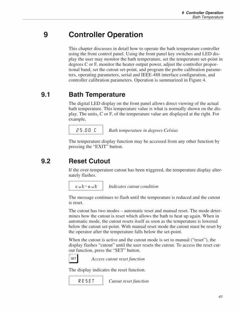
9.1 Bath TemperatureThe digital LED display on the front panel allows direct viewing of the actualbath temperature. This temperature value is what is normally shown on the dis-play. The units, C or F, of the temperature value are displayed at the right. Forexample,
25.00 C Bath temperature in degrees Celsius
The temperature display function may be accessed from any other function bypressing the “EXIT” button.
9.2 Reset CutoutIf the over-temperature cutout has been triggered, the temperature display alter-nately flashes.
cut-out Indicates cutout condition
The message continues to flash until the temperature is reduced and the cutoutis reset.
The cutout has two modes – automatic reset and manual reset. The mode deter-mines how the cutout is reset which allows the bath to heat up again. When inautomatic mode, the cutout resets itself as soon as the temperature is loweredbelow the cutout set-point. With manual reset mode the cutout must be reset bythe operator after the temperature falls below the set-point.
When the cutout is active and the cutout mode is set to manual (“reset”), thedisplay flashes “cutout” until the user resets the cutout. To access the reset cut-out function, press the “SET” button.
S Access cutout reset function
The display indicates the reset function.
RESET Cutout reset function
41
9 Controller OperationBath Temperature

7312 TPW Maintenance Bath
User’s Guide
42
SET/EXIT
CalibrationMenu
CTO
Adjust CTO
H
Adjust H
L
Adjust L
SET/EXIT
IEEE-488Interface
Menu
DeviceAddress
Adj. DeviceAddress
UP UP UP UP
DOWN DOWN DOWN DOWN
SET SET SET SET
OperatingParameters
Menu
SET
EXIT EXIT EXIT
EXITEXIT
EXIT
EXIT
EXIT
EXIT
EXITSET SET SET
SETSET
SET
SET
SET
SET
SET SET
SET/EXIT
SET/EXIT SET/EXIT SET/EXIT
SET/EXITSET/EXIT
SET/EXIT
ProbeMenu
D0
DG
Adj. D0
Adj. DG
SET/EXIT
SerialInterface
Menu
BAUDRate
AdjustBAUD Rate
SamplePeriod
Adj. SamplePeriod
DuplexMode
Adj. DuplexMode
Linefeed
AdjustLinefeed
EXITEXITEXIT EXIT EXIT
EXIT
EXIT
EXIT
EXIT
EXITSET +
Display Power
Set Proportional Band
Set Cutout Temp.
EXIT
EXIT
EXIT
SET
SET
SET
SET
SET
SET
SET
SET
SET
SET
Reset Cutout
Select Setpoint
Adjust Setpoint
EXIT
EXIT Adjust Vernier
Set Scale °C/°F
Cutout Active
DisplayTemperature
CutoutReset Mode
Adj. CutoutReset Mode
X 5
DO
NO
T C
HA
NG
ET
HE
SE
VAL
UE
S. S
EE
MA
NU
AL
Configuration Menu
Secondary Functions
IEEE-488Option Installed
InterfaceOption Installed
EXIT
SET
SET
SET/EXIT
Triple Point ofWater Cutout
Adj.TPCO
Triple Point ofWater Set-Point
Adj.TPSP
EXIT
EXIT
EXIT
EXIT
SET
SET
Figure 7 Controller Operation Flowchart

Press the “SET” button once more to reset the cutout.
S Reset cutout
This action also switches the display to the set temperature function. To returnto displaying the temperature, press the “EXIT” button. If the cutout is still inthe over-temperature fault condition, the display continues to flash “cutout”.The bath temperature must drop a few degrees below the cutout set-point be-fore the cutout can be reset.
9.3 Temperature Set-pointThe bath temperature can be set to any value within the range and with resolu-tion as given in the specifications. The operator must know the temperaturerange of the particular fluid used in the bath and the bath should only be oper-ated well below the upper temperature limit of the liquid. In addition, the cutouttemperature should also be set below the upper limit of the fluid.
Setting the bath temperature involves three steps: 1) selecting the set-pointmemory, 2) adjusting the set-point value, and 3) adjusting the vernier (ifdesired).
9.3.1 Programmable Set-pointsThe controller stores 8 set-point temperatures in memory. The set-points can bequickly recalled to conveniently set the bath to a previously programmed tem-perature set-point.
To set the bath temperature, first select the set-point memory. This function isaccessed from the temperature display function by pressing the “SET” button.The number of the set-point memory currently being used is shown at the lefton the display followed by the current set-point value.
25.00 C Bath temperature in degrees Celsius
S Access set-point memory
1, 25.0 Set-point memory 1, 25.0°C currently used
To change the set-point memory press the “UP” or “DOWN” button.
U Increment memory
Press the “SET” button to accept the new selection and access the set-pointvalue.
S Accept selected set-point memory
43
9 Controller OperationTemperature Set-point
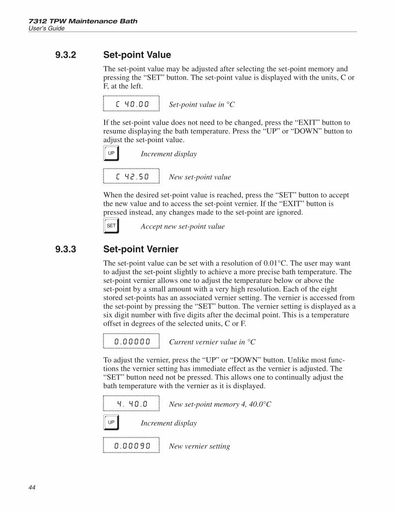
9.3.2 Set-point ValueThe set-point value may be adjusted after selecting the set-point memory andpressing the “SET” button. The set-point value is displayed with the units, C orF, at the left.
C 40.00 Set-point value in °C
If the set-point value does not need to be changed, press the “EXIT” button toresume displaying the bath temperature. Press the “UP” or “DOWN” button toadjust the set-point value.
U Increment display
C 42.50 New set-point value
When the desired set-point value is reached, press the “SET” button to acceptthe new value and to access the set-point vernier. If the “EXIT” button ispressed instead, any changes made to the set-point are ignored.
S Accept new set-point value
9.3.3 Set-point VernierThe set-point value can be set with a resolution of 0.01°C. The user may wantto adjust the set-point slightly to achieve a more precise bath temperature. Theset-point vernier allows one to adjust the temperature below or above theset-point by a small amount with a very high resolution. Each of the eightstored set-points has an associated vernier setting. The vernier is accessed fromthe set-point by pressing the “SET” button. The vernier setting is displayed as asix digit number with five digits after the decimal point. This is a temperatureoffset in degrees of the selected units, C or F.
0.00000 Current vernier value in °C
To adjust the vernier, press the “UP” or “DOWN” button. Unlike most func-tions the vernier setting has immediate effect as the vernier is adjusted. The“SET” button need not be pressed. This allows one to continually adjust thebath temperature with the vernier as it is displayed.
4. 40.0 New set-point memory 4, 40.0°C
U Increment display
0.00090 New vernier setting
7312 TPW Maintenance Bath
User’s Guide
44

Next press the “EXIT” button to return to the temperature display or the “SET”button to access the temperature scale units selection.
S Access scale units
9.4 Temperature Scale UnitsThe temperature scale units of the controller may be set by the user to degreesCelsius (°C) or Fahrenheit (°F). The units are used in displaying the bath tem-perature, set-point, vernier, proportional band, and cutout set-point.
The temperature scale units selection is accessed after the vernier adjustmentfunction by pressing the “SET” button. From the temperature display function,access the units selection by pressing “SET” 4 times.
25.0 Bath temperature
S Access et-point memory
1. 25.0 Set-point memory
S Access set-point value
C 25.00 Set-point value
S Access vernier
0.00000 Vernier setting
S Access scale units selection
Un= C Scale units currently selected
Press the “UP” or “DOWN” button to change the units.
U Change units
Un=F New units selected
Press the “SET” button to accept the new selection and resume displaying thebath temperature.
S Set the new units and resume temperature display
45
9 Controller OperationTemperature Scale Units

9.5 Secondary MenuFunctions, which are used less often, are accessed within the secondary menu.The secondary menu is accessed by pressing the “SET” and “EXIT” buttons si-multaneously and then releasing. The first function in the secondary menu isthe heater power display.
9.6 Heater PowerThe temperature controller controls the temperature of the bath by pulsing theheater on and off. The total power being applied to the heater is determined bythe duty cycle or the ratio of heater on time to the pulse cycle time. This valuemay be estimated by watching the red/green control indicator light or read di-rectly from the digital display. By knowing the amount of heating the user cantell if the bath is heating up to the set-point, cooling down, or controlling at aconstant temperature. Monitoring the percent heater power lets the user knowthe stability of the bath. With good control stability the percent heating powershould not fluctuate more than ±1% within one minute.
The heater power display is accessed in the secondary menu. Press the “SET”and “EXIT” button simultaneously and release. The heater power is displayedas a percentage of full power.
S+E Access heater power in secondary menu
12 Pct Heater power in percent
To exit out of the secondary menu, press the “EXIT” button. To continue on tothe proportional band setting, press the “SET” button.
E Return to temperature display
9.7 Proportional BandIn a proportional controller such as this the heater output power is proportionalto the bath temperature over a limited range of temperatures around theset-point. This range of temperature is called the proportional band. At the bot-tom of the proportional band the heater output is 100%. At the top of the pro-portional band the heater output is 0. Thus as the bath temperature rises theheater power is reduced, which consequently tends to lower the temperatureback down. In this way the temperature is maintained at a fairly constanttemperature.
The temperature stability of the bath depends on the width of the proportionalband (see Figure 5). If the proportional band is too wide, the bath temperaturedeviates excessively from the set-point due to varying external conditions. Thisis because the power output changes very little with temperature and the con-troller cannot respond very well to changing conditions or noise in the system.
7312 TPW Maintenance Bath
User’s Guide
46

If the proportional band is too narrow the bath temperature may swing backand forth because the controller overreacts to temperature variations. For bestcontrol stability the proportional band must be set for the optimum width.
The optimum proportional band width depends on several factors among whichare fluid volume, fluid characteristics (viscosity, specific heat, thermal conduc-tivity), heater power setting, operating temperature, and stirring. Thus the pro-portional band width may require adjustment for best bath stability when any ofthese conditions change. Of these, the most significant factors affecting the op-timum proportional width are heater power setting and fluid viscosity. The pro-portional band should be wider when the higher power setting is used so thatthe change in output power per change in temperature remains the same. Theproportional band should also be wider when the fluid viscosity is higher be-cause of the increased response time.
The proportional band width is easily adjusted from the bath front panel. Thewidth may be set to discrete values in degrees C or F depending on the selectedunits. The optimum proportional band width setting may be determined bymonitoring the stability with a high resolution thermometer or with the control-ler percent output power display. Narrow the proportional band width to thepoint at which the bath temperature begins to oscillate and then increase theband width from this point to 3 or 4 times wider. Table 3 lists typical propor-
47
9 Controller OperationProportional Band
Proportional Band too Narrow Proportional Band too Wide
Optimum Proportional Band
Figure 8 Bath Temperature Fluctuation at Various Proportional Band Settings

tional band settings for optimum performance with a variety of fluids at se-lected temperatures.
The proportional band adjustment may be accessed within the secondary menu.Press the “SET” and “EXIT” buttons to enter the secondary menu and show theheater power. Then press the “SET” button to access the proportional band.
S+E Access heater power in secondary menu
12 Pct Heater power in percent
S Access proportional band
Pb = 1.101C Proportional band setting
To change the proportional band, press the “UP” or “DOWN” buttons.
D Decrement display
Pb=0.060C New proportional band setting
To accept the new setting and access the cutout set-point, press the “SET” but-ton. Pressing the “EXIT” button exits the secondary menu ignoring anychanges just made to the proportional band value.
S Accept the new proportional band setting
7312 TPW Maintenance Bath
User’s Guide
48
Fluid Temperature Proportional Band Stability
Water 30°C 0.31°C ±0.003°C
Water 60°C 0.31°C ±0.003°C
Eth-Gly 50% 35°C 0.31°C ±0.005°C
Eth-Gly 50% 60°C 0.31°C ±0.005°C
Eth-Gly 50% 100°C 0.4°C ±0.010°C
Oil 200, 10cs 35°C 0.6°C ±0.004°C
Oil 200, 10cs 60°C 0.6°C ±0.004°C
Oil 200, 10cs 100°C 0.6°C ±0.004°C
Oil 710 200°C 0.4°C ±0.008°C
Table 3 Proportional Band - Fluid Table

9.8 CutoutAs a protection against software or hardware fault, shorted heater triac, or usererror, the bath is equipped with an adjustable heater cutout device that shuts offpower to the heater if the bath temperature exceeds a set value. This protectsthe heater and bath materials from excessive temperatures and, most impor-tantly, protects the bath fluids from being heated beyond the safe operatingtemperature preventing hazardous vaporization, breakdown, or ignition of theliquid. The cutout temperature is programmable by the operator from the frontpanel of the controller. It must always be set below the upper temperature limitof the fluid and no more than 10 degrees above the upper temperature limit ofthe bath.
If the cutout is activated because of excessive bath temperature, the power tothe heater is shut off and the bath cools. The bath cools until it reaches a fewdegrees below the cutout set-point temperature. At this point, the action of thecutout is determined by the setting of the cutout mode parameter.
The cutout has two selectable modes – automatic reset or manual reset. If themode is set to automatic, the cutout automatically resets when the bath temper-ature falls below the reset temperature allowing the bath to heat up again. If themode is set to manual, the heater remains disabled until the user manually re-sets the cutout.
The cutout set-point may be accessed within the secondary menu. Press the“SET” and “EXIT” button to enter the secondary menu and show the heaterpower. Then press the “SET” button twice to access the cutout set-point.
S+E Access heater power in secondary menu
12 Pct Heater power in percent
S Access proportional band
Pb = 0.101C Proportional band setting
S Access cutout set-point
CO = 110C Cutout set-point
To change the cutout set-point, press the “UP” or “DOWN” button.
D Decrement display
CO = 75C New cutout set-point
To accept the new cutout set-point, press the “SET” button.
49
9 Controller OperationCutout

S Accept cutout set-point
The next function is the configuration menu. Press the “EXIT” button to re-sume displaying the bath temperature.
9.9 Controller ConfigurationThe controller has a number of configuration and operating options and calibra-tion parameters, which are programmable via the front panel. These are ac-cessed from the secondary menu after the cutout set-point function by pressing“SET”. There are five sets of configuration parameters—probe parameters, op-erating parameters, serial interface parameters, IEEE-488 interface parameters,and controller calibration parameters. The menus are selected using the “UP”and “DOWN” buttons and then pressing the “SET” button.
9.10 Probe ParametersThe probe parameter menu is indicated by,
PrObE Probe parameters menu
Press the “SET” button to enter the menu. The probe parameters menu containsthe parameters, D0 and DG, which characterize the resistance-temperature rela-tionship of the thermistor control probe. These parameters may be adjusted toimprove the accuracy of the bath. This procedure is explained in detail in Sec-tion 11.
The probe parameters are accessed by pressing the “SET” button after the nameof the parameter is displayed. The value of the parameter may be changed us-ing the “UP” and “DOWN” buttons. After the desired value is reached, pressthe “SET” button to set the parameter to the new value. Pressing the “EXIT”button causes the parameter to be skipped ignoring any changes that may havebeen made.
9.10.1 D0This probe parameter refers to the resistance of the control probe at 0°C. Nor-mally this is set for –25.2290 ohms.
9.10.2 DGThis probe parameter refers to the average sensitivity of the probe between 0and 100°C. Normally this is set for 186.7940.
9.11 Operating ParametersThe operating parameters menu is indicated by,
7312 TPW Maintenance Bath
User’s Guide
50

Par Operating parameters menu
Press the “UP” button to enter the menu. The operating parameters menu con-tains the cutout reset mode parameter.
9.11.1 Cutout Reset ModeThe cutout reset mode determines whether the cutout resets automatically whenthe bath temperature drops to a safe value or must be manually reset by theoperator.
The parameter is indicated by,
CtorSt Cutout reset mode parameter
Press the “SET” button to access the parameter setting. Normally the cutout isset for manual mode.
Cto=rst Cutout set for manual reset
To change to automatic reset mode, press the “UP” button and then the “SET”button.
Cto=Auto Cutout set for automatic reset
9.11.2 Triple Point of Water CutoutThe triple point of water cutout protects the TPW cell in case of system failure,which may cause the bath to rapidly cool below the maintenance set-point. Thiscould cause the cell to rupture due to the expansion of ice. The cutout uses athermistor probe sensor and disengages the refrigeration compressor. If theprobe is replaced, the cutout board must be recalibrated. (See Section 12). Theuser may set the cutout temperature. A typical set-point is from –0.3 to –0.5°C.If undesired trips occur, the temperature may be reduced. The adjustment rangeis ±1.27°C from 0°C in 0.01°C increments.
The triple point of water cutout engages for three reasons: 1) the controllerdoes not send a watch dog signal to the cutout board (controller lockup), 2) thethermistor sensor is disconnected or opens, or 3) the bath goes below the cutoutset-point. (This could be if the temperature controller set-point is too low or ifthe heater fails.) When the TPW cutout is triggered, the display alternatelyflashes tP-cto and the current bath temperature. The serial port outputs “TPWCutout” every three seconds. Pressing any button causes the cutout error mes-sage to stop being output until another TPW cutout error has occurred. Eachtime the cutout is tripped, the bath temperature set-point automatically in-creases in 0.5°C increments until the set-point has reached a maximum of25°C.
The parameter is indicated by,
51
9 Controller OperationOperating Parameters

tP CO Triple point of water cutout parameter
Press the “SET” button to access the activation selection. Press the “UP” or“DOWN” button to turn the cutout on or off and then press the “SET” button.Normally the cutout is ON.
Press the “EXIT” button to return to the operating parameters menu.
tP SP Triple point of water set-point selection parameter
Press the “SET” button to access the parameter setting.
C -0.30 Cutout temperature in degrees C or F
To change the cutout temperature, use the “UP” or “DOWN” button. To acceptthe new cutout set-point, press the “SET” button.
Press the “EXIT” button to return to the operating parameters menu.
9.12 Serial Interface ParametersThe serial RS-232 interface parameters menu is indicated by,
SErIAL Serial RS-232 interface parameters menu
The serial interface parameters menu contains parameters, which determine theoperation of the serial interface. The parameters in the menu are – BAUD rate,sample period, duplex mode, and linefeed.
9.12.1 BAUD RateThe BAUD rate is the first parameter in the menu. The BAUD rate setting de-termines the serial communications transmission rate.
The BAUD rate parameter is indicated by,
BAUd Serial BAUD rate parameter
Press the “SET” button to choose to set the BAUD rate. The current BAUD ratevalue is displayed.
1200 b Current BAUD rate
The BAUD rate of the bath serial communications may be programmed to 300,600, 1200, or 2400 BAUD. Use the “UP” or “DOWN” button to change theBAUD rate value.
2400 b New BAUD rate
7312 TPW Maintenance Bath
User’s Guide
52

Press the “SET” button to set the BAUD rate to the new value or the “EXIT”button to abort the operation and skip to the next parameter in the menu.
9.12.2 Sample PeriodThe sample period is the next parameter in the serial interface parameter menu.The sample period is the time period in seconds between temperature measure-ments transmitted from the serial interface. If the sample rate is set to 5, thebath transmits the current measurement over the serial interface approximatelyevery five seconds. The automatic sampling is disabled with a sample period of0. The sample period is indicated by,
SAMPLE Serial sample period parameter
Press the “SET” button to choose to set the sample period. The current sampleperiod value is displayed.
SA = 1 Current sample period (seconds)
Adjust the value with the “UP” or “DOWN” button and then use the “SET”button to set the sample rate to the displayed value.
SA = 60 New sample period
9.12.3 Duplex ModeThe next parameter is the duplex mode. The duplex mode may be set to full du-plex or half duplex. With full duplex any commands received by the bath viathe serial interface are immediately echoed or transmitted back to the device oforigin. With half duplex the commands are executed but not echoed. The du-plex mode parameter is indicated by,
DUPL Serial duplex mode parameter
Press the “SET” button to access the mode setting
DUP=FULL Current duplex mode setting
The mode may be changed using the “UP” or “DOWN” button and then press-ing the “SET” button.
DUP=HALF New duplex mode setting
9.12.4 LinefeedThe final parameter in the serial interface menu is the linefeed mode. This pa-rameter enables (on) or disables (off) transmission of a linefeed character (LF,
53
9 Controller OperationSerial Interface Parameters

ASCII 10) after transmission of any carriage-return. The linefeed parameter isindicated by,
LF Serial linefeed parameter
Press the “SET” button to access the linefeed parameter.
LF=On Current linefeed setting
The mode may be changed using the “UP” or “DOWN” button and then press-ing the “SET” button.
LF=OFF New linefeed setting
9.13 IEEE-488 ParametersBaths may optionally be fitted with an IEEE-488 GPIB interface. In this casethe user may set the interface address and the transmission termination charac-ter within the IEEE-488 parameter menu. This menu does not appear on bathsnot fitted with the interface. The menu is indicated by,
IEEE IEEE-488 parameters menu
Press the “SET” button to enter the menu.
9.13.1 IEEE-488 AddressIEEE-488 interface must be configured to use the same address as the externalcommunicating device. The address is indicated by,
AddrESS IEEE-488 interface address
Press the “SET” button to access the address setting.
Add=22 Current IEEE-488 interface address
Adjust the value with the “UP” or “DOWN” button and then use the “SET”button to set the address to the displayed value.
Add=15 New IEEE-488 interface address
9.13.2 Transmission TerminationThe transmission termination character can be set to carriage return only, line-feed only, or carriage return and linefeed. Regardless of the option selected, the
7312 TPW Maintenance Bath
User’s Guide
54

instrument interprets either a carriage return or a linefeed as a command termi-nation during reception.
The termination parameter is indicated with,
EOS IEEE-488 termination
Press the “SET” button to access the termination setting.
EOS=Cr Present IEEE-488 termination
Use the “UP” or “DOWN” button to change the selection.
EOS=LF New termination selection
Use the “SET” button to save the new selection.
9.14 Calibration ParametersThe operator of the bath controller has access to a number of the bath calibra-tion constants namely CTO, H, and L. These values are set at the factory andmust not be altered. The correct values are important to the accuracy andproper and safe operation of the bath. These parameters should not be adjustedexcept in the event the controller’s memory fails. The user may then restorethese values to the factory settings. A list of these constants and their settingsare supplied to the user on the Report of Test with the manual.
CAUTION: DO NOT change the values of the bath calibration constantsfrom the factory set values. The correct setting of these parameters is im-portant to the safety and proper operation of the bath.
The calibration parameters menu is indicated by,
CAL Calibration parameters menu
Press the “SET” button five times to enter the menu.
9.14.1 CTOParameter CTO sets the calibration of the over-temperature cutout. This param-eter is not adjustable by software but is adjusted with an internal potentiometer.For the 7312 bath this parameter should read 160.
9.14.2 H and LThese parameters set the upper and lower set-point limits of the bath. DO NOTchange the values of these parameters from the factory set values. To do so may
55
9 Controller OperationCalibration Parameters

present danger of the bath exceeding its temperature range causing damage orfire.
7312 TPW Maintenance Bath
User’s Guide
56

10 Digital Communication Interface
The 7312 bath is capable of communicating with and being controlled by otherequipment through the digital interface. Two types of digital interface are avail-able—the RS-232 serial interface, which is standard, and the IEEE-488 GPIBinterface which is optional.
With a digital interface the bath may be connected to a computer or otherequipment. This allows the user to set the bath temperature, monitor the tem-perature, and access any of the other controller functions, all using remote com-munications equipment. In addition the cooling may be controlled using theinterface. To control the cooling with the interface the cooling power switchmust be OFF.
10.1 Serial CommunicationsThe RS-232 serial interface allows serial digital communications over fairlylong distances (15.24 meters). With the serial interface the user may access anyof the functions, parameters and settings discussed in Section 10, ControllerOperation with the exception of the BAUD rate setting. The serial interface op-erates with eight data bits, one stop bit, and no parity.
10.1.1 WiringThe serial communications cable attaches to the bath through the DB-9 connec-tor at the back of the instrument. Figure 9 shows the pin-out of this connector
57
10 Digital Communication InterfaceSerial Communications

and suggested cable wiring. To eliminate noise, the serial cable should beshielded with low resistance between the connector (DB-9) and the shield.
10.1.2 SetupBefore operation, the serial interface of the bath must first be set up by pro-gramming the BAUD rate and other configuration parameters. These parame-ters are programmed within the serial interface menu.
To enter the serial parameter programming mode first, press the “EXIT” buttonwhile pressing the “SET” button and release to enter the secondary menu. Pressthe “SET” button repeatedly until the display reads “ProbE”. This is the menuselection. Press the “UP” button repeatedly until the serial interface menu is in-dicated with “SErIAL”. Finally press the “SET” button to enter the serial pa-rameter menu. The serial interface parameter menu contains the BAUD rate, thesample rate, the duplex mode, and the linefeed parameter.
10.1.2.1 BAUD Rate
The BAUD rate is the first parameter in the menu. The display prompts withthe BAUD rate parameter by showing “BAUd”. Press the “SET” button tochoose to set the BAUD rate. The current BAUD rate value is displayed. The
7312 TPW Maintenance Bath
User’s Guide
58
Figure 9 Serial Communications Cable Wiring

BAUD rate of the bath may be programmed to 300, 600, 1200, or 2400 BAUD.The BAUD rate is pre-programmed to 2400 BAUD. Use “UP” or “DOWN” tochange the BAUD rate value. Press the “SET” button to set the BAUD to thenew value or the “EXIT” button to abort the operation and skip to the next pa-rameter in the menu.
10.1.2.2 Sample Period
The sample period is the next parameter in the menu and prompted with“SAMPLE”. The sample period is the time period, in seconds, between temper-ature measurements transmitted from the serial interface. If the sample rate isset to 5, the bath transmits the current measurement over the serial interface ap-proximately every five seconds. The automatic sampling is disabled with asample period of 0. Press the “SET” button to choose to set the sample period.Adjust the period with the “UP” or “DOWN” button and then use the “SET” toset the sample rate to the displayed value.
10.1.2.3 Duplex Mode
The next parameter is the duplex mode indicated with “dUPL”. The duplexmode may be set to half duplex (“HALF”) or full duplex (“FULL”). With fullduplex any commands received by the bath via the serial interface are immedi-ately echoed or transmitted back to the device of origin. With half duplex thecommands are executed but not echoed. The default setting is full duplex. Themode may be changed using “UP” or “DOWN” and pressing “SET”.
10.1.2.4 Linefeed
The final parameter in the serial interface menu is the linefeed mode. This pa-rameter enables (“On”) or disables (“OFF”) transmission of a linefeed charac-ter (LF, ASCII 10) after transmission of any carriage-return. The default settingis with linefeed on. The mode may be changed using “UP” or “DOWN” andpressing “SET”.
10.1.3 Serial OperationOnce the cable has been attached and the interface set up properly the control-ler immediately begins transmitting temperature readings at the programmedrate. The set-point and other commands may be sent to the bath via the serialinterface to set the bath and view or program the various parameters. The inter-face commands are discussed in Section 11.3, Interface Commands.
10.2 IEEE-488 Communication (optional)The IEEE-488 interface is available as an option. Baths supplied with this op-tion may be connected to a GPIB type communication bus, which allows manyinstruments to be connected and controlled simultaneously. To eliminate noise,the GPIB cable should be shielded.
59
10 Digital Communication InterfaceIEEE-488 Communication (optional)

10.2.1 SetupTo use the IEEE-488 interface connect an IEEE-488 standard cable to the backof the bath, set the device address, and set the transmission terminationcharacter.
To enter the IEEE-488 parameter programming menu, press the “EXIT” andthe “SET” button simultaneously and then release to enter the secondary menu.Press the “SET” button repeatedly until the display reaches “PrObE”. Press the“UP” button repeatedly until the IEEE-488 interface menu is indicated with“IEEE”. Press the “SET” button to enter the IEEE-488 parameter menu.
10.2.1.1 IEEE-488 Address
The IEEE-488 address is prompted with “AddrESS”. Press the “SET” button toprogram the address. The default address is 22. If necessary, change the deviceaddress of the bath to match the address used by the communication equip-ment. To change the device address, press the “UP” or DOWN” button and thenthe “SET” button.
10.2.1.2 Transmission Termination
The IEEE-488 transmission termination is prompted with “EOS”. Press the“SET” button to access the termination character. The present setting is dis-played. Press the “UP” or “DOWN” button to change the setting. Press the“SET” button to save the new selection.
10.2.2 IEEE-488 OperationCommands may now be sent via IEEE-488 interface to read or set the tempera-ture or access other controller functions. All commands are ASCII characterstrings and are terminated with a carriage-return (CR, ASCII 13). Interfacecommands are listed below.
10.3 Interface CommandsThe various commands for accessing the bath controller functions via the digi-tal interfaces are listed in this section (see Table 4). These commands are usedwith both the RS-232 serial interface and the IEEE-488 GPIB interface. In ei-ther case the commands are terminated with a carriage-return character. The in-terface makes no distinction between upper and lower case letters, hence eithermay be used. Commands may be abbreviated to the minimum number of let-ters, which determines a unique command. A command may be used to eitherset a parameter or display a parameter depending on whether or not a value issent with the command following a “=” character. For example, an “s”<cr> re-turns the current set-point and an “s=50.00”<cr> sets the set-point to 50.00degrees.
In the following list of commands, characters or date within brackets, “[“ and“]”, are optional. A slash, “/”, denotes alternate characters or data. Numeric
7312 TPW Maintenance Bath
User’s Guide
60

61
10 Digital Communication InterfaceInterface Commands
Command DescriptionCommandFormat
CommandExample Returned
ReturnedExample
AcceptableValues
Display Temperature
Read current set-point s[etpoint] s set: 9999.99 {C or F} set: 100.000 C
Set current set-point to n s[etpoint]=n s=100 InstrumentRange
Read vernier v[ernier] v v: 9.99999 v: 0.00000
Set vernier to n v[ernier]=n v=.00001 Depends onConfiguration
Read temperature t[emperature] t t: 9999.99 {C or F} t: 55.69 C
Read temperature units u[nits] u u: x u: c
Set temperature units: u[nits]=c/f C or F
Set temperature units to Celsius u[nits]=c u=c
Set temperature units toFahrenheit
u[nits]=f u=f
Secondary Menu
Read proportional band setting pr[op-band] pr pr: 999.9 pr: 15.9
Set proportional band to n pr[op-band]=n pr=8.83 Depends onConfiguration
Read cut-out setting c[utout] c c: 9999 {x},{xxx} c: 110 C, in
Set cut-out setting: c[utout]=n/r[eset]
Set cut-out to n degrees c[utout]=n c=110 TemperatureRange
Reset cut-out now c[utout]=r[eset] c=r
Read heater power(duty cycle)
po[wer] po po: 9999 po: 1
Configuration Menu
Probe Menu
Read D0 calibration parameter *d0 *d0 d0: 999.9999 d0: -25.2290
Set D0 calibration parameter to n *d0=n *d0=-25.2290 -999.9999 to999.9999
Read DG calibration parameter *dg *dg dg: 999.9999 dg:186.9740
Set DG calibration parameter to n *dg=n *dg=186.9740 -999.9999 to999.9999
Operating Parameters Menu
Read cut-out mode cm[ode] cm cm: {xxxx} cm: AUTO
Set cut-out mode: cm[ode]=r[eset]/a[uto] RESET orAUTO
Set cut-out to be reset manually cm[ode]=r[eset] cm=r
Table 4 Interface Command Summary.

7312 TPW Maintenance Bath
User’s Guide
62
Command DescriptionCommandFormat
CommandExample Returned
ReturnedExample
AcceptableValues
Set cut-out to be resetautomatically
cm[ode]=a[uto] cm=a
Read water triple point tpco tpco tpco:{ON or OFF} tpco=ON
Set water triple point tpco=ON/OFF tpco=ON ON or OFF
Read water triple point cutoutset-point
tpsp=n tpsp tpsp=99.99C tpsp=–0.31C
Set water triple point cutoutset-point
tpsp=n tpsp=–0.33 ±1.27°C(±2.28°F)
Serial Interface Menu
Read serial sample setting sa[mple] sa sa: 9 sa: 1
Set serial sampling setting to nseconds
sa[mple]=n sa=0 0 to 4000
Set serial duplex mode: du[plex]=f[ull]/h[alf] FULL or HALF
Set serial duplex mode to full du[plex]=f[ull] du=f
Set serial duplex mode to half du[plex]=h[alf] du=h
Set serial linefeed mode: lf[eed]=on/of[f] ON or OFF
Set serial linefeed mode to on lf[eed]=on lf=on
Set serial linefeed mode to off lf[eed]=of[f] lf=of
Calibration Menu
Read low set-point limit value *tl[ow] *tl tl: 999 tl: –80
Set low set-point limit to n *tl[ow]=n *tl=-80 –5 to 25°C
Read high set-point limit value *th[igh] *th th: 999 th: 205
Set high set-point limit to n *th[igh]=n *th=205 25 to 110°C
Miscellaneous (not on menus)
Read firmware version number *ver[sion] *ver ver.9999,9.99 ver.2100,3.56
Read structure of all commands h[elp] h list of commands
Read Refrigeration f2 f2 f2:9 f2:0
Set Refrigeration f2=1/0 0 or 1
Set Refrigeration to on f2=n f2=1
Set Refrigeration to off f2=n f2=0
Legend: [] Optional Command data
{} Returns either information
n Numeric data supplied by user
9 Numeric data returned to user
x Character data returned to user
Note: When DUPLEX is set to FULL and a command is sent to READ, the command is returned followed by acarriage return and linefeed. Then the value is returned as indicated in the RETURNED column.
Interface Command Summary continued
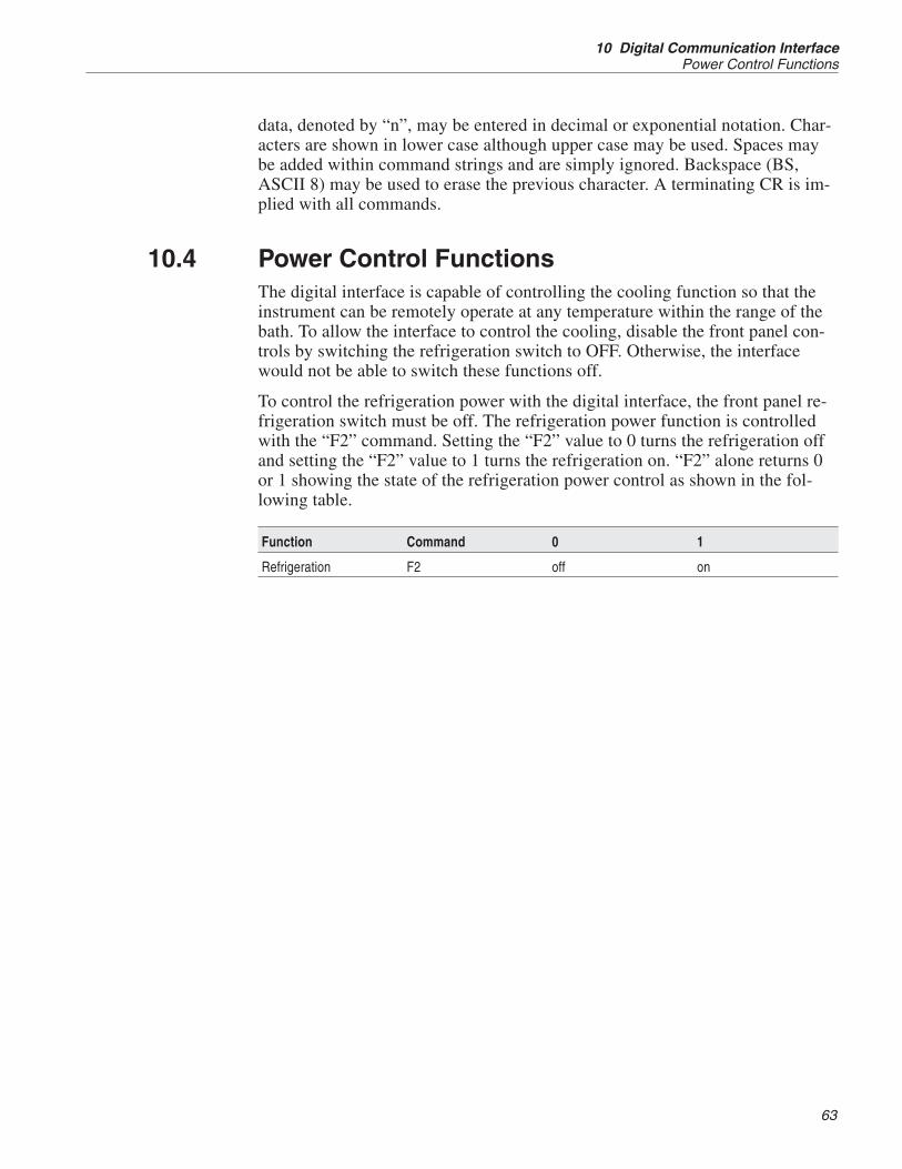
data, denoted by “n”, may be entered in decimal or exponential notation. Char-acters are shown in lower case although upper case may be used. Spaces maybe added within command strings and are simply ignored. Backspace (BS,ASCII 8) may be used to erase the previous character. A terminating CR is im-plied with all commands.
10.4 Power Control FunctionsThe digital interface is capable of controlling the cooling function so that theinstrument can be remotely operate at any temperature within the range of thebath. To allow the interface to control the cooling, disable the front panel con-trols by switching the refrigeration switch to OFF. Otherwise, the interfacewould not be able to switch these functions off.
To control the refrigeration power with the digital interface, the front panel re-frigeration switch must be off. The refrigeration power function is controlledwith the “F2” command. Setting the “F2” value to 0 turns the refrigeration offand setting the “F2” value to 1 turns the refrigeration on. “F2” alone returns 0or 1 showing the state of the refrigeration power control as shown in the fol-lowing table.
Function Command 0 1
Refrigeration F2 off on
63
10 Digital Communication InterfacePower Control Functions

11 Calibration Procedure
In some instances the user may want to calibrate the bath to improve the tem-perature set-point accuracy. Calibration is done by adjusting the controllerprobe calibration constants DO and DG so that the temperature of the bath asmeasured with a standard thermometer agrees more closely with the bathset-point. The thermometer used must be able to measure the bath fluid temper-ature with higher accuracy than the desired accuracy of the bath. By using agood thermometer and by carefully following the procedure, the bath can becalibrated to an accuracy of better than 0.1°C over a range of 50 degrees.
11.1 Calibration Points—2 Point CalibrationIn calibrating the bath DO and DG are adjusted to minimize the set-point errorat each of two different bath temperatures. Any two reasonably separated bathtemperatures may be used for the calibration however best results are obtainedwhen using bath temperatures which are just within the most useful operatingrange of the bath. The farther apart the calibration temperatures, the larger thecalibrated temperature range but the calibration error is also greater over therange. For instance, if 20°C and 80°C are chosen as the calibration tempera-tures, the bath may achieve an accuracy of say ±0.2°C over the range 20 to80°C. Choosing 30°C and 70°C may allow the bath to have a better accuracy ofmaybe ±0.05°C over the range 30 to 70°C but outside the range the accuracymay be only ±0.5°C.
11.2 Measuring the Set-point ErrorThe first step in the calibration procedure is to measure the temperature errors(including sign) at the two calibration temperatures. First, set the bath to thelower set-point, tL. Wait for the bath to reach the set-point and allow 15 minutesto stabilize at that temperature. Check the bath stability with the thermometer.When both the bath and the thermometer have stabilized, measure the bath tem-perature with the thermometer and compute the temperature error, errL, whichis the actual bath temperature minus the set-point temperature. For example, ifthe bath is set for a lower set-point of, tL=20°C and the bath reaches a measuredtemperature of 19.7°C then the error is –0.3°C.
Next, set the bath for the upper set-point, tH, and after stabilizing measure thebath temperature and compute the error, errH. For example, suppose the bathwas set for 80°C and the thermometer measured 80.1°C giving an error of+0.1°C.
11.3 Computing DO and DGBefore computing the new values for DO and DG the current values must beknown. The values may be found by either accessing the probe calibrationmenu from the controller panel or by inquiring through the digital interface.
65
11 Calibration ProcedureCalibration Points—2 Point Calibration

The user should keep a record of these values in case they may need to be re-stored in the future. The new values DO’ and DG’ are computed by entering theold values for DO and DG, the calibration temperature set-points, tL and tH, andthe temperature errors, errL and errH, into the following equations,
Derr t D err t D
t tDL H H L
H L
00 0
0′ =− − −
−+
( ) ( )
DGerr err
t tDGH L
H L
′ =−−
+⎡
⎣⎢
⎤
⎦⎥1
For example, if DO and DG were previously set for –25.229 and 186.9740 re-spectively and the data for tL, tH, errL, and errH were as given above then thenew values D0′ and DG′ would be computed as –25.831 and 188.220 respec-tively. Program the new values D0 and DG into the controller. The new con-stants are used the next time the bath temperature is set. Check the calibrationby setting the temperature to tL and tH and measuring the errors again. If de-sired, the calibration procedure may be repeated again to further improve theaccuracy.
11.4 Calibration ExampleThe bath is to be used between 25 and 75°C and it is desired to calibrate thebath as accurately as possible for operation within this range. The current val-ues for D0 and DG are –25.229 and 186.974 respectively. The calibrationpoints are chosen to be 25.00 and 75.00°C. The measured bath temperatures are24.869 and 74.901°C respectively. Refer to Figure 10 for applying the equa-tions to the example data and computing the new probe constants.
11.5 Single Point CalibrationWhen calibrating the bath for applications emphasizing a single temperature, asingle point calibration can be quicker, easier and more accurate. These appli-cations include maintenance of a triple point of water cell near zero degreesCelsius or for the gallium point near 30°C. An adjustment of only the D0 cali-bration constant is made in this process. The advantage of calibration is to havethe bath set-point temperature more closely reflect the desired bath tempera-ture. While this procedure improves the accuracy at a specific set-point, the re-sults may not be accurate enough alone to make the baths final temperatureadjustment. For example, for the maintenance of a triple point of water cell, thebath temperature must be known to within one thousandth of a degree Celsius.The calibration of the bath is not intended to get that close. Final adjustments
7312 TPW Maintenance Bath
User’s Guide
66

must be made using a thermometer and readout capable of making measure-ments to one thousandth of a degree.
11.6 Measuring the Set-point ErrorThe first step in this procedure is to measure the set-point error (including thesign) at the desired temperature. Set the bath to the desired set-point, for exam-ple 0.008°C for the triple point of water cell maintenance. Verify that the ver-nier is set at 0. Wait for the bath to reach that temperature and allow 30 minutesfor the bath to stabilize at that temperature. Check the bath stability with thethermometer. When both the bath and the thermometer have stabilized, measurethe bath temperature with the thermometer and compute the temperature error,which is the set-point temperature minus the actual bath temperature.
Error = Tsp – Tactual
67
11 Calibration ProcedureMeasuring the Set-point Error
D0 = -25.229
DG = 0.0028530
tL = 25.00°C
measured t = 24.869°C
tH = 75.00°C
measured t = 74.901°C
Compute errors,
errL = 24.869 – 25.00°C = –0.131°C
errH = 74.901 – 75.00°C = –0.099°C
Compute D0,
D00131 75 0 25 229 0 099 25 0 25 22′ = − − − − − − −( . )( . ( . )) ( . )( . ( . 9
75 0 25 025 229 25392
))
. .( . ) .
−+ − = −
Compute DG,
DG′ = − − −−
+⎡
⎣⎢
⎤
⎦⎥ =( . ) ( . )
. .. .
0 099 0131
75 0 25 01 0 0028530 0 0028548
Figure 10 Sample Calibration Computations

Example:
Actual temperature = +0.132°C
Set point temperature = +0.008°C
error = +0.008– (+0.132) = -0.124 (including sign)
11.7 Computing D0Before computing the new values for D0, the current value must be known. Thevalue may be found by either accessing the probe calibration menu from thecontroller panel or by inquiring through the digital interface. The user shouldkeep a record of this value in case it may need to be restored in the future. Thenew value D0’ is computed by subtracting the temperature error from the oldvalue for D0 as follows.
D0′ = D0 – error
Example:
Old D0 = -25.438
error = -0.124°C
D0′ = –25.438 – (–0.224) = –25.662
Enter the new D0 value into the controller and press the “SET” button. Wait forthe temperature to stabilize and measure the temperature again. If desired, thecalibration procedure may be repeated to further improve the accuracy.
11.8 Calibrating the Triple Point of Water CutoutThe under temperature cutout is provided to protect the triple point of watercell in case there is a temperature controller or sensor failure that would causethe bath to cool rapidly below the set-point temperature. Such a failure couldcause the cell to rupture due to rapid expansion of the ice inside it. The cutoutdeactivates the refrigeration thereby preventing the problem.
CAUTION: Only trained personnel should operate calibration equipment.
The cutout is calibrated at the triple point temperature at the factory. It mayneed to be recalibrated from time to time if there is drift in the cutout tempera-ture or if the cutout probe has been replaced. The actual cutout temperaturemay be observed by setting the bath to a temperature well below the cutoutset-point and monitoring the bath temperature until the cutout activates. Whenthe display flashes tP-c-out, note the temperature. If the error is less than0.5°C, it may be compensated for by resetting the water triple point cutout. Forgreater errors it may be best to recalibrate the cutout.
7312 TPW Maintenance Bath
User’s Guide
68

The cutout is calibrated by adjusting a potentiometer inside the unit while thebath is at the triple point maintenance temperature. The bath temperatureshould be known to within ±0.05°C. A DVM capable of measuring accuratelyto 10mV is required.
To access the cutout circuit board, the front panel must be removed. Be sure todisconnect the power to the unit before beginning. It is best to move quickly toavoid much bath temperature change. Begin by removing the 4 screws attach-ing the sloping controller panel. Lift up the controller panel to access the fas-teners attaching the front sheet metal panel. Remove the two fasteners locatedat the top left and right corners of the panel. The bottom of the panel is retainedby a screw on either side of the panel that is in a key-hole shaped slot. Lift upthe panel and wiggle slightly so that the screw heads come out through thelarger portion of the slot. The bottom screws are not to be removed. Once thepanel is removed, set it aside and temporarily replace the controller panel rein-stalling the screws to hold it in place.
Reestablish the power connection to the bath and allow the bath to regain stablecontrol at the required set-point. This procedure takes 15 minutes or longer de-pending on how long the bath has been off and how far it has drifted off tem-perature. Be aware that the bath has a low voltage line monitor that activateswhen the power is disconnected. Several minutes are required before the unit ispermitted to turn on. Note the amber light on the back of the unit.
WARNING: Shock hazard! High Voltage power is accessible.
Identify the cutout PC board on the left side of a sheet metal shelf below thetemperature controller boards. Locate on the cutout board the two test pointsTP1 and TP2 and attach the DVM.
In order to prevent the cutout from activating during adjustment it must beturned off in the controller menu. To disable the low temperature cutout, accessthe operating parameters menu. Follow the instructions in Section 9.11.2 andset the triple point cutout (tP CO) to OFF toggling with either the up or downkeys. Set the water triple point cutout to 0.01°C. With the bath controlling at0°C to 0.01°C, adjust VR1 on the board until the voltage reads 0 volts. Afterthe adjustment, return the cutout to the ON condition and set the water triplepoint cutout set-point to –0.3°C.
69
11 Calibration ProcedureCalibrating the Triple Point of Water Cutout

12 Charging Instructions
The 7312 uses R-134a with a polyolester oil. Care must be taken to avoid con-tamination from other types of refrigerants and oils.
12.1 Leak TestingLeak testing should be done with equipment designed for use with R-134a.Bubble, electronic halogen detector, or ultra-sonic leak testing may be viable insome instances.
12.2 EvacuationDO NOT leave the system open for more than 15 minutes. Polyolester oils arevery hygroscopic. Evacuate the system to a minimum of 200 microns. Evacuatefrom both high and low sides of the system. Schrader valves provide access tothe system.
12.3 ChargingAfter evacuation, charge the system with 160 grams of R-134a. Set the suctionpressure to 8-10 psig for operation.
NOTE: A fan must be placed in front of the condenser if the unit is oper-ated with the side panels removed. The unit requires the side panels to beinstalled for proper airflow across the condenser.
71
12 Charging InstructionsLeak Testing

13 Maintenance
• A battery is used to maintain operating parameters in the unit. All operat-ing parameters, including calibration parameters should be checked on aregular basis to insure accuracy and proper operation of the instrument.See the troubleshooting section for the procedure on checking the statusof the battery.
• The calibration instrument has been designed with the utmost care. Easeof operation and simplicity of maintenance have been a central theme inthe product development. Therefore, with proper care the instrumentshould require very little maintenance. Avoid operating the instrument indirty or dusty environments.
• If the outside of the bath becomes soiled, it may be wiped clean with adamp cloth and mild detergent. Do not use harsh chemicals on the sur-face, which may damage the paint.
• Periodically check the fluid level in the bath to ensure that the level hasnot dropped. A drop in the fluid level affects the stability of the bath.Changes in fluid level are dependent upon several factors specific to theconditions in which the equipment is used. A schedule cannot be outlinedto meet each set of conditions. Therefore, the bath should be checkedweekly and adjustments made as required.
• Heat transfer medium lifetime is dependent upon the type of medium andthe conditions of use. The fluid should be checked at least every monthfor the first year and regularly thereafter. This fluid check provides abaseline for knowledge of bath operation with clean, usable fluid. Oncesome fluids have become compromised, the break down can occur rap-idly. Particular attention should be paid to the viscosity of the fluid. A sig-nificant change in the viscosity can indicate that the fluid is contaminated,being used outside of its temperature limits, contains ice particles, or isclose to a chemical breakdown. Once data has been gathered, a specificmaintenance schedule can be outlined for the instrument. Refer to Section9, General Operation, for more information about the different types offluids used in calibration baths.
• Depending on the cleanliness of the environment, the internal parts (partsbehind the front cover only) of the cold bath should be cleaned and/orchecked at least every month for dust and dirt. Particular attention shouldbe paid to the condensing coil fins. The fins should be vacuumed orbrushed free of dust and dirt on a regular basis. Dust and dirt inhibit theoperation of the condensing coil and thus compromise the performanceand lifetime of the cooling system.
• If a hazardous material is split on or inside the equipment, the user is re-sponsible for taking the appropriate decontamination steps as outlined bythe national safety council with respect to the material. MSDS sheets ap-plicable to all fluids used in the baths should be kept in close proximity tothe instrument.
73
13 Maintenance

• If the mains supply cord becomes damaged, replace it with a cord withthe appropriate gauge wire for the current of the bath. If there are anyquestions, call an Authorized Service Center for more information.
• Before using any cleaning or decontamination method except those rec-ommended by Hart, users should check with an Authorized Service Cen-ter to be sure that the proposed method does not damage the equipment.
• If the instrument is used in a manner not in accordance with the equip-ment design, the operation of the bath may be impaired or safety hazardsmay arise.
• The over-temperature cutout should be checked every 6 months to see thatit is working properly. In order to check the user selected cutout, followthe controller directions (Section 10.2) for setting the cutout. Both themanual and the auto reset option of the cutout should be checked. Set thebath temperature higher than the cutout. Check to see if the displayflashes cutout and if the temperature is decreasing. Note: When checkingthe over-temperature cutout, be sure that the temperature limits of the bathfluid are not exceeded. Exceeding the temperature limits of the bath fluidcould cause harm to the operator, lab, and instrument.
7312 TPW Maintenance Bath
User’s Guide
74

14 Troubleshooting
This section contains information on troubleshooting, CE Comments, and awiring diagram. This information pertains to a number of bath models and cer-tain specifics may not pertain to your model.
14.1 TroubleshootingIn the event that the instrument appears to function abnormally, this sectionmay help to find and solve the problem. Several possible problem conditionsare described along with likely causes and solutions. If a problem arises, pleaseread this section carefully and attempt to understand and solve the problem. Ifthe probe seems faulty of the problem cannot otherwise be solved, contact anAuthorized Service Center (see Section 1.3) for assistance. Be sure to have themodel number, serial number, and voltage of your instrument available.
Problem Causes and Solutions
The bath does not turnon and the display re-mains blank
If a fault condition exists upon application of power, the bath will not energize.The bath needs to be plugged in to the line voltage for at least 2 minutes beforeturning power on. This is only necessary for the first time that the bath is ener-gized or when it is moved from one location to another.
If a high or low voltage condition exists for longer than 5 seconds, the compres-sor is de-energized and the “Mains Out of Range” light on the back panel illumi-nates indicating a fault condition.
Re-energization is automatic upon correction of the fault condition and after adelay cycle of about 2 minutes.
High and low voltage protection limits at 115 VAC:Voltage Cutout: ±12.5% (101 – 129 VAC)Voltage Cutin: ±7.5% (106 – 124 VAC)
High and low voltage protection limits at 230 VAC:Voltage Cutout: ±12.5% (203 – 257 VAC)Voltage Cutin: ±7.5% (213 – 247 VAC)
See the Caution in the front of this manual for additional information.
Testing the Line Voltage – If the power line voltage is too low (90% of thecompressor’s rated voltage), the compressor could be damaged. Place a DVMin the supply line on the wall that feeds the bath. Measure the line voltage underload (with the bath on). If the line voltage is low or marginal, disconnect anyother devices that are using the same line. Alternately, move the bath to a loca-tion where the supply voltage is good. If none of these are possible, contact anelectrician to re-route the correct power. If necessary, you can inspect the oper-ation of the line monitor by opening the electronics cover. See the Caution atthe front of this manual for a summary of the ICM491 operation. Hart does notrecommend adjustment of the operating voltage in order to use the instrument.Instead, an electrician should be consulted to alleviate the problem with thepower source.
75
14 TroubleshootingTroubleshooting

Problem Causes and Solutions
The heater indicator LEDstays red but the temper-ature does not increase
If the display does not show “cutout” and shows the correct bath temperature,consider the following possibilities:
No heating. This is caused by blown heater fuses and/or burned out heaters.Check the heater fuses to make sure that they are still good. Access the heaterfuses by removing the front panel under the display electronics. If they areblown, and continue to blow when replaced, the heaters may be shorted. If yoususpect that the heaters are shorted or burned out, contact an Authorized Ser-vice for assistance.
The controller displayflashes “CUTOUT” andthe heater does notoperate
If the display flashes “cut-out” alternately with the correct process temperature,check the following:
Wrong cutout setting. The cutout disconnects power to the heaters when thebath temperature exceeds the cutout set-point. This causes the bath tempera-ture to drop back down to a safe value. If the cutout mode is set to “AUTO”, theheater switches back on when the temperature drops. If the mode is set to “RE-SET”, the heater only comes on again when the temperature is reduced andwhen the cutout is manually reset by the operator. (Refer to Section 10.8.)
Check that the cutout set-point is adjusted to 10 or 20°C above the desiredmaximum bath operating temperature and that the cutout mode is set asdesired.
Continuous cutout. If the cutout activates when the bath temperature is wellbelow the cutout set-point or the cutout does not reset when the bath tempera-ture drops and it is manually reset, the cutout circuitry may be faulty. Try per-forming the Factory Reset Sequence explained below.
Factory Reset Sequence - Hold the “SET” and “EXIT” keys down at the sametime while powering up the unit. The display shows “-init”, the model number,and the firmware version. Each of the controller parameters and calibration con-stants must be re-programmed. The values can be found on the Report of Testthat was shipped with the instrument.
The display flashes“CUTOUT” alternatelywith an incorrect processtemperature
Low battery. A problem could exist with the memory back-up battery. If the bat-tery voltage is insufficient to maintain the memory, data may become scrambledcausing problems. A nearby large static discharge may also affect data in mem-ory. Access the battery by removing the L-shaped panel covering the displayelectronics.
Corrupt controller memory. If the problem reoccurs after the battery is re-placed, initialize the memory by performing a Factory Reset Sequence (de-scribed in a previous solution).
The controller displaysthe wrong temperatureand the bath continuallyheats or cools regardlessof the set-point value
Defective control probe. The bath control probe may be disconnected, burnedout, or shorted. Check first that the probe is connected properly to the connec-tor, J2, of the analog board.
The probe may be checked with an ohmmeter to see if it is open or shorted.The probe is a platinum 4-wire Din 43760 type. The probe connector resistanceshould read 9.4K ohms between pins 1 and 3, 3.2 K ohms between pins 3 and4, 12.4K ohms between pins 1 and 4, and no current on pin 2.
Corrupt controller memory. Initialize the memory by performing a Factory Re-set Sequence (described in a previous solution).
7312 TPW Maintenance Bath
User’s Guide
76

Problem Causes and Solutions
The controller controls orattempts to control at aninaccurate temperature
If the controller appears to operate normally except that the bath’s temperaturedoes not agree with the temperature measured by the user’s reference ther-mometer to within the specified accuracy, consider the following:
Erroneous parameters. Check that the calibration parameters are all correctaccording to the Report of Test. If not, reprogram the constants. If the controllerdoes not keep the correct parameters, the memory backup battery may beweak causing errors in data. See “Low Battery” in a previous solution.
Poor uniformity. There may be an actual difference between the bath’s controlprobe and the reference thermometer due to excess gradients in the bath.Check that the bath has an adequate amount of fluid in the tank and that thestirrer is operating properly. Also check that the reference thermometer andcontrol probe are both fully inserted into the bath to minimize temperature gradi-ent errors.
Defective control probe. Check that the control probe has not been struck,bent, or damaged. Refer to the previous solution for how to check the probe’sresistance.
The controller shows thatit is controlling at theproper temperature, butthe bath temperature isunstable
If the bath does not achieve the expected degree of temperature stability whenmeasured using a thermometer, consider the following:
Wrong proportional band setting. If the proportional band is set too narrow,the bath will oscillate causing poor stability. In this case, increase the width ofthe proportional band.
If the proportional band setting is too wide, the long-term stability of the bath isaffected. In this case decrease the width of the band. (Refer to Section 9.7.)
Bath fluid is too thick. Make sure that the bath fluid used is less than 50 centi-Stokes (10 is ideal) at the temperature at which the bath is controlling. Checkthe fluid manufacturer’s specifications.
You should also change the bath fluid regularly and if it changes colors or be-comes too thick.
Defective control probe. Check that the control probe has not been struck,bent, or damaged. Refer to the previous solution for how to check the probe’sresistance.
The controller alternatelyheats for a while thencools
Wrong proportional band setting. If the proportional band is set too narrow,the bath will oscillate between too much heating and too much cooling causinginstability. Increase the width of the proportional band until the temperature sta-bilizes. (Refer to Section 9.7.)
The bath does notachieve low temperatures
Insufficient cooling. This may be caused by lack of refrigerant because of aleak in the system. Refer to Section 12, Charging Instructions.
77
14 TroubleshootingTroubleshooting

Problem Causes and Solutions
The controller does notmaintain controller pa-rameters or parametersare reset each time thepower to the unit isremoved
Note: Before performing the memory check,you need to record the controllercalibration parameters (found in the CAL menu of the instrument) and anyuser-adjusted parameters that you have changed (such as the programmableset points and proportional band).Memory CheckDoing a memory check is the easiest way to verify the ability of the battery tomaintain controller parameters.1. Power off the instrument.2. Disconnect the instrument from AC power for 10 seconds.3. Reconnect the AC power and power on the instrument.4. If the display shows InIT and/or the cycle count shows a low number such as0002, the battery is spent and should be replaced. Contact an Authorized Ser-vice Center for assistance.5. After replacing the battery, you must reprogram the calibration and user-ad-justable parameters into the controller.
14.2 Comments
14.2.1 EMC DirectiveHart Scientifics’ equipment has been tested to meet the European Electromag-netic Compatibility Directive (EMC Directive, 89/336/EEC). The Declarationof Conformity for your instrument lists the specific standards to which the unitwas tested.
14.2.2 Low Voltage Directive (Safety)In order to comply with the European Low Voltage Directive (73/23/EEC),Hart Scientific equipment has been designed to meet the IEC 1010-1 (EN61010-1) and the IEC 1010-2-010 (EN 61010-2-010) standards.
7312 TPW Maintenance Bath
User’s Guide
78