VP-25AA User's Manual - Newport
22
High-Performance Precision Motorized Actuator VP-25AA USER’ S MANUAL G U A R A N T E E D S P E C I F I C A T I O N S
-
Upload
khangminh22 -
Category
Documents
-
view
1 -
download
0
Transcript of VP-25AA User's Manual - Newport

High-PerformancePrecision Motorized Actuator
VP-25AA
USER’S MANUAL
GUARANTEED
SPECIFICATIO
NS

EDH0187En1041 — 12/18 ii
VP-25AA High-Performance Precision Motorized Actuator
Warranty
Newport Corporation warrants this product to be free from defects inmaterial and workmanship for a period of 1 year from the date ofshipment. If found to be defective during the warranty period, the productwill either be repaired or replaced at Newport’s discretion.
To exercise this warranty, write or call your local Newport representative,or contact Newport headquarters in Irvine, California. You will be givenprompt assistance and return instructions. Send the instrument,transportation prepaid, to the indicated service facility. Repairs will bemade and the instrument returned, transportation prepaid. Repairedproducts are warranted for the balance of the original warranty period, orat least 90 days.
Limitation of Warranty
This warranty does not apply to defects resulting from modification ormisuse of any product or part.
This warranty is in lieu of all other warranties, expressed or implied,including any implied warranty of merchantability or fitness for aparticular use. Newport Corporation shall not be liable for any indirect,special, or consequential damages.
by Newport Corporation, Irvine, CA. All rights reserved.
Original instructions.
No part of this document may be reproduced or copied without the priorwritten approval of Newport Corporation. This document is provided forinformation only, and product specifications are subject to change withoutnotice. Any change will be reflected in future publishings.
CAUTION
Warranty does not apply to damages resulting from:
• Incorrect usage:
– Driven load greater than maximum specified load.
– Actuator speed higher than specified speed.
– Improper grounding.
¬ Connectors must be properly secured.
¬ When the load on the stage represents an electrical risk, it mustbe connected to ground.
– Excessive or improper cantilever loads.
• Modification of the actuator or any part thereof.
CAUTION
Please return equipment inthe original (or equivalent)packing.
You will be responsible fordamage incurred frominadequate packaging if theoriginal packaging is notused.
© 2018

iii EDH0187En1041 — 12/18
VP-25AA High-Performance Precision Motorized Actuator
Table of Contents
Warranty .................................................................................................................ii
EC Declaration of Conformity...............................................................................v
Definitions and Symbols.......................................................................................vi
Warnings ...............................................................................................................vii
Caution .................................................................................................................viii
1.0 — Introduction .................................................................................1
2.0 — Description ...................................................................................22.1 Design Details ............................................................................................2
3.0 — Characteristics ............................................................................33.1 Definitions ..................................................................................................3
3.2 Mechanical Specifications .......................................................................4
3.3 Axial Load Capacity (±Cx)........................................................................4
3.4 Load Characteristics.................................................................................4
3.5 Actuator Weight ........................................................................................4
4.0 — Drive and Motor.........................................................................54.1 DC-Servo Drive Version ............................................................................5
4.2 Sensor Position..........................................................................................5
4.3 Feedback Signal Position .........................................................................6
4.4 Pinouts........................................................................................................6
5.0 — Connection to Newport Controllers ................................75.1 Warnings on Controllers ..........................................................................7
5.2 Connection.................................................................................................8
5.3 Cables .........................................................................................................8
6.0 — Connection to Non-Newport Electronics ......................96.1 Connections ...............................................................................................9
7.0 — Dimensions .................................................................................10
8.0 — Maintenance ..............................................................................118.1 Maintenance ............................................................................................11
8.2 Repair .......................................................................................................11
8.3 Calibration ...............................................................................................11
Service Form .........................................................................................................13

EDH0187En1041 — 12/18 iv
VP-25AA High-Performance Precision Motorized Actuator

v EDH0187En1041 — 12/18
VP-25AA High-Performance Precision Motorized Actuator
VP-25AA EU Declaration of Conformity following Annex II-1A of Directive 2006/42/EC on machinery
The manufacturer: MICRO-CONTROLE Spectra-Physics, 9 rue du Bois Sauvage F-91055 Evry FRANCE
Hereby declares that the machinery: Description: "VP-25AA" Function: High-Performance Precision Motorized Actuator Models: (M-)VP-25AA
– the technical file of which was compiled by: Mr Hervé LE COINTE , Quality Director, MICRO-CONTROLE Spectra-Physics, Zone Industrielle - B.P.29 F-45340 Beaune La Rolande France
– complies with all the relevant provisions of the Directive 2006/42/EC on machinery. – complies with all the relevant provisions of the Directive 2014/30/EU relating to electro-magnetic compatibility. – complies with all the relevant provisions of the Directive 2011/65/EU relating to RoHS2.
– was designed and built in accordance with the following harmonised standards: NF EN 61326-1:2013 « Electrical equipment for measurement, control and
laboratory use – EMC requirements – Part 1: General requirements » NF EN 55011:2010/A1:2011 Class A
– was designed and built in accordance with the following other standards:
NF EN 61000-4-2 NF EN 61000-4-3 NF EN 61000-4-4 NF EN 61000-4-5 NF EN 61000-4-6
ORIGINAL DECLARATION Done in Beaune La Rolande on 16 May 2017 Hervé LE COINTE Quality Director
DC1-EN rev:A
EC Declaration of Conformity

EDH0187En1041 — 12/18 vi
VP-25AA High-Performance Precision Motorized Actuator
Definitions and Symbols
The following terms and symbols are used in this documentation and alsoappear on the product where safety-related issues occur.
General Warning or Caution
The exclamation symbol may appear in warning and caution tables in thisdocument. This symbol designates an area where personal injury ordamage to the equipment is possible.
The following are definitions of the Warnings, Cautions and Notes that maybe used in this manual to call attention to important information regardingpersonal safety, safety and preservation of the equipment, or importanttips.
WARNING
Warning indicates a potentially dangerous situation which can result inbodily harm or death.
CAUTION
Caution indicates a potentially hazardous situation which can result indamage to product or equipment.
NOTE
Note indicates additional information that must be considered by theuser or operator.
European Union CE Mark
The presence of the CE Mark on Newport Corporation equipment meansthat it has been designed, tested and certified as complying with allapplicable European Union (CE) regulations and recommendations.
Warnings and Cautions
ATTENTION
This stage is a Class A device. In a residential environment, this devicecan cause electromagnetic interference. In this case, suitable measuresmust be taken by the user.

vii EDH0187En1041 — 12/18
VP-25AA High-Performance Precision Motorized Actuator
Warnings
WARNING
The motion of objects of all types carries potential risks for operators.Ensure the protection of operators by prohibiting access to the dangerousarea and by informing the personnel of the potential risks involved.
WARNING
Do not use this actuator when its motor is emitting smoke or is unusuallyhot to the touch or is emitting any unusual odor or noise or is in anyother abnormal state.
Stop using the actuator immediately, switch off the motor power andthen disconnect the electronics power supply.
After checking that smoke is no longer being emitted contact yourNewport service facility and request repairs. Never attempt to repair theactuator yourself as this can be dangerous.
WARNING
Make sure that this actuator is not exposed to moisture and that liquiddoes not get into the actuator.
Nevertheless, if any liquid has entered the actuator, switch off the motorpower and then disconnect the electronics from power supply.
Contact your Newport service facility and request repairs.
WARNING
Do not insert or drop objects into this actuator, this may cause anelectric shock, or lock the drive.
Do not use this actuator if any foreign objects have entered the actuator.Switch off the motor power and then disconnect the electronics powersupply.
Contact your Newport service facility for repairs.
WARNING
Do not place this actuator in unstable locations such as on a wobblytable or sloping surface, where it may fall or tip over and cause injury.
If this actuator has been dropped or the case has been damaged, switchoff the motor power and then disconnect the electronics power supply.
Contact your Newport service facility and request repairs.
WARNING
Do not attempt to modify this actuator; this may cause an electric shockor downgrade its performance.

EDH0187En1041 — 12/18 viii
VP-25AA High-Performance Precision Motorized Actuator
Caution
CAUTION
Do not place this actuator in a hostile environment such as X-Rays, hardUV,… or in any vacuum environment.
CAUTION
Do not place this actuator in a location affected by dust, oil fumes, steamor high humidity. This may cause an electric shock.
CAUTION
Do not leave this actuator in places subject to extremely hightemperatures or low temperatures. This may cause an electric shock.
• Operating temperature: +10 to +35 °C
• Storage temperature: -10 to +40 °C (in its original packaging)
CAUTION
Do not move this actuator if its motor power is on.
Make sure that the cable to the electronics is disconnected beforemoving the actuator. Failure to do so may damage the cable and causean electrical shock.
CAUTION
Be careful that the actuator is not bumped when it is being carried. Thismay cause it to malfunction.
CAUTION
When handling this actuator, always unplug the equipment from thepower source for safety.
CAUTION
Contact your Newport service facility to request cleaning andspecification control every year.

1 EDH0187En1041 — 12/18
VP-25AA High-Performance Precision Motorized Actuator
High-PerformancePrecision Motorized ActuatorVP-25AA
1.0 —Introduction
This manual provides operating instructions for the VP-25AA high-performance precision motorized actuator.
VP-25AA motorized actuator.
RECOMMENDATION
We recommend you read carefully the chapter “Connection toelectronics” before using the VP-25AA actuator.

EDH0187En1041 — 12/18 2
VP-25AA High-Performance Precision Motorized Actuator
2.0 —Description
The VP-25AA actuator features an all aluminum body and recirculatingpreloaded ball bearing slides as guide ways to ensure accurate lineartravel. The actuator rod doesn’t rotate during its displacement.
A preloaded, backlash-free ballscrew with a 1 mm pitch provides smoothmotion. The screw is accurately ground to reduce the heating factor to aminimum and extend the lifetime of the stage.
The position is read on a metal optical scale with pitch of 20 µm and a200x interpolation of signals to obtain a 0.1 µm resolution.
The VP-25AA actuator features end-of-run limit switches at both ends toprevent bearing damage from over-travel. The origin (Mechanical Zero) isat the center of travel, with a reference on the optical scale.
For optimal performance, we recommend the use of our motioncontrollers.
The VP-25AA actuator is equipped with a cable of 1.5 m length and aSUB-D25 connector for connection to our motion controllers.
2.1 Design Details
Base Material AluminumBearings Recirculating ball bearingsDrive Mechanism Backlash-free ball screwDrive Screw Pitch 1 mmFeedback Linear steel scale, 20 µm signal period, 0.1 µm resolutionLimit Switches OpticalOrigin Optical, at center of travel, including mechanical zero signalMotor DC ServoCable Length 1.5 m

3 EDH0187En1041 — 12/18
VP-25AA High-Performance Precision Motorized Actuator
3.0 —Characteristics
3.1 Definitions
Specifications of our products are established in reference to ISO 230standard part II “Determination of accuracy and repeatability ofpositioning numerically controlled axes”.
This standard gives the definition of position uncertainty which dependson the 3 following parameters:
Absolute Accuracy
Difference between ideal position and real position.
Accuracy
Difference between ideal position and real position after the compensationof linear errors.
Linear errors include: cosine errors, inaccuracy of screw or linear scalepitch, angular deviation at the measuring point (Abbe error) and thermalexpansion effects. All Newport motion electronics can compensate forlinear errors.
The relation between absolute accuracy and on-axis accuracy is as follows:
Absolute Accuracy = Accuracy + Correction Factor x Travel
Repeatability
Ability of a system to achieve a commanded position over many attempts.
Reversal Value (Hysteresis)
Difference between actual position values obtained for a given targetposition when approached from opposite directions.
Minimum Incremental Motion (MIM or Sensitivity)
The smallest increment of motion a device is capable of deliveringconsistently and reliably.
Resolution
The smallest increment that a motion device can theoretically moveand/or detect. Resolution is not achievable, whereas MIM, is the realoutput of a motion system.
The testing of accuracy, repeatability, and reversal error are madesystematically with test equipment in controlled environment (20 ±1 °C).
A linear cycle with 21 data points on the travel and 4 cycles in eachdirection gives a total of 168 points.
Guaranteed and Typical Specifications
Guaranteed maximum performance values are verified per Newport's A167metrology test procedure. For more information, please consult themetrology tutorial section in the Newport catalog or at www.newport.com

EDH0187En1041 — 12/18 4
VP-25AA High-Performance Precision Motorized Actuator
3.2 Mechanical Specifications
The MTBF value indicated above is given to use the actuator with thefollowing parameters:
3.3 Axial Load Capacity (±Cx)
Maximum load an actuator can move while maintaining specifications.This value is given with speed and acceleration specified for the actuator.
This value is given for load along the direction of the drive train.
3.4 Load Characteristics
3.5 Actuator Weight
The actuator weight below includes the cable.
GUA
RANTEED
SPECIFICATIO
NS
Travel Range 25 mmMinimum Incremental Motion 0.1 µmUni-directional Repeatability, Typical (Guaranteed) (2) ±0.04 (0.10) µmBi-directional Repeatability, Typical (Guaranteed) (1) (2) ±0.2 (± 0.30) µmAccuracy, Typical (Guaranteed) (1) (2) ±0.5 (±1.0) µmMaximum Speed 25 mm/sMTBF 20,000 h
1) For the definition of Typical and Guaranteed specifications see “Motion Basics Terminology & Standards” Tutorialat www.newport.com
2) Measured on a linear stage attached to the actuator.
+Cx
-Cx, +Cx, Axial load capacity 40 N
Axial load 20 NDisplacements 2 mmSpeed 10 mm/sOperating rate on the cycle 20%Cycle 21 hours/day, 330 days/year
Max. Speed (mm/s) 25Max. Acceleration (mm/s2) 100
Weight [lb (kg)]VP-25AA 2.2 (1.0)
5 EDH0187En1041 — 12/18
VP-25AA High-Performance Precision Motorized Actuator
4.0 —Drive and Motor
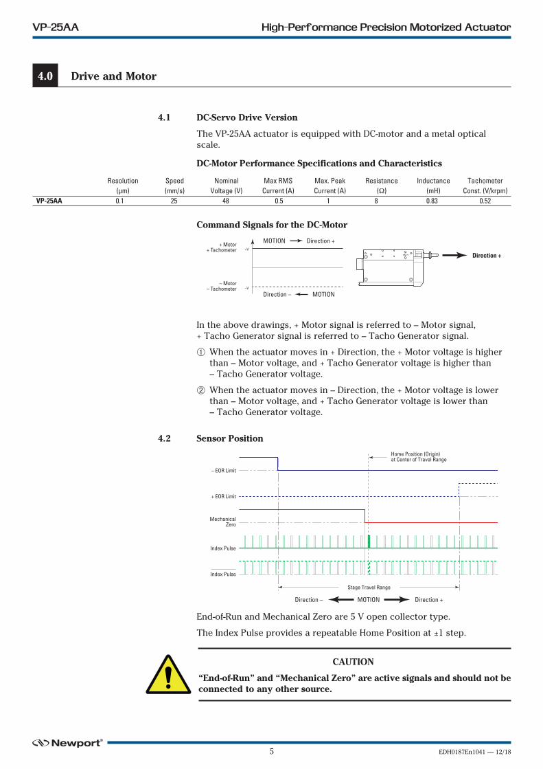
4.1 DC-Servo Drive Version
The VP-25AA actuator is equipped with DC-motor and a metal opticalscale.
DC-Motor Performance Specifications and Characteristics
Command Signals for the DC-Motor
In the above drawings, + Motor signal is referred to – Motor signal,+ Tacho Generator signal is referred to – Tacho Generator signal.
➀ When the actuator moves in + Direction, the + Motor voltage is higherthan – Motor voltage, and + Tacho Generator voltage is higher than– Tacho Generator voltage.
➁ When the actuator moves in – Direction, the + Motor voltage is lowerthan – Motor voltage, and + Tacho Generator voltage is lower than– Tacho Generator voltage.
4.2 Sensor Position
End-of-Run and Mechanical Zero are 5 V open collector type.
The Index Pulse provides a repeatable Home Position at ±1 step.
CAUTION
“End-of-Run” and “Mechanical Zero” are active signals and should not beconnected to any other source.
Resolution Speed Nominal Max RMS Max. Peak Resistance Inductance Tachometer (µm) (mm/s) Voltage (V) Current (A) Current (A) (Ω) (mH) Const. (V/krpm)VP-25AA 0.1 25 48 0.5 1 8 0.83 0.52
+V+ Motor
+ Tachometer
– Motor– Tachometer –V
MOTION Direction +
MOTIONDirection –
Direction +
– EOR Limit
MechanicalZero
Stage Travel Range
Index Pulse
Index Pulse
+ EOR Limit
Home Position (Origin)at Center of Travel Range
Direction – MOTION Direction +

EDH0187En1041 — 12/18 6
VP-25AA High-Performance Precision Motorized Actuator
4.3 Feedback Signal Position
The incremental sensor consists of an optical scale and an encoder head.When the carriage moves, the encoder head generates square signals inquadrature and sends to pins #19, #20, #23 and #24 of the SUB-D25connector.
“Encoder” and “Index Pulse” are “differential pair” (type RS-422) typeoutput signals. Using these signals permits a high immunity to noise.Emission circuits generally used by Newport are 26LS31 or MC3487.Reception circuits to use are 26LS32 or MC3486.
4.4 Pinouts
The pinout diagram for the VP-25AA actuator SUB-D25M connector isshown below.
0
1EncoderPhase A
0
1EncoderPhase A
1 2 3 4
0
1EncoderPhase B
0
1EncoderPhase B
Direction – MOTION Direction +
Direction +
SUD-D25 OR SUB-D15
Encoder Phase A 19 13
Encoder Phase A 23 6
Encoder Phase B 20 14
Encoder Phase B 24 7
Index Pulse Phase I 15 15
Index Pulse Phase I 25 8
21 12
22 5
NEWPORTSTAGE USER
CONNECTOR PIN #
Output Signals
Encoders & SensorsPower Supply
+5 V 5%150 mA max.
0 V }
1325
14 1
1 + Tachometer2 N.C.3 – Tachometer4 N.C.5 + Motor6 + Motor7 – Motor8 – Motor9 N.C.10 N.C.11 N.C.12 N.C.13 Mechanical Zero
14 Ground15 Index Pulse I16 0 V17 + End-of-Run18 – End-of-Run19 Encoder Phase A20 Encoder Phase B21 +5 V22 0 V23 Encoder Phase /A24 Encoder Phase /B25 Index Pulse /I

7 EDH0187En1041 — 12/18
VP-25AA High-Performance Precision Motorized Actuator
5.0 —Connection to Newport Controllers
5.1 Warnings on Controllers
Controllers are intended for use by qualified personnel who recognizeshock hazards and are familiar with safety precautions required to avoidpossible injury. Read the controller user’s manual carefully beforeoperating the instrument and pay attention to all written warnings andcautions.
WARNING
Disconnect the power plug under the following circumstances:
• If the power cord or any attached cables are frayed or damaged inany way.
• If the power plug is damaged in any way.
• If the unit is exposed to rain, excessive moisture, or liquids are spilledon the unit.
• If the unit has been dropped or the case is damaged.
• If you suspect service or repair is required.
• Whenever you clean the electronics unit.
CAUTION
To protect the unit from damage, be sure to:
• Keep all air vents free of dirt and dust.
• Keep all liquids away from the unit.
• Do not expose the unit to excessive moisture (85% humidity).
• Read this manual before using the unit for the first time.
WARNING
All attachment plug receptacles in the vicinity of this unit are to be ofthe grounding type and properly polarized.
Contact your electrician to check your receptacles.
WARNING
This product is equipped with a 3-wire grounding type plug.
Any interruption of the grounding connection can create an electricshock hazard.
If you are unable to insert the plug into your wall plug receptacle,contact your electrician to perform the necessary alterations to ensurethat the green (green-yellow) wire is attached to earth ground.
WARNING
This product operates with voltages that can be lethal.
Pushing objects of any kind into cabinet slots or holes, or spilling anyliquid on the product, may touch hazardous voltage points or short outparts.

EDH0187En1041 — 12/18 8
VP-25AA High-Performance Precision Motorized Actuator
5.2 Connection
There is a label on every stage indicating its part and serial numbers.
WARNING
Always turn the controller's power OFF before connecting to anactuator.
NOTE
These actuators are ESP compatible. Enhanced System Performance isNewport's exclusive technology that enables Newport ESP motioncontrollers to recognize the connected Newport ESP actuator and uploadthe actuator parameters. This ensures that the user can operate themotion system quickly and safely.
5.3 Cables
The VP-25AA actuator is delivered equipped with a 1.5-meter cable with aSUB-D25M connector for direct connection to Newport Controllers.
WARNING
This cable is shielded correctly. For a correct operation, make sure tolock connectors (ground continuity provided by the cable).
WARNING
Keep the motor cable at a safe distance from other electrical cables inyour environment to avoid potential cross talk.

9 EDH0187En1041 — 12/18
VP-25AA High-Performance Precision Motorized Actuator
6.0 —Connection to Non-Newport Electronics
6.1 Connections
WARNING
Newport is not responsible for malfunction or damage of VP-25AAactuators when used with non-Newport controllers.
WARNING
Newport guarantees “ ” compliance of VP-25AA actuators only if usedwith Newport cables and controllers.
It is the customer’s responsibility to modify the cable and take care ofsensor signal connections, when using the stage with non-Newportcontrollers.
End-of-Runs and Mechanical Zero are open collector type with a 5.6 Vprotective Zener diode.
.
Iin max.: 16 mAV max.: 5.25 V
NEWPORTSTAGE
5.6 V

EDH0187En1041 — 12/18 10
VP-25AA High-Performance Precision Motorized Actuator
7.0 —Dimensions
The VP-25AA actuator as a single-rail linear stage to positionsmall and light weight parts with the optional 561-RAIL rails.
1.04(26.4)
.53(13.5)
.59(15.1)
3.15(80)
BALL ø.20 (5)
ø.25(6)
6 HOLES M4 THD
CABLE LENGTH 1.5 M ANDSUB-D25M CONNECTOR
4 HOLES C’BORED FOR M4SCREW ON 3.94 x 1.97 (100 x 50)
.91 (23)
2.83(72)
6.53 ±.50 (165.8 ±12.7)
.61(15.6) 4.34 (110.3) .87 (22.2)
.31 (8).50
(12.7)
.08 (2) ø.97(9.52)
.63(16)
.43(10.9)
1.0(25.4)
3.0 (76.2)
.50(12.7)
.45(11.5)
2 HOLES ø.063 (1.6),.375 (9.525 SPACING)4 HOLES M2.5 THD
3.94 (100)
.13(3.2)
.47(12)
.06(1.5)
1.06 (27)
.02 (0.5).49
(12.5)
MODEL SHOWN: VP-25AADIMENSIONS IN INCHES (AND MILLIMETERS)

11 EDH0187En1041 — 12/18
VP-25AA High-Performance Precision Motorized Actuator
8.0 —Maintenance
RECOMMENDATION
Please contact Technical Sales Support team for recommendations onapplication specific maintenance.
8.1 Maintenance
The VP-25AA actuator requires no particular maintenance. Nevertheless,this is a precision mechanical device that must be kept and operated withcaution.
PRECAUTIONS
The VP-25AA actuator must be used or stocked in a clean environment,without dust, humidity, solvents or other substances.
RECOMMENDATION
It is recommended to return the stage to Newport for re-lubrication after2000 hours of use.
If the VP-25AA actuator is mounted on a workstation and cannot beeasily removed, please contact Newport's After Sales Service for furtherinstructions.
8.2 Repair
CAUTION
Never attempt to disassemble a component of the actuator that has notbeen covered in this manual.
To disassemble a non specified component can cause a malfunction ofthe actuator.
If you observe a malfunction in your actuator, please contact usimmediately to arrange for a repair.
CAUTION
Any attempt to disassemble or repair an actuator without priorauthorization will void your warranty.
8.3 Calibration
CAUTION
It is recommended to return your VP-25AA actuator to Newport once ayear for recalibration to its original specifications.

EDH0187En1041 — 12/18 12
VP-25AA High-Performance Precision Motorized Actuator

13 EDH0187En1041 — 12/18
Your Local RepresentativeTel.:Fax:
Name:
Company:
Address:
Country:
P.O. Number:
Item(s) Being Returned:
Model #:
Description:
Reasons of return of goods (please list any specific problems):
Return authorization #:(Please obtain prior to return of item)
Date:
Phone Number:
Fax Number:
Serial #:
Service Form

Visit Newport Online at:www.newport.com
North America & Asia
Newport Corporation
1791 Deere Ave.Irvine, CA 92606, USA
Sales
Tel.: (800) 222-6440
e-mail: [email protected]
Technical Support
Tel.: (800) 222-6440
e-mail: [email protected]
Service, RMAs & Returns
Tel.: (800) 222-6440
e-mail: [email protected]
Europe
MICRO-CONTROLE Spectra-Physics S.A.S
9, rue du Bois Sauvage91055 Évry CEDEXFrance
Sales & Technical Support
Tel.: +33 (0)1.60.91.68.68
e-mail: [email protected]
Service & Returns
Tel.: +33 (0)2.38.40.51.55