Fluke 3540 FC Three-Phase Power Monitor - PRUFTECHNIK
6
TECHNICAL DATA Fluke 3540 FC Three-Phase Power Monitor SAFETY FIRST Deploying cloud-connected power monitors limits worker interaction to difficult-to-reach or dangerous areas SHAREABLE DATA Keep everyone on the same page by sharing data with teams, experts, or executives MORE THAN JUST A LOGGER Powered from the measurement circuit, configuration checker can automatically correct connection errors ALWAYS ON The Monitor includes a mode to log measurements when no connection to Fluke Connect Cloud is available The 3540 FC Three-Phase Power Monitor is a portable, semi-fixed device that monitors electrical systems. When connected to Wi-Fi, the 3540 FC wirelessly transmits electrical measurements to the Fluke Connect™ cloud. Measurement data is available on any con- nected device using the Fluke Connect mobile app or web-based instance. Monitoring an asset’s electrical parameters—such as current and distortion—can reveal how the machinery or equipment is performing. Maintenance teams can view asset status without needing to be at assets or in dangerous areas. Graphs are available to show trends and fluctuations of measure- ments during the monitoring period. Alarm settings notify users immediately when measurement values are outside specified thresholds. Connecting the Fluke 3540 FC with Fluke Connect Condition Monitoring (FCCM) software allows teams to access asset data from anywhere. View real-time or historical measurements from a smart device, such as mobile phone, tablet, or PC/Mac computer. Having immediate access to machinery performance information can be the deciding factor between downtime and preventing a stop in production. Understanding changes in equipment performance triggers the need to investigate further, the alternative is unknowingly letting the machine run to fail. For example: • A baseline reading at a critical pump is trending dangerously close to the maximum current rating, taking service factor into account. • The total power at an induction furnace appears to be fluctuating abnormally during a curing cycle. • Determining how often a submersible or hydraulic pump is cycling on/off to maintain flow or pressures, in some cases simply validating there is power to the pump. Measurements: • Single, split, and three phase loads • Voltage, current, and frequency • Power, including Active Power (VA), Non-Active Power (VAR), and Power Factor (PF) • Total Harmonic Distortion (%)
-
Upload
khangminh22 -
Category
Documents
-
view
5 -
download
0
Transcript of Fluke 3540 FC Three-Phase Power Monitor - PRUFTECHNIK
TECHNICAL DATA
Fluke 3540 FC Three-Phase Power Monitor
SAFETY FIRSTDeploying cloud-connected power monitors limits worker interaction to difficult-to-reach or dangerous areas
SHAREABLE DATAKeep everyone on the same page by sharing data with teams, experts, or executives
MORE THAN JUST A LOGGERPowered from the measurement circuit, configuration checker can automatically correct connection errors
ALWAYS ON The Monitor includes a mode to log measurements when no connection to Fluke Connect Cloud is available
The 3540 FC Three-Phase Power Monitor is a portable, semi-fixed device that monitors electrical systems. When connected to Wi-Fi, the 3540 FC wirelessly transmits electrical measurements to the Fluke Connect™ cloud. Measurement data is available on any con-nected device using the Fluke Connect mobile app or web-based instance.
Monitoring an asset’s electrical parameters—such as current and distortion—can reveal how the machinery or equipment is performing. Maintenance teams can view asset status without needing to be at assets or in dangerous areas.
Graphs are available to show trends and fluctuations of measure-ments during the monitoring period. Alarm settings notify users immediately when measurement values are outside specified thresholds.
Connecting the Fluke 3540 FC with Fluke Connect Condition Monitoring (FCCM) software allows teams to access asset data from anywhere. View real-time or historical measurements from a smart device, such as mobile phone, tablet, or PC/Mac computer.
Having immediate access to machinery performance information can be the deciding factor between downtime and preventing a stop in production. Understanding changes in equipment performance triggers the need to investigate further, the alternative is unknowingly letting the machine run to fail.
For example: • A baseline reading at a critical pump is trending dangerously
close to the maximum current rating, taking service factor into account.
• The total power at an induction furnace appears to be fluctuating abnormally during a curing cycle.
• Determining how often a submersible or hydraulic pump is cycling on/off to maintain flow or pressures, in some cases simply validating there is power to the pump.
Measurements: • Single, split, and three phase loads• Voltage, current, and frequency• Power, including Active Power (VA), Non-Active Power (VAR),
and Power Factor (PF)• Total Harmonic Distortion (%)

2 Fluke Corporation Fluke 3540 FC Three-Phase Power Monitor
SpecificationsElectrical specifications
Single and Three Phase Topologies
Wiring configurations 1-Φ, 1-Φ IT, Split phase, 3-Φ wye, 3-Φ wye IT, 3-Φ wye balanced, 3-Φ delta, 3-Φ Aron/Blondel (2-element delta), 3-Φ delta open leg, 3-Φ high leg delta, 3-Φ delta balanced. Currents only (load studies)
Voltage inputs
Number of inputs 4 (3 phases and neutral)
Maximum input voltage 1,000 Vrms (1,700 Vpk) phase to neutral
Bandwidth 42.5 Hz to 3.5 kHz
Scaling 1:1, variable
Current inputs
Number of inputs 3, mode selected automatically for attached sensor
Bandwidth (-3 dB) 42.5 Hz to 3.5 kHz
Measurement Hardware Sampling
Resolution 16-bit synchronous sampling
Sampling frequency 10.24 kHz at 50/60 Hz, synchronized to mains frequency
Input signal frequency Mains 50/60 Hz (42.5 to 69 Hz)
Data storage Internal flash memory (not user replaceable)
Memory size Typical 1 offline logging session of 1 week with 1 second intervals. The number of possible logging sessions and logging period depends on user requirements.
Measured parameters Voltage, current, frequency, THD V, THD A, power, power factor, fundamental power, DPF
Averaging interval 1 s
Total harmonic distortion THD for voltage and current is calculated on 25 harmonics
Interfaces
USB-A Firmware updates, max. supply current: 120 mA
WiFi
Supported modes Direct connection and connection to infrastructure
Security WPA2-AES with pre-shared key
Power supply
Voltage range nominal 100 V to 500 V (85 V min to 550 V max) using safety plug input
Mains power nominal 100 V to 240 V (85 V min to 265 V max) using IEC 60320 C7 input
Power consumption Maximum 50 VA (max. 15 VA when powered using IEC 60320 input)
Standby power <0.3 W only when powered using IEC 60320 input
Efficiency ≥ 68.2 % (in accordance with energy efficiency regulations)
Mains frequency 50/60 Hz ± 15 %
Battery power Li-ion 3.7 V, 9.25 Wh, customer-replaceable
On-battery runtime Up to 4 hr (up to 5.5 hr in energy saving mode)
Charging time <6 hr
Power Source wall outlet and measurement input line

3 Fluke Corporation Fluke 3540 FC Three-Phase Power Monitor
Accuracy at reference conditions
Parameter Range Accuracy
Max. resolution Intrinsic accuracy at reference conditions (% of reading + % of range)
Voltage 1,000 V 0.1 V ± (0.2 % + 0.01 %)
Current
Direct input Rogowski Mode 15 mV 0.01 mV ± (0.3 % + 0.02 %)
150 mV 0.1 mV ± (0.3 % + 0.02 %)
Clamp Mode 50 mV 0.01 mV ± (0.2 % + 0.02 %)
500 mV 0.1 mV ± (0.2 % + 0.02 %)
1500 A iFlex 150 A 0.01 A ± (1 % + 0.02 %)
1,500 A 0.1 A ± (1 % + 0.02 %)
3000 A iFlex 300 A 1 A ± (1.5 % + 0.03 %)
3,000 A 10 A ± (1 % + 0.02 %)
6000 A iFlex 600 A 1 A ± (1.5 % + 0.03 %)
6,000 A 10 A ± (1.5 % + 0.03 %)
i40s-EL 40 A 4 A 1 mA ± (0.7 % + 0.02 %)
40 A 10 mA ± (0.7 % + 0.02 %)
Frequency 42.5 Hz to 69 Hz 0.01 Hz ± (0.1 %)
Voltage min/max 1,000 V 0.1 V ± (1 % + 0.1 %)
Current min/max defined by accessory defined by accessory ± (5 % + 0.2 %)
THD on voltage 1,000 % 0.1 % ± (2.5 % ± 0.05 %)
THD on current 1,000 % 0.1 % ± (2.5 % ± 0.05 %)
Power/Energy
Direct input1 iFlex1500-12 iFlex3000-24 iFlex6000-36 i40s-EL
Parameter Clamp: 50 mV/500 mV 150 A/1,500 A 300 A/3,000 A 600 A/6,000 A 4 A/40 A
Rogowski: 15 mV/150 mV
Power range W, VA, var
Clamp: 50 W/500 W 150 kW/1.5 MW 300 kW/3 MW 600 kW/6 MW 4 kW/40 kW
Rogowski: 15 W/150 W
Max. resolution W, VA, var
0.1 W 0.01 kW/0.10 kW 1 kW/10 kW 1 kW/10 kW 1 W/10 W
Max. resolution PF, DPFfund.
0.01
2.5 % of measured apparent power
Phase (voltage to current) of range1
± 0.2° ± 0.28° ± 1°
1 Only for calibration laboratories

4 Fluke Corporation Fluke 3540 FC Three-Phase Power Monitor
iFlex probe specifications
Measuring range
iFlex 1500-12 1 A ac to 150 A ac / 10 A ac to 1500 A ac
iFlex 3000-24 3 A ac to 300 A ac / 30 A ac to 3000 A ac
iFlex 6000-36 6 A ac to 600 A ac / 60 A ac to 6000 A ac
Nondestructive current 100 kA (50/60 Hz)
Intrinsic error at reference condition1
± 0.7 % of reading
Accuracy 3540 FC + iFlex
iFlex 1500-12 and iFlex 3000-24 ± (1 % of reading + 0.02 % of range)
iFlex 6000-36 ± (1.5 % of reading + 0.03 % of range)
Temperature coefficient over operating temperature range
iFlex 1500-12 and iFlex 3000-24 0.05 % of reading / °C (0.09 % of reading / °F)
iFlex 6000-36 0.1 % of reading / °C (0.18 % of reading / °F)
Bandwidth 10 Hz to 23.5 kHz (probe only)
Frequency derating I x f ≤385 kA Hz
Working voltage 1,000 V CAT III, 600 V CAT IV1Reference condition:
• Environmental: 23 °C ±5 °C, no external electrical/magnetic field, RH 65 %
• Primary conductor in center position
Transducer length
iFlex 1500-12 305 mm (12 in)
iFlex 3000-24 610 mm (24 in)
iFlex 6000-36 915 mm (36 in)
Transducer cable diameter
7.5 mm (0.3 in)
Minimum bending radius
38 mm (1.5 in)
Output cable length
iFlex 1500-12 2 m (6.6 ft)
iFlex 3000-24 and iFlex 6000-36
3 m (9.8 ft)
Weight
iFlex 1500-12 115 g (4 oz)
iFlex 3000-24 170 g (6 oz)
iFlex 6000-36 190 g (7 oz)
Material
Transducer cable TPR
Coupling POM + ABS/PC
Output cable TPR/PVC
Operating temperature
-20 °C to +70 °C (-4 °F to 158 °F) temperature of conductor under test shall not exceed 80 °C (176 °F)
Storage temperature
-40 °C to +80 °C (-40 °F to 176 °F)
Operating relative humidity
15% to 85% noncondensing
IP rating IEC 60529:IP50
Operating altitude 2,000 m (6,500 ft) up to 4,000 m (13,000 ft) derate to 1,000 V CAT II / 600 V CAT III / 300 V CAT IV
Storage altitude 12 km (40,000 ft)
Warranty 1 year
Positioning error with position of conductor in the probe window
iFlex 1500-12, iFlex 3000-24
iFlex 6000-36
ProbeWindow A
± (1 % of reading + 0.02 % of range)
± (1.5 % of reading + 0.03 % of range)
ProbeWindow B
± (1.5 % of reading + 0.02 % of range)
± (2.0 % of reading + 0.03 % of range)
ProbeWindow C
± (2.5 % of reading + 0.02 % of range)
± (4 % of reading + 0.03 % of range
iFlex 1500-12: 88mmiFlex 3000-24: 185mmiFlex 6000-36: 282mm
C
B
A
1/3
1/3
1/3
Figure. iFlex Probe Window
iFlex probe specifications
External magnetic field rejection in reference to external current (with cable >100 mm from the head-coupling and r-coil)
40 dB
Phase shift < ± 0.5°

5 Fluke Corporation Fluke 3540 FC Three-Phase Power Monitor
General specifications
Color LCD display 4.3-inch active matrix color TFT, 480 pixels x 272 pixels, resistive touch panel
Warranty 3540 FC and built-in power supply 2 years (battery not included)
Accessories 1 year
Calibration cycle 2 years
Dimensions (wxhxd)
3540 FC 19.8 cm x 16.7 cm x 5.5 cm (7.8 in x 6.6 in x 2.2 in)
Detachable power supply 13.0 cm x 13.0 cm x 4.5 cm (5.1 in x 5.1 in x 1.8 in)
3540 FC with power supply attached 19.8 cm x 16.7 cm x 9 cm (7.8 in x 6.6 in x 4.0 in)
Weight 3540 FC 1.1kg (2.5 lb)
Power Supply 400 g (0.9 lb)
Tamper protection Kensington lock
Environmental specifications
Operating temperature O °C to 45 °C (32 °F to 113 °F)
Storage temperature <20 °C to +60 °C (-4 °C to +140 °F), with battery: -20 °C to +50 °C (-4 °F to +122 °F)
Operating humidity <10 °C (<50 °F) non condensing
10 °C to 30 °C (50 °F to 86 °F) ≤95 %
30 °C to 40 °C (86 °F to 104 °F) ≤75 %
40 °C to 45 °C (104 °F to 113 °F) ≤45 %
Operating altitude 2000 m (6,500 ft) (up to 4,000 m derate to 1,000 V CAT II/600 V CAT III/300 V CAT IV)
Storage altitude 12,000 m (39,000 ft)
IP rating IEC 60529:IP50, in connected condition with protection caps in place
Vibration MIL-T-28800E, Type 3, Class III, Style B
Safety
IEC 61010-1 IEC mains input Overvoltage Category II, Pollution Degree 2
Voltage terminals Overvoltage Category IV, Pollution Degree 2
IEC 61010-2-033 CAT IV 600 V/CAT III 1,000 V
Electromagnetic compatibility (EMC)
International IEC 61326-1: Industrial
Korea (KCC) Class A Equipment (Industrial Broadcasting & Communication Equipment)
USA (FCC) 47 CFR 15 subpart B. This product is considered an exempt device per clause 15.103.
Wireless radio with adapter
Frequency range 2,412 MHz to 2,462 MHz
Output power <100 mW
6 Fluke Corporation Fluke 3540 FC Three-Phase Power Monitor
PRÜFTECHNIK Condition Monitoring GmbHOskar-Messter-Str. 19-21 85737 Ismaning Germany T + 49 8999616 420 [email protected]
©2019 Fluke Corporation. 4/2019 6008088h-en
Modification of this document is not permitted without written permission from Fluke Corporation.
Accelix. Connected Reliability.
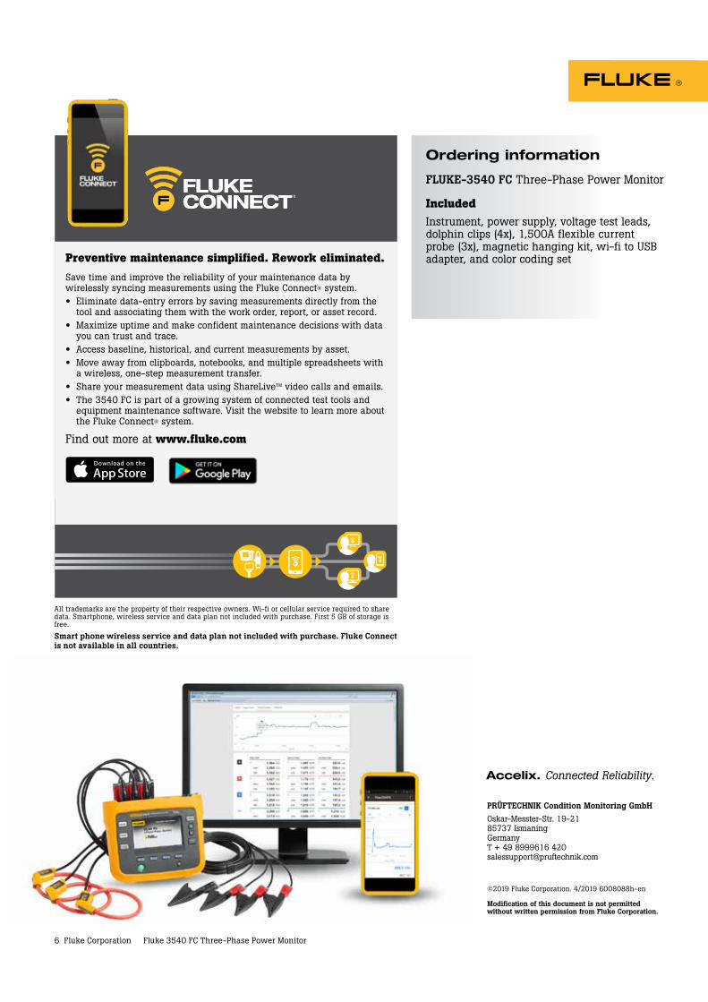
Ordering information
FLUKE-3540 FC Three-Phase Power Monitor
IncludedInstrument, power supply, voltage test leads, dolphin clips (4x), 1,500A flexible current probe (3x), magnetic hanging kit, wi-fi to USB adapter, and color coding set
All trademarks are the property of their respective owners. Wi-fi or cellular service required to share data. Smartphone, wireless service and data plan not included with purchase. First 5 GB of storage is free.
Smart phone wireless service and data plan not included with purchase. Fluke Connect is not available in all countries.
Preventive maintenance simplified. Rework eliminated.Save time and improve the reliability of your maintenance data by wirelessly syncing measurements using the Fluke Connect® system.• Eliminate data-entry errors by saving measurements directly from the
tool and associating them with the work order, report, or asset record.• Maximize uptime and make confident maintenance decisions with data
you can trust and trace.• Access baseline, historical, and current measurements by asset.• Move away from clipboards, notebooks, and multiple spreadsheets with
a wireless, one-step measurement transfer.• Share your measurement data using ShareLiveTM video calls and emails.• The 3540 FC is part of a growing system of connected test tools and
equipment maintenance software. Visit the website to learn more about the Fluke Connect® system.
Find out more at www.fluke.com