Process Calibration Tools Catalog EN - Fluke Corporation
64
Temperature Calibration Data Acquisition Pressure Calibration Software/Accessories Pressure Applications Temperature Applications Electrical, Multifunction, and mA Loop Calibration PROCESS CALIBRATION TOOLS CATALOG
-
Upload
khangminh22 -
Category
Documents
-
view
1 -
download
0
Transcript of Process Calibration Tools Catalog EN - Fluke Corporation

Temperature Calibration
Data Acquisition
Pressure Calibration
Software/Accessories
Pressure Applications
Temperature Applications
Electrical, Multifunction, and mA Loop Calibration PROCESS CALIBRATION TOOLS CATALOG

2 Process Calibration Tools
Process Calibration ToolsFrom Fluke and Fluke Calibration
Working in a process environment such as pharmaceutical, refining or other industrial area can be challenging. Whether you’re working at a bench, out in the plant, or in the field, you need accurate tools that you can count on.
Finding the right tools for the specific challenges you face every day is important,so we’ve provided an “at-a-glance” guide to the wide range of multifunction, mA loop, pressure and temperature calibrators that we carry. For complete information on our field and bench solutions to all your calibration needs visit www.fluke.com, www.flukecal.eu,or one of the product pages listed in this catalog.
Electrical and multifunction calibrationFluke offers a broad range of field and bench calibrators to source, simulate, and measure pressure, temperature, and electrical signals to help you verify and adjust your test equipment or almost any process instrument.
mA loop calibrationLoop calibrators are essential tools for working with 4-20 mA current loops. Fluke loop calibrators provide mA sourcing, simulation and measurement, readouts in both mA and % of span, 24 V loop supply, simple operation and accuracy you can count on.
Pressure calibrationInstrumentation is found in virtually every process plant. Periodic calibration of these instruments is required to keep plants operating efficiently and safely. Fluke provides a wide selection of field and bench calibration tools to help you quickly and reliably calibrate your pressure instrumentation.
Temperature calibrationTemperature calibration refers to the calibration of any device used in a system that measures temperature—from sensors to transmitters to displays. Fluke offers bench and field solutions to ensure process temperature accuracy of not only the system’s electronic temperature signals, but also the very temperature sensors that initiate those signals.

Process Calibration Tools 3
Multifunction calibrators ..................5mA loop calibrators ............................7
Data acquisition systems ..................9
Digital pressure calibrators ..............11
Pressure comparators and master gauges ..............................12
Manual pressure calibrators ............13
Reference pressure calibrator .........14
Bench deadweight testers ................14
Handheld temperature calibrators ..........................................17Pressure comparators and master gauges ...................................17Field temperature sources ..............18Infrared temperature sources ........19Thermometer standards ................. 20Ambient conditions monitor .......... 20Precision PRTs ..................................21Thermistors .......................................21
Process Calibration Tools
Electrical, Multifunction, and mA Loop Calibration
4
Data Acquisition
9
Pressure Applications
24
Temperature Applications
42
Temperature Calibration
16
Software ........................................... 22Temperature calibration software ............................................ 23Accessories ....................................... 23
Calibrating a HART smart pressure transmitter ....................... 26Pressure transmitter calibration at the bench ..................................... 28Pressure switch testing - manual .............................. 30Pressure switch testing - documented ..................... 32
Pressure Calibration
10
Software/Accessories
22
Gas custody transfer flow computer calibration ....................... 34Verifying process gauges, analog and digital........................... 36Calibrating at the bench with a deadweight tester .............. 38Calibrating at the bench with a pressure comparator .......... 40Use and selection of hand pumps and pressure test gauges for field pressure testing ............................... 42
Calibrating and testing RTD Sensors ..................................... 46Calibrating and testing thermocouple sensors ................... 48Simulating thermocouples and RTDs for calibration and testing .... 50Using a precision thermometer for single point process temperature verification ................ 52Temperature switch and controller testing in the field ........ 54Temperature switch and controller testing at the bench ..... 56Calibrating with a micro-bath ...... 58Infrared thermometer test and calibration ................................ 60Loop calibration with a temperature transmitter at the bench ..................................... 62

4 Electrical, Multifunction, and mA Loop Calibration
Electrical, Multifunction, and mA Loop
Calibration

5Electrical, Multifunction, and mA Loop Calibration
Multifunction CalibratorsThese field and bench calibrators source, simulate, and measure pressure, temperature, and electrical signals with exceptional precision.
753 Documenting Process CalibratorRugged handheld tool for sourc-ing, simulating and measuring pressure, temperature, and elec-trical signals.• Measure volts, mA, RTDs,
thermocouples, frequency, and ohms to test sensors, transmit-ters and other instruments
• Source/simulate volts, mA, ther-mocouples, RTDs, frequency, ohms, and pressure to calibrate transmitters
• Power transmitters during test using loop supply with simulta-neous mA measurement
• Download procedures and upload calibration results from field calibrations
• NIST traceable calibrationwww.fluke.com/753
754 Documenting Process Calibrator with HARTRugged, reliable tool for cal-ibrating, maintaining, and troubleshooting HART and other instrumentation. • Measure volts, mA, RTDs,
thermocouples, frequency, and ohms to test sensors, transmit-ters and other instruments
• Source/simulate volts, mA, ther-mocouples, RTDs, frequency, ohms, and pressure to calibrate transmitters
• Supports popular models of HART transmitters, with more device-specific command sup-port than any other HART field calibrator
• Download procedures and upload calibration results from field calibrations
• NIST traceable calibrationwww.fluke.com/754
7526A Precision Process CalibratorBest balance of economy and accuracy for calibration of temperature and pressure process measurement instrumentation.• Sources and measures dc volt-
age, current, resistance, RTDs and thermocouples
• Measures pressure using Fluke 700/525A-P pressure modules
• Includes 24 V dc loop power supply, automated switch-test function and measures 4 mA to 20 mA
• NIST traceable calibrationwww.flukecal.eu/7526A
753
7526A
754

6 Electrical, Multifunction, and mA Loop Calibration
726 Precision Multifunction Process CalibratorDesigned specifically for the process industry with broad workload coverage, calibration power and unsurpassed accu-racy. Includes all the features and functions of the 725 below plus:• Enhanced accuracy• Pulse count sourcing and pulse
measurement totalizing• Pressure switch test• Error % calculation• NIST traceable calibrationwww.fluke.com/726
725 Multifunction Process CalibratorA powerful and easy-to-use field calibrator to test and calibrate almost any process parameter. • Measure volts, mA, RTDs,
thermocouples, frequency, and ohms to test sensors and transmitters
• Source/simulate volts, mA, ther-mocouples, RTDs, frequency, ohms, and pressure to calibrate transmitters
• Measure/source pressure using any of 29 Fluke 700Pxx Pressure Modules
• Source mA with simultaneous pressure measurement to conduct valve and I/P tests
• NIST traceable calibrationwww.fluke.com/725
725EX IS Multifunction Process CalibratorEasy-to-use, intrinsically safe field calibrator can calibrate almost any process instrument needing service where explosive gasses may be present. • ATEX II 1 G Ex ia IIB 171 °C
KEMA 04ATEX 1303X • I.S. Class I, Division 1 Groups
B-D, 171 °C compliance • Measure Volts dc, mA, RTDs,
thermocouples, frequency and ohms
• Source or simulate volts dc, mA, RTDs, thermocouples, frequency and ohms
• Measure/source pressure using any of eight Fluke 700PEX Pressure Modules
• NIST traceable calibrationwww.fluke.com/725EX
8808A Digital MultimeterVersatile multimeter for manufacturing, development and service applications.• 5.5 digit resolution• Basic V dc accuracy of 0.015 %• Dual display• NIST traceable calibrationwww.flukecal.eu/8808A
8845A/8846A Precision MultimetersPrecision and versatility for bench or systems applications.• 6.5 digit resolution• Basic V dc accuracy of up to
0.0024 %• Dual display• /C models include accredited
calibrationwww.flukecal.eu/8845A
725Ex
8808A
8845A/8846A
726 725

7Electrical, Multifunction, and mA Loop Calibration
mA Loop CalibratorsFluke loop calibrators are ideal for a wide variety of calibration applications from 4 to 20 mA.
705 Loop CalibratorA cost-effective, integrated solu-tion for calibration, repair and maintenance of current loops.• mA sourcing, simulation and
measurement • Simultaneous mA and % of
span display • 24 V loop supply with mA
measure • 0 V dc to 28 V dc measurement
to check loop voltage• NIST traceable calibration www.fluke.com/705
707 Loop CalibratorA high performance, extremely fast and easy-to-use solution for calibration, repair and mainte-nance of current loops.• mA sourcing, simulation and
measurement • 24 V loop supply with mA
measure, including 250 Ω HART resistor
• 0 V dc to 28 V dc measurement to check loop voltage
• NIST traceable calibrationwww.fluke.com/707
707EX IS Loop CalibratorAn intrinsically safe option for use in explosion endangered areas—certified in accordance with the ATEX directive (Ex II 2 G Ex ia IIC T4) in Zones 1 and 2.• 1 µA resolution for mA source,
simulate and measure • Measures V dc to 28 V • 0-20 mA or 4-20 mA default
startup modes • HART® compatible resistance
is connected in series with the loop supply for compatibility with HART communicators
• NIST traceable calibrationwww.fluke.com/707EX
707
709
705
709 Precision Loop CalibratorReduces the time it takes to measure or source voltage or current and power up a loop.• Best-in-class accuracy at 0.01%
reading• Small rugged design operates
on six standard AAA batteries• Intuitive user interface with
Quick-Set knob for fast setup, easy use
• Built-in selectable 250 Ω resistor for HART communication
• 24 V dc loop power with mA Measure Mode (-25% to 125%)
• Resolution of 1 µA on mA ranges and 1 mV on voltages ranges
• NIST traceable calibrationwww.fluke.com/709
709H Precision Loop Calibrator with HART Communications/DiagnosticsDesigned to save time and produce high-quality results• HART Communication built
in for easy HART device maintenance
• Best-in-class accuracy at 0.01% reading
• Small rugged design operates on six standard AAA batteries
• Intuitive user interface with Quick-Set knob for fast setup, easy use
• Built-in selectable 250 Ω resistor for HART communication
• 24 V dc loop power with mA Measure Mode (-25% to 125%)
• Resolution of 1 µA on mA ranges and 1 mV on voltage ranges
• NIST traceable calibrationwww.fluke.com/709H
707EX
709H

8 Electrical, Multifunction, and mA Loop Calibration
715
710 mA Loop Valve TesterThe Fluke 710 Valve Testing Loop Calibrator is designed to enable users to perform quick, easy tests on HART smart control valves.• Key valve testing functions
include pre-configured valve signature test, speed test, step test, manual test, and bump/partial stroke test
• Key mA loop calibrator func-tions include mA source, mA simulate, mA read, mA read/loop power, and volts read
• ValveTrack™ Software enables upload to a PC for further in-depth analysis of valve mea-surements that are logged and recorded to memory
www.fluke.com/710
715 Volt/mA CalibratorOutstanding performance, durability and reliability.• Measure loop current (0-20 mA,
4-20 mA) signals with very high accuracy of 0.015% and 1 mA resolution
• Measure voltage output process signals from PLCs, transmitters
• Source or simulate 24 mA loop current
• Source voltage to 100 mV or 10 V• 24 V loop supply with simultane-
ous current measurement• Enhanced voltage and current
measure and source accuracy• NIST traceable calibrationwww.fluke.com/715
787B ProcessMeter™
The Fluke 787B ProcessMeter™ doubles troubleshooting capabil-ities by combining the power of a digital multimeter and mA loop calibrator into one tool.• 20 mA dc current source/
measure/simulate• Simultaneous mA and % of
scale readout• Fluke Connect® compatibility
for wireless data logging (with IR3000FC module)
• Precision 1000 V, 440 mA true-rms digital multimeter
• Frequency measurement to 20 kHz
• Min/Max/Average/Hold/Relative modes
• CAT IV 600 V/CAT III 1000 V rating
www.fluke.com/787B
789 ProcessMeter™
The 789 includes all the popular features of the 787B and adds:• 24 V loop power supply• HART mode setting with loop
power and a built-in 250 ohm resistor
www.fluke.com/789
771 Milliamp Process Clamp MeterSaves time by making fast, accu-rate measurements on 4-20 mA signal loops without breaking the circuit.• 0.01 mA resolution and
sensitivity• Measure mA signals for PLC and
control system analog I/O• Measure 10 to 50 mA signals in
older control systems using the 99.9 mA range
www.fluke.com/771
772 Milliamp Clamp MeterExpanded features of the popular 771 mA Clamp Meter by adding loop power and mA sourcing to the capabilities.• Measure 4 to 20 mA signals
with in-circuit measurement• Simultaneous mA in-circuit
measurement with 24 V loop power for powering and testing transmitters
• Source 4 to 20 mA signals for testing control system I/O or I/Ps
• Automatically ramp or step the 4 to 20 mA output for remote testing
www.fluke.com/772
773 Milliamp Process Clamp MeterThe premier mA clamp meter, adds advanced troubleshooting features and voltage source/ measure for testing voltage I/O. Icludes all the features of the 772 plus:• DC voltage sourcing and mea-
surement, verify 24 V power supplies or test voltage I/O signals
• Scaled mA output provides a continuous mA signal that corresponds to the 4 to 20 mA signal measured by the mA clamp
• Simultaneously source and measure mA signals
www.fluke.com/773
771/772/773
787B/789
715
710
9
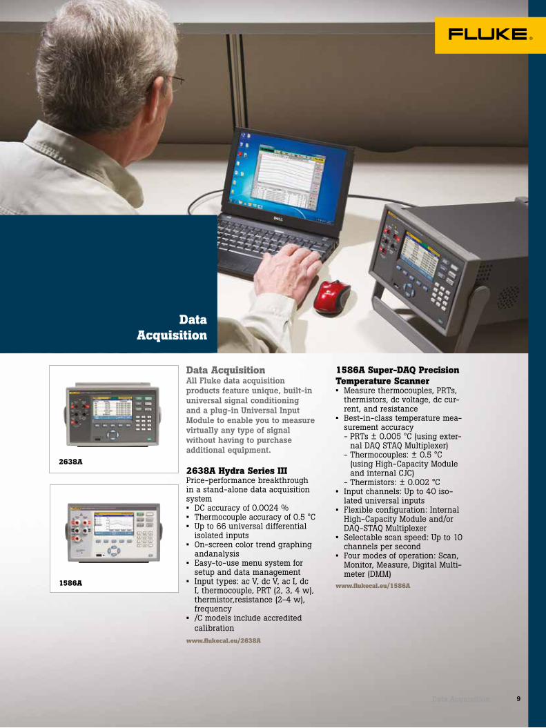
1586A
Data AcquisitionAll Fluke data acquisition products feature unique, built-in universal signal conditioning and a plug-in Universal Input Module to enable you to measure virtually any type of signal without having to purchase additional equipment.
2638A Hydra Series IIIPrice-performance breakthroughin a stand-alone data acquisitionsystem• DC accuracy of 0.0024 %• Thermocouple accuracy of 0.5 °C• Up to 66 universal differential
isolated inputs• On-screen color trend graphing
andanalysis• Easy-to-use menu system for
setup and data management• Input types: ac V, dc V, ac I, dc
I, thermocouple, PRT (2, 3, 4 w), thermistor,resistance (2-4 w), frequency
• /C models include accredited calibration
www.flukecal.eu/2638A
2638A
Data Acquisition
Data Acquisition
1586A Super-DAQ Precision Temperature Scanner• Measure thermocouples, PRTs,
thermistors, dc voltage, dc cur-rent, and resistance
• Best-in-class temperature mea-surement accuracy
- PRTs ± 0.005 °C (using exter-nal DAQ STAQ Multiplexer)
- Thermocouples: ± 0.5 °C (using High-Capacity Module and internal CJC)
- Thermistors: ± 0.002 °C• Input channels: Up to 40 iso-
lated universal inputs• Flexible configuration: Internal
High-Capacity Module and/or DAQ-STAQ Multiplexer
• Selectable scan speed: Up to 10 channels per second
• Four modes of operation: Scan, Monitor, Measure, Digital Multi-meter (DMM)
www.flukecal.eu/1586A

10 Pressure Calibration
Pressure Calibration
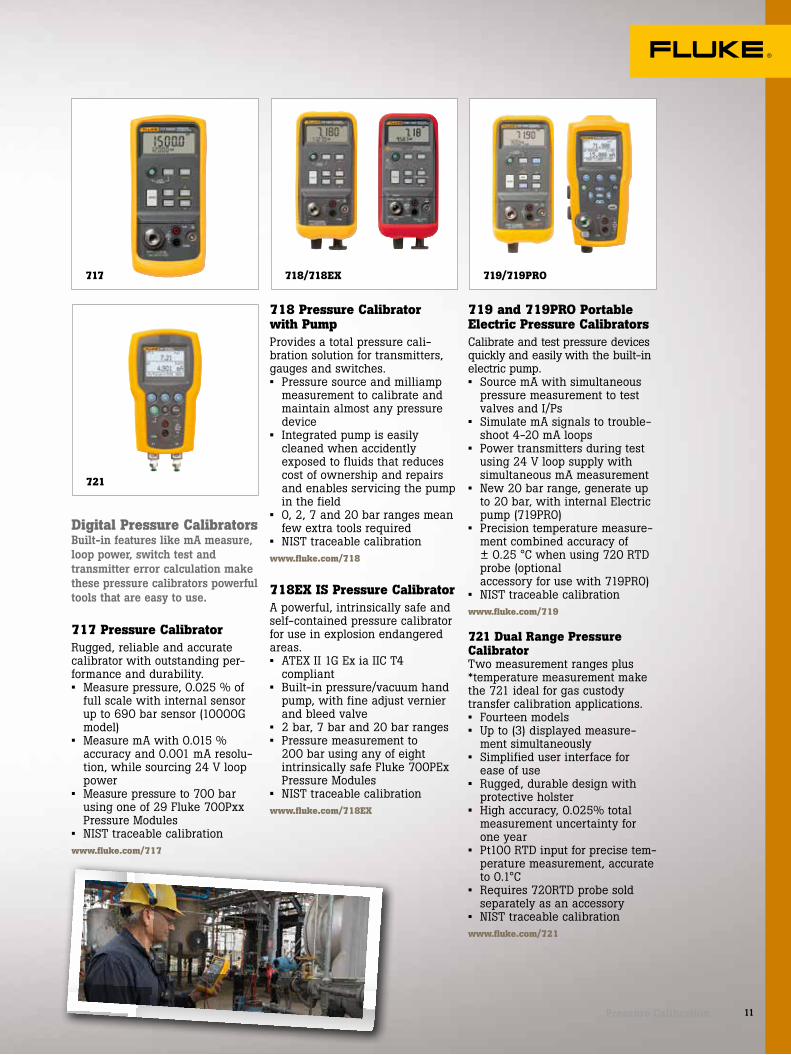
721
11Pressure Calibration
718 Pressure Calibrator with PumpProvides a total pressure cali-bration solution for transmitters, gauges and switches. • Pressure source and milliamp
measurement to calibrate and maintain almost any pressure device
• Integrated pump is easily cleaned when accidently exposed to fluids that reduces cost of ownership and repairs and enables servicing the pump in the field
• 0, 2, 7 and 20 bar ranges mean few extra tools required
• NIST traceable calibrationwww.fluke.com/718
718EX IS Pressure CalibratorA powerful, intrinsically safe and self-contained pressure calibrator for use in explosion endangered areas.• ATEX II 1G Ex ia IIC T4
compliant• Built-in pressure/vacuum hand
pump, with fine adjust vernier and bleed valve
• 2 bar, 7 bar and 20 bar ranges • Pressure measurement to
200 bar using any of eight intrinsically safe Fluke 700PEx Pressure Modules
• NIST traceable calibrationwww.fluke.com/718EX
717 719/719PRO718/718EX
Digital Pressure CalibratorsBuilt-in features like mA measure, loop power, switch test and transmitter error calculation make these pressure calibrators powerful tools that are easy to use.
717 Pressure CalibratorRugged, reliable and accurate calibrator with outstanding per-formance and durability.• Measure pressure, 0.025 % of
full scale with internal sensor up to 690 bar sensor (10000G model)
• Measure mA with 0.015 % accuracy and 0.001 mA resolu-tion, while sourcing 24 V loop power
• Measure pressure to 700 bar using one of 29 Fluke 700Pxx Pressure Modules
• NIST traceable calibrationwww.fluke.com/717
719 and 719PRO Portable Electric Pressure CalibratorsCalibrate and test pressure devices quickly and easily with the built-in electric pump.• Source mA with simultaneous
pressure measurement to test valves and I/Ps
• Simulate mA signals to trouble-shoot 4-20 mA loops
• Power transmitters during test using 24 V loop supply with simultaneous mA measurement
• New 20 bar range, generate up to 20 bar, with internal Electric pump (719PRO)
• Precision temperature measure-ment combined accuracy of ± 0.25 °C when using 720 RTD probe (optional accessory for use with 719PRO)
• NIST traceable calibrationwww.fluke.com/719
721 Dual Range Pressure CalibratorTwo measurement ranges plus *temperature measurement make the 721 ideal for gas custody transfer calibration applications.• Fourteen models • Up to (3) displayed measure-
ment simultaneously • Simplified user interface for
ease of use• Rugged, durable design with
protective holster• High accuracy, 0.025% total
measurement uncertainty for one year
• Pt100 RTD input for precise tem-perature measurement, accurate to 0.1°C
• Requires 720RTD probe sold separately as an accessory
• NIST traceable calibrationwww.fluke.com/721

12 Pressure Calibration
P5513
P5510
729 Automatic Pressure Calibrator Portable automatic pressure calibrator simplifies pressure calibration.• Automatic pressure generation
and regulation to 20 bar • Easily document the process
using onboard test templates • Automatic internal fine-pres-
sure adjustment • Measure, source and simulate 4
to 20 mA signals • 24V loop power for powering
transmitters for tests • HART communication for testing
HART smart transmitterswww.fluke.com/729
750P Pressure Modules A full range of differential, gage, absolute, vacuum, dual and intrinsically safe pressure mod-ules are available, from 2.5 mBar to 690 Bar.• Best-in-class 0.025 % reference
uncertainty• Rugged, chemical-resistant
packaging• Temperature compensated
0⁰C to 50⁰C• Digital communication to
calibrators; no analog losses or errors
• NIST traceable calibrationwww.fluke.com/700P
700PEx IS Pressure ModulesIntrinsically safe pressure mod-ules to create a complete pressure test solution.• Certified by CSA: I.S. Class I,
Div 1, Groups A-D T4, Ta = 0 °C to 50 °C
• ATEX II 1G Ex ia IIC T4 compliant
• NIST traceable calibrationwww.fluke.com/700PEX
Pressure Comparators and Master GaugesPrecise pressure generation for comparing a device under test to a master gauge.
P5510 Gas Pressure ComparatorEasy, efficient pressure and vacuum generation in a single device.• Pressure to 2 MPa• Vacuum to -80 kPawww.flukecal.eu/P5510
P5513 Gas Pressure ComparatorHigh quality, precise gas pressurecontrol. • Precise pressure regulation
to 210 MPa with high quality needle valves
• Built-in screw press for fine pressure adjustment
• Optional vacuum/pressure pump, -80 kPa to 2 MPa
www.flukecal.eu/P5513
729 700PEX750P

13Pressure Calibration
P5515
P5514
2700G
700G
700G Precision Pressure Gauge CalibratorRugged construction for reliable measurements in the field.• Twenty-three ranges from 1 bar
to 690 bar and 0.05 % accuracy • Combine with a comparator kit
for a complete solution • Four new absolute pressure
measurement ranges• Use the 700G/TRACK Software
to upload over 8,000 logged pressure measurements
• Up to 1500 hours battery life• I.S. rating, CSA; Class 1, Div 2,
Groups A-D rating, ATEX: rating: II 3 G Ex nA IIB T6
• NIST traceable calibrationwww.fluke.com/700G
2700G Series Reference Pressure GaugesBest-in-class accuracy from a master pressure gauge.• Precision pressure measure-
ment from 100 kPa to 70 MPa.• Accuracy to ± 0.02% of
full scale • Combine with the P55XX
Pressure Comparators for a complete benchtop pressure calibration solution
• /C models include accredited calibration
www.flukecal.eu/2700G
P5514 Hydraulic Pressure ComparatorEasy, efficient hydraulic pressure generation. • Generate and precisely adjust
pressure to 70 MPa• Compatible with a wide range
of fluidswww.flukecal.eu/P5514
P5515 Hydraulic Pressure ComparatorHigh quality, precise hydraulic pressure generation and control. • Generate and precisely adjust
pressure to 140 MPa• Integrated hand pump for
system priming and large volume applications
• Compatible with a wide range of fluids
www.flukecal.eu/P5515
Manual Pressure CalibratorsThe Fluke Calibration pneumatic calibrators are an easy-to-use alternative to traditional deadweight testers.
P55xx-2700G These pressure calibrators are conveniently bundled with up to six 2700G Reference Pressure Gauges for a complete, benchtop pressure calibration solution to provide the accuracy, reliabil-ity, and capability you need to calibrate dial gauges, digital test gauges and pressure transmitters.
• Best-in-class accuracy of 0.02% full scale for each 2700G Reference Gauge.
• Expand lower range capability with additional 2700G Refer-ence Gauges
• Adaptors to provide hand tight connection to common NPT, BSP, and metric fitting types
• Included reference gauges are battery operated and capable of using line power too
• Portable with a sturdy carrying case
P5515-2700G
P5514-2700G
P5510-2700G
P5513-2700G

14 Pressure Calibration
700HPPK Pneumatic Test Pump KitThe rugged, portable way to gen-erate pressure in the field quickly, safely and easily.• Generates and adjusts pneu-
matic pressure up to 21 MPa • Rugged and stable enough to
use almost anywhere, on any surface
• Reaches pressure in 20 seconds to full scale into a 30 cm3 volume
www.flukecal.eu/700HPPK
Reference Pressure CalibratorsPortable, high-quality pressure gauges
3130 Portable Pressure CalibratorEverything you need for highly accurate calibrations of pneumatic field instruments.• Measure and generate pres-
sures from vacuum to 2 MPa
• Accuracy of ±0.025% reading to ±0.01% FS
• Works with compressed plant air or internal pump
• 24 V loop power and electrical measurement for transmitters and switches
• Compatible with Fluke 750P pressure modules
• NiMH battery• /C models include accredited
calibrationwww.flukecal.eu/3130
Bench Deadweight TestersDeadweight testers are highly accurate, robust and flexible pressure measurement standards capable of calibrating a wide range of instruments.
P3010 Single Piston Gas Deadweight TesterA high quality, high performance gas deadweight tester.• 0.015 % of reading accuracy
(0.008 % optional)• Ranges cover from -100 kPa
vacuum to 3.5 MPa pressure• Integrated vacuum/pressure
pump available to 2 MPa • Accredited calibrationwww.flukecal.eu/P3010
700HPPK
P3020 Dual Piston Gas Deadweight TesterUnique suspended piston design offers vacuum and pressure cali-bration in a single instrument.• 0.015 % of reading accuracy
(0.008 % optional)• Ranges cover from 1.5 kPa
to 3.5 MPa• All models feature vacuum
measurement to -100 kPa• Integrated vacuum/pressure
pump available to 2 MPa • Accredited calibrationwww.flukecal.eu/P3020
P3030 High Pressure Gas Deadweight TesterInnovative liquid-lubricated piston offers low drop rates and high tolerance to contamination.• 0.015 % of reading accuracy
(0.008 % optional)• Ranges cover from 100 kPa
to 14 MPa• Integrated control valves and
screw press for fine adjustment• Accredited calibrationwww.flukecal.eu/P3030
P3010/P3020/P30303130

15
P3800 High Pressure Oil Deadweight TesterHigh performance, easy to use very high pressure oil calibration.• 0.02 % of reading accuracy
(0.015 % optional)• Ranges up to 400 MPa• Integrated pressure generation,
intensifier and control• Accredited calibrationwww.flukecal.eu/P3800
6531 Electronic Deadweight TesterA digital alternative to the tradi-tional deadweight tester.• 0.02 % of reading from 10 % to
100 % of instrument range (10:1 turndown)
• Ranges from 7 MPa to 200 MPa• Integrated hydraulic pressure
generation and control• Compatible with water and a
wide range of oils and other fluids
• Onboard test routines, data storage, and other advanced features
• Accredited calibrationwww.flukecal.eu/6531
6532 Extended Range Electronic Deadweight TesterAll the features of model 6531 with extended pressure range for maximum workload coverage.• 0.02 % of reading from 1 %
to 100 % of instrument range (100:1 turndown)
• Models with full scale ranges from 70 MPa to 200 MPa
• Accredited calibrationwww.flukecal.eu/6532
P3800
6532
6531
P3110 Single Piston Oil Deadweight TesterHigh quality, high performance, easy to use oil pressure calibration. • 0.015 % of reading accuracy
(0.008 % optional)• Ranges cover from 100 kPa
to 140 MPa• Integrated pressure generation
and control is standard• Accredited calibrationwww.flukecal.eu/P3110
P3120 Dual Piston Oil Deadweight Tester Dual piston design offers maxi-mum hydraulic pressure calibration workload coverage. • 0.015 % of reading accuracy
(0.008 % optional)• 100 kPa to 110 MPa in
a single instrument• Integrated pressure generation
and control is standard• Accredited calibrationwww.flukecal.eu/P3120
P3210 Single Piston Water Deadweight TesterSpecially designed to use water as a test medium.• 0.015 % of reading accuracy
(0.008 % optional)• Ranges cover from 100 kPa
to 70 MPa• Integrated pressure generation
and control is standard• Accredited calibrationwww.flukecal.eu/P3210
P3220 Dual Piston Water Deadweight TesterDual piston design offers maximum water pressure calibration workload coverage.• 0.015 % of reading accuracy
(0.008 % optional)• 100 kPa to 70 MPa in a
single instrument• Integrated pressure generation
and control is standard• Accredited calibrationwww.flukecal.eu/P3220
P3110/P3120/P3210/P3220
Pressure Calibration

16 Temperature Calibration
Temperature Calibration
17Temperature Calibration
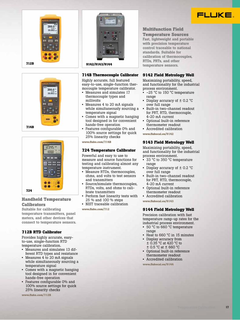
Handheld Temperature CalibratorsSuitable for calibrating temperature transmitters, panel meters, and other devices that connect to temperature sensors.
712B RTD CalibratorProvides highly accurate, easy-to-use, single-function RTD temperature calibration.• Measures and simulates 13 dif-
ferent RTD types and resistance• Measures 4 to 20 mA signals
while simultaneously sourcing a temperature signal
• Comes with a magnetic hanging tool designed in for convenient hands-free operation
• Features configurable 0% and 100% source settings for quick 25% linearity checks
www.fluke.com/712B
714B Thermocouple CalibratorHighly accurate, full featured easy-to-use, single-function ther-mocouple temperature calibrator.• Measures and simulates 17
thermocouple types and millivolts
• Measures 4 to 20 mA signals while simultaneously sourcing a temperature signal
• Comes with a magnetic hanging tool designed in for convenient hands-free operation
• Features configurable 0% and 100% source settings for quick 25% linearity checks
www.fluke.com/714B
724 Temperature CalibratorPowerful and easy to use to measure and source functions for testing and calibrating almost any temperature instrument.• Measure RTDs, thermocouples,
ohms, and volts to test sensors and transmitters
• Source/simulate thermocouples, RTDs, volts, and ohms to cali-brate transmitters
• Perform fast linearity tests with 25 % and 100 % steps
• NIST traceable calibrationwww.fluke.com/712
712B
724
9142/9143/9144
714B
Multifunction Field Temperature SourcesFast, lightweight and portable with precision temperature control traceable to national standards. Suitable for calibration of thermocouples, RTDs, PRTs, and other temperature sensors.
9142 Field Metrology WellMaximizing portability, speed, and functionality for the industrial process environment.• –25 °C to 150 °C temperature
range• Display accuracy of ± 0.2 °C
over full range• Built-in two-channel readout
for PRT, RTD, thermocouple, 4-20 mA current
• Optional built-in reference thermometer readout
• Accredited calibrationwww.flukecal.eu/9142
9143 Field Metrology WellMaximizing portability, speed, and functionality for the industrial process environment.• 33 °C to 350 °C temperature
range • Display accuracy of ± 0.2 °C
over full range • Built-in two-channel readout
for PRT, RTD, thermocouple, 4-20 mA current
• Optional built-in reference thermometer readout
• Accredited calibrationwww.flukecal.eu/9143
9144 Field Metrology WellPrecision calibration with fast temperature ramp-up rates for the industrial process environment.• 50 °C to 660 °C temperature
range• Heat to 660 °C in 15 minutes • Display accuracy from
± 0.35 °C at 420 °C to ± 0.5 °C at ± 660 °C
• Optional built-in reference thermometer readout
• Accredited calibration www.flukecal.eu/9144
9102S9100S
9009
9103/9140
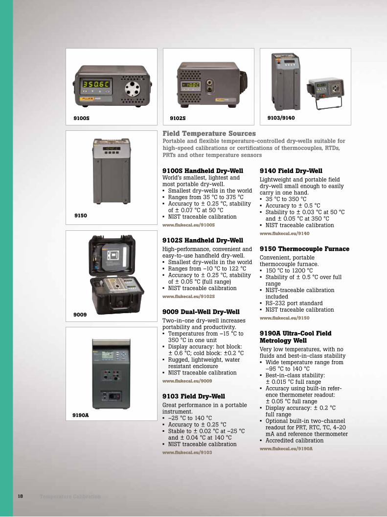
18 Temperature Calibration
9140 Field Dry-WellLightweight and portable field dry-well small enough to easily carry in one hand.• 35 °C to 350 °C • Accuracy to ± 0.5 °C• Stability to ± 0.03 °C at 50 °C
and ± 0.05 °C at 350 °C • NIST traceable calibrationwww.flukecal.eu/9140
9150 Thermocouple Furnace Convenient, portable thermocouple furnace.• 150 °C to 1200 °C • Stability of ± 0.5 °C over full
range • NIST-traceable calibration
included• RS-232 port standard• NIST traceable calibration www.flukecal.eu/9150
9190A Ultra-Cool Field Metrology WellVery low temperatures, with no fluids and best-in-class stability• Wide temperature range from
–95 °C to 140 °C• Best-in-class stability:
± 0.015 °C full range • Accuracy using built-in refer-
ence thermometer readout: ± 0.05 °C full range
• Display accuracy: ± 0.2 °C full range
• Optional built-in two-channel readout for PRT, RTC, TC, 4-20 mA and reference thermometer
• Accredited calibrationwww.flukecal.eu/9190A
9100S Handheld Dry-WellWorld’s smallest, lightest and most portable dry-well.• Smallest dry-wells in the world • Ranges from 35 °C to 375 °C • Accuracy to ± 0.25 °C, stability
of ± 0.07 °C at 50 °C• NIST traceable calibration www.flukecal.eu/9100S
9102S Handheld Dry-WellHigh-performance, convenient and easy-to-use handheld dry-well.• Smallest dry-wells in the world• Ranges from –10 °C to 122 °C• Accuracy to ± 0.25 °C, stability
of ± 0.05 °C (full range)• NIST traceable calibration www.flukecal.eu/9102S
9009 Dual-Well Dry-WellTwo-in-one dry-well increases portability and productivity.• Temperatures from –15 °C to
350 °C in one unit • Display accuracy: hot block:
± 0.6 °C; cold block: ±0.2 °C • Rugged, lightweight, water
resistant enclosure• NIST traceable calibration www.flukecal.eu/9009
9103 Field Dry-WellGreat performance in a portable instrument.• –25 °C to 140 °C • Accuracy to ± 0.25 °C• Stable to ± 0.02 °C at –25 °C
and ± 0.04 °C at 140 °C • NIST traceable calibrationwww.flukecal.eu/9103
9190A
Field Temperature SourcesPortable and flexible temperature-controlled dry-wells suitable for high-speed calibrations or certifications of thermocouples, RTDs, PRTs and other temperature sensors
9150

6109A/7109A
19Temperature Calibration
6102/7102/7103 Micro-BathsCalibrate a variety of probe dia-meters—no sleeves required.• Three models covering tem-
peratures from –30 °C to 200 °C• World’s smallest portable
calibration baths • Stability to ± 0.015 °C• NIST traceable calibration www.flukecal.eu/micro-baths
6109A/7109A Portable Calibration BathsCalibrate up to four tri-clamp sanitary sensors, or a batch of sanitary RTDs and temperature transmitters, at the same time.• Wide temperature range covers
most clean process applications: -6109A: 35 °C to 250 °C -7109A: –25 °C to 140 °C• Excellent display accuracy of ±
0.1 °C provides 4:1 test uncer-tainty ratio (TUR) for critical applications
• Easy to transport up stairs and across catwalks
• Stainless steel casing with-stands harsh sterilizing chemicals and is rust proof-per-fect for clean room use
• Easy to use and maintainwww.flukecal.eu/6109A
9170/9171/9172/9173 Metrology Wells Best possible accuracy in a dry-block calibrator• Best performing industrial tem-
perature sources in the world (stability as good as ±0.005 °C)
• Immersion depth to 203 mm• Optional built-in readout reads
reference PRTs to ± 0.006 °C• Ranges:
- 9170: –45 °C to 140 °C- 9171: –30 °C to 155 °C- 9172: 35 °C to 425 °C- 9173: 50 °C to 700 °C
• NVLAP accredited calibration ONLY with -R model
www.flukecal.eu/917X
Infrared Temperature SourcesBench and field precision infrared calibrators for accurate and reliable calibrations of IR thermometers.
4180/4181 Precision Infrared CalibratorsAccredited performance for point and shoot calibrations.• Calibrated radiometrically for
meaningful, consistent results• Accredited calibration included• Accurate, reliable performance
from –15 °C to 500 °C• Large 152 mm (6 in) diameter
target• Accredited radiometric
calibration reportwww.flukecal.eu/418X
9133
6102/7102/7103 9170/9171/9172/9173
9132/9133 Field Infrared CalibratorsPrecision when you need it for infrared temperature calibration.• Verify IR pyrometers from
–30 °C to 500 °C• RTD reference well for contact
temperature measurement• NIST traceable contact
calibrationwww.flukecal.eu/913X
4180/4181
9132

1551A Ex/1552A Ex
1502A/1504
1529
1523/1524
20 Temperature Calibration
Thermometer StandardsDelivering exceptional accuracy, wide measurement range, and designed to go where you work.
1551A Ex/1552A Ex “Stik” Thermometer The best substitute for precision mercury-filled glass thermometers.• Accuracy of ± 0.05 °C
(± 0.09 °F) over full range• Intrinsically safe (ATEX and
IECEx compliant)• Two models to choose from
(-50 °C to 160 °C or -80 °C to 300 °C)
• NVLAP-accredited, NIST-trace-able calibration
www.flukecal.eu/155X
1523/1524 Handheld Thermometer ReadoutMeasure, graph and record three sensor types with one tool.• High accuracy: PRTs:
± 0.011 °C; Thermocouples: ± 0.24 °C; Thermistors: ± 0.002 °C
• A simple user interface to see trends quickly
• Smart connectors to load probe information automatically
• Traceable cal as standard. -CAL versions with accredited cal
www.flukecal.eu/152X
1502A/1504 Thermometer Readouts Best performance thermometers in their price range.• Single-channel reference
thermometers, accurate to ±0.006 °C (meter only)
• Two models to choose from—reading PRTs or thermistors
• Best price/performance package• Accredited calibrationwww.flukecal.eu/150X
1529 Four-Channel Thermometer ReadoutLab-quality accuracy on four channels for PRTs, thermistors and thermocouples.• Accuracy of ±0.0025 °C
(meter only)• Displays eight user-selected
data fields from any channel• Logs up to 8,000 readings with
date and time stamps• Accredited calibrationwww.flukecal.eu/1529
Ambient Conditions MonitorFor precise measurement and recording of ambient temperature and humidity conditions wherever calibrations take place.
1620A Precision Thermo-HygrometerThe most accurate temperature and humidity graphical data logger on the market.• Superior accuracy• Network enabled• Powerful logging and
analysis tools• Measures temperature to
± 0.125 °C and humidity to ± 1.5 % on two channels
• NIST-traceable NVLAP accredited temperature and humidity calibration
www.flukecal.eu/1620A
1620A

5608/5609/5609-BND
5627A 5615
21Temperature Calibration
Precision PRTsHigh accuracy reference temperature measurements in temperature sources on the bench or in the field.
5627A Precision Industrial PRT• Vibration and shock resistant• Calibration accuracy of
± 0.046 °C at 0 °C• Available with a 90° bend• NVLAP-accredited calibration
included, lab code 200706-0www.flukecal.eu/5627
5615 Secondary ReferenceTemperature Standards• –200 °C to 420 °C• Calibrated accuracy ± 0.010 °C
at 0 °C• NVLAP-accredited calibration
included, lab code 200706-0www.flukecal.eu/5615
5608/5609/5609-BND Secondary Reference PRTsDrift rate of ± 0.01 °C at 0 °C after 100 hours at max temperature.• 5608: –200 °C to 500 °C
(80 mm minimum immersion)• 5609: –200 °C to 670 °C
(100 mm minimum immersion)• Comes with certificate
of compliance - optional NVLAP-accredited calibration
www.flukecal.eu/5608
5622 Fast Response PRTs• Time constants as fast as
0.4 seconds• Small probe diameters ranging
from 0.5 mm to 3.2 mm (four models available)
• Available as DIN/IEC Class A PRTs or with optional NVLAP-accredited calibration, lab code 200348-0
www.flukecal.eu/5622
5626/5628 Secondary SPRT, PRT, Temperature Sensors• Range to 661°C• Meets all ITS-90 requirements
for resistance ratios• Rtp drift < 20 mK after 500
hours at 661°C• Calibrated accuracy of ± 0.006
°C at 0 °C• NVLAP accredited fixed point
calibrationwww.flukecal.eu/5622
5618B Small Diameter Industrial RTDFast response for time-dependent measurements.• Small diameter sheath, 3.2 mm
(0.125 in)• Excellent stability• Includes ITS-90 coefficients• NVLAP accredited calibration,
lab code 200706-0www.flukecal.eu/5618B
5606 Full Immersion PRTFully immerse PRT transition junction inside freezers or furnaces.• Transition junction designed
to withstand full temperature range of probe
• -200 °C to 160 °C• Calibration accuracy of
± 0.05 °C (full range)• Optional NVLAP accredited
calibrationwww.flukecal.eu/5606
ThermistorsProviding accurate and rugged temperature measurements from 0 °C to 100 °C.
5610/5611/5611T Secondary Reference Thermistor ProbesEconomical lab-grade therm-istor probes with low drift susceptibility.• Short-term accuracy to
± 0.01 °C; one-year drift < ± 0.01 °C
• 5610: 3.2 mm diameter stain-less steel sheathed thermistor
• 5611: 1.5 mm diameter (tip) silicone coated thermistor
• 5611T: 3 mm diameter (tip) PTFE encapsulated thermistor
www.flukecal.eu/5610
5610
5622
5611T
5606
5611
5626/5628 5618B

22 Software/Accessories
Process Calibration Software
750 SW DPC/TRACK2 Software™
DPC/TRACK2 Software is a specialized calibration manage-ment database that can help you manage your instrumentation and address the documentation requirements of quality programs and regulations. With DPC/TRACK2 and a 754 DPC you can:• Manage your inventory of tags
and instruments, schedule for calibration
• Create tag specific procedures with instructions and comment
• Load those procedures to your DPC, and later upload the results to your PC
• Select and execute automated as found/as left procedures in the field, automatically captur-ing results
• Examine the calibration histories of your tags and instruments and print reports
• Import and export instrument data and procedures as ASCII text
• Import legacy DPC/TRACK datawww.fluke.com/750DPCsoftware
700G/TrackEasy-to-use software for managing instruments and calibration data.• Enables data download and
logging configurations to the 700G Series gauges for a remote logging event
• Configure logging event reading rate, duration and mea-surement units
• Upload measurements logged remotely and display or export measurements
www.fluke.com/700Gsoftware
Software/ Accessories

700PTP-1
700LTP-1
700HTP-2
700PMP
23Software/Accessories
Temperature Calibration Software 9938 MET/TEMP II Temperature Calibration Software v5.0New version of the proven solu-tion for automated temperature calibration• Compatible with Windows 7 and
8 operating systems• Adds support for 9190A Field
Metrology Well and 9118A Thermocouple Furnace
• Fully automated calibration of RTDs, TCs, thermistors and many heat sources
• Calibrates up to 100 sensors at up to 40 temperature points
TQSoft and TQAero Thermal Validation SoftwareFor FDA 21 CFR Part 11 and AMS2750 Compliant Data Collection.• Support for Fluke 2638A and
1586A, for enhanced data collection and reporting in reg-ulated industries
• Easy menu system and toolbar• Test equipment preparation and
sensor calibration• Data security, audit trail, and
compliance reports
LogWareTurn a Fluke Calibration sin-gle-channel handheld or 1502A/1504 readout into a real-time data logger.• Collects realtime data• Calculates statistics and
displays customizable graphs• Allows user-selected start
times, stop times and sample intervals
www.flukecal.eu/logware
LogWare IITurn any Fluke Calibration multi-channel thermometer read-out into a real-time data logger.• Collects real-time data using
Fluke Calibration multi-channel readouts
• Calculates statistics and dis-plays customizable graphs
• Allows user-selected start times, stop times and sample intervals
www.flukecal.eu/logware
LogWare IIIRemotely monitor and log a virtually unlimited number of con-current log sessions into a central data repository.• Up to two temperature and two
humidity inputs for each DewK• Customize your graph trace
color, alarms, and statistics as you go
www.flukecal.eu/logware
Process Tools Accessories
700HTP-2 Hydraulic Test PumpThe 700HTP-2 is designed to generate pressures up to 10,000 psi/700 bar. Use the Fluke 700PRV-1 adjustable relief valves to limit pressures from 1360 psi to 5450 psi. Use the 700HTH-1 test hose to connect from the pump to the device under test.
700HTH-1 Hydraulic Test HoseThe 700 HTH is a 700 bar test hose that connects to a calibra-tion unit under test from a Fluke 700HTP hydraulic test pump.
700PTP-1 Pneumatic Test PumpThe 700PTP-1 is a handheld pressure pump designed to generate either vacuum to -11.6 psi/-0.8 bar or pressure to 600 psi/40 bar.
700LTP-1 Low Pressure Test PumpHand operated pressure pump designed to generate either vacuum to -13 psi/-.90 bar or pressures to 100 psi/6.9 bar. Ideal for low pressure applications requiring accurate low pressure testing.
700PMP Pressure PumpThe 700PMP is a hand-operated pressure pump to provide pres-sures up to 10 bar. Output fittig is 1/8 FNPT.
700HTH-1

Pressure Applications
24 Pressure Applications

APPLICATION SELECTION GUIDE
Model number 754721/
721Ex719 Pro 719 718 717 700G 3130 2700G
Deadweight Testers
ApplicationCalibrating pressure transmitters (field) • • Ideal • • • •Calibrating pressure transmitters (bench) • • • • • • Ideal •Calibrating HART Smart transmitters Ideal
Documenting pressure transmitter calibrations
Ideal
Testing pressure switches in the field
Ideal • • • • • •
Testing pressure switches on the bench • • • • • • Ideal
Documenting pressure switch tests Ideal
Testing pressure switches with live (voltage) contacts
Ideal
Gas custody transfer computer tests • Ideal •
Verifying process pressure gauges (field)
Ideal • • • • • •
Verifying process pressure gauges (bench) • • • • • • • • Ideal
Logging pressure measurements • Ideal •Testing pressure devices using a reference gauge
Ideal
Hydrostatic vessel testing Ideal
Leak testing (pressure measurement logging) • Ideal
Products noted as “Ideal” are those best suited to a specific task. Model 754 requires the correct range 750P pressure module for pressure testing. Model 753 can be used for the same applications as model 754 except for HART device calibration. Model 725 and 726 can be used for the same applications as model 753 except for documenting and live contact testing of switches.
INTRODUCTIONProcess pressure devices provide critical process measurement information to process
plant’s control systems. The performance of process pressure instruments are often critical
to optimizing operation of the plant or proper functioning of the plant’s safety systems.
Process pressure instruments are often installed in harsh operating environments
causing their performance to shift or change over time. To keep these devices operating
within expected limits requires periodic verification, maintenance and calibration.
There is no one size fits all pressure test tool that meets the requirements of all users
performing pressure instrument maintenance.
25Pressure Applications

Suggested test tools
Calibrating a HART smart pressure transmitter
Pressure transmitter manufacturers have improved the accuracy and technology designed into these smart pressure measurement devices. Many conventional calibration tools have become inad-equate or simply unable to test and calibrate these high accuracy pressure transmitters. Better test solutions are required.
Verifying and documenting the performance and adjusting a HART smart pressure transmitter can require a bucket full of tools. Performing this task with a HART enabled calibrator like the Fluke 754 simplifies the task and reduces what you need to carry.
Before going to the field: install the pressure module adapter to the hand pump with thread seal. Once the adapter is properly installed on the pump, changing modules to different pressure ranges is a snap, no tools required.
To get the accuracy needed: to test these new high accuracy transmitters match the pressure measurement standard range closely to the device tested. For example, use a 100 psi pressure module to calibrate and test a transmitter ranged at 100 psi. Industry standards suggest the measurement standard should be 4-10 times more accurate than the device being tested so best-in-class accuracy is required.
The Fluke 754 utilizes the 750P series pressure modules and has built-in HART functionality to enable smart trims on trans-mitters. It can also document transmitter performance before and after adjustment and calculate pass/fail errors.
Fluke 754 Docu-menting Process Calibrator-HART
See pg 5
Fluke 750P Series Pressure Modules
See pg 12
Fluke 700G Precision Pressure Gauge Calibrator
See pg 13
Fluke 700PTP-1 Pneumatic Test Pump
See pg 23
26 Pressure Applications

Hand Pump
Pressure Input
mA Measure, 24V Loop
PressureModule
754 DOCUMENTING PROCESS CALIBRATOR
+ – –TEST
PWR/COMM
Sometimes it is necessary to trim the input sensor of the transmit-ter more than once. It is critical that the pressure module be ze-roed before test and adjustment. For best ßadjustment success:• After pressing Fetch for
the pressure measurement, select the trim button quickly before the pressure measure-ment changes.
• Give the measured mA and pressure time to settle for best measurement results.
• Always de-bug the pressure test setup for leaks in the shop before going to the field, including installing the pressure module connection adapter to the hand pump.
• If the full scale value of the transmitter is less than 25 % of the full scale of the pres-sure module, select a lower range pressure module for best results.
• If performing higher pressure calibrations with a hydraulic pump, use the cor-rect fluid such as mineral oil or de-ionized water. Standard tap water will leave deposits in the pump and cause erratic operation, leaks or difficulty priming.
• If the pass/fail accuracy is set at the limits for the transmit-ter, adjust the transmitter if the errors are greater than 25 % of limits.
• If the errors are less than 25 % of limits, it might be best to not adjust the transmitter as adjusting might make it less accurate.
Isolate the transmitter from the process being measured and its loop wiring. If measuring the mA signal across the transmitter test diode leave the wires intact, but note this method does not give the best mA measurement accuracy.
Connect the mA measurement jacks of the 754 to the transmitter.
Connect the pressure module cable to the 754 and connect the transmitter test hose from the hand pump to the transmitter.
Press the HART button on the calibrator to see the configuration of the transmitter.
Press HART again and the calibrator will offer the correct measure/source combination for the test. If documenting the calibration press As-Found, input the test tolerance and follow the prompts. If the measured mA signal at the test points is found within tolerance the test is complete. If not, adjustment is required.
Select adjust and trim the transmitter’s pressure zero, mA output signal and input sensor.
After adjustment select As-Left, document the condition of the transmitter after adjustment and if the test passes, it is complete.
STEP1
STEP2
STEP3
STEP4
STEP5
STEP6
STEP7
To perform the test:
Additional resources For more in depth information about this application check out these videos and application notes from Fluke.
See the smart pressure calibration video at: www.fluke.com/pressurevideo
HART Smart Transmitter calibration application note at: www.fluke.com/smarttranappnote
TECH TIPS
27Pressure Applications

Suggested test tools
Pressure transmitter calibration – at the bench
Technicians calibrate at the bench to ensure calibrations are effective and don’t result in degradation of performance. They ensure that all components are in good working order prior to installation, and can evaluate them when component failure is suspected. The bench provides a stable ambient environment for calibration, an opportunity to use the most accurate equipment, and protection from factory condi-tions during the commissioning, testing, and calibration of pressure transmitters.
Fluke 754 Documenting Process Calibrator-HART
See pg 5
Fluke 3130 Portable Pressure Calibrator
See pg 14
Fluke 719Pro Electric Pressure Calibrator
See pg 11
P3000 Hydraulic Deadweight Testers
See pg 14
Fluke 700PTP-1 Pneumatic Test Pump
See pg 23
28 Pressure Applications

V mASWITCH TEST COM
EXTERNALPRESSURE MODULE
24 V DC
30 V MAX
LOOP
PORTABLE PRESSURE CALIBRATOR3130
FLUKE CORPORATIONEVERETT, WA USAwww.flukecal.com
CHARGE
16 V DC5.6 A
SERIAL NO.
VENT LINE BEFORE MAKING SELECTIONCAUTION
OUTPUT
ISOLATIONVALVE
-12 PSI TO 300 PSI (-8 kPa TO 2 MPa)
AIR SUPPLY330 PSI MAX
(2.3 MPa)
PRESSURE
CLOSED
VACUUM
PUMP
FINEADJUSTMENT
VENT
SUPPLYMETERING VALVE
FINEADJUSTMENT
VENT
FILTER
PRESSURESENSOR
CLOSE VALVE BEFOREOPERATING PUMP
F1 F2 F3
HOME
ZERO PUMP
+ –
• Inaccurate calibration equipment will only degrade the performance of the transmitter.
• Manufacturers recommend using precise calibration equipment under stable, ambient conditions for best results.
• Commission transmitters at the bench so security settings and protection for failure modes can be set before exposing transmitter electronics to factory conditions.
Connect the transmitter test hose from the calibrator to the transmitter
Connect the mA measurement jacks of the calibrator to the transmitter
Set the pressure/vacuum selection knob to the necessary function
Close the vent knob and supply metering valve
Apply pressure or vacuum from the pump by holding down the pump button and release when the necessary pressure is reached
Correct the pressure with the fine pressure adjustment
Read the reference pressure and the current output of the transmitter from the display
Repeat for all test points. If the measured mA signal at the test points is found within tolerance the test is complete. If not, then adjustment is required.
STEP1
STEP2
STEP3
STEP4
STEP6
STEP7
To perform the test:
Additional resources For more in depth information about this application check out these videos and application notes from Fluke.
How to use a deadweight testerFluke 719 electric pressure calibrator demonstration
Transmitter Calibration with the Fluke 750 Series DPCHART transmitter calibration
TECH TIPS
STEP5
STEP8
29Pressure Applications

Suggested test tools
Pressure switch testing – manual approach
Accurate calibration of pressure switches is a critical step in ensuring process quality and the safe operation of equipment. The setup is similar to pressure gauge calibration except now a voltage or continuity across a set of switch contacts needs to be read either by a (Digital Multimeter) DMM or the calibrator. The purpose of the calibration is to detect and correct errors in the set point and deadband of the pressure switch. Calibrators can save you time by reducing steps and reducing the amount of equipment you have to bring to the job. With the right calibrator the entire process can be automated.
Fluke 3130-G2M Portable Pressure Calibrator
See pg 14
Fluke 719Pro Electric Pressure Calibrator
See pg 11
Fluke 750P Series Pressure Modules
See pg 12
Fluke 700PTP-1 Pneumatic Test Pump
See pg 23
Fluke 754 Documenting Process Calibrator-HART
See pg 5
30 Pressure Applications

PROCESSMETER789
%STEP COARSE FINESpanCheck
mA
mA
mA
mA
mVV
V
A
OUTPUT
LOOP POWER
250HART
OFF
mASOURCE
OUTPUT 0-24mASIMULATE
A COM V
MIN MAX100%
0%
HOLD
REL Hz
RANGE
Hand Pump
PressureGauge
Pressure Input
When you use a Fluke 754 or 3130 to automate the pressure switch calibration, vary the applied pressure slowly, back and forth across the setpoint and reset points. The display will make it apparent that the set/reset has changed and the actuals will be logged.
Safely disconnect the device from the process it controls.
Connect the calibrator or DMM to the common and NO (normally open) output terminals of the switch. The DMM or calibrator will measure an “open circuit”. if measuring continuity. If measuring V ac be sure the tool is properly rated for the voltage being measured.
Connect the pressure switch to a pressure source such as a hand pump connected to a gauge.
Increase the source pressure to the setpoint of the switch until the switch changes state from open to close. Manually record the pressure value when the DMM indicates a “short circuit” or if using a calibrator it will record the value for you.
Continue to increase the pressure until the maximum rated pressure. Slowly reduce the pressure until the switch changes state again, and resets from closed to open, then record the pressure.
The setpoint pressure was recorded when the pressure was rising.The deadband value is the difference between the rising setpoint pressure and the falling pressure reset point.
STEP1
STEP2
STEP3
STEP4
STEP6
To perform the test:Setup
Rising pressure
Falling pressure
Calculation
Additional resources For more in depth information about this application check out these videos and application notes from Fluke.
See the pressure switch test video at: www.fluke.com/pressureswitch
Calibrating pressure switches with a DPC
TECH TIPS
STEP5
31Pressure Applications

Suggested test tools
Pressure switch testing–documented
Classic methods for pressure switch testing have been superseded with the introduction of new pressure test tools. Today most pressure switches are tested with a pressure gauge mounted to a pump to supply and measure pressure, and a DMM set to continuity to verify the opening and closing of the switch. The technician or electrician making the test is required to interpret the pressure applied to the switch
when the continuity beeper sounds indicating contact closure of the switch. A workable solution but new tools can make this task easier.
Modern calibrators can automatically record the pressure applied when a pressure switch changes from open to closed and from closed to open. In doing so the switch set point and reset point and deadband are much easier to determine.
Fluke 754 Documenting Process Calibrator-HART
See pg 5
Fluke 750P Series Pressure Modules
See pg 12
Fluke 700PTP-1 Pneumatic Test Pump
See pg 23
Fluke 71X Hose Kit Accessory
32 Pressure Applications

Hand Pump
PressureModule
Pressure Input• The key to a good switch
test is repeatability. Repeatability is best achieved by applying a slow change in pressure to the switch as it approaches its set or reset pressure.
• When performing the test find out where the switch sets and make sure the vernier/fine adjustment of your test pump has enough adjustment to vary the pressure up to the set point. In this way the pressure can be changed slowly capturing an accurate switch set point pressure. Repeat this procedure for the reset point.
• With practice you can get the vernier of the pump within range of the set and reset point pressure and get excellent repeatability of your tests (within the limitations of the switch being tested).
TECH TIPS
To get started testing the switch, connect as shown above. In this example we will test dry contacts and continuity. To measure continuity for the test select resistance measurement. Then toggle to the source screen mode and select pressure to display the pressure generated by the hand pump and measured by the pressure module. Advance the calibrator mode to the split screen test mode.
The next step is to describe the switch and whether it is normally open or closed at ambient pressure. The relaxed state of the switch is the reset state. The set state is the condition of the switch it changes to with applied pressure or vacuum. In this example the switch is normally open and is expected to close when the pressure applied exceeds 10 psi. Next the allowable pressure variance of the switch set state and deadband size needs to be defined. In this example the ideal switch set value is 10 psi and is allowed +/- 1 psi of deviation. The allowable reset pressure is described in the deadband tolerance. In this instance the reset state must be more than 1 psi less than the found set pressure but not greater than 3 psi less than the found set pressure.
Once the test tolerances are fully defined start the test. Increase the pressure until the calibrator captures the set state pressure value. Then decrease the pressure until the reset pressure is found. Repeat increasing and decreasing the pressure across the switch looking for repeatability in your set and reset pressure measurements. Once satisfied with the result press done to get the pass/fail evaluation of the switch. If the switch fails the test adjustment or replacement of the switch may be required. If the switch is adjusted repeat the test to document the As-Left condition of the switch before putting back into service. The test result is now documented and ready for upload to calibration management software.
To perform the test:With a modern documenting calibrator you can test for dry contacts opening and closing on the switch or if you are using the Fluke 753 or 754 you can leave the switch connected to the live voltage and the calibrator will measure the changing AC voltage and interpret it as opening and closing of the switch.
One cautionary note: it is always safer to test a de-energized circuit, but this is not always possible. Also, do not measure AC voltages above 300 V ac as that is the maximum rating of the 75X family. 480 V ac 3-phase voltages must be de-energized and disconnected from the switch if testing with the 75X family.
Additional resources For more in depth information about this application check out these videos and application notes from Fluke.
Pressure switch video
Pressure switch application notePressure calibration application note
STEP1
STEP2
STEP3
33Pressure Applications

Suggested test tools
Gas custody transfer flow computer calibration
Gas custody transfer flow computers that calculate flow in pipelines by measuring the differential pressure across a flow restriction, such as an orifice plate or other differential pressure flow device, require special calibration to perform at optimum accuracy. Gas flow computers make three primary measurements to calculate flow: volumetric flow (difference in pressure across the orifice plate), static pressure in a pipeline and gas temperature. A calculation is performed using this data to determine the actual mass and volume of the gas flowing through the pipeline.
These calibrations can be made with three separate calibrators, a low pressure, high pressure and a temperature calibrator or use a multifunction calibration tool designed for this specific task.
An example of a calibrator purposed for this task is the Fluke 721 or 721Ex. It has two built-in pressure ranges and the ability to measure temperature. The most popular configuration is 16 psi/1 bar on the low pressure (P1) sensor side and 1500/100 bar or 3000 psi/200 bar on the high pressure (P2) sensor side. It measures temperature using a precision RTD accessory and can display all three measurements at once if desired.
Fluke 754 Documenting Process Calibrator-HART
See pg 5
Fluke 700G Precision Pressure Gauge Calibrator
See pg 13
Fluke 721 Precision Dual Range Pressure Calibrator
See pg 12
Fluke 750P Series Pressure Modules
See pg 12
34 Pressure Applications

Pump
Close valves
Close valves
720TRD RTD Probe
Fluidstream
Fluidstream
7.21psi 30V24mAMAX
VmA
COM
F1 F2 F3
ZERO
PRESSURECALIBRATOR721
To get started, isolate the flow computer from the pipeline. It is normally in-stalled with a 5 valve manifold. If so, closing the valves on the pipeline side of the manifold should isolate it. Be sure to follow local policy and safety procedures when performing this isolation step. Set the P1 sensor of the 721 to measure inH20 and the P2 sensor to measure PSI and the tempera-ture sensor to measure degrees Celsius or Fahrenheit as needed.
Low pressure differential pressure calibration is performed using atmospheric pressure as a low side reference. Vent the low connection of the flow computer or pressure transmitter and connect the high pressure connection of the flow computer or transmitter to the low pressure port (P1) on the calibrator.
Connect the computer (PC) to the flow computer serial or USB port. The PC will instruct the user to apply one or more test pressures to the flow com-puter or transmitter. For example, 0, 100 and 200 inH20. Squeeze the pump to get close to the test pressure and use the vernier or fine pressure adjust to dial in.
Static pressure calibration will normally be applied to either the same high pressure port of the flow computer or both the high and low pressure ports. Refer to the manufacturer’s instructions for details. Connect the high pressure sensor input (P2) to the appropriate port on the flow computer or transmitter and to the high pressure test source. The PC will instruct the pressures for the user to apply from the pressure source.
Temperature calibration of the temperature measurement on the flow computer is done with a single temperature point at the pipeline operating temperature. Insert the RTD probe into the test thermowell and allow time for the measurement to stabilize.
The PC will prompt the user to enter the temperature measured by the calibrator. Remove the RTD from the test thermowell and the calibration is complete.
Flow Computers with 4 to 20 mA inputs: Many flow computers utilize a low pressure, static and temperature transmitter to convert the measured parameters into 4 to 20 mA signals. In this instance these transmitters may need individual calibration if the test results are not satisfactory (see HART Transmitter Calibration application note or video for more details). Anoth-er source for errors in this configuration is the input A/D cards of the flow computer. These can be independently tested using a mA signal source from a loop calibrator.
STEP1
STEP2
STEP3
STEP4
To perform the test:
• Always center the vernier of your hand pump before starting any pressure calibration. This will allow you to increase or decrease the pressure when making fine adjustments.
• Store the temperature probe in a protective case such as the built in slot of the 721 soft case. Exposing the RTD probe to mechanical stress can reduce the measurement accuracy of the probe.
• Be careful to not connect the P1 low pressure side of the calibrator when doing high pressure calibrations or measurement or the sensor will be damaged and possibly rupture creating a dangerous condition.
• Inserting the RTD probe prior to the pressure calibrations typically allows sufficient time to reach a stable temperature measurement.
Additional resources For more in depth information about this application check out these videos and application notes from Fluke.
HART pressure and HART smart RTD transmitter 754 videos
Custody Transfer calibration application noteHART transmitter calibration
TECH TIPS
35Pressure Applications

Suggested test tools
Verifying process gauges, analog and digital
Both analog and digital process gauges need to be verified to detect errors related to drift, environment, electrical supply, addition of components to the output loop, and other process changes. Pressure gauges may be verified in the field or at the bench. Field calibration may save time, and allows for troubleshooting in the process environment. Multifunction calibrators make it easier to do this with one tool, and documenting calibrators make it easier to follow procedures, capture data and document results. Bench calibration provides an environment where the gauge can be cleaned, inspected, tested, and recertified under reference conditions for the best possible accuracy.
P5514, or P5515 Hydraulic Pressure Comparator
See pg 13
2700G Series Reference Pressure Gauges
See pg 13
Fluke 3130 Portable Pressure Calibrator
See pg 14
Traditional and Electronic Dead-weight Testers
See pg 14-15
36 Pressure Applications

Hand Pump
Pressure Input
PressureModule
Isolate the pressure gauge from the process using valves, or by removing the gauge from the process.
Connect the gauge to the calibrator or reference gauge. For hydraulic pressure gauges it’s important to remove any gas that might be trapped in the fluid in the gauge, calibrator, and connections by priming the system. When generating pressure allow a few moments for stability. Compare the reading of the gauge under test with the master gauge or calibrator.
For hydraulic pressure gauges it’s important prime the system. This will remove any gas that might be trapped in the fluid in the gauge, calibrator or connections.
When generating pressure allow a few moments for the measurement to stabilize. When using a hydraulic hand pump as a source it can take several minutes for the pressure to stabilize due to the thermodynamic effect of fluids.
Compare the reading of the gauge under test with the master gauge or calibrator.
STEP1
STEP2
STEP3
STEP4
STEP5
To perform the test:
Additional resources For more in depth information about this application check out these videos and application notes from Fluke.
TECH TIPS• Safety First! Check all
fittings, adapters and connecting tubing ratings for pressures used.
• Remember to tap analog gauges at each point due to friction in mechanical parts.
• Gas is preferred for cleanliness requirements but use caution when generating pressures above 2,000 psi.
• Industry standards usually desire calibration equipment to be 4-10 times more accurate than the device under test.
• When in the field, connect pressure gauges through a manifold or “tee” connector.
• Use adapter fittings when workloads require calibrating a wide variety of gauges.
• Consider first, the in-use orientation of a device and use an angle adapter at the bench to achieve similar orientation.
• Use a liquid-to-liquid separator to prevent contamination in hydraulic applications.
How to use a deadweight testerFluke 719 electric pressure calibrator demonstration
Transmitter Calibration with the Fluke 750 Series DPCHART transmitter calibration
37Pressure Applications

A deadweight tester is a proven method of pressure calibration that is usually chosen for bench applications when accuracy and reliability are the top requirements. Calibrations are performed at the bench for convenience and to maintain reference conditions. The bench is a convenient location to clean, inspect, calibrate and repair with all the necessary equipment available. Reference conditions are necessary to achieve the reference accuracy of the device under test and the calibration standards. Reference accuracy may be required to maintain the necessary test uncertainty ratios (TUR).
Suggested test tools
Calibrating at the bench with a deadweight tester
P3100, P3200, or P3800 Series Hydraulic Dead-weight Tester
See pg 15
6531, 6532 Electronic Deadweight Tester
See pg 15
P3000 Series Pneumatic Deadweight Tester
See pg 14
Using liquid: Using gas:
38 Pressure Applications
50%
0%
100%
50%
0%
100%
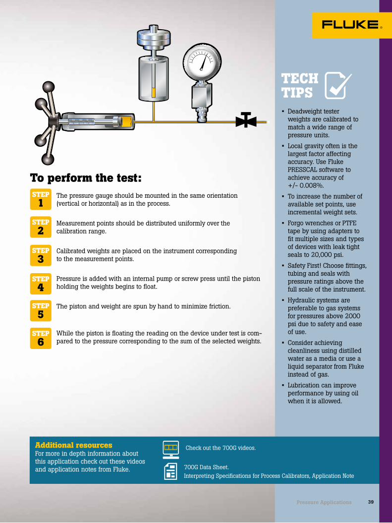
The pressure gauge should be mounted in the same orientation (vertical or horizontal) as in the process.
Measurement points should be distributed uniformly over the calibration range.
Calibrated weights are placed on the instrument corresponding to the measurement points.
Pressure is added with an internal pump or screw press until the piston holding the weights begins to float.
The piston and weight are spun by hand to minimize friction.
While the piston is floating the reading on the device under test is com-pared to the pressure corresponding to the sum of the selected weights.
• Deadweight tester weights are calibrated to match a wide range of pressure units.
• Local gravity often is the largest factor affecting accuracy. Use Fluke PRESSCAL software to achieve accuracy of +/- 0.008%.
• To increase the number of available set points, use incremental weight sets.
• Forgo wrenches or PTFE tape by using adapters to fit multiple sizes and types of devices with leak tight seals to 20,000 psi.
• Safety First! Choose fittings, tubing and seals with pressure ratings above the full scale of the instrument.
• Hydraulic systems are preferable to gas systems for pressures above 2000 psi due to safety and ease of use.
• Consider achieving cleanliness using distilled water as a media or use a liquid separator from Fluke instead of gas.
• Lubrication can improve performance by using oil when it is allowed.
STEP1
STEP2
STEP3
STEP4
STEP5
STEP6
To perform the test:
Additional resources For more in depth information about this application check out these videos and application notes from Fluke.
Check out the 700G videos.
700G Data Sheet.Interpreting Specifications for Process Calibrators, Application Note
TECH TIPS
39Pressure Applications

Suggested test tools
Calibrating at the bench with a pressure comparator
A pressure comparator is a convenient instrument for bench pressure calibration. Bench calibrations are performed to maintain reference conditions and to obtain the lowest possible uncertainties. The bench is also a convenient place to inspect, adjust, and repair the devices under test.
P5514, or P5515 Hydraulic Pressure Comparator
See pg 13
P5510, or P5513 Gas Pressure Comparator
See pg 12
2700G Series Reference Pressure Gauges
See pg 13
Using liquid: Using gas:
40 Pressure Applications

TECH TIPS
2000 PSI148 BAR2000 PSI148 BAR
50%
0%
100%
50%
0%
100%
The pressure gauge should be mounted in the same orientation (vertical or horizontal) as in the process. An angle adapter such as the P5543 may be used.
The reference pressure gauge (2700G) should be mounted such that the display is easily seen.
For hydraulic comparators prime the fluid with the priming pump, to remove any bubbles.
Measurement points should be distributed uniformly over the calibration range. Conveniently source pressure with a manual pump up to 300 psi, after that use an external pressure supply.
For gas comparators use the fine needle valve or fine adjustment screw press to precisely meter the pressure.
With hydraulic models use the screw press to source and fine adjust the pressure.
The source pressure can be adjusted until the device under test is reading a nominal pressure or until the reference gauge reads the nominal pressure.
• Use a reference gauge with better accuracy to meet test uncertainty ratios over a wider range of pressures.
• Forgo wrenches or PTFE tape by using adapters to fit multiple sizes and types of devices with leak tight seals to 20,000 psi.
• Safety first! Always use fittings, tubing, and seals with pressure ratings above full scale of the instrument.
• If possible use oil for better lubrication.
• Use gas to improve cleanliness or a liquid-to-liquid separator available from Fluke.
• Hydraulic systems are preferable to gas systems for pressures above 2000 psi due to safety and ease of use.
STEP1
STEP2
STEP3
STEP4
STEP5
STEP6
STEP7
To perform the test:
Additional resources For more in depth information about this application check out these videos and application notes from Fluke.
Check out the 700G videos.
700G Data Sheet.Interpreting Specifications for Process Calibrators, Application Note
41Pressure Applications

Suggested test tools
Use and selection of hand pumps and pressure test gauges for field pressure testing
It’s important to select the proper pump and gauge to match the testing application at hand—a good guideline is the testing device should be 4-10 times more accurate than the device being tested. To achieve this, match the measurement to be made as closely to the full scale value of the test gauge. This delivers the best accuracy from the gauge.
Fluke 700G Precision Pressure Gauge Calibrator
See pg 13
Fluke 700PTPK2 Pneumatic Test Pressure Kit
Fluke 700HTPK2 Hydraulic Test Pressure Kit
Fluke 700TTH 10K Transmitter Test Hose
42 Pressure Applications

The pressure gauge should be mounted in the same ori-entation (vertical or horizontal) as in the process.
The reference pressure gauge (2700G) should be mount-ed vertically.
For hydraulic comparators prime the fluid with the prim-ing pump, to remove any bubbles.
Measurement points should be distributed uniformly over the calibration range. Conveniently source pressure with a manual pump up to 300 psi, after that use an external pressure supply.
For gas comparators use the fine needle valve or fine adjustment screw press to precisely meter the pressure.
With hydraulic models use the screw press to source and fine adjust the pressure.
The source pressure can be adjusted until the device under test is reading a nominal pressure or until the reference gauge reads the nominal pressure.
• The key to a good experience in using a hand pump, either pneumatic or hydraulic, is to test and debug your test setup in the shop before going to the field. Minimizing the number of pressure connections minimizes the probability for leaks. Mount the test gauge carefully to the test pump in the shop.
• Be sure to consider the hoses that connect from the hand pump to the device to be tested. There are a variety of specialty “no tools required” connectors to connect to the test hose to make this easy. If these connectors are not available be sure to have a variety of adapters, wrenches and PFTE sealing tape to be able to connect from the test hose to the input port of the device for testing. If using “push fit” hoses it is likely they will eventually leak. Each time - a push fit hose is connected, it leaves a mark on the test hose and eventually does not seal well. To eliminate the leak cut off the affected portion of the test hose so there is a clean surface to connect to. This process will need to be repeated with use.
• When attempting to get maximum pressure out of a pneumatic pump, adjust the fine adjust vernier all the way to down to the stop so turning the vernier increases the pressure. When approaching the target pressure use the vernier to increase to your target pressure.
• When using hydraulic hand pumps remember the thermodynamic effect. Once any fluid is compressed, the temperature increases and the fluid expands. This becomes obvious when pumping to a target pressure with a hydraulic pump. Once the target pressure is met the fluid has expanded. As the fluid cools and contracts the pressure quickly bleeds down until it reaches temperature equilibrium, this can take 5 minutes or more. Once the temperature stops changing, dial the desired pressure back in with the vernier adjuster.
STEP1
STEP2
STEP3
STEP4
STEP5
STEP6
STEP7
To perform the test:
Additional resources For more in depth information about this application check out these videos and application notes from Fluke.
Check out the 700G videos.
700G Data Sheet.Interpreting Specifications for Process Calibrators, Application Note
TECH TIPS
43Pressure Applications

Temperature Applications
44 Temperature Applications

APPLICATION SELECTION GUIDE
INTRODUCTIONTemperature devices in process manufacturing environments provide measurements to
the process plants’ control systems. The performance of these temperature instruments
is often critical to optimized operation of the process manufacturing plant or proper
functioning of the plant’s safety systems.
Process temperature instruments are often installed in harsh operating environments,
causing their performance and the performance of their sensors to shift or change over
time. Keeping these devices measuring temperature within expected limits requires
periodic verification, maintenance and adjustments.
Model number 75X 72X712B/ 714B
1551A/1552A
1523/1524 914X 7526A 418X 1586A
Application
Calibrate and test RTD sensors •* •* *712B * * Ideal •* •*
Calibrate and test thermocouple sensors •* *714B * * Ideal * •*
Simulate RTDs • 712B •
Simulate thermocouples • 714B •Generate precision temperatures •Documenting temperature transmitter calibrations Ideal
Temperature transmitter calibration with sensor •* •Calibrating HART smart temperature transmitters Ideal
Temperature switch/ controller testing and calibration Ideal 726 • •Temperature switch/ controller testing live contacts Ideal
Infrared thermometer test and calibration Ideal
Verifying process temperature gauges • • • •Logging temperature measurements • 1552A Ideal •Precision temperature measurement • Ideal
Automated batch testing of temperature sensors** Ideal Ideal
* Requires a dry-well such as 914X or 910X** Requires both a dry-well and a 1586A
45Temperature Applications

Suggested test tools
Calibrating and testing RTD sensors
Typically RTDs are checked while calibrating the connected device, such as a panel meter or temperature transmitter. However, if a problem is suspected with a temperature sensor, sensor calibrations can be performed separately from the calibration of process electronics. Field checks of temperature sensors can be easily performed with a dry-block or Micro-Bath. For best results, a full calibration of a temperature sensor is performed at the bench.
9100S Handheld Dry-Well
See pg 18
9009 Industrial Dual-Block Thermometer Calibrator
See pg 18
726 Precision Multifunction Process Calibrator
See pg 6
9102S Handheld Dry-Well
See pg 18
6102 Micro-Bath Thermometer Calibrator and 1523-P1 Reference Thermometer
See pg 19 and 20
9144 Field Metrol-ogy Well and 5615 Secondary Refer-ence Temperature Standard
See pg 17
46 Temperature Applications

• Dry-wells have inserts that are interchangeable and have a variety of hole patterns to accommodate various probe sizes.
• To achieve published performance levels, the insert’s hole size should be no more than a few hundredths of an inch larger than the probe being calibrated.
• Avoid placing fluids in a dry-well. If fluids are required, use a Micro-Bath instead.
• If climbing a ladder is required, dry-wells are safer than baths, and handheld dry-wells may be the most convenient.
TECH TIPS
Additional resources For more in depth information about this application check out these videos and application notes from Fluke.
How to Calibrate an RTD Using a Dryblock Calibrator webinar
914X Field Metrology Wells Video Series
Industrial Temperature Calibrators Workload Matrix
To perform the test:Isolate the sensor from the process.
Fully immerse the sensor into a precision temperature source, such as a dry-well or bath capable of covering the required temperature range.
For best accuracy, also fully immerse a temperature standard into the dry-well or bath for comparison (the process version of Field Metrology Wells have a built-in precision readout for the temperature standard).
To check the calibration of the RTD separately from the control system temperature indicator, disconnect the RTD from the electronics.
Connect the RTD to a precision instrument capable of measuring resis-tance. (The process version of Field Metrology Wells have the required electronics built in.)
Adjust the temperature of the bath or dry-well to each of the test points (With Field Metrology Wells these test points can be preprogrammed and automated.)
At each test point record the readings of the temperature standard and RTD.
If measuring the RTD separate from its measurement electronics, compare the measured resistances to the expected resistance from the applicable temperature table. Otherwise, compare the reading on the instrument display to the reading of the temperature standard (which may be the dry-well).
STEP1
STEP2
STEP3
STEP4
STEP6
STEP8
STEP7
STEP5
F4F3F2F1
100.00°C
F4F3F2F1
100.00°C
ENTERMENU
100.2° C
47Temperature Applications

Suggested test tools
Calibrating and testing thermocouple sensors
Thermocouples are common in industry because they are inexpensive and cover a wide temperature range.
They should be tested during commissioning and again when removed from a process to verify that tolerances were met. Additionally, thermocouples may be tested at regular calibration intervals and when suspected of failing to meet their performance specifications.
Often thermocouples need to be calibrated prior to use for mapping a temperature controlled enclosure, or they have to be calibrated for use as a temperature standard.
Due to the unique characteristics of thermocouples, they are best calibrated in situ (in place) by comparison to a temperature standard. However, in situations where that is not practical, it is necessary to remove the thermocouple and place it in a precision temperature source such as a dry-well.
9150 Thermocouple Furnace
See pg 19
9100S Handheld Dry-Well
See pg 17
9144 Field Metrology Well
See pg 17
6102 Micro-Bath Thermometer Calibrator
See pg 19
48 Temperature Applications
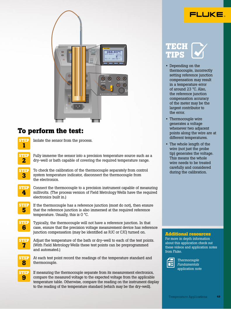
F4F3F2F1
100.00°C
F4F3F2F1
266.03°CSETPT: 266.00 °C
TC—T : 265.783 °C
HEAT: 22 •/•
• Depending on the thermocouple, incorrectly setting reference junction compensation may result in a temperature error of around 23 °C. Also, the reference junction compensation accuracy of the meter may be the largest contributor to the error.
• Thermocouple wire generates a voltage whenever two adjacent points along the wire are at different temperatures.
• The whole length of the wire (not just the probe tip) generates the voltage. This means the whole wire needs to be treated carefully and considered during the calibration.
Additional resources For more in depth information about this application check out these videos and application notes from Fluke.
Thermocouple Fundamentals application note
TECH TIPS
To perform the test:Isolate the sensor from the process.
Fully immerse the sensor into a precision temperature source such as a dry-well or bath capable of covering the required temperature range.
To check the calibration of the thermocouple separately from control system temperature indicator, disconnect the thermocouple from the electronics.
Connect the thermocouple to a precision instrument capable of measuring millivolts. (The process version of Field Metrology Wells have the required electronics built in.)
If the thermocouple has a reference junction (most do not), then ensure that the reference junction is also immersed at the required reference temperature. Usually, this is 0 °C.
Typically, the thermocouple will not have a reference junction. In that case, ensure that the precision voltage measurement device has reference junction compensation (may be identified as RJC or CJC) turned on.
Adjust the temperature of the bath or dry-well to each of the test points. (With Field Metrology Wells these test points can be preprogrammed and automated.)
At each test point record the readings of the temperature standard and thermocouple.
If measuring the thermocouple separate from its measurement electronics, compare the measured voltage to the expected voltage from the applicable temperature table. Otherwise, compare the reading on the instrument display to the reading of the temperature standard (which may be the dry-well).
STEP1
STEP2
STEP3
STEP4
STEP6
STEP8
STEP9
STEP7
STEP5
49Temperature Applications

Suggested test tools
Simulating thermocouples and RTDs for calibration and testing
Thermocouples and RTDs are the most common sensors used in process temperature measurements.
Simulating a process sensor signal into a process instrument or control system input enables a technician to verify whether the device responds correctly to the temperature measured by the instrument. There are many different ways to simulate these sensors for testing purposes.
You can use a mV dc source and a mV vs temperature look up table (below on the left), for simulating thermocouples or a resistance decade box and resistance vs temperature look up table (below on the right), for simulating RTDs. This method, however, has become outdated with modern temperature calibrators that do the conversion for the user. With modern calibrators, simply select the sensor type to simulate, input the temperature to source and connect to the devices under test.
Thermocouple Table – Temperature vs mV
RTD Table – Temperature vs Resistance
°C 0 1 2 3
0 0.000 0.039 0.079 0.119
10 0.397 0.437 0.477 0.517
20 0.796 0.838 0.879 0.919
30 1.203 1.244 1.285 1.326
40 1.612 1.653 1.694 1.735
50 2.023 2.064 2.106 2.147
60 2.436 2.478 2.519 2.561
70 2.851 2.893 2.934 2.976
80 3.267 3.308 3.350 3.391
90 3.682 3.723 3.765 3.806
100 4.096 4.136 4.179 4.220
°C Ohm Diff.
0 100.00 0.39
1 100.39 0.39
2 100.78 0.39
3 101.17 0.39
4 101.56 0.39
5 101.95 0.39
6 102.34 0.39
7 102.73 0.39
8 103.12 0.39
9 103.51 0.39
°C Ohm Diff.
10 103.90 0.39
11 104.29 0.39
12 104.68 0.39
13 105.07 0.39
14 105.46 0.39
15 105.85 0.39
16 106.24 0.39
17 106.63 0.39
18 107.02 0.39
19 107.40 0.38
°C Ohm Diff.
20 107.79 0.39
21 108.18 0.39
22 108.57 0.39
23 108.96 0.39
24 109.35 0.39
25 109.73 0.39
26 110.12 0.39
27 110.51 0.39
28 110.90 0.39
29 111.28 0.38
7526A Precision Process Calibrator
See pg 5
726 Precision Multifunction Process Calibrator
See pg 6
754 Documenting Process Calibrator
See pg 5
714B Thermocouple Temperature Calibrator
See pg 17
712B RTD Temperature Calibrator
See pg 17
50 Temperature Applications

754 DOCUMENTING PROCESS CALIBRATOR
TEST DC PWR++– –
754 DOCUMENTING PROCESS CALIBRATOR
TEST DC PWR++– –
C-2
C-1
S-3
S-2
S-4
S-1
Simulating Thermocouples and RTDs for calibration and testing
TC transmitter calibration connection
©2015 Fluke Corporation. Specifications subject to change without notice. 07/2015 6005865a-en
RTD transmitter calibration connection
754 DOCUMENTING PROCESS CALIBRATOR
TEST DC PWR++– –
754 DOCUMENTING PROCESS CALIBRATOR
TEST DC PWR++– –
C-2
C-1
S-3
S-2
S-4
S-1
Simulating Thermocouples and RTDs for calibration and testing
TC transmitter calibration connection
©2015 Fluke Corporation. Specifications subject to change without notice. 07/2015 6005865a-en
RTD transmitter calibration connection
51
• When simulating a thermo-couple signal from a simu-lator, always use the correct thermocouple wire for the test, either the exact same TC wire type or a compati-ble extension wire type.
• When simulating tempera-ture using a calibrator with active reference junction compensation, remember the calibrator actively compensates for tempera-ture changes. Changes in ambient temperature should be compensated for automatically.
• When testing 3-wire RTD circuits make sure to con-nect all three wires from the sourcing RTD simulator to the device being tested. Shorting out the compensa-tion wire at the transmitter defeats the lead compensa-tion circuit and introduces measurement errors.
Additional resources For more in depth information about this application check out these videos and application notes from Fluke.
Testing, troubleshooting, calibrating process temperature devices webinar
Temperature calibration application note
Fluke temperature calibrators deliver high accuracy, speed, and convenience
TECH TIPS
Connect the calibrator to the device input as shown in figure B.
Connect the calibrator output with the right combination to match the device configuration (2, 3 or 4-wire).
Use the test procedure at left for thermocouple testing, starting at step 3.
Disconnect the process measurement sensor and connect the test connection wires in its place (Figure A).
Connect the mini-connector from the test wires to the TC source connection of the cali-brator.
Connect a DMM or other mea-surement tool to the tested device’s mA output.
Verify the devices range or span. Apply the 0% value with the simulator and verify with the DMM that the output mA value or voltage is as expected.
Repeat the test, applying the 50% and 100% temperature signals.
If the measured output of the device is within limits, the test is complete. If not, adjust the device at zero (offset, 0%) and span (gain, 100%).
Repeat steps 4 and 5 and verify for a correct response.
To use a thermocouple simulator to test a device with a thermocouple input:
STEP1
STEP1
STEP2
STEP3
STEP2
STEP3
STEP4
STEP5
STEP6
STEP7
To perform the test:To use an RTD simulator to test a device with an RTD input:
51Temperature Applications

It’s not always possible or practical to remove instruments from a process for calibration. In situ verification at a single point may be the only way to know whether an instrument is performing as expected. A single point verification is most effective over a narrow temperature range and when combined with other trends and information related to the process and equipment. It also requires the process not to be in a dynamic state of change.
In a single point process temperature verification, a temperature standard such a reference PRT connected to a readout such as a 1523A is placed in thermal equilibrium with the sensor of the instrument to be verified without removing it from the process. Usually this is accomplished with a test well that is installed in a location adjacent to the sensor to be tested.
The reading from the temperature standard is compared to the reading on the panel meter, controller, or transmitter to determine the error and prove the tolerance condition of the loop.
Suggested test tools
Using a precision thermometer for single point process temperature verification
1551A Ex “Stik” Thermometer Readout
See pg 20
1524-P1 Reference Thermometer
See pg 20
1523-P1 Reference Thermometer
See pg 20
1552A Ex “Stik” Thermometer Readout
See pg 20
52 Temperature Applications

SAVE
NEXT
HOMELOG
RESET
ENTER
RECALL
HOLDSTATS °C °F
SETUP
TRENDmV
RS232 12 V DC30 V MAXT1 T2
1524 CALIBRATIONTHERMOMETERREADOUT
The test well (thermowell) should be within a few inches of the temperature transmitter and sensor assembly to be tested.
Make sure that the probe of the temperature standard is long enough to reach the bottom of the test well and that air gaps between the probe and well are minimized.
Wait for the temperature standard to reach the temperature of the test well. This will take a few minutes.
Check for temperature stability. A graphing digital thermometer such as the 1524 makes stability easier to recognize.
Record the reading from the measurement system and the temperature standard to determine whether the measurement system’s readings are suspect.
• For this type of application a battery powered digital thermometer is usually preferred.
• A graphing display helps the technician visualize trends such as stability quickly and easily.
• Ensure that both the probe and the readout of your temperature standard have traceable calibration certificates from a competent laboratory.
• If the probe and readout separate from each other, smart connectors, which include probe calibration constants, provide a best practice method of ensuring that the readout is using the correct probe calibration in its temperature readings.
STEP1
STEP2
STEP3
STEP4
STEP5
To perform the test:
Additional resources For more in depth information about this application check out these videos and application notes from Fluke.
Temperature measurement and calibration: What every instrument technician should know Industrial temperature readout and probe selection guideProcess Calibration Tools: Temperature Applications
TECH TIPS
53Temperature Applications

Deadband
Open
High Limit
ProcessVariable
Low Limit
Setpoint
Reset
Closed50 C
20 C
Deadband
Closed
Reset
Setpoint
Open
Temperature switch and controller testing in the field
Temperature switches and controllers are commonly used in small processes and in control loops where a programmable logic controller (PLC) or larger distributed control system (DCS) are not warranted.
Temperature controllers provide both switching capability based on rising and dropping temperatures, as well as a local indication of the measured temperature.
Most temperature controllers have some form of tuning, using damping and PID (Proportional, Integral and Derivative values) for smoothing out the measured process temperature, reducing variability.
The terminology around switches can be confusing. The set state of the switch is the action the switch takes when an input stimulus above or below a specified value is applied. This stimulus can prompt an action such as closing a switch, which in turn starts or stops a motor, or opens and closes a valve. The reset point is considered the relaxed state of the switch, which is typically referred to as “Normally Open” or “Normally Closed.” This describes the default condition of the switch. Lastly, deadband is the band of temperature equal to the difference between the temperatures where a switch sets, and resets. See illustration at left.
7526A Precision Process Calibrator
See pg 5
726 Precision Multifunction Process Calibrator
See pg 6
754 Documenting Process Calibrator
See pg 5
714B Thermocouple Temperature Calibrator
See pg 17
712B RTD Temperature Calibrator
See pg 17
Suggested test tools
54 Temperature Applications

TECH TIPS
754 DOCUMENTING PROCESS CALIBRATOR
ENTERMENU
200.0° C
Disconnect the process measurement sensor.
Connect the mini-connector from the test wires to the TC source connection of the calibrator (figure above).
Connect the calibrator resistance measurement terminals to the switch contacts to measure continuity.
Set the calibrator to source/simulate the correct thermocouple type and to measure resistance.
Configure the calibrator for the switch test describing the expected setpoint temperature, allowable deviation and expected deadband values.
Run the test and evaluate the test results.
Adjust the switch as needed and repeat the test, confirming that the adjustment was successful and the switch is performing as expected.
• When testing the tempera-ture switch, the applied temperature should agree with the temperature displayed on the controller or switch’s display. If it does not agree, the device’s input A/D may need adjustment per manufactur-er’s procedure.
• When testing a switch with damping (delay of output change for a change on the input) set, it might be necessary to test the switch manually by slowly changing the temperature in small tests.
• When testing a mechanical temperature switch (no external sensor), use a field temperature bath calibrator for best results.
• To test live switch contacts switching 24 V dc or 120-240 V ac, select a calibrator that can measure these live voltages, such as the Fluke 75X family of Documenting Process Calibrators. Most other temperature calibrators can only measure continuity changes when testing switches.
To perform the test:To use a thermocouple simulator to test a switch with a thermocouple input:
Additional resources For more in depth information about this application check out these videos and application notes from Fluke.
Testing, troubleshooting, calibrating process temperature devices webinarTesting a temperature switch with the Fluke 754
Process and temperature switch applications with documenting process calibrators Temperature calibration application noteFluke temperature calibrators deliver high accuracy, speed, and convenience
STEP1
STEP2
STEP3
STEP4
STEP5
STEP6
STEP7
55Temperature Applications

Suggested test tools
Temperature switch and controller testing at the bench
9142, 9143, 9144 Field Metrology Wells
See pg 17
6102 Micro-Bath Thermometer Calibrator
See pg 19
7103 Micro-Bath Thermometer Calibrator
See pg 19
6109A/7109A Micro-Bath
See pg 19
A temperature switch is a device that protects a thermal system by sensing temperature and closing or opening a switch to shut down a process or equipment if the temperature is outside the safe range.
Temperature switches are often calibrated or tested for safety reasons to determine how accurate and repeatable the device is. The temperature at which a switch activates is called the set point and is an important value that needs to be verified during testing.
Another critical safety related value is called the deadband. Below the low end of the deadband, the heating system turns on. Above the high end of the deadband, the heating system turns off.
Switch tests may be operated manually or automatically. If the electronics are not built into the dry-well for a switch test, then a DMM will be needed to determine the open/close condition. Metrology Wells and most Field Metrology Wells have built-in routines to automate switch testing.
56 Temperature Applications

Additional resources For more in depth information about this application check out these videos and application notes from Fluke.
TECH TIPS• Set the scan rate to a
low value, i.e. 1.0 °C per minute, for better accuracy.
• If the scan rate is too low, the duration of the test may be longer than necessary.
914X Field Metrology Wells Video Series
Best practices in temperature calibration
Testing Temperature Switches Using Metrology Wells
Isolate the switch from the process.
Fully immerse the switch into a precision temperature source such as a dry-well or bath capable of covering the required temperature range.
Connect the leads of the switch to a digital multimeter or to the switch test inputs of the dry-well.
If using a Metrology Well or Field Metrology Well, increase the temperature to the set point. Continue raising the temperature until the switch changes state and record that temperature.
Decrease the temperature until the switch resets (changes state again) and record the temperature.
Repeat the process as many times as needed, but reduce the ramp rate and target the last measured set point and reset points to verify accuracy and repeatability.
Record the deadband (difference between the set point and the reset point).
STEP1
STEP2
STEP3
STEP4
STEP5
STEP6
STEP7
To perform the test:
Switch sets - closed
Switch resets - open
Reset
Time
Tem
pera
ture Set-point
Deadband
57Temperature Applications

Suggested test tools
Calibrating with a micro-bath
Instrument technicians need to calibrate a wide variety of temperature sensors including liquid-in-glass thermometers, dial gauges, and sensors that come in odd shapes and sizes.
Problems of fit and immersion that may occur with short, square, or odd-shaped sensors are practically eliminated in a Micro-Bath because the probes are immersed in a fluid that is magnetically stirred for optimal stability.
Micro-Baths combine the portability of a dry-well with the stability and versatility of a calibration bath. They are lighter and smaller than most dry-wells and come with a spill-proof lid.
6102 Micro-Bath Thermometer Calibrator
See pg 19
7102 Micro-Bath Thermometer Calibrator
See pg 19
7103 Micro-Bath Thermometer Calibrator
See pg 19
6109A/7109A
See pg 19
1523-P1 Reference Thermometer
See pg 20
58 Temperature Applications

• Caution: the fluid level rises with higher temperatures and with the number and size of the probes placed into the fluid.
• Best results are obtained with the probe inserted to the full depth of the well.
• The stabilization time of the Micro-Bath depends on the conditions and temperatures involved. Typically stability is achieved within ten minutes.
Additional resources For more in depth information about this application check out these videos and application notes from Fluke.
TECH TIPS
To perform the test:Place the calibrator on a flat surface with at least six inches of free space around the instrument.
Carefully insert the probe basket into the well and fill with the appro-priate fluid.
For optimal performance allow the manufacturer-recommended warm-up period.
Insert the test probe to be calibrated into the well of the bath. For best performance, also insert a temperature standard for comparison.
Once the probe is inserted to the full depth of the bath, allow adequate stabilization time for the test probe temperature to settle.
Once the probes have settled to the temperature of the bath, their indi-cation may be compared to the calibrator display temperature (or to a temperature standard such as a 1551A).
STEP1
STEP2
STEP3
STEP4
STEP6
STEP5
Industrial Temperature Calibrators Workload Matrix
Process Calibration Tools: Temperature Applications
SET DOWN UP EXIT
7103 MICRO-BATH –30°C to 125°C
-25.0 C
SET DOWN UP EXIT
7103 MICRO-BATH –30°C to 125°C
125.0 C
ENTERMENU
125.0° C
59Temperature Applications

Suggested test tools
Infrared thermometer test and calibration
Infrared thermometer calibrations can be accurate with the proper setup and planning. It’s important to choose a calibrator with a radiometrically calibrated target that is large enough to accommodate the recommended calibration distance of common infrared thermometers, along with their various fields of view.
Common errors include pressing the infrared calibrator too close to the hot surface of the calibrator or simply moving the infrared thermometer back and forth until the desired reading is achieved.
The manufacturer will have calibrated the infrared thermometer at a specific distance with a source that meets certain size requirements and has a specific emissivity (often but not always 0.95). To have a meaningful calibration that determines whether the instrument continues to operate within its design specifications, those conditions need to be reproduced as closely as possible.
4180 Precision Infrared Calibrator
See pg 19
4181 Precision Infrared Calibrator
See pg 19
60 Temperature Applications

Additional resources For more in depth information about this application check out these videos and application notes from Fluke.
Emissivity makes a differenceHow to Calibrate an IR Thermometer webinar
Infrared Temperature Calibration 101 application noteInfrared Thermometer Calibration – A Complete Guide
• Emissivity makes a big difference in infrared temperature measurement.
• The temperature and emissivity of the 4180 and 4181 are calibrated radiometrically for the most reliable and traceable results.
• The Fluke 4180 and 4181 can be set to match the emissivity setting of fixed emissivity thermometers.
• The large area of the 4180 and 4181 target allows infrared thermometers to be calibrated at the recommended distance without including unwanted surfaces in the field of view.
• Use a mounting device such as a tripod to maintain the calibration distance.
• Measure the calibration distance from the flat plate surface to the surface of the front housing of the infrared thermometer.
TECH TIPS
To perform the test:Allow at least 15 minutes for the IR thermometer to reach the temperature of the shop or laboratory.
Set the radiation source to the desired calibration temperature. Depending on the temperature range a low, high, and midpoint temperature may be chosen.
If the infrared thermometer has an emissivity setting, it should be set to match the calibrated emissivity of the source.
Position the infrared thermometer at the manufacturer’s recommended calibration distance.
Center the infrared thermometer on the calibrator surface. Do this by adjusting the aim slightly side to side and up and down to maximize the signal.
The measurement time should be ten times longer than the infrared thermometer’s response time. This is typically five seconds for Fluke infrared thermometers.
Record the calibrator indicated reading and the indicated reading of the thermometer under test to determine the error and tolerance status of the thermometer at each set point.
Repeat for the other set point temperatures.
STEP1
STEP2
STEP3
STEP4
STEP6
STEP8
STEP7
STEP5
= IR thermometer field of view
Smaller target
Manufacturer recommendedlarge target
IR thermometerspot size
1 9 9 . 3
d
Measuring(d) distance
561 HVACProIR THERMOMETER
561 HVACProIR THERMOMETER
61Temperature Applications

Suggested test tools
Loop calibration with a temperature transmitter at the bench
In industrial process industries, temperature measurement equipment usually has two components: a sensing device such as an RTD or thermocouple and a transmitter to read and relay the signal to the control system.
All sensors, including RTDs, drift with time. Thus, testing the transmitter and not the sensor could result in misjudgment regarding a system’s performance. To avoid this potential problem, process instrument manufacturers recommend including the temperature sensor in loop calibration to prove the effectiveness of the entire system.
754 Documenting Process Calibrator with temperature source
See pg 5
7526A Precision Process Calibrator with temperature source
See pg 5
9142, 9143, 9144 Field Metrology Wells
See pg 17
62 Temperature Applications

• Streamline the process with automation and provide documentation using a Fluke 754.
• Seventy-five percent of the errors in a temperature measurement system comes from the sensor.
• At minimum, you need a calibrator, and a device to measure 4-20 mA and power the loop.
• Choose a temperature standard with a 90 degree angle bend to ensure both the temperature standard and the transmitter fit in the dry-well at the same time.
Additional resources For more in depth information about this application check out these videos and application notes from Fluke.
TECH TIPS
To perform the test:Isolate the sensor from the process.
Fully immerse the sensor into a precision temperature source such as a dry-well or bath capable of covering the required temperature range.
Connect the temperature standard and 4-20 mA output of the transmitter to a suitable meter or calibrator (for example, the process elec-tronics on a Fluke Field Metrology Well or the inputs of a Fluke 754).
Power the loop. (The Fluke 754 and the process electronics in a Field Metrology Well have this capability.)
Adjust the temperature of the bath or dry-well to each of the test points. (With Field Metrology Wells, these test points can be preprogrammed and automated.)
At each test point, monitor and record the readings of the temperature standard and the local or remote readings connected to the transmitter output.
Also, record the 4-20 mA output of the transmitter to determine which device needs adjustment if an adjustment is required.
STEP1
STEP2
STEP3
STEP4
STEP6
STEP7
STEP5
Eliminating Sensor Errors in Loop CalibrationsMultifunction calibration using the 7526A Precision Process CalibratorImproving loop calibration temperature accuracy
F4F3F2F1
100.00°C
TEST DC PWR++– –
63Temperature Applications

Fluke Corporation PO Box 9090, Everett, WA 98206 U.S.A.
Fluke Europe B.V. PO Box 1186, 5602 BD Eindhoven, The Netherlands
For more information call: In the U.S.A. (800) 443-5853 or Fax (425) 446-5116 In Europe/M-East/Africa +31 (0) 40 2675 200 or Fax +31 (0) 40 2675 222 In Canada (800)-36-FLUKE or Fax (905) 890-6866 From other countries +1 (425) 446-5500 or Fax +1 (425) 446-5116 Web access: www.flukecal.eu
©2017-2018 Fluke Corporation. Specifications subject to change without notice. Printed in the Netherlands 11/2018. Pub-ID 13581-eng
Modification of this document is not permitted without written permission from Fluke Corporation.
Keeping your world up and running®