hook blocks | GOSAN
19
hook blocks hook blocks chap. 1 chap. 2 chap. 3 chap. 4 chap. 5 chap. 6 28 chap. 03 03 hook blocks FOR LIFTING GEAR Gosan has developed a new series of blocks and tracks in accordance with the latest require- ments and techniques FEM 1001 and DIN STAN- DARD 15020. Safety when faced with breakage is in all cases greater than that required by FEM standards. The suspensions (hook, cross-axle, nut) corres- pond to DIN standards15411. The hooks correspond to DIN standards 15401 and 15402 and are made of forged steel, grade StE355 (class P, regulation DIN STANDARD 15400). Alloy 34CrMo4, 34CrNiMo6 and 30CrNiMo8 (clas- ses S, T, V) can be used if required. All the hooks are equipped with a safety bolt to prevent their escaping from the sling. They can be fitted with an anti-spinnnig system which is easily attached without the use of tools; this keeps the hook steady. The pulleys are made of rolled steel, designed and built by GOSAN, and are fitted with double cylindrical roller bearings, per- fectly located with special retainers. These bearings are greased by means of lubricating points, one for every pulley, located on the end of the axle and duly protected from any possible knocks. Special attention is paid to the shape of the throat when constructing the pulley. The bottom radius (DIN 15601 (r=0.525 d)) greatly extend the life of the cable, which will reach its maximum if the cable is properly placed in the pulley throat. Pulleys with the throat tempered will give an additional life extension to the cable and are available upon request. The distance between pulleys (blocks and tackles of four or more pulleys) is very small due to the type of bearings used. When calculating the diameter of the compen- sating pulley and the location of the return-pulleys, one must take into account the fact that the lateral deviation of the cable must be no greater than 4º. The diameter of the cable, as indicated in the ta- bles, has been determined in terms of the compo- sition WS. 6 x 36 + 1 and single resistence 180º kg/mm 2 . The present tendency to use cables with a grea- ter metallic section and resistence of 200 and 220 kg/mm 2 can reduce the diameter of the cable and consequently that of the pulleys. This aspect is of particular interest for large loads as it implies a more compact and, therefore, more economic block and tackle. The pulleys are protected by easily removable safety guards which can be removed even if the block and tackle is suspended from the cables. The output windows for the cables are reinforced and rounded on the edges in order not to damage the cable. The axle of the pulleys may be either grade F.1252 (42CrMo4). The support mats are very thick and have an out- side diameter greater than that of the pulleys. They are reinforced with vertical flatbars between the axle of the pulleys and the cross-axle. They are normally built of rolled steel S355J2. The blocks and tackles undergo rigorous quality control during the manufacturing process. Certifica- tes of receipt and supervision of the use of hooks, DIN 15404 and 15405, and manufacturing, DIN 50049-3.1, are delivered with the hook block. The standards which determine the components of the snatch block are indicated below, as a re- minder.
-
Upload
khangminh22 -
Category
Documents
-
view
1 -
download
0
Transcript of hook blocks | GOSAN

hook blocksh
oo
k b
loc
ks
ch
ap
. 1
ch
ap
. 2
c
ha
p. 3
c
ha
p. 4
c
ha
p. 5
c
ha
p. 6
28 chap. 03
03
hook
blo
cks
FOR
LIF
TIN
G G
EAR
Gosan has developed a new series of blocks and tracks in accordance with the latest require-ments and techniques FEM 1001 and DIN STAN-DARD 15020.
Safety when faced with breakage is in all cases greater than that required by FEM standards.
The suspensions (hook, cross-axle, nut) corres-pond to DIN standards15411.
The hooks correspond to DIN standards 15401 and 15402 and are made of forged steel, grade StE355 (class P, regulation DIN STANDARD 15400). Alloy 34CrMo4, 34CrNiMo6 and 30CrNiMo8 (clas-ses S, T, V) can be used if required.
All the hooks are equipped with a safety bolt to prevent their escaping from the sling.
They can be fitted with an anti-spinnnig system which is easily attached without the use of tools; this keeps the hook steady. The pulleys are made of rolled steel, designed and built by GOSAN, and are fitted with double cylindrical roller bearings, per-fectly located with special retainers. These bearings are greased by means of lubricating points, one for every pulley, located on the end of the axle and duly protected from any possible knocks.
Special attention is paid to the shape of the throat when constructing the pulley. The bottom radius (DIN 15601 (r=0.525 d)) greatly extend the life of the cable, which will reach its maximum if the cable is properly placed in the pulley throat. Pulleys with the throat tempered will give an additional life extension to the cable and are available upon request.
The distance between pulleys (blocks and tackles of four or more pulleys) is very small due to the type of bearings used.
When calculating the diameter of the compen- sating pulley and the location of the return-pulleys, one must take into account the fact that the lateral deviation of the cable must be no greater than 4º. The diameter of the cable, as indicated in the ta- bles, has been determined in terms of the compo- sition WS. 6 x 36 + 1 and single resistence 180º kg/mm2.
The present tendency to use cables with a grea- ter metallic section and resistence of 200 and 220 kg/mm2 can reduce the diameter of the cable and consequently that of the pulleys. This aspect is of particular interest for large loads as it implies a more compact and, therefore, more economic block and tackle.
The pulleys are protected by easily removable safety guards which can be removed even if the block and tackle is suspended from the cables. The output windows for the cables are reinforced and rounded on the edges in order not to damage the cable. The axle of the pulleys may be either grade F.1252 (42CrMo4).
The support mats are very thick and have an out- side diameter greater than that of the pulleys. They are reinforced with vertical flatbars between the axle of the pulleys and the cross-axle. They are normally built of rolled steel S355J2.
The blocks and tackles undergo rigorous quality control during the manufacturing process. Certifica- tes of receipt and supervision of the use of hooks, DIN 15404 and 15405, and manufacturing, DIN 50049-3.1, are delivered with the hook block.
The standards which determine the components of the snatch block are indicated below, as a re- minder.
hook blocks
03
hook blocks

hook blocks CLASSIFICATION OF THE LIFTING DEVICE - FEM 1.001
STATE OF LOAD LIFE IN REAL WORKING HOURS OF THE DEVICE
Factor K SERVICE 800 1.600 3.200 6.300 12.500 25.000 50.000
very low 0,125 frequency of M3 1 Bm M4 1 Am M5 2 m M6 3 m M7 4 m maximum load. low frequency 0,250 of maximum M3 1 Bm M4 1 Am M5 2 m M6 3 m M7 4 m M8 5 m load. approx same 0,500 frequency M3 1 Bm M4 1 Am M5 2 m M6 3 m M7 4 m M8 5 m M8 5 m of off-peak, med. & max loads. high frequency 1,000 of maximum M4 1 Am M5 2 m M6 3 m M7 4 m M8 5 m M8 5 m M8 5 m load.
DEFINING THE CABLE.
COEFFICIENTS ZP AND C FEM 1001 DIN 15020
MINIMUM SAFETY Zp COEFICIENT C mm / √ KP
GROUP CONVEN- NON GROUP CONVENTIONAL NON ROTATION TIONAL ROTATION WIRE ROPE WIRE ROPE WIRE ROPE WIRE ROPE 180 200 180 200
M3 3,55 4 1 Bm 0,265 0,250 0,250 0,236
M4 4 4,5 1Am 0,300 0,280 0,265 0,265
M5 4,5 5,6 2 m 0,335 0,335 0,300 0,300
M6 5,6 7,1 3 m 0,375 0,375 0,335 0,335
M7 7,1 9 4 m 0,425 0,425 0,375 0,375
M8 9 11,2 5 m 0,475 0,475 0,425 0,425
No of strands 2 3 4 5 6 7 8 9 10 11 12 13 14 pulleys with
N 0,99 0,98 0,97 0,96 0,95 0,94 0,93 0,92 0,91 0,91 0,90 0,89 0,88 bearing
The maximum pull S in the lifting cable is obtained by considering.
P = Maximum nominal load of the device.Q = Weight of the block and tackle itself of the supporting
element of the load.i = Block and tagle ratio.
N= Block and tagle capacity. (T.2.2).Fa = Accelerating force if greater than 10% of the load.
αm= Inclination of the cable at the end of a run if it is greater than 22.5º.
Therefore:
S= P + Q
i . N
S= P + Q
i . N . cos αm
S= P + Q + Fa
i . N
In the special case of self-gripping ladles, two cases are con-sidered:
1. A system of elevation that assures load spreading.Locking lines, S= 66% of the weight of the ladle divided by number of cables.Stay ropes, S= 66% of the total weight of the ladle divided by number of cables.
2. A system of elevation that does not assure load sprea- ding.
Locking lines, S=100% of the total weight of the ladle divi- ded by number of cables.Stay ropes, S=66% of the total weight of the ladle divided by number of cables.
Diameter of the cable.
FEM safety Zp ≥ Fo (cable breaking stress)
S (maximum pull of the rope)
DIN dmin = C √ S C= coef. Indicated in T-2-1
29
BLOCK AND TACKLE CAPACITY - DIN 15020
TABLE T - 2 - 1
TABLE T - 2 - 2
chap. 03

hook blocksh
oo
k b
loc
ks
30 chap. 03
ch
ap
. 1
ch
ap
. 2
c
ha
p. 3
c
ha
p. 4
c
ha
p. 5
c
ha
p. 6
COEFFICIENT H1
GROUP NORMAL CABLE NONROTATING CABLE
FEM DIN CABLE COMPENSAT. CABLE COMPENSAT
PULLEY PULLEY PULLEY PULLEY
M3 1 Bm 16 12,5 18 14
M4 1 Am 18 14 20 16
M5 2 m 20 14 22,4 16
M6 3 m 22,4 16 25 18
M7 4 m 25 16 28 18
M8 5 m 28 18 31,5 20
Determinig h2.
W = Bending coeficient on passing through a pulley or drum.
W = 1 –Cable drum.
W = 2 –Cable pulley with bending in the same direc- tion.
W = 4 –Cable pulley with bending in opposite direc- tion.
h2 = 1 –For Wtot equal to or lower than 5.
h2 = 1,12 –for Wtot between 6 and 9.
h2 = 1,25 –for Wtot greater than 10.
CONSULTING DATA.
With an aim to providing a hook block appropiate for the sevice required, the following information should ac- company any enquiry:
1. FEM/DIN group of lifting gear or description of the work of the crane of lifting device.
2. Maximum load to be lifted.
3. Diameter of the cable.
4. Number of strands of the block and tackle.
5. Lifting speed.
6. Diameter of the compensating pulley.
7. Arrangement of the upper pulleys.
PROGRAM OF HOOK BLOCKS.
The blocks and tackles listed are the so-called short ones with outside plate pulleys.
GOSAN designs and builds large blocks and tackles with pulleys arranged on the outside of the plates or some inside and others outside the plates.
We also build blocks and tackles without a hook, with swivel eyes or another system suitable for lifting devices.
PULLEY CABLES
Determining the minimum original diameter in the cable.
D ≥d1 . h1. h2
If:
d1= diameter of the cable.
h1= coefficient depending on the group where the lifting de-vice is classified. This coefficient defined by DIN 15020.
h2= increse factor of h1, balances the number of bendings in a cable on passing through the pulleys and the drum.
COEFFICIENT H2

hook blocks

hook blocksh
oo
k b
loc
ks
-s
us
pe
ns
ion
s
32 chap. 03
SUSPENSIONS WITH SINGLE HOOKFOR CRANES
ch
ap
. 1
ch
ap
. 2
c
ha
p. 3
c
ha
p. 4
c
ha
p. 5
c
ha
p. 6
TE
CH
NIC
AL
DA
TA
1 50 40 50 17,5 - - 25 - 10 39 - 130 51.106 1,6 56 45 65 17,5 - - 25 - 10 53 - 140 51.107 2,5 63 50 80 20 22,5 17 30 19 10 63,5 - 155 51.108 4 71 56 90 22,5 25 19 35 23 12 71 - 175 51.110 5 80 63 100 25 27,5 22 40 27 15 79,5 - 195 51.112 6 90 71 125 27,5 30 24 45 32 15 90 95 240 51.214 8 100 80 140 30 35 29 50 36 20 98 104 265 51.216 10 112 90 160 30 35 29 55 40 20 110 116 280 51.218 12 125 100 180 35 42,5 34 60 42 25 127 133 315 51.220 16 140 112 190 35 42,5 36 70 50 25 136 143 370 51.222 20 160 175 200 - 47,5 41 80 56 30 150 157 415 51.224 25 180 140 220 - 49 41 90 64 30 166 173 460 51.226 32 200 160 260 - 59 51 100 72 40 188 195 500 51.232 40 224 180 285 - 65 58 110 80 45 208 215 565 51.236 50 250 200 335 - 65 58 125 92 45 224 232 620 51.244 63 280 224 380 - 71 63 140 104 50 260 267 700 51.248 80 315 250 420 - 72,5 63 160 120 50 287 294 800 51.256 100 355 280 470 - 87,5 77 180 136 60 326 333 885 51.260 125 400 315 510 - 87,5 77 200 150 60 365 374 1.000 51.268 160 450 355 550 - 100 87 220 164 70 406 416 1.130 51.272 200 500 400 610 - 100 87 240 184 70 492 501 1.270 51.372 250 560 450 700 - 110 97 260 200 80 552 561 1.440 51.384
Nº a1 a2 b1 b2 b3 b4 d5 d6 s u1 u3 v BEARING HOOK
REF.: 020.101D
ES
CR
IPT
ION
Hooks in accordance with DIN15411
standards (with DIN15401 hooks).
Material:
The hooks are made of forged steel,
(class P).
We can use alloy steel if required
(class V).
All the hooks are equipped with a
safety latch to prevent their escaping
from the sling.
They can be fitted with an anti-turning
system which is easily attached
without the use of tools, this keeps
the hook steady.

hook blockshook blocks
33
DE
SC
RIP
TIO
N
Hooks in accordance with DIN15411
standards (with DIN15402 hooks)
Material:
The hooks are made of forged steel,
(class P). We can use alloy steel if requi-
red (class V).
All the hooks are equipped with a safety
latch to prevent their escaping from the
sling.
They can be fitted with an anti-turning
system which is easily attached without
the use of tools, this keeps the hook
steady.
TE
CH
NIC
AL
DA
TA
1 32 50 17,5 - - 25 - 10 39 - 130 51.106 1,6 36 65 17,5 - - 25 - 10 53 - 140 51.107 2,5 40 80 20 22,5 17 30 19 10 63,5 - 155 51.108 4 45 90 22,5 25 19 35 23 12 71 - 175 51.110 5 50 100 25 27,5 22 40 27 15 79,5 - 195 51.112 6 56 125 27,5 30 24 45 32 15 90 95 240 51.214 8 63 140 30 35 29 50 36 20 98 104 265 51.216 10 71 160 30 35 29 55 40 20 110 116 280 51.218 12 80 180 35 42,5 34 60 42 25 127 133 315 51.220 16 90 190 35 42,5 36 70 50 25 136 143 370 51.222 20 100 200 - 47,5 41 80 56 30 150 157 415 51.224 25 112 220 - 49 41 90 64 30 166 173 460 51.226 32 125 260 - 59 51 100 72 40 188 195 500 51.232 40 140 285 - 65 58 110 80 45 208 215 565 51.236 50 160 335 - 65 58 125 92 45 224 232 620 51.244 63 180 380 - 71 63 140 104 50 260 267 700 51.248 80 200 420 - 72,5 63 160 120 50 287 294 800 51.256 100 224 470 - 87,5 77 180 136 60 326 333 885 51.260 125 250 510 - 87,5 77 200 150 60 365 374 1.000 51.268 160 280 550 - 100 87 220 164 70 406 416 1.130 51.272 200 315 610 - 100 87 240 184 70 492 501 1.270 51.372 250 355 700 - 110 97 260 200 80 552 561 1.440 51.384
Nº a2 b1 b2 b3 b4 d5 d6 s u1 u3 v BEARING HOOK
REF.: 020.102
chap. 03
ch
ap
. 1 c
ha
p. 2
c
ha
p. 3
c
ha
p. 4
c
ha
p. 5
c
ha
p. 6
ho
ok
blo
ck
s-s
us
pe
ns
ion
s
SUSPENSIONS WITH DOUBLE HOOKFOR CRANES

hook blocks
34 chap. 03
ch
ap
. 1
ch
ap
. 2
c
ha
p. 3
c
ha
p. 4
c
ha
p. 5
c
ha
p. 6
ho
ok
blo
ck
s-fo
r h
ois
t HOOK BLOCKS FOR HOIST“1 Sheave”
TE
CH
NIC
AL
DA
TA
1 M4 3,2 9-10 180 320 16 011.1.M456 1 M5 2,5 9-10 180 320 16 011.1.M456 1 M6 2 9-10 180 320 16 011.1.M456 1,6 M4 5 13 240 390 29 011.1,6.M456 1,6 M5 4 13 240 390 29 011.1,6.M456 1,6 M6 3,2 13 240 390 29 011.1,6.M456 2,5 M4 8 16 290 450 45 011.2,5.M456 2,5 M5 6,3 16 290 450 45 011.2,5.M456 2,5 M6 --- 16 290 450 45 011.2,5.M456 4 M4 12,5 20-21-22 400 560 90 011.4.M456 4 M5 10 20-21-22 400 560 90 011.4.M456 4 M6 8 20-21-22 400 560 90 011.4.M456 5 M4 16 24 430 600 115 011.5.M456 5 M5 12,5 24 430 600 115 011.5.M456 5 M6 10 24 430 600 115 011.5.M456 6 M4 20 26 470 680 142 011.6.M456 6 M5 16 26 470 680 142 011.6.M456 6 M6 12,5 26 470 680 142 011.6.M456 8 M4 25 29 520 750 192 011.8.M456 8 M5 20 29 520 750 192 011.8.M456 8 M6 16 29 520 750 192 011.8.M456
Nº GROUP LOAD d1 d2 w WEIGHT REFERENCES
REF.: 021.111D
ES
CR
IPT
ION
State-of-the-art hook block, designed for very demanding conditions.
It complies with the FEM/DIN standards.
Suspensions follow DIN15411 and they are supplied with safety latch.
Material:
- suspension: class V(other qualities if requested)
- shaft: 42CrMo4.
- supports: S355J2.

hook blockshook blocks ho
ok
blo
ck
s-fo
r h
ois
t
35
HOOK BLOCKS FOR HOIST“2 Sheave”
DE
SC
RIP
TIO
N
State-of-the-art hook block, designed for very demanding conditions.
It complies with the FEM/DIN standards.
Suspensions follow DIN15411 and they are supplied with safety latch.
Material:
- suspension: class V (other qualities if requested)
- shaft: 42CrMo4
- supports: S355J2.
TE
CH
NIC
AL
DA
TA
1,6 M4 5 9-10 180 135 280 26 023.1,6.M456 1,6 M5 4 9-10 180 135 280 26 023.1,6.M456 1,6 M6 3,2 9-10 180 135 280 26 023.1,6.M456 2,5 M4 8 13 240 165 335 47 023.2,5.M456 2,5 M5 6,3 13 240 165 335 47 023.2,5.M456 2,5 M6 5 13 240 165 335 47 023.2,5.M456 4 M4 10 13 240 185 350 56 023.4.M456-1 4 M5 8 13 240 185 350 56 023.4.M456-1 4 M6 6,3 13 240 185 350 56 023.4.M456-1 4 M4 12,5 16 290 200 380 81 023.4.M456-2 4 M5 10 16 290 200 380 81 023.4.M456-2 4 M6 8 16 290 200 380 81 023.4.M456-2 5 M4 16 16 290 210 405 87 023.5.M456 5 M5 12,5 16 290 210 405 87 023.5.M456 5 M6 10 16 290 210 405 87 023.5.M456 6 M4 20 20-21-22 400 250 510 170 023.6.M456 6 M5 16 20-21-22 400 250 510 170 023.6.M456 6 M6 12,5 20-21-22 400 250 510 170 023.6.M456 8 M4 25 20-21-22 400 265 535 181 023.8.M456 8 M5 20 20-21-22 400 265 535 181 023.8.M456 8 M6 16 20-21-22 400 265 535 181 023.8.M456 10 M4 32 24 430 300 580 240 023.10.M456 10 M5 25 24 430 300 580 240 023.10.M456 10 M6 20 24 430 300 580 240 023.10.M456 12 M4 40 26 470 355 655 312 023.12.M456 12 M5 32 26 470 355 655 312 023.12.M456 12 M6 25 26 470 355 655 312 023.12.M456 16 M4 50 29 520 380 750 407 023.16.M456 16 M5 40 29 520 380 750 407 023.16.M456 16 M6 32 29 520 380 750 407 023.16.M456
Nº GROUP LOAD d1 d2 e1 W WEIGHT REF.
REF.: 021.023
chap. 03
ch
ap
. 1 c
ha
p. 2
c
ha
p. 3
c
ha
p. 4
c
ha
p. 5
c
ha
p. 6

hook blocksh
oo
k b
loc
k a
nd
ta
ck
le
36 chap. 03
HOOK BLOCK AND TACKLE“2 Sheaves”
ch
ap
. 1
ch
ap
. 2
c
ha
p. 3
c
ha
p. 4
c
ha
p. 5
c
ha
p. 6
TE
CH
NIC
AL
DA
TA
2,5 M3 1 Bm 6,3 1.600 10 180 210 255 40 160 250 170 285 50 40 40 022.2,5.M3 2,5 M4 1 Am 5 3.200 10 180 210 255 40 160 250 170 285 50 40 40 022.2,5.M4 2,5 M5 2 m 4 6.300 9 180 210 255 40 160 250 170 285 50 40 40 022.2,5 M5 2,5 M6 3 m 3,2 12.500 9 200 230 275 40 160 250 170 285 50 40 40 022.2,5.M6 2,5 M7 4 m 2,5 25.000 9 250 280 325 40 160 250 170 285 50 40 44 022.2,5.M7 2,5 M8 5 m 2 50.000 9 250 280 325 40 160 250 170 285 50 40 44 022.2,5.M8
4 M3 1 Bm 10 1.600 12 190 230 280 50 180 280 190 320 56 45 55 022.4.M3 4 M4 1 Am 8 3.200 12 190 230 280 50 180 280 190 320 56 45 55 022.4.M4 4 M5 2 m 6,3 6.300 11 225 260 310 50 180 280 190 320 56 45 58 022.4.M5 4 M6 3 m 5 12.500 11 245 280 330 50 180 280 190 320 56 45 58 022.4.M6 4 M7 4 m 4 25.000 11 280 315 365 40 190 280 190 320 56 45 62 022.4.M7 4 M8 5 m 3,2 50.000 11 280 315 365 40 190 280 190 320 56 45 62 022.4.M8
Nº
Group Load Life Wire Dimensions Weight
REF. ISO
DIN t h d1 d2 d3 d4 d5 e1 e2 v w Single Doub.
kgs. FEM a2
REF.: 020.022
DE
SC
RIP
TIO
N
State-of-the-art hook block, designed for very deman-ding conditions.
It complies with the FEM/DIN standards.
Suspensions follow DIN15411 and they are supplied with safety latch.
Material:
- Suspension: class P.(other qualities if requested)
- Shaft: 42CrMo4.
- Supports: S355J2.
Distance between sheaves is very small, due to the bearing used.

hook blockshook blocks
37
TE
CH
NIC
AL
DA
TA
Nº
Group Load Life Wire Dimensions Weight
REF. ISO
DIN t h d1 d2 d3 d4 d5 e1 e2 v w Single Doub.
kgs. FEM a2 5 M3 1 Bm 12,5 1.600 14 235 280 335 60 200 310 210 360 63 50 75 022.5.M3 5 M4 1 Am 10 3.200 14 235 280 335 60 200 310 210 360 63 50 75 022.5.M4 5 M5 2 m 8 6.300 12 240 280 335 50 200 297 210 360 63 50 75 022.5.M5 5 M6 3 m 6,3 12.500 12 275 315 370 50 200 297 210 360 63 50 75 022.5.M6 5 M7 4 m 5 25.000 12 315 355 410 50 210 307 210 360 63 50 80 022.5.M7 5 M8 5 m 4 50.000 12 315 355 410 50 210 307 210 360 63 50 80 022.5.M8
6 M3 1 Bm 16 1.600 16 265 315 370 60 240 350 240 420 71 56 102 022.6.M3 6 M4 1 Am 12,5 3.200 16 265 315 370 60 240 350 240 420 71 56 102 022.6.M4 6 M5 2 m 10 6.300 14 270 315 370 60 240 350 240 420 71 56 106 022.6.M6 6 M6 3 m 8 12.500 14 310 355 410 60 240 350 240 420 71 56 106 022.6.M6 6 M7 4 m 6,3 25.000 14 360 405 460 50 250 350 240 410 71 56 110 022.6.M7 6 M8 5 m 5 50.000 14 360 405 460 50 250 350 240 410 71 56 110 022.6.M8
8 M3 1 Bm 20 1.600 18 300 355 410 70 270 400 265 465 80 63 150 022.8.M3 8 M4 1 Am 16 3.200 18 300 355 410 70 270 400 265 465 80 63 150 022.8.M4 8 M5 2 m 12,5 6.300 16 305 355 410 60 270 380 265 465 80 63 152 022.8.M5 8 M6 3 m 10 12.500 16 355 405 460 60 270 380 265 465 80 63 152 022.8.M6 8 M7 4 m 8 25.000 16 405 455 510 60 280 390 265 455 80 63 155 022.8.M7 8 M8 5 m 6,3 50.000 16 405 455 510 60 280 390 265 455 80 63 155 022.8.M8
10 M3 1 Bm 25 1.600 20 295 355 565 80 290 430 280 500 90 71 178 022.10.M3 10 M4 1 Am 20 3.200 20 295 355 565 80 290 430 280 500 90 71 178 022.10.M4 10 M5 2 m 16 6.300 18 350 405 460 70 290 410 280 500 90 71 180 022.10.M5 10 M6 3 m 12,5 12.500 18 400 455 510 70 290 410 280 500 90 71 180 022.10.M6 10 M7 4 m 10 25.000 18 455 510 565 70 320 440 280 500 90 71 185 022.10.M7 10 M8 5 m 8 50.000 18 455 510 565 70 320 440 280 500 90 71 185 022.10.M8
12 M3 1 Bm 32 1.600 22 340 405 460 80 330 470 315 565 100 80 230 022.12.M3 12 M4 1 Am 25 3.200 22 340 405 460 80 330 470 315 565 100 80 230 022.12,M4 12 M5 2 m 20 6.300 20 395 455 510 80 330 470 315 565 100 80 235 022.12.M5 12 M6 3 m 16 12.500 20 450 510 570 80 330 470 315 565 100 80 235 022.12.M6 12 M7 4 m 12,5 25.000 20 500 570 630 80 360 500 315 565 100 80 240 022.12 M7 12 M8 5 m 10 50.000 20 500 570 630 80 360 500 315 565 100 80 240 022.12.M8
16 M3 1 Bm 40 1.600 24 380 455 510 90 350 500 370 645 112 90 335 022.16.M3 16 M4 1 Am 32 3.200 24 380 455 510 90 350 500 370 645 112 90 335 022.16.M4 16 M5 2 m 25 6.300 22 445 510 565 80 350 490 370 635 112 90 340 022.16.M5 16 M6 3 m 20 12.500 22 505 570 625 80 350 490 370 635 112 90 340 022.16.M6 16 M7 4 m 16 25.000 22 560 630 685 80 390 530 370 635 112 90 345 022.16.M7 16 M8 5 m 12.5 50.000 22 560 630 685 80 390 530 370 635 112 90 345 022.16.M8
20 M3 1 Bm 50 1.600 28 425 510 575 100 380 530 415 710 125 100 480 022.20.M3 20 M4 1 Am 40 3.200 28 425 510 575 100 380 530 415 710 125 100 480 022.20.M4 20 M5 2 m 32 6.300 26 490 570 635 90 380 530 415 700 125 100 485 022.20.M5 20 M6 3 m 25 12.500 26 550 630 695 90 380 530 415 700 125 100 485 022.20.M6 20 M7 4 m 20 25.000 26 630 710 775 90 420 570 415 705 125 100 490 022.20.M7 20 M8 5 m 16 50.000 26 630 710 775 90 420 570 415 705 125 100 490 022.20.M8
25 M3 1 Bm 63 1.600 30 480 570 635 110 420 590 460 775 140 112 635 022.25.M3 25 M4 1 Am 50 3.200 30 480 570 635 110 420 590 460 775 140 112 635 022.25.M4 25 M5 2 m 40 6.300 28 545 630 695 100 420 570 460 770 140 112 640 022.25.M5 25 M6 3 m 32 12.500 28 625 710 775 100 420 570 460 770 140 112 640 022.25.M6 25 M7 4 m 25 25.000 28 710 795 860 100 440 590 460 770 140 112 645 022.25.M7 25 M8 5 m 20 50.000 28 710 795 860 100 440 590 460 770 140 112 645 022.25.M8
32 M3 1 Bm 80 1600 34 525 630 695 120 480 660 500 850 160 125 800 022.32.M3 32 M4 1 Am 63 3.200 34 525 630 695 120 480 660 500 850 160 125 800 022.32.M4 32 M5 2 m 50 6.300 32 610 710 775 110 470 640 500 845 160 125 805 022.32.M5 32 M6 3 m 40 12.500 32 695 795 860 110 470 640 500 845 160 125 805 022.32.M6 32 M7 4 m 32 25.000 32 800 900 965 110 480 650 500 840 160 125 810 022.32.M7 32 M8 5 m 25 50.000 32 800 900 965 110 480 650 500 840 160 125 810 022.32.M8
40 M3 1 Bm 100 1.600 38 595 710 775 130 530 740 565 935 180 140 975 022.40.M3 40 M4 1 Am 80 3.200 38 595 710 775 130 530 740 565 935 180 140 975 022.40.M4 40 M5 2 m 63 6.300 36 685 795 860 120 520 700 565 930 180 140 985 022.40.M5 40 M6 3 m 50 12.500 36 790 900 965 120 520 700 565 930 180 140 985 022.40.M6 40 M7 4 m 40 25.000 36 900 1.010 1.075 120 520 700 565 930 180 140 990 022.40.M7 40 M8 5 m 32 50.000 36 900 1.010 1.075 120 520 700 565 930 180 140 990 022.40.M8
chap. 03
ch
ap
. 1 c
ha
p. 2
c
ha
p. 3
c
ha
p. 4
c
ha
p. 5
c
ha
p. 6
ho
ok
blo
ck
an
d ta
ck
le
HOOK BLOCK AND TACKLE“2 Sheaves”

hook blocksh
oo
k b
loc
k a
nd
ta
ck
le
38 chap. 03
HOOK BLOCK AND TACKLE“4 Sheaves”
ch
ap
. 1
ch
ap
. 2
c
ha
p. 3
c
ha
p. 4
c
ha
p. 5
c
ha
p. 6
DE
SC
RIP
TIO
N
State-of-the-art hook block, designed for very deman-ding conditions.
It complies with the FEM/DIN standards.
Suspensions follow DIN15411 and they are supplied with safety latch.
Material:
- Suspension: class P.(other qualities if requested)
- Shaft: 42CrMo4.
- Supports: S355J2.
Distance between sheaves is very small, due to the bearing used.
TE
CH
NIC
AL
DA
TA
Nº
Group Load Life Wire Dimensions Weight
REF. ISO
DIN t h d1 d2 d3 d4 d5 e1 e2 e3 v w Single Doub.
kgs. FEM a2
12 M3 1 Bm 32 1.600 16 305 355 410 80 320 580 60 315 565 100 80 300 041.12.M3
12 M4 1 Am 25 3.200 16 305 355 410 80 320 580 60 315 565 100 80 300 041.12.M4
12 M5 2 m 20 6.300 14 310 355 410 80 310 570 60 315 565 100 80 305 041.12.M5
12 M6 3 m 16 12.500 14 360 405 460 80 310 570 60 315 565 100 80 305 041.12.M6
12 M7 4 m 12,5 25.000 14 410 455 510 70 310 538 54 315 565 100 80 310 041.12.M7
12 M8 5 m 10 50.000 14 410 455 510 70 310 538 54 315 565 100 80 310 041.12.M8
16 M3 1 Bm 40 1.600 18 300 355 410 90 340 624 67 370 640 112 90 435 041.16.M3
16 M4 1 Am 32 3.200 18 300 355 410 90 340 624 67 370 640 112 90 435 041.16.M4
16 M5 2 m 25 6.300 16 355 405 460 80 330 590 60 370 640 112 90 440 041.16.M5
16 M6 3 m 20 12.500 16 405 455 510 80 330 590 60 370 640 112 90 440 041.16.M6
16 M7 4 m 16 25.000 16 460 510 565 80 330 590 60 370 640 112 90 445 041.16.M7
16 M8 5 m 12,5 50.000 16 460 510 565 80 330 590 60 370 640 112 90 445 041.16.M8
REF.: 020.041

hook blockshook blocks
39
TE
CH
NIC
AL
DA
TA
Nº
Group Load Life Wire Dimensions Weight
REF. ISO
DIN t h d1 d2 d3 d4 d5 e1 e2 e3 v w Single Doub.
kgs. FEM a2
20 M3 1 Bm 50 1.600 20 345 405 470 100 360 644 67 415 710 125 100 640 041.20.M3
20 M4 1 Am 40 3.200 20 345 405 470 100 360 644 67 415 710 125 100 640 041.20.M4
20 M5 2 m 32 6.300 18 400 455 520 90 350 634 67 415 710 125 100 645 041.20.M5
20 M6 3 m 25 12.500 18 455 510 575 90 350 634 67 415 710 125 100 645 041.20.M6
20 M7 4 m 20 25.000 18 515 570 635 80 350 610 60 415 700 125 100 650 041.20.M7
20 M8 5 m 16 50.000 18 515 570 635 80 350 610 60 415 700 125 100 650 041.20.M8
25 M3 1 Bm 63 1.600 22 385 455 520 110 390 720 80 460 775 140 112 810 041.25.M3
25 M4 1 Am 50 3.200 22 385 455 520 110 390 720 80 460 775 140 112 810 041.25.M4
25 M5 2 m 40 6.300 20 450 510 575 100 380 665 67 460 775 140 112 815 041.25.M5
25 M6 3 m 32 12.500 20 510 570 635 100 380 665 67 460 785 140 112 815 041.25.M6
25 M7 4 m 25 25.000 20 570 630 695 90 380 665 67 460 765 140 112 820 041.25.M7
25 M8 5 m 20 50.000 20 570 630 695 90 380 665 67 460 765 140 112 820 041.25.M8
32 M3 1 Bm 80 1.600 24 435 510 575 120 450 790 80 500 850 160 125 1.050 041.32.M3
32 M4 1 Am 63 3.200 24 435 510 575 120 450 790 80 500 850 160 125 1.050 041.32.M4
32 M5 2 m 50 6.300 22 500 570 635 110 450 780 80 500 840 160 125 1.060 041.32.M5
32 M6 3 m 40 12.500 22 560 630 695 110 450 780 80 500 840 160 125 1.060 041.32.M6
32 M7 4 m 32 25.000 22 640 710 775 100 450 734 67 500 840 160 125 1.070 041.32.M7
32 M8 5 m 25 50.000 22 640 710 775 100 450 734 67 500 840 160 125 1.070 041.32.M8
40 M3 1 Bm 100 1.600 28 485 570 635 130 500 850 95 565 940 180 140 1.260 041.40.M3
40 M4 1 Am 80 3.200 28 485 570 635 130 500 850 95 565 940 180 140 1.260 041.40.M4
40 M5 2 m 63 6.300 26 550 630 695 120 490 830 80 565 940 180 140 1.270 041.40.M5
40 M6 3 m 50 12.500 26 630 710 775 120 490 830 80 565 940 180 140 1.270 041.40.M6
40 M7 4 m 40 25.000 26 715 795 860 110 490 820 80 565 930 180 140 1.280 041.40.M7
40 M8 5 m 32 50.000 26 715 795 860 110 490 820 80 565 930 180 140 1.280 041.40.M8
50 M3 1 Bm 125 1.600 30 540 630 695 150 560 930 100 620 1.035 200 160 1.640 041.50.M3
50 M4 1 Am 100 3.200 30 540 630 695 150 560 930 100 620 1.035 200 160 1.640 041.50.M4
50 M5 2 m 80 6.300 28 625 710 775 130 550 890 95 620 1.035 200 160 1.650 041.50.M5
50 M6 3 m 63 12.500 28 710 795 860 130 550 890 95 620 1.035 200 160 1.650 041.50.M6
50 M7 4 m 50 25.000 28 815 900 965 120 550 890 80 620 1.020 200 160 1.660 041.50.M7
50 M8 5 m 40 50.000 28 815 900 965 120 550 890 80 620 1.020 200 160 1.660 041.50.M8
63 M3 1 Bm 160 1.600 34 605 710 780 160 620 1.067 109 700 1.160 224 180 2.180 041.63.M3
63 M4 1 Am 125 3.200 34 605 710 780 160 620 1.067 109 700 1.160 224 180 2.180 041.63.M4
63 M5 2 m 100 6.300 32 695 795 865 140 620 980 95 700 1.150 224 180 2.190 041.63.M5
63 M6 3 m 80 12.500 32 800 900 970 140 620 980 95 700 1.150 224 180 2.190 041.63.M6
63 M7 4 m 63 25.000 32 910 1.010 1.080 130 620 995 95 700 1.140 224 180 2.200 041.63.M7
63 M8 5 m 50 50.000 32 910 1.010 1.080 130 620 995 95 700 1.140 224 180 2.200 041.63.M8
80 M3 1 Bm 200 1.600 38 680 795 875 180 680 1.178 136 800 1.300 250 200 2.890 041.80.M3
80 M4 1 Am 160 3.200 38 680 795 875 180 680 1.178 136 800 1.300 250 200 2.890 041.80.M4
80 M5 2 m 125 6.300 36 790 900 980 160 670 1.080 109 800 1.290 250 200 2.900 041.80.M5
80 M6 3 m 100 12.500 36 900 1.010 1.090 160 670 1.080 109 800 1.290 250 200 2.900 041.80.M6
80 M7 4 m 80 25.000 36 1.000 1.110 1.190 150 670 1.070 100 800 1.280 250 200 2.910 041.80.M7
80 M8 5 m 63 50.000 36 1.000 1.110 1.190 150 670 1.070 100 800 1.280 250 200 2.910 041.80.M8
100 M3 1 Bm 250 1.600 42 770 900 955 200 770 1.270 150 885 1.435 280 224 3.810 041.100.M3
100 M4 1 Am 200 3.200 42 770 900 955 200 770 1.270 150 885 1.435 280 224 3.810 041.100.M4
100 M5 2 m 160 6.300 40 890 1.010 1.080 180 760 1.240 136 885 1.425 280 224 3.830 041.100.M5
100 M6 3 m 125 12.500 40 990 1.110 1.180 180 760 1.240 136 885 1.425 280 224 3.830 041.100.M6
100 M7 4 m 100 25.000 40 1.120 1.240 1.310 160 760 1.180 109 885 1.410 280 224 3.850 041.100.M7
100 M8 5 m 80 50.000 40 1.120 1.240 1.310 160 760 1.180 109 885 1.410 280 224 3.850 041.100.M8
125 M3 1 Bm 320 1.600 46 870 1.010 1.080 220 810 1.340 160 1.000 1.625 315 250 4.860 041.125.M3
125 M4 1 Am 250 3.200 46 870 1.010 1.080 220 810 1.340 160 1.000 1.625 315 250 4.860 041.125.M4
125 M5 2 m 200 6.300 44 970 1.110 1.180 200 800 1.320 150 1.000 1.610 315 250 4.880 041.125.M5
125 M6 3 m 160 12.500 44 1.100 1.240 1.310 200 800 1.320 150 1.000 1.610 315 250 4.880 041.125.M6
125 M7 4 m 125 25.000 44 1.240 1.380 1.470 180 800 1.280 136 1.000 1.590 315 250 4.900 041.125.M7
125 M8 5 m 100 50.000 44 1.240 1.380 1.470 180 800 1.280 136 1.000 1.590 315 250 4.900 041.125.M8
160 M3 1 Bm 400 1.600 52 950 1.110 1.180 240 900 1.440 160 1.130 1.790 355 280 6.520 041.160.M3
160 M4 1 Am 320 3.200 52 950 1.110 1.180 240 900 1.440 160 1.130 1.790 355 280 6.520 041.160.M4
160 M5 2 m 250 6.300 50 1.090 1.240 1.310 220 880 1.420 160 1.130 1.780 355 280 6.560 041.160.M5
160 M6 3 m 200 12.500 50 1.230 1.380 1.470 220 880 1.420 160 1.130 1.780 355 280 6.560 041.160.M6
160 M7 4 m 160 25.000 50 1.400 1.550 1.640 200 880 1.420 150 1.130 1.780 355 280 6.580 041.160.M7
160 M8 5 m 125 50.000 50 1.400 1.550 1.640 200 880 1.420 150 1.130 1.780 355 280 6.580 041.160.M8
chap. 03
ch
ap
. 1 c
ha
p. 2
c
ha
p. 3
c
ha
p. 4
c
ha
p. 5
c
ha
p. 6
ho
ok
blo
ck
an
d ta
ck
le
HOOK BLOCK AND TACKLE“4 Sheaves”

hook blocksh
oo
k b
loc
k a
nd
ta
ck
le
40 chap. 03
HOOK BLOCK AND TACKLE“6 Sheaves”
ch
ap
. 1
ch
ap
. 2
c
ha
p. 3
c
ha
p. 4
c
ha
p. 5
c
ha
p. 6
DE
SC
RIP
TIO
N
State-of-the-art hook block, designed for very deman-ding conditions.
It complies with the FEM/DIN standards.
Suspensions follow DIN15411 and they are supplied with safety latch.
Material:
- Suspension: class P.(other qualities if requested)
- Shaft: 42CrMo4.
- Supports: S355J2.
Distance between sheaves is very small, due to the bearing used.
TE
CH
NIC
AL
DA
TA
Nº
Group Load Life Wire Dimensions Weight
REF. ISO
DIN t h d1 d2 d3 d4 d5 e1 e2 e3 v w Single Doub.
kgs. FEM a2
20 M3 1 Bm 50 1.600 16 355 405 450 110 360 843 80 415 720 125 100 830 060.20.M3
20 M4 1 Am 40 3.200 16 355 405 450 110 360 843 80 415 720 125 100 830 060.20.M4
20 M5 2 m 32 6.300 15 360 405 450 100 360 778 67 415 720 125 100 840 060.20.M5
20 M6 3 m 25 12.500 15 410 455 500 100 360 778 67 415 720 125 100 840 060.20.M6
20 M7 4 m 20 25.000 15 465 510 555 90 360 778 67 415 720 125 100 850 060.20.M7
20 M8 5 m 16 50.000 15 465 510 555 90 360 778 67 415 720 125 100 850 060.20.M8
25 M3 1 Bm 63 1.600 18 400 455 500 120 390 890 80 460 775 140 112 1.040 060.25.M3
25 M4 1 Am 50 3.200 18 400 455 500 120 390 890 80 460 775 140 112 1.040 060.25.M4
25 M5 2 m 40 6.300 16 405 455 500 110 390 880 80 460 775 140 112 1.050 060.25.M5
25 M6 3 m 32 12.500 16 460 510 555 110 390 880 80 460 775 140 112 1.050 060.25.M6
25 M7 4 m 25 25.000 16 520 570 620 100 390 808 67 460 775 140 112 1.060 060.25.M7
25 M8 5 m 20 50.000 16 520 570 620 100 390 808 67 460 775 140 112 1.060 060.25.M8
REF.: 020.060

hook blockshook blocks
41
TE
CH
NIC
AL
DA
TA
Nº
Group Load Life Wire Dimensions Weight
REF. ISO
DIN t h d1 d2 d3 d4 d5 e1 e2 e3 v w Single Doub.
kgs. FEM a2
32 M3 1 Bm 80 1.600 21 445 510 555 140 450 1.020 95 500 860 160 125 1.350 060.32.M3
32 M4 1 Am 63 3.200 21 445 510 555 140 450 1.020 95 500 860 160 125 1.350 060.32.M4
32 M5 2 m 50 6.300 19 450 510 555 120 450 950 80 500 845 160 125 1.360 060.32.M5
32 M6 3 m 40 12.500 19 510 570 620 120 450 950 80 500 845 160 125 1.360 060.32.M6
32 M7 4 m 32 25.000 19 570 630 680 110 450 940 80 500 845 160 125 1.370 060.32.M7
32 M8 5 m 25 50.000 19 570 630 680 110 450 940 80 500 845 160 125 1.370 060.32.M8
40 M3 1 Bm 100 1.600 22 440 510 555 150 500 1.080 100 565 945 180 140 1.610 060.40.M3
40 M4 1 Am 80 3.200 22 440 510 555 150 500 1.080 100 565 945 180 140 1.610 060.40.M4
40 M5 2 m 63 6.300 21 505 570 620 130 500 1.050 95 565 935 180 140 1.620 060.40.M5
40 M6 3 m 50 12.500 21 565 630 680 130 500 1.050 95 565 935 180 140 1.620 060.40.M6
40 M7 4 m 40 25.000 21 645 710 765 120 500 1.000 80 565 935 180 140 1.630 060.40.M7
40 M8 5 m 32 50.000 21 645 710 765 120 500 1.000 80 565 935 180 140 1.630 060.40.M8
50 M3 1 Bm 125 1.600 26 550 630 680 160 570 1.180 109 620 1.030 200 160 2.040 060.50.M3
50 M4 1 Am 100 3.200 26 550 630 680 160 570 1.180 109 620 1.030 200 160 2.040 060.50.M4
50 M5 2 m 80 6.300 24 635 710 765 140 570 1.120 95 620 1.020 200 160 2.060 060.50.M5
50 M6 3 m 63 12.500 24 635 710 765 140 570 1.120 95 620 1.020 200 160 2.060 060.50.M6
50 M7 4 m 50 25.000 24 720 795 850 130 570 1.120 95 620 1.020 200 160 2.080 060.50.M7
50 M8 5 m 40 50.000 24 720 795 850 130 570 1.120 95 620 1.020 200 160 2.080 060.50.M8
63 M3 1 Bm 160 1.600 28 625 710 765 180 640 1.380 136 700 1.170 224 180 2.680 060.63.M3
63 M4 1 Am 125 3.200 28 625 710 765 180 640 1.380 136 700 1.170 224 180 2.680 060.63.M4
63 M5 2 m 100 6.300 26 630 710 765 160 620 1.230 109 700 1.160 224 180 2.695 060.63.M5
63 M6 3 m 80 12.500 26 715 795 850 160 620 1.230 109 700 1.160 224 180 2.695 060.63.M6
63 M7 4 m 63 25.000 26 820 900 955 150 620 1.180 100 700 1.160 224 180 2.710 060.63.M7
63 M8 5 m 50 50.000 26 820 900 955 150 620 1.180 100 700 1.160 224 180 2.710 060.63.M8
80 M3 1 Bm 200 1.600 32 695 795 850 200 690 1.520 150 800 1.320 250 200 3.390 060.80.M3
80 M4 1 Am 160 3.200 32 695 795 850 200 690 1.520 150 800 1.320 250 200 3.390 060.80.M4
80 M5 2 m 125 6.300 30 705 795 850 180 670 1.440 136 800 1.320 250 200 3.410 060.80.M5
80 M6 3 m 100 12.500 30 810 900 955 180 670 1.440 136 800 1.320 250 200 3.410 060.80.M6
80 M7 4 m 80 25.000 30 920 1.010 1.080 160 670 1.300 109 800 1.300 250 200 3.430 060.80.M7
80 M8 5 m 63 50.000 30 920 1.010 1.080 160 670 1.300 109 800 1.300 250 200 3.430 060.80.M8
100 M3 1 Bm 250 1.600 36 790 900 955 240 770 1.650 160 885 1.430 280 224 4.400 060.100M3
100 M4 1 Am 200 3.200 36 790 900 955 240 770 1.650 160 885 1.430 280 224 4.400 060.100.M4
100 M5 2 m 160 6.300 34 795 900 955 200 750 1.580 150 885 1.410 280 224 4.420 060.100.M5
100 M6 3 m 125 12.500 34 905 1.010 1.080 200 750 1.580 150 885 1.410 280 224 4.420 060.100.M6
100 M7 4 m 100 25.000 34 1.005 1.110 1.180 180 750 1.510 136 885 1.410 280 224 4.440 060.100.M7
100 M8 5 m 80 50.000 34 1.005 1.110 1.180 180 750 1.510 136 885 1.410 280 224 4.440 060.100.M8
125 M3 1 Bm 320 1.600 40 780 900 955 260 840 1.870 190 1.000 1.650 315 250 5.440 060.125.M3
125 M4 1 Am 250 3.200 40 780 900 955 260 840 1.870 190 1.000 1.650 315 250 5.440 060.125.M4
125 M5 2 m 200 6.300 38 895 1.010 1.080 220 820 1.690 160 1.000 1.620 315 250 5.470 060.125.M5
125 M6 3 m 160 12.500 38 995 1.110 1.180 220 820 1.690 160 1.000 1.620 315 250 5.470 060.125.M6
125 M7 4 m 125 25.000 38 1.125 1.240 1.310 200 820 1.640 150 1.000 1.620 315 250 5.490 060.125.M7
125 M8 5 m 100 50.000 38 1.125 1.240 1.310 200 820 1.640 150 1.000 1.620 315 250 5.490 060.125.M8
160 M3 1 Bm 400 1.600 44 875 1010 1080 280 900 1.930 190 1.130 1.810 355 280 7.250 060.160.M3
160 M4 1 Am 320 3.200 44 875 1010 1080 280 900 1.930 190 1.130 1.810 355 280 7.250 060.160.M4
160 M5 2 m 250 6.300 42 980 1.110 1.180 240 870 1.760 160 1.130 1.780 355 280 7.270 060.160.M5
160 M6 3 m 200 12.500 42 1.110 1.240 1.310 240 870 1.760 160 1.130 1.780 355 280 7.270 060.160.M6
160 M7 4 m 160 25.000 42 1.250 1.380 1.470 220 870 1.760 160 1.130 1.780 355 280 7.290 060.160.M7
160 M8 5 m 125 50.000 42 1.250 1.380 1.470 220 870 1.760 160 1.130 1.780 355 280 7.290 060.160.M8
chap. 03
ch
ap
. 1 c
ha
p. 2
c
ha
p. 3
c
ha
p. 4
c
ha
p. 5
c
ha
p. 6
ho
ok
blo
ck
an
d ta
ck
le
HOOK BLOCK AND TACKLE“6 Sheaves”
hook blocksh
oo
k b
loc
k a
nd
ta
ck
le
42 chap. 03
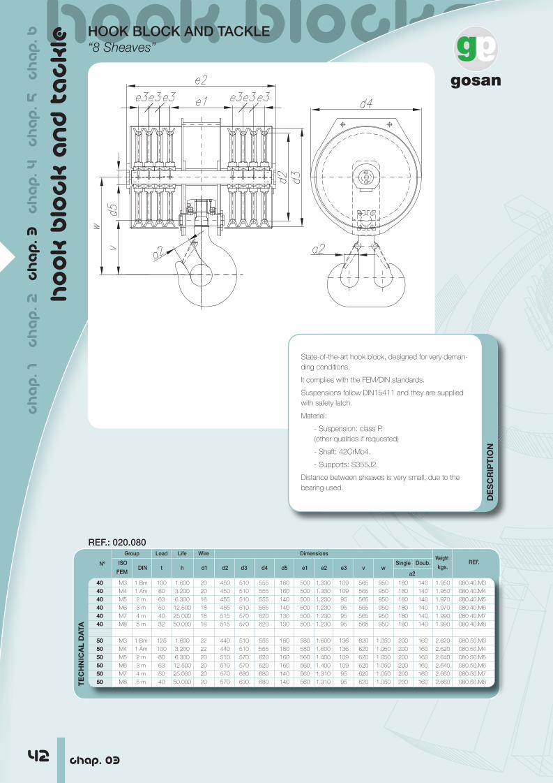
HOOK BLOCK AND TACKLE“8 Sheaves”
ch
ap
. 1
ch
ap
. 2
c
ha
p. 3
c
ha
p. 4
c
ha
p. 5
c
ha
p. 6
DE
SC
RIP
TIO
N
State-of-the-art hook block, designed for very deman-ding conditions.
It complies with the FEM/DIN standards.
Suspensions follow DIN15411 and they are supplied with safety latch.
Material:
- Suspension: class P.(other qualities if requested)
- Shaft: 42CrMo4.
- Supports: S355J2.
Distance between sheaves is very small, due to the bearing used.
TE
CH
NIC
AL
DA
TA
Nº
Group Load Life Wire Dimensions Weight
REF. ISO
DIN t h d1 d2 d3 d4 d5 e1 e2 e3 v w Single Doub.
kgs. FEM a2
40 M3 1 Bm 100 1.600 20 450 510 555 160 500 1.330 109 565 950 180 140 1.950 080.40.M3
40 M4 1 Am 80 3.200 20 450 510 555 160 500 1.330 109 565 950 180 140 1.950 080.40.M4
40 M5 2 m 63 6.300 18 455 510 555 140 500 1.230 95 565 950 180 140 1.970 080.40.M5
40 M6 3 m 50 12.500 18 455 510 555 140 500 1.230 95 565 950 180 140 1.970 080.40.M6
40 M7 4 m 40 25.000 18 515 570 620 130 500 1.230 95 565 950 180 140 1.990 080.40.M7
40 M8 5 m 32 50.000 18 515 570 620 130 500 1.230 95 565 950 180 140 1.990 080.40.M8
50 M3 1 Bm 125 1.600 22 440 510 555 180 580 1.600 136 620 1.050 200 160 2.620 080.50.M3
50 M4 1 Am 100 3.200 22 440 510 555 180 580 1.600 136 620 1.050 200 160 2.620 080.50.M4
50 M5 2 m 80 6.300 20 510 570 620 160 560 1.400 109 620 1.050 200 160 2.640 080.50.M5
50 M6 3 m 63 12.500 20 510 570 620 160 560 1.400 109 620 1.050 200 160 2.640 080.50.M6
50 M7 4 m 50 25.000 20 570 630 680 140 560 1.310 95 620 1.050 200 160 2.660 080.50.M7
50 M8 5 m 40 50.000 20 570 630 680 140 560 1.310 95 620 1.050 200 160 2.660 080.50.M8
REF.: 020.080

hook blockshook blocks
43
TE
CH
NIC
AL
DA
TA
Nº
Group Load Life Wire Dimensions Weight
REF. ISO
DIN t h d1 d2 d3 d4 d5 e1 e2 e3 v w Single Doub.
kgs. FEM a2
63 M3 1 Bm 160 1.600 24 495 570 620 220 660 1.850 160 700 1.200 224 180 3.180 080.63.M3
63 M4 1 Am 125 3.200 24 495 570 620 220 660 1.850 160 700 1.200 224 180 3.180 080.63.M4
63 M5 2 m 100 6.300 22 560 630 680 180 640 1.660 136 700 1.200 224 180 3.195 080.63.M5
63 M6 3 m 80 12.500 22 560 630 680 180 640 1.660 136 700 1.200 224 180 3.195 080.63.M6
63 M7 4 m 63 25.000 22 640 710 765 160 610 1.450 109 700 1.200 224 180 3.210 080.63.M7
63 M8 5 m 50 50.000 22 640 710 795 160 610 1.450 109 700 1.200 224 180 3.210 080.63.M8
80 M3 1 Bm 200 1.600 28 545 630 680 240 700 1.890 160 800 1.330 250 200 3.940 080.80.M3
80 M4 1 Am 160 3.200 28 545 630 680 240 700 1.890 160 800 1.330 250 200 3.940 080.80.M4
80 M5 2 m 125 6.300 26 715 795 850 200 690 1.810 150 800 1.330 250 200 3.960 080.80.M5
80 M6 3 m 100 12.500 26 715 795 850 200 690 1.810 150 800 1.330 250 200 3.960 080.80.M6
80 M7 4 m 80 25.000 26 820 900 955 180 680 1.710 136 800 1.330 250 200 3.990 080.80.M7
80 M8 5 m 63 50.000 26 820 900 955 180 680 1.710 136 800 1.330 250 200 3.990 080.80.M8
100 M3 1 Bm 250 1.600 32 695 795 850 260 800 2.200 190 885 1.440 280 224 5.200 080.100.M3
100 M4 1 Am 200 3.200 32 695 795 850 260 800 2.200 190 885 1.440 280 224 5.200 080.100.M4
100 M5 2 m 160 6.300 30 810 900 955 220 770 1.960 160 885 1.440 280 224 5.230 080.100.M5
100 M6 3 m 125 12.500 30 810 900 955 220 770 1.960 160 885 1.440 280 224 5.230 080.100.M6
100 M7 4 m 100 25.000 30 920 1.010 1.080 200 760 1.880 150 885 1.440 280 224 5.260 080.100.M7
100 M8 5 m 80 50.000 30 920 1.010 1.080 200 760 1.880 150 885 1.440 280 224 5.260 080.100.M8
125 M3 1 Bm 320 1.600 34 690 795 850 280 840 2.240 190 1.000 1.660 315 250 6.240 080.125.M3
125 M4 1 Am 250 3.200 34 690 795 850 280 840 2.240 190 1.000 1.660 315 250 6.240 080.125.M4
125 M5 2 m 200 6.300 32 800 900 955 240 810 2.000 160 1.000 1.660 315 250 6.260 080.125.M5
125 M6 3 m 160 12.500 32 800 900 955 240 810 2.000 160 1.000 1.660 315 250 6.260 080.125.M6
125 M7 4 m 125 25.000 32 1.010 1.110 1.180 220 810 2.000 160 1.000 1.660 315 250 6.290 080.125.M7
125 M8 5 m 100 50.000 32 1.010 1.110 1.180 220 810 2.000 160 1.000 1.660 315 250 6.290 080.125.M8
160 M3 1 Bm 400 1.600 38 785 900 955 300 930 2.550 218 1.130 1.820 355 280 7.910 080.160.M3
160 M4 1 Am 320 3.200 38 785 900 955 300 930 2.550 218 1.130 1.820 355 280 7.910 080.160.M4
160 M5 2 m 250 6.300 36 900 1.010 1.080 280 900 2.320 190 1.130 1.820 355 280 7.940 080.160.M5
160 M6 3 m 200 12.500 36 1.000 1.110 1.180 260 900 2.320 190 1.130 1.820 355 280 7.940 080.160.M6
160 M7 4 m 160 25.000 36 1.130 1.240 1.310 240 870 2.080 160 1.130 1.820 355 280 7.980 080.160.M7
160 M8 5 m 125 50.000 36 1.130 1.240 1.310 240 870 2.080 160 1.130 1.820 355 280 7.980 080.160.M8
200 M3 1 Bm 500 1.600 44 870 1.010 1.080 *200 940 2.150 150 1.270 1.960 400 315 9.710 080.200.M3
200 M4 1 Am 400 3.200 44 870 1.010 1.080 *180 940 2.050 136 1.270 1.960 400 315 9.710 080.200.M4
200 M5 2 m 320 6.300 42 985 1.110 1.180 300 990 2.620 218 1.270 1.960 400 315 9.810 080.200.M5
200 M6 3 m 250 12.500 42 1.115 1.240 1.310 280 960 2.390 190 1.270 1.960 400 315 9.810 080.200.M6
200 M7 4 m 200 25.000 42 1.255 1.380 1.470 280 960 2.390 190 1.270 1.960 400 315 9.850 080.200.M7
200 M8 5 m 160 50.000 42 1.255 1.380 1.470 260 960 2.390 190 1.270 1.960 400 315 9.850 080.200.M8
250 M3 1 Bm 500 1.600 48 965 1.110 1.180 *200 1.050 2.230 150 1.440 2.130 450 355 11.700 080.250.M3
250 M4 1 Am 500 3.200 48 965 1.110 1.180 *200 1.050 2.230 150 1.440 2.130 450 355 11.700 080.250.M4
250 M5 2 m 400 6.300 46 1.100 1.240 1.310 *180 1.050 2.130 136 1.440 2.130 450 355 11.740 080.250.M5
250 M6 3 m 320 12.500 46 1.240 1.380 1.470 *160 1.050 1.940 109 1.440 2.130 450 355 11.740 080.250.M6
250 M7 4 m 250 25.000 46 1.410 1.550 1.640 300 1.100 2.750 218 1.440 2.130 450 355 11.920 080.250.M7
250 M8 5 m 200 50.000 46 1.410 1.550 1.640 280 1.080 2.560 190 1.440 2.130 450 355 11.920 080.250.M8
chap. 03
ch
ap
. 1 c
ha
p. 2
c
ha
p. 3
c
ha
p. 4
c
ha
p. 5
c
ha
p. 6
ho
ok
blo
ck
an
d ta
ck
le
HOOK BLOCK AND TACKLE“8 Sheaves”

44 chap. 0344 chap. 03
other productso
the
r p
ro
du
cts
OTHER PRODUCTS
>>>>>> >>>offshore
>>>>>>>>>>>>>>>>>>>>>>>>>>>>>>>>>>>>>>>>>>>>>>>>>>>>>>>>>>>>>>>>>>>>>>>>>>>>>>>>>>>>>>>>>>>>>ch
ap
. 1
ch
ap
. 2
c
ha
p. 3
c
ha
p. 4
c
ha
p. 5
c
ha
p. 6
We at Gosan have gone beyond our historical markets and now we have a presence in offshore projects within the North Sea, where a large and complex offshore industry is located, as well as, in the Rest of the World.
Gosan has invested in R&D projects so as to manufacture products economically and in the most expeditious manner. Due to the nature of the oil industry, optimum delivery is critical.
To this end Gosan has developed a system to make sure orders are ready on time. We have an excellent team of Highly Qualified Engi-neers who work to make continuous improvements using CAD/CAM systems.
At Gosan we manufacture a wide range of;Sheaves, Hook blocks, Wheels for Offshore applications suitable for:Oil and Gas Platforms, Cargo Handling, Pipe Laying and Supply Ves-
sels, ROV operations, Sub-sea Operations, etc.
• According to International Design and uality Standards.• According to Customer Designs, we manufacture any lifting ele-
ment according to customer specifications thanks to the Know –How which we have developed as a competitive advantage over decades of service
• sing Gosan s Application Engineering team, applying the latest and most advanced hardware systems and calculation software.
All Gosan production is submitted to rigorous and exhaustive Quality Assurance procedures and to customer s indi idual requirements:
• Standard esting according to International Standards including ultrasonic, magnetic particle, Charply impact, mechanical properties, proof load...
• Custom esting according to customer specifications.With the option, in all cases, of product being inspected by interna-
tionally recognized Certifying Organizations or by the customer s quality assurance personnel.

45chap. 03 45chap. 03
other productsother products oth
er
pr
od
uc
tsOTHER PRODUCTS
>>>>>> >>>>>>offshore
ch
ap
. 1 c
ha
p. 2
c
ha
p. 3
c
ha
p. 4
c
ha
p. 5
c
ha
p. 6

>>>>>> >>>>>>>>>>>>>>>>>>>>>>>>>>>>>>>>>>>>>>>>>>>>>>>>>>>>>>>>>>>>>>>other products
46 chap. 03
oth
er
pr
od
uc
ts
OTHER PRODUCTS
industry
, ,
mobile crane
>>>>>>>>>>>>>>>>>> >>>>>>>>>>>>>>>>>>>>>>>>>>>>>>>>>ch
ap
. 1
ch
ap
. 2
c
ha
p. 3
c
ha
p. 4
c
ha
p. 5
c
ha
p. 6