Terminal Blocks - PC Components Company (PCC)
172
Bulletin 1492 Terminal Blocks Table of Contents 12-1 IEC Terminal Blocks S Mini Blocks Page 12-8 S Standard and Feed–Through Blocks Page 12-10 S Multi–Circuit Blocks Page 12-13 S Specialty Feed–Through Blocks Page 12-14 S Sensor Blocks Page 12-15 S Grounding Blocks Page 12-17 S Isolation Blocks Page 12-19 S Plug–In Style Blocks Page 12-21 S Two Level Plug–In Style Blocks Page 12-22 S Two Level Plug–In Style Blocks with Ground Page 12-23 S Fuse Blocks Page 12-24 S Installation Blocks Page 12-27 S Component Blocks Page 12-29 S Resistor Blocks Page 12-31 S Surge Suppressor Blocks Page 12-32 S Thermocouple Blocks Page 12-33 QuickClampt Terminal Blocks S Standard Blocks Page 12-36 S Plug–In Style Blocks Page 12-41 S Multi–Circuit Blocks Page 12-42 S Isolation Blocks Page 12-43 S Component Blocks Page 12-44 S Sensor Blocks Page 12-46 S Standard Grounding Blocks Page 12-49 Finger–Safe Terminal Blocks S High Density Page 12-53 S Isolation Switch Blocks Page 12-55 S Fuse Blocks Page 12-56 S Surge Suppressor Blocks Page 12-58 S Resistor Blocks Page 12-59 S Voltage Indicating Blocks Page 12-60 S Component Blocks Page 12-61 NEMA/EEMAC Terminal Blocks S Open Construction Blocks Page 12-64 S Isolation Switch Blocks Page 12-69 S Fuse Blocks Page 12-70
-
Upload
khangminh22 -
Category
Documents
-
view
0 -
download
0
Transcript of Terminal Blocks - PC Components Company (PCC)

Bulletin 1492
Terminal BlocksTable of Contents
12-1
IEC Terminal Blocks Mini Blocks Page 12-8 Standard and Feed–Through Blocks Page 12-10 Multi–Circuit Blocks Page 12-13 Specialty Feed–Through Blocks Page 12-14 Sensor Blocks Page 12-15 Grounding Blocks Page 12-17 Isolation Blocks Page 12-19 Plug–In Style Blocks Page 12-21 Two Level Plug–In Style Blocks Page 12-22 Two Level Plug–In Style Blocks with Ground Page 12-23 Fuse Blocks Page 12-24 Installation Blocks Page 12-27 Component Blocks Page 12-29 Resistor Blocks Page 12-31 Surge Suppressor Blocks Page 12-32 Thermocouple Blocks Page 12-33
QuickClamp Terminal Blocks Standard Blocks Page 12-36 Plug–In Style Blocks Page 12-41 Multi–Circuit Blocks Page 12-42 Isolation Blocks Page 12-43 Component Blocks Page 12-44 Sensor Blocks Page 12-46 Standard Grounding Blocks Page 12-49
Finger–Safe Terminal Blocks High Density Page 12-53 Isolation Switch Blocks Page 12-55 Fuse Blocks Page 12-56 Surge Suppressor Blocks Page 12-58 Resistor Blocks Page 12-59 Voltage Indicating Blocks Page 12-60 Component Blocks Page 12-61
NEMA/EEMAC Terminal Blocks Open Construction Blocks Page 12-64 Isolation Switch Blocks Page 12-69 Fuse Blocks Page 12-70

Bulletin 1492
Terminal BlocksTable of Contents
12-2
Panel Mount Blocks Panel Mount Blocks Page 12-74
Power Blocks Power Blocks Page 12-78
Circuit Protection Fuse Holders Page 12-90 Circuit Breakers Page 12-92
Programmable Controller WiringSystems Interface Modules Page 12-106 Cable Specifications Page 12-122 Pre–wired Cable and IFM Selection Tables Page 12-124 Marking Systems Page 12-127
Accessories and TechnicalSpecifications DIN Mounting Rails Page 12-143 Allen–Bradley Mounting Rails Page 12-144 End Anchors Page 12-146 End Barriers Page 12-147 Partition Plates/Seperation Plates Page 12-149 Jumpers/Fanning Strips/Fuse Holders Page 12-150 General Accessories Page 12-151 QuickClamp Accessories Page 12-152 Marking Systems Page 12-154 Technical Specifications Page 12-165 UL/CSA File and Guide Numbers Page 12-171

Bulletin 1492
Catalog Number Index
12-3
Catalog Number Page199-DR1 12-143. . . . . . . . . . . . . . . . . . . . . . . 1492-100X 12-83. . . . . . . . . . . . . . . . . . . . . . 1492-100XF 12-79. . . . . . . . . . . . . . . . . . . . . 1492-100Y 12-83. . . . . . . . . . . . . . . . . . . . . . 1492-100YF 12-79. . . . . . . . . . . . . . . . . . . . . 1492-15A 12-146. . . . . . . . . . . . . . . . . . . . . . 1492-15E 12-146. . . . . . . . . . . . . . . . . . . . . . 1492-15T 12-75. . . . . . . . . . . . . . . . . . . . . . . . 1492-25A 12-146. . . . . . . . . . . . . . . . . . . . . . 1492-25E 12-146. . . . . . . . . . . . . . . . . . . . . . 1492-25T 12-75. . . . . . . . . . . . . . . . . . . . . . . . 1492-50X 12-82. . . . . . . . . . . . . . . . . . . . . . . 1492-50XF 12-79. . . . . . . . . . . . . . . . . . . . . . 1492-50Y 12-82. . . . . . . . . . . . . . . . . . . . . . . 1492-50YF 12-78. . . . . . . . . . . . . . . . . . . . . . 1492-ACABLE-A 12-122. . . . . . . . . . . . . . . . 1492-ACABLE-B 12-122. . . . . . . . . . . . . . . . 1492-ACABLE-C 12-122. . . . . . . . . . . . . . . . 1492-ACABLE-D 12-122. . . . . . . . . . . . . . . . 1492-ACABLE-E 12-122. . . . . . . . . . . . . . . . 1492-ACABLE-F 12-122. . . . . . . . . . . . . . . . 1492-ACABLE-G 12-122. . . . . . . . . . . . . . . 1492-ACABLE-H 12-122. . . . . . . . . . . . . . . . 1492-ACABLE-J 12-122. . . . . . . . . . . . . . . . 1492-ACABLE-L 12-122. . . . . . . . . . . . . . . . 1492-ACBA1 12-95. . . . . . . . . . . . . . . . . . . . 1492-ACBA2 12-95. . . . . . . . . . . . . . . . . . . . 1492-ACBA3 12-95. . . . . . . . . . . . . . . . . . . . 1492-ACBA4 12-95. . . . . . . . . . . . . . . . . . . . 1492-ACBA5 12-95. . . . . . . . . . . . . . . . . . . . 1492-ACBCC1 12-95. . . . . . . . . . . . . . . . . . . 1492-ACBCL1 12-95. . . . . . . . . . . . . . . . . . . 1492-ACBCL2 12-95. . . . . . . . . . . . . . . . . . . 1492-ACBCL3 12-95. . . . . . . . . . . . . . . . . . . 1492-ACBH1 12-95. . . . . . . . . . . . . . . . . . . . 1492-ACBH2 12-95. . . . . . . . . . . . . . . . . . . . 1492-ACBHS1 12-95. . . . . . . . . . . . . . . . . . . 1492-ACBS1 12-95. . . . . . . . . . . . . . . . . . . . 1492-ACBS2 12-95. . . . . . . . . . . . . . . . . . . . 1492-AIFM16-F-3 12-121. . . . . . . . . . . . . . . 1492-AIFM16-F-5 12-121. . . . . . . . . . . . . . . 1492-AIFM4-3 12-119. . . . . . . . . . . . . . . . . . 1492-AIFM4C-F-5 12-120. . . . . . . . . . . . . . . 1492-AIFM4I-F-5 12-120. . . . . . . . . . . . . . . . 1492-AIFM6S-3 12-119. . . . . . . . . . . . . . . . . 1492-AIFM8-3 12-119. . . . . . . . . . . . . . . . . . 1492-AIFM8-F-5 12-120. . . . . . . . . . . . . . . . 1492-ALHFB 12-154. . . . . . . . . . . . . . . . . . . 1492-ALWFB 12-154. . . . . . . . . . . . . . . . . . . 1492-BE 12-83. . . . . . . . . . . . . . . . . . . . . . . . 1492-BF 12-84. . . . . . . . . . . . . . . . . . . . . . . . 1492-BG 12-85. . . . . . . . . . . . . . . . . . . . . . . . 1492-CA1 12-65. . . . . . . . . . . . . . . . . . . . . . . 1492-CA1175 12-65. . . . . . . . . . . . . . . . . . . . 1492-CA1L 12-65. . . . . . . . . . . . . . . . . . . . . . 1492-CA1L175 12-65. . . . . . . . . . . . . . . . . . 1492-CA2 12-66. . . . . . . . . . . . . . . . . . . . . . . 1492-CA2175 12-66. . . . . . . . . . . . . . . . . . . . 1492-CA3 12-68. . . . . . . . . . . . . . . . . . . . . . . 1492-CA3175 12-68. . . . . . . . . . . . . . . . . . . . 1492-CABLE–A 12-122. . . . . . . . . . . . . . . . . 1492-CABLE–B 12-122. . . . . . . . . . . . . . . . . 1492-CABLE–C 12-122. . . . . . . . . . . . . . . . .
Catalog Number Page1492-CABLE–D 12-122. . . . . . . . . . . . . . . . . 1492-CABLE–E 12-122. . . . . . . . . . . . . . . . . 1492-CABLE–F 12-122. . . . . . . . . . . . . . . . . 1492-CABLE–FF 12-122. . . . . . . . . . . . . . . . 1492-CABLE–G 12-122. . . . . . . . . . . . . . . . 1492-CABLE–H 12-122. . . . . . . . . . . . . . . . . 1492-CABLE–J 12-122. . . . . . . . . . . . . . . . . 1492-CABLE–K 12-122. . . . . . . . . . . . . . . . . 1492-CABLE–L 12-122. . . . . . . . . . . . . . . . . 1492-CABLE–M 12-122. . . . . . . . . . . . . . . . 1492-CABLE–N 12-122. . . . . . . . . . . . . . . . . 1492-CABLE–N3 12-123. . . . . . . . . . . . . . . 1492-CABLE–P 12-123. . . . . . . . . . . . . . . . . 1492-CABLE–Q 12-123. . . . . . . . . . . . . . . . 1492-CABLE–R 12-122. . . . . . . . . . . . . . . . . 1492-CABLE–RTBB 12-123. . . . . . . . . . . . 1492-CABLE–RTBO 12-123. . . . . . . . . . . . 1492-CABLE–RTBR 12-123. . . . . . . . . . . . 1492-CABLE–WA 12-123. . . . . . . . . . . . . . . 1492-CABLE–WD 12-123. . . . . . . . . . . . . . . 1492-CABLE–WH 12-123. . . . . . . . . . . . . . . 1492-CABLE–WHF 12-123. . . . . . . . . . . . . 1492-CABLE–WN 12-123. . . . . . . . . . . . . . . 1492-CAM1 12-66. . . . . . . . . . . . . . . . . . . . . 1492-CAM1L 12-66. . . . . . . . . . . . . . . . . . . . 1492-CAM2 12-67. . . . . . . . . . . . . . . . . . . . . 1492-CB1(CIRCUIT BREAKER) 12-94. . . 1492-CB2(CIRCUIT BREAKER) 12-94. . . 1492-CB3(CIRCUIT BREAKER) 12-94. . . 1492-CBB9–10 12-150. . . . . . . . . . . . . . . . . 1492-CD2 12-67. . . . . . . . . . . . . . . . . . . . . . . 1492-CD2130 12-67. . . . . . . . . . . . . . . . . . . . 1492-CD3 12-68. . . . . . . . . . . . . . . . . . . . . . . 1492-CD3130 12-68. . . . . . . . . . . . . . . . . . . . 1492-CD8 12-68. . . . . . . . . . . . . . . . . . . . . . . 1492-CD8130 12-68. . . . . . . . . . . . . . . . . . . . 1492-CE2 12-67. . . . . . . . . . . . . . . . . . . . . . . 1492-CE6 12-72. . . . . . . . . . . . . . . . . . . . . . . 1492-CE9 12-69. . . . . . . . . . . . . . . . . . . . . . . 1492-CJ11-10 12-11. . . . . . . . . . . . . . . . . . . 1492-CJ11-4 12-11. . . . . . . . . . . . . . . . . . . . . 1492-CJ11-5 12-11. . . . . . . . . . . . . . . . . . . . . 1492-CJ14-2 12-12. . . . . . . . . . . . . . . . . . . . 1492-CJ14-3 12-12. . . . . . . . . . . . . . . . . . . . 1492-CJ5-10 12-10, 12-14. . . . . . . . . . . . . 1492-CJ5-2 12-10, 12-14. . . . . . . . . . . . . . . . 1492-CJ5-3 12-10, 12-14. . . . . . . . . . . . . . . . 1492-CJ6-10 12-10. . . . . . . . . . . . . . . . . . . . 1492-CJ6-2 12-10. . . . . . . . . . . . . . . . . . . . . . 1492-CJ6-3 12-10. . . . . . . . . . . . . . . . . . . . . . 1492-CJ7-10 12-10. . . . . . . . . . . . . . . . . . . . 1492-CJ7-2 12-10. . . . . . . . . . . . . . . . . . . . . . 1492-CJ7-3 12-10. . . . . . . . . . . . . . . . . . . . . . 1492-CJ8-10 12-11. . . . . . . . . . . . . . . . . . . . 1492-CJ8-2 12-11. . . . . . . . . . . . . . . . . . . . . . 1492-CJ8-3 12-11. . . . . . . . . . . . . . . . . . . . . . 1492-CJCB5 12-152. . . . . . . . . . . . . . . . . . . 1492-CJCR5 12-152. . . . . . . . . . . . . . . . . . . 1492-CJCW5 12-152. . . . . . . . . . . . . . . . . . . 1492-CJCW6 12-152. . . . . . . . . . . . . . . . . . . 1492-CJD5-10 12-13. . . . . . . . . . . . . . . . . . . 1492-CJD5-2 12-13. . . . . . . . . . . . . . . . . . . . 1492-CJD5-3 12-13. . . . . . . . . . . . . . . . . . . .
Catalog Number Page1492-CJD6-10 12-8, 12-13, 12-29. . . . . . . . 1492-CJD6-2 12-8, 12-13, 12-29. . . . . . . . . 1492-CJD6-3 12-8, 12-13, 12-29. . . . . . . . . 1492-CJL5 12-150. . . . . . . . . . . . . . . . . . . . . 1492-CJL6 12-150. . . . . . . . . . . . . . . . . . . . . 1492-CJL7 12-150. . . . . . . . . . . . . . . . . . . . . 1492-CJL8 12-150. . . . . . . . . . . . . . . . . . . . . 1492-CJM5-10 12-8. . . . . . . . . . . . . . . . . . . . 1492-CJN6-10 12-27. . . . . . . . . . . . . . . . . . . 1492-CJN6-2 12-27. . . . . . . . . . . . . . . . . . . . 1492-CJN6-3 12-27. . . . . . . . . . . . . . . . . . . . 1492-CJR5–10 12-152. . . . . . . . . . . . . . . . . . 1492-CJR5–10–B 12-152. . . . . . . . . . . . . . . 1492-CJR5–10–R 12-152. . . . . . . . . . . . . . . 1492-CJR6–10 12-152. . . . . . . . . . . . . . . . . . 1492-CJR8–10 12-152. . . . . . . . . . . . . . . . . . 1492-CJRL5 12-152. . . . . . . . . . . . . . . . . . . . 1492-CJRL6 12-152. . . . . . . . . . . . . . . . . . . . 1492-CJSL6-2 12-150. . . . . . . . . . . . . . . . . . 1492-CJT5-10 12-15, 12-16. . . . . . . . . . . . . 1492-CP4 12-30. . . . . . . . . . . . . . . . . . . . . . . 1492-DISPEN 12-155. . . . . . . . . . . . . . . . . . . 1492-DP4 12-21, 12-23. . . . . . . . . . . . . . . . . 1492-DR3 12-143. . . . . . . . . . . . . . . . . . . . . . 1492-DR5 12-143. . . . . . . . . . . . . . . . . . . . . . 1492-DR6 12-143. . . . . . . . . . . . . . . . . . . . . . 1492-DR7 12-143. . . . . . . . . . . . . . . . . . . . . . 1492-EA15 12-146. . . . . . . . . . . . . . . . . . . . . 1492-EA35 12-146. . . . . . . . . . . . . . . . . . . . . 1492-EAH35 12-146. . . . . . . . . . . . . . . . . . . . 1492-EB10 12-147. . . . . . . . . . . . . . . . . . . . . 1492-EB10-Y 12-147. . . . . . . . . . . . . . . . . . . 1492-EB16 12-147. . . . . . . . . . . . . . . . . . . . . 1492-EB3 12-147. . . . . . . . . . . . . . . . . . . . . . 1492-EB3-Y 12-147. . . . . . . . . . . . . . . . . . . . 1492-EB35 12-147. . . . . . . . . . . . . . . . . . . . . 1492-EB3TW 12-147. . . . . . . . . . . . . . . . . . . 1492-EBD3 12-147. . . . . . . . . . . . . . . . . . . . . 1492-EBD4N 12-147. . . . . . . . . . . . . . . . . . . 1492-EBD4P 12-148. . . . . . . . . . . . . . . . . . . 1492-EBD6 12-148. . . . . . . . . . . . . . . . . . . . . 1492-EBKD3 12-147. . . . . . . . . . . . . . . . . . . 1492-EBKD6 12-147. . . . . . . . . . . . . . . . . . . 1492-EBM3 12-147. . . . . . . . . . . . . . . . . . . . 1492-EBM4 12-147. . . . . . . . . . . . . . . . . . . . 1492-EBMD1 12-147. . . . . . . . . . . . . . . . . . . 1492-EBR3 12-148. . . . . . . . . . . . . . . . . . . . . 1492-EBTF3 12-147. . . . . . . . . . . . . . . . . . . . 1492-EBTS3 12-147. . . . . . . . . . . . . . . . . . . . 1492-EC85 12-76. . . . . . . . . . . . . . . . . . . . . . 1492-ED103 12-76. . . . . . . . . . . . . . . . . . . . . 1492-ER35 12-153. . . . . . . . . . . . . . . . . . . . . 1492-EWP11-4 12-152. . . . . . . . . . . . . . . . . . 1492-EWP14-4 12-152. . . . . . . . . . . . . . . . . 1492-EWP5-4 12-152. . . . . . . . . . . . . . . . . . . 1492-EWP6-4 12-152. . . . . . . . . . . . . . . . . . . 1492-EWP7-4 12-152. . . . . . . . . . . . . . . . . . . 1492-EWP8-4 12-152. . . . . . . . . . . . . . . . . . . 1492-F1 12-64. . . . . . . . . . . . . . . . . . . . . . . . . 1492-F1209 12-64. . . . . . . . . . . . . . . . . . . . . 1492-F2 12-64. . . . . . . . . . . . . . . . . . . . . . . . . 1492-F2209 12-64. . . . . . . . . . . . . . . . . . . . . 1492-F3 12-64. . . . . . . . . . . . . . . . . . . . . . . . .

Bulletin 1492
Catalog Number Index
12-4
Catalog Number Page1492-F3175 12-64. . . . . . . . . . . . . . . . . . . . . 1492-F8 12-65. . . . . . . . . . . . . . . . . . . . . . . . . 1492-F8175 12-65. . . . . . . . . . . . . . . . . . . . . 1492-FB1 12-91. . . . . . . . . . . . . . . . . . . . . . . 1492-FB2 12-91. . . . . . . . . . . . . . . . . . . . . . . 1492-FB3 12-91. . . . . . . . . . . . . . . . . . . . . . . 1492-FP4 12-21, 12-22, 12-23. . . . . . . . . . . 1492-FP424 12-21, 12-22, 12-23. . . . . . . . . 1492-FP4250 12-21, 12-22, 12-23. . . . . . . . 1492-GH002 12-98. . . . . . . . . . . . . . . . . . . . . 1492-GH005 12-98. . . . . . . . . . . . . . . . . . . . . 1492-GH008 12-98. . . . . . . . . . . . . . . . . . . . . 1492-GH010 12-98. . . . . . . . . . . . . . . . . . . . . 1492-GH012 12-98. . . . . . . . . . . . . . . . . . . . . 1492-GH015 12-98. . . . . . . . . . . . . . . . . . . . . 1492-GH020 12-98. . . . . . . . . . . . . . . . . . . . . 1492-GH025 12-98. . . . . . . . . . . . . . . . . . . . . 1492-GH030 12-98. . . . . . . . . . . . . . . . . . . . . 1492-GH040 12-98. . . . . . . . . . . . . . . . . . . . . 1492-GH050 12-98. . . . . . . . . . . . . . . . . . . . . 1492-GH070 12-98. . . . . . . . . . . . . . . . . . . . . 1492-GH100 12-98. . . . . . . . . . . . . . . . . . . . . 1492-GH150 12-98. . . . . . . . . . . . . . . . . . . . . 1492-GM35 12-152. . . . . . . . . . . . . . . . . . . . . 1492-GS 12-102. . . . . . . . . . . . . . . . . . . . . . . 1492-H1 12-53. . . . . . . . . . . . . . . . . . . . . . . . 1492-H1296 12-53. . . . . . . . . . . . . . . . . . . . . 1492-H2 12-53. . . . . . . . . . . . . . . . . . . . . . . . 1492-H2148 12-53. . . . . . . . . . . . . . . . . . . . . 1492-H2C 12-61. . . . . . . . . . . . . . . . . . . . . . . 1492-H2D 12-61. . . . . . . . . . . . . . . . . . . . . . . 1492-H2K024 12-58. . . . . . . . . . . . . . . . . . . . 1492-H2K120 12-58. . . . . . . . . . . . . . . . . . . . 1492-H2K240 12-58. . . . . . . . . . . . . . . . . . . . 1492-H2RA*** 12-59. . . . . . . . . . . . . . . . . . . 1492-H2RB*** 12-59. . . . . . . . . . . . . . . . . . . 1492-H2RC001 12-59. . . . . . . . . . . . . . . . . . 1492-H2V24 12-60. . . . . . . . . . . . . . . . . . . . . 1492-H2V250 12-60. . . . . . . . . . . . . . . . . . . . 1492-H4 12-25, 12-56, 12-71. . . . . . . . . . . . 1492-H5 12-25, 12-56, 12-71. . . . . . . . . . . . 1492-H6 12-25, 12-56, 12-71. . . . . . . . . . . . 1492-H7 12-20, 12-55, 12-69. . . . . . . . . . . . 1492-HC6 12-74. . . . . . . . . . . . . . . . . . . . . . . 1492-HJ812 12-74. . . . . . . . . . . . . . . . . . . . . 1492-HJ86 12-74. . . . . . . . . . . . . . . . . . . . . . 1492-HM1 12-54. . . . . . . . . . . . . . . . . . . . . . . 1492-HM2 12-54. . . . . . . . . . . . . . . . . . . . . . . 1492-HM2C 12-51, 12-61. . . . . . . . . . . . . . . 1492-HM2D 12-51, 12-61. . . . . . . . . . . . . . . 1492-HM2K024 12-52, 12-58. . . . . . . . . . . . 1492-HM2K120 12-52, 12-58. . . . . . . . . . . . 1492-HM2K240 12-52, 12-58. . . . . . . . . . . . 1492-HM2RA*** 12-51, 12-59. . . . . . . . . . . . 1492-HM2RB001 12-51, 12-59. . . . . . . . . . . 1492-HM2RC001 12-51, 12-59. . . . . . . . . . . 1492-HM2V24 12-52, 12-60. . . . . . . . . . . . . 1492-HM2V250 12-52, 12-60. . . . . . . . . . . . 1492-HM3 12-54. . . . . . . . . . . . . . . . . . . . . . . 1492-IFM20D120 12-109. . . . . . . . . . . . . . . .
Catalog Number Page1492-IFM20D120-2 12-110. . . . . . . . . . . . . . 1492-IFM20D120A-2 12-110. . . . . . . . . . . . 1492-IFM20D120N 12-109. . . . . . . . . . . . . . 1492-IFM20D24 12-107. . . . . . . . . . . . . . . . . 1492-IFM20D24-2 12-108. . . . . . . . . . . . . . . 1492-IFM20D24-3 12-108. . . . . . . . . . . . . . . 1492-IFM20D24A-2 12-108. . . . . . . . . . . . . . 1492-IFM20D24N 12-107. . . . . . . . . . . . . . . 1492-IFM20F 12-106. . . . . . . . . . . . . . . . . . . 1492-IFM20F-2 12-106. . . . . . . . . . . . . . . . . 1492-IFM20F-3 12-107. . . . . . . . . . . . . . . . . 1492-IFM20F-F120-2 12-111. . . . . . . . . . . . 1492-IFM20F-F-2 12-111. . . . . . . . . . . . . . . 1492-IFM20F-F24-2 12-111. . . . . . . . . . . . . 1492-IFM20F-F24A-2 12-112. . . . . . . . . . . . 1492-IFM20FN 12-106. . . . . . . . . . . . . . . . . . 1492-IFM40D120-2 12-116. . . . . . . . . . . . . . 1492-IFM40D120A-2 12-117. . . . . . . . . . . . 1492-IFM40D24 12-114. . . . . . . . . . . . . . . . . 1492-IFM40D24-2 12-115. . . . . . . . . . . . . . . 1492-IFM40D24-3 12-116. . . . . . . . . . . . . . . 1492-IFM40D24A-2 12-115. . . . . . . . . . . . . . 1492-IFM40F 12-113. . . . . . . . . . . . . . . . . . . 1492-IFM40F-2 12-113. . . . . . . . . . . . . . . . . 1492-IFM40F-3 12-114. . . . . . . . . . . . . . . . . 1492-IFM40F-F-2 12-117. . . . . . . . . . . . . . . 1492-IFM40F-F120-2 12-118. . . . . . . . . . . . 1492-IFM40F-F24-2 12-118. . . . . . . . . . . . . 1492-IFMFH1 12-150. . . . . . . . . . . . . . . . . . . 1492-MP 12-159. . . . . . . . . . . . . . . . . . . . . . . 1492-MR9 12-152, 12-154. . . . . . . . . . . . . . . 1492-MR15 12-152, 12-154. . . . . . . . . . . . . . 1492-N1 12-144. . . . . . . . . . . . . . . . . . . . . . . 1492-N12 12-151. . . . . . . . . . . . . . . . . . . . . . 1492-N13 12-150. . . . . . . . . . . . . . . . . . . . . . 1492-N14 12-150. . . . . . . . . . . . . . . . . . . . . . 1492-N15 12-150. . . . . . . . . . . . . . . . . . . . . . 1492-N16 12-148. . . . . . . . . . . . . . . . . . . . . . 1492-N17 12-148. . . . . . . . . . . . . . . . . . . . . . 1492-N18 12-148. . . . . . . . . . . . . . . . . . . . . . 1492-N2 12-146. . . . . . . . . . . . . . . . . . . . . . . 1492-N20 12-150. . . . . . . . . . . . . . . . . . . . . . 1492-N21 12-150. . . . . . . . . . . . . . . . . . . . . . 1492-N22 12-144. . . . . . . . . . . . . . . . . . . . . . 1492-N23 12-146. . . . . . . . . . . . . . . . . . . . . . 1492-N24 12-150. . . . . . . . . . . . . . . . . . . . . . 1492-N25 12-144. . . . . . . . . . . . . . . . . . . . . . 1492-N26 12-145. . . . . . . . . . . . . . . . . . . . . . 1492-N27 12-145. . . . . . . . . . . . . . . . . . . . . . 1492-N28 12-145. . . . . . . . . . . . . . . . . . . . . . 1492-N29 12-145. . . . . . . . . . . . . . . . . . . . . . 1492-N3 12-150. . . . . . . . . . . . . . . . . . . . . . . 1492-N30 12-150. . . . . . . . . . . . . . . . . . . . . . 1492-N32 12-145. . . . . . . . . . . . . . . . . . . . . . 1492-N35 12-150. . . . . . . . . . . . . . . . . . . . . . 1492-N36 12-148. . . . . . . . . . . . . . . . . . . . . . 1492-N37 12-148. . . . . . . . . . . . . . . . . . . . . . 1492-N38 12-150. . . . . . . . . . . . . . . . . . . . . . 1492-N39 12-150. . . . . . . . . . . . . . . . . . . . . .
Catalog Number Page1492-N4 12-154. . . . . . . . . . . . . . . . . . . . . . . 1492-N40 12-148. . . . . . . . . . . . . . . . . . . . . . 1492-N41 12-154. . . . . . . . . . . . . . . . . . . . . . 1492-N42 12-150. . . . . . . . . . . . . . . . . . . . . . 1492-N43 12-154. . . . . . . . . . . . . . . . . . . . . . 1492-N43100 12-154. . . . . . . . . . . . . . . . . . . 1492-N4350 12-154. . . . . . . . . . . . . . . . . . . . 1492-N44 12-144. . . . . . . . . . . . . . . . . . . . . . 1492-N45 12-154. . . . . . . . . . . . . . . . . . . . . . 1492-N46 12-150. . . . . . . . . . . . . . . . . . . . . . 1492-N47 12-146. . . . . . . . . . . . . . . . . . . . . . 1492-N49 12-150. . . . . . . . . . . . . . . . . . . . . . 1492-N5 12-154. . . . . . . . . . . . . . . . . . . . . . . 1492-N711 12-95. . . . . . . . . . . . . . . . . . . . . . 1492-N712 12-95. . . . . . . . . . . . . . . . . . . . . . 1492-N713 12-95. . . . . . . . . . . . . . . . . . . . . . 1492-N714 12-95. . . . . . . . . . . . . . . . . . . . . . 1492-N715 12-95. . . . . . . . . . . . . . . . . . . . . . 1492-N8 12-154. . . . . . . . . . . . . . . . . . . . . . . 1492-N80 12-57, 12-72. . . . . . . . . . . . . . . . . 1492-N88 12-151. . . . . . . . . . . . . . . . . . . . . . 1492-N90 12-151. . . . . . . . . . . . . . . . . . . . . . 1492-N901 12-154. . . . . . . . . . . . . . . . . . . . . 1492-NBB3-1M 12-150. . . . . . . . . . . . . . . . . 1492-NM16 12-148. . . . . . . . . . . . . . . . . . . . . 1492-NM16BL 12-148. . . . . . . . . . . . . . . . . . 1492-NM16GL 12-148. . . . . . . . . . . . . . . . . . 1492-NM36 12-148. . . . . . . . . . . . . . . . . . . . . 1492-NM40 12-148. . . . . . . . . . . . . . . . . . . . . 1492-PD31123 12-81. . . . . . . . . . . . . . . . . . . 1492-PD3113 12-84. . . . . . . . . . . . . . . . . . . . 1492-PD3141 12-80. . . . . . . . . . . . . . . . . . . . 1492-PD3163 12-80. . . . . . . . . . . . . . . . . . . . 1492-PD3183 12-81. . . . . . . . . . . . . . . . . . . . 1492-PD32127 12-81. . . . . . . . . . . . . . . . . . . 1492-PD3226 12-84. . . . . . . . . . . . . . . . . . . . 1492-PD3263 12-80. . . . . . . . . . . . . . . . . . . . 1492-PD3287 12-82. . . . . . . . . . . . . . . . . . . . 1492-PD3C111 12-85. . . . . . . . . . . . . . . . . . . 1492-PD3C112 12-86. . . . . . . . . . . . . . . . . . 1492-PD3C141 12-85. . . . . . . . . . . . . . . . . . 1492-PD3C163 12-86. . . . . . . . . . . . . . . . . . 1492-PD3C2127 12-87. . . . . . . . . . . . . . . . . 1492-PD3C263 12-86. . . . . . . . . . . . . . . . . . 1492-PD3C287 12-87. . . . . . . . . . . . . . . . . . 1492-PDM3111 12-78. . . . . . . . . . . . . . . . . . 1492-PDM3141 12-78. . . . . . . . . . . . . . . . . . 1492-PLTKIT 12-155. . . . . . . . . . . . . . . . . . . 1492-PP10 12-149. . . . . . . . . . . . . . . . . . . . . 1492-PP16 12-149. . . . . . . . . . . . . . . . . . . . . 1492-PP3 12-149. . . . . . . . . . . . . . . . . . . . . . 1492-PP35 12-149. . . . . . . . . . . . . . . . . . . . . 1492-PPD3 12-149. . . . . . . . . . . . . . . . . . . . . 1492-PPD4P 12-149. . . . . . . . . . . . . . . . . . . 1492-PPD6 12-149. . . . . . . . . . . . . . . . . . . . . 1492-PPM3 12-149. . . . . . . . . . . . . . . . . . . . . 1492-PPMD1 12-149. . . . . . . . . . . . . . . . . . . 1492-PPSL3 12-19. . . . . . . . . . . . . . . . . . . . . 1492-PPTS3 12-149. . . . . . . . . . . . . . . . . . . .

Bulletin 1492
Catalog Number Index
12-5
Catalog Number Page1492-PS3-02 12-152. . . . . . . . . . . . . . . . . . . 1492-PS3-05 12-152. . . . . . . . . . . . . . . . . . . 1492-PS3-10 12-152. . . . . . . . . . . . . . . . . . . 1492-PS4-05 12-152. . . . . . . . . . . . . . . . . . . 1492-PS4-15 12-152. . . . . . . . . . . . . . . . . . . 1492-PS6-05 12-152. . . . . . . . . . . . . . . . . . . 1492-PS6-15 12-152. . . . . . . . . . . . . . . . . . . 1492-R3 12-36. . . . . . . . . . . . . . . . . . . . . . . . 1492-R3Q 12-36. . . . . . . . . . . . . . . . . . . . . . . 1492-R3T 12-37. . . . . . . . . . . . . . . . . . . . . . . 1492-R4 12-37. . . . . . . . . . . . . . . . . . . . . . . . 1492-R4DJ 12-38. . . . . . . . . . . . . . . . . . . . . . 1492-R4P 12-41. . . . . . . . . . . . . . . . . . . . . . . 1492-R4Q 12-38. . . . . . . . . . . . . . . . . . . . . . . 1492-R4T 12-39. . . . . . . . . . . . . . . . . . . . . . . 1492-R6 12-40. . . . . . . . . . . . . . . . . . . . . . . . 1492-R6T 12-40. . . . . . . . . . . . . . . . . . . . . . . 1492-RD3 12-42. . . . . . . . . . . . . . . . . . . . . . . 1492-RD3DF 12-44. . . . . . . . . . . . . . . . . . . . 1492-RD3DR 12-44. . . . . . . . . . . . . . . . . . . . 1492-RD3DRB 12-45. . . . . . . . . . . . . . . . . . . 1492-RD3SS 12-45. . . . . . . . . . . . . . . . . . . . 1492-RG3 12-49. . . . . . . . . . . . . . . . . . . . . . . 1492-RG4 12-49. . . . . . . . . . . . . . . . . . . . . . . 1492-RG6 12-50. . . . . . . . . . . . . . . . . . . . . . . 1492-RKD3 12-43. . . . . . . . . . . . . . . . . . . . . . 1492-RTS2 12-46. . . . . . . . . . . . . . . . . . . . . . 1492-RTSG2 12-46. . . . . . . . . . . . . . . . . . . . 1492-RTSG2LN 12-47. . . . . . . . . . . . . . . . . . 1492-RTSG2LP 12-47. . . . . . . . . . . . . . . . . . 1492-RTS2LN 12-48. . . . . . . . . . . . . . . . . . . 1492-RTS2LP 12-48. . . . . . . . . . . . . . . . . . . 1492-SJ5-10 12-150. . . . . . . . . . . . . . . . . . . . 1492-SJ6-10 12-150. . . . . . . . . . . . . . . . . . . . 1492-SJ8-10 12-150. . . . . . . . . . . . . . . . . . . . 1492-SJFB8-10 12-150. . . . . . . . . . . . . . . . . 1492-SJM5-10 12-150. . . . . . . . . . . . . . . . . . 1492-SJMD5-12 12-150. . . . . . . . . . . . . . . . 1492-SJT5-20-B 12-150. . . . . . . . . . . . . . . . 1492-SJT5-20-R 12-150. . . . . . . . . . . . . . . . 1492-SM5X12 12-155. . . . . . . . . . . . . . . . . . 1492-SM5X5 12-155. . . . . . . . . . . . . . . . . . . 1492-SM5X9 12-155. . . . . . . . . . . . . . . . . . . 1492-SM6X12 12-155. . . . . . . . . . . . . . . . . . 1492-SM6X9 12-155. . . . . . . . . . . . . . . . . . . 1492-SM8X12 12-155. . . . . . . . . . . . . . . . . . 1492-SM8X9 12-155. . . . . . . . . . . . . . . . . . . 1492-SMN81 12-155. . . . . . . . . . . . . . . . . . . 1492-SMN83 12-155. . . . . . . . . . . . . . . . . . . 1492-SP3 12-149. . . . . . . . . . . . . . . . . . . . . . 1492-SPD3 12-149. . . . . . . . . . . . . . . . . . . . . 1492-TA285 12-151. . . . . . . . . . . . . . . . . . . . 1492-TA40 12-151. . . . . . . . . . . . . . . . . . . . . 1492-TA40L 12-151. . . . . . . . . . . . . . . . . . . . 1492-TC3 12-153. . . . . . . . . . . . . . . . . . . . . . 1492-TC3Q 12-153. . . . . . . . . . . . . . . . . . . . . 1492-TC4 12-153. . . . . . . . . . . . . . . . . . . . . . 1492-TC4Q 12-153. . . . . . . . . . . . . . . . . . . . . 1492-TCD 12-153. . . . . . . . . . . . . . . . . . . . . .
Catalog Number Page1492-TCS 12-153. . . . . . . . . . . . . . . . . . . . . . 1492-TP15 12-151. . . . . . . . . . . . . . . . . . . . . 1492-TP23 12-151. . . . . . . . . . . . . . . . . . . . . 1492-TP28 12-151. . . . . . . . . . . . . . . . . . . . . 1492-UF3 12-57, 12-72. . . . . . . . . . . . . . . . . 1492-W10 12-11. . . . . . . . . . . . . . . . . . . . . . . 1492-W16 12-11. . . . . . . . . . . . . . . . . . . . . . . 1492-W16S 12-11. . . . . . . . . . . . . . . . . . . . . . 1492-W3 12-10. . . . . . . . . . . . . . . . . . . . . . . . 1492-W35 12-12. . . . . . . . . . . . . . . . . . . . . . . 1492-W3TW 12-14. . . . . . . . . . . . . . . . . . . . . 1492-W4 12-10. . . . . . . . . . . . . . . . . . . . . . . . 1492-W4P 12-21, 12-26, 12-30. . . . . . . . . . . 1492-W4PTP 12-21. . . . . . . . . . . . . . . . . . . . 1492-W6 12-10. . . . . . . . . . . . . . . . . . . . . . . . 1492-W70 12-12. . . . . . . . . . . . . . . . . . . . . . . 1492-WD3 12-13. . . . . . . . . . . . . . . . . . . . . . . 1492-WD4 12-13. . . . . . . . . . . . . . . . . . . . . . . 1492-WDG4N 12-27. . . . . . . . . . . . . . . . . . . . 1492-WNC16 12-150. . . . . . . . . . . . . . . . . . . 1492-WNC35 12-150. . . . . . . . . . . . . . . . . . . 1492-WDG4ND 12-27. . . . . . . . . . . . . . . . . . 1492-WDG4NSS 12-28. . . . . . . . . . . . . . . . . 1492-WD4C 12-29. . . . . . . . . . . . . . . . . . . . . 1492-WD4DF 12-29. . . . . . . . . . . . . . . . . . . . 1492-WD4DR 12-29. . . . . . . . . . . . . . . . . . . . 1492-WD4N 12-27. . . . . . . . . . . . . . . . . . . . . 1492-WD4P 12-22. . . . . . . . . . . . . . . . . . . . . 1492-WD4RA 12-31. . . . . . . . . . . . . . . . . . . . 1492-WD4RC001 12-31. . . . . . . . . . . . . . . . 1492-WD4PSS 12-22. . . . . . . . . . . . . . . . . . . 1492-WD4SS 12-32. . . . . . . . . . . . . . . . . . . . 1492-WDG4P 12-23. . . . . . . . . . . . . . . . . . . . 1492-WDG4PSS 12-23. . . . . . . . . . . . . . . . . 1492-WD6 12-13. . . . . . . . . . . . . . . . . . . . . . . 1492-WFB10 12-70. . . . . . . . . . . . . . . . . . . . 1492-WFB1024 12-70. . . . . . . . . . . . . . . . . . 1492-WFB10250 12-70. . . . . . . . . . . . . . . . . 1492-WFB10HD 12-55, 12-69. . . . . . . . . . . 1492-WFB4 12-24. . . . . . . . . . . . . . . . . . . . . 1492-WFB424 12-24. . . . . . . . . . . . . . . . . . . 1492-WFB4250 12-24. . . . . . . . . . . . . . . . . . 1492-WG10 12-18. . . . . . . . . . . . . . . . . . . . . 1492-WG10S 12-17. . . . . . . . . . . . . . . . . . . . 1492-WG16 12-18. . . . . . . . . . . . . . . . . . . . . 1492-WG35 12-18. . . . . . . . . . . . . . . . . . . . . 1492-WG4 12-17. . . . . . . . . . . . . . . . . . . . . . 1492-WG6 12-17. . . . . . . . . . . . . . . . . . . . . . 1492-WKD3 12-19. . . . . . . . . . . . . . . . . . . . . 1492-WKD3TP 12-19. . . . . . . . . . . . . . . . . . . 1492-WKD6 12-19. . . . . . . . . . . . . . . . . . . . . 1492-WLD10 12-20. . . . . . . . . . . . . . . . . . . . 1492-WLD10C 12-20. . . . . . . . . . . . . . . . . . . 1492-WM3 12-8. . . . . . . . . . . . . . . . . . . . . . . 1492-WM4 12-8. . . . . . . . . . . . . . . . . . . . . . . 1492-WMD1 12-9. . . . . . . . . . . . . . . . . . . . . . 1492-WMG3 12-9. . . . . . . . . . . . . . . . . . . . . . 1492-WMG4 12-9. . . . . . . . . . . . . . . . . . . . . . 1492-WR3 12-14. . . . . . . . . . . . . . . . . . . . . . .
Catalog Number Page1492-WTC3E 12-33. . . . . . . . . . . . . . . . . . . . 1492-WTC3J 12-33. . . . . . . . . . . . . . . . . . . . 1492-WTC3K 12-33. . . . . . . . . . . . . . . . . . . . 1492-WTC3T 12-33. . . . . . . . . . . . . . . . . . . . 1492-WTF3 12-15. . . . . . . . . . . . . . . . . . . . . . 1492-WTF3LN 12-15. . . . . . . . . . . . . . . . . . . 1492-WTF3LP 12-15. . . . . . . . . . . . . . . . . . . 1492-WTS3 12-16. . . . . . . . . . . . . . . . . . . . . 1492-WTS3LN 12-16. . . . . . . . . . . . . . . . . . . 1492-WTS3LP 12-16. . . . . . . . . . . . . . . . . . .

Bulletin 1492
Terminal Blocks
12-6
Regulatory ApprovalsAllen-Bradley Terminal Block, Circuit Protection, and InterfaceModule products generally have been designed to meet therequirements of one or more regulatory bodies. The followingis a listing of regulatory agencies applicable to Allen-Bradleyterminal block products. See the particular product descriptionfor information on specific approvals and ratings.
— Underwriters Laboratories (USA).
c — UL recognized per Canadian Safety Standards.
— Canadian Standards Association (Canada). A blocklisted in this selection guide with “CSA” ratings has CSAcertification.
— Most blocks listed in this selection guide meet therequirements of the Low Voltage Directive put forth by theEuropean Union. Blocks have been tested per EuropeanStandard EN 60947-7-1 or EN 60947–7–2. Circuit breakershave been tested to EN 60934.
IEC — International Electrotechnical CommissionA block listed in this selection guide with “IEC” ratings meetsthe requirements of IEC 947–7–1 or IEC 947–7–2
EEx e — Increased SafetyA block listed in this selection guide with “EEx e” ratings meetsthe increased safety requirements of IEC 79–0 and 79–7, aswell as Cenelec standards EN 50 014 and EN 50 019, as anEx component for Class 1, Zone 1 Hazardous Locations.

Bulletin 1492
IEC Terminal Blocks
12-7
The Allen-Bradley Line of IEC Terminal Blocks . . .International Products for a Worldwide MarketplaceAllen-Bradley’s Bulletin 1492–W line of internationally approved IEC style terminal blocks offer a wide range of features andbenefits ideally suited for many industrial applications. The 1492–W line has been designed to meet the tough requirements ofalmost every industrial application. Functional, internationally approved, finger-safe and cost effective — Allen-Bradley’s 1492–Wline.
Products Available in the 1492–W LineOur family of IEC terminal blocks consists of many different types of blocks, from general feed-through terminal blocks for controlwiring, to specialty blocks for grounding and isolating. We even offer thermocouple terminal blocks, specifically designed fortemperature dependent process control applications.Products offered within the 1492–W line include:• Feed-Through Blocks, capable of accommodating #22–3/0 AWG (0.5-70 mm2) wire
• Grounding Blocks for connecting a given circuit to a ground
• Mini Blocks for applications where panel space is at a premium
• Two Level Blocks which double circuit wiring density
• Multi–Conductor Blocks which allow splitting or joining of control circuits
• Three Level Sensor Blocks for coordination of three wire sensor groups
• Isolation Blocks for circuit isolation during testing and troubleshooting
• Fuse Blocks, with and without blown fuse indication, for easily integrated overcurrent protection
• Electrical Component Blocks which allow the insertion of fixed components into control circuits. Available componentsinclude resistors, diodes, surge suppression circuits and shunt bars
• Return Blocks which have both terminations on the same side of the terminal block allowing the rail to be mounted next tothe wall of an enclosure
• Plug–In Style Blocks which allow the insertion of removable plugs into control circuits. Available plugs include a DisconnectPlug, a Fuse Plug, and a Component Plug which accommodate various electrical components.
• Installation Blocks for space saving distribution of phase, neutral, and ground conductors in single phase circuits
• Thermocouple Terminal Blocks (Types E, J, K, T) for temperature control applications
• A wide variety of Snap-In Markers for individual or group circuit identification
• Multi-Pole Center Jumpers which provide a convenient method of commoning control circuits
Materials and Design FeaturesThe 1492–W line is specially designed for safety, installation ease, and ruggedness. Features using these design criteria includethe following:• Nickel plated terminals and stainless steel screws for superior corrosion resistance
• High copper content copper-alloy for excellent conductivity
• Four-sided funnel wire guides for easy wire insertion
• Finger-safe housings to prevent accidental contact with “live” circuits
• International approvals for worldwide use
• DIN rail (199–DR1) mountability allowing terminal blocks to be placed on the same channel as contactors, starters, relays, andother DIN rail mounted control devices
• Self-extinguishing, polyamide 6.6 housing material with UL 94–V2 flammability rating
• Backed out screws for fast wiring
• CE mark for use in the European Union

Bulletin 1492
IEC Terminal Blocks
12-8 Prices – Consult Sales Office or price list
1492–WM3 1492–WM4
Dimensions are not intendedfor manufacturing purposes.Note: Height dimension is
measured from top of railto top of terminal block.
1.14” (29 mm)
0.97
” (24
.6 m
m)
0.20”(5.0 mm) 1.26” (32 mm)
1.10
” (28
mm
)
0.24”(6 mm)
Specifications Single circuit mini-terminal block. Single circuit mini-terminal block.
Approvals (See Page 12-6) CSA IEC CSA IEC
Voltage Rating300V
AC/DC300V
AC/DC500V
AC/DC 300V AC/DC300V
AC/DC500V
AC/DC
Maximum Current 15A 15A 24A 20A 20A 32A
Wire Range (Rated Cross Section) #22-#14 AWG#22-#14
AWG0.5-2.5mm2 #22-#12 AWG
#22-#12AWG
0.5-4mm2
Wire Strip Length 0.24” (6 mm) 0.39” (10 mm)
Recommended Tightening Torque 4.2-4.6 lb.-in. (0.5 Nm) 5.0-5.6 lb.-in. (0.6 Nm)
Density 61 pcs./ft. (200/m) 50 pcs./ft. (166/m)
Insulation Temperature Range –40°C to +90°C –40°C to +90°C
Terminal Blocks Catalog No.Pcs./Pkg. Catalog No.
Pcs./Pkg.
Color: Gray 1492–WM3 50 1492–WM4 50
Red 1492–WM3–RE 50 1492–WM4–RE 50
Blue 1492–WM3–B 50 1492–WM4–B 50
Black 1492–WM3–BL 50 1492–WM4–BL 50
Green 1492–WM3–G 50 1492–WM4–G 50
Yellow 1492–WM3–Y 50 1492–WM4–Y 50
Orange 1492–WM3–OR 50 1492–WM4–OR 50
Accessories Catalog No.Pcs./Pkg. Catalog No.
Pcs./Pkg.
Mounting Rails: (Details Page 12-143)1 M Sym. Mini DIN (Steel) 1492–DR3 5 1492–DR3 5
End Barrier: (Details Page 12-147) 1492–EBM3 50 1492–EBM4 50
End Anchors: (Details Page 12-146)Mini DIN Rail — Normal Duty 1492–EA15 50 1492–EA15 50
Jumpers: (Details Page 12-150)Side Jumper — 10 Pole Insulated 1492–SJM5–10 10 1492–SJ6–10 10
Center Jumper — 10 Pole 1492–CJM5–10 10 1492–CJD6–10 10
Center Jumper — 3 Pole — — 1492–CJD6–3 10
Center Jumper — 2 Pole — — 1492–CJD6–2 10
Center Jumper Link 1492–CJL5 10 1492-CJL6 10
Other Accessories:Partition Plate 1492–PPM3 50 1492–PPM3 50
Test Plug — — 1492–TP28 10
Test Plug Adapter 1492–TA285 10 1492–TA40 10
Electrical Warning Plate (4 Pole) — — 1492-EWP6-4 10
Marking Systems: (See Page 12-155) 1492–SM5X5 5 1492–SM6X9 5
Mini Blocks

Bulletin 1492
IEC Terminal Blocks
12-9 Prices – Consult Sales Office or price list
1492–WMD1 1492–WMG3 1492–WMG4
Dimensions are not intendedfor manufacturing purposes.Note: Height dimension is
measured from top of railto top of terminal block.
1.76” (44.6 mm)
1.35
” (34
.3 m
m)
0.20”(5 mm) 0.84” (21.4 mm)
0.96
” (24
.5 m
m)
0.24”(6 mm) 1.34” (34 mm)
1.10
” (28
mm
)
0.24”(6 mm)
Specifications Two circuit mini-terminal block.Single circuit mini-grounding terminal
block.Single circuit mini-grounding terminal
block.
Approvals (See Page 12-6) CSA IEC IEC CSA IEC
Voltage Rating 300V AC/DC300V
AC/DC500V
AC/DC — — — —
Maximum Current 15A 15A 17.5A Grounding Grounding
Wire Range (Rated Cross Section) #22-#16 AWG#22-#16
AWG0.5-1.5mm2 #14 AWG (2.5 mm2 ) #22-#12 AWG
#22-#12AWG
0.5-4mm2
Wire Strip Length 0.35” (9 mm) 0.31” (8 mm) 0.39” (10 mm)
Recommended Tightening Torque 4.2-4.6 lb.-in. (0.5 Nm) 6.2 lb.-in. (0.7 Nm) 5.3 lb.-in. (0.6 Nm)
Density 61 pcs./ft. (200/m) 50 pcs./ft. (166/m) 50 pcs./ft. (166/m)
Insulation Temperature Range –40°C to +90°C — –40°C to +90°C
Terminal Blocks Catalog No.Pcs./Pkg. Catalog No.
Pcs./Pkg. Catalog No.
Pcs./Pkg.
Color: Gray 1492–WMD1 50 1492–WMG3 50 1492–WMG4 10
Red 1492–WMD1–RE 50 — — — —
Blue 1492–WMD1–B 50 — — — —
Black 1492–WMD1–BL 50 — — — —
Green 1492–WMD1–G 50 — — — —
Yellow 1492–WMD1–Y 50 — — — —
Orange 1492–WMD1–OR 50 — — — —
White 1492–WMD1–W 50 — — — —
Accessories Catalog No.Pcs./Pkg. Catalog No.
Pcs./Pkg. Catalog No.
Pcs./Pkg.
Mounting Rails: (Details Page 12-143)1 M Sym. Mini DIN (Steel) 1492–DR3 5 1492–DR3 5 1492–DR3 5
End Barrier: (Details Page 12-147) 1492–EBMD1 50 — — — —
End Anchors: (Details Page 12-146)Mini DIN Rail — Normal Duty 1492–EA15 50 — — 1492–EA15 50
Jumpers: (Details Page 12-150)Side Jumper — 12 Pole Insulated 1492–SJMD5–12 10 — — — —
Center Jumper — 10 Pole — — — — — —
Center Jumper — 3 Pole — — — — — —
Center Jumper — 2 Pole — — — — — —
Center Jumper Link — — — — — —
Other AccessoriesPartition Plate 1492–PPMD1 50 1492–PPM3 50 1492–PPM3 50
Test Plug — — — — — —
Test Plug Adapter — — — — — —
Electrical Warning Plate (4 Pole) — — — — — —
Marking Systems: (See Page 12-155) 1492–SM5X5 5 — — 1492–SM6X9 5
Mini Blocks

Bulletin 1492
IEC Terminal Blocks
12-10 Prices – Consult Sales Office or price list
1492–W3 1492–W4 1492–W6
Dimensions are not intendedfor manufacturing purposes.Note: Height dimension is
measured from top of railto top of terminal block.
1.78” (45.3 mm)
1.38
” (35
mm
)0.20”
(5 mm) 1.78” (45.3 mm)
1.38
” (35
mm
)
0.24”(6 mm) 1.87” (47.6 mm)
1.61
” (41
mm
)
0.28”(7 mm)
Specifications Single circuit terminal block. Single circuit terminal block. Single circuit terminal block.
Approvals (See Page 12-6) CSA IEC CSA IEC CSA IEC
Voltage Rating 600V AC/DC600V
AC/DC800V
AC/DC 600V AC/DC600V
AC/DC800V
AC/DC 600V AC/DC600V
AC/DC800V
AC/DC
Maximum Current 20A 20A 24A 30A 30A 32A 40A 40A 41A
Wire Range (Rated Cross Section) #22-#14 AWG#22-#14
AWG0.5-2.5mm2 #22-#10 AWG
#22-#10AWG
0.5-4mm2 #22-#10 AWG
#22-#10AWG
0.5-6mm2
Wire Strip Length 0.39” (10 mm) 0.35” (9 mm) 0.47” (12 mm)
Recommended Tightening Torque 5.0-5.6 lb.-in. (0.6 Nm) 5.0-5.6 lb.-in. (0.6 Nm) 5.6-6.8 lb.-in. (0.7 Nm)
Density 61 pcs./ft. (200/m) 50 pcs./ft. (166/m) 43 pcs./ft. (142/m)
Insulation Temperature Range –40°C to +90°C –40°C to +90°C –40°C to +90°C
Terminal Blocks Catalog No.Pcs./Pkg. Catalog No.
Pcs./Pkg. Catalog No.
Pcs./Pkg.
Color: Gray 1492–W3 50 1492–W4 50 1492–W6 50
Red 1492–W3–RE 50 1492–W4–RE 50 1492–W6–RE 50
Blue 1492–W3–B 50 1492–W4–B 50 1492–W6–B 50
Black 1492–W3–BL 50 1492–W4–BL 50 1492–W6–BL 50
Green 1492–W3–G 50 1492–W4–G 50 1492–W6–G 50
Yellow 1492–W3–Y 50 1492–W4–Y 50 1492–W6–Y 50
Orange 1492–W3–OR 50 1492–W4–OR 50 1492–W6–OR 50
White 1492–W3–W 50 1492–W4–W 50 1492–W6–W 50
Accessories Catalog No.Pcs./Pkg. Catalog No.
Pcs./Pkg. Catalog No.
Pcs./Pkg.
Mounting Rails: (Details Page 12-143)1 M Symmetrical DIN (Steel) 199–DR1 10 199–DR1 10 199–DR1 10
1 M Symmetrical DIN (Aluminum) 1492–DR5 10 1492–DR5 10 1492–DR5 10
1 M Hi-Rise Sym. DIN (Aluminum) 1492–DR6 2 1492–DR6 2 1492–DR6 2
1 M Angled Hi-Rise Sym. DIN (Steel) 1492–DR7 2 1492–DR7 2 1492–DR7 2
End Barrier: (Details Page 12-147) 1492–EB3 50 1492–EB3 50 1492–EB10 50
End Anchors: (Details Page 12-146)DIN Rail — Normal Duty 1492–EA35 50 1492–EA35 50 1492–EA35 50
DIN Rail — Heavy Duty 1492–EAH35 10 1492–EAH35 10 1492–EAH35 10
Jumpers: (Details Page 12-150)Side Jumper — 10 Pole Insulated 1492–SJ5-10 10 1492–SJ6–10 10 — —
Center Jumper — 10 Pole 1492–CJ5–10 10 1492–CJ6–10 10 1492–CJ7–10 10
Center Jumper — 3 Pole 1492–CJ5–3 10 1492–CJ6–3 10 1492–CJ7–3 10
Center Jumper — 2 Pole 1492–CJ5–2 10 1492–CJ6–2 10 1492–CJ7–2 10
Center Jumper Link 1492–CJL5 10 1492–CJL6 10 1492–CJL7 10
Center Jumper Cover 1492–CJCW5 10 1492–CJCW6 10 1492–CJCW6 10
Other Accessories:Partition Plate 1492–PP3 50 1492–PP3 50 1492–PP10 50
Separation Plate 1492–SP3 50 1492–SP3 50 — —
Test Plug — — 1492–TP28 10 1492–TP28 10
Test Plug Adapter 1492–TA285 10 1492–TA40 10 1492–TA40 10
Electrical Warning Plate (4 Pole) 1492–EWP5–4 10 1492–EWP6–4 10 1492–EWP7–4 10
Group Marking Carrier 1492–GM35 10 1492–GM35 10 1492–GM35 10
Marking Systems: (See Page 12-155) 1492–SM5X9 5 1492–SM6X12 5 1492–SM6X12 5
Standard Feed-Through Blocks

Bulletin 1492
IEC Terminal Blocks
12-11 Prices – Consult Sales Office or price list
1492–W10 1492–W16S 1492–W16
Dimensions are not intendedfor manufacturing purposes.Note: Height dimension is
measured from top of railto top of terminal block.
1.87” (47.6 mm)
1.61
” (41
mm
)
0.31”(8 mm) 1.87” (47.6 mm)
1.61
” (41
mm
)
0.43(11 mm) 2.17” (55 mm)
2.17
” (55
mm
)
0.43”(11 mm)
Specifications Single circuit terminal block. Single circuit terminal block. Single circuit terminal block.
Approvals (See Page 12-6) CSA IEC CSA IEC CSA IEC
Voltage Rating 600V AC/DC600V
AC/DC800V
AC/DC 600V AC/DC600V
AC/DC800V
AC/DC 600V AC/DC600V
AC/DC750V
AC/DC
Maximum Current 50A 50A 57A 85A 85A 76A 70A 105A 85A
Wire Range (Rated Cross Section) #22-#8 AWG#22-#8AWG
0.5-10mm2 #14-#4 AWG
#14-#4AWG
2.5-16mm2 #14-#4 AWG
#14-#4AWG
1.5-16mm2
Wire Strip Length 0.51” (13 mm) 0.51” (13 mm) 0.51” (13 mm)
Recommended Tightening Torque 12.2-13.4 lb.-in. (1.4 Nm) 18–20 lb.-in. (2.1 Nm) 22.1 lb.-in. (2.5 Nm)
Density 38 pcs./ft. (125/m) 27 pcs./ft. (90/m) 27 pcs./ft. (90/m)
Insulation Temperature Range –40°C to +90°C –40°C to +90°C –40°C to +90°C
Terminal Blocks Catalog No.Pcs./Pkg. Catalog No.
Pcs./Pkg. Catalog No.
Pcs./Pkg.
Color: Gray 1492–W10 50 1492–W16S 50 1492–W16 50
Red 1492–W10–RE 50 1492–W16S–RE 50 — —
Blue 1492–W10–B 50 1492–W16S–B 50 — —
Black 1492–W10–BL 50 1492–W16S–BL 50 — —
Green 1492–W10–G 50 1492–W16S–G 50 — —
Yellow 1492–W10–Y 50 1492–W16S–Y 50 1492–W16–Y 50
Orange 1492–W10–OR 50 1492–W16S–OR 50 — —
White 1492–W10–W 50 1492–W16S–W 50 — —
Accessories Catalog No.Pcs./Pkg. Catalog No.
Pcs./Pkg. Catalog No.
Pcs./Pkg.
Mounting Rails: (Details Page 12-143)1 M Symmetrical DIN (Steel) 199–DR1 10 199–DR1 10 199–DR1 10
1 M Symmetrical DIN (Aluminum) 1492–DR5 10 1492–DR5 10 1492–DR5 10
1 M Hi-Rise Sym. DIN (Aluminum) 1492–DR6 2 1492–DR6 2 1492–DR6 2
1 M Angled Hi-Rise Sym. DIN (Steel) 1492–DR7 2 1492–DR7 2 1492–DR7 2
End Barrier: (Details Page 12-147) 1492–EB10 50 1492–EB10 50 1492–EB16 50
End Anchors: (Details Page 12-146)DIN Rail — Normal Duty 1492–EA35 50 1492–EA35 50 1492–EA35 50
DIN Rail — Heavy Duty 1492–EAH35 10 1492–EAH35 10 1492–EAH35 10
Jumpers: (Details Page 12-150)Side Jumper — 10 Pole Insulated 1492–SJ8–10 10 — — — —
Center Jumper — 10 Pole 1492–CJ8–10 10 1492–CJS11–10 10 1492–CJ11–10 10
Center Jumper — 5 Pole — — — — 1492–CJ11–5 10
Center Jumper — 4 Pole — — — — 1492–CJ11–4 10
Center Jumper — 3 Pole 1492–CJ8–3 10 1492–CJS11–3 10 — —
Center Jumper — 2 Pole 1492–CJ8–2 10 1492–CJS11–2 10 — —
Center Jumper Link 1492–CJL8 10 — — — —
Center Jumper Cover 1492–CJCW6 10 — — — —
Other Accessories:Partition Plate 1492–PP10 50 1492–PP10 50 1492–PP16 50
Test Plug 1492–TP28 10 — — — —
Test Plug Adapter 1492–TA40 10 1492–TA40L 10 — —
Electrical Warning Plate (4 Pole) 1492–EWP8–4 10 1492–EWP11–4 10 1492–EWP11–4 10
Group Marking Carrier 1492–GM35 10 1492–GM35 10 1492–GM35 10
Marking Systems: (See Page 12-155) 1492–SM8X12 5 1492–SM6X12 5 1492–SM6X12 5
Standard Feed-Through Blocks

Bulletin 1492
IEC Terminal Blocks
12-12 Prices – Consult Sales Office or price list
1492–W35 1492–W70
Dimensions are not intendedfor manufacturing purposes.Note: Height dimension is
measured from top of railto top of terminal block.
2.36” (60 mm)2.
80” (
71 m
m)
0.55”(14 mm) 2.91” (74 mm)
2.80
” (71
mm
)
0.91”(23 mm)
Specifications Single circuit terminal block. Single circuit terminal block.
Approvals (See Page 12-6) CSA IEC CSA IEC
Voltage Rating 600V AC/DC600V
AC/DC750V
AC/DC 600V AC/DC600V
AC/DC750V
AC/DC
Maximum Current 125A 140A 138A 200A 310A 175A
Wire Range (Rated Cross Section) #14-1/0 AWG#14-1/0AWG
2.5-35mm2 #4-3/0 AWG
#4-3/0AWG
4-70mm2
Wire Strip Length 0.67” (17 mm) 1.02” (26 mm)
Recommended Tightening Torque 22.1 lb.-in. (2.5 Nm) 132.8 lb.-in. (15 Nm)
Density 21 pcs./ft. (71/m) 13 pcs./ft. (43/m)
Insulation Temperature Range –40°C to +90°C –40°C to +90°C
Terminal Blocks Catalog No.Pcs./Pkg. Catalog No.
Pcs./Pkg.
Color: Gray 1492–W35 10 1492–W70 5
Red — — — —
Blue — — — —
Black — — — —
Green — — — —
Yellow 1492–W35–Y 10 — —
Orange — — — —
Accessories Catalog No.Pcs./Pkg. Catalog No.
Pcs./Pkg.
Mounting Rails: (Details Page 12-143)1 M Symmetrical DIN (Steel) 199–DR1 10 199–DR1 10
1 M Symmetrical DIN (Aluminum) 1492–DR5 10 1492–DR5 10
1 M Hi-Rise Sym. DIN (Aluminum) 1492–DR6 2 1492–DR6 2
1 M Angled Hi-Rise Sym. DIN (Steel) 1492–DR7 2 1492–DR7 2
End Barrier: (Details Page 12-147) 1492–EB35 25 Not Required —
End Anchors: (Details Page 12-146)DIN Rail — Normal Duty 1492–EA35 50 — —
DIN Rail — Heavy Duty 1492–EAH35 10 1492–EAH35 10
Jumpers: (Details Page 12-150)Side Jumper — 10 Pole Insulated — — — —
Center Jumper — 10 Pole — — — —
Center Jumper — 3 Pole 1492–CJ14–3 10 — —
Center Jumper — 2 Pole 1492–CJ14–2 10 — —
Center Jumper Link — — — —
Other Accessories:Partition Plate 1492–PP35 25 — —
Test Plug — — — —
Test Plug Adapter — — — —
Electrical Warning Plate (4 Pole) 1492–EWP14–4 10 — —
Group Marking Carrier 1492–GM35 10 1492–GM35 10
Marking Systems: (See Page 12-155) 1492–SM6X12 5 1492–SM6X12 5
Standard Feed-Through Blocks

Bulletin 1492
IEC Terminal Blocks
12-13 Prices – Consult Sales Office or price list
1492–WD3 1492–WD4 1492–WD6
Dimensions are not intendedfor manufacturing purposes.Note: Height dimension is
measured from top of railto top of terminal block.
2.52” (64 mm)
1.91
” (48
.6 m
m)
0.20”(5.08 mm) 2.52” (64 mm)
1.91
” (48
.6 m
m)
0.24”(6 mm) 3.07” (78 mm)
2.48
” (63
mm
)
0.28”(7 mm)
Specifications Two circuit terminal block. Two circuit terminal block. Two circuit terminal block.
Approvals (See Page 12-6) CSA IEC CSA IEC CSA IEC
Voltage Rating 300V AC/DC300V
AC/DC500V
AC/DC 300V AC/DC300V
AC/DC500V
AC/DC 300V AC/DC300V
AC/DC500V
AC/DC
Maximum Current 15A 15A 24A 20A 20A 32A 50A 55A 41A
Wire Range (Rated Cross Section) #22-#14 AWG#22-#14
AWG0.5-2.5mm2 #22-#12 AWG
#22-#12AWG
0.5-4mm2 #18-#8 AWG
#18-#8AWG
0.5-6mm2
Wire Strip Length 0.39” (10 mm) 0.39” (10 mm) 0.35” (9 mm)
Recommended Tightening Torque 5.0-5.6 lb.-in. (0.6 Nm) 5.0-5.6 lb.-in. (0.6 Nm) 6.2 lb.-in. (0.7 Nm)
Density 60 pcs./ft. (197/m) 50 pcs./ft. (166/m) 43 pcs./ft. (142/m)
Insulation Temperature Range –40°C to +90°C –40°C to +90°C –40°C to +90°C
Terminal Blocks Catalog No.Pcs./Pkg. Catalog No.
Pcs./Pkg. Catalog No.
Pcs./Pkg.
Color: Gray 1492–WD3 50 1492–WD4 50 1492–WD6 20
Red 1492–WD3–RE 50 1492–WD4–RE 50 — —
Blue 1492–WD3–B 50 1492–WD4–B 50 — —
Black 1492–WD3–BL 50 1492–WD4–BL 50 — —
Green 1492–WD3–G 50 1492–WD4–G 50 — —
Yellow 1492–WD3–Y 50 1492–WD4–Y 50 — —
Orange 1492–WD3–OR 50 1492–WD4–OR 50 — —
Accessories Catalog No.Pcs./Pkg. Catalog No.
Pcs./Pkg. Catalog No.
Pcs./Pkg.
Mounting Rails: (Details Page 12-143)1 M Symmetrical DIN (Steel) 199–DR1 10 199–DR1 10 199–DR1 10
1 M Symmetrical DIN (Aluminum) 1492–DR5 10 1492–DR5 10 1492–DR5 10
1 M Hi-Rise Sym. DIN (Aluminum) 1492–DR6 2 1492–DR6 2 1492–DR6 2
1 M Angled Hi-Rise Sym. DIN (Steel) 1492–DR7 2 1492–DR7 2 1492–DR7 2
End Barrier: (Details Page 12-147) 1492–EBD3 50 1492–EBD3 50 1492–EBD6 50
End Anchors: (Details Page 12-146)DIN Rail — Normal Duty 1492–EA35 50 1492–EA35 50 1492–EA35 50
DIN Rail — Heavy Duty 1492–EAH35 10 1492–EAH35 10 1492–EAH35 10
Jumpers: (Details Page 12-150)Side Jumper — 10 Pole Insulated 1492–SJ5–10 10 1492–SJ6–10 10 — —
Center Jumper — 10 Pole 1492–CJD5–10 10 1492–CJD6–10 10 1492–CJ7–10 10
Center Jumper — 3 Pole 1492–CJD5–3 10 1492–CJD6–3 10 1492–CJ7–3 10
Center Jumper — 2 Pole 1492–CJD5–2 10 1492–CJD6–2 10 1492–CJ7–2 10
Center Jumper Link 1492–CJL5 10 1492–CJL6 — 1492–CJL7 10
Other Accessories:Partition Plate 1492–PPD3 50 1492–PPD3 50 1492–PPD6 50
Separation Plate 1492–SPD3 50 1492–SPD3 50 — —
Test Plug — — 1492–TP28 10 1492–TP28 10
Test Plug Adapter 1492–TA285 10 1492–TA40 10 1492–TA40 10
Electrical Warning Plate (4 Pole) 1492–EWP5–4 10 1492–EWP6–4 10 1492–EWP7–4 10
Group Marking Carrier 1492–GM35 10 1492–GM35 10 1492–GM35 5
Marking Systems: (See Page 12-155) 1492–SM5X9 5 1492–SM6X9 5 1492–SM6X12 5
Multi-Circuit Blocks

Bulletin 1492
IEC Terminal Blocks
12-14 Prices – Consult Sales Office or price list
1492–W3TW 1492–WR3
Dimensions are not intendedfor manufacturing purposes.Note: Height dimension is
measured from top of railto top of terminal block.
2.05” (52.1 mm)1.
64” (
41.6
mm
)0.20”
(5 mm) 1.78” (45.3 mm)
1.99
” (50
.5 m
m)
0.20”(5 mm)
Specifications Single circuit three-conductorterminal block.
Single circuit terminal block withterminals on common side.
Approvals (See Page 12-6) CSA IEC CSA IEC
Voltage Rating 600V AC/DC600V
AC/DC800V
AC/DC 300V AC/DC300V
AC/DC500V
AC/DC
Maximum Current 15A 15A 24A 15A 15A 24A
Wire Range (Rated Cross Section) #22-#14 AWG#22-#14
AWG0.5-2.5mm2 #22-#14 AWG
#22-#14AWG
0.5-2.5mm2
Wire Strip Length 0.35” (9 mm) 0.39” (10 mm)
Recommended Tightening Torque 4.2-4.6 lb.-in. (0.5 Nm) 5.0-5.6 lb.-in. (0.6 Nm)
Density 61 pcs./ft. (200/m) 61 pcs./ft. (200/m)
Insulation Temperature Range –40°C to +90°C –40°C to +90°C
Terminal Blocks Catalog No.Pcs./Pkg. Catalog No.
Pcs./Pkg.
Color: Gray 1492–W3TW 50 1492–WR3 50
Red 1492–W3TW–RE 50 — —
Blue 1492–W3TW–B 50 — —
Black 1492–W3TW–BL 50 — —
Green 1492–W3TW–G 50 — —
Yellow 1492–W3TW–Y 50 — —
Orange 1492–W3TW–OR 50 — —
White 1492–W3TW–W 50 — —
Accessories Catalog No.Pcs./Pkg. Catalog No.
Pcs./Pkg.
Mounting Rails: (Details Page 12-143)1 M Symmetrical DIN (Steel) 199–DR1 10 199–DR1 10
1 M Symmetrical DIN (Aluminum) 1492–DR5 10 1492–DR5 10
1 M Hi-Rise Sym. DIN (Aluminum) 1492–DR6 2 1492–DR6 2
1 M Angled Hi-Rise Sym. DIN (Steel) 1492–DR7 2 1492–DR7 2
End Barrier: (Details Page 12-147) 1492–EB3TW 50 1492–EBR3 50
End Anchors: (Details Page 12-146)DIN Rail — Normal Duty 1492–EA35 50 1492–EA35 50
DIN Rail — Heavy Duty 1492–EAH35 10 1492–EAH35 10
Jumpers: (Details Page 12-150)Side Jumper — 10 Pole Insulated 1492–SJ5–10 ➊ 10 1492–SJ5–10 10
Center Jumper — 10 Pole 1492–CJ5–10 10 1492–CJD5–10 10
Center Jumper — 3 Pole 1492–CJ5–3 10 1492–CJD5–3 10
Center Jumper — 2 Pole 1492–CJ5–2 10 1492–CJD5–2 10
Center Jumper Cover 1492–CJCW5 10 1492–CJCW5 10
Center Jumper Link 1492–CJL5 10 1492–CJL5 10
Other Accessories:Partition Plate 1492–PP10 50 1492–EBR3 50
End Cover➋ 1492–EC3TW 10 — —
Test Plug — — — — — —
Test Plug Adapter 1492–TA285 10 1492–TA285 10
Electrical Warning Plate (4 Pole) 1492–EWP5–4 10 1492–EWP5–4 10
Group Marking Carrier 1492–GM35 10 1492–GM35 10
Marking Systems: (See Page 12-155) 1492–SM5X9 5 1492–SM5X9 —
➊ Use side jumpers on the single conductor side only. ➋ Provides IP2X Finger Safety when a W3 is mounted on open side of 1492–W3TW.
Specialty Feed–Through Blocks

Bulletin 1492
IEC Terminal Blocks
12-15 Prices – Consult Sales Office or price list
1492–WTF3 1492–WTF3LP 1492–WTF3LN
Dimensions are not intendedfor manufacturing purposes.Note: Height dimension is
measured from top of railto top of terminal block.
3.54” (89.9 mm)
1.74
” (44
.1 m
m)
0.20”(5.08 mm) 3.54” (89.9 mm)
1.74
” (44
.1 m
m)
0.20”(5.08 mm) 3.54” (89.9 mm)
1.74
” (44
.1 m
m)
0.20”(5.08 mm)
Specifications Three circuit terminal block.Three circuit terminal block withLED indicator for PNP devices.
Three circuit terminal block with LED indicator for NPN devices.
Approvals (See Page 12-6) CSA IEC CSA IEC CSA IEC
Voltage Rating 300V 300V 500V 300V 50V 500V 300V 50V 500V
Maximum Current 10A 10A 24A 10A 10A 24A 10A 10A 24A
Wire Range (Rated Cross Section) #26-#14 AWG#26-#14
AWG0.5-2.5mm2 #26-#14 AWG
#26-#14AWG
0.5-2.5mm2 #26-#14 AWG
#26-#14AWG
0.5-2.5mm2
Leakage Current — 2.69mA@50V 2.69mA@50V
Wire Strip Length 0.31” (8 mm) 0.31” (8 mm) 0.31” (8 mm)
Recommended Tightening Torque 4.2-4.6 lb.-in. (0.5 Nm) 4.2-4.6 lb.-in. (0.5 Nm) 4.2-4.6 lb.-in. (0.5 Nm)
Density 60 pcs./ft. (197/m) 60 pcs./ft. (197/m) 60 pcs./ft. (197/m)
Insulation Temperature Range –40°C to +90°C –40°C to +90°C –40°C to +90°C
Terminal Blocks Catalog No.Pcs./Pkg. Catalog No.
Pcs./Pkg. Catalog No.
Pcs./Pkg.
Terminal Block: 1492–WTF3 50 1492–WTF3LP 50 1492–WTF3LN 50
Accessories Catalog No.Pcs./Pkg. Catalog No.
Pcs./Pkg. Catalog No.
Pcs./Pkg.
Mounting Rails: (Details Page 12-143)1 M Symmetrical DIN (Steel) 199–DR1 10 199–DR1 10 199–DR1 10
1 M Symmetrical DIN (Aluminum) 1492–DR5 10 1492–DR5 10 1492–DR5 10
1 M Hi-Rise Sym. DIN (Aluminum) 1492–DR6 2 1492–DR6 2 1492–DR6 2
1 M Angled Hi-Rise Sym. DIN (Steel) 1492–DR7 2 1492–DR7 2 1492–DR7 2
End Barrier: (Details Page 12-147) 1492–EBTF3 50 1492–EBTF3 50 1492–EBTF3 50
End Anchors: (Details Page 12-146)DIN Rail — Normal Duty 1492–EA35 50 1492–EA35 50 1492–EA35 50
DIN Rail — Heavy Duty 1492–EAH35 10 1492–EAH35 10 1492–EAH35 10
Jumpers: (Details Page 12-150)Side — 20 Pole Insulated Red 1492–SJT5–20–R 10 1492–SJT5–20–R 10 1492–SJT5–20–R 10
Side — 20 Pole Insulated Blue 1492–SJT5–20–B 10 1492–SJT5–20–B 10 1492–SJT5–20–B 10
Center Jumper — 10 Pole 1492–CJT5–10 10 1492–CJT5–10 10 1492–CJT5–10 10
Center Jumper — 1 meter long 1492–CJT5–1M 1 1492–CJT5–1M 1 1492–CJT5–1M 1
Center Jumper Link 1492–CJL5 10 1492–CJL5 10 1492–CJL5 10
Center Jumper Cover — Red 1492–CJCR5 10 1492–CJCR5 10 1492–CJCR5 10
Center Jumper Cover — Blue 1492–CJCB5 10 1492–CJCB5 10 1492–CJCB5 10
Other Accessories:Partition Plate 1492–PPTS3 50 1492–PPTS3 50 1492–PPTS3 50
Test Plug Adapter 1492–TA285 10 1492–TA285 10 1492–TA285 10
Electrical Warning Plate (4 Pole) 1492–EWP5–4 10 1492–EWP5–4 10 1492–EWP5–4 10
Group Marking Carrier 1492–GM35 10 1492–GM35 10 1492–GM35 10
Marking Systems: (See Page 12-155) 1492–SM5X9 5 1492–SM5X9 5 1492–SM5X9 5
Sensor Blocks

Bulletin 1492
IEC Terminal Blocks
12-16 Prices – Consult Sales Office or price list
1492–WTS3 1492–WTS3LP 1492–WTS3LN
Dimensions are not intendedfor manufacturing purposes.Note: Height dimension is
measured from top of railto top of terminal block.
2.66” (67.6 mm)1.
74” (
44.1
m)
0.20”(5.08 mm) 2.66” (67.6 mm)
1.74
” (44
.1 m
m)
0.20”(5.08 mm) 2.66” (67.6 mm)
1.74
” (44
.1 m
m)
0.20”(5.08 mm)
Specifications Three level sensor block.Three level sensor block with
LED indicator for PNP devices.Three level sensor block with
LED indicator for NPN devices.
Approvals (See Page 12-6) CSA IEC CSA IEC CSA IEC
Voltage Rating 300V 300V 500V 300V 50V 500V 300V 50V 500V
Maximum Current 10A 10A 24A 10A 10A 24A 10A 10A 24A
Wire Range (Rated Cross Section) #26-#14 AWG#26-#14
AWG0.5-2.5mm2 #26-#14 AWG
#26-#14AWG
0.5-2.5mm2 #26-#14 AWG
#26-#14AWG
0.5-2.5mm2
Leakage Current — 2.69mA@50V 2.69mA@50V
Wire Strip Length 0.31” (8 mm) 0.31” (8 mm) 0.31” (8 mm)
Recommended Tightening Torque 4.2-4.6 lb.-in. (0.5 Nm) 4.2-4.6 lb.-in. (0.5 Nm) 4.2-4.6 lb.-in. (0.5 Nm)
Density 60 pcs./ft. (197/m) 60 pcs./ft. (197/m) 60 pcs./ft. (197/m)
Insulation Temperature Range –40°C to +90°C –40°C to +90°C –40°C to +90°C
Terminal Blocks Catalog No.Pcs./Pkg. Catalog No.
Pcs./Pkg. Catalog No.
Pcs./Pkg.
Terminal Block: 1492–WTS3 50 1492–WTS3LP 50 1492–WTS3LN 50
Accessories Catalog No.Pcs./Pkg. Catalog No.
Pcs./Pkg. Catalog No.
Pcs./Pkg.
Mounting Rails: (Details Page 12-143)1 M Symmetrical DIN (Steel) 199–DR1 10 199–DR1 10 199–DR1 10
1 M Symmetrical DIN (Aluminum) 1492–DR5 10 1492–DR5 10 1492–DR5 10
1 M Hi-Rise Sym. DIN (Aluminum) 1492–DR6 2 1492–DR6 2 1492–DR6 2
1 M Angled Hi-Rise Sym. DIN (Steel) 1492–DR7 2 1492–DR7 2 1492–DR7 2
End Barrier: (Details Page 12-147) 1492–EBTS3 50 1492–EBTS3 50 1492–EBTS3 50
End Anchors: (Details Page 12-146)DIN Rail — Normal Duty 1492–EA35 50 1492–EA35 50 1492–EA35 50
DIN Rail — Heavy Duty 1492–EAH35 10 1492–EAH35 10 1492–EAH35 10
Jumpers: (Details Page 12-150)Side — 20 Pole Insulated Red 1492–SJT5–20–R 10 1492–SJT5–20–R 10 1492–SJT5–20–R 10
Side — 20 Pole Insulated Blue 1492–SJT5–20–B 10 1492–SJT5–20–B 10 1492–SJT5–20–B 10
Center Jumper — 10 Pole 1492–CJT5–10 10 1492–CJT5–10 10 1492–CJT5–10 10
Center Jumper — 1 meter long 1492–CJT5–1M 1 1492–CJT5–1M 1 1492–CJT5–1M 1
Center Jumper Link 1492–CJL5 10 1492–CJL5 10 1492–CJL5 10
Center Jumper Cover — Red 1492–CJCR5 10 1492–CJCR5 10 1492–CJCR5 10
Center Jumper Cover — Blue 1492–CJCB5 10 1492–CJCB5 10 1492–CJCB5 10
Other Accessories:Partition Plate 1492–PPTS3 50 1492–PPTS3 50 1492–PPTS3 50
Test Plug Adapter 1492–TA285 10 1492–TA285 10 1492–TA285 10
Electrical Warning Plate (4 Pole) 1492–EWP5–4 10 1492–EWP5–4 10 1492–EWP5–4 10
Group Marking Carrier 1492–GM35 10 1492–GM35 10 1492–GM35 10
Marking Systems: (See Page 12-155) 1492–SM5X9 5 1492–SM5X9 5 1492–SM5X9 5
Sensor Blocks

Bulletin 1492
IEC Terminal Blocks
12-17 Prices – Consult Sales Office or price list
1492–WG4 1492–WG6 1492–WG10S
Dimensions are not intendedfor manufacturing purposes.Note: Height dimension is
measured from top of railto top of terminal block.
1.89” (48 mm)
1.38
” (35
mm
)
0.24”(6 mm) 1.89” (48 mm)
1.61
” (41
mm
)
0.28”(7 mm) 1.89” (48 mm)
1.61
” (41
mm
)
0.31”(8 mm)
Specifications Single circuit groundingterminal block.
Single circuit groundingterminal block.
Single circuit groundingterminal block.
Approvals (See Page 12-6) CSA IEC CSA IEC CSA IEC
Voltage Rating — — — — — — — — —
Maximum Current Grounding Grounding Grounding
Wire Range (Rated Cross Section) #22-#12 AWG#22-#12
AWG 4 mm2 #22-#10 AWG#22-#10
AWG 6 mm2 #22-#8 AWG#22-#8AWG 10 mm2
Wire Strip Length 0.43” (11 mm) 0.47” (12 mm) 0.43” (11 mm)
Recommended Tightening Torque 5.6-6.8 lb.-in. (0.7 Nm) 5.6-6.8 lb.-in. (0.7 Nm) 7.1 lb.-in. (0.8 Nm)
Density 50 pcs./ft. (166/m) 43 pcs./ft. (142/m) 38 pcs./ft. (125/m)
Insulation Temperature Range –40°C to +90°C –40°C to +90°C –40°C to +90°C
Terminal Blocks Catalog No.Pcs./Pkg. Catalog No.
Pcs./Pkg. Catalog No.
Pcs./Pkg.
Terminal Block: 1492–WG4 50 1492–WG6 50 1492–WG10S 10
Accessories Catalog No.Pcs./Pkg. Catalog No.
Pcs./Pkg. Catalog No.
Pcs./Pkg.
Mounting Rails: (Details Page 12-143)1 M Symmetrical DIN (Steel) 199–DR1 10 199–DR1 10 199–DR1 10
1 M Symmetrical DIN (Aluminum) 1492–DR5 10 1492–DR5 10 1492–DR5 10
1 M Hi-Rise Sym. DIN (Aluminum) 1492–DR6 2 1492–DR6 2 1492–DR6 2
1 M Angled Hi-Rise Sym. DIN (Steel) 1492–DR7 2 1492–DR7 2 1492–DR7 2
End Barrier: (Details Page 12-147) 1492–EB3–Y 50 1492–EB10–Y 50 1492–EB10–Y 50
End Anchors: (Details Page 12-146)DIN Rail — Normal Duty 1492–EA35 50 1492–EA35 50 1492–EA35 —
DIN Rail — Heavy Duty 1492–EAH35 10 1492–EAH35 10 1492–EAH35 —
Other Accessories:Group Marking Carrier 1492–GM35 10 1492–GM35 10 1492–GM35 10
Marking Systems: (See Page 12-155) 1492–SM6X12 5 1492–SM6X12 5 1492–SM8X12 5
Grounding Blocks

Bulletin 1492
IEC Terminal Blocks
12-18 Prices – Consult Sales Office or price list
1492–WG10 1492–WG16 1492–WG35
Dimensions are not intendedfor manufacturing purposes.Note: Height dimension is
measured from top of railto top of terminal block.
1.89” (48 mm)
1.61
” (41
mm
)
0.43”(11 mm) 2.17” (55 mm)
2.17
” (55
mm
)
0.51”(13 mm) 2.36” (60 mm)
2.80
” (71
mm
)
0.71”(18 mm)
Specifications Single circuit groundingterminal block.
Single circuit groundingterminal block.
Single circuit groundingterminal block.
Approvals (See Page 12-6) CSA IEC CSA IEC CSA IEC
Voltage Rating — — — — — — — — —
Maximum Current Grounding Grounding Grounding
Wire Range (Rated Cross Section) #16-#6 AWG#16-#6AWG 10 mm2 #10-#4 AWG
#10-#4AWG 16 mm2 #6-1/0 AWG
#6-1/0AWG 35 mm2
Wire Strip Length 0.47” (12 mm) 0.70” (18 mm) 0.83” (21 mm)
Recommended Tightening Torque 15.9 lb.-in. (1.8 Nm) 22.1 lb.-in. (2.5 Nm) 44.3 lb.-in. (5.0 Nm)
Density 27 pcs./ft. (90/m) 23 pcs./ft. (76/m) 16 pcs./ft. (55/m)
Insulation Temperature Range –40°C to +90°C –40°C to +90°C –40°C to +90°C
Terminal Blocks Catalog No.Pcs./Pkg. Catalog No.
Pcs./Pkg. Catalog No.
Pcs./Pkg.
Terminal Block: 1492–WG10 10 1492–WG16 10 1492–WG35 10
Accessories Catalog No.Pcs./Pkg. Catalog No.
Pcs./Pkg. Catalog No.
Pcs./Pkg.
Mounting Rails: (Details Page 12-143)1 M Symmetrical DIN (Steel) 199–DR1 10 199–DR1 10 199–DR1 10
1 M Symmetrical DIN (Aluminum) 1492–DR5 10 1492–DR5 10 1492–DR5 10
1 M Hi-Rise Sym. DIN (Aluminum) 1492–DR6 2 1492–DR6 2 1492–DR6 2
1 M Angled Hi-Rise Sym. DIN (Steel) 1492–DR7 2 1492–DR7 2 1492–DR7 2
End Barrier: (Details Page 12-147) Not Required — Not Required — Not Required —
End Anchors: (Details Page 12-146)DIN Rail — Normal Duty Not Required — Not Required — Not Required —
DIN Rail — Heavy Duty Not Required — Not Required — Not Required —
Other Accessories:Group Marking Carrier 1492–GM35 10 1492–GM35 10 1492–GM35 10
Marking Systems: (See Page 12-155) 1492–SM6X12 5 1492–SM6X12 5 1492–SM6X12 5
Grounding Blocks

Bulletin 1492
IEC Terminal Blocks
12-19 Prices – Consult Sales Office or price list
1492–WKD3 1492–WKD3TP 1492–WKD6
Dimensions are not intendedfor manufacturing purposes.Note: Height dimension is
measured from top of railto top of terminal block.
1.88” (47.7 mm)
1.35
” (34
.3 m
m)
0.20”(5 mm) 1.88” (47.7 mm)
1.35
” (34
.3 m
m)
0.20”(5 mm) 2.95” (75 mm)
2.11
” (53
.5 m
m)
0.35”(9 mm)
Specifications Knife style isolating terminal block.Knife style isolating terminal block
with test plug screws. Knife style isolating terminal block.
Approvals (See Page 12-6) CSA IEC CSA IEC CSA IEC
Voltage Rating 600V AC/DC600V
AC/DC800V
AC/DC 300V AC/DC300V
AC/DC800V
AC/DC 600V AC/DC600V
AC/DC800V
AC/DC
Maximum Current 15A 15A 15A 15A 15A 15A 30A 30A 32A
Wire Range (Rated Cross Section) #22-#14 AWG#22-#14
AWG0.5-2.5mm2 #22-#14 AWG
#22-#14AWG
0.5-2.5mm2 #18-#10 AWG
#18-#10AWG
0.5-6mm2
Wire Strip Length 0.35” (9 mm) 0.35” (9 mm) 0.55” (14 mm)
Recommended Tightening Torque 5.0-5.6 lb.-in. (0.6 Nm) 5.0-5.6 lb.-in. (0.6 Nm) 7.1 lb.-in. (0.8 Nm)
Density 61 pcs./ft. (200/m) 61 pcs./ft. (200/m) 33 pcs./ft. (111/m)
Insulation Temperature Range –40°C to +90°C –40°C to +90°C –40°C to +90°C
Terminal Blocks Catalog No.Pcs./Pkg. Catalog No.
Pcs./Pkg. Catalog No.
Pcs./Pkg.
Color: Gray 1492–WKD3 50 1492–WKD3TP 50 1492–WKD6 20
Black — — — — — —
Accessories Catalog No.Pcs./Pkg. Catalog No.
Pcs./Pkg. Catalog No.
Pcs./Pkg.
Mounting Rails: (Details Page 12-143)1 M Symmetrical DIN (Steel) 199–DR1 10 199–DR1 10 199–DR1 10
1 M Symmetrical DIN (Aluminum) 1492–DR5 10 1492–DR5 10 1492–DR5 10
1 M Hi-Rise Sym. DIN (Aluminum) 1492–DR6 2 1492–DR6 2 1492–DR6 2
1 M Angled Hi-Rise Sym. DIN (Steel) 1492–DR7 2 1492–DR7 2 1492–DR7 2
End Barrier: (Details Page 12-147) 1492–EBKD3 50 1492–EBKD3 50 1492–EBKD6 —
End Anchors: (Details Page 12-146)DIN Rail — Normal Duty 1492–EA35 50 1492–EA35 50 1492–EA35 50
DIN Rail — Heavy Duty 1492–EAH35 10 1492–EAH35 10 1492–EAH35 10
Jumpers: (Details Page 12-150)Side Jumper — 10 Pole Insulated 1492–SJ5–10 10 1492–SJ5–10 10 — —
Side Jumper — 10 Pole Uninsulated — — — — — —
Commoning Bus Bar — — — — — —
Other Accessories:Partition Plate 1492–PPSL3 50 1492–PPSL3 50 — —
Test Plug — — 1492–TP15 10 — —
Group Marking Carrier 1492–GM35 10 1492–GM35 10 1492–GM35 10
Marking Systems: (See Page 12-155) 1492–SM5X9 5 1492–SM5X9 5 1492–SM6X12 5
Isolation Blocks

Bulletin 1492
IEC Terminal Blocks
12-20 Prices – Consult Sales Office or price list
1492–WLD10 1492–WLD10C 1492–H7
Dimensions are not intendedfor manufacturing purposes.Note: Height dimension is
measured from top of railto top of terminal block.
2.95” (75 mm)1.
93” (
49 m
m)
0.35”(9 mm) 2.95” (75 mm)
1.93
” (49
mm
)
0.35”(9 mm) 3.20” (81.3 mm)
1.85
” (47
mm
)
0.36”(9.1 mm)
Specifications Longitudinal style isolatingterminal block. Lateral isolating terminal block. Handle style isolating terminal block.
Approvals (See Page 12-6) CSA IEC CSA IEC CSA IEC
Voltage Rating 600V AC/DC600V
AC/DC380V
AC/DC 600V AC/DC600V
AC/DC800V
AC/DC 300V AC/DC300V
AC/DC500V
AC/DC
Maximum Current 30A 30A 32A 30A 30A 32A 15A 15A 15A
Wire Range (Rated Cross Section) #18-#8 AWG#18-#8AWG
0.5-10mm2 #18-#10 AWG
#18-#10AWG
0.5-6mm2 #30-#12 AWG
#30-#12AWG
0.05-4.0mm2
Wire Strip Length 0.55” (14 mm) 0.55” (14 mm) 0.38” (9.7 mm)
Recommended Tightening Torque 7.1 lb.-in. (0.8 Nm) 7.1 lb.-in. (0.8 Nm) 3-7 lb.-in. (0.3-0.8 Nm)
Density 33 pcs./ft. (111/m) 33 pcs./ft. (111/m) 33 pcs./ft. (109/m)
Insulation Temperature Range –40°C to +90°C –40°C to +90°C –40C to +105C
Terminal Blocks Catalog No.Pcs./Pkg. Catalog No.
Pcs./Pkg. Catalog No.
Pcs./Pkg.
Color: Gray 1492–WLD10 20 1492–WLD10C 20 — —
Black — — — — 1492–H7 25
Accessories Catalog No.Pcs./Pkg. Catalog No.
Pcs./Pkg. Catalog No.
Pcs./Pkg.
Mounting Rails: (Details Page 12-143)1 M Symmetrical DIN (Steel) 199–DR1 10 199–DR1 10 199–DR1 10
1 M Symmetrical DIN (Aluminum) 1492–DR5 10 1492–DR5 10 1492–DR5 10
1 M Hi-Rise Sym. DIN (Aluminum) 1492–DR6 2 1492–DR6 2 1492–DR6 2
1 M Angled Hi-Rise Sym. DIN (Steel) 1492–DR7 2 1492–DR7 2 1492–DR7 2
End Barrier: (Details Page 12-147) Not Required — 1492–EBKD6 50 1492–N37 50
End Anchors: (Details Page 12-146)DIN Rail — Normal Duty 1492–EA35 50 1492–EA35 50 1492–EA35 50
DIN Rail — Heavy Duty 1492–EAH35 10 1492–EAH35 10 1492–EAH35 10
Jumpers: (Details Page 12-150)Side Jumper — 10 Pole Insulated — — — — — —
Side Jumper — 10 Pole Uninsulated — — — — 1492–N49 10
Commoning Bus Bar — — 1492–CBB9–10 10 — —
Other Accessories:Partition Plate — — — — — —
Test Plug — — — — — —
Group Marking Carrier 1492–GM35 10 1492–GM35 10 1492–GM35 10
Marking Systems: (See Page 12-155) 1492–SM6X12 5 1492–SM6X12 5 1492–SM8X12 5
Isolation Blocks

Bulletin 1492
IEC Terminal Blocks
12-21 Prices – Consult Sales Office or price list
1492–W4P 1492–W4PTP
Dimensions are not intendedfor manufacturing purposes.Note: Height dimension is
measured from top of railto top of terminal block.
0.24”(6 mm)1.78” (45.3 mm)
➊
1.78” (45.3 mm)0.24”
(6 mm)
➊
Specifications Pluggable terminal block.Pluggable terminal block with test
plug screws
Approvals (See Page 12-6) CSA IEC CSA IEC
Voltage Rating 600V AC/DC600V
AC/DC800V
AC/DC 600V AC/DC600V
AC/DC800V
AC/DC
Maximum Current 20A 20A 32A 20A 20A 32A
Wire Range (Rated Cross Section) #22-#12 AWG#22-#12
AWG0.5-2.5mm2 #22-#12 AWG
#22-#12AWG
0.5-2.5mm2
Wire Strip Length 0.35” (9 mm) 0.35” (9 mm)
Recommended Tightening Torque 5.0-5.6 lb.-in. (0.6 Nm) 5.0-5.6 lb.-in. (0.6 Nm)
Density 50 pcs./ft. (166/m) 50 pcs./ft. (166/m)
Insulation Temperature Range –40C to +90C –40°C to +90°C
Terminal Blocks Catalog No.Pcs./Pkg. Catalog No.
Pcs./Pkg.
Terminal Block: 1492–W4P 50 1492–W4PTP 50
Inserts: Disconnect Plug 1492–DP4 501492–DP4
(shown) 50
Component Plug 1492–CP4 ➋ 50 1492–CP4 ➋ 50
Fuse Plug1492–FP4 ➌➍
(shown) 50 1492–FP4 ➌➍ 50
Fuse Plug w/Led Blown Fuse Indication 1492–FP424 ➌➍ 50 1492–FP424 ➌➍ 50
Fuse Plug w/Neon Blown Fuse Indication 1492–FP4250➌➍ 50 1492–FP4250➌➍ 50
Accessories Catalog No.Pcs./Pkg. Catalog No.
Pcs./Pkg.
Mounting Rails: (Details Page 12-143)1 M Symmetrical DIN (Steel) 199–DR1 10 199–DR1 10
1 M Symmetrical DIN (Aluminum) 1492–DR5 10 1492–DR5 10
1 M Hi-Rise Sym. DIN (Aluminum) 1492–DR6 2 1492–DR6 2
1 M Angled Hi-Rise Sym. DIN (Steel) 1492–DR7 2 1492–DR7 2
End Barrier: (Details Page 12-147) 1492–EB3 50 1492–EB3 50
End Anchors: (Details Page 12-146)DIN Rail — Normal Duty 1492–EA35 50 1492–EA35 50
DIN Rail — Heavy Duty 1492–EAH35 10 1492–EAH35 10
Jumpers: (Details Page 12-150)Side Jumper — 10 Pole Insulated 1492–SJ6–10 10 1492–SJ6–10 10
Other Accessories:Partition Plate 1492–PP3 50 1492–PP3 50
Test Plug — — 1492–TP23 50
Group Marking Carrier 1492–GM35 10 1492–GM35 10
Marking Systems: (See Page 12-155) 1492–SM6X12 5 1492–SM6X12 5
➊ Overall height varies with plug-in component. For 1492–DP4, use 1.8” (45 mm); for 1492–CP4, use 2.2”(55.5 mm); and for 1492–FP4.., use 2.4” (60.0 mm).
➋ Maximum current and voltage rating of component plug is 1 amp@ 600V. Maximum current rating forthe base terminal block is listed under Specifications.
➌ Maximum current and voltage ratings for the fuse plug are 10 amps and 250 volts, respectively.Maximum ratings for the base blocks are listed under Specifications.
➍ See page 12-170 for Fuse Plug Specifications.
Plug-In Style Blocks

Bulletin 1492
IEC Terminal Blocks
12-22 Prices – Consult Sales Office or price list
1492–WD4P ➊ 1492–WD4PSS ➊
Dimensions are not intendedfor manufacturing purposes.Note: Height dimension is
measured from top of railto top of terminal block.
2.64” (67 mm)0.24”
(6 mm)
➋
2.64” (67 mm)0.24”
(6 mm)
➋
Specifications
Two level terminal block with top levelcapable of accepting plug-in
components and lower level acting asan independent feed-through circuit.
Two level block with top level capableof accepting plug-in components,
lower level acting as an independentfeed-through circuit, and an MOVbetween top and bottom levels.
Approvals (See Page 12-6) CSA IEC CSA IEC
Voltage Rating 300V AC/DC300V
AC/DC500V
AC/DC 300V AC/DC ➌300V
AC/DC➌
500VAC/DC➌
Maximum Current 15A 15A 20A 15A ➌ 15A ➌ 20A ➌
Wire Range (Rated Cross Section) #22-#12 AWG#22-#12
AWG0.5-2.5mm2 #18-#12 AWG
#18-#12AWG
0.75-2.5mm2
Wire Strip Length 0.31” (8 mm) 0.31” (8 mm)
Recommended Tightening Torque 5.0-5.6 lb.-in. (0.6 Nm) 5.0-5.6 lb.-in. (0.6 Nm)
Density 50 pcs./ft. (166/m) 50 pcs./ft. (166/m)
Insulation Temperature Range –40°C to +90°C –40°C to +90°C
Terminal Blocks Catalog No.Pcs./Pkg. Catalog No.
Pcs./Pkg.
Terminal Block: 1492–WD4P ➊ 50 1492–WD4PSS➊ 50
Inserts: Disconnect Plug1492–DP4
(shown) 501492–DP4
(shown) 50
Component Plug 1492–CP4 ➍ 50 1492–CP4 ➍ 50
Fuse Plug 1492–FP4 ➎➏ 50 1492–FP4 ➎➏ 50
Fuse Plug w/LED Blown Fuse Indication 1492–FP424 ➎➏ 50 1492–FP424 ➎➏ 50
Fuse Plug w/LED Blown Fuse Indication 1492–FP4250➎➏ 50 1492–FP4250➎➏ 50
Accessories Catalog No.Pcs./Pkg. Catalog No.
Pcs./Pkg.
Mounting Rails: (Details Page 12-143)1 M Symmetrical DIN (Steel) 199–DR1 5 199–DR1 5
1 M Symmetrical DIN (Aluminum) 1492–DR5 5 1492–DR5 5
1 M Hi-Rise Sym. DIN (Aluminum) 1492–DR6 2 1492–DR6 2
1 M Angled Hi-Rise Sym. DIN (Steel) 1492–DR7 2 1492–DR7 2
End Barrier: (Details Page 12-148) 1492–EBD4P 50 1492–EBD4P 50
End Anchors: (Details Page 12-146)DIN Rail — Normal Duty 1492–EA35 50 1492–EA35 50
DIN Rail — Heavy Duty 1492–EAH35 10 1492–EAH35 10
Jumpers: (Details Page 12-150)Side Jumper — 10 Pole Insulated 1492–SJ6–10 10 1492–SJ6–10 10
Center Jumper — 10 Pole 1492–CJD6–10 10 1492–CJD6–10 10
Center Jumper — 3 Pole 1492–CJD6–3 10 1492–CJD6–3 10
Center Jumper — 2 Pole 1492–CJD6–2 10 1492–CJD6–2 10
Center Jumper Link 1492–CJL6 10 1492–CJL6 10
Other Accessories:Partition Plate 1492–PPD4P 50 1492–PPD4P 50
Test Plug 1492–TP28 10 1492–TP28 10
Test Plug Adapter 1492–TA40 10 1492–TA40 10
Group Marking Carrier 1492–GM35 10 1492–GM35 10
Marking Systems: (See Page 12-155) 1492–SM6X9 5 1492–SM6X9 5
➊ Version with test plug screws on upper level available by adding “TP” to end of Catalog No.. Example: 1492-WDG4PSSTP.➋ Overall height varies with plug-in component. For 1492–DP4, use 2.5” (63.5 mm); for 1492–CP4, use 2.9” (74 mm); and for 1492–FP4.., use 3.1” (78 mm).➌ See page 12-170 for Electrical Component Data. ➍ See footnote ➋ on page 12-21.➎ See footnote ➌ on page 12-21. ➏ See page 12-170 for Fuse Plug Specifications.
Two Level Plug-In Style Blocks

Bulletin 1492
IEC Terminal Blocks
12-23 Prices – Consult Sales Office or price list
1492–WDG4P ➊ 1492–WDG4PSS ➊
Dimensions are not intendedfor manufacturing purposes.Note: Height dimension is
measured from top of railto top of terminal block.
0.24”(6 mm)2.95” (75mm)
➋
0.24”(6 mm)
➋
2.95” (75mm)
Specifications
Three level terminal block with top levelcapable of accepting plug- in components,
second level acting as an independentfeed-through circuit, and third level acting as a
grounding circuit.
Two level block with top level capableof accepting plug-in components and
second level acting as a groundingcircuit, with an MOV between top and
bottom levels.
Approvals (See Page 12-6) CSA IEC CSA IEC
Voltage Rating 300V AC/DC300V
AC/DC500V
AC/DC 300V AC/DC ➌300V
AC/DC➌
500VAC/DC➌
Maximum Current 15A 15A 20A 15A ➌ 15A ➌ 20A ➌
Wire Range (Rated Cross Section) #22-#12 AWG#22-#12
AWG0.5-2.5mm2 #18-#12 AWG
#18-#12AWG
0.75-2.5mm2
Wire Strip Length 0.31” (8 mm) 0.31” (8mm)
Recommended Tightening Torque 5.0-5.6 lb.-in. (0.6 Nm) 5.0-5.6 lb.-in. (0.6 Nm)
Density 50 pcs./ft. (166/m) 50 pcs./ft. (166/m)
Insulation Temperature Range –40°C to +90°C –40°C to +90°C
Terminal Blocks Catalog No.Pcs./Pkg. Catalog No.
Pcs./Pkg.
Terminal Block: 1492–WDG4P ➊ 50 1492–WDG4PSS➊ 50
Inserts: Disconnect Plug1492–DP4
(shown) 501492–DP4
(shown) 50
Component Plug 1492–CP4 ➍ 50 1492–CP4 ➍ 50
Fuse Plug 1492–FP4 ➎➏ 50 1492–FP4 ➎➏ 50
Fuse Plug w/LED Blown Fuse Indication 1492–FP424 ➎➏ 50 1492–FP424 ➎➏ 50
Fuse Plug w/LED Blown Fuse Indication 1492–FP4250➎➏ 50 1492–FP4250➎➏ 50
Accessories Catalog No.Pcs./Pkg. Catalog No.
Pcs./Pkg.
Mounting Rails: (Details Page 12-143)1 M Symmetrical DIN (Steel) 199–DR1 50 199–DR1 50
1 M Symmetrical DIN (Aluminum) 1492–DR5 5 1492–DR5 5
1 M Hi-Rise Sym. DIN (Aluminum) 1492–DR6 2 1492–DR6 2
1 M Angled Hi-Rise Sym. DIN (Steel) 1492–DR7 2 1492–DR7 2
End Barrier: (Details Page 12-148) 1492–EBD4P 50 1492–EBD4P 50
End Anchors: (Details Page 12-146)DIN Rail — Normal Duty 1492–EA35 50 1492–EA35 50
DIN Rail — Heavy Duty 1492–EAH35 10 1492–EAH35 10
Jumpers: (Details Page 12-150)Side Jumper — 10 Pole Insulated 1492–SJ6–10 10 1492–SJ6–10 10
Center Jumper — 10 Pole 1492–CJD6–10 10 — —
Center Jumper — 3 Pole 1492–CJD6–3 10 — —
Center Jumper — 2 Pole 1492–CJD6–2 10 — —
Center Jumper Link 1492–CJL6 10 — —
Other Accessories:Partition Plate 1492–PPD4P 50 1492–PPD4P 50
Test Plug 1492–TP28 10 — —
Test Plug Adapter 1492–TA40 10 — —
Group Marking Carrier 1492–GM35 10 1492–GM35 10
Marking Systems: (See Page 12-155) 1492–SM6X9 5 1492–SM6X9 5
➊ Version with test plug screws on upper level available by adding “TP” to end of Catalog No.. Example: 1492-WDG4PSSTP.➋ Overall height varies with plug-in component. For 1492–DP4, use 2.5” (63.5 mm); for 1492–CP4, use 2.9” (74 mm); and for 1492–FP4.., use 3.1” (78 mm).➌ See page 12-170 for Electrical Component Data. ➍ See footnote ➋ on page 12-21.➎ See footnote ➌ on page 12-21. ➏ See page 12-170 for Fuse Plug Specifications.
Two Level Plug-In Style Blocks with Ground

Bulletin 1492
IEC Terminal Blocks
12-24 Prices – Consult Sales Office or price list
1492–WFB4 1492–WFB424 1492–WFB4250
Dimensions are not intendedfor manufacturing purposes.Note: Height dimension is
measured from top of railto top of terminal block.
2.0” (50.7 mm)0.31”
(8 mm)1.
55” (
39.4
mm
)2.0” (50.7 mm)
0.31”(8 mm)
1.55
” (39
.4 m
m)
2.0” (50.7 mm)0.31”
(8 mm)
1.55
” (39
.4 m
m)
Specifications Single circuit fuse block.Single circuit fuse block with LED
blown fuse indicator.Single circuit fuse block with neon
blown fuse indicator.
Approvals (See Page 12-6) CSA IEC CSA IEC CSA IEC
Voltage Rating 300V AC/DC300V
AC/DC500V
AC/DC 300V AC/DC300V
AC/DC500V
AC/DC 300V AC/DC300V
AC/DC500V
AC/DC
Maximum Current 15A 15A 15A ➊ 15A 15A 15A ➊ 15A 15A 15A ➊
Wire Range (Rated Cross Section) #22-#12 AWG#22-#12
AWG0.5-4mm2 #22-#12 AWG
#22-#12AWG
0.5-4mm2 #22-#12 AWG
#22-#12AWG
0.5-4mm2
Indicator Type Non-Indicating LED Neon
Leakage Current — 2mA @ 24V 1mA @ 264V
Working Voltage Per Fuse Rating 10-57V AC/DC 85-264V AC
Fuse Size (Not Supplied) 5 x 20 mm 5 x 20 mm 5 x 20 mm
Wire Strip Length 0.31” (8 mm) 0.31” (8 mm) 0.31” (8 mm)
Recommended Tightening Torque 5.0-5.6 lb.-in. (0.6 Nm) 5.0-5.6 lb.-in. (0.6 Nm) 5.0-5.6 lb.-in. (0.6 Nm)
Density 38 pcs./ft. (125/m) 38 pcs./ft. (125/m) 38 pcs./ft. (125/m)
Insulation Temperature Range –40C to +90C –40C to +90C –40C to +90C
Terminal Blocks Catalog No.Pcs./Pkg. Catalog No.
Pcs./Pkg. Catalog No.
Pcs./Pkg.
Terminal Block: 1492–WFB4 50 1492–WFB424 50 1492–WFB4250 50
Accessories Catalog No.Pcs./Pkg. Catalog No.
Pcs./Pkg. Catalog No.
Pcs./Pkg.
Mounting Rails: (Details Page 12-143)1 M Symmetrical DIN (Steel) 199–DR1 5 199–DR1 5 199–DR1 5
1 M Symmetrical DIN (Aluminum) 1492–DR5 5 1492–DR5 5 1492–DR5 5
1 M Hi-Rise Sym. DIN (Aluminum) 1492–DR6 2 1492–DR6 2 1492–DR6 2
1 M Angled Hi-Rise Sym. DIN (Steel) 1492–DR7 2 1492–DR7 2 1492–DR7 2
End Barrier: Not Required — Not Required — Not Required —
End Anchors: (Details Page 12-146)DIN Rail — Normal Duty 1492–EA35 50 1492–EA35 50 1492–EA35 50
DIN Rail — Heavy Duty 1492–EAH35 10 1492–EAH35 10 1492–EAH35 10
Jumpers: (Details Page 12-150)Side Jumper — 10 Pole Insulated 1492–SJFB8–10 10 1492–SJFB8–10 10 1492–SJFB8–10 10
Side Jumper — 10 Pole Uninsulated — — — — — —
Other Accessories:Partition Plate 1492–PPSL3 50 1492–PPSL3 50 1492–PPSL3 50
Group Marking Carrier 1492–GM35 10 1492–GM35 10 1492–GM35 10
Marking Systems: (See Page 12-155)For Base Block 1492–SM8X12 5 1492–SM8X12 5 1492–SM8X12 5
For Handle 1492–SM6X9 5 1492–SM6X9 5 1492–SM6X9 5
➊ IEC standards for 5 x 20mm fuses do not include ratings above 6.3A.
Fuse Blocks

Bulletin 1492
IEC Terminal Blocks
12-25 Prices – Consult Sales Office or price list
1492–H4 1492–H5 1492–H6
Dimensions are not intendedfor manufacturing purposes.Note: Height dimension is
measured from top of railto top of terminal block.
3.20” (81.3 mm)
1.85
” (47
mm
)
0.36”(9.1 mm) 3.20” (81.3 mm)
1.85
” (47
mm
)
0.36”(9.1 mm) 3.20” (81.3 mm)
1.85
” (47
mm
)
0.36”(9.1 mm)
Specifications Single circuit fusible terminal blockwith neon blown fuse indicator.
Single circuit fusible terminal blockwith LED blown fuse indicator.
Single circuit fusible terminal blockwithout a blown fuse indicator.
Approvals (See Page 12-6) CSA IEC CSA IEC CSA IEC
Voltage Rating 300V AC/DC300V
AC/DC500V
AC/DC 300V AC/DC300V
AC/DC500V
AC/DC 300V AC/DC300V
AC/DC500V
AC/DC
Maximum Current 12A 12A 12A 12A 12A 12A 12A 12A 12A
Wire Range (Rated Cross Section) #30-#12 AWG#30-#12
AWG0.05-4mm2 #30-#12 AWG
#30-#12AWG
0.05-4mm2 #30-#12 AWG
#30-#12AWG
0.05-4mm2
Indicator Type Neon LED Non-Indicating
Leakage Current 2mA @ 300V 2mA @ 24V —
Working Voltage 100-300V AC 10-57V AC/DC Per Fuse Rating
Fuse Size (Not Supplied) 1/4” x 1-1/4” 1/4” x 1-1/4” 1/4” x 1-1/4”
Wire Strip Length 0.38” (9.7 mm) 0.38” (9.7 mm) 0.38” (9.7 mm)
Recommended Tightening Torque 3-7 lb.-in. (0.3-0.8 Nm) 3-7 lb.-in. (0.3-0.8 Nm) 3-7 lb.-in. (0.3-0.8 Nm)
Density 33 pcs./ft. (109/m) 33 pcs./ft. (109/m) 33 pcs./ft. (109/m)
Insulation Temperature Range –40C to +105C –40C to +105C –40C to +105C
Terminal Blocks Catalog No.Pcs./Pkg. Catalog No.
Pcs./Pkg. Catalog No.
Pcs./Pkg.
Terminal Block: 1492–H4 25 1492–H5 25 1492–H6 25
Accessories Catalog No.Pcs./Pkg. Catalog No.
Pcs./Pkg. Catalog No.
Pcs./Pkg.
Mounting Rails: (Details Page 12-143)1 M Symmetrical DIN (Steel) 199–DR1 10 199–DR1 10 199–DR1 10
1 M Symmetrical DIN (Aluminum) 1492–DR5 10 1492–DR5 10 1492–DR5 10
1 M Hi-Rise Sym. DIN (Aluminum) 1492–DR6 2 1492–DR6 2 1492–DR6 2
1 M Angled Hi-Rise Sym. DIN (Steel) 1492–DR7 2 1492–DR7 2 1492–DR7 2
End Barrier: (Details Page 12-148) 1492–N37 50 1492–N37 50 1492–N37 50
End Anchors: (Details Page 12-146)DIN Rail — Normal Duty 1492–EA35 50 1492–EA35 50 1492–EA35 50
DIN Rail — Heavy Duty 1492–EAH35 10 1492–EAH35 10 1492–EAH35 10
Jumpers: (Details Page 12-150)Side Jumper — 10 Pole Insulated — — — — — —
Side Jumper — 10 Pole Uninsulated 1492–N49 10 1492–N49 10 1492–N49 10
Other Accessories:Partition Plate — — — — — —
Group Marking Carrier 1492–GM35 10 1492–GM35 10 1492–GM35 10
Marking Systems: (See Page 12-155) 1492–SM8X12 5 1492–SM8X12 5 1492–SM8X12 5
Fuse Blocks

Bulletin 1492
IEC Terminal Blocks
12-26 Prices – Consult Sales Office or price list
1492–W4P
Dimensions are not intendedfor manufacturing purposes.Note: Height dimension is
measured from top of railto top of terminal block.
➊
1.78” (45.3 mm)0.24”
(6 mm)
Specifications Pluggable terminal block.
Approvals (See Page 12-6) CSA IEC
Voltage Rating 600V AC/DC600V
AC/DC800V
AC/DC
Maximum Current 20A 20A 32A
Wire Range (Rated Cross Section) #22-#12 AWG#22-#12
AWG0.5-2.5mm2
Indicator Type —
Wire Strip Length 0.35” (9 mm)
Recommended Tightening Torque 5.0 – 5.6 lb.-in. (0.6 Nm)
Density 50 pcs./ft. (166/m)
Insulation Temperature Range –40°C to +90°C
Working Voltage —
Fuse Size (Not Supplied) 5 x 20 mm
Terminal Blocks Catalog No.Pcs./Pkg.
Terminal Block: 1492–W4P 50
Inserts: Disconnect Plug 1492–DP4 50
Component Plug 1492–CP4 ➋ 50
Fuse Plug 1492–FP4 ➌❹ 50
Fuse Plug w/LED Blown Fuse Indication1492–FP424 ➌➍
(shown) 50
Fuse Plug w/LED Blown Fuse Indication 1492–FP4250➌➍ 50
Accessories Catalog No.Pcs./Pkg.
Mounting Rails: (Details Page 12-143)1 M Symmetrical DIN (Steel) 199–DR1 10
1 M Symmetrical DIN (Aluminum) 1492–DR5 10
1 M Hi-Rise Sym. DIN (Aluminum) 1492–DR6 2
1 M Angled Hi-Rise Sym. DIN (Steel) 1492–DR7 2
End Barrier: (Details Page 12-147) 1492–EB3 50
End Anchors: (Details Page 12-146)DIN Rail — Normal Duty 1492–EA35 50
DIN Rail — Heavy Duty 1492–EAH35 10
Jumpers: (Details Page 12-150)Side Jumper — 10 Pole Insulated 1492–SJ6–10 10
Side Jumper — 10 Pole Uninsulated — —
Other Accessories:Partition Plate 1492–PP3 50
Marking Systems: (See Page 12-155) 1492–SM6X12 5
➊ Overall height varies with plug-in component. For 1492–DP4, use 1.8” (45 mm); for1492–CP4, use 2.2” (55.5 mm); and for 1492–FP4.., use 2.4” (60.0 mm).
➋ Maximum current and voltage rating of component plug is 1 amp@ 600V. Maximumcurrent rating for the base terminal block is listed under Specifications.
➌ Maximum current and voltage ratings for the fuse plug are 10 amps and 250 volts,recpectively. Maximum ratings for the base blocks are listed under Specifications.
➍ See page 12-170 for Fuse Plug Specifications.
Fuse Blocks

Bulletin 1492
IEC Terminal Blocks
12-27 Prices – Consult Sales Office or price list
1492–WD4N 1492–WDG4N 1492–WDG4ND
Dimensions are not intendedfor manufacturing purposes.Note: Height dimension is
measured from top of railto top of terminal block.
3.15” (80 mm)
1.97
” (50
mm
)
0.24”(6 mm) 3.50” (89 mm)
1.97
” (50
mm
)
0.24”(6 mm) 3.50” (89 mm)
1.89
” (48
mm
)
0.24”(6 mm)
Specifications Installation block with two conductorconnections.
Three level installation block with twoconductor connections and grounding
circuit.
Three level installation block with onephase connection, one neutral
disconnect connection, and groundingcircuit.
Approvals (See Page 12-6) c IEC c IEC c IEC
Voltage Rating 300V AC/DC300V
AC/DC500V
AC/DC 300V AC/DC300V
AC/DC500V
AC/DC 300V AC/DC300V
AC/DC500V
AC/DC
Maximum Current 20A 20A 32A 20A 20A 32A 20A 20A 32A
Wire Range (Rated Cross Section) #24-#12 AWG#24-#12
AWG 4 mm2 #24-#12 AWG#24-#12
AWG 4 mm2 #24-#12 AWG#24-#12
AWG 4 mm2
Wire Strip Length 0.35” (9 mm) 0.35” (9 mm) 0.35” (9 mm)
Recommended Tightening Torque 5.0-5.6 lb.-in. (0.6 Nm) 5.0-5.6 lb.-in. (0.6 Nm) 5.0-5.6 lb.-in. (0.6 Nm)
Density 50 pcs./ft. (166/m) 50 pcs./ft. (166/m) 50 pcs./ft. (166/m)
Insulation Temperature Range –40C to +90C –40C to +90C –40C to +90C
Terminal Blocks Catalog No.Pcs./Pkg. Catalog No.
Pcs./Pkg. Catalog No.
Pcs./Pkg.
Terminal Block: 1492–WD4N 20 1492–WDG4N 20 1492–WDG4ND 20
Accessories Catalog No.Pcs./Pkg. Catalog No.
Pcs./Pkg. Catalog No.
Pcs./Pkg.
Mounting Rails: (Details Page 12-143)1 M Symmetrical DIN (Steel) 199–DR1 10 199–DR1 10 199–DR1 10
1 M Symmetrical DIN (Aluminum) 1492–DR5 10 1492–DR5 10 1492–DR5 10
1 M Hi-Rise Sym. DIN (Aluminum) 1492–DR6 2 1492–DR6 2 1492–DR6 2
1 M Angled Hi-Rise Sym. DIN (Steel) 1492–DR7 2 1492–DR7 2 1492–DR7 2
End Barrier: (Details Page 12-147) 1492–EBD4N 50 1492–EBD4N 50 1492–EBD4N 50
End Anchors: (Details Page 12-146)DIN Rail — Normal Duty 1492–EA35 50 1492–EA35 50 1492–EA35 50
DIN Rail — Heavy Duty 1492–EAH35 10 1492–EAH35 10 1492–EAH35 10
Jumpers: (Details Page 12-150)Side Jumper — 10 Pole Insulated 1492–SJ6–10 10 1492–SJ6–10 10 1492–SJ6–10 10
Center Jumper — 10 Pole 1492–CJN6–10 10 1492–CJN6–10 10 1492–CJN6–10 10
Center Jumper — 3 Pole 1492–CJN6–3 10 1492–CJN6–3 10 1492–CJN6–3 10
Center Jumper — 2 Pole 1492–CJN6–2 10 1492–CJN6–2 10 1492–CJN6–2 10
Other Accessories:Neutral Connecting Block (16 mm2) — — — — 1492–WNC16 5
Neutral Connecting Block (35 mm2) — — — — 1492–WNC35 5
Neutral Busbar (1 M) — — — — 1492–NBB3–1M 1
Test Plug Adapter 1492–TA285 10 1492–TA285 10 1492–TA285 10
Group Marking Carrier 1492–GM35 10 1492–GM35 10 1492–GM35 10
Marking Systems: (See Page 12-155) 1492–SM6X9 5 1492–SM6X9 5 1492–SM6X9 5
Installation Blocks

Bulletin 1492
IEC Terminal Blocks
12-28 Prices – Consult Sales Office or price list
1492–WDG4NSS
Dimensions are not intendedfor manufacturing purposes.Note: Height dimension is
measured from top of railto top of terminal block.
3.50” (89 mm)1.
97” (
50 m
m)
0.24”(6 mm)
SpecificationsInstallation block with one
independent feed-through circuit,grounding circuit, and MOV between
the two levels.
Approvals (See Page 12-6) c IEC
Voltage Rating ➊ 300V AC/DC300V
AC/DC500V
AC/DC
Maximum Current ➊ 20A 20A 32A
Wire Range (Rated Cross Section) #18-#12 AWG#18-#12
AWG0.75-4mm2
Wire Strip Length 0.35” (9 mm)
Recommended Tightening Torque 5.0-5.6 lb.-in. (0.6 Nm)
Density 50 pcs./ft (166/m)
Insulation Temperature Range –40°C to +90°C
Terminal Blocks Catalog No.Pcs./Pkg.
Terminal Block: 1492–WDG4NSS 20
Accessories Catalog No.Pcs./Pkg.
Mounting Rails: (Details Page 12-143)1 M Symmetrical DIN (Steel) 199–DR1 10
1 M Symmetrical DIN (Aluminum) 1492–DR5 10
1 M Hi-Rise Sym. DIN (Aluminum) 1492–DR6 2
1 M Angled Hi-Rise Sym. DIN (Steel) 1492–DR7 2
End Barrier: (Details Page 12-147) 1492–EBD4N 50
End Anchors: (Details Page 12-146)DIN Rail — Normal Duty 1492–EA35 50
DIN Rail — Heavy Duty 1492–EAH35 10
Jumpers: (Details Page 12-150)Side Jumper — 10 Pole Insulated 1492–SJ6–10 10
Center Jumper — 10 Pole — —
Center Jumper — 3 Pole — —
Center Jumper — 2 Pole — —
Other Accessories:Neutral Connecting Block (16 mm2) — —
Neutral Connecting Block (35 mm2) — —
Neutral Busbar (1 M) — —
Test Plug Adapter — —
Group Marking Carrier 1492–GM35 10
Marking Systems: (See Page 12-155) 1492–SM6X9 5
➊ See page 12-170 for Electrical Component Data.
Installation Blocks

Bulletin 1492
IEC Terminal Blocks
12-29 Prices – Consult Sales Office or price list
1492–WD4C 1492–WD4DF 1492–WD4DR
Dimensions are not intendedfor manufacturing purposes.Note: Height dimension is
measured from top of railto top of terminal block.
2.52” (64 mm)
1.91
” (48
.6 m
m)
0.24”(6 mm) 2.52” (64 mm)
1.91
” (48
.6 m
m)
0.24”(6 mm) 2.52” (64 mm)
1.91
” (48
.6 m
m)
0.24”(6 mm)
SpecificationsTwo level terminal block with a
commoning bar between the upperand lower levels, providing multiple
outputs.
Two level terminal block with a diodein forward bias between the upper
and lower levels.
Two level terminal block with a diodein reverse bias between the upper
and lower levels.
Approvals (See Page 12-6) CSA IEC CSA IEC CSA IEC
Voltage Rating 300V AC/DC300V
AC/DC500V
AC/DC 300V AC/DC300V
AC/DC500V
AC/DC 300V AC/DC300V
AC/DC500V
AC/DC
Maximum Current 20A 20A 32A 1A (Diode)1A
(Diode)1A
(Diode) 1A (Diode)1A
(Diode)1A
(Diode)
Wire Range (Rated Cross Section) #22-#12 AWG#22-#12
AWG0.5-4mm2 #22-#12 AWG
#22-#12AWG
0.5-4mm2 #22-#12 AWG
#22-#12AWG
0.5-4mm2
Resistor Type — — —
Resistor Range — — —
Working Voltage — Diode 1N4007 ➊ Diode 1N4007 ➊
Wire Strip Length 0.39” (10 mm) 0.39” (10 mm) 0.39” (10 mm)
Recommended Tightening Torque 5.0-5.6 lb.-in. (0.6 Nm) 5.0-5.6 lb.-in. (0.6 Nm) 5.0-5.6 lb.-in. (0.6 Nm)
Density 50 pcs./ft. (166/m) 50 pcs./ft. (166/m) 50 pcs./ft. (166/m)
Insulation Temperature Range –40°C to +90°C –40°C to +90°C –40°C to +90°C
Terminal Blocks Catalog No.Pcs./Pkg. Catalog No.
Pcs./Pkg. Catalog No.
Pcs./Pkg.
Terminal Block: 1492–WD4C 1 1492–WD4DF 1 1492–WD4DR 1
Accessories Catalog No.Pcs./Pkg. Catalog No.
Pcs./Pkg. Catalog No.
Pcs./Pkg.
Mounting Rails: (Details Page 12-143)1 M Symmetrical DIN (Steel) 199–DR1 10 199–DR1 10 199–DR1 10
1 M Symmetrical DIN (Aluminum) 1492–DR5 10 1492–DR5 10 1492–DR5 10
1 M Hi-Rise Sym. DIN (Aluminum) 1492–DR6 2 1492–DR6 2 1492–DR6 2
1 M Angled Hi-Rise Sym. DIN (Steel) 1492–DR7 2 1492–DR7 2 1492–DR7 2
End Barrier: (Details Page 12-147) 1492–EBD3 50 1492–EBD3 50 1492–EBD3 50
End Anchors: (Details Page 12-146)DIN Rail — Normal Duty 1492–EA35 50 1492–EA35 50 1492–EA35 50
DIN Rail — Heavy Duty 1492–EAH35 10 1492–EAH35 10 1492–EAH35 10
Jumpers: (Details Page 12-150)Side Jumper — 10 Pole Insulated 1492–SJ6–10 10 1492–SJ6–10 10 1492–SJ6–10 10
Center Jumper — 10 Pole 1492–CJD6–10 10 1492–CJD6–10 10 1492–CJD6–10 10
Center Jumper — 3 Pole 1492–CJD6–3 10 1492–CJD6–3 10 1492–CJD6–3 10
Center Jumper — 2 Pole 1492–CJD6–2 10 1492–CJD6–2 10 1492–CJD6–2 10
Other Accessories:Partition Plate 1492–PPD3 50 1492–PPD3 50 1492–PPD3 50
Separation Plate 1492–SPD3 10 1492–SPD3 50 1492–SPD3 50
Test Plug 1492–TP28 10 1492–TP28 10 1492–TP28 10
Test Plug Adapter 1492–TA40 10 1492–TA40 10 1492–TA40 10
Group Marking Carrier 1492–GM35 10 1492–GM35 10 1492–GM35 10
Marking Systems: (See Page 12-155) 1492–SM6X9 5 1492–SM6X9 5 1492–SM6X9 5
➊ See Page 12-167 for Component Specifications.
Component Blocks

Bulletin 1492
IEC Terminal Blocks
12-30 Prices – Consult Sales Office or price list
1492–W4P
Dimensions are not intendedfor manufacturing purposes.Note: Height dimension is
measured from top of railto top of terminal block.
1.78” (45.3 mm)0.24”
(6 mm)
➊
Specifications Pluggable terminal block.
Approvals (See Page 12-6) CSA IEC
Voltage Rating 600V AC/DC600V
AC/DC800V
AC/DC
Maximum Current 20A 20A 32A
Wire Range (Rated Cross Section) #22-#12 AWG#22-#12
AWG0.5-2.5mm2
Wire Strip Length 0.35” (9 mm)
Recommended Tightening Torque 5.0 – 5.6 lb.-in. (0.6 Nm)
Density 50 pcs./ft. (166/m)
Insulation Temperature Range –40°C to +90°C
Terminal Blocks Catalog No.Pcs./Pkg.
Terminal Block: 1492–W4P 50
Inserts: Disconnect Plug 1492–DP4 50
Component Plug1492–CP4 ➋
(shown) 50
Fuse Plug 1492–FP4 ➌➍ 50
Fuse Plug w/LED Blown Fuse Indication 1492–FP424 ➌➍ 50
Fuse Plug w/LED Blown Fuse Indication 1492–FP4250➌➍ 50
Accessories Catalog No.Pcs./Pkg.
Mounting Rails: (Details Page 12-143)1 M Symmetrical DIN (Steel) 199–DR1 5
1 M Symmetrical DIN (Aluminum) 1492–DR5 5
1 M Hi-Rise Sym. DIN (Aluminum) 1492–DR6 2
1 M Angled Hi-Rise Sym. DIN (Steel) 1492–DR7 2
End Barrier: (Details Page 12-147) 1492–EB3 50
End Anchors: (Details Page 12-146)DIN Rail — Normal Duty 1492–EA35 50
DIN Rail — Heavy Duty 1492–EAH35 10
Jumpers: (Details Page 12-150)Side Jumper — 10 Pole Insulated 1492–SJ6–10 10
Other Accessories:Partition Plate 1492–PP3 50
Group Marking Carrier 1492–GM35 10
Marking Systems: (See Page 12-155) 1492–SM6X12 5
➊ Overall height varies with plug-in component. For 1492–DP4, use1.8” (45 mm); for 1492–CP4, use 2.2” (55.5 mm); and for1492–FP4.., use 2.4” (60.0 mm).
➋ Maximum current and voltage rating of component plug is 1 amp@600V. Maximum current rating for the base terminal block is listedunder Specifications.
➌ Maximum current and voltage ratings for the fuse plug are 10 ampsand 250 volts, respectively. Maximum ratings for the base blocks arelisted under Specifications.
➍ See page 12-170 for Fuse Plug Specifications.
Component Blocks

Bulletin 1492
IEC Terminal Blocks
12-31 Prices – Consult Sales Office or price list
1492–WD4RA . .➊ 1492–WD4RC001
Dimensions are not intendedfor manufacturing purposes.Note: Height dimension is
measured from top of railto top of terminal block.
2.52” (64 mm)0.24”
1.91
” (48
.6 m
m)
(6 mm) 2.52” (64 mm)
1.91
” (48
.6 m
m)
0.24”(6 mm)
Specifications Two level terminal block with a resistor secured between the upper and lowerlevels.
Approvals (See Page 12-6) CSA IEC CSA IEC
Maximum Working Voltage ➊300V
AC/DC300V
AC/DC300V
AC/DC250V
AC/DC250V
AC/DC250V
AC/DC
Maximum Current (Busses) 20A 20A 32A 20A 20A 32A
Maximum Current (Resistor) ➊ 0.5VA 0.5VA 0.5VA 0.5VA 0.5VA 0.5VA
Wire Range (Rated Cross Section) #22-#12 AWG#22-#12
AWG 4 mm2 #22-#12 AWG#22-#12
AWG 4 mm2
Resistor Type Carbon Fixed Precision Wirewound Fixed
Resistor Range 1.0 Ohm-100 MOhms, 1/2 Watt 249 Ohm, 1/2 Watt
Wire Strip Length 0.39” (10 mm) 0.39” (10 mm)
Recommended Tightening Torque 5.0-5.6 lb.-in. (0.6 Nm) 5.0-5.6 lb.-in. (0.6 Nm)
Density 50 pcs./ft. (166/m) 50 pcs./ft. (166/m)
Insulation Temperature Range –40C to +90C –40C to +90C
Terminal Blocks Catalog No.Pcs./Pkg. Catalog No.
Pcs./Pkg.
TerminalBlock: 1492–WD4RA..➋ 1 1492–WD4RC001 1
Accessories Catalog No.Pcs./Pkg. Catalog No.
Pcs./Pkg.
Mounting Rails: (Details Page 12-143)1 M Symmetrical DIN (Steel) 199–DR1 10 199–DR1 10
1 M Symmetrical DIN (Aluminum) 1492–DR5 10 1492–DR5 10
1 M Hi-Rise Sym. DIN (Aluminum) 1492–DR6 2 1492–DR6 2
1 M Angled Hi-Rise Sym. DIN (Steel) 1492–DR7 2 1492–DR7 2
End Barrier: (Details Page 12-147) 1492–EBD3 50 1492–EBD3 50
End Anchors: (Details Page 12-146)DIN Rail — Normal Duty 1492–EA35 10 1492–EA35 10
DIN Rail — Heavy Duty 1492–EAH35 10 1492–EAH35 10
Jumpers: (Details Page 12-150)Side Jumper — 10 Pole Insulated 1492–SJ6–10 10 1492–SJ6–10 10
Center Jumper — 10 Pole 1492–CJD6–10 10 1492–CJD6–10 10
Center Jumper — 3 Pole 1492–CJD6–3 10 1492–CJD6–3 10
Center Jumper — 2 Pole 1492–CJD6–2 10 1492–CJD6–2 10
Other Accessories:Partition Plate 1492–PPD3 10 1492–PPD3 10
Separation Plate 1492–SPD3 10 1492–SPD3 10
Test Plug 1492–TP28 10 1492–TP28 10
Test Plug Adapter 1492–TA40 50 1492–TA40 50
Group Marking Carrier 1492–GM35 50 1492–GM35 50
Marking Systems: (See Page 12-155) 1492–SM6X9 5 1492–SM6X9 5
➊ See Page 12-167 for Component Specifications.
➋ Catalog No. not complete. See page 12-169 to complete Catalog Number.
Resistor Blocks

Bulletin 1492
IEC Terminal Blocks
12-32 Prices – Consult Sales Office or price list
1492–WD4SS
Dimensions are not intendedfor manufacturing purposes.Note: Height dimension is
measured from top of railto top of terminal block.
2.52” (64 mm)1.
91” (
48.6
mm
)0.24”
(6 mm)
Specifications Two level terminal block with an MOVbetween the upper and lower levels.
Approvals (See Page 12-6) CSA IEC
Voltage Rating ➊ 300V AC/DC300V
AC/DC500V
AC/DC
Maximum Current ➊ 20A 20A 32A
Wire Range (Rated Cross Section) #18-#12 AWG#18-#12
AWG0.75-4mm2
Leakage Current —
Nominal Working Voltage 120V AC/DC
Wire Strip Length 0.39” (10 mm)
Recommended Tightening Torque 5.0-5.6 lb.-in. (0.6 Nm)
Density 50 pcs./ft. (166/m)
Insulation Temperature Range –40°C to +90°C
Terminal Blocks Catalog No.Pcs./Pkg.
Terminal Block: 1492–WD4SS 1
Accessories Catalog No.Pcs./Pkg.
Mounting Rails: (Details Page 12-143)1 M Symmetrical DIN (Steel) 199–DR1 10
1 M Symmetrical DIN (Aluminum) 1492–DR5 10
1 M Hi-Rise Sym. DIN (Aluminum) 1492–DR6 2
1 M Angled Hi-Rise Sym. DIN (Steel) 1492–DR7 2
End Barrier: (Details Page 12-147) 1492–EBD3 50
End Anchors: (Details Page 12-146)DIN Rail — Normal Duty 1492–EA35 50
DIN Rail — Heavy Duty 1492–EAH35 10
Jumpers: (Details Page 12-150)Side Jumper — 10 Pole Insulated 1492–SJ6–10 10
Center Jumper — 10 Pole 1492–CJD6–10 10
Center Jumper — 3 Pole 1492–CJD6–3 10
Center Jumper — 2 Pole 1492–CJD6–2 10
Other Accessories:Partition Plate 1492–PPD3 50
Separation Plate 1492–SPD3 50
Test Plug 1492–TP28 10
Test Plug Adapter 1492–TA40 10
Group Marking Carrier 1492–GM35 10
Marking Systems: (See Page 12-155) 1492–SM6X9 5
➊ See page 12-170 for Electrical Component Data.
Surge Suppressor Blocks

Bulletin 1492
IEC Terminal Blocks
12-33 Prices – Consult Sales Office or price list
1492–WTC3 . . .➊
Dimensions are not intendedfor manufacturing purposes.Note: Height dimension is
measured from top of railto top of terminal block.
1.78” (45.3 mm)
1.38
” (35
mm
)
0.39”(10 mm)
Specifications Two pole thermocouple block.
Approvals (See Page 12-6) — — —
Wire Range (Rated Cross Section) —#28-#14
AWG0.2-2.5mm2
Wire Strip Length 0.35” (10 mm)
Recommended Tightening Torque 5.0-5.6 lb.-in. (0.6 Nm)
Density 30 pcs./ft. (100/m)
Insulation Temperature Range –40°C to +90°C
Terminal Blocks Catalog No.Pcs./Pkg.
Material of Conductor: ➊1 Chromel, 1 Constantan 1492–WTC3E 10
1 Iron, 1 Constantan 1492–WTC3J 10
1 Chromel, 1 Alumel 1492–WTC3K 10
1 Copper, 1 Constantan 1492–WTC3T 10
Accessories Catalog No.Pcs./Pkg.
Mounting Rails: (Details Page 12-143)1 M Symmetrical DIN (Steel) 199–DR1 10
1 M Symmetrical DIN (Aluminum) 1492–DR5 10
1 M Hi-Rise Sym. DIN (Aluminum) 1492–DR6 2
1 M Angled Hi-Rise Sym. DIN (Steel) 1492–DR7 2
End Barrier: (Details Page 12-147) 1492–EB3 50
End Anchors: (Details Page 12-146)DIN Rail — Normal Duty 1492–EA35 50
DIN Rail — Heavy Duty 1492–EAH35 10
Other Accessories:Partition Plate 1492–PP3 50
Group Marking Carrier 1492–GM35 10
Marking Systems: (See Page 12-155) 1492–SM5X9 5
➊ Thermocouple Blocks are available with four different types ofconductor materials. See Material of Conductor under TerminalBlocks.
Thermocouple Blocks

Bulletin 1492
IEC Terminal Blocks
12-34 Prices – Consult Sales Office or price list
NOTES

Bulletin 1492
QuickClamp Terminal Blocks
12-35
The Allen-Bradley Line of QuickClamp Terminal Blocks . . .
Allen–Bradley’s new Bulletin 1492–R line of internationally approved screwless IEC style terminal blocks offers a variety ofproducts that can make any application:• Fast – Reduces wiring time by more than 50%.
• Practical – Requires only a flat–head screwdriver for easy installation. Maintenance–free, no need to retighten.
• Reliable – Secure contact is durable under extreme conditions such as vibration sensitive applications.
Products Available in the QuickClamp Line• Feed–Through Blocks , accommodating wire sizes from #26 – #8 AWG
• Grounding Blocks to eliminate the need for a separate grounding bus or lug
• Multi–Circuit Blocks for doubling circuit wiring density
• Isolation Blocks for circuit isolation during testing and troubleshooting
• Plug–In Style Terminal Blocks accommodating component plugs, fuse plugs, and disconnect plugs
• Sensor Blocks for coordination of three wire sensor groups with or without ground terminations
• Electrical Component Blocks which allow for the insertion of fixed components into control circuits. Components includeresistors, diodes, and surge suppression circuits
• A wide variety of snap–in markers, marking rods, and labels are available for individual or group circuit identification
• A broad offering of accessories such as screwless end anchors and combination end barriers/partition plates to provideexactly what the application requires
Materials and Design FeaturesThe 1492–R line is specially designed for safety, installation ease, and ruggedness. Features include:• Tin plated terminals and stainless steel spring clamps for superior resistance to corrosion and vibration
• Optimized spring clamp design to reduce stress relaxation and maintain contact force
• Top wire entry for ease of installation
• Interlocking feature which improves the rigidity of the terminal blocks on rail, allowing installation of several blocks at one time,and prevents open sides from touching
• Insulation stops to ensure electrical connection when using smaller gauge wires
• Markers which are visible after terminal blocks are wired
• Multiple marking options
• Common profiles to minimize stocking of accessories
• Self–extinguishing, polymide 6.6 housing materials with a flammability rating UL 94–V2

Bulletin 1492
QuickClamp Terminal Blocks
12-36 Prices – Consult Sales Office or price list
1492–R3 1492–R3Q
Dimensions are not intendedfor manufacturing purposes.Note: Height dimension is
measured from top of railto top of terminal block.
2.17” (55.1 mm)
1.23
” (31
.2 m
m)
0.20”(5 mm) 3.47” (88.1 mm)
1.23
” (31
.2 m
m)
0.20”(5 mm)
Specifications Single circuit terminal block.Single circuit terminal block with 4 wire
terminations
Approvals (See Page 12-6) c IEC EEx e c IEC EEx e
Voltage Rating 600V 600V 800V 550V 600V 600V 800V 550V
Maximum Current 20A 20A 24A 24A 20A 20A 24A 24A
Wire Range (Rated Cross Section) #26–#12 AWG (0.5–2.5 mm) #26–#12 AWG (0.5–2.5 mm)
Wire Strip Length 0.39” (10 mm) 0.39” (10 mm)
Density 61 pcs/ft (200/m) 61 pcs/ft (200/m)
Insulation Temperature Range –40°F to +195°F (–40°C to +90°C) –40°F to +195°F (–40°C to +90°C)
Terminal Blocks Catalog No.Pcs./Pkg. Catalog No.
Pcs./Pkg.
Color: Gray 1492–R3 50 1492–R3Q 25
Red 1492–R3–RE 50 1492–R3Q–RE 25
Blue 1492–R3–B 50 1492–R3Q–B 25
Black 1492–R3–BL 50 1492–R3Q–BL 25
Green 1492–R3–G 50 1492–R3Q–G 25
Yellow 1492–R3–Y 50 1492–R3Q–Y 25
Orange 1492–R3–OR 50 1492–R3Q–OR 25
White 1492–R3–W 50 1492–R3Q–W 25
Accessories Catalog No.Pcs./Pkg. Catalog No.
Pcs./Pkg.
Mounting Rails: (Details Page 12-143)1 M Symmetrical DIN (Steel) 199–DR1 10 199–DR1 10
1 M Symmetrical DIN (Aluminum) 1492–DR5 10 1492–DR5 10
1 M Hi–Rise Sym. DIN (Aluminum) 1492–DR6 2 1492–DR6 2
1 M Angled Hi–Rise Sym. DIN (Steel) 1492–DR7 2 1492–DR7 2
Terminal Cover/Partition Plate 1492–TC3 50 1492–TC3Q 25
Group Marking Carrier/End Retainer 1492–ER35 50 1492–ER35 50
Jumpers: (Details Page 12-150)Center Jumper — 10 Pole 1492–CJR5–10 10 1492–CJR5–10 10
Center Jumper Link 1492–CJRL5 1010 1492–CJRL5 10
Other Accessories:Insulation Stop 0.2mm wire(#26 – #24 AWG)
1492–PS3–02 10 1492–PS3–02 10
Insulation Stop 0.5mm wire(#22–#20 AWG) 1492–PS3–05 10 1492–PS3–05 10
Insulation Stop 0.75–1.0mm wire(#18 AWG) 1492–PS3–10 10 1492–PS3–10 10
Marking Systems: (See Page 12-155)Snap–In Marker 9mm 1492–SM5X9 5 1492–SM5X9 5
12 mm➊ 1492–SM5X12 5 1492–SM5X12 5
Marking Rod 9mm 1492–MR9 25 1492–MR9 25
15 mm➊ 1492–MR15 25 1492–MR15 25
Adhesive Label 9mm 1492–AL9 1 1492–AL9 1
15 mm 1492–AL15 1 1492–AL15 1
➊ Covers the center jumper area.
Standard Blocks

Bulletin 1492
QuickClamp Terminal Blocks
12-37 Prices – Consult Sales Office or price list
1492–R3T 1492–R4
Dimensions are not intendedfor manufacturing purposes.Note: Height dimension is
measured from top of railto top of terminal block.
2.8” (71.1 mm)
1.23
” (31
.2 m
m)
0.20”(5 mm) 2.58” (65.5 mm)
1.37
” (34
.7 m
m)
0.24”(6 mm)
Specifications Single circuit terminal block with 3 wireterminations Single circuit terminal block
Approvals (See Page 12-6) c IEC EEx e c IEC EEx e
Voltage Rating 600V 600V 800V 550V 600V 600V 800V 550V
Maximum Current 20A 20A 24A 24A 30A 30A 32A 24A
Wire Range (Rated Cross Section) #26–#12 AWG (0.5–2.5 mm) #22–#10 AWG (0.5–4.0 mm)
Wire Strip Length 0.39” (10 mm) 0.47” (12 mm)
Density 61 pcs/ft (200/m) 50 pcs/ft (166/m)
Insulation Temperature Range –40°F to +195°F (–40°C to +90°C) –40°F to +195°F (–40°C to +90°C)
Terminal Blocks Catalog No.Pcs./Pkg. Catalog No.
Pcs./Pkg.
Color: Gray 1492–R3T 25 1492–R4 50
Red 1492–R3T–RE 25 1492–R4–RE 50
Blue 1492–R3T–B 25 1492–R4–B 50
Black 1492–R3T–BL 25 1492–R4–BL 50
Green 1492–R3T–G 25 1492–R4–G 50
Yellow 1492–R3T–Y 25 1492–R4–Y 50
Orange 1492–R3T–OR 25 1492–R4–OR 50
White 1492–R3T–W 25 1492–R4–W 50
Accessories Catalog No.Pcs./Pkg. Catalog No.
Pcs./Pkg.
Mounting Rails: (Details Page 12-143)1 M Symmetrical DIN (Steel) 199–DR1 10 199–DR1 10
1 M Symmetrical DIN (Aluminum) 1492–DR5 10 1492–DR5 10
1 M Hi–Rise Sym. DIN (Aluminum) 1492–DR6 2 1492–DR6 2
1 M Angled Hi–Rise Sym. DIN (Steel) 1492–DR7 2 1492–DR7 2
Terminal Cover/Partition Plate 1492–TC3T 25 1492–TC4 50
Group Marking Carrier/End Retainer 1492–ER35 50 1492–ER35 50
Jumpers: (Details Page 12-150)Center Jumper — 10 Pole 1492–CJR5–10 10 1492–CJR6–10 10
Center Jumper Link 1492-CJRL5 10 1492–CJRL6 10
Other Accessories:Insulation Stop 0.2mm wire(#26–#24 AWG)
1492–PS3–02 10 _ –
Insulation Stop 0.5mm wire(#22–#20 AWG) 1492–PS3–05 10 1492–PS4–05 10
Insulation Stop 0.75–1.0mm wire(#18 AWG) 1492–PS3–10 10 _ –
Insulation Stop 0.75–1.5mm wire(#18–#16 AWG) _ – 1492–PS4–15 10
Marking Systems: (See Page 12-155)Snap–In Marker 9mm 1492–SM5X9 5 1492–SM5X9 5
12 mm➊ 1492–SM5X12 5 1492–SM5X12 5
Marking Rod 9mm 1492–MR9 25 1492–MR9 25
15 mm➊ 1492–MR15 25 1492–MR15 25
Adhesive Label 9mm 1492–AL9 1 1492–AL9 1
15 mm 1492–AL15 1 1492–AL15 1
➊ Covers the center jumper area.
Standard Blocks

Bulletin 1492
QuickClamp Terminal Blocks
12-38 Prices – Consult Sales Office or price list
1492–R4DJ 1492–R4Q
Dimensions are not intendedfor manufacturing purposes.Note: Height dimension is
measured from top of railto top of terminal block.
3.48” (88.5 mm)
1.37
” (34
.7 m
m)
0.24”(6 mm) 4.31” (109.5 mm)
1.37
” (34
.7 m
m)
0.24”(6 mm)
Specifications Single circuit terminal block with dualcommoning locations
Single circuit terminal block with 4 wireterminations.
Approvals (See Page 12-6) c IEC EEx e c IEC EEx e
Voltage Rating 600V 600V 800V 550V 600V 600V 800V 550V
Maximum Current 25A 25A 32A 32A 30A 30A 32A 32A
Wire Range (Rated Cross Section) #22–#10 AWG (0.5–4 mm) #22–#10 AWG (0.5–4 mm)
Wire Strip Length 0.47” (12 mm) 0.47” (12 mm)
Density 50 pcs/ft (166/m) 50 pcs/ft (166/m)
Insulation Temperature Range –40°F to +195°F (–40°C to +90°C) –40°F to +195°F (–40°C to +90°C)
Terminal Blocks Catalog No.Pcs./Pkg. Catalog No.
Pcs./Pkg.
Color: Gray 1492–R4DJ 25 1492–R4Q 25
Red 1492–R4DJ–RE 25 1492–R4Q–RE 25
Blue 1492–R4DJ–B 25 1492–R4Q–B 25
Black 1492–R4DJ–BL 25 1492–R4Q–BL 25
Green 1492–R4DJ–G 25 1492–R4Q–G 25
Yellow 1492–R4DJ–Y 25 1492–R4Q–Y 25
Orange 1492–R4DJ–OR 25 1492–R4Q–OR 25
White 1492–R4DJ–W 25 1492–R4Q–W 25
Accessories Catalog No.Pcs./Pkg. Catalog No.
Pcs./Pkg.
Mounting Rails: (Details Page 12-143)1 M Symmetrical DIN (Steel) 199–DR1 10 199–DR1 10
1 M Symmetrical DIN (Aluminum) 1492–DR5 10 1492–DR5 10
1 M Hi–Rise Sym. DIN (Aluminum) 1492–DR6 2 1492–DR6 2
1 M Angled Hi–Rise Sym. DIN (Steel) 1492–DR7 2 1492–DR7 2
Terminal Cover/Partition Plate 1492–TC4Q 25 1492–TC4Q 25
Group Marking Carrier/End Retainer 1492–ER35 50 1492–ER35 50
Jumpers: (Details Page 12-150)Center Jumper — 10 Pole 1492–CJR6–10 10 1492–CJR6–10 10
Center Jumper Link 1492-CJRL6 10 1492–CJRL6 10
Other Accessories:Insulation Stop 0.5mm wire(#22–#20 AWG)
1492–PS4–05 10 1492–PS4–05 10
Insulation Stop 0.75–1.5mm wire(#18–#16 AWG) 1492–PS4–15 10 1492–PS4–15 10
Marking Systems: (See Page 12-155)Snap–In Marker 9mm 1492–SM6X9 5 1492–SM6X9 5
12 mm➊ 1492–SM6X12 5 1492–SM6X12 5
Marking Rod 9mm 1492–MR9 25 1492–MR9 25
15 mm➊ 1492–MR15 25 1492–MR15 25
Adhesive Label 9mm 1492–AL9 1 1492–AL9 1
15 mm 1492–AL15 1 1492–AL15 1
➊ Covers the center jumper area.
Standard Blocks

Bulletin 1492
QuickClamp Terminal Blocks
12-39 Prices – Consult Sales Office or price list
1492–R4T
Dimensions are not intendedfor manufacturing purposes.Note: Height dimension is
measured from top of railto top of terminal block.
3.48” (88.5 mm)
1.37
” (34
.7 m
m)
0.24”(6 mm)
Specifications Single circuit terminal block with 3 wireterminations
Approvals (See Page 12-6) c IEC EEx e
Voltage Rating 600V 600V 800V 550V
Maximum Current 30A 30A 32A 32A
Wire Range (Rated Cross Section) #22–#10 AWG (0.5–4 mm)
Wire Strip Length 0.47” (12 mm)
Density 50 pcs/ft (166/m)
Insulation Temperature Range –40°F to +195°F (–40°C to +90°C)
Terminal Blocks Catalog No.Pcs./Pkg.
Color: Gray 1492–R4T 25
Red 1492–R4T–RE 25
Blue 1492–R4T–B 25
Black 1492–R4T–BL 25
Green 1492–R4T–G 25
Yellow 1492–R4T–Y 25
Orange 1492–R4T–OR 25
White 1492–R4T–W 25
Accessories Catalog No.Pcs./Pkg.
Mounting Rails: (Details Page 12-143)1 M Symmetrical DIN (Steel) 199–DR1 10
1 M Symmetrical DIN (Aluminum) 1492–DR5 10
1 M Hi–Rise Sym. DIN (Aluminum) 1492–DR6 2
1 M Angled Hi–Rise Sym. DIN (Steel) 1492–DR7 2
Terminal Cover/Partition Plate 1492–TC4Q 25
Group Marking Carrier/End Retainer 1492–ER35 50
Jumpers: (Details Page 12-150)Center Jumper — 10 Pole 1492–CJR6–10 10
Center Jumper Link 1492–CJRL6 10
Other Accessories:Insulation Stop 0.5mm wire(#22–#20 AWG)
1492–PS4–05 10
Insulation Stop 0.75–1.5mm wire(#18–#16 AWG) 1492–PS4–15 10
Marking Systems: (See Page 12-155)Snap–In Marker 9mm 1492–SM6X9 5
12 mm➊ 1492–SM6X12 5
Marking Rod 9mm 1492–MR9 25
15 mm➊ 1492–MR15 25
Adhesive Label 9mm 1492–AL9 1
15 mm 1492–AL15 1
➊ Covers the center jumper area.
Standard Blocks

Bulletin 1492
QuickClamp Terminal Blocks
12-40 Prices – Consult Sales Office or price list
1492–R6 1492–R6T
Dimensions are not intendedfor manufacturing purposes.Note: Height dimension is
measured from top of railto top of terminal block.
2.58” (65.5 mm)
1.37
” (34
.7 m
m)
0.31”(8 mm) 3.48” (88.5 mm)
1.37
” (34
.7 m
m)
0.31”(8 mm)
Specifications Single circuit terminal blockSingle circuit terminal block with 3 wire
terminations
Approvals (See Page 12-6) c IEC EEx e c IEC EEx e
Voltage Rating 600V 600V 800V 550V 600V 600V 800V 550V
Maximum Current 50A 50A 41A 41A 50A 50A 41A 41A
Wire Range (Rated Cross Section) #22–#8 AWG (0.5–6 mm) #22–#8 AWG (0.5–6 mm)
Wire Strip Length 0.47” (12 mm) 0.47” (12 mm)
Density 38 pcs/ft (125/m) 38 pcs/ft (125/m)
Insulation Temperature Range –40°F to +195°F (–40°C to +90°C) –40°F to +195°F (–40°C to +90°C)
Terminal Blocks Catalog No.Pcs./Pkg. Catalog No.
Pcs./Pkg.
Color: Gray 1492–R6 50 1492–R6T 25
Red 1492–R6–RE 50 1492–R6T–RE 25
Blue 1492–R6–B 50 1492–R6T–B 25
Black 1492–R6–BL 50 1492–R6T–BL 25
Green 1492–R6–G 50 1492–R6T–G 25
Yellow 1492–R6–Y 50 1492–R6T–Y 25
Orange 1492–R6–OR 50 1492–R6T–OR 25
White 1492–R6–W 50 1492–R6T–W 25
Accessories Catalog No.Pcs./Pkg. Catalog No.
Pcs./Pkg.
Mounting Rails: (Details Page 12-143)1 M Symmetrical DIN (Steel) 199–DR1 10 199–DR1 10
1 M Symmetrical DIN (Aluminum) 1492–DR5 10 1492–DR5 10
1 M Hi–Rise Sym. DIN (Aluminum) 1492–DR6 2 1492–DR6 2
1 M Angled Hi–Rise Sym. DIN (Steel) 1492–DR7 2 1492–DR7 2
Terminal Cover/Partition Plate 1492–TC4 50 1492–TC4Q 25
Group Marking Carrier/End Retainer 1492–ER35 50 1492–ER35 50
Jumpers: (Details Page 12-150)Center Jumper — 10 Pole 1492–CJR8–10 10 1492–CJR8–10 10
Center Jumper Link 1492-CJRL6 10 1492–CJRL6 10
Other Accessories:Insulation Stop 0.5mm wire(#22–#20 AWG)
1492–PS6–05 10 1492–PS6–05 10
Insulation Stop 0.75–1.5mm wire(#18–#16 AWG) 1492–PS6–15 10 1492–PS6–15 10
Marking Systems: (See Page 12-155)Snap–In Marker 9mm 1492–SM8X9 5 1492–SM8X9 5
12 mm➊ 1492–SM8X12 5 1492–SM8X12 5
Marking Rod 9mm 1492–MR9 25 1492–MR9 25
15 mm➊ 1492–MR15 25 1492–MR15 25
Adhesive Label 9mm 1492–AL9 1 1492–AL9 1
15 mm 1492–AL15 1 1492–AL15 1
➊ Covers the center jumper area.
Standard Blocks

Bulletin 1492
QuickClamp Terminal Blocks
12-41 Prices – Consult Sales Office or price list
1492–R4P
Dimensions are not intendedfor manufacturing purposes.Note: Height dimension is
measured from top of railto top of terminal block.
3.48” (88.5 mm)0.24”
(6 mm)
➊
Specifications Pluggable terminal block.
Approvals (See Page 12-6) c IEC EEx e
Voltage Rating 600V 600V 800V –
Maximum Current 15A 15A 20A –
Wire Range (Rated Cross Section) #22–#10 AWG (0.5–2.5 mm)
Wire Strip Length 0.47” (12 mm)
Density 50 pcs/ft (166/m)
Insulation Temperature Range –40°F to +195°F (–40°C to +90°C)
Terminal Blocks Catalog No.Pcs./Pkg.
Color: Gray 1492–R4P 25
Inserts: Disconnect Plug1492–DP4
(shown) 50
Component Plug 1492–CP4➋ 50
Fuse Plug 1492–FP4➌➍ 50
Fuse Plug w/LED Blown Fuse Indication 1492–FP424➌➍ 50
Fuse Plug w/LED Blown Fuse Indication 1492–FP4250➌➍ 50
Accessories Catalog No.Pcs./Pkg.
Mounting Rails: (Details Page 12-143)1 M Symmetrical DIN (Steel) 199–DR1 10
1 M Symmetrical DIN (Aluminum) 1492–DR5 10
1 M Hi–Rise Sym. DIN (Aluminum) 1492–DR6 2
1 M Angled Hi–Rise Sym. DIN (Steel) 1492–DR7 2
Terminal Cover/Partition Plate 1492–TC4Q 25
Group Marking Carrier/End Retainer 1492–ER35 50
Jumpers: (Details Page 12-150)Center Jumper — 10 Pole 1492–CJR6–10 10
Center Jumper Link 1492–CJRL6 10
Other Accessories:Insulation Stop 0.5mm (#22–#20 AWG) wire
1492–PS4–05 10
Insulation Stop 0.75–1.5mm (#18–#16 AWG) wire 1492–PS4–15 10
Marking Systems: (See Page 12-155)Snap–In Marker 9mm 1492–SM6X9 5
12 mm➎ 1492–SM6X12 5
Marking Rod 9mm 1492–MR9 25
15 mm➎ 1492–MR15 25
Adhesive Label 9mm 1492–AL9 1
15 mm 1492–AL15 1
➊ Overall hieght varies with plug–in component. For 1492–DP4, use 1.74” (44.3 mm); for 1492–CP4, use 2.15” (54.7 mm); for 1492–FP4, use2.33” (59.1 mm).
➋ Maximum current and voltage rating of component plug is 1 amp at 600V. Maximum ratings for the base block is listed under Specifications.
➌ Maximum current and voltage rating of fuse plug is 10 amps at 250V. Maximum ratings for the base block is listed under Specifications.
➍ See Page 12-170 for Fuse Plug Specifications.
➎ Covers the center jumper area.
Plug–In Style Blocks

Bulletin 1492
QuickClamp Terminal Blocks
12-42 Prices – Consult Sales Office or price list
1492–RD3
Dimensions are not intendedfor manufacturing purposes.Note: Height dimension is
measured from top of railto top of terminal block.
4.23” (107.35 mm)
1.73
” (43
.9 m
m)
0.20”(5.0 mm)
Specifications Two circuit terminal block.
Approvals (See Page 12-6) c IEC EEx e
Voltage Rating 300V 300V 500V 420V
Maximum Current 16A 16A 20A 20A
Wire Range (Rated Cross Section) #26–#12 AWG (0.5–2.5 mm)
Wire Strip Length 0.39” (10 mm)
Density 61 pcs/ft (200/m)
Insulation Temperature Range –40°F to +195°F (–40°C to +90°C)
Terminal Blocks Catalog No.Pcs./Pkg.
Color: Gray 1492–RD3 25
Red 1492–RD3–RE 25
Blue 1492–RD3–B 25
Black 1492–RD3–BL 25
Green 1492–RD3–G 25
Yellow 1492–RD3–Y 25
Orange 1492–RD3–OR 25
White 1492–RD3–W 25
Accessories Catalog No.Pcs./Pkg.
Mounting Rails: (Details Page 12-143)1 M Symmetrical DIN (Steel) 199–DR1 10
1 M Symmetrical DIN (Aluminum) 1492–DR5 10
1 M Hi–Rise Sym. DIN (Aluminum) 1492–DR6 2
1 M Angled Hi–Rise Sym. DIN (Steel) 1492–DR7 2
Terminal Cover/Partition Plate 1492–TCD 25
Group Marking Carrier/End Retainer 1492–ER35 50
Jumpers: (Details Page 12-150)Center Jumper — 10 Pole 1492–CJR5–10 10
Center Jumper Link 1492-CJRL5 10
Other Accessories:Insulation Stop 0.2mm wire(#26–#24 AWG)
1492–PS3–02 10
Insulation Stop 0.5mm wire(#22–#20 AWG) 1492–PS3–05 10
Insulation Stop 0.75–1.0mm wire(#18 AWG) 1492–PS3–10 10
Marking Systems: (See Page 12-155)Snap–In Marker 9mm 1492–SM5X9 5
12 mm➊ 1492–SM5X12 5
Marking Rod 9mm 1492–MR9 25
15 mm➊ 1492–MR15 25
Adhesive Label 9mm 1492–AL9 1
15 mm 1492–AL15 1
➊ Covers the center jumper area.
Multi–Circuit Blocks

Bulletin 1492
QuickClamp Terminal Blocks
12-43 Prices – Consult Sales Office or price list
1492–RKD3
Dimensions are not intendedfor manufacturing purposes.Note: Height dimension is
measured from top of railto top of terminal block.
2.80” (71.1 mm)
1.23
” (31
.2 m
m)
0.20”(5.0 mm)
Specifications Knife style isolating terminal block.
Approvals (See Page 12-6) c IEC EEx e
Voltage Rating 600V 600V 800V –
Maximum Current 15A 15A 15A –
Wire Range (Rated Cross Section) #26-#12 AWG (0.5–2.5mm)
Wire Strip Length 0.39” (10 mm)
Density 61 pcs./ft. (200/m)
Insulation Temperature Range –40°F to +195°F (–40°C to +90°C)
Terminal Blocks Catalog No.Pcs./Pkg.
Color: Gray 1492–RKD3 25
Accessories Catalog No.Pcs./Pkg.
Mounting Rails: (Details Page 12-143)1 M Symmetrical DIN (Steel) 199–DR1 10
1 M Symmetrical DIN (Aluminum) 1492–DR5 10
1 M Hi-Rise Sym. DIN (Aluminum) 1492–DR6 2
1 M Angled Hi-Rise Sym. DIN (Steel) 1492–DR7 2
Terminal Cover/Partition Plate 1492–TC3Q 25
Group Marking Carrier/End Retainer 1492–ER35 50
Jumpers: (Details Page 12-150)Center Jumper — 10 Pole 1492–CJR5-10 10
Center Jumper Link 1492–CJRL5 10
Other Accessories:Insulation Stop for 0.2mm wire(#26–#24 AWG)
1492–PS3–02 10
Insulation Stop for 0.5mm wire(#22–#20 AWG) 1492–PS3–05 10
Insulation Stop for 0.75–1.0mm wire(#18 AWG) 1492–PS3–10 10
Marking Systems: (See Page 12-155)Snap–In Marker 9mm 1492–SM5X9 5
12 mm➊ 1492–SM5X12 5
Marking Rod 9mm 1492–MR9 25
15 mm➊ 1492–MR15 25
Adhesive Label 9mm 1492–AL9 1
15 mm 1492–AL15 1
➊ Covers the center jumper area.
Isolation Blocks

Bulletin 1492
QuickClamp Terminal Blocks
12-44 Prices – Consult Sales Office or price list
1492–RD3DF 1492–RD3DR
Dimensions are not intendedfor manufacturing purposes.Note: Height dimension is
measured from top of railto top of terminal block.
4.23” (107.35 mm)
1.73
” (43
.9 m
m)
0.20”(5.0 mm) 4.23” (107.35 mm)
1.73
” (43
.9 m
m)
0.20”(5.0 mm)
Specifications Two circuit terminal block with a diode inforward bias between the upper and lower
levels.
Two circuit terminal block with a diode inreverse bias between the upper and lower
levels.
Approvals (See Page 12-6) c IEC EEx e c IEC EEx e
Voltage Rating 300V 300V 500V 420V 300V 300V 500V 420V
Maximum Current (busses)➊ 16A 16A 20A 20A 16A 16A 20A 20A
Wire Range (Rated Cross Section) #26-#12 AWG (0.5–2.5mm) #26-#12 AWG (0.5–2.5mm)
Working Voltage➊ Diode 1N4007 Diode 1N4007
Maximum Current (component) 1A (Diode) 1A (Diode)
Wire Strip Length 0.39” (10 mm) 0.39” (10 mm)
Density 61 pcs./ft. (200/m) 61 pcs./ft. (200/m)
Insulation Temperature Range –40°F to +195°F (–40°C to +90°C) –40°F to +195°F (–40°C to +90°C)
Terminal Blocks Catalog No.Pcs./Pkg. Catalog No.
Pcs./Pkg.
Color: Gray 1492–RD3DF 1 1492–RD3DR 1
Accessories Catalog No.Pcs./Pkg. Catalog No.
Pcs./Pkg.
Mounting Rails: (Details Page 12-143)1 M Symmetrical DIN (Steel) 199–DR1 10 199–DR1 10
1 M Symmetrical DIN (Aluminum) 1492–DR5 10 1492–DR5 10
1 M Hi-Rise Sym. DIN (Aluminum) 1492–DR6 2 1492–DR6 2
1 M Angled Hi-Rise Sym. DIN (Steel) 1492–DR7 2 1492–DR7 2
Terminal Cover/Partition Plate 1492–TCD 25 1492–TCD 25
Group Marking Carrier/End Retainer 1492–ER35 50 1492–ER35 50
Jumpers: (Details Page 12-150)Center Jumper — 10 Pole 1492–CJR5-10 10 1492–CJR5-10 10
Center Jumper Link 1492–CJRL5 10 1492–CJRL5 10
Other Accessories:Insulation Stop for 0.2mm wire(#26–#24 AWG)
1492–PS3–02 10 1492–PS3–02 10
Insulation Stop for 0.5mm wire(#22–#20 AWG) 1492–PS3–05 10 1492–PS3–05 10
Insulation Stop for 0.75–1.0mm wire(#18 AWG) 1492–PS3–10 10 1492–PS3–10 10
Marking Systems: (See Page 12-155)Snap–In Marker 9mm 1492–SM5X9 5 1492–SM5X9 5
12 mm➋ 1492–SM5X12 5 1492–SM5X12 5
Marking Rod 9mm 1492–MR9 25 1492–MR9 25
15 mm➋ 1492–MR15 25 1492–MR15 25
Adhesive Label 9mm 1492–AL9 1 1492–AL9 1
15 mm 1492–AL15 1 1492–AL15 1
➊ See page 12-170 for Component Specifications.
➋ Covers the center jumper area.
Component Blocks

Bulletin 1492
QuickClamp Terminal Blocks
12-45 Prices – Consult Sales Office or price list
1492–RD3RB...➋ 1492–RD3SS
Dimensions are not intendedfor manufacturing purposes.Note: Height dimension is
measured from top of railto top of terminal block.
4.23” (107.35 mm)
1.73
” (43
.9 m
m)
0.20”(5.0 mm) 4.23” (107.35 mm)
1.73
” (43
.9 m
m)
0.20”(5.0 mm)
Specifications Two circuit terminal block with a resistorsecured between the upper and lower levels.
Two circuit terminal block with a MOV securedbetween the upper and lower levels.
Approvals (See Page 12-6) c IEC EEx e c IEC EEx e
Voltage Rating 300V 300V 500V 250V 300V 300V 500V 120V
Maximum Current (busses)➊ 16A 16A 20A 20A 16A 16A 20A 20A
Wire Range (Rated Cross Section) #26-#12 AWG (0.5–2.5mm) #26-#12 AWG (0.5–2.5mm)
Resistor Type Metal Oxide Film Resistor –
Resistor Range 10 Ohms to 4.75 Meg ohms –
Maximum Current (component)➊ 0.25 VA –
Nominal Working Voltage – 120V
Wire Strip Length 0.39” (10 mm) 0.39” (10 mm)
Density 61 pcs./ft. (200/m) 61 pcs./ft. (200/m)
Insulation Temperature Range –40°F to +195°F (–40°C to +90°C) –40°F to +195°F (–40°C to +90°C)
Terminal Blocks Catalog No.Pcs./Pkg. Catalog No.
Pcs./Pkg.
Color: Gray – – 1492–RD3SS 1
Black 1492–RD3RB➋ 1 – –
Accessories Catalog No.Pcs./Pkg. Catalog No.
Pcs./Pkg.
Mounting Rails: (Details Page 12-143)1 M Symmetrical DIN (Steel) 199–DR1 10 199–DR1 10
1 M Symmetrical DIN (Aluminum) 1492–DR5 10 1492–DR5 10
1 M Hi-Rise Sym. DIN (Aluminum) 1492–DR6 2 1492–DR6 2
1 M Angled Hi-Rise Sym. DIN (Steel) 1492–DR7 2 1492–DR7 2
Terminal Cover/Partition Plate 1492–TCD 25 1492–TCD 25
Group Marking Carrier/End Retainer 1492–ER35 50 1492–ER35 50
Jumpers: (Details Page 12-150)Center Jumper — 10 Pole 1492–CJR5-10 10 1492–CJR5-10 10
Center Jumper Link 1492–CJRL5 10 1492–CJRL5 10
Other Accessories:Insulation Stop for 0.2mm wire(#26–#24 AWG)
1492–PS3–02 10 1492–PS3–02 10
Insulation Stop for 0.5mm wire(#22–#20 AWG) 1492–PS3–05 10 1492–PS3–05 10
Insulation Stop for 0.75–1.0mm wire(#18 AWG) 1492–PS3–10 10 1492–PS3–10 10
Marking Systems: (See Page 12-155)Snap–In Marker 9mm 1492–SM5X9 5 1492–SM5X9 5
12 mm➌ 1492–SM5X12 5 1492–SM5X12 5
Marking Rod 9mm 1492–MR9 25 1492–MR9 25
15mm➌ 1492–MR15 25 1492–MR15 25
Adhesive Label 9mm 1492–AL9 1 1492–AL9 1
15 mm 1492–AL15 1 1492–AL15 1
➊ See page 12-170 for Component Specifications.
➋ Catalog number is not complete. See page 12-168 to complete catalog number.
➌ Covers the center jumper area.
Component Blocks

Bulletin 1492
QuickClamp Terminal Blocks
12-46 Prices – Consult Sales Office or price list
1492–RTS2 1492–RTSG2
Dimensions are not intendedfor manufacturing purposes.Note: Height dimension is
measured from top of railto top of terminal block.
3.23” (82 mm)
1.57
” (40
mm
)0.20”
(5 mm) 3.78” (96 mm)
1.57
” (40
mm
)
0.20”(5 mm)
Specifications Three wire sensor block Three wire sensor block with ground.
Approvals (See Page 12-6) c IEC EEx e c IEC EEx e
Voltage Rating 50V 50V 60V 30V 50V 50V 60V 30V
Maximum Current 10A 10A 17.5A 17.5A 10A 10A 17.5A 17.5A
Wire Range (Rated Cross Section) #26-#14 AWG (0.2–1.5mm) #26-#14 AWG (0.2–1.5mm)
Wire Strip Length 0.39” (10 mm) 0.39” (10 mm)
Density 61 pcs./ft. (200/m) 61 pcs./ft. (200/m)
Insulation Temperature Range –40°F to +195°F (–40°C to +90°C) –40°F to +195°F (–40°C to +90°C)
Terminal Blocks Catalog No.Pcs./Pkg. Catalog No.
Pcs./Pkg.
Color: Gray 1492–RTS2 25 1492–RTSG2 25
Accessories Catalog No.Pcs./Pkg. Catalog No.
Pcs./Pkg.
Mounting Rails: (Details Page 12-143)1 M Symmetrical DIN (Steel) 199–DR1 10 199–DR1 10
1 M Symmetrical DIN (Aluminum) 1492–DR5 10 1492–DR5 10
1 M Hi-Rise Sym. DIN (Aluminum) 1492–DR6 2 1492–DR6 2
1 M Angled Hi-Rise Sym. DIN (Steel) 1492–DR7 2 1492–DR7 2
Terminal Cover/Partition Plate 1492–TCS 25 1492–TCS 25
Group Marking Carrier/End Retainer 1492–ER35 50 1492–ER35 50
Jumpers: (Details Page 12-150)Center Jumper — 10 Pole (black insulation)
1492–CJR5-10 10 1492–CJR5-10 10
Center Jumper — 10 Pole (blue insulation) 1492–CJR5–10–B 10 1492–CJR5–10–B 10
Center Jumper — 10 Pole (red insulation) 1492–CJR5–10–R 10 1492–CJR5–10–R 10
Center Jumper Link 1492–CJRL5 10 1492–CJRL5 10
Other Accessories:Insulation Stop for 0.2mm wire(#26–#24 AWG)
1492–PS3–02 10 1492–PS3–02 10
Insulation Stop for 0.5mm wire(#22–#20 AWG) 1492–PS3–05 10 1492–PS3–05 10
Insulation Stop for 0.75–1.0mm wire(#18 AWG) 1492–PS3–10 10 1492–PS3–10 10
Marking Systems: (See Page 12-155)Snap–In Marker 9mm 1492–SM5X9 5 1492–SM5X9 5
12 mm – – – –
Marking Rod 9mm➊ 1492–MR9 25 1492–MR9 25
15 mm – – – –
Adhesive Label 9mm 1492–AL9 1 1492–AL9 1
15 mm – – – –
➊ The corners of the terminal blocks may be labelled using a 1492–MR9 marking rod with or without a 1492–AL9 label.
Sensor Blocks

Bulletin 1492
QuickClamp Terminal Blocks
12-47 Prices – Consult Sales Office or price list
1492–RTSG2LN 1492–RTSG2LP
Dimensions are not intendedfor manufacturing purposes.Note: Height dimension is
measured from top of railto top of terminal block.
3.78” (96 mm)
1.57
” (40
mm
)
0.20”(5 mm) 3.78” (96 mm)
1.57
” (40
mm
)
0.20”(5 mm)
Specifications Three wire sensor block with LED indicator forNPN devices and ground.
Three wire sensor block with LED indicator forPNP devices and ground
Approvals (See Page 12-6) c IEC EEx e c IEC EEx e
Voltage Rating 50V 50V 60V 30V 50V 50V 60V 30V
Maximum Current 10A 10A 17.5A 17.5A 10A 10A 17.5A 17.5A
Wire Range (Rated Cross Section) #26-#14 AWG (0.2–1.5mm) #26-#14 AWG (0.2–1.5mm)
Wire Strip Length 0.39” (10 mm) 0.39” (10 mm)
Density 61 pcs./ft. (200/m) 61 pcs./ft. (200/m)
Insulation Temperature Range –40°F to +195°F (–40°C to +90°C) –40°F to +195°F (–40°C to +90°C)
Terminal Blocks Catalog No.Pcs./Pkg. Catalog No.
Pcs./Pkg.
Color: Gray 1492–RTSG2LN 25 1492–RTSG2LP 25
Accessories Catalog No.Pcs./Pkg. Catalog No.
Pcs./Pkg.
Mounting Rails: (Details Page 12-143)1 M Symmetrical DIN (Steel) 199–DR1 10 199–DR1 10
1 M Symmetrical DIN (Aluminum) 1492–DR5 10 1492–DR5 10
1 M Hi-Rise Sym. DIN (Aluminum) 1492–DR6 2 1492–DR6 2
1 M Angled Hi-Rise Sym. DIN (Steel) 1492–DR7 2 1492–DR7 2
Terminal Cover/Partition Plate 1492–TCS 25 1492–TCS 25
Group Marking Carrier/End Retainer 1492–ER35 50 1492–ER35 50
Jumpers: (Details Page 12-150)Center Jumper — 10 Pole (black insulation)
1492–CJR5-10 10 1492–CJR5–10 10
Center Jumper — 10 Pole (blue insulation) 1492–CJR5–10–B 10 1492–CJR5–10–B 10
Center Jumper — 10 Pole (red insulation) 1492–CJR5–10–R 10 1492–CJR5–10–R 10
Center Jumper Link 1492–CJRL5 10 1492–CJRL5 10
Other Accessories:Insulation Stop for 0.2mm wire(#26–#24 AWG)
1492–PS3–02 10 1492–PS3–02 10
Insulation Stop for 0.5mm wire(#22–#20 AWG) 1492–PS3–05 10 1492–PS3–05 10
Insulation Stop for 0.75–1.0mm wire(#18 AWG) 1492–PS3–10 10 1492–PS3–10 10
Marking Systems: (See Page 12-155)Snap–In Marker 9mm 1492–SM5X9 5 1492–SM5X9 5
12 mm – – – –
Marking Rod 9mm➊ 1492–MR9 25 1492–MR9 25
15 mm – – – –
Adhesive Label 9mm 1492–AL9 1 1492–AL9 1
15 mm – – – –
➊ The corners of the terminal blocks may be labelled using a 1492–MR9 marking rod with or without a 1492–AL9 label.
Sensor Blocks

Bulletin 1492
QuickClamp Terminal Blocks
12-48 Prices – Consult Sales Office or price list
1492–RTS2LN 1492–RTS2LP
Dimensions are not intendedfor manufacturing purposes.Note: Height dimension is
measured from top of railto top of terminal block.
3.23” (82 mm)
1.57
” (40
mm
)0.20”
(5 mm) 3.23” (82 mm)
1.57
” (40
mm
)
0.20”(5 mm)
Specifications Three wire sensor block with LED indicator forNPN devices.
Three wire sensor block with LED indicator forPNP devices.
Approvals (See Page 12-6) c IEC EEx e c IEC EEx e
Voltage Rating 50V 50V 60V 30V 50V 50V 60V 30V
Maximum Current 10A 10A 17.5A 17.5A 10A 10A 17.5A 17.5A
Wire Range (Rated Cross Section) #26-#14 AWG (0.2–1.5mm) #26-#14 AWG (0.2–1.5mm)
Wire Strip Length 0.39” (10 mm) 0.39” (10 mm)
Density 61 pcs./ft. (200/m) 61 pcs./ft. (200/m)
Insulation Temperature Range –40°F to +195°F (–40°C to +90°C) –40°F to +195°F (–40°C to +90°C)
Terminal Blocks Catalog No.Pcs./Pkg. Catalog No.
Pcs./Pkg.
Color: Gray 1492–RTS2LN 25 1492–RTS2LP 25
Accessories Catalog No.Pcs./Pkg. Catalog No.
Pcs./Pkg.
Mounting Rails: (Details Page 12-143)1 M Symmetrical DIN (Steel) 199–DR1 10 199–DR1 10
1 M Symmetrical DIN (Aluminum) 1492–DR5 10 1492–DR5 10
1 M Hi-Rise Sym. DIN (Aluminum) 1492–DR6 2 1492–DR6 2
1 M Angled Hi-Rise Sym. DIN (Steel) 1492–DR7 2 1492–DR7 2
Terminal Cover/Partition Plate 1492–TCS 25 1492–TCS 25
Group Marking Carrier/End Retainer 1492–ER35 50 1492–ER35 50
Jumpers: (Details Page 12-150)Center Jumper — 10 Pole (black insulation)
1492–CJR5-10 10 1492–CJR5–10 10
Center Jumper — 10 Pole (blue insulation) 1492–CJR5–10–B 10 1492–CJR5–10–B 10
Center Jumper — 10 Pole (red insulation) 1492–CJR5–10–R 10 1492–CJR5–10–R 10
Center Jumper Link 1492–CJRL5 10 1492–CJRL5 10
Other Accessories:Insulation Stop for 0.2mm wire(#26–#24 AWG)
1492–PS3–02 10 1492–PS3–02 10
Insulation Stop for 0.5mm wire(#22–#20 AWG) 1492–PS3–05 10 1492–PS3–05 10
Insulation Stop for 0.75–1.0mm wire(#18 AWG) 1492–PS3–10 10 1492–PS3–10 10
Marking Systems: (See Page 12-155)Snap–In Marker 9mm 1492–SM5X9 5 1492–SM5X9 5
12 mm – – – –
Marking Rod 9mm➊ 1492–MR9 25 1492–MR9 25
15 mm – – – –
Adhesive Label 9mm 1492–AL9 1 1492–AL9 1
15 mm – – – –
➊ The corners of the terminal blocks may be labelled using a 1492–MR9 marking rod with or without a 1492–AL9 label.
Sensor Blocks

Bulletin 1492
QuickClamp Terminal Blocks
12-49 Prices – Consult Sales Office or price list
1492–RG3 1492–RG4
Dimensions are not intendedfor manufacturing purposes.Note: Height dimension is
measured from top of railto top of terminal block.
2.17” (55.1 mm)
1.23
” (31
.2 m
m)
0.20”(5 mm) 2.58” (65.5 mm)
1.37
” (34
.7 m
m)
0.24”(6 mm)
Specifications Single circuit grounding block. Single circuit grounding block.
Approvals (See Page 12-6) c IEC EEx e c IEC EEx e
Voltage Rating – – – – – – – –
Maximum Current Grounding Grounding
Wire Range (Rated Cross Section) #26–12 AWG (0.5–2.5 mm) #22-10 AWG (0.5–4 mm)
Wire Strip Length 0.39” (10 mm) 0.47” (12 mm)
Density 61 pcs./ft. (200/m) 50 pcs./ft. (166/m)
Insulation Temperature Range –40°F to +195°F (–40°C to +90°C) –40°F to +195°F (–40°C to +90°C)
Terminal Blocks Catalog No.Pcs./Pkg. Catalog No.
Pcs./Pkg.
Terminal Block 1492–RG3 50 1492–RG4 50
Accessories Catalog No.Pcs./Pkg. Catalog No.
Pcs./Pkg.
Mounting Rails: (Details Page 12-143)1 M Symmetrical DIN (Steel) 199–DR1 10 199–DR1 10
1 M Symmetrical DIN (Aluminum) 1492–DR5 10 1492–DR5 10
1 M Hi-Rise Sym. DIN (Aluminum) 1492–DR6 2 1492–DR6 2
1 M Angled Hi-Rise Sym. DIN (Steel) 1492–DR7 2 1492–DR7 2
Terminal Cover/Partition Plate 1492–TC3–Y 50 1492–TC4–Y 50
Group Marking Carrier/End Retainer 1492–ER35 50 1492–ER35 50
Other Assessories:Insulation Stop for 0.2mm2 wire(#26–#24 AWG)
1492–PS3–02 10 — –
Insulation Stop for 0.5mm2 wire(#22–#20 AWG) 1492–PS3–05 10 1492–PS4–05 –
Insulation Stop for 1.0mm2 wire(#18 AWG) 1492–PS3–10 10 — –
Insulation Stop 0.75–1.5mm2
(#18–#16 AWG) – – 1492–PS4–15 10
Marking Systems: (See Page 12-155)Snap–In Marker 9mm 1492–SM5X9 5 1492–SM6X9 5
12 mm 1492–SM5X12 5 1492–SM6X12 5
Marking Rod 9mm 1492–MR9 25 1492–MR9 25
15 mm 1492–MR15 25 1492–MR15 25
Adhesive Label 9mm 1492–AL9 1 1492–AL9 1
15 mm 1492–AL15 1 1492–AL15 1
Standard Grounding Blocks

Bulletin 1492
QuickClamp Terminal Blocks
12-50 Prices – Consult Sales Office or price list
1492–RG6
Dimensions are not intendedfor manufacturing purposes.Note: Height dimension is
measured from top of railto top of terminal block.
2.58” (65.5 mm)
1.37
” (34
.7 m
m)
0.31”(8 mm)
Specifications Single circuit grounding block.
Approvals (See Page 12-6) c IEC EEx e
Voltage Rating – – – –
Maximum Current Grounding
Wire Range (Rated Cross Section) #22–8 AWG (0.5–6 mm2)
Wire Strip Length 0.47” (12 mm)
Density 38 pcs./ft. (125/m)
Insulation Temperature Range –40°F to +195°F (–40°C to +90°C)
Terminal Blocks Catalog No.Pcs./Pkg.
Terminal Block 1492–RG6 50
Accessories Catalog No.Pcs./Pkg.
Mounting Rails: (Details Page 12-143)1 M Symmetrical DIN (Steel) 199–DR1 10
1 M Symmetrical DIN (Aluminum) 1492–DR5 10
1 M Hi-Rise Sym. DIN (Aluminum) 1492–DR6 2
1 M Angled Hi-Rise Sym. DIN (Steel) 1492–DR7 2
Terminal Cover/Partition Plate 1492–TC4–Y 50
Group Marking Carrier/End Retainer 1492–ER35 50
Other Assessories:Insulation Stop for 0.5mm2 wire(#22–#20 AWG)
1492–PS6–05 10
Insulation Stop for 1.5mm2 wire(#18–#16 AWG) 1492–PS6–15 10
Marking Systems: (See Page 12-155)Snap–In Marker 9mm 1492–SM8X9 5
12 mm 1492–SM8X12 5
Marking Rod 9mm 1492–MR9 25
15 mm 1492–MR15 25
Adhesive Label 9mm 1492–AL9 1
15 mm 1492–AL15 1
Standard Grounding Blocks

Bulletin 1492
Finger-Safe Terminal Blocks
12-51
Product FeaturesAllen-Bradley has developed a product line of Finger-Safe terminal blocks that falls in-between the open style NEMA/EEMACterminal blocks and full function IEC style terminal blocks. Features of our Finger-Safe product line include:• Compact size to accommodate up to 100 terminations per foot (328 per meter) using the 1492–HM2 design
• Recessed terminals for “Finger-Safe” protection
• All products are UL Component Recognized and CSA Certified, some are IEC Certified
• Factory shipped with backed out screws for ease of wiring
• All products offer multi-rail mounting feet
• 11 colors are available for easy circuit identification (H1, H2, HM1, HM2, and HM3)
Fuse Blocks and Isolation SwitchesIn addition to our standard multi-rail terminal blocks, Allen-Bradley offers a wide range of fusible terminal blocks and isolationswitches. Fuse blocks are available in 3 styles for greater application requirements: 1/4” x 1-1/4” fuse size, 13/32” x 1-1/2” fusesize, and the 1492–UF3 which uses a ‘GMT’ type alarm fuse. Isolation switches are also available in 2 separate sizes formatching circuitry.
Special Component Terminal BlocksAllen-Bradley offers a varied line of special component blocks for your unique control designs and applications. Product offeringsinclude:Tie-Point BlockTie point block incorporates a shunt bar between the upper and lower current bars to provide a common point among all 4terminals.1492–HM2C
Total Current10 Amps Max.
4 Pole Tie Point Block
Diode BlockDiode block utilizes a 1N4007 diode between the upper and lower levels for insertion into a control circuit. This block is useful inlow voltage DC control circuits for directioning and suppression.1492–HM2D
1N4007
Resistor BlockResistor blocks permit the introduction of a 1 Ohm to 100M Ohm resistor into a control circuit.1492–HM2R

Bulletin 1492
Finger-Safe Terminal Blocks
12-52
Voltage Indicating BlocksVoltage indicating blocks offer a visual indication when a voltage is applied to a control circuit for trouble-shooting or continuitychecks.1492–HM2V241492–HM2V250
10–55VAC or VDC
100–300VAC
Surge Suppression BlockSurge suppression blocks provide a convenient means of incorporating transient suppression for relays, contactors andsolenoids into a control system.1492–HM2K0241492–HM2K120
24VAC/DC
LineSurgeSupp. Coil
120VAC/DC
LineSurgeSupp. Coil
1492–HM2K240
240VAC/DC
LineSurgeSupp. Coil

Bulletin 1492
Finger-Safe Terminal BlocksHigh Density
12-53 Prices – Consult Sales Office or price list
1492–H1 1492–H2
Dimensions are not intendedfor manufacturing purposes.Note: Height dimension is
measured from top of rail totop of terminal block.
1.56” (39.7 mm)
1.50
” (38
mm
)
0.24”(6.1 mm)
2.61” (66.3 mm)
2.80
” (71
mm
)
0.24”(6.1 mm)
Specifications Finger-Safe terminal block, singlecircuit, screw with pressure plate.
Finger-Safe terminal block, two circuit,screw with pressure plate.
Approvals (See Page 12-6) /CSA /CSA
Voltage Rating 600V AC/DC 600V AC/DC
Maximum Current 30A 24A
Wire Range (Rated Cross Section) #30-#12 AWG (0.05-4 mm2 ) #30-#12 AWG (0.05-4 mm2 )
Wire Strip Length 0.38” (9.7 mm) 0.38” (9.7 mm)
Recommended Tightening Torque 3-7 lb.-in. (0.3-0.8 Nm) 3-7 lb.-in. (0.3-0.8 Nm)
Density 50 pcs./ft. (164/m) 50 pcs./ft. (164/m)
Insulation Temperature Range –40C to +105C –40C to +105C
Terminal Blocks Catalog No.Pcs./Pkg. Catalog No.
Pcs./Pkg.
Colour: White 1492–H1 80 1492–H2 50
Two 3’ Rails White1492–H1296
(148/Rail) 11492–H2148(148/ Rail) 1
Gold 1492–H1GL 80 1492–H2GL 50
Red 1492–H1RE 80 1492–H2RE 50
Blue 1492–H1B 80 1492–H2B 50
Black 1492–H1BL 80 1492–H2BL 50
Green 1492–H1G 80 1492–H2G 50
Yellow 1492–H1Y 80 1492–H2Y 50
Brown 1492–H1BR 80 1492–H2BR 50
Violet 1492–H1VT 80 1492–H2VT 50
Gray 1492–H1GY 80 1492–H2GY 50
Orange 1492–H1OR 80 1492–H2OR 50
Accessories Catalog No.Pcs./Pkg. Catalog No.
Pcs./Pkg.
Mounting Rails: (Details Page 12-144)3’ Scored A-B Rail 1492–N1 20 1492–N1 20
3’ Rigid A-B Rail 1492–N22 20 1492–N22 20
3’ High Rise A-B Rail 1492–N44 2 1492–N44 2
Standoff Brackets (use every 12”) 1492–N25 2 1492–N25 2
1 Meter Symmetrical DIN — — — — — —
1 Meter Symmetrical DIN (alumin.) — — — — — —
1 Meter Hi-Rise Symmetrical DIN — — — — — —
1 Meter Angled Hi-Rise Sym. DIN — — — — — —
End Barrier: (Details Page 12-148) 1492–N36 50 1492–N40 50
End Anchors: (Details Page 12-146)A-B Rail — Heavy Duty 1492–N23 10 1492–N23 10
A-B Rail — Normal Duty 1492–N47 50 — — —
A-B Rail–Retaining Clip–Light Duty 1492–N2 50 — — —
DIN Rail — Normal Duty — — — — — —
DIN Rail — Heavy Duty — — — — — —
Jumpers: (Details Page 12-150)2 Pole Uninsulated 1492–N42 50 1492–N42 50
10 Pole Insulated 1492–SJ6–10 10 1492–SJ6–10 10
50 Pole Uninsulated 1492–N39 10 1492–N39 10
Marking Systems: (See Page 12-154) 1492–N41 50 1492–N41 50

Bulletin 1492
Finger-Safe Terminal BlocksHigh Density
12-54 Prices – Consult Sales Office or price list
1492–HM1 1492–HM2 1492–HM3
Dimensions are not intendedfor manufacturing purposes.Note: Height dimension is
measured from top of rail totop of terminal block.
1.56” (39.7 mm)1.
50” (
38 m
m)
0.24”(6.1 mm)
2.61” (66.28 mm)
2.84
” (72
mm
)
0.24”(6.1 mm)
1.56” (39.6 mm)
1.58
” (40
.1 m
m)
0.32”(8.1 mm)
Specifications Finger-Safe terminal block,single circuit, multi-rail mount.
Finger-Safe terminal block,two circuit, multi-rail mount.
Finger-Safe terminal block,single circuit, multi-rail mount.
Approvals (See Page 12-6) /CSA/IEC /CSA/IEC /CSA/IEC
Voltage Rating 600V AC/DC 600V AC/DC 600V AC/DC
Maximum Current 30A 24A [IEC: 30A] 55A [IEC: 57A]
Wire Range (Rated Cross Section) #30-#12 AWG (0.05-4 mm2 ) #30-#12 AWG (0.05-4 mm2 ) #22-#8 AWG (0.5–10 mm2)
Wire Strip Length 0.38” (9.7 mm) 0.38” (9.7 mm) 0.38” (9.7 mm)
Recommended Tightening Torque 3-7 lb.-in. (0.3-0.8 Nm) 3-7 lb.-in. (0.3-0.8 Nm) 8-16 lb.-in. (0.9-1.8 Nm)
Density 50 pcs./ft. (164/m) 50 pcs./ft. (164/m) 37 pcs./ft. (123/m)
Insulation Temperature Range –40C to +105C –40C to +105C –40C to +105C
Terminal Blocks Catalog No.Pcs./Pkg. Catalog No.
Pcs./Pkg. Catalog No.
Pcs./Pkg.
Colour: White 1492–HM1 80 1492–HM2 50 1492–HM3 50
Gold 1492–HM1GL 80 1492–HM2GL 50 — — —
Red 1492–HM1RE 80 1492–HM2RE 50 1492–HM3RE 50
Blue 1492–HM1B 80 1492–HM2B 50 1492–HM3B 50
Black 1492–HM1BL 80 1492–HM2BL 50 1492–HM3BL 50
Green 1492–HM1G 80 1492–HM2G 50 1492–HM3G 50
Yellow 1492–HM1Y 80 1492–HM2Y 50 1492–HM3Y 50
Brown 1492–HM1BR 80 1492–HM2BR 50 1492–HM3BR 50
Violet 1492–HM1VT 80 1492–HM2VT 50 1492–HM3VT 50
Gray 1492–HM1GY 80 1492–HM2GY 50 1492–HM3GY 50
Orange 1492–HM1OR 80 1492–HM2OR 50 1492–HM3OR 50
Accessories Catalog No.Pcs./Pkg. Catalog No.
Pcs./Pkg. Catalog No.
Pcs./Pkg.
Mounting Rails: (Details Page 12-144)3’ Scored A-B Rail 1492–N1 20 1492–N1 20 1492–N1 20
3’ Rigid A-B Rail 1492–N22 20 1492–N22 20 1492–N22 20
3’ High Rise A-B Rail 1492–N44 2 1492–N44 2 1492–N44 2
Standoff Brackets (use every 12”) 1492–N25 2 1492–N25 2 1492–N25 2
1 Meter Symmetrical DIN 199–DR1 10 199–DR1 10 199–DR1 5
1 Meter Symmetrical DIN (alumin.) 1492–DR5 10 1492–DR5 10 1492–DR5 5
1 Meter Hi-Rise Symmetrical DIN 1492–DR6 2 1492–DR6 2 1492–DR6 2
1 Meter Angled Hi-Rise Sym. DIN 1492–DR7 2 1492–DR7 2 1492–DR7 2
End Barrier: (Details Page 12-148) 1492–NM36 50 1492–NM40 50 1492–NM36 50
End Anchors: (Details Page 12-146)A-B Rail — Heavy Duty 1492–N23 10 1492–N23 10 1492–N23 10
A-B Rail — Normal Duty 1492–N47 50 — — — 1492–N47 50
A-B Rail–Retaining Clip–Light Duty 1492–N2 50 — — — — — —
DIN Rail — Normal Duty 1492–EA35 50 1492–EA35 50 1492–EA35 50
DIN Rail — Heavy Duty 1492–EAH35 50 1492–EAH35 50 1492–EAH35 50
Jumpers: (Details Page 12-150)2 Pole Uninsulated 1492–N42 50 1492–N42 50 — — —
10 Pole Insulated 1492–SJ6–10 10 1492–SJ6–10 10 1492–SJ8–10 5
50 Pole Uninsulated 1492–N39 10 1492–N39 10 — — —
Marking Systems: (See Page 12-155) 1492–SMN81 5 1492–SMN81 5 1492–SMN81 5

Bulletin 1492
Finger-Safe Terminal BlocksIsolation Switch Blocks
12-55 Prices – Consult Sales Office or price list
1492–H7 1492–WFB10HD
Dimensions are not intendedfor manufacturing purposes.Note: Height dimension is
measured from top of rail totop of terminal block.
3.20” (81.3 mm)
1.85
” (47
mm
)
0.36”(9.1 mm) 3.44” (87.4 mm)
2.33
” (59
.2 m
m)
0.68”(17.3 mm)
Specifications High density isolating terminal blockwith finger-safe terminals. Isolating terminal block.
Approvals (See Page 12-6) /CSA/IEC /CSA/IEC
Voltage Rating 300V AC/DC 600V AC/DC
Maximum Current 15A 30A
Wire Range (Rated Cross Section) #30-#12 AWG (0.05-4 mm2 ) #18-#8 AWG (0.5-10 mm2 )
Wire Strip Length 0.38” (9.7 mm) 0.5” (12.7 mm)
Recommended Tightening Torque 3-7 lb.-in. (0.3-0.8 Nm) 16-19 lb.-in. (1.80-2.14 Nm)
Fuse Size (not supplied) 1/4” x 1-1/4” Dummy Fuse (supplied)13/32” x 1-1/2” Dummy Fuse
(supplied)
Density 33 pcs./ft. (108/m) 17 pcs./ft. (58/m)
Insulation Temperature Range –40C to +105C –40C to +105C
Terminal Blocks Catalog No.Pcs./Pkg. Catalog No.
Pcs./Pkg.
Terminal Block: 1492–H7 25 1492–WFB10HD 10
Accessories Catalog No.Pcs./Pkg. Catalog No.
Pcs./Pkg.
Mounting Rails: (Details Page 12-144)3’ Scored A-B Rail 1492–N1 20 1492–N1 20
3’ Rigid A-B Rail 1492–N22 20 1492–N22 20
3’ High Rise A-B Rail 1492–N44 2 1492–N44 2
Standoff Brackets (use every 12”) 1492–N25 2 1492–N25 2
1 Meter Symmetrical DIN 199–DR1 10 199–DR1 10
1 Meter Symmetrical DIN (alumin.) 1492–DR5 10 1492–DR5 10
1 Meter Hi-Rise Symmetrical DIN 1492–DR6 2 1492–DR6 2
1 Meter Angled Hi-Rise Sym. DIN 1492–DR7 2 1492–DR7 2
End Barrier: (Details Page 12-148) 1492–N37 50 Not Required — —
End Anchors: (Details Page 12-146)A-B Rail — Heavy Duty 1492–N23 10 1492–N23 10
A-B Rail — Normal Duty 1492–N47 50 1492–N47 50
DIN Rail — Normal Duty 1492–EA35 50 1492–EA35 50
DIN Rail — Heavy Duty 1492–EAH35 50 1492–EAH35 50
Jumpers: (Details Page 12-150)10 Pole Uninsulated 1492–N49 10 — — —
1 Meter Insulated — — — 1492–SJ17–58 1
Marking Systems: (See Page 12-155) 1492–SM8X12 5 1492–SMN83 5

Bulletin 1492
Finger-Safe Terminal BlocksFuse Blocks
12-56 Prices – Consult Sales Office or price list
1492–H4 1492–H5 1492–H6
Dimensions are not intendedfor manufacturing purposes.Note: Height dimension is
measured from top of railto top of terminal block.
3.20” (81.3 mm)1.
85” (
47 m
m)
0.36”(9.1 mm) 3.20” (81.3 mm)
1.85
” (47
mm
)
0.36”(9.1 mm) 3.20” (81.3 mm)
1.85
” (47
mm
)
0.36”(9.1 mm)
Specifications Single circuit fusible terminal blockwith neon blown fuse indicator.
Single circuit fusible terminal blockwith LED blown fuse indicator.
Single circuit fusible terminal blockwithout a blown fuse indicator.
Approvals (See Page 12-6) CSA IEC CSA IEC CSA IEC
Voltage Rating 300V AC/DC300V
AC/DC500V
AC/DC 300V AC/DC300V
AC/DC500V
AC/DC 300V AC/DC300V
AC/DC500V
AC/DC
Maximum Current 12A 12A 12A 12A 12A 12A 12A 12A 12A
Wire Range (Rated Cross Section) #30-#12 AWG#30-#12
AWG0.05-4mm2 #30-#12 AWG
#30-#12AWG
0.05-4mm2 #30-#12 AWG
#30-#12AWG
0.05-4mm2
Indicator Type Neon LED Non-Indicating
Leakage Current 2mA @ 300V 2mA @ 24V —
Working Voltage 100-300V AC 10-57V AC/DC Per Fuse Rating
Fuse Size (Not Supplied) 1/4” x 1-1/4” 1/4” x 1-1/4” 1/4” x 1-1/4”
Wire Strip Length 0.38” (9.7 mm) 0.38” (9.7 mm) 0.38” (9.7 mm)
Recommended Tightening Torque 3-7 lb.-in. (0.3-0.8 Nm) 3-7 lb.-in. (0.3-0.8 Nm) 3-7 lb.-in. (0.3-0.8 Nm)
Density 33 pcs./ft. (109/m) 33 pcs./ft. (109/m) 33 pcs./ft. (109/m)
Insulation Temperature Range –40C to +105C –40C to +105C –40C to +105C
Terminal Blocks Catalog No.Pcs./Pkg. Catalog No.
Pcs./Pkg. Catalog No.
Pcs./Pkg.
Terminal Block: 1492–H4 25 1492–H5 25 1492–H6 25
Accessories Catalog No.Pcs./Pkg. Catalog No.
Pcs./Pkg. Catalog No.
Pcs./Pkg.
Mounting Rails: (Details Page 12-144)3’ Scored A-B Rail 1492–N1 20 1492–N1 20 1492–N1 20
3’ Rigid A-B Rail 1492–N22 20 1492–N22 20 1492–N22 20
3’ High Rise A-B Rail 1492–N44 2 1492–N44 2 1492–N44 2
Standoff Brackets (Use Every 12”) 1492–N25 2 1492–N25 2 1492–N25 2
1 Meter Symmetrical DIN 199–DR1 10 199–DR1 10 199–DR1 10
1 Meter Symmetrical DIN (Alumin.) 1492–DR5 10 1492–DR5 10 1492–DR5 10
1 Meter Hi-Rise Symmetrical DIN 1492–DR6 2 1492–DR6 2 1492–DR6 2
1 Meter Angled Hi-Rise Sym. DIN 1492–DR7 2 1492–DR7 2 1492–DR7 2
End Barrier: (Details Page 12-148) 1492–N37 50 1492–N37 50 1492–N37 50
End Anchors: (Details Page 12-146)A-B Rail — Heavy Duty 1492–N23 10 1492–N23 10 1492–N23 10
A-B Rail — Normal Duty 1492–N47 50 1492–N47 50 1492–N47 50
DIN Rail — Normal Duty 1492–EA35 50 1492–EA35 50 1492–EA35 50
DIN Rail — Heavy Duty 1492–EAH35 50 1492–EAH35 50 1492–EAH35 50
Jumpers: (Details Page 12-150)10 Pole Uninsulated 1492–N49 10 1492–N49 10 1492–N49 10
Marking Systems: (See Page 12-155) 1492–SM8X12 5 1492–SM8X12 5 1492–SM8X12 5

Bulletin 1492
Finger-Safe Terminal BlocksFuse Blocks
12-57 Prices – Consult Sales Office or price list
1492–UF3
Dimensions are not intendedfor manufacturing purposes.Note: Height dimension is
measured from top of rail totop of terminal block.
2.6” (66 mm)
2.48
” (63
mm
)
0.30”(7.6 mm)
SpecificationsFusible terminal block for GMT style
fuse. Fuse block comes with fusealarm circuit, finger-safe.
Approvals (See Page 12-6)
Voltage Rating 125V AC, 60V DC
Maximum Current 4A
Wire Range (Rated Cross Section) #30-#12 AWG (0.05-4 mm2 )
Wire Strip Length 0.38” (9.7 mm)
Recommended Tightening Torque 3-7 lb.-in. (0.3-0.8 Nm)
Fuse Size (Not Supplied) Bussmann “GMT” Type Alarm Fuse
Leakage Current (Indicator Circuit) —
Density 40 pcs./ft. (131/m)
Insulation Temperature Range –40C to +105C
Terminal Blocks Catalog No.Pcs./Pkg.
Terminal Block: 1492–UF3 40
Accessories Catalog No.Pcs./Pkg.
Mounting Rails: (Details Page 12-144)3’ Scored A-B Rail 1492–N1 20
3’ Rigid A-B Rail 1492–N22 20
3’ High Rise A-B Rail 1492–N44 2
Standoff Brackets (Use Every 12”) 1492–N25 2
1 Meter Symmetrical DIN 199–DR1 10
1 Meter Symmetrical DIN (Alumin.) 1492–DR5 10
1 Meter Hi-Rise Symmetrical DIN 1492–DR6 2
1 Meter Angled Hi-Rise Sym. DIN 1492–DR7 2
End Barrier: (Details Page 12-148) Not Required — —
End Anchors: (Details Page 12-146)A-B Rail — Heavy Duty 1492–N23 10
A-B Rail — Normal Duty 1492–N47 50
DIN Rail — Normal Duty 1492–EA35 50
DIN Rail — Heavy Duty 1492–EAH35 50
Jumpers: (Details Page 12-150)10 Pole Uninsulated 1492–N46 10
Marking Systems: (See Page 12-154) 1492–N80 10

Bulletin 1492
Finger-Safe Terminal BlocksSurge Suppressor Blocks
12-58 Prices – Consult Sales Office or price list
1492–HM2K024 1492–HM2K120 1492–HM2K240
Dimensions are not intendedfor manufacturing purposes.Note: Height dimension is
measured from top of rail totop of terminal block.
2.61” (66.28 mm)2.
80” (
71 m
m)
0.24”(6.1 mm) 2.61” (66.28 mm)
2.80
” (71
mm
)
0.24”(6.1 mm) 2.61” (66.28 mm)
2.80
” (71
mm
)
0.24”(6.1 mm)
Specifications Two circuit blocks consisting of a series resistor/capacitor connected in parallel with a metal oxide varistor (MOV).This device will suppress transient voltages developed by relay, contactor, and solenoid coils.
Approvals (See Page 12-6) /CSA /CSA /CSA
Voltage Rating 24V AC/DC 120V AC/DC 240V AC/DC
Working Voltage 30V AC Max., 38V DC Max. 140V AC Max., 180V DC Max. 275V AC Max., 369V DC Max.
Maximum Current 24A (Busses) 24A (Busses) 24A (Busses)
Peak Current (8/20 µs Pulse) 250A 150A 150A
Leakage Current 1.0mA 4.5mA 10.0mA
Wire Range (Rated Cross Section) #30-#12 AWG (0.05-4 mm2 ) #30-#12 AWG (0.05-4 mm2 ) #30-#12 AWG (0.05-4 mm2 )
Wire Strip Length 0.38” (9.7 mm) 0.38” (9.7 mm) 0.38” (9.7 mm)
Recommended Tightening Torque 3-7 lb.-in. (0.3-0.8 Nm) 3-7 lb.-in. (0.3-0.8 Nm) 3-7 lb.-in. (0.3-0.8 Nm)
Density 50 pcs./ft. (164/m) 50 pcs./ft. (164/m) 50 pcs./ft. (164/m)
Insulation Temperature Range –40C to +105C –40C to +105C –40C to +105C
Terminal Blocks Catalog No.Pcs./Pkg. Catalog No.
Pcs./Pkg. Catalog No.
Pcs./Pkg.
Terminal Block: 1492–HM2K024➊➋ 1 1492–HM2K120➊➋ 1 1492–HM2K240➊➋ 1
Accessories Catalog No.Pcs./Pkg. Catalog No.
Pcs./Pkg. Catalog No.
Pcs./Pkg.
Mounting Rails: (Details Page 12-144)3’ Scored A-B Rail 1492–N1 20 1492–N1 20 1492–N1 20
3’ Rigid A-B Rail 1492–N22 20 1492–N22 20 1492–N22 20
3’ High Rise A-B Rail 1492–N44 2 1492–N44 2 1492–N44 2
Standoff Brackets (Use Every 12”) 1492–N25 2 1492–N25 2 1492–N25 2
1 Meter Symmetrical DIN 199–DR1 10 199–DR1 10 199–DR1 10
1 Meter Symmetrical DIN (Alumin.) 1492–DR5 10 1492–DR5 10 1492–DR5 10
1 Meter Hi-Rise Symmetrical DIN 1492–DR6 2 1492–DR6 2 1492–DR6 2
1 Meter Angled Hi-Rise Sym. DIN 1492–DR7 2 1492–DR7 2 1492–DR7 2
End Barrier: (Details Page 12-148) 1492–NM40 50 1492–NM40 50 1492–NM40 50
End Anchors: (Details Page 12-146)A-B Rail — Heavy Duty 1492–N23 10 1492–N23 10 1492–N23 10
DIN Rail — Normal Duty 1492–EA35 50 1492–EA35 50 1492–EA35 50
DIN Rail — Heavy Duty 1492–EAH35 50 1492–EAH35 50 1492–EAH35 50
Jumpers: (Details Page 12-150)2 Pole Insulated 1492–N42 50 1492–N42 50 1492–N42 50
10 Pole Insulated 1492–SJ6–10 10 1492–SJ6–10 10 1492–SJ6–10 10
50 Pole Uninsulated 1492–N39 10 1492–N39 10 1492–N39 10
Marking Systems: (See Page 12-155) 1492–SMN81 5 1492–SMN81 5 1492–SMN81 5
➊ This block is available with an “A-B Rail Only” mounting foot. Delete the “M” after the “H” in the catalog number. Package quantities are asshown on this page. Order accessories from the list under the 1492–H2 block on Page 12-53.
➋ See Page 12-170 for Component Specifications.

Bulletin 1492
Finger-Safe Terminal BlocksResistor Blocks
12-59 Prices – Consult Sales Office or price list
1492–HM2RA . . . 1492–HM2RB . . . 1492–HM2RC001
Dimensions are not intendedfor manufacturing purposes.Note: Height dimension is
measured from top of rail totop of terminal block.
2.61” (66.28 mm)
2.80
” (71
mm
)
0.24”(6.1 mm) 2.61” (66.28 mm)
2.80
” (71
mm
)
0.24”(6.1 mm) 2.61” (66.28 mm)
2.80
” (71
mm
)
0.24”(6.1 mm)
Specifications Two circuit block with a resistor between the upper and lower circuits.Block provides a means of connecting a resistor into control circuitry.
Approvals (See Page 12-6) /CSA /CSA /CSA
Voltage Rating 600V AC/DC 600V AC/DC 600V AC/DC
Working Voltage 300V➊ 250V➊ 250V➊
Maximum Current 24A (Busses), 0.25-0.5VA (Resistor) ➊ 24A (Busses), 0.25VA (Resistor) ➊ 24A (Busses), 0.5VA (Resistor) ➊
Resistor Type Carbon Fixed Metal Oxide Film Resistor Precision Wirewound Fixed Resistor
Resistor Range 1.0-100M Ohms, 1/2 Watt 10 Ohms to 4.75 Meg ohms, 1/4 Watt 249 Ohm, 1/2 Watt
Wire Range (Rated Cross Section) #30-#12 AWG (0.05-4 mm2 ) #30-#12 AWG (0.05-4 mm2 ) #30-#12 AWG (0.05-4 mm2 )
Wire Strip Length 0.38” (9.7 mm) 0.38” (9.7 mm) 0.38” (9.7 mm)
Recommended Tightening Torque 3-7 lb.-in. (0.3-0.8 Nm) 3-7 lb.-in. (0.3-0.8 Nm) 3-7 lb.-in. (0.3-0.8 Nm)
Density 50 pcs./ft. (164/m) 50 pcs./ft. (164/m) 50 pcs./ft. (164/m)
Insulation Temperature Range –40C to +105C –40C to +105C –40C to +105C
Terminal Blocks Catalog No.Pcs./Pkg. Catalog No.
Pcs./Pkg. Catalog No.
Pcs./Pkg.
Terminal Block:1492–HM2RA...
➊➋➌1
1492–HM2RB...➊➌ ➍ 1
1492–HM2RC001➊➌
1
Accessories Catalog No.Pcs./Pkg. Catalog No.
Pcs./Pkg. Catalog No.
Pcs./Pkg.
Mounting Rails: (Details Page 12-144)3’ Scored A-B Rail 1492–N1 20 1492–N1 20 1492–N1 20
3’ Rigid A-B Rail 1492–N22 20 1492–N22 20 1492–N22 20
3’ High Rise A-B Rail 1492–N44 2 1492–N44 2 1492–N44 2
Standoff Brackets (Use Every 12”) 1492–N25 2 1492–N25 2 1492–N25 2
1 Meter Symmetrical DIN 199–DR1 10 199–DR1 10 199–DR1 10
1 Meter Symmetrical DIN (Alumin.) 1492–DR5 10 1492–DR5 10 1492–DR5 10
1 Meter Hi-Rise Symmetrical DIN 1492–DR6 2 1492–DR6 2 1492–DR6 2
1 Meter Angled Hi-Rise Sym. DIN 1492–DR7 2 1492–DR7 2 1492–DR7 2
End Barrier: (Details Page 12-148) 1492–NM40 50 1492–NM40 50 1492–NM40 50
End Anchors: (Details Page 12-146)A-B Rail — Heavy Duty 1492–N23 10 1492–N23 10 1492–N23 10
DIN Rail — Normal Duty 1492–EA35 50 1492–EA35 50 1492–EA35 50
DIN Rail — Heavy Duty 1492–EAH35 50 1492–EAH35 50 1492–EAH35 50
Jumpers: (Details Page 12-150)2 Pole Insulated 1492–N42 50 1492–N42 50 1492–N42 50
10 Pole Insulated 1492–SJ6–10 10 1492–SJ6–10 10 1492–SJ6–10 10
50 Pole Uninsulated 1492–N39 10 1492–N39 10 1492–N39 10
Marking Systems: (See Page 12-155) 1492–SMN81 5 1492–SMN81 5 1492–SMN81 5
➊ See Page 12-167 for Component Specifications.
➋ See Page 12-169 to select resistor value and complete the Catalog Number.
➌ This block is available with an “A-B Rail Only” mounting foot. Delete the “M” after the “H” in the catalog number. Package quantities are asshown on this page. Order accessories from the list under the 1492–H2 block on Page 12-53.
➍ See Page 12-168 to select resistor value and complete the Catalog Number.

Bulletin 1492
Finger-Safe Terminal BlocksVoltage Indicating Blocks
12-60 Prices – Consult Sales Office or price list
1492–HM2V24 1492–HM2V250
Dimensions are not intendedfor manufacturing purposes.Note: Height dimension is
measured from top of rail totop of terminal block.
2.61” (66.28 mm)2.
80” (
71 m
m)
0.24”(6.1 mm)
2.61” (66.28 mm)
2.80
” (71
mm
)
0.24”(6.1 mm)
SpecificationsProvides visual LED voltage
indication across upper and lowerterminals.
Provides visual neon AC voltageindication across upper and lower
terminals.
Approvals (See Page 12-6) /CSA /CSA
Voltage Rating 600V AC/DC 600V AC/DC
Working Voltage 10-55V AC/DC (Indicator Circuit) 100-300V AC (Indicator Circuit)
Maximum Current 24A (Busses) 24A (Busses)
Indicator Type LED Neon
Indicator Circuit Current 4.0mA @ 55V DC/0.6mA @ 10V DC 2.0mA @ 300V AC
Wire Range (Rated Cross Section) #30-#12 AWG (0.05-4 mm2 ) #30-#12 AWG (0.05-4 mm2 )
Wire Strip Length 0.38” (9.7 mm) 0.38” (9.7 mm)
Recommended Tightening Torque 3-7 lb.-in. (0.3-0.8 Nm) 3-7 lb.-in. (0.3-0.8 Nm)
Density 50 pcs./ft. (164/m) 50 pcs./ft. (164/m)
Insulation Temperature Range –40C to +105C –40C to +105C
Terminal Blocks Catalog No.Pcs./Pkg. Catalog No.
Pcs./Pkg.
Terminal Block: 1492–HM2V24➊ 1 1492–HM2V250➊ 1
Accessories Catalog No.Pcs./Pkg. Catalog No.
Pcs./Pkg.
Mounting Rails: (Details Page 12-144)3’ Scored A-B Rail 1492–N1 20 1492–N1 20
3’ Rigid A-B Rail 1492–N22 20 1492–N22 20
3’ High Rise A-B Rail 1492–N44 2 1492–N44 2
Standoff Brackets (Use Every 12”) 1492–N25 2 1492–N25 2
1 Meter Symmetrical DIN 199–DR1 10 199–DR1 10
1 Meter Symmetrical DIN (Alumin.) 1492–DR5 10 1492–DR5 10
1 Meter Hi-Rise Symmetrical DIN 1492–DR6 2 1492–DR6 2
1 Meter Angled Hi-Rise Sym. DIN 1492–DR7 2 1492–DR7 2
End Barrier: (Details Page 12-148) 1492–NM40 50 1492–NM40 50
End Anchors: (Details Page 12-146)A-B Rail — Heavy Duty 1492–N23 10 1492–N23 10
DIN Rail — Normal Duty 1492–EA35 50 1492–EA35 50
DIN Rail — Heavy Duty 1492–EAH35 50 1492–EAH35 50
Jumpers: (Details Page 12-150)2 Pole Insulated 1492–N42 50 1492–N42 50
10 Pole Insulated 1492–SJ6–10 10 1492–SJ6–10 10
50 Pole Uninsulated 1492–N39 10 1492–N39 10
Marking Systems: (See Page 12-155) 1492–SMN81 5 1492–SMN81 5
➊ This block is available with an “A-B Rail Only” mounting foot. Delete the “M” after the “H ” in the catalognumber. Package quantities are as shown on this page. Order accessories from the list under the1492–H2 block on Page 12-53.

Bulletin 1492
Finger-Safe Terminal BlocksComponent Blocks
12-61 Prices – Consult Sales Office or price list
1492–HM2C 1492–HM2D
Dimensions are not intendedfor manufacturing purposes.Note: Height dimension is
measured from top of rail totop of terminal block.
2.61” (66.28 mm)
2.80
” (71
mm
)
0.24”(6.1 mm)
2.61” (66.28 mm)
2.80
” (71
mm
)
0.24”(6.1 mm)
Specifications Two circuit block with a shunt barbetween the upper and lower circuits.
Two circuit block with a 1N4007 diodebetween the upper and lower circuits.
Approvals (See Page 12-6) /CSA /CSA
Voltage Rating 600V AC/DC 600V AC/DC
Working Voltage 600V AC/DC 600V AC/DC
Maximum Current 10A 24A (Busses), 1A (Diode)
Wire Range (Rated Cross Section) #30-#12 AWG (0.05-4 mm2 ) #30-#12 AWG (0.05-4 mm2 )
Wire Strip Length 0.38” (9.7 mm) 0.38” (9.7 mm)
Recommended Tightening Torque 3-7 lb.-in. (0.3-0.8 Nm) 3-7 lb.-in. (0.3-0.8 Nm)
Density 50 pcs./ft. (164/m) 50 pcs./ft. (164/m)
Insulation Temperature Range –40C to +105C –40C to +105C
Terminal Blocks Catalog No.Pcs./Pkg. Catalog No.
Pcs./Pkg.
Terminal Block: 1492–HM2C➊➋ 1 1492–HM2D➊➋ 1
Accessories Catalog No.Pcs./Pkg. Catalog No.
Pcs./Pkg.
Mounting Rails: (Details Page 12-144)3’ Scored A-B Rail 1492–N1 20 1492–N1 20
3’ Rigid A-B Rail 1492–N22 20 1492–N22 20
3’ High Rise A-B Rail 1492–N44 2 1492–N44 2
Standoff Brackets (use every 12”) 1492–N25 2 1492–N25 2
1 Meter Symmetrical DIN 199–DR1 10 199–DR1 10
1 Meter Symmetrical DIN (alumin.) 1492–DR5 10 1492–DR5 10
1 Meter Hi-Rise Symmetrical DIN 1492–DR6 2 1492–DR6 2
1 Meter Angled Hi-Rise Sym. DIN 1492–DR7 2 1492–DR7 2
End Barrier: (Details Page 12-148) 1492–NM40 50 1492–NM40 50
End Anchors: (Details Page 12-146)A-B Rail — Heavy Duty 1492–N23 10 1492–N23 10
DIN Rail — Normal Duty 1492–EA35 50 1492–EA35 50
DIN Rail — Heavy Duty 1492–EAH35 50 1492–EAH35 50
Jumpers: (Details Page 12-150)2 Pole Insulated 1492–N42 50 1492–N42 50
10 Pole Insulated 1492–SJ6–10 10 1492–SJ6–10 10
50 Pole Uninsulated 1492–N39 10 1492–N39 10
Marking Systems: (See Page 12-155) 1492–SMN81 5 1492–SMN81 5
➊ This block is available with an “A-B Rail Only” mounting foot. Delete the “M” after the “H” in the catalognumber. Package quantities are as shown on this page. Order accessories from the list under the1492–H2 block on Page 12-53.
➋ See Page 12-167 for Component Specifications.

Bulletin 1492
Finger-Safe Terminal Blocks
12-62
NOTES

Bulletin 1492
NEMA/EEMAC Terminal Blocks
12-63
Devices available in the Allen-Bradley NEMA/EEMAC➊ line include Terminal Blocks, Isolation Switch Blocks, and Fuse Blocks.Terminal Blocks:Allen-Bradley NEMA/EEMAC terminal blocks are available in eleven colors for easy circuit identification. Colors and suggesteduses are:• RED for AC Control Circuits • YELLOW for Externally Fed Circuits (Interlocks)
• BLUE for DC Control Circuits • BROWN for Miscellaneous Circuits
• BLACK for AC/DC Power Circuits • VIOLET/GRAY to denote PLC Inputs and Outputs
• ORANGE for Data Collection Circuits • GOLD to match Some IEC Products
• GREEN for Ground Circuits • WHITE for Neutral Circuits
Most NEMA/EEMAC blocks are available preassembled on a breakaway mounting channel, complete with one end-anchor,retaining clip and one end barrier.Open Construction Terminal Blocks:Open Construction blocks (Styles C and F) allow easy visual verification that the wire is properly positioned in the clamping area,and allows the use of a standard screwdriver for wiring. Style C and F blocks mount securely on Allen-Bradley rail. CatalogNumber 1492–CAM blocks also mount on DIN rail. Several Style C blocks accept a snap on marker for marking long wireidentifications. All Open Construction blocks have:• Tin plated copper alloy conductors for corrosion resistance
• A write-on marking surface for easy circuit identification
• Optional marking strips to make mass markings easier
Isolation Switch Blocks:• Allow easy, positive electrical circuit isolation
• Are available in both open and high density styles
• Feature a write-on marking surface for easy circuit identification
Fuse Blocks:• Provides a simple way to add overcurrent protection into a circuit
• Can be used with the following fuse styles: 13/32” x 1-1/2”, 1/4” x 1-1/4”, and GMT-type alarm fuses. Blown fuse indicators areavailable on the 1/4” x 1-1/4” and 13/32” x 1-1/2” blocks. The indicator lights up when the fuse is blown, speedingtroubleshooting. The GMT type fuse block has a visual alarm flag that also acts as an output contact for an electrical signalwhen the fuse is blown.
UL and CSA File Numbers:NEMA/EEMAC Style Terminal Blocks have a 94-V2 flammability rating. The NEMA/EEMAC line is UL Component Recognizedand CSA Certified.• UL File Number E40735, Guide Number XCFR2
• UL File Number E34648, Guide Number IZLT2 (for Catalog Number 1492–CE6 only)
• CSA File Number LR67896, Class 622801
➊ NEMA — National Electrical Manufacturer’s AssociationEEMAC — Electrical and Electronic Manufacturer’s Association of Canada

Bulletin 1492
NEMA/EEMAC Terminal BlocksOpen Construction Blocks
12-64 Prices – Consult Sales Office or price list
1492–F1 1492–F2 1492–F3
Dimensions are not intendedfor manufacturing purposes.Note: Height dimension is
measured from top of rail totop of terminal block.
1.25” (31.75 mm).8
6” (2
1.8
mm
)0.34”
(8.73 mm) 1.25” (31.75 mm)
.86”
(21.
8 m
m)
0.34”(8.73 mm) 1.25” (31.75 mm)
.86”
(21.
8 m
m)
0.41”(10.31 mm)
Specifications Terminal block, tubular screwwith pressure plate.
Terminal block, tubular screwwithout pressure plate.
Terminal block, screw terminalwith #6 screw.
Approvals (See Page 12-6) /CSA /CSA /CSAVoltage Rating 300V AC/DC 300V AC/DC 300V AC/DC
Maximum Current 25A 25A 25A
Wire Range (Rated Cross Section) #22-#14 AWG (0.5-2.5 mm2 ) #22-#14 AWG (0.5-2.5 mm2 ) #22-#14 AWG (0.5-2.5 mm2 )
Wire Strip Length 0.38” (9.7 mm) 0.38” (9.7 mm) Prepared Conductors Only ➊
Recommended Tightening Torque 4-14 lb.-in. (0.5-1.6 Nm) 6-14 lb.-in. (0.7-1.6 Nm) 6-14 lb.-in. (0.7-1.6 Nm)
Density 35 pcs./ft. (115/m) 35 pcs./ft. (115/m) 30 pcs./ft. (98/m)
Insulation Temperature Range –40C to +105C –40C to +105C –40C to +105C
Terminal Blocks Catalog No.Pcs./Pkg. Catalog No.
Pcs./Pkg. Catalog No.
Pcs./Pkg.
Color: White 1492–F1 50 1492–F2 50 1492–F3 50
Two 3’ Rails White1492–F1209
(105/Rail) 11492–F2209
(105/Rail) 11492–F3175
(88/Rail) 1
Gold 1492–F1GL 50 1492–F2GL 50 1492–F3GL 50
Red 1492–F1RE 50 1492–F2RE 50 1492–F3RE 50
Blue 1492–F1B 50 1492–F2B 50 1492–F3B 50
Black 1492–F1BL 50 1492–F2BL 50 1492–F3BL 50
Green 1492–F1G 50 1492–F2G 50 1492–F3G 50
Yellow 1492–F1Y 50 1492–F2Y 50 1492–F3Y 50
Brown 1492–F1BR 50 1492–F2BR 50 1492–F3BR 50
Violet 1492–F1VT 50 1492–F2VT 50 1492–F3VT 50
Gray 1492–F1GY 50 1492–F2GY 50 1492–F3GY 50
Orange 1492–F1OR 50 1492–F2OR 50 1492–F3OR 50
Accessories Catalog No.Pcs./Pkg. Catalog No.
Pcs./Pkg. Catalog No.
Pcs./Pkg.
Mounting Rails: (Details Page 12-144)3’ Scored A-B Rail 1492–N1 20 1492–N1 20 1492–N1 20
3’ Rigid A-B Rail 1492–N22 20 1492–N22 20 1492–N22 20
3’ High Rise A-B Rail 1492–N44 2 1492–N44 2 1492–N44 2
Standoff Brackets (Use Every 12”) 1492–N25 2 1492–N25 2 1492–N25 2
1 Meter Symmetrical DIN — — — — — — — — —
1 Meter Symmetrical DIN (Alumin.) — — — — — — — — —
1 Meter Hi-Rise Symmetrical DIN — — — — — — — — —
1 Meter Angled Hi-Rise Sym. DIN — — — — — — — — —
End Barrier: (Details Page 12-148) 1492–N18 50 1492–N18 50 1492–N18 50
End Anchors: (Details Page 12-146)A-B Rail — Heavy Duty 1492–N23 10 1492–N23 10 1492–N23 10
A-B Rail — Snap On — — — — — — — — —
A-B Rail–Retaining Clip–Light Duty 1492–N2 50 1492–N2 50 1492–N2 50
DIN Rail — Normal Duty — — — — — — — — —
DIN Rail — Heavy Duty — — — — — — — — —
Jumpers: (Details Page 12-150)2 Pole Uninsulated 1492–N13 50 1492–N13 50 1492–N14 50
50 Pole Uninsulated 1492–N24 10 1492–N24 10 — — —
Fanning Strip: (Details Page 12-150)(12 pole can cut to desired length) — — — — — — — — —
Marking Systems: (See Page 12-154) 1492–N5 ➋ 1 1492–N5 ➋ 1 1492–N5 ➋ 1
➊ Prepared conductors utilize ring, spade, or hook connectors.
➋ 1 sheet, 20 strips.

Bulletin 1492
NEMA/EEMAC Terminal BlocksOpen Construction Blocks
12-65 Prices – Consult Sales Office or price list
1492–F8 1492–CA1 1492–CA1L
Dimensions are not intendedfor manufacturing purposes.Note: Height dimension is
measured from top of rail totop of terminal block.
1.25” (31.75 mm)
.86”
(21.
8 m
m)
0.41”(10.31 mm) 1.5” (38.1 mm)
1.44
” (36
.6 m
m)
0.41”(10.31 mm) 1.5” (38.1 mm)
1.44
” (36
.6 m
m)
0.41”(10.31 mm)
Specifications Terminal block, screw terminalwith wire clamp.
Terminal block, tubular screwwith pressure plate.
Terminal block, screw withlarge head, pressure plate.
Approvals (See Page 12-6) /CSA /CSA /CSAVoltage Rating 300V AC/DC 600V AC/DC 600V AC/DC
Maximum Current 25A 55A 55A
Wire Range (Rated Cross Section) #22-#14 AWG (0.5-2.5 mm2 ) #22-#8 AWG (0.5-10 mm2 ) #22-#8 AWG (0.5-10 mm2 )
Wire Strip Length 0.25” (6.4 mm) 0.38” (9.7 mm) 0.38” (9.7 mm)
Recommended Tightening Torque 6-14 lb.-in. (0.7-1.6 Nm) 8-16 lb.-in. (0.9-1.8 Nm) 8-16 lb.-in. (0.9-1.8 Nm)
Density 30 pcs./ft. (98/m) 30 pcs./ft. (98/m) 30 pcs./ft. (98/m)
Insulation Temperature Range –40C to +105C –40C to +105C –40C to +105C
Terminal Blocks Catalog No.Pcs./Pkg. Catalog No.
Pcs./Pkg. Catalog No.
Pcs./Pkg.
Color: White 1492–F8 50 1492–CA1 50 1492–CA1L 50
Two 3’ Rails White1492–F8175
(88/Rail) 11492–CA1175
(88/Rail) 11492–CA1L175
(88/Rail) 1
Gold 1492–F8GL 50 1492–CA1GL 50 1492–CA1LGL 50
Red 1492–F8RE 50 1492–CA1RE 50 1492–CA1LRE 50
Blue 1492–F8B 50 1492–CA1B 50 1492–CA1LB 50
Black 1492–F8BL 50 1492–CA1BL 50 1492–CA1LBL 50
Green 1492–F8G 50 1492–CA1G 50 1492–CA1LG 50
Yellow 1492–F8Y 50 1492–CA1Y 50 1492–CA1LY 50
Brown 1492–F8BR 50 1492–CA1BR 50 1492–CA1LBR 50
Violet 1492–F8VT 50 1492–CA1VT 50 1492–CA1LVT 50
Gray 1492–F8GY 50 1492–CA1GY 50 1492–CA1LGY 50
Orange 1492–F8OR 50 1492–CA1OR 50 1492–CA1LOR 50
Accessories Catalog No.Pcs./Pkg. Catalog No.
Pcs./Pkg. Catalog No.
Pcs./Pkg.
Mounting Rails: (Details Page 12-144)3’ Scored A-B Rail 1492–N1 20 1492–N1 20 1492–N1 20
3’ Rigid A-B Rail 1492–N22 20 1492–N22 20 1492–N22 20
3’ High Rise A-B Rail 1492–N44 2 1492–N44 2 1492–N44 2
Standoff Brackets (Use Every 12”) 1492–N25 2 1492–N25 2 1492–N25 2
1 Meter Symmetrical DIN — — — — — — — — —
1 Meter Symmetrical DIN (Alumin.) — — — — — — — — —
1 Meter Hi-Rise Symmetrical DIN — — — — — — — — —
1 Meter Angled Hi-Rise Sym. DIN — — — — — — — — —
End Barrier: (Details Page 12-148) 1492–N18 50 1492–N16 50 1492–N16 50
End Anchors: (Details Page 12-146)A-B Rail — Heavy Duty 1492–N23 10 1492–N23 10 1492–N23 10
A-B Rail — Snap On — — — 1492–N47 50 1492–N47 50
A-B Rail–Retaining Clip–Light Duty 1492–N2 50 1492–N2 50 1492–N2 50
DIN Rail — Normal Duty — — — — — — — — —
DIN Rail — Heavy Duty — — — — — — — — —
Jumpers: (Details Page 12-150)2 Pole Uninsulated 1492–N14 50 1492–N3 50 1492–N3 50
50 Pole Uninsulated — — — 1492–N30 10 1492–N30 10
Fanning Strip: (Details Page 12-150)(12 pole can cut to desired length) — — — 1492–N20 1 1492–N20 1
Marking Systems: (See Page 12-154) 1492–N5 ➊ 1 1492–N45 20 1492–N45 20
➊ 1 sheet, 20 strips.

Bulletin 1492
NEMA/EEMAC Terminal BlocksOpen Construction Blocks
12-66 Prices – Consult Sales Office or price list
1492–CAM1 1492–CAM1L 1492–CA2
Dimensions are not intendedfor manufacturing purposes.Note: Height dimension is
measured from top of rail totop of terminal block.
1.5” (38.1 mm)1.
44” (
36.6
mm
)0.41”
(10.31 mm) 1.5” (38.1 mm)
1.44
” (36
.6 m
m)
0.41”(10.31 mm) 1.5” (38.1 mm)
1.44
” (36
.6 m
m)
0.41”(10.31 mm)
Specifications Terminal block, tubular screw withpressure plate, multi-rail mountable.
Terminal block, screw with large head,pressure plate, multi-rail mountable.
Terminal block, tubular screwwithout pressure plate.
Approvals (See Page 12-6) /CSA /CSA /CSAVoltage Rating 600V AC/DC 600V AC/DC 600V AC/DC
Maximum Current 55A 55A 55A
Wire Range (Rated Cross Section) #22-#8 AWG (0.5-10 mm2 ) #22-#8 AWG (0.5-10 mm2 ) #18-#8 AWG (1-10 mm2 )
Wire Strip Length 0.38” (9.7 mm) 0.38” (9.7 mm) 0.38” (9.7 mm)
Recommended Tightening Torque 8-16 lb.-in. (0.9-1.8 Nm) 8-16 lb.-in. (0.9-1.8 Nm) 10-16 lb.-in. (1.1-1.8 Nm)
Density 30 pcs./ft. (98/m) 30 pcs./ft. (98/m) 30 pcs./ft. (98/m)
Insulation Temperature Range –40C to +105C –40C to +105C –40C to +105C
Terminal Blocks Catalog No.Pcs./Pkg. Catalog No.
Pcs./Pkg. Catalog No.
Pcs./Pkg.
Color: White 1492–CAM1 50 1492–CAM1L 50 1492–CA2 50
Two 3’ Rails White — — — — — —1492–CA2175
(88/Rail) 1
Gold 1492–CAM1GL 50 1492–CAM1LGL 50 1492–CA2GL 50
Red 1492–CAM1RE 50 1492–CAM1LRE 50 1492–CA2RE 50
Blue 1492–CAM1B 50 1492–CAM1LB 50 1492–CA2B 50
Black 1492–CAM1BL 50 1492–CAM1LBL 50 1492–CA2BL 50
Green 1492–CAM1G 50 1492–CAM1LG 50 1492–CA2G 50
Yellow 1492–CAM1Y 50 1492–CAM1LY 50 1492–CA2Y 50
Brown 1492–CAM1BR 50 1492–CAM1LBR 50 1492–CA2BR 50
Violet 1492–CAM1VT 50 1492–CAM1LVT 50 1492–CA2VT 50
Gray 1492–CAM1GY 50 1492–CAM1LGY 50 1492–CA2GY 50
Orange 1492–CAM1OR 50 1492–CAM1LOR 50 1492–CA2OR 50
Accessories Catalog No.Pcs./Pkg. Catalog No.
Pcs./Pkg. Catalog No.
Pcs./Pkg.
Mounting Rails: (Details Page 12-144)3’ Scored A-B Rail 1492–N1 20 1492–N1 20 1492–N1 20
3’ Rigid A-B Rail 1492–N22 20 1492–N22 20 1492–N22 20
3’ High Rise A-B Rail 1492–N44 2 1492–N44 2 1492–N44 2
Standoff Brackets (Use Every 12”) 1492–N25 2 1492–N25 2 1492–N25 2
1 Meter Symmetrical DIN 199–DR1 10 199–DR1 10 — — —
1 Meter Symmetrical DIN (Alumin.) 1492–DR5 10 1492–DR5 10 — — —
1 Meter Hi-Rise Symmetrical DIN 1492–DR6 2 1492–DR6 2 — — —
1 Meter Angled Hi-Rise Sym. DIN 1492–DR7 2 1492–DR7 2 — — —
End Barrier: (Details Page 12-148) 1492–NM16 50 1492–NM16 50 1492–N16 50
End Anchors: (Details Page 12-146)A-B Rail — Heavy Duty 1492–N23 10 1492–N23 10 1492–N23 10
A-B Rail — Snap On 1492–N47 50 1492–N47 50 1492–N47 50
A-B Rail–Retaining Clip–Light Duty 1492–N2 50 1492–N2 50 1492–N2 50
DIN Rail — Normal Duty 1492–EA35 50 1492–EA35 50 — — —
DIN Rail — Heavy Duty 1492–EAH35 50 1492–EAH35 50 — — —
Jumpers: (Details Page 12-150)2 Pole Uninsulated 1492–N3 50 1492–N3 50 1492–N3 50
50 Pole Uninsulated 1492–N30 10 1492–N30 10 1492–N30 10
Fanning Strip: (Details Page 12-150)(12 pole can cut to desired length) 1492–N20 1 1492–N20 1 1492–N20 1
Marking Systems: (See Page 12-154) 1492–N45 20 1492–N45 20 1492–N45 20

Bulletin 1492
NEMA/EEMAC Terminal BlocksOpen Construction Blocks
12-67 Prices – Consult Sales Office or price list
1492–CAM2 1492–CD2 1492–CE2
Dimensions are not intendedfor manufacturing purposes.Note: Height dimension is
measured from top of rail totop of terminal block.
1.5” (38.1 mm)
1.44
” (36
.6 m
m)
0.41”(10.31 mm) 1.5” (38.1 mm)
1.35
” (34
.3 m
m)
0.55”(13.89 mm) 1.75” (44.45 mm)
1.72
” (43
.7 m
m)
0.75”(19.05 mm)
Specifications Terminal block, tubular screw withoutpressure plate, multi-rail mountable.
Terminal block, tubular screwwithout pressure plate.
Terminal block, tubular screwwithout pressure plate.
Approvals (See Page 12-6) /CSA /CSA /CSAVoltage Rating 600V AC/DC 600V AC/DC 600V AC/DC
Maximum Current 55A 100A 195A
Wire Range (Rated Cross Section) #18-#8 AWG (1-10 mm2 ) #14-#4 AWG (2.5-25 mm2 ) #12-#1/0 AWG (4-50 mm2 )
Wire Strip Length 0.38” (9.7 mm) 0.44” (11.2 mm) 0.69” (17.5 mm)
Recommended Tightening Torque 10-16 lb.-in. (1.1-1.8 Nm) 16-30 lb.-in. (1.8-3.4 Nm) 50 lb.-in. (5.6 Nm)
Density 30 pcs./ft. (98/m) 22 pcs./ft. (72/m) 16 pcs./ft. (52/m)
Insulation Temperature Range –40C to +105C –40C to +105C –40C to +105C
Terminal Blocks Catalog No.Pcs./Pkg. Catalog No.
Pcs./Pkg. Catalog No.
Pcs./Pkg.
Color: White 1492–CAM2 50 1492–CD2 50 1492–CE2 10
Two 3’ Rails White — — —1492–CD2130
(65/Rail) 1 — — —
Gold 1492–CAM2GL 50 1492–CD2GL 50 1492–CE2GL 10
Red 1492–CAM2RE 50 1492–CD2RE 50 1492–CE2RE 10
Blue 1492–CAM2B 50 1492–CD2B 50 1492–CE2B 10
Black 1492–CAM2BL 50 1492–CD2BL 50 1492–CE2BL 10
Green 1492–CAM2G 50 1492–CD2G 50 1492–CE2G 10
Yellow 1492–CAM2Y 50 1492–CD2Y 50 1492–CE2Y 10
Brown 1492–CAM2BR 50 1492–CD2BR 50 1492–CE2BR 10
Violet 1492–CAM2VT 50 1492–CD2VT 50 1492–CE2VT 10
Gray 1492–CAM2GY 50 1492–CD2GY 50 1492–CE2GY 10
Orange 1492–CAM2OR 50 1492–CD2OR 50 1492–CE2OR 10
Accessories Catalog No.Pcs./Pkg. Catalog No.
Pcs./Pkg. Catalog No.
Pcs./Pkg.
Mounting Rails: (Details Page 12-144)3’ Scored A-B Rail 1492–N1 20 1492–N1 20 1492–N1 20
3’ Rigid A-B Rail 1492–N22 20 1492–N22 20 1492–N22 20
3’ High Rise A-B Rail 1492–N44 2 1492–N44 2 1492–N44 2
Standoff Brackets (Use Every 12”) 1492–N25 2 1492–N25 2 1492–N25 2
1 Meter Symmetrical DIN 199–DR1 10 — — — — — —
1 Meter Symmetrical DIN (Alumin.) 1492–DR5 10 — — — — — —
1 Meter Hi-Rise Symmetrical DIN 1492–DR6 2 — — — — — —
1 Meter Angled Hi-Rise Sym. DIN 1492–DR7 2 — — — — — —
End Barrier: (Details Page 12-148) 1492–NM16 50 1492–N16 50 1492–N17 50
End Anchors: (Details Page 12-146)A-B Rail — Heavy Duty 1492–N23 10 1492–N23 10 1492–N23 10
A-B Rail — Snap On 1492–N47 50 1492–N47 50 1492–N47 50
A-B Rail–Retaining Clip–Light Duty 1492–N2 50 — — — — — —
DIN Rail — Normal Duty 1492–EA35 50 — — — — — —
DIN Rail — Heavy Duty 1492–EAH35 50 — — — — — —
Jumpers: (Details Page 12-150)2 Pole Uninsulated 1492–N3 50 — — 1492–N21 10
50 Pole Uninsulated 1492–N30 10 — — — — — —
Fanning Strip: (Details Page 12-150)(12 pole can cut to desired length) 1492–N20 1 — — — — — —
Marking Systems: (See Page 12-154) 1492–N45 20 1492–N8 25 1492–N8 25

Bulletin 1492
NEMA/EEMAC Terminal BlocksOpen Construction Blocks
12-68 Prices – Consult Sales Office or price list
1492–CA3 1492–CD3 1492–CD8
Dimensions are not intendedfor manufacturing purposes.Note: Height dimension is
measured from top of rail totop of terminal block.
1.5” (38.1 mm)1.
34” (
34.2
mm
)0.41”
(10.31 mm) 1.5” (38.1 mm)
1.42
” (36
.1 m
m)
0.55”(13.89 mm) 1.5” (38.1 mm)
1.42
” (36
.1 m
m)
0.55”(13.89 mm)
Specifications Terminal block, screw terminalwith #6 screw.
Terminal block, screw terminalwith #8 screw.
Terminal block, screw terminalwith wire clamp.
Approvals (See Page 12-6) /CSA /CSA /CSAVoltage Rating 600V AC/DC 600V AC/DC 600V AC/DC
Maximum Current 20A 35A 35A
Wire Range (Rated Cross Section) #22-#14 AWG (0.5-2.5 mm2 ) #22-#10 AWG (0.5-6 mm2 ) #22-#10 AWG (0.5-6 mm2 )
Wire Strip Length Prepared Conductors Only ➊ Prepared Conductors Only ➊ 0.38” (9.7 mm)
Recommended Tightening Torque 12 lb.-in. (1.4 Nm) 10-16 lb.-in. (1.1-1.8 Nm) 10-16 lb.-in. (1.1-1.8 Nm)
Density 30 pcs./ft. (98/m) 22 pcs./ft. (72/m) 22 pcs./ft. (72/m)
Insulation Temperature Range –40C to +105C –40C to +105C –40C to +105C
Terminal Blocks Catalog No.Pcs./Pkg. Catalog No.
Pcs./Pkg. Catalog No.
Pcs./Pkg.
Color: White 1492–CA3 50 1492–CD3 50 1492–CD8 50
Two 3’ Rails White1492–CA3175
(88/Rail) 11492–CD3130
(65/Rail) 11492–CD8130
(65/Rail) 1
Gold 1492–CA3GL 50 1492–CD3GL 50 1492–CD8GL 50
Red 1492–CA3RE 50 1492–CD3RE 50 1492–CD8RE 50
Blue 1492–CA3B 50 1492–CD3B 50 1492–CD8B 50
Black 1492–CA3BL 50 1492–CD3BL 50 1492–CD8BL 50
Green 1492–CA3G 50 1492–CD3G 50 1492–CD8G 50
Yellow 1492–CA3Y 50 1492–CD3Y 50 1492–CD8Y 50
Brown 1492–CA3BR 50 1492–CD3BR 50 1492–CD8BR 50
Violet 1492–CA3VT 50 1492–CD3VT 50 1492–CD8VT 50
Gray 1492–CA3GY 50 1492–CD3GY 50 1492–CD8GY 50
Orange 1492–CA3OR 50 1492–CD3OR 50 1492–CD8OR 50
Accessories Catalog No.Pcs./Pkg. Catalog No.
Pcs./Pkg. Catalog No.
Pcs./Pkg.
Mounting Rails: (Details Page 12-144)3’ Scored A-B Rail 1492–N1 20 1492–N1 20 1492–N1 20
3’ Rigid A-B Rail 1492–N22 20 1492–N22 20 1492–N22 20
3’ High Rise A-B Rail 1492–N44 2 1492–N44 2 1492–N44 2
Standoff Brackets (Use Every 12”) 1492–N25 2 1492–N25 2 1492–N25 2
1 Meter Symmetrical DIN — — — — — — — — —
1 Meter Symmetrical DIN (Alumin.) — — — — — — — — —
1 Meter Hi-Rise Symmetrical DIN — — — — — — — — —
1 Meter Angled Hi-Rise Sym. DIN — — — — — — — — —
End Barrier: (Details Page 12-148) 1492–N16 50 1492–N16 50 1492–N16 50
End Anchors: (Details Page 12-146)A-B Rail — Heavy Duty 1492–N23 10 1492–N23 10 1492–N23 10
A-B Rail — Snap On 1492–N47 50 1492–N47 50 1492–N47 50
A-B Rail–Retaining Clip–Light Duty 1492–N2 50 1492–N2 50 1492–N2 50
DIN Rail — Normal Duty — — — — — — — — —
DIN Rail — Heavy Duty — — — — — — — — —
Jumpers: (Details Page 12-150)2 Pole Uninsulated 1492–N14 50 1492–N15 50 1492–N15 50
50 Pole Uninsulated — — — — — — — — —
Fanning Strip: (Details Page 12-150)(12 pole can cut to desired length) — — — — — — — — —
Marking Systems: (See Page 12-154) 1492–N8 25 1492–N8 25 1492–N8 25
➊ Prepared conductors utilize ring, spade, or hook connectors.

Bulletin 1492
NEMA/EEMAC Terminal BlocksIsolation Switch Blocks
12-69 Prices – Consult Sales Office or price list
1492–CE9 1492–H7 1492–WFB10HD
Dimensions are not intendedfor manufacturing purposes.Note: Height dimension is
measured from top of rail totop of terminal block.
1.84” (46.84 mm)
1.86
” (47
.2 m
m)
0.75”(19.05 mm) 3.20” (81.3mm)
1.85
” (47
mm
)
0.36”(9.1 mm) 3.44” (87.4 mm)
2.33
” (59
.2 m
m)
0.68”(17.3 mm)
SpecificationsKnife disconnect isolating terminalblock with screw terminal and wire
clamp.
High density isolating terminal blockwith finger-safe terminals. Isolating terminal block.
Approvals (See Page 12-6) /CSA /CSA/IEC /CSA/IEC
Voltage Rating 600V AC/DC 300V AC/DC 600V AC/DC
Maximum Current 10A 15A 30A
Wire Range (Rated Cross Section) #22-#10 AWG (0.5-6 mm2 ) #30-#12 AWG (0.05-4 mm2 ) #18-#8 AWG (0.5-10 mm2 )
Wire Strip Length 0.38” (9.7 mm) 0.38” (9.7 mm) 0.5” (12.7 mm)
Recommended Tightening Torque 10-16 lb.-in. (1.1-1.8 Nm) 3-7 lb.-in. (0.3-0.8 Nm) 16-19 lb.-in. (1.80-2.14 Nm)
Fuse Size (Not Supplied) — 1/4” x 1-1/4” Dummy Fuse (supplied)13/32” x 1-1/2” Dummy Fuse
(supplied)
Density 16 pcs./ft. (52/m) 33 pcs./ft. (108/m) 17 pcs./ft. (58/m)
Insulation Temperature Range –40C to +105C –40C to +105C –40C to +105C
Terminal Blocks Catalog No.Pcs./Pkg. Catalog No.
Pcs./Pkg. Catalog No.
Pcs./Pkg.
Terminal Block: 1492–CE9 10 1492–H7 25 1492–WFB10HD 10
Accessories Catalog No.Pcs./Pkg. Catalog No.
Pcs./Pkg. Catalog No.
Pcs./Pkg.
Mounting Rails: (Details Page 12-144)3’ Scored A-B Rail 1492–N1 20 1492–N1 20 1492–N1 20
3’ Rigid A-B Rail 1492–N22 20 1492–N22 20 1492–N22 20
3’ High Rise A-B Rail 1492–N44 2 1492–N44 2 1492–N44 2
Standoff Brackets (Use Every 12”) 1492–N25 2 1492–N25 2 1492–N25 2
1 Meter Symmetrical DIN — — — 199–DR1 10 199–DR1 10
1 Meter Symmetrical DIN (Alumin.) — — — 1492–DR5 10 1492–DR5 10
1 Meter Hi-Rise Symmetrical DIN — — — 1492–DR6 2 1492–DR6 2
1 Meter Angled Hi-Rise Sym. DIN — — — 1492–DR7 2 1492–DR7 2
End Barrier: (Details Page 12-148) 1492–N17 50 1492–N37 50 Not Required — —
End Anchors: (Details Page 12-146)A-B Rail — Heavy Duty 1492–N23 10 1492–N23 10 1492–N23 10
A-B Rail — Snap On 1492–N47 50 1492–N47 50 1492–N47 50
DIN Rail — Normal Duty — — — 1492–EA35 50 1492–EA35 50
DIN Rail — Heavy Duty — — — 1492–EAH35 50 1492–EAH35 50
Jumpers: (Details Page 12-150)10 Pole Uninsulated — — — 1492–N49 10 — — —
1 Meter Insulated — — — — — — 1492–SJ17–58 1
Marking Systems: (See Page 12-155) — — — 1492–SM8X12 5 1492–SMN83 10
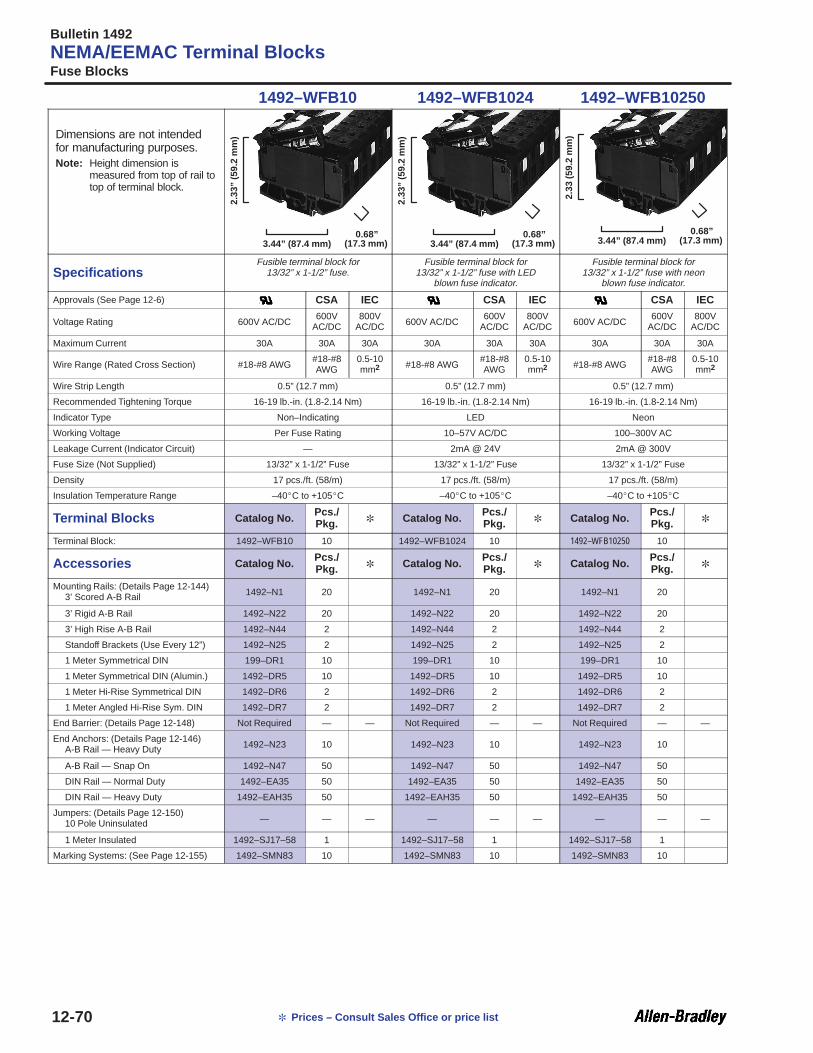
Bulletin 1492
NEMA/EEMAC Terminal BlocksFuse Blocks
12-70 Prices – Consult Sales Office or price list
1492–WFB10 1492–WFB1024 1492–WFB10250
Dimensions are not intendedfor manufacturing purposes.Note: Height dimension is
measured from top of rail totop of terminal block.
3.44” (87.4 mm)2.
33” (
59.2
mm
)0.68”
(17.3 mm) 3.44” (87.4 mm)
2.33
” (59
.2 m
m)
0.68”(17.3 mm) 3.44” (87.4 mm)
2.33
(59.
2 m
m)
0.68”(17.3 mm)
SpecificationsFusible terminal block for
13/32” x 1-1/2” fuse.Fusible terminal block for
13/32” x 1-1/2” fuse with LEDblown fuse indicator.
Fusible terminal block for13/32” x 1-1/2” fuse with neon
blown fuse indicator.
Approvals (See Page 12-6) CSA IEC CSA IEC CSA IEC
Voltage Rating 600V AC/DC600V
AC/DC800V
AC/DC 600V AC/DC600V
AC/DC800V
AC/DC 600V AC/DC600V
AC/DC800V
AC/DC
Maximum Current 30A 30A 30A 30A 30A 30A 30A 30A 30A
Wire Range (Rated Cross Section) #18-#8 AWG#18-#8AWG
0.5-10mm2 #18-#8 AWG
#18-#8AWG
0.5-10mm2 #18-#8 AWG
#18-#8AWG
0.5-10mm2
Wire Strip Length 0.5” (12.7 mm) 0.5” (12.7 mm) 0.5” (12.7 mm)
Recommended Tightening Torque 16-19 lb.-in. (1.8-2.14 Nm) 16-19 lb.-in. (1.8-2.14 Nm) 16-19 lb.-in. (1.8-2.14 Nm)
Indicator Type Non–Indicating LED Neon
Working Voltage Per Fuse Rating 10–57V AC/DC 100–300V AC
Leakage Current (Indicator Circuit) — 2mA @ 24V 2mA @ 300V
Fuse Size (Not Supplied) 13/32” x 1-1/2” Fuse 13/32” x 1-1/2” Fuse 13/32” x 1-1/2” Fuse
Density 17 pcs./ft. (58/m) 17 pcs./ft. (58/m) 17 pcs./ft. (58/m)
Insulation Temperature Range –40C to +105C –40C to +105C –40C to +105C
Terminal Blocks Catalog No.Pcs./Pkg. Catalog No.
Pcs./Pkg. Catalog No.
Pcs./Pkg.
Terminal Block: 1492–WFB10 10 1492–WFB1024 10 1492–WFB10250 10
Accessories Catalog No.Pcs./Pkg. Catalog No.
Pcs./Pkg. Catalog No.
Pcs./Pkg.
Mounting Rails: (Details Page 12-144)3’ Scored A-B Rail 1492–N1 20 1492–N1 20 1492–N1 20
3’ Rigid A-B Rail 1492–N22 20 1492–N22 20 1492–N22 20
3’ High Rise A-B Rail 1492–N44 2 1492–N44 2 1492–N44 2
Standoff Brackets (Use Every 12”) 1492–N25 2 1492–N25 2 1492–N25 2
1 Meter Symmetrical DIN 199–DR1 10 199–DR1 10 199–DR1 10
1 Meter Symmetrical DIN (Alumin.) 1492–DR5 10 1492–DR5 10 1492–DR5 10
1 Meter Hi-Rise Symmetrical DIN 1492–DR6 2 1492–DR6 2 1492–DR6 2
1 Meter Angled Hi-Rise Sym. DIN 1492–DR7 2 1492–DR7 2 1492–DR7 2
End Barrier: (Details Page 12-148) Not Required — — Not Required — — Not Required — —
End Anchors: (Details Page 12-146)A-B Rail — Heavy Duty 1492–N23 10 1492–N23 10 1492–N23 10
A-B Rail — Snap On 1492–N47 50 1492–N47 50 1492–N47 50
DIN Rail — Normal Duty 1492–EA35 50 1492–EA35 50 1492–EA35 50
DIN Rail — Heavy Duty 1492–EAH35 50 1492–EAH35 50 1492–EAH35 50
Jumpers: (Details Page 12-150)10 Pole Uninsulated — — — — — — — — —
1 Meter Insulated 1492–SJ17–58 1 1492–SJ17–58 1 1492–SJ17–58 1
Marking Systems: (See Page 12-155) 1492–SMN83 10 1492–SMN83 10 1492–SMN83 10
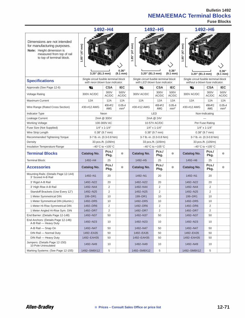
Bulletin 1492
NEMA/EEMAC Terminal BlocksFuse Blocks
12-71 Prices – Consult Sales Office or price list
1492–H4 1492–H5 1492–H6
Dimensions are not intendedfor manufacturing purposes.Note: Height dimension is
measured from top of railto top of terminal block.
3.20” (81.3 mm)
1.85
” (47
mm
)
0.36”(9.1 mm) 3.20” (81.3 mm)
1.85
” (47
mm
)
0.36”(9.1 mm) 3.20” (81.3 mm)
1.85
” (47
mm
)
0.36”(9.1 mm)
Specifications Single circuit fusible terminal blockwith neon blown fuse indicator.
Single circuit fusible terminal blockwith LED blown fuse indicator.
Single circuit fusible terminal blockwithout a blown fuse indicator.
Approvals (See Page 12-6) CSA IEC CSA IEC CSA IEC
Voltage Rating 300V AC/DC300V
AC/DC500V
AC/DC 300V AC/DC300V
AC/DC500V
AC/DC 300V AC/DC300V
AC/DC500V
AC/DC
Maximum Current 12A 12A 12A 12A 12A 12A 12A 12A 12A
Wire Range (Rated Cross Section) #30-#12 AWG#30-#12
AWG0.05-4mm2 #30-#12 AWG
#30-#12AWG
0.05-4mm2 #30-#12 AWG
#30-#12AWG
0.05-4mm2
Indicator Type Neon LED Non-Indicating
Leakage Current 2mA @ 300V 2mA @ 24V —
Working Voltage 100-300V AC 10-57V AC/DC Per Fuse Rating
Fuse Size (Not Supplied) 1/4” x 1-1/4” 1/4” x 1-1/4” 1/4” x 1-1/4”
Wire Strip Length 0.38” (9.7 mm) 0.38” (9.7 mm) 0.38” (9.7 mm)
Recommended Tightening Torque 3-7 lb.-in. (0.3-0.8 Nm) 3-7 lb.-in. (0.3-0.8 Nm) 3-7 lb.-in. (0.3-0.8 Nm)
Density 33 pcs./ft. (109/m) 33 pcs./ft. (109/m) 33 pcs./ft. (109/m)
Insulation Temperature Range –40C to +105C –40C to +105C –40C to +105C
Terminal Blocks Catalog No.Pcs./Pkg. Catalog No.
Pcs./Pkg. Catalog No.
Pcs./Pkg.
Terminal Block: 1492–H4 25 1492–H5 25 1492–H6 25
Accessories Catalog No.Pcs./Pkg. Catalog No.
Pcs./Pkg. Catalog No.
Pcs./Pkg.
Mounting Rails: (Details Page 12-144)3’ Scored A-B Rail 1492–N1 20 1492–N1 20 1492–N1 20
3’ Rigid A-B Rail 1492–N22 20 1492–N22 20 1492–N22 20
3’ High Rise A-B Rail 1492–N44 2 1492–N44 2 1492–N44 2
Standoff Brackets (Use Every 12”) 1492–N25 2 1492–N25 2 1492–N25 2
1 Meter Symmetrical DIN 199–DR1 10 199–DR1 10 199–DR1 10
1 Meter Symmetrical DIN (Alumin.) 1492–DR5 10 1492–DR5 10 1492–DR5 10
1 Meter Hi-Rise Symmetrical DIN 1492–DR6 2 1492–DR6 2 1492–DR6 2
1 Meter Angled Hi-Rise Sym. DIN 1492–DR7 2 1492–DR7 2 1492–DR7 2
End Barrier: (Details Page 12-148) 1492–N37 50 1492–N37 50 1492–N37 50
End Anchors: (Details Page 12-146)A-B Rail — Heavy Duty 1492–N23 10 1492–N23 10 1492–N23 10
A-B Rail — Snap On 1492–N47 50 1492–N47 50 1492–N47 50
DIN Rail — Normal Duty 1492–EA35 50 1492–EA35 50 1492–EA35 50
DIN Rail — Heavy Duty 1492–EAH35 50 1492–EAH35 50 1492–EAH35 50
Jumpers: (Details Page 12-150)10 Pole Uninsulated 1492–N49 10 1492–N49 10 1492–N49 10
Marking Systems: (See Page 12-155) 1492–SM8X12 5 1492–SM8X12 5 1492–SM8X12 5

Bulletin 1492
NEMA/EEMAC Terminal BlocksFuse Blocks
12-72 Prices – Consult Sales Office or price list
1492–CE6 1492–UF3
Dimensions are not intendedfor manufacturing purposes.Note: Height dimension is
measured from top of rail totop of terminal block.
1.75” (44.45 mm)1.
73” (
43.9
mm
)0.75”
(19.05 mm) 2.6” (66 mm)
2.48
” (63
mm
)
0.30”(7.6 mm)
Specifications 13/32” x 1-1/2” fuse block with screwterminals and wire clamp.
GMT style fuse block with blown fusealarm circuit, finger-safe.
Approvals (See Page 12-6) /CSA
Voltage Rating 600V AC/DC 125V AC, 60V DC
Maximum Current 10A 4A
Wire Range (Rated Cross Section) #22-#10 AWG (0.5-6 mm2 ) #30-#12 AWG (0.05-4 mm2 )
Wire Strip Length 0.38” (9.7 mm) 0.38” (9.7 mm)
Recommended Tightening Torque 10-16 lb.-in. (1.1-1.8 Nm) 3-7 lb.-in. (0.3-0.8 Nm)
Fuse Size (Not Supplied) 13/32” x 1-1/2” Fuse Bussmann “GMT” Type Alarm Fuse
Leakage Current (Indicator Circuit) — —
Density 16 pcs./ft. (52/m) 40 pcs./ft. (131/m)
Insulation Temperature Range –40C to +105C –40C to +105C
Terminal Blocks Catalog No.Pcs./Pkg. Catalog No.
Pcs./Pkg.
Terminal Block: 1492–CE6 10 1492–UF3 40
Terminal Block: Two 3’ Rails White1492–CE695
(48/Rail) 1 — —
Accessories Catalog No.Pcs./Pkg. Catalog No.
Pcs./Pkg.
Mounting Rails: (Details Page 12-144)3’ Scored A-B Rail 1492–N1 20 1492–N1 20
3’ Rigid A-B Rail 1492–N22 20 1492–N22 20
3’ High Rise A-B Rail 1492–N44 2 1492–N44 2
Standoff Brackets (Use Every 12”) 1492–N25 2 1492–N25 2
1 Meter Symmetrical DIN — — — 199–DR1 10
1 Meter Symmetrical DIN (Alumin.) — — — 1492–DR5 10
1 Meter Hi-Rise Symmetrical DIN — — — 1492–DR6 2
1 Meter Angled Hi-Rise Sym. DIN — — — 1492–DR7 2
End Barrier: (Details Page 12-148) 1492–N17 50 Not Required — —
End Anchors: (Details Page 12-146)A-B Rail — Heavy Duty 1492–N23 10 1492–N23 10
A-B Rail — Snap On 1492–N47 50 1492–N47 50
DIN Rail — Normal Duty — — — 1492–EA35 50
DIN Rail — Heavy Duty — — — 1492–EAH35 50
Jumpers: (Details Page 12-150)10 Pole Uninsulated — — — 1492–N46 10
Fuse Puller: (Details Page 12-151) 1492–N12 50 — — —
Marking Systems: (See Page 12-154) — — — 1492–N80 10

Bulletin 1492
Panel Mount Blocks
12-73
Allen-Bradley Panel Mount Blocks are most often used when the installation requires only a few terminations. Designed to saveon installation time, Allen-Bradley Panel Mount Blocks are ready to wire after mounting, no rail is needed. Available in fourdifferent styles and seven different types, the wide variety meets the needs of most applications.Catalog Number 1492–HC6 blocks feature six poles in a two-inch long, finger-safe design. The Catalog Number 1492–HC6 hasan interlocking feature which saves space in multi-block installations. Mounting screws are included.
Other Panel Mount Block Styles Include:• Multiple Barrier Strip (Catalog Numbers 1492–HJ86, 1492–HJ812), for simple connection of solid or stranded wires, 6 or 12
poles.
• Pull-apart Blocks (Catalog Numbers 1492–EC85, 1492–ED103), which allow the disconnection of multiple poles at once, areavailable in three or five pole versions and are used extensively in Motor Control Centers.
• High Temperature Dovetail Blocks (Catalog Numbers 1492–15T, 1492–25T), capable of handling up to 150C. These blockshave a dovetail design which allows multiple poles to be interlocked. They require only two fastening points every 12 blocks.
Note: Panel Mount terminal blocks come standard with a write-on marking surface for easy product identification. All Panel Mount Blocks aremade of materials with a 94-V2 flammability rating except Catalog Numbers 1492–15T and 1492–25T, which are made of 94-V0 material.
Note: Most Panel Mount Blocks are UL Component Recognized and CSA Certified. Look for “UL” or “CSA” in the product specifications.
• UL File Number E40735, Guide Number XCFR2
• CSA File Number LR67896, Class 622801

Bulletin 1492
Panel Mount Blocks
12-74 Prices – Consult Sales Office or price list
1492–HC6 1492–HJ86 1492–HJ812
Dimensions are not intendedfor manufacturing purposes.
1.54” (39.1 mm)1.
34” (
34 m
m)
1.8”(45.7 mm)
➌
➋
❶ ❶
1.5” (38.1 mm)
0.97
” (24
.6 m
m)
2.81”(71.4 mm)➍
➋
❶
1.5” (38.1 mm)
0.97
” (24
.6 m
m)
5.2”(132.1 mm)➍
➋
SpecificationsHigh density 6 pole panel mount
terminal block. Can be interconnectedto make 12 and 18 pole units.
Standard 6 pole panel mount block.Screw terminal with wire clamp.
Standard 12 pole panel mount block.Screw terminal with wire clamp.
Approvals (See Page 12-6) /CSA /CSA /CSA
Voltage Rating 600V AC/DC 600V AC/DC 600V AC/DC
Maximum Current (per pole) 25A 25A 25A
Wire Range (Rated Cross Section) #30-#12 AWG (0.05-4 mm2) #18-#12 AWG (1-4 mm2) #18-#12 AWG (1-4 mm2)
Wire Strip Length 0.38” (9.7 mm) 0.38” (9.7 mm) 0.38” (9.7 mm)
Recommended Tightening Torque 3-7 lb.-in. (0.3-0.8 Nm) 8-16 lb.-in. (0.9-1.8 Nm) 8-16 lb.-in. (0.9-1.8 Nm)
Insulation Temperature Range –40C to +105C –40C to +105C –40C to +105C
Terminal Blocks Catalog No.Pcs./Pkg. Catalog No.
Pcs./Pkg. Catalog No.
Pcs./Pkg.
Terminal Block: 1492–HC6 1 1492–HJ86 1 1492–HJ812 1
Accessories Catalog No.Pcs./Pkg. Catalog No.
Pcs./Pkg. Catalog No.
Pcs./Pkg.
Jumpers: (Details Page 12-150)2 Pole Uninsulated 1492–N38 50 1492–N35 50 1492–N35 50
50 Pole Uninsulated 1492–N39 10 — — — — — —
Anchor Unit: (Details Page 12-146)(required every 12th block) Not Required — — Not Required — — Not Required — —
End Piece: (Details Page 12-146) Not Required — — Not Required — — Not Required — —
➊ #8-32 screw.
➋ Measurement between mounting screw centers.
➌ Mounting screws are offset 0.31” (7.9 mm) from centerline.
➍ Mounting screws are offset 0.19” (4.76 mm) from centerline.

Bulletin 1492
Panel Mount Blocks
12-75 Prices – Consult Sales Office or price list
1492–15T 1492–25T
Dimensions are not intendedfor manufacturing purposes.
1.5” (38.1 mm)
1.03
” (26
.2 m
m)
0.69”(17.5 mm) 1.88” (47.8 mm)
1.19
” (30
.22
mm
)
0.69”(17.5 mm)
SpecificationsHigh temperature one pole panel
mount block, wire clamp. Gangablefor multi-pole installation.
High temperature one pole panelmount block, wire clamp. Gangable
for multi-pole installation.
Voltage Rating 600V AC/DC 600V AC/DC
Maximum Current (per pole) 35A 45A
Wire Range (Rated Cross Section) #16-#12 AWG (1.5-4 mm2) #16-#10 AWG (1.5-6 mm2)
Wire Strip Length 0.38” (9.7 mm) 0.38” (9.7 mm)
Recommended Tightening Torque 10-16 lb.-in. (1.1-1.8 Nm) 10-16 lb.-in. (1.1-1.8 Nm)
Insulation Temperature Range –40C to +149C –40C to +149C
Terminal Blocks Catalog No.Pcs./Pkg. Catalog No.
Pcs./Pkg.
Terminal Block: 1492–15T 100 1492–25T 100
Accessories Catalog No.Pcs./Pkg. Catalog No.
Pcs./Pkg.
Anchor Unit: (Details Page 12-146)(required every 12th block) 1492–15A 10 1492–25A 10
End Piece: (Details Page 12-146) 1492–15E 25 1492–25E 25

Bulletin 1492
Panel Mount Blocks
12-76 Prices – Consult Sales Office or price list
1492–EC85 1492–ED103
Dimensions are not intendedfor manufacturing purposes.
❶
1.25” (31.75 mm)2.
25” (
57.1
5 m
m)
3.13”(79.5 mm)
❶
1.25” (31.75 mm)
2.25
” (57
.15
mm
)
3.13”(79.5 mm)
Specifications 5 pole terminal block. Pulls apart todisconnect all poles from the circuit.
3 pole terminal block. Pulls apart todisconnect all poles from the circuit.
Approvals (See Page 12-6) /CSA /CSA
Voltage Rating 600V AC/DC 600V AC/DC
Maximum Current (per pole) 25A 60A
Wire Range (Rated Cross Section) #20-#12 AWG (0.75-4 mm2) #14-#4 AWG (2.5-25 mm2)
Wire Strip Length 0.38” (9.7 mm) 0.38” (9.7 mm)
Recommended Tightening Torque 6-16 lb.-in. (0.7-1.8 Nm) 10-30 lb.-in. (1.1-3.4 Nm)
Insulation Temperature Range –40C to +105C –40C to +105C
Terminal Blocks Catalog No.Pcs./Pkg. Catalog No.
Pcs./Pkg.
Terminal Block: 1492–EC85 1 1492–ED103 1
Accessories Catalog No.Pcs./Pkg. Catalog No.
Pcs./Pkg.
Anchor Unit: (Details Page 12-146)(required every 12th block) Not Required — — Not Required — —
End Piece: (Details Page 12-146) Not Required — — Not Required — —
➊ #8-32 screw.

Bulletin 1492
Power Blocks
12-77
The broad line of Allen-Bradley Power Blocks are designed to meet most application needs. Power Blocks feature easy circuitmarking (all but 1492–PDM mini-style blocks have a write-on marking surface). In addition, mounting dimensions are providedwith each unit and wire ranges and tightening torques are labeled on the product to simplify installation.
Four Styles of Power Blocks are AvailableMini Blocks:• Rated at 600V AC/DC, 115A; these blocks offer high current carrying capacity in a very small package to save on panel space
• Two configurations available: 3 pole feed through with 1 line opening and 1 load opening per pole; 3 pole power distributionwith 1 line opening and 4 load openings per pole
3 Pole Power Distribution Blocks WithAluminum Connectors:• Ideal for distributing power to multiple loads
• Rated at 600V AC/DC, 175–760A
• 1 or 2 line openings per pole, 4, 6, 8, or 12 load openings per pole
Feed Through/Splicer Blocks WithAluminum Connectors:• Allow easy connection of field wiring to a cabinet
• Rated at 600V AC/DC, 175–760A
• 1 and 3 pole configurations
• 1 line opening, 1 load opening per pole (2 line/2 load for higher current applications)
Power Distribution and Feed ThroughBlocks With Copper Connectors:• Meet the copper-only standard for the automotive industry
• Rated at 600V AC/DC, 175–760A
• 1 and 3 pole configurations
Power Blocks are UL Component Recognized and CSA Certified.• UL File Number E40735, Guide Number XCFR2
• CSA File Number LR19766, Class 905204

Bulletin 1492
Power Blocks
12-78 Prices – Consult Sales Office or price list
1492–PDM3111 1492–PDM3141 1492–50YF
Line Line Line
Load Load Load
Specifications PDM Mini Style PDM Mini Style Tap with Binding Screw
Approvals (See Page 12-6) /CSA /CSA /CSA
Current Rating (per pole) 115A 115A 175A
Voltage Rating (per pole) 600V AC/DC 600V AC/DC 600V AC/DC
Number of Poles 3 Pole 3 Pole 1 Pole
Insulating MaterialMax. Temperature Rating 125C 125C 150C
Flammability Rating 94V-O 94V-O 94V-O
Terminal Blocks Catalog No.Pcs./Pkg. Catalog No.
Pcs./Pkg. Catalog No.
Pcs./Pkg.
Terminal Block: 1492–PDM3111 1 1492–PDM3141 1 1492–50YF 1
Block Characteristics Line Load Line Load Line Load
Openings Per Pole 1 1 1 4 1 1
Wire Range (AWG) #2-14 #2-14 #2-14 #10-18 #2/0-14 1/4” Tap withRated Cross Section (mm2) 35-2.5 35-2.5 35-2.5 6-0.75 70-2.5 Binding Screw
Tightening Torque Range(also on block by specific wire size)
35-50 lb.-in.(4.0-5.6 Nm)
35-50 lb.-in.(4.0-5.6 Nm)
35-50 lb.-in.(4.0-5.6 Nm)
7 lb.-in.(0.79 Nm)
35-120 lb.-in.(4.0-13.5 Nm)
35 lb.-in.(4.0 Nm)
Marking Strip None Provided None Provided Single White Strip
Connector Material Aluminum Aluminum Aluminum
Dimensions See Page 12-88 See Page 12-88 See Page 12-88

Bulletin 1492
Power Blocks
12-79 Prices – Consult Sales Office or price list
1492–100YF 1492–50XF 1492–100XF
Line Line Line
Load Load Load
Specifications Tap with Binding Screw Tap with Binding Screw Tap with Binding Screw
Approvals (See Page 12-6) /CSA /CSA /CSA
Current Rating (per pole) 175A 175A 175A
Voltage Rating (per pole) 600V AC/DC 600V AC/DC 600V AC/DC
Number of Poles 1 Pole 3 Pole 3 Pole
Insulating MaterialMax. Temperature Rating 150C 150C 150C
Flammability Rating 94V-O 94V-O 94V-O
Terminal Blocks Catalog No.Pcs./Pkg. Catalog No.
Pcs./Pkg. Catalog No.
Pcs./Pkg.
Terminal Block: 1492–100YF 1 1492–50XF 1 1492–100XF 1
Block Characteristics Line Load Line Load Line Load
Openings Per Pole 1 1 1 1 1 1
Wire Range (AWG) #2/0-14 1/4” Tap with #2/0-14 1/4” Tap with #2/0-14 1/4” Tap with
Rated Cross Section (mm2) 70-2.5 Binding Screw 70-2.5 Binding Screw 70-2.5 Binding Screw
Tightening Torque Range(also on block by specific wire size)
35-120 lb.-in.(4.0-13.5 Nm)
35 lb.-in.(4.0 Nm)
35-120 lb.-in.(4.0-13.5 Nm)
35 lb.-in.(4.0 Nm)
35-120 lb.-in.(4.0-13.5 Nm)
35 lb.-in.(4.0 Nm)
Marking Strip Single White Strip Single White Strip Single White Strip
Connector Material Aluminum Aluminum Aluminum
Dimensions See Page 12-88 See Page 12-88 See Page 12-88

Bulletin 1492
Power Blocks
12-80 Prices – Consult Sales Office or price list
1492–PD3141 1492–PD3263 1492–PD3163
Line Line Line
Load Load Load
Specifications Power Distribution Block Power Distribution Block Power Distribution Block
Approvals (See Page 12-6) /CSA /CSA /CSA
Current Rating (per pole) 175A 350A 335A
Voltage Rating (per pole) 600V AC/DC 600V AC/DC 600V AC/DC
Number of Poles 3 Pole 3 Pole 3 Pole
Insulating MaterialMax. Temperature Rating 150C 150C 150C
Flammability Rating 94V-O 94V-O 94V-O
Terminal Blocks Catalog No.Pcs./Pkg. Catalog No.
Pcs./Pkg. Catalog No.
Pcs./Pkg.
Terminal Block: 1492–PD3141 1 1492–PD3263 1 1492–PD3163 1
Block Characteristics Line Load Line Load Line Load
Openings Per Pole 1 4 2 6 1 6
Wire Range (AWG) #2/0-14 #4-14 #2/0-14 #4-14400kcmil–#6
AWG #2-14
Rated Cross Section (mm2) 70-2.5 25-2.5 70-2.5 25-2.5 185-16 35-2.5
Tightening Torque Range(also on block by specific wire size)
35-120 lb.-in.(4.0-13.5 Nm)
35-45 lb.-in.(4.0-5.1 Nm)
35-120 lb.-in.(4.0-13.5 Nm)
35-45 lb.-in.(4.0-5.1 Nm)
275 lb.-in.(31.1 Nm)
35-50 lb.-in.(4.0-5.6 Nm)
Marking Strip Single White Strip Single White Strip Single White Strip
Connector Material Aluminum Aluminum Aluminum
Dimensions See Page 12-88 See Page 12-88 See Page 12-88

Bulletin 1492
Power Blocks
12-81 Prices – Consult Sales Office or price list
1492–PD3183 1492–PD31123 1492–PD32127
Line Line Line
Load Load Load
Specifications Power Distribution Block Power Distribution Block Power Distribution Block
Approvals (See Page 12-6) /CSA /CSA /CSA
Current Rating (per pole) 335A 380A 760A
Voltage Rating (per pole) 600V AC/DC 600V AC/DC 600V AC/DC
Number of Poles 3 Pole 3 Pole 3 Pole
Insulating MaterialMax. Temperature Rating 150C 150C 150C
Flammability Rating 94V-O 94V-O 94V-O
Terminal Blocks Catalog No.Pcs./Pkg. Catalog No.
Pcs./Pkg. Catalog No.
Pcs./Pkg.
Terminal Block: 1492–PD3183 1 1492–PD31123 1 1492–PD32127 1
Block Characteristics Line Load Line Load Line Load
Openings Per Pole 1 8 1 12 2 12
Wire Range (AWG)400kcmil-#6 AWG #2-14
500kcmil-#4 AWG #2-14
500kcmil-#4 AWG #4-14
Rated Cross Section (mm2) 185-16 35-2.5 240-25 35-2.5 240-25 25-2.5
Tightening Torque Range(also on block by specific wire size)
275 lb.-in.(31.1 Nm)
35-50 lb.-in.(4.0-5.6 Nm)
375 lb.-in.(42.4 Nm)
35-50 lb.-in.(4.0-5.6 Nm)
375 lb.-in.(42.4 Nm)
35-45 lb.-in.(4.0-5.1 Nm)
Marking Strip Single White Strip Single White Strip Single White Strip
Connector Material Aluminum Aluminum Aluminum
Dimensions See Page 12-88 See Page 12-88 See Page 12-88

Bulletin 1492
Power Blocks
12-82 Prices – Consult Sales Office or price list
1492–PD3287 1492–50Y 1492–50X
Line Line Line
Load Load Load
Specifications Power Distribution Block Standard Feed Thru/Splicer Block Standard Feed Thru/Splicer Block
Approvals (See Page 12-6) /CSA /CSA /CSA
Current Rating (per pole) 760A 115A 115A
Voltage Rating (per pole) 600V AC/DC 600V AC/DC 600V AC/DC
Number of Poles 3 Pole 1 Pole 3 Pole
Insulating MaterialMax. Temperature Rating 150C 150C 150C
Flammability Rating 94V-O 94V-O 94V-O
Terminal Blocks Catalog No.Pcs./Pkg. Catalog No.
Pcs./Pkg. Catalog No.
Pcs./Pkg.
Terminal Block: 1492–PD3287 1 1492–50Y 1 1492–50X 1
Block Characteristics Line Load Line Load Line Load
Openings Per Pole 2 8 1 1 1 1
Wire Range (AWG)500kcmil-#4
AWG #2/0-14 #2-14 #2-14 #2-14 #2-14
Rated Cross Section (mm2) 240-25 70-2.5 35-2.5 35-2.5 35-2.5 35-2.5
Tightening Torque Range(also on block by specific wire size)
375 lb.-in.(42.4 Nm)
35-120 lb.-in.(4.0-13.5 Nm)
35-50 lb.-in.(4.0-5.6 Nm)
35-50 lb.-in.(4.0-5.6 Nm)
35-50 lb.-in.(4.0-5.6 Nm)
35-50 lb.-in.(4.0-5.6 Nm)
Marking Strip Single White Strip Single White Strip Single White Strip
Connector Material Aluminum Aluminum Aluminum
Dimensions See Page 12-88 See Page 12-88 See Page 12-88

Bulletin 1492
Power Blocks
12-83 Prices – Consult Sales Office or price list
1492–100Y 1492–100X 1492–BE
Line Line Line
Load Load Load
Specifications Standard Feed Thru/Splicer Block Standard Feed Thru/Splicer Block Standard Feed Thru/Splicer Block
Approvals (See Page 12-6) /CSA /CSA /CSA
Current Rating (per pole) 175A 175A 255A
Voltage Rating (per pole) 600V AC/DC 600V AC/DC 600V AC/DC
Number of Poles 1 Pole 3 Pole 1 Pole
Insulating MaterialMax. Temperature Rating 150C 150C 150C
Flammability Rating 94V-O 94V-O 94V-O
Terminal Blocks Catalog No.Pcs./Pkg. Catalog No.
Pcs./Pkg. Catalog No.
Pcs./Pkg.
Terminal Block: 1492–100Y 1 1492–100X 1 1492–BE 1
Block Characteristics Line Load Line Load Line Load
Openings Per Pole 1 1 1 1 1 1
Wire Range (AWG) #2/0-14 #2/0-14 #2/0-14 #2/0-14250kcmil-#6 AWG
250kcmil-#6 AWG
Rated Cross Section (mm2) 70-2.5 70-2.5 70-2.5 70-2.5 120-16 120-16
Tightening Torque Range(also on block by specific wire size)
35-120 lb.-in.(4.0-13.5 Nm)
35-120 lb.-in.(4.0-13.5 Nm)
35-120 lb.-in.(4.0-13.5 Nm)
35-120 lb.-in.(4.0-13.5 Nm)
275 lb.-in.(31.1 Nm)
275 lb.-in.(31.1 Nm)
Marking Strip Single White Strip Single White Strip Single White Strip
Connector Material Aluminum Aluminum Aluminum
Dimensions See Page 12-88 See Page 12-88 See Page 12-88

Bulletin 1492
Power Blocks
12-84 Prices – Consult Sales Office or price list
1492–PD3113 1492–BF 1492–PD3226
Line Line Line
Load Load Load
Specifications Standard Feed Thru/Splicer Block Standard Feed Thru/Splicer Block Standard Feed Thru/Splicer Block
Approvals (See Page 12-6) /CSA /CSA /CSA
Current Rating (per pole) 310A 420A 620A
Voltage Rating (per pole) 600V AC/DC 600V AC/DC 600V AC/DC
Number of Poles 3 Pole 1 Pole 3 Pole
Insulating MaterialMax. Temperature Rating 150C 150C 150C
Flammability Rating 94V-O 94V-O 94V-O
Terminal Blocks Catalog No.Pcs./Pkg. Catalog No.
Pcs./Pkg. Catalog No.
Pcs./Pkg.
Terminal Block: 1492–PD3113 1 1492–BF 1 1492–PD3226 1
Block Characteristics Line Load Line Load Line Load
Openings Per Pole 1 1 1 1 2 2
Wire Range (AWG)350kcmil-#6 AWG
350kcmil-#6 AWG
600kcmil-#4 AWG
600kcmil-#4 AWG
350kcmil-#6 AWG
350kcmil-#6 AWG
Rated Cross Section (mm2) 185-16 185-16 300-25 300-25 185-16 185-16
Tightening Torque Range(also on block by specific wire size)
275 lb.-in.(31.1 Nm)
275 lb.-in.(31.1 Nm)
500 lb.-in.(56.4 Nm)
500 lb.-in.(56.4 Nm)
275 lb.-in.(31.1 Nm)
275 lb.-in.(31.1 Nm)
Marking Strip Single White Strip Single White Strip Single White Strip
Connector Material Aluminum Aluminum Aluminum
Dimensions See Page 12-88 See Page 12-88 See Page 12-88

Bulletin 1492
Power Blocks
12-85 Prices – Consult Sales Office or price list
1492–BG 1492–PD3C111 1492–PD3C141
Line Line Line
Load Load Load
Specifications Standard Feed Thru/Splicer Block Copper Connector Block Copper Connector Block
Approvals (See Page 12-6) /CSA /CSA /CSA
Current Rating (per pole) 760A 150A 175A
Voltage Rating (per pole) 600V AC/DC 600V AC/DC 600V AC/DC
Number of Poles 1 Pole 3 Pole 3 Pole
Insulating MaterialMax. Temperature Rating 150C 150C 150C
Flammability Rating 94V-O 94V-O 94V-O
Terminal Blocks Catalog No.Pcs./Pkg. Catalog No.
Pcs./Pkg. Catalog No.
Pcs./Pkg.
Terminal Block: 1492–BG 1 1492–PD3C111 1 1492–PD3C141 1
Block Characteristics Line Load Line Load Line Load
Openings Per Pole 2 2 1 1 1 4
Wire Range (AWG)500kcmil-#4 AWG
500kcmil-#4 AWG #1/0-18 #1/0-18 #2/0-14 #4-14
Rated Cross Section (mm2) 240-25 240-25 50-0.75 50-0.75 70-2.5 25-2.5
Tightening Torque Range (also on block by specific wire size)
375 lb.-in.(42.4 Nm)
375 lb.-in.(42.4 Nm)
35-50 lb.-in.(4.0-5.6 Nm)
35-50 lb.-in.(4.0-5.6 Nm)
35-120 lb.-in.(4.0-13.5 Nm)
35-50 lb.-in.(4.0-5.6 Nm)
Marking Strip Single White Strip Single White Strip Single White Strip
Connector Material Aluminum Copper Copper
Dimensions See Page 12-88 See Page 12-88 See Page 12-88

Bulletin 1492
Power Blocks
12-86 Prices – Consult Sales Office or price list
1492–PD3C112 1492–PD3C263 1492–PD3C163
Line Line Line
Load Load Load
Specifications Copper Connector Block Copper Connector Block Copper Connector Block
Approvals (See Page 12-6) /CSA /CSA /CSA
Current Rating (per pole) 255A 350A 380A
Voltage Rating (per pole) 600V AC/DC 600V AC/DC 600V AC/DC
Number of Poles 3 Pole 3 Pole 3 Pole
Insulating MaterialMax. Temperature Rating 150C 150C 150C
Flammability Rating 94V-O 94V-O 94V-O
Terminal Blocks Catalog No.Pcs./Pkg. Catalog No.
Pcs./Pkg. Catalog No.
Pcs./Pkg.
Terminal Block: 1492–PD3C112 1 1492–PD3C263 1 1492–PD3C163 1
Block Characteristics Line Load Line Load Line Load
Openings Per Pole 1 1 2 6 1 6
Wire Range (AWG)250kcmil-#6 AWG
250kcmil-#6 AWG #2/0-14 #4-14
500kcmil-#4 AWG #2-14
Rated Cross Section (mm2) 120-16 120-16 70-2.5 25-2.5 240-25 35-2.5
Tightening Torque Range(also on block by specific wire size)
375 lb.-in.(42.4 Nm)
375 lb.-in.(42.4 Nm)
35-120 lb.-in.(4.0-13.5 Nm)
35-45 lb.-in.(4.0-5.1 Nm)
375 lb.-in.(42.4 Nm)
35-50 lb.-in.(4.0-5.6 Nm)
Marking Strip Single White Strip Single White Strip Single White Strip
Connector Material Copper Copper Copper
Dimensions See Page 12-88 See Page 12-88 See Page 12-88

Bulletin 1492
Power Blocks
12-87 Prices – Consult Sales Office or price list
1492–PD3C2127 1492–PD3C287
Line Line
Load Load
Specifications Copper Connector Block Copper Connector Block
Approvals (See Page 12-6) /CSA /CSA
Current Rating (per pole) 760A 760A
Voltage Rating (per pole) 600V AC/DC 600V AC/DC
Number of Poles 3 Pole 3 Pole
Insulating MaterialMax. Temperature Rating 150C 150C
Flammability Rating 94V-O 94V-O
Terminal Blocks Catalog No.Pcs./Pkg. Catalog No.
Pcs./Pkg.
Terminal Block: 1492–PD3C2127 1 1492–PD3C287 1
Block Characteristics Line Load Line Load
Openings Per Pole 2 12 2 8
Wire Range (AWG)500kcmil-#4
AWG #2-14500kcmil-#4
AWG #2/0-14
Rated Cross Section (mm2) 240-25 35-2.5 240-25 70-2.5
Tightening Torque Range(also on block by specific wire size)
375 lb.-in.(42.4 Nm)
35-50 lb.-in.(4.0-5.6 Nm)
375 lb.-in.(42.4 Nm)
35-120 lb.-in.(4.0-13.5 Nm)
Marking Strip Single White Strip Single White Strip
Connector Material Copper Copper
Dimensions See Page 12-88 See Page 12-88

Bulletin 1492
Power Blocks
12-88
Approximate DimensionsAll dimensions are in inches (millimeters). Dimensions are not intended to be used for manufacturing purposes.
HDia.Hole
DF
G B
A
HDia.Hole
D
G B
A
E HDia.Hole
DF
GB
A
E
C C
FIGURE 1 FIGURE 2 FIGURE 3
F
C
Catalog Number Figure A B C D E F G H
1492–PDM3111 3➊ 2.03 (51.56) 2.29 (58.17) 1.62 (41.15) 0.38 (9.68) 1.27 (32.26) 0.19 (4.83) 1.93 (49.02) 0.201 (5.11)
1492–PDM3141 3➊ 2.03 (51.56) 2.29 (58.17) 1.62 (41.15) 0.38 (9.68) 1.27 (32.26) 0.19 (4.83) 1.93 (49.02) 0.201 (5.11)
1492–50Y 1 1.13 (28.7) 2.88 (73.15) 1.88 (47.8) 0.56 (14.22) — 0.31 (7.87) 2.25 (57.15) 0.205 (5.21)
1492–100Y 1 1.13 (28.7) 2.88 (73.15) 1.88 (47.8) 0.56 (14.22) — 0.31 (7.87) 2.25 (57.15) 0.205 (5.21)
1492–50X 3 2.75 (69.85) 2.88 (73.15) 1.88 (47.8) 0.56 (14.22) 1.62 (41.2) 0.31 (7.87) 2.25 (57.15) 0.205 (5.21)
1492–100X 3 2.75 (69.85) 2.88 (73.15) 1.88 (47.8) 0.56 (14.22) 1.62 (41.2) 0.31 (7.87) 2.25 (57.15) 0.205 (5.21)
1492–50XF 3 2.75 (69.85) 2.88 (73.15) 1.88 (47.8) 0.56 (14.22) 1.62 (41.2) 0.31 (7.87) 2.25 (57.15) 0.205 (5.21)
1492–50YF 1 1.13 (28.7) 2.88 (73.15) 1.88 (47.8) 0.56 (14.22) — 0.31 (7.87) 2.25 (57.15) 0.205 (5.21)
1492–100XF 3 2.75 (69.85) 2.88 (73.15) 1.88 (47.8) 0.56 (14.22) 1.62 (41.2) 0.31 (7.87) 2.25 (57.15) 0.205 (5.21)
1492–100YF 1 1.13 (28.7) 2.88 (73.15) 1.88 (47.8) 0.56 (14.22) — 0.31 (7.87) 2.25 (57.15) 0.205 (5.21)
1492–PD3C111 3 2.75 (69.85) 2.88 (73.15) 1.88 (47.8) 0.56 (14.22) 1.62 (41.2) 0.31 (7.87) 2.25 (57.15) 0.205 (5.21)
1492–PD3C141 3 2.75 (69.85) 2.88 (73.15) 1.88 (47.8) 0.56 (14.22) 1.62 (41.2) 0.31 (7.87) 2.25 (57.15) 0.205 (5.21)
1492–PD3141 3 2.75 (69.85) 2.88 (73.15) 1.88 (47.8) 0.56 (14.22) 1.62 (41.2) 0.31 (7.87) 2.25 (57.15) 0.205 (5.21)
1492–BE 1 1.94 (49.28) 4 (101.6) 2.72 (69.1) 0.97 (24.64) — 0.31 (7.87) 3.38 (85.85) 0.203 (5.16)
1492–PD3C112 2 5 (127) 4 (101.6) 2.72 (69.1) 0.97 (24.64) 1.53 (38.86) 0.31 (7.87) 3.38 (85.85) 0.203 (5.16)
1492–PD3113 2 5 (127) 4 (101.6) 2.72 (69.1) 0.97 (24.64) 1.53 (38.86) 0.31 (7.87) 3.38 (85.85) 0.203 (5.16)
1492–PD3263 2 5 (127) 4 (101.6) 2.72 (69.1) 0.97 (24.64) 1.53 (38.86) 0.31 (7.87) 3.38 (85.85) 0.203 (5.16)
1492–PD3163 2 5 (127) 4 (101.6) 2.72 (69.1) 0.97 (24.64) 1.53 (38.86) 0.31 (7.87) 3.38 (85.85) 0.203 (5.16)
1492–PD3C163 2 5 (127) 4 (101.6) 2.72 (69.1) 0.97 (24.64) 1.53 (38.86) 0.31 (7.87) 3.38 (85.85) 0.203 (5.16)
1492–PD3C263 2 5 (127) 4 (101.6) 2.72 (69.1) 0.97 (24.64) 1.53 (38.86) 0.31 (7.87) 3.38 (85.85) 0.203 (5.16)
1492–BF 1 2.28 (57.91) 4.75 (120.65) 2.92 (74.2) 1.12 (28.45) — 0.31 (7.87) 4.13 (104.9) 0.203 (5.16)
1492–PD3183 2 6.04 (153.42) 4.75 (120.65) 2.92 (74.2) 1.12 (28.45) 1.88 (47.75) 0.31 (7.87) 4.13 (104.9) 0.203 (5.16)
1492–BG 1 3.17 (80.25) 5.50 (139.7) 3.23 (82.0) 1.58 (40.13) — 0.38 (9.68) 4.75 (120.65) 0.265 (6.73)
1492–PD31123 2 8.54 (216.92) 5.50 (139.7) 3.23 (82.0) 1.58 (40.13) 2.69 (68.58) 0.38 (9.68) 4.75 (120.65) 0.265 (6.73)
1492–PD3287 2 8.54 (216.92) 5.50 (139.7) 3.23 (82.0) 1.58 (40.13) 2.69 (68.58) 0.38 (9.68) 4.75 (120.65) 0.265 (6.73)
1492–PD32127 2 8.54 (216.92) 5.50 (139.7) 3.23 (82.0) 1.58 (40.13) 2.69 (68.58) 0.38 (9.68) 4.75 (120.65) 0.265 (6.73)
1492–PD3226 2 8.54 (216.92) 5.50 (139.7) 3.23 (82.0) 1.58 (40.13) 2.69 (68.58) 0.38 (9.68) 4.75 (120.65) 0.265 (6.73)
1492–PD3C2127 2 8.54 (216.92) 5.50 (139.7) 3.23 (82.0) 1.58 (40.13) 2.69 (68.58) 0.38 (9.68) 4.75 (120.65) 0.265 (6.73)
1492–PD3C287 2 8.54 (216.92) 5.50 (139.7) 3.23 (82.0) 1.58 (40.13) 2.69 (68.58) 0.38 (9.68) 4.75 (120.65) 0.265 (6.73)
➊ No Marker Strip.

Bulletin 1492
Circuit Protection
12-89
Allen-Bradley Thermal Magnetic Circuit Breakers are ideal for protecting control circuitry components from damage due toovercurrents and short circuits.Circuit Breakers are UL Component Recognized and CSA Certified.• UL File Number E65138, Guide Number QVNU2
• CSA File Number LR37712. Class 9091–01 (1492–CB)
• CSA File Numbers LR67768, LR16185. Class 9091–01 (1492–GH)
• VDE Specification 0642
Potential applications include:• Solenoids
• Relay/contactor coils
• Transformers
• PLCs
• Computers
• Medical equipment
• Power supplies
• PLC I/O points
Three types of rail-mounted circuit breakers are available:• Energy Limiting style CB
• High density style GH – single pole
• High density style GS – multi pole
1492–CB Energy Limiting Circuit Breakers:1492–CB Circuit Breakers are offered in 1, 2, and 3 pole devices. These circuit breakers are DIN rail mountable and rated at480/277V AC, 0.5 to 50A. They meet international standards for a wide range of applications.Features include:• IP2X Finger-Safe rating per IEC 947
• Six trip characteristics for a variety of applications
• Energy Limiting design limits damaging “let-through” energy during short circuits to a level well below that of conventionalbreakers
• Optional accessory modules for auxiliary contacts, signal contacts, relay trip modules and switched neutral modules
• 10,000A Interrupting Capacity
High-Density Style GH Circuit Breakers:Mount on A-B rails or DIN rails, and are rated 250/125V AC, 65V DC – 0.2 to 15A.• 1 pole with screw terminations
• Push button type actuation
• High density by design, each pole is only 0.49” thick.
GS Circuit Breakers:Mount on A-B rails or DIN rails, and are rated 480/277V AC, 65V DC – 0.2 to 25A.• Toggle style handle for easy opening/closing
• Optional auxillary contact requires no additional space
• Available in 1, 2, and 3 pole desings
1492–FB Fuse Holders:1492–FB Class CC Fuse Holders provide a DIN Rail mounted package for use in Class CC fuse applications like transformersand motors.Features include:• UL listed
• DIN #3 rail mounted
• Optional blown fuse indicator

Bulletin 1492
Circuit ProtectionFuse Holders
12-90
DescriptionBulletin 1492 Class CC Fuse Holdersprovide a safe and convenient means forthe installation of Class CC fuses. The1492–FB Fuse Holders are available in1, 2, and 3 pole configurations and havean optional blown fuse indication light.The fuse holder is 30A rated at 600V andis UL listed. The FB Fuse Holder utilizesa self lifting box lug on the line and loadside of the block, each capable ofaccepting a #6–#14 AWG copper wire.
Features• The Patented handle design isolates
the fuse from line power when thehandle is opened for insertion orremoval.
• Optional blown fuse indicators – allowfor easy troubleshooting of electricalcircuits.
• UL Listed

Bulletin 1492
Circuit ProtectionFuse Holders
12-91 Prices – Consult Sales Office or price list
1492–FB1 1492–FB2 1492–FB3
Dimensions are not intendedfor manufacturing purposes.Note: Height dimension is
measured from top of railto top of terminal block.
0.69” (17.5 mm)
3.07
” (78
mm
)
2.13”(54 mm) 1.38” (35 mm)
3.07
” (78
mm
)
2.13”(54 mm) 2.07” (52.5 mm)
3.07
” (78
mm
)
2.13”(54 mm)
Specifications 1 pole fuse block 2 pole fuse block 3 pole fuse block
Approvals (See Page 12-6) UL CSA UL CSA UL CSA
Voltage Rating 600V AC/DC 600V AC/DC 600V AC/DC 600V AC/DC 600V AC/DC 600V AC/DC
Maximum Current 30A 30A 30A 30A 30A 30A
Wire Range (Rated Cross Section) #14-#6 AWG #14-#6 AWG #14-#6 AWG #14-#6 AWG #14-#6 AWG #14-#6 AWG
Wire Strip Length 0.5” (12.7 mm) 0.5” (12.7 mm) 0.5” (12.7 mm)
Recommended Tightening Torque 15 lb.-in. (1.7 Nm) 15 lb.-in. (1.7 Nm) 15 lb.-in. (1.7 Nm)
Working Voltage (Indicating Circuit) 95–600V AC, 110–600V DC 95–600V AC, 110–600V DC 95–600V AC, 110–600V DC
Leakage Current (Indicating Circuit) 0.8 mA max @ 600V 0.8 mA max @ 600V 0.8 mA max @ 600V
Fuse Type Use class CC fuse only➊ Use class CC fuse only➊ Use class CC fuse only➊
Insulation Temperature Range –40°C to +105°C –40°C to +105°C –40°C to +105°C
Fuse Holder Catalog No.Pcs./Pkg. Catalog No.
Pcs./Pkg. Catalog No.
Pcs./Pkg.
Without Blown Fuse Indicator 1492–FB1C30 6 1492–FB2C30 3 1492–FB3C30 2
With Blown Fuse Indicator 1492–FB1C30–L 6 1492–FB2C30–L 3 1492–FB3C30–L 2
Accessories Catalog No.Pcs./Pkg. Catalog No.
Pcs./Pkg. Catalog No.
Pcs./Pkg.
Mounting Rails: (Details Page 12-143)1 M Symmetrical DIN (Steel) 199–DR1 10 199–DR1 10 199–DR1 10
1 M Symmetrical DIN (Aluminum) 1492–DR5 10 1492–DR5 10 1492–DR5 10
1 M Hi-Rise Sym. DIN (Aluminum) 1492–DR6 2 1492–DR6 2 1492–DR6 2
1 M Angled Hi-Rise Sym. DIN (Steel) 1492–DR7 2 1492–DR7 2 1492–DR7 2
End Anchors: (Details Page 12-146)DIN Rail — Normal Duty 1492–EA35 50 1492–EA35 50 1492–EA35 50
DIN Rail — Heavy Duty 1492–EAH35 10 1492–EAH35 10 1492–EAH35 10
➊ Gould ATQR 1–1/4, I=0.42A max.Gould ATQR 1–4/10, I=0.47A max.

Bulletin 1492
Circuit ProtectionCircuit Breakers
12-92
DescriptionBulletin 1492 “Energy Limiting” circuitbreakers are thermal magnetic typesupplementary overcurrent protectivedevices. Bulletin 1492–CB circuitbreakers are available in one, two andthree pole units rated from 0.5 to 50amps. AC units are rated 65V asstandard. Two and three pole devicesare connected internally and at thehandle for simultaneous operation.Wire termination is achieved by aclamping style, self-lifting box lug on allBulletin 1492–CB units. Both line andload side termination points will accept#16–6 AWG (1.5–16mm2) copper wires.
Features• “Energy Limiting” Design — protects
downstream components better thanconventional breakers during shortcircuits
• Field mountable options for selectiveapplications
• True IP2X “Finger-Safe” design (topand sides)
• International approvals — meets NEMAand IEC standards for worldwideacceptance
• Ratings to 480V AC and 10,000AInterrupt Capacity
• AC and DC voltage ratings — in oneconvenient device
• A “positively trip free” mechanism
• Time delay (H characteristic) for highinrush currents during inductivestart-ups such as transformers andpower supplies
• Superior shock and vibration resistancecapabilities — helps to preventnuisance tripping
Energy Limitations1492–CB vs. Conventional BreakersThe 1492–CB line features the uniqueability to achieve short circuit interruptionsfar more effectively than conventionalbreakers.In conventional circuit breakers, shortcircuit interruption time required isapproximately one or two half cycles ofan AC sine wave. When the contactsopen, the resulting arc continues to burnuntil the current level passes throughzero. The arc may re-ignite because ofthe insufficient width of the contact gap.The current that flows until the arc isextinguished produces a heating effectproportional to the I2t value(let-through-energy) of the fault current.
Short Circuit Interruption Diagrams
The 1492–CB “Energy Limiting” circuitbreaker is designed to substantiallyreduce the amount of let-through-currentand the resulting let-through-energy thatcan damage protected components. The1492–CB has the ability to interrupt shortcircuit current within the first half cycle ofthe fault.
The Benefits of LimitingLet-Through-EnergyLimiting Let-Through-Energy will protectagainst the harmful effects of overcurrentand is focused primarily on avoiding thefollowing:• Excessive Heat
• Mechanical Damage
Both of these factors are proportional tothe square of the current. Thermal energyis proportional to the square of the RMSvalue and magnetic forces areproportional to the square of the peakvalue. The most effective way to provideprotection is to substantially limitlet-through-energy. This provides thefollowing advantages:• Far less damage at the location of the
short circuit.
• Fast electric separation of a faulty unitfrom the system, especially powersupplies connected in parallel that areswitched off when the voltage of thepower bus drops below a certainlevel.
A = Instant when the short is initiatedB = Instant when the contacts open and the arc is initiatedC = Instant when the arc extinguishes and the current ceases to flow
TIME
MAX ARC VOLTAGE
RECOVERY VOLTAGE
A B C
79,000 A2 s
3,500 A2s
VOLT
AGE
ACR
OSS
BR
EAKE
RC
UR
REN
T
CA B
Short Circuit Interruption 10 kA – 120 Volts ACInstant of initiation: 15° after voltage zero.
CONVENTIONAL BREAKERS ALLEN-BRADLEY 1492–CB
Let t
hrou
gh I
2t

Bulletin 1492
Circuit ProtectionCircuit Breakers
12-93
The Benefits of LimitingLet-Through-Energy (cont’d)• Far less wear on the circuit breaker
itself. This means more safeinterruptions.
• Better protection of all components inthe short circuit path.
• Far wider range of selective actionwhen used with an upstream protectivedevice. (No nuisance shut downs fromfeeder line interruptions, causing ablackout in all connected branches.)
ApplicationsBulletin 1492–CB “Energy Limiting”circuit breakers have a wide range of tripcharacteristics for a wide range ofapplications.• “F” trip characteristic (3–5 x In)➊ for
low fault tolerant loads, such as PLCoutputs, solid state control equipment,and also for selective action with anupstream fault device
• “G” trip characteristic (6–10 x In)➊ forstandard duty loads, such as relaycoils, control circuitry, and testequipment
• “H” trip characteristic (12–20 x In)➊ forhigh inrush loads, such as powersupplies, heaters, and transformerprimaries.
A type “F” has a fault level interruptionapproximately half that of type “G”. Thetype “H” has a fault level interruptionapproximately twice that of type “G”.
AccessoriesNote: Maximum of 2 accessories per device.
Auxiliary Contacts
Auxiliary Contacts:Refer to Specifications on page 12-96 forratings. Each auxiliary contact modulecontains one (1) contact, either NormallyOpen or Normally Closed. Actuation ofthe contact is determined by the handleposition of the adjacent poles.
Signal Contacts
Signal Contacts:Refer to Specifications on page 12-96 forratings. Each contact module containsone contact that will be linked internallywith the adjacent poles, but not throughthe handle. Contacts are actuated by afault condition on the protected poles,not by the manual operation of them.Note: The difference between anAuxiliary contact and a Signal contact isthe protected poles adjacent to theSignal contact may be manually shut offwithout affecting the status of the signalcontact, whereas the auxiliary contact isactivated either by manual (possibly toservice a panel) or automatic operation(fault) of the protected poles. Manualoperation of the protected poles does notalter the contact state of the Signalcontact (which may be connected to analarm circuit for fault indication only).
Relay Trip (Shunt-Trip)
Relay Trip (Shunt-Trip):Refer to the table at the top of the nextcolumn for ratings. The Relay tripmodule can be used to trip the adjacentcurrent carrying poles from a remotelocation by applying a voltage (pick-upvoltage) to the Relay trip terminals.Contacts operate between 8 and 16milliseconds after the pick-up voltagehas been applied.
TypePick-Up
Voltage Range Impedance
A1 5–15 Volts AC/DC 1.1 Ohms
A2 10–24 Volts AC/DC 4.7 Ohms
A3 20–48 Volts AC/DC 16 Ohms
A4 40–110 Volts AC/DC 63 Ohms
A5 90–240 Volts AC/DC 395 Ohms
Switched Neutral Module(not field mountable)
Switched Neutral Module(not field mountable):Refer to Specifications on page 12-96 forratings. This module is used to open theneutral line of the circuit as a result of thecondition of the protected poles. It isused as a safety measure (required bysome standards) for the protection ofnetworks with a grounded neutralsystem. The switched neutral pole opensafter and closes before the adjacentprotected pole (i.e. early make, latebreak). Automatic actuation is a result ofthe adjacent pole trip mechanism andmanual actuation is by the linkedhandles.
➊ In = Rated Current

1492 – CB 3 G 200 – N ➊➍
BulletinNumber
Bulletin 1492
Circuit ProtectionCircuit Breakers
12-94 Prices – Consult Sales Office or price list
How to Order 1492–CBThe following information must be knownto select the proper circuit breaker:• What is the full load amperage that will
be available in the system?• Is it a 1, 2, or 3 phase system?• What are the start-up or inrush proper-
ties of the load?
• Will the system require additional“shaping” options? Auxiliary contacts,signal contacts, etc.
After defining these few parameters, theselection can be done by following thechart below. All options are fieldmountable except the Neutral switch,which comes installed from the factory.
Selection InformationYou can order a basic one, two, or threepole circuit breaker from the followingtables and add an accessory module tomeet your specific applicationrequirements.
Energy LimitingCircuit Breaker
CB Screw Terminal
SwitchedNeutral Module
N ➍ 277V–65A
Number ofRated Voltage ➌ ByTrip Characteristic
PolesF, G, H
DF,DG, DH
1 One Pole277V AC65V DC 120V DC
2 Two Pole480V AC65V DC 240V DC
3 Three Pole480V AC65V DC ➋
Trip CharacteristicCode Magnetic Trip Range
F 3–5 x In
G 6–10 x In
H 12–20 x In
DF➍➎ 4.2–7 x In
DG➍➎ 8.5–14 x In
DH➍➎ 17–28 x In
In = Rated Current
TripChar. Current Rating Code (Standard Trip Characteristic is Type G)
F 005 010 020 030 040 050 060 070 100 120 150➍ 160➍ 200➍ 250➍ 300➍ 320➍ 400➍ 500➍
G 005 010 020 030 040 050 060 070 100 120 150 160 200 250 300 320 400 500
H 005 010 020 030 040 050 060 070 100 120 150 160 200 250 300 320 400 500
DF➍➎ 005 010 020 030 040 050 060 070 100 120 150 160 200 250 300 320 400 —
DG➍➎ 005 010 020 030 040 050 060 070 100 120 150 160 200 250 300 320 400 —
DH➍➎ — — — — — — 060 070 100 120 150 160 200 250 300 320 400 —
AmpRating 0.5 1 2 3 4 5 6 7 10 12 15 16 20 25 30 32 40 50
➊ This alphanumeric character is for the optional neutral module. ➋ Consult factory. ➌ Rated volts are UL Recognized.
➍ Minimum order of 10 breakers required for any configuration of the items with this footnote.
➎ Attention: Do not use these DC versions in AC networks. Polarity markings must be observed with the DC versions.

Bulletin 1492
Circuit ProtectionCircuit Breakers
Prices – Consult Sales Office or price list 12-95
Accessories Used with All 1492–CB Circuit Breakers
Accessory Catalog No.Pcs./Pkg.
Mounting Rails: (Details Page 12-143)1 Meter Symmetrical DIN 199–DR1 10
1 M Symmetrical DIN (Alumin.) 1492–DR5 10
1 M Hi-Rise Symmetrical DIN 1492–DR6 2
1 M Angled Hi-Rise Symmetrical DIN 1492–DR7 2
End Anchor 1492–EAH35 50
Group Marking 1492–GM35 10
Marking Systems (See Page 12-155) 1492–SMN83 5
Field Mounted Accessories Used with 1492–CB Circuit Breakers
Accessory Catalog No.Pcs./Pkg.
Auxiliary Contacts:Normally Open ➊ 1492–ACBH1 1
Normally Closed ➋ 1492–ACBH2 1
Signal Contacts:Normally Open ➊ 1492–ACBS1 1
Normally Closed ➋ 1492–ACBS2 1
Relay Trip Module:5–12V AC/DC 1492–ACBA1 1
10–24V AC/DC 1492–ACBA2 1
20–48V AC/DC 1492–ACBA3 1
40–110V AC/DC 1492–ACBA4 1
90–240V AC/DC 1492–ACBA5 1
Connecting Clip 1492–ACBCC1 8
Opening Seal 1492–ACBHS1 10
Commoning Links1 Meter – 1 Pole (56 devices/meter) 30 Amps
1492–ACBCL1 1
1 Meter – 2 Pole (29 devices/meter) 40 Amps 1492–ACBCL2 1
1 Meter – 3 Pole (19 devices/meter)40 Amps 1492–ACBCL3 1
Front Panel Mounting Brackets:1 Pole 1492–N711 5
2 Pole 1492–N712 5
3 Pole 1492–N713 5
4 Pole 1492–N714 5
5 Pole 1492–N715 5
➊ Normally Open — Contact assumes the same position as the protected poles.When breaker is off, contact is open.
➋ Normally Closed — Contact assumes the opposite position of the protectedpoles. When breaker is off, contact is closed.

Width
3.53
(89.
7)
1.77
(45)
0.89
(22.
6)1.
77(4
5)
60
CL of Rail
O
1.76 (44.7)
2.44 (62)
2.72 (69)
Bulletin 1492
Circuit ProtectionCircuit Breakers
12-96
1492–CBSpecifications ➊
Catalog Number 1492–CB1 1492–CB2 1492–CB3
Description 1 Pole 2 Pole 3 Pole
Approvals ➋ , CSA, VDE , CSA, VDE , CSA, VDE
Short Circuit Capacityin DC Circuits
1492–CB1D10,000A at 120V DC
1492–CB2D10,000A at 240V DC
1492–CB3D10,000A at 360V DC
Maximum Voltage Ratings480V AC, 65 Volts DC Max.
DC Version up to 120 Volts per Pole.A Three Pole Breaker will operate to 360V DC.
Internal Impedance Type GTrip Characteristic
Amp. Rating (Amps.)Impedance (Ohms)
0.55.6
11.33
2.33
4.09
6.04
10.02
16.008
20.005
25.005
32.003
40.003
50.025
Dielectric Strength 1960V AC
Shock 25G Half Sine Wave for 11 Milliseconds (Three Axes)
Vibration10–500 Hz for 1 HourAmplitude: 10–57 Hz; .030 inches peak to peak
57–500 Hz; 5G peak
Maximum Interrupting Capacity Up to 10,000 Amps. See page 12-97 for details on specific devices.
Operating Temperature Range –20C to +60C (–4F to +140F)
Shipment and Short TermTemperature Limits –40C to +85C (–40F to +185F)
Housing Material Melamine — Phenolic
Wire Size #16–6 AWG (1.5-16 mm2)
Recommended WireStrip Length 0.51” (13 mm)
Electromechanical Life
Up to 6A 50,000 Cycles7 to 16A 30,000 Cycles20 to 32A 20,000 Cycles40 to 50A 12,000 Cycles
Auxiliary Contact Ratings277V AC, 6A125V DC, 1A50V DC, 6A
Signal Contact Ratings277V AC, 6A125V DC, 1A50V DC, 6A
Switched Neutral Rating 277V AC, 65A
➊ Performance Data — See Page Important-2.
➋ Circuit breakers also meet the requirements of AS, BS and SEV.
Approximate DimensionsDimensions shown in inches (millimeters). Dimensions are not intended to be used for manufacturing purposes.
No. ofPoles 1 2 3 4 5
Width(inches) 0.7 1.4 2.1 2.8 3.5
Width(millimeters) 17.5
+0.05–0 35
+1–0 52.5
+1.5–0 70
+2–0 87.5
+2.5–0

Bulletin 1492
Circuit ProtectionCircuit Breakers
12-97
Electrical Characteristics and Approvals
PROTECTED POLES — AC/DC VERSIONS (F, G, H)
Agency/StandardTerminal
Block Style PolesTripping
CharacteristicsRated
Currents VAC VDCInterrupting
Capacity
UL 1077 CB 1 F, G, H 0.5-50A 277 65 5000/2000 A
UL 1077 CB 1 F, G, 0.5-40A 240 65 10000/2000 A
UL 1077 CB 1 H 0.5-40A 277 65 5000/2000 A
UL 1077 CB 2 F, G, H 0.5-50A 480 65 5000/2000 A
UL 1077 CB 2 F, G, 0.5-40A 480 65 10000/2000 A
UL 1077 CB 2 H 0.5-40A 480 65 5000/2000 A
UL 1077 CB 3 F, G, H 0.5-50A 480 65 5000/2000 A
UL 1077 CB 3 F, G 0.5-40A 480 65 10000/2000 A
UL 1077 CB 3 H 0.5-40A 480 65 5000/2000 A
VDE REG. NO.2806 CB 1 F, G 0.5-25A 240/420 — 10000A
VDE REG. NO.2806 CB 1 H 0.5-40A 240/420 — 6000A
VDE REG. NO.2806 CB 1 F, G 30-40A 240/420 — 6000A
VDE REG. NO.2806 CB 2 F, G 0.5-25A 420 — 10000A
VDE REG. NO.2806 CB 2 H 0.5-40A 420 — 6000A
VDE REG. NO.2806 CB 2 F, G 30-40A 420 — 6000A
VDE REG. NO.2806 CB 3 F, G 0.5-25A 420 — 10000A
VDE REG. NO.2806 CB 3 H 0.5-40A 420 — 6000A
VDE REG. NO.2806 CB 3 F, G 30-40A 420 — 6000A
CSA 22.2 NO.14 CB 1 F, G, H 0.5-50A 277 65 5000/2000 A
CSA 22.2 NO.14 CB 2 F, G 0.5-40A 480 65 10000/2000 A
CSA 22.2 NO.14 CB 2 F, G, H 45-50A 480 65 5000/2000 A
CSA 22.2 NO.14 CB 2 H 0.5-40A 480 65 5000/2000 A
CSA 22.2 NO.14 CB 3 F, G 0.5-40A 480 65 10000/2000 A
CSA 22.2 NO.14 CB 3 F, G, H 45-50A 480 65 5000/2000 A
CSA 22.2 NO.14 CB 3 H 0.5-40A 480 65 5000/2000 A
On standard AC/DC versions (F, G, H) line and load connections may be reversed.

Bulletin 1492
Circuit ProtectionCircuit Breakers
12-98 Prices – Consult Sales Office or price list
1492–GH Circuit BreakersHigh Density Circuit Breakers
1492–GH . . .
3.15” (80.0 mm)
2.89
” (73
.4 m
m)
0.49”(12.4 mm)
SpecificationsHigh density one pole circuit breaker,thermal magnetic, mounts on A-B rail
and DIN rails.
Approvals (See Page 12-6) /CSA/VDE
Maximum Voltage Rating250V AC (0.2-7A),
125V AC (10-15A), 65V DC
Maximum Interrupting Capacity(that allows continued use)
200A(not to exceed 100 times rated current)
Wire Range (Rated Cross Section) #22-#10 AWG (0.5-6 mm2)
Wire Strip Length 0.44” (11.2 mm)
Recommended Screw Tightening Torque 10-12 lb.-in. (1.13-1.4 Nm)
Insulation Temperature Range –40C to +105C
Terminal Blocks Catalog No.Pcs./Pkg.
Amperage Rating: 0.2A 1492–GH002 1
0.5A 1492–GH005 1
0.8A 1492–GH008 1
1.0A 1492–GH010 1
1.2A 1492–GH012 1
1.5A 1492–GH015 1
2.0A 1492–GH020 1
2.5A 1492–GH025 1
3.0A 1492–GH030 1
4.0A 1492–GH040 1
5.0A 1492–GH050 1
7.0A 1492–GH070 1
10.0A 1492–GH100 1
15.0A 1492–GH150 1
Accessories Catalog No.Pcs./Pkg.
Mounting Rails: (Details Page 12-143)1 Meter Symmetrical DIN 199–DR1 10
1 Meter Symmetrical DIN (Alumin.) 1492–DR5 10
1 Meter Hi-Rise Symmetrical DIN 1492–DR6 2
1 Meter Angled Hi-Rise Sym. DIN 1492–DR7 2
3’ Scored Channel 1492–N1 20
3’ Rigid Channel 1492–N22 20
3’ Hi-Rise Channel 1492–N44 2
Standoff Brackets 1492–N25➊ 2
End Anchors: (Details Page 12-146)A-B Rail — Heavy Duty 1492–N23 10
A-B Rail — Snap On 1492–N47 50
DIN Rails — Normal Duty 1492–EA35 50
DIN Rails — Heavy Duty 1492–EAH35 50
Marking Systems: (See Page 12-155) 1492–SMN83 5
Group Marker (DIN Rail only) 1492–GM35 10
➊ Use every 12” with 1492–N22 rail.
DescriptionBulletin 1492 “High Density” circuit breakers arethermal magnetic type supplementary overcurrentprotective devices. Bulletin 1492–GH circuit breakersare available in one pole units. The 1492–GH is ratedfrom 0.2 to 7 amps at 240V AC and 10–15 amps at125V AC, and has a 65V DC rating as standard.Wire termination is achieved by a clamping style, selflifting box lug.
Features• high density design allows 24 one pole breakers
per foot
• wide range of currents for precise circuitrequirements
• international approvals — meets NEMA and IECstandards for worldwide acceptance
• ratings to 250V AC
• AC and DC voltage ratings — in one convenientdevice
• a “positively trip free” mechanism
• superior shock and vibration resistance capabilities— helps prevent nuisance tripping
• universal mounting foot for a variety of mountingchannels
One Pole Style 1492–GHSingle pole high density circuit breaker thatincorporates a thermal portion and a magnetic tripfunction for the combined advantages of two sensingsystems. The 1492–GH style of breakers uses a pushto set mechanism for circuit actuation and comes witha manual trip button for manually opening the circuit.ApplicationsIncluded but not limited to the protection of testequipment, control instrumentation, solenoids andpower supplies. The wide range of current values andthe use of a thermal magnetic trip system allows for avariety of applications where a very accurate andcompact breaker is required.

Bulletin 1492
Circuit ProtectionCircuit Breakers
12-99
1492–GH Circuit BreakersNEMA & IEC Rated Circuit Breakers
Selection Guide — To select a circuitbreaker use the following procedure:• Determine the inrush correction factor
from Table 1.
• Determine the temperature correctionfactor from Table 2.
• Determine the sealed current of theload being protected.
• Multiply the sealed current by the twocorrection factors and select theclosest higher ampere rating.
Example — What size circuit breakershould be selected for a solenoid withsealed current of 0.5 amp, an inrush ratioof 1:8, and an ambient temperature of+110F?0.5 x 1.7 x 1.15 = 0.9775Select the 1.0 amp circuit breaker.
Table 1Inrush Ratio Correction Table
Inrush Ratio 1:1 to 1:4 1:5 1:6 1:7 1:8
Factor 1.3 1.4 1.5 1.6 1.7
Note: For resistive loads, use inrush correction factor of 1.0.
Table 2Ambient Temperature Correction Table
Ambient Temperature70F
(21.1C)100F
(37.8C)120F
(48.9C)140F(60C)
160F(71.1C)
180F(82.2C)
200F(93.3C)
Factor 1.0 1.1 1.2 1.3 1.4 1.5 1.6
Tripping time of the circuit breaker is determined from Table 3 below. Divide the circuit breaker value by the temperaturecorrection factor from Table 2 above to determine the actual rated current referenced in Table 3.
Table 3Tripping Time
Tripping Times in Seconds at 70 °F (21.1°C)Percent RatedCurrent 100% 200% 300% 400% 500% 600% 1000%
2000%Greater
Tripping Times(Seconds)
NoTrip 10-40 3-18 1.5-9 0.8-6 0.003-4 0.003-2
Maximum0.02
Note: When several breakers are rail mounted adjacent to each other, the “no-trip” current will be 80% of rated current at 70F (21.1C).
Trip Current
.003
.004
.300
.400
108
60
.001
.006
.008
.040
.060
1008060
40006000
100008000
1
30002000
1000800600400300200
403020
6432
.800
.600
.200
.100
.080
.030
.020
.010
.002
SEC
ON
DS
TRIP
PIN
G T
IME
AT 7
0 F
1000 800
600
1000
0
8000
6000
5000
4000
3000
2000
1500 500
400
300
200
150
100 80 70 50
Trip current is 140% of rated current.
Protector will hold 100% of ratedcurrent indefinitely.
Will trip within one hour at 140% ofrated current.
PERCENT RATED CURRENT
0.05 to 7.5 amp
8 to 15 amp
°
700

Bulletin 1492
Circuit ProtectionCircuit Breakers
12-100
SPECIFICATIONS➊
Catalog Number 1492–GH Series B
DescriptionSingle Pole with universal mounting foot for Allen-Bradley and DIN
rail mounting.
Approvals ➋ , CSA, VDE
Maximum Voltage Ratings250V AC 50/60 Hz (0.2-7A)125V AC 50/60 Hz (10-15A)
65V DC
Standard Current RatingsInternal Resistance per Pole
(Amps.) 0.2, 0.5, 0.8, 1.0, 1.2, 1.5,2.0, 2.5, 3.0, 4.0, 5.0, 7.0, 10.0, 15.0
(Ohms) 44, 6.6, 2.55, 1.97, 1.22, 0.86, 0.49,0.313, 0.205, 0.104, 0.082, 0.034 <0.20, <0.20
Dielectric Strength 1500V AC
Shock and VibrationSpecifications
Shock 25G, 11ms durationVibration: 5G (10 to 500 Hz)
Insulation Resistance 100 megaohms @ 500V DC
Current Capacity of AuxiliaryContacts (N.O., N.C.) Not Applicable
Shunt Circuit Not Applicable
Maximum Interrupting Capacity200A, but not exceeding 100 times rated current.
(UL tested to 1000 Amps.)
Operating Life6000 cycles @ rated current (UL 1077)
4000 cycles @ 200% rated current
Temperature Range –40C to +65C
Housing Material Glass filled Polyamide 6.6
Wire Size #22–#10 AWG (0.5-6 mm2)
Recommended WireStrip Length 0.44” (11.2 mm)
Terminals Tubular screw with self lifting box lug.
Recommended TighteningTorque 10-12 lb.-in. (1.13-1.4 Nm)
➊ Performance Data — See Page Important-2.
➋ Circuit Breakers also meet the requirements of AS, BS and SEV.

5 lb-in(0.6 Nm)
3.15 in(80 mm)
3.48 in(88.5 mm)
Aux.Main
Si Si2
3.28 in(83.5 mm)
.49 in(12.5 mm)
.98 in(25 mm)
1.47 in(37.5 mm)
0 1
.41 in(10.5 mm)
.51 in(13 mm)
1
#18-16 AWG(0.75-1.5 mm2)
#18-10 AWG(0.75-6 mm2)
t (S)
10 000
1000
100
10
1
0,1
0,01
0,0011 2 3 4 6 810 20 30 50 70100
x ln (rated current)
x In1
1.051.46.012.0
t
> 1 hr< 1 hr> 0.1s< 0.1s
8-25A0.1-7.5A
VAC, 73F/23C
Bulletin 1492
Circuit ProtectionCircuit Breakers
Prices – Consult Sales Office or price list 12-101
DescriptionBulletin 1492 “High Density” circuitbreakers are thermal magnetic typesupplementary overcurrent protectivedevices. Bulletin 1492–GS circuitbreakers are available in one, two andthree pole units, and all are availablewith an internally mounted auxillarycontact. The 1492–GS is rated .2 – 25amps at 277V/480V AC with aninterrupting rating of up to 5k AIC. The1492–GS also has a DC voltage rating of65V DC.
Features• “High Density” Design — allows 24 one
pole breakers per foot.
• A larger current range for precise circuitrequirements.
• International approvals — meets NEMA,IEC, and CE standards for worldwideacceptance
• Ratings to 480V AC for 2 and 3 poledevices, and 277V AC for single poledevices.
• Universal mounting foot for a variety ofmounting channels.
• Toggle style handle for ease ofoperation.

1492 – GS 2 G 008 – H1BulletinNumber
Bulletin 1492
Circuit ProtectionCircuit Breakers
12-102 Prices – Consult Sales Office or price list
How to Order 1492–GSThe following information must be knownto select the proper circuit breaker:• What is the full load amperage that will
be available in the system?• Is it a 1, 2, or 3 phase system?• What are the start-up or inrush proper-
ties of the load?
• Will the system require additional“shaping” options or auxiliarycontacts?
After defining these few parameters, theselection can be done by following thechart below.
Selection InformationYou can order a basic one, two, or threepole circuit breaker from the followingtables and add an accessory module tomeet your specific applicationrequirements.
Circuit BreakerGS Screw Terminal
Optional AuxilliaryContacts
H1 Normally Open
H2 Normally Closed
Note: 1 contact max. for 1 pole circuitbreaker. 2 contacts max for 2 and3 pole circuit breakers.
Number ofPoles
Rated Voltage ByTrip Characteristic Poles
G
1 One Pole277V AC65V DC
2 Two Pole480V AC65V DC
3 Three Pole480V AC65V DC
Trip CharacteristicCode Magnetic Trip Range
G 6–10 x In
In = Rated Current
Current Rating Code (Standard Trip Characteristic is Type G)Code 002 005 008 010 015 020 025 030 040 050 060 080 100 120 150 160 200 250
Amp Rating 0.2 0.5 0.8 1 1.5 2 2.5 3 4 5 6 8 10 12 15 16 20 25
Accessories Used with All 1492–GS Circuit Breakers
Accessory Catalog No.Pcs./Pkg.
Mounting Rails: (Details Page 12-143)1 Meter Symmetrical DIN 199–DR1 10
1 M Symmetrical DIN (Alumin.) 1492–DR5 10
1 M Hi-Rise Symmetrical DIN 1492–DR6 2
1 M Angled Hi-Rise Symmetrical DIN 1492–DR7 2
3’ Scored A–B Rail 1492–N1 10
3’ Rigid A–B Rail 1492–N22 2
3’ High Rise A–B Rail 1492–N44 2
End AnchorDIN Rail 1492–EAH35 50
A–B Rail (Heavy Duty) 1492–N23 10
Group Marking (DIN Rail) 1492–GM35 10
Marking Systems (See Page 12-155) 1492–SMN83 5

Bulletin 1492
Circuit ProtectionCircuit Breakers
Prices – Consult Sales Office or price list 12-103
NOTES

Bulletin 1492
Programmable Controller Wiring Systems
12-104
Product DescriptionAllen-Bradley Interface Modules and Cables provide convenient I/O connection points to sensors and actuators, as doconventional terminal blocks. However, unlike conventional terminal blocks, they connect through pre-wired cables to digital andanalog I/O modules; this can eliminate up to 50% of the point-to-point wiring between the I/O modules and sensors/actuators.Installation time is quicker than with traditional wiring methods.Mount the interface module onto a standard DIN #3 rail. Then attach the pre-wired wiring arm or removable terminal block (atone end of the pre-wired cable) to the I/O module, and plug the connector on the other end of the cable into the interface module.The wiring systems eliminate the need to assemble rails of terminal blocks and cut, strip, label, and terminate 20 to 40 wires perI/O module, which reduces the probability of wiring errors and start-up problems.

Bulletin 1492
Programmable Controller Wiring Systems
12-105
Digital Interface Module (IFM) DescriptionThese IFMs are available with either 20- or 40-pin cable connectors. The number of terminals varies with the type of module —from one to three terminals per I/O. Standard IFMs have one terminal per I/O for applications where the device’s power isterminated remotely from the I/O module panel. Extra terminal IFMs have two terminals per I/O providing a power bus toterminate the device’s power connections within the I/O module panel. Sensor IFMs have three terminals per input, providingtwo power buses for compactly terminating three-wire sensors.Voltage indicating LEDs are available on the standard, extra terminal and sensor IFMs. The LEDs provide troubleshootingdiagnostics through the on/off status of either an input or a programmable controller output circuit. When used in conjunctionwith the programmable controller LEDs, the IFM LEDs can help determine if a problem resides in the I/O module or the deviceand wiring.Fuse clips (5x20mm), which are available on the extra terminal IFMs, add overcurrent protection into programmable controlleroutput wiring. Optional blown fuse indicators reduce the troubleshooting time to locate and replace a blown fuse on the IFM. Afusible IFM with blown fuse indicators is available for 24V input modules.
Analog Interface Module (AIFM) DescriptionThese AIFMs are available with either 15- or 25-pin D–shell cable connectors. The number of terminals varies with the type ofmodule – from three to five terminals per I/O. Feed–through AIFMs have three terminals per I/O channel to wire the I/O moduleconnections and device shield. The 5x20mm fusible AIFMs with blown fuse indicators provide overcurrent protection for 2-, 3-, or4-wire input transmitters. These AIFMs have up to 5 terminals per input channel to wire the input module connections, deviceshield, and transmitter power connections. The additional field–side terminals on both styles of AIFMs and the power busses onthe fusible AIFMs eliminate the need for extra terminal blocks and jumper accessories.
Digital and Analog Interface Module Features• Polarized connectors with locking tabs for easy installation and secure connection of pre-wired cables
• High-current interface modules allow 2A per circuit
• High-density wiring terminals allow more connections in less space
• Wiring terminals accept #22-12 AWG wire
• Pre-printed and blank adhesive marking strips provide I/O addresses or your own application identification
• Large marking area for quick identification during troubleshooting
Digital and Analog Pre-Wired CablesThe broad offering of pre-wired cables supports more than 40 different 16- and 32-I/O SLC and PLC digital I/O modules andmore than 15 different 4-, 8-, and 16-channel SLC and PLC analog I/O modules. The cables are tested for continuity to helpensure a positive connection and are available in 0.5, 1.0, 2.5, and 5.0 meter lengths for a variety of applications. Custom lengthcables (made to order) are also available.
Digital Interface Module-Ready CablesIFM-ready cables have a cable connector on one end to attach to the interface module (IFM) and either 20 or 40 individuallycolored conductors on the other. These cables allow the digital IFMs to be used in specialty applications that require customconnections.
Digital I/O Module-Ready CablesI/O module-ready cables have a pre-wired 1771 wiring arm or 1746 removable terminal block on one end to connect to theprogrammable controller and 12-40 individually colored #18 AWG conductors on the other (1492–CABLE➊ N3 uses #22 AWGconductors). These cables provide the convenience of a pre-wired digital I/O module connector while still allowing the flexibilityto wire to standard terminal blocks.For I/O Module, Cable, and Interface Module compatibility, refer to pages 12-124 to 12-126.Refer to the Digital I/O Wiring Systems Interface Modules and Cables Product Data (publication 1492-2.12), or the Analog I/OWiring Systems Interface Modules and Cables Product Data (publication 1492-2.15) for more information.

Bulletin 1492
Programmable Controller Wiring Systems
12-106 Prices – Consult Sales Office or price list
1492–IFM20F 1492–IFM20FN 1492–IFM20F–2
Dimensions are not intendedfor manufacturing purposes.Note: Height dimension is
measured from top of railto top of Interface Module.Width dimension ismeasured across the rail.Length dimension ismeasured along the rail.
Specifications 20-point Interface Module. 20-point narrow Interface Module.20-point Interface Module
with extra terminals
Approvals (Details Page 12-6) /CSA /c /CSA
Voltage Rating 0-132V AC/DC 0-132V AC/DC 0-132V AC/DC
Maximum Peak Voltage➊ 600Vp 600Vp 600Vp
Maximum Current (per Circuit) 2A 2A 2A
Maximum Current (per Module) 12A 12A 12A
Indicator Circuit Current (Nominal) — — —
No. of Terminals per Device Common — — 10
Wire Range (Rated Cross Section) #22-#12 AWG (0.2-4 mm2) #22-#12 AWG (0.2-4 mm2) #22-#12 AWG (0.2-4 mm2)
Wire Strip Length 0.32” (8 mm) 0.32” (8 mm) 0.32” (8 mm)
Recommended Tightening Torque 3.5-4.5 lb.-in. (0.38-0.50 Nm) 3.5-4.5 lb.-in. (0.38-0.50 Nm) 3.5-4.5 lb.-in. (0.38-0.50 Nm)
Operating Temperature Range 0C to +60C 0C to +60C 0C to +60C
Dimensions (L x W x H)4.33” x 3.27” x 1.67”
(110 mm x 83 mm x 42.5 mm)2.36” x 3.27” x 2.19”
(60 mm x 83 mm x 55.5 mm)4.33” x 3.27” x 2.19”
(110 mm x 83 mm x 55.5 mm)
Interface Module Catalog No.Pcs./Pkg. Catalog No.
Pcs./Pkg. Catalog No.
Pcs./Pkg.
Interface Module: 1492–IFM20F 1 1492–IFM20FN 1 1492–IFM20F–2 1
Accessories Catalog No.Pcs./Pkg. Catalog No.
Pcs./Pkg. Catalog No.
Pcs./Pkg.
Mounting Rails: (Details Page 12-143)1 M Symmetrical DIN (Steel) 199–DR1 10 199–DR1 10 199–DR1 10
1 M Symmetrical DIN (Alumin.) 1492–DR5 10 1492–DR5 10 1492–DR5 10
1 M Hi-Rise Sym. DIN (Alumin.) 1492–DR6 2 1492–DR6 2 1492–DR6 2
1 M Angled Hi-Rise Sym. DIN (Steel) 1492–DR7 2 1492–DR7 2 1492–DR7 2
End Anchors: (Details Page 12-146)DIN Rail — Normal Duty 1492–EA35 50 1492–EA35 50 1492–EA35 50
DIN Rail — Heavy Duty 1492–EAH35 10 1492–EAH35 10 1492–EAH35 10
Jumpers: (Details Page 12-150)Side Jumper — 10 Pole Insulated 1492–SJM5–10 10 1492–SJM5–10 10 1492–SJM5–10 10
Group Marking Carrier(Details Page 12-152) 1492–GM35 10 1492–GM35 10 1492–GM35 10
Replacement Fuse Holders:(Details Page 12-150) — — — — — —
Marking Systems:(Details Page 12-127) Pre-Printed and Blank Strips Included Pre-Printed and Blank Strips Included Pre-Printed and Blank Strips Included
➊ For transients >600Vp use a UL recognized suppression device rated at 2.5kV withstand.
Digital Interface Modules

Bulletin 1492
Programmable Controller Wiring Systems
12-107 Prices – Consult Sales Office or price list
1492–IFM20F–3 1492–IFM20D24 1492–IFM20D24N
Dimensions are not intendedfor manufacturing purposes.Note: Height dimension is
measured from top of railto top of Interface Module.Width dimension ismeasured across the rail.Length dimension ismeasured along the rail.
Specifications 20-point Interface Modulefor 3–wire sensor–type input devices.
20-point Interface Modulewith 24V AC/DC LEDs
20-point narrow Interface Modulewith 24V AC/DC LEDs
Approvals (See Page 12-6) /CSA /CSA /cVoltage Rating 0-132V AC/DC 10-30V AC/DC 10-30V AC/DC
Maximum Peak Voltage➊ 600Vp 600Vp 600Vp
Maximum Current (per Circuit) 2A 2A 2A
Maximum Current (per Module) 12A 12A 12A
Indicator Circuit Current (Nominal) — 2mA 2mA
No. of Terminals per Device Common 18 16 16
Wire Range (Rated Cross Section) #22-#12 AWG (0.2-4 mm2) #22-#12 AWG (0.2-4 mm2) #22-#12 AWG (0.2-4 mm2)
Wire Strip Length 0.32” (8 mm) 0.32” (8 mm) 0.32” (8 mm)
Recommended Tightening Torque 3.5-4.5 lb.-in. (0.38-0.50 Nm) 3.5-4.5 lb.-in. (0.38-0.50 Nm) 3.5-4.5 lb.-in. (0.38-0.50 Nm)
Operating Temperature Range 0C to +60C 0C to +60C 0C to +60C
Dimensions (L x W x H)4.33” x 3.27” x 2.74”
(110 mm x 83 mm x 69.5 mm)4.33” x 3.27” x 1.67”
(110 mm x 83 mm x 42.5 mm)2.36” x 3.27” x 2.19”
(60 mm x 83 mm x 55.5 mm)
Interface Module Catalog No.Pcs./Pkg. Catalog No.
Pcs./Pkg. Catalog No.
Pcs./Pkg.
Interface Module: 1492–IFM20F–3 1 1492–IFM20D24 1 1492–IFM20D24N 1
Accessories Catalog No.Pcs./Pkg. Catalog No.
Pcs./Pkg. Catalog No.
Pcs./Pkg.
Mounting Rails: (Details Page 12-143)1 M Symmetrical DIN (Steel) 199–DR1 10 199–DR1 10 199–DR1 10
1 M Symmetrical DIN (Alumin.) 1492–DR5 10 1492–DR5 10 1492–DR5 10
1 M Hi-Rise Sym. DIN (Alumin.) 1492–DR6 2 1492–DR6 2 1492–DR6 2
1 M Angled Hi-Rise Sym. DIN (Steel) 1492–DR7 2 1492–DR7 2 1492–DR7 2
End Anchors: (Details Page 12-146)DIN Rail — Normal Duty 1492–EA35 50 1492–EA35 50 1492–EA35 50
DIN Rail — Heavy Duty 1492–EAH35 10 1492–EAH35 10 1492–EAH35 10
Jumpers: (Details Page 12-150)Side Jumper — 10 Pole Insulated 1492–SJM5–10 10 1492–SJM5–10 10 1492–SJM5–10 10
Group Marking Carrier(Details Page 12-152) 1492–GM35 10 1492–GM35 10 1492–GM35 10
Replacement Fuse Holders:(Details Page 12-150) — — — — — —
Marking Systems:(Details Page 12-127) Pre-Printed and Blank Strips Included Pre-Printed and Blank Strips Included Pre-Printed and Blank Strips Included
➊ For transients >600Vp use a UL recognized suppression device rated at 2.5kV withstand.
Digital Interface Modules

Bulletin 1492
Programmable Controller Wiring Systems
12-108 Prices – Consult Sales Office or price list
1492–IFM20D24–2 1492–IFM20D24A–2 1492–IFM20D24–3
Dimensions are not intendedfor manufacturing purposes.Note: Height dimension is
measured from top of railto top of Interface Module.Width dimension ismeasured across the rail.Length dimension ismeasured along the rail.
Specifications20-point Interface Module
with 24V AC/DC LEDs and extraterminals for outputs.
20-point Interface Modulewith 24V AC/DC LEDs and extra
terminals for inputs.
20-point Interface Module with 24VAC/DC LEDs for 3–wire sensor type
input devices.
Approvals (See Page 12-6) /CSA /CSA /CSA
Voltage Rating 10-30V AC/DC 10-30V AC/DC 10-30V AC/DC
Maximum Peak Voltage➊ 600Vp 600Vp 600Vp
Maximum Current (per Circuit) 2A 2A 2A
Maximum Current (per Module) 12A 12A 12A
Indicator Circuit Current (Nominal) 2mA 2mA 2mA
No. of Terminals per Device Common 10 20 18
Wire Range (Rated Cross Section) #22-#12 AWG (0.2-4 mm2) #22-#12 AWG (0.2-4 mm2) #22-#12 AWG (0.2-4 mm2)
Wire Strip Length 0.32” (8 mm) 0.32” (8 mm) 0.32” (8 mm)
Recommended Tightening Torque 3.5-4.5 lb.-in. (0.38-0.50 Nm) 3.5-4.5 lb.-in. (0.38-0.50 Nm) 3.5-4.5 lb.-in. (0.38-0.50 Nm)
Operating Temperature Range 0C to +60C 0C to +60C 0C to +60C
Dimensions (L x W x H)4.33” x 3.27” x 2.19”
(110 mm x 83 mm x 55.5 mm)4.33” x 3.27” x 2.19”
(110 mm x 83 mm x 55.5 mm)4.33” x 3.27” x 2.74”
(110 mm x 83 mm x 69.5 mm)
Interface Module Catalog No.Pcs./Pkg. Catalog No.
Pcs./Pkg. Catalog No.
Pcs./Pkg.
Interface Module: 1492–IFM20D24–2 1 1492–IFM20D24A–2 1 1492–IFM20D24–3 1
Accessories Catalog No.Pcs./Pkg. Catalog No.
Pcs./Pkg. Catalog No.
Pcs./Pkg.
Mounting Rails: (Details Page 12-143)1 M Symmetrical DIN (Steel) 199–DR1 10 199–DR1 10 199–DR1 10
1 M Symmetrical DIN (Alumin.) 1492–DR5 10 1492–DR5 10 1492–DR5 10
1 M Hi-Rise Sym. DIN (Alumin.) 1492–DR6 2 1492–DR6 2 1492–DR6 2
1 M Angled Hi-Rise Sym. DIN (Steel) 1492–DR7 2 1492–DR7 2 1492–DR7 2
End Anchors: (Details Page 12-146)DIN Rail — Normal Duty 1492–EA35 50 1492–EA35 50 1492–EA35 50
DIN Rail — Heavy Duty 1492–EAH35 10 1492–EAH35 10 1492–EAH35 10
Jumpers: (Details Page 12-150)Side Jumper — 10 Pole Insulated 1492–SJM5–10 10 1492–SJM5–10 10 1492–SJM5–10 10
Group Marking Carrier(Details Page 12-152) 1492–GM35 10 1492–GM35 10 1492–GM35 10
Replacement Fuse Holders:(Details Page 12-150) — — — — — —
Marking Systems:(Details Page 12-127) Pre-Printed and Blank Strips Included Pre-Printed and Blank Strips Included Pre-Printed and Blank Strips Included
➊ For transients >600Vp use a UL recognized suppression device rated at 2.5kV withstand.
Digital Interface Modules

Bulletin 1492
Programmable Controller Wiring Systems
12-109 Prices – Consult Sales Office or price list
1492–IFM20D120 1492–IFM20D120N
Dimensions are not intendedfor manufacturing purposes.Note: Height dimension is
measured from top of railto top of Interface Module.Width dimension ismeasured across the rail.Length dimension ismeasured along the rail.
Specifications 20-point Interface Modulewith 120V AC/DC LEDs.
20-point narrow Interface Modulewith 120V AC LEDs.
Approvals (See Page 12-6) /CSA /cVoltage Rating 85-132V AC/DC 85–132V AC
Maximum Peak Voltage➊ 600Vp 600Vp
Maximum Current (per Circuit) 2A 2A
Maximum Current (per Module) 12A 12A
Indicator Circuit Current (Nominal) 2.5mA 2.5mA
No. of Terminals per Device Common 8 16
Wire Range (Rated Cross Section) #22-#12 AWG (0.2-4 mm2) #22-#12 AWG (0.2-4 mm2)
Wire Strip Length 0.32” (8 mm) 0.32” (8 mm)
Recommended Tightening Torque 3.5-4.5 lb.-in. (0.38-0.50 Nm) 3.5-4.5 lb.-in. (0.38-0.50 Nm)
Operating Temperature Range 0C to +60C 0C to +60C
Dimensions (L x W x H)4.33” x 3.27” x 1.67”
(110 mm x 83 mm x 42.5 mm)2.36” x 3.27” x 2.19”
(60 mm x 83 mm x 55.5 mm)
Interface Module Catalog No.Pcs./Pkg. Catalog No.
Pcs./Pkg.
Interface Module: 1492–IFM20D120 1 1492–IFM20D120N 1
Accessories Catalog No.Pcs./Pkg. Catalog No.
Pcs./Pkg.
Mounting Rails: (Details Page 12-143)1 M Symmetrical DIN (Steel) 199–DR1 10 199–DR1 10
1 M Symmetrical DIN (Alumin.) 1492–DR5 10 1492–DR5 10
1 M Hi-Rise Sym. DIN (Alumin.) 1492–DR6 2 1492–DR6 2
1 M Angled Hi-Rise Sym. DIN (Steel) 1492–DR7 2 1492–DR7 2
End Anchors: (Details Page 12-146)DIN Rail — Normal Duty 1492–EA35 50 1492–EA35 50
DIN Rail — Heavy Duty 1492–EAH35 10 1492–EAH35 10
Jumpers: (Details Page 12-150)Side Jumper — 10 Pole Insulated 1492–SJM5–10 10 1492–SJM5–10 10
Group Marking Carrier(Details Page 12-152) 1492–GM35 10 1492–GM35 10
Replacement Fuse Holders:(Details Page 12-150) — — — —
Marking Systems:(Details Page 12-127) Pre-Printed and Blank Strips Included Pre-Printed and Blank Strips Included
➊ For transients >600Vp use a UL recognized suppression device rated at 2.5kV withstand.
Digital Interface Modules

Bulletin 1492
Programmable Controller Wiring Systems
12-110 Prices – Consult Sales Office or price list
1492–IFM20D120–2 1492–IFM20D120A–2
Dimensions are not intendedfor manufacturing purposes.Note: Height dimension is
measured from top of railto top of Interface Module.Width dimension ismeasured across the rail.Length dimension ismeasured along the rail.
Specifications20-point Interface Module with 120V
AC LEDs and extra terminals foroutputs.
20-point Interface Module with 120VAC LEDs and extra terminals for
inputs.
Approvals (See Page 12-6) /CSA /CSA
Voltage Rating 85-132V AC 85-132V AC
Maximum Peak Voltage➊ 600Vp 600Vp
Maximum Current (per Circuit) 2A 2A
Maximum Current (per Module) 12A 12A
Indicator Circuit Current (Nominal) 2.5mA 2.5mA
No. of Terminals per Device Common 10 20
Wire Range (Rated Cross Section) #22-#12 AWG (0.2-4 mm2) #22-#12 AWG (0.2-4 mm2)
Wire Strip Length 0.32” (8 mm) 0.32” (8 mm)
Recommended Tightening Torque 3.5-4.5 lb.-in. (0.38-0.50 Nm) 3.5-4.5 lb.-in. (0.38-0.50 Nm)
Operating Temperature Range 0C to +60C 0C to +60C
Dimensions (L x W x H)4.33” x 3.27” x 2.19”
(110 mm x 83 mm x 55.5 mm)4.33” x 3.27” x 2.19”
(110 mm x 83 mm x 55.5 mm)
Interface Module Catalog No.Pcs./Pkg. Catalog No.
Pcs./Pkg.
Interface Module: 1492–IFM20D120–2 1 1492–IFM20D120A–2 1
Accessories Catalog No.Pcs./Pkg. Catalog No.
Pcs./Pkg.
Mounting Rails: (Details Page 12-143)1 M Symmetrical DIN (Steel) 199–DR1 10 199–DR1 10
1 M Symmetrical DIN (Alumin.) 1492–DR5 10 1492–DR5 10
1 M Hi-Rise Sym. DIN (Alumin.) 1492–DR6 2 1492–DR6 2
1 M Angled Hi-Rise Sym. DIN (Steel) 1492–DR7 2 1492–DR7 2
End Anchors: (Details Page 12-146)DIN Rail — Normal Duty 1492–EA35 50 1492–EA35 50
DIN Rail — Heavy Duty 1492–EAH35 10 1492–EAH35 10
Jumpers: (Details Page 12-150)Side Jumper — 10 Pole Insulated 1492–SJM5–10 10 1492–SJM5–10 10
Group Marking Carrier(Details Page 12-152) 1492–GM35 10 1492–GM35 10
Replacement Fuse Holders:(Details Page 12-150) — — — —
Marking Systems:(Details Page 12-127) Pre-Printed and Blank Strips Included Pre-Printed and Blank Strips Included
➊ For transients >600Vp use a UL recognized suppression device rated at 2.5kV withstand.
Digital Interface Modules

Bulletin 1492
Programmable Controller Wiring Systems
12-111 Prices – Consult Sales Office or price list
1492–IFM20F–F–2 1492–IFM20F–F24–2 1492–IFM20F–F120–2
Dimensions are not intendedfor manufacturing purposes.Note: Height dimension is
measured from top of railto top of Interface Module.Width dimension ismeasured across the rail.Length dimension ismeasured along the rail.
Specifications20-point Interface Module with 5 x
20mm fuse clips and extra terminalsfor outputs.
20-point Interface Module with 5 x20mm fuse clips, 24V AC/DC blown
fuse indicators, and extra terminals foroutputs.
20-point Interface Module with 5 x20mm fuse clips, 120V AC blown fuse
indicators, and extra terminals foroutputs.
Approvals (See Page 12-6) /CSA /CSA /CSA
Voltage Rating 0-132V AC/DC 10-30V AC/DC 85-132V AC
Maximum Peak Voltage➋ 600Vp 600Vp 600Vp
Maximum Current (per Circuit) 2A 2A 2A
Maximum Current (per Module) 12A 12A 12A
Indicator Circuit Current (Nominal) — 2mA 2.5mA
No. of Terminals per Device Common 10 10 10
Wire Range (Rated Cross Section) #22-#12 AWG (0.2-4 mm2) #22-#12 AWG (0.2-4 mm2) #22-#12 AWG (0.2-4 mm2)
Wire Strip Length 0.32” (8 mm) 0.32” (8 mm) 0.32” (8 mm)
Recommended Tightening Torque 3.5-4.5 lb.-in. (0.38-0.50 Nm) 3.5-4.5 lb.-in. (0.38-0.50 Nm) 3.5-4.5 lb.-in. (0.38-0.50 Nm)
Operating Temperature Range 0C to +60C 0C to +60C 0C to +60C
Dimensions (L x W x H)4.33” x 3.27” x 2.19”
(110 mm x 83 mm x 55.5 mm)4.33” x 3.27” x 2.19”
(110 mm x 83 mm x 55.5 mm)4.33” x 3.27” x 2.19”
(110 mm x 83 mm x 55.5 mm)
Interface Module Catalog No.Pcs./Pkg. Catalog No.
Pcs./Pkg. Catalog No.
Pcs./Pkg.
Interface Module: 1492–IFM20F–F–2 1 1492–IFM20F–F24–2 1 1492–IFM20F–F120–2 1
Accessories Catalog No.Pcs./Pkg. Catalog No.
Pcs./Pkg. Catalog No.
Pcs./Pkg.
Mounting Rails: (Details Page 12-143)1 M Symmetrical DIN (Steel) 199–DR1 10 199–DR1 10 199–DR1 10
1 M Symmetrical DIN (Alumin.) 1492–DR5 10 1492–DR5 10 1492–DR5 10
1 M Hi-Rise Sym. DIN (Alumin.) 1492–DR6 2 1492–DR6 2 1492–DR6 2
1 M Angled Hi-Rise Sym. DIN (Steel) 1492–DR7 2 1492–DR7 2 1492–DR7 2
End Anchors: (Details Page 12-146)DIN Rail — Normal Duty 1492–EA35 50 1492–EA35 50 1492–EA35 50
DIN Rail — Heavy Duty 1492–EAH35 10 1492–EAH35 10 1492–EAH35 10
Jumpers: (Details Page 12-150)Side Jumper — 10 Pole Insulated 1492–SJM5–10 10 1492–SJM5–10 10 1492–SJM5–10 10
Group Marking Carrier(Details Page 12-152) 1492–GM35 10 1492–GM35 10 1492–GM35 10
Replacement Fuse Holders:(Details Page 12-150) ➊ 1492–IFMFH1➊ 20 1492–IFMFH1➊ 20 1492–IFMFH1➊ 20
Marking Systems:(Details Page 12-127) Pre-Printed and Blank Strips Included Pre-Printed and Blank Strips Included Pre-Printed and Blank Strips Included
➊ 20 Fuse Holders are included with Catalog Numbers 1492–IFM20F–F–2, 1492–IFM20F–F24–2 and 1492–IFM20F–F120–2.
➋ For transients >600Vp use a UL recognized suppression device rated at 2.5kV withstand.
Digital Interface Modules

Bulletin 1492
Programmable Controller Wiring Systems
12-112 Prices – Consult Sales Office or price list
1492–IFM20F–F24A–2
Dimensions are not intendedfor manufacturing purposes.Note: Height dimension is
measured from top of railto top of Interface Module.Width dimension ismeasured across the rail.Length dimension ismeasured along the rail.
Specifications20-point Interface Module with 5 x 20mm
fuse clips, 24V AC/DC blown fuseindicators, and extra terminals for inputs.
Approvals (See Page 12-6) /CSA
Voltage Rating 10-30V AC/DC
Maximum Peak Voltage➋ 600Vp
Maximum Current (per Circuit) 2A
Maximum Current (per Module) 12A
Indicator Circuit Current (Nominal) 2mA
No. of Terminals per Device Common 10
Wire Range (Rated Cross Section) #22-#12 AWG (0.2-4 mm2)
Wire Strip Length 0.32” (8 mm)
Recommended Tightening Torque 3.5-4.5 lb.-in. (0.38-0.50 Nm)
Operating Temperature Range 0C to +60C
Dimensions (L x W x H)4.33” x 3.27” x 2.19”
(110 mm x 83 mm x 55.5 mm)
Interface Module Catalog No.Pcs./Pkg.
Interface Module: 1492–IFM20F–F24A–2 1
Accessories Catalog No.Pcs./Pkg.
Mounting Rails: (Details Page 12-143)1 M Symmetrical DIN (Steel) 199–DR1 10
1 M Symmetrical DIN (Alumin.) 1492–DR5 10
1 M Hi-Rise Sym. DIN (Alumin.) 1492–DR6 2
1 M Angled Hi-Rise Sym. DIN (Steel) 1492–DR7 2
End Anchors: (Details Page 12-146)DIN Rail — Normal Duty 1492–EA35 50
DIN Rail — Heavy Duty 1492–EAH35 10
Jumpers: (Details Page 12-150)Side Jumper — 10 Pole Insulated 1492–SJM5–10 10
Group Marking Carrier(Details Page 12-152) 1492–GM35 10
Replacement Fuse Holders:(Details Page 12-150) ➊ 1492–IFMFH1➊ 20
Marking Systems:(Details Page 12-127) Pre-Printed and Blank Strips Included
➊ 20 Fuse Holders are included with Catalog Number 1492–IFM20F–F24A–2.
➋ For transients >600Vp use a UL recognized suppression device rated at 2.5kV withstand.
Digital Interface Modules
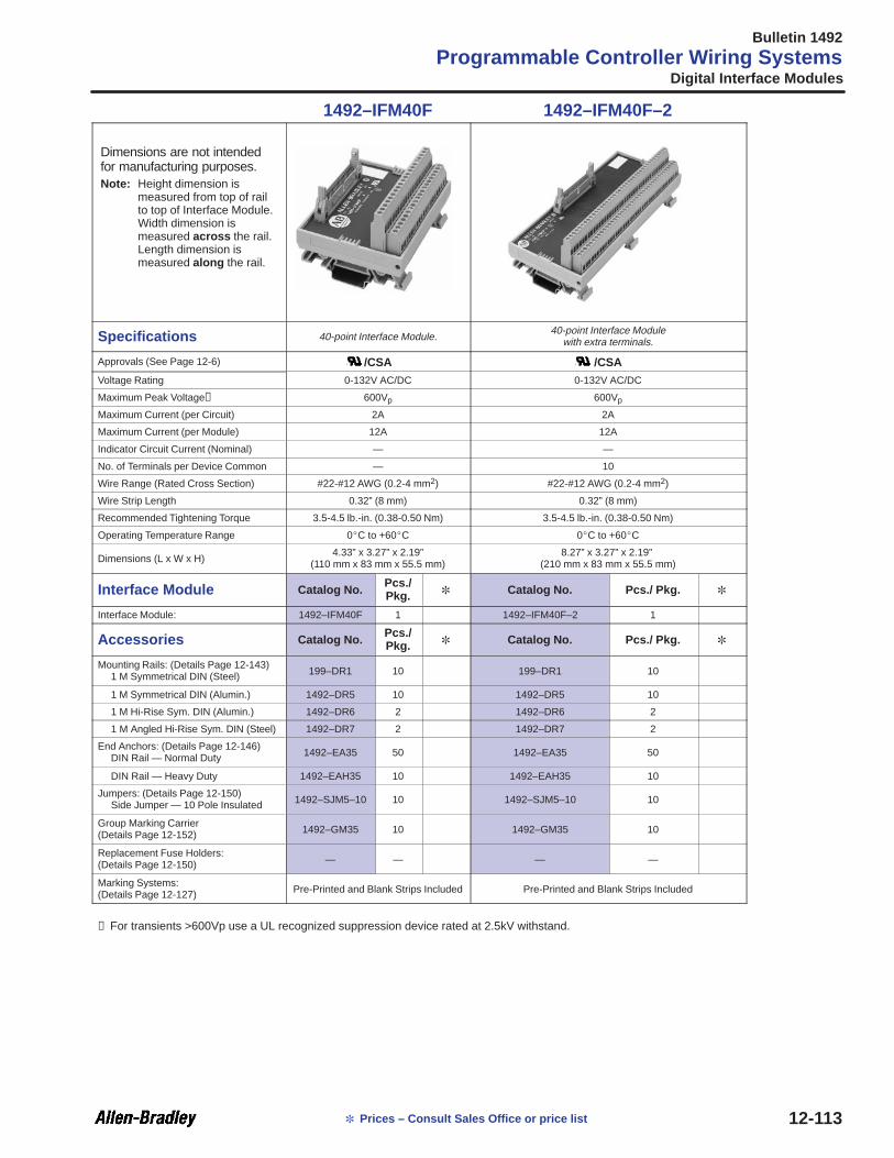
Bulletin 1492
Programmable Controller Wiring Systems
12-113 Prices – Consult Sales Office or price list
1492–IFM40F 1492–IFM40F–2
Dimensions are not intendedfor manufacturing purposes.Note: Height dimension is
measured from top of railto top of Interface Module.Width dimension ismeasured across the rail.Length dimension ismeasured along the rail.
Specifications 40-point Interface Module.40-point Interface Module
with extra terminals.
Approvals (See Page 12-6) /CSA /CSA
Voltage Rating 0-132V AC/DC 0-132V AC/DC
Maximum Peak Voltage➊ 600Vp 600Vp
Maximum Current (per Circuit) 2A 2A
Maximum Current (per Module) 12A 12A
Indicator Circuit Current (Nominal) — —
No. of Terminals per Device Common — 10
Wire Range (Rated Cross Section) #22-#12 AWG (0.2-4 mm2) #22-#12 AWG (0.2-4 mm2)
Wire Strip Length 0.32” (8 mm) 0.32” (8 mm)
Recommended Tightening Torque 3.5-4.5 lb.-in. (0.38-0.50 Nm) 3.5-4.5 lb.-in. (0.38-0.50 Nm)
Operating Temperature Range 0C to +60C 0C to +60C
Dimensions (L x W x H)4.33” x 3.27” x 2.19”
(110 mm x 83 mm x 55.5 mm)8.27” x 3.27” x 2.19”
(210 mm x 83 mm x 55.5 mm)
Interface Module Catalog No.Pcs./Pkg. Catalog No. Pcs./ Pkg.
Interface Module: 1492–IFM40F 1 1492–IFM40F–2 1
Accessories Catalog No.Pcs./Pkg. Catalog No. Pcs./ Pkg.
Mounting Rails: (Details Page 12-143)1 M Symmetrical DIN (Steel) 199–DR1 10 199–DR1 10
1 M Symmetrical DIN (Alumin.) 1492–DR5 10 1492–DR5 10
1 M Hi-Rise Sym. DIN (Alumin.) 1492–DR6 2 1492–DR6 2
1 M Angled Hi-Rise Sym. DIN (Steel) 1492–DR7 2 1492–DR7 2
End Anchors: (Details Page 12-146)DIN Rail — Normal Duty 1492–EA35 50 1492–EA35 50
DIN Rail — Heavy Duty 1492–EAH35 10 1492–EAH35 10
Jumpers: (Details Page 12-150)Side Jumper — 10 Pole Insulated 1492–SJM5–10 10 1492–SJM5–10 10
Group Marking Carrier(Details Page 12-152) 1492–GM35 10 1492–GM35 10
Replacement Fuse Holders:(Details Page 12-150) — — — —
Marking Systems:(Details Page 12-127) Pre-Printed and Blank Strips Included Pre-Printed and Blank Strips Included
➊ For transients >600Vp use a UL recognized suppression device rated at 2.5kV withstand.
Digital Interface Modules

Bulletin 1492
Programmable Controller Wiring Systems
12-114 Prices – Consult Sales Office or price list
1492–IFM40F–3 1492–IFM40D24
Dimensions are not intendedfor manufacturing purposes.Note: Height dimension is
measured from top of railto top of Interface Module.Width dimension ismeasured across the rail.Length dimension ismeasured along the rail.
Specifications 40-point Interface Modulefor 3-wire sensor–type input devices.
40-point Interface Modulewith 24V AC/DC LEDs
Approvals (See Page 12-6) /CSA /CSA
Voltage Rating 0-60V AC/DC 10-30V AC/DC
Maximum Peak Voltage➊ 600Vp 600Vp
Maximum Current (per Circuit) 2A 2A
Maximum Current (per Module) 12A 12A
Indicator Circuit Current (Nominal) — 2mA
No. of Terminals per Device Common 18 32
Wire Range (Rated Cross Section) #22-#12 AWG (0.2-4 mm2) #22-#12 AWG (0.2-4 mm2)
Wire Strip Length 0.32” (8 mm) 0.32” (8 mm)
Recommended Tightening Torque 3.5-4.5 lb.-in. (0.38-0.50 Nm) 3.5-4.5 lb.-in. (0.38-0.50 Nm)
Operating Temperature Range 0C to +60C 0C to +60C
Dimensions (L x W x H)8.27” x 3.27” x 2.74”
(210 mm x 83 mm x 69.5 mm)4.33” x 3.27” x 2.19”
(110 mm x 83 mm x 55.5 mm)
Interface Module Catalog No. Pcs./ Pkg. Catalog No.Pcs./Pkg.
Interface Module: 1492–IFM40F–3 1 1492–IFM40D24 1
Accessories Catalog No. Pcs./ Pkg. Catalog No.Pcs./Pkg.
Mounting Rails: (Details Page 12-143)1 M Symmetrical DIN (Steel) 199–DR1 10 199–DR1 10
1 M Symmetrical DIN (Alumin.) 1492–DR5 10 1492–DR5 10
1 M Hi-Rise Sym. DIN (Alumin.) 1492–DR6 2 1492–DR6 2
1 M Angled Hi-Rise Sym. DIN (Steel) 1492–DR7 2 1492–DR7 2
End Anchors: (Details Page 12-146)DIN Rail — Normal Duty 1492–EA35 50 1492–EA35 50
DIN Rail — Heavy Duty 1492–EAH35 10 1492–EAH35 10
Jumpers: (Details Page 12-150)Side Jumper — 10 Pole Insulated 1492–SJM5–10 10 1492–SJM5–10 10
Group Marking Carrier(Details Page 12-152) 1492–GM35 10 1492–GM35 10
Replacement Fuse Holders:(Details Page 12-150) — — — —
Marking Systems:(Details Page 12-127) Pre-Printed and Blank Strips Included Pre-Printed and Blank Strips Included
➊ For transients >600Vp use a UL recognized suppression device rated at 2.5kV withstand.
Digital Interface Modules

Bulletin 1492
Programmable Controller Wiring Systems
12-115 Prices – Consult Sales Office or price list
1492–IFM40D24–2 1492–IFM40D24A–2
Dimensions are not intendedfor manufacturing purposes.Note: Height dimension is
measured from top of railto top of Interface Module.Width dimension ismeasured across the rail.Length dimension ismeasured along the rail.
Specifications 40-point Interface Modulewith 24V AC/DC LEDs and extra terminals for outputs.
40-point Interface Modulewith 24V AC/DC LEDs and extra terminals for inputs.
Approvals (See Page 12-6) /CSA /CSA
Voltage Rating 10-30V AC/DC 10-30V AC/DC
Maximum Peak Voltage➊ 600Vp 600Vp
Maximum Current (per Circuit) 2A 2A
Maximum Current (per Module) 12A 12A
Indicator Circuit Current (Nominal) 2mA 2mA
No. of Terminals per Device Common 10 10
Wire Range (Rated Cross Section) #22-#12 AWG (0.2-4 mm2) #22-#12 AWG (0.2-4 mm2)
Wire Strip Length 0.32” (8 mm) 0.32” (8 mm)
Recommended Tightening Torque 3.5-4.5 lb.-in. (0.38-0.50 Nm) 3.5-4.5 lb.-in. (0.38-0.50 Nm)
Operating Temperature Range 0C to +60C 0C to +60C
Dimensions (L x W x H)8.27” x 3.27” x 2.19”
(210 mm x 83 mm x 55.5 mm)8.27” x 3.27” x 2.19”
(210 mm x 83 mm x 55.5 mm)
Interface Module Catalog No. Pcs./ Pkg. Catalog No. Pcs./ Pkg.
Interface Module: 1492–IFM40D24–2 1 1492–IFM40D24A–2 1
Accessories Catalog No. Pcs./ Pkg. Catalog No. Pcs./ Pkg.
Mounting Rails: (Details Page 12-143)1 M Symmetrical DIN (Steel) 199–DR1 10 199–DR1 10
1 M Symmetrical DIN (Alumin.) 1492–DR5 10 1492–DR5 10
1 M Hi-Rise Sym. DIN (Alumin.) 1492–DR6 2 1492–DR6 2
1 M Angled Hi-Rise Sym. DIN (Steel) 1492–DR7 2 1492–DR7 2
End Anchors: (Details Page 12-146)DIN Rail — Normal Duty 1492–EA35 50 1492–EA35 50
DIN Rail — Heavy Duty 1492–EAH35 10 1492–EAH35 10
Jumpers: (Details Page 12-150)Side Jumper — 10 Pole Insulated 1492–SJM5–10 10 1492–SJM5–10 10
Group Marking Carrier(Details Page 12-152) 1492–GM35 10 1492–GM35 10
Replacement Fuse Holders:(Details Page 12-150) — — — —
Marking Systems:(Details Page 12-127) Pre-Printed and Blank Strips Included Pre-Printed and Blank Strips Included
➊ For transients >600Vp use a UL recognized suppression device rated at 2.5kV withstand.
Digital Interface Modules

Bulletin 1492
Programmable Controller Wiring Systems
12-116 Prices – Consult Sales Office or price list
1492–IFM40D24–3 1492–IFM40D120–2
Dimensions are not intendedfor manufacturing purposes.Note: Height dimension is
measured from top of railto top of Interface Module.Width dimension ismeasured across the rail.Length dimension ismeasured along the rail.
Specifications40-point Interface Module
with 24V AC/DC LEDs for 3-wire sensor-type inputdevices.
40-point Interface Modulewith 120V AC LEDs and extra terminals for outputs.
Approvals (See Page 12-6) /CSA /CSA
Voltage Rating 10-30V AC/DC 85-132V AC
Maximum Peak Voltage➊ 600Vp 600Vp
Maximum Current (per Circuit) 2A 2A
Maximum Current (per Module) 12A 12A
Indicator Circuit Current (Nominal) 2mA 2.5mA
No. of Terminals per Device Common 18 10
Wire Range (Rated Cross Section) #22-#12 AWG (0.2-4 mm2) #22-#12 AWG (0.2-4 mm2)
Wire Strip Length 0.32” (8 mm) 0.32” (8 mm)
Recommended Tightening Torque 3.5-4.5 lb.-in. (0.38-0.50 Nm) 3.5-4.5 lb.-in. (0.38-0.50 Nm)
Operating Temperature Range 0C to +60C 0C to +60C
Dimensions (L x W x H)8.27” x 3.27” x 2.74”
(210 mm x 83 mm x 69.5 mm)8.27” x 3.27” x 2.19”
(210 mm x 83 mm x 55.5 mm)
Interface Module Catalog No. Pcs./ Pkg. Catalog No. Pcs./ Pkg.
Interface Module: 1492–IFM40D24–3 1 1492–IFM40D120–2 1
Accessories Catalog No. Pcs./ Pkg. Catalog No. Pcs./ Pkg.
Mounting Rails: (Details Page 12-143)1 M Symmetrical DIN (Steel) 199–DR1 10 199–DR1 10
1 M Symmetrical DIN (Alumin.) 1492–DR5 10 1492–DR5 10
1 M Hi-Rise Sym. DIN (Alumin.) 1492–DR6 2 1492–DR6 2
1 M Angled Hi-Rise Sym. DIN (Steel) 1492–DR7 2 1492–DR7 2
End Anchors: (Details Page 12-146)DIN Rail — Normal Duty 1492–EA35 50 1492–EA35 50
DIN Rail — Heavy Duty 1492–EAH35 10 1492–EAH35 10
Jumpers: (Details Page 12-150)Side Jumper — 10 Pole Insulated 1492–SJM5–10 10 1492–SJM5–10 10
Group Marking Carrier(Details Page 12-152) 1492–GM35 10 1492–GM35 10
Replacement Fuse Holders:(Details Page 12-150) — — — —
Marking Systems:(Details Page 12-127) Pre-Printed and Blank Strips Included Pre-Printed and Blank Strips Included
➊ For transients >600Vp use a UL recognized suppression device rated at 2.5kV withstand.
Digital Interface Modules

Bulletin 1492
Programmable Controller Wiring Systems
12-117 Prices – Consult Sales Office or price list
1492–IFM40D120A–2 1492–IFM40F–F–2
Dimensions are not intendedfor manufacturing purposes.Note: Height dimension is
measured from top of railto top of Interface Module.Width dimension ismeasured across the rail.Length dimension ismeasured along the rail.
Specifications 40-point Interface Modulewith 120V AC LEDs and extra terminals for inputs.
40-point Interface Module with 5 x 20mm fuse clips andextra terminals.
Approvals (See Page 12-6) /CSA /CSA
Voltage Rating 85-132V AC 0-132V AC/DC
Maximum Peak Voltage➋ 600Vp 600Vp
Maximum Current (per Circuit) 2A 2A
Maximum Current (per Module) 12A 12A
Indicator Circuit Current (Nominal) 2.5mA —
No. of Terminals per Device Common 10 10
Wire Range (Rated Cross Section) #22-#12 AWG (0.2-4 mm2) #22-#12 AWG (0.2-4 mm2)
Wire Strip Length 0.32” (8 mm) 0.32” (8 mm)
Recommended Tightening Torque 3.5-4.5 lb.-in. (0.38-0.50 Nm) 3.5-4.5 lb.-in. (0.38-0.50 Nm)
Operating Temperature Range 0C to +60C 0C to +60C
Dimensions (L x W x H)8.27” x 3.27” x 2.19”
(210 mm x 83 mm x 55.5 mm)8.27” x 3.27” x 2.19”
(210 mm x 83 mm x 55.5 mm)
Interface Module Catalog No. Pcs./ Pkg. Catalog No. Pcs./ Pkg.
Interface Module: 1492–IFM40D120A–2 1 1492–IFM40F–F–2 1
Accessories Catalog No. Pcs./ Pkg. Catalog No. Pcs./ Pkg.
Mounting Rails: (Details Page 12-143)1 M Symmetrical DIN (Steel) 199–DR1 10 199–DR1 10
1 M Symmetrical DIN (Alumin.) 1492–DR5 10 1492–DR5 10
1 M Hi-Rise Sym. DIN (Alumin.) 1492–DR6 2 1492–DR6 2
1 M Angled Hi-Rise Sym. DIN (Steel) 1492–DR7 2 1492–DR7 2
End Anchors: (Details Page 12-146)DIN Rail — Normal Duty 1492–EA35 50 1492–EA35 50
DIN Rail — Heavy Duty 1492–EAH35 10 1492–EAH35 10
Jumpers: (Details Page 12-150)Side Jumper — 10 Pole Insulated 1492–SJM5–10 10 1492–SJM5–10 10
Group Marking Carrier(Details Page 12-152) 1492–GM35 10 1492–GM35 10
Replacement Fuse Holders:(Details Page 12-150) ➊ — — 1492–IFMFH1➊ 20
Marking Systems:(Details Page 12-127) Pre-Printed and Blank Strips Included Pre-Printed and Blank Strips Included
➊ 40 Fuse Holders are included with Catalog Number: 1492–IFM40F–F–2.
➋ For transients >600Vp use a UL recognized suppression device rated at 2.5kV withstand.
Digital Interface Modules

Bulletin 1492
Programmable Controller Wiring Systems
12-118 Prices – Consult Sales Office or price list
1492–IFM40F–F24–2 1492–IFM40F–F120–2
Dimensions are not intendedfor manufacturing purposes.Note: Height dimension is
measured from top of railto top of Interface Module.Width dimension ismeasured across the rail.Length dimension ismeasured along the rail.
Specifications 40-point Interface Module with 5 x 20mm fuse clips, 24VAC/DC blown fuse indicators, and extra terminals.
40-point Interface Module with 5 x 20mm fuse clips, 120VAC blown fuse indicators, and extra terminals.
Approvals (See Page 12-6) /CSA /CSA
Voltage Rating 10-30V AC/DC 85-132V AC
Maximum Peak Voltage➋ 600Vp 600Vp
Maximum Current (per Circuit) 2A 2A
Maximum Current (per Module) 12A 12A
Indicator Circuit Current (Nominal) 2mA 2.5mA
No. of Terminals per Device Common 10 10
Wire Range (Rated Cross Section) #22-#12 AWG (0.2-4 mm2) #22-#12 AWG (0.2-4 mm2)
Wire Strip Length 0.32” (8 mm) 0.32” (8 mm)
Recommended Tightening Torque 3.5-4.5 lb.-in. (0.38-0.50 Nm) 3.5-4.5 lb.-in. (0.38-0.50 Nm)
Operating Temperature Range 0C to +60C 0C to +60C
Dimensions (L x W x H)8.27” x 3.27” x 2.19”
(210 mm x 83 mm x 55.5 mm)8.27” x 3.27” x 2.19”
(210 mm x 83 mm x 55.5 mm)
Interface Module Catalog No. Pcs./ Pkg. Catalog No. Pcs./ Pkg.
Interface Module: 1492–IFM40F–F24–2 1 1492–IFM40F–F120–2 1
Accessories Catalog No. Pcs./ Pkg. Catalog No. Pcs./ Pkg.
Mounting Rails: (Details Page 12-143)1 M Symmetrical DIN (Steel) 199–DR1 10 199–DR1 10
1 M Symmetrical DIN (Alumin.) 1492–DR5 10 1492–DR5 10
1 M Hi-Rise Sym. DIN (Alumin.) 1492–DR6 2 1492–DR6 2
1 M Angled Hi-Rise Sym. DIN (Steel) 1492–DR7 2 1492–DR7 2
End Anchors: (Details Page 12-146)DIN Rail — Normal Duty 1492–EA35 50 1492–EA35 50
DIN Rail — Heavy Duty 1492–EAH35 10 1492–EAH35 10
Jumpers: (Details Page 12-150)Side Jumper — 10 Pole Insulated 1492–SJM5–10 10 1492–SJM5–10 10
Group Marking Carrier(Details Page 12-152) 1492–GM35 10 1492–GM35 10
Replacement Fuse Holders:(Details Page 12-150) ➊ 1492–IFMFH1 ➊ 20 1492–IFMFH1 ➊ 20
Marking Systems:(Details Page 12-127) Pre-Printed and Blank Strips Included Pre-Printed and Blank Strips Included
➊ 40 Fuse Holders are included with Catalog Numbers: 1492–IFM40F–F24–2, and 1492–IFM40F–F120–2.
➋ For transients >600Vp use a UL recognized suppression device rated at 2.5kV withstand.
Digital Interface Modules

Bulletin 1492
Programmable Controller Wiring Systems
12-119 Prices – Consult Sales Office or price list
1492–AIFM4–3 1492–AIFM6S–3 1492–AIFM8–3
Dimensions are not intendedfor manufacturing purposes.Note: Height dimension is
measured from top of railto top of Interface Module.Width dimension ismeasured across the rail.Length dimension ismeasured along the rail.
Specifications4–channel IFM with 3 terminals perchannel and optional 250Ω current
limit resistors for 1771–OFE
6–channel isolated IFM with 3–4terminals per channel
8–channel IFM with 3 terminals perchannel
Approvals (See Page 12-6) /c /c /cVoltage Rating 0-132V AC/DC 0-132V AC/DC 0-132V AC/DC
Maximum Peak Voltage➊ 600Vp 600Vp 600Vp
Maximum Current (per Circuit) 2A 2A 2A
Maximum Current (per Module) 12A 12A 12A
Indicator Circuit Current (Nominal) — — —
No. of Terminals per Shield Common 4 6 8
Wire Range (Rated Cross Section) #22-#12 AWG (0.2-4 mm2) #22-#12 AWG (0.2-4 mm2) #22-#12 AWG (0.2-4 mm2)
Wire Strip Length 0.32” (8 mm) 0.32” (8 mm) 0.32” (8 mm)
Recommended Tightening Torque 3.5-4.5 lb.-in. (0.38-0.50 Nm) 3.5-4.5 lb.-in. (0.38-0.50 Nm) 3.5-4.5 lb.-in. (0.38-0.50 Nm)
Operating Temperature Range 0C to +60C 0C to +60C 0C to +60C
Dimensions (L x W x H)2.36” x 3.27” x 2.19”
(60 mm x 83 mm x 55.5 mm)3.15” x 3.27” x 2.19”
(80 mm x 83 mm x 55.5 mm)4.33” x 3.27” x 2.19”
(110 mm x 83 mm x 55.5 mm)
Interface Module Catalog No.Pcs./Pkg. Catalog No.
Pcs./Pkg. Catalog No.
Pcs./Pkg.
Interface Module: 1492–AIFM4–3 1 1492–AIFM6S–3 1 1492–AIFM8–3 1
Accessories Catalog No.Pcs./Pkg. Catalog No.
Pcs./Pkg. Catalog No.
Pcs./Pkg.
Mounting Rails: (Details Page 12-143)1 M Symmetrical DIN (Steel) 199–DR1 10 199–DR1 10 199–DR1 10
1 M Symmetrical DIN (Alumin.) 1492–DR5 10 1492–DR5 10 1492–DR5 10
1 M Hi-Rise Sym. DIN (Alumin.) 1492–DR6 2 1492–DR6 2 1492–DR6 2
1 M Angled Hi-Rise Sym. DIN (Steel) 1492–DR7 2 1492–DR7 2 1492–DR7 2
End Anchors: (Details Page 12-146)DIN Rail — Normal Duty 1492–EA35 50 1492–EA35 50 1492–EA35 50
DIN Rail — Heavy Duty 1492–EAH35 10 1492–EAH35 10 1492–EAH35 10
Jumpers: (Details Page 12-150)Side Jumper — 10 Pole Insulated 1492–SJM5–10 10 1492–SJM5–10 10 1492–SJM5–10 10
Group Marking Carrier(Details Page 12-152) 1492–GM35 10 1492–GM35 10 1492–GM35 10
Replacement Fuse Holders:(Details Page 12-150) — — — — — —
Marking Systems:(Details Page 12-127) Pre-Printed and Blank Strips Included Pre-Printed and Blank Strips Included Pre-Printed and Blank Strips Included
➊ For transients >600Vp use a UL recognized suppression device rated at 2.5kV withstand.
Analog Interface Modules

Bulletin 1492
Programmable Controller Wiring Systems
12-120 Prices – Consult Sales Office or price list
1492–AIFM4I–F–5 1492–AIFM4C–F–5 1492–AIFM8–F–5
Dimensions are not intendedfor manufacturing purposes.Note: Height dimension is
measured from top of railto top of Interface Module.Width dimension ismeasured across the rail.Length dimension ismeasured along the rail.
Specifications4–channel fusible IFM with 24V blown
fuse indicators, test points, and 5terminals per input.
2–channel fusible IFM with 24V blownfuse indicators, test points, 5
terminals per input, and 3 terminalsper output.
8–channel fusible IFM with 24V blownfuse indicators and 5 terminals per
input.
Approvals (Details Page 12-6) /c /c /cVoltage Rating 10–30V DC 10–30V DC 10–30V DC
Maximum Peak Voltage➊ 600Vp 600Vp 600Vp
Maximum Current (per Circuit) 2A 2A 2A
Maximum Current (per Module) 12A 12A 12A
Indicator Circuit Current (Nominal) 2mA 2mA 2mA
No. of Terminals per Shield Common 4 4 18
Wire Range (Rated Cross Section) #22-#12 AWG (0.2-4 mm2) #22-#12 AWG (0.2-4 mm2) #22-#12 AWG (0.2-4 mm2)
Wire Strip Length 0.32” (8 mm) 0.32” (8 mm) 0.32” (8 mm)
Recommended Tightening Torque 3.5-4.5 lb.-in. (0.38-0.50 Nm) 3.5-4.5 lb.-in. (0.38-0.50 Nm) 3.5-4.5 lb.-in. (0.38-0.50 Nm)
Operating Temperature Range 0C to +60C 0C to +60C 0C to +60C
Dimensions (L x W x H)3.15” x 3.27” x 2.19”
(80 mm x 83 mm x 55.5 mm)3.15” x 3.27” x 2.19”
(80 mm x 83 mm x 55.5 mm)4.72” x 3.27” x 2.74”
(120 mm x 83 mm x 69.5 mm)
Interface Module Catalog No.Pcs./Pkg. Catalog No.
Pcs./Pkg. Catalog No.
Pcs./Pkg.
Interface Module: 1492–AIFM4I–F–5 1 1492–AIFM4C–F–5 1 1492–AIFM8–F–5 1
Accessories Catalog No.Pcs./Pkg. Catalog No.
Pcs./Pkg. Catalog No.
Pcs./Pkg.
Mounting Rails: (Details Page 12-143)1 M Symmetrical DIN (Steel) 199–DR1 10 199–DR1 10 199–DR1 10
1 M Symmetrical DIN (Alumin.) 1492–DR5 10 1492–DR5 10 1492–DR5 10
1 M Hi-Rise Sym. DIN (Alumin.) 1492–DR6 2 1492–DR6 2 1492–DR6 2
1 M Angled Hi-Rise Sym. DIN (Steel) 1492–DR7 2 1492–DR7 2 1492–DR7 2
End Anchors: (Details Page 12-146)DIN Rail — Normal Duty 1492–EA35 50 1492–EA35 50 1492–EA35 50
DIN Rail — Heavy Duty 1492–EAH35 10 1492–EAH35 10 1492–EAH35 10
Jumpers: (Details Page 12-150)Side Jumper — 10 Pole Insulated 1492–SJM5–10 10 1492–SJM5–10 10 1492–SJM5–10 10
Group Marking Carrier(Details Page 12-152) 1492–GM35 10 1492–GM35 10 1492–GM35 10
Replacement Fuse Holders:➋(Details Page 12-150) 1492–IFMFH1➋ 20 1492–IFMFH1➋ 20 1492–IFMFH1➋ 20
Marking Systems:(Details Page 12-127) Pre-Printed and Blank Strips Included Pre-Printed and Blank Strips Included Pre-Printed and Blank Strips Included
➊ For transients >600Vp use a UL recognized suppression device rated at 2.5kV withstand.
➋ 10 Fuse Holders are included with Catalog Numbers: 1492–AIFM4I–F–5, 1492–AIFM4C–F–5, and 1492–AIFM8–F–5.
Analog Interface Modules

Bulletin 1492
Programmable Controller Wiring Systems
12-121 Prices – Consult Sales Office or price list
1492–AIFM16–F–3 1492–AIFM16–F–5
Dimensions are not intendedfor manufacturing purposes.Note: Height dimension is
measured from top of railto top of Interface Module.Width dimension ismeasured across the rail.Length dimension ismeasured along the rail.
Specifications16–channel fusible IFM with 24V
blown fuse indicators and 3 terminalsper input.
16–channel fusible IFM with 24V blown fuse indicatorsand 5 terminals per input
Approvals (Details Page 12-6) /c /c
Voltage Rating 10–30V DC 10–30V DC
Maximum Recurring Peak Voltage➊ 600Vp 600Vp
Maximum Current (per Circuit) 2A 2A
Maximum Current (per Module) 12A 12A
Indicator Circuit Current (Nominal) 2mA 2mA
No. of Terminals per Shield Common 18 16
Wire Range (Rated Cross Section) #22-#12 AWG (0.2-4 mm2) #22-#12 AWG (0.2-4 mm2)
Wire Strip Length 0.32” (8 mm) 0.32” (8 mm)
Recommended Tightening Torque 3.5-4.5 lb.-in. (0.38-0.50 Nm) 3.5-4.5 lb.-in. (0.38-0.50 Nm)
Operating Temperature Range 0C to +60C 0C to +60C
Dimensions (L x W x H)4.72” x 3.27” x 2.74”
(120 mm x 83 mm x 69.5 mm)8.27” x 3.27” x 2.74”
(210 mm x 83 mm x 69.5 mm)
Interface Module Catalog No.Pcs./Pkg. Catalog No. Pcs./ Pkg.
Interface Module: 1492–AIFM16–F–3 1 1492–AIFM16–F–5 1
Accessories Catalog No.Pcs./Pkg. Catalog No. Pcs./ Pkg.
Mounting Rails: (Details Page 12-143)1 M Symmetrical DIN (Steel) 199–DR1 10 199–DR1 10
1 M Symmetrical DIN (Alumin.) 1492–DR5 10 1492–DR5 10
1 M Hi-Rise Sym. DIN (Alumin.) 1492–DR6 2 1492–DR6 2
1 M Angled Hi-Rise Sym. DIN (Steel) 1492–DR7 2 1492–DR7 2
End Anchors: (Details Page 12-146)DIN Rail — Normal Duty 1492–EA35 50 1492–EA35 50
DIN Rail — Heavy Duty 1492–EAH35 10 1492–EAH35 10
Jumpers: (Details Page 12-150)Side Jumper — 10 Pole Insulated 1492–SJM5–10 10 1492–SJM5–10 10
Group Marking Carrier(Details Page 12-152) 1492–GM35 10 1492–GM35 10
Replacement Fuse Holders:➋(Details Page 12-150) 1492–IFMFH1➋ 20 1492–IFMFH1➋ 20
Marking Systems:(Details Page 12-127) Pre-Printed and Blank Strips Included Pre-Printed and Blank Strips Included
➊ For transients >600Vp use a UL recognized suppression device rated at 2.5kV withstand.
➋ 20 Fuse Holders are included with Catalog Numbers: 1492–AIFM16–F–3 and 1492–AIFM16–F–5.
Analog Interface Modules

Bulletin 1492
Programmable Controller Wiring Systems
12-122 Prices – Consult Sales Office or price list
Digital Pre-wired Cable Specifications
Catalog Number InsulationRa i
Conductorize I/O Mod le Connector
gand Length ➊
la ioRating
Co oSize I/O Module Connector
0.5 m 1.0 m 2.5m 5.0m1492-CABLE➊ A 300V 80°C #22 AWG 1746-RT25R Red Removable Terminal Block
1492-CABLE➊ B 300V 80°C #22 AWG 1746-RT25B Blue Removable Terminal Block
1492-CABLE➊ C➋ 300V 80°C #22 AWG 1746-RT25R Red Removable Terminal Block
1492-CABLE➊ D➋ 300V 80°C #22 AWG 1746-RT25C Orange Removable Terminal Block
1492-CABLE➊ E 300V 80°C #22 AWG 1746-RT25B Blue Removable Terminal Block
1492-CABLE➊ F 300V 80°C #22 AWG 1771-WH (16-Point/21 Terminal) Wiring Arm
1492-CABLE➊ FF 300V 80°C #22 AWG 1771-WHF (16-Point/21 Terminal) Fused Wiring Arm
1492-CABLE➊ G➌ 300V 80°C #22 AWG 1746-RT25R Red Removable Terminal Block
1492-CABLE➊ H 300V 80°C #22 AWG 1746-N3 (32-Point/40 Pin) Connector
1492-CABLE➊ J 300V 80°C #22 AWG 1771-WN (32-Point/40 Terminal) Wiring Arm
1492-CABLE➊ K 300V 80°C #22 AWG 1771-WN (32-Point/40 Terminal) Wiring Arm
1492-CABLE➊ L 300V 80°C #22 AWG 1771-WN (32-Point/40 Terminal) Wiring Arm
1492-CABLE➊ M 300V 80°C #22 AWG 1771-WN (32-Point/40 Terminal) Wiring Arm
1492-CABLE➊ N❸ 300V 80°C #22 AWG 1746-RT25C Orange Removable Terminal Block
1492-CABLE➊ R 300V 80°C #22 AWG 1771-WN (32-Point/40 Terminal) Wiring Arm
➊ Cables are available in lengths of 0.5m, 1.0m, 2.5m and 5.0m. To order, insert the desired cable length code into the Catalog Number(“005” = 0.5m, “010” =1.0m, “025” = 2.5m and “050” = 5.0m). Example: Catalog Number 1492-CABLE005A is for a 0.5m cable for the1746-IA16 I/O Module. See also Custom Lengths.
➋ Cable not for use with narrow IFMs (1492–IFM20_ _N).
➌ Cable only for use with narrow IFMs (1492–IFM20_ _N).
Analog Pre-wired Cable Specifications
CatalogN mber and Insulation
Ra iConductor
ize I/O Mod le ConnectorGeneral
De i io
Number and
Length ➊
la ioRating
Co oSize I/O Module Connector
Ge e alDescription➋ 0.5 m 1.0 m 2.5m 5.0m
1492-ACABLE➊ A 300V 80°C #22 AWG 1746-RT28 12-Position Removable Terminal Block 5 Twisted Pairs
1492-ACABLE➊ B 300V 80°C #22 AWG 1746-RT26 2-Position and 1746-RT27 8-PositionRemovable Terminal Block
5 Twisted Pairs
1492-ACABLE➊ C 300V 80°C #24 AWG 1746-RT25G Green Removable Terminal Block 9 Twisted Pairs
1492-ACABLE➊ D 300V 80°C #22 AWG 1746-RT25G Green Removable Terminal Block 20 Conductors
1492-ACABLE➊ E 300V 80°C #24 AWG 1771-WG (21 terminal) Wiring Arm 9 Twisted Pairs
1492-ACABLE➊ F 300V 80°C #22 AWG 1771-WG (21 terminal) Wiring Arm 20 Conductors
1492-ACABLE➊ G 300V 80°C #22 AWG 1771-WC (10 terminal) Wiring Arm 5 Twisted Pairs
1492-ACABLE➊ H 300V 80°C #24 AWG 1771-WF (18 terminal) Wiring Arm 9 Twisted Pairs
1492-ACABLE➊ J 300V 80°C #22 AWG 1771-WF (18 terminal) Wiring Arm 20 Conductors
1492-ACABLE➊ L 300V 80°C #22 AWG 1746-RT28 12-Position Removable Terminal Block 5 Twisted Pairs
➊ Cables are available in lengths of 0.5m, 1.0m, 2.5m and 5.0m. To order, insert the desired cable length code into the Catalog Number(“005” = 0.5m, “010” =1.0m, “025” = 2.5m and “050” = 5.0m). Example: Catalog Number 1492-ACABLE005A is for a 0.5m cable for the1746-NI4 I/O Module. See also Custom Lengths.
➋ All pre–wired analog cables have an overall shield. On 1492-ACABLE➊ C and 1492-ACABLE➊ D the drain wire is connected to the shieldterminal on the I/O module connector. All other 1492-ACABLEs have a ring lug on the 7.87” (200mm) exposed drain wire at the I/O moduleend of the cable.
Cable Specifications

Bulletin 1492
Programmable Controller Wiring Systems
12-123 Prices – Consult Sales Office or price list
Digital IFM-Ready Cable Specifications
Catalog Number Insulation No. of Conductor Current/ Compatible gand Length ➊ Rating Conductors Size Conductor
pIFMs 1.0 m 2.5 m 5.0 m
1492-CABLE➊ P 300V 80°C 20 #22 AWG 2 Amps IFM20_ _ _
1492-CABLE➊ Q 300V 80°C 40 #22 AWG 2 Amps IFM40_ _ _
➊ Cables are available in lengths of 1.0m, 2.5m and 5.0m. To order, insert the desired cable length code into the Catalog Number (“010” =1.0m, “025” = 2.5m and “050” = 5.0m). Example: Catalog Number 1492-CABLE025P is for a 2.5m cable for an IFM20_ _ _. See alsoCustom Lengths.
Digital I/O Module-Ready Cable Specifications
Catalog Number Insulation No. of ConductorI/O Mod le Connector
gand Length ➊ Rating Conductors Size I/O Module Connector
1.0 m 2.5 m 5.0 m
1492-CABLE➊ N3 300V 80°C 40 #22 AWG1746-N3 (32-Point/40 Pin)Connector
1492-CABLE➊ RTBB 300V 80°C 20 ➋ #18 AWG1746-RT25B Blue RemovableTerminal Block
1492-CABLE➊ RTBO 300V 80°C 20 ➋ #18 AWG1746-RT25C Orange RemovableTerminal Block
1492-CABLE➊ RTBR 300V 80°C 20 ➋ #18 AWG1746-RT25R Red RemovableTerminal Block
1492-CABLE➊ WA 300V 80°C 12 ➋ #18 AWG1771-WA (8-Point/10 Terminal)Wiring Arm
1492-CABLE➊ WD 300V 80°C 12 #18 AWG1771-WD (8-Point/12 Terminal)Wiring Arm
1492-CABLE➊ WH 300V 80°C 20 #18 AWG1771-WH (16-Point/21 Terminal)Wiring Arm
1492-CABLE➊ WHF 300V 80°C 20 #18 AWG1771-WHF (16-Point/21 Terminal)Fused Wiring Arm
1492-CABLE➊ WN 300V 80°C 40 #18 AWG1771-WN (32-Point/40 Terminal)Wiring Arm
➊ Cables are available in lengths of 1.0m, 2.5m and 5.0m. To order, insert the desired cable length code into the Catalog Number (“010” =1.0m, “025” = 2.5m and “050” = 5.0m). Example: Catalog Number 1492-CABLE025WH is for a 2.5m cable with a pre-wired 1771-WHWiring Arm on one end. See also Custom Lengths.
➋ Two conductors are not wired to I/O module connector.
Custom LengthsAll 1492 Cables are available in custom lengths. Contact your local Allen–Bradley Distributor or sales office for availability.
Length Increment Size Cable Length Codes Examples
0.1m–2.0m 0.1m 001–020 1492–CABLE015A
2.0m–10.0m 0.5m 020–100 1492–CABLE075P
10.0m–99.0m 1.0m 100–990 1492–CABLE150RTBB
Note: Some I/O modules may have recommended maximum cable lengths. For example, the recommended maximum cable length for the1746-IB32 and -IV32 is 10m and for the 1746-OB32 and -OV32 is 3m. Refer to the appropriate I/O module product datas for moreinformation.
Cable Specifications

Bulletin 1492
Programmable Controller Wiring Systems
12-124 Prices – Consult Sales Office or price list
Pre-wired Cable and IFM Selection Tables for Digital I/O ModulesTo Use :• Select the appropriate table.
• Locate your I/O Module in one of the shaded areas.
• Follow down the selected column to the cable selection code that indicates the compatible IFMs. If the space is blank, the I/O Module and IFMare not recommended for use together.
Note: To configure a cable catalog number, order 1492–CABLE ➊➋ .
➊ Cables are available in 0.5, 1.0, 2.5, and 5.0 m lengths. Insert the cable length code into the catalog number. Cable length codes are as follows (“005” =0.5m, “010 ”=1.0m, “025” =2.5m, and “050 ”=5.0m).
➋ Insert cable selection code. Example: 1492–CABLE025FF is a 2.5m, 16–point fused, wiring arm cable for the 1771–OAD output module.
SLC 500 8-Point Isolated and 16-Point Digital 1746 I/O ModulesI/O Module Catalog Number
Type of IFM DescriptionIFM
CatalogNumber
1746
-IA16
1746
-IB16
1746
-IC16
1746
-IG16
1746
-IH16
1746
-IN16
1746
-ITB1
617
46-IT
V16
1746
-IV16
1746
-OA1
617
46-O
B16
1746
-OBP
16
1746
-OG
1617
46-O
V16
1746
-OVP
16
1746
-OW
1617
46-O
X8
Feed-Through 20-Point Standard 1492-IFM20F A B B E B B B B B C E E E E E D D
20-Point Narrow Standard 1492-IFM20FN A B B E B B B B B G E E E E E N N
20-Point Extra Terminal 1492-IFM20F-2 A B B E B B B B B C E E E E E D
20-Point Sensor 1492-IFM20F-3 A B B E B B B B B
LED Indicating 20-Point Standard with 24V LEDs 1492-IFM20D24 B B B B B E E E E D
20-Point Narrow Standard with 24V LEDs 1492-IFM20D24N B B B B B E E E E N
20-Point Standard with 120V LEDs 1492-IFM20D120 A B C D
20-Point Narrow Standard with 120V LEDs 1492-IFM20D120N A G N
20-Point Extra Terminal with 24V LEDs for Outputs 1492-IFM20D24-2 E E E E D
20-Point Extra Terminal with 24V LEDs for Inputs 1492-IFM20D24A-2 B B B B B
20-Point Extra Terminal with 120V LEDs for Outputs 1492-IFM20D120-2 C D
20-Point Extra Terminal with 120V LEDs for Inputs 1492-IFM20D120A-2 A
20-Point Sensor with 24V LEDs 1492-IFM20D24-3 B B B B B
Fusible 20-Point Extra Terminal for Outputs 1492-IFM20F-F-2 C E E E E D
20-Point Extra Terminal with 24V Blown Fuse Indicators for Outputs 1492-IFM20F-F24-2 E E E E D
20-Point Extra Terminal with 120V Blown Fuse Indicators for Outputs 1492-IFM20F-F120-2 C D
20-Point Extra Terminal with 24V Blown Fuse Indicators for Inputs 1492-IFM20F-F24A-2 B B B E E
PLC 16-Point Digital 1771 I/O ModulesI/O Module Cat. No.
Type of IFM DescriptionIFM
CatalogNumber 17
71-IA
D17
71-IB
D17
71-IC
D17
71-IG
D17
71-IN
D
1771
-OAD
1771
-OBD
1771
-OG
D
1771
-OND
Feed-Through 20-Point Standard 1492-IFM20F F F F F F F,FF F,FF F F,FF
20-Point Narrow Standard 1492-IFM20FN F F F F F F,FF F,FF F F,FF
20-Point Extra Terminal 1492-IFM20F-2 F F F F F F,FF F,FF F F,FF
20-Point Sensor 1492-IFM20F-3 F F F F F
LED Indicating 20-Point Standard with 24V LEDs 1492-IFM20D24 F F F F,FF F,FF F,FF
20-Point Narrow Standard with 24V LEDs 1492-IFM20D24N F F F F,FF F,FF F,FF
20-Point Standard with 120V LEDs 1492-IFM20D120 F
20-Point Narrow Standard with 120V LEDs 1492-IFM20D120N F F,FF
20-Point Extra Terminal with 24V LEDs for Outputs 1492-IFM20D24-2 F,FF F,FF F,FF
20-Point Extra Terminal with 24V LEDs for Inputs 1492-IFM20D24A-2 F F F
20-Point Extra Terminal with 120V LEDs for Outputs 1492-IFM20D120-2 F,FF
20-Point Extra Terminal with 120V LEDs for Inputs 1492-IFM20D120A-2 F
20-Point Sensor with 24V LEDs 1492-IFM20D24-3 F F
Fusible 20-Point Extra Terminal for Outputs 1492-IFM20F-F-2 F F F
20-Point Extra Terminal with 24V Blown Fuse Indicators for Outputs 1492-IFM20F-F24-2 F F F
20-Point Extra Terminal with 120V Blown Fuse Indicators for Outputs 1492-IFM20F-F120-2 F
20-Point Extra Terminal with 24V Blown Fuse Indicators for Inputs 1492-IFM20-F24A-2 F F F
Digital Cable Compatibility Table

Bulletin 1492
Programmable Controller Wiring Systems
12-125 Prices – Consult Sales Office or price list
Pre-wired Cable and IFM Selection Tables for Digital I/O Modules
SLC 500 32-Point Digital 1746 I/O ModulesI/O ModuleCatalog No.
Type of IFM DescriptionIFM
CatalogNumber
1746
-IB32
1746
-IV32
1746
-OB3
2
1746
-0V3
2
Feed-Through 40-Point Standard 1492-IFM40F H H H➊ H➊
40-Point Extra Terminal 1492-IFM40F-2 H H H➊ H➊
40-Point Sensor 1492-IFM40F-3 H H
LED Indicating 40-Point Standard with 24V LEDs 1492-IFM40D24 H H H➊ H➊
40-Point Extra Terminal with 24V LEDs for Outputs 1492-IFM40D24-2 H➊ H➊
40–Point Extra Terminal with 24V LEDs for Inputs 1492-IFM40D24A-2 H H
40-Point Extra Terminal with 120V LEDs for Outputs 1492-IFM40D120-2
40-Point Extra Terminal with 120V LEDs for Inputs 1492-IFM40D120A-2
40-Point Sensor with 24V LEDs 1492-IFM40D24-3 H H
Fusible 40-Point Extra Terminal for Outputs 1492-IFM40F-F-2 H➊ H➊
40-Point Extra Terminal with 24V Blown Fuse Indicators for Outputs 1492-IFM40F-F24-2 H➊ H➊
40-Point Extra Terminal with 120V Blown Fuse Indicators for Outputs 1492-IFM40F-F120-2
➊ 5.0m cable length is not recommended for use with the 1746–OB32 and 1746–OV32 SLC Output Modules.
PLC 16-Point Isolated and 32 -Point Digital 1771 I/O ModulesI/O Module Cat. No.
Type of IFM DescriptionIFM
CatalogNumber 17
71-IA
N17
71-IB
N17
71-ID
1617
71-IQ
1617
71-IV
N17
71-O
AN17
71-O
BN17
71-O
D16
1771
-ODD
1771
-OQ
1617
71-O
VN17
71-O
W16
1771
-OW
N17
71-O
WNA
Feed-Through 40-Point Standard 1492-IFM40F J J M M K L L M M M L R L L
40-Point Extra Terminal 1492-IFM40F-2 J J K L L L R L L
40-Point Sensor 1492-IFM40F-3 J K
LED Indicating 40-Point Standard with 24V LEDs 1492-IFM40D24 J K L L L L
40-Point Extra Terminal with 24V LEDs for Outputs 1492-IFM40D24-2 L L L L
40-Point Extra Terminal with 24V LEDs for Inputs 1492-IFM40D24A-2 J K
40-Point Extra Terminal with 120V LEDs for Outputs 1492-IFM40D120-2 L L L
40-Point Extra Terminal with 120V LEDs for Inputs 1492-IFM40D120A-2 J
40-Point Sensor with 24V LEDs 1492-IFM40D24-3 J K
Fusible 40-Point Extra Terminal for Outputs 1492-IFM40F-F-2 L L L L L
40-Point Extra Terminal with 24V Blown Fuse Indicators for Outputs 1492-IFM40F-F24-2 L L L L
40-Point Extra Terminal with 120V Blown Fuse Indicators for Outputs 1492-IFM40F-F120-2 L L L
Digital Cable Compatibility Table

Bulletin 1492
Programmable Controller Wiring Systems
12-126 Prices – Consult Sales Office or price list
Pre-wired Cable and AIFM Selection Tables for Analog I/O ModulesTo Use :• Locate your I/O Module in one of the shaded areas.
• Follow down the selected column to the cable selection code that indicates the compatible AIFMs. If the space is blank, the I/O Module andAIFM are not recommended for use together.
Note: To configure a cable catalog number, order 1492-ACABLE ➊➋ .
➊ Cables are available in 0.5, 1.0, 2.5, and 5.0 m lengths. Insert the cable length code into the catalog number. Cable length codes are as follows (“005” =0.5m, “010 ”=1.0m, “025” =2.5m, and “050 ”=5.0m).
➋ Insert cable selection code. Example: 1492-ACABLE005A is a 0.5m cable for the 1746-NI4 I/O module.
SLC 500 1746 and PLC 1771 Analog I/O ModulesI/O Module Catalog Number
Type of IFM DescriptionAIFM
CatalogNumber
1746
-FIO
4I17
46-F
IO4V
1746
-NI4
1746
-NI8
1746
-NIO
4I17
46-N
IO4V
1746
-NO
4I17
46-N
O4V
1746
-NR4
1771
-IFE
(Diff
eren
tial)
1771
-IFE
(Sin
gle–
Ende
d)
1771
-IL17
71-IR
1771
-OFE
117
71-O
FE2
1771
-OFE
3
Feed-Through 4-Channel with 3 Terminals per Channel and Optional250 Current Limit Resistors for 1771-OFE
1492-AIFM4-3 L L A L L B B G G G
6-Channel isolated with 3-4 Terminals per Channel 1492-AIFM6S-3 D J
8-Channel with 3 Terminals per Channel 1492-AIFM8-3 C E F H
Fusible 4-Channel with 24V Blown Fuse Indicators, test points,and 5 Terminals per Input
1492-AIFM4I-F-5 A
2-Channel with 24V Blown Fuse Indicators, tests points,5 Terminals per Input, and 3 terminals per output
1492-AIFM4C-F-5 L L L L
8-Channel with 24V Blown Fuse Indicators and 5Terminals per Input
1492-AIFM8-F-5 C E
16-Channel with 24V Blown Fuse Indicators and 3Terminals per Input
1492-AIFM16-F-3 F
16-Channel with 24V Blown Fuse Indicators and 5Terminals per Input
1492-AIFM16-F-5 F
Analog Cable Compatibility Table

Bulletin 1492
Programmable Controller Wiring Systems
12-127 Prices – Consult Sales Office or price list
Pre-printed and Blank Adhesive Label CardsAll Bulletin 1492 IFMs and AIFMs come with an adhesive label card. The label card provides the field-side connectiondescriptions for the programmable controller I/O module. The label strips basically copy the wiring descriptions from the I/Omodule in the chassis down to the IFM terminals on the DIN rail.The label cards list all of the compatible I/O modules and their respective wiring descriptions. Depending on the I/O module thatis used, the label strip(s) are simply peeled from the label card and applied to the field-side terminals on the IFM. Refer to therespective I/O Module Product Data for actual wiring connections and recommendations.Labels are provided in the octal and decimal numbering systems for 1746 I/O modules. Labels for 1771 I/O modules are suppliedin the octal numbering system, like the I/O modules themselves. IFMs with LEDs or fuse clips come with the LEDs or fuseclips/blown fuse indicators numbered in decimal. LED and fuse labels are also provided in octal for use with 1771 I/O modules.The LED or fuse conversion label(s) would be placed directly on the circuit board of the IFM. For extra terminal modules,pre-printed labels are provided to identify the power bus(ses) or commoned terminals (middle and/or lower rows of terminals) onthe IFM. For each I/O module, corresponding labels with L1, L2, COM, or +V are provided. The labels indicate isolated powerbusses or grouped commons with a different letter or number. For example, L1-A, L1-B, L1-C or CM1, CM2, CM3, etc.In addition, if generic numbering of the field-side terminals is desired, “Numeric” labels are provided. Examples: 1-20, 1-40, andevens and odds. For write-on identification, the label cards contain blank label strips (for field-side terminals) and rectangularboxes (for the large group marking area on each IFM or AIFM).The 14 different labels are shown actual size on Pages 12-128 through 12-141. This information is helpful for determiningfield-side wiring layouts prior to installation.An example of how the labels are applied is shown below:
Marking Systems

00 01 02 03 04 05 06 07 10 11 12 13 14 15 16 17 COM COM
MODULE LABELI/O CAT. NO.
0 1 2 3 4 5 6 7 8 9 10 11 12 13 14 15 L2 L2
0 1 2 3L1-A L1-A 4 5 6 7 8 9 10 11 12 13 14 15 L1-B L1-B
00 01 02 03L1-A L1-A 04 05 06 07 10 11 12 13 14 15 16 17 L1-B L1-B
0 1 2 3+V +V 4 5 6 7 8 9 10 11 12 13 14 15 COM COM
00 01 02 03+V +V 04 05 06 07 10 11 12 13 14 15 16 17 COM COM
0 1 2 3+V1 +V1 4 5 6 7 8 9 10 11 12 13 14 15 +V2 +V2
00 01 02 03+V1 +V1 04 05 06 07 10 11 12 13 14 15 16 17 +V2 +V2
0 L1/+ 1 L1/+L1/+ 2 L1/+ 3 4 L1/+ 5 L1/+ 6 L1/+ 7 L1/+
00 01 02 03L1/+ 04 05 06 07 10 11 12 13 14 15 16 17 L2/-
00 01 02 03 04 05 06 07 10 11 12 13 14 15 16 17 COM
00 01 02 03L1 L1 04 05 06 07 10 11 12 13 14 15 16 17 L1 L2
00 01 02 03+V +V 04 05 06 07 10 11 12 13 14 15 16 17 +V COM
00 01 02 03 04 05 06 07 10 11 12 13 14 15 16 17 L2 L2
0 1 2 3 4 5 6 7 8 9 10 11 12 13 14 15 COM COM
0 1 2 3 4 5 6 7 8 9 10 11 12 13 14 15 +V +V
00 01 02 03 04 05 06 07 10 11 12 13 14 15 16 17 +V +V
3 4 5 61 2 7 8 9 10 11 12 13 14 15 16 17 18 19 20
00 01 02 03 04 05 06 07 10 11 12 13 14 15 16 17
1746-IA16, IN16
1746-IB16, IN16,ITB16
1746-IV16, ITV16
1746-OA16, OW16
1746-IG16, OB16,OBP16, OG16,OV16, OVP16
1746-OX8
1746-OW16
1771-IAD, IND
1771-IBD, ICD
1771-OAD, OND
1771-IGD, OBD,OGD
NUMERIC
LED LABEL
43006-253-01 (D)
Bulletin 1492
Programmable Controller Wiring Systems
12-128 Prices – Consult Sales Office or price list
Adhesive Label Card for Catalog Numbers 1492-IFM20F, -IFM20D24, -IFM20D120
Marking Systems

CM200 01 02 03CM1 CM1 04 05 06 07 10 11 12 13 14 15 16 17 CM2
+V400 01 02 03+V3 +V3 04 05 06 07 10 11 12 13 14 15 16 17 +V4
10= 10= COM
23 24 25 2621 22 27 28 29 30 31 32 33 34 35 36 37 38 39 40
00 01 02 03CM2 CM3 04 05 06 07 10 11 12 13 14 15 16 17
00 01 02 03 04 05 06 07 10 11 12 13 14 15 16 17
00 01 02 03 04 05 06 07 10 11 12 13 14 15 16 17
00 01 02 03CM0 CM1 04 05 06 07 10 11 12 13 14 15 16 17
1771-OQ16
1771-OWN, OWNA
NUMERIC
43006-253-02 (E)
MODULE LABEL
00 01 02 03+V1 +V1 04 05 06 07 10 11 12 13 14 15 16 17 +V2 +V2
00 01 02 03+V2 +V2 04 05 06 07 10 11 12 13 14 15 16 17 CM2 CM2
00 01 02 03L2-C L2-C 04 05 06 07 10 11 12 13 14 15 16 17 L2-D L2-D
00 01 02 03L2-A L2-A 04 05 06 07 10 11 12 13 14 15 16 17 L2-B L2-B
16 17 18 19+V3 +V3 20 21 22 23 24 25 26 27 28 29 30 31 +V4 +V4
16 17 18 19+V2 +V2 20 21 22 23 24 25 26 27 28 29 30 31 CM2 CM2
0 1 2 3+V1 +V1 4 5 6 7 8 9 10 11 12 13 14 15 CM1 CM1
00 01 02 03+V1 +V1 04 05 06 07 10 11 12 13 14 15 16 17 CM1 CM1
0 1 2 3+V1 +V1 4 5 6 7 8 9 10 11 12 13 14 15 +V2 +V2
00 01 02 03CM2 CM2 04 05 06 07 10 11 12 13 14 15 16 17 CM3 CM3
00 01 02 03CM0 CM0 04 05 06 07 10 11 12 13 14 15 16 17 CM1 CM1
COM COM COM COM COM COM COM COM COM COM COM COM COM COM COM COM
L2 L2 L2 L2 L2 L2 L2 L2 L2 L2 L2 L2 L2 L2 L2 L2
16 17 18 19CM3 CM3 20 21 22 23 24 25 26 27 28 29 30 31 CM4 CM4
0 1 2 3CM1 CM1 4 5 6 7 8 9 10 11 12 13 14 15 CM2 CM2
Upper
Lower
Upper
Lower
Upper
Lower
Upper
Lower
Upper
Lower
Upper
Lower
Upper
Lower
Lower
Upper
Lower
Upper
Upper
Lower
Lower
Lower
Upper
CM400 01 02 03CM3 CM3 04 05 06 07 10 11 12 13 14 15 16 17 CM4
00 01 02 03+V2 +V2 04 05 06 07 10 11 12 13 14 15 16 17 +V3 +V3
00 01 02 03+V2 +V3 04 05 06 07 10 11 12 13 14 15 16 17 CM2 CM3
00 01 02 03+V0 +V1 04 05 06 07 10 11 12 13 14 15 16 17 CM0 CM1
00 01 02 03+V0 +V0 04 05 06 07 10 11 12 13 14 15 16 17 +V1 +V1
00 01 02 03L1-C L1-D 04 05 06 07 10 11 12 13 14 15 16 17
00 01 02 03L1-A L1-B 04 05 06 07 10 11 12 13 14 15 16 17
1746-IB32
1746-IV32
1746-OB32, OV32
1771-ID16, IQ16
1771-IAN
1771-IBN
1771-IVN
1771-OAN
1771-OBN, OVN
11= COM 12= 12= COM 17= 17= COM
07= COM06= COM05= COM04= COM03= COM02= COM01= COM00= COM 11=
I/O CAT. NO.
+V +V +V +V +V +V +V +V +V +V +V +V +V +V +V +V
00 01 02 03 04 05 06 07 10 11 12 13 14 15 16 17
L1 L1 L1 L1 L1 L1 L1 L1 L1 L1 L1 L1 L1 L1 L1 L1
3 4 5 61 2 7 8 9 10 11 12 13 14 15 16 17 18 19 20
5 7 9 111 3 13 15 17 19 21 23 25 27 29 31 33 35 37 39
6 8 10 122 4 14 16 18 20 22 24 26 28 30 32 34 36 38 40
00 01 02 03 04 05 06 07 10 11 12 13 14 15 16 17
00 01 02 03 04 05 06 07 10 11 12 13 14 15 16 17
LEVEL
1771-OD16, ODD
1771-OW16 = (N.O.) = (N.C.)
LED LABELS
13= 13= COM 14= 14= COM 15= 15= COM 16= 16= COM Upper
Upper
Lower
Upper
Lower
Upper
Lower
Lower
Upper
Lower
Upper
Bulletin 1492
Programmable Controller Wiring Systems
12-129 Prices – Consult Sales Office or price list
Adhesive Label Card for Catalog Numbers 1492-IFM40F, -IFM40D24
Marking Systems

Upper
1771-IBD, ICD
FUSE LABEL
LED LABEL
NUMERIC
1771-OAD, OND
1771-IGD, OBD,OGD
43006-253-03 (B)
MODULE LABEL
Upper
Upper
LEVEL
01 02 03 0400 05 06 07 10 11 12 13 14 15 16 17
I/O CAT. NO.
L1L1
L2L2
+V+V
COMCOM
+V+V
L1L1
+V+V
+V+V
COMCOM
COMCOM
L2-BL2-A
0 1 2 3+V +V 4 5 6 7 8 9 10 11 12 13 14 15 COM COM
00 01 02 03+V +V 04 05 06 07 10 11 12 13 14 15 16 17 COM COM
0 1 2 3+V +V 4 5 6 7 8 9 10 11 12 13 14 15 COM COM
0 1 2 3L1-A L1-A 4 5 6 7 8 9 10 11 12 13 14 15 L1-B L1-B
00 01 02 03L1-A L1-A 04 05 06 07 10 11 12 13 14 15 16 17 L1-B L1-B
0 1 2 3 4 5 6 7 8 9 10 11 12 13 14 15 L2 L2
00 01 02 03 04 05 06 07 10 11 12 13 14 15 16 17 L2 L2
0 1 2 3 4 5 6 7 8 9 10 11 12 13 14 15 +V +V
00 01 02 03 04 05 06 07 10 11 12 13 14 15 16 17 +V +V
0 1 2 3 4 5 6 7 8 9 10 11 12 13 14 15 COM COM
00 01 02 03 04 05 06 07 10 11 12 13 14 15 16 17 COM COM
COM2COM1
00 01 02 03 04 05 06 07 10 11 12 13 14 15 16 17 COM COM+V +V
00 01 02 03 04 05 06 07 10 11 12 13 14 15 16 17 L2L1
00 01 02 03 04 05 06 07 10 11 12 13 14 15 16 17 COM+V
0 1 2 3+V1 +V1 4 5 6 7 8 9 10 11 12 13 14 15 +V2 +V2
1 2 3 4 5 6 7 8 9 10 11 12 13 14 15 16 17 18 19 20
00 01 02 03 04 05 06 07 10 11 12 13 14 15 16 17 COM
21 22 23 24 25 26 27 28 29 30 31 32 33 34 35 36 37 38 39 40
1 3 5 7 9 11 13 15 17 19 21 23 25 27 29 31 33 35 37 39
2 4 6 8 10 12 14 16 18 20 22 24 26 28 30 32 34 36 38 40
00 01 02 03 04 05 06 07 10 11 12 13 14 15 16 17
+V1 +V1 00 01 02 03 04 05 06 07 10 11 12 13 14 15 16 17 +V2 +V2
1746-IA16, IN16,
1746-IB16, IN16,ITB16
1746-IG16, OB16,OBP16
1746-IV16, ITV16
1746-OA16, OW16
1746-OW16
1771-IAD, IND
1746-OG16, OV16,OVP16
00 01 02 03+V +V 04 05 06 07 10 11 12 13 14 15 16 17 +V COM
L1 L1 00 01 02 03 04 05 06 07 10 11 12 13 14 15 16 17 L1 L2
Upper
Lower
Upper
Lower
Upper
Lower
Lower
Upper
Upper
Lower
Upper
Upper
Lower
Upper
Upper
Lower
Upper
Lower
Upper
Upper
Lower
Upper
Upper
Lower
Upper
Lower
Upper
Lower
Bulletin 1492
Programmable Controller Wiring Systems
12-130 Prices – Consult Sales Office or price list
Adhesive Label Card for Catalog Numbers 1492-IFM20F-2, -IFM20D24-2, -IFM20D24A-2, -IFM20D120-2,-IFM20D120A-2, -IFM20F-F-2, -IFM20F-F24-2, and -IFM20F-F120-2
Marking Systems

Bulletin 1492
Programmable Controller Wiring Systems
12-131 Prices – Consult Sales Office or price list
Adhesive Label Card for Catalog Number 1492-IFM20F-F24A-2• The 1492–IFM20F–F24A–2 comes with the label shown on page 12-130.
• For the upper row of terminals, use the standard “Upper Level” decimal or octal label per the I/O Module.
• For the lower row of terminals, use the “Upper Level” label from the output module described in the table below.
For the Lower Row of Terminals in This Application Use the “Upper Level”Label From This O tp t
I/O Module Voltage Number SystemLabel From This Output
Module
1746–IB16, –ITB16 DC Decimal 1746–OW16 Decimal
1746–IB16, –ITB16 DC Octal 1746–OW16 Octal
1746–IN16 AC Decimal 1746–OA16, –OW16 Decimal
1746–IN16 AC Octal 1746–OA16, –OW16 Octal
1746–IN16 DC Decimal 1746–OW16 Decimal
1746–IN16 DC Octal 1746–OW16 Octal
1746–OV16, –OVP16 DC Decimal 1746–OW16 Decimal
1746–OV16, –OVP16 DC Octal 1746–OW16 Octal
1771–IBD, –ICD DC Octal 1746–OW16 Octal
1771–IND AC Octal 1746–OA16, –OW16 Octal
1771–IND DC Octal 1746–OW16 Octal
Marking Systems

COM
+V
COM
+V
NUMERIC
LED LABELS
43006-253-04 (A)
MODULE LABEL
1 2 3 40 5 6 7 8 10 11 12 13 14 15
01 02 03 0400 05 06 07 10
9
11 12 13 14 15 16 17
1 2 3 40 5 6 7 8 10 11 12 13 14 15
01 02 03 0400 05 06 07 10
9
11 12 13 14 15 16 17
1 2 3 40 5 6 7 8 10 11 12 13 14 15
01 02 03 0400 05 06 07 10
9
11 12 13 14 15 16 17
01 0200 05 06 10 14
01 02 03
03
04
04
00 05 06 07
07
10 11
11
12
12
13
13
14 15
15
16
16
17
17
1 2 3 40 5 6 7 8 10 11 12 13 14 15
01 02 03 0400 05 06 07 10
9
11 12 13 14 15 16 17
01 02 03 0400 05 06 07 10
25
11 12 13 14 15 16 17
2 3 4 51 6 7 8 9 11 12 13 14 15 1610
18 19 20 2117 22 23 24 25 26 27 28 29 30 31 32 33 34
18 19 20 2117 22 23 24 25 26 27 28 29 30 31 32
36 37 38 3935 40 41 42 43 44 45 46 47 48 49 50 51 52
2 3 4 51 6 7 8 9 11 12 13 14 15 1610
2618 19 20 2117 22 23 24 25 27 28 29 30 31 32 33 34
36 37 38 3935 40 41 42 43 45 46 47 48 49 50 5144 52
70 71 72 7369 74 75 76 77 79 80 81 82 83 84 85 8678
34 35 36 3733 38 39 40 41 43 44 45 46 47 48 49 5042
52 53 54 5551 56 57 58 59 61 62 63 64 65 66 67 6860
88 89 90 9187 92 93 94 95 97 98 99 100 101 102 103 104 96
54 55 56 5753 58 59 60 61 62 63 64 65 66 67 68
01 02 03 0400 05 06 07 10
25
11 12 13 14 15 16 17
1746-IV32,1771-IVN
I/O CAT. NO.
COM
+V
+V
COM
+V
COM
+V
COM
17 18 19 2016 21 22 23 24 26 27 28 29 30 31
1746-IV16, ITV16
1746-IB32,1771-IBN
17 18 19 2016 21 22 23 24 26 27 28 29 30 31
Upper
Upper
Middle
Lower
Upper
Upper
Middle
Lower
Upper Lf
Upper Lf
Middle Lf
Lower Lf
Upper Rt
Upper Rt
Middle Rt
Lower Rt
Upper Lf
Upper Lf
Middle Lf
Lower Lf
Upper Rt
Upper Rt
Middle Rt
Lower Rt
1746-IB16, ITB16,IN161771-IBD, ICD
Bulletin 1492
Programmable Controller Wiring Systems
12-132 Prices – Consult Sales Office or price list
Adhesive Label Card for Catalog Numbers 1492-IFM20F-3, -IFM20D24-3, -IFM40F-3, and -IFM40D24-3
Marking Systems

Part 1 of Adhesive Label Card for Catalog Numbers 1492-IFM40F-2, -IFM40D24-2, -IFM40D24A-2,
MODULE LABELI/O CAT. NO.
00 01 02 03+V1 +V1 04 05 06 07 10 11 12 13 14 15 16 17 CM1 CM1 00 01 02 03+V2 +V2 04 05 06 07 10 11 12 13 14 15 16 17 CM2 CM2
0 1 2 3CM1 CM1 4 5 6 7 8 9 10 11 12 13 14 15 CM2 CM2 16 17 18 19CM3 CM3 20 21 22 23 24 25 26 27 28 29 30 31 CM4 CM4
00 01 02 03CM1 CM1 04 05 06 07 10 11 12 13 14 15 16 17 CM2 CM2 00 01 02 03CM3 CM3 04 05 06 07 10 11 12 13 14 15 16 17 CM4 CM4
0 1 2 3+V1 +V1 4 5 6 7 8 9 10 11 12 13 14 15 +V2 +V2 16 17 18 19+V3 +V3 20 21 22 23 24 25 26 27 28 29 30 31 +V4 +V4
0 1 2 3+V1 +V1 4 5 6 7 8 9 10 11 12 13 14 15 CM1 CM1 16 17 18 19+V2 +V2 20 21 22 23 24 25 26 27 28 29 30 31 CM2 CM2
00 01 02 03+V1 +V1 04 05 06 07 10 11 12 13 14 15 16 17 CM1 CM1 00 01 02 03+V2 +V2 04 05 06 07 10 11 12 13 14 15 16 17 CM2 CM2
00 01 02 03+V0 +V0 04 05 06 07 10 11 12 13 14 15 16 17 +V1 +V1 00 01 02 03+V2 +V2 04 05 06 07 10 11 12 13 14 15 16 17 +V3 +V3
00 01 02 03+V0 +V1 04 05 06 07 10 11 12 13 14 15 16 17 CM0 CM1 00 01 02 03+V2 +V3 04 05 06 07 10 11 12 13 14 15 16 17 CM2 CM3
00 01 02 03+V0 +V1 04 05 06 07 10 11 12 13 14 15 16 17 CM0 CM1 00 01 02 03+V2 +V3 04 05 06 07 10 11 12 13 14 15 16 17 CM2 CM3
00 01 02 03L2-A L2-A 04 05 06 07 10 11 12 13 14 15 16 17 L2-B L2-B 00 01 02 03L2-C L2-C 04 05 06 07 10 11 12 13 14 15 16 17 L2-D L2-D
00 01 02 03L1-A L1-B 04 05 06 07 10 11 12 13 14 15 16 17 00 01 02 03L1-C L1-D 04 05 06 07 10 11 12 13 14 15 16 17
00 01 02 03CM0 CM0 04 05 06 07 10 11 12 13 14 15 16 17 CM1 CM1 00 01 02 03CM2 CM2 04 05 06 07 10 11 12 13 14 15 16 17 CM3 CM3
0 1 2 3+V1 +V1 4 5 6 7 8 9 10 11 12 13 14 15 CM1 CM1 16 17 18 19+V2 +V2 20 21 22 23 24 25 26 27 28 29 30 31 CM2 CM2
00 01 02 03+V1 +V1 04 05 06 07 10 11 12 13 14 15 16 17 +V2 +V2 00 01 02 03+V3 +V3 04 05 06 07 10 11 12 13 14 15 16 17 +V4 +V4
1771-IVN
1771-IBN
1746-OV32
1771-OBN
+V2+V1 +V4+V3
CM2CM1 CM4CM3
CM1CM1 CM2CM2
CM1CM0 CM3CM2
CM1CM0 CM3CM2
L1-BL1-A L1-DL1-C
L2-BL2-A L2-DL2-C
+V1 +V1 +V2+V2
+V0 +V1 +V3+V2
+V0 +V1 +V3+V2.
LEVEL
1771-OVN
1771-OAN
1771-IAN
1746-OB32
1746-IV32
1746-IB32
Lower
Upper
Lower
Upper
Lower
Upper
Lower
Upper
Lower
Upper
Lower
Upper
Lower
Upper
Upper
Lower
Upper
Upper
Lower
Upper
Upper
Lower
Upper
Upper
43006-253-05 (B)
-IFM40D120-2, -IFM40D120A-2, -IFM40F-F-2, -IFM40F-F24-2, and -IFM40F-F120-2
Bulletin 1492
Program
mable C
ontroller Wiring S
ystems
12-133
Prices – C
onsult Sales O
ffice or price list
Marking S
ystems

Part 2 of Adhesive Label Card for Catalog Numbers 1492-IFM40F-2, -IFM40D24-2, -IFM40D24A-2,
3 4 5 61 2 7 8 9 10 11 12 13 14 15 16 17 18 19 20
5 7 9 111 3 13 15 17 19 21 23 25 27 29 31 33 35 37 39
23 24 25 2621 22 27 28 29 30 31 32 33 34 35 36 37 38 39 40
43 44 45 4641 42 47 48 49 50 51 52 53 54 55 56 57 58 59 60 63 64 65 6661 62 67 68 69 70 71 72 73 74 75 76 77 78 79 80
45 47 49 5141 43 53 55 57 59 61 63 65 67 69 71 73 75 77 79
6 8 10 122 4 14 16 18 20 22 24 26 28 30 32 34 36 38 40
00 01 02 03 04 05 06 07 10 11 12 13 14 15 16 17
46 48 50 5242 44 54 56 58 60 62 64 66 68 70 72 74 76 78 80
00 01 02 03CM0 CM1 04 05 06 07 10 11 12 13 14 15 16 17 00 01 02 03CM2 CM3 04 05 06 07 10 11 12 13 14 15 16 171771-OWN, OWNA
FUSE LABEL
LED LABEL
43006-253-06 (B)
COM+V COM+V
L2L1 L2L1
+V+V +V+V
COMCOM COMCOM
L1L1 L1L1
L2L2 L2L2
+V3+V2
CM3CM2
L1-DL1-C
L2-DL2-C
+V1
CM1
L1-B
L2-B
+V0
CM0
L1-A
L2-A
00 01 02 03 04 05 06 07 10 11 12 13 14 15 16 17
01 02 03 0400 05 06 07 10 11 12 13 14 15 16 17 01 02 03 0400 05 06 07 10 11 12 13 14 15 16 17
NUMERIC
COM00= COM01= COM02= COM03= COM04= COM05= COM06= COM07= COM10= 10= COM11= 11= COM12= 12= COM13= 13= COM14= 14= COM15= 15= COM16= 16= COM17= 17=
Lower
Lower
Lower
Lower
Upper
Lower
Lower
Lower
Lower
Lower
Lower
Upper1771-OW16 = (N.O.) = (N.C.)
-IFM40D120-2, -IFM40D120A-2, -IFM40F-F-2, -IFM40F-F24-2, and -IFM40F-F120-2
Bulletin 1492
Program
mable C
ontroller Wiring S
ystems
12-134
Prices – C
onsult Sales O
ffice or price list
Marking S
ystems

Bulletin 1492
Programmable Controller Wiring Systems
12-135 Prices – Consult Sales Office or price list
Adhesive Label Card for Catalog Numbers 1492-IFM20FN, -IFM20D24N, and -IFM20D120N
I/O CAT. NO. MODULE LABEL LEVEL
1746-IA16, IN16 8 9 10 11 12 13 14 15 L2 Upper
0 1 2 3 4 5 6 7 L2 Lower
10 11 12 13 14 15 16 17 L2 Upper
00 01 02 03 04 05 06 07 L2 Lower
1746-IB16, IC16,IH16 IN16 ITB16
8 9 10 11 12 13 14 15 COM UpperIH16, IN16, ITB16
0 1 2 3 4 5 6 7 COM Lower
10 11 12 13 14 15 16 17 COM Upper
00 01 02 03 04 05 06 07 COM Lower
1746-IG16, OB16,OBP16 OG16
+V 8 9 10 11 12 13 14 15 COM UpperOBP16, OG16,OV16, OVP16 +V 0 1 2 3 4 5 6 7 COM Lower
+V 10 11 12 13 14 15 16 17 COM Upper
+V 00 01 02 03 04 05 06 07 COM Lower
1746-IV16, ITV16 8 9 10 11 12 13 14 15 +V Upper
0 1 2 3 4 5 6 7 +V Lower
10 11 12 13 14 15 16 17 +V Upper
00 01 02 03 04 05 06 07 +V Lower
1746-OA16,OW16
L1 8 9 10 11 12 13 14 15 L2 UpperOW16,1771-OAD, OND L1 0 1 2 3 4 5 6 7 L1 Lower
L1 10 11 12 13 14 15 16 17 L2 Upper
L1 00 01 02 03 04 05 06 07 L1 Lower
1746-OW16 +V 8 9 10 11 12 13 14 15 COM Upper
+V 0 1 2 3 4 5 6 7 +V Lower
+V 10 11 12 13 14 15 16 17 COM Upper
+V 00 01 02 03 04 05 06 07 +V Lower
1746-OX8 4 4L1 5 5L1 6 6L1 7 7L1 Upper
0L1 0 1L1 1 2L1 2 3L1 3 Lower
4 +V4 5 +V5 6 +V6 7 +V7 Upper
+V0 0 +V1 1 +V2 2 +V3 3 Lower
1771-IAD, IND 10 11 12 13 14 15 16 17 L2 Upper
L1 00 01 02 03 04 05 06 07 Lower
10 11 12 13 14 15 16 17 COM Upper
+V 00 01 02 03 04 05 06 07 Lower
1771-IBD, ICD 10 11 12 13 14 15 16 17 COM Upper
00 01 02 03 04 05 06 07 Lower
1771-IGD, OBD,OGD
+V 10 11 12 13 14 15 16 17 COM UpperOGD
+V 00 01 02 03 04 05 06 07 +V Lower
NUMERIC 1 2 3 4 5 6 7 8 9 10
11 12 13 14 15 16 17 18 19 20
1 3 5 7 9 11 13 15 17 19
2 4 6 8 10 12 14 16 18 20
LED LABEL 10 11 12 13 14 15 16 17
00 01 02 03 04 05 06 07
44006-274-02 (C)
Marking Systems

Bulletin 1492
Programmable Controller Wiring Systems
12-136 Prices – Consult Sales Office or price list
Adhesive Label Card for Catalog Number 1492-AIFM4-3
I/O CAT. NO. MODULE LABEL LEVEL
1746-NI4 2+ 2- C SH 3+ 3- C SH UPPER
0+ 0- C SH 1+ 1- C SH LOWER
1746-NIO4I,NIO4V FIO4I
O/0 C SH O/1 C SH UPPER-NIO4V, -FIO4I,-FIO4V 0+ 0- C SH 1+ 1- C SH LOWER
1746-NO4I, -NO4V, 2 C +V SH 3 C -V SH UPPER
0 C +V SH 1 C -V SH LOWER
2 C SH 3 C SH UPPER
0 C SH 1 C SH LOWER
1771-OFE 3+ 3- SH 4+ 4- SH UPPER
1+ 1- SH 2+ 2- SH LOWER
NUMERIC 1 2 3 4 5 6 7 8
9 10 11 12 13 14 15 16
1 3 5 7 9 11 13 15
2 4 6 8 10 12 14 16
45006-034-01 (A)
Marking Systems

Bulletin 1492
Programmable Controller Wiring Systems
12-137 Prices – Consult Sales Office or price list
Adhesive Label Card for Catalog Numbers 1492-AIFM4C-F-5 and 1492-AIFM4I-F-5
I/0 CAT. NO. MODULE LABEL LEVEL
1746-NI4 0+ 0- 1+ 1- 2+ 2- 3+ 3- +V VCOM UPPER
V0 V1 V2 V3 –––––– VCOM –––––– –––––– SHIELD ––––– LOWER
1746-NIO4I,NIO4V FIO4I
0+ 0- 1+ 1- O/0 C O/1 C +V VCOM UPPER-NIO4V, -FIO4I,-FIO4V V0 V1 –––––– VCOM –––––– –––––– SHIELD ––––– LOWER
LED 1 2 3 4
NUMERIC 1 2 3 4 5 6 7 8 9 10 11 12
13 14 15 16 17 18 19 20 21 22 23 24
1 3 5 7 9 11 13 15 17 19 21 23
2 4 6 8 10 12 14 16 18 20 22 24
45006-021-02 (B)
Marking Systems

Bulletin 1492
Programmable Controller Wiring Systems
12-138 Prices – Consult Sales Office or price list
Adhesive Label Card for Catalog Number 1492-AIFM6S-3
I/0 CAT. NO. MODULE LABEL LEVEL
1756-IT6I,OF6CI OF6VI
0 R0 1 R1 2 R2 3 R3 4 R4 5 R5 UPPER-OF6CI, -OF6VI,-IF61 SH SH SH SH SH SH LOWER
1756-IR6I A0 R/C0 A1 R/C1 A2 R/C2 A3 R/C3 A4 R/C4 A5 R/C5 UPPER
B0 SH B1 SH B2 SH B3 SH B4 SH B5 SH LOWER
1746-NR4 I0 S0 I1 S1 I2 S2 I3 S3 UPPER
R0 SH R1 SH R2 SH R3 SH LOWER
1771-IR A1 C1 A2 C2 A3 C3 A4 C4 A5 C5 A6 C6 UPPER
B1 SH B2 SH B3 SH B4 SH B5 SH B6 SH LOWER
NUMERIC 1 2 3 4 5 6 7 8 9 10 11 12
13 14 15 16 17 18 19 20 21 22 23 24
1 3 5 7 9 11 13 15 17 19 21 23
2 4 6 8 10 12 14 16 18 20 22 24
45006-021-01 (B)
Marking Systems

Bulletin 1492
Programmable Controller Wiring Systems
12-139 Prices – Consult Sales Office or price list
Adhesive Label Card for Catalog Number 1492-AIFM8-3
I/0 CAT. NO. MODULE LABEL LEVEL
1771-IFE1 2 3 4 5 6 7 8 9 10 11 12 13 14 15 16 UPPER
1771 IFESINGLE ENDED
SHIELD MODULE COM LOWER
1771-IFE1+ 1- 2+ 2- 3+ 3- 4+ 4- 5+ 5- 6+ 6- 7+ 7- 8+ 8- UPPER
1771 IFE DIFFERENTIAL
SHIELD MODULE COM LOWER
1771-IL1+ 1- 2+ 2- 3+ 3- 4+ 4- 5+ 5- 6+ 6- 7+ 7- 8+ 8- UPPER
1771-IL SHIELD COM LOWER
1746-NI80+ 0- 1+ 1- 2+ 2- 3+ 3- 4+ 4- 5+ 5- 6+ 6- 7+ 7- UPPER
1746-NI8 SHIELD COM LOWER
NUMERIC 1 2 3 4 5 6 7 8 9 10 11 12 13 14 15 16 UPPER
17 18 19 20 21 22 23 24 25 26 27 28 29 30 31 32 LOWER
1 3 5 7 9 11 13 15 17 19 21 23 25 27 29 31 UPPER
2 4 6 8 10 12 14 16 18 20 22 24 26 28 30 32 LOWER
45006-019-01 (A)
Marking Systems

Bulletin 1492
Programmable Controller Wiring Systems
12-140 Prices – Consult Sales Office or price list
Adhesive Label Card for Catalog Numbers 1492-AIFM16-F-3 and -AIFM8-F-5
I/O CAT. NO. MODULE LABEL LEVEL
1771-IFE V1 V2 V3 V4 V5 V6 V7 V8 V9 V10 V11 V12 V13 V14 V15 V16 Upper
1771 IFE SINGLE ENDED +V 1 2 3 4 5 6 7 8 9 10 11 12 13 14 15 16 COM Middle
SHIELD Lower
1771-IFE DIFFER-1+ 1- 2+ 2- 3+ 3- 4+ 4- 5+ 5- 6+ 6- 7+ 7- 8+ 8- Upper
1771 IFE DIFFERENTIAL +V V1 V2 V3 V4 V5 V6 V7 V8 V COM Middle
SHIELD Lower
1746-NI80+ 0- 1+ 1- 2+ 2- 3+ 3- 4+ 4- 5+ 5- 6+ 6- 7+ 7- Upper
1746-NI8+V V0 V1 V2 V3 V4 V5 V6 V7 V COM Middle
SHIELD Lower
LED LABEL 0 1 2 3 4 5 6 7
NUMERIC 1 2 3 4 5 6 7 8 9 10 11 12 13 14 15 16
17 18 19 20 21 22 23 24 25 26 27 28 29 30 31 32 33 34
35 36 37 38 39 40 41 42 43 44 45 46 47 48 49 50 51 52
44006-274-01 (D)
Marking Systems

Bulletin 1492
Programmable Controller Wiring Systems
12-141 Prices – Consult Sales Office or price list
Adhesive Label Card for Catalog Number 1492-AIFM16-F-5
I/0 CAT. NO. MODULE LABEL LEVEL
1771-IFESINGLE ENDED
1 2 3 4 5 6 7 8 MODULE COM UPPER LFSINGLE ENDED
+V V1 V2 V3 V4 V5 V6 V7 V8 V COM MIDDLE LF
SHIELD 1J-1 1J-2 LOWER LF
9 10 11 12 13 14 15 16 MODULE COM UPPER RT
+V V9 V10 V11 V12 V13 V14 V15 V16 V COM MIDDLE RT
SHIELD LOWER RT
NUMERIC 1 2 3 4 5 6 7 8 9 10 11 12 13 14 15 16 TB1
17 18 19 20 21 22 23 24 25 26 27 28 29 30 31 32 33 34
35 36 37 38 39 40 41 42 43 44 45 46 47 48 49 50 51 52
1 2 3 4 5 6 7 8 9 10 11 12 13 14 15 16 TB2
17 18 19 20 21 22 23 24 25 26 27 28 29 30 31 32 33 34
35 36 37 38 39 40 41 42 43 44 45 46 47 48 49 50 51 52
53 54 55 56 57 58 59 60 61 62 63 64 65 66 67 68
69 70 71 72 73 74 75 76 77 78 79 80 81 82 83 84 85 86
87 88 89 90 91 92 93 94 95 96 97 98 99 100 101 102 103 104
17 18 19 20 21 22 23 24 25 26 27 28 29 30 31 32
33 34 35 36 37 38 39 40 41 42 43 44 45 46 47 48 49 50
51 52 53 54 55 56 57 58 59 60 61 62 63 64 65 66 67 68
LED LABEL 0 1 2 3 4 5 6 7 LEFT
8 9 10 11 12 13 14 15 RIGHT
45006-018-01 (A)
Marking Systems

Bulletin 1492
Accessories
12-142
The following pages use photographs and dimensions to describe accessories that Allen-Bradley offers for its 1492 TerminalBlock line. The accessory section is set up as follows:
Mounting RailsMounting rails allow many blocks to be fastened in a panel with only a few screws to anchor the rail to the panel. Mounting railsallow easy installation and removal of a block in a row
End Anchors/End RetainersEnd anchors and End retainers mount at both ends of a group of terminal blocks to add rigidity to the terminal assembly andprevent sliding along the rail
End BarriersEnd barriers are required to provide the necessary insulation for the last terminal block in a group
Partition PlatesPartition plates allow visual and electrical separation of terminal groups and provide the necessary electrical spacing betweenadjacent insulated jumpers or between exposed ends of cut jumpers
Separation PlatesSeparation plates consist of flexible thermoplastic material and are used between terminal blocks to isolate adjacent centerjumpers both visually and electrically. Separation plates must be used between adjacent center jumpers to obtain full ratedisolation voltage
Terminal CoversTerminal covers are for use with QuickClamp terminal blocks and are designed to act as end barriers and/or partition plateswhen special tabs are snapped apart
Fanning StripsFanning strips, used with the 1492–CA1, –CAM1, –CA2, –CAM2 terminal blocks, keep wires in an orderly row and allow easydisconnect and reconnect of multiple adjacent wires
Side JumpersSide jumpers use the terminal block wire openings. Multipole jumpers can be cut into a smaller number of poles. Two polejumpers are also available for some blocks. All jumpers except the 1492–N21 carry 100% of rated terminal block current. The1492–N21 carries 100AThe back of IEC style jumpers are plastic insulated. An adjacent partition plate provides the necessary electrical spacingsbetween adjacent jumpers or between exposed ends of cut jumpers
Center Jumpers — IEC OnlyThese center jumpers use the threaded holes between the terminal block clamping screws to interconnect circuits and do notreduce the wiring capacity of the blocks. The center jumper assembly is inserted into the terminal block housing and the screwstightenedIf center jumpers are used adjacent to each other, the appropriate separation plate or partition plate must be used to obtain fullrated isolation voltage. Center jumpers carry 100% of rated current
Center Jumpers — QuickClamp OnlyThese center jumpers are insulated and are available in 10 poles. They mount into the QuickClamp terminal blocks withoutscrews, and can be connected together with a specially designed center jumper link
Center Jumper CoversCenter jumper covers can be used to enclose the center jumper channel, as well as an extruded marking surface for circuitidentification
Test Plugs and Sockets — IEC OnlyThe sockets fit into the center bridge screw hole and allow easy connection of test plugs for circuit testing and troubleshooting
Marking SystemsVarious marking systems are available to simplify circuit identification. NEMA blocks come with a painted marking surfaceIEC blocks use snap-in markers. Markers are available in blank form for hand writing, preprinted in ascending number format, orcustom printed for unique requirements. Extended marking strips and adhesive labels are available for long circuit identifications.A group marking carrier for easy group terminal block identification is also available. Marking rods can be used withQuickClamp style terminal blocks to simplify mass marking solutions
Insulation Stops — QuickClamp OnlyProtective insulation stops prevent the insulation on conductors from being introduced into clamp and current bar area
Warning PlatesWarning plates provide visual identification for high voltage applications
Agency ApprovalsIn general, accessories for terminal blocks are not eligible for recognition by UL, CSA, or other third party approval agencies. Thesuitability of the installation must be judged in the end use application due to the wide variety of possible uses. However,accessories are designed to meet, and are tested to, the terminal block assembly requirements such as electrical spacings, etc.
Application of Accessories

Bulletin 1492
Accessories
12-143
DIN MOUNTING RAILS
Item Description Pcs./Pkg. Dimensions ➊
199–DR1 Symmetrical Rail35 mm x 7.5 mm3.28’ (1m) long.Zinc Plated, YellowChromated SteelEN50022
DIN #3
10
0.04 (1.0)
#10–32 or M5 Recommended Maximum Mounting Screw Size
1.97 (50.0)0.98 (25.0)
0.20 (5.2 )
1.38 (35.0)
1.06 (27.0)
0.30 (7.5)
0.03 R (0.8)
0.49 (12.5)
1492–DR5 Symmetrical Rail 35 mm x 7.5 mm3.28’ (1m) long.Copper FreeAluminum EN50022
DIN #3
10
0.04 (1.0)
0.30 (7.5)
1.97 (50.0)0.98 (25.0)
0.22 (5.5)
1.38 (35.0)
1.06 (27.0)
0.49 (12.5)
0.03 R (0.8)
#12–24 or M5 Recommended Maximum Mounting Screw Size
1492–DR6➋ Symmetrical Rail35 mm x 7.5 mm2.26” (57.4 mm) high3.28’ (1m) long.Copper FreeAluminum
DIN #3
2
0.875 Dia.(22.2)
0.75(19.1)
2.26(57.4)
6 (152.4)1.69(42.9)
1.38(35.0)
2.26(57.4)
0.88(22.4)
0.30(7.5)
1.14(29.0)
Wire insulator plug for wire access thru rail — use Heyco UB875
1492–DR7➋ Symmetrical Rail35 mm x 7.5 mm2.80” (71.0 mm) high3.28’ (1m) long.Angled 30°Zinc Plated,Chromated Steel
DIN #3
2
For detail of mounting rail, see 199–DR1
0.84(21.3)
1.13(28.7)
1.87(47.5)
2.80(71.0)
30°
1492–DR3 Mini 15 mm x 5.5mmRail 3.28’ (1m) long.Zinc Plated, YellowChromated SteelEN50045
DIN #2
5
0.98(25.0)
0.21(5.3)
0.49(12.5)
0.59(15.0)
0.04(1.0)
0.33(8.5)
0.22(5.5)
0.17(4.3)
0.32(8.0)
SLOT DETAIL
#8–32 or M4 Recommended Maximum Mounting Screw Size
➊ Dimensions shown in inches (millimeters). Dimensions are not intended to be used for manufacturing purposes.
➋ 0.218” (5.5 mm) x 0.50” (12.7 mm) slotted mounting holes every 3” (76.2 mm) starting 1.69” (42.9 mm) from end.
DIN Mounting Rails

Bulletin 1492
Accessories
12-144
NEMA/EEMAC MOUNTING RAILS
Item Description Pcs./Pkg. Dimensions ➊
1492–N1
BreakawayMounting Rail3’ (.91m) long.Scored every 0.203”(5.2mm) so it willbreak off to thedesired length.
20
#8–32 or M4 Recommended Mounting Screw Size
36.60 (929.6)
0.88(22.4)
0.20(5.1)
0.34(8.6)
0.41(10.4)
0.5(12.7)
0.27(6.9)
1492–N22
Rigid Mounting Rail3’ (.91m) long. 20
#8–32 or M4 Recommended Mounting Screw Size
36.60 (929.6)
0.20(5.1)
0.34(8.6)
0.41(10.4)
0.88(22.4)
0.5(12.7)
0.27(6.9)
1492–N44➋
2.26” (57.4 mm)High RiseMounting Rail3’ (.91m) long.Aluminum.
2 2.26(57.4)
0.88(22.4)
0.3(7.6)
0.60(15.2)
0.82(20.8)
0.5(12.7)
1492–N25
Mounting RailStandoff Brackets.Used with1492–N22 RigidMounting Rail.
2
0.38(9.7)
0.18 (4.6)
0.69(17.5)
8-32UNC-2B
1.5(38.1)
0.75(19.1)
0.28(7.1)
0.41 (10.4)
1 (25.4)
30°
0.69(17.5)
0.12(3.0)
0.13(3.2)
0.38(9.7)
0.53(13.5) 0.12
(3.0)
➊ Dimensions shown in inches (millimeters). Dimensions are not intended to be used for manufacturing purposes.
➋ 0.19” (4.8 mm) x 0.4” (10.2 mm) slotted mounting holes every 3” (76.2 mm) starting 1.5” (38.1 mm) from end.
Allen–Bradley Mounting Rails

Bulletin 1492
Accessories
12-145 Prices – Consult Sales Office or price list
STACKING BRIDGE KITS
1492–N26 1492–N32 1492–N27 1492–N28 1492–N29
Description Description Description Description Description
External Mounting Feet Internal Mounting Feet Side Plate Extensions 18” Bridge 12” Bridge
CatalogNo.
Pcs./Pkg.
CatalogNo.
Pcs./Pkg.
CatalogNo.
Pcs./Pkg.
CatalogNo.
Pcs./Pkg.
CatalogNo.
Pcs./Pkg.
1492–N26 1 Kit 1492–N32 1 Kit 1492–N27 1 Kit 1492–N28 1 1492–N29 1
Description — Stacking bridges are usedwith Style C, F and H rail mountedterminal blocks. They are designed tosave panel space and increase terminalaccessibility. Stacking bridge kits allowstacking of up to four terminal block stripsA stacking bridge consists of mountingfeet, side plate extensions, and 12” or 18”bridges.
Note: Rigid mounting rail is attached tothe bridge.) Five kits are available tocustom build stacking bridges as listed inthe above table.IMPORTANT — Fuse blocks, disconnectblocks, large Style C terminal blocks(Catalog Number 1492–CE2) and circuitbreakers should only be mounted on theupper-most bridge of any assembly.
ORDERING EXAMPLE — A typicalordering example for a Two Level 18”Stacking Bridge is as follows:One Catalog Number 492–N26 or1492–N32 mounting foot kit.One Catalog Number 1492–N27 side plateextension kit, and Two Catalog Number1492–N28 18” bridges.Both 12” and 18” stacking bridges are builtin this manner with up to four levelsmaximum.
G
SidePlate
Extension
ExternalMounting
Foot Bridge KitInternal
MountingFoot
0.91” (23.1 mm)
HA
0.28” (7.1 mm)
B
C
D
E
F
0.56” (14.2 mm)
STACKING BRIDGE
Dimensions In Inches (millimeters)
Stacking HStackingBridge
SiA B C D E F G Number of Levels
Size 1 2 3 4
12”12.06
(306.3)18.06
(458.7)17
(431.8)15.19
(385.8)12.69
(322.3)10.97
(278.6)14.53
(369.1)2.34
(59.5)4.50
(114.3)6.63
(168.4)8.78
(223.0)
18”18.63
(473.2)24.06
(611.1)23
(584.2)21.19
(538.2)18.69
(474.7)16.97
(431.0)20.53
(521.5)2.34
(59.5)4.50
(114.3)6.63
(168.4)8.78
(223.0)
Mounting Rails

Bulletin 1492
Accessories
12-146
END ANCHORS — IEC
1492–EA15
0.79” (20 mm)
0.79
” (20
mm
)
0.30”(7.5 mm)
1492–EA35
2.04” (51.9 mm)
1.09
” (27
.6 m
m)
0.31”(8 mm)
1492–EAH35
1.97” (50 mm)
1.97
” (50
mm
)
0.47”(12 mm)
END ANCHORS — NEMA/EEMAC
1492–N2
0.13” (3.2 mm)
1492–15A, 1492–25A
CD
Width = AHeight = B
A E
1492–N23
1.44” (36.5 mm)
1.25
” (31
.8 m
m)
0.56”(14.3 mm)
1492–15E, 1492–25E
C D
Width = AHeight = B
1492–N47
1.50” (38.1 mm)
1.70
” (43
.2 m
m)
0.34”(8.6 mm)
Catalog Number A B C D E
1492–15A1.5”
(38.1 mm)1.03”
(26.2 mm)0.594”
(15.1 mm)0.234”
(5.9 mm)0.75”
(19.1 mm)
1492–15E1.5”
(38.1 mm)1.03”
(26.2 mm)0.594”
(15.1 mm)0.234”
(5.9 mm) —
1492–25A1.88”
(47.8 mm)1.19”
(30.2 mm)0.688”
(17.5 mm)0.203”
(5.2 mm)0.97”
(24.6 mm)
1492–25E1.88”
(47.8 mm)1.19”
(30.2 mm)0.688”
(17.5 mm)0.234”
(5.9 mm) —
End Anchors

Bulletin 1492
Accessories
12-147
END BARRIERS — IEC
1492–EB3, 1492–EB3–Y,1492–EB10, 1492–EB10–Y,1492–EBM3, 1492–EBM4
A
B
C
CatalogNumber A B C
1492–EB31492–EB3–Y
1.46”(37 mm)
1.38”(35 mm)
0.06”(1.5 mm)
1492–EB101492–EB10–Y
1.77”(45 mm)
1.61”(41 mm)
0.06”(1.5 mm)
1492–EBM31.10”
(28 mm)0.97”
(24.6 mm)0.06”
(1.5 mm)
1492–EBM41.22”
(31 mm)1.09”
(27.7 mm)0.06”
(1.5 mm)
1492–EBMD1
1.65” (42 mm)
1.32
” (33
.5 m
m)
0.06”(1.5 mm)
1492–EBTS3
2.61 (66.2 mm)
1.74
” (44
.1 m
m)
0.06”(1.5 mm)
1492–EB16, 1492–EB35,1492–EBD4N
A
B
C
CatalogNumber A B C
1492–EB162.17”
(55 mm)2.15”
(54.5 mm)0.08”
(2 mm)
1492–EB352.36”
(60 mm)2.80”
(71 mm)0.08”
(2 mm)
1492–EBD4N3.50”
(89 mm)1.97”
(50 mm)0.08”
(2 mm)
1492–EBD3
2.44” (62 mm)
1.91
” (48
.6 m
m)
0.06”(1.5 mm)
1492–EBTF3
3.51” (89.1 mm)
1.74
” (44
.1 m
m)
0.06”(1.5 mm)
1492–EBKD6
2.95” (75 mm)
1.93
” (49
mm
)
0.08”(2 mm)
1492–EB3TW
1.79” (45.4 mm)1.
64” (
41.6
mm
)0.06”
(1.5 mm)
1492–EBKD3
1.81” (46 mm)
1.35
” (34
.3 m
m)
0.06”(1.5 mm)
Note: Height dimension of products that mount on rail is from top of rail to top of end barrier.
End Barriers — IEC

Bulletin 1492
Accessories
12-148
END BARRIERS — IEC (Continued)
1492–EBD4P
2.97” (75.4 mm)
2.36
” (60
mm
)
0.06”(1.5 mm)
1492–EBD6
2.91” (74 mm)
2.52
” (64
mm
)0.08”
(2 mm)
1492–EBR3
1.65” (42 mm)
2.19
” (55
.5 m
m)
0.06”(1.5 mm)
END BARRIERS — NEMA/EEMAC
1492–NM16, 1492–NM16BL,1492–NM16GL, 1492–NM36
A
B
C
CatalogNumber A B C
1492–NM161.50”
(38.1 mm)1.39”
(35.3 mm)0.07”
(1.78 mm)
1492–NM16BL1.50”
(38.1 mm)1.39”
(35.3 mm)0.07”
(1.78 mm)
1492–NM16GL1.50”
(38.1 mm)1.39”
(35.3 mm)0.07”
(1.78 mm)
1492–NM361.56”
(39.6 mm)1.45”
(36.8 mm)0.07”
(1.78 mm)
1492–N40
2.61” (66.3 mm)
3.03
” (77
.0 m
m)
0.11”(2.8 mm)
1492–N16, 1492–N17,1492–N18, 1492–N36
A
B
C
CatalogNumber A B C
1492–N161.50”
(38.1 mm)1.78”
(45.2 mm)0.11”
(2.8 mm)
1492–N171.75”
(44.5 mm)2”
(50.8 mm)0.14”
(3.6 mm)
1492–N181.25”
(31.8 mm)1.13”
(28.7 mm)0.11”
(2.8 mm)
1492–N361.56”
(39.6 mm)1.68”
(42.5 mm)0.11”
(2.8 mm)
1492–NM40
2.61” (66.3 mm)
2.70
” (68
.6 m
m)
0.07”(1.8 mm)
1492–N37
2.81” (71.4 mm)
1.96
” (49
.8 m
m)
0.11”(2.8 mm)
End Barriers — IEC

Bulletin 1492
Accessories
12-149
PARTITION PLATES
1492–PP35, 1492–PPM3,1492–PP16
A
B
C
CatalogNumber A B C
1492–PP352.68”
(68 mm)2.99”
(76 mm)0.08”
(2 mm)
1492–PPM31.57”
(40 mm)1.20”
(30.5 mm)0.08”
(2 mm)
1492–PP162.36”
(60 mm)2.34”
(59.5 mm)0.08”
(2 mm)
1492–PPMD1
2.28” (58 mm)
1.51
” (38
.3 m
m)
0.014”(0.35 mm)
1492–PPSL3, 1492–PP3,1492–PP10
A
B
C
CatalogNumber A B C
1492–PP31.85”
(47 mm)1.57”
(40 mm)0.06”
(1.5 mm)
1492–PP102.17”
(55 mm)1.81”
(46 mm)0.06”
(1.5 mm)
1492–PPSL32.20”
(56 mm)1.54”
(39 mm)0.08”
(2 mm)
1492–PPD4P
3.30” (83.7 mm)
2.45
” (62
.1 m
m)
0.014”(0.35 mm)
1492–PPD3, 1492–PPD6
A
B
C
CatalogNumber A B C
1492–PPD32.82”
(71.6 mm)2.09”
(53.2 mm)0.08”
(2.0 mm)
1492–PPD63.31”
(84 mm)2.72”
(69 mm)0.08”
(2.0 mm)
1492–PPTS3
2.88” (73.2 mm)
1.85
” (47
.1 m
m)
0.014”(0.35 mm)
SEPARATION PLATES
1492–SP3
1.76” (44.8 mm)
1.57
” (40
.0 m
m)
0.014”(0.35 mm)
1492–SPD3
2.44” (62.0 mm)
2.19
” (55
.5 m
m)
0.014”(0.35 mm)
Note: Height dimension is measured from top of rail to top of partition or separation plate.
Partition Plates/Separation Plates

1492–N21
1492–N31492–N131492–N38
1492–N141492–N151492–N35
1492–N42
1492–N461492–N491492–SJMD5–12
1492–N241492–N301492–N39
1492–N20
1492–SJ8–101492–SJM5–101492–SJ5–101492–SJ6–10
1492–SJT5–20–B1492–SJT5–20–R
1492–SJFB8–10
1492–CBB9–10
1492–NBB3–1M
1492–WNC35
1492–WNC16
10 pole
2 pole3 pole
1492–CJL51492–CJL61492–CJL71492–CJL8
Bulletin 1492
Accessories
12-150
SIDE JUMPERS/FANNING STRIP/INSTALLATION ACCESSORIES
CENTER JUMPER BARS – IEC FUSE HOLDER1492–CJ... 1492–IFMFH1
Jumpers/Fanning Strips/Fuse Holder

Bulletin 1492
Accessories
12-151
FUSE PULLER
1492–N12For the 1492–CE6 Terminal Block
SCREWDRIVER ANDMARKING PEN
1492–N8810 Pcs. / Pkg.
1492–N905 Pcs. / Pkg.
TEST PLUG/TEST SOCKETS
1492–TA285
1492–TP23
1492–TA40, 1492–TA40L
1492–TP28
1492–TP15
General Accessories

Bulletin 1492
Accessories
12-152 Prices – Consult Sales Office or price list
WARNING PLATES/COVERS/GROUP MARKER
1492–EWP
1492–CJCR5
1492–CJCB5
1492–CJCW51492–CJCW6
1492–GM35(Writing area1–1/2” X 3/8”)
1492–MR9 (Not Shown)1492–MR15 (Not Shown)
c QUICKCLAMP CENTERJUMPERS/LINKS
Catalog No. Pcs./Pkg.
1492–CJR5–10 10
1492–CJR5–10–B 10
1492–CJR5–10–R 10
1492–CJR6–10 10
1492–CJR8–10 10
1492–CJRL5 10
1492–CJRL6 10
QUICKCLAMPINSULATION STOPS
Catalog No. Pcs./Pkg.
1492–PS3–02 10
1492–PS3–05 10
1492–PS3–10 10
1492–PS4–05 10
1492–PS4–15 10
1492–PS6–05 10
1492–PS6–15 10
General Accessories

Bulletin 1492
Accessories
12-153
END RETAINERS and TERMINAL COVERS
1492–ER35
1.78” (45.2 mm)
0.93
” (23
.7 m
m)
0.31”(8 mm)
1492–TC3Q
3.47” (88.1 mm)
1.41
” (35
.7 m
m)
0.08”(2 mm)
1492–TCD
4.23” (107.4 mm)
1.86
” (47
.2 m
m)
0.08”(2 mm)
1492–TC4
2.54” (64.5 mm)
1.54
” (39
.2 m
m)
0.08”(2 mm)
1492–TC4Q
4.31” (109.5 mm)
1.54
” (39
.2 m
m)
0.08”(2 mm)
1492–TC3
2.13” (54.1 mm)
1.41
” (35
.7 m
m)
0.08”(2 mm)
1492–TCS
3.78” (96 mm)
1.77
” (45
mm
)
0.08”(2 mm)
QuickClamp Accessories

1492–N901For 1492–HM Blocks and1492–ER35 End Retainers
1492–N41For 1492–H1, H2
Blocks
1492–N45For 1492–CA1, CA2, CAM
Blocks1492–N4 (25’ Long)
For 1492–C, F, H1 Blocks
1492–N5 (1 Sheet, 20 Strips 3/8” x 11”)For 1492–C, F, H Blocks
1492–N8 (18” Long Engraveable)For 1492–C, F, H1 Blocks
For 1492–N41, N45, N9011492–N43 (1 Sheet, 132 Labels /Sheet)1492–N4350 (50 Sheets)1492–N43100 (100 Sheets)
For 1492–H Fuse Blocks, and 1492–ER35 End Retainers1492–ALHFB (1 Sheet, 50 Labels/Sheet)
For 1492–WFB10 Fuse Blocks1492–ALWFB (1 Sheet, 20 Labels/Sheet)
For 1492–R QuickClamp Terminal Blocks1492–AL9 (1 Sheet, 25 Labels/Sheet)1492–AL15 (2 Sheets, 14 Labels/Sheet)
Bulletin 1492
Accessories
12-154 Prices – Consult Sales Office or price list
MARKING SYSTEMS
Note: The center and the corners of the 1492–R terminal blocks may be labelled using a 1492–MR9 marking rod, or 1492–AL9 label, or both.For maximum marking space, the 1492–MR15 can be used with or without the 1492–AL15 in the center of the block (this will cover thecenter jumper area).
Catalog No.Pcs./Pkg.
1492–N4 1
1492–N5 1
1492–N8 25
1492–N41 50
1492–N43 1
1492–N4350 1
1492–N43100 1
1492–N45 20
1492–N901 50
1492–ALHFB 1
1492–ALWFB 1
1492–MR9(Not Shown) 25
1492–MR15(Not Shown) 25
PLACEMENT OF LABEL ON HOLDER
Marking Systems

Bulletin 1492
Accessories
12-155
MARKER CARDS
Catalog No.Number of
Labels/Card
1492–SM5X5 100
1492–SM5X9 100
1492–SM5X12 100
1492–SM6X9 100
1492–SM6X12 100
1492–SM8X9 100
1492–SM8X12 100
1492–SMN81 100
1492–SMN83 50
IEC MARKING SYSTEMS
MARKING SYSTEM HARDWARE
Description Catalog No.Pcs./Pkg.
Plotter Starter Kit:Plotter & CableSoftwareBase Plate
(6) IEC Spacers(6) SMN Spacers(6) SM5X5 Spacers
1492–PLTKIT 1
Disposable Plotter Pen 1492–DISPEN 4
Marking Systems

HORIZONTAL(Shown approx. 50% of actual size.)
1 2 3 4 5 6 7 8 9 10
1 2 3 4 5 6 7 8 9 10
1 2 3 4 5 6 7 8 9 10
1 2 3 4 5 6 7 8 9 10
1 2 3 4 5 6 7 8 9 10
1 2 3 4 5 6 7 8 9 10
1 2 3 4 5 6 7 8 9 10
1 2 3 4 5 6 7 8 9 10
1 2 3 4 5 6 7 8 9 10
1 2 3 4 5 6 7 8 9 10
1492 – SM 6X9 H 1–10
Bulletin 1492
Accessories
12-156 Prices – Consult Sales Office or price list
STANDARD PRE-PRINTED MARKER CARDS, 10 Numbers in Series(Mininum Order of 1 Card)
CATALOG NUMBER EXPLANATION
Bulletin Number
Marker TypeSM Snap-in Marker
OrientationCode Direction
H Horizontal
V Vertical
Marker CodeCode Width (mm) Height (mm)5X5 5 5
5X9 5 9
5X12 5 12
6X9 6 9
6X12 6 12
8X9 8 9
8X12 8 12
N81 6 10
N83 10 10
PrintingCode Numbers Printed1–10 Printed “1–10”
11–20 Printed “11–20”
21–30 Printed “21–30”
•••
•••
471–480 Printed “471–480”
481–490 Printed “481–490”
491–500 Printed “491–500”
Marking Systems

43
36
HORIZONTAL(Shown approx. 50% of actual size.)
1 2 3 4 5 6 7 8 9 10
11 12 13 14 15 16 17 18 19 20
21 22 24 25 26 27 28 29 3023
31 32 34 35 37 38 39 4033
41 42 44 45 47 5046 48 49 43
36
1 2 3 4 5 6 7 8 9 10
11 12 13 14 15 16 17 18 19 20
21 22 24 25 26 27 28 29 3023
31 32 34 35 37 38 39 4033
41 42 44 45 47 5046 48 49
1492 – SM 6X9 H 1–50
Bulletin 1492
Accessories
12-157
STANDARD PRE-PRINTED MARKER CARDS, 50 Numbers in Series(Mininum Order of 1 Card)
CATALOG NUMBER EXPLANATION
Bulletin Number
Marker TypeSM Snap-in Marker
OrientationCode Direction
H Horizontal
V Vertical
Marker CodeCode Width (mm) Height (mm)5X5 5 5
5X9 5 9
5X12 5 12
6X9 6 9
6X12 6 12
8X9 8 9
8X12 8 12
N81 6 10
N83 10 10
PrintingCode Numbers Printed1–50 Printed “1–50”
51–100 Printed “51–100”
101–150 Printed “101–150”
•••
•••
351–400 Printed “351–400”
401–450 Printed “401–450”
451–500 Printed “451–500”
Marking Systems

VERTICAL(Shown approx. 50% of actual size.)
91 92 93 94 95 96 97 98 99 100
81 82 83 84 85 86 87 88 89 90
71 72 73 74 75 76 77 78 79 80
61 62 63 64 65 66 67 68 69 70
51 52 53 54 55 56 57 58 59 60
41 42 43 44 45 46 47 48 49 50
31 32 33 34 35 36 37 38 39 40
21 22 23 24 25 26 27 28 29 30
11 12 13 14 15 16 17 18 19 20
1 2 3 4 5 6 7 8 9 10
1492 – SM 6X9 V 1–100
Bulletin 1492
Accessories
12-158 Prices – Consult Sales Office or price list
STANDARD PRE-PRINTED MARKER CARDS, 100 Numbers in Series(Mininum Order of 1 Card)
CATALOG NUMBER EXPLANATION
Bulletin Number
Marker TypeSM Snap-in Marker
OrientationCode Direction
H Horizontal
V Vertical
Marker CodeCode Width (mm) Height (mm)5X5 5 5
5X9 5 9
5X12 5 12
6X9 6 9
6X12 6 12
8X9 8 9
8x12 8 12
N81 6 10
PrintingCode Numbers Printed1–100 Printed “1–100”
101–200 Printed “101–200”
201–300 Printed “201–300”
301–400 Printed “301–400”
401–500 Printed “401–500”
Marking Systems

Bulletin 1492
Accessories
12-159
SINGLE DIGIT PRE-PRINTED MARKER TABS
1 1 11 1 1 1 1 1 1 1 2 43 5 6 7 8 9 0
Numbers Number Series
NumbersPrinting Catalog Number Pcs/Pkg
0 1492–MP–0 10
1 1492–MP–1 10
2 1492–MP–2 10
3 1492–MP–3 10
4 1492–MP–4 10
5 1492–MP–5 10
6 1492–MP–6 10
7 1492–MP–7 10
8 1492–MP–8 10
9 1492–MP–9 10
Number SeriesPrinting Catalog Number Pcs/Pkg
0–9 1492–MP 10
LettersPrinting Catalog Number Pcs/Pkg
A 1492–MP–A 10
B 1492–MP–B 10
C 1492–MP–C 10
D 1492–MP–D 10
E 1492–MP–E 10
F 1492–MP–F 10
G 1492–MP–G 10
H 1492–MP–H 10
I 1492–MP–I 10
J 1492–MP–J 10
K 1492–MP–K 10
L 1492–MP–L 10
M 1492–MP–M 10
N 1492–MP–N 10
P 1492–MP–P 10
Q 1492–MP–Q 10
R 1492–MP–R 10
S 1492–MP–S 10
T 1492–MP–T 10
U 1492–MP–U 10
V 1492–MP–V 10
W 1492–MP–W 10
X 1492–MP–X 10
Y 1492–MP–Y 10
Z 1492–MP–Z 10
Special SymbolsPrinting Catalog Number Pcs/Pkg
+ 1492–MP–POS 10
1492–MP–GND 10
– 1492–MP–NEG 10
1492–MP–AC 10
= 1492–MP–DC 10
Marking Systems

HORIZONTAL(Shown approx. 50% of actual size.)
Bulletin 1492
Accessories
12-160
CUSTOM PRINTED MARKER CARDS
PROCEDURE FOR ORDERING CUSTOM 1492 MARKER CARDSStep 1Locate the correct form on the followingpages. Fill out the customer informationat the top. (Contact name and phonenumber are very important.)
Step 2Check the marker type desired.
Step 3Fill in the order form, observing thefollowing:• Each marker card consists of 50 or
100 labelsOneLabel
TenLabels
• A minimum of one marker CARD of aspecified type is required to place anorder.
• Marked cards are available only inblack ink.
• Print as clearly as possible or type.
• Box in all numbers on the order formto distinguish them from alphacharacters. Unboxed numbers will beread as alpha characters.
101010
3I O
23IL
O
• Sequential numbering is acceptableusing an arrow between the first andlast label.
2 11
724 733
• Distinguish the lower case letter “l”from the capital letter “I” by scriptingthe letter “ ” and including both thetop and bottom lines on the letter “I”.
abe
nput
I I
• Blank spaces are acceptable andshould be shown with a carat (^).(Example: PLC^DER )
• Blank labels are also acceptable andshould be left entirely blank with notext or markings of any kind. DO NOTwrite the word “BLANK,” as it will beprinted.
Step 4Review order form for clarity andaccuracy. Make sure all the requestedinformation is provided.
Step 5Make a copy of all completed forms foryour records.
Step 6Send original forms to your localAllen-Bradley distributor for order entry.
Marking Systems

Bulletin 1492
Accessories
12-161
EXAMPLES AND SPECIFICATIONS FOR CUSTOM MARKING CARDS
Terminal Block Marker Coordination TableThe table below coordinates the marker card with a given terminal block or terminal block prefix.
1492–SM5X5C 1492–SM5X9C 1492–SM6X9C 1492–SM6X12C 1492–SM8X12C
1492–WM31492–WMD11492–CP4
1492–W31492–WR31492–WD31492–W3TW1492–WKD31492–WKD3TP1492–WTC3E1492–WTC3J1492–WTC3K1492–R31492–R3T1492–R3Q1492–RKD31492–RTS2
1492–WTC3T1492–WTF31492–WTF3LP1492–WTF3LN1492–WTS31492–WTS3LP1492–WTS3LN1492–RTSG21492–RG3
1492–WM41492–WD41492–WD4C1492–WD4PTP1492–WD4DF1492–WD4DR1492–WD4RA1492–WDG4ND1492–WDG4NSS1492–FP41492–FP4241492–FP42501492–WD4P1492–R41492–R4T1492–R4Q1492–R4P1492–R4DU1492–RG4
1492–WDG4P1492–WD4N1492–WDG4N1492–WDG41492–WFB4➊1492–WFB424➊1492–WFB4250➊1492–WDG4PTP1492–WD4RC0011492–WD4SS1492–WD4PSS1492–WD4PSSTP1492–WDG4PSS1492–WDG4PSSTP
1492–EA351492–W41492–W61492–W161492–W16S1492–W351492–W701492–W16S1492–W4PTP1492–WD61492–R4➌1492–R4T➌1492–R4Q➌
1492–WG41492–WG61492–WG101492–WG161492–WG351492–WLD101492–W4P1492–WKD61492–WLD10C1492–R4P➌1492–R4DJ1492–RG4
1492–WFB4➋1492–WFB424➋1492–WFB4250➋1492–W101492–WG10S1492–R6➌1492–R6T➌1492–RG61492–ER351492–H41492–H51492–H61492–H7
1492–SMN81C 1492–SMN83C 1492–SM5X12 1492–SM8X9
1492–HM11492–HM21492–HM2...1492–HM31492–WFB10...➌
1492–WFB10...➊1492–CB...1492–GH...1492–GS...
1492–R31492–R3T1492–R3Q1492–RKD31492–RTS21492–RTSG21492–RG3
1492–R61492–R6T1492–RG61492–ER351492–H41492–H51492–H61492–H7
➊ Handle Marker SIze.
➋ Base Marker Size.
➌ Marker will block center jumper access.
Maximum Marking ParametersThe following table shows the maximum number of characters allowed per label. Maximums are represented by the first label ofeach strip in the examples below.
Marker Orientation
Marker Type Horizontal Vertical
Rows Characters Rows Characters1492–SM5X5 1 5 1 4
1492–SM5X9 2 5 1 10
1492–SM5X12 3 5 1 12
1492–SM6X9 2 6 2 10
1492–SM6X12 3 6 2 12
1492–SM8X9 2 8 3 10
1492–SM8X12 3 8 3 12
1492–SMN81 2 6 2 10
1492–SMN83 2 10 3 10
Marking Systems

Bulletin 1492
Accessories
12-162
Marking Examples
HORIZONTALLY ORIENTED MARKER
123 124 125 A61 RML TJF LOM NDSM5X5C
SM8X12C
SMN81C
SM6X12C
SM6X9C
SM5X9C
12345
1234 B124 230 231 232 233 234 C51 X1
VERTICALLY ORIENTED MARKER
123
SM5X5C
SMN83C
SMN81C SM6X12C SM6X9C
SM5X9C
PS
1234567
A4206
6643/21
1234567
A4206
6643/21
A21
Z6242
10
20
30
1234567
A4206
6643/21
A21
Z6242
10
20
30
123456
66:4
A4231
A642B
B2000
67421
AA4000
100
123456
66:4
A4231
A642B
B2000
67421
AA4000
100
124
125
A61
RML
TJF
LOM
ND
123 124 125 A61 RML TJF LOM ND PS
1234 B124 230 231 232 233 234 C51 X1
1234 B124 230 231 232 233 234 C51 X1
SM8X12C
12345678
SMN83C 12345 JKL; P1 P2
SM5X12C 12345 JKL; P1 P2
SM8X9C 12345 JKL; P1 P2
SM5X12C
1234567
A4206
6643/21
SM8X9C
1234567
A4206
6643/21
Available Marking SymbolsThe following symbols can be marked on an individual label. Draw the symbol desired (in the correct orientation) on the markercard order form.
Marking Systems

A-B Sales Order # Item
Distributor Contact Name
(For Distributor Use Only)
Please orient text as desired on the card.Vertical Example Horizontal Example
V 24 + GND x027I
V24
+
GN
D
x02
7I
A B C D E F G H I J K L M N
Page of
Bulletin 1492
Accessories
12-163
CUSTOM PRINTED MARKER — ORDER FORMNote: For the maximum number of rows and characters that may be used, please refer to Maximum Marking Parameters on page 12-161.
Customer: Date:Customer Contact Name: Phone Number:Distributor:Note: Consult local sales office for special
marking requests.
Marker Card(Select only one type per page byplacing an “X” in the desired box.)
Quantity Used on the Following Terminal Blocks and Accessories
1492–SM5X5C 1492–WM3, WMD1, CP4,
1492–SM5X9C 1492–W3, WR3, WD3, W3TW, WKD3, WKD3TP, WTC3E, WTC3J, WTC3K, WTC3T, WTF3, WTF3LP,WTF3LN, WTS3, WTS3LP, WTS3LN, R3, R3T, R3Q, RKD3, RD3, RTS2, RTSG2, RG3
1492–SM5X12C 1492–R3, R3T, R3Q, RKD3, RD3, RG3
1492–SM6X9C 1492–WM4, WD4, WD4C, FP4, FP424, FP4250, WD4P, WDG4P, WD4N, WDG4N, WDG4, WFB4,WFB424, WFB4250, R4, R4T, R4Q, R4P, R4DJ, RG4, WMG4
1492–SM6X12C 1492–EA35, W4, W6, W16, W35, W70, WSL3, W4PTP, WD6, WG4, WG6, WG10, WG16, WG35, WLD10,W4P, WKD6, W16S, WLD10C, R4, R4T, R4Q, R4P, R4DJ, RG4
1492–SM8X9C 1492–R6, R6T, ER35, RG6, H4, H5, H6, H7
1492–SM8X12C 1492–WFB4, WFB424, WFB4250, W10, WG10S, R6, R6T, ER35, RG6, H4, H5, H6, H7
1492–SMN81C 1492–WFB10..., HM1, HM2, HM3
Marking Systems

A-B Sales Order # Item
Distributor Contact Name
(For Distributor Use Only)
Vertical Example Horizontal ExamplePlease orient text as desired on the card.
V 24 + GND x027I
V24
+
GN
D
x02
7I
A B C D
Page of
Bulletin 1492
Accessories
12-164
CUSTOM PRINTED MARKER — ORDER FORMNote: For the maximum number of rows and characters that may be used, please refer to Maximum Marking Parameters on page 12-161.
Customer: Date:Customer Contact Name: Phone Number:Distributor:Note: Consult local sales office for special
marking requests.
Marker Card(Select only one type perpage by placing an “X” in thedesired box.)
Quantity Used on the Following Terminal Blocks
1492–SMN83C For use with: 1492–CB, GH, GS, WFB10HD, WFB10, WFB1024, WFB10250
Marking Systems

Bulletin 1492
Technical Specifications
12-165
MULTIPLE WIRE CONNECTION COMBINATIONS FOR STRANDED COPPER CONDUCTORS OF THE SAMECROSS SECTION FOR ALLEN-BRADLEY TERMINAL BLOCKS
IEC RATED TERMINAL BLOCKS
Wire Size AWG (mm 2)
Catalog Number #22#20(0.5)
#18(0.75)
#16(1.5)
#14(2.5)
#12(4)
#10(6)
#8(10)
#6(16)
#4(25)
#2(35)
#1(40)
1/0(50)
2/0(70)
3/0(80)
Number of the Same Size Wires Per Terminal Block
1492–H4, –H5, –H6, –H7 4 4 3 2 2 1 — — — — — — — — —
1492–IFM..., –AIFM... 3 3 3 2 1 1 — — — — — — — — —
1492–W4 4 4 3 2 2 1 1 — — — — — — — —
1492–W4P — 3 2 2 2 1 — — — — — — — — —
1492–W4PTP — 3 2 2 2 1 — — — — — — — — —
1492–W6 4 4 3 2 2 1 1 — — — — — — — —
1492–W10 4 4 4 4 3 2 1 1 — — — — — — —
1492–W16➊ — — — — 2 2 2 1 1 1 — — — — —
1492–W16S — — — — 4 3 2 2 1 1 — — — — —
1492–W35➊ — — — — 3 2 2 2 1 1 1 1 1 — —
1492–W70➊ — — — — — — — — — 1 1 1 1 1 1
1492–WD6➊ — — 3 2 2 1 1 — — — — — — — —
1492–WD4DF 4 4 3 2 2 1 — — — — — — — — —
1492–WD4DR 4 4 3 2 2 1 — — — — — — — — —
1492–WD4P 4 4 3 2 2 1 — — — — — — — — —
1492–WD4PSS — — 3 2 2 1 — — — — — — — — —
1492–WD4PSSTP — — 3 2 2 1 — — — — — — — — —
1492–WD4PTP 4 4 3 2 2 1 — — — — — — — — —
1492–WD4RA 4 4 3 2 2 1 — — — — — — — — —
1492–WD4RC001 4 4 3 2 2 1 — — — — — — — — —
1492–WD4SS — — 3 2 2 1 — — — — — — — — —
1492–WD4N➊ ➋ 4 4 3 2 2 1 — — — — — — — — —
1492–WDG4N➊ ➋ 4 4 3 2 2 1 — — — — — — — — —
1492–WDG4ND➊ ➋ 4 4 3 2 2 1 — — — — — — — — —
1492–WDG4NSS➊ ➋ — — 3 2 2 1 — — — — — — — — —
1492–WDG4P... 4 4 3 2 2 1 — — — — — — — — —
1492–WDG4PTP 4 4 3 2 2 1 — — — — — — — — —
1492–WDG4PSS — — 3 2 2 1 — — — — — — — — —
1492–WDG4PSSTP — — 3 2 2 1 — — — — — — — — —
1492–WFB4 4 4 3 2 2 1 — — — — — — — — —
1492–WFB10➊ — — 4 3 2 2 1 1 — — — — — — —
1492–WG4 4 4 3 2 1 1 — — — — — — — — —
1492–WG6 4 4 3 2 2 1 1 1 — — — — — — —
1492–WG10➊ — — — 2 2 2 1 1 1 — — — — — —
1492–WG10S➊ 4 4 4 4 3 2 1 1 — — — — — — —
1492–WG16➊ — — — — — — 2 1 1 1 — — — — —
1492–WG35➊ — — — — — — — — 2 1 1 1 1 — —
1492–WKD3TP 4 4 3 2 1 — — — — — — — — — —
1492–WKD6➊ — — 3 2 2 1 1 — — — — — — — —
1492–WLD10➊ , –WLD10C➊ — — 3 2 2 1 1 1 — — — — — — —
1492–WMD1 2 1 1 1 — — — — — — — — — — —
1492–WMG3➊ — — — — 1 — — — — — — — — — —
1492–WM3, –W3TW 4 3 2 1 1 — — — — — — — — — —
1492–WTF3, –WTS3➌ 4 4 3 2 1 — — — — — — — — — —
1492–UF3 4 4 3 2 2 1 — — — — — — — — —
1492–W3, –WD3, –WKD3, –WR3 4 4 3 2 1 — — — — — — — — — —
1492–WM4, –WD4, –WD4C,–WMG4➊ 4 4 3 2 2 1 — — — — — — — — —
➊ The Multiple wire combinations for these products had not been tested at time of publication. Consult factory for latest wire combination information.➋ These products have been approved for use with #24 AWG wire.
➌ 1492–WTF.. and 1492–WTS.. blocks have also been tested for 4 #26 AWG and 4 #24 AWG wires.

Bulletin 1492
Technical Specifications
12-166
MULTIPLE WIRE CONNECTION COMBINATIONS FOR STRANDED COPPER CONDUCTORS OF THE SAMECROSS SECTION FOR ALLEN-BRADLEY TERMINAL BLOCKS...CONTINUED
NEMA RATED TERMINAL BLOCKSWire Size AWG
Catalog Number #22 #20 #18 #16 #14 #12 #10 #8 #6 #4 #2 #1/0
Number of the Same Size Wires Per Terminal Block
1492–F1➊ , –F2➊ , –F8➊ 3 3 3 2 1 — — — — — — —
1492–CA1➊ 4 4 4 3 2 2 1 1 — — — —
1492–CA1L➊ 4 4 4 3 2 2 1 1 — — — —
1492–CAM1➊ 4 4 4 3 2 2 1 1 — — — —
1492–CAM1L➊ 4 4 4 3 2 2 1 1 — — — —
1492–CA2➊ 4 4 4 3 2 2 1 1 — — — —
1492–CAM2➊ 4 4 4 3 2 2 1 1 — — — —
1492–CD2➊ — — — — 4 3 2 2 1 1 — —
1492–CE2➊ — — — — — 4 4 4 3 2 1 1
1492–CD8➊ 4 4 4 3 2 2 1 — — — — —
1492–CE6➊ 4 4 4 3 2 2 1 — — — — —
1492–CE9➊ 4 4 4 3 2 2 1 — — — — —
1492–H1, –HM1➊ 4 4 3 2 2 1 — — — — — —
1492–H2, –HM2➊➋ 4 4 3 2 2 1 — — — — — —
1492–H4, –H5, –H6, –H7 4 4 3 2 2 1 — — — — — —
1492–HC6 4 4 3 2 2 1 — — — — — —
1492–HM3➊ 4 4 4 3 2 2 1 1 — — — —
1492–UF3 4 4 3 2 2 1 — — — — — —
➊ Also colors.
➋ Also Catalog Numbers 1492–H2D, –H2R, –H2K, –H2C, –H2V, –HM2D, –HM2R, –HM2K, –HM2C, –HM2V.Note: All 1492–R Style Terminal Blocks terminate one wire per termination, regardless of wire size.

Bulletin 1492
Technical Specifications
12-167
NEMA & IEC TERMINAL BLOCK COMPONENT SPECIFICATIONS ➊
Tie Point Terminal Blocks — Type H2C, HM2C and WD4C
ATTENTION: The total current flow through these terminal blocks (thesum of all inputs or the sum of all outputs) must not exceed the ratedcurrent for the device.!
Description Type Rating
Maximum Total Current Flow Through the Terminal BlockH2C, HM2C 10A
Maximum Total Current Flow Through the Terminal BlockWD4C 20A
Maximum Working VoltageH2C, HM2C 600V
Maximum Working VoltageWD4C 300V
Operating Ambient Temperature Range All –20° to +40°C
Storage Temperature Range All –40° to +75°C
Diode Terminal Blocks — Types H2D, HM2D, WD4DF, WD4DR, RD3DF and RD3DR
Description Symbol Type Rating
Peak Repetitive Reverse VoltageWorking Peak Reverse Voltage
V (RRM)V (RWM)
H2D, HM2D 600VWorking Peak Reverse VoltageDC Blocking Voltage
V (RWM)V (R) RD3DF, RD3DR, WD4DF, WD4DR 300V
Non Repetitive Peak Reverse Voltage (Halfwave single phase 60 Hz) V (RSM)H2D, HM2D 600V
Non-Repetitive Peak Reverse Voltage (Halfwave, single phase, 60 Hz) V (RSM)RD3DF, RD3DR, WD4DF, WD4DR 300V
RMS Reverse Voltage ➋ V (Rrms)H2D, HM2D 600V
RMS Reverse Voltage ➋ V (Rrms)RD3DF, RD3DR, WD4DF, WD4DR 300V
Average Rectified Forward Current Single Phase, Resistive Load, 60 Hz I (O) All 1.0A
Non-Repetitive Peak Surge Current (Surge applied at rated load) I (FSM) All 30A (1 cycle)
Maximum Forward Voltage Drop [I (F) = 1.0A] V (F) All 1.1 Volt
Maximum Reverse Current I (R) All 10 µA
Operating Ambient Temperature Range T (A) All –20° to +40°C
Storage Temperature Range T (S) All –40° to +75°C
All parameters measured at 25°C.
Resistor Terminal Blocks — Types H2RA, H2RB, H2RC, HM2RA, HM2RB, HM2RC, RD3RB, WD4RA, and WD4RC
DescriptionModel Code
Identifier Rating
A Carbon Fixed Resistor ➌
Resistor Type B Metal Film Resistor ➍
C Wire Wound Precision Resistor
A 1.0 Ohms to 100 Megohms
Standard Resistance Range B 10 Ohms to 4.75 Megohms
C 55 Ohms to 250 Ohms
A ± 5%
Resistance Tolerance B ± 1%
C ± 1%
Power Rating (Resistor) A 0.5 WattsPower Rating (Resistor)Maximum ContinuousW tt t 30°C A bi t
B 0.25 WattsWatts at 30°C Ambient C 0.5 Watts
A 0.5xR or 300V Max.
Rated Continuous Working Voltage (Resistor) B 0.25xR or 250V Max.
C 0.5xR or 250V Max.
Operating Ambient Temperature Range All –20° to +40°CStorage Temperature Range All –40° to +75°C
Dielectric Withstanding Voltage (Resistor)A 700 Volts
Dielectric Withstanding Voltage (Resistor)B & C 500 Volts
➊ Performance Data — See Page Important-2.
➋ The maximum voltage rating of the diode terminal blocks listed in the above table should not be exceeded eventhough the maximum reverse voltage rating of the diode alone is 1000V.
➌ The power rating of the resistor block operating in ambient temperatures of 30°C to 40°C should be derated for maximum resistor life. Thederating curve is linear between 30°C and 40°C where the power rating is 100% of specified power at 30°C and 85% at 40°C.
➍ For further information on resistor performance consult your nearest Allen-Bradley Sales Office.

Bulletin 1492
Technical Specifications
12-168
RESISTOR CODES FOR 1492–RD3RB . . ., H2RB . . ., and HM2RB TERMINAL BLOCKSOrdering InformationIn order to complete the catalog number for 1492–RD3RB . . ., 1492–H2RB . . ., or 1492–HM2RB ... add the desired resistorcode from the table below.Example: Catalog Number 1492–RD3RB101 is a resistor terminal block with a 100 Ohm-1/4 Watt resistor.
ResistorValue
(Ohms)
ResistorCode
ResistorValue
(Ohms)
ResistorCode
ResistorValue
(Ohms)
ResistorCode
ResistorValue
(Ohms)
ResistorCode
1011
12.11315
100110120130150
432475511562619
431471511561621
2210024300267003010033200
223243273303333
0.909M1.0M1.1M1.24M1.3M
914105115125135
1618.220
22.124.3
160180200220240
6817508259091000
681751821910102
3570039200432004750051100
363393433473513
1.5M1.62M1.82M2.0M2.21M
155165185205225
26.730.133.235.739.2
270300330360390
11001210130015001620
112122132152162
5620061900681007500082500
563623683753823
2.43M2.67M3.01M3.32M3.57M
245275305335365
43.247.551.156.261.9
430470510560620
18202000221024302670
182202222242272
909000.10M0.11M
0.121M0.13M
913104114124134
3.92M4.32M4.75M
395435475
68.175
82.590.9100
680750820910101
29403320357039204750
302332362392472
0.15M0.162M0.182M0.20M0.221M
154164184204224
110121130150162
111121131151161
51105620681075008250
512562682752822
0.243M0.267M0.301M0.332M0.357M
244274304334364
182200221243267
181201221241271
909010000110001210013000
912103113123133
0.392M0.432M0.475M0.511M0.562M
394434474514564
301332357392
301331361391
15000162001820020000
153163183203
0.619M0.681M0.75M0.825M
624684754824

Bulletin 1492
Technical Specifications
12-169
RESISTOR CODES FOR 1492–H2RA . . ., HM2RA . . ., and WD4RA . . . TERMINAL BLOCKSOrdering InformationIn order to complete the catalog number for 1492–H2RA . . ., 1492–HM2RA . . ., or 1492–WD4RA ... add the desired resistorcode from the table below.Example: Catalog Number 1492–H2RA101 is a resistor terminal block with a 100 Ohm-1/2 Watt resistor.
ResistorValue
(Ohms)
ResistorCode
ResistorValue
(Ohms)
ResistorCode
ResistorValue
(Ohms)
ResistorCode
ResistorValue
(Ohms)
ResistorCode
ResistorValue
(Ohms)
ResistorCode
1.01.11.21.31.5
10G11G12G13G15G
4347515662
430470510560620
18002000220024002700
182202222242272
7500082000910000.10M0.11M
753823913104114
3.3M3.6M3.9M4.3M4.7M
335365395435475
1.61.82.02.22.4
16G18G20G22G24G
68758291100
680750820910101
30003300360039004300
302332362392432
0.12M0.13M0.15M0.16M0.18M
124134154164184
5.1M5.6M6.2M6.8M7.5M
515565625685755
2.73.03.33.63.9
27G30G33G36G39G
110120130150160
111121131151161
47005100560062006800
472512562622682
0.20M0.22M0.24M0.27M0.30M
204224244274304
8.2M9.1M10M11M12M
825915106116126
4.34.75.15.66.2
43G47G51G56G62G
180200220240270
181201221241271
7500820091001000011000
752822912103113
0.33M0.36M0.39M0.43M0.47M
334364394434474
13M15M16M18M20M
136156166186206
6.87.58.29.110
68G75G82G91G100
300330360390430
301331361391431
1200013000150001600018000
123133153163183
0.51M0.56M0.62M0.68M0.75M
514564624684754
22M24M27M30M33M
226246276306336
1112131516
110120130150160
470510560620680
471511561621681
2000022000240002700030000
203223243273303
0.82M0.91M1.0M1.1M1.2M
824914105115125
36M39M43M47M51M
366396436476516
1820222427
180200220240270
75082091010001100
751821911102112
3300036000390004300047000
333363393433473
1.3M1.5M1.6M1.8M2.0M
135155165185205
56M62M68M75M82M
566626686756826
30333639
300330360390
1200130015001600
122132152162
51000560006200068000
513563623683
2.2M2.4M2.7M3.0M
225245275305
91M100M
916107

Bulletin 1492
Technical Specifications
12-170
SURGE SUPPRESSOR PERFORMANCE CHARACTERISTICS AND ELECTRICAL COMPONENT DATA ➊
SURGE SUPPRESSOR TERMINAL BLOCKSCatalog Number
PerformanceCharacteristic 1492–H2K024
1492–HM2K0241492–H2K1201492–HM2K120
1492–H2K2401492–HM2K240
1492–RD3SS1492–WD4SS
1492–WD4PSS1492–WDG4PSS
1492–WD4PSSTP1492–WDG4PSSTP
1492–WDG4NSS
Nominal Working Voltage (Volts AC or DC) 24 120 240 120 230
Maximum AC Working VoltageRMS Continuous (60 Hz) 30 140 275 140 275
Maximum DC Working VoltageContinuous 38 180 369 180 350
Maximum Clamping Voltage at Current lp(8/20 s Pulse)
92 Voltslp = 6A
360 Voltslp = 14A
710 Voltslp = 17A
360 Voltslp = 10A
710 Voltslp50A
Maximum Voltage Rate of RiseBulletin 100 Contactors Types A38 through B180Bulletin 500 Contactors & Starters, Size 0 through 5Bulletin 700 Relays
— 10 V/s 10 V/s — —
Peak Current (8/20 s Pulse) 250A 150A 150A 1200A 4500A
Typical Leakage Current at NominalAC Working Voltage 1.0mA 4.5mA 10.0mA — —
Typical Leakage Current at NominalAC Working Voltage — — — 0.1mA 0.1mA
Metal Oxide Varistor (MOV)Maximum Clamping Voltageat Current lp (8/20 s Pulse)Maximum Transient EnergyMaximum Power Dissipation
— — —
360 Voltslp = 10A12 joules
0.25 Watts
710 Voltslp = 50A71 joules0.6 Watts
Component SpecificationsSuppressor Catalog Number
Characteristic 1492–H2K0241492–HM2K024
1492–H2K1201492–HM2K120
1492–H2K2401492–HM2K240
CapacitorNominal ValueToleranceMaximum DC Working Voltage
0.10 F 20%
500 Volts DC
0.10 F 20%
500 Volts DC
0.10 F 20%
500 Volts DC
Metal Oxide Varistor (MOV)Maximum Clamping Voltageat Current lp (8/20 s Pulse)Maximum Transient EnergyMaximum Power Dissipation
92 Voltslp = 5A
1.8 joules0.25 Watts
360 Voltslp = 10A12 joules
0.25 Watts
710 Voltslp = 10A23 joules
0.25 Watts
ResistorNominal ValueTolerancePower Rating
100 Ohms 20%
2 Watts at +40°C
100 Ohms 20%
2 Watts at +40°C
100 Ohms 20%
2 Watts at +40°C
TECHNICAL SPECIFICATIONS FOR FUSE PLUGS ➋
Characteristic 1492–FP4 1492–FP424 1492–FP4250Indicator Type Non-Indicating LED Neon
Leakage Current — 2mA @ 24V 1mA @ 264V
Working Voltage Per Fuse Rating 10-57V AC/DC 85-264V AC
Fuse Size (Not Supplied) 5 X 20 mm 5 X 20 mm 5 X 20 mm
➊ Performance Data — See Page Important-2.
Performance data given in this catalog is provided as a guide for the user indetermining suitability and does not constitute a warranty. It may represent the result ofaccelerated testing at elevated stress levels and the user should correlate it to actualapplication requirements. Actual performance is subject to Allen-Bradley WARRANTYand LIMIT OF LIABILITY.
➋ Maximum current rating for the fuse plug is 10 amps at 250 volts. IEC standards for5x20 mm fuses do not include ratings above 6.3 Amps.

Bulletin 1492
UL/CSA File and Guide Numbers
12-171
UL/CSA FILE AND GUIDE NUMBERS ARRANGED BY BASE CATALOG NUMBERS
Base Catalog N mber
UL Number CSA Number
Base Catalog Number
File Guide File Class
1492–CA, –CE, –CD E40735 XCFR2 LR67896 622801
1492–CB E65138 QVNU2 LR37712 9091–01
1492–CE6 E34648 IZLT2 LR67896 622801
1492–EC85, –ED103 E40735 XCFR2 — —
1492–F E40735 XCFR2 LR67896 622801
1492–FB E34648 IZLT LR70915 622501
1492–GH, –GS E65138 QVNU2 LR67768 9091–01
1492–H1, –H2, –HM1, –HM2, –HM3 E40735 XCFR2 LR67896 622801
1492–H4, –H5, –H6, –H7 E40735 XCFR2 LR67896 622801
1492–HC6, –HJ E40735 XCFR2 LR67896 622801
1492–IFM, –AIFM E113724 NRAQ2 LR1234 321107
1492–PD, –50, –100 E40735 XCFR2 LR19766 905204
1492–R E40735 XCFR2 E40735➊ XCFR8➊
1492–RG E160646 KDER2 E160646➊ KDER8➊
1492–UF3 E40735 XCFR2 LR67896 622801
1492–W ➋ E40735 XCFR2LR67896LR14074
622801622801
1492–WG ➋ E160646 KDER2LR67896LR14074
622801622801
➊ These numbers are actually UL file and guide numbers, as these products are UL recognized components perCanadian Safety Standards (cUR).
➋ All extensions of this product number are recognized except WTC3*.

Bulletin 1492
12-172 Discount Schedule T
NOTES