
Industrial Fittings
160
Industrial Fittings Section F Time-tested and innovative conduit fittings, cord connectors and cable glands move power where you need it simply and safely in any electrical installation. New Products in the Industrial Fittings Product Line Section • Terminator™ II TMCX Cable Glands 4F
-
Upload
khangminh22 -
Category
Documents
-
view
6 -
download
0
Transcript of Industrial Fittings

Industrial FittingsSection FTime-tested and innovative conduit fittings, cord connectors and cable glands move power where you need it simply and safely in any electrical installation.
New Products in the Industrial Fittings Product Line Section• Terminator™ II TMCX Cable Glands 4F
2 www.crouse-hinds.com US: 1-866-764-5454 CAN: 1-800-265-0502 Copyright© 2013 Eaton’s Crouse-Hinds Business
F Electrical FittingsTable of Contents
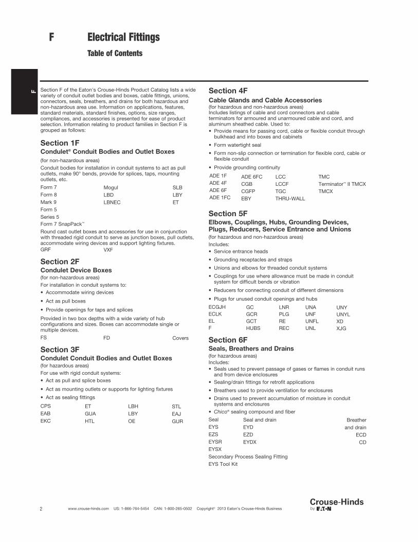
Section F of the Eaton's Crouse-Hinds Product Catalog lists a widevariety of conduit outlet bodies and boxes, cable fittings, unions,connectors, seals, breathers, and drains for both hazardous andnon-hazardous area use. Information on applications, features,standard materials, standard finishes, options, size ranges,compliances, and accessories is presented for ease of productselection. Information relating to product families in Section F isgrouped as follows:
Section 1FCondulet® Conduit Bodies and Outlet Boxes
(for non-hazardous areas)Conduit bodies for installation in conduit systems to act as pulloutlets, make 90° bends, provide for splices, taps, mountingoutlets, etc.
Form 7 Mogul SLBForm 8 LBD LBYMark 9 LBNEC ETForm 5Series 5Form 7 SnapPack™
Round cast outlet boxes and accessories for use in conjunctionwith threaded rigid conduit to serve as junction boxes, pull outlets,accommodate wiring devices and support lighting fixtures.GRF VXF
Section 2FCondulet Device Boxes(for non-hazardous areas)For installation in conduit systems to:• Accommodate wiring devices
• Act as pull boxes
• Provide openings for taps and splices
Provided in two box depths with a wide variety of hubconfigurations and sizes. Boxes can accommodate single ormultiple devices.FS FD Covers
Section 3FCondulet Conduit Bodies and Outlet Boxes(for hazardous areas)For use with rigid conduit systems:• Act as pull and splice boxes
• Act as mounting outlets or supports for lighting fixtures
• Act as sealing fittings
CPS ET LBH STLEAB GUA LBY EAJEKC HTL OE GUR
Section 5FElbows, Couplings, Hubs, Grounding Devices,Plugs, Reducers, Service Entrance and Unions
(for hazardous and non-hazardous areas)Includes:• Service entrance heads
• Grounding receptacles and straps
• Unions and elbows for threaded conduit systems
• Couplings for use where allowance must be made in conduitsystem for difficult bends or vibration
• Reducers for connecting conduit of different dimensions
• Plugs for unused conduit openings and hubs
ECGJH GC LNR UNA UNYECLK GCR PLG UNF UNYLEL GCT RE UNFL XDF HUBS REC UNL XJG
Section 6FSeals, Breathers and Drains(for hazardous areas)Includes:• Seals used to prevent passage of gases or flames in conduit runs
and from device enclosures• Sealing/drain fittings for retrofit applications
• Breathers used to provide ventilation for enclosures
• Drains used to prevent accumulation of moisture in conduitsystems and enclosures
• Chico® sealing compound and fiber
Seal Seal and drain BreatherEYS EYD and drainEZS EZD ECDEYSR EYDX CDEYSXSecondary Process Sealing FittingEYS Tool Kit
F Section 4F
Cable Glands and Cable Accessories(for hazardous and non-hazardous areas)Includes listings of cable and cord connectors and cableterminators for armoured and unarmoured cable and cord, andaluminum sheathed cable. Used to:• Provide means for passing cord, cable or flexible conduit through
bulkhead and into boxes and cabinets
• Form watertight seal
• Form non-slip connection or termination for flexible cord, cable orflexible conduit
• Provide grounding continuity
ADE 1F ADE 6FC LCC TMCADE 4F CGB LCCF Terminator™ II TMCXADE 6F CGFP TGC TMCXADE 1FC EBY THRU-WALL

3www.crouse-hinds.com US: 1-866-764-5454 CAN: 1-800-265-0502 Copyright© 2013 Eaton’s Crouse-Hinds Business
1FCondulet® Conduit Bodies and Outlet BoxesNon-Hazardous
1F
1FDescription Page No.
Application/Selection see page 4
Shape Selector Chart see page 5
Conduit Bodies - Cast Iron or Aluminum
Forms 7 & 8, Mark 9, Series 5 and Form 5 see pages 6–81
Form 7 SnapPack™ see page 9
Mogul Series see pages 13–14
LBD Series see page 15
LBNEC Mogul Pulling Elbows see page 16
Covers for Cast Iron or Aluminum Conduit Bodies
Blank
Forms 7 & 8, Mark 9, Series 5 and Form 5 see page 8
Mogul Series see pages 13–14
Gaskets for Cast Iron or Aluminum Conduit Bodies
Forms 7 & 8, Mark 9, Series 5 and Form 5 see page 8
LBD Series see page 15
Mogul Series see pages 13–14
Conduit Bodies, Covers and Gaskets - Stainless Steel see pages 17–27
Condulet® Outlet Boxes
GRF Series see page 19
VXF Series see page 19
Service Entrance Elbows & Tees
ET Tees see page 20
LBY & SLB Elbows see page 20
4 www.crouse-hinds.com US: 1-866-764-5454 CAN: 1-800-265-0502 Copyright© 2013 Eaton’s Crouse-Hinds Business
Application and Selection
Condulet® Conduit Bodies and Outlet Boxes
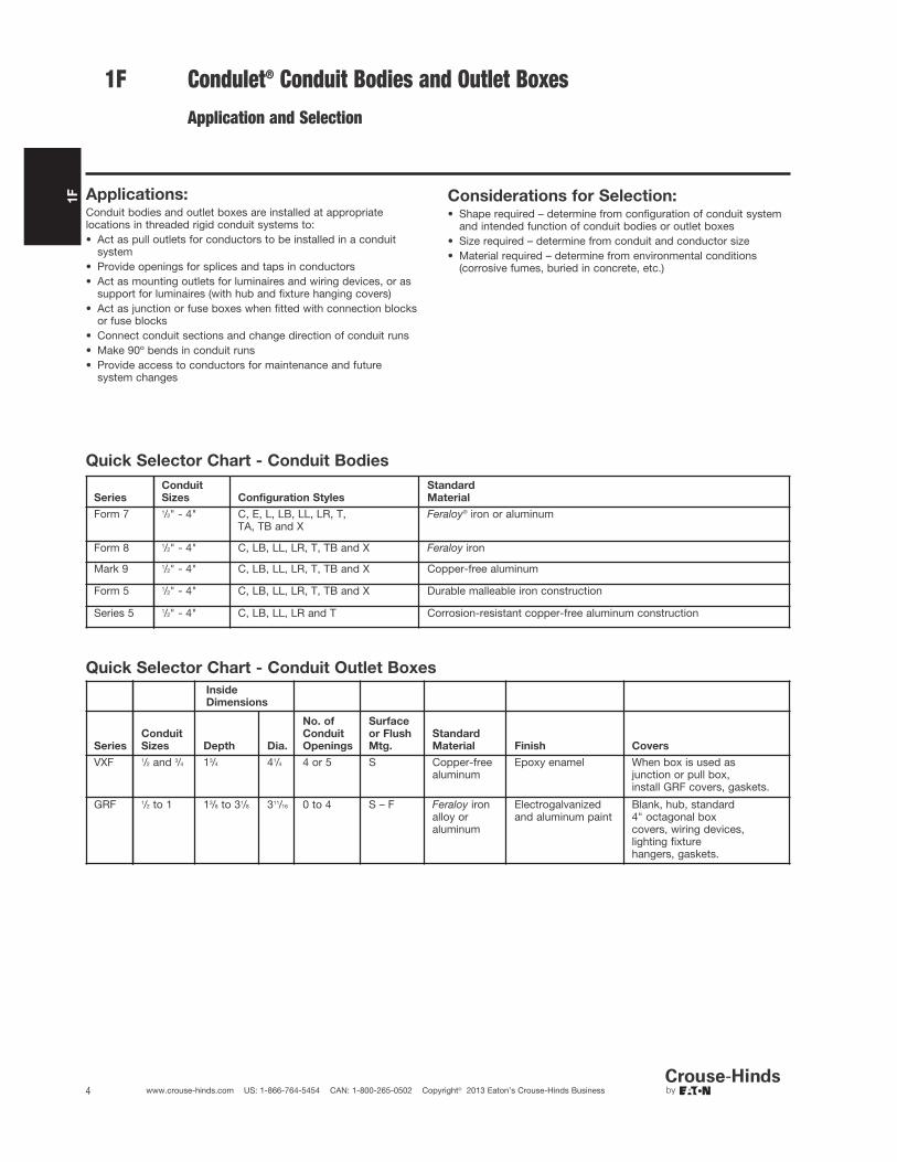
Considerations for Selection:• Shape required – determine from configuration of conduit system
and intended function of conduit bodies or outlet boxes• Size required – determine from conduit and conductor size• Material required – determine from environmental conditions
(corrosive fumes, buried in concrete, etc.)
Quick Selector Chart - Conduit Bodies
Quick Selector Chart - Conduit Outlet Boxes
1F
Series
Conduit
Sizes Configuration Styles
Standard
Material
Form 7 1/2" - 4" C, E, L, LB, LL, LR, T,TA, TB and X
Feraloy® iron or aluminum
Form 8 1/2" - 4" C, LB, LL, LR, T, TB and X Feraloy iron
Mark 9 1/2" - 4" C, LB, LL, LR, T, TB and X Copper-free aluminum
Form 5 1/2" - 4" C, LB, LL, LR, T, TB and X Durable malleable iron construction
Series 5 1/2" - 4" C, LB, LL, LR and T Corrosion-resistant copper-free aluminum construction
Inside
Dimensions
Series
Conduit
Sizes Depth Dia.
No. of
Conduit
Openings
Surface
or Flush
Mtg.
Standard
Material Finish Covers
VXF 1/2 and 3/4 13/4 41/4 4 or 5 S Copper-freealuminum
Epoxy enamel When box is used asjunction or pull box,install GRF covers, gaskets.
GRF 1/2 to 1 13/8 to 31/8 311/16 0 to 4 S – F Feraloy ironalloy oraluminum
Electrogalvanizedand aluminum paint
Blank, hub, standard4" octagonal boxcovers, wiring devices,lighting fixturehangers, gaskets.
Applications:Conduit bodies and outlet boxes are installed at appropriatelocations in threaded rigid conduit systems to:• Act as pull outlets for conductors to be installed in a conduit
system• Provide openings for splices and taps in conductors• Act as mounting outlets for luminaires and wiring devices, or as
support for luminaires (with hub and fixture hanging covers)• Act as junction or fuse boxes when fitted with connection blocks
or fuse blocks• Connect conduit sections and change direction of conduit runs• Make 90º bends in conduit runs• Provide access to conductors for maintenance and future
system changes
1F
5www.crouse-hinds.com US: 1-866-764-5454 CAN: 1-800-265-0502 Copyright© 2013 Eaton’s Crouse-Hinds Business
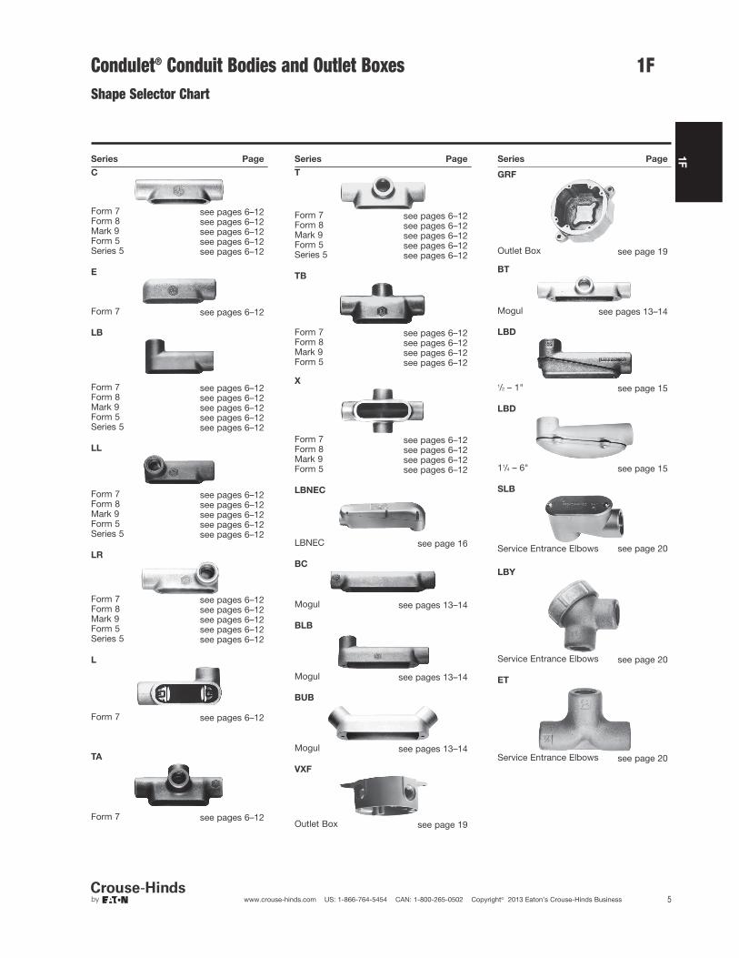
Condulet® Conduit Bodies and Outlet BoxesShape Selector Chart
Series Page
C
Form 7 see pages 6–12Form 8 see pages 6–12Mark 9 see pages 6–12Form 5 see pages 6–12Series 5 see pages 6–12
E
Form 7 see pages 6–12
LB
Form 7 see pages 6–12Form 8 see pages 6–12Mark 9 see pages 6–12Form 5 see pages 6–12Series 5 see pages 6–12
LL
Form 7 see pages 6–12Form 8 see pages 6–12Mark 9 see pages 6–12Form 5 see pages 6–12Series 5 see pages 6–12
LR
Form 7 see pages 6–12Form 8 see pages 6–12Mark 9 see pages 6–12Form 5 see pages 6–12Series 5 see pages 6–12
L
Form 7 see pages 6–12
TA
Form 7 see pages 6–12
Series Page
T
Form 7 see pages 6–12Form 8 see pages 6–12Mark 9 see pages 6–12Form 5 see pages 6–12Series 5 see pages 6–12
TB
Form 7 see pages 6–12Form 8 see pages 6–12Mark 9 see pages 6–12Form 5 see pages 6–12
X
Form 7 see pages 6–12Form 8 see pages 6–12Mark 9 see pages 6–12Form 5 see pages 6–12
LBNEC
LBNEC see page 16
BC
Mogul see pages 13–14
BLB
Mogul see pages 13–14
BUB
Mogul see pages 13–14
VXF
Outlet Box see page 19
GRF
Series Page
Outlet Box see page 19
BT
Mogul see pages 13–14
LBD
1/2 – 1" see page 15
LBD
11/4 – 6" see page 15
SLB
Service Entrance Elbows see page 20
LBY
Service Entrance Elbows see page 20
ET
Service Entrance Elbows see page 20
1F1F

1F
6 www.crouse-hinds.com US: 1-866-764-5454 CAN: 1-800-265-0502 Copyright© 2013 Eaton’s Crouse-Hinds Business
1F Condulet® Conduit Bodies - Cast Iron or AluminumGasket and Covers see page 8
Applications:Conduit outlet bodies are installed in conduit systems to:
• Act as pull outlets for conductors being installed
• Provide openings for making splices and taps in conductors
• Connect conduit sections
• Provide taps for branch conduit runs
• Make 90° bends in conduit runs
• Provide for access to conductors for maintenance and futuresystem changes
Features:
Conduit Outlet Bodies• Form 7 Condulet outlet bodies approach conduit in size for neat,
compact installations
• Form 8 and Mark 9 bodies provide more room for heavierconductors
• Many shapes and sizes are available for rigid threaded conduit –for complete listings see pages 6–12
• Conduit hubs have tapered threads and feature integral bushingsfor protection of wire insulation
• Form 7 has exclusive snaptight and wedgenut cover attachment toprovide clear, unobstructed cover opening
• Built-in rollers on all Form 5 11/4" to 4" C and LB bodies to facilitate wire pulling
• Series 5 bodies available in optional configuration with set screwson hubs for EMT conduit (add suffix -MT to catalog number)
GasketsSolid gaskets:
• Are used with blank covers
• For Mark 9 and Form 5, can be converted to open type gaskets bytearing out center section along scored lines – 1/2" to 2" sizes
• For Form 7 are used with all covers
Open gaskets:
• For Form 8 – 1/2" to 4" sizes
• For Mark 9 – 21/2" to 4" sizes
Blank CoversStainless steel cover screws are standard on Form 7, Form 8, Mark 9, Series 5 and Form 5 covers.
• Form 7
Wedge nut design facilitates installation and removal. Nuts are heldcaptive in cover. Covers can be used with or without gaskets.SNAPTIGHT™ Form 7 Covers with integral sealing gaskets areinstalled without the use of screws, reducing installation time andcosts. Covers are reusable.
• Form 8
Two cover screws provided on all sizes to provide tight cover andgasket assembly. Feraloy iron alloy covers have dome shapes foradded strength and extra wiring room.
• Mark 9
Self-retaining cover screws.
Standard Materials:• Form 7, Form 8 outlet bodies – Feraloy iron alloy• Mark 9 outlet bodies – copper-free aluminum• Form 5 – malleable iron• Series 5 – die cast aluminum
Standard Finishes:• Form 7, Form 8 outlet bodies – electrogalvanized with aluminum
acrylic paint• Mark 9 outlet bodies – natural• Form 5 – electrogalvanized with aluminum acrylic paint• Series 5 – aluminum acrylic paint
Options:Description Suffix
Form 7 body and cover only:Copper-free aluminum . . . . . . . . . . . . . . . . . . . . . . . . . . . . . . . . SACorro-free™ epoxy powder coat - external body only . . . . . . . . . S752Corro-free™ epoxy powder coat - internal and external . . . . . . . S753Series 5 in an EMT version with set screws on all hubs . . . . . . . MTSeries 5 pre-packaged with neoprene gasket and cover . . . . . . CGN
Certifications and Compliances:Outlet Bodies –• UL Standard: 514B• Fed. Spec.: W-C-586D• CSA Standard 22.2 No. 18• NEMA 3R Raintight (when installed with cover and gasket)
Form 7
Mark 9
Form 8
Mogul

1F
7www.crouse-hinds.com US: 1-866-764-5454 CAN: 1-800-265-0502 Copyright© 2013 Eaton’s Crouse-Hinds Business
Condulet® Conduit Bodies - Cast Iron or AluminumDimensions Pgs. See pages 10–12 (Dimensions for Form 5 – see Section CP)
Threaded Rigid BodiesHub Size
Shape Style 1/23/4 1 11/4 11/2 2 21/2 3 31/2 4
C
Form 7 C17 C27 C37 C47 C57 C67 C77 C87Form 8 C18 C28 C38 C448 C58 C68 C78 C88Mark 9 C19 C29 C39 C49 C59 C69 C789 C889 C989 C1089Form 5 C50M C75M C100M C125M* C150M* C200M* C250M* C300M* C350M* C400M*Series 5 C15 C25 C35 C45 C55 C65 C75 C85 C95* C105*
E
Form 7 E17 E27 E37
L
Form 7 L17 L27 L37 L47 L57 L67
Double faced – may be used as LL or LR – has 2 openings, one of which is furnished with a blank sheet steel cover
LB
Form 7 LB17 LB27 LB37 LB47 LB57 LB67 LB777 LB87 LB97 LB107Form 8 LB18 LB28 LB38 LB448 LB58 LB68 LB78 LB888 LB98 LB108Mark 9 LB19 LB29 LB39 LB49 LB59 LB69 LB789 LB889 LB989 LB1089Form 5 LB50M LB75M LB100M LB125M* LB150M* LB200M* LB250M* LB300M* LB350M* LB400M*Series 5 LB15 LB25 LB35 LB45 LB55 LB65 LB75 LB85 LB95 LB105
LL
Form 7 LL17 LL27 LL37 LL47 LL57 LL67 LL777 LL87 LL97 LL107Form 8 LL18 LL28 LL38 LL448 LL58 LL68 LL78 LL888Mark 9 LL19 LL29 LL39 LL49 LL59 LL69 LL789 LL889 LL989 LL1089Form 5 LL50M LL75M LL100M LL125M LL150M LL200M LL250M LL300M LL350M LL400MSeries 5 LL15 LL25 LL35 LL45 LL55 LL65 LL75 LL85 LL95 LL105
LR
Form 7 LR17 LR27 LR37 LR47 LR57 LR67 LR777 LR87 LR97 LR107Form 8 LR18 LR28 LR38 LR448 LR58 LR68 LR78 LR888Mark 9 LR19 LR29 LR39 LR49 LR59 LR69 LR789 LR889 LR989 LR1089Form 5 LR50M LR75M LR100M LR125M LR150M LR200M LR250M LR300M LR350M LR400MSeries 5 LR15 LR25 LR35 LR45 LR55 LR65 LR75 LR85 LR95 LR105
T
Form 7 T17 T27 T37 T47 T57 T67 T77 T87 T97 T107Form 8 T18 T28 T38 T448 T58 T68 T78 T88Mark 9 T19 T29 T39 T49 T59 T69 T789 T889 T989 T1089Form 5 T50M T75M T100M T125M T150M T200M T250M T300M T350M T400MSeries 5 T15 T25 T35 T45 T55 T65 T75 T85 T95* T105*
TA
Form 7 TA17 TA27 TA37 TA47 TA57 TA67
TB
Form 7 TB17 TB27 TB37 TB47 TB57 TB67Form 8 TB18 TB28 TB38 TB448 TB58 TB68Mark 9 TB19 TB29 TB39 TB49 TB59 TB69
Form 5 TB50M TB75M TB100M TB125M TB150M TB200M
1F
* 11/4" - 4" Form 5 LB and C bodies are supplied with built-in rollers to facilitate wire pulling.
Series 5 TB15 TB25 TB35 TB45 TB55 TB65
X
Form 7 X17 X27 X37 X47 X57 X67Form 8 X18 X28 X38 X448 X58 X68Mark 9 X19 X29 X39
Form 5 X50M X75M X100M X125M X150M X200MSeries 5 X15 X25 X35 X45 X55 X65
1F
8 www.crouse-hinds.com US: 1-866-764-5454 CAN: 1-800-265-0502 Copyright© 2013 Eaton’s Crouse-Hinds Business
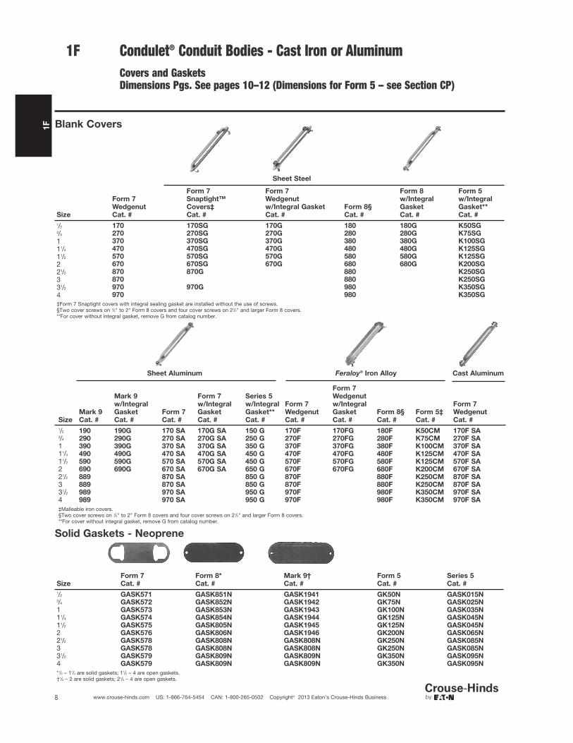
1F Condulet® Conduit Bodies - Cast Iron or AluminumCovers and GasketsDimensions Pgs. See pages 10–12 (Dimensions for Form 5 – see Section CP)
Blank Covers
Sheet Steel
Size
Form 7
Wedgenut
Cat. #
Form 7
Snaptight™
Covers‡
Cat. #
Form 7
Wedgenut
w/Integral Gasket
Cat. #
Form 8§
Cat. #
Form 8
w/Integral
Gasket
Cat. #
Form 5
w/Integral
Gasket**
Cat. #
1/2 170 170SG 170G 180 180G K50SG3/4 270 270SG 270G 280 280G K75SG
1 370 370SG 370G 380 380G K100SG
11/4 470 470SG 470G 480 480G K125SG
11/2 570 570SG 570G 580 580G K125SG
2 670 670SG 670G 680 680G K200SG
21/2 870 870G 880 K250SG
3 870 880 K250SG
31/2 970 970G 980 K350SG
4 970 980 K350SG
‡Form 7 Snaptight covers with integral sealing gasket are installed without the use of screws.§Two cover screws on 1/2" to 2" Form 8 covers and four cover screws on 21/2" and larger Form 8 covers.**For cover without integral gasket, remove G from catalog number.
Sheet Aluminum Feraloy® Iron Alloy Cast Aluminum
Solid Gaskets - Neoprene
Size
Form 7
Cat. #
Form 8*
Cat. #
Mark 9†
Cat. #
Form 5
Cat. #
Series 5
Cat. #
1/2 GASK571 GASK851N GASK1941 GK50N GASK015N3/4 GASK572 GASK852N GASK1942 GK75N GASK025N1 GASK573 GASK853N GASK1943 GK100N GASK035N11/4 GASK574 GASK854N GASK1944 GK125N GASK045N11/2 GASK575 GASK805N GASK1945 GK125N GASK045N2 GASK576 GASK806N GASK1946 GK200N GASK065N21/2 GASK578 GASK808N GASK808N GK250N GASK085N3 GASK578 GASK808N GASK808N GK250N GASK085N31/2 GASK579 GASK809N GASK809N GK350N GASK095N4 GASK579 GASK809N GASK809N GK350N GASK095N
*1/2 – 11/4 are solid gaskets; 11/2 – 4 are open gaskets.†1/2 – 2 are solid gaskets; 21/2 – 4 are open gaskets.
Size
Mark 9
Cat. #
Mark 9
w/Integral
Gasket
Cat. #
Form 7
Cat. #
Form 7
w/Integral
Gasket
Cat. #
Series 5
w/Integral
Gasket**
Cat. #
Form 7
Wedgenut
Cat. #
Form 7
Wedgenut
w/Integral
Gasket
Cat. #
Form 8§
Cat. #
Form 5‡
Cat. #
Form 7
Wedgenut
Cat. #
1/2 190 190G 170 SA 170G SA 150 G 170F 170FG 180F K50CM 170F SA3/4 290 290G 270 SA 270G SA 250 G 270F 270FG 280F K75CM 270F SA1 390 390G 370 SA 370G SA 350 G 370F 370FG 380F K100CM 370F SA11/4 490 490G 470 SA 470G SA 450 G 470F 470FG 480F K125CM 470F SA11/2 590 590G 570 SA 570G SA 450 G 570F 570FG 580F K125CM 570F SA2 690 690G 670 SA 670G SA 650 G 670F 670FG 680F K200CM 670F SA21/2 889 870 SA 850 G 870F 880F K250CM 870F SA3 889 870 SA 850 G 870F 880F K250CM 870F SA31/2 989 970 SA 950 G 970F 980F K350CM 970F SA4 989 970 SA 950 G 970F 980F K350CM 970F SA
‡Malleable iron covers.§Two cover screws on 1/2" to 2" Form 8 covers and four cover screws on 21/2" and larger Form 8 covers.**For cover without integral gasket, remove G from catalog number.

1F
9www.crouse-hinds.com US: 1-866-764-5454 CAN: 1-800-265-0502 Copyright© 2013 Eaton’s Crouse-Hinds Business
1FCondulet® Conduit Bodies - Cast Iron or AluminumForm 7 SnapPack™
Pre-Assembled Body, Gasket and Cover
Applications:Form 7 Condulets are installed in conduitsystems to:
• Act as pull outlets for conductors beinginstalled
• Provide an opening for making splicesand taps in conductors
• Connect conduit sections
• Provide taps for branch conduit runs
• Make 90-degree bends in conduit runs
• Provide access to conductors in aconduit system for maintenance andfuture system changes
Features:• All SnapPack product is individually bar
coded to facilitate more efficientinventory control
• Distributors and end-users need tostock a single SKU instead of threeseparate component numbers – orderthe body, cover and gasket with onecatalog number – saving transactioncosts, and making product selection and merchandising fast and easy
• Form 7 conduit bodies are compact witha round back design for neat, efficientinstallations
• Conduit hubs have tapered threads andintegral bushings for protection of wireinsulation
• Many shapes and trade sizes available
• Sheet-steel wedge nut cover is providedwith integral gasket. The wedge nutdesign facilitates installation andremoval. Nuts and screws are heldcaptive in cover
• Cover screws are stainless steel with acombination slotted and Phillips head,for easy installation and superiorcorrosion protection
Standard Materials:• Body – Feraloy® iron alloy
• Gasket – urethane
• Cover – sheet steel
• Cover screws – stainless steel
Standard Finishes:• Feraloy – electrogalvanized with
aluminum acrylic paint
• Sheet steel – electrogalvanized
Certifications andCompliances:• UL Standard: 514B
• CSA Standard: C22.2 No. 18
Trade
Size Shape Cat. #
1/2" C C17 CG3/4" C C27 CG
1" C C37 CG
11/4" C C47 CG
11/2" C C57 CG
2" C C67 CG
1/2" LB LB17 CG3/4" LB LB27 CG
1" LB LB37 CG
11/4" LB LB47 CG
11/2" LB LB57 CG
2" LB LB67 CG
1/2" LL LL17 CG3/4" LL LL27 CG
1" LL LL37 CG
11/4" LL LL47 CG
11/2" LL LL57 CG
2" LL LL67 CG
1/2" LR LR17 CG3/4" LR LR27 CG
1" LR LR37 CG
11/4" LR LR47 CG
11/2" LR LR57 CG2" LR LR67 CG
1/2" T T17 CG3/4" T T27 CG
1" T T37 CG
11/4" T T47 CG
11/2" T T57 CG
2" T T67 CG
1/2" TB TB17 CG3/4" TB TB27 CG
1" TB TB37 CG
11/4" TB TB47 CG
11/2" TB TB57 CG
2" TB TB67 CG
1/2" X X17 CG3/4" X X27 CG
1" X X37 CG
11/4" X X47 CG
11/2" X X57 CG
2" X X67 CG
Form 7 Condulets and covers are available in additional configurations, sizes andmaterials. For a complete listing of Form 7, Form 8 and Mark 9 conduit bodies andcovers see pages 6–12.
Ordering Information

1F
10 www.crouse-hinds.com US: 1-866-764-5454 CAN: 1-800-265-0502 Copyright© 2013 Eaton’s Crouse-Hinds Business
1F Condulet® Conduit Bodies - Cast Iron or AluminumDimensions (In Inches)
C
Form 7 CSize 1/2
3/4 1 11/4 11/2 2 21/2 3
a 53/8 6 7 77/16 83/16 93/16 12 113/4
b 13/8 15/8 17/8 25/16 29/16 31/8 35/8 43/8
c 13/8 19/16 13/4 23/16 27/16 3 41/4 41/4
d 15/16 11/8 13/8 13/4 115/16 27/16 39/16 39/16
e 33/16 313/16 41/2 5 57/16 63/8 83/8 83/8
Form 8 CSize 1/2
3/4 1 11/4 11/2 2 21/2 3
a 511/16 69/32 75/16 81/2 103/8 121/4 155/8 155/8
b 17/16 111/16 115/16 23/8 225/32 39/16 47/16 413/16
c 13/8 13/16 13/4 23/16 23/4 33/4 5 5d 1 13/16 13/8 13/4 21/8 3 41/4 41/4
e 35/16 315/16 49/16 55/16 61/2 89/16 107/8 107/8
Mark 9 CSize 1/2
3/4 1 11/4 11/2 2 21/2 3 31/2 4
a 5 511/16 619/32 71/2 81/4 101/2 155/8 155/8 183/4 183/4
b 13/8 15/8 17/8 21/2 23/4 37/16 47/16 413/16 511/16 515/16
c 13/8 19/16 13/4 23/16 21/2 33/16 5 5 61/4 61/4
d 13/16 13/8 11/2 115/16 21/4 27/8 41/4 41/4 57/16 57/16
e 35/16 315/16 49/16 55/16 6 81/16 107/8 107/8 137/16 137/16
E
Form 7 ESize 1/2
3/4 1
a 49/16 53/16 6b 13/8 15/8 17/8
c 13/8 19/16 13/4
d 15/16 11/8 13/8
e 33/16 313/16 41/2
L
Form 7 LSize 1/2
3/4 1 11/4 11/2 2
a 49/16 53/16 6 61/2 71/8 31/8
b 13/8 15/8 17/8 25/16 29/16 31/8
c 21/4 27/16 23/4 33/16 39/16 41/8
d 15/16 11/8 13/8 13/4 115/16 27/16
e 33/16 313/16 41/2 5 57/16 63/8
1F
11www.crouse-hinds.com US: 1-866-764-5454 CAN: 1-800-265-0502 Copyright© 2013 Eaton’s Crouse-Hinds Business
Dimensions (In Inches)
1F
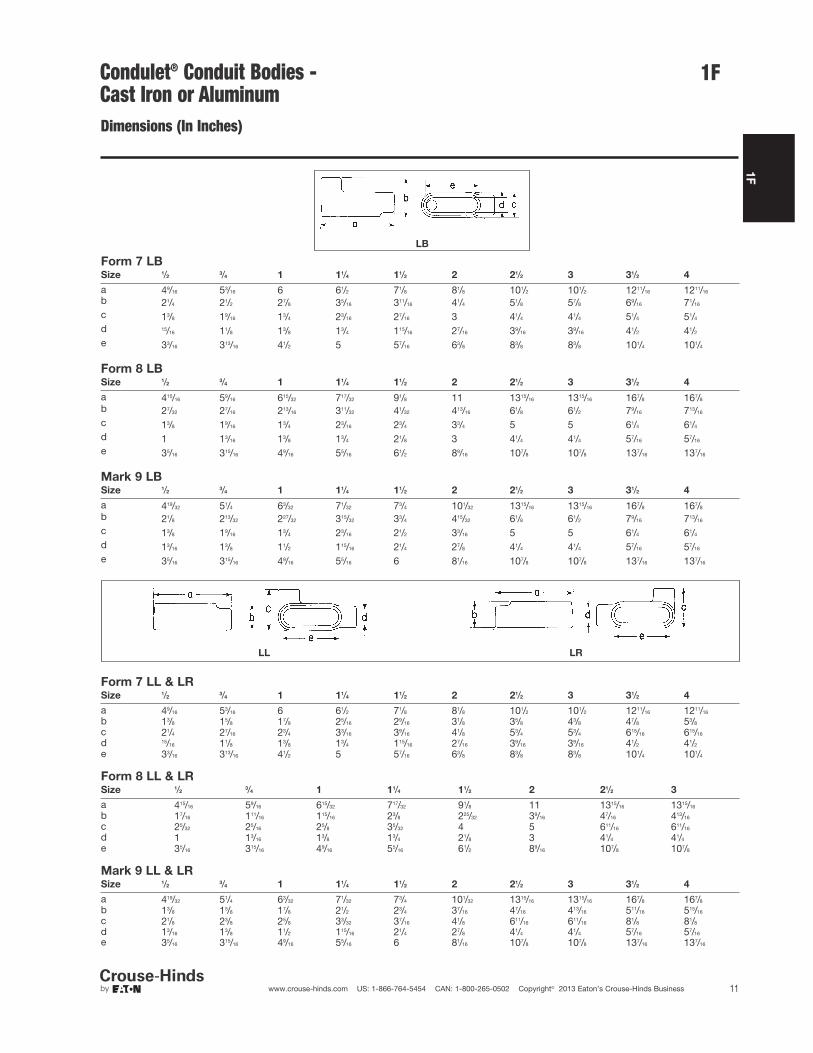
Form 7 LBSize 1/2
3/4 1 11/4 11/2 2 21/2 3 31/2 4
a 49/16 53/16 6 61/2 71/8 81/8 101/2 101/2 1211/16 1211/16
21/4 21/2 27/8 35/16 311/16 41/4 51/8 57/8 69/16 71/16
c 13/8 19/16 13/4 23/16 27/16 3 41/4 41/4 51/4 51/4
d 15/16 11/8 13/8 13/4 115/16 27/16 39/16 39/16 41/2 41/2
e 33/16 313/16 41/2 5 57/16 63/8 83/8 83/8 101/4 101/4
Form 8 LBSize 1/2
3/4 1 11/4 11/2 2 21/2 3 31/2 4
a 415/16 59/16 615/32 717/32 91/8 11 1315/16 1315/16 167/8 167/8
b 27/32 27/16 213/16 311/32 41/32 413/16 61/8 61/2 79/16 713/16
c 13/8 19/16 13/4 23/16 23/4 33/4 5 5 61/4 61/4
d 1 13/16 13/8 13/4 21/8 3 41/4 41/4 57/16 57/16
e 35/16 315/16 49/16 55/16 61/2 89/16 107/8 107/8 137/16 137/16
Mark 9 LBSize 1/2
3/4 1 11/4 11/2 2 21/2 3 31/2 4
a 419/32 51/4 63/32 71/32 73/4 101/32 1315/16 1315/16 167/8 167/8
b 21/8 213/32 227/32 315/32 33/4 415/32 61/8 61/2 79/16 713/16
c 13/8 19/16 13/4 23/16 21/2 33/16 5 5 61/4 61/4
d 13/16 13/8 11/2 115/16 21/4 27/8 41/4 41/4 57/16 57/16
e 35/16 315/16 49/16 55/16 6 81/16 107/8 107/8 137/16 137/16
Form 7 LL & LRSize 1/2
3/4 1 11/4 11/2 2 21/2 3 31/2 4
a 49/16 53/16 6 61/2 71/8 81/8 101/2 101/2 1211/16 1211/16
b 13/8 15/8 17/8 25/16 29/16 31/8 35/8 43/8 47/8 53/8
c 21/4 27/16 23/4 33/16 39/16 41/8 53/4 53/4 615/16 615/16
d 15/16 11/8 13/8 13/4 115/16 27/16 39/16 39/16 41/2 41/2
e 33/16 313/16 41/2 5 57/16 63/8 83/8 83/8 101/4 101/4
Form 8 LL & LRSize 1/2
3/4 1 11/4 11/2 2 21/2 3
a 415/16 59/16 615/32 717/32 91/8 11 1315/16 1315/16
b 17/16 111/16 115/16 23/8 225/32 39/16 47/16 413/16
c 25/32 25/16 25/8 35/32 4 5 611/16 611/16
d 1 13/16 13/8 13/4 21/8 3 41/4 41/4
e 35/16 315/16 49/16 55/16 61/2 89/16 107/8 107/8
Mark 9 LL & LRSize 1/2
3/4 1 11/4 11/2 2 21/2 3 31/2 4
a 419/32 51/4 63/32 71/32 73/4 101/32 1315/16 1315/16 167/8 167/8
b 13/8 15/8 17/8 21/2 23/4 37/16 47/16 413/16 511/16 515/16
c 21/8 23/8 25/8 33/32 37/16 41/8 611/16 611/16 81/8 81/8
d 13/16 13/8 11/2 115/16 21/4 27/8 41/4 41/4 57/16 57/16
e 35/16 315/16 49/16 55/16 6 81/16 107/8 107/8 137/16 137/16
Condulet® Conduit Bodies - Cast Iron or Aluminum
b
LB
LL LR
TA
1F
12 www.crouse-hinds.com US: 1-866-764-5454 CAN: 1-800-265-0502 Copyright© 2013 Eaton’s Crouse-Hinds Business
1F
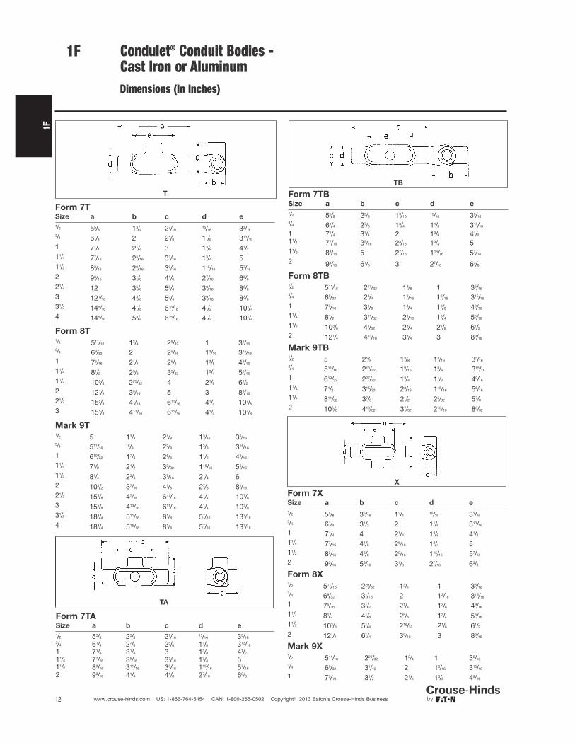
T
Form 7TSize a b c d e
1/2 55/8 13/4 27/1615/16 33/16
3/4 61/4 2 25/8 11/8 313/16
1 71/4 21/4 3 13/8 41/2
11/4 77/16 25/16 33/16 13/4 511/2 83/16 29/16 39/16 115/16 57/16
2 93/16 31/8 41/8 27/16 63/8
21/2 12 35/8 53/4 39/16 83/8
3 121/16 43/8 53/4 39/16 83/8
31/2 145/16 47/8 615/16 41/2 101/4
4 145/16 53/8 615/16 41/2 101/4
Form 8T1/2 511/16 13/4 25/32 1 35/16
3/4 69/32 2 25/16 13/16 315/16
1 75/16 21/4 25/8 13/8 49/16
11/4 81/2 25/8 35/32 13/4 55/16
11/2 103/8 225/32 4 21/8 61/2
2 121/4 39/16 5 3 89/16
21/2 155/8 47/16 611/16 41/4 107/8
3 155/8 413/16 611/16 41/4 107/8
Mark 9T1/2 5 13/8 21/8 13/16 35/16
3/4 511/1615/8 23/8 13/8 315/16
1 619/32 17/8 25/8 11/2 49/16
11/4 71/2 21/2 33/32 115/16 55/16
11/2 81/4 23/4 37/16 21/4 62 101/2 37/16 41/8 27/8 81/16
21/2 155/8 47/16 611/16 41/4 107/8
3 155/8 413/16 611/16 41/4 107/8
31/2 183/4 511/16 81/8 57/16 137/16
4 183/4 515/16 81/8 57/16 137/16
Form 7TASize a b c d e
1/2 55/8 25/8 27/1615/16 33/16
3/4 61/4 27/8 25/8 11/8 313/16
1 71/4 31/4 3 13/8 41/2
11/4 77/16 35/16 33/16 13/4 511/2 83/16 311/16 39/16 115/16 57/16
2 93/16 41/4 41/8 27/16 63/8
Condulet® Conduit Bodies - Cast Iron or Aluminum
Form 7TBSize a b c d e
1/2 55/8 25/8 19/1615/16 33/16
3/4 61/4 27/8 13/4 11/8 313/16
1 71/4 31/4 2 13/8 41/2
11/4 77/16 35/16 23/16 13/4 511/2 83/16 5 27/16 115/16 57/16
2 93/16 61/8 3 27/16 63/8
Form 8TB1/2 511/16 217/32 13/8 1 35/16
3/4 69/32 23/4 19/16 13/16 315/16
1 75/16 31/8 13/4 13/8 49/16
11/4 81/2 311/32 23/16 13/4 55/16
11/2 103/8 41/32 23/4 21/8 61/2
2 121/4 413/16 33/4 3 89/16
Mark 9TB1/2 5 21/8 13/8 13/16 35/16
3/4 511/16 213/32 19/16 13/8 315/16
1 619/32 227/32 13/4 11/2 49/16
11/4 71/2 315/32 23/16 115/16 55/16
11/2 811/32 37/8 21/2 25/32 57/8
2 105/8 419/32 37/32 213/16 83/32
Form 7XSize a b c d e
1/2 55/8 35/16 13/415/16 33/16
3/4 61/4 31/2 2 11/8 313/16
1 71/4 4 21/4 13/8 41/2
11/4 77/16 41/8 25/16 13/4 511/2 83/16 45/8 29/16 115/16 57/16
2 93/16 53/16 31/8 27/16 63/8
Form 8X1/2 511/16 229/32 13/4 1 35/16
3/4 69/32 31/16 2 13/16 315/16
1 75/16 31/2 21/4 13/8 49/16
11/4 81/2 41/8 25/8 13/4 55/16
11/2 103/8 51/4 215/32 21/8 61/2
2 121/4 61/4 39/16 3 89/16
Mark 9X1/2 511/16 229/32 13/4 1 35/16
3/4 69/32 31/16 2 13/16 315/16
1 75/16 31/2 21/4 13/8 49/16
TB
X
Dimensions (In Inches)

1F
13www.crouse-hinds.com US: 1-866-764-5454 CAN: 1-800-265-0502 Copyright© 2013 Eaton’s Crouse-Hinds Business
1F
Mogul Bodies, Covers and Gaskets
Applications:Mogul bodies are installed in conduitsystems to:• Act as pull outlets for conductors that
are stiff, due to large size or type of insulation
• Provide the longer openings neededwhen pulling large conductors
• Prevent sharp bends and kinks in largeconductors (protects insulation duringinstallation)
• Provide ample openings for splices andtaps
• Provide access to wiring formaintenance and future system changes
Standard Materials:• Feraloy® iron alloy
Standard Finishes:• Feraloy – electrogalvanized and
aluminum acrylic paint
Options:Description Suffix
Material – copper-free aluminum SAHot dipped galvanized HDG
Certifications andCompliances:• UL Standard: 514B• Fed. Spec.: W-C-586d• CSA Standard: C22.2 No. 18
BC
Mogul SeriesSize Cat. #
1 BC3
11/4 BC4
11/2 BC5
2 BC6
21/2 BC7
3 BC8
31/2 BC9
4 BC10
BLB†
Mogul SeriesSize Cat. #
1 BLB3
11/4 BLB4
11/2 BLB5
2 BLB6
21/2 BLB7
3 BLB8
31/2 BLB9
4 BLB10
† For 5" size use LBD012.For 6" size use LBD014.
Condulet® Conduit Bodies -Cast Iron or Aluminum
Dimensions
In Inches:
BC BLB
Mogul Series BCSize 1 11/4 11/2 2 21/2 3 31/2 4
a 99/16 99/16 133/4 133/4 183/8 183/8 233/4 233/4
b 17/8 25/16 29/16 31/8 35/8 43/8 47/8 53/8
c 23/16 23/16 3 3 41/4 41/4 51/4 51/4
d 17/8 17/8 25/8 25/8 313/16 313/16 43/4 43/4
e 6 6 10 10 15 15 20 20
Mogul Series BLBSize 1 11/4 11/2 2 21/2 3 31/2 4
a 819/32 819/32 1211/16 1211/16 1629/32 1629/32 221/8 221/8
b 227/32 39/32 35/8 43/16 53/32 527/32 61/2 7c 23/16 23/16 3 3 41/4 41/4 51/4 51/4
d 17/8 17/8 25/8 25/8 313/16 313/16 43/4 43/4
e 6 6 10 10 15 15 20 20
Features:Mogul bodies have:• Long openings• Provision for easy bends• Taper tapped hubs with integral
bushings• Stainless steel cover screws• Covers are designed with integral gasket
1F
14 www.crouse-hinds.com US: 1-866-764-5454 CAN: 1-800-265-0502 Copyright© 2013 Eaton’s Crouse-Hinds Business
1F
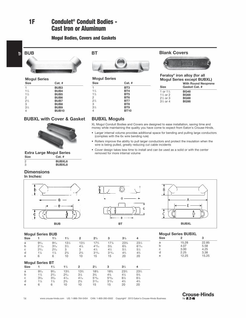
BUB
Mogul SeriesSize Cat. #
1 BUB311/4 BUB411/2 BUB52 BUB621/2 BUB73 BUB831/2 BUB94 BUB10
BT
Mogul Series
Size Cat. #
1 BT311/4 BT411/2 BT52 BT621/2 BT73 BT831/2 BT94 BT10
Blank Covers
Feraloy® iron alloy (for allMogul Series except BUBXL)
Size
With Round Neoprene
Gasket Cat. #
1 or 11/4 BG4811/2 or 2 BG6821/2 or 3 BG8831/2 or 4 BG98
BUBXL with Cover & Gasket
Extra Large Mogul SeriesSize Cat. #
2 BUBXL63 BUBXL8
Condulet® Conduit Bodies - Cast Iron or AluminumMogul Bodies, Covers and Gaskets
BUBXL MogulsXL Mogul Conduit Bodies and Covers are designed to ease installation, saving time andmoney while maintaining the quality you have come to expect from Eaton's Crouse-Hinds.
• Larger internal volume provides additional space for bending and pulling large conductors(complies with the 6x wire bending rule)
• Rollers improve the ability to pull larger conductors and protect the insulation when thewire is being pulled, greatly reducing cut cable incidents
• Cover design takes less time to install and can be used as a solid or with the centerremoved for more internal volume
DimensionsIn Inches:
BUB BT
Mogul Series BUBSize 1 11/4 11/2 2 21/2 3 31/2 4
a 93/16 95/16 131/2 131/2 173/4 177/8 233/8 231/4
b 211/16 33/16 31/2 41/8 413/16 55/8 63/8 613/16
c 23/16 23/16 3 3 41/4 41/4 51/4 51/4
d 17/8 17/8 25/8 25/8 313/16 313/16 43/4 43/4
e 6 6 10 10 15 15 20 20
Mogul Series BTSize 1 11/4 11/2 2 21/2 3 31/2 4
a 99/16 99/16 133/4 133/4 183/8 183/8 233/4 233/4
b 17/8 25/16 29/16 31/8 35/8 43/8 47/8 53/8
c 35/32 35/32 41/16 41/16 519/32 523/32 67/8 67/8
d 17/8 17/8 25/8 25/8 313/16 313/16 43/4 43/4
e 6 6 10 10 15 15 20 20
AE
B
C D
BUBXL
Mogul Series BUBXLSize 2 3
a 15.28 22.85b 4.07 5.58c 3.00 4.25d 2.25 3.38e 12.25 15.25
1F
15www.crouse-hinds.com US: 1-866-764-5454 CAN: 1-800-265-0502 Copyright© 2013 Eaton’s Crouse-Hinds Business
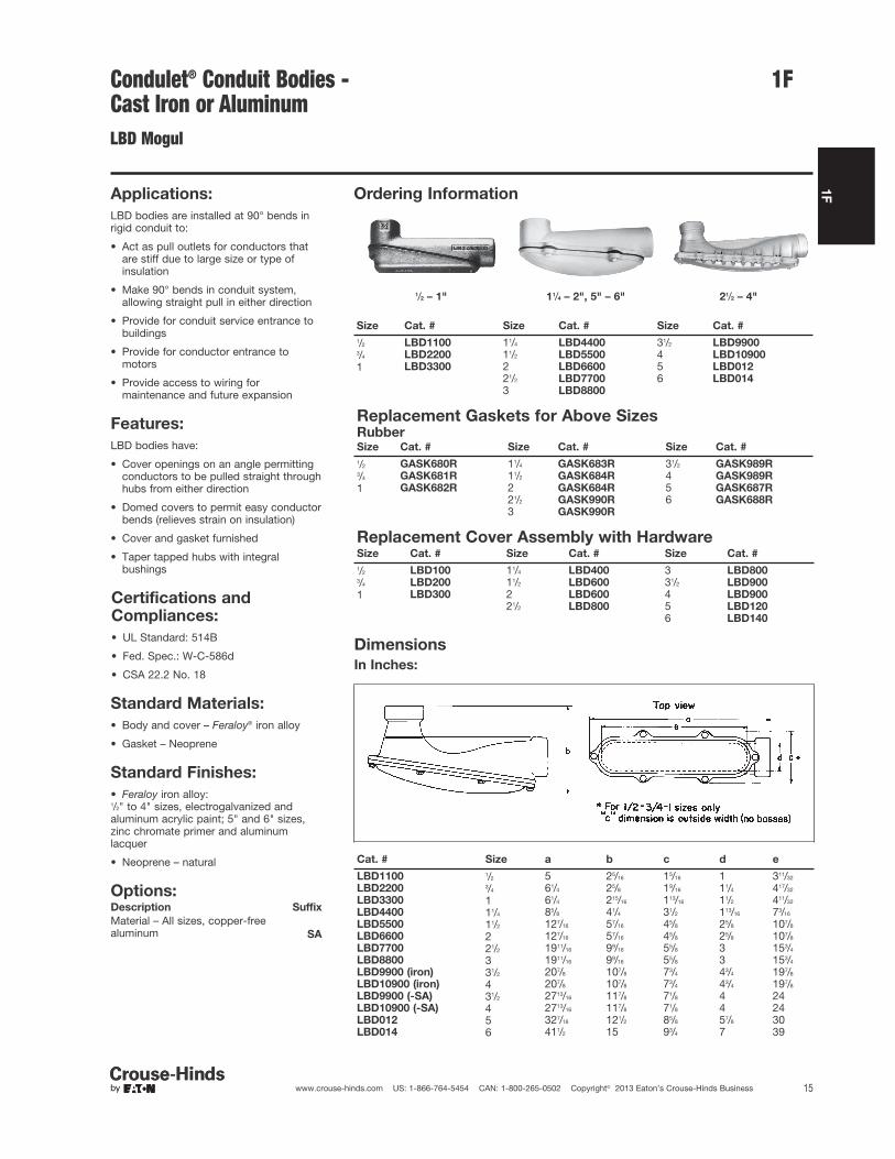
1FCondulet® Conduit Bodies - Cast Iron or AluminumLBD Mogul
Applications:
LBD bodies are installed at 90° bends inrigid conduit to:
• Act as pull outlets for conductors thatare stiff due to large size or type ofinsulation
• Make 90° bends in conduit system,allowing straight pull in either direction
• Provide for conduit service entrance tobuildings
• Provide for conductor entrance tomotors
• Provide access to wiring formaintenance and future expansion
Features:
LBD bodies have:
• Cover openings on an angle permittingconductors to be pulled straight throughhubs from either direction
• Domed covers to permit easy conductorbends (relieves strain on insulation)
• Cover and gasket furnished
• Taper tapped hubs with integralbushings
Standard Materials:
• Body and cover – Feraloy® iron alloy
• Gasket – Neoprene
Standard Finishes:
• Feraloy iron alloy:1/2" to 4" sizes, electrogalvanized andaluminum acrylic paint; 5" and 6" sizes,zinc chromate primer and aluminumlacquer
• Neoprene – natural
Options:Description Suffix
Material – All sizes, copper-freealuminum SA
Certifications andCompliances:
• UL Standard: 514B
• Fed. Spec.: W-C-586d
• CSA 22.2 No. 18
Ordering Information
1/2 – 1" 11/4 – 2", 5" – 6" 21/2 – 4"
Size Cat. # Size Cat. # Size Cat. #
1/2 LBD1100 11/4 LBD4400 31/2 LBD99003/4 LBD2200 11/2 LBD5500 4 LBD10900
1 LBD3300 2 LBD6600 5 LBD01221/2 LBD7700 6 LBD0143 LBD8800
Replacement Gaskets for Above SizesRubberSize Cat. # Size Cat. # Size Cat. #
1/2 GASK680R 11/4 GASK683R 31/2 GASK989R3/4 GASK681R 11/2 GASK684R 4 GASK989R
1 GASK682R 2 GASK684R 5 GASK687R21/2 GASK990R 6 GASK688R3 GASK990R
Replacement Cover Assembly with HardwareSize Cat. # Size Cat. # Size Cat. #
1/2 LBD100 11/4 LBD400 3 LBD8003/4 LBD200 11/2 LBD600 31/2 LBD900
1 LBD300 2 LBD600 4 LBD90021/2 LBD800 5 LBD120
6 LBD140
Dimensions
In Inches:
Cat. # Size a b c d e
LBD1100 1/2 5 25/16 15/16 1 311/32
LBD2200 3/4 61/4 25/8 19/16 11/4 417/32
LBD3300 1 61/4 215/16 113/16 11/2 411/32
LBD4400 11/4 85/8 41/4 31/2 113/16 73/16
LBD5500 11/2 127/16 57/16 45/8 25/8 107/8
LBD6600 2 127/16 57/16 45/8 25/8 107/8
LBD7700 21/2 1911/16 99/16 55/8 3 153/4
LBD8800 3 1911/16 99/16 55/8 3 153/4
LBD9900 (iron) 31/2 207/8 107/8 73/4 43/4 197/8
LBD10900 (iron) 4 207/8 107/8 73/4 43/4 197/8
LBD9900 (-SA) 31/2 2713/16 117/8 71/8 4 24LBD10900 (-SA) 4 2713/16 117/8 71/8 4 24LBD012 5 327/16 121/2 85/8 57/8 30LBD014 6 411/2 15 93/4 7 39

1F
16 www.crouse-hinds.com US: 1-866-764-5454 CAN: 1-800-265-0502 Copyright© 2013 Eaton’s Crouse-Hinds Business
1F Condulet® Conduit Bodies -Cast Iron or AluminumMogul Pulling Elbows
Weather Resistant
Applications:
Die cast mogul pulling elbows are installedin conduit systems to provide:
• An accessible weather resistantchamber for containing heavy dutyconductors
• A chamber for containing 90° turn inlarge stiff conductors. Used either tochange conductor direction or to enterbuildings
• A pull box for pulling large conductors
• A chamber for making splices and taps
• An accessible opening to accommodatefuture changes of the system
Features:
• Large dome cover permits easy, straightthrough pull
• Dimension from centerline of back hubto bushing of end hub exceeds six timesthe trade diameter of the conduit
• Tapered threads provide easy assembly,tight construction
• Heavy duty machine screws for cover
• Cover is gasketed
• Smooth design and finish make handlingeasy and complement any constructionjob
Standard Materials:
• Die cast copper-free aluminum
Standard Finishes:
• Aluminum lacquer
Certifications andCompliances:
• UL Standard: 514A
• NEC: Article 314
• CSA C22.2 No. 18
• CEC: 22.1
LBNEC Furnished With Cover, Gasket and Screws
Size Cat. # Bending Radius
21/2 LBNEC7 51/4
3 LBNEC8 53/4
31/2 LBNEC9 74 LBNEC10 73/8
Dimensions
In Inches:
Cat. # Size a b c
LBNEC7 21/2 2111/16 89/32 41/2
LBNEC8 3 2111/16 89/32 41/2
LBNEC9 31/2 2811/16 97/32 51/2
LBNEC10 4 2811/16 97/32 51/2

1F
17www.crouse-hinds.com US: 1-866-764-5454 CAN: 1-800-265-0502 Copyright© 2013 Eaton’s Crouse-Hinds Business
1FCondulet® Conduit Outlet Bodies,Covers and Gaskets - Stainless Steel
Eaton's Crouse-Hinds Condulet® Stainless Steel Fittings deliver
power where you need it, saving you time and money throughout
the life of your facility.
Superior resistance to corrosion and heat, combined with unmatchedstrength, make stainless steel Condulet bodies and boxes a long-term solution for even the most extreme environments.
Applications:Conduit outlet bodies are installed in conduit systems to:• Act as pull outlets for conductors being installed• Provide openings for making splices and taps in conductors• Act as mounting outlets for lighting fixtures and wiring devices• Connect conduit sections• Provide taps for branch conduit runs• Make 90° bends in conduit runs• Provide for access to conductors for maintenance and future
system changes
Standard Materials:• Bodies - 316 stainless steel• Covers - 316 stainless steel• Cover Screws - 316 stainless steel• Gasket - neoprene
Certifications and Compliances:• UL Standard 514A• CSA Standard C22.2 No. 18.1-04• Raintight - when installed with cover and gasket
Features:• Self-healing properties of stainless steel fittings help reduce the
penetration of rust/corrosion and eliminate damage to the fitting• Stainless steel fittings retain their strength in extreme heat and
extreme cold conditions• Fitting surface is easy to maintain and keep clean• Easy cleaning capabilities make these fittings perfect for food
processing and other hygienic areas where wash downs arecommon
• Superior strength and durability greatly reduce replacement offittings - this will lower your total cost of ownership and increaseyour return on investment
• Stainless steel fittings do not require harsh environment-damagingcleaners to keep them looking like new
• Conduit hubs have tapered threads and feature integral bushingfor protection of wire insulation
• Outlet bodies designed to match conduit size for neat, compactinstallations
DimensionA Overall lengthB Overall heightC Overall widthD Width of openingE Length of opening

1F
18 www.crouse-hinds.com US: 1-866-764-5454 CAN: 1-800-265-0502 Copyright© 2013 Eaton’s Crouse-Hinds Business
1F
Ordering Information - conduit body supplied with cover and gasket
T Conduit Body, Cover and Gasket
LB Conduit Body, Cover and Gasket
TB Conduit Body, Cover and Gasket
C Conduit Body, Cover and Gasket
LR Conduit Body, Cover and Gasket
Condulet® Conduit Outlet Bodies,Covers and Gaskets - Stainless Steel
LL Conduit Body, Cover and Gasket
Catalog
Number
Trade
Size A B C D E
T18SS 1/2" 5.56 1.75 1.31 1.02 3.15T28SS 3/4" 6.61 2.00 1.63 1.27 3.92T38SS 1" 7.53 2.31 1.78 1.42 4.61T48SS 11/4" 8.75 2.50 2.25 1.83 5.50T58SS 11/2" 9.37 2.75 2.47 2.03 6.12T68SS 2" 11.50 3.38 3.13 2.50 8.00T88SS 3" 15.00 4.63 4.34 3.71 10.25T108SS 4" 18.25 5.44 5.50 4.87 13.00
Catalog
Number
Trade
Size A B C D E
LB18SS 1/2" 4.86 1.35 1.31 1.02 3.15LB28SS 3/4" 5.75 1.63 1.63 1.27 3.94LB38SS 1" 6.48 2.00 1.78 1.42 4.55LB48SS 11/4" 7.75 3.50 2.25 1.83 5.50LB58SS 11/2" 8.38 2.75 2.47 2.03 6.13LB68SS 2" 10.50 3.38 3.13 2.50 8.00LB88SS 3" 13.50 6.13 4.34 3.71 10.25LB108SS 4" 16.63 7.25 5.50 4.87 13.00
Catalog
Number Trade Size A B C D E
TB28SS 3/4" 6.61 2.88 1.63 1.27 3.95TB38SS 1" 7.53 3.23 1.78 1.42 4.61TB48SS 11/4" 8.75 3.50 2.25 1.83 5.50TB58SS 11/2" 9.37 3.75 2.47 2.03 6.12TB68SS 2" 11.50 4.38 3.13 2.50 8.00
Catalog
Number
Trade
Size A B C D E
C18SS 1/2" 5.56 1.38 1.31 1.02 3.15C28SS 3/4" 6.56 1.63 1.63 1.27 3.94C38SS 1" 7.50 2.00 1.78 1.42 4.61
Catalog
Number
Trade
Size A B C D E
LL28SS 3/4" 5.72 1.63 1.63 1.27 3.95LL38SS 1" 6.59 2.00 1.78 1.42 4.61
Catalog
Number Trade Size A B C D E
LR28SS 3/4" 5.72 1.63 1.63 1.27 3.95LR38SS 1" 6.59 2.00 1.78 1.42 4.61
1F
19www.crouse-hinds.com US: 1-866-764-5454 CAN: 1-800-265-0502 Copyright© 2013 Eaton’s Crouse-Hinds Business
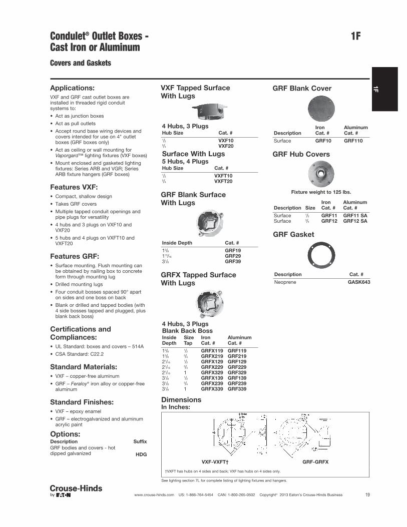
1FCondulet® Outlet Boxes - Cast Iron or AluminumCovers and Gaskets
Applications:
VXF and GRF cast outlet boxes areinstalled in threaded rigid conduit systems to:
• Act as junction boxes
• Act as pull outlets
• Accept round base wiring devices andcovers intended for use on 4" outletboxes (GRF boxes only)
• Act as ceiling or wall mounting forVaporgard™ lighting fixtures (VXF boxes)
• Mount enclosed and gasketed lightingfixtures: Series ARB and VGR; SeriesARB fixture hangers (GRF boxes)
Features VXF:
• Compact, shallow design
• Takes GRF covers
• Multiple tapped conduit openings andpipe plugs for versatility
• 4 hubs and 3 plugs on VXF10 andVXF20
• 5 hubs and 4 plugs on VXFT10 andVXFT20
Features GRF:
• Surface mounting. Flush mounting canbe obtained by nailing box to concreteform through mounting lug
• Drilled mounting lugs
• Four conduit bosses spaced 90° aparton sides and one boss on back
• Blank or drilled and tapped bodies (with4 side bosses tapped and plugged, plusblank back boss)
Standard Materials:
• VXF – copper-free aluminum
• GRF – Feraloy® iron alloy or copper-freealuminum
Standard Finishes:
• VXF – epoxy enamel
• GRF – electrogalvanized and aluminumacrylic paint
Certifications and
Compliances:
• UL Standard: boxes and covers – 514A
• CSA Standard: C22.2
VXF Tapped Surface
With Lugs
4 Hubs, 3 PlugsHub Size Cat. #
1/2 VXF103/4 VXF20
Surface With Lugs5 Hubs, 4 PlugsHub Size Cat. #
1/2 VXFT103/4 VXFT20
GRF Blank Surface
With Lugs
Inside Depth Cat. #
13/8 GRF19115/16 GRF2931/8 GRF39
GRFX Tapped Surface
With Lugs
4 Hubs, 3 PlugsBlank Back BossInside
Depth
Size
Tap
Iron
Cat. #
Aluminum
Cat. #
13/81/2 GRFX119 GRF119
13/83/4 GRFX219 GRF219
21/161/2 GRFX129 GRF129
21/163/4 GRFX229 GRF229
21/16 1 GRFX329 GRF32931/8
1/2 GRFX139 GRF13931/8
3/4 GRFX239 GRF23931/8 1 GRFX339 GRF339
GRF Blank Cover
GRF Hub Covers
Fixture weight to 125 lbs.
Description Size
Iron
Cat. #
Aluminum
Cat. #
Surface 1/2 GRF11 GRF11 SASurface 3/4 GRF12 GRF12 SA
GRF Gasket
Description Cat. #
Neoprene GASK643
DimensionsIn Inches:
VXF-VXFT† GRF-GRFX
†VXFT has hubs on 4 sides and back; VXF has hubs on 4 sides only.
See lighting section 7L for complete listing of lighting fixtures and hangers.
Description
Iron
Cat. #
Aluminum
Cat. #
Surface GRF10 GRF110
Options:Description Suffix
GRF bodies and covers - hotdipped galvanized HDG
1F
20 www.crouse-hinds.com US: 1-866-764-5454 CAN: 1-800-265-0502 Copyright© 2013 Eaton’s Crouse-Hinds Business
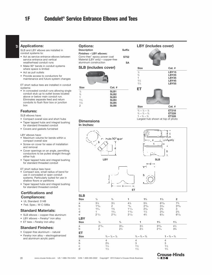
1F Condulet® Service Entrance Elbows and Tees
Applications:SLB and LBY elbows are installed inconduit systems to:• Act as service entrance elbows between
service entrance and verticalweatherhead conduit runs
• Make 90° bends in conduit systemswhere space is limited
• Act as pull outlets• Provide access to conductors for
maintenance and future system changes
ET short radius tees are installed in conduitsystems:• In concealed conduit runs allowing single
conduit stub up to outlet boxes locatedabove or below main conduit run.Eliminates separate feed and returnconduits to flush floor box or junctionbox
Features:SLB elbows have:• Compact overall size and short hubs• Taper tapped hubs and integral bushing
for standard threaded conduit• Covers and gaskets furnished
LBY elbows have:• Maximum volume for bends within a
compact overall size• Screw-on cover for ease of installation
and removal• Cover openings on an angle, permitting
conductors to be pulled straight througheither hub
• Taper tapped hubs and integral bushingfor standard threaded conduit
ET short radius tees have:• Compact size, small radius of bend for
use in concealed or open conduitsystems. Particularly suited for use inshallow floors or partitions
• Taper tapped hubs and integral bushingfor standard threaded conduit
Standard Materials:• SLB elbows – copper–free aluminum• LBY elbows – Feraloy® iron alloy• ET tees – Feraloy iron alloy
Standard Finishes:• Copper-free aluminum – natural• Feraloy iron alloy – electrogalvanized
and aluminum acrylic paint
Options:Description Suffix
Finishes – LBY elbows:
Corro-free™ epoxy power coat S752Material (LBY only) – copper-freealuminum construction SA
Certifications and
Compliances:• UL Standard: 514B• Fed. Spec.: W-C-586a
SLB (includes cover)
Size Cat. #
1/2 SLB13/4 SLB21 SLB311/4 SLB411/2 SLB52 SLB6
LBY (includes cover)
Size Cat. #
1/2 LBY153/4 LBY251 LBY3511/4 LBY4511/2 LBY55
ET
Size Cat. #
3/4 – 1/2 – 1/2 ET2183/4 – 3/4 – 3/4 ET2281 – 3/4 – 3/4 ET328Largest hub shown at top of photo
DimensionsIn Inches:
LBY SLB
ET
SLBSize 1/2
3/4 1 13/4 11/2 2
a 31/8 31/2 41/8 53/8 623/32 73/4
b 125/32 2 19/32 225/32 31/32 329/32
c 13/16 13/8 111/16 23/32 23/8 3d 1 13/16 115/32 17/8 25/32 25/8
e 211/16 215/16 311/32 43/4 61/32 631/32
LBYSize 1/2
3/4 1 13/4 11/2
a 213/16 33/16 31/4 325/32 41/2
b 2 21/4 21/2 215/16 33/8
ETSize 3/4 – 1/2 – 1/2
3/4 – 3/4 – 3/4 1 – 3/4 – 3/4
a 4 4 4b 25/8 3 3c 11/4 11/2 11/2
d 11/2 11/2 13/4

2F
21www.crouse-hinds.com US: 1-866-764-5454 CAN: 1-800-265-0502 Copyright© 2013 Eaton’s Crouse-Hinds Business
Condulet® Device BoxesNon-hazardous
2F
Description Page No.
Application/Selection see page 22
Shape Selector Charts see page 23
Device Boxes - Cast Iron or Aluminum
FS/FD Series
Single gangBlank see pages 31–34
Cast hubs see pages 25–28
Multi-gangBlank see pages 31–34
Cast hubs see pages 29–30
Covers for Cast Iron or Aluminum Device Boxes
WLR and WLG Wet Locations Covers For NEMAConfiguration and GFCI Receptacles
Blank see page 39
Pilot light see page 43
Push button see page 41
Receptacle see page 37
Switch see page 39
Device Boxes and Covers - Stainless Steel
FS/FD Series see pages 35–36
Plugs and Receptacles
DS Series see page 42
DS/WP Series see page 42
FSE Series see page 46

2F
22 www.crouse-hinds.com US: 1-866-764-5454 CAN: 1-800-265-0502 Copyright© 2013 Eaton’s Crouse-Hinds Business
2F Condulet® Cast Device Boxes and Covers
Application and Selection
Applications:Cast device boxes are installed in conduit and cable systems to:
• Accommodate wiring devices
• Act as pull boxes for conductors in a conduit system
• Provide openings to make splices and taps in conductors
• Provide access to conductors for maintenance and future systemchanges
Considerations for Selection of Device Box
Type of conduit system:
• Should be compatible with conduit or cable system.
• Boxes are standard with mounting lugs and internal green groundscrew.
• Boxes are available for rigid steel, IMC; rigid aluminum; flexibleconduit and cable systems.
Number of devices to be used in the box:
• Standard flush devices require one gang each
Depth:
• Two box types are available – standard (FS) and deep (FD), singlethrough five gang.
• Standard flush wiring devices will normally fit in the FS boxes.
• Some special purpose devices of higher ratings will require thedeeper box (FD).
• In addition, the need for additional wiring space will require thedeep box.
Hub configuration and size:
• The layout of the conduit system dictates the conduit openinglocations of the box.
The table below indicates the types of conduit and the boxesavailable. Drilled and tapped openings can be supplied in blankboxes to meet your requirements.
• Hub size is the same as conduit size. A variety of hub sizes areavailable. Where the specific hub size is not available, reducingbushings can be used.
Materials and finishes:
• The environment and the use of the box will determine the materialand finish needed. Areas of the country with harsh weather andcorrosive environments may require different materials and finishesfor added protection.
• Standard material and finish is Feraloy® iron alloy withelectrogalvanized and aluminum acrylic paint. Many items are alsoavailable in copper-free aluminum.
• Optional finishes can be obtained if environment warrants. SeeOptions listings.
Considerations for Selection of Covers,Devices, and Accessories
Both general purpose and weatherproof, waterproof devices andcovers are available. Selection will depend on individual conditions.To provide for a wide variety of applications, the following coversand devices are available:
Covers Pg.General use snap switch see pages 39–41 and 44–45Pushbutton switch see page 41Plug and receptacle see pages 37, 39, 42, and 44–46Blank see pages 39 and 44–45Pilot light see page 43Receptacle see pages 37–39, 42, and 44–46
Devices Pg.
Receptacle see page 42Pilot lights see page 43Wiring device see page 42
Accessories Pg.
Gaskets see page 43Box extensions see page 43Flush mtg. adapter see page 43
Options:Description Suffix
Corro-free™ epoxy powder coat S752
Quick Selector Chart
Box Depth Gang
Conduit
Type
Standard
Material
Standard
Finish
FS 111/16 1-3 Threaded rigid Feraloy iron alloy(some are copper-freealuminum)
Feraloy iron alloy – electrogalvanizedand aluminum acrylic paint.Copper-free aluminum – natural
FD 21/2 1-3 Threaded rigid Feraloy iron alloy Feraloy iron alloy – electrogalvanizedand aluminum acrylic paint
FD-SS 3.03 1 Threaded rigid Stainless steel Natural
FS blank bodies Drilled and tapped
115/16 1-41-3
Threaded rigid Feraloy iron alloy Feraloy iron alloy – electrogalvanizedand aluminum acrylic paint
FD blank bodies Drilled & tapped
21/2 1-51-3
Threaded rigid Feraloy iron alloy Feraloy iron alloy – electrogalvanizedand aluminum acrylic paint
2F
23www.crouse-hinds.com US: 1-866-764-5454 CAN: 1-800-265-0502 Copyright© 2013 Eaton’s Crouse-Hinds Business
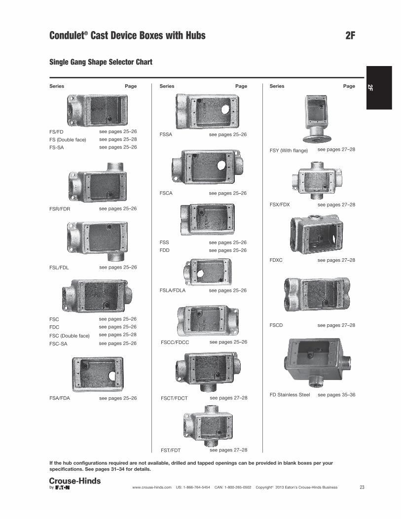
2FCondulet® Cast Device Boxes with Hubs
Single Gang Shape Selector Chart
FS/FD see pages 25–26
FSA/FDA see pages 25–26
FS (Double face) see pages 25–28
FS-SA see pages 25–26
FSR/FDR see pages 25–26
FSSA see pages 25–26
FSL/FDL see pages 25–26
FSCA see pages 25–26
FSC see pages 25–26
FSS see pages 25–26
FDC see pages 25–26
FDD see pages 25–26
FSC (Double face) see pages 25–28
FSC-SA see pages 25–26
FSLA/FDLA see pages 25–26
Series PageSeries PageSeries Page
FSCC/FDCC see pages 25–26
FSX/FDX see pages 27–28
FSCT/FDCT see pages 27–28
FDXC see pages 27–28
FST/FDT see pages 27–28
FSCD see pages 27–28
FSY (With flange) see pages 27–28
FD Stainless Steel see pages 35–36
If the hub configurations required are not available, drilled and tapped openings can be provided in blank boxes per your
specifications. See pages 31–34 for details.

2F
24 www.crouse-hinds.com US: 1-866-764-5454 CAN: 1-800-265-0502 Copyright© 2013 Eaton’s Crouse-Hinds Business
2F
Series Page Series Page Series Page
FSC (Two gang tandem)
see pages 29–30 FSD (Two gang) see pages 29–30 FS/FD (Three gang) see pages 29–30
FS/FD (Two gang) see pages 29–30 FSS/FDS (Two gang) see pages 29–30 FSS (Three gang) see pages 29–30
FSC/FDC (Two gang) see pages 29–30 FSE (Two gang) see pages 29–30
If the hub configurations required are not available, drilled and tapped openings can be provided in blank boxes per your
specifications. See pages 31–34 for details.
Condulet® Cast Device Boxes with Hubs
Multi-Gang Shape Selector Chart

2F
25www.crouse-hinds.com US: 1-866-764-5454 CAN: 1-800-265-0502 Copyright© 2013 Eaton’s Crouse-Hinds Business
2FAccessoriessee pages 37–45
Applications:Cast device boxes are installed to:• Accommodate wiring devices• Act as pull boxes for conductors in a
conduit system• Provide openings to make splices and
taps in conductors• Provide access to conductors for
maintenance and future system changes• Connect conduit sections• FSY boxes for mounting surface devices
on floor or bench (used with single gangcovers)
Features:• Internal green ground screw standard on
boxes• Suitable for use in wet locations when
used with gasketed covers• Mounting lugs standard on most boxes• Tapered threaded hubs (NPT) with
integral bushing• Available for surface mounting (with
mounting lugs) or flush mounting(without mounting lugs) as listed
• Available as shallow (FS) or deep (FD)configuration. Use FD if device to beenclosed exceeds 15/8" in depth
• Ample wiring room provided in either FSor FD configuration
• Wide selection of surface or flush coversavailable in three materials (sheet steel,Feraloy®, aluminum)
• Covers for flush mounting extend toconceal the rough plaster line
• Available in single gang and multi-gangconfigurations with hubs, and as blankbodies for drilled and tapped openings
Standard Materials:• Feraloy iron alloy or copper-free
aluminum.
Standard Finishes:• Feraloy – electrogalvanized and
aluminum acrylic paint• Aluminum – natural
Size Ranges:• Hubs – 1/2" to 1"
Certifications andCompliances:• UL Standard: 514• ANSI Standard: C33.84• Fed. Spec.: W-C-5860• CSA Standard: C22.2 No. 18
FS & FD
Size Cat. # Cat. #
1/2 FSR1 FDR13/4 FSR2 FDR2*†
Size Cat. # Cat. #
1/2 FSC1* FDC1†3/4 FSC2* FDC2†1 FSC3† FDC3†
Size Cat. # Cat. #
1/2 FSL1 FDL13/4 FSL2 FDL2*†
*Available in sand cast copper-free aluminum – addsuffix SCA to Cat. No.†Available in sand cast copper-free aluminum – addsuffix SA to Cat. No.
Die Cast Aluminum‡
Size Cat. # Cat. #
1/2 FS1 SA FSC1 SA3/4 FS2 SA FSC2 SA
‡Mounting lugs and ground screw are not offered withstandard die cast aluminum box. For sand castaluminum box with mounting lugs and ground screw,change "SA" in catalog number to "SCA" (Example: FS1 SCA).
Size Cat. # Cat. #
1/2 FS1* FD1†3/4 FS2* FD2†1 FS3† FD3†
With and Without Mounting Lugs forThreaded Rigid and IMC Conduit
Options:Description Suffix
Finishes:
Corro-free™ epoxy powder coat- external body S752Corro-free™ epoxy powder coat- internal and external S753Hot dipped galvanized HDG
Condulet® Single Gang Device Boxes -Cast Iron or Aluminum

2F
26 www.crouse-hinds.com US: 1-866-764-5454 CAN: 1-800-265-0502 Copyright© 2013 Eaton’s Crouse-Hinds Business
2F
FS & FD
Size Cat. #† Cat. #†
1/2 FSA1 FDA13/4 FSA2 FDA2
Size Cat. #† Cat. #†
1/2 FSS1* FDD13/4 FSS2* FDD2*1 FSS3 FDD3
Size Cat. # Cat. #
1/2 FSCC1 FDCC13/4 FSCC2 FDCC2
Size Cat. #
1/2 FSCA13/4 FSCA2
Size Cat. #†
3/4 FSSA2
Size Cat. # Cat. #
1/2 FSLA1 FDLA13/4 FSLA2 FDLA2
*Available in copper-free aluminum; add suffix "SA".†Mounting lugs not available.
Dimensions
In Inches:
Series Hub Size a b c d
FS 1/2 7/8 17/8 111/165/8
3/4 7/8 17/8 111/163/4
1 1 17/8 111/167/8
FD1/2 7/8 211/16 21/2
5/83/4 7/8 211/16 21/2
3/4
1 1 211/16 21/27/8
Condulet® Single Gang Device Boxes - Cast Iron or Aluminum
Accessoriessee pages 37–45
With and Without Mounting Lugs forThreaded Rigid and IMC Conduit

2F
27www.crouse-hinds.com US: 1-866-764-5454 CAN: 1-800-265-0502 Copyright© 2013 Eaton’s Crouse-Hinds Business
2F
FS & FD
Size Cat. # Cat. #
1/2 FSCT1 FDCT13/4 FSCT2* FDCT2*1 FSCT3 FDCT3
Size Cat. # Cat. #
1/2 FST1* FDT13/4 FST2* FDT21 FDT3
Size Cat. # Cat. #
1/2 FSX1 FDX13/4 FSX2 FDX21 FDX3
Size Cat. #‡
1/2 FSCD13/4 FSCD2
FSY
Description Hub Size Cat. # ‡
Single face 1 FSY311Double face 1 FSY312
FDXC†
Hub Size Cat. #‡
3/4 FDXC219
*Available in copper-free aluminum; add suffix "SA".†6 Hubs – all 3/4" pipe tap.‡ Not avaliable with mounting lugs.
Dimensions
In Inches:
FSCT, FSX, FST, FSCD
FDXCFSY
FSCT, FSX, FST, FSCDSeries Hub Size a b c d
FS 1/27/8 17/8 111/16
5/8
3/47/8 17/8 111/16
3/4
1 1 17/8 111/167/8
FSYDescription Hub Size a b
Single gang, single face 1 23/4 115/16
Single gang, double face 1 23/4 33/8
Condulet® Single Gang Device Boxes - Cast Iron or Aluminum
Accessoriessee pages 37–45
With and Without Mounting Lugs forThreaded Rigid and IMC Conduit

2F
28 www.crouse-hinds.com US: 1-866-764-5454 CAN: 1-800-265-0502 Copyright© 2013 Eaton’s Crouse-Hinds Business
2F Condulet® Single Gang Device Boxes -Cast Iron or AluminumWith and Without Mounting Lugs
FS
Double FaceSize Cat. #†
1/2 FS1523/4 FS252
Double FaceSize Cat. #†
1/2 FSC1523/4 FSC252
†Mounting lugs not available.
Dimensions
In Inches:
Double face
Series Hub Size a b c
FS 1/2 35/16 31/8 11/4
3/4 311/16 31/2 11/2
Accessoriessee pages 37–45

2F
29www.crouse-hinds.com US: 1-866-764-5454 CAN: 1-800-265-0502 Copyright© 2013 Eaton’s Crouse-Hinds Business
2FCondulet® Multi-Gang Device Boxes -Cast Iron or AluminumWith and Without Mounting Lugs forThreaded Rigid and IMC Conduit
Accessoriessee pages 37–45
FS†
Two Gang TandemSize Cat. #
1/2 FS173/4 FS27
FSC†
Two Gang TandemSize Cat. #
1/2 FSC173/4 FSC27
†Use single gang covers only.
FS & FD
Two GangSize Cat. # Cat. #
1/2 FS12* FD123/4 FS22* FD22*1 FS32 FD32
FSC & FDC
Two GangSize Cat. # Cat. #
1/2 FSC12 FDC123/4 FSC222 FDC222*1 FSC32 FDC32
FSE
Two GangSize Cat. #
3/4 FSE22
*Available in copper-free aluminum;add suffix "SA".
Dimensions
In Inches:
Two gang tandem Two gang
Two gang tandem
Series
Hub
Size a b e
FS 1/27/8
5/8 11/4
3/47/8
3/4 11/2
Two gangSeries Hub Size a b c d h
FS 1/27/8 21/4 17/8 111/16
5/8
3/47/8 21/4 17/8 111/16
3/4
1 1 21/2 17/8 111/167/8
FD1/2
7/8 21/4 211/16 21/25/8
3/47/8 21/4 211/16 21/2
3/4
1 1 21/2 211/16 21/27/8

2F
30 www.crouse-hinds.com US: 1-866-764-5454 CAN: 1-800-265-0502 Copyright© 2013 Eaton’s Crouse-Hinds Business
2F
FSS & FDS
Two GangSize Cat. # Cat. #
3/4 FSS222 FDS222
FS & FD
Three GangSize Cat. # Cat. #
3/4 FS23 FD231 FS33
FSD
Two GangSize Cat. #
3/4 FSD212*
*Hubs on 2 hub side are 1/2"
FSS
Three GangSize Cat. #
3/4 FSS23
Dimensions
In Inches:
Two gang with mounting lugs Three gang
Three gang
Series
Hub
Size a c d
FS 3/47/8 17/8 111/16
1 1 17/8 111/16
FD 3/47/8 211/16 21/2
Condulet® Multi-Gang Device Boxes -Cast Iron or AluminumWith and Without Mounting Lugs forThreaded Rigid and IMC Conduit
Accessoriessee pages 37–45

2F
31www.crouse-hinds.com US: 1-866-764-5454 CAN: 1-800-265-0502 Copyright© 2013 Eaton’s Crouse-Hinds Business
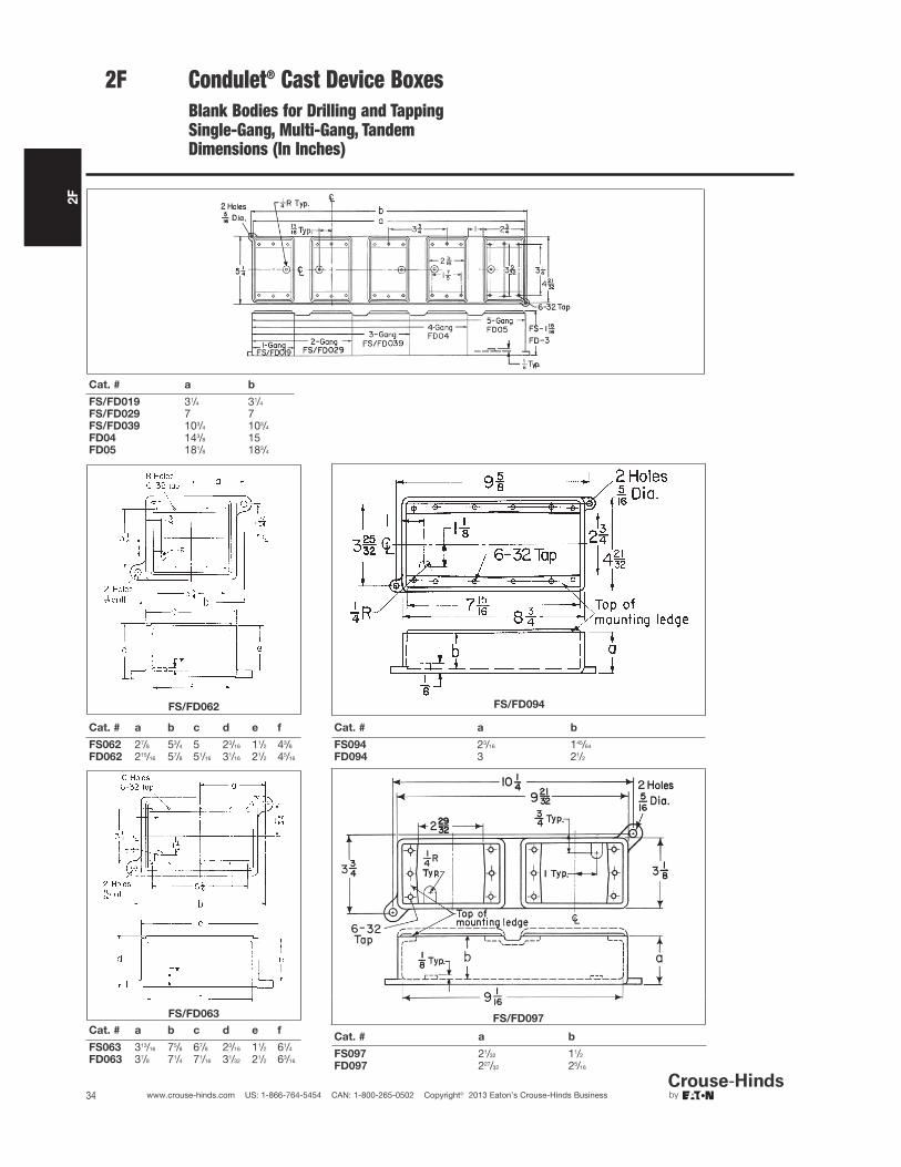
2FCondulet® Blank Device Boxes - Cast IronBlank Bodies With Mounting Lugs forDrilling and Tapping Single Gang,Multi-Gang, Tandem
Accessoriessee pages 37–45
Applications:
Blank cast device boxes are used:
• Where several wiring devices are to begrouped together
• To assemble special combinations ofwiring devices
• Where special arrangements of conduithubs or entrances are required
Features:
• Available in shallow (FS) or deep (FD)configurations.
• FS/FD bodies have thick walls for drillingand tapping conduit entrances.
• Internal green ground screw standard onboxes.
• Available in single, two, three, four andfive gang and two gang tandem bodies.
• Cast mounting lugs at diagonallyopposite corners.
• For a wide selection of standard surfaceor flush covers see pages 37–45.
Standard Materials:
• Feraloy iron alloy
Standard Finishes:
• Feraloy – electrogalvanized andaluminum acrylic paint
Certifications andCompliances:
• UL Standard: 514A
• CSA Standard: C22.2 No. 18
FS019, FD019 single gang
FS029, FD029 two gang
FS039, FD039 three gang
FD04 four gang
FD05 five gang
FS062, FD062 two gang
FS063, FD063 three gang
FS094, FD094 four gang
FS097, FD097 two gang tandem
Ordering Information:
Description
Shallow
Cat. #
Deep
Cat. #
Single gang FS019 FD019*
Two gang FS029 FD029*
Three gang FS039 FD039*
Four gang FD04
Five gang FD05
Two gang (takes onetwo gang cover) FS062 FD062
Three gang (takes onethree gang cover) FS063 FD063
Four gang (takes onefour gang cover) FS094 FD094
Two gang tandem FS097 FD097
*Available in copper-free aluminum. To order add suffixSA to Cat. No.

2F
32 www.crouse-hinds.com US: 1-866-764-5454 CAN: 1-800-265-0502 Copyright© 2013 Eaton’s Crouse-Hinds Business
2F Condulet® Blank Device Boxes - Cast Iron
Blank Bodies for Drilling and TappingOrdering Information
Ordering Information:
To order one of the blank bodies withdrilled and tapped holes listed on seepages 31–33, proceed as follows:Step 1
Select the required box.Step 2
Select the arrangement that meets therequirements from Table 1.Step 3
Determine the maximum size and spacingof conduit openings from Table 2.Step 4
Substitute the appropriate symbol fromTable 4 for each conduit entrance, using‘‘0’’ (zero) for those locations onarrangement where an entrance is notrequired.Example:Step 1 – box required FS062Step 2 – arrangement 1Step 3 – conduit entrances – 1/2" at "a",none at "b"; 1" at "c" and "d"; none at "e"and "f".Step 4 – symbols are substituted andwritten in alphabetical order starting withlocation "a". For this example A0CC00.
Complete Cat. No. is made up of three parts:Part 1 – box number; Part 2 – arrangement number; Part 3 – symbols for conduit entrances.For this example:FS062-1-A0CC00.
Table 1/Drilling and Tapping Arrangements*
Two, Three, Four and Five Gang
*Drilling and tapping arrangements other than those in Table 1 are available. Consult Eaton's Crouse-Hinds.†If only one conduit entry is specified or permitted (see Table 2) on a side wall that conduit entry will be centered on the wall.
Single Gang Only (FS or FD019)
Two Gang Tandem (FS or FD097)
1 2† 3†
4† 5
2F
33www.crouse-hinds.com US: 1-866-764-5454 CAN: 1-800-265-0502 Copyright© 2013 Eaton’s Crouse-Hinds Business
2F
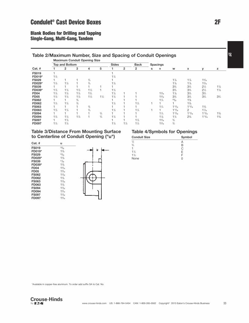
Table 3/Distance From Mounting Surfaceto Centerline of Conduit Opening ("u")
Cat. # u
FS019 29/32
FD019* 13/8
FS029 29/32
FD029* 13/8
FS039 31/32
FD039* 13/8
FD04 19/16
FD05 19/16
FS062 15/32
FD062 15/8
FS063 15/32
FD063 15/8
FS094 15/32
FD094 19/16
FS097 15/32
FD097 19/16
Table 2/Maximum Number, Size and Spacing of Conduit OpeningsMaximum Conduit Opening Size
Top and Bottom Sides Back Spacings
Cat. # 1 2 3 4 5 1 2 2 s v w x y z
FS019 1 1FD019* 11/2 11/2
FS029 1 1 1 3/4 1 17/8 17/8 15/16
FD029* 11/2 11/2 1 3/4 11/2 17/8 17/8 15/16
FS039 1 1 1 1 1 1 33/4 33/4 21/2 17/8
FD039* 11/2 11/2 11/2 11/2 1 11/2 33/4 33/4 21/2 17/8
FD04 11/2 11/2 11/2 11/2 11/2 1 1 13/16 17/8 33/4 33/4
FD05 11/2 11/2 11/2 11/2 11/2 11/2 1 1 13/16 33/4 33/4 33/4 33/4
FS062 1 1 3/4 1 1 1 11/429/32 15/8
FD062 11/2 11/43/4 11/2 1 11/4 1 1 1 13/8
FS063 1 1 1 3/4 1 1 1 11/4 113/16 113/16 15/8
FD063 11/2 11/4 1 3/4 11/2 1 11/4 1 1 113/16 2 17/16
FS094 1 1 1 1 3/4 1 1 1 11/4 113/16 113/16 113/16 15/8
FD094 11/2 11/2 11/2 1 3/4 11/2 1 1 11/8 11/2 25/8 113/16 15/8
FS097 1 11/2 1 1 11/2 15/163/4
FD097 11/2 11/2 11/2 11/2 11/2 15/163/4
Table 4/Symbols for OpeningsConduit Size Symbol
1/2 A3/4 B1 C11/4 E11/2 FNone 0
Condulet® Cast Device Boxes
Blank Bodies for Drilling and TappingSingle-Gang, Multi-Gang, Tandem
*Available in copper-free aluminum. To order add suffix SA to Cat. No.
2F
34 www.crouse-hinds.com US: 1-866-764-5454 CAN: 1-800-265-0502 Copyright© 2013 Eaton’s Crouse-Hinds Business
2F
FS/FD062
Cat. # a b c d e f
FS062 27/8 53/4 5 23/16 11/2 43/8
FD062 215/16 57/8 51/16 31/16 21/2 45/16
FS/FD063
Cat. # a b c d e f
FS063 313/16 75/8 67/8 23/16 11/2 61/4
FD063 37/8 71/4 71/16 31/32 21/2 63/16
FS/FD094
Cat. # a b
FS094 23/16 145/64
FD094 3 21/2
Cat. # a b
FS097 21/32 11/2
FD097 227/32 25/16
FS/FD097
Cat. # a b
FS/FD019 31/4 31/4
FS/FD029 7 7FS/FD039 103/4 103/4
FD04 143/8 15FD05 181/8 183/4
Condulet® Cast Device BoxesBlank Bodies for Drilling and TappingSingle-Gang, Multi-Gang, TandemDimensions (In Inches)

2F
35www.crouse-hinds.com US: 1-866-764-5454 CAN: 1-800-265-0502 Copyright© 2013 Eaton’s Crouse-Hinds Business
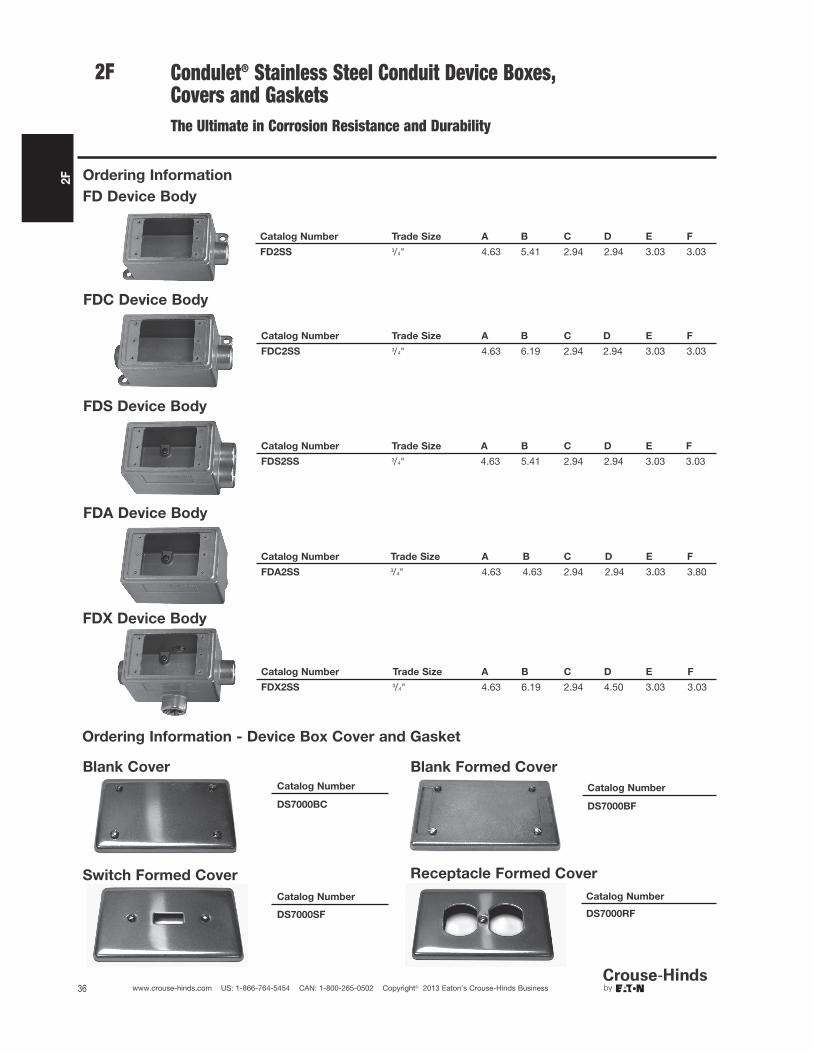
2FCondulet® Stainless Steel Conduit Device Boxes, Covers and Gaskets
Eaton's Crouse-Hinds Condulet® Stainless Steel Device Boxes
deliver power where you need it, saving you time and money
throughout the life of your facility.
Superior resistance to corrosion and heat, combined with unmatchedstrength, make stainless steel Condulet bodies and boxes a long-term solution for even the most extreme environments.
Features:• Self-healing properties of stainless steel fittings help reduce the
penetration of rust/corrosion and eliminate damage to the fitting• Stainless steel fittings retain their strength in extreme heat and
extreme cold conditions• Fitting surface is easy to maintain and keep clean• Easy cleaning capabilities make these fittings perfect for food
processing and other hygienic areas where wash downs arecommon
• Superior strength and durability greatly reduce replacement offittings - this will lower your total cost of ownership and increaseyour return on investment
• Stainless steel fittings do not require harsh environment-damagingcleaners to keep them looking like new
• Internal green grounding screw - standard• Tapered threads for protection of wire insulation• Wide selection of covers available• Single or double conduit entry• Ample wiring room provided for easy installations
Applications:Cast device boxes are installed in conduit systems to:• Accommodate wiring devices• Act as pull boxes for conductors in a conduit system• Provide openings to make splices and taps in conductors• Provide access to conductors for maintenance and future
system changes• Connect conduit systems
Standard Materials:• Bodies - 316 stainless steel• Covers - 316 stainless steel• Cover Screws - 316 stainless steel• Gasket - neoprene
Certifications and Compliances:• UL Standard 514A• CSA Standard C22.2 No. 18.1-04• Raintight - when installed with cover and gasket
DimensionA Length of boxB Overall length (including hubs)C Width of boxD Overall width (including hubs)E Height of boxF Overall height (including hubs)
2F
36 www.crouse-hinds.com US: 1-866-764-5454 CAN: 1-800-265-0502 Copyright© 2013 Eaton’s Crouse-Hinds Business
2F
Ordering Information
FDC Device Body
FDS Device Body
FDA Device Body
FDX Device Body
Ordering Information - Device Box Cover and Gasket
Blank Cover
Switch Formed Cover
Blank Formed Cover
Receptacle Formed Cover
Condulet® Stainless Steel Conduit Device Boxes,Covers and GasketsThe Ultimate in Corrosion Resistance and Durability
Catalog Number
DS7000BC
Catalog Number
DS7000SF
Catalog Number
DS7000BF
Catalog Number
DS7000RF
Catalog Number Trade Size A B C D E F
FDC2SS 3/4" 4.63 6.19 2.94 2.94 3.03 3.03
Catalog Number Trade Size A B C D E F
FDS2SS 3/4" 4.63 5.41 2.94 2.94 3.03 3.03
Catalog Number Trade Size A B C D E F
FDA2SS 3/4" 4.63 4.63 2.94 2.94 3.03 3.80
Catalog Number Trade Size A B C D E F
FDX2SS 3/4" 4.63 6.19 2.94 4.50 3.03 3.03
FD Device Body
Catalog Number Trade Size A B C D E F
FD2SS 3/4" 4.63 5.41 2.94 2.94 3.03 3.03
2F
37www.crouse-hinds.com US: 1-866-764-5454 CAN: 1-800-265-0502 Copyright© 2013 Eaton’s Crouse-Hinds Business
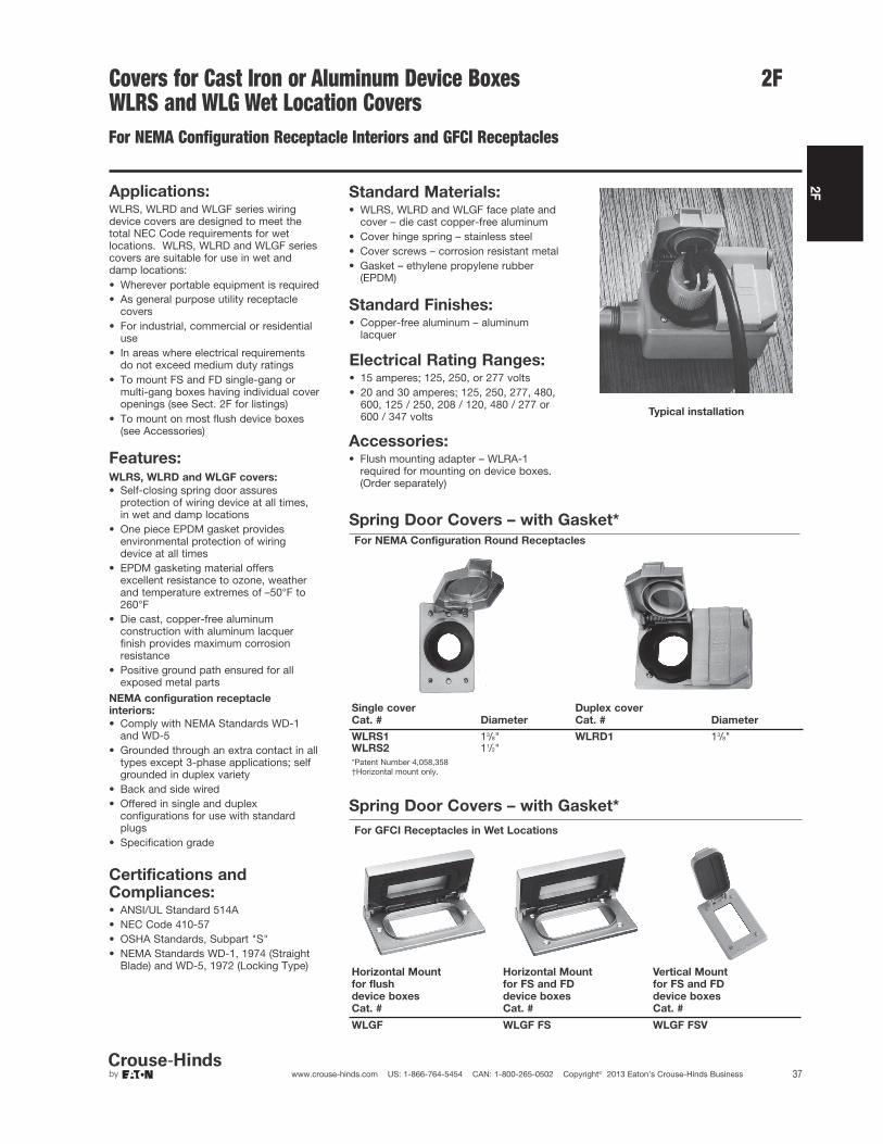
2FCovers for Cast Iron or Aluminum Device BoxesWLRS and WLG Wet Location CoversFor NEMA Configuration Receptacle Interiors and GFCI Receptacles
Applications:WLRS, WLRD and WLGF series wiringdevice covers are designed to meet thetotal NEC Code requirements for wetlocations. WLRS, WLRD and WLGF seriescovers are suitable for use in wet anddamp locations:• Wherever portable equipment is required• As general purpose utility receptacle
covers• For industrial, commercial or residential
use• In areas where electrical requirements
do not exceed medium duty ratings• To mount FS and FD single-gang or
multi-gang boxes having individual coveropenings (see Sect. 2F for listings)
• To mount on most flush device boxes(see Accessories)
Typical installation
Certifications andCompliances:• ANSI/UL Standard 514A• NEC Code 410-57• OSHA Standards, Subpart "S"• NEMA Standards WD-1, 1974 (Straight
Blade) and WD-5, 1972 (Locking Type)
Standard Materials:• WLRS, WLRD and WLGF face plate and
cover – die cast copper-free aluminum• Cover hinge spring – stainless steel• Cover screws – corrosion resistant metal• Gasket – ethylene propylene rubber
(EPDM)
Standard Finishes:• Copper-free aluminum – aluminum
lacquer
Electrical Rating Ranges:• 15 amperes; 125, 250, or 277 volts• 20 and 30 amperes; 125, 250, 277, 480,
600, 125 / 250, 208 / 120, 480 / 277 or600 / 347 volts
Accessories:• Flush mounting adapter – WLRA-1
required for mounting on device boxes.(Order separately)
Spring Door Covers – with Gasket*
For NEMA Configuration Round Receptacles
Single cover
Cat. # Diameter
Duplex cover
Cat. # Diameter
WLRS1 13/8" WLRD1 13/8"WLRS2 11/2"*Patent Number 4,058,358†Horizontal mount only.
Features:WLRS, WLRD and WLGF covers:
• Self-closing spring door assuresprotection of wiring device at all times, in wet and damp locations
• One piece EPDM gasket providesenvironmental protection of wiring device at all times
• EPDM gasketing material offers excellent resistance to ozone, weatherand temperature extremes of –50°F to260°F
• Die cast, copper-free aluminumconstruction with aluminum lacquerfinish provides maximum corrosionresistance
• Positive ground path ensured for allexposed metal parts
NEMA configuration receptacle
interiors:
• Comply with NEMA Standards WD-1 and WD-5
• Grounded through an extra contact in alltypes except 3-phase applications; selfgrounded in duplex variety
• Back and side wired• Offered in single and duplex
configurations for use with standardplugs
• Specification grade
Spring Door Covers – with Gasket*
For GFCI Receptacles in Wet Locations
Horizontal Mount
for flush
device boxes
Cat. #
Horizontal Mount
for FS and FD
device boxes
Cat. #
Vertical Mount
for FS and FD
device boxes
Cat. #
WLGF WLGF FS WLGF FSV
2F
38 www.crouse-hinds.com US: 1-866-764-5454 CAN: 1-800-265-0502 Copyright© 2013 Eaton’s Crouse-Hinds Business
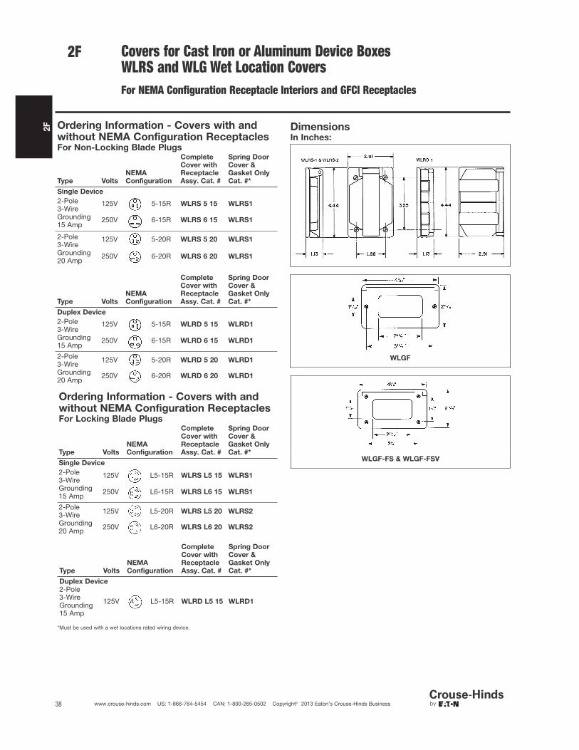
2F Covers for Cast Iron or Aluminum Device BoxesWLRS and WLG Wet Location CoversFor NEMA Configuration Receptacle Interiors and GFCI Receptacles
Ordering Information - Covers with andwithout NEMA Configuration ReceptaclesFor Non-Locking Blade Plugs
Type Volts
NEMA
Configuration
Complete
Cover with
Receptacle
Assy. Cat. #
Spring Door
Cover &
Gasket Only
Cat. #*
Single Device
2-Pole3-WireGrounding15 Amp
125V 5-15R WLRS 5 15 WLRS1
250V 6-15R WLRS 6 15 WLRS1
2-Pole3-WireGrounding20 Amp
125V 5-20R WLRS 5 20 WLRS1
250V 6-20R WLRS 6 20 WLRS1
Type Volts
NEMA
Configuration
Complete
Cover with
Receptacle
Assy. Cat. #
Spring Door
Cover &
Gasket Only
Cat. #*
Duplex Device
2-Pole3-WireGrounding15 Amp
125V 5-15R WLRD 5 15 WLRD1
250V 6-15R WLRD 6 15 WLRD1
2-Pole3-WireGrounding20 Amp
125V 5-20R WLRD 5 20 WLRD1
250V 6-20R WLRD 6 20 WLRD1
Ordering Information - Covers with andwithout NEMA Configuration ReceptaclesFor Locking Blade Plugs
Type Volts
NEMA
Configuration
Complete
Cover with
Receptacle
Assy. Cat. #
Spring Door
Cover &
Gasket Only
Cat. #*
Single Device
2-Pole3-WireGrounding15 Amp
125V L5-15R WLRS L5 15 WLRS1
250V L6-15R WLRS L6 15 WLRS1
2-Pole3-WireGrounding20 Amp
125V L5-20R WLRS L5 20 WLRS2
250V L6-20R WLRS L6 20 WLRS2
Type Volts
NEMA
Configuration
Complete
Cover with
Receptacle
Assy. Cat. #
Spring Door
Cover &
Gasket Only
Cat. #*
Duplex Device
2-Pole3-WireGrounding15 Amp
125V L5-15R WLRD L5 15 WLRD1
*Must be used with a wet locations rated wiring device.
DimensionsIn Inches:
WLGF
WLGF-FS & WLGF-FSV

2F
39www.crouse-hinds.com US: 1-866-764-5454 CAN: 1-800-265-0502 Copyright© 2013 Eaton’s Crouse-Hinds Business
2FCovers for Cast Iron or Aluminum Device Boxes
Single Gang
Blank cover for enclosing splices and
taps where device not used.
Description Material Cat. #
Surface Sheet aluminum DS100Flush Sheet steel DSS100
Blank cover with gasket for enclosing
splices and taps where device not used.
Description Material Cat. #
Surface orFlush Cast aluminum DS100G
DS21 DS21G
For standard and 3-pole, 2-wire
grounding type round flush
receptacles. Opening diameter 17/16".
Description Material Cat. #
Surface Sheet steel DS21
Surface Sheetaluminum DS21 SA
Surfaceor flush
Feraloy®
iron alloywith gasket
DS21G
For GFI receptacles.
Description Material Cat. #
Surface Sheet steel DS23 GFI
For flush plug receptacle requiring 15/8"
opening diameter.
Description Material Cat. #
Surface Sheet steel DS35
For duplex convenience receptacles.
Description Material Cat. #
Surface Sheet steel DS23Surface Sheet aluminum DS23 SAFlush Sheet steel DSS23
For standard and 3-pole, 2-wire
grounding type duplex convenience
receptacles. Gasket included.
Description Material Cat. #
Surfaceor flush
Feraloy®
iron alloy DS23G
For square handle general use snap or
toggle switches – unguarded.
Description Material Cat. #
Surface Sheet steel DS32Surface Sheet aluminum DS32 SA
For square handle general use snap or
toggle switches – guarded.
Description Material Cat. #
Surfaceor flush
Feraloy®
iron alloywith gasket
DS32G
Surface Sheet steel DS52
Adapter plate for mounting WLRS/
WLRD covers to flush device boxes.
Description Cat. #
Flush Device Adapter WLRA1
Also can be used to mount all covers withfour corner screws listed see pages37, 39, 40, 41, 42 and 43 to flush deviceboxes.
See page 42 for receptacle specifications and listings ofcomplete receptacle/cover combinations.†Must be used with a wet locations rated wiring device.
Ordering Information

2F
40 www.crouse-hinds.com US: 1-866-764-5454 CAN: 1-800-265-0502 Copyright© 2013 Eaton’s Crouse-Hinds Business
2F Covers for Cast Iron or Aluminum Device Boxes
Single Gang - Raintight Covers (Gasket Included)
For general use snap switches.
Includes gasket.
Description Material Cat. #
For standardON-OFFoperation
Copper-freealuminum DS181
For general use snap switches.
Includes gasket.
Description Material Cat. #
For standardON-OFFoperation.With hole forlock
Die castaluminum DS185
For general use snap switches.
Includes gasket.
Description Material Cat. #
For standardoperation.MarkedON-OFFhandle
Castaluminum DS128
Ordering Information

2F
41www.crouse-hinds.com US: 1-866-764-5454 CAN: 1-800-265-0502 Copyright© 2013 Eaton’s Crouse-Hinds Business
Covers for Cast Iron or Aluminum Device Boxes
Single Gang - Switches and Motor Control Push Button
Raintight
For manual motor starting switches.
Fits FS and FD boxes. Takes
Westinghouse switches MST01 (1-pole)
and MST02 (2-pole). Includes gasket.
Description Material Cat. #
For standardON-OFF operation
Feraloyiron alloy DS199
Furnished with buttons for operating motor control push button switches.
Includes gasket.
Push ButtonsDescription No. Color Material Cat. #
Button (normally open) marked START 1 Green Feraloy iron alloy DS171F ➀
Button (normally closed) marked STOP 1 Red Feraloy iron alloy DS171G ➀
Button (normally open) marked 1 GreenFeraloy iron alloy DS171 ➀START and button (normally closed)
marked STOP1 Red
Description No. Color Material Cat. #
Two push button 2 Black Feraloy iron alloy DS171J ➀
➀ If desired, markings on indicating plates may be added to catalog number. Select from the list of
standard markings below:
HAND CLOSE OFF AUTO. UP RUNEMER. DOWN JOG FORWARD START RESETREVERSE STOP TRIP OPEN ON TESTLGT. ON
Heavy duty motor control push button switch
No. of
Buttons Normal Positions Cat. #
1 1 circuit universal ED11
2 2 circuits universal ED12†
†Two universal contact blocks, must be wired as two circuits, with one normally open and one normally closed.
DS Covers use the switches shown in the list below.
Cover Takes Switch Cover Takes Switch
DS171 ED12 DS171F ED11DS171G ED11 DS266 ED12
DS265 ED11
2F
Ordering Information

2F
42 www.crouse-hinds.com US: 1-866-764-5454 CAN: 1-800-265-0502 Copyright© 2013 Eaton’s Crouse-Hinds Business
2F Covers for Cast Iron or Aluminum Device Boxes
Single Gang - DS Receptacles and WP Plugs
Weatherproof
Applications:WP plugs and DS receptacles are used:• Wherever dust, dirt, moisture and
corrosion are a problem• Outdoors or in locations where frequent
washdowns occur, as in dairies andfood processing plants
Features:DS receptacle housings are used:• With FS and FD cast device boxes,
either surface mounted or installed flushin a wall
• With single gang, two gang tandem andmultiple gang boxes having individualcover openings
• A threaded cap which effectively sealshousing when not in use
WP plugs include:• A molded Neoprene hood with integral
sleeve to seal the cord entrance• An aluminum ring which clamps the
hood to receptacle housing face, tocomplete watertight seal when plug is inuse
Standard Materials:• Receptacle housings: body – Feraloy®
iron alloy; cap – copper-free aluminum• Plug exteriors: hood – Neoprene;
fastening ring – copper-free aluminum
Standard Finishes:• Feraloy iron alloy – electrogalvanized
and aluminum acrylic paint• Copper-free aluminum – natural• Neoprene – natural (black or yellow)
Electrical Rating Ranges:• 15 amperes, 125 volts• 20 amperes, 125, 250 volts
Certifications andCompliances:• UL Standards: 498; 514A• NEMA/EEMAC: WD-1; WD-5• CSA Standard: C22.2 No. 42*
*Compliance.
DS Receptacle
housings
WP Plugs CC Replacement
receptacle
Grounding Type ReceptaclesFor Plugs with U shaped or Round Grounding Contacts
Rating
Cover With
Recept.
Cat. # Diagram Style
Plug
Cat. # Diagram Cord Dia.
Repl.
Recept.
Cat. #
15 amps125 volts
DS96*2-wire,3-pole† WP820
.500 to
.625 CC55
NEMA: 5-15R NEMA: 5-15P
20 amps125 volts DS222
2-wire,3-pole† WP832
.500 to
.625 CC71
NEMA: 5-20R NEMA: 5-20P
20 amps250 volts DS290
2-wire,3-pole† WP930
.500 to
.625 CC90
NEMA: 6-20R NEMA: 6-20P†Third pole grounded.*Compliance
For listing of typical FS cast devices boxes, see pages 23 and 24.
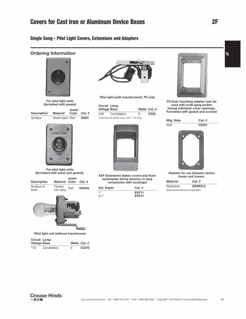
2F
43www.crouse-hinds.com US: 1-866-764-5454 CAN: 1-800-265-0502 Copyright© 2013 Eaton’s Crouse-Hinds Business
Covers for Cast Iron or Aluminum Device Boxes
Single Gang - Pilot Light Covers, Extensions and Adapters
For pilot light units
(furnished with jewels)
Description Material
Jewel
Color Cat. #
Surface Sheet steel Red DS24
For pilot light units
(furnished with jewel and gasket).
Description Material
Jewel
Color Cat. #
Surface orflush
Feraloyiron alloy Red DS24G
Pilot light unit (without transformer)
Circuit
Voltage
Lamp
Base Watts Cat. #
110 Candelabra 6 C3310
Pilot light (with transformer)†, FD only
Circuit
Voltage
Lamp
Base Watts Cat. #
440 Candelabra 6 C333
†Transformer 50–60 cycle, 440 / 110 volts.
EXF Extensions (takes covers and flush
rectangular wiring devices, or plug
receptacles with housings)
Ext. Depth Cat. #
1" EXF1121/2" EXF21
FS flush mounting adapter (can be
used with multi-gang bodies
having individual cover openings.
Furnished with gasket and screws)
Mtg. Style Cat. #
Wall FS031
Gaskets for use between device
boxes and covers.
Material Cat. #
Neoprene GASK91‡
‡Not recommended as watertight.
2F
Ordering Information
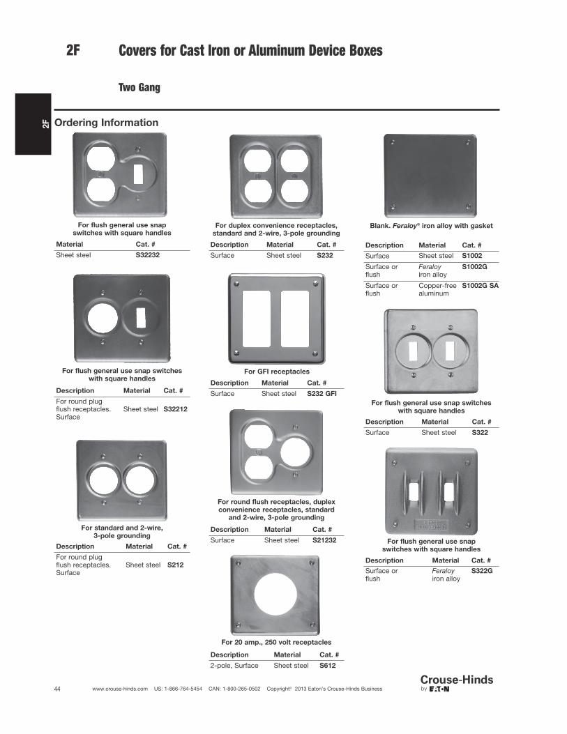
2F
44 www.crouse-hinds.com US: 1-866-764-5454 CAN: 1-800-265-0502 Copyright© 2013 Eaton’s Crouse-Hinds Business
2F Covers for Cast Iron or Aluminum Device Boxes
Two Gang
For flush general use snap
switches with square handles
Material Cat. #
Sheet steel S32232
For flush general use snap switches
with square handles
Description Material Cat. #
For round plugflush receptacles.Surface
Sheet steel S32212
For standard and 2-wire,
3-pole grounding
Description Material Cat. #
For round plugflush receptacles.Surface
Sheet steel S212
For duplex convenience receptacles,
standard and 2-wire, 3-pole grounding
Description Material Cat. #
Surface Sheet steel S232
For GFI receptacles
Description Material Cat. #
Surface Sheet steel S232 GFI
For round flush receptacles, duplex
convenience receptacles, standard
and 2-wire, 3-pole grounding
Description Material Cat. #
Surface Sheet steel S21232
For 20 amp., 250 volt receptacles
Description Material Cat. #
2-pole, Surface Sheet steel S612
Blank. Feraloy® iron alloy with gasket
Description Material Cat. #
Surface Sheet steel S1002
Surface or flush
Feraloyiron alloy
S1002G
Surface or flush
Copper-freealuminum
S1002G SA
For flush general use snap switches
with square handles
Description Material Cat. #
Surface Sheet steel S322
For flush general use snap
switches with square handles
Description Material Cat. #
Surface or flush
Feraloyiron alloy
S322G
Ordering Information

2F
45www.crouse-hinds.com US: 1-866-764-5454 CAN: 1-800-265-0502 Copyright© 2013 Eaton’s Crouse-Hinds Business
Covers for Cast Iron or Aluminum Device Boxes
Two Gang
2F
With operating mechanism and gasket
Description Material Cat. #
Two gang. Foroperation ofgeneral use snapswitches. Surfaceor flush
Feraloy®
iron alloy DS1282
With operating mechanism and gasket
Description Material Cat. #
Three gang withgasket. Forexternal operationof general usesnap switches.Surface or flush.
Feraloyiron alloy DS1283
Blank with gasket
Description Material Cat. #
Surface Sheet steel S1003
Surface or flush
Feraloyiron alloy
S1003G
Surface or flush
Copper-freealuminum
S1003G SA
*Includes gasket
For flush general use snap switches
with square handles
Description Material Cat. #
Surface, three gang Sheet steel S323
Blank with gasket
Description Material Cat. #
Surface or flush Feraloyiron alloy S1004G
For flush general use snap switches
with square handles
Description Material Cat. #
Surface, four gang† Sheet steel S324
†For FS094 and FD094 boxes.
Gasket for use between
device box and cover
Description Material Cat. #
Two gang Rubber GASK434Three gang Rubber GASK460Four gang Rubber GASK461
Ordering Information

2F
46 www.crouse-hinds.com US: 1-866-764-5454 CAN: 1-800-265-0502 Copyright© 2013 Eaton’s Crouse-Hinds Business
2F FSE Receptacle and Breaker Assemblies
Applications:• FSE series assemblies are used in
outdoor areas for supplying power inremote locations, particularly parkinglots, automobile engine block heaters,marinas, drive-in theaters, trailer camps, etc.
Features:• Compact design.• Suitable for a variety of combinations.• U ground duplex receptacle.• Circuit breaker protection.• Breakers cannot be manually tripped.
Size:• 2" integral hub for pole mounting.
Standard Materials:• Body and cover – copper-free aluminum
Standard Finishes:• Copper-free aluminum – natural
Electrical Ratings:• 15A 120V
Certifications andCompliances:• CSA Standard C22.2 No. 18
FSE 6121 FSE 612
Cat. # Description
FSE612 Double face receptacle body onlyFSE6121 Fitting complete with 1-15 amp. duplex receptacle and blank cover.
FSE6122 Fitting complete with 2-15 amp. duplex receptacles.
FSE61212 Fitting complete with 1-15 amp. duplex receptacle and two 1- pole Minibreakers
FSE61211 Fitting complete with 1-15 amp. duplex receptacle and one 1- pole Minibreaker.
Other combinations available on request
Ordering Information
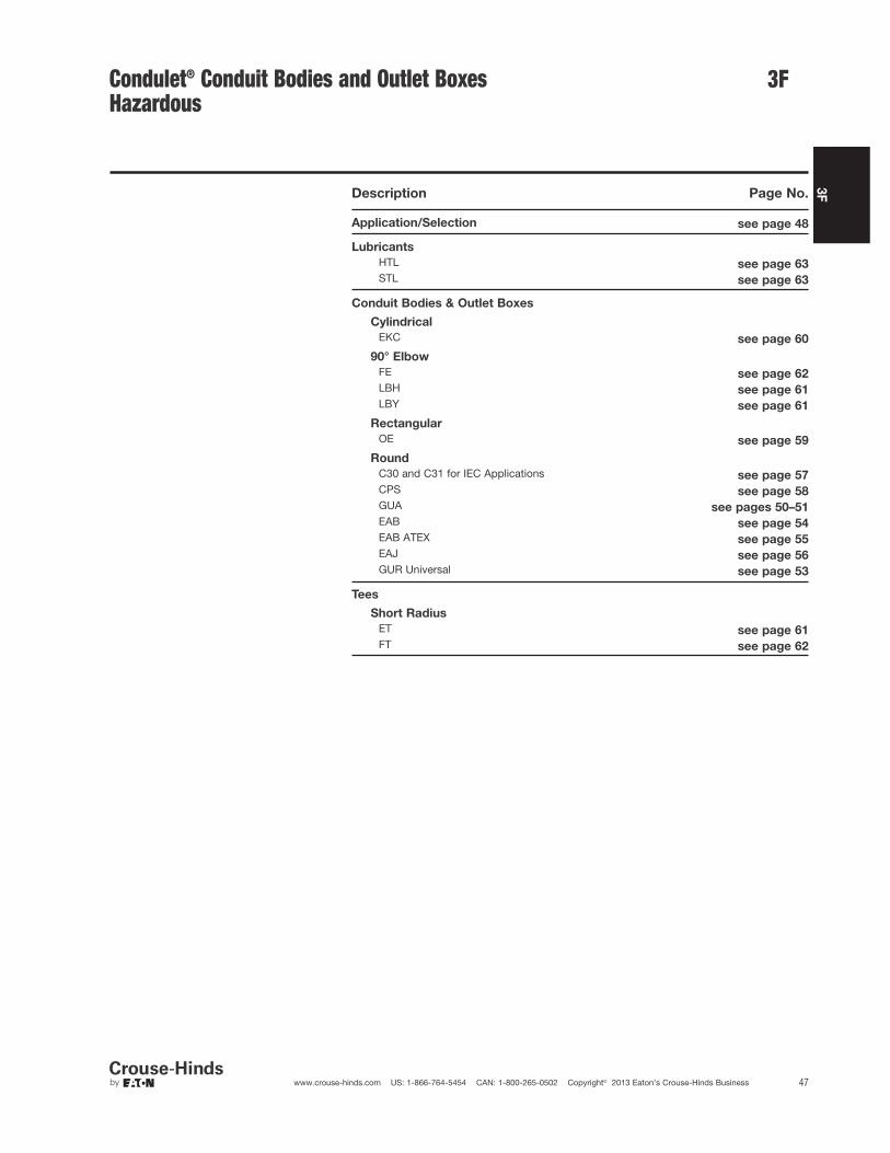
3F
47www.crouse-hinds.com US: 1-866-764-5454 CAN: 1-800-265-0502 Copyright© 2013 Eaton’s Crouse-Hinds Business
3FCondulet® Conduit Bodies and Outlet BoxesHazardous
Description Page No.
Application/Selection see page 48
Lubricants
HTL see page 63
STL see page 63
Conduit Bodies & Outlet Boxes
Cylindrical
EKC see page 60
90° Elbow
FE see page 62
LBH see page 61
LBY see page 61
Rectangular
OE see page 59
Round
C30 and C31 for IEC Applications see page 57
CPS see page 58
GUA see pages 50–51
EAB see page 54
EAB ATEX see page 55
EAJ see page 56
GUR Universal see page 53
Tees
Short Radius
ET see page 61
FT see page 62

3F
48 www.crouse-hinds.com US: 1-866-764-5454 CAN: 1-800-265-0502 Copyright© 2013 Eaton’s Crouse-Hinds Business
3F Condulet® Conduit Bodies andOutlet BoxesApplication and Selection
Applications:
Hazardous area conduit bodies and outlet boxes are installed in rigidconduit systems in Class I and II hazardous locations to:
• Protect conductors
• Act as pull and splice boxes
• Connect lengths of conduit
• Change conduit direction
• Provide access to conductors for maintenance and future systemchanges
• Act as mounting outlets for fixtures (with appropriate covers)
• Act as sealing fittings (with appropriate covers)
Considerations for Selection:
• Determine the area classification per National Electrical CodeHazardous Area Groups. Based on this classification, select theproduct families that are acceptable for use in the particularlocation.:
• Establish functional physical requirements these will help todetermine box size, cover, shape and mounting for the particularinstallation.
• Each product family has features suitable for specific functions:
• i.e., boxes used as mountings for lighting fixtures are generally ofa small size, and provided with mounting lugs when required tosupport lighting fixtures.
• Boxes used for wire pulling should generally be larger to provideroom for easy pulling.
• Boxes used to splice and/or tap conductors should be largeenough to permit ease of work and sufficient room for the requiredsize and number of conductors.
• Hub size and configuration – dependent on the conduit systemconfiguration and the conduit size used.
• Material and finish – determine from environmental conditions(corrosive fumes, weather, buried in concrete, etc.)
Options and Accessories:
• Flat blank covers (surface and flanged flush), fixture support andsealing covers and extensions are available. See specific productlisting for details.
• Lubricant (STL and HTL) are available to make joints raintight,provide for easy cover removal and to lubricate shafts over a widetemperature range.
• Corro-free™ epoxy powder coat – information available onrequest.
Quick Selector Chart
Series
NEC
Class I & II
Groups
IEC
Certifications
Normal
Function
Cover
Opening
Diameter
Hub
Size†
Cover
Type
GUA C, D E, F, G Mtg. ltg. fixt., taps, pulling,splicing
2–5 1/2-2 Threaded
EAJ A, B, C, D E, F, G Pulling, splicing, taps 33/16 & 5 1/2-2 Threaded
C30 / C31 Ex II 2 G EEx d IIC T6Ex II 2 D IP66 T 85ºC
Pulling, splicing, taps 98mm (C30)130mm (C31)
1/2-1 Threaded
EAB A, B, C, D E, F, G Pulling, splicing, taps 3 1/2-1 Threaded
EAB ATEX A, B, C, D E, F, G II 2 G EEx d IIC T5PTB 05 ATEX 1052
Pulling, splicing, taps 33/41/2-1 Threaded
CPS C, D E, F, G Fixt. support, pulling,splicing
31/21/2 & 3/4 Ground joint
OE C, D E, F, G Pulling 1/2-1 Ground joint
ET C, D E, F, G Stub up 1/2-1
FT Flameproof, Exd, IIB,IP67, Zone 1Combustible Dust Zone21 & 22
Stub up 20mm -25mm
Threaded
LBY C, D E, F, G Pulling 1/2 – 11/4 Threaded
LBH B, C, D E, F, G Pulling 1/2-4 Ground joint
FE Flameproof, Exd, IIB,IP67, Zone 1Combustible Dust Zone21 & 22
Pulling 20mm -25mm
Threaded
EKC C, D E, F, G Pulling 1/2-3 Ground joint
GUR C, D E, F, G Pulling, splicing 1/2-1 Threaded
†See following table for standard hub configuration.
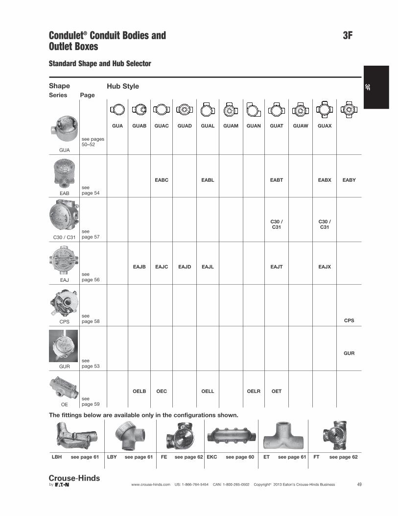
3F
49www.crouse-hinds.com US: 1-866-764-5454 CAN: 1-800-265-0502 Copyright© 2013 Eaton’s Crouse-Hinds Business
Condulet® Conduit Bodies andOutlet BoxesStandard Shape and Hub Selector
Shape Hub Style
Series Page
GUA GUAB GUAC GUAD GUAL GUAM GUAN GUAT GUAW GUAX
GUA
see pages50–52
EABC EABL EABT EABX EABY
EABseepage 54
C30 /
C31
C30 /
C31
C30 / C31seepage 57
EAJB EAJC EAJD EAJL EAJT EAJX
EAJseepage 56
CPSseepage 58 CPS
GUR
GURseepage 53
OELB OEC OELL OELR OET
OEseepage 59
The fittings below are available only in the configurations shown.
LBH see page 61 LBY see page 61 see page 62FE EKC see page 60 ET see page 61 see page 62FT
3F

3F
50 www.crouse-hinds.com US: 1-866-764-5454 CAN: 1-800-265-0502 Copyright© 2013 Eaton’s Crouse-Hinds Business
Condulet® Conduit Outlet Boxes With CoversGUA Series
Cl. I, Div. 1 & 2, Groups C, DCl. II, Div. 1, Groups E, F, GCl. II, Div. 2, Groups F, GCl. IIINEMA 3, 4, 7CD, 9EFG
ExplosionproofDust-IgnitionproofRaintightWet Locations
Applications:GUA series conduit outlet boxes areinstalled within hazardous area conduitsystems to:• Protect conductors in threaded
rigid conduit• Act as pull and splice boxes• Connect lengths of conduit• Change conduit direction• Provide access to conductors for
maintenance and future system changes• Act as mounting outlets for fixtures
(with appropriate covers)• Act as sealing fittings (with appropriate
covers)
Features:GUA conduit boxes have:• Neoprene "O" ring standard to meet
NEMA 4 requirements• Cast ears on cover to permit easy
removal and tightening• Four standard mounting pads except for
boxes with bottom hubs• Threaded cover openings• Ten different hub arrangements• Taper threaded hubs to provide
grounding continuity• Smooth integral hub bushing protects
conductor insulation when pulling• Surface covers furnished with boxes• Sealing covers, dome covers, and fixture
hanger covers are available• Cover threads are 12 pitch
Standard Materials:• Bodies – Feraloy iron alloy• Covers – Copper-free aluminum
Standard Finishes:• Feraloy iron alloy – electrogalvanized and
aluminum acrylic paint• Aluminum – natural
Size Ranges:• Hub – 1/2" to 2"• Cover opening – 2" to 5" dia.
Options:Description Suffix
Bodies – copper-free aluminum SA†*Covers – Feraloy iron alloy –electrogalvanized and aluminumacrylic paint WODGUA Form 6 (with 3" cover opening)are available with optional coverwith viewing window. VWCorro-free epoxy powder coat S752To order box less cover add "0" to end ofcatalog number ie.GUAT260.
Certifications andCompliances:• NEC/CEC:
Class I, Division 1 & 2, Groups C, DClass II, Division 1, Groups E, F, GClass II, Division 2, Groups F, GClass III
• UL Standard: 1203• ANSI Standard: C33.27• CSA Standard: C22.2 No. 30• NEMA/EEMAC 3, 4
When assembled with sealing type cover, GUA seriesoutlet boxes provide adequate sealing for 40% fill inhazardous areas – Class I, Groups C, D; Class II, GroupsE, F, G; and Class III. Seals can be made in eitherhorizontal or vertical positions. Use Chico® "A" sealingcompound or Chico® SpeedSeal only. Conductor splicesor connections must not be made in enclosures wheresealing compound is to be used per NEC.
GUA
Hub
Size
Cover
Opening
Dia. Cat. #
1/2 2 GUA143/4 2 GUA241/2 3 GUA163/4 3 GUA26*1 3 GUA3611/4 35/8 GUA4711/2 5 GUA59
GUAC
Hub
Size
Cover
Opening
Dia. Cat. #
1/2 2 GUAC14†3/4 2 GUAC24†1/2 3 GUAC16*3/4 3 GUAC26*1 3 GUAC36*11/4 35/8 GUAC47†11/4 5 GUAC4911/2 5 GUAC59†2 5 GUAC69†
GUAB
Hub
Size
Cover
Opening
Dia. Cat. #
1/2 2 GUAB14†3/4 2 GUAB241/2 3 GUAB16*3/4 3 GUAB26*1 3 GUAB36*11/4 35/8 GUAB47†11/2 5 GUAB59†2 5 GUAB69†
DimensionsIn Inches:
Length of Hub
Hub Size
Dimension "e"
Length
1/2 - 3/4 7/8
1 – 11/4 111/2 – 2 11/16
GUA, GUAD, GUAM,GUAW, GUAXCat. # a b c d
14 21/2 113/16 13/45/8
24 21/2 2 2 3/4
16 31/2 2 17/85/8
26 31/2 2 17/83/4
36 31/2 25/16 23/167/8
37 41/4 25/16 23/87/8
47 41/4 211/16 23/4 13/32
49 53/4 313/16 33/4 13/32
59 53/4 313/16 33/4 19/32
69 53/4 41/16 4 19/16
GUAD
Hub
Size
Cover
Opening
Dia. Cat. #
1/2 2 GUAD14†3/4 2 GUAD241/2 3 GUAD163/4 3 GUAD26†1 3 GUAD36†11/4 5 GUAD49
†Available in copper-free aluminum, add suffix -SA.*Available in copper-free aluminum, add suffix -SA. GUAoutlet boxes marked with * when ordered with suffix -SAare listed for Class I, Division 1 & 2, Groups B, C and D,Class II, Division 1, Groups E, F, G and Class III. Covers have 16 pitch threads. Replacement cover is a GUA06-GB.
3F
GUAB Only All others
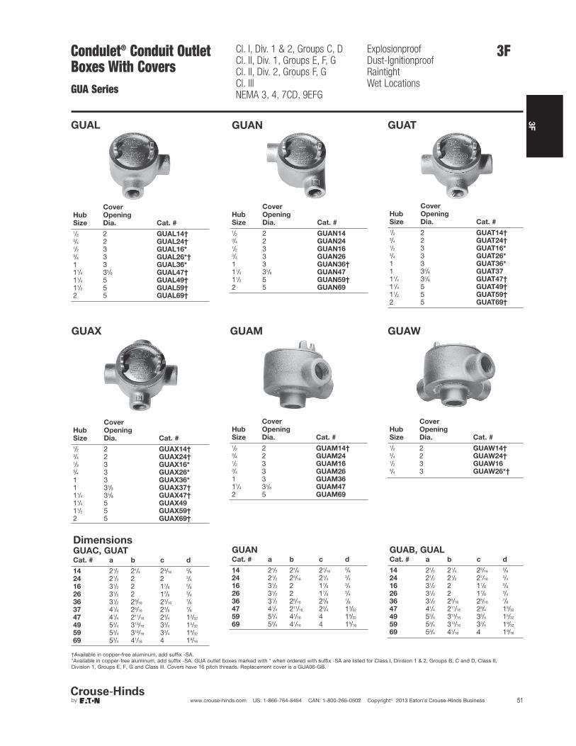
3F
51www.crouse-hinds.com US: 1-866-764-5454 CAN: 1-800-265-0502 Copyright© 2013 Eaton’s Crouse-Hinds Business
GUAL
Hub
Size
Cover
Opening
Dia. Cat. #
1/2 2 GUAL14†3/4 2 GUAL24†1/2 3 GUAL16*3/4 3 GUAL26*†1 3 GUAL36*11/4 35/8 GUAL47†11/4 5 GUAL49†11/2 5 GUAL59†2 5 GUAL69†
GUAN
Hub
Size
Cover
Opening
Dia. Cat. #
1/2 2 GUAN143/4 2 GUAN241/2 3 GUAN163/4 3 GUAN261 3 GUAN36†11/4 35/8 GUAN4711/2 5 GUAN59†2 5 GUAN69
GUAT
Hub
Size
Cover
Opening
Dia. Cat. #
1/2 2 GUAT14†3/4 2 GUAT24†1/2 3 GUAT16*3/4 3 GUAT26*1 3 GUAT36*1 35/8 GUAT3711/4 35/8 GUAT47†11/4 5 GUAT49†11/2 5 GUAT59†2 5 GUAT69†
GUAX
Hub
Size
Cover
Opening
Dia. Cat. #
1/2 2 GUAX14†3/4 2 GUAX24†1/2 3 GUAX16*3/4 3 GUAX26*1 3 GUAX36*1 35/8 GUAX37†11/4 35/8 GUAX47†11/4 5 GUAX4911/2 5 GUAX59†2 5 GUAX69†
GUAM
Hub
Size
Cover
Opening
Dia. Cat. #
1/2 2 GUAM14†3/4 2 GUAM241/2 3 GUAM163/4 3 GUAM261 3 GUAM3611/4 35/8 GUAM472 5 GUAM69
GUAW
Hub
Size
Cover
Opening
Dia. Cat. #
1/2 2 GUAW14†3/4 2 GUAW24†1/2 3 GUAW163/4 3 GUAW26*†
DimensionsGUAC, GUATCat. # a b c d
14 21/2 21/4 23/165/8
24 21/2 2 2 3/4
16 31/2 2 17/85/8
26 31/2 2 17/83/4
36 31/2 25/16 23/167/8
37 41/4 25/16 23/87/8
47 41/4 211/16 23/4 13/32
49 53/4 313/16 33/4 15/32
59 53/4 313/16 33/4 19/32
69 53/4 41/16 4 19/16
GUANCat. # a b c d
14 21/2 21/8 21/165/8
24 21/2 25/16 21/43/4
16 31/2 2 17/83/4
26 31/2 2 17/83/4
36 31/2 25/16 23/87/8
47 41/4 211/16 23/4 13/32
59 53/4 41/16 4 19/32
69 53/4 41/16 4 19/16
GUAB, GUALCat. # a b c d
14 21/2 21/4 23/165/8
24 21/2 21/2 27/163/4
16 31/2 2 17/85/8
26 31/2 2 17/83/4
36 31/2 25/16 23/167/8
47 41/4 211/16 23/4 13/32
49 53/4 313/16 33/4 15/32
59 53/4 313/16 33/4 19/32
69 53/4 41/16 4 19/16
†Available in copper-free aluminum, add suffix -SA.*Available in copper-free aluminum, add suffix -SA. GUA outlet boxes marked with * when ordered with suffix -SA are listed for Class I, Division 1 & 2, Groups B, C and D, Class II, Division 1, Groups E, F, G and Class III. Covers have 16 pitch threads. Replacement cover is a GUA06-GB.
Condulet® Conduit Outlet Boxes With CoversGUA Series
Cl. I, Div. 1 & 2, Groups C, DCl. II, Div. 1, Groups E, F, GCl. II, Div. 2, Groups F, GCl. IIINEMA 3, 4, 7CD, 9EFG
ExplosionproofDust-IgnitionproofRaintightWet Locations
3F
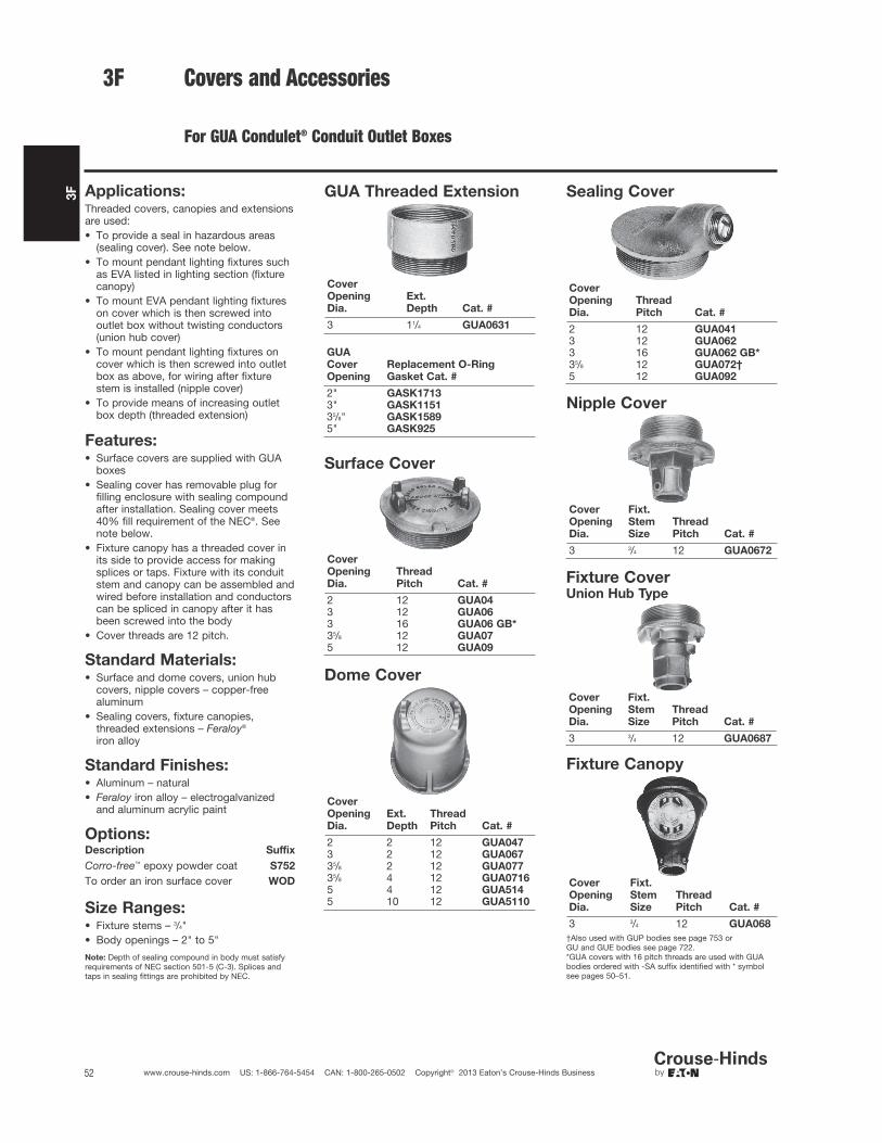
52 www.crouse-hinds.com US: 1-866-764-5454 CAN: 1-800-265-0502 Copyright© 2013 Eaton’s Crouse-Hinds Business
3F
Covers and Accessories
For GUA Condulet® Conduit Outlet Boxes
Applications:Threaded covers, canopies and extensionsare used:• To provide a seal in hazardous areas
(sealing cover). See note below.• To mount pendant lighting fixtures such
as EVA listed in lighting section (fixturecanopy)
• To mount EVA pendant lighting fixtureson cover which is then screwed intooutlet box without twisting conductors(union hub cover)
• To mount pendant lighting fixtures oncover which is then screwed into outletbox as above, for wiring after fixturestem is installed (nipple cover)
• To provide means of increasing outletbox depth (threaded extension)
Features:• Surface covers are supplied with GUA
boxes• Sealing cover has removable plug for
filling enclosure with sealing compoundafter installation. Sealing cover meets40% fill requirement of the NEC®. Seenote below.
• Fixture canopy has a threaded cover inits side to provide access for makingsplices or taps. Fixture with its conduitstem and canopy can be assembled andwired before installation and conductorscan be spliced in canopy after it hasbeen screwed into the body
• Cover threads are 12 pitch.
Standard Materials:• Surface and dome covers, union hub
covers, nipple covers – copper-freealuminum
• Sealing covers, fixture canopies,threaded extensions – Feraloy®
iron alloy
Standard Finishes:• Aluminum – natural• Feraloy iron alloy – electrogalvanized
and aluminum acrylic paint
Options:Description Suffix
Corro-free™ epoxy powder coat S752
To order an iron surface cover WOD
Size Ranges:• Fixture stems – 3/4"• Body openings – 2" to 5"
Note: Depth of sealing compound in body must satisfyrequirements of NEC section 501-5 (C-3). Splices andtaps in sealing fittings are prohibited by NEC.
GUA Threaded Extension
Cover
Opening
Dia.
Ext.
Depth Cat. #
3 11/4 GUA0631
GUA
Cover
Opening
Replacement O-Ring
Gasket Cat. #
2" GASK17133" GASK115135/8" GASK15895" GASK925
Surface Cover
Cover
Opening
Dia.
Thread
Pitch Cat. #
2 12 GUA043 12 GUA063 16 GUA06 GB*35/8 12 GUA075 12 GUA09
Dome Cover
Cover
Opening
Dia.
Ext.
Depth
Thread
Pitch Cat. #
2 2 12 GUA0473 2 12 GUA06735/8 2 12 GUA07735/8 4 12 GUA07165 4 12 GUA5145 10 12 GUA5110
Sealing Cover
Cover
Opening
Dia.
Thread
Pitch Cat. #
2 12 GUA0413 12 GUA0623 16 GUA062 GB*35/8 12 GUA072†5 12 GUA092
3F
Nipple Cover
Cover
Opening
Dia.
Fixt.
Stem
Size
Thread
Pitch Cat. #
3 3/4 12 GUA0672
Fixture Canopy
Cover
Opening
Dia.
Fixt.
Stem
Size
Thread
Pitch Cat. #
3 3/4 12 GUA068
†Also used with GUP bodies see page 753 orGU and GUE bodies see page 722.*GUA covers with 16 pitch threads are used with GUAbodies ordered with -SA suffix identified with * symbolsee pages 50–51.
Fixture CoverUnion Hub Type
Cover
Opening
Dia.
Fixt.
Stem
Size
Thread
Pitch Cat. #
3 3/4 12 GUA0687

3F
53www.crouse-hinds.com US: 1-866-764-5454 CAN: 1-800-265-0502 Copyright© 2013 Eaton’s Crouse-Hinds Business
Condulet® Conduit Outlet Boxes With CoversGUR Series
Cl. I, Div. 1 & 2, Groups C, DCl. II, Div. 1, Groups E, F, GCl. II, Div. 2, Groups F, GCl. IIINEMA 4
ExplosionproofDust-IgnitionproofRaintightWet Locations
Applications:GUR conduit outlet boxes are installed within hazardous areas:• To protect conductors in threaded rigid conduit• To act as pull and splice boxes• To connect lengths of conduit• To provide access to conductors for maintenance and future
system changes• To change conduit direction• Where space is limited, such as underneath gasoline pumps
Features:GUR outlet boxes feature:• Neoprene O-ring standard in cover to meet NEMA 4/UL Type 4
requirements• Internal green ground screw• Five standard hubs with three pipe plugs included• Threaded cover opening• Recesses in cover to assist in cover tightening and removal• Smooth, integral hub bushing to protect conductor insulation
when pulling• Compact design for confined spaces• UL and cUL listing• Optional all-aluminum construction
Standard Materials:• Bodies – Feraloy® iron alloy• Covers – copper-free aluminum
Standard Finishes:• Feraloy iron alloy – electrogalvanized with aluminum acrylic paint• Aluminum – natural
Certifications and Compliances:• NEC/CEC
Class I, Division 1 and 2, Groups C and DClass II, Division 1, Groups E, F and GClass IIIZone 1 and 2
• UL Standard 1203• cUL to CSA Standard C22.2 No. 30• NEMA 4
Options:Description Suffix
Bodies – copper-free aluminum SA
DimensionsIn Inches:
3F
Ordering Information:Hub Size Cat. #
1/2" GUR13/4" GUR21" GUR3

3F
54 www.crouse-hinds.com US: 1-866-764-5454 CAN: 1-800-265-0502 Copyright© 2013 Eaton’s Crouse-Hinds Business
Condulet® Conduit Outlet Boxes With CoversEAB Series
Cl. I, Div. 1 & 2, Groups A, B, C, DCl. II, Div. 1, Groups E, F, GCl. II, Div. 2, Groups F, GCl. IIINEMA 3,4,7ABCD,9EFG
ExplosionproofDust-IgnitionproofRaintightWet Locations
Applications:EAB series conduit outlet boxes areinstalled in conduit systems withinhazardous areas to:• Provide protection against exterior
explosion where acetylene, hydrogenand other hazardous gases are present
• Protect conductors in threaded rigid conduit
• Act as pull and splice boxes• Interconnect lengths of conduit• Change conduit direction• Provide access to conductors for
maintenance and future system changes
Features:EAB series conduit outlet boxes have:• Five different hub configurations• Taper threaded hubs to provide ground
continuity• Smooth integral hub bushing to protect
conductor insulation when pulling• Threaded cover openings• Surface covers furnished with boxes• Neoprene "o"-ring gasket and green
ground screw are both standard.• Four standard mounting pads,
except for EABY.• Cover threads are 16 pitch.
Standard Materials:• Bodies – Feraloy® iron alloy• Covers – Copper-free aluminum
Standard Finishes:• Feraloy – electrogalvanized and
aluminum acrylic paint• Aluminum – natural
Options:Description Suffix
Bodies – copper-free aluminum SA†*Covers – Feraloy iron alloy –electrogalvanized and aluminumacrylic paint WODCorro-free epoxy powder coat S752
Size Ranges:• Hub – 1/2" to 1"• Cover opening – 3" dia.
Certifications andCompliances:• NEC/CEC:
Class I, Division 1 & 2, Groups A, B, C, DClass II, Division 1, Groups E, F, GClass II, Division 2, Groups F, GClass III
• UL Standard: 1203• CSA Standard: C22.2 No. 30
EABC
Hub
Size Cat. #
1/2 EABC16†3/4 EABC261 EABC36†
EABT
Hub
Size Cat. #
1/2 EABT16†3/4 EABT26†1 EABT36†
EABL
Hub
Size Cat. #
1/2 EABL16†3/4 EABL26†1 EABL36†
3F
EABX
Hub
Size Cat. #
1/2 EABX16†3/4 EABX26†1 EABX36†
EABY
Hub
Size Cat. #
1/2 EABY16†3/4 EABY26†
Replacement Cover:Size Cat. #
3" EAB06
Replacement O-Ring:Description Cat. #
Replacement O-Ring GASK1151
DimensionsIn Inches:
EAB Series
EAB SeriesCat. # a b c d e f
16 33/4 217/32 11/23/4 55/16 33/32
26 33/4 225/32 13/47/8 59/16 33/32
36 33/4 225/32 13/47/8 59/16 33/32
†Available in copper-free aluminum, add suffix -SA.*EAB0687 is listed for Group C & D only.
Fixture CoverUnion Hub Type
Cover
Opening
Dia.
Fixt.
Stem
Size Cat. #
3" 3/4 EAB0687*
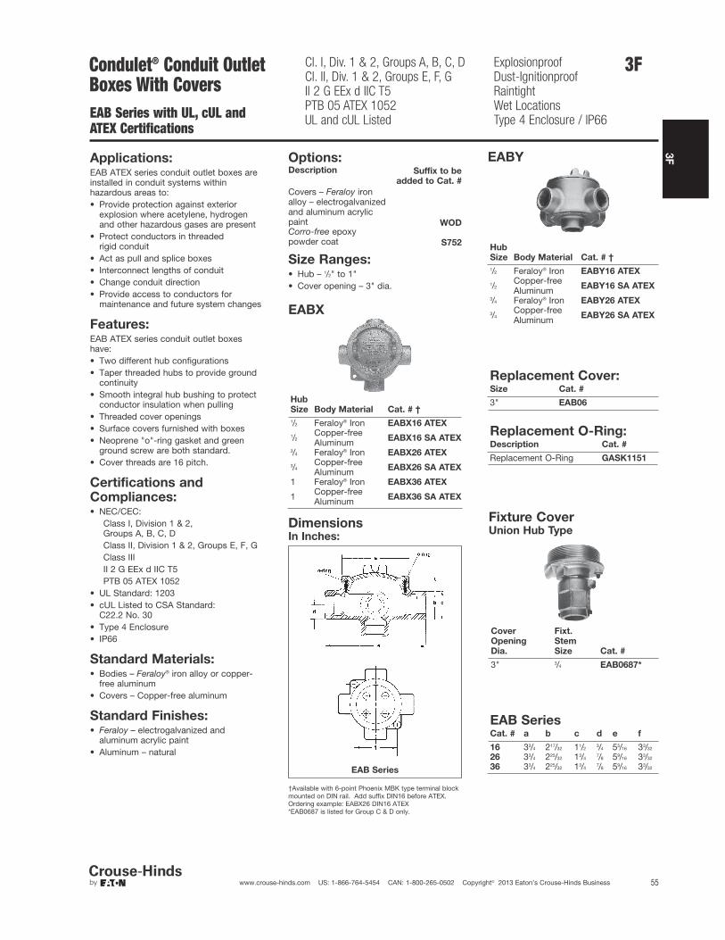
3F
55www.crouse-hinds.com US: 1-866-764-5454 CAN: 1-800-265-0502 Copyright© 2013 Eaton’s Crouse-Hinds Business
3FCondulet® Conduit Outlet Boxes With CoversEAB Series with UL, cUL and ATEX Certifications
Cl. I, Div. 1 & 2, Groups A, B, C, DCl. II, Div. 1 & 2, Groups E, F, GII 2 G EEx d IIC T5PTB 05 ATEX 1052UL and cUL Listed
ExplosionproofDust-IgnitionproofRaintightWet LocationsType 4 Enclosure / IP66
Applications:EAB ATEX series conduit outlet boxes areinstalled in conduit systems withinhazardous areas to:• Provide protection against exterior
explosion where acetylene, hydrogenand other hazardous gases are present
• Protect conductors in threaded rigid conduit
• Act as pull and splice boxes• Interconnect lengths of conduit• Change conduit direction• Provide access to conductors for
maintenance and future system changes
Features:EAB ATEX series conduit outlet boxeshave:• Two different hub configurations• Taper threaded hubs to provide ground
continuity• Smooth integral hub bushing to protect
conductor insulation when pulling• Threaded cover openings• Surface covers furnished with boxes• Neoprene "o"-ring gasket and green
ground screw are both standard.• Cover threads are 16 pitch.
Standard Materials:• Bodies – Feraloy® iron alloy or copper-
free aluminum• Covers – Copper-free aluminum
Standard Finishes:• Feraloy – electrogalvanized and
aluminum acrylic paint• Aluminum – natural
Options:Description Suffix to be
added to Cat. #
Covers – Feraloy ironalloy – electrogalvanizedand aluminum acrylicpaint WODCorro-free epoxypowder coat S752
Size Ranges:• Hub – 1/2" to 1"• Cover opening – 3" dia.
EABX
Hub
Size Body Material Cat. # †
1/2 Feraloy® Iron EABX16 ATEX
1/2Copper-freeAluminum EABX16 SA ATEX
3/4 Feraloy® Iron EABX26 ATEX
3/4Copper-freeAluminum EABX26 SA ATEX
1 Feraloy® Iron EABX36 ATEX
1 Copper-freeAluminum EABX36 SA ATEX
EABY
Hub
Size Body Material Cat. # †
1/2 Feraloy® Iron EABY16 ATEX
1/2Copper-freeAluminum EABY16 SA ATEX
3/4 Feraloy® Iron EABY26 ATEX
3/4Copper-freeAluminum EABY26 SA ATEX
Replacement Cover:Size Cat. #
3" EAB06
Replacement O-Ring:Description Cat. #
Replacement O-Ring GASK1151
DimensionsIn Inches:
EAB Series
EAB SeriesCat. # a b c d e f
16 33/4 217/32 11/23/4 55/16 33/32
26 33/4 225/32 13/47/8 59/16 33/32
36 33/4 225/32 13/47/8 59/16 33/32
†Available with 6-point Phoenix MBK type terminal blockmounted on DIN rail. Add suffix DIN16 before ATEX.Ordering example: EABX26 DIN16 ATEX*EAB0687 is listed for Group C & D only.
Certifications andCompliances:• NEC/CEC:
Class I, Division 1 & 2, Groups A, B, C, DClass II, Division 1 & 2, Groups E, F, GClass IIIII 2 G EEx d IIC T5PTB 05 ATEX 1052
• UL Standard: 1203• cUL Listed to CSA Standard:
C22.2 No. 30• Type 4 Enclosure• IP66
Fixture CoverUnion Hub Type
Cover
Opening
Dia.
Fixt.
Stem
Size Cat. #
3" 3/4 EAB0687*
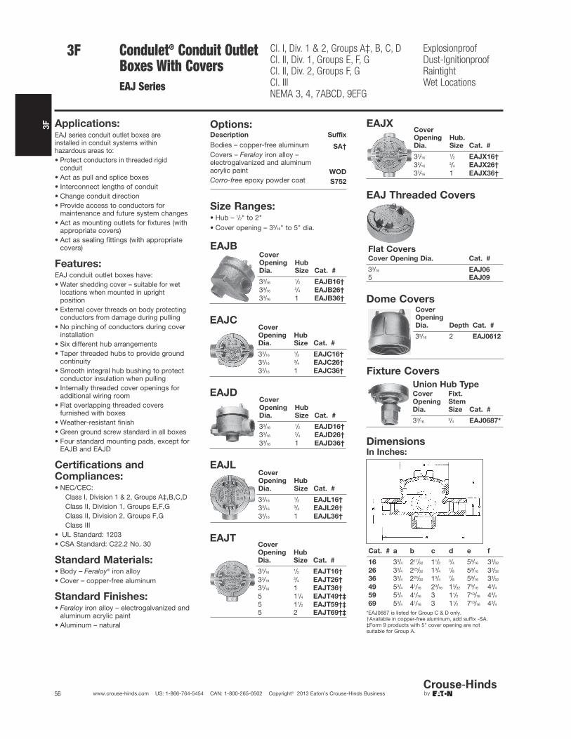
3F
56 www.crouse-hinds.com US: 1-866-764-5454 CAN: 1-800-265-0502 Copyright© 2013 Eaton’s Crouse-Hinds Business
3F Cl. I, Div. 1 & 2, Groups A‡, B, C, DCl. II, Div. 1, Groups E, F, GCl. II, Div. 2, Groups F, GCl. IIINEMA 3, 4, 7ABCD, 9EFG
ExplosionproofDust-IgnitionproofRaintightWet Locations
Condulet® Conduit Outlet Boxes With CoversEAJ Series
Applications:EAJ series conduit outlet boxes are installed in conduit systems within hazardous areas to:• Protect conductors in threaded rigid
conduit• Act as pull and splice boxes• Interconnect lengths of conduit• Change conduit direction• Provide access to conductors for
maintenance and future system changes• Act as mounting outlets for fixtures (with
appropriate covers)• Act as sealing fittings (with appropriate
covers)
Features:EAJ conduit outlet boxes have:• Water shedding cover – suitable for wet
locations when mounted in uprightposition
• External cover threads on body protectingconductors from damage during pulling
• No pinching of conductors during coverinstallation
• Six different hub arrangements• Taper threaded hubs to provide ground
continuity• Smooth integral hub bushing to protect
conductor insulation when pulling• Internally threaded cover openings for
additional wiring room• Flat overlapping threaded covers
furnished with boxes• Weather-resistant finish• Green ground screw standard in all boxes• Four standard mounting pads, except for
EAJB and EAJD
Standard Materials:• Body – Feraloy® iron alloy• Cover – copper-free aluminum
Standard Finishes:• Feraloy iron alloy – electrogalvanized and
aluminum acrylic paint• Aluminum – natural
Size Ranges:• Hub – 1/2" to 2"• Cover opening – 33/16" to 5" dia.
Certifications andCompliances:• NEC/CEC:
Class I, Division 1 & 2, Groups A‡,B,C,DClass II, Division 1, Groups E,F,GClass II, Division 2, Groups F,GClass III
• UL Standard: 1203• CSA Standard: C22.2 No. 30
Options:Description Suffix
Bodies – copper-free aluminum SA†
Covers – Feraloy iron alloy –electrogalvanized and aluminumacrylic paint WOD
Corro-free epoxy powder coat S752
EAJBCover
Opening
Dia.
Hub
Size Cat. #
33/161/2 EAJB16†
33/163/4 EAJB26†
33/16 1 EAJB36†
EAJCCover
Opening
Dia.
Hub
Size Cat. #
33/161/2 EAJC16†
33/163/4 EAJC26†
33/16 1 EAJC36†
EAJDCover
Opening
Dia.
Hub
Size Cat. #
33/161/2 EAJD16†
33/163/4 EAJD26†
33/16 1 EAJD36†
EAJLCover
Opening
Dia.
Hub
Size Cat. #
33/161/2 EAJL16†
33/163/4 EAJL26†
33/16 1 EAJL36†
EAJTCover
Opening
Dia.
Hub
Size Cat. #
33/161/2 EAJT16†
33/163/4 EAJT26†
33/16 1 EAJT36†
5 11/4 EAJT49†‡
5 11/2 EAJT59†‡
5 2 EAJT69†‡
EAJ Threaded Covers
Flat CoversCover Opening Dia. Cat. #
33/16 EAJ06
5 EAJ09
EAJXCover
Opening
Dia.
Hub.
Size Cat. #
33/161/2 EAJX16†
33/163/4 EAJX26†
33/16 1 EAJX36†
Dome CoversCover
Opening
Dia. Depth Cat. #
33/16 2 EAJ0612
Fixture Covers
Union Hub TypeCover
Opening
Dia.
Fixt.
Stem
Size Cat. #
33/163/4 EAJ0687*
DimensionsIn Inches:
Cat. # a b c d e f
16 33/4 217/32 11/23/4 55/16 33/32
26 33/4 225/32 13/47/8 59/16 33/32
36 33/4 225/32 13/47/8 59/16 33/32
49 53/4 41/16 23/16 13/32 75/16 43/4
59 53/4 41/16 3 11/2 713/16 43/4
69 53/4 41/16 3 11/2 713/16 43/4
*EAJ0687 is listed for Group C & D only.†Available in copper-free aluminum, add suffix -SA.‡Form 9 products with 5" cover opening are not suitable for Group A.

3F
57www.crouse-hinds.com US: 1-866-764-5454 CAN: 1-800-265-0502 Copyright© 2013 Eaton’s Crouse-Hinds Business
3FCondulet® Conduit Outlet Boxes With Coversfor IEC Applications
Ex II 2 G EEx d IIC T6Ex II 2 D IP66 T 85ºC
Zone 1, 2, 21 and 22
C30 Series C31 SeriesApplications:C30 and C31 series conduit outlet boxesare installed in electrical systems withinhazardous areas to:• Provide protection against exterior
explosion where acetylene, hydrogenand other hazardous gases are present
• Protect conductors in threaded rigidconduit
• Act as pull and splice boxes• Interconnect lengths of conduit• Change conduit direction• Provide access to conductors for
maintenance and future system changes
Certifications andCompliances:• IEC:
Ex d IIC T6Ex tD A21 IP67 T85ºCEC-Type examination certificate LOM02 ATEX 2037 XCompliant to EN60079-0
• IP67
Standard Materials:• Bodies – Light alloy, natural finish• Covers – Light alloy, natural finish
Technical Specifications
Operating temperaturerange
-50ºC to +55ºC
Degree of protection IP67
Rated voltage up to 690V
Rated current Acc. terminals
Terminals C30 Series:
up to 6mm2
C31 Series:
up to 10 mm2
Ordering InformationSeries Shape Hub Size Cat. # †
C30 T 3 x 1/2" NOR 000 001 151 181C30 T 3 x 3/4" NOR 000 001 151 199C30 X 4 x 1/2" NOR 000 001 151 206C30 X 4 x 3/4" NOR 000 001 151 214C31 T 3 x 1/2" NOR 000 111 150 001C31 T 3 x 3/4" NOR 000 111 150 002C31 T 3 x 1" NOR 000 111 150 003C31 X 4 x 1/2" NOR 000 111 150 004C31 X 4 x 3/4" NOR 000 111 150 005C31 X 4 x 1" NOR 000 111 150 006
Description Cat. #
C30 Mounting plate with pillar terminals 4 x 4mm2 NOR 000 001 151 222C30 support rail DIN 46877 NOR 000 000 115 314
C30 mounting plate without terminals NOR 000 000 115 302
C30 pending support NOR 000 000 115 311
C31 mounting plate with pillar terminals 4 x 4mm2 NOR 000 111 150 009C31 mounting plate without terminals NOR 000 000 115 306
C31 support rail DIN 46877 NOR 000 000 115 315
DimensionsIn Inches:
C30 Series C31 Series
†Other entries available upon request.
Accessories
Features:C30 and C31 series conduit outlet boxes have:• Taper threaded hubs to provide ground
continuity• Smooth integral hub bushing to protect
conductor insulation when pulling• Threaded cover openings• Surface covers furnished with boxes• Neoprene "o"-ring gasket and green
ground screw are both standard• Cover threads are 16 pitch
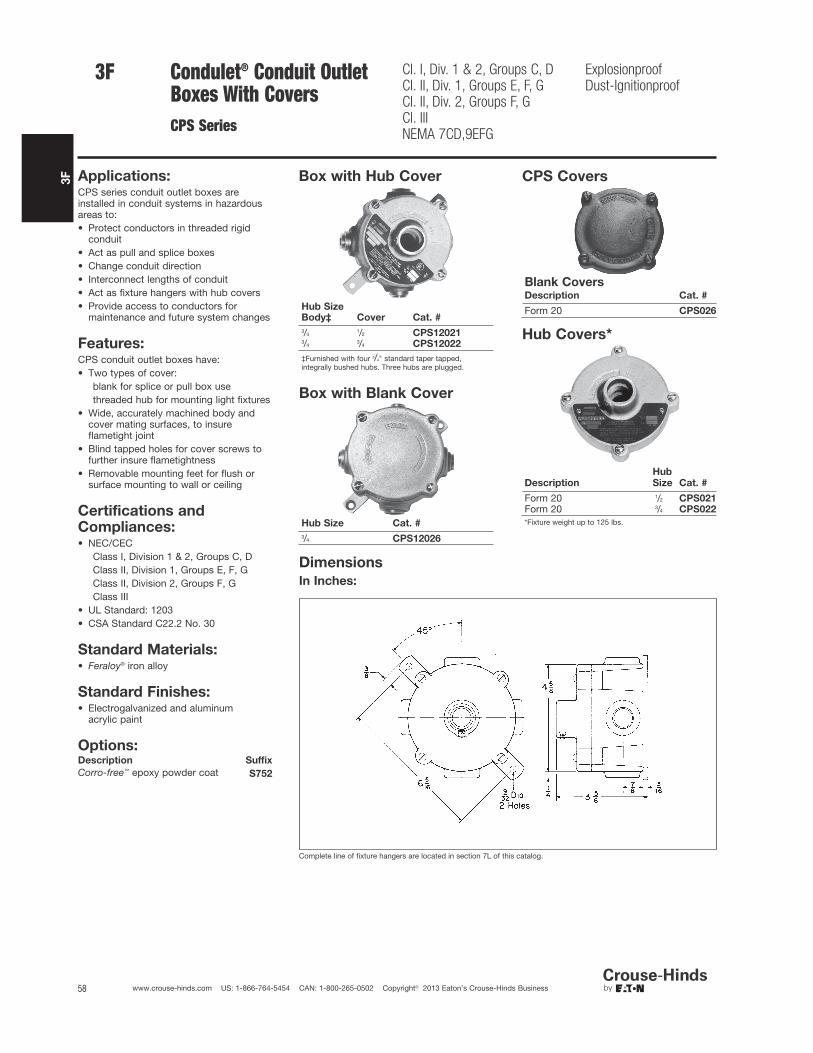
3F
58 www.crouse-hinds.com US: 1-866-764-5454 CAN: 1-800-265-0502 Copyright© 2013 Eaton’s Crouse-Hinds Business
Condulet® Conduit Outlet Boxes With CoversCPS Series
Cl. I, Div. 1 & 2, Groups C, DCl. II, Div. 1, Groups E, F, GCl. II, Div. 2, Groups F, GCl. IIINEMA 7CD,9EFG
ExplosionproofDust-Ignitionproof
Applications:CPS series conduit outlet boxes areinstalled in conduit systems in hazardousareas to:• Protect conductors in threaded rigid
conduit• Act as pull and splice boxes• Change conduit direction• Interconnect lengths of conduit• Act as fixture hangers with hub covers• Provide access to conductors for
maintenance and future system changes
Features:CPS conduit outlet boxes have:• Two types of cover:
blank for splice or pull box usethreaded hub for mounting light fixtures
• Wide, accurately machined body andcover mating surfaces, to insureflametight joint
• Blind tapped holes for cover screws tofurther insure flametightness
• Removable mounting feet for flush orsurface mounting to wall or ceiling
Standard Materials:• Feraloy® iron alloy
Standard Finishes:• Electrogalvanized and aluminum
acrylic paint
Options:Description Suffix
Corro-free™ epoxy powder coat S752
Certifications andCompliances:• NEC/CEC
Class I, Division 1 & 2, Groups C, DClass II, Division 1, Groups E, F, GClass II, Division 2, Groups F, GClass III
• UL Standard: 1203• CSA Standard C22.2 No. 30
Box with Hub Cover
Hub SizeBody‡ Cover Cat. #
3/41/2 CPS12021
3/43/4 CPS12022
‡Furnished with four 3/4" standard taper tapped,integrally bushed hubs. Three hubs are plugged.
Box with Blank Cover
Hub Size Cat. #
3/4 CPS12026
CPS Covers
Blank CoversDescription Cat. #
Form 20 CPS026
Hub Covers*
Description
Hub
Size Cat. #
Form 20 1/2 CPS021Form 20 3/4 CPS022
*Fixture weight up to 125 lbs.
Complete line of fixture hangers are located in section 7L of this catalog.
Dimensions
In Inches:
3F

3F
59www.crouse-hinds.com US: 1-866-764-5454 CAN: 1-800-265-0502 Copyright© 2013 Eaton’s Crouse-Hinds Business
3FCondulet® Conduit BodiesWith CoversOE Series
Cl. I, Div. 1 & 2, Groups C, DCl. II, Div. 1, Groups E, F, GCl. II, Div. 2, Groups F, GCl. IIINEMA 7CD, 9EFG
ExplosionproofDust-Ignitionproof
Applications:OE series are installed in conduit systemswithin hazardous areas to:• Protect conductors in threaded
rigid conduit• Act as pulling and splice fittings• Interconnect lengths of conduit• Change direction of conduit• Provide access for maintenance and
future system changes
Features:OE conduit outlet bodies have:• Taper threaded hubs for ground
continuity• Smooth integral hub bushings to protect
conductor insulation when pulling• Five different hub arrangements• Accurately machined body with blind
tapped screw holes• Most compact design of all hazardous
area outlet bodies
Standard Materials:• Feraloy® iron alloy (1/2" and 3/4" fittings)• Copper-free aluminum (1" fittings)
Standard Finishes:• Electrogalvanized and aluminum
acrylic paint
Options:Description Suffix
Corro-free™ epoxy powder coat S752
Certifications andCompliances:• NEC/CEC:
Class I, Division 1 & 2, Groups C, DClass II, Division 1, Groups E, F, GClass II, Division 2, Groups F, GClass III
• UL Standard: 1203• CSA Standard: C22.2 No. 30
OEC OET
OELBOELL
Hub Size Cat. #1/2 OEC13/4 OEC21 OEC3 SA
Hub Size Cat. #
1/2 OELL13/4 OELL21 OELL3 SA
Hub Size Cat. #
1/2 OET13/4 OET2
1 OET3 SA
Hub Size Cat. #
1/2 OELB13/4 OELB21 OELB3 SA
OELR
Hub Size Cat. #
1/2 OELR13/4 OELR21 OELR3 SA
DimensionsIn Inches:
OE Series
Hub
Size in. a b c d e f
1/2 41/16 19/16 113/1611/16
7/85/8
3/4 45/16 17/8 21/1611/16
7/83/4
Size Ranges:• Hub - 1/2" to 1"

3F
60 www.crouse-hinds.com US: 1-866-764-5454 CAN: 1-800-265-0502 Copyright© 2013 Eaton’s Crouse-Hinds Business
Condulet® Conduit BodiesWith CoversEKC Series
Cl. I, Div. 1 & 2, Groups C, DCl. II, Div. 1, Groups E, F, GCl. II, Div. 2, Groups F, GCl. IIINEMA 7CD,9EFG
ExplosionproofDust-Ignitionproof
Applications:
EKC series conduit outlet bodies are installedin conduit systems within hazardous areas to:
• Provide convenient opening in conduitsystem for pulling or splicing conductors
Features:EKC bodies have:
• Accurately machined body and covermating surfaces to ensure flametightjoint when properly assembled
• Extra long cover opening to facilitatepulling and splicing of conductors
• Taper threaded hubs and integralbushing for rigid threaded conduit
Standard Materials:• EKC bodies – Feraloy iron alloy
Standard Finishes:• Feraloy – electrogalvanized and
aluminum acrylic paint
Options:Description Suffix
EKC series:Corro-free™ epoxy powder coat S752
Size Ranges:• EKC bodies – hub size – 1" to 3"
Certifications andCompliances:• NEC:
EKC 30 – 60Class I, Division 1 & 2, Groups C, DClass II, Division 1, Groups E, F, GClass II, Division 2, Groups F, GClass IIIEKC 70, 80Class I, Division 1 & 2, Group DClass II, Division 1, Groups E, F, GClass II, Division 2, Groups F, GClass III
• UL Standard: 1203• CSA Standard: C22.2 No. 30
Ordering Information
EKC
Hub Size Cat. #
1 EKC3011/4 EKC4011/2 EKC502 EKC6021/2 EKC703 EKC80
DimensionsIn Inches:
EKC
EKCSize a b c d e f
1 – 11/4 125/8 31/16 37/16 13/4 9 411/2 – 2 1515/16 37/8 45/16 21/2 12 521/2 – 3 213/4 51/2 6 33/4 16 65/8
3F

3F
61www.crouse-hinds.com US: 1-866-764-5454 CAN: 1-800-265-0502 Copyright© 2013 Eaton’s Crouse-Hinds Business
Condulet® Conduit BodiesWith Covers; Elbows and TeesLBH, LBY, ET Series
Cl. I, Div. 1 & 2, Groups A, B, C, D*Cl. II, Div. 1, Groups E, F, GCl. II, Div. 2, Groups F, GCl. IIINEMA 7ABCD,9EFG
ExplosionproofDust-Ignitionproof
Applications:LBH conduit outlet bodies are installed inhazardous areas to:• Act as pull outlets especially for
conductors that are stiff due to large sizeor type of insulation
• Make 90° bends in conduit system,allowing straight pull in either direction
• Provide for conduit service entrance tobuildings
• Provide for conductor entrance to motors• Provide access to wiring for maintenance
and future system changesLBY elbows are installed in conduit systemswithin hazardous areas to:• Make 90° bends in conduit systems where
space is limited• Act as pull outlets• Provide access to conductors for
maintenance and future system changesET series short radius tees are installed inconduit systems within hazardous areas to:• Allow single conduit stub up to outlet and
device boxes located above or below mainconduit runs. Eliminates separate feed andreturn conduits
Features:LBH bodies have:• Cover openings on an angle, permitting
conductors to be pulled straight throughhubs from either direction
• Domed covers to permit easy conductorbends (relieves strain on insulation)
• Taper threaded hubs with integralbushings
LBY elbows have:• Maximum volume for bends within a
compact overall size• Screw on cover for ease of installation and
removal• Over opening on an angle, permitting
conductors to be pulled straight througheither hub
• Taper threaded hubs and integral bushingfor rigid threaded conduit
ET short radius tees have:• Compact size and small radius of bend for
use in concealed, or open conduitsystems.
• Particularly suited for use in shallow floorsor partitions
• Taper threaded hubs and integral bushingfor rigid threaded conduit
Standard Materials:• LBH, LBY and ET – Feraloy® iron alloy
Standard Finishes:• LBH, LBY and ET – electrogalvanized and
aluminum acrylic paint
Options:Description Suffix
LBH and LBY series – copper-freealuminum SALBH and LBY series – Corro-free™
epoxy powder coat S752
Size Ranges:• LBH bodies – hub size 1/2" to 4"• LBY elbows – hub size 1/2" to 11/2"
Certifications andCompliances:• NEC:
LBH 10-20 –Class I, Division 1 & 2, Groups B, C, DClass II, Division 1, Groups E, F, GClass II, Division 2, Groups F, GClass III
LBH Hub Size Cat. #
1/2 LBH103/4 LBH201 LBH3011/4 LBH4011/2 LBH502 LBH6021/2 LBH703 LBH8031/2 LBH904 LBH100
LBY Hub Size Cat. #
1/2 LBY153/4 LBY251 LBY3511/4 LBY4511/2 LBY55
ET Hub Size Cat. #
3/4–1/2–1/2‡ ET2183/4–3/4–3/4‡ ET2281–3/4–3/4‡ ET328
‡Largest hub is shown attop of photo.
LBHSize a b c d e f
1/2–3/4 51/16 219/32 4 13/16 4 23/4
1–1/4 77/8 313/32 51/4 13/4 7 411/2 1015/16 41/2 73/32 21/2 10 52 1021/32 425/32 73/32 21/2 10 52-1/2–3 155/8 51/2 91/2 3 153/4 55/8
3-1/2–4 239/16 611/16 113/4 4 24 71/8
LBYSize a b
1/2 29/16 23/4 213/16 21/4
1 33/32 21/2
11/4 33/4 215/16
11/2 41/4 33/8
ETSize a b c d
3/4–1/2–1/2 4 25/8 11/4 11/23/4–3/4–3/4 4 3 11/2 11/2
1–3/4–3/4 4 3 11/2 13/4
*See Compliances for classification of each product.
LBH 30-100Class I, Division 1 & 2, Group DClass II, Division 1, Groups E, F, GClass II, Division 2, Groups F, GClass IIILBY –Class I, Division 1 & 2, Groups C, DClass II, Division 1, Groups E, F, GClass II, Division 2, Groups F, GClass IIIET –Class I, Division 1 & 2, Groups A, B, C, DClass II, Division 1, Groups E, F, GClass II, Division 2, Groups F, GClass III
• UL Standard: 1203• CSA Standard: C22.2 No. 30
DimensionsIn Inches:
LBH
LBY ET
3F
Ordering Information

3F
62 www.crouse-hinds.com US: 1-866-764-5454 CAN: 1-800-265-0502 Copyright© 2013 Eaton’s Crouse-Hinds Business
Condulet® Elbows and TeesIEC CertificationsFE and FT Series
Zone 1 Zone 21Zone 2 Zone 22
Applications:
FE and FT conduit fittings are installed inhazardous areas to:
• Act as draw-in outlets especially forcables that are stiff due to large size ortype of insulation
• Make 90º bends in conduit systems,allowing for a straight pull in eitherdirection
• Provide access to wiring formaintenance and future system changes
Features:
• Maximum volume for bends within acompact overall size
• Large openings to facilitate cable pulling
Certifications andCompliances:
Type of Protection
• Ex d, DIP A21, IP67
Degree of Protection
• IP67
Gas Group
• IIB
Approvals
• Ex1108U
Standard Materials:
• Body – Copper-free aluminum
• Cover – Brass
Standard Finishes:
• Natural
Ordering Information:Inspection Elbows and Tees Selection
Cat. # Type Entry Size (metric)
FE1 Elbow M20 (F)-M20 (F)FE2 Elbow M25 (F)-M25 (F)FT1 Tee M20 (F)-M20 (F)FT2 Tee M25 (F)-M25 (F)
Options:Description Suffix
NPT & BSP thread sizes Consult Factory
Dimensions (mm)
3F

3F
63www.crouse-hinds.com US: 1-866-764-5454 CAN: 1-800-265-0502 Copyright© 2013 Eaton’s Crouse-Hinds Business
3FLubricants
Applications:
• STL thread lubricant is used between any screw thread and itstapped opening, on any rotating shaft – threaded or plain, and toinhibit corrosion on any metal-to-metal joint of apparatus andcontrol enclosures.
• HTL high temperature lubricant is used on lighting fixture threadedjoints and on threaded joints of the enclosures of any heat-producing apparatus or control.
Features:
STL thread lubricant is lithium based, antigalling and:
• Is especially effective between parts made of dissimilar metals
• Is effective and stable from –20°F to +300°F
• Maintains grounding continuity; should not be used on exposedcurrent-carrying parts
• Has excellent adhesion qualities; a liberal application on threadedjoints maintains raintightness and inhibits corrosion
HTL is a high temperature, anti-seize, conductive thread lubricant:
• Effective and stable from –70°F to +1800°F
• Prevents seizure, galling, rust, galvanic action
• Maintains grounding continuity; should not be used on exposedcurrent-carrying parts
• Effective between parts made of dissimilar metals
Certifications and Compliances:
• Complies with NEC 2008, Article 300.6
STL Thread Lubricant
Net Wt. Cat. #
13/4 oz. (tube) STL28 oz. (can) STL8
HTL High Temperature Thread Lubricant
Net Wt. Cat. #
4 oz. (tube) HTL4
MSDS Sheets are available at www.crouse-hinds.com
3F

3F
3F
64 www.crouse-hinds.com US: 1-866-764-5454 CAN: 1-800-265-0502 Copyright© 2013 Eaton’s Crouse-Hinds Business
3F

4F
65www.crouse-hinds.com US: 1-866-764-5454 CAN: 1-800-265-0502 Copyright© 2013 Eaton’s Crouse-Hinds Business
4FCable Glands and Cable AccessoriesHazardous and Non-hazardous
Description Page No.
Application see page 66
Cable Glands - International Standards
Quick Selection Guide see pages 67–70
Flameproof and Increased Safety
ADE 1F see page 71
ADE 4F see page 72
ADE 6F see page 73
ADE 6FC see page 74
ADE 1FC see page 75
Ex - e see page 76
Ex - i see page 77
Trumpet see page 78
Enlargement and Multiple see page 79
Industrial
ADE 4I see page 80
Cable Glands - North AmericanStandards
Quick Selection Guide see pages 67–70
Explosionproof
Terminator™ II TMCX see pages 81–82
TMCX see page 83
ADE 6FC see page 84
ADE 1FC see page 85
CGBS see page 86
EBY see page 86
General Purpose
TMC see page 87
TECK see page 88
CGB see pages 89–90
CGD see page 91
CGE see page 92
CGB1013 see page 93
CGFP see page 94
NCG see page 95
NCGB see page 95
Cable Glands - Accessories
A Series see page 96
B Series see page 100
D Series see page 101
E Series see page 102
Breathers and Drains see page 103
Cable Tray Clamps
Conduit
LCC, LCCF Series see page 104
Grounding Conductor
TGC Series see page 105
Cable/Conduit Sealing Devices
Thru-Wall Barrier®
TW Series see pages 106–107
Link Seal – For Conduit
Environmental Seal see pages 112–113
Fire Seal see pages 114–115
Description Page No.

4F
66 www.crouse-hinds.com US: 1-866-764-5454 CAN: 1-800-265-0502 Copyright© 2013 Eaton’s Crouse-Hinds Business
Cable Glands and Cable Accessories
Application and Selection
Applications:
Cable glands and cord fittings:
• Provide means for passing a cord, cable (armored or unarmored)or flexible conduit into an enclosure, through a bulkhead or into arigid conduit
• Form a mechanical grip and water and/or oil-resistant seal for cordand unarmored or jacketed armored, round cables
• Form a non-slip connection or termination for flexible cord, cable(armored or unarmored), or flexible conduit
• Provide grounding continuity for cable armor and flexible conduit
Cable glands with sealing fitting or epoxy are installed to:
• Provide means for passing armored, metal clad, jacketed orunjacketed and unarmored cables through a bulkhead orenclosure in hazardous areas. These fittings are suitable for use inClass I, Groups C, D locations only when Chico® A sealingcompound or TSC epoxy (TMCX) is used to make the seal in thefitting*
• Form a mechanical grip and water and/or oil-resistant termination
• Provide ground continuity of cable armor and flexible conduit
TMC (non-hazardous) and TMCX (hazardous) fittings are designedfor use with Type MC jacketed steel or aluminum metal clad cableswith interlocked or corrugated armor and Type TC tray cable (TMCX).
LCC cable tray conduit clamps are used for installation on cable trayside rails with inside flanges (requiring inside tray mounting) andoutside flanges; LCCF clamps are for use exclusively on insideflanges. LCC/LCCF series cable tray conduit clamps are installed to:
• Provide a means of clamping metal conduit (rigid steel oraluminum, IMC and EMT) to cable tray for the exit of power and/orcontrol cables from tray
• Provide a means to firmly bond exiting conduit to cable tray forbest grounding continuity
TW Series THRU-WALL BARRIER® cable/conduit sealing devices areinstalled to:
• Seal cables or conduits penetrating fire rated walls, ceilings, orfloors
• Restrict entrance of water and dust and contain treated air
• Provide a seal for cable/conduit penetrations through steel,masonry or concrete; to restrict the entrance of contaminantsthrough cable/conduit penetrations into clean areas
TGC cable tray grounding conductor clamp provides a means forsecurely attaching a grounding conductor to cable tray to providegrounding continuity for the entire tray system. TGC cable traygrounding conductor clamps provide a reliable method for carryingground fault current for equipment protection. TGC clamp may beinstalled on most types of cable trays – with inside or outsideflanges.
Considerations for Selection:
• Selection of the proper cable gland involves consideration of thetype of cable to be installed and the environment that will surroundthe cable after installation.
• A proper matching of the cable and its gland is necessary toprevent physical damage to the cable when installed. Some typesof cable glands depend on gripping methods (set screws, etc.)which may lead to damage of the cable outer covering. Eaton'sCrouse-Hinds cable glands and cord fittings utilize compression ofsplit lead or tapered neoprene bushings to provide high grippingstrength for adequate cable support and strain relief withoutdamage to the cable sheath.
• Compression of bushing provides a strong electrical bond thatassures grounding continuity.
• Compression of a tapered neoprene bushing assures thewatertight integrity of Eaton's Crouse-Hinds cable glands.Additional watertightness, to prevent water seepage into the fittingbody, can be obtained by use of a potting head filled with a hotpouring compound.
• To meet National Electrical Code requirements for electricalinstallations in hazardous atmospheres, a sealing fitting may berequired in conjunction with the cable or cord fitting.
*With specific cords and cables when installed in accordance with NEC/CEC requirements.
4F
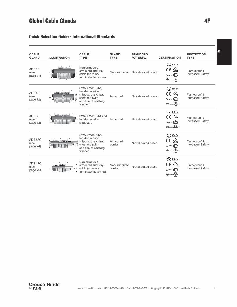
4F
67www.crouse-hinds.com US: 1-866-764-5454 CAN: 1-800-265-0502 Copyright© 2013 Eaton’s Crouse-Hinds Business
Global Cable Glands
ADE 1F(see page 71)
Non-armoured,armoured and traycable (does notterminate the armour)
Non-armoured Nickel-plated brass Flameproof &Increased Safety
ADE 1FC(see page 75)
Non-armoured,armoured and traycable (does notterminate the armour)
Non-armouredbarrier Nickel-plated brass Flameproof &
Increased Safety
ADE 4F(see page 72)
SWA, SWB, STA,braided marineshipboard and leadsheathed (withaddition of earthingwasher)
Armoured Nickel-plated brass Flameproof &Increased Safety
ADE 6F(see page 73)
SWA, SWB, STA andbraided marineshipboard
Armoured Nickel-plated brass Flameproof &Increased Safety
CABLE
GLAND ILLUSTRATION
CABLE
TYPE
GLAND
TYPE
STANDARD
MATERIAL CERTIFICATION
PROTECTION
TYPE
ADE 6FC(see page 74)
SWA, SWB, STA,braided marineshipboard and leadsheathed (withaddition of earthingwasher)
Armouredbarrier Nickel-plated brass Flameproof &
Increased Safety
4F
Quick Selection Guide - International Standards
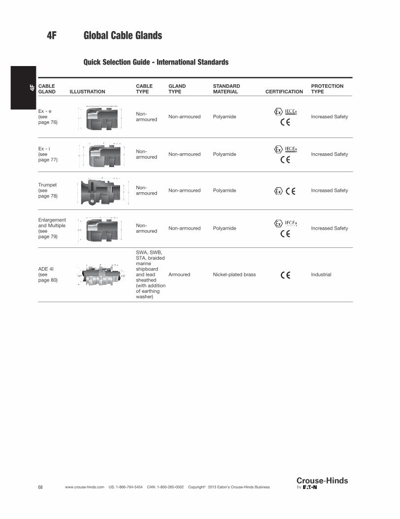
4F
68 www.crouse-hinds.com US: 1-866-764-5454 CAN: 1-800-265-0502 Copyright© 2013 Eaton’s Crouse-Hinds Business
Ex - e(seepage 76)
Non-armoured Non-armoured Polyamide Increased Safety
Ex - i(seepage 77)
Non-armoured Non-armoured Polyamide Increased Safety
Trumpet(seepage 78)
Non-armoured Non-armoured Polyamide Increased Safety
Enlargementand Multiple(seepage 79)
Non-armoured Non-armoured Polyamide Increased Safety
ADE 4I(seepage 80)
SWA, SWB,STA, braidedmarineshipboardand leadsheathed(with additionof earthingwasher)
Armoured Nickel-plated brass Industrial
CABLE
GLAND ILLUSTRATION
CABLE
TYPE
GLAND
TYPE
STANDARD
MATERIAL CERTIFICATION
PROTECTION
TYPE
Global Cable Glands4F
Quick Selection Guide - International Standards
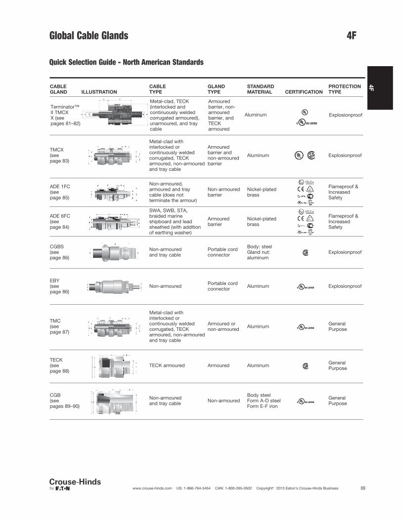
4F
69www.crouse-hinds.com US: 1-866-764-5454 CAN: 1-800-265-0502 Copyright© 2013 Eaton’s Crouse-Hinds Business
Quick Selection Guide - North American Standards
TMCX(seepage 83)
Metal-clad withinterlocked orcontinuously weldedcorrugated, TECKarmoured, non-armouredand tray cable
Armouredbarrier andnon-armouredbarrier
Aluminum Explosionproof
ADE 1FC(seepage 85)
Non-armoured,armoured and traycable (does notterminate the armour)
Non-armouredbarrier
Nickel-platedbrass
Flameproof &IncreasedSafety
ADE 6FC(seepage 84)
SWA, SWB, STA,braided marineshipboard and leadsheathed (with additionof earthing washer)
Armouredbarrier
Nickel-platedbrass
Flameproof &IncreasedSafety
CGBS(seepage 86)
Non-armoured and tray cable
Portable cordconnector
Body: steelGland nut:aluminum
Explosionproof
EBY(seepage 86)
Non-armoured Portable cordconnector Aluminum Explosionproof
TMC(seepage 87)
Metal-clad withinterlocked orcontinuously weldedcorrugated, TECKarmoured, non-armouredand tray cable
Armoured ornon-armoured Aluminum General
Purpose
TECK(seepage 88)
TECK armoured Armoured Aluminum GeneralPurpose
CABLE
GLAND ILLUSTRATION
CABLE
TYPE
GLAND
TYPE
STANDARD
MATERIAL CERTIFICATION
PROTECTION
TYPE
CGB(seepages 89–90)
Non-armoured and tray cable Non-armoured
Body steelForm A-D steelForm E-F iron
GeneralPurpose
Global Cable Glands 4F
Terminator™II TMCXX (seepages 81–82)
GC
E
D
F
BA
Metal-clad, TECK(interlocked andcontinuously weldedcorrugated armoured),unarmoured, and traycable
Armouredbarrier, non-armouredbarrier, andTECKarmoured
Aluminum Explosionproof
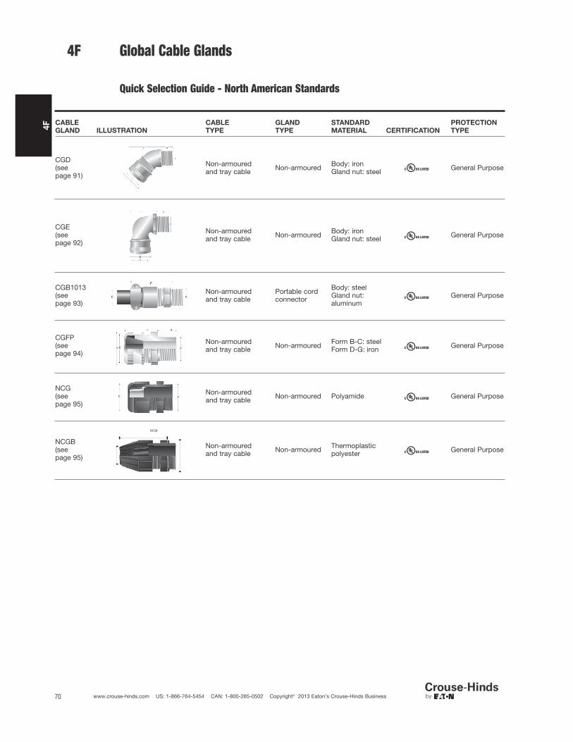
4F
70 www.crouse-hinds.com US: 1-866-764-5454 CAN: 1-800-265-0502 Copyright© 2013 Eaton’s Crouse-Hinds Business
CGE(seepage 92)
Non-armoured and tray cable Non-armoured Body: iron
Gland nut: steel General Purpose
CGB1013(seepage 93)
Non-armoured and tray cable
Portable cordconnector
Body: steelGland nut:aluminum
General Purpose
CGFP(seepage 94)
Non-armoured and tray cable Non-armoured Form B-C: steel
Form D-G: iron General Purpose
CGD(seepage 91)
Non-armoured and tray cable Non-armoured Body: iron
Gland nut: steel General Purpose
CABLE
GLAND ILLUSTRATION
CABLE
TYPE
GLAND
TYPE
STANDARD
MATERIAL CERTIFICATION
PROTECTION
TYPE
NCG(seepage 95)
Non-armoured and tray cable Non-armoured Polyamide General Purpose
NCGB(seepage 95)
NCGB
Non-armoured and tray cable Non-armoured Thermoplastic
polyester General Purpose
4F Global Cable Glands
Quick Selection Guide - North American Standards

–
4F
71www.crouse-hinds.com US: 1-866-764-5454 CAN: 1-800-265-0502 Copyright© 2013 Eaton’s Crouse-Hinds Business
Features:
• Standard material is nickel-plated brass for superior corrosionresistance
• Provides a flameproof and weatherproof seal on the outer sheathof the cable
• Standard neoprene seal suitable for use in operating temperaturesATEX (-60°C to 100°C), IECEx and cULus (-40°C to 100°C)
• Available with optional silicone seal for extreme temperatures
• Available with metric or NPT threads
• See pages 96–103 for related accessories
ORDERING EXAMPLE:
CAP81640 4 KX
OptionsGlandType
9 Stainless steel (316L)
8 Bronze
7 Aluminum
5 Silicone sealing ring with temperature range of
-70°C to 220°C
K1 Includes locknut and fiber washer
K2 Includes locknut, fiber washer, earth tag, and
shroud
OPTIONS (replace last digit with option number):
ADE 1F
International Standards - Flameproof and Increased Safety
Gland
Size
Entry Thread Size ‘A’ Thread
Length ‘B’
Metric
(NPT)
Cable AcceptanceGland
Length ‘F’
(less entry)
Hexagon Dimensions
Metric
Size
Metric
Catalog #
NPT
SizeNPT
Catalog #
Outer Sheath‘E’Across
Flats
Across
Corners ‘G’Min Max
4 M12 CAP816404 1/4" CAP818404 15 (12.0) 4.0 8.0 20 – 16.54 M16 CAP816594 3/8" CAP818594 15 (12.0) 4.0 8.5 20 – 20.95 M16 CAP816504 1/2" CAP818694 15 (12.0) 6.0 12.0 22 – 20.94 M20 CAP816674 1/2" CAP818674 15 (20.2) 4.0 8.5 20 – 26.45 M20 CAP816694 1/2" CAP818694 15 (20.2) 6.0 12.0 22 – 26.46 M20 CAP816604 1/2" CAP818604 15 (20.2) 8.5 16.0 25 – 26.45 M25 CAP816774 3/4" CAP818774 15 (20.2) 6.0 12.0 22 – 336 M25 CAP816794 3/4" CAP818794 15 (20.2) 8.5 16.0 25 – 337 M25 CAP816704 3/4" CAP818704 15 (20.2) 12.0 21.0 27 – 337 M32 CAP816894 1" CAP818894 15 (25.3) 12.0 21.0 27 – 39.68 M32 CAP816804 1" CAP818804 15 (25.3) 16.0 27.5 34 – 45.18 M40 CAP816994 11/4" CAP818994 15 (26.0) 16.0 27.5 34 – 48.49 M40 CAP816904 11/4" CAP818904 15 (26.0) 21.0 34.0 36 – 52.89 M50 CAP817094 11/2" CAP819094 15 (26.5) 21.0 34.0 36 – 60.5
10 M50 CAP817004 11/2" CAP819004 15 (26.5) 27.0 41.0 39 – 60.511 M63 CAP817294 2" CAP819294 17 (27.2) 33.0 48.0 41 – 73.712 M63 CAP817204 2" CAP819204 17 (27.2) 40.0 56.0 43 – 79.212 M75 CAP817394 21/2" CAP819494 18 (40.5) 40.0 56.0 43 – 8813 M75 CAP817304 21/2" CAP819404 18 (40.5) 47.0 65.0 49 – 93.514 M90 CAP817594 3" CAP819594 22 (42.0) 54.0 74.0 56 – 104.515 M90 CAP817504 3" CAP819504 22 (42.0) 63.0 78.0 61 – 12116 M110 CAP817794 31/2" CAP819604 22 (43.2) 72.0 92.0 62 132
SELECTION TABLE
4FATEXIECExcULus Listed for Class I, Zone 2cULus Marine Listed for Class I, Zone 2
CEPELGOST-RNEPSINEMA 4X and IP68
Gland Type:Non-armoured
Cable Type:Non-armoured, armoured and tray cable (does not terminate thearmour)
Certifications and Compliances:
• ATEX LCIE 97 ATEX 6008X – Exd IIC/Exe II/Ex tD /Ex II 2 GD
• IECEx LCI 05.0004X
• cULus Listed for Class I Zone 2 AEx e II/Ex e II E310130
• cULus Marine Listed for Class I Zone 2 AEx e II/Ex e II E314047
• NEMA 4X and IP68
• CEPEL cepel-EX-558/05X
• GOST-R POCC FR.B02011
• NEPSI N° GYJ071336U & GYJ071337U

4F
72 www.crouse-hinds.com US: 1-866-764-5454 CAN: 1-800-265-0502 Copyright© 2013 Eaton’s Crouse-Hinds Business
ADE 4FInternational Standards - Flameproof and Increased Safety
Gland Type:Armoured
Cable Type:
Steel wire armoured, steel wire braided, steel tape armoured, braidedmarine shipboard and lead sheathed (with addition of earthingwasher)
Certifications and Compliances:
• ATEX LCIE 97 ATEX 6008X – Exd IIC/Exe II/Ex tD/Ex II 2 GD
• IECEx LCI 05.0004X
• cULus listed for Class I, Zone 2 AEx e II/Ex e II E310130
• cULus Marine listed for Class I, Zone 1 AEx e II/Ex e II E314047
• NEMA 4X and IP68
• CEPEL cepel-EX-559/05X
• GOST-R POCC FR.B02011
• NEPSI N° GYJ071336U & GYJ071337U
Features:• Standard material is nickel-plated brass for superior corrosion
resistance• Armour clamping and bonding with no reversible components for
easy installation, minimizing error• Provides flameproof seal on inner jacket and weatherproof seal on
outer sheath of cable• Optional earthing washer for use with lead sheathed cable
(see page 97)• Standard neoprene seal suitable for use in operating temperatures
ATEX (-60°C to 100°C), IECEx and cULus (-40°C to 100°C)• Available with optional silicone seal for extreme temperatures• Available with metric or NPT threads• See pages 96–103 for related accessories
4F
ORDERING EXAMPLE:
CAP84640 4 KX
OptionsGlandType
9 Stainless steel (316L)
8 Bronze
7 Aluminum
5 Silicone sealing ring with temperature range of
-70°C to 220°C
K1 Includes locknut and fiber washer
K2 Includes locknut, fiber washer, earth tag, and
shroud
OPTIONS (replace last digit with option number):
SELECTION TABLE
Gland
Size
Entry Thread Size ‘A’
Thread
Length ‘B’
Metric
(NPT)
Cable Acceptance
Armour
(max)
Gland
Length
‘F’ (less
entry)
Hexagon
Dimensions
Metric
Size
Metric
Catalog #
NPT
Size NPT Catalog #
Inner Sheath
‘D’
Outer Sheath
‘E’Across
Flats
Across
Corners
‘G’Min Max Min Max
5 M12 CAP846404 1/4" CAP848404 15 (12.0) 4.0 8.0 6.0 12.0 0.9 36 – 20.95 M16 CAP846594 3/8" CAP848594 15 (12.0) 4.0 8.5 6.0 12.0 0.9 36 – 20.96 M16 CAP846504 3/8" CAP848504 15 (12.0) 6.0 12.0 8.5 16.0 1.25 42 – 26.45 M20 CAP846674 1/2" CAP848674 15 (20.2) 4.0 8.5 6.0 12.0 0.9 36 – 26.46 M20 CAP846694 1/2" CAP848694 15 (20.2) 6.0 12.0 8.5 16.0 1.25 42 – 26.47 M20 CAP846604 1/2" CAP848604 15 (20.2) 8.5 16.0 12.0 21.0 1.25 46 – 33.06 M25 CAP846774 3/4" CAP848774 15 (20.2) 6.0 12.0 8.5 16.0 1.25 42 – 33.07 M25 CAP846794 3/4" CAP848794 15 (20.2) 8.5 16.0 12.0 21.0 1.25 46 – 33.08 M25 CAP846704 3/4" CAP848704 15 (20.2) 12.0 20.5 16.0 27.5 1.6 56 – 45.18 M32 CAP846894 1" CAP848894 15 (25.3) 12.0 21.0 16.0 27.5 1.6 56 – 45.19 M32 CAP846804 1" CAP848804 15 (25.3) 16.0 27.5 21.0 34.0 1.6 63 – 52.89 M40 CAP846994 11/4" CAP848994 15 (26.0) 16.0 27.5 21.0 34.0 1.6 63 – 52.8
10 M40 CAP846904 11/4" CAP848904 15 (26.0) 21.0 34.0 27.0 41.0 2.0 68 – 60.510 M50 CAP847094 11/2" CAP849094 15 (26.5) 21.0 34.0 27.0 41.0 2.0 68 – 60.511 M50 CAP847004 11/2" CAP849004 15 (26.5) 27.0 41.0 33.0 48.0 2.5 74 – 70.412 M63 CAP847294 2" CAP849294 17 (27.2) 27.0 41.0 33.0 48.0 2.5 77 – 79.213 M63 CAP847204 2" CAP849204 17 (27.2) 33.0 48.0 47.0 56.0 2.5 85 – 93.513 M75 CAP847394 21/2" CAP849494 18 (40.5) 40.0 56.0 47.0 65.0 2.5 85 – 93.514 M75 CAP847304 21/2" CAP849404 18 (40.5) 47.0 65.0 54.0 74.0 2.5 92 – 104.515 M90 CAP847794 3" CAP849594 22 (42.0) 54.0 74.0 63.0 83.0 3.15 104 – 121.016 M90 CAP847504 3" CAP849504 22 (42.0) 63.0 82.0 72.0 93.0 3.15 108 – 132.016 M90 CAP847574 31/2" CAP849604 N/A (43.2) 63.0 82.0 72.0* 93.0* 3.15 108 – 132.017 M110 CAP847794 4" CAP849704 22 (44.5) 72.0 92.0 85.0 107.0 3.15 115 – 148.5
All dimensions in millimeters unless otherwise noted * CAP849604 “outer sheath” min: 85 max: 107.
ATEXIECExcULus Listed for Class I, Zone 2cULus Marine Listed for Class I,Zone 1
CEPELGOST-RNEPSINEMA 4X and IP68

5 M16 CAP965594 3/8" CAP967594 15 (12.0) 3.0 7.5 6.0 12.0 0.9 46.0 – 20.95 M20 CAP965674 1/2" CAP967674 15 (20.2) 3.0 7.5 6.0 12.0 0.9 46.0 – 26.46 M20 CAP965694 1/2" CAP967694 15 (20.2) 6.5 11.0 8.5 16.0 1.25 53.0 – 26.47 M20 CAP965604 1/2" CAP967604 15 (20.2) 9.0 14.5 12.0 21.0 1.25 59.0 – 33.07 M25 CAP965794 3/4" CAP967794 15 (20.2) 9.0 14.5 12.0 21.0 1.25 59.0 – 33.08 M25 CAP965704 3/4" CAP967704 15 (20.2) 12.0 19.5 16.0 27.5 1.6 74.5 – 45.18 M32 CAP965894 1" CAP967894 15 (25.3) 12.0 19.5 16.0 27.5 1.6 74.5 – 45.19 M32 CAP965804 1" CAP967804 15 (25.3) 17.5 26.0 21.0 34.0 1.6 83.5 – 52.89 M40 CAP965994 11/4" CAP967994 15 (26.0) 17.5 26.0 21.0 34.0 1.6 83.5 – 52.810 M40 CAP965904 11/4" CAP967904 15 (26.0) 23.0 33.0 27.0 41.0 2.0 92.0 – 60.510 M50 CAP966094 CAP968094 16 (26.5) 23.0 33.0 27.0 41.0 2.0 92.0 – 60.511 M50 CAP966004 2" CAP968294 16 (27.2) 28.5 41.0 33.0 48.0 2.5 104.0 – 70.4
4F
73www.crouse-hinds.com US: 1-866-764-5454 CAN: 1-800-265-0502 Copyright© 2013 Eaton’s Crouse-Hinds Business
SELECTION TABLE
Gland
Size
Entry Thread Size ‘A’Thread
Length ‘B’
Metric
(NPT)
Cable Acceptance
Armour
(max)
Gland
Length
‘F’ (less
entry)
HexagonDimensions
Metric
Size
Metric
Catalog #
NPT
Size
NPT
Catalog #
Inner
Sheath ‘D’
Outer
Sheath ‘E’Across
Flats
Across
Corners
‘G’Min Max Min Max
Larger sizes available in ADE 4F design, see page 72.All dimensions in millimeters unless otherwise noted.
4FADE 6F
International Standards - Flameproof and Increased Safety
Features:• Standard material is nickel-plated brass for superior corrosion
resistance• Armour clamping and bonding with no reversible components for
easy installation, minimizing error• Provides fully inspectable inner seal after installation• Flameproof diaphragm seal on inner jacket does not damage
cables exhibiting “cold-flow”; weatherproof seal on outer sheath of cable
• Deluge boot provides enhanced protection from water ingress• Standard neoprene seal suitable for use in operating temperatures
ATEX (-60°C to 100°C), IECEx and cULus (-40°C to 100°C)• Available with metric or NPT threads• See pages 96–103 for related accessories
Gland Type:Armoured
Cable Type:Steel wire armoured, steel wire braided, steel tape armoured andbraided marine shipboard
11/2"
Certifications and Compliances:
• ATEX LCIE 97 6008X - Exd IIC / Exe II / Ex tD / Ex II 2GD
• IECEx LCI 05.0004X
• cULus Listed for Class I, Zone 2 AEx e II / Ex e II E310130
• cULus Marine Listed for Class I, Zone 2 AEx e II / Ex e II E314047
• NEMA 4X and IP68
• CEPEL
• GOST-R
• NEPSI
ATEXIECExcULus Listed for Class I, Zone 2cULus Marine Listed for Class I,Zone 2
CEPELGOST-RNEPSINEMA 4X and IP68

4F
74 www.crouse-hinds.com US: 1-866-764-5454 CAN: 1-800-265-0502 Copyright© 2013 Eaton’s Crouse-Hinds Business
4F ADE 6FC
International Standards - Flameproof and Increased Safety
ATEXIECExcULus Listed for Class I, Zone 2cULus Marine Listed for Class I, Div. 1
CEPELGOST-RNEMA 4X and IP68
Gland Type:Armoured barrier
Cable Type:Steel wire armoured, steel wire braided, steel tape armoured,braided marine shipboard and lead sheathed (with addition ofearthing washer)
ORDERING EXAMPLE:
CAP96959 4 KX
OptionsGlandType
9 Stainless steel (316L)
8 Bronze
7 Aluminum
K1 Includes locknut and fiber washer
K2 Includes locknut, fiber washer, earth tag, and
shroud
OPTIONS (replace last digit with option number):
Certifications and Compliances:• ATEX LCIE 97 ATEX 6008X - Exd IIC/Exe II/Ex tD/Ex II 2 GD• IECEx LCI 05.0004X• cULus Listed for Class I, Zone 2 AEx de II/Ex de II• cULus Marine Listed for Class I, Division 1, Groups A, B, C, D• NEMA 4X and IP68• CEPEL-EX-558/05X• GOST-R POCC FR Bo2011• NEPSI N° GYJ071336U & GYJ071337U• ABS approbation:
n° 10-HS 577243-PDA / P1836754-X• DNV N° E-10892• Lloyds
Features• Standard material is nickel-plated brass for superior corrosion
resistance• Armour clamping with no reversible components for easy
installation, minimizing error• Provides explosionproof compound seal (denoted by red back nut)
on conductors and weatherproof seal on outer sheath of cable• Deluge boot provides enhanced protection from water ingress• Standard neoprene seal suitable for use in operating temperatures
-60°C (-25°C UL) to 80°C• Available with metric or NPT threads• See pages 96–103 for related accessories
5 M16 CAP969594 3/8" CAP974594 15 (12.0) 6.5 7.5 6.0 6.0 12.0 0.9 46.0 – 20.9
5 M20 CAP969674 1/2" CAP971674 15 (20.2) 6.5 7.5 6.0 6.0 12.0 0.9 46.0 – 26.4
6 M20 CAP969694 1/2" CAP971694 15 (20.2) 9.5 11.0 6.0 8.5 16.0 1.25 53.0 – 26.4
7 M20 CAP969604 1/2" CAP971604 15 (20.2) 12.0 14.5 10.0 12.0 21.0 1.25 59.0 – 33.0
7 M25 CAP969794 3/4" CAP971794 15 (20.5) 12.0 14.5 10.0 12.0 21.0 1.25 59.0 – 33.0
8 M25 CAP969704 3/4" CAP971704 15 (20.5) 17.0 19.5 21.0 16.0 27.5 1.6 74.5 – 45.1
8 M32 CAP969894 1" CAP971894 15 (25.3) 17.0 19.5 21.0 16.0 27.5 1.6 74.5 – 45.1
9 M32 CAP969804 1" CAP971804 15 (25.3) 23.0 28.0 42.0 21.0 34.0 1.6 83.5 – 52.8
9 M40 CAP969994 11/4" CAP971994 15 (26.0) 23.0 28.0 42.0 21.0 34.0 1.6 83.5 – 52.8
10 M40 CAP969904 11/4" CAP971904 15 (26.0) 29.0 33.0 60.0 27.0 41.0 2.0 92.0 – 60.5
10 M50 CAP970094 11/2" CAP972094 16 (26.5) 29.0 33.0 60.0 27.0 41.0 2.0 92.0 – 60.5
11 M50 CAP970004 11/2" CAP972004 16 (27.2) 36.5 41.0 80.0 33.0 48.0 2.5 104.0 – 70.4
12 M63 CAP970294 2" CAP972274 17 (29.2) 43.0 48.0 100.0 40.0 56.0 2.5 108.0 – 79.2
13 M63 CAP970204 2" CAP972204 17 (29.2) 50.0 56.0 100.0 46.0 65.0 2.5 118.0 – 93.5
13 M75 CAP970394 21/2" CAP972494 18 (42.5) 50.0 56.0 100.0 46.0 65.0 2.5 118.0 – 93.5
14 M75 CAP970304 21/2" CAP972404 18 (42.5) 59.0 65.0 120.0 54.0 74.0 2.5 124.0 – 104.5
14 – – 3" CAP972574 (44) 59.0 65.0 120.0 54.0 74.0 2.5 124.0 – 104.5
15 M90 CAP970594 3" CAP972594 22 (44.0) 66.0 73.0 140.0 63.0 83.0 3.15 133.0 – 121.0
15 – – 31/2" CAP972694 (45.2) 66.0 73.0 140.0 63.0 83.0 3.15 133.0 – 121.0
16 M90 CAP970504 3" CAP972504 22 (44.0) 75.0 82.0 140.0 72.0 93.0 3.15 137.0 – 132.0
16 – – 31/2" CAP972604 (45.2) 75.0 82.0** 140.0 72.0 93.0 3.15 137.0 – 132.0
17 M110 CAP970794 4" CAP972704 22 (46.5) 85.0 92.0** 200.0 85.0 107.0 3.15 142.0 – 148.5All dimensions in millimeters unless otherwise noted.*Aluminum not currently available with UL marine certification.**Contact Customer Service or your field sales representative for amended UL marine range.
SELECTION TABLE
Gland
Size
Entry Thread Size ‘A’
Thread
Length
‘B’
Metric
(NPT)
Cable Acceptance
Armour
(max)
Gland
Length
‘F’ (less
entry)
Hexagon
Dimensions
Metric
Size
Metric
Catalog #
NPT
Size
NPT
Catalog #
Inner Sheath
and Cores
Outer
Sheath ‘E’
Across
Flats
Across
Corners
‘G’
Max
Over
Cores
'C'
Max
Inner
Sheath
'D'
Max
No. of
Cores Min Max
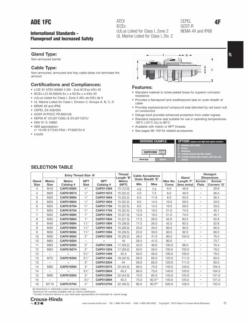
4F
75www.crouse-hinds.com US: 1-866-764-5454 CAN: 1-800-265-0502 Copyright© 2013 Eaton’s Crouse-Hinds Business
4FADE 1FC
International Standards - Flameproof and Increased Safety
Gland Type:Non-armoured barrier
Cable Type:Non-armoured, armoured and tray cable (does not terminate thearmour)
Features:• Standard material is nickel-plated brass for superior corrosion
resistance• Provides a flameproof and weatherproof seal on outer sheath of
cable• Provides explosionproof compound seal (denoted by red back nut)
on conductors• Deluge boot provides enhanced protection from water ingress• Standard neoprene seal suitable for use in operating temperatures
-60°C (-25°C UL) to 80°C• Available with metric or NPT threads• See pages 96–103 for related accessories
SELECTION TABLE
Gland
Size
Thread
Length ‘B’
Metric
(NPT)
Cable Acceptance
Max No.
Cores
Gland
Length ‘F’
(less entry)
Hexagon
Dimensions
Metric
Size
Metric
Catalog #
NPT
Size
NPT
Catalog #
Outer Sheath ‘E’Across
Flats
Across
Corners ‘G’Min Max
4 M16 CAP019594 3/8" CAP011594 15 (12.0) 4.0 7.5 6.0 46.0 –––––––––––––––––––––––
20.9
4 M20 CAP019674 1/2" CAP011674 15 (22.2) 4.0 7.5 6.0 46.0 26.45 M20 CAP019694 1/2" CAP011694 15 (22.2) 6.5 11.0 6.0 53.0 26.46 M20 CAP019604 1/2" CAP011604 15 (22.2) 9.0 14.5 10.0 59.0 33.06 M25 CAP019794 3/4" CAP011794 15 (22.5) 9.0 14.5 10.0 59.0 33.07 M25 CAP019704 3/4" CAP011704 15 (22.5) 12.0 19.5 21.0 74.5 45.17 M32 CAP019894 1" CAP011894 15 (27.3) 12.0 19.5 21.0 74.5 45.18 M32 CAP019804 1" CAP011804 15 (27.3) 17.5 26.0 42.0 83.5 52.88 M40 CAP019994 11/4" CAP011994 15 (28.0) 17.5 26.0 42.0 83.5 52.89 M40 CAP019904 11/4" CAP011904 15 (28.0) 23.0 33.0 60.0 92.0 60.59 M50 CAP019094 11/2" CAP011094 16 (28.5) 23.0 33.0 60.0 92.0 60.5
10 M50 CAP019004 2" CAP011004 16 (29.2) 28.5 41.0 80.0 104.0 70.410 M63 CAP019204 – – 16 28.5 41.0 80.0 – 73.711 M63 CAP019294 2" CAP011294 17 (29.2) 43.0 48.0 100.0 98.0 70.412 M63 CAP019274 2" CAP011204 17 (29.2) 50.0 56.0 100.0 103.0 79.212 – – 21/2" CAP011494 42.5 50.0 56.0 100.0 103.0 79.213 M75 CAP019304 21/2" CAP011404 18 (42.5) 59.0 65.0 120.0 111.0 93.513 – – 3" CAP012504 44 59.0 65.0 120.0 111.0 93.514 M90 CAP010594 3" CAP012574 22 (44.0) 66.0 73.0 140.0 120.0 104.514 – – 31/2" CAP012604 45.2 66.0 73.0 140.0 120.0 104.515 M90 CAP010504 3" CAP012594 22 (44.0) 75.0 82.0 140.0 125.0 121.015 – – 31/2" CAP012694 45.2 75.0 82.0** 140.0 125.0 121.016 M110 CAP010794 4" CAP012704 22 (46.5) 85.0 92.0** 200.0 128.0 132.0
All dimensions in millimeters unless otherwise noted.*Aluminum not currently available with UL marine certification.**Contact Customer Service or your field sales representative for amended UL marine range.
Entry Thread Size ‘A’
ATEXIECExcULus Listed for Class I, Zone 2UL Marine Listed for Class I, Div. 2
CEPELGOST-RNEMA 4X and IP68
Certifications and Compliances:• LCIE 97 ATEX 6008X II GD - Exd IIC/Exe II/Ex tD• IECEx LCI 05.0004X Ex c e IIC/Ex c e II/Ex tD• cULus Listed for Class I, Zone 2 AEx de II/Ex de II• UL Marine Listed for Class I, Division 2, Groups A, B, C, D• NEMA 4X and IP68• CEPEL EX-558/05X• GOST-R POCC FR.B03126• NEPSI N° GYJ071336U & GYJ071337U• DNV N° E-10892• ABS approbation:
n° 10-HS 577243-PDA / P1836754-X• Lloyds
ORDERING EXAMPLE:
CAP01959 4 KX
OptionsGlandType
9 Stainless steel (316L)
8 Bronze
7 Aluminum
K1 Includes locknut and fiber washer
K2 Includes locknut, fiber washer, earth tag, and
shroud
OPTIONS (replace last digit with option number):
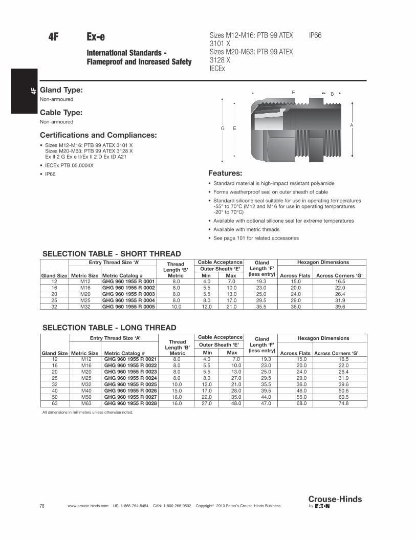
4F
76 www.crouse-hinds.com US: 1-866-764-5454 CAN: 1-800-265-0502 Copyright© 2013 Eaton’s Crouse-Hinds Business
Ex-eInternational Standards -Flameproof and Increased Safety
Sizes M12-M16: PTB 99 ATEX3101 XSizes M20-M63: PTB 99 ATEX3128 XIECEx
IP66
Gland Type:Non-armoured
Cable Type:Non-armoured
Certifications and Compliances:
• Sizes M12-M16: PTB 99 ATEX 3101 XSizes M20-M63: PTB 99 ATEX 3128 XEx II 2 G Ex e II/Ex II 2 D Ex tD A21
• IECEx PTB 05.0004X
• IP66 Features:
• Standard material is high-impact resistant polyamide
• Forms weatherproof seal on outer sheath of cable
• Standard silicone seal suitable for use in operating temperatures -55° to 70°C (M12 and M16 for use in operating temperatures -20° to 70°C)
• Available with optional silicone seal for extreme temperatures
• Available with metric threads
• See page 101 for related accessories
SELECTION TABLE - LONG THREAD
Gland Size
Entry Thread Size ‘A’Thread
Length ‘B’
Metric
Cable Acceptance Gland
Length ‘F’
(less entry)
Hexagon Dimensions
Metric Size Metric Catalog #
Outer Sheath ‘E’
Across Flats Across Corners ‘G’Min Max
12 M12 GHG 960 1955 R 0021 8.0 4.0 7.0 19.3 15.0 16.516 M16 GHG 960 1955 R 0022 8.0 5.5 10.0 23.0 20.0 22.02025
M20 GHG 960 1955 R 0023 8.0 5.5 13.0 25.0 24.0 26.4M25 GHG 960 1955 R 0024 8.0 8.0 27.0 29.5 29.0 31.9
32 M32 GHG 960 1955 R 0025 10.0 12.0 21.0 35.5 36.0 39.640 M40 GHG 960 1955 R 0026 15.0 17.0 28.0 39.5 46.0 50.650 M50 GHG 960 1955 R 0027 16.0 22.0 35.0 44.0 55.0 60.563 M63 GHG 960 1955 R 0028 16.0 27.0 48.0 47.0 68.0 74.8
All dimensions in millimeters unless otherwise noted.
4F
SELECTION TABLE - SHORT THREAD
Gland Size
Entry Thread Size ‘A’ Thread
Length ‘B’
Metric
Cable Acceptance Gland
Length ‘F’
(less entry)
Hexagon Dimensions
Metric Size Metric Catalog #
Outer Sheath ‘E’
Across Flats Across Corners ‘G’Min Max
12 M12 GHG 960 1955 R 0001 8.0 4.0 7.0 19.3 15.0 16.516 M16 GHG 960 1955 R 0002 8.0 5.5 10.0 23.0 20.0 22.020 M20 GHG 960 1955 R 0003 8.0 5.5 13.0 25.0 24.0 26.425 M25 GHG 960 1955 R 0004 8.0 8.0 17.0 29.5 29.0 31.932 M32 GHG 960 1955 R 0005 10.0 12.0 21.0 35.5 36.0 39.6

4F
77www.crouse-hinds.com US: 1-866-764-5454 CAN: 1-800-265-0502 Copyright© 2013 Eaton’s Crouse-Hinds Business
Ex-iInternational Standards -Flameproof and Increased Safety
Sizes M12-M16: PTB 99 ATEX3101 XSizes M20-M63: PTB 99 ATEX3128 XIECEx
IP66
Gland Type:Non-armoured
Cable Type:Non-armoured
Certifications and Compliances:
• Sizes M12-M16: PTB 99 ATEX 3101 XSizes M20-M63: PTB 99 ATEX 3128 XEx II 2 G Ex e II/Ex II 2 D Ex tD A21
• IECEx PTB 05.0004X
• IP66 Features:
• Standard material is high-impact resistant polyamide (gland nut isblue for intrinsically safe circuits)
• Forms weatherproof seal on outer sheath of cable
• Standard silicone seal suitable for use in operating temperatures -55° to 70°C (M12 and M16 for use in operating temperatures -20° to 70°C)
• Available with metric threads
• See page 101 for related accessories
SELECTION TABLE – LONG THREAD
Gland Size
Entry Thread Size ‘A’ Thread
Length ‘B’
Metric
Cable Acceptance Gland
Length ‘F’
(less entry)
Hexagon Dimensions
Metric Size Metric Catalog #
Outer Sheath ‘E’Across Flats Across Corners ‘G’
Min Max
12 M12 GHG 960 1955 R 0121 12.0 4.0 7.0 19.3 15.0 16.516 M16 GHG 960 1955 R 0122 12.0 5.5 10.0 23.0 20.0 22.020 M20 GHG 960 1955 R 0123 13.0 5.5 13.0 25.0 24.0 26.425 M25 GHG 960 1955 R 0124 13.0 8.0 17.0 29.5 29.0 31.932 M32 GHG 960 1955 R 0125 15.0 12.0 21.0 35.5 36.0 39.640 M40 GHG 960 1955 R 0126 15.0 17.0 28.0 39.5 46.0 50.650 M50 GHG 960 1955 R 0127 16.0 22.0 35.0 44.0 55.0 60.563 M63 GHG 960 1955 R 0128 16.0 27.0 48.0 47.0 68.0 74.8
All dimensions in millimeters unless otherwise noted.
4F
SELECTION TABLE – SHORT THREAD
Gland Size
Entry Thread Size ‘A’ Thread
Length ‘B’
Metric
Cable Acceptance Gland
Length ‘F’
(less entry)
Hexagon Dimensions
Metric Size Metric Catalog #
Outer Sheath ‘E’Across Flats Across Corners ‘G’
Min Max
12 M12 GHG 960 1955 R 0101 8.0 4.0 7.0 19.3 15.0 16.516 M16 GHG 960 1955 R 0102 8.0 5.5 10.0 23.0 20.0 22.020 M20 GHG 960 1955 R 0103 8.0 5.5 13.0 25.0 24.0 26.425 M25 GHG 960 1955 R 0104 8.0 8.0 17.0 29.5 29.0 31.932 M32 GHG 960 1955 R 0105 10.0 12.0 21.0 35.5 36.0 39.6
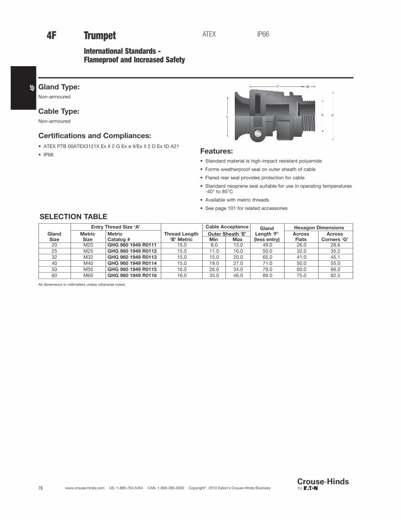
4F
78 www.crouse-hinds.com US: 1-866-764-5454 CAN: 1-800-265-0502 Copyright© 2013 Eaton’s Crouse-Hinds Business
TrumpetInternational Standards -Flameproof and Increased Safety
ATEX IP66
Gland Type:
Non-armoured
Cable Type:
Non-armoured
Certifications and Compliances:
• ATEX PTB 00ATEX3121X Ex II 2 G Ex e II/Ex II 2 D Ex tD A21
• IP66 Features:
• Standard material is high-impact resistant polyamide
• Forms weatherproof seal on outer sheath of cable
• Flared rear seal provides protection for cable
• Standard neoprene seal suitable for use in operating temperatures-40° to 85°C
• Available with metric threads
• See page 101 for related accessories
SELECTION TABLE
Entry Thread Size ‘A’
Thread Length
‘B’ Metric
Cable Acceptance Gland
Length ‘F’
(less entry)
Hexagon Dimensions
Metric
Size
Metric
Catalog #Outer Sheath ‘E’ Across
Flats
Across
Corners ‘G’Min Max
20 M20 GHG 960 1949 R0111 15.0 8.0 13.0 49.0 26.0 28.625 M25 GHG 960 1949 R0112 15.0 11.0 16.0 50.0 32.0 35.232 M32 GHG 960 1949 R0113 15.0 15.0 20.0 65.0 41.0 45.140 M40 GHG 960 1949 R0114 15.0 19.0 27.0 71.0 50.0 55.050 M50 GHG 960 1949 R0115 16.0 26.0 34.0 79.0 60.0 66.060 M60 GHG 960 1949 R0116 16.0 35.0 46.0 89.0 75.0 82.5
All dimensions in millimeters unless otherwise noted.
4F
Gland
Size

SELECTION TABLE – MULTIPLE
4F
79www.crouse-hinds.com US: 1-866-764-5454 CAN: 1-800-265-0502 Copyright© 2013 Eaton’s Crouse-Hinds Business
Enlargement and MultipleInternational Standards -Flameproof and Increased Safety
Sizes M16: PTB 99 ATEX 3101 XSizes M20-M63: PTB 99 ATEX3128 XIECEx
IP66
Gland Type:
Non-armoured
Cable Type:
Non-armoured
Certifications and Compliances:
• Sizes M16: PTB 99 ATEX 3101 XSizes M20-M63: PTB 99 ATEX 3128 XEx II 2 G Ex e II/Ex II 2 D Ex tD A21
• IECEx PTB 05.0004X
• IP66
Features:• Standard material is high-impact resistant polyamide• Forms weatherproof seal on outer sheath of cable• Provides reduced entry threads for larger gland size• Standard silicone seal suitable for use in operating temperatures
-55° to 70°C (M16 for use in operating temperatures -20° to 70°C)• Available with metric threads• See page 101 for related accessories
SELECTION TABLE – ENLARGEMENT
Gland
Size
Entry Thread Size ‘A’ Thread
Length ‘B’
Metric
Cable Acceptance Gland
Length ‘F’
(less entry)
Hexagon Dimensions
Metric
Size
Metric
Catalog #
Outer Sheath ‘E’ Across
Flats
Across
Corners ‘G’Min Max
16/20 M16 GHG 960 1956 R0002 12.0 5.5 13.0 25.0 24.0 26.420/25 M20 GHG 960 1956 R0003 13.0 8.0 17.0 29.5 29.0 31.925/32 M25 GHG 960 1956 R0004 13.0 12.0 21.0 35.5 36.0 39.632/40 M32 GHG 960 1956 R0005 15.0 16.0 28.0 39.5 46.0 50.640/50 M40 GHG 960 1956 R0006 15.0 21.0 35.0 44.0 55.0 60.550/63 M50 GHG 960 1956 R0007 16.0 27.0 48.0 47.0 68.0 74.8
4F
Gland
Size
Entry Thread Size ‘A’ Thread
Length ‘B’
Metric
Cable Acceptance Maximum
Number of
Conductors
Gland
Length ‘F’
(less entry)
Hexagon Dimensions
Metric
Size Metric Catalog #
Outer Sheath ‘E’ Across
Flats
Across
Corners ‘G’Min Max
25 M25 GHG 960 1955 R0054 8.0 4.5 7.0 2 29.5 36.0 39.632 M32 GHG 960 1955 R0055 10.0 4.5 7.0 4 39.5 46.0 50.6
All dimensions in millimeters unless otherwise noted.

4F
80 www.crouse-hinds.com US: 1-866-764-5454 CAN: 1-800-265-0502 Copyright© 2013 Eaton’s Crouse-Hinds Business
4F ADE 4I
International Standards - Industrial
NEMA 4X and IP68
Gland Type:Armoured
Cable Type:Steel wire armoured, steel wire braided, steel tape armoured,braided marine shipboard lead sheathed (with addition of earthingwasher) and tray cable
Certifications and Compliances:• NEMA 4X and IP68 Features:
• Standard material is nickel-plated brass for superior corrosionresistance
• Armour clamping and bonding with no reversible components foreasy installation, minimizing error
• Provides seal on inner jacket and weatherproof seal on outersheath of the cable
• An optional earthing washer for use with lead sheathed cable ( see page 97)
• Standard neoprene seal suitable for use in operating temperaturesof -60°C to 100°C
• Available with optional silicone seal for extreme temperatures• Available with metric or NPT threads• See pages 96–103 for related accessories
SELECTION TABLE
Gland
Size
Entry Thread Size ‘A’
Thread
Length
‘B’ Metric
(NPT)
Cable Acceptance
Armour
(max)
Gland
Length
‘F’ (less
entry)
Hexagon
Dimensions
Metric
Size
Metric
Catalog #
NPT
Size
NPT
Catalog #
Inner Sheath
‘D’
Outer Sheath
‘E’ Across
Flats
Across
Corners
‘G’Min Max Min Max
5 M12 CAP946404 1/4" CAP948404 15 (12.0) 4.0 8.0 6.0 12.0 0.9 36.0 – 20.95 M16 CAP946594 3/8" CAP948594 15 (12.0) 4.0 8.5 6.0 12.0 0.9 36.0 – 20.96 M16 CAP946504 3/8" CAP948504 15 (12.0) 6.0 12.0 8.5 16.0 1.25 42.0 – 26.45 M20 CAP946674 1/2" CAP948674 15 (20.2) 4.0 8.5 6.0 12.0 0.9 36.0 – 26.46 M20 CAP946694 1/2" CAP948694 15 (20.2) 6.0 12.0 8.5 16.0 1.25 42.0 – 26.47 M20 CAP946604 1/2" CAP948604 15 (20.2) 8.5 16.0 12.0 21.0 1.25 46.0 – 33.06 M25 CAP946774 3/4" CAP948774 15 (20.2) 6.0 12.0 8.5 16.0 1.25 42.0 – 33.07 M25 CAP946794 3/4" CAP948795 15 (20.2) 8.5 16.0 12.0 21.0 1.25 46.0 – 33.08 M25 CAP946704 3/4" CAP948704 15 (20.2) 12.0 20.5 16.0 27.5 1.6 56.0 – 45.18 M32 CAP946894 1" CAP948894 15 (25.3) 12.0 21.0 16.0 27.5 1.6 56.0 – 45.19 M32 CAP946804 1" CAP948804 15 (25.3) 16.0 27.5 21.0 34.0 1.6 63.0 – 52.89 M40 CAP946994 11/4" CAP948994 15 (26.0) 16.0 27.5 21.0 34.0 1.6 63.0 – 52.810 M40 CAP946904 11/4" CAP948904 15 (26.0) 21.0 34.0 27.0 41.0 2.0 68.0 – 60.510 M50 CAP947094 11/2" CAP949904 16 (26.5) 21.0 34.0 27.0 41.0 2.0 68.0 – 60.511 M50 CAP947004 11/2" CAP949004 16 (26.5) 27.0 41.0 33.0 48.0 2.5 74.0 – 70.412 M63 CAP947294 2" CAP949294 17 (27.2) 27.0 41.0 33.0 48.0 2.5 77.0 – 79.213 M63 CAP947204 2" CAP949204 17 (27.2) 33.0 48.0 40.0 56.0 2.5 85.0 – 93.513 M75 CAP947394 21/2" CAP949949 18 (40.5) 40.0 56.0 47.0 65.0 2.5 85.0 – 93.514 M75 CAP947304 21/2" CAP949404 18 (40.5) 47.0 65.0 54.0 74.0 2.5 92.0 – 104.515 M90 CAP947594 3" CAP949564 22 (42.0) 54.0 74.0 63.0 83.0 3.15 104.0 – 121.016 M90 CAP947504 3" CAP949504 22 (42.0) 63.0 82.0 72.0 93.0 3.15 108.0 – 132.016 – – 31/2" CAP949604 – (43.2) 63.0 82.0 72.0 93.0 3.15 108.0 – 132.017 M110 CAP947794 4" CAP949704 22 (44.5) 72.0 92.0 85.0 107.0 3.15 115.0 – 148.5
All dimensions in millimeters unless otherwise noted.

4F
81www.crouse-hinds.com US: 1-866-764-5454 CAN: 1-800-265-0502 Copyright© 2013 Eaton’s Crouse-Hinds Business
Gland Type:Armoured barrier, TECK armoured, andnon-armoured barrier
Cable Type:Metal-clad and TECK (interlocked andcontinuously welded corrugatedarmoured), unarmoured, and tray cable
Certifications andCompliances:• Class I, Division 1, Groups A, B, C, D• Class II, Groups E, F, G• Class III• NEMA 6P• UL/cULus Listed - File No. E122485• IECEx/ATEX (Pending)
Features:• Designed to minimize the opportunity for
incorrect assembly• Simple selection process and field
preparation aids to ensure the right gland isselected every time
• Full coverage of all popular cables and hubsizes, ensuring a perfect seal in all instances
• Use of nickel-plated brass and stainless steelto increase corrosion resistance and maintainintegrity in the harshest environments
• Chico® LiquidSeal, an innovative liquidcompound with fast gel and cure times,reduces waiting times
• Complete with integral dam to facilitateliquid pour
• Integral union design reduces the number oftimes the gland has to be assembled anddisassembled during installation
• Mating components have generous lead-insto ensure that assembly is as trouble-free aspossible, even with the heaviest cables
• Use of neoprene seal allows use intemperatures from -40°C to +60°C; forspecific temperature information, pleasecontact your local sales representative
• Metric size threads allow interfacing toEuropean machinery
• Wide range of global certifications andapprovals
• See page 102 for related accessories
SELECTION TABLE
EntryThread‘C’
NPTCatalog #
EntryThread ‘C’(MetricOption)
MetricCatalog #
Over
Conductors
O.D. Max.
Inches ‘G’
‘A’ Armour O.D. ‘B’ Cable O.D.†
Across
Corners
‘D’
Thread
Length
NPT ‘E’
(Metric
mm.)
Length
‘F’Min. Max. Min. Max.
1/2" TMCX050 1 M20 TMCXM20 1 0.4800.40(10.16)
0.86(21.84)
0.49(12.45)
0.90(22.86)
1.75(44.45)
1.00(25.40)
3.05(77.47)
1/2" TMCX050 2 M20 TMCXM20 2 0.4800.56(14.22)
1.14(28.96)
0.65(16.51)
1.18(29.97)
2.25(57.15)
1.00(25.40)
3.18(80.77)
3/4" TMCX075 1 M25 TMCXM25 1 0.7130.40(10.16)
0.86(21.84)
0.49(12.45)
0.90(22.86)
1.75(44.45)
1.00(25.40)
3.05(77.47)
3/4" TMCX075 2 M25 TMCXM25 2 0.7130.56(14.22)
1.14(28.96)
0.65(16.51)
1.18(29.97)
2.25(57.15)
1.00(25.40)
3.18(80.77)
1" TMCX100 1 M32 TMCXM32 1 0.9390.56(14.22)
1.14(28.96)
0.65(16.51)
1.18(29.97)
2.25(57.15)
1.08(27.40)
3.18(80.77)
1" TMCX100 2 M32 TMCXM32 2 0.9390.78(19.81)
1.35(34.29)
0.87(22.10)
1.39(35.31)
2.56(65.02)
1.08(27.40)
3.30(83.82)
11/4" TMCX125 1 M40 TMCXM40 1 1.1720.78(19.81)
1.35(34.29)
0.87(22.10)
1.39(35.31)
2.56(65.02)
1.08(27.40)
3.30(83.82)
All dimensions in inches; metric millimeters shown in parenthesis. Sizes 11/2" and above will be available soon.†When making your cable gland selection based on Cable O.D., be sure to also observe the Over Conductors O.D. dimension.
GC
E
D
F
BA
Terminator™ II TMCX
North American Standards -Explosionproof
UL/cULus Listed Cl. I, Div. 1, Groups A, B, C, DCl. II, Groups E, F, GCl. III
NEMA 6PIECEx/ATEX (Pending)
4F

4F
82 www.crouse-hinds.com US: 1-866-764-5454 CAN: 1-800-265-0502 Copyright© 2013 Eaton’s Crouse-Hinds Business
Catalog Numbering System:
4F Terminator™ II TMCX
North American Standards -Explosionproof
UL/cULus Listed Cl. I, Div. 1, Groups A, B, C, DCl. II, Groups E, F, GCl. III
NEMA 6PIECEx/ATEX (Pending)
TMCX 050 1 NP LHub Size
NPT Hub (in.) Metric Hub (mm.)
050 ½ ” M20 20
075 ¾ ” M25 25
100 1” M32 32
125 1-¼ ” M40 40
Cable Sealing Range
Hub Size Code Thread
Sealing Range Code
Standard Cable Sealing Range
050 ½ ” NPT1 0.49” - 0.90”
2 0.65” - 1.18”
075 ¾ ” NPT1 0.49” - 0.90”
2 0.65” - 1.18”
100 1” NPT1 0.65” - 1.18”
2 0.87” - 1.39”
125 1-¼ ” NPT 1 0.87” - 1.39”
M20 M20 ISO1 12.4 mm - 22.8 mm
2 16.5 mm - 29.9 mm
M25 M25 ISO1 12.4 mm - 22.8 mm
2 16.5 mm - 29.9 mm
M32 M32 ISO1 16.5 mm - 29.9 mm
2 22.0 mm - 35.3 mm
M40 M40 ISO 1 22.0 mm - 35.3 mm
Material
BLANK Aluminum
SS 316 Stainless Steel
NP Nickel-plated Brass
Compound Type
BLANK TSC
L Liquid

4F
83www.crouse-hinds.com US: 1-866-764-5454 CAN: 1-800-265-0502 Copyright© 2013 Eaton’s Crouse-Hinds Business
SELECTION TABLEEntry Thread Size ‘A’
Thread
Length
‘B’ NPT
Cable Acceptance
Gland Length
‘F’ (less entry)
Hexagon Dimensions
NPT
Size
NPT
Catalog #
Armour Range ‘H’ Outer Sheath ‘E’Across
Flats
Across
Corners ‘G’Min Max Min Max1/2" TMCX165 0.750 0.440 0.650 0.490 0.781 2.625 1.250 1.3753/4" TMCX285 0.781 0.600 0.850 0.650 1.000 2.875 1.500 1.6251" TMCX3112 0.938 0.800 1.120 0.850 1.313 3.125 1.875 2.000
11/4" TMCX4140 0.969 1.100 1.400 1.150 1.625 3.125 2.250 2.43811/2" TMCX5161 0.969 1.330 1.610 1.380 1.781 3.375 2.500 2.7502" TMCX6206 1.000 1.570 2.060 1.630 2.313 5.313 3.250 3.500
21/2" TMCX7247 1.438 1.930 2.470 1.990 2.719 6.063 3.750 4.0003" TMCX8302 1.438 2.450 3.020 2.525 3.281 6.063 4.500 4.875
31/2" TMCX9352 1.625 2.950 3.520 3.025 3.781 7.750 5.000 5.3754" TMCX10402 1.625 3.500 4.020 3.585 4.281 8.313 5.500 5.875
All dimensions in inches unless otherwise noted.
4FTMCX
North American Standards - Explosionproof
Gland Type:Armoured barrier, TECK armoured and non-armoured barrier
Cable Type:Metal-clad (interlocked or continuously welded corrugatedarmoured), non-armoured and tray cable
Certifications and Compliances:
• UL Listed, CSA Certified Class I, Div. 1, Groups, A, B, C, D; Class II; Class III – UL File E122485, CSA File LR13046
• NEMA 4 and IP56 rated
• Wet locations
Features:• Standard material is aluminum• Stainless steel copper-plated spring provides grounding continuity
of cable armour (MC cable only)• Provides explosionproof compound seal on conductors and
watertight seal on outer sheath of cable• Standard neoprene seal suitable for use in operating temperatures
-25° to 60°C• Cold Shrink™ Kit is available for extra protection in aggressive
environments (see page 102)• Available with NPT threads• See page 102 for related accessories
UL Listed CSA Certified Class I, Div. 1,Groups A, B, C, DClass II; Class III
NEMA 4 and IP56Wet locations

4F
84 www.crouse-hinds.com US: 1-866-764-5454 CAN: 1-800-265-0502 Copyright© 2013 Eaton’s Crouse-Hinds Business
ADE 6FC ATEXIECExcULus Listed for Class I, Zone 2cULus Marine Listed for Class I, Div. 1
CEPELGOST-RNEMA 4X and IP68
Features:• Standard material is nickel-plated brass for superior corrosion
resistance• Armour clamping with no reversible components for easy
installation, minimizing error• Provides explosionproof compound seal (denoted by red back nut)
on conductors and weatherproof seal on outer sheath of cable• Deluge boot provides enhanced protection from water ingress• Standard neoprene seal suitable for use in operating temperatures
-60°C (-25°C UL) to 80°C• Available with metric or NPT threads• See pages 96–99 for related accessories
4F
North American Standards - Explosionproof
Gland Type:Armoured barrier
Cable Type:Steel wire armoured, steel wire braided, steel tape armoured,braided marine shipboard and lead sheathed (with addition ofearthing washer)
All dimensions in millimeters unless otherwise noted.*Aluminum not currently available with UL marine certification.**Contact Customer Service or your field sales representative for amended UL marine range.
ORDERING EXAMPLE:
CAP96959 4 KX
OptionsGlandType
9 Stainless steel (316L)
8 Bronze
7 Aluminum
K1 Includes locknut and fiber washer
K2 Includes locknut, fiber washer, earth tag, and
shroud
OPTIONS (replace last digit with option number):
Max
Over
Cores
'C'
Max
Inner
Sheath
'D'
Max
No. of
Cores Min Max
SELECTION TABLE
Gland
Size
Entry Thread Size ‘A’
Thread
Length
‘B’
Metric
(NPT)
Cable Acceptance
Armour
(max)
Gland
Length
‘F’ (less
entry)
Hexagon
Dimensions
Metric
Size
Metric
Catalog #
NPT
Size
NPT
Catalog #
Inner Sheath
and Cores
Outer
Sheath ‘E’
Across
Flats
Across
Corners
‘G’
5 M16 CAP969594 3/8" CAP974594 15 (12.0) 6.5 7.5 6.0 6.0 12.0 0.9 46.0 – 20.95 M20 CAP969674 1/2" CAP971674 15 (20.2) 6.5 7.5 6.0 6.0 12.0 0.9 46.0 – 26.46 M20 CAP969694 1/2" CAP971674 15 (20.2) 9.5 11.0 6.0 8.5 16.0 1.25 53.0 – 26.47 M20 CAP969604 1/2" CAP971604 15 (20.2) 12.0 14.5 10.0 12.0 21.0 1.25 59.0 – 33.07 M25 CAP969794 3/4" CAP971794 15 (20.5) 12.0 14.5 10.0 12.0 21.0 1.25 59.0 – 33.08 M25 CAP969704 3/4" CAP971704 15 (20.5) 17.0 19.5 21.0 16.0 27.5 1.6 74.5 – 45.18 M32 CAP969894 1" CAP971894 15 (25.3) 17.0 19.5 21.0 16.0 27.5 1.6 74.5 – 45.19 M32 CAP969804 1" CAP971804 15 (25.3) 23.0 28.0 42.0 21.0 34.0 1.6 83.5 – 52.89 M40 CAP969994 11/4" CAP971994 15 (26.0) 23.0 28.0 42.0 21.0 34.0 1.6 83.5 – 52.810 M40 CAP969904 11/4" CAP971904 15 (26.0) 29.0 33.0 60.0 27.0 41.0 2.0 92.0 – 60.510 M50 CAP970094 11/2" CAP972094 16 (26.5) 29.0 33.0 60.0 27.0 41.0 2.0 92.0 – 60.511 M50 CAP970004 11/2" CAP972004 16 (27.2) 36.5 41.0 80.0 33.0 48.0 2.5 104.0 – 70.412 M63 CAP970294 2" CAP972274 17 (29.2) 43.0 48.0 100.0 40.0 56.0 2.5 108.0 – 79.213 M63 CAP970204 2" CAP972204 17 (29.2) 50.0 56.0 100.0 46.0 65.0 2.5 118.0 – 93.513 M75 CAP970394 21/2" CAP972494 18 (42.5) 50.0 56.0 100.0 46.0 65.0 2.5 118.0 – 93.514 M75 CAP970304 21/2" CAP972404 18 (42.5) 59.0 65.0 120.0 54.0 74.0 2.5 124.0 – 104.514 – – 3" CAP972574 (44) 59.0 65.0 120.0 54.0 74.0 2.5 124.0 – 104.515 M90 CAP970594 3" CAP972594 22 (44.0) 66.0 73.0 140.0 63.0 83.0 3.15 133.0 – 121.015 – – 31/2" CAP972694 (45.2) 66.0 73.0 140.0 63.0 83.0 3.15 133.0 – 121.016 M90 CAP970504 3" CAP972504 22 (44.0) 75.0 82.0 140.0 72.0 93.0 3.15 137.0 – 132.016 – – 31/2" CAP972604 (45.2) 75.0 82.0** 140.0 72.0 93.0 3.15 137.0 – 132.017 M110 CAP970794 4" CAP972704 22 (46.5) 85.0 92.0** 200.0 85.0 107.0 3.15 142.0 – 148.5
Certifications and Compliances:• ATEX LCIE 97 ATEX 6008X - Exd IIC/Exe II/Ex tD/Ex II 2 GD• IECEx LCI 05.0004X• cULus Listed for Class I, Zone 2 AEx de II/Ex de II• cULus Marine Listed for Class I, Division 1, Groups A, B, C, D• NEMA 4X and IP68• CEPEL-EX-558/05X• GOST-R POCC FR Bo2011• NEPSI N° GYJ071336U & GYJ071337U• ABS approbation:
n° 10-HS 577243-PDA / P1836754-X• DNV N° E-10892• Lloyds
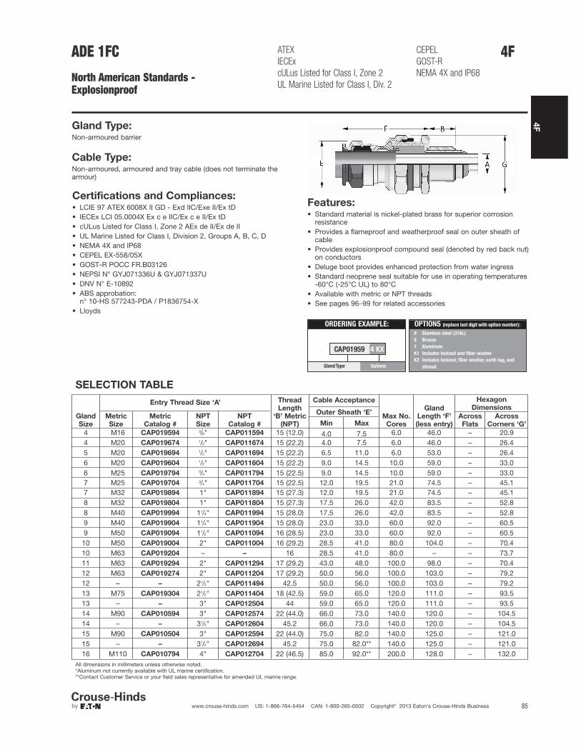
4F
85www.crouse-hinds.com US: 1-866-764-5454 CAN: 1-800-265-0502 Copyright© 2013 Eaton’s Crouse-Hinds Business
4FADE 1FC
North American Standards - Explosionproof
Features:• Standard material is nickel-plated brass for superior corrosion
resistance• Provides a flameproof and weatherproof seal on outer sheath of
cable• Provides explosionproof compound seal (denoted by red back nut)
on conductors• Deluge boot provides enhanced protection from water ingress• Standard neoprene seal suitable for use in operating temperatures
-60°C (-25°C UL) to 80°C• Available with metric or NPT threads• See pages 96–99 for related accessories
Gland Type:Non-armoured barrier
Cable Type:Non-armoured, armoured and tray cable (does not terminate thearmour)
ATEX
IECEx
cULus Listed for Class I, Zone 2
UL Marine Listed for Class I, Div. 2
CEPEL
GOST-R
NEMA 4X and IP68
SELECTION TABLE
Gland
Size
Entry Thread Size ‘A’ Thread
Length
‘B’ Metric
(NPT)
Cable Acceptance
Max No.
Cores
Gland
Length ‘F’
(less entry)
Hexagon
Dimensions
Metric
Size
Metric
Catalog #
NPT
Size
NPT
Catalog #
Outer Sheath ‘E’Across
Flats
Across
Corners ‘G’Min Max
4 M16 CAP019594 3/8" CAP011594 15 (12.0) 4.0 7.5 6.0 46.0 – 20.94 M20 CAP019674 1/2" CAP011674 15 (22.2) 4.0 7.5 6.0 46.0 – 26.45 M20 CAP019694 1/2" CAP011694 15 (22.2) 6.5 11.0 6.0 53.0 – 26.46 M20 CAP019604 1/2" CAP011604 15 (22.2) 9.0 14.5 10.0 59.0 – 33.06 M25 CAP019794 3/4" CAP011794 15 (22.5) 9.0 14.5 10.0 59.0 – 33.07 M25 CAP019704 3/4" CAP011704 15 (22.5) 12.0 19.5 21.0 74.5 – 45.17 M32 CAP019894 1" CAP011894 15 (27.3) 12.0 19.5 21.0 74.5 – 45.18 M32 CAP019804 1" CAP011804 15 (27.3) 17.5 26.0 42.0 83.5 – 52.88 M40 CAP019994 11/4" CAP011994 15 (28.0) 17.5 26.0 42.0 83.5 – 52.89 M40 CAP019904 11/4" CAP011904 15 (28.0) 23.0 33.0 60.0 92.0 – 60.59 M50 CAP019094 11/2" CAP011094 16 (28.5) 23.0 33.0 60.0 92.0 – 60.5
10 M50 CAP019004 2" CAP011004 16 (29.2) 28.5 41.0 80.0 104.0 – 70.410 M63 CAP019204 – – 16 28.5 41.0 80.0 – – 73.711 M63 CAP019294 2" CAP011294 17 (29.2) 43.0 48.0 100.0 98.0 – 70.412 M63 CAP019274 2" CAP011204 17 (29.2) 50.0 56.0 100.0 103.0 – 79.212 – – 21/2" CAP011494 42.5 50.0 56.0 100.0 103.0 – 79.213 M75 CAP019304 21/2" CAP011404 18 (42.5) 59.0 65.0 120.0 111.0 – 93.513 – – 3" CAP012504 44 59.0 65.0 120.0 111.0 – 93.514 M90 CAP010594 3" CAP012574 22 (44.0) 66.0 73.0 140.0 120.0 – 104.514 – – 31/2" CAP012604 45.2 66.0 73.0 140.0 120.0 – 104.515 M90 CAP010504 3" CAP012594 22 (44.0) 75.0 82.0 140.0 125.0 – 121.015 – – 31/2" CAP012694 45.2 75.0 82.0** 140.0 125.0 – 121.016 M110 CAP010794 4" CAP012704 22 (46.5) 85.0 92.0** 200.0 128.0 – 132.0
All dimensions in millimeters unless otherwise noted.*Aluminum not currently available with UL marine certification.**Contact Customer Service or your field sales representative for amended UL marine range.
ORDERING EXAMPLE:
CAP01959 4 KX
OptionsGlandType
9 Stainless steel (316L)
8 Bronze
7 Aluminum
K1 Includes locknut and fiber washer
K2 Includes locknut, fiber washer, earth tag, and
shroud
OPTIONS (replace last digit with option number):
Certifications and Compliances:• LCIE 97 ATEX 6008X II GD - Exd IIC/Exe II/Ex tD• IECEx LCI 05.0004X Ex c e IIC/Ex c e II/Ex tD• cULus Listed for Class I, Zone 2 AEx de II/Ex de II• UL Marine Listed for Class I, Division 2, Groups A, B, C, D• NEMA 4X and IP68• CEPEL EX-558/05X• GOST-R POCC FR.B03126• NEPSI N° GYJ071336U & GYJ071337U• DNV N° E-10892• ABS approbation:
n° 10-HS 577243-PDA / P1836754-X• Lloyds

4F
86 www.crouse-hinds.com US: 1-866-764-5454 CAN: 1-800-265-0502 Copyright© 2013 Eaton’s Crouse-Hinds Business
4F CGBS and EBY
North American Standards - Explosionproof
Gland Type:Portable cord connector
Cable Type:Non-armoured and tray cable
Certifications and Compliances:
• CSA Certified Class I, Div. 1, Groups C, D
• Class II, Div. 1 & 2, Groups E, F, G
• Class III – CSA File LR13046CGBS Features:• Body – steel with zinc electroplate and chromate finish coat• Gland nut – aluminum• Body well for Chico A sealing compound (for ordering
information please contact customer service)• Standard neoprene seal suitable for use in operating
temperatures -25° to 40°C• Available with NPT threads
SELECTION TABLE
Entry Thread Size ‘A’ FormOuter Sheath ‘E’
Gland Length ‘F’ (less entry)NPT Size NPT Catalog # Min Max
1/2" CGBS1013 A 0.312 0.437 51/4"3/4" CGBS2013 A 0.312 0.437 51/4"3/4" CGBS2014 A 0.375 0.500 51/4"1" CGBS3015 B 0.500 0.625 27/8"1" CGBS3016 B 0.625 0.750 215/16"
11/4" CGBS4017 B 0.750 0.875 213/16"11/4" CGBS4018 B 0.875 1.000 31/2"11/4" CGBS4019 B 1.000 1.188 39/16"
All dimensions in inches unless otherwise noted.
Gland Type:Portable cord connector
Cable Type:Non-armoured
EBY Features:• Standard material is aluminum• Factory sealed conductors and seal on outer sheath of cable• Three, 12-inch long, #12 type SF-2 (150°C rating) stranded
pigtails; two circuit wires and one identified grounding wire
• Three pressure connectors for 3-conductor cord, range #18 to #12 AWG
• Standard neoprene seal suitable for use in operating temperatures -25° to 40°C
• Available with NPT threads
SELECTION TABLE
Entry Thread Size ‘A’ Outer Sheath ‘E’
NPT Size NPT Catalog # Min Max3/4" EBY2672 0.250 0.4373/4" EBY2682 0.375 0.5003/4" EBY26102 0.500 0.625
All dimensions in inches unless otherwise noted.
Certifications and Compliances:• UL, cUL Listed Class I, Div. 1, Groups B, C, D
• Class II, Div. 1, Groups, F, G – UL File E10279
CGBS:CSA Certified Class I,Div. 1, Groups C, DClass II, Div. 1 & 2, Groups E, F, GClass III
EBY:UL, cUL Listed Class I,Div. 1, Groups B, C, DClass II, Div. 1, Groups F, G

4F
87www.crouse-hinds.com US: 1-866-764-5454 CAN: 1-800-265-0502 Copyright© 2013 Eaton’s Crouse-Hinds Business
4FTMC
North American Standards - General Purpose
UL, CSA Listed NEMA 4 and IP56Wet locations
Gland Type:Armoured and TECK armoured
Cable Type:Metal-clad (interlocked or continuously welded corrugated armoured)and TECK
Features:• Standard material is aluminum• Stainless steel copper-plated spring provides grounding continuity
of cable armour• Watertight seal on outer sheath of cable• Standard neoprene seal suitable for use in operating temperatures
-25° to 60°C• Cold Shrink™ Kit is available for extra protection in aggressive
environments (see page 102)• Available with NPT threads• See page 102 for related accessories
SELECTION TABLE
Entry Thread Size ‘A’Thread
Length
‘B’ NPT
Cable Acceptance Gland
Length
‘F’ (less
entry)
Hexagon Dimensions
NPT
Size
NPT
Catalog #
Armour Range ‘H’ Across
Flats
Across
Corners ‘G’Min Max Min Max1/2" TMC165 0.750 0.440 0.650 0.490 0.781 2.375 1.250 1.3753/4" TMC285 0.781 0.600 0.850 0.650 1.000 2.625 1.500 1.6251" TMC3112 0.938 0.800 1.120 0.850 1.313 2.625 1.875 2.000
11/4" TMC4140 0.969 1.100 1.400 1.150 1.625 2.750 2.250 2.43811/2" TMC5161 0.969 1.330 1.610 1.380 1.781 2.750 2.500 2.752" TMC6206 1.000 1.570 2.060 1.630 2.313 4.500 3.250 3.500
21/2" TMC7247 1.438 1.930 2.470 1.990 2.719 4.750 3.750 4.0003" TMC8302 1.438 2.450 3.020 2.525 3.281 4.875 4.500 4.875
31/2" TMC9352 1.625 2.950 3.520 3.025 3.781 5.375 5.000 5.3754" TMC10402 1.625 3.500 4.020 3.585 4.281 5.500 5.500 5.875
All dimensions in inches unless otherwise noted.
Outer Sheath ‘E’
Certifications and Compliances:• UL Listed – UL File E36379• CSA Listed – CSA File LR291• NEMA 4 and IP56• Wet locations
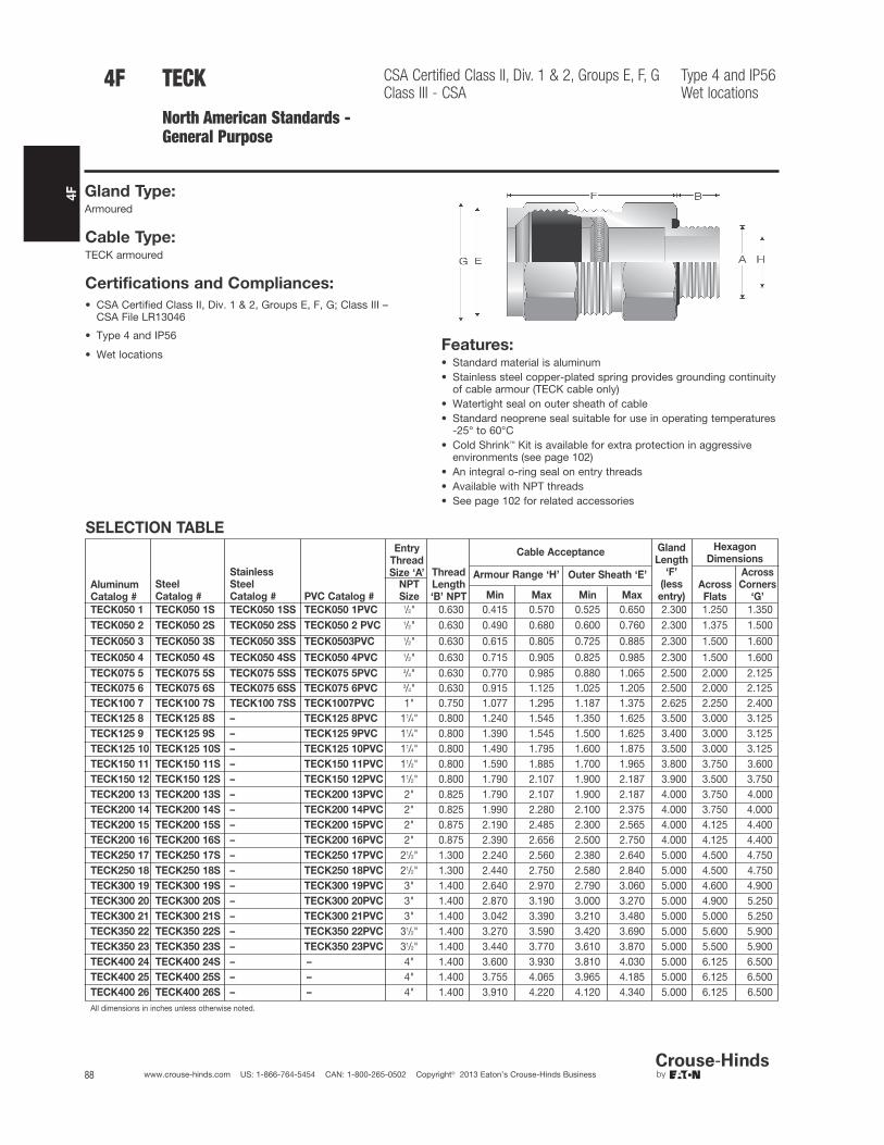
4F
88 www.crouse-hinds.com US: 1-866-764-5454 CAN: 1-800-265-0502 Copyright© 2013 Eaton’s Crouse-Hinds Business
4F TECK
North American Standards - General Purpose
CSA Certified Class II, Div. 1 & 2, Groups E, F, GClass III - CSA
Type 4 and IP56Wet locations
Gland Type:Armoured
Cable Type:TECK armoured
Certifications and Compliances:
• CSA Certified Class II, Div. 1 & 2, Groups E, F, G; Class III – CSA File LR13046
• Type 4 and IP56
• Wet locationsFeatures:• Standard material is aluminum• Stainless steel copper-plated spring provides grounding continuity
of cable armour (TECK cable only)• Watertight seal on outer sheath of cable• Standard neoprene seal suitable for use in operating temperatures
-25° to 60°C• Cold Shrink™ Kit is available for extra protection in aggressive
environments (see page 102)• An integral o-ring seal on entry threads• Available with NPT threads• See page 102 for related accessories
SELECTION TABLE
Aluminum
Catalog #
Steel
Catalog #
Stainless
Steel
Catalog # PVC Catalog #
Entry
Thread
Size ‘A’ Thread
Length
‘B’ NPT
Cable Acceptance Gland
Length
‘F’
(less
entry)
Hexagon
Dimensions
NPT
Size
Armour Range ‘H’ Outer Sheath ‘E’Across
Flats
Across
Corners
‘G’Min Max Min Max
TECK050 1 TECK050 1S TECK050 1SS TECK050 1PVC 1/2" 0.630 0.415 0.570 0.525 0.650 2.300 1.250 1.350TECK050 2 TECK050 2S TECK050 2SS TECK050 2 PVC 1/2" 0.630 0.490 0.680 0.600 0.760 2.300 1.375 1.500
TECK050 3 TECK050 3S TECK050 3SS TECK0503PVC 1/2" 0.630 0.615 0.805 0.725 0.885 2.300 1.500 1.600
TECK050 4 TECK050 4S TECK050 4SS TECK050 4PVC 1/2" 0.630 0.715 0.905 0.825 0.985 2.300 1.500 1.600TECK075 5 TECK075 5S TECK075 5SS TECK075 5PVC 3/4" 0.630 0.770 0.985 0.880 1.065 2.500 2.000 2.125TECK075 6 TECK075 6S TECK075 6SS TECK075 6PVC 3/4" 0.630 0.915 1.125 1.025 1.205 2.500 2.000 2.125TECK100 7 TECK100 7S TECK100 7SS TECK1007PVC 1" 0.750 1.077 1.295 1.187 1.375 2.625 2.250 2.400TECK125 8 TECK125 8S – TECK125 8PVC 11/4" 0.800 1.240 1.545 1.350 1.625 3.500 3.000 3.125TECK125 9 TECK125 9S – TECK125 9PVC 11/4" 0.800 1.390 1.545 1.500 1.625 3.400 3.000 3.125TECK125 10 TECK125 10S – TECK125 10PVC 11/4" 0.800 1.490 1.795 1.600 1.875 3.500 3.000 3.125TECK150 11 TECK150 11S – TECK150 11PVC 11/2" 0.800 1.590 1.885 1.700 1.965 3.800 3.750 3.600TECK150 12 TECK150 12S – TECK150 12PVC 11/2" 0.800 1.790 2.107 1.900 2.187 3.900 3.500 3.750TECK200 13 TECK200 13S – TECK200 13PVC 2" 0.825 1.790 2.107 1.900 2.187 4.000 3.750 4.000TECK200 14 TECK200 14S – TECK200 14PVC 2" 0.825 1.990 2.280 2.100 2.375 4.000 3.750 4.000TECK200 15 TECK200 15S – TECK200 15PVC 2" 0.875 2.190 2.485 2.300 2.565 4.000 4.125 4.400TECK200 16 TECK200 16S – TECK200 16PVC 2" 0.875 2.390 2.656 2.500 2.750 4.000 4.125 4.400TECK250 17 TECK250 17S – TECK250 17PVC 21/2" 1.300 2.240 2.560 2.380 2.640 5.000 4.500 4.750TECK250 18 TECK250 18S – TECK250 18PVC 21/2" 1.300 2.440 2.750 2.580 2.840 5.000 4.500 4.750TECK300 19 TECK300 19S – TECK300 19PVC 3" 1.400 2.640 2.970 2.790 3.060 5.000 4.600 4.900TECK300 20 TECK300 20S – TECK300 20PVC 3" 1.400 2.870 3.190 3.000 3.270 5.000 4.900 5.250TECK300 21 TECK300 21S – TECK300 21PVC 3" 1.400 3.042 3.390 3.210 3.480 5.000 5.000 5.250TECK350 22 TECK350 22S – TECK350 22PVC 31/2" 1.400 3.270 3.590 3.420 3.690 5.000 5.600 5.900TECK350 23 TECK350 23S – TECK350 23PVC 31/2" 1.400 3.440 3.770 3.610 3.870 5.000 5.500 5.900TECK400 24 TECK400 24S – – 4" 1.400 3.600 3.930 3.810 4.030 5.000 6.125 6.500TECK400 25 TECK400 25S – – 4" 1.400 3.755 4.065 3.965 4.185 5.000 6.125 6.500TECK400 26 TECK400 26S – – 4" 1.400 3.910 4.220 4.120 4.340 5.000 6.125 6.500All dimensions in inches unless otherwise noted.

4F
89www.crouse-hinds.com US: 1-866-764-5454 CAN: 1-800-265-0502 Copyright© 2013 Eaton’s Crouse-Hinds Business
CGB
North American Standards - General Purpose
cULus Listed
Gland Type:Non-armoured
Cable Type:Non-armoured and tray cable
Features:• Form A - D bodies and gland nuts – steel with zinc electroplate
and chromate finish coat• Form E - F bodies and gland nuts – Feraloy® iron alloy with
electrogalvanized and aluminum acrylic paint• Weatherproof seal on outer sheath of cable• Standard neoprene seal suitable for use in operating temperatures
-25° to 40°C• Available with NPT threads• Available in all aluminum construction• See page 102 for related accessories
SELECTION TABLE
3/8" CGB3814 A 0.438 0.125 0.250 1.063 – 0.750 0.8753/8" CGB3816 A 0.438 0.250 0.375 1.063 – 0.750 0.8753/8" CGB3817 A 0.438 0.375 0.437 1.063 – 0.750 0.8753/8" CGB3892 B 0.438 0.125 0.250 1.313 – 1.000 1.1883/8" CGB3893 B 0.438 0.250 0.375 1.313 – 1.000 1.1883/8" CGB3894 B 0.438 0.375 0.500 1.313 – 1.000 1.1881/2" CGB114† A 0.625† 0.125 0.250 1.000 – 0.875 1.1881/2" CGB116† A 0.625† 0.250 0.375 1.000 – 0.875 1.1881/2" CGB117† A 0.625† 0.375 0.437 1.000 – 0.875 1.1881/2" CGB192*† B 0.750*† 0.125 0.250 1.313 – 1.000 1.1881/2" CGB193*† B 0.750*† 0.250 0.375 1.313 – 1.000 1.1881/2" CGB194*† B 0.750*† 0.375 0.500 1.313 – 1.000 1.1881/2" CGB195*† B 0.750*† 0.500 0.625 1.313 – 1.000 1.1881/2" CGB196* C 0.625* 0.625 0.750 1.750 – 1.500 1.6561/2" CGB197*† C 0.625*† 0.750 0.875 1.750 – 1.500 1.6563/4" CGB292† B 0.625† 0.125 0.250 1.375 – 1.060 1.2503/4" CGB293† B 0.625† 0.250 0.375 1.375 – 1.060 1.2503/4" CGB294† B 0.625† 0.375 0.500 1.375 – 1.060 1.2503/4" CGB295† B 0.625† 0.500 0.625 1.375 – 1.060 1.2503/4" CGB296*† C 0.625*† 0.625 0.750 1.750 – 1.630 1.6563/4" CGB297*† C 0.625*† 0.750 0.875 1.750 – 1.630 1.6563/4" CGB298*† D 0.625*† 0.875 1.000 2.500 2.250 – –1" CGB393† B 0.688† 0.250 0.375 1.375 – 1.375 1.6251" CGB394† B 0.688† 0.375 0.500 1.375 – 1.375 1.6251" CGB395*† C 0.688*† 0.500 0.625 1.688 – 1.500 1.8751" CGB396*† C 0.688*† 0.625 0.750 1.688 – 1.500 1.8751" CGB397*† C 0.688*† 0.750 0.875 1.688 – 1.500 1.8751" CGB3239† C 0.688† 0.875 1.000 1.688 – – 1.8751" CGB398*† D 0.625*† 0.875 1.000 2.375 2.375 – –1" CGB399*† D 0.625*† 1.000 1.188 2.375 2.375 – –1" CGB3911*† D 0.625*† 1.188 1.375 2.375 2.375 – –
All dimensions in inches unless otherwise noted.
*With optional Sealing Gasket.
†With optional Aluminum Construction.
4F
Min Max
NPT
Size
NPT
Catalog #
Outer Sheath ‘E’Across
Flats
Across
Corners ‘G’
Entry Thread Size ‘A’
Form
Thread
Length ‘B’
NPT
Cable AcceptanceGland
Length ‘F’
(less entry)
External
Diameter
‘G’
Hexagon Dimensions
Certifications and Compliances:• cULus Listed - UL File E23223• Suitable for use in Class I, Div. 2 hazardous locations when
installed in accordance with NEC501.10(B)(2)

4F
90 www.crouse-hinds.com US: 1-866-764-5454 CAN: 1-800-265-0502 Copyright© 2013 Eaton’s Crouse-Hinds Business
11/4" CGB498 D 0.688 0.875 1.000 2.313 2.250 – –11/4" CGB499 D 0.688 1.000 1.188 2.313 2.250 – –11/4" CGB4911 D 0.688 1.188 1.375 2.313 2.250 – –11/4" CGB4913 E 0.688 1.375 1.625 2.625 3.000 – –11/4" CGB4915 E 0.688 1.625 1.875 2.625 3.000 – –11/2" CGB598 D 0.813 0.875 1.000 2.313 2.250 – –11/2" CGB599 D 0.813 1.000 1.188 2.313 2.250 – –11/2" CGB5911 D 0.813 1.188 1.375 2.313 2.250 – –11/2" CGB5913 E 0.813 1.375 1.625 2.625 3.000 – –11/2" CGB5915 E 0.813 1.625 1.875 2.625 3.000 – –2" CGB6913 E 0.813 1.375 1.625 2.625 3.000 – –2" CGB6915 E 0.813 1.625 1.875 2.625 3.000 – –2" CGB6917 F 0.813 1.875 2.188 2.563 3.750 – –2" CGB6920 F 0.813 2.188 2.500 2.563 3.750 – –
21/2" CGB7913 E 1.000 1.375 1.625 2.625 3.125 – –21/2" CGB7915 E 1.000 1.625 1.875 2.625 3.125 – –21/2" CGB7917 F 1.000 1.875 2.188 2.625 3.750 – –21/2" CGB7920 F 1.000 2.188 2.500 2.625 3.750 – –3" CGB8917 F 1.000 1.875 2.188 2.625 3.750 – –3" CGB8920 F 1.000 2.188 2.500 2.625 3.750 – –
Min Max
NPT
Size
NPT
Catalog #
Outer Sheath ‘E’Across
Flats
Across
Corners ‘G’
Entry Thread Size ‘A’
Form
Thread
Length ‘B’
NPT
Cable AcceptanceGland
Length ‘F’
(less entry)
External
Diameter
‘G’
Hexagon Dimensions
CGB
North American Standards -General Purpose
cULus Listed4F

4F
91www.crouse-hinds.com US: 1-866-764-5454 CAN: 1-800-265-0502 Copyright© 2013 Eaton’s Crouse-Hinds Business
CGDNorth American Standards -General Purpose
cULus Listed
SELECTION TABLE
Entry Thread Size ‘A’
Thread Length
‘B’ NPT
Cable Acceptance
Gland Length
‘F’ (less entry)
External
Diameter ‘G’NPT Size NPT Catalog #
Outer Sheath ‘E’
Min Max1/2" CGD192 0.630 0.125 0.250 1.688 1.1881/2" CGD193 0.630 0.250 0.375 1.688 1.1881/2" CGD194 0.630 0.375 0.500 1.688 1.1881/2" CGD195 0.630 0.500 0.625 1.688 1.1881/2" CGD196 0.630 0.625 0.750 2.063 1.6251/2" CGD197 0.630 0.750 0.875 2.063 1.6253/4" CGD292 0.630 0.125 0.250 1.938 1.1413/4" CGD293 0.630 0.250 0.375 1.938 1.1413/4" CGD294 0.630 0.375 0.500 1.938 1.1253/4" CGD295 0.630 0.500 0.625 1.938 1.1253/4" CGD296 0.630 0.625 0.750 2.000 1.6253/4" CGD297 0.630 0.750 0.875 2.000 1.625
All dimensions in inches unless otherwise noted.
4F
Features:• 45° angle with male thread• Standard body material is Feraloy® iron alloy• Standard gland nut material is steel• Weatherproof seal on outer sheath of cable• Standard neoprene seal suitable for use in operating temperatures
-25° to 40°C• Available with NPT threads• See page 102 for related accessories
Gland Type:Non-armoured
Cable Type:Non-armoured and tray cable
Certifications and Compliances:• cULus Listed - UL File E23223• Suitable for use in Class I, Div. 2 hazardous locations when
installed in accordance with NEC501.10(B)(2)

4F
92 www.crouse-hinds.com US: 1-866-764-5454 CAN: 1-800-265-0502 Copyright© 2013 Eaton’s Crouse-Hinds Business
CGENorth American Standards -General Purpose
cULus Listed
SELECTION TABLEEntry Thread Size ‘A’
Thread
Length
‘B’ NPT
Cable Acceptance
Gland Length
‘F’ (less entry)
External
Diameter ‘G’
NPT
Size
NPT
Catalog #
Outer Sheath ‘E’
Min Max
1/2" CGE192 0.710 0.1250 0.2500 1.438 1.1881/2" CGE193 0.710 0.2500 0.3750 1.438 1.1881/2" CGE194 0.710 0.3750 0.5000 1.438 1.1881/2" CGE195 0.710 0.5000 0.6250 1.438 1.1881/2" CGE196 0.710 0.6250 0.7500 2.000 1.6251/2" CGE197 0.710 0.7500 0.8750 2.000 1.6253/4" CGE292 0.710 0.1250 0.2500 1.406 1.1883/4" CGE293 0.710 0.2500 0.3750 1.406 1.1883/4" CGE294 0.710 0.3750 0.5000 1.406 1.1883/4" CGE295 0.710 0.5000 0.6250 1.406 1.1883/4" CGE296 0.710 0.6250 0.7500 1.875 1.6253/4" CGE297 0.710 0.7500 0.8750 1.875 1.6251" CGE395 0.710 0.5000 0.6250 2.063 1.6251" CGE396 0.710 0.6250 0.7500 2.094 1.6251" CGE397 0.710 0.7500 0.8750 2.094 1.6251" CGE3239 0.710 0.8750 1.0000 2.094 2.2501" CGE398 0.710 0.8750 1.0000 2.656 2.2501" CGE399 0.710 1.0000 1.1880 2.656 1.6251" CGE3911 0.710 1.1880 1.3750 2.656 2.250
All dimensions in inches unless otherwise noted.
4F
Features:• 90° angle with male thread• Standard body material is Feraloy® iron alloy• Standard gland nut material is steel• Weatherproof seal on outer sheath of cable• Standard neoprene seal suitable for use in operating temperatures
-25° to 40°C• Available with NPT threads• See page 102 for related accessories
Gland Type:Non-armoured
Cable Type:Non-armoured and tray cable
Certifications and Compliances:• cULus Listed - UL File E23223• Suitable for use in Class I, Div. 2 hazardous locations when
installed in accordance with NEC501.10(B)(2)

4F
93www.crouse-hinds.com US: 1-866-764-5454 CAN: 1-800-265-0502 Copyright© 2013 Eaton’s Crouse-Hinds Business
4FCGB1013North American Standards -General Purpose
cULus Listed
Features:• Body – steel with zinc electroplate and chromate finish coat• Gland nut – material is aluminum• Standard neoprene seal suitable for use in operating temperatures
-25° to 40°C• Available with NPT threads• See page 102 for related accessories
SELECTION TABLE
Entry Thread Size ‘A’ Outer Sheath ‘E’
NPT Size NPT Catalog # Min Max1/2" CGB1013 0.312 0.4371/2" CGB1014 0.375 0.5001/2" CGB1015 0.500 0.6253/4" CGB2013 0.312 0.4373/4" CGB2014 0.375 0.5003/4" CGB2015 0.500 0.625
All dimensions in inches unless otherwise noted.
Gland Type:Portable cord connector
Cable Type:Non-armoured and tray cable
Certifications and Compliances:• cULus Listed - UL File E23223• Suitable for use in Class I, Div. 2 hazardous locations when
installed in accordance with NEC501.10(B)(2)

4F
94 www.crouse-hinds.com US: 1-866-764-5454 CAN: 1-800-265-0502 Copyright© 2013 Eaton’s Crouse-Hinds Business
CGFPNorth American Standards -General Purpose
Features:
• Form B - C standard body and gland nut are turned steel
• Form D - G standard body and gland nut are Feraloy® iron alloy
• Weatherproof seal on outer sheath of cable
• Standard neoprene seal suitable for use in operating temperatures-25° to 40°C
• Available with NPT threads
• See page 102 for related accessories
SELECTION TABLE
Entry Thread Size ‘A’
Form
Thread Length
‘B’ NPT
Cable Acceptance
Gland Length
‘F’ (less entry)
External
Diameter ‘G’NPT Size NPT Catalog #
Outer Sheath ‘E’
Min Max1/2" CGFP192 B 0.750 0.1250 0.2500 1.375 1.2811/2" CGFP193 B 0.750 0.2500 0.3750 1.375 1.2811/2" CGFP194 B 0.750 0.3750 0.5000 1.375 1.2811/2" CGFP195 B 0.750 0.5000 0.6250 1.375 1.2813/4" CGFP296 C 0.750 0.6250 0.7500 1.750 1.7813/4" CGFP297 C 0.750 0.7500 0.8750 1.750 1.7813/4" CGFP2239 C 0.750 0.8750 1.0000 1.750 1.7811" CGFP396 C 0.938 0.6250 0.7500 1.750 1.7811" CGFP397 C 0.938 0.7500 0.8750 1.750 1.7811" CGFP3239 C 0.938 0.8750 1.0000 1.750 1.781
11/4" CGFP499 D 0.938 1.0000 1.1880 2.375 2.25011/4" CGFP4911 D 0.938 1.1880 1.3750 2.375 2.25011/2" CGFP599 D 0.938 1.0000 1.1880 2.375 2.25011/2" CGFP5911 D 0.938 1.1880 1.3750 2.375 2.2502" CGFP6913 E 1.000 1.3750 1.6250 3.250 3.250
2" CGFP6915 E 1.000 1.6250 1.8750 3.250 3.25021/2" CGFP7917 F 1.438 1.8750 2.1880 3.250 3.87521/2" CGFP7920 F 1.438 2.1880 2.5000 3.250 3.8753" CGFP8917 F 1.500 1.8750 2.1880 3.250 3.8753" CGFP8920 F 1.500 2.1880 2.5000 3.250 3.875
31/2" CGFP923 G 1.563 2.5000 3.0000 4.250 5.50031/2" CGFP927 G 1.563 3.0000 3.5000 4.250 5.500
4" CGFP1023 G 1.625 2.5000 3.0000 4.250 5.5004" CGFP1027 G 1.625 3.0000 3.5000 4.250 5.500
All dimensions in inches unless otherwise noted.
4F
Gland Type:Non-armoured
Cable Type:Non-armoured and tray cable
Certifications and Compliances:• Suitable for use in Class I, Div. 2 hazardous locations when
installed in accordance with NEC501.10(B)(2)

4F
95www.crouse-hinds.com US: 1-866-764-5454 CAN: 1-800-265-0502 Copyright© 2013 Eaton’s Crouse-Hinds Business
NCG and NCGBNorth American Standards -General Purpose
cULus ListedNEMA 3, 4X (NCGB only)
Gland Type:Non-armoured
Cable Type:Non-armoured and tray cable
Certifications and Compliances:• cULus Listed - UL File E23223
NCG Features:• Standard material is polyamide 6
• Weatherproof seal on outer sheath of cable
• Standard neoprene seal suitable for use in operating temperatures-25° to 40°C
• Available with NPT threads
SELECTION TABLEEntry Thread Size ‘A’ Outer Sheath ‘E’
NPT Size NPT Catalog # Min Max3/8" NCG38 35 0.10 0.351/2" NCG50 50 0.20 0.503/4" NCG75 75 0.35 0.751" NCG100 100 0.55 1.00
All dimensions in inches unless otherwise noted.
Gland Type:Non-armoured
Cable Type:Non-armoured and tray cable
Certifications and Compliances:• cULus Listed - UL File E23223
• NEMA 3, 4X
SELECTION TABLE
NPT
Size
NPT
Catalog #
Cable
Acceptance
Range 'E'
Gland Length
(Less Entry)
'F'
External
Diameter
'G'Min Max1/2" NCGB1231 0.25 0.42 2.25 1.331/2" NCGB1232 0.40 0.57 2.25 1.333/4" NCGB2233 0.54 0.68 2.52 1.583/4" NCGB2234 0.64 0.78 2.52 1.581" NCGB3235 0.76 0.91 3.19 2.021" NCGB3236 0.89 1.03 3.19 2.02
All dimensions in inches unless otherwise noted.
4F
POLYAMIDE LOCK NUT SELECTION TABLE
Size Catalog #3/8" 10N
1/2" 11N
3/4" 12N
1" 13N
NCGB Features:• Standard material is thermoplastic polyester• Tightens by hand to create a watertight seal• Gasket on entry threads included• Compact design allows close grouping of connectors• Available with NPT threads
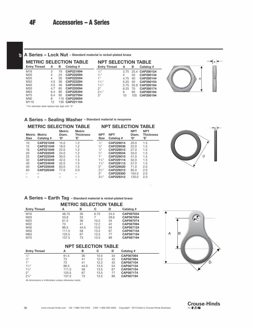
4F
96 www.crouse-hinds.com US: 1-866-764-5454 CAN: 1-800-265-0502 Copyright© 2013 Eaton’s Crouse-Hinds Business
4F Accessories – A Series
A Series – Lock Nut – Standard material is nickel-plated brass
A Series – Sealing Washer
METRIC SELECTION TABLE
Metric
Size
Metric
Catalog #
Metric
Diam.
‘D’
Metric
Thickness
‘E’
10 CAP221049 15.0 1.212 CAP221249 18.0 1.216 CAP221649 22.0 1.220 CAP222049 24.0 1.225 CAP222549 30.0 1.532 CAP223249 42.0 1.540 CAP224049 52.0 1.550 CAP225049 63.0 1.563 CAP226349 77.0 2.0– – – –– – – –
NPT SELECTION TABLE
NPT
Size
NPT
Catalog #
NPT
Diam.
‘D’
NPT
Thickness
‘E’
1/4" CAP229014 20.0 1.53/8" CAP229038 22.0 1.51/2" CAP229012 27.0 1.53/4" CAP229034 33.0 1.51" CAP229010 41.0 1.511/4" CAP229114 52.0 1.511/2" CAP229112 57.0 1.52" CAP229020 71.0 2.021/2" CAP229212 85.0 2.03" CAP229300 104.0 2.031/2" CAP229312 120.0 2.0
4F
A Series – Earth Tag – Standard material is nickel-plated brass
METRIC SELECTION TABLEEntry Thread A B C D Catalog #
M16 48.75 30 6.75 24.5 CAP567034M20 53.8 33 7 28.6 CAP567054M25 61.5 36 10.5 34 CAP567074M32 73 41 12.2 42 CAP567094M40 86.5 44.5 13.5 54 CAP567124M50 111.5 58 13.5 67 CAP567154M63 125.5 67 13.5 77 CAP567184M75 137.5 73 13.5 89 CAP567194
NPT SELECTION TABLEEntry Thread A B C D Catalog #
1/2" 61.5 36 10.5 34 CAP5670643/4" 73 41 12.2 42 CAP5670841" 73 41 12.2 42 CAP56710411/4" 86.5 44.5 13.5 54 CAP56713411/2" 111.5 58 13.5 67 CAP5671542" 125.5 67 13.5 77 CAP56717421/2" 137.5 73 13.5 89 CAP567194
All dimensions in millimeters unless otherwise noted.
– Standard material is neoprene
METRIC SELECTION TABLEEntry Thread A B Catalog #
M16 3 19 CAP221694M20 4 24 CAP222094M25 4 30 CAP222594M32 4.5 36 CAP223294M40 4.5 46 CAP224094M50 4.7 65 CAP225094M63 6.4 80 CAP226394M75 6.4 95 CAP227594M90 8 110 CAP229094M110 12 130 CAP221104
* For stainless steel replace last digit with "9".
NPT SELECTION TABLEEntry Thread A B Catalog #
1/2" 3.75 25.4 CAP2801243/4" 4 33 CAP2801341" 4.75 40 CAP28014411/4" 5.25 50 CAP28015411/2" 5.75 55.9 CAP2801642" 6.25 70 CAP28017421/2" 9 90 CAP2801843" 10 105 CAP280194

4F
97www.crouse-hinds.com US: 1-866-764-5454 CAN: 1-800-265-0502 Copyright© 2013 Eaton’s Crouse-Hinds Business
4FAccessories – A Series
A Series – Serrated Lock Washer
– Standard material is stainless steel
SELECTION TABLEMetric Size External Diameter Catalog #
16 25.5 CAP28006920 32.5 CAP28002925 39.5 CAP28025932 49.5 CAP28032940 64.5 CAP28040950 80.5 CAP28050963 100 CAP28063975 112 CAP28075990 123 CAP280099
A-Series – Shroud
– Standard material is PVC
SELECTION TABLEGland Size Catalog #
4 CAP5060405 CAP5060506 CAP5060607 CAP5060708 CAP5060809 CAP50609010 CAP50610011 CAP50611012 CAP50612013 CAP50613014 CAP50614015 CAP50615016 CAP506160
A Series – Clamping Module– Standard materials are nickel-plated brass body with stainless steel screws and washers
SELECTION TABLECable Range Gland Size Across Flats Width Thickness Catalog #
4-8.5 4 15 18 5 CAP8104346-11 5 19 22 5 CAP8105348.5-16 6 24 27.5 6 CAP81063412-21 7 30 33.5 8 CAP81073416-27.5 8 41 45 8 CAP81083421-34 9 48 52 9.5 CAP81093427-41 10 55 59 9.5 CAP81103433-48 11 64 69 12 CAP81113440-56 12 72 78 12 CAP81123447-65 13 85 92 16 CAP81133454-74 14 95 103 16 CAP81143463-83 15 110 118 18 CAP81153472-93 16 120 128 18 CAP811634
A Series – Earthing Washer – Standard material is brass
METRIC SELECTION TABLE
Gland Size
Lead Sheath Sealing RangeCable
Diameter Catalog #Min Max
5 4 7.5 10 CAP5605306 6 11 13.9 CAP5606307 9 15 18.3 CAP5607308 12 20 23.8 CAP5608309 16 26.5 31 CAP56093010 21 32.5 38.3 CAP56103011 28 39.5 45.3 CAP56113012 33 46.5 52.8 CAP56123013 40 54.5 60.8 CAP56133014 46.5 61 71 CAP56143015 54 72.5 80.5 CAP56153016 63 81.5 89.5 CAP561630
All dimensions in millimeters unless otherwise noted.

4F
98 www.crouse-hinds.com US: 1-866-764-5454 CAN: 1-800-265-0502 Copyright© 2013 Eaton’s Crouse-Hinds Business
METRIC x NPT SELECTION TABLEFemale →
Male 1/4" 3/8" 1/2" 3/4" 1" 11/4" 11/2" 2" 21/2" 3" 31/2"
M12 744104M16 744194 744694M20 744204 744214 744704 744964M25 744714 744974 745234M32 744724 744984 745244 745504M40 744994 745254 745514 745774M50 745264 745524 745784 746044M63 745794 746054 746314M75 746064 746324 746584M90 744304M110
Accessories – A Series
A Series – Adaptors and Reducers
METRIC x METRIC SELECTION TABLEFemale →
Male M12 M16 M20 M25 M32 M40 M50 M63 M75 M80 M90 M110
M12 745334M16 745834 740274M20 745844 740024 740544M25 740034 740294 740814M32 740304 740564 741084M40 740574 740834 741354M50 740844 741104 741624M63 741114 741374 741894M75 741384 741644 745394M90 745864M110
Size available – no part number
Size not available
NPT x METRIC SELECTION TABLEFemale →
Male M12 M16 M20 M25 M32 M40 M50 M63 M75 M90 M100 M1101/4" 740614 7406243/8" 740884 740894 7409041/2" 740914 740194 740454 7407143/4" 740204 740464 740724 7409841" 740474 740734 740994 741264 741524
11/4" 740744 741004 741274 741534 74179411/2" 741104 741284 741544 741804 7420642" 741554 741814
21/2" 7418243"
31/2"4"
NPT x NPT SELECTION TABLEFemale →
Male 1/4" 3/8" 1/2" 3/4" 1" 11/4" 11/2" 2" 21/2" 3" 31/2" 4"
1/4"3/8" 745574 7446241/2" 745594 7451343/4" 744884 7454041" 744894 745154 745674
11/4" 745164 745424 74594411/2" 745434 745694 7462142" 745704 745964 746484
21/2" 7462343" 746244 746504
31/2"4"
* For stainless steel replace last digit with "9".
4F
– Standard material is nickel-plated brass
ATEX Exe Exd with LCIE 98 ATEX 00010
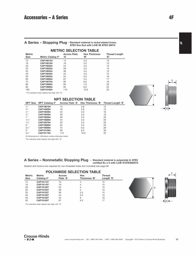
4F
99www.crouse-hinds.com US: 1-866-764-5454 CAN: 1-800-265-0502 Copyright© 2013 Eaton’s Crouse-Hinds Business
Accessories – A Series
A Series – Stopping Plug
METRIC SELECTION TABLEMetric
Size Metric Catalog #*
Across Flats
‘A’
Hex Thickness
‘B’
Thread Length
‘E’
12 CAP190124 14 2.8 1516 CAP190164 18 3.0 1520 CAP190204 23 3.0 1525 CAP190254 28 3.5 1532 CAP190324 36 4.0 1540 CAP190404 44 4.0 1550 CAP190504 54 5.0 1663 CAP190634 67 5.5 1775 CAP190754 80 6.0 1880 CAP190804 85 7.0 2090 CAP199904 95 8.0 22100 CAP191004 110 10.0 22* For stainless steel replace last digit with "9".
NPT SELECTION TABLENPT Size NPT Catalog #* Across Flats ‘A’ Hex Thickness ‘B’ Thread Length ‘E’
1/4" CAP190194 14 2.8 123/8" CAP109294 18 2.8 121/2" CAP190394 22 3.0 163/4" CAP190494 28 3.0 161" CAP190594 36 3.5 2011/4" CAP190694 44 4.0 2011/2" CAP190794 50 5.0 202" CAP190894 64 5.5 2021/2" CAP190994 75 6.0 283" CAP191094 90 6.0 3031/2" CAP191194 110 10.0 32All dimensions in millimeters unless otherwise noted.
*For stainless steel replace last digit with "9".
*For stainless steel replace last digit with "9".
A Series – Nonmetallic Stopping Plug – Standard material is polyamide 6; ATEX
certified Ex e II with LCIE 97ATEX6007X
Washer and locknut are required for non-threaded holes (not included) see page 96
4F
POLYAMIDE SELECTION TABLEMetric
Size
Metric
Catalog #*
Across
Flats ‘A’
Hex
Thickness ‘B’
Thread
Length ‘E’
12 CAP191127 15 4 1516 CAP191167 19 4 1520 CAP191207 23 4 1525 CAP191257 28 5 1532 CAP191327 36 5.5 1540 CAP191407 44 5.5 1550 CAP191507 54 6 1663 CAP191637 67 6.5 17
– Standard material is nickel-plated brass;
ATEX Exe Exd with LCIE 98 ATEX 00010

4F
100 www.crouse-hinds.com US: 1-866-764-5454 CAN: 1-800-265-0502 Copyright© 2013 Eaton’s Crouse-Hinds Business
Accessories – B Series
B Series – Lock Nut – Standard material is brass
NPT SELECTION TABLENPT Entry Thread Catalog #
1/2" BLN/050NPT3/4" BLN/075NPT1" BLN/100NPT11/4" BLN/125NPT11/2" BLN/150NPT2" BLN/200NPT21/2" BLN/250NPT3" BLN/300NPT31/2" BLN/350NPT4" BLN/400NPT
B Series – Sealing Washer – Standard material is nylon
NPT SELECTION TABLENPT Entry Thread Catalog #
1/2" RNSW/050NPT3/4" RNSW/075NPT1" RNSW/100NPT11/4" RNSW/125NPT11/2" RNSW/150NPT2" RNSW/200NPT21/2" RNSW/250NPT3" RNSW/300NPT31/2" RNSW/350NPT4" RNSW/400NPT
B Series – Earth Tag – Standard material is brass
METRIC SELECTION TABLEMetric Entry Thread Catalog #
M16 BET/M16M20 BET/M20M25 BET/M25M32 BET/M32M40 BET/M40M50 BET/M50M63 BET/M63M75 BET/M75M80 BET/M80M85 BET/M85M90 BET/M90M100 BET/M100
NPT SELECTION TABLENPT Entry Thread Catalog #
1/2" BET/050NPT3/4" BET/075NPT1" BET/100NPT11/4" BET/125NPT11/2" BET/150NPT2" BET/200NPT21/2" BET/250NPT3" BET/300NPT31/2" BET/350NPT4" BET/400NPT
B Series – Shroud
PVC SELECTION TABLESize (Gland Size) Catalog #
L24 (16, 20s) PVC-L24L30 (20) PVC-L30L38 (25) PVC-L38L46 (32) PVC-L46L55 (40) PVC-L55L65 (50, 50s) PVC-L65L80 (63, 63s) PVC-L80L90 (75, 75s) PVC-L90L104 (80,85) PVC-L104L114 (90, 100) PVC-L114
PCP SELECTION TABLESize Catalog #
L24 (16, 20s) PCP-L24L30 (20) PCP-L30L38 (25) PCP-L38L46 (32) PCP-L46L55 (40) PCP-L55L65 (50, 50s) PCP-L65L80 (63, 63s) PCP-L80L90 (75, 75s) PCP-L90L104 (80, 85) PCP-L104
All dimensions in millimeters unless otherwise noted.
METRIC SELECTION TABLEMetric Entry Thread Catalog #
M16 BLN/M16M20 BLN/M20M25 BLN/M25M32 BLN/M32M40 BLN/M40M50 BLN/M50M63 BLN/M63M75 BLN/M75M80 BLN/M80M85 BLN/M85M90 BLN/M90M100 BLN/M100
METRIC SELECTION TABLEMetric Entry Thread Catalog #
M16 RNSW/M16M20 RNSW/M20M25 RNSW/M25M32 RNSW/M32M40 RNSW/M40M50 RNSW/M50M63 RNSW/M63M75 RNSW/M75M80 RNSW/M80M85 RNSW/M85M90 RNSW/M90M100 RNSW/M100
4F
PCP
PVC

4F
101www.crouse-hinds.com US: 1-866-764-5454 CAN: 1-800-265-0502 Copyright© 2013 Eaton’s Crouse-Hinds Business
D Series – Lock Nut – Standard material is polyamide
SELECTION TABLEMetric Entry Diameter Width Thickness Catalog #
M12 x 1.5 17.00 5.00 GHG 960 1941 R0031M16 x 1.5 22.00 5.00 GHG 960 1941 R0032M20 x 1.5 26.00 6.00 GHG 960 1941 R0033M25 x 1.5 32.00 6.00 GHG 960 1941 R0034M32 x 1.5 41.00 7.00 GHG 960 1941 R0035M40 x 1.5 50.00 7.00 GHG 960 1941 R0036M50 x 1.5 60.00 8.00 GHG 960 1941 R0037M63 x 1.5 75.00 8.00 GHG 960 1941 R0038
D Series – Reducing Ring – Standard material is polyamide
SELECTION TABLE
Thread 1 Thread 2 Length 1 Length 2 Length 3
Across
Flats Catalog #
20 x 1.5 M16 x 1.5 12.00 8.00 8.00 24.00 GHG 960 1946 R0071
25 x 1.5 M20 x 1.5 14.00 8.00 8.00 29.00 GHG 960 1946 R0072
32 x 1.5 M20 x 1.5 16.00 10.00 6.00 36.00 GHG 960 1946 R0056
32 x 1.5 M25 x 1.5 16.00 10.00 10.00 36.00 GHG 960 1946 R0074
40 x 1.5 M25 x 1.5 16.00 10.00 8.00 46.00 GHG 960 1946 R0059
40 x 1.5 M32 x 1.5 16.00 10.00 10.00 46.00 GHG 960 1946 R0077
50 x 1.5 M32 x 1.5 18.00 12.00 10.00 55.00 GHG 960 1946 R0062
50 x 1.5 M40 x 1.5 18.00 12.00 10.00 68.00 GHG 960 1946 R0080
63 x 1.5 M40 x 1.5 18.00 12.00 10.00 68.00 GHG 960 1946 R0065
63 x 1.5 M50 x 1.5 18.00 12.00 12.00 68.00 GHG 960 1946 R0083
D Series – Screw Plug – Standard material is polyamide
SELECTION TABLEThread 1 Diameter Length 1 Length 2 Catalog #
16 x 1.5 21.50 4.00 12.00 GHG 960 1952 R011120 x 1.5 25.50 4.00 13.00 GHG 960 1952 R011225 x 1.5 30.50 4.00 13.00 GHG 960 1952 R011332 x 1.5 37.50 5.50 15.00 GHG 960 1952 R011440 x 1.5 45.50 5.50 15.00 GHG 960 1952 R011550 x 1.5 55.50 5.50 16.00 GHG 960 1952 R011663 x 1.5 85.00 6.50 16.00 GHG 960 1952 R0117
D Series – Blanking Plug – For sealing unused cable glands;
Standard material is polyamide
SELECTION TABLEThread 1 Diameter Length 1 Catalog #
12 6.00 30.30 GHG 960 1944 R010116 7.00 33.00 GHG 960 1944 R010220 8.50 34.50 GHG 960 1944 R010325 11.00 36.00 GHG 960 1944 R010432 14.00 39.50 GHG 960 1944 R010540 20.00 42.00 GHG 960 1944 R010650 26.00 44.00 GHG 960 1944 R010763 34.00 45.00 GHG 960 1944 R0108
All dimensions in millimeters unless otherwise noted.
Accessories – D Series 4F

4F
102 www.crouse-hinds.com US: 1-866-764-5454 CAN: 1-800-265-0502 Copyright© 2013 Eaton’s Crouse-Hinds Business
Accessories – E Series
E Series – TSC Epoxy Sealing Compound
SELECTION TABLE
Std. Carton Qty. Tube Size Catalog #
10 0.5 oz. TSC0510 1.0 oz. TSC15 4.0 oz. TSC4
E Series – Wire Mesh Grip
SELECTION TABLECord Range Diameter Gland Nut Wire Mesh Grip Catalog #
.375 to .500 NUT94 RPE417-115
.500 to .625 NUT94 RPE417-116
.500 to .625 NUT95 RPE417-129
.625 to .750 NUT95 RPE417-117
.750 to .875 NUT95 RPE421-119
.875 to 1.000 NUT98 16676N
.875 to 1.000 NUT98 16676N
.875 to 1.000 NUT95 RPE421-120
.875 to 1.000 NUT98 16676N1.000 to 1.188 NUT98 RPE421-1211.188 to 1.375 NUT98 RPE433-1221.375 to 1.625 NUT913 RPE433-1231.625 to 1.875 NUT913 17317N
E Series – Cold Shrink™ Kit
SELECTION TABLEEntry Thread Catalog #
1/2" TMC-K13/4" TMC-K21" TMC-K311/4" TMC-K411/2" TMC-K52" TMC-K621/2" TMC-K73" TMC-K831/2" TMC-K94" TMC-K10
All dimensions in inches unless otherwise noted.
Cold Shrink™ Corrosion Protection Kits are specially designed for Eaton's Crouse-Hinds TMC, TMCX, and TECK fittings to provide protectionagainst corrosive elements like salt spray and moisture. The TMC-K kit is made of a Cold Shrink material that is quick and easy to install onthe gland. The Cold Shrink material is made of EPDM rubber that contains no chlorides or sulfurs. The protection kit installs easily over thegland without the use of a heat source to shrink the material tightly over the seal. The Cold Shrink material can be removed easily from thegland by simply cutting it off. See ordering information for complete offering of TMC-K Cold Shrink kits for corrosion protection. Cold Shrinkis a registered trademark of the 3M Company.
4F
E Series – Chico® LiquidSeal
SELECTION TABLEStd. Carton Qty. Size (ml.) Catalog #
10 10 ml. LSC 1010 20 ml. LSC 205 50 ml. LSC 50

4F
103www.crouse-hinds.com US: 1-866-764-5454 CAN: 1-800-265-0502 Copyright© 2013 Eaton’s Crouse-Hinds Business
4F
Breather Drain – SIRA 99 ATEX 3050 U
I M2 II, 2GD, EExe I & II (Stainless steel & brass only)
II 2GD, EExe II (Nylon only)
Enclosure type 4X IP66
Breathing and Drainage Plug – Standard material is glass-filled polyamide;
SIRA 99 ATEX 3050 U Ex 1126 Exe II
SELECTION TABLEThread 1 Catalog #
M25 x 1.5 GHG 960 1954 R0002
All dimensions in millimeters unless otherwise noted.
Please refer to section 6F for additional breather and drain options.
Drainage Plug – Standard material is polyamide; PTB01 ATEX 1128X Ex 1126 Exe II
SELECTION TABLEThread 1 Diameter Length 1 Length 2 Catalog #
M25 x 1.5 30.00 19.00 4.50 GHG 960 1927 R0105
SELECTION TABLEEntry Thread Material Catalog #
M20 Brass DPE1004S3M20 Stainless Steel DPE3004S3M20 Nylon DPE4004S3M25 Brass DPE1005S3M25 Stainless Steel DPE3005S3M25 Nylon DPE4005S31/2” Brass DPE1029S31/2” Stainless Steel DPE3029S33/4” Brass DPE1030S33/4” Stainless Steel DPE3030S3
Accessories – Breathers & Drains

4F
104 www.crouse-hinds.com US: 1-866-764-5454 CAN: 1-800-265-0502 Copyright© 2013 Eaton’s Crouse-Hinds Business
LCC Series Cable TrayConduit Clamps
Applications:LCC cable tray conduit clamps are used for installation on cable trayside rails with inside flanges (requiring inside tray mounting) andoutside flanges; LCCF clamps are for use exclusively on insideflanges.
LCC/LCCF cable tray conduit clamps:
• Provide a means of clamping metal conduit (rigid steel oraluminum, IMC and EMT) to cable tray to provide for the exit ofpower and/or control cables from tray
• Provide a means to firmly bond exit conduit to cable tray for bestgrounding continuity
• Provide strong mechanical support for exit conduits and cables
• Can be used indoors or outdoors, wherever cable tray systems areinstalled
• Facilitate the safe exit of cables from tray – insure protection ofcables from damage
Features:• Quick and easy installation – low installed cost. Merely tighten
clamp nut and/or set screw(s)
• Swivel hook clears conduit. No disassembly required forinstallation
• No drilling or welding necessary for installation
• Provides superior ground continuity between conduit and cabletray
• Clamps conduit at any angle with relation to tray – facilitates wirepulling, minimizes conduit bending
• Malleable iron body provides great strength
• Knurled body has no-slip surface for conduit and tray – positivegrip assured
• Compact design has low profile – minimum tray space required forassembly
• Design accommodates all popular types of cable tray
• Accommodates wide range of conduit sizes – 1/2" through 4"
LCCF features:
• Outside mounting facilitates inside rail installation
• Adjustable hook assures positive grip on inside rail
• Accommodates 3/4" through 13/4" wide flange
Standard Materials:• Body – cast iron
• Hook – steel
• Set screws and clamping nut – steel
• Hook cap – vinyl
Standard Finishes:• Cast iron – electrogalvanized and aluminum acrylic paint
• Steel – zinc electroplate
• Vinyl – natural
Conduit Size Ranges:• 1/2" to 4"
Certifications and Compliances:• UL Standard: 467 (Grounding and Bonding Equipment)
LCC LCCF
For use with outside rail tray For use with inside rail tray
DimensionsIn Inches:
LCC LCCF
LCC LCCFConduit Size a b a b c
1/2 33/16 111/16 31/8 15/8 111/323/4 37/16 111/16 311/32 15/8 111/32
1 39/16 111/16 319/32 15/8 111/32
11/4 4 111/16 315/16 15/8 111/32
11/2 413/16 211/16 43/4 23/4 111/16
2 55/16 211/16 51/4 23/4 111/16
21/2 513/16 211/16 53/4 23/4 111/16
3 613/16 33/4 63/4 311/16 23/16
31/2 75/16 33/4 71/4 311/16 23/16
4 713/16 33/4 73/4 311/16 23/16
Ordering InformationConduit Size Cat. # Cat. #
1/2 LCC1 LCCF13/4 LCC2 LCCF21 LCC3 LCCF311/4 LCC4 LCCF411/2 LCC5 LCCF52 LCC6 LCCF621/2 LCC7 LCCF73 LCC8 LCCF831/2 LCC9 LCCF94 LCC010 LCCF010
4F

4F
105www.crouse-hinds.com US: 1-866-764-5454 CAN: 1-800-265-0502 Copyright© 2013 Eaton’s Crouse-Hinds Business
4F
Applications:Cable tray grounding conductor clampsare designed for use in heavy industrialapplications:• To provide a means for securely
attaching a grounding conductor tocable tray to maintain groundingcontinuity for the entire cable traysystem
• To provide protection of equipmentthrough a reliable method for carryingground fault currents
• To meet UL and NEC Coderequirements
• For installation indoors or outdoors, withmost types of cable trays with inside oroutside flanges
Features:
• Meets requirements of NEC Code Article318-7 for grounding and bonding
• Quick and easy installation – lowinstalled cost. No drilling or special toolsrequired.
• Accommodates solid (where suitable) orstranded aluminum or copper groundingconductors in sizes from #6 to 2/0
• Set screw bonds the clamp to the trayand another set screw securely attachesthe grounding conductor to the clamp –outstanding pull-out and vibrationresistance
• Design accommodates most populartypes of cable tray
• Mechanical device – can be easilyinspected
• Malleable iron body provides highstrength
Standard Materials:
• Body – malleable iron
• Set screws – steel
Standard Finishes:
• Malleable iron and steel –electrogalvanized
Certifications andCompliances:
• UL Standard: 467 (Grounding andBonding Equipment)
Ordering Information
Ground Wire Size Cat. #
#6 to 2/0 TGC40
TGC Clamp installs on cable trays with
inside or outside flanges
DimensionsIn Inches:
TGC Cable Tray Ground Conductor Clamp
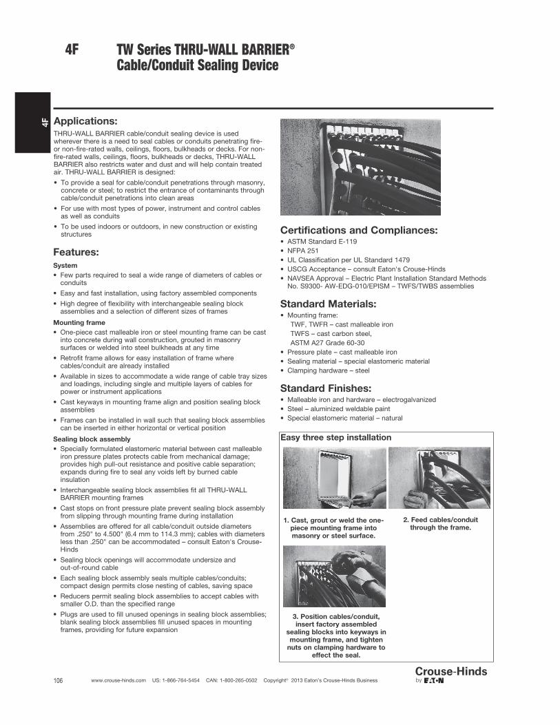
4F
106 www.crouse-hinds.com US: 1-866-764-5454 CAN: 1-800-265-0502 Copyright© 2013 Eaton’s Crouse-Hinds Business
TW Series THRU-WALL BARRIER®
Cable/Conduit Sealing Device
Applications:THRU-WALL BARRIER cable/conduit sealing device is usedwherever there is a need to seal cables or conduits penetrating fire-or non-fire-rated walls, ceilings, floors, bulkheads or decks. For non-fire-rated walls, ceilings, floors, bulkheads or decks, THRU-WALLBARRIER also restricts water and dust and will help contain treatedair. THRU-WALL BARRIER is designed:
• To provide a seal for cable/conduit penetrations through masonry,concrete or steel; to restrict the entrance of contaminants throughcable/conduit penetrations into clean areas
• For use with most types of power, instrument and control cablesas well as conduits
• To be used indoors or outdoors, in new construction or existingstructures
Features:
System
• Few parts required to seal a wide range of diameters of cables orconduits
• Easy and fast installation, using factory assembled components
• High degree of flexibility with interchangeable sealing blockassemblies and a selection of different sizes of frames
Mounting frame
• One-piece cast malleable iron or steel mounting frame can be castinto concrete during wall construction, grouted in masonrysurfaces or welded into steel bulkheads at any time
• Retrofit frame allows for easy installation of frame wherecables/conduit are already installed
• Available in sizes to accommodate a wide range of cable tray sizesand loadings, including single and multiple layers of cables forpower or instrument applications
• Cast keyways in mounting frame align and position sealing blockassemblies
• Frames can be installed in wall such that sealing block assembliescan be inserted in either horizontal or vertical position
Sealing block assembly
• Specially formulated elastomeric material between cast malleableiron pressure plates protects cable from mechanical damage;provides high pull-out resistance and positive cable separation;expands during fire to seal any voids left by burned cableinsulation
• Interchangeable sealing block assemblies fit all THRU-WALLBARRIER mounting frames
• Cast stops on front pressure plate prevent sealing block assemblyfrom slipping through mounting frame during installation
• Assemblies are offered for all cable/conduit outside diametersfrom .250" to 4.500" (6.4 mm to 114.3 mm); cables with diametersless than .250" can be accommodated – consult Eaton's Crouse-Hinds
• Sealing block openings will accommodate undersize and out-of-round cable
• Each sealing block assembly seals multiple cables/conduits;compact design permits close nesting of cables, saving space
• Reducers permit sealing block assemblies to accept cables withsmaller O.D. than the specified range
• Plugs are used to fill unused openings in sealing block assemblies;blank sealing block assemblies fill unused spaces in mountingframes, providing for future expansion
Standard Materials:• Mounting frame:
TWF, TWFR – cast malleable ironTWFS – cast carbon steel,ASTM A27 Grade 60-30
• Pressure plate – cast malleable iron• Sealing material – special elastomeric material• Clamping hardware – steel
Standard Finishes:• Malleable iron and hardware – electrogalvanized• Steel – aluminized weldable paint• Special elastomeric material – natural
Certifications and Compliances:• ASTM Standard E-119• NFPA 251• UL Classification per UL Standard 1479• USCG Acceptance – consult Eaton's Crouse-Hinds• NAVSEA Approval – Electric Plant Installation Standard Methods
No. S9300- AW-EDG-010/EPISM – TWFS/TWBS assemblies
Easy three step installation
1. Cast, grout or weld the one-
piece mounting frame into
masonry or steel surface.
2. Feed cables/conduit
through the frame.
3. Position cables/conduit,
insert factory assembled
sealing blocks into keyways in
mounting frame, and tighten
nuts on clamping hardware to
effect the seal.
4F

4F
107www.crouse-hinds.com US: 1-866-764-5454 CAN: 1-800-265-0502 Copyright© 2013 Eaton’s Crouse-Hinds Business
4F
.500–.750.250–.500Opening
Size
Range
.750–1.000
TWB Sealing Block Assemblies
TWB sealing block assemblies are offeredfor cable/conduit outside diameters (O.D.)from .250" to 4.500" (6.4 mm to 114.3mm). Cables with diameters less than.250" can be accommodated – consultEaton's Crouse-Hinds. Each assemblyopening will accommodate a .250" (6.4 mm) O.D. range. When clampinghardware is tightened, the elastomericmaterial is uniformly compressed aroundall cable/conduits for a completely tight fit.
TWB2063
Depending on opening size range, a
standard sealing block assembly will
seal from one to eleven cables
In.mm
1.000–1.250 1.250–1.500 1.500–1.750 1.750–2.000 2.000–2.250 2.250–2.500
6.4–12.7 12.7–19.1 19.1–25.4 25.4–31.8 31.8–38.1 38.1–44.5 44.5–50.8 50.8–57.2 57.2–63.5
No. Openings
In Block11 11
Added* 6 11Added* 6 5 4 3 3 3 2
Sealing
Block
Assembly
Cat. #
TWB2111 TWB2062
TWB2063 TWB3054 TWB3045 TWB30355 TWB4036 TWB40366 TWB5027TWB1111 TWB2112
Frame
Spaces
Required
2 1 2 2 2 3 3 3 4 4 5
Plug Cat. # TWP1 TWP3 TWP5 TWP6 TWP7
Reducer
Cat. # §— TWR2 TWR3 TWR4 TWR5 TWR55 TWR6 TWR66 TWR7
TWF Mounting FramesTWF(S) mounting frames may be installedeither horizontally or vertically. TWFR retrofitframes are used wherever cables/conduitsare already installed through a fire- or non-fire-rated wall, floor or ceiling. They aredesigned with a removable section to permitinstallation around cables/conduits. TWFRretrofit frames can be grouted into walls,floors, or ceilings, or welded into steelbulkheads or decks. TWFR retrofit frameswill perform in the same manner as the one-piece TWF(S) frames.
TWFS steel mounting frames are weldeddirectly into steel bulkheads, decks andprepared sleeves. For marine applications,keeper bars are provided to securely holdTWBS sealing block assemblies in positionwhen installed.
TWF12
TWF6
TWF10TWFS10
†For 3.5" - 4" cable/conduit – use TWB7011010 assembly and reduce down using TWR reducers.*Catalog # TWB1111 and TWB2112 are used between TWB2111 and TWB2062 in cases where the number of cables to be sealed in .250-.750 range exceeds the number of openings instandard assemblies. Use as many of these higher density assemblies as needed, sandwiched between halves of a standard assembly.§TWR reducers match TWB sealing block assemblies shown in column above Cat. No. and reduce openings to accept cable size ranges shown in adjacent column to the left (in direction ofarrow).
Sealing block assemblies are offered foruse in marine applications. Each assemblyhas the required lubrication and sealinggaskets to meet U.S. Navy HydrostaticPressure Test Requirements. Assembliesfor marine applications are available forcable/conduit outside diameters (O.D.)from .250" (6.4 mm) through 3.500" (88.9 mm). To order, add suffix S to TWBsealing block assembly Cat. No. Example:TWBS4036.
No. of Spaces
Available Frame Cat. #
Retrofit
Frame Cat. #
Cast Steel
Frame Cat. #
6 TWF6 TWFR610 TWF10 TWFR10 TWFS1012 TWF12† TWFR12†20 TWF20 TWFR20 TWFS2024 TWF24 TWFR2430 TWF30 TWFR30 TWFS30
†Includes removable partition.
TW Series THRU-WALL BARRIER®
Cable/Conduit Sealing DeviceSealing Block Assemblies & Mounting FramesOrdering Information

4F
108 www.crouse-hinds.com US: 1-866-764-5454 CAN: 1-800-265-0502 Copyright© 2013 Eaton’s Crouse-Hinds Business
5
4F TW Series THRU-WALL BARRIER®
Cable/Conduit Sealing DevicePlugs, Reducers, Closure Cover Kits, Anchors & LubricantOrdering Information
TWB2112 TWB2062
TWP Plugs
TWP plugs will close any unused openingsin sealing block assemblies. See table forplug catalog numbers which matchspecific sealing block assemblies.
TWR Reducers
TWR reducers will reduce openings by.250" (6.4 mm) in sealing blockassemblies. See table for reducer catalognumbers which match specific sealingblock assemblies. More than one reducercan be used in a single opening.
It is possible to increase cable fill density with double-sided sealing block assemblies (TWB1111 and TWB2112) sandwiched between halvesof a standard assembly.
2.500–2.750 2.750–3.000 3.000–3.250 3.250–3.500 3.500–4.250† 4.250–4.500 Blank – NoOpenings63.5–69.9 69.9–76.2 76.2–82.6 82.6–88.9 101.6–108.0 108.0–114.3
2 2 2 2 1 1 None None
TWB50277 TWB5028 TWB60288 TWB6029 TWB7011010 TWB70111 TWB1 TWB3
5 6 6 7 7 1 3
TWP7 TWP8 TWP9 TWP10 TWP11 —
TWR77 TWR8 TWR88TWR9 TWR1010
TWR11 —TWR99 TWR10
TWB Closure Cover KitsTWB closure cover kits offer an optional method to close TWFframes installed for future expansion or those that are abandoned.Closure cover kits include two covers clamped to opposite sides ofthe frame with hardware provided. The insulating material provided issandwiched between the two covers to maintain the fire rating of theassembly. See table below for closure kit catalog numbers.
No. of
Spaces
Available
Closure
Cover Kit
Cat. #*
6 TWB600‡10 TWB100012 TWB600‡20 TWB200024 TWB240030 TWB3000
*TWB closure cover kits are not designed to provide awatertight seal in marine/shipboard applications orwashdown areas. One kit seals one unused frameopening of same size. Example: use one TWB2000 kit toseal one TWF20, or TWFR20 frame.‡Use two TWB600 kits to seal one TWF12 or TWFR12frame opening.
TWK AnchorsTWK anchor assemblies are used to attach mounting frames to wall,ceiling or floor when grouting in frames.
Mounting Type Cat. #
Flush TWK1Recessed TWK2
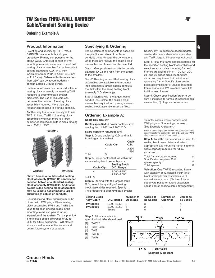
4F
109www.crouse-hinds.com US: 1-866-764-5454 CAN: 1-800-265-0502 Copyright© 2013 Eaton’s Crouse-Hinds Business
4F
Product InformationSelecting and specifying THRU-WALLBARRIER components is a simpleprocedure. Primary components for theTHRU-WALL BARRIER consist of TWFmounting frames in various sizes and TWBsealing block assemblies for cable/conduitoutside diameters (O.D.) in 1/4-inchincrements from .250" to 4.500" (6.4 mmto 114.3 mm). Cables with diameters lessthan .250" can be accommodated –consult Eaton's Crouse-Hinds.
Cable/conduit sizes can be mixed within asealing block assembly by inserting TWRreducers to accommodate smallerdiameters. The use of reducers candecrease the number of sealing blockassemblies required. More than onereducer can be used in a single opening.
Another way to increase density is to useTWB1111 and TWB2112 sealing blockassemblies wherever there is a largenumber of cables/conduits in sizes rangingfrom .250" to .750".
TWB2112
TWB2062 TWB2062
Shown here is a double-sided sealing
block assembly (TWB2112) sandwiched
between halves of a standard sealing
block assembly (TWB2062). Additional
double-sided sealing block assemblies
may be used to accommodate larger
quantities of cables or conduits.
Unused sealing block openings must beclosed with TWP plugs. Blank sealingblock assemblies TWB1 and TWB3 areused to fill each unused space in themounting frame and permit futureexpansion of the system. Typical practiceis to include space allowance of 20 to50% for future expansion. TWB closurekits are used to seal entire frames andpermit future system expansion.
Specifying & OrderingThe selection of components is based onthe quantity and sizes of cables orconduits going through the penetrations.Once these are known, the sealing blockassemblies and frames can be selected.
Step 1. Group cables/conduits by outsidediameter (O.D.) and rank from the largestto the smallest.
Step 2. Keeping in mind that sealing blockassemblies are available in one-quarterinch increments, group cables/conduitsthat fall within the same sealing blockassembly O.D. size range.
Step 3. Starting with the largest cable/conduit O.D., select the sealing blockassemblies required. All openings in eachsealing block assembly must be filled.
Ordering Example A:Cable tray size: 24"
Cables specified: 5 power cables – sizesranging from 1.960" to 2.200" O.D.
Spare capacity required: 50%Step 1. Group cables by O.D. and rankfrom largest to smallest.
Cable Qty.
Cable
O.D.
4 2.2001 1.960
Total 5Step 2. Group cables that fall within thesame sealing block assembly size.
Cable Qty.
Sealing Block
O.D. Range
4 2.000–2.2501 1.750–2.000
Total 5Step 3. Starting with the largest cableO.D., select the quantity of sealing block assemblies required. Specify TWR reducers to accommodate smaller
Note: In the example, one TWR66 reducer is required toaccommodate the cable with 1.960 O.D. and one TWP6plug is required for the unused opening.
Step 4. Total the frame spaces required forsealing block assemblies and selectappropriate size mounting frame. Factor inspare capacity required for futureexpansion.
Total frame spaces required 8Specification requires 50%spare capacity 4
Total spaces 12
Selection: One TWF12 mounting framewith capacity of 12 spaces. Four TWB1blank sealing block assemblies to fillunused frame space. (Choice of framecould vary based on future expansionneeds and/or specific cable arrangement.)
Sealing Block
Assy Cat. # O.D. Range
Number of
Openings
Cables to
be Sealed
Number of
Openings
Cables to
be Sealed
TWB40366 2.000–2.250 3 3 — 4TWB40366 2.000–2.250 3 2 1 4
Totals 66 5 1 8
Step 5. Bill of materials forspecification/order should read:
(1) TWF12(2) TWB40366(4) TWB1(1) TWR66(1) TWP6
Example A diagram
Specify TWR reducers to accommodatesmaller diameter cables where possibleand TWP plugs to fill openings not used.
Step 4. Total the frame spaces required forthe specified sealing block assemblies andselect an appropriate mounting frame(s).Frames are available in 6-, 10-, 12-, 20-,24- and 30-space sizes. Keep futureexpansion requirements in mind whenspecifying frame. Specify blank sealingblock assemblies to fill unused mountingframe space and TWB closure cover kitsto fill unused frames.
Step 5. Check specification/order to besure it includes 1) frames, 2) sealing blockassemblies, 3) plugs and 4) reducers.
diameter cables where possible and TWP plugs to fill openings not used. (See Example A diagram.)
TW Series THRU-WALL BARRIER®
Cable/Conduit Sealing DeviceOrdering Example A
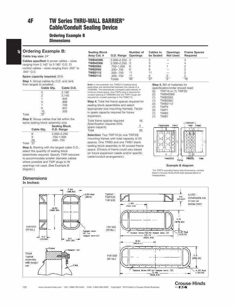
4F
110 www.crouse-hinds.com US: 1-866-764-5454 CAN: 1-800-265-0502 Copyright© 2013 Eaton’s Crouse-Hinds Business
4F TW Series THRU-WALL BARRIER®
Cable/Conduit Sealing DeviceOrdering Example BDimensions
Ordering Example B:Cable tray size: 24"
Cables specified: 6 power cables – sizesranging from 2.140" to 2.180" O.D. 31control cables – sizes ranging from .550" to.945" O.D.
Spare capacity required: 25%
Step 1. Group cables by O.D. and rankfrom largest to smallest.
Cable Qty. Cable O.D.
4 2.1802 2.1401 .9454 .8907 .7009 .63710 .550
Total 37
Step 2. Group cables that fall within thesame sealing block assembly size.
Cable Qty.
Sealing Block
O.D. Range
6 2.000–2.2505 .750–1.00026 .500–.750
Total 37Step 3. Starting with the largest cable O.D.,select the quantity of sealing blockassemblies required. Specify TWR reducersto accommodate smaller diameter cableswhere possible and TWP plugs to fillopenings not used. (See Example Bdiagram.)
Sealing Block
Assy Cat. # O.D. Range
Number of
Openings
Cables to
be Sealed
Openings
Not Used
Frame Spaces
Required
TWB40366 2.000–2.250 3 3 — 4TWB40366 2.000–2.250 3 3 — 4TWB2063 .750–1.000 6 5 1 2TWB2062 .500–.750 6 6 — 2TWB2112 .500–.750 11 11 — 2TWB2112 .500–.750 11 9 2 2
Totals 40 37 3 16
Note: In this example, two TWB2112 sealing blockassemblies are sandwiched between two halves of aTWB2062. This dramatically increases cable density inminimum frame space. One TWP3 plug is required forunused opening in TWB2063 and two TWP1 plugs arerequired for unused openings in the TWB2112.
Step 4. Total the frame spaces required forsealing block assemblies and selectappropriate size mounting frame(s). Factorin spare capacity required for futureexpansion.
Total frame spaces required 16Specification requires 25%spare capacity 4
Total 20
Selection: Two TWF10 (or one TWF20)mounting frames with total capacity of 20spaces. One TWB3 and one TWB1 blanksealing block assembly to fill unused framespace. (Choice of frame could vary basedon future expansion needs and/or specificcable/conduit arrangement.)
Step 5. Bill of materials forspecification/order should read:(2) TWF10 or (1) TWF20(2) TWB40366(1) TWB2063(1) TWB2062(2) TWB2112(1) TWP3(2) TWP1(1) TWB3(1) TWB1
*For TWFS mounting frame hole dimensions, contactEaton's Crouse-Hinds ECM field representative orheadquarters.
DimensionsIn Inches:
Example B diagram

4F
111www.crouse-hinds.com US: 1-866-764-5454 CAN: 1-800-265-0502 Copyright© 2013 Eaton’s Crouse-Hinds Business
4F
DimensionsIn Inches:
TWF6 (20 lbs.) TWF12 (38 lbs.)
TWF10 (25 lbs.)TWF20 (82 lbs.)
TWF24 (88 lbs.)
TWB
TWF30 (97 lbs.)
TWK
*For TWF mounting frame hole dimensions, contact Eaton's Crouse-Hinds ECM field representative or headquarters.
1. Dimensions are shown as inches (mm).2. Dimensions shown for TWF frames also apply for TWFR retrofit frames.
TW Series THRU-WALL BARRIER®
Cable/Conduit Sealing DeviceDimensions*

4F
112 www.crouse-hinds.com US: 1-866-764-5454 CAN: 1-800-265-0502 Copyright© 2013 Eaton’s Crouse-Hinds Business
Link-Seal® DevicesEnvironmental Seal forConduit Passing ThroughConcrete Walls, Floors, or Ceilings
Link-Seal Devices
Wet LocationsCorrosive Environments
Applications:• Eaton's Crouse-Hinds Link-Seal® is the
quick, economical way to seal aroundconduit in concrete walls, floors andcasings. Link-Seal is a modularmechanical seal used for any type ofpenetration.
Features and Benefits:• Saves time and money – Link-Seal
installs in up to 75% less time thancompetition products
• Positive Hydrostatic Sealing – properlyinstalled, Link-Seal is rated at 20 psig (40 feet of head), which exceeds theperformance requirements of mostapplications
• Environment Seals – Link-Sealenvironmental seal is designed for longlife and use as a permanent seal. Sealelements are specially compounded toresist aging, ozone, sunlight, water and awide range of chemicals
• Fire Seals – for fire protection in floorand wall penetrations Link-Seal isFactory Mutual approved
• Resistance to high and low temperatures– Link-Seal environmental seal ismanufactured from special compoundsthat resist temperatures from –40°F to +250°F. Link-Seal Fire Seal is manufactured from a siliconematerial that resists temperatures from–67°F to +400°F
• Corrosion protection – where installationagainst galvanic corrosion (orelectrolysis) is required, Link-Sealprovides complete separation pipe andcasing. Metal-to-metal contact iseliminated
• Compensates for misalignment – Link-Seal allows for some angular andoff-center conduit conditions and stillseals effectively
• Absorbs shock, sound and vibration –this inherent benefit of Link-Seal helpsreduce conduit failure due to fatigue andthreaded connections
Standard Materials:• Rubber Seal Elements:EPDM (Black) – Environmental SealsSilicone (Grey) – Fire Seals• Pressure Plates:Glass Reinforced Nylon – EnvironmentalSealsSteel w/Zinc Dichromate Plate – Fire Seals• Fasteners:Carbon Steel, Zinc Dichromate Plate –Environmental Seals316 Stainless Steel – Environmental withOption S316Carbon Steel w/Zinc Dichromate – FireSeals
Environmental ConduitSeal
Ordering Information:It’s easy. Locate the conduit size and typeyou are installing in the columns on theleft. Then locate the seal and sleeve partnumbers under the installation methodyou’ve selected. No sleeve is needed forcored or cast hole installation.
Cored or Cast HoleMethod:Note the appropriate hole diameter andselect the seal part number. Example: For 3/4" EMT conduit through a cored hole – Core a 2" diameter hole and installthe conduit using Link-Seal part numberLSA200-C-04.
Sleeve Methods:Select either the plastic or metal sleeve.Both types of sleeves are designed to becast into concrete walls or floors. Sleevesare ordered separately. Remember to addthe wall or floor thickness to the steelsleeve part number to insure the sleeve isprovided in the proper length. Plasticsleeves are a standard 16 long and can bemodified in the field.
Materials:The standard product for environmentalconduit seals is made from EPDM suppliedwith steel bolts and nuts with a zincdichromate finish. These seals are suitablefor use in water, direct ground burial andatmospheric conditions. They provideelectrical insulation where cathodicprotection is required. EPDM rubber isresistant to most inorganic acids andalkalis, and some organic chemicals(acetone, alcohol, ketones).
Options:To order the standard product with 316stainless steel bolts and nuts, for corrosiveenvironments, replace the "C" in the sealcatalog number with "S316". For example,a 1/2" seal for rigid steel conduit for a coredhole is an LSA200-C-04; ordered withstainless steel bolts and nuts the catalognumber becomes LSA200-S316-04.
4F
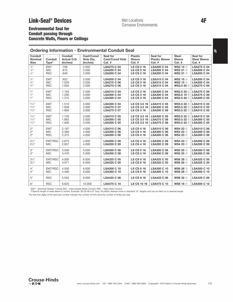
4F
113www.crouse-hinds.com US: 1-866-764-5454 CAN: 1-800-265-0502 Copyright© 2013 Eaton’s Crouse-Hinds Business
4F
The last two digits of the seal part number indicate the number of links (and the number of bolts) per seal.
Ordering Information - Environmental Conduit Seal
Conduit
Nominal
Size
Conduit
Type*
Conduit
Actual O.D.
(inches)
Cast/Cored
Hole Dia.
(inches)
Seal for
Cast/Cored Hole
Cat. #
Plastic
Sleeve
Cat. #
Seal for
Plastic Sleeve
Cat. #
Steel
Sleeve
Cat. #
Seal for
Steel Sleeve
Cat. #
1/2" EMT .706 2.000 LSA275 C 04 LS CS 2 16 LSA200 C 04 WS2 15 ➀ LSA275 C 041/2" IMC .815 2.000 LSA200 C 04 LS CS 2 16 LSA200 C 04 WS2 21 ➀ LSA200 C 041/2" RSC .840 2.000 LSA200 C 04 LS CS 2 16 LSA200 C 04 WS2 21 ➀ LSA200 C 04
3/4" EMT .922 2.000 LSA200 C 04 LS CS 3 16 LSA315 C 04 WS2 15 ➀ LSA200 C 043/4" IMC 1.029 2.500 LSA275 C 06 LS CS 3 16 LSA315 C 04 WS2 15 ➀ LSA200 C 043/4" RSC 1.050 2.500 LSA275 C 06 LS CS 3 16 LSA315 C 04 WS2.5 20 ➀ LSA275 C 06
1" EMT 1.163 2.500 LSA315 C 04 LS CS 3 16 LSA300 C 04 WS2.5 20 ➀ LSA275 C 061" IMC 1.290 3.000 LSA300 C 04 LS CS 3 16 LSA300 C 04 WS2.5 10 ➀ LSA275 C 061" RSC 1.315 3.000 LSA300 C 04 LS CS 3 16 LSA300 C 04 WS2.5 20 ➀ LSA200 C 05
11/4" EMT 1.510 3.000 LSA300 C 04 LS CS 3.5 16 LSA315 C 05 WS3.5 22 ➀ LSA315 C 0511/4" IMC 1.638 3.000 LSA275 C 07 LS CS 3.5 16 LSA300 C 05 WS3.5 22 ➀ LSA315 C 0511/4" RSC 1.660 3.000 LSA275 C 07 LS CS 3 16 LSA200 C 06 WS3.5 22 ➀ LSA315 C 05
11/2" EMT 1.740 3.500 LSA315 C 05 LS CS 3.5 16 LSA300 C 05 WS3.5 32 ➀ LSA315 C 0511/2" IMC 1.883 3.500 LSA300 C 05 LS CS 3.5 16 LSA275 C 08 WS3.5 22 ➀ LSA300 C 0511/2" RSC 1.900 3.500 LSA300 C 05 LS CS 3.5 16 LSA275 C 08 WS3.5 22 ➀ LSA300 C 05
2" EMT 2.197 4.000 LSA315 C 06 LS CS 4 16 LSA315 C 06 WS4 23 ➀ LSA315 C 062" IMC 2.360 4.000 LSA300 C 06 LS CS 4 16 LSA300 C 06 WS4 23 ➀ LSA300 C 062" RSC 2.375 4.000 LSA300 C 06 LS CS 4 16 LSA300 C 06 WS4 23 ➀ LSA300 C 06
21/2" EMT/RSC 2.875 4.000 LSA200 C 09 LS CS 4 16 LSA200 C 09 WS4 23 ➀ LSA200 C 0921/2" IMC 2.857 4.000 LSA200 C 09 LS CS 4 16 LSA200 C 09 WS4 23 ➀ LSA200 C 09
3" EMT/RSC 3.500 5.000 LSA300 C 08 LS CS 5 16 LSA300 C 08 WS5 25 ➀ LSA300 C 083" IMC 3.476 5.000 LSA300 C 08 LS CS 5 16 LSA300 C 08 WS5 25 ➀ LSA300 C 08
31/2" EMT/RSC 4.000 6.000 LSA325 C 05 LS CS 6 16 LSA325 C 05 WS6 28 ➀ LSA325 C 0531/2" IMC 3.971 6.000 LSA325 C 05 LS CS 6 16 LSA325 C 05 WS6 28 ➀ LSA325 C 05
4" EMT/RSC 4.500 6.000 LSA300 C 10 LS CS 6 16 LSA300 C 10 WS6 28 ➀ LSA300 C 104" IMC 4.466 6.000 LSA300 C 10 LS CS 6 16 LSA300 C 10 WS6 28 ➀ LSA300 C 10
5" RSC 5.563 8.000 LSA425 C 06 LS CS 8 16 LSA425 C 06 WS8 32 ➀ LSA425 C 06
6" RSC 6.625 10.000 LSA475 C 10 LS CS 10 16 LSA475 C 10 WS8 18 ➀ LSA300 C 15
*EMT – Electrical Metallic Tubing; IMC – Intermediate Metal Conduit; RSC – Rigid Steel Conduit➀Specify length of steel sleeve in inches. Example: S6-28-08 is 8" long. All plastic sleeves come in standard 16" lengths and can be field cut to desired length.
Link-Seal® DevicesEnvironmental Seal forConduit passing throughConcrete Walls, Floors or Ceilings
Wet LocationsCorrosive Environments
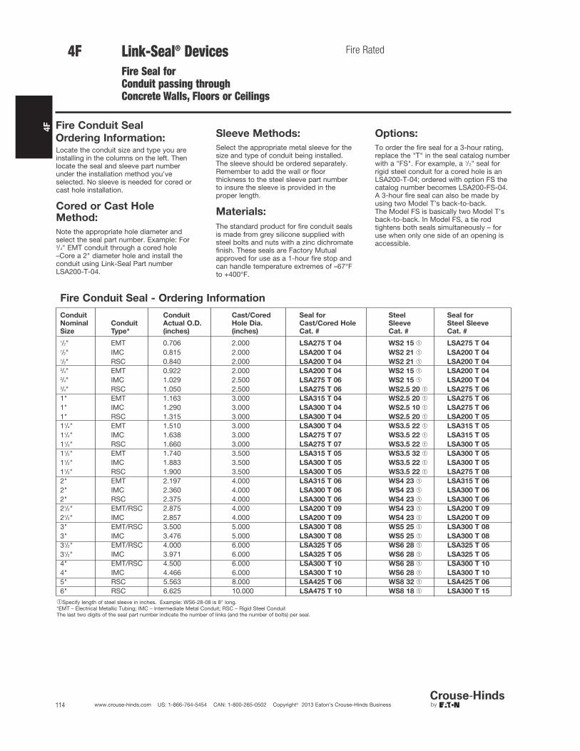
1/2"1/2"1/2"3/4"3/4"3/4"1"1"1"11/4"11/4"11/4"11/2"11/2"11/2"2"2"2"21/2"21/2"3"3"31/2"31/2"4"4"5"6"
4F
114 www.crouse-hinds.com US: 1-866-764-5454 CAN: 1-800-265-0502 Copyright© 2013 Eaton’s Crouse-Hinds Business
4F Link-Seal® DevicesFire Seal for Conduit passing through Concrete Walls, Floors or Ceilings
Fire Rated
Fire Conduit Seal
Ordering Information:Locate the conduit size and type you areinstalling in the columns on the left. Thenlocate the seal and sleeve part numberunder the installation method you'veselected. No sleeve is needed for cored orcast hole installation.
Cored or Cast HoleMethod:
Note the appropriate hole diameter andselect the seal part number. Example: For3/4" EMT conduit through a cored hole–Core a 2" diameter hole and install theconduit using Link-Seal Part numberLSA200-T-04.
Sleeve Methods:
Select the appropriate metal sleeve for thesize and type of conduit being installed.The sleeve should be ordered separately.Remember to add the wall or floorthickness to the steel sleeve part numberto insure the sleeve is provided in theproper length.
Materials:
The standard product for fire conduit sealsis made from grey silicone supplied withsteel bolts and nuts with a zinc dichromatefinish. These seals are Factory Mutualapproved for use as a 1-hour fire stop andcan handle temperature extremes of –67°Fto +400°F.
Options:
To order the fire seal for a 3-hour rating,replace the "T" in the seal catalog numberwith a "FS". For example, a 1/2" seal forrigid steel conduit for a cored hole is anLSA200-T-04; ordered with option FS thecatalog number becomes LSA200-FS-04.A 3-hour fire seal can also be made byusing two Model T’s back-to-back.The Model FS is basically two Model T'sback-to-back. In Model FS, a tie rodtightens both seals simultaneously – foruse when only one side of an opening isaccessible.
Fire Conduit Seal - Ordering Information
Conduit
Nominal
Size
Conduit
Type*
Conduit
Actual O.D.
(inches)
Cast/Cored
Hole Dia.
(inches)
Seal for
Cast/Cored Hole
Cat. #
Steel
Sleeve
Cat. #
Seal for
Steel Sleeve
Cat. #
EMT 0.706 2.000 LSA275 T 04 WS2 15 ➀ LSA275 T 04
IMC 0.815 2.000 LSA200 T 04 WS2 21 ➀ LSA200 T 04
RSC 0.840 2.000 LSA200 T 04 WS2 21 ➀ LSA200 T 04
EMT 0.922 2.000 LSA200 T 04 WS2 15 ➀ LSA200 T 04
IMC 1.029 2.500 LSA275 T 06 WS2 15 ➀ LSA200 T 04
RSC 1.050 2.500 LSA275 T 06 WS2.5 20 ➀ LSA275 T 06
EMT 1.163 3.000 LSA315 T 04 WS2.5 20 ➀ LSA275 T 06
IMC 1.290 3.000 LSA300 T 04 WS2.5 10 ➀ LSA275 T 06
RSC 1.315 3.000 LSA300 T 04 WS2.5 20 ➀ LSA200 T 05
EMT 1.510 3.000 LSA300 T 04 WS3.5 22 ➀ LSA315 T 05
IMC 1.638 3.000 LSA275 T 07 WS3.5 22 ➀ LSA315 T 05
RSC 1.660 3.000 LSA275 T 07 WS3.5 22 ➀ LSA300 T 05
EMT 1.740 3.500 LSA315 T 05 WS3.5 32 ➀ LSA300 T 05
IMC 1.883 3.500 LSA300 T 05 WS3.5 22 ➀ LSA300 T 05
RSC 1.900 3.500 LSA300 T 05 WS3.5 22 ➀ LSA275 T 08
EMT 2.197 4.000 LSA315 T 06 WS4 23 ➀ LSA315 T 06
IMC 2.360 4.000 LSA300 T 06 WS4 23 ➀ LSA300 T 06
RSC 2.375 4.000 LSA300 T 06 WS4 23 ➀ LSA300 T 06
EMT/RSC 2.875 4.000 LSA200 T 09 WS4 23 ➀ LSA200 T 09
IMC 2.857 4.000 LSA200 T 09 WS4 23 ➀ LSA200 T 09
EMT/RSC 3.500 5.000 LSA300 T 08 WS5 25 ➀ LSA300 T 08
IMC 3.476 5.000 LSA300 T 08 WS5 25 ➀ LSA300 T 08
EMT/RSC 4.000 6.000 LSA325 T 05 WS6 28 ➀ LSA325 T 05
IMC 3.971 6.000 LSA325 T 05 WS6 28 ➀ LSA325 T 05
EMT/RSC 4.500 6.000 LSA300 T 10 WS6 28 ➀ LSA300 T 10
IMC 4.466 6.000 LSA300 T 10 WS6 28 ➀ LSA300 T 10
RSC 5.563 8.000 LSA425 T 06 WS8 32 ➀ LSA425 T 06
RSC 6.625 10.000 LSA475 T 10 WS8 18 ➀ LSA300 T 15
➀Specify length of steel sleeve in inches. Example: WS6-28-08 is 8" long.*EMT – Electrical Metallic Tubing; IMC – Intermediate Metal Conduit; RSC – Rigid Steel ConduitThe last two digits of the seal part number indicate the number of links (and the number of bolts) per seal.

4F
115www.crouse-hinds.com US: 1-866-764-5454 CAN: 1-800-265-0502 Copyright© 2013 Eaton’s Crouse-Hinds Business
4F
Dimensions
In Inches:
Technical InformationRubber Sealing Element Pressure Plate Bolt
Link-Seal
Cat. #
Actual
Thickness
(inches)
Free
Length
(inches)
Avg. Length After
Tightening
(inches)
A
(inches)
R
(inches)
T
(inches)
Hex
Across
Flats
H
(inches)
Thread
Size
(inches) L
LSA200 C .478 13/4 13/8 11/6 21/45/16
M5slotted hex .180 M5 21/2
LSA275 C .607 13/4 13/87/8 17/8
5/16M5slotted hex .180 M5 21/2
LSA300 C .687 21/2 2 11/2 21/27/16
1/27/32 5/16–5/18 31/2
LSA315 C .807 21/2 2 17/16 21/27/16
1/27/32 5/16–5/18 31/2
LSA325 C .875 3 23/8 31/8 2 1/21/2
7/32 5/16–5/18 4
LSA425 C 1.062 31/2 23/4 31/2 3 3/49/16
1/4 3/8–3/16 5
LSA475 C 1.562 31/2 23/4 31/2 31/21/2
9/161/4 3/8–3/16 41/2
Link-Seal® Devices Dimensions

4F
116 www.crouse-hinds.com US: 1-866-764-5454 CAN: 1-800-265-0502 Copyright© 2013 Eaton’s Crouse-Hinds Business
4F

117www.crouse-hinds.com US: 1-866-764-5454 CAN: 1-800-265-0502 Copyright© 2013 Eaton’s Crouse-Hinds Business
5FElbows, Couplings, Hubs, GroundingDevices, Plugs, Reducers, ServiceEntrance and UnionsHazardous and Non-hazardous
Description Page No. Description Page No.
Application/Selection see page 118
Elbows
EL Series see page 121
FE / FT Series see page 122
Flexible & Expansion Joint Couplings
EC Series see pages 127–128
XD Series see page 129
XJG Series see page 130
XJG-EMT Series see page 131
XJGD Series see page 132
Grounding Devices, Straps, Clamps
GC Series see page 134
Hubs
HUB Series see page 133
Pipe Plugs
PLG Series see page 124
NOR Series see page 126
Reducers and Adapters
AMN / ANM Series see page 125
RE Series see page 124
REA Series see page 124
REC Series see page 124
NOR Series see page 126
Service Entrance Fittings
Heads
F Series see page 135
Unions
Non-Expansion
UNA Series see page 121
UNF Series see page 120
UNL Series see page 120
UNY Series see page 120
Expansion
UNF Series see page 123
UNY Series see page 123
UNFL Series see page 123
UNYL Series see page 123
Nipples
NOR Series see page 126
Conduit Liners
LNR Series see page 136
5F
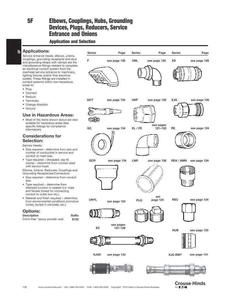
5F
118 www.crouse-hinds.com US: 1-866-764-5454 CAN: 1-800-265-0502 Copyright© 2013 Eaton’s Crouse-Hinds Business
Elbows, Couplings, Hubs, GroundingDevices, Plugs, Reducers, ServiceEntrance and UnionsApplication and Selection
Applications:Service entrance heads, elbows, unions,couplings, grounding receptacle and studand grounding straps with clamps are themiscellaneous fittings needed to completean electrical conduit system from theoverhead service entrance to machinery,lighting fixtures and/or final electricaloutlets. These fittings are installed inconduit systems within non-hazardousareas to:• Plug• Connect• Reduce• Terminate• Change direction• Ground
Use in Hazardous Areas:• Most of the items shown above are also
suitable for hazardous areas (seespecific listings for complianceinformation).
Considerations forSelection:Service Heads:• Size required – determine from size and
number of conductors in service andconduit or mast size.
• Type required – (threaded, slip fit,clamp) – determine from conduit usedwith service head.
Elbows, Unions, Reducers, Couplings andGrounding Receptacles/Connectors:• Size required – determine from conduit
size.• Type required – determine from
intended function in system (i.e. maleand female thread for connectingconduit to outlet box etc.)
• Material and finish required – determinefrom environmental conditions (corrosivefumes, buried in concrete, etc.)
Options:Description Suffix
Corro-free™ epoxy powder coat S752
Series Page Series Page Series Page
F see page 135 UNL see page 120 XD see page 129
GCT see page 134 UNF see page 120 XJG see page 130
RE see page 124
REA / AMN see page 124GCR see page 134 LNR see page 136
REC see page 124UNYLsee page 123 PLG
EC
see pages
127–128HUB see page 133
XJGD see page 132 XJG-EMT see page 131
GC see page 134 EL / FE
see pages
121–122
5F
see
page 124
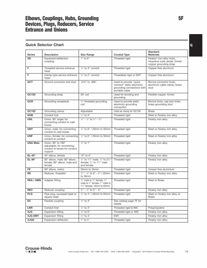
5F
119www.crouse-hinds.com US: 1-866-764-5454 CAN: 1-800-265-0502 Copyright© 2013 Eaton’s Crouse-Hinds Business
Elbows, Couplings, Hubs, GroundingDevices, Plugs, Reducers, ServiceEntrance and Unions
Quick Selector Chart
XD Expansion/deflectioncoupling
1" to 6" Threaded rigid Feraloy® iron alloy hubs,neoprene outer jacket, tinnedcopper grounding strap
F Threaded service entrance head
1/2" to 4" conduit Threaded rigid Copper-free aluminum
F Clamp type service entrance head
3/4" to 2" conduit Threadless rigid or EMT Copper-free aluminum
GCT Ground connector and stud .312" to .406" Used to provide "quickconnect" static electricitygrounding connections withportable cable
Bronze connector body;aluminum cable clamp; brassstud
GC100 Grounding strap 50' coil Used for bonding and grounding
Flexible copper, tinned
GCR Grounding receptacle 3/4" threaded groundingrod
Used to provide static electricity grounding connection
Bronze body, cap and chain;brass grounding stud
GC102 Grounding clamp Adjustable Used as clamp for GC100 Brass
HUB Conduit hub 1/2" to 4" Threaded rigid Steel or Feraloy iron alloy
UNL Union, 90° angle; for connecting conduit to cast boxes
1/2" - 1/2" to 3/4" - 3/4" Threaded rigid Feraloy iron alloy
UNY Union, male; for connectingconduit to cast boxes
1/2" to 6" / 20mm to 50mm Threaded rigid Steel or Feraloy iron alloy
UNF Union, female; for connectingconduit to conduit
1/2" to 6" / 20mm to 50mm Threaded rigid Steel or Feraloy iron alloy
UNA Male Union, 90° to 180° adjustable; for connecting conduit to boxes for conduit support
1/2" to 1" Threaded rigid Feraloy iron alloy
EL-45° 45° elbow, female 12" to 4" Threaded rigid Feraloy iron alloy
EL-90° 90° elbow, male; 90° elbow, female; 90° elbow, male and female
1/2" to 11/4" male; 1/2" to 21/2"female; 1/2" to 11/4" maleand female
Threaded rigid Feraloy iron alloy
FE 90º elbow, metric 20mm to 25mm Threaded rigid Cooper-free aluminium
RE Reducer, threaded 1/2" - 1/8" to 6" - 5" / 20mmto 50mm
Threaded rigid Steel or Feraloy iron alloy
REA / AMN Adapter fitting 1/2" male to 3/4" female; 3/4"male to 1" female; 1" male to11/4" female; 16mm to 63mm
Threaded rigid Steel or Brass
REC Reducer coupling 3/4" - 1/2" to 5" - 4" Threaded rigid Feraloy iron alloy
PLG Pipe plug, recessed head or square head
1/2" to 4" / 20mm to 63mm Threaded rigid Steel or Feraloy iron alloy orBrass
EC Flexible coupling 1/2" to 4" See catalog page 7F for details
LNR Conduit liner 1/2" to 4" Threaded rigid & IMC Polypropylene
XJG Expansion fitting 1/2" to 6" Threaded rigid or IMC Feraloy iron alloy
XJG-EMT Expansion fitting 1/2" to 4" EMT Feraloy iron alloy
Series Description Size Range Conduit Type
Standard
Materials
XJGD Expansion-deflection 1" to 4" Threaded rigid Feraloy iron alloy
5F

5F
120 www.crouse-hinds.com US: 1-866-764-5454 CAN: 1-800-265-0502 Copyright© 2013 Eaton’s Crouse-Hinds Business
Unions and Elbows Cl. I, Div. 1 & 2, Groups A, B, C, D†Cl. II, Div. 1, Groups E, F, GCl. II, Div. 2, Groups F, GCl. III
ExplosionproofDust-Ignitionproof
Applications:UNY and UNF unions are installed inthreaded thickwall conduit systems:• UNY – to connect conduit to a conduit
fitting, junction box or device enclosure• UNF – to connect conduit to conduit, or
to provide a means for futuremodification of the conduit system
UNA unions are used in conduit and fittinginstallations when entrance angle isbetween 90° and 180°.EL elbows are installed in conduit run or inbox or fitting hub:• To change direction in threaded rigid
conduit run by 90°, or when terminatingat a box or fitting
Features:UNY, UNF and UNL unions have:• Compact design which permits
assembly with a minimum of clearanceto other adjacent conduit and/orequipment
• Strong and durable constructionUNA unions:• Have a single clamping nut on angle,
making it both a union and a connector• Permit conduit joints at angles between
90° and 180°EL elbows have a smooth interior and areboth strong and compact.
Standard Materials:• UNY, UNF unions – 1/2" to 1" – steel• UNY, UNF unions – 11/4" to 6" – Feraloy®
iron alloy• UNL, UNA unions – Feraloy iron alloy• EL elbows – Feraloy iron alloy or ductile
iron
Standard Finishes:• Steel – electrogalvanized with chromate
treatment• Feraloy iron alloy, malleable iron –
electrogalvanized and aluminum acrylicpaint
Options:Description Suffix
Copper-free aluminum SANot available on UNA or 5" and6" UNY/UNF
†See compliances for classification of each product.
Certifications andCompliances:• NEC/CEC:
Class I, Division 1 & 2, Groups A, B, C, DClass II, Division 1, Groups E, F, GClass II, Division 2, Groups F, GClass III
EL 1/2", 3/4", 1"UNF/UNY 105, -215, -205, -305UNL 105, -125, -215, -205
Class I, Division 1 & 2, Groups B, C, DClass II, Division 1, Groups E, F, GClass II, Division 2, Groups F, GClass III
UNF/UNY406, -506,-606, -706, -806,-905, -1005
Class I, Division 1 & 2, Groups C, DClass II, Division 1, Groups E, F, GClass II, Division 2, Groups F, GClass III
EL, UNF, UNL, UNY - all sizes
Class I, Division 1 & 2, Group DClass II, Division 1, Groups E, F, GClass II, Division 2, Groups F, GClass III
UNA
• UL Standard: 1203• CSA Standard: C22.2 No. 30
UNL
90° AngleSize Cat. #
1/2 to 1/2 UNL1053/4 female to 1/2 male UNL1251/2 female to 3/4 male UNL2153/4 to 3/4 UNL205
DimensionsIn Inches:
UNY UNF
1/2" – 4" 1/2" – 4"
5" – 6" 5" – 6"
Male Female
Size Cat. # Size Cat. #
1/2 UNY105 1/2 UNF1051/2 femaleto 3/4 male UNY215 3/4 to 1/2 UNF215
3/4 UNY205 3/4 UNF2051 UNY305 1 UNF30511/4 UNY405 11/4 UNF40511/4 UNY406 11/4 UNF40611/2 UNY505 11/2 UNF50511/2 UNY506 11/2 UNF5062 UNY605 2 UNF6052 UNY606 2 UNF60621/2 UNY705 21/2 UNF70521/2 UNY706 21/2 UNF7063 UNY805 3 UNF8053 UNY806 3 UNF80631/2 UNY905 31/2 UNF9054 UNY1005 4 UNF10055 UNY012 5 UNF0126 UNY014 6 UNF014
UNY UNF
Size Length
Max.
Dia. Length
Max.
Dia.
1/2 25/8 11/2 113/16 11/2
3/4 – 1/2 211/16 113/16 13/4 113/16
3/4 211/16 113/16 13/4 113/16
1 3 17/8 2 17/8
11/4 311/16 23/4 21/4 23/4
11/2 41/4 31/16 25/8 31/16
2 41/4 313/16 29/16 313/16
21/2 57/16 45/16 33/16 45/16
3 53/4 51/16 37/16 51/16
31/2 61/2 511/16 41/8 511/16
4 65/8 63/16 41/8 63/16
5 61/8 83/16 313/16 83/16
6 61/8 95/16 313/16 95/16
UNLDim. 105 125 215 205
a 211/16 211/16 27/8 27/8
b 117/32 113/16 113/16 113/16
c 21/16 21/16 21/4 21/4
d 17/16 17/16 15/8 15/8
5F
UNY
DIA LENGTH
www.crouse-hinds.com US: 1-866-764-5454 CAN: 1-800-265-0502 Copyright© 2013 Eaton’s Crouse-Hinds Business

5F
121www.crouse-hinds.com US: 1-866-764-5454 CAN: 1-800-265-0502 Copyright© 2013 Eaton’s Crouse-Hinds Business
5FUnions and Elbows Cl. I, Div. 1 & 2, Groups C, D†Cl. II, Div. 1, Groups E, F, GCl. II, Div. 2, Groups F, GCl. III
ExplosionproofDust-Ignitionproof
UNA
Male (with removable nipple)
MaleSize Cat. #
1/2 UNA163/4 UNA261 UNA36
EL
90° Male
45° Female
90° MaleSize Cat. #
1/2 EL1953/4 EL2951 EL395
45° FemaleSize Cat. #
1/2 EL13/4 EL21 EL311/4 EL411/2 EL52 EL621/2 EL73 EL831/2 EL94 EL10
90° Female
90° Male and female
90° FemaleSize Cat. #
1/2 EL19*3/4 EL29*1 EL39*11/4 EL49*11/2 EL59*2 EL69*21/2 EL79
90° Male and FemaleSize Cat. #
1/2 EL196*3/4 EL296*1 EL396*11/4 EL496
*Available in copper free aluminum – add suffix SA tocatalog number.
UNAMaleSize Length Width
1/2 45/16 25/83/4 413/16 27/8
1 511/16 31/2
DimensionsIn Inches:
90° Male 90° Female
45° Female 90° Male and
female
EL
EL
45°
Female
90°
Male
90°
Female
90°
Male &
Female
Size a a a a
1/2 13/16 17/16 117/32 117/32
3/4 13/8 15/8 13/4 15/8
1 121/32 17/8 2 17/8
11/4 13/4 21/4 21/8
11/2 115/16 42 21/4 521/2 23/4 67/16
3 31/6
31/2 37/16
4 35/8
†See compliances for classification of each product.
www.crouse-hinds.com US: 1-866-764-5454 CAN: 1-800-265-0502 Copyright© 2013 Eaton’s Crouse-Hinds Business

122 www.crouse-hinds.com US: 1-866-764-5454 CAN: 1-800-265-0502 Copyright© 2013 Eaton’s Crouse-Hinds Business
5F
Condulet® Elbows and TeesFor IEC ApplicationsFE and FT Series
Zone 1 Zone 21Zone 2 Zone 22
Applications:
FE and FT conduit fittings are installed inhazardous areas to:
• Act as draw-in outlets especially forcables that are stiff due to large size ortype of insulation
• Make 90º bends in conduit systems,allowing for a straight pull in eitherdirection
• Provide access to wiring formaintenance and future system changes
Features:
• Maximum volume for bends within acompact overall size
• Large openings to facilitate cable pulling
Certifications andCompliances:
Type of Protection
• Ex d, DIP A21, IP67
Degree of Protection
• IP67
Gas Group
• IIB
Approvals
• Ex1108U
Standard Materials:
• Body – Copper-free aluminum
• Cover – Brass
Standard Finishes:
• Natural
Ordering Information:
Inspection Elbows and Tees SelectionCat. # Type Entry Size (metric)
FE1 Elbow M20 (F)-M20 (F)FE2 Elbow M25 (F)-M25 (F)FT1 Tee M20 (F)-M20 (F)FT2 Tee M25 (F)-M25 (F)
Options:Description Suffix
NPT & BSP thread sizes Consult Factory
Dimensions (mm)
5F

5F
123www.crouse-hinds.com US: 1-866-764-5454 CAN: 1-800-265-0502 Copyright© 2013 Eaton’s Crouse-Hinds Business
5F
Applications:
UNF/UNY expansion unions are designedto be used in all threaded rigid metal†conduit systems indoors and outdoors, inhazardous locations to:
• Connect conduit to conduit
• Connect conduit to a junction box ordevice enclosure
• Compensate for conduit cut too short
• Allow for expansion and contraction ofconduit
• Connect stub-ups to threaded conduit
• Replace sections of conduit runs
Features:
• Compact design
• Internal beryllium copper groundingspring to insure positive groundingcontinuity.
• Knurled surface on body and sleeveallows secure gripping with wrench.
• Steel construction for maximumstrength.
• Available in two styles – short lengthwhere space is limited, long length whenextra expansion is required.
Standard Materials:
• Body and sleeve – steel
• Grounding spring – beryllium copper
Standard Finishes:
• Steel – electrogalvanized with chromatefinish
• Beryllium copper – natural
Certifications andCompliances:
• NEC/CEC:
Class I, Division 1 & 2, Groups C, D
Class II, Division 1, Groups E, F, G
Class II, Division 2, Groups F, G
Class III
• UL Standard: 1203
• CSA Standard: C22.2 No. 30
UNYL UNFL
UNYL with sleeve extended UNFL with sleeve extended
UNYMale – ShortConduit Size Cat. #
1/2 UNY173/4 UNY271 UNY37
UNFFemale – ShortConduit Size Cat. #
1/2 UNF173/4 UNF271 UNF37
UNYLMale – LongConduit Size Cat. #
1/2 UNYL173/4 UNYL271 UNYL37
UNFLFemale – LongConduit Size Cat. #
1/2 UNFL173/4 UNFL271 UNFL37
DimensionsIn Inches:
DimensionSize a* b c‡ d
UNY1/2 35/16 13/16
1/2 21/163/4 33/8 17/16
1/2 21/8
1 313/16 111/165/8 21/4
UNYL1/2 45/16 13/16 1 29/163/4 41/2 17/16 11/16 211/16
1 53/16 111/16 15/16 215/16
DimensionSize a* b c‡ d
UNF1/2 33/8 13/16
1/2 27/83/4 37/16 17/16
1/2 215/16
1 313/16 111/165/8 33/16
UNFL1/2 43/8 13/16 1 33/83/4 49/16 17/16 11/16 31/2
1 51/8 111/16 15/16 313/16
*Overall length at maximum expansion‡Maximum expansion
†Suitable with intermediate Metal Conduit in non-hazardous locations
UNF/UNY Expansion Unions Cl. I, Div. 1 & 2, Groups C, DCl. II, Div. 1, Groups E, F, GCl. II, Div. 2, Groups F, GCl. III
ExplosionproofDust-Ignitionproof
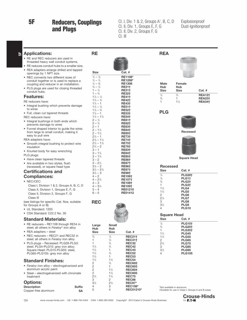
5F
124 www.crouse-hinds.com US: 1-866-764-5454 CAN: 1-800-265-0502 Copyright© 2013 Eaton’s Crouse-Hinds Business
Reducers, Couplingsand Plugs
Cl. I, Div. 1 & 2, Groups A†, B, C, DCl. II, Div. 1, Groups E, F, GCl. II, Div. 2, Groups F, GCl. III
ExplosionproofDust-Ignitionproof
Applications:• RE and REC reducers are used in
threaded heavy wall conduit systems.• RE reduces conduit hubs to a smaller size.• REA adapters enlarge drilled and tapped
openings by 1 NPT size.• REC connects two different sizes of
conduit together or is used to replace acoupling and reducer in an installation.
• PLG plugs are used for closing threadedconduit hubs.
Features:RE reducers have:• Integral bushing which prevents damage
to wires• Full, clean cut tapered threadsREC reducers have:• Integral bushings in both ends which
prevents damage to wires• Funnel shaped interior to guide the wires
from large to small conduit, making iteasy to pull wire
REA adapters have:• Smooth integral bushing to protect wire
insulation• Knurled body for easy wrenchingPLG plugs:• Have clean tapered threads• Are available in two styles, flush
(recessed), or square head type
Standard Materials:• RE reducers – RE1108 through RE54 in
steel; all others in Feraloy® iron alloy• REA adapters – steel• REC reducers – REC21 and REC32 in
steel; all others in Feraloy iron alloy• PLG plugs – Recessed: PLG28-PLG3:
steel, PLG4-PLG10: grey iron alloy;Square Head: PLG15-PLG55: steel,PLG65-PLG105: grey iron alloy
Standard Finishes:• Feraloy iron alloy – electrogalvanized and
aluminum acrylic paint• Steel – electrogalvanized with chromate
treatment
Certifications andCompliances:• NEC/CEC:
Class I, Division 1 & 2, Groups A, B, C, DClass II, Division 1, Groups E, F, GClass II, Division 2, Groups F, GClass III
(see listings for specific Cat. Nos. suitablefor Groups A or B)• UL Standard: 1203• CSA Standard: C22.2 No. 30
Options:Description Suffix
Copper-free aluminum SA
RE
REC
Large
Hub
Size
Small
Hub
Size Cat. #
3/41/2 REC21†
1 1/2 REC31†1 3/4 REC3211/4
3/4 REC4211/4 1 REC4311/2
3/4 REC5211/2 1 REC5311/2 11/4 REC542 3/4 REC6022 1 REC6032 11/4 REC6042 11/2 REC60521/2 11/2 REC753 2 REC8631/2 21/2 REC97*4 3 REC108*5 4 REC01210*
REA
Male
Hub
Size
Female
Hub
Size Cat. #
1/23/4 REA12†
3/4 1 REA23†1 11/4 REA34†
PLG
Recessed
Square Head
RecessedSize Cat. #
1/4 PLG28†1/2 PLG1†3/4 PLG2†1 PLG3†11/4 PLG411/2 PLG52 PLG621/2 PLG73 PLG831/2 PLG94 PLG10
Square HeadSize Cat. #
1/2 PLG15†3/4 PLG25†1 PLG35†11/4 PLG4511/2 PLG552 PLG6521/2 PLG753 PLG8531/2 PLG954 PLG105
*Not available in aluminum.†Suitable for use in Class I, Groups A and B areas.
5F
Size Cat. #
1/2 – 1/8 RE1108*1/2 – 1/4 RE1208*1/2 – 3/8 RE13083/4 – 1/2 RE21†1 – 1/2 RE31†1 – 3/4 RE32†11/4 – 1/2 RE41†11/4 – 3/4 RE42†11/4 – 1 RE43†11/2 – 1/2 RE51†11/2 – 3/4 RE52†11/2 – 1 RE53†11/2 – 11/4 RE54†2 – 1/2 RE61†2 – 3/4 RE62†2 – 1 RE63†2 – 11/4 RE64†2 – 11/2 RE65†21/2 – 1 RE73†21/2 – 11/4 RE74†21/2 – 11/2 RE75†21/2 – 2 RE76†3 – 1 RE83†3 – 11/4 RE84†3 – 11/2 RE85†3 – 2 RE86†3 – 21/2 RE87†31/2 – 2 RE96†31/2 – 21/2 RE97†31/2 – 3 RE98†4 – 2 RE106†4 – 21/2 RE107†4 – 3 RE108†4 – 31/2 RE109†5 – 4 RE012106 – 5 RE01412

5F
125www.crouse-hinds.com US: 1-866-764-5454 CAN: 1-800-265-0502 Copyright© 2013 Eaton’s Crouse-Hinds Business
5F
Application:Adapters are used to change the thread form and/or size in a widerange of BSP, NPT, and metric cable and conduit entries.
Certifications and Compliances:Type of Protection
• Ex d, DIP A21, IP67
Degree of Protection
• IP66/67
Gas Group
• IIC
Approvals
• Ex1108U
Standard Materials:• Brass, nickel plated
Standard Finish:• Natural
Options:Stainless Steel - Replace NP with SS
Size Ranges:• Standard sizes listed in table below; other sizes may be available;
please consult factory
Notes:1. Adapters have different size thread at each end2. Adapters may step up the same type of thread3. Downwards adapters are Type A; upward or same size adapters
are Type B4. For downward adapters of same thread type, see Reducers
Catalog Page5. For same size and type of thread, see Unions Catalog Page
Ordering Information:
AMN / ANM AdaptersFor IEC Applications
Zone 1 Zone 21Zone 2 Zone 22

5F
126 www.crouse-hinds.com US: 1-866-764-5454 CAN: 1-800-265-0502 Copyright© 2013 Eaton’s Crouse-Hinds Business
Reducers, Adapters, Plugs andNipples for IEC Applications
Ex II 2 G EEx e IIEx II 2 G EEx d IICEx II 2 D
IP67
Applications:• Reducers are used in threaded heavy wall conduit systems to
reduce conduit hubs to a smaller size or to connect two differentsizes of conduit together
• Adapters enlarge drilled and tapped openings by 1 NPT size• Plugs are used for closing unused threaded conduit hubs
Features:Reducers:• Integral bushing which prevents damage to wires• Full, clean cut tapered threads• Funnel shaped interior to guide the wires from large to small
conduit, making it easy to pull wireAdapters:• Smooth integral bushing to protect wire insulation• Knurled body for easy wrenchingPlugs:• Full, clean cut tapered threads
Certifications and Compliances:• Plugs:
Ex II 2 G EEx e IIEx II 2 G EEx d IICEC-Type examination certificate LOM 02 ATEX 3035UIP67
• Reducers and Adapters:Ex II 2 G EEx e IIEx II 2 G EEx d IICEx II 2 DEC-Type examination certificate LOM 03 ATEX 3019UIP67
• Nipples:Ex II 2 G EEx d IICEC-Type examination certificate LOM 03 ATEX 3019UIP67
Standard Materials:• Reducers, Adapters, Plugs and Nipples - Zinc Plated Steel
Ordering Information - PlugsThread Size Cat. #
1/2" ISO 7/1 NOR 000 002 140 1173/4" ISO 7/1 NOR 000 002 140 1251" ISO 7/1 NOR 000 002 140 1331" NPT NOR 000 002 140 365M20 x 1.5 NOR 000 002 140 655M25 x 1.5 NOR 000 002 140 656M32 x 1.5 NOR 000 002 140 657M50 x 1.5 NOR 000 002 140 658M60 x 1.5 NOR 000 002 140 659
Type PLG
Ordering Information - ReducersMale Thread Female Thread Cat. #
3/4" ISO 7/11/2" ISO 7/1 NOR 000 002 190 112
1" ISO 7/13/4" ISO 7/1 NOR 000 002 190 188
1/2" ISO 7/13/4" ISO 7/1 NOR 000 002 190 675
3/4" ISO 7/1 1" ISO 7/1 NOR 000 002 190 740
Ordering Information - AdaptersMale Thread Female Thread Cat. #
M20 x 1.5 1/2" ISO 7/1 NOR 000 112 190 010PG13 1/2" ISO 7/1 NOR 000 112 190 015PG16 1/2" ISO 7/1 NOR 000 112 190 014M20 x 1.5 3/4" ISO 7/1 NOR 000 112 190 009M25 x 1.5 3/4" ISO 7/1 NOR 000 112 190 008PG13 3/4" ISO 7/1 NOR 000 112 190 013PG16 3/4" ISO 7/1 NOR 000 112 190 012PG21 3/4" ISO 7/1 NOR 000 112 190 0111/2" ISO 7/1 M20 x 1.5 NOR 000 112 190 0023/4" ISO 7/1 M20 x 1.5 NOR 000 112 190 001PG13 M20 x 1.5 NOR 000 112 190 017PG16 M20 x 1.5A NOR 000 112 190 0163/4" ISO 7/1 M25 x 1.5 NOR 000 112 190 000PG16 M25 x 1.5 NOR 000 112 190 0201/2" ISO 7/1 PG13 NOR 000 112 190 0073/4" ISO 7/1 PG13 NOR 000 112 190 0051/2" ISO 7/1 PG16 NOR 000 112 190 0063/4" ISO 7/1 PG16 NOR 000 112 190 004M20 x 1.5 PG16 NOR 000 112 190 018M25 x 1.5 PG16 NOR 000 112 190 0193/4" ISO 7/1 PG21 NOR 000 112 190 003
Ordering Information - NipplesThread Size Type Cat. #
1/2" ISO 7/1 EMM 1 NOR 000 002 130 1183/4" ISO 7/1 EMM 2 NOR 000 002 130 1261" ISO 7/1 EMM 3 NOR 000 002 130 1341/2" ISO 7/1 EMF 1 NOR 000 002 130 2173/4" ISO 7/1 EMF 2 NOR 000 002 130 2251" ISO 7/1 EMF 3 NOR 000 002 130 233
5F
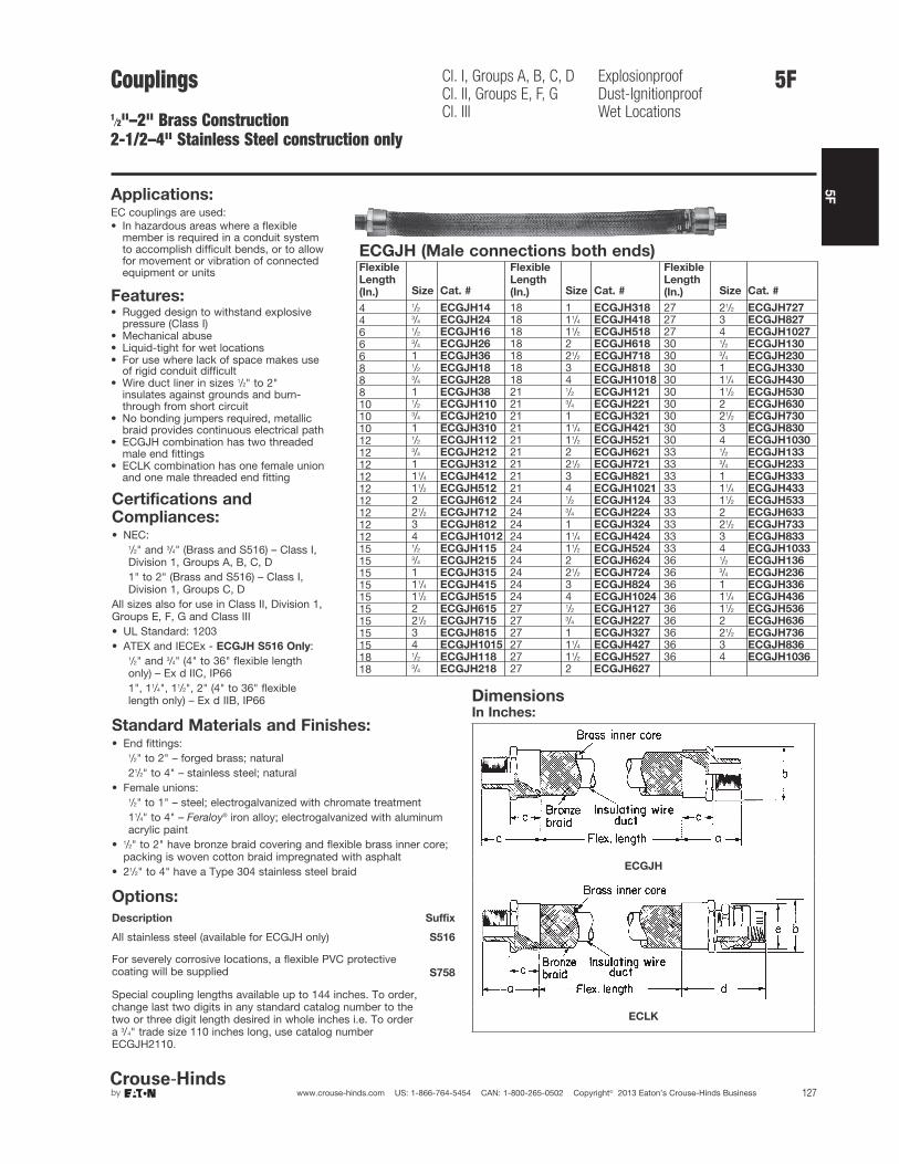
5F
127www.crouse-hinds.com US: 1-866-764-5454 CAN: 1-800-265-0502 Copyright© 2013 Eaton’s Crouse-Hinds Business
5F
Applications:EC couplings are used:• In hazardous areas where a flexible
member is required in a conduit systemto accomplish difficult bends, or to allowfor movement or vibration of connectedequipment or units
Features:• Rugged design to withstand explosive
pressure (Class I)• Mechanical abuse• Liquid-tight for wet locations• For use where lack of space makes use
of rigid conduit difficult• Wire duct liner in sizes 1/2" to 2"
insulates against grounds and burn-through from short circuit
• No bonding jumpers required, metallicbraid provides continuous electrical path
• ECGJH combination has two threadedmale end fittings
• ECLK combination has one female unionand one male threaded end fitting
ECGJH (Male connections both ends)Flexible
Length
(In.) Size Cat. #
Flexible
Length
(In.) Size Cat. #
Flexible
Length
(In.) Size Cat. #
4 1/2 ECGJH14 18 1 ECGJH318 27 21/2 ECGJH727
4 3/4 ECGJH24 18 11/4 ECGJH418 27 3 ECGJH827
6 1/2 ECGJH16 18 11/2 ECGJH518 27 4 ECGJH1027
6 3/4 ECGJH26 18 2 ECGJH618 30 1/2 ECGJH130
6 1 ECGJH36 18 21/2 ECGJH718 30 3/4 ECGJH230
8 1/2 ECGJH18 18 3 ECGJH818 30 1 ECGJH330
8 3/4 ECGJH28 18 4 ECGJH1018 30 11/4 ECGJH430
8 1 ECGJH38 21 1/2 ECGJH121 30 11/2 ECGJH530
10 1/2 ECGJH110 21 3/4 ECGJH221 30 2 ECGJH630
10 3/4 ECGJH210 21 1 ECGJH321 30 21/2 ECGJH730
10 1 ECGJH310 21 11/4 ECGJH421 30 3 ECGJH830
12 1/2 ECGJH112 21 11/2 ECGJH521 30 4 ECGJH1030
12 3/4 ECGJH212 21 2 ECGJH621 33 1/2 ECGJH133
12 1 ECGJH312 21 21/2 ECGJH721 33 3/4 ECGJH233
12 11/4 ECGJH412 21 3 ECGJH821 33 1 ECGJH333
12 11/2 ECGJH512 21 4 ECGJH1021 33 11/4 ECGJH433
12 2 ECGJH612 24 1/2 ECGJH124 33 11/2 ECGJH533
12 21/2 ECGJH712 24 3/4 ECGJH224 33 2 ECGJH633
12 3 ECGJH812 24 1 ECGJH324 33 21/2 ECGJH733
12 4 ECGJH1012 24 11/4 ECGJH424 33 3 ECGJH833
15 1/2 ECGJH115 24 11/2 ECGJH524 33 4 ECGJH1033
15 3/4 ECGJH215 24 2 ECGJH624 36 1/2 ECGJH136
15 1 ECGJH315 24 21/2 ECGJH724 36 3/4 ECGJH236
15 11/4 ECGJH415 24 3 ECGJH824 36 1 ECGJH336
15 11/2 ECGJH515 24 4 ECGJH1024 36 11/4 ECGJH436
15 2 ECGJH615 27 1/2 ECGJH127 36 11/2 ECGJH536
15 21/2 ECGJH715 27 3/4 ECGJH227 36 2 ECGJH636
15 3 ECGJH815 27 1 ECGJH327 36 21/2 ECGJH736
15 4 ECGJH1015 27 11/4 ECGJH427 36 3 ECGJH836
18 1/2 ECGJH118 27 11/2 ECGJH527 36 4 ECGJH1036
18 3/4 ECGJH218 27 2 ECGJH627
DimensionsIn Inches:
ECGJH
ECLK
Certifications andCompliances:• NEC:
1/2" and 3/4" (Brass and S516) – Class I,Division 1, Groups A, B, C, D1" to 2" (Brass and S516) – Class I,Division 1, Groups C, D
All sizes also for use in Class II, Division 1,Groups E, F, G and Class III• UL Standard: 1203• ATEX and IECEx - ECGJH S516 Only:
1/2" and 3/4" (4" to 36" flexible lengthonly) – Ex d IIC, IP661", 11/4", 11/2", 2" (4" to 36" flexiblelength only) – Ex d IIB, IP66
Standard Materials and Finishes:• End fittings:
1/2" to 2" – forged brass; natural21/2" to 4" – stainless steel; natural
• Female unions:1/2" to 1" – steel; electrogalvanized with chromate treatment11/4" to 4" – Feraloy® iron alloy; electrogalvanized with aluminumacrylic paint
• 1/2" to 2" have bronze braid covering and flexible brass inner core;packing is woven cotton braid impregnated with asphalt
• 21/2" to 4" have a Type 304 stainless steel braid
Options:
Description Suffix
All stainless steel (available for ECGJH only) S516
For severely corrosive locations, a flexible PVC protectivecoating will be supplied S758
Special coupling lengths available up to 144 inches. To order,change last two digits in any standard catalog number to thetwo or three digit length desired in whole inches i.e. To order a 3/4" trade size 110 inches long, use catalog numberECGJH2110.
Couplings1/2"–2" Brass Construction2-1/2–4" Stainless Steel construction only
Cl. I, Groups A, B, C, DCl. II, Groups E, F, GCl. III
ExplosionproofDust-IgnitionproofWet Locations

5F
128 www.crouse-hinds.com US: 1-866-764-5454 CAN: 1-800-265-0502 Copyright© 2013 Eaton’s Crouse-Hinds Business
ECLK (ECGJH provide with UNF Female union – maleconnection 1 end, female connection 1 end)
Flexible
Length (In.) Size Cat. #
Flexible
Length (In.) Size Cat. #
Flexible
Length (In.) Size Cat. #
4 1/2 ECLK14 18 1 ECLK318 27 21/2 ECLK727
4 3/4 ECLK24 18 11/4 ECLK418 27 3 ECLK827
6 1/2 ECLK16 18 11/2 ECLK518 27 4 ECLK1027
6 3/4 ECLK26 18 2 ECLK618 30 1/2 ECLK130
6 1 ECLK36 18 21/2 ECLK718 30 3/4 ECLK230
8 1/2 ECLK18 18 3 ECLK818 30 1 ECLK330
8 3/4 ECLK28 18 4 ECLK1018 30 11/4 ECLK430
8 1 ECLK38 21 1/2 ECLK121 30 11/2 ECLK530
10 1/2 ECLK110 21 3/4 ECLK221 30 2 ECLK630
10 3/4 ECLK210 21 1 ECLK321 30 21/2 ECLK730
10 1 ECLK310 21 11/4 ECLK421 30 3 ECLK830
12 1/2 ECLK112 21 11/2 ECLK521 30 4 ECLK1030
12 3/4 ECLK212 21 2 ECLK621 33 1/2 ECLK133
12 1 ECLK312 21 21/2 ECLK721 33 3/4 ECLK233
12 11/4 ECLK412 21 3 ECLK821 33 1 ECLK333
12 11/2 ECLK512 21 4 ECLK1021 33 11/4 ECLK433
12 2 ECLK612 24 1/2 ECLK124 33 11/2 ECLK533
12 21/2 ECLK712 24 3/4 ECLK224 33 2 ECLK633
12 3 ECLK812 24 1 ECLK324 33 21/2 ECLK733
12 4 ECLK1012 24 11/4 ECLK424 33 3 ECLK833
15 1/2 ECLK115 24 11/2 ECLK524 33 4 ECLK1033
15 3/4 ECLK215 24 2 ECLK624 36 1/2 ECLK136
15 1 ECLK315 24 21/2 ECLK724 36 3/4 ECLK236
15 11/4 ECLK415 24 3 ECLK824 36 1 ECLK336
15 11/2 ECLK515 24 4 ECLK1024 36 11/4 ECLK436
15 2 ECLK615 27 1/2 ECLK127 36 11/2 ECLK536
15 21/2 ECLK715 27 3/4 ECLK227 36 2 ECLK636
15 3 ECLK815 27 1 ECLK327 36 21/2 ECLK736
15 4 ECLK1015 27 11/4 ECLK427 36 3 ECLK836
18 1/2 ECLK118 27 11/2 ECLK527 36 4 ECLK1036
18 3/4 ECLK218 27 2 ECLK627
ECGJH and ECLKSize a b c d e
1/2 17/8 11/2 11/8 3 19/163/4 21/16 17/8 13/16 31/4 113/16
1 21/2 21/8 11/2 35/8 17/8
11/4 27/8 215/16 17/8 43/16 23/4
11/2 35/16 31/2 17/8 53/16 31/16
2 31/4 41/4 2 51/16 313/16
21/2 3 47/16 15/8 51/16 45/16
3 31/8 49/16 13/4 53/8 51/16
4 45/8 415/16 31/4 71/2 63/16
Minimum Recommended Radius of Bend
Size Radius Size Radius
1/2 10 2 163/4 12 21/2 161 14 3 1811/4 14 4 3011/2 16
5F Couplings1/2"–2" Brass Construction2-1/2–4" Stainless Steel construction only
Cl. I, Groups A, B, C, DCl. II, Groups E, F, GCl. III
ExplosionproofDust-IgnitionproofWet Locations
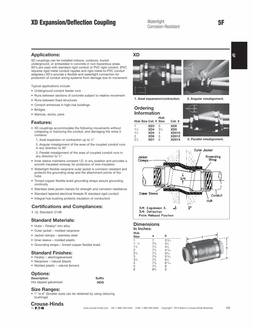
5F
129www.crouse-hinds.com US: 1-866-764-5454 CAN: 1-800-265-0502 Copyright© 2013 Eaton’s Crouse-Hinds Business
5F
Applications:XD couplings can be installed indoors, outdoors, buriedunderground, or embedded in concrete in non-hazardous areas.XD's are used with standard rigid conduit or PVC rigid conduit. (PVCrequires rigid metal conduit nipples and rigid metal-to-PVC conduitadapters.) XD's provide a flexible and watertight connection forprotection of conduit wiring systems from damage due to movement.
Typical applications include:
• Underground conduit feeder runs
• Runs between sections of concrete subject to relative movement
• Runs between fixed structures
• Conduit entrances in high-rise buildings
• Bridges
• Marinas, docks, piers
Features:• XD couplings accommodate the following movements without
collapsing or fracturing the conduit, and damaging the wires itcontains:
1. Axial expansion or contraction up to 3/4"
2. Angular misalignment of the axes of the coupled conduit runsin any direction to 30°
3. Parallel misalignment of the axes of coupled conduit runs inany direction to 3/4"
• Inner sleeve maintains constant I.D. in any position and provides asmooth insulated wireway for protection of wire insulation
• Watertight flexible neoprene outer jacket is corrosion resistant andprotects the grounding strap and the attachment points of thehubs
• Tinned copper flexible braid grounding straps assure groundingcontinuity
• Stainless steel jacket clamps for strength and corrosion resistance
• Standard tapered electrical threads fit standard rigid conduit
• Integral hub bushing protects insulation of conductors
Certifications and Compliances:• UL Standard: 514B
Standard Materials:• Hubs – Feraloy® iron alloy
• Outer jacket – molded neoprene
• Jacket clamps – stainless steel
• Inner sleeve – molded plastic
• Grounding straps – tinned copper flexible braid
Standard Finishes:• Feraloy – electrogalvanized• Neoprene – natural (black)• Molded plastic – natural (brown)
Options:Description Suffix
Hot dipped galvanized HDG
Size Ranges:• 1" to 6" (Smaller sizes can be obtained by using reducing
bushings)
XD
1. Axial expansion/contraction. 2. Angular misalignment.
3. Parallel misalignment.
OrderingInformation
Hub Size Cat. #
Hub
Size Cat. #
1 XD3 3 XD811/4 XD4 31/2 XD911/2 XD5 4 XD0102 XD6 5 XD01221/2 XD7 6 XD014
DimensionsIn Inches:Hub
Size a b
1 7 315/16
1- 1/4 73/8 41/4
11/2 71/4 41/2
2 71/4 415/16
21/2 71/2 55/16
3 75/8 515/16
31/2 73/4 61/2
4 77/8 615/16
5 73/4 86 83/8 9
XD Expansion/Deflection Coupling WatertightCorrosion-Resistant

5F
130 www.crouse-hinds.com US: 1-866-764-5454 CAN: 1-800-265-0502 Copyright© 2013 Eaton’s Crouse-Hinds Business
XJG Conduit Expansion JointsWith Internal GroundingFor Rigid Metal Conduit and IMC
Wet Locations
Applications:XJG expansion couplings are used withrigid metal conduit and IMC:• Without the need for an external bonding
jumper and clamps (up to 4")• To couple together two (2) sections of
conduit subject to longitudinalmovement
• In long conduit runs to permit linearmovement caused by thermal expansionand contraction
• On long conduit runs to prevent conduitfrom buckling and ensuing circuit failures
• Indoors or outdoors where conduitexpansion occurs and there are widetemperature ranges
• In conduit runs that cross structuraljoints
• In conduit runs to prevent damage toconduit supports such as in a building oron a bridge
• With optional redundant visiblegrounding strap
Standard Materials andFinishes:Body
• Steel - electrogalvanized• Copper-free aluminum - natural• Feraloy® iron alloy - electrogalvanized (5"
+ 6" only)Reducer
• 1/2" through 1" - Steel - electrogalvanized• 11/4" through 6" - Feraloy® iron alloy -
electrogalvanized and aluminum paint• Copper-free aluminum - naturalGland Nut
• 1/2" through 1" - Steel - electrogalvanized• 11/4" through 6" - Feraloy® iron alloy -
electrogalvanized and aluminum paint• Copper-free aluminum - naturalPacking
• Teflon® (trademark of E.I. DuPont Co.)Washer
• Steel - electrogalvanized• Copper-free aluminum - naturalGasket
• Vellum
Bushing
• 1/2" through 1" - Steel - electrogalvanized• 11/4" through 6" - Feraloy® iron alloy -
electrogalvanized and aluminum paint• Copper-free aluminum - naturalGround Springs
• Phosphor bronze - electrogalvanizedGround Strap
• Braided tinned copperU-Bolts
• Malleable iron – electrogalvanized
Patented Design
Ordering Information
Conduit
Size
Maximum
Conduit
Movement Cat. #
Optional
Bonding
Jumper†
A
Diameter
B
Length
Bonding
Jumper
Length
1/24 XJG14 BJ14 1.75 6.75 20"8 XJG18 BJ18 1.75 10.75 30"
3/44 XJG24 BJ24 2.12 6.75 20"8 XJG28 BJ28 2.12 10.75 30"
14 XJG34 BJ34 2.43 7.25 20"8 XJG38 BJ38 2.43 11.25 30"
11/44 XJG44 BJ44 3.19 7.56 24"8 XJG48 BJ48 3.19 11.56 30"
11/24 XJG54 BJ54 3.68 7.87 24"8 XJG58 BJ58 3.68 11.87 30"
24 XJG64 BJ64 4.75 8.25 24"8 XJG68 BJ68 4.75 12.25 30"
21/24 XJG74 BJ74 4.87 9.31 24"8 XJG78 BJ78 4.87 13.31 36"
34 XJG84 BJ84 5.37 10.00 30"8 XJG88 BJ88 5.37 14.00 36"
31/24 XJG94 BJ94 6.62 9.81 30"8 XJG98 BJ98 6.62 13.81 36"
44 XJG104 BJ104 6.62 9.81 30"8 XJG108 BJ108 6.62 13.81 36"
5 8 XJ128‡ — 7.64 15.50 —
6 8 XJ148‡ — 9.56 16.00 —†XJG expansion couplings use a metallic bushing and ground springs to create a high integrity internal ground connection.External ground straps offer a redundant ground path and easy visible indication of ground.‡XJ128 and XJ148 are not internally grounded. A pair of 36" bonding jumpers are provided with fitting.
Size Ranges:• 1/2" through 6" conduit size• 4" and 8" maximum conduit movement
Certifications andCompliances:• UL Standard: 514B• CSA Standard: C22.2 No. 18• NEC Articles 250-77 and 300-7 (b)• NEMA FB1• Wet Locations
DimensionsIn Inches:
XJG shown with optional bonding
jumper
5F
Options:Description Suffix
Available in copper-free aluminum SANot available on 5" and 6" sizes
Hot dipped galvanized HDG
Available with redundant† ground strapfor visible indication of grounding –order separately (BJ Series)

5F
131www.crouse-hinds.com US: 1-866-764-5454 CAN: 1-800-265-0502 Copyright© 2013 Eaton’s Crouse-Hinds Business
5F
Applications:XJG expansion couplings are used withEMT Conduit:• Without the need for an external bonding
jumper and clamps
• To couple together two (2) sections ofconduit subject to longitudinal movement
• In long conduit runs to permit linearmovement caused by thermal expansionand contraction
• On long conduit runs to prevent conduitfrom buckling and ensuing circuit failures
• Indoors or outdoors where conduitexpansion occurs and there are widetemperature ranges
• In conduit runs that cross structural joints
• In conduit runs to prevent damage toconduit supports such as in a building oron a bridge
• With optional redundant visiblegrounding strap
Standard Materials andFinishes:Body
• Steel - electrogalvanized• Copper-free aluminum - naturalReducer
• 1/2" through 1" - Steel - electrogalvanized• 11/4" through 4" - Feraloy® iron alloy -
electrogalvanized and aluminum paintGland Nut
• 1/2" through 1" - Steel - electrogalvanized• 11/4" through 4" - Feraloy® iron alloy -
electrogalvanized and aluminum paintPacking
• Teflon® (trademark of E.I. DuPont Co.)Washer
• Steel - electrogalvanizedGasket
• VellumBushing
• 1/2" through 1" - Steel - electrogalvanized• 11/4" through 4" - Feraloy® iron alloy -
electrogalvanized and aluminum paintGround Springs
• Phosphor bronze - electrogalvanizedGround Strap
• Braided tinned copperU-Bolts
• Malleable iron – electrogalvanized
Options:Available with redundant† ground strapfor visible indication of grounding – orderseparately (BJ Series)
Size Ranges:• 1/2" through 4" conduit size• 4" maximum conduit movement
Certifications andCompliances:• UL Standard: 514B• CSA Standard: C22.2 No. 18• NEC Articles 250-77 and 300-7 (b)• NEMA FB1
Ordering Information
Conduit
Size
Maximum
Conduit
Movement Cat. #
Optional
Bonding
Jumper
A
Diameter
B
Length
1/2" 4" XJG14 EMT BJ14 13/4" 103/4"3/4" 4" XJG24 EMT BJ24 21/8" 11"1" 4" XJG34 EMT BJ34 27/16" 111/2"11/4" 4" XJG44 EMT BJ44 31/8" 151/4"11/2" 4" XJG54 EMT BJ54 35/8" 151/2"2" 4" XJG64 EMT BJ64 43/4" 151/2"21/2" 4" XJG74 EMT BJ74 47/8" 183/4"3" 4" XJG84 EMT BJ84 53/8" 197/8"31/2" 4" XJG94 EMT BJ94 65/8" 211/4"4" 4" XJG104 EMT BJ104 65/8" 211/4"
XJG shown with optional bonding jumper
†XJG expansion couplings use a metallic bushing and ground springs to create a highintegrity internal ground connection. External ground straps offer a redundant ground pathand easy visible indication of ground.
XJG-EMT Conduit ExpansionJoints With Internal GroundingFor EMT Conduit

5F
132 www.crouse-hinds.com US: 1-866-764-5454 CAN: 1-800-265-0502 Copyright© 2013 Eaton’s Crouse-Hinds Business
5F XJGD CombinationExpansion/Deflection Couplingand Expansion JointInternally Grounded
Wet Locations
Applications:XJGD combination fittings are used withrigid metal conduit and IMC:• To accommodate axial expansion,
angular misalignment and parallelmisalignment
• To couple together two (2) sections ofconduit subject to longitudinalmovement
• To maintain a ground connection withoutthe need for an external bonding jumperand clamps
• In long conduit runs to prevent conduitfrom buckling and causing circuit failures
• Indoors or outdoors where conduitexpansion occurs and there are widetemperature swings
• In conduit runs that cross structuraljoints
• In conduit runs to prevent damage toconduit supports such as in a building oron a bridge
Standard Materials:• Body, Hubs, Gland Nut, Washer,
Bushing – Feraloy®
• Packing – Teflon®
• Gasket – vellum• Ground Spring – phosphor bronze• Outer Jacket – molded neoprene• Jacket Clamps – stainless steel• Inner Sleeve – molded plastic• Ground Straps – tinned copper braid
Standard Finishes:• Feraloy® – electrogalvanized
Certifications andCompliances:• UL Standard: 514B
Ordering Information
Hub Size
Maximum
Conduit
Movement Cat. #
A
Diameter
B
Length
1" 4" XJGD34 315/16" 173/4"11/4" 4" XJGD44 41/4" 181/8"11/2" 4" XJGD54 41/2" 185/8"2" 4" XJGD64 415/16" 191/4"21/2" 4" XJGD74 55/16" 203/4"3" 4" XJGD84 515/16" 215/8"31/2" 4" XJGD94 61/2" 215/8"4" 4" XJGD104 8" 273/4"
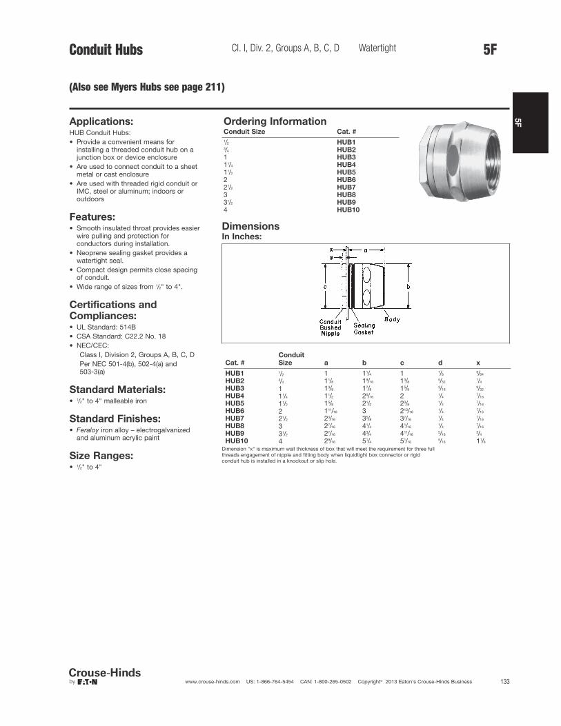
5F
133www.crouse-hinds.com US: 1-866-764-5454 CAN: 1-800-265-0502 Copyright© 2013 Eaton’s Crouse-Hinds Business
5FConduit Hubs
(Also see Myers Hubs see page 211)
Cl. I, Div. 2, Groups A, B, C, D Watertight
Applications:HUB Conduit Hubs:• Provide a convenient means for
installing a threaded conduit hub on ajunction box or device enclosure
• Are used to connect conduit to a sheetmetal or cast enclosure
• Are used with threaded rigid conduit orIMC, steel or aluminum; indoors oroutdoors
Features:• Smooth insulated throat provides easier
wire pulling and protection forconductors during installation.
• Neoprene sealing gasket provides awatertight seal.
• Compact design permits close spacingof conduit.
• Wide range of sizes from 1/2" to 4".
Standard Materials:• 1/2" to 4" malleable iron
Standard Finishes:• Feraloy iron alloy – electrogalvanized
and aluminum acrylic paint
Size Ranges:• 1/2" to 4"
Certifications andCompliances:• UL Standard: 514B• CSA Standard: C22.2 No. 18• NEC/CEC:
Class I, Division 2, Groups A, B, C, DPer NEC 501-4(b), 502-4(a) and 503-3(a)
Cat. #
Conduit
Size a b c d x
HUB1 1/2 1 11/4 1 1/89/64
HUB2 3/4 11/8 19/16 13/85/32
1/4
HUB3 1 13/8 17/8 15/83/16
9/32
HUB4 11/4 11/2 25/16 2 1/47/16
HUB5 11/2 15/8 21/2 23/81/4
7/16
HUB6 2 111/16 3 213/161/4
7/16
HUB7 21/2 23/16 35/8 37/161/4
7/16
HUB8 3 27/16 41/4 41/161/4
7/16
HUB9 31/2 27/16 43/4 411/165/16
3/4
HUB10 4 29/16 51/4 51/165/16 11/8
Dimension "x" is maximum wall thickness of box that will meet the requirement for three fullthreads engagement of nipple and fitting body when liquidtight box connector or rigidconduit hub is installed in a knockout or slip hole.
Ordering InformationConduit Size Cat. #
1/2 HUB13/4 HUB21 HUB311/4 HUB411/2 HUB52 HUB621/2 HUB73 HUB831/2 HUB94 HUB10
DimensionsIn Inches:

5F
134 www.crouse-hinds.com US: 1-866-764-5454 CAN: 1-800-265-0502 Copyright© 2013 Eaton’s Crouse-Hinds Business
Grounding Devices Straps and Clamps
Applications:• GCR grounding receptacles are used to
provide static electricity groundingconnections; particularly suited for, butnot limited to, use in aircraft hangarfloors and airport aprons.
• GCT ground connector and studs areused to provide "quick-connect" staticelectricity grounding connections withportable cable.
• GC grounding strap and clamp aresuitable for bonding and groundingequipment in wiring systems, such asmeter circuits, service entranceequipment, and appliances per NECrequirements.
Features:GCR grounding receptacles have:• Grounding stud integral with housing• Grounding stud designed to accept
standard battery clip• Thread at bottom for attaching to 3/4"
threaded grounding rod• Cover attached to receptacle by chain to
prevent loss of cover• Corrosion resistant materialGCT grounding connector and studs have:• Substantial clip tension for grounding• Integral cable clamp to prevent cable
from breaking free of connector orfraying at connector
• Lock washer on stud to maintain goodelectrical contact
GC strap:• Is pliable, strong and corrosion resistant• Assures a lasting bond. Prongs on strap
clamp engage strap perforations,preventing slippage.
Standard Materials:• GCR – Bronze body, cap and chain;
brass grounding stud• GCT – Bronze connector body;
aluminum cable clamp; brass stud• Strap – flexible copper• Clamp – brass
Standard Finishes:• Bronze, brass, aluminum parts – natural• Flexible copper strap – tinned
Certifications andCompliances:• UL Standard: GC strap and clamps – 467• CSA Standard: C22.2 No. 41
GCT Grounding Connector
Cable Dia. Cat. #
.312" to .406" GCT8
GCT Stud*
Description
Thread
Size Cat. #
Brass 3/8 - 16 GCT2
*Not a replacement for grounding stud in GCRreceptacle.
GC Grounding Strap
Used with GC102 Strap ClampDescription Cat. #
50' coil, 1" wide GC100
GCR ReceptaclesFor Static Electricity Grounding
Strap Clamp
Description Cat. #
Brass GC102
DimensionsIn Inches:
GCR
Description Thread Size Cat. #
With cap andchain
5/16 - 18 GCR210
5F

5F
135www.crouse-hinds.com US: 1-866-764-5454 CAN: 1-800-265-0502 Copyright© 2013 Eaton’s Crouse-Hinds Business
5FService Entrance Heads and Replacement Covers
Applications:F type service entrance heads are used:• For overhead service entrance to
buildings• With threaded rigid, threadless rigid or
threadless thinwall (EMT) conduit andrigid conduit masts
Features:Two types available:• Threaded rigid – threads to conduit.• Threadless rigid or EMT – clamps to
conduit.• Available knockouts in covers allow use
with variety of sizes and numbers ofwires.
• Simple construction and easy assembly.• Consists of only two pieces plus the
insulating knockout cover.• Easy to install.
Standard Materials:• Copper-free aluminum
Standard Finishes:• Natural
Certifications andCompliances:• UL Standard: 514B• CSA Standard: C22.2 No. 18
F Service Heads
1/2" size 3/4" – 2" size 1/2" size
Threaded Rigid
Conduit
Size Number and Dia. of Cover Knockouts Cat. #
Replacement
Cover Cat. #
1/2 6 – 9/32 F186 CF690
3/4 2 – 3/8 and 3 – 13/32 F285 5 H
1 2 – 7/16 and 3 – 1/2 F385 5 NS
11/4 2 – 27/64 and 3 – 5/8 F485 5 NL
11/2 2 – 27/64 and 3 – 5/8 F585 5 NL
2 2 – 7/8, 1 – 13/16, 1 – 11/16,1 – 9/16 and 1 – 21/32 F686 CF60
21/2 2 – 17/16, 1 – 17/32, 1 – 11/64, 1 – 61/64 and 1 – 55/64 F766 CF707
3 2 – 17/16, 1 – 17/32, 1 – 11/64, 1 – 61/64 and 1 – 55/64 F866 CF707
31/2 3 – 13/4, 1 – 17/16, 1 – 15/16 and 1 – 13/16 F966 CF708
4 3 – 13/4, 1 – 17/16, 1 – 15/16 and 1 – 13/16 F1066 CF708
Overall Dimensions of Replacement Coversfor F Series Service Heads
Cat. # Dim.
CF690 11/2 dia.5 H 131/32 dia.5 NS 215/64 dia.5 NL 219/32 dia.CF60 33/16 dia.CF707 713/16 × 311/16
CF708 101/4 × 43/4
Clamp TypeThreadless Rigid or EMT
Conduit
Size Number and Dia. of Cover Knockouts Cat. #
Replacement
Cover Cat. #
3/4 2 – 3/8 and 3 – 13/32 F235 5 H
1 2 – 7/16 and 3 – 1/2 F335 5 NS
11/4 2 – 27/64 and 3 – 5/8 F435 5 NL
11/2 2 – 27/64 and 3 – 5/8 F535 5 NL
2 2 – 7/8, 1 – 13/16, 1 – 11/16, 1 – 9/16 and 1 – 21/32 F636 CF60

5F
136 www.crouse-hinds.com US: 1-866-764-5454 CAN: 1-800-265-0502 Copyright© 2013 Eaton’s Crouse-Hinds Business
5F LNR Conduit Liner
Applications:LNR conduit liners are installed in rigid metal conduit or IMC:• To provide a smooth wire entry from conduit into enclosures to
protect wires from abrasion as they are pulled.• With thin wall or thick wall enclosures.• Entering drilled and tapped openings or slip holes.• Entering an enclosure vertically or horizontally.• Regardless of where the conduit ends in relation to the
enclosure wall.
Features:• UL listed and CSA certified.• No need for threaded bushings, reducers, or special machining.• Corrosion and heat resistant polypropylene material.• Smooth flange providing easy wire pulling and protects conductors
being installed.• Space saving.• Molded ribs ensure a tight fit, preventing the liner from sliding out
while conductors are being pulled.• Quick and easy to install.
Standard Materials:• Polypropylene
Standard Finishes:• Natural (clear)
Sizes:• 1/2" through 4"
Certifications and Compliances:• NEC Article 346-8• UL Standard 514B• CSA Standard C22.2 No. 18• U.S. Patent No. 5,383,688
DimensionsIn Inches:
Ordering InformationCat. # Size A B C D
LNR1 1/2" 13/16" 7/8" 5/8" 9/16"LNR2 3/4" 19/16" 11/8" 13/16" 3/4"LNR3 1" 21/16" 13/8" 11/16" 7/8"LNR4 11/4" 21/16" 13/4" 13/8" 11/4"LNR5 11/2" 29/16" 2" 15/8" 17/16"LNR6 2" 29/16" 27/16" 21/16" 17/8"LNR7 21/2" 27/8" 27/16" 21/4"LNR8 3" 27/8" 39/16" 31/16" 27/8"LNR9 31/2" 31/16" 41/16" 39/16" 33/8"LNR10 4" 31/16" 49/16" 4" 37/8"

6F
137www.crouse-hinds.com US: 1-866-764-5454 CAN: 1-800-265-0502 Copyright© 2013 Eaton’s Crouse-Hinds Business
6FConduit Seals, Breathers and DrainsHazardous
Description Page No.
Application/Selection see page 138
Breathers & Drains
Standard
ECD Series see page 158
CD Series (Non-hazardous) see page 159
Universal
ECD Series see page 158
Sealing Compound
Chico® A see pages 155–156
Chico® SpeedSeal™ see pages 155–156
Sealing Fiber
Chico® X see pages 155–156
Sealing Fittings Tool Kit
EYS Tool Kit see page 157
Seals
Drains
EYD Series see page 144
EZD Series see page 145
EYDX Series see page 147
Elbows
EYS see page 140
Horizontal/Vertical
ES Series see page 149
EYS Series see page 140
EYS Series with ATEX see page 142
EYSA Series see page 143
EYSX Series see page 146
Inspection
EZD Series see page 145
Retrofit
EYSR Series see page 148
Universal
EZS Series see page 141
EZS Series with ATEX see page 142
Secondary Process Seals
Ultra High Pressure Seal see page 150
Secondary Process Seal Assembly with Rupture Sensor see pages 151–154

6F
138 www.crouse-hinds.com US: 1-866-764-5454 CAN: 1-800-265-0502 Copyright© 2013 Eaton’s Crouse-Hinds Business
Conduit Seals, Breathers and DrainsApplication and Selection
Applications:
Seals:
• Seals are installed in conduit runs toprevent the passage of gases, vapors orflames from one portion of the electricalinstallation to another through theconduit, limiting any explosion to theenclosure and preventingprecompression or "pressure piling."
• While not a National Electrical Coderequirement, many engineers consider itgood practice to sectionalize longconduit runs by inserting seals not morethan 50' to 100' apart, depending on theconduit size, to minimize the effects of"pressure piling."
Breathers:
• Breathers (vents), are installed in the topof enclosures to provide ventilation tominimize condensation in enclosures.
Drains:
• Drains are used in humid atmospheresor in wet locations where it is likely thatwater can gain entrance to the interiorsof enclosures or raceways. Theraceways should be inclined so thatwater will not collect in enclosures or onseals, but will be led to low points whereit may pass out through ECD drains.
• Frequently the arrangement of racewayruns makes this method impractical ifnot impossible. In such instances, EZDor EYD drain seal fittings should beused. These fittings prevent harmfulaccumulations of water above the seal.
Considerations forSelection:
Seals:
• Select the proper sealing fitting for thehazardous vapor involved; i.e., Class I,Division 1 & 2, Groups A, B, C or D.
• Select the appropriate seal for new orretrofit installations.
• Select a sealing fitting for the proper usein respect to mounting position. This isparticularly critical when the conduitruns between hazardous and non-hazardous areas. Improper positioningof a seal may permit hazardous gases orvapors to enter the system beyond theseal and permit them to escape intoanother portion of the hazardous area orto enter a non-hazardous area. Someseals are designed to be mounted in anyposition; others are restricted to verticalmounting.
The amount of Chico® fiber and compound required forany seal is determined by volume, hub size and mountingposition of the seal.
Drains:• In locations which are usually
considered dry, surprising amounts ofwater frequently collect in conduitsystems. No conduit system is airtight,therefore, it may "breathe". Alternateincreases and decreases in temperatureand/or in barometric pressure, due toweather changes or due to the nature ofthe process carried on in the locationwhere the conduit is installed, will cause"breathing," resulting in condensationand water accumulation.
• In view of this likelihood, it is thereforegood practice to insure against suchwater accumulations and probablesubsequent insulation failures byinstalling breathers, drain seals, orinspection seals, even though conditionsprevailing at the time of planning orinstalling do not indicate their need.
Options:Description Suffix
Corro-free™ epoxy powder coat S752
EZS Horizontal seal EYSR Retrofit seal
EYS 1 Vertical sealing
EYS Horizontal seal
6F

6F
139www.crouse-hinds.com US: 1-866-764-5454 CAN: 1-800-265-0502 Copyright© 2013 Eaton’s Crouse-Hinds Business
Conduit Seals, Breathers and DrainsShape Selector ChartQuick Selector Chart
Series Page Series Page Series Page Series Page Series Page Series Page
EYS /
EYSA
see
page 140 EZD
see
page 145
ECD
Standard
see
page 158ECD
Universal
see
page 158 EYSX
see
page 146
EYS
Elbow Seal
see
page 140 ES
see
page 149
EYDX
see
page 147
EZS
see
page 141EYD
see
page 144 EYSR
see
page 144
Quick Selector Chart
6F
Series Description
NEC
Hazardous Group
For Conduit
Angle
EYS Seal Class I, Groups A, B, C, DClass II, Groups E, F, G
Vertical and Horizontal
EYS ATEX Seal Ex II 2 G EEx d IIC Vertical and Horizontal
EYSA Seal Flameproof, Exd, IIC Vertical and Horizontal
EYS 29 Elbow Seal Class I, Groups C, DClass II, Groups E, F, G
90° turn
EYSR Retrofit Seal/Drain Seal* Class I, Div. 2, Groups C, DClass II, Div. 2, Groups E, F, GClass III
Vertical and Horizontal
EYSX Expanded Fill SealingFittings
Class I, Groups B, C, DClass II, Groups E, F, G
Vertical and Horizontal
EZS Seal Class I, Groups C, DClass II, Groups E, F, G
All
EZS ATEX Seal Ex II 2 G EEx d IIC All
ES Sealing Hub Class I, Groups C, D Vertical
EYD Seal and Drain Class I, Groups B, C, DClass II, Groups F, G
Vertical
EYDX Expanded Fill SealingFittings and Drain
Class I, Groups B, C, DClass II, Groups F, G
Vertical
EZD Inspection Seal and Drain –Inspection Seal only
Class I, Groups C, DClass II, Groups E, F, G
Vertical
ECD Standard Breather onlyDrain only
Class I, Groups B, C, DClass II, Groups E, F, GClass III
ECD Universal Drain – Breather Class I, Groups C, DClass II, Groups F, G
CD Non-hazardous Drain
UHPS Ultra High Pressure Seal Class I, Div. 1, Groups B, C, DCertified to CSA Standards through QPS
SPSR Secondary Process Seal withRupture Sensor
Class I, Div. 1 & 2, Groups B, C, DClass I, Zone 1 & 2 IIB + H2
Class II, Div. 1 & 2, Groups E, F, G
*Drain purchased separately.
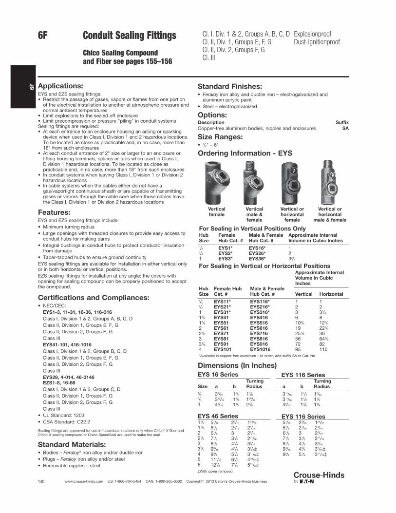
6F
140 www.crouse-hinds.com US: 1-866-764-5454 CAN: 1-800-265-0502 Copyright© 2013 Eaton’s Crouse-Hinds Business
For Sealing in Vertical or Horizontal PositionsApproximate Internal
Volume in Cubic
InchesHub
Size
Female Hub
Cat. #
Male & Female
Hub Cat. # Vertical Horizontal
1/2 EYS11* EYS116* 1 13/4 EYS21* EYS216* 2 21 EYS31* EYS316* 3 33/4
11/4 EYS41 EYS416 6 811/2 EYS51 EYS516 103/4 121/4
2 EYS61 EYS616 19 223/4
21/2 EYS71 EYS716 251/2 303 EYS81 EYS816 56 641/2
31/2 EYS91 EYS916 72 824 EYS101 EYS1016 95 110*Available in copper-free aluminum – to order, add suffix SA to Cat. No.
6F Conduit Sealing Fittings
Chico Sealing Compoundand Fiber see pages 155–156
Cl. I, Div. 1 & 2, Groups A, B, C, DCl. II, Div. 1, Groups E, F, GCl. II, Div. 2, Groups F, GCl. III
ExplosionproofDust-Ignitionproof
Applications:EYS and EZS sealing fittings:• Restrict the passage of gases, vapors or flames from one portion
of the electrical installation to another at atmospheric pressure andnormal ambient temperatures
• Limit explosions to the sealed off enclosure• Limit precompression or pressure "piling" in conduit systemsSealing fittings are required:• At each entrance to an enclosure housing an arcing or sparking
device when used in Class I, Division 1 and 2 hazardous locations.To be located as close as practicable and, in no case, more than18" from such enclosures
• At each conduit entrance of 2" size or larger to an enclosure orfitting housing terminals, splices or taps when used in Class I,Division 1 hazardous locations. To be located as close aspracticable and, in no case, more than 18" from such enclosures
• In conduit systems when leaving Class I, Division 1 or Division 2hazardous locations
• In cable systems when the cables either do not have agas/vaportight continuous sheath or are capable of transmittinggases or vapors through the cable core when those cables leavethe Class I, Division 1 or Division 2 hazardous locations
Features:EYS and EZS sealing fittings include:• Minimum turning radius• Large openings with threaded closures to provide easy access to
conduit hubs for making dams• Integral bushings in conduit hubs to protect conductor insulation
from damage• Taper-tapped hubs to ensure ground continuityEYS sealing fittings are available for installation in either vertical onlyor in both horizontal or vertical positions.EZS sealing fittings for installation at any angle; the covers withopening for sealing compound can be properly positioned to acceptthe compound.
Standard Materials:• Bodies – Feraloy® iron alloy and/or ductile iron• Plugs – Feraloy iron alloy and/or steel• Removable nipples – steel
Standard Finishes:• Feraloy iron alloy and ductile iron – electrogalvanized and
aluminum acrylic paint• Steel – electrogalvanized
Options:Description Suffix
Copper-free aluminum bodies, nipples and enclosures SA
Size Ranges:• 1/2" – 6"
Certifications and Compliances:• NEC/CEC:
EYS1-3, 11-31, 16-36, 116-316
Class I, Division 1 & 2, Groups A, B, C, DClass II, Division 1, Groups E, F, GClass II, Division 2, Groups F, GClass IIIEYS41-101, 416-1016
Class I, Division 1 & 2, Groups B, C, DClass II, Division 1, Groups E, F, GClass II, Division 2, Groups F, GClass IIIEYS29, 4-014, 46-0146
EZS1-8, 16-86
Class I, Division 1 & 2, Groups C, DClass II, Division 1, Groups F, GClass II, Division 2, Groups F, GClass III
• UL Standard: 1203• CSA Standard: C22.2
Ordering Information - EYS
Vertical
female
Vertical
male &
female
Vertical or
horizontal
female
Vertical or
horizontal
male & female
For Sealing in Vertical Positions OnlyHub
Size
Female
Hub Cat. #
Male & Female
Hub Cat. #
Approximate Internal
Volume in Cubic Inches
1/2 EYS1* EYS16* 13/4 EYS2* EYS26* 21 EYS3* EYS36* 33/4
EYS 46 Series EYS 116 Series11/4 51/16 23/16 123/32 51/16 23/16 123/32
11/2 51/2 27/16 21/16 51/2 27/16 21/16
2 61/4 3 25/16 61/4 3 25/16
21/2 71/2 31/2 211/16 71/2 31/2 211/16
3 81/2 41/4 35/16 81/2 41/4 35/16
31/2 93/16 43/4 37/16‡ 93/16 43/4 37/16‡4 93/4 51/4 311/16‡ 93/4 51/4 311/16‡5 111/16 61/2 419/32‡6 121/8 75/8 511/32‡‡With cover removed.
Dimensions (In Inches)
EYS 16 Series EYS 116 Series
Size a b
Turning
Radius a b
Turning
Radius
1/2 39/32 11/4 15/8 311/16 11/4 15/323/4 312/16 11/2 129/32 311/16 11/2 11/4
1 45/16 13/4 23/8 45/16 13/4 13/8
Sealing fittings are approved for use in hazardous locations only when Chico® X fiber andChico A sealing compound or Chico SpeedSeal are used to make the seal.
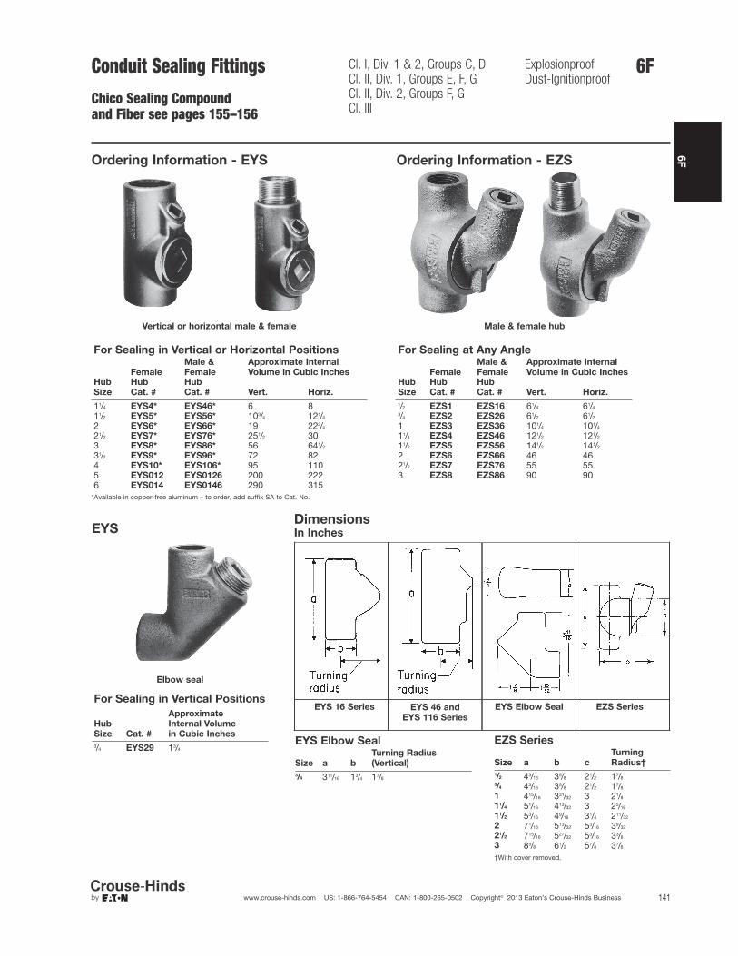
6F
141www.crouse-hinds.com US: 1-866-764-5454 CAN: 1-800-265-0502 Copyright© 2013 Eaton’s Crouse-Hinds Business
6FConduit Sealing Fittings
Chico Sealing Compoundand Fiber see pages 155–156
Cl. I, Div. 1 & 2, Groups C, DCl. II, Div. 1, Groups E, F, GCl. II, Div. 2, Groups F, GCl. III
ExplosionproofDust-Ignitionproof
Ordering Information - EYS
Vertical or horizontal male & female
For Sealing in Vertical or Horizontal Positions
Female
Male &
Female
Approximate Internal
Volume in Cubic InchesHub
Size
Hub
Cat. #
Hub
Cat. # Vert. Horiz.
11/4 EYS4* EYS46* 6 811/2 EYS5* EYS56* 103/4 121/4
2 EYS6* EYS66* 19 223/4
21/2 EYS7* EYS76* 251/2 303 EYS8* EYS86* 56 641/2
31/2 EYS9* EYS96* 72 824 EYS10* EYS106* 95 1105 EYS012 EYS0126 200 2226 EYS014 EYS0146 290 315
*Available in copper-free aluminum – to order, add suffix SA to Cat. No.
EYS
Elbow seal
For Sealing in Vertical Positions
Hub
Size Cat. #
Approximate
Internal Volume
in Cubic Inches
3/4 EYS29 13/4
Ordering Information - EZS
Male & female hub
For Sealing at Any Angle
Female
Male &
Female
Approximate Internal
Volume in Cubic InchesHub
Size
Hub
Cat. #
Hub
Cat. # Vert. Horiz.
1/2 EZS1 EZS16 61/4 61/4
3/4 EZS2 EZS26 61/2 61/2
1 EZS3 EZS36 101/4 101/4
11/4 EZS4 EZS46 121/2 121/2
11/2 EZS5 EZS56 141/2 141/2
2 EZS6 EZS66 46 4621/2 EZS7 EZS76 55 553 EZS8 EZS86 90 90
DimensionsIn Inches
EYS 16 Series EYS 46 and
EYS 116 Series
EYS Elbow Seal EZS Series
EYS Elbow Seal
Size a b
Turning Radius
(Vertical)
3/4 311/16 13/4 17/8
EZS Series
Size a b c
Turning
Radius†
1/2 43/16 35/8 21/2 17/83/4 43/16 35/8 21/2 17/8
1 415/16 331/32 3 21/8
11/4 51/16 413/32 3 25/16
11/2 53/16 49/16 31/4 211/32
2 71/16 513/32 53/16 39/32
21/2 715/16 527/32 53/16 33/8
3 85/8 61/2 57/8 37/8
†With cover removed.

6F
142 www.crouse-hinds.com US: 1-866-764-5454 CAN: 1-800-265-0502 Copyright© 2013 Eaton’s Crouse-Hinds Business
6F Conduit Sealing Fittings
for IEC Applications
Ex II 2 G EEx d IIC Zone 1 and 2
Applications:EYS and EZS sealing fittings:• Restrict the passage of gases, vapors or flames from one portion
of the electrical installation to another at atmospheric pressure andnormal ambient temperatures
• Limit explosions to the sealed off enclosure• Limit precompression or pressure "piling" in conduit systemsSealing fittings are required:• At each entrance to an enclosure housing an arcing or sparking
device when used in Class I, Division 1 and 2 hazardous locations.To be located as close as practicable and, in no case, more than18" from such enclosures
• At each conduit entrance of 2" size or larger to an enclosure orfitting housing terminals, splices or taps when used in Class I,Division 1 hazardous locations. To be located as close aspracticable and, in no case, more than 18" from such enclosures
• In conduit systems when leaving Class I, Division 1 or Division 2hazardous locations
• In cable systems when the cables either do not have agas/vaportight continuous sheath or are capable of transmittinggases or vapors through the cable core when those cables leavethe Class I, Division 1 or Division 2 hazardous locations
Features:EYS and EZS sealing fittings include:• Minimum turning radius• Large openings with threaded closures to provide easy access to
conduit hubs for making dams• Integral bushings in conduit hubs to protect conductor insulation
from damage• Taper-tapped hubs to ensure ground continuityEYS sealing fittings are available for installation in either vertical onlyor in both horizontal or vertical positions.EZS sealing fittings for installation at any angle; the covers withopening for sealing compound can be properly positioned to acceptthe compound.
Certifications and Compliances:• IEC:
Ex II 2 G EEx d IICEC-Type examination certificate LOM 03 ATEX 2108
• IP67 according to EN 60529
Standard Materials:• Bodies – Light alloy, natural finish• Plugs – Light alloy, natural finish• Removable nipples – Light alloy, natural finish
Size Ranges:• EYS - 1/2" – 4"• EZS - 1/2" – 1"
Ordering Information:Series Mounting Direction Hub Size Cat. #
EYS Vertical 1/2" NPT NOR 000 002 220 117EYS Vertical 3/4" NPT NOR 000 002 220 125EYS Vertical 1" ISO NOR 000 002 220 133EYS Vertical 1" NPT NOR 000 002 220 620EYS Horizontal 11/2" NPT NOR 000 002 220 160EYS Horizontal 2" NPT NOR 000 002 220 168EZS Horizontal 1/2" NPT NOR 000 002 220 216EZS Horizontal 3/4"NPT NOR 000 002 220 224EZS Horizontal 1" ISO NOR 000 002 220 232EZS Horizontal 1" NPT NOR 000 002 220 729
EZS
EYS

6F
143www.crouse-hinds.com US: 1-866-764-5454 CAN: 1-800-265-0502 Copyright© 2013 Eaton’s Crouse-Hinds Business
6FConduit Sealing Fittings
EYSA Flameproof Sealing Fitting
Zone 1Zone 2
Zone 21Zone 22
Applications:EYSA sealing fittings:• Restrict the passage of gases, vapors,
or flames from one portion of theelectrical installation to another atatmospheric pressure and normalambient temperatures
• Limit explosions to the sealed offenclosure
• Prevent pre-compression or "pressurepiling" in conduit systems
Sealing fittings are required:• At each entrance to an enclosure
housing an arcing or sparking devicewhen used in Zone 1, hazardouslocations to be located as close aspracticable and in no case more than450mm from such enclosures
• In conduit systems when leaving theZone 1 area and entering an area oflesser hazard
Features:• Minimum turning radius• Large openings with threaded closures
to provide easy access to conduit hubsfor making dams
• Integral bushings to protect conductorinsulation from damage
• Removable male nipple supplied whenmale and female hub style is ordered
Certifications andCompliances:• Type of Protection: Ex d, DIP A21,
T60ºC, IP66• Degree of Protection: IP66• Gas Group: IIC• Approvals: IEC Ex TSA07.0015-1
Standard Materials:• Bodies - copper-free aluminum• Removable nipples and plugs - brass
Standard Finishes:• Body - polyurethane gray• Nipples and plugs - natural
Ordering Information:
Entry Size Female
Male &
Female
Weight of
Sealing
Compound
per Seal (g)
Weight of
Chico X
Fiber
per Seal (g)
20mm/20mm EYSA1M EYSA16M 50 125mm/25mm EYSA2M EYSA26M 100 232mm/32mm EYSA3M EYSA36M 188 3.540mm/40mm EYSA4M EYSA46M 406 750mm/50mm EYSA5M EYSA56M 550 143/4" BSP/3/4" BSP EYSA2B EYSA26B 100 220mm/1/2" BSP EYSA11MB - 50 120mm/3/4" BSP EYSA12MB - 50 125mm/1/2" BSP EYSA21MB - 100 225mm/3/4" BSP EYSA22MB - 100 2
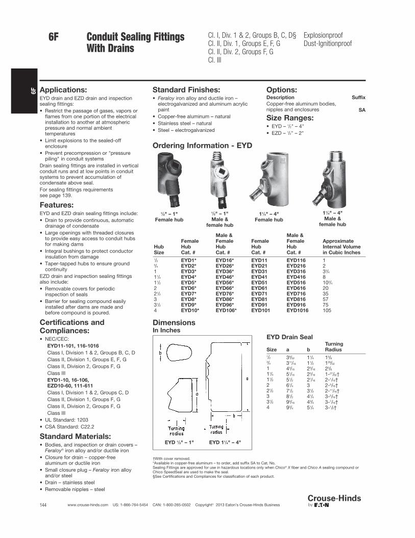
6F
144 www.crouse-hinds.com US: 1-866-764-5454 CAN: 1-800-265-0502 Copyright© 2013 Eaton’s Crouse-Hinds Business
Conduit Sealing Fittings With Drains
Cl. I, Div. 1 & 2, Groups B, C, D§Cl. II, Div. 1, Groups E, F, GCl. II, Div. 2, Groups F, GCl. III
ExplosionproofDust-Ignitionproof
Applications:EYD drain and EZD drain and inspectionsealing fittings:• Restrict the passage of gases, vapors or
flames from one portion of the electricalinstallation to another at atmosphericpressure and normal ambienttemperatures
• Limit explosions to the sealed-offenclosure
• Prevent precompression or "pressurepiling" in conduit systems
Drain sealing fittings are installed in verticalconduit runs and at low points in conduitsystems to prevent accumulation ofcondensate above seal.For sealing fittings requirements see page 139.
Features:EYD and EZD drain sealing fittings include:• Drain to provide continuous, automatic
drainage of condensate• Large openings with threaded closures
to provide easy access to conduit hubsfor making dams
• Integral bushings to protect conductorinsulation from damage
• Taper-tapped hubs to ensure groundcontinuity
EZD drain and inspection sealing fittingsalso include:• Removable covers for periodic
inspection of seals• Barrier for sealing compound easily
installed after dams are made andbefore compound is poured.
Standard Materials:• Bodies, and inspection or drain covers –
Feraloy® iron alloy and/or ductile iron• Closure for drain – copper-free
aluminum or ductile iron• Small closure plug – Feraloy iron alloy
and/or steel• Drain – stainless steel• Removable nipples – steel
Certifications andCompliances:• NEC/CEC:
EYD11-101, 116-1016
Class I, Division 1 & 2, Groups B, C, DClass II, Division 1, Groups E, F, GClass II, Division 2, Groups F, GClass IIIEYD1-10, 16-106,
EZD10-60, 111-611
Class I, Division 1 & 2, Groups C, DClass II, Division 1, Groups F, GClass II, Division 2, Groups F, GClass III
• UL Standard: 1203• CSA Standard: C22.2
Ordering Information - EYD
1/2" – 1"
Female hub
1/2" – 1"
Male &
female hub
11/4" – 4"
Female hub
11/4" – 4"
Male &
female hub
Hub
Size
Female
Hub
Cat. #
Male &
Female
Hub
Cat. #
Female
Hub
Cat. #
Male &
Female
Hub
Cat. #
Approximate
Internal Volume
in Cubic Inches
1/2 EYD1* EYD16* EYD11 EYD116 13/4 EYD2* EYD26* EYD21 EYD216 21 EYD3* EYD36* EYD31 EYD316 33/4
11/4 EYD4* EYD46* EYD41 EYD416 811/2 EYD5* EYD56* EYD51 EYD516 103/4
2 EYD6* EYD66* EYD61 EYD616 2021/2 EYD7* EYD76* EYD71 EYD716 353 EYD8* EYD86* EYD81 EYD816 5731/2 EYD9* EYD96* EYD91 EYD916 754 EYD10* EYD106* EYD101 EYD1016 105
DimensionsIn Inches
EYD 1/2" – 1" EYD 11/4" – 4"
†With cover removed.*Available in copper-free aluminum – to order, add suffix SA to Cat. No.Sealing Fittings are approved for use in hazardous locations only when Chico® X fiber and Chico A sealing compound orChico SpeedSeal are used to make the seal.§See Certifications and Compliances for classification of each product.
6F
Standard Finishes:• Feraloy iron alloy and ductile iron –
electrogalvanized and aluminum acrylicpaint
• Copper-free aluminum – natural• Stainless steel – natural• Steel – electrogalvanized
Options:Description Suffix
Copper-free aluminum bodies, nipples and enclosures SA
Size Ranges:• EYD – 1/2" – 4"• EZD – 1/2" – 2"
EYD Drain Seal
Size a b
Turning
Radius
1/2 39/32 11/4 15/83/4 311/16 11/2 129/32
1 45/16 23/16 23/8
11/4 51/16 23/16 1-27/32†11/2 51/2 27/16 2-1/16†2 61/4 3 2-5/16†21/2 71/2 31/2 2-11/16†3 81/2 41/4 3-5/16†31/2 93/16 43/4 3-7/16†4 93/4 51/4 3-1/2†

6F
145www.crouse-hinds.com US: 1-866-764-5454 CAN: 1-800-265-0502 Copyright© 2013 Eaton’s Crouse-Hinds Business
Conduit Sealing Fittings withDrain and Inspection CoverChico Sealing Compound and Fibersee pages 155–156
Cl. I, Div. 1 & 2, Groups C, DCl. II, Div. 1, Groups E, F, GCl. II, Div. 2, Groups F, GCl. III
ExplosionproofDust-Ignitionproof
EZD With Drain Cover
Hub
Size Cat. #
Approximate
Internal Volume
in Cubic Inches
1/2 EZD111 53/4 EZD211 61 EZD311 1011/4 EZD411 1111/2 EZD511 132 EZD611 40
DimensionsIn Inches:
EZD Drain and Inspection SealsSize a b Drain Cover c Turning Radius†
1/2 43/16 3 33/8 21/163/4 43/16 3 35/8 23/16
1 415/16 31/2 37/8 27/16
11/4 415/16 31/2 45/16 25/8
11/2 53/16 31/2 49/16 211/16
2 71/8 59/16 51/4 311/16
†With cover removed.
6F
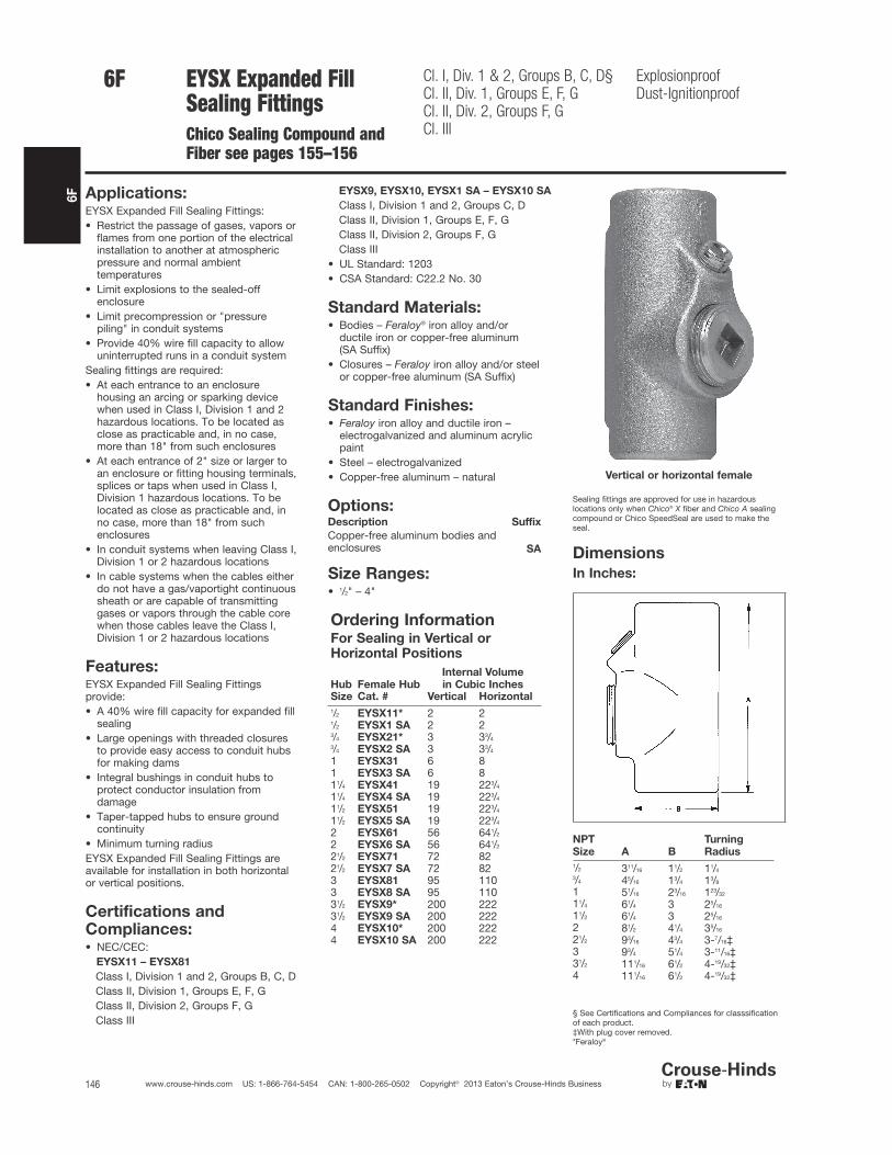
6F
146 www.crouse-hinds.com US: 1-866-764-5454 CAN: 1-800-265-0502 Copyright© 2013 Eaton’s Crouse-Hinds Business
EYSX Expanded FillSealing FittingsChico Sealing Compound andFiber see pages 155–156
Cl. I, Div. 1 & 2, Groups B, C, D§Cl. II, Div. 1, Groups E, F, GCl. II, Div. 2, Groups F, GCl. III
ExplosionproofDust-Ignitionproof
Applications:EYSX Expanded Fill Sealing Fittings:• Restrict the passage of gases, vapors or
flames from one portion of the electricalinstallation to another at atmosphericpressure and normal ambienttemperatures
• Limit explosions to the sealed-offenclosure
• Limit precompression or "pressurepiling" in conduit systems
• Provide 40% wire fill capacity to allowuninterrupted runs in a conduit system
Sealing fittings are required:• At each entrance to an enclosure
housing an arcing or sparking devicewhen used in Class I, Division 1 and 2hazardous locations. To be located asclose as practicable and, in no case,more than 18" from such enclosures
• At each entrance of 2" size or larger toan enclosure or fitting housing terminals,splices or taps when used in Class I,Division 1 hazardous locations. To belocated as close as practicable and, inno case, more than 18" from suchenclosures
• In conduit systems when leaving Class I,Division 1 or 2 hazardous locations
• In cable systems when the cables eitherdo not have a gas/vaportight continuoussheath or are capable of transmittinggases or vapors through the cable corewhen those cables leave the Class I,Division 1 or 2 hazardous locations
Features:EYSX Expanded Fill Sealing Fittingsprovide:• A 40% wire fill capacity for expanded fill
sealing• Large openings with threaded closures
to provide easy access to conduit hubsfor making dams
• Integral bushings in conduit hubs toprotect conductor insulation fromdamage
• Taper-tapped hubs to ensure groundcontinuity
• Minimum turning radiusEYSX Expanded Fill Sealing Fittings areavailable for installation in both horizontalor vertical positions.
Standard Materials:• Bodies – Feraloy® iron alloy and/or
ductile iron or copper-free aluminum (SA Suffix)
• Closures – Feraloy iron alloy and/or steelor copper-free aluminum (SA Suffix)
Standard Finishes:• Feraloy iron alloy and ductile iron –
electrogalvanized and aluminum acrylicpaint
• Steel – electrogalvanized• Copper-free aluminum – natural
Options:Description Suffix
Copper-free aluminum bodies andenclosures SA
Size Ranges:• 1/2" – 4"
Certifications andCompliances:• NEC/CEC:
EYSX11 – EYSX81
Class I, Division 1 and 2, Groups B, C, DClass II, Division 1, Groups E, F, GClass II, Division 2, Groups F, GClass III
EYSX9, EYSX10, EYSX1 SA – EYSX10 SA
Class I, Division 1 and 2, Groups C, DClass II, Division 1, Groups E, F, GClass II, Division 2, Groups F, GClass III
• UL Standard: 1203• CSA Standard: C22.2 No. 30
Ordering InformationFor Sealing in Vertical orHorizontal Positions
Hub Female Hub
Internal Volume
in Cubic InchesSize Cat. # Vertical Horizontal
1/2 EYSX11* 2 21/2 EYSX1 SA 2 23/4 EYSX21* 3 33/4
3/4 EYSX2 SA 3 33/4
1 EYSX31 6 81 EYSX3 SA 6 811/4 EYSX41 19 223/4
11/4 EYSX4 SA 19 223/4
11/2 EYSX51 19 223/4
11/2 EYSX5 SA 19 223/4
2 EYSX61 56 641/2
2 EYSX6 SA 56 641/2
21/2 EYSX71 72 8221/2 EYSX7 SA 72 823 EYSX81 95 1103 EYSX8 SA 95 11031/2 EYSX9* 200 22231/2 EYSX9 SA 200 2224 EYSX10* 200 2224 EYSX10 SA 200 222
Vertical or horizontal female
Sealing fittings are approved for use in hazardouslocations only when Chico® X fiber and Chico A sealingcompound or Chico SpeedSeal are used to make theseal.
NPT
Size A B
Turning
Radius
1/2 311/16 11/2 11/43/4 45/16 13/4 13/8
1 51/16 23/16 123/32
11/4 61/4 3 25/16
11/2 61/4 3 25/16
2 81/2 41/4 35/16
21/2 93/16 43/4 3-7/16‡3 93/4 51/4 3-11/16‡31/2 111/16 61/2 4-19/32‡4 111/16 61/2 4-19/32‡
§ See Certifications and Compliances for classsificationof each product.‡With plug cover removed.*Feraloy®
Dimensions
In Inches:
6F
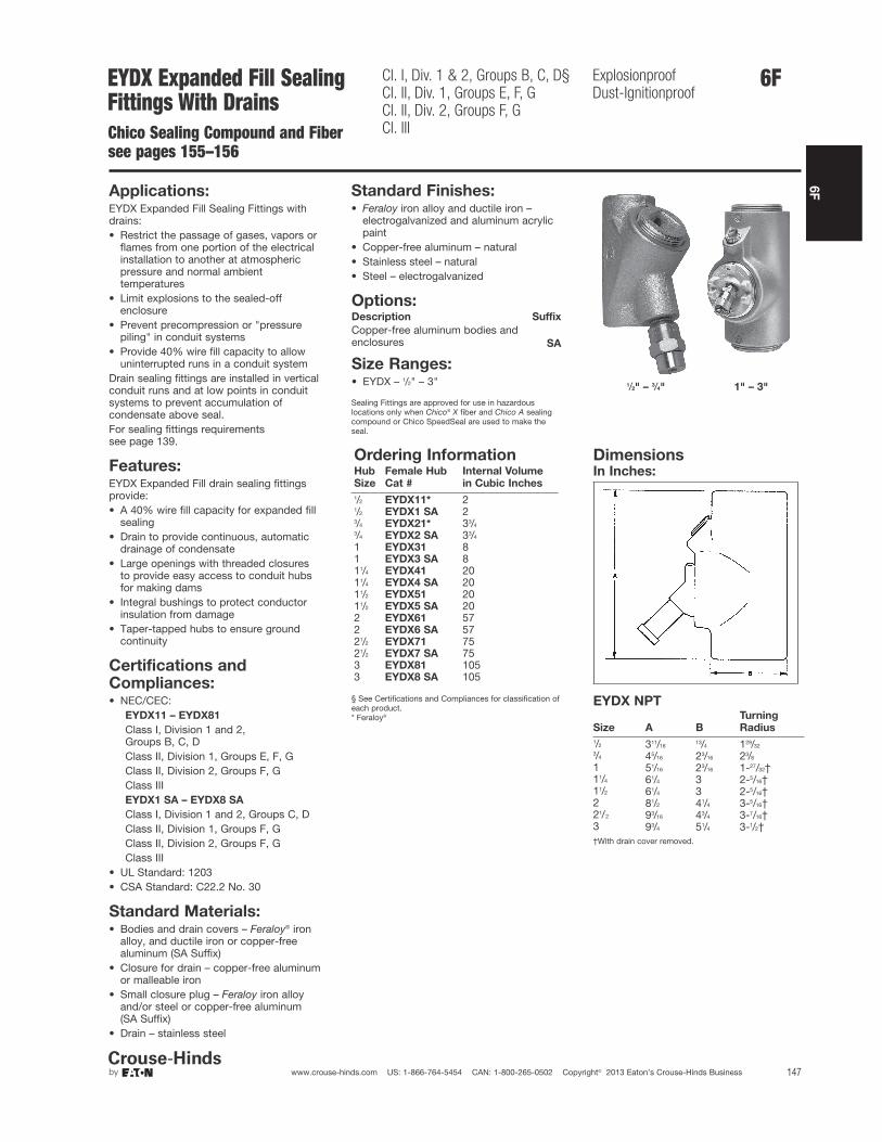
6F
147www.crouse-hinds.com US: 1-866-764-5454 CAN: 1-800-265-0502 Copyright© 2013 Eaton’s Crouse-Hinds Business
EYDX Expanded Fill SealingFittings With DrainsChico Sealing Compound and Fibersee pages 155–156
Cl. I, Div. 1 & 2, Groups B, C, D§Cl. II, Div. 1, Groups E, F, GCl. II, Div. 2, Groups F, GCl. III
ExplosionproofDust-Ignitionproof
Applications:EYDX Expanded Fill Sealing Fittings withdrains:• Restrict the passage of gases, vapors or
flames from one portion of the electricalinstallation to another at atmosphericpressure and normal ambienttemperatures
• Limit explosions to the sealed-offenclosure
• Prevent precompression or "pressurepiling" in conduit systems
• Provide 40% wire fill capacity to allowuninterrupted runs in a conduit system
Drain sealing fittings are installed in verticalconduit runs and at low points in conduitsystems to prevent accumulation ofcondensate above seal.For sealing fittings requirements see page 139.
Features:EYDX Expanded Fill drain sealing fittingsprovide:• A 40% wire fill capacity for expanded fill
sealing• Drain to provide continuous, automatic
drainage of condensate• Large openings with threaded closures
to provide easy access to conduit hubsfor making dams
• Integral bushings to protect conductorinsulation from damage
• Taper-tapped hubs to ensure groundcontinuity
Standard Materials:• Bodies and drain covers – Feraloy® iron
alloy, and ductile iron or copper-freealuminum (SA Suffix)
• Closure for drain – copper-free aluminumor malleable iron
• Small closure plug – Feraloy iron alloyand/or steel or copper-free aluminum (SA Suffix)
• Drain – stainless steel
Standard Finishes:• Feraloy iron alloy and ductile iron –
electrogalvanized and aluminum acrylicpaint
• Copper-free aluminum – natural• Stainless steel – natural• Steel – electrogalvanized
Options:Description Suffix
Copper-free aluminum bodies andenclosures SA
Size Ranges:• EYDX – 1/2" – 3"
Certifications andCompliances:• NEC/CEC:
EYDX11 – EYDX81
Class I, Division 1 and 2, Groups B, C, DClass II, Division 1, Groups E, F, GClass II, Division 2, Groups F, GClass IIIEYDX1 SA – EYDX8 SA
Class I, Division 1 and 2, Groups C, DClass II, Division 1, Groups F, GClass II, Division 2, Groups F, GClass III
• UL Standard: 1203• CSA Standard: C22.2 No. 30
Sealing Fittings are approved for use in hazardouslocations only when Chico® X fiber and Chico A sealingcompound or Chico SpeedSeal are used to make theseal.
1/2" – 3/4" 1" – 3"
DimensionsIn Inches:
EYDX NPT
Size A B
Turning
Radius
1/2 311/1613/4 129/32
3/4 45/16 23/16 23/8
1 51/16 23/16 1-27/32†11/4 61/4 3 2-5/16†11/2 61/4 3 2-5/16†2 81/2 41/4 3-5/16†21/2 93/16 43/4 3-7/16†3 93/4 51/4 3-1/2††With drain cover removed.
§ See Certifications and Compliances for classification ofeach product.* Feraloy®
6F
Ordering InformationHub
Size
Female Hub
Cat #
Internal Volume
in Cubic Inches
1/2 EYDX11* 21/2 EYDX1 SA 23/4 EYDX21* 33/4
3/4 EYDX2 SA 33/4
1 EYDX31 81 EYDX3 SA 811/4 EYDX41 2011/4 EYDX4 SA 2011/2 EYDX51 2011/2 EYDX5 SA 202 EYDX61 572 EYDX6 SA 5721/2 EYDX71 7521/2 EYDX7 SA 753 EYDX81 1053 EYDX8 SA 105
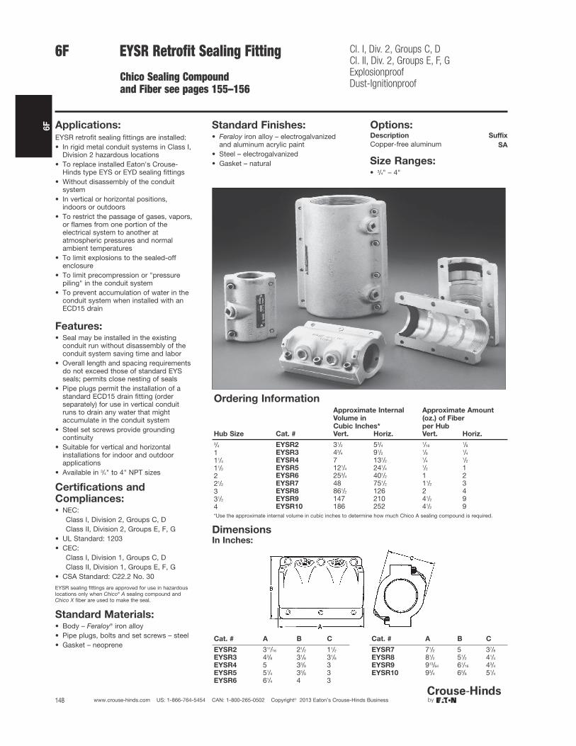
6F
148 www.crouse-hinds.com US: 1-866-764-5454 CAN: 1-800-265-0502 Copyright© 2013 Eaton’s Crouse-Hinds Business
6F EYSR Retrofit Sealing Fitting
Chico Sealing Compoundand Fiber see pages 155–156
Cl. I, Div. 2, Groups C, DCl. II, Div. 2, Groups E, F, GExplosionproofDust-Ignitionproof
Applications:EYSR retrofit sealing fittings are installed:• In rigid metal conduit systems in Class I,
Division 2 hazardous locations• To replace installed Eaton's Crouse-
Hinds type EYS or EYD sealing fittings• Without disassembly of the conduit
system• In vertical or horizontal positions,
indoors or outdoors• To restrict the passage of gases, vapors,
or flames from one portion of theelectrical system to another atatmospheric pressures and normalambient temperatures
• To limit explosions to the sealed-offenclosure
• To limit precompression or "pressurepiling" in the conduit system
• To prevent accumulation of water in theconduit system when installed with anECD15 drain
Features:• Seal may be installed in the existing
conduit run without disassembly of theconduit system saving time and labor
• Overall length and spacing requirementsdo not exceed those of standard EYSseals; permits close nesting of seals
• Pipe plugs permit the installation of astandard ECD15 drain fitting (orderseparately) for use in vertical conduitruns to drain any water that mightaccumulate in the conduit system
• Steel set screws provide groundingcontinuity
• Suitable for vertical and horizontalinstallations for indoor and outdoorapplications
• Available in 3/4" to 4" NPT sizes
Standard Materials:• Body – Feraloy® iron alloy• Pipe plugs, bolts and set screws – steel• Gasket – neoprene
Standard Finishes:• Feraloy iron alloy – electrogalvanized
and aluminum acrylic paint• Steel – electrogalvanized• Gasket – natural
Options:Description Suffix
Copper-free aluminum SA
Size Ranges:• 3/4" – 4"
Certifications andCompliances:• NEC:
Class I, Division 2, Groups C, DClass II, Division 2, Groups E, F, G
• UL Standard: 1203• CEC:
Class I, Division 1, Groups C, DClass II, Division 1, Groups E, F, G
• CSA Standard: C22.2 No. 30
EYSR sealing fittings are approved for use in hazardouslocations only when Chico® A sealing compound andChico X fiber are used to make the seal.
Ordering InformationApproximate Internal
Volume in
Cubic Inches*
Approximate Amount
(oz.) of Fiber
per HubHub Size Cat. # Vert. Horiz. Vert. Horiz.
3/4 EYSR2 31/2 53/41/16
1/8
1 EYSR3 43/4 91/21/8
1/4
11/4 EYSR4 7 131/21/4
1/2
11/2 EYSR5 121/4 241/41/2 1
2 EYSR6 253/4 401/2 1 221/2 EYSR7 48 751/2 11/2 33 EYSR8 861/2 126 2 431/2 EYSR9 147 210 41/2 94 EYSR10 186 252 41/2 9*Use the approximate internal volume in cubic inches to determine how much Chico A sealing compound is required.
DimensionsIn Inches:
Cat. # A B C
EYSR2 311/16 21/2 11/2
EYSR3 43/8 31/8 31/8
EYSR4 5 33/8 3EYSR5 51/4 35/8 3EYSR6 61/4 4 3
Cat. # A B C
EYSR7 71/2 5 37/8
EYSR8 81/2 51/2 41/4
EYSR9 913/64 61/16 43/4
EYSR10 93/4 65/8 51/4
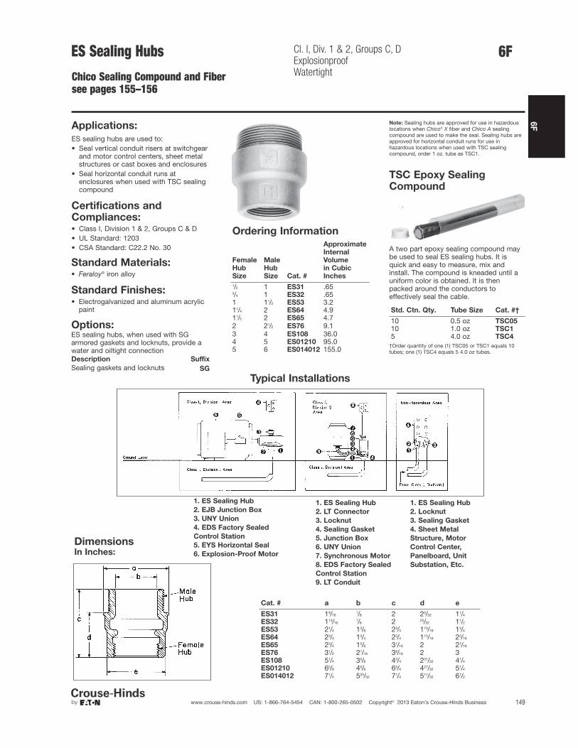
6F
149www.crouse-hinds.com US: 1-866-764-5454 CAN: 1-800-265-0502 Copyright© 2013 Eaton’s Crouse-Hinds Business
ES Sealing Hubs
Chico Sealing Compound and Fibersee pages 155–156
Cl. I, Div. 1 & 2, Groups C, DExplosionproofWatertight
Applications:
ES sealing hubs are used to:• Seal vertical conduit risers at switchgear
and motor control centers, sheet metalstructures or cast boxes and enclosures
• Seal horizontal conduit runs atenclosures when used with TSC sealingcompound
Standard Materials:• Feraloy® iron alloy
Standard Finishes:• Electrogalvanized and aluminum acrylic
paint
Options:ES sealing hubs, when used with SGarmored gaskets and locknuts, provide awater and oiltight connectionDescription Suffix
Sealing gaskets and locknuts SG
Certifications andCompliances:• Class I, Division 1 & 2, Groups C & D• UL Standard: 1203• CSA Standard: C22.2 No. 30
Note: Sealing hubs are approved for use in hazardouslocations when Chico® X fiber and Chico A sealingcompound are used to make the seal. Sealing hubs areapproved for horizontal conduit runs for use inhazardous locations when used with TSC sealingcompound, order 1 oz. tube as TSC1.
6F
TSC Epoxy SealingCompound
A two part epoxy sealing compound maybe used to seal ES sealing hubs. It isquick and easy to measure, mix andinstall. The compound is kneaded until auniform color is obtained. It is thenpacked around the conductors toeffectively seal the cable.
Std. Ctn. Qty. Tube Size Cat. #†
10 0.5 oz TSC0510 1.0 oz TSC15 4.0 oz TSC4
†Order quantity of one (1) TSC05 or TSC1 equals 10tubes; one (1) TSC4 equals 5 4.0 oz tubes.
Typical Installations
1. ES Sealing Hub
2. EJB Junction Box
3. UNY Union
4. EDS Factory Sealed
Control Station
5. EYS Horizontal Seal
6. Explosion-Proof Motor
1. ES Sealing Hub
2. LT Connector
3. Locknut
4. Sealing Gasket
5. Junction Box
6. UNY Union
7. Synchronous Motor
8. EDS Factory Sealed
Control Station
9. LT Conduit
1. ES Sealing Hub
2. Locknut
3. Sealing Gasket
4. Sheet Metal
Structure, Motor
Control Center,
Panelboard, Unit
Substation, Etc.
DimensionsIn Inches:
Cat. # a b c d e
ES31 19/167/8 2 25/32 11/4
ES32 113/167/8 2 25/32 11/2
ES53 21/4 13/8 23/4 115/16 13/4
ES64 23/4 13/4 23/4 115/16 23/16
ES65 23/4 15/8 31/16 2 27/16
ES76 31/2 21/16 39/16 2 3ES108 51/4 35/8 43/4 231/32 41/4
ES01210 65/8 45/8 63/4 427/32 51/4
ES014012 71/4 525/32 71/4 511/32 61/2
Ordering Information
Female
Hub
Size
Male
Hub
Size Cat. #
Approximate
Internal
Volume
in Cubic
Inches
1/2 1 ES31 .653/4 1 ES32 .651 11/2 ES53 3.211/4 2 ES64 4.911/2 2 ES65 4.72 21/2 ES76 9.13 4 ES108 36.04 5 ES01210 95.05 6 ES014012 155.0

6F
150 www.crouse-hinds.com US: 1-866-764-5454 CAN: 1-800-265-0502 Copyright© 2013 Eaton’s Crouse-Hinds Business
6F Ultra High Pressure Seal
Rated to 1500 PSI
Applications:• If the primary seal in an instrument should fail, the Eaton's Crouse-
Hinds Ultra High Pressure Seal (UHPS) will prevent gases frommigrating through the electrical system into a non-classifiedlocation.
• Are designed to prevent the passage of gases under pressurethrough conduits, cables and conductors.
• Are ideal where volatile liquids or gases are stored, processed ortransported under pressure.
Certifications & Compliances:• Class I, Division 1, Groups B, C, D• Certified to CSA Standards through QPS• 24 Volt DC - 120 Volt AC• Wire grade is rated to a 600 Volt safety factor• 1/2” MNPT x 1/2” NPT• Conforms to Section 18-108 and 18-158 of the CEC® for The
Requirements of a Secondary Seal.
Standard Materials & Finishes:• Stainless steel body - natural finish
Ordering Information:Catalog Number Description
CH6DR500X002D14G UHPS, 2 wire, 14 gaugeCH6DR500X002D16G UHPS, 2 wire, 16 gaugeCH6DR500X002D18G UHPS, 2 wire, 18 gaugeCH6DR500X002D22G UHPS, 2 wire, 22 gaugeCH6DR500X004D14G UHPS, 4 wire, 14 gaugeCH6DR500X004D16G UHPS, 4 wire, 16 gaugeCH6DR500X004D18G UHPS, 4 wire, 18 gaugeCH6DR500X004D22G UHPS, 4 wire, 22 gaugeCH6DR500X234D14G UHPS, 4 wire, 14G, 2' input, 3' outputCH6DR500X264D16G UHPS, 4 wire, 16G, 2' input, 6' outputCH6DR500X294D16G UHPS, 4 wire, 16G, 2' input, 9' outputCH6DR500X2D2D16G UHPS, 2 wire, 16G, 2' input, CF output
INSTALLATION EXAMPLE:
Quality Assurance:Each fitting is tested at 1.5 times working pressure (max. workingpressure 1500 PSI) as a gas and liquidtight explosionproof fitting.Each seal is also di-electric and resistance tested.
Cl. I, Div. 1, Groups B, C, DCertified to CSA Standards through QPS

6F
151www.crouse-hinds.com US: 1-866-764-5454 CAN: 1-800-265-0502 Copyright© 2013 Eaton’s Crouse-Hinds Business
Secondary ProcessSeal Assemblies
Cl. I, Div. 1 & 2, Groups B, C, DCl. I, Zone 1 & 2 IIB + H2
Cl. II, Div. 1 & 2, Groups E, F, G
NEMA 3, 4, 7BCD, 9
Applications:Eaton's Crouse-Hinds Secondary Process Seal Assembly withRupture Indication Sensor is designed to prevent the passage ofgases under pressure through conduit, cables and conductors whileproviding immediate notification of a dangerous, potentially explosiveseal rupture. These assemblies are ideal where volatile liquids orgases are stored, processed or transported under pressure. If theprimary seal in an instrument should fail, the Eaton's Crouse-HindsSecondary Process Seal will prevent gases, vapors and liquids frommigrating into the non-classified location through the electricalsystem.
Rupture Indication Sensor:The Secondary Process Seal features a rupture indication sensor thatopens safely at 60 psi minimum and activates a circuit to a controlsystem or alarm, which immediately alerts maintenance personnelthat the primary seal has ruptured. The location of the problem canbe pinpointed so the problem can be quickly addressed.
Innovative, intelligent technology combined with easy installation andlow maintenance cost provides a safe and reliable solution fordetection of a process seal rupture within your facility.
Features and Benefits:Secondary Process Seal• CSA and CSAus certified• Meets or exceeds ANSI / ISA / CSA / CEC / NEC / API
requirements for a secondary process seal and explosionproofconduit seal
• Sealed to 1500 psi, operates in any position• Simplified design allows for easier installation in new and existing
applications• Integrated packaging contains all necessary components for
installation• The explosionproof drain allows for the safe release of gas, vapor
or liquid from the electrical system to meet required codes• Explosionproof terminal box features a simple design to provide
access for quick connection of circuits• Assembly with drain provides local "make obvious" indication of
primary seal failure
Rupture Indication Sensor• Rupture detection and indication at 60 psi• Provides remote, immediate notification of a seal rupture, allowing
for maintenance to quickly address the problem and isolate safetyconcerns
• Stainless steel construction provides superior corrosion resistanceand durability
Ordering Information:
Assembly with
Vent/Drain
Assembly with
Rupture Indication
Sensor and Vent/Drain
2 wire, 14 gauge SPS214 SPS214R2 wire, 16 gauge SPS216 SPS216R2 wire, 18 gauge SPS218 SPS218R2 wire, 22 gauge SPS222 SPS222R4 wire, 14 gauge SPS414 SPS414R4 wire, 16 gauge SPS416 SPS416R4 wire, 18 gauge SPS418 SPS418R4 wire, 22 gauge SPS422 SPS422R
For Process Seal Rupture Indication Sensor replacement, order catalog #PSRIS.
6F
Options:Description Suffix
No terminal blocks (leave option blank)2 terminal blocks DIN124 terminal blocks DIN14
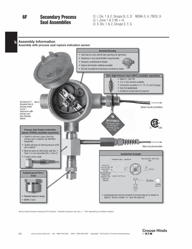
6F
152 www.crouse-hinds.com US: 1-866-764-5454 CAN: 1-800-265-0502 Copyright© 2013 Eaton’s Crouse-Hinds Business
Assembly InformationAssembly with process seal rupture indication sensor
*60 psi internal pressure rating at 25°C ambient. Activation pressure may vary +/ - 10% depending on ambient variation.
Secondary ProcessSeal Assemblies
Cl. I, Div. 1 & 2, Groups B, C, DCl. I, Zone 1 & 2 IIB + H2
Cl. II, Div. 1 & 2, Groups E, F, G
NEMA 3, 4, 7BCD, 96F

6F
153www.crouse-hinds.com US: 1-866-764-5454 CAN: 1-800-265-0502 Copyright© 2013 Eaton’s Crouse-Hinds Business
Installation Examples
Secondary Process Seal with local "make obvious"indication using an ECD explosionproof drain
Secondary Process Seal with Rupture IndicationSensor for remote indication, and ECDexplosionproof drain for local "make obvious"indication
Technical Data - AssemblyProduct CertificationThe Secondary Process Seal and Assemblies are CSA certified(Canada, U.S.)
Operating Pressure RatingRupture protection to 1500 psiRupture indication at 60 psi minimum
Operating Temperature Range-25ºC to +50ºC
Note: For more extreme temperature and/or pressure requirements, please consultfactory.
Technical Data - Components
Components Construction Certifications and Compliances Rating Area Suitability
Process Seal Rupture
Indication Sensor
Hub - 316 stainless steel
ANSI / ISA 12.27.01 - 2003CEC 18 - 108, 158NEC 501.15(F)(3)
–
Cl. I, Div. 1 & 2, GroupsB, C, DCl. II, Div. 1 & 2, GroupsE, F, GZone 1 IIB+H2 and Zone 2 IIB+H2
NEMA 3, 4, 7BCD, 9
Switch Assembly -hermetically sealed,nickeled brass, withsilicon cable
(Div. 1, Zone 1) intrinsically safe(Div. 2, Zone 2) non-incendiveSimple apparatus (NEC 504.4)
174 mA24VDCT6 (Tamb ≤ 40°C)T5 (40°C < Tamb ≤ 55°C)T4 (55°C < Tamb ≤ 80°C)
Ultra High Pressure Seal Stainless steel
CSA 22.2 No. 30 - 03 CSA 22.2 No. 14 - 2005ANSI / ISA 12.27.01 - 2003CEC 18 - 108, 158NEC 501.15(F)(3)
24VDC120VAC
Terminal HousingCopper-freealuminum
UL1203CSA C22.2 No. 30 –
Drain / Vent Stainless steel UL1203CSA C22.2 No. 30 –
6FSecondary ProcessSeal Assemblies
Cl. I, Div. 1 & 2, Groups B, C, DCl. I, Zone 1 & 2 IIB + H2
Cl. II, Div. 1 & 2, Groups E, F, G
NEMA 3, 4, 7BCD, 9
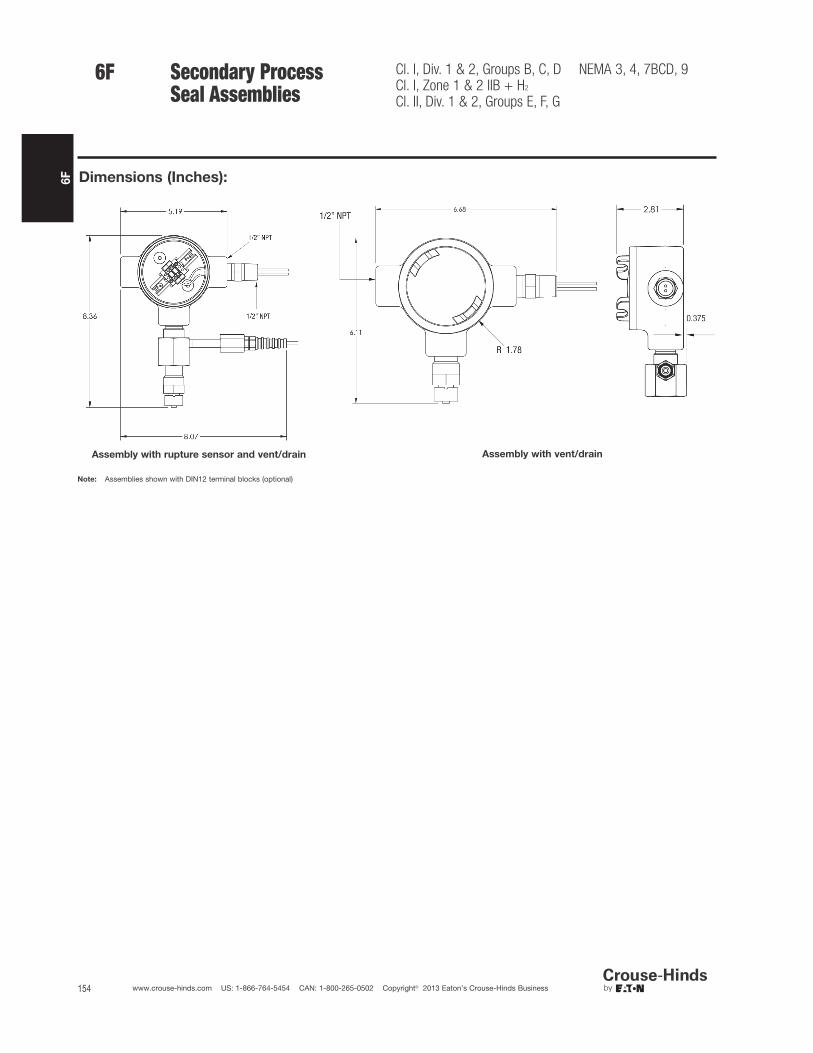
6F
154 www.crouse-hinds.com US: 1-866-764-5454 CAN: 1-800-265-0502 Copyright© 2013 Eaton’s Crouse-Hinds Business
6F Secondary ProcessSeal Assemblies
Cl. I, Div. 1 & 2, Groups B, C, DCl. I, Zone 1 & 2 IIB + H2
Cl. II, Div. 1 & 2, Groups E, F, G
NEMA 3, 4, 7BCD, 9
Dimensions (Inches):
Assembly with rupture sensor and vent/drain Assembly with vent/drain
Note: Assemblies shown with DIN12 terminal blocks (optional)

6F
155www.crouse-hinds.com US: 1-866-764-5454 CAN: 1-800-265-0502 Copyright© 2013 Eaton’s Crouse-Hinds Business
Chico® A and Chico® A-P Sealing CompoundChico® X FiberChico® SpeedSeal™
For Sealing Fittings and Hubs
Applications:Chico X fiber:• Forms a dam between the integral bushing of the sealing fitting and
the end of the conduit and around the electrical conductors enteringthe hub
Chico A sealing compound:• Forms a seal around each electrical conductor and between them
and inside of the sealing fitting to restrict the passage of gases,vapors or flames through the sealing fitting at atmospheric pressureand at normal ambient temperatures
Chico® SpeedSeal™ Compound:• Designed to separate and form an explosionproof seal around each
electrical conductor in Eaton's Crouse-Hinds EYS and EYD sealingfittings
• Restricts the passage of gases, vapors or flames through thesealing fitting
• Creates a seal for Class I, Division 1, Groups C, D and Class II,Division 1, Groups E, F, G hazardous areas
6F
Size Ranges:• Chico A compound – 1 lb. to 5 lbs. (provides 23–115 cubic
inches of compound)• Chico X fiber – 2 oz. to 1 lb.• Chico A-P (5 pouches per carton) – provides 25 and 55 cubic
inches of compound• Chico SpeedSeal - 2 oz. or 6 oz. cartridge
Eaton's Crouse-Hinds sealing fittings are approved for use in hazardous locationsonly when Chico X fiber and Chico A Sealing Compound or Chico SpeedSeal areused to make the seal.
Ordering Information - Chico A
Ordering Information - Chico A-P Intrapak®
*A sixth pouch, containing an appropriate quantity of Chico X fiber, is included inthese cartons.
Cu. In.
Fill per
Pouch†
No. of
Pouches
per Carton Cat. #
5 5 Chico A19 PX*11 5 Chico A39 PX*
Net
Weight
Vol.
Cu. In.† Cat. #
1 lb. 23 Chico A31 lb.‡ 23 Chico A45 lb. 115 Chico A05
†Number of cubic inches this amount will fill when set. See internal volumerequirements for EYS, EZS, EYD, EZD and EYSR sealing fittings and ES sealinghubs (see pages 140–149).‡Includes 1 oz. Chico X fiber.
Features:Chico A sealing compound: • A water soluble powder that can be easily mixed and poured. The
compound, unusually dense, expands slightly when hardening andbonds to inner walls of sealing fittings. Compound hardens in 60–70minutes
• Chico A cure time is 8 hours for Class I, Group C and D applicationsand 72 hours for Class I, Group A and B applications.
• Chico A has a 1 year shelf life from date of manufacture.• Chico A ambient temperature range (after curing) is –40°F to +165°F.Chico A-P Intrapak®:• Packaged in two-compartment plastic pouch with precise amount of
water for mixing. No mixing or measuring implements required.• A hard squeeze of the water compartment forces the water into the
compartment containing the Chico compound. Mixing is completed bykneading the pouch for one minute.
• The mixed sealing compound is poured directly into the sealing fitting– no funnel required. The package label indicates the size and quantityof sealing fittings each pouch will properly fill. Compound hardens in60–70 minutes.
Chico X fiber:• A mineral wool that packs easily, forming around each conductorChico® SpeedSeal™ Compound:• Installs a reliable seal in five minutes - every time• Hardens to a dense, strong mass that is suitable for Class I, Division 1,
Groups C, D and Class II, Division 1, Groups E, F, G hazardousapplications.
• UL and cUL Listed for use with 1/2" to 2" Eaton's Crouse-Hinds sealingfittings only.
• Packaged in a 2 oz. or 6 oz. pre-measured cartridge, eliminating theneed for measuring before mixing.
• Packaged with a screw-on nozzle for accurate dispensing.• Expands four times its original size in the sealing fitting, eliminating the
need to separate the individual conductors with Chico X fiber.• Chico X fiber dams are not required in horizontal applications,
reducing installation times.• Completely hardens in 20 minutes, simplifying use for OEMs.• Suitable for cold temperature environments without the costly need to
build a temporary shelter around sealing fittings. All ice crystals mustbe removed from inside the conduit seal before dispensing ChicoSpeedSeal compound. The Chico SpeedSeal compound should bekept above 10°C (50°F) and below 85°F (29°C) prior to mixing. The sealing fitting must be kept at or above 4°C (40°F) during the 4 to 10 minute expansion/gel time of the compound.
• 18 months shelf-life.• Patent pending.
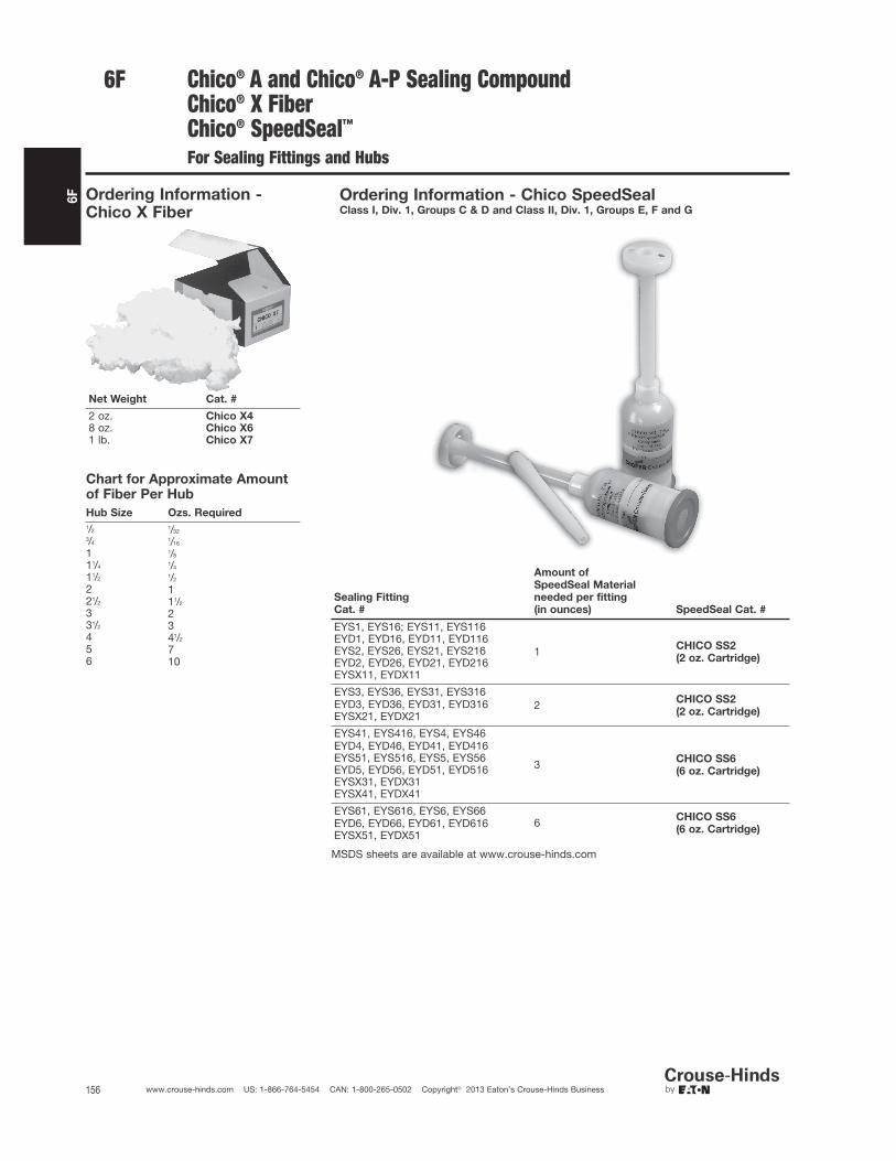
6F
156 www.crouse-hinds.com US: 1-866-764-5454 CAN: 1-800-265-0502 Copyright© 2013 Eaton’s Crouse-Hinds Business
Ordering Information - Chico X Fiber
Net Weight Cat. #
2 oz. Chico X48 oz. Chico X61 lb. Chico X7
Chart for Approximate Amountof Fiber Per Hub
Hub Size Ozs. Required
1/2 1/323/4 1/16
1 1/8
11/4 1/4
11/2 1/2
2 121/2 11/2
3 231/2 34 41/2
5 76 10
MSDS sheets are available at www.crouse-hinds.com
Chico® A and Chico® A-P Sealing CompoundChico® X FiberChico® SpeedSeal™
For Sealing Fittings and Hubs
6F
Sealing Fitting
Cat. #
Amount of
SpeedSeal Material
needed per fitting
(in ounces) SpeedSeal Cat. #
EYS1, EYS16; EYS11, EYS116
1 CHICO SS2
(2 oz. Cartridge)
EYD1, EYD16, EYD11, EYD116EYS2, EYS26, EYS21, EYS216EYD2, EYD26, EYD21, EYD216EYSX11, EYDX11
EYS3, EYS36, EYS31, EYS3162 CHICO SS2
(2 oz. Cartridge)EYD3, EYD36, EYD31, EYD316EYSX21, EYDX21
EYS41, EYS416, EYS4, EYS46
3 CHICO SS6
(6 oz. Cartridge)
EYD4, EYD46, EYD41, EYD416EYS51, EYS516, EYS5, EYS56EYD5, EYD56, EYD51, EYD516EYSX31, EYDX31EYSX41, EYDX41
EYS61, EYS616, EYS6, EYS666 CHICO SS6
(6 oz. Cartridge)EYD6, EYD66, EYD61, EYD616EYSX51, EYDX51
Ordering Information - Chico SpeedSealClass I, Div. 1, Groups C & D and Class II, Div. 1, Groups E, F and G

6F
157www.crouse-hinds.com US: 1-866-764-5454 CAN: 1-800-265-0502 Copyright© 2013 Eaton’s Crouse-Hinds Business
EYS Tool Kit
For Use with Sealing Fittings and Hubs
Features and Benefits:
• The EYS Tool Kit consists of five tools and a canvas tool bag. Fourtools have two unique ends for a total of 9 different tools.
• Each tool is numbered for easy identification.
• Tools are constructed of durable plastic with smooth and roundedsurfaces that will not abrade the electrical insulation.
• The Hook tool (#3) with a large hook on one end and a small hookon the other end is designed to lift and separate individual wires.
• The Packing tools (#1, #2 & #4) have rounded ends designed forpacking fiber in between and around electrical conductors.
• The Wedge tools (#2 & #5) are designed for hands-free separationof conductors while packing fiber.
• The Mirrored tool (#5) allows for easy inspection of the sealingfittings.
• All tools are sized and precisely angled to accomodate varioussizes of fittings.
• The canvas tool bag is designed to neatly store and protect toolswhile not in use.
Ordering InformationDescription Cat. #
EYS Tool Kit EYS TOOL KIT
Eaton's Crouse-Hinds EYS Tool Kit lets you safely and reliably packthe fiber dam in explosionproof sealing fittings. Consisting of fivepatented, two-sided tools in a handy canvas bag, the EYS Tool Kitmakes the critical steps of separating electrical conductors andpacking fiber dams quick and easy.
The large hook on Tool #3 quickly lifts
all the conductors.With one of the packing tools, packing
fiber in between and around electrical
conductors is effortless.
The mirrored tool allows for proper
inspection of the fiber dam in difficult
to see areas.
6F
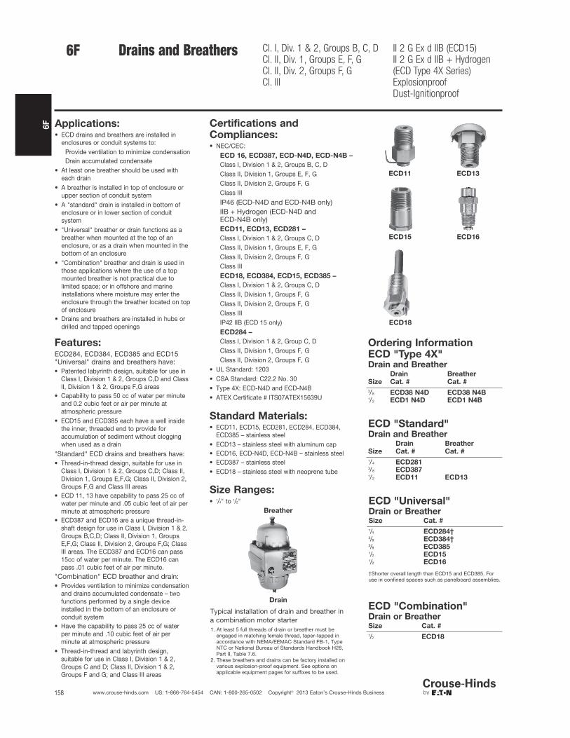
6F
158 www.crouse-hinds.com US: 1-866-764-5454 CAN: 1-800-265-0502 Copyright© 2013 Eaton’s Crouse-Hinds Business
Drains and Breathers Cl. I, Div. 1 & 2, Groups B, C, DCl. II, Div. 1, Groups E, F, GCl. II, Div. 2, Groups F, GCl. III
II 2 G Ex d IIB (ECD15)II 2 G Ex d IIB + Hydrogen(ECD Type 4X Series)ExplosionproofDust-Ignitionproof
Applications:• ECD drains and breathers are installed in
enclosures or conduit systems to:Provide ventilation to minimize condensationDrain accumulated condensate
• At least one breather should be used witheach drain
• A breather is installed in top of enclosure orupper section of conduit system
• A "standard" drain is installed in bottom ofenclosure or in lower section of conduitsystem
• "Universal" breather or drain functions as abreather when mounted at the top of anenclosure, or as a drain when mounted in thebottom of an enclosure
• "Combination" breather and drain is used inthose applications where the use of a topmounted breather is not practical due tolimited space; or in offshore and marineinstallations where moisture may enter theenclosure through the breather located on topof enclosure
• Drains and breathers are installed in hubs ordrilled and tapped openings
Features:ECD284, ECD384, ECD385 and ECD15"Universal" drains and breathers have:• Patented labyrinth design, suitable for use in
Class I, Division 1 & 2, Groups C,D and ClassII, Division 1 & 2, Groups F,G areas
• Capability to pass 50 cc of water per minuteand 0.2 cubic feet or air per minute atatmospheric pressure
• ECD15 and ECD385 each have a well insidethe inner, threaded end to provide foraccumulation of sediment without cloggingwhen used as a drain
"Standard" ECD drains and breathers have:• Thread-in-thread design, suitable for use in
Class I, Division 1 & 2, Groups C,D; Class II,Division 1, Groups E,F,G; Class II, Division 2,Groups F,G and Class III areas
• ECD 11, 13 have capability to pass 25 cc ofwater per minute and .05 cubic feet of air perminute at atmospheric pressure
• ECD387 and ECD16 are a unique thread-in-shaft design for use in Class I, Division 1 & 2,Groups B,C,D; Class II, Division 1, GroupsE,F,G; Class II, Division 2, Groups F,G; ClassIII areas. The ECD387 and ECD16 can pass15cc of water per minute. The ECD16 canpass .01 cubic feet of air per minute.
"Combination" ECD breather and drain:• Provides ventilation to minimize condensation
and drains accumulated condensate – twofunctions performed by a single deviceinstalled in the bottom of an enclosure orconduit system
• Have the capability to pass 25 cc of waterper minute and .10 cubic feet of air perminute at atmospheric pressure
• Thread-in-thread and labyrinth design,suitable for use in Class I, Division 1 & 2,Groups C and D; Class II, Division 1 & 2,Groups F and G; and Class III areas
Size Ranges:• 1/4" to 1/2"
Ordering InformationECD "Type 4X"Drain and Breather
Size
Drain
Cat. #
Breather
Cat. #
3/8 ECD38 N4D ECD38 N4B1/2 ECD1 N4D ECD1 N4B
ECD "Standard"Drain and Breather
Size
Drain
Cat. #
Breather
Cat. #
1/4 ECD2813/8 ECD3871/2 ECD11 ECD13
ECD "Universal"Drain or BreatherSize Cat. #
1/4 ECD284†3/8 ECD384†3/8 ECD3851/2 ECD151/2 ECD16
†Shorter overall length than ECD15 and ECD385. Foruse in confined spaces such as panelboard assemblies.
ECD "Combination"Drain or BreatherSize Cat. #
1/2 ECD18
ECD11 ECD13
ECD15 ECD16
ECD18
Standard Materials:• ECD11, ECD15, ECD281, ECD284, ECD384,
ECD385 – stainless steel• ECD13 – stainless steel with aluminum cap• ECD16, ECD-N4D, ECD-N4B – stainless steel• ECD387 – stainless steel• ECD18 – stainless steel with neoprene tube
Certifications andCompliances:• NEC/CEC:
ECD 16, ECD387, ECD-N4D, ECD-N4B –
Class I, Division 1 & 2, Groups B, C, DClass II, Division 1, Groups E, F, GClass II, Division 2, Groups F, GClass IIIIP46 (ECD-N4D and ECD-N4B only)IIB + Hydrogen (ECD-N4D and ECD-N4B only)ECD11, ECD13, ECD281 –
Class I, Division 1 & 2, Groups C, DClass II, Division 1, Groups E, F, GClass II, Division 2, Groups F, GClass IIIECD18, ECD384, ECD15, ECD385 –
Class I, Division 1 & 2, Groups C, DClass II, Division 1, Groups F, GClass II, Division 2, Groups F, GClass IIIIP42 IIB (ECD 15 only)ECD284 –
Class I, Division 1 & 2, Group C, DClass II, Division 1, Groups F, GClass II, Division 2, Groups F, G
• UL Standard: 1203• CSA Standard: C22.2 No. 30• Type 4X: ECD-N4D and ECD-N4B• ATEX Certificate # ITS07ATEX15639U
Breather
Drain
Typical installation of drain and breather ina combination motor starter1. At least 5 full threads of drain or breather must be
engaged in matching female thread, taper-tapped in accordance with NEMA/EEMAC Standard FB-1, Type NTC or National Bureau of Standards Handbook H28, Part II, Table 7.6.
2. These breathers and drains can be factory installed onvarious explosion-proof equipment. See options on applicable equipment pages for suffixes to be used.
6F

6F
159www.crouse-hinds.com US: 1-866-764-5454 CAN: 1-800-265-0502 Copyright© 2013 Eaton’s Crouse-Hinds Business
CD Series Ordinary Location Drain
Straight Body • Male Thread
Applications:CD Series drains are for use in conduit systems to:
• Drain accumulated condensate.
• Provide ventilation to minimize condensation.
Drains are installed in hubs or drilled and tapped openings.
Standard Materials:• CD bodies and nuts – steel or aluminum
• CD screen – stainless steel
Standard Finishes:• Steel – electrogalvanized with chromate treatment.
Certifications and Compliances:• UL Standard 514B
Options:Description Suffix
Copper-free aluminum construction SA
Ordering InformationSize Cat. #
1/2 CD13/4 CD2
NEMA 4X Breather/Drain
ATEX and CENELEC Range
I M2 II 2GD, E Exe I & II(Stainless Steel & Brass only)II 2GD, E Exe II (Nylon version)CSA Class I, Division 2, GroupsA, B, C & D, Exe II
Enclosure Type 4XIP66
Certifications and Compliances:• SIRA 99 ATEX 3050U
• I M2 II 2GD, E Exe I & II (Stainless Steel & Brass only)
• II 2GD, E Exe II (Nylon only)
• CSA Class I, Division 2, Groups A, B, C & D, Exe II
• Enclosure Type 4X
• IP66
Operating Temperature:• –50°C to +85°C
Applications:For use in enclosures to provide a method to effectively drainmoisture while allowing the enclosure to breathe.
Features:All NEMA 4X breather/drains offer:• Castellated locknuts that allow moisture to pass between the
enclosure and the locknut to the drain holes in the fitting.• Available in brass, stainless steel (Type 316) or 30% glass filled nylon.• Captive "O" ring on recess of the face of the breather/drain to
optimize ingress protection.• ATEX and CSA Certified for worldwide market acceptance.• Available with metric or NPT threads.
Ordering InformationEntry
Method Material Cat. #
M20 Brass ACDPEB/M20/15M20 Stainless Steel ACDPES/M20/15M20 Nylon ACDPEN/M20/15M25 Brass ACDPEB/M25/15M25 Stainless Steel ACDPES/M25/15M25 Nylon ACDPEN/M25/151/2" Brass ACDPEB/050NPT/151/2" Stainless Steel ACDPES/050NPT/153/4" Brass ACDPEB/075NPT/153/4" Stainless Steel ACDPES/075NPT/15
6F

6F
160 www.crouse-hinds.com US: 1-866-764-5454 CAN: 1-800-265-0502 Copyright© 2013 Eaton’s Crouse-Hinds Business
6F