HDPE Pipes And Fittings - Netsolhost.com
56
-
Upload
khangminh22 -
Category
Documents
-
view
0 -
download
0
Transcript of HDPE Pipes And Fittings - Netsolhost.com


www.ALMUNIF PIPES.com

We, Munir Abdullah Al-Munif Factory for Plastic Pipes and Fittings Company, are specialized in producing all types of plastic pipes with all its accessories of fittings. Our company was established 30 years ago.
Al-Munif Factories are located in Riyadh where the solid and flexible polyethylene is being produced as high and low densi-ty at diameters starting from 10mm to 1600mm with different lengths and pressure ratings as one of the leading factories in the region in producing such big diameters.
Besides producing Polyethylene Pipes; we are also producing PP-R pipes and Fittings for hot water applications with capac-ity of about 2000 ton with diameters starting from 20mm up to 160mm. Moreover; we are also producing uPVC and cPVC pipes and fittings for Potable water, drainage and sewerage network, and electrical and telecommunication networks, in addition to GRP pipes and fittings and Rubber products.
Production censorship is done in our laboratories to be sure of specifications compatibility. Our Laboratories has been equipped with all types of necessary systems to do those compatibility tests.
The production capacity is estimated with about 42,000 ton per year which is marketed and sold inside and outside the Kingdom.
COMPANY PROFILE
1MMP |

2 | www.ALMUNIFPIPES.com

Why HDPE Pipes• Field of application of HDPE Pipes• Manufacturing Standards• Raw Material• Design• Quality Control
HDPE Pipes for Gas Application
HDPE Pipes for Water
HDPE for Irrigation
Material Handling Guide
Assembly Procedure• Butt welding• Electrofusion
Installation
HDPE Butt Welding Fittngs
HDPE Electro-Fusion Fittings
HDPE Telecommunication Duct• STC HDPE Telecommunication Duct• SEC HDPE Telecommunication Duct• Mobily HDPE Telecommunication Duct• HDPE Double Wall Corrugated Duct• HDPE Telecommunication Corrugated Duct
4567811
14
16
24
27
293031
32
35
42
464748495051
Page CONTENTS
3MMP |

WHY HDPE PIPES?EXCELLENT PERFORMANCEHDPE is characterized by the combination of superior performance for the production of pipes with a good long term strength and long life which makes it the best for transportation of water and gaseous fuels.
This property is one of the most important properties of HDPE, for this it can be used safely to transport drinking water without any side effects, corrosion is one of the most dangerous phenomenon accompanied with transportation of water in steel pipes, but in the case of HDPE Pipes this phenomenon disappear. Another property in the field of environmental variations is the soil movement, because the great flexibility of HDPE Pipes it resist the soil movement.
HDPE Pipes is a competitive pipe because it is characterize by light, stable, weather-resistant, water proof and easy to handle. HDPE Pipe installations are the most competitive by key advantages.
• Ease of handling due to flexibility and light weight.• Leak-tight installation due to excellent fusion-welding possibilities.• Long life with low operational cost.• Capability for relining pipelines.• Possibility for on-site extrusion, alternative installations.• No limitations to pH-value of the water (no corrosion)• Taste and odor neutral• Bacteriologically neutral• Chemical resistance
RESIST TO ENVIRONMENTAL VARIATIONS
HDPE PIPES IS A COMPETITIVE PIPES
4 | www.ALMUNIFPIPES.com

FIELDS OF APPLICATIONHDPE PIPES
Non toxic HDPE pipes will not affect the taste, color or smell of drinking water.
HDPE pipes are ideal for agricultural irrigation and sprinkler systems.
HDPE pipes shows superior resistance to most chemicals which qualify it to used for transporting fuels at elevated pressures.
HDPE pipes are used for underground drain-age systems, waste discharge systems,
drainage soil.
D
R I N K I N G W AT E R
IRR
I G AT I O N S Y S T E MS
G A S E O U S F U E L S
SO
I L , W A S T E W AT ER
5MMP |

6 | www.ALMUNIFPIPES.com
MANUFACTURING STANDARDS
DIN 8074
ISO 4427
AWWA C906
SASO ISO4427
DIN 8075
ISO 4437
EN 122101
Polyethylene (PE) - Pipes PE 80, PE 100- Dimensions
Plastic piping systems - Polyethylene (PE) pipes and fittings for water supply
Polyethylene (PE) Pressure Pipe and Fittings, 4 In. thru 65 In. (100 mm Through 1650 mm), for Waterworks
Plastics piping systems - Polyethylene (PE) pipes and fittingd for water supply
Polyethylene (PE) - Pipes PE 80, PE 100- general quality requirements, testing
Platic piping systems for the supply of gaseuos fuels-Polyethylene (PE)
Plastics piping systems for water supply, and for drainage and sewerage under pressure. Polyethylene
(PE)
WHY HDPE PIPES?

7MMP |
RAW MATERIALMaterial Data Sheet
UV RESISTANCE
MINIMUM REQUIRED STRENGTH: MRS
WATER QUALITY
Material Data Sheet of High Density Polyethylen
Our HDPE pipes are suitable for drinking water. Due to the high quality of our HDPE pipes. It has no effect on water taste, odor, appearance of water and growth of aquatic micro-organisms.
HDPE 80 and HDPE 100 materials are compounded with special additional including UV stabilizers, which protect the pipe from degradation caused by intensive ultra violet light. For specific appli-cations, such as pipework above the ground, where it is known that the pipe will be subjected to UV light, the material can be compounded with carbon black which provides additional long-term protection.
Property PE 100 PE 80 Unit Test Method
Density (Compound) 959 956 Kg/m3 ISO 1183
Melt Flow Rate (MFR) 190 ˚C / 2.16 kg < 0.1 < 0.1 g/10 min ISO 1133
Melt Flow Rate (MFR) 190 ˚C / 5.0 kg 0.25 0.3 g/10 min ISO 1133
Tensile Stress at Yield 50mm/min 25 22 Mpa ISO 527-2
Elongation at Break >600 >600 % ISO 527-2
Tensile Modulus 50mm/min 900 800 Mpa ISO 527-2
Charpy Impact Notched at (0 °C) 16 14 Kj/m2 ISO 179/1eA
Hardness, Shore D 60 59 - ISO 868
Carbon Black Content 2 - 2.5 2 - 2.5 % ASTM D 1603
Carbon Black Dispersion ≤ Grade 3 ≤ Grade 3 - ISO 18553
Brittleness Temperature < - 70 < - 70 ˚C ASTM D 746
ESCR (10% Lgepal), F50 >10000 >10000 h ASTM D 1693-A
Thermal Stability (210 °C) >20 >20 min EN 728
Total Volatiles ≤ 350 ≤ 350 mg/kg EN 12009
Water Content ≤ 300 ≤ 300 mg/kg EN 12118
Coeffecient of Linear Thermal Expansion 2.0 x 10⁻⁴ 2.0 x 10⁻⁴ mm/mm/˚C ASTM D 696
Thermal Conductivity 0.41 0.41 W/km DIN 52612
Material Designation MRS Mpa
PE 100 10.0
PE 80 8.0
PE 63 6.3

8 | www.ALMUNIFPIPES.com
DESIGN
CHEMICAL RESISTANCE:
LIFETIME:
Our HDPE pipes are generally resistant to the chemicals commonly used for water treatment and disinfection. Our HDPE pipes have excellent resistance to naturally occuring chemicals found in the soil. For industrial purposes our HDPE 100 pipes have excellent resistance to different media.
Maximum Operating Temperature for PE 100 in different media:
Allowable Working Pressure for Pipes Made of PE 100, Conveying water
HDPE Material has a 50 year life time at 20 °C, but for example PE 100 has actual strength greater than the design strength and hence the expected resulting service lifetimes are greatly in excess of the nominal 50-year requirement when the pipe is operating within its design envelope.
Safety factor C = 1.25Reference DIN 8074: 2011-12
Medium Maximum operating temperature °C PE 100
Sulphuric Acid 30% 60
Hydrochloric Acid 20% 60
Phosphoric Acid 85% 60
Nitric Acid 30% 40
Chromic Acid 20% 20
Hydrofluoric Acid 40% 40
Formic Acid 50% 40
Caustic Soda Solution 30% 60
Acetone Technical Grade 40
Ethanol 96% 60
Temperature ˚C Years of service
Pipe series (S)20 12.5 8.3 8 6.3 5 4
Standard dimension ratio (SDR)41 26 17.6 17 13.6 11 9
Allowable working pressure (Bar)
10
5 5.0 7.9 11.9 12.5 15.8 19.9 25.110 4.9 7.7 11.7 12.3 15.5 19.5 24.625 4.8 7.6 11.5 12.0 15.2 19.1 24.150 4.7 7.5 11.3 11.9 15.0 18.9 23.8
100 4.6 7.3 11.1 11.7 14.7 18.5 23.3
20
5 4.2 6.6 10.0 10.5 13.3 16.7 21.010 4.1 6.5 9.9 10.4 13.1 16.5 20.825 4.0 6.4 9.7 10.1 12.8 16.1 20.350 4.0 6.3 9.6 10.0 12.5 16.0 20.0
100 3.9 6.1 9.4 9.8 12.3 15.5 19.5
30
5 3.5 5.6 8.5 8.9 11.2 14.1 17.810 3.5 5.5 8.3 8.8 11.0 13.9 17.525 3.4 5.4 8.2 8.6 10.9 13.7 17.350 3.4 5.4 8.1 8.5 10.7 13.5 17.0
40
5 3.0 4.8 7.3 7.6 9.6 12.1 15.310 3.0 4.7 7.1 7.5 9.5 11.9 15.025 2.9 4.6 7.0 7.4 9.3 11.7 14.850 2.9 4.6 6.9 7.3 9.1 11.5 14.5
505 2.6 4.2 6.3 6.6 8.3 10.5 13.3
10 2.6 4.1 6.2 6.5 8.2 10.3 13.015 2.6 4.1 6.2 6.5 8.2 10.3 13.0
60 5 2.3 3.6 5.5 5.7 7.2 9.1 11.570 2 2.1 3.3 5.0 5.2 6.6 8.3 10.5
WHY HDPE PIPES?

9MMP |
Temperature ˚C
Years of service
Pipe series (S)
25 20 16 12,5 10.5 10 8.3 8 6.3 5 4
Standar Dimension Ratio (SDR)
51 41 33 26 22 21 17.6 17 13.6 11 9
Allowable Working Pressure (bar)
10
5 3.2 4.0 5.1 6.4 7.7 8.1 9.7 10.1 12.8 16.1 20.3
10 3.1 4.0 5.0 6.3 7.6 8.0 9.5 10.0 12.6 15.9 20.0
25 3.1 3.9 4.9 6.1 7.4 7.8 9.3 9.8 12.3 15.5 19.5
50 3.0 3.8 4.7 6.0 7.2 7.6 9.1 9.5 12.0 15.1 19.0
100 2.9 3.7 4.7 5.9 7.2 7.5 8.9 9.4 11.8 14.9 18.8
20
5 2.7 3.4 4.2 5.4 6.5 6.8 8.1 8.5 10.7 13.5 17.0
10 2.6 3.3 4.1 5.2 6.3 6.6 7.9 8.3 10.4 13.1 16.5
25 2.5 3.2 4.1 5.1 6.2 6.5 7.7 8.1 10.3 12.9 16.3
50 2.5 3.2 4.0 5.0 6.0 6.4 7.4 8.0 10.0 12.5 16.0
100 2.4 3.1 3.9 4.9 5.9 6.2 7.4 7.8 9.8 12.3 15.5
30
5 2.2 2.8 3.5 4.5 5.4 5.7 6.8 7.1 9.0 11.3 14.3
10 2.2 2.8 3.5 4.4 5.3 5.6 6.7 7.0 8.8 11.1 14.0
25 2.1 2.7 3.4 4.3 5.2 5.5 6.5 6.9 8.7 10.9 13.8
50 2.1 2.7 3.4 4.2 5.1 5.4 6.4 6.7 8.5 10.7 13.5
40
5 1.9 2.4 3.0 3.8 4.7 4.9 5.8 6.1 7.7 9.7 12.3
10 1.9 2.4 3.0 3.8 4.6 4.8 5.7 6.0 7.6 9.5 12.0
25 1.8 2.3 2.9 3.7 4.5 4.7 5.6 5.9 7.4 9.3 11.8
50 1.8 2.3 2.9 3.6 4.4 4.6 5.5 5.7 7.2 9.1 11.5
50
5 1.6 2.1 2.6 3.3 4.0 4.2 5.0 5.2 6.6 8.3 10.5
10 1.6 2.0 2.5 3.2 3.9 4.1 4.9 5.1 6.4 8.1 10.2
15 1.6 2.0 2.5 3.2 3.9 4.1 4.9 5.1 6.4 8.1 10.2
60 5 1.4 1.8 2.3 2.9 3.5 3.7 4.4 4.6 5.8 7.3 9.2
70 2 1.3 1.6 2.0 2.6 3.1 3.3 3.9 4.1 5.2 6.5 8.2
Allowable Working Pressure for Pipes Made of PE80, (S) Conveying Water
Safety factor C = 1.25Reference DIN 8074: 2011-12
HDPE pipe length variation due to temperature change (°C)
Temperature Change (˚C)
Length Variationmm/meter
5 1
10 2
15 3
20 4
25 5
30 6
35 7
40 8
mm/m/ °C 0.2 = Coefficient of thermal expansion

10 | www.ALMUNIFPIPES.com
PRESSURE
STANDARD DIMENSION: SDR
Maximum SustainedTemperature, (°C) Multiply working pressure at (20 ˚C) by these factors
20 1
25 0.92
30 0.84
35 0.78
40 0.72
Maximum operating pressure (MOP) = 20 x MRS where C is design safety factorC x (SDR-1)
Relationship between the admissible nominal pressure PN, SDR and Performance classes PE 80, PE 100 (for water 20 °C, 50 years service Life and C = 1.25).
Nominal Pressure PN(Bar)
SDRPE 80
SDRPE 100
3.2 41 -
4 33 41
5 26 33
6 22 -
6.3 21 26
8 17 21
10 13.6 17
12.5 11 13.6
16 9 11
20 7.4 9
25 6 7.4
WHY HDPE PIPES?
10 | www.ALMUNIFPIPES.com

11MMP |
QUALITY CONTROL
RAW MATERIAL INSPECTION
IN PROCESS INSPECTION
LABORATORY TESTING
FINAL INSPECTION
HDPE pipes manufactured by ALMUNIF PIPES are subjected to the following quality program:
• Density
• Melt Flow Rate (MFR)
• Volatile Content
• Moisture Content
• Carbon Black Content
• Carbon Black Dispersion
• Oxidation Induction Time (OIT)
All visual inspection and dimension measurements are conducted during pipe manufacturing.
All physical and mechanical properties of product are conducted
• Hydrostatic Strength
• Melt Flow Rate
• Longitudinal Reversion Test
• Tensile Properties
• Oxidation Induction Time
Final inspection conducted to pipes dispatching to the customer to be sure that they are free
from visual physical damages:

12 | www.ALMUNIFPIPES.com
Raw Material Inspection Process
Final Product Inspection Process
Delivery of rawmaterial
In-processInspection
Incoming goodscontrol
Lab. Tests
Raw materialstore
Final Inspection
• Density• MFR• Volatile content• Moisture content• Carbon black content• Carbon black dispersion• OIT
• Visual inspection• Measurement of dimensions
• Physical Properties• Mechanical Properties
• Viasual Inspection
WHY HDPE PIPES?

13MMP |
PRODUCTION FLOW CHART
13MMP |
WHY HDPE PIPES?
13MMP |

HDPE PIPESFOR GAS APPLICATIONS
14 | www.ALMUNIFPIPES.com

15MMP |
Nominal Outside Diameter (mm)
SDR 17.6PE 100 PN 6
PE 80 PN 4.8
SDR 11PE 100 PN 10
PE 80 PN 8Minimum Wall
Thickness (mm) Weight (kg/m) Minimum Wall Thickness (mm) Weight (kg/m)
16 2.3 0.10 3.0 0.12
20 2.3 0.13 3.0 0.16
25 2.3 0.17 3.0 0.21
32 2.3 0.22 3.0 0.28
40 2.3 0.36 3.7 0.43
50 2.9 0.46 4.6 0.67
63 3.6 0.69 5.8 1.06
75 4.3 0.98 6.8 1.50
90 5.2 1.40 8.2 2.14
110 6.3 2.09 10.0 3.17
125 7.1 2.68 11.4 4.10
140 8.0 3.36 12.7 5.15
160 9.1 4.38 14.6 6.71
180 10.3 5.51 16.4 8.47
200 11.4 6.83 18.2 10.45
225 12.8 8.60 20.5 13.22
250 14.2 10.62 22.7 16.31
280 15.9 13.27 25.4 20.44
315 17.9 16.80 28.6 25.86
355 20.2 21.29 32.3 32.80
400 22.8 27.03 36.4 41.63
450 25.6 34.16 40.9 52.69
500 28.4 42.12 45.5 64.95
560 31.9 53.10 50.9 81.55
630 35.8 67.20 57.3 102.90
PE 100 and PE 80 pipes for the transportation of GASEOUS FUELSaccording to ISO 4437
MaterialMinimum required strengthDesign stressDesign safety factorMaterialMinimum required strengthDesign stressDesign safety factorColorLength
PE 100MRS = 10.0 MPaσs = 5.0 MpaC = 2.0 for gasPE 80MRS = 8.0 Mpaσs = 4.0 MpaC = 2.0 for gasBlack or YellowSizes from 16mm to 32mm are available in coils of 100, 200 and 300 up to 1500 meters. Sizes from 40mm to 125mm are available in coils of 100 meters. larger diameters are available in straight lengths of 12 meters. Different lengths can be supplied on request.
::::::::::
PN = 20 x MRS
C x (SDR - 1)
HDPE PIPES FOR GAS APPLICATIONS

16 | www.ALMUNIFPIPES.com
HDPE PIPES FOR WATER
16 | www.ALMUNIFPIPES.com

17MMP |
SDR 41 SDR 26 SDR 17 SDR 13.6 SDR 11 SDR 9
S 20 S 12.5 S 8 S 6.3 S 5 S 4
Nominal pressure (PN)
PE 80 PN 3.2 PN 5 PN 8 PN 10 PN 12.5 PN 16
PE 100 PN 4 PN 6 PN 10 PN 12.5 PN 16 PN 20
Nominal Outside Diameter (mm)
Wall Thickness (mm)
Wall Thickness (mm)
Wall Thickness (mm)
Wall Thickness (mm)
Wall Thickness (mm)
Wall Thickness (mm)
16 - - - - - 2.020 - - - - 2.0 2.325 - - - 2.0 2.3 3.032 - - 2.0 2.4 3.0 3.640 - - 2.4 3.0 3.7 4.550 - 2.0 3.0 3.7 4.6 5.663 - 2.5 3.8 4.7 5.8 7.175 - 2.9 4.5 5.6 6.8 8.490 - 3.5 5.4 6.7 8.2 10.1110 - 4.2 6.6 8.1 10.0 12.3125 - 4.8 7.4 9.2 11.4 14.0140 - 5.4 8.3 10.3 12.7 15.7160 - 6.2 9.5 11.8 14.6 17.9180 - 6.9 10.7 13.3 16.4 20.1200 - 7.7 11.9 14.7 18.2 22.4225 - 8.6 13.4 16.6 20.5 25.2250 - 9.6 14.8 18.4 22.7 27.9280 - 10.7 16.6 20.6 25.4 31.3315 7.7 12.1 18.7 23.2 28.6 35.2355 3.5 13.6 21.1 26.1 32.2 39.7400 9.8 15.3 23.7 29.4 36.3 44.7450 11.0 17.2 26.7 33.1 40.9 50.3500 12.3 19.1 29.7 36.8 45.4 55.8560 13.7 21.4 33.2 41.2 50.8 62.5630 15.4 24.1 37.4 46.3 57.2 70.3710 17.4 27.2 42.1 52.2 64.5 79.3800 19.6 30.6 47.4 58.8 72.6 89.3900 22.0 34.4 53.3 66.2 81.7 -1000 24.5 38.2 59.3 72.5 90.2 -1200 29.4 45.9 67.9 88.2 - -1400 34.3 53.5 82.4 102.9 - -1600 39.2 61.2 94.1 117.6 - -
PE 100, PE 80 pressure pipes for water supply according to ISO 4427-2
MaterialMinimum required strengthDesign stressDesign safety factorColorLength
PE 100MRS = 10.0 Mpaσs = 8.0 MpaC = 1.25 for waterBlacksizes from 16mm to 32mm are available in coils of 100, 200 and 300 up to 1500 meters. Sizes from 40mm to 160mm are available in coils of 100 meters. larger diameters are available in straight lengths of 12 meters. Different lengths can be supplied on request.
PE 80MRS = 8.0 Mpaσs = 6.4 MpaC = 1.25 for waterBlack
::::::
PN = 20 x MRS
C x (SDR - 1)
HDPE PIPES FOR WATER

18 | www.ALMUNIFPIPES.com
Nominal Outside
Diameter (mm)
SDR 41S 20PN 4
SDR 26S 12.5PN 6.3
SDR 17S 8
PN 10
SDR 13.6S 6.3
PN 12.5
SDR 11S 5
PN 16
SDR 9S 4
PN 20Wall
Thickness (mm)
Weight kg/m
Wall Thickness
(mm)
Weight kg/m
Wall Thickness
(mm)
Weight kg/m
Wall Thickness
(mm)
Weight kg/m
Wall Thickness
(mm)
Weight kg/m
Wall Thickness
(mm)
Weight kg/m
16 - - - - - - - - - - 2.0 0.092
20 - - - - - - - - 2.0 0.118 2.3 0.134
25 - - - - - - 2.0 0.151 2.3 0.173 3.0 0.202
32 - - - - 2.0 0.198 2.4 0.235 3.0 0.282 3.6 0.331
40 - - 1.8 0.229 2.4 0.299 3.0 0.360 3.7 0.434 4.5 0.514
50 - - 2.0 0.317 3.0 0.458 3.7 0.555 4.6 0.673 5.6 0.796
63 1.8 0.368 2.5 0.500 3.8 0.728 4.7 0.883 5.8 1.06 7.1 1.27
75 1.9 0.462 2.9 0.683 4.5 1.03 5.6 1.25 6.8 1.48 8.4 1.78
90 2.2 0.647 3.5 0.988 5.4 1.47 6.7 1.79 8.2 2.14 10.1 2.57
110 2.7 0.952 4.2 1.45 6.6 2.19 8.1 2.64 10.0 3.18 12.3 3.82
125 3.1 1.25 4.8 1.86 7.4 2.79 9.2 3.40 11.4 4.12 14.0 4.92
140 3.5 1.56 5.4 2.35 8.3 3.50 10.3 4.26 12.7 5.13 15.7 6.18
160 4.0 2.02 6.2 3.08 9.5 4.57 11.8 5.56 14.6 6.74 17.9 8.04
180 4.4 2.51 6.9 3.83 10.7 5.77 13.3 7.05 16.4 8.51 20.1 10.2
200 4.9 3.08 7.7 4.74 11.9 7.12 14.7 8.65 18.2 10.5 22.4 12.6
225 5.5 3.90 8.6 5.96 13.4 9.03 16.6 11.0 20.5 13.3 25.2 15.9
250 6.2 4.88 9.6 7.38 14.8 11.1 18.4 13.5 22.7 16.3 27.9 19.6
280 6.9 6.04 10.7 9.20 16.6 13.9 20.6 16.9 25.4 20.5 31.3 24.6
315 7.7 7.59 12.1 11.7 18.7 17.6 23.2 21.5 28.6 25.9 35.2 31.1
355 8.7 9.65 13.6 14.8 21.1 22.4 26.1 27.2 32.2 32.9 39.7 39.5
400 9.8 12.2 15.3 18.8 23.7 28.3 29.4 34.5 36.3 41.7 44.7 50.1
450 11.0 15.4 17.2 23.7 26.7 35.8 33.1 43.7 40.9 52.8 50.3 63.4
500 12.3 19.2 19.1 29.2 29.7 44.2 36.8 53.9 45.4 65.2 55.8 78.1
560 13.7 23.9 21.4 36.6 33.2 55.4 41.2 67.6 50.8 81.7 62.5 98.0
630 15.4 30.2 24.1 46.4 37.4 70.2 46.3 85.5 57.2 103 - -
710 17.4 38.4 27.2 59.0 42.1 89.0 52.2 109 64.5 131 - -
800 19.6 48.7 30.6 74.7 47.4 113 58.8 138 - - - -
900 22.0 31.3 34.4 94.4 53.3 143 66.1 174 - - - -
1000 24.5 75.9 38.2 117 59.3 176 - - - - - -
1200 29.4 109 45.9 168 - - - - - - - -
1400 34.3 149 53.5 230 - - - - - - - -
1600 39.2 194 61.2 298 - - - - - - - -
PE 100 pressure pipes for water supply according to DIN 8074/8075
MaterialMinimum required strength:Design stressDesign safety factorColorLength
PE 100MRS = 10.0 Mpaσs = 8.0 MpaC = 1.25 for waterBlacksizes from 16mm to 32mm are available in coils of 100, 200 and 300 up to 1500 meters. Sizes from 40mm to 125mm are available in coils of 100 meters. Larger diameters are available in straight lengths of 12 meters. Different lengths can be supplied on request.
::::::
PN = 20 x MRS
C x (SDR - 1)
HDPE PIPES FOR WATER

19MMP |
PE 100 pressure pipes for water supply according to DIN 8074/8075
MaterialMinimum required strengthDesign stressDesign safety factorColorLength
PE 100MRS = 10.0 Mpaσs = 6.25 MpasC = 1.6 for waterBlacksizes from 16mm to 32mm are available in coils of 100, 200 and 300 up to 1500 meters. Sizes from 40mm to 125mm are available in coils of 100 meters. larger diameters are available in straight lengths of 12 meters. Different lengths can be supplied on request.
::::::
PN = 20 x MRS
C x (SDR - 1)
Nominal Outside
Diameter (mm)
SDR 41S 20
PN 3.2
SDR 33S 16PN 4
SDR 13.6S 6.3
PN 9.9
SDR 11S 5
PN 12.5
SDR 9S 4
PN 15.6
SDR 7.4S 3.2
PN 19.2Wall
Thickness (mm)
Weight kg/m
Wall Thickness
(mm)
Weight kg/m
Wall Thickness
(mm)
Weight kg/m
Wall Thickness
(mm)
Weight kg/m
Wall Thickness
(mm)
Weight kg/m
Wall Thickness
(mm)
Weight kg/m
16 - - - - - - - - 2.0 0.092 2.3 0.103
20 - - - - - - 2.0 0.118 2.3 0.134 3.0 0.164
25 - - - - 2.0 0.151 2.3 0.173 3.0 0.202 3.5 0.243
32 - - - - 2.4 0.235 3.0 0.282 3.6 0.331 4.4 0.390
40 - - - - 3.0 0.360 3.7 0.434 4.5 0.514 5.5 0.607
50 - - 1.8 0.290 3.7 0.555 4.6 0.673 5.6 0.796 6.9 0.945
63 1.8 0.368 2.0 0.403 4.7 0.883 5.8 1.06 7.1 1.27 8.6 1.49
75 1.9 0.462 2.3 0.557 5.6 1.25 6.8 1.48 8.4 1.78 10.3 2.12
90 2.2 0.647 2.8 0.800 6.7 1.79 8.2 2.14 10.1 2.57 12.3 3.03
110 2.7 0.952 3.4 1.19 8.1 2.64 10.0 3.18 12.3 3.82 15.1 4.54
125 3.1 1.25 3.9 1.53 9.2 3.4 11.4 4.12 14.0 4.92 17.1 5.84
140 3.5 1.56 4.3 1.09 10.3 4.26 12.7 5.13 15.7 6.18 19.2 7.33
160 4.0 2.02 4.9 2.45 11.8 5.56 14.6 6.74 17.9 8.04 21.9 9.54
180 4.4 2.51 5.5 3.10 13.3 7.05 16.4 8.51 20.1 10.2 24.6 12.1
200 4.9 3.08 6.2 3.88 14.7 8.65 18.2 10.5 22.4 12.6 27.4 14.9
225 5.5 3.90 6.9 4.82 16.6 11.0 20.5 13.3 25.2 15.9 30.8 18.8
250 6.2 4.88 7.7 5.98 18.4 13.5 22.7 16.3 27.9 19.6 34.2 23.3
280 6.9 6.04 8.6 7.47 20.6 16.9 25.4 20.5 31.3 24.6 38.3 29.2
315 7.7 7.59 9.7 9.47 23.2 21.5 28.6 25.9 35.2 31.1 43.1 36.9
355 8.7 9.65 10.9 12.0 26.1 27.2 32.2 32.9 39.7 39.5 48.5 46.8
400 9.8 12.2 12.3 15.2 29.4 34.5 36.3 41.7 44.7 50.1 54.7 59.4
450 11.0 15.4 13.8 19.2 33.1 43.7 40.9 52.8 50.3 63.4 61.5 75.2
500 12.3 19.2 15.3 23.6 36.8 53.9 45.4 65.2 55.8 78.1 68.3 92.8
560 13.7 23.9 17.2 29.7 41.2 67.6 50.8 81.7 62.5 89.0 - -
630 15.4 30.2 19.3 37.5 46.3 85.5 57.2 103 - - - -
710 17.4 38.4 21.8 47.7 52.2 109 64.5 131 - - - -
800 19.6 48.7 24.5 60.4 58.8 138 - - - - - -
900 22.0 61.3 27.6 76.4 66.1 174 - - - - - -
1000 24.5 75.9 30.6 94.1 - - - - - - - -
1200 29.4 109 36.7 135 - - - - - - - -
1400 34.3 149 42.9 184 - - - - - - - -
1600 39.2 194 49.0 241 - - - - - - - -

20 | www.ALMUNIFPIPES.com
MaterialMinimum required strengthDesign stressDesign safety factorColorLength
PE 80MRS = 8.0 Mpaσs = 6.4 MpaC = 1.25 for waterBlackSizes from 16mm to 32mm are available in coils of 100, 200 and 300 up to 1500 meters. Sizes from 40mm to 125mm are available in coils of 100 meters. Larger diameters are available in straight lengths of 12 meters. Different lengths can be supplied on request.
::::::
PN = 20 x MRS
C x (SDR - 1)
PE 80 pressure pipes for water supply according to DIN 8074/8075
Nominal Outside
Diameter (mm)
SDR 41S 20PN 4
SDR 33S 16PN 4
SDR 22S 10.5PN 6
SDR 13.6S 6.3PN 10
SDR 11S 5
PN 12.5
SDR 9S 4
PN 16Wall
Thickness (mm)
Weight kg/m
Wall Thickness
(mm)
Weight kg/m
Wall Thickness
(mm)
Weight kg/m
Wall Thickness
(mm)
Weight kg/m
Wall Thickness
(mm)
Weight kg/m
Wall Thickness
(mm)
Weight kg/m
16 - - - - - - - - - - 1.8 0.084
20 - - - - - - 1.8 0.107 1.9 0.112 2.3 0.133
25 - - - - - - 1.9 0.144 2.3 0.171 2.8 0.200
32 - - - - - - 2.4 0.232 2.9 0.272 3.6 0.327
40 - - - - 1.9 0.238 3.0 0.356 3.7 0.430 4.5 0.509
50 - - 1.8 0.287 2.3 0.361 3.7 0.549 4.6 0.666 5.6 0.788
63 1.8 0.364 2.0 0.399 2.9 0.563 4.7 0.873 5.8 1.05 7.1 1.26
75 1.9 0.457 2.3 0.551 3.5 0.807 5.6 1.24 6.8 1.47 8.4 1.76
90 2.2 0.643 2.8 0.791 4.1 1.14 6.7 1.77 8.2 2.12 10.1 2.54
110 2.7 0.943 3.4 1.17 5.0 1.67 8.1 2.62 10.0 3.14 12.3 3.78
125 3.1 1.23 3.9 1.51 5.7 2.16 9.2 3.37 11.4 4.08 14.0 4.87
140 3.5 1.54 4.3 1.88 6.4 2.72 10.3 4.22 12.7 5.08 15.7 6.11
160 4.0 2.0 4.9 2.42 7.3 3.54 11.8 5.50 14.6 6.67 17.9 7.96
180 4.4 2.49 5.5 3.07 8.2 4.47 13.3 6.98 16.4 8.42 20.1 10.1
200 4.9 3.05 6.2 3.84 9.1 5.57 14.7 8.56 18.2 10.4 22.4 12.4
225 5.5 3.86 6.9 4.77 10.3 7.00 16.6 10.9 20.5 13.1 25.2 15.8
250 6.2 4.83 7.7 5.92 11.4 8.59 18.4 13.4 22.7 16.2 27.9 19.4
280 6.9 5.98 8.6 7.40 12.8 10.8 20.6 16.8 25.4 20.3 31.3 24.3
315 7.7 7.52 9.7 9.37 14.4 13.6 23.2 21.2 28.4 25.6 35.2 30.8
355 8.7 9.55 10.9 11.8 16.2 17.3 26.1 26.9 32.2 32.5 39.7 39.1
400 9.8 12.1 12.3 15.1 18.2 21.9 29.4 34.1 36.3 41.3 44.7 49.6
450 11.0 15.3 13.8 19.0 20.5 27.7 33.1 43.2 40.9 52.3 50.3 62.7
500 12.3 19.0 15.3 23.4 22.8 34.2 36.8 53.3 45.4 64.5 55.8 77.3
560 13.7 23.6 17.2 29.4 25.5 42.8 41.2 66.9 50.8 80.8 62.5 97.0
630 15.4 29.9 19.3 37.1 28.7 54.1 46.3 84.6 57.2 102 - -
710 17.4 38.0 21.8 47.2 32.3 68.7 52.2 107 64.5 130 - -
800 19.6 48.1 24.5 59.7 36.4 87.2 58.8 136 - - - -
900 22 60.9 27.6 75.6 41 110 66.1 172 - - - -
1000 24.5 75.2 30.6 93.1 45.5 136 - - - - - -
1200 29.4 108 36.7 134 54.6 196 - - - - - -
1400 34.4 147 42.9 183 63.7 267 - - - - - -
1600 39.2 192 49 238 - - - - - - - -
HDPE PIPES FOR WATER

21MMP |
PE 80 pressure pipes for water supply according to DIN 8074/8075
Nominal Outside
Diameter (mm)
SDR 33S 16
PN 3.1
SDR 26S 12.5PN 4
SDR 17.6S 8.3PN 6
SDR 11S 5
PN 10
SDR 9S 4
PN 12.5
SDR 7.4S 3.2
PN 15.3Wall
Thickness (mm)
Weight kg/m
Wall Thickness
(mm)
Weight kg/m
Wall Thickness
(mm)
Weight kg/m
Wall Thickness
(mm)
Weight kg/m
Wall Thickness
(mm)
Weight kg/m
Wall Thickness
(mm)
Weight kg/m
16 - - - - - - - - 1.8 0.084 2.2 0.099
20 - - - - - - 1.9 0.112 2.3 0.133 2.8 0.154
25 - - - - - - 2.3 0.171 2.8 0.200 3.5 0.240
32 - - - - 1.8 0.179 2.9 0.272 3.6 0.327 4.4 0.386
40 - - 1.8 0.227 2.3 0.285 3.7 0.430 4.5 0.509 5.5 0.600
50 1.8 0.287 2.0 0.314 2.9 0.440 4.6 0.666 5.6 0.788 6.9 0.936
63 2.0 0.399 2.5 0.494 3.6 0.688 5.8 1.05 7.1 1.26 8.6 1.47
75 2.3 0.551 2.9 0.675 4.3 0.966 6.8 1.47 8.4 1.76 10.3 2.09
90 2.8 0.791 3.5 0.978 5.1 1.39 8.2 2.12 10.1 2.54 12.3 3.0
110 3.4 1.17 4.2 1.43 6.3 2.08 10.0 3.14 12.3 3.78 15.1 4.49
125 3.9 1.51 4.8 1.84 7.1 2.66 11.4 4.08 14.0 4.87 17.1 5.77
140 4.3 1.88 5.4 2.32 8.0 3.34 12.7 5.08 15.7 6.11 19.2 7.25
160 4.9 2.42 6.2 3.04 9.1 4.35 14.6 6.67 17.9 7.96 21.9 9.44
180 5.5 3.07 6.9 3.79 10.2 5.48 16.4 8.42 20.1 10.1 24.6 11.9
200 6.2 3.84 7.7 4.69 11.4 6.79 18.2 10.4 22.4 12.4 27.4 14.8
225 6.9 4.77 8.6 5.89 12.8 8.55 20.5 13.1 25.2 15.8 30.8 18.6
250 7.7 5.92 9.6 7.30 14.2 10.6 22.7 16.2 27.9 19.4 34.2 23.0
280 8.6 7.40 10.7 9.10 15.9 13.2 25.4 20.3 31.3 24.3 38.3 28.9
315 9.7 9.37 12.1 11.6 17.9 16.7 28.6 25.6 35.2 30.8 43.1 36.5
355 10.9 11.8 13.6 14.6 20.1 21.2 32.2 32.5 39.7 39.1 48.5 46.3
400 12.3 15.1 15.3 18.6 22.7 26.9 36.3 41.3 44.7 49.6 54.7 58.8
450 13.8 19.0 17.2 23.5 25.5 34.0 40.9 52.3 50.3 62.7 61.5 74.4
500 15.3 23.4 19.1 28.9 28.4 42.0 45.4 64.5 55.8 77.3 68.3 91.8
560 17.2 29.4 21.4 36.2 31.7 52.5 50.8 80.8 62.5 97.0 - -
630 19.3 37.1 24.1 45.9 35.7 66.5 57.2 102 - - - -
710 21.8 47.2 27.2 58.4 40.2 84.4 64.5 130 - - - -
800 24.5 59.7 30.6 73.9 45.3 107 - - - - - -
900 27.6 75.6 34.4 93.4 51 136 - - - - - -
1000 30.6 93.1 38.2 115 56.7 167 - - - - - -
1200 36.7 134 45.9 166 68 241 - - - - - -
1400 42.9 183 53.5 226 - - - - - - - -
1600 49 238 61.2 295 - - - - - - - -
MaterialMinimum required strengthDesign stressDesign safety factorColorLength
PE 80MRS = 8.0 Mpaσs = 5.0 MpaC = 1.6 for waterBlacksizes from 16mm to 32mm are available in coils of 100, 200 and 300 up to 1500 meters. Sizes from 40mm to 125mm are available in coils of 100 meters. Larger diameters are available in straight lengths of 12 meters. Different lengths can be supplied on request.
::::::
PN = 20 x MRS
C x (SDR - 1)
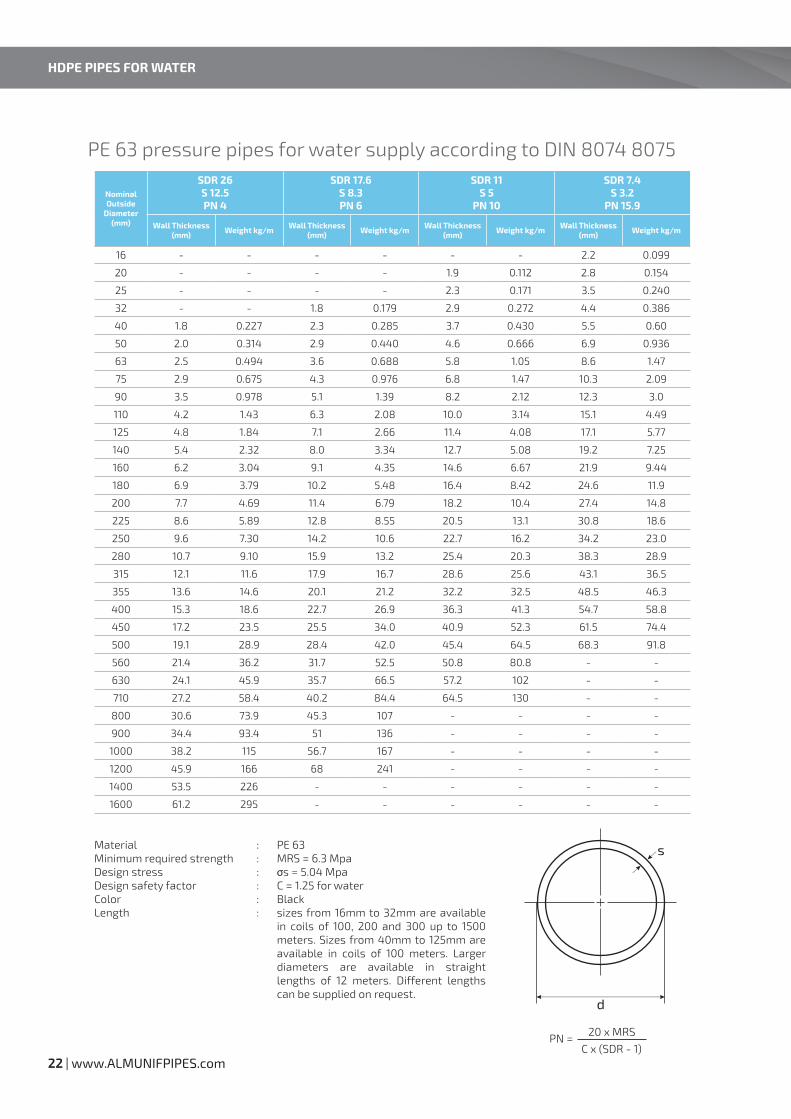
22 | www.ALMUNIFPIPES.com
MaterialMinimum required strengthDesign stressDesign safety factorColorLength
PE 63MRS = 6.3 Mpaσs = 5.04 MpaC = 1.25 for waterBlacksizes from 16mm to 32mm are available in coils of 100, 200 and 300 up to 1500 meters. Sizes from 40mm to 125mm are available in coils of 100 meters. Larger diameters are available in straight lengths of 12 meters. Different lengths can be supplied on request.
::::::
PN = 20 x MRS
C x (SDR - 1)
PE 63 pressure pipes for water supply according to DIN 8074 8075
Nominal Outside
Diameter (mm)
SDR 26S 12.5PN 4
SDR 17.6S 8.3PN 6
SDR 11S 5
PN 10
SDR 7.4S 3.2
PN 15.9
Wall Thickness (mm) Weight kg/m Wall Thickness
(mm) Weight kg/m Wall Thickness (mm) Weight kg/m Wall Thickness
(mm) Weight kg/m
16 - - - - - - 2.2 0.099
20 - - - - 1.9 0.112 2.8 0.154
25 - - - - 2.3 0.171 3.5 0.240
32 - - 1.8 0.179 2.9 0.272 4.4 0.386
40 1.8 0.227 2.3 0.285 3.7 0.430 5.5 0.60
50 2.0 0.314 2.9 0.440 4.6 0.666 6.9 0.936
63 2.5 0.494 3.6 0.688 5.8 1.05 8.6 1.47
75 2.9 0.675 4.3 0.976 6.8 1.47 10.3 2.09
90 3.5 0.978 5.1 1.39 8.2 2.12 12.3 3.0
110 4.2 1.43 6.3 2.08 10.0 3.14 15.1 4.49
125 4.8 1.84 7.1 2.66 11.4 4.08 17.1 5.77
140 5.4 2.32 8.0 3.34 12.7 5.08 19.2 7.25
160 6.2 3.04 9.1 4.35 14.6 6.67 21.9 9.44
180 6.9 3.79 10.2 5.48 16.4 8.42 24.6 11.9
200 7.7 4.69 11.4 6.79 18.2 10.4 27.4 14.8
225 8.6 5.89 12.8 8.55 20.5 13.1 30.8 18.6
250 9.6 7.30 14.2 10.6 22.7 16.2 34.2 23.0
280 10.7 9.10 15.9 13.2 25.4 20.3 38.3 28.9
315 12.1 11.6 17.9 16.7 28.6 25.6 43.1 36.5
355 13.6 14.6 20.1 21.2 32.2 32.5 48.5 46.3
400 15.3 18.6 22.7 26.9 36.3 41.3 54.7 58.8
450 17.2 23.5 25.5 34.0 40.9 52.3 61.5 74.4
500 19.1 28.9 28.4 42.0 45.4 64.5 68.3 91.8
560 21.4 36.2 31.7 52.5 50.8 80.8 - -
630 24.1 45.9 35.7 66.5 57.2 102 - -
710 27.2 58.4 40.2 84.4 64.5 130 - -
800 30.6 73.9 45.3 107 - - - -
900 34.4 93.4 51 136 - - - -
1000 38.2 115 56.7 167 - - - -
1200 45.9 166 68 241 - - - -
1400 53.5 226 - - - - - -
1600 61.2 295 - - - - - -
HDPE PIPES FOR WATER

23MMP |
PE 63 pressure pipes for water supply according to DIN 8074/8075
Nominal Outside
Diameter (mm)
SDR 21S 10
PN 3.9
SDR 13.6S 6.3
PN 6.2
SDR 9S 4
PN 9.8
SDR 6S 2.5
PN 15.7Wall
Thickness (mm)
Weight kg/mWall
Thickness (mm)
Weight kg/mWall
Thickness (mm)
Weight kg/mWall
Thickness (mm)
Weight kg/m
16 - - - - 1.8 0.084 2.7 0.115
20 - - 1.8 0.107 2.3 0.133 3.4 0.180
25 - - 1.9 0.144 2.8 0.200 4.2 0.278
32 - - 2.4 0.232 3.6 0.327 5.4 0.454
40 1.9 0.239 3.0 0.356 4.5 0.509 6.7 0.701
50 2.4 0.374 3.7 0.549 5.6 0.788 8.3 1.09
63 3.0 0.580 4.7 0.873 7.1 1.26 10.5 1.73
75 3.6 0.828 5.6 1.24 8.4 1.76 12.5 2.44
90 4.3 1.18 6.7 1.77 10.1 2.54 15.0 3.51
110 5.3 1.77 8.1 2.62 12.3 3.78 18.3 5.24
125 6.0 2.27 9.2 3.37 14.0 4.87 20.8 6.75
140 6.7 2.83 10.3 4.22 15.7 6.11 23.3 8.47
160 7.7 3.72 11.8 5.50 17.9 7.96 26.6 11.0
180 8.6 4.67 13.3 6.98 20.1 10.1 29.9 14.0
200 9.6 5.78 14.7 8.56 22.4 12.4 33.2 17.2
225 10.8 7.30 16.6 10.9 25.2 15.8 37.4 21.8
250 11.9 8.93 18.4 13.4 27.9 19.4 41.6 27.0
280 13.4 11.3 20.6 16.8 31.3 24.3 46.5 33.8315 15.0 14.2 23.2 21.2 35.2 30.8 52.3 42.7355 16.9 18.0 26.1 26.9 39.7 39.1 59.0 54.3
400 19.1 22.9 29.4 34.1 44.7 49.6 66.5 68.9
450 21.5 28.9 33.1 43.2 50.3 62.7 - -
500 23.9 35.7 36.8 53.3 55.8 77.3 - -
560 26.7 44.7 41.2 66.9 62.5 97.0 - -
630 30.0 56.4 46.3 84.6 - - - -
710 33.9 71.8 52.2 107 - - - -
800 38.1 91.1 58.8 136 - - - -
900 42.9 115 66.1 172 - - - -
1000 47.7 142 - - - - - -
1200 57.2 205 - - - - - -
1400 66.7 278 - - - - - -
1600 - - - - - - - -
MaterialMinimum required strengthDesign stressDesign safety factorColorLength
PE 63MRS = 6.3 Mpaσs = 3.94 MpaC = 1.6 for waterBlacksizes from 16mm to 32mm are available in coils of 100, 200 and 300 up to 1500 meters. Sizes from 40mm to 125mm are available in coils of 100 meters. larger diameters are available in straight lengths of 12 meters. Different lengths can be supplied on request.
::::::
PN = 20 x MRS
C x (SDR - 1)

24 | www.ALMUNIFPIPES.com
HDPE PIPESFOR IRRIGATION
24 | www.ALMUNIFPIPES.com

25MMP |
MaterialMinimum required strengthDesign stressDesign safety factorColorLength
PE 80MRS = 8.0 Mpaσs = 6.4 MpaC = 1.25 for waterBlackSizes from 16mm to 32mm are available in coils of 100, 200 and 300 up to 1500 meters. Sizes from 40mm to 125mm are available in coils of 100 meters. Larger diameters are available in straight lengths of 12 meters. Different lengths can be supplied on request.
::::::
PN = 20 x MRS
C x (SDR - 1)
PE 80 pressure pipes irrigation systems according to DIN 8074/8075
Nominal Outside
Diameter (mm)
SDR 41S 20PN 4
SDR 33S 16PN 4
SDR 22S 10.5PN 6
SDR 13.6S 6.3PN 10
SDR 11S 5
PN 12.5
SDR 9S 4
PN 16Wall
Thickness (mm)
Weight kg/m
Wall Thickness
(mm)
Weight kg/m
Wall Thickness
(mm)
Weight kg/m
Wall Thickness
(mm)
Weight kg/m
Wall Thickness
(mm)
Weight kg/m
Wall Thickness
(mm)
Weight kg/m
16 - - - - - - - - - - 1.8 0.084
20 - - - - - - 1.8 0.107 1.9 0.112 2.3 0.133
25 - - - - - - 1.9 0.144 2.3 0.171 2.8 0.200
32 - - - - - - 2.4 0.232 2.9 0.272 3.6 0.327
40 - - - - 1.9 0.238 3.0 0.356 3.7 0.430 4.5 0.509
50 - - 1.8 0.287 2.3 0.361 3.7 0.549 4.6 0.666 5.6 0.788
63 1.8 0.364 2.0 0.399 2.9 0.563 4.7 0.873 5.8 1.05 7.1 1.26
75 1.9 0.457 2.3 0.551 3.5 0.807 5.6 1.24 6.8 1.47 8.4 1.76
90 2.2 0.643 2.8 0.791 4.1 1.14 6.7 1.77 8.2 2.12 10.1 2.54
110 2.7 0.943 3.4 1.17 5.0 1.67 8.1 2.62 10.0 3.14 12.3 3.78
125 3.1 1.23 3.9 1.51 5.7 2.16 9.2 3.37 11.4 4.08 14.0 4.87
140 3.5 1.54 4.3 1.88 6.4 2.72 10.3 4.22 12.7 5.08 15.7 6.11
160 4.0 2.0 4.9 2.42 7.3 3.54 11.8 5.50 14.6 6.67 17.9 7.96
180 4.4 2.49 5.5 3.07 8.2 4.47 13.3 6.98 16.4 8.42 20.1 10.1
200 4.9 3.05 6.2 3.84 9.1 5.57 14.7 8.56 18.2 10.4 22.4 12.4
225 5.5 3.86 6.9 4.77 10.3 7.00 16.6 10.9 20.5 13.1 25.2 15.8
250 6.2 4.83 7.7 5.92 11.4 8.59 18.4 13.4 22.7 16.2 27.9 19.4
280 6.9 5.98 8.6 7.40 12.8 10.8 20.6 16.8 25.4 20.3 31.3 24.3
315 7.7 7.52 9.7 9.37 14.4 13.6 23.2 21.2 28.4 25.6 35.2 30.8
355 8.7 9.55 10.9 11.8 16.2 17.3 26.1 26.9 32.2 32.5 39.7 39.1
400 9.8 12.1 12.3 15.1 18.2 21.9 29.4 34.1 36.3 41.3 44.7 49.6
450 11.0 15.3 13.8 19.0 20.5 27.7 33.1 43.2 40.9 52.3 50.3 62.7
500 12.3 19.0 15.3 23.4 22.8 34.2 36.8 53.3 45.4 64.5 55.8 77.3
560 13.7 23.6 17.2 29.4 25.5 42.8 41.2 66.9 50.8 80.8 62.5 97.0
630 15.4 29.9 19.3 37.1 28.7 54.1 46.3 84.6 57.2 102 - -
710 17.4 38.0 21.8 47.2 32.3 68.7 52.2 107 64.5 130 - -
800 19.6 48.1 24.5 59.7 36.4 87.2 58.8 136 - - - -
900 22 60.9 27.6 75.6 41 110 66.1 172 - - - -
1000 24.5 75.2 30.6 93.1 45.5 136 - - - - - -
1200 29.4 108 36.7 134 54.6 196 - - - - - -
1400 34.4 147 42.9 183 63.7 267 - - - - - -
1600 39.2 192 49 238 - - - - - - - -
HDPE PIPES FOR IRRIGATION

26 | www.ALMUNIFPIPES.com
MaterialColorLength
Material:ColorLength
LDPEBlacksizes from 1/2” to 1” are available in coils of 100, 200 and 300 meters. Sizes from 1 1/4” to 4” are available in coils of 100 meters. Different lengths can be supplied on request.
HDPEBlacksizes from 1/2” to 1” are available in coils of 100, 200 and 300 meters. Sizes from 1 1/4” to 4” are available in coils of 100 meters. Different lengths can be supplied on request.
:::
:::
HDPE for irrigation systems according to BS 1972
HDPE for irrigation systems according to BS 3284
Nominal Size Inch
Outside diameter mm
Wall Thickness mm
Class B 6.1 kgf/cm2
Class C 9.1 kgf/cm2
Class D 12.2 kgf/cm2
Min. Max. Min. Max. Min. Max. Min. Max.
1/2” 21.2 21.5 - - 2.7 3.0 3.4 3.7
3/4” 26.6 26.9 2.3 2.6 3.4 3.7 4.3 4.7
1” 33.4 33.7 3.0 3.3 4.2 4.6 5.4 5.9
1 1/4” 42.1 42.5 3.7 4.1 5.3 5.8 6.8 7.5
1 1/2” 48.1 48.5 4.3 4.7 6.1 6.7 7.8 8.6
2” 60.1 60.6 5.3 5.8 7.6 8.4 - -
3” 88.6 89.3 7.8 8.6 11.2 12.3 - -
4” 113.9 114.7 10.0 11.0 - - - -
Nominal Size Inch
Outside diameter mm
Wall Thickness mm
Class C 9.1 kgf/cm2
Class D 12.2 kgf/cm2
Min. Max. Min. Max. Min. Max.
1/2” 21.2 21.5 1.8 2.0 2.3 2.6
3/4” 26.6 26.9 2.3 2.6 2.9 3.2
1” 33.4 33.7 2.8 3.1 3.7 4.1
1 1/4” 42.1 42.5 3.6 4.0 4.6 5.1
1 1/2” 48.1 48.5 4.1 4.5 5.3 5.8
2” 60.1 60.6 5.1 5.6 6.6 7.3
3” 88.6 89.3 7.5 8.2 9.7 10.7
4” 113.9 114.7 9.6 10.6 - -
HDPE PIPES FOR IRRIGATION

27MMP |
MATERIAL HANDLING GUIDE
Lifting and Handling HDPE Pipes and Fittings
Loading, Unloading and Transporting HDPE Pipes And Fittings
Pipe And Fitting Storage
If the pipes stored off-site, follow the following steps
If the pipes stored in job-site, follow the following steps
HDPE pipes manufactured by ALMUNIF are subjected to the following quality program:
Lifting and handling HDPE pipes and fittings must be done by trained people.Safety shoes or boots with impact protection are required any time an employee is engaged in lifting or carrying heavy objects.Employers of pipe fitters should routinely consider eye and face protection when working with pipe.When lifting equipments used; safety precautions must be followed.
Pipe is loaded into flatbed trailers fitted with metal stakes on the side.Loose loaded pipe shall be loaded in layers according to specified quantities and patterns.When pipe unloaded all safety precautions must be followed.Avoid any sharp tools may cause damages to the pipes.
The storage area should provide adequate protection against physical damage to components.It should be large enough to accommodate piping components as well as allow handling equipment tomove about freely.The storage area should have a relatively smooth, level surface free of stones, debris or othermaterials that could damage the pipe or fittings.
Store small pipe in racks according to the length and size of the pipe.Block or strap the pipe to prevent it from rolling or falling off the rack.Pipe larger than 63mm in diameter should be stacked with spacing strips between each row.Arrange and block each row of stacked pipe to prevent it from rolling off the pile.
When pipes of variable wall thickness are received, it is recommended that the pipe be segregated into piles, each pile containing a single size and pressure rating to minimize confusion at a later date.The thickest pipe should always be stored at the bottom of the pile. The pile should be constructed in a pyramidal, freestanding manner, with each successive layer having one less pipe than the layer below.The bottom layer should be braced to prevent movement.The maximum allowable stacking heights for polyethylene pipe should not exceed those in Table 1.Pipe coils should be stored upright on a level surface.
••
•
•
••••
••
•
••••
•
••
••
•
MATERIAL HANDLING GUIDE

28 | www.ALMUNIFPIPES.com
Indoor / Outdoor Storage
Suggested Loose Storage Stacking Heights for HDPE pipe
MMP black HDPE pipe generally contains greater than 2% carbon black, it will resist damage from sunlight.Expansion and contraction caused by uneven heating in the sun may cause the pipe to bow if not restrained by racks.
•
•
Nominal Diameter(mm)
No. of Rows
Above SDR 17 SDR 17 & Below
110 15 12
160 10 8
200 9 7
225 8 6
250 6 5
315 5 4
400 4 3
500 3 3
630 3 2
710 2 2
800 2 2
900 2 1
1000 1 1
Straight pipes not tangled upor crossing over each other
Blockingprevents movement
Rows per table
MATERIAL HANDLING GUIDE

JOINTING AND FITTINGSHeating Element Butt Welded Joints:
Butt Fusion Fittings:
Electro-fusion fittings:
Mechanical Fittings:
Two pipe end faces are heated together by using heating element until reaching melting temperature, then the pipe ends pressed together to form a uniform permanent bond.
Spigot end fittings produced specially for butt fusion to pipe. These must be specified to match both the pressure rating and the SDR of the pipe. The pressure rating of the fittings must be equivalent or higher than that of the pipe.
Electro-fusion fittings are specified by their pressure rating, such that they are at least rated the same as the pipe pressure rating. The heating energy of this fittings are produced by heating wires.
Electro-fusion fittings are specified by their pressure rating, such that they are at least rated the same as the pipe pressure rating. The heating energy of this fittings are produced by heating wires.
ASSEMBLY PROCEDURE
29MMP |
30 | www.ALMUNIFPIPES.com
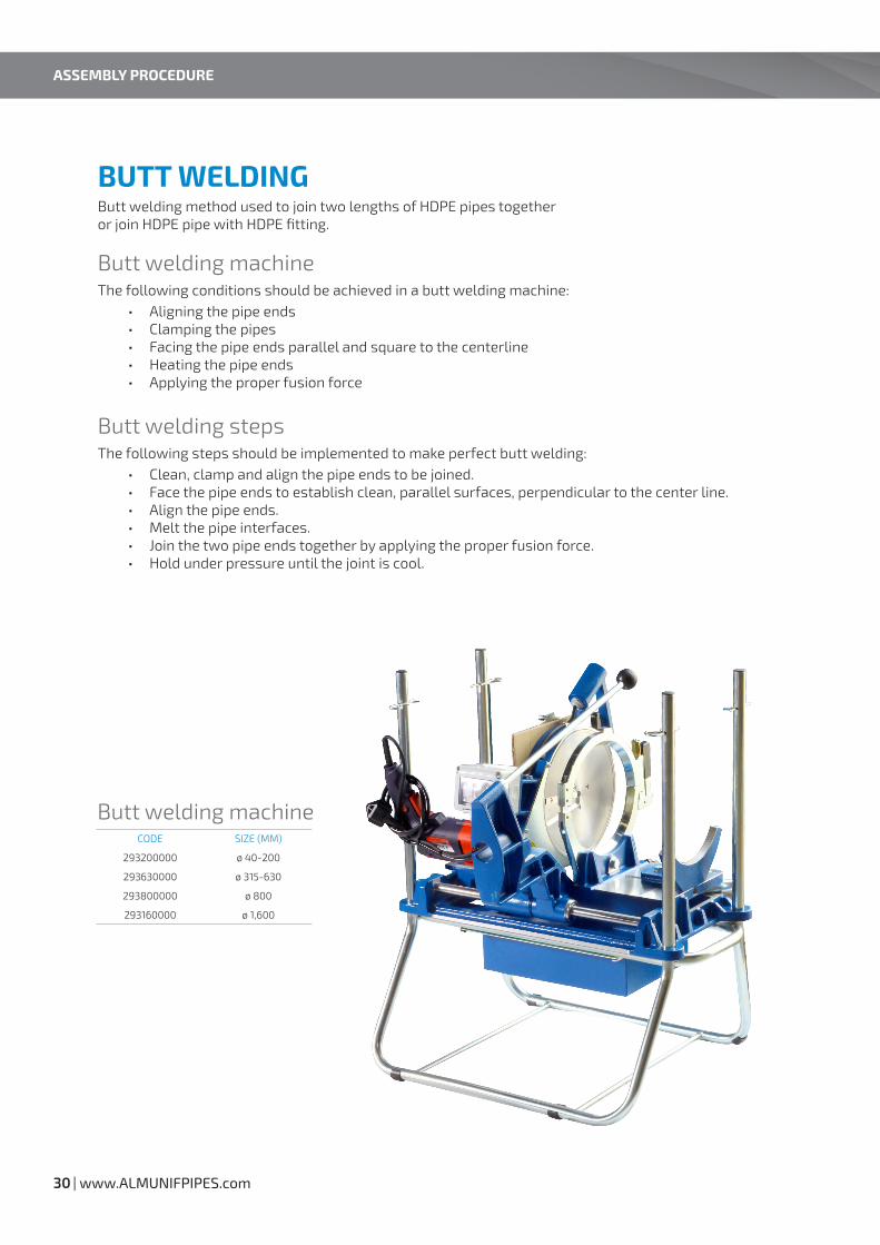
BUTT WELDING
Butt welding machine
Butt welding steps
Butt welding machine
Butt welding method used to join two lengths of HDPE pipes togetheror join HDPE pipe with HDPE fitting.
The following conditions should be achieved in a butt welding machine:
The following steps should be implemented to make perfect butt welding:
Aligning the pipe endsClamping the pipesFacing the pipe ends parallel and square to the centerlineHeating the pipe endsApplying the proper fusion force
Clean, clamp and align the pipe ends to be joined.Face the pipe ends to establish clean, parallel surfaces, perpendicular to the center line.Align the pipe ends.Melt the pipe interfaces.Join the two pipe ends together by applying the proper fusion force.Hold under pressure until the joint is cool.
•••••
••••••
CODE SIZE (MM)
293200000 ø 40-200
293630000 ø 315-630
293800000 ø 800
293160000 ø 1,600
ASSEMBLY PROCEDURE

31MMP |
ELECTRO-FUSION
01 - Prepare the pipes (Scrape, Clean)
02 - Mark the pipes
03 - Apply electric current
04 - Cool joints and remove clamps
05 - Documenting Fusion
Electro-fusion welding machine
Electro-fusion welding used to join two lengths of HDPE pipestogether by using electro-fusion joint from the same material.The electro-fusion joint is heated internally by electric current passes through a coilinside the joint causing fusion.The following steps should be implemented when performing electro-fusion joining:
Be sure that the pipe ends are cut square when joining using electro-fusion couplings.The fusion area must be clean from dirt or contaminants; use 90% isopropyl alcohol.The pipe surface in the fusion must be scraped, about 0.2mm layer from the pipe outer surface, must be removed by using special tools (scraper).
Mark the pipe for stab depth of couplings or the proper fusion location of saddles.(Caution should be taken to assure that a non-petroleum marker is used).Align and restrain pipe and fitting.Place the pipe(s) and fitting in the clamping fixture to prevent movement of the pipe(s) or fitting.Give special attention to proper positioning of the fitting on the prepared pipe surfaces.
Connect the electro-fusion control box to the fitting and to the power source.Apply electric current to the fitting as specified in the manufacturer’s instructions.Read the barcode which is supplied with the electro-fusion fitting.If the control does not do so automatically, turn off the current when the proper time has elapsed to heat the
Allow the joint to cool for the recommended time.If using clamps, premature removal from the clamps and any strain on a joint that has not fully cooled can be detrimental to joint performance.
The Electro-fusion control box that applies current to the fitting also controls and monitors the critical parameters of fusion, (time, temperature, & pressure).The control box is a micro- processor capable of storing the specific fusion data for each joint.This information can be downloaded to a computer for documentation and inspection of the day’s work.
•••
•
•••
••••
••
••••
•
•
•
CODE SIZE (MM)
20258000000 ø 25-800

32 | www.ALMUNIFPIPES.com
INSTALLATION OF PLASTIC PIPES
TRENCH CONSTRUCTION
GeneralExcavate trenches to insure that sides will be stable under all working conditionsExcavated material should be stockpiled in a manner that will not endanger the work.Minimum Trench WidthThe following table shows the relation between Nominal Pipe Size and Minimum Trench Width
•••
Nominal Pipe Size (mm) Minimum Trench Width (mm)
< 90 300
90-630 Pipe OD. + 300
630 - 1600 Pipe OD. + 600
INSTALLATION

33MMP |
Initial Backfill
Final Backfill
Initial backfill is that portion of the pipe embedment beginning at the spring line of extending some distance over the pipe and the top of the pipe.Since little or no additional side support is gained above the spring line, native soils may be used without special compaction efforts.The sole purpose of somewhat careful placement of these native trench materials is to protect the pipe from the dropping of large rocks or other impact loads that may occur during final backfill.Minimum cover is recommended to be 6 inch (150mm).
The material used in the final backfilling operation need not be as carefully selected as was the bedding, haunching, and initial backfill. In the final backfill material, exclude boulders, frozen clumps of dirt, and rubble which could damage the pipe.
•
•
•
•
Preparation of Trench Bottom
Bedding
Haunching
The trench bottom should be constructed to provide a firm, stable, and uniform support for the full length of the pipe.When an unstable sub-grade condition is encountered which will provide inadequate pipe support, additional trench depth should be excavated and refilled with suitable foundation material as specified by the engineer.The ground water level in the trench should be kept below the pipe.
Bedding is required primarily to bring the trench bottom up to grade.Bedding materials should be placed to provide uniform and adequate longitudinal support under the pipe.A compacted depth of 4 to 6 inches (100 to 150 mm) is generally sufficient bedding thickness.Bedding material should be free of ridges, hollows and lumps.The trench bottom should be smooth and free of rock.Bedding should consist of free flowing material such as gravel, sand, salty sand or clayey sand that is free of stones or hard particles larger than 1 ½ inch.
The most important factor affecting pipe performance and deflection is the haunching material and its density.Material should be placed and consolidated under the pipe haunch to provide adequate side support to the pipe while avoiding both vertical and lateral displacement of the pipe from proper alignment.Where coarse materials with voids have been used for bedding, the same coarse material should also be used for haunching and consideration should be given to native soil migration.Haunching is placed up to the pipe spring line.
•
•
•
••
••••
•
•
•
•

34 | www.ALMUNIFPIPES.com
Embedment MaterialsEmbedment material including bedding, hunching and initial backfill material
The following Table shows the maximum particle size for class I and class II materials
Minimum Bend Radius for PE Pipe Installed in Open Cut Trench
•
Nominal Pipe Size (mm) Maximum Particle Size (Inch)
≤ 110 1/2
160 - 225 3/4
250 - 355 1
≥ 400 1 1/2
Cold (Field) Bending
Dimension Ration, DR Minimum Cold Bend Radius
7, 7.3, 9 20 x Pipe OD
11, 13.5 25 x Pipe OD
17, 21 27 x Pipe OD
26 34 x Pipe OD
32.5 42 x Pipe OD
41 52 x Pipe OD
Fitting or flange pesent in bend 100 x Pipe OD
Dimensions in (mm)
INSTALLATION

HDPE BUTT WELDINGFITTINGS
35MMP |
36 | www.ALMUNIFPIPES.com
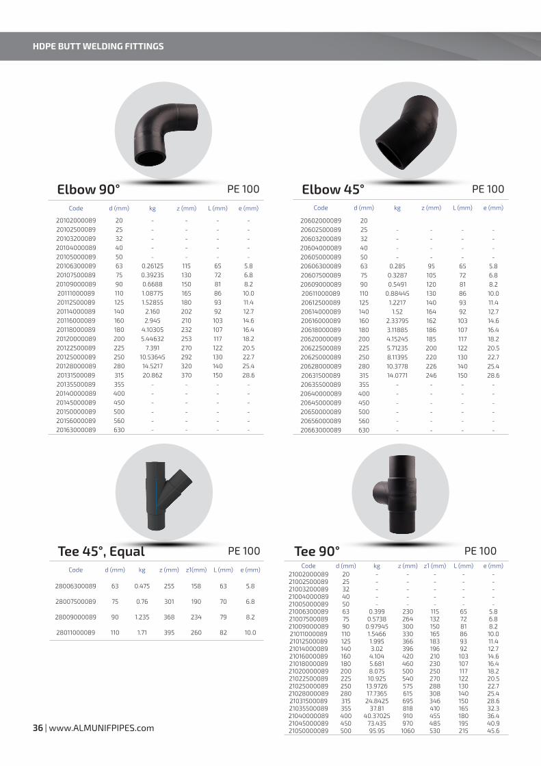
Code d (mm) kg z (mm) L (mm) e (mm)
20102000089 20 - - - -20102500089 25 - - - -20103200089 32 - - - -20104000089 40 - - - -20105000089 50 - - - -20106300089 63 0.26125 115 65 5.820107500089 75 0.39235 130 72 6.820109000089 90 0.6688 150 81 8.220111000089 110 1.08775 165 86 10.020112500089 125 1.52855 180 93 11.420114000089 140 2.160 202 92 12.720116000089 160 2.945 210 103 14.620118000089 180 4.10305 232 107 16.420120000089 200 5.44632 253 117 18.220122500089 225 7.391 270 122 20.520125000089 250 10.53645 292 130 22.720128000089 280 14.5217 320 140 25.420131500089 315 20.862 370 150 28.620135500089 355 - - - -20140000089 400 - - - -20145000089 450 - - - -20150000089 500 - - - -20156000089 560 - - - -20163000089 630 - - - -
Elbow 90° PE 100 Elbow 45° PE 100
Code d (mm) kg z (mm) L (mm) e (mm)
20602000089 2020602500089 25 - - - -20603200089 32 - - - -20604000089 40 - - - -20605000089 50 - - - -20606300089 63 0.285 95 65 5.820607500089 75 0.3287 105 72 6.820609000089 90 0.5491 120 81 8.220611000089 110 0.88445 130 86 10.020612500089 125 1.2217 140 93 11.420614000089 140 1.52 164 92 12.720616000089 160 2.33795 162 103 14.620618000089 180 3.11885 186 107 16.420620000089 200 4.15245 185 117 18.220622500089 225 5.71235 200 122 20.520625000089 250 8.11395 220 130 22.720628000089 280 10.3778 226 140 25.420631500089 315 14.0771 246 150 28.620635500089 355 - - - -20640000089 400 - - - -20645000089 450 - - - -20650000089 500 - - - -20656000089 560 - - - -20663000089 630 - - - -
Tee 45°, Equal PE 100
Code d (mm) kg z (mm) z1(mm) L (mm) e (mm)
28006300089 63 0.475 255 158 63 5.8
28007500089 75 0.76 301 190 70 6.8
28009000089 90 1.235 368 234 79 8.2
28011000089 110 1.71 395 260 82 10.0
Tee 90° PE 100Code d (mm) kg z (mm) z1 (mm) L (mm) e (mm)
21002000089 20 - - - - -21002500089 25 - - - - -21003200089 32 - - - - -21004000089 40 - - - - -21005000089 50 - - - - -21006300089 63 0.399 230 115 65 5.821007500089 75 0.5738 264 132 72 6.821009000089 90 0.97945 300 150 81 8.221011000089 110 1.5466 330 165 86 10.021012500089 125 1.995 366 183 93 11.421014000089 140 3.02 396 196 92 12.721016000089 160 4.104 420 210 103 14.621018000089 180 5.681 460 230 107 16.421020000089 200 8.075 500 250 117 18.221022500089 225 10.925 540 270 122 20.521025000089 250 13.9726 575 288 130 22.721028000089 280 17.7365 615 308 140 25.421031500089 315 24.8425 695 346 150 28.621035500089 355 37.81 818 410 165 32.321040000089 400 40.37025 910 455 180 36.421045000089 450 73.435 970 485 195 40.921050000089 500 95.95 1060 530 215 45.6
HDPE BUTT WELDING FITTINGS

37MMP |
Tee Reducer 90° PE 100Code d x d (mm) kg z (mm) z1 (mm) L (mm) L1 (mm) e (mm) e1 (mm)
21005002089 50x20 - - - - - - -21005002589 50x25 - - - - - - -21005003289 50x32 - - - - - - -21005004089 50x40 - - - - - - -21006303289 *63 x 32 0.3591 230 145 65 53 5.8 3.021006304089 *63 x 40 0.6811 230 145 65 57 5.8 3.721006305089 63 x 50 0.2811 215 103 63 56 5.8 4.621007503289 75 x 32 0.4711 256 108 70 46 6.9 3.021007504089 75 x 40 0.7361 264 180 72 57 6.8 3.721007505089 75 x 50 0.5111 253 108 70 56 6.9 4.621007506389 75 x 63 0.5411 255 117 70 63 6.9 5.821009005089 90 x 50 0.8011 280 117 79 55 8.2 4.621009006389 90 x 63 0.7561 269 136 79 64 8.2 5.821009007589 90 x 75 0.7741 272 138 73 70 8.2 6.921011006389 110 x 63 1.2481 309 156 84 65 10.0 5.821011007589 110 x 75 1.2251 309 151 82 70 10.0 6.921011009089 110 x 90 1.2561 321 162 85 79 10.0 8.221012506389 125 x 63 2.8311 366 225 92 61 11.4 5.821012507589 *125 x 75 2.3701 366 225 92 72 11.4 6.921012509089 125 x 90 1.7031 335 170 90 83 11.4 8.221012511089 125 x 110 1.8411 341 170 88 82 11.4 10.021014007589 140 x 75 4.0311 396 230 92 70 12.7 6.821014009089 140 x 90 4.0761 396 235 92 79 12.7 8.221014011089 140 x 110 3.5811 396 240 92 82 12.7 10.021014012589 140 x 125 4.1511 396 240 92 90 12.7 11.421016006389 160 x 63 2.6611 340 176 98 65 14.6 5.821016007589 160 x 75 2.8071 340 180 98 74 14.6 6.921016009089 160 x 90 3.7561 410 180 98 79 14.6 8.221016011089 160 x 110 3.2811 420 265 98 82 14.6 10.021016012589 *160 x 125 4.4461 420 265 102 92 14.6 11.421016014089 160 x 140 5.8761 420 270 102 96 14.6 12.721018009089 180 x 90 4.0811 420 202 136 98 16.4 8.221018011089 180 x 110 4.3601 - - - - 16.4 10.021018012589 *180 x 125 6.4611 460 285 107 92 16.4 11.421018014089 180 x 140 9.0511 460 295 107 110 16.4 12.721018016089 180 x 160 4.3601 4.3601 411 205 102 94 16.4 14.621020006389 200 x 63 7.2811 500 190 122 63 18.2 5.821020009089 200 x 90 9.7111 503 215 120 81 18.2 8.221020011089 200 x 110 9.7111 503 218 120 84 18.2 10.021020012589 *200 x 125 8.1311 500 295 117 92 18.2 11.421020014089 200 x 140 10.5511 500 310 117 110 18.2 12.721020016089 200 x 160 9.7111 503 236 120 101 18.2 14.621020018089 200 x 180 10.8811 441 310 117 110 18.2 16.421022507589 225 x 75 6.4811 441 227 119 75 20.5 6.921022509089 225 x 90 9.7111 441 225 119 79 20.5 8.221022511089 225 x 110 9.7611 540 237 118 83 20.5 10.021022514089 *225 x 125 10.8811 540 320 122 92 20.5 11.421022514089 225 x 140 14.5551 540 335 122 110 20.5 12.721022516089 225 x 160 10.2011 543 320 120 106 20.5 14.621022518089 225 x 180 9.3561 540 277 132 132 20.5 16.421022520089 225 x 200 14.9061 586 340 122 117 20.5 18.221025011089 250 x 110 9.7111 586 245 132 85 22.7 10.021025016089 250 x 160 9.7111 576 264 132 101 22.7 14.621025018089 250 x 180 18.8711 576 350 130 105 22.7 16.421025020089 250 x 200 18.259 576 360 130 112 22.7 18.221025022589 250 x 225 18.7055 576 390 130 120 22.7 20.521028020089 280 x 200 23.294 616 410 139 112 25.4 18.221028022589 280 x 225 23.51725 616 420 139 120 25.4 20.521028025089 280 x 250 23.9495 616 420 139 130 25.4 22.721031511089 315 x 110 14.535 695 277 150 82 28.6 10.021031516089 315 x 160 15.77 695 296 150 102 28.6 14.621031520089 315 x 200 32.2525 690 470 150 134 28.6 18.221031522589 315 x 225 19.475 650 335 170 145 28.6 20.521031525089 315 x 250 20.9 695 325 150 130 28.6 22.721031528089 315 x 280 33.2025 690 480 150 139 28.6 25.421035525089 355 x 250 46.455 818 165 130 139 32.3 25.721035528089 355 x 280 46.835 818 480 165 139 32.3 25.421035531589 355 x 315 47.2055 818 480 165 150 32.3 28.6

38 | www.ALMUNIFPIPES.com
Tee Reducer 90° PE 100
Code d x d (mm) kg z (mm) L (mm) L1 (mm) e (mm) e1 (mm)
24003202589 32x25 - - - - - -24004003289 40x32 - - - - - -24005002589 50x25 - - - - - -24005003289 50x32 - - - - - -24005004089 50x40 - - - - - -24006303289 63 x 32 0.10355 150 65 53 5,8 3,024006304089 63 x 40 0.1235 150 65 57 5,8 3,724006305089 63 x 50 0.1235 150 65 63 5,8 4,624007504089 75 x 40 0.1691 170 72 57 6,8 3,724007505089 75 x 50 0.18145 170 72 63 6,8 4,624007506389 75 x 63 0.1197 170 72 65 6,8 5,824009005089 90 x 50 0.27645 190 81 63 8,2 4,624009006389 90 x 63 0.30115 190 81 65 8,2 5,824009007589 90 x 75 0.33725 190 81 70 8,2 6.824011006389 110 x 63 0.44555 205 86 65 10.0 5.824011007589 110 x 75 0.47215 205 86 70 10.0 6.824011009089 110 x 90 0.52915 205 86 81 10.0 8.224012506389 125 x 63 0.55005 200 87 63 11.4 5.824012507589 125 x 75 0.627 215 92 72 11.4 6.824012509089 125 x 90 0.69825 215 92 81 11.4 8.224012511089 125 x 110 0.77805 215 92 86 11.4 10.024014007589 140 x 75 0.532 230 110 70 12.7 6.824014009089 140 x 90 0.6555 230 110 79 12.7 8.224014011089 140 x 110 0.779 230 110 82 12.7 10.024014012589 140 x 125 0.9386 235 110 90 12.7 11.424016009089 160 x 90 1.007 248 120 79 14.6 8.224016011089 160 x 110 1.2331 245 102 86 14.6 10.024016012589 160 x 125 1.33285 245 102 92 14.6 11.424016014089 160 x 140 1.2825 260 120 110 14.6 12.724018009089 180 x 90 1.4535 245 105 79 16.4 8.224018012589 180 x 125 1.634 255 107 92 16.4 11.424018011089 180 x 110 1.634 270 105 82 16.4 10.024018014089 180 x 140 1.881 270 120 110 116.4 12.724018016089 180 x 160 1.881 255 107 102 16.4 14.624020014089 200 x 140 2.1945 275 120 110 18.2 12.724020016089 200 x 160 2.2515 265 117 102 18.2 14.624020018089 200 x 180 2.54695 265 117 107 18.2 16.424022514089 225 x 140 2.755 295 130 110 20.5 12.724022516089 225 x 160 2.9621 280 122 102 20.5 14.624022518089 225 x 180 3.11315 280 122 107 20.5 16.424022520089 225 x 200 3.3611 280 122 117 20.5 18.224025016089 250 x 160 2.26575 290 130 100 22.7 14.624025018089 250 x 180 3.8475 295 130 105 22.7 16.424025020089 250 x 200 2.26575 302 130 112 22.7 18.224025022589 250 x 225 2.26575 332 130 120 22.7 20.524028020089 280 x 200 6.5075 333 140 112 25.4 18.224028022589 280 x 225 5.7855 335 140 120 25.4 20.524028025089 280 x 250 2.26575 340 140 130 25.4 22.724031520089 315 x 200 2.26575 380 180 134 28.6 18.224031522589 315 x 225 7.4005 365 150 120 28.6 20.524031525089 315 x 250 2.26575 365 150 130 28.6 22.724031528089 315 x 280 8.36 365 150 139 28.6 25.424035525089 355 x 250 8.645 390 165 130 32.3 22.724035528089 355 x 280 9.025 390 165 139 32.3 25.424035531589 355 x 315 9.405 390 165 150 32.3 28.6
24040028089 400 x 280 9.899 415 180 139 36.4 25.424040031589 400 x 315 10.5735 415 180 150 36.4 28.624040035589 400 x 355 11.02 420 180 165 36.4 32.324045028089 450 x 280 15.39 389 195 139 40.9 25.424045031589 450 x 315 15.865 390 195 150 40.9 28.624045035589 450 x 355 16.625 393 195 164 40.9 32.324045040089 450 x 400 17.575 395 195 179 40.9 36.424050031589 500 x 315 20.805 422 212 150 45.5 28.624050035589 500 x 355 21.47 424 212 164 45.5 32.324050040089 500 x 400 22.42 426 212 179 45.5 36.424050045089 500 x 450 23.845 428 212 195 45.5 40.924056035589 560 x 355 28.595 459 230 164 50.9 32.324056040089 560 x 400 29.45 461 230 179 50.9 36.424056045089 560 x 450 30.78 463 230 195 50.9 40.924056050089 560 x 500 32.395 466 230 212 50.9 45.524063040089 630 x 400 39.805 502 250 179 57.3 36.424063045089 630 x 450 40.945 503 250 195 57.3 40.924063050089 630 x 500 42.465 506 250 212 57.3 45.524063056089 630 x 560 44.46 506 250 230 57.3 50.9
HDPE BUTT WELDING FITTINGS

39MMP |
PE 100 Backing Flange PP-V for Butt Fusion Systems Metric
Code d (mm) kg inch DN (mm) PN
29106300089 63 0.361 - 65 16
29107500089 75 0.456 - 72 16
29109000089 90 0.494 - 81 16
29111000089 110 0.646 - 86 16
29112500089 125 0.722 - 93 16
29114000089 140 0.76 - 92 16
29116000089 160 1.14 6 103 16
29118000089 180 1.14 - 107 16
29120000089 200 1.33 8 117 16
29122500089 225 1.33 9 122 16
29125000089 250 1.615 - 130 16
29128000089 280 1.615 - 140 16
29131500089 315 2.28 - 150 16
End CapCode d (mm) kg z (mm) e (mm)
23002000089 20 0.00855 52 3.0
23002500089 25 0.01235 52 3.0
23003200089 32 0.01615 54 3.0
23004000089 40 0.02945 57 3.7
23005000089 50 0.0475 57 3.7
23006300089 63 0.08075 65 5.8
23007500089 75 0.13775 80 6.8
23009000089 90 0.228 90 8.2
23011000089 110 0.36765 98 10.0
23012500089 125 0.5187 105 11.4
23014000089 140 0.79325 136 12.7
23016000089 160 0.9747 192 14.6
23018000089 180 1.30055 120 16.4
23020000089 200 1.74705 60 18.2
23022500089 225 2.375 60 20.5
23025000089 250 3.73065 32 22.7
23028000089 280 5.0768 16 25.4
23031500089 315 6.8172 16 28.6
Flange Adaptor LS, PE 100 Combined Jointing Face: Flat and SerratedCode DN (mm) d (mm) kg d1 (mm) d2 (mm) d3 (mm) d4 (mm) L (mm) L1 (mm) L2 (mm) e (mm)
23504000089 40 - - - - - - - - - -
29006300089 50 63 0.1653 75 102 - 51 98 69 14 5.8
29007500089 65 *75 0.285 89 122 66 61 125 89 16 6.8
29009000089 80 *90 0.418 105 138 78 73 140 103 17 8.2
29011000089 100 *110 0.65075 125 158 100 90 160 117 18 10.0
29012500089 100 *125 0.7942 132 158 114 102 170 125 25 11.4
29014000089 125 *140 1.23025 155 188 127 114 200 147 25 12.7
29016000089 150 *160 1.5618 175 212 158 130 200 147 25 14.6
29018000089 150 *180 1.77935 180 212 158 147 200 170 30 16.4
29020000089 200 *200 2.6201 232 268 203 163 200 128 32 18.2
29022500089 200 *225 2.8234 235 268 210 184 200 138 32 20.5
29025000089 250 *250 4.30825 285 320 245 204 219 138 35 22.7
29028000089 250 *280 4.67875 291 320 265 229 231 144 35 25.4
29031500089 300 *315 6.07335 335 370 300 257 239 158 35 28.6
23540000089 - *400 - - - - - - - - -
23563000089 - *630 - - - - - - - - -

40 | www.ALMUNIFPIPES.com
Segmented Reduced Tee 90°Code DE H (mm) z (mm)
21616000089 160 150 460
21618000089 180 200 580
21620000089 200 200 600
21622500089 225 200 625
21625000089 250 200 650
21628000089 280 200 680
21631500089 315 300 915
21635500089 355 300 955
21640000089 400 300 1000
21650000089 500 300 1100
21656000089 560 350 1260
21663000089 630 350 1330
21671000089 710 400 1510
21680000089 800 400 1600
21690000089 900 400 1700
21610000089 1000 400 1800
Segmented Tee 45°Code DE H (mm) z (mm)
21911000089 110 400 535
21912500089 125 400 520
21914000089 140 400 553
21916000089 160 400 613
21918000089 180 400 675
21920000089 200 400 683
21922500089 225 450 743
21925000089 250 550 853
21928000089 280 550 865
21931500089 315 600 1030
21935500089 355 600 1047
21940000089 400 800 1265
21945000089 450 800 1065
21950000089 500 1000 1487
21956000089 560 1000 1582
21963000089 630 1200 1810
Segmented CrossCode DE H (mm) z (mm)
21211000089 110 92 338
21212500089 125 90 355
21214000089 140 96 390
21216000089 160 104 427
21218000089 180 107 450
21220000089 200 115 500
21222500089 225 120 540
21225000089 250 132 610
21228000089 280 140 680
21231500089 315 152 707
21235500089 355 230 1000
21240000089 400 230 960
21245000089 450 230 1040
21250000089 500 230 1060
21256000089 560 350 1260
21263000089 630 350 1330
Segmented Bend 90°Code DE H (mm) z (mm)
20211000089 110 - -
20212500089 125 - -
20214000089 140 - -
20216000089 160 150 427
20218000089 180 200 473
20220000089 200 200 467
20222500089 225 200 490
20225000089 250 200 507
20228000089 280 200 545
20231500089 315 300 688
20235500089 355 300 737
20240000089 400 300 790
20245000089 450 300 1139
20250000089 500 300 1164
20256000089 560 350 1258
20263000089 630 350 1293
20271000089 710 400 1397
20280000089 800 400 1442
20290000089 900 400 1505
20210000089 1000 400 1555
HDPE BUTT WELDING FITTINGS

41MMP |
Segmented Bend 60°Code DE H (mm) z (mm)
20311000089 110 - -
20312500089 125 - -
20314000089 140 - -
20316000089 160 150 279
20318000089 180 200 279
20320000089 200 200 328
20322500089 225 200 339
20325000089 250 200 345
20328000089 280 200 355
20331500089 315 300 478
20335500089 355 300 477
20340000089 400 300 511
20345000089 450 300 689
20350000089 500 300 704
20356000089 560 350 777
20363000089 630 350 797
20371000089 710 400 876
20380000089 800 400 902
20390000089 900 400 937
20310000089 1000 400 965
Segmented Bend 45°Code DE H (mm) z (mm)
20706300089 63 -20707500089 75 - -20709000089 90 - -20711000089 110 - -20712500089 125 - -20714000089 140 - -20716000089 160 150 27320718000089 180 200 32320720000089 200 200 32220722500089 225 200 33320725000089 250 200 33820728000089 280 200 34920731500089 315 300 47020735500089 355 300 47020740000089 400 300 50220745000089 450 300 63620750000089 500 300 64720756000089 560 350 71520763000089 630 350 72920771000089 710 400 80120780000089 800 400 82020790000089 900 400 84620710000089 1000 400 866
Segmented Bend 30°Code DE H (mm) z (mm)
20806300089 63 -20807500089 75 - -20809000089 90 - -20811000089 110 - -20812500089 125 - -20814000089 140 - -20816000089 160 150 17120818000089 180 200 22420820000089 200 200 22620822500089 225 200 23020825000089 250 200 23320828000089 280 200 23720831500089 315 300 324220835500089 355 300 34720840000089 400 300 35320845000089 450 300 36020850000089 500 300 36720856000089 560 350 42520863000089 630 350 43420871000089 710 400 49520880000089 800 400 50720890000089 900 400 52020810000089 1000 400 534

HDPEELECTRO-FUSIONFITTINGS
42 | www.ALMUNIFPIPES.com

43MMP |
HDPEELECTRO-FUSIONFITTINGS
Elbow 90°Code Size (mm)
20102000091 20
20102500091 25
20103200091 32
20104000091 40
20105000091 50
20106300091 63
20107500091 75
20109000091 90
20111000091 110
20112500091 125
20116000091 160
20118000091 180
20120000091 200
20122500091 225
20125000091 250
20131500091 315
Elbow 45°Code Size (mm)
20602000091 20
20602500091 25
20603200091 32
20604000091 40
20605000091 50
20606300091 63
20607500091 75
20609000091 90
20611000091 110
20612500091 125
20616000091 160
20618000091 180
20620000091 200
20622500091 225
20625000091 250
20631500091 315
Tee 90°Code Size (mm)
21002000091 20
21002500091 25
21003200091 32
21004000091 40
21005000091 50
21006300091 63
21007500091 75
21009000091 90
21011000091 110
21012500091 125
21016000091 160
21018000091 180
21020000091 200
21022500091 225
21025000091 250
21031500091 315
HDPE ELECTRO-FUSION FITTINGS

44| www.ALMUNIFPIPES.com
Tee Reducer 90°Code Size (mm)
21003202591 32x25
21005003291 50x32
21006303291 63x32
21006305091 63x50
21016011091 160x110
21018012591 180x125
Code Size (mm)
21502000091 2021502500091 2521503200091 3221504000091 4021505000091 5021506300091 6321507500091 7521509000091 9021511000091 11021512500091 12521514000091 14021516000091 16021518000091 18021520000091 20021522500091 22521525000091 25021528000091 28021531500091 31521535500091 35521540000091 40021545000091 45021550000091 50021556000091 56021563000091 630
CouplerReducerCode Size (mm)
24002502091 25x2024003202091 32x2024003202591 32x2524004002091 40x2024004002591 40x2524004003291 40x3224005002591 50x2524005003291 50x3224005004091 50x4024006303291 63x3224006304091 63x4024006305091 63x5024007505091 75x5024007506391 75x6324009005091 90x5024009006391 90x6324011006391 110x6324011009091 110x9024012502591 125x2524012509091 125x9024012511091 125x110
24016009091 160x9024016011091 160x11024016012591 160x12524022516091 225x160
HDPE ELECTRO-FUSION FITTINGS

45MMP |
Male AdaptorCode Size (mm)
25503200991 32x3/4"
25503201291 32x1"
25503210091 32x1"
25505001891 50x11/2"
25506302491 63x2"
Female AdaptorCode Size (mm)
25003201291 32x1"
25005001891 50x11/2"
CapCode Size (mm)
219033000 3323002000091 2023002500091 2523003200091 3223004000091 4023005000091 5023006300091 6323007500091 7523009000091 9023011000091 11023012500091 12523014000091 14023016000091 16023018000091 18023020000091 20023022500091 22523025000091 25023028000091 28023031500091 315

MMP HDPE TELECOMMUNICATION PIPE
HDPETELECOMMUNICATION DUCT
HDPE duct solutions for cable management (electrical & telecommunication). A range of ducting products which are available in a variety of materials, diameters and wall construction to offer a ‘fit for purpose’ product for several ducting applications.
Suitable for domestic, commercial and industrial (electrical & telecommunications) installations
Benifits
Applications
Coloured for easy identificationWeather durableFlexible & StrongEasy to installStandards ApprovedProducts can be manufactured to customers specifications
46 | www.ALMUNIFPIPES.com

47MMP |
MaterialMaterial DesignationLength
HDPE345440 C/EDifferent lengths can be supplied on request.
:::
STC HDPE TELECOMMUNICATION DUCT
HDPE TELECOMMUNICATION DUCT
Nominal Outside Diameter (mm)
Minimum Wall Thickness (mm)
ID(mm) SDR Color Lenght (Mtr)
110 5 100 22 Black with 4 - orange strips 100
50 3 44 17 Black with 4 - orange strips 300 & 500
32 1.9 28.2 17 Black with 4 - orange strips 300 & 500
32 1.9 28.2 17 Full Black 300 & 500
32 1.9 28.2 17 Full orange 300 & 500
20 1.8 16.4 10 Black with 4 - orange strips 600 & 1200
20 1.8 16.4 10 Full Black 600 & 1200

48 | www.ALMUNIFPIPES.com
MaterialMaterial DesignationLength
HDPE345440 C/EDifferent lengths can be supplied on request.
:::
SEC HDPE ELECTRICAL DUCT
HDPE TELECOMMUNICATION DUCT
Nominal Outside Diameter (mm)
Minimum Wall Thickness (mm)
ID(mm) SDR Color Lenght (Mtr)
50 3 44 17 Black with 4 - green strips 300 & 500

49MMP |
MaterialMaterial DesignationLength
HDPE345440 C/EDifferent lengths can be supplied on request.
:::
MOBILY / ITC HDPE TELECOMMUNICATION DUCT
HDPE TELECOMMUNICATION DUCT
Nominal Outside Diameter (mm)
Minimum Wall Thickness (mm)
ID(mm) SDR Color Lenght (Mtr)
50 4.6 40.8 11 Blue 300 & 500
50 4.6 40.8 11 Orange 300 & 500
50 4.6 40.8 11 Black 300 & 500
20 1.9 16.2 11 Blue 600 & 1200
20 1.9 16.2 11 Orange 600 & 1200
20 1.9 16.2 11 Black 600 & 1200

External Orange Black Black Others
Internal Yellow Blue Green Others
Color:
Nominal Outside Diameter (mm)
ID(mm)
Lenght (Mtr)
110 92 500
50 | www.ALMUNIFPIPES.com
HDPEDOUBLE WALLCORRUGATED DUCT
TECHNICAL FEATURES
Construction
Use
Minimum Bending Radius
Packaging
Accessories
Corrugated externally and smooth internally.
8 times the external diameter
Coil of 500 meters with closing cap at both ends of the coil.
Jointing coupling already fitted on each coil/bar seals upon requestInstallation In underground trench
Underground protection for telephone and low voltage cables.
Combination of corrugated exterior and a smooth interior for excellent stiffness in a high-density polyethylene (HDPE Double Wall) duct can be used in a variety electrical and telecommunication applications.

51MMP |
MaterialLength
HDPEDifferent lengths can be supplied on request.
::
Type Nominal Outside Diameter (mm)
Minimum Wall Thickness (mm)
ID (mm)
Color Lenght (Mtr)
type 1main duct 110mm 2.5 90 Bright Orange
300 & 5005 sub-duct 33mm 2.5 28
4 sub-duct bright orange & 1 sub-duct full black
type 2main duct 110mm 2.5 90 Bright Orange
300 & 5003 sub-duct 42mm 2.8 36 Bright Orange
type 3 empty main duct 110mm 2.5 90 Bright Orange 300 & 500
Ø 110 mm Empty main duct Ø 110 mm with 33mm x 5 sub-duct Ø 110 mm with 42mm x 3 sub-duct
Railways
PWDs (Protected Wireline Distribution System)
Telecommunication Companies
State Electricity Board
Airport Authorities
Power Distribution Companies
DEMANDED BY
51MMP |
HDPE TELECOMMUNICATION CORRUGATED DUCT
HDPE TELECOMMUNICATION DUCT


August 30, 2018