
PN-/;(lee-()1JL - USAID
43
I I I I I I I I I I I I I I I· I I I I I I PN-/ ;(lee -()1JL 14133 Environmental Policy and Technology Project Contract No. CCN-003-Q-OO-3165 Operation and Maintenance Manual Kosaman and BerdykoI Wellfieids September 1996 Prepared by: Central Asian Regional EPT Office in Almaty, Kazakstan Environmental Policy and Technology Project /1 For the New Independent States of the former Soviet Union N A USAID Project Consortium Led by CH2M Hill
-
Upload
khangminh22 -
Category
Documents
-
view
3 -
download
0
Transcript of PN-/;(lee-()1JL - USAID

IIIIIIIIIIIIIII·IIIIII
PN-/;(lee -()1JL14133
Environmental Policyand Technology Project
Contract No. CCN-003-Q-OO-3165
Operation and Maintenance ManualKosaman and BerdykoI Wellfieids
September 1996
Prepared by:Central Asian Regional EPT Office in Almaty, Kazakstan
Environmental Policy and Technology Project /1For the New Independent States of the former Soviet Union N
A USAID Project Consortium Led by CH2M Hill

IIIIIIIIIIIIIIIIIIIII
Table of Contents
SECTION 1 Wellfield Equipment ........•••...••.•.•..•••.••....•...•.
1.1 Pumping .
1.2 Electric Motor .
1.3 Submersible Pump .
1.4 Sand Separator .
1.5 Electric/Safety Cable .
1.6 Control Panel .
SECTION 2 Wellfield Operation ............................•.........
2.1 Well Drawdown .
2.2 Pump Idle Time , .
SECTION 3 Equipment MaintenancelRemovallInstallation .
3.1 Maintenance .
3.2 PumplMotor Removal Instructions .
3.3 Pump Installation Instructions .
SECTION 4 Manufacturers Information ..•..................•..........
4.1 J-Line Pump Drawing .
4.2 Owner's Manual .
4.3 Installation and Operation Instructions .
4.4 Submersible Turbine Pump Specifications .
4.5 Turbine Pump Performance Curves .
4.6 Heat Shrink Kits .
4.7 Lakos Pump Protection Separator .
4.8 Weld-On Saddle Flowmeter .
4.9 McCrometer Flowmeter Installation ~ .
4.10 Acid Redevelopment Procedures .
1-4
1
1
1-2
2
..,oJ
3-4
5
5
5
6-8
6
6-7
7-8
9
10
11-14
15-26
27-29
30-32
33
34-37
38-39
40
41

IIIIIIIIIIIIIIIIIIIII
SECTION 1Wellfield Equipment
1.1 PUMPING
This section describes pumping equipment installed at Kosaman and Berdykol wellfields in1995 and 1996. The submersible pumping systems are composed of the following:
• Electric Motor• Submersible Pump• Sand Separator (15 systems)• Electric/Safety Cable
• Control Panel• Flowmeter
1.2 ELECTRIC MOTOR
Three sizes of electric motors were purchased for the well field rehabilitation project: 10, 25,and 50 horsepower. All the motors are designed to run at 2900 revolutions per minute (rpm)on a 380 Volt, 50 Hertz, 3 phase power supply. Table I summarizes the number and type ofelectric motors purchased for the wellfield rehabilitation project.
Table I. Electric Motors
Horsepower (HP) Kilowatts (kW) Number Purchased
10 7.5 5
25 18.6 23
50 37.3 4*
*3 in 1995, 1 in 1996
There are four motor leads for the electrical connection, one for each of the three phases andone ground wire. The ground wire is not connected to the surface ground but is grounded tothe earth via groundwater.
1.3 SUBMERSIBLE PUMP
Four sizes of submersible turbine pumps were purchased for the Wellfield RehabilitationProject: 9.5, 18.9,22 and 31.1 Lis. The flow rates produced once the pumps are installedvary and depend on the total dynamic head (THD) exerted on the pump. The closer the actualflow rates are to the design flow rate, the greater is the efficiency of the pump, which resultsin lower energy costs.

·1IIIIIIIIIIIIIIIIIIII
Table 2 summarizes the number and type ofpumps purchased, the optimum TDH, and theoperational range of the pumps. Section 4.0 contains performance curves and othermanufacturer specifications for the submersible turbine pumps.
Table 2. Submersible Turbine Pumps
Optimum Optimum Operational TDH Operational Flow NumberFlow TDH Range Range Purchased(Lis) (meters) (meters) (Lis)
9.5 44 34-49 6-10.3 5
18.9 110 84-137 11-24 3*
22 60 42-69 14-26 23
31.5 62 51-67 30-44 1
*Purchased in 1995
The flow rate of the pump should fall within the operational flow range of the pump formaximum efficiency. The TDH of the submersible pumps purchased in 1995 are higher thanthose purchased for the 1996 rehabilitation program.
1.4 SAND SEPARATOR
Sand separators are designed to remove sand through centrifugal action from groundwaterbefore it reaches the pump intake. This significantly extends the life of the pump by reducingabrasion from sand. Removed sand is discharged to the bottom of the well. The well does notfill up with sand because sand stops entering the well after a period oftime (see Section 4.0for more details on this). A total of 15 sand separators of two types were purchased. Type Gis for flow rates greater than 325 gpm (21 Lis) and type F is for flow rates less than 325 gpm(21 Lis). Table 3 summarizes the number of each type purchased, the acceptable flow range,and the outer diameter of each. Section 4.0 contains manufacturers specifications and otherdetails.
Table 3. Sand Separators
Type Flow Range Outside Diameter Number Purchased(lis) (mm)
F 9.5-21 168.4 5
G 21-41 219.2 10
The sand separators are attached to a pump enclosure shell. Since the pump and motor areinstalled inside the shell, it is of larger diameter than the separators. The shell serves twopurposes: to prevent sand laden water from entering the pump and to allow a sufficientamount of cooling water to pass by the motor.
2

IIIIIIIIIIIIIIIIIIIII
1.5 ELECTRIC/SAFETY CABLE
Since there is a variety of motor sizes, there is a variety ofelectric cable sizes. Despitedifferences in size or gauge, all the cables are made of three strands ofcopper wires enclosedin a flat rubber insulating shell and are specifically designed for submersible pumpapplications. Table 4 lists the US standard size of copper wire used for each type of motorand the minimum diameter of the wire in millimeters.
Table 4. Electric Cable
Motor Size Minimum Diameter, Gauge of CableHP (kW) Copper Wire (US AWG Standard)
(mm)
10 (7.5) 2.6 10
25 (18.6) 3.3 8
50 (37.3) 5.2 4
If the copper wire needs to be replaced by aluminum wire, please account for differences inconductivity of copper and aluminum. It is critical that the proper splice equipment be usedto connect the cable and the motor leads. Splicing should be done by experienced personnelwith the proper equipment. Each pumping system installed during the full-scale wellfieldrehabilitation project has a steel safety cable attaching the pump or sand separator to thewellhead at the surface. Do not remove or unattach the safety cable from the wellhead. Thiscable will prevent the pump from falling to the bottom of the well in the vent there is a failurein the riser pipe assembly.
1. 6 CONTROL PANEL
The control panels contain many devices designed to protect the pumping systems fromdamage. The power monitor protects the motor from overvoltage, undervoltage, phase loss,phase reversal, and phase unbalance. The frequency monitor protects the motor fromfrequencies above and below acceptable limits. A lightning arrestor, which is mounted on theoutside of the panel, protects the motor from being damaged by voltage surges caused bylightning. The motor starter contains overload protection that will shut off the motor if theamperes exceeds a set limit. The pump is protected by water level shutoff switches that aretriggered by the water level dropping below or rising above predetermined level.
3
IIIIIIIIIIIIIIIIIIIII
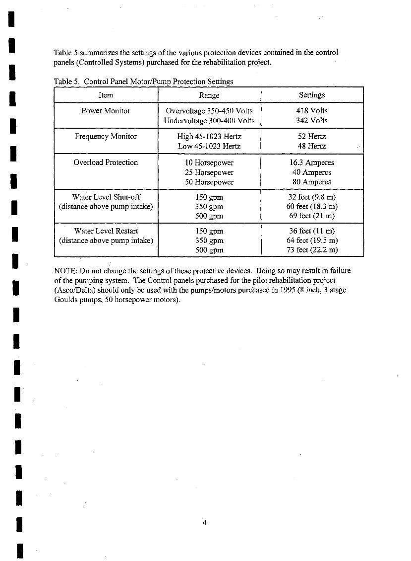
Table 5 summarizes the settings of the various protection devices contained in the controlpanels (Controlled Systems) purchased for the rehabilitation project.
Table 5. Control Panel Motor/Pump Protection Settings
Item Range Settings
Power Monitor Overvoltage 350-450 Volts 418 VoltsUndervoltage 300-400 Volts 342 Volts
Frequency Monitor High 45-1023 Hertz 52 HertzLow 45-1023 Hertz 48 Hertz
Overload Protection 10 Horsepower 16.3 Amperes25 Horsepower 40 Amperes50 Horsepower 80 Amperes
Water Level Shut-off 150 gpm 32 feet (9.8 m)(distance above pump intake) 350 gpm 60 feet (18.3 m)
500 gpm 69 feet (21 m)
Water Level Restart 150 gpm 36 feet (11 m) .(distance above pump intake) 350 gpm 64 feet (19.5 m)
500 gpm 73 feet (22.2 m)
NOTE: Do not change the settings of these protective devices. Doing so may result in failureof the pumping system. The Control panels purchased for the pilot rehabilitation project(Asco/Delta) should only be used with the pumps/motors purchased in 1995 (8 inch, 3 stageGoulds pumps, 50 horsepower motors).
4

IIIIIIIIIIIIIIIIIIIII
SECTION 2Wellfield Operation
This section describes how the Kosaman and Berdykol wellfields should be operated. Thetwo main factors that must be considered are well drawdown and pump idle time.
2.1 WELL DRA WDOWN
The most efficient way to operate the wellfield is to meet the demand with the smallestpossible drawdown in the operating wells. Minimizing the drawdown means less energy isrequired to lift the water to the surface. To minimize drawdowns, pumping wells should bespaced as far apart as practically possible. For example, if ten wells are needed at Kosaman,every third well should be pumped rather than pumping ten neighboring wells. In the centralportion of the Kosaman wellfield there are three wells (Wells No. 19,22,23) with relativelyhigh drawdowns. As a result, special attention must be paid as to what wells can be pumped.To prevent automatic shutdowns due to excessive drawdown, follow these guidelines:
• Do not pump Wells No. 22 and 23 at the same time• Do not pump Wells No. 18 and 21 when Well No. 19 is pumping
2.2 PUMP IDLET/ME
Pumps are designed for continuous operation. Damage to a pump and motor may occur if itis allowed to remain inactive for a long period of time. Well efficiency can also be adverselyaffected by long periods of inactivity. Therefore, it is important to operate every pump on amonthly basis so that no pump remains inactive for longer than 30 days.
5

IIIIIIIIIIIIIIIIIIIII
SECTION 3Equipment Maintenance/Removal/Installation
This section describes equipment maintenance procedures and instructions for the removaland installation of submersible pumping systems.
3.1 MAINTENANCE
Submersible pumping systems require little maintenance other than operating themperiodically, as mentioned in Section 2.
The control panels require no maintenance, but should be well protected from rain, snow anddust. Therefore, the top openings on the pump houses should be kept well covered at alltimes and the doors of the pump houses should be shut and locked at all times.
The flowmeters require little maintenance. After a long period of inactivity, the grease in thebearings of the propeller may become hard. If the flowmeter fails to operate, it may benecessary to remove the flowmeter and hand loosen the propeller before reinstalling (Seemanufacturer's instructions in Section 4.0 for more details).
The wells may need maintenance if the capacity of the well begins to decline. If pumpingwater levels are reaching the water-level shutoffprobe without adjacent wells pumping, thenthe well may need rehabilitation. The first step is to chlorinate the well. This is done bydissolving 4 kg of calcium hypochlorite in water and then dumping it into the well throughthe opening on the wellhead. Allow to sit for 2 days and then pump for 1 day. Be extremelycareful when working with chlorine. Excessive exposure can be very harmful, even fatal. Ifchlorination is not successful, it may be necessary to redevelop the well using acid basedchemicals. Instructions for the use of such chemicals is included in Section 4.0.
NOTE: Acid based chemicals are extremely hazardous and should only be used byexperienced personnel with proper equipment.
3.2 PUMP/MOTOR REMOVAL INSTRUCTIONS
If a pumping system needs to be removed, some basic instructions are provided below.Please consult Section 4.0 for additional information on installation and removal of pumpingequipment.
1. Tum the power off on the pump control panel and tag it.2. Tum the circuit breaker on the transformer control panel off and tag it.3. Disconnect high-voltage power switch on the transformer.4. Disconnect the submersible pump cable and water level probe wires (orange and bluewires) at the wellhead.5. Close the gate valves on the wellhead assembly.6. Disconnect the flange connections on the wellhead elbow/cross.
6

IIIIIIIIIIIIIIIIIIIII
7. Remove the wellhead elbow/cross and riser pipe from the well. When removing the riserpipe, be very careful not to damage the submersible pump cable, wires for the water levelprobes, and safety cable.8. As the cables and wires are removed, coil them neatly off to the side, away from the workarea. This keep the work area safe and prevent the cables and wires from getting entangled.9. Once the pump has been pulled out, it may be necessary to have a cutting torch or weldingunit available to separate the various parts of the pump assembly.10. If the electrical connection must be severed, cut the protective rubber coat off the splicedwires and cut the three wires from the motor as close to the splice as possible.11. Inspect the pump and motor ofobvious signs ofdamage or wear.13. If there are problems with the pumping system, see Section 4.0, ManufacturersInformation.
3.3 PUMP INSTALLATION INSTRUCTIONS
Detailed pump installation instructions are provided by the manufacturer of the pump and arecontained in Section 4.0. The instructions listed below supplement those contained in Section4.0.
1. Chlorinate the well with 4 lb. (2 kg) calcium hypochlorite or equivalent.2. Attach motor to pump.
For Systems With No Sand Separator1. Attach check valve to pump discharge, using a pipe nipple. Be sure the check valve isoriented correctly (the spring on the valve should be pointing towards the pump and the flatside of the valve should be facing upward, towards the ground surface).2. Attach a flanged connection to the check valve.3. Weld a short piece of wire connecting the flanged connection to the check valve, the checkvalve to the nipple, and the nipple to the pump. This wire will ensure that the assembly doesnot come unscrewed.4. Splice motor leads (black, red and yellow wires) to electric cable, matching like coloredwires. Use copper tube connectors, crimped tightly to the wires and heat shrink or equivalentsplicing method (See Section 4.0 for more detailed information on splicing methods).5. Install wire screen over pump intake and place cable guard over spliced cable.6. Wrap safety cable tightly around the pump, under the electric cable, and fasten with threeclamps.
For Systems With a Sand Separator1. Remove the screws attaching the riser assembly to the shell.2. Attach a check valve to the threaded connection at the top of the riser assembly and thenattach a flanged connection to the check valve.3. Attach the pump to the bottom threaded connection of the riser assembly.4. Weld a short piece of wire connecting the flanged connection to the check valve, the checkvalve to the riser assembly, and the riser assembly to the pump. This wire will ensure that theassembly does not come unscrewed.5. Thread electric cable through the hole in plate on riser assembly before splicing.
7

IIIIIIIIIIIIIIIIIIIII
6. Splice motor leads (black, red and yellow wires) to electric cable, matching like coloredwires. Use copper tube connectors, crimped tightly to the wires and heat shrink or equivalentsplicing method (See Section 4.0 for more detailed information on splicing methods).7. Replace wire screen over pump intake and place cable guard over spliced cable.8. Install the sand separator (the smaller diameter pipe) in the well with the threadedconnection above the top of the casing.9. Screw empty pump/motor shell onto the sand separator. Make sure the separator is secureso it does not fall into the well as the shell is screwed on.10. Once the shell is screwed on, weld a short piece ofwire connecting the shell to theseparator.11. Place the pump/riser assembly into the shell and secure with the screws.12. Wrap some rubber and tape around the electric cable where it goes into the hole in theriser assembly. It is important to plug this hole so the water cannot bypass the separator.13. Attach safety cable to the loop on the shell using three clamps.
Basic Instructions Continued• When connecting flanges, use all bolt holes and properly sized bolts. Failure to do so
increases the likelihood ofpumping system dropped into the well.• Fasten electric cable above and below each flanged connection and in the middle of
each section of pipe. Place the cable within the cut-out in the flanges and keep italigned with this cut-out during installation.
• Fasten the safety cable with tape at each flanged connection. Be sure to wrap the tapeunder the electric cable so in the vent the pump falls, the safety cable will not damageof severe the electric cable. Place the safety cable within the cut-out in the flanges toprevent damage to the cable during installation.
• At the proper depth, attach the water level shut-off/restart probes to the riser pipe.
The following table indicates the distance above the pump intake the probes need to be set foreach type of pumping system.
Pump Capacity Water Level Shut-Off Probe Water Level Restart Probe(l/s) feet (meters) above pump intake feet (meters) above pump
intake
9.5 10.3 11.6
22 18.3 19.5
31.5 22 23.2
8

IIIIIIIIIIIIIII··IIIIII
SECTION 4Manufacturers Information
4.1 J-Line Pump Drawing
4.2 Owner's Manual
4.3 Installation and Operation Instructions
4.4 Submersible Turbine Pump Specifications
4.5 Turbine Pump Performance Curves
4.6 Heat Shrink Kits
4.7 Lakos Pump Protection Separator
4.8 Weld-On Saddle Flowmeter
4.9 McCrometer Flowmeter Installation
4.10 Acid Redevelopment Procedures
9

III
cJ]6~0[N]ill ®PUMP COMPANY
, ' , , ',LINESH'AF'T &- SUBMERSIBLE,~ , : ': TURBINE PUMPS '
10
For More Complete InformationCall Toll Free
VARIABLE STYLE/ DISCHARGE FLANGES
~~ TWO PIECE..~ HEADSHAFTS
l~l'/ COMPANION. tf~ . / FLANGEIo~~~/......1irl~~1r1.::S'~ REPLACEABLE.r: :-: ,:~:l;j SH" FT SLr:r:.VE
"
••~ M _I-..1- ~.. " ....SAND PACKAGE,
1Jil'jI; ,I_;1 .
,I~: / HEAVY DUTY BEARINGS
'fj~ ' / CAST BRONZE IMPELLERS\ :~; ;,~i~/ HEAT STRAIGHTENING~ i:'~,J:'~ FULL LINE OFBOWLS~~~~ / SAND COLLARs~~I.~._~~.)f.l1~~/ HEAVY DUTY b7a-~~~: GRE~SE-PACKED ~l '.Jl}rU.~~~----- BOnOM BEARINGS ~~J' -~
,.~~18_~q~~
\it
OIL LUBE
I 1-800-888-7167
-IIII

I
POv,,:::R CABLE
&hroud OY'er the unit to e=an adeqUAtefk:,w of watcr over the motor for coolingpUIJXX=-
R.=fer to the factory for r-...:::o=cndationsif thc p=p is to be innaJ.jcd other th1Ulvc:rti::aliy ~ in a ""Cll.
METIlOD I - TAPED SPUCE
1. Rc:mOVt: tell inellc::s from the out:::jaci:etl> of jaci:etc:d cabl= Be =ful not
to <:la:rui~ ~e in=1aOOll of the LOdividualconduaoIb...
E:::plov a compctcllt ele---::rician to roli:::the 'motor lc:a~ to the cable by one of thefollowing methods.. Splicing bo; arc shov.'tlin CBtaJog Section 246.
If thc p=p &en:i:lg c=edl: 100 f<:<:t, installa elleci: Vltive at the fint joiot in the merpipe al>oYc the puc:p. Always woe anadditional elleck val\.-e at the &urlac: if thepump is pan of aP= S\'l>tcm. or if the~re' head~ .sOO f<:<:t.. If the~:::i.=; e--"s 500 f<:<:t, i::s'..:ill a :.!:i.-cell:.:± vwv: (non..;;1.am type) in :.he merpipe at t'<\.'O-thi.--dJ; of the s=r::ing abc:7\-e thep=p.
~. S::np one-b..:ill ineb of in..-uJ.auon £roo theend 0: c.s..:b \1f1.I'C and t-""'n!p<: :..be meWde:.::.::...
::.. Tr.:n the motor leadJ; w that the \-::llow"'1:-:: is tbrcc inellc::s l'.b=r and the' blaci:wtr= tbrcc LOeb:::::; loog:r = the red ooe.
3. Trin: the "'= of the :able: w that the!'e1J0'" WITt: u; tltrc:: m::hc:s lon~r and theb~ ...u: thr-..:: LO::n::s &harter than thered one,
:;. jD'.n lfre-coJo=d "'= Wlth co==on;..~--.:.r:: :..t1c: connCC'tQn; With nn.bn~ pi.J<:nwei fill = =e-'""1or WlU: wid::: LO
= rn=ClI.! and e,=Cli.l JOw="
6. Brnd = conne-'""1Jon wttb l!"J'PT'O""'C",If-oon~ rubber tape. wtth the ~Uo'Cl' =n~ ooe tDCll over tnetonlUluoc.. and tne <c=nd Uovc:r =n~one t=.b t>cvond tne bn~
Wat.:: from an unde....:loPe:l w:ll oftencon= an =n.-e =o~t of =ci. dt.-.,a:ld aOra=-e wtti~h c:!D c!a=l:: tile pump.Coo.=:uen!h', INSIALL TEE PUMP INA ""Eli. WI{Jrn H:\S ALREADY BEENPROPERLY DEVELOPED with 8 t=pu::::;:.
Pl=. read :.he :nak:r's &...-re.r.!lte
in.--=-.:..--ti0tl manual for tile :00:.0::, .md ke-t'it fa:: furur.: refer:n:::.
I 1
Tne o=p !mit is =cdcd in the ...-::11by :h; ~1' piPe, and Poo.-er is tai:eo dO"'llt=o:::. the ",~li head 'to til: motor by 8
=:::.:r::ible Qbl: ~'"U!"'...d at int=r\~ to
~e r'.scr pipe.
INSTALLATION INSTRUCTIONS
Submersible Turbine Pumps
INS?;:cnON
Tne pu:::p unit CO:::lP~a \-::rtiC%! turiJinep=p =:::blj" dirca-coupicd to 8
itUbroen;ible el=i~mota::. Theconn::..-::i:::g
bnld:et ==0d3tC$ the coupiinj;bet'<\.=!l pump and motor ~f::oand &::1'..-e:;also ~ the p~p intake.
GE'-IERAL DESCRI?110N
~e equipme!lt at time of '=ipt..OJ:':± that power Olbie iJ; not c:::t ordo-ogcl. ~d that all c:qu.ipme:::t is ==:tfor ~e particular innallatio::. Hlmdlep=p aDd able Q.oocfclJy end do Dot loadother I!Ulter'..al 0tI toP of them. Th.is is\-e1')" iJ::lporo1lI1t be=a"= of the~a.!i~llt of the a=r::.biy l!Jld theVllbet'Wiliry of the Clbl:::.
OWNER'S" MANUAL
PLEASE READ THIS MANUAL BEFORE INSTALLING THE PUMP
R.=:llt: :he c=tv and &::=t; of the pumpto ~e !1dd of the ...-e1L Proper &::1::"--:J0tI
"'~ ~-ent h:L.-m.ful &hod loadl; on thet>c"..-..::;::.. ..."IllCb would =~r ...,th thetnte=:-t=nl entry of = ano WBter if theWB t=r ic:v:i wt:rc d.nrw"D 0DW::l to :.b:. pw::::.pm:.ax=.
e,ect UUt the """ll .. ~ enoupl LO
ali"", lJll't.lillAUOI: of the Dl:OlP ll: ther=lllI:iJ oeptt.. K=p tlle pum~ llt I=:
frvo: teel trom the bOn=. 1llUtlC1UlUt\'
...-ne"" tllen: ~ a inaorv at ""'0'10 tlle wt:ll.Do ll<X wnaJ.l th<: vum" bclOtr tlle~peno!'JlUQO.l; 10 th<: well c:.cIll:. l1IUal: th<:
~~ P<:mlIll: U>c mualwloo at I
LJ! ~t I
LJ) II
tJ~LINEI ,llj/:Wl=«;;Jll,~,I;;::
FORMERLY JACUZZI
I

IIIIIIIIIIIIIIIIIIIII
7. Appty two Laycn; of p~tie ~uLatingtape:, cadl c:%1C1ding ODe iochbeyood tbe previow; Ooc. .
. &. Bind tbe three cooducton; togcthc=T with oDe layer of apprt:M:d;clf-booding rubber tape. aDd two Laycn; of applOY'<:.d elc..-mca..l tape,all encoding over the outer ~heath if a ja::ketc:d able is =d.
MErrlOD 2 • MOLDED SPUCE
Read the imtru.."tioDS eo~OGGd with the splicing Icit. Because of tbespeed a[ whicb it ;co;, do 001 mix: lbe r-...s1D befon; completing tbepreparatioo of the oplic:.
CAtmON
TAKE GREAT CARE TO PREVE."T DA..'JAGE TO TIlE CABLEDURING INSTAllATION.
Wheo tbe ::able iJ; su??iied 00 a reel, &t:ppon the reel 00 a piece ofpipe laid a= a pair of. srurdy saw ho=. LooHe the r-..::! abOut.ix fce: fro::: the w::U ro that the cable :.mwiods :;0::0 the top.
Avoid pinching tbe cable either in tbe pipc cl=1::G, or be1""'-c:eo them.::r rIpe and tile ",-:U C2SUlg. • • •
Should the cable get d·-·g-..d, either cut out the def::.:::"'-: le::;th andsplice tbe eD~ as des...'7itx:.d pr=-.10u.sly, or r.:pair the d.arna;:: in thefolla..ing m.ann:::r.
REPAIR
Althout:D C',.!l:l; and abra>iollS may OOt pu:::::ure the cable illSulatioo,repair theo in tile folla..ing Ol1l.llIler:
1. Usc a rotve:;t. su.':h a paint thinDer or psoline to clean tbe cablein the I':gioo of dama;::. Rougheo tbe su:::a= of the iosulanoo witb&andpaper, or by s...""'PUlg it ....itb a bii:.
2. Apply a =ring of rubber cement (Goodyear Pliobood,' 3MScctchcme. or equal) to the prc~d su:::ac:, acd Ie: it dry for halfbour.
3. Cut of." a lenCtb of 3/4 incb ....ide \in\~ plastic :lc..'7.i:allZPC aboutooe inch io::;::; than :be cut or abras;o~ acd lay it smoothly evt:rthe d.ama~. Sr.ar. bind:'::!: tbe cable w::h the &aIDe tllPC ooe :Dcb infront of the d.amage. la"piDg each wrap haln:.'3y O\-:~ Ibe pl"C\iousooe, until ~be binding er.end.> one inch b::vood [be d.a=g-=. Windthe Ulpe smoothly ""thout ~'rinl:.les ane a\'Oid nr:~:::.ir:g it unduly.Add :b.r-..:: =orc l:ly::=- LO a similar m=e~ e.a::h er.ending 1/2 incbbeyood tba: beneath. App1r a Cooling of l'.lbber c::n::o: O\-c:~ tbercpar:- as an addlliooaJ bohd aod to ~'tlp;o.-:: the =isra.oee to oil andWlVen:J;.
Employ a compelen: elc..-:7iciao to do tbe winog in a=rdaoce "'ithtbe local clc..-.rtc:al cod::. Convcctlooal O\-c:rcesd or uoc::~uod
~IllU!ltlon 15 ~tlsia::ton' fo~ tbe ::l=n=al power U"..=saussIOO EO tbe"'-:ll b cad. . .
C,::<:i: tna: r.n:: p0"0-::r sunol\' eon-.slXJncls ",-i:o Wt shcrn'D 00 Ibena.::l=?1.3t~ of the ::10:0; "nod co~tro! bo::.. Not: tl:l2~ everyUlSt.a1..i.suon r-.....qu.:.....-....s .3 iu..s..::c d:s....""'Onoc=: sv.1tC:l or ~....""::1.ljt O:--:ii:::::".
A S1J';G:..E-PHASE unl: induCes a ::c::=J t>oI Ul::crpor.l.tl.Og
Q'\.1:':1DaC :'::Jay~. bu: :-:::..quu-...s a ma;=::::: tt:t..""1:: ior autOIIL1t1cO?=r:9.tlon.
A T.--!REE-!,!-L·\SE :':OJt rcou:r-..s a mAt:nell: sUt."lc~ ""Ib (orce·legPl"Ol=lOr. 1'.3'.'1.D1: 0 ~1 C'h-ITJ!' A.\ffiIE.'\j -CO~a'=-"'SAITDO'.-c:nooo r::Ul\'l;'.
NOTE 'Ir.AT THE GL:ARAJ\'T'=...E IS vorn IJ' INCOR.RECTOVERI...o.Aj) REL-\YS ARE USED.
Mount the control equipment venically on a post or wall, and protectit from dir-..o: sunlighl aod c:nrcmes of temperature. Malee theconnections 10 the control equipmerll in a=rd.anec "';th the wiringdiagram to llVOid damage to the motor.
PRELIMINARY ElECTRICAL TEST WTI1-l PUMP ABOVEGROUND
Aftcr splici:l& Ille mOlOr lead.& to the cable, usc a SOO-volt megohmmeter (mewr) to tcot tbe iDl:ulatioo. Conn~: tbc ground lead ofthe i~trullleot 10 the motor frame, and the line lead to the ends oftbe cable conducton:. TUrD Ille =ok of tbe mcgger for frvc to ten=ods, and elle::!: thaI tbe needle shows a value of at least 50megoil::ls. R.:moYt: tbe megger and wet dOWD the motor lead.> andpower cable ~11h 2 hooe or bucket. Rc:conn~: tbe megg-:~ aod checkthe =is'..anc: again. Should tbe value be appr-..::'lably less thanbefore, it indi::atcs d.arnagc:d insulation. Locate the damage either byvisual i::s:pe:.icn o~ by dlccbng the res:istance as suc..":SSiv:: =tionsof the cable a..-: i:nJ:Je~ iD water. U the cable is oew, it isprobable u::n:c--...ssary to ebcck its entire length, but Check ittborougb.ly from JUSt above the splice down 10 tbe motor.
Cocci: the :-?tzUOll of the pump unit before illSlZlling it in tbe ...-:U.Ca::n::.:: the c:.bie temporarily to tbe control equipment. Hold :hepump shell and apply the J'O"''Cr mom::::ltariiy by soapping the linesv.itcb aui::i:h' 00 and off. Ii ~be rotarioD is corr-..c.:. :be r-...actioo oftbe silell "'-'J.i be doci:-...-ise ",-neD \icw::d from tbe pu:::p dis.:ha:-;;e(that is, the pump silaft ...ilI be s.:eo [0 :-?t.ate eou::ter::jo.:~""i.sc ifthere is 00 ;b:.::1: "aive to obstruct the view).
Carr-...::: tile rotztion of a th.:-:e.ph= motor by iDrercb.:a::;;:ing any 1""''0motor lC3Cs at toe starter. Rder to the mal:er's illStr.::.:ioo manua.Jfor rt:\-::s'.::g ~be rotztioo of a single.pbase motor. Dis..-c:uJ::'::~ thecable fro:n the control Clluipmcnt bcforc imtalling tbe puop, butma..~ the i:.a=S and te=inals for eorre...... r-:-connc.......Oll laler.
bstzlI ii!,±~g a:r-..sters to pro:::.::t the submersible motor a~ttbe cfi::::s of :lc.."t':'i:al &[orms. Altbough tbe)' "'ill 001 g:rvcprOl=.icn agzizt dir...::! sr..-i.\:es, tbey .....ill ground the surges causedin r:zllS::::IisslC':: E.::es br su:-:o:mding sto=.
One a,-:-:::;:er is su::::::en: fo~ a siDgJe-pb= unit, but IWO arcocc=....· f;)~ a Ic..-...c-ph= unit. l.ns:all them in ac.."OrCa::lce "'itb Ibemaker's '&C=:e insITuctions. either io :be control bex or: ro=esint:ie-:::ba.~S'\'S:e::JS, o~ i:J the sutmlv line i=u:lediatciv abead of tbeco;troi ~u:?::::e::t. Pay par.:·l~iar attention to the groundconn::.::ion. DO NOT USE A GROU7\1) ROD. Usc :be bestgrouod 00 tile pr:ci=, v,-:Jich is usualiy Ibe me:al l'iscr pipe frootbe 1'U::l1' or orhcr me:.a! "''3ter pipe. Obtain tbe eo~-=: size ofgrouod conn=or for the pipe from ao el=nca.1 supply house, aDdmake :he COll:l=ioo bel"O.-c:eo the arrester and the co~=or ...,th#10 (c~ b::.......ier) straDOcC copper wi.~-:. Bar.: and insulated ~-u-: issuilZbie.
\\"oe:': :b:l'C 1.5 ll::l i.'1SuiaIloc JOL:l! (su:h as a pl:.:e of rubber h=)in to: !:ItDC ::-0::0 the ",-:U. be surt: that Ihe ground ::O~:':~lOn ismade o~ "the ",-:li side of the JoiDt.
TM2 GF..E.',T CARE TO PR.-C'\-c:-.T D......MAGETO r.-rE C-'3LEDL'Rl."G L'-'S7ALl.A1l0:-\.
Wo::: the: ::30::: :s sl::::JiJ=-d or. a r:c::. supoor:: th:: r=:::i 00 a Cle.:.: orDfDC :.liO a=:-c:ss !! ~. of s:urO\' s.sw ho~. Loc.al~ :~:: ;--::~; aDeu:£~ t::=: :~= ~:l: ~-=L: s.o :~3: to:; cabl: urn~.:1Dc1s iro~ :h: :cp.
Avolc :cHn=:ll.:J;: :.n: eJoi=. ::I:nC: 1D In:: pIpe :i':':"''':1P:;. 0: DCtv.1:C::' :"'''lC
=r pIne :lCC :n: well =LD[:.
12

II
CAl:TlON
PERJODIC CHECK-UP
Average: 56.3 amp
Example: Phase 1 54.0 amp
Phase 2 55.0 amp
Phase 3 60.0 amp
% unbalance = 60.0· 56.3 x 1DO56.3
37 x lDO = 6.6%56.3
10%. Note that the highest reading must not exceed ttle maximumpermissible for the mOlar.
Should the unbalance exceed 10%, ask the power company toimprove the VOltage balance between the incoming lines.
5. Use a voltmeler to chec!: the voltage at the staner while lhepump is :-Jnning. The average must be ..iihin 10% of the mOlorrating, and the maximum nriatlon of any phase of a three-ph=S)'Stem from the average snould no: exceed 1'ie. Tne effe::: of anunbalanced supply voltag: causes a current unbalanee and increasedlosses in the motor far out Df proper-ion [Q th: VOltage unbalance.
6. Co::tinue to run the pump until the draw-<lO"-"Tl of the water inthe well becomes slable. . •
A.lwa\'S i::stali a relief \etve if th: pump is capable of developingpressu:-::.s in the disch3J1;: ~'StC::1 p-....:tr:.r than :h: pr::ssur: :-a::r:g:sof indi\~ciual components. Tn: r::it:f "a/\"e must be large enough :0handle Ine pump ourput at the relief pressure.
j\lEVER RU;-': THE PU:-'1P U;-"l-ESS IT IS CO MPLET.ELYSUBM=:RG=:D IN WATER, oth:l""'lSe damage can occur :0 bothDump and :notor. In addition. air dra"'"Tl into the puml) can cause anair lock. • •
Should the "el:r level drop to the pump intake to admIt air. use on:or more of the follo"'ing methods to ?rotecl the installation.
(a) I::s:all additional riser ?ipe to place pump lower in wdl. ifpossible.
(b) Use a cod. or similar \eh'C in the dis.:hargc line to :hrollle th:pump ou:,?ut to suit the )ieJd Df the well.
(c) II'.5taU a Fl.OAnESS LIQUID LEVEL COf\;TROL
(d) Use a pr-...ssure sv.,tch ",i:h lev.' ...<Iter prote:::lon or a ~pa:-::te
IDw·..<Iter cutout mitch. N:l:her of these de_ices give as :ehab!:protection as a floatless liquid level control, and both r=gulre cal'Cfulapplication.
(e) Replac: the pump ",ith a s:::alier unit to avoid over-pumping tbe1'.':11.
RELIE:' V.t>J.VE
Tn: mas: reliable indicatior.s of :h: condition of a submer.;;ible p:J:::?ar::
(a) Tne C~r7e::t Ol"llWTI br the mOIOr;
(b) Tn: Insulation resIstance of the mstallatlon belo,,-' ~und.
.A.s the o~:np W=:lrs. the: motor curr::l1 incr::ascs. until cvcntu.all ... theoveri03Cs :no 10 orote:: th: mOlar. Wh,ie thIS aUlOma:lC PTOIe=:lO:looks af::r ~n c~C:Ihen~y sItuatIon. proper '0.-= of .2 S~b~::rslblcIn5r3J1aucn snould Incluc:: p.::no.:iic :::=d~-uos to t!\."OIC lnle~..10:Jo::.s
in thc ~Qt:: sUDPi\'. Usc 3 'rn:::("Of':r to cn::..::i:· the Insuiatlo~ r:.5tStar::-:C"o"::rv SLX montr.s.. Rc:'ord I;':~ ~SulatiOO and the: r..1~nln~ ~u~nt f:::future r::"cr:n::-:. "W'h:n ~n:: msuJauon :-...sLStar'l=e fal1s belou ~O
mc;-on:":'~. .:n::::c}.;. It tr:ou:::ntIY fOi iu:tne=- o::t=:10~UO::'. and pui;
4. Us: a hOOk-<ln :l.mmel:r :0 read .[he curr:n:. ""hi:h ShDUldapproA.i:::a:: the full-load cu:r:::: p"e:: on the mOle: ::ame1l!al:. butmusl nOI :xe:ed Ihe Senie: rac:or ratlng of the motOr. T.~: SeT\iceFac:or V:!:::S \\1t:t the ::1.:!k: ~nd ~h:: hDrs:'DO~'=: of the ::1:1:0:'.
Consu.l! th: :3:tO:y if insufii;:::~: 1:lfo~3!ion is p\":~ about S:f\~::::F:!ctor p-:n Dr:r.:!nc~.
Cneck the pump and "'ell per1o=ance before making th: finalconn-=::io:l to the djs~harge sYSt::n.
3. 0:J::::1 the b3te val\'~ to ti\":= a low now until vou ~:: c:::2in thatthe "'::11 "'il! ::or )i:Jd'sand~ Open the gate \"IlI;'C ~dualiy :0 P":full 00"".
Use an ohmmet::r or m::ggc: to make cominuiry and insulationchecl:s on the cable at intervals of 10 10 20 feet as the pu:np islowered. Tnrs ....ill locate any fault in the cable.
Tnread the first length of riser pipe into the pump discharge andraise the DumD and pioe into a vehical position over the welL Becareful n~lthe; to dng' the pump along the ground, nor leI it strikeother objectS.
Lower the pumD about 10 feet into the well, and fasten the C3ble tothe riser p{pe to prevent tangJi:Jg and damage. Use electriC3! tapefor light C3ble and stamless steel bands for heavy C3ble. Continue toadd lengthS in the same manner until the required ?:Jmp selling isreacned. Secure the C3bl: to the mer pipe at regula: intervals ~ith
tape or bands.
Should the C1ble get damaged, either cut out the ddeaivc lengthand splice the endS, or repair the damage, as described in the se:tionon POWER CABLE-
lYfake tinal continuity and insulation (50 rnegoh:rJs c:- ~:g...~::=) =~:.=ks
before cO:Jnee:Ing the c:l.ble :0 the control equipme:Jt. C1e::J; Ibatthe. suppiy vo!tage is 'Q.;:hin 107( of tn: motor rati:1g. It is pZ':f::-2::'le.for the supply VOltage to be 0:: the high side. CiJeck all phases of athree-phase supply.
1. Install a pressure gauge :l.lld gate valve on the :::d of the pipe.aose t!1e 62te \elv:_
2. Star; :he Dump, and che=k :h: :::essure dC"eio1led a~ainst theclose \eive. if thj~ pressure is subsiantially less Ihan e".pee:ed (donot forge: to alia",' for the deF:h 10 "-eter 1"':1), the pump may berunnin£ ba~h-;.-ard. To chan~= :h:: =-o~atjont rr:.f:=- ro ~he s:ction onPRE!...I~\ll:-;ARY ELECTRIC.>J. ~lS \l,TIH ?U.\iP ABOVEGROW'iD.
Place the sanita])' "'ell, seal. surface plate. Dr other adapt::: Dn thelast length of riser pipe, and pass [he submersible able through theope:Jing provided. Tnen attach the discharge tee or elbDw tD theris::r pipe. Low::: the ;-;se: pipe to its final positiDn and tIghte:: thewell seal or other de\ice to suppor. the installation in the well.
C"1::ck trj:l: t~:. cur:-::r:ts in t:-:: :~dl\idu31 oh:ises of z th::e-o!l2.S::sYStc:n are ~pp:-oXJ:TI.1rely ::~~~!. \\'h~=-; ther: is conslci~r:lbl::difier::nc: D:l'''':e:: tn:r::. eha::~: all three connections at the st:l.l"1eras ShO~T, b:low (SO :n::n ro::!.:~:;::1 :::i:1~ins th: s.1m:": to ob:.1:n :h:most CO::.s~')I:~: r::301:1f:S.
START::": L L ,
C.-'-.BL5 :1) BI~:k Y::::,w Red:""', R:': B:~:>: Yello'"\_.
,_'I Yellow R'~ BlackII
II
III
-I
II
IIII
II
I
1 13
I
IIIIIIIIII
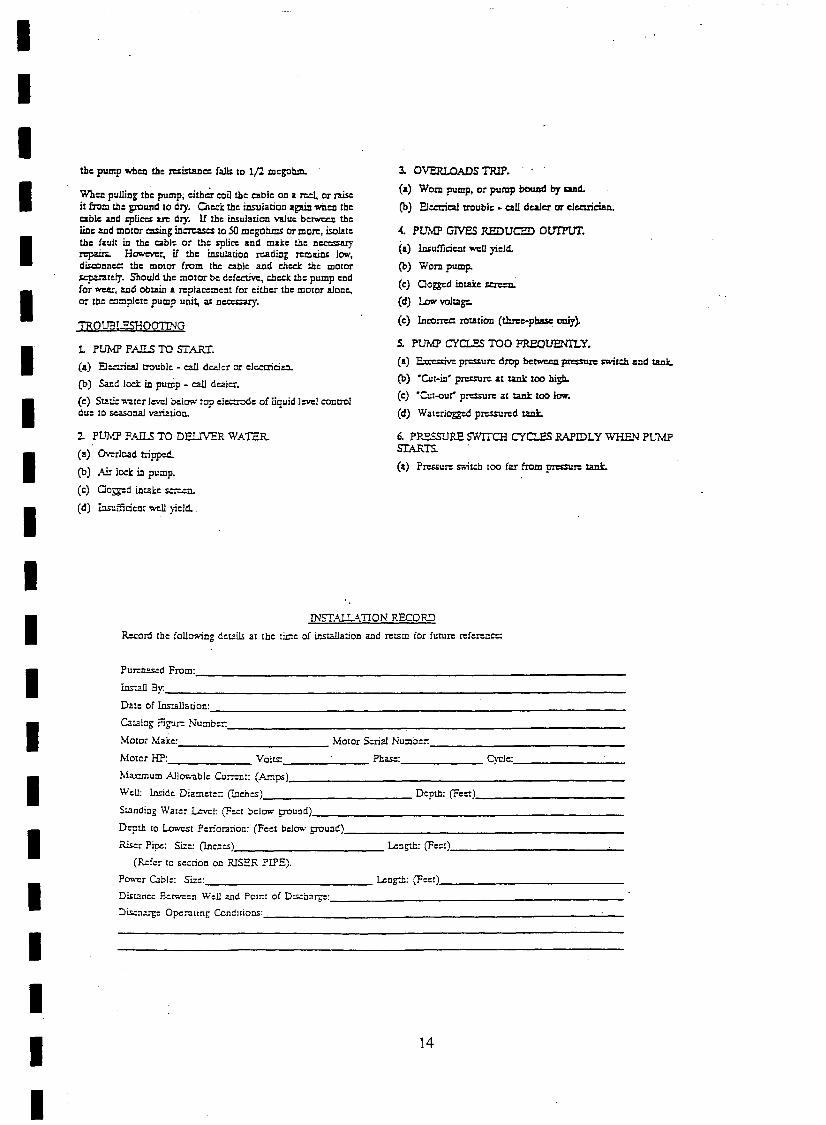
the pump wbcn the =istancc f~ to 1(2 megohm.
When pulling tbe pump; either coil the able on a reel., or n.iseit b'om the ptlWldlO dry. Oed: the insulation again wilen tbeable aDd ~li= arc dry. U the insulation value belWCC%l theline and mOtor CllSing ina=c:z to 50 megohms or mo~, isolatethe Caull in the cable or the splicc and make the ncc=aryrcpain.. HClWeYCr, if the insulation reading remaim low,dis.::onnc:d the motor from the able and check the motor~tely. Should the motor be defective, chccl:: the pump endfor we.a:, and obtain .e. replacement for eitber the motor alone,or tbe complete pump unit, a& n=ry.
TROUBLESHOOTING
1. PUMP FAn..S TO START.
(II) EJ:c-_-iClll trouble - call dealer or electrician.
(b) SaDd loc!: in pump - call dealer.
(e) $uue"",'ater 1=1 below top el=tXle of liquid lc:vel controldue to =cnal variation.
2. PUMP FAILS TO DELIVER WATER.
(a) C)-.o:rlcad tripped.
(b) Air locl: in pump.
(c) Cogged intake s...........en.
(d) 1:JJ;l.:fficienr well yield. .
3. OVERLOADS TRIP.
(.e.) WOrtl pump. or pump bowJd by god.
(b) Electrical trouble • call dealer or electrician.
4. PUMP GIVES REDUCED 0UIl'UT.
(.e.) lmufficient well yield.
(b) WOrtl pump.
(e) Cogged intake screen.
(d) Low voltagt:.
(e) Inco=ct rotation (thr:e-pbasc: only).
S. PUMP CYCLES TOO FREOtJENI1.Y.
(a) E:tc=ive pr=ure drop bel:M:Cl1 p=re switch zmd tank.
(b) 'Cut-in' p=~ at tank too high.
(e) 'Cut-ou( prcssu~ at tank too low.
(d) Waterlogged pn:=red tlUl.l:.
6. PRESSURE SWITCH CYCLES RAPIDLY 'WHEN PUMPSTARTS.
(a) Pressure switch tOO far b'om p=re tank.
IIIIIIIIII
INSTALLA.TION RECORD
R.c...--ord the follcw.'ing details at the tiJ::le of insullation and retain for future reference:
Pur::h=d From: _
Im-.:lll By: _
Date of lnstallation: _
wUlog Figurc Numbe:: _
Motor Make: Motor Serial Numbcr: _
Motor HP: Volts: Phase: C)"ele: _
Maximum Allov.'able CU:7.:n:: (Amps) _
Wei!: Inside Diameter: (Inencs) Depth: (Fcet) _
Sunding Water L-'"Vt:l: (F~t below !7Ound) _
Depth to Lowest Perior:nion: (Feet belO"l>' !7Ound) _
Riser Pipe: Size: (lnebes) Lengtt: (Feet), _
(Refer to section on RISER PIPE),Pov.",r Cab!:: Size: Leogtl:: (Feet) _
Di>unc: Berwe::n Well and POint of Dis.:balb=: _
Dis.:n~<;e Oper:llinl; COncltions: -'-_
14

Shipment Inspection
Installation and Operation Instructions
5TAINLESS STEELSUBMERSIBLE PUMPS
Pre-Installation Checklist
IIIIIIIIIIIIIIIIIIIII
Your Gn.mdfos Submersible Pump is of the utmostquality. Combined with proper installation, yourGrundfos pump will give you many years of reliableserJice.
SECT/ON 1.
£.ramine the components carefully to make sure no damage hasDccurred fa tile pump-end, mator, cahle or control box duringshipment.
This Gru:1dfos St.:bmersible Pump should remain in (tS.shipping carton until it is ready to be installed. The carton isspecially designed to protect it fram damage. During~npacking and pr;or to installation, make sura that the :pumpJS nel dropped or mishandled.
SECTION 2.
Befare beginnIng installation, tl1e !ol1owing checks should bemade. They ilre all crfUcal far the proper Instal/alian af tl1fsSUbmersible pump.
[2] A. CONDITION OF THE WELL·If the pump is to be installed in a new well, the well shouldbe tuliy develope<! and bailed or blown free of cuttings andsand. The stainless steel construction of the Grundfos .submersible make it resistant to abrasio:1; however, nopump, made of any material. can forever withsla"d thedesm.:cti'/8 wearthat occurs when constantly pumping sandy'wate:.
If this pump is used to replace an oil-filled submersible oroil-lubricated line-shatt turbine in an existing weH, the wellmust be blown or bailed clear ot oil.
Determine the maximum depth of the well. and the drawdown level at the pump's maximum capacity. Pump selectionand setting depth should be based on this data.
The ins:de diameter of the well casing shOUld be checked toensure that it is not smaller than the size of the pump andmo:or.
[2] B. CONDmON OF THE WATERSUbmersible pumps are designed for pumping clear and coldwater that is free of air and gases. Decreased pumppertormance and life expectancy can occur if the water is.not coid and c!ear iJr contains air and gases.
To ensure the proper installation ofthe pump, carefullyread the complete manilalbefare attempting to installthe pump.
The motoris eqUipped with an electrical cable. Under nocircumstance should the cable be used to support the waight ofthe pump.
You will find alaosadata plate wired tothe pump. It shouldbe securely mounted at the well or attached to the control box.
Maximum waler temperature should not excesd 11J2C F. Spec:alconsideration must be given to the pump and motor if it isto be used to pump water above 102"F.
The Grundfas stalnless steel submersible is highly resistantto the normal corrosive environment found in some waterwells. If water well tests determine the water has an excessiveorunusual corrosive quality, or exceeds 102c F, contact yourGrundfos representative for information concerning speciallydesigned pumps for these applications.
[2] C. INSTAllATION DEPTHAcheck should be made to ensure that the Installation depthat the pump will always be at least three feet below themaximum draw-<Jown level of the well. For flow ratesexceeding 100 gpm, the NPSH may have to be considered.Refer to NPSH curves in the technical brochure.
The bottom of the motorshould never be ins1alled lower thanthe top of the well screen orwithin five feet afthe wall bottom.
If the pump is to be installed in a lake, pond. tank or largediameterwell. the watervelocity passing overthe motor mustbe sufficient to ensure proper mater cooling. The minimumrecommended watertlowrc..tes which ensure proper coolingare listed in Table A.
o D. ELECTRICAL SUPPLYThe motor voltage, phase and frequency indicated on themotor nameplate should be checked against the actualelectricaJ supply.
15

II
SEcnON3.
I Wire Cable Typewire cable used between the ~ump and control box or
I ~- ,61 should be approved for su:::rr.ersib:e pumpapplications. The conductor may be soiid or stranded. The:;able may consist of individually insuiated conduc::crs twistedtogether, insulate<:! conductors mo:ded side by side In oneI flat cable or insulated conductors with a round overa:1 jacket.
The conductor insulation should be type RW, RUW, TW,TWU or equivalent and must be suitable for use wrth5utmersible pumps. An equivalent Canadian StandardsAssvciation certified wire may also be used. See Tajle 0for recommended sizes of cable lengths.
I s£CTlON4.Splicing the Motor Cable
I A goad cabls splice Is critical ta proper operation af theSllbmersible pump and must be dane with enreme care.
If the splice is carefully made, it wiil war!< as well as any
I other portion at the cable, and will be completeiywatertight.
Gr1.Jndfas recommends using a heat shrink splice kit Thesplice should be made in accordance with the kit
Imanufacture's instructions. Typica~lya heat shrink splice canbe made as follows:
1. Examine the motor cable and the drop cable carefully fordamage.
I 2. Cui the motor leads off in astaggered manner. Cut theends of the draa cable so that the ends match up with themotor leads (see Figure 4-A). On single-phase motors, hesure to match the colors. .I 3. Strip back and trim off 112 inch of insulation from each
.d. making sure to scrape the wire bare to obtain a good
conn~ian.Be carefUl not to damage the copper cond\.;ctcrWhen stripping off the insulation.
4. Slide the heat shrink tubing on to each lead. Insert aproperiy sized aSta-ken" type connector on each lead.making sure that lead colors are matched. Using a ·Sta-kon"crimping pliers, indent l~e lugs (rigure 4-8). Be ~ure tosqueeze hard on the pliers, partIcularly when uSIng largecable.
5. Center1he heat shrink tubing overthe connector. Usinga propane torc:J, lighter, or electric heat gun, uniformly heatthe tubing starting first in the centerwori<ing toward the ends(FigiJre 4-C).
6. Coniinue to apply the heat to the tUbing using care notto let the flame dIrectly contact the tubing. When the tubingshrinks and the sealant flows from the ends of the tubing,the splice Is complete (Figure 4-0).
'- ....
---~l· ,~'.~£f:' ,,':'~'i£ 7~'
FIG. 4-0
FIG. 4-8
-~.:...- ~_r-----··-
.......
F .4·
IIIIIIIII 16
I

SECTION 5.Installation
IIIIIIIIIIIIIIIIIIIII
T1Je flsef pipe Of hose should be properly sized and selectedbased an estimated flaw rates ;Imi frir:tian-Iass factOrs.
A b3C~-<-UP wrench shou:d be used when the riser pipe ISattached to the pump. The pump should be gnpped only bythe ~ats on the top of the discharge chamber. The body oftI1e pump, :able guanJ ormolor should not ba gripped Under <lnycircumstance.
If Steel Riser Pipe is Used:We recommend that steel riser pipes always be used withthe larger submersibles. An approved pipe thread compoundshould be used on all joints. Make sure the joints areadequately tightened in order to resist the tendency of themotor to loosen the joints when stopping and starting.
When tightened, tile flrstsectial1 althe riser pipe must not comein contaci with the checl(valve retainer in the discharge chamberof the pump.After L18 first section of the riser pipe has been atlacherl t('ltne pump, the liftIng cable or e!evatorshould be clamped tothe pipe. Do not clamp the pump. When raising the pump andriser section, be careful not to place bending stress on thepump by picking it up by the pump-end only.
Make sure that tlle ele[;tri[;a!,' cables are not cut or damaged inany way when the pump is being lowered in the well.
The drap cable should be secured to the riser pipe at frequentintervals to prevent sagging, looping or possible cabledamage. Nylon cable clips or waterproof tape may be used.rhe cable splice should be protected by securing itwith clipsor tape just above and below the splice.
If Plastic or Rexible Riser Pipe is Used:It is recommended that plastic type riser pipe be used onlywith the smaller domestic submersibles. The pipemanufactureror representative should be contacted t9 insurethe pipe type and physical characteristics are suitable forthlS use. Use the correct joint compound recommerided bythe pipe manufacturer. In addition to making sure that jointsare securely fastened. the use of a torque arrester isrecommended wnen using plastic pipe.
Do not connect the first plastic or flexible riser section directlyto the pump. Always attach ametallic nipple ar adapter into thedischarge chamber of the pump. Wilen tightened, the threadedend of the nipple or adapter must not come in contact with thecheck valve retainer in the discharge chamber of the pump.
The drop cable should be secured to the roser pipe at frequentintervals to prevent sagging, looping and possible Cablp.
camaae. Nylon cable clips or waterproof tape may be used.Tns canle spiice shOuld be protec:ed by securing it with clipsor tape just above each joint.
IMPORTANT- Plastic and flexIble pipe tend to streich under load.This stretching must be taken into account when securing thecable 10 the riser pipe. Leave 3 to 4 inches af slaclllJctweenclips Dr taped points to allow for this stretching. This mnliencyfor plasllc and lIexible pipe 10 stretch will also affect the ,.calculallon ot 1M pump selling depth. As a general rule, youcan estimate fhat plastic pipe wjl[ stretch 10 iipproximately 2%of its length. For example, [f you installed 200 leel of plasticriser pipe, the pump may actually be down 204 feet. If tile depthsetting Is critical, cheCK wilh the manufacturer of the pipe todetermine how tD compensate for pIpe stmtch.
When plastic riser pipe is used, it is recommended 1hat asaiety cable be attacl1ed to the pump to fower and raise it.The disch3fge piece of a Grund/os 4 inc." submersible isdesigned to accommodate this cab[e (Figure 5-A).
FIG.5-A
Check va/res:A check vaive should always be installed at the surface ofthe well. In addition, for installations deeper than 200 feet.check valves should be installed at no more than 200 footintervals.
Protect the well from cantamlnaJlon:To protect agajnst surface water entering the well andcontaminating the water source, the well should be finishedoff above grade. and a locally approved well seal or pitlessadapter unit utilized_
17

IIISECTJON6.
Electrical
All electrical workshould be performed byaqualifiedelectrician
I in accorrfance with the latest edif/an 0/ the National ElectricalCade, 10C21 cDries anct regulations.
Verification of the electrical supply should be mace to ensure
I the voltage, ;::hase and frequency match that of the motor.Motor voltage. phase, frequency and fuJI-load currentlnformation can be found on the nameplate attached to themotor. Motor electrical data can be found in Table E.
I lfYoit3ge variations are larger than::: 10%, do nat operate thepump_!?irect on·line starting is used due to the extremely fast run-up
ItIme of the motor (0.1 second maximum), and the lowmon:ent at inertia of the pump and motor. Direct on-line~tartlng current (locked rotor amp) is between 4 and 6.5'times tile fu!l-Ioad current. If direct on-line starting is not'
Ia~ptable and reduced starting current is required. anaL.1cHransfonner or resistant starters should be used for. 5to 30 HP motars (depending on cable length). For motorsover 30 HP. use auto-transformer starters.
I Engine-Driven Generators•1,a su~mersible pump is going to be operated using an
engme drrven generator, we suggest the manufacturer of the
I generator be contacted to ensure the proper generator issefected and used. See Table B for generatorsizing guide,
If power is golng to be supplied through transformers,Table C outlines the minimum 'r0IA rating and capacityreqUired lor satisfactory pump operation.
Control Box/Panel Wiring1. SIngle-Phase Motars:Single-phase motors must be connected as indicated in themotor control box. A typical single-phase wirtng diagramusing a Grundfos control box is shovm (Figure 6-A).
2. Three-Phase Motors:Three-phase motors mustbe used with the proper size andtype of motorstarter to ensure the motor is protected againstdamage from low voltage, phase failure, current unbalanceand overload C'...Jrrent. A properly sized starter with ambientcompensated extra quick-trip overfoads must be used to giveIhe best possible motor winding protection. Each of the threemotor legs mu:>1 be protected with overloads. The thermaloverloads must trip in [ess than 10 seconds at locked rotor(starting) current. For starter and overload protection guide,seeTabte H. A three--phase motorwiring diagram is illustratedbelow (See Figure 6-8) ..
Pumps should NEVER be sf3rted to check rotatian unless thepump is totally submerged. Sellers damage may be t:3userf tothe pump and motar " they are run dry. ,
Figure 6-A
Power Supply,
Agure 6-8
MagneticStarter
Three-Phase Wiring Diagramfor GRUNDFOS and FRANKLIN Motors
18
,\
230V .... l115V
I Fused9 ~'::"~
u~ dotted line for,'SV opor.stion
Pressure ~, ....,:,'l
Single-Phase Wiring Diagramfor GRUNDFOS Control Boxes
Can:ra!Box
III'IIIIII

I
Figure 6-C
Single Phase Hookup
Control Box/Panel GroundingThe control box or panel shall be permanently grounded Inaccordance with the National Elec1ricaJ COde and loca~codesor regulations. The ground wire should be a bare copperconductor at least the same size as the drop cable wire size.The ground wire should be run as short a distance aspossible and be securely fastened to a true grounding point.
Tr~egroundIng points are considered to be: a grounding reddnven IOta the water strata. steel well casing submerged intothe water lower than the pump setting level, and steeldischarge pipes without insulating couplings. Jf plasticdi,sc~arge l?ipe and well casing are used or if a groundingwire IS reqUired by local codes. a properly sized bare copperwire should be connected to a stud on the motorand run tothe control panel. Do not ground to a gas supply line. Connect,the grounding wire to the ground point first and then to thltennina! in the control box or panel.
Wiring Checks and InstallationBefore making the final surface wiring connection of the dropcable to the control box or panel, It is a good practice tocheck the inSUlation resistance to ensure that the cable andsplice are good. Measurements for a new installation mustbe at least 2,000.000 ohm. Do not start the pump if themeasurement is less than this.
If it is higher than 2.000,000 ohm. the drop cable should thenbe run through the well seal by means of a conduit connectorin such a way as to eliminate any possibiHty of foreign matterentering the well casing. Conduit should always be usedfrom the pump to the control box or panel to protect the dropcable (See Figure 6-E). Finish wiring and verify that allelectrical connections are made in accordance with thewiring diagram. Check to ensure the control box or paneland high voltage surge arrester have been grounded.
The wam.nty on all t1lrec-phase submerolble motlJrs ii VOiD If:
1. TIle motor is operated wllh sin{lle-phase power through 3phase converter.
2. Three-leg ambient compensated extra qUick-trip overloadprotectors are not Ilsed.
3. Three-phase current untlalartc21s not chadced and recorded.(See START-UP Section 7 lor InlOtructJons.)
4. High voltage surgll arresters are not Installed.
Figure 6-E
19
TrueGroundPoInt
True? Grounding
POint
1
L3GRN Puma
Panel
0 T3II
IIII
,
0 T2If
I,II
L1
L'I N ' Ground
CO 01-------0 ~00
To SP Motor
Three-phase hookup
~T11IIIII
Figure 6-0
UghtningArrester
Single PhasePower Supply
Three-phase power supp'ly,J ,
High Voltage Surge ArrestersA high voltage surge arrester should be used to protect themotor against lightning and switching surges. Lightningvoltage surges in power lines are caused when lightningstrikes somewhere in the area. Switching surges are causedby the opening and closing of switches on the r:12Jn highvoltage distribution power lines.
The ccrreet voltage-rated surge ;;mestershould be installedon the supply (line) side of the control box (Figure 6-C and6-0). The arrester must be grounded in accordance with tileNational Electrical Code and local codes and reguJations.
III
IIII
IIIIIII'IIIIII

ISECTION 7.II
./le pump llJS been set Into the well ;md the wiringTlnectfans /J3ve been mHde, the fallowing procedures should
, performed:
On three-phase units, check direction of relation andcurrent unbalance according 10 the instructions below.
For single-phase Units proceed d:rectly to ·Oevelopingthe Well'.
D. Under no circumstances should the pump be operatedfor any prolonged period of time with the discharge valveclosed. This can result in motor and pump damage dueto overtleating. A properly sized relief valve shouid beinstalled at the well head to prevent the pump fromrunning against a closed valve.
Measure and record current readings in amps loreach leg (hookup 1). Disconnect power.
ri.\
.[fi
B. Shift or roll the motor leads from left to right so the dropcable lead that was on terminal 1 is now on 2, leadon 2 is now on 3. and lead on 3 is nOw on 1 (hookup 2).Rolling the motor leads in this manner will notreverse the motor rotation. Start the pump, measure.and record current reading cn each leg. Disconnectpower.
C. Again shift drop cable leads from left to right so thelead on terminal 1 goes to 2. 2 to 3 and 3 to 1(hookup 3). Start pump, measure and record currentreading on each leg. Disconnect power.
D. Add the values for each hookup.
E. Divide the total by 3to obtain the average.
F•.Compare each single leg reading from the averageto obtain the greatest amp difference from t.~e
average.
G. Divide this difference by t."'le average to obtain theprecentage of unbalance
UseJha wiring hookUp which provides the lowest percentageot. unbalance. (See Table F for a specific example ofcorrec!ing for three-phase power unbalance.)
Developing the WellAfter proper rotation and current unbalance have beenchecked. start the pump and let it operate until the waterruns clear of sand, silt and other impurities.
Siowly open the valve in small increments as the water ciearsuntil the desired flow rate is reached. Do not operate thepump beyond Its maximum flow rating. The pump should notbe stoppad until the water runs clear.
If the water is clean and clearwhen the pump is first started,the valve should still be slowly opened until the desired flowrate Is reached. As the valve is being opened, the drawdownshould be checked to ensure the pump is always SUbmerged.The dynamic water level should always be more than 3 festabove the Inlet strainer or the pump.
Disconnect the temporary piping arrangements and completethe final piping connections.
Under no circumsbnces should the pump be operated for anyprolonged period of time with the discharge valvB closed. Thiscan resu/l In motor and pump damage due to trJarheating. Ap.roperly sized relict valVB should be Installed at the well headto prevent tha pump Irom l'tInning against a closed valve.Start tl-te pump and test the system. Check and record theVOltage and current draw on each motor lead.
3Average current =
Inree-Phase Motors1. Check the directian of mtatian
rree-phase motors can run in either direction dependingIf how they are connected to the power supply. When the
It Iree cable leads are first connected to the power supply!here is a 50% chance that the motor will run in the proper
I rectJon. To make sura tl1e motor Is running In the propar 'redlon, C<lrel1Jlly follow the procedures below:
A. Start the pump and check the water quantity andpressure developed.I B. Stop the pump arid interchange any two leads.
C. Start the pump and again check the water quantityandpressure.
I O. Compare the results observed. The wire connectlonwhich gave the highest pressure and largest waterquantity is the correct connection.
I.Check for cumnt unbalance,urrent unbalance causes the motor to have reduced startlng
torque. overload tripping, excessive vibration and poor
'
rformance which can result in early motor failure. It is veryportant that current unbalance be checked in all three
hase systems. Current unbalance between the legs should notexceed 5% under normal operating conditions. .
~p. supply power service should be verfied to see if it is: aa or three transformer system. If two transformers are
resent, the system is an Yopen" delta or wye. If threetransformers are present, the system is true three-phase.
I·.aka su.re the transformer ratings in kilOVolt amps ()(VA) Isufflclent for the motor load. See Table C.
The percentage of current unbalance can be cafcdated by
IUSing the following formulas and procedures: i
Total of current values measuredon each leg
IGrC::ltest amp difference from
the avemge
I Current u.nbal<lnc:c = ------..;;;....---- X100average current
To d~termine the percentage at current unoa/;mce:
I '20
I

II Operation
I'1. The pump and system should be periadiC.:lily checked torwater quantity, pressure. drawdown. penocs of cycling andoperation of controls.
2. If the pump iails to o:em:e. or tt:ere :5 a loss ofperformance. rdcr to Truubleshooting. Section 8.
TroubleshootingIII
SECTION 8.
Tile majority of problems that develop with SUbmersiblepumps are electrical, and most of these problems can be'corrected without pulling the pump from the welf. Thefollowing chart covers most of the submersible service work.'As with anytroubJeshooting procedure, start with the simplestsolution first; always make all the above-ground checks '
betore pulling the pump from the well.
Usually only wo instruments are needed - a combinationvoltmeler/ammeter, and an ohmmeter. These are relalive!yInexpensive and can be cbtained from most water systeMssuppliers. '
WHEN WORKING WITH ELECTRICAL ClRCUITS, USE CAUTION TO AVOID ElECTRICAL SHOCK. rt is reCtlmmendad lhatrubber !Jloves Iand boots oe worn and that cara Is taken to have metal control boxes and motors grounded to power supply groumt or steel droppipe or casl~g extending into the well. WARNING: Submersible motors are Intenoed for opera,tlon in a well. When not operated II
In a weil, f,lIlure to connect motor frame to power supply ground may result in serious electncaJ shock.
What it MeansIf the amp draw exceeds the listed servicefactor amps (SFA) or if the current unbalanceis greater than 5% baween each leg on threephase units. check for the following:1. Burnt contacts on motor starter.2. Loose terminals in starter or control box or
possible cable defect. Check winding andinsulation resistances .
3. Supply voltage too high or low.4. Motor windings are shorted.5. Pump is damaged, causing a motor
overload.
What it MeansWhen the motor is under load, the voltageshould be within == 10% of the namepl2.tevoltage. Larger voltage variation may ~use
winding damage.
Large variations in the VOltage indicate a pcorelectrical supply and the pump should not beoperated until these variations have beencorrected.lf the voltage constantly remains high or low,the motor should be changed 10 the correctsupply voltage.
How to MeasureBy use of an ammeter, set o,n the Rroper scale,measure the C'Jrrent on ea.c!'J,Pow~r lead at thecontrol box or starter. See. Electrical Data,Table E, for motor amp draw information.
Current should be measured when the pumpis operating at a constant discharge pressurewiih the motor fully loadeq.,
Preliminary TestsSUPPLY How to MeasureVOLTAGE By means of a voltmeter, which nas been set
~o the proper scale, measure the voltage at thecontrol box or starter.
On single-phase units. measure between lineand neutral.
On three-phase units measure between thelegs (phases.)
CURRENTMEASUREMENT
IIIIIIIIIIIII
WINDINGRESISTANCE
How to MeasureTurn off power and disconnect the drop cableleads in the control box or starter. Using anohmmeter, set the scale selectors to Rx1 forvalues under 10 ohms and and Ax1 a for valuesover 10 ohms.Zero-adjust the meter and measure theresistance between leads: Record the values.
,~", .-Motor resistancs values can be found InElectrical Data, Table E. ,cable resistancevalues are in Table G.
What it MeansIf all the ohm values are nOnTl81. and the cablecolors correct. the windings are not damaged.If anyone ohm value is less than nOnTlal. themotor may be shorted.If anyone ohm value is greater Ulan normal.there is a poor cable connection or joint. Thewindings or cable may also be open.
If some of the ohm values are greater thannormal and some less, the drop cable leadsare mixed. To verify lead colors. see resistancevalues in Eiectrical Data, Table E-
I 21
I

IIII
INSULATIONAESISTANCE
01r~Ti~f:/-.~~
How to MeasureTurn off Dower ::md disronneet rha'drop C3bleleads In tlie contio! box or starler. Using anohm ormega ohmmeter, set the scale selectorto Rx100K and zero-adjust the meter.
Measure the rosistance between the lead andground (discharge pipe or well casing, jf steel).
What it MeansFer ohm values. refer to table below. Motorsof all HP. voltage. phase and cycle duties havethe same value of insulation resistance.
IIIIIIIIIIIIIIIII
OHM VALUE MEGAOHM VALUE I CONDmON OF MOTORAND LEADS
Motornot yet instllled:
2.000,000 (ormore) 2.0 New Molar.
1,000,000 (ormore) 1.0 Used motorwhich can be reinstalled in the wefl.
Motorin wen (Ohm readIngs are for drop cable plus motor):
500.000 - 1,000,000 0.5 - 1.0 A motor In reasonably good condition.
20.000 - 5DO.OOO 0.02 - 0.5 A motorwhic:, may have been damaged by lighming orwith damagedleads. Do notpun the pump for this reason.
10,000 - 20,000 0.01 - 0.02 A metorwhich definitely has been damaged orwith damaged cable. Th epump should be pUlled and repairs made to the cable orthe motor
\'''''''It,," 1a,cca
repiaced. The motorwill sti!l operate, but probably net for long.0-0.01 A motorwh·lch has failed orwith completely destroyed cable insulation.
The pump must be pUlled and the cable repaired orthe motorfeplacad.Thecmotorwill not run In this condition.
Troubleshooting ChartFAULT POSSIBLE CAUSES ·1 HOVI TO CH ECK HOWTO CORRECT
A. Pump Does Not Run 1. No power at pt,;mp panel. I Check torvo~ge at panel. Ilf no voltage at panel. checkI teeder panel for tripped drCUits.
2. Fuses are blown or cirC"Jit IRemove fuses and check for Replace blown fuses or resetbreakers are tripped. continuity with ohmmeter. circ:.Jit breaker. Jf new fuses blow
or circuit breaker trips, theelectrical installation and motormust be checked.
3. Motor starter overloads are: Check lorvol!age on iine and Replace bumt heaters orresetburnt or have tripped out load side of starter. Inspectstarter for otherdamage.(three-phase only). If heater trips again. check the
suppfyvoltage and starterheldlng coil.
4. Startsrdoes not em!rgize ..1E:'lsrgize control circuit and Ifno voltage. check control(L"ree-phase onlY). check forvoltage at the circuit. Ifvoltage, check holding
holding coil. coli for shorts. Replace bad coil.
5. D€fe:::tive controls. CheCK aJl safe!'1 and pressure Replace worn ordefective parts.switches for operatIon. Inspectcontacts in c::mtrol devices.
6. Moter and/or cable Turn ott power. Disconnect If open motorwinding or groundare defective. motor leads from contra! box. is found, remove pump and
Measure the lead-la-lead rech eck values at the surface.resistances with the ohmmeter Repair or replace motororcalJle.(Rx1). Measure lead-to-groundvalues with ohmmeter(Ax1 001<). Record measuredvalues.
7. Defective capacitor Tum off the power, then Itthere Is no needle movement.(single-phase or.ly). discharge capacitor. Check with replaca the capacitor.
an ohmmeter (Rx1 OOK). Whenmeter Is connected. the needleShould jump forward and slowlydrittback.
22

IIIIIIIIIIIIIIIIIIIII
Troubleshooting Chart (contmueaJFAULT I POSSIBLE CAlJSES ! HOWTOCHECl< HOWTO CORRECT I
8. Pump Runs But Does Not
I1. Groundwater level in well.. IChecK weil craw-down. Weter If not, lower pump If possible, or I
DelIver Water is teo low or well is collapsed. level should 00 at least 3 ft. above throttle discharge valve andpump inlet dunng operation. install water level controL
2. Integral pump Check valve Install pressure gauge, start II not close to the pump curve,is blocked. pump, gradually close the remove pump and inspect
otsc.'1arge vaive and road discharge sectIOn. Removepressure at shut-olf. Aftertaking blockage, repaJrvalve and valvereading. open vaiYe to its seat If necessary. Cheddar otherprevious pcsrtion. Convert PSI damage. Rinse 01,,1 pump andto feet re-install.(For water: PSI x 2.31 ttlPSI =_ ft.),andaddthislOthetotal vertical distance from the ..
pressure gauge to the water levelin the weU while the pump is
. running. Refertothe specificpump curve tortne shut-otf headfor that pump model. If themeasured head Is close to thecurve. pump Isprobably OK.
3. Inlet st:"ainer is dogged. I Same as 82 above. It notdoss to the pump curve,remove pump and inspect. Cleanstrainer. inspect integral checkvalve for blockage, rinse outpump and reinstall.
4. Pump Is damaged: : ISame as B.2 above. It damaged. repair as nacessary.Rinse out pump and ra--install.
C. Pump Runs But at Reduced 1. Wrong rotation jCheck lor proper electrical COITectwiring and change leadsCapacity . (three-Phase only). connection in control panel. as required.
2. Draw-down is largerthan ICheck draw-down dlmng pump Lower pump if possible. If not.anCldpated. operation. throttle discharge valva and
install water level control.
3. Discharge piping or valve Examine system for leaks. Repair leaks.leaking.
4. Pump strainer or chec~ Same as 8.2 above. If not dose to the pump curve.valve are clogged. remove pump and inspect. Clean
strainer. Inspect integral checkvalva for blockage, rinse out~umpand reinstall.
5. Pumpwcrn. Same asB.2.above. If not close to pump curve,remove pump and inspect.
D. Pump Cycics Too MuCh 1. Pressure switch is not Check pressure setting on Re-adjust switch or replace ifproperly adius1ed or is switch and operation. Check defec.ive.
Idefective. voltage across closed
contacts.
2. level control is not Check set'Jng and operation. IRe-adjust setting (refer toproperlysetor is'defective. manufacturer data.) Replace it
de!ec1Jve.3. Insufficient air charging or Pump air into tank.or Repair or replace damaged
leaking tank or piping. diaphram chamber. component.Check diaphram for leak. Checktank and piping for leaks withsoap and water solution. Checkelr to watervolume.
4. Plugged snifter.valve or Examme valve and orifice tor' Clean and/or replace If detective.blood orifice. di rt or corrosion.
5. Taruos too small. ChacKtank sl:z:e. Tank (t tD.nk is too small, replaca wIthvolume should be approximately proper size tank.10 gallons tor each gpm ofpump capacity.
23

IIIIIIII
FAULT 1 POSSIBLECAUSES HOWTO CHECK I HOWTO CORRECTE. Fuses Biow or CirC'..llt 1, High ar law voltage. C~ec.'{ voltage Dt pump panei. I Ifwlro size is corre<::. contae!
Brc;:xkers Trip It net within =10%. check wire power company. Ifnot, cerrectsize snd length of run to pump and/or replace as nocoss::ITY.;w1el.
i 2. Three-pNl~current Check c:.;rrent draw on eaeM If C'..Jrrent unbalance i~ nor withinunc:lJanca. lead. Unoalance must be within =5~1a. contact power campa"y.
... <;:lI__ ,a.
3. CAntroi box wiring and Che::x tl1at centrol box pariS Correctas requiredcom::x:monts match the parts iist. Check(sini;ie-pM!lc only). to sse thefwmng matches
Wiring d:agr.:lIl1. Ched< forloose or broken wires orterminals.
4. Defec::ve caoacr.cr Tum off power and di::;charge If no meter movement. replace(single-phase cnly). c~aotor. Check using an the capacitor. .
ohmmeter (Rx1 aOK). Whenthe meter is connected. theneedleshould jump forward andslowiydmtbad<.
5, StarJng relay (FrankIin ICheck resisiance of relay coil Replaea defecr.ve relay.single·phase motorS only) with an ohmmeter (Rx1 OOOK).
Checi< contacts lorwear.
I SECTiON 9. Technical Data
IIIIIIIIIIII
Table AMinimum Water Flow Requirements forSubmersible Pump Motors
MOTOR CASING OR SLEEVE MIN. R.OW PASTOlAMSTER I.D.IN INCHES TI-lE MOTOR (GPMj
4' 4 1.25 I 76 I 137 I 21S I 30 I
6"' 6 , 107 I 28
-8 I 45
10 I 8512 I 14014 19816 I 275
S" 8 I 10 I
10 I 55 I12 11014 I 18016 I 255
10" 10 I 30
12 8514 I 14516 I 22lJ
I 18 I 305
NOTES: 1. A now Inducar or Sleeve must be useo it the wuter entersthe well above L'Ye motor or If there i~ insutfldern waterflow past the motor.
2. Tho minimum recommended WOller va Iodty= 4' molcmlis 0.25 feet per baCOnc:L
3. Tho minimum recommend.od water velOCIty ovor 6 a and10' motClfS IS 0.5 feet per Second. • •
Table 8Guide for Engine-Driven Generators inSuhmersible Pulnp Applications
MINIMUMKILOWA, I RATING OFGENERATOR FOR THREE:-WIA~SUBMERSIBLE PUMP MOTORS
MOTORHPFOR EXTERNAll.Y INTEFlNAL~YSINGLE OR THREE REGULATED REGULATED
PHASE UNITS GENERATOR GENEP.ATOR
O.33HP I 1.5KW I l.2K'N,
0.50 2.0 1.5 I0.i5 3.0 2.01.0 4.0 2.51.S I 5.0 I 3.02.0 I 7.!S 4.0 I3.0 I 10.0 I 5.05.0 I 15.0 7.57.5 I 20.0 10.0
10.0 30.0 15.015.0 40.0 20020.0 60.0 25.025.0 75.0 I 30.030.0 100.0 40.040.0 I 100.0 50.0SO.O 150.0 60.060.0 175.0 I 75.075.0 250.0 100.0
100.0 I 300.0 150.0125.0 375.0 175.0150.0 450.0 200.0200.0 600.0 Z75.0
NOTES: 1. TablO ie 00sad on lyJlicat eooc rh;a continuous dutygenerntcrs with 35% maximum voltage dIp during ..=t~p ofslngla-p/l1lSl! and ItIr8&1lnase motors.
2. Cont3ct the m8l'lula.dllrar at the genera:or to =ro tho unithll.:l a.dequa18 CllJllcrty to nln the submel':libfe mCllor.
3. If tho generalOr r.rting is in KVA Instsad al kilowsrtG. muitJpIytno allOVe rRllnge by 1.2S 10 otllBin KVA.
24

IIIIIIIII
Table CTral'!stcrmer Capacity RequirEd ror Three-PhaseSubmersible Pump Motors
I M1NIMUMKVAMnNGFOR EACH TRANSFORMER
THRE=-PHASEj MINIMUM I2TRANSFORME~S I:1TRANSFORMERSMOTORHP TOTALKVA OPSN DELTA DELTA OR WYE
REQUIRED' OR'NYE .1.5 I 3 I 2 I ,12 I 4 I :2 I 1~
:1 I 5 I :1 I 25 , 7'1: I 5 I :17.5 I 10 I 7';' I 5
10 I 15 I 10 I 515 I 20 I 15 I 7%20 I 25 I 15 I 10
25 I 30 I 20 I IQI 30 I 4V , 2:: I 15I 4V I 50 I 30 I 20
50 I 60 I 35 I 2060 I ·75 I 40 I 2575 I 90 I 50 I 30
100 I 120 I 55 I 40125 I 150 I 85 I 50150 I 175 I 100 I 60200 I 230 I 130 I 75
, Pump motor l<:IJA requirements only, a."ld does not include allowances ,;for c:har ioacs. . : •
SINGLE-PHASE MOTORMAXIMUM CABLE LENGTH(Motor .to serVice entrance}(2)
CAUTION: Use of WIre Slzg smaller than listed will VOid warrantY.FOOTNOTES;
1. :1 aluminum cor-due::::, is =ed. multiply lengthsoy 0.5. Maxunum allowable length of aluminum Is cons:deral:lly shanar ttllU1c~rwlreof :lIUOO clzo.2. Thg por1~naltha IOlal c:Ible wmcnlG oalWgen the servles anlrenee snd :13'" motor stm1er s."auld flDl exceed 25% of !tie total maximum lengt.'1 to
=1"0 rellaJ:lle ~.arter operalJon. Singlll-1ll'\;lSa con11C! COlle. m:l.y De connected at any peine at the total caDle length.
3. ~lGs #14 to 11'0000 are AWG sizs&. and 2.."0 to 300 ara MG."d:lIUl5.
MOTOR ElATING I COPPER IlJIRE SlZEVOLTS I HP I 14 I lZ I 10 I B I & I 4 I Z I a I (llJ I 0tIll I DllOlJ \ Z5lJ I 31lO
115 'I> I 130 I 210 I 340 I 540 I 840 I 130."0- I 1960 I 2910 I I I I II "" I 100 I 160 I 250 / 390 I 620 I 960 I 1460 2160 I I I I I
230 ';' I 5SO I 880 I 1390 2190 I 3400 I 5250 I 7960 I I I I I'Iz I 400 I .650 I 1020 . 1610 I 2510 I 3880 I S880 I I I I I:v. I :l00 I 480 I 760 I 1200 1 1870 I 2B90 i 4370 6470 I I I I I1 I 250 I 400 I 530 I 990 / 1540 I 23SO I 3510 I 5380 I 55.."0 I I I I
1';" I 190 I 310 I 480 770 I 1200 I 1870 I 2B5O I 42BO I 5240 I I ! I2 I 150 1 250 I 390 520 1 970 I 1530 I 2360 I 3B2O I 4480 I I I I3 I 120 ; 190 I 300 470 I 750 I 1190 I 11150 , 2.B9O I 3610 I I I I5 I I I 180 .1 280 I 450 I 710 I 1110 I 17.(J) I 2170 I . I I7'1: I I I I 200 I :Jl0 I 490 ; 750 1140 I 1410 I I I I10 I I I I I 250 I 390 i 600 I 9:lO I 1160 I I I I
IIIIIIIIII
Table 0Suhmerslble Pump Cable SelectionChart (50 Hz)
The following tables list the recommended copper cablesizes and various cable leng:hs for s~brr.ersiblepumpmotors.
These tables comply with the '978 edi:icn of the NationalEleet,icTable 310-16, Column 2 for 75"C wire. The ampacity{current carrying properties cf a conductor) have been
divided by 1.25 per the N.E.G., Article 430-22, for motorbranch circuits based on motor amps at rated horsepower.
To assure adequate starting torque, the maximum cablelengt.'1s are calculated to maintain 95% of the serviceentrance voltage at the motor when the motor is running atmaximum nal11eplate amps. Cable sizes larger than specifiedmay always be used and will reduce power usage.
The use of cables smaller than the recommended sIze:: will voidthe warranty. Smaller cable SIZBS will cause reduced startingtorque and poor motor operation.
II
25

IIIIIIIIIIIIIIIIIIIII
TI-iREE-PHASE MOTOR MAXIMUM CABLE LENGTH(Motor to service entrance)(2)
MOTOR RAnNG 1 COPPER WIRE SIZEVOlT3 I RP I 1-4 I 12 I 10 I 8 , 5 4 I z I 0 I 00 ann I 11000 I zstJ I JlXl~ZlJ8 i I'll I 310 I soo I 790 I 1250 I I I I I I I I
2 I 240 I 390 r 610 I 970 I 1520 I I 1 I3 ~60 I ~ I 470 I 740 I 1160 I 1810 I I I
1 5 I no I 200 I 440 I 690 J 1080 I 1660 II 7'h I I I 200 I 310 i .we I no 11ao I 1770I 10 I r I I 2"..0 I 370 I 570 880 , 1330 I 1640 I I
15 I t I I I 2SlJ I 390 600 I 910 I 1110 I 1340 I I I20 I I I I I I 300 I 460 I 700 8!50 I 1050 I 1270 I I2S I I I I I 370 570 I 700 I a.4O I 1030 I 1170 I ,
t
30 I I I I I I :110 470 I 580 I 700 I 850 I 970 1110
Z3U 1'17 I :;60 I 580 I 920; 1450 I I I I I I
I 2 280 I 450 I 700.'1 1110 I 1740. I I I I II 3 210 I 340 t S40 :1 8SO , 1340 I 2080 I I II
5 I 200 I 320 I 510 I 8001 1240 1900 I I I I IT','z I I 230 ,I 360 I 510 I 890 I 1350 I 2030 I I I
10 I I .,1 270 L 420 I SSO I 1010 I 1520 1870 I I I I15 1 I ,',' : I 290 , 450 I 690 I 1040 1 1200 I 1540 I . I I£0 , I i I I 350 530 I 810 I 990 I 1200 I 1450 I I25 I I I I I 280 430 650 I 800 I 97'0 I 117'0 I 130m I00 I I I ,.1 I 350 I 5-40 650 aoo 970 I 1110 I 1270
.t6O 1'h 11700 I I .. I I· I I I I2 I ~:lCO 2070 '. I I I I3 I 1000 I 1000 I 25-"0 I I I I5 590 I 950 I 1500 I 2:360 I I I IT'h '20 I 680 I 1070 I 1600 I 2540 I I I I
10 .310 \ SCO I 790 1250 I 1960 I 3050 I I I15 I I 540.1 850 I 1340 2090 3200 , I I20 I I '410. , • 85Q. I 1030 1610 2470 I 37:30 I25 , , .I 530 I 830 1300 , 1990 3010 3700 I I30 I i I ., 430 I 680 I 1070 I 1640 2490 I 3060 I 3700 I I4{) I I ·1 I 790 1 1210 1830 .22.."'0 I 2710 3290 I I50 I .. ·1 I 640 I 980 1480 1a10 I 2190 2650 I 3010 I60 I 1 I 630 1250 1540 I 1650 2240 2540 28SO75 . I ! I I I 1030 I 1260 I 1520 1850 2100 I 2400...
HXI I ::' I I I 9-40 I 1130 1380 '1560 I 1790125 I I I : I I I 1080 I 1220 '1390150 I I : : I I I I 1050 1190200 I I I I I I 1Ceo 1300250 I I I I I IMO
575 1',", 2B2O ... I I I I2 2O:lO I .. I , I I I I I3 I 1580 1 2530 I .:. I , I I I5 I 920 1480 I 23:lO I ,I I7'h I 680 lOBO I 1680 , 2550 , I
10 I 490 7llO I 1240 I 1950 I I15 I 5:30 I 850 I :1340 , ::09020 I SSO I 1030 I 1610 I 2520 \ I25 I I 520 I 830 I 1300 20:30 I 3110 I I30 I I .j I 680 I 1070 1570 I 2560 3BBO I40 I \ .: ;1 ~. I 790 1240 1900 2BSO I 3510 I I ISO I '. j 1000 I 1540 2310 2840 t 3420 I I60 I I I 850 I 1300 1960 2400 I 2ll9O 3500 I I7S I I I 1 1060. I 1600 1970 23SO 2890 I 3290 I
100 I I I l1go 1480 ,.770 I 2150 I·U'O I 2700
CAunON: U:5e 01 wi"" l:izs smOlJler th:m Ii:lted will void warrantv.FOOTNOTES:
1. tf aluminum conduc-.cr Is used. mulUply lengths byO.S. Maximum allowable length 01 aluminum Is considcmblyshorn:rtnan c:cpperwlre ot same !lize.2. Tho portiOn at tne total cable wnich is bSlW9Qn t/19 SBrvice emrll11C8 and a 3l2l motorstarter :should nol exceed 25% 01111010131 mllXimum length 10
assure reftable S1at1ar opal':lllcn. Single-phase centrol boxes may be ccnnect1ld al any poinl of thEi total cable length.
3. cables 1'14 to #<lOCO are AWG sizes. and 250 1Q 300 arB MCM ·ll~.
26

SpecificationsPage C2
MATERIAL OF CONSTRUCTION
Bowl Ca.sr T ('0 n IImpeller (Oro r'l2f!Sowl Shaft Li/6 S.C;. IShaft Coupling 5.S.Sowl Bearings 0(<!)r1 Ze Isowl W/R
Strainer S.C;. /Impeller W/R
PUMP
TypeSvbmuS;b~ IModel C;; TC H6 L.{ IGPM ISO ITDH 130Deeth Gauge: Required: Not Required:
Air Line: Required: Not Required:
MOTOR
HP 10 HP IRPM 2900I
Phase 3 J Her'..z 50 I
Voltage 3Bo 1
CABLE
Size 10/3 ILength ..8 50 r;eP.JType ~Zt Tkf. svb.Calb4
DISCHARGE ELBOW
8ase Plate Isolt Holes: .; -
Diameter Solt Circle: R.F. 150# ASA Discharge FlangeBolt Holes: Diameter Flange:
JUNCTION BOX
RecUired: INot Required: IRISER r.R..C)V"Vl e" de d
Pipe Size Lt I' ISection Length 21 r:eefOTHER SPECIFICATIONS
Drawing Nc. ISenal No.
Fluid J Spec. GraVity
VISCOSity ITemperature I!PH !NO.Units RecUlred
ICUS10r:1 e~ T T\ r-Q r n CL·t0 n oj T.ec (lO 0 c9 I'Q S
jAdoress /L.{' GLooml·IIudu. (1c...;rt-\.)
SUBMERSIBLE TURBINE PUMP
ITel 801 'q~Y-j - 329--1 rax. ( 3:;?J )Q5'-1 - 3'1 2' 2 ':IRe:I! SUDDIlC',
C;-.iy;;]'./:I ! I
__=-11'__.:;.._= ==::::::='====---~
ill : I
)' ;I~
I!_;_I\_1_'I
~I:I~::...,..-----;
;1 ! i
/-11-1~--
Ii II:
\ (4) ~ OlA HO~
~ __•. __ LS
(~ ANSI RAlSE:D FACE FtC
-0-:'~ -:"" 9 ~r< I .
i
I s:"Z0
.J~LINE~
IIIIIIIIIIIIIIIIIIIII

SpecificationsPage C2
is;Jlc,,mon G()STr'"WLJ ( 7c-Q..iQ~V"
IC~s::Jmer r" h,rAc1--T,'O "loY 1£ C'Y\.QW c); e s.!Ac:Jress It-.{ 0Loom.'T1<fl &u. Wu {tv I
'Cit" Mockv,"/ Je '-J Si Md. ZIP ZO,9 S zJfTeL \]() {' qca'-l - 329-fFax, (..:IrJ I) g8~ - 3'122:iRec !
!Succller ..J - L; N Pv""'" JJ CU.
MATERIAL OF CONSTRUCTlON
Bowl Co-rot Tror1 /Impeller ro,.-nnZfBowl Shaft L.j I G SIS._ IShaft Coupling S,S.Bowf 6eanngs CO (O..., ? e IBowl W/R
Strainer S.C;. !Impeller W/R
PUMP IType Subm US; 66: IMooe! 9£HC.Z3 IGPM 500 ITDH .z 15 IDepth Gauge: ReqUired: Not Recuired:
Air Line: Required: Not Required: IMOTOR
HP 50 IRPM ZqOoPhase 3 iHer.z 50Voltage 380 I
CABLE
Size Lf/3 ILength Z 5 0 'r"eQ. f-Type'f="Ld..J ..itl-.fu.btt.1
orSCHARGE ELBOW IBase Plate 6 ,- /60ft Holes: 4 •
Diameter Bolt Circle: R.F. 150;: ASA Discharge FlangeBolt Holes: Diameter Flange:
JUNCTION BOX
.1 RecUlre:: INot Required:
RISER re.CO MQrodeJ
Pioe Size 6 ,. ISectIOn Length .goret+OTHER SPECtFICATIONS
,Drawing No, ISenal No,
Fluid ISoec. Gravity
V:sccslly !Temoerature IIPH I Nc.Uni:s ReoUired
28
SUBMERSIBLE TURBINE PUMP
'\ (4)! DlA HOLE:$
~__', __ LS
~ ~ ANSI RAJSC:D FACE FLG
I :
-\2~j): I
I I
I ;I!II
n((;1/~1'-I /f:Ui II;' !
,,..---=-'=--=-= ===.====== ----'-i Ill......!..-..:I I, I
I ~~ :1:-11-
1.-:
I :::::--=:::_11_1 _[
-;-!__ 111-/-i II 11;""----
I,iIII ", "1
338
I
i 11\, 'I:
-'--_....:-__~ i_''_'
IIIIIIIIIIIIIIIIIIIII

SpecificationsPage C2
MATERIAL OF CONSTRUCTION
Bowl Co..st T r 0 t'"l IImpeller (Oro 11 "2 e ,Bowl Shaft L!lb 9.S. IShaft Coupling S.S.Bowl Bearings (0 T () 71 2.e ISowl W/R
Strainer S,S. IImpeller W/R
PUMP IType SvbmQrs; hLe IModel 8 KC,63 IGPM 350 ITDH 100Depth Gauge: Requirec: Not Reouired:
Air Line: ReqUired: Not Required: IMOTOR I
HP .<.,5 jRPM ~qOO iPhase :;, IHeiLZ 50 IVoltage 3t?O I I
CABLE
Size 6/3 ILength ZSD Feef IType}:,L~r SkI-. SJbci:J.,ie
DISCHARGE ELBOWI
Base Plate IBolt Holes: 4 -
Diamele~ Bolt Circle: R.F. 150# ASA Discharge FlangeBolt Holes: Diameter Flange:
JUNCTION BOX
Required: INot Required: IRISER r.eCOY"'L..end eel I
Pioe Size <6 ,- ISection Length Zc.?F~; tI
OTHER SPECIFICATIONS IDraWing No. ISerial No.
Fluid ISpec. Gravity,Viscosity ITemperature I
!PH !NO.Units Recuired
ISalesm<Jn
ICUSlOmer Tn ±Q r nQ.:t I QY\Ql t:z. Co h t1~"""es!IAcoress Ik.{ roLuQ YYl ,. ,..., ~ dv./...e Wu (f V iICily(:{ockv; II ~ \j si,A.-fd. ZIP :209521ITel. ( 300 q6'-1- '32 S4 Fax. (3cJ I) q g '-( - 39 ZZ-I, Reo
ISUODller
29
SUBMERSIBLE TURBINE PUMP
__", __ LS
ANSI RAlSE:D FACE FLG
___ CIA HOL£S
\-~:~
I
IV/?l'lLU --....:...~ILl]~,-,-,-I~
=n----0T 1m
-'-!--~
I W i"
I ,,1JJ'--~ D.mmLJ11~~ij1~t:;:j=1:'
"::.:::----; ,.' :
~'I
II
Ir
Ii
_I
I/I\!----'----~£
III'1IIIIIIIIIIIIIIIII

I TURBINE PUMP CURVE
IJULY 1995
, I
, I
. I 30 ..- _-;-__--'~ , .....
I c:: -+----l1 := -'----II ~ --;.----l'rh' =
I
I~
III
! ,
, I
I--,I, '
I ,
, -.....::II1
I
, '
I ''I'
, 1 •
EmCIENCY IN PERCENT;"".:......,-.,.....;....;.-.--+----'_,_+---...:....---1r I \ I
I ,
I I1 I I I I
, I
I I , I
I I I r I
I, ,II
I!
I ill! ; J '
8Ke 2900 RPM
I-,-I
! I I I I • I 1 ; , II 1 I I 1
t---~---+_----'---~:----'---...;....:..:----i: NPSHRI II ,
I II '._
!--'-~-+~_-=:::::::..._-...::::'-~_--'_...;.I-'-..:-:.-' .;.,-'-..:...."--+'_~:-:-+..:...~_-:-'....,..-'-.......;-+-:-.......;_-!-_~..;..+ -'-__-j:.--;-'-'-;--~....,..----=- ......;::-..;..I-,-.......;,_ #_,_'_'_i._'-' ';-:-'-:-'~'-'...;..'-:-i-'-.;--.;-+.:..'...:'-;-....,..+-~--+---:--+-----lI I __ '0, ' ' ! 0' , , ..-'-.L;..,;",'....,........!I..;..~.......;+.......;....;...:_!-....;...;...-+...;....;.......;....!.._......;......;....j
1 !' ~ ' "I""CV i ",,' ;.. I 'J.,i.-..;...!-....,---+-....;.--+-...:.....:..-.:----I•__ I 1 ~ ,f\, ""It)' ~lQ':'"....,---:-'....,...--:_-!-__--!- -'-....,-_-I1 ! -,.........;.. / . 11\....:.._-1.'__ --+----+---+----1'__ 1 ~, ~;
- -~ I'~I .....
iDH1.1. FT.
I '
32 b(A) ,100
28 ciS)'
24- 80~C)'
FdD\'20
60, .
i6 .
12 40
8
204
0
IIIIIII
5
I--'---~ BHP
l---,-~--:.......:..--+-...:....;.-L: .:.....:._....L......;,,_-'-__~__.._:.....-.:.....:.._-1-_,_..:..-+--_+-----:,.--__l 10I
, II
IJ.!PELLER DATA EOWL DATA
I=pelier Nu=ber 3680 'TRIM: (A) 6.313" X 18" Eo"'" Nu=ber 3591 C.I./ENAM.
MaterW..l BRONZE (8) 6.000" X 18" Eo."" Dia.. 7.93S"max 7.S00"min
Type CLOSED (C) 5.750" X 10 1La.:r.. No. Stage:!! 14
'!'b...."'"USt Factor K:=3.9:3 (D) 5.500" X 18' Ono Stage Weight 130 Ib
Eye Area 5.72 sq. in. Add'l SUl.iO Weight 30 Ib
Weight 5.50 lb.Minimum submergence
, .000 inabove eye of bottom Std. Shaft Dio..impeller. 16 in.
Std. Lateral 0.438 in
.E.£EICrsNCY coRP.EC:10 H Discharge S:::e 5 - 5 in
Nu=be:- of Eo...-is 1 2 ! :3 I i Suction Si=e 5 - 6 in
Cha..t:l.ge = follo-.r:!l ; -- ; -2,
0 I 1L=:. Sphere Size 0.375 in
Clle..=.gco e!~~cle~=7 M= Operntion P~S_L -c'? (sne:::ia:),~
::::~:- !itfc~t both !:le!:~ 2.l:c. hO:"'3epo..,..-e:-.0 __
Pe'tic~ce based On p=pm.: clec:. ~sh wat<::- at a u:::np<:~"t.ure D.O~ ove:- 85- ... /:.Dc:. '!reeof go..s. e..l:" or abr-....sl'<"es. c.1J.d .,r-"'" ::>o'tris p:-op<:=-ly 0. d;u..s t.e d o...::ld l'ubI:lerged..
IIIIIIII
I ', ! I
I
0 4-0 80 120 160 200 24-0 280 320 360 4-00 4-4-0I0 10 20 .30 40 50 60 70 80 90 100
CAPACITY
U.S.GPM1 I
o
II 30
I

8EHC 2900 RPM
IIIIII
TDH.Y. FT.
32
28
24
2060
I,
I
! ,I I , I
I I I-- II , ~
I TURBINE PUMP CURVEJULY 1995
I '
I ,-.........' ./' I • I ' ~. ! ...~ I '.L ; I I I
, 1·1; I I i I !
rIl 1-', I .... :-:-i---~"':"-'--I
. I! II
I
I ' ~, -I' I
I ". II I'
I I I I. ,:
I ' , ," I 'I I
• I ,
; ., ' I I' I I II ' I I, I ,
I---.....;...-....;...,....;...:.......;....;-+,-'-.:--'-r-.:.:.....:.....:-!-'"':""';--;-NPSH Rf-',.;...,-~-+I ~_---r"~_---:~+-,':.....:' c:: -+__--'-....;...__~!-'--'--!--"':"-'-t-'-',,;,'_'~'..:.I....:I---'--+_--'--..;.I--'--'-~--'--+...:..-.--:.~~'::=:.-=-...:..-.'--!-I....;..---+-'--';-;; c...:+----+-----4
I " I I ,;~ 'I ~'; I1---:--+--:--:-;'-;',..;.,....;...:...+....;..-:.-.!....:-+..:...-+I-.,....,--:..-+I-_....;..-::h....;.c::::=-~....:....-:.....;..+..:....,..--+i?l.,.;,....;'; §: ;,-'+--'----:,-+,--'---I
4
8
o
20
16
12
III
IYPELI..ER DATA BOn DATA
Im.pellcr Nu=ber 2978 TRIM: (A) 6.313- X 29S Bowl Nu='ber 2883 C·J./ENAM.
Material BRONZE (8) 6.000" X ?O -. Bowl Dia. 7.93S"mox 7.S00·min-_ •.':>
Type CLOSED (C) 5.750" X 29S lLa:r. No. Stagezr 7
TI:u-u:::s t Factor K=5.4-0 (D) 5.500" X ?O -. 00" Stage Weight 130 Ib-_ •.':>
Eye Area 8.33 sq. in. Add'! Stage We~t 30 IbMinimum submeraence
Weight 5.00 lb. above eye of bottom SUi. Shatt Dia. 1.000 inimpeller. 19 in.
0.375SUi. lAteral in
EFFICIENCY CORRECTION nu.ch.ar~.. 81::.. 5 - 6 in
N=ber of Bowi:l I 1 I 2 I 3 I 4 I S=tion 31::e 5 - 6 in
Cbnng.. = follo"lr.l I -.;: I -2 ! -1 I 0 I li=:. Sphere 31::., 0.525 in
Change 1D e!!icle=.cy may o.1tect both head and nOT':leDo....-e:". loL= Operalion P.3.L 692 (special)
Per:tor=tUlce bd:Ied 00 p=p1ng deer. trezrh -water at a temperature oot over 85· F.. aDd tre"of ~=. ex:- or abnurtvel!l. and 'With bowhl properly adi=ted and l!Iubxnerli:ed.
150' 225
1-'----'- 3H?
I r I I
101
I !,I ,,
5750 825 U.S.G?l.l
I I168.75 187.50 M JjHR
I '
675
150.00
, I II
I I
1
600i
131.25
525
;' I I, 1!, I
, I
, ," I, ,
I
112.50
I , I I I I I
CAPACfT'(
-I
9.3.75
375 450
75.00
300
! j , I
I III1
I
I I I I, !
! , , I
I , '
I ,
37.50 56.25
75
18.75
oIo
I
I
II
I
II
III
I 31
I

II
TTURBINE PUMP CJ~~~E 1
IYPELLER DATA FLANGED BOn DAT.A
lm.pell~r Number 5606 TRIM: (A) 4.688R
X 20· Bom N=ber 6616 C.l./ENAM.
Yau,~ BRONZ::: (8) 4.250" X 20· Bom Dia. 5.563R
Type CLOSED (C) 3.750R
X 20· ~ No. Stages 37
Th.."'""'U:!t Fe.ctor K=2.24 OD~ Stage We~ht 75 Ib- 1=;- Add'l We~t 15 IbEye Area -:l.v;:) sq. in. Sta.:e
Minimum submeraence'Weight 2.38 lb. above eve of bottom Std. Shatt. Dia. 1.000 in
impeller. '9 in,0.500Std. Lateral in
EFFICIENCY COP.P..EC:10N Di:sch.c.r.:e Si::e 4- in
Nt=ber of Bo.....-is ! 1 I 2 i 3 I 4- ! SUCtioD Si::e 4- in
C~e 0.:1 10110"1m I. I -2 i -i I 0 I 1L=.:. Sphere Size 0.188 in- ... I
Change ill e!!icle:::lcy ::::lay e..!fect bett bead e..nd bo:-se?Owe:-. 11.= opo1""'0.ticD. P.S.L 360 (special)
Pcno=ce ba.oJed OD. p=pms; clee.=. tre"h -.r.> te:" at. e. toe=per-ature not over 65- :r.. and troeof g=. alI" or abr=i""'B. c.nd '1'I"'1t.=:. bo....-i.s properly ad~t.ed c.n.d tJub=ergod.
c:....3:o0wVlIX:
:2
....~
«0:::CD
2
oU.S.G?M
,; I
I 1
I '
50
220
1 ,
, i
I I
200180
CAPACITY
I ,
• I ,,-
20 25 .30 35
80 100 120 H.Q 160
I I
I I! r I j
I' 1
1 "
I 1
10 " 15
1I ,
I 1 1 J I ,'I
I
40 60
I I 1 II i J ,
_' I---.l
I 1 III II
, I 1
1 :, EiTICIENCY IN PERCENT r-.:.....;....,.....-+-.,......,.....-t-' "';"'-,.,.....!-:~,---+-,-"';"'--1
6JCH 2900 RPM
5
I I , 1 I I I I
20
I r I I I' Ii ~i I I
~~~';:~(A~)~E~~~E~~'~'§~~~i~~~E~~~~~~~f,~V}d:;),~'i:j:~c~:'\o:·::3:~~,....:--;-: ..:..'--+---~+: ~.....;..-:-+....:--.:...~-.:....;.-l1= I ,; 1 , I" ,. I~")..' --; I ! I
I , , I I --......c ~ ~"::J"z.~;..+-..;._--:':~, +I::::~:tj:,:,:;:~t:::::+:::::~1 I J I ' . "\ ,--, I
'I I I I 1 "::J+' -l.. _'...;'~'-:-+'_'":"-_"':"":"-.,....-_-1I , 1 / ' ,'I"k+ I ':'\o----+---~--_i1 I I 1 I "\ . ~0i':"i-:---+"';"'.,.....---i-""';---l,__ I II
I--.... I
"lo.. ' , ~~-:-'~.,....-.--:-I.,....-.---i
I---~f--'--'-.:......;--_--l.:"","""'; 8HP I
~:::::::~:I~=':::::~::::::::::::::t:::lt'::::::::::t::::=~::~L...N-P-S-HL...R- :"...--++_-~:.....;..,;. - _.:.._"':I=:::~::±~~::;:::~'r-",,-__;;:==::,;-:---'"_::...;.::~-:- ,--++:~~: t -'...;-------it-:-7~7""":r--7-~::-;-,-7""":-+-:--7,-7-..:..-!-:--....:....~,!-:---:....+-.....;_--:'~__..----::=,=.,....-~+-:--....:....-;I-:-'-;-~:-+I_I:....;I 0:::';..'"';--~----i
~==::;~==~:====+:::ic:tl :1~+=~:::~,===~=~~JI===:t: ===::t:==~+=~=t:~"i: ~ ~:~::::::=:
oIo
10
S 20
2
o
8
50
30
TDH... FT.
18 60
20
16
12 .w
14
10
IIII
II
II 32
I

Heat Shrink· Kits·
·A heat source is required to complete splices. The heat source may be a pro~ane or butanetorch, lighter, or electric heat gun. For best results the wires must be dean.
IIIIIIIIIIIIIIIIIIIII
Instructions .
.Basic 2 and 3 Wire Splice KIts
1. SliD shrink tUbing an each wire.2. crimp Burr Connec:ors an eaC:l stripped wire.3. Canter TUbing over CQnne<::or.4. Heat U,e tUbing beginning at th ecanter and working t:Jward
the ends wnile keeping the heat source moving.5. When the tUbing snrinks to shape and the sealarn flows
from the encs, the splica is complete.
33
g.~{;
EC$1t1D

Lakos Pump Protection Separators
Flow Range:100 - 3,180 U.S. gpm(23 - 722 m3/hr.)
This series consists of 16 models,each engineered for a specific flowrange and a minimum water well I.C,.(see details, page 2). Proper mOdelselection is critical - see page 5 fordetails. For lower (or higher) flowrates, ask about Lakos SUB-KPump Protection Separators (orconsult your LaKos represemauvel.
34
Sand·free water is drawn10 center of separ-llorand up Ihrougn vonexoutlet 10 pump's suellon.
FlapperValveOpenSand
olsel1argesdeep 1010 well
Flap~er
ValveClcsed-~c;:>t
Sana Q::;';~iJ;a[es
IIIIII
IIIII
II
IIIIIII
I

These insrructions are preDared specifically for installation of Lakos Separators in water wells. However. these units may alsoapplied to other submerged uses. Consult your Lakos representative for details.
II. Installation Instructions
IIIIIIIIIIIIIIIIIII
I. OperationLakes Pump Protection Separators are designed for the spec:ific: purposeof remoltlng sand from water at the suc:tion side of turoine and submersiblepumps. The sandy water is drawn through the inlet slots. thereby c:reating anac:c:elerated C:lrc:ular flow within the separator. ThIs action forc:es the sandto the perimeter of the separation c:hamber. where a loss of velocity allowsthe sand to gradually settle to the bottom of the unit and out the purgeopemng. Low pressure. c:aused by the c:entrifugal action (and the pump'ssuction). draws the now sand·free water to the lIOnel( finder and throughthe separator'S outlet to the pump's intake'(see diagram. front c:over).
NOTE: See footnotes in "Reauired Data," page 5 for specificrestnctions In well depth and drawdown water level.
1 Lakos Pump Protection Separators come in a variety of• sizes and may be shIpped In a number of ways. Most
often. however. each unit is shipped complete, strapped ontoa wooden skid. Before any installation, remove all labels,decals and shipping instructions from each unit to avoidplugging the inlet slots.
2 Lakos Pump Protection Separators are desianed to• continuously flush separated particles back into the
source water. Should this not be possible, sand removal to the~urfaceor other remote site may be accomplished using anIntegral Lakos (periodic) Eductor System. See back cover formore information or ask your Lakos representative for details.
3 TURBINE MODELS ONLY· Lakos Turbine Separators• are manufactured with a standard riser size (note chart
on page 2). Should this riser not match the connection to yourpump's bowl assembly, you'll need to arrange for the properconnection (i.e.,reaucer. etc.)
Lifting lugs are provided on the riser af all models size HE"through "KKA" for ease of installation. Once the separator hasbeen eased into the well oDening and secured at the lugs.carefUlly thread the bowl assembly ta the sepamtor's riser.
At this poin:. you may proceed with your customary routine forinstalling the pump.
\!Vhere does the sand go?Certainly the most common procedure for (and objection to)dlSDDsing 0: separated sand is to discharge that sand deep intothe "','a:e, v,'e!l. It has ai\·vavs been ... and alwavs will be ... ab~ner 211er~atlve than gmiding up a pump and destroying itsemcle:1cy.':"nd. thouoh the accumulation of sand In a wellcouia. eve:1Ualiy. require evacuation (though It very seldomaoes). thai :::2S1 is tar less than the certainty of exoensive pumpre::,'Ur 10" ,e:::;acernent) an.] excessive enemy costs throuahrec~:::e:: 2j;:len:\ .....-'
But tna sand most likelv will never fill up the well. ::xtensivereS8_3;::--. :2~8:'~::=:: ~~. ':;~::' ~~I\'e:sil\'. unaei tne dIrection oftne f\lauo~.?. \\!a~e~ I~ O':eli ,":'.ss: :;2:tan. ~'nmaskec the mvsterv ofvma: .:: :JU~::: :XOE:::! I0:-. sa:-:::: se:J3i'cto, can reail\' do 10 sol~etne :J~:JD!e~~~,:;: c:. .33:18\' ':;e: .::::.::..:::. l.~v';;I~" \"'''8',"JO' ';r;a-' rO-t~nor.. ' _ _ .... - _ r ........ ~ ~ J ~I I.. .... vw .... ,
,9S:) :ssue =sse~I;c.ij\ :~;:? 3:~:::\' revealed rna: a PU:1l;J orole:::t1C);'! Se:J2~21:Jr C1::~a:~: .. ~:':::'s c"rea!e 2 S~ate 0: '"eau:iloflum."vlr:uallV e!;:-:~:n(lling :ne en:~\ 2: aa0l110nai san::: 1n1O a wei:'Tecnn:::3i:\. ;. :s aes::rIDe~ :;'E' ::ucr--.
4 SUBMERSIBLE MODELS ONLY - To make Lakos PL~I"
• Protection Separators operate properly, the pu.mp's er intake must be directed first through the actual separator. "[achieve this with a submersible pump, we provide a pumpenclosure shell (see diagrams, pages 2 and 4). The submE'sible pump is contained within this shell and then anachecdirectly to the separator itself. (See instructions on page 4 ~
proper installation of the pump in the shell) .
With the pump properly secured in the shell, the riser is nc"attached directly to the column pipe. Be sure to arrange fordifference in pipe size between column pipe and riser. Ins:~
tion may now proceed as normal for submersible pumps.
5 Once installed, Lakos Pump Protection Separators• require no routine maintenance. Systems with educt
or other solids purging techniques should be operatedaccording to your Lakos representative's instructions. ShOtyou ever need to pull your pump, always take such anopportunity to inspect the separator and purge assembly.
6 Lakos Pump Protection Separators must be operate t
• according to the flow range per model designated inchart on page 2. Should your original flow rate vary significantly, note the instructions on page 4 for use of the adjust.flow collar on selected models.
1. Sand is carried into a well by the velocity and efficiency cthe incoming. water.
2. The sand separator removes and discharges that sand tinto the well until the well fills up to a certain level.
3. At that level, the flow pattern of the incoming water thrauthe ground formations and into the well is sufficiently distolto reduce its actual incoming velocity and efficiency.
4. At such a reduced efficiency, the water is then no longercaoable of carrying sand into the well.
5. The sand separator maintains that equilibnum ::>y preverthe pump tram evacuating sand ...whlch vvouic olnerwissencourage conditions In tne well to maw In more sane.
CONCLUSIO~: The seoarated sand tram a LaKos PumaProtection Separator most otten will not fili UD tne we!1 2.....
may. Instead. actually SlOP additional sana irom eve:l emethe well.
II
35

I
-+-- Lakos Separator
tIMPORTANT: Se!>a..tor moclels will'I smg.
'} :.:~~~=requite amll\llllumsUbme'gence DC 30feet (9.2m) Dltlow tnedrawdown waler!eYe1.MOdels wrIll tnr.....
~;'-+---J lener deslpll8llOl'lS
""'"1"---- requIte 60 feet (l8.3m)sUbmergence.
D
*"l'~:- ...... ,
c
IMPORTANT: Sepa..tor models WIIll sIng","lener deslgnallons(i.e. O. E. F. etc.)reQuire a minimumsuomeroence 0130leel (9.2m) below tiled'8wdown waler level.Models wnn tn,.....lener oes'gnallonsreCluire 60 leet (1803m)suomergenee.
u.kos SeDaralor
o
SUBMERSIBLE.SEPARATOR
r;:===:3- A
c
InstallationSchematics
Required dallllcr proper modelselection:
A. Maximum &minimum !tow rate ofpump .
B. Minimum insiCle diamerer (J.D.) ofwell
C. Deplhofwell
ID. Depth of pump seningE. Static waler levelF. Drawdown water levelG. Maximum diameter of pump/mororH. Overall length of pump/molorJ. Pump's riser size (N.P.T.)I
IIII
~eneral Specifications.,e following data applies only to the basic turbine separator. Since the pump enclosure shell for asubmersible separator is.edicated on the actual pump's dimensions, standard specifications cannot be published. See worksheet.
MINIMUMMINIMUM FLOW RANGE OUTSIDE LENGTH RISER WELLl.D.WELL 1.0. U.S. gpm DIAMETER WITH RISER SiZe: WEIGHT FOR EDUCTOR'
MODEL in./ mm m'l hr in. I mm in./mm N.?T. lbs./ kg in. I mm
D 6 100· i75 4'12 8331e2'/2' inCh
72 10152.4 23 ·40 114.3 2117.7 32.7 254
E 7 125·250 59/,6 102 3-inch114 10
't77.8 29-57 141.3 2590:8 5'('7 2548 150·325 6s18 115'1. lo~ 11
F 4 - inch -v
203.2 34":74- 168:3 2927.4 85.5 280
I GSA 93/< 325· 520 6s/a 119 6 - inch295 12
~47.6 ' U:, 18· 168.3 3022.6 . 133.8 305
GGA93/~ 520·710 65/6 125 6·inch
307 12.247.6 116:161 16B.::! 8175.0 139'.3 305
G 103/< 325· ,,:"in 85/8 127'/2 6· inch2B5 1~
273.1 74 ·148 . ~1\j.1 3238.5 129.3 330
HSA 12 600·910 8s/s 136'/2 6 - inch340 14
304.8 136·207 219.1 3467.1 154.2 356
I HHA 12 880·1375 8s18 14031.8 - inch
355 14304.8 200·312 219.1 3575.1 161.0 356
H 13'/. 550· il10 103/< 133 8- inch345 15
336.6 125·252 273.1 3378.2 56.5 381
ISA 13'1. 1290 ·1700 103/< 145112 8- inch465 15
336.6 293·336 273.1 ;;695.7 210.9 38115'/~ 625· '45D 123/~ 149 6 -Inch
443 17387.4 187-329 323.8 3784.6 200.9 432
JSA 15'/< 1460·2040 123/. 153 10 -Inch518 18
387.4 332·463 323.8 3886.2 234.9 457
Ji 7··;~ 10'0· , 800 14 155 iO-mcn
525 is438.2 230 -409 355.6 4013.2 238.1 457.~.
17Se· Z~20 14 165 628 20
J-;~-Ii / ...
'0 ·,nen438.2 404·550 355.6 4191.0 284.9 508
K1~:/~ 1640 ~ :560 16 180 10 ~ Inch
670 20488.9 373·532 406.4 4572.0 303.9 508
Eh ' 9 ~ J.~ :5:C·· 3180 16 19612·m:h
7,5 20488.9 573·723 406.4 49784 324.3 508
ad Loss: Typically. S· 14 tee! (2.7-:· ~.27 ml Minimum Clearance Below Separator's MemcsmMaXimum PartiCle Size: \~ - men (6.3 mOll) Purge Discharge: 30 feet (9.2 011) shaoed bands
~IXimumPartlcle con.c~ntratlon: ;.000 ppm • See baCK cover for more Iniormatlon on Educlor Svsiem
I 36
I

B
A
A
B
A
A
A
8
8
8
A
8
Collar On
CollarOH
Collar 011
CollarOt1
Collar Off
Collar Off
CollarQff
Positionof ColJar
CollarOH
Metrics shown in shaded bands.
Flow Range(U.S. gpm· m:l/hr.)
...:..ti"'.~~~'. '.~O":f',~@..!:~~~~..... , . ....ft.~ .... ;.
F
E
G
J
K
. H
tModel
For Submersible Pump Protection Models Only
1. Remove the riser assembly from the shell by removing the stainlesssteel set screws.
2. Attach the riser assembly to the pump's discharge.
3. Thread the pump's electrical cord through the opening in the riserplate. A rubber grommet is provided to establish a good seal.
The pump enclosure shell is designed to make certain that all waterentering the pump is first drawn through the separator. This, therefore,requires that the pump intake be properly shielded as described below.
5. Gap between riser plate and shell should be sealed with a waterproof plastIC sealant, putty or caUlking compound to prevent waterentry at this polOt.
4. Slide the pump into the shell and secure riser with the screws.
6. Pump and shell assembly are now ready for installation. A pair 01lifting lugs are provided to make hoistlnc and adding column pipeeasy. Shell assembly should be attached directly to the separatorUnit. (See diagram. page 2).
Collar
Screws
Pump
...-- Shell
Lifting Lugs
~se'Plat'~/
~~'i'-:Pump's Electrical j.;'.~:.' .:, ',.Cord
Threaded Coupling
Column Pipe
Rubber Grommet
Screw
Inlet Slots
Standard on selected models. this manual adjustment allows you to''fine-tune'' the performance of Lakes Pump Protection Separators. Itis designed specifically for a significant variation in your pump's actualflow rate. Most often. this adjustment will be made at the factoryaccording to the flow rate specified when ordering. Should a changeof flow rate indicate an appropriate adjustment (according the chart atright) you may wish to make that adjustment at your earliest opportunity. To do so. simply remove the screws holding the collar in place andslide the coUar to the proper position. Replace screws in proper insets.
Flow Adjustment Collar
Enclosing the Pump in the Shell
I
II
I
IIIIIIIII
II
III
I 37
I

IIII
1IIIIIIIIiliBULl.ET1N MlNGOO
.... ....... . .::-=--\..:, .: ....
IIIIII
DESCRIPTION
Model MW600 Weld..Qn Saddle Meter is machined to thesame radius as the tube on which it is to oe installed to proVide accurate alignment. The Model MW600 is manufacturedto comply with applicable provisions of AmeriCanl WitterWorks Association Standard No. 0704-92 for prooeuer:-ttPeflowmeters. As with all McCrometer propeller lInwmeters,standard features include a magnetically coupl9l1 nnve in
stantaneous t10wrate indicator and straight readll!lq, S1x-djgittotalizer.
Impellers are manufactured of hlgh-lmpaet plastic, capableof retaining their shape and accuracy over the life of themeter. Each impeller is individually calibrated at1tle factDryto accommodate the use of any standard McCTometlilrregister, and since no change gears are used, the MWeoocan bo field-sorvieacl without tho noed for factory recalibra·tion. Factory lubricated, stainless steel bearings·are used tosupport the impeller shaft. The sealed bearing deSIgn limits
the entry of materials and fluids into the bearing chamberprovidIng maximum bearing pmtsdion.
The instamaneous f10wrate IndIcator is standard andavailable in gallons per minute, cUbic feet per second, litersper second and other units. The register is driven by a flexible steel cable encased within a protective vinyl liner. Theregister housing protects bott1 the register and cable drive
· system from moisture while allowing clear reading of thefrowrate indicator and totalizar.
INSTALLATION
Standard instaJlation is horizontal mount. If the meter Is to· be mounted in the vertical position, please advise the factory. A straight run of full pipe the length of five diam8te~
ahead and one diametor behind the meter is the minimum· normally recommended.
IIIIIIIIIII
APPLICATIONSThe McCrometer propeller meter is the most widely usedflowmeter for municipal and wastewater treatment.appications as well as agricultural and turfirrigation measurement. Typicalapplications Include:
• Water and wastewater management
• Center pivot systems
• Sprinkler irrigation systems
• Drip irrigation systems
• Golf course and park watermanagement
• GraVity turnouts from undergroundpipelines
• Commercial nurseries
,t... ..:'~.:.,lilt .....,." ..." ".~:' .::.:~';t;.
":.':-'2,~Jjy. .... ~..'.';\.."'."
38

I WELD-ON SADDLE METER MODEL MW600
SPECIFICATIONS
PERFORMANCE
ACCURACY/REPEATABILITY: ±2% of readingguaranteed throughout fUll range. ±1% over reducedrange. Repeatablfity 0..25% or berrer.
RANGE: (se9 dimensions chart below).
HEAD LOSS: (see dimensions chart below).
MAXIMUM TEMPERATURE: (Standard Construction)160 0 F constant,
PRESSURE RATING: 150 psi. Consult factory forhigher ratad version.
MATERIALS
SADDLE: Carbon steel.
BEARING ASSEMBLY: Impeller shaft is 316 stainlesssteel. Ball bearings are 440C stainless steel.
MAGNETS: Permanent type. Cast or sintered alnico•.
BEARING HOUSING: Brass; stainless steel optional.
REGISTER: An instantaneous fJowrate indicator andsix-digit straight-reading totalizer are standard. Theregister is hermetically sealed within a die cast
IIIIIIIIIII
........r·--=---I
~-A.
IT-
\\ ,
'" . '..... t' ................ '
aluminum case. This protectiva housing inclUdes adomed acrylic lens and hinged lens cover With lOCkinghasp.
IMPEllER: Impellers are manufactureci of high-impactplastic, retaining their shape and accuracy aver thelife of the meter. High temperature impeller isoptional. '
COATING; Fusion-bonded epoxy.OPTIONS
• Wel(j..(]n saddle can be profiled to fit any outsidediameter pipe dimensions
• Forward/reverse flow messun;Jment
• Register extensions
• All stainless steel construction
• High temperature ccnstruction
• "Over Run" bearing assembly far higher thannormal flowrates
• Electronic propeller meter avallable in all sizes ot thismodal
• A complete line of flow recording/centrolinstrumentation
• Certified calibration test results
• Stainlass steel bearing housing
II
-:,:,;,:,C_~~'';<-':;~!;'1:'' ,,:~,~ . MW60mr-i-:.o;,:-;:. "-;".;.-_'; _: .' .. j@:."",':,;::,":,,,l,.. ,_..-.~q- '.-':'~ _.' '!:. :'.':--':'::.:.-; ". DIMENSIONS: ...../.~...:-...:~
MeterS~ (Inches) 4 6 "1 10 12 14 1& 1. 20 24 3D 3& ..2 .8M8ximum Flow U.s. GPI:'J GOO '200 fsoo lSDQ 2500 3000 4000 5000 6000 8500 12500 17QOO12So00 30000
Minimum Flaw U.S. GPM 50 90 100 125 150 2.50 275 400 475 700 1200 1500 2000 2500-Apprall'. H8lIId Loss In Inches 111 Max. Flaw 23.0 17,0 6.75 3.75 2.75 2.00 1.75 1.50 1.25 UXJ -,7 .5 .45 .3Shl~lng Weight, Ib$. 30 45 ,70 90 120 12.5 130 150 175 190 205 210 221) 230-A (Inche.) 11.:37 12.67 12.87 12.12 12.12 12.12 12.12 15.00 15.00 15.0D 15.00 15.00 15.00 15.00
~ ..B (Inche=sl 10.75 10.75 11.75 13.75 14.75 14.75 16.75 18.75 18.75 20.75 22.38 26.38 29.38 32.38
C· (Inches, 4112 6S/8 8518 1°.314 2314 ~2 314 2314 115 16 18 18 20 2D 20..
IIIIII
FOR MORE INFORMATION CONTACT;
39
3255 W. Slol:lan Ave.Hemet. CA 92S45(909) 852-6811 I Telex: 878 343Fax: (UD9J 652-3078
e 1993. by KETEMA. INC. JPrJnlBd In U.s.A.

IIIIIIIIIIIIIIIIIIIII
McCrometer Flowmeter Installation
Required tools:• 3 open end ratchet wrenches with W' and 9/16" openings (each wrench has both
sizes)• 3 open end ratchet wrenches with 1 3/8" and 15/16 openings• 3 wire cutters• 2 hammers• 3 small wire brushes for cleaning threads• I can light machine oil• 3 small levels• 3 half-round files
Installation instructions:• Place saddle on discharge line at least 5 pipe diameters (2.5 feet) from the existing
flowmeter housing.• Place level on saddle and make sure it is centered and level on discharge pipe.• Trace outline of inside of saddle on discharge pipe with a marking pen.• Cut hole in discharge pipe corresponding to trace of saddle.• File off any rough edges or burrs on the discharge pipe after hole is cut.• Place saddle over hole and level once again.• Tack weld saddle to hold it in place during welding. Remove level.• Weld saddle on with 2 passes on the exterior and on the interior.• After pipe and saddle cool, install flowmeter.• Use light machine oil to lubricate bolts fastening meter to saddle.• Use wire brush, cloth, or air to remove any metal shavings in threaded holes before
inserting bolts.
The bearings are sealed, therefore sand production will have little effect on the flowmeters;however, they are lubricated with graphite, which can stiffen up after long periods inactivity.This means we will have to include a note in the O&M manual we produce for them thatstates that if flowmeter does not work after a pump has been inactive for a long period of time(2-3 months or more), the flowmeter should be removed and the propeller forcibly turned toloosen up the graphite lubricant. Once this is done, the flowmeter should be reinstalled.
40

IIIIIIIIIIIIIIIIIIIII
Acid Redevelopment Procedures
These redevelopment procedures are based on the use of SWYCO SIC and SWYCO BIE.
Before placing acid in well, be sure all personnel are outside pump house, preferably evenfurther away .The person installing the acid must be wearing a dust mask and safety goggles,not glasses.
Pour 250 lbs of SWYCO SIC into well.
Swab screen section of well for 15 minutes per 10 feet interval. This means that for 150 feetof screen, it will take approximately 4 hours to swab the screened interval one time.
Start swabbing from the top of the screen section and work downward.
After swabbing entire section 2 times, sample water from the well and check pH.
If pH is 2 to 3 then add 150 lbs of SWYCO BIE.
IfpH is greater than 3, add 50 lbs ofSWYCO SIC and swab screened section 1 time, thenadd 1501bs ofSWYCO BIE.
Swab screen section 2 times after SWYCO BIE is added.
During the procedure, the well will sit overnight with the chemicals in the well.
After pump is installed, pump water to waste for 4 hours.
Add 3.5 lbs ofchlorine and let sit 24 hours before well is pumped.
41