SETTING PROCEDURE FOR PNA 442 V5.03 WITH 485 ...
10
1 SETTING PROCEDURE FOR PNA 442 V5.03 WITH 485 MODBUS (AUTO RESET) STEP 1: Connect the suitable auxiliary supply (Refer wiring diagram) to Pin no 13(V+) and pin no 14(V-) of terminal block First display shows - Display appears as in the main screen Indicating the R phase, Y phase, B phase & E earth Primary Current magnitude Note: If the primary faults magnitude is above 1000A Display as well as events recorded as 1.0 KA STEP2: Hold the SET/ F-RST key for 3 sec, display changes to the Relay- setting mode, if pass word enabled in the previous setting Now enter the Factory set password – 1000 (Press > key once and then press SET key three times) And then display changes to the password option Enable / disable mode. In this mode password can be disabled by pressing The > key / < key and then SET F-RST key Then display change to Relay type (CT -Rated current) Configuration mode Now select the 1A/5A by using, the > key or < key and then press the SET/ F-RST key to go to primary CT Ratio configuration mode In this mode, enter the CT Ratio by using the The > key / < key. After selecting the CT Ratio, press the SET/ F-RST key NOTE: For example, CT used is 100/1 Enter CT Ratio as 100/1 For example, CT used is 100/5 Enter CT Ratio as 100/5 Then Display changes to Phase low set Ps configuration mode, In this mode enter the phase plug setting (ps) By using the > key / < key in steps of 0.01 After selecting the (ps), Press the SET/ F-RST key Note: For 5A Relay type, Phase current bandwidth ranges from [0.1 - 2.5] Step size: 0.01 PROK DEVICES PRIVATE LIMITED B-80, 2 nd & 3 rd Floor, KSSIDC Industrial Estate, 4 th Main, 6 th Block, Rajaji Nagar, Bengaluru- 560010 080-43487777, 080-43487700, Email: prokdvs@ blr.vsnl.net.in www.prokdvs.com
-
Upload
khangminh22 -
Category
Documents
-
view
7 -
download
0
Transcript of SETTING PROCEDURE FOR PNA 442 V5.03 WITH 485 ...

1
SETTING PROCEDURE FOR PNA 442 V5.03 WITH 485 MODBUS (AUTO RESET)
STEP 1: Connect the suitable auxiliary supply (Refer wiring diagram) to Pin no 13(V+) and pin no 14(V-) of terminal block
First display shows -
Display appears as in the main screen
Indicating the R phase, Y phase, B phase & E earth
Primary Current magnitude
Note: If the primary faults magnitude is above 1000A
Display as well as events recorded as 1.0 KA
STEP2: Hold the SET/ F-RST key for 3 sec, display changes to the Relay- setting mode, if pass word enabled in the previous
setting
Now enter the Factory set password – 1000
(Press > key once and then press SET key three times)
And then display changes to the password option
Enable / disable mode.
In this mode password can be disabled by pressing
The > key / < key and then SET F-RST key
Then display change to Relay type (CT -Rated current)
Configuration mode
Now select the 1A/5A by using, the > key or < key and then press the SET/ F-RST key to go to primary CT Ratio configuration
mode
In this mode, enter the CT Ratio by using the
The > key / < key. After selecting the CT Ratio, press the
SET/ F-RST key
NOTE: For example, CT used is 100/1
Enter CT Ratio as 100/1
For example, CT used is 100/5
Enter CT Ratio as 100/5
Then Display changes to Phase low set Ps configuration mode,
In this mode enter the phase plug setting (ps)
By using the > key / < key in steps of 0.01
After selecting the (ps), Press the SET/ F-RST key
Note: For 5A Relay type, Phase current bandwidth ranges from [0.1 - 2.5]
Step size: 0.01
PROK DEVICES PRIVATE LIMITED B-80, 2nd & 3rd Floor, KSSIDC Industrial Estate, 4th Main,
6th Block, Rajaji Nagar, Bengaluru- 560010 080-43487777, 080-43487700, Email: prokdvs@ blr.vsnl.net.in
www.prokdvs.com

2
Display changes to phase curve selection mode, in this mode select any one of the following 7 IDMT characteristic curves or
Definite Time for phase,
0. Normal Inverse
1. Extreme Inverse
2. Restricted Invr
3. Very Inverse
4. 1.3 sec’s
5. 3 sec’s
6. Long Time Delay
7. Definite Time
8. 0.6 Sec’s
By using the > key /< key.
After selecting the IDMT Characteristic curve,
Press the SET/ F-RST, Display change to Phase TMS configuration mode
In this mode select the required phase time multiplier setting (TMS) by using
The > key / < key in steps of 0.01
After selecting the phase TMS
Press the SET/ F-RST key
Display changes to Phase High set enable or disable option mode,
In this mode select the Phase High set enable or disable option by using
The > key / < key
After selecting the Phase High set option
Press the SET/ F-RST key
Note: If the High set option was disabled display skips and changes to Next set Parameter
Display changes to Phase High set PS selection mode,
In this mode select the Phase High set PS by using
The > key / < key in steps of 0.1
After selecting the High set PS
Press the SET/ F-RST key
Display changes to Phase High set time selection mode,
In this mode select the Phase High set time by using
The > key / < key in steps of 0.1
After selecting the Phase High set time Press the SET/ F-RST key
Display changes to Earth low set Ps configuration mode
In this mode select the Earth low set Ps by using
The > key / < key in steps of 0.01
After selecting the Earth low set Ps Press the SET/ F-RST key
Display changes to Earth curve selection mode, in this mode select any one of the following 7 IDMT characteristic curves or
Definite Time for earth
0. Normal Inverse
1. Extreme Inverse
2. Restricted Invr
3
3. Very Inverse
4. 1.3 sec’s
5. 3 sec’s
6. Long Time Delay
7. Definite Time
8. 0.6 Sec’s
By using the > key /< key.
After selecting the IDMT Characteristic curve,
Press the SET/ F-RST, Display change to Earth TMS configuration mode
In this mode select the required Earth time multiplier setting (TMS) by using
The > key / < key in steps of 0.01
After selecting the Earth TMS
Press the SET/ F-RST key
Display changes to Earth High set enable or disable option mode,
In this mode select the Earth High set enable or disable option by using
The > key / < key
After selecting the Earth High set option
Press the SET/ F-RST key
Note: If the High set option was disabled display skips and changes to Next set Parameter
Display changes to Earth High set PS selection mode,
In this mode select the Earth High set PS by using
The > key / < key in steps of 0.1
After selecting the High set PS
Press the SET/ F-RST key
Display changes to Earth High set time selection mode,
In this mode select the Earth High set time by using
The > key / < key in steps of 0.1
After selecting the Earth High set time Press the SET/ F-RST key
Display changes to Phase L. Set Rly configuration Mode
In this mode select the phase L.Set trip either RLY 1 or RLY 2 by using
The > key / < key
After selecting the phase L.Set trip RLY
Press the SET/ F-RST key
Display changes to Phase H. Set Rly configuration Mode
In this mode select the phase H.Set trip either RLY 1 or RLY 2 by using
The > key / < key
After selecting the phase H.Set trip RLY
Press the SET/ F-RST key
Display changes to Earth L. Set Rly configuration Mode
In this mode select the Earth L.Set trip either RLY 1 or RLY 2 by using
The > key / < key
After selecting the Earth L.Set trip RLY
Press the SET/ F-RST key
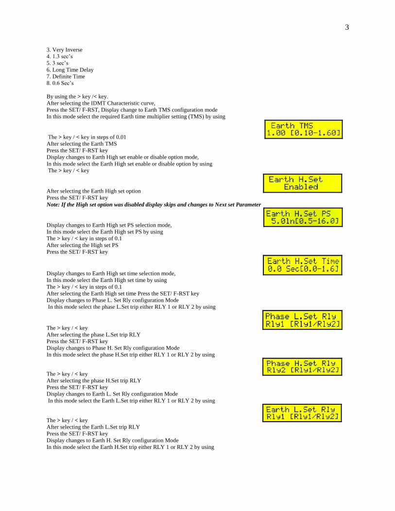
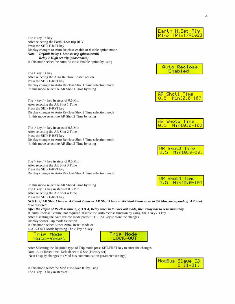
Display changes to Earth H. Set Rly configuration Mode
In this mode select the Earth H.Set trip either RLY 1 or RLY 2 by using
4
The > key / < key
After selecting the Earth H.Set trip RLY
Press the SET/ F-RST key
Display changes to Auto Re close enable or disable option mode
Note: Default Relay 1-Low set trip (phase/earth)
Relay 2-High set trip (phase/earth) In this mode select the Auto Re close Enable option by using
The > key / < key
After selecting the Auto Re close Enable option
Press the SET/ F-RST key
Display changes to Auto Re close Shot 1 Time selection mode
In this mode select the AR Shot 1 Time by using
The > key / < key in steps of 0.5 Min
After selecting the AR Shot 1 Time
Press the SET/ F-RST key
Display changes to Auto Re close Shot 2 Time selection mode
In this mode select the AR Shot 2 Time by using
The > key / < key in steps of 0.5 Min
After selecting the AR Shot 2 Time
Press the SET/ F-RST key
Display changes to Auto Re close Shot 3 Time selection mode
In this mode select the AR Shot 3 Time by using
The > key / < key in steps of 0.5 Min
After selecting the AR Shot 3 Time
Press the SET/ F-RST key
Display changes to Auto Re close Shot 4 Time selection mode
In this mode select the AR Shot 4 Time by using
The > key / < key in steps of 0.5 Min
After selecting the AR Shot 4 Time
Press the SET/ F-RST key
NOTE: If AR Shot 1 time or AR Shot 2 time or AR Shot 3 time or AR Shot 4 time is set to 0.0 Min corresponding AR Shot
time disabled
After the elapse of Re close time 1, 2, 3 & 4, Relay enter in to Lock out mode, then relay has to reset manually
If Auto Reclose Feature not required disable the Auto reclose function by using The > key / < key
After disabling the Auto reclose mode press SET/FRST key to store the changes
Display shows Trip mode Selection
In this mode select Either Auto- Reset Mode or
LOCK-OUT Mode by using The > key / < key
After Selecting the Required type of Trip mode press SET/FRST key to store the changes
Note: Auto Reset time- Default set to 5 Sec (Factory set)
Next Display changes to (Mod bus communication parameter settings)
In this mode select the Mod Bus Slave ID by using
The > key / < key in steps of 1

5
After selecting the Mod Bus Slave ID
Press the SET/ F-RST key
Display changes to Mod Bus Baud rate configuration mode
In this mode select the suitable Mod Bus Baud rate by using
The > key / < key
0. 1200 bps
1. 2400 bps
2. 4800 bps
3. 9600 bps
4. 19.2 kbps
5. 38.4 kbps
6. 115.2 kbps
After selecting the Mod Bus Baud rate, Press the SET/ F-RST key
Display changes to Date/ Month/ Year configuration mode
In this mode select YES (Y) option to edit the Date
In this mode select NO (N) option to retain the same Date
After selecting the edit Date option, Press the SET/ F-RST key
Display changes to Date/ Month/ Year Edit mode
In this mode Edit the Date / Month/ Year by using
The > key / < key
After selecting the Date / Month/ Year, Press the SET/ F-RST key
Display changes to Hour/ Min/ Sec configuration mode
In this mode select YES (Y) option to edit the Time
In this mode select NO (N) option to retain the same Time
After selecting the edit time option, Press the SET/ F-RST key
Display changes to HH/ MM/ SS Edit mode
In this mode Edit the HH/ MM/SS by using
The > key / < key
After selecting the HH/ MM/SS, Press the SET/ F-RST key
Display changes to save changes option
If the Save changes option is Yes (Y)
Entered parameters are saved in the memory
Then Display shows for a while
And comes back to main screen
If the Save changes option is NO (N)
Entered parameters are not saved in the memory and retain the last set Parameters and returns to main screen

6
NOTE: If none of the parameters were not edited in the setting mode data save changes option not appear in the setting
mode.
Change CR 2032 Button cell after every 5 years for error free time/date format
This completes the setting procedure.
******************************************************
Step 3: TO view the stored data:
STEP2: Hold the SET/ F-RST key for 3 sec, display changes to the Relay- setting
mode, if pass word enabled in the previous setting
Now enter the Factory set password – 1000
(Press > key once and then press SET key three times)
And then display changes to the password option
Enable / disable mode.
n this mode password can be disabled by pressing
The > key / < key and then SET F-RST key
NOTE: If password is disabled and saved in the relay setting mode
Setting password mode was bypassed
Display shows directly
NOTE: [While setting the parameters too much delayed >30 sec display time out occurs, and the entered settings are not updated user has to once again follow the steps setting procedure]
Step 4: TO view the trip events:
Hold the > key for 3 sec
Display changes to the last occurred fault event, last 99 events can be viewed by using the > key and < key.
For example;
Note: If the primary fault magnitude is above 1000A
Display as well as event recorded as 1.0 KA
Note: After 99 trip events trip events will be
Recorded on first in first out basis [FIFO] only
Step5: TO test the relay with trip mechanism
Hold the < key for 3 sec
Display changes to the relay trip test mode
Press > key to trip the relay with led & output relay ports in on position
Press < key to close the relay with led & output relay ports in off position (Reset)

7
User Parameters
Sl.
No. Parameter
Min
Value
Max
Value
Step
Size Dfault Comment
1 Relay Rated Current 1 5 5 Amp’s
2 CT Ratio for 5A 5 3000 5 5
3 CT Ratio for 1A 1 3000 1 5
4 Phase Curve 0 8 1 4 0 = Normal Inverse
1 = Extremely Inverse
2 = Restricted Inverse
3 = Very Inverse
4 = 1.3 Sec’s Curve
5 = 3 Sec’s Curve
6 = Long Time Delay
7 = Definite Time
8 = 0.6 Sec’s Curve
5 Phase LowSet PS for 5A 0.10 2.50 0.01 0.50
6 Phase LowSet PS for 1A 0.50 2.50 0.01 0.50
7 Phase TMS 0.10 1.60 0.01 1.00
8 Phase Definite Time 1.00 160.00 0.10 1.00 Sec’s
9 Phase HighSet Option 0 1 1 0 = Disable
1 = Enable
10 Phase HighSet PS 2.00 30.00 0.10 5.00
11 Phase HighSet Time 0.00 1.60 0.10 0.00 Sec’s
0.00 = Instantaneous
12 Earth Curve 0 8 1 4 0 = Normal Inverse
1 = Extremely Inverse
2 = Restricted Inverse
3 = Very Inverse
4 = 1.3 Sec’s Curve
5 = 3 Sec’s Curve
6 = Long Time Delay
7 = Definite Time
8 = 0.6 Sec’s Curve
13 Earth LowSet PS 0.10 0.80 0.01 0.50
14 Earth TMS 0.10 1.60 0.01 1.00
15 Earth Definite Time 1.00 160.00 0.10 1.00 Sec’s
16 Earth HighSet Option 0 1 1 0 = Disable
1 = Enable
17 Earth HighSet PS 0.50 16.00 0.10 5.00
18 Earth HighSet Time 0.00 1.60 0.10 0.00 Sec’s
0.00 = Instantaneous
19 Phase LowSet Relay 1 2 1 1 = Upper Relay
2 = Lower Relay 20 Phase HighSet Relay 1 2 2
21 Earth LowSet Relay 1 2 1
22 Earth HighSet Relay 1 2 2
23 Auto Reclose Option 0 1 0 0 = Disable
1 = Enable
24 AR Shot1 Time 0.00 10.00 0.50 0.50 Min’s
0.00 = Shot Bypass. 25 AR Shot2 Time 0.00 10.00 0.50 0.50
26 AR Shot3 Time 0.00 10.00 0.50 0.50
27 AR Shot4 Time 0.00 10.00 0.50 0.50
28 ModBus Slave ID 1 31 1 1

8
29 Baud Rate 0 6 1 3 0 = 1200 bps
1 = 2400 bps
2 = 4800 bps
3 = 9600 bps
4 = 19.2 kbps
5 = 38.4 kbps
6 = 115.2 kbps
30 Date 1 31 1 1
31 Month 1 12 1 9
32 Year 0 99 1 10
33 Hour 0 23 1 10
34 Minutes 0 59 1 10
35 Seconds 0 59 1 0
ModBus Address Map
Read Registers
Function Code : 03 ( Read Holding Register)
Address Description Data Type Comment
40001 Relay Rated Current 16 Bit
40002 CT Ratio for 5A 16 Bit
40003 CT Ratio for 1A 16 Bit
40004 Phase Curve 16 Bit
40005 Phase LowSet PS for 5A 16 Bit Represents float, 100 = 1.00
40006 Phase LowSet PS for 1A 16 Bit Represents float, 100 = 1.00
40007 Phase TMS 16 Bit Represents float, 100 = 1.00
40008 Phase Definite Time 16 Bit Represents float, 100 = 1.00
40009 Phase HighSet Option 16 Bit
40010 Phase HighSet PS 16 Bit Represents float, 100 = 1.00
40011 Phase HighSet Time 16 Bit Represents float, 100 = 1.00
40012 Earth Curve 16 Bit
40013 Earth LowSet PS 16 Bit Represents float, 100 = 1.00
40014 Earth TMS 16 Bit Represents float, 100 = 1.00
40015 Earth Definite Time 16 Bit Represents float, 100 = 1.00
40016 Earth HighSet Option 16 Bit
40017 Earth HighSet PS 16 Bit Represents float, 100 = 1.00
40018 Earth HighSet Time 16 Bit Represents float, 100 = 1.00
40019 Phase LowSet Relay 16 Bit
40020 Phase HighSet Relay 16 Bit
40021 Earth LowSet Relay 16 Bit
40022 Earth HighSet Relay 16 Bit
40023 Auto Reclose Option 16 Bit
40024 AR Shot1 Time 16 Bit Represents float, 100 = 1.00
40025 AR Shot2 Time 16 Bit Represents float, 100 = 1.00
40026 AR Shot3 Time 16 Bit Represents float, 100 = 1.00
40027 AR Shot4 Time 16 Bit Represents float, 100 = 1.00
40028 Baud Rate 16 Bit
40029 Clock – Hour 16 Bit
40030 Clock – Minutes 16 Bit
40031 Clock – Seconds 16 Bit
40032 Clock – Date 16 Bit
40033 Clock – Month 16 Bit
40034 Clock – Year 16 Bit 00 to 99
40035 Relay Model 16 Bit See Ref[1]
40036 R Phase Magnitude – LS Word 16 Bit Represents float, 100 = 1.00
40037 R Phase Magnitude – HS Word 16 Bit
40038 Y Phase Magnitude – LS Word 16 Bit Represents float, 100 = 1.00
40039 Y Phase Magnitude – HS Word 16 Bit

9
40040 B Phase Magnitude – LS Word 16 Bit Represents float, 100 = 1.00
40041 B Phase Magnitude – HS Word 16 Bit
40042 Earth Magnitude – LS Word 16 Bit Represents float, 100 = 1.00
40043 Earth Magnitude – HS Word 16 Bit
40044 Trip Status 16 Bit See Ref[2]
40045 Trip Magnitude – LS Word 16 Bit Represents float, 100 = 1.00
40046 Trip Magnitude – HS Word 16 Bit
40047 Trip Time – Hour 16 Bit
40048 Trip Time – Minutes 16 Bit
40049 Trip Time – Seconds 16 Bit
40050 Trip Time – Date 16 Bit
40051 Trip Time – Month 16 Bit
40052 Trip Time – Year 16 Bit 00 to 99
40053 Trip Type 16 Bit 0 = Lock-Out, 1= Reset
Ref[1] : Relay Models
ID Model Number Description
0 PNA442 3 Over Current + 1 Earth Fault Relay
1 PNA430 3 Over Current Relay
2 PNA420 2 Over Current Relay
3 PNA410 1 Over Current Relay
4 PNA422 2 Over Current + 1 Earth Fault Relay
5 PNA402 1 Earth Fault Relay
Ref[2] : Trip Status Description
Bit 7 Bit 6 Bit 5 Bit 4 Bit 3 Bit 2 Bit 1 Bit 0
0 0 High Set Low Set E B Y R
Bit 15 Bit 14 Bit 13 Bit 12 Bit 11 Bit 10 Bit 9 Bit 8
0 0 0 LockOut Reclose4 Reclose3 Reclose2 Reclose1
Write Registers
Function Code : 06 ( Preset Single Register)
Address Description Data Type Comment
60001 Relay Rated Current 16 Bit
60002 CT Ratio for 5A 16 Bit
60003 CT Ratio for 1A 16 Bit
60004 Phase Curve 16 Bit
60005 Phase LowSet PS for 5A 16 Bit Represents float, 100 = 1.00
60006 Phase LowSet PS for 1A 16 Bit Represents float, 100 = 1.00
60007 Phase TMS 16 Bit Represents float, 100 = 1.00
60008 Phase Definite Time 16 Bit Represents float, 100 = 1.00
60009 Phase HighSet Option 16 Bit
60010 Phase HighSet PS 16 Bit Represents float, 100 = 1.00
60011 Phase HighSet Time 16 Bit Represents float, 100 = 1.00
60012 Earth Curve 16 Bit
60013 Earth LowSet PS 16 Bit Represents float, 100 = 1.00
60014 Earth TMS 16 Bit Represents float, 100 = 1.00
60015 Earth Definite Time 16 Bit Represents float, 100 = 1.00
60016 Earth HighSet Option 16 Bit
60017 Earth HighSet PS 16 Bit Represents float, 100 = 1.00
60018 Earth HighSet Time 16 Bit Represents float, 100 = 1.00
60019 Phase LowSet Relay 16 Bit

10
60020 Phase HighSet Relay 16 Bit
60021 Earth LowSet Relay 16 Bit
60022 Earth HighSet Relay 16 Bit
60023 Auto Reclose Option 16 Bit
60024 AR Shot1 Time 16 Bit Represents float, 100 = 1.00
60025 AR Shot2 Time 16 Bit Represents float, 100 = 1.00
60026 AR Shot3 Time 16 Bit Represents float, 100 = 1.00
60027 AR Shot4 Time 16 Bit Represents float, 100 = 1.00
60028 Baud Rate 16 Bit
60029 Clock – Hour 16 Bit
60030 Clock – Minutes 16 Bit
60031 Clock – Seconds 16 Bit
60032 Clock – Date 16 Bit
60033 Clock – Month 16 Bit
60034 Clock – Year 16 Bit 00 to 99
60035 Trip Reset 16 Bit 1 = Trip Reset
60036 Trip Type 16 Bit 0 = Lock-Out, 1= Reset
NOTE : Relay will not respond to Write Register query in the following cases,
When the user is in the settings mode.
When the relay has been picked up for the fault.
Note: Do Not Connect Terminals 19 & 20 (A& B Of Rs 485) For Hv Test
RS 232 Port is provided on the front facia