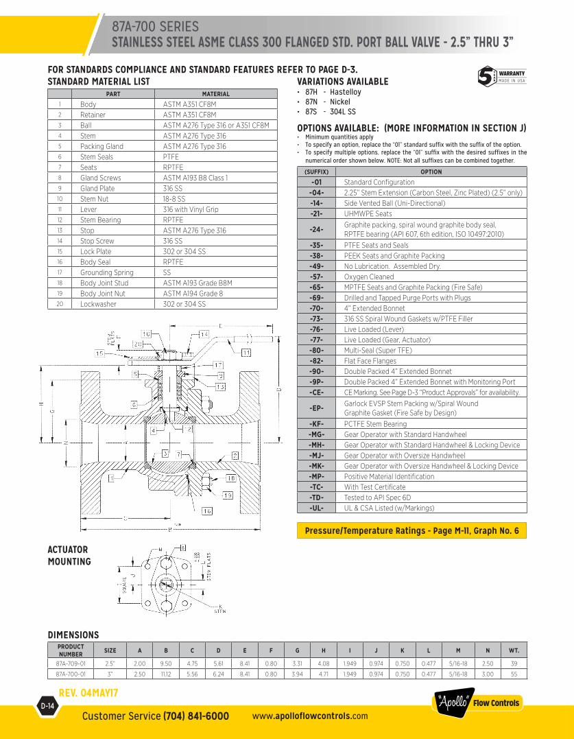
87a-700 series stainless steel asme class 300 flanged std ...
7
D-13 Customer Service (704) 841-6000 industrial.apollovalves.com “Apollo” Flow Controls FOR STANDARDS COMPLIANCE AND STANDARD FEATURES REFER TO PAGE D-3. Pressure/Temperature Ratings - Page M-11, Graph No. 6 STANDARD MATERIAL LIST PART MATERIAL 1 Body ASTM A351 CF8M 2 Retainer ASTM A276 Type 316 3 Ball ASTM A276 Type 316 4 Stem ASTM A276 Type 316 5 Packing Gland ASTM A276 Type 316 6 Stem Seals PTFE 7 Seats RPTFE 8 Gland Screws ASTM A193 B8 Class 1 9 Gland Plate 302 & 304 SS 10 Stem Nut 316 SS 11 Lever 302 & 304 SS with Vinyl Grip 12 Stem Bearing RPTFE 13 Stop ASTM A276 Type 316 14 Stop Screw 18-8 SS 15 Lock Plate 302 or 304 SS 16 Body Seal RPTFE 17 Lockwasher 302 or 304 SS 18 Grounding Spring SS DIMENSIONS PRODUCT NUMBER SIZE A B C D E F G H I J K L M N WT. 87A-707-01A 1.5” 1.25 7.50 4.50 4.85 6.53 0.47 1.85 2.38 1.392 0.696 0.500 0.287 1/4-20 1.50 15.7 87A-708-01 2” 1.50 8.50 5.19 4.62 6.65 0.72 2.41 3.09 1.949 0.974 0.625 0.412 5/16-18 2.00 24.0 VARIATIONS AVAILABLE • 87H - Hastelloy • 87M - Monel • 87N - Nickel • 87S - 304L SS OPTIONS AVAILABLE: (MORE INFORMATION IN SECTION J) • Minimum quantities apply • To specify an option, replace the “01” standard suffix with the suffix of the option. • To specify multiple options, replace the “01” suffix with the desired suffixes in the numerical order shown below. NOTE: Not all suffixes can be combined together. (SUFFIX) OPTION -01 Standard Configuration -04- 2.25” Stem Extension (Carbon Steel, Zinc Plated) -14- Side Vented Ball (See Page J-2) -15- Wheel Handle, Steel -21- UHMWPE Seats -24- Graphite packing, spiral wound graphite body seal, RPTFE bearing (API 607, 6th edition, ISO 10497:2010) -35- PTFE Seats and Seals -38- PEEK Seats and Graphite Packing -49- No Lubrication. Assembled Dry. -57- Oxygen Cleaned -65- MPTFE Seats and Graphite Packing (Fire Safe) -69- Drilled and Tapped Purge Ports with Plugs -70- 4” Extended Bonnet -73- 316 SS Spiral Wound Gaskets w/PTFE Filler -76- Live Loaded (Lever) -77- Live Loaded (Gear, Actuator) -80- Multi-Seal (Super TFE) -82- Flat Face Flanges -90- Double Packed 4” Extended Bonnet -9P- Double Packed 4” Extended Bonnet with Monitoring Port -CE- CE Marking. See Page D-3 “Product Approvals” for availability. -EP- Garlock EVSP Stem Packing w/Spiral Wound Graphite Gasket (Fire Safe by Design) -KF- PCTFE Stem Bearing -MP- Positive Material Identification -TC- With Test Certificate -TD- Tested to API Spec 6D -UL- UL & CSA Listed (w/Markings) 87A-700 SERIES STAINLESS STEEL ASME CLASS 300 FLANGED STD. PORT BALL VALVE - 1.5” THRU 2” ACTUATOR MOUNTING REV. 04MAY17
-
Upload
khangminh22 -
Category
Documents
-
view
0 -
download
0
Transcript of 87a-700 series stainless steel asme class 300 flanged std ...

D-13Customer Service (704) 841-6000industrial.apollovalves.com
“Apollo” Flow Controls
FOR STANDARDS COMPLIANCE AND STANDARD FEATURES REFER TO PAGE D-3.
Pressure/Temperature Ratings - Page M-11, Graph No. 6
STANDARD MATERIAL LISTPART MATERIAL
1 Body ASTM A351 CF8M2 Retainer ASTM A276 Type 3163 Ball ASTM A276 Type 3164 Stem ASTM A276 Type 3165 Packing Gland ASTM A276 Type 3166 Stem Seals PTFE7 Seats RPTFE8 Gland Screws ASTM A193 B8 Class 19 Gland Plate 302 & 304 SS10 Stem Nut 316 SS11 Lever 302 & 304 SS with Vinyl Grip12 Stem Bearing RPTFE13 Stop ASTM A276 Type 31614 Stop Screw 18-8 SS15 Lock Plate 302 or 304 SS16 Body Seal RPTFE17 Lockwasher 302 or 304 SS18 Grounding Spring SS
DIMENSIONSPRODUCT NUMBER SIZE A B C D E F G H I J K L M N WT.
87A-707-01A 1.5” 1.25 7.50 4.50 4.85 6.53 0.47 1.85 2.38 1.392 0.696 0.500 0.287 1/4-20 1.50 15.7
87A-708-01 2” 1.50 8.50 5.19 4.62 6.65 0.72 2.41 3.09 1.949 0.974 0.625 0.412 5/16-18 2.00 24.0
VARIATIONS AVAILABLE • 87H - Hastelloy• 87M - Monel• 87N - Nickel• 87S - 304L SS
OPTIONS AVAILABLE: (MORE INFORMATION IN SECTION J)• Minimum quantities apply• To specify an option, replace the “01” standard suffix with the suffix of the option.• To specify multiple options, replace the “01” suffix with the desired suffixes in the
numerical order shown below. NOTE: Not all suffixes can be combined together.
(SUFFIX) OPTION
-01 Standard Configuration-04- 2.25” Stem Extension (Carbon Steel, Zinc Plated)-14- Side Vented Ball (See Page J-2)-15- Wheel Handle, Steel-21- UHMWPE Seats
-24- Graphite packing, spiral wound graphite body seal, RPTFE bearing (API 607, 6th edition, ISO 10497:2010)
-35- PTFE Seats and Seals-38- PEEK Seats and Graphite Packing-49- No Lubrication. Assembled Dry.-57- Oxygen Cleaned-65- MPTFE Seats and Graphite Packing (Fire Safe)-69- Drilled and Tapped Purge Ports with Plugs-70- 4” Extended Bonnet-73- 316 SS Spiral Wound Gaskets w/PTFE Filler-76- Live Loaded (Lever)-77- Live Loaded (Gear, Actuator)-80- Multi-Seal (Super TFE)-82- Flat Face Flanges-90- Double Packed 4” Extended Bonnet-9P- Double Packed 4” Extended Bonnet with Monitoring Port-CE- CE Marking. See Page D-3 “Product Approvals” for availability.
-EP- Garlock EVSP Stem Packing w/Spiral Wound Graphite Gasket (Fire Safe by Design)
-KF- PCTFE Stem Bearing-MP- Positive Material Identification-TC- With Test Certificate-TD- Tested to API Spec 6D-UL- UL & CSA Listed (w/Markings)
87A-700 SERIESSTAINLESS STEEL ASME CLASS 300 FLANGED STD. PORT BALL VALVE - 1.5” THRU 2”
ACTUATORMOUNTING
REV. 04MAY17
D-14Customer Service (704) 841-6000 www.apolloflowcontrols.com
“Apollo” Flow Controls
FOR STANDARDS COMPLIANCE AND STANDARD FEATURES REFER TO PAGE D-3.
Pressure/Temperature Ratings - Page M-11, Graph No. 6
STANDARD MATERIAL LISTPART MATERIAL
1 Body ASTM A351 CF8M2 Retainer ASTM A351 CF8M3 Ball ASTM A276 Type 316 or A351 CF8M4 Stem ASTM A276 Type 3165 Packing Gland ASTM A276 Type 3166 Stem Seals PTFE7 Seats RPTFE8 Gland Screws ASTM A193 B8 Class 19 Gland Plate 316 SS10 Stem Nut 18-8 SS11 Lever 316 with Vinyl Grip12 Stem Bearing RPTFE13 Stop ASTM A276 Type 31614 Stop Screw 316 SS15 Lock Plate 302 or 304 SS16 Body Seal RPTFE17 Grounding Spring SS18 Body Joint Stud ASTM A193 Grade B8M19 Body Joint Nut ASTM A194 Grade 820 Lockwasher 302 or 304 SS
DIMENSIONSPRODUCT NUMBER SIZE A B C D E F G H I J K L M N WT.
87A-709-01 2.5” 2.00 9.50 4.75 5.61 8.41 0.80 3.31 4.08 1.949 0.974 0.750 0.477 5/16-18 2.50 39
87A-700-01 3” 2.50 11.12 5.56 6.24 8.41 0.80 3.94 4.71 1.949 0.974 0.750 0.477 5/16-18 3.00 55
VARIATIONS AVAILABLE• 87H - Hastelloy• 87N - Nickel• 87S - 304L SS
OPTIONS AVAILABLE: (MORE INFORMATION IN SECTION J)• Minimum quantities apply• To specify an option, replace the “01” standard suffix with the suffix of the option.• To specify multiple options, replace the “01” suffix with the desired suffixes in the
numerical order shown below. NOTE: Not all suffixes can be combined together.
(SUFFIX) OPTION
-01 Standard Configuration-04- 2.25” Stem Extension (Carbon Steel, Zinc Plated) (2.5” only)-14- Side Vented Ball (Uni-Directional)-21- UHMWPE Seats
-24- Graphite packing, spiral wound graphite body seal, RPTFE bearing (API 607, 6th edition, ISO 10497:2010)
-35- PTFE Seats and Seals-38- PEEK Seats and Graphite Packing-49- No Lubrication. Assembled Dry.-57- Oxygen Cleaned -65- MPTFE Seats and Graphite Packing (Fire Safe)-69- Drilled and Tapped Purge Ports with Plugs-70- 4” Extended Bonnet-73- 316 SS Spiral Wound Gaskets w/PTFE Filler-76- Live Loaded (Lever)-77- Live Loaded (Gear, Actuator)-80- Multi-Seal (Super TFE)-82- Flat Face Flanges-90- Double Packed 4” Extended Bonnet-9P- Double Packed 4” Extended Bonnet with Monitoring Port-CE- CE Marking. See Page D-3 “Product Approvals” for availability.
-EP- Garlock EVSP Stem Packing w/Spiral Wound Graphite Gasket (Fire Safe by Design)
-KF- PCTFE Stem Bearing-MG- Gear Operator with Standard Handwheel-MH- Gear Operator with Standard Handwheel & Locking Device-MJ- Gear Operator with Oversize Handwheel-MK- Gear Operator with Oversize Handwheel & Locking Device-MP- Positive Material Identification-TC- With Test Certificate-TD- Tested to API Spec 6D-UL- UL & CSA Listed (w/Markings)
87A-700 SERIESSTAINLESS STEEL ASME CLASS 300 FLANGED STD. PORT BALL VALVE - 2.5” THRU 3”
ACTUATORMOUNTING
REV. 04MAY17

D-15Customer Service (704) 841-6000industrial.apollovalves.com
“Apollo” Flow Controls
FOR STANDARDS COMPLIANCE AND STANDARD FEATURES REFER TO PAGE D-3.
Pressure/Temperature Ratings - Page M-11, Graph No. 6
STANDARD MATERIAL LISTPART MATERIAL
1 Body ASTM A351 CF8M2 Retainer ASTM A276 Type 3163 Ball ASTM A276 Type 316 or A351 CF8M4 Stem ASTM A276 Type 3165 Packing Gland ASTM A276 Type 3166 Stem Seals PTFE7 Seats RPTFE8 Gland Screws ASTM A193 B8 Class 19 Gland Plate 316 SS10 Adapter Screw 18-8 SS11 Handle Adapter 316 SS12 Stem Bearing RPTFE13 Stop ASTM A276 Type 31614 Stop Screw 316 SS15 Lock Plate 302 or 304 SS16 Body Seal RPTFE17 Grounding Spring SS18 Body Joint Stud ASTM A193 Grade B8M19 Body Joint Nut ASTM A194 Grade 820 Adapter Screw 18-8 SS21 Pipe Handle Galvanized Steel (not shown)
DIMENSIONSPRODUCT NUMBER SIZE A B C D E F G H I J K L M N WT.
87A-70A-01 4” 3.00 12.00 5.68 8.80 4.06 0.50 4.75 5.95 2.840 1.420 1.250 0.725 3/8-16 4.00 95
87A-70C-01 6” 4.00 15.88 7.38 9.99 5.25 0.50 5.94 7.13 2.840 1.420 1.250 0.725 3/8-16 6.00 187
87A-70E-01 8” 6.00 19.75 9.00 13.73 7.30 1.00 7.75 9.48 4.596 2.298 2.000 1.375 3/4-10 8.00 400
VARIATIONS AVAILABLE• 87H - Hastelloy• 87N - Nickel• 87S - 304L SS
OPTIONS AVAILABLE: (MORE INFORMATION IN SECTION J)• Minimum quantities apply• To specify an option, replace the “01” standard suffix with the suffix of the option.• To specify multiple options, replace the “01” suffix with the desired suffixes in the
numerical order shown below. NOTE: Not all suffixes can be combined together.
(SUFFIX) OPTION
-01 Standard Configuration-14- Side Vented Ball (Uni-Directional)-21- UHMWPE Seats
-24- Graphite packing, spiral wound graphite body seal, RPTFE bearing (API 607, 6th edition, ISO 10497:2010)
-35- PTFE Seats and Seals-49- No Lubrication. Assembled Dry.-57- Oxygen Cleaned-65- MPTFE Seats and Graphite Packing (Fire Safe)-69- Drilled and Tapped Purge Ports with Plugs-70- 4” Extended Bonnet -73- 316 SS Spiral Wound Gaskets w/PTFE Filler-76- Live Loaded (Lever)-77- Live Loaded (Gear, Actuator)-80- Multi-Seal (Super TFE)-82- Flat Face Flanges-90- Double Packed 4” Extended Bonnet-9P- Double Packed 4” Extended Bonnet with Monitoring Port-CE- CE Marking. See Page D-3 “Product Approvals” for availability.
-EP- Garlock EVSP Stem Packing w/Spiral Wound Graphite Gasket (Fire Safe by Design)
-KF- PCTFE Stem Bearing-MG- Gear Operator with Standard Handwheel-MH- Gear Operator with Standard Handwheel & Locking Device-MJ- Gear Operator with Oversize Handwheel-MK- Gear Operator with Oversize Handwheel & Locking Device-MP- Positive Material Identification-TC- With Test Certificate-TD- Tested to API Spec 6D-UL- UL & CSA Listed (w/Markings)
87A-700 SERIESSTAINLESS STEEL ASME CLASS 300 FLANGED STD. PORT BALL VALVE - 4” THRU 8”
ACTUATORMOUNTING
REV. 04MAY17

D-16Customer Service (704) 841-6000 www.apolloflowcontrols.com
“Apollo” Flow Controls
FOR STANDARDS COMPLIANCE AND STANDARD FEATURES REFER TO PAGE D-3.
Pressure/Temperature Ratings - Page M-11, Graph No. 6
STANDARD MATERIAL LISTPART MATERIAL
1 Body ASTM A351 CF8M2 Retainer ASTM A351 CF8M3 Ball ASTM A276 Type 316 or A351 CF8M4 Stem ASTM A276 Type 3165 Packing Gland ASTM A276 Type 3166 Stem Seals PTFE7 Seats RPTFE8 Gland Screws ASTM A193 B8 Class 19 Gland Plate 316 SS10 Stem Bearing RPTFE11 Body Seal RPTFE12 Body Joint Stud ASTM A193 Grade B8M13 Body Joint Nut ASTM A194 Grade 8
DIMENSIONSPRODUCT NUMBER SIZE A B C D E F G H I J K L M
87A-70G-01 10” 8.00 22.38 10.69 12.83 9.56 1.00 10.22 4.596 2.298 2.000 1.375 3/4-10 10.00
VARIATIONS AVAILABLE • 87H - Hastelloy• 87N - Nickel• 87S - 304L SS
OPTIONS AVAILABLE: (MORE INFORMATION IN SECTION J)• Minimum quantities apply• To specify an option, replace the “01” standard suffix with the suffix of the option.• To specify multiple options, replace the “01” suffix with the desired suffixes in the
numerical order shown below. NOTE: Not all suffixes can be combined together.
(SUFFIX) OPTION
-01 Standard Configuration (Less Gear Operator)-14- Side Vented Ball (See Page J2)-21- UHMWPE Seats
-24- Graphite packing, spiral wound graphite body seal, RPTFE bearing (API 607, 6th edition, ISO 10497:2010)
-35- PTFE Seats and Seals-49- No Lubrication. Assembled Dry.-57- Oxygen Cleaned-65- MPTFE Seats and Graphite Packing (Fire Safe)-69- Drilled and Tapped Purge Ports with Plugs-70- 4” Extended Bonnet-77- Live Loaded 87A/88A Series (Gear, Actuator)-80- Multi-Seal (Super TFE) 87A/88A Series-82- Flat Face Flanges-90- Double Packed 4” Extended Bonnet-9P- Double Packed 4” Extended Bonnet with Monitoring Port-CE- CE Marking. See Page D-3 “Product Approvals” for availability.
-EP- Garlock EVSP Stem Packing w/Spiral Wound Graphite Gasket (Fire Safe by Design)
-KF- PCTFE Stem Bearing-MG- Gear Operator with Standard Handwheel-MH- Gear Operator with Standard Handwheel & Locking Device-MJ- Gear Operator with Oversize Handwheel-MK- Gear Operator with Oversize Handwheel & Locking Device-MP- Positive Material Identification-TC- With Test Certificate-TD- Tested to API Spec 6D-UL- UL & CSA Listed (w/Markings)
87A-700 SERIESSTAINLESS STEEL ASME CLASS 300 FLANGED STD. PORT BALL VALVE - 10”
ACTUATORMOUNTING
REV. 04MAY17
M-3Customer Service (704) 841-6000industrial.apollovalves.com
“Apollo” Flow Controls
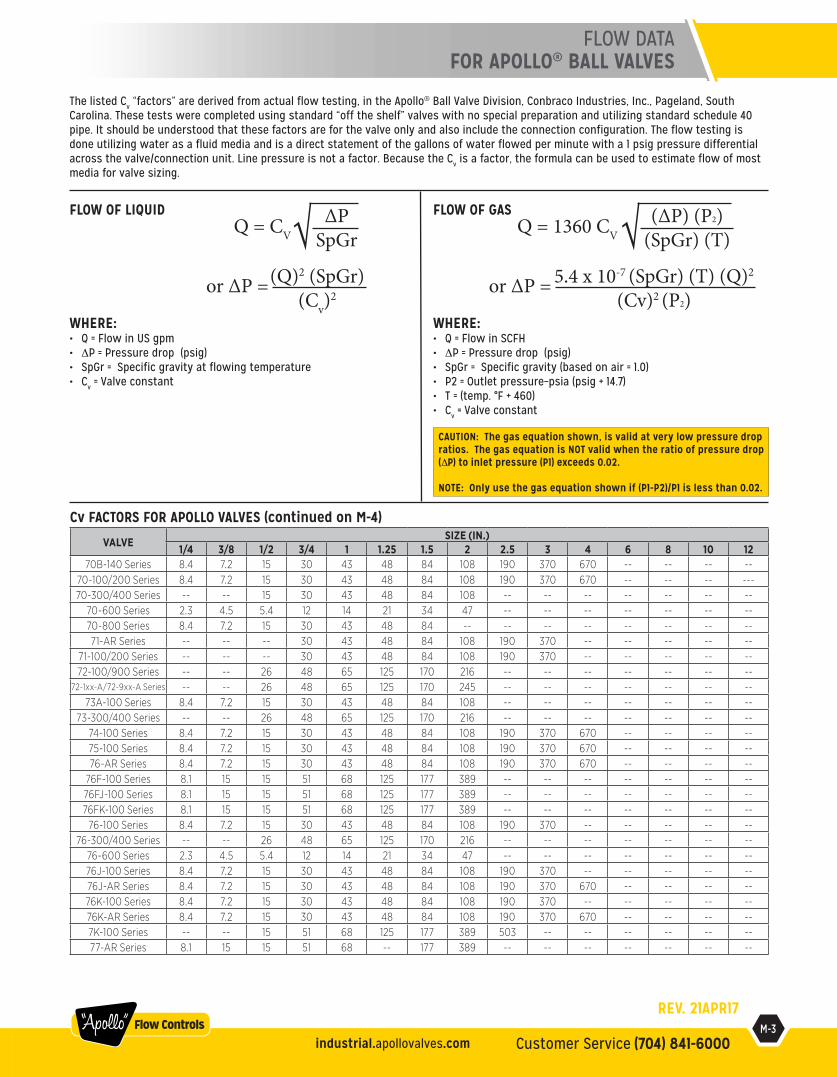
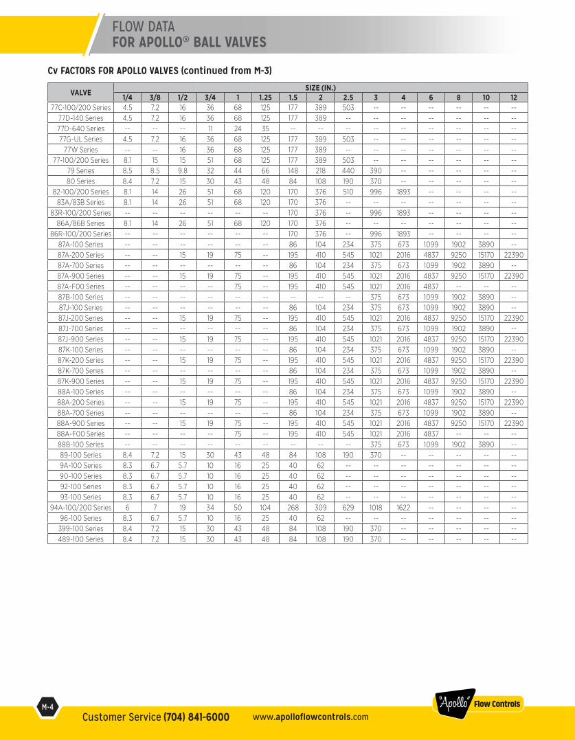
The listed Cv “factors” are derived from actual flow testing, in the Apollo® Ball Valve Division, Conbraco Industries, Inc., Pageland, South Carolina. These tests were completed using standard “off the shelf” valves with no special preparation and utilizing standard schedule 40 pipe. It should be understood that these factors are for the valve only and also include the connection configuration. The flow testing is done utilizing water as a fluid media and is a direct statement of the gallons of water flowed per minute with a 1 psig pressure differential across the valve/connection unit. Line pressure is not a factor. Because the Cv is a factor, the formula can be used to estimate flow of most media for valve sizing.
Cv FACTORS FOR APOLLO VALVES (continued on M-4)
VALVE SIZE (IN.)1/4 3/8 1/2 3/4 1 1.25 1.5 2 2.5 3 4 6 8 10 12
70B-140 Series 8.4 7.2 15 30 43 48 84 108 190 370 670 -- -- -- --70-100/200 Series 8.4 7.2 15 30 43 48 84 108 190 370 670 -- -- -- ---70-300/400 Series -- -- 15 30 43 48 84 108 -- -- -- -- -- -- --
70-600 Series 2.3 4.5 5.4 12 14 21 34 47 -- -- -- -- -- -- --70-800 Series 8.4 7.2 15 30 43 48 84 -- -- -- -- -- -- -- --71-AR Series -- -- -- 30 43 48 84 108 190 370 -- -- -- -- --
71-100/200 Series -- -- -- 30 43 48 84 108 190 370 -- -- -- -- --72-100/900 Series -- -- 26 48 65 125 170 216 -- -- -- -- -- -- --
72-1xx-A/72-9xx-A Series -- -- 26 48 65 125 170 245 -- -- -- -- -- -- --73A-100 Series 8.4 7.2 15 30 43 48 84 108 -- -- -- -- -- -- --
73-300/400 Series -- -- 26 48 65 125 170 216 -- -- -- -- -- -- --74-100 Series 8.4 7.2 15 30 43 48 84 108 190 370 670 -- -- -- --75-100 Series 8.4 7.2 15 30 43 48 84 108 190 370 670 -- -- -- --76-AR Series 8.4 7.2 15 30 43 48 84 108 190 370 670 -- -- -- --
76F-100 Series 8.1 15 15 51 68 125 177 389 -- -- -- -- -- -- --76FJ-100 Series 8.1 15 15 51 68 125 177 389 -- -- -- -- -- -- --76FK-100 Series 8.1 15 15 51 68 125 177 389 -- -- -- -- -- -- --
76-100 Series 8.4 7.2 15 30 43 48 84 108 190 370 -- -- -- -- --76-300/400 Series -- -- 26 48 65 125 170 216 -- -- -- -- -- -- --
76-600 Series 2.3 4.5 5.4 12 14 21 34 47 -- -- -- -- -- -- --76J-100 Series 8.4 7.2 15 30 43 48 84 108 190 370 -- -- -- -- --76J-AR Series 8.4 7.2 15 30 43 48 84 108 190 370 670 -- -- -- --76K-100 Series 8.4 7.2 15 30 43 48 84 108 190 370 -- -- -- -- --76K-AR Series 8.4 7.2 15 30 43 48 84 108 190 370 670 -- -- -- --7K-100 Series -- -- 15 51 68 125 177 389 503 -- -- -- -- -- --77-AR Series 8.1 15 15 51 68 -- 177 389 -- -- -- -- -- -- --
∆PSpGr
Q = CV√FLOW OF LIQUID
WHERE:• Q = Flow in US gpm• ∆P = Pressure drop (psig)• SpGr = Specific gravity at flowing temperature• Cv = Valve constant
FLOW OF GAS
WHERE:• Q = Flow in SCFH• ∆P = Pressure drop (psig)• SpGr = Specific gravity (based on air = 1.0)• P2 = Outlet pressure–psia (psig + 14.7)• T = (temp. °F + 460)• Cv = Valve constant
(Q)2 (SpGr)(Cv)
2 or ∆P =
(∆P) (P2)(SpGr) (T)
Q = 1360 CV √5.4 x 10⁻⁷ (SpGr) (T) (Q)2
(Cv)2 (P2) or ∆P =
CAUTION: The gas equation shown, is valid at very low pressure drop ratios. The gas equation is NOT valid when the ratio of pressure drop (∆P) to inlet pressure (P1) exceeds 0.02.
NOTE: Only use the gas equation shown if (P1-P2)/P1 is less than 0.02.
REV. 21APR17
FLOW DATAFOR APOLLO® BALL VALVES
M-4Customer Service (704) 841-6000 www.apolloflowcontrols.com
“Apollo” Flow Controls
Cv FACTORS FOR APOLLO VALVES (continued from M-3)
FLOW DATA FOR APOLLO® BALL VALVES
VALVE SIZE (IN.)1/4 3/8 1/2 3/4 1 1.25 1.5 2 2.5 3 4 6 8 10 12
77C-100/200 Series 4.5 7.2 16 36 68 125 177 389 503 -- -- -- -- -- --77D-140 Series 4.5 7.2 16 36 68 125 177 389 -- -- -- -- -- -- --77D-640 Series -- -- -- 11 24 35 -- -- -- -- -- -- -- -- --77G-UL Series 4.5 7.2 16 36 68 125 177 389 503 -- -- -- -- -- --
77W Series -- -- 16 36 68 125 177 389 -- -- -- -- -- -- --77-100/200 Series 8.1 15 15 51 68 125 177 389 503 -- -- -- -- -- --
79 Series 8.5 8.5 9.8 32 44 66 148 218 440 390 -- -- -- -- --80 Series 8.4 7.2 15 30 43 48 84 108 190 370 -- -- -- -- --
82-100/200 Series 8.1 14 26 51 68 120 170 376 510 996 1893 -- -- -- --83A/83B Series 8.1 14 26 51 68 120 170 376 -- -- -- -- -- -- --
83R-100/200 Series -- -- -- -- -- -- 170 376 -- 996 1893 -- -- -- --86A/86B Series 8.1 14 26 51 68 120 170 376 -- -- -- -- -- -- --
86R-100/200 Series -- -- -- -- -- -- 170 376 -- 996 1893 -- -- -- --87A-100 Series -- -- -- -- -- -- 86 104 234 375 673 1099 1902 3890 --87A-200 Series -- -- 15 19 75 -- 195 410 545 1021 2016 4837 9250 15170 2239087A-700 Series -- -- -- -- -- -- 86 104 234 375 673 1099 1902 3890 --87A-900 Series -- -- 15 19 75 -- 195 410 545 1021 2016 4837 9250 15170 2239087A-F00 Series -- -- -- -- 75 -- 195 410 545 1021 2016 4837 -- -- --87B-100 Series -- -- -- -- -- -- -- -- -- 375 673 1099 1902 3890 --87J-100 Series -- -- -- -- -- -- 86 104 234 375 673 1099 1902 3890 --87J-200 Series -- -- 15 19 75 -- 195 410 545 1021 2016 4837 9250 15170 2239087J-700 Series -- -- -- -- -- -- 86 104 234 375 673 1099 1902 3890 --87J-900 Series -- -- 15 19 75 -- 195 410 545 1021 2016 4837 9250 15170 2239087K-100 Series -- -- -- -- -- -- 86 104 234 375 673 1099 1902 3890 --87K-200 Series -- -- 15 19 75 -- 195 410 545 1021 2016 4837 9250 15170 2239087K-700 Series -- -- -- -- -- -- 86 104 234 375 673 1099 1902 3890 --87K-900 Series -- -- 15 19 75 -- 195 410 545 1021 2016 4837 9250 15170 2239088A-100 Series -- -- -- -- -- -- 86 104 234 375 673 1099 1902 3890 --88A-200 Series -- -- 15 19 75 -- 195 410 545 1021 2016 4837 9250 15170 2239088A-700 Series -- -- -- -- -- -- 86 104 234 375 673 1099 1902 3890 --88A-900 Series -- -- 15 19 75 -- 195 410 545 1021 2016 4837 9250 15170 2239088A-F00 Series -- -- -- -- 75 -- 195 410 545 1021 2016 4837 -- -- --88B-100 Series -- -- -- -- -- -- -- -- -- 375 673 1099 1902 3890 --89-100 Series 8.4 7.2 15 30 43 48 84 108 190 370 -- -- -- -- --9A-100 Series 8.3 6.7 5.7 10 16 25 40 62 -- -- -- -- -- -- --90-100 Series 8.3 6.7 5.7 10 16 25 40 62 -- -- -- -- -- -- --92-100 Series 8.3 6.7 5.7 10 16 25 40 62 -- -- -- -- -- -- --93-100 Series 8.3 6.7 5.7 10 16 25 40 62 -- -- -- -- -- -- --
94A-100/200 Series 6 7 19 34 50 104 268 309 629 1018 1622 -- -- -- --96-100 Series 8.3 6.7 5.7 10 16 25 40 62 -- -- -- -- -- -- --
399-100 Series 8.4 7.2 15 30 43 48 84 108 190 370 -- -- -- -- --489-100 Series 8.4 7.2 15 30 43 48 84 108 190 370 -- -- -- -- --
M-11Customer Service (704) 841-6000industrial.apollovalves.com
“Apollo” Flow Controls
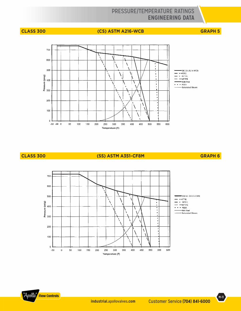
PRESSURE/TEMPERATURE RATINGSENGINEERING DATA
CLASS 300 (SS) ASTM A351-CF8M GRAPH 6
CLASS 300 (CS) ASTM A216-WCB GRAPH 5