Presentation of a Comprehensive Collection of Orthodox "digital icons"
CEC1993-3904 - ASME Digital Collection
12
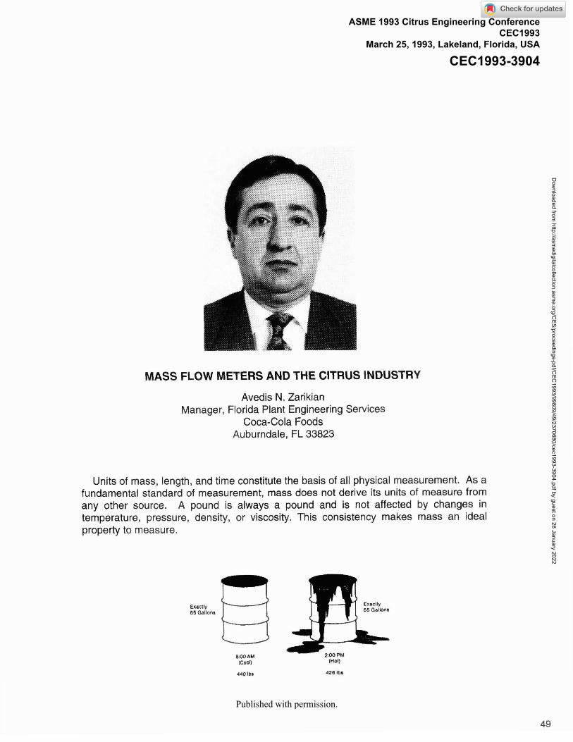
MASS FLOW METERS AND THE CITRUS INDUSTRY Avedis N. Zarikian Manager, Florida Plant Engineering Services Coca-Cola Foods Auburndale, FL 33823 Units of mass, length, and time constitute the basis of all physical measurement. As a fundamental standard of measurement, mass does not derive its units of measure from any other source. A pound is always a pound and is not affected by changes in temperature, pressure, density, or viscosity. This consistency makes mass an ideal property to measure. Published with permission. ASME 1993 Citrus Engineering Conference CEC1993 March 25, 1993, Lakeland, Florida, USA CEC1993-3904 Downloaded from http://asmedigitalcollection.asme.org/CES/proceedings-pdf/CEC1993/99809/49/2370680/cec1993-3904.pdf by guest on 26 January 2022
-
Upload
khangminh22 -
Category
Documents
-
view
4 -
download
0
Transcript of CEC1993-3904 - ASME Digital Collection
MASS FLOW METERS AND THE CITRUS INDUSTRY
Avedis N. Zarikian Manager, Florida Plant Engineering Services
Coca-Cola Foods Auburndale, FL 33823
Units of mass, length, and time constitute the basis of all physical measurement. As a fundamental standard of measurement, mass does not derive its units of measure from any other source. A pound is always a pound and is not affected by changes in temperature, pressure, density, or viscosity. This consistency makes mass an ideal property to measure.
Published with permission.
ASME 1993 Citrus Engineering Conference CEC1993
March 25, 1993, Lakeland, Florida, USA
CEC1993-3904
Dow
nloaded from http://asm
edigitalcollection.asme.org/C
ES/proceedings-pdf/CEC
1993/99809/49/2370680/cec1993-3904.pdf by guest on 26 January 2022

In the early days, orange juice concentrate was stored in drums and scales were the dominant measuring devices. Drums were filled to a certain level, weighed, and placed in freezers. Blending was controlled by using known quantities of concentrate. Water was the main ingredient that was metered and the existing volumetric meters were more than adequate. The Citrus Processing Industry developed and changed, but the measuring technology it needed did not keep pace. As the industry moved into the Tank Farm era and bulk concentrate became prevalent, some problems in material management be- came apparent.
The first challenge was in how to measure concentrate pumped to the Tank Farm. The Citrus Industry relied on volumetric meters and calculations to reach the final desired quantity, weight, and #s solids. Entrapped gases in the product became a major problem, causing the flow meters to indicate higher than actual flow rates and therefore signaling higher than actual concentrate production rates at the processing facilities. Extended periods of storage in large tanks enabled the entrapped air to escape, causing the tank gauges to indicate lower concentrate levels in the tanks. This perceived solids losses had major implications on recovery and yield calculations.
The second challenge was in using of concentrate from the Tank Farms. As more and more concentrate was used from bulk rather than drums, inaccuracies in the blending operations became a problem. Several attempts were made at correcting this. In opera- tions where Batching was used, load cells became typical application. While this solved one problem (weighing the ingredients), it created a new one; each component of the blend had to be added separately and this prolonged the blending operation, causing loss of efficiency. There was therefore a need to establish a practical method of measuring mass in motion.
The initial attempts at mass flow metering were combinations of old technologies refined to meet the new needs with "intelligent" instruments and microprocessor based electronics. Output signals from volumetric meters and density measuring devices were sent to a microprocessor and flow rates were calculated. Temperature sensing devices were added to increase the accuracy of the density measurements. While this was an improvement, the accuracy level was not there. The accuracy of a volumetric meter is based on reference conditions. These conditions define specific fluid properties under which the flow meter will meet the manufacturer's specifications. The fluid properties include density, viscosity, and chemical composition. The fluid must be Homogenous and Newtonian, and must flow at a steady state with turbulent flow profile. As the properties of the fluids measured through these meters changed, so did the results. These methods combined the inaccuracies of the flow and density meters.
Positive displacement flow meters were used in an attempt to overcome the problems encountered due to changing fluid properties, but their accuracy fell short of expectations, mainly due to entrapped gases in the product. Other volumetric flow devices were tried but led to similar results.
With the failure of these attempts to measure mass flow using volumetric meters, the need for direct and accurate mass flow meter was clear. In recent years, a number of flow meters have been developed which measure mass flow directly. They accomplish this by using:
Dow
nloaded from http://asm
edigitalcollection.asme.org/C
ES/proceedings-pdf/CEC
1993/99809/49/2370680/cec1993-3904.pdf by guest on 26 January 2022

A - Temperature: Either heat gain or heat loss is measured at two (2) fixed points and mass is calculated by temperature difference.
B - Radiation Absorption: Density is measured by absorption of radiation and mass is calculated coupled with a flow measurement by a flow meter.
C - Coriolis Force: The force exerted by moving mass is measured at a sensing device and is used to calculate mass.
Technology using Coriolis force to measure mass flow rate has proven to be the most reliable and accurate method to date, and the remainder of this paper will try to open a window into the advantages and applications of this method.
The following are comments from Micro Motion, Inc., one of the manufacturers of a Coriolis force flow meter:
THEORY OF OPERATION:
The Coriolis mass flow meter, which got its start in the aviation electronics industry (conceptually from the gyroscope), uses the Coriolis force to calculate mass, according to Newton's second law of motion.
where force is equal to mass X acceleration.
This is true whether the sensor has a single or double flow tube configuration. For simplicity's sake, this discussion will refer to single flow tubes.
Inside the sensor housing, the flow tube is vibrated at its natural frequency by an electromagnetic drive system. Its vibration is similar to that of a tuning fork, typically having an amplitude of less than 1 mm and a frequency of about 80 Hz. Sensor tube frequency varies according to fluid density. Tube frequency is used to compute fluid density.
As fluid moves through the vibrating tube, it is forced to take on the tube's vertical momentum. During half of the vibration cycle, when the tube is moving upward, fluid flowing into the sensor pushes downward against the tube, resisting this upward force. Conversely, fluid flowing out of the sensor, having been forced upward, now resists
Dow
nloaded from http://asm
edigitalcollection.asme.org/C
ES/proceedings-pdf/CEC
1993/99809/49/2370680/cec1993-3904.pdf by guest on 26 January 2022

having its vertical momentum decreased and pushes upward against the tube. This combination of resistive forces causes the flow sensor tube to twist. This is called the "Coriolis effect." During the second half of the vibration cycle, when the tube moves downward, the resultant twist will be in the opposite direction.
Fluid Force
Fluid Face
The amount that the sensor tube twists is directly proportional to the mass flow rate of the fluid flowing through it. Electromagnetic sensors are located on each side of the flow tube to measure the respective velocity of the vibrating tube at these two (2) points. Any time difference between these two (2) velocity signals is caused by the twisting of the tube. The electromagnetic sensors send this information to the transmitter where it is processed and converted to an output signal directly proportional to mass flow rate.
Twist Angle
TWlSt
0 Angle
Driving Force
In sensors with double flow tubes, the two (2) tubes vibrate and twist 180' out of phase, and their combined twist determines mass flow rate.
CONSTRUCTION:
The construction of a Coriolis mass flow meter involves two (2) sensor tubes with known vibrational characteristics. The tubes are vibrated at their natural frequency by an electromagnetic drive assembly. The twist of the flow tubes is sensed by magnetic velocity detectors. The coil and magnet arrangements are mounted at the point of maximum deflection. As the coil moves within the uniform magnetic field, a voltage is created. The voltage induced is proportional to the velocity of the coil.
Dow
nloaded from http://asm
edigitalcollection.asme.org/C
ES/proceedings-pdf/CEC
1993/99809/49/2370680/cec1993-3904.pdf by guest on 26 January 2022

Under "no flow1' conditions the sinusoidal voltages generated by the velocity detector coils exhibit no phase shift. Under flow conditions one side leg lags behind the other, due to Coriolis forces. This resultant phase shift is measured as a time difference (Figure 5). The mass flow rate is scaled to be in direct proportion to this time difference.
Several advantages exist with the dual U-shaped sensor tube assembly over a single tube assembly. The drive coil and velocity detector coils can be mounted directly on the tubes, isolating the reference system from the surrounding environment. Also, the resonant frequency of both of the tubes will change as a function of the density of the fluid1 tube assembly. This enhances the density measurement capabilities of the sensor.
The natural frequency of a tuning fork is a function of the geometry and the material of construction. For a tubular system, the natural frequency is a function of the material within the pipe. Therefore, for a given tube geometry of a given material of construction, the specific gravity (density) of the fluid within can be determined by measuring the natural frequency of the tuning fork.
The dual-tube mass flow meter consists of a pair of U-shaped sensor tubes having the same natural frequencies of oscillation. The flow meter control circuitry keeps the flow tubes oscillating 180" out of phase with each other at their natural frequency. Using the same coil and magnet detection system employed for mass flow, an electrical signal representative of the frequency of oscillation is available. A temperature sensor is used to account for the changes in the modulus of elasticity of the tube due to temperature changes. Since both tubes are of the same material and the same mass, and are filled with a fluid of the same density, the period of oscillation is related to the density of the fluid in the flow tubes.
Dow
nloaded from http://asm
edigitalcollection.asme.org/C
ES/proceedings-pdf/CEC
1993/99809/49/2370680/cec1993-3904.pdf by guest on 26 January 2022

R
(a) Law Density Fluid (b) High Density Fluid
During density measurement of a fluid, the density monitoring system periodically measures the sensor tube's period and temperature. The fluid density is calculated using a linear relationship between fluid density and tube period, and calibration constants, to produce an output representing fluid density. Also, when mass and density are measured directly, volume can be calculated.
With the use of application-specific software and a microprocessor, the specific gravity signal can be converted to percent solids or other dependent variables such as Brix or % high fructose corn syrup (%HFCS). Multiplying the percent solids by the mass flow rate will produce a "dry" (net) solids flow rate. This information can be useful in areas requiring knowledge of net-solids flow rate such as orange juice concentration or soft drink blend- ing.
In flow testing, accuracies of k0.2 percent full scale have been attained. Testing with Newtonian and non-Newtonian fluids has indicated total insensitivity to this parameter. The technology makes it possible to measure pulsating fluid flows and fluids with high percentages of entrained gas. Density measurement accuracy to +0.0005 glcc is attain- able, dependent upon sensor size.
EVOLUTION OF THE CORlOLlS EFFECT MASS FLOW METER
In 1835, at the Ecole Polytechnique in Paris, Gaspard Gustave de Coriolis quantified the natural phenomenon that caused objects moving freely over the surface of the earth to appear to curve. This effect was later termed the t-Coriolis- effect. The Coriolis effect, coupled with Newton's second law (Force = Mass X Acceleration), would ultimately lay the foundation for developing a true direct mass flow meter.
In the early 1950's, U.S. patents began to be published for gyroscopic mass flow meters. Figure 8 shows a +-Flowmeter- patented in 1953 by John Pearson for Sun Oil Company.
Figure 8
Dow
nloaded from http://asm
edigitalcollection.asme.org/C
ES/proceedings-pdf/CEC
1993/99809/49/2370680/cec1993-3904.pdf by guest on 26 January 2022

William Jones and George Chernlak patented their +Gyroscopic Flowmeter* in 1958 (Figure 9).
Figure 9
In 1958 and 1964, Wilfred Roth also patented the +Gyroscopic Mass Flowmeters- (Figures 10 and 1 1 respectively).
Figure 10 Figure 11
The flow meters invented by Pearson and Jones used a continuously rotating curved member. The design patented by Roth used an oscillating curved member. All used flexible couplings or bellows. Research continued in the area of using the Coriolis effect to measure mass flow. The most notable research was conducted by inventors Wilfred Roth, Anatole Sipin, and James Smith. All three inventors used the oscillating drive technique.
However, a practical and accurate design remained elusive until July 20, 1978. On this date, James Smith filed a patent application entitled +Method and Structure for Flow Measurement- This new flow meter overcame most of the problems encountered by the other patented designs. Significantly, it used a cantilevered beam-like mounting of a t -U- shaped conduit which minimized the distortion resulting from the influence of the two non-measured forces of velocity drag and acceleration of mass. Mounting the conduit in a beam like fashion also eliminated the need for bellows or highly flexible conduit.
Dow
nloaded from http://asm
edigitalcollection.asme.org/C
ES/proceedings-pdf/CEC
1993/99809/49/2370680/cec1993-3904.pdf by guest on 26 January 2022

James Smith continued his research and filed additional patents resulting in the introduction of the first mass flow meter to be used within process control environments, manufactured by Micro Motion, Inc., Boulder, Colorado, U.S.A.
DESIGN EVOLUTlON
The initial commercial Coriolis meter manufactured by Micro Motion, Inc. was the Model B. This design used optical sensor technology, a single flow tube, and a center tine with a natural frequency close to the t-U- shaped flow tube. The optical sensors limited the applications of the B meter to non-hazardous environments. The center tine had a weight that could be adjusted to accommodate various density ranges.
The Model C Mass Flow Meter design incorporated the use of the single flow tube with an additional counterbalance tube and weights. Patented magnetic velocity sensors, consisting of a magnet affixed to each side of the enclosure and coils attached to the flow tube, replaced the optical sensors allowing the "C" meter to be placed in hazardous environments. But external vibration of the case could induce error into the mass mea- surement signal. The counterbalance tube and weights also required adjustment for specific fluid density ranges.
Efforts continued to refine the Coriolis meter technology and Model D Mass Flow Meter was introduced in 1983. The Model D sensor utilized dual flow tubes where, in essence, the second tube functioned as the counterbalance giving both tubes the same resonant frequency regardless of the fluid density. This design change allowed the Model D to be placed in service where wide fluid density changes might occur. Attaching the magnets to one tube assembly and the coils to the other tube, increased the sensitivity of the measurement and made its accuracy far less susceptible to external vibrations. This in turn, allowed the sensor to be mounted directly in the process line.
As the Coriolis effect direct mass flow measurement gained acceptance, a number of companies introduced flow meters that use the same principle. Virtually all other manufac- turers of Coriolis effect direct mass flow meters have adopted the dual flow tube design although tube geometries differ. To date, the following companies have announced that they have or are developing Coriolis effect mass flow meters:
1) Accurate Metering Systems, Inc. 8) The Foxboro Company 2) Bailey Controls 9) K-Flow 3) Bopp and Reuther 10) Krohne 4) Danfoss 1 1) Micro Motion, Inc. 5) Endress + Hauser 12) MoorcoISmith Meter 6) EXAC 13) Neptune
7) Fisher and Porter 14) Schlumberger Industries
Though more than a dozen of different brand name Coriolis type mass flow meters use different sensor tube configuration, their accuracies are relatively equal. However, some units have distinct capabilities that other units do not. The following are some of the questions that need to be answered when selecting from different brand names:
Dow
nloaded from http://asm
edigitalcollection.asme.org/C
ES/proceedings-pdf/CEC
1993/99809/49/2370680/cec1993-3904.pdf by guest on 26 January 2022

Is the unit self drainina? Some tube designs allow the product to drain out of the meter when installed in a vertical line, while others do not. This can be an important consider- ation for application where complete removal of the material (chemicals) from the meter is required.
Can the unit provide direct densitv readout? This is very important in applications where brix or #solids are desired outputs. Also important is whether the density readout is temperature compensated or not, since this has a great bearing on accuracy.
What is the pressure drop of the instrument? It is well known that higher pressure drops will translate into higher pumping costs. This is very important when considering the overall cost of a given application, especially in an existing system, if it means replacing a pumplmotor that would otherwise not be changed.
Can the instrument measure bi-directional flow? This is very important in liquid material shippinglreceiving applications such as Tank Farms. Being able to use one meter to receive and ship product will reduce investment and operation costs. It will also provide an effective system for inventory management.
Can the instrument measure liquids with aaslparticles? Entrapped gas is a common situation faced in the processing industry where product is exposed to mixers, agitators, and pumps. The ability of a given instrument to overcome the effects of entrapped gases and maintain a high level of accuracy is essential. Designs are available where accura- cies are maintained at up to 20% concentration of gases as long as they are uniformly mixed in the product. No unit is capable of measuring accurately when large slugs of gas are present, but the impact of such a condition can be minimized by the venting of the gas or by the "voiding" of the measurement for the period where significant density change is sensed in the meter. System design should include steps to eliminate or, at the very least, minimize slugs of gas going through the meters. These steps should include consider- ations to reduce or eliminate pump cavitation.
Can the instrument be cleaned in place? This is an important consideration for applica- tions where frequent clean-ups are necessary, such as blending.
Is the unit sensitive to external vibration? The first units were very sensitive to external vibration and they required extensive structural support work to overcome this problem. Newer models have incorporated design changes to overcome this problem and now can be installed by using one clamp at the inlet and another at the outlet side of the meters. Some straight flow tube designs use higher oscillation frequencies of 700-1100 Hz instead of 40-120 Hz. Since these higher frequencies are well above the common pipe vibration, vibration noise does not affect these units.
Can the instrument provide liquid coolinalheating? One manufacturer offers a meter that provides means to either cool or heat the product in the meter. This is ideal for applications where product is left in the meter and a certain product temperature is to be maintained.
Does the instrument provide secondary containment? In applications involving hazard- ous or flammable materials, a secondary containment might be necessary in case a
Dow
nloaded from http://asm
edigitalcollection.asme.org/C
ES/proceedings-pdf/CEC
1993/99809/49/2370680/cec1993-3904.pdf by guest on 26 January 2022

sensor tube fails. Some manufacturers have developed designs that provide complete containment of the sensor tube inside a strong metal casing.
Does the unit come in wide ranae of sizes? Current process mass flow meters range in size from 111 6" to 6" and measure flow rates from 0-2 Iblminute up to 0120,000 Iblminute. Most manufacturers have meters up to 2" and some offer up to 3" meters. Currently only one manufacturer offers meters up to 6".
The development and the subsequent improvements of the Coriolis mass flow meters over the last ten years have been significant. More than a dozen firms have introduced their own version, and this fact indicates the strong demand for such a measuring device. Each manufacturer has brought in new ideas or improved over the existing ones. Output signals from mass flow sensors combined with a microprocessor or a computer have now been configured to provide a wide range of information such as #s solids, total weight, and temperature (at the beginning, the units had limited capabilities showing only flow in either different weight unitsltime or volume unitsltime). Some of these units have become very sophisticated in the tasks they perform and the information they provide, and are in fact, computers. One such device is what one manufacturer calls Net Flow Computer. Coriolis effect mass flow meters are now being used for:
Batchina: Mass flow meters enable the process industry to add numerous ingredi- ents simultaneously to a mix tank. Each ingredient can then be measured in its unique quantity, be it pounds, pounds solids, or gallons. This will result in consistent batches, reduced raw material losses, and a more efficient operation.
Continuous Blending: Knowing the composition of each component in a blending operation is essential to determining the correct amount of each component required to produce the final product. The ability of the Coriolis effect mass flow meters to measure the composition of fluids (#s solids, % HFCS, or "Brix) enables it to control the percentage of each component being added to the blend, yielding highly-repeat- able and accurately-blended final products.
Process control and mass balance: The mass flow meters can also be used as process control instruments. Using two (2) mass flow meters, a scheme can be developed for automatic taste evaporator control. Simultaneously, Brix in, Brix out, #s solids in, and #s solids out information can be collected to calculate real time mass balance.
Custodv transfer: The certification of the Micro Motion mass flow meter for custody transfer has provided a reliable method to receive and ship bulk concentrate and liquid sweeteners.
CALIBRATION:
Calibration of the mass flow meter at the factory is typically performed using a certified weighing instrument and a volumetric container for holding the measured liquid. A number of runs are made at the same flow rate. Different rates are used to determine if the meter is within the maximum permissible error range. In the field, the liquid can be pumped to a tanker and weighed on a certified truck scale. As more and more mass flow meters are
Dow
nloaded from http://asm
edigitalcollection.asme.org/C
ES/proceedings-pdf/CEC
1993/99809/49/2370680/cec1993-3904.pdf by guest on 26 January 2022

placed in service, acceptable mass provers must be developed. A portable, high accuracy mass flow meter can be used as "master calibration meter" to prove operating meters in place if provisions are made to connect the two meters in series. The master flow meter can be periodically sent back to the factory for certification. Some manufacturers are introducing portable proving units and/or offering service contracts to maintain and prove meters on site.
Manufacturing sensor tubes out of 316L stainless steel, Titanium, Zirconium and other materials, makes the mass flow meters suitable for virtually all food and beverage applications. The sensor can be used for virtually any application of liquid or gas flow with sufficient mass flow to induce Coriolis twist. The wide range of product temperature (- 330°F to +400°F) that some units can accommodate, open up applications such as hot oils and fats, steam, ammonia, food slurries, vitamin additions, juice concentration and tomato products.
Like computer technology, mass flow technology is changing regularly as manufactur- ers try to meet The Industry's needs. Newer, higher accuracy meters are currently being developed which can be used in tracking % oil in solution and calculating actual viscosity of the liquid.
Any technology that is accepted and fully utilized must satisfy a need. The Coriolis mass flow meter fits this definition. There is a real need in The Food Industry, particularly in The Citrus Industry, to measure fluid flow in mass. The current meters have proven to be reliable tools, easy to install and maintain. With no mechanical moving parts and obstruction in the process line, they can be used for a wide range of fluids, even fluids with particles. They are indeed very accurate instruments with proven performance record in the processing environment.
Dow
nloaded from http://asm
edigitalcollection.asme.org/C
ES/proceedings-pdf/CEC
1993/99809/49/2370680/cec1993-3904.pdf by guest on 26 January 2022
PUBLICATIONS - ACKNOWLEDGMENTS
Wilkin Chin, Flow Product Manager, Khrone America, Inc., Peabody, MA, "Coriolis mass flowmeter is ready for the tough jobs".
Brian Hoover, Product Market Manager, Micro Motion, Inc., Boulder, CO, "Direct mass flow measurement a metrological perspective".
Steven J. Smith, Industry Market Manager, Micro Motion, Inc., Boulder, CO, " Coriolis sensor technology in Food and Beverage".
Technical Bulletins from the following manufacturers:
The Accurate Metering Systems, Inc. Bailey Controls Bopp And Reuther
Danfoss Endress + Hauser EXAC Fisher and Porter The Foxboro Company K-Flow Krohne Micro Motion, Inc. MoorcoISmith Meter Neptune Schlumberger Industries
Dow
nloaded from http://asm
edigitalcollection.asme.org/C
ES/proceedings-pdf/CEC
1993/99809/49/2370680/cec1993-3904.pdf by guest on 26 January 2022