leser-457-458-esite-241033.pdf - Armatec
17
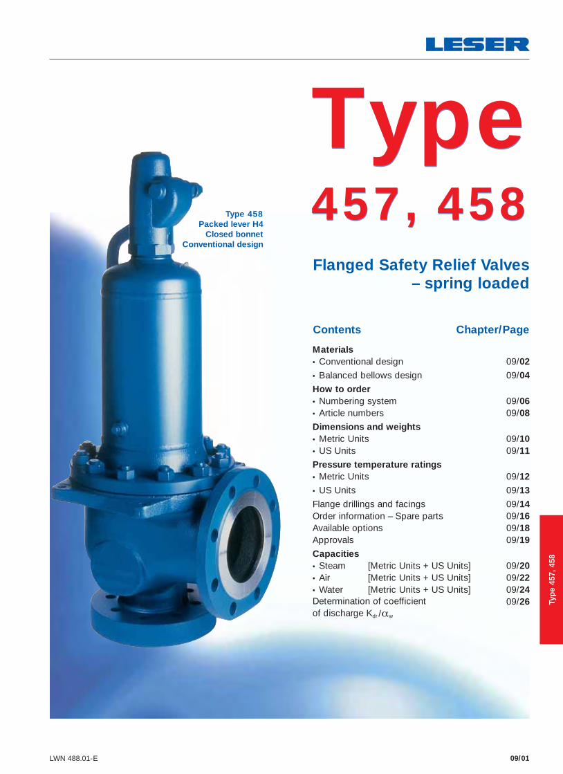
09/01 LWN 488.01-E Type 458 Packed lever H4 Closed bonnet Conventional design Contents Chapter/Page Flanged Safety Relief Valves – spring loaded Materials • Conventional design 09/02 • Balanced bellows design 09/04 How to order • Numbering system 09/06 • Article numbers 09/08 Dimensions and weights • Metric Units 09/10 • US Units 09/11 Pressure temperature ratings • Metric Units 09/12 • US Units 09/13 Flange drillings and facings 09/14 Order information – Spare parts 09/16 Available options 09/18 Approvals 09/19 Capacities • Steam [Metric Units + US Units] 09/20 • Air [Metric Units + US Units] 09/22 • Water [Metric Units + US Units] 09/24 Determination of coefficient 09/26 of discharge K dr /α w Type 457, 458 Type 457, 458 Type 457, 458
-
Upload
khangminh22 -
Category
Documents
-
view
3 -
download
0
Transcript of leser-457-458-esite-241033.pdf - Armatec
09/01LWN 488.01-E
Type 458Packed lever H4
Closed bonnetConventional design
Contents Chapter/Page
Flanged Safety Relief Valves – spring loaded
Materials • Conventional design 09/02
• Balanced bellows design 09/04
How to order
• Numbering system 09/06 • Article numbers 09/08
Dimensions and weights • Metric Units 09/10 • US Units 09/11
Pressure temperature ratings • Metric Units 09/12
• US Units 09/13
Flange drillings and facings 09/14 Order information – Spare parts 09/16 Available options 09/18 Approvals 09/19
Capacities • Steam [Metric Units + US Units] 09/20 • Air [Metric Units + US Units] 09/22 • Water [Metric Units + US Units] 09/24 Determination of coefficient 09/26 of discharge Kdr /αw
Type 457, 458
Type 457, 458
Typ
e 45
7, 4
58

How to order – Article numbers
09/08 LWN 488.01-E
Type 457, 458Type 457, 458
Type 458Packed lever H4Closed bonnet
Conventional design
Type 458Cap H2
Closed bonnetConventional design
Type 458Plain lever H3Closed bonnet
Conventional design
Type 457Plain lever H3 Open bonnet
Conventional design
Type 458Cap H2
Closed bonnetBalanced bellows design
Typ
e 45
7, 4
58
How to order – Article numbers
09/09LWN 488.01-E
Type 457, 458Type 457, 458
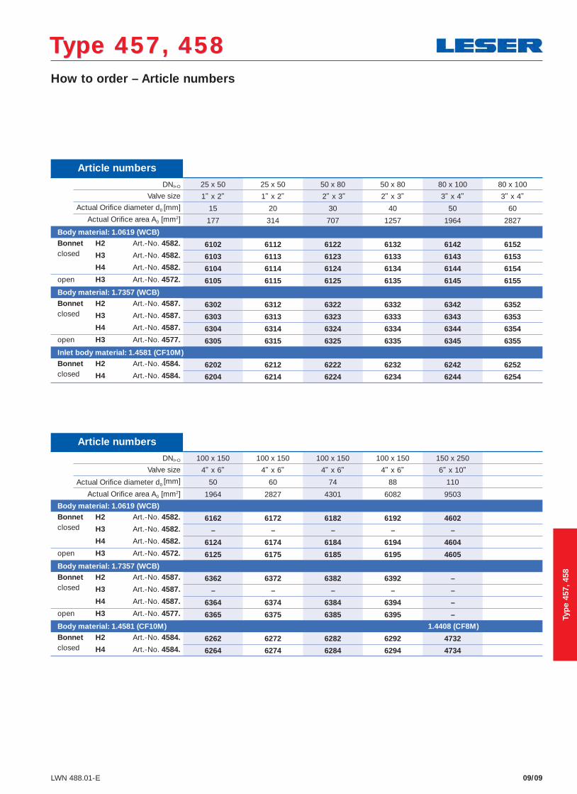
Article numbers
DNI+O 25 x 50 25 x 50 50 x 80 50 x 80 80 x 100 80 x 100 Valve size 1" x 2" 1" x 2" 2" x 3" 2" x 3" 3" x 4" 3" x 4"
Actual Orifi ce diameter d0 [mm] 15 20 30 40 50 60 Actual Orifi ce area A0 [mm2] 177 314 707 1257 1964 2827
Body material: 1.0619 (WCB)Bonnet H2 Art.-No. 4582. 6102 6112 6122 6132 6142 6152closed H3 Art.-No. 4582. 6103 6113 6123 6133 6143 6153
H4 Art.-No. 4582. 6104 6114 6124 6134 6144 6154open H3 Art.-No. 4572. 6105 6115 6125 6135 6145 6155
Body material: 1.7357 (WCB)Bonnet H2 Art.-No. 4587. 6302 6312 6322 6332 6342 6352closed H3 Art.-No. 4587. 6303 6313 6323 6333 6343 6353
H4 Art.-No. 4587. 6304 6314 6324 6334 6344 6354open H3 Art.-No. 4577. 6305 6315 6325 6335 6345 6355
Inlet body material: 1.4581 (CF10M)Bonnet H2 Art.-No. 4584. 6202 6212 6222 6232 6242 6252closed H4 Art.-No. 4584. 6204 6214 6224 6234 6244 6254
Article numbers
DNI+O 100 x 150 100 x 150 100 x 150 100 x 150 150 x 250 Valve size 4" x 6" 4" x 6" 4" x 6" 4" x 6" 6" x 10"
Actual Orifi ce diameter d0 [mm] 50 60 74 88 110 Actual Orifi ce area A0 [mm2] 1964 2827 4301 6082 9503
Body material: 1.0619 (WCB)Bonnet H2 Art.-No. 4582. 6162 6172 6182 6192 4602closed H3 Art.-No. 4582. – – – – –
H4 Art.-No. 4582. 6124 6174 6184 6194 4604open H3 Art.-No. 4572. 6125 6175 6185 6195 4605
Body material: 1.7357 (WCB)Bonnet H2 Art.-No. 4587. 6362 6372 6382 6392 –closed H3 Art.-No. 4587. – – – – –
H4 Art.-No. 4587. 6364 6374 6384 6394 –open H3 Art.-No. 4577. 6365 6375 6385 6395 –
Body material: 1.4581 (CF10M) 1.4408 (CF8M)Bonnet H2 Art.-No. 4584. 6262 6272 6282 6292 4732closed H4 Art.-No. 4584. 6264 6274 6284 6294 4734
Typ
e 45
7, 4
58

Type 457, 458Type 457, 458Conventional design
09/02 LWN 488.01-E
40 Cap H2
19 Lock nut
18 Adjusting screw
16 Upper spring plate
12 Spindle
9 Bonnet
54 Spring
14 Split ring
17 Lower spring plate
60 Gasket
8 Guide with bushing
22 Lift stopper
66 Screw
57 Ball
61 Ball
7 Disc
5 Nozzle
1 Body
55 Stud
56 Nut
Typ
e 45
7, 4
58
Conventional design
09/03LWN 488.01-E
Type 457, 458Type 457, 458
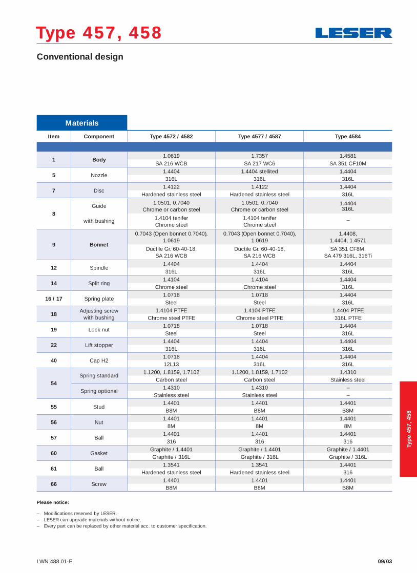
Please notice:
– Modifications reserved by LESER.– LESER can upgrade materials without notice.– Every part can be replaced by other material acc. to customer specification.
Materials
Item Component Type 4572 / 4582 Type 4577 / 4587 Type 4584
1 Body1.0619 1.7357 1.4581
SA 216 WCB SA 217 WC6 SA 351 CF10M
5 Nozzle1.4404 1.4404 stellited 1.4404316L 316L 316L
7 Disc1.4122 1.4122 1.4404
Hardened stainless steel Hardened stainless steel 316L
8Guide
with bushing
1.0501, 0.7040Chrome or carbon steel
1.0501, 0.7040Chrome or carbon steel
1.4404316L
1.4104 teniferChrome steel
1.4104 teniferChrome steel
–
9 Bonnet
0.7043 (Open bonnet 0.7040), 1.0619
0.7043 (Open bonnet 0.7040), 1.0619
1.4408,1.4404, 1.4571
Ductile Gr. 60-40-18,SA 216 WCB
Ductile Gr. 60-40-18,SA 216 WCB
SA 351 CF8M, SA 479 316L, 316Ti
12 Spindle1.4404 1.4404 1.4404316L 316L 316L
14 Split ring1.4104 1.4104 1.4404
Chrome steel Chrome steel 316L
16 / 17 Spring plate1.0718 1.0718 1.4404Steel Steel 316L
18Adjusting screw
with bushing1.4104 PTFE 1.4104 PTFE 1.4404 PTFE
Chrome steel PTFE Chrome steel PTFE 316L PTFE
19 Lock nut1.0718 1.0718 1.4404Steel Steel 316L
22 Lift stopper1.4404 1.4404 1.4404316L 316L 316L
40 Cap H21.0718 1.4404 1.440412L13 316L 316L
54Spring standard
1.1200, 1.8159, 1.7102 1.1200, 1.8159, 1.7102 1.4310Carbon steel Carbon steel Stainless steel
Spring optional1.4310 1.4310 –
Stainless steel Stainless steel –
55 Stud1.4401 1.4401 1.4401B8M B8M B8M
56 Nut1.4401 1.4401 1.4401
8M 8M 8M
57 Ball1.4401 1.4401 1.4401
316 316 316
60 GasketGraphite / 1.4401 Graphite / 1.4401 Graphite / 1.4401Graphite / 316L Graphite / 316L Graphite / 316L
61 Ball1.3541 1.3541 1.4401
Hardened stainless steel Hardened stainless steel 316
66 Screw1.4401 1.4401 1.4401B8M B8M B8M
Typ
e 45
7, 4
58

Balanced bellows design
09/04 LWN 488.01-E
Type 457, 458Type 457, 458
Typ
e 45
7, 4
58
40 Cap H2
19 Lock nut
18 Adjusting screw
16 Upper spring plate
9 Bonnet
12 Spindle
54 Spring
14 Split ring
17 Lower spring plate
56 Nut
8 Guide with bushing
11 Bonnet spacer
22 Lift stopper
15 Bellows
66 Screw
7 Disc
5 Nozzle
1 Body
55 Stud
60 Gasket
60 Gasket
61 Ball
57 Ball
Balanced bellows design
09/05LWN 488.01-E
Type 457, 458Type 457, 458
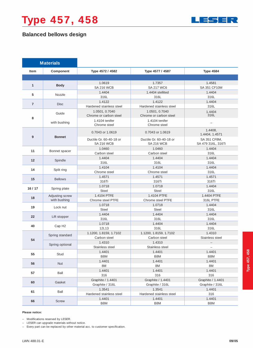
Please notice:
– Modifications reserved by LESER.– LESER can upgrade materials without notice.– Every part can be replaced by other material acc. to customer specification.
Materials
Item Component Type 4572 / 4582 Type 4577 / 4587 Type 4584
1 Body1.0619 1.7357 1.4581
SA 216 WCB SA 217 WC6 SA 351 CF10M
5 Nozzle1.4404 1.4404 stellited 1.4404316L 316L 316L
7 Disc1.4122 1.4122 1.4404
Hardened stainless steel Hardened stainless steel 316L
8Guide
with bushing
1.0501, 0.7040Chrome or carbon steel
1.0501, 0.7040Chrome or carbon steel
1.4404316L
1.4104 teniferChrome steel
1.4104 teniferChrome steel
–
9 Bonnet0.7043 or 1.0619 0.7043 or 1.0619
1.4408,1.4404, 1.4571
Ductile Gr. 60-40-18 orSA 216 WCB
Ductile Gr. 60-40-18 orSA 216 WCB
SA 351 CF8M,SA 479 316L, 316Ti
11 Bonnet spacer1.0460 1.0460 1.4404
Carbon steel Carbon steel 316L
12 Spindle1.4404 1.4404 1.4404316L 316L 316L
14 Split ring1.4104 1.4104 1.4404
Chrome steel Chrome steel 316L
15 Bellows1.4571 1.4571 1.4571316Ti 316Ti 316Ti
16 / 17 Spring plate1.0718 1.0718 1.4404Steel Steel 316L
18Adjusting screw
with bushing1.4104 PTFE 1.4104 PTFE 1.4404 PTFE
Chrome steel PTFE Chrome steel PTFE 316L PTFE
19 Lock nut1.0718 1.0718 1.4404Steel Steel 316L
22 Lift stopper1.4404 1.4404 1.4404316L 316L 316L
40 Cap H21.0718 1.4404 1.440412L13 316L 316L
54Spring standard
1.1200, 1.8159, 1.7102 1.1200, 1.8159, 1.7102 1.4310Carbon steel Carbon steel Stainless steel
Spring optional1.4310 1.4310 –
Stainless steel Stainless steel –
55 Stud1.4401 1.4401 1.4401B8M B8M B8M
56 Nut1.4401 1.4401 1.4401
8M 8M 8M
57 Ball1.4401 1.4401 1.4401
316 316 316
60 GasketGraphite / 1.4401 Graphite / 1.4401 Graphite / 1.4401Graphite / 316L Graphite / 316L Graphite / 316L
61 Ball1.3541 1.3541 1.4401
Hardened stainless steel Hardened stainless steel 316
66 Screw1.4401 1.4401 1.4401B8M B8M B8M
Typ
e 45
7, 4
58

Type 457, 458Type 457, 458Dimensions and weights
09/10 LWN 488.01-E
Metric UnitsDNI+O 25 x 50 25 x 50 50 x 80 50 x 80 80 x 100 80 x 100 100 x 150 100 x 150 100 x 150 100 x 150 150 x 250
Valve size 1" x 2" 1" x 2" 2" x 3" 2" x 3" 3" x 4" 3" x 4" 4" x 6" 4" x 6" 4" x 6" 4" x 6" 6" x 10"
Actual Orifi ce diameter d0 [mm] 15 20 30 40 50 60 50 60 74 88 110
Actual Orifi ce area A0 [mm2] 177 314 707 1257 1964 2827 1964 2827 4301 6082 9503
Weight 20 20 45 45 88 88 157 157 157 157 131[kg] with bellows 22 22 48 48 108 108 188 188 188 188 162
Center to face Inlet a 135 135 170 170 190 190 225 225 225 225 300[mm] Outlet b PN 40 120 120 145 145 180 180 235 235 235 235 225
Outlet b PN 63 120 120 145 145 205 205 265 265 265 265 –
Outlet b PN 160 130 130 – – – – – – – – –
Measure [mm] PN 40 – 160 s 41 41 53 53 53 53 60 60 60 60 43Used to fi nd bolt lenght for inlet fl ange
PN 250 s 41 41 53 53 60 60 68 68 68 68 –
PN 400 s 50 50 – – – – – – – – –
Height (H4) Standard H max. 506 506 699 699 832 832 1079 1079 1079 1079 1098[mm] Bellows H max. 541 541 779 779 930 930 1170 1170 1170 1170 1156
Support brackets A 140 140 184 184 278 278 364 364 364 364 320[mm] B – – 110 110 160 160 210 210 210 210 185
(drilled only on request) C Ø 14 Ø 14 Ø 14 Ø 14 Ø 18 Ø 18 Ø 18 Ø 18 Ø 18 Ø 18 Ø 18
D 162 162 209 209 240 240 303 303 303 303 392 E 18 18 18 18 27 27 32 32 32 32 28
Body material: 1.0619 (WCB)
DIN Flange Inlet PN 63 – 250 PN 63 – 160 PN 40
Outlet PN 40 – 63 PN 40 PN 16
Body material: 1.7357 (WC6)
DIN Flange Inlet PN 63 – 250 PN 63 – 160 –
Outlet PN 40 – 63 PN 40 –
Body material: 1.4581 (CF10M) 1.4408 (CF8M)
DIN Flange Inlet PN 63 – 250 PN 63 – 160 PN 40
Outlet PN 40 – 63 PN 40 PN 16
Typ
e 45
7, 4
58
Conventional design Balanced bellows design
s s
DB
C
A
E
D
C
A
E
Support brackets
DN 25, Valve size 1"
DN 50 – 150, Valve size 2" – 6"

Type 457, 458Type 457, 458Pressure temperature ratings
09/12 LWN 488.01-E
Metric Units
DNI+O 25 x 50 25 x 50 50 x 80 50 x 80 80 x 100 80 x 100 100 x 150 100 x 150 100 x 150 100 x 150 150 x 250
Valve size 1" x 2" 1" x 2" 2" x 3" 2" x 3" 3" x 4" 3" x 4" 4" x 6" 4" x 6" 4" x 6" 4" x 6" 6" x 10" Actual Orifi ce diameter d0 [mm] 15 20 30 40 50 60 50 60 74 88 110
Actual Orifi ce area A0 [mm2] 177 314 707 1257 1964 2827 1964 2827 4301 6082 9503 Body material: 1.0619 (WCB)
DIN Flange Inlet PN 63 – 250 PN 63 – 160 PN 40Outlet PN 40 – 63 PN 40 PN 40
Minimump [barg] S/G/L 2,5 2,5 2,5 2,5 2,5 2,5 2,5 2,5 2,5 2,5 2,5set pressure
Min. set pressure1) p [barg] S/G/L 13,5 13,5 20 2,5 10 10 10 6 5 5 5standard bellows
Min. set pressurep [barg] S/G/Llow press. bellows
Maximump [barg] S/G/L 300 180 125 98 130 77 43 46 53 34 18set pressure
Max. set pressurep [barg] S/G/L 300 180 210 114,5 160 77 160 160 77 53 40with special spring
Temperature min. [°C] -85acc. to DIN EN max. [°C] +450
Temperature min. [°C] -29acc. to ASME max. [°C] +427
on request
Body material: 1.7357 (WCB)
DIN Flange Inlet PN 63 – 250 PN 63 – 160 –Outlet PN 40 – 63 PN 40 –
Minimump [barg] S/G/L 2,5 2,5 2,5 2,5 2,5 2,5 2,5 2,5 2,5 2,5 –set pressure
Min. set pressure1) p [barg] S/G/L 13,5 13,5 20 2,5 10 10 10 6 5 5 –standard bellows
Min. set pressurep [barg] S/G/L –low press. bellows
Maximump [barg] S/G/L 300 180 125 98 130 77 43 46 53 34 –set pressure
Max. set pressurep [barg] S/G/L 300 180 210 114,5 160 77 160 160 77 53 –with special spring
Temperature min. [°C] -85acc. to DIN EN max. [°C] +550
Temperature min. [°C] -29acc. to ASME max. [°C] +538
on request
Body material: 1.4581 (CF10M) 1.4408 (CF8M)
DIN Flange Inlet PN 63 – 250 PN 63 – 160 PN 40Outlet PN 40 – 63 PN 40 PN 16
Minimump [barg] S/G/L 2,5 2,5 2,5 2,5 2,5 2,5 2,5 2,5 2,5 2,5 2,5set pressure
Min. set pressure1) p [barg] S/G/L 13,5 13,5 20 2,5 10 10 10 6 5 5 5standard bellows
Min. set pressurep [barg] S/G/L –low press. bellows
Maximump [barg] S/G/L 250 146 82 61 61 35 15,8 11 16,9 0 4,4set pressure
Max. set pressurep [barg] S/G/L 250 146 130 65 104 51,5 71 55 49 32 10with special spring
Temperature min. [°C] -85 -270acc. to DIN EN max. [°C] +550 +400
Temperature min. [°C] -29 -268acc. to ASME max. [°C] +538 +538
on request
1) Min. set pressure standard bellows = Max. set pressure low pressure bellows.
Typ
e 45
7, 4
58

Type 457, 458Type 457, 458Flange drillings
09/14 LWN 488.01-E
Flange drillings DNI+O 25 x 50 25 x 50 50 x 80 50 x 80 80 x 100 80 x 100 100 x 150 100 x 150 100 x 150 100 x 150 150 x 250
Valve size 1" x 2" 1" x 2" 2" x 3" 2" x 3" 3" x 4" 3" x 4" 4" x 6" 4" x 6" 4" x 6" 4" x 6" 6" x 10"
Actual Orifi ce diameter d0 [mm] 15 20 30 40 50 60 50 60 74 88 110
Actual Orifi ce area A0 [mm2] 177 314 707 1257 1964 2827 1694 2827 4301 6082 9503
Body material: 1.0619 (WCB), 1.7357 (CF10M), 1.4408 (CF8M)
Inlet
DIN EN 1092
PN 16 H47 H47 H47 H47 H47 H47 – – – – –
PN 25 H47 H47 H47 H47 H47 H47 H47 H47 H47 H47 * PN 40 H47 H47 H47 H47 H47 H47 H47 H47 H47 H47 * PN 63 * * H10 H10 H10 H10 H10 H10 H10 H10 S01
PN 100 * * * * * * * * * * –
PN 160 * * * * * * * * * * –
PN 250 H12 H12 H12 H12 S01 S01 S01 S01 S01 S01 –
PN 320 S01 S01 S01 S01 S01 S01 S01 S01 S01 S01 –
PN 400 S01 S01 S01 S01 S01 S01 S01 S01 S01 S01 –
ASME B16.5
CL150 – – – – – – – – – – H64
CL300 H65 H65 H65 H65 H65 H65 H65 H65 H65 H65 –
CL600 H67 H67 H67 H67 H67 H67 H67 H67 H67 H67 –
CL900 H69 H69 H69 H69 S01 S01 S01 S01 S01 S01 –
CL1500 H69 H69 H69 H69 S01 S01 S01 S01 S01 S01 –
CL2500 S01 S01 S01 S01 S01 S01 S01 S01 S01 S01 –
Outlet
DIN EN 1092
PN 10 * * * * H51 H51 H51 H51 H51 H51 H50
PN 16 * * * * H51 H51 H51 H51 H51 H51 * PN 25 * * * * * * * * * * –
PN 40 * * * * * * * * * * –
PN 63 H16 H16 H16 H16 S01 S01 S01 S01 S01 S01 –
ASME B16.5 CL150 H79 H79 H79 H79 H79 H79 H79 H79 H79 H79 H79
CL300 H80 H80 H80 H80 S01 S01 S01 S01 S01 S01 –
Typ
e 45
7, 4
58
Flange facings
09/15LWN 488.01-E
Type 457, 458Type 457, 458
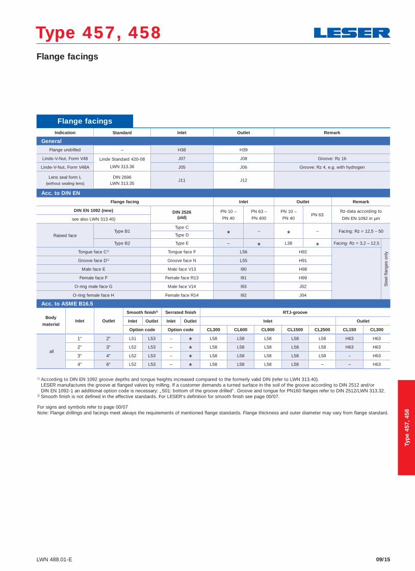
1) According to DIN EN 1092 groove depths and tongue heights increased compared to the formerly valid DIN (refer to LWN 313.40). LESER manufactures the groove at flanged valves by milling. If a customer demands a turned surface in the soil of the groove according to DIN 2512 and/or DIN EN 1092-1 an additional option code is necessary: „S01: bottom of the groove drilled”. Groove and tongue for PN160 flanges refer to DIN 2512/LWN 313.32.
2) Smooth finish is not defined in the effective standards. For LESER‘s definition for smooth finish see page 00/07.
For signs and symbols refer to page 00/07Note: Flange drillings and facings meet always the requirements of mentioned flange standards. Flange thickness and outer diameter may vary from flange standard.
Flange facingsIndication Standard Inlet Outlet Remark
General
Flange undrilled – H38 H39
Linde-V-Nut, Form V48 Linde Standard 420-08
LWN 313.36
J07 J08 Groove: Rz 16
Linde-V-Nut, Form V48A J05 J06 Groove: Rz 4, e.g. with hydrogen
Lens seal form L(without sealing lens)
DIN 2696LWN 313.35
J11 J12
Acc. to DIN EN
Flange facing Inlet Outlet Remark
DIN EN 1092 (new) DIN 2526(old)
PN 10 –
PN 40
PN 63 –
PN 400
PN 10 –
PN 40PN 63
Rz-data according to
DIN EN 1092 in µmsee also LWN 313.40)
Raised faceType B1
Type C
* – * – Facing: Rz = 12,5 – 50Type D
Type B2 Type E – * L38 * Facing: Rz = 3,2 – 12,5
Ste
el f
lang
es o
nlyTongue face C1) Tongue face F L56 H92
Groove face D1) Groove face N L55 H91
Male face E Male face V13 I90 H98
Female face F Female face R13 I91 H99
O-ring male face G Male face V14 I93 J02
O-ring female face H Female face R14 I92 J04
Typ
e 45
7, 4
58
Acc. to ASME B16.5
Body
materialInlet Outlet
Smooth finish2) Serrated finish RTJ-groove
Inlet Outlet Inlet Outlet Inlet Outlet
Option code Option code CL300 CL600 CL900 CL1500 CL2500 CL150 CL300
all
1“ 2“ L51 L53 – * L58 L58 L58 L58 L58 H63 H63
2“ 3“ L52 L53 – * L58 L58 L58 L58 L58 H63 H63
3“ 4“ L52 L53 – * L58 L58 L58 L58 L58 – H63
4“ 6“ L52 L53 – * L58 L58 L58 L58 – – H63

Approvals
09/19LWN 488.01-E
Type 457, 458Type 457, 458
Approvals DNI+O 25 x 50 25 x 50 50 x 80 50 x 80 80 x 100 80 x 100 100 x 150 100 x 150 100 x 150 100 x 150 150 x 250
Valve size 1" x 2" 1" x 2" 2" x 3" 2" x 3" 3" x 4" 3" x 4" 4" x 6" 4“ x 6“ 4“ x 6“ 4" x 6" 6" x 10"
Actual Orifi ce diameter d0 [mm] 15 20 30 40 50 60 50 60 74 88 110
Actual Orifi ce area A0 [mm2] 177 314 707 1257 1964 2827 1694 2827 4301 6082 9503
Europe Coefficient of discharge Kdr
DIN EN ISO 4126-1 Approval No. 072020111Z0008/0/12
S/G 0,83 0,84 0,84 0,8 0,83 0,75 0,84 0,8 0,8 0,75 0,7
L 0,63 0,6 0,58 0,54 0,58 0,5 0,6 0,54 0,56 0,49 0,45 Germany Coefficient of discharge αw
AD 2000-Merkblatt A2 Approval No. TÜV SV 934
S/G 0,83 0,84 0,84 0,8 0,83 0,75 0,84 0,8 0,8 0,75 0,7
L 0,63 0,6 0,58 0,54 0,58 0,5 0,6 0,54 0,56 0,49 0,45 United States Coefficient of discharge K
ASME Sec. VIII Approval No. M37066 M37066 M37066 M37066 M37066 M37088 M37066 M37066 M37066 M37088 M37088
S/G 0,798 0,798 0,798 0,798 0,798 0,754 0,798 0,798 0,798 0,754 0,754
Approval No. M37077 M37077 M37077 M37077 M37077 M37099 M37077 M37077 M37077 M37099 M37099
L 0,572 0,572 0,572 0,572 0,572 0,479 0,572 0,572 0,572 0,479 0,479 Canada Coefficient of discharge K
Canada: CRN Approval No. –
S/G 0,798 0,798 0,798 0,798 0,798 0,754 0,798 0,798 0,798 0,754 0,754
L 0,572 0,572 0,572 0,572 0,572 0,479 0,572 0,572 0,572 0,479 0,479 China Coefficient of discharge αw
CSBQTS Approval No.
S/G 0,83 0,84 0,84 0,8 0,83 0,75 0,84 0,8 0,8 0,75 0,7
L 0,63 0,6 0,58 0,54 0,58 0,5 0,6 0,54 0,56 0,49 0,45 Russia Coefficient of discharge αw
GGTN/GOSGOTECHNADZORGOST R
Approval No. PPC 00-18458
S/G 0,83 0,84 0,84 0,8 0,83 0,75 0,84 0,8 0,8 0,75 0,7
L 0,63 0,6 0,58 0,54 0,58 0,5 0,6 0,54 0,56 0,49 0,45 Classification societies
on request
Typ
e 45
7, 4
58

Type 457, 458Type 457, 458
09/20 LWN 488.01-E
Capacities – Steam
Metric Units AD 2000-Merkblatt A2 [kg/h]DN I+O 25 x 50 25 x 50 50 x 80 50 x 80 80 x 100 80 x 100 100 x 150 100 x 150 100 x 150 100 x 150 150 x 250
Valve size 1" x 2" 1" x 2" 2" x 3" 2" x 3" 3" x 4" 3" x 4" 4" x 6" 4" x 6" 4" x 6" 4" x 6" 6" x 10"
Act. Orifice dia. d0 [mm] 15 20 30 40 50 60 50 60 74 88 110
Act. Orifice area A0 [mm2] 177 314 707 1257 1964 2827 1694 2827 4301 6082 9503
LEOS/G*) [inch2] 0,224 0,399 0,897 1,594 2,491 3,389 2,491 3,587 5,456 7,29 11,391
Set pressure [bar] Capacities [kg/h]
2,5 305 535 1205 2036 3429 4403 3388 4641 7149 9470 13998
3 352 619 1409 2385 3915 5094 3915 5366 8265 10958 15980
4 439 781 1779 3011 4882 6352 4940 6775 10306 13664 19926
5 526 946 2129 3605 5844 7604 5914 8111 12338 16358 23855
6 612 1102 2479 4197 6803 8853 6885 9443 14363 19043 27771
7 697 1253 2820 4774 7739 10070 7832 10742 16339 21662 31591
8 782 1407 3167 5362 8692 11310 8797 12064 18351 24329 35480
9 868 1562 3513 5949 9643 12548 9760 13385 20360 26992 39364
10 953 1715 3860 6535 10594 13785 10722 14704 22367 29653 43244
12 1124 2023 4552 7707 12494 16257 12645 17341 26378 34972 51000
14 1292 2324 5230 8855 14355 18678 14527 19923 30306 40179 58594
16 1463 2631 5921 10024 16250 21145 16446 22555 34308 45486 66333
18 1633 2939 6612 11195 18149 23615 18367 25189 38316 50799 74081
20 1804 3247 7305 12368 20050 26089 20291 27828 42330 56120 81842
22 1970 3545 7977 13506 21894 28489 22158 30388 46224 61283 89371
24 2142 3854 8671 14681 23799 30967 24085 33031 50245 66614 97145
26 2314 4163 9366 15859 25708 33452 26018 35682 54276 71958 104939
28 2486 4473 10064 17040 27623 35943 27956 38340 58319 77318 112756
30 2659 4784 10764 18225 29544 38443 29900 41006 62374 82695 120596
32 2832 5096 11466 19414 31471 40950 31850 43680 66443 88089 128463
34 2998 5394 12137 20549 33311 43345 33713 46235 70328 93240 135975
36 3172 5707 12842 21743 35247 45863 35671 48921 74414 98657 143875
38 3347 6022 13549 22941 37189 48391 37637 51617 78515 104094 151804
40 3523 6338 14260 24144 39140 50929 39611 54324 82632 109553 159765
50 4411 7937 1 7858 30235 49014 63777 49605 68029 103480 137192
60 5306 9546 21479 36366 58952 76709 59663 81823 124462
70 6236 11221 25246 42745 69294 90166 70129 96177 146296
80 7174 12907 29042 49171 79711 80671 110634
90 8160 14682 33035 55932 90670 91763 125846
100 9156 16473 37065 62756 101733 102959 141201
120 11326 20378 45850 125844 127361 174666
140 13773 24781 55758 153039 154882 212410
160 16604 29873 67215 184485 186707 256056
180 20171 36291 81656
200 24970 101082
220 26183
240 27342
260 28455
280 29525
300 30558
*) LEOS/G = LESER Effective Orifice steam/gas please refer to page 00/11How to use capacity-sheets refer to page 00/09
Capacities for saturated steam according to AD 2000-Merkblatt A2, based on set pressure plus 10 % overpressure.Capacities at 1 bar (14,5 psig) and below are based on 0,1 bar (1,45 psig) overpressure.
Typ
e 45
7, 4
58

Type 457, 458Type 457, 458Capacities – Air
09/22 LWN 488.01-E
Metric Units AD 2000-Merkblatt A2 [mn3/h]
DN I+O 25 x 50 25 x 50 50 x 80 50 x 80 80 x 100 80 x 100 100 x 150 100 x 150 100 x 150 100 x 150 150 x 250
Valve size 1" x 2" 1" x 2" 2" x 3" 2" x 3" 3" x 4" 3" x 4" 4" x 6" 4" x 6" 4" x 6" 4" x 6" 6" x 10"
Act. Orifice dia. d0 [mm] 15 20 30 40 50 60 50 60 74 88 110
Act. Orifice area A0 [mm2] 177 314 707 1257 1964 2827 1694 2827 4301 6082 9503
LEOS/G*) [inch2] 0,224 0,399 0,897 1,594 2,491 3,389 2,491 3,587 5,456 7,29 11,391
Set pressure [bar] Capacities [mn3/h]
2,5 371 652 1466 2478 4173 5357 4122 5647 8700 11524 17033
3 430 756 1722 2914 4783 6224 4783 6556 10098 13388 19524
4 540 961 2187 3704 6004 7812 6076 8333 12676 16805 24507
5 650 1170 2632 4457 7225 9401 7312 10027 15253 20222 29490
6 760 1368 3077 5210 8445 10989 8547 11722 17830 23639 34474
7 870 1565 3522 5963 9666 12578 9783 13416 20407 27056 39457
8 980 1763 3967 6716 10887 14166 11018 15111 22985 30473 44440
9 1090 1961 4411 7469 12108 15755 12254 16805 25562 33890 49423
10 1200 2158 4856 8222 13328 17343 13489 18499 28139 37307 54406
12 1419 2554 5746 9728 15770 20520 15960 21888 33294 44141 64372
14 1639 2949 6635 11234 18211 23697 18431 25277 38449 50974 74338
16 1859 3344 7525 12740 20653 26874 20902 28665 43603 57808 84304
18 2079 3740 8414 14246 23094 30051 23373 32054 48758 64642 94270
20 2298 4135 9304 15752 25536 33228 25844 35443 53912 71476 104236
22 2518 4530 10193 17258 27977 36404 28315 38831 59067 78310 114202
24 2738 4926 11083 18764 30419 39581 30785 42220 64221 85144 124168
26 2957 5321 11972 20271 32860 42758 33256 45609 69376 91978 134134
28 3177 5716 12862 21777 35302 45935 35727 48997 74531 98812 144100
30 3397 6112 13751 23283 37744 49112 38198 52386 79685 105645 154066
32 3617 6507 14641 24789 40185 52289 40669 55775 84840 112479 164032
34 3836 6902 15530 26295 42627 55466 43140 59164 89994 119313 173998
36 4056 7298 16420 27801 45068 58643 45611 62552 95149 126147 183964
38 4276 7693 17310 29307 47510 61820 48082 65941 100304 132981 193930
40 4496 8088 18199 30813 49951 64997 50553 69330 105458 139815 203897
50 5594 10065 22647 38344 62159 80881 62907 86273 131231 173984
60 6693 12042 27094 45874 74366 96766 75262 103217 157004
70 7792 14019 31542 53404 86574 112650 87617 120160 182777
80 8890 15995 35990 60935 98781 99971 137104
90 9989 17972 40437 68465 110989 112326 154047
100 11088 19949 44885 75996 123196 124681 170991
120 13285 23902 53780 147611 149390 204877
140 15482 27856 62676 172026 174099 238764
160 17680 31809 71571 196442 198808 272651
180 19877 35763 80466
200 22074 89362
220 24272
240 26469
260 28667
280 30864
300 33061
*) LEOS/G = LESER Effective Orifice steam/gas please refer to page 00/11How to use capacity-sheets refer to page 00/09
Capacities for air according to AD 2000-Merkblatt A2, based on set pressure plus 10 % overpressure at 0 °C and 1013 mbar. Capacities at 1 bar (14,5 psig) and below are based on 0,1 bar (1,45 psig) overpressure.
Typ
e 45
7, 4
58
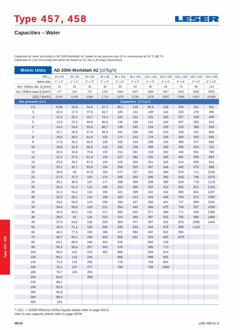
Type 457, 458Type 457, 458Capacities – Water
09/24 LWN 488.01-E
Metric Units AD 2000-Merkblatt A2 [103kg/h]DN I+O 25 x 50 25 x 50 50 x 80 50 x 80 80 x 100 80 x 100 100 x 150 100 x 150 100 x 150 100 x 150 150 x 250
Valve size 1" x 2" 1" x 2" 2" x 3" 2" x 3" 3" x 4" 3" x 4" 4" x 6" 4“ x 6“ 4" x 6" 4" x 6" 6" x 10"
Act. Orifice dia. d0 [mm] 15 20 30 40 50 60 50 60 74 88 110
Act. Orifice area A0 [mm2] 177 314 707 1257 1964 2827 1694 2827 4301 6082 9503
LEOL*) [inch2] 0,241 0,429 0,964 1,714 2,678 3,230 2,678 3,857 5,866 6,947 10,855
Set pressure [bar] Capacities [103kg/h]
2,5 9,39 15,9 34,6 57,2 96,1 119 99,4 129 203 251 361
3 10,3 17,4 37,9 62,7 105 131 109 141 223 275 395
4 11,9 20,1 43,7 72,4 122 151 126 163 257 318 456
5 13,3 22,5 48,9 80,9 136 169 141 182 287 355 510
6 14,5 24,6 53,6 88,7 149 185 154 200 315 389 559
7 15,7 26,6 57,9 95,8 161 200 166 215 340 421 604
8 16,8 28,4 61,9 102 172 213 178 230 363 450 645
9 17,8 30,2 65,6 109 182 226 189 244 385 477 684
10 18,8 31,8 69,2 114 192 238 199 258 406 503 721
12 20,6 34,8 75,8 125 210 261 218 282 445 551 790
14 22,2 37,6 81,8 135 227 282 235 305 481 595 854
16 23,8 40,2 87,5 145 243 302 251 326 514 636 913
18 25,2 42,7 92,8 154 258 320 267 346 545 675 968
20 26,6 45 97,8 162 272 337 281 364 575 711 1020
22 27,9 47,2 103 170 285 354 295 382 603 746 1070
24 29,1 49,3 107 177 298 369 308 399 629 779 1118
26 30,3 51,3 112 185 310 385 320 415 655 811 1163
28 31,4 53,2 116 192 321 399 333 431 680 841 1207
30 32,5 55,1 120 198 333 413 344 446 704 871 1250
32 33,6 56,9 124 205 344 427 356 461 727 899 1291
34 34,6 58,6 128 211 354 440 366 475 749 927 1330
36 35,6 60,3 131 217 365 452 377 489 771 954 1369
38 36,6 62 135 223 374 465 387 502 792 980 1406
40 37,6 63,6 138 229 384 477 397 515 813 1005 1443
50 42,0 71,1 155 256 430 533 444 576 909 1124
60 46,0 77,9 169 280 471 584 487 631 995
70 49,7 84,1 183 303 508 631 526 681 1075
80 53,1 89,9 196 324 543 562 729
90 56,3 95,4 207 343 576 596 773
100 59,4 101 219 362 608 628 814
120 65,1 110 240 666 688 892
140 70,3 119 259 719 744 964
160 75,1 127 277 768 795 1030
180 79,7 135 293
200 84,0 309
220 88,1
240 92,0
260 95,8
280 99,4
300 103
*) LEOL = LESER Effective Orifice liquids please refer to page 00/12How to use capacity-sheets refer to page 00/09
Capacities for water according to AD 2000-Merkblatt A2, based on set pressure plus 10 % overpressure at 20 °C (68 °F). Capacities at 1 bar (14,5 psig) and below are based on 0,1 bar (1,45 psig) overpressure..
Typ
e 45
7, 4
58
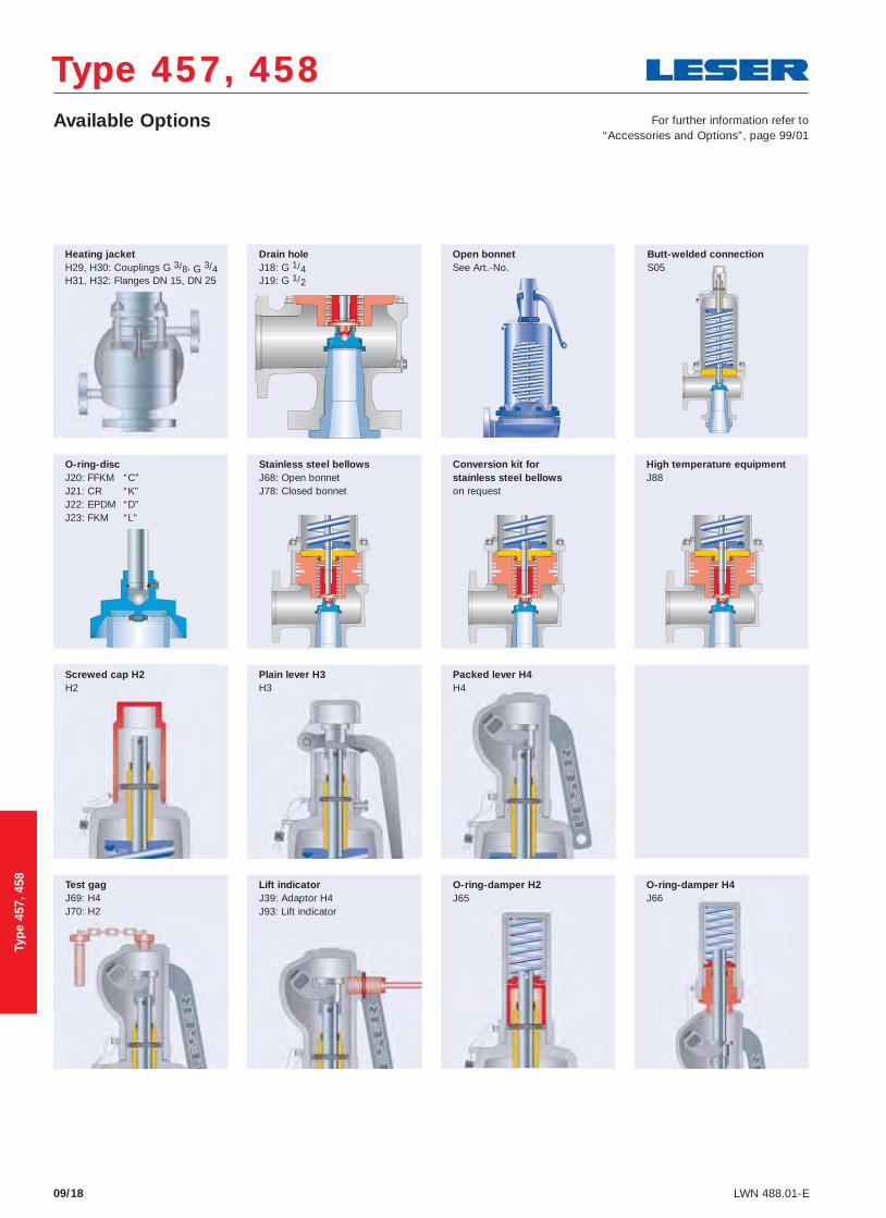
09/18 LWN 488.01-E
Heating jacket H29, H30: Couplings G 3/8, G 3/4 H31, H32: Flanges DN 15, DN 25
Open bonnet See Art.-No.
Drain hole J18: G 1/4 J19: G 1/2
O-ring-disc J20: FFKM “C” J21: CR “K” J22: EPDM “D” J23: FKM “L”
Packed lever H4 H4
Plain lever H3 H3
Screwed cap H2 H2
O-ring-damper H2 J65
Lift indicator J39: Adaptor H4 J93: Lift indicator
Test gag J69: H4 J70: H2
High temperature equipment J88
O-ring-damper H4 J66
Type 457, 458Type 457, 458Available Options For further information refer to
“Accessories and Options”, page 99/01
Butt-welded connection S05
Stainless steel bellows J68: Open bonnet J78: Closed bonnet
Conversion kit for stainless steel bellows on request
Typ
e 45
7, 4
58

Op
tio
ns
High temperature equipment
Accessories and OptionsAccessories and Options
99/16 LWN 488.01-E
For fluid temperatures higher than 400 °C / 752 °F high temperature equipment is necessary to protect the inner parts and the spring against inadmissible influence of temperature. The maximum inlet temperature is 550 °C / 1022 °F. The equipment shown is only fitted in Type 457 / 458. For all other Types an open bonnet and a stainless steel bellows is necessary for fluid temperatures exceeding 400 °C / 752 °F up to max. 450 °C / 842 °F.
Temperature limits [°C] > 400 fl uid temperature
[°F] > 752 fl uid temperature
max. [°C] 550 inlet temperature
max. [°F] 1022 inlet temperature
Materials High temperature equipment
Item Component
1 Body1.7357WC6
5 Nozzle1.4404316L
7 Disc1.4404 stellited316L stellited
9 Bonnet open1.0619WCB
11 Cooling spool1.4404316L
15 Bellows1.4571316L
54 Spring1.7102, 1.8159
High temperature alloy steel
55 Studs1.7709
B16
56 Nuts1.7258
7M
Specifi cation
Series 458
Design
Option code J88
Operating conditions
55
56
9
11
1
15
54
7
5