p ro te c ted - LESER GmbH & Co. KG
474
LESER Global Standard High Efficiency Maintenance Introduction LGS 4119 Page 1/7 disclosure cat.: II proofread: Cal published date: tbd effect. date: 02/12 author: AW released by: KUW replaces: initial status: published resp. depart.: PP date of release: 01/31/12 revision No.: 0 doc. type: LGS change rep. No.: retention period: 10y. protected Content 1 Purpose ......................................................................................................... 1 2 Scope ............................................................................................................. 1 3 References .................................................................................................... 1 4 Introduction ................................................................................................... 1 1 Purpose This LESER Global (LGS) describes an overview of LESER documents for Maintenance and Repair of LESER Pilot Operated Safety Valves. 2 Scope This LGS applies to all members of the LESER quality cluster as defined in the global quality management manual. 3 References LGS 4119 to 4138 LWN 753.00 4 Introduction LESER provides maintenance instruction for the LESER product Pilot Operated Safety Valves Serie 810 and 820.
-
Upload
khangminh22 -
Category
Documents
-
view
0 -
download
0
Transcript of p ro te c ted - LESER GmbH & Co. KG

LESER Global Standard
High Efficiency Maintenance Introduction
LGS 4119
Page 1/7
disclosure cat.: II proofread: Cal published date: tbd effect. date: 02/12 author: AW released by: KUW replaces: initial status: published resp. depart.: PP date of release: 01/31/12 revision No.: 0 doc. type: LGS change rep. No.: retention period: 10y.
pro
tected
Content 1 Purpose ......................................................................................................... 1 2 Scope ............................................................................................................. 1 3 References .................................................................................................... 1 4 Introduction ................................................................................................... 1
1 Purpose
This LESER Global (LGS) describes an overview of LESER documents for Maintenance and Repair of LESER Pilot Operated Safety Valves.
2 Scope
This LGS applies to all members of the LESER quality cluster as defined in the global quality management manual.
3 References
LGS 4119 to 4138 LWN 753.00
4 Introduction
LESER provides maintenance instruction for the LESER product Pilot Operated Safety Valves Serie 810 and 820.
LESER Global Standard
High Efficiency Maintenance Introduction
LGS 4119
Page 2/7
disclosure cat.: II proofread: Cal published date: tbd effect. date: 02/12 author: AW released by: KUW replaces: initial status: published resp. depart.: PP date of release: 01/31/12 revision No.: 0 doc. type: LGS change rep. No.: retention period: 10y.
pro
tected
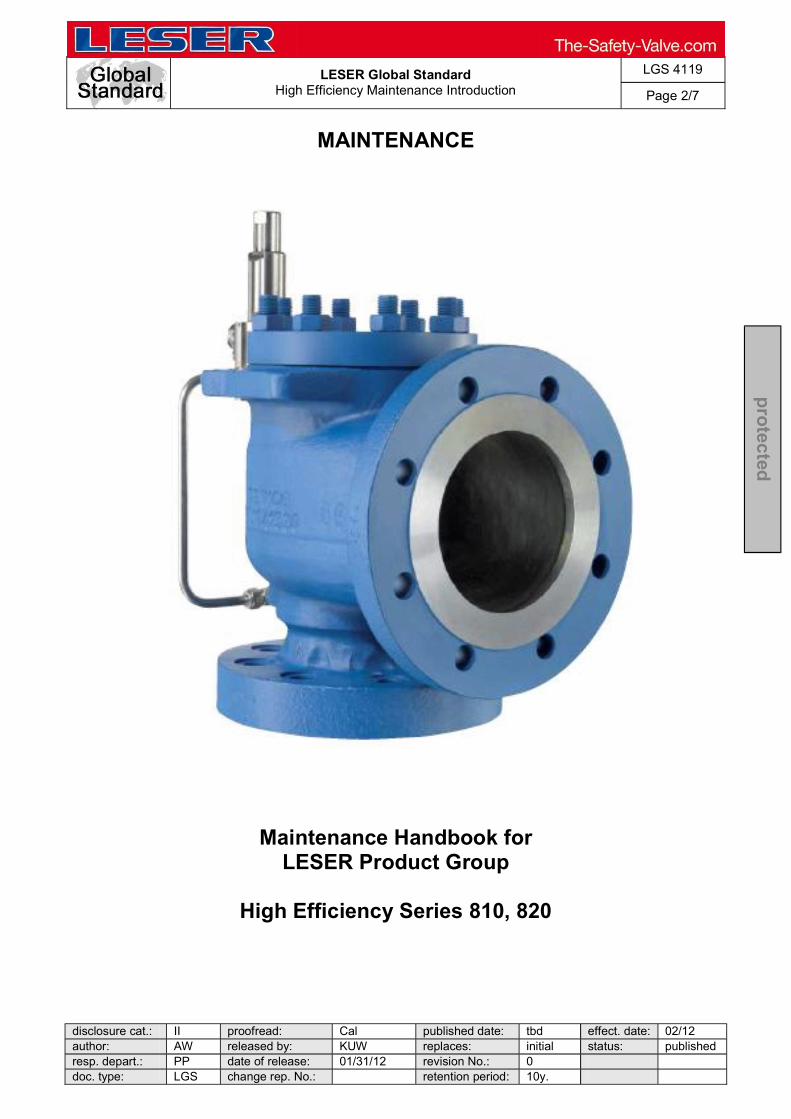
MAINTENANCE
Maintenance Handbook for LESER Product Group
High Efficiency Series 810, 820

LESER Global Standard
High Efficiency Maintenance Introduction
LGS 4119
Page 3/7
disclosure cat.: II proofread: Cal published date: tbd effect. date: 02/12 author: AW released by: KUW replaces: initial status: published resp. depart.: PP date of release: 01/31/12 revision No.: 0 doc. type: LGS change rep. No.: retention period: 10y.
pro
tected
About MAINTENANCE
MAINTENANCE provides a collection of documents for repairing or maintaining LESER safety valves. The following topics are covered:
Maintenance Fundamentals of LESER safety valves (terminology, design elements relevant for valve operation)
Repair process
Suggested equipment for assembling, disassembling and rework of critical parts
Disassembly, including sectional drawings
Rework of critical parts including an overview of critical dimensions
Assembly, including options
Spring charts
Testing procedures (set pressure and leak tests)
Spare parts lists
Guidelines for inspection, storage and transport

LESER Global Standard
High Efficiency Maintenance Introduction
LGS 4119
Page 4/7
disclosure cat.: II proofread: Cal published date: tbd effect. date: 02/12 author: AW released by: KUW replaces: initial status: published resp. depart.: PP date of release: 01/31/12 revision No.: 0 doc. type: LGS change rep. No.: retention period: 10y.
pro
tected
Contents
Chapter Content Sources
1.1 Introduction Introduction and table of contents LGS 4119
1.2 Maintenance Fundamentals
Terminology
- Parts
- Set pressure
- Overpressure & blowdown
- Nozzle & disc
- Spring
- Adjusting ring
- Parts providing alignment
- Lifting devices
Illustrations
- Main valve
- Pop action pilot valve
- Modulate action pilot valve
- Accessories
Operation procedure
- Main valve
- Pop action pilot valve
- Modualte action pilot valve
LGS_4120_Maintenance Fundamentals
1.3 Repair process -Process of Safety Valves to Repair
-Repair Traveller POSV
LGS_4121_Repair Traveller POSV
1.4 Suggested equipment Equipment for disassembly and lapping
- Required equipment
- Technical requirements of the tools
LGS_4122_Recommended Equipment POSV
LGS_4456_EN_Stand..
LGS_1116_Operating materials and supplies for

LESER Global Standard
High Efficiency Maintenance Introduction
LGS 4119
Page 5/7
disclosure cat.: II proofread: Cal published date: tbd effect. date: 02/12 author: AW released by: KUW replaces: initial status: published resp. depart.: PP date of release: 01/31/12 revision No.: 0 doc. type: LGS change rep. No.: retention period: 10y.
pro
tected
Chapter Content Sources
- Illustrations
- Order numbers
repaired valves_EN
1.5 Disassembly and Cleaning
Disassembly instruction -step-by-step
- Main valve
- Pop action pilot valve
-Modulate action pilot valve (diaphragm design)
-Modulate action pilot valve (piston design)
Cleaning
- Main valve
- Pilot valve
- Accessories
LGS_4129 Cleaning the POSV Parts-EN
LGS_4128 Disassembly Accessories-EN
LGS_4124 Disassembly Main Valve-EN
LGS_4126 Disassembly Modulate Action Dia-EN
LGS_4127 Disassembly Modulate Action Piston-EN
LGS_4125 Disassembly Pop Action Pilot-EN
LGS_4123 Separate Pilot Valve from Main
1.6 Rework of critical parts
Inspection and replacement
- Main Valve
- Pilot Valve
- Accessories
Critical dimensions for refinishing disc and nozzle
- Lowest allowable tolerances for refinishing
LDeS 3309.05 Refinishing of seats and discs
LGS 4130_Inspection Replacement_EN
LGS_1113_Reworking repaired valves_EN
LESER Global Standard
High Efficiency Maintenance Introduction
LGS 4119
Page 6/7
disclosure cat.: II proofread: Cal published date: tbd effect. date: 02/12 author: AW released by: KUW replaces: initial status: published resp. depart.: PP date of release: 01/31/12 revision No.: 0 doc. type: LGS change rep. No.: retention period: 10y.
pro
tected
Chapter Content Sources
1.7 Assembly Tightening torques
- Main valve
- Pilot Valve
- Accessories
Assembly instruction step-by-step-
- Main Valve
- Pop action pilot valve
- Modulate action pilot valve (diaphragm design)
- Modulate action pilot valve (piston design)
- Accessories
LGS_4135 Assembly Accessories-EN
LGS_4131 Assembly Main Valve-EN
LGS_4133 Assembly Modulate Action Diaphragm-EN
LGS_4134 Assembly Modulate Action Pilot Valve Piston-EN
LGS_4132 Assembly Pop Action Pilot Valve-EN
LGS_4136 Marriage Pilot Valve and Main Valve-EN
LGS 3323 Torques ranges for screws and bolts
After Assembly
- Color finishing and painting
- Component plate
-up and painting repaired
1.8 Spring charts
Spring charts
- Overview of spring ranges for set pressure adjustments and spring selection in bar and psi
LGS 3632 Spring data list type 810
LGS 3633 Spring data list type 820
1.9 Testing Procedures Testing set pressure
- Procedures and equipment for setting and testing the cold differential test pressure, including tolerances
LDeS 1001.69 Cold differential test pressure
Leak testing
- Procedures and equipment for testing functional tightness (disc-nozzle connection)
LGS 4434 Standardisation of Worldwide Warehouses Performing Leak Tests

LESER Global Standard
High Efficiency Maintenance Introduction
LGS 4119
Page 7/7
disclosure cat.: II proofread: Cal published date: tbd effect. date: 02/12 author: AW released by: KUW replaces: initial status: published resp. depart.: PP date of release: 01/31/12 revision No.: 0 doc. type: LGS change rep. No.: retention period: 10y.
pro
tected
Chapter Content Sources
- Procedures and equipment for testing shell tightness (nozzle, cap)
Tightness requirements
- Seat tightness
- Shell tightness
- Back seat tightness
LGS 0201 Tightness Test
Last visual check up inspection of repaired
Testing procedure instruction LGS_4137_Testing Procedure Instructions-EN
1.10 Spare parts Spare part
- Sectional drawings
- Location of the components
- Example spare part kit
LGS_4138_Spare Parts-EN
1.11 Installation & storage Testing and inspection before installation
- visual inspection of the valve
- hydraulic pressure test
Extract from LWN 753-00
Safety Valves before
Inspection intervals Extract from LWN 753-00 Recommendation for Testing and Inspection
Storage and transport Extract from LWN 753-00
LESER Global Standard
Maintenance Fundamentals
LGS 4120
Page 1/18
disclosure cat.: II proofread: Cal published date: tbd effect. date: 02/12 author: AW released by: KUW replaces: initial status: published resp. depart.: PP date of release: 01/31/12 revision No.: 0 doc. type: LGS change rep. No.: retention period: 10y.
pro
tected
Content 1 Maintenance fundamentals Pilot Operated Safety Valve ........................... 1 2 Purpose ......................................................................................................... 1 3 Competences ................................................................................................ 2 4 Scope ............................................................................................................. 2 5 Disclaimer ...................................................................................................... 2 6 Terminology .................................................................................................. 2 7 Definition of set pressure ............................................................................. 5 8 Definition of overpressure ........................................................................... 5 9 Definition of blowdown................................................................................. 5 10 General Introduction ..................................................................................... 7 11 Operation procedure .................................................................................... 13
Content
1 Maintenance fundamentals Pilot Operated Safety Valve
2 Purpose
The purpose of this section is to describe the maintenance fundamentals of the LESER Pilot Operated Safety Valve.
You will find tables to standardize the terminology, covering the most used devices. The tables also include a description of their characteristics. Furthermore cross sectional drawings of the main valve, pilot valve (pop action and modulate action) manifold block and accessories are presented to get an overview of the location. The final section describes the operation procedure of the main valve and the pilot valve.
LESER Global Standard
Maintenance Fundamentals
LGS 4120
Page 2/18
disclosure cat.: II proofread: Cal published date: tbd effect. date: 02/12 author: AW released by: KUW replaces: initial status: published resp. depart.: PP date of release: 01/31/12 revision No.: 0 doc. type: LGS change rep. No.: retention period: 10y.
pro
tected
3 Competences
The generation, maintenance and distribution of the documentation takes place in the organisation department. The defaults will be generated by the technical department in consultation with the final assembly department and production planning department.
4 Scope This document must be applied to the disassembling, assembling, rework and refinishing parts of a Pilot Operated Safety Valve in agencies and subsidiaries of LESER GmbH & Co. KG, customers and independent service center.
5 Disclaimer
LESER puts in a great deal of effort into making up-to-date and correct documentation available. Nevertheless, LESER GmbH & Co. KG gives no guarantee that the recommended actions presented here are entirely correct and error free. This document is to be applied exclusively to the specified type. LESER GmbH & Co. KG declines any liability or responsibility for the correctness and completeness of the content. LESER GmbH & Co. KG reserves the right to change the information contained in this document, which is for the products of LESER GmbH & Co. KG and is intended for LESER subsidiaries, at any time and without prior announcement. LESER GmbH & Co. KG is available to the users of this document to provide additional information.
6 Terminology
6.1 Parts description acc. to ASME PTC 25: Main valve
Item Component Description per ASME PTC 25 Parts used by LESER Main valve Main
relieving valve
That part of a pilot-operated pressure relief device through which the rated flow occurs during relief.
1 Body A pressure-retaining or containing component of a pressure relief device that supports the parts of the valve assembly and has provision(s) for connecting to the primary and/or secondary pressure source(s).

LESER Global Standard
Maintenance Fundamentals
LGS 4120
Page 3/18
disclosure cat.: II proofread: Cal published date: tbd effect. date: 02/12 author: AW released by: KUW replaces: initial status: published resp. depart.: PP date of release: 01/31/12 revision No.: 0 doc. type: LGS change rep. No.: retention period: 10y.
pro
tected
2 Pitot tube -
5 Nozzle A primary pressure- containing component in a safety valve that forms a part or the entire inlet flow passage.
6 Piston The moving element in the main relieving valve of a pilot-operated piston-type pressure relief valve which contains the seat that forms the primary pressure containment zone when in contact with the nozzle.
7 Disc A component of a direct spring valve or of a pilot in a pilot-operated valve that supports the spring. It may or may not be pressure containing.
9 Top plate Closes the body of the main valve.
59 Dome spring The element in a safety valve that provides the force to keep the disc on the nozzle.
Dome The volume on the side of the unbalanced moving member opposite the nozzle in the main relieving valve of a pilot operated pressure relief device.
Table 1: Parts description acc. to ASME PTC 25
6.2 Parts description acc. to ASME PTC 25: Pilot valve
Item Component Description per ASME PTC 25 Parts used by LESER Pilot Valve Pilot The pressure- or vacuum-sensing component of a pilot-
operated pressure relief valve that controls the opening and closing of the main relieving valve.
1 Body A pressure-retaining or containing component of a pressure relief device that supports the parts of the valve assembly and has provision(s) for connecting to the primary and/or secondary pressure source(s).
2 Guide A component in a direct spring or pilot-operated pressure relief device used to control the lateral movement of the disc or disc

LESER Global Standard
Maintenance Fundamentals
LGS 4120
Page 4/18
disclosure cat.: II proofread: Cal published date: tbd effect. date: 02/12 author: AW released by: KUW replaces: initial status: published resp. depart.: PP date of release: 01/31/12 revision No.: 0 doc. type: LGS change rep. No.: retention period: 10y.
pro
tected
holder.
5 Seat feeding (upper)
The pressure-sealing surfaces of the fixed and moving pressure-containing components.
7 Disc feeding (upper)
A component of a direct spring valve or of a pilot in a pilot-operated valve that supports the spring. It may or may not be pressure containing.
8 Disc feeding (lower)
9 Bonnet Or spring step: a load-transferring component in a safety valve that supports the spring. 10 Bonnet base
part 12/18 Adjusting
screw A screw used to adjust the set pressure or the reseat pressure of a reclosing pressure relief device.
12 Spindle A part whose axial orientation is parallel to the travel of the disc. It may be used in one or more of the following functions: (a) assist in alignment, (b) guide disc travel, and (c) transfer of internal or external forces to the seats.
13 Seat exhaust (upper)
The pressure-sealing surfaces of the fixed and moving pressure-containing components.
14 Seat exhaust (lower)
15 Plunger - 17 Spring plate Or spring step: a load-transferring component in a safety valve
that supports the spring.
40 Cap A component used to restrict access and/or protect the adjustment screw in a reclosing pressure-relief device. It may or may not be a pressure containing part.
41 Piston The moving element in the main relieving valve of a pilot-operated piston-type pressure relief valve which contains the seat that forms the primary pressure containment zone when in contact with the nozzle.
72 Diaphragm A flexible metallic, plastic or elastomer pressure-containing member of a reclosing pressure relief device used to sense pressure or to provide opening or closing force.
Table 2: Parts description acc. to ASME PTC 25
LESER Global Standard
Maintenance Fundamentals
LGS 4120
Page 5/18
disclosure cat.: II proofread: Cal published date: tbd effect. date: 02/12 author: AW released by: KUW replaces: initial status: published resp. depart.: PP date of release: 01/31/12 revision No.: 0 doc. type: LGS change rep. No.: retention period: 10y.
pro
tected
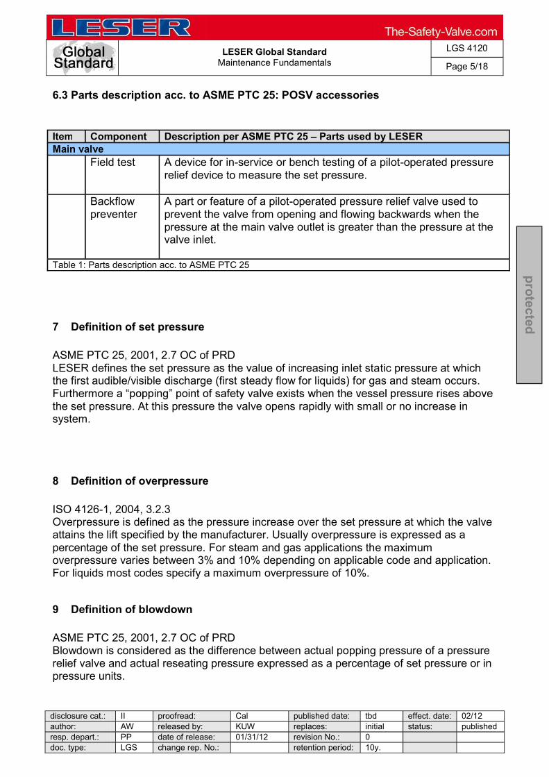
6.3 Parts description acc. to ASME PTC 25: POSV accessories
Item Component Description per ASME PTC 25 Parts used by LESER Main valve Field test A device for in-service or bench testing of a pilot-operated pressure
relief device to measure the set pressure.
Backflow preventer
A part or feature of a pilot-operated pressure relief valve used to prevent the valve from opening and flowing backwards when the pressure at the main valve outlet is greater than the pressure at the valve inlet.
Table 1: Parts description acc. to ASME PTC 25
7 Definition of set pressure
ASME PTC 25, 2001, 2.7 OC of PRD LESER defines the set pressure as the value of increasing inlet static pressure at which the first audible/visible discharge (first steady flow for liquids) for gas and steam occurs.
the set pressure. At this pressure the valve opens rapidly with small or no increase in system.
8 Definition of overpressure
ISO 4126-1, 2004, 3.2.3 Overpressure is defined as the pressure increase over the set pressure at which the valve attains the lift specified by the manufacturer. Usually overpressure is expressed as a percentage of the set pressure. For steam and gas applications the maximum overpressure varies between 3% and 10% depending on applicable code and application. For liquids most codes specify a maximum overpressure of 10%.
9 Definition of blowdown
ASME PTC 25, 2001, 2.7 OC of PRD Blowdown is considered as the difference between actual popping pressure of a pressure relief valve and actual reseating pressure expressed as a percentage of set pressure or in pressure units.
LESER Global Standard
Maintenance Fundamentals
LGS 4120
Page 6/18
disclosure cat.: II proofread: Cal published date: tbd effect. date: 02/12 author: AW released by: KUW replaces: initial status: published resp. depart.: PP date of release: 01/31/12 revision No.: 0 doc. type: LGS change rep. No.: retention period: 10y.
pro
tected
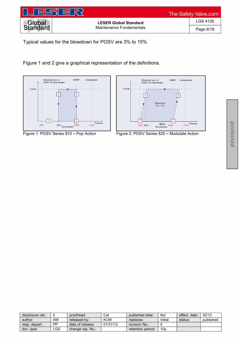
Typical values for the blowdown for POSV are 3% to 15%
Figure 1 and 2 give a graphical representation of the definitions.
Figure 1: POSV Series 810 Pop Action Figure 2: POSV Series 820 Modulate Action

LESER Global Standard
Maintenance Fundamentals
LGS 4120
Page 7/18
disclosure cat.: II proofread: Cal published date: tbd effect. date: 02/12 author: AW released by: KUW replaces: initial status: published resp. depart.: PP date of release: 01/31/12 revision No.: 0 doc. type: LGS change rep. No.: retention period: 10y.
pro
tected
10 General Introduction
10.1 Main valve illustration
Below is a schematic drawing of the parts layout for the LESER POSV main valve including both the Standard and Extra Orifice designs.
Figure 3: Illustration of the main valve
LESER Global Standard
Maintenance Fundamentals
LGS 4120
Page 8/18
disclosure cat.: II proofread: Cal published date: tbd effect. date: 02/12 author: AW released by: KUW replaces: initial status: published resp. depart.: PP date of release: 01/31/12 revision No.: 0 doc. type: LGS change rep. No.: retention period: 10y.
pro
tected
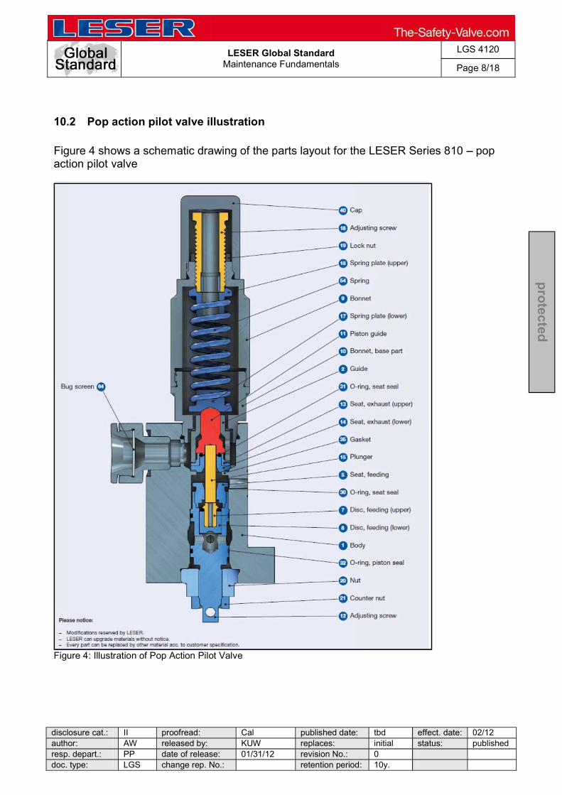
10.2 Pop action pilot valve illustration
Figure 4 shows a schematic drawing of the parts layout for the LESER Series 810 pop action pilot valve
Figure 4: Illustration of Pop Action Pilot Valve

LESER Global Standard
Maintenance Fundamentals
LGS 4120
Page 9/18
disclosure cat.: II proofread: Cal published date: tbd effect. date: 02/12 author: AW released by: KUW replaces: initial status: published resp. depart.: PP date of release: 01/31/12 revision No.: 0 doc. type: LGS change rep. No.: retention period: 10y.
pro
tected
10.3 Illustration of modulate action pilot valve (diaphragm)
Figure 5 shows a schematic drawing of the parts layout for the LESER Series 820 modulate action pilot valve.
Figure 5: Illustration of Modulate Action Pilot Valve, Diaphragm Design

LESER Global Standard
Maintenance Fundamentals
LGS 4120
Page 10/18
disclosure cat.: II proofread: Cal published date: tbd effect. date: 02/12 author: AW released by: KUW replaces: initial status: published resp. depart.: PP date of release: 01/31/12 revision No.: 0 doc. type: LGS change rep. No.: retention period: 10y.
pro
tected
10.4 Illustration of modulate action pilot valve (piston)
Figure 6 shows a schematic drawing of the parts layout for the LESER Series 820 modulate action pilot valve.
Figure 6: Illustration of modulate action pilot valve, piston design
LESER Global Standard
Maintenance Fundamentals
LGS 4120
Page 11/18
disclosure cat.: II proofread: Cal published date: tbd effect. date: 02/12 author: AW released by: KUW replaces: initial status: published resp. depart.: PP date of release: 01/31/12 revision No.: 0 doc. type: LGS change rep. No.: retention period: 10y.
pro
tected
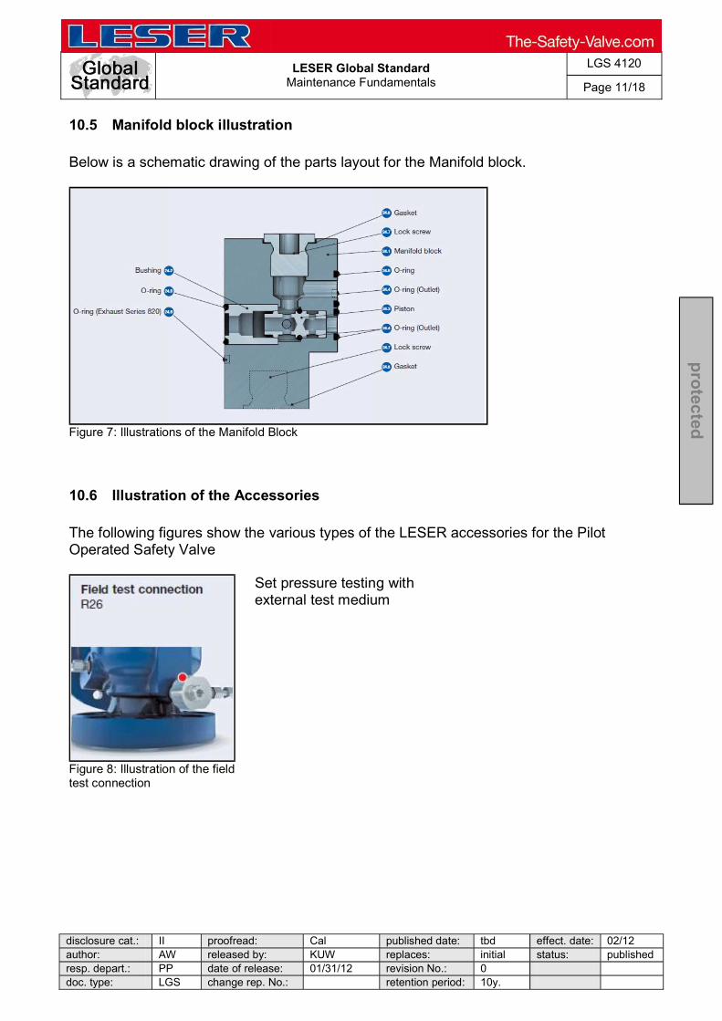
10.5 Manifold block illustration
Below is a schematic drawing of the parts layout for the Manifold block.
Figure 7: Illustrations of the Manifold Block
10.6 Illustration of the Accessories
The following figures show the various types of the LESER accessories for the Pilot Operated Safety Valve
Set pressure testing with external test medium
Figure 8: Illustration of the field test connection

LESER Global Standard
Maintenance Fundamentals
LGS 4120
Page 12/18
disclosure cat.: II proofread: Cal published date: tbd effect. date: 02/12 author: AW released by: KUW replaces: initial status: published resp. depart.: PP date of release: 01/31/12 revision No.: 0 doc. type: LGS change rep. No.: retention period: 10y.
pro
tected
Prevents return flow of the medium from the discharge into the system to be secured
Figure 9: Illustration of the backflow preventer
Filter to prevent plugging of the pilot
Figure 10: Illustration of pilot supplyfilter
Functional test of main valve piston
Figure 11: Illustration of the manual blowdown
LESER Global Standard
Maintenance Fundamentals
LGS 4120
Page 13/18
disclosure cat.: II proofread: Cal published date: tbd effect. date: 02/12 author: AW released by: KUW replaces: initial status: published resp. depart.: PP date of release: 01/31/12 revision No.: 0 doc. type: LGS change rep. No.: retention period: 10y.
pro
tected
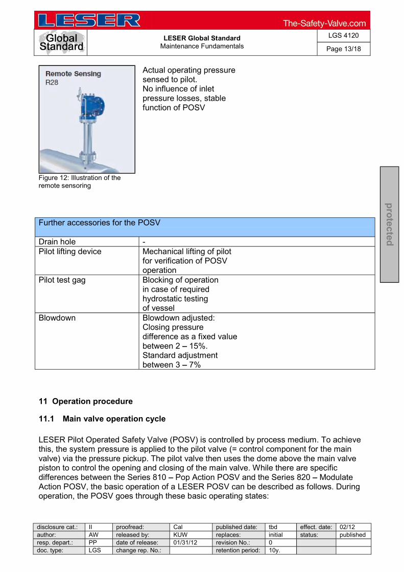
Actual operating pressure sensed to pilot. No influence of inlet pressure losses, stable function of POSV
Figure 12: Illustration of the remote sensoring
Further accessories for the POSV Drain hole - Pilot lifting device Mechanical lifting of pilot
for verification of POSV operation
Pilot test gag Blocking of operation in case of required hydrostatic testing of vessel
Blowdown Blowdown adjusted: Closing pressure difference as a fixed value between 2 15%. Standard adjustment between 3 7%
11 Operation procedure
11.1 Main valve operation cycle
LESER Pilot Operated Safety Valve (POSV) is controlled by process medium. To achieve this, the system pressure is applied to the pilot valve (= control component for the main valve) via the pressure pickup. The pilot valve then uses the dome above the main valve piston to control the opening and closing of the main valve. While there are specific differences between the Series 810 Pop Action POSV and the Series 820 Modulate Action POSV, the basic operation of a LESER POSV can be described as follows. During operation, the POSV goes through these basic operating states:

LESER Global Standard
Maintenance Fundamentals
LGS 4120
Page 14/18
disclosure cat.: II proofread: Cal published date: tbd effect. date: 02/12 author: AW released by: KUW replaces: initial status: published resp. depart.: PP date of release: 01/31/12 revision No.: 0 doc. type: LGS change rep. No.: retention period: 10y.
pro
tected
1. Below set pressure: normal operation During normal operation, the system pressure is picked up at the main valve inlet and routed to the dome (see illustration). Since the dome area is larger than the area of the main valve seat, the closing force is greater than the opening force. This keeps the main valve tightly closed.
2. At set pressure: actuating state At set pressure, the pilot valve actuates. The medium is no longer routed to the dome (see illustration). This prevents a further rise in dome pressure. Also, the dome is vented. As a result, the closing force ceases as a precondition for the system overpressure to push the main valve open.
3. Main valve opening The main valve opens. Depending on the design of the pilot valve, this opening is either rapid and complete (Pop Action) or gradual and partial following system pressure (Modulate Action).
4. At closing pressure: refilling the dome If system pressure drops to closing pressure, the pilot valve actuates and again routes the medium to the dome. The pressure in the dome builds up and the main valve recloses either rapid and complete (Pop Action) or gradual and partial following system pressure (Modulate Action).

LESER Global Standard
Maintenance Fundamentals
LGS 4120
Page 15/18
disclosure cat.: II proofread: Cal published date: tbd effect. date: 02/12 author: AW released by: KUW replaces: initial status: published resp. depart.: PP date of release: 01/31/12 revision No.: 0 doc. type: LGS change rep. No.: retention period: 10y.
pro
tected
11.2 Pop action pilot valve 1. Below set pressure: normal operation feeding seat open, exhaust seat closed The system pressure is routed to the top side of the main valve piston via the pressure pickup, the pilot valve and the dome of the main valve (see illustration). Since the pressure contact surface is larger on the top side than on the underside of the piston, there is always a stronger net force acting on the top side. The main valve is kept tightly closed.
2. At set pressure: feeding seat opening, exhaust seat closing When set pressure is reached, the pilot valve opens the exhaust seat and closes the feeding seat. This releases the dome pressure. The release of dome pressure is a pre-condition for the opening of the main valve by system pressure. 3. At and above set pressure (+ max. 1%): pop opening At set pressure, the main valve opens abruptly and completely feeding seat closed, exhaust seat open (Pop Action) (see bottom chart). The medium is channelled from the dome to atmosphere (see illustration on right).
4. At closing pressure: feeding seat open, exhaust seat closed When the system pressure drops to closing pressure, the pilot valve actuates and again channels the system pressure to the dome of the main valve. Here, the system pressure builds up, the main valve recloses. The closing stage (blowdown) can be adjusted from at least 3% (when pressure loss at the inlet is low) to max. 15% blowdown difference.
LESER Global Standard
Maintenance Fundamentals
LGS 4120
Page 16/18
disclosure cat.: II proofread: Cal published date: tbd effect. date: 02/12 author: AW released by: KUW replaces: initial status: published resp. depart.: PP date of release: 01/31/12 revision No.: 0 doc. type: LGS change rep. No.: retention period: 10y.
pro
tected
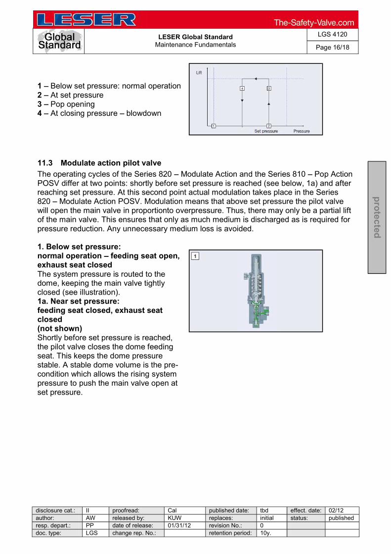
1 Below set pressure: normal operation 2 At set pressure 3 Pop opening 4 At closing pressure blowdown
11.3 Modulate action pilot valve
The operating cycles of the Series 820 Modulate Action and the Series 810 Pop Action POSV differ at two points: shortly before set pressure is reached (see below, 1a) and after reaching set pressure. At this second point actual modulation takes place in the Series 820 Modulate Action POSV. Modulation means that above set pressure the pilot valve will open the main valve in proportionto overpressure. Thus, there may only be a partial lift of the main valve. This ensures that only as much medium is discharged as is required for pressure reduction. Any unnecessary medium loss is avoided. 1. Below set pressure: normal operation feeding seat open, exhaust seat closed The system pressure is routed to the dome, keeping the main valve tightly closed (see illustration). 1a. Near set pressure: feeding seat closed, exhaust seat closed (not shown) Shortly before set pressure is reached, the pilot valve closes the dome feeding seat. This keeps the dome pressure stable. A stable dome volume is the pre-condition which allows the rising system pressure to push the main valve open at set pressure.

LESER Global Standard
Maintenance Fundamentals
LGS 4120
Page 17/18
disclosure cat.: II proofread: Cal published date: tbd effect. date: 02/12 author: AW released by: KUW replaces: initial status: published resp. depart.: PP date of release: 01/31/12 revision No.: 0 doc. type: LGS change rep. No.: retention period: 10y.
pro
tected
2. At set pressure (+ max. 1%): feeding seat closed, exhaust seat open With a further slight pressure increase, set pressure is reached and the pilot valve opens the dome exhaust seat. The dome volume is discharged and the main valve opens.
3. Modulate opening: feeding seat closed or open, exhaust seat closed or open At this point, modulation takes place. This means that if overpressure remains within the modulating range of 93 110% of set pressure, the pilot valve will again close the dome exhaust seat. This stops discharge from the dome and keeps the main valve piston unchanged at the achieved lift. The achieved lift will always be enough to ensure pressure reduction, but not more than is required. During blow-off this intermediate state with a stable dome volume and main valve lift can occur repeatedly and at different pressure levels. To change the lift, there can also be partial opening movements with the exhaust seat opened, or closing movements with the feeding seat opened. Modulation ensures that only as much medium is discharged as is necessary to prevent the overpressure from exceeding the modulating range
4. At closing pressure: full closing feeding seat open, exhaust seat closed When system pressure drops below the modulating range to reach blowdown pressure , the pilot returns to its first state (with feeding seat open and exhaust seat closed). The main valve closes completely.
LESER Global Standard
Maintenance Fundamentals
LGS 4120
Page 18/18
disclosure cat.: II proofread: Cal published date: tbd effect. date: 02/12 author: AW released by: KUW replaces: initial status: published resp. depart.: PP date of release: 01/31/12 revision No.: 0 doc. type: LGS change rep. No.: retention period: 10y.
pro
tected
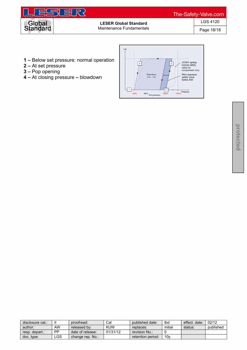
1 Below set pressure: normal operation 2 At set pressure 3 Pop opening 4 At closing pressure blowdown
LESER Global Standard Process for Safety Valves to Repair
LGS 4111
Page 1/2
disclosure cat.: II proofread: SSt published date: 03/06/18 effect. date: 03/18
author: Nieh released by: KUW replaces: initial status: Published
resp. depart.: IE date of release: 03/06/18 revision No.: 1
doc. type: LGS change rep. No.: NA retention period: 10
pro
tecte
d
Content
1 Purpose ............................................................................................................... 1
2 Scope .................................................................................................................. 1
3 Introduction .......................................................................................................... 1
4 Safety valve to repair ........................................................................................... 2
1 Purpose
This LESER Global Standard (LGS) shows the process for safety valves to repair.
2 Scope
This LGS applies to all members of the LESER Quality Cluster. 3 Introduction
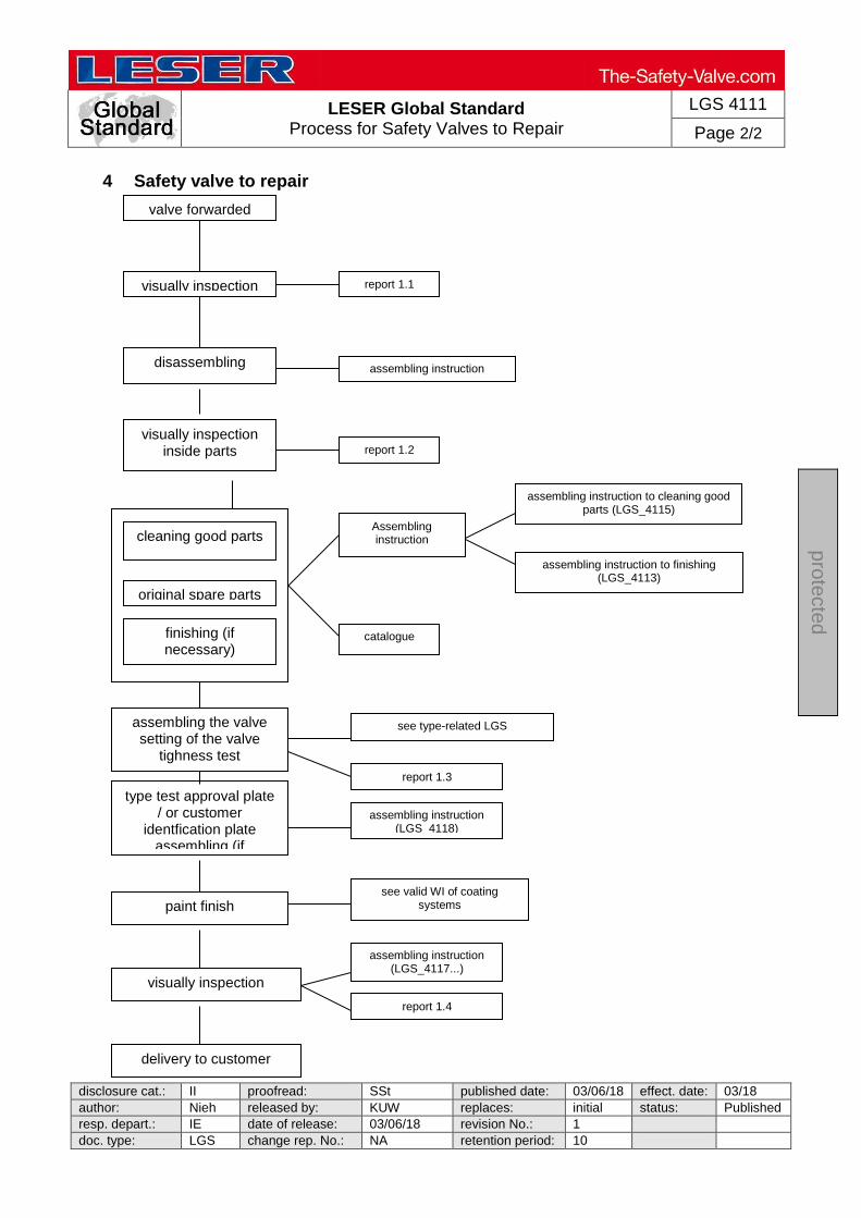
The following flow chart shows the process steps, which are necessary for valve repair. The right side give references to forms of inspection documentation, LESER standards, instructions and spare part lists.
LESER Global Standard Process for Safety Valves to Repair
LGS 4111
Page 2/2
disclosure cat.: II proofread: SSt published date: 03/06/18 effect. date: 03/18
author: Nieh released by: KUW replaces: initial status: Published
resp. depart.: IE date of release: 03/06/18 revision No.: 1
doc. type: LGS change rep. No.: NA retention period: 10
pro
tecte
d
4 Safety valve to repair
valve forwarded
visually inspection
disassembling
report 1.1
visually inspection inside parts
assembling instruction (LGS...)
report 1.2
cleaning good parts
original spare parts
finishing (if necessary)
Assembling instruction
catalogue
assembling the valve setting of the valve
tighness test
see type-related LGS
type test approval plate / or customer
identfication plate assembling (if
necessary)
assembling instruction (LGS_4118)
paint finish
visually inspection
delivery to customer
see valid WI of coating systems
assembling instruction (LGS_4117...)
report 1.4
assembling instruction to cleaning good parts (LGS_4115)
assembling instruction to finishing (LGS_4113)
report 1.3

LESER Global Form Repair Traveller POSV
LGF 4121
Page 1/5
disclosure cat.: II proofread: Cal published date: tbd effect. date: 02/12 author: AW released by: KUW replaces: initial status: published resp. depart.: PP date of release: 01/31/12 revision No.: 0 doc. type: LGF change rep. No.: retention period: 10y.
pro
tected
Repair Traveller Customer Date Valve type Serial no. / Job no. Medium 1.1 Forwarded Inspection Repair necessary Remarks Painting ________________ Inlet / outlet surface ________________ Lead seal ________________ Type test approval plate ________________ 1.2 Disassembling Main Vale Repair necessary Remarks 50 Dome spring ________________ 6 Piston ________________ 8 Piston guide ________________ 7 Disc ________________ 5 Nozzle ________________
LESER Global Form Repair Traveller POSV
LGF 4121
Page 2/5
disclosure cat.: II proofread: Cal published date: tbd effect. date: 02/12 author: AW released by: KUW replaces: initial status: published resp. depart.: PP date of release: 01/31/12 revision No.: 0 doc. type: LGF change rep. No.: retention period: 10y.
pro
tected
9 Top plate ________________ 2 Pitot tube ________________ 3, 4 Fittings / Tubes ________________ Pilot Valve POP Act. Repair necessary Remarks 40 Cap ________________ 18, 12 Adjusting screw ________________ 16, 17 Spring plates ________________ 54 Spring ________________ 9 Bonnet ________________ 2 Guide ________________ 13 Seat, exhaust (upper) ________________ 14 Seat, exhaust (lower) ________________ 15 Plunger ________________ 5 Seat, feeding ________________ 7 Disc, feeding (upper) ________________
LESER Global Form Repair Traveller POSV
LGF 4121
Page 3/5
disclosure cat.: II proofread: Cal published date: tbd effect. date: 02/12 author: AW released by: KUW replaces: initial status: published resp. depart.: PP date of release: 01/31/12 revision No.: 0 doc. type: LGF change rep. No.: retention period: 10y.
pro
tected
8 Disc, feeding (lower) ________________ 1 Body ________________ ------------------------------------------------------------------------------------------------------------------------ Pilot Valve Modulate Act. Repair necessary Remarks 40 Cap ________________ 12 Spindle ________________ 18 Adjusting screw ________________ 16, 17 Spring plates ________________ 54 Spring ________________ 47 Piston upper ________________ 41 Piston ________________ 72 Diaphragm ________________ 42 Return spring ________________ 2 Guide ________________ 7 Disc, feeding (upper) ________________

LESER Global Form Repair Traveller POSV
LGF 4121
Page 4/5
disclosure cat.: II proofread: Cal published date: tbd effect. date: 02/12 author: AW released by: KUW replaces: initial status: published resp. depart.: PP date of release: 01/31/12 revision No.: 0 doc. type: LGF change rep. No.: retention period: 10y.
pro
tected
8 Disc, feeding (lower) ________________ 5 Seat, feeding ________________ 11 Disc, exhaust (lower) ________________ 1 Body ________________ 45 Disc extension ________________ Pilot Valve Accessories Repair necessary Remarks Filter ________________ Field test connector (FTC) ________________ Manual blowdown ________________ 1.3 Assembling Inspection Set pressure psig target: actual: Seat tightness bubbles / min. target: actual: i.o. n.i.o. Backpressure / 6 psig ------------------------------------------------------------------------------------------------------------------------
LESER Global Form Repair Traveller POSV
LGF 4121
Page 5/5
disclosure cat.: II proofread: Cal published date: tbd effect. date: 02/12 author: AW released by: KUW replaces: initial status: published resp. depart.: PP date of release: 01/31/12 revision No.: 0 doc. type: LGF change rep. No.: retention period: 10y.
pro
tected
1.4 Delivery inspection i.o. n.i.o. Type test approval plate Painting Components _______________________ Date/Signature

LESER Global Standard Ablaufplan für Reparaturventile
LGS 4111
Page 1/2
disclosure cat.: II proofread: OR published date: 9/14/11 effect. date: 18.11.201author: Nieh released by: KUW replaces: initial status: published resp. depart.: PP date of release: 11/8/11 revision No.: 0 doc. type: LGS change rep. No.: 651A retention period: 10
pro
tected
Inhalt
1 Zweck .................................................................................................................. 1 2 Geltungsbereich................................................................................................... 1 3 Einleitung ............................................................................................................. 1 4 Ablaufplan für Reparaturventile ........................................................................... 2 1 Zweck
Dieser LESER Global Standard (LGS) zeigt den Ablaufplan für Reparaturventile auf.
2 Geltungsbereich
Dieser LGS gilt für alle Mitglieder des LESER Qualitätsverbunds. 3 Einleitung
Der nachfolgend aufgezeigte Ablaufplan zeigt die Prozessschritte, die nötig sind, eine Ventilreparatur abzuwickeln. Die rechte Seite gibt Hinweise auf Formblätter für Prüfdokumentationen, LESER Werknormen, Anleitungen und Ersatzteilkataloge.
LESER Global Standard Ablaufplan für Reparaturventile
LGS 4111
Page 2/2
disclosure cat.: II proofread: OR published date: 9/14/11 effect. date: 18.11.201author: Nieh released by: KUW replaces: initial status: published resp. depart.: PP date of release: 11/8/11 revision No.: 0 doc. type: LGS change rep. No.: 651A retention period: 10
pro
tected
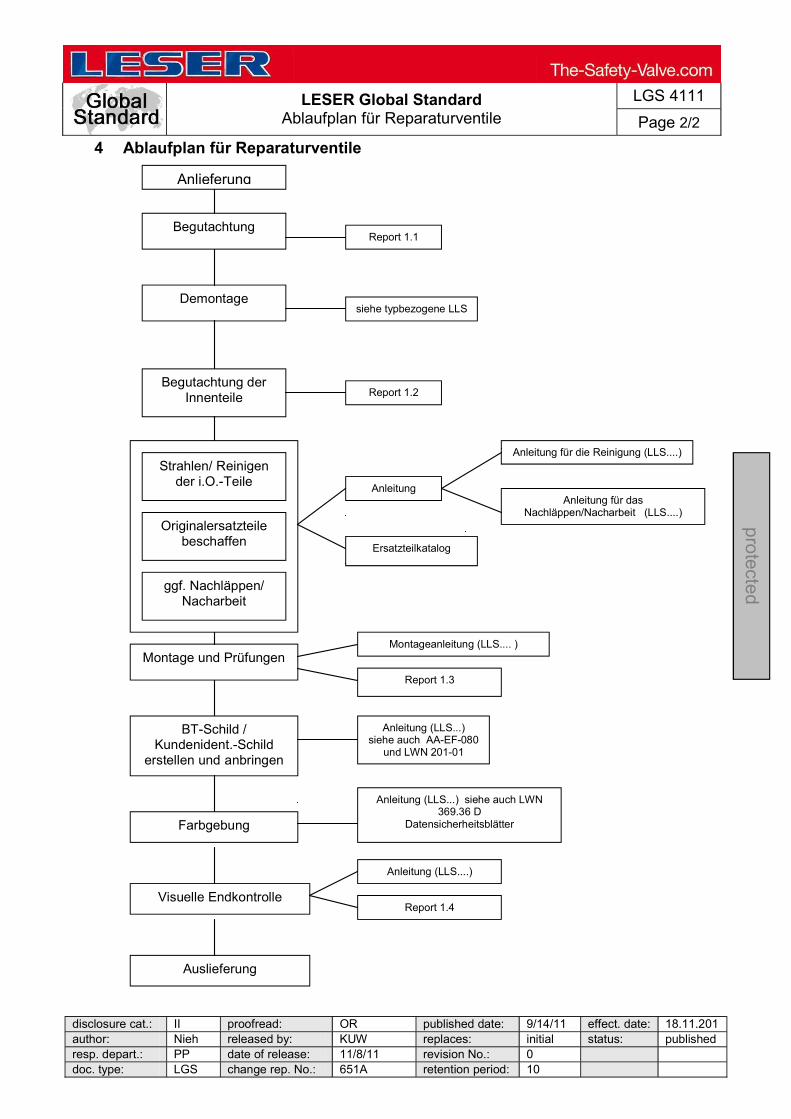
4 Ablaufplan für Reparaturventile
Anlieferung
Begutachtung
Demontage
Report 1.1
Begutachtung der Innenteile
siehe typbezogene LLS
Report 1.2
Strahlen/ Reinigen der i.O.-Teile
Originalersatzteile beschaffen
ggf. Nachläppen/ Nacharbeit
Anleitung
Ersatzteilkatalog
Montage und Prüfungen Montageanleitung (LLS.... )
BT-Schild / Kundenident.-Schild
erstellen und anbringen
Anleitung (LLS...) siehe auch AA-EF-080
und LWN 201-01
Farbgebung
Visuelle Endkontrolle
Auslieferung
Anleitung (LLS...) siehe auch LWN 369.36 D
Datensicherheitsblätter
Anleitung (LLS....)
Report 1.4
Anleitung für die Reinigung (LLS....)
Anleitung für das Nachläppen/Nacharbeit (LLS....)
Report 1.3
LESER Global Standard
Recommended Equipment POSV
LGS 4122
Page 1/18
disclosure cat.: II proofread: Cal published date: tbd effect. date: 02/12 author: AW released by: KUW replaces: initial status: published resp. depart.: PP date of release: 01/31/12 revision No.: 0 doc. type: LGS change rep. No.: retention period: 10y.
pro
tected
Content 1 Recommended equipment for disassembling, assembling and rework a Pilot Operated Safety Valve ....................................................................................... 2 2 Purpose ......................................................................................................... 2 3 Competences ................................................................................................ 2 4 Scope ............................................................................................................. 2 5 Disclaimer ...................................................................................................... 2 6 Tools for the pilot operated safety valves .................................................. 3 7 Customized tools for the pilot operated safety valve ................................ 10
LESER Global Standard
Recommended Equipment POSV
LGS 4122
Page 2/18
disclosure cat.: II proofread: Cal published date: tbd effect. date: 02/12 author: AW released by: KUW replaces: initial status: published resp. depart.: PP date of release: 01/31/12 revision No.: 0 doc. type: LGS change rep. No.: retention period: 10y.
pro
tected
1 Recommended equipment for disassembling, assembling and rework a Pilot Operated Safety Valve
2 Purpose
This document describes the recommended Tool KIT requirements for equipping an agency or a warehouse for goods receiving/storage, adjusting, testing and shipping of a POSV
3 Competences
The generation, maintenance and distribution of the documentation takes place in the organisation department. The defaults will be generated by the technical department in consultation with the final assembly department and production planning department.
4 Scope
This document must be applied to the disassembling, assembling, rework and refinishing parts of a Pilot Operated Safety Valve in agencies and subsidiaries of LESER GmbH & Co. KG, customers and independent service center.
5 Disclaimer
LESER puts in a great deal of effort into making up-to-date and correct documentation available. Nevertheless, LESER GmbH & Co. KG gives no guarantee that the recommended actions presented here are entirely correct and error free. This document is to be applied exclusively to the specified type. LESER GmbH & Co. KG declines any liability or responsibility for the correctness and completeness of the content. LESER GmbH & Co. KG reserves the right to change the information contained in this document, which is for the products of LESER GmbH & Co. KG and is intended for LESER subsidiaries, at any time and without prior announcement. LESER GmbH & Co. KG is available to the users of this document to provide additional information.
LESER Global Standard
Recommended Equipment POSV
LGS 4122
Page 3/18
disclosure cat.: II proofread: Cal published date: tbd effect. date: 02/12 author: AW released by: KUW replaces: initial status: published resp. depart.: PP date of release: 01/31/12 revision No.: 0 doc. type: LGS change rep. No.: retention period: 10y.
pro
tected
6 Tools for the pilot operated safety valves
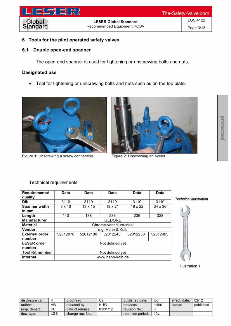
6.1 Double open-end spanner
The open-end spanner is used for tightening or unscrewing bolts and nuts.
Designated use
Tool for tightening or unscrewing bolts and nuts such as on the top plate.
Figure 1: Unscrewing a screw connection Figure 2: Unscrewing an eyelet
Technical requirements
Requirements/ quality
Data Data Data Data Data
Illustration 1
DIN 3110 3110 3110 3110 3110 Spanner width in mm
8 x 10 13 x 15 18 x 21 19 x 22 34 x 36
Length 140 188 236 236 328 Manufacturer GEDORE Material Chrome-vanadium-steel Vendor e.g. Hahn & Kolb External order number
52012070 52012180 52012245 52012250 52012405
LESER order number
Not defined yet
Tool Kit number Not defined yet Internet www.hahn-kolb.de

LESER Global Standard
Recommended Equipment POSV
LGS 4122
Page 4/18
disclosure cat.: II proofread: Cal published date: tbd effect. date: 02/12 author: AW released by: KUW replaces: initial status: published resp. depart.: PP date of release: 01/31/12 revision No.: 0 doc. type: LGS change rep. No.: retention period: 10y.
pro
tected
6.2 Ring spanner
The ring spanner is used for tightening or unscrewing bolts and nuts.
Designated use
Tool for tightening or unscrewing bolts and nuts such as top plates.
Figure 3: Ring spanner Technical requirements Requirements/ quality
Data Data Data Data Data Data
DIN 3113 3113 3113 3113 3113 3113 Spanner width in mm
13 18 24 30 41 46
Length 185 245 318 390 520 550 Manufacturer GEDORE Material Chrome-vanadium-steel Vendor e.g. Hahn & Kolb External order number
52042630
52042680
52042740 52042800 52042880
52042890
LESER order number
Not defined yet
Tool Kit number
Not defined yet
Internet www.hahn-kolb.de

LESER Global Standard
Recommended Equipment POSV
LGS 4122
Page 5/18
disclosure cat.: II proofread: Cal published date: tbd effect. date: 02/12 author: AW released by: KUW replaces: initial status: published resp. depart.: PP date of release: 01/31/12 revision No.: 0 doc. type: LGS change rep. No.: retention period: 10y.
pro
tected
6.3 Deep cranked ring spanner
The deep cranked ring spanner is used for tightening or unscrewing nuts which are located deeper than the surrounded surface. They are not approachable with an usual open-end spanner.
Designated use
Tool for tightening or unscrewing nuts in difficult approachable areas
Figure 4: Deep cranked ring spanner
Requirements/ quality
Data Data Technical illustration
Illustration 2
DIN 3113B 3113B Spanner width in mm
17 19
Length 232 258 Manufacturer GEDORE Material Chrome-vanadium-steel Vendor e.g. Hahn & Kolb External order number
52042670 52042690
LESER order number
Not defined yet
Tool Kit number
Not defined yet
Internet www.hahn-kolb.de

LESER Global Standard
Recommended Equipment POSV
LGS 4122
Page 6/18
disclosure cat.: II proofread: Cal published date: tbd effect. date: 02/12 author: AW released by: KUW replaces: initial status: published resp. depart.: PP date of release: 01/31/12 revision No.: 0 doc. type: LGS change rep. No.: retention period: 10y.
pro
tected
6.4 Single-ended open spanner
Single-ended open spanners are required for tightening or unscrewing the lever and cap.
Designated use
For example lever and cap screw connections
Figure 5: Tightening a cap Figure 6: Tightening a cap Requirements /
Quality Data Data Single open end spanner
Technical illustration 3
DIN 894
Spanner width in mm
70 cranked
Manufacturer ORION
Material Special steel
Length 575
Vendor e.g. Hahn & Kolb
External order number
52002070
LESER order number
Not defined yet
Tool kit number Not defined yet
Internet www.hahn-kolb.de

LESER Global Standard
Recommended Equipment POSV
LGS 4122
Page 7/18
disclosure cat.: II proofread: Cal published date: tbd effect. date: 02/12 author: AW released by: KUW replaces: initial status: published resp. depart.: PP date of release: 01/31/12 revision No.: 0 doc. type: LGS change rep. No.: retention period: 10y.
pro
tected
6.5 Allen key
The allen key is used for tightening or unscrewing allen screws.
Designated use
Tool for tightening or unscrewing screws such as used at the manifold block
Figure 7: Allen key with torque wrench Requirements /
Quality Data Illustration : Tool box with allen keys for ratchet/ torque
wrench
Technical illustration 4
DIN -
Sizes in mm
4, 5, 6, 8, 10, 12, 14, 17, 19
Manufacturer ORION
Material Special steel
Vendor e.g. Hahn & Kolb
External order number 52458150
LESER order number Not defined yet
Tool kit number Not defined yet
Internet www.hahn-kolb.de

LESER Global Standard
Recommended Equipment POSV
LGS 4122
Page 8/18
disclosure cat.: II proofread: Cal published date: tbd effect. date: 02/12 author: AW released by: KUW replaces: initial status: published resp. depart.: PP date of release: 01/31/12 revision No.: 0 doc. type: LGS change rep. No.: retention period: 10y.
pro
tected
6.6 Socket
The socket is used together with the torque wrench (see LGS 4456 standard tool kit) and the plug-in reversible ratchet (see LGS 4456 standard tool kit). It is used, for example, for the screw connection of the top plate to the body.
Designated use
Screw connections of top plates
Figure 8: Tightening a nut Figure 9: Tightening a nut
Technical requirements
Requirements / Quality
Data
DIN 3120
Size 8mm 41 mm 50 mm
Material Special steel
Vendor e.g. Hahn & Kolb
External order number
58612080 58972041 58972050
LESER order number
Not defined yet
Tool kit number Not defined yet
Internet www.hahn-kolb.de
Technical illustration
Illustration 5:Socket

LESER Global Standard
Recommended Equipment POSV
LGS 4122
Page 9/18
disclosure cat.: II proofread: Cal published date: tbd effect. date: 02/12 author: AW released by: KUW replaces: initial status: published resp. depart.: PP date of release: 01/31/12 revision No.: 0 doc. type: LGS change rep. No.: retention period: 10y.
pro
tected
6.7 Impact wrench
The Impact wrench is used for tightening or unscrewing bolts and nuts mechanically. It is just a helpful tool, but not necessary for disassembly or assembly the POSV valve.
Designated use
Tool for tightening or unscrewing nuts such as used at the top plate of the POSV
Figure 11: Impact wrench

LESER Global Standard
Recommended Equipment POSV
LGS 4122
Page 10/18
disclosure cat.: II proofread: Cal published date: tbd effect. date: 02/12 author: AW released by: KUW replaces: initial status: publishedresp. depart.: PP date of release: 01/31/12 revision No.: 0 doc. type: LGS change rep. No.: retention period: 10y.
pro
tected
7 Customized tools for the pilot operated safety valve
7.1 O-ring mounting aid
The O-ring mounting aid is used for an easier assembly of the O-rings. It is just a helpful tool, but not necessary for disassembly or assembly the POSV valve.
Designated use
Tool for pulling O-rings on their foreseen components such as pistons or seats
Figure 12: O-ring mounting aid
Figure 13: O-ring mounting aid
Technical requirements
Requirements / Quality Data
Diameter [mm] 30 ; 32 ; 34
Length Not defined yet
Vendor LESER

LESER Global Standard
Recommended Equipment POSV
LGS 4122
Page 11/18
disclosure cat.: II proofread: Cal published date: tbd effect. date: 02/12 author: AW released by: KUW replaces: initial status: published resp. depart.: PP date of release: 01/31/12 revision No.: 0 doc. type: LGS change rep. No.: retention period: 10y.
pro
tected
LESER order number Not defined yet
Tool kit number Not defined yet
Order [email protected]
7.2 Hook for O-rings
The hook for O-rings is used for an easier assembly and disassembly of O-rings.
Figure 14: O-ring tool box
Technical requirements
Requirements / Quality Data
Manufacturer APSOparts
Material metal
Vendor e.g. Angst+Pfister Gruppe
External order number 11.4052.5000
LESER order number Not defined yet
Tool kit number Not defined yet
Internet Angst-pfister.com
LESER Global Standard
Recommended Equipment POSV
LGS 4122
Page 12/18
disclosure cat.: II proofread: Cal published date: tbd effect. date: 02/12 author: AW released by: KUW replaces: initial status: published resp. depart.: PP date of release: 01/31/12 revision No.: 0 doc. type: LGS change rep. No.: retention period: 10y.
pro
tected
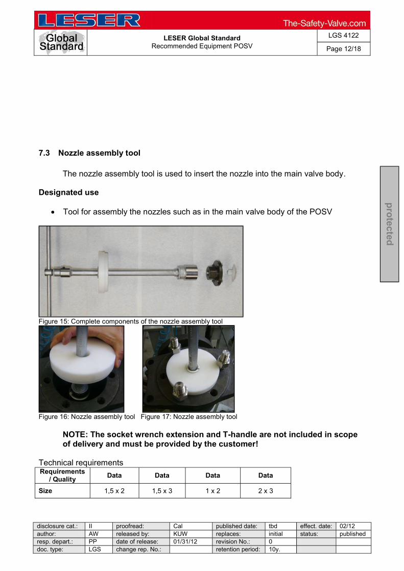
7.3 Nozzle assembly tool The nozzle assembly tool is used to insert the nozzle into the main valve body.
Designated use
Tool for assembly the nozzles such as in the main valve body of the POSV
Figure 15: Complete components of the nozzle assembly tool
Figure 16: Nozzle assembly tool Figure 17: Nozzle assembly tool
NOTE: The socket wrench extension and T-handle are not included in scope of delivery and must be provided by the customer!
Technical requirements Requirements
/ Quality Data Data Data Data
Size 1,5 x 2 1,5 x 3 1 x 2 2 x 3
LESER Global Standard
Recommended Equipment POSV
LGS 4122
Page 13/18
disclosure cat.: II proofread: Cal published date: tbd effect. date: 02/12 author: AW released by: KUW replaces: initial status: published resp. depart.: PP date of release: 01/31/12 revision No.: 0 doc. type: LGS change rep. No.: retention period: 10y.
pro
tected
Material Metal ; plastic
Vendor LESER
LESER order number
445.5239.0000 445.5339.0000 445.5939.0000 445.5439.0000
Tool kit number
Not defined yet
Internet Leser.com
Order [email protected]
Requirements
/ Quality Data Data Data Data
Size 3 x 4 4 x 6 6 x 8 8 x 10
Material Metal ; plastic
Vendor LESER
LESER order number
445.5539.0000 445.5639.0000 445.5739.0000 445.5839.0000
Tool kit number Not defined yet
Internet www.leser.com
Order [email protected]

LESER Global Standard
Recommended Equipment POSV
LGS 4122
Page 14/18
disclosure cat.: II proofread: Cal published date: tbd effect. date: 02/12 author: AW released by: KUW replaces: initial status: published resp. depart.: PP date of release: 01/31/12 revision No.: 0 doc. type: LGS change rep. No.: retention period: 10y.
pro
tected
7.4 Pitot tube assembly tool
The pitot tube assembly tool is used to align the pitot tube while tightening the fitting the main valve body.
Designated use
Tool to align the pitot tube such as in the main valve body of the POSV.
Figure 18: Pitot tube assembly tool

LESER Global Standard
Recommended Equipment POSV
LGS 4122
Page 15/18
disclosure cat.: II proofread: Cal published date: tbd effect. date: 02/12 author: AW released by: KUW replaces: initial status: published resp. depart.: PP date of release: 01/31/12 revision No.: 0 doc. type: LGS change rep. No.: retention period: 10y.
pro
tected
Figure 19 : Pitot assembly tool
Figure 20: Pitot assembly tool
Technical requirements
Requirements / Quality Data
Length Not defined yet
Quantity 1
Vendor LESER
LESER order number Not defined yet
Tool kit number Not defined yet
Internet [email protected]
7.5 Piston disassembly tool
The disassembly tool is used to pull the piston out of the piston guide. It is just a helpful tool, but not necessary for disassembly or assembly the POSV valve.
Designated use
Use the piston disassembly tool during the disassembly process by screwing the tool into the top of the piston. Afterwards you can easily pull the piston out of the guide.

LESER Global Standard
Recommended Equipment POSV
LGS 4122
Page 16/18
disclosure cat.: II proofread: Cal published date: tbd effect. date: 02/12 author: AW released by: KUW replaces: initial status: published resp. depart.: PP date of release: 01/31/12 revision No.: 0 doc. type: LGS change rep. No.: retention period: 10y.
pro
tected
Figure 21: Piston disassembly tool Figure 22: Disassembly of a piston
Technical requirements
Requirements / Quality Data
Length Not defined yet
Quantity 1
Vendor LESER
LESER order number Not defined yet
Tool kit number Not defined yet
Internet [email protected]
7.6 Gap gage for clamp ring
The gap gage is used to check the connections of the compression fittings.
Designated use
Tool to examine a right connection such as between the tube and main valve. 1. Screw the nut up to the gap gage 2. Pull out the gap gage 3. Tighten the nut a further ¼ - ½ turn
For further details refer to the manufacturer of the compression fitting
LESER Global Standard
Recommended Equipment POSV
LGS 4122
Page 17/18
disclosure cat.: II proofread: Cal published date: tbd effect. date: 02/12 author: AW released by: KUW replaces: initial status: published resp. depart.: PP date of release: 01/31/12 revision No.: 0 doc. type: LGS change rep. No.: retention period: 10y.
pro
tected
Technical requirements
Requirements / Quality Data
Technical illustration 6
Manufacturer Schwer
Material metal
Vendor e.g. Schwer
External order number GG
LESER order number Not defined yet
Tool kit number Not defined yet
Internet www.schwer.com
7.7 Assembling aid pilot
The assembling aid is used for an easier assembly of the seats/ discs and adjusting screws. It is just a helpful tool, but not necessary for disassembly or assembly the POSV valve.
Designated use
Aid in which you can place the adjusting screw or the disc and seat unit of the pilot valve. Therefore it is easier to assembly or disassembly these components
LESER Global Standard
Recommended Equipment POSV
LGS 4122
Page 18/18
disclosure cat.: II proofread: Cal published date: tbd effect. date: 02/12 author: AW released by: KUW replaces: initial status: published resp. depart.: PP date of release: 01/31/12 revision No.: 0 doc. type: LGS change rep. No.: retention period: 10y.
pro
tected
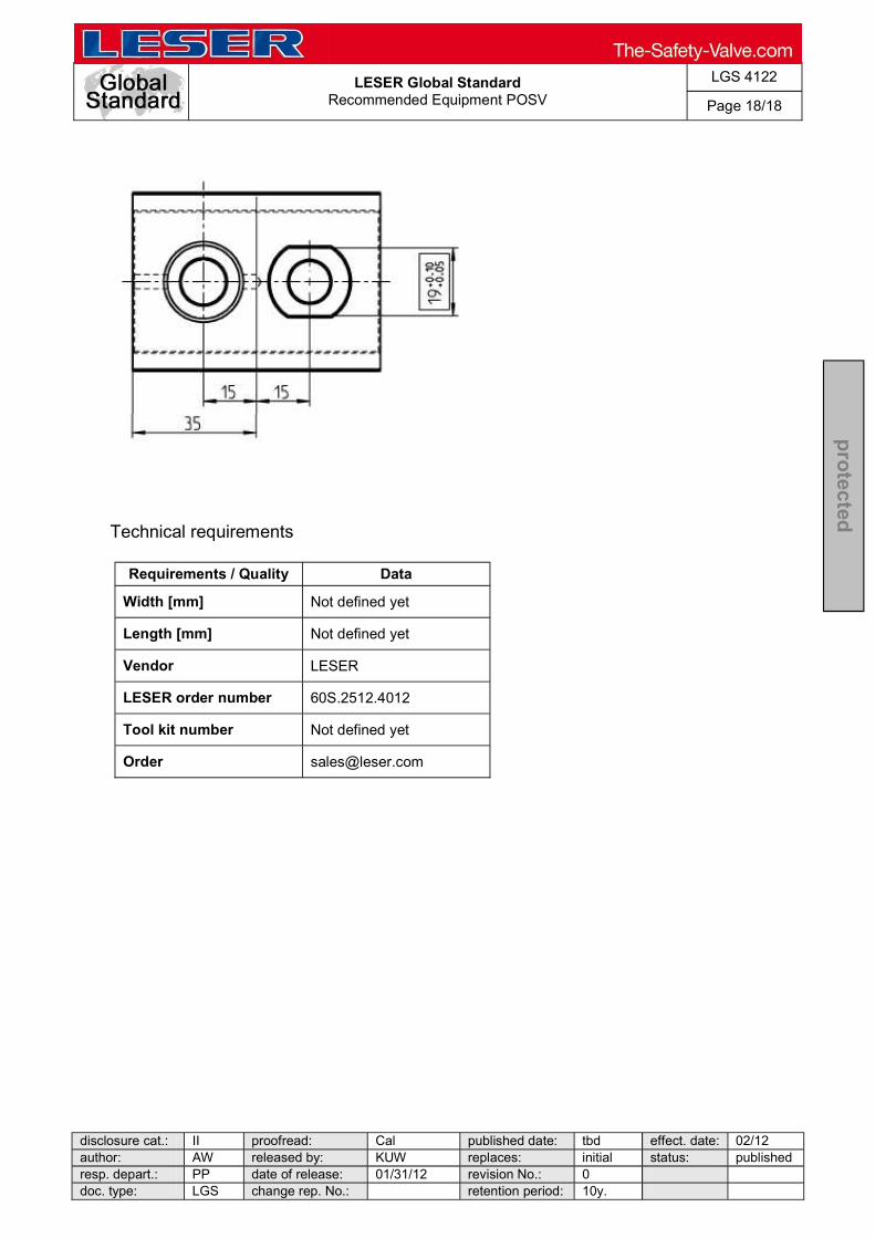
Technical requirements
Requirements / Quality Data
Width [mm] Not defined yet
Length [mm] Not defined yet
Vendor LESER
LESER order number 60S.2512.4012
Tool kit number Not defined yet
Order [email protected]
LESER Global Standard
Standardisation of Worldwide Warehouses Standard: Tool-Kit Specifikations
LGS 4456
Page 1/36
disclosure cat.: II proofread: Kuw published date: 8/31/11 effect. date: 10/11 author: Kro released by: KUW replaces: 369-56 status: published resp. depart.: PP date of release: 9/15/11 revision No.: 0 doc. type: LGS change rep. No.: 00882A retention period: 10y.
pro
tecte
d
Content 1 Purpose ......................................................................................................... 1 2 Scope ............................................................................................................. 1 3 Introduction ................................................................................................... 1 4 Components of the Standard Tool KIT ........................................................ 2
1 Purpose
This LESER Global (LGS) describes the recommended Took KIT requirements for equipping an agency or a warehouse for goods receiving/storage, adjusting, testing and shipping of safety valves.
2 Scope
This LGS applies to all members of the LESER quality cluster as defined in the global quality management manual.
3 Introduction
The Tool KIT is an important part of the equipment of an
assembly workplace. It is required for the different work listed for most series of safety valves.
Order number 0161.0000
Internet [email protected]
3.1 Designated use
Assembly of safety valves Disassembly of safety valves Adjusting the set pressure of safety valves Lapping the valve seat Repair work

LESER Global Standard
Standardisation of Worldwide Warehouses Standard: Tool-Kit Specifikations
LGS 4456
Page 2/36
disclosure cat.: II proofread: Kuw published date: 8/31/11 effect. date: 10/11 author: Kro released by: KUW replaces: 369-56 status: published resp. depart.: PP date of release: 9/15/11 revision No.: 0 doc. type: LGS change rep. No.: 00882A retention period: 10y.
pro
tecte
d
4 Components of the Standard Tool KIT
All tools found in this LWN are part of the Standard Tool
KIT. The following pages specify the individual tools through descriptions and by giving practical examples. The technical illustrations show how the respective tools look.
4.1 Double-ended open spanner with unequal widths across flats
The double-ended open spanner is used for tightening or unscrewing bolts and nuts.
Designated use
Tool for tightening or unscrewing bolts and nuts such as caps, levers, and inflow devices
Technical requirements (1)
Requirements / Quality Data Data Data
DIN 3110
Spanner width in mm 16 x 18 17 x 19 22 x 24
Length 205 mm 222 mm 250 mm
Manufacturer GEDORE
Material Chrome-vanadium-steel
Vendor Hahn & Kolb External order number 52012-222 52012-230 52012-290
Fig. 1 Unscrewing a screw connection Fig. 2 Sealing the drain hole
Technical illustration
Fig. 1: Double-ended open spanner

LESER Global Standard
Standardisation of Worldwide Warehouses Standard: Tool-Kit Specifikations
LGS 4456
Page 3/36
disclosure cat.: II proofread: Kuw published date: 8/31/11 effect. date: 10/11 author: Kro released by: KUW replaces: 369-56 status: published resp. depart.: PP date of release: 9/15/11 revision No.: 0 doc. type: LGS change rep. No.: 00882A retention period: 10y.
pro
tecte
d
LESER order number 596.0058.0000
Tool kit number 0161.0000
Internet www.hahn-kolb.de
Technical requirements (2)
Requirements / Quality Data Data Data
DIN 3110
Spanner width in mm 27 x 32 41 x 46 50 x 55
Manufacturer GEDORE
Material Chrome-vanadium-steel
Length 302 mm 400 mm 460 mm
Vendor Hahn & Kolb External order number 52012-370 52012-420 52008-370
LESER order number 596.0061.000 596.0062.000 596.0063.000
Tool kit number 0161.0000
Internet www.hahn-kolb.de

LESER Global Standard
Standardisation of Worldwide Warehouses Standard: Tool-Kit Specifikations
LGS 4456
Page 4/36
disclosure cat.: II proofread: Kuw published date: 8/31/11 effect. date: 10/11 author: Kro released by: KUW replaces: 369-56 status: published resp. depart.: PP date of release: 9/15/11 revision No.: 0 doc. type: LGS change rep. No.: 00882A retention period: 10y.
pro
tecte
d

LESER Global Standard
Standardisation of Worldwide Warehouses Standard: Tool-Kit Specifikations
LGS 4456
Page 5/36
disclosure cat.: II proofread: Kuw published date: 8/31/11 effect. date: 10/11 author: Kro released by: KUW replaces: 369-56 status: published resp. depart.: PP date of release: 9/15/11 revision No.: 0 doc. type: LGS change rep. No.: 00882A retention period: 10y.
pro
tecte
d
4.2 Single-ended open spanner
Single-ended open spanners are required for tightening or unscrewing the lever and cap.
Designated use
lever and cap screw connections
Technical requirements
Requirements / Quality Data Data
DIN 894
Spanner width in mm 41 60
Manufacturer ORION
Material Special steel
Length 345 mm 495 mm
Head thickness 14 mm 18 mm
Vendor Hahn & Kolb External order number 52002-041 52002-060
LESER order number 596.0063.0000 596.0030.0000
Tool kit number 0161.0000
Internet www.hahn-kolb.de
Technical illustration
Illustration 2: Single-ended open spanner
Fig. 3 Installation of the lever and cap

LESER Global Standard
Standardisation of Worldwide Warehouses Standard: Tool-Kit Specifikations
LGS 4456
Page 6/36
disclosure cat.: II proofread: Kuw published date: 8/31/11 effect. date: 10/11 author: Kro released by: KUW replaces: 369-56 status: published resp. depart.: PP date of release: 9/15/11 revision No.: 0 doc. type: LGS change rep. No.: 00882A retention period: 10y.
pro
tecte
d
4.3 Flat-tip and Phillips PH screwdrivers
The screw driver is required for a variety of auxiliary work such as, for example, to remove jammed workpieces or to insert an O-ring.
Designated use
screwing in of locking screws (H4 lever) insert O-rings (type 462) remove jammed workpieces
Technical requirements
Requirements / Quality Data Data Data Data
DIN 5265A
Edge width mm 3.5 4.5 5.5 6.5
Edge thickness mm 0.6 0.8 1.0 1.2
Shaft length mm 100 125 150 150
Total length mm 204 236 261 268
Vendor Hahn & Kolb External order number 52736-120 52736-135 52736-141 52736-150
LESER order number 596.0039.0000
Tool kit number 0161.0000
Internet www.hahn-kolb.de
Technical illustration
Illustration 3: Flat-
head/Phillips screwdriver
Fig. 3 Lifting the protective cap

LESER Global Standard
Standardisation of Worldwide Warehouses Standard: Tool-Kit Specifikations
LGS 4456
Page 7/36
disclosure cat.: II proofread: Kuw published date: 8/31/11 effect. date: 10/11 author: Kro released by: KUW replaces: 369-56 status: published resp. depart.: PP date of release: 9/15/11 revision No.: 0 doc. type: LGS change rep. No.: 00882A retention period: 10y.
pro
tecte
d
4.4 Combination pliers
The combination pliers are required as an auxiliary tool for various work. For example, it can be used to cut soft and hard wire. The long cutting edges are suitable for thick cable.
Designated use
removal of sealing wire
Technical requirements
Requirements / Quality Data
DIN ISO 5746
Length 180 mm
Largest Ø that can be cut 3.4 mm
Cutting edges Induction-hardened 60 HRC
Vendor Hahn & Kolb
External order number 52279-130
LESER order number 596.0064.0000
Tool kit number 0161.0000
Internet www.hahn-kolb.de
Technical illustration
Illustration 4: Combination pliers

LESER Global Standard
Standardisation of Worldwide Warehouses Standard: Tool-Kit Specifikations
LGS 4456
Page 8/36
disclosure cat.: II proofread: Kuw published date: 8/31/11 effect. date: 10/11 author: Kro released by: KUW replaces: 369-56 status: published resp. depart.: PP date of release: 9/15/11 revision No.: 0 doc. type: LGS change rep. No.: 00882A retention period: 10y.
pro
tecte
d
4.5 Pin punch
The pin punch is required for the assembly and disassembly of discs and spindles. The pins are driven in and out by means of a pin punch.
Designated use
driving pins in and out fixing the spindle in place, when adjusting the set pressure
Technical requirements
Requirements / Quality Data
DIN 6450 C
Tips Ø mm 3 / 4 / 5 / 6 / 7 / 8
Length x thickness mm 150 x 10/ 150 x 10/ 150 x 10/ 150 x 10/ 150 x 12/ 150 x 12
Punch head Hardened and tempered
Delivery In holder with base
Vendor Hahn & Kolb
External order number 51284-500
LESER order number 596.0065.0000
Tool kit number 0161.0000
Internet www.hahn-kolb.de
Technical illustration
Illustration 5: Combination pliers
LESER Global Standard
Standardisation of Worldwide Warehouses Standard: Tool-Kit Specifikations
LGS 4456
Page 9/36
disclosure cat.: II proofread: Kuw published date: 8/31/11 effect. date: 10/11 author: Kro released by: KUW replaces: 369-56 status: published resp. depart.: PP date of release: 9/15/11 revision No.: 0 doc. type: LGS change rep. No.: 00882A retention period: 10y.
pro
tecte
d
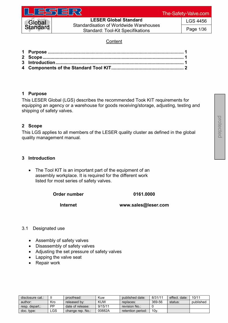
4.6 Hammer
The hammer is used for marking flanges and bodies and for fastening individual parts like, for example, discs and spindles.
Designated use
hammering in punch numbers fastening of discs and spindles hammering in pins
Technical requirements
Requirements / Quality Data Data
DIN 1041
Weight without handle 200 800
Manufacturer ORION
External order number 51180-510 51180-560
LESER order number 596.0066.0000 596.0067.0000
Tool kit number 0161.0000
Internet www.hahn-kolb.de
Technical illustration
Illustration 6: Hammer
LESER Global Standard
Standardisation of Worldwide Warehouses Standard: Tool-Kit Specifikations
LGS 4456
Page 10/36
disclosure cat.: II proofread: Kuw published date: 8/31/11 effect. date: 10/11 author: Kro released by: KUW replaces: 369-56 status: published resp. depart.: PP date of release: 9/15/11 revision No.: 0 doc. type: LGS change rep. No.: 00882A retention period: 10y.
pro
tecte
d
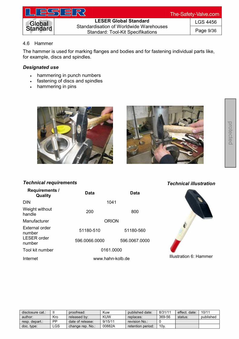
4.7 Punch numbers
Punch numbers are required for a variety or marking work. At the request of the customer, the safety valve must also be marked on the edge of the flange or on the body with the set pressure or tag.
Designated use
marking flanges and bodies
Technical requirements
Requirements / Quality Data Data
DIN 1451
Type of characters Numbers
Character height 0.2 mm 0.6 mm
Characters 0 - 9 0 - 9
Number of punches 9
Max workpiece strength 1200 Nm² 1200 Nm²
Hardness on end of punch 58 60 HRC 58 60 HRC
Vendor Hahn & Kolb
External order number 56930-020 56930-060
LESER order number 596.0068.0000 596.0069.0000
Tool kit number 0161.0000
Internet www.hahn-kolb.de
Technical illustration
Illustration 7: Punch numbers
LESER Global Standard
Standardisation of Worldwide Warehouses Standard: Tool-Kit Specifikations
LGS 4456
Page 11/36
disclosure cat.: II proofread: Kuw published date: 8/31/11 effect. date: 10/11 author: Kro released by: KUW replaces: 369-56 status: publishedresp. depart.: PP date of release: 9/15/11 revision No.: 0 doc. type: LGS change rep. No.: 00882A retention period: 10y.
pro
tecte
d
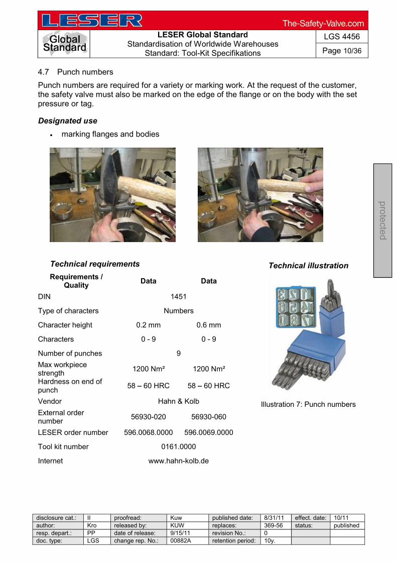
4.8 Punch letters
Punch letters are required for a variety or marking work. At the request of the customer, the safety valve must also be marked on the edge of the flange or on the body with the set pressure or tag or name.
Designated use
marking flanges and bodies
Technical requirements
Requirements / Quality Data Data
DIN 1451
Type of characters Letters
Character height 0.2 mm 0.6 mm
Characters A - Z - &
Number of punches 27
Max workpiece strength 1200 Nm² 1200 Nm²
Hardness on end of punch 58 60 HRC 58 60 HRC
Vendor Hahn & Kolb
External order number 56932-020 56932-060
LESER order number 596.0070.0000 596.0071.0000
Tool kit number 0161.0000
Internet www.hahn-kolb.de
Technical illustration
Illustration 8: Punch letters
LESER Global Standard
Standardisation of Worldwide Warehouses Standard: Tool-Kit Specifikations
LGS 4456
Page 12/36
disclosure cat.: II proofread: Kuw published date: 8/31/11 effect. date: 10/11 author: Kro released by: KUW replaces: 369-56 status: published resp. depart.: PP date of release: 9/15/11 revision No.: 0 doc. type: LGS change rep. No.: 00882A retention period: 10y.
pro
tecte
d
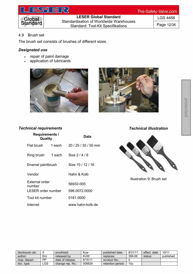
4.9 Brush set
The brush set consists of brushes of different sizes.
Designated use
repair of paint damage application of lubricants
Technical requirements
Requirements / Quality Data
Flat brush 1 each 20 / 25 / 35 / 50 mm
Ring brush 1 each Size 2 / 4 / 6
Enamel paintbrush Size 10 / 12 / 16
Vendor Hahn & Kolb
External order number 56932-005
LESER order number 596.0072.0000
Tool kit number 0161.0000
Internet www.hahn-kolb.de
Technical illustration
Illustration 9: Brush set

LESER Global Standard
Standardisation of Worldwide Warehouses Standard: Tool-Kit Specifikations
LGS 4456
Page 13/36
disclosure cat.: II proofread: Kuw published date: 8/31/11 effect. date: 10/11 author: Kro released by: KUW replaces: 369-56 status: published resp. depart.: PP date of release: 9/15/11 revision No.: 0 doc. type: LGS change rep. No.: 00882A retention period: 10y.
pro
tecte
d
4.10 Sliding vernier calliper
Basically, the sliding vernier calliper is used to measure components, for example stroke limits. The set pressure for several identical safety valves can be roughly adjusted with the sliding vernier calliper.
Designated use
pressure setting measuring stroke limits measuring components
Technical requirements
Requirements / Quality Data
DIN 862
Application outside, inside, step and depth measurements
Material INOX steel
Measuring span 150 mm
Measuring jaw length 40 mm
Length of the vernier 15.5 mm Manufacturer ATRON
Vendor Hahn & Kolb
External order number 31065-110
LESER order number 596.0074.0000
Tool kit number 0161.0000
Internet www.hahn-kolb.de
Technical illustration
Illustration 10: Sliding vernier calliper

LESER Global Standard
Standardisation of Worldwide Warehouses Standard: Tool-Kit Specifikations
LGS 4456
Page 14/36
disclosure cat.: II proofread: Kuw published date: 8/31/11 effect. date: 10/11 author: Kro released by: KUW replaces: 369-56 status: published resp. depart.: PP date of release: 9/15/11 revision No.: 0 doc. type: LGS change rep. No.: 00882A retention period: 10y.
pro
tecte
d
4.11 Sealing pliers
Sealing pliers are required for sealing the bonnet and the body after setting the pressure of the safety valve.
Designated use
sealing bonnets and bodies
Technical requirements
Requirements / Quality Data
Length 150 mm
Seal Ø 9 mm
Colour Blue
Vendor Hahn & Kolb
External order number 53205-145
LESER order number 596.0053.0000
Tool kit number 0161.0000
Internet www.hahn-kolb.de
Technical illustration
Illustration 11: Sealing pliers

LESER Global Standard
Standardisation of Worldwide Warehouses Standard: Tool-Kit Specifikations
LGS 4456
Page 15/36
disclosure cat.: II proofread: Kuw published date: 8/31/11 effect. date: 10/11 author: Kro released by: KUW replaces: 369-56 status: published resp. depart.: PP date of release: 9/15/11 revision No.: 0 doc. type: LGS change rep. No.: 00882A retention period: 10y.
pro
tecte
d
4.12 V-Block
When assembling the disc and spindle, there is a risk of damaging the spindle or disc by incorrect loading. To prevent this, the V-block is used as an underlay or to fix the round components in place.
Designated use
assembly of discs and spindles offloading the spindle
Technical requirements
Requirements / Quality Data Data
Name Small V-block Large V-block
Weight 0.93 kg 0.90 kg
Material Steel
Vendor LESER
LESER order number 445.0759.0000 445.0859.0000
Tool kit number 0161.0000
Internet [email protected]
Technical illustration
Illustration 19: V-block
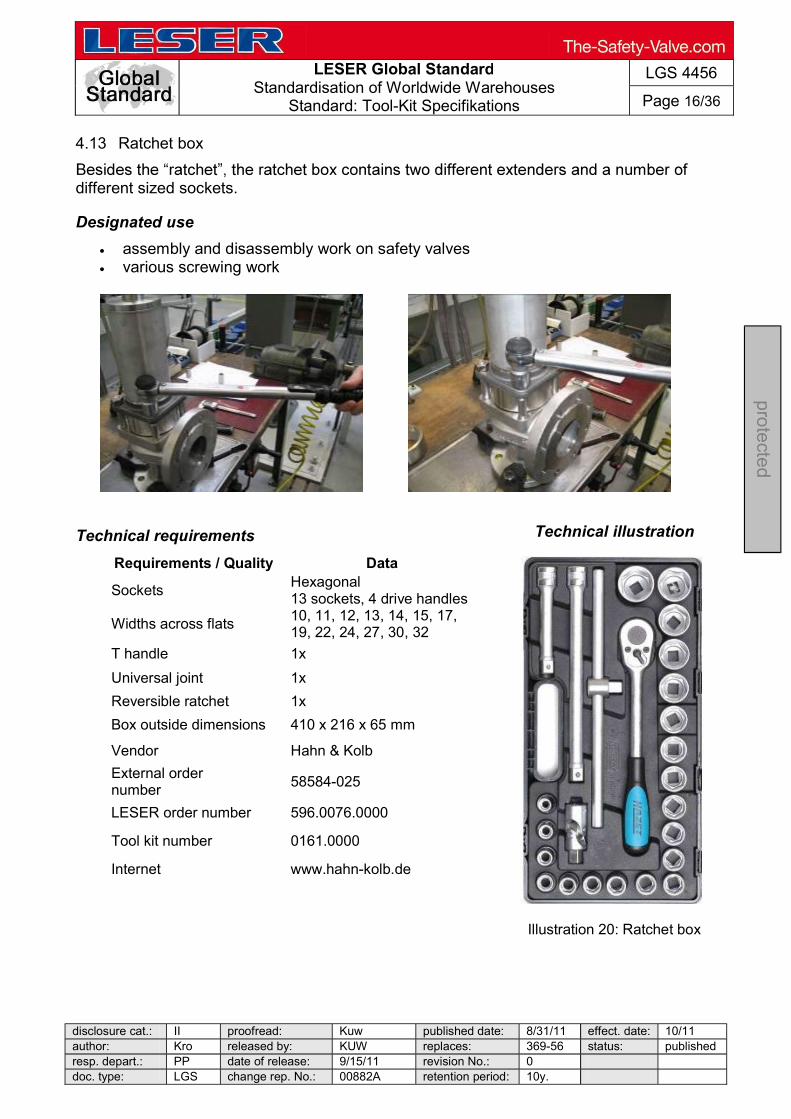
LESER Global Standard
Standardisation of Worldwide Warehouses Standard: Tool-Kit Specifikations
LGS 4456
Page 16/36
disclosure cat.: II proofread: Kuw published date: 8/31/11 effect. date: 10/11 author: Kro released by: KUW replaces: 369-56 status: published resp. depart.: PP date of release: 9/15/11 revision No.: 0 doc. type: LGS change rep. No.: 00882A retention period: 10y.
pro
tecte
d
4.13 Ratchet box
different sized sockets.
Designated use
assembly and disassembly work on safety valves various screwing work
Technical requirements
Requirements / Quality Data
Sockets Hexagonal 13 sockets, 4 drive handles
Widths across flats 10, 11, 12, 13, 14, 15, 17, 19, 22, 24, 27, 30, 32
T handle 1x
Universal joint 1x
Reversible ratchet 1x
Box outside dimensions 410 x 216 x 65 mm
Vendor Hahn & Kolb
External order number 58584-025
LESER order number 596.0076.0000
Tool kit number 0161.0000
Internet www.hahn-kolb.de
Technical illustration
Illustration 20: Ratchet box
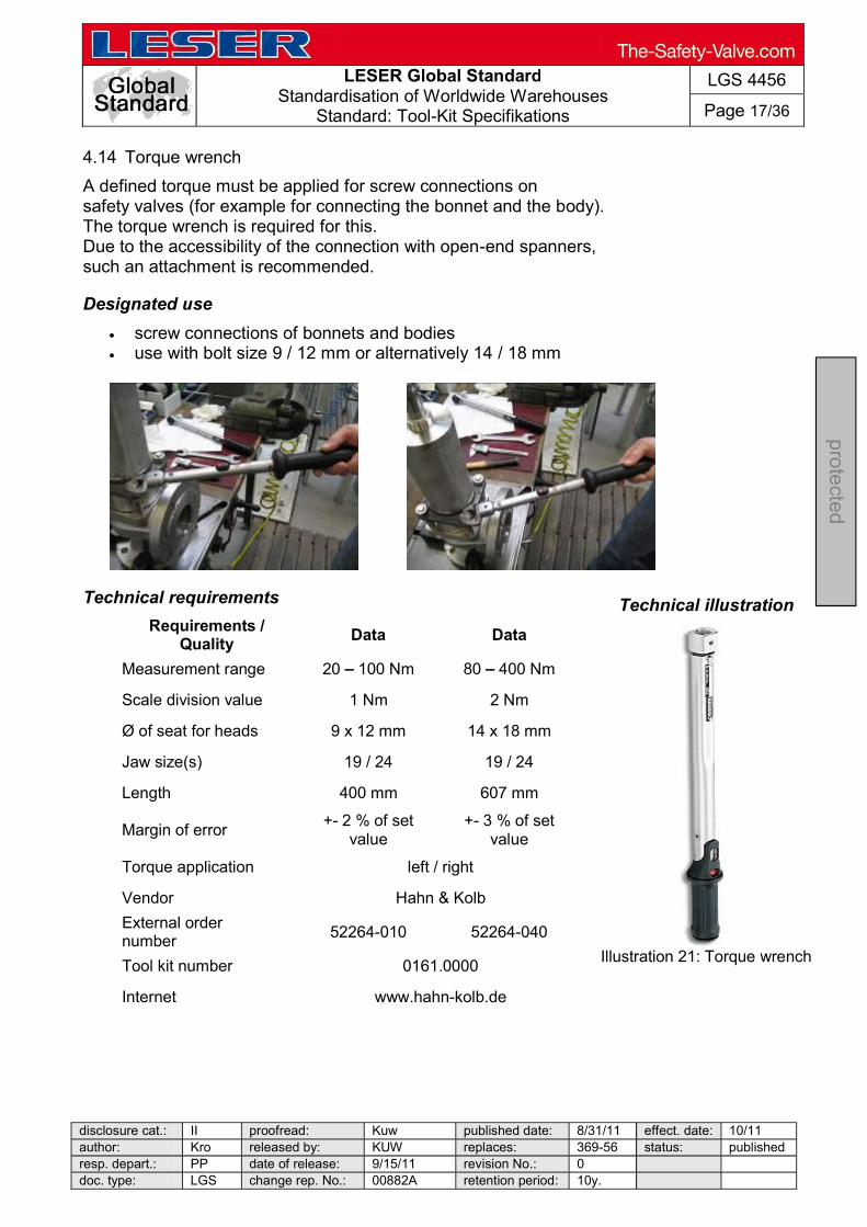
LESER Global Standard
Standardisation of Worldwide Warehouses Standard: Tool-Kit Specifikations
LGS 4456
Page 17/36
disclosure cat.: II proofread: Kuw published date: 8/31/11 effect. date: 10/11 author: Kro released by: KUW replaces: 369-56 status: published resp. depart.: PP date of release: 9/15/11 revision No.: 0 doc. type: LGS change rep. No.: 00882A retention period: 10y.
pro
tecte
d
4.14 Torque wrench
A defined torque must be applied for screw connections on safety valves (for example for connecting the bonnet and the body). The torque wrench is required for this. Due to the accessibility of the connection with open-end spanners, such an attachment is recommended.
Designated use
screw connections of bonnets and bodies use with bolt size 9 / 12 mm or alternatively 14 / 18 mm
Technical requirements
Requirements / Quality Data Data
Measurement range 20 100 Nm 80 400 Nm
Scale division value 1 Nm 2 Nm
Ø of seat for heads 9 x 12 mm 14 x 18 mm
Jaw size(s) 19 / 24 19 / 24
Length 400 mm 607 mm
Margin of error +- 2 % of set value
+- 3 % of set value
Torque application left / right
Vendor Hahn & Kolb
External order number 52264-010 52264-040
Tool kit number 0161.0000
Internet www.hahn-kolb.de
Technical illustration
Illustration 21: Torque wrench

LESER Global Standard
Standardisation of Worldwide Warehouses Standard: Tool-Kit Specifikations
LGS 4456
Page 18/36
disclosure cat.: II proofread: Kuw published date: 8/31/11 effect. date: 10/11 author: Kro released by: KUW replaces: 369-56 status: published resp. depart.: PP date of release: 9/15/11 revision No.: 0 doc. type: LGS change rep. No.: 00882A retention period: 10y.
pro
tecte
d
4.15 Jaw attachments
Jaw attachments for the torque wrench are required, for example, for connecting the bonnet to the body. The jaw attachments are used together with the torque wrench (see 6.14).
Designated use
screw connections of bonnets and bodies bolt size 19 / 24 mm
Technical requirements
Requirements / Quality Data Data
Spanner width 19 mm 24 mm
Width 41 mm 51 mm
Height 9 mm 11 mm
Plug-in shaft 14 x 18 mm 14 x 18 mm
Vendor Hahn & Kolb
External order number 52286-119 52286-124
External order LESER 596.0078.0000 596.0079.0000
Tool kit number 0161.0000
Internet www.hahn-kolb.de
Technical illustration
Illustration 22: Jaw
attachment
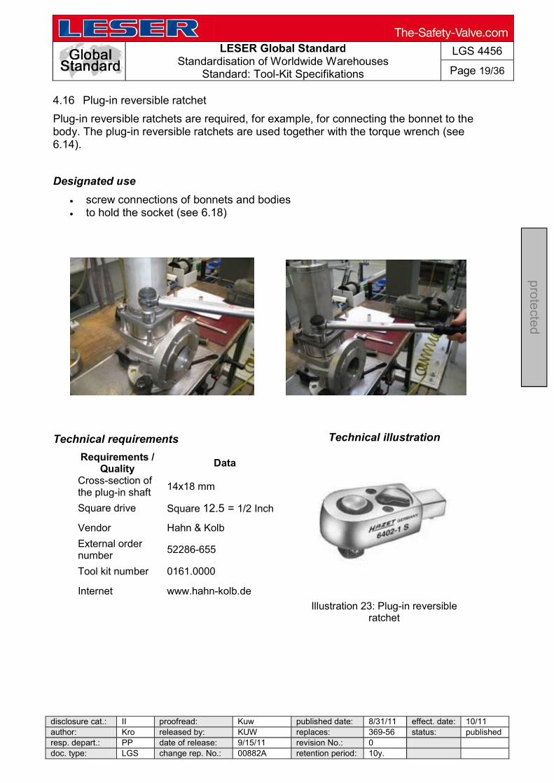
LESER Global Standard
Standardisation of Worldwide Warehouses Standard: Tool-Kit Specifikations
LGS 4456
Page 19/36
disclosure cat.: II proofread: Kuw published date: 8/31/11 effect. date: 10/11 author: Kro released by: KUW replaces: 369-56 status: published resp. depart.: PP date of release: 9/15/11 revision No.: 0 doc. type: LGS change rep. No.: 00882A retention period: 10y.
pro
tecte
d
4.16 Plug-in reversible ratchet
Plug-in reversible ratchets are required, for example, for connecting the bonnet to the body. The plug-in reversible ratchets are used together with the torque wrench (see 6.14).
Designated use
screw connections of bonnets and bodies to hold the socket (see 6.18)
Technical requirements
Requirements / Quality Data
Cross-section of the plug-in shaft 14x18 mm
Square drive Square 12.5 = 1/2 Inch
Vendor Hahn & Kolb
External order number 52286-655
Tool kit number 0161.0000
Internet www.hahn-kolb.de
Technical illustration
Illustration 23: Plug-in reversible ratchet
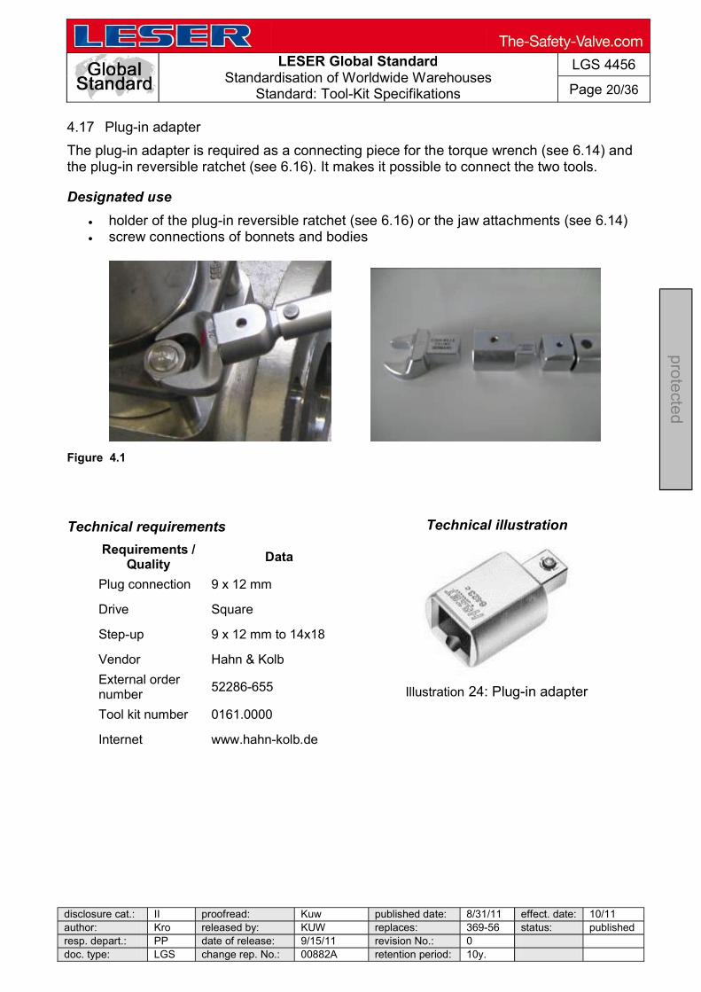
LESER Global Standard
Standardisation of Worldwide Warehouses Standard: Tool-Kit Specifikations
LGS 4456
Page 20/36
disclosure cat.: II proofread: Kuw published date: 8/31/11 effect. date: 10/11 author: Kro released by: KUW replaces: 369-56 status: published resp. depart.: PP date of release: 9/15/11 revision No.: 0 doc. type: LGS change rep. No.: 00882A retention period: 10y.
pro
tecte
d
4.17 Plug-in adapter
The plug-in adapter is required as a connecting piece for the torque wrench (see 6.14) and the plug-in reversible ratchet (see 6.16). It makes it possible to connect the two tools.
Designated use
holder of the plug-in reversible ratchet (see 6.16) or the jaw attachments (see 6.14) screw connections of bonnets and bodies
Figure 4.1
Technical requirements
Requirements / Quality Data
Plug connection 9 x 12 mm
Drive Square
Step-up 9 x 12 mm to 14x18
Vendor Hahn & Kolb
External order number 52286-655
Tool kit number 0161.0000
Internet www.hahn-kolb.de
Technical illustration
Illustration 24: Plug-in adapter

LESER Global Standard
Standardisation of Worldwide Warehouses Standard: Tool-Kit Specifikations
LGS 4456
Page 21/36
disclosure cat.: II proofread: Kuw published date: 8/31/11 effect. date: 10/11 author: Kro released by: KUW replaces: 369-56 status: published resp. depart.: PP date of release: 9/15/11 revision No.: 0 doc. type: LGS change rep. No.: 00882A retention period: 10y.
pro
tecte
d
4.18 Socket
The socket is used together with the torque wrench (see 6.14) and the plug-in reversible ratchet (see 6.16). It is used, for example, for the screw connection of the bonnet to the body.
Designated use
screw connections of bonnets and bodies
Technical requirements
Requirements / Quality Data
DIN 3120
Width across flats 36 mm
Size ø 60/49.5 mm
Material 31 Cr V 3
Vendor Hahn & Kolb
External order number 58596-360
LESER order number 596.0082.0000
Tool kit number 0161.0000
Internet www.hahn-kolb.de
Technical illustration
Illustration 25:Socket
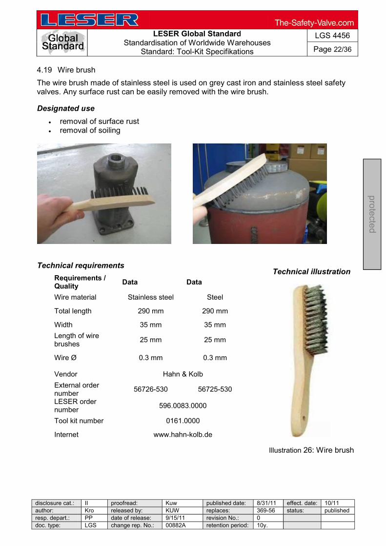
LESER Global Standard
Standardisation of Worldwide Warehouses Standard: Tool-Kit Specifikations
LGS 4456
Page 22/36
disclosure cat.: II proofread: Kuw published date: 8/31/11 effect. date: 10/11 author: Kro released by: KUW replaces: 369-56 status: published resp. depart.: PP date of release: 9/15/11 revision No.: 0 doc. type: LGS change rep. No.: 00882A retention period: 10y.
pro
tecte
d
4.19 Wire brush
The wire brush made of stainless steel is used on grey cast iron and stainless steel safety valves. Any surface rust can be easily removed with the wire brush.
Designated use
removal of surface rust removal of soiling
Technical requirements
Requirements / Quality Data Data
Wire material Stainless steel Steel
Total length 290 mm 290 mm
Width 35 mm 35 mm
Length of wire brushes 25 mm 25 mm
Wire Ø 0.3 mm 0.3 mm
Vendor Hahn & Kolb
External order number 56726-530 56725-530
LESER order number 596.0083.0000
Tool kit number 0161.0000
Internet www.hahn-kolb.de
Technical illustration
Illustration 26: Wire brush

LESER Global Standard
Standardisation of Worldwide Warehouses Standard: Tool-Kit Specifikations
LGS 4456
Page 23/36
disclosure cat.: II proofread: Kuw published date: 8/31/11 effect. date: 10/11 author: Kro released by: KUW replaces: 369-56 status: published resp. depart.: PP date of release: 9/15/11 revision No.: 0 doc. type: LGS change rep. No.: 00882A retention period: 10y.
pro
tecte
d
4.20 Safety glasses
The safety glasses are used to protect your eyes. They must be worn during grinding work on safety valves.
Designated use
general safety of the eyes to be worn during grinding work on the safety valve
Technical requirements
Requirements / Quality Data
DIN EN 166 F
Manufacturer ARTILUX
Design with side guards
Vendor Hahn & Kolb
External order number 55660-100
LESER order number 596.0085.0000
Tool kit number 0161.0000
Internet www.hahn-kolb.de
Technical illustration
Illustration 27:Safety glasses
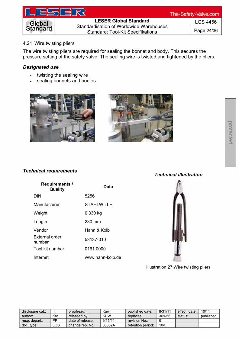
LESER Global Standard
Standardisation of Worldwide Warehouses Standard: Tool-Kit Specifikations
LGS 4456
Page 24/36
disclosure cat.: II proofread: Kuw published date: 8/31/11 effect. date: 10/11 author: Kro released by: KUW replaces: 369-56 status: published resp. depart.: PP date of release: 9/15/11 revision No.: 0 doc. type: LGS change rep. No.: 00882A retention period: 10y.
pro
tecte
d
4.21 Wire twisting pliers
The wire twisting pliers are required for sealing the bonnet and body. This secures the pressure setting of the safety valve. The sealing wire is twisted and tightened by the pliers.
Designated use
twisting the sealing wire sealing bonnets and bodies
Technical requirements
Requirements /
Quality Data
DIN 5256
Manufacturer STAHLWILLE
Weight 0.330 kg
Length 230 mm
Vendor Hahn & Kolb
External order number 53137-010
Tool kit number 0161.0000
Internet www.hahn-kolb.de
Technical illustration
Illustration 27:Wire twisting pliers

LESER Global Standard
Standardisation of Worldwide Warehouses Standard: Tool-Kit Specifikations
LGS 4456
Page 25/36
disclosure cat.: II proofread: Kuw published date: 8/31/11 effect. date: 10/11 author: Kro released by: KUW replaces: 369-56 status: publishedresp. depart.: PP date of release: 9/15/11 revision No.: 0 doc. type: LGS change rep. No.: 00882A retention period: 10y.
pro
tecte
d
4.22 Sealing blocks
The sealing blocks are used to seal the cap / lever and thus certify the set pressure that has been set.
Designated use
sealing safety valves
Technical requirements
Requirements / Quality Data
Size L x H x D 9 x 9 x 5 mm
1.5 mm
Material Plastic
Temp. application limit + 85° C
Vendor Johan Pützfeld B.V.
LESER order number 525.0107.0000
Tool kit number 0161.0000
Internet www.skiffy.com
Technical illustration
Illustration 29:Sealing
blocks
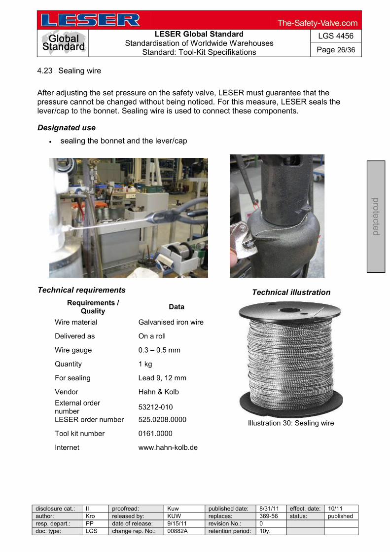
LESER Global Standard
Standardisation of Worldwide Warehouses Standard: Tool-Kit Specifikations
LGS 4456
Page 26/36
disclosure cat.: II proofread: Kuw published date: 8/31/11 effect. date: 10/11 author: Kro released by: KUW replaces: 369-56 status: published resp. depart.: PP date of release: 9/15/11 revision No.: 0 doc. type: LGS change rep. No.: 00882A retention period: 10y.
pro
tecte
d
4.23 Sealing wire
After adjusting the set pressure on the safety valve, LESER must guarantee that the pressure cannot be changed without being noticed. For this measure, LESER seals the lever/cap to the bonnet. Sealing wire is used to connect these components.
Designated use
sealing the bonnet and the lever/cap
Technical requirements
Requirements / Quality Data
Wire material Galvanised iron wire
Delivered as On a roll
Wire gauge 0.3 0.5 mm
Quantity 1 kg
For sealing Lead 9, 12 mm
Vendor Hahn & Kolb
External order number 53212-010
LESER order number 525.0208.0000
Tool kit number 0161.0000
Internet www.hahn-kolb.de
Technical illustration
Illustration 30: Sealing wire
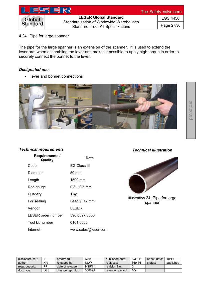
LESER Global Standard
Standardisation of Worldwide Warehouses Standard: Tool-Kit Specifikations
LGS 4456
Page 27/36
disclosure cat.: II proofread: Kuw published date: 8/31/11 effect. date: 10/11 author: Kro released by: KUW replaces: 369-56 status: published resp. depart.: PP date of release: 9/15/11 revision No.: 0 doc. type: LGS change rep. No.: 00882A retention period: 10y.
pro
tecte
d
4.24 Pipe for large spanner
The pipe for the large spanner is an extension of the spanner. It is used to extend the lever arm when assembling the lever and makes it possible to apply high torque in order to securely connect the bonnet to the lever.
Designated use
lever and bonnet connections
Technical requirements
Requirements / Quality Data
Code EG Class III
Diameter 50 mm
Length 1500 mm
Rod gauge 0.3 0.5 mm
Quantity 1 kg
For sealing Lead 9, 12 mm
Vendor LESER
LESER order number 596.0097.0000
Tool kit number 0161.0000
Internet [email protected]
Technical illustration
Illustration 24: Pipe for large
spanner

LESER Global Standard
Standardisation of Worldwide Warehouses Standard: Tool-Kit Specifikations
LGS 4456
Page 28/36
disclosure cat.: II proofread: Kuw published date: 8/31/11 effect. date: 10/11 author: Kro released by: KUW replaces: 369-56 status: published resp. depart.: PP date of release: 9/15/11 revision No.: 0 doc. type: LGS change rep. No.: 00882A retention period: 10y.
pro
tecte
d
4.25 Folding rule
A folding rule is required for any measuring work.
Designated use
measuring the outside dimensions of packaging
Technical requirements
Requirements / Quality Data
Length 2 m
Material Wood
Width of sections 16 mm
EC class III
Vendor Hahn & Kolb
External order number 37332-005
LESER order number TB D
Tool kit number 0161.0000
Internet www.hahn-kolb.de
Technical illustration
Illustration. 32: Folding rule
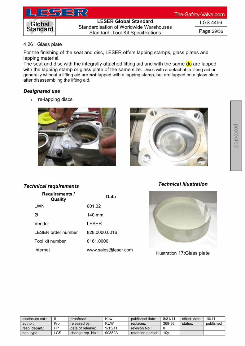
LESER Global Standard
Standardisation of Worldwide Warehouses Standard: Tool-Kit Specifikations
LGS 4456
Page 29/36
disclosure cat.: II proofread: Kuw published date: 8/31/11 effect. date: 10/11 author: Kro released by: KUW replaces: 369-56 status: published resp. depart.: PP date of release: 9/15/11 revision No.: 0 doc. type: LGS change rep. No.: 00882A retention period: 10y.
pro
tecte
d
4.26 Glass plate
For the finishing of the seat and disc, LESER offers lapping stamps, glass plates and lapping material. The seat and disc with the integrally attached lifting aid and with the same do are lapped with the lapping stamp or glass plate of the same size. Discs with a detachable lifting aid or generally without a lifting aid are not lapped with a lapping stamp, but are lapped on a glass plate after disassembling the lifting aid. Designated use
re-lapping discs
Technical requirements
Requirements / Quality Data
LWN 001.32
Ø 140 mm
Vendor LESER
LESER order number 828.0000.0016
Tool kit number 0161.0000
Internet [email protected]
Technical illustration
Illustration 17:Glass plate

LESER Global Standard
Standardisation of Worldwide Warehouses Standard: Tool-Kit Specifikations
LGS 4456
Page 30/36
disclosure cat.: II proofread: Kuw published date: 8/31/11 effect. date: 10/11 author: Kro released by: KUW replaces: 369-56 status: published resp. depart.: PP date of release: 9/15/11 revision No.: 0 doc. type: LGS change rep. No.: 00882A retention period: 10y.
pro
tecte
d
4.27 Lapping stamp
For the finishing of the seat and disc, LESER offers lapping stamps, glass plates and lapping material. The seat and disc with the integrally attached lifting aid and with the same do are lapped with the lapping stamp of the same size.
Designated use
relapping seats and nozzles
Technical illustration
Technical requirements (1)
Requirements / Quality Data Data Data
Number 3 4 5
do 18 23 29
Material 0.6025 / 1.4021 0.6025 / 1.4021 0.6025 / 1.4021
Manufacturer LESER
Length 205 mm 222 mm 250 mm
LESER order number 445.1359.0000 445.1459.0000 445.1559.0000
Tool kit number 0161.0000
Internet [email protected]
LESER Global Standard
Standardisation of Worldwide Warehouses Standard: Tool-Kit Specifikations
LGS 4456
Page 31/36
disclosure cat.: II proofread: Kuw published date: 8/31/11 effect. date: 10/11 author: Kro released by: KUW replaces: 369-56 status: published resp. depart.: PP date of release: 9/15/11 revision No.: 0 doc. type: LGS change rep. No.: 00882A retention period: 10y.
pro
tecte
d
Technical requirements (2)
Requirements / Quality Data Data Data Data
Number 6 7 8 9
do 37 46 60 74
Material 0.6025 / 1.4021 0.6025 / 1.4021 0.6025 / 1.4021 0.6025 / 1.4021
Manufacturer LESER
Length 172 mm 205 mm 222 mm 250 mm
LESER order number 445.1659.0000 445.1759.0000 445.1859.0000 445.1959.0000
Tool kit number 0161.0000
Internet [email protected]
Requirements /
Quality Data Data Data Data
Number 10 12 13 14
do 92 125 165 200
Material 0.6025 / 1.4021 0.6025 / 1.4021 0.6025 / 1.4021 0.6025 / 1.4021
Manufacturer LESER
Length 172 mm 205 mm 222 mm 250 mm
LESER order number 445.2059.0000 445.2259.0000 445.2359.0000 445.2459.0000
Tool kit number 0161.0000
Internet [email protected]

LESER Global Standard
Standardisation of Worldwide Warehouses Standard: Tool-Kit Specifikations
LGS 4456
Page 32/36
disclosure cat.: II proofread: Kuw published date: 8/31/11 effect. date: 10/11 author: Kro released by: KUW replaces: 369-56 status: published resp. depart.: PP date of release: 9/15/11 revision No.: 0 doc. type: LGS change rep. No.: 00882A retention period: 10y.
pro
tecte
d
4.28 Lapping pastes
As a lapping paste, LESER uses ready-to-use, water-soluble lapping pastes with different grit size depending on the damage to the sealing surface.
Designated use
lapping discs
Technical requirements
Requirements / Quality Data Data Data Data
LWN 001.32 001.32 001.32 001.32 Name TETRABOR
Identifier F 320 F 600 F 800 F 1200
49 17 19 3 14 2 7 1
Packaging Tube
Contents 75 ml
Vendor Artur Glöckler GmbH
LESER order number 599.0301.0000 599.0401.0000 599.0101.0000 599.0201.0000
Tool kit number 0161.0000
Internet http://www.gloeckler.com
Technical illustration
Illustration 15: Lapping paste
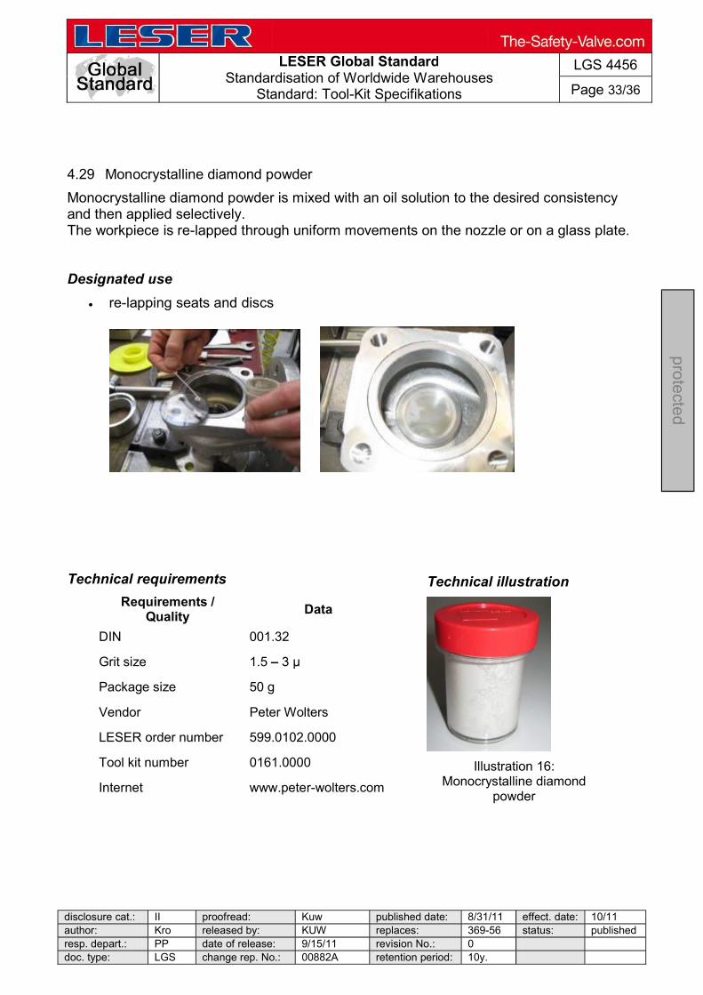
LESER Global Standard
Standardisation of Worldwide Warehouses Standard: Tool-Kit Specifikations
LGS 4456
Page 33/36
disclosure cat.: II proofread: Kuw published date: 8/31/11 effect. date: 10/11 author: Kro released by: KUW replaces: 369-56 status: published resp. depart.: PP date of release: 9/15/11 revision No.: 0 doc. type: LGS change rep. No.: 00882A retention period: 10y.
pro
tecte
d
4.29 Monocrystalline diamond powder
Monocrystalline diamond powder is mixed with an oil solution to the desired consistency and then applied selectively. The workpiece is re-lapped through uniform movements on the nozzle or on a glass plate. Designated use
re-lapping seats and discs
Technical requirements
Requirements / Quality Data
DIN 001.32
Grit size 1.5
Package size 50 g
Vendor Peter Wolters
LESER order number 599.0102.0000
Tool kit number 0161.0000
Internet www.peter-wolters.com
Technical illustration
Illustration 16:
Monocrystalline diamond powder
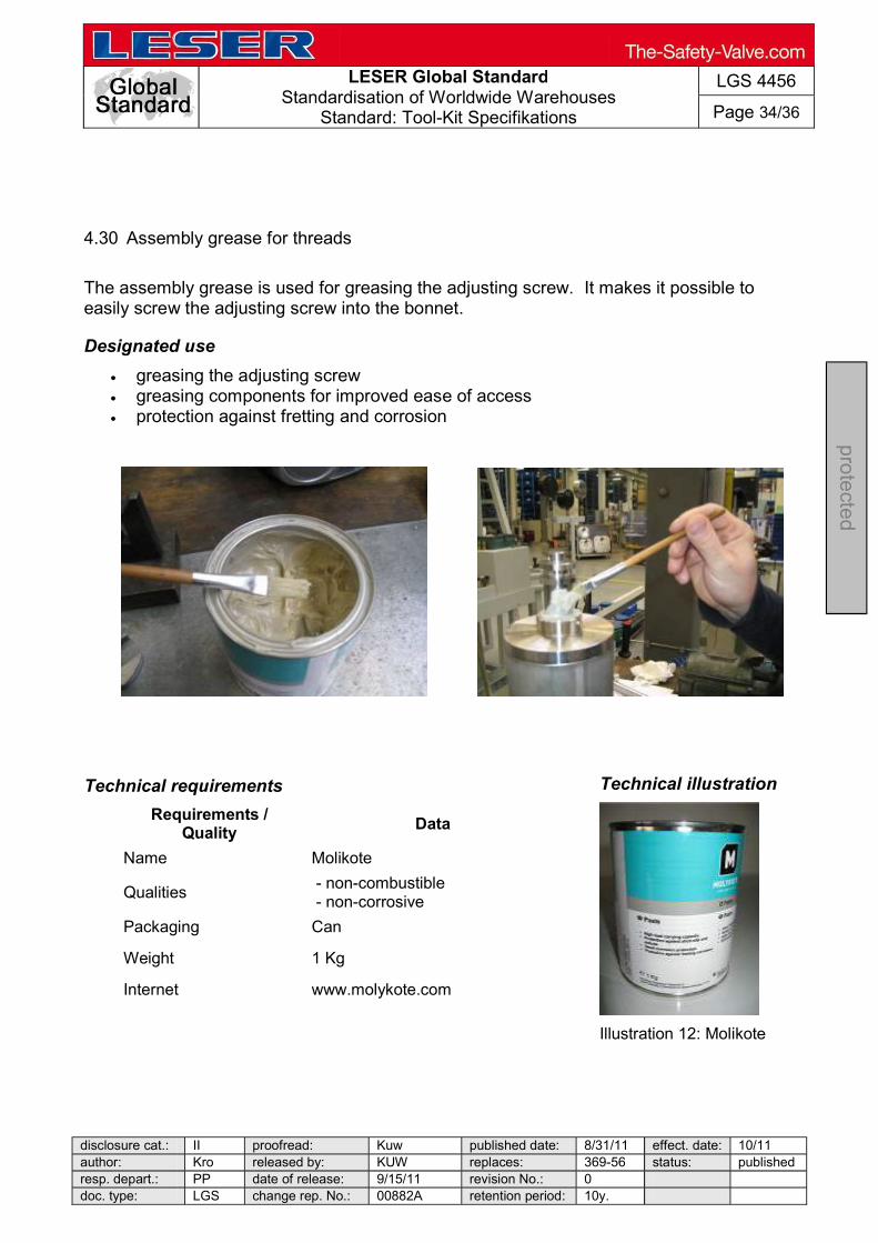
LESER Global Standard
Standardisation of Worldwide Warehouses Standard: Tool-Kit Specifikations
LGS 4456
Page 34/36
disclosure cat.: II proofread: Kuw published date: 8/31/11 effect. date: 10/11 author: Kro released by: KUW replaces: 369-56 status: publishedresp. depart.: PP date of release: 9/15/11 revision No.: 0 doc. type: LGS change rep. No.: 00882A retention period: 10y.
pro
tecte
d
4.30 Assembly grease for threads
The assembly grease is used for greasing the adjusting screw. It makes it possible to easily screw the adjusting screw into the bonnet.
Designated use
greasing the adjusting screw greasing components for improved ease of access protection against fretting and corrosion
Technical requirements
Requirements / Quality Data
Name Molikote
Qualities - non-combustible - non-corrosive
Packaging Can
Weight 1 Kg
Internet www.molykote.com
Technical illustration
Illustration 12: Molikote

LESER Global Standard
Standardisation of Worldwide Warehouses Standard: Tool-Kit Specifikations
LGS 4456
Page 35/36
disclosure cat.: II proofread: Kuw published date: 8/31/11 effect. date: 10/11 author: Kro released by: KUW replaces: 369-56 status: published resp. depart.: PP date of release: 9/15/11 revision No.: 0 doc. type: LGS change rep. No.: 00882A retention period: 10y.
pro
tecte
d
4.31 Leak detection spray
The required body seal tightness is checked by means of a leak detection spray. The leak is located based on bubble formation after applying the leak detection spray to the valve contour. In addition, it can also be used to visualise leaks in the manometer screw connections.
Designated use
external leak testing of the safety valve functional leak testing testing the seal tightness of manometer screw connections
Technical requirements
Requirements / Quality Data
Name Güpoflex
Application Gas and compressed air
Qualities - non-combustible - non-corrosive - toxicologically safe
Package size 500 ml spray can
Packaging unit 10 cans
Vendor GÜPO
LESER order number 596.0094.0000
Tool kit number 0161.0000
Technical illustration
Illustration 13: Leak detection
spray
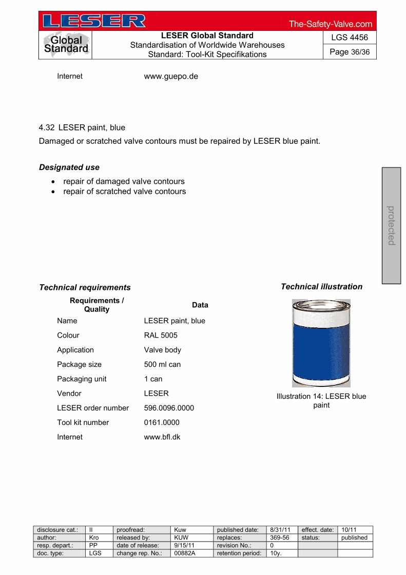
LESER Global Standard
Standardisation of Worldwide Warehouses Standard: Tool-Kit Specifikations
LGS 4456
Page 36/36
disclosure cat.: II proofread: Kuw published date: 8/31/11 effect. date: 10/11 author: Kro released by: KUW replaces: 369-56 status: published resp. depart.: PP date of release: 9/15/11 revision No.: 0 doc. type: LGS change rep. No.: 00882A retention period: 10y.
pro
tecte
d
Internet www.guepo.de
4.32 LESER paint, blue
Damaged or scratched valve contours must be repaired by LESER blue paint.
Designated use
repair of damaged valve contours repair of scratched valve contours
Technical requirements
Requirements / Quality Data
Name LESER paint, blue
Colour RAL 5005
Application Valve body
Package size 500 ml can
Packaging unit 1 can
Vendor LESER
LESER order number 596.0096.0000
Tool kit number 0161.0000
Internet www.bfl.dk
Technical illustration
Illustration 14: LESER blue
paint

LESER Global Standard Operating materials and supplies for repaired valves
LGS 4116
Page 1/3
disclosure cat.: II proofread: OR published date: 9/14/11 effect. date: 18.11.201author: Nieh released by: KUW replaces: initial status: published resp. depart.: PP date of release: 11/8/11 revision No.: 0 doc. type: LGS change rep. No.: 651A retention period: 10
pro
tected
Contents
1 Purpose ............................................................................................................... 1 2 Scope .................................................................................................................. 1 3 Disclaimer ............................................................................................................ 1 4 Qualified fitting personnel .................................................................................... 2 5 General Information .............................................................................................26 Operating materials and supplies ........................................................................ 2 1 Purpose
This LESER Global Standard (LGS) provides a list of operating materials that are used during the assembly of LESER safety valves.
2 Scope
This document must be observed by all agencies and subsidiaries of LESER GmbH & Co. KG.
3 Disclaimer
LESER puts in a great deal of effort into making up-to-date and correct documentation available. Nevertheless, LESER GmbH & Co. KG gives no guarantee that the recommended actions presented here are completely correct and error free. This document is to be used exclusively with the specified type. LESER GmbH & Co. KG declines any liability or responsibility for the correctness and completeness of the content. LESER GmbH & Co. KG reserves the right to change the information contained in this document about the products of LESER GmbH & Co. KG that is intended for the LESER subsidiaries at any time and without prior announcement. LESER GmbH & Co. KG is available to the users of this document to provide additional information.
LESER Global Standard Operating materials and supplies for repaired valves
LGS 4116
Page 2/3
disclosure cat.: II proofread: OR published date: 9/14/11 effect. date: 18.11.201author: Nieh released by: KUW replaces: initial status: published resp. depart.: PP date of release: 11/8/11 revision No.: 0 doc. type: LGS change rep. No.: 651A retention period: 10
pro
tected
4 Qualified fitting personnel
The operating materials/supplies that are used during the installation of LESER safety valves must be used exclusively by trained or qualified fitters. The qualifications must be obtained through the appropriate training measures.
5 General Information
Observe the safety regulations and warnings on the packaging.
6 Operating materials and supplies
Lapping paste - Tetrabor Grit size 320
600 800 1200
Monocrystalline diamond powder - material number N145 Grit size 1.5 3 µm Assembly grease Molykotepaste D Paste Klübersynth UH1 14-151 Halocarbon oil Oleic acid - PH. EUR 6.0 material number N-206 Superglue
Delo-Ca Delo-ML 5449 anaerobic high temperature resistant Leak detection spray

LESER Global Standard Operating materials and supplies for repaired valves
LGS 4116
Page 3/3
disclosure cat.: II proofread: OR published date: 9/14/11 effect. date: 18.11.201author: Nieh released by: KUW replaces: initial status: published resp. depart.: PP date of release: 11/8/11 revision No.: 0 doc. type: LGS change rep. No.: 651A retention period: 10
pro
tected
Güpoflex for gas & compressed air
Quickleen universal cleaner Screw glue LocTITE 222

LESER Global Standard
Separate Pilot Valve from Main Valve
LGS 4123
Page 1/8
disclosure cat.: II proofread: Cal published date: tbd effect. date: 02/12 author: AW released by: KUW replaces: initial status: published resp. depart.: PP date of release: 01/31/12 revision No.: 0 doc. type: LGS change rep. No.: retention period: 10y.
pro
tected
Content 1 General information for separating the main valve from the pilot valve .. 2 2 Purpose ......................................................................................................... 2 3 Competences ................................................................................................ 2 4 Scope ............................................................................................................. 2 5 Disclaimer ...................................................................................................... 2 6 Qualified fitting personnel ............................................................................ 2 7 Remarks ......................................................................................................... 2 8 Basic safety guidelines ................................................................................ 3 9 Disassembly instructions ............................................................................. 6

LESER Global Standard
Separate Pilot Valve from Main Valve
LGS 4123
Page 2/8
disclosure cat.: II proofread: Cal published date: tbd effect. date: 02/12 author: AW released by: KUW replaces: initial status: published resp. depart.: PP date of release: 01/31/12 revision No.: 0 doc. type: LGS change rep. No.: retention period: 10y.
pro
tected
1 General information for separating the main valve from the pilot valve
2 Purpose
The documentation describes the separation of the main valve and the pilot valve. The description contains every single working step, supplies, tools and appliances.
3 Competences
The generation, maintenance and distribution of the documentation takes place in the organisation department. The defaults will be generated by the technical department in consultation with the final assembly department and product planning department.
4 Scope
This document must be applied to the dismantling of a Pilot Operated Safety Valve in agencies and subsidiaries of LESER GmbH & Co. KG, customers and independent service center.
5 Disclaimer
LESER puts in a great deal of effort into making up-to-date and correct documentation available. Nevertheless, LESER GmbH & Co. KG gives no guarantee that the recommended actions presented here are entirely correct and error free. This document is to be applied exclusively to the specified type. LESER GmbH & Co. KG declines any liability or responsibility for the correctness and completeness of the content. LESER GmbH & Co. KG reserves the right to change the information contained in this document, which is for the products of LESER GmbH & Co. KG and is intended for LESER subsidiaries, at any time and without prior announcement. LESER GmbH & Co. KG is available to the users of this document to provide additional information.
6 Qualified fitting personnel
LESER safety valves may only be dismantled by trained or qualified fitters. The qualifications must be obtained through the appropriate training measures.
7 Remarks
Gloves must be worn during the entire dismantling process.

LESER Global Standard
Separate Pilot Valve from Main Valve
LGS 4123
Page 3/8
disclosure cat.: II proofread: Cal published date: tbd effect. date: 02/12 author: AW released by: KUW replaces: initial status: published resp. depart.: PP date of release: 01/31/12 revision No.: 0 doc. type: LGS change rep. No.: retention period: 10y.
pro
tected
8 Basic safety guidelines
Dangerous media Poisoning, caustic burns, burns, injuries
Foreign bodies in the safety valve Danger from failure of safety valve or leaks
ore installation of a safety valve. objects.
Bug screen is damaged or missing (B or option) Dirt, objects or insects get into the safety valve. Danger from malfunction of the safety valve.
nstall the bug screen correctly.
Ambient temperature is too high Material expansion. Danger from malfunction of the safety valve. Ambient temperature is too low Icing, freezing vapours, reduced flow rate due to congealing media. Danger from functional disruption of the safety valve. Abrasive or corrosive media Moving parts jam or become stuck. Danger from functional disruption of the safety valve.
it opens. Media with high proportion of particles (only B)

LESER Global Standard
Separate Pilot Valve from Main Valve
LGS 4123
Page 4/8
disclosure cat.: II proofread: Cal published date: tbd effect. date: 02/12 author: AW released by: KUW replaces: initial status: published resp. depart.: PP date of release: 01/31/12 revision No.: 0 doc. type: LGS change rep. No.: retention period: 10y.
pro
tected
Deposits and clogging. Danger from malfunction of the safety valve.
filter capacity. Residual media in the safety valve Poisoning, caustic burns, burns, injuries
WARNING Leaky safety valve Danger from leaking media due to damaged gaskets and sealing surfaces.
and blows especially during transport and installation.
Open bonnet or spindle guides Danger from leaking media
leaking media.
. CAUTION Hot medium Burns or scalding.
Hot surfaces Burns.
Aggressive medium Caustic burns.
Open bonnet or spindle guides

LESER Global Standard
Separate Pilot Valve from Main Valve
LGS 4123
Page 5/8
disclosure cat.: II proofread: Cal published date: tbd effect. date: 02/12 author: AW released by: KUW replaces: initial status: published resp. depart.: PP date of release: 01/31/12 revision No.: 0 doc. type: LGS change rep. No.: retention period: 10y.
pro
tected
Pinching danger from moving parts.
Sharp edges and burrs Danger of injury.
High noise emission Hearing damage. Wear ear protection.
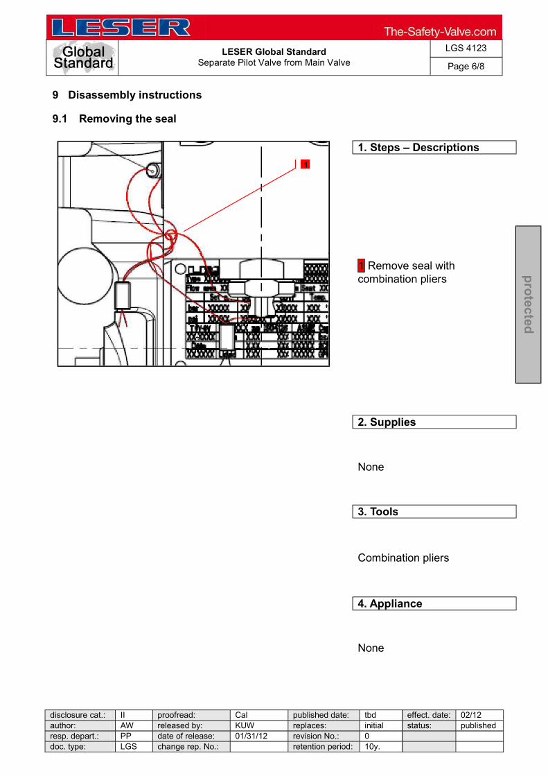
LESER Global Standard
Separate Pilot Valve from Main Valve
LGS 4123
Page 6/8
disclosure cat.: II proofread: Cal published date: tbd effect. date: 02/12 author: AW released by: KUW replaces: initial status: published resp. depart.: PP date of release: 01/31/12 revision No.: 0 doc. type: LGS change rep. No.: retention period: 10y.
pro
tected
9 Disassembly instructions
9.1 Removing the seal
1. Steps Descriptions
1 Remove seal with combination pliers
2. Supplies
None
3. Tools
Combination pliers
4. Appliance
None
1

LESER Global Standard
Separate Pilot Valve from Main Valve
LGS 4123
Page 7/8
disclosure cat.: II proofread: Cal published date: tbd effect. date: 02/12 author: AW released by: KUW replaces: initial status: published resp. depart.: PP date of release: 01/31/12 revision No.: 0 doc. type: LGS change rep. No.: retention period: 10y.
pro
tected
9.2 Disassembly of the tube
1. Steps Descriptions
Pay special attention, when opening a closed system regarding any remaining critical media in tubes 1 Loosen compression fittings 2 While loosing compression fittings counter fittings Remove tube
2. Supplies
None
3. Tools
Open-end wrench acc. to LID
4. Appliance
Test bench
1
2
1
2
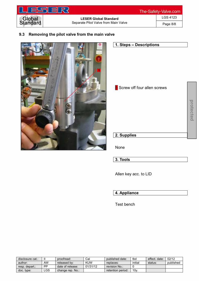
LESER Global Standard
Separate Pilot Valve from Main Valve
LGS 4123
Page 8/8
disclosure cat.: II proofread: Cal published date: tbd effect. date: 02/12 author: AW released by: KUW replaces: initial status: published resp. depart.: PP date of release: 01/31/12 revision No.: 0 doc. type: LGS change rep. No.: retention period: 10y.
pro
tected
9.3 Removing the pilot valve from the main valve
1. Steps Descriptions
5 Screw off four allen screws
2. Supplies
None
3. Tools
Allen key acc. to LID
4. Appliance
Test bench
5

LESER Global Standard
Disassembly Main Valve EN
LGS 4124
Page 1/15
disclosure cat.: II proofread: Cal published date: tbd effect. date: 02/12 author: AW released by: KUW replaces: initial status: published resp. depart.: PP date of release: 01/31/12 revision No.: 0 doc. type: LGS change rep. No.: retention period: 10y.
pro
tected
Content General Information for Disassembling the Main Valve ................................. 1 1 Purpose ......................................................................................................... 2 2 Scope ............................................................................................................. 2 3 Responsibilities ............................................................................................ 2 4 Disclaimer ...................................................................................................... 2 5 Qualification of Personnel ............................................................................ 2 6 Safety Guidelines .......................................................................................... 3 7 Disassembly Instructions ............................................................................. 6 7.1 General ......................................................................................................... 6 For instructions for removing the POSV pilot valve refer to other applicable LESER disassembly instructions. ..................................................................................... 6
General Information for Disassembling the Main Valve

LESER Global Standard
Disassembly Main Valve EN
LGS 4124
Page 2/15
disclosure cat.: II proofread: Cal published date: tbd effect. date: 02/12 author: AW released by: KUW replaces: initial status: published resp. depart.: PP date of release: 01/31/12 revision No.: 0 doc. type: LGS change rep. No.: retention period: 10y.
pro
tected
1 Purpose
This document describes the LESER-approved procedures for disassembly of the main valve (series 810/820) of the pilot operated safety valve (POSV). It describes specific step by step work procedures and identifies all required supplies, tools and appliances.
2 Scope
This document applies to all agencies and subsidiaries of LESER GmbH & Co. KG, as well as its customers and independent service centers and must be utilized when disassembling LESER Pilot Operated Safety Valves.
3 Responsibilities
The Organization Department is responsible for the generation, maintenance and distribution of this document. The standards for this document are generated by the Technical Department in consultation with the Final Assembly and Production Planning departments.
4 Disclaimer
LESER puts a great deal of effort into making up-to-date and correct documentation available. Nevertheless, LESER GmbH & Co. KG gives no guarantee that the recommended actions presented here are entirely correct and error free. This document is to be applied exclusively to the specified valve type. LESER GmbH & Co. KG declines any liability or responsibility for the correctness and completeness of the content. LESER GmbH & Co. KG reserves the right to change the information contained in this document, which is for the products of LESER GmbH & Co. KG and is intended for LESER subsidiaries, at any time and without prior announcement. LESER GmbH & Co. KG is available to the users of this document to provide additional information as required.
5 Qualification of Personnel
LESER safety valves may only be disassembled by trained and qualified fitters. Specific qualifications must be obtained through the appropriate training measures.
LESER Global Standard
Disassembly Main Valve EN
LGS 4124
Page 3/15
disclosure cat.: II proofread: Cal published date: tbd effect. date: 02/12 author: AW released by: KUW replaces: initial status: published resp. depart.: PP date of release: 01/31/12 revision No.: 0 doc. type: LGS change rep. No.: retention period: 10y.
pro
tected
6 Safety Guidelines
6.1 Potential Dangers and Protective Measures Dangerous media Danger of poisoning, caustic burns, burns, or injury
able collecting tanks.
Foreign objects in the safety valve Danger from failure of safety valve or leakage
h the system before installing a safety valve.
reign objects as necessary Damaged or missing bug screen Dirt, foreign objects or insects get into the safety valve and cause a danger of safety valve malfunction.
Abrasive or corrosive media Moving parts may jam or become stuck and cause a danger of safety valve malfunction.
opening.
Media with high proportion of particles Deposits and clogging cause a danger of safety valve malfunction.
overall filter capacity.
Residual media in the safety valve Danger of poisoning, caustic burns, burns, or injuries
sidual media

LESER Global Standard
Disassembly Main Valve EN
LGS 4124
Page 4/15
disclosure cat.: II proofread: Cal published date: tbd effect. date: 02/12 author: AW released by: KUW replaces: initial status: published resp. depart.: PP date of release: 01/31/12 revision No.: 0 doc. type: LGS change rep. No.: retention period: 10y.
pro
tected
6.2 Warnings and Related Protective Measures Leaky safety valve Danger from leaking media due to damaged gaskets and/or sealing surfaces.
installation.
Open bonnet or spindle guide Danger from leaking media
6.3 Cautions and Related Protective Measures Hot medium Burns or scalding.
Hot surfaces Burns.
Aggressive medium Caustic burns.
Open bonnet or spindle guide Pinching danger from moving parts.
Sharp edges and burrs Danger of injury.

LESER Global Standard
Disassembly Main Valve EN
LGS 4124
Page 5/15
disclosure cat.: II proofread: Cal published date: tbd effect. date: 02/12 author: AW released by: KUW replaces: initial status: published resp. depart.: PP date of release: 01/31/12 revision No.: 0 doc. type: LGS change rep. No.: retention period: 10y.
pro
tected
High noise emission Hearing damage.
ear protection 6.4 Required Protective Equipment
Proper protective gloves must be worn during the entire dismantling process!
In addition to any protective equipment described in this document and/or required by local and international safety standards proper protective gloves must be worn during the entire disassembly process.

LESER Global Standard
Disassembly Main Valve EN
LGS 4124
Page 6/15
disclosure cat.: II proofread: Cal published date: tbd effect. date: 02/12 author: AW released by: KUW replaces: initial status: published resp. depart.: PP date of release: 01/31/12 revision No.: 0 doc. type: LGS change rep. No.: retention period: 10y.
pro
tected
7 Disassembly Instructions
7.1 General
For instructions for removing the POSV pilot valve refer to other applicable LESER disassembly instructions.
7.2 Disassembly of Fittings
1. Steps Descriptions
1 Loosen and screw off angular screw-in fitting, while loosing counter fitting [4] 2 Remove compression fitting
2. Supplies
None
3. Tools
Open-end wrench acc. to LID
4. Appliances
Test bench
1
2

LESER Global Standard
Disassembly Main Valve EN
LGS 4124
Page 7/15
disclosure cat.: II proofread: Cal published date: tbd effect. date: 02/12 author: AW released by: KUW replaces: initial status: published resp. depart.: PP date of release: 01/31/12 revision No.: 0 doc. type: LGS change rep. No.: retention period: 10y.
pro
tected
7.3 Removal the Top Plate
1. Steps Descriptions
1 Loosen ring nuts [57] and screw them off Loosen and remove nuts [56] Remove top plate [9] 2 Remove stud bolts [55] (if necessary) 3 Remove dome spring [59] 4 Remove O-rings [60], [67] 5 Remove roll pin [10] (if necessary)
2. Supplies
None
3. Tools
Ring wrench acc. to LID Helpful: Impact wrench acc. to LID
4. Appliances
Test bench
1
1
2
4
5
3
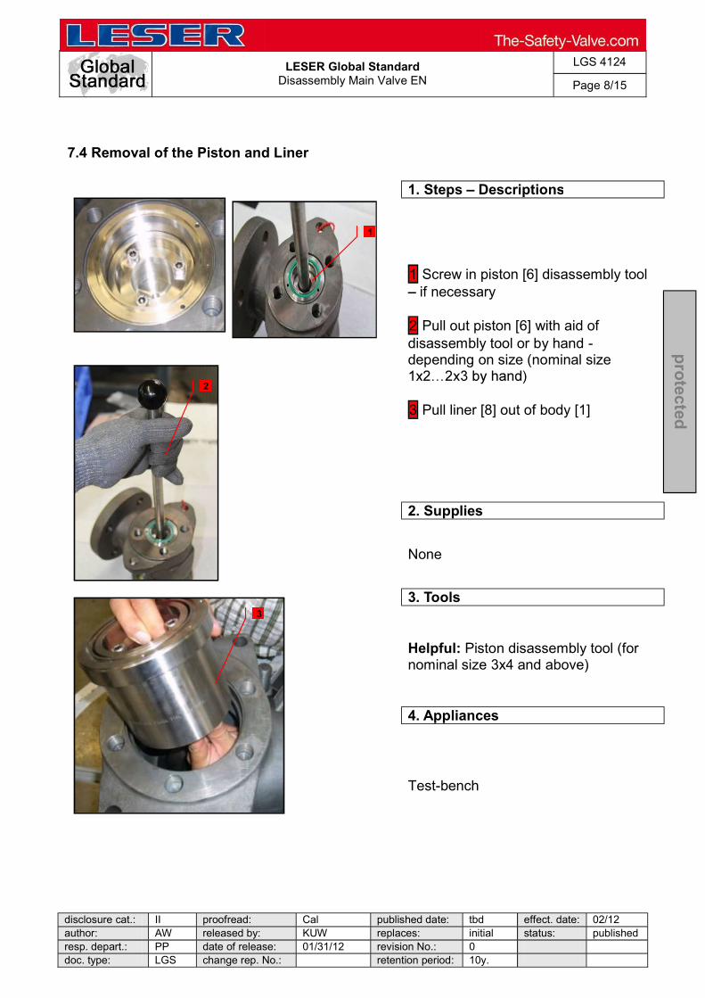
LESER Global Standard
Disassembly Main Valve EN
LGS 4124
Page 8/15
disclosure cat.: II proofread: Cal published date: tbd effect. date: 02/12 author: AW released by: KUW replaces: initial status: published resp. depart.: PP date of release: 01/31/12 revision No.: 0 doc. type: LGS change rep. No.: retention period: 10y.
pro
tected
7.4 Removal of the Piston and Liner
1. Steps Descriptions
1 Screw in piston [6] disassembly tool if necessary
2 Pull out piston [6] with aid of disassembly tool or by hand - depending on size (nominal size
3 Pull liner [8] out of body [1]
2. Supplies
None
3. Tools
Helpful: Piston disassembly tool (for nominal size 3x4 and above)
4. Appliances
Test-bench
1
2
3

LESER Global Standard
Disassembly Main Valve EN
LGS 4124
Page 9/15
disclosure cat.: II proofread: Cal published date: tbd effect. date: 02/12 author: AW released by: KUW replaces: initial status: published resp. depart.: PP date of release: 01/31/12 revision No.: 0 doc. type: LGS change rep. No.: retention period: 10y.
pro
tected
7.5 Disassembly of the Piston and Liner
1. Steps Descriptions
1 Push piston [6] through liner [8] to separate piston [6] and liner [8]
For piston Pull piston [6] out of liner [8]
2. Supplies
None
3. Tools
None
4. Appliances
None
1
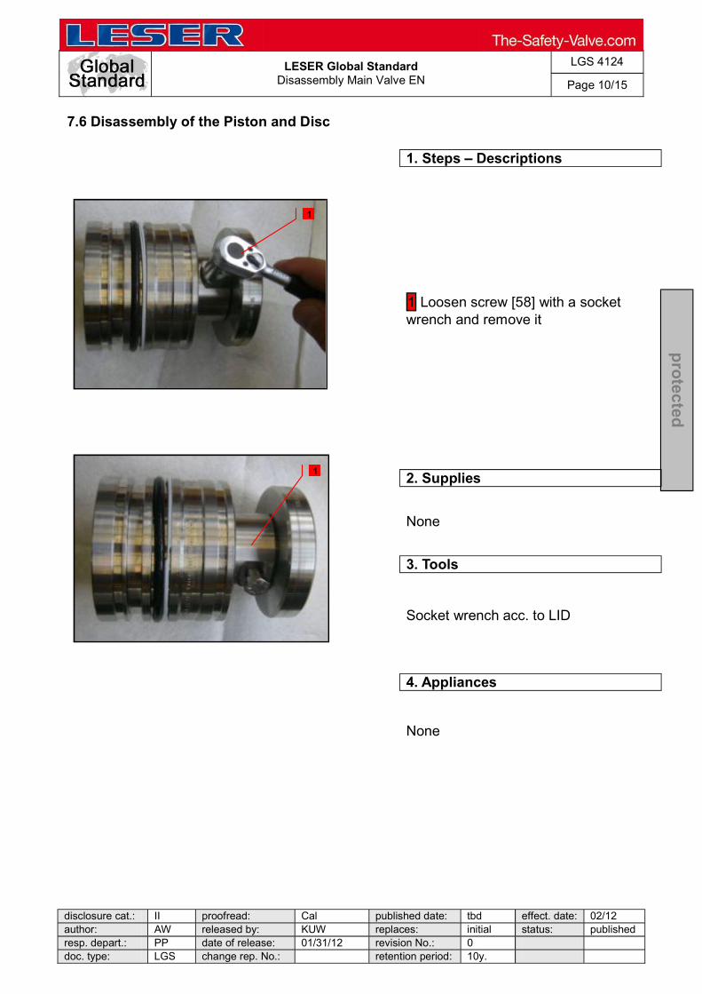
LESER Global Standard
Disassembly Main Valve EN
LGS 4124
Page 10/15
disclosure cat.: II proofread: Cal published date: tbd effect. date: 02/12 author: AW released by: KUW replaces: initial status: published resp. depart.: PP date of release: 01/31/12 revision No.: 0 doc. type: LGS change rep. No.: retention period: 10y.
pro
tected
7.6 Disassembly of the Piston and Disc
1. Steps Descriptions
1 Loosen screw [58] with a socket wrench and remove it
2. Supplies
None
3. Tools
Socket wrench acc. to LID
4. Appliances
None
1
1
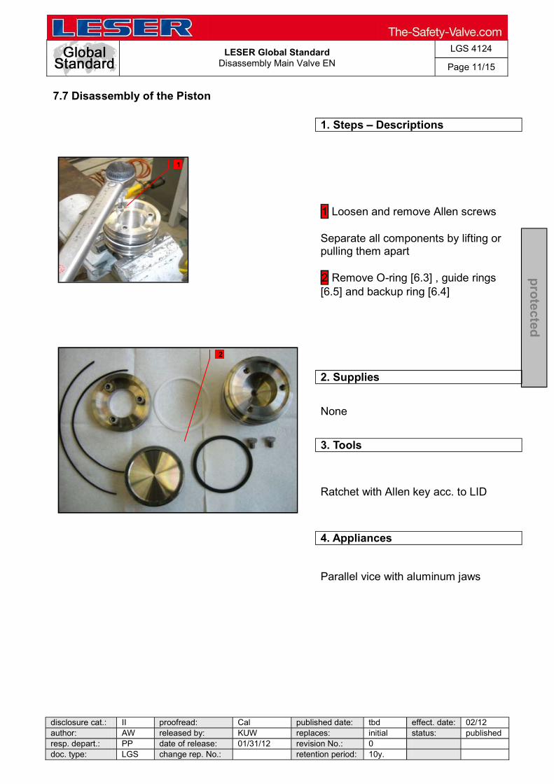
LESER Global Standard
Disassembly Main Valve EN
LGS 4124
Page 11/15
disclosure cat.: II proofread: Cal published date: tbd effect. date: 02/12 author: AW released by: KUW replaces: initial status: published resp. depart.: PP date of release: 01/31/12 revision No.: 0 doc. type: LGS change rep. No.: retention period: 10y.
pro
tected
7.7 Disassembly of the Piston
1. Steps Descriptions
1 Loosen and remove Allen screws Separate all components by lifting or pulling them apart 2 Remove O-ring [6.3] , guide rings [6.5] and backup ring [6.4]
2. Supplies
None
3. Tools
Ratchet with Allen key acc. to LID
4. Appliances
Parallel vice with aluminum jaws
1
2

LESER Global Standard
Disassembly Main Valve EN
LGS 4124
Page 12/15
disclosure cat.: II proofread: Cal published date: tbd effect. date: 02/12 author: AW released by: KUW replaces: initial status: published resp. depart.: PP date of release: 01/31/12 revision No.: 0 doc. type: LGS change rep. No.: retention period: 10y.
pro
tected
7.8 Disassembly of the Luproseal OC R20
1 Steps Descriptions
1 Loosen and remove the Allen screws. Separate all components by lifting or pulling them apart 2 Remove Luproseal lip seal [6.3] OC R20
2. Supplies
None
3. Tools
Ratchet with Allen key acc. to LID
4. Appliances
Parallel vice with aluminum jaws
1
2
3
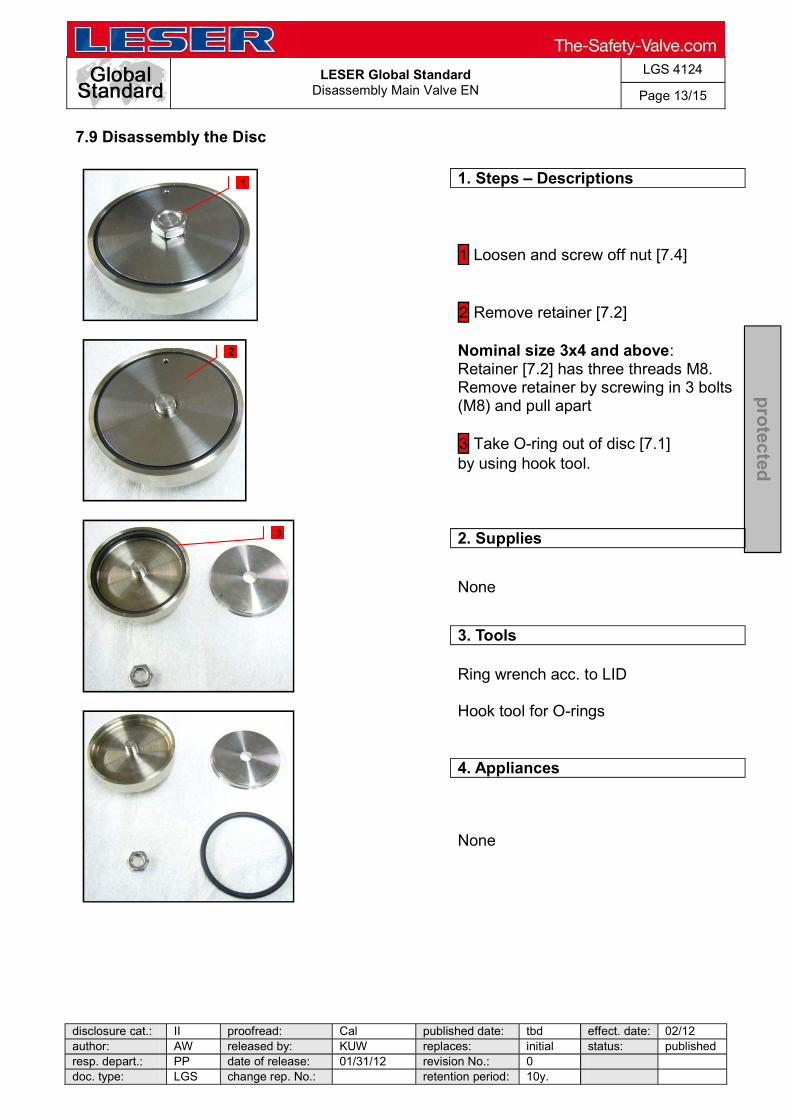
LESER Global Standard
Disassembly Main Valve EN
LGS 4124
Page 13/15
disclosure cat.: II proofread: Cal published date: tbd effect. date: 02/12 author: AW released by: KUW replaces: initial status: published resp. depart.: PP date of release: 01/31/12 revision No.: 0 doc. type: LGS change rep. No.: retention period: 10y.
pro
tected
7.9 Disassembly the Disc
1. Steps Descriptions
1 Loosen and screw off nut [7.4] 2 Remove retainer [7.2] Nominal size 3x4 and above: Retainer [7.2] has three threads M8. Remove retainer by screwing in 3 bolts (M8) and pull apart 3 Take O-ring out of disc [7.1] by using hook tool.
2. Supplies
None
3. Tools
Ring wrench acc. to LID Hook tool for O-rings
4. Appliances
None
1
2
3

LESER Global Standard
Disassembly Main Valve EN
LGS 4124
Page 14/15
disclosure cat.: II proofread: Cal published date: tbd effect. date: 02/12 author: AW released by: KUW replaces: initial status: published resp. depart.: PP date of release: 01/31/12 revision No.: 0 doc. type: LGS change rep. No.: retention period: 10y.
pro
tected
7.10 Disassembly of the Seat
1. Steps Descriptions
1 Clamp body [1] at inlet 2 Mount seat-assembly-tool - step by step Unscrew and remove nozzle [5] 2 Remove O-ring [61] and back up ring [62] of nozzle
2. Supplies
None
3. Tools
Necessary Seat-assembly-tool acc. to nominal size
4. Appliances
Test bench
1
2 2
2 2
2 2

LESER Global Standard
Disassembly Main Valve EN
LGS 4124
Page 15/15
disclosure cat.: II proofread: Cal published date: tbd effect. date: 02/12 author: AW released by: KUW replaces: initial status: published resp. depart.: PP date of release: 01/31/12 revision No.: 0 doc. type: LGS change rep. No.: retention period: 10y.
pro
tected
7.11 Disassembly of the Pitot Tube
1. Steps Descriptions
1 Clamp body with outlet 2 Loosen and remove fitting [4] Remove pipe and pitot tube Depending on nominal size, tube [3] may not be applicable. 3 Remove O-ring [63]
2. Supplies
None
3. Tools
Hook tool for O-rings Open-end wrench acc. to LID
4. Appliances
Test bench
1
2
3

LESER Global Standard
Disassembly Pop Action Pilot
LGS 4125
Page 1/15
disclosure cat.: II proofread: Cal published date: tbd effect. date: 02/12 author: AW released by: KUW replaces: initial status: published resp. depart.: PP date of release: 01/31/12 revision No.: 0 doc. type: LGS change rep. No.: retention period: 10y.
pro
tected
Content 1 General informations for disassembling the Pop Action Pilot .................. 2 2 Purpose ......................................................................................................... 2 3 Competences ................................................................................................ 2 4 Scope ............................................................................................................. 2 5 Disclaimer ...................................................................................................... 2 6 Qualified fitting personnel ............................................................................ 2 7 Remarks ......................................................................................................... 2 8 Basic safety guidelines ................................................................................ 3 9 Disassembly Instructions ............................................................................. 6
LESER Global Standard
Disassembly Pop Action Pilot
LGS 4125
Page 2/15
disclosure cat.: II proofread: Cal published date: tbd effect. date: 02/12 author: AW released by: KUW replaces: initial status: published resp. depart.: PP date of release: 01/31/12 revision No.: 0 doc. type: LGS change rep. No.: retention period: 10y.
pro
tected
1 General informations for disassembling the Pop Action Pilot
2 Purpose
The documentation describes the disassembly of the pop action pilot valve. The description contains every single working step, supplies, tools and appliances.
3 Competences
The generation, maintenance and distribution of the documentation takes place in the organisation department. The defaults will be generated by the technical department in consultation with the final assembly department and production planning department.
4 Scope This document must be applied to the dismantling of a Pilot Operated Safety Valve in agencies and subsidiaries of LESER GmbH & Co. KG, customers and independent service center.
5 Disclaimer
LESER puts in a great deal of effort into making up-to-date and correct documentation available. Nevertheless, LESER GmbH & Co. KG gives no guarantee that the recommended actions presented here are entirely correct and error free. This document is to be applied exclusively to the specified type. LESER GmbH & Co. KG declines any liability or responsibility for the correctness and completeness of the content. LESER GmbH & Co. KG reserves the right to change the information contained in this document, which is for the products of LESER GmbH & Co. KG and is intended for LESER subsidiaries, at any time and without prior announcement. LESER GmbH & Co. KG is available to the users of this document to provide additional information.
6 Qualified fitting personnel
LESER safety valves may only be dismantled by trained or qualified fitters. The qualifications must be obtained through the appropriate training measures.
7 Remarks
Gloves must be worn during the entire dismantling process.
LESER Global Standard
Disassembly Pop Action Pilot
LGS 4125
Page 3/15
disclosure cat.: II proofread: Cal published date: tbd effect. date: 02/12 author: AW released by: KUW replaces: initial status: published resp. depart.: PP date of release: 01/31/12 revision No.: 0 doc. type: LGS change rep. No.: retention period: 10y.
pro
tected
8 Basic safety guidelines
Dangerous media Poisoning, caustic burns, burns, injuries
Foreign bodies in the safety valve Danger from failure of safety valve or leaks
of a safety valve. objects.
Bug screen is damaged or missing (B or option) Dirt, objects or insects get into the safety valve. Danger from malfunction of the safety valve.
een correctly.
Ambient temperature is too high Material expansion. Danger from malfunction of the safety valve. Ambient temperature is too low Icing, freezing vapours, reduced flow rate due to congealing media. Danger from functional disruption of the safety valve. Abrasive or corrosive media Moving parts jam or become stuck. Danger from functional disruption of the safety valve.
it opens. Media with high proportion of particles (only B)

LESER Global Standard
Disassembly Pop Action Pilot
LGS 4125
Page 4/15
disclosure cat.: II proofread: Cal published date: tbd effect. date: 02/12 author: AW released by: KUW replaces: initial status: published resp. depart.: PP date of release: 01/31/12 revision No.: 0 doc. type: LGS change rep. No.: retention period: 10y.
pro
tected
Deposits and clogging. Danger from malfunction of the safety valve.
filter capacity. Residual media in the safety valve Poisoning, caustic burns, burns, injuries
WARNING Leaky safety valve Danger from leaking media due to damaged gaskets and sealing surfaces.
and blows especially during transport and installation.
Open bonnet or spindle guides Danger from leaking media
leaking media.
CAUTION Hot medium Burns or scalding.
Hot surfaces Burns.
Aggressive medium Caustic burns.
Open bonnet or spindle guides
LESER Global Standard
Disassembly Pop Action Pilot
LGS 4125
Page 5/15
disclosure cat.: II proofread: Cal published date: tbd effect. date: 02/12 author: AW released by: KUW replaces: initial status: published resp. depart.: PP date of release: 01/31/12 revision No.: 0 doc. type: LGS change rep. No.: retention period: 10y.
pro
tected
Pinching danger from moving parts.
Sharp edges and burrs Danger of injury.
High noise emission Hearing damage. Wear ear protection.

LESER Global Standard
Disassembly Pop Action Pilot
LGS 4125
Page 6/15
disclosure cat.: II proofread: Cal published date: tbd effect. date: 02/12 author: AW released by: KUW replaces: initial status: published resp. depart.: PP date of release: 01/31/12 revision No.: 0 doc. type: LGS change rep. No.: retention period: 10y.
pro
tected
9 Disassembly Instructions
9.1 Removing the seal
1. Steps Descriptions
1 Cut wire with combination pliers Pull out seal
2. Supplies
None
3. Tools
Combination pliers
4. Appliance
None
1
1
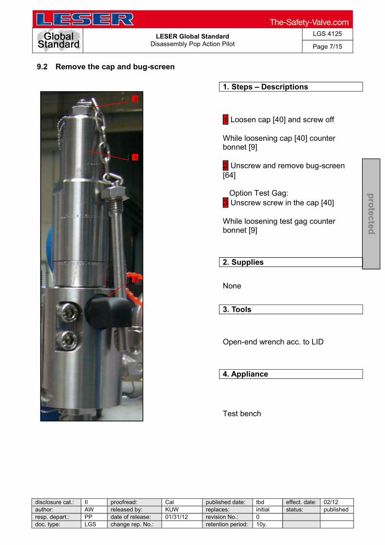
LESER Global Standard
Disassembly Pop Action Pilot
LGS 4125
Page 7/15
disclosure cat.: II proofread: Cal published date: tbd effect. date: 02/12 author: AW released by: KUW replaces: initial status: published resp. depart.: PP date of release: 01/31/12 revision No.: 0 doc. type: LGS change rep. No.: retention period: 10y.
pro
tected
9.2 Remove the cap and bug-screen
1. Steps Descriptions
1 Loosen cap [40] and screw off While loosening cap [40] counter bonnet [9] 2 Unscrew and remove bug-screen [64] Option Test Gag: 3 Unscrew screw in the cap [40] While loosening test gag counter bonnet [9]
2. Supplies
None
3. Tools
Open-end wrench acc. to LID
4. Appliance
Test bench
3
1
2
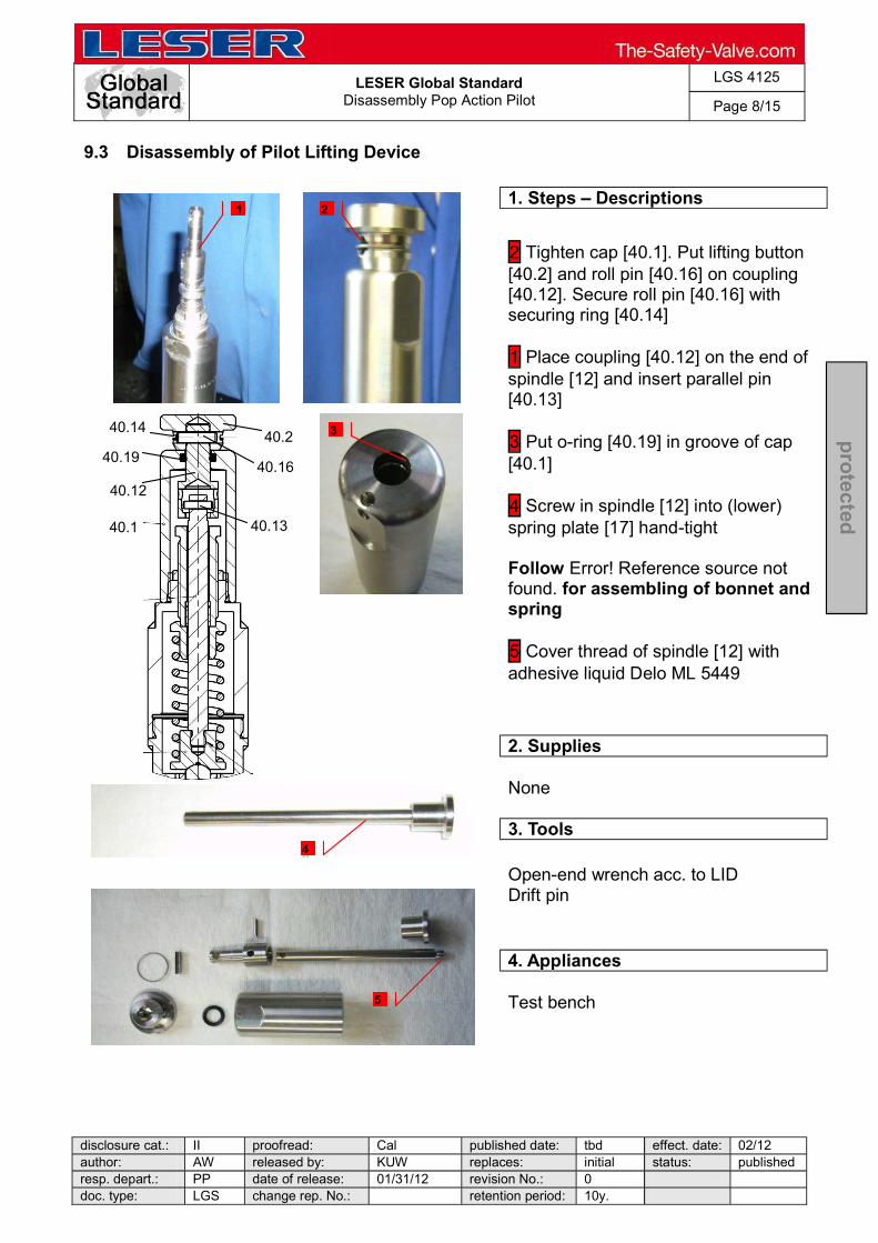
LESER Global Standard
Disassembly Pop Action Pilot
LGS 4125
Page 8/15
disclosure cat.: II proofread: Cal published date: tbd effect. date: 02/12 author: AW released by: KUW replaces: initial status: published resp. depart.: PP date of release: 01/31/12 revision No.: 0 doc. type: LGS change rep. No.: retention period: 10y.
pro
tected
9.3 Disassembly of Pilot Lifting Device
1. Steps Descriptions
2 Tighten cap [40.1]. Put lifting button [40.2] and roll pin [40.16] on coupling [40.12]. Secure roll pin [40.16] with securing ring [40.14] 1 Place coupling [40.12] on the end of spindle [12] and insert parallel pin [40.13] 3 Put o-ring [40.19] in groove of cap [40.1] 4 Screw in spindle [12] into (lower) spring plate [17] hand-tight Follow Error! Reference source not found. for assembling of bonnet and spring 5 Cover thread of spindle [12] with adhesive liquid Delo ML 5449
2. Supplies
None
3. Tools
Open-end wrench acc. to LID Drift pin
4. Appliances
Test bench
340.2
40.1 40.13
40.16
40.14
40.19
40.12
5
4
2 1
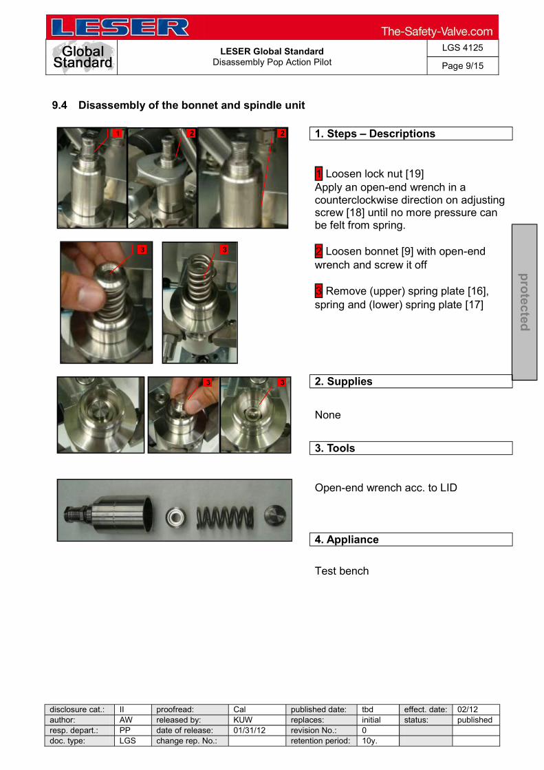
LESER Global Standard
Disassembly Pop Action Pilot
LGS 4125
Page 9/15
disclosure cat.: II proofread: Cal published date: tbd effect. date: 02/12 author: AW released by: KUW replaces: initial status: published resp. depart.: PP date of release: 01/31/12 revision No.: 0 doc. type: LGS change rep. No.: retention period: 10y.
pro
tected
9.4 Disassembly of the bonnet and spindle unit
1. Steps Descriptions
1 Loosen lock nut [19] Apply an open-end wrench in a counterclockwise direction on adjusting screw [18] until no more pressure can be felt from spring. 2 Loosen bonnet [9] with open-end wrench and screw it off 3 Remove (upper) spring plate [16], spring and (lower) spring plate [17]
2. Supplies
None
3. Tools
Open-end wrench acc. to LID
4. Appliance
Test bench
1 2 2
3
3 3
3

LESER Global Standard
Disassembly Pop Action Pilot
LGS 4125
Page 10/15
disclosure cat.: II proofread: Cal published date: tbd effect. date: 02/12 author: AW released by: KUW replaces: initial status: published resp. depart.: PP date of release: 01/31/12 revision No.: 0 doc. type: LGS change rep. No.: retention period: 10y.
pro
tected
9.5 Disassembly of the bonnet
1. Steps Descriptions
1 Screw adjusting screw unit out of bonnet [9] 2 Screw off lock nut [19] 3 Detach PTFE-bushing out of adjusting screw [18]
2. Supplies
None
3. Tools
If necessary, in case of sluggishness an open-end wrench
4. Appliance
Test bench
1
2 3
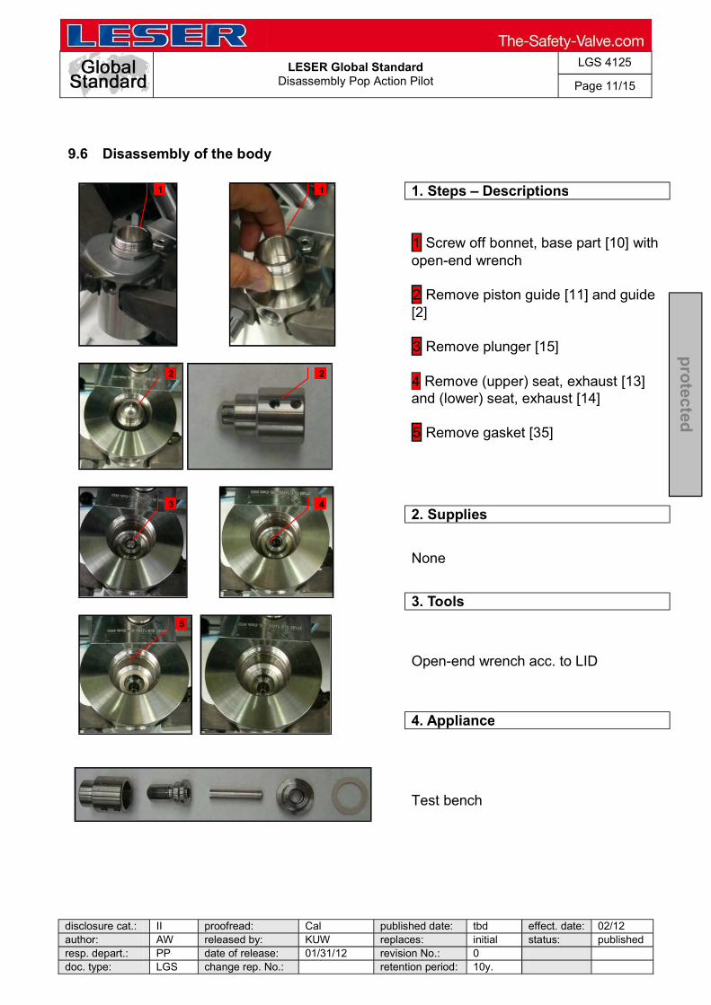
LESER Global Standard
Disassembly Pop Action Pilot
LGS 4125
Page 11/15
disclosure cat.: II proofread: Cal published date: tbd effect. date: 02/12 author: AW released by: KUW replaces: initial status: published resp. depart.: PP date of release: 01/31/12 revision No.: 0 doc. type: LGS change rep. No.: retention period: 10y.
pro
tected
9.6 Disassembly of the body
1. Steps Descriptions
1 Screw off bonnet, base part [10] with open-end wrench 2 Remove piston guide [11] and guide [2] 3 Remove plunger [15] 4 Remove (upper) seat, exhaust [13] and (lower) seat, exhaust [14] 5 Remove gasket [35]
2. Supplies
None
3. Tools
Open-end wrench acc. to LID
4. Appliance
Test bench
1 1
2 2
3 4
5
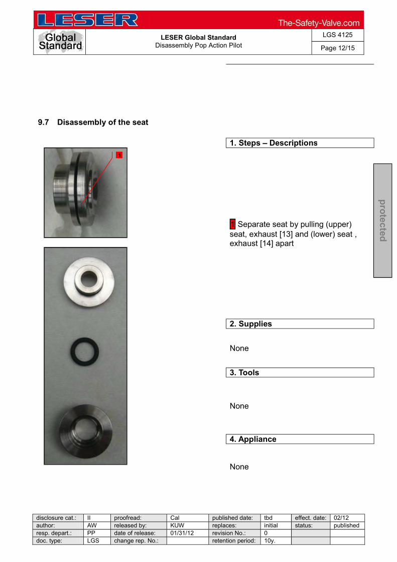
LESER Global Standard
Disassembly Pop Action Pilot
LGS 4125
Page 12/15
disclosure cat.: II proofread: Cal published date: tbd effect. date: 02/12 author: AW released by: KUW replaces: initial status: published resp. depart.: PP date of release: 01/31/12 revision No.: 0 doc. type: LGS change rep. No.: retention period: 10y.
pro
tected
9.7 Disassembly of the seat
1. Steps Descriptions
1 Separate seat by pulling (upper) seat, exhaust [13] and (lower) seat , exhaust [14] apart
2. Supplies
None
3. Tools
None
4. Appliance
None
1

LESER Global Standard
Disassembly Pop Action Pilot
LGS 4125
Page 13/15
disclosure cat.: II proofread: Cal published date: tbd effect. date: 02/12 author: AW released by: KUW replaces: initial status: published resp. depart.: PP date of release: 01/31/12 revision No.: 0 doc. type: LGS change rep. No.: retention period: 10y.
pro
tected
9.8 Removing the adjusting screw
1. Steps Descriptions
Measure adjustment of adjusting screw [12] to establish same adjustment after refinishing pilot valve
1 Loosen and remove counter nut [21] 2 Loosen nut [20] of adjusting screw [12] 3 Pull out adjusting screw [12]
2. Supplies
None
3. Tools
Hook tool for O-rings Open-end wrench acc. to LID
4. Appliance
Test bench
1
2
3
2

LESER Global Standard
Disassembly Pop Action Pilot
LGS 4125
Page 14/15
disclosure cat.: II proofread: Cal published date: tbd effect. date: 02/12 author: AW released by: KUW replaces: initial status: published resp. depart.: PP date of release: 01/31/12 revision No.: 0 doc. type: LGS change rep. No.: retention period: 10y.
pro
tected
9.9 Disassembly of the adjusting screw
1. Steps Descriptions
1 Unscrew nut [20] of adjusting screw [12] with open-end wrench 2 Remove O-rings with hook tool 3 Place adjusting screw [12] in assembling aid pilot (optional: parallel vice with aluminium jaws). Unscrew seat, feeding [5] and screw it off the adjusting screw [12] with open-end wrench 4 Pull (upper) disc feeding [7] and (lower) disc feeding [8] out of adjusting screw [12] 6 Pull (upper) disc, feeding [7] out of (lower) seat feeding [8] Remove O-Ring 6,07x1,78 [30] from (upper) disc feeding [7]
2. Supplies
None
3. Tools
Open-end wrench acc. to LID Hook tool for O-ring Drift pin
4. Appliance
Parallel vice with aluminium jaws Or as recommended with Assembling aid (60S.2512.4012)
4
6
5
3 3
2
1

LESER Global Standard
Disassembly Pop Action Pilot
LGS 4125
Page 15/15
disclosure cat.: II proofread: Cal published date: tbd effect. date: 02/12 author: AW released by: KUW replaces: initial status: published resp. depart.: PP date of release: 01/31/12 revision No.: 0 doc. type: LGS change rep. No.: retention period: 10y.
pro
tected
9.10 Disassembly of the manifold block
1. Steps Descriptions
1 Remove piston [24.3], bushing [24.2] and O-rings 2 Remove O-rings of piston [24.3] 3 Remove O-rings of bushing [24.2] 4 Screw off lock screw [24.7] and take out gasket [24.8]
2. Supplies
None
3. Tool
Allen key acc. to LID Hook tool for O-rings
4. Appliance
Parallel vice with aluminium jaws Test bench
1 1
1
2
3
4

LESER Global Standard
Disassembly Modulate Action Dia
LGS 4126
Page 1/19
disclosure cat.: II proofread: Cal published date: tbd effect. date: 02/12 author: AW released by: KUW replaces: initial status: published resp. depart.: PP date of release: 01/31/12 revision No.: 0 doc. type: LGS change rep. No.: retention period: 10y.
pro
tected
Content 1 General informations for disassembling the Modulate Action Pilot Valve (Diaphragm Design) ........................................................................................... 2 2 Purpose ......................................................................................................... 2 3 Competences ................................................................................................ 2 4 Scope ............................................................................................................. 2 5 Disclaimer ...................................................................................................... 2 6 Qualified fitting personnel ............................................................................ 2 7 Remarks ......................................................................................................... 2 8 Basic safety guidelines ................................................................................ 3 9 Disassembly instructions ............................................................................. 6

LESER Global Standard
Disassembly Modulate Action Dia
LGS 4126
Page 2/19
disclosure cat.: II proofread: Cal published date: tbd effect. date: 02/12 author: AW released by: KUW replaces: initial status: published resp. depart.: PP date of release: 01/31/12 revision No.: 0 doc. type: LGS change rep. No.: retention period: 10y.
pro
tected
1 General informations for disassembling the Modulate Action Pilot Valve (Diaphragm Design)
2 Purpose
The documentation describes the disassembly of the modulate action pilot valve. The description contains every single working step, supplies, tools and appliances.
3 Competences
The generation, maintenance and distribution of the documentation takes place in the organisation department. The defaults will be generated by the technical department in consultation with the final assembly department and product planning department.
4 Scope
This document must be applied to the dismantling of a Pilot Operated Safety Valve in agencies and subsidiaries of LESER GmbH & Co. KG, customers and independent service center.
5 Disclaimer
LESER puts in a great deal of effort into making up-to-date and correct documentation available. Nevertheless, LESER GmbH & Co. KG gives no guarantee that the recommended actions presented here are entirely correct and error free. This document is to be applied exclusively to the specified type. LESER GmbH & Co. KG declines any liability or responsibility for the correctness and completeness of the content. LESER GmbH & Co. KG reserves the right to change the information contained in this document, which is for the products of LESER GmbH & Co. KG and is intended for LESER subsidiaries, at any time and without prior announcement. LESER GmbH & Co. KG is available to the users of this document to provide additional information.
6 Qualified fitting personnel
LESER safety valves may only be dismantled by trained or qualified fitters. The qualifications must be obtained through the appropriate training measures.
7 Remarks
Gloves must be worn during the entire dismantling process.
LESER Global Standard
Disassembly Modulate Action Dia
LGS 4126
Page 3/19
disclosure cat.: II proofread: Cal published date: tbd effect. date: 02/12 author: AW released by: KUW replaces: initial status: published resp. depart.: PP date of release: 01/31/12 revision No.: 0 doc. type: LGS change rep. No.: retention period: 10y.
pro
tected
8 Basic safety guidelines
Dangerous media Poisoning, caustic burns, burns, injuries
Foreign bodies in the safety valve Danger from failure of safety valve or leaks
of a safety valve. objects.
Bug screen is damaged or missing (B or option) Dirt, objects or insects get into the safety valve. Danger from malfunction of the safety valve.
Ambient temperature is too high Material expansion. Danger from malfunction of the safety valve. Ambient temperature is too low Icing, freezing vapours, reduced flow rate due to congealing media. Danger from functional disruption of the safety valve. Abrasive or corrosive media Moving parts jam or become stuck. Danger from functional disruption of the safety valve.
fter each time it opens. Media with high proportion of particles (only B) Deposits and clogging. Danger from malfunction of the safety valve.
LESER Global Standard
Disassembly Modulate Action Dia
LGS 4126
Page 4/19
disclosure cat.: II proofread: Cal published date: tbd effect. date: 02/12 author: AW released by: KUW replaces: initial status: published resp. depart.: PP date of release: 01/31/12 revision No.: 0 doc. type: LGS change rep. No.: retention period: 10y.
pro
tected
filter capacity.
Residual media in the safety valve Poisoning, caustic burns, burns, injuries
WARNING Leaky safety valve Danger from leaking media due to damaged gaskets and sealing surfaces.
against vibrations and blows especially during transport and installation.
Open bonnet or spindle guides Danger from leaking media
leaking media.
CAUTION Hot medium Burns or scalding.
Hot surfaces Burns.
Aggressive medium Caustic burns.
Open bonnet or spindle guides Pinching danger from moving parts.

LESER Global Standard
Disassembly Modulate Action Dia
LGS 4126
Page 5/19
disclosure cat.: II proofread: Cal published date: tbd effect. date: 02/12 author: AW released by: KUW replaces: initial status: published resp. depart.: PP date of release: 01/31/12 revision No.: 0 doc. type: LGS change rep. No.: retention period: 10y.
pro
tected
Sharp edges and burrs Danger of injury.
High noise emission Hearing damage. Wear ear protection.

LESER Global Standard
Disassembly Modulate Action Dia
LGS 4126
Page 6/19
disclosure cat.: II proofread: Cal published date: tbd effect. date: 02/12 author: AW released by: KUW replaces: initial status: published resp. depart.: PP date of release: 01/31/12 revision No.: 0 doc. type: LGS change rep. No.: retention period: 10y.
pro
tected
9 Disassembly instructions
9.1 Remove the seal
1. Steps Descriptions
1 Cut wire with combination pliers Remove seal
2. Supplies
None
3. Tools
Combination pliers
4. Appliance
None
1
1
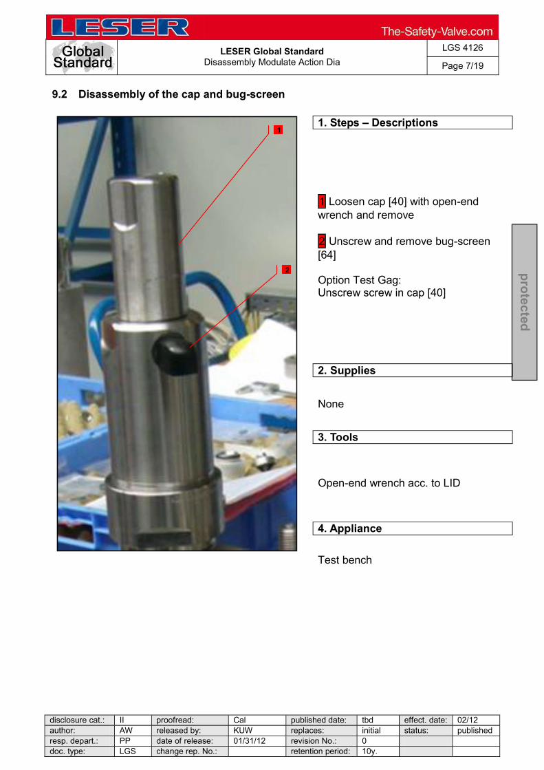
LESER Global Standard
Disassembly Modulate Action Dia
LGS 4126
Page 7/19
disclosure cat.: II proofread: Cal published date: tbd effect. date: 02/12 author: AW released by: KUW replaces: initial status: published resp. depart.: PP date of release: 01/31/12 revision No.: 0 doc. type: LGS change rep. No.: retention period: 10y.
pro
tected
9.2 Disassembly of the cap and bug-screen
1. Steps Descriptions
1 Loosen cap [40] with open-end wrench and remove 2 Unscrew and remove bug-screen [64] Option Test Gag: Unscrew screw in cap [40]
2. Supplies
None
3. Tools
Open-end wrench acc. to LID
4. Appliance
Test bench
1
2

LESER Global Standard
Disassembly Modulate Action Dia
LGS 4126
Page 8/19
disclosure cat.: II proofread: Cal published date: tbd effect. date: 02/12 author: AW released by: KUW replaces: initial status: published resp. depart.: PP date of release: 01/31/12 revision No.: 0 doc. type: LGS change rep. No.: retention period: 10y.
pro
tected
9.3 Disassembly of the bonnet and spindle unit
1. Steps Descriptions
1 Loosen lock nut [19] with open-end wrench 2 Apply an open-end wrench in a counterclockwise direction on adjusting screw [18] until no more pressure can be felt from spring. 3 Loosen bonnet [9] with open-end wrench 4 Lift up bonnet [9] along with spindle unit 5 Take spindle unit out of bonnet [9]
2. Supplies
None
3. Tools
Open-end wrench acc. to LID
4. Appliance
Test bench
1
3
4 5
2

LESER Global Standard
Disassembly Modulate Action Dia
LGS 4126
Page 9/19
disclosure cat.: II proofread: Cal published date: tbd effect. date: 02/12 author: AW released by: KUW replaces: initial status: published resp. depart.: PP date of release: 01/31/12 revision No.: 0 doc. type: LGS change rep. No.: retention period: 10y.
pro
tected
9.4 Disassembly of the spindle unit
1. Steps Descriptions
1 Remove successively bushing; bearing [69]; (upper) spring plate [16] and spring [54] of spindle [12] 2 Screw off (lower) spring plate [17] of spindle [12]
2. Supplies
None
3. Tools
Drift pin
4. Appliance
Parallel vice with aluminium jaws
1
2

LESER Global Standard
Disassembly Modulate Action Dia
LGS 4126
Page 10/19
disclosure cat.: II proofread: Cal published date: tbd effect. date: 02/12 author: AW released by: KUW replaces: initial status: published resp. depart.: PP date of release: 01/31/12 revision No.: 0 doc. type: LGS change rep. No.: retention period: 10y.
pro
tected
9.5 Disassembly of the bonnet
1. Steps Descriptions
1 Loosen lock nut [19] of adjusting screw [18] 2 Screw adjusting screw [18] out of bonnet [9] 3 Completely unscrew lock nut [19] of adjusting screw [18] 4 Remove guide ring [80] 5 Remove (upper) piston [47]
2. Supplies
None
3. Tools
Open-end wrench acc. to LID
4. Appliance
None
1
2
4
3
5 5

LESER Global Standard
Disassembly Modulate Action Dia
LGS 4126
Page 11/19
disclosure cat.: II proofread: Cal published date: tbd effect. date: 02/12 author: AW released by: KUW replaces: initial status: published resp. depart.: PP date of release: 01/31/12 revision No.: 0 doc. type: LGS change rep. No.: retention period: 10y.
pro
tected
9.6 Disassembly of the body´s bottom side
1. Steps Descriptions
1 Loosen plug [20] with open-end wrench and remove 2 Take out O-ring 3 Remove parallel pin [44] with drift pin 4 Remove coupling [43] and return spring [42] by lifting them upwards
2. Supplies
None
3. Tools
Open-end wrench acc. to LID Drift pin Hook tool for O-rings
4. Appliance
Test bench
1
2
3 3
4

LESER Global Standard
Disassembly Modulate Action Dia
LGS 4126
Page 12/19
disclosure cat.: II proofread: Cal published date: tbd effect. date: 02/12 author: AW released by: KUW replaces: initial status: published resp. depart.: PP date of release: 01/31/12 revision No.: 0 doc. type: LGS change rep. No.: retention period: 10y.
pro
tected
9.7 Disassembly of the diaphragm
1. Steps Descriptions
1 Loosen nut [70] with cranked ring wrench, while loosening nut [70] counter piston [41] 2 Remove diaphragm washer [71] 3 Remove ring [76] 4 Remove diaphragm [72] If implemented: Remove FEP protective foil 5 Remove O-ring 6 Remove diaphragm retainer [78]
2. Supplies
None
3. Tools
Deep cranked ring wrench and Open-end wrench acc. to LID Hook tool for O-rings
4. Appliance
Test bench
1
2 2
3
4
5
3
4
6
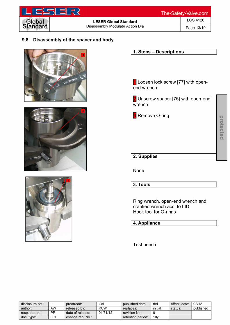
LESER Global Standard
Disassembly Modulate Action Dia
LGS 4126
Page 13/19
disclosure cat.: II proofread: Cal published date: tbd effect. date: 02/12 author: AW released by: KUW replaces: initial status: published resp. depart.: PP date of release: 01/31/12 revision No.: 0 doc. type: LGS change rep. No.: retention period: 10y.
pro
tected
9.8 Disassembly of the spacer and body
1. Steps Descriptions
1 Loosen lock screw [77] with open-end wrench 2 Unscrew spacer [75] with open-end wrench 3 Remove O-ring
2. Supplies
None
3. Tools
Ring wrench, open-end wrench and cranked wrench acc. to LID Hook tool for O-rings
4. Appliance
Test bench
1
2
3

LESER Global Standard
Disassembly Modulate Action Dia
LGS 4126
Page 14/19
disclosure cat.: II proofread: Cal published date: tbd effect. date: 02/12 author: AW released by: KUW replaces: initial status: published resp. depart.: PP date of release: 01/31/12 revision No.: 0 doc. type: LGS change rep. No.: retention period: 10y.
pro
tected
9.9 Removing the piston unit
1. Steps Descriptions
1 Pull out piston unit
2. Supplies
None
3. Tools
None
4. Appliance
Test bench
1

LESER Global Standard
Disassembly Modulate Action Dia
LGS 4126
Page 15/19
disclosure cat.: II proofread: Cal published date: tbd effect. date: 02/12 author: AW released by: KUW replaces: initial status: published resp. depart.: PP date of release: 01/31/12 revision No.: 0 doc. type: LGS change rep. No.: retention period: 10y.
pro
tected
9.10 Removing the guide bush from the piston
1. Steps Descriptions
1 Pull guide bush [2] off piston unit 2 Remove O-rings
2. Supplies
None
3. Tools
Hook tool for O-rings
4. Appliance
None
1
2
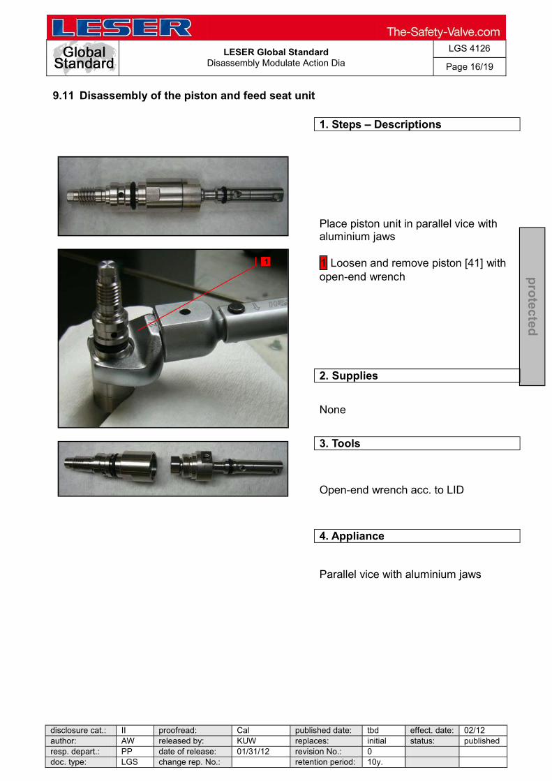
LESER Global Standard
Disassembly Modulate Action Dia
LGS 4126
Page 16/19
disclosure cat.: II proofread: Cal published date: tbd effect. date: 02/12 author: AW released by: KUW replaces: initial status: published resp. depart.: PP date of release: 01/31/12 revision No.: 0 doc. type: LGS change rep. No.: retention period: 10y.
pro
tected
9.11 Disassembly of the piston and feed seat unit
1. Steps Descriptions
Place piston unit in parallel vice with aluminium jaws 1 Loosen and remove piston [41] with open-end wrench
2. Supplies
None
3. Tools
Open-end wrench acc. to LID
4. Appliance
Parallel vice with aluminium jaws
1

LESER Global Standard
Disassembly Modulate Action Dia
LGS 4126
Page 17/19
disclosure cat.: II proofread: Cal published date: tbd effect. date: 02/12 author: AW released by: KUW replaces: initial status: published resp. depart.: PP date of release: 01/31/12 revision No.: 0 doc. type: LGS change rep. No.: retention period: 10y.
pro
tected
9.12 Remove the O-rings
1. Steps Descriptions
1 Remove O-rings
2. Supplies
None
3. Tools
Hook tool for O-rings
4. Appliance
None
1
1
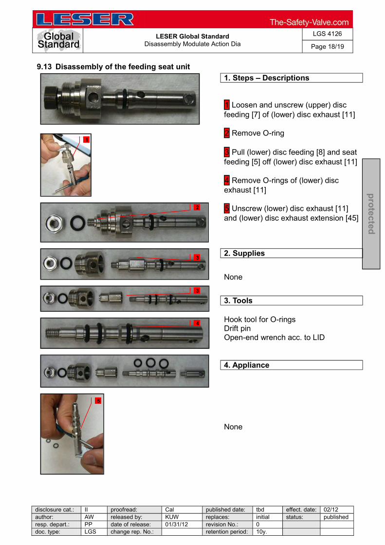
LESER Global Standard
Disassembly Modulate Action Dia
LGS 4126
Page 18/19
disclosure cat.: II proofread: Cal published date: tbd effect. date: 02/12 author: AW released by: KUW replaces: initial status: published resp. depart.: PP date of release: 01/31/12 revision No.: 0 doc. type: LGS change rep. No.: retention period: 10y.
pro
tected
9.13 Disassembly of the feeding seat unit
1. Steps Descriptions
1 Loosen and unscrew (upper) disc feeding [7] of (lower) disc exhaust [11] 2 Remove O-ring 3 Pull (lower) disc feeding [8] and seat feeding [5] off (lower) disc exhaust [11] 4 Remove O-rings of (lower) disc exhaust [11] 5 Unscrew (lower) disc exhaust [11] and (lower) disc exhaust extension [45]
2. Supplies
None
3. Tools
Hook tool for O-rings Drift pin Open-end wrench acc. to LID
4. Appliance
None
1
2
3
3
4
5
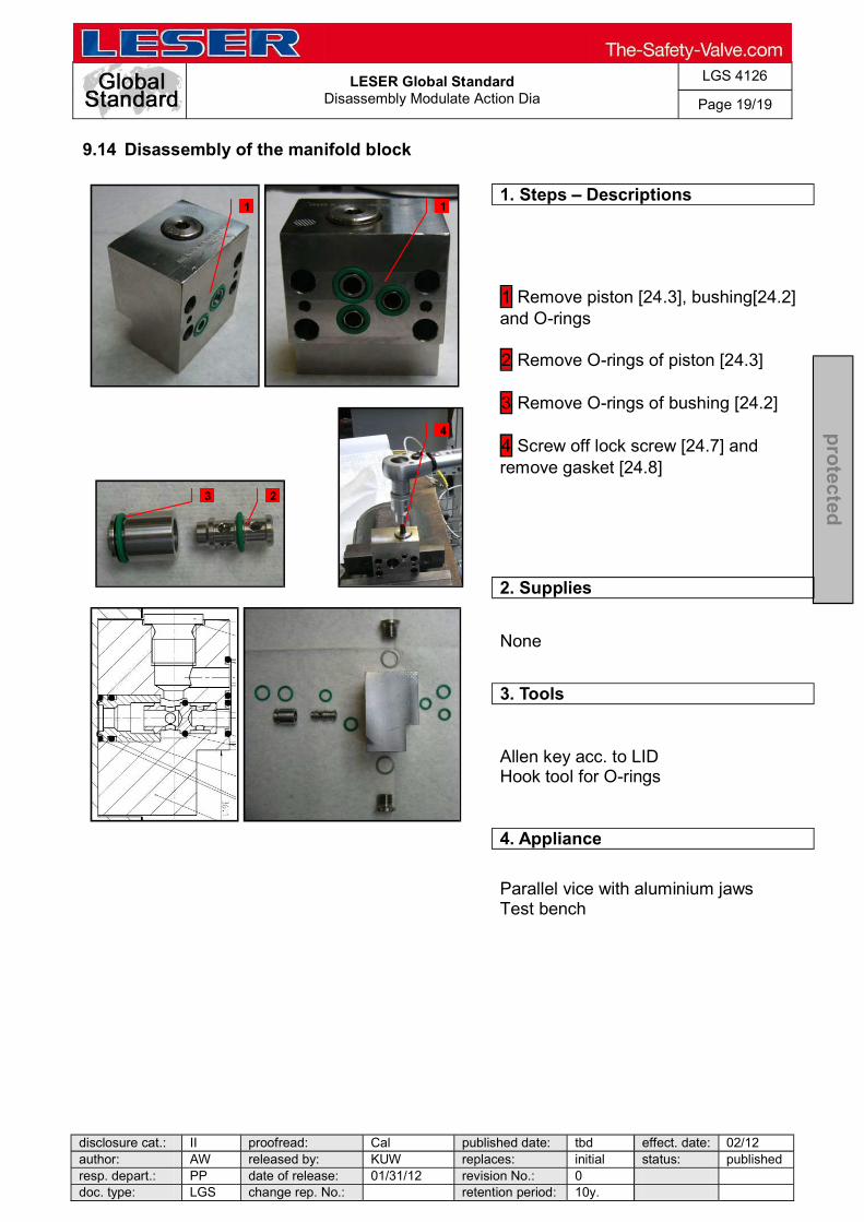
LESER Global Standard
Disassembly Modulate Action Dia
LGS 4126
Page 19/19
disclosure cat.: II proofread: Cal published date: tbd effect. date: 02/12 author: AW released by: KUW replaces: initial status: published resp. depart.: PP date of release: 01/31/12 revision No.: 0 doc. type: LGS change rep. No.: retention period: 10y.
pro
tected
9.14 Disassembly of the manifold block
1. Steps Descriptions
1 Remove piston [24.3], bushing[24.2] and O-rings 2 Remove O-rings of piston [24.3] 3 Remove O-rings of bushing [24.2] 4 Screw off lock screw [24.7] and remove gasket [24.8]
2. Supplies
None
3. Tools
Allen key acc. to LID Hook tool for O-rings
4. Appliance
Parallel vice with aluminium jaws Test bench
1 1
2 3
4
LESER Global Standard
Disassembly Modulate Action Piston
LGS 4127
Page 1/17
disclosure cat.: II proofread: Cal published date: tbd effect. date: 02/12 author: AW released by: KUW replaces: initial status: published resp. depart.: PP date of release: 01/31/12 revision No.: 0 doc. type: LGS change rep. No.: retention period: 10y.
pro
tected
Content 1 General informations for disassembling the Modulate Action Pilot (Piston Design) ................................................................................................................ 2 2 Purpose ......................................................................................................... 2 3 Competences ................................................................................................ 2 4 Scope ............................................................................................................. 2 5 Disclaimer ...................................................................................................... 2 6 Qualified fitting personnel ............................................................................ 2 7 Remarks ......................................................................................................... 2 8 Basic safety guidelines ................................................................................ 3 9 Disassembly instructions ............................................................................. 6

LESER Global Standard
Disassembly Modulate Action Piston
LGS 4127
Page 2/17
disclosure cat.: II proofread: Cal published date: tbd effect. date: 02/12 author: AW released by: KUW replaces: initial status: published resp. depart.: PP date of release: 01/31/12 revision No.: 0 doc. type: LGS change rep. No.: retention period: 10y.
pro
tected
1 General informations for disassembling the Modulate Action Pilot (Piston Design)
2 Purpose
The documentation describes the disassembly of the modulate action pilot valve (piston design). The description contains every single working step, supplies, tools and appliances.
3 Competences
The generation, maintenance and distribution of the documentation takes place in the organisation department. The defaults will be generated by the technical department in consultation with the final assembly department and production planning department.
4 Scope
This document must be applied to the dismantling of a Pilot Operated Safety Valve in agencies and subsidiaries of LESER GmbH & Co. KG, customers and independent service center.
5 Disclaimer
LESER puts in a great deal of effort into making up-to-date and correct documentation available. Nevertheless, LESER GmbH & Co. KG gives no guarantee that the recommended actions presented here are entirely correct and error free. This document is to be applied exclusively to the specified type. LESER GmbH & Co. KG declines any liability or responsibility for the correctness and completeness of the content. LESER GmbH & Co. KG reserves the right to change the information contained in this document, which is for the products of LESER GmbH & Co. KG and is intended for LESER subsidiaries, at any time and without prior announcement. LESER GmbH & Co. KG is available to the users of this document to provide additional information.
6 Qualified fitting personnel
LESER safety valves may only be dismantled by trained or qualified fitters. The qualifications must be obtained through the appropriate training measures.
7 Remarks
Gloves must be worn during the entire dismantling process.

LESER Global Standard
Disassembly Modulate Action Piston
LGS 4127
Page 3/17
disclosure cat.: II proofread: Cal published date: tbd effect. date: 02/12 author: AW released by: KUW replaces: initial status: published resp. depart.: PP date of release: 01/31/12 revision No.: 0 doc. type: LGS change rep. No.: retention period: 10y.
pro
tected
8 Basic safety guidelines
Dangerous media Poisoning, caustic burns, burns, injuries
Foreign bodies in the safety valve Danger from failure of safety valve or leaks
of a safety valve. objects.
Bug screen is damaged or missing (B or option) Dirt, objects or insects get into the safety valve. Danger from malfunction of the safety valve.
Ambient temperature is too high Material expansion. Danger from malfunction of the safety valve. Ambient temperature is too low Icing, freezing vapours, reduced flow rate due to congealing media. Danger from functional disruption of the safety valve. Abrasive or corrosive media Moving parts jam or become stuck. Danger from functional disruption of the safety valve.
alve after each time it opens. Media with high proportion of particles (only B)

LESER Global Standard
Disassembly Modulate Action Piston
LGS 4127
Page 4/17
disclosure cat.: II proofread: Cal published date: tbd effect. date: 02/12 author: AW released by: KUW replaces: initial status: published resp. depart.: PP date of release: 01/31/12 revision No.: 0 doc. type: LGS change rep. No.: retention period: 10y.
pro
tected
Deposits and clogging. Danger from malfunction of the safety valve.
filter capacity.
Residual media in the safety valve Poisoning, caustic burns, burns, injuries
WARNING Leaky safety valve Danger from leaking media due to damaged gaskets and sealing surfaces.
valve against vibrations and blows especially during transport and installation.
Open bonnet or spindle guides Danger from leaking media
leaking media. tance.
CAUTION Hot medium Burns or scalding.
Hot surfaces Burns.
Aggressive medium Caustic burns.
nt.

LESER Global Standard
Disassembly Modulate Action Piston
LGS 4127
Page 5/17
disclosure cat.: II proofread: Cal published date: tbd effect. date: 02/12 author: AW released by: KUW replaces: initial status: published resp. depart.: PP date of release: 01/31/12 revision No.: 0 doc. type: LGS change rep. No.: retention period: 10y.
pro
tected
Open bonnet or spindle guides Pinching danger from moving parts.
Sharp edges and burrs Danger of injury.
High noise emission Hearing damage. Wear ear protection.
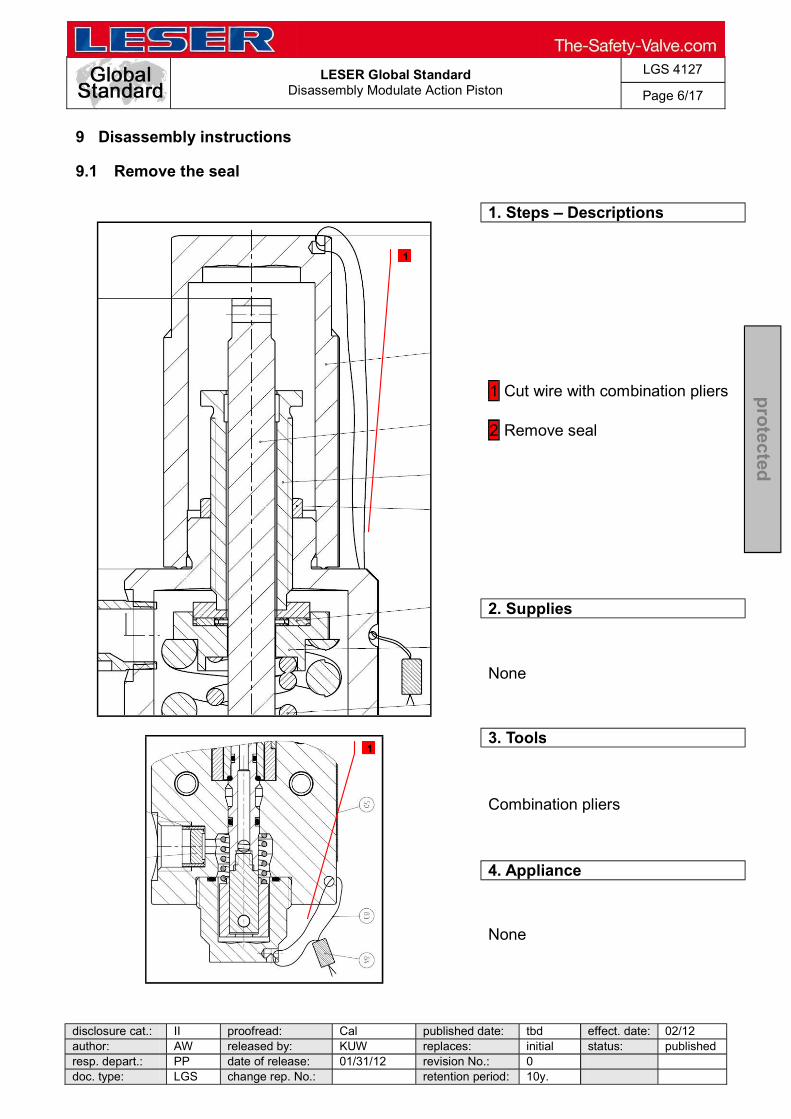
LESER Global Standard
Disassembly Modulate Action Piston
LGS 4127
Page 6/17
disclosure cat.: II proofread: Cal published date: tbd effect. date: 02/12 author: AW released by: KUW replaces: initial status: published resp. depart.: PP date of release: 01/31/12 revision No.: 0 doc. type: LGS change rep. No.: retention period: 10y.
pro
tected
9 Disassembly instructions
9.1 Remove the seal
1. Steps Descriptions
1 Cut wire with combination pliers 2 Remove seal
2. Supplies
None
3. Tools
Combination pliers
4. Appliance
None
1
1

LESER Global Standard
Disassembly Modulate Action Piston
LGS 4127
Page 7/17
disclosure cat.: II proofread: Cal published date: tbd effect. date: 02/12 author: AW released by: KUW replaces: initial status: published resp. depart.: PP date of release: 01/31/12 revision No.: 0 doc. type: LGS change rep. No.: retention period: 10y.
pro
tected
9.2 Disassembly of the cap and bug-screen
1. Steps Descriptions
1 Loosen cap [40] with open-end wrench and remove 2 Unscrew and remove bug-screen [64] Option Test Gag: Unscrew screw in cap
2. Supplies
None
3. Tools
Open-end wrench acc. to LID
4. Appliance
Test bench
1
2
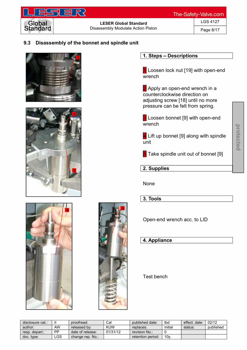
LESER Global Standard
Disassembly Modulate Action Piston
LGS 4127
Page 8/17
disclosure cat.: II proofread: Cal published date: tbd effect. date: 02/12 author: AW released by: KUW replaces: initial status: published resp. depart.: PP date of release: 01/31/12 revision No.: 0 doc. type: LGS change rep. No.: retention period: 10y.
pro
tected
9.3 Disassembly of the bonnet and spindle unit
1. Steps Descriptions
1 Loosen lock nut [19] with open-end wrench 2 Apply an open-end wrench in a counterclockwise direction on adjusting screw [18] until no more pressure can be felt from spring. 3 Loosen bonnet [9] with open-end wrench 4 Lift up bonnet [9] along with spindle unit 5 Take spindle unit out of bonnet [9]
2. Supplies
None
3. Tools
Open-end wrench acc. to LID
4. Appliance
Test bench
1
2
3
5 4

LESER Global Standard
Disassembly Modulate Action Piston
LGS 4127
Page 9/17
disclosure cat.: II proofread: Cal published date: tbd effect. date: 02/12 author: AW released by: KUW replaces: initial status: published resp. depart.: PP date of release: 01/31/12 revision No.: 0 doc. type: LGS change rep. No.: retention period: 10y.
pro
tected
9.4 Disassembly of the spindle unit
1. Steps Descriptions
1 Remove successively bushing; bearing [69]; (upper) spring plate [16] and spring [54] of spindle [12] 2 Screw off (lower) spring plate [17] of spindle [12]
2. Supplies
None
3. Tools
Drift pin
4. Appliance
Parallel vice with aluminium jaws
1 2

LESER Global Standard
Disassembly Modulate Action Piston
LGS 4127
Page 10/17
disclosure cat.: II proofread: Cal published date: tbd effect. date: 02/12 author: AW released by: KUW replaces: initial status: published resp. depart.: PP date of release: 01/31/12 revision No.: 0 doc. type: LGS change rep. No.: retention period: 10y.
pro
tected
9.5 Disassembly of the bonnet
1. Steps Descriptions
1 Loosen lock nut [19] of adjusting screw [18] 2 Screw adjusting screw [18] out of bonnet [9] 3 Completely unscrew lock nut [19] of adjusting screw [18]
2. Supplies
None
3. Tools
None
4. Appliance
None
1 3
2

LESER Global Standard
Disassembly Modulate Action Piston
LGS 4127
Page 11/17
disclosure cat.: II proofread: Cal published date: tbd effect. date: 02/12 author: AW released by: KUW replaces: initial status: published resp. depart.: PP date of release: 01/31/12 revision No.: 0 doc. type: LGS change rep. No.: retention period: 10y.
pro
tected
9.6 Disassembly of the body´s bottom side
1. Steps Descriptions
1 Loosen plug [20] with open-end wrench and screw off 2 Take out O-ring 3 Remove parallel pin [44] with drift pin 4 Remove coupling [43] and return spring [42] by lifting them upwards
2. Supplies
None
3. Tools
Open-end wrench acc. to LID Hook tool for O-rings Drift pin
4. Appliance
Test bench
1
3 4
2

LESER Global Standard
Disassembly Modulate Action Piston
LGS 4127
Page 12/17
disclosure cat.: II proofread: Cal published date: tbd effect. date: 02/12 author: AW released by: KUW replaces: initial status: published resp. depart.: PP date of release: 01/31/12 revision No.: 0 doc. type: LGS change rep. No.: retention period: 10y.
pro
tected
9.7 Disassembly of the piston unit and body
1. Steps Descriptions
1 Pull piston unit out of body [1]
2. Supplies
None
3. Tools
None
4. Appliance
Test bench
1

LESER Global Standard
Disassembly Modulate Action Piston
LGS 4127
Page 13/17
disclosure cat.: II proofread: Cal published date: tbd effect. date: 02/12 author: AW released by: KUW replaces: initial status: published resp. depart.: PP date of release: 01/31/12 revision No.: 0 doc. type: LGS change rep. No.: retention period: 10y.
pro
tected
9.8 Disassembly of the guide bush and piston upper
1. Steps Descriptions
Place unit in parallel vice with aluminium jaws 1 Unscrew piston, upper [47] 2 Pull guide bush [2] off piston [41]
2. Supplies
None
3. Tools
Open-end wrench acc. to LID
4. Appliance
Parallel vice with aluminium jaws Assembling aid
1
2

LESER Global Standard
Disassembly Modulate Action Piston
LGS 4127
Page 14/17
disclosure cat.: II proofread: Cal published date: tbd effect. date: 02/12 author: AW released by: KUW replaces: initial status: published resp. depart.: PP date of release: 01/31/12 revision No.: 0 doc. type: LGS change rep. No.: retention period: 10y.
pro
tected
9.9 Disassembly of the piston and feeding seat unit
1. Steps Descriptions
Place piston unit in parallel vice with aluminium jaws 1 Loosen and remove piston [41] with open-end wrench
2. Supplies
None
3. Tools
Open-end wrench acc. to LID
4. Appliance
Parallel vice with aluminium jaws
1

LESER Global Standard
Disassembly Modulate Action Piston
LGS 4127
Page 15/17
disclosure cat.: II proofread: Cal published date: tbd effect. date: 02/12 author: AW released by: KUW replaces: initial status: published resp. depart.: PP date of release: 01/31/12 revision No.: 0 doc. type: LGS change rep. No.: retention period: 10y.
pro
tected
9.10 Removing the O-rings
1. Steps Descriptions
1 Remove O-rings
2. Supplies
None
3. Tools
Hook tool for O-rings
4. Appliance
None
1
1
1
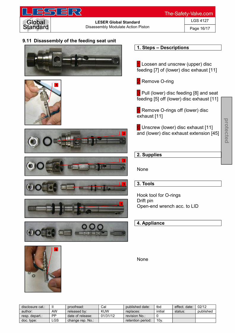
LESER Global Standard
Disassembly Modulate Action Piston
LGS 4127
Page 16/17
disclosure cat.: II proofread: Cal published date: tbd effect. date: 02/12 author: AW released by: KUW replaces: initial status: published resp. depart.: PP date of release: 01/31/12 revision No.: 0 doc. type: LGS change rep. No.: retention period: 10y.
pro
tected
9.11 Disassembly of the feeding seat unit
1. Steps Descriptions
1 Loosen and unscrew (upper) disc feeding [7] of (lower) disc exhaust [11] 2 Remove O-ring 3 Pull (lower) disc feeding [8] and seat feeding [5] off (lower) disc exhaust [11] 5 Remove O-rings off (lower) disc exhaust [11] 6 Unscrew (lower) disc exhaust [11] and (lower) disc exhaust extension [45]
2. Supplies
None
3. Tools
Hook tool for O-rings Drift pin Open-end wrench acc. to LID
4. Appliance
None
1
2
3
5
3
6

LESER Global Standard
Disassembly Modulate Action Piston
LGS 4127
Page 17/17
disclosure cat.: II proofread: Cal published date: tbd effect. date: 02/12 author: AW released by: KUW replaces: initial status: published resp. depart.: PP date of release: 01/31/12 revision No.: 0 doc. type: LGS change rep. No.: retention period: 10y.
pro
tected
9.12 Disassembly of the manifold block
1. Steps Descriptions
1 Remove piston [24.3] bushing [24.4] and O-rings 2 Remove O-rings of piston [24.3] 3 Remove O-rings of bushing [24.4] 4 Screw off lock screw [24.7] and remove gasket [24.8]
2. Supplies
None
3. Tools
Allen key acc. to LID Hook tool for O-rings
4. Appliance
Parallel vice with aluminium jaws Test bench
1 1
3 2
4

LESER Global Standard Disassembly Accessories
LGS 4128
Page 1/10
disclosure cat.: II proofread: Cal published date: tbd effect. date: 02/12 author: AW released by: KUW replaces: initial status: published resp. depart.: PP date of release: YY/MM revision No.: 0 doc. type: LGS change rep. No.: retention period: 10y.
pro
tected
Content 1 General information for disassembling the POSV accessories ................ 2 2 Purpose ......................................................................................................... 2 3 Competences ................................................................................................ 2 4 Scope ............................................................................................................. 2 5 Disclaimer ...................................................................................................... 2 6 Qualified fitting personnel ............................................................................ 2 7 Remarks ......................................................................................................... 2 8 Basic safety guidelines ................................................................................ 3 9 Disassembly instructions ............................................................................. 6

LESER Global Standard Disassembly Accessories
LGS 4128
Page 2/10
disclosure cat.: II proofread: Cal published date: tbd effect. date: 02/12 author: AW released by: KUW replaces: initial status: published resp. depart.: PP date of release: YY/MM revision No.: 0 doc. type: LGS change rep. No.: retention period: 10y.
pro
tected
1 General information for disassembling the POSV accessories
2 Purpose
The documentation describes the disassembly of the POSV accessories. The description contains every single working step, supplies, tools and appliances.
3 Competences
The generation, maintenance and distribution of the documentation takes place in the organisation department. The defaults will be generated by the technical department in consultation with the final assembly department and production planning department.
4 Scope
This document must be applied to the assembling of a Pilot Operated Safety Valve with accessories in agencies and subsidiaries of LESER GmbH & Co. KG, customers and independent service center.
5 Disclaimer
LESER puts in a great deal of effort into making up-to-date and correct documentation available. Nevertheless, LESER GmbH & Co. KG gives no guarantee that the recommended actions presented here are entirely correct and error free. This document is to be applied exclusively to the specified type. LESER GmbH & Co. KG declines any liability or responsibility for the correctness and completeness of the content. LESER GmbH & Co. KG reserves the right to change the information contained in this document, which is for the products of LESER GmbH & Co. KG and is intended for LESER subsidiaries, at any time and without prior announcement. LESER GmbH & Co. KG is available to the users of this document to provide additional information.
6 Qualified fitting personnel
LESER safety valves may only be dismantled by trained or qualified fitters. The qualifications must be obtained through the appropriate training measures.
7 Remarks
Gloves must be worn during the entire dismantling process.

LESER Global Standard Disassembly Accessories
LGS 4128
Page 3/10
disclosure cat.: II proofread: Cal published date: tbd effect. date: 02/12 author: AW released by: KUW replaces: initial status: published resp. depart.: PP date of release: YY/MM revision No.: 0 doc. type: LGS change rep. No.: retention period: 10y.
pro
tected
8 Basic safety guidelines
Dangerous media Poisoning, caustic burns, burns, injuries
Foreign bodies in the safety valve Danger from failure of safety valve or leaks
of a safety valve. objects.
Bug screen is damaged or missing (B or option) Dirt, objects or insects get into the safety valve. Danger from malfunction of the safety valve.
reen correctly.
Ambient temperature is too high Material expansion. Danger from malfunction of the safety valve. Ambient temperature is too low Icing, freezing vapours, reduced flow rate due to congealing media. Danger from functional disruption of the safety valve. Abrasive or corrosive media Moving parts jam or become stuck. Danger from functional disruption of the safety valve.
it opens. Media with high proportion of particles (only B)

LESER Global Standard Disassembly Accessories
LGS 4128
Page 4/10
disclosure cat.: II proofread: Cal published date: tbd effect. date: 02/12 author: AW released by: KUW replaces: initial status: published resp. depart.: PP date of release: YY/MM revision No.: 0 doc. type: LGS change rep. No.: retention period: 10y.
pro
tected
Deposits and clogging. Danger from malfunction of the safety valve.
filter capacity. Residual media in the safety valve Poisoning, caustic burns, burns, injuries
WARNING Leaky safety valve Danger from leaking media due to damaged gaskets and sealing surfaces.
and blows especially during transport and installation.
Open bonnet or spindle guides Danger from leaking media
leaking media.
CAUTION Hot medium Burns or scalding.
Hot surfaces Burns.
Aggressive medium Caustic burns.
Open bonnet or spindle guides

LESER Global Standard Disassembly Accessories
LGS 4128
Page 5/10
disclosure cat.: II proofread: Cal published date: tbd effect. date: 02/12 author: AW released by: KUW replaces: initial status: published resp. depart.: PP date of release: YY/MM revision No.: 0 doc. type: LGS change rep. No.: retention period: 10y.
pro
tected
Pinching danger from moving parts.
Sharp edges and burrs Danger of injury.
High noise emission Hearing damage. Wear ear protection.
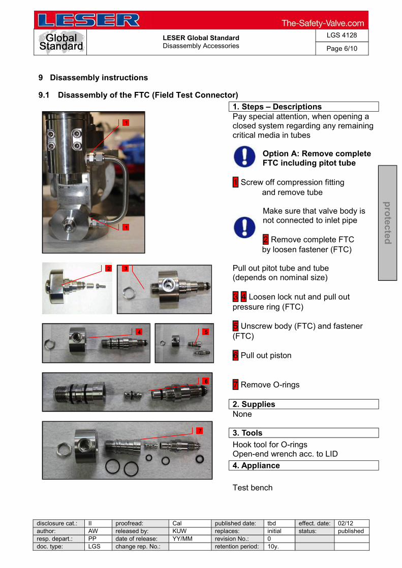
LESER Global Standard Disassembly Accessories
LGS 4128
Page 6/10
disclosure cat.: II proofread: Cal published date: tbd effect. date: 02/12 author: AW released by: KUW replaces: initial status: published resp. depart.: PP date of release: YY/MM revision No.: 0 doc. type: LGS change rep. No.: retention period: 10y.
pro
tected
9 Disassembly instructions
9.1 Disassembly of the FTC (Field Test Connector)
1. Steps Descriptions
Pay special attention, when opening a closed system regarding any remaining critical media in tubes
Option A: Remove complete FTC including pitot tube
1 Screw off compression fitting and remove tube
Make sure that valve body is not connected to inlet pipe 2 Remove complete FTC
by loosen fastener (FTC) Pull out pitot tube and tube (depends on nominal size) 3 4 Loosen lock nut and pull out pressure ring (FTC) 5 Unscrew body (FTC) and fastener (FTC) 6 Pull out piston 7 Remove O-rings
2. Supplies
None
3. Tools
Hook tool for O-rings Open-end wrench acc. to LID
4. Appliance
Test bench
1
1
3 2
4 5
6
7

LESER Global Standard Disassembly Accessories
LGS 4128
Page 7/10
disclosure cat.: II proofread: Cal published date: tbd effect. date: 02/12 author: AW released by: KUW replaces: initial status: published resp. depart.: PP date of release: YY/MM revision No.: 0 doc. type: LGS change rep. No.: retention period: 10y.
pro
tected
9.2 Disassembly of the FTC (Field Test Connector)
1. Steps Descriptions
Pay special attention, when opening a closed system regarding any remaining critical
media in tubes Option B: Remove FTC exclusive pitot tube 1 Screw off the compression fitting and remove the tube
Make sure that fastener (FTC) stays tightened during disassembly in order that pitot tube stays tightened!
2 Loosen lock nut (FTC) 3 Pull out pressure ring (FTC) 4 Unscrew body (FTC) by securing fastener (FTC) with a second open-end wrench 5 Pull out piston (FTC) 6 Remove O-rings
2. Supplies
None
3. Tools
Hook tool for O-rings Open-end wrench acc. to LID
4. Appliance
Test bench
1
1
4
2
5
3
6
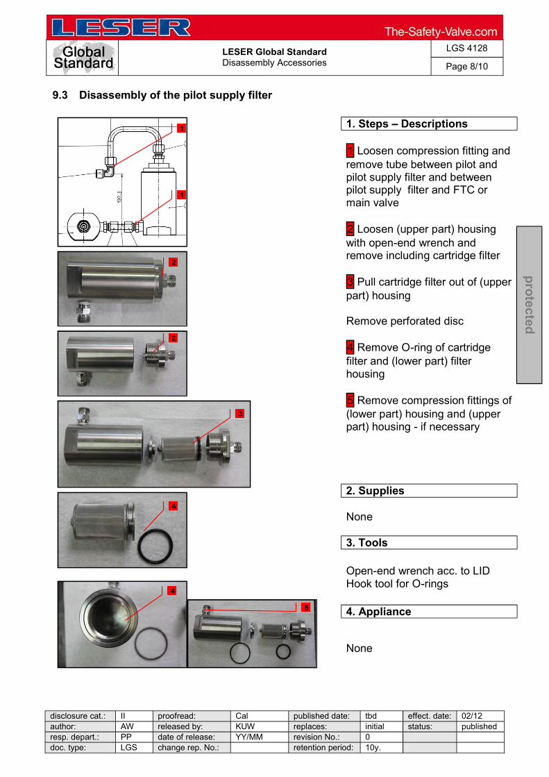
LESER Global Standard Disassembly Accessories
LGS 4128
Page 8/10
disclosure cat.: II proofread: Cal published date: tbd effect. date: 02/12 author: AW released by: KUW replaces: initial status: published resp. depart.: PP date of release: YY/MM revision No.: 0 doc. type: LGS change rep. No.: retention period: 10y.
pro
tected
9.3 Disassembly of the pilot supply filter
1. Steps Descriptions
1 Loosen compression fitting and remove tube between pilot and pilot supply filter and between pilot supply filter and FTC or main valve 2 Loosen (upper part) housing with open-end wrench and remove including cartridge filter 3 Pull cartridge filter out of (upper part) housing Remove perforated disc 4 Remove O-ring of cartridge filter and (lower part) filter housing 5 Remove compression fittings of (lower part) housing and (upper part) housing - if necessary
2. Supplies
None
3. Tools
Open-end wrench acc. to LID Hook tool for O-rings
4. Appliance
None
1
1
2
3
4
4
2
5

LESER Global Standard Disassembly Accessories
LGS 4128
Page 9/10
disclosure cat.: II proofread: Cal published date: tbd effect. date: 02/12 author: AW released by: KUW replaces: initial status: published resp. depart.: PP date of release: YY/MM revision No.: 0 doc. type: LGS change rep. No.: retention period: 10y.
pro
tected
9.4 Disassembly of the manual blowdown
1. Steps Descriptions
Option A: Manual blowdown into main valve outlet Make sure that sealing
tape is accurately removed from threads and do not fall into dome
in any case 1 Loosen compression fittings 2 Remove L- tube (MBI.2) and U-tube (MBI.1) and male end fittings of top plate, ball valve and body 3 Option B: Manual blowdown into atmosphere 1 Loosen compression fittings 2 Remove L- tube (MBI.2) and male fittings of top plate and ball valve
2. Supplies
None
3. Tools
Open-end wrench acc. to LID
4. Appliance
None
1
1
1
1
1
1
2
2
3
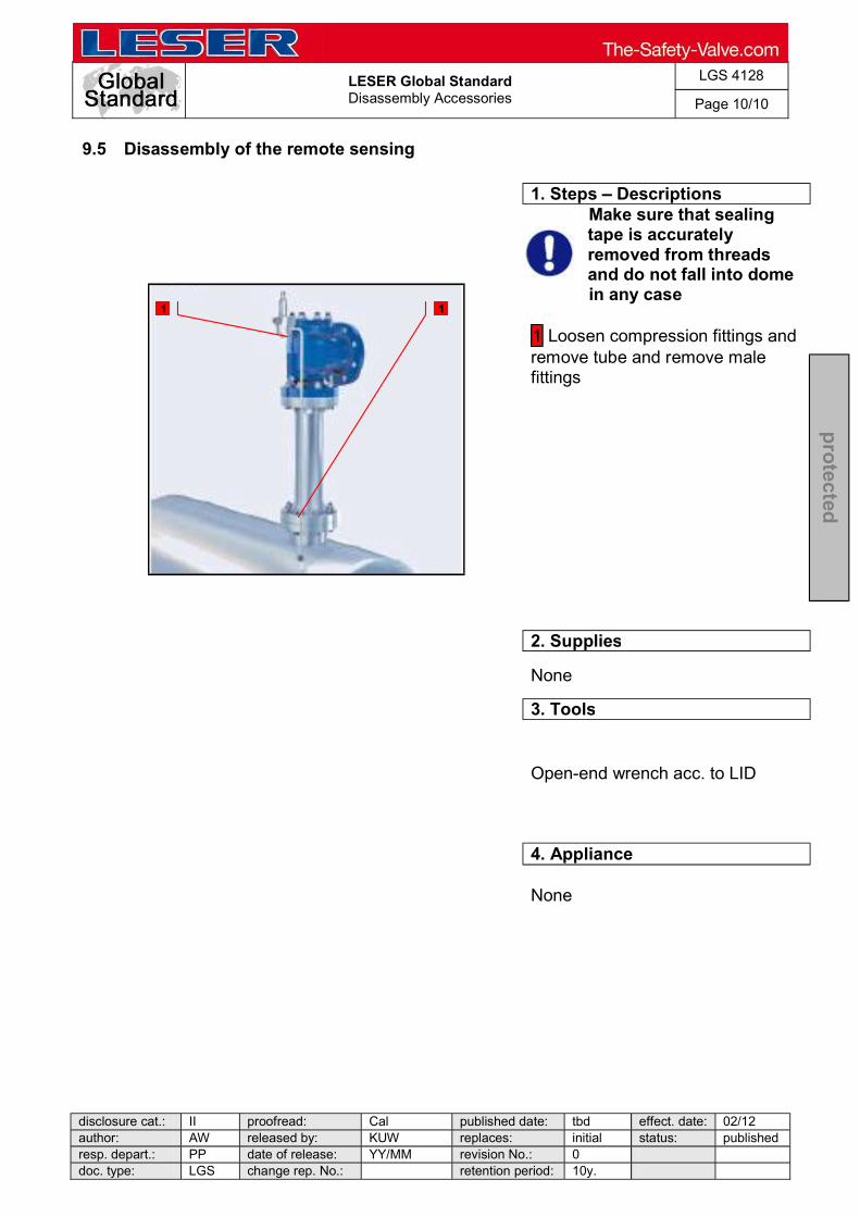
LESER Global Standard Disassembly Accessories
LGS 4128
Page 10/10
disclosure cat.: II proofread: Cal published date: tbd effect. date: 02/12 author: AW released by: KUW replaces: initial status: published resp. depart.: PP date of release: YY/MM revision No.: 0 doc. type: LGS change rep. No.: retention period: 10y.
pro
tected
9.5 Disassembly of the remote sensing
1. Steps Descriptions
Make sure that sealing tape is accurately removed from threads and do not fall into.dome
in any case 1 Loosen compression fittings and remove tube and remove male fittings
2. Supplies
None
3. Tools
Open-end wrench acc. to LID
4. Appliance
None
1 1

LESER Global Standard Cleaning the POSV Parts
LGS 4129
Page 1/7
disclosure cat.: II proofread: Cal published date: tbd effect. date: 02/12 author: AW released by: KUW replaces: initial status: published resp. depart.: PP date of release: 01/31/12 revision No.: 0 doc. type: LGS change rep. No.: retention period: 10y.
pro
tected
Content 1 General information for assembling the POSV accessories ..................... 2 2 Purpose ......................................................................................................... 2 3 Competences ................................................................................................ 2 4 Scope ............................................................................................................. 2 5 Disclaimer ...................................................................................................... 2 6 Qualified fitting personnel ............................................................................ 2 7 Remarks ......................................................................................................... 2 8 Basic safety guidelines ................................................................................ 3 9 Cleaning the main valve ............................................................................... 6 10 Cleaning the pilot valve ................................................................................ 7

LESER Global Standard Cleaning the POSV Parts
LGS 4129
Page 2/7
disclosure cat.: II proofread: Cal published date: tbd effect. date: 02/12 author: AW released by: KUW replaces: initial status: published resp. depart.: PP date of release: 01/31/12 revision No.: 0 doc. type: LGS change rep. No.: retention period: 10y.
pro
tected
1 General information for assembling the POSV accessories
2 Purpose
The documentation describes the assembly of POSV accessories. The description contains every single working step, supplies, tools and appliances.
3 Competences
The generation, maintenance and distribution of the documentation takes place in the organisation department. The defaults will be generated by the technical department in consultation with the final assembly department and production planning department.
4 Scope
This document must be applied to the assembling of a Pilot Operated Safety Valve with accessories in agencies and subsidiaries of LESER GmbH & Co. KG, customers and independent service center.
5 Disclaimer
LESER puts in a great deal of effort into making up-to-date and correct documentation available. Nevertheless, LESER GmbH & Co. KG gives no guarantee that the recommended actions presented here are entirely correct and error free. This document is to be applied exclusively to the specified type. LESER GmbH & Co. KG declines any liability or responsibility for the correctness and completeness of the content. LESER GmbH & Co. KG reserves the right to change the information contained in this document, which is for the products of LESER GmbH & Co. KG and is intended for LESER subsidiaries, at any time and without prior announcement. LESER GmbH & Co. KG is available to the users of this document to provide additional information.
6 Qualified fitting personnel
LESER safety valves may only be dismantled by trained or qualified fitters. The qualifications must be obtained through the appropriate training measures.
7 Remarks
Gloves must be worn during the entire dismantling process.

LESER Global Standard Cleaning the POSV Parts
LGS 4129
Page 3/7
disclosure cat.: II proofread: Cal published date: tbd effect. date: 02/12 author: AW released by: KUW replaces: initial status: published resp. depart.: PP date of release: 01/31/12 revision No.: 0 doc. type: LGS change rep. No.: retention period: 10y.
pro
tected
8 Basic safety guidelines
Dangerous media Poisoning, caustic burns, burns, injuries
Foreign bodies in the safety valve Danger from failure of safety valve or leaks
of a safety valve. objects.
Bug screen is damaged or missing (B or option) Dirt, objects or insects get into the safety valve. Danger from malfunction of the safety valve.
Ambient temperature is too high Material expansion. Danger from malfunction of the safety valve. Ambient temperature is too low Icing, freezing vapours, reduced flow rate due to congealing media. Danger from functional disruption of the safety valve. Abrasive or corrosive media Moving parts jam or become stuck. Danger from functional disruption of the safety valve.
me it opens. Media with high proportion of particles

LESER Global Standard Cleaning the POSV Parts
LGS 4129
Page 4/7
disclosure cat.: II proofread: Cal published date: tbd effect. date: 02/12 author: AW released by: KUW replaces: initial status: published resp. depart.: PP date of release: 01/31/12 revision No.: 0 doc. type: LGS change rep. No.: retention period: 10y.
pro
tected
(only B) Deposits and clogging. Danger from malfunction of the safety valve.
filter capacity.
Residual media in the safety valve Poisoning, caustic burns, burns, injuries
WARNING Leaky safety valve Danger from leaking media due to damaged gaskets and sealing surfaces.
rations and blows especially during transport and installation.
Open bonnet or spindle guides Danger from leaking media
leaking media.
able protective equipment. CAUTION Hot medium Burns or scalding.
Hot surfaces Burns.
Aggressive medium Caustic burns.
LESER Global Standard Cleaning the POSV Parts
LGS 4129
Page 5/7
disclosure cat.: II proofread: Cal published date: tbd effect. date: 02/12 author: AW released by: KUW replaces: initial status: published resp. depart.: PP date of release: 01/31/12 revision No.: 0 doc. type: LGS change rep. No.: retention period: 10y.
pro
tected
Open bonnet or spindle guides Pinching danger from moving parts.
Sharp edges and burrs Danger of injury.
High noise emission Hearing damage. Wear ear protection. .
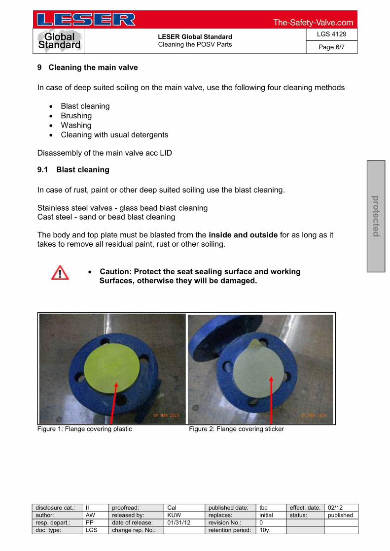
LESER Global Standard Cleaning the POSV Parts
LGS 4129
Page 6/7
disclosure cat.: II proofread: Cal published date: tbd effect. date: 02/12 author: AW released by: KUW replaces: initial status: published resp. depart.: PP date of release: 01/31/12 revision No.: 0 doc. type: LGS change rep. No.: retention period: 10y.
pro
tected
9 Cleaning the main valve
In case of deep suited soiling on the main valve, use the following four cleaning methods
Blast cleaning Brushing Washing Cleaning with usual detergents
Disassembly of the main valve acc LID
9.1 Blast cleaning
In case of rust, paint or other deep suited soiling use the blast cleaning. Stainless steel valves - glass bead blast cleaning Cast steel - sand or bead blast cleaning The body and top plate must be blasted from the inside and outside for as long as it takes to remove all residual paint, rust or other soiling.
Caution: Protect the seat sealing surface and working
Surfaces, otherwise they will be damaged.
Figure 1: Flange covering plastic Figure 2: Flange covering sticker

LESER Global Standard Cleaning the POSV Parts
LGS 4129
Page 7/7
disclosure cat.: II proofread: Cal published date: tbd effect. date: 02/12 author: AW released by: KUW replaces: initial status: published resp. depart.: PP date of release: 01/31/12 revision No.: 0 doc. type: LGS change rep. No.: retention period: 10y.
pro
tected
9.2 Brushing
The body´s inside and top plate have to be cleaned with a wire-cup brush and drill / pneumatic grinder until they are clean - until all soiling is removed.
Caution: Protect the seat sealing surface and working surfaces, otherwise they will be damaged.
9.3 Washing
When washing, make sure that all parts that belong to one repaired safety valve are washed together. When filling the washing machine, make sure that the washing medium can flow out of the bodies, bonnets and caps / levers without any residue.
9.4 Cleaning with detergents
In case of slight soiling like oil, grease and so on, use a suitable detergent in combination with a cotton cloth or paper towel to clean out all components of the Main Valve.
Consider a compatibility of the detergents and the soft sealings
10 Cleaning the pilot valve
Clean the disassembled parts of the pilot valve with a suitable cleaner and a cotton cloth or paper towel. Disassembly the pilot valve acc. LID
Consider a compatibility of the detergents and the soft sealings
LESER Global Standard Inspection Replacement
LGS 4130
Page 1/16
disclosure cat.: II proofread: Cal published date: tbd effect. date: 02/12 author: AW released by: KUW replaces: initial status: published resp. depart.: PP date of release: 01/31/12 revision No.: 0 doc. type: LGS change rep. No.: retention period: 10y.
pro
tected
Content 1 General information for assembling the POSV accessories ..................... 2 2 Purpose ......................................................................................................... 2 3 Competences ................................................................................................ 2 4 Scope ............................................................................................................. 2 5 Disclaimer ...................................................................................................... 2 6 Qualified fitting personnel ............................................................................ 2 7 Remarks ......................................................................................................... 2 8 Basic safety guidelines ................................................................................ 3 9 Process .......................................................................................................... 6 10 Critical Parts .................................................................................................. 7 11 Inspection of the parts.................................................................................. 8

LESER Global Standard Inspection Replacement
LGS 4130
Page 2/16
disclosure cat.: II proofread: Cal published date: tbd effect. date: 02/12 author: AW released by: KUW replaces: initial status: published resp. depart.: PP date of release: 01/31/12 revision No.: 0 doc. type: LGS change rep. No.: retention period: 10y.
pro
tected
1 General information for assembling the POSV accessories
2 Purpose
The documentation describes the assembly of POSV accessories. The description contains every single working step, supplies, tools and appliances.
3 Competences
The generation, maintenance and distribution of the documentation takes place in the organisation department. The defaults will be generated by the technical department in consultation with the final assembly department and production planning department.
4 Scope
This document must be applied to the assembling of a Pilot Operated Safety Valve with accessories in agencies and subsidiaries of LESER GmbH & Co. KG, customers and independent service center.
5 Disclaimer
LESER puts in a great deal of effort into making up-to-date and correct documentation available. Nevertheless, LESER GmbH & Co. KG gives no guarantee that the recommended actions presented here are entirely correct and error free. This document is to be applied exclusively to the specified type. LESER GmbH & Co. KG declines any liability or responsibility for the correctness and completeness of the content. LESER GmbH & Co. KG reserves the right to change the information contained in this document, which is for the products of LESER GmbH & Co. KG and is intended for LESER subsidiaries, at any time and without prior announcement. LESER GmbH & Co. KG is available to the users of this document to provide additional information.
6 Qualified fitting personnel
LESER safety valves may only be dismantled by trained or qualified fitters. The qualifications must be obtained through the appropriate training measures.
7 Remarks
Gloves must be worn during the entire dismantling process.
LESER Global Standard Inspection Replacement
LGS 4130
Page 3/16
disclosure cat.: II proofread: Cal published date: tbd effect. date: 02/12 author: AW released by: KUW replaces: initial status: published resp. depart.: PP date of release: 01/31/12 revision No.: 0 doc. type: LGS change rep. No.: retention period: 10y.
pro
tected
8 Basic safety guidelines
Dangerous media Poisoning, caustic burns, burns, injuries
Foreign bodies in the safety valve Danger from failure of safety valve or leaks
of a safety valve. objects.
Bug screen is damaged or missing (B or option) Dirt, objects or insects get into the safety valve. Danger from malfunction of the safety valve.
Ambient temperature is too high Material expansion. Danger from malfunction of the safety valve. Ambient temperature is too low Icing, freezing vapours, reduced flow rate due to congealing media. Danger from functional disruption of the safety valve. Abrasive or corrosive media Moving parts jam or become stuck. Danger from functional disruption of the safety valve.
safety valve after each time it opens. Media with high proportion of particles (only B) Deposits and clogging. Danger from malfunction of the safety valve.
filter capacity.
LESER Global Standard Inspection Replacement
LGS 4130
Page 4/16
disclosure cat.: II proofread: Cal published date: tbd effect. date: 02/12 author: AW released by: KUW replaces: initial status: published resp. depart.: PP date of release: 01/31/12 revision No.: 0 doc. type: LGS change rep. No.: retention period: 10y.
pro
tected
Residual media in the safety valve Poisoning, caustic burns, burns, injuries
WARNING Leaky safety valve Danger from leaking media due to damaged gaskets and sealing surfaces.
he safety valve against vibrations and blows especially during transport and installation.
Open bonnet or spindle guides Danger from leaking media
leaking media. safe distance.
CAUTION Hot medium Burns or scalding.
Hot surfaces Burns.
Aggressive medium Caustic burns.
e equipment. Open bonnet or spindle guides Pinching danger from moving parts.

LESER Global Standard Inspection Replacement
LGS 4130
Page 5/16
disclosure cat.: II proofread: Cal published date: tbd effect. date: 02/12 author: AW released by: KUW replaces: initial status: published resp. depart.: PP date of release: 01/31/12 revision No.: 0 doc. type: LGS change rep. No.: retention period: 10y.
pro
tected
Sharp edges and burrs Danger of injury.
High noise emission Hearing damage. Wear ear protection.

LESER Global Standard Inspection Replacement
LGS 4130
Page 6/16
disclosure cat.: II proofread: Cal published date: tbd effect. date: 02/12 author: AW released by: KUW replaces: initial status: published resp. depart.: PP date of release: 01/31/12 revision No.: 0 doc. type: LGS change rep. No.: retention period: 10y.
pro
tected
9 Process
Figure 1
Cleaned components
Reintegrate the components
Repairable damages
Inspection of the components/ critical parts
Inspection OK
Damaged
Yes
No
Replace through LESER original spare parts
Rework acc. LID

LESER Global Standard Inspection Replacement
LGS 4130
Page 7/16
disclosure cat.: II proofread: Cal published date: tbd effect. date: 02/12 author: AW released by: KUW replaces: initial status: published resp. depart.: PP date of release: 01/31/12 revision No.: 0 doc. type: LGS change rep. No.: retention period: 10y.
pro
tected
10 Critical Parts
During the maintenance procedure pay a special attention to the following parts. They have to suffer a high load during their application. Their viability is determining for the POSV performance.
10.1 Main Valve
O-rings ; guide rings ; back up rings Nozzle Disc Internal tubing in the top plate Internal tubing in piston guide Piston + piston guide Running surfaces
10.2 Pilot Valve
O-rings Movable parts Running surfaces Diaphragm Piston Nozzle Disc
10.3 Accessories
O-rings Piston FTC Tubes/ fittings

LESER Global Standard Inspection Replacement
LGS 4130
Page 8/16
disclosure cat.: II proofread: Cal published date: tbd effect. date: 02/12 author: AW released by: KUW replaces: initial status: published resp. depart.: PP date of release: 01/31/12 revision No.: 0 doc. type: LGS change rep. No.: retention period: 10y.
pro
tected
11 Inspection of the parts
11.1 Main Valve
11.1.1 General inspections
Examine all sundries like
Screws / threads Washers Spring plates Rollpins
referring damages like
Corrosion Worn out areas Grooves Cracks/fractures
In case of these damages replace the sundries by LESER original spare parts.
11.1.2 O-rings; back up rings; guide rings
All O-rings have to be replaced exceptionless and independently on the respective condition of the old part during every maintenance interval, because:
best possible performance of the reworked safety valve is ensured maintenance time is reduced due to omitted testing of old parts
Replace the O-rings only by LESER original spare parts Independently of replacing the O-rings, examine the condition of every O-ring to check the load of the last work-interval. In case of highly loaded rings the maintenance intervals should be shortened This extends to back up rings and guide rings

LESER Global Standard Inspection Replacement
LGS 4130
Page 9/16
disclosure cat.: II proofread: Cal published date: tbd effect. date: 02/12 author: AW released by: KUW replaces: initial status: published resp. depart.: PP date of release: 01/31/12 revision No.: 0 doc. type: LGS change rep. No.: retention period: 10y.
pro
tected
Figure 2: Damaged O-ring
11.1.3 Body
Accomplish a visual check of the cleaned main valve body. Make sure that there are no damages through the application or environment on the surface (inside/outside), holes and flange areas such as:
Rust Grooves Cracks Deformations Other kinds of damages
In case of any non-repairable damages on the body do not reintegrate the component for the further application. Replace the body by original LESER spare parts. In Case of no damages you can reuse the body.
11.1.4 Piston complete
Accomplish a visual check of the complete cleaned piston and piston guide. Make sure that there are no damages through the application or contacted medium. In particular check the surface of the piston body; guide and in addition the internal tubing of the piston guide referring damages like:
Grooves - caused by the movement Worn out areas Corrosion of the internal tubing
LESER Global Standard Inspection Replacement
LGS 4130
Page 10/16
disclosure cat.: II proofread: Cal published date: tbd effect. date: 02/12 author: AW released by: KUW replaces: initial status: published resp. depart.: PP date of release: 01/31/12 revision No.: 0 doc. type: LGS change rep. No.: retention period: 10y.
pro
tected
Reduction of the bore diameter Astringencies of the Internal tubing Other kinds of damages
Based on small tolerances in the rework process consider the chart with the refinishing tolerances in the LDeS_3309.05_EN In case of damages replace the piston and piston guide by LESER original spare parts. Note: Replace generally piston and piston guide together.
O-rings; back up rings, guide rings acc LID
11.1.5 O-ring disc, complete
Accomplish a visual check for any damages caused though the application such as:
Grooves in the contact area Crushed O-rings Cracks Corrosion / rust Other kinds of damages
In case of damages replace the component by LESER original spare parts.
O-ring acc. LID
11.1.6 Nozzle
Accomplish a visual check of the nozzle surface. Make sure that there are no damages such as
Surface irregularities in the contact area Cracks Corrosion / rust Other kinds of damages
Based on small tolerances in the rework process consider the chart with the refinishing tolerances LDeS_3309.05_EN
In case of damages:
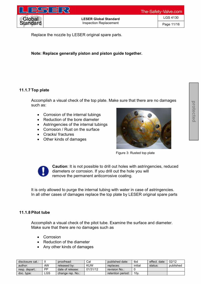
LESER Global Standard Inspection Replacement
LGS 4130
Page 11/16
disclosure cat.: II proofread: Cal published date: tbd effect. date: 02/12 author: AW released by: KUW replaces: initial status: published resp. depart.: PP date of release: 01/31/12 revision No.: 0 doc. type: LGS change rep. No.: retention period: 10y.
pro
tected
Replace the nozzle by LESER original spare parts.
Note: Replace generally piston and piston guide together.
11.1.7 Top plate
Accomplish a visual check of the top plate. Make sure that there are no damages such as:
Corrosion of the internal tubings Reduction of the bore diameter Astringencies of the internal tubings Corrosion / Rust on the surface Cracks/ fractures Other kinds of damages
Figure 3: Rusted top plate
Caution: It is not possible to drill out holes with astringencies, reduced diameters or corrosion. If you drill out the hole you will . remove the permanent anticorrosive coating.
It is only allowed to purge the internal tubing with water in case of astringencies. In all other cases of damages replace the top plate by LESER original spare parts
11.1.8 Pitot tube
Accomplish a visual check of the pitot tube. Examine the surface and diameter. Make sure that there are no damages such as
Corrosion Reduction of the diameter Any other kinds of damages

LESER Global Standard Inspection Replacement
LGS 4130
Page 12/16
disclosure cat.: II proofread: Cal published date: tbd effect. date: 02/12 author: AW released by: KUW replaces: initial status: published resp. depart.: PP date of release: 01/31/12 revision No.: 0 doc. type: LGS change rep. No.: retention period: 10y.
pro
tected
Replace the soft sealing acc. LID In case of damages replace the pitot tube or any of its components through LESER original spare parts
11.1.9 Dome spring
Accomplish a visual check of the spring. Make sure that there are no damages such as
Corrosion / Rust Fractures Permanent compressions Other kind of damages
Measure the length of the spring after the disassembly procedure. Check whether the spring has still the original length or suffered any permanent compressions. In case of damages replace the spring by a spring of LESER original spare parts.
11.2 Pilot Valve
11.2.1 General inspections
Examine all sundries like
Screws / threads Washers Spring plates
referring damages like
Corrosion Worn out areas Grooves Cracks/fractures Other kinds of damages
In case of these damages replace the sundries by LESER original spare parts.
Check the space of the bonnet whether there are any remaining fluids. - Occurring fluids may indicate a leaking pilot valve. Furthermore check the free movement of every movable part.
- Sluggishness of the parts may indicate any damages of the components.
LESER Global Standard Inspection Replacement
LGS 4130
Page 13/16
disclosure cat.: II proofread: Cal published date: tbd effect. date: 02/12 author: AW released by: KUW replaces: initial status: published resp. depart.: PP date of release: 01/31/12 revision No.: 0 doc. type: LGS change rep. No.: retention period: 10y.
pro
tected
Figure 4: Corroded manifold block
11.2.2 O-rings
All O-rings have to be replaced exceptionless during every maintenance interval. Replace the O-rings only with LESER original spare parts to ensure further on a correct operation of the POSV. Independently of replacing the O-rings examine the condition of every single ring to check the load during the last work-interval In case of highly loaded rings the maintenance intervals should be shortened This extends to back up rings and guide rings
11.2.3 Body, complete bonnet, cap
Make a visual check of the surface and threads. Make sure that there are no damages such as
Corrosion / rust Cracks Deformations Worn out areas Other kinds of damages
In case of damages replace the component by LESER original spare parts.
11.2.4 Piston Examine the piston and its components such as

LESER Global Standard Inspection Replacement
LGS 4130
Page 14/16
disclosure cat.: II proofread: Cal published date: tbd effect. date: 02/12 author: AW released by: KUW replaces: initial status: published resp. depart.: PP date of release: 01/31/12 revision No.: 0 doc. type: LGS change rep. No.: retention period: 10y.
pro
tected
Running surfaces Contact areas
referring damages like
Corrosion / rust Worn out areas Cracks Grooves Other kinds of damages
In case of such damages replace the components by LESER original spare parts
11.2.5 Diaphragm The Diaphragm has to be replaced exceptionless during every maintenance interval. Independently of replacing the diaphragm examine the condition of the diaphragm to check the load during the last work-interval In case of highly loaded diaphragms the maintenance intervals should be shortened.
11.2.6 Return spring
Examine the spring and make sure that there are no damages like
Corrosion Fractures Permanent compressions Other kinds of damages
In case of damages replace the spring by LESER original spare parts.
11.3 Accessories
LESER Global Standard Inspection Replacement
LGS 4130
Page 15/16
disclosure cat.: II proofread: Cal published date: tbd effect. date: 02/12 author: AW released by: KUW replaces: initial status: published resp. depart.: PP date of release: 01/31/12 revision No.: 0 doc. type: LGS change rep. No.: retention period: 10y.
pro
tected
11.3.1 Field test connector
Accomplish a visual check. In particular examine the inside and running surfaces regarding any damages like
Corrosion Grooves in the running surfaces Reduced diameters Other kinds of damages
In case of damages replace all concerned components by LESER original spare parts.
11.3.2 Pilot supply filter
Accomplish a visual check of the filter. Examine the cartridge filter referring
Pollution Corrosion Astringencies Other kinds of pollutions / damages
In case of damages replace the concerned parts by LESER original spare parts In case of pollution clean the components
11.3.3 Manual blowdown Check the ball valve referring the
Free movement of the lever Damages of the inner ball Corrosion Any other damages
Check the tubework referring the
Corrosion Reduced diameters
In case of damages replace the ball valve, fittings or tubes by LESER original spare parts.
LESER Global Standard Inspection Replacement
LGS 4130
Page 16/16
disclosure cat.: II proofread: Cal published date: tbd effect. date: 02/12 author: AW released by: KUW replaces: initial status: published resp. depart.: PP date of release: 01/31/12 revision No.: 0 doc. type: LGS change rep. No.: retention period: 10y.
pro
tected
11.3.4 Remote sensing Accomplish a visual check of the tubes and fittings. Make sure that there are no damages like
Astringencies of the tubes Corrosion / rust Other kinds of damages
In case of damages replace the concerned components by LESER original spare parts.

LESER Deutschland Standard Refinishing of seats and discs
LDeS 3309.05
Page 1/23
disclosure cat.: I proofread: Bi published date: 06/17/16 effect. date: 10/15 author: Haa released by: JR replaces: 309-05 status: Draft resp. depart.: TD date of release: 05/29/16 revision No.: 4 doc. type: LLS change rep. No.: NA retention period: 10y.
protected
Content 1 Purpose ........................................................................................................... 1 2 Scope .............................................................................................................. 1 3 References ...................................................................................................... 1 4 Conditional Agreement .................................................................................... 2 5 Introduction ...................................................................................................... 2 6 Execution ......................................................................................................... 2 7 Refinishing of seat and disc for types 441 and 421, metal sealing .................. 4 8 Refinishing of seat and disc for types 431 and 411, metal sealing .................. 6 9 Refinishing of seat and disc types 441 and 431, O-ring seals ......................... 7 10 Refinishing of seat and disc for type 455 and 456, metal sealing .................... 8 11 Refinishing of seat and disc types 455 and 456, O-Ring seals ........................ 9 12 Refinishing of seat and disc for full nozzle types 457 and 458, metal sealing . 10 13 Seat geometry for flat sealing O-ring disc design (for valves delivered before 2002) 12 14 Refinishing of seat and disc type 526, metal sealing ....................................... 13 15 Refinishing of seat and disc type 437, metal sealing or sealing plate .............. 15 16 Refinishing of seat and disc type 438, O-Ring seals ........................................ 18 17 Refinishing of seat and disc type 439, Vulcanized soft seat ............................ 19 18 Refinishing of seat and disc type 459, metal sealing, sealing plate ................. 20 19 Refinishing of seat and disc type 462, O-Ring disc.......................................... 21 20 Refinishing of seat and disc of POSV type 811/821 ........................................ 22
1 Purpose
This LDeS gives information about the dimensions and the surface quality which have to be observed during the refinishing work, it also provides the work instructions. This LDeS replaces dimensional drawing no. 395 19 09.
2 Scope
This LDeS applies to the LESER sites Hamburg and Hohenwestedt. This LDeS is valid for: - semi nozzles - discs without lifting gear - discs with removable lifting gear for screwed nozzles
3 References
None

LESER Deutschland Standard Refinishing of seats and discs
LDeS 3309.05
Page 2/23
disclosure cat.: I proofread: Bi published date: 06/17/16 effect. date: 10/15 author: Haa released by: JR replaces: 309-05 status: Draft resp. depart.: TD date of release: 05/29/16 revision No.: 4 doc. type: LLS change rep. No.: NA retention period: 10y.
protected
4 Conditional Agreement
The further mentioned rules for the refinishing of seats and discs have been issued and explained in all conscience and describe the particular final design of the components. LESER reserves the right to make necessary modifications at the components without determining these changes in this standard directly. So, if there are any doubts on user side when applying these rules, LESER has to be contacted before performance of rework to clarify the actual situation. When applying these rules and regulations it has to be considered generally that they describe the refinishing at components which have an effect on the function and capacity of the safety valves. Even marginal deviations to this guidelines can effect a malfunction or constricted capacity of the safety valve and therewith an inadmissible pressure increase can arise during application/operation. This could possibly have serious consequences for humans and environment. Therefore it has to be proceed carefully when applying these rules. LESER assumes no liability for safety devices which have been repaired or reworked in accordance with this LDeS. The repair shop is solely responsible for the function and capacity of the re-introduced safety device. The user of this LDeS should be clear on the fact that the repair of a safety device against inadmissible overpressure is subjected to European and international laws. The violation of valid rules will be traced and avenged acc. to relevant legislations. In case of any doubts during application of this LDeS, LESER has to be consulted before starting repair or rework of LESER safety devices.
5 Introduction
If the sealing surfaces of seat and disc have been damaged by frequent setting, for example, or by impurities in the medium, the original sealing quality can be restored by refinishing of the sealing surfaces. 6 Execution
The refinishing by smooth turning and grinding with final lapping should be done on the seat and if necessary also on the disc with the least possible swarf. Please see the limiting values in the following tables. 6.1 Measures and facing profile
Tables 5.1, 6.1, 8.1, 9.1, 10.1, 11.1, 12.1, 13.1, 14.1, 15.1, 16.1 and 17.1, together with the corresponding illustrations, contain the linear and square dimensions which have to be observed. After processing of the seat surface it is also important that the seat profile is restored moderately using inner and outer chamfers. If necessary the contact surface
LESER Deutschland Standard Refinishing of seats and discs
LDeS 3309.05
Page 3/23
disclosure cat.: I proofread: Bi published date: 06/17/16 effect. date: 10/15 author: Haa released by: JR replaces: 309-05 status: Draft resp. depart.: TD date of release: 05/29/16 revision No.: 4 doc. type: LLS change rep. No.: NA retention period: 10y.
protected
between the spindle guide and the body has to be refinished coplanar and concentric to the seat. 6.2 Surface quality
A surface quality to a mean roughness depth of Rz1 (Mirror Finish) must be achieved on both sealing surfaces through lapping. 6.3 Test
In a final test on the mounted valve, it has to be guaranteed that: - The semi rings on the spindle must be off the guide when the valve is closed. - The lower spring plate may not touch the guide when the spring is assembled. - In lift restricted valves, the lift restriction must be checked and if necessary the lift
restriction bushing extended.
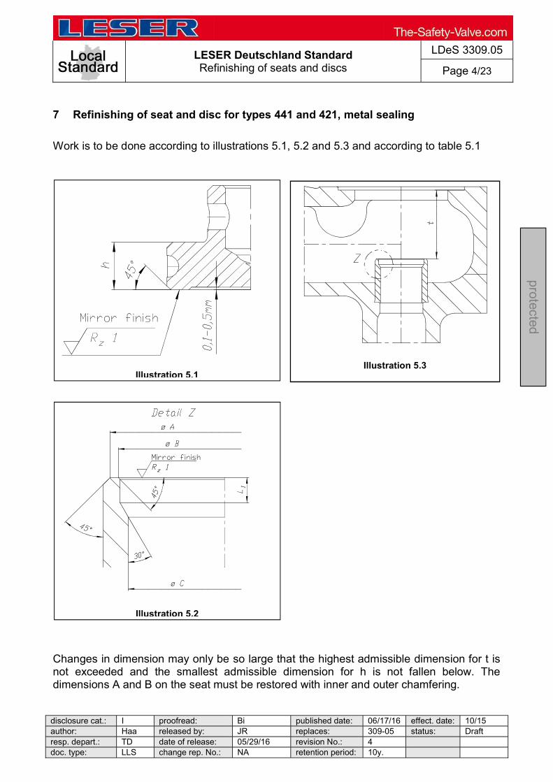
LESER Deutschland Standard Refinishing of seats and discs
LDeS 3309.05
Page 4/23
disclosure cat.: I proofread: Bi published date: 06/17/16 effect. date: 10/15 author: Haa released by: JR replaces: 309-05 status: Draft resp. depart.: TD date of release: 05/29/16 revision No.: 4 doc. type: LLS change rep. No.: NA retention period: 10y.
protected
7 Refinishing of seat and disc for types 441 and 421, metal sealing
Work is to be done according to illustrations 5.1, 5.2 and 5.3 and according to table 5.1
Changes in dimension may only be so large that the highest admissible dimension for t is not exceeded and the smallest admissible dimension for h is not fallen below. The dimensions A and B on the seat must be restored with inner and outer chamfering.
Illustration 5.1
Illustration 5.3
Illustration 5.2
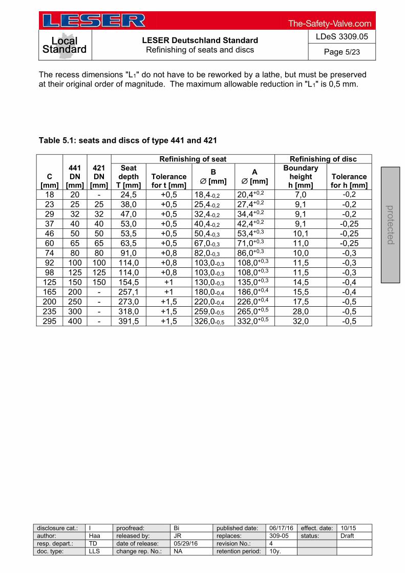
LESER Deutschland Standard Refinishing of seats and discs
LDeS 3309.05
Page 5/23
disclosure cat.: I proofread: Bi published date: 06/17/16 effect. date: 10/15 author: Haa released by: JR replaces: 309-05 status: Draft resp. depart.: TD date of release: 05/29/16 revision No.: 4 doc. type: LLS change rep. No.: NA retention period: 10y.
protected
The recess dimensions "L1" do not have to be reworked by a lathe, but must be preserved at their original order of magnitude. The maximum allowable reduction in "L1" is 0,5 mm. Table 5.1: seats and discs of type 441 and 421
C [mm]
441 DN
[mm]
421 DN
[mm]
Refinishing of seat Refinishing of disc Seat
depth T [mm]
Tolerance for t [mm]
B [mm]
A [mm]
Boundary height h [mm]
Tolerance for h [mm]
18 20 - 24,5 +0,5 18,4-0,2 20,4+0,2 7,0 -0,2 23 25 25 38,0 +0,5 25,4-0,2 27,4+0,2 9,1 -0,2 29 32 32 47,0 +0,5 32,4-0,2 34,4+0,2 9,1 -0,2 37 40 40 53,0 +0,5 40,4-0,2 42,4+0,2 9,1 -0,25 46 50 50 53,5 +0,5 50,4-0,3 53,4+0,3 10,1 -0,25 60 65 65 63,5 +0,5 67,0-0,3 71,0+0,3 11,0 -0,25 74 80 80 91,0 +0,8 82,0-0,3 86,0+0,3 10,0 -0,3 92 100 100 114,0 +0,8 103,0-0,3 108,0+0,3 11,5 -0,3 98 125 125 114,0 +0,8 103,0-0,3 108,0+0,3 11,5 -0,3
125 150 150 154,5 +1 130,0-0,3 135,0+0,3 14,5 -0,4 165 200 - 257,1 +1 180,0-0,4 186,0+0,4 15,5 -0,4 200 250 - 273,0 +1,5 220,0-0,4 226,0+0,4 17,5 -0,5 235 300 - 318,0 +1,5 259,0-0,5 265,0+0,5 28,0 -0,5 295 400 - 391,5 +1,5 326,0-0,5 332,0+0,5 32,0 -0,5
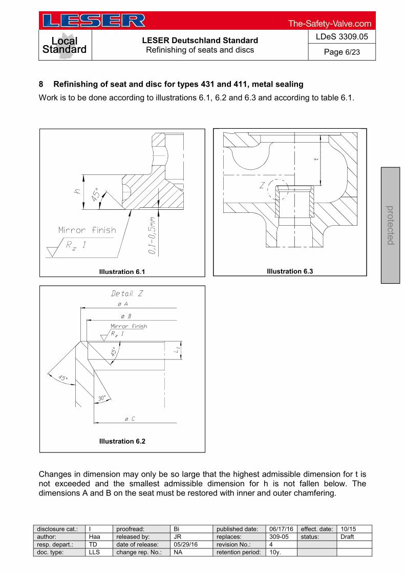
LESER Deutschland Standard Refinishing of seats and discs
LDeS 3309.05
Page 6/23
disclosure cat.: I proofread: Bi published date: 06/17/16 effect. date: 10/15 author: Haa released by: JR replaces: 309-05 status: Draft resp. depart.: TD date of release: 05/29/16 revision No.: 4 doc. type: LLS change rep. No.: NA retention period: 10y.
protected
8 Refinishing of seat and disc for types 431 and 411, metal sealing
Work is to be done according to illustrations 6.1, 6.2 and 6.3 and according to table 6.1.
Changes in dimension may only be so large that the highest admissible dimension for t is not exceeded and the smallest admissible dimension for h is not fallen below. The dimensions A and B on the seat must be restored with inner and outer chamfering.
Illustration 6.1
Illustration 6.3
Illustration 6.2

LESER Deutschland Standard Refinishing of seats and discs
LDeS 3309.05
Page 7/23
disclosure cat.: I proofread: Bi published date: 06/17/16 effect. date: 10/15 author: Haa released by: JR replaces: 309-05 status: Draft resp. depart.: TD date of release: 05/29/16 revision No.: 4 doc. type: LLS change rep. No.: NA retention period: 10y.
protected
The recess dimensions "L1" do not have to be reworked by a lathe, but must be preserved at their original order of magnitude. The maximum allowable reduction in "L1" is 0,5 mm. Table 6.1: seats and discs of type 431 and 411
C [mm]
431 DN
[mm]
411 DN
[mm]
Refinishing of seat Refinishing of disc Seat
depth t [mm]
Tolerance for t [mm]
B [mm]
A [mm]
Boundary height h [mm]
Tolerance for h [mm]
12 15 - 22,0 +0,3 13,7-0,2 15,3+0,2 20 -0,2 18 20-32 20-32 22,5 +0,5 18,4-0,2 20,4+0,2 7,0 -0,2 23 40 40 25,0 +0,5 25,4-0,2 27,4+0,2 9,1 -0,2 29 50 50 28,0 +0,5 32,4-0,2 34,4+0,2 9,1 -0,2 37 65 65 35,0 +0,5 40,0-0,2 42,4+0,2 9,1 -0,25 46 80 80 39,0 +0,5 50,4-0,3 53,4+0,3 10,1 -0,25 60 100 100 55,0 +0,5 67,0-0,3 71,0+0,3 11,0 -0,25 74 125 125 62,0 +0,8 82,0-0,3 86,0+0,3 10,0 -0,3 92 150 150 72,0 +0,8 103,0-0,3 108,0+0,3 11,5 -0,3 9 Refinishing of seat and disc types 441 and 431, O-ring seals
Work is to be done according to illustration 7.1 The outer chamfer of these seats is responsible for the sealing (see illustration 7.1), therefore the diameter of the seat must not be changed. In case of edge damage, the seat surface may be turned or ground by between 0,2 and 0,4 mm until the damage is removed. After that the edge should be carefully treated with smooth emery paper to restore an angle of 45°. Please make sure that the edge is free for burrs. The O-ring in the disc must be renewed.
Illustration 7.1

LESER Deutschland Standard Refinishing of seats and discs
LDeS 3309.05
Page 8/23
disclosure cat.: I proofread: Bi published date: 06/17/16 effect. date: 10/15 author: Haa released by: JR replaces: 309-05 status: Draft resp. depart.: TD date of release: 05/29/16 revision No.: 4 doc. type: LLS change rep. No.: NA retention period: 10y.
protected
10 Refinishing of seat and disc for type 455 and 456, metal sealing
Work is to be carried out according to the illustrations 8.1, 8.2 and 8.3 and according to table 8.1.
Changes in dimension may only be so large that the highest admissible dimension for t is not exceeded and the smallest admissible dimension for b is not fallen below. The dimensions A and B on the seat must be restored with inner and outer chamfering.
Illustration 8.1
Illustration 8.3
Illustration 8.2
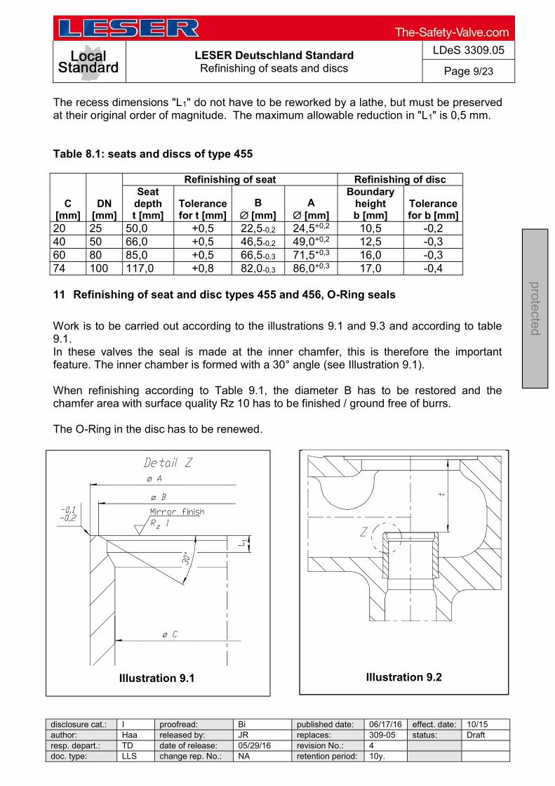
LESER Deutschland Standard Refinishing of seats and discs
LDeS 3309.05
Page 9/23
disclosure cat.: I proofread: Bi published date: 06/17/16 effect. date: 10/15 author: Haa released by: JR replaces: 309-05 status: Draft resp. depart.: TD date of release: 05/29/16 revision No.: 4 doc. type: LLS change rep. No.: NA retention period: 10y.
protected
The recess dimensions "L1" do not have to be reworked by a lathe, but must be preserved at their original order of magnitude. The maximum allowable reduction in "L1" is 0,5 mm. Table 8.1: seats and discs of type 455
C [mm]
DN [mm]
Refinishing of seat Refinishing of disc Seat
depth t [mm]
Tolerance for t [mm]
B [mm]
A [mm]
Boundary height b [mm]
Tolerance for b [mm]
20 25 50,0 +0,5 22,5-0,2 24,5+0,2 10,5 -0,2 40 50 66,0 +0,5 46,5-0,2 49,0+0,2 12,5 -0,3 60 80 85,0 +0,5 66,5-0,3 71,5+0,3 16,0 -0,3 74 100 117,0 +0,8 82,0-0,3 86,0+0,3 17,0 -0,4 11 Refinishing of seat and disc types 455 and 456, O-Ring seals
Work is to be carried out according to the illustrations 9.1 and 9.3 and according to table 9.1. In these valves the seal is made at the inner chamfer, this is therefore the important feature. The inner chamber is formed with a 30° angle (see Illustration 9.1). When refinishing according to Table 9.1, the diameter B has to be restored and the chamfer area with surface quality Rz 10 has to be finished / ground free of burrs. The O-Ring in the disc has to be renewed.
Illustration 9.1
Illustration 9.2

LESER Deutschland Standard Refinishing of seats and discs
LDeS 3309.05
Page 10/23
disclosure cat.: I proofread: Bi published date: 06/17/16 effect. date: 10/15 author: Haa released by: JR replaces: 309-05 status: Draft resp. depart.: TD date of release: 05/29/16 revision No.: 4 doc. type: LLS change rep. No.: NA retention period: 10y.
protected
Table 9.1: seats and discs of type 455 and 456
C [mm]
DN [mm]
Refinishing of seat Seat
depth t [mm]
Tolerance for t [mm]
B [mm]
A [mm]
20 25 50,0 +0,5 22,5-0,2 24,5+0,2
40 50 66,0 +0,5 46,5-0,2 49,0+0,2
60 80 85,0 +0,5 66,5-0,3 71,5+0,3
74 100 117,0 +0,8 82,0-0,3 86,0+0,3
12 Refinishing of seat and disc for full nozzle types 457 and 458, metal sealing
Work is to be carried out according to the illustrations 10.1, 10.2 and according to table 10.1.
Illustration 10.1

LESER Deutschland Standard Refinishing of seats and discs
LDeS 3309.05
Page 11/23
disclosure cat.: I proofread: Bi published date: 06/17/16 effect. date: 10/15 author: Haa released by: JR replaces: 309-05 status: Draft resp. depart.: TD date of release: 05/29/16 revision No.: 4 doc. type: LLS change rep. No.: NA retention period: 10y.
protected
Changes in dimension may only be such as not to reduce dimensions b and/or L below the lowest allowable tolerance (see table 10.1). The dimensions A and B on the seat must be restored with inner and outer chamfering. The recess dimensions "L1" do not have to be reworked by a lathe, but must be preserved at their original order of magnitude. "L1
table 10.1). Table 10.1: seats and discs full nozzle type 457/458
Valve DN
Seat Disc Diameter Length Angle
b [mm]
Tolerance b
[mm]
do
[mm]
D
[mm]
B
[mm]
A
[mm] L
[mm] L1
[mm] L2
[mm]
Tolerance
L; L1; L2 [mm]
W1 [°]
W2
[°]
W3
[°]
25 15 16 17 19
130 3 - - 0,2
30 30 30
10,5 -0,1 20 21 22,5 24,5 3 - - 0,2 60 30
50 30 32 36 39
162 3,5 12,5 - 0,3
30 60 45
12,5 -0,2 40 43 46 49 3 - - 0,3 -
80 50 52 55,4 59,4
180 3 4 - 0,3
30 60 45 17,0 -0,2
60 62 66,5 71,5 4 - - 0,3 60
100
50 52 55,4 59,4
215
3 4 - 0,3 30 60 45 17,0 -0,2 60 64 67,5 71,5 5 - - 0,3 30 60 45 17,0 -0,2 74 79 82 86 5 6 - 0,3 30 60 - 17,0 -0,2 88 93 99 103 6 - - 0,3 30 60 - 17,0 -0,2
150 110 116 120 124 277,5 5 - - 0,3 30 90 - 17,0 -0,3
Illustration 10.2
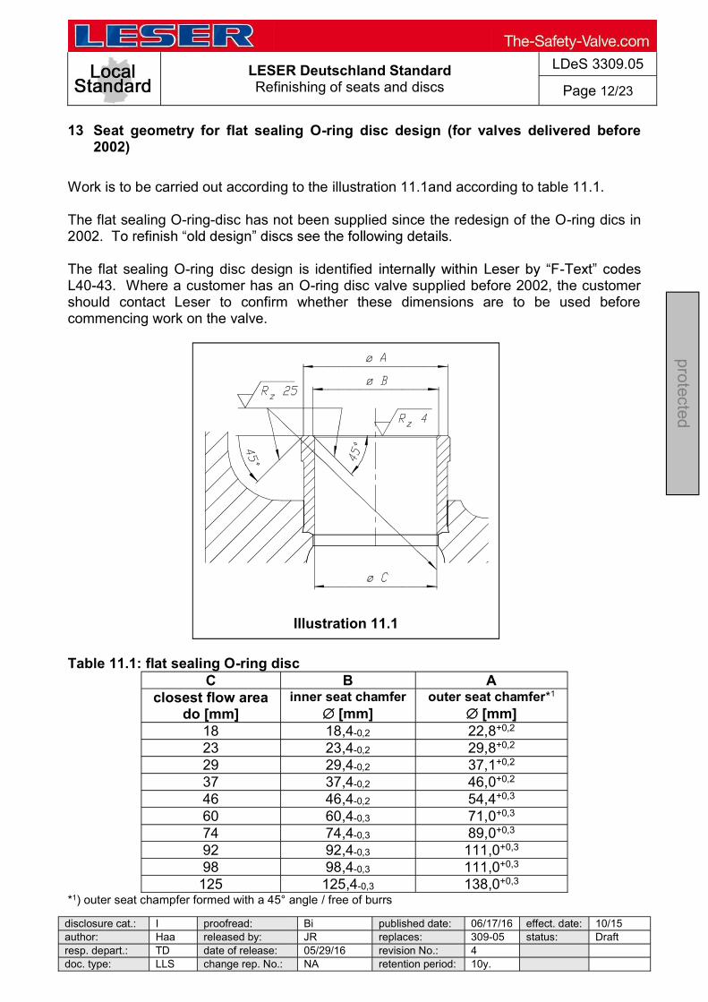
LESER Deutschland Standard Refinishing of seats and discs
LDeS 3309.05
Page 12/23
disclosure cat.: I proofread: Bi published date: 06/17/16 effect. date: 10/15 author: Haa released by: JR replaces: 309-05 status: Draft resp. depart.: TD date of release: 05/29/16 revision No.: 4 doc. type: LLS change rep. No.: NA retention period: 10y.
protected
13 Seat geometry for flat sealing O-ring disc design (for valves delivered before 2002)
Work is to be carried out according to the illustration 11.1and according to table 11.1. The flat sealing O-ring-disc has not been supplied since the redesign of the O-ring dics in
The flat sealing O-ring disc design is identified -L40-43. Where a customer has an O-ring disc valve supplied before 2002, the customer should contact Leser to confirm whether these dimensions are to be used before commencing work on the valve. Table 11.1: flat sealing O-ring disc
C B A closest flow area
do [mm] inner seat chamfer
[mm] outer seat chamfer*1
[mm] 18 18,4-0,2 22,8+0,2 23 23,4-0,2 29,8+0,2 29 29,4-0,2 37,1+0,2 37 37,4-0,2 46,0+0,2 46 46,4-0,2 54,4+0,3 60 60,4-0,3 71,0+0,3 74 74,4-0,3 89,0+0,3 92 92,4-0,3 111,0+0,3 98 98,4-0,3 111,0+0,3
125 125,4-0,3 138,0+0,3 *1) outer seat champfer formed with a 45° angle / free of burrs
Illustration 11.1

LESER Deutschland Standard Refinishing of seats and discs
LDeS 3309.05
Page 13/23
disclosure cat.: I proofread: Bi published date: 06/17/16 effect. date: 10/15 author: Haa released by: JR replaces: 309-05 status: Draft resp. depart.: TD date of release: 05/29/16 revision No.: 4 doc. type: LLS change rep. No.: NA retention period: 10y.
protected
14 Refinishing of seat and disc type 526, metal sealing
Work is to be carried out according to the illustrations 12.1, 12.2 and according to table 12.1.
Changes in dimension may only be such as not to reduce dimensions b and/or L below the lowest allowable tolerance (see table 12.1). The dimensions A and B on the seat must be restored with inner and outer chamfering. The recess dimensions "L1" do not have to be reworked by a lathe, but must be preserved at their original order of magnitude. "L1
table 12.1).
Illustration 12.1
Illustration 12.2

LESER Deutschland Standard Refinishing of seats and discs
LDeS 3309.05
Page 14/23
disclosure cat.: I proofread: Bi published date: 06/17/16 effect. date: 10/15 author: Haa released by: JR replaces: 309-05 status: Draft resp. depart.: TD date of release: 05/29/16 revision No.: 4 doc. type: LLS change rep. No.: NA retention period: 10y.
protected
Table 12.1: seats and discs type 526
Ori
fic
e
Size
Pressure range
Inlet / Outlet [lbs]
Seat Disc
Diameter Length Angle
b [mm]
To
lera
nce
[m
m]
A [mm]
B [mm]
D [mm]
L [mm]
L1
[mm] L2
[mm]
To
lera
nc
e
L;
L1;
L2
[m
m]
W1 [°]
W2 [°]
W3 [°]
E 1"x2" 300 x 150 19,6+0,2 18,0-0,2 17,4 87,3 10,0 - - 0,2 45,0 60,0 45,0 10,5 -0,1
1 ½"x2" 1500 x 300 18,7+0,2 16,6-0,2 16,1 87,3 5,0 3,0 - 0,2 45,0 60,0 60,0 10,5 -0,1
1 ½"x3" 2500 x 300 18,6+0,2 16,6-0,2 16,1 122,2 5,0 3,0 - 0,2 45,0 60,0 60,0 10,5 -0,1 F 1 ½"x2" 900 x 300 22,5+0,2 20,5-0,2 19,5 106,3 5,0 3,0 - 0,2 45,0 60,0 60,0 10,5 -0,2
1 ½"x3" 2500 x 300 20,5+0,2 19,1-0,2 19,5 122,6 5,0 3,0 - 0,2 45,0 60,0 60,0 10,5 -0,2 G 1½"x3" 900 x 300 27,5+0,2 25,0-0,2 23,5 106,3 5,0 3,0 - 0,2 45,0 60,0 60,0 10,5 -0,2
2"x3" 1500 x 300 27,5+0,2 25,0-0,2 23,5 128,1 5,0 3,0 - 0,2 45,0 60,0 60,0 10,5 -0,2 H 1½"x3" 150 x 150 36,0+0,2 33,0-0,2 30,5 106,3 5,0 3,0 - 0,2 45,0 60,0 45,0 10,5 -0,2
2"x3" 600 x 150 35,2+0,2 33,0-0,2 29,4 102,2 5,0 3,0 - 0,2 30,0 60,0 30,0 10,5 -0,2
2"x3" 1500 x 300 35,2+0,2 33,0-0,2 29,4 126,5 5,0 3,0 - 0,2 30,0 60,0 30,0 10,5 -0,2 J 2"x3" 150 x 150 43,5+0,2 41,0-0,2 39,0 102,2 6,0 6,0 - 0,2 30,0 60,0 30,0 12,5 -0,2
3"x4" 900 x 300 43,5+0,2 41,0-0,2 37,0 156,5 6,0 6,0 - 0,3 30,0 60,0 30,0 12,5 -0,2 K 3"x4" 150 x 150 50,5+0,3 47,0-0,2 45,0 127,9 6,0 6,0 - 0,2 30,0 60,0 30,0 12,5 -0,2
3"x6" 600 x 150 50,5+0,3 47,0-0,2 45,0 156,5 6,0 6,0 - 0,3 30,0 60,0 30,0 12,5 -0,2
3"x6" 1500 x 300 50,5+0,3 47,0-0,2 45,0 169 6,0 7,0 - 0,3 30,0 60,0 45,0 12,5 -0,2 L 3"x4" 150 x 150 61,5+0,3 58,0-0,2 56,0 127,9 6,0 6,0 - 0,2 30,0 60,0 30,0 15,0 -0,2
4"x6" 600 x 150 61,5+0,3 58,0-0,2 56,0 149,9 6,0 6,0 - 0,2 30,0 60,0 30,0 15,0 -0,2
4"x6" 600 x 150 61,5+0,3 58,0-0,3 56,0 149,9 6,0 6,0 - 0,2 30,0 60,0 30,0 15,0 -0,2
4"x6" 1500 x 150 61,5+0,3 58,0-0,3 56,0 169 6,0 6,0 - 0,3 30,0 60,0 30,0 15,0 -0,2 M 4"x6" 600 x 150 68,0+0,3 64,5-0,3 61,5 149,9 5,0 6,0 - 0,3 30,0 60,0 30,0 15,0 -0,2
900 x 150 69,0+0,3 64,5-0,3 61,5 169 5,0 6,5 - 0,3 30,0 60,0 30,0 15,0 -0,2 N 900 x 150 74,0+0,3 70,0-0,3 67,0 169 4,0 6,0 - 0,3 30,0 60,0 30,0 15,0 -0,2 P 4"x6" 150 x 150 89,0+0,3 85,0-0,3 82,0 153,1 5,0 6,0 - 0,3 30,0 45,0 45,0 15,0 -0,2
4"x6" 900 x 150 89,0+0,3 85,0-0,3 82,0 197,5 5,0 6,0 - 0,3 30,0 45,0 45,0 15,0 -0,2 Q 6"x8" 300 x 150 114,5+0,3 111,0-0,3 108,5 209,5 6,0 6,0 - 0,3 45,0 45,0 45,0 17,0 -0,2 R 6"x8" 300 x 150 137,5+0,3 133,0-0,3 131,0 209,5 25,0 6,0 - 0,3 45,0 60,0 45,0 17,0 -0,2
6"x10" 600 x 150 137,5+0,3 133,0-0,3 131,0 189,3 25,0 6,0 - 0,3 45,0 60,0 45,0 17,0 -0,2 T 8"x10" 300 x 150 171,5+0,4 167,0-0,4 164,0 225,7 6,0 6,0 - 0,3 30,0 60,0 45,0 17,0 -0,3
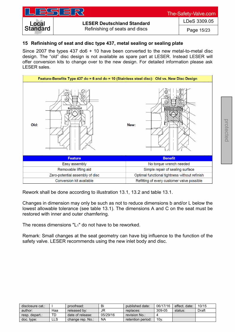
LESER Deutschland Standard Refinishing of seats and discs
LDeS 3309.05
Page 15/23
disclosure cat.: I proofread: Bi published date: 06/17/16 effect. date: 10/15 author: Haa released by: JR replaces: 309-05 status: Draft resp. depart.: TD date of release: 05/29/16 revision No.: 4 doc. type: LLS change rep. No.: NA retention period: 10y.
protected
15 Refinishing of seat and disc type 437, metal sealing or sealing plate
Since 2007 the types 437 do6 + 10 have been converted to the new metal-to-metal disc design. The old disc design is not available as spare part at LESER. Instead LESER will offer conversion kits to change over to the new design. For detailed information please ask LESER sales.
Rework shall be done according to illustration 13.1, 13.2 and table 13.1. Changes in dimension may only be such as not to reduce dimensions b and/or L below the lowest allowable tolerance (see table 13.1). The dimensions A and C on the seat must be restored with inner and outer chamfering. The recess dimensions "L1" do not have to be reworked. Remark: Small changes at the seat geometry can have big influence to the function of the safety valve. LESER recommends using the new inlet body and disc.

LESER Deutschland Standard Refinishing of seats and discs
LDeS 3309.05
Page 16/23
disclosure cat.: I proofread: Bi published date: 06/17/16 effect. date: 10/15 author: Haa released by: JR replaces: 309-05 status: Draft resp. depart.: TD date of release: 05/29/16 revision No.: 4 doc. type: LLS change rep. No.: NA retention period: 10y.
protected
Table 13.1: Seat and disc type 437
do
Seat Disc
Diameter Length Angle
A
[mm]
B
[mm]
C
[mm]
L
[mm]
L1
[mm]
L2
[mm]
max. Tolerance L; L1; L2
[mm]
W1
[°]
W2
[°]
W3
[°]
b
[mm]
max. Tolerance
b
[mm]
L2
[mm]
6 10,5-0,05 7,5+0,05 8,5+0,1 16,5 - 1,5 - 0,1 45 18 45 6,0 +/- 0,25 0,5
10 14,0-0,05 12,0+0,05 - 16,5 - 2,0 - 0,1 - 18 - 6,0 +/- 0,25 0,5 Since April 2014 the inlet body of type 437 do10 have been supplied with new seat geometry. The former inlet body is not available as spare part at LESER. The seat geometry of type 437 do6 has been still the same. The rework of type 437 do10 with new seat geometry shall be done according to illustration 13.1, 13.2 and table 13.2. Changes in dimension may only be such as not to reduce dimensions b and/or L below the lowest allowable tolerance (see table 13.2). The dimensions A and B on the seat must be restored with inner and outer chamfering. The recess dimensions "L1" do not have to be reworked.
Illustration 13.1
Illustration 13.2
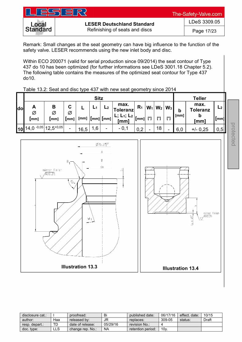
LESER Deutschland Standard Refinishing of seats and discs
LDeS 3309.05
Page 17/23
disclosure cat.: I proofread: Bi published date: 06/17/16 effect. date: 10/15 author: Haa released by: JR replaces: 309-05 status: Draft resp. depart.: TD date of release: 05/29/16 revision No.: 4 doc. type: LLS change rep. No.: NA retention period: 10y.
protected
Remark: Small changes at the seat geometry can have big influence to the function of the safety valve. LESER recommends using the new inlet body and disc. Within ECO 200071 (valid for serial production since 09/2014) the seat contour of Type 437 do 10 has been optimized (for further informations see LDeS 3001.18 Chapter 5.2). The following table contains the measures of the optimized seat contour for Type 437 do10. Table 13.2: Seat and disc type 437 with new seat geometry since 2014
do
Sitz Teller
A
[mm]
B
[mm]
C
[mm]
L
[mm]
L1
[mm]
L2
[mm]
max. Toleranz L; L1; L2
[mm]
R1
[mm]
W1
[°]
W2
[°]
W3
[°]
b [mm]
max. Toleranz
b [mm]
L2
[mm]
10 14,0 -0,05 12,5+0,05 - 16,5 1,6 - - 0,1 0,2 - 18 - 6,0 +/- 0,25 0,5
Illustration 13.3
Illustration 13.4
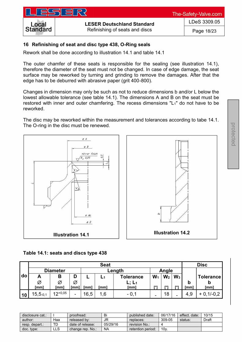
LESER Deutschland Standard Refinishing of seats and discs
LDeS 3309.05
Page 18/23
disclosure cat.: I proofread: Bi published date: 06/17/16 effect. date: 10/15 author: Haa released by: JR replaces: 309-05 status: Draft resp. depart.: TD date of release: 05/29/16 revision No.: 4 doc. type: LLS change rep. No.: NA retention period: 10y.
protected
16 Refinishing of seat and disc type 438, O-Ring seals
Rework shall be done according to illustration 14.1 and table 14.1 The outer chamfer of these seats is responsible for the sealing (see illustration 14.1), therefore the diameter of the seat must not be changed. In case of edge damage, the seat surface may be reworked by turning and grinding to remove the damages. After that the edge has to be deburred with abrasive paper (grit 400-800). Changes in dimension may only be such as not to reduce dimensions b and/or L below the lowest allowable tolerance (see table 14.1). The dimensions A and B on the seat must be restored with inner and outer chamfering. The recess dimensions "L1" do not have to be reworked. The disc may be reworked within the measurement and tolerances according to tabe 14.1. The O-ring in the disc must be renewed.
Table 14.1: seats and discs type 438
do
Seat Disc Diameter Length Angle
b [mm]
Tolerance b
[mm]
A
[mm]
B
[mm]
D
[mm]
L
[mm]
L1
[mm]
Tolerance L; L1 [mm]
W1
[°]
W2
[°]
W3
[°]
10 15,5-0,1 12+0,05 - 16,5 1,6 - 0,1 - 18 - 4,9 + 0,1/-0,2
Illustration 14.1
Illustration 14.2

LESER Deutschland Standard Refinishing of seats and discs
LDeS 3309.05
Page 19/23
disclosure cat.: I proofread: Bi published date: 06/17/16 effect. date: 10/15 author: Haa released by: JR replaces: 309-05 status: Draft resp. depart.: TD date of release: 05/29/16 revision No.: 4 doc. type: LLS change rep. No.: NA retention period: 10y.
protected
17 Refinishing of seat and disc type 439, Vulcanized soft seat
The rework shall be done according to illustration 15.1 and table 15.1. Changes in dimension may only be such as not to reduce dimensions b and/or L below the lowest allowable tolerance (see table 15.1). The dimensions A and B on the seat must be restored with inner and outer chamfering. The recess dimensions "L1" do not have to be reworked
Table 15.1: seats and discs type 439
do
Seat Diameter Length Angle
A
[mm]
B
[mm]
D
[mm]
L
[mm]
L1
[mm]
Tolerance L; L1 [mm]
W1
[°]
W2
[°]
W3
[°]
10 15,5-0,1 12+0,05 - 16,5 1,6 - 0,1 - 18 -
Illustration 15.1

LESER Deutschland Standard Refinishing of seats and discs
LDeS 3309.05
Page 20/23
disclosure cat.: I proofread: Bi published date: 06/17/16 effect. date: 10/15 author: Haa released by: JR replaces: 309-05 status: Draft resp. depart.: TD date of release: 05/29/16 revision No.: 4 doc. type: LLS change rep. No.: NA retention period: 10y.
protected
18 Refinishing of seat and disc type 459, metal sealing, sealing plate
Work is to be done according illustration 16.1, 16.2. Changes in dimension may only be such as not to reduce dimensions b and/or L below the lowest allowable tolerance (see table 16.1). The dimensions A and B on the seat must be restored with inner and outer chamfering. The recess dimensions "L1" do not have to be reworked by a lathe, but must be preserved at their original order of magnitude. "L1" can be minimized by about a maximum of table 16.1).
Table 16.1: seats and discs type 459
do
Seat Disc Diameter Length Angle
b
[mm]
Tolerance b
[mm]
A [mm]
B [mm]
L
[mm]
L1
[mm]
L2
[mm]
Tolerance L; L1; L2
[mm]
W1
[°]
W2
[°]
W3
[°]
6 10,5-0,05 8,5+0,1 29,0 2,5 0,9 - 0,1 - 18 45 8,0 + 0,1
9 12,9+0,1 11,5+0,05 29,0 2,0 1,1 - 0,1 - 18 45 8,0 + 0,1
13 18,1+0,1 16,5+0,05 29,0 2,0 1,5 - 0,1 - 30 45 8,0 + 0,1
17,5 23,8+0,1 22,0+0,05 29,0 2,0 1,5 - 0,1 - 30 45 7,9 + 0,1
Illustration 16.2
Illustration 16.1
b
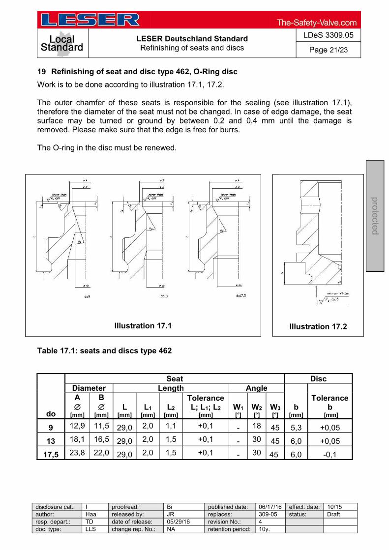
LESER Deutschland Standard Refinishing of seats and discs
LDeS 3309.05
Page 21/23
disclosure cat.: I proofread: Bi published date: 06/17/16 effect. date: 10/15 author: Haa released by: JR replaces: 309-05 status: Draft resp. depart.: TD date of release: 05/29/16 revision No.: 4 doc. type: LLS change rep. No.: NA retention period: 10y.
protected
19 Refinishing of seat and disc type 462, O-Ring disc
Work is to be done according to illustration 17.1, 17.2. The outer chamfer of these seats is responsible for the sealing (see illustration 17.1), therefore the diameter of the seat must not be changed. In case of edge damage, the seat surface may be turned or ground by between 0,2 and 0,4 mm until the damage is removed. Please make sure that the edge is free for burrs. The O-ring in the disc must be renewed.
Table 17.1: seats and discs type 462
do
Seat Disc Diameter Length Angle
b [mm]
Tolerance b
[mm]
A
[mm]
B
[mm] L
[mm] L1
[mm] L2
[mm]
Tolerance L; L1; L2
[mm] W1 [°]
W2 [°]
W3 [°]
9 12,9 11,5 29,0 2,0 1,1 +0,1 - 18 45 5,3 +0,05
13 18,1 16,5 29,0 2,0 1,5 +0,1 - 30 45 6,0 +0,05
17,5 23,8 22,0 29,0 2,0 1,5 +0,1 - 30 45 6,0 -0,1
Illustration 17.1
Illustration 17.2

LESER Deutschland Standard Refinishing of seats and discs
LDeS 3309.05
Page 22/23
disclosure cat.: I proofread: Bi published date: 06/17/16 effect. date: 10/15 author: Haa released by: JR replaces: 309-05 status: Draft resp. depart.: TD date of release: 05/29/16 revision No.: 4 doc. type: LLS change rep. No.: NA retention period: 10y.
protected
20 Refinishing of seat and disc of POSV type 811/821
Rework shall be done in accordance to illustration 18.1, 18.2 and table 18. Illustration 18.1: Steel disc Illustration 18.2: Seat (semi-nozzle)

LESER Deutschland Standard Refinishing of seats and discs
LDeS 3309.05
Page 23/23
disclosure cat.: I proofread: Bi published date: 06/17/16 effect. date: 10/15 author: Haa released by: JR replaces: 309-05 status: Draft resp. depart.: TD date of release: 05/29/16 revision No.: 4 doc. type: LLS change rep. No.: NA retention period: 10y.
protected
Rework shall be limited to the lowest allowable dimensions [Lmin] and hmin. The radii [R 0.5] and [R 0.3] and the shoulder [1.35+0.1] at the seat shall be reworked exactly to assure the tightness of the o-ring disc. The rework of the shoulder [1.5] and the angle W of the seat and the shoulder s of the steel disc is recommended.
NP
S x
NP
S
DN
x
DN
Ori
fic
e
Seat (semi-nozzle) Steel disc
A+0,1
[mm]
B-0,1
[mm]
CH11
[mm] [L]
[mm] [Lmin] [mm]
W [°]
h [mm]
hmin
[mm]
s [mm]
1x2 25x50 D 29,5 26,5 11 33,4 32,4 45 8,5 7,5 1
E 29,5 26,5 14,7 33,4 32,4 45 8,5 7,5 1
F 29,5 26,5 18,4 33,4 32,4 45 8,5 7,5 1
G 29,5 26,5 23 33,4 32,4 45 8,5 7,5 1 1,5x2 40x50 D 37,5 34,5 11 33,4 32,4 45 10,5 9,5 1
E 37,5 34,5 14,7 33,4 32,4 45 10,5 9,5 1
F 37,5 34,5 18,4 33,4 32,4 45 10,5 9,5 1
H 37,5 34,5 29 33,4 32,4 45 10,5 9,5 1 1,5x3 40x80 G 37,5 34,5 23,6 39,4 38,4 45 10,5 9,5 1
H 37,5 34,5 29,4 39,4 38,4 45 10,5 9,5 1
J 38 35,7 35,7 33,4 32,4 - 10,5 9,5 1 2x3 50x80 G 56,5 52,5 23,6 40,4 39,4 30 13,5 12,5 1
H 56,5 52,5 29,4 40,4 39,4 30 13,5 12,5 1
J 56,5 52,5 38 40,4 39,4 30 13,5 12,5 1
K+ 56,5 52,5 48 35,4 34,4 30 13,5 12,5 1 3x4 80x100 J 80,5 76 38 61,7 60,7 30 15,4 14,4 1
K 80,5 76 45 61,7 60,7 30 15,4 14,4 1
L 80,5 76 56 61,7 60,7 30 15,4 14,4 1
N+ 80,5 76 75 41,7 40,7 30 15,4 14,4 1 4x6 100x150 L 102,5 98 56 64,7 63,7 30 20 19 2
M 102,5 98 63 64,7 63,7 30 20 19 2
N 102,5 98 69 64,7 63,7 30 20 19 2
P 102,5 98 83 50,7 49,7 30 20 19 2
P+ 102,5 98 95 41,7 40,7 30 20 19 2 6x8 150x200 Q 150 145 110 56,7 55,7 30 30 29 2
R 150 145 133 56,7 55,7 30 30 29 2
R+ 150 145 142 46,7 45,7 30 30 29 2 8x10 200x250 T 188 182 168 68,2 67,2 30 30 29 2
T+ 188 182 180 58,2 57,2 30 30 29 2 Table 18: Seat and steel disc of type 811/821
LESER Global Standard Reworking repaired valves
LGS 4113
Page 1/3
disclosure cat.: II proofread: OR published date: 9/14/11 effect. date: 18.11.201author: Nieh released by: KUW replaces: initial status: published resp. depart.: PP date of release: 11/8/11 revision No.: 0 doc. type: LGS change rep. No.: 651A retention period: 10
pro
tected
Contents
1 Purpose ............................................................................................................... 1 2 Scope .................................................................................................................. 1 3 References .......................................................................................................... 1 4 Disclaimer ............................................................................................................ 1 5 Qualified fitting personnel .................................................................................... 2 6 General Information ............................................................................................. 2 7 Reworking the of the working surfaces ................................................................ 2 8 Re-lapping ........................................................................................................... 2
8.1 Re-lapping seat and disc sealing surfaces ................................................... 2 1 Purpose
This LESER Global Standard (LGS) provides instruction on reworking LESER safety valves. The required work steps and materials are described.
2 Scope
This document must be applied when reworking safety valves in agencies and subsidiaries of LESER GmbH & Co. KG. 3 References
LWN 313.32 to 313.40
4 Disclaimer
LESER puts in a great deal of effort into making up-to-date and correct documentation available. Nevertheless, LESER GmbH & Co. KG gives no guarantee that the recommended actions presented here are entirely correct and error free. This document is to be applied exclusively to the specified type. LESER GmbH & Co. KG declines any liability or responsibility for the correctness and completeness of the content. LESER GmbH & Co. KG reserves the right to change the information contained in this document, which is for the products of LESER GmbH & Co. KG and is intended for LESER subsidiaries, at any time and without prior announcement. LESER GmbH & Co. KG is available to the users of this document to provide additional information.
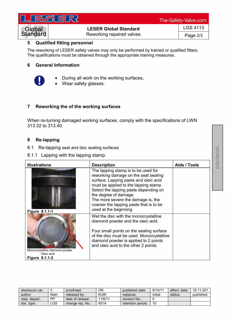
LESER Global Standard Reworking repaired valves
LGS 4113
Page 2/3
disclosure cat.: II proofread: OR published date: 9/14/11 effect. date: 18.11.201author: Nieh released by: KUW replaces: initial status: published resp. depart.: PP date of release: 11/8/11 revision No.: 0 doc. type: LGS change rep. No.: 651A retention period: 10
pro
tected
5 Qualified fitting personnel
The reworking of LESER safety valves may only be performed by trained or qualified fitters. The qualifications must be obtained through the appropriate training measures.
6 General Information
During all work on the working surfaces, Wear safety glasses.
7 Reworking the of the working surfaces
When re-turning damaged working surfaces, comply with the specifications of LWN 313.32 to 313.40. 8 Re-lapping
8.1 Re-lapping seat and disc sealing surfaces
8.1.1 Lapping with the lapping stamp.
Illustrations Description Aids / Tools
Figure 8.1.1-1
The lapping stamp is to be used for reworking damage on the seat sealing surface. Lapping paste and oleic acid must be applied to the lapping stamp. Select the lapping paste depending on the degree of damage. The more severe the damage is, the coarser the lapping paste that is to be used at the beginning
Monocrystalline diamond powder
Oleic acidFigure 8.1.1-2
Wet the disc with the monocrystalline diamond powder and the oleic acid. Four small points on the sealing surface of the disc must be used. Monocrystalline diamond powder is applied to 2 points and oleic acid to the other 2 points.
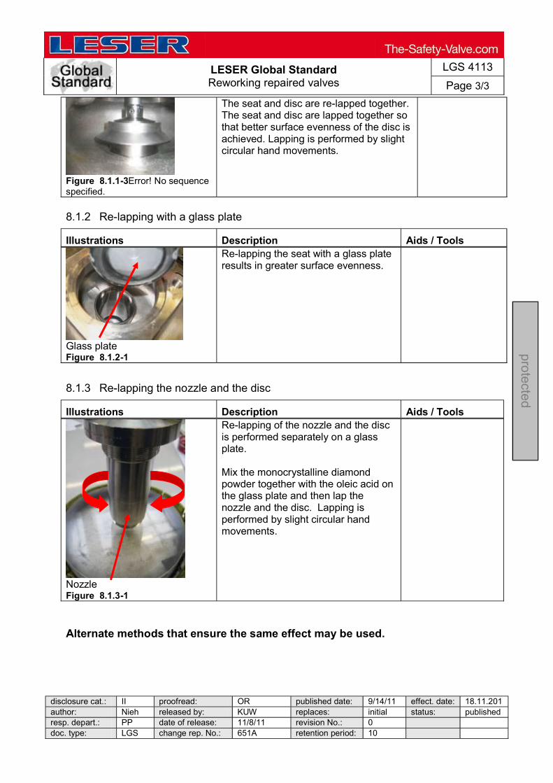
LESER Global Standard Reworking repaired valves
LGS 4113
Page 3/3
disclosure cat.: II proofread: OR published date: 9/14/11 effect. date: 18.11.201author: Nieh released by: KUW replaces: initial status: published resp. depart.: PP date of release: 11/8/11 revision No.: 0 doc. type: LGS change rep. No.: 651A retention period: 10
pro
tected
Figure 8.1.1-3Error! No sequence specified.
The seat and disc are re-lapped together. The seat and disc are lapped together so that better surface evenness of the disc is achieved. Lapping is performed by slight circular hand movements.
8.1.2 Re-lapping with a glass plate
Illustrations Description Aids / Tools
Glass plate Figure 8.1.2-1
Re-lapping the seat with a glass plate results in greater surface evenness.
8.1.3 Re-lapping the nozzle and the disc
Illustrations Description Aids / Tools
Nozzle Figure 8.1.3-1
Re-lapping of the nozzle and the disc is performed separately on a glass plate. Mix the monocrystalline diamond powder together with the oleic acid on the glass plate and then lap the nozzle and the disc. Lapping is performed by slight circular hand movements.
Alternate methods that ensure the same effect may be used.

LESER Global Standard
Assembly Main Valve
LGS 4131
Page 1/16
disclosure cat.: II proofread: Cal published date: tbd effect. date: 02/12 author: AW released by: KUW replaces: initial status: published resp. depart.: PP date of release: 01/31/12 revision No.: 0 doc. type: LGS change rep. No.: retention period: 10y.
pro
tected
Content 1 General information for assembling of main valve .................................... 2 2 Purpose ......................................................................................................... 2 3 Competences ................................................................................................ 2 4 Scope ............................................................................................................. 2 5 Disclaimer ...................................................................................................... 2 6 Qualified fitting personnel ............................................................................ 2 7 Remarks ......................................................................................................... 2 8 Basic safety guidelines ................................................................................ 3 9 Assembly instructions.................................................................................. 6
LESER Global Standard
Assembly Main Valve
LGS 4131
Page 2/16
disclosure cat.: II proofread: Cal published date: tbd effect. date: 02/12 author: AW released by: KUW replaces: initial status: published resp. depart.: PP date of release: 01/31/12 revision No.: 0 doc. type: LGS change rep. No.: retention period: 10y.
pro
tected
1 General information for assembling of main valve
2 Purpose
The documentation describes the assembly of the main valve series 810/820. The description contains every single working step, aids, tools and appliances.
3 Competences
The generation, maintenance and distribution of the documentation takes place in the organisation department. The defaults will be generated by the technical department in consultation with the final assembly department and production planning department.
4 Scope
This document must be applied to the dismantling of a Pilot Operated Safety Valve in agencies and subsidiaries of LESER GmbH & Co. KG, customers, independent service center.
5 Disclaimer
LESER puts in a great deal of effort into making up-to-date and correct documentation available. Nevertheless, LESER GmbH & Co. KG gives no guarantee that the recommended actions presented here are entirely correct and error free. This document is to be applied exclusively to the specified type. LESER GmbH & Co. KG declines any liability or responsibility for the correctness and completeness of the content. LESER GmbH & Co. KG reserves the right to change the information contained in this document, which is for the products of LESER GmbH & Co. KG and is intended for LESER subsidiaries, at any time and without prior announcement. LESER GmbH & Co. KG is available to the users of this document to provide additional information.
6 Qualified fitting personnel
LESER safety valves may only be dismantled by trained or qualified fitters. The qualifications must be obtained through the appropriate training measures.
7 Remarks
Gloves must be worn during the entire assembly procedure
LESER Global Standard
Assembly Main Valve
LGS 4131
Page 3/16
disclosure cat.: II proofread: Cal published date: tbd effect. date: 02/12 author: AW released by: KUW replaces: initial status: published resp. depart.: PP date of release: 01/31/12 revision No.: 0 doc. type: LGS change rep. No.: retention period: 10y.
pro
tected
8 Basic safety guidelines
Dangerous media Poisoning, caustic burns, burns, injuries
devices
Foreign bodies in the safety valve Danger from failure of safety valve or leaks
of a safety valve. objects.
Bug screen is damaged or missing (B or option) Dirt, objects or insects get into the safety valve. Danger from malfunction of the safety valve.
Ambient temperature is too high Material expansion. Danger from malfunction of the safety valve. Ambient temperature is too low Icing, freezing vapours, reduced flow rate due to congealing media. Danger from functional disruption of the safety valve. Abrasive or corrosive media Moving parts jam or become stuck. Danger from functional disruption of the safety valve.
it opens. Media with high proportion of particles

LESER Global Standard
Assembly Main Valve
LGS 4131
Page 4/16
disclosure cat.: II proofread: Cal published date: tbd effect. date: 02/12 author: AW released by: KUW replaces: initial status: published resp. depart.: PP date of release: 01/31/12 revision No.: 0 doc. type: LGS change rep. No.: retention period: 10y.
pro
tected
(only B) Deposits and clogging. Danger from malfunction of the safety valve.
filter capacity.
Residual media in the safety valve Poisoning, caustic burns, burns, injuries
move residual media
WARNING Leaky safety valve Danger from leaking media due to damaged gaskets and sealing surfaces.
and blows especially during transport and installation.
leaks. Open bonnet or spindle guides Danger from leaking media
leaking media.
CAUTION Hot medium Burns or scalding.
equipment. Hot surfaces Burns.
Aggressive medium Caustic burns.

LESER Global Standard
Assembly Main Valve
LGS 4131
Page 5/16
disclosure cat.: II proofread: Cal published date: tbd effect. date: 02/12 author: AW released by: KUW replaces: initial status: published resp. depart.: PP date of release: 01/31/12 revision No.: 0 doc. type: LGS change rep. No.: retention period: 10y.
pro
tected
Open bonnet or spindle guides Pinching danger from moving parts.
Sharp edges and burrs Danger of injury.
High noise emission Hearing damage. Wear ear protection.

LESER Global Standard
Assembly Main Valve
LGS 4131
Page 6/16
disclosure cat.: II proofread: Cal published date: tbd effect. date: 02/12 author: AW released by: KUW replaces: initial status: published resp. depart.: PP date of release: 01/31/12 revision No.: 0 doc. type: LGS change rep. No.: retention period: 10y.
pro
tected
9 Assembly instructions
9.1 Assembly of the pitot tube
1. Steps Descriptions
1 Span body [1] with outlet on test bench 2 Insert pitot tube [2] in body [1] 3 Complete with tube [3] (depends on nominal size) 4 Cover O-ring [63] (O-ring is 9,19x2,62) with soapy water and pull on fitting [4]
Make sure that O-rings are twist free
5 Screw fitting [4] in body [1] 6 While tightening fitting [4], align pitot tube [2] in direction of inlet with pitot tube assembly tool
Make sure that inlet of pitot tube is aligned within
approx. ± 5° 2. Supplies
Soapy water Molycote D paste Lubricate components acc. to LID
3. Tools
Hook tool for O-rings Helpful: Pitot tube-assembly tool Open-end wrench acc. to LID Torque wrench (Tightening torques acc. to LID)
4. Appliance
Test bench
2
5
1
3 4
6
6
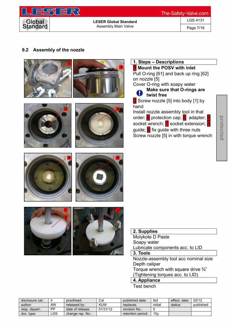
LESER Global Standard
Assembly Main Valve
LGS 4131
Page 7/16
disclosure cat.: II proofread: Cal published date: tbd effect. date: 02/12 author: AW released by: KUW replaces: initial status: published resp. depart.: PP date of release: 01/31/12 revision No.: 0 doc. type: LGS change rep. No.: retention period: 10y.
pro
tected
9.2 Assembly of the nozzle
1. Steps Descriptions
1 Mount the POSV with inlet Pull O-ring [61] and back up ring [62] on nozzle [5] Cover O-ring with soapy water
Make sure that O-rings are twist free
3 Screw nozzle [5] into body [1] by hand Install nozzle assembly tool in that order: 4 protection cap; 5 adapter; 6 socket wrench; 7 socket extension; 8 guide; 9 fix guide with three nuts Screw nozzle [5] in with torque wrench
2. Supplies
Molykote D Paste Soapy water Lubricate components acc. to LID
3. Tools
Nozzle-assembly tool acc nominal size Depth caliper
(Tightening torques acc. to LID) 4. Appliance Test bench
1 2
3 4
5 6
7 9
8
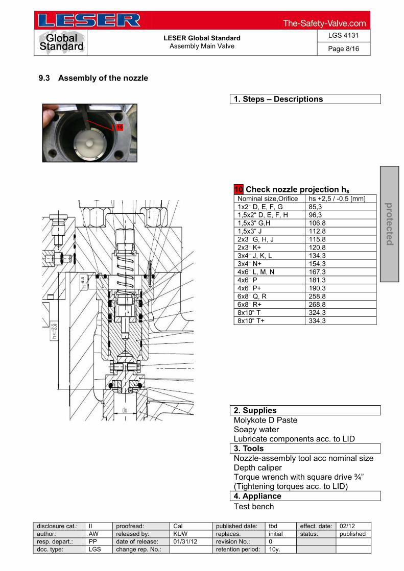
LESER Global Standard
Assembly Main Valve
LGS 4131
Page 8/16
disclosure cat.: II proofread: Cal published date: tbd effect. date: 02/12 author: AW released by: KUW replaces: initial status: published resp. depart.: PP date of release: 01/31/12 revision No.: 0 doc. type: LGS change rep. No.: retention period: 10y.
pro
tected
9.3 Assembly of the nozzle
1. Steps Descriptions
10 Check nozzle projection hs Nominal size,Orifice hs +2,5 / -0,5 [mm]
85,3 96,3
106,8 112,8
115,8 120,8
134,3 154,3
167,3 181,3
190,3 258,8
268,8 324,3
334,3
2. Supplies
Molykote D Paste Soapy water Lubricate components acc. to LID
3. Tools
Nozzle-assembly tool acc nominal size Depth caliper Torque wrench with square dri(Tightening torques acc. to LID)
4. Appliance Test bench
10
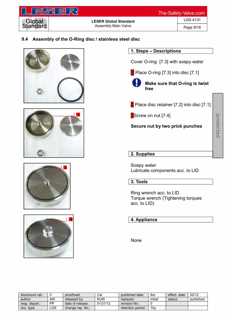
LESER Global Standard
Assembly Main Valve
LGS 4131
Page 9/16
disclosure cat.: II proofread: Cal published date: tbd effect. date: 02/12 author: AW released by: KUW replaces: initial status: published resp. depart.: PP date of release: 01/31/12 revision No.: 0 doc. type: LGS change rep. No.: retention period: 10y.
pro
tected
9.4 Assembly of the O-Ring disc / stainless steel disc
1. Steps Descriptions
Cover O-ring [7.3] with soapy water 1 Place O-ring [7.3] into disc [7.1]
Make sure that O-ring is twist free
2 Place disc retainer [7.2] into disc [7.1] 3Screw on nut [7.4] Secure nut by two prick punches
2. Supplies
Soapy water Lubricate components acc. to LID
3. Tools
Ring wrench acc. to LID Torque wrench (Tightening torques acc. to LID)
4. Appliance
None
1
2
3

LESER Global Standard
Assembly Main Valve
LGS 4131
Page 10/16
disclosure cat.: II proofread: Cal published date: tbd effect. date: 02/12 author: AW released by: KUW replaces: initial status: published resp. depart.: PP date of release: 01/31/12 revision No.: 0 doc. type: LGS change rep. No.: retention period: 10y.
pro
tected
9.5 Assembly of the piston and back up ring
1. Steps Descriptions
1 Put piston top [6.2] and piston body [6.1] with O-ring [6.3] and back up ring [6.4] together 2 Lubricate O-ring and guide rings [6.5] with Halocarbon 56 S acc. to LID 3 Screw piston top [6.2] and piston body [6.1] together with allen head screws [6.6]
2. Supplies
Halocarbon 56 S Lubricate components acc. to LID
3. Tools
Torque wrench with allen key acc. to LID Torque wrench (Tightening torques acc. to LID)
4. Appliance
Parallel vice with aluminium jaws
1
2
3
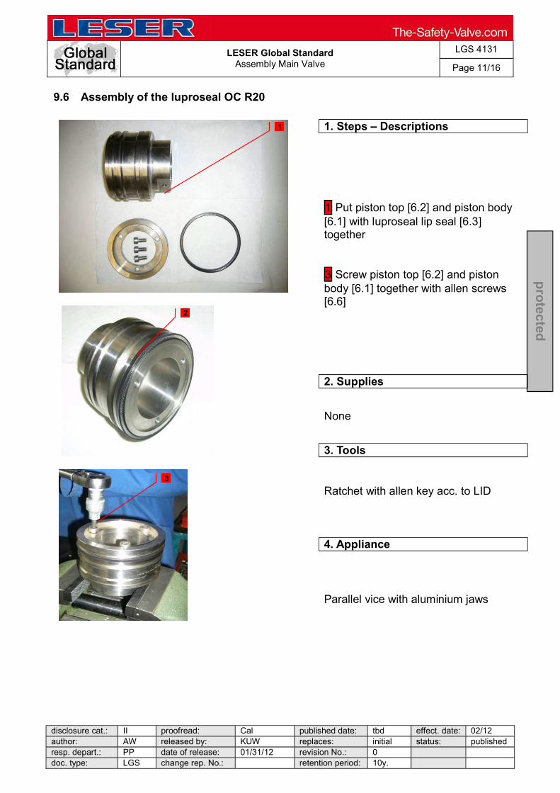
LESER Global Standard
Assembly Main Valve
LGS 4131
Page 11/16
disclosure cat.: II proofread: Cal published date: tbd effect. date: 02/12 author: AW released by: KUW replaces: initial status: published resp. depart.: PP date of release: 01/31/12 revision No.: 0 doc. type: LGS change rep. No.: retention period: 10y.
pro
tected
9.6 Assembly of the luproseal OC R20
1. Steps Descriptions
1 Put piston top [6.2] and piston body [6.1] with luproseal lip seal [6.3] together 3 Screw piston top [6.2] and piston body [6.1] together with allen screws [6.6]
2. Supplies
None
3. Tools
Ratchet with allen key acc. to LID
4. Appliance
Parallel vice with aluminium jaws
1
2
3

LESER Global Standard
Assembly Main Valve
LGS 4131
Page 12/16
disclosure cat.: II proofread: Cal published date: tbd effect. date: 02/12 author: AW released by: KUW replaces: initial status: published resp. depart.: PP date of release: 01/31/12 revision No.: 0 doc. type: LGS change rep. No.: retention period: 10y.
pro
tected
9.7 Assembly of the piston and disc
1. Steps Descriptions
1 Screw piston compl. [6] and disc [7] unit - out of step 9.6 and 9.5 - together with hexagon screw [58]
2. Supplies
None
3. Tools
Socket wrench acc. to LID Torque wrench (Tightening torques acc. to LID)
4. Appliance
None
1
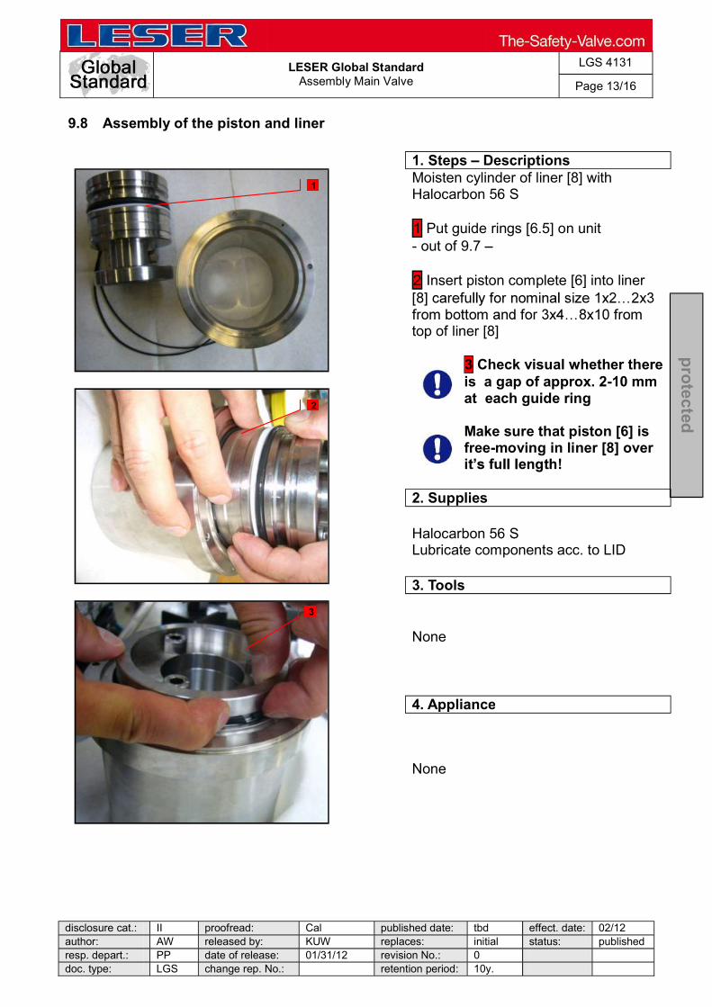
LESER Global Standard
Assembly Main Valve
LGS 4131
Page 13/16
disclosure cat.: II proofread: Cal published date: tbd effect. date: 02/12 author: AW released by: KUW replaces: initial status: published resp. depart.: PP date of release: 01/31/12 revision No.: 0 doc. type: LGS change rep. No.: retention period: 10y.
pro
tected
9.8 Assembly of the piston and liner
1. Steps Descriptions
Moisten cylinder of liner [8] with Halocarbon 56 S 1 Put guide rings [6.5] on unit - out of 9.7 2 Insert piston complete [6] into liner
top of liner [8]
3 Check visual whether there is a gap of approx. 2-10 mm at each guide ring
Make sure that piston [6] is free-moving in liner [8] over
2. Supplies
Halocarbon 56 S Lubricate components acc. to LID
3. Tools
None
4. Appliance
None
1
3
2

LESER Global Standard
Assembly Main Valve
LGS 4131
Page 14/16
disclosure cat.: II proofread: Cal published date: tbd effect. date: 02/12 author: AW released by: KUW replaces: initial status: published resp. depart.: PP date of release: 01/31/12 revision No.: 0 doc. type: LGS change rep. No.: retention period: 10y.
pro
tected
9.9 Assembly of the piston with liner and body
1. Steps Descriptions
1 Place piston [6] and liner [8] into body [1] by using piston disassembly tool for nominal size above 3x4 Push piston [6] into lowest position.
2 Makesure that minimum lift h of the main valve is reached.
Inlet
x Size
Orifice [Designator]
Min. Lift [mm]
Min. Lift [inch]
1 x 2 D 4,0 0,157 1 x 2 E 4,0 0,157 1 x 2 F 4,0 0,157 1 x 2 G 8,0 0,315
1,5 x 2 D 6,0 0,236 1,5 x 2 E 6,0 0,236 1,5 x 2 F 6,0 0,236 1,5 x 2 G 10,0 0,394 1,5 x 3 G 10,0 0,394 1,5 x 3 H 10,0 0,394 1,5 x 3 J 16,0 0,630 2 x 3 G 15,0 0,591 2 x 3 H 15,0 0,591 2 x 3 J 15,0 0,591 2 x 3 K+ 20,0 0,787 3 x 4 J 20,0 0,787 3 x 4 K 20,0 0,787 3 x 4 L 20,0 0,787 3 x 4 N+ 40,0 1,575 4 x 6 L 20,0 0,787 4 x 6 M 20,0 0,787 4 x 6 N 20,0 0,787 4 x 6 P 34,0 1,339 4 x 6 P+ 43,0 1,693 6 x 8 Q 60,0 2,362 6 x 8 R 60,0 2,362 6 x 8 R+ 70,0 2,756
8 x 10 T 80,0 3,150 8 x 10 T+ 90,0 3,543
1
2
1
1
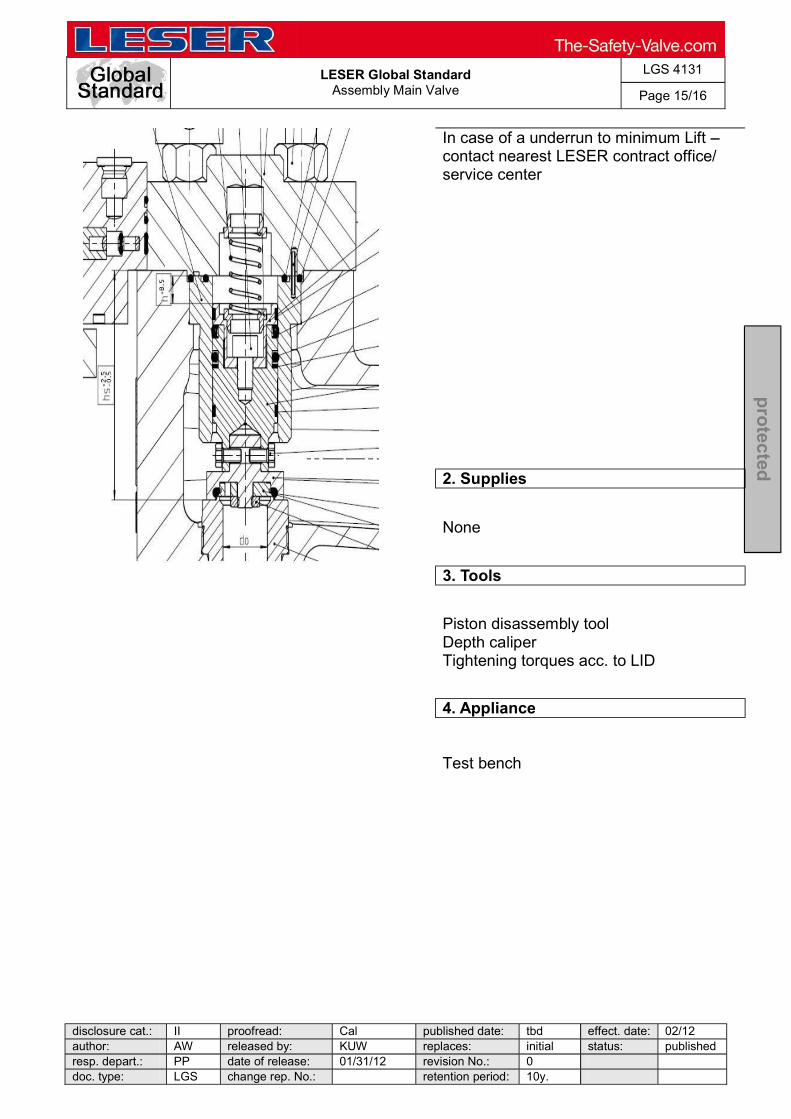
LESER Global Standard
Assembly Main Valve
LGS 4131
Page 15/16
disclosure cat.: II proofread: Cal published date: tbd effect. date: 02/12 author: AW released by: KUW replaces: initial status: published resp. depart.: PP date of release: 01/31/12 revision No.: 0 doc. type: LGS change rep. No.: retention period: 10y.
pro
tected
In case of a underrun to minimum Lift contact nearest LESER contract office/ service center
2. Supplies
None
3. Tools
Piston disassembly tool Depth caliper Tightening torques acc. to LID
4. Appliance
Test bench

LESER Global Standard
Assembly Main Valve
LGS 4131
Page 16/16
disclosure cat.: II proofread: Cal published date: tbd effect. date: 02/12 author: AW released by: KUW replaces: initial status: published resp. depart.: PP date of release: 01/31/12 revision No.: 0 doc. type: LGS change rep. No.: retention period: 10y.
pro
tected
9.10 Assembly of the top plate
1. Steps Descriptions
1 Stick rollpin [10] into hole of liner [8]
Make sure that roll pin is orientated to outlet.flange 2 Put O-rings [60, 67] into groove of liner [8] carefully Lubricate studs with Molycote D paste acc. to LID 3 Screw studs [55] into threaded holes of body [1] 4 Place dome spring [52] in dome
Make sure that O-rings [60,67] do not pop out of
open groove 5 Assembly top plate [9] on body [1] with nuts [56] 5 Screw ring nuts [57] on studs [55]
2. Supplies
Molycote D paste Lubricate components LID
3. Tools
Helpful: Impact wrench acc. to LID Ring wrench acc. to LID Torque wrench (Tightening torques acc. to LID)
4. Appliance
Test bench
1
2
3
5
4

LESER Global Standard
Assembly Pop Action Pilot Valve
LGS 4132
Page 1/15
disclosure cat.: II proofread: Cal published date: tbd effect. date: 02/12 author: AW released by: KUW replaces: initial status: published resp. depart.: PP date of release: 01/31/12 revision No.: 0 doc. type: LGS change rep. No.: retention period: 10y.
pro
tected
Content 1 General information for assembling of pop action pilot valve .................. 2 2 Purpose ......................................................................................................... 2 3 Competences ................................................................................................ 2 4 Scope ............................................................................................................. 2 5 Disclaimer ...................................................................................................... 2 6 Qualified fitting personnel ............................................................................ 2 7 Remarks ......................................................................................................... 2 8 Basic safety guidelines ................................................................................ 3 9 Assembly instructions.................................................................................. 6

LESER Global Standard
Assembly Pop Action Pilot Valve
LGS 4132
Page 2/15
disclosure cat.: II proofread: Cal published date: tbd effect. date: 02/12 author: AW released by: KUW replaces: initial status: published resp. depart.: PP date of release: 01/31/12 revision No.: 0 doc. type: LGS change rep. No.: retention period: 10y.
pro
tected
1 General information for assembling of pop action pilot valve
2 Purpose
The documentation describes the assembly of the pop action pilot valve. The description contains the assembly procedure, additional supplies, tools and appliances.
3 Competences
The generation, maintenance and distribution of the documentation take place in the organisation department. The defaults will be generated by the technical department in consultation with the final assembly department and production planning department.
4 Scope
This document must be applied to the assembly of a Pilot Operated Safety Valve in agencies and subsidiaries of LESER GmbH & Co. KG, customers and independent service center.
5 Disclaimer
LESER puts in a great deal of effort into making up-to-date and correct documentation available. Nevertheless, LESER GmbH & Co. KG gives no guarantee that the recommended actions presented here are entirely correct and error free. This document is to be applied exclusively to the specified type. LESER GmbH & Co. KG declines any liability or responsibility for the correctness and completeness of the content. LESER GmbH & Co. KG reserves the right to change the information contained in this document, which is for the products of LESER GmbH & Co. KG and is intended for LESER subsidiaries, at any time and without prior announcement. LESER GmbH & Co. KG is available to the users of this document to provide additional information.
6 Qualified fitting personnel
LESER safety valves may only be assembled by trained or qualified fitters. The qualifications must be obtained through the appropriate training measures.
7 Remarks Gloves must be worn during the entire assembly procedure

LESER Global Standard
Assembly Pop Action Pilot Valve
LGS 4132
Page 3/15
disclosure cat.: II proofread: Cal published date: tbd effect. date: 02/12 author: AW released by: KUW replaces: initial status: published resp. depart.: PP date of release: 01/31/12 revision No.: 0 doc. type: LGS change rep. No.: retention period: 10y.
pro
tected
8 Basic safety guidelines
Dangerous media Poisoning, caustic burns, burns, injuries
Use suitable protective devices
Foreign bodies in the safety valve Danger from failure of safety valve or leaks
of a safety valve. afety valve for foreign objects.
Bug screen is damaged or missing (B or option) Dirt, objects or insects get into the safety valve. Danger from malfunction of the safety valve.
screen regularly.
Ambient temperature is too high Material expansion. Danger from malfunction of the safety valve. Ambient temperature is too low Icing, freezing vapours, reduced flow rate due to congealing media. Danger from functional disruption of the safety valve. Abrasive or corrosive media Moving parts jam or become stuck. Danger from functional disruption of the safety valve.
it opens. Media with high proportion of particles (only B)

LESER Global Standard
Assembly Pop Action Pilot Valve
LGS 4132
Page 4/15
disclosure cat.: II proofread: Cal published date: tbd effect. date: 02/12 author: AW released by: KUW replaces: initial status: published resp. depart.: PP date of release: 01/31/12 revision No.: 0 doc. type: LGS change rep. No.: retention period: 10y.
pro
tected
Deposits and clogging. Danger from malfunction of the safety valve.
filter capacity. Residual media in the safety valve Poisoning, caustic burns, burns, injuries
otective equipment.
WARNING Leaky safety valve Danger from leaking media due to damaged gaskets and sealing surfaces.
and blows especially during transport and installation.
fety valve regularly for leaks. Open bonnet or spindle guides Danger from leaking media
leaking media.
CAUTION Hot medium Burns or scalding.
Wear suitable protective equipment. Hot surfaces Burns.
Aggressive medium Caustic burns.
Open bonnet or spindle guides

LESER Global Standard
Assembly Pop Action Pilot Valve
LGS 4132
Page 5/15
disclosure cat.: II proofread: Cal published date: tbd effect. date: 02/12 author: AW released by: KUW replaces: initial status: published resp. depart.: PP date of release: 01/31/12 revision No.: 0 doc. type: LGS change rep. No.: retention period: 10y.
pro
tected
Pinching danger from moving parts. feguards.
Sharp edges and burrs Danger of injury.
High noise emission Hearing damage. Wear ear protection.

LESER Global Standard
Assembly Pop Action Pilot Valve
LGS 4132
Page 6/15
disclosure cat.: II proofread: Cal published date: tbd effect. date: 02/12 author: AW released by: KUW replaces: initial status: published resp. depart.: PP date of release: 01/31/12 revision No.: 0 doc. type: LGS change rep. No.: retention period: 10y.
pro
tected
9 Assembly instructions
9.1 Assembly of the manifold block
1. Steps Descriptions
1 Screw in lock screw [24.7] with gasket [24.8] into manifold block [24.1] Tightening torque acc. to LID 2 Complete bushing [24.2] with O-ring [24.5] (O-ring is 10,82 x 1,78)
3 Complete piston [24.3] with O-ring [24.4] without soapy water (O-ring is 7,65 x 1,78)
4 Complete manifold block [24.1] with piston [ 24.3], bushing [24.2] and O- rings 2 x 7,65 x 1,78; 2 x 9,25 x 1,78; 1 x10,82 x 1,78;
Check the correct orientation of the piston using the diagram 5
Check the ease of movement of piston by rotating the manifold block
2. Supplies
Use soapy water for easy assembly of O-rings Lubricant acc. to LID
3.Tools
Allen key acc. to LID Hook tool for O-rings Torque wrench (Tightening torques acc. to LID)
4. Appliances
Parallel vice with aluminium jaws Test bench
1
2 3
4
5
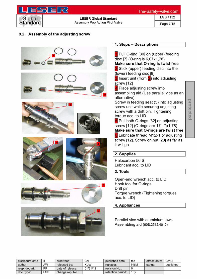
LESER Global Standard
Assembly Pop Action Pilot Valve
LGS 4132
Page 7/15
disclosure cat.: II proofread: Cal published date: tbd effect. date: 02/12 author: AW released by: KUW replaces: initial status: published resp. depart.: PP date of release: 01/31/12 revision No.: 0 doc. type: LGS change rep. No.: retention period: 10y.
pro
tected
9.2 Assembly of the adjusting screw
1. Steps Descriptions
1 Pull O-ring [30] on (upper) feeding disc [7] (O-ring is 6,07x1,78) Make sure that O-ring is twist free 2 Stick (upper) feeding disc into the (lower) feeding disc [8] 3 Insert unit (from 2) into adjusting screw [12] 4 Place adjusting screw into assembling aid (Use parallel vice as an alternative). Screw in feeding seat (5) into adjusting screw unit while securing adjusting screw with a drift pin. Tightening torque acc. to LID 5 Pull both O-rings [32] on adjusting screw [12] (O-rings are 17,17x1,78) Make sure that O-rings are twist free 6 Lubricate thread M12x1 of adjusting screw [12]. Screw on nut [20] as far as it will go
2. Supplies
Halocarbon 56 S Lubricant acc. to LID
3. Tools
Open-end wrench acc. to LID Hook tool for O-rings Drift pin Torque wrench (Tightening torques acc. to LID)
4. Appliances
Parallel vice with aluminium jaws Assembling aid (60S.2512.4012)
1
3
2
4 4
6
5
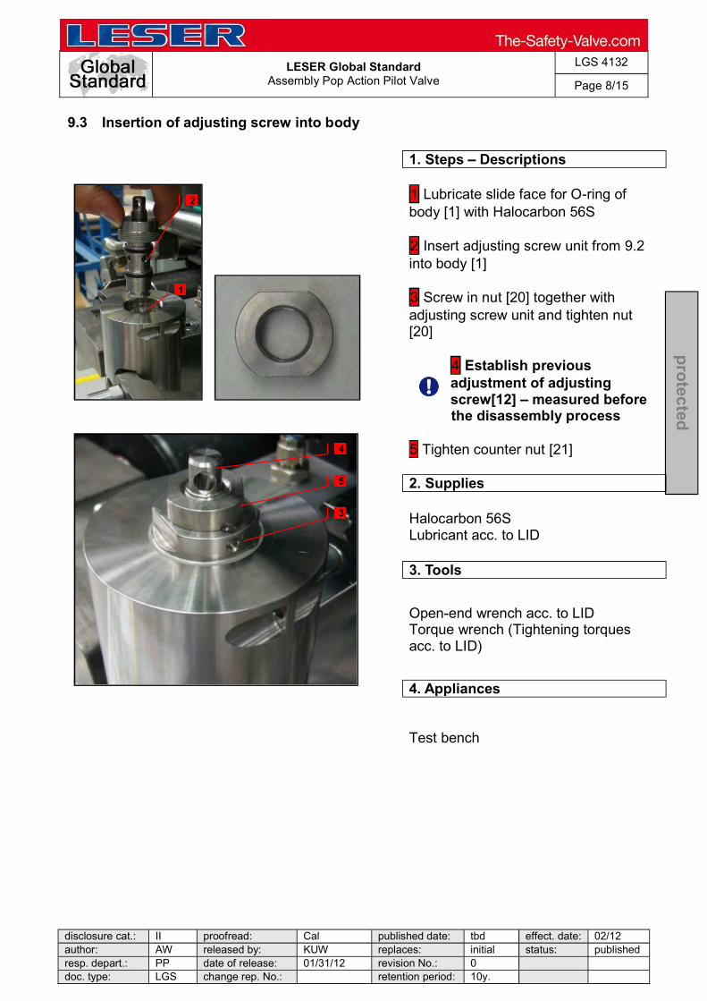
LESER Global Standard
Assembly Pop Action Pilot Valve
LGS 4132
Page 8/15
disclosure cat.: II proofread: Cal published date: tbd effect. date: 02/12 author: AW released by: KUW replaces: initial status: published resp. depart.: PP date of release: 01/31/12 revision No.: 0 doc. type: LGS change rep. No.: retention period: 10y.
pro
tected
9.3 Insertion of adjusting screw into body
1. Steps Descriptions
1 Lubricate slide face for O-ring of body [1] with Halocarbon 56S 2 Insert adjusting screw unit from 9.2 into body [1] 3 Screw in nut [20] together with adjusting screw unit and tighten nut [20]
4 Establish previous adjustment of adjusting screw[12] measured before the disassembly process
5 Tighten counter nut [21]
2. Supplies
Halocarbon 56S Lubricant acc. to LID
3. Tools
Open-end wrench acc. to LID Torque wrench (Tightening torques acc. to LID)
4. Appliances
Test bench
2
3
4
5
1

LESER Global Standard
Assembly Pop Action Pilot Valve
LGS 4132
Page 9/15
disclosure cat.: II proofread: Cal published date: tbd effect. date: 02/12 author: AW released by: KUW replaces: initial status: published resp. depart.: PP date of release: 01/31/12 revision No.: 0 doc. type: LGS change rep. No.: retention period: 10y.
pro
tected
9.4 Assembly of exhaust seat
1. Steps Descriptions
1 Place O-ring [31] into (upper) exhaust seat [13]. 2 Insert (lower) exhaust seat [14] into (upper) exhaust seat [13] (O-ring is 7,65x1,78)
3 Assembled exhaust seat
2. Supplies
None
3. Tools
None
4. Appliances
None
1
1
3
2

LESER Global Standard
Assembly Pop Action Pilot Valve
LGS 4132
Page 10/15
disclosure cat.: II proofread: Cal published date: tbd effect. date: 02/12 author: AW released by: KUW replaces: initial status: published resp. depart.: PP date of release: 01/31/12 revision No.: 0 doc. type: LGS change rep. No.: retention period: 10y.
pro
tected
9.5 Insertion of the outlet valve into the body
1. Steps Descriptions
1 Insert flat gasket [35] and unit from 9.4 into body [1] 2 Insert plunger [15] 3 Insert outlet disc [11] into guide bushing [2] and place both into body 4 Insert, screw in and tighten bonnet (base part) [10]
2. Supplies
Halocarbon 56S Lubricant acc. to LID
3. Tools
Open-end wrench acc. to LID Torque wrench (Tightening torques acc. to LID)
4. Appliances
Test bench
1
1 2
3
4 4
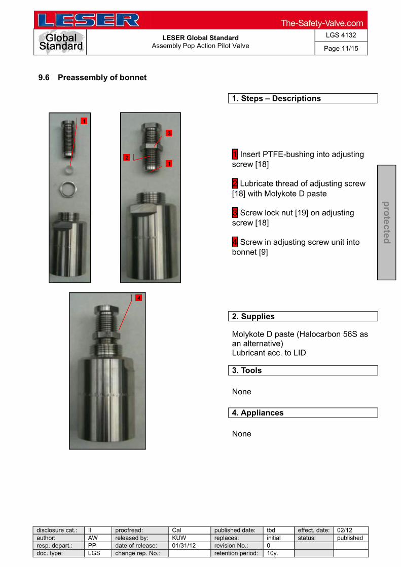
LESER Global Standard
Assembly Pop Action Pilot Valve
LGS 4132
Page 11/15
disclosure cat.: II proofread: Cal published date: tbd effect. date: 02/12 author: AW released by: KUW replaces: initial status: published resp. depart.: PP date of release: 01/31/12 revision No.: 0 doc. type: LGS change rep. No.: retention period: 10y.
pro
tected
9.6 Preassembly of bonnet
1. Steps Descriptions
1 Insert PTFE-bushing into adjusting screw [18] 2 Lubricate thread of adjusting screw [18] with Molykote D paste 3 Screw lock nut [19] on adjusting screw [18] 4 Screw in adjusting screw unit into bonnet [9]
2. Supplies
Molykote D paste (Halocarbon 56S as an alternative) Lubricant acc. to LID
3. Tools
None
4. Appliances
None
1
1
2
4
3

LESER Global Standard
Assembly Pop Action Pilot Valve
LGS 4132
Page 12/15
disclosure cat.: II proofread: Cal published date: tbd effect. date: 02/12 author: AW released by: KUW replaces: initial status: published resp. depart.: PP date of release: 01/31/12 revision No.: 0 doc. type: LGS change rep. No.: retention period: 10y.
pro
tected
9.7 Assembly of bonnet and spring
1. Steps Descriptions
Make sure that spring is selected in accordance with spring chart LGS 3632
1 Place (lower) spring plate [17] and spring [54] onto outlet disc [11] Note: If a pilot lifting device is applied follow 9.8 for spindle assembly. 2 Place (upper) spring plate [16] into spring [54] 3 Screw on bonnet [9] on base part [10] by hand
Make sure that upper spring plate [16] is vertically aligned to
adjusting screw [18] by screwing in adjusting screw as far as possible until spring force is felt. If necessary use a drift pin to align 4 Tighten bonnet [9] while securing base part [10] with an open-end wrench
Follow test procedure instructions acc. to LIDxxx
2. Supplies
Lubricant acc. to LID
3. Tools
Open-end wrench acc. to LID Drift pin Torque wrench (Tightening torques acc. to LID)
4. Appliances
Test bench
1 1 1
1 2
3 4

LESER Global Standard
Assembly Pop Action Pilot Valve
LGS 4132
Page 13/15
disclosure cat.: II proofread: Cal published date: tbd effect. date: 02/12 author: AW released by: KUW replaces: initial status: published resp. depart.: PP date of release: 01/31/12 revision No.: 0 doc. type: LGS change rep. No.: retention period: 10y.
pro
tected
9.8 Assembly of Pilot Lifting Device
1. Steps Descriptions
1 Cover thread of spindle [12] with adhesive liquid Delo ML 5449 2 Screw in spindle [12] into (lower) spring plate [17] hand-tight Follow 9.7 for assembling of bonnet and spring 3 Place coupling [40.12] on the end of spindle [12] and insert parallel pin [40.13] 4 Put o-ring [40.19] in groove of cap [40.1] 5 Lubricate thread of cap [40.1] with Molykote D paste 6 Tighten cap [40.1]. Put lifting button [40.2] and roll pin [40.16] on coupling [40.12]. Secure roll pin [40.16] with securing ring [40.14]
2. Supplies
Molykote D paste (Halocarbon 56S as an alternative) Adhesive liquid Delo ML 5449 Lubricant acc. to LID
3. Tools
Open-end wrench acc. to LID Drift pin Torque wrench (Tightening torques acc. to LID)
4. Appliances
Test bench
1
2
3
4
5
6
40.2
40.1 40.13
40.16
40.14
40.19
40.12
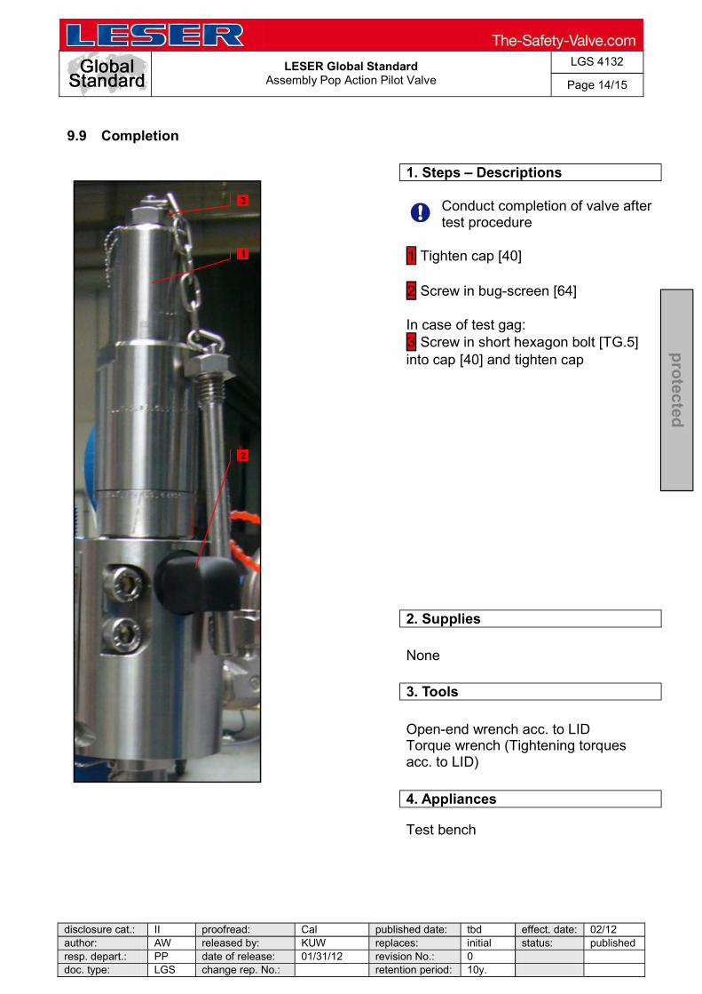
LESER Global Standard
Assembly Pop Action Pilot Valve
LGS 4132
Page 14/15
disclosure cat.: II proofread: Cal published date: tbd effect. date: 02/12 author: AW released by: KUW replaces: initial status: published resp. depart.: PP date of release: 01/31/12 revision No.: 0 doc. type: LGS change rep. No.: retention period: 10y.
pro
tected
9.9 Completion
1. Steps Descriptions
Conduct completion of valve after test procedure
1 Tighten cap [40] 2 Screw in bug-screen [64] In case of test gag: 3 Screw in short hexagon bolt [TG.5] into cap [40] and tighten cap
2. Supplies
None
3. Tools
Open-end wrench acc. to LID Torque wrench (Tightening torques acc. to LID)
4. Appliances
Test bench
3
1
2
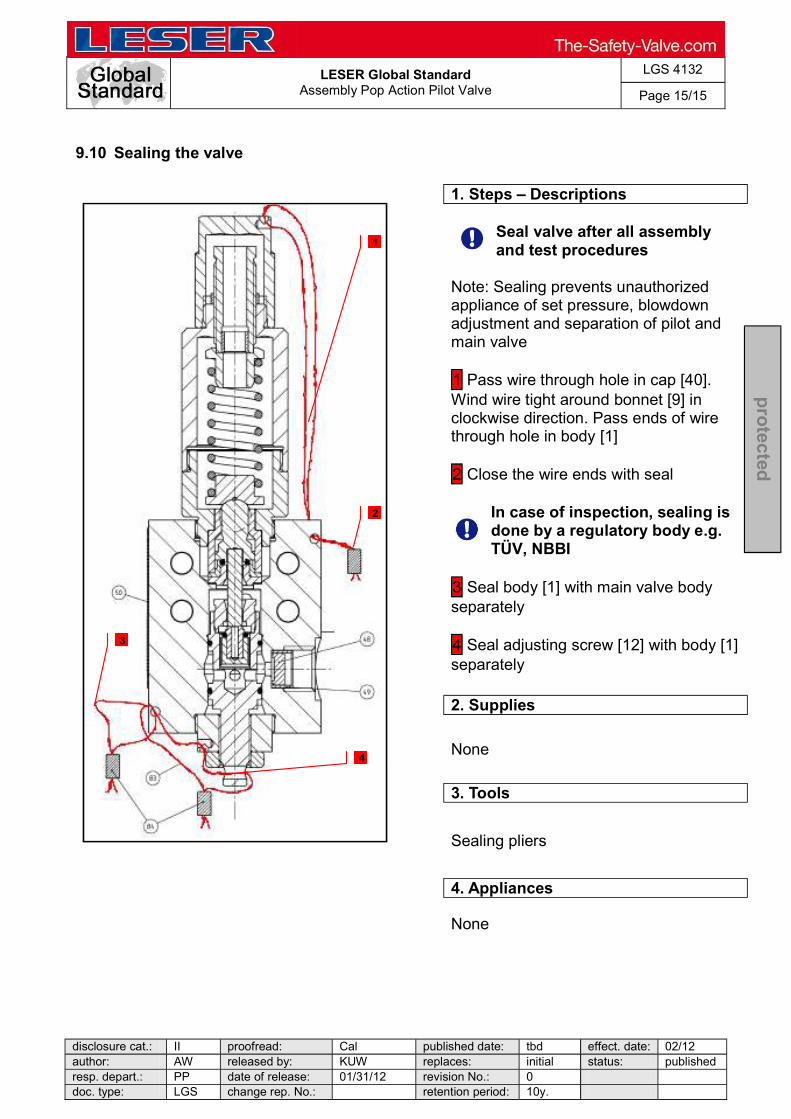
LESER Global Standard
Assembly Pop Action Pilot Valve
LGS 4132
Page 15/15
disclosure cat.: II proofread: Cal published date: tbd effect. date: 02/12 author: AW released by: KUW replaces: initial status: published resp. depart.: PP date of release: 01/31/12 revision No.: 0 doc. type: LGS change rep. No.: retention period: 10y.
pro
tected
9.10 Sealing the valve
1. Steps Descriptions
Seal valve after all assembly and test procedures
Note: Sealing prevents unauthorized appliance of set pressure, blowdown adjustment and separation of pilot and main valve 1 Pass wire through hole in cap [40]. Wind wire tight around bonnet [9] in clockwise direction. Pass ends of wire through hole in body [1] 2 Close the wire ends with seal
In case of inspection, sealing is done by a regulatory body e.g. TÜV, NBBI
3 Seal body [1] with main valve body separately 4 Seal adjusting screw [12] with body [1] separately
2. Supplies
None
3. Tools
Sealing pliers
4. Appliances
None
1
4
2
3

LESER Global Standard
Assembly Modulate Action Diaphragm
LGS 4133
Page 1/19
disclosure cat.: II proofread: Cal published date: tbd effect. date: 02/12 author: AW released by: KUW replaces: initial status: published resp. depart.: PP date of release: 01/31/12 revision No.: 0 doc. type: LGS change rep. No.: retention period: 10y.
pro
tected
Content 1 General informations for disassembling the modulate action valve with diaphragm .......................................................................................................... 2 2 Purpose ......................................................................................................... 2 3 Competence .................................................................................................. 2 4 Scope ............................................................................................................. 2 5 Disclaimer ...................................................................................................... 2 6 Qualified fitting personnel ............................................................................ 2 7 Remarks ......................................................................................................... 2 8 Basic safety guidelines ................................................................................ 3 9 Assembly instructions.................................................................................. 6

LESER Global Standard
Assembly Modulate Action Diaphragm
LGS 4133
Page 2/19
disclosure cat.: II proofread: Cal published date: tbd effect. date: 02/12 author: AW released by: KUW replaces: initial status: published resp. depart.: PP date of release: 01/31/12 revision No.: 0 doc. type: LGS change rep. No.: retention period: 10y.
pro
tected
1 General informations for disassembling the modulate action valve with diaphragm
2 Purpose
The documentation describes the disassembly of the modulate action pilot valve with diaphragm. The description contains every single working step, supplies, tools and appliances.
3 Competence
The generation, maintenance and distribution of the documentation takes place in the organisation department. The defaults will be generated by the technical department in consultation with the final assembly department and production planning department.
4 Scope
This document must be applied to the dismantling of a Pilot Operated Safety Valve in agencies and subsidiaries of LESER GmbH & Co. KG, customers and independent service center.
5 Disclaimer
LESER puts in a great deal of effort into making up-to-date and correct documentation available. Nevertheless, LESER GmbH & Co. KG gives no guarantee that the recommended actions presented here are entirely correct and error free. This document is to be applied exclusively to the specified type. LESER GmbH & Co. KG declines any liability or responsibility for the correctness and completeness of the content. LESER GmbH & Co. KG reserves the right to change the information contained in this document, which is for the products of LESER GmbH & Co. KG and is intended for LESER subsidiaries, at any time and without prior announcement. LESER GmbH & Co. KG is available to the users of this document to provide additional information.
6 Qualified fitting personnel
LESER safety valves may only be dismantled by trained or qualified fitters. The qualifications must be obtained through the appropriate training measures.
7 Remarks Gloves must be worn during the entire dismantling process.

LESER Global Standard
Assembly Modulate Action Diaphragm
LGS 4133
Page 3/19
disclosure cat.: II proofread: Cal published date: tbd effect. date: 02/12 author: AW released by: KUW replaces: initial status: published resp. depart.: PP date of release: 01/31/12 revision No.: 0 doc. type: LGS change rep. No.: retention period: 10y.
pro
tected
8 Basic safety guidelines
Dangerous media Poisoning, caustic burns, burns, injuries
Foreign bodies in the safety valve Danger from failure of safety valve or leaks
the system before installation of a safety valve. objects.
Bug screen is damaged or missing (B or option) Dirt, objects or insects get into the safety valve. Danger from malfunction of the safety valve.
Ambient temperature is too high Material expansion. Danger from malfunction of the safety valve. Ambient temperature is too low Icing, freezing vapours, reduced flow rate due to congealing media. Danger from functional disruption of the safety valve. Abrasive or corrosive media Moving parts jam or become stuck. Danger from functional disruption of the safety valve.
it opens. Media with high proportion of particles (only B)
LESER Global Standard
Assembly Modulate Action Diaphragm
LGS 4133
Page 4/19
disclosure cat.: II proofread: Cal published date: tbd effect. date: 02/12 author: AW released by: KUW replaces: initial status: published resp. depart.: PP date of release: 01/31/12 revision No.: 0 doc. type: LGS change rep. No.: retention period: 10y.
pro
tected
Deposits and clogging. Danger from malfunction of the safety valve.
filter capacity. Residual media in the safety valve Poisoning, caustic burns, burns, injuries
WARNING Leaky safety valve Danger from leaking media due to damaged gaskets and sealing surfaces.
and blows especially during transport and installation.
Open bonnet or spindle guides Danger from leaking media
leaking media.
tive equipment. CAUTION Hot medium Burns or scalding.
Hot surfaces Burns.
Aggressive medium Caustic burns.
Open bonnet or spindle guides

LESER Global Standard
Assembly Modulate Action Diaphragm
LGS 4133
Page 5/19
disclosure cat.: II proofread: Cal published date: tbd effect. date: 02/12 author: AW released by: KUW replaces: initial status: published resp. depart.: PP date of release: 01/31/12 revision No.: 0 doc. type: LGS change rep. No.: retention period: 10y.
pro
tected
Pinching danger from moving parts.
Sharp edges and burrs Danger of injury.
High noise emission Hearing damage. Wear ear protection.
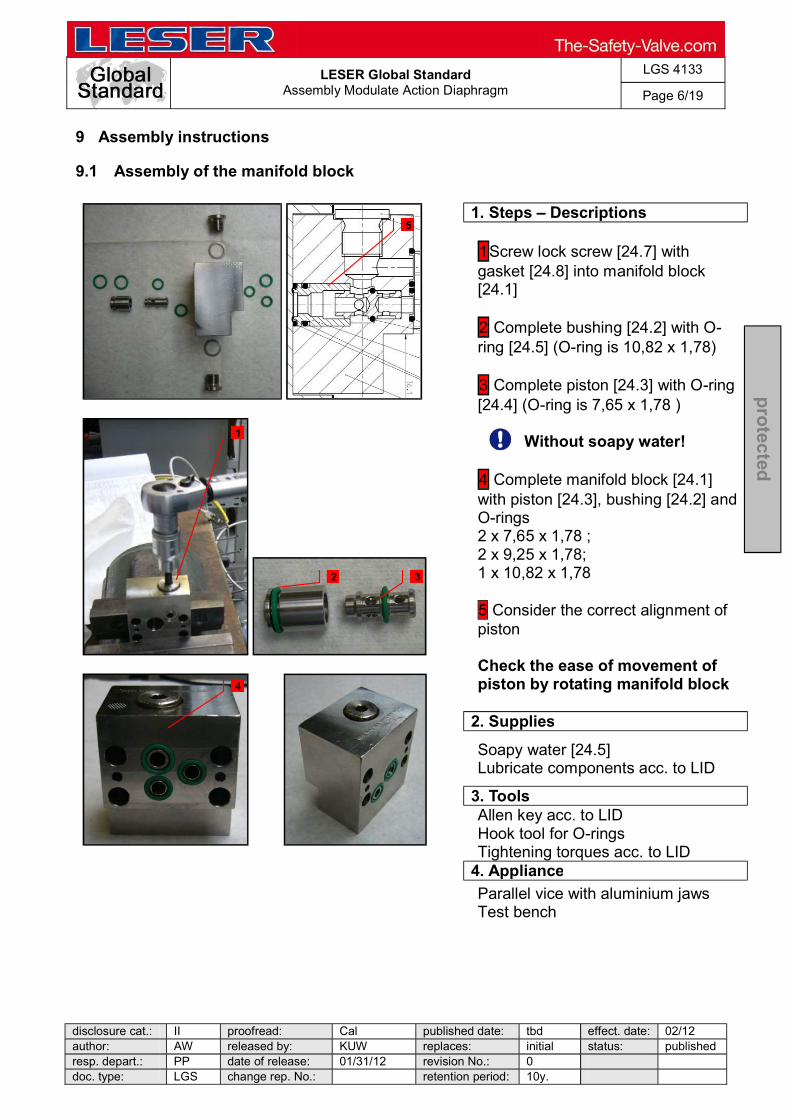
LESER Global Standard
Assembly Modulate Action Diaphragm
LGS 4133
Page 6/19
disclosure cat.: II proofread: Cal published date: tbd effect. date: 02/12 author: AW released by: KUW replaces: initial status: published resp. depart.: PP date of release: 01/31/12 revision No.: 0 doc. type: LGS change rep. No.: retention period: 10y.
pro
tected
9 Assembly instructions
9.1 Assembly of the manifold block
1. Steps Descriptions
1Screw lock screw [24.7] with gasket [24.8] into manifold block [24.1]
2 Complete bushing [24.2] with O-ring [24.5] (O-ring is 10,82 x 1,78)
3 Complete piston [24.3] with O-ring [24.4] (O-ring is 7,65 x 1,78 )
Without soapy water!
4 Complete manifold block [24.1] with piston [24.3], bushing [24.2] and O-rings 2 x 7,65 x 1,78 ; 2 x 9,25 x 1,78; 1 x 10,82 x 1,78 5 Consider the correct alignment of piston Check the ease of movement of piston by rotating manifold block
2. Supplies
Soapy water [24.5] Lubricate components acc. to LID
3. Tools
Allen key acc. to LID Hook tool for O-rings Tightening torques acc. to LID
4. Appliance
Parallel vice with aluminium jaws Test bench
1
2 3
4
5

LESER Global Standard
Assembly Modulate Action Diaphragm
LGS 4133
Page 7/19
disclosure cat.: II proofread: Cal published date: tbd effect. date: 02/12 author: AW released by: KUW replaces: initial status: published resp. depart.: PP date of release: 01/31/12 revision No.: 0 doc. type: LGS change rep. No.: retention period: 10y.
pro
tected
9.2 Assembly of the feeding seat unit
1. Steps Descriptions
1 Screw (lower) disc exhaust [11] together with (lower) disc exhaust extension [45] Cover O-ring (30 below + 34) with soapy water 2 Pull O-rings (30 below, 31, 34) on disc exhaust (lower) [11] Caution: Do not mix up O-ring (31) with PTFE-coating with O-rings (30 lower)! Make sure that O-rings are twist free 3 Stick (lower) disc, feeding [8] and seat feeding [5] on (lower) disc exhaust [11], put O-ring [30 upper] on (lower) disc, feeding [8] screw together with (upper) disc feeding [7] Make sure that O-rings are twist free
2. Supplies
Soapy water Lubricate components acc. to LID
3. Tools
Helpful: O-ring-mounting aid (30+34) Hook tool for O-rings Drift pin Open-end wrench acc. to LID Torque wrench (Tightening torques acc. to LID)
4. Appliance
None
1
2
3
3
3
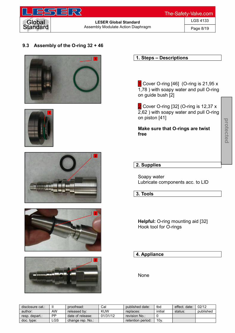
LESER Global Standard
Assembly Modulate Action Diaphragm
LGS 4133
Page 8/19
disclosure cat.: II proofread: Cal published date: tbd effect. date: 02/12 author: AW released by: KUW replaces: initial status: published resp. depart.: PP date of release: 01/31/12 revision No.: 0 doc. type: LGS change rep. No.: retention period: 10y.
pro
tected
9.3 Assembly of the O-ring 32 + 46
1. Steps Descriptions
1 Cover O-ring [46] (O-ring is 21,95 x 1,78 ) with soapy water and pull O-ring on guide bush [2]
2 Cover O-ring [32] (O-ring is 12,37 x 2,62 ) with soapy water and pull O-ring on piston [41]
Make sure that O-rings are twist free
2. Supplies
Soapy water Lubricate components acc. to LID
3. Tools
Helpful: O-ring mounting aid [32] Hook tool for O-rings
4. Appliance
None
1
1
2
2
2
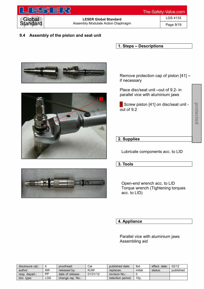
LESER Global Standard
Assembly Modulate Action Diaphragm
LGS 4133
Page 9/19
disclosure cat.: II proofread: Cal published date: tbd effect. date: 02/12 author: AW released by: KUW replaces: initial status: published resp. depart.: PP date of release: 01/31/12 revision No.: 0 doc. type: LGS change rep. No.: retention period: 10y.
pro
tected
9.4 Assembly of the piston and seat unit
1. Steps Descriptions
Remove protection cap of piston [41] if necessary Place disc/seat unit out of 9.2- in parallel vice with aluminium jaws
1 Screw piston [41] on disc/seat unit -out of 9.2
2. Supplies
Lubricate components acc. to LID
3. Tools
Open-end wrench acc. to LID Torque wrench (Tightening torques acc. to LID)
4. Appliance
Parallel vice with aluminium jaws Assembling aid
1
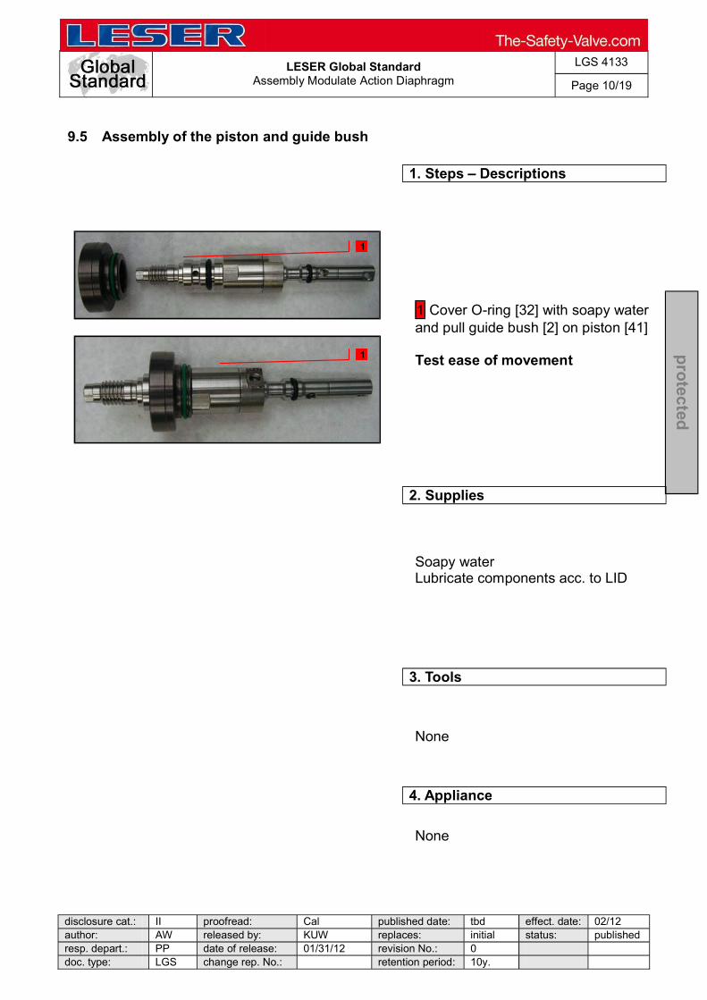
LESER Global Standard
Assembly Modulate Action Diaphragm
LGS 4133
Page 10/19
disclosure cat.: II proofread: Cal published date: tbd effect. date: 02/12 author: AW released by: KUW replaces: initial status: published resp. depart.: PP date of release: 01/31/12 revision No.: 0 doc. type: LGS change rep. No.: retention period: 10y.
pro
tected
9.5 Assembly of the piston and guide bush
1. Steps Descriptions
1 Cover O-ring [32] with soapy water and pull guide bush [2] on piston [41]
Test ease of movement
2. Supplies
Soapy water Lubricate components acc. to LID
3. Tools
None
4. Appliance
None
1
1
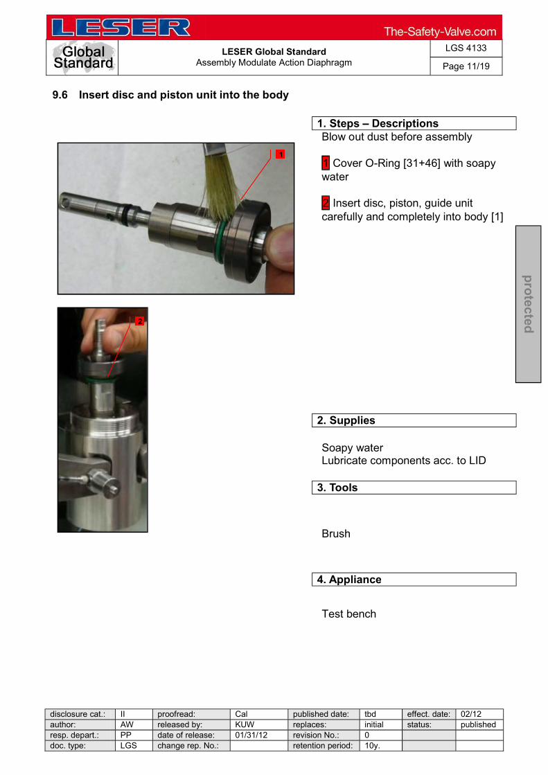
LESER Global Standard
Assembly Modulate Action Diaphragm
LGS 4133
Page 11/19
disclosure cat.: II proofread: Cal published date: tbd effect. date: 02/12 author: AW released by: KUW replaces: initial status: published resp. depart.: PP date of release: 01/31/12 revision No.: 0 doc. type: LGS change rep. No.: retention period: 10y.
pro
tected
9.6 Insert disc and piston unit into the body
1. Steps Descriptions
Blow out dust before assembly 1 Cover O-Ring [31+46] with soapy water
2 Insert disc, piston, guide unit carefully and completely into body [1]
2. Supplies
Soapy water Lubricate components acc. to LID
3. Tools
Brush
4. Appliance
Test bench
1
2
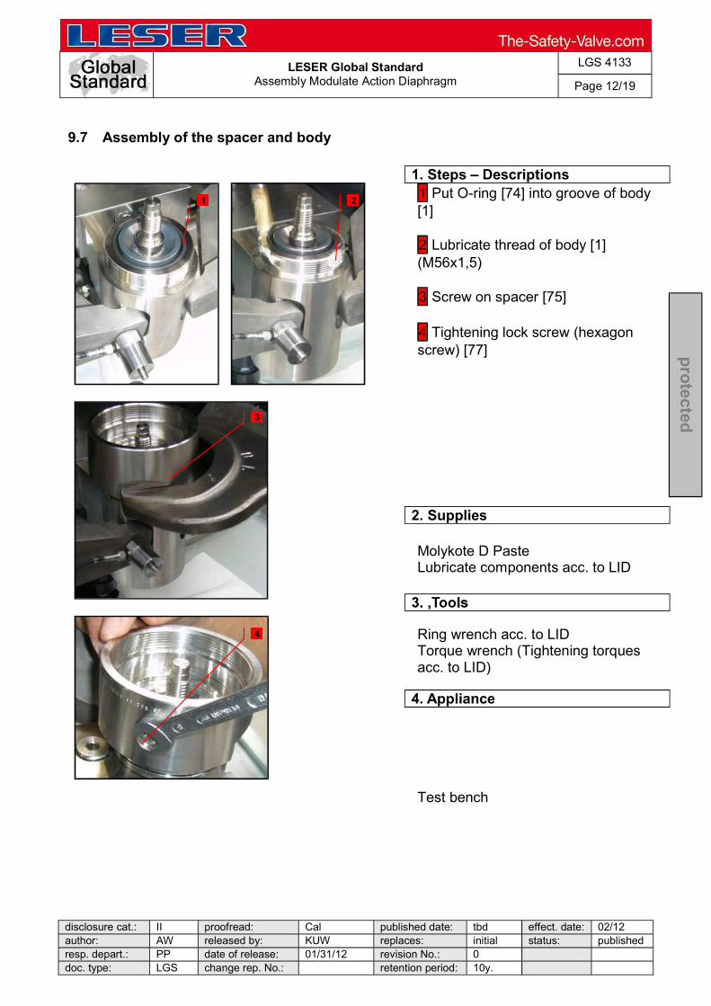
LESER Global Standard
Assembly Modulate Action Diaphragm
LGS 4133
Page 12/19
disclosure cat.: II proofread: Cal published date: tbd effect. date: 02/12 author: AW released by: KUW replaces: initial status: published resp. depart.: PP date of release: 01/31/12 revision No.: 0 doc. type: LGS change rep. No.: retention period: 10y.
pro
tected
9.7 Assembly of the spacer and body
1. Steps Descriptions
1 Put O-ring [74] into groove of body [1] 2 Lubricate thread of body [1] (M56x1,5) 3 Screw on spacer [75] 4 Tightening lock screw (hexagon screw) [77]
2. Supplies
Molykote D Paste Lubricate components acc. to LID
Ring wrench acc. to LID Torque wrench (Tightening torques acc. to LID)
4. Appliance
Test bench
1 2
3
4

LESER Global Standard
Assembly Modulate Action Diaphragm
LGS 4133
Page 13/19
disclosure cat.: II proofread: Cal published date: tbd effect. date: 02/12 author: AW released by: KUW replaces: initial status: published resp. depart.: PP date of release: 01/31/12 revision No.: 0 doc. type: LGS change rep. No.: retention period: 10y.
pro
tected
9.8 Assembly of the diaphragm
1. Steps Descriptions
1 Push diaphragm retainer [78] on piston [41] 2 Cover O-ring [73] (O-ring is 10,77x2,62 9) with soapy water 3 Put O-ring (73) into groove Optional: Check FEP-protection foil (79) for any damage Optional: put in FEP-protection foil Check diaphragm for any damage 4 Insert diaphragm [72] with labelling to bottom 5 Insert ring [76]
(hexagon screw for positioning) 6 Push diaphragm washer [71] on piston 7 Lubricate thread of piston [41] 8 Screw nut [70] until 1 mm against stop by hand 9 Tightening nut with wrench and counter piston with a second wrench
2. Supplies
Soapy water Molykote D paste Lubricate components acc. to LID
3. Tools
Ring wrench acc. to LID Open-end wrench acc. to LID Torque wrench (Tightening torques acc. to LID)
4. Appliance
Test bench
1
2 1
4 4
5
3
5
6 6
7 8
9 9

LESER Global Standard
Assembly Modulate Action Diaphragm
LGS 4133
Page 14/19
disclosure cat.: II proofread: Cal published date: tbd effect. date: 02/12 author: AW released by: KUW replaces: initial status: published resp. depart.: PP date of release: 01/31/12 revision No.: 0 doc. type: LGS change rep. No.: retention period: 10y.
pro
tected
9.9 Closing the body´s bottom side
1. Steps Descriptions
Spin body [1] by 180° 1 Insert return spring [42] into body [1]
2 Put coupling [43] on lower end of spring,
3 Span return spring [42] with coupling [43] and save coupling [43] by sticking parallel pin [44] into hole
4 Put O-ring [35] (O-ring is 21,95x1,78) into groove of plug [20]
5 Lubricate thread of plug [20]
6 Screw plug [20] and body [1] together
2. Supplies
Molykote D Paste Lubricate components acc. to LID
3. Tools
Open-end wrench acc. to LID Torque wrench (Tightening torques acc. to LID)
4. Appliance
Test bench
1
2
3 3
4
6
5
6

LESER Global Standard
Assembly Modulate Action Diaphragm
LGS 4133
Page 15/19
disclosure cat.: II proofread: Cal published date: tbd effect. date: 02/12 author: AW released by: KUW replaces: initial status: published resp. depart.: PP date of release: 01/31/12 revision No.: 0 doc. type: LGS change rep. No.: retention period: 10y.
pro
tected
9.10 Assembly of the bonnet
1. Steps Descriptions
Spin body [1] by 180° 1 Place (upper) piston [47] on piston [41] Check free movement of (upper) piston [47] to avoid a clamp 2 Put guide ring [80] into groove of bonnet [9] Make sure, whether guiding ring is completely in groove 3 Lubricate thread of adjusting screw [18] 4 Screw lock nut [19] on adjusting screw [18] Check ease of movement of adjusting screw [18] 5 Screw adjusting screw unit approx 15 mm into bonnet [9]
2. Supplies
Molykote D Paste Lubricate components acc. to LID
3. Tools
None
4. Appliance
None
1 1
2 2
3
4
5

LESER Global Standard
Assembly Modulate Action Diaphragm
LGS 4133
Page 16/19
disclosure cat.: II proofread: Cal published date: tbd effect. date: 02/12 author: AW released by: KUW replaces: initial status: published resp. depart.: PP date of release: 01/31/12 revision No.: 0 doc. type: LGS change rep. No.: retention period: 10y.
pro
tected
9.11 Assembly of the spindle unit
1. Steps Descriptions
1 Cover thread of spindle [12] with screw locking liquid Delo ML 5449
2 Screw spindle [12] and (lower) spring plate [17] together
3 Put on in that order: spring [54] (optional inner spring [53]), (upper) spring plate [16], needle bearing [69.2] (lubricate bearing) and washer [69.1]
2. Supplies
Screw locking liquid Delo ML 5449 Molykote D Paste Lubricate components acc. to LID
3. Tools
Drift pin Torque wrench (Tightening torques acc. to LID)
4. Appliance
Parallel vice with aluminium jaws
1
2
3
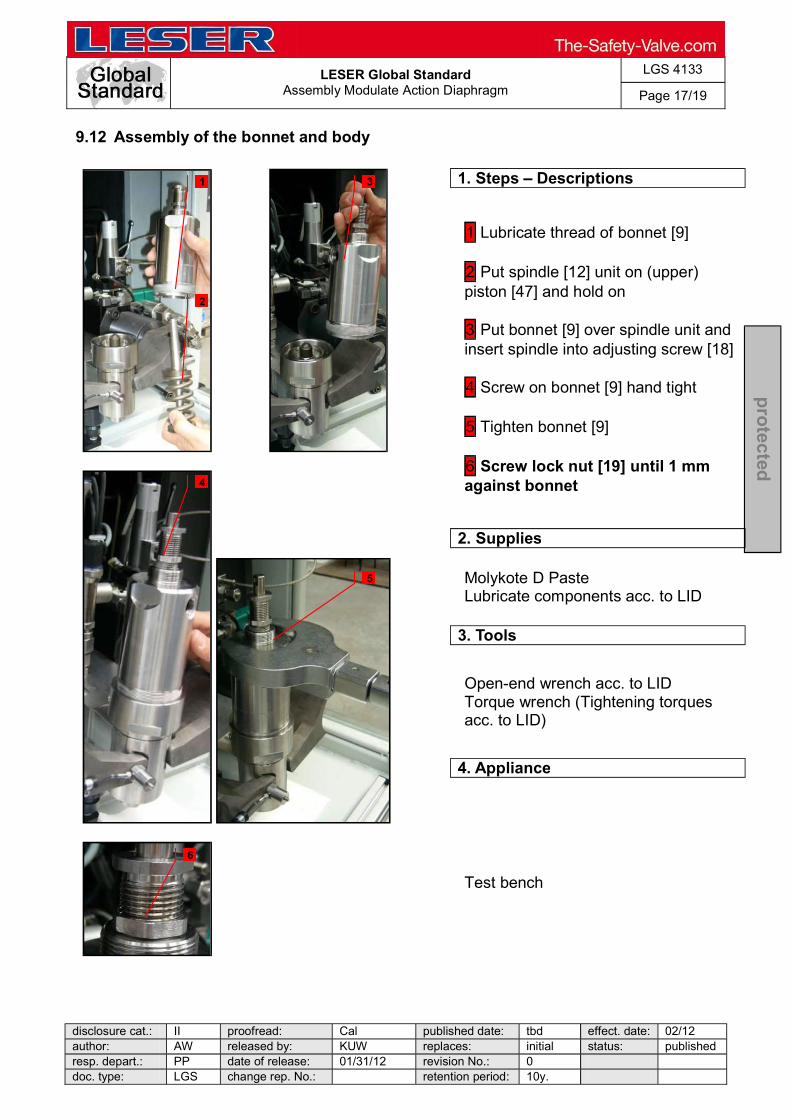
LESER Global Standard
Assembly Modulate Action Diaphragm
LGS 4133
Page 17/19
disclosure cat.: II proofread: Cal published date: tbd effect. date: 02/12 author: AW released by: KUW replaces: initial status: published resp. depart.: PP date of release: 01/31/12 revision No.: 0 doc. type: LGS change rep. No.: retention period: 10y.
pro
tected
9.12 Assembly of the bonnet and body
1. Steps Descriptions
1 Lubricate thread of bonnet [9] 2 Put spindle [12] unit on (upper) piston [47] and hold on
3 Put bonnet [9] over spindle unit and insert spindle into adjusting screw [18]
4 Screw on bonnet [9] hand tight
5 Tighten bonnet [9]
6 Screw lock nut [19] until 1 mm against bonnet
2. Supplies
Molykote D Paste Lubricate components acc. to LID
3. Tools
Open-end wrench acc. to LID Torque wrench (Tightening torques acc. to LID)
4. Appliance
Test bench
3 1
2
4
5
6

LESER Global Standard
Assembly Modulate Action Diaphragm
LGS 4133
Page 18/19
disclosure cat.: II proofread: Cal published date: tbd effect. date: 02/12 author: AW released by: KUW replaces: initial status: published resp. depart.: PP date of release: 01/31/12 revision No.: 0 doc. type: LGS change rep. No.: retention period: 10y.
pro
tected
9.13 Completion
1. Steps Descriptions
1 Screw on cap [40] loosely 2 Screw in bug-screen [64]
Option Test Gag: Screw short screw [TG.5] into cap [40] (finger tight)
2. Supplies
None
3. Tools
Open-end wrench acc. to LID Torque wrench (Tightening torques acc. to LID)
4. Appliance
Test bench
1
2
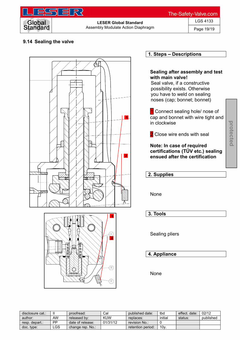
LESER Global Standard
Assembly Modulate Action Diaphragm
LGS 4133
Page 19/19
disclosure cat.: II proofread: Cal published date: tbd effect. date: 02/12 author: AW released by: KUW replaces: initial status: published resp. depart.: PP date of release: 01/31/12 revision No.: 0 doc. type: LGS change rep. No.: retention period: 10y.
pro
tected
9.14 Sealing the valve
1. Steps Descriptions
Sealing after assembly and test with main valve!
Seal valve, if a constructive possibility exists. Otherwise you have to weld on sealing noses (cap; bonnet; bonnet) 1 Connect sealing hole/ nose of cap and bonnet with wire tight and in clockwise
2 Close wire ends with seal
Note: In case of required certifications (TÜV etc.) sealing ensued after the certification
2. Supplies
None
3. Tools
Sealing pliers
4. Appliance
None
1
1
2
2

LESER Global Standard
Assembly Modulate Action Pilot Valve Piston
LGS 4134
Page 17/17
disclosure cat.: II proofread: SSt published date: 02/06/18 effect. date: 02/18 author: AW released by: KUW replaces: initial status: Published resp. depart.: IE date of release: 02/06/18 revision No.: 1 doc. type: LGS change rep. No.: NA retention period: 10y.
pro
tecte
d
9.11 Sealing the valve
1. Steps Descriptions
Sealing after assembly and test with main valve! Seal valve, if constructive possibility exists. Otherwise next workstation has to weld on sealing noses (cap; bonnet; body) 1 Connect sealing hole/ nose of cap and bonnet with wire tight and in clockwise 2 Close wire ends with seal Note: In case of required certifications (TÜV etc.) sealing ensued after certification
2. Supplies
None
3. Tools
Sealing pliers
4. Appliance
None
1
1
2
2
LESER Global Standard
Assembly Modulate Action Pilot Valve Piston
LGS 4134
Page 1/17
disclosure cat.: II proofread: SSt published date: 02/06/18 effect. date: 02/18
author: AW released by: KUW replaces: initial status: Published
resp. depart.: IE date of release: 02/06/18 revision No.: 1
doc. type: LGS change rep. No.: NA retention period: 10y.
pro
tec
ted
Content 1 General informations for disassembling the modulate pilot valve (piston) 2 2 Purpose .......................................................................................................... 2 3 Competences ................................................................................................. 2 4 Scope .............................................................................................................. 2
5 Disclaimer ...................................................................................................... 2 6 Qualified fitting personnel ............................................................................ 2 7 Remarks ......................................................................................................... 2 8 Basic safety guidelines ................................................................................. 3 9 Assembly instructions .................................................................................. 6

LESER Global Standard
Assembly Modulate Action Pilot Valve Piston
LGS 4134
Page 2/17
disclosure cat.: II proofread: SSt published date: 02/06/18 effect. date: 02/18
author: AW released by: KUW replaces: initial status: Published
resp. depart.: IE date of release: 02/06/18 revision No.: 1
doc. type: LGS change rep. No.: NA retention period: 10y.
pro
tec
ted
1 General informations for disassembling the modulate pilot valve (piston)
2 Purpose
The documentation describes the disassembly of the modulate action pilot valve with
piston. The description contains every single working step, supplies, tools and appliances.
3 Competences
The generation, maintenance and distribution of the documentation takes place in the organisation department. The defaults will be generated by the technical department in consultation with the final assembly department and production planning department.
4 Scope
This document must be applied to the dismantling of a Pilot Operated Safety Valve in agencies and subsidiaries of LESER GmbH & Co. KG, customers and independent service center.
5 Disclaimer
LESER puts in a great deal of effort into making up-to-date and correct documentation available. Nevertheless, LESER GmbH & Co. KG gives no guarantee that the recommended actions presented here are entirely correct and error free. This document is to be applied exclusively to the specified type. LESER GmbH & Co. KG declines any liability or responsibility for the correctness and completeness of the content. LESER GmbH & Co. KG reserves the right to change the information contained in this document, which is for the products of LESER GmbH & Co. KG and is intended for LESER subsidiaries, at any time and without prior announcement. LESER GmbH & Co. KG is available to the users of this document to provide additional information.
6 Qualified fitting personnel
LESER safety valves may only be dismantled by trained or qualified fitters. The qualifications must be obtained through the appropriate training measures.
7 Remarks
Gloves must be worn during the entire dismantling process.
LESER Global Standard
Assembly Modulate Action Pilot Valve Piston
LGS 4134
Page 3/17
disclosure cat.: II proofread: SSt published date: 02/06/18 effect. date: 02/18
author: AW released by: KUW replaces: initial status: Published
resp. depart.: IE date of release: 02/06/18 revision No.: 1
doc. type: LGS change rep. No.: NA retention period: 10y.
pro
tec
ted
8 Basic safety guidelines
Dangerous media Poisoning, caustic burns, burns, injuries • Use suitable protective devices • Use suitable collecting tanks. • Wear suitable protective equipment. Foreign bodies in the safety valve Danger from failure of safety valve or leaks • Flush the system before installation of a safety valve. • Check the safety valve for foreign objects. • Remove foreign objects Bug screen is damaged or missing (B or option) Dirt, objects or insects get into the safety valve. Danger from malfunction of the safety valve. • Install the bug screen correctly. • Check the bug screen regularly. Ambient temperature is too high Material expansion. Danger from malfunction of the safety valve. Ambient temperature is too low Icing, freezing vapours, reduced flow rate due to congealing media. Danger from functional disruption of the safety valve. Abrasive or corrosive media Moving parts jam or become stuck. Danger from functional disruption of the safety valve. • Service the safety valve after each time it opens. Media with high proportion of particles
LESER Global Standard
Assembly Modulate Action Pilot Valve Piston
LGS 4134
Page 4/17
disclosure cat.: II proofread: SSt published date: 02/06/18 effect. date: 02/18
author: AW released by: KUW replaces: initial status: Published
resp. depart.: IE date of release: 02/06/18 revision No.: 1
doc. type: LGS change rep. No.: NA retention period: 10y.
pro
tec
ted
(only B) Deposits and clogging. Danger from malfunction of the safety valve. • Use a filter with the correct mesh size. • Use additional filters to increase the filter capacity. Residual media in the safety valve Poisoning, caustic burns, burns, injuries • Wear suitable protective equipment. • Remove residual media WARNING Leaky safety valve Danger from leaking media due to damaged gaskets and sealing surfaces. • Protect the safety valve against vibrations and blows especially during transport and installation. • Check safety valve regularly for leaks. Open bonnet or spindle guides Danger from leaking media • Make sure that no danger can arise from leaking media. • Keep a safe distance. • Wear suitable protective equipment. CAUTION Hot medium Burns or scalding. • Wear suitable protective equipment. Hot surfaces Burns. • Wear suitable protective equipment. Aggressive medium Caustic burns. • Wear suitable protective equipment.
LESER Global Standard
Assembly Modulate Action Pilot Valve Piston
LGS 4134
Page 5/17
disclosure cat.: II proofread: SSt published date: 02/06/18 effect. date: 02/18
author: AW released by: KUW replaces: initial status: Published
resp. depart.: IE date of release: 02/06/18 revision No.: 1
doc. type: LGS change rep. No.: NA retention period: 10y.
pro
tec
ted
Open bonnet or spindle guides Pinching danger from moving parts. • Install suitable safeguards. Sharp edges and burrs Danger of injury. • Wear safety gloves. • Handle the safety valve carefully High noise emission Hearing damage. Wear ear protection.
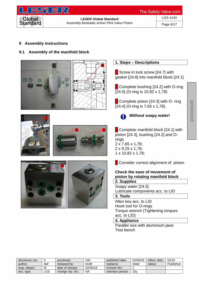
LESER Global Standard
Assembly Modulate Action Pilot Valve Piston
LGS 4134
Page 6/17
disclosure cat.: II proofread: SSt published date: 02/06/18 effect. date: 02/18
author: AW released by: KUW replaces: initial status: Published
resp. depart.: IE date of release: 02/06/18 revision No.: 1
doc. type: LGS change rep. No.: NA retention period: 10y.
pro
tec
ted
9 Assembly instructions
9.1 Assembly of the manifold block
1. Steps – Descriptions
1 Screw in lock screw [24.7] with
gasket [24.8] into manifold block [24.1]
2 Complete bushing [24.2] with O-ring
[24.5] (O-ring is 10,82 x 1,78)
3 Complete piston [24.3] with O- ring
[24.4] (O-ring is 7,65 x 1,78).
Without soapy water!
4 Complete manifold block [24.1] with
piston [24.3], bushing [24.2] and O- rings 2 x 7,65 x 1,78; 2 x 9,25 x 1,78; 1 x 10,82 x 1,78;
5 Consider correct alignment of piston
Check the ease of movement of piston by rotating manifold block
2. Supplies
Soapy water [24.5] Lubricate components acc. to LID
3. Tools
Allen key acc. to LID Hook tool for O-rings Torque wrench (Tightening torques acc. to LID)
4. Appliance
Parallel vice with aluminium jaws Test bench
1
3 2
4
5

LESER Global Standard
Assembly Modulate Action Pilot Valve Piston
LGS 4134
Page 7/17
disclosure cat.: II proofread: SSt published date: 02/06/18 effect. date: 02/18
author: AW released by: KUW replaces: initial status: Published
resp. depart.: IE date of release: 02/06/18 revision No.: 1
doc. type: LGS change rep. No.: NA retention period: 10y.
pro
tec
ted
Assembly of the seat unit
1. Steps – Descriptions
1 Screw (lower) disc, exhaust [11]
together with (lower) disc exhaust, extension [45] Cover O-ring (30 below + 34) with soapy water
2 Pull O-rings (30 below, 31, 34) on
(lower) disc exhaust [11] Caution: Do not mix up O-rings (31) with PTFE-coating with O-rings (30 lower)! Make sure that O-rings are twist free
3 Stick (lower) disc, feeding [8] and
seat feeding [5] on (lower) disc exhaust [11), put the O-ring [30 upper] on (lower) disc, feeding [8] screw together with (upper) disc feeding [7]
4 After assembly there has to be a gap
between (lower) disc, feeding [8] and (upper) disc feeding [7]. Make sure that O-rings are twist free
2. Supplies
Soapy water Lubricate components acc. to LID
3. Tools
Helpful: O-ring-mounting aid (30 + 34) Hook tool for O-rings Drift pin Open-end wrench acc. to LID Torque wrench (Tightening torques acc. to LID)
4. Appliance
None
1
2
3
3
3

LESER Global Standard
Assembly Modulate Action Pilot Valve Piston
LGS 4134
Page 8/17
disclosure cat.: II proofread: SSt published date: 02/06/18 effect. date: 02/18
author: AW released by: KUW replaces: initial status: Published
resp. depart.: IE date of release: 02/06/18 revision No.: 1
doc. type: LGS change rep. No.: NA retention period: 10y.
pro
tec
ted
9.2 Assembly of the O-ring 32 + 33 + 46
1. Steps – Descriptions
As from 100 bar, mount additional back up rings (81 + 82)!
1 Cover O-ring [32] (O-ring is 7,59 x
2,62) with soapy water pull O-ring on piston [41]
2 Cover O-ring [33] (O-ring is 20,29 x
2,62) with soapy water and pull O-ring on piston, upper [47]
3 Cover O-ring [46] (O-ring is 21,95 x
1,78) with soapy water and pull O-ring on guide bush [2] Make sure that O-rings are twist free
2. Supplies
Soapy water Lubricate components acc. to LID
3. Tools
Helpful: O-ring mounting aid [32] Hook tool for O-rings Torque wrench (Tightening torques acc. to LID)
4. Appliance
None
1
1
2 2
3 3

LESER Global Standard
Assembly Modulate Action Pilot Valve Piston
LGS 4134
Page 9/17
disclosure cat.: II proofread: SSt published date: 02/06/18 effect. date: 02/18
author: AW released by: KUW replaces: initial status: Published
resp. depart.: IE date of release: 02/06/18 revision No.: 1
doc. type: LGS change rep. No.: NA retention period: 10y.
pro
tec
ted
9.3 Assembly of the piston and seat unit
1. Steps – Descriptions
Remove protection cap of piston [41] - if necessary Place disc/seat unit –out of 9.2- in parallel vice with aluminium jams
1 Screw piston [41] on seat unit –out of
9.2
2. Supplies
Halocabon 56S Lubricate components acc. to LID
3. Tools
Open-end wrench acc. to LID Torque wrench (Tightening torques acc. to LID)
4. Appliance
Parallel vice with aluminium jaws
1

LESER Global Standard
Assembly Modulate Action Pilot Valve Piston
LGS 4134
Page 10/17
disclosure cat.: II proofread: SSt published date: 02/06/18 effect. date: 02/18
author: AW released by: KUW replaces: initial status: Published
resp. depart.: IE date of release: 02/06/18 revision No.: 1
doc. type: LGS change rep. No.: NA retention period: 10y.
pro
tec
ted
9.4 Assembly of the seat/disc unit, guide bush and piston, upper
1. Steps – Descriptions
Cover O-ring [32] with soapy water Place seat,piston unit in parallel vice with aluminium jams
1 Lubricate thread of piston [41]
Cover O-ring [33] with soapy water
2 Stick guide bush [2] on piston [41]
and screw together with piston, upper [47]
2. Supplies
Soapy water Molykote D Paste Lubricate components acc. to LID
3. Tools
Open-end wrench acc. to LID Torque wrench (Tightening torques acc. to LID)
4. Appliance
Parallel vice with aluminium jaws Assembling aid
2
1

LESER Global Standard
Assembly Modulate Action Pilot Valve Piston
LGS 4134
Page 11/17
disclosure cat.: II proofread: SSt published date: 02/06/18 effect. date: 02/18
author: AW released by: KUW replaces: initial status: Published
resp. depart.: IE date of release: 02/06/18 revision No.: 1
doc. type: LGS change rep. No.: NA retention period: 10y.
pro
tec
ted
9.5 Insert disc, piston unit into the body
1. Steps – Descriptions
Blow out dust before assembly Cover O-ring [31+46] with soapy water
1 Insert disc, piston unit carefully and
completely into body [1] Test the ease of movement
2. Supplies
Soapy water Lubricate components acc. to LID
3. Tools
None
4. Appliance
Test bench
1

LESER Global Standard
Assembly Modulate Action Pilot Valve Piston
LGS 4134
Page 12/17
disclosure cat.: II proofread: SSt published date: 02/06/18 effect. date: 02/18
author: AW released by: KUW replaces: initial status: Published
resp. depart.: IE date of release: 02/06/18 revision No.: 1
doc. type: LGS change rep. No.: NA retention period: 10y.
pro
tec
ted
9.6 Closing the body´s bottom side
1. Steps – Descriptions
Spin body [1] by 180°
1 Insert return spring [42] into body [1]
2 Put coupling [43] on lower end of
spring
3 Span return spring [42] with coupling
[43] and save coupling by sticking parallel pin [44] into hole
4 Put O-ring [35] (O-ring is 21,95x1,78)
into groove of plug [20]
5 Lubricate thread of plug [20]
6 Screw plug [20] and body [1]
together
2. Supplies
Molykote D Paste Lubricate components acc. to LID
3. Tools
Open-end wrench acc. to LID Torque wrench (Tightening torques acc. to LID)
4. Appliance
Test bench
1
2 3
4 6
5
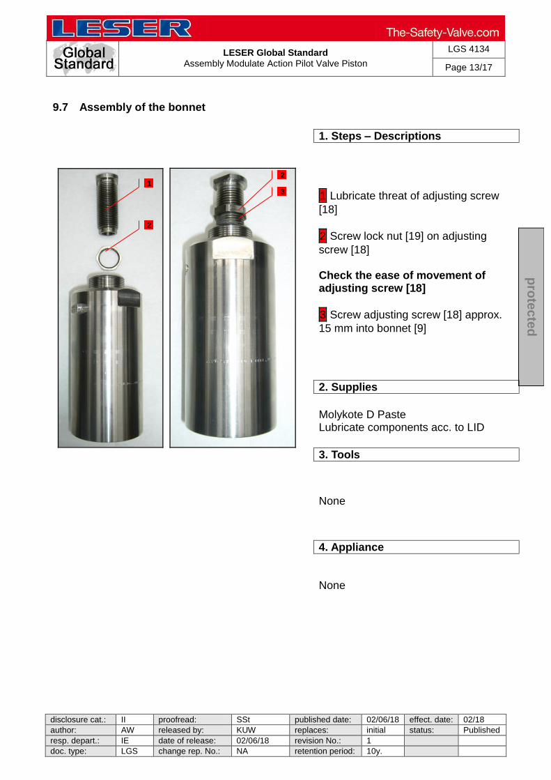
LESER Global Standard
Assembly Modulate Action Pilot Valve Piston
LGS 4134
Page 13/17
disclosure cat.: II proofread: SSt published date: 02/06/18 effect. date: 02/18
author: AW released by: KUW replaces: initial status: Published
resp. depart.: IE date of release: 02/06/18 revision No.: 1
doc. type: LGS change rep. No.: NA retention period: 10y.
pro
tec
ted
9.7 Assembly of the bonnet
1. Steps – Descriptions
1 Lubricate threat of adjusting screw
[18]
2 Screw lock nut [19] on adjusting
screw [18] Check the ease of movement of adjusting screw [18]
3 Screw adjusting screw [18] approx.
15 mm into bonnet [9]
2. Supplies
Molykote D Paste Lubricate components acc. to LID
3. Tools
None
4. Appliance
None
1
2
2
3

LESER Global Standard
Assembly Modulate Action Pilot Valve Piston
LGS 4134
Page 14/17
disclosure cat.: II proofread: SSt published date: 02/06/18 effect. date: 02/18
author: AW released by: KUW replaces: initial status: Published
resp. depart.: IE date of release: 02/06/18 revision No.: 1
doc. type: LGS change rep. No.: NA retention period: 10y.
pro
tec
ted
9.8 Assembly of the spindle unit
1. Steps – Descriptions
1 Cover thread of spindle [12] with
screw locking liquid Delo ML 5327
2 Screw spindle [12] and (lower) spring
plate [17] together
3 Put on in that order: spring [54]
(optional inner spring [53]), spring plate (upper) [16], needle bearing [69.2] (lubricate needle bearing) and washer [69.1]
2. Supplies
Screw locking liquid Delo ML 5327 Molykote D Paste Lubricate components acc. to LID
3. Tools
Drift pin Torque wrench (Tightening torques acc. to LID)
4. Appliance
Parallel vice with aluminium jaws
1 3
2

LESER Global Standard
Assembly Modulate Action Pilot Valve Piston
LGS 4134
Page 15/17
disclosure cat.: II proofread: SSt published date: 02/06/18 effect. date: 02/18
author: AW released by: KUW replaces: initial status: Published
resp. depart.: IE date of release: 02/06/18 revision No.: 1
doc. type: LGS change rep. No.: NA retention period: 10y.
pro
tec
ted
9.9 Assembly of the bonnet and body
1. Steps – Descriptions
1 Lubricate thread of bonnet [9]
Put spindle unit on piston, upper unit and hold on
2 Put bonnet [9] over spindle unit and
insert spindle into adjusting screw [18] Screw on bonnet [9] - hand tight
3 Tighten bonnet
4 Screw lock nut (19) until 1 mm
against bonnet
2. Supplies
Molykote D Paste Lubricate components acc. to LID
3. Tools
Open-end wrench acc. to LID Torque wrench (Tightening torques acc. to LID)
4. Appliance
Test bench
1 2
3
4

LESER Global Standard
Assembly Modulate Action Pilot Valve Piston
LGS 4134
Page 16/17
disclosure cat.: II proofread: SSt published date: 02/06/18 effect. date: 02/18
author: AW released by: KUW replaces: initial status: Published
resp. depart.: IE date of release: 02/06/18 revision No.: 1
doc. type: LGS change rep. No.: NA retention period: 10y.
pro
tec
ted
9.10 Completion
1. Steps – Descriptions
1 Screw on cap [40] loosely
2 Screw in bug-screen [64]
Option Test Gag: Screw short screw [TG.5] into cap [40] (finger tight)
2. Supplies
None
3. Tools
Open-end wrench acc. to LID Torque wrench (Tightening torques acc. to LID)
4. Appliance
Test bench
1
2

LESER Global Standard
Assembly Modulate Action Pilot Valve Piston
LGS 4134
Page 17/17
disclosure cat.: II proofread: SSt published date: 02/06/18 effect. date: 02/18
author: AW released by: KUW replaces: initial status: Published
resp. depart.: IE date of release: 02/06/18 revision No.: 1
doc. type: LGS change rep. No.: NA retention period: 10y.
pro
tec
ted
9.11 Sealing the valve
1. Steps – Descriptions
Sealing after assembly and test with main valve! Seal valve, if constructive possibility exists. Otherwise next workstation has to weld on sealing noses (cap; bonnet; body)
1 Connect sealing hole/ nose of
cap and bonnet with wire tight and in clockwise
2 Close wire ends with seal
Note: In case of required certifications (TÜV etc.) sealing ensued after certification
2. Supplies
None
3. Tools
Sealing pliers
4. Appliance
None
1
1
2
2

LESER Global Standard
Assembly Accessories
LGS 4135
Page 1/13
disclosure cat.: II proofread: Cal published date: tbd effect. date: 02/12 author: AW released by: KUW replaces: initial status: published resp. depart.: PP date of release: 01/31/12 revision No.: 0 doc. type: LGS change rep. No.: retention period: 10y.
pro
tected
Content 1 General information for assembling the POSV accessories ..................... 2 2 Purpose ......................................................................................................... 2 3 Competences ................................................................................................ 2 4 Scope ............................................................................................................. 2 5 Disclaimer ...................................................................................................... 2 6 Qualified fitting personnel ............................................................................ 2 7 Remarks ......................................................................................................... 2 8 Basic safety guidelines ................................................................................ 3 9 Assembly instructions.................................................................................. 6
LESER Global Standard
Assembly Accessories
LGS 4135
Page 2/13
disclosure cat.: II proofread: Cal published date: tbd effect. date: 02/12 author: AW released by: KUW replaces: initial status: published resp. depart.: PP date of release: 01/31/12 revision No.: 0 doc. type: LGS change rep. No.: retention period: 10y.
pro
tected
1 General information for assembling the POSV accessories
2 Purpose
The documentation describes the assembly of POSV accessories. The description contains every single working step, supplies, tools and appliances.
3 Competences
The generation, maintenance and distribution of the documentation takes place in the organisation department. The defaults will be generated by the technical department in consultation with the final assembly department and production planning department.
4 Scope
This document must be applied to the assembling of a Pilot Operated Safety Valve with accessories in agencies and subsidiaries of LESER GmbH & Co. KG, customers and independent service center.
5 Disclaimer
LESER puts in a great deal of effort into making up-to-date and correct documentation available. Nevertheless, LESER GmbH & Co. KG gives no guarantee that the recommended actions presented here are entirely correct and error free. This document is to be applied exclusively to the specified type. LESER GmbH & Co. KG declines any liability or responsibility for the correctness and completeness of the content. LESER GmbH & Co. KG reserves the right to change the information contained in this document, which is for the products of LESER GmbH & Co. KG and is intended for LESER subsidiaries, at any time and without prior announcement. LESER GmbH & Co. KG is available to the users of this document to provide additional information.
6 Qualified fitting personnel
LESER safety valves may only be dismantled by trained or qualified fitters. The qualifications must be obtained through the appropriate training measures.
7 Remarks
Gloves must be worn during the entire dismantling process.

LESER Global Standard
Assembly Accessories
LGS 4135
Page 3/13
disclosure cat.: II proofread: Cal published date: tbd effect. date: 02/12 author: AW released by: KUW replaces: initial status: published resp. depart.: PP date of release: 01/31/12 revision No.: 0 doc. type: LGS change rep. No.: retention period: 10y.
pro
tected
8 Basic safety guidelines
Dangerous media Poisoning, caustic burns, burns, injuries
Foreign bodies in the safety valve Danger from failure of safety valve or leaks
of a safety valve. objects.
Bug screen is damaged or missing (B or option) Dirt, objects or insects get into the safety valve. Danger from malfunction of the safety valve.
heck the bug screen regularly.
Ambient temperature is too high Material expansion. Danger from malfunction of the safety valve. Ambient temperature is too low Icing, freezing vapours, reduced flow rate due to congealing media. Danger from functional disruption of the safety valve. Abrasive or corrosive media Moving parts jam or become stuck. Danger from functional disruption of the safety valve.
it opens. Media with high proportion of particles (only B) Deposits and clogging. Danger from malfunction of the safety valve.

LESER Global Standard
Assembly Accessories
LGS 4135
Page 4/13
disclosure cat.: II proofread: Cal published date: tbd effect. date: 02/12 author: AW released by: KUW replaces: initial status: published resp. depart.: PP date of release: 01/31/12 revision No.: 0 doc. type: LGS change rep. No.: retention period: 10y.
pro
tected
filter capacity.
Residual media in the safety valve Poisoning, caustic burns, burns, injuries
r suitable protective equipment.
WARNING Leaky safety valve Danger from leaking media due to damaged gaskets and sealing surfaces.
and blows especially during transport and installation.
Open bonnet or spindle guides Danger from leaking media
leaking media.
CAUTION Hot medium Burns or scalding.
Hot surfaces Burns.
Aggressive medium Caustic burns.
Open bonnet or spindle guides Pinching danger from moving parts.
LESER Global Standard
Assembly Accessories
LGS 4135
Page 5/13
disclosure cat.: II proofread: Cal published date: tbd effect. date: 02/12 author: AW released by: KUW replaces: initial status: published resp. depart.: PP date of release: 01/31/12 revision No.: 0 doc. type: LGS change rep. No.: retention period: 10y.
pro
tected
l suitable safeguards. Sharp edges and burrs Danger of injury.
High noise emission Hearing damage. Wear ear protection.
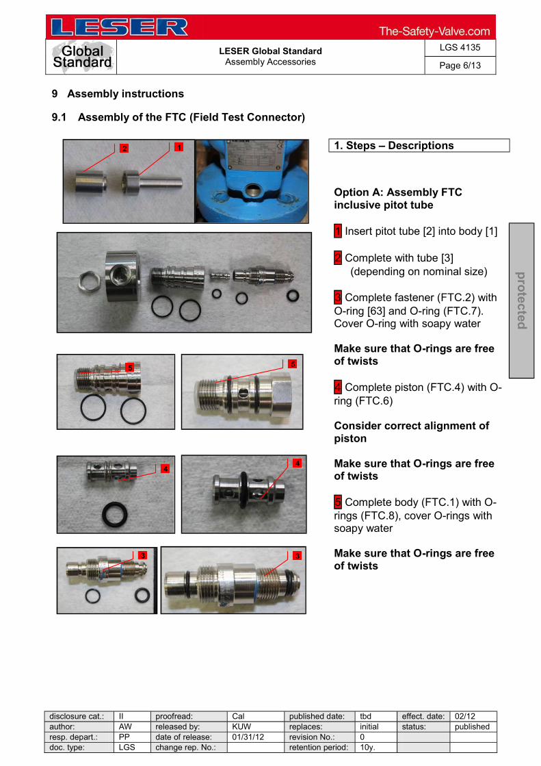
LESER Global Standard
Assembly Accessories
LGS 4135
Page 6/13
disclosure cat.: II proofread: Cal published date: tbd effect. date: 02/12 author: AW released by: KUW replaces: initial status: published resp. depart.: PP date of release: 01/31/12 revision No.: 0 doc. type: LGS change rep. No.: retention period: 10y.
pro
tected
9 Assembly instructions
9.1 Assembly of the FTC (Field Test Connector)
1. Steps Descriptions
Option A: Assembly FTC inclusive pitot tube 1 Insert pitot tube [2] into body [1] 2 Complete with tube [3]
(depending on nominal size) 3 Complete fastener (FTC.2) with O-ring [63] and O-ring (FTC.7). Cover O-ring with soapy water Make sure that O-rings are free of twists 4 Complete piston (FTC.4) with O-ring (FTC.6) Consider correct alignment of piston Make sure that O-rings are free of twists 5 Complete body (FTC.1) with O-rings (FTC.8), cover O-rings with soapy water Make sure that O-rings are free of twists
1
5
4
3
2
5
4
3

LESER Global Standard
Assembly Accessories
LGS 4135
Page 7/13
disclosure cat.: II proofread: Cal published date: tbd effect. date: 02/12 author: AW released by: KUW replaces: initial status: published resp. depart.: PP date of release: 01/31/12 revision No.: 0 doc. type: LGS change rep. No.: retention period: 10y.
pro
tected
1. Steps Descriptions
6 Insert piston (FTC.4) into fastener (FTC.2) 7 , 8 Screw together body (FTC.1) and fastener (FTC.2) Check ease of movement of piston by rotating this assembly group 9 Cover O-rings (FTC.8) with soapy water, mount pressure ring (FTC.3), align pressure ring and screw on
10 Wrap thread of compression
fitting 1 turn with PTFE tape and
screw it into pressure ring (FTC.3). 11 Screw in fastener (FTC2) with complete FTC into body, while tightening fastener, align pitot tube [2] in direction of inlet with pitot tube assembly tool 12 While mounting tube align the pressure ring (FTC.3) (possibly with pilot supply filter) exactly in direction of pilot valve and tighten lock nut (FTC.5) Orientate pressure ring (FTC.2) so that compression fitting faces horizontally to right (viewing direction to outlet) After assembly of tube (possibly with pilot supply filter) pressure ring then lock nut (FTC.3) has to be tightened
6
7 8
9
10
11 12
9
10
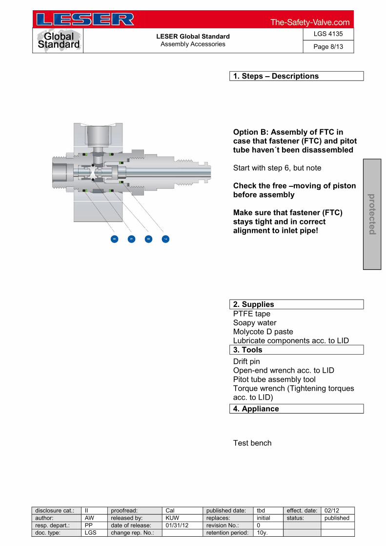
LESER Global Standard
Assembly Accessories
LGS 4135
Page 8/13
disclosure cat.: II proofread: Cal published date: tbd effect. date: 02/12 author: AW released by: KUW replaces: initial status: published resp. depart.: PP date of release: 01/31/12 revision No.: 0 doc. type: LGS change rep. No.: retention period: 10y.
pro
tected
1. Steps Descriptions
Option B: Assembly of FTC in case that fastener (FTC) and pitot tube haven´t been disassembled Start with step 6, but note Check the free moving of piston before assembly Make sure that fastener (FTC) stays tight and in correct alignment to inlet pipe!
2. Supplies
PTFE tape Soapy water Molycote D paste Lubricate components acc. to LID
3. Tools
Drift pin Open-end wrench acc. to LID Pitot tube assembly tool Torque wrench (Tightening torques acc. to LID)
4. Appliance
Test bench
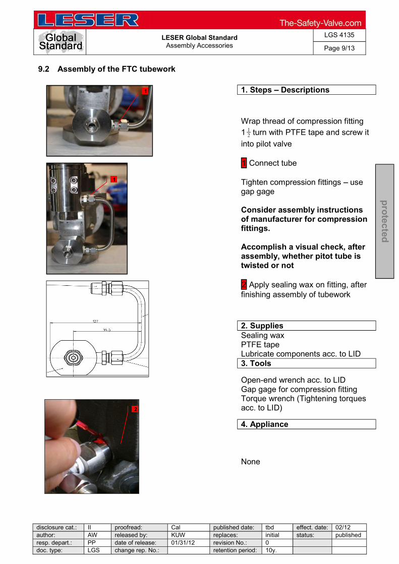
LESER Global Standard
Assembly Accessories
LGS 4135
Page 9/13
disclosure cat.: II proofread: Cal published date: tbd effect. date: 02/12 author: AW released by: KUW replaces: initial status: published resp. depart.: PP date of release: 01/31/12 revision No.: 0 doc. type: LGS change rep. No.: retention period: 10y.
pro
tected
9.2 Assembly of the FTC tubework
1. Steps Descriptions
Wrap thread of compression fitting 1 turn with PTFE tape and screw it
into pilot valve 1 Connect tube Tighten compression fittings use gap gage Consider assembly instructions of manufacturer for compression fittings. Accomplish a visual check, after assembly, whether pitot tube is twisted or not 2 Apply sealing wax on fitting, after finishing assembly of tubework
2. Supplies
Sealing wax PTFE tape Lubricate components acc. to LID
3. Tools
Open-end wrench acc. to LID Gap gage for compression fitting Torque wrench (Tightening torques acc. to LID)
4. Appliance
None
1
1
2
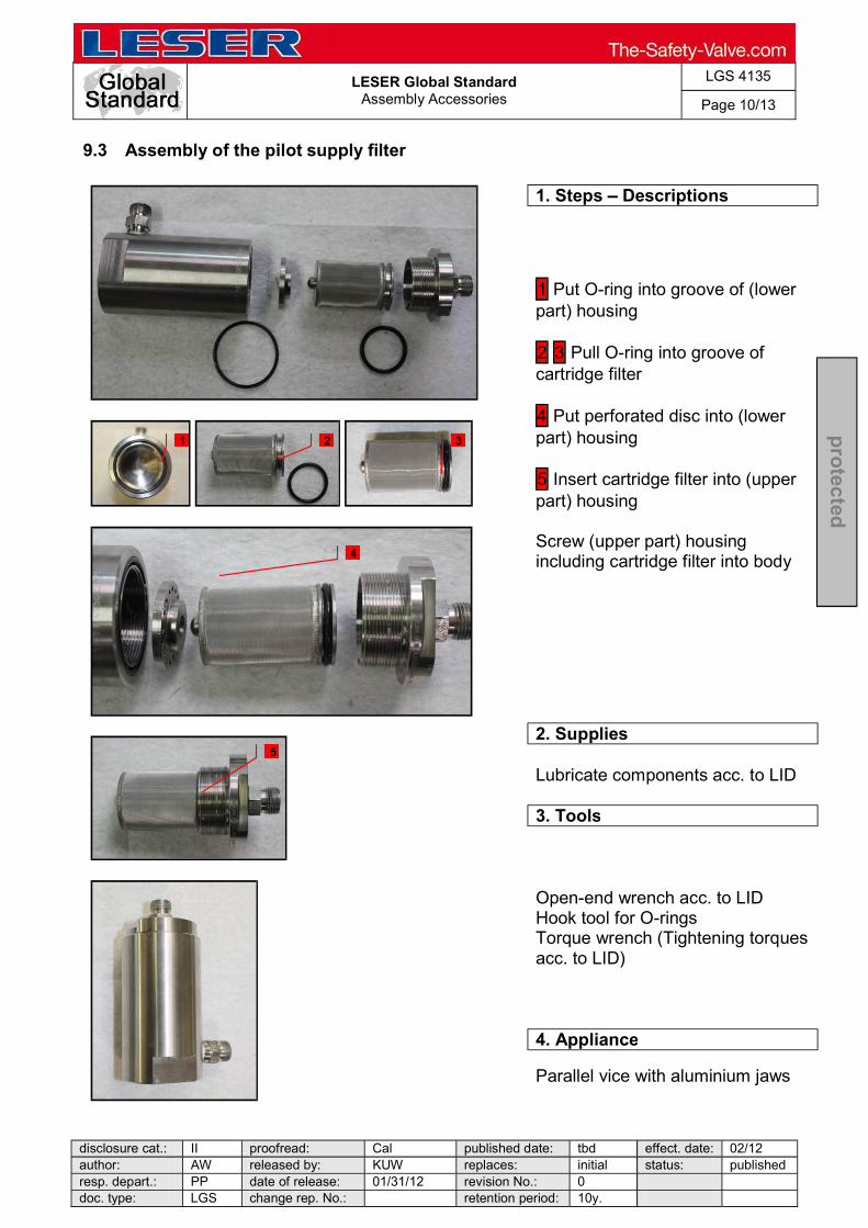
LESER Global Standard
Assembly Accessories
LGS 4135
Page 10/13
disclosure cat.: II proofread: Cal published date: tbd effect. date: 02/12 author: AW released by: KUW replaces: initial status: published resp. depart.: PP date of release: 01/31/12 revision No.: 0 doc. type: LGS change rep. No.: retention period: 10y.
pro
tected
9.3 Assembly of the pilot supply filter
1. Steps Descriptions
1 Put O-ring into groove of (lower part) housing 2 3 Pull O-ring into groove of cartridge filter 4 Put perforated disc into (lower part) housing 5 Insert cartridge filter into (upper part) housing Screw (upper part) housing including cartridge filter into body
2. Supplies
Lubricate components acc. to LID
3. Tools
Open-end wrench acc. to LID Hook tool for O-rings Torque wrench (Tightening torques acc. to LID)
4. Appliance
Parallel vice with aluminium jaws
1 2 3
4
5
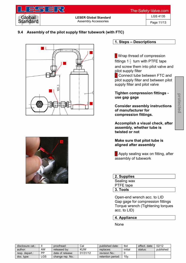
LESER Global Standard
Assembly Accessories
LGS 4135
Page 11/13
disclosure cat.: II proofread: Cal published date: tbd effect. date: 02/12 author: AW released by: KUW replaces: initial status: published resp. depart.: PP date of release: 01/31/12 revision No.: 0 doc. type: LGS change rep. No.: retention period: 10y.
pro
tected
9.4 Assembly of the pilot supply filter tubework (with FTC)
1. Steps Descriptions
1 Wrap thread of compression
fittings 1 turn with PTFE tape
and screw them into pilot valve and pilot supply filter 2 Connect tube between FTC and pilot supply filter and between pilot supply filter and pilot valve Tighten compression fittings - use gap gage Consider assembly instructions of manufacturer for compression fittings. Accomplish a visual check, after assembly, whether tube is twisted or not Make sure that pitot tube is aligned after assembly 3 Apply sealing wax on fitting, after assembly of tubework
2. Supplies
Sealing wax PTFE tape
3. Tools
Open-end wrench acc. to LID Gap gage for compression fittings Torque wrench (Tightening torques acc. to LID)
4. Appliance
None
1
1
2
3
1
2

LESER Global Standard
Assembly Accessories
LGS 4135
Page 12/13
disclosure cat.: II proofread: Cal published date: tbd effect. date: 02/12 author: AW released by: KUW replaces: initial status: published resp. depart.: PP date of release: 01/31/12 revision No.: 0 doc. type: LGS change rep. No.: retention period: 10y.
pro
tected
9.5 Assembly of the manual blowdown
1. Steps Descriptions
1 Wrap threads of compression
fittings 1 turn with PTFE tape
and screw them into ball valve and main valve Option A: Manual blowdown into main valve outlet 2 Mount L-tube (MBl.2) between top plate [9] and ball valve 3 Mount U-tube (MBl.3) between ball valve and body [1] Tighten compression fittings use gap gage Consider assembly instructions of manufacturer for compression fittings. Accomplish a visual check, after assembly, whether tube is twisted or not Close ball valve (MBl.1), screw off lever, tightening screw, fix lever sideways on ball valve with a strap Option B: Manual blowdown into atmosphere 3 Mount L-tube (MBl.2) between top plate and ball valve, align ball valve in direction of outlet Tighten compression fittings- use the gap gage Close ball valve (MBl.1), screw off lever, screw on screw, fix lever sideways on ball valve with a strap
2. Supplies None 3. Tools
Gap gage for compression fittings Open-end wrench acc. to LID Torque wrench (Tightening torques acc. to LID)
4. Appliance None
1
1
1 1
2
3
1
1
2
1
1
3
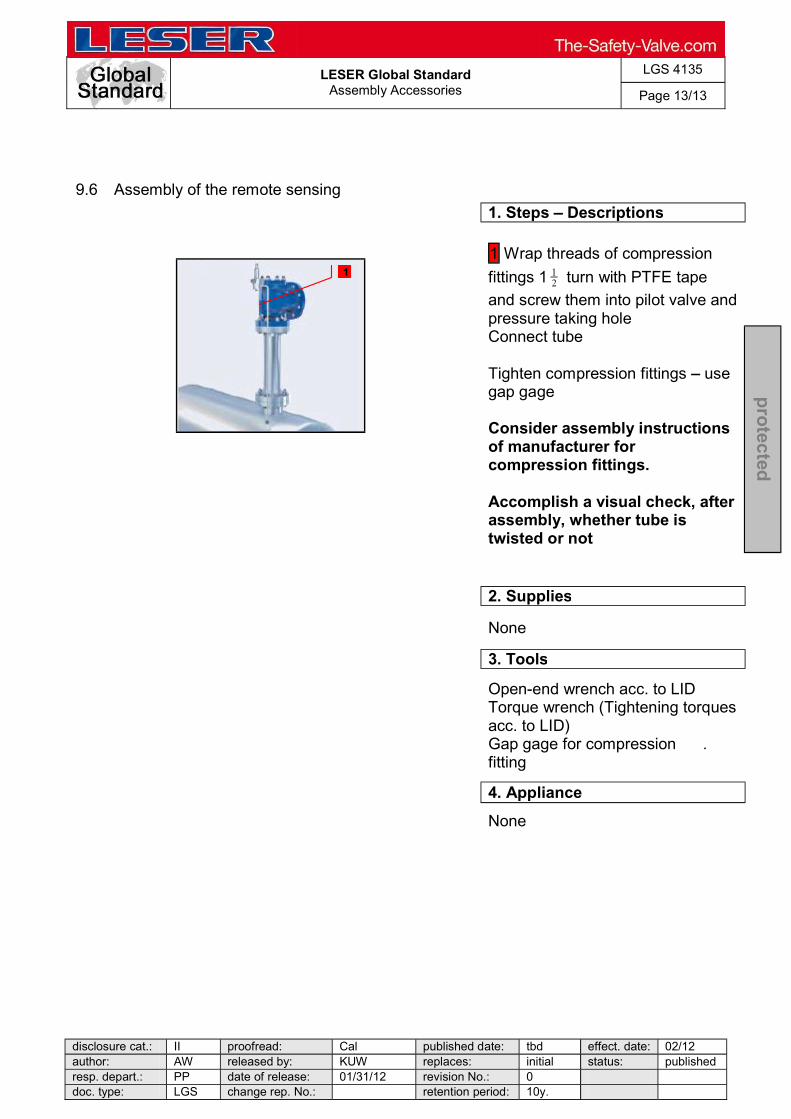
LESER Global Standard
Assembly Accessories
LGS 4135
Page 13/13
disclosure cat.: II proofread: Cal published date: tbd effect. date: 02/12 author: AW released by: KUW replaces: initial status: published resp. depart.: PP date of release: 01/31/12 revision No.: 0 doc. type: LGS change rep. No.: retention period: 10y.
pro
tected
9.6 Assembly of the remote sensing
1. Steps Descriptions
1 Wrap threads of compression
fittings 1 turn with PTFE tape
and screw them into pilot valve and pressure taking hole Connect tube Tighten compression fittings use gap gage Consider assembly instructions of manufacturer for compression fittings. Accomplish a visual check, after assembly, whether tube is twisted or not
2. Supplies
None
3. Tools
Open-end wrench acc. to LID Torque wrench (Tightening torques acc. to LID) Gap gage for compression . fitting
4. Appliance
None
1

LESER Global Standard
Marriage Pilot Valve and Main Valve
LGS 4136
Page 1/8
disclosure cat.: II proofread: Cal published date: tbd effect. date: 02/12 author: AW released by: KUW replaces: initial status: published resp. depart.: PP date of release: 01/31/12 revision No.: 0 doc. type: LGS change rep. No.: retention period: 10y.
pro
tected
Content 1 General information for separating the Main Valve from the Pilot Valve . 2 2 Purpose ......................................................................................................... 2 3 Competences ................................................................................................ 2 4 Scope ............................................................................................................. 2 5 Disclaimer ...................................................................................................... 2 6 Qualified fitting personnel ............................................................................ 2 7 Remarks ......................................................................................................... 2 8 Basic safety guidelines ................................................................................ 3 9 Disassembly instructions ............................................................................. 6

LESER Global Standard
Marriage Pilot Valve and Main Valve
LGS 4136
Page 2/8
disclosure cat.: II proofread: Cal published date: tbd effect. date: 02/12 author: AW released by: KUW replaces: initial status: published resp. depart.: PP date of release: 01/31/12 revision No.: 0 doc. type: LGS change rep. No.: retention period: 10y.
pro
tected
1 General information for separating the Main Valve from the Pilot Valve
2 Purpose
The documentation describes the marriage of the main valve and the pilot valve. The description contains every single working step, supplies, tools and appliances.
3 Competences
The generation, maintenance and distribution of the documentation takes place in the organisation department. The defaults will be generated by the technical department in consultation with the final assembly department and production planning department.
4 Scope
This document must be applied to the dismantling of a Pilot Operated Safety Valve in agencies and subsidiaries of LESER GmbH & Co. KG customers and independent service center.
5 Disclaimer
LESER puts in a great deal of effort into making up-to-date and correct documentation available. Nevertheless, LESER GmbH & Co. KG gives no guarantee that the recommended actions presented here are entirely correct and error free. This document is to be applied exclusively to the specified type. LESER GmbH & Co. KG declines any liability or responsibility for the correctness and completeness of the content. LESER GmbH & Co. KG reserves the right to change the information contained in this document, which is for the products of LESER GmbH & Co. KG and is intended for LESER subsidiaries, at any time and without prior announcement. LESER GmbH & Co. KG is available to the users of this document to provide additional information.
6 Qualified fitting personnel
LESER safety valves may only be dismantled by trained or qualified fitters. The qualifications must be obtained through the appropriate training measures.
7 Remarks
Gloves must be worn during the entire dismantling process.

LESER Global Standard
Marriage Pilot Valve and Main Valve
LGS 4136
Page 3/8
disclosure cat.: II proofread: Cal published date: tbd effect. date: 02/12 author: AW released by: KUW replaces: initial status: published resp. depart.: PP date of release: 01/31/12 revision No.: 0 doc. type: LGS change rep. No.: retention period: 10y.
pro
tected
8 Basic safety guidelines
Dangerous media Poisoning, caustic burns, burns, injuries
Foreign bodies in the safety valve Danger from failure of safety valve or leaks
efore installation of a safety valve. objects.
Bug screen is damaged or missing (B or option) Dirt, objects or insects get into the safety valve. Danger from malfunction of the safety valve. Install the bug screen correctly.
Ambient temperature is too high Material expansion. Danger from malfunction of the safety valve. Ambient temperature is too low Icing, freezing vapours, reduced flow rate due to congealing media. Danger from functional disruption of the safety valve. Abrasive or corrosive media Moving parts jam or become stuck. Danger from functional disruption of the safety valve.
it opens. Media with high proportion of particles

LESER Global Standard
Marriage Pilot Valve and Main Valve
LGS 4136
Page 4/8
disclosure cat.: II proofread: Cal published date: tbd effect. date: 02/12 author: AW released by: KUW replaces: initial status: published resp. depart.: PP date of release: 01/31/12 revision No.: 0 doc. type: LGS change rep. No.: retention period: 10y.
pro
tected
(only B) Deposits and clogging. Danger from malfunction of the safety valve.
filter capacity.
Residual media in the safety valve Poisoning, caustic burns, burns, injuries
WARNING Leaky safety valve Danger from leaking media due to damaged gaskets and sealing surfaces.
and blows especially during transport and installation.
Open bonnet or spindle guides Danger from leaking media
leaking media.
nt. CAUTION Hot medium Burns or scalding.
Hot surfaces Burns.
Aggressive medium Caustic burns.

LESER Global Standard
Marriage Pilot Valve and Main Valve
LGS 4136
Page 5/8
disclosure cat.: II proofread: Cal published date: tbd effect. date: 02/12 author: AW released by: KUW replaces: initial status: published resp. depart.: PP date of release: 01/31/12 revision No.: 0 doc. type: LGS change rep. No.: retention period: 10y.
pro
tected
Open bonnet or spindle guides Pinching danger from moving parts.
Sharp edges and burrs Danger of injury.
High noise emission Hearing damage. Wear ear protection.

LESER Global Standard
Marriage Pilot Valve and Main Valve
LGS 4136
Page 6/8
disclosure cat.: II proofread: Cal published date: tbd effect. date: 02/12 author: AW released by: KUW replaces: initial status: published resp. depart.: PP date of release: 01/31/12 revision No.: 0 doc. type: LGS change rep. No.: retention period: 10y.
pro
tected
9 Disassembly instructions
9.1 Marriage of the pilot valve and the main valve
1. Steps Descriptions
1 Screw pilot valve and manifold block with 4 screws [22] on top plate [9] of main valve
2. Supplies
Lubricate components acc. to LID
3. Tools
Allen key acc. to LID Torque wrench (Tightening torques acc. to LID)
4. Appliance
1
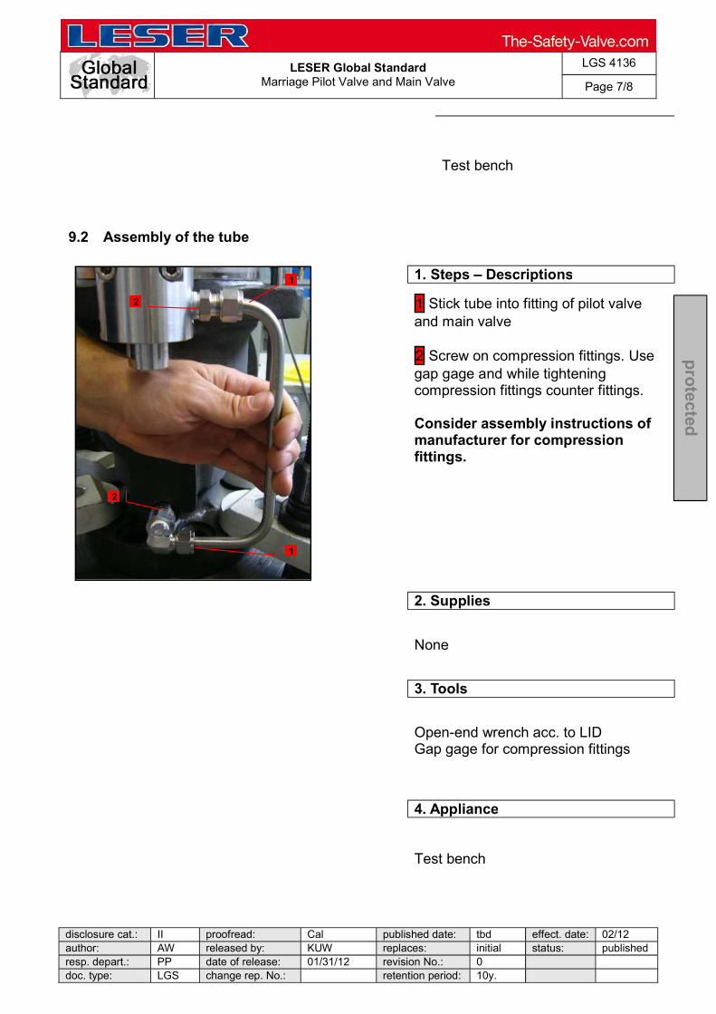
LESER Global Standard
Marriage Pilot Valve and Main Valve
LGS 4136
Page 7/8
disclosure cat.: II proofread: Cal published date: tbd effect. date: 02/12 author: AW released by: KUW replaces: initial status: published resp. depart.: PP date of release: 01/31/12 revision No.: 0 doc. type: LGS change rep. No.: retention period: 10y.
pro
tected
Test bench
9.2 Assembly of the tube
1. Steps Descriptions
1 Stick tube into fitting of pilot valve and main valve 2 Screw on compression fittings. Use gap gage and while tightening compression fittings counter fittings. Consider assembly instructions of manufacturer for compression fittings.
2. Supplies
None
3. Tools
Open-end wrench acc. to LID Gap gage for compression fittings
4. Appliance
Test bench
1
2
1
2

LESER Global Standard
Marriage Pilot Valve and Main Valve
LGS 4136
Page 8/8
disclosure cat.: II proofread: Cal published date: tbd effect. date: 02/12 author: AW released by: KUW replaces: initial status: published resp. depart.: PP date of release: 01/31/12 revision No.: 0 doc. type: LGS change rep. No.: retention period: 10y.
pro
tected
9.3 Sealing the valve
1. Steps Descriptions
Sealing after assembly and passed tests! Seal valve, if constructive possibility exists. Otherwise next workstation has to weld on sealing noses (cap; bonnet; body) 1 Connect sealing hole/ nose of pilot valve and main valve with wire tight and in clockwise 2 Close wire ends with seal Note: In case of required certifications (TÜV etc.) sealing ensued after certification
2. Supplies
None
3. Tools
Sealing pliers
4. Appliance
None
1
2 1

LESER Global Standard Overview of the Tightening Torques POSV
LGS 3322_EN
Seite 1/15
disclosure cat.: II proofread: Haa published date: 9/25/14 effect. date: 9/14 author: TK released by: JR replaces: 3322- status: published resp. depart.: TB date of release: 9/25/14 revision No.: 4 doc. type: LGS change rep. No.: 200153 retention period: 10y.
pro
tecte
d
Content
1 PURPOSE 1
2 SCOPE 1
3 REFERENCES 1
4 POP ACTION PILOT TYPE 8104.1000 UND 8104.2000 2
5 MODULATE ACTION PILOT VALVE TYPE 8204.1000 (DIAPHRAGM) 3
6 MODULATE ACTION PILOT VALVE TYPE 8204.2000 UND 8204.3000 (PISTON UP TO 3713PSI) 4
7 MODULATE ACTION PILOT VALVE TYPE 8204.4000 (PISTON OVER 3713PSI) 5
8 MAIN VALVE SEMI NOZZLE AND FULL NOZZLE 6
9 ACCESSORIES 11
9.1 STANDARD TUBING 11 9.2 FIELD-TEST-CONNECTOR (FTC) 12 9.3 FTC AND PILOT SUPPLY FILTER 13 9.4 MANUAL BLOWDOWN 14 9.5 NEEDLE VALVE FOR FTC 15
1 Purpose
This LESER global standard (LGS) describes tightening torques and lubrication of pilot safety valves. 2 Scope
This LGS pertains to all LESER quality associates. 3 References
None

LESER Global Standard Overview of the Tightening Torques POSV
LGS 3322_EN
Seite 2/15
disclosure cat.: II proofread: Haa published date: 9/25/14 effect. date: 9/14 author: TK released by: JR replaces: 3322- status: published resp. depart.: TB date of release: 9/25/14 revision No.: 4 doc. type: LGS change rep. No.: 200153 retention period: 10y.
pro
tecte
d
4 Pop Action Pilot Type 8104.1000 und 8104.2000
Figure 1: Cross section pop action pilot valve
Index Thread connections
[pos. number] Thread SW
Torque [Nm]
Lubrication Tool
I Bonnet [9 ] / cap /lever [40]
M24 x 1,5 27 50-55 Molykote D
Paste Open-end spanner
II Bonnet [9] / bonnet base part [10]
M36 x 1,5 34 60-70 Halocarbon-oil
56 S Open-end spanner
III Bonnet base part [10] / bod [1]
M30 x 1,5 36
cranked 70-80
Halocarbon-oil 56 S
Open-end spanner
IV Manifold block [24.1] / plug [24.7]
G1/4 6 55-60 Halocarbon-oil
56 S Allen key
V Seat, feeding [5] / adjusting screw [12]
M16 x 1 16 30-35 Halocarbon-oil
56 S Open-end spanner
VI Nut [20] / body [1] M33 x 1,5 24 45-50 Molykote D
paste Open-end spanner
VII Counter nut [21] / adjusting screw [12]
M12 x 1 19 25-30 Molykote D
Paste Open-end spanner
VIII Test gag [93] / bonnet [9]
M10 16 40-50 Halocarbon-oil
56 S Open-end spanner
Table 1: Overview of the pop action pilot valve screw connections
II
VI
V
IV
III
I
VIII

LESER Global Standard Overview of the Tightening Torques POSV
LGS 3322_EN
Seite 3/15
disclosure cat.: II proofread: Haa published date: 9/25/14 effect. date: 9/14 author: TK released by: JR replaces: 3322- status: published resp. depart.: TB date of release: 9/25/14 revision No.: 4 doc. type: LGS change rep. No.: 200153 retention period: 10y.
pro
tecte
d
5 Modulate action pilot valve Type 8204.1000 (diaphragm)
Figure 2: Cross section of the modulate action pilot valve (diaphragm)
Index Thread connection
[Pos. Nummer] Thread SW
Torque [Nm]
Lubrication Tool
I Bonnet [9] / cap [40] M33 x 1,5 41 55-65 Molykote D
paste Open-end spanner
II Spidle [12] / spring plate [17]
M8 10 Paste into Delo ML 5449 ---
Open-end spanner
III Bonnet [9]/ spacer [75]
M68 x 1,5 60 140-150 Halocarbon-oil
56 S Open-end spanner
IV Hexagon-screw M5 8 4-6 --- Ring spanner
V Spacer [75] / body [1] M56 x 1,5 70 cranked 170-180
Molykote D paste
Open-end spanner
VI Disc feeding (upper) [7] / disc exhaust (lower) [11]
M6 13 8-10 --- Open-end spanner
VII Seat feeding [5] / piston [41] M18 x 1 21 65-70 --- Open-end spanner
VIII Disc exhaust (lower) [11]/ disc extension [45]
M6 8 8-10 --- Open-end spanner
IX Plug [20] / body [1] M33 x 1,5 26 45-50 Molykote D
paste Open-end spanner
X Nut [70] / piston [41] M12 19/8 22-26 --- Deep cranked
double ring spanner + os
XI Manifold block [24.1] / plug [24.7]
G1/4 6 55-60 Halocarbon-oil
56 S Allen key
Table 2: Overview of the modulate action pilot valve (diaphragm) screw connections
IX
VIII
VII
VI
V
III
II
I
XI
X IV
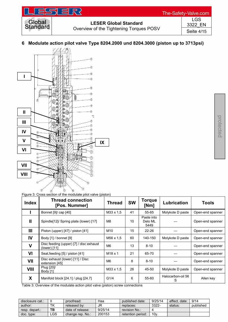
LESER Global Standard Overview of the Tightening Torques POSV
LGS 3322_EN
Seite 4/15
disclosure cat.: II proofread: Haa published date: 9/25/14 effect. date: 9/14 author: TK released by: JR replaces: 3322- status: published resp. depart.: TB date of release: 9/25/14 revision No.: 4 doc. type: LGS change rep. No.: 200153 retention period: 10y.
pro
tecte
d
6 Modulate action pilot valve Type 8204.2000 und 8204.3000 (piston up to 3713psi)
Figure 3: Cross section of the modulate pilot valve (piston)
Index Thread connection
[Pos. Nummer] Thread SW
Torque [Nm]
Lubrication Tools
I Bonnet [9]/ cap [40] M33 x 1,5 41 55-65 Molykote D paste Open-end spanner
II Spindle[12]/ Spring plate (lower) [17] M8 10 Paste into Delo ML
5449 --- Open-end spanner
III Piston (upper) [47] / piston [41] M10 15 22-26 --- Open-end spanner
IV Body [1] / bonnet [9] M56 x 1,5 60 140-150 Molykote D paste Open-end spanner
V Disc feeding (upper) [7] / disc exhaust (lower) [11]
M6 13 8-10 --- Open-end spanner
VI Seat,feeding [5] / piston [41] M18 x 1 21 65-70 --- Open-end spanner
VII Disc exhaust (lower) [11] / Disc extension [45]
M6 8 8-10 --- Open-end spanner
VIII Plug [20]/ Body [1]
M33 x 1,5 26 45-50 Molykote D paste Open-end spanner
X Manifold block [24.1] / plug [24.7] G1/4 6 55-60 Halocarbon-oil 56
S Allen key
Table 3: Overview of the modulate action pilot valve (piston) screw connections
IX
I
II
III
IV
VI
VIII
VII
V
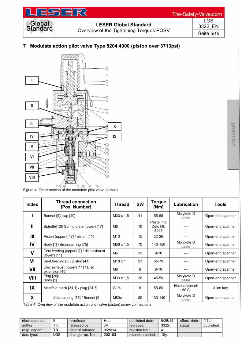
LESER Global Standard Overview of the Tightening Torques POSV
LGS 3322_EN
Seite 5/15
disclosure cat.: II proofread: Haa published date: 9/25/14 effect. date: 9/14 author: TK released by: JR replaces: 3322- status: published resp. depart.: TB date of release: 9/25/14 revision No.: 4 doc. type: LGS change rep. No.: 200153 retention period: 10y.
pro
tecte
d
7 Modulate action pilot valve Type 8204.4000 (piston over 3713psi)
Figure 4: Cross section of the modulate pilot valve (piston)
Index Thread connection
[Pos. Number] Thread SW
Torque [Nm]
Lubrication Tools
I Bonnet [9]/ cap [40] M33 x 1,5 41 55-65 Molykote D
paste Open-end spanner
II Spindle[12]/ Spring plate (lower) [17] M8 10 Paste into Delo ML
5449 --- Open-end spanner
III Piston (upper) [47] / piston [41] M10 15 22-26 --- Open-end spanner
IV Body [1] / distance ring [75] M56 x 1,5 70 140-150 Molykote D
paste Open-end spanner
V Disc feeding (upper) [7] / disc exhaust (lower) [11]
M6 13 8-10 --- Open-end spanner
VI Seat,feeding [5] / piston [41] M18 x 1 21 65-70 --- Open-end spanner
VII Disc exhaust (lower) [11] / Disc extension [45]
M6 8 8-10 --- Open-end spanner
VIII Plug [20]/ Body [1]
M33 x 1,5 26 45-50 Molykote D
paste Open-end spanner
IX Manifold block [24.1] / plug [24.7] G1/4 6 55-60 Halocarbon-oil
56 S Allen key
X distance ring [75] / Bonnet [9 M80x1 80 130-140 Molykote D paste Open-end spanner
Table 4: Overview of the modulate action pilot valve (piston) screw connections
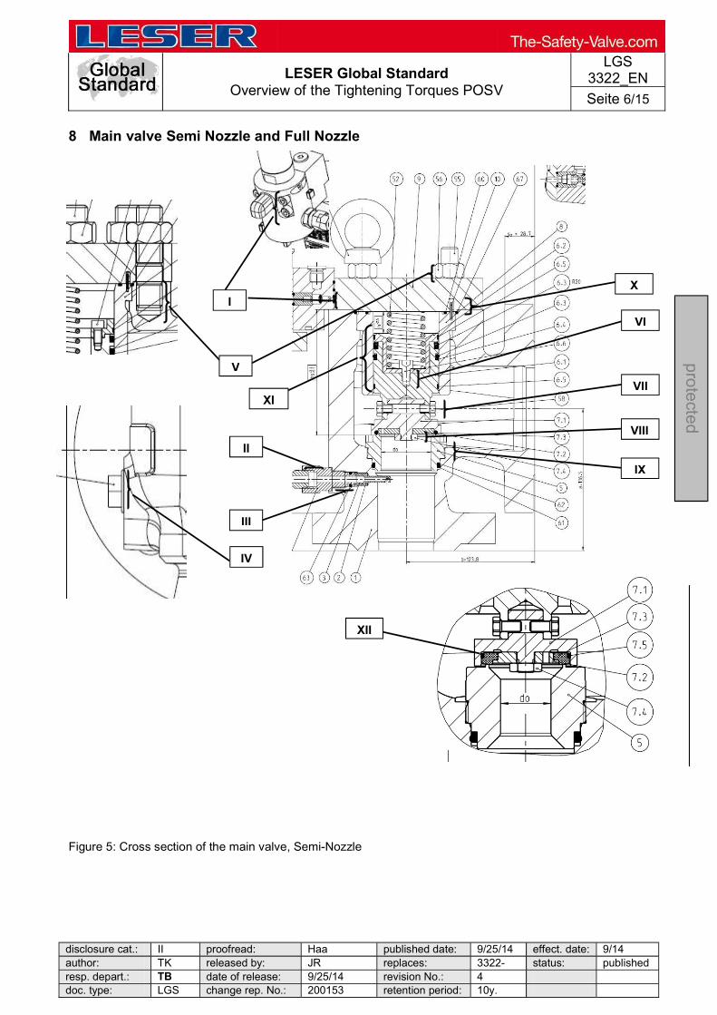
LESER Global Standard Overview of the Tightening Torques POSV
LGS 3322_EN
Seite 6/15
disclosure cat.: II proofread: Haa published date: 9/25/14 effect. date: 9/14 author: TK released by: JR replaces: 3322- status: published resp. depart.: TB date of release: 9/25/14 revision No.: 4 doc. type: LGS change rep. No.: 200153 retention period: 10y.
pro
tecte
d
8 Main valve Semi Nozzle and Full Nozzle
Figure 5: Cross section of the main valve, Semi-Nozzle
IX
VIII
VII
VI
X
III
II
IV
V
I
XII
XI
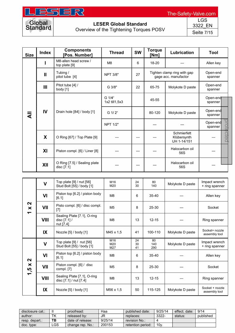
LESER Global Standard Overview of the Tightening Torques POSV
LGS 3322_EN
Seite 7/15
disclosure cat.: II proofread: Haa published date: 9/25/14 effect. date: 9/14 author: TK released by: JR replaces: 3322- status: published resp. depart.: TB date of release: 9/25/14 revision No.: 4 doc. type: LGS change rep. No.: 200153 retention period: 10y.
pro
tecte
d
Size Index
Components [Pos. Number]
Thread SW Torque
[Nm] Lubrication Tool
All
I M8-allen head screw / top plate [9]
M8 6 18-20 --- Allen key
II Tubing / pitot tube [4]
NPT 3/8" 27 Tighten clamp ring with gap
gage acc. manufactor Open-end spanner
III Pitot tube [4] / body [1]
G 3/8" 22 65-75 Molykote D paste Open-end spanner
IV Drain hole [84] / body [1]
1x2 till1,5x3
45-55 Open-end spanner
80-120 Molykote D paste Open-end spanner
NPT 1/2" --- --- Open-end spanner
X O Ring [67] / Top Plate [9] --- --- --- Schmierfett Klübersynth UH 1-14/151
---
XI Piston compl. [6] / Liner [8] --- --- --- Halocarbon oil
56S ---
XII O Ring [7.5] / Sealing plate disc [7.1]
--- --- --- Halocarbon oil
56S ---
1 x
2
V Top plate [9] / nut [56] Stud Bolt [55] / body [1]
M16 M20
24 30
80 140 Molykote D paste
Impact wrench + ring spanner
VI Piston top [6.2] / piston body [6.1]
M8 6 35-40 --- Allen key
VII Pisto compl. [6] / disc compl. [7]
M5 8 25-30 --- Socket
VIII Sealing Plate [7.1], O-ring disc [7.1] / nut [7.4]
M8 13 12-15 --- Ring spanner
IX Nozzle [5] / body [1] M45 x 1,5 41 100-110 Molykote D paste Socket+ nozzle assembly tool
1,5
x 2
V Top plate [9] / nut [56] Stud Bolt [55] / body [1]
M16 M20 M27
24 30 41
80 140 290
Molykote D paste Impact wrench + ring spanner
VI Piston top [6.2] / piston body [6.1]
M8 6 35-40 --- Allen key
VII Piston compl. [6] / disc compl. [7]
M5 8 25-30 --- Socket
VIII Sealing Plate [7.1], O-ring disc [7.1] / nut [7.4]
M8 13 12-15 --- Ring spanner
IX Nozzle [5] / body [1] M56 x 1,5 50 115-125 Molykote D paste Socket + nozzle assembly tool
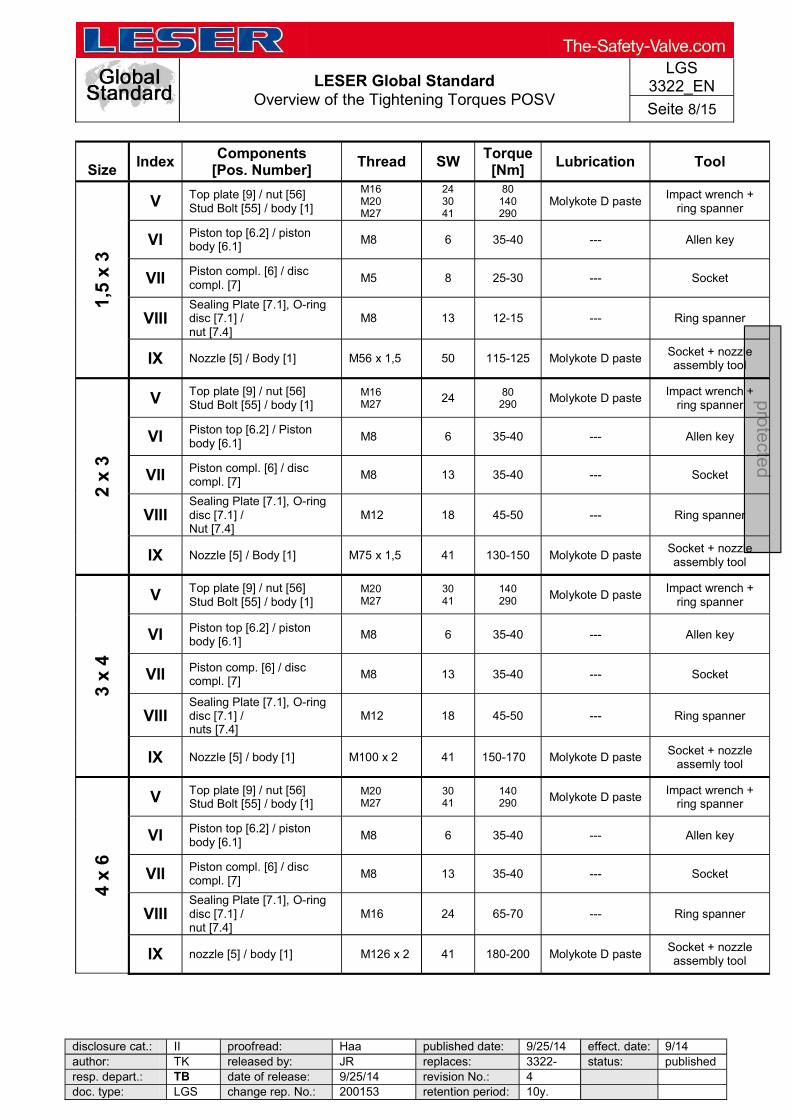
LESER Global Standard Overview of the Tightening Torques POSV
LGS 3322_EN
Seite 8/15
disclosure cat.: II proofread: Haa published date: 9/25/14 effect. date: 9/14 author: TK released by: JR replaces: 3322- status: published resp. depart.: TB date of release: 9/25/14 revision No.: 4 doc. type: LGS change rep. No.: 200153 retention period: 10y.
pro
tecte
d
Size Index
Components [Pos. Number]
Thread SW Torque
[Nm] Lubrication Tool
1,5
x 3
V Top plate [9] / nut [56] Stud Bolt [55] / body [1]
M16 M20 M27
24 30 41
80 140 290
Molykote D paste Impact wrench +
ring spanner
VI Piston top [6.2] / piston body [6.1]
M8 6 35-40 --- Allen key
VII Piston compl. [6] / disc compl. [7]
M5 8 25-30 --- Socket
VIII Sealing Plate [7.1], O-ring disc [7.1] / nut [7.4]
M8 13 12-15 --- Ring spanner
IX Nozzle [5] / Body [1] M56 x 1,5 50 115-125 Molykote D paste Socket + nozzle assembly tool
2 x
3
V Top plate [9] / nut [56] Stud Bolt [55] / body [1]
M16 M27 24 80
290 Molykote D paste Impact wrench +
ring spanner
VI Piston top [6.2] / Piston body [6.1]
M8 6 35-40 --- Allen key
VII Piston compl. [6] / disc compl. [7]
M8 13 35-40 --- Socket
VIII Sealing Plate [7.1], O-ring disc [7.1] / Nut [7.4]
M12 18 45-50 --- Ring spanner
IX Nozzle [5] / Body [1] M75 x 1,5 41 130-150 Molykote D paste Socket + nozzle assembly tool
3 x
4
V Top plate [9] / nut [56] Stud Bolt [55] / body [1]
M20 M27
30 41
140 290 Molykote D paste
Impact wrench + ring spanner
VI Piston top [6.2] / piston body [6.1]
M8 6 35-40 --- Allen key
VII Piston comp. [6] / disc compl. [7]
M8 13 35-40 --- Socket
VIII Sealing Plate [7.1], O-ring disc [7.1] / nuts [7.4]
M12 18 45-50 --- Ring spanner
IX Nozzle [5] / body [1] M100 x 2 41 150-170 Molykote D paste Socket + nozzle
assemly tool
4 x
6
V Top plate [9] / nut [56] Stud Bolt [55] / body [1]
M20 M27
30 41
140 290 Molykote D paste
Impact wrench + ring spanner
VI Piston top [6.2] / piston body [6.1]
M8 6 35-40 --- Allen key
VII Piston compl. [6] / disc compl. [7]
M8 13 35-40 --- Socket
VIII Sealing Plate [7.1], O-ring disc [7.1] / nut [7.4]
M16 24 65-70 --- Ring spanner
IX nozzle [5] / body [1] M126 x 2 41 180-200 Molykote D paste Socket + nozzle assembly tool
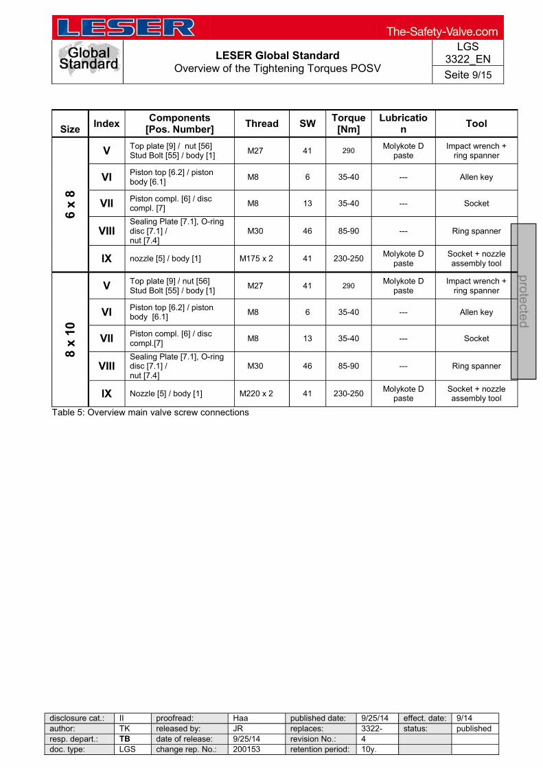
LESER Global Standard Overview of the Tightening Torques POSV
LGS 3322_EN
Seite 9/15
disclosure cat.: II proofread: Haa published date: 9/25/14 effect. date: 9/14 author: TK released by: JR replaces: 3322- status: published resp. depart.: TB date of release: 9/25/14 revision No.: 4 doc. type: LGS change rep. No.: 200153 retention period: 10y.
pro
tecte
d
Size Index Components
[Pos. Number] Thread SW
Torque [Nm]
Lubrication
Tool
6 x
8
V Top plate [9] / nut [56] Stud Bolt [55] / body [1]
M27 41 290 Molykote D paste
Impact wrench + ring spanner
VI Piston top [6.2] / piston body [6.1]
M8 6 35-40 --- Allen key
VII Piston compl. [6] / disc compl. [7]
M8 13 35-40 --- Socket
VIII Sealing Plate [7.1], O-ring disc [7.1] / nut [7.4]
M30 46 85-90 --- Ring spanner
IX nozzle [5] / body [1] M175 x 2 41 230-250 Molykote D
paste Socket + nozzle assembly tool
8 x
10
V Top plate [9] / nut [56] Stud Bolt [55] / body [1]
M27 41 290 Molykote D paste
Impact wrench + ring spanner
VI Piston top [6.2] / piston body [6.1]
M8 6 35-40 --- Allen key
VII Piston compl. [6] / disc compl.[7]
M8 13 35-40 --- Socket
VIII Sealing Plate [7.1], O-ring disc [7.1] / nut [7.4]
M30 46 85-90 --- Ring spanner
IX Nozzle [5] / body [1] M220 x 2 41 230-250 Molykote D
paste Socket + nozzle assembly tool
Table 5: Overview main valve screw connections
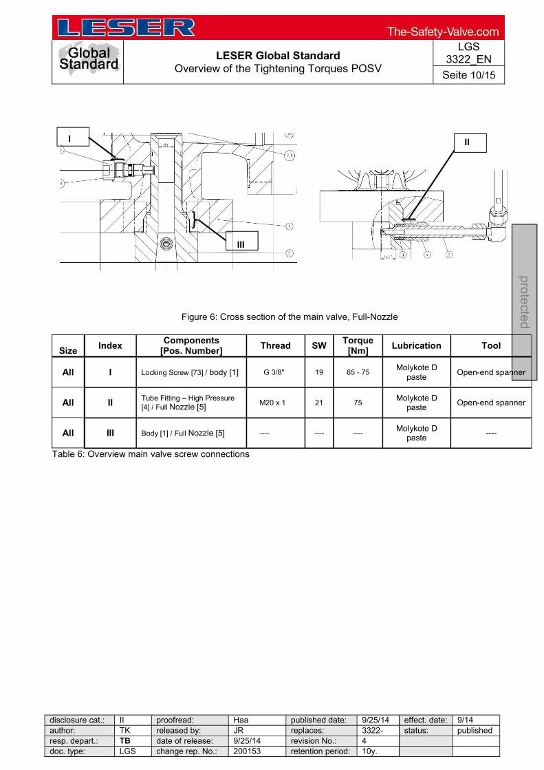
LESER Global Standard Overview of the Tightening Torques POSV
LGS 3322_EN
Seite 10/15
disclosure cat.: II proofread: Haa published date: 9/25/14 effect. date: 9/14 author: TK released by: JR replaces: 3322- status: published resp. depart.: TB date of release: 9/25/14 revision No.: 4 doc. type: LGS change rep. No.: 200153 retention period: 10y.
pro
tecte
d
Figure 6: Cross section of the main valve, Full-Nozzle
Size
Index Components
[Pos. Number] Thread SW
Torque [Nm]
Lubrication Tool
All I Locking Screw [73] / body [1] G 3/8" 19 65 - 75 Molykote D
paste Open-end spanner
All II Tube Fitting High Pressure [4] / Full Nozzle [5] M20 x 1 21 75
Molykote D paste
Open-end spanner
All III Body [1] / Full Nozzle [5] ---- ---- ---- Molykote D
paste ----
Table 6: Overview main valve screw connections
I II
III

LESER Global Standard Overview of the Tightening Torques POSV
LGS 3322_EN
Seite 11/15
disclosure cat.: II proofread: Haa published date: 9/25/14 effect. date: 9/14 author: TK released by: JR replaces: 3322- status: published resp. depart.: TB date of release: 9/25/14 revision No.: 4 doc. type: LGS change rep. No.: 200153 retention period: 10y.
pro
tecte
d
9 Accessories
9.1 Standard tubing
Figure 7: Standard tubing
Components Index Thread SW Torque [Nm]
Standard tubing
Pilot valve I 18 / 19 Tighten clamp ring with gap gage acc. manufactor
Body II 16 / 19 Tighten clamp ring with gap gage acc. manufactor
Table 7: Overview of the standard tubing screw connections
I
II

LESER Global Standard Overview of the Tightening Torques POSV
LGS 3322_EN
Seite 12/15
disclosure cat.: II proofread: Haa published date: 9/25/14 effect. date: 9/14 author: TK released by: JR replaces: 3322- status: published resp. depart.: TB date of release: 9/25/14 revision No.: 4 doc. type: LGS change rep. No.: 200153 retention period: 10y.
pro
tecte
d
9.2 Field-test-connector (FTC)
Figure 8: Tubing with FTC
Figure 9: Tubing with FTC full-nozzle
Components Index Thread SW Torque [Nm]
Lubrication Tool
FTC
Pilot valve I 18 / 19
Tighten clamp ring with gap gage acc.
manufactor ---
Open-end spanner
Tube II 18 / 19
Tighten clamp ring with gap gage acc.
manufactor ---
Open-end spanner
Pitot tube III G 3/8" 22 60-70 Molykote D
Paste Open-end spanner
Body (FTC) / Clasp (FTC)
IV M20x1,5 27/ 22 100-120 Halocarbo-oil
56 S Open-end spanner
Body (FTC) / Clasp (FTC)
Full Nozzle VI M30x1,5 32 100 -120
Halocarbo-oil 56 S
Open-end spanner
Nut FTC V 24 45-50 Halocarbo-oil
56 S Open-end spanner
Table 8: Overview of the FTC screw connections
I
II
III
V
IV
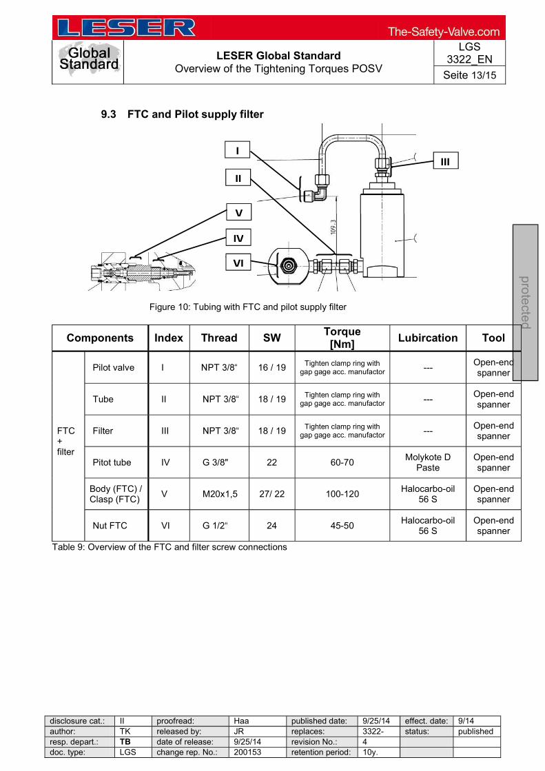
LESER Global Standard Overview of the Tightening Torques POSV
LGS 3322_EN
Seite 13/15
disclosure cat.: II proofread: Haa published date: 9/25/14 effect. date: 9/14 author: TK released by: JR replaces: 3322- status: published resp. depart.: TB date of release: 9/25/14 revision No.: 4 doc. type: LGS change rep. No.: 200153 retention period: 10y.
pro
tecte
d
9.3 FTC and Pilot supply filter
Figure 10: Tubing with FTC and pilot supply filter
Components Index Thread SW Torque [Nm]
Lubircation Tool
FTC + filter
Pilot valve I 16 / 19 Tighten clamp ring with gap gage acc. manufactor ---
Open-end spanner
Tube II 18 / 19 Tighten clamp ring with gap gage acc. manufactor ---
Open-end spanner
Filter III 18 / 19 Tighten clamp ring with gap gage acc. manufactor ---
Open-end spanner
Pitot tube IV G 3/8" 22 60-70 Molykote D
Paste Open-end spanner
Body (FTC) / Clasp (FTC)
V M20x1,5 27/ 22 100-120 Halocarbo-oil
56 S Open-end spanner
Nut FTC VI 24 45-50 Halocarbo-oil
56 S Open-end spanner
Table 9: Overview of the FTC and filter screw connections
III
IV
VI
I
II
V
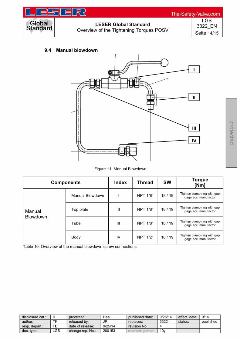
LESER Global Standard Overview of the Tightening Torques POSV
LGS 3322_EN
Seite 14/15
disclosure cat.: II proofread: Haa published date: 9/25/14 effect. date: 9/14 author: TK released by: JR replaces: 3322- status: published resp. depart.: TB date of release: 9/25/14 revision No.: 4 doc. type: LGS change rep. No.: 200153 retention period: 10y.
pro
tecte
d
9.4 Manual blowdown
Figure 11: Manual Blowdown
Components Index Thread SW Torque [Nm]
Manual Blowdown
Manual Blowdown I 18 / 19 Tighten clamp ring with gap gage acc. manufactor
Top plate II 18 / 19 Tighten clamp ring with gap gage acc. manufactor
Tube III 18 / 19 Tighten clamp ring with gap gage acc. manufactor
Body IV 18 / 19 Tighten clamp ring with gap gage acc. manufactor
Table 10: Overview of the manual blowdown screw connections
I
II
III
IV
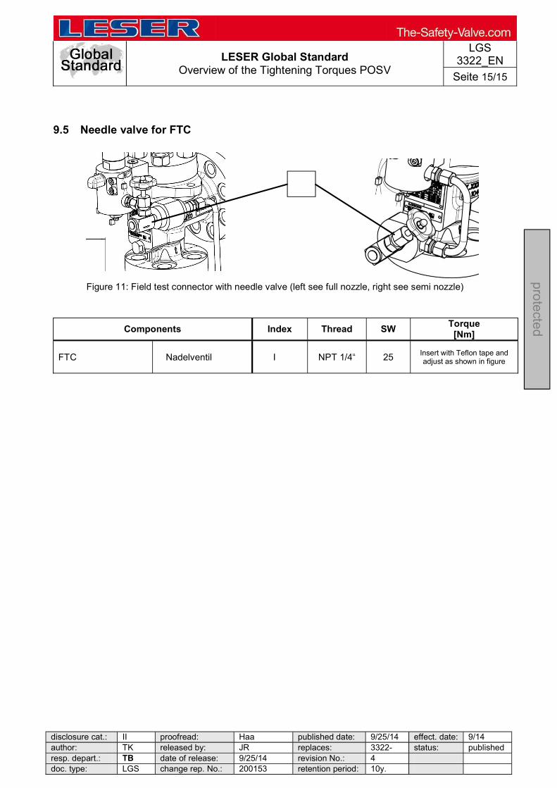
LESER Global Standard Overview of the Tightening Torques POSV
LGS 3322_EN
Seite 15/15
disclosure cat.: II proofread: Haa published date: 9/25/14 effect. date: 9/14 author: TK released by: JR replaces: 3322- status: published resp. depart.: TB date of release: 9/25/14 revision No.: 4 doc. type: LGS change rep. No.: 200153 retention period: 10y.
pro
tecte
d
9.5 Needle valve for FTC
Figure 11: Field test connector with needle valve (left see full nozzle, right see semi nozzle)
Components Index Thread SW Torque
[Nm]
FTC Nadelventil I NPT 1/4 25 Insert with Teflon tape and adjust as shown in figure
LESER Global Standard Component Plates
LGS 4118
Page 1/10
disclosure cat.: II proofread: OR published date: 9/14/11 effect. date: 18.11.201author: Nieh released by: KUW replaces: initial status: published resp. depart.: PP date of release: 11/8/11 revision No.: 0 doc. type: LGS change rep. No.: 651A retention period: 10
pro
tected
Contents
1 Purpose ............................................................................................................... 1 2 Scope .................................................................................................................. 1 3 Disclaimer ............................................................................................................ 1 4 Qualified fitting personnel .................................................................................... 2 5 General Information ............................................................................................. 2 6 Attaching component/customer identification plates ............................................ 2
6.1 Standard plate .............................................................................................. 3 6.2 World plate (NGA) ........................................................................................ 4 6.3 Fastening to bonnets with welding spots ...................................................... 8
1 Purpose
This LESER Global Standard (LGS) provides instructions on attaching the name plates of LESER safety valves. The required work steps and materials are described.
2 Scope
This LGS must be applied when attaching the name plates of safety valves in agencies and subsidiaries of LESER GmbH & Co. KG. 3 Disclaimer
LESER puts in a great deal of effort into making up-to-date and correct documentation available. Nevertheless, LESER GmbH & Co. KG gives no guarantee that the recommended actions presented here are entirely correct and error free. This document is to be applied exclusively to the specified type. LESER GmbH & Co. KG declines any liability or responsibility for the correctness and completeness of the content. LESER GmbH & Co. KG reserves the right to change the information contained in this document, which is for the products of LESER GmbH & Co. KG and is intended for LESER subsidiaries, at any time and without prior announcement. LESER GmbH & Co. KG is available to the users of this document to provide additional information.

LESER Global Standard Component Plates
LGS 4118
Page 2/10
disclosure cat.: II proofread: OR published date: 9/14/11 effect. date: 18.11.201author: Nieh released by: KUW replaces: initial status: published resp. depart.: PP date of release: 11/8/11 revision No.: 0 doc. type: LGS change rep. No.: 651A retention period: 10
pro
tected
4 Qualified fitting personnel
The name plates of LESER safety valves must attached exclusively by trained or qualified fitters. The relevant qualifications must be obtained through appropriate training measures. 5 General Information
Gloves must be worn for all fitting work (except for stainless steel and painted valves).
Wear safety glasses. 6 Attaching component/customer identification plates
If grooved pins with round heads are not required, the plate is to be welded to the designated place with the spot welding device. The world plate (NGA) is fastened to the bonnet. In exceptional cases, it may also be fastened with grooved pins with round heads, in which case it may also be fastened to the body. The standard plate is welded to the flat surface designated for that purpose. Types 437, 438, 439 - outlet body Types 459, 462, - bonnet Flanged valves - on the right side as seen from the outlet side. Exception: Types 457 / 458 / 526 - on the back side using the set screw
No fastening with grooved pins with round heads
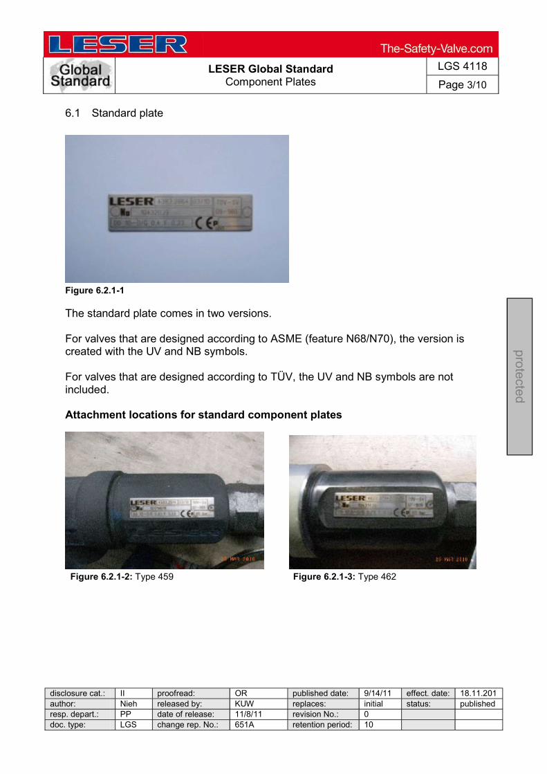
LESER Global Standard Component Plates
LGS 4118
Page 3/10
disclosure cat.: II proofread: OR published date: 9/14/11 effect. date: 18.11.201author: Nieh released by: KUW replaces: initial status: published resp. depart.: PP date of release: 11/8/11 revision No.: 0 doc. type: LGS change rep. No.: 651A retention period: 10
pro
tected
6.1 Standard plate
Figure 6.2.1-1 The standard plate comes in two versions. For valves that are designed according to ASME (feature N68/N70), the version is created with the UV and NB symbols. For valves that are designed according to TÜV, the UV and NB symbols are not included. Attachment locations for standard component plates
Figure 6.2.1-2: Type 459 Figure 6.2.1-3: Type 462

LESER Global Standard Component Plates
LGS 4118
Page 4/10
disclosure cat.: II proofread: OR published date: 9/14/11 effect. date: 18.11.201author: Nieh released by: KUW replaces: initial status: published resp. depart.: PP date of release: 11/8/11 revision No.: 0 doc. type: LGS change rep. No.: 651A retention period: 10
pro
tected
Figure 6.2.1-4: Type 437 Figure 6.2.1-5: Type 462
Figure 6.2.1-6: Standard plate on a Figure 6.2.1-7: Types 457 / 458 / 526 flanged valve 6.2 World plate (NGA)
Figure 6.2.1-1
The world plate (NGA) comes in two versions.

LESER Global Standard Component Plates
LGS 4118
Page 5/10
disclosure cat.: II proofread: OR published date: 9/14/11 effect. date: 18.11.201author: Nieh released by: KUW replaces: initial status: published resp. depart.: PP date of release: 11/8/11 revision No.: 0 doc. type: LGS change rep. No.: 651A retention period: 10
pro
tected
For valves that are designed according to ASME (feature N68/N70), the version is created with the UV and NB symbols. For valves that are designed according to TÜV, the UV and NB symbols are not lasered on. 6.2.1 Pre-curving of the NGA
For bonnets with a curved cross-section, the plate must be pre-curved with a radius. To do this, place the labelled plates in the apparatus with the lettering facing down. Illustrations Description Aids / Tools
Figure 6.2.1-1
Pre-curving the plate Apparatus
Pre-curving the plate for open bonnets (V20-V25)
Apparatus
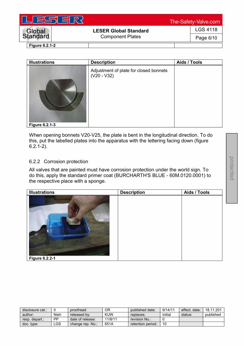
LESER Global Standard Component Plates
LGS 4118
Page 6/10
disclosure cat.: II proofread: OR published date: 9/14/11 effect. date: 18.11.201author: Nieh released by: KUW replaces: initial status: published resp. depart.: PP date of release: 11/8/11 revision No.: 0 doc. type: LGS change rep. No.: 651A retention period: 10
pro
tected
Figure 6.2.1-2
Illustrations Description Aids / Tools
Figure 6.2.1-3
Adjustment of plate for closed bonnets (V20 - V32)
When opening bonnets V20-V25, the plate is bent in the longitudinal direction. To do this, put the labelled plates into the apparatus with the lettering facing down (figure 6.2.1-2). 6.2.2 Corrosion protection
All valves that are painted must have corrosion protection under the world sign. To do this, apply the standard primer coat (BURCHARTH'S BLUE - 60M.0120.0001) to the respective place with a sponge. Illustrations Description Aids / Tools
Figure 6.2.2-1

LESER Global Standard Component Plates
LGS 4118
Page 7/10
disclosure cat.: II proofread: OR published date: 9/14/11 effect. date: 18.11.201author: Nieh released by: KUW replaces: initial status: published resp. depart.: PP date of release: 11/8/11 revision No.: 0 doc. type: LGS change rep. No.: 651A retention period: 10
pro
tected
Illustrations Description Aids / Tools
Figure 6.2.2-2
Sponge
Figure 6.2.2-3
The points where the world plate will be welded must be free of paint.
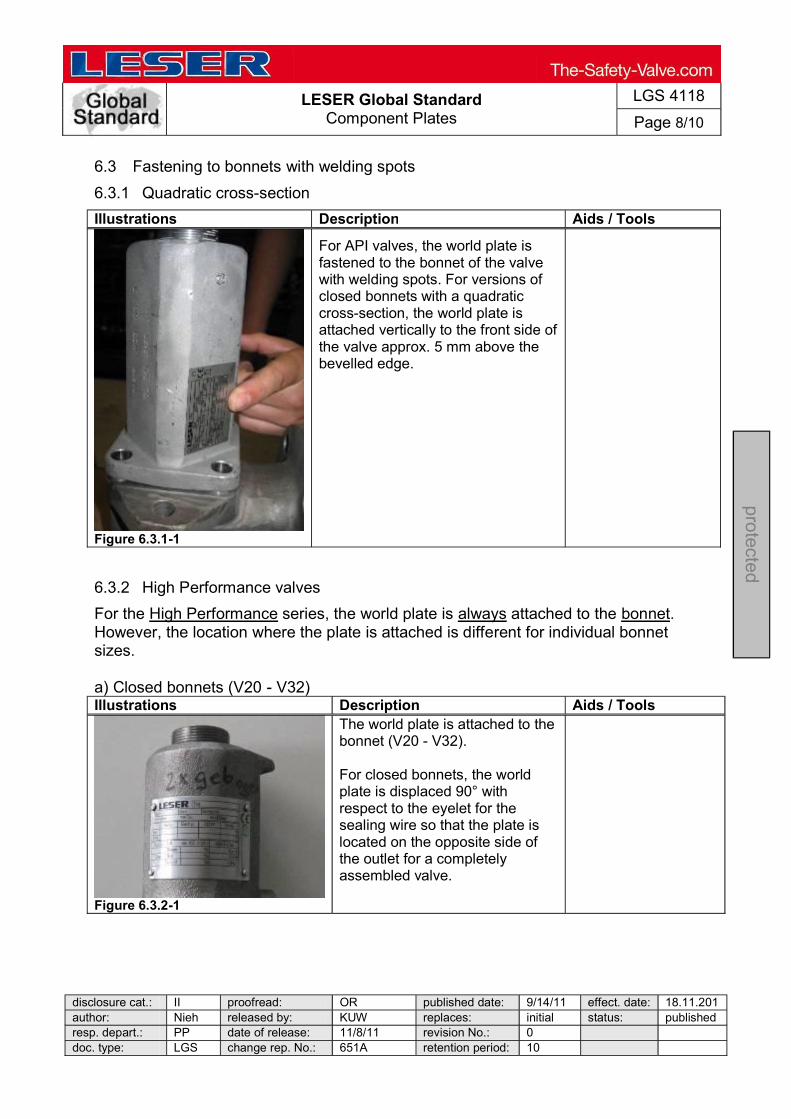
LESER Global Standard Component Plates
LGS 4118
Page 8/10
disclosure cat.: II proofread: OR published date: 9/14/11 effect. date: 18.11.201author: Nieh released by: KUW replaces: initial status: published resp. depart.: PP date of release: 11/8/11 revision No.: 0 doc. type: LGS change rep. No.: 651A retention period: 10
pro
tected
6.3 Fastening to bonnets with welding spots
6.3.1 Quadratic cross-section
Illustrations Description Aids / Tools
Figure 6.3.1-1
For API valves, the world plate is fastened to the bonnet of the valve with welding spots. For versions of closed bonnets with a quadratic cross-section, the world plate is attached vertically to the front side of the valve approx. 5 mm above the bevelled edge.
6.3.2 High Performance valves
For the High Performance series, the world plate is always attached to the bonnet. However, the location where the plate is attached is different for individual bonnet sizes. a) Closed bonnets (V20 - V32) Illustrations Description Aids / Tools
Figure 6.3.2-1
The world plate is attached to the bonnet (V20 - V32). For closed bonnets, the world plate is displaced 90° with respect to the eyelet for the sealing wire so that the plate is located on the opposite side of the outlet for a completely assembled valve.

LESER Global Standard Component Plates
LGS 4118
Page 9/10
disclosure cat.: II proofread: OR published date: 9/14/11 effect. date: 18.11.201author: Nieh released by: KUW replaces: initial status: published resp. depart.: PP date of release: 11/8/11 revision No.: 0 doc. type: LGS change rep. No.: 651A retention period: 10
pro
tected
b) Open bonnets (V20 - V25) Illustrations Description Aids / Tools
Figure 6.3.2-2
The world plate is attached to open bonnets V20 - V25. It is attached above the cast LESER lettering and should be flush with the letter "L".
The plate must be mounted so that it can be read from the right (as shown in the picture).
c) Open bonnet (V32) Illustrations Description Aids / Tools
Figure 6.3.2-3
For open bonnets V32, the world plate is displaced 90° with respect to the eyelet in front of the sealing wire so that the plate is displaced by 90° with respect to the outlet for a completely assembled valve.
The top edge of the plate should be flush with the bevel of the bonnet.
d) Open bonnet (V40) Position of the bonnet: The raised identifier of the product form manufacturer (foundry) is mounted in the direction of the outlet flange. Position of the world plate The world plate is positioned on the free back side on the bottom edge of the bonnet. 6.3.3 Fastening with grooved pins with round heads
Illustrations Description Aids / Tools
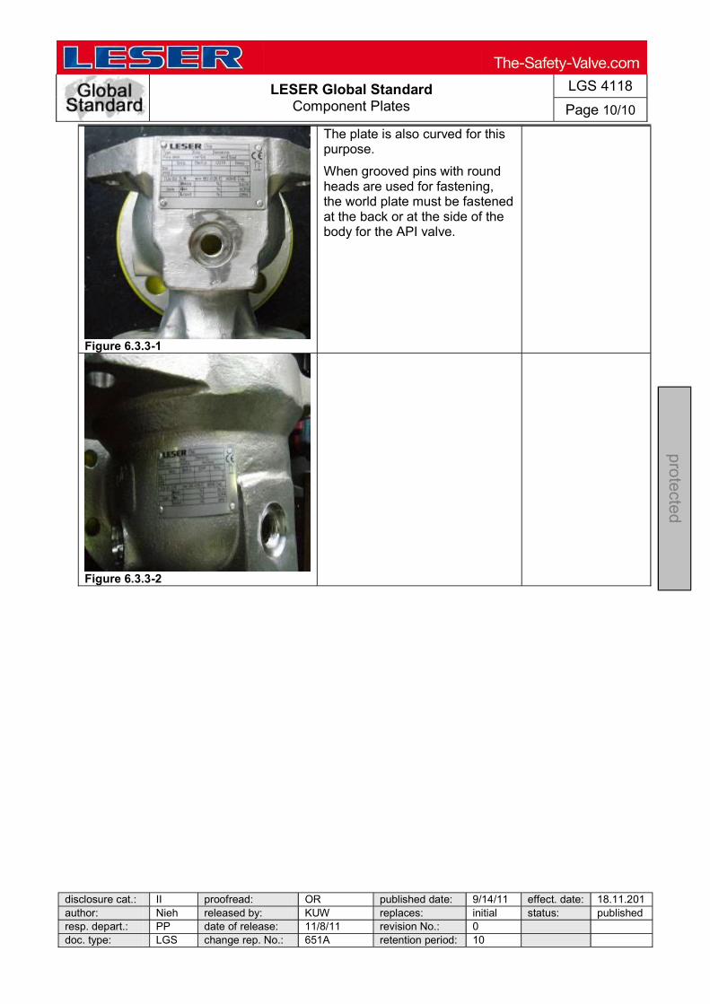
LESER Global Standard Component Plates
LGS 4118
Page 10/10
disclosure cat.: II proofread: OR published date: 9/14/11 effect. date: 18.11.201author: Nieh released by: KUW replaces: initial status: published resp. depart.: PP date of release: 11/8/11 revision No.: 0 doc. type: LGS change rep. No.: 651A retention period: 10
pro
tected
Figure 6.3.3-1
The plate is also curved for this purpose.
When grooved pins with round heads are used for fastening, the world plate must be fastened at the back or at the side of the body for the API valve.
Figure 6.3.3-2
LESER Global Standard Paint touch-up and painting repaired valves
LGS 4114
Page 1/4
disclosure cat.: II proofread: OR published date: 9/14/11 effect. date: 18.11.201author: Nieh released by: KUW replaces: initial status: published resp. depart.: PP date of release: 11/8/11 revision No.: 0 doc. type: LGS change rep. No.: 651A retention period: 10
pro
tected
Contents
1 Purpose ............................................................................................................... 1 2 Scope .................................................................................................................. 1 3 Disclaimer ............................................................................................................ 1 4 Qualified fitting personnel .................................................................................... 1 5 General Information ............................................................................................. 2 6 Paint touch-up and painting repaired valves ........................................................ 2 1 Purpose
This LESER Global Standard (LGS) provides instructions on painting LESER safety valves. The required work steps and materials are described.
2 Scope
This document must be applied when painting safety valves in agencies and subsidiaries of LESER GmbH & Co. KG.
3 Disclaimer
LESER puts in a great deal of effort into making up-to-date and correct documentation available. Nevertheless, LESER GmbH & Co. KG gives no guarantee that the recommended actions presented here are entirely correct and error free. This document is to be applied exclusively to the specified type. LESER GmbH & Co. KG declines any liability or responsibility for the correctness and completeness of the content. LESER GmbH & Co. KG reserves the right to change the information contained in this document, which is for the products of LESER GmbH & Co. KG and is intended for LESER subsidiaries, at any time and without prior announcement. LESER GmbH & Co. KG is available to the users of this document to provide additional information. 4 Qualified fitting personnel
The assembly of LESER safety valves may only be performed by trained or qualified fitters. The qualifications must be obtained through the appropriate training measures.

LESER Global Standard Paint touch-up and painting repaired valves
LGS 4114
Page 2/4
disclosure cat.: II proofread: OR published date: 9/14/11 effect. date: 18.11.201author: Nieh released by: KUW replaces: initial status: published resp. depart.: PP date of release: 11/8/11 revision No.: 0 doc. type: LGS change rep. No.: 651A retention period: 10
pro
tected
5 General Information
Wear safety glasses Wear respirator/dust mask
6 Paint touch-up and painting repaired valves
For valves that have to be repainted, the facing and the welded-on component/customer ID plates must be masked off correctly. Any additional plates will only be attached after painting, if welding is not required. Open bonnets must be sealed with protective caps. The same applies to any existing threaded holes. Outside threads must be protected with a suitable protective cap / existing painting socket or with masking tape.
Figure 6-1: Protective cap for open bonnet Figure 6-2: Flange sticker

LESER Global Standard Paint touch-up and painting repaired valves
LGS 4114
Page 3/4
disclosure cat.: II proofread: OR published date: 9/14/11 effect. date: 18.11.201author: Nieh released by: KUW replaces: initial status: published resp. depart.: PP date of release: 11/8/11 revision No.: 0 doc. type: LGS change rep. No.: 651A retention period: 10
pro
tected
Figure 6-3: Component plate sticker Figure 6-4: Protective cap
Figure 6-5: Component plate sticker Figure 6-6: Protective cap
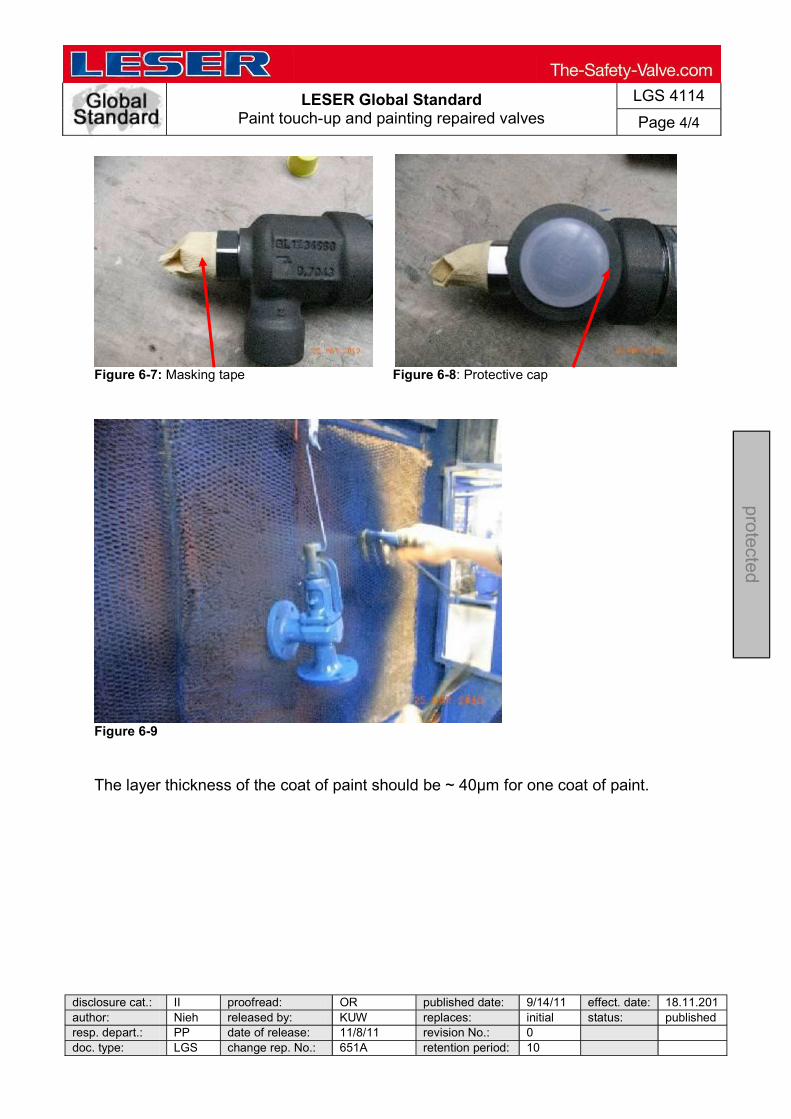
LESER Global Standard Paint touch-up and painting repaired valves
LGS 4114
Page 4/4
disclosure cat.: II proofread: OR published date: 9/14/11 effect. date: 18.11.201author: Nieh released by: KUW replaces: initial status: published resp. depart.: PP date of release: 11/8/11 revision No.: 0 doc. type: LGS change rep. No.: 651A retention period: 10
pro
tected
Figure 6-7: Masking tape Figure 6-8: Protective cap
Figure 6-9 The layer thickness of the coat of paint should be ~ 40µm for one coat of paint.

L
ES
ER
Glo
bal
Sta
nd
ard
F
eder
date
n-T
abe
llen
Typ
e 8
10
Spr
ing
dat
a lis
t ty
pe 8
10
LGS
363
2
Sei
te 1
/2
d
iscl
osur
e c
at.
: II
pro
ofre
ad:
B
J pu
blis
hed
date
: 10
/6/1
1 ef
fect
. da
te:
10/1
1 au
tho
r:
Sch
m
rele
ase
d b
y:
BJ
rep
lace
s:
060.
32
stat
us:
pu
blis
hed
resp
. de
part
.: T
B
date
of
rele
ase
: 9/
16/
11
revi
sion
No.
: 0
do
c. ty
pe:
LGS
ch
ang
e re
p. N
o.:
0088
8A
re
ten
tion
perio
d:
10y.
protected
Erk
läru
nge
n s
iehe
/ e
xpla
natio
n se
e :
LGS
36
00
/ O
rific
e D
-T+
A
usf
üh
run
g (
mod
el)
war
mfe
st (
cree
p-re
sist
ant
ste
el)
h
oc
hw
arm
fest
(h
igh
cre
ep-r
esis
tant
ste
el)
korr
osi
on
sfes
t (
sta
inle
ss s
tee
l) In
con
el
X7
50
p [
bar
]
p
[ b
ar ]
p [
ba
r ]
p
[ b
ar ]
vo
n
bis
F
ed
er-
Indizes
von
b
is
Fe
der
-
Indizes
von
b
is
Fe
der
-
Indizes
von
b
is
Fe
der
-
Indizes
p1
p
2
Sac
hn
um
me
r p
1 p
2
Sac
hn
um
me
r p
1 p
2 S
ach
nu
mm
er
p1
p2
S
ach
nu
mm
er
up
to
stoc
k no
. up
to
st
ock
no.
up
to
stoc
k no
. up
to
st
ock
no.
1
D2
- 2
K+
3
1
D2
- 2
K+
3
1
D2
- 2
K+
3
1
D2
- 2
K+
3
Sta
nd
ard
Ve
rsio
n L
o=
55
S
tan
da
rd V
ers
ion
Lo
=5
5
Sta
nd
ard
Ve
rsio
n L
o=
55
Sta
nd
ard
Ve
rsio
n L
o=
55
1
,00
- 1
,50
5
40
.302
4.0
000
1
,00
-
1,5
0
54
0.3
024
.00
00
1,0
0
- 1
,50
5
40
.302
7.0
000
1
,51
- 2
,30
5
40
.303
4.0
000
1,5
1
- 2
,30
5
40
.303
4.0
000
1
,51
-
2,3
0
54
0.3
037
.00
00
2,3
1 -
3,5
0
54
0.3
044
.00
00
2
,31
-
3,5
0
54
0.3
044
.00
00
2,3
1
- 3
,50
5
40
.304
7.0
000
3
,51
- 5
,50
5
40
.305
4.0
000
3,5
1
- 5
,50
5
40
.305
4.0
000
3
,51
-
5,5
0
54
0.3
057
.00
00
5,5
1 -
8,5
0
54
0.3
064
.00
00
5
,51
-
8,5
0
54
0.3
064
.00
00
5,5
1
- 8
,50
5
40
.306
7.0
000
8
,51
- 1
3,0
0
54
0.3
074
.00
00
8
,51
-
13
,00
5
40
.307
4.0
000
8
,51
-
13
,00
5
40
.307
7.0
000
13
,01
-
19
,00
5
40
.308
4.0
000
1
3,0
1
- 1
9,0
0
54
0.3
084
.00
00
1
3,0
1
- 1
9,0
0
54
0.3
087
.00
00
1
9,0
1
- 2
6,5
0
54
0.3
094
.00
00
19
,01
-
26
,50
5
40
.309
4.0
000
19
,01
-
26
,50
5
40
.309
7.0
000
26
,51
-
37
,50
5
40
.310
4.0
000
2
6,5
1
- 3
7,5
0
54
0.3
104
.00
00
2
6,5
1
- 3
7,5
0
54
0.3
107
.00
00
3
7,5
1
- 5
2,5
0
54
0.3
114
.00
00
37
,51
-
52
,50
5
40
.311
4.0
000
37
,51
-
52
,50
5
40
.311
7.0
000
52
,51
-
75
,50
5
40
.31
64
.00
00
52
,51
-
75
,50
5
40
.316
4.0
000
52
,51
-
75
,50
5
40
.316
7.0
000
75
,51
-
11
3,5
0 5
40
.317
4.0
000
7
5,5
1
- 1
13
,50
54
0.3
174
.00
00
7
5,5
1
- 1
13
,50
54
0.3
177
.00
00
1
13
,51
-
15
1,0
0 5
40
.320
4.0
000
1
13
,51
- 1
51
,00
54
0.3
204
.00
00
1
13
,51
- 1
51
,00
54
0.3
207
.00
00
L
on
g V
ers
ion
Lo
=7
5
Lo
ng
Ve
rsio
n L
o=
75
L
on
g V
ers
ion
Lo
=7
5
Lo
ng
Ve
rsio
n L
o=
75
1
51
,01
-
21
4,0
0 5
40
.930
4.0
000
1
51
,01
- 2
14
,00
54
0.9
304
.00
00
1
51
,01
- 2
14
,00
54
0.9
307
.00
00
2
14
,01
-
30
9,0
0 5
40
.931
4.0
000
2
14
,01
- 3
09
,00
54
0.9
314
.00
00
2
14
,01
- 3
09
,00
54
0.9
317
.00
00
3
09
,01
-
42
6,0
0 5
40
.932
4.0
000
30
9,0
1 -
42
6,0
0 5
40
.932
4.0
000
30
9,0
1 -
42
6,0
0 5
40
.932
7.0
000
3
J4
- 4
P+
6
3
J4
- 4
P+
6
3
J4
- 4
P+
6
3
J4
- 4
P+
6
Sta
nd
ard
Ve
rsio
n L
o=
55
S
tan
da
rd V
ers
ion
Lo
=5
5
Sta
nd
ard
Ve
rsio
n L
o=
55
S
tan
da
rd V
ers
ion
Lo
=5
5
1
,00
- 1
,50
5
40
.302
4.0
000
1
,00
-
1,5
0
54
0.3
024
.00
00
1,0
0
- 1
,50
5
40
.302
7.0
000
1
,51
- 2
,30
5
40
.303
4.0
000
1
,51
-
2,3
0
54
0.3
034
.00
00
1,5
1
- 2
,30
5
40
.303
7.0
000
2
,31
- 3
,50
5
40
.304
4.0
000
2
,31
-
3,5
0
54
0.3
044
.00
00
2,3
1
- 3
,50
5
40
.304
7.0
000
3
,51
- 5
,50
5
40
.305
4.0
000
3
,51
-
5,5
0
54
0.3
054
.00
00
3,5
1
- 5
,50
5
40
.305
7.0
000
5
,51
- 8
,50
5
40
.306
4.0
000
5
,51
-
8,5
0
54
0.3
064
.00
00
5,5
1
- 8
,50
5
40
.306
7.0
000
8
,51
- 1
3,0
0
54
0.3
074
.00
00
8,5
1
- 1
3,0
0
54
0.3
074
.00
00
8,5
1
- 1
3,0
0
54
0.3
077
.00
00
1
3,0
1
- 1
9,0
0
54
0.3
084
.00
00
1
3,0
1
- 1
9,0
0
54
0.3
084
.00
00
1
3,0
1
- 1
9,0
0
54
0.3
087
.00
00
1
9,0
1
- 2
6,5
0
54
0.3
094
.00
00
1
9,0
1
- 2
6,5
0
54
0.3
094
.00
00
1
9,0
1
- 2
6,5
0
54
0.3
097
.00
00
2
6,5
1
- 3
7,5
0
54
0.3
104
.00
00
2
6,5
1
- 3
7,5
0
54
0.3
104
.00
00
2
6,5
1
- 3
7,5
0
54
0.3
107
.00
00
3
7,5
1
- 5
2,5
0
54
0.3
11
4.0
000
37
,51
-
52
,50
5
40
.311
4.0
000
37
,51
-
52
,50
5
40
.311
7.0
000
52
,51
-
75
,50
5
40
.316
4.0
000
52
,51
-
75
,50
5
40
.316
4.0
000
52
,51
-
75
,50
5
40
.316
7.0
000
75
,51
-
11
3,5
0 5
40
.317
4.0
000
75
,51
-
11
3,5
0 5
40
.317
4.0
000
75
,51
-
11
3,5
0 5
40
.317
7.0
000
11
3,5
1
- 1
51
,00
54
0.3
204
.00
00
1
13
,51
- 1
51
,00
54
0.3
204
.00
00
1
3,5
1 -
15
1,0
0 5
40
.320
7.0
000
Lo
ng
Ve
rsio
n L
o=
75
L
on
g V
ers
ion
Lo
=7
5
Lo
ng
Ve
rsio
n L
o=
75
L
on
g V
ers
ion
Lo
=7
5
15
1,0
1
- 2
14
,00
54
0.9
304
.00
00
1
51
,01
- 2
14
,00
54
0.9
304
.00
00
1
51
,01
- 2
14
,00
54
0.9
307
.00
00
2
14
,01
-
25
6,0
0 5
40
.931
4.0
000
21
4,0
1 -
25
6,0
0 5
40
.931
4.0
000
21
4,0
1 -
25
6,0
0 5
40
.931
7.0
000
6
Q8
- 8
T+
10
6Q
8 -
8T
+1
0
6
Q8
- 8
T+
10
6Q
8 -
8T
+1
0
Sta
nd
ard
Ve
rsio
n L
o=
55
S
tan
da
rd V
ers
ion
Lo
=5
5
Sta
nd
ard
Ve
rsio
n L
o=
55
S
tan
da
rd V
ers
ion
Lo
=5
5
1
,00
- 1
,50
5
40
.302
4.0
000
1,0
0
- 1
,50
5
40
.302
4.0
000
1
,00
-
1,5
0
54
0.3
027
.00
00
1,5
1 -
2,3
0
54
0.3
034
.00
00
1
,51
-
2,3
0
54
0.3
034
.00
00
1,5
1
- 2
,30
5
40
.303
7.0
000
2
,31
- 3
,50
5
40
.304
4.0
000
2,3
1
- 3
,50
5
40
.304
4.0
000
2
,31
-
3,5
0
54
0.3
047
.00
00
3,5
1 -
5,5
0
54
0.3
054
.00
00
3
,51
-
5,5
0
54
0.3
054
.00
00
3,5
1
- 5
,50
5
40
.305
7.0
000
5
,51
- 8
,50
5
40
.306
4.0
000
5,5
1
- 8
,50
5
40
.306
4.0
000
5
,51
-
8,5
0
54
0.3
067
.00
00
8,5
1 -
13
,00
5
40
.307
4.0
000
8,5
1
- 1
3,0
0
54
0.3
074
.00
00
8,5
1
- 1
3,0
0
54
0.3
077
.00
00
1
3,0
1
- 1
9,0
0
54
0.3
084
.00
00
13
,01
-
19
,00
5
40
.308
4.0
000
13
,01
-
19
,00
5
40
.308
7.0
000
19
,01
-
26
,50
5
40
.309
4.0
000
1
9,0
1
- 2
6,5
0
54
0.3
094
.00
00
1
9,0
1
- 2
6,5
0
54
0.3
097
.00
00
2
6,5
1
- 3
7,5
0
54
0.3
104
.00
00
26
,51
-
37
,50
5
40
.310
4.0
000
26
,51
-
37
,50
5
40
.310
7.0
000
37
,51
-
52
,50
5
40
.311
4.0
000
3
7,5
1
- 5
2,5
0
54
0.3
114
.00
00
3
7,5
1
- 5
2,5
0
54
0.3
117
.00
00
5
2,5
1
- 7
5,5
0
54
0.3
164
.00
00
52
,51
-
75
,50
5
40
.316
4.0
000
52
,51
-
75
,50
5
40
.316
7.0
000
75
,51
-
10
2,0
0 5
40
.317
4.0
000
7
5,5
1
- 1
02
,00
54
0.3
174
.00
00
7
5,5
1
- 1
02
,00
54
0.3
177
.00
00
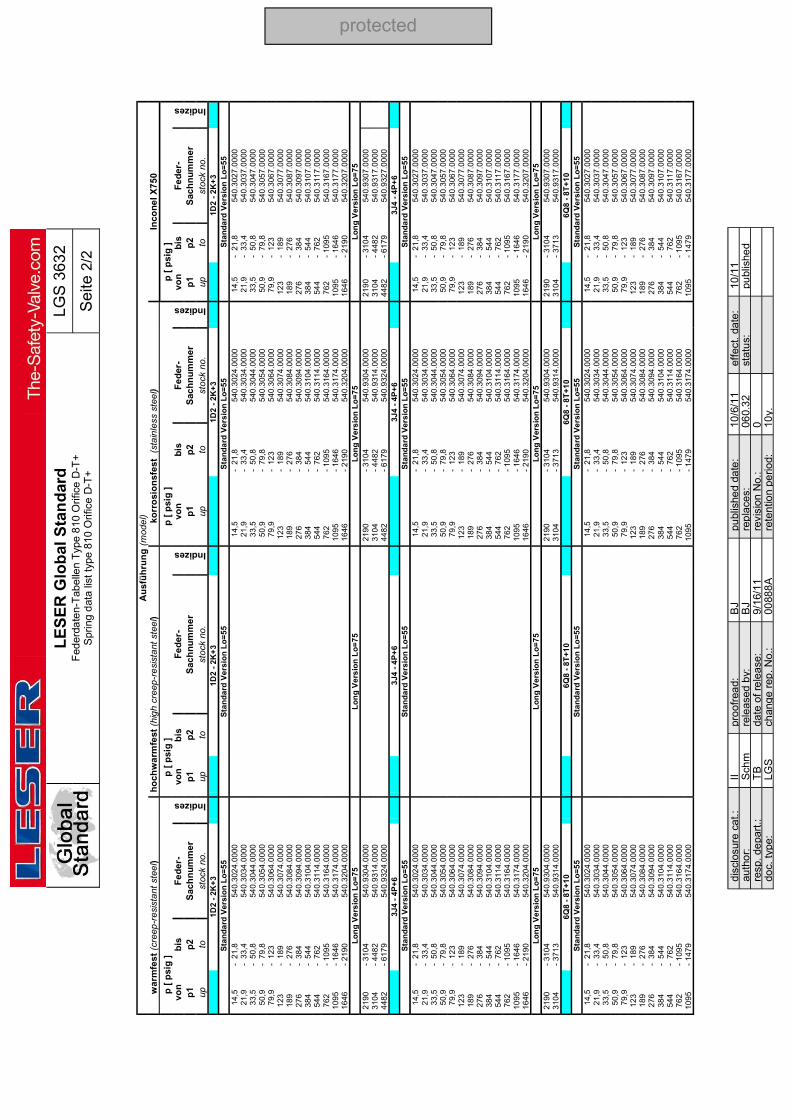
L
ES
ER
Glo
bal
Sta
nd
ard
F
eder
date
n-T
abe
llen
Typ
e 8
10 O
rific
e D
-T+
Spr
ing
dat
a lis
t ty
pe 8
10 O
rific
e D
-T+
LGS
363
2
Sei
te 2
/2
d
iscl
osur
e c
at.
: II
pro
ofre
ad:
B
J pu
blis
hed
date
: 10
/6/1
1 ef
fect
. da
te:
10/1
1 au
tho
r:
Sch
m
rele
ase
d b
y:
BJ
rep
lace
s:
060.
32
stat
us:
pu
blis
hed
resp
. de
part
.: T
B
date
of
rele
ase
: 9/
16/
11
revi
sion
No.
: 0
do
c. ty
pe:
LGS
ch
ang
e re
p. N
o.:
0088
8A
re
ten
tion
perio
d:
10y.
protected
A
usf
üh
run
g (
mod
el)
war
mfe
st
(cre
ep-r
esis
tant
ste
el)
h
oc
hw
arm
fest
(h
igh
cre
ep-r
esi
sta
nt s
tee
l)
ko
rro
sio
nsf
est
(s
tain
less
ste
el)
Inco
ne
l X
75
0
p [
psi
g ]
p
[ p
sig
]
p [
psi
g ]
p
[ p
sig
]
von
b
is
Fe
der
-
Indizes
von
b
is
Fe
der
-
Indizes
von
b
is
Fe
der
-
Indizes
von
b
is
Fe
der
-
Indizes
p1
p
2
Sac
hn
um
me
r p
1
p2
S
ach
nu
mm
er
p1
p
2
Sac
hn
um
me
r p
1
p2
S
ach
nu
mm
er
up
to
stoc
k no
. up
to
st
ock
no.
up
to
stoc
k no
. up
to
st
ock
no.
1
D2
- 2
K+
3
1
D2
- 2
K+
3
1
D2
- 2
K+
3
1
D2
- 2
K+
3
Sta
nd
ard
Ve
rsio
n L
o=
55
S
tan
da
rd V
ers
ion
Lo
=5
5
Sta
nd
ard
Ve
rsio
n L
o=
55
S
tan
da
rd V
ers
ion
Lo
=5
5
14
,5
- 2
1,8
5
40
.302
4.0
000
1
4,5
-
21
,8
54
0.3
024
.00
00
1
4,5
-
21
,8
54
0.3
027
.00
00
2
1,9
-
33
,4
54
0.3
034
.00
00
21
,9
- 3
3,4
5
40
.303
4.0
000
21
,9
- 3
3,4
5
40
.303
7.0
000
33
,5
- 5
0,8
5
40
.304
4.0
000
3
3,5
-
50
,8
54
0.3
044
.00
00
3
3,5
-
50
,8
54
0.3
047
.00
00
5
0,9
-
79
,8
54
0.3
054
.00
00
50
,9
- 7
9,8
5
40
.305
4.0
000
50
,9
- 7
9,8
5
40
.305
7.0
000
79
,9
- 1
23
5
40
.306
4.0
000
7
9,9
-
12
3
54
0.3
064
.00
00
7
9,9
-
12
3
54
0.3
067
.00
00
1
23
- 1
89
5
40
.307
4.0
000
1
23
-
18
9
54
0.3
074
.00
00
1
23
- 1
89
5
40
.307
7.0
000
18
9 -
27
6
54
0.3
084
.00
00
18
9
- 2
76
5
40
.308
4.0
000
18
9 -
27
6
54
0.3
087
.00
00
2
76
- 3
84
5
40
.309
4.0
000
2
76
-
38
4
54
0.3
094
.00
00
2
76
- 3
84
5
40
.309
7.0
000
38
4 -
54
4
54
0.3
104
.00
00
38
4
- 5
44
5
40
.310
4.0
000
38
4 -
54
4
54
0.3
107
.00
00
5
44
- 7
62
5
40
.311
4.0
000
5
44
-
76
2
54
0.3
114
.00
00
5
44
- 7
62
5
40
.311
7.0
000
76
2 -
10
95
5
40
.316
4.0
000
7
62
-
10
95
5
40
.316
4.0
000
76
2 -
10
95
5
40
.316
7.0
000
10
95
-
16
46
5
40
.317
4.0
000
1
09
5 -
16
46
5
40
.317
4.0
000
10
95
-
16
46
5
40
.317
7.0
000
16
46
-
21
90
5
40
.320
4.0
000
1
64
6 -
21
90
5
40
.320
4.0
000
16
46
-
21
90
5
40
.320
7.0
000
Lo
ng
Ve
rsio
n L
o=
75
L
on
g V
ers
ion
Lo
=7
5
Lo
ng
Ve
rsio
n L
o=
75
L
on
g V
ers
ion
Lo
=7
5
21
90
-
31
04
5
40
.930
4.0
000
2
19
0 -
31
04
5
40
.930
4.0
000
21
90
-
31
04
5
40
.930
7.0
000
31
04
-
44
82
5
40
.931
4.0
000
3
10
4 -
44
82
5
40
.931
4.0
000
31
04
-
44
82
5
40
.931
7.0
000
44
82
-
61
79
5
40
.932
4.0
000
4
48
2 -
61
79
5
40
.932
4.0
000
44
82
-
61
79
5
40
.932
7.0
000
3
J4
- 4
P+
6
3
J4
- 4
P+
6
3
J4
- 4
P+
6
3
J4
- 4
P+
6
Sta
nd
ard
Ve
rsio
n L
o=
55
S
tan
da
rd V
ers
ion
Lo
=5
5
Sta
nd
ard
Ve
rsio
n L
o=
55
S
tan
da
rd V
ers
ion
Lo
=5
5
14
,5
- 2
1,8
5
40
.302
4.0
000
14
,5
- 2
1,8
5
40
.302
4.0
000
14
,5
- 2
1,8
5
40
.302
7.0
000
21
,9
- 3
3,4
5
40
.303
4.0
000
21
,9
- 3
3,4
5
40
.303
4.0
000
21
,9
- 3
3,4
5
40
.303
7.0
000
33
,5
- 5
0,8
5
40
.304
4.0
000
33
,5
- 5
0,8
5
40
.304
4.0
000
33
,5
- 5
0,8
5
40
.304
7.0
000
50
,9
- 7
9,8
5
40
.305
4.0
000
50
,9
- 7
9,8
5
40
.305
4.0
000
50
,9
- 7
9,8
5
40
.305
7.0
000
79
,9
- 1
23
5
40
.306
4.0
000
79
,9
- 1
23
5
40
.306
4.0
000
79
,9
- 1
23
5
40
.306
7.0
000
12
3 -
18
9
54
0.3
074
.00
00
1
23
-
18
9
54
0.3
074
.00
00
1
23
- 1
89
5
40
.307
7.0
000
18
9 -
27
6
54
0.3
084
.00
00
1
89
-
27
6
54
0.3
084
.00
00
1
89
- 2
76
5
40
.308
7.0
000
27
6 -
38
4
54
0.3
094
.00
00
2
76
-
38
4
54
0.3
094
.00
00
2
76
- 3
84
5
40
.309
7.0
000
38
4 -
54
4
54
0.3
104
.00
00
3
84
-
54
4
54
0.3
104
.00
00
3
84
- 5
44
5
40
.310
7.0
000
54
4 -
76
2
54
0.3
114
.00
00
5
44
-
76
2
54
0.3
114
.00
00
5
44
- 7
62
5
40
.311
7.0
000
76
2 -
10
95
5
40
.316
4.0
000
76
2
- 1
09
5
54
0.3
164
.00
00
7
62
- 1
09
5
54
0.3
167
.00
00
1
09
5
- 1
64
6
54
0.3
174
.00
00
1
09
5 -
16
46
5
40
.317
4.0
000
10
95
-
16
46
5
40
.317
7.0
000
16
46
-
21
90
5
40
.320
4.0
000
16
46
- 2
19
0
54
0.3
204
.00
00
1
64
6
- 2
19
0
54
0.3
207
.00
00
L
on
g V
ers
ion
Lo
=7
5
Lo
ng
Ve
rsio
n L
o=
75
L
on
g V
ers
ion
Lo
=7
5
Lo
ng
Ve
rsio
n L
o=
75
2
19
0
- 3
10
4
54
0.9
304
.00
00
2
19
0 -
31
04
5
40
.930
4.0
000
21
90
-
31
04
5
40
.930
7.0
000
31
04
-
37
13
5
40
.931
4.0
000
31
04
- 3
71
3
54
0.9
314
.00
00
3
10
4
- 3
71
3
54
0.9
317
.00
00
6Q
8 -
8T
+1
0
6
Q8
- 8
T+
10
6Q
8 -
8T
+1
0
6
Q8
- 8
T+
10
S
tan
da
rd V
ers
ion
Lo
=5
5
Sta
nd
ard
Ve
rsio
n L
o=
55
S
tan
da
rd V
ers
ion
Lo
=5
5
Sta
nd
ard
Ve
rsio
n L
o=
55
1
4,5
-
21
,8
54
0.3
024
.00
00
1
4,5
-
21
,8
54
0.3
024
.00
00
1
4,5
-
21
,8
54
0.3
027
.00
00
2
1,9
-
33
,4
54
0.3
034
.00
00
21
,9
- 3
3,4
5
40
.303
4.0
000
21
,9
- 3
3,4
5
40
.303
7.0
000
33
,5
- 5
0,8
5
40
.304
4.0
000
3
3,5
-
50
,8
54
0.3
044
.00
00
3
3,5
-
50
,8
54
0.3
047
.00
00
5
0,9
-
79
,8
54
0.3
054
.00
00
50
,9
- 7
9,8
5
40
.305
4.0
000
50
,9
- 7
9,8
5
40
.305
7.0
000
79
,9
- 1
23
5
40
.306
4.0
000
7
9,9
-
12
3
54
0.3
064
.00
00
7
9,9
-
12
3
54
0.3
067
.00
00
1
23
- 1
89
5
40
.307
4.0
000
1
23
-
18
9
54
0.3
074
.00
00
1
23
- 1
89
5
40
.307
7.0
000
18
9 -
27
6
54
0.3
084
.00
00
18
9
- 2
76
5
40
.308
4.0
000
18
9 -
27
6
54
0.3
087
.00
00
2
76
- 3
84
5
40
.309
4.0
000
2
76
-
38
4
54
0.3
094
.00
00
2
76
- 3
84
5
40
.309
7.0
000
38
4 -
54
4
54
0.3
104
.00
00
38
4
- 5
44
5
40
.310
4.0
000
38
4 -
54
4
54
0.3
107
.00
00
5
44
- 7
62
5
40
.311
4.0
000
5
44
-
76
2
54
0.3
114
.00
00
5
44
- 7
62
5
40
.311
7.0
000
76
2 -
10
95
5
40
.316
4.0
000
7
62
-
10
95
5
40
.316
4.0
000
76
2 -
10
95
5
40
.316
7.0
000
10
95
-
14
79
5
40
.317
4.0
000
1
09
5 -
14
79
5
40
.317
4.0
000
1
09
5
- 1
47
9
54
0.3
177
.00
00

L
ES
ER
Glo
bal
Sta
nd
ard
F
eder
date
n-T
abe
llen
Typ
e 8
20 O
rific
e D
-T+
S
prin
g d
ata
list
type
820
Orif
ice
D-T
+
LG
S 3
633
Se
ite 1
/7
disc
losu
re c
at.:
II pr
oofr
ead:
T
K
pub
lishe
d da
te:
07/0
1/15
ef
fect
. dat
e:
10/1
1 au
thor
: S
chm
re
leas
ed b
y:
JR
repl
aces
: 06
0-33
3
stat
us:
Pub
lishe
d re
sp.
depa
rt.:
TD
da
te o
f rel
ease
: 07
/01/
15
revi
sion
No.
: 3
doc.
type
: LG
S
chan
ge
rep.
No.
: 20
007
5 re
tent
ion
per
iod:
10
y.
Co
nte
nts
1
Pu
rpo
se ..
....
....
....
....
....
....
. 1
2
Sc
op
e ..
....
....
....
....
....
....
....
1
3
Re
fere
nc
es ..
....
....
....
....
....
1
1
P
urp
os
e T
his
LE
SE
R G
loba
l Sta
nda
rd (
LG
S)
con
tain
s th
e in
form
atio
n a
bo
ut p
ress
ure
ran
ge o
f a
ll sp
rings
, w
hic
h a
re
inst
alle
d in
val
ve-
typ
e 8
20
. 2
S
co
pe
Th
is L
GS
app
lies
to a
ll m
embe
rs o
f th
e L
ES
ER
qu
alit
y cl
ust
er
as
def
ine
d in
th
e gl
ob
al q
ua
lity
man
age
me
nt m
anu
al.
Th
is L
GS
con
tain
s in
form
atio
n a
bou
t the
pre
ssu
re r
an
ge o
f all
sprin
gs,
wh
ich
are
inst
alle
d in
va
lve
- ty
pe
82
0.
The
pre
ssu
re r
ange
s of
the
vario
us
mo
de
ls a
re g
ive
n f
irst i
n p
ress
ure
-un
it [b
ar]
. T
his
is fo
llow
ed b
y th
e p
ress
ure
-un
it [p
sig]
. 3
R
efe
ren
ces
L
De
S 3
060
.01,
LD
eS
32
65.0
1
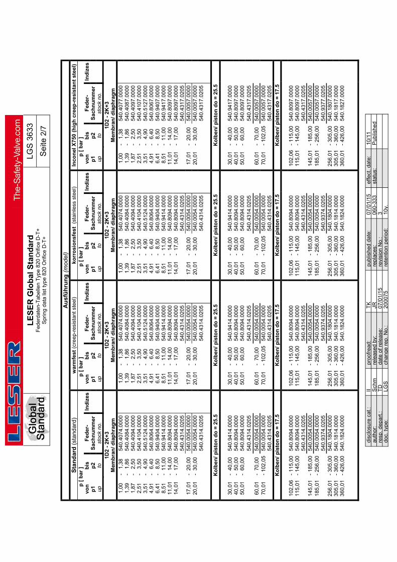
L
ES
ER
Glo
bal
Sta
nd
ard
F
eder
date
n-T
abe
llen
Typ
e 8
20 O
rific
e D
-T+
S
prin
g d
ata
list
type
820
Orif
ice
D-T
+
LG
S 3
633
Se
ite 2
/7
disc
losu
re c
at.:
II pr
oofr
ead:
T
K
pub
lishe
d da
te:
07/0
1/15
ef
fect
. dat
e:
10/1
1 au
thor
: S
chm
re
leas
ed b
y:
JR
repl
aces
: 06
0-33
3
stat
us:
Pub
lishe
d re
sp.
depa
rt.:
TD
da
te o
f rel
ease
: 07
/01/
15
revi
sion
No.
: 3
doc.
type
: LG
S
chan
ge
rep.
No.
: 20
007
5 re
tent
ion
per
iod:
10
y.
Au
sfü
hru
ng
(m
od
el)
Sta
nd
ard
(st
and
ard
) w
arm
fest
(cr
eep
-res
ista
nt s
teel
) k
orr
osi
on
sfes
t (
stai
nle
ss s
teel
) In
con
el X
750
(h
igh
cre
ep-r
esi
stan
t st
eel)
p
[ b
ar ]
p
[ b
ar ]
p
[ b
ar ]
p
[ b
ar ]
vo
n
bis
F
eder
- In
diz
es
von
b
is
Fed
er-
Ind
ize
s vo
n
bis
F
eder
- In
diz
es
von
b
is
Fed
er-
Ind
ize
s p
1 p
2 S
ach
nu
mm
er
p
1 p
2 S
ach
nu
mm
er
p
1 p
2 S
ach
nu
mm
er
p
1 p
2 S
ach
nu
mm
er
up
to
st
ock
no.
up
to
st
ock
no.
up
to
st
ock
no.
up
to
st
ock
no.
1D2
- 2K
+3
Mem
bra
n/ d
iap
hra
gm
1D
2 -
2K+
3 M
emb
ran
/ dia
ph
rag
m
1D2
- 2K
+3
Mem
bra
n/ d
iap
hra
gm
1D
2 -
2K+
3 M
emb
ran
/ dia
ph
rag
m
1
,00
-
1,38
54
0.4
074.
0000
1
,00
-
1,38
54
0.4
074.
0000
1
,00
-
1,38
54
0.4
074.
0000
1
,00
-
1,38
54
0.4
077.
0000
1
,39
-
1,8
6 54
0.40
84.0
000
1,3
9 -
1,
86
540
.408
4.00
00
1,3
9 -
1,
86
540
.408
4.00
00
1,3
9 -
1,
86
540
.408
7.00
00
1
,87
-
2,5
0 54
0.40
94.0
000
1,8
7 -
2,
50
540
.409
4.00
00
1,8
7 -
2,
50
540
.409
4.00
00
1,8
7 -
2,
50
540
.409
7.00
00
2
,51
-
3,5
0 54
0.41
04.0
000
2,5
1 -
3,
50
540
.410
4.00
00
2,5
1 -
3,
50
540
.410
4.00
00
2,5
1 -
3,
50
540
.410
7.00
00
3,5
1 -
4,
90
540.
5124
.000
0
3
,51
-
4,90
54
0.5
124.
0000
3
,51
-
4,90
54
0.5
124.
0000
3
,51
-
4,90
54
0.5
127.
0000
4
,91
-
6,40
54
0.8
064.
0000
4
,91
-
6,40
54
0.8
064.
0000
4
,91
-
6,40
54
0.8
064.
0000
4
,91
-
6,40
54
0.8
067.
0000
6
,41
-
8,50
54
0.9
404.
0000
6
,41
-
8,50
54
0.9
404.
0000
6
,41
-
8,50
54
0.9
404.
0000
6
,41
-
8,50
54
0.9
407.
0000
8
,51
- 1
1,00
54
0.9
414.
0000
8
,51
- 1
1,00
54
0.9
414.
0000
8
,51
- 1
1,00
54
0.9
414.
0000
8
,51
- 1
1,00
54
0.9
417.
0000
11
,01
- 1
4,00
54
0.8
094.
0000
11
,01
- 1
4,00
54
0.8
094.
0000
11
,01
- 1
4,00
54
0.8
094.
0000
11
,01
- 1
4,00
54
0.8
097.
0000
14
,01
- 1
7,00
54
0.8
094.
0000
14
,01
- 1
7,00
54
0.8
094.
0000
14
,01
- 1
7,00
54
0.8
094.
0000
14
,01
- 1
7,00
54
0.8
097.
0000
540
.431
4.02
05
54
0.4
314.
0205
540
.431
4.02
05
54
0.4
317.
0205
17
,01
- 2
0,00
54
0.0
054.
0000
17
,01
- 2
0,00
54
0.0
054.
0000
17
,01
- 2
0,00
54
0.0
054.
0000
17
,01
- 2
0,00
54
0.0
057.
0000
20
,01
- 3
0,00
54
0.0
054.
0000
20
,01
- 3
0,00
54
0.0
054.
0000
20
,01
- 3
0,00
54
0.0
054.
0000
20
,01
- 3
0,00
54
0.0
057.
0000
540
.431
4.02
05
54
0.4
314.
0205
540
.431
4.02
05
54
0.4
317.
0205
Ko
lbe
n/
pis
ton
do
= 2
5.5
K
olb
en/
pis
ton
do
= 2
5.5
Ko
lben
/ p
isto
n d
o =
25
.5
Ko
lbe
n/
pis
ton
do
= 2
5.5
30
,01
- 4
0,0
0 54
0.9
414.
0000
30
,01
- 4
0,0
0 54
0.9
414.
0000
30
,01
- 4
0,0
0 54
0.9
414.
0000
30
,01
- 4
0,0
0 54
0.9
417.
0000
40
,01
- 5
0,0
0 54
0.8
094.
0000
40
,01
- 5
0,0
0 54
0.8
094.
0000
40
,01
- 5
0,0
0 54
0.8
094.
0000
40
,01
- 5
0,0
0 54
0.8
097.
0000
50
,01
- 6
0,0
0 54
0.8
094.
0000
50
,01
- 6
0,0
0 54
0.8
094.
0000
50
,01
- 6
0,0
0 54
0.8
094.
0000
50
,01
- 6
0,0
0 54
0.8
097.
0000
540.
4314
.020
5
540
.431
4.02
05
54
0.4
314.
0205
540
.431
7.02
05
60
,01
- 7
0,00
54
0.0
054.
0000
60
,01
- 7
0,00
54
0.0
054.
0000
60
,01
- 7
0,00
54
0.0
054.
0000
60
,01
- 7
0,00
54
0.0
057.
000
0
70
,01
- 10
2,0
5 54
0.0
054.
0000
70
,01
- 10
2,0
5 54
0.0
054.
0000
70
,01
- 10
2,0
5 54
0.0
054.
0000
70
,01
- 10
2,0
5 54
0.0
057.
000
0
540
.431
4.02
05
54
0.4
314.
0205
540
.431
4.02
05
54
0.4
317.
020
5
Ko
lbe
n/
pis
ton
do
= 1
7.5
K
olb
en
/ p
isto
n d
o =
17
.5
Ko
lbe
n/
pis
ton
do
= 1
7.5
K
olb
en
/ p
isto
n d
o =
17
.5
102
,06
- 11
5,00
54
0.8
094.
0000
102
,06
- 11
5,00
54
0.8
094.
0000
102
,06
- 11
5,00
54
0.8
094.
0000
102
,06
- 11
5,00
54
0.8
097.
0000
115
,01
- 14
5,00
54
0.8
094.
0000
115
,01
- 14
5,00
54
0.8
094.
0000
115
,01
- 14
5,00
54
0.8
094.
0000
115
,01
- 14
5,00
54
0.8
097.
0000
540.
4314
.020
5
540.
4314
.020
5
540.
4314
.020
5
540.
4317
.020
5
145
,01
- 18
5,00
54
0.0
054.
0000
145
,01
- 18
5,00
54
0.0
054.
0000
145
,01
- 18
5,00
54
0.0
054.
0000
145
,01
- 18
5,00
54
0.0
057.
0000
185
,01
- 25
6,00
54
0.0
054.
0000
185
,01
- 25
6,00
54
0.0
054.
0000
185
,01
- 25
6,00
54
0.0
054.
0000
185
,01
- 25
6,00
54
0.0
057.
0000
540.
9374
.020
5
540.
9374
.020
5
540.
9374
.020
5
540.
9377
.020
5
256
,01
- 30
5,00
54
0.1
804.
0000
256
,01
- 30
5,00
54
0.1
804.
0000
256
,01
- 30
5,00
54
0.1
804.
0000
256
,01
- 30
5,00
54
0.1
807.
0000
305
,01
- 36
0,00
54
0.1
814.
0000
305
,01
- 36
0,00
54
0.1
814.
0000
305
,01
- 36
0,00
54
0.1
814.
0000
305
,01
- 36
0,00
54
0.1
817.
0000
360
,01
- 42
6,00
54
0.1
824.
0000
360
,01
- 42
6,00
54
0.1
824.
0000
360
,01
- 42
6,00
54
0.1
824.
0000
360
,01
- 42
6,00
54
0.1
827.
0000

L
ES
ER
Glo
bal
Sta
nd
ard
F
eder
date
n-T
abe
llen
Typ
e 8
20 O
rific
e D
-T+
S
prin
g d
ata
list
type
820
Orif
ice
D-T
+
LG
S 3
633
Se
ite 3
/7
disc
losu
re c
at.:
II pr
oofr
ead:
T
K
pub
lishe
d da
te:
07/0
1/15
ef
fect
. dat
e:
10/1
1 au
thor
: S
chm
re
leas
ed b
y:
JR
repl
aces
: 06
0-33
3
stat
us:
Pub
lishe
d re
sp.
depa
rt.:
TD
da
te o
f rel
ease
: 07
/01/
15
revi
sion
No.
: 3
doc.
type
: LG
S
chan
ge
rep.
No.
: 20
007
5 re
tent
ion
per
iod:
10
y.
Au
sfü
hru
ng
(m
od
el)
Sta
nd
ard
(st
and
ard
) w
arm
fest
(cr
eep
-res
ista
nt s
teel
) k
orr
osi
on
sfes
t (
stai
nle
ss s
teel
) In
con
el X
750
(h
igh
cre
ep-r
esi
stan
t st
eel)
p
[ b
ar ]
p
[ b
ar ]
p
[ b
ar ]
p
[ b
ar ]
vo
n
bis
F
eder
- In
diz
es
von
b
is
Fed
er-
Ind
ize
s vo
n
bis
F
eder
- In
diz
es
von
b
is
Fed
er-
Ind
ize
s p
1 p
2 S
ach
nu
mm
er
p
1 p
2 S
ach
nu
mm
er
p
1 p
2 S
ach
nu
mm
er
p
1 p
2 S
ach
nu
mm
er
up
to
st
ock
no.
up
to
st
ock
no.
up
to
st
ock
no.
up
to
st
ock
no.
3J4
- 4
P+
6 M
emb
ran
/ dia
ph
rag
m
3J4
- 4
P+
6 M
emb
ran
/ dia
ph
rag
m
3J4
- 4
P+
6 M
emb
ran
/ dia
ph
rag
m
3J4
- 4
P+
6 M
emb
ran
/ dia
ph
rag
m
1
,00
-
1,38
54
0.4
074.
0000
1
,00
-
1,38
54
0.4
074.
0000
1
,00
-
1,38
54
0.4
074.
0000
1
,00
-
1,38
54
0.4
077.
0000
1
,39
-
1,8
6 54
0.40
84.0
000
1,3
9 -
1,
86
540
.408
4.00
00
1,3
9 -
1,
86
540
.408
4.00
00
1,3
9 -
1,
86
540
.408
7.00
00
1
,87
-
2,5
0 54
0.40
94.0
000
1,8
7 -
2,
50
540
.409
4.00
00
1,8
7 -
2,
50
540
.409
4.00
00
1,8
7 -
2,
50
540
.409
7.00
00
2
,51
-
3,5
0 54
0.41
04.0
000
2,5
1 -
3,
50
540
.410
4.00
00
2,5
1 -
3,
50
540
.410
4.00
00
2,5
1 -
3,
50
540
.410
7.00
00
3,5
1 -
4,
90
540.
5124
.000
0
3
,51
-
4,90
54
0.5
124.
0000
3
,51
-
4,90
54
0.5
124.
0000
3
,51
-
4,90
54
0.5
127.
0000
4
,91
-
6,40
54
0.8
064.
0000
4
,91
-
6,40
54
0.8
064.
0000
4
,91
-
6,40
54
0.8
064.
0000
4
,91
-
6,40
54
0.8
067.
0000
6
,41
-
8,50
54
0.9
404.
0000
6
,41
-
8,50
54
0.9
404.
0000
6
,41
-
8,50
54
0.9
404.
0000
6
,41
-
8,50
54
0.9
407.
0000
8
,51
- 1
1,00
54
0.9
414.
0000
8
,51
- 1
1,00
54
0.9
414.
0000
8
,51
- 1
1,00
54
0.9
414.
0000
8
,51
- 1
1,00
54
0.9
417.
0000
11
,01
- 1
4,00
54
0.8
094.
0000
11
,01
- 1
4,00
54
0.8
094.
0000
11
,01
- 1
4,00
54
0.8
094.
0000
11
,01
- 1
4,00
54
0.8
097.
0000
14
,01
- 1
7,00
54
0.8
094.
0000
14
,01
- 1
7,00
54
0.8
094.
0000
14
,01
- 1
7,00
54
0.8
094.
0000
14
,01
- 1
7,00
54
0.8
097.
0000
540
.431
4.02
05
54
0.4
314.
0205
540
.431
4.02
05
54
0.4
317.
0205
17
,01
- 2
0,00
54
0.0
054.
0000
17
,01
- 2
0,00
54
0.0
054.
0000
17
,01
- 2
0,00
54
0.0
054.
0000
17
,01
- 2
0,00
54
0.0
057.
0000
20
,01
- 3
0,00
54
0.0
054.
0000
20
,01
- 3
0,00
54
0.0
054.
0000
20
,01
- 3
0,00
54
0.0
054.
0000
20
,01
- 3
0,00
54
0.0
057.
0000
540
.431
4.02
05
54
0.4
314.
0205
540
.431
4.02
05
54
0.4
317.
0205
Ko
lbe
n/
pis
ton
do
= 2
5.5
K
olb
en/
pis
ton
do
= 2
5.5
Ko
lben
/ p
isto
n d
o =
25
.5
Ko
lbe
n/
pis
ton
do
= 2
5.5
30
,01
- 4
0,0
0 54
0.9
414.
0000
30
,01
- 4
0,0
0 54
0.9
414.
0000
30
,01
- 4
0,0
0 54
0.9
414.
0000
30
,01
- 4
0,0
0 54
0.9
417.
0000
40
,01
- 5
0,0
0 54
0.8
094.
0000
40
,01
- 5
0,0
0 54
0.8
094.
0000
40
,01
- 5
0,0
0 54
0.8
094.
0000
40
,01
- 5
0,0
0 54
0.8
097.
0000
50
,01
- 6
0,0
0 54
0.8
094.
0000
50
,01
- 6
0,0
0 54
0.8
094.
0000
50
,01
- 6
0,0
0 54
0.8
094.
0000
50
,01
- 6
0,0
0 54
0.8
097.
0000
540.
4314
.020
5
540
.431
4.02
05
54
0.4
314.
0205
540
.431
7.02
05
60
,01
- 7
0,00
54
0.0
054.
0000
60
,01
- 7
0,00
54
0.0
054.
0000
60
,01
- 7
0,00
54
0.0
054.
0000
60
,01
- 7
0,00
54
0.0
057.
000
0
70
,01
- 10
2,0
5 54
0.0
054.
0000
70
,01
- 10
2,0
5 54
0.0
054.
0000
70
,01
- 10
2,0
5 54
0.0
054.
0000
70
,01
- 10
2,0
5 54
0.0
057.
000
0
540
.431
4.02
05
54
0.4
314.
0205
540
.431
4.02
05
54
0.4
317.
020
5
Ko
lbe
n/
pis
ton
do
= 1
7.5
K
olb
en
/ p
isto
n d
o =
17
.5
Ko
lbe
n/
pis
ton
do
= 1
7.5
K
olb
en
/ p
isto
n d
o =
17
.5
102
,06
- 11
5,00
54
0.8
094.
0000
102
,06
- 11
5,00
54
0.8
094.
0000
102
,06
- 11
5,00
54
0.8
094.
0000
102
,06
- 11
5,00
54
0.8
097.
0000
115
,01
- 14
5,00
54
0.8
094.
0000
115
,01
- 14
5,00
54
0.8
094.
0000
115
,01
- 14
5,00
54
0.8
094.
0000
115
,01
- 14
5,00
54
0.8
097.
0000
540.
4314
.020
5
540.
4314
.020
5
540.
4314
.020
5
540.
4317
.020
5
145
,01
- 18
5,00
54
0.0
054.
0000
145
,01
- 18
5,00
54
0.0
054.
0000
145
,01
- 18
5,00
54
0.0
054.
0000
145
,01
- 18
5,00
54
0.0
057.
0000
185
,01
- 25
6,00
54
0.0
054.
0000
185
,01
- 25
6,00
54
0.0
054.
0000
185
,01
- 25
6,00
54
0.0
054.
0000
185
,01
- 25
6,00
54
0.0
057.
0000
540.
9374
.020
5
540.
9374
.020
5
540.
9374
.020
5
540.
9377
.020
5
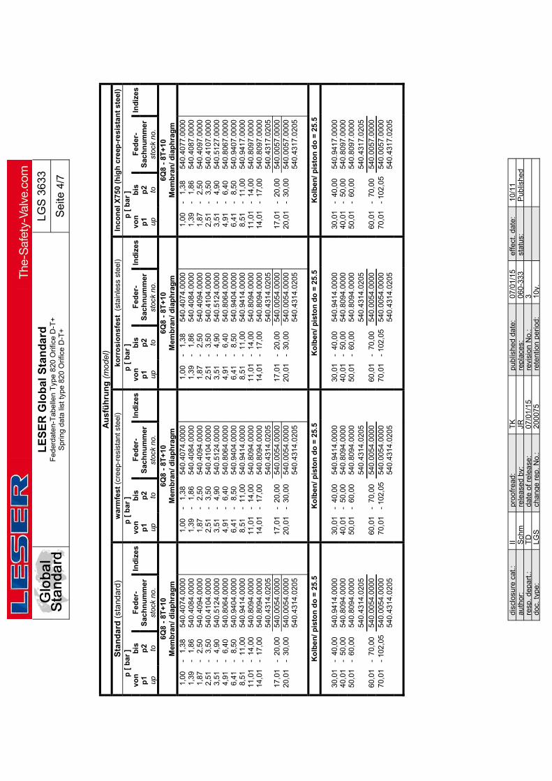
L
ES
ER
Glo
bal
Sta
nd
ard
F
eder
date
n-T
abe
llen
Typ
e 8
20 O
rific
e D
-T+
S
prin
g d
ata
list
type
820
Orif
ice
D-T
+
LG
S 3
633
Se
ite 4
/7
disc
losu
re c
at.:
II pr
oofr
ead:
T
K
pub
lishe
d da
te:
07/0
1/15
ef
fect
. dat
e:
10/1
1 au
thor
: S
chm
re
leas
ed b
y:
JR
repl
aces
: 06
0-33
3
stat
us:
Pub
lishe
d re
sp.
depa
rt.:
TD
da
te o
f rel
ease
: 07
/01/
15
revi
sion
No.
: 3
doc.
type
: LG
S
chan
ge
rep.
No.
: 20
007
5 re
tent
ion
per
iod:
10
y.
Au
sfü
hru
ng
(m
od
el)
Sta
nd
ard
(st
and
ard
) w
arm
fest
(cr
eep
-res
ista
nt s
teel
) k
orr
osi
on
sfes
t (
stai
nle
ss s
teel
) In
con
el X
750
(h
igh
cre
ep-r
esi
stan
t st
eel)
p
[ b
ar ]
p [
bar
]
p [
bar
]
p [
bar
]
von
b
is
Fed
er-
Ind
ize
s vo
n
bis
F
eder
- In
diz
es
von
b
is
Fed
er-
Ind
ize
s vo
n
bis
F
eder
- In
diz
es
p1
p2
Sac
hn
um
me
r
p1
p2
Sac
hn
um
mer
p1
p2
Sac
hn
um
me
r
p1
p2
Sac
hn
um
me
r
up
to
stoc
k no
.
up
to
stoc
k no
.
up
to
stoc
k no
.
up
to
stoc
k no
.
6Q8
- 8T
+10
M
emb
ran
/ dia
ph
rag
m
6Q8
- 8T
+10
M
emb
ran
/ dia
ph
rag
m
6Q8
- 8T
+10
M
emb
ran
/ dia
ph
rag
m
6Q8
- 8T
+10
M
emb
ran
/ dia
ph
rag
m
1
,00
-
1,3
8 54
0.40
74.0
000
1,0
0 -
1,
38
540
.407
4.0
000
1,0
0 -
1,
38
540
.407
4.0
000
1,0
0 -
1,
38
540
.40
77.0
000
1
,39
-
1,8
6 54
0.40
84.0
000
1,3
9 -
1,
86
540
.408
4.0
000
1,3
9 -
1,
86
540
.408
4.0
000
1,3
9 -
1,
86
540
.40
87.0
000
1
,87
-
2,5
0 54
0.40
94.0
000
1,8
7 -
2,
50
540
.409
4.0
000
1,8
7 -
2,
50
540
.409
4.0
000
1,8
7 -
2,
50
540
.40
97.0
000
2
,51
-
3,5
0 54
0.41
04.0
000
2,5
1 -
3,
50
540
.410
4.0
000
2,5
1 -
3,
50
540
.410
4.0
000
2,5
1 -
3,
50
540
.41
07.0
000
3,5
1 -
4,
90
540
.512
4.0
000
3,5
1 -
4,
90
540
.512
4.00
00
3,5
1 -
4,
90
540
.512
4.00
00
3,5
1 -
4,
90
540
.512
7.00
00
4,9
1 -
6,
40
540.
8064
.000
0
4
,91
-
6,40
54
0.8
064.
0000
4
,91
-
6,40
54
0.8
064.
0000
4
,91
-
6,40
54
0.8
067.
0000
6
,41
-
8,50
54
0.9
404.
000
0
6
,41
-
8,50
54
0.9
404.
0000
6
,41
-
8,50
54
0.9
404.
0000
6
,41
-
8,50
54
0.9
407.
0000
8
,51
- 1
1,00
54
0.9
414.
000
0
8
,51
- 1
1,00
54
0.9
414.
0000
8
,51
- 1
1,00
54
0.9
414.
0000
8
,51
- 1
1,00
54
0.9
417.
0000
11
,01
- 1
4,00
54
0.8
094.
000
0
11
,01
- 1
4,00
54
0.8
094.
0000
11
,01
- 1
4,00
54
0.8
094.
0000
11
,01
- 1
4,00
54
0.8
097.
0000
14
,01
- 1
7,00
54
0.8
094.
000
0
14
,01
- 1
7,00
54
0.8
094.
0000
14
,01
- 1
7,00
54
0.8
094.
0000
14
,01
- 1
7,00
54
0.8
097.
0000
540
.431
4.0
205
54
0.4
314.
0205
540
.431
4.02
05
54
0.4
317.
0205
17
,01
- 2
0,00
54
0.0
054.
000
0
17
,01
- 2
0,00
54
0.0
054.
000
0
17
,01
- 2
0,00
54
0.0
054.
0000
17
,01
- 2
0,00
54
0.0
057.
0000
20
,01
- 3
0,00
54
0.0
054.
000
0
20
,01
- 3
0,00
54
0.0
054.
0000
20
,01
- 3
0,00
54
0.0
054.
0000
20
,01
- 3
0,00
54
0.0
057.
0000
540.
4314
.020
5
540
.431
4.0
205
54
0.4
314.
020
5
540
.43
17.0
205
Ko
lbe
n/
pis
ton
do
= 2
5.5
K
olb
en/
pis
ton
do
= 2
5.5
Ko
lben
/ p
isto
n d
o =
25
.5
Ko
lbe
n/
pis
ton
do
= 2
5.5
30
,01
- 4
0,0
0 54
0.94
14.0
000
30,0
1 -
40,
00
540.
9414
.000
0
30
,01
- 4
0,0
0 54
0.94
14.0
000
30,0
1 -
40,
00
540.
9417
.000
0
40
,01
- 5
0,00
54
0.8
094.
000
0
40
,01
- 5
0,00
54
0.8
094.
0000
40
,01
- 5
0,00
54
0.8
094.
0000
40
,01
- 5
0,00
54
0.8
097.
000
0
50
,01
- 6
0,00
54
0.8
094.
000
0
50
,01
- 6
0,00
54
0.8
094.
0000
50
,01
- 6
0,00
54
0.8
094.
000
0
50
,01
- 6
0,00
54
0.8
097.
000
0
540.
4314
.020
5
540
.431
4.0
205
54
0.4
314.
020
5
540
.43
17.0
205
60
,01
- 7
0,00
54
0.0
054.
000
0
60
,01
- 7
0,00
54
0.0
054.
0000
60
,01
- 7
0,00
54
0.0
054.
0000
60
,01
- 7
0,00
54
0.0
057.
000
0
70
,01
- 10
2,0
5 54
0.0
054.
000
0
70
,01
- 10
2,0
5 54
0.0
054.
0000
70
,01
- 10
2,0
5 54
0.0
054.
0000
70
,01
- 10
2,0
5 54
0.0
057.
000
0
540
.431
4.0
205
54
0.4
314.
0205
540
.431
4.02
05
54
0.4
317.
020
5

L
ES
ER
Glo
bal
Sta
nd
ard
F
eder
date
n-T
abe
llen
Typ
e 8
20 O
rific
e D
-T+
S
prin
g d
ata
list
type
820
Orif
ice
D-T
+
LG
S 3
633
Se
ite 5
/7
disc
losu
re c
at.:
II pr
oofr
ead:
T
K
pub
lishe
d da
te:
07/0
1/15
ef
fect
. dat
e:
10/1
1 au
thor
: S
chm
re
leas
ed b
y:
JR
repl
aces
: 06
0-33
3
stat
us:
Pub
lishe
d re
sp.
depa
rt.:
TD
da
te o
f rel
ease
: 07
/01/
15
revi
sion
No.
: 3
doc.
type
: LG
S
chan
ge
rep.
No.
: 20
007
5 re
tent
ion
per
iod:
10
y.
Au
sfü
hru
ng
(m
od
el)
Sta
nd
ard
(st
and
ard
) w
arm
fest
(cr
eep
-res
ista
nt s
teel
) ko
rro
sio
nsf
est
(s
tain
less
ste
el)
Inco
nel
X75
0 (h
igh
cre
ep-r
esis
tan
t st
eel)
p
[ p
sig
]
p [
psi
g ]
p
[ p
sig
]
p [
psi
g ]
vo
n
bis
F
eder
- In
diz
es
von
b
is
Fed
er-
Ind
ize
s vo
n
bis
F
eder
- In
diz
es
von
b
is
Fed
er-
Ind
ize
s p
1 p
2 S
ach
nu
mm
er
p
1 p
2 S
ach
nu
mm
er
p
1 p
2 S
ach
nu
mm
er
p
1 p
2 S
ach
nu
mm
er
up
to
st
ock
no.
up
to
st
ock
no.
up
to
st
ock
no.
up
to
st
ock
no.
1D2
- 2K
+3
Mem
bra
n/ d
iap
hra
gm
1D
2 -
2K+
3 M
emb
ran
/ dia
ph
rag
m
1D2
- 2K
+3
Mem
bra
n/ d
iap
hra
gm
1D
2 -
2K+
3 M
emb
ran
/ dia
ph
rag
m
14
,5
- 2
0,0
540
.407
4.00
00
14,5
-
20,
0 54
0.4
074.
0000
14
,5
- 2
0,0
540
.407
4.00
00
14,5
-
20,
0 54
0.4
077.
0000
20
,1
- 2
7,0
540
.408
4.00
00
20,1
-
27,
0 54
0.4
084.
0000
20
,1
- 2
7,0
540
.408
4.00
00
20,1
-
27,
0 5
40.4
087.
0000
27
,1
- 3
6,3
540
.409
4.00
00
27,1
-
36,
3 54
0.4
094.
0000
27
,1
- 3
6,3
540
.409
4.00
00
27,1
-
36,
3 5
40.4
097.
0000
36
,4
- 5
0,8
540
.410
4.00
00
36,4
-
50,
8 54
0.4
104.
0000
36
,4
- 5
0,8
540
.410
4.00
00
36,4
-
50,
8 5
40.4
107.
0000
50
,9
- 7
1,1
540
.512
4.00
00
50,9
-
71,
1 54
0.5
124.
0000
50
,9
- 7
1,1
540
.512
4.00
00
50,9
-
71,
1 5
40.5
127.
0000
71
,2
- 9
2,8
540
.806
4.00
00
71,2
-
92,
8 54
0.8
064.
0000
71
,2
- 9
2,8
540
.806
4.00
00
71,2
-
92,
8 54
0.8
067.
0000
92
,9
- 1
23
540
.940
4.00
00
92,9
-
123
54
0.9
404.
0000
92
,9
- 1
23
540
.940
4.00
00
92,9
-
123
54
0.9
407.
0000
123
-
160
54
0.9
414.
0000
123
-
160
54
0.9
414.
0000
123
-
160
54
0.9
414.
0000
123
-
160
54
0.9
417.
0000
160
-
203
54
0.8
094.
0000
160
-
203
54
0.8
094.
0000
160
-
203
54
0.8
094.
0000
160
-
203
54
0.8
097.
0000
203
-
247
54
0.8
094.
0000
203
-
247
54
0.8
094.
0000
203
-
247
54
0.8
094.
0000
203
-
247
54
0.8
097.
0000
540
.431
4.02
05
54
0.4
314.
0205
540
.431
4.02
05
54
0.4
317.
020
5
247
-
290
54
0.0
054.
0000
247
-
290
54
0.0
054.
0000
247
-
290
54
0.0
054.
0000
247
-
290
54
0.0
057.
0000
290
-
435
54
0.0
054.
0000
290
-
435
54
0.0
054.
0000
290
-
435
54
0.0
054.
0000
290
-
435
54
0.0
057.
0000
540
.431
4.02
05
54
0.4
314.
0205
540
.431
4.02
05
54
0.4
317.
0205
Ko
lbe
n/
pis
ton
do
= 2
5.5
K
olb
en/
pis
ton
do
= 2
5.5
Ko
lben
/ p
isto
n d
o =
25.
5 K
olb
en
/ p
isto
n d
o =
25
.5
435
-
580
54
0.9
414
.000
0
435
-
580
5
40.9
414.
0000
435
-
580
54
0.94
14.0
000
4
35
- 5
80
540
.941
7.00
00
5
80
- 7
25
540
.80
94.0
000
5
80
- 7
25
540
.809
4.00
00
5
80
- 7
25
540.
8094
.000
0
580
-
725
5
40.8
097.
0000
725
-
870
54
0.8
094
.000
0
725
-
870
5
40.8
094.
0000
725
-
870
54
0.80
94.0
000
7
25
- 8
70
540
.809
7.00
00
54
0.4
314
.020
5
540
.431
4.02
05
54
0.43
14.0
205
5
40.4
317.
0205
870
-
101
5 54
0.0
054.
0000
870
-
101
5 54
0.0
054.
0000
870
-
101
5 54
0.0
054.
0000
870
-
101
5 54
0.0
057.
000
0
101
5 -
148
0 54
0.0
054.
0000
101
5 -
148
0 54
0.0
054.
0000
101
5 -
1480
54
0.0
054.
0000
101
5 -
148
0 54
0.0
057.
000
0
540
.431
4.02
05
54
0.4
314.
0205
540
.431
4.02
05
54
0.4
317.
020
5
Ko
lbe
n/
pis
ton
do
= 1
7.5
K
olb
en
/ p
isto
n d
o =
17
.5
Ko
lbe
n/
pis
ton
do
= 1
7.5
K
olb
en
/ p
isto
n d
o =
17
.5
148
0 -
166
8 54
0.8
094.
0000
148
0 -
166
8 54
0.8
094.
0000
148
0 -
166
8 54
0.8
094.
0000
148
0 -
1668
54
0.80
97.0
000
16
68
- 2
103
540
.809
4.00
00
16
68
- 2
103
540
.809
4.00
00
16
68
- 2
103
540
.809
4.00
00
16
68
- 21
03
540.
8097
.000
0
540
.43
14.0
205
54
0.43
14.0
205
54
0.43
14.0
205
54
0.43
17.0
205
21
03
- 2
683
540
.005
4.00
00
21
03
- 2
683
540
.005
4.00
00
21
03
- 2
683
540
.005
4.00
00
21
03
- 26
83
540.
0057
.000
0
268
3 -
371
3 54
0.0
054.
0000
268
3 -
371
3 54
0.0
054.
0000
268
3 -
371
3 54
0.0
054.
0000
268
3 -
3713
54
0.00
57.0
000
54
0.9
374
.020
5
540.
9374
.020
5
540.
9374
.020
5
540.
9377
.020
5
371
3 -
442
4 54
0.1
804.
0000
371
3 -
442
4 54
0.1
804.
0000
371
3 -
442
4 54
0.1
804.
0000
371
3 -
4424
54
0.18
07.0
000
44
24
- 5
221
540
.181
4.00
00
44
24
- 5
221
540
.181
4.00
00
44
24
- 5
221
540
.181
4.00
00
44
24
- 52
21
540.
1817
.000
0
522
1 -
617
9 54
0.1
824.
0000
522
1 -
617
9 54
0.1
824.
0000
522
1 -
617
9 54
0.1
824.
0000
522
1 -
6179
54
0.18
27.0
000

L
ES
ER
Glo
bal
Sta
nd
ard
F
eder
date
n-T
abe
llen
Typ
e 8
20 O
rific
e D
-T+
S
prin
g d
ata
list
type
820
Orif
ice
D-T
+
LG
S 3
633
Se
ite 6
/7
disc
losu
re c
at.:
II pr
oofr
ead:
T
K
pub
lishe
d da
te:
07/0
1/15
ef
fect
. dat
e:
10/1
1 au
thor
: S
chm
re
leas
ed b
y:
JR
repl
aces
: 06
0-33
3
stat
us:
Pub
lishe
d re
sp.
depa
rt.:
TD
da
te o
f rel
ease
: 07
/01/
15
revi
sion
No.
: 3
doc.
type
: LG
S
chan
ge
rep.
No.
: 20
007
5 re
tent
ion
per
iod:
10
y.
Au
sfü
hru
ng
(m
od
el)
Sta
nd
ard
(st
and
ard
) w
arm
fest
(cr
eep
-res
ista
nt s
teel
) ko
rro
sio
nsf
est
(s
tain
less
ste
el)
Inco
nel
X75
0 (h
igh
cre
ep-r
esis
tan
t st
eel)
p
[ p
sig
]
p [
psi
g ]
p
[ p
sig
]
p [
psi
g ]
vo
n
bis
F
eder
- In
diz
es
von
b
is
Fed
er-
Ind
ize
s vo
n
bis
F
eder
- In
diz
es
von
b
is
Fed
er-
Ind
ize
s p
1 p
2 S
ach
nu
mm
er
p
1 p
2 S
ach
nu
mm
er
p
1 p
2 S
ach
nu
mm
er
p
1 p
2 S
ach
nu
mm
er
up
to
st
ock
no.
up
to
st
ock
no.
up
to
st
ock
no.
up
to
st
ock
no.
3J4
- 4
P+
6 M
emb
ran
/ dia
ph
rag
m
3J4
- 4
P+
6 M
emb
ran
/ dia
ph
rag
m
3J4
- 4
P+
6 M
emb
ran
/ dia
ph
rag
m
3J4
- 4
P+
6 M
emb
ran
/ dia
ph
rag
m
14
,5
- 2
0,0
540
.407
4.00
00
14,5
-
20,
0 54
0.4
074.
0000
14
,5
- 2
0,0
540
.407
4.00
00
14,5
-
20,
0 54
0.4
077.
0000
20
,1
- 2
7,0
540
.408
4.00
00
20,1
-
27,
0 54
0.4
084.
0000
20
,1
- 2
7,0
540
.408
4.00
00
20,1
-
27,
0 5
40.4
087.
0000
27
,1
- 3
6,3
540
.409
4.00
00
27,1
-
36,
3 54
0.4
094.
0000
27
,1
- 3
6,3
540
.409
4.00
00
27,1
-
36,
3 5
40.4
097.
0000
36
,4
- 5
0,8
540
.410
4.00
00
36,4
-
50,
8 54
0.4
104.
0000
36
,4
- 5
0,8
540
.410
4.00
00
36,4
-
50,
8 5
40.4
107.
0000
50
,9
- 7
1,1
540
.512
4.00
00
50,9
-
71,
1 54
0.5
124.
0000
50
,9
- 7
1,1
540
.512
4.00
00
50,9
-
71,
1 5
40.5
127.
0000
71
,2
- 9
2,8
540
.806
4.00
00
71,2
-
92,
8 54
0.8
064.
0000
71
,2
- 9
2,8
540
.806
4.00
00
71,2
-
92,
8 54
0.8
067.
0000
92
,9
- 1
23
540
.940
4.00
00
92,9
-
123
54
0.9
404.
0000
92
,9
- 1
23
540
.940
4.00
00
92,9
-
123
54
0.9
407.
0000
123
-
160
54
0.9
414.
0000
123
-
160
54
0.9
414.
0000
123
-
160
54
0.9
414.
0000
123
-
160
54
0.9
417.
0000
160
-
203
54
0.8
094.
0000
160
-
203
54
0.8
094.
0000
160
-
203
54
0.8
094.
0000
160
-
203
54
0.8
097.
0000
203
-
247
54
0.8
094.
0000
203
-
247
54
0.8
094.
0000
203
-
247
54
0.8
094.
0000
203
-
247
54
0.8
097.
0000
540
.431
4.02
05
54
0.4
314.
0205
540
.431
4.02
05
54
0.4
317.
0205
247
-
290
54
0.0
054.
0000
247
-
290
54
0.0
054.
0000
247
-
290
54
0.0
054.
0000
247
-
290
54
0.0
057.
0000
290
-
435
54
0.0
054.
0000
290
-
435
54
0.0
054.
0000
290
-
435
54
0.0
054.
0000
290
-
435
54
0.0
057.
0000
540
.431
4.02
05
54
0.4
314.
0205
540
.431
4.02
05
54
0.4
317.
0205
Ko
lbe
n/
pis
ton
do
= 2
5.5
K
olb
en/
pis
ton
do
= 2
5.5
Ko
lben
/ p
isto
n d
o =
25.
5 K
olb
en
/ p
isto
n d
o =
25
.5
435
-
580
54
0.9
414
.000
0
435
-
580
5
40.9
414.
0000
435
-
580
54
0.94
14.0
000
4
35
- 5
80
540
.941
7.00
00
5
80
- 7
25
540
.80
94.0
000
5
80
- 7
25
540
.809
4.00
00
5
80
- 7
25
540.
8094
.000
0
580
-
725
5
40.8
097.
0000
725
-
870
54
0.8
094
.000
0
725
-
870
5
40.8
094.
0000
725
-
870
54
0.80
94.0
000
7
25
- 8
70
540
.809
7.00
00
54
0.4
314
.020
5
540
.431
4.02
05
54
0.43
14.0
205
5
40.4
317.
0205
870
-
101
5 54
0.0
054.
0000
870
-
101
5 54
0.0
054.
0000
870
-
101
5 54
0.0
054.
0000
870
-
101
5 54
0.0
057.
0000
101
5 -
148
0 54
0.0
054.
0000
101
5 -
148
0 54
0.0
054.
0000
101
5 -
148
0 54
0.0
054.
0000
101
5 -
148
0 54
0.0
057.
0000
540.
431
4.02
05
54
0.4
314.
0205
540
.431
4.02
05
54
0.4
317.
0205
Ko
lbe
n/
pis
ton
do
= 1
7.5
K
olb
en
/ p
isto
n d
o =
17
.5
Ko
lbe
n/
pis
ton
do
= 1
7.5
K
olb
en
/ p
isto
n d
o =
17
.5
148
0 -
166
8 54
0.8
094.
0000
148
0 -
166
8 54
0.8
094.
0000
148
0 -
166
8 54
0.8
094.
0000
148
0 -
1668
54
0.80
97.0
000
16
68
- 2
103
540
.809
4.00
00
16
68
- 2
103
540
.809
4.00
00
16
68
- 2
103
540
.809
4.00
00
16
68
- 21
03
540.
8097
.000
0
540
.43
14.0
205
54
0.43
14.0
205
54
0.43
14.0
205
54
0.43
17.0
205
21
03
- 2
683
540
.005
4.00
00
21
03
- 2
683
540
.005
4.00
00
21
03
- 2
683
540
.005
4.00
00
21
03
- 26
83
540.
0057
.000
0
268
3 -
371
3 54
0.0
054.
0000
268
3 -
371
3 54
0.0
054.
0000
268
3 -
371
3 54
0.0
054.
0000
268
3 -
3713
54
0.00
57.0
000
54
0.9
374
.020
5
540.
9374
.020
5
540.
9374
.020
5
540.
9377
.020
5

L
ES
ER
Glo
bal
Sta
nd
ard
F
eder
date
n-T
abe
llen
Typ
e 8
20 O
rific
e D
-T+
S
prin
g d
ata
list
type
820
Orif
ice
D-T
+
LG
S 3
633
Se
ite 7
/7
disc
losu
re c
at.:
II pr
oofr
ead:
T
K
pub
lishe
d da
te:
07/0
1/15
ef
fect
. dat
e:
10/1
1 au
thor
: S
chm
re
leas
ed b
y:
JR
repl
aces
: 06
0-33
3
stat
us:
Pub
lishe
d re
sp.
depa
rt.:
TD
da
te o
f rel
ease
: 07
/01/
15
revi
sion
No.
: 3
doc.
type
: LG
S
chan
ge
rep.
No.
: 20
007
5 re
tent
ion
per
iod:
10
y.
Au
sfü
hru
ng
(m
od
el)
Sta
nd
ard
(st
and
ard
) w
arm
fest
(cr
eep
-res
ista
nt s
teel
) ko
rro
sio
nsf
est
(s
tain
less
ste
el)
Inco
nel
X75
0 (h
igh
cre
ep-r
esis
tan
t st
eel)
p
[ p
sig
]
p [
psi
g ]
p
[ p
sig
]
p [
psi
g ]
vo
n
bis
F
eder
- In
diz
es
von
b
is
Fed
er-
Ind
ize
s vo
n
bis
F
eder
- In
diz
es
von
b
is
Fed
er-
Ind
ize
s p
1 p
2 S
ach
nu
mm
er
p
1 p
2 S
ach
nu
mm
er
p
1 p
2 S
ach
nu
mm
er
p
1 p
2 S
ach
nu
mm
er
up
to
st
ock
no.
up
to
st
ock
no.
up
to
st
ock
no.
up
to
st
ock
no.
6Q8
- 8T
+10
M
emb
ran
/ dia
ph
rag
m
6Q8
- 8T
+10
M
emb
ran
/ dia
ph
rag
m
6Q8
- 8T
+10
M
emb
ran
/ dia
ph
rag
m
6Q8
- 8T
+10
M
emb
ran
/ dia
ph
rag
m
14
,5
- 2
0,0
540
.407
4.00
00
14,5
-
20,
0 54
0.4
074.
0000
14
,5
- 2
0,0
540
.407
4.00
00
14,5
-
20,
0 5
40.4
077.
0000
20
,1
- 2
7,0
540
.408
4.00
00
20,1
-
27,
0 54
0.4
084.
0000
20
,1
- 2
7,0
540
.408
4.00
00
20,1
-
27,
0 5
40.4
087.
0000
27
,1
- 3
6,3
540
.409
4.00
00
27,1
-
36,
3 54
0.4
094.
0000
27
,1
- 3
6,3
540
.409
4.00
00
27,1
-
36,
3 5
40.4
097.
0000
36
,4
- 5
0,8
540
.410
4.00
00
36,4
-
50,
8 54
0.4
104.
0000
36
,4
- 5
0,8
540
.410
4.00
00
36,4
-
50,
8 5
40.4
107.
0000
50
,9
- 7
1,1
540
.512
4.00
00
50,9
-
71,
1 54
0.5
124.
0000
50
,9
- 7
1,1
540
.512
4.00
00
50,9
-
71,
1 54
0.5
127.
0000
71
,2
- 9
2,8
540
.806
4.00
00
71,2
-
92,
8 54
0.8
064.
0000
71
,2
- 9
2,8
540
.806
4.00
00
71,2
-
92,
8 54
0.8
067.
0000
92
,9
- 1
23
540
.940
4.00
00
92,9
-
123
54
0.9
404.
0000
92
,9
- 1
23
540
.940
4.00
00
92,9
-
123
54
0.9
407.
0000
123
-
160
54
0.9
414.
0000
123
-
160
54
0.9
414.
0000
123
-
160
54
0.9
414.
0000
123
-
160
54
0.9
417.
0000
160
-
203
54
0.8
094.
0000
160
-
203
54
0.8
094.
0000
160
-
203
54
0.8
094.
0000
160
-
203
54
0.8
097.
0000
203
-
247
54
0.8
094.
0000
203
-
247
54
0.8
094.
0000
203
-
247
54
0.8
094.
0000
203
-
247
54
0.8
097.
0000
540
.431
4.02
05
54
0.4
314.
0205
540
.431
4.02
05
54
0.4
317.
0205
247
-
290
54
0.0
054.
0000
247
-
290
54
0.0
054.
0000
247
-
290
54
0.0
054.
0000
247
-
290
54
0.0
057.
0000
290
-
435
54
0.0
054.
0000
290
-
435
54
0.0
054.
0000
290
-
435
54
0.0
054.
0000
290
-
435
54
0.0
057.
0000
540
.43
14.0
205
5
40.4
314.
0205
540.
4314
.020
5
540
.431
7.02
05
Ko
lbe
n/
pis
ton
do
= 2
5.5
K
olb
en/
pis
ton
do
= 2
5.5
Ko
lben
/ p
isto
n d
o =
25.
5 K
olb
en
/ p
isto
n d
o =
25
.5
435
-
580
54
0.9
414
.000
0
435
-
580
5
40.9
414.
0000
435
-
580
54
0.94
14.0
000
4
35
- 5
80
540
.941
7.00
00
5
80
- 7
25
540
.809
4.00
00
5
80
- 7
25
540
.809
4.00
00
5
80
- 7
25
540
.809
4.00
00
5
80
- 7
25
540
.809
7.00
00
7
25
- 8
70
540
.809
4.00
00
7
25
- 8
70
540
.809
4.00
00
7
25
- 8
70
540
.809
4.00
00
7
25
- 8
70
540
.809
7.00
00
54
0.4
314
.020
5
540
.431
4.02
05
54
0.43
14.0
205
5
40.4
317.
0205
870
-
101
5 54
0.0
054.
0000
870
-
101
5 54
0.0
054.
0000
870
-
101
5 54
0.0
054.
0000
870
-
101
5 54
0.0
057.
0000
101
5 -
148
0 54
0.0
054.
0000
101
5 -
148
0 54
0.0
054.
0000
101
5 -
148
0 54
0.0
054.
0000
101
5 -
148
0 54
0.0
057.
0000
540
.431
4.02
05
54
0.4
314.
0205
540
.431
4.02
05
54
0.4
317.
0205
L
ES
ER
Glo
bal
Sta
nd
ard
F
eder
date
n-T
abe
llen
Typ
e 8
20 O
rific
e D
-T+
S
prin
g d
ata
list
type
820
Orif
ice
D-T
+
LG
S 3
633
Se
ite 1
/7
disc
losu
re c
at.:
II pr
oofr
ead:
T
K
pub
lishe
d da
te:
07/0
1/15
ef
fect
. dat
e:
10/1
1 au
thor
: S
chm
re
leas
ed b
y:
JR
repl
aces
: 06
0-33
3
stat
us:
Pub
lishe
d re
sp.
depa
rt.:
TD
da
te o
f rel
ease
: 07
/01/
15
revi
sion
No.
: 3
doc.
type
: LG
S
chan
ge
rep.
No.
: 20
007
5 re
tent
ion
per
iod:
10
y.
Co
nte
nts
1
Pu
rpo
se ..
....
....
....
....
....
....
. 1
2
Sc
op
e ..
....
....
....
....
....
....
....
1
3
Re
fere
nc
es ..
....
....
....
....
....
1
1
P
urp
os
e T
his
LE
SE
R G
loba
l Sta
nda
rd (
LG
S)
con
tain
s th
e in
form
atio
n a
bo
ut p
ress
ure
ran
ge o
f a
ll sp
rings
, w
hic
h a
re
inst
alle
d in
val
ve-
typ
e 8
20
. 2
S
co
pe
Th
is L
GS
app
lies
to a
ll m
embe
rs o
f th
e L
ES
ER
qu
alit
y cl
ust
er
as
def
ine
d in
th
e gl
ob
al q
ua
lity
man
age
me
nt m
anu
al.
Th
is L
GS
con
tain
s in
form
atio
n a
bou
t the
pre
ssu
re r
an
ge o
f all
sprin
gs,
wh
ich
are
inst
alle
d in
va
lve
- ty
pe
82
0.
The
pre
ssu
re r
ange
s of
the
vario
us
mo
de
ls a
re g
ive
n f
irst i
n p
ress
ure
-un
it [b
ar]
. T
his
is fo
llow
ed b
y th
e p
ress
ure
-un
it [p
sig]
. 3
R
efe
ren
ces
L
De
S 3
060
.01,
LD
eS
32
65.0
1

L
ES
ER
Glo
bal
Sta
nd
ard
F
eder
date
n-T
abe
llen
Typ
e 8
20 O
rific
e D
-T+
S
prin
g d
ata
list
type
820
Orif
ice
D-T
+
LG
S 3
633
Se
ite 2
/7
disc
losu
re c
at.:
II pr
oofr
ead:
T
K
pub
lishe
d da
te:
07/0
1/15
ef
fect
. dat
e:
10/1
1 au
thor
: S
chm
re
leas
ed b
y:
JR
repl
aces
: 06
0-33
3
stat
us:
Pub
lishe
d re
sp.
depa
rt.:
TD
da
te o
f rel
ease
: 07
/01/
15
revi
sion
No.
: 3
doc.
type
: LG
S
chan
ge
rep.
No.
: 20
007
5 re
tent
ion
per
iod:
10
y.
Au
sfü
hru
ng
(m
od
el)
Sta
nd
ard
(st
and
ard
) w
arm
fest
(cr
eep
-res
ista
nt s
teel
) k
orr
osi
on
sfes
t (
stai
nle
ss s
teel
) In
con
el X
750
(h
igh
cre
ep-r
esi
stan
t st
eel)
p
[ b
ar ]
p
[ b
ar ]
p
[ b
ar ]
p
[ b
ar ]
vo
n
bis
F
eder
- In
diz
es
von
b
is
Fed
er-
Ind
ize
s vo
n
bis
F
eder
- In
diz
es
von
b
is
Fed
er-
Ind
ize
s p
1 p
2 S
ach
nu
mm
er
p
1 p
2 S
ach
nu
mm
er
p
1 p
2 S
ach
nu
mm
er
p
1 p
2 S
ach
nu
mm
er
up
to
st
ock
no.
up
to
st
ock
no.
up
to
st
ock
no.
up
to
st
ock
no.
1D2
- 2K
+3
Mem
bra
n/ d
iap
hra
gm
1D
2 -
2K+
3 M
emb
ran
/ dia
ph
rag
m
1D2
- 2K
+3
Mem
bra
n/ d
iap
hra
gm
1D
2 -
2K+
3 M
emb
ran
/ dia
ph
rag
m
1
,00
-
1,38
54
0.4
074.
0000
1
,00
-
1,38
54
0.4
074.
0000
1
,00
-
1,38
54
0.4
074.
0000
1
,00
-
1,38
54
0.4
077.
0000
1
,39
-
1,8
6 54
0.40
84.0
000
1,3
9 -
1,
86
540
.408
4.00
00
1,3
9 -
1,
86
540
.408
4.00
00
1,3
9 -
1,
86
540
.408
7.00
00
1
,87
-
2,5
0 54
0.40
94.0
000
1,8
7 -
2,
50
540
.409
4.00
00
1,8
7 -
2,
50
540
.409
4.00
00
1,8
7 -
2,
50
540
.409
7.00
00
2
,51
-
3,5
0 54
0.41
04.0
000
2,5
1 -
3,
50
540
.410
4.00
00
2,5
1 -
3,
50
540
.410
4.00
00
2,5
1 -
3,
50
540
.410
7.00
00
3,5
1 -
4,
90
540.
5124
.000
0
3
,51
-
4,90
54
0.5
124.
0000
3
,51
-
4,90
54
0.5
124.
0000
3
,51
-
4,90
54
0.5
127.
0000
4
,91
-
6,40
54
0.8
064.
0000
4
,91
-
6,40
54
0.8
064.
0000
4
,91
-
6,40
54
0.8
064.
0000
4
,91
-
6,40
54
0.8
067.
0000
6
,41
-
8,50
54
0.9
404.
0000
6
,41
-
8,50
54
0.9
404.
0000
6
,41
-
8,50
54
0.9
404.
0000
6
,41
-
8,50
54
0.9
407.
0000
8
,51
- 1
1,00
54
0.9
414.
0000
8
,51
- 1
1,00
54
0.9
414.
0000
8
,51
- 1
1,00
54
0.9
414.
0000
8
,51
- 1
1,00
54
0.9
417.
0000
11
,01
- 1
4,00
54
0.8
094.
0000
11
,01
- 1
4,00
54
0.8
094.
0000
11
,01
- 1
4,00
54
0.8
094.
0000
11
,01
- 1
4,00
54
0.8
097.
0000
14
,01
- 1
7,00
54
0.8
094.
0000
14
,01
- 1
7,00
54
0.8
094.
0000
14
,01
- 1
7,00
54
0.8
094.
0000
14
,01
- 1
7,00
54
0.8
097.
0000
540
.431
4.02
05
54
0.4
314.
0205
540
.431
4.02
05
54
0.4
317.
0205
17
,01
- 2
0,00
54
0.0
054.
0000
17
,01
- 2
0,00
54
0.0
054.
0000
17
,01
- 2
0,00
54
0.0
054.
0000
17
,01
- 2
0,00
54
0.0
057.
0000
20
,01
- 3
0,00
54
0.0
054.
0000
20
,01
- 3
0,00
54
0.0
054.
0000
20
,01
- 3
0,00
54
0.0
054.
0000
20
,01
- 3
0,00
54
0.0
057.
0000
540
.431
4.02
05
54
0.4
314.
0205
540
.431
4.02
05
54
0.4
317.
0205
Ko
lbe
n/
pis
ton
do
= 2
5.5
K
olb
en/
pis
ton
do
= 2
5.5
Ko
lben
/ p
isto
n d
o =
25
.5
Ko
lbe
n/
pis
ton
do
= 2
5.5
30
,01
- 4
0,0
0 54
0.9
414.
0000
30
,01
- 4
0,0
0 54
0.9
414.
0000
30
,01
- 4
0,0
0 54
0.9
414.
0000
30
,01
- 4
0,0
0 54
0.9
417.
0000
40
,01
- 5
0,0
0 54
0.8
094.
0000
40
,01
- 5
0,0
0 54
0.8
094.
0000
40
,01
- 5
0,0
0 54
0.8
094.
0000
40
,01
- 5
0,0
0 54
0.8
097.
0000
50
,01
- 6
0,0
0 54
0.8
094.
0000
50
,01
- 6
0,0
0 54
0.8
094.
0000
50
,01
- 6
0,0
0 54
0.8
094.
0000
50
,01
- 6
0,0
0 54
0.8
097.
0000
540.
4314
.020
5
540
.431
4.02
05
54
0.4
314.
0205
540
.431
7.02
05
60
,01
- 7
0,00
54
0.0
054.
0000
60
,01
- 7
0,00
54
0.0
054.
0000
60
,01
- 7
0,00
54
0.0
054.
0000
60
,01
- 7
0,00
54
0.0
057.
000
0
70
,01
- 10
2,0
5 54
0.0
054.
0000
70
,01
- 10
2,0
5 54
0.0
054.
0000
70
,01
- 10
2,0
5 54
0.0
054.
0000
70
,01
- 10
2,0
5 54
0.0
057.
000
0
540
.431
4.02
05
54
0.4
314.
0205
540
.431
4.02
05
54
0.4
317.
020
5
Ko
lbe
n/
pis
ton
do
= 1
7.5
K
olb
en
/ p
isto
n d
o =
17
.5
Ko
lbe
n/
pis
ton
do
= 1
7.5
K
olb
en
/ p
isto
n d
o =
17
.5
102
,06
- 11
5,00
54
0.8
094.
0000
102
,06
- 11
5,00
54
0.8
094.
0000
102
,06
- 11
5,00
54
0.8
094.
0000
102
,06
- 11
5,00
54
0.8
097.
0000
115
,01
- 14
5,00
54
0.8
094.
0000
115
,01
- 14
5,00
54
0.8
094.
0000
115
,01
- 14
5,00
54
0.8
094.
0000
115
,01
- 14
5,00
54
0.8
097.
0000
540.
4314
.020
5
540.
4314
.020
5
540.
4314
.020
5
540.
4317
.020
5
145
,01
- 18
5,00
54
0.0
054.
0000
145
,01
- 18
5,00
54
0.0
054.
0000
145
,01
- 18
5,00
54
0.0
054.
0000
145
,01
- 18
5,00
54
0.0
057.
0000
185
,01
- 25
6,00
54
0.0
054.
0000
185
,01
- 25
6,00
54
0.0
054.
0000
185
,01
- 25
6,00
54
0.0
054.
0000
185
,01
- 25
6,00
54
0.0
057.
0000
540.
9374
.020
5
540.
9374
.020
5
540.
9374
.020
5
540.
9377
.020
5
256
,01
- 30
5,00
54
0.1
804.
0000
256
,01
- 30
5,00
54
0.1
804.
0000
256
,01
- 30
5,00
54
0.1
804.
0000
256
,01
- 30
5,00
54
0.1
807.
0000
305
,01
- 36
0,00
54
0.1
814.
0000
305
,01
- 36
0,00
54
0.1
814.
0000
305
,01
- 36
0,00
54
0.1
814.
0000
305
,01
- 36
0,00
54
0.1
817.
0000
360
,01
- 42
6,00
54
0.1
824.
0000
360
,01
- 42
6,00
54
0.1
824.
0000
360
,01
- 42
6,00
54
0.1
824.
0000
360
,01
- 42
6,00
54
0.1
827.
0000
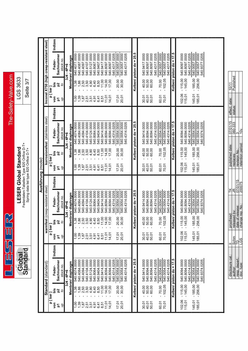
L
ES
ER
Glo
bal
Sta
nd
ard
F
eder
date
n-T
abe
llen
Typ
e 8
20 O
rific
e D
-T+
S
prin
g d
ata
list
type
820
Orif
ice
D-T
+
LG
S 3
633
Se
ite 3
/7
disc
losu
re c
at.:
II pr
oofr
ead:
T
K
pub
lishe
d da
te:
07/0
1/15
ef
fect
. dat
e:
10/1
1 au
thor
: S
chm
re
leas
ed b
y:
JR
repl
aces
: 06
0-33
3
stat
us:
Pub
lishe
d re
sp.
depa
rt.:
TD
da
te o
f rel
ease
: 07
/01/
15
revi
sion
No.
: 3
doc.
type
: LG
S
chan
ge
rep.
No.
: 20
007
5 re
tent
ion
per
iod:
10
y.
Au
sfü
hru
ng
(m
od
el)
Sta
nd
ard
(st
and
ard
) w
arm
fest
(cr
eep
-res
ista
nt s
teel
) k
orr
osi
on
sfes
t (
stai
nle
ss s
teel
) In
con
el X
750
(h
igh
cre
ep-r
esi
stan
t st
eel)
p
[ b
ar ]
p
[ b
ar ]
p
[ b
ar ]
p
[ b
ar ]
vo
n
bis
F
eder
- In
diz
es
von
b
is
Fed
er-
Ind
ize
s vo
n
bis
F
eder
- In
diz
es
von
b
is
Fed
er-
Ind
ize
s p
1 p
2 S
ach
nu
mm
er
p
1 p
2 S
ach
nu
mm
er
p
1 p
2 S
ach
nu
mm
er
p
1 p
2 S
ach
nu
mm
er
up
to
st
ock
no.
up
to
st
ock
no.
up
to
st
ock
no.
up
to
st
ock
no.
3J4
- 4
P+
6 M
emb
ran
/ dia
ph
rag
m
3J4
- 4
P+
6 M
emb
ran
/ dia
ph
rag
m
3J4
- 4
P+
6 M
emb
ran
/ dia
ph
rag
m
3J4
- 4
P+
6 M
emb
ran
/ dia
ph
rag
m
1
,00
-
1,38
54
0.4
074.
0000
1
,00
-
1,38
54
0.4
074.
0000
1
,00
-
1,38
54
0.4
074.
0000
1
,00
-
1,38
54
0.4
077.
0000
1
,39
-
1,8
6 54
0.40
84.0
000
1,3
9 -
1,
86
540
.408
4.00
00
1,3
9 -
1,
86
540
.408
4.00
00
1,3
9 -
1,
86
540
.408
7.00
00
1
,87
-
2,5
0 54
0.40
94.0
000
1,8
7 -
2,
50
540
.409
4.00
00
1,8
7 -
2,
50
540
.409
4.00
00
1,8
7 -
2,
50
540
.409
7.00
00
2
,51
-
3,5
0 54
0.41
04.0
000
2,5
1 -
3,
50
540
.410
4.00
00
2,5
1 -
3,
50
540
.410
4.00
00
2,5
1 -
3,
50
540
.410
7.00
00
3,5
1 -
4,
90
540.
5124
.000
0
3
,51
-
4,90
54
0.5
124.
0000
3
,51
-
4,90
54
0.5
124.
0000
3
,51
-
4,90
54
0.5
127.
0000
4
,91
-
6,40
54
0.8
064.
0000
4
,91
-
6,40
54
0.8
064.
0000
4
,91
-
6,40
54
0.8
064.
0000
4
,91
-
6,40
54
0.8
067.
0000
6
,41
-
8,50
54
0.9
404.
0000
6
,41
-
8,50
54
0.9
404.
0000
6
,41
-
8,50
54
0.9
404.
0000
6
,41
-
8,50
54
0.9
407.
0000
8
,51
- 1
1,00
54
0.9
414.
0000
8
,51
- 1
1,00
54
0.9
414.
0000
8
,51
- 1
1,00
54
0.9
414.
0000
8
,51
- 1
1,00
54
0.9
417.
0000
11
,01
- 1
4,00
54
0.8
094.
0000
11
,01
- 1
4,00
54
0.8
094.
0000
11
,01
- 1
4,00
54
0.8
094.
0000
11
,01
- 1
4,00
54
0.8
097.
0000
14
,01
- 1
7,00
54
0.8
094.
0000
14
,01
- 1
7,00
54
0.8
094.
0000
14
,01
- 1
7,00
54
0.8
094.
0000
14
,01
- 1
7,00
54
0.8
097.
0000
540
.431
4.02
05
54
0.4
314.
0205
540
.431
4.02
05
54
0.4
317.
0205
17
,01
- 2
0,00
54
0.0
054.
0000
17
,01
- 2
0,00
54
0.0
054.
0000
17
,01
- 2
0,00
54
0.0
054.
0000
17
,01
- 2
0,00
54
0.0
057.
0000
20
,01
- 3
0,00
54
0.0
054.
0000
20
,01
- 3
0,00
54
0.0
054.
0000
20
,01
- 3
0,00
54
0.0
054.
0000
20
,01
- 3
0,00
54
0.0
057.
0000
540
.431
4.02
05
54
0.4
314.
0205
540
.431
4.02
05
54
0.4
317.
0205
Ko
lbe
n/
pis
ton
do
= 2
5.5
K
olb
en/
pis
ton
do
= 2
5.5
Ko
lben
/ p
isto
n d
o =
25
.5
Ko
lbe
n/
pis
ton
do
= 2
5.5
30
,01
- 4
0,0
0 54
0.9
414.
0000
30
,01
- 4
0,0
0 54
0.9
414.
0000
30
,01
- 4
0,0
0 54
0.9
414.
0000
30
,01
- 4
0,0
0 54
0.9
417.
0000
40
,01
- 5
0,0
0 54
0.8
094.
0000
40
,01
- 5
0,0
0 54
0.8
094.
0000
40
,01
- 5
0,0
0 54
0.8
094.
0000
40
,01
- 5
0,0
0 54
0.8
097.
0000
50
,01
- 6
0,0
0 54
0.8
094.
0000
50
,01
- 6
0,0
0 54
0.8
094.
0000
50
,01
- 6
0,0
0 54
0.8
094.
0000
50
,01
- 6
0,0
0 54
0.8
097.
0000
540.
4314
.020
5
540
.431
4.02
05
54
0.4
314.
0205
540
.431
7.02
05
60
,01
- 7
0,00
54
0.0
054.
0000
60
,01
- 7
0,00
54
0.0
054.
0000
60
,01
- 7
0,00
54
0.0
054.
0000
60
,01
- 7
0,00
54
0.0
057.
000
0
70
,01
- 10
2,0
5 54
0.0
054.
0000
70
,01
- 10
2,0
5 54
0.0
054.
0000
70
,01
- 10
2,0
5 54
0.0
054.
0000
70
,01
- 10
2,0
5 54
0.0
057.
000
0
540
.431
4.02
05
54
0.4
314.
0205
540
.431
4.02
05
54
0.4
317.
020
5
Ko
lbe
n/
pis
ton
do
= 1
7.5
K
olb
en
/ p
isto
n d
o =
17
.5
Ko
lbe
n/
pis
ton
do
= 1
7.5
K
olb
en
/ p
isto
n d
o =
17
.5
102
,06
- 11
5,00
54
0.8
094.
0000
102
,06
- 11
5,00
54
0.8
094.
0000
102
,06
- 11
5,00
54
0.8
094.
0000
102
,06
- 11
5,00
54
0.8
097.
0000
115
,01
- 14
5,00
54
0.8
094.
0000
115
,01
- 14
5,00
54
0.8
094.
0000
115
,01
- 14
5,00
54
0.8
094.
0000
115
,01
- 14
5,00
54
0.8
097.
0000
540.
4314
.020
5
540.
4314
.020
5
540.
4314
.020
5
540.
4317
.020
5
145
,01
- 18
5,00
54
0.0
054.
0000
145
,01
- 18
5,00
54
0.0
054.
0000
145
,01
- 18
5,00
54
0.0
054.
0000
145
,01
- 18
5,00
54
0.0
057.
0000
185
,01
- 25
6,00
54
0.0
054.
0000
185
,01
- 25
6,00
54
0.0
054.
0000
185
,01
- 25
6,00
54
0.0
054.
0000
185
,01
- 25
6,00
54
0.0
057.
0000
540.
9374
.020
5
540.
9374
.020
5
540.
9374
.020
5
540.
9377
.020
5

L
ES
ER
Glo
bal
Sta
nd
ard
F
eder
date
n-T
abe
llen
Typ
e 8
20 O
rific
e D
-T+
S
prin
g d
ata
list
type
820
Orif
ice
D-T
+
LG
S 3
633
Se
ite 4
/7
disc
losu
re c
at.:
II pr
oofr
ead:
T
K
pub
lishe
d da
te:
07/0
1/15
ef
fect
. dat
e:
10/1
1 au
thor
: S
chm
re
leas
ed b
y:
JR
repl
aces
: 06
0-33
3
stat
us:
Pub
lishe
d re
sp.
depa
rt.:
TD
da
te o
f rel
ease
: 07
/01/
15
revi
sion
No.
: 3
doc.
type
: LG
S
chan
ge
rep.
No.
: 20
007
5 re
tent
ion
per
iod:
10
y.
Au
sfü
hru
ng
(m
od
el)
Sta
nd
ard
(st
and
ard
) w
arm
fest
(cr
eep
-res
ista
nt s
teel
) k
orr
osi
on
sfes
t (
stai
nle
ss s
teel
) In
con
el X
750
(h
igh
cre
ep-r
esi
stan
t st
eel)
p
[ b
ar ]
p [
bar
]
p [
bar
]
p [
bar
]
von
b
is
Fed
er-
Ind
ize
s vo
n
bis
F
eder
- In
diz
es
von
b
is
Fed
er-
Ind
ize
s vo
n
bis
F
eder
- In
diz
es
p1
p2
Sac
hn
um
me
r
p1
p2
Sac
hn
um
mer
p1
p2
Sac
hn
um
me
r
p1
p2
Sac
hn
um
me
r
up
to
stoc
k no
.
up
to
stoc
k no
.
up
to
stoc
k no
.
up
to
stoc
k no
.
6Q8
- 8T
+10
M
emb
ran
/ dia
ph
rag
m
6Q8
- 8T
+10
M
emb
ran
/ dia
ph
rag
m
6Q8
- 8T
+10
M
emb
ran
/ dia
ph
rag
m
6Q8
- 8T
+10
M
emb
ran
/ dia
ph
rag
m
1
,00
-
1,3
8 54
0.40
74.0
000
1,0
0 -
1,
38
540
.407
4.0
000
1,0
0 -
1,
38
540
.407
4.0
000
1,0
0 -
1,
38
540
.40
77.0
000
1
,39
-
1,8
6 54
0.40
84.0
000
1,3
9 -
1,
86
540
.408
4.0
000
1,3
9 -
1,
86
540
.408
4.0
000
1,3
9 -
1,
86
540
.40
87.0
000
1
,87
-
2,5
0 54
0.40
94.0
000
1,8
7 -
2,
50
540
.409
4.0
000
1,8
7 -
2,
50
540
.409
4.0
000
1,8
7 -
2,
50
540
.40
97.0
000
2
,51
-
3,5
0 54
0.41
04.0
000
2,5
1 -
3,
50
540
.410
4.0
000
2,5
1 -
3,
50
540
.410
4.0
000
2,5
1 -
3,
50
540
.41
07.0
000
3,5
1 -
4,
90
540
.512
4.0
000
3,5
1 -
4,
90
540
.512
4.00
00
3,5
1 -
4,
90
540
.512
4.00
00
3,5
1 -
4,
90
540
.512
7.00
00
4,9
1 -
6,
40
540.
8064
.000
0
4
,91
-
6,40
54
0.8
064.
0000
4
,91
-
6,40
54
0.8
064.
0000
4
,91
-
6,40
54
0.8
067.
0000
6
,41
-
8,50
54
0.9
404.
000
0
6
,41
-
8,50
54
0.9
404.
0000
6
,41
-
8,50
54
0.9
404.
0000
6
,41
-
8,50
54
0.9
407.
0000
8
,51
- 1
1,00
54
0.9
414.
000
0
8
,51
- 1
1,00
54
0.9
414.
0000
8
,51
- 1
1,00
54
0.9
414.
0000
8
,51
- 1
1,00
54
0.9
417.
0000
11
,01
- 1
4,00
54
0.8
094.
000
0
11
,01
- 1
4,00
54
0.8
094.
0000
11
,01
- 1
4,00
54
0.8
094.
0000
11
,01
- 1
4,00
54
0.8
097.
0000
14
,01
- 1
7,00
54
0.8
094.
000
0
14
,01
- 1
7,00
54
0.8
094.
0000
14
,01
- 1
7,00
54
0.8
094.
0000
14
,01
- 1
7,00
54
0.8
097.
0000
540
.431
4.0
205
54
0.4
314.
0205
540
.431
4.02
05
54
0.4
317.
0205
17
,01
- 2
0,00
54
0.0
054.
000
0
17
,01
- 2
0,00
54
0.0
054.
000
0
17
,01
- 2
0,00
54
0.0
054.
0000
17
,01
- 2
0,00
54
0.0
057.
0000
20
,01
- 3
0,00
54
0.0
054.
000
0
20
,01
- 3
0,00
54
0.0
054.
0000
20
,01
- 3
0,00
54
0.0
054.
0000
20
,01
- 3
0,00
54
0.0
057.
0000
540.
4314
.020
5
540
.431
4.0
205
54
0.4
314.
020
5
540
.43
17.0
205
Ko
lbe
n/
pis
ton
do
= 2
5.5
K
olb
en/
pis
ton
do
= 2
5.5
Ko
lben
/ p
isto
n d
o =
25
.5
Ko
lbe
n/
pis
ton
do
= 2
5.5
30
,01
- 4
0,0
0 54
0.94
14.0
000
30,0
1 -
40,
00
540.
9414
.000
0
30
,01
- 4
0,0
0 54
0.94
14.0
000
30,0
1 -
40,
00
540.
9417
.000
0
40
,01
- 5
0,00
54
0.8
094.
000
0
40
,01
- 5
0,00
54
0.8
094.
0000
40
,01
- 5
0,00
54
0.8
094.
0000
40
,01
- 5
0,00
54
0.8
097.
000
0
50
,01
- 6
0,00
54
0.8
094.
000
0
50
,01
- 6
0,00
54
0.8
094.
0000
50
,01
- 6
0,00
54
0.8
094.
000
0
50
,01
- 6
0,00
54
0.8
097.
000
0
540.
4314
.020
5
540
.431
4.0
205
54
0.4
314.
020
5
540
.43
17.0
205
60
,01
- 7
0,00
54
0.0
054.
000
0
60
,01
- 7
0,00
54
0.0
054.
0000
60
,01
- 7
0,00
54
0.0
054.
0000
60
,01
- 7
0,00
54
0.0
057.
000
0
70
,01
- 10
2,0
5 54
0.0
054.
000
0
70
,01
- 10
2,0
5 54
0.0
054.
0000
70
,01
- 10
2,0
5 54
0.0
054.
0000
70
,01
- 10
2,0
5 54
0.0
057.
000
0
540
.431
4.0
205
54
0.4
314.
0205
540
.431
4.02
05
54
0.4
317.
020
5

L
ES
ER
Glo
bal
Sta
nd
ard
F
eder
date
n-T
abe
llen
Typ
e 8
20 O
rific
e D
-T+
S
prin
g d
ata
list
type
820
Orif
ice
D-T
+
LG
S 3
633
Se
ite 5
/7
disc
losu
re c
at.:
II pr
oofr
ead:
T
K
pub
lishe
d da
te:
07/0
1/15
ef
fect
. dat
e:
10/1
1 au
thor
: S
chm
re
leas
ed b
y:
JR
repl
aces
: 06
0-33
3
stat
us:
Pub
lishe
d re
sp.
depa
rt.:
TD
da
te o
f rel
ease
: 07
/01/
15
revi
sion
No.
: 3
doc.
type
: LG
S
chan
ge
rep.
No.
: 20
007
5 re
tent
ion
per
iod:
10
y.
Au
sfü
hru
ng
(m
od
el)
Sta
nd
ard
(st
and
ard
) w
arm
fest
(cr
eep
-res
ista
nt s
teel
) ko
rro
sio
nsf
est
(s
tain
less
ste
el)
Inco
nel
X75
0 (h
igh
cre
ep-r
esis
tan
t st
eel)
p
[ p
sig
]
p [
psi
g ]
p
[ p
sig
]
p [
psi
g ]
vo
n
bis
F
eder
- In
diz
es
von
b
is
Fed
er-
Ind
ize
s vo
n
bis
F
eder
- In
diz
es
von
b
is
Fed
er-
Ind
ize
s p
1 p
2 S
ach
nu
mm
er
p
1 p
2 S
ach
nu
mm
er
p
1 p
2 S
ach
nu
mm
er
p
1 p
2 S
ach
nu
mm
er
up
to
st
ock
no.
up
to
st
ock
no.
up
to
st
ock
no.
up
to
st
ock
no.
1D2
- 2K
+3
Mem
bra
n/ d
iap
hra
gm
1D
2 -
2K+
3 M
emb
ran
/ dia
ph
rag
m
1D2
- 2K
+3
Mem
bra
n/ d
iap
hra
gm
1D
2 -
2K+
3 M
emb
ran
/ dia
ph
rag
m
14
,5
- 2
0,0
540
.407
4.00
00
14,5
-
20,
0 54
0.4
074.
0000
14
,5
- 2
0,0
540
.407
4.00
00
14,5
-
20,
0 54
0.4
077.
0000
20
,1
- 2
7,0
540
.408
4.00
00
20,1
-
27,
0 54
0.4
084.
0000
20
,1
- 2
7,0
540
.408
4.00
00
20,1
-
27,
0 5
40.4
087.
0000
27
,1
- 3
6,3
540
.409
4.00
00
27,1
-
36,
3 54
0.4
094.
0000
27
,1
- 3
6,3
540
.409
4.00
00
27,1
-
36,
3 5
40.4
097.
0000
36
,4
- 5
0,8
540
.410
4.00
00
36,4
-
50,
8 54
0.4
104.
0000
36
,4
- 5
0,8
540
.410
4.00
00
36,4
-
50,
8 5
40.4
107.
0000
50
,9
- 7
1,1
540
.512
4.00
00
50,9
-
71,
1 54
0.5
124.
0000
50
,9
- 7
1,1
540
.512
4.00
00
50,9
-
71,
1 5
40.5
127.
0000
71
,2
- 9
2,8
540
.806
4.00
00
71,2
-
92,
8 54
0.8
064.
0000
71
,2
- 9
2,8
540
.806
4.00
00
71,2
-
92,
8 54
0.8
067.
0000
92
,9
- 1
23
540
.940
4.00
00
92,9
-
123
54
0.9
404.
0000
92
,9
- 1
23
540
.940
4.00
00
92,9
-
123
54
0.9
407.
0000
123
-
160
54
0.9
414.
0000
123
-
160
54
0.9
414.
0000
123
-
160
54
0.9
414.
0000
123
-
160
54
0.9
417.
0000
160
-
203
54
0.8
094.
0000
160
-
203
54
0.8
094.
0000
160
-
203
54
0.8
094.
0000
160
-
203
54
0.8
097.
0000
203
-
247
54
0.8
094.
0000
203
-
247
54
0.8
094.
0000
203
-
247
54
0.8
094.
0000
203
-
247
54
0.8
097.
0000
540
.431
4.02
05
54
0.4
314.
0205
540
.431
4.02
05
54
0.4
317.
020
5
247
-
290
54
0.0
054.
0000
247
-
290
54
0.0
054.
0000
247
-
290
54
0.0
054.
0000
247
-
290
54
0.0
057.
0000
290
-
435
54
0.0
054.
0000
290
-
435
54
0.0
054.
0000
290
-
435
54
0.0
054.
0000
290
-
435
54
0.0
057.
0000
540
.431
4.02
05
54
0.4
314.
0205
540
.431
4.02
05
54
0.4
317.
0205
Ko
lbe
n/
pis
ton
do
= 2
5.5
K
olb
en/
pis
ton
do
= 2
5.5
Ko
lben
/ p
isto
n d
o =
25.
5 K
olb
en
/ p
isto
n d
o =
25
.5
435
-
580
54
0.9
414
.000
0
435
-
580
5
40.9
414.
0000
435
-
580
54
0.94
14.0
000
4
35
- 5
80
540
.941
7.00
00
5
80
- 7
25
540
.80
94.0
000
5
80
- 7
25
540
.809
4.00
00
5
80
- 7
25
540.
8094
.000
0
580
-
725
5
40.8
097.
0000
725
-
870
54
0.8
094
.000
0
725
-
870
5
40.8
094.
0000
725
-
870
54
0.80
94.0
000
7
25
- 8
70
540
.809
7.00
00
54
0.4
314
.020
5
540
.431
4.02
05
54
0.43
14.0
205
5
40.4
317.
0205
870
-
101
5 54
0.0
054.
0000
870
-
101
5 54
0.0
054.
0000
870
-
101
5 54
0.0
054.
0000
870
-
101
5 54
0.0
057.
000
0
101
5 -
148
0 54
0.0
054.
0000
101
5 -
148
0 54
0.0
054.
0000
101
5 -
1480
54
0.0
054.
0000
101
5 -
148
0 54
0.0
057.
000
0
540
.431
4.02
05
54
0.4
314.
0205
540
.431
4.02
05
54
0.4
317.
020
5
Ko
lbe
n/
pis
ton
do
= 1
7.5
K
olb
en
/ p
isto
n d
o =
17
.5
Ko
lbe
n/
pis
ton
do
= 1
7.5
K
olb
en
/ p
isto
n d
o =
17
.5
148
0 -
166
8 54
0.8
094.
0000
148
0 -
166
8 54
0.8
094.
0000
148
0 -
166
8 54
0.8
094.
0000
148
0 -
1668
54
0.80
97.0
000
16
68
- 2
103
540
.809
4.00
00
16
68
- 2
103
540
.809
4.00
00
16
68
- 2
103
540
.809
4.00
00
16
68
- 21
03
540.
8097
.000
0
540
.43
14.0
205
54
0.43
14.0
205
54
0.43
14.0
205
54
0.43
17.0
205
21
03
- 2
683
540
.005
4.00
00
21
03
- 2
683
540
.005
4.00
00
21
03
- 2
683
540
.005
4.00
00
21
03
- 26
83
540.
0057
.000
0
268
3 -
371
3 54
0.0
054.
0000
268
3 -
371
3 54
0.0
054.
0000
268
3 -
371
3 54
0.0
054.
0000
268
3 -
3713
54
0.00
57.0
000
54
0.9
374
.020
5
540.
9374
.020
5
540.
9374
.020
5
540.
9377
.020
5
371
3 -
442
4 54
0.1
804.
0000
371
3 -
442
4 54
0.1
804.
0000
371
3 -
442
4 54
0.1
804.
0000
371
3 -
4424
54
0.18
07.0
000
44
24
- 5
221
540
.181
4.00
00
44
24
- 5
221
540
.181
4.00
00
44
24
- 5
221
540
.181
4.00
00
44
24
- 52
21
540.
1817
.000
0
522
1 -
617
9 54
0.1
824.
0000
522
1 -
617
9 54
0.1
824.
0000
522
1 -
617
9 54
0.1
824.
0000
522
1 -
6179
54
0.18
27.0
000

L
ES
ER
Glo
bal
Sta
nd
ard
F
eder
date
n-T
abe
llen
Typ
e 8
20 O
rific
e D
-T+
S
prin
g d
ata
list
type
820
Orif
ice
D-T
+
LG
S 3
633
Se
ite 6
/7
disc
losu
re c
at.:
II pr
oofr
ead:
T
K
pub
lishe
d da
te:
07/0
1/15
ef
fect
. dat
e:
10/1
1 au
thor
: S
chm
re
leas
ed b
y:
JR
repl
aces
: 06
0-33
3
stat
us:
Pub
lishe
d re
sp.
depa
rt.:
TD
da
te o
f rel
ease
: 07
/01/
15
revi
sion
No.
: 3
doc.
type
: LG
S
chan
ge
rep.
No.
: 20
007
5 re
tent
ion
per
iod:
10
y.
Au
sfü
hru
ng
(m
od
el)
Sta
nd
ard
(st
and
ard
) w
arm
fest
(cr
eep
-res
ista
nt s
teel
) ko
rro
sio
nsf
est
(s
tain
less
ste
el)
Inco
nel
X75
0 (h
igh
cre
ep-r
esis
tan
t st
eel)
p
[ p
sig
]
p [
psi
g ]
p
[ p
sig
]
p [
psi
g ]
vo
n
bis
F
eder
- In
diz
es
von
b
is
Fed
er-
Ind
ize
s vo
n
bis
F
eder
- In
diz
es
von
b
is
Fed
er-
Ind
ize
s p
1 p
2 S
ach
nu
mm
er
p
1 p
2 S
ach
nu
mm
er
p
1 p
2 S
ach
nu
mm
er
p
1 p
2 S
ach
nu
mm
er
up
to
st
ock
no.
up
to
st
ock
no.
up
to
st
ock
no.
up
to
st
ock
no.
3J4
- 4
P+
6 M
emb
ran
/ dia
ph
rag
m
3J4
- 4
P+
6 M
emb
ran
/ dia
ph
rag
m
3J4
- 4
P+
6 M
emb
ran
/ dia
ph
rag
m
3J4
- 4
P+
6 M
emb
ran
/ dia
ph
rag
m
14
,5
- 2
0,0
540
.407
4.00
00
14,5
-
20,
0 54
0.4
074.
0000
14
,5
- 2
0,0
540
.407
4.00
00
14,5
-
20,
0 54
0.4
077.
0000
20
,1
- 2
7,0
540
.408
4.00
00
20,1
-
27,
0 54
0.4
084.
0000
20
,1
- 2
7,0
540
.408
4.00
00
20,1
-
27,
0 5
40.4
087.
0000
27
,1
- 3
6,3
540
.409
4.00
00
27,1
-
36,
3 54
0.4
094.
0000
27
,1
- 3
6,3
540
.409
4.00
00
27,1
-
36,
3 5
40.4
097.
0000
36
,4
- 5
0,8
540
.410
4.00
00
36,4
-
50,
8 54
0.4
104.
0000
36
,4
- 5
0,8
540
.410
4.00
00
36,4
-
50,
8 5
40.4
107.
0000
50
,9
- 7
1,1
540
.512
4.00
00
50,9
-
71,
1 54
0.5
124.
0000
50
,9
- 7
1,1
540
.512
4.00
00
50,9
-
71,
1 5
40.5
127.
0000
71
,2
- 9
2,8
540
.806
4.00
00
71,2
-
92,
8 54
0.8
064.
0000
71
,2
- 9
2,8
540
.806
4.00
00
71,2
-
92,
8 54
0.8
067.
0000
92
,9
- 1
23
540
.940
4.00
00
92,9
-
123
54
0.9
404.
0000
92
,9
- 1
23
540
.940
4.00
00
92,9
-
123
54
0.9
407.
0000
123
-
160
54
0.9
414.
0000
123
-
160
54
0.9
414.
0000
123
-
160
54
0.9
414.
0000
123
-
160
54
0.9
417.
0000
160
-
203
54
0.8
094.
0000
160
-
203
54
0.8
094.
0000
160
-
203
54
0.8
094.
0000
160
-
203
54
0.8
097.
0000
203
-
247
54
0.8
094.
0000
203
-
247
54
0.8
094.
0000
203
-
247
54
0.8
094.
0000
203
-
247
54
0.8
097.
0000
540
.431
4.02
05
54
0.4
314.
0205
540
.431
4.02
05
54
0.4
317.
0205
247
-
290
54
0.0
054.
0000
247
-
290
54
0.0
054.
0000
247
-
290
54
0.0
054.
0000
247
-
290
54
0.0
057.
0000
290
-
435
54
0.0
054.
0000
290
-
435
54
0.0
054.
0000
290
-
435
54
0.0
054.
0000
290
-
435
54
0.0
057.
0000
540
.431
4.02
05
54
0.4
314.
0205
540
.431
4.02
05
54
0.4
317.
0205
Ko
lbe
n/
pis
ton
do
= 2
5.5
K
olb
en/
pis
ton
do
= 2
5.5
Ko
lben
/ p
isto
n d
o =
25.
5 K
olb
en
/ p
isto
n d
o =
25
.5
435
-
580
54
0.9
414
.000
0
435
-
580
5
40.9
414.
0000
435
-
580
54
0.94
14.0
000
4
35
- 5
80
540
.941
7.00
00
5
80
- 7
25
540
.80
94.0
000
5
80
- 7
25
540
.809
4.00
00
5
80
- 7
25
540.
8094
.000
0
580
-
725
5
40.8
097.
0000
725
-
870
54
0.8
094
.000
0
725
-
870
5
40.8
094.
0000
725
-
870
54
0.80
94.0
000
7
25
- 8
70
540
.809
7.00
00
54
0.4
314
.020
5
540
.431
4.02
05
54
0.43
14.0
205
5
40.4
317.
0205
870
-
101
5 54
0.0
054.
0000
870
-
101
5 54
0.0
054.
0000
870
-
101
5 54
0.0
054.
0000
870
-
101
5 54
0.0
057.
0000
101
5 -
148
0 54
0.0
054.
0000
101
5 -
148
0 54
0.0
054.
0000
101
5 -
148
0 54
0.0
054.
0000
101
5 -
148
0 54
0.0
057.
0000
540.
431
4.02
05
54
0.4
314.
0205
540
.431
4.02
05
54
0.4
317.
0205
Ko
lbe
n/
pis
ton
do
= 1
7.5
K
olb
en
/ p
isto
n d
o =
17
.5
Ko
lbe
n/
pis
ton
do
= 1
7.5
K
olb
en
/ p
isto
n d
o =
17
.5
148
0 -
166
8 54
0.8
094.
0000
148
0 -
166
8 54
0.8
094.
0000
148
0 -
166
8 54
0.8
094.
0000
148
0 -
1668
54
0.80
97.0
000
16
68
- 2
103
540
.809
4.00
00
16
68
- 2
103
540
.809
4.00
00
16
68
- 2
103
540
.809
4.00
00
16
68
- 21
03
540.
8097
.000
0
540
.43
14.0
205
54
0.43
14.0
205
54
0.43
14.0
205
54
0.43
17.0
205
21
03
- 2
683
540
.005
4.00
00
21
03
- 2
683
540
.005
4.00
00
21
03
- 2
683
540
.005
4.00
00
21
03
- 26
83
540.
0057
.000
0
268
3 -
371
3 54
0.0
054.
0000
268
3 -
371
3 54
0.0
054.
0000
268
3 -
371
3 54
0.0
054.
0000
268
3 -
3713
54
0.00
57.0
000
54
0.9
374
.020
5
540.
9374
.020
5
540.
9374
.020
5
540.
9377
.020
5

L
ES
ER
Glo
bal
Sta
nd
ard
F
eder
date
n-T
abe
llen
Typ
e 8
20 O
rific
e D
-T+
S
prin
g d
ata
list
type
820
Orif
ice
D-T
+
LG
S 3
633
Se
ite 7
/7
disc
losu
re c
at.:
II pr
oofr
ead:
T
K
pub
lishe
d da
te:
07/0
1/15
ef
fect
. dat
e:
10/1
1 au
thor
: S
chm
re
leas
ed b
y:
JR
repl
aces
: 06
0-33
3
stat
us:
Pub
lishe
d re
sp.
depa
rt.:
TD
da
te o
f rel
ease
: 07
/01/
15
revi
sion
No.
: 3
doc.
type
: LG
S
chan
ge
rep.
No.
: 20
007
5 re
tent
ion
per
iod:
10
y.
Au
sfü
hru
ng
(m
od
el)
Sta
nd
ard
(st
and
ard
) w
arm
fest
(cr
eep
-res
ista
nt s
teel
) ko
rro
sio
nsf
est
(s
tain
less
ste
el)
Inco
nel
X75
0 (h
igh
cre
ep-r
esis
tan
t st
eel)
p
[ p
sig
]
p [
psi
g ]
p
[ p
sig
]
p [
psi
g ]
vo
n
bis
F
eder
- In
diz
es
von
b
is
Fed
er-
Ind
ize
s vo
n
bis
F
eder
- In
diz
es
von
b
is
Fed
er-
Ind
ize
s p
1 p
2 S
ach
nu
mm
er
p
1 p
2 S
ach
nu
mm
er
p
1 p
2 S
ach
nu
mm
er
p
1 p
2 S
ach
nu
mm
er
up
to
st
ock
no.
up
to
st
ock
no.
up
to
st
ock
no.
up
to
st
ock
no.
6Q8
- 8T
+10
M
emb
ran
/ dia
ph
rag
m
6Q8
- 8T
+10
M
emb
ran
/ dia
ph
rag
m
6Q8
- 8T
+10
M
emb
ran
/ dia
ph
rag
m
6Q8
- 8T
+10
M
emb
ran
/ dia
ph
rag
m
14
,5
- 2
0,0
540
.407
4.00
00
14,5
-
20,
0 54
0.4
074.
0000
14
,5
- 2
0,0
540
.407
4.00
00
14,5
-
20,
0 5
40.4
077.
0000
20
,1
- 2
7,0
540
.408
4.00
00
20,1
-
27,
0 54
0.4
084.
0000
20
,1
- 2
7,0
540
.408
4.00
00
20,1
-
27,
0 5
40.4
087.
0000
27
,1
- 3
6,3
540
.409
4.00
00
27,1
-
36,
3 54
0.4
094.
0000
27
,1
- 3
6,3
540
.409
4.00
00
27,1
-
36,
3 5
40.4
097.
0000
36
,4
- 5
0,8
540
.410
4.00
00
36,4
-
50,
8 54
0.4
104.
0000
36
,4
- 5
0,8
540
.410
4.00
00
36,4
-
50,
8 5
40.4
107.
0000
50
,9
- 7
1,1
540
.512
4.00
00
50,9
-
71,
1 54
0.5
124.
0000
50
,9
- 7
1,1
540
.512
4.00
00
50,9
-
71,
1 54
0.5
127.
0000
71
,2
- 9
2,8
540
.806
4.00
00
71,2
-
92,
8 54
0.8
064.
0000
71
,2
- 9
2,8
540
.806
4.00
00
71,2
-
92,
8 54
0.8
067.
0000
92
,9
- 1
23
540
.940
4.00
00
92,9
-
123
54
0.9
404.
0000
92
,9
- 1
23
540
.940
4.00
00
92,9
-
123
54
0.9
407.
0000
123
-
160
54
0.9
414.
0000
123
-
160
54
0.9
414.
0000
123
-
160
54
0.9
414.
0000
123
-
160
54
0.9
417.
0000
160
-
203
54
0.8
094.
0000
160
-
203
54
0.8
094.
0000
160
-
203
54
0.8
094.
0000
160
-
203
54
0.8
097.
0000
203
-
247
54
0.8
094.
0000
203
-
247
54
0.8
094.
0000
203
-
247
54
0.8
094.
0000
203
-
247
54
0.8
097.
0000
540
.431
4.02
05
54
0.4
314.
0205
540
.431
4.02
05
54
0.4
317.
0205
247
-
290
54
0.0
054.
0000
247
-
290
54
0.0
054.
0000
247
-
290
54
0.0
054.
0000
247
-
290
54
0.0
057.
0000
290
-
435
54
0.0
054.
0000
290
-
435
54
0.0
054.
0000
290
-
435
54
0.0
054.
0000
290
-
435
54
0.0
057.
0000
540
.43
14.0
205
5
40.4
314.
0205
540.
4314
.020
5
540
.431
7.02
05
Ko
lbe
n/
pis
ton
do
= 2
5.5
K
olb
en/
pis
ton
do
= 2
5.5
Ko
lben
/ p
isto
n d
o =
25.
5 K
olb
en
/ p
isto
n d
o =
25
.5
435
-
580
54
0.9
414
.000
0
435
-
580
5
40.9
414.
0000
435
-
580
54
0.94
14.0
000
4
35
- 5
80
540
.941
7.00
00
5
80
- 7
25
540
.809
4.00
00
5
80
- 7
25
540
.809
4.00
00
5
80
- 7
25
540
.809
4.00
00
5
80
- 7
25
540
.809
7.00
00
7
25
- 8
70
540
.809
4.00
00
7
25
- 8
70
540
.809
4.00
00
7
25
- 8
70
540
.809
4.00
00
7
25
- 8
70
540
.809
7.00
00
54
0.4
314
.020
5
540
.431
4.02
05
54
0.43
14.0
205
5
40.4
317.
0205
870
-
101
5 54
0.0
054.
0000
870
-
101
5 54
0.0
054.
0000
870
-
101
5 54
0.0
054.
0000
870
-
101
5 54
0.0
057.
0000
101
5 -
148
0 54
0.0
054.
0000
101
5 -
148
0 54
0.0
054.
0000
101
5 -
148
0 54
0.0
054.
0000
101
5 -
148
0 54
0.0
057.
0000
540
.431
4.02
05
54
0.4
314.
0205
540
.431
4.02
05
54
0.4
317.
0205
LESER Global Standard
Testing Procedure Instructions
LGS 4137
Page 1/11
disclosure cat.: II proofread: Cal published date: tbd effect. date: 02/12 author: AW released by: KUW replaces: initial status: published resp. depart.: PP date of release: 01/31/12 revision No.: 0 doc. type: LGS change rep. No.: retention period: 10y.
pro
tected
Content 1 General information for assembling the POSV accessories ..................... 2 2 Purpose ......................................................................................................... 2 3 Competences ................................................................................................ 2 4 Scope ............................................................................................................. 2 5 Disclaimer ...................................................................................................... 2 6 Qualified fitting personnel ............................................................................ 2 7 Remarks ......................................................................................................... 2 8 Basic safety guidelines ................................................................................ 3 9 Testing instructions ...................................................................................... 6
LESER Global Standard
Testing Procedure Instructions
LGS 4137
Page 2/11
disclosure cat.: II proofread: Cal published date: tbd effect. date: 02/12 author: AW released by: KUW replaces: initial status: published resp. depart.: PP date of release: 01/31/12 revision No.: 0 doc. type: LGS change rep. No.: retention period: 10y.
pro
tected
1 General information for assembling the POSV accessories
2 Purpose
The documentation describes the assembly of POSV accessories. The description contains every single working step, supplies, tools and appliances.
3 Competences
The generation, maintenance and distribution of the documentation takes place in the organisation department. The defaults will be generated by the technical department in consultation with the final assembly department and production planning department.
4 Scope
This document must be applied to the assembling of a Pilot Operated Safety Valve with accessories in agencies and subsidiaries of LESER GmbH & Co. KG, customers and independent service center.
5 Disclaimer
1. LESER puts in a great deal of effort into making up-to-date and correct 2. documentation available. Nevertheless, LESER GmbH & Co. KG gives no guarantee 3. that the recommended actions presented here are entirely correct and error free. 4. This document is to be applied exclusively to the specified type. LESER GmbH & Co. 5. KG declines any liability or responsibility for the correctness and completeness of the 6. content. 7. LESER GmbH & Co. KG reserves the right to change the information contained in 8. this document, which is for the products of LESER GmbH & Co. KG and is intended 9. for LESER subsidiaries, at any time and without prior announcement. LESER GmbH & Co. KG is available to the users of this document to provide 10. additional information. 11.
6 Qualified fitting personnel
LESER safety valves may only be dismantled by trained or qualified fitters. The qualifications must be obtained through the appropriate training measures.
7 Remarks
Gloves must be worn during the entire dismantling process.

LESER Global Standard
Testing Procedure Instructions
LGS 4137
Page 3/11
disclosure cat.: II proofread: Cal published date: tbd effect. date: 02/12 author: AW released by: KUW replaces: initial status: published resp. depart.: PP date of release: 01/31/12 revision No.: 0 doc. type: LGS change rep. No.: retention period: 10y.
pro
tected
8 Basic safety guidelines
Dangerous media Poisoning, caustic burns, burns, injuries
Foreign bodies in the safety valve Danger from failure of safety valve or leaks
of a safety valve. Check the safety valve for foreign objects.
Bug screen is damaged or missing (B or option) Dirt, objects or insects get into the safety valve. Danger from malfunction of the safety valve.
eck the bug screen regularly.
Ambient temperature is too high Material expansion. Danger from malfunction of the safety valve. Ambient temperature is too low Icing, freezing vapours, reduced flow rate due to congealing media. Danger from functional disruption of the safety valve. Abrasive or corrosive media Moving parts jam or become stuck. Danger from functional disruption of the safety valve.
it opens. Media with high proportion of particles

LESER Global Standard
Testing Procedure Instructions
LGS 4137
Page 4/11
disclosure cat.: II proofread: Cal published date: tbd effect. date: 02/12 author: AW released by: KUW replaces: initial status: published resp. depart.: PP date of release: 01/31/12 revision No.: 0 doc. type: LGS change rep. No.: retention period: 10y.
pro
tected
(only B) Deposits and clogging. Danger from malfunction of the safety valve.
filter capacity.
Residual media in the safety valve Poisoning, caustic burns, burns, injuries
suitable protective equipment.
WARNING Leaky safety valve Danger from leaking media due to damaged gaskets and sealing surfaces.
and blows especially during transport and installation.
Open bonnet or spindle guides Danger from leaking media
leaking media.
CAUTION Hot medium Burns or scalding.
Hot surfaces Burns.
Aggressive medium Caustic burns.
LESER Global Standard
Testing Procedure Instructions
LGS 4137
Page 5/11
disclosure cat.: II proofread: Cal published date: tbd effect. date: 02/12 author: AW released by: KUW replaces: initial status: published resp. depart.: PP date of release: 01/31/12 revision No.: 0 doc. type: LGS change rep. No.: retention period: 10y.
pro
tected
Open bonnet or spindle guides Pinching danger from moving parts.
all suitable safeguards. Sharp edges and burrs Danger of injury.
High noise emission Hearing damage. Wear ear protection.
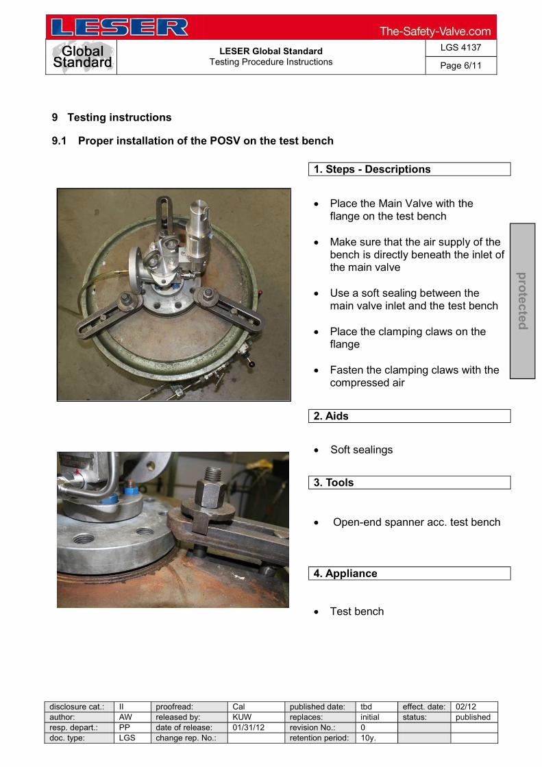
LESER Global Standard
Testing Procedure Instructions
LGS 4137
Page 6/11
disclosure cat.: II proofread: Cal published date: tbd effect. date: 02/12 author: AW released by: KUW replaces: initial status: published resp. depart.: PP date of release: 01/31/12 revision No.: 0 doc. type: LGS change rep. No.: retention period: 10y.
pro
tected
9 Testing instructions
9.1 Proper installation of the POSV on the test bench
1. Steps - Descriptions
Place the Main Valve with the flange on the test bench
Make sure that the air supply of the
bench is directly beneath the inlet of the main valve
Use a soft sealing between the
main valve inlet and the test bench Place the clamping claws on the
flange Fasten the clamping claws with the
compressed air
2. Aids
Soft sealings
3. Tools
Open-end spanner acc. test bench
4. Appliance
Test bench

LESER Global Standard
Testing Procedure Instructions
LGS 4137
Page 7/11
disclosure cat.: II proofread: Cal published date: tbd effect. date: 02/12 author: AW released by: KUW replaces: initial status: published resp. depart.: PP date of release: 01/31/12 revision No.: 0 doc. type: LGS change rep. No.: retention period: 10y.
pro
tected
9.2 Test devices
1. Steps - Descriptions
Test bench Bubble counting unit
(Kellog test) Rubber plugs/ test
plugs Leak detection spray
2. Aids
None
3. Tools
None
4. Appliance
Rubber plug Test bench

LESER Global Standard
Testing Procedure Instructions
LGS 4137
Page 8/11
disclosure cat.: II proofread: Cal published date: tbd effect. date: 02/12 author: AW released by: KUW replaces: initial status: published resp. depart.: PP date of release: 01/31/12 revision No.: 0 doc. type: LGS change rep. No.: retention period: 10y.
pro
tected
9.3 Test the set pressure adjustment
1. Steps - Descriptions
Mount POSV acc. step 9.1 with the inlet on the test bench
Check set pressure 3x
If necessary: Screw off the cap;
loosen the lock nut; readjust the adjusting screw - acc. LID disassembly / assembly
Check set pressure 3 x
Repeat procedure until the set
pressure is 3 x OK Afterwards fasten the lock nut and
cap acc. LID assembly
2. Aids
None
3. Tools
Open-end spanner acc. test bench
4. Appliance
Test bench

LESER Global Standard
Testing Procedure Instructions
LGS 4137
Page 9/11
disclosure cat.: II proofread: Cal published date: tbd effect. date: 02/12 author: AW released by: KUW replaces: initial status: published resp. depart.: PP date of release: 01/31/12 revision No.: 0 doc. type: LGS change rep. No.: retention period: 10y.
pro
tected
9.4 Seat tightness test
1. Steps - Descriptions
Mount POSV acc. test
description with the inlet on the test bench
Trigger the safety valve
once Lower the pressure
by 10% of the set pressure In case of set pressures
bar (5.08 psi) Place the hose of the
bubble counting unit in the rubber plug
Start after 10 sec to count
the bubbles Compare the result with the
LID to decide whether the POSV pass the test or not
2. Aids
None
3. Tools
Open-end spanner acc. test bench
4. Appliance
Test bench Rubber plug acc. DM Bubble counting unit

LESER Global Standard
Testing Procedure Instructions
LGS 4137
Page 10/11
disclosure cat.: II proofread: Cal published date: tbd effect. date: 02/12 author: AW released by: KUW replaces: initial status: published resp. depart.: PP date of release: 01/31/12 revision No.: 0 doc. type: LGS change rep. No.: retention period: 10y.
pro
tected
9.5 Shell tightness test
1. Steps - Descriptions
Mount the POSV acc. step 9.1 with the inlet on the test bench
Charge the POSV with a pressure
close to the set pressure Make sure that the POSV does not reach the set pressure
After establishing a suitable
pressure cover the contact areas, fittings, threads and so on with leak detection spray
Observe these areas to detect any
leaks Leaks will be indicated by bubbles
When there is no recognized foam
the test is passed
2. Aids
Leak detection spray
3. Tools
Open-end spanner acc. test bench
4. Appliance
Test bench

LESER Global Standard
Testing Procedure Instructions
LGS 4137
Page 11/11
disclosure cat.: II proofread: Cal published date: tbd effect. date: 02/12 author: AW released by: KUW replaces: initial status: published resp. depart.: PP date of release: 01/31/12 revision No.: 0 doc. type: LGS change rep. No.: retention period: 10y.
pro
tected
9.6 Back seat tightness, test P21 (tightness outwards)
1. Steps - Description
Mount the POSV acc. test description with the outlet on the test bench
Establish a test pressure of 6 bar
Cover all connections, threads, fittings with leak detection spray
When no foam is recognized, the test is passed
Connect the bubble counting unit
Start after 10 sec to count the bubbles
Compare the result with the LID to decide whether the POSV pass the test or not
2. Aids
None
3. Tools
None
4. Appliance
Rubber plug Bubble counting unit Test bench

LESER Global Standard
Tightness Test
LGS 0201
Page 1/29
Disclosure cat.: II proofread by: Ku publish date: 05/01/18 effect.date: 05/18 author: Mi released by: Win replaces: 220-01 status: Publisheresp. depart.: QM date of release: 05/01/18 revision No.: 13 doc. type: LGS change rep. No.: NA retention 10y.
Content 1 Purpose .......................................................................................................... 1 2 Scope .............................................................................................................. 1 3 References ..................................................................................................... 1 4 Introduction .................................................................................................... 2 5 Test Procedures at LESER ........................................................................... 3 6 Test Equipment at LESER ............................................................................. 3 7 Seat tightness test procedure, Test P12 ...................................................... 3 8 Shell Tightness test procedure P11 ............................................................. 14 9 Back seat tightness, test P21 (tightness outwards) ................................... 16 10 Tightness of Pressure Seals of POSVs ....................................................... 18 11 Qualifications of the staff .............................................................................. 20 12 Certification .................................................................................................... 20 13 Demands of standards .................................................................................. 20 14 Appendix 1: Seat tightness requirements acc. to API 527 ......................... 22 15 Appendix 2: Seat tightness LESER Standard tightness requirement for spring safety valve ......................................................................................................... 23 16 Appendix 3: Seat tightness LESER increased tightness requirements .... 25 17 Appendix 4: Seat tightness LESER increased tightness requirements POSV, Type 810, Pop Action pilot .......................................................................................... 26 18 Appendix 4: Seat tightness LESER increased tightness requirements POSV, Type 810, Modulate Action Pilot ................................................................................. 27 19 Back Seat tightness, LESER standard requirements for POSVs .............. 28 20 Seat tightness acc. to PAS 1085 -SV ............................................................ 29
1 Purpose
This LESER Global (LGS) compiles the requirements of standards and describes the procedure of tightness testing of safety valves and pilot operated safety valves and also their Certification.
2 Scope
This LGS applies to all members of the LESER quality cluster, as well as at national and overseas representatives and approved LESER service repair shops, in case of service on
3 References
LID_DE 1704.41, LGS 0201, LGS 0222, LDeS_0201.02 DIN EN ISO 4126-1 Safety devices for protection against excessive pressure
Part 1: Safety valves, DIN EN ISO 4126-4 Safety devices for protection against excessive pressure
Part 4: Pilot-operated safety valves DIN EN ISO 12266-1 Industrial valves: Testing of valves, part 1: Pressure tests, test
procedures and acceptance criteria
LESER Global Standard
Tightness Test
LGS 0201
Page 2/29
Disclosure cat.: II proofread by: Ku publish date: 05/01/18 effect.date: 05/18 author: Mi released by: Win replaces: 220-01 status: Publisheresp. depart.: QM date of release: 05/01/18 revision No.: 13 doc. type: LGS change rep. No.: NA retention 10y.
DIN EN ISO 12266-2 Industrial valves Testing of valves, part 2: Tests, test procedures and acceptance criteria, supplementary requirements
DIN EN 1593 Tightness test, bubble test DIN EN 14291 Foam producing solutions for leak detection on gas installations DIN EN 10204 Metallic products- Types of inspection documents ASME Code Section VIII Rules for Construction of Pressure Vessels API 527 American Petroleum Institute Seat Tightness of Pressure Relief Valves
4 Introduction
All LESER safety valves have to be test on tightness except SKD Kits Compact Performance-Valves (ref. to LID_DE 1704.41). The tightness test is a production test and is set up to ensure that each safety valve fulfils the requirements for which they have been design without suffering from leakage of pressurized parts or seals. The tightness test is standard practised at LESER (100 %) after the set pressure was be demonstrated. The leakage rates shall be document. In case the observed leakage rate exceeds the defined specification limit, the valve must be subject to the LESER quality rework process. The test requirements and acceptance criteria shall be according to Appendix.
4.1 Test media
The following test media are to be use at LESER: Air, helium, water and steam. The test medium for determining the seat tightness, air, steam or water, shall be the same as that used for determining the set pressure of the valve. For dual- service valves, the test medium, air, steam or water, shall be the same as the primary relieving medium. (API Standard 527). Upon customer request, LESER can conduct the tightness test using Helium as test medium for higher accuracy.
4.2 Pressure range
The set pressure range by safety valve is regulate as follows: - acc. to ASME Code pressure range starts with 15 psi (1,03 bar) - acc. to DGRL 97/23 pressure range starts with 0,5 bar - acc. to DIN EN ISO 4126-1 pressure range starts with 0,1 bar.
The test pressure for the leakage is applied according the set pressure range.
LESER Global Standard
Tightness Test
LGS 0201
Page 3/29
Disclosure cat.: II proofread by: Ku publish date: 05/01/18 effect.date: 05/18 author: Mi released by: Win replaces: 220-01 status: Publisheresp. depart.: QM date of release: 05/01/18 revision No.: 13 doc. type: LGS change rep. No.: NA retention 10y.
4.3 Test pressure
The test pressure is regulated according set pressure range and requirement by API527 for each test procedure and is fixed in Appendix 1 to 11.
4.4 Test duration
The test duration is regulated according standards requirement for each test procedure and is fixed in Appendix 1 to 11.
4.5 Temperature
As a standard technique, the minimum or maximum temperature shall not be bellow 5°C (40°F) nor above 50°C (125°F) during the test. (ASME Code Section V, Article 10).
4.6 Acceptance Criteria
Leakage rates, measured during the determined test period, shall not exceed the fixed leakage rates defined for the relevant types/designs. The leakages rates are fixed in Appendix.
5 Test Procedures at LESER
Following test procedures for tightness are to be applied for LESER safety valves and POSVs:
- Seat tightness test procedure, Test P12 - Shell tightness test procedure, Test P11 - Back seat Tightness test procedure, Test P21 - Tightness test procedure for pressure seals
Test medium is water, gas (air or helium) and steam.
6 Test Equipment at LESER
The LESER safety valves are assembled and tested on an assembly and test benches. The assembly and test benches consist of the following subunits:
- fixture system (incl. adaptors) - pressure system (air) - pressure measurement system - bubble count device (Kellog test) - valve submerge basin
LESER POSVs are assembled and tested on assembly and test benches for POSVs. The benches consist of the following sub units:
- pilot assembly and test bench where the pilots are assembled and set - assembly and test bench for fully assembled POSV: in this place the full POSV is
assembled, set and tested.
7 Seat tightness test procedure, Test P12
7.1 Definition
Seat tightness means tightness between seat and disc. A safety valve/POSV is considered to be tight between seat and disc, if all requirements of the relevant standard are performed.

LESER Global Standard
Tightness Test
LGS 0201
Page 4/29
Disclosure cat.: II proofread by: Ku publish date: 05/01/18 effect.date: 05/18 author: Mi released by: Win replaces: 220-01 status: Publisheresp. depart.: QM date of release: 05/01/18 revision No.: 13 doc. type: LGS change rep. No.: NA retention 10y.
Following measures for determination of seat tightness can be used: o Leakage Rate in mbar l/s, o Leakage Volume in cm³/min. and o Number of bubbles/min.
Testing of seat tightness will be carried out at ambient temperature.
7.2 Requirements of LESER
Due to the fact that API 527 is the sole international approved standard which regulates tightness requirements for safety valves in special, LESER in its function as global company refers to this standard only. However, LESER considers also tightness requirements acc. to DIN EN 12266 and EN ISO 4126-4. Appendix 1: Seat tightness API 527 Requirements Test conditions and requirements for seat tightness acc. to API 527 are subject of this Appendix. Appendix 2: Seat tightness, LESER standard requirements for SVs, Test conditions and tightness requirements acc. to API 527 and DIN EN 12266 for seat tightness and general requirements are deviated in Appendix 2 to 4.
Appendix 3: Seat tightness, LESER improved tightness requirements for SVs, Test conditions and requirements of tightness for increased tightness are summarized in this Appendix. The allowable leakage rate for metal-sealing safety
exceed the standard higher lapping effort and higher costs will arise. Appendix 4: Seat tightness, LESER standard requirements for POSVs Test conditions and requirements for seat tightness acc. to API 527, EN ISO 4126-4 and DIN EN 12266 of POSVs (standard requirements) are subject of this Appendix.
7.3 Scope
The testing procedure of seat tightness for each valve occurs after setting and checking of cold differential set pressure on test bench in accordance with operation chart, which is deposited in SAP System.
7.4 Test media The following test media are to be used at LESER: Air, helium, water and steam.
7.5 Test pressure
The pressure range is regulated as follows: - Acc. to ASME Code pressure range starts with 15 psi (1,03 bar) - Acc. to DGRL 97/23 pressure range starts with 0,5 bar - Acc. to DIN EN ISO 4126-1 pressure range starts with 0,1 bar. At LESER the performance of pressure range and test pressure requirements acc. to API 527 is as follows (table 1):
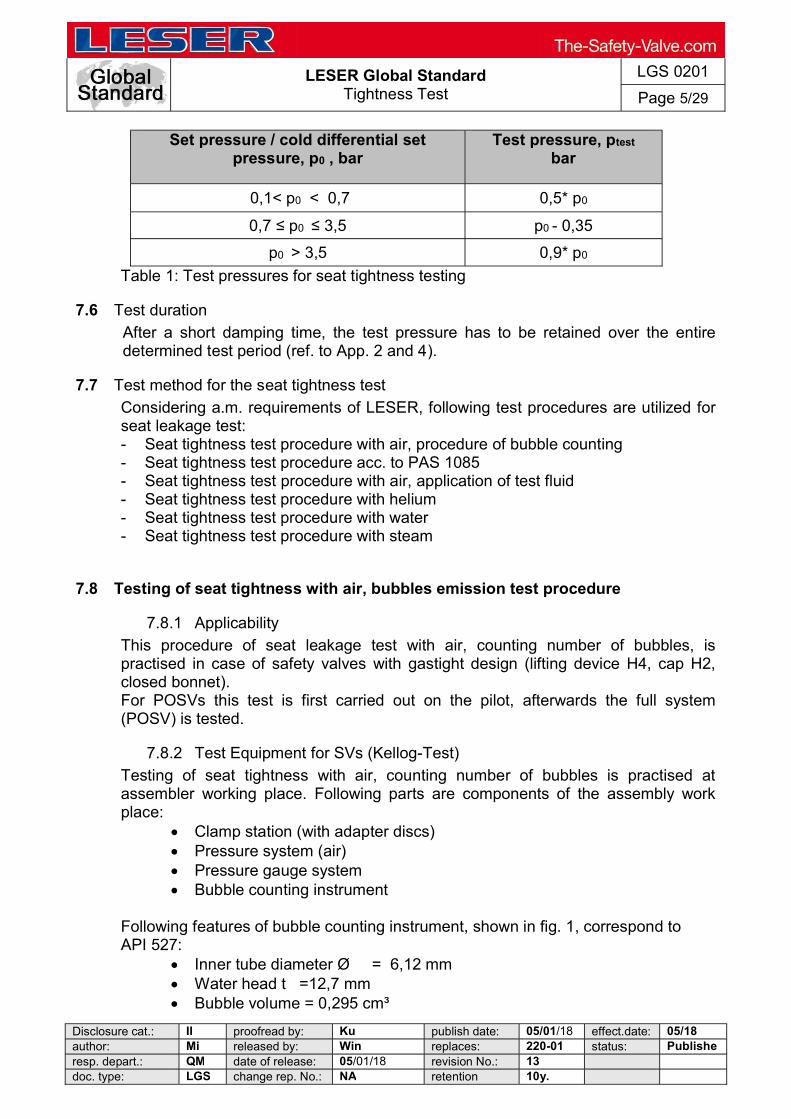
LESER Global Standard
Tightness Test
LGS 0201
Page 5/29
Disclosure cat.: II proofread by: Ku publish date: 05/01/18 effect.date: 05/18 author: Mi released by: Win replaces: 220-01 status: Publisheresp. depart.: QM date of release: 05/01/18 revision No.: 13 doc. type: LGS change rep. No.: NA retention 10y.
Set pressure / cold differential set pressure, p0 , bar
Test pressure, ptest bar
0,1< p0 < 0,7 0,5* p0
0,7 p0 3,5 p0 - 0,35
p0 > 3,5 0,9* p0
Table 1: Test pressures for seat tightness testing
7.6 Test duration
After a short damping time, the test pressure has to be retained over the entire determined test period (ref. to App. 2 and 4).
7.7 Test method for the seat tightness test
Considering a.m. requirements of LESER, following test procedures are utilized for seat leakage test: - Seat tightness test procedure with air, procedure of bubble counting - Seat tightness test procedure acc. to PAS 1085 - Seat tightness test procedure with air, application of test fluid - Seat tightness test procedure with helium - Seat tightness test procedure with water - Seat tightness test procedure with steam
7.8 Testing of seat tightness with air, bubbles emission test procedure
7.8.1 Applicability
This procedure of seat leakage test with air, counting number of bubbles, is practised in case of safety valves with gastight design (lifting device H4, cap H2, closed bonnet). For POSVs this test is first carried out on the pilot, afterwards the full system (POSV) is tested.
7.8.2 Test Equipment for SVs (Kellog-Test)
Testing of seat tightness with air, counting number of bubbles is practised at assembler working place. Following parts are components of the assembly work place:
Clamp station (with adapter discs) Pressure system (air) Pressure gauge system Bubble counting instrument
Following features of bubble counting instrument, shown in fig. 1, correspond toAPI 527:
Inner tube diameter Ø = 6,12 mm Water head t =12,7 mm Bubble volume = 0,295 cm³

LESER Global Standard
Tightness Test
LGS 0201
Page 6/29
Disclosure cat.: II proofread by: Ku publish date: 05/01/18 effect.date: 05/18 author: Mi released by: Win replaces: 220-01 status: Publisheresp. depart.: QM date of release: 05/01/18 revision No.: 13 doc. type: LGS change rep. No.: NA retention 10y.
Fig. 1
7.8.3 Test Equipment for POSVs
The test of seat tightness of the pilot is tested on the pilot assembly bench. For this purpose a bubble test device fulfilling the requirements of API 527 is installed. The full POSV the test is carried out on the PSV assembly bench, which is also equipped with a bubble test device. A sketch of the bubble test device is given by graph 1. This device is fulfilling the API527 requirements with the following parameters:
7.8.4 Test duration
After a short damping time, the test pressure has to be retained over the entire determined test period (ref. to App. 2 and 4).
7.8.5 Test pressure
After setting and checking of cold differential set pressure p0 a blow down up to test pressure ptest has to be carried out. The test pressure ptest is defined in table 1. Attention: For POSV with a set pressure greater than 30 bar, the seat tightness is additionally checked at 30% of the set pressure after the functional tightness test.
7.8.6 Test description
Spring Safety Valves Angle typed flanged safety valves are mounted via clamping jaw vertically at the inlet 0flange on the test bench. For the sealing a rubber pad is laid down under the inlet flange of safety valve. For safety valves with screwed connection, a clamping device with screwed connection is needed. After valve setting the leakage test is carried out.
LESER Global Standard
Tightness Test
LGS 0201
Page 7/29
Disclosure cat.: II proofread by: Ku publish date: 05/01/18 effect.date: 05/18 author: Mi released by: Win replaces: 220-01 status: Publisheresp. depart.: QM date of release: 05/01/18 revision No.: 13 doc. type: LGS change rep. No.: NA retention 10y.
The pressure will be reduced by 10% resp. in case of set pressures 3,5 bar by 0,35 bar. After 10 seconds of slowdown the leakage rate will be determined (test time 10 s). The amount of air leakage escaping from the inlet via the seal between seat and disc causes a low excess pressure in the closed outlet chamber. This excess pressure will be decomposed in the water tank in form of escaping bubbles. The escaping bubbles are counted in determined test time (ref. to appendix 2 and 3). The volume of bubbles is defined by resp. depends on the water head and inner width of dipping tube.
The leakage rate shall not exceed the limited leakage rates depending on the flow area d0 and valve design as mentioned in appendix 2 and 3.
POSV The testing of POSVs corresponds to a two sets sequence: 1/
The pilot is fixed on the PILOT assembly bench, set and tested for tightness. Pilot bodies along with the manifold block are attached to the pilot assembly bench with four screws. Sealing is achieved using suitable o-rings. After assembly and pressure setting of the pilot the seat tightness test is carried out. The inlet pressure is increased to meet the test pressure and after a defined damping period the leakage rate is determined. The bubble test device is hooked up to the outlet and the bubbles created within the test period are counted. The testing procedures are implemented as part of the overall assembly and testing procedure of the control program.
2/ Every completed POSV is tested for its respective CDTP. Usually this is achieved by setting the PILOT and therefore no additional setting is required. Consequently tightness of the seat is tested.
For the fully assembled POSV the tightness of the seat is defined as the tightness between seat and disk of the main valve. For the test the inlet of the POSV is clamped (perpendicular) to the test bench. The pressure in the inlet is increased to the respective test pressure and after a suitable damping period the leakage rate is determined. The observable bubbles within the testing period are then counted.
7.8.7 Acceptance criteria
Leakage rates, measured during the determined test period, shall not exceed the fixed leakage rates defined for the relevant types/designs. The leakages rates are fixed in Appendix 2 and 4.
The seat tightness standard - requirements of spring safety valve made in Works- Hohenwestedt are defined at LDeS 0201.02.

LESER Global Standard
Tightness Test
LGS 0201
Page 8/29
Disclosure cat.: II proofread by: Ku publish date: 05/01/18 effect.date: 05/18 author: Mi released by: Win replaces: 220-01 status: Publisheresp. depart.: QM date of release: 05/01/18 revision No.: 13 doc. type: LGS change rep. No.: NA retention 10y.
7.8.8 Certification
The testing of seat tightness with air (bubble emission procedure) is documented in the SAP system and confirmed by inspection test certificate 3.1 acc. to DIN EN 10204. (LESER CGA) If test report for seat leakage test is required, it has to be accessed with option code M66.
7.9 Testing of seat tightness of safety valve with sealing plate disc
This requirements shall be applied to spring loaded safety valve with configuration sealing plate discs at PTFE, Kel - F or VESPEL materials only. For all spring loaded safety valves with seal plate configuration, test pressure is defined as described in 15 Appendix 2:
ptest = p0 x (formula, please find in column under 15 Appendix 2) ptest = test pressure
p0 = cold differential test pressure The test duration shall be applied according with the Appendix 2 and 3. Leakage Test
1. Before starting the seat tightness test, the set pressure shall be demonstrated according at LGS0202.
2. The safety valve shall than waiting for 48 hours. 3. After 48 Hours the seat tightness test as described above shall be determinate
again. 4. In case the valve has opened/lifted any time after the 48hour period, the procedure
has to be repeated beginning with step 2.
7.10 Tightness Test acc. to PAS 1085:2008
7.10.1 Scope
The seat tightness test according to PAS 1085 is only applied to spring loaded safety valves. The seat tightness test is only applied to safety valves in gas tight configurations (lifting aid H4, cap H2 and closed bonnet).
7.10.2 Test Pressure, Stabilizing Time and Inspection Time
The test pressure and stabilizing time depend on the CDTP and the nominal size, respectively. The inspection time is 1 minute for all safety valves. The defined stabilizing times and test pressures are listed in tables 2 and 3.
Set pressure, p0
bar Test pressure,
ptestf bar
>= 1,0 0,97 x p0
< 1,0 0,9 x p0 Table 2: Test pressure for seat tightness test, acc. to PAS 1085

LESER Global Standard
Tightness Test
LGS 0201
Page 9/29
Disclosure cat.: II proofread by: Ku publish date: 05/01/18 effect.date: 05/18 author: Mi released by: Win replaces: 220-01 status: Publisheresp. depart.: QM date of release: 05/01/18 revision No.: 13 doc. type: LGS change rep. No.: NA retention 10y.
Nominal size
Stabilizing time Inspection Time
Allowed leakage (Bubbles/Minute)
Up to DN 200
1 min. 1 min. 3
Over DN 250
3 min. 1 min. 3
Table 3: Stabilizing Time, Inspection Time and leakage rates acc. to PAS 1085
7.10.3 Test Procedure
- Fix safety valve on test bench in upright position - Adjust set pressure of safety valves acc. to LGS 0202 - Release pressure and attach inspection tube to outlet, then increase pressure to test
pressure according to table 2. - Determination of leakage rate starts after the stabilizing time defined in table 3 or latest
after the release of the first bubble from the tube opening. - The determination of the leakage rate is done over a period of one minute. Relevant
are only those bubbles, which were released from the tube during this inspection time. - The observed number of relevant bubbles is recorded. If this number exceeds the
allowed number of bubbles as defined in table 3, the valve must be subject to the LESER quality rework process.
7.10.4 Acceptance Criteria
The test parameters and the acceptance criteria are listed in the table of appendix 14.12 (seat tightness acc. PAS 1085 for safety valves).
7.11 Seat tightness test procedure with air, another method
7.11.1 Applicability
In case of non-gas tight safety valve design (lifting device H3, open bonnet), the seat leakage test is carried out with procedure of applying test fluid (acc. to DIN EN 1593). The application of test fluid is a qualitative test procedure, because the quantitative procedure of bubble counting (leakage rate) is not possible.
7.11.2 Test equipment
The seat leakage test by using air, procedure of test fluid application, can be carried out at the assembly working place. Following parts are components of the assembly working place:
Clamp station (with adapter discs) Pressure system (air) Pressure gauge system Bubble counting instrument
As test fluid a foamy lotion acc. to DIN EN 14291, leakage finder, is used. The test fluid shall be non-volatile (it shall not dry at test temperature during test period) and viscous.
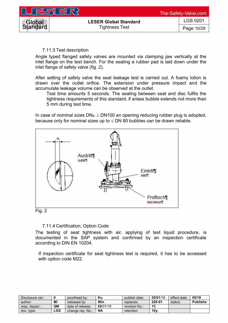
LESER Global Standard
Tightness Test
LGS 0201
Page 10/29
Disclosure cat.: II proofread by: Ku publish date: 05/01/18 effect.date: 05/18 author: Mi released by: Win replaces: 220-01 status: Publisheresp. depart.: QM date of release: 05/01/18 revision No.: 13 doc. type: LGS change rep. No.: NA retention 10y.
7.11.3 Test description
Angle typed flanged safety valves are mounted via clamping jaw vertically at the inlet flange on the test bench. For the sealing a rubber pad is laid down under the inlet flange of safety valve (fig. 2). After setting of safety valve the seat leakage test is carried out. A foamy lotion is drawn over the outlet orifice. The extension under pressure impact and the accumulate leakage volume can be observed at the outlet.
Test time amounts 5 seconds. The sealing between seat and disc fulfils the tightness requirements of this standard, if arises bubble extends not more than 5 mm during test time.
In case of nominal sizes DNA DN100 an opening reducing rubber plug is adopted, because only for nominal sizes up to DN 80 bubbles can be drawn reliable.
Fig. 2
7.11.4 Certification, Option Code
The testing of seat tightness with air, applying of test liquid procedure, is documented in the SAP system and confirmed by an inspection certificate according to DIN EN 10204.
If inspection certificate for seat tightness test is required, it has to be accessed with option code M22.

LESER Global Standard
Tightness Test
LGS 0201
Page 11/29
Disclosure cat.: II proofread by: Ku publish date: 05/01/18 effect.date: 05/18 author: Mi released by: Win replaces: 220-01 status: Publisheresp. depart.: QM date of release: 05/01/18 revision No.: 13 doc. type: LGS change rep. No.: NA retention 10y.
7.12 Seat tightness test procedure with helium
7.12.1 Applicability
The testing of seat tightness with helium is a special case of testing and is practised on customer demand only. This test can be carried out for all safety valve types, even though the helium test is very extensive for open valves.
7.12.2 Test equipment
LESER uses a helium leak detector for the helium test procedure: Technical Characteristic: Max. Pressure 15 mbar Minimum detectable Helium. Leakage rate:
- Vacuum method -12 mbar l/sec - sniffing method < 1* 10 -7 mbar l/sec
Maximum indicated Helium- Leakage rate 0,1 mbar l/sec Measuring range 12 decade
7.12.3 Test method
With this helium leak detector different test procedures for seat tightness can be practised. LESER uses following test methods:
Procedure of overpressure (sniffing method) Procedure of leakage detector in vacuum.(spraying method)
7.12.4 Test pressure
The test pressure has to correspond to the pressure values at ambient temperature mentioned in App. 2 and 3.
7.12.5 Test duration
The test pressure has to hold up at least 5 min.
7.12.6 Test description Overpressure procedure (sniffing method):
After setting the relevant safety valve with air on cold-differential set pressure, it will be carried to the helium test lab. After safety valve is mounted via clamping jaw at the inlet flange on the test bench, it will be pressurized with helium. After reaching the test pressure leakage rate is determined via probe at the outlet.
Procedure of leakage detection in vacuum:
After setting the relevant safety valve with air on cold- differential set pressure, it will be carried to the helium test lab.
Via adapter the valve is connected airproof with the helium leakage detector at the inlet. After evacuation (vacuum occurs in the fitting) an airgun is injection helium between disc and sealing in the outlet. The test result is metered after 5 min.

LESER Global Standard
Tightness Test
LGS 0201
Page 12/29
Disclosure cat.: II proofread by: Ku publish date: 05/01/18 effect.date: 05/18 author: Mi released by: Win replaces: 220-01 status: Publisheresp. depart.: QM date of release: 05/01/18 revision No.: 13 doc. type: LGS change rep. No.: NA retention 10y.
7.12.7 Acceptance criteria
Leakage rates, measured during the determined test period, shall not exceed the fixed leakage rates defined for the relevant types/designs.In case of metal-to-metal sealed safety valves leakage rates up to 10-3 mbar l/s are possible. Dependent on the test procedure leakage rates up to 10-9 mbar l/s can be reached in case of soft-sealed safety valves. The standard test value for seat tightness of LESER safety valves with soft seal amounts < 1x10⁻⁵ mbar l/s. Following option codes shall be used for seat leakage test with helium:
- Option Code N62, for sniffing method - Option Code M86, for vacuum method
7.12.8 Certification
The testing of seat tightness with helium is documented in the SAP system and confirmed by inspection test certificate acc. to DIN EN 10204 / test report. Following information are to be considered: - Test subject - Requirements of Standard - Reference terms / Main technical characteristics
Test medium, Helium Test equipment: helium leakage detector
- Test results - Test method for each test result - Relevant Units, mbar l/s, for each test result. If inspection certificate for seat tightness test with helium is required, it has to be accessed with following option code: - M 77 for seat tightness, overpressure procedure (sniffing method) - M 81 for seat tightness, procedure of leakage detection in vacuum
7.13 Seat tightness test procedure with water
7.13.1 Scope
All valves, which are set with medium water, must be seat tightness tested. The seat tightness test is carried out with the medium water after setting up the set pressure. The test conditions, test pressure, test time and allowed leakage are defined in Appendix 2 resp. 3.
7.13.2 Test description
The valve shall be mounting vertically on the water test stand. Before the leakage test, the set pressure must be determined. After a successful set pressure test with water, the seat tightness test follows. The pressure shall be lowered to zero.

LESER Global Standard
Tightness Test
LGS 0201
Page 13/29
Disclosure cat.: II proofread by: Ku publish date: 05/01/18 effect.date: 05/18 author: Mi released by: Win replaces: 220-01 status: Publisheresp. depart.: QM date of release: 05/01/18 revision No.: 13 doc. type: LGS change rep. No.: NA retention 10y.
Wait until no more water drains/flows off the outlet area. It is not allowed to wipe dry the moistened outlet area (or the used testing device (stream detector)) of the valve. Steadily the inlet pressure shall than be increased to the test pressure. When reach the test pressure the valve outlet area shall be observed for 1 minute. The leakage of the seat is determined by counting of draining off water drops in outlet area of the valve or in the testing device.
7.13.1 Acceptance criteria
The leakage rate shall not exceed the acceptance criteria defined in Appendix 2.1.
Photo 4: Falling water drop at the edge of stream detector
LESER Global Standard
Tightness Test
LGS 0201
Page 14/29
Disclosure cat.: II proofread by: Ku publish date: 05/01/18 effect.date: 05/18 author: Mi released by: Win replaces: 220-01 status: Publisheresp. depart.: QM date of release: 05/01/18 revision No.: 13 doc. type: LGS change rep. No.: NA retention 10y.
7.14 Seat tightness test procedure with steam
7.14.1 Applicability
Testing of seat tightness with steam is practised for safety valves, which are set on cold-differential set pressure with steam.
7.14.2 Test equipment
The test is carried out at the steam test lab in Hohenwestedt site.
7.14.3 Test pressure
The test pressure has to be in accordance with test values determined in Appendices 2 and 3.
7.14.4 Test duration
The test pressure has to be retained acc. to the determined test period in Appendices 2 and 3.
7.14.5 Test description
After setting the relevant valve on cold-differential test pressure and testing, the seat leakage test is carried out with steam. The pressure is to be dropped to test pressure and after a short damping time the qualitative statement can be determined.
7.14.6 Acceptance criteria, Option Code
The valve obtains to be tight, if the qualitative estimation criteria acc. to App. 2 resp. 3 are fulfilled: no noticeable or visible leakage, no pressure drop at the pressure gauge is recognized.
7.14.7 Certification
The seat leakage test with steam is documented in the SAP system and confirmed by inspection test certificate acc. to DIN EN 10204.
8 Shell Tightness test procedure P11
8.1 Applicability
The shell tightness test procedure, at LESER called body tightness, is carried out for all LESER safety valves, Pilot Operated Safety Valves and Change Over Valves. For Safety Valves with a heating jacket the shell tightness test procedure is carried out at the heating jacket itself including all connections.
8.2 General, Definition
The shell tightness test procedure is a collateral production pressure test to prove the tightness of pressure retaining body and is carried out at LESER as a standard test.
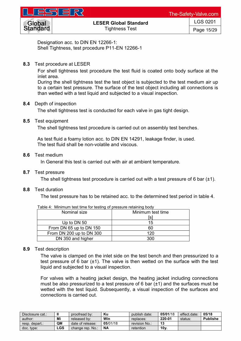
LESER Global Standard
Tightness Test
LGS 0201
Page 15/29
Disclosure cat.: II proofread by: Ku publish date: 05/01/18 effect.date: 05/18 author: Mi released by: Win replaces: 220-01 status: Publisheresp. depart.: QM date of release: 05/01/18 revision No.: 13 doc. type: LGS change rep. No.: NA retention 10y.
Designation acc. to DIN EN 12266-1: Shell Tightness, test procedure P11-EN 12266-1
8.3 Test procedure at LESER
For shell tightness test procedure the test fluid is coated onto body surface at the inlet area. During the shell tightness test the test object is subjected to the test medium air up to a certain test pressure. The surface of the test object including all connections is than wetted with a test liquid and subjected to a visual inspection.
8.4 Depth of inspection
The shell tightness test is conducted for each valve in gas tight design.
8.5 Test equipment
The shell tightness test procedure is carried out on assembly test benches.
As test fluid a foamy lotion acc. to DIN EN 14291, leakage finder, is used. The test fluid shall be non-volatile and viscous.
8.6 Test medium
In General this test is carried out with air at ambient temperature.
8.7 Test pressure
The shell tightness test procedure is carried out with a test pressure of 6 bar (±1).
8.8 Test duration
The test pressure has to be retained acc. to the determined test period in table 4.
Table 4: Minimum test time for testing of pressure retaining body Nominal size Minimum test time
[s] Up to DN 50 15
From DN 65 up to DN 150 60 From DN 200 up to DN 300 120
DN 350 and higher 300
8.9 Test description
The valve is clamped on the inlet side on the test bench and then pressurized to a test pressure of 6 bar (±1). The valve is then wetted on the surface with the test liquid and subjected to a visual inspection.
For valves with a heating jacket design, the heating jacket including connections must be also pressurized to a test pressure of 6 bar (±1) and the surfaces must be wetted with the test liquid. Subsequently, a visual inspection of the surfaces and connections is carried out.

LESER Global Standard
Tightness Test
LGS 0201
Page 16/29
Disclosure cat.: II proofread by: Ku publish date: 05/01/18 effect.date: 05/18 author: Mi released by: Win replaces: 220-01 status: Publisheresp. depart.: QM date of release: 05/01/18 revision No.: 13 doc. type: LGS change rep. No.: NA retention 10y.
8.10 Acceptance criteria
There shall be no continuous bubble formation which could indicate a leak in the wall or at the connections.
8.11 Certification, Option Code
The shell tightness test with air is confirmed by inspection test certificate acc. to DIN EN 10204. As standard testing the leakage test of pressure retaining body effects without access of option code. The certification of the test is controlled by option code M18
9 Back seat tightness, test P21 (tightness outwards)
9.1 Scope
The tightness test of the back sealing, LESER named it tightness outwards, is afety valves in gastight design and at all POSV.
9.2 Definition
The test is a pre-expediting pressure test for certification that the determined leakage rate of the back sealing is kept to the moment of the manufacture. The tightness outwards has reference to the test of the tightness at the connections body/bonnet, bonnet/lifting device H4 (cap H2) as well as the outlet of the body. POSV at the connections: Top plat and body with spray, manifold block and top plate with spray and at backflow preventer with the Kellog test method. Marking in accordance with DIN EN 12266-2, Tightness of back seal, test P21-EN 12266.2
9.3 Applicability
The tightness of the back seal, test P21, is in accordance with the task schedule which is deposited in the data base of the SAP-system for every safety valve in gastight design. At , this test is standard which is integrated in the production process.
9.4 Test equipment
s the test of the tightness of the back seal takes place at the test benches.
9.5 Test medium
with air in room temperature. The back seat tightness can be realized with helium test procedure if the customer requests.
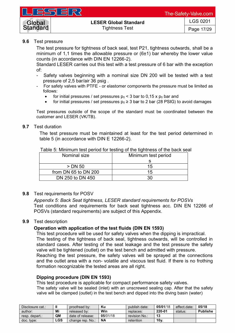
LESER Global Standard
Tightness Test
LGS 0201
Page 17/29
Disclosure cat.: II proofread by: Ku publish date: 05/01/18 effect.date: 05/18 author: Mi released by: Win replaces: 220-01 status: Publisheresp. depart.: QM date of release: 05/01/18 revision No.: 13 doc. type: LGS change rep. No.: NA retention 10y.
9.6 Test pressure
The test pressure for tightness of back seal, test P21, tightness outwards, shall be a minimum of 1,1 times the allowable pressure or (6±1) bar whereby the lower value counts (in accordance with DIN EN 12266-2). Standard LESER carries out this test with a test pressure of 6 bar with the exception of: - Safety valves beginning with a nominal size DN 200 will be tested with a test
pressure of 2,5 bar/air 36 psig . - For safety valves with PTFE - or elastomer components the pressure must be limited as
follows: for initial pressures / set pressures p0 < 3 bar to 0,15 x p0 bar and for initial pressures / set pressures p0 to avoid damages
Test pressures outside of the scope of the standard must be coordinated between the customer and LESER (VK/TB).
9.7 Test duration
The test pressure must be maintained at least for the test period determined in table 5 (in accordance with DIN E 12266-2). Table 5: Minimum test period for testing of the tightness of the back seal
Nominal size Minimum test period s
> DN 50 15 from DN 65 to DN 200 15
DN 250 to DN 450 30
9.8 Test requirements for POSV Appendix 5: Back Seat tightness, LESER standard requirements for POSVs Test conditions and requirements for back seat tightness acc. DIN EN 12266 of POSVs (standard requirements) are subject of this Appendix.
9.9 Test description
Operation with application of the test fluids (DIN EN 1593) This test procedure will be used for safety valves when the dipping is impractical.
The testing of the tightness of back seal, tightness outwards, will be controlled in standard cases. After testing of the seat leakage and the test pressure the safety valve will be tightened (outlet) on the test bench and admitted with pressure. Reaching the test pressure, the safety valves will be sprayed at the connections and the outlet area with a non- volatile and viscous test fluid. If there is no frothing formation recognizable the tested areas are all right.
Dipping procedure (DIN EN 1593) This test procedure is applicable for compact performance safety valves. The safety valve will be sealed (inlet) with an unscrewed sealing cap. After that the safety valve will be clamped (outlet) in the test bench and dipped into the diving basin (water)
LESER Global Standard
Tightness Test
LGS 0201
Page 18/29
Disclosure cat.: II proofread by: Ku publish date: 05/01/18 effect.date: 05/18 author: Mi released by: Win replaces: 220-01 status: Publisheresp. depart.: QM date of release: 05/01/18 revision No.: 13 doc. type: LGS change rep. No.: NA retention 10y.
The specified test pressure 6 bar / air will start. If there are no bubbles on the outside surface of the safety valve the tested safety valve is all right. The test pressure will blow off and the safety valve will be detached from the test control unit.
Remark! During the test period the test pressure has to be kept constantly. The safety vale should be blistered dry with compressed air.
9.10 Helium test
This testing method, tightness of the back seal with helium, will be realized if customer requires. Apart from testing with air the test can also be realized with Helium. The determined leakage rate will be >10-5 mbar l / s in standard cases With the leak detector used by LESER, the tightness test with the vacuum-method is realized. The safety valve will be sealed (at the inlet) with a sealing cap. Afterwards the safety valve will be clamped (at the outlet) on the leak detector. When the evacuation process is finished (in the safety valve is now a vacuum) helium will be sprayed with an air gun on every connection for 3 4 sec. The test result will be read if the LED display is stabled.
9.11 Certification, Option Code
The back seat tightness test tightness outwards, will be mentioned in the SAP system and confirmed with the inspection certificate in accordance with DIN EN 10204
As a standard test with air, the tightness test of the back sealing, tightness outwards, will follow without option code. The tightness test of the back sealing, tightness outwards, with Helium will be regulated with option code N64. If inspection certificate for back seat test tightness outwards is required, it has to be accessed with following Option Codes: - M 28 Back seat tightness test outwards, application of test fluids - M 78 Back seat tightness test outwards, dipping procedure - M 82 Back seat tightness test outwards with helium, overpressure method
(sniffing method)
10 Tightness of Pressure Seals of POSVs
10.1 Scope
The tightness test of pressure seals is carried out on all LESER POSV.
10.2 Definition
The tightness of pressure seals refers to the tightness verification of the valve, the loading and unloading tubes (pilot, manifold block, main valve), pilot and tubing (pilot, tubing, pilot tube).
LESER Global Standard
Tightness Test
LGS 0201
Page 19/29
Disclosure cat.: II proofread by: Ku publish date: 05/01/18 effect.date: 05/18 author: Mi released by: Win replaces: 220-01 status: Publisheresp. depart.: QM date of release: 05/01/18 revision No.: 13 doc. type: LGS change rep. No.: NA retention 10y.
10.3 Test Procedure
The tightness test of the pressure sealing is carried out using the bubble count procedure and/or with the application of a leakage detection agent (foaming test).
10.4 Applicability
The tightness test of pressure seals is performed according to the work plan defined in the SAP system for every POSV. At LESER this test is a standard test integrated into the assembly procedures,
10.5 Test Equipment
The tightness test of pressure seals is carried out on the assembly benches for POSV: The pilot is tested at the pilot assembly bench and the completed POSV is then testes on the POSV assembly bench. For the Kellogg test the bubble count device at the assembly bench is used. For the foaming test an foaming fluid according to DIN 14291 is used. This fluid must be non-volatile (it may not dry within the testing period at the test temperature) and viscous.
10.6 Test Media
At LESER these tests are performed using air at ambient temperatures.
10.7 Test Pressure
The test is carried out at 10% or 0.35bar whichever is greater below set pressure.
10.8 Test Duration
The test pressure must be applied for one minute.
10.9 Test Procedure
The tightness test of pressure seals is carried out during and after assembly of the complete POSV. A detailed description of the testing procedure is documented within the assembly instructions for POSVs. The following seals/connections are tested for tightness: Pilot: - The connection between adjusting screw and body is tested during assembly - bubble count method. - After setting of CDTP and test of the seat tightness: - Connection between manifold block and body leakage finder - forward bubble count method. POSV: After testing of the set pressure the tightness test of the pressurized seals is carried out on the seals.
10.10 Acceptance Criteria
No leakage of the pressure seals may occur.
LESER Global Standard
Tightness Test
LGS 0201
Page 20/29
Disclosure cat.: II proofread by: Ku publish date: 05/01/18 effect.date: 05/18 author: Mi released by: Win replaces: 220-01 status: Publisheresp. depart.: QM date of release: 05/01/18 revision No.: 13 doc. type: LGS change rep. No.: NA retention 10y.
10.11 Certification
The tightness testing of pressure seals is always documented within the SAP system and is certified by a 3.1 inspection certificate according to DIN EN 10204.
11 Qualifications of the staff
The test staffs are in the situation, because of their professional knowledge as well as physical qualifications to carry out the a. m. test procedures correctly.
12 Certification
Test results are reported standardly in the SAP system and are proved by an inspection certificate according to 3.1 of DIN EN 10204. Following information has to be included in the inspection certificate 3.1:
- Test subject - Requirements of Standard - Used procedures - Reference terms / technical characteristics
Test medium, test liquid, test device - Test results - Test method for each test result - Relevant units, mbar l/s, for each test result.
13 Demands of standards
DIN EN ISO 4126-1, Safety devices for protection against excessive pressure Part 1: Safety valves, chapter. 6 Production testing, 6.6 Seat leakage test:
leakage rate shall be agreed between the manufacturer and DIN EN ISO 4126-4, Safety devices for protection against excessive pressure Part 4: Pilot-operated safety valves, Chapter 6 Production Testing,
6.6 Seat leakage test: d out after the
adjustment of the set or the cold differential test pressure. The test procedure and the leakage rate shall be agreed between the manufacturer and the purchaser. When it is not the case, the values in 6.6.3 and 6.6.4 shall be used.
6.7 Pressure Seals
tested. If appropriate, hold for 1 min at 10% or 0.35 bar whichever is the greater below set pressure, using air or nitrogen. Leakage is not acceptable. ASME Code Section VIII Rules for Construction of Pressure Vessels, Part UG-136(d) Production Testing by Manufacturers and Assemblers UG- 136 (d) (3) The secondary pressure zone of each closed bonnet pressure relief valve exceeding NPS 1 (DN 25) inlet size when such pressure relief valves are designed for discharge to a closed system shall be tested with air or other gas at a pressure of at least

LESER Global Standard
Tightness Test
LGS 0201
Page 21/29
Disclosure cat.: II proofread by: Ku publish date: 05/01/18 effect.date: 05/18 author: Mi released by: Win replaces: 220-01 status: Publisheresp. depart.: QM date of release: 05/01/18 revision No.: 13 doc. type: LGS change rep. No.: NA retention 10y.
UG- 136(d) (5) After completion of the tests required by (d) (4) above, a seat tightness test
relief valve specification or another specification agreed to by the user, the seat tightness test and acceptance criteria sh DIN EN 12266-1 Industrial valves: Testing of valves, part 1: Pressure tests, test procedures and acceptance criteria- Mandatory requirements, edition 2003, chapter.4 Test requirements: 4.2 o the shell tightness test, reference P11, listed in
DIN EN 12266-2 Industrial valves Testing of valves, part 2: Tests, test procedures and acceptance criteria, edition 2003, A.3 Back seat tightness, test P21

LE
SE
R G
lob
al S
tan
da
rd
Tig
htn
ess
Te
st
LG
S 0
201
Pa
ge 2
2/2
9
Dis
clo
sure
ca
t.:
II
pro
ofr
ead
by:
K
u
pu
blis
h d
ate
: 0
5/0
1/1
8 e
ffe
ct.d
ate:
0
5/1
8 a
uth
or:
M
i re
leas
ed
by:
W
in
rep
lace
s:
22
0-0
1 st
atu
s:
Pu
bli
sh
ere
sp. d
epa
rt.:
Q
M
da
te o
f re
lea
se:
05
/01
/18
revi
sion
No
.: 1
3
d
oc.
typ
e:
LG
S
cha
nge
re
p. N
o.:
NA
re
ten
tion
1
0y.
14
Ap
pe
nd
ix 1
: S
ea
t ti
gh
tnes
s r
eq
uir
em
en
ts a
cc.
to
AP
I 5
27
2)
Not
e: s
ee
App
endi
x 6
API 527
Tes
t co
nd
itio
ns
T
igh
tne
ss r
equ
ire
me
nts
Test medium
T
est
Tim
e
BZ
= d
ampi
ng
time
P
Z =
Tes
t T
ime
M
in
d0
1
8mm
d
0 >
18
mm
Se
t p
ress
ure
p
o
(rel
atin
g t
o 1
6°C
)
Aft
er t
estin
g of
set
pre
ssur
e p o
/
Blo
w d
ow
n u
p o
Tes
t p
res
sure
Le
akag
e ra
te
(r
elat
ed t
o 16
°C;
bubb
le v
olu
me
VB=
0,2
95 c
m3 ,
tu
be
= 6
,12m
m)
Le
akag
e ra
te
(r
elat
ed t
o 16
°C;
bubb
le v
olu
me
VB=
0,2
95 c
m3,
tu
be
= 6
,12m
m)
bar
M
Pa
D
N
50
DN
65
...1
00
DN
>
100
Num
ber
of
bub
bles
bu
bbl
e/ m
in
Lea
kage
vo
lum
e cm
3 / m
in
Lea
kage
ra
te
Mba
r l/s
Num
ber
of
bub
bles
B
ubbl
e/ m
in
Lea
kage
vo
lum
e cm
3 / m
in
Lea
kage
ra
te
Mba
r l/s
B
Z
PZ
B
Z
PZ
B
Z
PZ
Air (Gases)
Metal-to-metal sealing
1,03
-68,
9 10
3
130
17
2
207
27
6
385
41
4
0,10
3-6,
896
10,3
13
,0
17,2
20
,7
27,6
38
,5
41,4
if p
o
3,4
5 b
ar
(0,3
45
MP
a)
then
p
Prü
f =
p0
- 0
,345
ba
r
tes
t
(0,0
345
MP
a)
if p
0 >
3,4
5 b
ar
(0,3
45
MP
a)
the
n p
Prü
f.= 0
,9*p
o
te
st
1 1
2 1
5 1
40
60
80
100
100
11,8
0 17
,70
23,6
0 29
,50
29
,50
1,9x
10-1
2,
8x10
-1
3,8x
10-1
4,7x
10-1
4,7x
10-1
20
30
40
50
60
80
100
10
0
5,90
8,
85
11,8
0 14
,75
17,7
0 23
,60
29,5
0 29
,50
9,4x
10-2
1,
4x10
-1
1,8x
10-1
2,
3x10
-1
2,8x
10-1
3,
8x10
-1
4,7x
10-1
4,7x
10-1
Soft sealing
- -
1 1
2 1
5 1
0 0
<4,
7x10
-3
0 0
<4,
7x10
-3
Steam
Metal-to-metal
sealing Soft sealing
- -
B
Z=
dam
pin
g t
ime
= 3
min
T
Z=
test
tim
e =
1 m
in
N
o re
cogn
ize
d or
vis
ible
leak
age
Water
Metal-to-metal
sealing
- -
TZ
- te
st ti
me
= 1
min
N
W
Lea
kage
vol
ume
10cm
3 /h
x I
nle
t nom
inal
siz
e /
inch
(L
eaka
ge
volu
me
0,
166c
m3 /
min
x I
nlet
nom
inal
siz
e /
inch
)
le
akag
e vo
lum
e 10
cm3 /
h*
Soft
sealing
- -
T
Z-
test
tim
e =
1 m
in
N
o le
akag
e

LE
SE
R G
lob
al S
tan
da
rd
Tig
htn
ess
Te
st
LG
S 0
201
Pa
ge 2
3/2
9
Dis
clo
sure
ca
t.:
II
pro
ofr
ead
by:
K
u
pu
blis
h d
ate
: 0
5/0
1/1
8 e
ffe
ct.d
ate:
0
5/1
8 a
uth
or:
M
i re
leas
ed
by:
W
in
rep
lace
s:
22
0-0
1 st
atu
s:
Pu
bli
sh
ere
sp. d
epa
rt.:
Q
M
da
te o
f re
lea
se:
05
/01
/18
revi
sion
No
.: 1
3
d
oc.
typ
e:
LG
S
cha
nge
re
p. N
o.:
NA
re
ten
tion
1
0y.
15
Ap
pe
nd
ix 2
: S
ea
t ti
gh
tnes
s L
ES
ER
Sta
nd
ard
tig
htn
es
s r
eq
uir
em
en
t fo
r s
pri
ng
sa
fety
va
lve
LESER-Standard
Tes
t co
nd
itio
ns
T
igh
tne
ss r
equ
ire
me
nts
Test medium
Se
t p
ress
ure
p
o
(r
ela
ted
to 1
6°C
)
Tes
t p
res
sure
p
test
A
fter
tes
ting
of s
et
pres
sure
po
Blo
w d
own
up
to..
. T
est p
ress
ure
T
est
tim
e
B
Z-d
ampi
ng ti
me
TZ
-Te
st ti
me
d 0
18m
m
d 0 >
18m
m
Le
akag
e ra
te
(r
ela
ted
to 1
6°C
; bu
bble
vol
ume
VB=
0,2
95
cm3
tube
=
6,1
2mm
)
Le
akag
e ra
te
(r
ela
ted
to 1
6°C
; bu
bble
vol
ume
VB=
0,2
95
cm3
tube
=
6,1
2mm
)
P
ress
ure
sta
ges
acc.
to
LGS
02
22
bar
M
Pa
Blo
w-d
ow
n o
f...
T
est p
ress
ure
s
/ min
Num
ber
of
bub
ble
s bu
bbl
e/m
in
Lea
kage
vol
ume
Lea
kage
ra
te
mba
rl/s
Num
ber
of
bub
bles
bu
bbl
e/m
in
Lea
kage
vol
ume
Lea
kage
ra
te
mba
rl/s
cm
3 /m
in
m
m³/
sec
cm
3 /m
in
m
m³/
sec
Air (Gases)
Metal-to-metal sealing
0,1-
66
>
66-1
65
>
165-
70
0
0,01
- 6,
6
>6,
6-16
,5
>
16,5
- 7
0,0
if 0,
1< p
o <
0,7
(b
ar)
0,01
< p
o <
0,0
7 (M
Pa
) th
en
Pte
st =
0,5
*p0
if 0,
7 p o
3
,5
(ba
r)
0,07
p
o 0,
35 (
MP
a)
then
p
test=
p0
-
0,3
5ba
r
if p 0
>
3,5
bar
po
>0,
35 (
MP
a)
then
p
test =
0,9
*po
BZ
= 1
0s
TZ
=
10s
40 60 80
11,8
0
17,7
0
23,6
0
196
,66
29
5,0
0
393
,33
1,9x
10-1
2,
8x10
-1
3,
8x10
-1
20 30 40
5,90
8,85
11,8
0
98,3
3
147
,50
19
6,6
6
9,4x
10-2
1,
4x10
-1
1,
8x10
-1
Soft sealing plate
- -
BZ
= 1
0s
TZ
= 1
0s
20
5,
90
98,3
3 9,
4x10
-2
10
2,95
49
,16
4,7x
10-2
Soft sealing O-Ring or
disc With
vulcanized soft sealing
- -
BZ
=10
s T
Z =
10s
0 0
0 9x
10-5
0
0 0
9x10
-5
Steam
Metal-to-metal
sealing Soft
sealing
- -
BZ
= 3
min
P
Z =
1 m
in
No
reco
gniz
ed
or v
isib
le le
akag
e
No
indi
catio
n o
f pre
ssur
e dr
op
at th
e pr
ess
ure
gaug
e
Water
Metal-to-metal
sealing Soft sealing
- -
TZ
= 1
min
See
App
endi
x 2.
1

LE
SE
R G
lob
al S
tan
da
rd
Tig
htn
ess
Te
st
LG
S 0
201
Pa
ge 2
4/2
9
Dis
clo
sure
ca
t.:
II
pro
ofr
ead
by:
K
u
pu
blis
h d
ate
: 0
5/0
1/1
8 e
ffe
ct.d
ate:
0
5/1
8 a
uth
or:
M
i re
leas
ed
by:
W
in
rep
lace
s:
22
0-0
1 st
atu
s:
Pu
bli
sh
ere
sp. d
epa
rt.:
Q
M
da
te o
f re
lea
se:
05
/01
/18
revi
sion
No
.: 1
3
d
oc.
typ
e:
LG
S
cha
nge
re
p. N
o.:
NA
re
ten
tion
1
0y.
Ap
pe
nd
ix 2
.1:
Sea
t ti
gh
tne
ss
LE
SE
R S
tan
da
rd t
igh
tne
ss
re
qu
ire
me
nt,
te
sti
ng
wit
h w
ate
r
Tes
t
Med
ium
S
eat
No
min
al s
ize
Tig
htn
es
s r
eq
uir
em
ents
Le
akag
e
Le
akag
e v
olu
me
W
ate
r D
rop
s
(re
late
d to
16
°C; D
rop
vol
um
e V
T =
0,1
cm
3)
D
N
inch
cm
³/h
cm³/
h cm
³/m
in
dro
p / m
in
dro
p / m
in
ex
akt
Ab
ge
rund
et
Wat
er
Me
tal-
seat
ed
No
min
al s
ize
Lea
kage
vol
ume
10
cm3 /
h x
nom
inal
siz
e in
inch
)
(Lea
kag
e 0,
166
cm3 /
min
x n
omin
al s
ize
in in
ch)
25
1 10
x 1
1
0
0,16
666
666
7
1,6
66
6666
67
1
40
1 1/
2
10 x
1 1
/2
15
0,
25
2,5
2
50
2 10
x 2
2
0
0,33
333
333
3
3,3
33
3333
33
3
80
3 10
x 3
3
0
0,5
5
5
100
4
1
0 x
4
40
0,6
666
666
67
6,
6666
66
667
6
125
5
1
0 x
5
50
0,8
333
333
33
8,
3333
33
333
8
150
6
1
0 x
6
60
1
10
10
200
8
1
0 x
8
80
1,3
333
333
33
13
,333
33
333
13
250
10
10
x 1
0
100
1
,66
666
666
7
16,6
666
666
7
16
300
12
1
0x12
1
20
2
20
20
400
16
1
0x16
1
60
2,6
666
666
67
26
,666
66
667
26
L
eaka
ge v
olum
e
10c
m3 /
h (
0,1
66cm
3 m
in)
10
0,
16
666
666
7
1,6
666
66
667
1
So
ft -
se
ate
d
No
visi
ble
leak
age
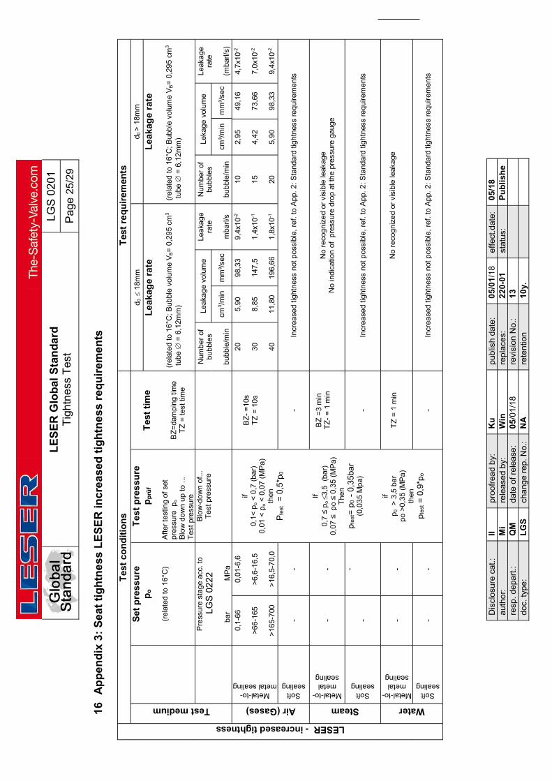
LE
SE
R G
lob
al S
tan
da
rd
Tig
htn
ess
Te
st
LG
S 0
201
Pa
ge 2
5/2
9
Dis
clo
sure
ca
t.:
II
pro
ofr
ead
by:
K
u
pu
blis
h d
ate
: 0
5/0
1/1
8 e
ffe
ct.d
ate:
0
5/1
8 a
uth
or:
M
i re
leas
ed
by:
W
in
rep
lace
s:
22
0-0
1 st
atu
s:
Pu
bli
sh
ere
sp. d
epa
rt.:
Q
M
da
te o
f re
lea
se:
05
/01
/18
revi
sion
No
.: 1
3
d
oc.
typ
e:
LG
S
cha
nge
re
p. N
o.:
NA
re
ten
tion
1
0y.
16
Ap
pe
nd
ix 3
: S
ea
t ti
gh
tne
ss
LE
SE
R in
cre
ase
d t
igh
tne
ss
re
qu
ire
me
nts
LESER - increased tightness
Tes
t co
nd
itio
ns
T
est
req
uir
emen
ts
Test medium
S
et
pre
ssu
re
po
(r
elat
ed t
o 16
°C)
Tes
t p
res
sure
p
prü
f
Aft
er t
estin
g of
set
pr
essu
re p
o
Blo
w d
ow
n u
p to
...
Tes
t pre
ssur
e
T
est
tim
e
B
Z=
dam
ping
tim
e T
Z =
tes
t tim
e
d 0
18m
m
d 0 >
18m
m
Le
akag
e ra
te
(r
elat
ed t
o 16
°C;
Bub
ble
volu
me
VB=
0,2
95
cm3
tub
e =
6,1
2mm
)
Le
akag
e ra
te
(r
elat
ed t
o 16
°C;
Bub
ble
volu
me
VB=
0,2
95
cm3
tub
e =
6,1
2mm
)
P
ress
ure
sta
ge a
cc. t
o
LG
S 0
22
2
ba
r
MP
a
Blo
w-d
ow
n o
f...
T
est p
ress
ure
N
umbe
r of
bu
bbl
es
bu
bbl
e/m
in
Lea
kage
vol
ume
Lea
kage
ra
te
m
barl/
s
Num
ber
of
bub
bles
bub
ble/
min
Leka
ge
volu
me
Lea
kage
ra
te
(m
barl/
s)
cm3 /
min
m
m³/
sec
cm³/
min
m
m³/
sec
Air (Gases)
Metal-to-metal sealing
0,1-
66
>
66-1
65
>
165-
700
0,01
-6,6
>6,
6-16
,5
>
16,5
-70
,0
if 0,
1< p
o <
0,7
(b
ar)
0,01
< p
o <
0,0
7 (M
Pa
) th
en
Pte
st
= 0
,5*p
0
If
0,7
p o
3,5
(b
ar)
0,07
p
o 0,
35 (
MP
a)
The
n
pte
st=
p0
-
0,3
5ba
r (0
,035
Mp
a)
if
p 0
> 3
,5 b
ar
po >
0,35
(M
Pa
) th
en
pte
st =
0,9
*po
BZ
- =
10s
TZ
= 1
0s
20 30 40
5,90
8,85
11,8
0
98,3
3
147
,5
19
6,6
6
9,4x
10-2
1,
4x10
-1
1,
8x10
-1
10 15 20
2,95
4,42
5,90
49,1
6
73,6
6
98,3
3
4,7x
10-2
7,
0x10
-2
9,
4x10
-2
Soft sealing
- -
- In
crea
sed
tight
ness
not
pos
sibl
e, r
ef.
to A
pp.
2: S
tand
ard
tight
ness
re
quire
men
ts
Steam
Metal-to-metal
sealing
- -
BZ
=3
min
T
Z-
= 1
min
No
reco
gniz
ed
or v
isib
le le
akag
e
No
indi
catio
n o
f pr
essu
re d
rop
at th
e pr
essu
re g
auge
Soft sealing
-
-
- In
crea
sed
tight
ness
not
pos
sibl
e, r
ef.
to A
pp.
2: S
tand
ard
tight
nes
s re
quire
men
ts
Water
Metal-to-metal
sealing
- -
T
Z =
1 m
in
N
o re
cogn
ize
d or
vis
ible
leak
age
Soft sealing
- -
- In
crea
sed
tight
ness
not
pos
sibl
e, r
ef.
to A
pp.
2: S
tand
ard
tight
ness
re
quir
em
ents
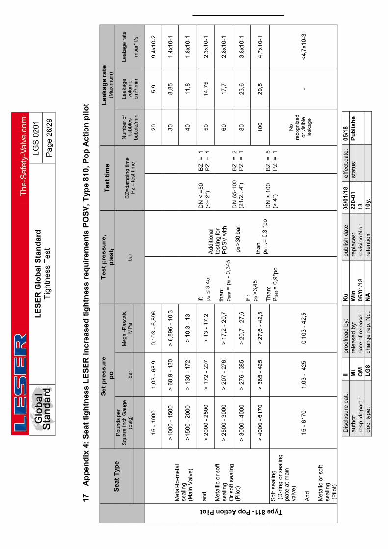
LE
SE
R G
lob
al S
tan
da
rd
Tig
htn
ess
Te
st
LG
S 0
201
Pa
ge 2
6/2
9
Dis
clo
sure
ca
t.:
II
pro
ofr
ead
by:
K
u
pu
blis
h d
ate
: 0
5/0
1/1
8 e
ffe
ct.d
ate:
0
5/1
8 a
uth
or:
M
i re
leas
ed
by:
W
in
rep
lace
s:
22
0-0
1 st
atu
s:
Pu
bli
sh
ere
sp. d
epa
rt.:
Q
M
da
te o
f re
lea
se:
05
/01
/18
revi
sion
No
.: 1
3
d
oc.
typ
e:
LG
S
cha
nge
re
p. N
o.:
NA
re
ten
tion
1
0y.
17
Ap
pe
nd
ix 4
: S
ea
t ti
gh
tne
ss
LE
SE
R i
nc
reas
ed
tig
htn
ess
re
qu
irem
en
ts P
OS
V,
Typ
e 8
10,
Po
p A
cti
on
pil
ot
Se
at T
ype
Se
t p
ress
ure
p
o
Tes
t p
res
sure
, p
test
f T
est
tim
e
Le
akag
e ra
te
(Ma
xim
um)
Pou
nds
per
S
quar
e In
ch G
auge
(p
sig)
ba
r M
ega
-Pas
cals
, M
Pa
bar
BZ
=da
mpi
ng t
ime
Pz
= te
st ti
me
Num
ber
of
bub
bles
bu
bbl
e/m
in
Lea
kage
vo
lum
e
cm3 /
min
Lea
kage
rat
e
mba
r* l/
s
Type 811- Pop Action Pilot
Me
tal-
to-m
eta
l se
alin
g
(Ma
in V
alv
e)
an
d
Me
talli
c o
r so
ft se
alin
g
Or
soft
se
alin
g
(Pilo
t)
15
- 1
000
1,0
3 -
68
,9
0,1
03
- 6
,89
6
if:
po
3
,45
th
an
: p
test =
p0 -
0,3
45
If
:
p0
>3
,45
T
ha
n:
Pte
st.=
0,9
*po
Ad
diti
on
al
test
ing
for
PO
SV
with
p
0 >
30 b
ar
tha
n
pte
st.=
0,3
*p
o
DN
< =
50
DN
65
-10
0
DN
> 1
00
BZ
=
1
P
Z
=
1
BZ
=
2
P
Z
=
1
BZ
=
5
P
Z
=
1
20
5,9
9
,4x1
0-2
>1
00
0 -
150
0 >
68
,9 -
130
>
6,8
96 -
10
,3
30
8,8
5 1
,4x1
0-1
>1
50
0 -
200
0 >
13
0 -
17
2 >
10
,3 -
13
40
11
,8
1,8
x10
-1
> 2
00
0 -
250
0 >
17
2 -
20
7 >
13
- 1
7,2
5
0 1
4,7
5 2
,3x1
0-1
> 2
50
0 -
300
0 >
20
7 -
27
6 >
17
,2 -
20
,7
60
17
,7
2,8
x10
-1
> 3
00
0 -
400
0 >
27
6 -
38
5 >
20
,7 -
27
,6
80
23
,6
3,8
x10
-1
> 4
00
0 -
617
0 >
38
5 -
42
5 >
27
,6 -
42
,5
10
0 2
9,5
4
,7x1
0-1
So
ft s
ea
ling
(
O-r
ing
or
seal
ing
p
late
at m
ain
va
lve
) A
nd
M
eta
lic o
r so
ft
sea
ling
(
Pilo
t)
15
- 6
170
1,0
3 -
42
5 0
,10
3 -
42
,5
No
reco
gniz
ed
or v
isib
le
leak
age
- <
4,7
x10
-3
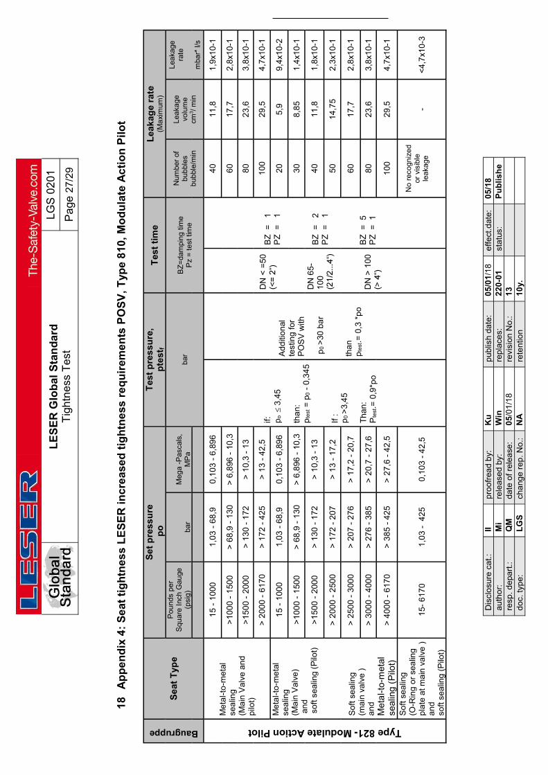
LE
SE
R G
lob
al S
tan
da
rd
Tig
htn
ess
Te
st
LG
S 0
201
Pa
ge 2
7/2
9
Dis
clo
sure
ca
t.:
II
pro
ofr
ead
by:
K
u
pu
blis
h d
ate
: 0
5/0
1/1
8 e
ffe
ct.d
ate:
0
5/1
8 a
uth
or:
M
i re
leas
ed
by:
W
in
rep
lace
s:
22
0-0
1 st
atu
s:
Pu
bli
sh
ere
sp. d
epa
rt.:
Q
M
da
te o
f re
lea
se:
05
/01
/18
revi
sion
No
.: 1
3
d
oc.
typ
e:
LG
S
cha
nge
re
p. N
o.:
NA
re
ten
tion
1
0y.
18
Ap
pe
nd
ix 4
: S
ea
t ti
gh
tne
ss
LE
SE
R i
nc
rea
sed
tig
htn
ess
re
qu
irem
en
ts P
OS
V,
Typ
e 8
10,
Mo
du
late
Ac
tio
n P
ilot
Baugruppe
Se
at T
ype
Se
t p
ress
ure
p
o
Tes
t p
res
sure
, p
test
f T
est
tim
e L
eak
age
rate
(M
axi
mum
) P
ound
s pe
r
Squ
are
Inch
Gau
ge
(psi
g)
bar
Meg
a -P
asca
ls,
MP
a ba
r B
Z=
dam
ping
tim
e P
z =
test
tim
e
Num
ber
of
bub
bles
bu
bbl
e/m
in
Lea
kage
vo
lum
e
cm3 /
min
Lea
kage
ra
te
m
bar*
l/s
Type 821- Modulate Action Pilot M
eta
l-to
-me
tal
sea
ling
(M
ain
Va
lve
an
d
pilo
t)
15
- 1
000
1,0
3 -
68
,9
0,1
03
- 6
,89
6
if:
po
3
,45
th
an
: p
test =
p0 -
0,3
45
If
:
p0
>3
,45
T
ha
n:
Pte
st.=
0,9
*po
Ad
diti
on
al
test
ing
for
PO
SV
with
p
0 >
30 b
ar
tha
n
pte
st.=
0,3
*p
o
DN
< =
50
DN
65
-1
00
DN
> 1
00
BZ
=
1
P
Z
=
1
BZ
=
2
P
Z
=
1
BZ
=
5
P
Z
=
1
40
11
,8
1,9
x10
-1
>1
00
0 -
150
0 >
68
,9 -
130
>
6,8
96 -
10
,3
60
17
,7
2,8
x10
-1
>1
50
0 -
200
0 >
13
0 -
17
2 >
10
,3 -
13
80
23
,6
3,8
x10
-1
> 2
00
0 -
617
0 >
17
2 -
42
5 >
13
- 4
2,5
1
00
29
,5
4,7
x10
-1
Me
tal-
to-m
eta
l se
alin
g
(Ma
in V
alv
e)
a
nd
s
oft
se
alin
g (
Pilo
t)
So
ft s
ea
ling
(m
ain
va
lve
) a
nd
M
eta
l-to-
met
al
seal
ing
(P
ilot)
15
- 1
000
1,0
3 -
68
,9
0,1
03
- 6
,89
6 2
0 5
,9
9,4
x10
-2
>1
00
0 -
150
0 >
68
,9 -
130
>
6,8
96 -
10
,3
30
8,8
5 1
,4x1
0-1
>1
50
0 -
200
0 >
13
0 -
17
2 >
10
,3 -
13
40
11
,8
1,8
x10
-1
> 2
00
0 -
250
0 >
17
2 -
20
7 >
13
- 1
7,2
5
0 1
4,7
5 2
,3x1
0-1
> 2
50
0 -
300
0 >
20
7 -
27
6 >
17
,2 -
20
,7
60
17
,7
2,8
x10
-1
> 3
00
0 -
400
0 >
27
6 -
38
5 >
20
,7 -
27
,6
80
23
,6
3,8
x10
-1
> 4
00
0 -
617
0 >
38
5 -
42
5 >
27
,6 -
42
,5
10
0 2
9,5
4
,7x1
0-1
So
ft s
ea
ling
(O
-Rin
g o
r se
alin
g p
late
at m
ain
va
lve
)
an
d
soft
se
alin
g (
Pilo
t)
15
- 6
170
1,0
3 -
42
5 0
,10
3 -
42
,5
No
reco
gniz
ed
or v
isib
le
leak
age
- <
4,7
x10
-3

LE
SE
R G
lob
al S
tan
da
rd
Tig
htn
ess
Te
st
LG
S 0
201
Pa
ge 2
8/2
9
Dis
clo
sure
ca
t.:
II
pro
ofr
ead
by:
K
u
pu
blis
h d
ate
: 0
5/0
1/1
8 e
ffe
ct.d
ate:
0
5/1
8 a
uth
or:
M
i re
leas
ed
by:
W
in
rep
lace
s:
22
0-0
1 st
atu
s:
Pu
bli
sh
ere
sp. d
epa
rt.:
Q
M
da
te o
f re
lea
se:
05
/01
/18
revi
sion
No
.: 1
3
d
oc.
typ
e:
LG
S
cha
nge
re
p. N
o.:
NA
re
ten
tion
1
0y.
19
Ba
ck
Se
at
tig
htn
ess
, L
ES
ER
sta
nd
ard
re
qu
ire
me
nts
fo
r P
OS
Vs
Se
t p
ress
ure
po
Tes
t p
ress
ure
, p
te
st,
bar
/ p
sig
T
est
Du
rati
on
Se
c.
Lea
kag
e r
ate
B
ub
ble
/ M
in
Tes
t pro
cedu
re
at L
ES
ER
P
ilo
t P
OS
V +
Po
p P
ilo
t M
od
ula
te
Ac
tio
n
Pil
ot
Mai
n V
alve
P
OS
V
po
if:
p o
6
the
n:
pte
st =
1,1
x p
0
if p o
6
the
n:
p tes
t = 6
ba
r
if:
p o
6
the
n:
p tes
t = 1
,1x
p 0
if:
p o
6
th
en:
p t
est =
6 b
ar
if:
p o
2,5
th
en:
p t
est =
1,1
x p 0
if:
p o
2,5
th
en:
p t
est =
2,5
ba
r
DN
< =
20
0 (
<=
8")
D
N >
25
0 t
o 4
50
(10
" to
18"
)
15
30
No
reco
gni
zed
or
visi
ble
lea
kage
No
re
cog
niz
ed
or v
isib
le
lea
kage
No
re
cog
nize
d or
vi
sibl
e le
aka
ge
Ba
bb
le
emis
sion
an
d /
or
Ap
plic
atio
n w
ith
test
s flu
id

LE
SE
R G
lob
al S
tan
da
rd
Tig
htn
ess
Te
st
LG
S 0
201
Pa
ge 2
9/2
9
Dis
clo
sure
ca
t.:
II
pro
ofr
ead
by:
K
u
pu
blis
h d
ate
: 0
5/0
1/1
8 e
ffe
ct.d
ate:
0
5/1
8 a
uth
or:
M
i re
leas
ed
by:
W
in
rep
lace
s:
22
0-0
1 st
atu
s:
Pu
bli
sh
ere
sp. d
epa
rt.:
Q
M
da
te o
f re
lea
se:
05
/01
/18
revi
sion
No
.: 1
3
d
oc.
typ
e:
LG
S
cha
nge
re
p. N
o.:
NA
re
ten
tion
1
0y.
20
Se
at
tig
htn
ess
acc
. to
PA
S 1
085
-S
V
Se
at
Typ
e
Se
t p
res
su
re,
po
T
es
t p
res
su
re, p
te
st,
Ne
nn
wei
te
Te
st
Tim
e L
ea
kag
e r
ate
Po
un
ds p
er
S
qu
are
Inch
Gau
ge
(psi
g)
ba
r M
eg
a -
Pa
sca
ls,
MP
a
ba
r B
Z=
dam
ping
tim
e [
Min
. ]
Pz
= t
est t
ime
[ M
in.
]
Num
ber
of
bub
bles
bu
bbl
e/m
in
Lea
kage
vol
ume
cm
3 / m
in
Seat tightness acc. to PAS 1085
Me
tal-t
o-m
etal
se
alin
g
an
d
soft
se
alin
g
15
< 1
5
1,0
< 1
,0
0,1
< 0
,1
97%
x
p0
90%
x
p0
DN
2
00
(D
N
1 1
3
0
,89
Me
tal-t
o-m
etal
se
alin
g
an
d
soft
se
alin
g
15
< 1
5
1,0
< 1
,0
0,1
< 0
,1
97%
x
p0
90%
x
p0
DN
> 2
00
3
1
3
0,8
9
LESER Deutschland Standard CDTP – Cold differential test pressure
LDeS 1001.69
Page 1/19
disclosure cat.: II proofread: Boy published date: 09/02/18 effect. date: 08/18
author: Cal released by: KHa replaces: 001-69 status: Published
resp. depart.: M date of release: 09/02/18 revision No.: 1
doc. type: LLS change rep. No.: NA retention period: 10y.
pro
tecte
d
Content 1 Purpose .......................................................................................................... 1 2 Scope .............................................................................................................. 1
3 References ..................................................................................................... 1 4 Introduction .................................................................................................... 1 5 What is CDTP? ............................................................................................... 2 6 What is CDTP Correction? ............................................................................ 2 7 Which influences on safety valves are covered with the setting at CDTP? 2
8 How is the CDTP Correction calculated? .................................................... 3
9 How does LESER set the safety valves depending on different service conditions with temperature and back pressure? .............................................................. 6 10 How is the influence of balanced bellows? ................................................. 6 11 How does an open/closed bonnet influence the CDTP? ............................ 9 12 How does the spring material influence the CDTP? ................................... 10 13 How does the medium influence the CDTP? ............................................... 10
14 Where can CDTP values be found? ............................................................. 11 15 Example .......................................................................................................... 12
16 Original confirmation of German TÜV Nord ................................................ 14 17 CDTP for POSV .............................................................................................. 16
18 How is the CDTP correction calculated? ..................................................... 17 19 How does the design of pilot control have influence on the CDTP? ........ 17
20 CDTP Correction for Precipitate Installation of Spring Loaded Safety Valves 18 21 Example .......................................................................................................... 19
1 Purpose
This LESER Deutschland Standard (LDeS) describes the definition of CDTP and the use of CDTP correction for LESER safety valves. 2 Scope
This LDeS applies to the LESER sites Hamburg and Hohenwestedt. 3 References
None 4 Introduction
According to international standards like ASME VIII and ISO 4126-1 and 4126-4 the service conditions are to be considered for setting at ambient temperature.

LESER Deutschland Standard CDTP – Cold differential test pressure
LDeS 1001.69
Page 2/19
disclosure cat.: II proofread: Boy published date: 09/02/18 effect. date: 08/18
author: Cal released by: KHa replaces: 001-69 status: Published
resp. depart.: M date of release: 09/02/18 revision No.: 1
doc. type: LLS change rep. No.: NA retention period: 10y.
pro
tecte
d
5 What is CDTP?
Cold differential test pressure (CDTP) is defined in standard - DIN EN ISO 4126-1 Edition 2004, chapter 3.2.5 - ASME Sec. VIII, Div. 1, Edition 2010, UG 136 (d) 4 - API 520-1 8. Edition 2008, chapter 3.4.1 - ASME PTC 25 - 2008 chapter 2.7
CDTP is used if correction of set pressure of safety valves according to deviation of service conditions is necessary. Extract from ASME Sec. VIII, Div. 1, UG 136 (d) 4: When a valve is adjusted to correct for service conditions of superimposed back pressure, temperature, or the differential in popping pressure between steam and air, the actual test pressure (cold differential test pressure) shall be marked on the valve per 129
Extract from DIN EN ISO 4126-1 chapter 3.2.5: statischer Druck auf der Eintrittsseite, bei dem ein Sicherheitsventil auf dem Prüfstand zu öffnen beginnt. ANMERKUNG Dieser Druck schließt Korrekturen für Betriebsbedingungen, z. B. Gegendruck und/oder Temperatur, ein.
Extract from API 520 chapter 3.13: Cold differential test pressure The pressure at which a pressure relief valve is adjusted to open on the test stand. The cold differential test pressure includes corrections for the service conditions of backpressure or temperature or both.
Extract from API 520 chapter 4.2.3: The actual service conditions under which a pressure relief valve is required to open, may be different form the conditions at which the pressure relief valve is set to operate on a test stand. To compensate for this effect, a CDTP is specified for adjusting the set pressure of the valve on the test stand. The CDTP may include a correction for actual service conditions of back pressure and/or temperature.
Extract from ASME PTC 25-2008 chapter 2.7: the inlet static pressure at which a pressure relief valve is adjusted to open on the test stand. This test pressure includes corrections for service conditions of superimposed back pressure and/ or temperature.
6 What is CDTP Correction?
The CDTP correction is the correction of set pressure at test bench conditions to achieve the correct set pressure at service conditions. 7 Which influences on safety valves are covered with the setting at CDTP?
The set pressure on test bench deviating from service condition is influenced by: - temperature - superimposed back pressure
Basically effects at the setting by:
- set pressure tolerance - medium
The CDTP only covers influences of superimposed back pressure and/or temperature.

LESER Deutschland Standard CDTP – Cold differential test pressure
LDeS 1001.69
Page 3/19
disclosure cat.: II proofread: Boy published date: 09/02/18 effect. date: 08/18
author: Cal released by: KHa replaces: 001-69 status: Published
resp. depart.: M date of release: 09/02/18 revision No.: 1
doc. type: LLS change rep. No.: NA retention period: 10y.
pro
tecte
d
8 How is the CDTP Correction calculated?
The CDTP correction is provided by the manufacturer. LESER has done measurements on steam test laboratory at high temperature service conditions. These measurements have been monitored and plotted as curve which has been approved by German TÜV Nord. In case of superimposed back pressure and temperature the corrected set pressure is calculated with a formula. This formula is valid for conventional or balanced bellows design. The formula is valid for LESER standard spring materials only, 1.1200, 1.7102, 1.8159, 1.4310. For High Alloy and Tungsten spring material the correction is not used, exclusive Inconel as defined in table in chapter 8.2.
The term )( aset pp considers influences of superimposed backpressure.
The factor Tk covers influences of temperature.
Design Superimposed backpressure variable (0 – x) [bar g]
Superimposed backpressure constant y [bar g]
Built-up backpressure [bar g]
Conventional pa = x pa = y Not valid for calculation
Bellows pa = 0 pa = 0 Not valid for calculation
Table 1: backpressure according to different safety valve design 8.1 Description of formula
pset: set pressure at service conditions [psig or barg] pa: superimposed back pressure, constant or variable [psig or barg]. If variable and
conventional design, the max. superimposed back pressure should be used. If balanced bellows design is used pa is set to 0 bar or 0 psig.
kT: correction factor for CDTP [-], this is depending on valve design/conventional design/balanced bellows design/open or closed bonnet
T: temperature in [°C] 8.2 Calculation formula:
Open or closed bonnet with balanced bellows
kT=0,97339+0,00039(T-200)-0,0000015477(T-200)²+0,0000000029977(T-200)³
equation (1)
Closed bonnet conventional design
kT=0,97339+0,00039T-0,0000015477T²+0,0000000029977T³
equation (2)
Open bonnet kT=0,97339+0,00039(T-50)-
Tasetcdtp kppp *)(

LESER Deutschland Standard CDTP – Cold differential test pressure
LDeS 1001.69
Page 4/19
disclosure cat.: II proofread: Boy published date: 09/02/18 effect. date: 08/18
author: Cal released by: KHa replaces: 001-69 status: Published
resp. depart.: M date of release: 09/02/18 revision No.: 1
doc. type: LLS change rep. No.: NA retention period: 10y.
pro
tecte
d
conventional design
0,0000015477(T-50)²+0,0000000029977(T-50)³
equation (3)
Table 2: Formulas of kT calculation

LESER Deutschland Standard CDTP – Cold differential test pressure
LDeS 1001.69
Page 5/19
disclosure cat.: II proofread: Boy published date: 09/02/18 effect. date: 08/18
author: Cal released by: KHa replaces: 001-69 status: Published
resp. depart.: M date of release: 09/02/18 revision No.: 1
doc. type: LLS change rep. No.: NA retention period: 10y.
pro
tecte
d
LESER datasheet of CDTP (Cold differential test pressure)
Tasetcdtp kppp *)( Tafsetcdtp kkpp *)*( (Type 459/462 only)
pcdtp: cold differential test pressure [psig or barg] pset: set pressure at service conditions [psig or barg] pa: superimposed back pressure, constant (pa is equal paf) [psig or barg] kT : correction factor for CDTP , temperature influence [-] kaf: correction factor for type 459 / 462, deviating effective area influence [-]
°C °F
Open bonnet conventional
Closed bonnet conventional
Open bonnet balanced bellows or Inconel spring with or without
bellows
Closed bonnet balanced bellows or Inconel spring with or without
bellows 550 1022 Limitation at 427°C
(only with balanced bellows)
Limitation at 350°C (only with balanced
bellows)
1,049 1,049
500 932 1,032 1,032
450 842 1,021 1,021
400 752 1,049 1,013 1,013
350 662 1,032 1,049 1,007 1,007
300 572 1,021 1,032
1,000 1,000 250 482 1,013 1,021
200 392 1,007 1,013
150 302 1,000 1,007
100 212
No influence of service condition on CDTP, correction factor: 1,000
50 122
0 32
-50 -58
-100 -148
-150 -238
-200 -328
-250 -418
Table 3: correction factor kT depending ond safety valve design

LESER Deutschland Standard CDTP – Cold differential test pressure
LDeS 1001.69
Page 6/19
disclosure cat.: II proofread: Boy published date: 09/02/18 effect. date: 08/18
author: Cal released by: KHa replaces: 001-69 status: Published
resp. depart.: M date of release: 09/02/18 revision No.: 1
doc. type: LLS change rep. No.: NA retention period: 10y.
pro
tecte
d
LESER diagram kaf for for type 459 / 462
paf/p * 100 [%] d0 = 9 [mm] d0= 17,5 [mm] paf/p * 100 [%] d0 = 9 [mm] d0= 17,5 [mm]
0,0 0,999 0,998 20,0 1,083 0,872
1,0 1,001 0,990 22,0 1,097 0,863
2,0 1,003 0,983 24,0 1,111 0,855
3,0 1,005 0,975 26,0 1,126 0,847
4,0 1,008 0,968 28,0 1,143 0,840
5,0 1,011 0,961 30,0 1,160 0,833
6,0 1,014 0,954 32,0 1,178 0,827
7,0 1,018 0,947 34,0 1,197 0,822
8,0 1,021 0,940 35,0 1,207 0,819
9,0 1,025 0,934
10,0 1,029 0,927
12,0 1,038 0,915
14,0 1,048 0,904
16,0 1,059 0,893
18,0 1,070 0,882
Note: Types 459/462 with do = 13mm is not influenced by correction factor kaf. It is in all case = 1.correction factor kT depending on safety valve design
9 How does LESER set the safety valves depending on different service
conditions with temperature and back pressure?
LESER has made steam tests on LESER test laboratory. These measurements have been monitored, evaluated and processed into a correction curve. This curve was approved by German TÜV Nord to be an adequate practicable procedure to correct set pressure to cold differential test pressure concerning deviation of service conditions. The original confirmation of TÜV Nord and an English translation is attached in chapter 9. Please note, that for gas service the setting is defined as “first audible discharge”. For full opening of valve please add another 10%.
10 How is the influence of balanced bellows?
10.1 How is the influence of balanced bellows in general for safety valves?
The stainless steel bellows protect the upper area of safety valves against temperature and compensate backpressure. The medium cannot get in contact with the spring. This
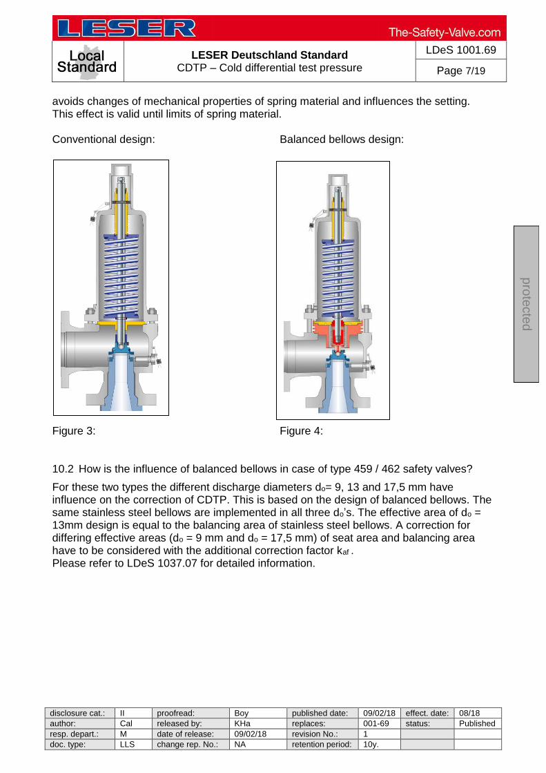
LESER Deutschland Standard CDTP – Cold differential test pressure
LDeS 1001.69
Page 7/19
disclosure cat.: II proofread: Boy published date: 09/02/18 effect. date: 08/18
author: Cal released by: KHa replaces: 001-69 status: Published
resp. depart.: M date of release: 09/02/18 revision No.: 1
doc. type: LLS change rep. No.: NA retention period: 10y.
pro
tecte
d
avoids changes of mechanical properties of spring material and influences the setting. This effect is valid until limits of spring material. Conventional design: Balanced bellows design: Figure 3: Figure 4: 10.2 How is the influence of balanced bellows in case of type 459 / 462 safety valves?
For these two types the different discharge diameters do= 9, 13 and 17,5 mm have influence on the correction of CDTP. This is based on the design of balanced bellows. The same stainless steel bellows are implemented in all three do’s. The effective area of do = 13mm design is equal to the balancing area of stainless steel bellows. A correction for differing effective areas (do = 9 mm and do = 17,5 mm) of seat area and balancing area have to be considered with the additional correction factor kaf . Please refer to LDeS 1037.07 for detailed information.

LESER Deutschland Standard CDTP – Cold differential test pressure
LDeS 1001.69
Page 8/19
disclosure cat.: II proofread: Boy published date: 09/02/18 effect. date: 08/18
author: Cal released by: KHa replaces: 001-69 status: Published
resp. depart.: M date of release: 09/02/18 revision No.: 1
doc. type: LLS change rep. No.: NA retention period: 10y.
pro
tecte
d
kaf (d0=9 mm) = 1,1575E-4*(paf /p*100%)²+1,899E-3*(paf /p*100%)+0,9987
kaf (d0=17.5 mm) = 7,78E-5*(paf /p*100%)²-7,8332E-3*(paf /p*100%)+0,998
0,80
0,90
1,00
1,10
1,20
1,30
0 5 10 15 20 25 30 35paf/p [%]
kaf
Diagram 1: correction factor kaf for balanced bellows design for type 459 / 462

LESER Deutschland Standard CDTP – Cold differential test pressure
LDeS 1001.69
Page 9/19
disclosure cat.: II proofread: Boy published date: 09/02/18 effect. date: 08/18
author: Cal released by: KHa replaces: 001-69 status: Published
resp. depart.: M date of release: 09/02/18 revision No.: 1
doc. type: LLS change rep. No.: NA retention period: 10y.
pro
tecte
d
11 How does an open/closed bonnet influence the CDTP?
The bonnet design could be open or closed design. Open Design: Closed Design: Closed Design: Figure 5: Figure 6: Open design is recommended for applications which are not harmful for the environment. Closed design is recommended for applications with higher safety aspects. This has to be preselected by the customer. The open bonnet design allows higher temperatures of medium because of the cooling effect with free circulation of air. The temperature increase in comparison to closed bonnet design is smaller. The correction factor is listed in table 1.
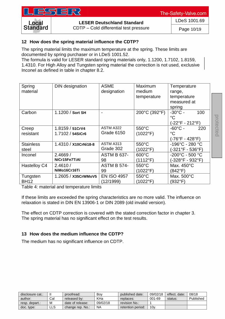
LESER Deutschland Standard CDTP – Cold differential test pressure
LDeS 1001.69
Page 10/19
disclosure cat.: II proofread: Boy published date: 09/02/18 effect. date: 08/18
author: Cal released by: KHa replaces: 001-69 status: Published
resp. depart.: M date of release: 09/02/18 revision No.: 1
doc. type: LLS change rep. No.: NA retention period: 10y.
pro
tecte
d
12 How does the spring material influence the CDTP?
The spring material limits the maximum temperature at the spring. These limits are documented by spring purchaser or in LDeS 1001.52. The formula is valid for LESER standard spring materials only, 1.1200, 1.7102, 1.8159, 1.4310. For High Alloy and Tungsten spring material the correction is not used, exclusive Inconel as defined in table in chapter 8.2.
Spring material
DIN designation ASME designation
Maximum medium temperature
Temperature range, temperature measured at spring
Carbon 1.1200 / Sort SH - 200°C (392°F) -30°C - 100 °C (-22°F - 212°F)
Creep resistant
1.8159 / 51CrV4 1.7102 / 54SiCr6
ASTM A322
Grade 6150 550°C (1022°F)
-60°C - 220 °C (-76°F - 428°F)
Stainless steel
1.4310 / X10CrNi18-8 ASTM A313
Grade 302 550°C (1022°F)
-196°C - 280 °C (-321°F - 536°F)
Inconel 2.4669 / NiCr15Fe7TiAl
ASTM B 637-98
600°C (1112°F)
-200°C - 500 °C (-328°F - 932°F)
Hastelloy C4 2.4610 / NiMo16Cr16Ti
ASTM B 574-99
550°C (1022°F)
Max. 450°C (842°F)
Tungsten BH12
1.2605 / X35CrWMoV5 EN ISO 4957 (12/1999)
550°C (1022°F)
Max. 500°C (932°F)
Table 4: material and temperature limits If these limits are exceeded the spring characteristics are no more valid. The influence on relaxation is stated in DIN EN 13906-1 or DIN 2089 (old invalid version). The effect on CDTP correction is covered with the stated correction factor in chapter 3. The spring material has no significant effect on the test results. 13 How does the medium influence the CDTP?
The medium has no significant influence on CDTP.
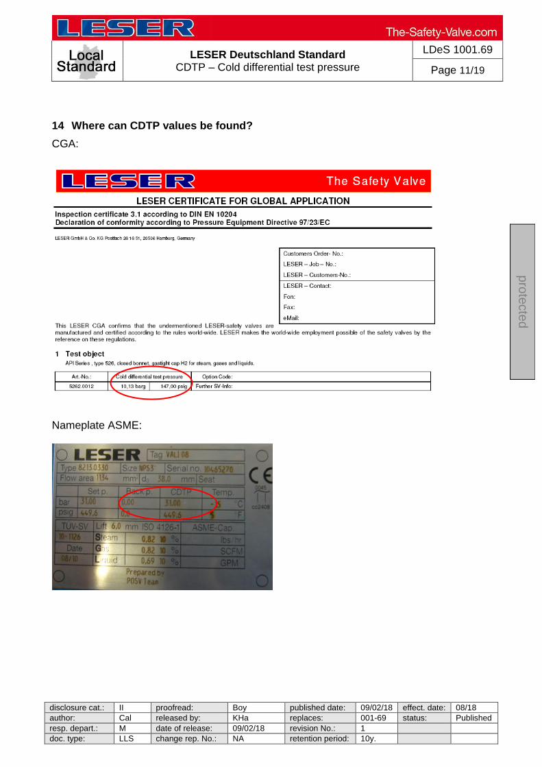
LESER Deutschland Standard CDTP – Cold differential test pressure
LDeS 1001.69
Page 11/19
disclosure cat.: II proofread: Boy published date: 09/02/18 effect. date: 08/18
author: Cal released by: KHa replaces: 001-69 status: Published
resp. depart.: M date of release: 09/02/18 revision No.: 1
doc. type: LLS change rep. No.: NA retention period: 10y.
pro
tecte
d
14 Where can CDTP values be found?
CGA:
Nameplate ASME:
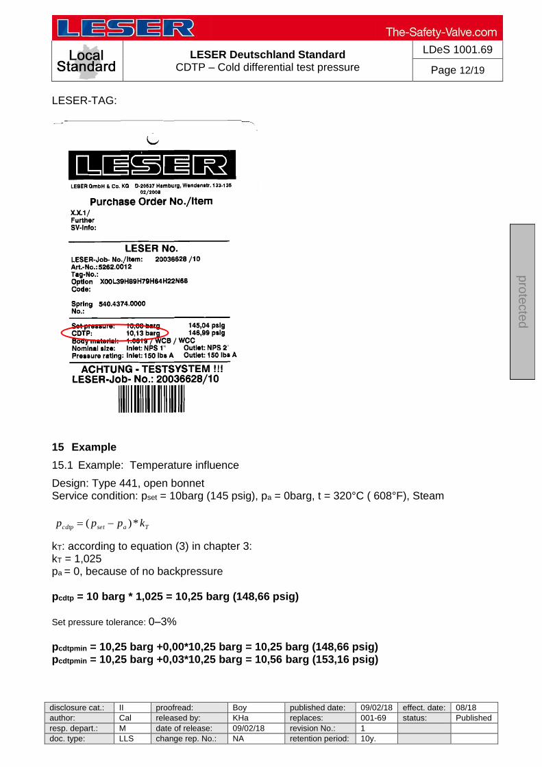
LESER Deutschland Standard CDTP – Cold differential test pressure
LDeS 1001.69
Page 12/19
disclosure cat.: II proofread: Boy published date: 09/02/18 effect. date: 08/18
author: Cal released by: KHa replaces: 001-69 status: Published
resp. depart.: M date of release: 09/02/18 revision No.: 1
doc. type: LLS change rep. No.: NA retention period: 10y.
pro
tecte
d
LESER-TAG:
15 Example
15.1 Example: Temperature influence
Design: Type 441, open bonnet Service condition: pset = 10barg (145 psig), pa = 0barg, t = 320°C ( 608°F), Steam
kT: according to equation (3) in chapter 3: kT = 1,025 pa = 0, because of no backpressure pcdtp = 10 barg * 1,025 = 10,25 barg (148,66 psig) Set pressure tolerance: 0–3%
pcdtpmin = 10,25 barg +0,00*10,25 barg = 10,25 barg (148,66 psig) pcdtpmin = 10,25 barg +0,03*10,25 barg = 10,56 barg (153,16 psig)
Tasetcdtp kppp *)(
LESER Deutschland Standard CDTP – Cold differential test pressure
LDeS 1001.69
Page 13/19
disclosure cat.: II proofread: Boy published date: 09/02/18 effect. date: 08/18
author: Cal released by: KHa replaces: 001-69 status: Published
resp. depart.: M date of release: 09/02/18 revision No.: 1
doc. type: LLS change rep. No.: NA retention period: 10y.
pro
tecte
d
15.2 Example: Temperature and constant backpressure influence
Design: Type 459 do = 9mm, closed bonnet, balanced bellows Service condition: pset = 50barg (725 psig), pa = 5barg (72,5 psig), t = 400°C ( 752°F), Air
Tafsetcdtp kkpp *)*(
kT: according to equation (1) in chapter 3: kT = 1,013 kaf: According to diagram 1 in chapter 5.1: kaf = 1,029 pcdtp = 50 barg * 1,029 * 1,013= 52,12 barg (755,74 psig) Set pressure tolerance: 0–3% pcdtpmin = 52,12 barg +0,00*52,12 barg = 52,12 barg (755,74 psig) pcdtpmin = 52,12 barg +0,03*52,12 barg = 53,68 barg (778,36 psig) 15.3 Example: Temperature and variable backpressure influence
Design: Type 441, closed bonnet, Service condition: pset = 10barg (145 psig), pa = 0 – 1,5 barg, t = 320°C ( 608°F), air kT: according to equation (2) in chapter 3: kT = 1,038 pa = 1,5 barg, because of conventional design and worst case situation pcdtp = (10 barg – 1,5barg) * 1,038 = 8,82 barg (127,93 psig) Set pressure tolerance: 0–3% pcdtpmin = 8,82 barg +0,00*8,82 barg = 8,82 barg (127,89 psig) pcdtpmin = 8,82 barg +0,03*8,82 barg = 9,09 barg (131,81 psig)

LESER Deutschland Standard CDTP – Cold differential test pressure
LDeS 1001.69
Page 14/19
disclosure cat.: II proofread: Boy published date: 09/02/18 effect. date: 08/18
author: Cal released by: KHa replaces: 001-69 status: Published
resp. depart.: M date of release: 09/02/18 revision No.: 1
doc. type: LLS change rep. No.: NA retention period: 10y.
pro
tecte
d
16 Original confirmation of German TÜV Nord

LESER Deutschland Standard CDTP – Cold differential test pressure
LDeS 1001.69
Page 15/19
disclosure cat.: II proofread: Boy published date: 09/02/18 effect. date: 08/18
author: Cal released by: KHa replaces: 001-69 status: Published
resp. depart.: M date of release: 09/02/18 revision No.: 1
doc. type: LLS change rep. No.: NA retention period: 10y.
pro
tecte
d
LESER Deutschland Standard CDTP – Cold differential test pressure
LDeS 1001.69
Page 16/19
disclosure cat.: II proofread: Boy published date: 09/02/18 effect. date: 08/18
author: Cal released by: KHa replaces: 001-69 status: Published
resp. depart.: M date of release: 09/02/18 revision No.: 1
doc. type: LLS change rep. No.: NA retention period: 10y.
pro
tecte
d
Translation by LESER: Dear Mr. Stremme,
We think it is a realistic way to consider the temperature at the Cold Differential Test Pressure of
safety valves according to the enclosed diagram.
The multiplication factor for the Cold Differential Test Pressure at the operating temperature is
given by the enclosed diagram.
This procedure will be applied only if the customer states it explicitly and annotated this on the
column “further manufacturers’ instructions”.
Sincerely yours
Schwenn
TÜV Inspector
17 CDTP for POSV
(Separate chapter beside spring loaded safety valve) Which influences on safety valves are covered with the setting at CDTP? The set pressure on test bench deviating from service condition is influence by:
- Temperature
Basically effects at the setting by: - set pressure tolerance - medium
The CDTP only covers influences of temperature. The superimposed back pressure does not affect the set pressure, because it is completely balanced design.

LESER Deutschland Standard CDTP – Cold differential test pressure
LDeS 1001.69
Page 17/19
disclosure cat.: II proofread: Boy published date: 09/02/18 effect. date: 08/18
author: Cal released by: KHa replaces: 001-69 status: Published
resp. depart.: M date of release: 09/02/18 revision No.: 1
doc. type: LLS change rep. No.: NA retention period: 10y.
pro
tecte
d
18 How is the CDTP correction calculated?
The calculation is based on pressure testing under temperature of POSV. The results have been curves which are composed in formulas. The formula is as follows:
y = 1+ (((0,0221*operating temp.) - 0,5348)/100)
Formula for Pop Action with boarders: > 3 bar and > 100°C. Formula for Modulate Action with boarders: >3 bar and < -20°C or > 100°C.
°C °F Pop Action
Pilot Modulate Action
Pilot
180 356 1,0344
150 302 1,0278
100 212 1,0168
50 122
No influence
No influence 20 68
-20 -4 0,9902
-40 -40 0,9858 table 5: Correction factor kT for LESER POSV
19 How does the design of pilot control have influence on the CDTP?
The pressure chambers in the Pop Action Pilot are sealed with soft sealing discs. Above temperatures of 100°C the effective area of o-ring geometry is influenced. The result is a deviation of set pressure.
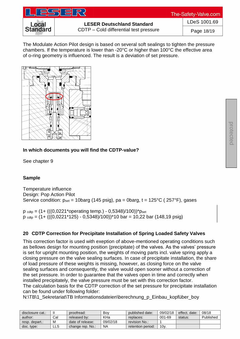
LESER Deutschland Standard CDTP – Cold differential test pressure
LDeS 1001.69
Page 18/19
disclosure cat.: II proofread: Boy published date: 09/02/18 effect. date: 08/18
author: Cal released by: KHa replaces: 001-69 status: Published
resp. depart.: M date of release: 09/02/18 revision No.: 1
doc. type: LLS change rep. No.: NA retention period: 10y.
pro
tecte
d
The Modulate Action Pilot design is based on several soft sealings to tighten the pressure chambers. If the temperature is lower than -20°C or higher than 100°C the effective area of o-ring geometry is influenced. The result is a deviation of set pressure.
In which documents you will find the CDTP-value? See chapter 9 Sample Temperature influence Design: Pop Action Pilot Service condition: pset = 10barg (145 psig), pa = 0barg, t = 125°C ( 257°F), gases
p cdtp = (1+ (((0,0221*operating temp.) - 0,5348)/100))*pset p cdtp = (1+ (((0,0221*125) - 0,5348)/100))*10 bar = 10,22 bar (148,19 psig) 20 CDTP Correction for Precipitate Installation of Spring Loaded Safety Valves
This correction factor is used with exeption of above-mentioned operating conditions such as bellows design for mounting position (precipitate) of the valves. As the valves’ pressure is set for upright mounting position, the weights of moving parts incl. valve spring apply a closing pressure on the valve sealing surfaces. In case of precipitate installation, the share of load pressure of these weights is missing, however, as closing force on the valve sealing surfaces and consequently, the valve would open sooner without a correction of the set pressure. In order to guarantee that the valves open in time and correctly when installed precipitately, the valve pressure must be set with this correction factor. The calculation basis for the CDTP correction of the set pressure for precipitate installation can be found under following folder: N:\TB\1_Sekretariat\TB Informationsdateien\berechnung_p_Einbau_kopfüber_boy

LESER Deutschland Standard CDTP – Cold differential test pressure
LDeS 1001.69
Page 19/19
disclosure cat.: II proofread: Boy published date: 09/02/18 effect. date: 08/18
author: Cal released by: KHa replaces: 001-69 status: Published
resp. depart.: M date of release: 09/02/18 revision No.: 1
doc. type: LLS change rep. No.: NA retention period: 10y.
pro
tecte
d
21 Example
21.1 Example 1: Influence of temperature and precipitate mounting position:
Design: Type 441 DN80, open bonnet Service condition: pset = 4,2barg (61,51 psig), pa = 0barg, t = 320°C (608°F), superheated steam
a.) CDTP – correction for temperature influence:
kT: acc. to equation (3) in chapter 3: kT = 1,022 pa = 0, as no back pressure pcdtp = 4,2 barg * 1,022 = 4,29 barg (62,2 psig)
b.) CDTP – correction for precipitate mounting position: Pkcdtp= 0,2barg (see link)
c.) Total correction factor = Pcdtp+Pkctdp= 4,29barg+0,2barg=4,49barg(65,1 psig)
Tasetcdtp kppp *)(

LESER Global Standard Final visual inspection of repaired valves
LGS 4117
Page 1/8
disclosure cat.: II proofread: OR published date: 9/14/11 effect. date: 18.11.201author: Nieh released by: KUW replaces: initial status: published resp. depart.: PP date of release: 11/8/11 revision No.: 0 doc. type: LGS change rep. No.: 651A retention period: 10
pro
tected
Contents
1 Purpose ............................................................................................................... 1 2 Scope .................................................................................................................. 1 3 Disclaimer ............................................................................................................ 1 4 Qualified fitting personnel .................................................................................... 2 5 General Information .............................................................................................26 Flow chart for the visual inspection (final inspection) ........................................... 2 7 Performing the final inspection ............................................................................. 3
7.1 General inspections ...................................................................................... 3 7.2 Visual inspection of other items .................................................................... 4 7.3 Fault notification process .............................................................................. 8
1 Purpose
This LESER Global Standard (LGS) provides instruction on the visual final inspection of LESER safety valves. The required work steps and materials are described.
2 Scope
This document must be observed in the visual final inspection of safety valves in agencies and subsidiaries of LESER GmbH & Co. KG.
3 Disclaimer
LESER puts in a great deal of effort into making up-to-date and correct documentation available. Nevertheless, LESER GmbH & Co. KG gives no guarantee that the recommended actions presented here are entirely correct and error free. This document is to be applied exclusively to the specified type. LESER GmbH & Co. KG declines any liability or responsibility for the correctness and completeness of the content. LESER GmbH & Co. KG reserves the right to change the information contained in this document, which is for the products of LESER GmbH & Co. KG and is intended for LESER subsidiaries, at any time and without prior announcement. LESER GmbH & Co. KG is available to the users of this document to provide additional information.
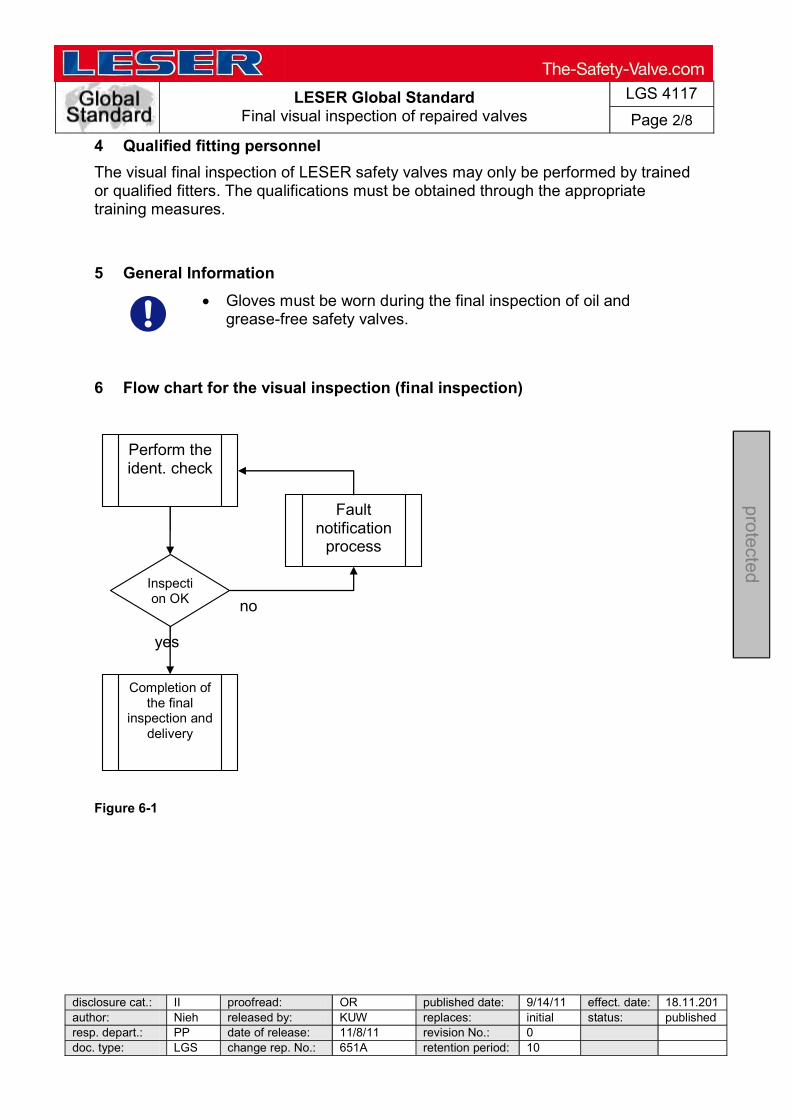
LESER Global Standard Final visual inspection of repaired valves
LGS 4117
Page 2/8
disclosure cat.: II proofread: OR published date: 9/14/11 effect. date: 18.11.201author: Nieh released by: KUW replaces: initial status: published resp. depart.: PP date of release: 11/8/11 revision No.: 0 doc. type: LGS change rep. No.: 651A retention period: 10
pro
tected
4 Qualified fitting personnel
The visual final inspection of LESER safety valves may only be performed by trained or qualified fitters. The qualifications must be obtained through the appropriate training measures.
5 General Information
Gloves must be worn during the final inspection of oil and grease-free safety valves.
6 Flow chart for the visual inspection (final inspection)
Figure 6-1
Perform the ident. check
Completion of the final
inspection and delivery
Inspection OK
Fault notification
process
yes
no

LESER Global Standard Final visual inspection of repaired valves
LGS 4117
Page 3/8
disclosure cat.: II proofread: OR published date: 9/14/11 effect. date: 18.11.201author: Nieh released by: KUW replaces: initial status: published resp. depart.: PP date of release: 11/8/11 revision No.: 0 doc. type: LGS change rep. No.: 651A retention period: 10
pro
tected
7 Performing the final inspection
7.1 General inspections
a) Compare the content of the valve inspection plan or repair order to the valve model.
Figure 7.1-1
Figure 7.1-2: Check the type number against the valve inspection plan / repair order
Figure 7.1-3: Check the BT plate / customer ID plate data against the valve inspection plan / repair order
EXAMPLE / SPECIMEN
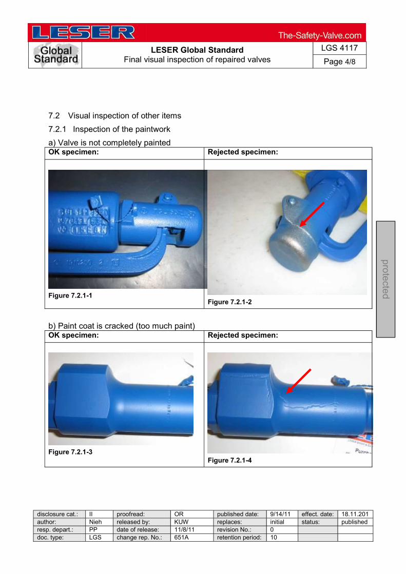
LESER Global Standard Final visual inspection of repaired valves
LGS 4117
Page 4/8
disclosure cat.: II proofread: OR published date: 9/14/11 effect. date: 18.11.201author: Nieh released by: KUW replaces: initial status: published resp. depart.: PP date of release: 11/8/11 revision No.: 0 doc. type: LGS change rep. No.: 651A retention period: 10
pro
tected
7.2 Visual inspection of other items
7.2.1 Inspection of the paintwork
a) Valve is not completely painted OK specimen: Rejected specimen:
Figure 7.2.1-1
Figure 7.2.1-2
b) Paint coat is cracked (too much paint) OK specimen: Rejected specimen:
Figure 7.2.1-3
Figure 7.2.1-4
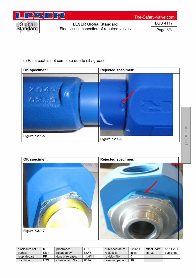
LESER Global Standard Final visual inspection of repaired valves
LGS 4117
Page 5/8
disclosure cat.: II proofread: OR published date: 9/14/11 effect. date: 18.11.201author: Nieh released by: KUW replaces: initial status: published resp. depart.: PP date of release: 11/8/11 revision No.: 0 doc. type: LGS change rep. No.: 651A retention period: 10
pro
tected
c) Paint coat is not complete due to oil / grease
OK specimen: Rejected specimen:
Figure 7.2.1-5 Figure 7.2.1-6
OK specimen: Rejected specimen:
Figure 7.2.1-7

LESER Global Standard Final visual inspection of repaired valves
LGS 4117
Page 6/8
disclosure cat.: II proofread: OR published date: 9/14/11 effect. date: 18.11.201author: Nieh released by: KUW replaces: initial status: published resp. depart.: PP date of release: 11/8/11 revision No.: 0 doc. type: LGS change rep. No.: 651A retention period: 10
pro
tected
Figure 7.2.1-8
d) Paint on masked off areas
OK specimen: Rejected specimen:
Figure 7.2.1-9
Figure 7.2.1-10
OK specimen: Rejected specimen:
Figure 7.2.1-11
Figure 7.2.1-12
Reason: The legibility of the plate is not guaranteed.
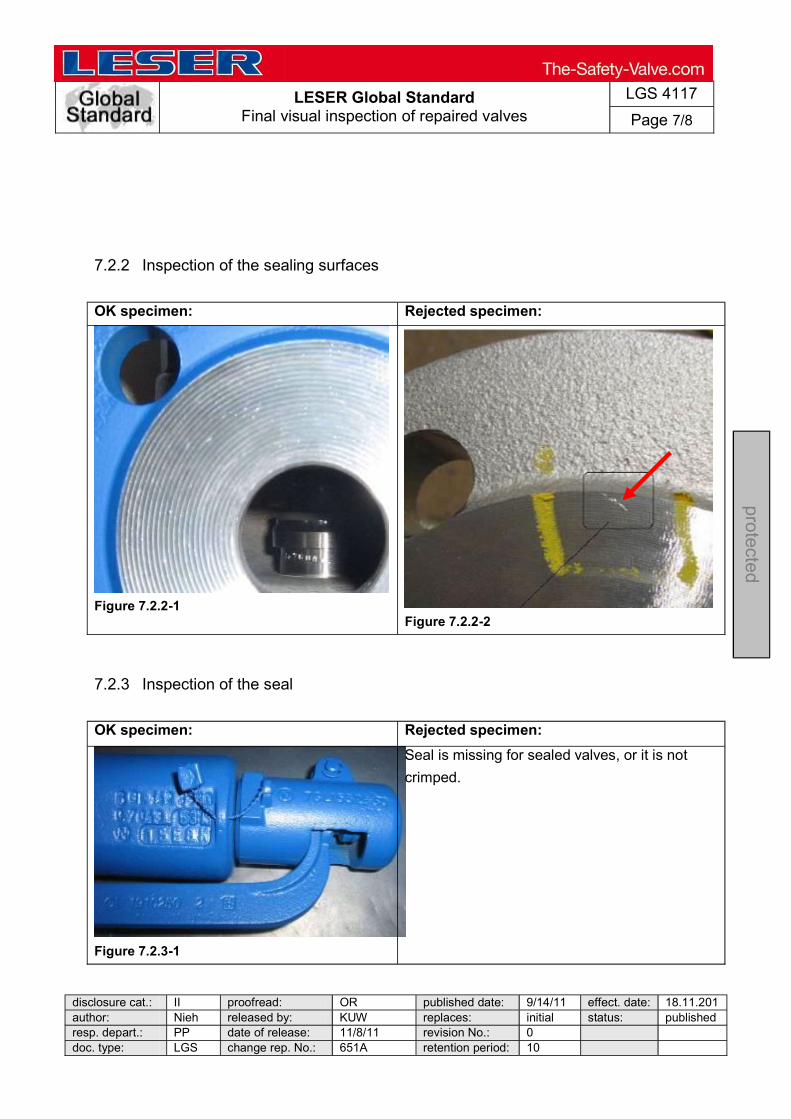
LESER Global Standard Final visual inspection of repaired valves
LGS 4117
Page 7/8
disclosure cat.: II proofread: OR published date: 9/14/11 effect. date: 18.11.201author: Nieh released by: KUW replaces: initial status: published resp. depart.: PP date of release: 11/8/11 revision No.: 0 doc. type: LGS change rep. No.: 651A retention period: 10
pro
tected
7.2.2 Inspection of the sealing surfaces
OK specimen: Rejected specimen:
Figure 7.2.2-1
Figure 7.2.2-2
7.2.3 Inspection of the seal
OK specimen: Rejected specimen:
Figure 7.2.3-1
Seal is missing for sealed valves, or it is not
crimped.
LESER Global Standard Final visual inspection of repaired valves
LGS 4117
Page 8/8
disclosure cat.: II proofread: OR published date: 9/14/11 effect. date: 18.11.201author: Nieh released by: KUW replaces: initial status: published resp. depart.: PP date of release: 11/8/11 revision No.: 0 doc. type: LGS change rep. No.: 651A retention period: 10
pro
tected
If the result of the inspection is okay, then the safety valve is sent for packaging and shipment.
7.3 Fault notification process
If the result of the inspection is not okay, then the fitting is sent to the fault
notification process that is to be determined. The final inspection is performed again after completion of the fault notification
process.

LESER Global Standard
Standardisation of Worldwide Warehouses Performing Leak Tests
LGS 4434
Page 1/39
disclosure cat.: II proofread: Kuw published date: 8/31/11 effect. date: 10/11 author: Kro released by: KUW replaces: 369-34 status: published resp. depart.: PP date of release: 9/15/11 revision No.: 0 doc. type: LGS change rep. No.: 00882A retention period: 10y.
pro
tecte
d
Content 1 Purpose ......................................................................................................... 1 2 Scope ............................................................................................................. 1 3 References .................................................................................................... 1 4 Introduction ................................................................................................... 2 5 Distinguishing features of valve designs ................................................... 6 6 Test description ............................................................................................ 7
1 Purpose
This LESER Global (LGS) describes professional application of the test procedures. It summarises the user information in a target-group-oriented manner.
2 Scope
This LGS applies to all members of the LESER quality cluster as defined in the global quality management manual.
3 References
LGS 0201, LGS 4430, LGS 4432, LGS 4433, LGS 4455, LGS 4431, The standards that are taken into consideration and applied by LESER for testing for leaks are established in LGS 0201. It also contains the
standard requirements for functional seal tightness (seat seal tightness) as well as increased seal tightness requirements of the functional seal tightness (seat seal
tightness) for gas-tight and non-gas-tight valves.
LESER Global Standard
Standardisation of Worldwide Warehouses Performing Leak Tests
LGS 4434
Page 2/39
disclosure cat.: II proofread: Kuw published date: 8/31/11 effect. date: 10/11 author: Kro released by: KUW replaces: 369-34 status: published resp. depart.: PP date of release: 9/15/11 revision No.: 0 doc. type: LGS change rep. No.: 00882A retention period: 10y.
pro
tecte
d
4 Introduction
Performing Leak Tests
The instructions for leak testing presented here describe the leak tests that are used for:
safety valves in a gas-tight design and safety valves in a non-gas-tight design
Information: Always keep the test manual at the assembly test bench. The manual must always be immediately available.
4.1 Improper use
Uses of the test equipment other than those given in this document are forbidden. Improper use may have adverse effects on the operation and consequently lead to inaccurate test results.
4.2 Informal measures
The operating manual must always be kept at the testing station and used in the event of any unclarity in the test procedure.

LESER Global Standard
Standardisation of Worldwide Warehouses Performing Leak Tests
LGS 4434
Page 3/39
disclosure cat.: II proofread: Kuw published date: 8/31/11 effect. date: 10/11 author: Kro released by: KUW replaces: 369-34 status: published resp. depart.: PP date of release: 9/15/11 revision No.: 0 doc. type: LGS change rep. No.: 00882A retention period: 10y.
pro
tecte
d

LESER Global Standard
Standardisation of Worldwide Warehouses Performing Leak Tests
LGS 4434
Page 4/39
disclosure cat.: II proofread: Kuw published date: 8/31/11 effect. date: 10/11 author: Kro released by: KUW replaces: 369-34 status: published resp. depart.: PP date of release: 9/15/11 revision No.: 0 doc. type: LGS change rep. No.: 00882A retention period: 10y.
pro
tecte
d
4.3 Operational materials and supplies
The operational materials and supplies given in the following must be ready for use in testing safety valves in a gas-tight and non-gas-tight design.
Leak detection spray Material no.: 0161.0000 Valve-specific test caps Material no.: not yet defined Valve-specific test plugs Material no.: 0172.0001
Fig. 1: Leak detection
Fig. 2: Test caps
Fig. 3: Test plugs
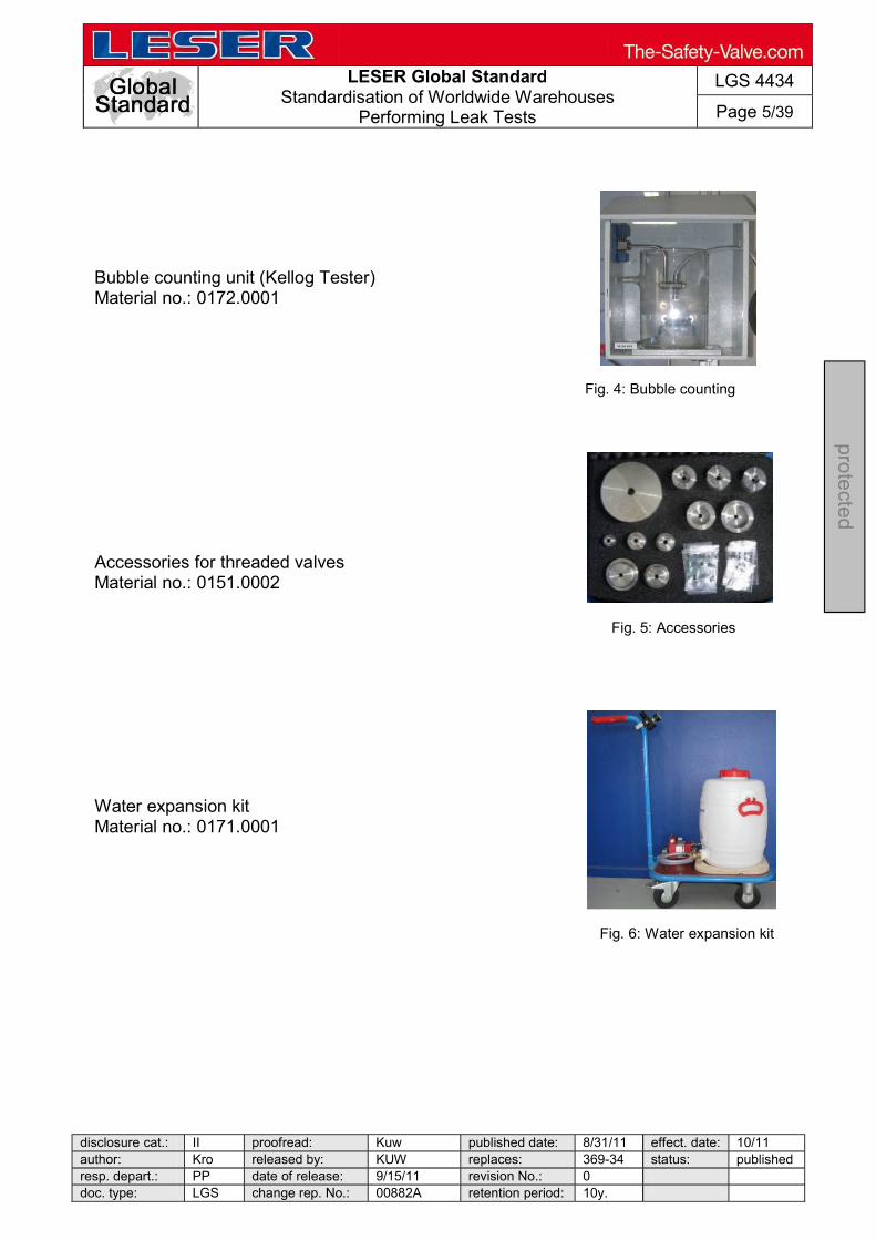
LESER Global Standard
Standardisation of Worldwide Warehouses Performing Leak Tests
LGS 4434
Page 5/39
disclosure cat.: II proofread: Kuw published date: 8/31/11 effect. date: 10/11 author: Kro released by: KUW replaces: 369-34 status: published resp. depart.: PP date of release: 9/15/11 revision No.: 0 doc. type: LGS change rep. No.: 00882A retention period: 10y.
pro
tecte
d
Fig. 4: Bubble counting unit
Fig. 5: Accessories
Bubble counting unit (Kellog Tester) Material no.: 0172.0001 Accessories for threaded valves Material no.: 0151.0002 Water expansion kit Material no.: 0171.0001
Fig. 6: Water expansion kit

LESER Global Standard
Standardisation of Worldwide Warehouses Performing Leak Tests
LGS 4434
Page 6/39
disclosure cat.: II proofread: Kuw published date: 8/31/11 effect. date: 10/11 author: Kro released by: KUW replaces: 369-34 status: publishedresp. depart.: PP date of release: 9/15/11 revision No.: 0 doc. type: LGS change rep. No.: 00882A retention period: 10y.
pro
tecte
d
5 Distinguishing features of valve designs
5.1 Safety valves in a gas-tight design
5.2 Safety valves in a non-gas-tight design
Closed bonnet
Closed lever (H4)
Flanged valves Threaded valves
Closed lever (H2)
Open bonnet
Flanged valves
Open lever (H3)

LESER Global Standard
Standardisation of Worldwide Warehouses Performing Leak Tests
LGS 4434
Page 7/39
disclosure cat.: II proofread: Kuw published date: 8/31/11 effect. date: 10/11 author: Kro released by: KUW replaces: 369-34 status: publishedresp. depart.: PP date of release: 9/15/11 revision No.: 0 doc. type: LGS change rep. No.: 00882A retention period: 10y.
pro
tecte
d
6 Test description
6.1 Safety valves in a gas-tight design
6.1.1 Flanged valves
Valve assembly: The safety valve is assembled and adjusted to the set pressure (see assembly documentation)
LWN 369.30 LWN 369.32 LWN 369.33
Testing of the functional seal tightness (seat seal tightness):
Testing of functional seal tightness with air Testing of functional seal tightness with water
1.
2.
Testing of the body seal: Testing of body seal tightness with air and application of a test liquid
Testing of the back seal: Testing of the interconnection points and the entire outlet area with the aid of air and by application of a test liquid.
3.
4.

LESER Global Standard
Standardisation of Worldwide Warehouses Performing Leak Tests
LGS 4434
Page 8/39
disclosure cat.: II proofread: Kuw published date: 8/31/11 effect. date: 10/11 author: Kro released by: KUW replaces: 369-34 status: publishedresp. depart.: PP date of release: 9/15/11 revision No.: 0 doc. type: LGS change rep. No.: 00882A retention period: 10y.
pro
tecte
d
1. Valve assembly:
The valve must be assembled according to the assembly documentation.
LGS 4430 LGS 4432 LGS 4433
2. Testing of the functional seal tightness with air and water: Test data for testing the functional seal tightness with air: The following test data must be observed when testing the functional seal tightness with gas-tight valves.
Test data Test characteristic Seal tightness between the seat and disc
Testing standard Number of bubbles per second, see LGS 0201, Attachment 1-3
Testing depth Every safety valve, 100% testing
Test medium Air
Test pressure 90% of set pressure
Testing device Bubble counting unit
Length of test Settling time of at least 10 seconds + testing time of 10 seconds Test data for testing the functional seal tightness with water: The following test data must be observed when testing the functional seal tightness with gas-tight valves.
Test data Test characteristic Seal tightness between the seat and disc
Testing standard Leak volume [cm³/min.] depending on the nominal diameter, see LGS 0201, TABLE 3
Testing depth Only at the request of the customer
Test medium Water
Test pressure 90% of set pressure
Testing device Water expansion kit, LGS 4455 Auxiliary materials:
Fig. 7: API gas-tight

LESER Global Standard
Standardisation of Worldwide Warehouses Performing Leak Tests
LGS 4434
Page 9/39
disclosure cat.: II proofread: Kuw published date: 8/31/11 effect. date: 10/11 author: Kro released by: KUW replaces: 369-34 status: published resp. depart.: PP date of release: 9/15/11 revision No.: 0 doc. type: LGS change rep. No.: 00882A retention period: 10y.
pro
tecte
d
The following auxiliary materials must be available when testing the functional seal tightness.
Auxiliary material Material no. Valve-specific test caps not yet defined Valve-specific test plugs 0172.0001 Bubble counting unit (Kellog tester) 0172.0001 Water expansion kit (on customer request)
0171.0001
Note: Tests with water are only permissible if the functional operation of the safety valve will not be adversely affected. A qualitative assessment of the leak volume as per LGS 0201 Table 3 cannot be conducted in a technically reasonable way. If a quantitative statement is requested (leak rate) on the functional seal tightness for safety valves that must be set with water, then the functional seal tightness of the valves will be tested with air after finishing the adjustment of the set pressure. Testing of the functional seal tightness with water can only represent a quantitative statement.

LESER Global Standard
Standardisation of Worldwide Warehouses Performing Leak Tests
LGS 4434
Page 10/39
disclosure cat.: II proofread: Kuw published date: 8/31/11 effect. date: 10/11 author: Kro released by: KUW replaces: 369-34 status: published resp. depart.: PP date of release: 9/15/11 revision No.: 0 doc. type: LGS change rep. No.: 00882A retention period: 10y.
pro
tecte
d
-10%
Testing of functional seal tightness with air Operations: a) The inlet side of the safety valve must be vertically
attached to the chuck.
Clean sealing surfaces are a basic requirement for accurate measurement results.
b) Select the correct test cap and then install
the gas-tight test cap on the bonnet.
Tighten the test cap finger-tight. No test air may escape.
c) Select a tapered end-plug to fit the outlet and insert
the test plug in the outlet flange of the safety valve. d) Trigger the safety valve once. Then lower the
pressure by 10% of the set pressure, or more precisely, by 0.35 bar (5.08 psi) for set pressures
Fig. 10: Install the test plug
Fig. 11: Test pressure reduction
Fig. 8: Clamped on valve
Fig. 9: Select the test cap
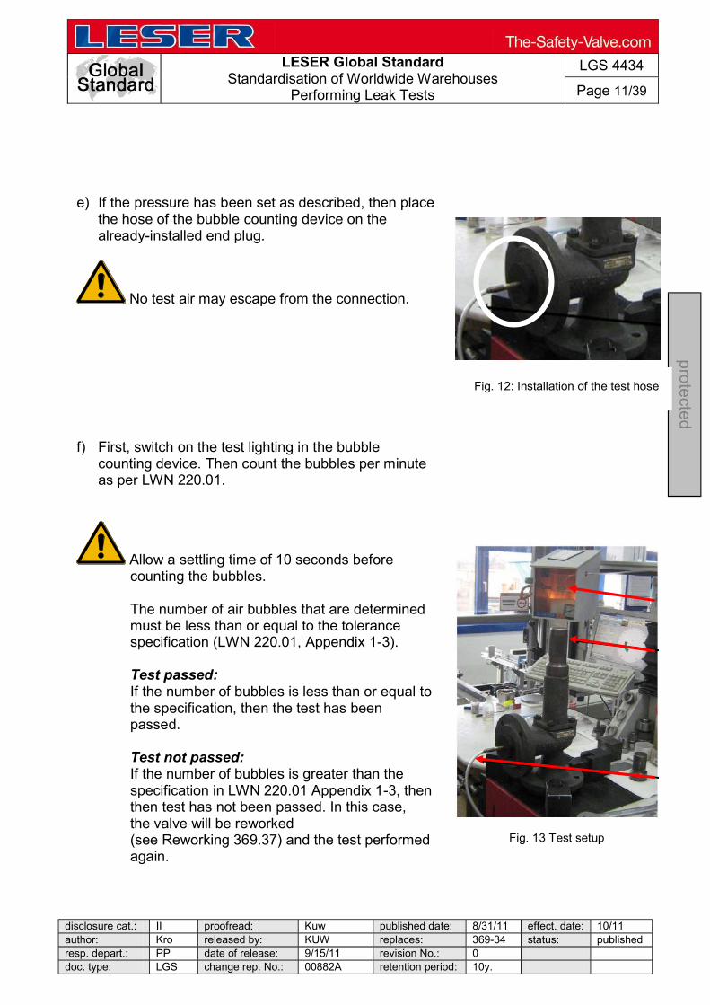
LESER Global Standard
Standardisation of Worldwide Warehouses Performing Leak Tests
LGS 4434
Page 11/39
disclosure cat.: II proofread: Kuw published date: 8/31/11 effect. date: 10/11 author: Kro released by: KUW replaces: 369-34 status: published resp. depart.: PP date of release: 9/15/11 revision No.: 0 doc. type: LGS change rep. No.: 00882A retention period: 10y.
pro
tecte
d
.
Fig. 12: Installation of the test hose
Fig. 13 Test setup
e) If the pressure has been set as described, then place the hose of the bubble counting device on the already-installed end plug.
No test air may escape from the connection. f) First, switch on the test lighting in the bubble
counting device. Then count the bubbles per minute as per LWN 220.01.
Allow a settling time of 10 seconds before counting the bubbles.
The number of air bubbles that are determined must be less than or equal to the tolerance specification (LWN 220.01, Appendix 1-3). Test passed: If the number of bubbles is less than or equal to the specification, then the test has been passed. Test not passed: If the number of bubbles is greater than the specification in LWN 220.01 Appendix 1-3, then then test has not been passed. In this case, the valve will be reworked (see Reworking 369.37) and the test performed again.
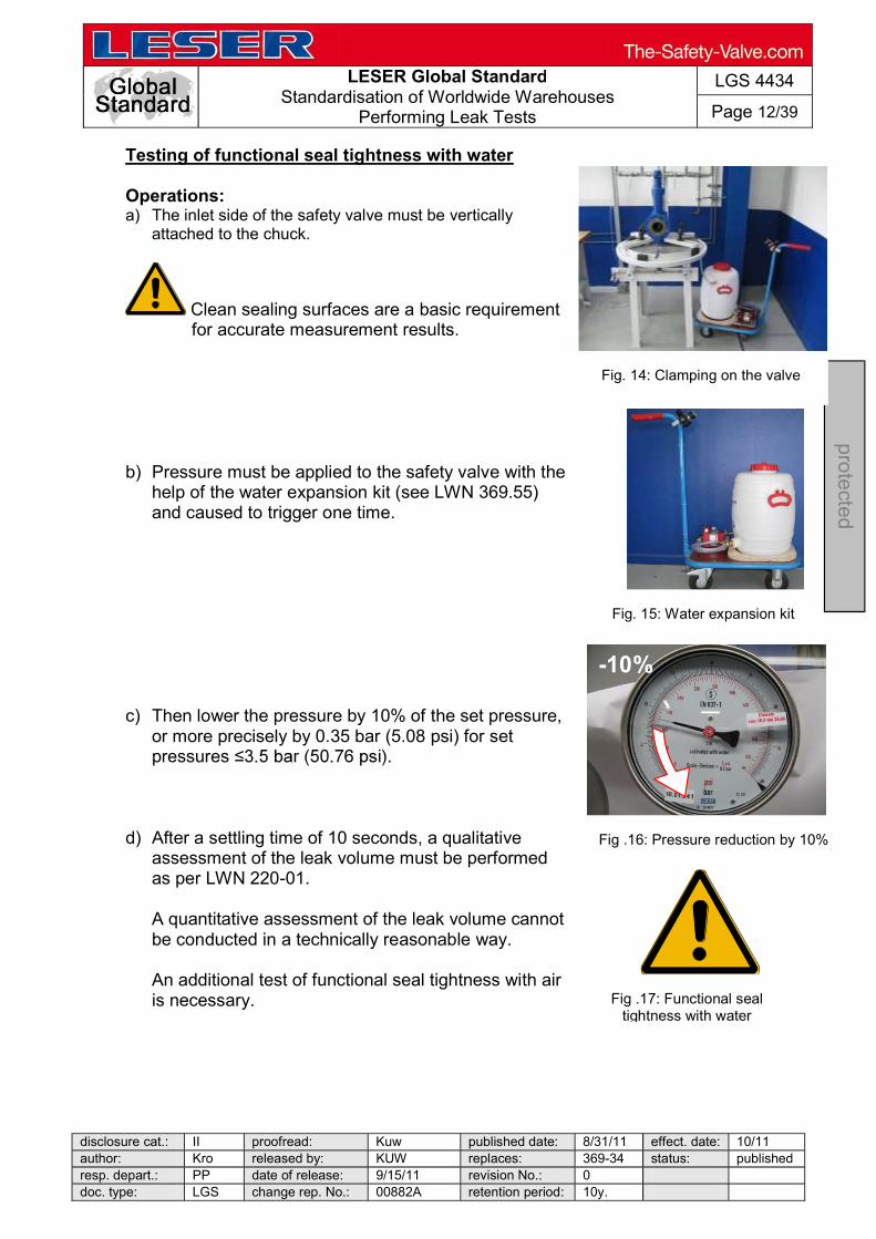
LESER Global Standard
Standardisation of Worldwide Warehouses Performing Leak Tests
LGS 4434
Page 12/39
disclosure cat.: II proofread: Kuw published date: 8/31/11 effect. date: 10/11 author: Kro released by: KUW replaces: 369-34 status: published resp. depart.: PP date of release: 9/15/11 revision No.: 0 doc. type: LGS change rep. No.: 00882A retention period: 10y.
pro
tecte
d
Testing of functional seal tightness with water Operations: a) The inlet side of the safety valve must be vertically
attached to the chuck.
Clean sealing surfaces are a basic requirement for accurate measurement results.
b) Pressure must be applied to the safety valve with the
help of the water expansion kit (see LWN 369.55) and caused to trigger one time.
c) Then lower the pressure by 10% of the set pressure,
or more precisely by 0.35 bar (5.08 psi) for set pressures
d) After a settling time of 10 seconds, a qualitative
assessment of the leak volume must be performed as per LWN 220-01.
A quantitative assessment of the leak volume cannot be conducted in a technically reasonable way. An additional test of functional seal tightness with air is necessary.
Fig. 14: Clamping on the valve
Fig. 15: Water expansion kit
-10%
Fig .16: Pressure reduction by 10%
Fig .17: Functional seal tightness with water

LESER Global Standard
Standardisation of Worldwide Warehouses Performing Leak Tests
LGS 4434
Page 13/39
disclosure cat.: II proofread: Kuw published date: 8/31/11 effect. date: 10/11 author: Kro released by: KUW replaces: 369-34 status: publishedresp. depart.: PP date of release: 9/15/11 revision No.: 0 doc. type: LGS change rep. No.: 00882A retention period: 10y.
pro
tecte
d
3. Testing body seal tightness: Test data: The following test data must be observed when testing the seal tightness of the pressure-bearing body.
Test data Test characteristic Testing the body seal tightness
Testing standard The valve must not have any visual signs of leaks
Testing depth Every safety valve with a cast body and a rolled-in seat, 100% testing
Test medium Air
Test pressure The test pressure is 6 bar (87.02 psi)
Testing device Application of test liquid
Length of test
Settling time of at least 10 seconds + 15 seconds up to DN 50 60 seconds up to DN 200 180 seconds above DN 200
Auxiliary materials: The following auxiliary materials must be provided when testing the body seal tightness.
Auxiliary material Material no. Leak detection spray 0161.0000
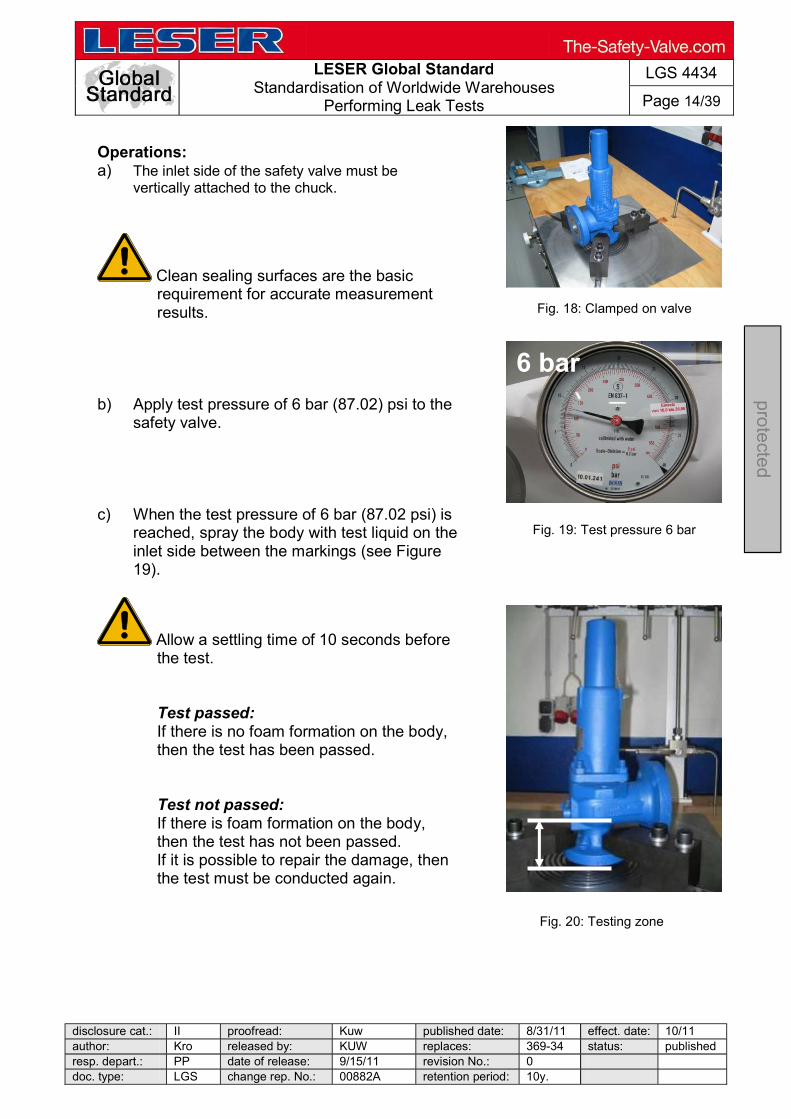
LESER Global Standard
Standardisation of Worldwide Warehouses Performing Leak Tests
LGS 4434
Page 14/39
disclosure cat.: II proofread: Kuw published date: 8/31/11 effect. date: 10/11 author: Kro released by: KUW replaces: 369-34 status: published resp. depart.: PP date of release: 9/15/11 revision No.: 0 doc. type: LGS change rep. No.: 00882A retention period: 10y.
pro
tecte
d
Fig. 20: Testing zone
6 bar
Fig. 19: Test pressure 6 bar
Operations: a) The inlet side of the safety valve must be
vertically attached to the chuck.
Clean sealing surfaces are the basic requirement for accurate measurement results.
b) Apply test pressure of 6 bar (87.02) psi to the
safety valve. c) When the test pressure of 6 bar (87.02 psi) is
reached, spray the body with test liquid on the inlet side between the markings (see Figure 19).
Allow a settling time of 10 seconds before the test.
Test passed: If there is no foam formation on the body, then the test has been passed.
Test not passed: If there is foam formation on the body, then the test has not been passed. If it is possible to repair the damage, then the test must be conducted again.
Fig. 18: Clamped on valve
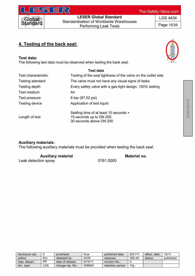
LESER Global Standard
Standardisation of Worldwide Warehouses Performing Leak Tests
LGS 4434
Page 15/39
disclosure cat.: II proofread: Kuw published date: 8/31/11 effect. date: 10/11 author: Kro released by: KUW replaces: 369-34 status: publishedresp. depart.: PP date of release: 9/15/11 revision No.: 0 doc. type: LGS change rep. No.: 00882A retention period: 10y.
pro
tecte
d
4. Testing of the back seal: Test data: The following test data must be observed when testing the back seal.
Test data Test characteristic Testing of the seal tightness of the valve on the outlet side
Testing standard The valve must not have any visual signs of leaks
Testing depth Every safety valve with a gas-tight design, 100% testing
Test medium Air
Test pressure 6 bar (87.02 psi)
Testing device Application of test liquid
Length of test Settling time of at least 10 seconds + 15 seconds up to DN 200 30 seconds above DN 200
Auxiliary materials: The following auxiliary materials must be provided when testing the back seal.
Auxiliary material Material no. Leak detection spray 0161.0000

LESER Global Standard
Standardisation of Worldwide Warehouses Performing Leak Tests
LGS 4434
Page 16/39
disclosure cat.: II proofread: Kuw published date: 8/31/11 effect. date: 10/11 author: Kro released by: KUW replaces: 369-34 status: published resp. depart.: PP date of release: 9/15/11 revision No.: 0 doc. type: LGS change rep. No.: 00882A retention period: 10y.
pro
tecte
d
6 bar
Operations: a) The outlet side of the safety valve must be
attached to the chuck. Clean sealing surfaces are the basic requirement for accurate measurement results.
b) Apply test pressure of 6 bar (87.02) psi to
the safety valve with the help of the hand-wheel needle valves.
c) When the test pressure of 6 bar (87.02 psi)
is reached, spray the body with test liquid on the outlet side between the markings (see Figure 23).
Allow a settling time of 10 seconds before testing.
Fig. 23: Testing zone
Fig. 22: Test pressure 6 bar
Fig.: 21: Clamping on the valve

LESER Global Standard
Standardisation of Worldwide Warehouses Performing Leak Tests
LGS 4434
Page 17/39
disclosure cat.: II proofread: Kuw published date: 8/31/11 effect. date: 10/11 author: Kro released by: KUW replaces: 369-34 status: published resp. depart.: PP date of release: 9/15/11 revision No.: 0 doc. type: LGS change rep. No.: 00882A retention period: 10y.
pro
tecte
d
Test passed: If there is no foam formation on the surface of the valve, then the test has been passed.
Test not passed: If there is foam formation on the surface of the valve, then the test has not been passed. If it is possible to repair the damage, then the test must be conducted again.
Fig. 24: Foam formation

LESER Global Standard
Standardisation of Worldwide Warehouses Performing Leak Tests
LGS 4434
Page 18/39
disclosure cat.: II proofread: Kuw published date: 8/31/11 effect. date: 10/11 author: Kro released by: KUW replaces: 369-34 status: publishedresp. depart.: PP date of release: 9/15/11 revision No.: 0 doc. type: LGS change rep. No.: 00882A retention period: 10y.
pro
tecte
d
6.1.2 Threaded valves
Figure 28
Valve assembly: The safety valve is assembled and adjusted to the set pressure (see assembly documentation)
LWN 369.31
Testing of functional seal tightness (seat seal tightness): Testing of the functional seal tightness with air Testing of the functional seal tightness with water
1.
2.
Testing body seal tightness: Testing of the body seal tightness with air and application of testing liquid
Testing of the back seal: Testing of the interconnection points and the entire outlet area with the help of air and by applying test liquid.
3.
4.
LESER Global Standard
Standardisation of Worldwide Warehouses Performing Leak Tests
LGS 4434
Page 19/39
disclosure cat.: II proofread: Kuw published date: 8/31/11 effect. date: 10/11 author: Kro released by: KUW replaces: 369-34 status: publishedresp. depart.: PP date of release: 9/15/11 revision No.: 0 doc. type: LGS change rep. No.: 00882A retention period: 10y.
pro
tecte
d
1. Valve assembly:
The valve must be assembled according to the assembly documentation.
LGS 4431
2. Testing of functional seal tightness with air and water: Test data for testing functional seal tightness with air: The following test data must be observed when testing the functional seal tightness with gas-tight valves.
Test data Test characteristic Seal tightness between the seat and disc
Testing standard Number of bubbles per second, see LGS 0201, Attachment 1-3
Testing depth Every safety valve, 100% testing
Test medium Air
Test pressure 90% of set pressure
Testing device Bubble counting unit
Length of test Settling time of at least 10 seconds + testing time of 10 seconds Test data for testing functional seal tightness with water: The following test data must be observed when testing the functional seal tightness with gas-tight valves.
Test data Test characteristic Seal tightness between the seat and disc
Testing standard Leak volume [cm³/min.] depending on the nominal diameter, see LGS 0201, TABLE 3
Testing depth Only at the request of the customer
Test medium Water
Test pressure 90% of set pressure
Testing device Water expansion kit, LGS 4455
Fig. 30: CP valve

LESER Global Standard
Standardisation of Worldwide Warehouses Performing Leak Tests
LGS 4434
Page 20/39
disclosure cat.: II proofread: Kuw published date: 8/31/11 effect. date: 10/11 author: Kro released by: KUW replaces: 369-34 status: published resp. depart.: PP date of release: 9/15/11 revision No.: 0 doc. type: LGS change rep. No.: 00882A retention period: 10y.
pro
tecte
d
Auxiliary materials: The following auxiliary materials must be provided when testing the seal tightness of the seat for threaded valves.
Auxiliary material Material no. Valve-specific test plugs
0172.0001
Accessories for threaded valves
0151.0002
Bubble counting unit (Kellog tester)
0172.0001
Water expansion kit (on customer request)
0171.0001
Note: Tests with water are only permissible if the functional operation of the safety valve will not be adversely affected. A quantitative assessment of the leak volume as per LGS 0201 Table 3 cannot be conducted in a technically reasonable way. If a quantitative statement is requested (leak rate) on the functional seal tightness for safety valves that must be set with water, then the functional seal tightness of the valves will be tested with air after finishing the adjustment of the set pressure. Testing of the functional seal tightness with water can only represent a quantitative statement.

LESER Global Standard
Standardisation of Worldwide Warehouses Performing Leak Tests
LGS 4434
Page 21/39
disclosure cat.: II proofread: Kuw published date: 8/31/11 effect. date: 10/11 author: Kro released by: KUW replaces: 369-34 status: published resp. depart.: PP date of release: 9/15/11 revision No.: 0 doc. type: LGS change rep. No.: 00882A retention period: 10y.
pro
tecte
d
Figure 31
Testing of functional seal tightness with air: Operations: a) The inlet side of the safety valve must be
vertically attached to the clamping device (see LWN 0121.0001).
Clean sealing surfaces are a basic requirement for accurate measurement results.
b) If the test is performed on the Manual Basic Test
Bench, then the valve must be attached to the test bench with the help of the accessories for threaded valves (material no.: 0151.0002) as shown in Figure 33.
Clean sealing surfaces are a basic requirement for accurate measurement results.
Fig. 33: Clamping on the Manual Basic Test Bench
Fig. 32: Clamping the valve in the clamping device
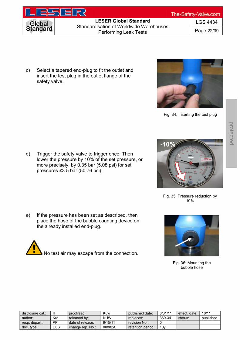
LESER Global Standard
Standardisation of Worldwide Warehouses Performing Leak Tests
LGS 4434
Page 22/39
disclosure cat.: II proofread: Kuw published date: 8/31/11 effect. date: 10/11 author: Kro released by: KUW replaces: 369-34 status: publishedresp. depart.: PP date of release: 9/15/11 revision No.: 0 doc. type: LGS change rep. No.: 00882A retention period: 10y.
pro
tecte
d
c) Select a tapered end-plug to fit the outlet and
insert the test plug in the outlet flange of the safety valve.
d) Trigger the safety valve to trigger once. Then
lower the pressure by 10% of the set pressure, or more precisely, by 0.35 bar (5.08 psi) for set
e) If the pressure has been set as described, then
place the hose of the bubble counting device on the already installed end-plug.
No test air may escape from the connection.
Fig. 34: Inserting the test plug
-10%
Fig. 35: Pressure reduction by 10%
Fig. 36: Mounting the bubble hose

LESER Global Standard
Standardisation of Worldwide Warehouses Performing Leak Tests
LGS 4434
Page 23/39
disclosure cat.: II proofread: Kuw published date: 8/31/11 effect. date: 10/11 author: Kro released by: KUW replaces: 369-34 status: published resp. depart.: PP date of release: 9/15/11 revision No.: 0 doc. type: LGS change rep. No.: 00882A retention period: 10y.
pro
tecte
d
f) First, switch on the test lighting in the bubble
counting device. Then count the bubbles per minute as per LWN 220.01.
Allow a settling time of 10 seconds before counting the bubbles.
The number of air bubbles that are determined must be less than or equal to the tolerance specification (LWN 220.01). Test passed: If the number of bubbles is less than or equal to the tolerance specification, the the test has been passed. Test not passed: If the number of bubbles is greater than the tolerance specification, then the test has not been passed. In this case, the valve will be reworked (see LWN 369.37) and the test performed again.
Fig. 37: Counting bubbles
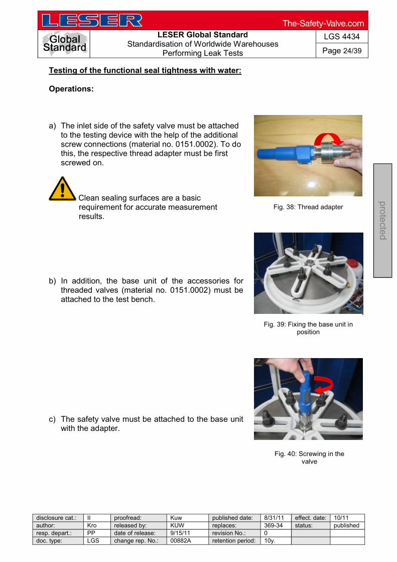
LESER Global Standard
Standardisation of Worldwide Warehouses Performing Leak Tests
LGS 4434
Page 24/39
disclosure cat.: II proofread: Kuw published date: 8/31/11 effect. date: 10/11 author: Kro released by: KUW replaces: 369-34 status: published resp. depart.: PP date of release: 9/15/11 revision No.: 0 doc. type: LGS change rep. No.: 00882A retention period: 10y.
pro
tecte
d
Testing of the functional seal tightness with water: Operations: a) The inlet side of the safety valve must be attached
to the testing device with the help of the additional screw connections (material no. 0151.0002). To do this, the respective thread adapter must be first screwed on.
Clean sealing surfaces are a basic requirement for accurate measurement results.
b) In addition, the base unit of the accessories for threaded valves (material no. 0151.0002) must be attached to the test bench.
c) The safety valve must be attached to the base unit
with the adapter.
Fig. 38: Thread adapter
Fig. 39: Fixing the base unit in position
Fig. 40: Screwing in the valve
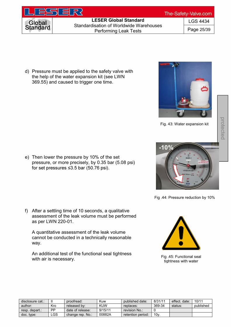
LESER Global Standard
Standardisation of Worldwide Warehouses Performing Leak Tests
LGS 4434
Page 25/39
disclosure cat.: II proofread: Kuw published date: 8/31/11 effect. date: 10/11 author: Kro released by: KUW replaces: 369-34 status: published resp. depart.: PP date of release: 9/15/11 revision No.: 0 doc. type: LGS change rep. No.: 00882A retention period: 10y.
pro
tecte
d
d) Pressure must be applied to the safety valve with
the help of the water expansion kit (see LWN 369.55) and caused to trigger one time.
e) Then lower the pressure by 10% of the set
pressure, or more precisely, by 0.35 bar (5.08 psi)
f) After a settling time of 10 seconds, a qualitative
assessment of the leak volume must be performed as per LWN 220-01.
A quantitative assessment of the leak volume cannot be conducted in a technically reasonable way. An additional test of the functional seal tightness with air is necessary.
Fig. 43: Water expansion kit
-10%
Fig .44: Pressure reduction by 10%
Fig .45: Functional seal tightness with water

LESER Global Standard
Standardisation of Worldwide Warehouses Performing Leak Tests
LGS 4434
Page 26/39
disclosure cat.: II proofread: Kuw published date: 8/31/11 effect. date: 10/11 author: Kro released by: KUW replaces: 369-34 status: publishedresp. depart.: PP date of release: 9/15/11 revision No.: 0 doc. type: LGS change rep. No.: 00882A retention period: 10y.
pro
tecte
d
3. Testing body seal tightness: Test data: The following test data must be observed when testing the body seal tightness.
Test data Test characteristic Testing of the seal tightness of the pressure-bearing body
Testing standard The body must not have any visual signs of leaks
Testing depth Every safety valve with a cast body and a rolled-in seat, 100% testing
Test medium Air
Test pressure 6 bar (87.02 psi)
Testing device Application of test liquid
Length of test Settling time of at least 10 seconds +
Auxiliary materials: The following auxiliary materials must be provided when testing the seal tightness of the pressure-bearing body for threaded valves.
Auxiliary material Material no. Leak detection spray
0161.0000
Accessories for threaded valves
0151.0002
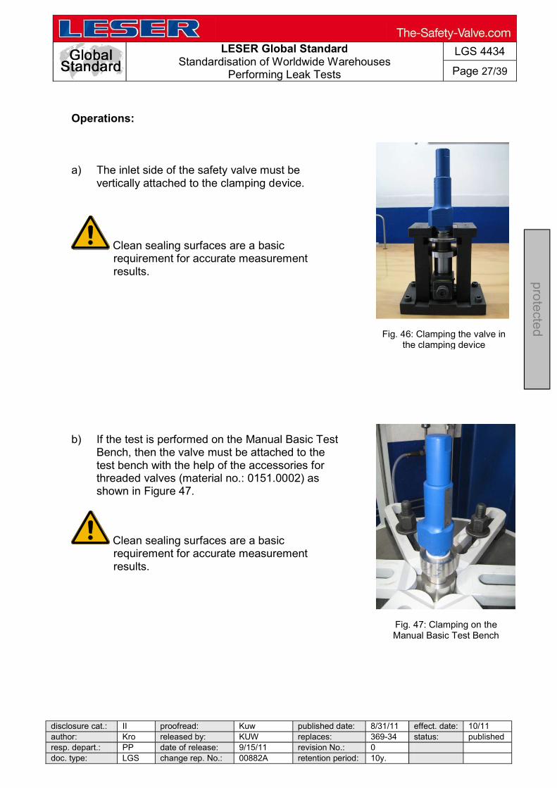
LESER Global Standard
Standardisation of Worldwide Warehouses Performing Leak Tests
LGS 4434
Page 27/39
disclosure cat.: II proofread: Kuw published date: 8/31/11 effect. date: 10/11 author: Kro released by: KUW replaces: 369-34 status: published resp. depart.: PP date of release: 9/15/11 revision No.: 0 doc. type: LGS change rep. No.: 00882A retention period: 10y.
pro
tecte
d
Operations: a) The inlet side of the safety valve must be
vertically attached to the clamping device.
Clean sealing surfaces are a basic requirement for accurate measurement results.
b) If the test is performed on the Manual Basic Test
Bench, then the valve must be attached to the test bench with the help of the accessories for threaded valves (material no.: 0151.0002) as shown in Figure 47.
Clean sealing surfaces are a basic requirement for accurate measurement results.
Fig. 47: Clamping on the Manual Basic Test Bench
Fig. 46: Clamping the valve in the clamping device

LESER Global Standard
Standardisation of Worldwide Warehouses Performing Leak Tests
LGS 4434
Page 28/39
disclosure cat.: II proofread: Kuw published date: 8/31/11 effect. date: 10/11 author: Kro released by: KUW replaces: 369-34 status: published resp. depart.: PP date of release: 9/15/11 revision No.: 0 doc. type: LGS change rep. No.: 00882A retention period: 10y.
pro
tecte
d
6 bar
Figure 50
c) Apply test pressure of 6 bar (87.02) psi to the safety valve.
d) When the test pressure of 6 bar (87.02 psi) is
reached, spray the body with test liquid on the inlet side between the markings (see Figure 49).
Allow a settling time of 10 seconds before the test.
Test passed: If there is no foam formation on the body, then the test has been passed. Test not passed: If there is foam formation on the body, then the test has not been passed. If it is possible to repair the damage, then the test must be conducted again.
Fig. 48: Test pressure 6 bar
Fig. 49: Testing zone
Fig. 51: Bubble formation
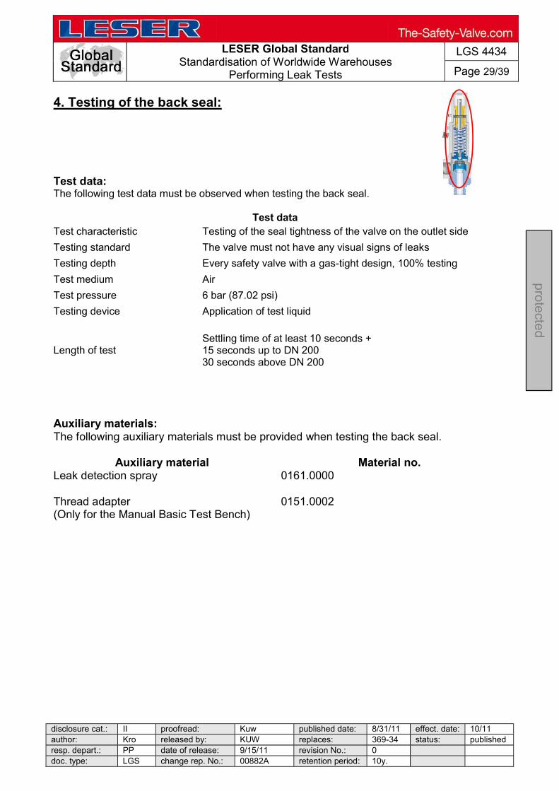
LESER Global Standard
Standardisation of Worldwide Warehouses Performing Leak Tests
LGS 4434
Page 29/39
disclosure cat.: II proofread: Kuw published date: 8/31/11 effect. date: 10/11 author: Kro released by: KUW replaces: 369-34 status: publishedresp. depart.: PP date of release: 9/15/11 revision No.: 0 doc. type: LGS change rep. No.: 00882A retention period: 10y.
pro
tecte
d
4. Testing of the back seal: Test data: The following test data must be observed when testing the back seal.
Test data Test characteristic Testing of the seal tightness of the valve on the outlet side
Testing standard The valve must not have any visual signs of leaks
Testing depth Every safety valve with a gas-tight design, 100% testing
Test medium Air
Test pressure 6 bar (87.02 psi)
Testing device Application of test liquid
Length of test Settling time of at least 10 seconds + 15 seconds up to DN 200 30 seconds above DN 200
Auxiliary materials: The following auxiliary materials must be provided when testing the back seal.
Auxiliary material Material no. Leak detection spray
0161.0000
Thread adapter (Only for the Manual Basic Test Bench)
0151.0002

LESER Global Standard
Standardisation of Worldwide Warehouses Performing Leak Tests
LGS 4434
Page 30/39
disclosure cat.: II proofread: Kuw published date: 8/31/11 effect. date: 10/11 author: Kro released by: KUW replaces: 369-34 status: published resp. depart.: PP date of release: 9/15/11 revision No.: 0 doc. type: LGS change rep. No.: 00882A retention period: 10y.
pro
tecte
d
Fig. 52: Screw in the thread adapter
Fig. 53: Screw the valve into the adapter
Fig. 54: marked testing zone
a) The outlet side of the safety valve must be attached to the testing device with the help of the additional screw connections. To do this, the respective thread adapter must be screwed on first.
Clean sealing surfaces are a basic requirement for accurate measurement results.
b) In addition, the base unit must be attached to the test bench. The safety valve must be attached to the base unit with the adapter.
c) The testing zone is marked in colour (see
Figure 54)

LESER Global Standard
Standardisation of Worldwide Warehouses Performing Leak Tests
LGS 4434
Page 31/39
disclosure cat.: II proofread: Kuw published date: 8/31/11 effect. date: 10/11 author: Kro released by: KUW replaces: 369-34 status: published resp. depart.: PP date of release: 9/15/11 revision No.: 0 doc. type: LGS change rep. No.: 00882A retention period: 10y.
pro
tecte
d
d) Test the marked zone with leak detection spray.
e) Count the bubbles per minute according to
LWN 220.01.
Allow a settling time of 10 seconds before counting the bubbles.
Fig. 55: Applying the
leak detection spray
Fig. 56: Foam formation
Test passed: If there is no foam formation on the body, then test has been passed. Test not passed: If there is foam formation on the body, then test has not been passed. If it is possible to repair the damage, then the test must be conducted again.

LESER Global Standard
Standardisation of Worldwide Warehouses Performing Leak Tests
LGS 4434
Page 32/39
disclosure cat.: II proofread: Kuw published date: 8/31/11 effect. date: 10/11 author: Kro released by: KUW replaces: 369-34 status: published resp. depart.: PP date of release: 9/15/11 revision No.: 0 doc. type: LGS change rep. No.: 00882A retention period: 10y.
pro
tecte
d

LESER Global Standard
Standardisation of Worldwide Warehouses Performing Leak Tests
LGS 4434
Page 33/39
disclosure cat.: II proofread: Kuw published date: 8/31/11 effect. date: 10/11 author: Kro released by: KUW replaces: 369-34 status: publishedresp. depart.: PP date of release: 9/15/11 revision No.: 0 doc. type: LGS change rep. No.: 00882A retention period: 10y.
pro
tecte
d
6.2 Safety valves in a non-gas-tight design:
6.2.1 Flanged valves
Valve assembly: The safety valve is assembled and adjusted to the set pressure (see assembly documentation)
LWN 369.30 LWN 369.32 LWN 369.33
Testing of the functional seal tightness: Testing of the functional seal tightness with air and application of testing liquid
Testing the body seal tightness: Testing of the body seal tightness with air and application of testing liquid
1.
2.
3.
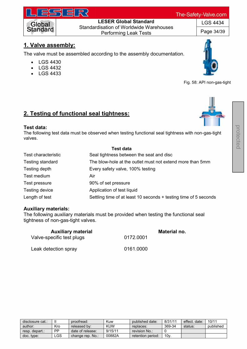
LESER Global Standard
Standardisation of Worldwide Warehouses Performing Leak Tests
LGS 4434
Page 34/39
disclosure cat.: II proofread: Kuw published date: 8/31/11 effect. date: 10/11 author: Kro released by: KUW replaces: 369-34 status: publishedresp. depart.: PP date of release: 9/15/11 revision No.: 0 doc. type: LGS change rep. No.: 00882A retention period: 10y.
pro
tecte
d
1. Valve assembly:
The valve must be assembled according to the assembly documentation.
LGS 4430 LGS 4432 LGS 4433
2. Testing of functional seal tightness: Test data: The following test data must be observed when testing functional seal tightness with non-gas-tight valves.
Test data Test characteristic Seal tightness between the seat and disc
Testing standard The blow-hole at the outlet must not extend more than 5mm
Testing depth Every safety valve, 100% testing
Test medium Air
Test pressure 90% of set pressure
Testing device Application of test liquid
Length of test Settling time of at least 10 seconds + testing time of 5 seconds Auxiliary materials: The following auxiliary materials must be provided when testing the functional seal tightness of non-gas-tight valves.
Auxiliary material Material no. Valve-specific test plugs
0172.0001
Leak detection spray
0161.0000
Fig. 58: API non-gas-tight
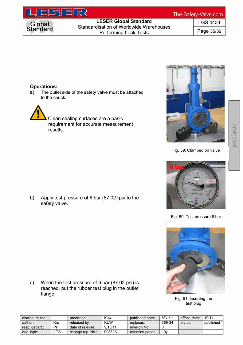
LESER Global Standard
Standardisation of Worldwide Warehouses Performing Leak Tests
LGS 4434
Page 35/39
disclosure cat.: II proofread: Kuw published date: 8/31/11 effect. date: 10/11 author: Kro released by: KUW replaces: 369-34 status: published resp. depart.: PP date of release: 9/15/11 revision No.: 0 doc. type: LGS change rep. No.: 00882A retention period: 10y.
pro
tecte
d
6 bar
Operations: a) The outlet side of the safety valve must be attached
to the chuck.
Clean sealing surfaces are a basic requirement for accurate measurement results.
b) Apply test pressure of 6 bar (87.02) psi to the
safety valve. c) When the test pressure of 6 bar (87.02 psi) is
reached, put the rubber test plug in the outlet flange.
Fig. 59: Clamped on valve
Fig. 60: Test pressure 6 bar
Fig. 61: Inserting the test plug
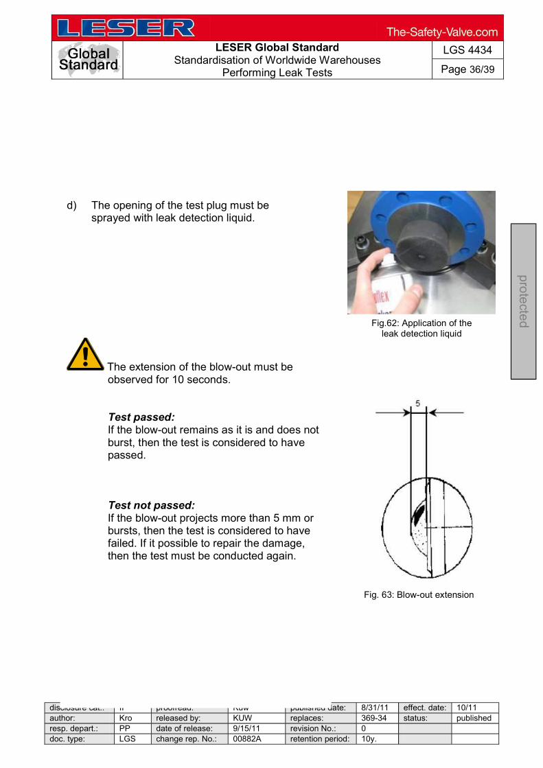
LESER Global Standard
Standardisation of Worldwide Warehouses Performing Leak Tests
LGS 4434
Page 36/39
disclosure cat.: II proofread: Kuw published date: 8/31/11 effect. date: 10/11 author: Kro released by: KUW replaces: 369-34 status: published resp. depart.: PP date of release: 9/15/11 revision No.: 0 doc. type: LGS change rep. No.: 00882A retention period: 10y.
pro
tecte
d
d) The opening of the test plug must be sprayed with leak detection liquid.
The extension of the blow-out must be observed for 10 seconds.
Test passed: If the blow-out remains as it is and does not burst, then the test is considered to have passed.
Test not passed: If the blow-out projects more than 5 mm or bursts, then the test is considered to have failed. If it possible to repair the damage, then the test must be conducted again.
Fig.62: Application of the leak detection liquid
Fig. 63: Blow-out extension

LESER Global Standard
Standardisation of Worldwide Warehouses Performing Leak Tests
LGS 4434
Page 37/39
disclosure cat.: II proofread: Kuw published date: 8/31/11 effect. date: 10/11 author: Kro released by: KUW replaces: 369-34 status: publishedresp. depart.: PP date of release: 9/15/11 revision No.: 0 doc. type: LGS change rep. No.: 00882A retention period: 10y.
pro
tecte
d
3. Testing body seal tightness: Test data: The following test data must be observed when testing the body seal tightness.
Test data Test characteristic Testing of the seal tightness of the pressure-bearing body
Testing standard The body must not have any visual signs of leaks
Testing depth Every safety valve with a cast body and a rolled-in seat, 100% testing
Test medium Air
Test pressure A test pressure must be chosen that is slightly lower than the set pressure.
Testing device Application of test liquid
Length of test
Settling time of at least 10 seconds + 15 seconds up to DN 50 60 seconds up to DN 200 180 seconds above DN 200
Auxiliary materials: The following auxiliary materials must be provided when testing body seal tightness for non-gas-tight valves.
Auxiliary material Material no. Leak detection spray
0161.0000
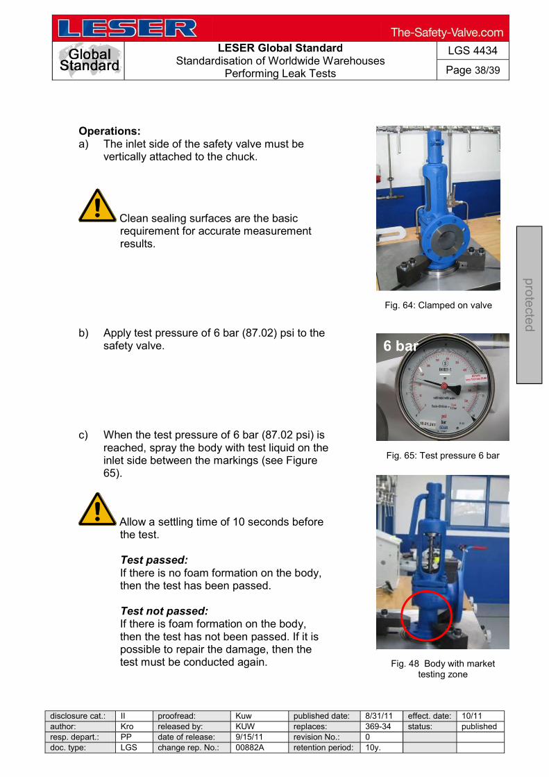
LESER Global Standard
Standardisation of Worldwide Warehouses Performing Leak Tests
LGS 4434
Page 38/39
disclosure cat.: II proofread: Kuw published date: 8/31/11 effect. date: 10/11 author: Kro released by: KUW replaces: 369-34 status: published resp. depart.: PP date of release: 9/15/11 revision No.: 0 doc. type: LGS change rep. No.: 00882A retention period: 10y.
pro
tecte
d
6 bar
Operations: a) The inlet side of the safety valve must be
vertically attached to the chuck.
Clean sealing surfaces are the basic requirement for accurate measurement results.
b) Apply test pressure of 6 bar (87.02) psi to the
safety valve. c) When the test pressure of 6 bar (87.02 psi) is
reached, spray the body with test liquid on the inlet side between the markings (see Figure 65).
Allow a settling time of 10 seconds before the test.
Test passed: If there is no foam formation on the body, then the test has been passed.
Test not passed: If there is foam formation on the body, then the test has not been passed. If it is possible to repair the damage, then the test must be conducted again.
Fig. 64: Clamped on valve
Fig. 65: Test pressure 6 bar
Fig. 48 Body with market testing zone
LESER Global Standard
Standardisation of Worldwide Warehouses Performing Leak Tests
LGS 4434
Page 39/39
disclosure cat.: II proofread: Kuw published date: 8/31/11 effect. date: 10/11 author: Kro released by: KUW replaces: 369-34 status: published resp. depart.: PP date of release: 9/15/11 revision No.: 0 doc. type: LGS change rep. No.: 00882A retention period: 10y.
pro
tecte
d

LESER Global Standard
Spare Parts
LGS 4138
Page 1/5
disclosure cat.: II proofread: SSt published date: 06/11/19 effect. date: 06/19
author: SE released by: KUW replaces: initial status: Published
resp. depart.: IE date of release: 06/11/19 revision No.: 1
doc. type: LGS change rep. No.: NA retention period: 10y.
pro
tec
ted
Content 1 Scope .............................................................................................................. 1 2 Application advices ....................................................................................... 2
3 Assembly and maintenance Instructions .................................................... 2 4 Relationship of spare part kits and safety valves ....................................... 2
5 Sample spare part kit ................................................................................... 2
1 Scope
This document supports the use of a spare part kit for LESER pilot operated safety valves.

LESER Global Standard
Spare Parts
LGS 4138
Page 2/5
disclosure cat.: II proofread: SSt published date: 06/11/19 effect. date: 06/19
author: SE released by: KUW replaces: initial status: Published
resp. depart.: IE date of release: 06/11/19 revision No.: 1
doc. type: LGS change rep. No.: NA retention period: 10y.
pro
tec
ted
2 Application advices
This spare part kit provides all spare parts which are recommended by LESER to be replaced during rework of a safety valve. LESER proposes to replace those parts generally – independent on the respective condition of the old part, because:
best possible performance of the reworked safety valve is ensured maintenance time is reduced due to omitted testing of old parts easy warehouse-handling of the complete kit instead of single parts
Depending on the condition, further components of the valve may have to be replaced.
3 Assembly and maintenance Instructions
For assembly and maintenance instructions please refer to the LESER website www.leser.com under “Maintenance”.
4 Relationship of spare part kits and safety valves
Article numbers of spare part kits for pilot valves and other valve sizes or pressure ratings can be found in the LESER pricelist. LESER Spare part Kits LID number: LID_DE 3700.30 – LID_DE 3700.65
5 Sample spare part kit
Main valve 1½”x3”with FFKM soft sealing flange rating class (inlet) 150-600
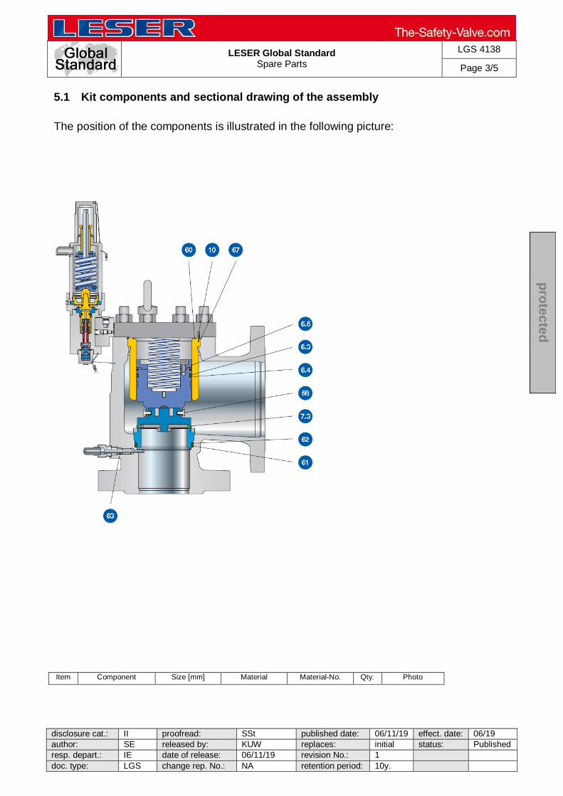
LESER Global Standard
Spare Parts
LGS 4138
Page 3/5
disclosure cat.: II proofread: SSt published date: 06/11/19 effect. date: 06/19
author: SE released by: KUW replaces: initial status: Published
resp. depart.: IE date of release: 06/11/19 revision No.: 1
doc. type: LGS change rep. No.: NA retention period: 10y.
pro
tec
ted
5.1 Kit components and sectional drawing of the assembly
The position of the components is illustrated in the following picture:
Item Component Size [mm] Material Material-No. Qty. Photo
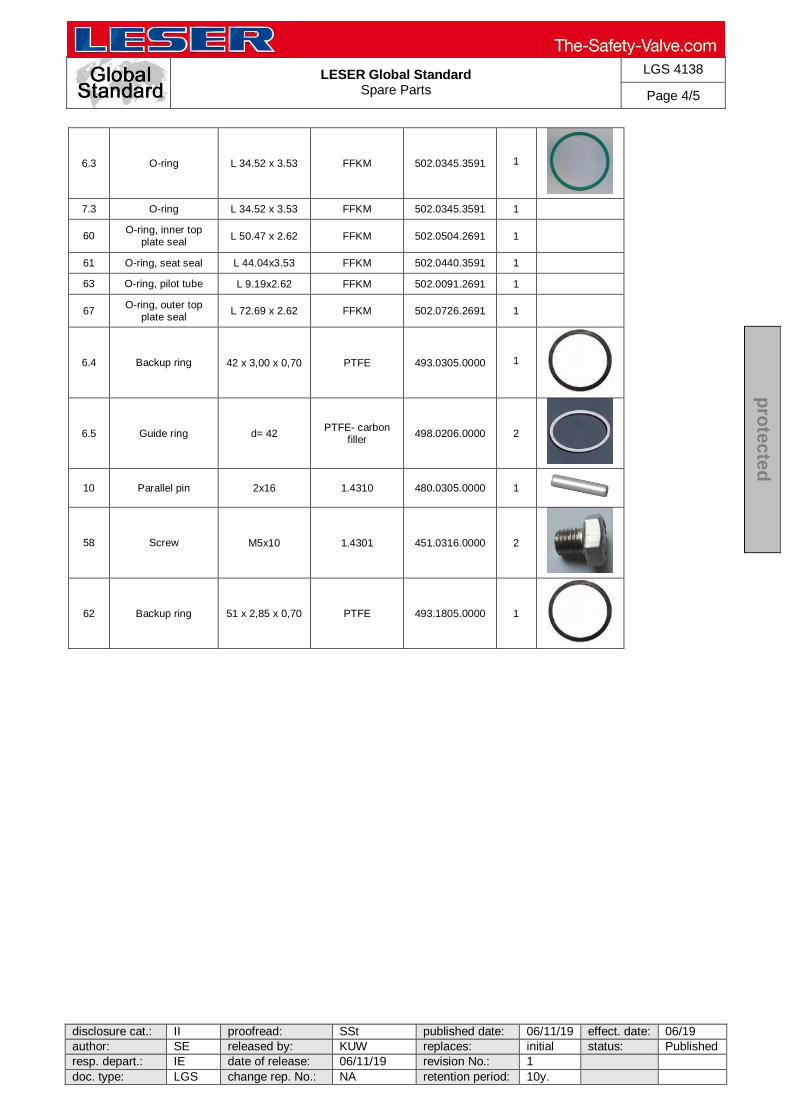
LESER Global Standard
Spare Parts
LGS 4138
Page 4/5
disclosure cat.: II proofread: SSt published date: 06/11/19 effect. date: 06/19
author: SE released by: KUW replaces: initial status: Published
resp. depart.: IE date of release: 06/11/19 revision No.: 1
doc. type: LGS change rep. No.: NA retention period: 10y.
pro
tec
ted
6.3 O-ring L 34.52 x 3.53 FFKM 502.0345.3591 1
7.3 O-ring L 34.52 x 3.53 FFKM 502.0345.3591 1
60 O-ring, inner top
plate seal L 50.47 x 2.62 FFKM 502.0504.2691 1
61 O-ring, seat seal L 44.04x3.53 FFKM 502.0440.3591 1
63 O-ring, pilot tube L 9.19x2.62 FFKM 502.0091.2691 1
67 O-ring, outer top
plate seal L 72.69 x 2.62 FFKM 502.0726.2691 1
6.4 Backup ring 42 x 3,00 x 0,70 PTFE 493.0305.0000 1
6.5 Guide ring d= 42 PTFE- carbon
filler 498.0206.0000 2
10 Parallel pin 2x16 1.4310 480.0305.0000 1
58 Screw M5x10 1.4301 451.0316.0000 2
62 Backup ring 51 x 2,85 x 0,70 PTFE 493.1805.0000 1

LESER Global Standard
Spare Parts
LGS 4138
Page 5/5
disclosure cat.: II proofread: SSt published date: 06/11/19 effect. date: 06/19
author: SE released by: KUW replaces: initial status: Published
resp. depart.: IE date of release: 06/11/19 revision No.: 1
doc. type: LGS change rep. No.: NA retention period: 10y.
pro
tec
ted
5.2 Lubricants
Item Component Size [mm] Material Material-No. Qty. Photo
General application – small packaging
Lubricant 22 x 47 Molykote D 333.0660.0001 1
Lubricant oil 22 x 61 Halocarbon oil
56S 333.0660.0016 1
General application – large packaging
Lubricant Molykote D 596.0094.0000 1kg
Lubricant oil Halocarbon oil
56S 596.0110.0000 2kg
Oxygen / Oil & grease free application – in Preparation.
Please refer to producer-websites for additional information (handling instruction, technical data sheet, safety data sheet etc.): Molykote: https://www.dupont.com
Halocarbon: https://www.halocarbon.com
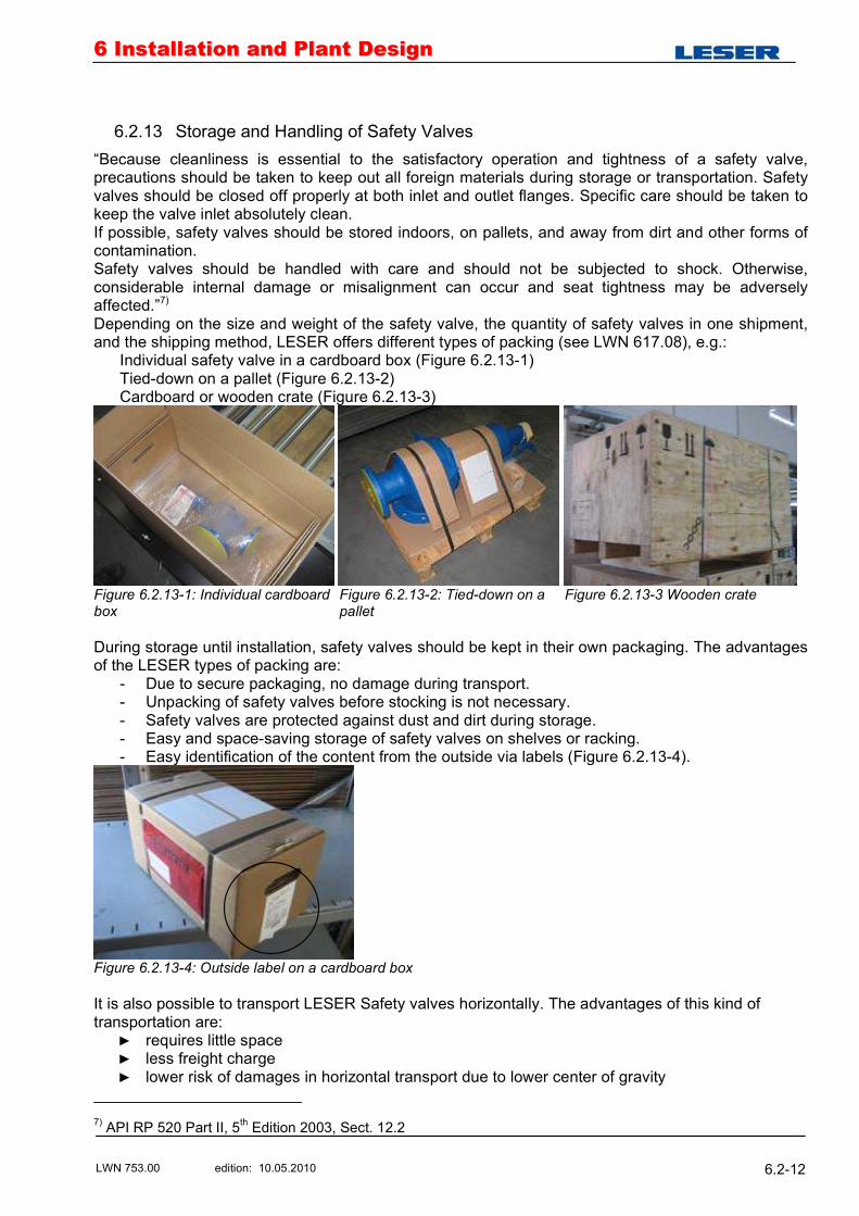
66 IInnssttaallllaattiioonn aanndd PPllaanntt DDeessiiggnn
LWN 753.00 edition: 10.05.2010 6.2-12
6.2.13 Storage and Handling of Safety Valves
�Because cleanliness is essential to the satisfactory operation and tightness of a safety valve, precautions should be taken to keep out all foreign materials during storage or transportation. Safety valves should be closed off properly at both inlet and outlet flanges. Specific care should be taken to keep the valve inlet absolutely clean. If possible, safety valves should be stored indoors, on pallets, and away from dirt and other forms of contamination. Safety valves should be handled with care and should not be subjected to shock. Otherwise, considerable internal damage or misalignment can occur and seat tightness may be adversely affected.�7) Depending on the size and weight of the safety valve, the quantity of safety valves in one shipment, and the shipping method, LESER offers different types of packing (see LWN 617.08), e.g.:
Individual safety valve in a cardboard box (Figure 6.2.13-1) Tied-down on a pallet (Figure 6.2.13-2) Cardboard or wooden crate (Figure 6.2.13-3)
Figure 6.2.13-1: Individual cardboard box
Figure 6.2.13-2: Tied-down on a pallet
Figure 6.2.13-3 Wooden crate
During storage until installation, safety valves should be kept in their own packaging. The advantages of the LESER types of packing are:
- Due to secure packaging, no damage during transport. - Unpacking of safety valves before stocking is not necessary. - Safety valves are protected against dust and dirt during storage. - Easy and space-saving storage of safety valves on shelves or racking. - Easy identification of the content from the outside via labels (Figure 6.2.13-4).
Figure 6.2.13-4: Outside label on a cardboard box It is also possible to transport LESER Safety valves horizontally. The advantages of this kind of transportation are:
requires little space less freight charge lower risk of damages in horizontal transport due to lower center of gravity
7) API RP 520 Part II, 5th Edition 2003, Sect. 12.2
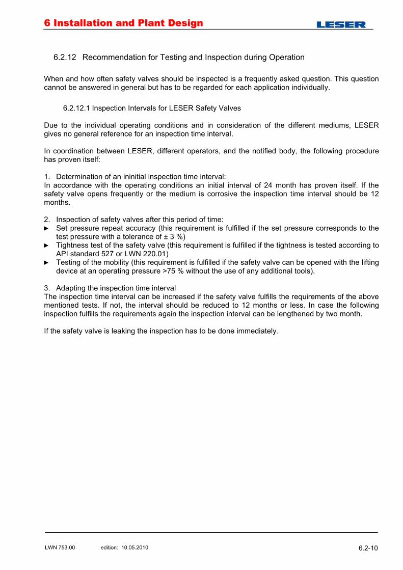
66 IInnssttaallllaattiioonn aanndd PPllaanntt DDeessiiggnn
LWN 753.00 edition: 10.05.2010 6.2-10
6.2.12 Recommendation for Testing and Inspection during Operation
When and how often safety valves should be inspected is a frequently asked question. This question cannot be answered in general but has to be regarded for each application individually.
6.2.12.1 Inspection Intervals for LESER Safety Valves Due to the individual operating conditions and in consideration of the different mediums, LESER gives no general reference for an inspection time interval. In coordination between LESER, different operators, and the notified body, the following procedure has proven itself: 1. Determination of an ininitial inspection time interval: In accordance with the operating conditions an initial interval of 24 month has proven itself. If the safety valve opens frequently or the medium is corrosive the inspection time interval should be 12 months. 2. Inspection of safety valves after this period of time:
Set pressure repeat accuracy (this requirement is fulfilled if the set pressure corresponds to the test pressure with a tolerance of ± 3 %)
Tightness test of the safety valve (this requirement is fulfilled if the tightness is tested according to API standard 527 or LWN 220.01)
Testing of the mobility (this requirement is fulfilled if the safety valve can be opened with the lifting device at an operating pressure >75 % without the use of any additional tools).
3. Adapting the inspection time interval The inspection time interval can be increased if the safety valve fulfills the requirements of the above mentioned tests. If not, the interval should be reduced to 12 months or less. In case the following inspection fulfills the requirements again the inspection interval can be lengthened by two month. If the safety valve is leaking the inspection has to be done immediately.
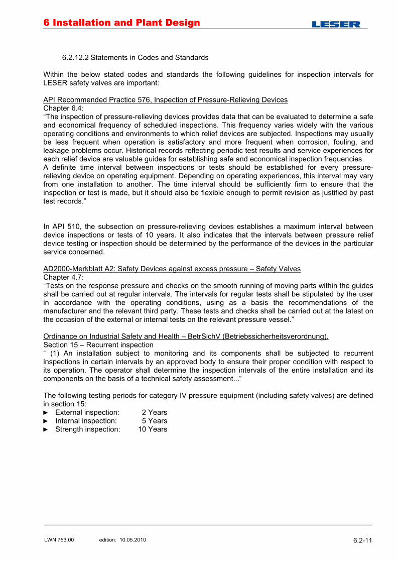
66 IInnssttaallllaattiioonn aanndd PPllaanntt DDeessiiggnn
LWN 753.00 edition: 10.05.2010 6.2-11
6.2.12.2 Statements in Codes and Standards Within the below stated codes and standards the following guidelines for inspection intervals for LESER safety valves are important: API Recommended Practice 576, Inspection of Pressure-Relieving Devices Chapter 6.4: �The inspection of pressure-relieving devices provides data that can be evaluated to determine a safe and economical frequency of scheduled inspections. This frequency varies widely with the various operating conditions and environments to which relief devices are subjected. Inspections may usually be less frequent when operation is satisfactory and more frequent when corrosion, fouling, and leakage problems occur. Historical records reflecting periodic test results and service experiences for each relief device are valuable guides for establishing safe and economical inspection frequencies. A definite time interval between inspections or tests should be established for every pressure-relieving device on operating equipment. Depending on operating experiences, this interval may vary from one installation to another. The time interval should be sufficiently firm to ensure that the inspection or test is made, but it should also be flexible enough to permit revision as justified by past test records.� In API 510, the subsection on pressure-relieving devices establishes a maximum interval between device inspections or tests of 10 years. It also indicates that the intervals between pressure relief device testing or inspection should be determined by the performance of the devices in the particular service concerned. AD2000-Merkblatt A2: Safety Devices against excess pressure � Safety Valves Chapter 4.7: �Tests on the response pressure and checks on the smooth running of moving parts within the guides shall be carried out at regular intervals. The intervals for regular tests shall be stipulated by the user in accordance with the operating conditions, using as a basis the recommendations of the manufacturer and the relevant third party. These tests and checks shall be carried out at the latest on the occasion of the external or internal tests on the relevant pressure vessel.� Ordinance on Industrial Safety and Health � BetrSichV (Betriebssicherheitsverordnung). Section 15 � Recurrent inspection � (1) An installation subject to monitoring and its components shall be subjected to recurrent inspections in certain intervals by an approved body to ensure their proper condition with respect to its operation. The operator shall determine the inspection intervals of the entire installation and its components on the basis of a technical safety assessment...� The following testing periods for category IV pressure equipment (including safety valves) are defined in section 15:
External inspection: 2 Years Internal inspection: 5 Years Strength inspection: 10 Years
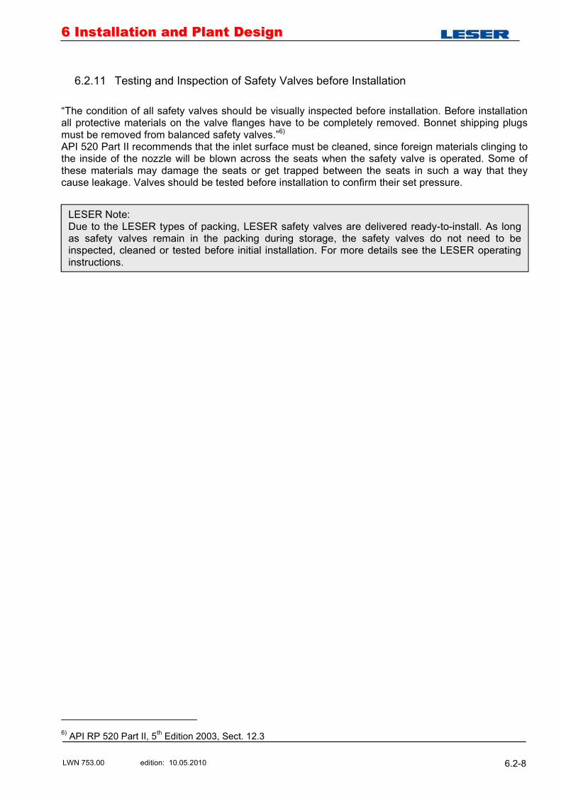
66 IInnssttaallllaattiioonn aanndd PPllaanntt DDeessiiggnn
LWN 753.00 edition: 10.05.2010 6.2-8
6.2.11 Testing and Inspection of Safety Valves before Installation
�The condition of all safety valves should be visually inspected before installation. Before installation all protective materials on the valve flanges have to be completely removed. Bonnet shipping plugs must be removed from balanced safety valves.�6) API 520 Part II recommends that the inlet surface must be cleaned, since foreign materials clinging to the inside of the nozzle will be blown across the seats when the safety valve is operated. Some of these materials may damage the seats or get trapped between the seats in such a way that they cause leakage. Valves should be tested before installation to confirm their set pressure.
6) API RP 520 Part II, 5th Edition 2003, Sect. 12.3
LESER Note: Due to the LESER types of packing, LESER safety valves are delivered ready-to-install. As long as safety valves remain in the packing during storage, the safety valves do not need to be inspected, cleaned or tested before initial installation. For more details see the LESER operating instructions.
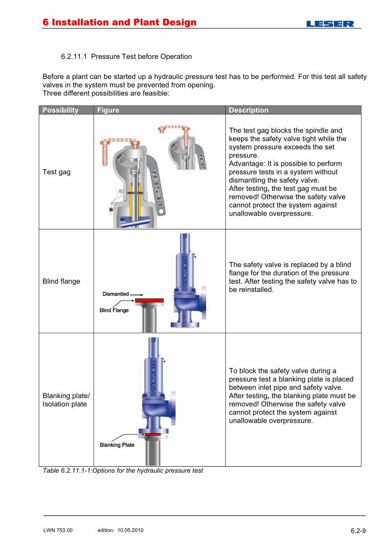
66 IInnssttaallllaattiioonn aanndd PPllaanntt DDeessiiggnn
LWN 753.00 edition: 10.05.2010 6.2-9
6.2.11.1 Pressure Test before Operation
Before a plant can be started up a hydraulic pressure test has to be performed. For this test all safety valves in the system must be prevented from opening. Three different possibilities are feasible: Possibility Figure Description
Test gag
The test gag blocks the spindle and keeps the safety valve tight while the system pressure exceeds the set pressure. Advantage: It is possible to perform pressure tests in a system without dismantling the safety valve. After testing, the test gag must be removed! Otherwise the safety valve cannot protect the system against unallowable overpressure.
Blind flange
Blind Flange
Dismantled
Blind Flange
Dismantled
The safety valve is replaced by a blind flange for the duration of the pressure test. After testing the safety valve has to be reinstalled.
Blanking plate/ Isolation plate
Blanking PlateBlanking Plate
To block the safety valve during a pressure test a blanking plate is placed between inlet pipe and safety valve. After testing, the blanking plate must be removed! Otherwise the safety valve cannot protect the system against unallowable overpressure.
Table 6.2.11.1-1:Options for the hydraulic pressure test