Vacuum Techniques and Analysis
54
Vacuum Techniques and Analysis BY BENJAMIN B. DAYTON Distillation Products, Inc., Rochester, New York CONTENTS Page 1. Introduction 334 2. The Measurement of Low Pressures 334 2.1. Range of Common Types of Vacuum Gauges 334 2.2. Absolute Gauges 334 2.3. Analysis of Gases with Nonabsolute Gauges 338 2.4. Measurement of Ultimate Vacuum 338 2.5. Theory of the Pirani and Thermocouple Gauges 339 2.6. The Construction and Calibration of McLeod Gauges 341 3. The Production of Low Pressures and the Transfer of Gases 344 3.1. Types of Pumps Available Commercially 344 3.2. Mercury Operated Pumps for Analytical Work 346 3.3. Pumping Water Vapor 348 3.4. Traps and Baffles 349 3.5. Assembly of Vacuum Systems 350 3.6. The Flow of Gases through Vacuum Pipe Lines and Absorption Tubes 350 3.7. The Circulation and Transfer of Gases with Diffusion Pumps and Toepler Pumps 352 3.8. Mercury Cut-Offs, Needle Valves and Stopcocks 353 3.9. Manostats 354 3.10. Outgassing and Leak Hunting 354 4. The Vacuum Fusion Method for the Analysis of Gaseous Elements in Metals 356 4.1. History and General Principles 356 4.2. Apparatus 357 4.3. Procedure 361 4.4. Limitations and Accuracy 361 4.5. Extension to Nonferrous Metals 362 5. Determination of Carbon by the Low-Pressure Combustion Method 362 5.1. General Principles 362 5.2. Apparatus and Procedure 363 5.3. Limitations and Accuracy 365 6. The Microanalysis of Gases at Low Pressures 366 6.1. Methods of Langmuir and Ryder 366 6.2. Methods of Prescott and Morrison 368 6.3. Low Temperature Method of N. R. Campbell 370 6.4. Other Methods and Special Techniques 372 333
-
Upload
khangminh22 -
Category
Documents
-
view
3 -
download
0
Transcript of Vacuum Techniques and Analysis

Vacuum Techniques and Analysis
B Y
B E N J A M I N B . D A Y T O N
Distillation Products, Inc., Rochester, New York
CONTENTS
Page 1. Introduction 334 2. The Measurement of Low Pressures 334
2.1. Range of Common Types of Vacuum Gauges 334 2.2. Absolute Gauges 334 2.3. Analysis of Gases with Nonabsolute Gauges 338 2.4. Measurement of Ultimate Vacuum 338 2.5. Theory of the Pirani and Thermocouple Gauges 339 2.6. The Construction and Calibration of McLeod Gauges 341
3. The Production of Low Pressures and the Transfer of Gases 344 3.1. Types of Pumps Available Commercially 344 3.2. Mercury Operated Pumps for Analytical Work 346 3.3. Pumping Water Vapor 348 3.4. Traps and Baffles 349 3.5. Assembly of Vacuum Systems 350 3.6. The Flow of Gases through Vacuum Pipe Lines and Absorption Tubes 350 3.7. The Circulation and Transfer of Gases with Diffusion Pumps and
Toepler Pumps 352 3.8. Mercury Cut-Offs, Needle Valves and Stopcocks 353 3.9. Manostats 354 3.10. Outgassing and Leak Hunting 354
4. The Vacuum Fusion Method for the Analysis of Gaseous Elements in Metals 356 4.1. History and General Principles 356 4.2. Apparatus 357 4.3. Procedure 361 4.4. Limitations and Accuracy 361 4.5. Extension to Nonferrous Metals 362
5. Determination of Carbon by the Low-Pressure Combustion Method 362 5.1. General Principles 362 5.2. Apparatus and Procedure 363 5.3. Limitations and Accuracy 365
6. The Microanalysis of Gases at Low Pressures 366 6.1. Methods of Langmuir and Ryder 366 6.2. Methods of Prescott and Morrison 368 6.3. Low Temperature Method of N. R. Campbell 370 6.4. Other Methods and Special Techniques 372
333
334 B E N J A M I N Β . D A Y T O N
Page 7. Analytical Molecular Distillation 373
7.1. Boiling Points and the Elimination Curve 373 7.2. The Cyclic Molecular Still 377 7.3. Future of the Elimination Curve Technique 378
8. Miscellaneous Vacuum Techniques Used in Analysis 378 References 380
1. I N T R O D U C T I O N
Several of the uni t operations described in other chapters involve vacuum techniques. I t is the purpose of this section to outline the proper methods of assembly and operation of vacuum systems constructed with the aid of modern diffusion p u m p s and uni t pa r t s available from manufacturers of scientific glass appa ra tus and vacuum equipment . This outline is supplemented by a fairly complete bibl iography on vacuum technique. As examples of typical vacuum systems certain uni t operations not described elsewhere in this volume will be briefly t rea ted .
2. T H E M E A S U R E M E N T O F L O W P R E S S U R E S
2.1. Range of Common Types of Vacuum Gauges
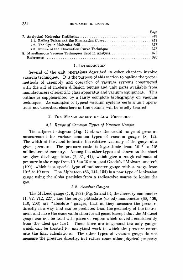
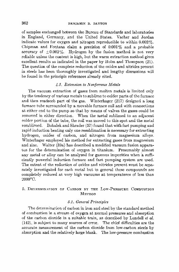
The adjacent diagram (Fig. 1) shows the useful range of pressure measurement for various common types of vacuum gauges (8, 12). The width of the band indicates the relative accuracy of the gauge a t a given pressure. The pressure scale is logarithmic from 10~ 8 to 10 2
millimeters of mercury. Among the other types not shown on the char t are glow discharge tubes (2, 31 , 41), which give a rough est imate of pressure in the range from 10~ 2 to 10 mm., and Gaede 's " Molvacuumeter " (100), which is a special type of radiometer gauge wi th a range from 10~ 7 to 10 mm. The Alphatron (83, 144, 154) is a new type of ionization gauge using the alpha particles from a radioactive source to ionize the gas.
2.2. Absolute Gauges
The McLeod gauge (1, 6, 193) (Fig. 2a and b) , the mercury manometer (1, 92, 212, 227), and the buty l ph tha la te (or oil) manometer (69, 109, 116, 203) are " a b s o l u t e " gauges, t h a t is, they measure the pressure directly in a way t h a t can be predicted from the geometry of the instrument and have the same calibration for all gases (except t h a t the McLeod gauge can not be used with gases or vapors which deviate considerably from the ideal gas law). These three are in general the only gauges which can be t rus ted for analytical work in which the pressure enters into t he final calculations. The other types of vacuum gauge do not measure the pressure directly, bu t ra ther some other physical proper ty

VACUUM TECHNIQUES AND ANALYSIS 335
of the gas such as the t ranspor t of hea t (Pirani and thermocouple gauges) or the ionization produced by a s t ream of electrons (ionization and Philips gauges). They are usually cal ibrated against a McLeod gauge on a manifold wi th cold t r aps to eliminate vapors , and the calibration
ΚΓ* i<rT ίο-· io-» ίο-4 ιο-* κτ* ιοΗ ιο° ιο' ιο*
I O N I Z A T I ON G A U G E I I
R A D I O M E T ER G A U G E i n L I Q U ID A I R
Q U A R TZ M E M B R A NE V I S C O S I TY GAUG E
L A R GE B U L B M C L E OD G A U G E
RADIOMETER ( K N U D S E N) G A U GE
i ι ι ι PIRANI GAUGE i n L I Q U ID A IR
P H I L I PS GAUG E |
I I I I Q U A R TZ F I B E R V I S C O S I TY G A U GE
ι ι ι ι I M E D I UM B U L B D O U B LE RANGE MCLEOD G A U GE
I Ί 1 1 ι , PIRANI GAUG E - C O M P E N S A T ED A T Z E R O THERMOCOUPLE G A U G E
ι ι A L P H A T R ON
P I R A NI G A U G E - C O M P E N S A T ED A T I MM .
S M A LL B U L B M C L E O D GAUGE
ι ι ι — ι — Γ B U T YL P H T H A L A TE M A N O M E T ER
ι ι — — B O U R D ON T Y P E G A U G E
MERCURY M A N O M E T ER
ιο"· iorT κτ· ιο'* tor4 ιο-' ίο-* lor1 ι ο 0 ισ' ισ β
MM. O F HG.
FIG. 1. Range of vacuum gauges.
factor is not t he same for all gases. T h e construction and calibration of McLeod gauges is described briefly in Section 2.6.
T h e Knudsen gauge is sometimes classed as an absolute gauge, bu t its calibration varies slightly wi th different gases because of differences in the accommodation coefficient and other factors (6, 38, 84, 97).

336 BENJAMIN Β. DAYTON
There are m a n y variat ions in the design of Knudsen gauges, which are also known as radiometer gauges (70, 96, 97, 121, 140) and Klumb and Schwarz (131) have described a t ype involving a suspended cylindrical vane system with a heater inside and liquid air cooling on the outside
FIG. 2. a) McLeod gauge (long form), b) McLeod gauge (short form).
capable of measuring to less t han 1 0 - 7 mm. of Hg. The principle of operation of Knudsen gauges is to move a suspended vane system by directing rapidly moving molecules, which have come in contact with a hot surface, against one side of the vanes while less energetic molecules coming from a cool surface impinge on the opposite side (132, 208).

VACUUM TECHNIQUES AND ANALYSIS 337
.1 . 2 . 3 . 4 . 5 . 6 . 7 . 8 . 9 1. 0
0 - . 7 5 M M. S C A L E R E A D I N G
a
FIG. 3 . a) Calibration of Pirani gauge, type PG-1 A, for various gases. (Distillation Products, Inc.) b) Calibration of Alphatron for various gases. (National Research Corp.)

338 BENJAMIN Β. DAYTON
2.3. Analysis of Gases with Nonabsolute Gauges
While it is possible to t ake advantage of the fact t h a t t he " n o n -abso lu t e " gauges have different calibration curves for various gases in analyzing simple gas mixtures, the accuracy obtainable is not very good unless extreme precautions are taken to eliminate variat ions in the calibration due to surface changes (accommodation coefficient, etc.)
presence of vapors from rubber or grease exposed in the system, fluctuations in the power supply, electrical leakage, electrical clean-up, e tc . While the s tandard types of ionization gauge (1, 6, 12, 86, 152) have been calibrated for various gases, this gauge is very unreliable because of clean-up effects (7, 56, 183). Calibrat ion curves for the Pirani gauge (Type PG-1A) and a radioactive-source ion gauge (Alphatron) for various gases are shown in Fig. 3a and b .
Corrosive gases react with the metal pa r t s of gauges and even relatively inert gases (e.g., carbon dioxide) m a y react with the incandescent filament of the ionization gauge. For analytical work with extremely corrosive gases such as bromine and chlorine a t low pressures the quar tz-fiber viscosity gauges (12, 38) are recommended since these can be made with all exposed surfaces of glass or quar tz (Fig. 4) .
2.4. Measurement of Ultimate Vacuum
I t is frequently necessary to evacuate a system to as low a pressure as possible (ul t imate vacuum) before admi t t ing a gas sample or reagent.
FIG. 4. Q u a r t z - f i b e r v i s c o s i t y g a u g e .

VACUUM TECHNIQUES AND ANALYSIS 339
Any of the gauges listed (except the McLeod) can be safely used t o determine when the system is sufficiently evacuated to permit filling with some gas a t a pressure over one hundred t imes the u l t imate vacuum t h a t can be measured wi th the gauge. However, while the usual Pirani gauge (6, 12, 31 , 68, 87) or thermocouple gauge (1, 148, 177) can be read down to 1 micron (0.001 mm.) of mercury or lower, these gauges are subject to zero shifts of as much as 2 or 3 microns or more and hence an ionization gauge is to be preferred for checking the u l t imate vacuum when gases are to be introduced a t pressures less t h a n 100 microns. The hot-filament t ype ionization gauge is used when pressures less t h a n 10~ 5 m m . of H g mus t be reached. The cold-cathode type , or Philips ionization gauge (165, 166, 167), has a shorter range as shown in Fig. 1 bu t has the advan tage t h a t there is no filament to burn out by accidental exposure to high pressures. Briefly, t he principle of the Philips gauge is the measurement of the current t r ansmi t t ed through a glow discharge in the gas excited by voltages of about 2000 volts in the presence of a magnetic field t h a t lengthens t he p a t h of the moving electrons, t hus maintaining the discharge to lower pressures t han are permi t ted in an ordinary Geissler tube .
The McLeod gauge does not show the presence of condensable vapors (95), and unless the system is completely protected a t all t imes wi th a liquid air or dry ice t r a p the t rue pressure in the system is frequently somewhat higher t h a n t h a t indicated by the McLeod gauge. In general, vapors from oils, " v a c u u m " greases, and rubber, and "v i r t u a l l e a k s " (38) due to frosted cold t raps are the chief sources of t rouble in a high vacuum system. These can always be detected by comparing the reading of a McLeod gauge and some other type of manometer which does not condense the vapors, or by other procedures such as plot t ing the r a t e of rise of pressure on a Pirani gauge when the system is isolated b y valves.
2.5. Theory of the Pirani and Thermocouple Gauges
The Pirani gauge consists of a Whea ts tone bridge circuit, Fig. 5, to indicate the change in resistance of a heated filament (of tungsten, p la t inum, nickel, or other stable meta l with large t empera tu re coefficient of resistance) mounted in a t ube a t t ached to the vacuum system. The thermocouple gauge, Fig. 6, measures changes in the t empera tu re of a heated filament by means of a thermocouple junct ion welded to t he center of the filament. The sensit ivity formula for bo th gauges depends on the na tu re of the gas through the factor
/ = 4.38 X 10 5 , — in c.g.s. units

340 BENJAMIN Β. DAYTON
where Cv is the specific heat of the gas a t constant volume per mole, R is the molar gas constant 8.315 Χ ΙΟ 7, Μ is the molecular weight of the gas, T' is the tempera ture of the gas a t the entrance to the Pirani or thermocouple tube , and a is the accommodat ion coefficient (128, 141). When the heat lost by conduction to the filament supports is negligible,
115 ν A. C
RECTIFIER TRANSF ORME R
FIG. 5. Pirani gauge circuit.
it can be shown (87) t h a t the ra te of change of filament tempera ture , T, with pressure, p, is
dT = —f(T - To) dp ±ekT*+fp
where To is the wall temperature , k the Bol tzmann radiat ion constant , and e is the tota l emissivity coefficient. At low pressures and high filament tempera tures the t e r m / p in the denominator can be neglected.
The change in filament tempera ture , dT, is measured as a change in resistance, dr, on the Pirani gauge and as a change in electromotive force, dV, on the thermocouple gauge. Since dr/dT = r 0a, where ro is t he filament resistance at Τ = 273° absolute and a is the linear t empera tu re coefficient of resistance, the ra te of change of filament resistance with pressure, dr/dp, is obtained by multiplying the above formula for dT/dp by r 0a. Similarly the ra te of change of E M F with pressure for the thermocouple gauge is obtained from dV/dp = (dV/dT) (dT/dp) where 7 = («ι - a2){T - To) + Ηβι - β 2)(Τ - To)2 is t he ordinary formula for the E M F produced by two metals with thermoelectric coefficients cti, ot 2, βi, and β 2 when the hot junction is a t t empera ture Τ and the cold junction a t t empera ture To. F rom these equat ions the response of t he

VACUUM TECHNIQUES AND ANALYSIS 341
gauges for any gas could be predicted except for the fact t h a t the emis-sivity, e, and accommodat ion coefficient, a, depend on the condition of the surface of the filament and mus t be determined experimental ly for each filament and each gas.
The sensitivity of the gauges can be increased by lowering the wall t empera tu re T0. Normal variat ions in room tempera tu re do not change the sensitivity by more t h a n a few per cent. For example, a t t he higher pressures, as To increases the filament t empera tu re Τ also increases so t h a t Τ — To is nearly constant (when the wa t t input to the filament is cons tant ) , and the quan t i t y (T - To)/Tz is only slightly decreased because Τ is in absolute uni ts .
In the Pirani gauge the main purpose of the compensat ing tube is to decrease the effect of variat ions in the bridge voltage and to prevent slight zero shifts with changes in room tempera ture . The gauge is usually operated by calibrating the galvanometer deflection in te rms of pressure. The galvanometer current is proport ional to the resistance change dr and also to the voltage drop across the filament. I t is inversely proport ional to a t e rm involving the resistances of the arms and the galvanometer resistance. The resistance of each a rm and the galvanometer resistance should all be approximately equal for maximum sensitivity.
2.6. The Construction and Calibration of McLeod Gauges
Since the McLeod gauge serves as the labora tory s tandard for calibrating other gauges and is the principal gauge used in analysis a t low pressures, the construction and calibration of this gauge deserves special a t ten t ion . Barr and Anhorn (1) have presented an excellent t r ea tmen t of this topic and the reader should also consult Dunoyer (6).
A method of sealing the top of the closed capillary by fusing a fitted plug of glass to obtain a flat closure is i l lustrated by Barr and Anhorn and was originally described by Ferguson (93). This reduces the zero error introduced by a rounded closure and also by bulbous t ips which make difficult t he ad jus tment of the top of the closed capillary to the zero line. Another impor tan t element of construction is a sharp cut-off which m a y be obtained by adding an orifice by means of a ring seal jus t above the opening to the side a rm as shown in Fig. 2a, and a t (F) in Fig. 2b, and also in the article by Bar r and Anhorn. This orifice also diverts air bubbles which sometimes rise with the mercury along the tube wall below the cut-off. For large sensitive McLeod gauges Rosenberg (180) recom-
MA r**: -0s
FIG. 6. Thermocouple gauge circuit.

342 BENJAMIN Β. DAYTON
mends grinding the capillaries with No. 600 Alundum to reduce the sticking of the mercury. Care must be taken, however, to avoid the use of coarse ha rd abrasives such as Carborundum, which m a y introduce deep pits in the capillary wall t h a t are not filled by the mercury because of surface tension. I t is also advisable to place a t r a p or splash bulb (E in Fig. 2b) between the McLeod gauge and the system to avoid forcing mercury into the system accidentally by expansion of air t rapped in the bulb a t higher pressure when the operator forgets to lower the mercury before reducing the pressure in the system. A t r a p for air bubbles should also be provided between the cut-off and the mercury reservoir, either by t he orifice ment ioned above or a bulb and ring seal as shown a t tached to the rubber tube and leveling bulb in Fig. 10 (which represents a Toepler p u m p bu t is similar in construction and operation to a McLeod gauge).
There are m a n y schemes for raising and lowering the mercury in a McLeod gauge (1, 201). The use of rubber tubing in any form is to be avoided because of contaminat ion of the mercury and bubbles formed by outgassing of the rubber. However, a leveling bulb and rubber connecting hose are frequently used on home-made gauges because of ease of construction. The tubing, if used, should be of pure gum rubber free of sulfur (6, 38). The short-form McLeod with reservoir is usually provided with a s tandard two-way stopcock to connect the reservoir to the a tmosphere or to a vacuum p u m p . However, some form of needle-valve control is advisable. An arrangement which the au thor has found to be very smooth acting is shown in Fig. 2b. I t consists of the Τ type of two-way stopcock (C) with a needle-valve on the vacuum line consisting of a short piece of rubber hose (A) through which a piece of No. 27 wire is th readed and pinched by a large screw clamp (B) while the air line is thro t t led by a short piece of broken thermometer tube (D) . By opening the Τ stopcock to bo th air and vacuum and adjusting the screw clamp the mercury can be raised, held s ta t ionary, or lowered a t will in a smooth and continuous fashion.
A method of calibrating McLeod gauges which are already assembled and installed on a vacuum system has been described by R a m a s w a m y (175). A calibrated bure t t e with open end dipping in mercury (or a low vapor pressure oil, such as Octoil) is a t tached to the system and a known volume of air a t atmospheric pressure admi t t ed from the bure t t e through a stopcock to a previously evacuated section of the appara tus including the McLeod gauge. The stopcock is opened only momentar i ly , the air in the bu re t t e being mainta ined a t atmospheric pressure by raising the mercury reservoir to keep the levels equal inside and outside the bure t te . The final pressure in the system is obtained b y measuring the drop in the

VACUUM TECHNIQUES AND ANALYSIS 343
level of the mercury meniscus below the cut-off of the McLeod, this fall being of the order of 5 or 6 cm. Boyle's law then gives a t once the volume of the isolated system. The system is then re-evacuated and a small volume of air a t atmospheric pressure admi t ted from a fine capillary tube of known diameter dipping in concentrated sulfuric acid unti l the pressure in the system is such t h a t on raising the mercury in the McLeod a reading can be obtained a t some point on the McLeod capillary. The compression rat io of the McLeod can then be computed by measuring the distance between the mercury and the top of the closed capillary and using the previously determined value of the system volume.
Usually, however, a McLeod is cal ibrated before installation on a vacuum system by direct determinat ion of the capillary cross section (πτ2) wi th a weighed mercury pellet and measurement of the to ta l bulb (and capillary) volume (V) by invert ing the glass head and filling with water or mercury to the cut-off. The " q u a d r a t i c " scale is prepared by plot t ing the equat ion log ρ = log (wr2/V) + 2 log Λ on 3 cycle log-log graph paper, a s traight line wi th slope equal to 2 being obtained. Suitable values of pressure (p) are listed wi th corresponding values of the distance (h) from the top of the closed capillary by reference to the graph, and a scale is then constructed lightly in pencil. After adjusting the pencil lines t o give uniformity of spacing where inspection reveals obvious errors, the scale is inked or etched on a suitable plate . Correction for a rounded top of the capillary should not be necessary if t he sealed-in plug method of closure is used; however, if necessary, then the zero line is shifted slightly wi thout moving the other lines unti l agreement is obtained wi th previously calibrated McLeods.
Some gauges have mult iple ranges, and usually the higher pressures are read from a " l i n e a r " scale prepared from the formula ρ = ν (ρ + h + x)/V where ν is the volume t rapped between the top of the closed capillary and the mercury when adjusted to a fixed reference dine h mm. below the top of this capillary, V is t he to ta l capillary and bulb volume to the cut-off, and χ is the algebraic distance above or below the top of the closed capillary to which the mercury climbs in the open capillary.
Since the vapor pressure of water a t room tempera ture is about 20 m m . of Hg, if t he par t ia l pressure of water vapor in the system is less t h a n 20v/V, t he water vapor will not be condensed out when the mercury is raised to the mark corresponding to v. If t he -pa r t i a l pressure is greater t h a n 20v/V, some vapor will condense as moisture in the top of the capillary and the par t ia l pressure of the remaining vapor in the volume ν will be 20 mm. I t is possible to surround the McLeod capillaries with a heat ba th , such as a steam-jacket , to increase the operating range for condensable vapors. Correction mus t then be made for the change

344 B E N J A M I N Β . D A Y T O N
in the densi ty of mercury with t empera ture and the change in pressure with t empera tu re according to Charles law. Although m a n y gases, such as N H 3 , CO2, SO2, C 2 H 2 , etc., deviate appreciably from Boyle's law, it can be shown (6, 12) t ha t the error from this cause is usually negligible. However, readings on chemically active gases, such as S 0 2 and N H 3 , are often meaningless because of the sorption of these gases by the walls of the gauge. The presence of moisture would presumably increase this effect. D a t a which illustrates the importance of eliminating all moisture and adsorbed gases from a McLeod by strong heat ing (360°C.) and prolonged pumping is given by Dunoyer (6). Gaede (99) observed t h a t oxygen a t tacks the mercury (presumably aided by static charges and formation of ozone as the mercury moves in the tubes) forming a scum on the surface t h a t causes sticking. This can be removed by gently heat ing the capillary. Incidentally, we have observed t h a t the stat ic charges developed by the moving mercury are sufficient to produce a red glow discharge near the meniscus when the McLeod is filled with neon gas.
Space l imitations prevent a discussion of the technique of constructing, installing, and operating the other types of vacuum gauges beyond the special points of importance in analytical work. If the gauge is purchased from an equipment manufacturer , adequate installation and operat ing instruct ions usually accompany the ins t rument .
3. T H E P R O D U C T I O N O F L O W P R E S S U R E S A N D T H E T R A N S F E R O F G A S E S
3.1. Types of Pumps Available Commercially
Except for large electron microscopes, large mass spectrometers, and a few other special types of appara tus requiring high speed pumps exhausting through por ts of 4-inch diameter or larger, most analytical procedures involve small systems with connecting tubes less t han 2 inches in diameter . The pumps m a y therefore be relatively small and inexpensive. There are several excellent small oil-sealed ro ta ry mechanical pumps available from different manufacturers and a great var ie ty of small oil or mercury diffusion pumps* for reducing the pressure below the limit obtainable by mechanical pumps (about 10~ 3 mm. Hg) .
Diffusion pumps consist of one or more jets of vapor from nozzles located in a pipe or tube through which air can diffuse easily only in the direction parallel to the vapor jet . The principle differs from t h a t of a
* Ace Glass, Inc., Vineland, N.J.; Central Scientific Co., Chicago, 111.; Distillation Products, Inc., Rochester, Ν.Υ.; Eck and Krebs, New York, N.Y.; James G. Biddle Co. (Leybold dealer), Philadelphia, Pa.; Kinney Manufacturing Co., Boston, Mass.; National Research Corporation, Boston, Mass.; Scientific Glass Apparatus Co., Bloomfield, N.J.; W. M. Welch Scientific Co., Chicago, 111.

VACUUM TECHNIQUES AND ANALYSIS 345
water aspirator or a s team ejector in t h a t the air is not entrained as a fluid by the formation of eddies in a boundary* layer between air and vapor, bu t ra ther each molecule of air wanders more or less accidentally into a rapidly diverging jet of vapor with no sharp boundary , so t h a t the molecule has a good chance of penet ra t ing into the denser, forward-moving pa r t of the vapor s t ream before it is driven to the wall and on towards the "fore v a c u u m . " A fore vacuum (or forepressure) of the order of 0.1 mm. is usually required to permit the vapor to flow from the
ΙΣ7 IO« TO9 ΙΟ« ΙΟ3 ο-* ΚΤ' Ι 10 100 ooo MILLIMETERS OF MERCURY
FIG. 7. Performance curves for typical pumps.
nozzle to the wall since the mercury or oil vapor in diffusion pumps is generated in small boilers a t pressures of 1 mm. or less and expands after leaving the nozzle. However, mercury and certain oils can be vaporized under high pressure (1 to 100 m m . of Hg) and ejected a t high densities through nozzles and diffusers similar t o those in s team ejectors, and under these conditions the air m a y be entrained by the ejector principle and passed into a fore vacuum of 0.5 to 50 m m . (depending on the boiler pressure).
There are seven distinct classes of vapor jet pumps, depending on the operat ing fluid and the range of pressure covered:
(1) S team ejectors, 760-1 mm. (2) Oil ejectors, 3 -10" 2 mm. (3) Oil booster pumps , 1 0 ^ - 5 X 10~ 5 m m . (4) Semifractionating oil diffusion pumps , 10~ 2 -5 "X 10~ 6 mm. (5) Frac t ionat ing oil diffusion pumps , 10~ 2 -10~ 7 mm. (6) Mercury pumps with ejector stages, 4 0 - 1 0 - 7 mm. (7) Mercury diffusion pumps, 1 0 _ 2 - 1 0 - 7 mm. Figure 7 shows the performance curves for some typical pumps .
Class (1) is i l lustrated by one stage (SI) , two stage (S2), th ree s tage (S3), and four stage (S4) s team ejectors. The long low curve (RP) is typical

346 BENJAMIN Β. DAYTON
of a large ro ta ry oil-sealed mechanical p u m p . The other curves represent typical oil vapor pumps . Class (2) corresponds to K B , class (3) to M B , class (4) to M C , and class (5) to V M F and G F . Ordinary mercury diffusion pumps , class (7), with a liquid air t r a p would have a performance curve similar to t h a t marked G F .
M a n y analytical procedures require only a small oil-sealed mechanical pump and a cold t r ap to keep the vapors of the sealing oil out of the system or to keep water vapor out of t he p u m p . However, ro ta ry
pumps can seldom produce a vacuum below 0.001 m m . in a complicated system because their efficiency is very low at pressures under 0.1 m m . They can easily produce t he necessary fore vacuum for diffusion pumps and the la t ter are indispensable for reaching the low pressures required in the analytical procedures described in this chapter . Oil diffusion p u m p s are more convenient to operate t han mercury pumps because they do not require a cold t r ap to reach low pressures and the vapor is not poisonous. However, t he oil vapor is subject t o decomposition and contaminat ion by foreign organic molecules, and only when employed in "fract ionat ing p u m p s " (115) can the oil be mainta ined sufficiently pure to permit vacuums of 10~ 6 mm. or less. Fract ionat ion is accomplished by part ia l condensation and refluxing and by circulating the condensed oil th rough a series of boilers, see Fig. 9, so t h a t the unwanted volatile const i tuents will be ejected in the first boilers and the best oil is fed to t he last jet from whence only the
least volatile vaporized fractions are exposed to the vacuum system. New p u m p fluids composed of certain silicone compounds are now available which are claimed t o be less subject t o decomposition t h a n purely organic fluids (214).
8.2. Mercury Operated Pumps for Analytical Work
Mercury diffusion pumps with two or more stages (nozzles in series) capable of compressing a gas from 0.01 m m . or less up to 10 or 20 m m . of H g are t o be preferred for handling gases to be analyzed (Fig. 8) .
FIG. 8. Mercury pump.

VACUUM TECHNIQUES AND ANALYSIS 347
Oil diffusion pumps (Fig. 9) are excellent for producing a high vacuum without cold t raps , bu t in general t hey can not be used to store t he gas
FIG. 9. Two-stage fractionating oil diffusion pump. (Distillation Products, Inc.)
by compressing it into reservoirs a t pressures much above 1 m m . of Hg because the required oil vapor t empera tu re would exceed the decomposition t empera tu re a t those pressures. The forepressure against which a diffusion p u m p will operate with full efficiency is in general about equal to one half of the boiler pressure, and the la t ter can be es t imated by measuring the boiler t emperatu re and referring to the vapor pressure curves supplied by the manufacturer of the p u m p fluid. The boiler pressure can be varied by changing the heater input and is roughly a linear function of wat tage .
For very accurate quan t i t a t ive transfer of a gas from one reservoir to another a Toepler pump , or various modifications described below, must be used. The Toepler p u m p can also be used to obtain a high vacuum bu t is seldom used for this purpose since the advent of high speed diffusion pumps . The only good quan t i ta t ive method of removing the whole of a gas sample for storage a t atmospheric pressure is the use of a Toepler p u m p discharging through a long vertical capillary tube extending under a bot t le of mercury
FIG. 10. Toepler pump and collecting tube.

348 BENJAMIN Β. DAYTON
inverted in a dish of mercury (Fig. 10). An au tomat ic Toepler p u m p and control circuit designed by Prescot t and Morrison (32) is shown in Fig. 11. The mercury is lifted by compressed air admi t ted through a two-way solenoid valve to the reservoir. When the mercury overflows into the capillary a t the top of the pump , the valve switches the reservoir from the compressed air line to the a tmosphere and the mercury
FIG. 11. Automatic Toepler pump.
falls. The valve is operated by a polarized telegraph relay controlled by a vacuum tube circuit and three contacts sealed into the pump .
8.8. Pumping Water Vapor
Water vapor can be passed directly through an oil or mercury diffusion p u m p wi thout spoiling the pumping action, bu t the water vapor is condensed in a mechanical p u m p and after a short t ime enough will accumulate in the oil used to seal the pumps so t h a t the part ia l pressure of water vapor on the vacuum side can not be reduced below a few ten ths of a millimeter. Most types of diffusion p u m p discharging into a mechanical p u m p which has been sa tura ted with water vapor will not operate efficiently since they usually require a forepressure of less t h a n 0.2 m m . Hence the water vapor should be condensed out by a dry ice t r a p placed between the diffusion p u m p and the mechanical p u m p .

VACUUM TECHNIQUES AND ANALYSIS 349
3.4. Traps and Baffles
Traps are necessary on the high-vacuum side of mercury diffusion pumps when the presence of mercury vapor within the system is not desirable. A t r ap cooled by liquid air is necessary for pressures of 10~ 7
mm. or less. Although the vapor pressure of mercury a t dry-ice temperatures is about 10~ 9 mm., experience has shown t h a t pressures less t h a n 10~ 6 mm. are difficult to achieve with dry-ice t raps designed to have low resistance to gas flow. The t r a p m a y be part ial ly filled with gold
J l
FIG. 12. Three types of cold traps.
foil or an alloy of one par t sodium to two pa r t s potassium (94) which acts as a " g e t t e r " for mercury vapor. In general no t r a p is required with oil diffusion pumps since the vapor pressure of the common p u m p fluids is less t h a n 10~ 5 mm. H g a t room tempera ture , and by using a fractionating p u m p and a water cooled baffle pressures of the order of 10~ 7 m m . H g can be obtained with fluids such as Octoil-S wi thout a cold t r ap . However, certain equipment , such as the mass spectrometer, m a y be sensitive to traces of oil vapor and hence a cold t r a p should be used.
Wi th the aid of a dry-ice t r a p a vacuum of 10~ 4 mm. or less can be produced wi th a good ro tary oil-sealed mechanical pump, bu t wi thout a t r a p a pressure of 0.005 mm. or higher is usually indicated by a Pirani gauge because of the vapor of the sealing oil. I t is not uncommon to overlook the presence of this vapor when a McLeod gauge is t he only manometer used. Dry-ice and acetone will cool a t r ap to about — 7 8 ° C , bu t it should be noted t h a t the vapor pressure of ice is about 10~ 3 mm. at this t empera ture . If pressures below 10~ 3 mm. are desired, the water vapor should be allowed to pass un t rapped through a diffusion p u m p or else t rapped with liquid air. Traps mus t be defrosted when it becomes evident t h a t they are giving rise to "v i r t ua l l e a k s " (38).
Three s tandard forms of cold t r a p are i l lustrated in Fig. 12a, b , and c. Type a can be easily defrosted by lowering the Dewar flask and gently

350 BENJAMIN Β. DAYTON
flaming the U tube , bu t to defrost type b the refrigerant must be scooped or blown out of the reservoir, and type c is even more troublesome since frost collected on the inner tube is only slowly removed by flaming the outer tube , unless t he pressure is allowed to rise above 100 microns. Type c is preferred when the vapor condenses to form a large quan t i ty of liquid a t t he bo t tom of the t r ap .
For further information on cold t raps , charcoal t raps , and baffles consult references (1, 25, 35a, 38, 47a, 61, 129, 150, 151, 153, 195).
8.5. Assembly of Vacuum Systems
The assembly of the type of vacuum system commonly used in analysis usually involves simple glass blowing such as t he bending and joining of Pyrex glass tubes of less t han 20 mm. diameter . However, the system is often divided into uni ts joined by s tandard taper or spherical ground glass joints, or by the introduction of rubber tubing, tape , or gaskets. S tandard taper joints and stopcocks should be lapped together with a 900 mesh grit. Spherical joints are best sealed together with a thin film of vacuum wax (e.g., Apiezon W, Dekhot insky, Picein, M y v a -wax). If grease is used, the joint should not be left unguarded overnight but should be protected with vacuum paint (glyptal) and always held together with the s tandard clamps for spherical joints. The silicone high-vacuum greases are recommended for stopcocks. Tests on s topcocks ro ta ted a t intervals in a vacuum line have shown t h a t the greatest number of tu rns before " f reez ing" can be achieved with this type of grease, and the viscosity is less affected by changes in tempera ture .
The vapors and occluded gas escaping from rubber and " v a c u u m " grease are frequently the limiting factor in a t ta in ing a low pressure. Wherever possible joints should be made by fusing the glass or using a good vacuum wax applied carefully to avoid decomposition during melting. Fur the r information on technique in making joints and seals is given in references (1, 6, 11, 12, 25, 38, 44, 85, 179, 181, 210).
3.6. The Flow of Gases through Vacuum Pipe Lines and Absorption Tubes
The t ime required to evacuate the system and also to transfer gas a t low pressures from one par t of the system to another depends on the ra te of flow of gases a t low pressures through the connecting tubes and absorption tubes. At pressures below 1 mm. this ra te of flow is usually the limiting factor because of the practice of using long narrow tubes whose conductance is much less t h a n the speed of t he pumps a t these pressures. If the conductance of a tube is U and the p u m p speed is S0, then the net pumping speed available a t the end of the connecting tube will be given by S in the formula

VACUUM TECHNIQUES AND ANALYSIS 351
providing the p u m p speed, So, is measured under conditions consistent with t he definition of U (75a).
The p u m p speed So is usually given in the manufacturer ' s catalog in te rms of liters per second or cubic centimeters per second, or some other uni ts of volume and t ime for all pressures in the operat ing range. The conductance U m a y be computed from the geometry of t he tube , the mean pressure, and the physical propert ies of the gas (6, 60, 72, 128, 141). Char t s are available* which will give the conductance of any cylindrical tube a t pressures up to the point a t which the flow becomes turbulent .
The following table gives t he approximate conductance in liters per second of 1-foot lengths (30 cm.) of small diameter tub ing for various mean pressures of air a t 25°C.
Inside diameter Mean pressure in mm. of Hg
in mm. 10" 4 10" 8 10" 2 10" 1 10° 10
4 0.026 0.026 0.025 0.038 0 17 1.5 6 0.083 0.083 0.080 0.14 0 80 7 .3 8 0.19 0.19 0.19 0.38 2 5 23
10 0.37 0.37 0.37 0.86 5 8 54 18 2 .2 2 .1 2 .4 7.7 60 570
The conductance of a t ube of length L inches can be found by mul t i plying the values in the table by 12/L. The conductance is approximate ly constant unti l t he product of the mean pressure in millimeters of Hg and the diameter in millimeters exceeds 0.2 and then increases rapidly as this product increases. When this product is less t h a n 0.1, t he mean-free-path of the air molecules is greater t h a n the diameter of the tube and the Knudsen "molecular flow" formula applies. This formula s ta tes t h a t the conductance is proport ional to the quan t i t y \/T/M where Τ is t he absolute t empera tu re and Μ is t he molecular weight of the gas. For air a t room tempera tures the " m o l e c u l a r " conductance of a long tube in liters per second m a y be es t imated by dividing the cube of the radius in millimeters by the length in millimeters. For short tubes (length less t han ten t imes the diameter) , such as the bore of a stopcock, the conductance is smaller because the maximum admi t t ance in liters per second of the end of t he t ube is limited to 11.7 t imes the cross-section in square centimeters. This end correction is incorporated in the char ts mentioned above according t o Clausing's formula.
* These are contained in a pamphlet on "The Flow of Gases through Vacuum Pipe Lines" which may be obtained from Distillation Products, Inc., Rochester, N.Y. Charts are also available from Central Scientific Co., Chicago, 111. and National Research Corporation, Boston, Mass. Cf. J. Applied Phys. 17, 811 (1946).

352 BENJAMIN Β. DAYTON
K e n t y and Reuter (128a) have made use of the fact t ha t molecular flow is proport ional to \/T/M in the identification of residual inert gases during the analysis of the minute quant i t ies of gas impurit ies occurring in certain vacuum tubes . If a gas of molecular weight Μ is isolated in a system of volume V which contains no surfaces capable of evolving an appreciable amount of gas a t the given tempera ture , and the system is then opened to the p u m p through a capillary whose conductance, U, is much smaller t h a n the p u m p speed or the conductance of any other pa r t of the system, then the pressure, p, will decrease with t ime, t}
according to the formula (38) ρ = Poe -u-toW/v
where p0, the initial pressure a t t ime to, mus t be so small t ha t the flow through the capillary is molecular. The conductance, [ 7 , which in this case is also equal to the " speed of exhaus t , " S, can be computed from
Γ , . * - . M I L ίο. (ζ)
providing p 2 is more t han 20 t imes the " u l t i m a t e pressure ' 1 a t ta inable in the system after pumping through the capillary for a very long t ime. The speed of exhaust will remain constant as the pressure falls and can be correlated with the molecular weight, M, by Knudsen 's formula for molecular conductance or by calibrating the system with a known gas. The relative concentrat ions of two known gases can be determined by reference to a calibration curve as shown by Ken ty and Reuter .
Absorption tubes packed with Ascarite, Anhydrone, copper oxide, etc. not only offer a high impedance to the flow of gases a t low pressures bu t require a very long t ime for evacuat ing and outgassing. Accordingly the absorbent should be loosely packed granules not much smaller than 20 mesh retained by loosely wadded plugs of glass wool. Complete absorption m a y be insured by repeated circulation of the gas through the t u b e and hence a long densely packed tube is not needed. According to Vacher and Jo rdan (39) a 2-inch column of 20 mesh Ascarite in a f-inch diameter tube will absorb a t least 0.2 g. carbon dioxide (100 ml. a t N . T . P . ) .
3.7. The Circulation and Transfer of Gases with Diffusion Pumps and Toepler Pumps
The modern method is to circulate the gas through the absorption t ra in with a mercury diffusion pump . Naugh ton and Uhlig (29) have designed a modified p u m p with an extra water-cooled member, labeled N U C in Fig. 8, which creates a sharp boundary between the vapor jet and the gas in the fore vacuum so t h a t the gas can be compressed into a well-

VACUUM TECHNIQUES AND ANALYSIS 353
defined volume independent of the variat ions in heater input . Details of this method are given in the section on the vacuum fusion appara tus .
A circulating p u m p employing a ro ta t ing helical glass tube dipping in diffusion p u m p oil (or mercury) in a glass reservoir has been described by Harr ington (110). The p u m p is driven by a ro ta t ing electromagnetic field and is reversible. A constant-volume p u m p for circulating gases designed by Puddington (172) consists of two Toepler pumps connected in t andem and al ternately t ipped by a cam mechanism so t h a t the mercury oscillates between the pumps . An automat ic Toepler p u m p involving an electrically operated valve for controlling the supply of compressed air for raising the mercury is described by Williamson (216). Other modifications of the Toepler p u m p will be found in references (6, 12, 123a, 173, 192). A simple method for the microanalysis of gases with d ry reagents in which a combinat ion Toepler p u m p and McLeod gauge is employed has been published by Haden and L u t t r o p p (108). Puddington (171) has also described a scheme for collecting gases employing a mercury diffusion p u m p and a long capillary tube in which the exhaust gas is entrained by the condensed mercury on its way back to the boiler of the p u m p . Beeck et al. (51) designed a small glass turbine with magnetic drive for circulating gas in a glass system during adsorption studies. Nickels (159) has also described a glass circulating p u m p for gases and liquids using mercury, and Simons et al. (185) developed an au tomat ic gas circulating p u m p using oscillating columns of mercury.
3.8. Μercury Cut-Offs, Needle Valves, and Stopcocks
Valves for controlling the flow and isolating gases in appara tus for analysis m a y be separated into six classes:
(a) Mercury cut-offs (1, 6, 12, 25, 37, 183a). (b) Stopcocks lubricated with vacuum grease (1, 12, 25). (c) Greaseless valves (12, 73, 202). (d) Float or magnetic check valves (1, 25). (e) Needle valves (12). (f) Mercury controlled variable leaks (12, 50, 135, 178, 187).
Detai ls of the construction and operation of individual types of valves in each class will be found in the references. Figure* 13 shows a typical mercury cut-off with float-valves as used by Stock in his research on the boron hydrides. Figure 16 i l lustrates the use of several mercury cut-offs (at F , G, Η, I and L) . The mercury m a y be raised and lowered by any of the methods mentioned in Section 2.6 for operating McLeod gauges. In designing a cut-off the length of the a rms of the U must be greater t han the maximum possible pressure differential unless efficient float-valves

354 BENJAMIN Β . DAYTON
are used. Large-bore, hollow-plug glass stopcocks lapped with 900 mesh corundum and lubricated with Apiezon N , Myvacene-S (silicone high-vacuum grease), or other good vacuum grease, are now often used where mercury cut-offs were considered necessary a few years ago.
Most of the valves described in the references as well as large high vacuum valves, solenoid valves, special vacuum stopcocks, and vacuum
grease can be obtained from the manufacturers of vacuum equipment previously listed (see footnote, p . 344). Since valves and joints are two of the chief sources of t rouble and contaminat ion in a vacuum system, especially where rubber or a " v a c u u m " grease is employed, considerable care should be given to the selection of suitable designs.
3.9. Manostats
A steady pressure mus t sometimes be maintained within specified limits of fluctuation as gas flows into a system and is either pumped out or absorbed. A large number of manos ta t s have been described in the l i terature and while certain designs, such as the Cartesian Manos ta t* (104), are available commercially, most of t hem are home-made devices built for a special purpose and the reader must consult references (12, 25, 47, 66, 74, 81, 89, 92, 105, 109, 138, 139, 143, 160, 188, 196, 205) for designs which m a y suit his application. No te t h a t some of the earlier models, for example, the Bailey pressure regulator (47), were found to have slight defects (bouncing) which were eliminated by later workers (74). At tent ion is called to the problem
of variat ion in composition of a gas mixture flowing a t low pressures through a tube system and in part icular to the article by Honig (119) on this problem as related to the mass spectrometer.
3.10. Outgassing and Leak Hunting
Most laboratory equipment for analysis a t low pressures is constructed of glass, and pinholes in the glass or leaks through joints can be quickly detected with a high-voltage spark coil (leak detectorf ) . Care must be taken, however, to avoid punctur ing the glass wi th strong
* American Technical Co., 532 Addison Street, Chicago 13, 111.; Emil Greiner Co., 161 Sixth Ave., New York, N.Y.
t Central Scientific Co., Chicago, 111.; W. M. Welch Scientific Co., Chicago, 111.
FIG. 1 3 . Mercury cutoff.

VACUUM TECHNIQUES AND ANALYSIS 355
sparks (more t h a n 10 m m . in length) (2, 6, 38). Wherever possible the glass pa r t s t h a t m a y need leak test ing should be supported on asbestos blocks well removed from any meta l suppor t which would draw the " l eak de t ec to r " discharge away from the glass. Wood and felt suppor ts can not be used if t he glass is to be outgassed by torching with a Bunsen flame.
Leaks in metal appa ra tus (as well as glass appara tus) m a y be found by the following me thods :
(1) Helium plus the " M a s s Spectrometer Leak D e t e c t o r " (197, 220). (2) Acetone, hydrogen, i l luminating gas, etc. plus a Pirani gauge,
ionization gauge, etc. (38, 137, 209, 155, 156). (3) Soap solution or t u b of water plus compressed air (2). (4) Sealing material (grease, glyptal , etc.) plus vacuum gauge (38). (5) Freon gas plus copper-plate halide flame indicator (23). (6) R a t e of rise of pressure in sections isolated by valves, plugs,
cover plates, etc. (2, 41).
Other methods have been used bu t these are the principle techniques, and the references mus t be consulted for details and special methods . The helium leak detector* is the most sensitive and quickest method but the appa ra tus is expensive to install and mainta in . Me thod (3) is commonly used for large leaks, method (4) for porous areas and cracks in t empora ry set-ups, method (6) for complicated systems with numerous joints, seams, and valves where leaks might occur, while method (2) is the most common general procedure for small leaks and involves numerous variat ions in technique. I n par t icular under method (2) the Pirani gauge, thermocouple gauge, glow-discharge tube , Alphatron, and Philips gauge m a y be used when the leak results in pressures from 10~ 3 to 1 m m . (or higher) and the probe gas m a y be hydrogen, i l luminating gas (containing hydrogen, methane , etc.) , carbon dioxide, methane , propane, helium, etc. or an organic liquid such as acetone, alcohol, ether, benzene, etc. m a y be brushed or sprayed over the suspected areas. If t he leak is so small t h a t the p u m p can main ta in a pressure below 10~ 3
mm., the ionization gauge or the Philips gauge is used. Wi th the i o n gauge bo th the collector current and the electron current (emission from hot filament) m a y fluctuate as the probe gas enters t he leak. For example oxygen gas entering a leak will cause a decrease in the emission from the tungs ten filament of an ion tube which is more easily detected than a change in positive ion current (137, 156). Nelson (155) has
* Consolidated Engineering Corp., Pasadena, California; Distillation Products, Inc., Rochester, N.Y.; General Electric Co., Schenectady, N.Y.; National Research Corp., Boston, Massachusetts; Vacuum Electronic Engineering Corp., Brooklyn, N.Y.

3 5 6 B E N J A M I N Β . D A Y T O N
developed a modification of this technique in which hydrogen entering the leak diffuses through a heated pal ladium tube* into an evacuated and sealed ionization gauge while other gases can not pass through the palladium.
"Vi r tua l l e a k s " may be caused by vapors from grease, rubber, mercury, or condensate in cold t raps and are most easily detected by comparing a McLeod gauge reading with t h a t of a Pirani or other gauge which does not condense the vapors. The presence of vapor or occluded gas is also indicated by plot t ing the ra te of rise of pressure and noting whether or not the slope of the curve decreases wi th t ime. When the system contains a sa tura ted vapor, the pressure (as indicated by any gauge except a McLeod) will usually rise or fall much more rapidly with change in room tempera ture , or the t empera ture of a cold t r ap , t h a n would be indicated by the perfect gas law ρ = nkT/v.
Leak hunt ing in a complex system should be systematic and in general begins with a check on the mechanical p u m p and then proceeds backwards toward the vacuum chamber, each section being isolated in turn , wherever possible, by valves or cover plates. Provision for such test ing should be made when designing the system.
4 . T H E V A C U U M F U S I O N M E T H O D F O R T H E A N A L Y S I S O F G A S E O U S
E L E M E N T S I N M E T A L S
4.1. History and General Principles
When a steel sample is fused in a graphi te crucible under vacuum a t tempera tures of 1 6 0 0 - 1 7 0 0 ° C . all oxygen-containing compounds are reduced to oxides of carbon, nitr ides and hydrides are decomposed, and any dissolved gases are liberated. If the gases are removed quickly by a fast mercury diffusion p u m p and stored in a reservoir, t he interference due to manganese and a luminum vapors, which condense as active metal films on the colder pa r t s of the furnace and then reabsorb the gases, can be reduced to a minimum. The gases are then analyzed by circulating through absorption tubes or t r aps and not ing the changes in pressure or the increase in weight of the absorption tube .
The present method was developed by Jo rdan ( 3 9 , 1 2 4 , 1 2 5 ) and his associates a t the Bureau of S tandards from 1 9 2 5 to 1 9 3 1 . The history of the development from the original work of Walker and Pat r ick in 1 9 1 2 to the t ime ( 1 9 3 1 ) of Jordan ' s last article is summarized on pages 3 7 5 - 3 7 7 of reference ( 3 9 ) and addit ional references will be found in the footnotes on these pages. Subsequent improvements were made by
* A complete leak detector employing this principle is manufactured by the Radio Corporation of America, Harrison, New Jersey.

VACUUM TECHNIQUES AND ANALYSIS 357
Chipman and F o n t a n a (4) in 1935 and by Naugh ton and Uhlig (29) in 1943. Various means of simplifying the appara tus and reducing the t ime required for determinat ion of oxygen have been developed by Derge (76) and by Alexander et al. (42).
N o s tandard procedure has been adopted for the vacuum fusion method and the l i terature on various modifications of t he technique is a lready quite extensive. Complete details of the appara tus and procedures used in England have been appearing regularly in a series of reports by the Oxygen Sub-Commit tee of the Jo in t Commit tee on the Heterogenei ty of Steel Ingots , published by the I ron and Steel Ins t i tu te (28 Victoria Street , London) .* Most of the developments in Germany appear in the Archiv fur das Eisenhuttenwesen in articles by Hessenbruch and Oberhoffer (111), Diergar ten (80), Meyer and Willems (146), Willems and co-workers (215). I n t h e Uni ted Sta tes numerous papers will be found in Metals Technology and the Transactions of the American Institute of Mining and Metallurgical Engineers as well as the Bureau of S tandards publications and the Analytical Edition of Industrial and Engineering Chemistry (now Analytical Chemistry).
Oxygen has been the principal gaseous element of interest in steel analyses bu t hydrogen has also been the object of special s tudy . Holm and Thompson (21) in 1941 recommended a low tempera tu re (400-800°C.) extract ion method instead of fusion for hydrogen. They found t h a t the diffusion of oxygen and nitrogen through the solid steel is so slow t h a t all of the hydrogen can be extracted wi thout much contamination from the other gases. However Moore (149) and his co-workers have studied the ra te of evolution of hydrogen as a function of temperatu re and conclude t h a t the extract ion is not always complete, even a t 1000°C. A symposium on the determinat ion of hydrogen in steel is repor ted in t he Trans. Am. Inst. Mining Met. Engrs. (Jan. 1945) where a simplified fusion appara tus for hydrogen is described by Derge and co-workers (77). Carney, Ch ipman and Gran t (3a) have described a "t in-fusion m e t h o d " for the de terminat ion of hydrogen in steel in which the sample is dropped into a " l a k e " of molten t in a t 1150°C.
4.2. Apparatus
A diagram of t he appa ra tu s designed b y Vacher and Jo rdan is reproduced in Fig. 14. Chipman and F o n t a n a used a similar system bu t modified the furnace (A) to include graphi te radiat ion shields and a graphi te " s p l a s h " plug. They also chose to introduce the samples by suspending them on a fine nickel wire wound on a stainless steel windlass ra ther t han using the Oberhoffer sample loading device (illustrated in
* First report 1937, 75 pages; second report 1939, 15 pages; third report 1941.

358 BENJAMIN Β. DAYTON
the article by Vacher and Jordan (39)). Alexander et al. (42) found t h a t the radiat ion shields and splash plug can be eliminated if t he crucible is imbedded in graphi te powder and a prel iminary " l a k e " of mol ten metal is formed in the bo t tom of the crucible before running the samples.
The crucible and sample are usually heated by a high-frequency induction uni t bu t Meyer and Willems (146) and Newell (158) have described graphi te spiral furnaces (21, 22, 59). The induction uni t
FIG. 14 . Vacuum fusion apparatus of Vacher and Jordan.
should have a capacity of about 30 kva for fusion of 20-g. steel samples, about 20 kw being used to outgas the furnace during the blank while about 10-15 kw is sufficient to fuse the samples (22). However, only about 3 kva is required for bringing the samples to red heat (800°C.) in the extraction of hydrogen by the method of Holm and Thompson (21). Alexander et al. (42) used a 5-kva (output) power oscillator a t 550 kc mean frequency for 5-g. steel samples.
The furnace tube is made of fused silica with a wall thickness of 2 to 5 mm. The crucible, shields, and " s p a t t e r p l u g " (or the insulating powder) are turned (or filed) from Acheson graphite . The head piece is made of brass or stainless steel and is sealed to the furnace tube with a

VACUUM TECHNIQUES AND ANALYSIS 359
vacuum wax, such as picein, Cenco Sealstix, Myvawax, or Apiezon W. The connection to the p u m p is usually located in the head and should be 20 mm. or more in diameter, if possible, similar to the tube used on Raine 's carbon-spiral furnace (22) ra ther t h a n the narrow tubes illust ra ted in the articles by Jo rdan and by Chipman and Fon t ana (4). An optical pyrometer is used to view the specimen through a small Pyrex glass window sealed in the head. Guldner and Beach (106a) have described an all-glass furnace.
The rest of t he system is constructed of Pyrex glass,* a l though the mercury vapor p u m p m a y be of meta l . The diffusion pumps should be equipped with t he Naugh ton and Uhlig condenser (see Fig. 8) for providing a sharp gas-vapor boundary in t he fore vacuum (29). They mus t be capable of compressing about 10 liter-millimeters (13 cc. a t a tmospheric pressure) of gas into the main reservoir. The general formula for storage of gas a t room tempera tu re (300°K.) is PV = 19000 m/M, where Ρ is the pressure in millimeters in t he reservoir of volume V liters when filled with m grams of a gas having molecular weight Μ. Thus if an 8-g. sample contains 0 . 1 % oxygen, we m a y expect 0.014 g. CO for which Μ = 28 so t h a t PV = 9.5 liter-millimeters. Usually the gas evolved from a 10- to 20-g. sample is less t h a n 10 liter-millimeters, and therefore if the mercury p u m p is capable of operat ing against a forepressure of 5 mm., or more, the volume of the reservoir m a y be about 2 liters. Vacher and Jo rdan used a modified Stimson p u m p (191) capable of working against a forepressure of 15 m m . They found it advisable t o use only one 700-ml. reservoir when analyzing 20-g. samples, a larger volume unnecessarily increasing the t ime for clean-up of oxidized gases (39). I n cases where t he gas evolution would m a k e the pressure in t he reservoirs exceed the forepressure limit of the pump , t hey recommend circulating the gases th rough the absorbents for short intervals wi thout wait ing to complete the extract ion from the furnace. This is possible only when the gravimetric procedure is used (39). Chipman and Fon t ana adopted the pract ice of removing pa r t of the stored gas, after reading the to ta l s torage pressure, by passing it out th rough the mechanical fore p u m p and then analyzing only the remainder in cases where considerably more gas was evolved t h a n expected (4).
The McLeod gauge is usually specially constructed for this work with three or more scale ranges. Vacher and Jo rdan used a gauge covering the range 20 to 0.001 m m . I n general the gauge should cover t he range from 0.0001 m m . to slightly above the limiting forepressure a t which the diffusion p u m p breaks down. A Pirani gauge m a y be included if desired
* A complete Vacuum Fusion Apparatus is manufactured by Distillation Products, Inc., Rochester, N.Y.

360 BENJAMIN Β. DAYTON
to aid in leak hunt ing and to give a continuous indication of the lower pressures, bu t the analysis should be done with the McLeod.
The analytical t ra in consists of a reservoir with inlet tube reaching to the bot tom, a U-tube filled with fresh copper oxide heated b y an electric furnace followed by a tube containing anhydrous magnesium perchlorate (Anhydrone) or phosphorus pentoxide for absorbing water vapor, an absorption tube for carbon dioxide filled with sodium hydroxide on asbestos (Ascarite) backed by a drying agent such as Anhydrone, a mercury diffusion p u m p with Naugh ton and Uhlig condenser for circulating the gases, and the McLeod gauge for measuring the pressure a t t he reservoir and other points in the t ra in. Alexander et al. (42) prepared the cupric oxide reagent by impregnat ing porous beryllia fragments with sa tura ted copper n i t ra te solution under vacuum and then heat ing in a muffle furnace a t 450°C. until evolution of nitrogen oxides ceased, reducing to copper by a s t ream of hydrogen a t 350°C. and then reoxidizing by a s t ream of oxygen a t 400°C. Stopcocks and connecting tubes are provided so t h a t the gases can be circulated through any one of any combinat ion of absorption tubes a t will and so t h a t any pa r t of the t ra in m a y be isolated, removed from the system, or evacuated by the mechanical p u m p without disturbing the pressure in the rest of the system. The absorption tubes m a y be a t tached by ground glass joints and in addit ion to the large tubes used for m a n y consecutive runs by the volumetric method a set of small absorption tubes with matching ground glass joints should be provided for checking the volumetric method by the procedure of weighing the absorption tube on an analytical balance.
In the volumetric method the storage pa r t of the system mus t be accurately calibrated while the diffusion p u m p is operating to determine the volume included by the reservoir, the McLeod gauge (with mercury a t t he cut-off), and the connecting tubes to the stopcocks and the boundary between vapor and gas in the forepressure end of the diffusion p u m p as determined by the Naughton and Uhlig condenser. An es t imate is first made of this volume from the dimensions of the pa r t s involved. A known volume of purified nitrogen a t atmospheric pressure is then admi t ted from a calibrated bure t te . The pressure before and after admi t t ing the nitrogen is read on the McLeod gauge, and the volume of the storage system is then readily calculated (4). The to ta l volume can also be easily determined if the volume of some pa r t of the system is accurately known, such as the volume of t he reservoir t o t he stopcocks, or the volume of the bulb and capillary of the McLeod. Nitrogen is t r apped in the known volume after measuring the pressure and the rest of the storage system is then evacuated. The t rapped nitrogen is then expanded into the whole storage system and the pressure measured again.

VACUUM TECHNIQUES AND ANALYSIS 361
4.3. Procedure
The references mus t be consulted for details of the procedure as well as a further description of the appara tus . A general idea of t he steps involved in the fusion method can be obtained from the following outline.
(1) Prepara t ion and loading of clean samples (2) Evacuat ion of system and degassing of furnace (1900°C.) (3) Blank run (1600°C) . Check base pressure and ra te of rise (P 0 ) (4) Fusion of sample (1600°C) . Reservoir pressure (Pi) (5) Absorption of carbon dioxide (may be omit ted) (Pi — P 2 ) (6) Oxidation of hydrogen and carbon monoxide by hot copper oxide (7) Absorption of water vapor in Anhydrone ( P 2 — P3) (8) Absorption of carbon dioxide in Ascarite ( P 3 — P4) (9) Residual gas computed as nitrogen (P 4 )
(10) Evacua te , check base pressure and ra te of rise
The warm extract ion method for hydrogen differs from the above procedure in omit t ing the degassing of the furnace a t high t empera tu re and in heat ing the sample to only 800°C. while the absorption t ra in consists only of the copper oxide tube and furnace followed by a tube of anhydrous magnesium perchlorate (Anhydrone) .
Derge (76, 77) prefers t o analyze the gases by fractional freezing ra ther t h a n by absorption and reads the pressure on a buty l ph tha la te manometer .*
4.4- Limitations and Accuracy
The vacuum fusion method yields only total oxygen and nitrogen and gives no information about t h e actual compound present in the steel. A fractional method suggested by Reeve (176) is useful for es t imat ing the different types of oxide in weld meta l . Manganese and a luminum interfere wi th the determinat ion of oxygen by distilling on to the colder pa r t s of t he furnace, forming a film t h a t readsorbs the oxygen. Previous invest igators have published figures of the order of 0 . 5 % for the amount of these metals t h a t can be tolerated in the crucible and the samples under certain conditions, b u t Chipman and Fon tana main ta in t h a t the error can be avoided by providing high speed removal of the evolved gases and by cleaning the furnace and using a new crucible after each analysis in which considerable manganese or a luminum was present (4, 22).
The precision and accuracy of the vacuum-fusion method has been well established by Chipman and Fon t ana and by cooperative analyses
* The Derge apparatus is available from the Central Scientific Co., Chicago, 111.
362 B E N J A M I N Β . D A Y T O N
of samples exchanged between the Bureau of S tandards and laboratories in England, Germany, and the Uni ted Sta tes . Vacher and Jo rdan indicate values for oxygen and nitrogen reproducible to within 0 .002%. Chipman and Fon t ana claim a precision of 0 . 0 0 1 % and a probable accuracy of ± 0 . 0 0 2 % . Hydrogen b y the fusion method is not very reliable unless the content is high, bu t the warm extract ion method gives excellent results as indicated in the paper by Holm and Thompson (21). The question of the complete reduct ion of t he oxides and nitrides present in steels has been thoroughly invest igated and lengthy discussions will be found in the principle references already cited.
4.5. Extension to Nonferrous Metals
The vacuum extraction of gases from molten metals is limited only by the tendency of various metals to sublime to colder pa r t s of the furnace and then readsorb par t of the gas. Winterhager (217) designed a long furnace tube surrounded by a movable furnace coil and with connections a t either end to the p u m p so t h a t by means of valves the gases could be removed in either direction. When the meta l sublimed to an adjacent colder port ion of the tube , the coil was moved to this spot and the metal resublimed. Bobalek and Shrader (57) found t h a t wi th fast pumping and rapid induction heat ing only one resublimation is necessary for extract ing hydrogen, oxides of carbon, and nitrogen from magnesium alloys. Winterhager employed his method for extract ing gases from magnesium and zinc. Walter (39a) has described a modified vacuum fusion apparatus for the determinat ion of oxygen in t i t an ium. Presumably almost any metal or alloy can be analyzed for gaseous impuri t ies when a sufficiently powerful induction furnace and fast pumping system are used. The extent of the reduction of oxides and nitr ides present mus t be separately investigated for each meta l b u t in general these compounds are completely reduced a t very high vacuums a t t empera tures of less t h a n 2000°C.
5. D E T E R M I N A T I O N O F C A R B O N B Y T H E L O W - P R E S S U R E C O M B U S T I O N
M E T H O D
5.1. General Principles
The determinat ion of carbon in iron and steel by the s tandard method of combust ion in a s t ream of oxygen a t normal pressures and absorpt ion of the carbon dioxide in a suitable t ra in , as described by Lundell et al. (142), is subject to m a n y sources of error. The chief difficulties are t he accurate measurement of the carbon dioxide from low-carbon steels by absorpt ion and the relatively large blank. The low-pressure combustion

VACUUM TECHNIQUES AND ANALYSIS 363
method developed by Wooten and Guldner (40) and improved by M u r r a y and co-workers (26, 27) avoids these difficulties by using an all-glass system in which the carbon dioxide is separated from the oxygen by freezing in a liquid nitrogen t r a p and then expanded into a known volume and measured by a McLeod gauge.
Similar methods for the determinat ion of carbon in low-carbon iron were described previously by Yensen (221), Zhuravleva and Chufarov (225), and Ziegler (226), b u t Cioffi (71) and Wooten were the first to employ high-frequency heat ing and an all-glass system. Gur ry and Trigg (15) have investigated the precision and accuracy of t he method and claim a precision about three t imes t h a t of the s tandard combustion method for low-carbon steel. Stanley and Yensen (190) have reduced the t ime for analysis of a 1-g. sample to 20 minutes , requiring only about 5 minutes for complete combustion whereas M u r r a y and Niedrach allow 15 minutes for combustion of a 0.5-g. sample and a to ta l analysis t ime of about 40 minutes per sample. The difference appears to be due to the use by Stanley and Yensen of a nickel boa t containing the sample reduced to particles from —20 to + 1 0 0 mesh on a bed of fused 100 mesh alumina in a narrow horizontal combustion tube wi th induction coil of small radius whereas M u r r a y and Niedrach use larger particles t r ans ferred by a magnet to a crucible in a wide vertical combustion tube . M u r r a y and Ashley (40) found t h a t cut t ing the sample into small particles introduces too much contaminat ion and t h a t the combustion of large steel fragments was effected more easily and thoroughly.
Recent ly Nesbi t t and Henderson (157) have described a new apparatus using a s tandard high-pressure combustion t ra in with sodium hydroxide solution to absorb the carbon dioxide, the la t te r being subsequent ly released by acid into a low-pressure gasometric appara tus .
5.2. Apparatus and Procedure
The form of the appara tus , as described by M u r r a y and Niedrach, is shown in Fig. 15. The oxygen enters from a cylinder connected by copper tubing to the point marked 0 2 in the upper r ight corner. Ε is a mercury safety valve. The oxygen passes first th rough a liquid nitrogen t r ap Ti and then over a pal ladium catalyst G heated to 400°C. or more by the electric furnace F to oxidize all organic impurit ies (such as methane) which might be present in the oxygen supply. The purified oxygen can be stored, if necessary, in the liquid nitrogen t r a p T 2 .
The combustion system consists of a Pyrex tubula r chamber in which is suspended a p la t inum crucible Ν with a magnesia or beryllia liner Ο and which is connected to the system through a d ry ice t r a p T 3 . The " h a t r a c k " a t tached to the chamber is a multiple loading system b y

364 BENJAMIN Β. DAYTON
which successive samples can be moved by a magnet in to t h e tube leading to the crucible wi thout opening the system. A high-frequency heat ing coil is placed around the Pyrex chamber and the walls cooled by an electric air blower to prevent overheating by radiat ion from the p la t inum crucible. M u r r a y used one 1.5-kva (output) converter with a frequency
TO 2 U S UNIT ^ —
Γ TO MEASURING SYSTEM " B "
(DUPLICATE O F V )
FIG. 1 5 . Carbon analysis apparatus of Murray and Niedrach.
range 170-500 kc for operating four combustion systems (26). A tempera ture of 1100-1300°C. is required (26, 40).
The analysis system consists of a liquid nitrogen t r a p T4A, a McLeod gauge M A , and a bulb X A located between stopcocks Szx and S 4 A . In the earlier forms of the appara tus mercury cut-offs were used instead of stopcocks, bu t M u r r a y and Niedrach have found t h a t large-bore, precision-ground, hollow-plug stopcocks lubricated with Apiezon-L are quite satisfactory and much more convenient.
The pumping system consists of a two-stage mercury diffusion p u m p

VACUUM TECHNIQUES AND ANALYSIS 365
P A , a liquid nitrogen t r ap TSA , and a smalli(0.5 l./sec.) oil-sealed mechanical p u m p .
The volume of t he analysis system is calibrated by t rapping gas in the McLeod gauge, whose volume is known, evacuat ing the rest of the system, and then expanding the t r apped gas into the volume between stopcocks S3A and S4A.
The procedure of M u r r a y and Niedrach will be outlined briefly here ; the reader should consult t h e original articles for details. After the system is thoroughly evacuated and outgassed the t r aps Ti, T 2 and T 5 A are surrounded by liquid nitrogen and T 3 by dry ice and acetone. Oxygen is then admi t t ed slowly through the purification system unti l the pressure is 15 to 20 cm. as indicated b y depression of the mercury column below the McLeod bulb . The oxygen supply is cut off a t S2 and t r a p T4A cooled wi th liquid nitrogen. A blank is run first under the same conditions as used for a sample. The burning of a (0.5-g.) sample involves heat ing t he p la t inum crucible t o 1200-1300°C. and continuing for 15 minutes a t th is t empera tu re . Stopcock S4A is then opened very slightly and the gas pumped slowly from the combustion vessel through T 4 A
which t r aps out t he carbon dioxide. The system is finally pumped rapidly to 0.1 mm. , SSA is closed and the measuring system evacuated to 10~ 5 m m . with the diffusion p u m p . S 4 A is then closed and the carbon dioxide expanded into the known volume and measured with the McLeod. The small amoun t of carbon dioxide left in the combustion system a t the t ime S 3 A is closed can be shown to be negligible (27). The reason for closing S 3 A a t a pressure of 0.1 m m . is to avoid interference by transfer of wate r vapor from the d ry ice t r a p T 3 to the liquid nitrogen t r a p T 4 A (15). A second similar measuring system is a t t ached a t S 3 B and a second sample can be burned for analysis in Β while the first sample is being analyzed in system A.
5.3. Limitations and Accuracy
Wooten and Guldner (40) concluded t ha t the method is not suitable for the analysis of samples containing greater t h a n 0 . 1 % sulfur, unless modified to ensure complete oxidation of sulfur to sulfur trioxide. However, most samples of low carbon conten t are also low in sulfur, and under the usual conditions only sulfur trioxide is formed which is adsorbed on the walls of the combust ion vessel or condensed in the dry ice t r a p T 3 .
Gur ry and Trigg have established t h a t the precision of the low-pressure me thod is about ± 0 . 0 0 0 5 % carbon, a l though under favorable circumstances the precision m a y approach the value of the blank (about 0.0002%), and t h a t it is a t least three t imes as good as t h a t of the ordinary combustion method (15). However, since the ^ m p l e is usually small

366 B E N J A M I N Β . D A Y T O N
(0.5 g.), great care must be exercised in selecting and handling samples. The accuracy was also determined to be of the same order as the precision.
Naugh ton and Uhlig (29a) investigated possible sources of discrepancies between the carbon content of Bureau of S tandards samples as obtained by the low pressure method and the s tandard combust ion-weighing method. They concluded t h a t the low pressure method was more reliable.
As s ta ted by Wooten and Guldner, t he method deserves wide application not only to low-carbon alloys bu t also to higher carbon alloys where only very small samples are available. The method is generally applicable to the determinat ion of microquanti t ies of carbon.
6. T H E M I C R O A N A L Y S I S O F G A S E S AT Low P R E S S U R E S
Several low-pressure methods have been developed for determining small amounts of hydrogen, oxygen, carbon dioxide, carbon monoxide, sulfur dioxide, water vapor, and gaseous hydrocarbons (methane, etc.) mixed with nitrogen. The gases m a y be separated by absorption in chemicals, adsorpt ion and desorption with active carbon and cold t raps , and fractional evaporat ion from cold t raps . Combust ion with an excess of pure oxygen m a y be employed to convert hydrogen, carbon monoxide, and the hydrocarbons to water and carbon dioxide which are easily separated from nitrogen. The gases are usually measured in a calibrated fixed volume with a McLeod gauge, bu t a differential manometer , Pirani gauge, or other type of vacuum gauge m a y be used, especially where water vapor and condensable gases are present . About 1 cc. of gas at s tandard t empera tu re and pressure is normally used as the sample, but the methods are capable of fair accuracy when applied to as little as 0.001 cc. (N.T.P. ) of gas (12, 16, 28, 32).
6.1. Methods of Langmuir and Ryder
Langmuir in 1912 described briefly an appara tus consisting of mercury cut-offs, a Toepler pump, a McLeod gauge, a U tube dipping into liquid air, and a plat inum-wire combustion bulb which he used to analyze successfully samples as small as 1 cu. m m . of the gas l iberated from incandescent lamps (6, 136). In 1918 Η. M. Ryder (35) described a similar appara tus as shown in Fig. 16. Ryder used a diffusion pump , which Langmuir developed in 1916, to evacuate the system and an "opt ica l l eve r " differential manometer (D) to measure the water vapor (12, 184).
The carbon dioxide and water vapor are first condensed in the liquid air t r ap (E) , and the pressure of the noncondensable gases measured with the McLeod (M) . The lat ter gases are then pushed by the Toepler

VACUUM TECHNIQUES AND ANALYSIS 3 6 7
p u m p (J) th rough a vertical capillary of length sufficient to balance the final pressure in the combustion bulb (K), which, in Langmuir ' s appara tus , consisted of a short piece (2 mm.) of fine p la t inum wire inside a bulb of about 1-cc. volume. T h e carbon dioxide in (E) is allowed to evapora te by removing the liquid air flask and replacing with a Dewar filled with d ry ice and acetone. The C 0 2 is measured by (M) and then completely pumped out a t (A). Prolonged pumping mus t be avoided to prevent loss of H 2 0 from (E) since a t — 80°C. the vapor pressure of water is 10~ 3 mm. (12). The t r a p (E) is then brought to room tempera tu re and
FIG. 16 . Gas analysis apparatus of Η . M . Ryder.
the pressure of the water vapor determined by the optical lever manometer (D) . The volumes t r apped between the manometer and the cut-off (F) and between (D) and (M) mus t of course be determined b y means previously described. The quan t i t y of C 0 2 and H 2 0 can then be computed.
The gases in (K) are analyzed by admi t t ing a measured quan t i ty of oxygen, checking its pressure on (M) , and transferring to (K) by operating (J) . The p la t inum filament is brought to red heat for a few minutes and the resulting C 0 2 and H 2 0 condensed in t r a p (E) . The residual oxygen and noncombustible gas is measured on (M) and then re turned to (K) . The C 0 2 and H 2 0 in (E) are then released and measured as described above (if t he previous H 2 0 was not pumped out, then the last determinat ion of H 2 0 mus t be diminished by the previous amount to find the par t produced by combust ion of hydrogen) . The residual gas in (K) now contains only nitrogen and oxygen. If oxygen was present in the original mixture , then a measured amoun t of carbon monoxide must be introduced into (K) and the filament glowed again. The C O 2 formed is measured as before, and the original amount of oxygen

368 BENJAMIN Β. DAYTON
can then be calculated. The remainder is assumed to be nitrogen. If a hydrocarbon is present as well as oxygen, the procedure mus t be modified (6).
6.2. Methods of Prescott and Morrison
I n 1928 Prescot t (12, 168) described a microgas-analysis appa ra tus in which t h e separat ion of t he gases was accomplished by chemical absorpt ion tubes ra ther t h a n by cold t r aps as in t he above methods . T h e gas was measured on a McLeod gauge, circulated th rough the absorpt ion tubes wi th a Toepler pump , soda lime being used for CO2, ho t CuO for H 2 and CO, and P2O5 mixed wi th powdered pumice for the H 2 0 formed, and the pressure on the McLeod noted after each absorption was complete.
I n 1938 Prescot t and Morrison (169) published details of an improved appa ra tus developed in connection wi th their s tudy of oxide-coated filaments and in 1939 gave a complete description of their appa ra tus (32) of which a few key pa r t s are shown in Fig. 17. I n the latest form of the appa ra tus t hey incorporated the minia ture diffusion p u m p (Fig. 17, F) to circulate the gases th rough the absorpt ion t ra in . When absorpt ion is complete (about 2 minutes) , t he gas is passed from the diffusion p u m p to an au tomat ic Toepler p u m p (see Fig. 11), which in four strokes collects the gas in a special capillary pipet operated like a McLeod gauge.
They subs t i tu ted magnesium perchlorate for t he P 2 0 6 used earlier and packed about 0.3 g. of this reagent be tween plugs of glass wool in t he tube shown in Fig. 17, D . The soda lime is placed in a similar t ube while t he copper oxide (0.8 g. powdered wire segments) is sandwiched between Pyrex wool and copper screen in t he middle of a special tube (Fig. 17, E ) . The p la t inum filament l amp (Fig. 17, A) is used to determine oxygen b y slow-combustion in an excess of hydrogen or carbon monoxide. Since the au thors found t h a t p la t inum filaments are readily a t t acked b y oxygen a t 700°C. or above, t hey have introduced the explosion pipet (Fig. 17, B) for determining me thane b y adding an excess of oxygen. The gas is compressed t o abou t 17 cm. in th is pipet and then exploded b y a spark from an induct ion coil. I t should be noted t h a t Ransley (175a) found t h a t an alumina-coated p la t inum filament could be used a t 1150°C. to achieve complete oxidation of me thane wi thout oxidation of the p la t inum.
Since t he appara tus is designed t o handle samples of 0.6 t o 25 cu. m m . (at 0°C. and 1 a tmosphere) , when larger quant i t ies are evolved in the process being studied, the gas is s tored in special bot t les as shown in Fig. 17, C. The gas is transferred from the bo t t l e t o t he system by bringing the upper porous plug (of baked I ta l ian lavite) in contact with

V A C U U M T E C H N I Q U E S A N D A N A L Y S I S 369
the plug sealed in the top of t he soft glass bot t le , t he mercury (shown in black) being forced completely to one side by its surface tension.
For details of t he procedure t he article mus t be consulted. The au thors claim t h a t on samples of 5 t o 25 cu. m m . ( N . T . P . j , errors for
® ® © P L A T I N UM L A M P E X P L O S I O N P I P E T G A S B O T T L E
D E T A I LS O F A P P A R A T US
FIG. 1 7 . Gas analysis apparatus of Prescott and Morrison.
each component will be as low as 2 % of the to ta l sample. One hour is required for a complete general analysis of H 2 0 , C 0 2 , H 2 , CO, and oxygen or me thane . The limit of detect ion for each component is abou t 0.025 cu. m m . (N .T .P . ) .

370 BENJAMIN Β. DAYTON
6.8. Low Temperature Method of N.R. Campbell
A method which is fundamental ly different from the two already described was first developed by Campbel l (3, 6) in 1921 for the common gases and extended by Sebast ian and Howard (12, 16, 36) in 1934 to analysis of hydrocarbon mixtures using samples of about 1 cc. a t N . T . P . This method depends on the determinat ion of the dew-points of the gases and vapors by plot t ing the vapor pressure as a function of the t empera tu re of a t r a p from which a condensed phase slowly evaporates .
The principle of the method is i l lustrated b y the diagrams (12, 36) in Fig. 18. The gas mixture is first condensed in t he appendix on the reservoir Β by liquid air placed in t he Dewar flask a t T . On removing the Dewar, if t he appendix is allowed to warm u p uniformly and slowly, and t h e pressure in Β is p lo t ted as a function of t empera tu re , t h e curve obtained for a single substance has the form shown in Fig. 18a. The curve rises slowly a t first and then rapidly unt i l t he condensed phase disappears. Beyond this point (from b to c) there is practically no rise with t empera tu re since the warming of the appendix has little effect on the vapor pressure in t h e bu lb ; and even if t h e bulb t empera tu re is increased, the rise in pressure would be very slow a t low vapor densities. If there is another less volatile substance present which does not form a solid solution with the first, t hen a second knee will be obtained a t a higher t empera tu re as shown in Fig. 18b. If t he two substances form one phase in the condensed s ta te , the curve depends on Raoul t ' s law and the par t ia l pressure of the vapor is lowered according to the concentration in the condensed phase so t h a t the knee is less distinct as shown by the dot ted curve in Fig. 18b. Sebast ian and Howard have shown t h a t an accurate determinat ion is still possible in m a n y cases where t he mixtu re gives a curve with only slight inflections. Their article should be consulted for complete details on the in terpre ta t ion of t he curves.
The design of the cooling b a t h is extremely impor tan t . Campbell used mercury or organic solvents chilled with liquid air. Sebast ian and Howard used a copper-plated tube bonded to a copper-constant an thermocouple immersed in copper turnings chilled with liquid nitrogen. Campbel l applied t he me thod to t he common gases, hydrogen, carbon monoxide, carbon dioxide, etc., and used a special Pirani gauge which he had calibrated for the various gases using a null me thod in which the Pirani filament is mainta ined a t cons tant t empera tu re . Sebast ian and Howard used a special McLeod gauge. However, as s ta ted by Fa rkas and Melville (12), t he Pirani gauge, or any other continuously reading gauge would be more convenient since the appa ra tus is preferably calibrated with a known mixture in any case. All of the gases except one mus t be

VACUUM TECHNIQUES AND ANALYSIS 371
FIG. 18 . Gas analysis by low temperature distillation.
easily condensable by liquid air. I t is therefore necessary to convert hydrogen to water vapor and carbon monoxide to carbon dioxide by passing over hot copper oxide. Since the me thod depends merely on a t empera tu re difference between the evaporat ion bulb and the space for storing and measuring the vapor , it is apparen t t h a t t he method is not limited to analyses in which the t empera tu re rises from t h a t of liquid air

372 BENJAMIN Β. DAYTON
to t h a t of the room. B y enclosing the vapor storage and measuring system in a control led-temperature ba th , t he method could be applied to higher boiling substances t h a n te r t i a ry pen tane or water .
The t ime required for an analysis of a hydrocarbon mixture in t h e appa ra tus described by Sebast ian and Howard is 3 t o 5 hours a n d a n accuracy of about 1 % m a y be expected (16). Campbell claimed t h a t 1 % water in carbon dioxide m a y be detected and 0.0005 m m . of C 0 2
could be detected in an unlimited quan t i t y of vapors with higher evaporat ion tempera tures , or in 0.05 mm. of pe rmanent gases. He was able to run complete analyses on the common gases in about half an hour. Dunoyer es t imated the accuracy to be between 5 and 1 0 % (6).
6.4. Other Methods and Special Techniques
For easy reference we have classified t he modifications of the above methods and special techniques in the following outline.
(1) Microanalysis of the common gases wi th dry reagents : (a) Using combined Toepler p u m p and McLeod gauge, 1916,
Guye and Germann (6, 107); 1941, Haden and L u t t r o p p (108); 1946, Nash (28).
(b) Using cold t r a p and separate Toepler pump , 1935, Dal ton (12, 75) ; 1940, Spence (189); 1944, Nor ton and Marshal l (30a); 1949, Keilholtz and Bergin (126a).
(c) Separat ing hydrogen by diffusion through pal ladium or iron, 1946, Thoneman (197a); 1947, Ransley (175a); Somerville (187a); 1949, Pepkowitz and P roud (166a).
(2) Microanalysis of hydrocarbons : (a) B y fractional desorption from active carbon, 1936, Euchen
and Knick (90); 1939, Kuchler and Weller (134). (b) B y fractional distillation, 1940, Ar is tarkhova (45); 1941,
Bensen (52); Savelli (181b); 1947, Hooper (119a). (c) B y fractional condensation, 1947, K e n t y and Reu te r (128a).
(3) Thermal conduct ivi ty me thods : 1924, Hur s t and Rideal (123); 1935, Barrer and Rideal (48); H . A. Daynes (5); Fa rkas and Melville (12); 1947, K e n t y and Reu te r (128a).
(4) Analysis of t he hydrides of boron and silicon: A. Stock (37).
(5) Microanalysis of helium, neon, argon, k ryp ton , and xenon by adsorpt ion on calcium, ac t ivated charcoal, etc. and by fractional distillation and desorption (Cady and Cady, 65).
(6) Microanalysis of inert gases by speed of exhaus t : 1947, K e n t y and Reu te r (128a).

V A C U U M T E C H N I Q U E S A N D A N A L Y S I S 373
Special a t t en t ion is called t o t he article b y N a s h (28) in which a simple and compact appa ra tu s is described for analysis of 1-cc. samples of the common gases, including methane , wi th an accuracy of a few t en ths of a per cent , t he me thane being determined in t he presence of hydrogen and carbon monoxide b y fractional combust ion on a p la t inum catalyst . T h e outl ine lists t he principle references which mus t be consulted for the details. M a n y of these schemes were devised before the modern developmen t of accurate methods using capillary tubes and microburet tes a t a tmospheric pressure which m a y provide a more convenient means of microgas analysis when vacuum is not otherwise required (12, 16).
The boiling point of a pure organic compound is sometimes used as evidence in t he identification of t he substance. Compounds t h a t decompose unless distilled under vacuum can also sometimes be characterized by t h e distillation curve a t a given pressure, most of t h e material distilling in a narrow t empera tu re range. However, when the vacuum is so high t h a t t he organic molecules can evapora te freely and pass directly t o t he condenser wi thout colliding with gas molecules, there is no well defined boiling point or narrow range of distillation. The ra te of evaporat ion under these condit ions (molecular distillation) is given by Langm u i r ^ equat ion (10)
where η is t he moles per second of compound of molecular weight Μ evaporat ing from a distilling surface of area A and absolute t empera tu re Ty R is t he ideal gas constant , and Ρ is either the vapor pressure of the pure substance a t t empera tu re Τ or, in the case of impure substances, t he par t ia l pressure of the vapor above the solution a t equilibrium.
The ident i ty of a pure substance could be part ial ly established by measuring the sa tura t ion vapor pressure above a liquid phase a t a given t empera tu re . Such a measurement is always possible b u t frequently difficult when the vapor pressure is low and the sample small. Jacobs and Kapff have recent ly described (126) a "molecular dew-point apparat u s " which is suitable for small quant i t ies of oils with very low vapor pressure. However, t he substance to be analyzed can not always be obtained in a pure s ta te and frequently occurs in mixtures t h a t can not be separa ted b y crystallization, absorption, or processes other t h a n distillation. In these cases molecular distillation becomes necessary, and
7. A N A L Y T I C A L M O L E C U L A R D I S T I L L A T I O N
7. / . Boiling Points and the Elimination Curve

374 BENJAMIN Β. DAYTON
by a special method known as the "e l iminat ion curve t e c h n i q u e " much information about the relative boiling points, hea ts of vaporization, and concentrat ion of two or more const i tuents can be obtained directly while distilling the material into a number of fractions.
This method requires a ra ther complicated appa ra tus (Fig. 19), and can only be applied to substances whose relative concentrat ion in a
FIG. 19. Falling film molecular still. (Distillation Products, Inc.)
series of fractions can be easily determined by some quant i t a t ive procedure such as t i t ra t ion, color comparison, biological assay, or absorpt ion spectroscopy. Moreover the original mixture mus t be relatively simple and capable of par t ia l fractionation by repeated molecular distillations. In spite of these l imitat ions the technique has proved quite valuable in the s tudy of the na tura l fats and oils, especially in connection with the resolution of v i tamin complexes. The appa ra tu s itself is not l imited to analytical distillation bu t serves as an all-purpose labora tory

VACUUM TECHNIQUES AND ANALYSIS 3 7 5
molecular still for fractionation and purification of a wide var ie ty of organic mater ials .
The elimination curve is obta ined b y plot t ing as a function of t empera ture t he per cent yield of t h e key const i tuent in each fraction obtained b y passing the residual distil land over the ho t column of a falling-film cyclic molecular still (described below) in a predetermined cons tant t ime interval (e.g. 10 minutes) , t he t empera tu re of the distil land being kep t
P E R C E NT Y I E L D E L I M I N A T I O N C U R V E
T E M P E R A T U RE O F D I S T I L L A T I O N
FIG. 20. Theoretical elimination curve.
constant during the t ime interval bu t j umped quickly by a uniform increment (e.g. 10°C.) between cycles. Pilot dyes m a y be added to the mixture so t h a t the distillation can be " c a l i b r a t e d " by plot t ing simultaneously t h e curve for t h e pilot dye (18).
T h e elimination curve has the form of t he Gaussian error curve (Fig. 20), rising to a max imum at a t empera tu re which can be reproduced by a careful operator to within ± 1°C. The position of this maximum has been shown experimental ly by Hickman (18) and theoretically by E m b r e e (10) to be as characterist ic of the compound as a boiling point . The exact shape of the curve and position of the max imum is dependent on t he distillability of the substance and the length of the t ime intervals . T h e viscosity of the mater ia l m a y also affect the curve if the oil does not spread in a th in uniform film over the hot column or if t he distillate

376 BENJAMIN Β. DAYTON
clings to the condenser without draining into the receiver. Hickman (18, 49) has advocated the use of " cons t an t -y i e ld" oil as a diluent t o promote uniform flow and complete drainage. Quackenbush and Steenbock (33) have designed a still in which a constant-yield oil is not necessary, t he condenser being easily removed for washing or scraping
Α Β c D
1 I I ι ι ι ι ι ι ι I 6 0 7 0 8 0 9 0 1 0 0 11 0 1 2 0 1 3 0 1 4 0 15 0
T E M P. O F D I S T I L L A N D — e C .
FIG. 21. Elimination maxima of saturated fatty acids.
the last of the distillate into a receiver and the evaporat ing surface being-designed to provide uniform heat ing and flow. The elimination curve technique can also be applied to small centrifugal molecular stills (54a).
Examples of elimination curves for four sa tu ra ted fa t ty acids (A, lauric acid; B , myristic acid; C, palmitic acid; D , stearic acid) are shown in Fig. 21 and curves for four unsa tu ra ted fa t ty acids and stearic acid (A, linoleic acid; B, oleic acid; C, stearic acid; D , 9, 11-linoleic acid; E , α-eleostearic acid) are given in Fig. 22. I t has been shown (106) t h a t t he addit ion of one CH2 group to a compound increases t he t empera tu re

VACUUM TECHNIQUES AND ANALYSIS 377
corresponding t o the elimination max imum b y 5°C. as shown in Fig. 21 . Unsa tura t ion wi thout conjugation lowers t he maximum 2°C. The addit ion of a conjugated double bond raises t he max imum abou t 3°C.
Α Β c D Ε
I I I I I I I I 1 I 8 0 9 0 1 0 0 11 0 1 2 0 1 3 0 1 4 0 1 5 0 1 6 0
T E M P. O F D I S T I L L A N D — Β C
FIG. 22. Effect of structure on the elimination maximum.
7.2. The Cyclic Molecular Still
The method of operation of a cyclic still is made clear by t he diagram, Fig. 19. The oil flows by gravi ty down the hea ted cylindrical column A. The distillate collects on the cooled walls, B , and the residue drops over the bulb of t he thermometer th rough a cooling tube,*C, in to the upper reservoir, D . The residue m a y be recycled as m a n y t imes as necessary by opening the magnetically operated ball valve, E , and passing the oil into the lower reservoir, D , from which i t is boosted by the magnetic circulating pump , F , th rough the preheater tube , G, t o the top of the hot column. The distillate flows down the walls of t he Pyrex casing,

378 B E N J A M I N Β . D A Y T O N
Β, and is guided by an alembic into a receiving bot t le , L. The pressure in the still is measured on a Pirani gauge, H . The principles involved in the design and operation of this appa ra tu s and similar cyclic falling film stills are fully discussed in articles by Hickman (17, 18, 112) and b y Quackenbush and Steenbock (33).
7.3. Future of the Elimination Curve Technique
The elimination curve is a new means of characterizing organic molecules which, like the parachor, when properly defined, measured, and t abu la ted serves as a means of identification and classification. The curves for several pilot dyes, biologically active compounds, fa t ty acids, glycerides, cholesterol esters and petroleum residues have been obtained (17, 94a) bu t no reliable and self-consistent table of values has been compiled. The method was found useful a few years ago in studies of v i tamin complexes in fish liver oils (18, 117) and the relative " d i s tillability " of various fa t ty acids and glycerides (88). The method deserves wider application, b u t further s tandardizat ion will be necessary before the curves for various compounds can be correlated and the technique adopted by various laboratories. While m a n y laboratories now have cyclic ba tch stills of this type , the practice of "ana ly t i ca l molecular dis t i l la t ion ' ' has nearly died out in recent years. This m a y be due in pa r t to the experience of those using the method who have found it ra ther tedious because of the frequent ad jus tment of heater input required to mainta in the correct t empera ture over the exact t ime interval . Nevertheless, the procedure remains as a unique method of gaining information about materials which evapora te readily between 100 and 300°C. in a high vacuum (e.g., organic compounds wi th molecular weight between 100 and 1000).
8. M I S C E L L A N E O U S V A C U U M T E C H N I Q U E S U S E D I N A N A L Y S I S
The per cent of volatile solvents or moisture in various materials is frequently determined by placing the sample on a shelf in a glass or meta l j a r (vacuum desiccator) and pumping for several hours with a small mechanical vacuum p u m p protected b y a cold t r a p . T h e loss in weight is interpreted as moisture content , plasticizer content , or solvent content according to the known history of preparat ion of the sample. I n some cases the condensate in the cold t r a p m a y be removed and analyzed. Frequent ly it is advisable to warm the sample by heat ing coils or r ad ian t heat to compensate for the cooling by evaporat ion, t hus speeding up the analysis. The method is obviously applicable to a wide var ie ty of mater ials ; for example, it has been applied to the determinat ion of the

VACUUM TECHNIQUES AND ANALYSIS 379
moisture content of photographic film and the plasticizer content of cellulose ester plastics (55, 127).
Vacuum distillation techniques have been applied to the analysis of alloys. Treadwell and Frey (199) described a method of analyzing brass b y subl imation a t 800°C. in a vacuum of 10~ 4 m m . Hg. The components are made to condense in different pa r t s of a tube . Price (170) extended this technique to other alloys and he determined Zn in Sn-Zn, Zn-Cu and gun meta ls ; P b in Sn-Pb, Cu-Pb and gun meta ls ; Ρ in phosphor- t in ; and Cd in copper alloys.
M a n y organic substances, which can not be distilled a t atmospheric pressure wi thout rapid decomposition, can be distilled a t lower pressures,
and m a n y types of distilling columns and techniques have been developed for fractional distillation a t low pressures. The high-vacuum techniques described in th is chapter are par t icular ly useful for "molecular distillat i o n ' 1 where t he pressure is main ta ined so low t h a t molecules can pass from the surface of t he hea ted distilland to a nearby condensing surface without in general colliding wi th other molecules. Analytical molecular distillation has been described in Section 7. Other analytical applications of molecular distillation are limited to separat ion and purification of compounds prior t o identification. For work with small samples the Hickman (118) molecular pot still, Fig. 23, is frequently used for par t ia l separat ion of organic fluid or solid mixtures which would decompose in conventional types of fractionating stills. References (17, 62, 63, 78, 79, 91 , 98, 113, 114, 120, 122, 182, 206, 207, 218, 219) consist of long review articles on vacuum distillation in which extensive bibliographies will be found.
Special vacuum techniques are required in the analytical procedures using isotopes of carbon, oxygen and ni trogen (2a, 50a, 106b).
The bibl iography a t t he end of this chapter includes most of t he impor tan t applications of high vacuum techniques described in t he Analytical Edition of Industrial and Engineering Chemistry ( renamed
TO PUM P
HOT PLAT E DISTILLAT E
FIG. 2 3 . Hickman molecular pot still.
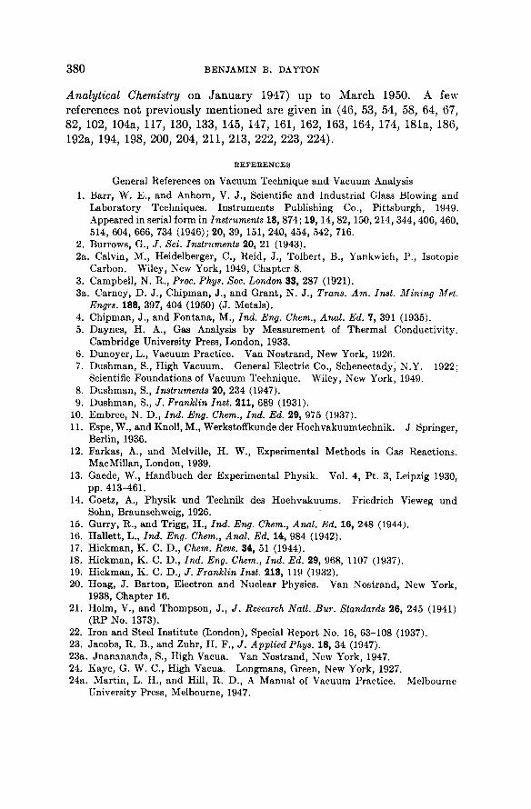
380 BENJAMIN Β. DAYTON
Analytical Chemistry on J a n u a r y 1947) u p to March 1950. A few references not previously ment ioned are given in (46, 53, 54, 58, 64, 67, 82, 102, 104a, 117, 130, 133, 145, 147, 161, 162, 163, 164, 174, 181a, 186, 192a, 194, 198, 200, 204, 211, 213, 222, 223, 224).
REFERENCES
General References on Vacuum Technique and Vacuum Analysis 1. Barr, W. E., and Anhorn, V. J., Scientific and Industrial Glass Blowing and
Laboratory Techniques. Instruments Publishing Co., Pittsburgh, 1949. Appeared in serial form in Instruments 18, 874; 19, 14, 82, 150, 214, 344, 406, 460. 514, 604, 666, 734 (1946); 20, 39, 151, 240, 454, 542, 716.
2. Burrows, G., J. Set. Instruments 20, 21 (1943). 2a. Calvin, M., Heidelberger, C , Reid, J., Tolbert, B., Yankwich, P., Isotopic
Carbon. Wiley, New York, 1949, Chapter 8. 3. Campbell, N. R., Proc. Phys. Soc. London 33, 287 (1921). 3a. Carney, D. J., Chipman, J., and Grant, N. J., Trans. Am. Inst. Mining Met.
Engrs. 188, 397, 404 (1950) (J. Metals). 4. Chipman, J., and Fontana, M., Ind. Eng. Chem., Anal. Ed. 7, 391 (1935). 5. Daynes, Η. Α., Gas Analysis by Measurement of Thermal Conductivity.
Cambridge University Press, London, 1933. 6. Dunoyer, L., Vacuum Practice. Van Nostrand, New York, 1926. 7. Dushman, S., High Vacuum. General Electric Co., Schenectady, N.Y. 1922;
Scientific Foundations of Vacuum Technique. Wiley, New York, 1949. 8. Dushman, S., Instruments 20, 234 (1947). 9. Dushman, S., / . Franklin Inst. 211, 689 (1931).
10. Embree, N. D., Ind. Eng. Chem., Ind. Ed. 29, 975 (1937). 11. Espe, W., and Knoll, M., Werkstoffkunde der Hochvakuumtechnik. J Springer,
Berlin, 1936. 12. Farkas, Α., and Melville, H. W., Experimental Methods in Gas Reactions.
MacMillan, London, 1939. 13. Gaede, W., Handbuch der Experimental Physik. Vol. 4, Pt. 3, Leipzig 1930,
pp. 413-461. 14. Goetz, Α., Physik und Technik des Hochvakuums. Friedrich Vieweg und
Sohn, Braunschweig, 1926. 15. Gurry, R., and Trigg, H., Ind. Eng. Chem., Anal. Ed. 16, 248 (1944). 16. Hallett, L., Ind. Eng. Chem., Anal. Ed. 14, 984 (1942). 17. Hickman, K. C. D., Chem. Revs. 34, 51 (1944). 18. Hickman, K. C. D., Ind. Eng. Chem., Ind. Ed. 29, 968, 1107 (1937). 19. Hickman, K. C. D. , Franklin Inst. 213, 119 (1932). 20. Hoag, J. Barton, Electron and Nuclear Physics. Van Nostrand, New York,
1938, Chapter 16. 21. Holm, V., and Thompson, J., J. Research Natl. .Bur. Standards 26, 245 (1941)
(RP No. 1373). 22. Iron and Steel Institute (London), Special Report No. 16, 63-108 (1937). 23. Jacobs, R. B., and Zuhr, H. F., J. Applied Phys. 18, 34 (1947). 23a. Jnanananda, S., High Vacua. Van Nostrand, New York, 1947. 24. Kaye, G. W. C , High Vacua. Longmans, Green, New York, 1927. 24a. Martin, L. H., and Hill, R. D., A Manual of Vacuum Practice. Melbourne
University Press, Melbourne, 1947.

VACUUM TECHNIQUES AND ANALYSIS 381
25. Monch, G., Vakuumtechnik im Laboratorium. Edwards Bros. Lithoprint, 1944.
26. Murray, W. M., Jr., and Ashley, S. E. Q., Ind. Eng. Chem., Anal. Ed] 16, 242 (1944).
27. Murray, W. M., Jr., and Niedrach, L., Ind. Eng. Chem., Anal. Ed. 16, 634 (1944). 28. Nash, L., Ind. Eng. Chem., Anal. Ed. 18, 505 (1946). 29. Naughton, J., and Uhlig, H., Ind. Eng. Chem., Anal. Ed. 16, 750 (1943). 29a. Naughton, J., and Uhlig, H., Anal. Chem. 20, 477 (1948). 30. Newman, F. H., The Production and Measurement of Low Pressures. Van
Nostrand, New York, 1925. 30a. Norton, F. J., and Marshall, A. L.: Trans. Am. Inst. Mining Met. Engrs. 156,
351 (1944); A.I.M.E.-T.P. No. 1643 (1943). 31. Pirani, M., and Newmann, R., Electronic Eng. 17, 277, 322, 367, 422 (1945). 32. Prescott, C. H., and Morrison, J., Ind. Eng. Chem., Anal. Ed. 11, 230 (1939). 33. Quackenbush, F. W., and Steenbock, H., Ind. Eng. Chem., Anal. Ed. 15, 468
(1943). 34. Reilly, J., and Rae, W. N., Physico-Chemical Methods. Van Nostrand, New
York, 1939, Vol. I, Chapter VII, pp. 573-582. 35. Ryder, Η. M., / . Am. Chem. Soc. 40, 1656 (1918). 35a. Sanderson, R. T., Vacuum Manipulation of Volatile Compounds. Wiley,
New York, 1948. 36. Sebastian, J., and Howard, H., Ind. Eng. Chem., Anal. Ed. 6, 172 (1934). 37. Stock, Α., The Hydrides of Boron and Silicon. Cornell University Press, Ithaca,
1933, Chapter X X X . 38. Strong, J., Procedures in Experimental Physics. Prentice-Hall, New York,
1938. 39. Vacher, H., and Jordan, L., J. Research Natl. Bur. Standards 7, 375 (1931) (RP
No. 346). 39a. Walter, D . I., Anal. Chem. 22, 297 (1950). 40. Wooten, L., and Guldner, W. G., Ind. Eng. Chem., Anal. Ed. 14, 835 (1942). 41. Yarwood, J., High Vacuum Technique. Chapman and Hall, London, 1945.
Other References Cited
42. Alexander, L., Murray, W. M., and Ashley, S. E. Q., Ind. Eng. Chem., Anal. Ed. 19, 417 (1947).
43. Anderson, P. Α., Rev. Set. Instruments 8, 493 (1937). 44. Archer, R. M., / . Sci. Instruments 13, 161 (1936). 45. Aristarkhova, M., Zavodskaya Lab. 9, 1096 (1940). 46. Aston, J. G., and Fink, H. L., Ind. Eng. Chem., Anal. Ed. 19, 218 (1947). 47. Bailey, A. J., Ind. Eng. Chem., Anal. Ed. 15, 283 (1943). 47a. Baldwin, R. R., J. Chem. Soc. London, 1949, 720. 48. Barrer, R., and Rideal, E., Proc. Roy. Soc. London A149, 231 (1935). 49. Baxter, J., Gray, E., and Tischer, Α., Ind. Eng. Chem., Ind. Ed. 29, 1112 (1937). 50. Bazzoni, C. B., Rev. Sci. Instruments 8, 171 (1937). 50a. Beamer, W. H., and Atchison, G. J., Anal. Chem. 22, 303 (1950). 51. Beeck, O., Smith, A. E., and Wheeler, Α., Proc. Roy. Soc. London A177, 62 (1940). 52. Benson, S., Ind. Eng. Chem., Anal. Ed. 13, 502 (1941). 53. Benson, S., Ind. Eng. Chem., Anal. Ed. 14, 189 (1942). 54. Berl, E., Rueff, G., and Carpenter, Ch., Ind. Eng. Chem., Anal. Ed. 10,220 (1938). 54a. Biehler, R. M., Hickman, K. C. D. , and Perry, E. S., Anal. Chem. 21, 638 (1949).

382 BENJAMIN Β. DAYTON
55. Biggs, Β., and Erickson, R., Ind. Eng. Chem., Anal. Ed. 16, 93 (1944). 56. Blears, J., Nature 154, 20 (1944). 57. Bobalek, E. G., and Shrader, S. Α., Ind. Eng. Chem., Anal. Ed. 17, 544 (1945). 58. Booth, H. S., Ind. Eng. Chem., Anal. Ed. 4, 380 (1932). 59. Bramley, G., and Raine, T., Iron and Steel Institute (London), Special Report
No. 25, 87-96 (1939). 60. Brown, G., DiNardo, Α., Cheng, G., and Sherwood, T., Applied Phys. 17,
802 (1946). 61. Bull, C , and Klemperer, O., / . Sci. Instruments 20, 179 (1943). 62. Burch, C , and van Dijck, W., J. Soc. Chem. Ind. 68, 39 (1939). 63. Burrows, G., </. Soc. Chem. Ind. 68, 50 (1939). 64. Burton, M., Ind. Eng. Chem., Anal. Ed. 9, 335 (1937). 65. Cady, G. H., and Cady, H. D., Ind. Eng. Chem., Anal. Ed. 17, 760 (1945). 66. Caldwell, M. J., and Barham, Η. N., Ind. Eng. Chem., Anal. Ed. 14, 485 (1942). 67. Cameron, A. E., Ind. Eng. Chem., Anal. Ed., 5, 419 (1933). 68. Campbell, N. R., Proc. Phys. Soc. London 33, 287 (1921). 69. Chadwick, T. C , and Palkin, S., Ind. Eng. Chem., Anal. Ed. 10, 399 (1938). 70. Chem. Eng. News, 2370 (Dec. 25, 1945). 71. Cioffi, P., Phys. Revs. 39, 363-7 (1932). 72. Clausing, P., Ann. Physik 12, 961 (1932). 73. Crist, R. H., and Brown, F. B., Ind. Eng. Chem., Anal. Ed. 11, 396 (1939). 74. Dalin, G. Α., Ind. Eng. Chem., Anal. Ed. 15, 731 (1943). 75. Dalton, R. H., J. Am. Chem. Soc. 57, 2150 (1935). 75a. Dayton, Β. B., Ind. Eng. Chem. 40, 795 (1948). 76. Derge, G., Metals Technol. 10 (Jan. 1943), A.I.M.E.-T.P. No. 1544. 77. Derge, G., Peifer, W., and Alexander, B., Trans. Am. Inst. Mining Met. Engrs.
162, 361-368 (Jan. 1945). 78. Detwiler, S., Abstracts of Articles and Patents on Molecular or Short-Path
Distillation. U.S. Regional Soybean Industrial Products Laboratory, Urbana, Illinois (1941).
79. Detwiler, S., and Markley, K. S., Oil and Soap 16, 2-5 (1939). 80. Diergarten, H., Arch. Eisenhuttenw. 2, 813-28 (1929). 81. Donahue, Η. B., Russell, R. R., and Vander Werf, C. Α., Ind. Eng. Chem., Anal.
Ed. 18, 156 (1946). 82. Douslin, D. R., and Walls, W. S., Ind. Eng. Chem., Anal. Ed. 16, 40 (1944). 83. Downing, J. R., and Mellen, G., Rev. Sci. Instruments 17, 218 (1946). 84. Du Mond, J. W., and Pickels, W. M., Rev. Sci. Instruments 6, 362 (1935). 85. Durau, F., Z. Physik 89, 148 (1934). 86. Dushman, S., and Young, A. H., Phys. Rev. 68, 278 (1945). 87. Ellett, Α., and Zabel, R. M., Phys. Rev. 37, 1102 (1931). 88. Embree, N. D., Chem. Revs. 29, No. 2, 317 (1941). 89. Emerson, R. L., and Woodward, R. B., Ind. Eng. Chem., Anal. Ed. 9, 347 (1937). 90. Euchen, Α., and Knick, H., Brenstoff-Chem. 17, 241 (1936). 91. Fawcett, E., Soc. Chem. Ind. 58, 43 (1939). 92. Ferguson, B., Ind. Eng. Chem., Anal. Ed. 14, 164 (1942). 93. Ferguson, W., Rev. Sci. Instruments 11, 134 (1940). 94. Finch, G. I., Nature 119, 856 (1927). 94a. Fletcher, G. L., Insalaco, M., Cobler, J. G., and Hodge, H. C , Anal. Chem.
20, 943 (1948). 95. Flosdorf, E. W., Ind. Eng. Chem., Anal. Ed. 17, 198 (1945).

VACUUM TECHNIQUES AND ANALYSIS 383
96. Fredlund, E., Ann. Physik 14, 617 (1932). 97. Fredlund, Ε , Ann. Physik 30, 99 (1937). 98. Furter, M., Mitt. Gebiete Lebensm. Hyg. 30, 200 (1939). 99. Gaede, W., Ann. Physik 41, 289 (1913).
100. Gaede, W., Z. tech. Physik 15, 664 (1934). 101. Garner, L. P., Rev. Sci. Instruments 8, 329 (1937). 102. Germann, F. Ε. E., and Gagos, Κ. Α., Ind. Eng. Chem., Anal. Ed. 15, 285 (1943). 103. Germann, F. Ε. E., Gagos, Κ. Α., and Neilson, C. Α., Ind. Eng. Chem., Anal. Ed.
6, 215 (1934). 104. Gilmont, R., Ind. Eng. Chem., Anal. Ed., 18, 633 (1946). 104a. Gilmont, R., Anal. Chem. 20, 474 (1948). 105. Gilmont, R., and Othmer, D. F., Ind. Eng. Chem., Anal. Ed. 15, 641 (1943). 106. Gray, E., and Cawley, J., J. Biol. Chem. 134, 397 (1940). 106a. Guldner, W. G., and Beach, A. L., Anal. Chem. 22, 366 (1950). 106b. Grosse, Α. V., Hindin, S. G., and Kirshenbaum, A. D., Anal. Chem. 21, 386
(1949). 107. Guye, Ρ. Α., and Germann, F. Ε. E., J. chim. phys. 14, 195 (1916). 108. Haden, W., and Luttropp, E., Ind. Eng. Chem., Anal. Ed. 13, 571 (1941). 109. Hall, S. Α., and Palkin, S., Ind. Eng. Chem., Anal. Ed. 14, 652 (1942).
•110. Harrington, E., Rev. Sci. Instruments 3, 476 (1932). 111. Hessenbruch, W., and Oberhoffer, P., Arch. Eisenhuttenw. 1, 583 (1928). 112. Hickman, K. C. D., Ind. Eng. Chem., Anal. Ed. 14, 250 (1942). 113. Hickman, K. C. D., Colloid Chem. 5, 253 (1944). 114. Hickman, K. C. D., Ind. Eng. Chem., Ind. Ed. 32, 1451 (1940). 115. Hickman, K. C. D., / . Applied Phys. 11, 303 (1940). 116. Hickman, K. C. D., Rev. Sci. Instruments 6, 161 (1934). 117. Hickman, K. C. D., and Gray, E., Ind. Eng. Chem., Ind. Ed. 30, 796 (1938). 118. Hickman, K. C. D., and Sanford, C., Phys. Chem. 34, 637 (1930). 119. Honig, R. E., J. Applied Phys. 16, 646 (1945). 119a. Hooper, J., Analyst 72, 513 (1947). 120. Howat, D., Chem. Age London 45, 309, 323 (1941); 46, 3 (1942). 121. Hughes, A. L., Rev. Sci. Instruments 8, 409 (1937). 122. Hunger, H., Seifensieder-Ztg. 67, 450, 473, 483, 497 (1940). 123. Hurst, W., and Rideal, E., J. Chem. Soc. 125, 694 (1924). 123a. Johnson, M., and Glover, J., Anal. Chem. 22, 204 (1950). 124. Jordan, L., and Eckman, J. R., National Bureau of Standards Scientific Paper
No. 514 (1925). 125. Jordan, L., and Eckman, J. R., National Bureau of Standards Scientific Paper
No. 563 (1927). 126. Kapff, S. F., and Jacobs, R. B., Rev. Sci. Instruments 18, 581 (1947). 126a. Keilholtz, G. W., and Bergin, M. J., Instruments 22, 320 (1949). 127. Kemp, A. R., and Straitiff, W. G., Ind. Eng. Chem., Anal. Ed. 17, 387 (1945). 128. Kennard, Ε. H., Kinetic Theory of Gases. McGraw-Hill, New York, 1938. 128a. Kenty, C., and Reuter, F. W., Rev. Sci. Instruments 18, 918 (1947). 129. Kerris, W., Z. tech. Physik 16, 120 (1935). 130. Kline, E. R., Ind. Eng. Chem., Anal. Ed. 14, 542 (1942). 131. Klumb, H., and Schwarz, Η., Z. Physik 122, 418 (1944). 132. Knudsen, M., Ann. Physik 28, 75 (1909); 32, 809 (1910). 133. Krieger, Κ. Α., Ind. Eng. Chem., Anal. Ed. 16, 398 (1944). 134. Kuchler, L., and Weller, O., Mikrochemie 26, 44 (1939).
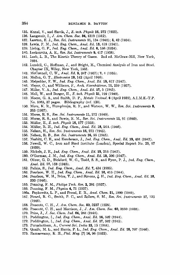
384 BENJAMIN Β. DAYTON
135. Kunzl, V., and Slavik, J., Z. tech. Physik 16, 272 (1935). 136. Langmuir, I., J. Am. Chem. Soc. 34, 1310 (1912). 137. Lawton, E. J., Rev. Sci. Instruments 11, 134 (1940); 5, 42 (1934). 138. Lewis, F. M., Ind. Eng. Chem., Anal. Ed. 13, 418 (1941). 139. Liebig, G. F., Ind. Eng. Chem., Anal. Ed. 6, 156 (1934). 140. Lockenvitz, A. E., Rev. Sci. Instruments 9, 417 (1938). 141. Loeb, L. B., The Kinetic Theory of Gases. 2nd ed. McGraw-Hill, New York,
1934. 142. Lundell, G., Hoffman, J., and Bright, H., Chemical Analysis of Iron and Steel.
Chapter IX, Wiley, New York, 1931. 143. McConnell, C. W., Anal. Ed. 9, 347 (1937); 7, 4 (1935). 144. Mellen, G. T., Electronics 19, 142 (April 1946). 145. Melpolder, F. W., Ind. Eng. Chem., Anal. Ed. 19, 617 (1947). 146. Meyer, O., and Williams, F., Arch. Eisenhuttenw. 11, 259 (1937). 147. Miller, V. Α., Ind. Eng. Chem., Anal. Ed. 17, 5 (1945). 148. Moll, W., and Burger, Η., Z. tech. Physik 21, 199 (1940). 149. Moore, G. Α., and Smith, D. P., Metals Technol. 6 (April 1939), A.I.M.E.-T.P.
No. 1065, 37 pages. Bibliography (ref. 123). 150. More, K. R., Humphreys, R. F., and Watson, W. W., Rev. Sci. Instruments 8,
263 (1937). 151. Morse, R. S., Rev. Sci. Instruments 11, 272 (1940). 152. Morse, R. S., and Bowie, R. M., Rev. Sci. Instruments 11, 91 (1940). 153. Muller, Ε., Z. tech. Physik 16, 177 (1935). 154. Muller, R. H., Ind. Eng. Chem., Anal. Ed. 18, 25A (1946). 155. Nelson, H., Rev. Sci. Instruments 16, 273 (1945). 156. Nelson, R. B., Rev. Sci. Instruments 16, 55 (1945). 157. Nesbitt, C. E., and Henderson, J., Ind. Eng. Chem., Anal. Ed. 19, 401 (1947). 158. Newell, W. C , Iron and Steel Institute (London), Special Report No. 25, 97
(1939). 159. Nickels, J. E., Ind. Eng. Chem., Anal. Ed. 19, 216 (1947). 160. O'Gorman, J. M., Ind. Eng. Chem., Anal. Ed. 19, 506 (1947). 161. Oliver, G. D., Bickford, W. G., Todd, S. S., and Fynn, P. J., Ind. Eng. Chem.,
Anal. Ed. 17, 158 (1945). 162. Palkin, S., Ind. Eng. Chem., Anal. Ed. 7, 434 (1935). 163. Pearlson, W. H., Ind. Eng. Chem., Anal. Ed. 16, 415 (1944). 164. Pearlson, W. H., Brice, T. J., and Simons, \ . H., Ind. Eng. Chem., Anal. Ed. 18,
330 (1946). 165. Penning, F. M., Philips Tech. Rev. 2, 201 (1937). 166. Penning, F. M., Physica 4, 71 (1937). 166a. Pepkowitz, L. P., and Proud, E. R., Anal. Chem. 21, 1000 (1949). 167. Picard, R. G., Smith, P. C , and Zollers, S. M., Rev. Sci. Instruments 17, 125
(1946). 168. Prescott, C. H., Am. Chem. Soc. 60, 3237 (1928). 169. Prescott, C. H., and Morrison, J., J. Am. Chem. Soc. 60, 3050 (1938). 170. Price, J., J. Soc. Chem. Ind. 64, 283 (1945). 171. Puddington, I., Ind. Eng. Chem., Anal. Ed. 16, 592 (1944). 172. Puddington, I., Ind. Eng. Chem., Anal. Ed. 17, 592 (1945). 173. Purushotham, Α., Current Sci. India 12, 15 (1944). 174. Quaife, M. L., and Harris, P. L., Ind. Eng. Chem., Anal. Ed. 18, 707 (1946). 175. Ramaswamy, Κ. H., Phil. Mag. [7] 14, 96 (1932).
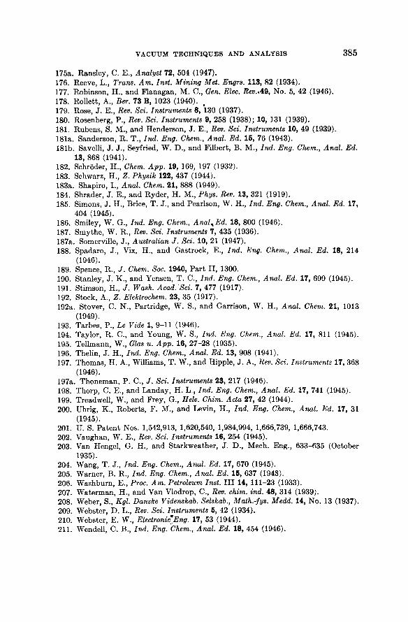
VACUUM TECHNIQUES AND ANALYSIS 385
175a. Ransley, C. E., Analyst 72, 504 (1947). 176. Reeve, L., Trans. Am. Inst. Mining Met. Engrs. 113, 82 (1934). 177. Robinson, H., and Flanagan, M. C , Gen. Elec. Rev.AS, No. 5, 42 (1946). 178. Rollett, Α., Ber. 73 B, 1023 (1940). 179. Rose, J. E., Rev. Sci. Instruments 8, 130 (1937). 180. Rosenberg, P., Rev. Sci. Instruments 9, 258 (1938); 10, 131 (1939). 181. Rubens, S. M., and Henderson, J. E., Rev. Sci. Instruments 10, 49 (1939). 181a. Sanderson, R. T., Ind. Eng. Chem., Anal. Ed. 15, 76 (1943). 181b. Savelli, J. J., Seyfried, W. D., and Filbert, Β. M., Ind. Eng. Chem., Anal. Ed.
13, 868 (1941). 182. Schroder, H., Chem. App. 19, 169, 197 (1932). 183. Schwarz, Η., Z. Physik 122, 437 (1944). 183a. Shapiro, I., Anal. Chem. 21, 888 (1949). 184. Shrader, J. E., and Ryder, Η. M., Phys. Rev. 13, 321 (1919). 185. Simons, J. H., Brice, T. J., and Pearlson, W. H., Ind. Eng. Chem., Anal. Ed. 17,
404 (1945). 186. Smiley, W. G., Ind. Eng. Chem., Anal^Ed. 18, 800 (1946). 187. Smythe, W. R., Rev. Sci. Instruments 7, 435 (1936). 187a. Somerville, J., Australian J. Sci. 10, 21 (1947). 188. Spadaro, J., Vix, H., and Gastrock, E., Ind. Eng. Chem., Anal. Ed. 18, 214
(1946). 189. Spence, R., J. Chem. Soc. 1940, Part II, 1300. 190. Stanley, J. K., and Yensen, T. C., Ind. Eng. Chem., Anal. Ed. 17, 699 (1945). 191. Stimson, H., J. Wash. Acad. Sci. 7, 477 (1917). 192. Stock, Α., Ζ. Elektrochem. 23, 35 (1917). 192a. Stover, C. N., Partridge, W. S., and Garrison, W. H., Anal Chem. 21, 1013
(1949). 193. Tarbes, P., Le Vide 1, 9-11 (1946). 194. Taylor, R. C., and Young, W. S., Ind. Eng. Chem., Anal. Ed. 17, 811 (1945). 195. Tellmann, W., Glas u. App. 16, 27-28 (1935). 196. Thelin, J. H., Ind. Eng. Chem., Anal. Ed. 13, 908 (1941). 197. Thomas, Η. Α., Williams, T. W., and Hippie, J. Α., Rev. Sci. Instruments 17, 368
(1946). 197a. Thoneman, P. C. f Sci. Instruments 23, 217 (1946). 198. Thorp, C. E., and Landay, H. L , Ind. Eng. Chem., Anal. Ed. 17, 741 (1945). 199. Treadwell, W., and Frey, G., Helv. Chim. Acta 27, 42 (1944). 200. Uhrig, K., Roberts, F. M., and Levin, H., Ind. Eng. Chem., Anal. Ed. 17, 31
(1945). 201. U. S. Patent Nos. 1,542,913, 1,620,540, 1,984,994, 1,666,739, 1,666,743. 202. Vaughan, W. E., Rev. Sci. Instruments 16, 254 (1945). 203. Van Hengel, G. H., and Starkweather, J. D., Mech. Eng., 633-635 (October
1935). 204. Wang, T. J., Ind. Eng. Chem., Anal. Ed. 17, 670 (1945). 205. Warner, B. R., Ind. Eng. Chem., Anal. Ed. 16, 637 (1948). 206. Washburn, E., Proc. Am. Petroleum Inst. I l l 14, 111-23 (1933). 207. Waterman, H., and Van Vlodrop, C., Rev. chim. ind. 48, 314 (1939). 208. Weber, S., Kgl. Danske Videnskab. Selskab., Math.-fys. Medd. 14, No. 13 (1937). 209. Webster, D . L., Rev. Sci. Instruments 5, 42 (1934). 210. Webster, E. W., Electronic Eng. 17, 53 (1944). 211. Wendell, C. B., Ind. Eng. Chem., Anal. Ed. 18, 454 (1946).

386 BENJAMIN Β. DAYTON
212. Werner, J., Ind. Eng. Chem., Anal. Ed. 10, 645 (1938). 213. Werner, J., Ind. Eng. Chem., Anal. Ed. 17, 865 (1945). 214. Wilcock, D. F., Gen. Elec. Rev. 49, 32 (1946). 215. Willems, F., and co-workers: Arch. Eisenhuttenw. 12, 485 (1938/1939); 13, 309
(1939/1940). 216. Williamson, Α., Rev. Set. Instruments 3, 782 (1932). 217. Winterhager, H., Aluminum-Arch. 12, 7 (1938); Z. Ver. deut. Ing. 83, 898 (1939). 218. Wittka, F., Angew. Chem. 53, 557 (1940). 219. Wittka, F., Neuere Methoden der Praparativen Organischen Chemie. W.
Foerst, editor, Verlag Chemie, Berlin, 1944, Vol. I, pp. 513-546. 220. Worcester, W. G., and Doughty, E. G., A.I.E.E. Technical Paper No. 46-142,
A.I.E.E., New York, May 1946. 221. Yensen, T., Trans. Am. Electrochem. Soc. 37, 227 (1920). 222. Young, W. S., Ind. Eng. Chem., Anal. Ed. 17, 742 (1945). 223. Young, W. S., and Taylor, R. C , Ind. Eng. Chem., Anal. Ed. 19, 135 (1947). 224. Young, W. S., and Taylor, R. C , Ind. Eng. Chem., Anal. Chem. 19, 133 (1947). 225. Zhuravleva, G., and Chufarov, G., Zavodskaya Lab. 9, 498 (1940). 226. Ziegler, N., Trans. Am. Electrochem. Soc. 66, 231 (1929). 227. Zimmerli, Α., Ind. Eng. Chem., Anal. Ed. 10, 283 (1938).