Vacuum Components & Systems - Thermionics
335
Vacuum Components & Systems 2021 Catalog
-
Upload
khangminh22 -
Category
Documents
-
view
0 -
download
0
Transcript of Vacuum Components & Systems - Thermionics

Vacuum Components & Systems 2021 Catalog

Vacuum Components& Systems
Catalog 2021
Ion Pumps
e-Guns
Flanges
Systems
Valves
Manipulators and Mechanical Feedthroughs
TMPI Cleaning Services
Electrical and Fluid Feedthroughs
Custom Chambers
Material, Surface and Molecular Beam Sciences
Instrumentation
Ion Pumps, Titanium Sublimation Pumps, Combo-Vac Pumps, Power Supplies, Rebuilding
Electron Beam Evaporation Sources 6-20 kW, Hanks HM2-Single and Multiple Crucibles, Co-Evaporation Hydra and Triad. 4 Crucible Rotary Guns 3 kW Single and Multiple Crucible; Power Supplies
Pyra Flat Rectangular, ConFlat, Adapters, ASA
Ion Pumped TTS Systems, Evaporators, Custom Systems,Cold Wall Furnace, Sorption Pumps and Super-Sorb Carts
Gate Valves, Angle Valves, Inline Valves, Bi-Pass Valves, On Axis Valves, Bakeable/All Metal Valves
XYZ Manipulators, RNN Rotary Seals, Linear and RotaryFeedthroughs, Heating and Cooling, Sample Transfer
Precision Cleaning, Mechanical Blasting, Helium Leak Testing, Passivation, RGA Testing
Electrical, Instrumentation, RF and Liquid Feedthroughs
Surface Analysis Chambers, Custom Designs and Modifications
MBE, RHEED, PLO, Molecular Beam and Surface Chemistry
Gauges and Controls, Thermocouple. Cold Cathode, Pirani, LN2
2
4
7
10
9
3
1
5
11
12
6
Copyright © 2021, Thermionics Laboratory, Inc. Reproduction in whole or in part, in any language, without the prior written approval of Thermionics is prohibited. All rights reserved.
i
Fittings, Accessories and HardwareFittings-ConFlat and ISO, ISO Flanges, RL Fittirgs,Feedthrough Collars, Components, Hoses, Traps
8

Table of Contents
TMPI Cleaning Services
Ion Pumps
Manipulatorsand MechanicalFeedthroughs1
2
3 3Cleaning Types
Technical Information
Introduction
Rotary Feedthroughs
Linear Feedthroughs
Linear- Rotary Feedthroughs
Sample Heating and Cooling
Sample Transfer Systems
Load Lock
Wobble Sticks
Faraday Cup Actuator
JS Series Thimble Jack Stages
Locking Jaw Systems
DRS-1000 Optical Temperature Monitoring
RFH Series Feedthrough HatsGoniometers & Precision Motion Gearbox HeadsPulsed Laser Deposition Target Stage
Viewport, Shutters
Motor Drive Systems
XYZ Manipulators
Z Motion Translators
XY Stage
RNN Series DifferentiallyPumped Rotary SealsSpecifications/Ordering Info
Precision Cleaning......................Passivation..................................Helium Leak Testing...................Pickling........................................Oxygen Cleaning.........................Derouging....................................Mechanical Blasting....................Precious Metal Reclamation.......Cleanroom Packaging.................Residual Gas Analysis (RGA).....
Theory of Operation....................Ion Pump Guide..........................Sizing the Pump..........................Pumping Speed vs. Pressure.....
Terminology................................Custom Equipment.....................
FRM Series.................................FRMRE Magnetic Series............FPRM Precision Series..............FRRC Precision Dual Axis Series.........................................WOA Open Axis Series..............
FLML Series...............................FLMR Series...............................FLMM Series..............................FLMH Series...............................
FRLC Precision Dual Axis Series.........................................FLLRE Magnetic Series..............RPLR Series...............................FLRM Series...............................BPLR Series...............................
Sample Mounting........................Sample Heating........................Heating & Cooling Accessories..LN2 Sample Cooling Options......LN2 Sample Cooling....................Sample Heater Power Supplies..
STLC Turn-to-Lock Series..........SPF Dual Groove Disk Series....
QAC Series Quick Access CapsLLC Series Load Lock Chambers...................................QAD Series Quick Access Doors..........................................
VRS Series Viewport Shutters....VLS Series Viewport Shutters...ClearView Series Heated Viewports....................................Delta Shutters.............................
Motor Drive Options....................Accessories................................YMC Series SynchronnusMotor Controllers........................
EC Series....................................EMC Series.................................EMX Series.................................FM Series...................................FB Series....................................
DBT Series.................................ZB Series....................................FBT Series..................................ECT Series.................................
Diode Pumps..............................Noble Diode Pumps....................Hydrogen Diode Pumps.............Triode Pumps.............................Accessories................................Pump Physical Dimensions........Power Supplies, Ion Pump.........Appendage Pumps.....................Custom Design Pumps...............Titanium Sublimation Pumps......Power Supply, Sublimation.........Combo-Vac Pumps....................LN2 Shroud.................................Pump Rebuilding........................
1-11-21-31-41-41-51-61-61-71-8
2-12-32-42-6
3-23-3
3-303-333-34
3-353-36
3-373-373-373-39
3-353-403-423-443-48
3-493-503-513-523-533-54
3-703-72
3-73
3-74
3-75
3-46
3-82
3-82
3-48
3-55
3-56
3-58
3-69
3-68
3-763-77
3-783-78
3-793-80
3-81
3-43-63-83-103-12
3-143-163-183-20
2-82-92-102-112-112-122-162-172-172-182-182-192-192-22
3-22
3-27
Tilt Stages 3-243-26Virtual Axis Tilt...........................
ii
Manipulatorsand MechanicalFeedthroughs

iii
Table of Contents
e-Guns™Electrical & Fluid Feedthroughs Flanges
Instrumentation
4 5 7
6
Technical Information Electrical Feedthroughs Technical Information
Thermocouple Gauge Tubesand Controllers
6 kW Multiple Position Linear
4- 12 kW Power Supplies
e-Gun Power Supplies
Sweep Controllers
3 kW e-Guns
Training Classes
Evaporation Tables
Hanks HM2 e-Guns, 6-20 kW
Fluid Feedthroughs
PyraFlat Rectangular Flanges
ConFlat Flanges
Adapter Flanges (ConFlat)
Wire Seal Flanges
ASA Flanges
Cold Cathode Ionization Gauges and Controllers
Bayard-Alpert Ionization Gauges
Liquid Nitrogen Level Controller
Pirani Gauges and Controllers
Theory of Operation....................Custom e-Guns...........................
FMC Medium Current.................FHV High Voltage.......................FHC High Current.......................FMH & FBN Instrumentation......FSH & FBSH Instrumentation.....FIM Coaxial.................................FEP Multi-Conductor..................PLC Push-On Connectors..........Thermocouple.............................Film Thickness Monitor...............
General Information....................Specifications..............................
Technical Information.............Gauge Tube Ordering Information.............................3 & 4 Crucbiles...........................
Technical Information.................Specifications..............................
4 kW Power Supply....................6 kW Power Supply....................8 kW Power Supply....................10 kW Power Supply..................12 kW Power Supply..................
Digital Sweep Controller.............Programmable Sweep................
Single Position............................Multiple Position 3, 4, and 5 Crucibles.....................................Rod Fed......................................Accessories Replacement Parts, Feedthroughs, Beam Sweep................. Crucbile Liners...............
General Description....................Single Crucbile...........................Rotary Multiple Crucible.............Hydra-2, Co-Evaporation, Dual Array, Multiple Crucible/Emitters......................................Hydra-1, Co-Evaporation, Single Array, Multiple Crucible/Emitters......................................Triad, Co-Evaporation, Three Crucibles....................................Accessories Replacement Parts, Feedthroughs, Crucible Liners.............................
FCW Water Cooling....................FLN Cryogenic............................
Technical Information.................Ordering Information...................Assembly Hardware....................Applications................................
Technical Information.................Ordering Information...................Rotatable....................................Tapped Rotatable.......................Non-Rotatable............................Tapped Non-Rotatable...............Dimensinal Drawings..................Note: Assembly Hardware and Gasket are shown on the same page
Double Sided Flanges................Note: Assembly Hardware and Gasket are shown on the same pageReducing Flanges.......................
Bolt-Type Wire Seal Flanges......Clamp-Type Wire Seal Flanges..Note: Assembly Hardware and Gasket are shown on the same page
Standard ASA Flanges...............ASA/ConFlat Adapter Flanges...
Technical Information.................Gauge Tube Ordering Information.................................Controller Ordering Information..
Glass Envelope Type.................Nude Type..................................Replacement Filaments..............
Technical Information.................Ordering Information...................LN2 Transfer Line........................
Technical Information.................Ordering Information...................
4-14-1
5-15-25-35-45-65-75-85-85-95-10
7-17-1
6-1
6-16-2
6-2
6-36-46-56-6
4-9
4-24
4-25
4-104-11
4-194-204-214-224-23
4-124-13
4-14
4-154-17
4-184-18
4-24-34-4
4-5
4-6
4-7
4-8
5-115-12
7-27-27-37-4
7-27-67-67-87-107-127-14
7-16
7-18
7-207-22
7-247-25
6-7
6-76-8
6-106-116-11
6-126-126-12
6-96-9
Gauge Tube Specifications....Cross Reference GuideEquivalency Table..................TC Gauge Controllers Analog........................ Battery Powered......... Digital.........................
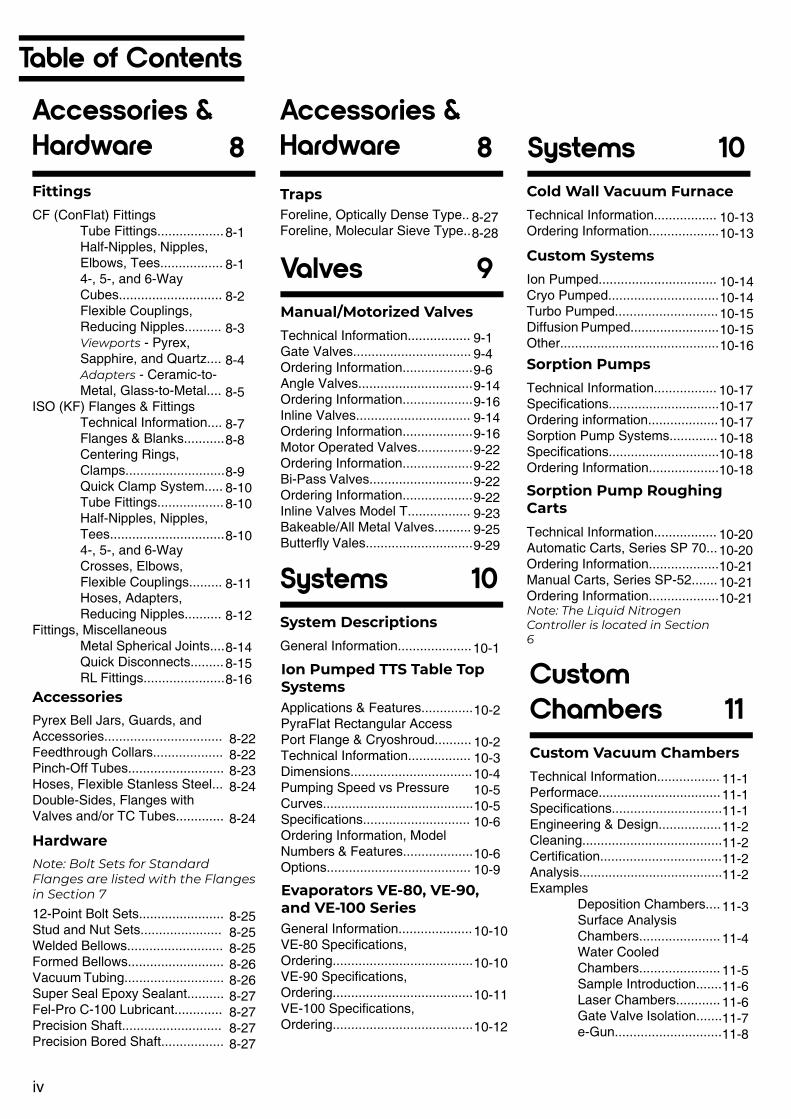
Table of Contents
Accessories & Hardware 8Fittings
Accessories
Note: Bolt Sets for Standard Flanges are listed with the Flanges in Section 7
Hardware
CF (ConFlat) Fittings Tube Fittings.................. Half-Nipples, Nipples, Elbows, Tees................. 4-, 5-, and 6-Way Cubes............................ Flexible Couplings, Reducing Nipples.......... Viewports - Pyrex, Sapphire, and Quartz.... Adapters - Ceramic-to- Metal, Glass-to-Metal....ISO (KF) Flanges & Fittings Technical Information.... Flanges & Blanks........... Centering Rings, Clamps........................... Quick Clamp System..... Tube Fittings.................. Half-Nipples, Nipples, Tees............................... 4-, 5-, and 6-Way Crosses, Elbows, Flexible Couplings......... Hoses, Adapters, Reducing Nipples..........Fittings, Miscellaneous Metal Spherical Joints.... Quick Disconnects......... RL Fittings......................
Pyrex Bell Jars, Guards, and Accessories................................Feedthrough Collars...................Pinch-Off Tubes..........................Hoses, Flexible Stanless Steel...Double-Sides, Flanges with Valves and/or TC Tubes.............
12-Point Bolt Sets.......................Stud and Nut Sets......................Welded Bellows..........................Formed Bellows..........................Vacuum Tubing...........................Super Seal Epoxy Sealant..........Fel-Pro C-100 Lubricant.............Precision Shaft...........................Precision Bored Shaft.................
8-1
8-1
8-2
8-3
8-4
8-5
8-78-8
8-98-108-10
8-10
8-11
8-12
8-148-158-16
8-228-228-238-24
8-24
8-258-258-258-268-268-278-278-278-27
Valves
Accessories & Hardware Systems
Systems
Custom Chambers
9
8 10
10
11
Manual/Motorized Valves
System Descriptions
Sorption Pumps
Custom Vacuum Chambers
Sorption Pump Roughing Carts
Cold Wall Vacuum Furnace
Custom Systems
Ion Pumped TTS Table Top Systems
Evaporators VE-80, VE-90, and VE-100 Series
Technical Information.................Gate Valves................................Ordering Information...................Angle Valves...............................Ordering Information...................Inline Valves...............................Ordering Information...................Motor Operated Valves...............Ordering Information...................Bi-Pass Valves............................Ordering Information...................Inline Valves Model T.................Bakeable/All Metal Valves..........Butterfly Vales.............................
General Information....................
Technical Information.................Specifications..............................Ordering information...................Sorption Pump Systems.............Specifications..............................Ordering Information...................
Technical Information.................Performace.................................Specifications..............................Engineering & Design.................Cleaning......................................Certification.................................Analysis.......................................Examples Deposition Chambers.... Surface Analysis Chambers...................... Water Cooled Chambers...................... Sample Introduction....... Laser Chambers............ Gate Valve Isolation....... e-Gun.............................
Technical Information.................Automatic Carts, Series SP 70...Ordering Information...................Manual Carts, Series SP-52.......Ordering Information...................Note: The Liquid Nitrogen Controller is located in Section 6
Technical Information.................Ordering Information...................
Ion Pumped................................Cryo Pumped..............................Turbo Pumped............................Diffusion Pumped........................Other...........................................
Applications & Features..............PyraFlat Rectangular Access Port Flange & Cryoshroud..........Technical Information.................Dimensions.................................Pumping Speed vs Pressure Curves.........................................Specifications.............................Ordering Information, Model Numbers & Features...................Options.......................................
General Information....................VE-80 Specifications, Ordering......................................VE-90 Specifications, Ordering......................................VE-100 Specifications, Ordering......................................
9-19-49-69-149-169-149-169-229-229-229-229-239-259-29
10-1
10-1710-1710-1710-1810-1810-18
11-111-111-111-211-211-211-2
11-3
11-4
11-511-611-611-711-8
10-2010-2010-2110-2110-21
10-1310-13
10-1410-1410-1510-1510-16
10-2
10-210-310-410-510-510-6
10-610-9
10-10
10-10
10-11
10-12
TrapsForeline, Optically Dense Type..Foreline, Molecular Sieve Type..
8-278-28
iv

v
Table of ContentsMaterial, Surface & Molecular Beam Science
Material, Surface & Molecular Beam Science12 12
Molecular Beam Epitaxy
Reflection High Energy Electron Diffraction (RHEED)
Molecular Beam andSurface Chemistry Products
Pulsed Laser Deposition (PLD)
Technical Information.................MBE Systems/Specifications......Series VT-100.............................Series VT-105.............................Series VT-108.............................Series VT-110.............................Organic MBE, Series VV-301.....Ion Beam Sources......................Acessories: Sample Handling, Manipultators, e-Guns, etc.........MBE Components.......................
Technical Information.................RHEED Guns.............................Specifications..............................Dimensions.................................Ordering Information...................RHEED Power Supplies.............Specificaitons..............................Ordering Information...................Accessories.................................Phospor Screens........................Viewports....................................Viewport Shutters.......................Camera and Mount.....................Isolation Valves...........................
Laser Test Chamber, with Time-of-Flight Mass Spectrometer......Rotatable Time-of-Flight MassSpectrometer with Laser Window.......................................Molecular Beam Pulsed Nozzle Valve...........................................Heated/Chilled Molecular Beam Nozzle.........................................Differentially Pumped MolecularBeam Source Chamber..............Crystal Cleaver...........................Quick Change Manipulator Gearbox/Sample Holder.............Gearless Miniature SAM Manipulator.................................Modular Cart Systems................UHV Cold Trap Assembly...........Raman Cell.................................
Technical Information.................Specifications..............................Illustrations..................................
12-112-212-212-412-612-612-712-8
12-912-10
12-1112-1212-1212-1212-1212-1412-1412-1412-1512-1512-1512-1612-1612-16
12-20
12-22
12-24
12-2612-28
12-30
12-31
12-3212-3312-3412-34
12-1712-1812-18

Ordering Information
vi
About the Company Ordering Information
Minority Statement
Thermionics Northwest, Inc.
Thermionics Laboratory, Inc.
Vacuum Training CoursesPrices and Specifications
Course DescriptionTerms of Payment
Discounts
Minimum Order
Delivery
FOB Point
Method of Shipment
Since 1958, Thermionics has designed, developed, and manufactured vacuum equipment for scientific and industrial applications. Our products are the result of careful research and development. rigorous testing, and continuing performance evaluation. Our commitment to quality and reliability is one reason researchers and OEM manufacturers specify Thermionics’ products
We listen to our customers. They are the best source for information about current and emerging processes and technologies. These discussions stimulate product development and ensure continuous improvement.
For new components and systems, or the modification and repair of existing equipment, Thermionics will deliver the best equipment and value to you.
Orders are placed directly with the company. Contact the office nearest you. If you cannot find the product you need, or if you have any questions, please do not hesitate to contact us. We will provide all the assistance you may need.
When you purchase products from Thermionics Laboratory, Inc., you fulfill the minority vendor requirements for all Government Institutions and Contractors.
231-B Otto Street, Port Townsend, WA 98368Phone: (360) 385-7707
Toll Free: (800) 962-2310Email: [email protected]
Website: thermionics.com
3118 Depot Road, Hayward, CA 94545Phone: (510) 225-6975 ext 100
Toll Free: (800) 962-2310Email: [email protected]
Website: thermionics.com
Three-day basic vacuum technology courses tailored to meet the needs of your personnel, and those individuals wanting to learn more about high and ultra-high vacuum technology.
Prices and specifications are subject to change without notice, please contact us for firm price quotations and current specifications.
An introduction to basic vacuum technology, theory and fundamentals, including, but not limited to: gas behavior, conductance, viscous flow, molecular flow, vap or pressure, vacuum measurement, mean free path, etc.
Familiarization with the physical construction, operation, and maintenance of mechanical, diffusion, ion, cryo, turbo and sorption pumps, mass spectrometer leak detectors, residual gas analyzers, deposition monitors, e-Guns, sputtering systems, etc.
Introduction to practical vacuum system design concepts using accessory vacuum equipment such as valves, traps, fanges, feedthroughs, viewports, pumps, chambers, etc.
As a rule, all classes are held at the Thermionics facility, located at 3118 Depot Rd, Hayward, CA 94545, but classes can be scheduled at your facility.
Courses can be customized to meet most special requirements. On-site training requires a suitable classroom, audiovisual equipment, and operating equipment.
Please contact us at [email protected] for further information about schedules and fees.
Domestic: Net 30 days upon approval of credit. Export: Letter of Credit on deposit prior to shipment.
OEM, quantity, and domestic educational discounts are available, on request, to qualified customers, when applicable.
There is a $100.00 minimum order, for non-replacement parts.
An inventory level is maintained on all items shown in this catalog. Delivery will be quoted at the time the order is placed.
Shipments are FOB our plant, unless quoted otherwise.
Shipments are normally sent on a prepay and add basis. Firm shipment arrangements are quoted at the time of order.

Thermionics’ Commitment
viii
Thermionics’ One
Standard products manufactured by Thermionics Vacuum Products and its subsidiaries are guaranteed to be free of material and workmanship defects for a period of one (1) year. Expendable component parts are guaranteed for their expected service life.
Thermionics Laboratory, Inc. (herein called THERMIONICS) warrants to the original purchaser.
Scope
Expected Service Life
Standard catalog products manufactured by THERMIONICS against defects in workmanship for a period of one (1) year from the date goods are received at the customer’s facility
In-warranty repaired, or replaceable parts are warranted only for the remaining portion of the original warranty period, applicable to the parts which have been repaired or replaced, and the total equipment is warranted for the balance of the one (1) year period. After expiration of the applicable warranty period, the buyer shall be charged at THERMIONICS’ current prices for parts and labor, plus freight and per diem, when applicable
Expendable component parts, including, but not limited to pump elements, cold cathode gauges, bellows, thermo-couple gauges, hot cathode gauges, sublimator filaments, emissive filaments, heaters, elastomers, bearings and gasket, etc. are guaranteed for their expected service life. If the expendab1e component parts a to give reasonable service, as determined solely by THERMIONICS, they will be repaired or replaced at our discretion
Pump Elements Diode, Differential Diode Hydrogen and TriodeCold Cathode GaugesBellows Valves Manipulators Linear Actuation Rotary FeedthroughsThermocouple Gauges Hot Cathode Gauges Sublimator Filaments Emissive Filaments Heater, ElastomersBearings
Gaskets
40,000 hours at 2 x 101 Torr30,000 hours at 2 x 101 Torr40,000 hours at 2 x 101 Torr
10,000 full cycles
10,000 full cycles700,000 rotationsMeet specifications upon receipt. Life is dependent upon operating conditions
Life is dependent upon service conditions and maintenance One time use
Liability under this warranty is expressly limited to repair or replacement of defective part THERMIONICS, at its sole option, may at any time discharge its warranty as to any of its products by refunding the purchase price and taking back the product(s).
Special products and electronic components are covered for a period of one (1) year from the date goods are received at the customer’s facility
This warranty applies only to parts manufactured and labor provided by THERMIONICS.
Valid warranty claims must be received by THERMIONICS within the warranty period and are subject to the terms and conditions herein.
All warranty replacement or repair of parts shall be limited to equipment malfunctions which at the sole discretion of THERMIONICS, are due or traceable to defects in original materials or workmanship.
Malfunctions, which in the sole opinion of THERMIONICS, are caused by abnormal wear and tear, lack of maintenance, abuse, operation maintenance or care inconsistent with the product manual, accident, or neglect of equipment are expressly not covered by this warranty. It is the responsibility of the user to operate the equipment in a reasonable and prudent manner, consistent with the stated intended use
I.
II.
A.
F.
G.
A.
B.
B.
C.
D.
E.
If, for any reason, you are not completely satisfied with our products, let us know. We want to address your concerns.
Our relationship with the user does not end with the delivery of the equipment. We have a large stake in your new equipment operating up to your expecta-tions. Our goal is to be part of your success.

ix
Thermionics’ Commitment
Year Warranty
Conditions Procedures
THERMIONICS expressly disclaims responsibility for any loss or damage caused by the use of its products, when not used in accordance with proper operating and safety procedures in accordance with specifications, or if the equipment is used without the proper recommended maintenance. Reasonable care must be taken by the user to avoid hazards.
If you wish to return equipment for repair, contact the THERMIONICS DIVISION which sold you the product in question. You will be given an RMA Authorization Number and instructions on how and by what means to ship the product to the factory. NO SHIPMENT WILL BE ACCEPTED WITHOUT PRIOR APPROVAL and completed RMA Authorization Form.
Except as stated herein, THERMIONICS makes no warranty, express or implied, either in fact or by operation of law; and, as stated herein, THERMIONICS shall have no liability under any warranty, express or implied, either in fact or by operation of law.
In the first year, goods must be returned, freight prepaid, to the factory and will be returned, freight prepaid, to the customer. After the first year, all freight costs must be paid by the customer.
THERMIONICS shall have no liability for special or consequential damages of any kind, or from any cause arising out of the sale, installation, or use of any of its products. Statements made by any person, including representatives of THERMIONICS, which are inconsistent or in conflict with the terms of this warranty shall not be binding upon THERMIONICS unless reduced to writing and approved by an authorized officer of THERMIONICS.
This warranty does not cover normal maintenance requirements which are the customer’s responsibility.
This warranty does not extend to equipment that a) someone other than Thermionics approved personnel have disassembled or attempted to repair,b) has been modified or altered, orc) has been contaminated with hazardous material or induced activation
III. IV.
A. A.
B. B.
C.
D.
E.

Trademarks & Copyrights
x
The trademarks and registered trademarks listed below are the property of their respective companies.
Alberox Corp.AlcatelVacuumProducts, Inc.Hoskins Mfg. Co.Allied Corp.American Standards AssociationAmerican Society of Mechanical EngineersAmerican Society for Testing and MaterialsAutoDesk CorpThermionics Laboratory, Inc.Felt Products Mfg. Co.Swagelok Marketing Co.Wellman Thermal SystemsCeramxHoskins Mfg. CoThermionics Northwest, Inc.Thermionics Laboratory, Inc.Varian AssociatesWilbur B. Driver Co.
Helix Technology Corp.CVC Products, Inc.E.I. DuPont de Nemours & Co, Inc.Diversey Corp.Dow Corning Corp.Thermionics Northwest, Inc.Welch Vacuum, Thomas Industries. Inc.
Anatech, LtdEdwards High Vacuum InternationalThermionics Laboratory, Inc.EPI, Inc.Poca Graphite, Inc.Felt Products Mfg., Inc. Ferrofluidics CorpAusimont U.S.AFredricks Co.E.I. DuPont de Nemours & Co, Inc.Gast Mfg. Corp.
Omicron Corp GmbHPerkin-Elmer Corp.Thermionics Laboratory, Inc.Thermionics Laboratory, Inc.Corning, Inc.Instruments S.A.Thermionics Laboratory, Inc.Saes Getters S.p.A.Monsanto Co.Welch Vacuum Technology, Inc. Varian AssociatesThermionics Northwest, Inc.E.I. DuPont de Nemours & Co., Inc.
Superior ElectricThermionics Laboratory, Inc.Heraeus Amersil, Inc.Thermionics Laboratory, Inc.Swagelok Marketing Co.E.I. DuPont de Nemours & Co., Inc.Thermionics Laboratory, Inc.Thermionics Laboratory, Inc.Thermionics Laboratory, Inc.Thermionics Laboratory, Inc.Thermionics Laboratory, Inc.Swagelok Marketing Co.Technipower, Inc.Vanan AssociatesSwagelok Marketing Co.Swagelok Marketing Co.Veeco Instruments, Inc.Danaher ControlsE.I. DuPont de Nemours & Co., Inc.Vacuum Generators Ltd.DuPont Dow Elastomers L.L.C.Welch Vacuum, Thomas Industries, Inc.Varian AssociatesMicrosoft Corp.Microsoft Corp.
General Valve Corp.Granville-Phillips Co.
Thermionics Laboratory, Inc.Teledyne Hastings-Raydist, Inc.Haynes International, Inc.Heli-Coil Corp.Thermionics Laboratory, Inc.Thermionics Laboratory, Inc.
Thermionics Laboratory, Inc.International Business Machines Corp. International Business Machines Corp.International Nickel Co.Intevac, lnc./EPI, Inc.International Standards OrganizationDuPont Dow Elastomers L.L.C.E.I. DuPont de Nemours & Co., Inc.Leybold Vacuum Products. Inc.Newport/Klinger CorpWestinghouse Electric Corp.Thermionics Laboratory, Inc.Corning, Inc.Thermionics Laboratory, Inc.Varian AssociatesMicrodot Corp.MKS Instruments, Inc.International Nickel Co.Microsoft CorpNippon Electric CorpCorning, Inc.Varian AssociatesSwagelok Marketing Co.Copper Development Assn.Phelps-Dodge Specialty Copper Products; American Metals Climax, Inc.
AlberoxAlcatelAlumelAmphenolASA
ASME
ASTM
AutoCADBiMetlC-100CajonCalrodCeramasealChromelClearviewCombo-VacConFlatConstantanCTI-CryogenicsCVCDelrin
DiverseyDow CorningDRS-1000DuoSeal
Dynamic Electron EmitterEdwards
e-GunEPIFabmateFel-ProFerrofluidicsFomblinFredricksFreon
Gast
OmicronPerkin-ElmerPLD-2200PyraFlatPyrexRiberRNNSaes GettersSantovacSargent-Welch
StarCellSTLCStyrofoam
Superior ElectricSuper-SorbSuprasilSure-LokSwagelokTeflon
TogleLokTriadTriBondTriMetlTTS Table TopUltra-TorrVariacVarianVCOVCRVeecoVeeder-RootVespel
VGViton
Welch
WheelerWindowsWindows 95
General ValveGranville-PhilipsHanks HM2 e-GunHastings
Haynes AlloyHeli-CoilHM2 HydraHyper-Unimelt, Hyper-Unimelt, SweepIBM
IBM PC
InconelIntevacISO
Kalrez
Kel-F
KF
Klinger StageKovarLoad-LokMacormaTCedMegaSorbMicrodotMKSMonelMS-DOSNECNonexNRCNuproOFEOFHC
OFHC and OFE Copper
OFHC was a registered trademark of American Metals Climax. Inc. The trademark, proprietary process, product line and production machinery were sold to Phelps Dodge Phelps Dodge retired the product.
ASTM F68 was the specification for proprietary OFHC copper product The Copper De-velopment Association, a trade organization, proposed and adopted specification UNSC-10 100. UNSC-10100 and ASTM F68 are identical specifications.
In the market OFHC copper has been replaced by OFE copper products. Throughout this catalog references to OFHC have been replaced with OFE. OFE is produced as a generic copper product. OFHC and OFE are interchangeable.

TMPI Precision Cleaning1

TMPI Precision Cleaning
1
ServicesPrecision Cleaning...........................................Passivation.......................................................Helium Leak Testing.........................................Pickling.............................................................Oxygen Cleaning..............................................Derouging.........................................................Mechanical Blasting.........................................Precious Metal Reclamation............................Cleanroom Packaging......................................Residual Gas Analysis (RGA)..........................
1-11-21-31-41-41-51-61-61-71-8

1Precision Cleaning
1-1(510) 786-0680 [email protected]
Precision CleaningAbout
Precision Cleaning Techniques
What is Precision Cleaning?
Although all manufacturing operations require cleaning as part of their process, it is important to understand the distinct difference between “cleaning” and “precision cleaning.” For some industries, a surface that is visually clean may be sufficient while for others, even the most microscopic contaminants need to be removed to ensure the safety and quality of the equipment. Precision cleaning is the process that is utilized to achieve these critical levels of cleanliness in a wide array of industries, including Space, Aviation, Military & Defense, Medical Device, Semiconductor, Laser and Automotive.
Aqueous Cleaning: This method allows parts to have a long dwell time in the cleaning solution. Additives such as detergents and surfactants are added to water that has been treated by deionization or reverse osmosis. This water-based cleaning method is very effective at removing different soils on parts that are compatible with water. The result is in an environmentally friendly method for achieving the desired level of cleanliness.
Solvent Cleaning: Cleaning by immersion in solvents is particularly effective on parts with complex configurations and for certain soil compositions. This method utilizes the chemical properties of the solvent to remove the contaminants from the part. For some applications, solvent cleaning is used in conjunction with ultrasonic cleaning.
Ultrasonic Cleaning: This technique uses cavitation which is induced by high frequency sound waves to agitate the cleaning solution aiding in dislodging particles. It is particularly effective for precision parts cleaning of complex parts with threads, rough surfaces and blind interior spots that are inaccessible by other cleaning methods. Ultrasonic cleaning typically employs aqueous, semi-aqueous and solvent-based cleaning systems and detergents. This combination removes contaminants at nearly a microscopic level, with higher sound frequencies generally able to remove finer particles.
High-Pressure Spray Cleaning: This procedure utilizes the kinetic energy of a water jet to “blast” the particles and soils from a surface. It is most often used in conjunction with detergents or surfactants to chemically loosen or solubilize the soils in order for the water jet to more effectively remove the contaminants from the surface. The ability to vary the water pressure, nozzle size and/or spray pattern allows this method to be easily customizable for different materials of construction and soil compositions.
Wipe Cleaning: This method uses special lint- and particle-free wipes or swabs, often wetted with solvents or deionized water, to hand clean delicate surfaces that cannot withstand more aggressive cleaning methods.
Flush Cleaning: Using a turbulent velocity, cleaning liquids are flooded through the interior of tubes, pipes, and other internal pathways to flush the contaminants out of the hardware or component as it rotates. This method is particularly useful for precision cleaning of components of varying shape and size for which high-pressure sprays are not useful.
Vacuum Bakeout: This methodology uses vacuum baking to volatilize hydrocarbon contaminants and remove hydrocarbons that are entrapped in the pores of sensitive equipment. It also reduces the outgassing rates to acceptable levels for aerospace instrumentation.
Based on the above factors, one or more of the following techniques may be employed:
Precision cleaning removes contaminants such as particles, fibers, oils, and greases, resulting in a surface so clean it must be validated on a microscopic level. Ineffective removal of these contaminants can be costly and have a significant impact on a company’s productivity, profitability and reputation. TMPI understands the importance of providing quality cleaning services. We recognize that each industry and every component have its own unique requirements. The proper cleaning solution will be based on a combination of factors including:
As such, we test and certify all materials prior to the cleaning process. Our cleaning methodologies are comprised of two core elements.
The first element involves cleaning the surface using specific precision cleaning techniques combined with an approved cleaner in a process that has been validated for the stated purpose.
The second element involves testing and verification that the surface is cleaned to the level of precision necessary for it to be safely used in its intended environment. Our degreed scientists test the critical surfaces for residues using a process called Gravimetric Non-Volatile Residue Mass Determination (NVR) Testing. We also quantify and size any remaining particles that are found on the critical surfaces.
• The material composition and configuration of the hardware/components
• The level and composition of the contamination that is present
• The level of cleanliness that is required by the customer

1 Passivation
(510) 786-0680 [email protected]
PassivationAbout
Nitric Acid
Citric Acid
The passivation of stainless steel is a method carried out to create a passive layer, i.e. making a surface film that allows the surface to lose its chemical reactivity. Steels with more than 11 percent chromium are capable of forming on their surface a transparent, inert or inactive, self-repairing oxide film. However, iron particles, tool steel or abrasive particles may be embedded or deposited on the surfaces of stainless steel components during handling and processing such as rolling, forming, machining, pressing, tumbling, and lapping. If allowed to remain, these particles can cause corrosion of a surface of stainless steel to adversely affect the sanitary condition or mechanical operation of a part, component or system or contaminate a process fluid.
Passivation, consisting of immersion of stainless steel parts in a nitric or citric acid solution without oxidizing salts, dissolves the embedded metal and preserves the initial corrosion-resistant coating by creating a thin, translucent oxide film.
Passivation is also accomplished through electropolishing, an electrochemical process that is a stainless steel “super passivator” resulting in a more passive surface than the other methods mentioned above. A combination of electropolishing and treatment of nitric and/or citric acid is recommended for maximum corrosion resistance.
In house passivation processes:
Citrus acid passivation was created by Adolf Coors brewing company for the passivation of within lager barrels. It offers a compelling option in contrast to nitric passivation with less handling and is consider earth inviting being on the GRAS (Generally Recognized as Safe) list for the FDA making it perfect for nourishment and refreshment applications.
When looking at nitric versus citrus passivation, citrus arrangements can viably passivate a more extensive scope of hardened steel compounds contrasted with any one nitric corrosive passivation arrangement, considering congregations of a few treated steel amalgams to be passivated.
Passivation sciences expel free iron from the surface yet can likewise expel some nickel and chromium from tempered steel.
TMPI (Thermionics Metal Processing, Inc.) has over 35 years of experience perfecting our proprietary UHV passivation chemistries and processes for SST 300 and 400 series. In addition, TMPI’s modern equipment, highly trained technicians, controlled environments, Class 100/1000 Cleanroom packaging, and in-house testing ensures consistent quality and compliance to industry standards and customers specific standards. We have a state-of-the-art plant that can accommodate parts and chambers of various sizes and complexities.
To accommodate various passivation industry standards, we have in house capability of building special tank chemistries based on the size and complexity of the part.
Our proprietary passivation process is environmentally friendly that bind metal ions preventing redepositing on surfaces. Thus, incapacitating. redepositing on surfaces reducing material out-gassing, handling requirements and optimizing the passive layer on the stainless-steel surface
higher the nitric corrosive temperature, the all the more oxidizing potential the passivation science has. Sodium dichromate can likewise be added to the nitric corrosive to build the oxidizing capacity of the shower improving it for less erosion safe treated steels, for example, precipitation solidified, martensitic and ferritic evaluations of hardened steel. These evaluations of hardened steel have less nickel and chromium in them making them increasingly helpless to drawing. The higher the oxidizing capability of the science, the quicker and progressively successful the detached oxide boundary is shaped superficially, diminishing the potential for carving.
Tainting of passivation science can prompt glimmer assault of the surface, which produce a vigorously carved or darker surface. A typical control that prompts glimmer assault is chlorides which can emerge out of a few sources incorporating hauling in acids or utilizing having chloride in the water. What’s more, natural development in passivation showers, for example, the drag-in of machining oils from parts that are not appropriately cleaned, can prompt glimmer assault or scratching of the hardened steel. All things considered, customary scientific examination and support of passivation sciences is required. Certain passivation techniques are additionally more impervious to glimmer assaults than others. For nitric corrosive passivation the showers with expanded oxidizing potential are additionally increasingly impervious to blaze assaults. Nitric corrosive likewise is increasingly impervious to blaze assault contrasted with citrus extract.
Evacuating nickel and chrome decreases the erosion safe material at the surface leaving a more slender oxide layer. Citrus extract passivation specifically expels iron over nickel and chromium leaving a thicker erosion safe oxide layer than nitric corrosive passivation.
Once of different points of interest of citrus extract is the shower plan can be acclimated to diminish process durations over nitric corrosive, taking into account increment throughput and decreased expenses of passivation stanzas that of nitric corrosive. Process durations as low as 4 minutes are conceivable with certain citrus extract passivation plans.
• QQ-P-35• ASTM A967/ ASTM A380• AMS 2700
Nitric vs Citric Passivation Methods
Benefits of TMPI’s UHV Passivation
When looking at nitric versus citrus passivation, the most well-known strategy utilized all through industry is nitric corrosive passivation. The Nitric corrosive passivation procedures was the first passivation prepared determined in QQ-P-35, the primary military detail covering passivation, amendment A being discharged during the 1960s. Nitric corrosive passivation offers a scope of choices to redo the oxidizing capability of the corrosive to suit a particular evaluation of hardened steel. The different strategies and sorts of nitric corrosive passivation incorporate a few warmed alternatives just as choices that incorporate a sodium dichromate.
The higher nitric corrosive focus and the

(510) 786-0680 [email protected] 1-3
1Helium Leak TestingHelium Leak TestingAbout
What are the Benefits of Helium Leak Testing?
How Does Helium Leak Testing Work?
Helium is an inert, stable, and non-condensable gas that is often used as a tracer gas to identify leaks in parts and systems. The very small atomic size allows the helium to easily pass through leaks, and because it is inert, it will not react with virtually any of the materials within the part or system that is being tested. Since helium is only naturally present in the atmosphere in small amounts (~5 ppm), qualitative helium leak testing can be performed in ambient air to test areas that need rewelding, fittings that need tightening, failed gaskets, and other pressure system leak points. It is also used to determine what the total leak of a system is before it is put into service.
For the aerospace industry, the ability to test for leaks with high-level sensitivity is imperative to ensuring mission success, and at times, safety. Failure to identify and repair even small leaks can have detrimental consequences. During regular operations, all aircraft, satellites and rocket systems are subjected to different temperatures, atmospheric pressures and other stressors that can result in more severe leaks. An airplane leaking fuel may have a fire and not reach its destination safely. Spacecraft missions, with their limited resource supplies, will be compromised if the gas within a tank or primed system leaks out before the mission is complete.
Helium leak detection has been used for many years in the aerospace industry for the following:
There are many benefits associated with helium leak testing, which include:
Helium leak detection methods are also used across a variety of other industries including medical, automotive, and oil and gas processing. Helium leak detectors are used in the quality control of production parts such as medical devices, hydraulic lines, condensers, radiators, manifolds, fuel lines, fittings, and COPV tanks. Pressurized systems such as those found in oil and gas processing and vacuum systems, including vacuum furnaces, isolation glove boxes and laser process equipment, also utilize helium leak detectors to ensure the integrity of those systems prior to start-up and as part of their preventative maintenance procedures.
Helium leak testing utilizes a Helium Leak Detector, also referred to as a Mass Spectrometer Leak Detector (MSLD), to find a leak inside or outside of a system and then measure the leak rate. The helium leaks in/out of the tested product and is measured by the detector. The detector determines the leak rate based on the helium concentration and flow rate.
A complete Helium Leak Detector system contains the following elements:
• Critical gas lines• Fuel systems and COPV tanks• Sealed electronic enclosures• Missile guidance systems• Solid rocket booster cone assemblies• Antennas• Heat exchangers• Hydraulic systems• Valves• Cockpit instruments
• Leaks can be detected and quantified with a high level of sensitivity
• No adverse impact on the materials being tested due to the inert properties of helium
• The test process is essentially dry and temperature independent
• Helium mass spectrometer to detect the mass of the helium
• Vacuum system to maintain sufficiently low pressure for the spectrometer
• Valves which control individual steps of the measuring cycle: evacuation, testing, and venting
• Electronic measuring and control systems• Power sources for individual components –
valves, circuits, etc.• Fixtures, which connect the tested product
to the detector
• Microscopic leaks can be fixed before they do significant damage
• Lost production, time and costs can be avoided by repairing leaks before putting the part into service
• Reduced operational and maintenance costs for equipment through preventative maintenance

1 Pickling
(510) 786-0680 [email protected]
Pickling
Oxygen Cleaning
About
About
Types of Contaminants Removed in Oxygen Cleaning
When steel is heated by welding or other means to the extent that a heat tint or oxide scale layer is visible, the layer below that has been depleted of chromium, thereby making the steel less resistant to corrosion. Pickling steel is the process of applying an acid solution to remove heat affected zones along with the underlying chromium reduced layer
from the stainless steel. Pickled steel is free from surface carbon steel contamination and embedded iron particles. It typically leaves a dull, matte gray finish. Simply stated, pickling removes the heat affected layer of stainless steel and prepares the surface for passivation.
Oxygen cleaning services can be defined as specialized cleaning for components, equipment, piping, and systems used in the production, storage, distribution and use of gaseous oxygen (GOX) and liquid oxygen (LOX). LOX is the liquid form of elemental oxygen (O2). Examples of industries that use LOX systems include Aerospace, Military and Defense (NASA), and the Compressed Gas industry.
Oxygen cleaning services are necessary for both safety and product purity considerations. Oxygen cleaning reduces contaminants that can lead to a fire or potential explosion. It also reduces the chance of autoignition at a temperature much lower than expected by material selection. Combustion in systems that contain enriched oxygen requires only fuel and an ignition source because the gaseous or liquid oxygen is the oxidizer.
Oxygen equipment and systems, including all components and parts, must be appropriately cleaned to remove harmful contamination prior to the introduction of oxygen. An example of this is hydrocarbon-based residue. These are often made up of small amounts of oils and greases, which are commonly used in manufacturing environments and end up on the surfaces of newly-produced hardware.
When a hydrocarbon-based residue comes into contact with an enriched oxygen atmosphere or a strong oxidizer, the temperature at which it will ignite and burn is lowered – sometimes low enough that it will catch fire at or below room temperature. If a fire ignites, the presence of many oxygen molecules in the immediate area causes it to burn hotter and faster than usual, so much so that it may even cause an explosion.
The other contaminant of concern is
particulate matter. These can travel in a stream of moving gas within a pipe or tube. In an oxygen-enriched atmosphere, especially one under high pressure, things that normally are not considered flammable may catch fire and burn. The only requirement is a spark. If particles are travelling with the gas stream and they strike the wall of the pipe or tube with enough velocity, a small hot spot may develop.
Moreover, if the particle is metallic, a spark might even occur. In either case, contaminants in the pipe, or even the wall of the pipe itself, may catch fire. This can result in a pipe rupture, releasing high-pressure gas and thereby endangering everything in the area. High-pressure gas ruptures are essentially explosions and it is not uncommon for shrapnel to be propelled for some distance.For oxygen-enriched environments constructed using certain alloys (i.e. Stainless Steel) , require not only combustible organic and particulate contamination removal but also an optimal passive surface which provides corrosion resistance. A passive layer surface will inhibit oxidation and corrosive reactions, thus minimizing particulate contamination.
The primary goal of Precision Cleaning for oxygen service is the removal of any material, chemical, residue, contaminant, or particulate matter that could promote combustion or impact product purity.
Contaminants can be classified into three categories:
1. Organic Compounds
2. Inorganic Compounds
3. Particulates
• Volatile organic compounds (VOC)• Grease and oils (Hydrocarbon based)
• Nitrates• Phosphates• Water-based detergents and cutting oils• Mineral acids and solvents
• Weld slag and metal grindings or filings from fabrication
• Dust• Particles, lint, and fibers
Oxygen Cleaning

(510) 786-0680 [email protected] 1-5
1DerougingDerougingAbout
What is Rouge?
Before Derouging After Derouging
Whether it is the FDA, NASA or some other external agency – many organizations have mandates to ensure that corrosion (rust or rouge) is not present in their product and distribution systems, tanks, vessels or equipment as if left untreated can cause issues with equipment cleaning and validation. Therefore, stainless steel systems for water, steam or products must be free of corrosion to prevent equipment downtime. Removing corrosion also referred to as ‘derouging’, is critical for product safety and also extends the life of systems and equipment. Rouge not only can cause surface degradation but also expose contaminants into the final product. In addition, rouge areas may exacerbate bioburden issues within the system itself causing greater contamination.
A general term used to describe a variety of discolorations in high purity stainless steel systems. It is composed of metallic (primarily iron) oxides and/or Hydroxides. Three types of Rouge are as follows:
Type 1: Rouge originates from an external source. It usually appears as a lightly-adhered red or orange “dusting” of the surface. Most Type 1 Rouge is metal oxide particles that are broken loose by the erosion of rouge or cavitation at pump impellers or internals. This type of rouge is relatively easy to remove chemically or by electropolishing. Generally, a wipe may or may not remove Rouge Type 1. However, it is best to passivate the surface after Type 1 rouge removal to ensure Rouge removal.
Type 2: Rouge forms at the site where it is seen and where chloride exposure is induced. It typically has a red, reddish-orange, or brownish color. A chemical process removes the rouge or it may need more aggressive derouging formulations or by electropolishing. The surface must be passivated after Type 1 rouge removal.
Type 3: Rouge normally contains a form of iron oxide called magnetite, which is black in color and forms in high-temperature steam systems. It often has relatively high silica content in many cases which can make it resistant to chemical removal, necessitating the use of more aggressive chemicals. On shiny surfaces, it may appear tightly adhered to and shiny, but on rough surfaces, it is less tightly adhered and may have a powdery appearance. Removal of Type 3 Rouge, includes aggressive chemical solution, or mechanical polishing and/or electropolishing.
Each type of rouge has specific chemistry and process for remediation. Post derouging, it is imperative to Passivate in order to provide enhanced corrosion resistance. The passivation process applied will help with the formation of chromium oxide layer, helping in corrosion resistance.

1 Mechanical Blasting
Precious Metal Reclamation
(510) 786-0680 [email protected]
Mechanical BlastingAbout
Blasting Applications
TMPI provides Air (Pneumatic) Pressure blasting method in which compressed air is used to apply abrasives to the surface. Direct air pressure blasting is applied where pressurized container is used to feed abrasive through a blast hose. Air pressure used to apply media onto the metal surface is also controlled and can be adjusted based on Customer process requirements.
Most common abrasive medias used at TMPI are Aluminum Oxide, Glass and Silicon Carbide—all used based upon Customer request.
An angular, durable blasting abrasive, aluminum oxide (or aluminum oxide) can be recycled many times. It is the most widely used abrasive grain in sand blast finishing and surface preparation because of its cost,
longevity, and hardness. Harder than other commonly used blasting materials, aluminum oxide grit powder penetrates and cuts even the hardest metals and sintered carbide.
Glass Bead Blasting media available in wide selection of grit sizes is not only an economical media to choose from, it is also silica free offering aggressive surface profiling and coatings removal. It can also be used when surface preparation is required to increase the
bonding during sputtering processes.
Silicon Carbide is the hardest blasting media currently available that is used due to its angular grain shape as it provides required finish is sorter blast times when compared with other medias.
Choose from wide variety of available grit blast sizes for Aluminum oxide, Glass and Silicon Carbide medias available in house.
• Etching Metal• Paint Stripping• Prepping Surfaces for Coatings• Monument Etching• Cleaning Discoloration from Welding• Surface Prep for Metalizing and Welding• Preparation for Bonding
Precious Metal ReclamationThe Challenge Reclaimable Metals Reclaimed Rates Achieved
Key IndustriesThe Solution
Precious metals are often lost as a result of internal manufacturing processes as metals can adhere to chamber shields or become by-products or scrap. The challenge is to recover the greatest amount of precious metal feasible from shields in order to decrease total cost-of-production. This requires a trusted service partner with the technical capabilities to provide high-value metal recovery services while minimizing manufacturing downtime.
TMPI routinely removes and recovers the following metals:
Pure Precious Metals Reclaim: > 90%Middle-Grade Precious Metals Reclaim: > 85%Low-Grade Precious Metals Reclaim: > 70%
Reclamation programs for precious metals and other valuable materials from thin film deposition processes originating in a variety of industries:
TMPI employs advanced and cost-effective methods of shield cleaning and precious metal removal. Our industry-leading process includes innovative chemical cleaning, advanced surface treatments, clean room conditions for cleaning, final conditioning and testing, and onsite logistical support. We collect most precious metals without aggressive mechanical procedures to expedites the cleaning process with high metal returns. Full life-cycle precious metals management lowers the total-cost-of ownership.
• Gold – Au• Silver- Ag• Palladium- Pd• Platinum- Pt• Iridium- In• Rhodium- Rh• Ruthenium- Ru
• Wireless• LED• Photovoltaic• Semiconductor• Optics• Medical

(510) 786-0680 [email protected] 1-7
1Cleanroom Packaging Class 100 and 1000 Cleanroom PackagingWhy is Cleanroom Packaging Important?Cleanroom Packaging is the method of using clean, certified packaging materials and sealing techniques to protect the cleanliness of precision cleaned surfaces and components. After hardware and components undergo precision cleaning and cleanliness verification testing, the final step Cleanroom packaging to preserve the cleanliness level provided. Once Cleanroom packaging is applied, precision cleaned parts can then be safely transported and stored outside of cleanroom environments without compromising cleanliness.
The material must also be capable of protecting the part during transportation and handling, which means it must resist punctures and tearing. Additional cushion is also provided for select parts per Customer request using Cleanroom approved Lint free clothes and Cleanroom approved foam. Foam is not directly applied onto the direct cleaned surface hence Aluminum foil or lint free is applied prior to foam application, followed by Cleanroom Bag application.
Additionally, the packaging material itself cannot be the source of contaminants. Particles resulting from friction between the material itself and the part inside or outgassing of plasticizers are commonly found in flexible materials in everyday commercial packaging.TMPI has approved Class 100 and 1000 Cleanrooms certified annualy per FED-STD 209E specialized in precision cleaning packaging options such as polyethylene and nylon film. Polyethylene and nylon films are available in plain or antistatic varieties, which protect sensitive electronic components from damage induced by static electricity.
The plastic films that we employ undergo rigorous testing prior to use. The amount of particulate contamination and residue on the film surface is measured and then certified to a corresponding cleanliness level.
• TMPI packages cleaned product according to best practices or to customer specification after precision cleaning;
• The application of customer specs is subject to explicit ordering;
• State of the art “standard packaging” is supposed to preserve the integrity during transfer back into the control of the customer and to allow a proper transfer into the customer’s clean room (e.g. double bagging);
• State of the art packaging consists of the proper foils and evacuation and back-filling as well as controlled bag-sealing.
• In case of rough surfaces, Al foil and lint free paper can be added inside the bags;
• TMPI does not make any claim to the shelf life of parts inside packages as it is solely dependent upon the bag type and method dictated by the Customer.

1 Residual Gas Analysis (RGA)
(510) 786-0680 [email protected]
Residual Gas Analysis (RGA)About Quality Assurance
Vacuum Process Gas Analyzer A Differentially Pumped RGA System for Vacuum Process Monitoring
TMPI (Thermionics Metal Processing, Inc.) offers precisely measure outgassing rates of a wide range of atomic mass units (AMU’s) from 1-300 using a highly precise, state-of-the-art RGA test system.
Benefits:
Periodic defect analysis results in process improvements with narrower acceptable limits on subsequent production runs. TMPI’s quality system is ISO 9001:2015 certified. Our chamber qualification test benches, that include vacuum pumps, gauges, RGA, heaters, nitrogen back fill and a leak detection. Once water and other background are eliminated by the 150°C bakeout, we can provide customized scans and reports to detect the slightest contamination enabling us to attain the highest possible cleanliness for your application!
and contaminants in sputtering, CVD, ALS, MOCVD, PECVD, PVD, evaporation and optical coatings
• Re-entrant orifice provides for fast response, high sensitivity sampling
• Special high conductance sampling path provides for residual gas analysis when the chamber is at less than 10-3 mbar or at base vacuum
• Cart mounted system design has small footprint, adjustable RGA height, and mobile
• Leak valve design extends sampling pressure range
• Mass range: 300 AMU• Dual Faraday cup and single channel
electron multiplier• 500 measurements per second• Data examples: vacuum diagnostics, base
pressure, residuals, backfill, sputter-on, bake-out, leak checking
• Trend Analysis: water, hydrogen, hydrocarbons CO2, Ar, N2 in four titanium nitride deposition cycles
• Temperature controlled Sample Chamber heater jacket, maximum operation temperature 150°C (302°F)
• Certification of the cleanliness of parts cleaned by TMPI to customers’ OEM specifications
• Failure analyses of contaminated parts• Information on processing, storage
conditions, hermeticity and material reactions
• Detect various gaseous, e.g., Moisture, Oxygen, Argon, Carbon Dioxide, Helium, Freon, Methane, Pump Oil, Chlorine, Halogen Compounds, Hydrogen and Organic Vapors
• Analyze processes with high dynamic range operating at pressures >10-4 Torr
• Sampling connection to the process chamber is optimized to maintain fast response time and maximum sensitivity
• High conductance path from orifice to RGA• Capable of monitoring gas composition
RGA System

Ion Pumps2

Ion Pumps
2
Technical Information
Specifications/Ordering Information
Theory of Operation.........................................Ion Pump Guide...............................................Sizing the Pump...............................................Pumping Speed vs Pressure............................
2-12-32-42-6
2-82-92-102-112-112-122-162-172-172-182-182-192-182-22
Diode Pumps....................................................Noble Diode Pumps.........................................Hydrogen Diode Pumps...................................Triode Pumps...................................................Accessories......................................................Pump Physical Dimensions..............................Power Supplies, Ion Pump...............................Appendage Pumps...........................................Custom Design Pumps.....................................Titanium Sublimation Pumps...........................Power Supply, Sublimation..............................Combo-Vac Pumps..........................................LN2 Shroud.......................................................Pump Rebuilding..............................................
2Theory of Operation
2-1(360) 385-7707 [email protected]
Sputter ion pumps operate by ionizing gas within a magnetically confined cold cathode discharge. The events that combine to enable pumping of gases under vacuum are:
1. Entrapment of electrons in orbit by a magnetic field.2. Ionization of gas by collision with electrons.3. Sputtering of titanium by ion bombardment.4. Titanium gettering of active gases.5. Pumping of heavy noble gases by ion burial.6. Diffusion of hydrogen and helium into titanium.7. Dissociation of complex molecules into simple ones for pumping ease, e.g., CH4 breaks down into C and 2H2. Hydrogen is pumped separately. Carbon is no longer part of the residual gas and resides in solid form.
Burial is the basic means of pumping heavy noble gases. Argon ions neutralized via glancing collisions with a sputter cathode impact the pump wall and are coated with sputtered titanium. Triode pumps are specially designed to maximize the kind of collisions that produce energetic neutrals.
Argon is permanently pumped on the wall behind the cathode in these pumps. The wall area receives titanium for inert gas burial but, because of a retarding electrical field between the cathode and the wall, it is not subjected to ion bombardment and thus gases are not resputtered
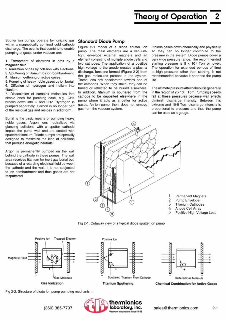
Standard Diode PumpFigure 2-1 model of a diode sputter ion pump. The main elements are a vacuum-tight envelope external magnets and an element consisting of multiple anode cells and two cathodes. The application of a positive high voltage to the anode creates a plasma discharge. Ions are formed (Figure 2-2) from the gas molecules present in the system. These ions are accelerated toward one of the cathodes. When they strike. they can be buried or reflected to be buried elsewhere. In addition. titanium is sputtered from the cathode to be deposited elsewhere in the pump where it acts as a getter for active gases. An ion pump, then, does not remove gas from the vacuum system.
It binds gases down chemically and physically so they can no longer contribute to the pressure in the system. Diode pumps cover a very wide pressure range. The recommended starting pressure is 5 x 10⁻³ Torr or lower. The operation for extended periods of time at high pressure, other than starting, is not recommended because it shortens the pump life.
The ultimate pressure after bakeout is generally in the region of 2 x 10-11 Torr. Pumping speeds fall at these pressures because wall effects diminish discharge intensity. Between this extreme and 10-5 Torr, discharge intensity is proportional to pressure and thus the pump can be used as a gauge.
1 Permanent Magnets2 Pump Envelope3 Titanium Cathodes4 Anode Cell Array5 Positive High Voltage Lead
Fig 2-1. Cutaway view of a typical diode sputter ion pump
Fig 2-2. Structure of diode ion pump pumping mechanism.

2-2 (360) 385-7707 [email protected]
Figure 2-3 is a sketch of a triode sputter ion pump.
Triode sputter ion pumps include:
1. External magnets which intensify the discharge.2. Stainless steel, internally welded pump envelope.3. Two-sputter cathodes consisting of multiple strips of titanium held at a negative high voltage.4. An array of stainless-steel anode cells which are at ground potential.
As in the diode. a plasma discharge is created within the anode cells upon the application of high voltage to the cathode grid. The ions impinge upon the sputter cathode and dislodge titanium atoms as in the diode. At this point, there is a significant difference. Because the cathode grids are open considerable titanium reaches the pump walls where it cannot be further disturbed by ion bombardment. This has at least two favorable results: Undisturbed deposits mean less regurgitation of previously pumped gases; and deposits at the pump wall mean that titanium compounds are kept cooler in the starting mode.
A further benefit of the open cathode grid structure is a higher production rate for energetic neutral atoms. These energetic neutrals are produced by glancing collisions at the cathode and are readily buried at the pump wall This burial without reemission accounts for the triode’s high speed for noble gases.
Triode Pumps
2 Theory of Operation
1 Permanent Magnets2 Pump Envelope3 Titanium Strip Cathodes4 Anode Cell Array
Fig 2-3. Cutaway view of a typical triode sputter ion pump.
Fig 2-4. Argon (noble) pumping mechanism. Cross section views of single cells.

2Ion Pump Guide
2-3(360) 385-7707 [email protected]
Thermionics manufactures a full line of sputter ion pumps.
These are:
• Standard Diode Pumps (IP Series)• Noble Diode Pumps (NP Series)• Hydrogen Diode (HP Series)• Triode Pumps (TP Series)
Each pump Is
• Designed for a specific application• Able to provide continuous and contaminant• free pumping• Reliable from 1 micron to 2 x 10 -11 Torr
(measured)• Free from backstreaming• Bakeable to 300°C assembled• Bakeable to 450°C magnets removed• Able to act as its own vacuum gauge
All pumps are manufactured to exacting UHV standards Pump bodies, flanges and element anodes are made of 304 stainless steel, bakeable to 450°C. Double re-entrant electrical insulators are made of high-quality aluminum oxide, bakeable to 450°C, and are equipped with sputter shields. Pump magnets are high-strength ferrites bakeable to 300°C.
As a full line vacuum manufacturer, TLI can recommend the best pump for your job without reservation or bias We cover the full line of ion pumps. The table below gives a comparison between pumps for different pumping applications.
Standard Diode Pump use two titanium cathodes in each pumping element. They are the pump of choice for most applications for their long life, reliability, and high speed per unit price. Not recommended when significant amounts of hydrogen or noble gases are to be pumped or where frequent high starting loads are encountered.
Triode Pumps use reverse electrical polarity and a radically different cathode design to achieve two important advantages over the diode pumps: (1) an electrically isolated cathode allows the starting glow discharge to be confined at significantly higher pressures, resulting in shorter starting times; (2) the sputter cathode design allows noble and non-noble gases to be permanently buried without resputtering. Triodes have the highest speeds for noble gases and freedom from argon instability in the event of an air leak Disadvantage: because of the sputter cathode design, the triode pump requires more frequent service.
Hydrogen Diode Pumps are also similar to standard diodes. There are two differences in construction. The first is a thicker cathode. Because hydrogen diffuses into titanium like water into a sponge, the more titanium the more capacity for hydrogen the pump has. This absorption of hydrogen can lead to a structural problem, however, Titanium swells and distorts as it absorbs large amounts of hydrogen. Therefore, hydrogen pumps have special structural modifications to prevent distortion from causing electrical shorts.
Noble Diode Pumps use one titanium and one tantalum cathode to improve pumping speed for noble gases. Increased speed eliminates the pressure and speed instabilities shown by standard diodes when pumping against a prolonged air leak while retaining the long life and reliability of the standard diode. Most stable pump for noble gas loads.
Noble diodes were deve1oped to pump noble gases in every instance but one they are identical to a standard diode. The difference is the use of one tantalum cathode in place of one of the two titanium cathodes in the standard pump. The tantalum. because of its larger atomic number. produces a greater number of energetic neutrals that can now bury themselves in locations that are less subject to resputtering.
Choosing the Right Pump for Your Application
Pump Characteristics Normalized to the Standard Diode
Pump Type Air Speed
Argon Speed(% of Air)
Hydrogen Speed
Starting Performance
Life Time at1 x 10-6 Torr
Standard Diode 100% 1% 200-270%
Light Duty OnlyAverage
10 μ5 x 10⁴
hours
Noble Diode 95% 1% Not
Recommended
Below Aver-age5 μ
5 x 10⁴
hours
Hydrogen Diode 100% 1% 200-270% Average
10 μ7.5 x 10⁴
hours
Triode 85% 21% 200-270%Light Duty Only
Good50 μ
3.5 x 10⁴
hours
Tantalum is somewhat less effective than titanium as a getter. Therefore, the speed of the noble diode is approximately 5% lower than the standard diode. Another fact of note is the lessened solubility of hydrogen in tantalum at elevated temperatures. Since elevated temperatures will be encountered during prolonged starting, it would be wise to avoid applications that require this pump to handle large amounts of hydrogen. Naturally, applications differ. Should you have any questions about the applicability of a pump for your use, please give us a call. We have a wide variety of prior applications to draw upon.
These extra construction details make the hydrogen diode a good choice for long pump life applications. Examples might be pumps operating in radioactive environments or operating at remote locations Recommended when major gas load is hydrogen or hydrogen-containing gases such as water vapor Also pumps other non-noble gases

2-4 (360) 385-7707 [email protected]
For many applications, starting performance is not a criterion when choosing a pump because the system is seldom brought up to ai. In other applications, such as surface analysis equipment or process related equipment, the time lost waiting for pumpdown to operating pressures is a very important consideration. In some cases, the labor costs saved by shorter pumpdowns can earn back the differential in the price of a triode pump in less than a month. The figure below demonstrates the value of the higher triode speed at higher pressures. Two pumps, a 60 I/sec triode and a 440 I/sec diode, were attached to the same large vacuum chamber. The smaller triode pump first pumped the chamber down. It was then released to air and pumped down by the larger diode. The triode, despite a 7-to-1 speed disadvantage. showed a very significant advantage over the diode in reaching the 10-5 region. The diode, despite its larger rated speed at lower pressures, took more than three hours to match the pressure achieved by the smaller pump. Naturally, pumpdown performance depends on other variables such as the roughing system, prior chamber exposure. etc . but if pumpdown time is important to your ion pumped system, a triode is the pump of choice.
After you have selected the type of pump you need for your application; you must then determine its size. This section gives sample computations for three common pumping applications. They are: (1) pumping with no load other than wall out-gassing: (2) pumping with an additional load, and (3) pumping with an additional pump of another type. If you are accustomed to the large speeds required by diffusion pumped systems, you may be surprised at the capabilities of TLI ion pumps. Ion pumps do not need elaborate baffles to protect the system from contamination, hence effective speeds are not diminished by those conductance considerations.
1. What species of gases will be found in your system and what is the anticipated outgassing rate? (This, 1n large part, can be determined from your expected bakeout temperature.)
2. What is the surface area of the system?3. What additional gas loads, if any, will be
introduced as a result of the work done in the system?
4. What is the conductance between the pump and the system?
5. What is the desired process pressure and/ or desired ultimate pressure?
Any of the ion pumps will do a good job in a general pumping application. (1) The diode pump is usually the choice when there is no requirement for pumping noble gases and when the initial price is an important criterion. (2) The noble diode is designed for pumping noble gases with longer life, and does so at a lower price (3) The hydrogen diode is used not only where large amounts of hydrogen are expected, such as tube processing, but also in applications where a longer lifetime is needed. (4) The triode is the pump of choice when frequent pumpdowns are expected. It is also excellent for noble gas pumping.
Starting PerformanceSizing the Pump to Your Applications System Information Needed
Summary
2 Ion Pump Guide
Fig 2-5. Alternate pumpdown times for a diode and triode on large chamber
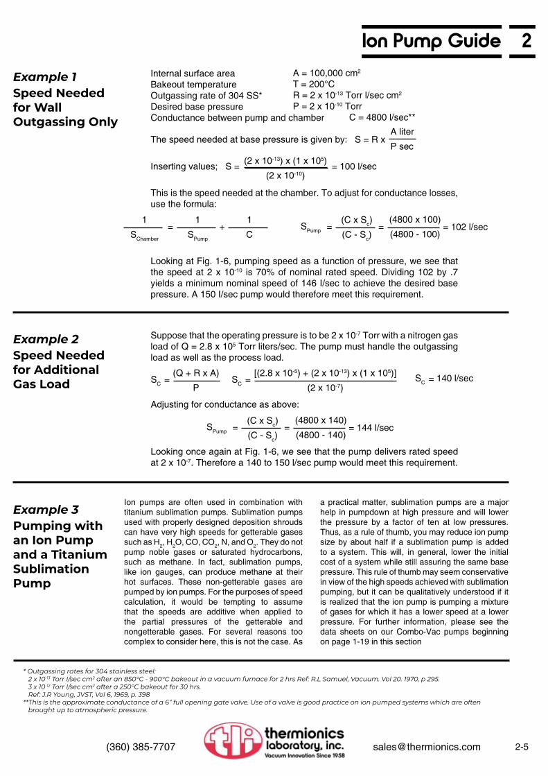
Internal surface areaBakeout temperatureOutgassing rate of 304 SS*Desired base pressureConductance between pump and chamber
The speed needed at base pressure is given by: S = R x
This is the speed needed at the chamber. To adjust for conductance losses, use the formula:
Looking at Fig. 1-6, pumping speed as a function of pressure, we see that the speed at 2 x 10⁻¹⁰ is 70% of nominal rated speed. Dividing 102 by .7 yields a minimum nominal speed of 146 I/sec to achieve the desired base pressure. A 150 I/sec pump would therefore meet this requirement.
Suppose that the operating pressure is to be 2 x 10⁻⁷ Torr with a nitrogen gas load of Q = 2.8 x 10⁵ Torr liters/sec. The pump must handle the outgassing load as well as the process load.
Ion pumps are often used in combination with titanium sublimation pumps. Sublimation pumps used with properly designed deposition shrouds can have very high speeds for getterable gases such as H2, H2O, CO, CO2, N, and O2. They do not pump noble gases or saturated hydrocarbons, such as methane. In fact, sublimation pumps, like ion gauges, can produce methane at their hot surfaces. These non-getterable gases are pumped by ion pumps. For the purposes of speed calculation, it would be tempting to assume that the speeds are additive when applied to the partial pressures of the getterable and nongetterable gases. For several reasons too complex to consider here, this is not the case. As
a practical matter, sublimation pumps are a major help in pumpdown at high pressure and will lower the pressure by a factor of ten at low pressures. Thus, as a rule of thumb, you may reduce ion pump size by about half if a sublimation pump is added to a system. This will, in general, lower the initial cost of a system while still assuring the same base pressure. This rule of thumb may seem conservative in view of the high speeds achieved with sublimation pumping, but it can be qualitatively understood if it is realized that the ion pump is pumping a mixture of gases for which it has a lower speed at a lower pressure. For further information, please see the data sheets on our Combo-Vac pumps beginning on page 1-19 in this section
Looking once again at Fig. 1-6, we see that the pump delivers rated speed at 2 x 10⁻⁷. Therefore a 140 to 150 l/sec pump would meet this requirement.
* Outgassing rates for 304 stainless steel: 2 x 10-13 Torr I/sec cm2 after an 850°C - 900°C bakeout in a vacuum furnace for 2 hrs Ref: R.L Samuel, Vacuum. Vol 20. 1970, p 295. 3 x 10-12 Torr I/sec cm2 after a 250°C bakeout for 30 hrs. Ref: J.R Young, JVST, Vol 6, 1969, p. 398**This is the approximate conductance of a 6” full opening gate valve. Use of a valve is good practice on ion pumped systems which are often brought up to atmospheric pressure.
Adjusting for conductance as above:
= =
=
= ==
SPump
SPump
SCSC 140 l/secSC
= 102 l/sec
= 144 l/sec
+ =
=
Inserting values; S = = 100 l/sec
A liter
P sec
(2 x 10-13) x (1 x 105)
(2 x 10⁻¹⁰)
1
SChamber
1
SPump
(C x Sc)
(C - Sc)
(C x Sc)
(C - Sc)
(Q + R x A)
P
[(2.8 x 10⁻⁵) + (2 x 10-13) x (1 x 105)]
(2 x 10⁻⁷)
1
C
(4800 x 100)
(4800 - 100)
(4800 x 140)
(4800 - 140)
A = 100,000 cm2
T = 200°CR = 2 x 10-13 Torr l/sec cm2
P = 2 x 10⁻¹⁰ Torr C = 4800 l/sec**
Example 1
Example 2
Example 3
Speed Needed for Wall Outgassing Only
Speed Needed for Additional Gas Load
Pumping with an Ion Pump and a Titanium Sublimation Pump
2Ion Pump Guide
2-5(360) 385-7707 [email protected]

2-6 (360) 385-7707 [email protected]
2 Long-Term Pumping Speed
Gas Triode Speed
Diode SpeedStandard & Hydrogen
Noble Diodes
Nitrogen 100% 100% 100%
Carbon Monoxide 100% 100% 108%
Water Vapor 100% 100% 100%
Carbon Dioxide 100% 100% 100%
Hydrogen 200 to 250% 200 to 250% 160%
Misc. Hydrocarbons 50 to 150% 50 to 150% 90%
Oxygen1 50% 50% 70%
Helium2 30% 10% 30%
Argon 21% 1% or less3 6 to 20%
Long-Term Pumping Speed as a Percentage of Rated Ion PumpSpeed for Various Gases
Air Pumping Speed as a Percentage of Rated Speed vs. Pressure
1. Low oxygen speed is thought to be due to formation of a sputter-resistant oxide film on the cathod e. Speed for oxygen when other gases are present is undoubtedly much higher.
2. In all ion pumps, the pumping mechanism for helium limits the long-term pumping speed for helium. When helium saturation occurs, which is a function of the load over time, pump ing speeds for helium will be less than the percentages shown.
3. Diodes are qwte satisfacto,y for pumpdown of systems backfilled with argon. They do exhibit instabilities when pumping against air or pure argon leaks.
Fig. 2-6. Universal speed and throughput curves for all TLI diode-type ion pumps. To find speed in liters per second at a given pressure, multiply % speed at that pressure times rated speed.

2Long-Term Pumping Speed
2-7(360) 385-7707 [email protected]
Performance Curves, Triode Pumps
60 Years Experience in Ion Pump Development and Manufacturing - 1000’s Sold
Sizes
Models Construction Service and Parts
Rebuilding
Each Pump is:
Choosing the Right Pump for Your Application Power Supplies, Cables
Fig. 2-8. Percentage of nominal rated pumping speed vs pressure
Fig. 2-9. Pressure vs Current
Starting and ThroughputPumpdown time is determined by net pumping speed in the 10-3 to 10-4 Torr range. Net pumping speed is rated speed minus outgassing due to power dissipation in the pump. Thus net speed is time dependent. Any factor such as a leak or a dirty system which prolongs the time spent in the high power region can seriously lengthen pumpdown times.
• Most complete line of ion pumps, power supplies and accessories
• Fastest, most reliable ion pumps available. • Thermionics ion pumps are 100% compatible with your
existing Varian or Perkin-Elmer power supplies.
• 0.2 l/sec to 1,000 l/sec
• Diode configurations Standard (IP Series) Nobile (D-I) (NP Series Hydrogen (HP Series)• Triode configurations Standard (TP Series) Greater (GT Series)• Combo-Vac Pumps Combining a Noble (D-I) or Triode pump, Titanium Sublimation Pump (TSP), and Cryo panel
• Able to provide continuous and contaminant free pumping
• Reliable from 1 micron to 2 x 10-11 Torr• Free from backstreaming• Bakeable to 300°C assembled• Bakeable to 450°C magnets removed• Able to act as its own vacuum gauge
• As a full line vacuum manufacturer, TLI can provide the best pump for your job without reservation or bias
• We manufacture a full range of ion pumps
• TLI will custom design pumps for a special application
We offer five power supply models: from a small power supply, which operates with an input voltage of either 110 Vac or 12 Vdc, and is capable of starting and operation small pumps or “holding” larger pumps; to a large, reliable, no frolls, 1.0 A output power supply capable of starting and operating the largest of ion pump. We sell replacement cables for Varian and P-E power supplies
• All pumps are manufactured to exacting UHV standards
• Pump bodies, fIanges and element anodes are made of 304 stainless steel
• Double re-entrant electrical insulators are made of high-quality aluminum oxide, with sputter shields
• Pump magnets are high-strength ferrites bakeable to 300°C
We service, repair, and supply replacement parts for all pumps including TLI, Varian, Perkin-Elmer, Ultek, Ion Equipment, Hughes, Ulvac, Anelva, etc.
We rebuild and repair all sizes and manufacturers of ion pumps, elements, and power supplies. Please refer to page 2-22 for futher information.

2-8 (360) 385-7707 [email protected]
2 Diode Pump Specifications and Order Information
Model Number Rates Pump Speedl/sec
Flange I.D./O.D.1,2
Inches
Weightlbs Dimensions Bakeout Heater
Quantity3Replacement
Elements8
IP-011 11 1.5/2.75 14 Fig. A(page 2-12) 0 Fact. repl.
IP-020 IP-020/IH 204 1.5/2.75 26 Fig. B
(page 2-12)0 1 Fact. repl.
IP-025 IP-025/IH 254 2.0/3.375 31 Fig. C
(page 2-12)0 1 Fact. repl.
IP-050 IP-050/DE 80/505 4.9/8.0 94 Fig. D
(page 2-12) 2 PE-100 2 ea
IP-100 IP-100/DE 150/1005 6.0/8.0 127
142Fig. E
(page 2-12) 4 PE-100 4 ea
IP-140 IP-140/DE 1405,6 6.0/8.0 140
150Fig. L
(page 2-13) 0 DE-110 1 ea
IP-150 IP-150/DE 220/1505 6.0/8.0 145
160Fig. F
(page 2-13) 4 PE-100 6 ea
IP-200 IP-200/DE 270/2005 6.0/8.0 141
156Fig. G
(page 2-13) 4 PE-100 8 ea
IP-270 IP-270/DE 2705 6.0/8.0 250
290Fig. M
(page 2-15) 0 DE-110 2 ea
IP-400 IP-400/DE 500/4005 6.0/8.0 275
290Fig. H
(page 2-13) 8 PE-100 16 ea
IP-500 IP-500/DE 5005,6 6.0/8.0 400
460Fig. N
(page 2-15) 0 DE-110 4 ea
IP-1000 IP-1000/DE 10005,7 10.75/12.75
Wire seal fIange930 990
Fig. O(page 2-15)
Bakeout shroud available
DE-110 8 ea
1 See Section 7 for matching gasket and bolt and nut sets. 2 All flanges ConFlat compatible except 1,000 I/sec pumps.3 Heaters are model IH-100 Calrod heaters which fit into matching interior heater
wells in most pumps.4 IH signifies interior heater well available as option. 5 DE specifies a double-ended option6 No bakeout heaters available for this pump.7 Larger pumps available on special order. 8 See Accessories, page 2-11
Ion Pump Power Supplies
‘Pumping Speed Ratings for Ion Pumps
Please refer to page 2-16 for power supply applications and specifications
Some pumps in this table have two pumping speeds shown, ie. 150/100. The lower number is observed when the measurement standard established by the American Vacuum Society (AVS) is followed. The higher number is observed when the same pump is measured under optimum pumping speed conditions. Some manufacturers only report the optimum pumping speed number. Both ratings are provided here to allow the customer to make an informed choice.
11 I/sec Pump

2Noble Diode Pump Specifications & Order Information
2-9(360) 385-7707 [email protected]
Model Number Rates Pump Speedl/sec
Flange I.D./O.D.1,2
Inches
Weightlbs Dimensions Bakeout Heater
Quantity3Replacement
Elements8
NP-011 11 1.5/2.75 14 Fig. A(page 2-12) 0 Fact. repl.
NP-020 NP-020/IH 204 1.5/2.75 26 Fig. B
(page 2-12)0 1 Fact. repl.
NP-025 NP-025/IH 254 2.0/3.375 31 Fig. C
(page 2-12)0 1 Fact. repl.
NP-050 NP-050/DE 60/505 4.9/8.0 82
94Fig. D
(page 2-12) 2 PE-100N 2 ea
NP-100 NP-100/DE 120/1005 6.0/8.0 127
142Fig. E
(page 2-12) 4 PE-100N 4 ea
NP-140 NP-140/DE 1155,6 6.0/8.0 143
154Fig. L
(page 2-14) 0 DE-110N 1 ea
NP-150 NP-150/DE 160/1505 6.0/8.0 145
160Fig. F
(page 2-13) 4 PE-100N 6 ea
NP-200 NP-200/DE 220/2005 6.0/8.0 145
160Fig. G
(page 2-13) 4 PE-100N 8 ea
NP-220 NP-220/DE 2205 6.0/8.0 250
290Fig. M
(page 2-15) 0 DE-110N 2 ea
NP-400 NP-400/DE 4005 6.0/8.0 276
290Fig. H
(page 2-13) 8 PE-100N 16 ea
NP-500 NP-500/DE 4005 6.0/8.0 402
460Fig. N
(page 2-15) 0 DE-110N 4 ea
NP-1000 NP-1000/DE 8005,7 10.75/12.75
Wire seal fIange932 990
Fig. O(page 2-15)
Bakeout shroud available
DE-110N 8 ea
1 See Section 7 for matching gasket and bolt and nut sets. 2 All flanges ConFlat compatible except 1,000 I/sec pumps.3 Heaters are model IH-100 Calrod heaters which fit into matching interior heater
wells in most pumps.4 IH signifies interior heater well available as option. 5 DE specifies a double-ended option6 No bakeout heaters available for this pump.7 Larger pumps available on special order. 8 See Accessories, page 2-11
Ion Pump Power Supplies
‘Pumping Speed Ratings for Ion Pumps
Please refer to page 2-16 for power supply applications and specifications
Some pumps in this table have two pumping speeds shown, ie. 150/100. The lower number is observed when the measurement standard established by the American Vacuum Society (AVS) is followed. The higher number is observed when the same pump is measured under optimum pumping speed conditions. Some manufacturers only report the optimum pumping speed number. Both ratings are provided here to allow the customer to make an informed choice.
20 I/sec Pumps

2-10 (360) 385-7707 [email protected]
2 Hydrogen Diode Pump Specifications and Order Information
Model Number Rates Pump Speedl/sec
Flange I.D./O.D.1,2
Inches
Weightlbs Dimensions Bakeout Heater
Quantity3Replacement
Elements8
HP-011 11 1.5/2.75 14 Fig. A(page 2-12) 0 Fact. repl.
HP-020 HP-020/IH 204 1.5/2.75 26 Fig. B
(page 2-12)0 1 Fact. repl.
HP-025 HP-025/IH 254 2.0/3.375 32 Fig. C
(page 2-12)0 1 Fact. repl.
HP-050 HP-050/DE 80/505 4.9/8.0 82
96Fig. D
(page 2-12) 2 PE-100H 2 ea
HP-100 HP-100/DE 150/1005 6.0/8.0 129
144Fig. E
(page 2-13) 4 PE-100H 4 ea
HP-140 HP-140/DE 1405,6 6.0/8.0 143
154Fig. L
(page 2-14) 0 DE-110H 1 ea
HP-150 HP-150/DE 220/1505 6.0/8.0 147
162Fig. F
(page 2-13) 4 PE-100H 6 ea
HP-200 HP-200/DE 270/2005 6.0/8.0 143
158Fig. G
(page 2-13) 4 PE-100H 8 ea
HP-270 HP-270/DE 2705 6.0/8.0 252
292Fig. M
(page 2-15) 0 DE-110H 2 ea
HP-400 HP-400/DE 500/4005 6.0/8.0 278
294Fig. H
(page 2-13) 8 PE-100H 16 ea
HP-500 HP-500/DE 5005 6.0/8.0 404
464Fig. N
(page 2-15) 0 DE-110H 4 ea
HP-1000 HP-1000/DE 10005,7 10.75/12.75
Wire seal fIange936 996
Fig. O(page 2-15)
Bakeout shroud available
DE-110H 8 ea
1 See Section 7 for matching gasket and bolt and nut sets. 2 All flanges ConFlat compatible except 1,000 I/sec pumps.3 Heaters are model IH-100 Calrod heaters which fit into matching interior heater
wells in most pumps.4 IH signifies interior heater well available as option. 5 DE specifies a double-ended option6 No bakeout heaters available for this pump.7 Larger pumps available on special order. 8 See Accessories, page 2-11
Ion Pump Power Supplies
‘Pumping Speed Ratings for Ion Pumps
Please refer to page 2-16 for power supply applications and specifications
Some pumps in this table have two pumping speeds shown, ie. 150/100. The lower number is observed when the measurement standard established by the American Vacuum Society (AVS) is followed. The higher number is observed when the same pump is measured under optimum pumping speed conditions. Some manufacturers only report the optimum pumping speed number. Both ratings are provided here to allow the customer to make an informed choice.
COV-1000S: 200 l/sec Triode Pump with Cryoshroud andTi Sublimation Pump (shown with Power Supply)
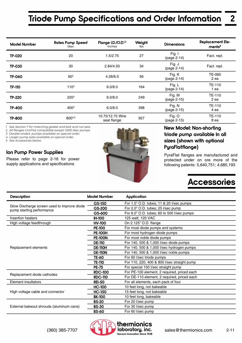
2Triode Pump Specifications and Order Information
Accessories
2-11(360) 385-7707 [email protected]
Model Number Rates Pump Speedl/sec
Flange I.D./O.D.1,2Inches
Weightlbs Dimensions Replacement Ele-
ments8
TP-020 20 1.5/2.75 27 Fig. I(page 2-14) Fact. repl.
TP-030 30 2.84/4.50 34 Fig. J(page 2-14) Fact. repl.
TP-060 603 4.26/6.0 56 Fig. K(page 2-14)
TE-060 2 ea
TP-110 1103 6.0/8.0 164 Fig. L(page 2-14)
TE-110 1 ea
TP-220 2203 6.0/8.0 249 Fig. M(page 2-15)
TE-110 2 ea
TP-400 4003 6.0/8.0 398 Fig. N(page 2-15)
TE-110 4 ea
TP-800 8003,6 10.75/12.75 Wire seal fIange 927 Fig. O
(page 2-15)TE-110
8 ea
Description Model Number Application
Glow Discharge screen used to improve diode pump starting performance
GS-150 For 1.5” O.D. tubes; 11 & 20 I/sec pumpsGS-200 For 2.0” O.D. tubes; 25 l/sec pumpGS-600 For 6.0” O.D. tubes; 60 to 500 l/sec pumps
Insertion heaters IH-100 125 watt, 120 VACHigh voltage feedthrough HV-100 On 2.125” O.D. fIange
Replacement elements
PE-100 For most diode pumps and systemsPE-100H For most hydrogen diode pumpsPE-100N For most noble diode pumpsDE-110 For 140, 500 & 1,000 l/sec diode pumpsDE-110H For 140, 500 & 1,000 l/sec hydrogen pumpsDE-110N For 140, 500 & 1,000 l/sec noble pumpsTE-60 For 60 l/sec triode pumpsTE-110 For 110, 220, 400 & 800 l/sec straight pumpPE-75 For special 150 l/sec straight pump
Replacement diode cathodes RDC-100 For PE-100 element, 2 required, priced eachRDC-110 For DE-110 element, 2 required, priced each
Element insultators REI-50 For all elements, each pack of four
High voltage cable and connectorHC-100 10 feet long, not bakeableHC-150 15 feet long, not bakeableBK-100 10 feet long, bakeable
External bakeout shrouds (aluminum cans)BS-20 For 20 l/sec pumpBS-30 For 30 l/sec pumpBS-60 For 60 l/sec pump
1 See Section 7 for matching gasket and bolt and nut sets. 2 All flanges ConFlat compatible except 1,000 I/sec pumps.3 Double-ended pumps available on special order.4 Larger pump sizes available on special order. 5 See Accessories below.
Ion Pump Power Supplies
New Model: Non-shorting triode pump available In all sizes (shown with optional PyraFlatflange)
Please refer to page 2-16 for power supply applications and specifications
PyraFlat flanges are manufactured and protected under on ore more of the following patents: 5,640,751; 4,685,193

2-12 (360) 385-7707 [email protected]
2 Physical Dimensions of Diode/Noble/Hydrogen Pumps
A 11 l/secStandard Pump
B
C
D
20 l/secStandard Pump
25 l/secStandard Pump
60 l/sec Standard Pump50 l/sec Noble Pump
Dimensions in:
inches
mm

2Physical Dimensions of Diode/Noble/Hydrogen Pumps
2-13(360) 385-7707 [email protected]
E 120 l/sec Noble Pump150 l/sec Standard Pump
F
G
H
160 l/sec Noble Pump220 l/sec Standard Pump
220 l/sec Noble Pump270 l/sec Standard Pump
400 l/sec Noble Pump500 l/sec Standard Pump

2-14 (360) 385-7707 [email protected]
2 Physical Dimensions of Triode/Diode Pumps
I 20 l/sec Triode Pump
J
K
L
30 l/ecTriode Pump
60 l/secTriode Pum
110 l/sec Triode Pump140 l/sec Standard Pump

2Physical Dimensions of Triode/Diode Pumps
2-15(360) 385-7707 [email protected]
M 220 l/sec Triode Pump270 l/sec Standard Pump
N
O
400 l/sec Triode Pump500 l/sec Standard Pump
800 l/sec Triode Pump1000 l/sec Standard Pump

2-16 (360) 385-7707 [email protected]
2 Ion Pump Control Units
Front Panel: Front Panel:
Front Panel:
Ion Pump Control Unit Specifications
Front Panel:
PS-20 PS-100 or PS-100N
PS-350 or PS-350N
Thermionics offers five different ion pump controllers to suit various pump sizes and operating conditions
PS-350 and PS-500 for Combo Pump
Features• Reliable - proven design• Includes high voltage cable at no extra cost• Recorder output
TLI’s ion pump control units provide matched power and control for all the pumps listed in the catalog. When ordering, please specify diode or triode operation. Control units for triode pumps have the suffix “N” added to their model number.
The table to the left indicates the range of controller sizes recommended for various pump sizes. For more specific application informtaion, please contact us.
Model Number PPS-5* (Portable) PS-10 PS-100 (N)** PS-350 (N)** PS-1000 (N)**
PhyscialRack MountH x W x DShip Weight
No9” x 8.1” x 14.125”30 lbs (24 lbs actual)
Yes (requires rack adapter)5.25” x 5” x 8.75”6.5 lbs
Yes (requires rack adapter)5.5” x 8” 14”14 lbs
Yes8” x 17” 14”85 lbs
Yes8” x 17” 14”110 lbs
Electrical Input(Single phase)VoltageCurrentAC Cord
95-240 VAC, 50/60 Hz or 12 VDChas internal battery(<50 Watts)AC and DC cords included
120 VAC, 60 Hz230 VAC, 50 Hz available0.5 A15’ with plug
120 VAC, 60 Hz230 VAC, 50 Hz available5 A15’ with plug
50 / 60 Hz120/230 VAC15/8 A15’ with plug
50 / 60 Hz208/230 VAC25/22 A15’ with plug
Electrical OutputVoltageCurrentProtection circuitHV coax cable
4.8 kV DC @ mA5 mAAdjustable4’ w/ dual safety ground straps & cable halyard
4.2 kV DC @ 1 mA10 mACurrent limit 12 mA10’ w/ connectorboth ends
5 kV DC @ 10 mA120 mA20-25 mA trip10’ w/ connector both ends
5 kV DC350 mA210-280 mA trip10’ w/ connector both ends
5 kV DC 1,000 mA60-1,000 mA trip10’ w/ connector both ends
Recorder Output No Yes Yes Yes Yes
Display Digital Meter LED Digital Meter Meter Meter
Accessories
Rack Adaptor for the PS-10 and PS-100 (N) 19” rack adapter, space for three PS-10 or two PS-100 (N)PS-05HRA
Recommended for All Power SuppliesDS-GR Grounding Rod
Additional HV Coax Cable
Additional Bakeable HV Coax Cable
* Capable of maintaining a pump for > 48 hours (< 1 mA draw) without external power**Triode Pump supplies (N) provide (-) voltage, other provide (+) voltage
Ion Pump Controller
Application (pump size, l/sec)
StartingSustaining Output
PPS-5 5 mAPS-10 10 mAPS-100 (N) 120 mAPS-350 (N) 350 mAPS-1000 (N) 1,000 mA
2 2 20 200 1000

2Appendage Pumps
2-17(360) 385-7707 [email protected]
Features
AP-2/133
Appendage Pumps
Magnets for TU and Varian Appendage Pumps
AIP-2/275
In-Line, Tube Type Ion PumpStraight Through, 150 l/sec, Line of Sight Ion Pump
SP-150
Nom.Speed(l/sec) Pump Inlet
Pump Design
TLI Style Varian Style
Model Number Model Number0.2 90˚, 3/8” SS AIP-0.2T **
0.2 90˚, 3/8” CU AIP-0.2TC **
0.2 90˚, mini fIange AIP-0.2/133 **
2.0 180˚, 3/4” SS AIP-2T 913-0032
2.0 180˚, mini fIange AIP-2/133 913-5000
8.0 180˚, 2.75 fIange AIP-8/233 911-5005
Size (l/sec) Type Gauss Model Number Varian Model Number0.2 Alnico 800+ MP-0.2 914-0042
2.0 Alnico 1200 MP-2 913-0011
2.0 Sm-Co — 1200 MEV-2 913-00112
8.0 Sm-Co — 1200 ME-8 *
8.0 Sm-Co — 1200 MEV-8 913-0030
• Pumps are either vacuum processed and pinched off (after 400˚C+ bake out) or shipped in up-to-air configuration
• Inlet ports are 3/8”, ¾” O.D. copper or SS tubes; 1.33” mini or 2.75” O.D. ConFlat type flanges
• High-voltage feedthroughs are TLI, P-E (Alberox type), Varian style or standard BNC type connectors
• All pumps are tested for vacuum integrity and excessive electrical leakage current
Appendage pumps are available in 0.2 l/sec, 2 l/sec, and 8 l/sec sizes, with the following features:
To meet your special application requirements, any of our pumps can be built in a custom configuration. All of the pumps are manufactured in the USA. Prefab pump subassemblies are kept in stock. We can modify them, process, and ship your custom pump in two weeks or less.
vacuum mass spectrometer. Either of the large ports or the small ports can be attached to the system, providing good conductance and a savings in the cost of fittings.This pump allows line-of-sight conductance for X-ray beams, laser beams, and high-energy particle beams. Because of the small magnetic fringing field, it is not recommended for low-energy particle beams.LengthHeightLarge FlangeSmall FlangeModel Number
32 1/4”16 3/4”8” O.D., 4.5” I.D.6” O.D., 2.5”I.D SP-150
This unusual ion pump illustrates TLl’s ability to meet special needs. In this case, the need was for pumping on either side of the magnetic defIection sector of an ultra-high
Please refer to page 2-16 for power supply applications and specifications.
**TLI pump performance is fully comparable to a Varian pump
*Long life Samarium-Cobalt magnet mounted in low stray field enclosure
Custom Design

2-18 (360) 385-7707 [email protected]
2 Titanium Sublimation PumpsTitanium Sublimation Pump
SB-1000
SB-1020
SB-1002B
SB-1001
Specifications
PS-500 Sublimator Power Supply
Titanium Sublimation Pumps (TSP’s) are used to pump chemically reactive, getterable gases. Titanium is effective, is easily sublimed, and is inexpensive.
TSP’s have high pumping speeds. At pressures below 10-6 Torr, pumping speed is dependent upon available surface area for condensation. Pumping speed is increased by cooling the sub-strate surfaces with water or liquid nitrogen
The filaments of the titanium sublimation pump are 85% titanium and 15% molybdenum, a combination which prevents premature filament “burnout.”
TSP with 3.38” mounting fIange.
TSP with 2.75” mounting fIange.
Bakeable adapter with Amphenol female MS connector and bakeable cable
12 spiral filaments
Specify if used with sublimator with 2.75” or 3.38” fIange. Example: PS-500/275 or PS-500/338.
Model No. A* B C D
SB-1000 9.5” 2.26” 3.38” 1.625”
SB-1020 9.5” 3.07” 2.75” 1.312”
*Standard length Special lengths on request.
MaterialLength
WeightUsable Ti
85% Ti, 15% Mo8 5/8” before cooling;4 5/8” coiled3.6 grams/filament1.5 grams/filament
Physcial Electrical Input1 Electrical Output2 Timer DisplayRack SizeChassis DimensionsShip WeightAC Cord
19”8 3/4” x 17” x 12”50 lbs15 feet with plug
Voltage 115 VACFrequency 60HZ
Voltage 12 VACMax current 50 ASelector switchfor 4 filaments
OFF-time (range)ON-time
2 to 120 min4 to 120 sec
Analogmeter,current 75A
1 230/208 VAC and/or 50 Hz available as special order. Please specify on order. 2 WithSB-1001 spiral filaments

2Combo-Vac Pumps
Combo-Vac Pumps: Ion, Cryo and TSP Combined in One Pump
2-19(360) 385-7707 [email protected]
Liquid Nitrogen Shroudfor Use with TSP
Model S5400/275
Model SS400/338
What is a Combo-Vac Pump?
LN2 Controller
Model LNC-400
High-speed LN2 cooled cryoshroud. Full-fIood design keeps all surfaces at LN2 temperature. Readily removeable for maintenance purposes All stainless-steel construction
with 8” O.D. main falnge and 2.75” mounting fIange
with 8” O.D. main falnge and 3.38” mounting fIange
For specifications, see Section 6, page 6-12
Combo-Vac pumps are a combination of titanium sublimation pumps and noble diode ion pumps in one cryo-cooled package. (Model COV-500 is an exception, as it has an integral wa-ter-cooled jacket rather than a cryoshroud ) They are often used in factory processing of high-power vacuum tubes, Xray sources, etc. It is well suited to the gases evolved by such devices in their initial processing. They are tremendously cost effective for certain applications, i.e., where reliable, clean, contaminant-free pumping is a major consideration Their high speed is the result of the ability of a freshly deposited titanium film in vacuum to chemisorb such gases as oxygen, nitrogen, water vapor, carbon monoxide, and carbon dioxide. When the walls on which titanium is deposited are water-cooled, speeds of 40 to 90 I/sec (depending upon gas spe-cies) for each square inch of substrate are obtained. Thus total pump speeds can be quite large for large deposition chambers The ion pumps handle gases that are not pumped by the sublima-tion pump-more about this later.
Because you control the rate at which titanium is deposited on the walls, you can adjust pump-ing speeds to suit your needs. For example, if you must pump down to a certain pressure before starting a process, you can reach that pressure more quickly by increasing the sublimation rate. If your process liberates gas, you will be able to
speed the process with more speed at your dis-posal. Conversely, when the system is not in active use, the ion pump alone will maintain it at a low pressure indefinitely, thus conserving the titanium supply of the sublimation pump.
At this point, you might have a question about the ion pump: Since its speed is so much lower than that of the sublimation pump, why include it at all? One reason has already been mentioned. It is a reliable way to maintain a holding vacuum when the system is not in active use. The most important reason, however, is the noble ion pump’s ability to pump the non-getterable gases such as methane and the noble gases. Since these gases are generally present in small quantities in most systems, a small ion pump is able to handle the load, providing it is specially designed to pump noble gases. Caution: If your process produces large quantities of non-getterable gases, this will determine the size of ion pump needed.
All Combo-Vacs use the SB-1000 sublimator assembly with a PS-500 control unit. (See page 2-18.) The sublimator assembly holds four separate spiral titanium filaments, each with 1.5 grams of usable titanium. In normal operations, power is supplied to the filament for 90 sec-onds and then removed for an interval. The OFF interval is continuously selectable in
the range of 2 to 120 minutes by means of a front panel control knob.
Pumping results are better with cyclic operation than with continuous operation. One reason has to do with the characteristics of heated surfaces in vacuum. The power dissipated has two undesirable effects. One is that it causes outgassing of inferior substrates just as a bakeout does though in lesser degree. The second is the formation of methane at the hot filament. This is thought to be a catalyzed reaction between hydrogen or water vapor and carbon or carbon diox-ide at the hot filament. Because methane is not pumped by the sublimator, it must be pumped by the ion pump. Obviously, intermittent operation produces less methane and less work for the sputter ion pump. What is observed during operation of the sublimation pump is a brief pres-sure rise as the filament comes up to sublimation temperature, followed by a gradual decline in pressure as the fresh titanium deposits and cools at the substrate. When the power is removed from the filament, the pressure will generally drop by an order of magnitude. No new titanium will be needed until the pressure begins to rise again This last period of time is dependent on the rate of gas evolution in the system but is usually within the range of the sublimator control unit timer.
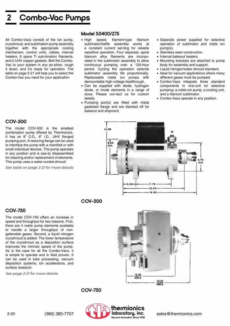
2-20 (360) 385-7707 [email protected]
2 Combo-Vac Pumps
Model S5400/275
COV-500
COV-750
COV-500
COV-750
All Combo-Vacs consist of the ion pump, cryoshroud, and sublimation pump assembly together with the appropriate cooling mechanism, control units, cables, internal heaters, 6 spare Ti sub-limation filaments, and 2 UHV copper gaskets. Bolt the Combo-Vac to your system in any po-sition, rough it down, and it’s ready for operation. The table on page 2-21 will help you to select the Combo-Vac you need for your application
The model COV-500 is the smallest combination pump offered by Thermionics. It has an 8” O.D., 6” I.D., UHV flanged pumping port. A reducing flange can be used to interface the pump with a manifold or with small individual devices. The pump operates in any position and is eas-ily disassembled for cleaning and/or replacement of elements. This pump uses a water-cooled shroud.
The model COV-750 offers an increase in speed and throughput for two reasons. First, there are 4 noble pump elements available to handle a larger throughput of non-getterable gases. Second, a liquid nitrogen cryoshroud is added. The lower temperature of the cryoshroud as a deposition surface improves the intrinsic speed of the pump. As is the case for all the Combo-Vacs, it is simple to operate and is field proven. It can be used in tube processing, vacuum deposition systems, ion accelerators, and surface research.
See table on page 2-21 for more details
See page 2-21 for more details
• High speed, filament-type titanium sublimator/baffle assembly works at a constant current set-ting for reliable repetitive operation. Four separate, spiral titanium alloy filaments are incorpo-rated in the sublimator assembly to allow continuous pumping over a 120-hour period. Cycling the operation extends sublimator assembly life proportionally. Replaceable noble ion pumps with demountable high-voltage feedthrough.
• Can be supplied with diode, hydrogen diode, or triode elements in a range of sizes. Please con-tact us for custom details.
• Pumping port(s) are fitted with metal gasketed flange and are blanked off for bakeout and shipment.
• Separate power supplied for selective operation of sublimator and noble ion pump(s).
• Stainless steel construction.• Internal bakeout heaters.• Mounting brackets are attached to pump
body for assembly and support.• Liquid nitrogen/water shroud standard.• Ideal for vacuum applications where many
different gases must be pumped.• Combo-Vacs integrate three standard
components in one-unit lor selective pumping: a noble ion pump, a cooling unit, and a titanium sublimator.
• Combo-Vacs operate in any position.

2Combo-Vac Pumps
2-21(360) 385-7707 [email protected]
COV-1000
COV-2000
COV-1000
Combo-Vac Pumping Systems and Controls
COV-2000
The COV- 1000 is the pump of choice when the non-getterable gas load 1s larger than the COV-750 can comfortably handle.
As with the other Combo-Vacs. It is shipped complete with all the components needed to get your system operational. You simply remove the blank-off fIange and attach the Combo-Vac to your system. The control units are designed for rack mounting and are supplied with the high voltage and high current cables which attach to the pump. Filaments are already mounted in the sublimator assembly. Rough the system down, add LN2 to the cryoshroud (or use TLI model LNC-400 liquid nitrogen level controller; see Section 6, page 6-12), and turn on the control units. The final adjustment made at operating pressure, is to adjust the sublimator interval so that the sublimator turns on after the ores sure has risen 60 to 100% over its previous low value.
The COV-2000 offers additional throughput because the ion pump’s capacity is double that of the COV-1000. That means additional speed for non-getterable gases. The overall system speed is increased by use of larger fIange and shorter pump neck.
COV-500 COV-750 COV-1000 COV-2000Nom. nitrogen speed, I/sec (sublimator & ion pump) 500 plus 1000 1000 2000
Nom. air speed, I/sec (ion pump) 30/60 120 220 400
Max. argon speed, I/sec (ion pump) 7 28 56 112
Sublimator control unit (see page 2-18) PS-500 PS-500 PS-500 PS-500
Ion pump control unit (see page 2-16) PS-100 PS-350 PS-350 PS-1000
Number of internal heaters 2 4 4 8
UHV fIange size (I.D. /O.D. in inches) 6.0/8.0 6.0/8.0 6.0/8.0 6.0/8.0
Substrate coolant water LN2 LN2 LN2
Shipping Weight {lbs) 85 130 200 304

2-22 (360) 385-7707 [email protected]
2 Combo-Vac Pumps
Ion Pump Rebuilding: All Makes, All Sizes
AccessoriesDescription Part Number Qty./Pkg.OFE copper gaskets for 2.75” O.D. fIanges GK-275 10/pkg
OFE copper gaskets for 3.38” O.D. fIanges GK-338 10/pkg
OFE copper gaskets for 8” O.D. fIanges GK-800 10/pkg
Titanium filaments SB-1001 12/pkg
Bakeout heater, 125 watts, 120 VAC IH-100 1 ea.
Pump replacement elements See Page 2-11Automatic LN2 level controller (see sec. 6, page 6-12) LNC-400 1 ea
PumpSize
(l/sec)
TLI Varian Perkin-Elmer
Model Number Model Number Model Number8, 11 IP-11 911-505 30800/9020/25 IP-020/025 911-5030/36 32000/90
30 - 911-5032/37 43000/1060/80 IP-050 911-5034/38 -100 IP-100 912-7006 70120/140 IP-140 912-7000 Old 150 l/sec220 IP-200 912-7014 70230/32270 IP-270 912-7008 70280/82400 IP-400 912-7022 70420/22500 IP-500 912-7016 70500/02/04HIQ CONTACT US
Price Includes: Price Does Not Include:
Prior Authorization
We offer the following services:• Rebuild and repair all makes and sizes of
ion pumps, elements and power supplies• Reconditioned ion pumps and power
supplies comply with new equipment specifications and carry a 90-day guarantee
• Reconditioned pumps are in stock for exchange or sale, please call for availability
• TLI, Varian and P-E pump elements, parts and accessories available. We rebuild the Varian StarCell pump, please call for details
Please call to receive authorization from TLI prior to shipment. No shipment will be accepted without prior authorization.
Pumps are to be securely crated with pinch-off fIange and sent to Thermionics Laboratory, Inc., freight prepaid, to the attention of Customer Service.
• Inspection• Complete disassembly• Chemical and mechanical cleaning of
the pump body, elements and ceramic components
• Re-assembly• 400˚C bakeout• Pinch-off under vacuum• Exterior refinishing• 24-hour bench test• 90-day guarantee
• New pumping elements• New high voltage leadthroughs or ceramic
insulators• Replacement of damaged fIanges or
magnets• Blank pinch-off fIange
These items will be quoted separately after our incoming inspection.

Manipulators andMechanical Feedthroughs
3
Manipulators and Mechanical Feedthroughs
3
Introduction
Rotary Feedthroughs
Linear Feedthroughs
Linear- Rotary Feedthroughs
Wobble Sticks
Locking Jaw Systems
XYZ Manipulators
Z Motion Translators
XY Stage
RNN Series DifferentiallyPumped Rotary Seals
Terminology................................Custom Equipment.....................
FRM Series.................................FRMRE Magnetic Series............FPRM Precision Series..............FRRC Precision Dual Axis Series.........................................WOA Open Axis Series..............
FLML Series...............................FLMR Series...............................FLMM Series..............................FLMH Series...............................
FRLC Precision Dual Axis Series.........................................FLLRE Magnetic Series..............RPLR Series...............................FLRM Series...............................BPLR Series...............................
EC Series....................................EMC Series.................................EMX Series.................................FM Series...................................FB Series....................................
DBT Series.................................ZB Series....................................FBT Series..................................ECT Series.................................
3-23-3
3-303-333-34
3-353-36
3-373-373-373-39
3-353-403-423-443-48
3-46
3-48
3-43-63-83-103-12
3-143-163-183-20
3-22
3-27
Tilt Stages 3-243-26Virtual Axis Tilt...........................
Sample Heating and Cooling
Sample Transfer Systems
Load Lock
Faraday Cup Actuator
JS Series Thimble Jack Stages
DRS-1000 Optical Temperature Monitoring
RFH Series Feedthrough HatsGoniometers & Precision Motion Gearbox HeadsPulsed Laser Deposition Target Stage
Viewport, Shutters
Motor Drive Systems
Sample Mounting........................Sample Heating........................Heating & Cooling Accessories..LN2 Sample Cooling Options......LN2 Sample Cooling....................Sample Heater Power Supplies..
STLC Turn-to-Lock Series..........SPF Dual Groove Disk Series....
QAC Series Quick Access CapsLLC Series Load Lock Chambers...................................QAD Series Quick Access Doors..........................................
VRS Series Viewport Shutters....VLS Series Viewport Shutters...ClearView Series Heated Viewports....................................Delta Shutters.............................
Motor Drive Options....................Accessories................................YMC Series SynchronnusMotor Controllers........................
3-493-503-513-523-533-54
3-703-72
3-73
3-74
3-75
3-82
3-82
3-55
3-56
3-58
3-69
3-68
3-763-77
3-783-78
3-793-80
3-81

3Ultra-High Vacuum Positioning
3-1(360) 385-7707 [email protected]
Thermionics Northwest manufactures the broadest line of UHV positioning equipment current-ly available. Our goal is to provide researchers with the high-quality equipment needed in their endeavors by incorporating the greatest functional value at the lowest cost.
Standard products manufactured by Thermionics are guaranteed to be free of mate-rial and workmanship defects for a period of one year. Special products and electronic components are guaranteed for a period of one-year. Expendable component parts are guaranteed for their expected service life. See complete text on page viii.
If, for any reason, you are not completely satisfied with our products, let us know. We want to address your concerns.
In this manner, our relationship with the user does not end with the delivery of the equipment. We have a large stake in your new equipment operating up to your expectations. Our goal is to be part of your success.
We routinely manufacture several series of equipment that perform the same basic task. Each series has its own characteristics with different performance levels. This is true for XYZ manipulators, translators, linear-rotary feedthroughs, etc. If in doubt, please contact us to discuss your particular application. Perhaps we can suggest a successful and more cost effective way to obtain the desired result.
In most manipulator applications, the sample size. degrees and range of freedom, and need of accuracy and rigidity determine the exact specifications of the equipment required. Increasing levels of versatility tend to increase the needed bellows size and thus the required superstructure. This can escalate into larger equipment and greater cost. Careful establishment of the needed requirements will minimize the cost of the equipment and assure performance consistent with your expectations.
Layout drawings are available for all our standard products. These provide the dimensions re-quired to ensure the equipment will fit in or on your system. Many of these drawings are shown in this catalog. You can also find more drawings, models, pictures and more on our website at www.thermionics.com
We can supply layout drawings on disk for your application. They are produced using SolidWorks®. Many are in 3D. Many CAD files can be found on our website at www.thermionics.com. If you are unable to find what you’re looking for there, please contact us.
Thermionics expands its standard product line continually by developing new and custom products to meet the technical needs of researchers worldwide. Contact Thermionics Northwest for its latest and most complete UHV sample manipulation product line. Our equipment is designed with a modular
Framework. This permits the user to select the needed functional devices and have them work well together. This way, custom equipment, matching the requirements of the application, can be assembled efficiently. Changes in capabil-ity can also be made during the functional life of the equipment.
Equipment Selection
Thermionics Catalog
Thermionics Commitment
Design Philosophy
One Year Guarantee
Layout Drawings
CAD Users

3-2 (360) 385-7707 [email protected]
3 Ultra-High Vacuum Positioning
We have adopted the following functional definitions when used in reference to our equipment.
A manipulator is a 3-axis (X. Y, Z) positioning device. For most applications, the instrument hardware is mounted outside the vacuum chamber, with a welded bellows providing a flexible vacuum curtain. The X axis passes in front of the vertical, mechanical structure, or “back-frame,” with the Y axis moving to and away from the backframe. The Z axis is perpendicular to the X and Y axes and moves up and down directly against the vacuum pressure differential. The polar axis is the same as the Z axis. The polar axis is also referred to as theta (θ).
The limit of X and Y travel is normally a circular pattern. The range is indicated as a vector sum. This means a ±1/2” range of X and Y allows the polar axis to be moved anywhere inside a 1” diameter circle. The sum of the X and Y vectors is limited to .5”. Square pattern XY stages are available as options on some models.
A translator is a single axis positioning device, utilizing a bellows as a vacuum seal. They are also referred to as a “Z only” stage. This axis is normally perpendicular to the chamber. This causes the Z axis to work directly against the force from the pressure differential.
The XY stage provides the X and Y axes only. No Z motion is available.
The polar axis is the same as the Z axis, above. Rotation about the polar axis is commonly achieved by mounting a rotary feedthrough at the center of the traveling fIange of a manipulator or translator. This degree of freedom can also be achieved with a differentially pumped rotary seal.
The azimuthal axis (α) is perpendicular to the polar axis (θ). Sample azimuthal rotation refers to rotation of the sample about an axis normal to the sample face and perpendicular to the polar axis.
Flip motion is the changing of an axis normal to the sample face from parallel (or coaxial) to the polar axis to coaxial with the azimuthal axis. The range of this change of axis may be 90°, 180° or full 360°.
Tilt refers to changing the polar axis with respect to the X, Y and Z axes. This is usually done at the traveling flange of a 3-axis manipulator (or other exterior mounting stage). Tilt range is of-ten limited by the bellows I.D. and the O.D. of the probe passing through the bellows. The max-imum angle practical is about ± 7°. When used in this manner, translation in X, Y and (slightly) Z will occur with adjustment of the tilt angle. Tilt stages are available in single or dual axis units.
Our equipment is manufactured with the primary axis straddling adjacent bolt holes on the mounting flange (American Standard). Most equipment can be supplied with the axis passing through a bolt hole axis (European Standard) on request. Some equipment is field adjustable.
Terminology Translators (Z) Flip (β)
Tilt (γ)
Bolt Pattern Orientation
Bolt Pattern Orientation
Manipulator Terminology (FB Manuipulator shown)
XY Stage
Polar Rotation (θ)
Azimuthal Axis (α)
Manipulator (X, Y, Z)

3Custom or Modified Equipment
3-3(360) 385-7707 [email protected]
Our goal is to provide researchers with the high-quality equipment needed in their endeavor. Our modular design philosophy allows us to tailor standard instruments to a particular applica-tion at a minimum cost. Often, fully meeting a customer’s equipment requirements means mak-ing a modification to an existing instrument design. It may mean designing a new unit to the customer specifications. We accept this challenge as being part and parcel of our commitment to assist the researcher. Indeed, many of our new equipment designs are outgrowths of respond-ing to specific customer needs. We have even interfaced our equipment and sample handling with that of many other manufacturers.
We strive to supply this design and manufacturing service as efficiently as possible, both in terms of price and delivery. We encourage you to email us a hand sketch of your equipment needs. We are comfortable bidding to your specifications. Our standard policy is the customer reviews and approves the design drawings before custom equipment is manufactured.
A sampling of custom equipment is shown here. We can supply further information on these and many other existing designs if requested.
Polar, fIip and detector angle resolution repeatabilityU, V and W axis position resolution repeatability
Performace
Large Optic Soft X-Ray Reflectometer
8-Axis Goniometer (close up view)
8-Axis Goniometer
< 0.003˚< 0.002˚
< 0.003˚< 0.003˚

3-4 (360) 385-7707 [email protected]
3 EC Series Precision ManipulatorsThe EC series manipulators provide high precision positioning at minimum cost. They feature precision pre-loaded cross-roller stage control with pre-loaded micrometer-to-stage coupling. The XY guide system is made of hardened carbon steel.
• 1.39”, 2” or 2.5” I.D. bellows
• ±0.5” X and Y travel, circular pattern, preloaded micrometer-to-stage coupling, 0.001” (or 0.0001”) micrometer divisions
• Micrometers bakeable to 200°C
• 2” micrometer drive Z travel, 0.025”/turn, 0.001” division, 2” diameter drive knob (1.39” I.D only)
• 2”, 4” and 6” Acme Z travel, 0.100”/turn knob adjust
• 2.75” O.D. traveling fIange, tapped
• Bakeable to 200˚C fully assembled; no castings used in construction
• Hardened steel X and Y cross-roller guides• Dual 0.75” I.D. hardened stainless sleel Z
guide rods• Aluminum stage construction• All position operation• Stainless steel only material exposed to
vacuum
Bellows
X & Y Axes
Z Axis
Traveling Flange
Features
EC Series Specifications
EC-1.39-2
X axis
Y axis
2” Z range micrometer drive
2” to 6” Z range Acme drive
rigidity (1.39” I.D. bellows only)
rigidity (1.39” I.D. bellows only)
Motion Specifications< 0.001”< 0.00015”< 0.00015”
< 0.0001”< 0.00015”< 0.00015”
< 0.0001”< 0.00015”< 0.00015”
< 0.0005”< 0.0005”< 0.0007”
< 0.001” change with 20lb load change
< 0.001” change with5lb load change
resolutionrepeatabilitybacklash
resolutionrepeatabilitybacklash
resolutionrepeatabilitybacklash
resolutionrepeatabilitybacklash
(0.0025 mm)(0.0038 mm) (0.0038 mm)
(0.0025 mm) (0.0038 mm) (0.0038 mm)
(0.0025 mm) (0.0038 mm) (0.0038 mm)
(0.013 mm) (0.013 mm) (0.018 mm)
Ordering Information — 3-Axis Ultra High Vacuum Precision Manipulators
Base Flange O.D. Bellows I.D. Z Travel Model Number
2.75 1.39” 2” EC-1.39-2*1.39” 4” EC-1.39-41.39” 6” EC-1.39-6
4.5 1.87” 2” EC-1.87-21.87” 4” EC-1.87-41.87” 6” EC-1.87-62.0” 2” EC-2.0-22.0” 4” EC-2.0-62.0” 6” EC-2.0-82.5” 2” EC-2.5-22.5” 4” EC-2.5-42.5” 6” EC-2.5-6
* This model is equipped with micrometer Z drive. All other models are equipped with Acme drive

3EC Series Precision Manipulators
3-5(360) 385-7707 [email protected]
/B-6 6” O.D. base fIange
/B-6M 6” O.D. base fIange with 5 miniports
• Large micrometers with 0.0001” divisions• Set of two
• Replaces carbon steel cross roller bearings
• Supplies traveling fIange with clearance holes
• Modifies traveling stage to allow screw heads
• Allows direct mouting of tapped fIange to traveling stage (e.g. RNN-150)
Note: Traveling flange bolt pattern changed to “on axis”
• Low cost drive for X and/or Y axes• Direct Acme screw drive• Axial drive stepping motors• No manual adjust on motors
See page 3-81
Polar rotation Rotary seals Rotary feedthroughs Reducer feedthrough hatsTiltsSample motion Mounting Heating Cooling
3-273-303-563-243-583-493-503-52
Page No.
Base Flange
/LM XY Micrometers
/SSB Stainless Steel Bearings
/FCL Traveling Flange Modification
/MSA Axial Stepping Motor Drive
/SMC Stepping Motor Controllers
Other Options
Options
EC-1.39-4 (shown with RNN-150/FA)
EC-1.39-2/B-6M

3-6 (360) 385-7707 [email protected]
3 EMC-200 Series Precision ManipulatorsThe EMC-200 series is the basic workhorse of our manipulator line. It can be easily and efficiently customized to meet a broad range of applications. The EMC units have ±0.5” of travel in X and Y, with Z travel of 2” standard. The EMC series may be supplied with Z travels of up to 36” or more. They are available with 1.39” I.D. or 1.87’’ I.D. bellows. They are supplied with 2.75”, 4.5”, 6” or 8” O.D. base flanges.
• 1.39” or 1.87” I.D. bellows
• ±0.5” X and Y travel, circular pattern, preloaded micrometer-to-stage coupling, 0.0001” micrometer divisions, large drum dial micrometers (metric micrometers optional)
• 2” to 36+” Z travel, gearbox Acme drive, 0.100”/turn, 10 turns/inch, 0 001” divisions, position lock
• 6” O.D. (standard), 2.75”, 4.5” and 8” optional
• 5 mini-ports on a 6” or 8” O.D. base fIange (6 mini-ports with 1.39” I.D. bellows available on special request)
• 2.75” O.D. traveling fIange
• 0.375” O.D hardened stainless steel X and Y guide rods
• 0.500” O.D. hardened stainless steel Z guide rods
• All linear bearings hardened stainless stell• Bakeable to 200˚C fully assembled• X micrometer can be ordered with either
left or right side mount• Stainless steel only material exposed to
vacuum
Bellows
X & Y Axes
Z Axis
Base Flange
Traveling Flange
Features
EMC Series Specifications
EMC-201.39-1-1-2
X axis
Y axis
Y axis
Motion Specifications< 0.0001”< 0.0001”< 0.00015”
< 0.0001”< 0.0001”< 0.00015”
< 0.0005”< 0.0005”< 0.0007”
resolutionrepeatabilitybacklash
resolutionrepeatabilitybacklash
resolutionrepeatabilitybacklash
(0.0025 mm)(0.0025 mm) (0.0038 mm)
(0.0025 mm) (0.0025 mm) (0.0038 mm)
(0.0127 mm) (0.0127 mm) (0.0178 mm)
Ordering Information — 3-Axis Ultra High Vacuum Precision Manipulators - with 2” of Z travel
Bellows I.D.Dimensions
Model NumberA C min*
1.39” 11.4” 6.3” EMC-201.39-1-1-21.87” 11.8” 6.7” EMC-201.87-1-1-2
*NOTE: This equipment has the shortest possible minimum flange-to-flange “C min” dimensions. This distance can be changed by a large number of possible options. The C min dimension shown is only for the exact model listed. Please consult the factory for further information.
** Available in 2 inch increments

3EMC-200 Series Precision Manipulators
3-7(360) 385-7707 [email protected]
EMC series manipulators can be customized to meet your exact requirements. The following options can be incorporated at the time of manufacture. Some can be field retrofitted after delivery. Please consult the factory for further information.
EMC Layout
Change from 6” O.D. to/B-2.75 - 2.75” O.D. no mini-fIanges/B-4.5 - 4.5” O.D. no mini-fIanges
/B-8 - 8” O.D. 5 mini-fIanges
• Provides 1” square pattern of X and Y motion for a 3/8” O.D. probe
• Requires a 1.87” I.D. bellows
• Supplies traveling fIange with clearance holes
• Extends traveling fIange nipple and backframe
• Allows direct mouting of tapped fIange to traveling stage (e.g. RNN-150)
• Support tube, 0.75” O.D., end bearing support
• Requires 1.87” I.D. bellows
• Available on 2” travel, 1.39” I.D. bellows only
• 2” diameter dial• 0.0001” divisions
• Set of two• ±0.5” travel
See page 3-79
All stainless steel construction available. Please consult the factory
Polar rotation Rotary seals Rotary feedthroughs Reducer feedthrough hatsTiltsSample motion Mounting Heating Cooling
3-273-303-563-243-583-493-503-52
Page No.
Base Flange
/SQ Square Pattern XY
/FCL Traveling Flange Modifications
/ST-.75 Support Tube
MZD Micrometer Z Drive
/SM Small Micrometers with 0.001” Divisions
/SMC Stepping Motor Controllers
Other Options
Options

3-10 (360) 385-7707 [email protected]
3 FM Series Compound Precision ManipulatorsThe FM series compound precision manipulator combines the XY stage from the FB manipulator series with the Z stage from the ZB precision translators. This combination works well vertically or horizontally. The FM series is available with horizontal mounting packages with custom-rated counterbalance springs to maintain “instrument”’ positioning. The Z stage can be separated from the XY stage. The FM series compound precision manipulators are XYZ units utilizing two bellows. A large I.D. short bellows located at the base of the unit is used to provide the XY operating range. A smaller I.D. bellows supplies the Z axis travel. XY bellows I.D’s of 2”, 2.5”, 3” and 4” are standard, with inside diameters to 6.3” I.D. possible. These units are available with ±0.5” or ±1” of X and Y travel. They can be supplied with Z travel of up to 36” or more, with Z bellows I.D.s of 1.04”, 1.39” and 1.87” standard. This approach provides considerable savings over the single large I.D. bellows systems, where a clear bore is not required and significant Z travel is needed.
A non-rotating tubular probe can also be provided with a stabilizing linear bearing at the base of the Z stage. This results in a more stable probe assembly, with a shorter effective “lever arm.”
This probe option provides a center less, ground, hollow, stainless steel tube extending through the center of the manipulator bellows. This probe is mounted to the traveling flange with a double-sided fIange and can be easily removed for equipment installation. This tube is stabilized by a stainless-steel linear bearing mounted at the base of the Z travel system. This bearing dramatically improves the stability of the probe. In addition, differentially pumped rotary seals can be fitted to these manipulators. They provide an additional degree of rotary freedom for the customers’ equipment. The probe bearing can be modified to allow probe polar rotation as well as polar axis linear travel. This system provides an excellent method of utility delivery.
FM Series
FM Layout
• ±0.5” X and Y travel, circular pattern, preloaded micrometer-to-stage coupling, 0.0001” micrometer divisions, large drum dial micrometers (metric micrometers optional)
• 2” to 36+” Z travel, gearbox Acme drive, 0.001” divisions, pre-loaded lead screw and worm shaft, position lock; comes with extended backgrame
• 4.5”, 6” (standard, tapped), 8” or 10” O.D. base fIange
• 2.75” (standard, tapped), 3.38” and 4.5” O.D traveling fIange
• /EB (standard) extended backframe• Hardened stainless stell bearings and guide
rods throughout• All XY bearings adjustable• Maximum bakeout temperature: 200°C
X & Y Axes
Z Axis
Base Flange
Traveling Flange
Features
FM Series Specifications
Motion SpecificationsX axis
Y axis
Y axis
< 0.0001”< 0.0001”< 0.00015”
< 0.0001”< 0.0001”< 0.00015”
< 0.0005”< 0.0005”< 0.0007”
resolutionrepeatabilitybacklash
resolutionrepeatabilitybacklash
resolutionrepeatabilitybacklash
(0.0025 mm)(0.0025 mm) (0.0038 mm)
(0.0025 mm) (0.0025 mm) (0.0038 mm)
(0.0127 mm) (0.0127 mm) (0.0178 mm)

3FM Series Compound Precision Manipulators
3-11(360) 385-7707 [email protected]
Ordering Information — 3-Axis Ultra High Vacuum Precision Manipulators - with 2” of Z travel
XY I.D.
Z I.D.
X & YTravel
DimensionsModel Number
A B C min* D2” 1.04” ±0.5” 11.0” 10.0” 6.50” 15.4” FM-102-1.04-1-1-2
2.5”
1.04”
±0.5” 11.0” 10.0” 6.58” 15.5” FM-102.5-1.04-1-1-2±1” 13.5” 10.0” 7.29” 16.4” FM· 102.5-1,04-2·2-2
1.39”*** ±0.5” 11.0” 10.0” 6.58” 15.5” FM-102.5-1.39-1-1-23”
1.04”
±0.5” 11.0” 10.0” 6.79” 15.7” FM-103-1.04-1-1-2±1” 13.5” 10.0” 7.67” 16.6” FM-103-1.04-2-2-2
1.39”***
±0.5” 11.0” 10.0” 6.79” 15.7” FM-103-1.39-1-1-2±1” 13.5” 10.0” 7.67” 16.6” FM-103-1 .39-2-2-2
1.87”
±0.5” 11.0” 10.0” 6.58” 15.5” FM-103-1.87-1-1-2±1” 13.5” 10.0” 7.29” 16.4” FM-103-1.87-2-2·2
2.25”
±0.5” 11.0” 10.0” 6.79” 16.6” FM-103-2.25-1-1-2±1” 13.5” 10.0” 7.29” 17.4” FM-103-2.25-2-2-2
4”
1.04”
±0.5” 11.0” 10.0” 7.38” 16.3” FM-104-1.04-1-1-2±1” 13.8” 10.3” 8.47” 17.4” FM-104-1 .04-2-2-2
1.39”***
±0.5” 11.0” 10.0” 7.38” 16.3” FM-104-1.39-1-1-2±1” 13.8” 10.3” 8.47” 17.4” FM-104-1.39-2-2·2
1.87”
±0.5” 11.0” 10.0” 6.79” 15.7” FM-104-1 .87-1-2±1” 13.8” 10.3” 8.47” 17.4” FM-104-1.87-2-2-2
2.25”
±0.5” 11.0” 10.0” 6.79” 15. 7” FM-104-2.25-1-1-2±1” 13.8” 10.3” 8.47” 17.4” FM-104-2.25-2-2-2
Larger diameters upon request.* NOTE: This equipment has the shortest possible minimum flange-to-flange “C min” dimensions. This distance can be changed by a large number of possible options. The C min dimension shown is only for the exact model listed. Please consult the factory for further information.
* *Additional Z travel is available in 2” increments.* **When Z stroke exceeds 12” this model is changed to a 1.53” bellows I.D. at no additional charge.
* NOTE: 1.87” bellows recommended for 1.5” probes
Tube O.D. Add to “C” Dimension Model Number
0.75” 2.50” /PL-.751.00” 2.65” /PL-11.50” 2.25” /PL-1 .5*2.00” 2.50” /PL-2
Tube O.D. Add to “C” Dimension Model Number Teflon
Model Number0.75” 2.50” /PLR-.75 /PFT-.751.00” 3.30” /PLR-1 /PFT-11.50” 2.63” /PLR-1 .5* /PFT-1 .5*2.00” 2.50” /PLR-2 /PFT-2
Adds linear all stainless steel bearlng at base of Z stage
Adds linear-rotary all stainless steel or TefIon bearing Commonly used with RNN series rotary platform and rotating support tube
/PL Probe Support Option
/PLR or /PTF Probe Support Option
FM series compound precision manipulators can be customized to meet your exact requirements. The following options can be incorporated at the time of manufacture. Some can be field retrofitted after delivery. Please consult the factory for further information.
6” O.D. (standard) base fIange, tapped (clearance available, without additional charge.)
/B-8T 8” O.D. base fIange, tapped
/B-10T 10” O.D. base fIange, tapped
/T-3.3T 3.38” O.D. traveling fIange, tapped
/T-4.5T 4.5” O.D. traveling Fiange, tapped
(Suitable for most FM models, up to 6” Z travel)• Base fIanges modified as required• Oversized guide rods• Two force spring assemblies, custom force
level based on customer payload
• Stainless steel lifting eyes• Custom sling assembly• Suitable for up to 200 lb systems
• Stainless steel lifting handles• Consult factory for application
• End bearing support for rotary shaft• Length specified by customer
Set of two• ±0.5” travel• ±1” travel
See page 3-79
Base Flange
Traveling Flange
/HMP Horizontal Mounting Package
/LP Lifting Package
/LH Lifting Handles
/ST-.75 Custom Support Tube, 0.75” to 3”0.D.
/SM Small Micrometers with 0.001” Divisions
/MS Stepping or /MY Synchronous Motor Drive
Options

3-12 (360) 385-7707 [email protected]
3 FB Series Precision ManipulatorsFB series manipulators provide large I.D. bellows and the mechanical strength required for significant payloads. Bellows I.D.s of 2”, 25”, 3” and 4” are standard, with inside diameters to 6.3” I.D. possible. These manipulators are available with ±0 5” or ±1 “X and Y travel. 2” Z travel is standard. Travels of up to 36” or more can be supplied.
The FB series can be ordered in the standard cantilever model or with the 3-lead screw option. The cantilever model has an 80 lb payload rating in the vertical orientation, and the 3-lead screw model has a 200 lb payload rating.
The FB series is available with horizontal mounting packages with custom-rated counterbalance springs to maintain “instrument” positioning.
Differentially pumped rotary seals provide an additional degree of rotary freedom for customers’ equipment at full bellows I .D.
• ±0.5” X and Y travel, circular pattern, preloaded micrometer-to-stage coupling, 0.0001” micrometer divisions, large drum dial micrometers (metric micrometers optional)
• 2” to 36+” Z travel, 4.1 worm Acme gearbox drive, 0.050”/turn (20 turns/inch), 0.001” divisions. pre-loaded lead screw and worm shaft, position lock
• 4.5”, 6” (standard), 8” or 10” O.D. base fIange
• 4.5”, 6” (standard) or 8” O.D. traveling fIange
• Super rigid 5-sided box construction• Hardened stainless steel bearings and guide
rods throughout• All bearings adjustable• Wide spacing (7” to 9”) on all guide rods• Wide spacing (6’’) of bearings on rods• Maximum bakeout temperature: 200°C with
micrometers attached
X & Y Axes
Z Axis
Base Flange
Traveling Flange
Features
FB Series Specifications
Motion SpecificationsX axis
Y axis
Y axis
< 0.0001”< 0.0001”< 0.00015”
< 0.0001”< 0.0001”< 0.00015”
< 0.0002”< 0.0003”< 0.0006”
resolutionrepeatabilitybacklash
resolutionrepeatabilitybacklash
resolutionrepeatabilitybacklash
(0.0025 mm)(0.0025 mm) (0.0038 mm)
(0.0025 mm) (0.0025 mm) (0.0038 mm)
(0.0051 mm) (0.0076 mm) (0.0152 mm)
FB Series
Ordering Information — 3-Axis Ultra High Vacuum Precision Manipulators - with 2” of Z travel
Bellows I.D. X & YTravel
DimensionsModel Number
A B C min*2” ±0.5” 11.0” 10.0” 4.66” FB-102-1-1-2
2.5” ±0.5” 11.0” 10.0” 4.66” FB-102.5-1-1-2±1” 13.5” 10.0” 5.08” FB-102.5-2-2-2
3” ±0.5” 11.0” 10.0” 4.69” FB-103-1-1-2±1” 13.5” 10.0” 5.57” FB-103-2-2-2
4” ±0.5” 11.0” 10.0” 5.30” FB-104-1-1-2±1” 13.8” 10.3” 6.39” FB-104-2-2-2
Larger diameter bellows available upon request
*NOTE: This equipment has the shortest possible minimum flange-to-flange “C min” dimensions. This distance can be changed by a large number of possible options. The C min dimension shown is only for the exact model listed. Please consult the factory for further information.

3FB Series Precision Manipulators
3-13(360) 385-7707 [email protected]
FB-104
• 6” O.D. (standard) base flange, tapped (clearance available, without additional charge)
• /B-8T - 8” O.D. base fIange, tapped• /B-10T - 10” O.D. base fIange, tapped
• End bearing support for rotary shaft• Length specified by customer
• 3 Acme screw support to traveling flange• Minimizes traveling fIange deflection• Used for increased payload requirements• Used for long Z stroke application• Required when mounting an RNN-400/FA
to the traveling fIange
Z drive anti-backlash coupling available on all drives
• Provides ±5˚ tilt in two axes• Uncalibrated adjusting screws• Provides full manipulator bellows I.D.
(Suitable for most FB models, up to 6” Z travel)• Base flanges modified as required• Oversized guide rods• Two force spring assemblies, custom
force level based on customer payload
Set of two• ±0.5”travel• ± 1”travel
See page 3-79
• Stainless steel lifting handles
• Stainless steel lifting eyes• Custom sling assembly• Suitable for up to 200 lb systems
• XY stage is mounted on the traveling flange
• Suitable for horizontal mounting of long stroke, wide bore manipulators
• All items in /HMP package above, except only one spring assembly, as required
• Stationary Z back allowing simple additional support
• Traveling X & Y stages, with a maximum throat diameter of 2.87” I.D.
Base Flange
/ST-.75 Custom Support Tube, 0.75” to 3” O.D.
/3LS 3-Lead Screw
/TLT-4-2-FB Integral Tilt Stage
/HMP Horizontal Mounting Package /SM Small Micrometers with 0.001” Divisions
/MS Stepping or /MY SynchronousMotor Drive
/LH Lifting Handles
/LP Lifting Package/FB-160 Long Stroke Horizontal Mounting Package
Options
• /T-4.5T - 4.5” O.D. traveling fIange, tapped
• /T-8T - 8” O.D. traveling fIange, tapped
Traveling Flange

3-18 (360) 385-7707 [email protected]
3 FBT Series Precision TranslatorsFBT series translators provide single-axis (Z only) motion. They are based on the FB-100 series manipulator Z drive. These units offer unparalleled mechanical support for customer payloads. They are available with bellows I.D.s of 2”, 2.5’’, 3” and 4”, with larger I.D.s available. Standard base and traveling fIange sizes are 6” O.D., with tapped or clearance holes, as required. Other fIange diameters available. Options include 3-lead screw version for extra-heavy payloads (to 200 lbs) and 10” O.D. base fIange for horizontal mounting. The Z drive is an Acme screw with a precision 4:1 gearbox. The stage position is indicated to 0.001” divisions.
• 2” to 36+” Z travel, 4.1 worm Acme gearbox drive, 0.050”/turn (20 turns/inch), 0.001” divisions. pre-loaded lead screw and worm shaft, position lock
• 4.5”, 6” (standard), 8” or 10” O.D. base fIange
• 4.5”, 6” (standard) or 8” O.D. traveling fIange
• Super rigid 5-sided box construction• Hardened stainless steel bearings and guide
rods throughout• All bearings adjustable• Wide spacing (7” to 9”) on all guide rods• Wide spacing (6’’) of bearings on rods• Maximum bakeout temperature: 200°C with
micrometers attached
Z Axis
Base Flange
Traveling Flange
Features
FB Series Specifications
Motion SpecificationsZ axis
< 0.0002”< 0.0005”< 0.0008”
resolutionrepeatabilitybacklash
(0.005 mm) (0.013 mm) (0.020 mm)
FBT Series
Ordering Information — 3-Axis Ultra High Vacuum Precision Translators - with 2” of Z travel
Bellows I.D.Dimensions
Model NumberC min*
2” 3.06” FB-102-22.5” 3.06” FB-102.5-23” 3.06” FB-103-24” 3.06” FB-104-26” Consult factory FB-106-2**8” Consult factory FB-108-2**
Larger diameter bellows available upon request
*NOTE: This equipment has the shortest possible minimum flange-to-flange “C min” dimensions. This distance can be changed by a large number of possible options. The C min dimension shown is only for the exact model listed. Please consult the factory for further information.
**NOTE: Requires /3LS option

3FBT Series Precision Translators
3-19(360) 385-7707 [email protected]
• 3 Acme screw support to traveling flange• Used for increased payload requirements• Used for long Z stroke application
Z drive anti-backlash coupling available on all drives
• Stainless steel lifting eyes• Custom sling assembly• Suitable for up to 200 lb systems
• Stainless steel lifting handles
See page 3-79
Polar rotation Rotary seals Rotary feedthroughs Reducer feedthrough hatsTiltsSample motion Mounting Heating Cooling
/3LS 3-Lead Screw
/LP Lifting Package
/LH Lifting Handles
IMS Stepping or /MY SynchronousMotor Drive
Other Options
Options
FBT Layout
3-273-303-563-243-583-493-503-52
Page No.

3-20 (360) 385-7707 [email protected]
3 ECT Jacking StagesECT series translators provide single axis (Z only) motion. This series provides short strokes of Z travel with a wide range of bellows I.D. All units employ two or three lead screws and two or three precision-ground stainless steel guide rods. These units offer excellent mechanical support. They are well suited to applications involving equipment insertion and withdrawal from investigative points where space is restricted. These jacking stages are all metal and bakeable. Adjustable preset stops are optional.
The ECT series is designed to handle customer payloads up to 45 lbs standard, in a vertical orientation with the center of gravity on axis. Horizontal mounting and cantilever loads can be handled on many units. Please consult the factory for your particular application.
The stages are available with bellows I.D.s from 1.39” through 6” standard, with larger I.D.s available.
• 2” to 6” Z travel. worm Acme gearbox drive, pre-loaded lead screw and worm shaft, position lock
• /2LS 2-Lead Screw 2. 75” or 4.5” 0 .0. base flange detail 2.75” or 4.5” O.D. traveling flange detail, tapped
• /3LS 3-Lead Screw 4.5”, 6” or ff’ 0 .0. base flange detail 4.5”, 6” or 8” O.D. traveling flange detail, tapped
• Hardened stainless steel guide rods throughout
• Bronze bushings • Maximum bakeout temperature: 200°C • Without position indicator
ECT Series Specifications
Motion SpecificationsY axisWith /Pl option readable to 0.01”
< 0.001”resolution (0.025 mm)
ECT Series
ECT/2LS Layout

3ECT Jacking Stages
3-21(360) 385-7707 [email protected]
ECT/3LS Layout
ECT-4-2/3LS-6
ECT-3-2/3LS-6 with RNN-250/FA/MFD
Ordering Information — Single-Axis Ultra High Vacuum Precision Translators - with 2” of Z travel
Bellows I.D. Lead Screws Flange Detail Max. Z Travel Available Model Number
1.39” /2LS 2.75” 6 ECT-1.39-2/2LS-2.751.87” /2LS 2.75” 6 ECT-1.87-2/2LS-2.752.50” /2LS 4.50” 6 ECT-2.5-2/2LS-4.53.00” /3LS 6.00” 6 ECT-3-2/3LS-6
/3LS 8.00” 6 ECT-3-2/3LS-84.00” /3LS 6.00” 6 ECT-4-2/3LS-6
/3LS 8.00” 6 ECT-4-2/JLS-85.00” /3LS 8.00” 6 ECT-5-2/JLS-86.00” /3LS 8.00” 6 ECT-6-2/3LS-8
• Adjustable Acme screw stop with set
• Scale and pointer
/STOP Adjustable Preset Stop
/Pl Position Indicator
Options

3-22 (360) 385-7707 [email protected]
3 XY Stages With BellowsXY stages use the standard manipulator XY platforms to provide precise 2-axis positioning. The stages are available in four sizes. All include bellows. Stages are available with I.D.s from 1.39” to 6.3” (see below). Stage construction is of 6061 series aluminum (300 series stainless steel available) All feature pre-loaded micrometer-to-stage coupling and all stainless steel guide rails and bearings (the EC and EB series use hardened carbon steel cross-rollers). Larger units incorporate fully adjustable bearings. Maximum bakeout temperature: 200°C
Motion Specifications
X & Y Axes
X & Y Axes
X & Y Axes
X & Y Axes
< 0.0001”< 0.00015”< 0.00015”
< 0.0001”< 0.0001”< 0.00015”
< 0.0001”< 0.0001”< 0.00015”
< 0.0001”< 0.0001”< 0.00015”
resolutionrepeatabilitybacklash
resolutionrepeatabilitybacklash
resolutionrepeatabilitybacklash
resolutionrepeatabilitybacklash
(0.0025 mm) (0.0038 mm) (0.0038 mm)
(0.0025 mm) (0.0025 mm) (0.0038 mm)
(0.0025 mm) (0.0025 mm) (0.0038 mm)
(0.0025 mm) (0.0025 mm) (0.0038 mm)
ECXY Series FBXY Series
EMXY Series EBXY Series
ECXYB
EMXYB
FBXYB
• 2.75” O.D. base flange, tapped, on 1 39” I.D. bellows unit
• 4.5” O.D. base flange tapped, on 1.87” I.D. bellows unit
• 6” O.D. (Standard) base flange, tappedOther flange sizes available
• 8” O.D. (Standard) base flange, tappedOther flange sizes available
Base FlangeECXYB and EMXYB
FBXYB
EBXYB
• 2.75” O.D. traveling flange, tapped
• 6” O.D. (standard) traveling flange, tappedOther flange sizes available
Traveling FlangeECXYB and EMXYB
FBXYB
• Removable micrometers for bakeout• All stainless steel guide rods and bearings• Pre-loaded micrometer-to-stage coupling• Large units incorporate fully adjustable
bearings• Maximum bakeout temperature: 200°C
Features
Options
• Larger (up to 10” O.D.) base flange, as required, flange face O.D. as per customer requirements
• Oversized guide rods, as required• Modified travel limit• Two force spring assemblies, custom
force level based on customer payload
/HMP Horizontal Mounting Package for ECXYB, EMXYB, FBXYB and EBXYB Units
XY Stage with Bellows
I.D. X & YRange Mat
Dimensions XYRods Model Number
B C1.39” ±0.5” Al - 4.70” - ECXYB-1.39-11.39” ±0.5” Al - 3.18” 3/8” EMXYB-1.39-A-11.39” ±0.5” SS - 3.18” 3/8” EMXYB-1.39-S-11.87” ±0.5” Al - 4.20” 3/8” EMXYB-1.87-2A-11.87” ±0.5” SS - 4.20” 3/8” EMXYB-1.87-2S-12.00” ±0.5” Al 10” 3.69” 1/2” FBXYB-2.0-A12.50” ±0.5” Al 10” 4.09” 1/2” FBXYB-2.5-A12.50” ±1” Al 10” 4.89” 1/2” FBXYB-2.5-A23.00” ±0.5” Al 10” 4.20” 1/2” FBXYB-3.0-A13.00” ±1” Al 10” 5.08” 1/2” FBXYB-3.0-A24.00” ±0.5” Al 10” 4.81” 1/2” FBXYB-4.0-A14.00” ±1” Al 10.25” 5.78” 5/8” FBXYB-4.0-A25.00” ±1” Al - - - EBXYB-5.0-A26.30” ±1” Al - - - EBXYB-6.3-A2

3XY Stages With Bellows
3-23(360) 385-7707 [email protected]
ECXYB Layout
EBXYB Layout
EMXYB Layout
FBXYB Layout
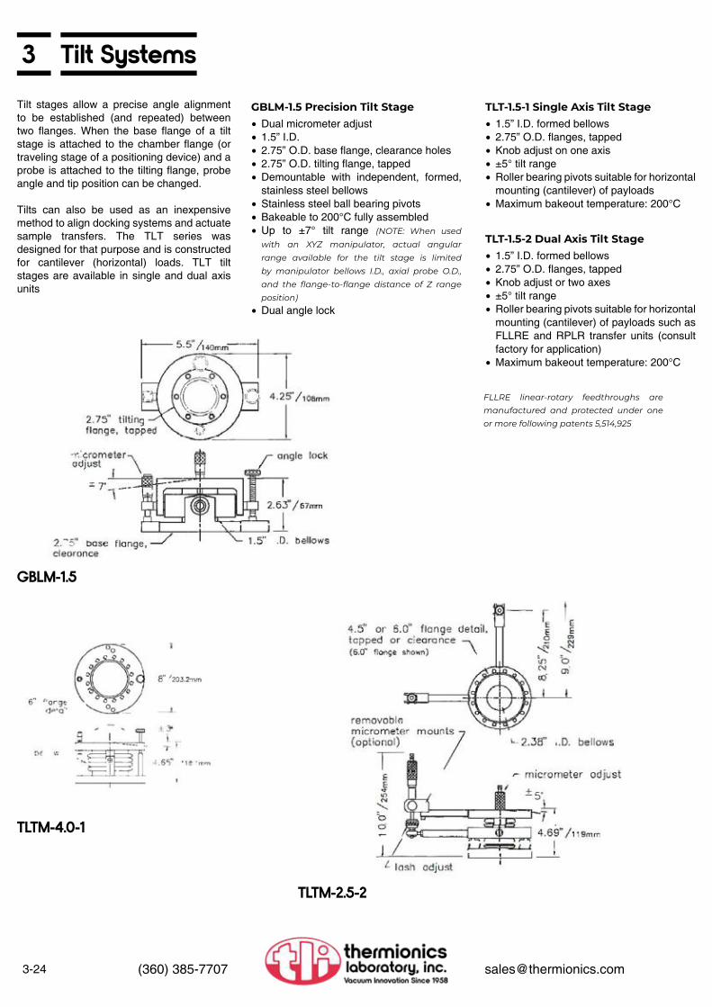
3-24 (360) 385-7707 [email protected]
3 Tilt SystemsTilt stages allow a precise angle alignment to be established (and repeated) between two flanges. When the base flange of a tilt stage is attached to the chamber flange (or traveling stage of a positioning device) and a probe is attached to the tilting flange, probe angle and tip position can be changed.
Tilts can also be used as an inexpensive method to align docking systems and actuate sample transfers. The TLT series was designed for that purpose and is constructed for cantilever (horizontal) loads. TLT tilt stages are available in single and dual axis units
FLLRE linear-rotary feedthroughs are manufactured and protected under one or more following patents 5,514,925
• Dual micrometer adjust• 1.5” I.D.• 2.75” O.D. base flange, clearance holes• 2.75” O.D. tilting flange, tapped• Demountable with independent, formed,
stainless steel bellows• Stainless steel ball bearing pivots• Bakeable to 200°C fully assembled• Up to ±7° tilt range (NOTE: When used
with an XYZ manipulator, actual angular range available for the tilt stage is limited by manipulator bellows I.D., axial probe O.D., and the flange-to-flange distance of Z range position)
• Dual angle lock
• 1.5” I.D. formed bellows• 2.75” O.D. flanges, tapped• Knob adjust on one axis• ±5° tilt range• Roller bearing pivots suitable for horizontal
mounting (cantilever) of payloads• Maximum bakeout temperature: 200°C
• 1.5” I.D. formed bellows• 2.75” O.D. flanges, tapped• Knob adjust or two axes• ±5° tilt range• Roller bearing pivots suitable for horizontal
mounting (cantilever) of payloads such as FLLRE and RPLR transfer units (consult factory for application)
• Maximum bakeout temperature: 200°C
GBLM-1.5 Precision Tilt Stage TLT-1.5-1 Single Axis Tilt Stage
TLT-1.5-2 Dual Axis Tilt Stage
GBLM-1.5
TLTM-4.0-1
TLTM-2.5-2

3Tilt Systems
3-25(360) 385-7707 [email protected]
• Micrometer adjust, bakeable• 4.0” I.D. formed bellows• 6” O.D. flange faces, tapped, 8” flange• ±5° tilt range• Roller bearing pivots• Maximum bakeout temperature: 200°C
Other bellows I.D. dual axis and angle range available
• Wrench adjust on two axes (3-point adjustment)
• 1.5” I.D. formed bellows• 2.75” O.D. falnges, tapped• ±4° tilt range• Suitable for horizontal mouonting
(cantilever) of payloads.• Maximum bakeout temperature: 200°C
• For all TLT series• Replaces 2.75” O.D. base with 6” O.D.• Allows throughhole mounting
• Add counter spring to tilt• Relieves load on micrometers
• Micrometer adjust• Heavy built for mounting manipulator on
top• 2.5” I.D. formed bellows• 6’’ base flange with clearance holes• 6” top flange. tapped• ±5° tilt range• Suitable for vertical or horizontal
(cantilever) payloads
TLTM-4.0-1 Single Axis Tilt Stage TLTW-1.5-2 Dual Axis Tilt Stage
/B-6 Base Flange
/HMPT Horizontal Mounting Package
/MA Micrometer Adjust
Options
TLTM-2.5-2 Dual Axis Tilt Stage
TLT-1.5-1
TLT-1.5-2
TLTW-1.5-2
TLT-1.5-2/8-6/MA

3-26 (360) 385-7707 [email protected]
3 VXT Series Virtual Axis Tilting/Positioning AssemblyThe VXT series precision tilt was developed to hold and position larger excitation sources or special detector systems.
Typical applications include positioning of larger electron guns, UV or X-ray sources, as in ESCA-XPS applications or RHEED studies. Extreme flexibility of positioning allows concise targeting.
This device provides five independent degrees of freedom. The critical freedom is the ability to “pivot’’ the source/detector about the target. with a point on the target surface becoming a focal point or “virtual axis” point of the motion of the VXT.
The arc radius guides are custom-made to suit specific target-to-flange distance requirements.
The stepping motor option can provide automated arc-scan motion.
The VXT is particularly suitable for payloads up to 35 lbs in vertical operation.
When using an X-ray slit source or a polarized excitation source, a differentially pulled rotary seal can be mounted to the VXT and the source on top. This configuration allows the source to be rotated about the polar axis and then scanned.
±2° ±2°±15°±3° (based on 12” radius)0.1°Better than 0.01°Knob, approx. 6 turns/degree
• 4.5” O.D. mounting flange face, tapped• 2.75” O.D. traveling flange, tapped• 1.87” I.D. stainless steel welded bellows• Virtual axis to mounting flange face: Per
customer requirements• Angle ranges:
A Arc focal point aimB Gun aim (2 axes, 3 pt. adj.)C Arc plane rotationD Gun arc
Scale graduations Resolution
Adjustment
Other flanging, bellows available
VXT Specifications
• Superior Electric stepping motorMO62-FC09E motor200 steps/revolution100 oz-in holding torque
• Ball screw, drive• Adjustable backlash
0.001” travel/full stepApprox. 0.005 °/step
• Ball bearing motor pivots
/MS Custom Stepping MotorOptions
VXT-1.87/MS
VXT-1.87/MS Layout
VXT-1.87/MS (shown with RHEED gun)

3RNN Series Differentially Pumped Rotary Seals
3-27(360) 385-7707 [email protected]
• Models with clear inside diameters of 1.53” to 10” standard (see table). Larger sizes on request. All units are bakeable to 150°C
• Stationery and rotation flanges, tapped• Flange face-to-flange face distance
approximately that of two Con Flat-type flanges of the corresponding size
• 2 stage differentially pumped• Base pressures in 10-11 Torr range• 0-360° scale with Vernier, standard
Standard scaleMechanical counterMicro stepped motor drive required for maximum resolution
• Fine adjust worm drive• Digital read-out on fine adjust
0.1° read-out, mechanical, nonresetable• Anti-backlash stepping motor drive
0.018˚ per full step (0.0225°/full step on RNN-150/MS) With manual, knob
• Custom pumpout tube lengths and crank shaft lengths on /FA units available
RNN Series Specifications
Readability Specifications
Options
Typical Performance Specificationsfor RNN-400 and larger models 1.0˚
0.1˚< 0,004˚< 0.008˚< 0.035˚
resolutionrepeatabilitybacklash
OptionsThe standard maximum payloads are indicated below. Larger loads may be handled under specific applications. Please consult the factory for custom applications. • The center of gravity of the payload is within
“X” of the polar axis of the unit, where X isequal to 10% of the RNN I.D.
• The center of gravity of the payload is within “Y” distance of the rotating flange on the horizontal mounted units, where Y is the flange I.D
• The overall maximum size “A” of the payload outside vacuum is:
7 x falnge O.D.5 x flange O.D.7 x flange O.D.
Vertical operationHorizontal operationInverted operation
Payload Location
Maximum Payload “W”
Model No. Vertical Horizontal InvertedRNN-150 54 lbs 30 lbs 45 lbs
RNN-250 90 lbs 38 lbs 70 lbs
RNN-400 144 lbs 66 lbs 110 lbs
RNN-600 180 lbs 84 lbs 140 lbs
RNN-800 200 lbs 91 lbs 160 lbs
RNN-1000 370 lbs 160 lbs 280 lbs
RNN-2000 430 lbs 200 lbs 350 lbs
Differentially pumped rotary seals (RNNs) provide 360° of continuous rotary freedom through the vacuum wall of a UHV system. The RNN has two stages of differential pumping isolated by graphite-impregnated, expanded, Teflon seals on special sealing surfaces. A pre-loaded ball bearing set accurately controls the rotating stage position. This allows the unit to be successfully used with manipulators and other precision positioning devices.
RNNs are available with worm drive fine adjust option. This allows for easier and more accurate angle adjustment. RNNs are also available with anti-backlash stepping or synchronous motor drive.
RNNs with up to 12” I.D. are listed. Larger I.D.s have been built with excellent performance. Please consult factory for special applications.

3-28 (360) 385-7707 [email protected]
3 RNN Series Differentially Pumped Rotary Seals
Ordering Information — Differentially Pumped Rotary Seals - (includes a removeable adiustment wrench) Dimensions in Inches
I.D. Flange O.D A B C D E F G H Model No.
1.53 2.75 4.50 2.99 1.0 3.18 2.75 .49 .13 60˚ RNN-1501.53 2.75/6* 6.00 2.99 1.34 3.33 2.75 .15 .13 45˚ RNN-150/62.53 4.5 5.75 3.64 1.36 3.58 4.50 .49 .03 45˚ RNN-2502.53 4.5/6* 6.00 3.64 1.52 3.71 4.50 .33 .03 45˚ RNN-250/64.03 6 7.75 4.57 1.68 4.34 6.02 .37 .06 45˚ RNN-4006.03 8 10.25 6.16 1.74 5.70 8.00 .42 .13 54˚ RNN-6008.00 10 12.05 7.03 1.94 6.70 10.00 .42 .13 45˚ RNN-800
10.00 13.25 15.75 8.81 2.37 8.50 13.28 .29 .13 24˚ RNN-100012.00 14 20.00 - 2.25 - - - - - RNN-1200
Differentially Pumped Rotary Seals with Fine Adjust**
Differentially Pumped Rotary Seals with Anti-Backlash /MS Stepping or /MY Synchronous Motor Drive***
I.D. Flange O.D A B C D E F G H I Drive
Ratio Model No.
1.53 2.75 5.13 3.38 1.00 4.95 2.75 .49 0.37 60˚ 3 80:1 RNN-150/FA1.53 2.75/6* 6.00 3.84 1.34 5.32 2.75 .15 0.37 45˚ 3 100:1 RNN-150/6/FA2.53 4.5 6.38 4.20 1.36 6.11 4.50 .49 0.41 45˚ 3 100:1 RNN-250/FA2.53 4.5/6* 6.38 4.20 1.52 6.11 4.50 .33 0.41 45˚ 3 100:1 RNN-250/6/FA4.03 6 8.50 8.25 1.68 9.28 6.02 .37 0.54 45˚ 4 100:1 RNN-400/FA6.03 8 10.25 8.50 1.74 9.93 8.00 .42 1.10 54˚ 5 100:1 RNN-600/FA8.00 10 12.75 9.56 1.94 11.50 10.00 .42 1.10 45˚ 5 100:1 RNN-800/FA
10.00 13.25 17.00 11.83 2.37 17.25 13.28 .29 0.91 24˚ 7 100:1 RNN-1000/FA12.00 14 Consult Factory RNN-1200/FA
I.D. Flange O.D A B C D E F G H I Drive
Ratio Model No.
1.53 2.75 5.13 10.00 1.00 9.97 2.75 .49 0.74 60˚ 3.39 80:1 RNN-150/MS or /MY1.53 2.75/6* 5.13 10.00 1.34 9.97 2.75 .15 0.74 45˚ 3.39 100:1 RNN-150/6/MS or /MY2.53 4.5 6.38 10.10 1.36 8.30 4.50 .49 0.41 45˚ 3.39 100:1 RNN-250/MS or /MY2.53 4.5/6* 6.38 10.10 1.52 8.30 4.50 .33 0.41 45˚ 3.39 100:1 RNN-250/6/MS or /MY4.03 6 8.50 9.77 1.68 11.69 6.02 .37 0.54 45˚ 3.39 100:1 RNN-400/MS or /MY6.03 8 10.20 10.13 1.74 11.69 8.00 .42 1.10 54˚ 3.39 100:1 RNN-600/MS or /MY8.00 10 12.75 11.39 1.94 11.69 10.00 .42 1.10 45˚ 3.39 100:1 RNN-800/MS or /MY
10.00 13.25 Consult Factory RNN-1000/MS or /MY12.00 14 Consult Factory RNN-1200/MS or /MY18.00 24 Consult Factory RNN-1800/MS or /MY24.00 34 Consult Factory RNN-2400/MS or /MY
*Signifies rotating/mounting flange sizes respectively**The fine adjust utilizes worm drive and are dynamic anti-backlash on RNN-400 and larger models They come with large knobs and crank handles.***The motor drive units utilize worm drive and are all dynamic anti-backlash with hand knobs at the rear of the motor.

3RNN Series Differentially Pumped Rotary Seals
3-29(360) 385-7707 [email protected]
RNN
RNN-400/FA to RNN-1000/FA
RNN/MS Stepping or /MY Synchronous Motor Drive
RNN-800/FA/MFO/MC
• Add digital read-out to fine adjust or motor drive unit
• 0.1° read-out, mechanical, non-resetable• Viewable from the side• Solution to difficulty caused by equipment
mounted to platform obstructing view of degree scale
When /MC option is selected the Vernier scale is not included
• Allows first stage pump to evacuate second stage pump
• Includes:Two 1.33” O.D flange nipples, modified1.33” O.D. hardwareBVV-025 bakeable valveFlexible metal plumbing
• Assembled on RNN platform
• Allows access to measure vacuum levels at each differentially pumped zone
• RNN-150 only (includes digital read-out)• 0.01° resolution• <0.1 ° backlash
Options/MC Mechanical Counter
/MFD Valve Manifold System
/TC Thermocouple Access Tubes
/EFA High Resolution Fine Adjust

3-30 (360) 385-7707 [email protected]
3 Rotary Motion Feedthroughs
FRM-133-25/MC
FRM-133-25
FRM-133-25/MC
FRM-133-25/MS
• 1/4” O.D. output shaft• Bellows sealed• Maximum bakeout temperature: 200°C• 1.33” O.D. flange with position lock• Torque limit: 150 oz-in• Maximum speed: 300 rpm• Uses 7 ball bearings• 2° graduations. 0° to 360°
1/4” Shaft Rotary FeedthroughsFRM-133-25 Rotary Feedthrough
Thermionics Northwest manufactures a full line of metal sealed rotary motion feed throughs. These feedthroughs are designed and manufactured to the highest standard of quality and care in the industry. Our design is conservative, utilizing the same principles as those of our precision feedthrough line. We use welded bellows, and all ball bearing construction.
Custom shaft lengths and shaft extensions are available.
• 1/4” O.D. output shaft• 1.33” O.D. mounting flange• Bellows sealed• Maximum bakeout temperature: 200°C• Mechanical torque limit. 150 oz-in• This is a coarse positioning device
for FRM-133-25• 5-digit Veeder Root mecha111cal counter,
metal case• 3.6:1 spur gear drive• Adjustable counter orientation• 36 counts per feedthrough rotation• Removable for bakeout• Retrofit kit allows mounting without
breaking vacuum
• 1/4” O.D. output shaft• Bellows sealed• Maximum bakeout temperature: 200˚C• Mechanical torque unit: 150 oz-in• Maximum speed: 300 rpm• With integral motor drive• 1.33” O.D mounting flange• /MS stepping or /MY synchronous motor
50 oz-in holding torque (higher torque motors available)
• Low inertia design• Manual knob• Without motor controller
FRMC-133-25 Rotary ShutterFeedthrough
/MC Mechanical Counter Option
FRM-133-25/MS Stepping or /MY Synchronous Motorized Rotary Feedthrough

3Rotary Motion Feedthroughs
3-31(360) 385-7707 [email protected]
• 1/4” O.D. output shaft• 1.33” O.D. mounting flange• Bellows sealed• Manual knob• Maximum bakeout temperature: 200°C• Mechanical torque limit: 150 oz-in• Maximum speed: 300 rpm• High speed worm drive
Self-locking/MS stepping or /MY synchronous motor50 oz-in holding torque (higher available)
• Without motor controller
FRM-133-25/MS/W or /MY/WMotorized Rotary Feedthrough
for FRM-133-25/MS or /MY• Mounts to rear of stepping or synchronous
drive motors• Indicates step count. 200 counts/motor
revolution100 counts on last digit wheel (100 divisions)
• Maximum motor speed: 2,500 pps• 9,999,999 maximum count (50,000 motor
revolutions)• 5-digit Veeder Root mechanical counter,
metal case2:1 ratio gear driveAdjustable counter orientationRemoves with motor for bakeoutRetrofit kit available
/MC Mechanical Counter Option
FRM-275-25/MS/W
FRM-275-25/MS/W/MC
FRM-133-25/SCC
Options
• 1/4” O.D. output shaft• 1.33” O.D. mounting flange• Bellows sealed• Low inertia design• Manual knob• Maximum bakeout temperature: 200°C• Mechanical torque limit: 150 oz-in• Maximum speed: 300 rpm• Speed control motor, with controller
5-95 RPM with 50 oz-in torque standardOptions available:
Higher torque motorsDifferent speed rangesSwitchable direction
FRM-133-25/SCC Speed ControlledMotorized Rotary Feedthroughwith Controller
• 1/4” O.D. output shaft• 1.33” O.D. flange• Bellows sealed• Torque limit: 150 oz-in• 90° rotation• 180° or 270˚ rotations available• Adjustable stops available
for FRM-133-25/PNM• Mounted to feedthrough• Valve-to-rotary actuator plumbing installed• Control voltage 24 VDC standard or per
customer requirements• With flow controls, both directions
• 2.75” mounting flange replaces 1.33”• All other dimensions remain the same
FRM-133-25/PNM PneumaticallyOperated Rotary Feedthrough /ACV-24 Air Control Valve Option
FRM-133(275)-25
/CL Custom Length Shaft

3-32 (360) 385-7707 [email protected]
3 Rotary Motion Feedthroughs
• 3/8” O.D. output• 2.75” O.D. flange• Bellows sealed• Position lock• Angle dial• Uses 8 ball bearings• 2° graduations, 0° to 360°• Maximum bakeout temperature: 200°C• Torque limit: 1,100 oz-in• Maximum speed: 300 rpm
3/8” Shaft Rotary Feedthroughs
• 5 digit Veeder Root mechanical counter, metal case
• 3.6:1 spur gear drive• Adjustable counter orientation• 36 counts per feedthrough rotation• Removable for bakeout• Retrofit kit allows mounting without
breaking vacuum
/MC Mechanical Counter Option
FRM-275-38 Rotary Feedthrough
• Direct drive• 3/8” O.D. output shaft• 2.75” O.D. flange• Bellows sealed• Uses 8 ball bearings• Manual knob• IN Maximum bakeout temperature: 200°C• Mechanical torque limit: 1,100 oz-in• Maximum speed: 300 rpm• With integral motor drive
/MS stepping or /MY synchronous motor 100 oz-in holding torque (higher torque motors available)
Without motor controllerLow inertia design
FRM-275-38/MS Stepping or /MY Synchronous Motorized Rotary Feedthrough
• Mounts to rear of stepping or synchronous drive motors
• Read-out of step count, 200 counts/motor revolution
100 counts on last digit wheel (100 divisions)
• Maximum motor speed: 2,500 pps• 9,999,999 maximum count (50,000 motor
revolutions)• 5 digit Veeder Root mechanical counter,
metal case2:1 ratio gear driveAdjustable counter orientationRemoved with motor as an assembly
for bakeoutRetrofit kit available
• 3/8” O.D. output shaft• 2.75” O.D flange• Bellows sealed• Employs 8 ball bearings• Low inertia design• Maximum bakeout temperature: 200°C• Mechanical torque limit: 1,100 oz-in• Maximum speed: 300 rpm• Speed control motor, with controller
5-95 rpm with 50 oz-in torque standardOptions available:
Higher torque motorsDifferent speed rangesSwitchable direction
• 3/8” 0.0. output shaft• 2.75” 0.0. mounting flange• Bellows sealed• Manual knob• Maximum bakeout temperature: 200°C• Mechanical torque limit: 1,100 oz-in• Maximum speed: 300 rpm• Worm drive (50,000 motor revolutions)
Self locking/MS stepping or /MY synchronous motor50 oz-in holding torque (higher available)
• Without motor controller
• Up to 24”
/MC Mechanical Counter Optionfor FRM-275-38/MS or /MY
FRM-275-38/SCC Speed ControlledMotorized Rotary Feedthroughwith Controller
FRM-275-38/MS/W or /MY/WMotorized Rotary Feedthrough
/CL Custom Length Shaft Option
FRM-275-38
FRM-275-38/MS/W
FRM-275-38/SCC

3FRMRE Series Rare Earth Rotary Feedthroughs
3-33(360) 385-7707 [email protected]
• 3/8” O.D. rotating shaft• 2.75” O.D. mounting flange• Manual drive knob with position lock• 4,000,000 revolutions before internal
bearing service• 200°C bake-out (magnetic drive removed)• Mechanical torque limit: 150 oz-in• Removable neodymium iron boron
magnetic drive for bake-out
FRMRE-275-38 Rare Earth Magnetic Rotary Feedthrough
The rare earth magnetic series single and dual rotary drives are designed to provide exceptional, long life performance. They are UHV compatible and are an excel lent option to conventional bellows sealed and other rotary devices. They can be adapted to PLO target clocking and contin uous rotation of targets and substrates, as well as applications which require small profiles and high performance.
There are no sliding seals or magnets in vacuum and stray magnetic fields are virtually nonexistent. The in-vacuum armature is made of paramagnetic materials with stainless steel and silicon nitride bearings and is capable of repeated bake-out to 200°C (with magnets removed). Out-of-vacuum bearings are accessible for lubrication and the magnet drive is easily removable.
• Manual adjustment of 3/4” diameter shaft• Ideal for PLO target gearboxes• Speed control motor, with controller for 3/8”
diameter shaft• 5-95 rpm with 50 oz-in torque standard
Options available:Higher torque motorsDifferent speed rangesSwitchable direction
FRRMRE-275-.75/.38/SCC Dual Axis Speed Controlled Motor Drive with Controller
Options
• Speed control motor, with controller• 5-95 rpm with 50 oz-in torque standard
Options available:Higher torque motorsDifferent speed rangesSwitchable direction
Higher torque drives available. Stepping motor drive option available.
FRMRE feedthroughs and FRRMRE motor drives are manufactured and protectedunder one or more of the following patents: 5,514,925
/SCC Speed Controlled Motor Drive with Controller
FRRMRE-275-.75/.38/SCC Dual Rotary Magnetic Drive
FRMRE-275-38
FRMRE-275-38/SCC
FRRMRE-275-.75/.38/SCC

3-34 (360) 385-7707 [email protected]
3 Precision Rotary Motion Feedthroughs
Angular resolutionShaft run-outThree seconds with Klinger stage
Standard scale/FA with Vernier
<0.1°0.005”
1 ° graduations1 minute
Motion Specifications
Readability Specifications
Precision rotary feedthroughs are commonly used to define a polar axis for a sample or probe. They provide 360° continuous rotation and are mounted on top of XYZ manipulators and other stages to provide polar axis freedom. They are also used separately where precision angular orientation is needed.
All our precision rotary feedthroughs are all metal sealed, utilizing welded bellows. All ball bearings are stainless steel.
All units have 0.1 ° resolution minimum. Standard feedthroughs have 1° graduated dials. The fine adjust option utilizes a tangential screw and is calibrated to one minute with a Vernier scale. All have position locks. The maximum acceptable output shaft runout is 0.005”.
These feedthroughs are available with custom output shaft lengths for your specific application. Field-mountable shaft extensions are also available. All are available with optional anti-backlash stepping motor drive.
• 1/4” O.D. shaft• 1.33” O.D. mounting flange• 0.1° resolution, 1° graduations• Position lock• Maximum bakeout temperature: 200°C• For sample rotation
• 3/8” O.D. shaft• 2.75” O.D. mounting flange• 0.1° resolution, 1° graduations• Position lock• Maximum bakeout temperature: 200°C• For sample rotation
FPRM-133-25 Precision Rotary Feedthrough
FPRM-275-38Precision Rotary Feedthrough
• Up to 24”, tip-to-flange face
• Utilizes a precision Klinger stage for rotary actuation
• Resolution <0.1°• Three seconds on Klinger stage
• Adds a precision worm gear to rotary feedthrough
• FPRM-275-38 gear ratio 96:1 (standard), 48:1, 24:1 optional gear ratios
• FPRM-133-25 gear ratio 100:1 (standard), 50:1, 25:1 optional gear ratios
• Self-locking• 50 oz-in holding torque• Manual knob
/CL Custom Length Shaft Option
/FA Fine Adjust
/FA/W Fine Adjust Worm Drive
/MS Stepping or /MY SynchronousMotor Drive
Options
/MS/W Stepping or /MY/WSynchronous Motor Drive with Worm Gear
FPRM-275-38
FPRM-133-25
FPRM-275-38

3Precision Dual Axis Motion Feedthroughs
3-35(360) 385-7707 [email protected]
• With coaxial linear-rotary shaft• 3/8” O.D. outer shaft• 1/8” O.D. inner shaft, micrometer adjust for
1/2” or 1” linear travel• 9” shaft length standard• 0.1° resolution, 1° graduations• Position lock• Maximum bakeout temperature: 200°C
• With coaxial rotary-rotary shafts• 3/8” O.D. outer shaft• 1/8” O.D. inner rotary coax• 360° continuous rotation, both shafts,
independent• 0.1° resolution, 1° graduations• Lockable as dependent or independent
rotation• Maximum bakeout temperature: 200°C• Combines two FPRMs (see page 3-34)
FRLC-275-0.5 or FRLC-275-1Precision Rotary Feedthrough
FRRC-275 Dual PrecisionRotary Feedthrough
/MS Stepping or /MY SynchronousMotor Drive
• Up to 24”, tip-to-flange face
• Utilizes a precision Klinger stage for rotary actuation
• Resolution of 0.1°• One minute Vemier reading
• Precision 1/4” O.D. stainless steel shaft• Split clamp attachment to existing shaft• Shaft extension length 2” to 24”, as per
customer requirements• Simple field installation or removal• Mounts to 1/4” O.D. shaft FPRM-133,
FRM-133-25, FRM-275-25 and others
• Precision 3/8” O.D. stainless steel tube• Includes 1/8” O.D. center push rod
extension with return spring• 1/2” push rod range• Split clamp attachment to existing shaft• Shaft extension length 3” to 24”, as per
customer requirements• Simple field installation or removal• Mounts to 3/8’’ O.D. shaft FRLC-275-0.5
and others
• Precision 3/8” O.D. stainless steel tube• Includes 1/8” O.D. center rotational shaft
with end guide bearing• Split clamp attachment to existing shaft• Shaft extension length 3” to 24”, as per
customer requirements• Simple field installation or removal• Mounts to 3/8” O.D. shaft FRRC-275 and
others
• Same as above with precision 3/8” O.D. stainless steel shaft
• Mounts to 3/8” O.D. shaft FPRM-275, FRM-275-38 and others • Same as above except for 1“ push rod
range
/CL Custom Length Shaft Option
/FA Fine Adjust Option
EXTS-FPRM-25 Shaft Extension EXTS-FRLC-0.5 Shaft Extension EXTS-FRRC Shaft Extension
EXTS-FPRM-38 Shaft Extension
EXTS-FRLC-1 Shaft Extension
Options
Retrofit Shaft Extensions
FRLC-275-0.5 & 1
FRRC-275

3-36 (360) 385-7707 [email protected]
3 WOA Series Precision Open Axis Rotary FeedthroughThe WOA rotary feedthrough is an all metal-sealed rotary feedthrough with unique features and exceptional performance.
Open Axis
Precision
Readability
The top flange does not rotate with the tube. The output tube rotates, but not the top flange.
The feedthrough is hollow through the entire shaft. The output shaft is a 3/4” diameter tube with a 0.55” bore clear diameter. The top of the rotary feedthrough has a 1.33” O.D. flange (2.75” O.D. optional).
This open axis feature allows a multi-axis feedthrough to be constructed by stacking multiple WOA feedthroughs atop each other and using smaller and smaller output tubes (see photo). Unlimited coaxial-linear travel is possible by simply adding the appropriate linear feedthrough to the top of this rotary feedthrough. Continuous coaxial-rotary drives are now simpler and more reliable.
The WOA feedthrough demonstrates unique rotary precision. Tests confirm resolution of better than 0.003° with a backlash of less than 0.005° for positioning (no torque load) applications.
Standard scale/FA with Vernier
1° graduations1 minute
WOA-550/FA
WOA-550
Tri-Axial Mount (two WOA-550/MS, one FRM-133-25/MS)
• 3/4” O.D. stainless steel output tube• To 24”
• Utilizes a precision Klinger stage for rotary actuation
• Three seconds on Klinger stage• One minute Vernier reading
/CL Custom Length Shaft Option
/FA Fine Adjust
Options
• Adds a precision worm gear• 96:1 (standard), 48:1, 24:1 optional gear
ratios
• Precision 3/4” O.D. stainless steel tube• Split clamp attachment to existing shaft• Shaft extension length 3” to 24”, as per
customer requirements• With end guide bearing, as required• Simple field installation or removal• Mounts to 3/4” O.D. shaft WOA and others
/FA/W Fine Adjust Worm Drive
EXTS-WOA Shaft Extension
/MS Stepping or /MY SynchronousMotor Drive
• 2.75” O.D. top flange, replacing the 1.33”O.D. • 3/4” O.D. stainless steel output tube
• 0.55” clear axis up through feedthrough
• 3/4” O.D. stainless steel output tube• Without clear axis
/TF-275 Top Flange WOA-550 Clear AxisRotary Feedthrough
WOA-550-B PrecisionRotary Feedthrough

3Linear Feedthroughs
3-37(360) 385-7707 [email protected]
Thermionics manufactures a full line of metal-sealed linear motion feedthroughs. They are designed and manufactured to a high level of quality. They are all metal, using welded bellows and stainless-steel linear bearings. All manual units are bakeable to 200°c fully assembled. Higher bakeouts may be used with partial disassembly. These feedthroughs are available with a number of custom options, listed below.
Custom shaft lengths and shaft extensions are available.
• 1/4” O.D. shaft• 1.33” O.D. mounting flange• 1”, 2” or 3” stroke• Stainless steel bellows sealed• Coarse linear actuated• Stainless steel linear shaft bearing
• 1/4” O.D. shaft• 1.33” O.D. mounting flange• 1”, 2” or 3” stroke• Stainless steel bellows sealed• Rotary actuated, 28 turns/inch, all ball
bearing drive• Stainless steel linear shaft bearing• Includes position indicator
Other strokes available
Other strokes available
FLML-133-25 SeriesLinear Vacuum Feedthroughs
FLMR-133-25 SeriesLinear Vacuum Feedthroughs
FLMR-133-25-2
FLML-133-25
FLMR-133-25
FLMM-133-1 & 2
Stroke A Model No.1” 7.25” FLML-133-25-12” 8.75” FLML-133-25-23” 10.85” FLML-133-25-3
Custom shaft length
Stroke A Model No.1” 5.6” FLMR-133-25-12” 7.1” FLMR-133-25-23” 9.2” FLMR-133-25-3
Custom shaft length
• 1/4” O.D. shaft• 1.33’’ O.D. mounting flange• 1” or 2” stroke• Stainless steel bellows sealed• Micrometer actuated, 40 turns/inch,
preloaded coupling• 3” minimum flange face to probe tip• Stainless steel linear shaft bearing
Other strokes available
FLMR-133-25 SeriesLinear Vacuum Feedthroughs
Stroke A Model No.1” 5.6” FLMR-133-25-12” 7.1” FLMR-133-25-2
Custom shaft length

3-38 (360) 385-7707 [email protected]
3 Linear Feedthroughs
FLMR-133-1/MS
FLML-133·25·1/PNM (with /ACV-24)
FLMLQA-133-25-3
• 1/4” O.D. shaft• 1.33” O.D. mounting flange• 1”, 2” or 3” stroke• Stainless steel bellows sealed• Stainless steel linear shaft bearing• Stepping motor actuated, 28 turns/inch• Integral motor drive
/MS stepping or /MY synchronous motor100 oz-in holding torque (higher torque
motors available)Without motor controllerLow inertia design
• Manual knob
• 1/4” O.D. shaft• 1.33” O.D. mounting flange• 1”, 2” or 3” stroke• Stainless steel bellows sealed• Stainless steel linear shaft bearing• Pneumatically actuated
3/4” I.D. cylinder50 to 150 psi air pressureStainless steel rod and cylinder with
bumpers, both ends• Performance (with optional /ACV-24 valve
below): <180 msec from coil energize to finish of 4” travel with 80 psi on an FLM-133-4/PNM with shutter
Other strokes available
Other strokes available
FLMR-133/MS Stepping or /MYSynchronous Series MotorizedLinear Vacuum Feedthroughs
FLML-133-25/PNM SeriesPneumatically ActuatedLinear Vacuum Feedthroughs
Stroke Model No.1” FLMR-133-1/MS or /MY2” FLMR-133-2/MS or /MY3” FLMR-133-3/MS or /MY
Stroke Model No.1” FLML-133-25-1/PNM2” FLML-133-25-2/PNM3” FLML-133-25-3/PNM
As above, but mounted on a2.75” O.D. flange
• Mounted to feed through• Valve-to-actuator plumbing installed• Control voltage 24 VDC standard or per
customer requirements• With flow controls, both directions
• 1/4” O.D. shaft• 1.33” O.D. mounting flange• 3” stroke, 4 positions, 1” apart• Excellent for sample positioning or indexing• Stainless steel bellows sealed• Stainless steel linear shaft bearing• Position lock• With line adjust
/A CV-24 Air Control Valve Option for FLM-133-25/PNM series feedthroughs
FLMLQA-133-25-3 Fast ActingLinear Vacuum Feedthrough
/CL Custom Length Shaft Option
Options
SMC Stepping or YMC SynchronousMotor Controller

3Linear Feedthroughs
3-39(360) 385-7707 [email protected]
• 1/2” O.D. main shaft• 2.75” O.D. mounting flange• Up to 15” stroke or more• Stainless steel bellows sealed• Push-pull actuated, with adjustable position
stop• Position lock• Linear bushings
NOTE: The probe (1/2” dia.) supports itself beyond the mounting flange. In horizontal operation. depending on stroke, extension and payload, some deflection may occur
FLML-275-50 SeriesLinear Vacuum Feedthroughs
Stroke A B Model No.1” 6.26 1.40 FLML-275-50-12” 7.65 1.79 FLML-275-50-210” 20.77 4.91 FLML-275-50-10
Additional stroke, per inch
FLML-275-50
FLMM-275-50
FLMH-275-50
FLMH/R-275-50-2
/FA Fine Adjust Option
• Knob adjustment• 10 turns/inch linear travel• Ball bearing mount
• 1/2” O.D. main shaft• 2.75” O.D. mounting flange• 1” or 2” stroke• Stainless steel bellows sealed• Micrometer actuated. with pre-loaded
micrometer-to-probe coupling• Linear bushings
• 1/2” O.D. support tubeOpen through unit 1.33” O.D. flange
• Up to 16” linear travel• 1” or 2” stroke• Push-pull linear (12 lb maximum force)• Position stop (adjustable) and lock
• 1.33” O.D. flange mounted on vacuum side• Liquid or gas feedthrough to mini-flange in
vacuum
FLMM-275-50 SeriesLinear Vacuum Feedthroughs
FLMH-275-50 SeriesHollow Linear Feedthroughs
/R Reversed Flange Option
Stroke A B C Model No.1” 8.20 1.40 4.34 FLMM-275-50-12” 10.00 1.79 6.03 FLMM-275-50-2
Stroke Model No.1” FLMH-275-50-14” FLMH-275-50-46” FLMH-275-50-6
Additional stroke, per inch

3-40 (360) 385-7707 [email protected]
3 FLLRE Series Magnetically Coupled Linear-Rotary Feedthroughs
FLLRE-275-38/LD
FLLRE-275/.25 Layout
FLLRE-450/.75 Layout
The FLLRE modular magnetic linear-rotary feedthroughs offer exceptional coupling with a small magnetic driver package. The driver is only 2.75” O.D. and 2” long. It provides more than 150 oz-in of torque and four lbs of linear force. Because of their small size, two drivers can be added together to double coupling strengths. Linear force can also be enhanced with the addition of the linear driver. The linear driver is a separate module that has been developed for its exceptional linear force.
The FLLRE stainless steel probe tube has a polished I.D. The inside traveler has no magnets, but it is made of magnetically-permeable material. The design uses eight all stainless-steel bearings for long life even with repeated bakeout to 200°C (with magnets removed).
Four probe sizes are available — 1/4”, 3/8”, 1/2” and 3/4” O.D. The selection of the probe diameter will depend on the travel distance, mass of the sample, and physical constraints of the chamber and related equipment. Please call the factory to discuss your specific requirements
FLLRE linear-rotary feedthroughs are manufactured and protected under one or more of the following patents: 5,514,925
• 1/4”, 3/8” and 1/2” O.D. probe sizes• 2.75” O.D. mounting flange• Up to 36” stroke ( 1/2” O.D. probe model)• Mechanical torque limit: 150 oz-in• Linear force: 4 lbs• Eight all stainless-steel bearings• 200°C bakeout (magnetic drive removed)• Removeable neodymium iron boron magnetic
drive
• 3/4” O.D. probe size• 4.50” O.D. mounting flange• Up to 48” stroke (3/4” O.D. probe model)• Mechanical torque limit: 150 oz-in• Linear force: 15 lbs• Eight all stainless-steel bearings• 200°C bakeout (magnetic drive removed)• Removeable neodymium iron boron magnetic
drive
FLLRE-275 SeriesLinear-Rotary Feedthrough
FLLRE-450 SeriesLinear-Rotary Feedthrough
FLLRE Series Specifications and Ordering Information
Probe Size Standard Stroke Max Stroke Model No.1/4” 10” 24” FLLRE-275-10/.253/8” 12” 30” FLLRE-275-12/.381/2” 18” 36” FLLRE-275-18/.503/4” 24” 38” FLLRE-450-24/.75

3FLLRE Series Magnetically Coupled Linear-Rotary Feedthroughs
3-41(360) 385-7707 [email protected]
Available on all units and recommended for high mass payloads and longer strokes
• Adds a linear magnetic external driver• Adds a linear internal traveler• Torque: 150oz-in
• For use on any FLLRE• Linear and rotary actuation can be performed
from several feet away• Allows practical single operator sample
transfer
• Actuates jaws, pincers or other devices requiring dual rotational motion
• May be used in place of expensive rack and pinion devices
FLLRRE DualLinear-Rotary Feedthrough
Optional Force Package
/LD Linear Magnet Driver
/REM Remote Rotary Operation
FLLRE-275-12/.38/REM
Options
FLLRE-450/LD/REM (shown integrated on custom modular cart system)For more information about the Thermionics Northwest modular carts see page 11-33.
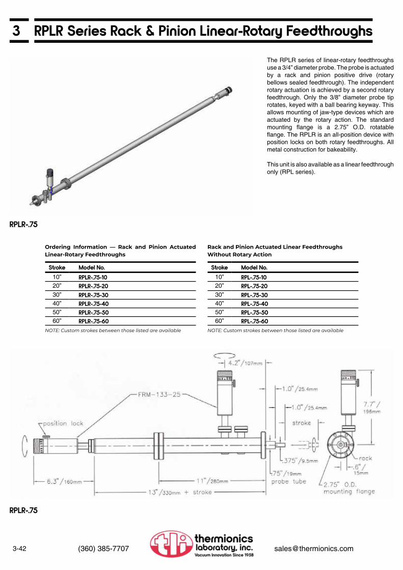
3-42 (360) 385-7707 [email protected]
3 RPLR Series Rack & Pinion Linear-Rotary Feedthroughs
RPLR-.75
The RPLR series of linear-rotary feedthroughs use a 3/4” diameter probe. The probe is actuated by a rack and pinion positive drive (rotary bellows sealed feedthrough). The independent rotary actuation is achieved by a second rotary feedthrough. Only the 3/8” diameter probe tip rotates, keyed with a ball bearing keyway. This allows mounting of jaw-type devices which are actuated by the rotary action. The standard mounting flange is a 2.75” O.D. rotatable flange. The RPLR is an all-position device with position locks on both rotary feedthroughs. All metal construction for bakeability.
This unit is also available as a linear feedthrough only (RPL series).
Stroke Model No.10” RPLR-.75-1020” RPLR-.75-2030” RPLR-.75-3040” RPLR-.75-4050” RPLR-.75-5060” RPLR-.75-60
Stroke Model No.10” RPL-.75-1020” RPL-.75-2030” RPL-.75-3040” RPL-.75-4050” RPL-.75-5060” RPL-.75-60
Ordering Information — Rack and Pinion Actuated Linear-Rotary Feedthroughs
Rack and Pinion Actuated Linear FeedthroughsWithout Rotary Action
NOTE: Custom strokes between those listed are available NOTE: Custom strokes between those listed are available
RPLR-.75

3RPLR Series Rack & Pinion Linear-Rotary Feedthroughs
3-43(360) 385-7707 [email protected]
RPLR Layout (shown with remote rotary option)
• 40 counts per feedthrough rotation (approximately 0.034” linear travel per count on RPLR)
• Removable for bakeout• Retrofit kit allows mounting without breaking
vacuum
• Mounts to rear of stepping or synchronous drive motors
• Read-out of step count, 200 counts/motor revolution
100 counts on last digit wheel (100 divisions)
• Maximum motor speed: 2,500 pps• 9,999,999 maximum count (50,000 motor
revolutions)• 5-digit Veeder Root mechanical counter,
metal case2:1 ratio gear driveAdjustable counter orientationRemoves with motor for bakeoutRetrofit kit available
• With integral motor drive• Speed control motor, with controller
5-95 rpm with 50 oz-in torque standardOptions available:
Higher torque motorsDifferent speed ranges (300 rpm max.)Switchable direction
• For use on long stroke RPLRs• Locates a rotary actuator knob near the
linear actuator feedthrough• Position lock
See page 3-80
See page 3-81
• With integral motor drive• /MS stepping or /MY synchronous motor
drive50 oz-in holding torque (higher torque motors available)
• Low inertia design• Manual knob
• High speed worm drive• Self locking• /MS stepping or /MY synchronous motor
driveSupplied with motorWithout controller
• Capable of driving up to 16”/min minimum at 1,000 pps
• May be field-mounted without breaking vacuum, or returned to the factory for installation
/MC Mechanical Counter —Manual Operation
/MC Mechanical Counter —Motorized Operation
/SCC Speed Controlled Motorized Rotary Feedthrough with Controller
/RRO Remote Rotary Operation
/RLS-40/MS Rotary Limit SwitchActuator Assembly
SMC Stepping or YMC SynchronousMotor Controller
/MS Stepping or /MY SynchronousMotorized Rotary Feedthroughfor RPLR rotary drive
/MS/W Stepping or /MY/W Synchronous Motorized Rotating Feedthrough for RPL or RPLR rotary drive
Options
NOTE: This motor drive is self-locking. This is necessary to protect the probe and associated equipment from spinning down if the power is removed from the motor. Because of the self-locking design, the drive can generate significant torque at the FRM, and thus do damage if overdriven.
NOTE: The /MS or /MY motor option is suitable for the rotary actuation on an RPLR and the linear actuation when the operation is horizontal. When the linear travel is other than horizontal, the /MS/W option should be used.
We strongly recommend the use of limit switches on this or any other motor drive being used to actuate the linear drive on the RPLR. The limit switch actuator assembly specified below (or one similar) should be used to protect the RPLR from being overdriven. See the RLS-40/MS rotary limit switch option on page 3-80.
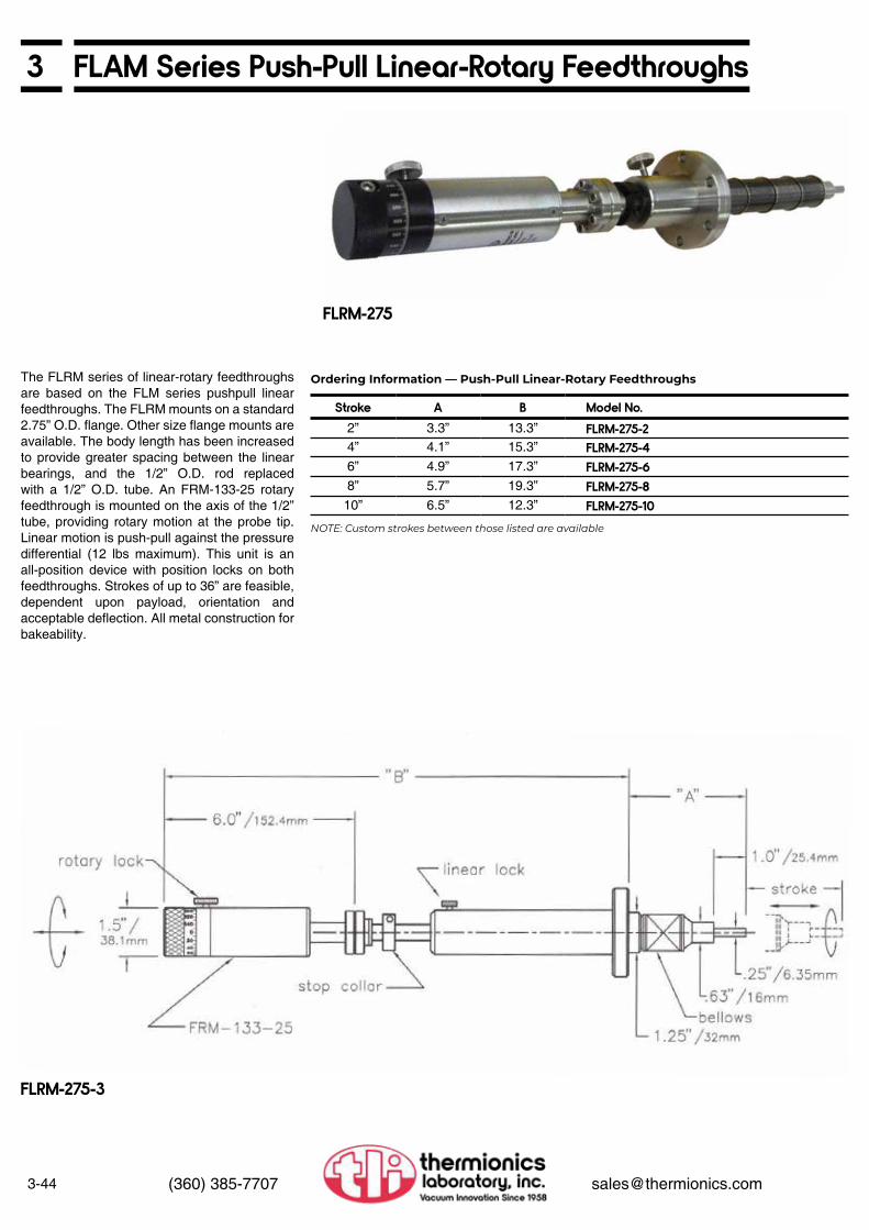
3-44 (360) 385-7707 [email protected]
3 FLAM Series Push-Pull Linear-Rotary Feedthroughs
FLRM-275
The FLRM series of linear-rotary feedthroughs are based on the FLM series pushpull linear feedthroughs. The FLRM mounts on a standard 2.75” O.D. flange. Other size flange mounts are available. The body length has been increased to provide greater spacing between the linear bearings, and the 1/2” O.D. rod replaced with a 1/2” O.D. tube. An FRM-133-25 rotary feedthrough is mounted on the axis of the 1/2” tube, providing rotary motion at the probe tip. Linear motion is push-pull against the pressure differential (12 lbs maximum). This unit is an all-position device with position locks on both feedthroughs. Strokes of up to 36” are feasible, dependent upon payload, orientation and acceptable deflection. All metal construction for bakeability.
Ordering Information — Push-Pull Linear-Rotary Feedthroughs
NOTE: Custom strokes between those listed are available
FLRM-275-3
Stroke A B Model No.2” 3.3” 13.3” FLRM-275-24” 4.1” 15.3” FLRM-275-46” 4.9” 17.3” FLRM-275-68” 5.7” 19.3” FLRM-275-8
10” 6.5” 12.3” FLRM-275-10

3FLRM Series Push-Pull Linear-Rotary Feedthroughs
3-45(360) 385-7707 [email protected]
FLRM-275-8/LFA
• With integral motor drive• /MS stepping or /MY synchronous motor
drive50 oz-in holding torque (higher torque motors available)
• Low inertia design• Manual knob
• Digital read-out of motor drive location• Mounts to rear of stepping or synchronous
drive motors• Read-out of step count, 200 counts/ motor
revolution100 counts on last digit wheel (100 divisions)
• Maximum motor speed: 2,500 pps• 999,999 maximum count (5,000 motor
revolutions)• 5-digit Veeder Root mechanical counter,
metal case2:1 ratio gear driveAdjustable counter orientationRemoves with motor for bakeoutRetrofit kit available
• Digital read-out of motor drive location• 5-digit Veeder Root mechanical counter,
metal case• 4:1 ratio bevel gear drive• Adjustable gear lash• Adjustable counter orientation• 40 counts per feedthrough rotation• Removable for bakeout
/MC Mechanical Counter Optionfor /MS or /MY Motorized Rotary Feedthrough /MC Mechanical Counter Option
for /SCC Motorized Rotary Feedthrough
/MS Stepping or /MY SynchronousMotorized Rotary Feedthrough
/SCC Speed Controlled MotorizedRotary Feedthrough with Controller
/LFA/MS/W Stepping or /LFA/MY/WSynchronous Motorized Fine Adjust
FLLM-275-2F-1 Linear/LinearCoaxialFeedthrough
/LFA Fine Adjust
OptionsRotary Options Linear Options
• With integral motor drive• Speed control motor, with controller
5-95 rpm 50 oz-in torque minimumOptions available:
Higher torque motorsDifferent speed rangesSwitchable direction • /MS stepping or /MY synchronous motor
• Worm drive• Ball bearing support• With manual knob• Suitable for use up to 6”
Requires longer housing on longer travels
• 2” linear travel• Linear travel via thread/collar adjust• Position lock• 1/2” O.D. support tube, bearing/bushing
mount• Adjustable travel limit
• 1” linear travel• Rotary adjust• Linear ball bearing nose support• Eight lb force maximum• Uses FRM-133-25 rotary feedthrough• Position lock• Custom shaft lengths on both linear probes
1ST LINEAR
2ND LINEAR
• 10 threads/inch• Ball bearing support• Suitable for use up to 6”
Requires longer housing on longer travels

3-46 (360) 385-7707 [email protected]
3 Wobble Sticks
FWS-44R-275-4
FWS-44R-275-4
FWS-44-275-10
FWS-15-275
FWS series wobble stick probes supply a combination of Z axis, polar rotation, and polar axis tilt to allow tip positioning inside the vacuum chamber. They can be fitted with clamp jaws, hooks, or forks to attach and release samples. The user can specify the required Z travel.
FWS-15-275-1 Wobble Stick
FWS-44-275-1 Wobble Stick
FWS-44R-275-2 Wobble Stick
• 3/8” O.D. shaft• 2.75” O.D. mounting flange• ± 7.5° angular range• 1” linear travel (on axis)• Without fork
• ±22 ° angular range• 1” Z stroke• Independent bellows for Z and θ• Special spherical bearing mount• Z travel position lock• Includes tip fitted with hook, per customer
requirements
• ± 22° angular range• 2” Z stroke• Independent bellows for Z and θ• Special spherical bearing mount• Z travel position lock• 360° probe rotation via FRM-133-25
Removable unit• Includes tip fitted with hook, per customer
requirements

3Wobble Sticks
3-47(360) 385-7707 [email protected]
FWS-44R-275-8/PW
/PDME Single Jaw Pincer
/POE Omicron Double Jaw Pincer
FWS-44R-275-4/PW
Thermionics Northwest offers a variety of pincers for your application. Custom pincers can be supplied on request.
FWS-44R-275-2/P Wobble Stick
• ±22 ° angular range• 2” Z stroke• Independent bellows for Z and θ• Special spherical bearing mount• Z travel position lock• 360° probe rotation• Includes push knob with 0.20” of linear
actuation• Order pincer below
Pincer Options
/PW Standard Single Jaw Pincer
/PDME DME Single Jaw Pincer
/PO Omicron Single Jaw Pincer
/POE Omicron Double Jaw Pincer
/PS Special Pincer
• Single jaw action• Suitable for thin wafers
• Single jaw action• Handles DME rectangular platens
• Single jaw action• Handles Omicron brand platens
• Handles Omicron brand platens• Edge grip double jaw action
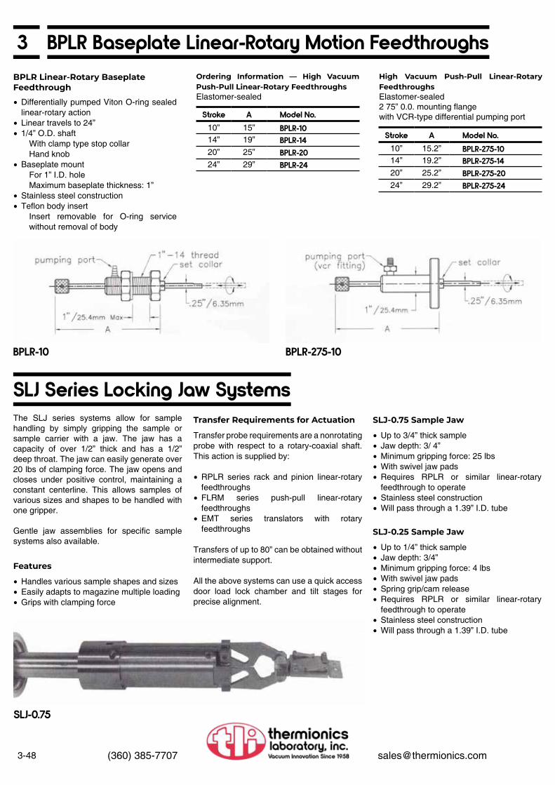
3-48 (360) 385-7707 [email protected]
3 BPLR Baseplate Linear-Rotary Motion FeedthroughsOrdering Information — High Vacuum Push-Pull Linear-Rotary FeedthroughsElastomer-sealed
High Vacuum Push-Pull Linear-Rotary FeedthroughsElastomer-sealed2 75” 0.0. mounting flangewith VCR-type differential pumping portStroke A Model No.
10” 15” BPLR-1014” 19” BPLR-1420” 25” BPLR-2024” 29” BPLR-24
Stroke A Model No.10” 15.2” BPLR-275-1014” 19.2” BPLR-275-1420” 25.2” BPLR-275-2024” 29.2” BPLR-275-24
BPLR Linear-Rotary BaseplateFeedthrough
• Differentially pumped Viton O-ring sealed linear-rotary action
• Linear travels to 24”• 1/4” O.D. shaft
With clamp type stop collarHand knob
• Baseplate mountFor 1” I.D. holeMaximum baseplate thickness: 1”
• Stainless steel construction• Teflon body insert
Insert removable for O-ring service without removal of body
BPLR-10 BPLR-275-10
SLJ-0.75
SLJ Series Locking Jaw SystemsThe SLJ series systems allow for sample handling by simply gripping the sample or sample carrier with a jaw. The jaw has a capacity of over 1/2” thick and has a 1/2” deep throat. The jaw can easily generate over 20 lbs of clamping force. The jaw opens and closes under positive control, maintaining a constant centerline. This allows samples of various sizes and shapes to be handled with one gripper.
Gentle jaw assemblies for specific sample systems also available.
Features
Transfer Requirements for Actuation
• Handles various sample shapes and sizes• Easily adapts to magazine multiple loading• Grips with clamping force
Transfer probe requirements are a nonrotating probe with respect to a rotary-coaxial shaft. This action is supplied by:
• RPLR series rack and pinion linear-rotary feedthroughs
• FLRM series push-pull linear-rotary feedthroughs
• EMT series translators with rotary feedthroughs
Transfers of up to 80” can be obtained without intermediate support.
All the above systems can use a quick access door load lock chamber and tilt stages for precise alignment.
SLJ-0.75 Sample Jaw
SLJ-0.25 Sample Jaw
• Up to 3/4” thick sample• Jaw depth: 3/ 4”• Minimum gripping force: 25 lbs• With swivel jaw pads• Requires RPLR or similar linear-rotary
feedthrough to operate• Stainless steel construction• Will pass through a 1.39” I.D. tube
• Up to 1/4” thick sample• Jaw depth: 3/4”• Minimum gripping force: 4 lbs• With swivel jaw pads• Spring grip/cam release• Requires RPLR or similar linear-rotary
feedthrough to operate• Stainless steel construction• Will pass through a 1.39” I.D. tube

3Sample Mounting
3-49(360) 385-7707 [email protected]
SMR-1 Sample Mount
• 3/8” shaft or gearbox mounting• “0” sample face offset to 4” offset. Per
customer requirements• Sample orientation per customer
requirements• 1” diameter sample area, 1.4” diameter
sample plate• Clip sample mount• Removable sample plate, electrically-
isolated
Thermionics sample mounts provide platen-based support for customer samples. They interface with the supporting structure (rod, gearbox, etc.) and provide mechanical support for the sample. All standard sample mounts provide the following:
• Removable platen• Clip sample restraint• Electrically-isolated platen
A wide variety of options or modifications are available for the sample mount to obtain the customers’ exact requirements. They include:
• Sample HeatingResistive
StandardNude filamentPBNQuartz lamp
e-Beam• Sample Cooling
Direct LN2Indirect LN2Water
• Sample transfer• Sample bias, RF
These options are described more fully in the following pages.
SMR Series
SMR (shown with 1” sample heater, LN2 cooling, electrical isolation and GB-7 gearbox)

3-50 (360) 385-7707 [email protected]
3 UHV Environment Heater OptionsThe following heating options may be mounted to the SMR sample mounts.
• Maintains electrical isolation• Moly sample plate with three sample clips• With all necessary feedthroughs.
Atmosphere side connectors, internal wiring, temperature thermocouple, and spare filaments
• Temperatures up to 1,000°C depending upon application
• Maintains electrical isolation• Moly sample plate with three sample clips• With all necessary feedthroughs,
atmosphere side connectors, internal wiring, temperature thermocouples, and spare filaments
• Temperatures up to 1,200°C depending upon application
• Modifies STLC platen for direct heating• Moly sample plate with two power supply
clips• Sapphire sample electrical isolation• With alt necessary feedthroughs,
atmosphere side connectors. internal wiring, and STLC moly platen
• Moly sample plate with three sample clips• Electrically grounded sample plate• With all necessary feedthroughs,
atmosphere side connectors, internal wiring, temperature thermocouples and spare filaments
• Temperatures up to 2,000°C depending upon application
• 0.6” O.D. sample size• 1,200°C maximum temperature• Low power filament (approx. 40 watts)• Suitable for 500 VDC biasing• With all necessary atmosphere side
connectors, internal wiring, temperature thermocouples and spare filaments
• Tungsten, moly, tantalum. alumina and stainless steel construction
/HR-1 Radiant Resistive Heater
/HR Graph
/HRN Graph
/HR-1 Radiant Resistive Heater
/HRN-2 Nude Filament Heater
/HRD Intrinsic Resistve Heater
/ERH-0.6 Electron Beam Heater
/HEB Electron Beam Heater/HEB Graph
/ERH Graph
/HRN-1 Nude Filament Radiant Resistive Heater
/HRD Intrinsic Resistive Heater
/HEB Electron Beam Heater
/ERH-0-6-1200 Electron BeamEnhanced Resistive Heater
NOTE: The performance ratings are for specific applications, generally without sample cooling or sample transfer. Depending on parameters such as sample size, temperature requirements, and motions involved, cooling of the substrate or heater framework may be required. Please consult factory for your specific application
STLC sample transfer systems are manufactured and protected under one or more of the following patents: 5,705,128

3Oxygen or Chemical Vapor Environment Heater Options
Heating and Cooling Accessories
3-51(360) 385-7707 [email protected]
The following heating options may be mounted to the SMR sample mounts.
• For 2” O.D. (standard) maximum sample size (optional sizes to 5”O.D.)
• Electrically isolated sample• Haynes alloy sample plate with three
sample clips• Best temperature uniformity: 1” O.D.• Maximum temperature: 700°C continuous 1,000°C peak• Utility requirements: Thermionics model SPS-232/M or SPS- 232/A (page 3-54) 0 to 110 VAC, 8A variable power supply Requires 0.5 gallons per minute water cooling• Maintains electrical isolation• Comes mounted to 2.75” O.D. and
support shaft up to 24” long, per customer requirements, dual bakeable electrical feedthroughs, re-entrant metal seal, dual cooling feedthrough and all necessary atmosphere side connectors
• Supplied without thermocouples
• For chemical vapor (CV) applications• Extends thermal shield above sample
plane• Single gas shower ring, stainless steel
construction• Gas ring clamped to heat shield
• For evaporation or sputter applications
• Approximately 1/8” O.D.• OFE copper• Suitable for UHV cooling transfer• Available in custom lengths
• 300 series stainless steel screws• Vent cut through screw threads and base
of head• Allows pumpout of each thread• Available in all standard screw sizes arid
head types
• 300 series stainless steel screws• Plated with silver• Resists galling• Improves heat transfer• Available in all standard screw sizes and
head types• Vented or unvented
• Manufactured from tantalum/rhenium• 0-80 screw size• 3/16” tip to head base• Filister head
• Two replacement tungsten filaments• Replacement ceramic insulators
• Heating to 1,200°C in UHV• Heating to 800°C in oxygen environment
without heater degradation• Maintains electrical isolation• Includes all necessary feedthroughs,
atmosphere side connectors, and internal wiring
• Heater outgassing above 1,100°C
GB-3O-5/SHQ-5/GS/SA (see page 3-67)
/PBN-1 Pyrolytic Boron Nitride Heater
/SHQ-2 Radiant Quartz Lamp Heater*
/GS Gas Shower Ring Option
/SA Shutter Assembly Option
ACS-CR Copper Rope ACS-SVS Slot Vented ScrewsACS-Ag Silver Plated Screws
ACS-TS Tantalum ScrewsSMRHR-HS Heater Spares Kit
/PBN-1 Radiant ResistivePyrolytic Boron Nitride Heater*
*WARNING
Operations involving enriched oxygen environments can be hazardous including explosive. Many materials commonly considered non-hazardous become dangerous in such environments. Simple mechanical pumps using oil can explode, putting both personnel and equipment at great risk. Many other common materials will react violently to oxygen. The SHQ series heater has not been tested in enriched oxygen environments and is not intended for that use. We recommend systems utilizing enriched environments be undertaken only by those properly skilled to perform such operations in a safe and cautious manner.

3-52 (360) 385-7707 [email protected]
3 LN2 Sample Cooling OptionsThe following cooling options may be added to the SMR sample mounts.
There are two basic methods of cooling samples using LN2 for vacuum application, direct cooling and indirect cooling.
In most cases direct contact of the LN2 Dewar with the sample achieves the highest rate of heat transfer and the most rapid cooling to the lowest temperature. If the sample is mounted to a goniometer head or precision gearbox, the plumbing of the LN2 to the Dewar can restrict the motion. In such cases a clamping Dewar may be considered.
A clamping Dewar can allow certain degrees of freedom, such as continuous rotation, and still achieve maximum cooling. A heated rotating sample can be cooled by stopping the motion and activating a Dewar that clamps to the sample platen.
The indirect cooling method cools the sample by conduction through a flexible copper rope to a remote LN2 Dewar. The copper rope can be an effective means of cooling. Sample motion and temperature are restricted by the length and number of copper ropes used to achieve the desired level of cooling.
The ability of a cooling system to cool the sample to its lowest temperature is limited by many factors: Direct versus indirect cooling, size of sample, sample heating attachments, limitations required by goniometer, number of copper ropes used. sample transfer requirements, electrical isolation requirements of the sample. and the ability to use a clamping Dewar.
Dewars have an internal phase separator that maximizes thermal transfer. The liquid LN2 contacts the copper and is allowed to boil, releasing nitrogen gas that is separated and allowed to escape. This technique maximizes contact of the copper with the liquid and keeps boiled-off nitrogen gas (a poor thermal transfer medium) away from the copper heat transfer surfaces. This dramatically lowers the temperature of the Dewar and increases its capacity for thermal transfer. True OFE copper rope is clamped to the copper side of the Dewar for indirect cooling to the sample. A 1.33” CF re-entrant seal, with plumbing made to length, may be used to connect the Dewar to the atmosphere side of the LN2 source. The welded plumbing connected to the re-entrant seal eliminates the need for in-vacuum fittings and possible leaks. All Dewars are helium leak-tested at LN2 temperatures prior to shipping.
Dewars are fabricated from composite, explosively-bonded OFE copper to stainless steel. This material is formed in an explosive process that creates a high-quality metallurgical bond. A high explosive charge compresses the copper and stainless plate material at supersonic speeds and at extreme pressures forming a plasma at the contact point. The plasma scours the surfaces to molten conditions as the plates collide and instantaneously cool. The resulting knitted mechanical bond of copper-to-stainless has excellent mechanical and thermal properties for UHV LN2 Dewar applications.
Dewars fabricated of this composite material allow LN2 to flow in contact with high thermal transfer capacity copper, with stainless steel plumbing (TIG welded) to the stainless steel side of the bonded Dewar. No brazing is required reducing the possibility of contamination and virtual leaks.
LN2 Sample Cooling
Dewar Materials
Dewar Design
SMR-1/CLND-1
/CLND-1(temperature graph showing direct cooling of substrate between heating cycles)
SMR-1/CLNI-1
/CLNl-1(Cooling using in-vacuum Dewar and copper rope connections to sample plate)
Explosive Process
Direct Cooling Indirect Cooling
• SMR-1 sample mount• Resistive heating• Direct cooling• Screw platen attachment
• STLP-1 sample transfer• Molybdenum platen• Indirect cooling 2” x 6” copper rope Copper Dewar 8” x 1/8” feed lines
Time-Temperature Test Time-Temperature Test

3LN2 Sample Cooling
3-53(360) 385-7707 [email protected]
The following cooling options may be added to the SM or SMR sample mounts.
/CLNl-1/CEI-I
/RE-ENTRANT Seal
Direct Cooling
Clamping Dewar (with heater sample transfer and sample rotation)
• 1” O.D., 2” long• Explosively-bonded OFE copper to
stainless steel• Two OFE copper ropes, 12” length• Internal phase separator• Electrically grounds sample• With VCR fittings• 1/8” O.D. or 0.093” O.D. supply tubes• Includes FLN-133-2 LN2 feedthrough (see
page 5-13)• Includes custom supply tube lengths, coils,
thermally-isolated mounting hardware, as required
• Provides electrical isolation for indirect cooling
• Provides electrical isolation for direct cooling
• Allows Dewar to be connected to atmosphere without in-vacuum VCR fittings
• Fits on 1.33” O.D. fIange
• Annular Dewar mounted around 1” sample plate
• Explosively-bonded OFE copper to stainless steel
• Internal phase separator• Electrically grounds sample• With VCR fittings• 1/8” O.D. or 0.093” O.D. supply tubes• Includes FLN-133-2 LN2 feedthrough (see
page 5-13)• Includes custom supply tube lengths, coils,
thermally-isolated mounting hardware, as required
• Application depends upon gearbox and range of degrees of freedom
• Actuated clamping annular Dewar• Explosively-bonded OFE copper to
stainless steel• Internal phase separator• Electrically grounds sample• With VCR fittings• 1/8” O. D. or 0.093” O.D. supply tubes• Includes FLN-133-2 LN2 feedthrough (see
page 5-13)• Includes custom supply lube lengths, coils,
thermally-isolated mounting hardware, as required
• Application depends upon gearbox and range of degrees of freedom
/CLNl-1 LN2 Indirect Cooling
/CEl-I Ceramic Electrical Isolation
/CEI-D Ceramic Electrical Isolation
/RE-ENTRANT Re-entrant Seal
/CLNl-1 LN2 Direct Cooling
/CDC LN2 Clamping Direct Cooling
Options

3-54 (360) 385-7707 [email protected]
3 SPS Series Sample Heater Power Supplies
SPS-252/A
Samples to 1” O.D.For /HR and /HRN radiant resistive heatersMaximum output. 10 A at 50 VDCInput: 120 V 60 Hz AC input (220 VAC units available)• Current limit• Current meter• Rack-mount chassis
Adds these features to the SPS-232/M:• With temperature read-out and PID
automatic controlAccuracy: < 3°CRepeatability: < 0.3°CStabilty: 3 μV/°C including compensationSet-point resolution: 1°C
• Auto-tuning• Includes thermocouple cable• Requires system thermocouple• To be used with Type “K” Chromel-Alumel
thermocouple (-200°C to 1,300°C)
Consult factory for sample size capabilityFor /HEB electron beam heaterMaximum output: 15 A at 20 VAC filament
0-3,000 VDC bias up to0.5 A emission
Input: 220 V 50/60 Hz AC• Adjustable power limits, filament and
emission• Current meters, filament and emission• Voltage meter, bias• With safety ground cable
Adds these features to the SPS-202M:• Automatic PID temperature control• Automatic system tuning• Digital temperature read-out• True phase-fired proportional control, with
adjustable bias (minimum output control)• Adjustable power limit• To be used with Type “K” Chromel-Alumel
thermocouple (-200°C to 1,300°C)
Consult factory for sample size capabilityFor /HEB electron beam heaterMaximum output: 14 A at 60 VAC filament
0-2,000 VDC bias up to0.25 A emission
Input: 220 V 50/60 Hz AC• Adjustable power limits, filament and
emission• Current read-outs, filament and emission• Voltage read-out, bias• With safety ground cable
• Consult factory for sample size capability• For /HEB electron beam heater• Maximum output: 15 A at 20 VAC filament• 0-3,000 VDC bias up to• 0.5 A emission• Input: 220 V 50/60 Hz AC• Automatic PID temperature control• Digital temperature read-out• True phase-fired proportional control of
filament or bias high voltage, switchable with adjustable output bias (minimum output control)
• Adjustable power limits, filament and emission
• Current meters, filament and emission• Voltage meter, bias• With safety ground cable• To be used with Type “K” Chromel-Alumel
thermocouple (-200°C to 1,300°C), (Type “C” thermocouple available)
Samples to 3” O.D.For /SHQ radiant quartz lamp heaters and
/HR and /HRN radiant resistive heatersMaximum output: 10A at 120 VDCInput: 120 V 60 Hz AC input
(220 VAC units available)• With isolation transformer• With current limit• Current meter
Adds these features to the SPS-252/M:• Automatic PID temperature control• Digital temperature read-out• True phase-fired proportional control of
filament or bias high voltage, switchable with adjustable output bias (minimum output control)
• To be used with Type “K” Chromel-Alumel thermocouple (-200°C to 1,300°C), (Type “C” thermocouple available)
For e-beam heater models ERH-0.6-1200Maximum output: 8A at 12 VAC filament
0-500 VDC bias up to0.2A emission
Input: 120V 60 Hz AC input(220 VAC units available)
• Automatic PIO temperature control• Automatic system tuning• Digital temperature read-out• True phase-fired proportional control of
filament with stable bias (minimum output control)
• Adjustable current limit with read-out• Adjustable bias at 0.25 A with current meter
and on/off switch• Rack mount chassis
SPS-202/M Sample Heater PowerSupply—Manual Operation
SPS-232/A Sample Heater PowerSupply—Automatic Operation
SPS-262/M Sample Heater PowerSupply—Manual Operation*
SPS-202/A Sample Heater PowerSupply—Automatic Operation
SPS-252/M Sample HeaterPower Supply—Manual Operation*
SPS-262/A Sample Heater PowerSupply—Automatic Operation*
SPS-232/M Sample Heater PowerSupply—Manual Operation
SPS-252/A Sample Heater PowerSupply—Automatic Operation*
SPS-253/A Sample Heater PowerSupply—Automatic Operation
Options
• Available on all automatic controllers• RS-232 interface-to-PID control• Complete set-up and operational
commands
• Available on all automatic controllers• Computer interface capability• Up to eight adjustable ramp and soak
periods
/Cl Computer Interface
/RSC Ramp and Soak Process Controller
*NOTE: These units do not include external plugs for use with alternating current meters. This provision would access the high voltage circuitry to the outside chassis. We believe this design to be hazardous.

3Temperature Monitoring
3-55(360) 385-7707 [email protected]
0-800°C0-700°C0-600°C
• Calibrations for substrate materials include:GaAs InP Silicon
• ± 0.5°C resolution and repeatability• One second updates• Attaches to standard 2. 75” ConFlat flanges• Temperature control feedback provided
with RS-232 communications or analog output voltage
• Molecular Beam Epitaxy (MBE)• Chemical Beam Epitaxy (CBE)• Metal Organic Chemical Vapor Deposition
(MOCVD)• Silicon Wafer Etching
The VHW series heated viewports (page 3-78) allow the DRS-1000 to operate continuously in deposition environments.
Diffuse Reflectance Spectroscopy
DRS-1000 System
Model DRS-1000In-situ Temperature Measurement, Temperature Control, Process Monitoring
Specifcations Applications
This Innovative patented optical technology provides accurate, real time temperature measurement and control for semiconductors. Unlike pyrometry, this process is not affected by emissivity or thin coatings. The noncontact, non-invasive system gives precise (± 0.5°C) readings with one second updates.
Diffusely reflected light intensity as a function of wavelength displays a characteristic absorption edge that is related to the bandgap of a semiconductor. This edge shifts with temperature. The technique can be used on bare wafers, patterned wafers and multilayer wafers.
The light output module is a broadband, modulated light source that illuminates the wafer through an optical port. The collection module, located on a second (non-specular) port, focuses the diffusely scattered light onto a fiber optic bundle. The spectrum information is transmitted to the scanning monochromator /detector/lock-in amplifier module. A control computer running the DRS-1000 software measures the absorption edge and generates temperature values based on internal calibration information. The software runs under WINDOWS and is equipped with a user-friendly graphical interface.
DRS-1000 System (shown mounted on Test Chamber)
Schematic of the DRS-1000 System Components

3-56 (360) 385-7707 [email protected]
3 RFH Series Feedthrough Hats
Goniometers and precision gearboxes with heating and cooling have requirements for many types of utility feedthroughs:
• Rotary and/or linear motion for goniometer actuation
• Electrical power for sample heaters• Thermocouple for temperature
measurement• Sample biasing for processing• Water cooling for gearbox cooling• LN2 cooling for sample cooling
Polar rotation of the sample is a fundamental requirement of most goniometers and precision gearboxes. When using base flange utility delivery, polar rotation causes utility lines to flex and abrade against one another in vacuum. Flexing can cause line failure and abrasion can cause particle contamination. To avoid these potential risks an axial utility delivery system can be used.
A standard axial utility delivery assembly consists of the following components:
The Axial Utility Delivery method organizes the utilities to eliminate flexing and abrading. The RFH top hat delivers the entire utility package axially through a probe support tube assembly to the sample head.
Polar rotation is achieved by mounting the entire utility package (top hat, probe support tube and sample head) through the center of a differentially pumped rotary seal (see page 3-27). This procedure organizes the entire in-vacuum sample assembly on to the rotating top flange of the platform. The package now rotates as a unit with no in-vacuum utility line flexing or abrading. Flexing of utility lines
Utility Delivery Axial Utility Deliveryoccurs out of vacuum where you can deal with it.
The RFH series feedthrough hats are available on 2.75”, 4.5” and 6” O.D. base flanges. Top flanges are either 2.75” or 1.33” O.D. flanges. The utility delivery ports are “crowned” to improve access, ease installation, and avoid kinking of utility lines.
Re-entrant seals are available for single piece LN2 systems (see page 3-53).
These assemblies are supplied without blank-off flanges
Utility Delivery System (heating, thermocouple and LN2 lines delivered through RFH-275-133-3 top hat and EC-1.39-2/B-6M manipulator to GB-7 gearbox)
Ordering Information — Feedthrough Hat Assemblies
Base Flange O.D.
Top Flange O.D
Number of Mini-Ports
Top Flange toBase FlangeDimension
Model Number
2.75” 2.75” 2 5.0” RFH-275-275-23 5.0” RFH-275-275-34 5.0” RFH-275-275-45 5.0” RFH-275-275-56 5.0” RFH-275-275-6
none 3 0.0” RFH-275-0-31.33” 3 3.75” RFH-275-133-3
4 5.75” RFH-275-133-44.5” 2.75” 2 4.5” RFH-450-275-2
4 4.5” RFH-450-275-46 4.5” RFH-450-275-6
1.33” 4 4.5” RFH-450-133-46” 2.75” 2 4.5” RFH-600-275-2
4 4.0” RFH-600-275-46 4.0” RFH-600-275-68 4.0” RFH-600-275-8
Application Note
Utility Porting The RHF series feedthrough hat provides utility porting for utility-intensive probe assemblies.
Sample Head Any goniometer or precision gearbox with related sample heating and cooling or other sample environmental conditioning.
Polar Rotation The RNN series differentially pumped rotary seals (see page 3-27) provide 360° polar rotation.
Probe Support Tube Delivery Channel Mounted to the top hat and attached to the sample head. Probes are typically a minimum of 0.75” and at least 1.5” O.D. when heating and LN2 utilities are required.
Large diameter probe support tubes and substantial stability to the sample head. Additional bearing support can be added to the probe at the base flange of linear translators and FM style compound manipulators (see page 3-10).

3RFH Series Feedthrough Hats
3-57(360) 385-7707 [email protected]
Options
• 0.75” O.D. stainless steel construction• End bearing support for rotary shaft• Length specified by customer
• Allows hat assembly to rotate with minimum effective radius
• Cannot be used with high voltage connectors or WOA feedthroughs
• Extends tubulations and installs elbows under each mini-port flange
• Aligns mini-port polar axis parallel to mounting flange axis
• Sample as /PP above except:• Allows for high voltage connectors and
WOA feedthroughs
/ST-0.75 Custom Support Probe Tube
/PP Parallel Mini-Port
/PPE Extended Parallel Mini-Port
RFH-275-133-3
RFH-600-275-8
RFH-275-275-4/PPE
RFH-450-275-6
RFH-275-133-4/ST-1.5

3-58 (360) 385-7707 [email protected]
3 Goniometers and Precision Motion GearboxesA goniometer head permits precision sample positioning and alignment motion at the sample location. Installation of a goniometer head increases the number of degrees of freedom of the sample. Rotations, translations and flip movements can be supplied with various accuracies.
Sample faces can be held on axis, allowing a single sample site to be investigated during a change of angle. Virtual axis goniometers allow unobstructed surface access for glancing angle studies.
Precision gearboxes are designed to provide motion for sample processing. Precision gearboxes can rotate the sample continuously during deposition, ablation or for other growth processing requirements.
All goniometer and precision gearboxes are suitable fer UHV use. All stainless-steel construction, anti-backlash spring-loaded gearing is standard. Optional heating, cooling and sample transfer are available for most units.
The goniometers and precision gearboxes shown above are some of the models also available. Please consult the factory for details.
/NM Non-Magnetic Option: Most goniometers and precision gearboxes can be constructed of non-magnetic materials. Beryllium Copper (BeCu) bearings and 300 series stainless steel are used for basic non-magnetic applications and titanium is used for even lower Gauss levels. Please consult the factory for your application cost.

3Goniometers and Precision Motion Gearboxes
3-59(360) 385-7707 [email protected]
STLC sample transfer systems are manufactured and protected under one or more of the following patents: 5,705,128
GB-2/OA Open Axis Goniometer HeadAzimuthal and Polar Rotation• Up to 2” O.D. samples• Open azimuthal axis required for
nonrotating heater• Requires coaxial rotary-linear drive• Rack and pinion gear drive, adjustable lash• All ball bearing drive• Adjustable sample orientation
SpecificationsOptions
• 360° continuous without utility delivery, or when mounted to support tube for heating and cooling utility delivery and by using an RNN series differentially pumped rotary platform for polar rotation
• ± 180° capability when utilities are delivered from the base flange, using a clear axis rotary feedthrough such as the WOA or using a rotary-linear feedthrough such as the FRLC for polar and azimuthal rotation
• STLC Series (turn-to-lock-3—70)• SPF Series (dual groove—3-72)• SMR (direct mount, no sample transfer—
3-49)
• /OS (custom offset sample available) Consult factory
• ±90° using a linear feedthrough such as the FLMM-1 or the dual coaxial FRLC-1 with 1.0” linear stroke
• ±180° with 2.0” linear stroke, limited by the cooling
• /HR (radiant resistive, 1,000°C—3-50)• /HAN (nude filament, radiant resistive,
1,200° C—3-50)• /PBN (pyrolytic boron nitride, above 1,200°
C—3-51)• May require gearbox cooling depending
upon application
• /EBS (electrical bias of sample)
• 0.8” standard sample offset
• /CLNI (indirect, copper rope—3-53)• /CWGB (water cooling to gearbox)• /CEI (ceramic electrical isolation of
sample—3-53)
• /FSD (live sample drive)
• /NM (beryllium copper bearings, bronze gears, titanium construction—3-58)
Polar
Sample Transfer
Typical Activation Components
Offset
Azimuthal
Heating
Bias
Sample Offset
Cooling
Multpile Sample
Non-Magnetic
GB-2/OA/HR/CLNI/STLC (shown withoptions)
GB-2/0A (shown without options)
GB-2/OA/HR/CLNI/STLC (shown with options mounted to FM XYZ manipulator)
GB-2/OA/HR/CLNI/STLC (shown with options)
Azim Polar 1 Polar 2 Flip
FRLC (page 3-35) x x - -FLMM-1 (page 3-37) x - - -WOA (page 3-36) - x - -FLMM-1 (page 3-37) x - - -RNN (page 3-27) - x - -
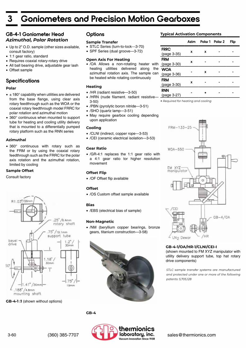
3-60 (360) 385-7707 [email protected]
3 Goniometers and Precision Motion Gearboxes
STLC sample transfer systems are manufactured and protected under one or more of the following patents: 5,705,128
+ Required for heating and cooling
GB-4-1 Goniometer HeadAzimuthal, Polar Rotation• Up to 2” O.D. sample (other sizes available,
consult factory)• 1:1 gear ratio, standard• Requires coaxial rotary-rotary drive• All ball bearing drive, adjustable gear lash• Offset sample
Specifications
Options
• ± 180° capability when utilities are delivered from the base flange, using clear axis rotary feedthrough such as the WOA or the coaxial rotary feedthrough model FRRC for polar rotation and azimuthal motion
• 360° continuous when mounted to support tube for heating and cooling utility delivery that is mounted to a differentially pumped rotary platform such as the RNN series
• STLC Series (turn-to-lock—3-70)• SPF Series (dual groove—3-72)
• /GR-4:1 replaces the 1:1 gear ratio with a 4:1 gear ratio tor higher resolution movement
• 360° continuous with rotary such as the FRM or by using the coaxial rotary feedthrough such as the FRRC for the polar axis rotation and the azimuthal rotation, limited by cooling
• /HR (radiant resistive—3-50)• /HRN (nude filament. radiant resistive—
3-50)• /PBN (pyrolytic boron nitride—3-51)• /SHO (quartz lamp—3-51)• May require gearbox cooling depending
upon application
• /OA Allows a non-rotating heater with heating utilities delivered along the azimuthal rotation axis. The sample can be heated while rotating continuously
• /OF Offset flip availableConsult factory
• /CLNI (indirect, copper rope—3-53)• /CEI (ceramic electrical isolation—3-53)
• /OS Custom offset sample available
• /EBS (electrical bias of sample)
• /NM (beryllium copper bearings, bronze gears, titanium construction—3-58)
Polar
Sample Transfer
Typical Activation Components
Gear Ratio
Azimuthal
Heating
Open Axis For Heating
Offset FlipSample Offset
Cooling
Offset
Bias
Non-Magnetic
GB-4-1 :1 (shown without options)
GB-4-1/OA/HR-1/CLNI/CEI-I(shown mounted to FM XYZ manipulator with utility delivery support tube, top hat rotary drive components)
GB-4
Azim Polar 1 Polar 2 Flip
FRRC (page 3-35)
x x - -
FRM(page 3-30)
x - - -
WOA (page 3-36)
- x - -
FRM (page 3-30)
x - - -
RNN (page 3-27)
- + - -

3Goniometers and Precision Motion Gearboxes
3-61(360) 385-7707 [email protected]
• Provides fine 360” fIip• Requires WOA (or support tube) and FRM• All ball bearing actuation, anti-backlash
gearing• Sample platform surface 0.94” behind
rotational axis
GB-5 Gearbox
GB-5/HA Gearbox
• Provides over 90˚ of flip from perpendicular to parallel to main shaft axis
• Requires FRLC-275-0.5 for actuation• Linear response• Sample flip axis and face not on polar axis
GB-6 Geared Flip
GB-5
GB-6
GB-5/HA
• 0.312’ hollow access through axis shafts allowing 0° to 2: glancing angle studies
• Provides fine 360” continuous flip rotation• All ball bearing actuation, adjustable and
anti-backlash gearing• Mounts to a 3/4” O.D. shaft (WOA or
support tube)• Driven by an FRM-133-25 rotary
feedthrough• Sample polar axis and azimuthal axis “0”
offset• Sample mount 1” behind sample axis

3-62 (360) 385-7707 [email protected]
3 Goniometers and Precision Motion Gearboxes
STLC sample transfer systems are manufactured and protected under one or more of the following patents: 5,705,128
GB-7-1 Goniometer HeaterAzimuthal and Polar Rotation• Up to 1.5” O.D. sample (other sizes• available, consult factory)• High resolution azimuthal rotation• Requires coaxial rotary-rotary drive• Open azimuthal axis for non-rotating heater• All ball bearing drive, adjustable anti-
backlash gearing• Adjustable to zero sample offset
Specifications
Options• ± 180° limited when cooling utilities are
delivered from the base flange, using a clear axis rotary feedthrough such as the WOA for polar rotation
• 360° continuous when utilities are delivered by support tube and top hat mounted to an RNN series differentially pumped rotary platform for polar rotation
• STLC Series (turn-to-lock--3-70)• SPF Series (dual groove--3-72)
• /EBS (electrical bias of sample)
• 360˚ continuous orthogonal to the polar axis by using a rotary feedthrough such as the FRM
• ± 180˚ limited by sample cooling• 20:1 gear ratio for precision azimuthal
angle positioning
• /HR (radiant resistive--3-50)• /HRN (nude filament, radiant
resistive--3-50)• /PBN (pyrolytic boron nitride--3-51)• /SHO (quartz lamp--3-51)• /HEB (electron beam--3-50)• May require gearbox cooling depending
upon application
• /NM (beryllium copper bearings, bronze gears, titanium construction—3-58)
• /CLND (direct cooling--3-53)• /CLNI (indirect, copper rope--3-53)• /CWGB (water cooling to gearbox)• /CEI (ceramic electrical isolation--3-53)
• /DP (dual polar rotation)
Polar
Sample Transfer
Typical Activation Components
Bias
Azimuthal
Heating
Non-Magnetic
Cooling
Dual Polar
GB-7-1/HR-1/CLNI(shown withoptions)
GB-7-1 (shown without options)
GB-7-1/HR-1/CLNI(shown with options mounted to FM XYZ manipulator)
GB-7-1/HR-1/CLNI(shown with options)
Azim Polar 1 Polar 2 Flip
FRM (page 3-30) x - - -WOA (page 3-36) - x - -FRM (page 3-30) x - - -RNN (page 3-27) - x - -Precision Azimuthal Motion
FPRM (page 3-34) x - - -WOA (page 3-36) - x - -FPRM (page 3-34) x - - -RNN (page 3-27) - x - -

3Goniometers and Precision Motion Gearboxes
3-63(360) 385-7707 [email protected]
STLC sample transfer systems are manufactured and protected under one or more of the following patents: 5,705,128
GB-8-2 Virtual AxisGoniometer Headwith Virtual Axis Flip• Up to 2” O.D. sample (other sizes available,
consult factor,• Zero sample off set all axes of movement• Requires linear drive• Open axis for non-relation heater• All ball bearing drive
Specifications
• ± 180˚ limited by heating and cooling utilities are delivered from the base flange, using clear axis rotary feedthrough such as the WOA for polar rotation
• 360˚ continuous when using support tube and top hat for heating and cooling utility delivery mounted to an RNN series differentially pumped rotary platform for polar rotation
Polar
Typical Activation Components
GB-8-2 (shown without options)
GB-8-1/AZ/HR-1/CLNl-1(shown with options)
GB-8-1/AZ/HR-1/CLNl-1(shown with options mounted to FM XYZ manipulator)
Azim Polar 1 Polar 2 Flip
FLRM (page 3-44) x - - xRNN (page 3-27) - x - -JS (page 3-82) - - - xFRM (page 3-30) x - - -RNN (page 3-27) - x - -
• +5°/-100˚ with clear surface virtual axis about the intersection of the azimuthal and polar axes actuated by 1” linear drive such as the JS jacking stage (see page 3-82)
Flip
Options
• STLC Series (turn-to-lock--3-70)• SPF Series (dual groove--3-72)
• /MINI For small sample virtual axis movement (see page 11-32)
• /HR (radiant resistive--3-50)• /PBN ( pyrolytic boron nitride--3-51)• May require gearbox cooling
depending upon application
• /NM (beryllium copper bearings, bronze gears, titanium construction--3-58)
• /CLNI (indirect, copper rope--3-53)• /CWGB (water cooling to gearbox)
• /EBS (electrical bias of sample)
• /AZ (azimuthal rotation)• 360° continuous with rotary drive such as
an FRM• ±90˚ limited by cooling utility delivery
Sample Transfer
Miniature
Heating
Non-Magnetic
Cooling
Bias
Azimuthal

3-64 (360) 385-7707 [email protected]
3 Goniometers and Precision Motion Gearboxes
• Provides 360° continuous azimuthal rotation (perpendicular to polar axis)
• All ball bearing actuation• Mounts to a 3/4” O.D. shaft (WOA or
support tube)• Driven by an FRM-133-25 feedthrough
Allows sample face on polar axisLarge hollow bore allowing stationary
heaterElectrically-isolated sample
• Provides 100° of flip from perpendicular to parallel to main shaft axis
• Requires FRLC-275-1 or FLMM-133-1 with rotary coupling for actuation
• Linear responseDual rack and pinion drive, with antibacklash adjustment
• All ball bearing actuation• Sample face on polar axis and flip axis
Allows glancing angle as small as 10°2” square sample sizeAccommodates up to 0.5” thick
samples, easily positioning sample face on polar and flip axis
Removable sample platesWill install through standard 4” O.D. tube
GB-14 Gearbox
GB-15 Large Zero Offset Geared Flip
GB-14 (shown with SHQ heater)
GB-15

3Goniometers and Precision Motion Gearboxes
3-65(360) 385-7707 [email protected]
STLC sample transfer systems are manufactured and protected under one or more of the following patents: 5,705,128
• Non-destructive depth profiling• Ion scattering• Angle resolved electron or ion spectroscopy
(XPS, Auger)• Photo electron diffraction
Applications
GB-16 Virtual Axis Goniometer Head Polar Rotation, Azimuthal Rotation, Flip
• Virtual axis sample mount• Up to 0.9” O.D. samples• All ball bearing drive• Dynamic anti-backlash bevel and spur
gears deliver precision control
Specifications
Options
• 360° continuous with clear axis rotary drive such as the WOA or ANN differentially pumped rotary platform
• ± 180° when heating and cooling utilities are delivered from the base flange
• STLC Series (turn-to-lock—3-70)• SMR (direct mount, no sample transfer—
3-49)
• /HR (radiant resistive, 1,000°C—3-50)• /HAN (nude filament. radiant resistive,
1,200°C—3-50)• /PBN (pyrolytic boron nitride, above
1, 200°C—3-51 )• May require gearbox cooling depending
upon application
• /CLNI (indirect, copper rope—3-53)• /CEI (ceramic electrical isolation—3-53)
• /NM (beryllium copper bearings, bronze gears, titanium construction—3-58)
• 180° rotation of sample
• +95°/-5° from the axis orthogonal to the polar axis
• Actuated with precision micrometer-linear feedthrough such as the FLMM linear feedthrough with 1” linear movement
Polar
Sample Transfer
Heating
Cooling
Non-Magnetic
Azimuthal
Flip
Virtual Axis Sample Positioning
GB-16 Azimuthal Goniometer (shown with STLC-TTC transferable thermocouple and intrinsic heating)
System PerformanceAzimuthal
AxisFlipAxis Polar Axis
Resolution <0.018° <0.025° 0.01°Repeatability <0.012° <0.006° —Backlash <0.040° <0.084° <0.01°Range 360+° ±47° 360+°
GB-16/AZ Dimensions
• The precision polar rotation, azimuthal rotation and flip motions move the sample about the virtual axis of the sample plane without line-of-sight interference. Virtual axis allows glancing angle studies without gearbox shadow.

3-66 (360) 385-7707 [email protected]
3 Goniometers and Precision Motion Gearboxes
STLC sample transfer systems are manufactured and protected under one or more of the following patents: 5,705,128
GB-17-.8 Goniometer HeadAzimuthal, Polar Rotation with Flip
• Up to 0.8” O.D. (standard) sample (optional 1.5” O.D. available) (other sizes available, consult factory)
• Requires tri-axial rotary-rotary-rotary drive• Dynamic anti-backlash spur gears• All ball bearing drive• Zero sample offset
Specifications
Options
• 360° continuous with clear axis rotary drive such as the RNN series differentially pumped rotary platform
• ± 180° when heating and cooling utilities are delivered from the base flange
• STLC Series (turn-to-lock—3-70)• SMR (direct mount, no sample transfer—
3-49)• 360° continuous with clear axis rotary drive such as the WOA or by using a dual rotary drive such as the FRRC
• ±90° limited with the addition of cooling
• Flip axis is aligned orthogonal to the polar axis
• 360° capability actuated by rotary feedthrough such as the FRM or using a dual rotary drive such as the FRRC
• ± 130° limited when heating option is added• ±90° limited when cooling option is added
• Zero sample offset-samples’ polar and azimuthal rotation and flip motion are all on the sample plane
• /HR (radiant resistive, 1,000°C—3-50)• /HRN (nude filament, radiant resistive,
1,200°C—3-50)• /PBN (pyrolytic boron nitride, above
1,200°C—3-51)• May require gearbox cooling depending
upon application
• /NM (beryllium copper bearings, bronze gears, titanium construction—3-58)
• /CLNI (indirect, copper rope—3-53)• /CEI (ceramic electrical isolation—3-53)
• /EBS (electrical bias of sample)
Polar
Sample Transfer
Typical Activation Components
Azimuthal
Flip
Sample Offset
Heating
Non-Magnetic
Cooling
Bias
GB-17-.8/HR-1/CLNI(shown with options)
GB-17-.8 (shown without options)
GB-17-1.5/HR-1/CLNI(shown with options mounted to FM XYZ manipulator with RNN differentially pumped rotary seal, utility delivery top hat and clear axis rotary feedthrough and rotary feedthrough)
GB-17-.8/HR-1/CLNI(shown with options)
Azim Polar 1 Polar 2 Flip
RNN (page 3-27) — x — —FRM (page 3-30) x — — —WOA (page 3-36) — — — xFRRC (page 3-35) x — — xRNN (page 3-27) — x — —

3Goniometers and Precision Motion Gearboxes
3-67(360) 385-7707 [email protected]
GB-30-2/SHQ/STLC Precision GearboxHead with Oxygen Environment Heater and Sample Transfer Motorized Continuous Polar Rotation• Provides continuous rotation during
deposition• Complete sample drive-includes all heating,
feedthroughs, flanges and connectors• For 2” O.D. (standard) maximum sample
(optional sizes to 5” O.D.)• Includes motorized rotary feedthrough and
controller• Quartz lamp heater for oxygen or chemical
vapor environments• Utilizes custom top hat motor drive• Water-cooled gear drive for heater
assembly• All ball bearing drive• Edge clip turn-to-lock sample transfer dock• Sample face center on polar axis• Electrically-isolated sample
Specifications
• ±360° continuous with heating and gearbox cooling
• 4.5-88 rpm using the FRM-SC integral speed-control rotary drive feedthrough with manual knob and motor controller
• /SHQ quartz lamp heater 1,000 watt (standard), temperature to 700°C continuous, 1,000° C peak
• Requires 110 VAC, 8 A variable power supply with proper isolation and overload protection such as the SPS-232/A sample power supply
• /CWGB water cooling to back of heater to protect heater and gear chain
• STLC Series edge clip sample transfer dock, platens, and fork
• /CEI (ceramic electrical isolation)
Polar
Sample Rotation Speed
Heater
Gearbox Cooling
Sample Transfer
Electrical Isolation
GB-30-5/SHQ-5 /STLC/SA (shown with options)
GB-30-2/SHQ/STLC/SA/GS(shown with options)
GB-30-2/SHQ/STLC/SA/GS(shown with options mounted to FM XYZ manipulator with utility delivery top hat and linear drive for shutter actuation with gas shower ring and feedthrough)
Typical Activation ComponentsAzim Polar 1 Polar 2 Flip
FRM/SCC x x — —Speed controlled motor drive (standard) (Page 3-32)
FRM/MY x x — —Synchronous motor drive (Page 3-31)
FRM/MS x x — —Stepping motor drive (Page 3-31)
FRM (page 3-30) x — — —RNN Non-motorized(page 3-27)
— x — —
Options
• SMR (direct mount, no sample transfer included—3-49)
• /PBN (pyrolytic boron nitride, above 1,200°C—3-51)
• Consult factory for options (also see 3-53)
• /GS (gas shower ring to sample during rotation—3-51)
• /SA (shutter assembly moves shutter between sample and deposition source— 3-51)
• /EBS (electrical bias of sample)
Sample Transfer
Heating
Sample Cooling
Gas Shower
Shutter
Bias
STLC sample transfer systems are manufactured and protected under one or more of the following patents: 5,705,128

3-68 (360) 385-7707 [email protected]
3 UHV/Pulsed Laser Deposition Target Stage
FRMRE magnetic rotary feedthroughs are manufactured and protected under one or more of the following patents 5,514,925
TGB-4-1 Target Gearbox forLaser Deposition Azimuthal Target RotationThe TGB is a target gearbox only. To be a complete target drive system it must be connected to two rotary feedthroughs, one for the target rotation and the second used for clocking the targets into position to face the laser from behind the protective shroud. • Provides continuous target rotation during
ablation• Holds 4 one-inch O.D. targets• Includes shroud/probe tube exposing one
target at a time (shroud actuation requires RNN or WOA)
• All stainless steel construction
SpecificationsOptions
• 360° continuous target rotation
• TGB-6-0.5 Six 1/2” O.D. targets• TGB-3-2 Three 2” O.D. targets
• FRMRE-275-25/SCC Magnetic rotary drive designed for continuous operation, 4,000,000 revolutions in vacuum conditions. Comes with speed control motor and hand-held controller.
• +/- 0.1 ° about the azimuthal axis of the target. This capability can be used to sweep the ablated plume across the substrate.
• /TT Bayonet target transfer system
• RNN-275/MS Differentially pumped rotary Seal. Used for the entire probe mounting with shroud. Rotate the RNN and a fresh target is clocked from behind the shroud into position for ablation.
Polar
Target Size and Number
Positioning
Target Rotation
Typical Activation Components
Target Rotation
Azimuthal
Target Transfer (used to transfer the target through a load-lock)
Target Clocking
Recommended Rotational Drivers
TGB-6-.5/TT (shown with options)
Typical Vacuum Chamber(shown with sample and target manipulator)
TGB-6-.5/TT Layout
Complete Target Positioning and GearDrive ManipulatorTGB-3-2, TGB-4-1, TGB-6-.5
XY ZEC Series manipulator x xEMC Series manipulator x x
Aximuthal ClockingFRMRE Rare earth rotary drives
x —
WOA Hollow axis rotary drives
x x
RNN Differentially pumped rotary seals
— x

3Sample Transfer Systems
3-69(360) 385-7707 [email protected]
Transfer Axes
There are many factors that influence the selection of a sample handling system. Thermionics NW manufactures several standard sample transfer systems, each with its own features and performance characteristics.
Factors that influence the selection of a sample transfer system vary by application.
• Sample motion requirements • Heating requirements • Cooling requirements • Sample size • Size of chamber tubulations available • Geometry of the chambers relative to
manipulators and type of transfer translator and load-lock
• Motion available for actuation • Compatibility with existing or planned
equipment • Ease and reliability of operation
When selecting a sample handling system, consideration must be given to its operation with goniometers and precision gearboxes. These devices typically require that the sample be solidly held and moved in a precise way. The sample plate must be docked to a goniometer so as not to limit the degrees of freedom or degrade the goniometer’s resolution.
Sample Transfer and Heating
Sample Transfer Terminology
Sample Transfer and Cooling
Sample transfer reduces heating performance at the highest temperatures (see page 3-50). The ideal transfer system for heating the sample to the highest temperatures should use thin sample plates made of material to withstand the temperature, that can be placed as close to the heater as possible. Thick, high mass, sample plates reduce thermal response and lower peak heating temperatures.
The following functional definitions can be used in reference to sample transfer.
Sample transfer reduces cooling performance at low operating temperatures. The ideal transfer system for cooling the sample to the lowest temperatures should use thin, highly conductive, sample plates that contact the Dewar with a large surface area. Thick, high mass, sample plates reduce thermal response and reduce peak cooling performance.
• Linear Motion — linear movement of the sample along any axis
FLRM (see page 3-44)FLLRE (see page 3-40)Z motion translators (see pages 3-14,
3-16, 3-18)• Rotary Motion — rotary motion about any
axisFLRM (see page 3-44)RPLR (see page 3-42)FLLRE (see page 3-40)Rotary motion feedthroughs (see pages
3-30, 3-32, 3-34)• Tilt Motion — angular positioning
movement of the horizontal or orthogonal axis. The weight of the sample, plate, fork and translator can cause deflection that misaligns the axis of transfer. A tilt stage (see page 3-24) can be used to re-align the axis to enable a transfer.
Types of Motion Used For Transfer Actuation
FLLRE linear-rotary feedthroughs are manufactured and protected under one or more of the following patents: 5,514,925
• Sample Platen — the transferable plate that holds the sample
• Sample Fork — attaches to a translator arm from the load-lock and holds the sample platen
• Sample Dock — attaches to a workstation (manipulator) and holds the platen for processing or positioning the sample
• Axial Fork — a sample fork with the plane of the sample platen face orthogonal to the axis of the translator on which the fork is mounted
• Radial Fork — a sample fork with the plane of the sample platen face parallel to the axis of the translator on which the fork is mounted
• Axial Dock — a sample dock with the plane of the sample platen face orthogonal to the axis of the manipulator on which the dock is mounted
• Radial Dock — a sample dock with the plane of the sample platen face parallel to the axis of the manipulator to which the dock is mounted
Transfer Components
Fork and Dock Configurations
Axial Fork Radial Fork

3-70 (360) 385-7707 [email protected]
3 STLC Locking Clip Turn-To-Lock Sample Transfer SystemThe STLC sample transfer system uses thin (.040”) sample plates with six, saw tooth shaped ramps, profiled on the plate’s edge. The sample transfer probe is fitted with a fork consisting of three, tab-shaped, spring fingers positioned radially on a barrel. The sample plate locks on to the fork by rotating the fork’s fingers over three of the six ramps. When the fork is rotated, the locking fingers slide up the ramps to stops. The plate is gripped by the spring fingers holding it tight to the barrel of the fork.
Transferring the sample from the probe fork to a manipulator sample dock is done with a rotary motion. The dock has the same type of locking fingers as the fork. The plate is mated to the dock by orienting it so that the three unused ramps can receive the dock’s fingers. Rotating the fork releases the plate at the same time the fingers on the dock grip and lock the plate to the manipulator. This rotary movement makes a smooth sample transfer from the fork to dock and back again.
• Available from 1.33” to 6” O.D. sample platens
• Easy, forgiving transfer operation• Fast thermal response and greater
extremes• Larger samples may be introduced through
smaller I.D. plumbing• Wide range of sample sizes• Excellent sample plane repeatability• Adapts to most goniometers and precision
gearboxes• Excellent performance for direct cooling
(see page 3-53)• Transferable thermocouple, optional• Transferable intrinsic direct heating
• STLCP- sample platen, a thin sample plate with three sample holding clips screwed to the plate
• STLCD - sample dock, mounts to the manipulator SMR sample mount. The dock comes in many configurations determined by the requirements of the SMR (see page 3-49). Standard configuration is radial
• STLCF - sample fork, mounts to the linear translator
• Standard configuration is axial
• Linear Motion - linear movement of the sample about the horizontal axis
FLRM (see page 3-44)FLLRE (see page 3-40)Z motion translators (see pages 3-14,
3-16, 3-18)• Rotary Motion - rotary motion about any
axisFLRM (see page 3-44)RPLR (see page 3-42)FLLRE (see page 3-40)Rotary motion feedthroughs (see pages
3-30, 3-32, 3-34)• Tilt Motion - angular positioning movement
of the horizontal axis. The weight of the sample, plate, fork and translator can cause deflection that mis-aligns the axis of transfer. A tilt stage (see page 3-24) can be use to re-align the axis to enable a transfer. Flip motion at the goniometer head can provide similar alignment of the axis of transfer
Features
STLC System Basic Components
Types of Motion Used ForTransfer Actuation
FLLRE linear-rotary feedthroughs are manufactured and protected under one or more of the following patents: 5,514,925
Note: Consult factory for larger sizes to 12” O.D. STLC sample transfer systems are manufactured and protected under one or more of the following patents: 5,705,128
Ordering Information — Sample Transfer SystemsSample platen with axial fork, radial dockStainless steel construction
Sample O.D. Description Model Number0.5” Platen STLCP-0.5
Fork STLCF-0.5Dock STLCD-0.5
1” Platen STLCP-1Fork STLCF-1Dock STLCD-1
2” Platen STLCP-2Fork STLCF-2Dock STLCD-2
3” Platen STLCP-3Fork STLCF-3Dock STLCD-3
STLC Locking Clip System

3STLC Locking Clip Turn-To-Lock Sample Transfer System
3-71(360) 385-7707 [email protected]
• Modifies STLCP sample platen and STLCD sample dock
• Allows thermocouples to be placed on sample face
• 1.3” O.D. minimum• Adds a second ramped locking ring with:
Electrical contact ramps for thermocoupleElectrically-isolated sample ramps
• Stainless steel construction• Chromel-Alumel materials for Type “K”
thermocouples
/TTC Transferable Thermocouple
Options
• Holds two STLCP-1 sample platens• Two sample forks back-to-back• Three spring docking fingers• Sample face parallel to axis of linear
translator• Mounts to linear feedthrough• Stainless steel construction
• Holds three STLCP-1 sample platens• Four sample forks radially-mounted
together• Sample face parallel to axis of linear
translator• 3/8” O.D. mounting shaft• Mounts to rotary feedthrough• Stainless steel construction
STLCF-1/DUAL Radially-MountedSample Forks
STLCF-1/CAROUSEL Four Radially Mounted Forks
• Modifies STLCP sample platen and STLCD sample dock
• Adds second ramped locking ring with:Electrical power connectionsElectrical contact ramps for heater
connectionElectrically-isolated contact ramps
• Electrically-isolated sample• Molybdenum platen construction
/HRD Intrinsic Resistive Heater —Transferable
• Rapid heating ( 18° per second) and cooling to -172° C
/LR High Thermal Performance Platen
STLCP and STLCD (shown mounted on heater head)
/DUAL (holds two samples)
/LR Heating and Cooling Performance
/TTC Layout (transferable thermocouple platen and dock)
/CAROUSEL (holds foour samples)

3-72 (360) 385-7707 [email protected]
3 SPF Series Dual Groove Disc SystemThe SPFP sample platen has two grooves around its perimeter. The SPFF sample fork has a counter-bored receiver machined into the fork’s prongs. The prongs slide into the grooves of the platen and the platen is lowered into the counter-bored receiver. The SPFD has the same configuration as the fork and uses the second groove on the platen for docking. Docks using hold-down rails are also available
Sample size: 0.4” Sample size: 1.0” Sample size: 3.0”
• Available from 1” diameter to 6” diameter or larger puck
• Sample lock onto transfer probe via gravity or spring load
Dual groove, allowing direct transfer of sample from one transfer arm to another, running at a different angle
• Easily adapts to magazine multiple loading• Requires sample disk thickness of
approximately 0.5”• Usually limited to side loading only
Features
Transfer Requirements for Actuation
Transfer probe requirement is a horizontal probe with SPF fork, capable of linear motion from the side of the sample. Short vertical travel is required to uncouple/recouple the sample. This can be supplied by a tilt stage at the linear probe mounting flange, or by vertical motion of the sample dock (i.e., manipulator). This action can be supplied by:
• APL series rack and pinion linear feedthrough (see page 3-42)
• Z motion translators (see pages 3-14, 3-16, 3-18)
• FLLRE series linear-rotary feedthroughs (see page 3-40)
• APL or RPLR series rack and pinion linear-rotary feedthroughs (see page 3-42)
• FLAM series push-pull linear-rotary feedthroughs (see page 3-44)
Transfers of up to 60” can be easily obtained without intermediate support.
FLLRE linear-rotary feedthroughs are manufactured and protected under one or more of the following patents: 5,514,925
SPFP-0.4
SPFF-0.4
Equipment Selection Guide — SPF Series Sample Handling SystemsAll stainless steel construction
Type Model NumberPlaten SPFP-0.4
Transfer Grip SPFF-0.4Dock SPFD·0.4
Type Model NumberPlaten SPFP·1
Transfer Grip SPFF-1Dock SPFD-1
Type Model NumberPlaten SPFP-3
Transfer Grip SPFF-3Dock SPFD·3

3QAC Series Quick Access Caps
3-73(360) 385-7707 [email protected]
Quick access caps are designed to provide quick and easy covers for open ports. Capable of operating at 10-8 Torr, quick caps can serve many applications when time and convenience are critical.
Only stainless steel is exposed to the vacuum, for excellent UHV vacuum compatibility. The seal is a spring-loaded Viton O-ring which seals against the ports’ ConFlat knife-edge detail. Sizes are available from 1.33” to 8” O.D.
• Synchrotron beam lines, cap-off during experimental change
• Load-lock chambers quick access doors• Vacuum chamber maintenance, remove
equipment, cap and pumpdown• Adapt as connector for vacuum hose to
portable roughing pumps• Adapt with hollow access for feedthroughs
• Removal and replacement in seconds• Cover ports for pumpdown during
maintenance• Use as low-cost quick access door• Viton-sealed• Vacuum to 10-8 Torr• Maximum bakeout temperature: 200°C
Applications
QAC Series Quick Access Cap
QuickAccess Caps are manufactured and protected under one or more of the following patents: 5,228,587
Flange Size Model Number1.33” QAC-1332.75” QAC-2753.38” QAC-3384.50” QAC-4506.00” QAC-6008.00” QAC-800
QAC-275
QAC-133
QAC-600
QAC-275 QAC-450

3-74 (360) 385-7707 [email protected]
3 LLC Series Quick Access Load Lock ChambersThermionics manufactures a full line of high vacuum load lock chambers. These include:
• Mitered elbow body • QAD access doors for ease and speed
of access where a Viton gasket seal to atmosphere is acceptable
• One roughing port, 2.75” O.D. flange • HV pumpout port (optional) • One linear feedthrough port, 2. 75” O.D.
flange • Chem-cleaned chamber
Available in three standard sizes. We will customize these units to meet the customer’s specific need for such applications as magazine load, sample preparation, sample storage, dry box transfer, etc.
Gate valves with larger mounting flanges than standard are available. This permits the valve to be no larger than required for the actual transfer diameter.
LLC
LLC Left Hand Model
LLC-4
Mounting Flange
O.D.Tube O.D.
HV Pumpout Dimensions
Model NumberPort
FlangeTube O.D. A B C
6” 4” None None 3.8” 5.31” 8.31” LLC-4-06” 4” 4.5” 1.5” 3.8” 5.31” 8.31” LLC-4-1.56” 4” 6.0” 3.0” 3.8” 5.31” 8.31” LLC-4-38” 6” None None 4.5” 6.56” 11.06” LLC-6-08” 6” 6.0” 4.0” 4.5” 6.56” 11.06” LLC-6-48” 6” 8.0” 6.0” 4.5” 6.56” 11.06” LLC-6-6
10” 8” None None 6.2” 8.00” 13.00” LLC-8-010” 8” 6.0” 4.0” 6.2” 8.00” 13.00” LLC-8-410” 8” 8.0” 6.0” 6.2” 8.00” 13.00” LLC-8-6
Ordering Information — Quick Access Load Lock Chambers

3QAD Series Quick Access Doors
3-75(360) 385-7707 [email protected]
Thermionics manufactures a full line of high vacuum doors. These are designed for use in load lock systems and other applications requiring ease and speed of access where a Viton gasket seal to atmosphere is acceptable. Our design incorporates a number of features which ensure a long, trouble-free life.
Available as a weld-on or bolt-on unit, the user has the option of constructing a permanent or adaptable assembly.
The bolt-on “F” Series design mates to the system via a standard ConFlat-type flange.
The “T” Series can be welded to a standard O.D. tube on a chamber.
QAD-1000-F (shown mounted on LLC with FLLRE feedthrough)
FLLRE linear-rotary feedthroughs are manufactured and protected under one or more of the following patents: 5,514,925
QuickAccess Caps are manufactured and protected under one or more of the following patents: 5,228,587
• Captured Viton gasket (with gasket pumpout)
• Swing-away clamp design with handoperated knob for speed and ease of operation. No parts are removed during use
• Axial force is applied to door for uniform sealing pressure
• Extra rugged construction
Features
Mounting Dimensions
Model NumberFlange
O.D.Tube O.D. A B C
2.75” — Use Quick Access Camps(See page 3-73)
QAD-275-F4.5” — QAD-450-F6” — 3.63” 4.38” 1.88” QAD-600-F8” — 4.68” 5.43” 1.98” QAD-800-F10” — 5.71” 6.40” 2.19” QAD-1000-F— 4” 3.69” 4.38” 1.45” QAD-600-T— 6” 4.75” 5.43” 1.52” QAD-800-T— 8” 5.71” 6.40” 1.73” QAD-1000-T
Ordering Information — Quick Access Vacuum Doors
Options
Consult factory
/DW Door Windows
QAD/DW (with window)
QAC-133 QAC-275

3-76 (360) 385-7707 [email protected]
3 VRS Series Viewport Shutters133-25 rotary feedthrough (included)—see page 3-30. This supplies positive mechanical control of shutter position and does not introduce stray magnetic fields. This also makes a number of drive options available at competitive prices. The standard unit includes a position lock.
Thermionics manufactures a series of rotary-actuated shutter assemblies. They are of the 90° shutter swing type, suitable for mounting behind “zero height” viewports. VRS Series shutters are built into double-sided flanges.
Rotary actuation is supplied by our FRMC-
• Double-sided flange mount• Suitable for mounting behind viewport on
tube neck• All metal sealed• Actuated with attached FRMC with position
lock• All stainless-steel ball bearing construction• Attached shutter covers > 80% of standard
viewport window• Protects viewport from depositing materials
Specifications
MountingFlange O.D. A B C Model Number
2.75” 6.05” 0.53” .750” VRS-2754.50” 6.66” 1.16” .687” VRS-4504.63” 6.69” 1.22” .812 VRS-4636.00” 7.10” 1.78” .781” VRS-6008.00” 8.31” 2.53” .875” VRS-800
Ordering Information — Rotary-Actuated Viewport Shutters
NOTE: Sliding shutters with and without housings are available. See page 3-77
VRS Series
VRS-600
Options
• Uses FRM-133-25 rotary feedthrough• Integral motor drive• /MS stepping or /MY synchronous motor 50
oz-in holding torque (higher torque motors available)
• Low inertia design• Manual knob
• Uses FRM-133-25 rotary feedthrough• High speed worm drive• Self-locking
/MS stepping or /MY synchronous motorSupplied with motor without controller
• Can be retrofitted• May be field mounted without breaking
vacuum or returned to the factory for installation
• Allows 90° actuation of FRM• For 110 VAC use - additional cost
/MS Stepping or /MY SynchronousMotorized Rotary Feedthrough
/MS/W or /MY/W Motorized Rotary—Self-Locking
/LSA-90 Limit Switch Package
• 1/4” O.D. output shaft• Bellows sealed• Torque limit: 150 oz-in• 90° rotation• Adjustable stops available
• Mounted to feedthrough• Valve to actuator plumbing installed• Control voltage 24 VDC standard or per
customer requirements• With flow controls. both directions
/PNM Pneumatically Operated
/ACV-24 Air Control Valve Option

3VLS Series Viewport Shutters
3-77(360) 385-7707 [email protected]
Thermionics manufactures a series of linear-actuated shutter assemblies. They are of the “gate valve actuation” type. Linear actuation is supplied by our FLM-133- 25 push-pull linear feedthrough (included). This supplies positive mechanical control of shutter position, and does not introduce stray magnetic fields. This also makes a number of drive options available at competitive prices.
• All metal sealed• Actuated with attached FLM with position
lock• All stainless steel construction• Attached shutter covers 100% of standard
viewport window• Protects viewport from depositing materials
Specifications
Pneumatic actuation available. Other sizes available
Mounting Flange O.D I.D. Model No.
2.75” 1.50” VLS-2756.00” 3.75” VLS-600
Ordering Information — Linear-Actuated Viewport Shutter
VLS-600/PNM/ ACV-24(with pneumatic actuation)
VLS-600
VLS-600 VLS-275
Options
• 1/4” O.D. output shaft• Bellows sealed
• Mounted to feedthrough• Valve to actuator plumbing installed• Control voltage 24 VDC standard or per
customer requirements• With flow controls, both directions
/PNM Pneumatically Operated
/ACV-24 Air Control Valve Option

3-78 (360) 385-7707 [email protected]
3 Clearview VHW Series Self-Cleaning Optical Window
VHW Series Heated Window
The ClearView™ self-cleaning optical viewports are ideal for use in deposition environments. The viewport consists of an in-vacuum heated quartz disk, thermally isolated behind a standard vacuum window. Material that would normally cloud or obscure the view through a vacuum window encounters the protective heated disk instead. The material re-evaporates from the heated disk at a rate dependent upon its vapor pressure/temperature.
The sturdy filament-style construction of the ClearView viewport will withstand repeated temperature cycling and sustained temperatures up to 550°C (450°C for 4.50” flange mount).
The ClearView viewport is available in 1.5” and 2.5” nominal port diameter configurations. The 150 model includes fan-cooling, whereas the 250 model includes water-cooling. See specifications below and options on back.
Features
/B-4.5 Mounting Flange
/B-6.0 Mounting Flange
/PID Temperature Control
/Q Quartz Viewport
/RMA Rack Mount Adapter
/S Custom configurations
Options
Model No: VHW-150-275-G
Model No: VHW-250-450-G
VHW-150 for 2.75” Port Specifications
VHW-250 for 4.50” Port Specifications
• Thin profile provides large viewing area• Sturdy filament design• Variable temperature control• Continuous temperature up to 550°C
(450°C for 4.50” viewport)
• For VHW-150-275 only• Viewport modified for mounting on a 4.50”
diameter chamber port
• For VHW-250-450 only• Viewport modified for mounting on a 6.0”
diameter chamber port
• Option for VHW Series power supplies• Closed loop temperature control• Thermocouple placed at heated element• Allows variable temperature setting control• Temperature display
• Replaces 7056 glass vacuum viewport
• 19” rack adapter for mounting up to three VHW Series power supplies
• Please consult factory with your specific requirements
• 2.75” mounting flange, 4.5” optional• 1.37” diameter viewing area• 7056 glass vacuum viewport, quartz
optional• Fused silica heated element• Continuous operation up to 550°C• Forced air cooling of housing• Includes variable temperature power supply• Suitable for UHV environment
• 4.50” mounting flange, 6.0” optional • 2.375” diameter viewing area• 7056 glass vacuum viewport, quartz
optional• Fused silica heated element• Continuous operation up to 450°C• Water-cooling of housing• Includes variable temperature power supply• Suitable for UHV environment
Delta ShutterThe Delta viewport shutter assembly uses a pendulum-type shutter that is opened and closed by placing the removable magnetic actuator against the curved edge of the shutter body. It provides a completely unobstructed view and there is no stray magnetic field with the actuator removed from the body. There is no position lock provided.
Features• All metal sealed, UHV compatible• May be mounted in any axial position on a
chamber• Unobstructed view• Magnetically actuated with an external,
removable magnet assembly• No stray field with the actuator removed• Constructed of 304 and 400 stainless steel,
and Pyrex• Pyrex viewport glass is standard - sapphire,
quartz, fused silica, etc., are available upon request, at additional cost
Ordering Information
Flange O.D. Model Number
1.33” ZPV-133-075-DS2.12” ZPV-212-100-DS2.75” ZPV-275-150-DS3.38” ZPV-338-200-DS4.50” ZPV-450-250-DS4.62” ZPV-462-300-DS6.00” ZPV-600-400-DS6.75” ZPV-675-500-DS8.00” ZPV-800-600-DS

3Motor Drives
3-79(360) 385-7707 [email protected]
Thermionics can provide motor drive to almost all motion systems. We commonly mount 200 steps/rev (400 steps/rev in half step) stepping motors or synchronous motors. Micro-step and speed control motors are also available. We use double-ended motors to provide hand knob adjustment and/or encoder read-out.
Manipulator Motor DriveMotor Drive, each axis• /MS stepping or /MY synchronous• X and Y axes motorized micrometer drive• Z axis
FB, FM, TPM, EM, FBT. EMT. LMAB• Without motor controller
Ordering Information - Motor Drive Options
Axis Motor Type Drive Systems Model Number
X Stepping Micrometer /MS-XMX Synchronous Micrometer /MY-XMY Stepping Micrometer /MS-YMY Synchronous Micrometer /MY-YMZ Stepping Acme /MS-ZZ Synchronous Acme /MY-Z
• FB, FM, TPM and EM Series manipulators• FBT, EMT and LMAB Series translators• FBXY, EMXY, EBXY and ECXY Series stages
• FPRM. FRLC, WOA and FRRC Series
Worm Gear Rotary Drive Actuation
Linear Drive Actuation
/MS/W or /MY/W Motor Drive
/MS/L or /MY/L Motor Drive
SMC Stepping or YMC SynchronousMotor Controllers
• Worm gear drive• With /MS stepping or /MY synchronous
motor• Without motor controller• Anti-backlash worm drive• With manual knob
• For FRLC coaxial-linear• With /MS stepping or /MY synchronous
motor• Without motor controller• With manual knob• Requires limit switch package
Ordering Information — Motor Drive Options
Ordering Information — Motor Drive Options
Motor Type Model Number
Stepping /MS/WSynchronous /MY/W
Motor Type Model Number
Stepping /MS/LSynchronous /MY/L
FB-104/MS-XB/MS-VB/MS-Z with RNN/MS

3-80 (360) 385-7707 [email protected]
3 Motor Drives & Accessories
FPRM with /MS/W FPRM-275-38/MS/W
/RLS-40
Options/LS Series Limit Switch Sets
/RLS Series Adjustable Rotary Limit Switch
/EDR-200-0 Shaft Encoders
/AD Adaptor Option
/MO Mount Option
/ZPI Zero Position Indicator
/OPS Origin Position Indicator
• Mounted on sub-plates for easy dismount for bakeout
• We strongly recommend the use of limit switches on any motor drive. Consult the factory for custom limit switch applications
• Suitable for logic voltage only
• Supplies limit switch protection to multi-turn rotary feedthroughs
• Adjustable, one turn to maximum• Switch contact ratings: 5A• Compact unit 1.5” O.D. stainless steel body
Length determined by maximum number of turns
• 1/4” O.D. input shaft• All ball bearing operation• Without mount
• Mounted to rear of drive motors• Five VDC pulses bi-directional (sine/
cosine)• 200 pulses per revolution (other counts/rev
available)• With “zero” pulse location• Other types and mounting available
• Allows mounting of /RLS Series rotary limit switch to motorized FPRM- 133/MS/W or /MY/W
• Includes drive gear
• Allows mounting of /RLS Series rotary limit switch to rear shaft of MO60 Series stepping motor
• Aluminum construction• Includes shaft coupler
• Slit/photo-diode principle• Indicates stage position to within
approximately 0.015”• Couple with “zero” pulse from encoder to
establish unique system zero position• Includes mounting and wire pigtail
• Mechanical switch• Located at mid-travel• Includes mounting and wire pigtail• Available for most motor drives
Ordering Information — Limit Switch Sets
Axis Switch Systems Model No.
X & Y Dual Axis /LS-XYZ Single Axis /MY-Z
Maximum Turns Model No.
40 /RLS-40100 /RLS-100200 /RLS-200500 /RLS-500

3-82 (360) 385-7707 [email protected]
3 Faraday Cup and Linear Actuator Assembly
AC-3/FD-1
FD-0.4
AC-3/FD-1 Faraday Cupwith Linear Actuator AssemblyTypically used as a remotely removable Faraday Cup in a charged particle accelerator beamline.Consisting of:• Actuator AC-3
3” travel, bellows sealed6” O.D. flange, mounted1/2” diameter actuator shaft“In” position adjustable ±0.25” in
two axesActuator reproducibility less than 0.010”Air operated. electro-pneumatic valve
installedValve voltage optional400 W maximum power (with optional
ceramic wire insulation, Teflon normally supplied)
With secondary electron suppression ring
Tantalum cup, face shield and screw cover to minimize induced activation
“Signal” and “B-“ BNC feedthroughs• Mounting flange face to cup centerline (in
position) distance: 5.31 (standard 4” tee or cross suitable as operating chamber)
JS Series Clear Bore Linear Motion Thimble Jacking Stages
FD-0.4 Faraday Cup Assembly• Maximum active area: 1 cm diameter• Cup face plate drilled per customer
requirements• Tantalum face and cup lining• With secondary electron suppression ring• Stainless steel, tantalum and alumina
construction• 1/4” shaft mount, orientation per customer
requirements• Requires two electrical connections (HV
and signal)
JS-275-1 JS Thimble
Thimble jacking stages are precision linear motion devices with a clear bore flange/bellows assembly. A knurled Acme screw threaded collar actuates the linear drive. The top flange slides up and down on three stainless steel guide pins maintaining a ridged mount.
Thimble jacking stages are ideal for precision linear probe positioning of distances less than 2”. Rotating the Acme screw threaded collar jacks the top flange with a range of one or two inches. One rotation of the Acme threaded collar moves the top flange 0.1” (0.001” per gradation). • 2.75” O.D. rotatable top flange • 2.75” O.D. base flange• 1.39” I.D. bellows • Bakeable to 200°C • 0.001” resolution per gradation • Available with optional guide bearing
Ordering Information —Thimble Jacking Stages
Z Travel Bore I.D. Model Number
1” 1.0” JS-275-12” 1.0” JS-275-2
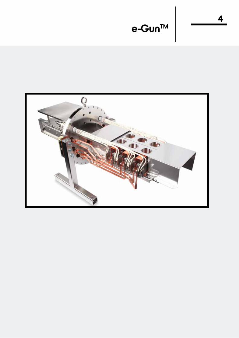
e-GunTM4

e-GunTM
4
Technical Information
Hanks HM2 e-Guns, 6-20 kW
6 kW Multiple Position Linear
Beam Sweep Controllers
4-12 kW Power Supplies
Theory of Operation................................Custom e-Guns.......................................
General Description.................................Single Crucible........................................Rotary, Multiple Crucibles.......................Hydra-2, Co-Evaporation, Dual Array, Multiple Crucibles/Emitters......................Hydra-1, Co-Evaporation, Single Array, Multiple Crucibles/Emitters......................Triad, Co-Evaporation, Three Crucibles..Accessories Replacement Parts, Feedthroughs.... Crucibles Liners.................................
3 and 4 Crucibles....................................
Digital, X-Y..............................................Programmable.........................................
Technical Information..............................Specifications..........................................
4-14-1
4-24-34-4
4-5
4-6
4-74-8
4-9
4-124-13
4-104-11
e-Gun Power Supplies
3 kW e-Guns
Training Classes
Evaporation Tables
4 kW Power Supply....................6 kW Power Supply....................8 kW Power Supply....................10 kW Power Supply..................12 kW Power Supply..................
Single Position............................Multiple Position 3, 4, and 5 Crucibles.....................................Rod Fed......................................Accessories Replacement Parts, Feedthroughs, Beam Sweep................. Crucbile Liners...............
4-24
4-25
4-194-204-214-224-23
4-14
4-154-17
4-184-18

4e-Guns Designed for Today’s Technology
4-1(360) 385-7707 [email protected]
Custom Installation: Twin HM2 e-Guns Mounted on a Single Flange (Inside View (note: this e-Gun assembly is shown mounted on a 13.25” flange)
Outside View Hanks HM2 e-Guns are manufactured and protected under one or more of the following patents: 4,835,789; 4,891,821; 4,947,404
The Thermionics e-Gun, an electron beam evaporation source, is used to produce uniform high-purity films and optical coatings. The compact design and ease of maintenance make it useful in practically all vacuum systems and for many varied applications. It has been used to evaporate refractory and dielectric mater ials, as well as the more common conduc tive and semi-conductor materials. e-Gun evaporation sources are reliable and simple to operate. They are equally suited for re search or production applications.
Each gun is available in three standard mounting configurations: 1. e-Gun mounted on a PyraFlat or ConFlat metal
seal type flange, which uses a standard OFE copper gasket
2. e-Gun with a 1” diameter bolt-type mount, which mounts through a 1” diam eter hole, and is sealed by a compres sion O-ring
3. e-Gun alone with no mounting flange
Please specify the mounting configura tion at the time the order is placed.
Other mounting flanges, configurations and geometries are routinely supplied, please call the factory for further information.
Any e-Gun can be designed and manu-factured to fit existing or new systems. Please consult the factory with your special requirements.
PyraFlat flanges are manufactured and protected under one or more of the following patents: 5,640,751; 4,685,193
Electron beam heating is an efficient way of achieving temperatures in excess of 3500°C (6300°F) for uniform thin film, optical coating and vacuum metallurgic processes. The all-metal sealed models are bakeable to 230°C (446°F). The e-Gun source and companion control power sup ply have been designed to be part of any high or ultra-high vacuum system.
The e-Gun source is a self-accelerated electron beam device. A beam of electrons, held at a high negative potential, is pro-duced by the hot tungsten filament. The beam of electrons leaving the filament is magnetically focused and then deflected 270° by the integral permanent magnet. The electron beam is accelerated into the evaporant material contained within the water-cooled, grounded crucible. The beam strikes the evaporant material with a spot of approximately 1/8” diameter and an inten sity of approximately 25 kW/cm2. Sweeping
the electron beam across the evaporant material contained in the crucible is per-formed by an electro-magnetic system, with either manual or automatic controls. Larger Thermionics e-Guns offer the sweep capability as a standard feature, 3 kW model sweep capability is available as an option. The focused electron beam is capable of producing temperatures over 3500°C in source materials, so virtually any material may be evaporated.
The rate at which source materials may be evaporated is dependent upon power input, charge size, charge shape, and the characteristics of the material to be evaporated. The highest evaporation rates are obtained with materials that have low evaporation temperatures and low thermal conductivity.
The evaporant vapor cannot become contaminated because the focused electron beam strikes only the evaporant source material in the crucible. The beam deflection and effective shielding keeps the filament hidden from the evaporant vapor. The crucible is cooled so efficiently that its surface never gets warm enough to unite with the evaporant material.
The e-Gun source will operate in a system base pressure as low as 5 x 10-11 Torr. The magnitude of pressure, which normally increases during evaporation, depends on the pumping capacity of the system and the cleanliness of the evaporant material. This pressure increase is minimized by the high
Introduction
Mounting Configurations
Ordering Information
Custom e-Guns
Theory of Operation
thermal efficiency of the source. There is minimal outgassing of surrounding surfaces because only the evaporant is heated.

4-2 (360) 385-7707 [email protected]
4The Revolutionary Hanks HM2 e-Gun with Modular Magnet Design and Hyper-Unimelt Sweep
By means of a unique modular magnetic configuration, the Hanks HM2 e-Gun offers a more efficient electron beam heated source. It is 2/3 the size of traditional evaporation sources, yet provides the same crucible volume, evaporation rate, and power capa-bility of physically larger guns.
The Hanks HM2 e-Gun is approximately 350% more efficient magnetically, which is reflected in its reduced physical size. It is also markedly different from other e-Guns because of the unique method used to generate the magnetic field. e-Gun manufacturers that use a transverse field for beam focusing place the permanent magnet horizontally at the rear of the source and conduct the magnetic field lines through steel pole pieces. The use of this system results in an inherently high magnetic leakage flux and thus, larger magnets must be used.
In the Hanks HM2 e-Gun, the magnetic field generator is rotated 90˚ from a horizontal to a vertical position. It is made of two sets of a number of small individual magnets arranged vertically along the two sides of the crucible and the beam path. This allows placement of the top ends of the magnets at a position slightly above the crucible top, which is the optimum position from which to deliver the flux to the desired magnetic field area. This very short length path reduces leakage flux. Leakage flux is further reduced by the use of a steel plate which connects the bottom end of the magnets to form a unitized magnetic structure. The desired changes and shaping of the magnetic gradient along the beam path are accomplished by shaping and positioning the individual magnets along the two sides of the beam path. The magnets can be either permanent magnets, electromagnets, or both, depending upon the application.
Hanks HM2 e-Guns are manufactured and pro tected under one or more of the following patents: 4,835,789; 4,891,821; 4,947,404
Fig. 4-1. Dimensional diagram of single crucible, 15 cc Hanks HM2 e-Gun.
• Elimination of beam curl - Electrons impact the melt at a 90˚ angle providing maximum energy transfer with a minimum of energy-wasting secondary electrons. This is the result of a carefully graduated magnetic field which is stronger at the top of the crucible than at the bottom.
• Elimination of pole pieces - Vertically mounted magnets result in less magnetic flux leakage. This improves electron cap-ture, and it improves efficiency. Thus, the more compact a magnetic circuit is, the smaller its source footprint.
• Easy filament alignment-Filaments are quickly, easily, and very accurately aligned by simply removing the emitter assembly from the vacuum system. An alignment tool is included with each gun.
• The Hyper-Unimelt high frequency sweep system virtually eliminates tunneling and source material eruptions. Operating from 0-200 Hz, it is over twice as fast as any other beam sweep system.
The high Hz sweep capability facilitates uniform heating of dielectric and sublimating materials. Without it, tunnels will develop, producing high evaporation rates, but with restricted distribution. Uniform heating is essential for maintaining a uniform flat evaporant surface. Maintaining the uniformity of the surface of the material being evaporated produces superior results.
• More efficient electron collimation - Our new design produces a better collimated beam with fewer stray electrons.
• Minimal filament distortion - By clamping the filament adjacent to the spiral, filament movement is held to a minimum.
• Electron tails - Special filament shielding prevents low energy electrons from leaving the filament environ ment, eliminating electron tails.
• Larger crucible size - 40 cc crucible volume in a footprint 2/3 the size of traditional evaporation sources.
Unique Electron Beam Heated Evaporation Sources
New Features and Benefits 200 Hz Sweep

4The Hanks HM2 Single Crucible, Single Emitter e-Gun
4-3(360) 385-7707 [email protected]
Single Crucible Models - Single Emitter
The Hanks HM2 e-Gun — 6, 10, 15, 20 kW Crucible Volumes — 7, 10, 15, 40, 75, 100, and 156 cc
Hanks HM2 Single Crucible e-Gun
Model No. Power Crucible Volume0607 6 kW 7 cc
0610 6 kW 10 cc
1010 10 kW 10 cc
1015 10 kW 15 cc
1540 15 kW 40 cc
1575 15 kW 75 cc
15100 15 kW 100 cc15156 15 kW 156 cc20156 20 kW 156 cc
Twin — Two Single Crucible e-Guns
Specifcations
Model No. Power Crucible VolumeD1010 10 kW 10 cc
D1015 10 kW 15 cc
D1540 15 kW 40 cc
Power Output 6 kW 10 kW 15 kW 20 kW7.5 kV 10 kV 10 kV 10 kV
0 to 800 mA 0 to 1.0 A 0 to 1.5 A 0 to 2.0 A
Crucible Volume 7/10 cc 10/15/40 cc 40/75/100/156 cc 156 cc
Dimensions 2.50” h 2.50” h 2.50” h 3.00” h3.25” w 3.25” w 3.50” w 5.00” w4.50” l 4.50” l 5.00” l 6.00” l
Weight 5 lbs 5 lbs 7 lbs 11 lbs
Filament 12 VAC 60 A
Electron Beam 270˚ deflection
Evaporation rates (for aluminum)
1 gm /min at 10 kW 1.5 gm /min at 15 kW3.6 microns at 25 cm 50,000 A min
Beam spot size .25" circular (approximate)(beam can be adjusted and located electricallywith beam sweep controller)
Crucible OFE copper
Bakeout temperature 230°C ( 446°F)
Water 3.0 gpm (filtered) at 70 psi
Minimum water tube size 3/8” dia ( 6/10/15 kW) 1/2” dia (20 kW)
Pressure differential 50 psi minimum
X and Y sweep Hyper-Unimelt sweep ( 0 to above 200 Hz)
Metal-sealed, fully UHV compatible, measured base pressure 2 x 10-11 Torr.
Hanks HM2 e-Guns are manufactured and pro- tected under one or more of the following patents: 4,835.789; 4,891,821; 4,947,404
UHV Compatible

4-4 (360) 385-7707 [email protected]
4 Hanks HM2 Rotary Pocket e-GunRotary, Multiple Crucible e-Guns(Not all models appear in this pricing grid, please consult factory)
Hanks HM2 Rotary Pocket e-Gun
High Vacuum CompatibleMetal and elastomer seals, measured base pressure: 2 x 10⁻⁹ Torr.
Specifications
Model No. Power Crucible No. Crucible VolumeR0607-4 6 kW 4 7 cc
R0610-4 6 kW 4 10 cc
R0615-4 6 kW 4 15 ccR1010-4 10 kW 4 10 cc
R1015-4 10 kW 4 15 cc
R1025-4 10 kW 4 25 cc
Power Output 6 kW 10kW7.5 kV 10 kV
0 to 800 mA 0 to 1.0A
Crucible Volume 7/10/15 cc 7/10/15/25 cc
Filament 12 VAC 60A
Electron beam 270˚ deflection
Evaporation rates(for aluminum)
1 gm/min at 10 kW3.6 microns at 25 cm
Beam spot size .25” circular (approximate)(beam can be adjusted and located electrically with beam sweep controller)
Crucible OFE CopperBakeout temperature 120°C (250°F)
Water 3.0 gpm (filtered) at 70 psi
Minimum water tube size 3/8” dia (6kW/10 kW)
Pressure differential 50 psi minimum
X and Y sweep Hyper-Unimelt sweep (0 to above 200 Hz)
The unique modular magnet concept is incorporated in the rotary pocket Hanks HM2 e-Gun design. This concept makes possible a very compact unit (see outline drawing). All of the Hanks HM2 unique features are incorporated in this model.
High frequency sweep (0-200 Hz) provides the user with total flexibility in the operation of the e-Gun. By operating a sweep controller, the beam can be varied in size to suit the material being evaporated. This is very beneficial for
optical coatings and other materials, where beam size plays an important role in optimum control from 1-2 A to very high deposition rates.
Hanks HM2 e-Guns are manufactured and protected under one or more of the following patents: 4,835.789; 4,891,821; 4,947,404
Modular Magnets
Modular Magnets(Optimum Control on Low or High Rates)
Fig. 4-2 Dimensional drawing of Hanks HM2 rotary pocket e-Gun.

4Hanks HM2 Hydra-2
4-5(360) 385-7707 [email protected]
PyraFlat flanges are manufactured and protected under one or more of the following patents: 5,640,751; 4,685,193
Hanks HM2 e-Guns are manufactured and protected under one or more of the following patents: 4,835.789; 4,891,821; 4,947,404
Hydra-2 (shown mounted on a PyraFlat flange, with an optional stand)
The Hydra evaporation system is specifically designed to meet the current technological challenges posed by complex co-deposition processes and “leading-edge” materials research. The Hydra design consists of a compact array of crucibles and electron emitters which translate linearly with respect to each other to provide for the co-deposition of up to six different materials simultaneously. By the efficient utilization of space, four different combinations of six crucibles or up to forty-two permutations of two-material combinations are available for co-deposition in a single vacuum pumpdown.
Innovative technology and a creative approach to magnetic field concepts has been fostered by Thermionics to result in several new, unique electron emission configurations. The Hydra configuration eliminates adjacent source interactions without complex beam directions and bulky field shunting components. Thus, the design allows close source proximity for uniform coating and material interaction. Each source crucible is independently water cooled to prevent steam buildup. Each source crucible has separate sweep coils, ensuring the independent operational integrity of each source, and eliminating cross talk interference from any adjacent source.
A Breakthrough in Co-Evaporation Technology
Metal-sealed, fully UHV compatible, measured base pressure: 2 x 10-11 Torr.
Prices are dependent upon many factors, i.e.: system, mounting flange, and e-Gun configurations, geometries, etc. Our engineering group will work closely with you to determine your requirements, then a firm quotation can be given.
UHV Compatible
Prices
Specifications
Power Output 10 kW 15 kW10 kV 10 kV
0 to 1.0 A 0 to 1.5 ACrucible Volume 10/15 cc 40 cc
Dimensions(Please refer to diagram on page 4-6 for reference dimensions)
10/15 cc 40 cc6.25” h 6.25” h11.0” w 11.5” w
15” I 15” I
Filament 12 VAC 60A
Electron beam 270° deflection
Evaporation rates(for aluminum)
1 gm/min at 10 kW3.6 microns at 25 cm
1.5 gm/min at 15 kW50,000 Å min
Beam spot size .25” circular (approximate) (beam can be adjusted and located electrically with beam sweep controller)
Crucible OFE CopperBakeout temperature 230°C (446°F)
Water 30 gpm (filtered) at 70 psi (each crucible has its own water supply, common return)—(3 gpm/crucible)
Pressure differential 50 psi minimum
X and Y sweep Hyper-Unimelt sweep (0 to above 200 Hz)
Inside View of Hydra-2 (shields removed for clarity) Overall View of Hydra-2 (shields removed for clarity)

4-6 (360) 385-7707 [email protected]
4 Hanks HM2 Hydra-2
40cc Hydra System Dimensions Hanks HM2 e-Guns are manufactured and protected under one or more of the following patents: 4,835.789; 4,891,821; 4,947,404
Hanks HM2 Hydra-1
Available with:• 5 crucibles, other options available upon request• 1-3 emitters, other options available upon request
Prices are dependent upon many factors, i.e.: system, mounting flange, and e-Gun configurations, geometries, etc. Our engineering group will work closely with you to determine your requirements, then a firm quotation can be given.
Co-Evaporation Technology — Single Array
Hydra-1 Single Array Gun
UHV CompatibleMetal-sealed, fully UHV compatible, measured base pressure: 2 x 10-11 Torr.
Specifications
Power Output 10 kW 15 kW10 kV 10 kV
0 to 1.0 A 0 to 1.5A
Crucible Volume 10/15 cc 40 cc
Dimensions(Please refer to the diagram above for reference dimensions)
10/15 cc 40 cc6.25” h 6.25” h5.5” w 5.75” w15” I 15” I
Filament 12 VAC 60A
Electron beam 270° deflection
Evaporation rates(for aluminum)
1 gm/min at 10 kW3.6 microns at 25 cm
1.5 gm/min at 15 kW 50,000 Å min
Beam spot size .25” circular (approximate)(beam can be adjusted and located electrically with beam sweep controller)
Crucible OFE copperBakeout temperature 230°C (446°F)
Water 15 gpm (filtered) at 70 psi(each crucible has its own water supply, common return)—(3 gpm/crucible)
Pressure differential 50 psi minimum
X and Y sweep Hyper-Unimelt sweep (0 to above 200 Hz)
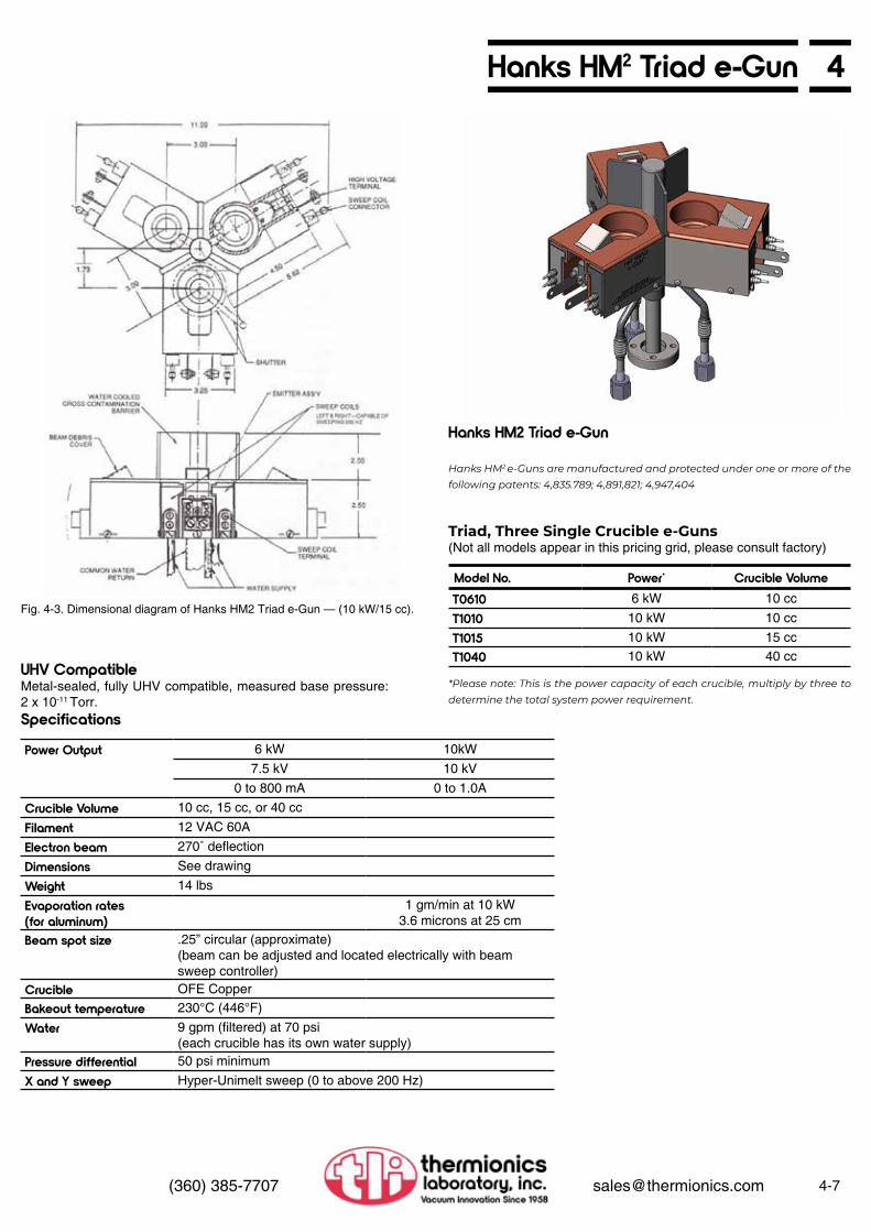
4Hanks HM2 Triad e-Gun
4-7(360) 385-7707 [email protected]
Fig. 4-3. Dimensional diagram of Hanks HM2 Triad e-Gun — (10 kW/15 cc).
Hanks HM2 Triad e-Gun
Hanks HM2 e-Guns are manufactured and protected under one or more of the following patents: 4,835.789; 4,891,821; 4,947,404
*Please note: This is the power capacity of each crucible, multiply by three to determine the total system power requirement.
Triad, Three Single Crucible e-Guns(Not all models appear in this pricing grid, please consult factory)
Model No. Power* Crucible VolumeT0610 6 kW 10 cc
T1010 10 kW 10 cc
T1015 10 kW 15 ccT1040 10 kW 40 cc
UHV CompatibleMetal-sealed, fully UHV compatible, measured base pressure: 2 x 10-11 Torr.Specifications
Power Output 6 kW 10kW7.5 kV 10 kV
0 to 800 mA 0 to 1.0A
Crucible Volume 10 cc, 15 cc, or 40 cc
Filament 12 VAC 60A
Electron beam 270˚ deflection
Dimensions See drawing
Weight 14 lbs
Evaporation rates(for aluminum)
1 gm/min at 10 kW3.6 microns at 25 cm
Beam spot size .25” circular (approximate)(beam can be adjusted and located electrically with beam sweep controller)
Crucible OFE CopperBakeout temperature 230°C (446°F)
Water 9 gpm (filtered) at 70 psi(each crucible has its own water supply)
Pressure differential 50 psi minimum
X and Y sweep Hyper-Unimelt sweep (0 to above 200 Hz)

4-8 (360) 385-7707 [email protected]
4 Hanks HM2 e-Gun AccessoriesReplacement Parts
Accessories
e-Gun Crucible LinersOrdering information
Starter Charges
Feedthroughs and Connectors
Model No. DescriptionA111555 Filament
A111556 Beam deflector
A112019-01 New beam deflector
A111557 Beam former
A111558 Insulator post
A111562-01 Anode
A111906 Main insulator
A111418-03 Ceramic washer
B111336 Beam cover
A526482-04 Emitter assembly
C111540-01 Sweep coil right sideC111540-02 Sweep coil left sideA111366 HM2 emitter rebuild kit —
includes screws, washers, ceramic insulators and spacers, two filaments and a filament alignment tool
Model No. Description210-SW Water interlock switch
SVA-GROUND Grounding rod
Model No. Description111139-04 4-pin instrument feedthrough mounted on a 1.33” ConFlat flange
111140-04 4-pin instrument feedthrough mounted on a 2.75” ConFlat flange
B111136-12 Two electrical feedthroughs mounted on a 2.75” ConFlat flange,12 kV @ 70 A (use with connector/cable assembly HVC-D-12)
HVC-D-12 Dual feedthrough connector w/interlock and 10’ dual cable assembly (use with dual feedthrough B111136-12)
EBFT-100 One electrical feedthrough mounted on a 2.75” ConFlat flange, 12 kV @ 70 A, two are required for each e-Gun(use with connector/cable assembly HVC-T-12)
EBFT-100-1B One electrical feedthrough mounted on a 1” bolt-type baseplatefeedthrough, 12 kV @ 70 A, two are required for each e-Gun(use with connector/cable assembly HVC-T-12)
EBFT-133 One electrical feedthrough mounted on a 1.33” ConFlat flange,12 kV © 70 A, two are required for each e-Gun(use with connector/cable assembly HVC-T-12)
HVC-T-12 Single feedthrough connector and 10’ cable assembly, two are required for each e-Gun (use with single feedthroughs EBFT-100, EBFT-100-1B, and EBFT-133)
EBFT-200 Dual pass water, 1/4” O.D. tubesEBFT-300 Dual pass water, 3/8” O.D. tubes
EBFT-400 Instrumentation, 10-pinEBFT-500 Rotary, 1/4” O.D. shaftEBFT-600 Rotary, with right angle translation, 1/4” O.D. shaftEBFK-700 Feedthrough Kit, for single crucible e-GunEBFK-800 Feedthrough Kit, for rotary multiple crucible e-GunEBFK-900 Feedthrough Kit, for rotary multiple crucible e-Gun, with right angle
translationEBCR-4 Automatic Indexer, four crucible, rotary model111489 Feedthrough connector, internal 1/4” rod to 10-32 screw connector086190 Feedthrough connector, internal 1/4” rod to 0.090” wire
Hanks HM2 e-Guns are manufactured and protected under one or more of the following patents: 4,835.789; 4,891,821; 4,947,404
• Please consult the factory if there is a special material you need.
• If you are unsure which liner fits your gun, please contact the factory and we will send you a template.
The model numbers listed are for the 1” diameter bolt-type baseplate feedthrough configuration. To specify the 2.75” flange mounting, please add the suffix /275 to the model number, i.e.: EBFT-200/275.
Please consult the factory for information concerning starter charges.
Each feedthrough is available in two mounting configurations:
• A 1” diameter bolt-type mounts through a 1” diameter hole, sealed by a compression O-ring;
• A 2.75” O.D. ConFlat-type flange uses a standard copper gasket. Other mounting flanges are routinely supplied, please call the factory for information and prices.
Accessories
Material Type 10 cc Model No. 15 cc Model No. 40 cc Model No. 156 cc Model No.Graphite 111959-G 111962-G 111368-G 111466-GGlassy carbon 111959-CG 111962-CG 111368-CG 111466-CGFabmate 111959-FM 111962-FM 111368-FM 111466-FMTantalum 111959-TA 111962-TA 111368-TA 111466-TAAlumina 111959-AL 111962-AL 111368-AL 111466-ALMolybdenum 111959-MO 111962-MO 111368-MO 111466-MOTungsten 111959-W 111962-W 111368-W 111466-WBoron nitride 111959-BN 111962-BN 111368-BN 111466-BNCopper 111959-CU 111962-CU 111368-CU 111466-CU

46 kW Multiple Position Linear e-Gun
4-9(360) 385-7707 [email protected]
Fig. 4-7. Dimensional drawing of Model 600-0060-33 (e-Gun shown fully retracted).
Specials UHV CompatibleAll multiple position e-Guns can be mounted on larger diameter ConFlat or rectangular PyraFlat flanges.
Metal-sealed, fully UHV compatible, measured base pressure: 2 x 10-11 Torr.
PyraFlat flanges are manufactured and protected under one or more of the following patents: 5,640,751; 4,685,193
See pages 4-10 and 4-11 for power supply information.
Specifications
Operating pressure Below 5 x 10⁻⁵ Torr is desirable for best operation
Beam voltage 6,000 V
Beam current 0 -1 A continuously variable
Maximum power 6,000W
Cooling water 2 gpm, minimum
Cooling waterconnection
Two 3/8” stainless steel tubing
Maximum bakeouttemperature
230°C (446°F)
Electrical feedthrough
Two 7 kV 50 A
Filament current 0-40 A
Filament voltage 0-10 VAC (filament isalso at high DC volt-age)
Beam deflection 220°Crucible volume 7 cc
Standard Models
6 kW e-Gun Replacement Parts 6 kW e-Gun Accessories
Model No. Description600-0060-30 3 crucible model, no sweep
600-0060-33 3 crucible model with X-Y sweep coils
600-0060-40 4 crucible model, no sweep
600-0060-44 4 crucible model with X -Y sweep coils
Model No. Description610-40 6 kW filament assembly
610-15 6 kW filaments, each
610-25 Anode shield, each
Special Repair 6 kW beam intensifier
Model No. DescriptionDSC-1.5A Digital Sweep Controller (See
page 4-12 for specifications)PSC-1.5A Programmable Sweep
Controller (See page 4-13 for specifications)
680-1040 High current feedthrough(2 required)
210-S/W Water interlock switch
PS-GR Grounding rod
111139-04 4-pin instrument feedthrough on 1.33” ConFlat
111140-04 4-pin instrument feedthrough on 2.75” ConFlat

4-10 (360) 385-7707 [email protected]
4 Electron Beam Power SuppliesThermionics e-Gun source (ebeam gun) solid state power supplies offer our users state-of-the-art technology in switching mode power supplies. Extensive arc management provides fast recovery, arc counting and duration sensing technology. Ranging from 4 kW to 12kW these supplies are available in single or multi-source output configuration. Current regulation is <0.5%. Adjustable output current and ultra-low ripple are a great advantage to our users. When combined with the Digital Sweep, these e-Gun power supplies afford extremely stable beam position and repeatable results. The use of separate controllers offers fast support and minimal downtime in the event of failures. Thermionics solid state power supplies are rack mountable and air cooled for easy installation.Handheld remote control units with voltage and current displays are available.
• Maximum power 4/6/8/10/12kW• Simultaneous operation of up to 2 e-Gun
sources• All Solid-State switch mode design• Rugged well overrated IGBT inverter for
superior reliability• Extensive arc management for outstanding
performance, fastest arc recovery, arc counter and arc duration sensor
• Adjustable voltage 0 to -10kV (0 to -8kV for SVA-4) with precise regulation (<+/- 0.25%) for stable beam position, ultra-low ripple for minimum beam size
• Constant emission current regulation <+/- 0.5%
• Full remote operation from PLC or optional Handheld for both High Voltage and Source
• 19 inch rack mountable, ultra-compact, ST chassis: 8.75˚ (5U), Controller: 1.75˚ (1U), Digital Sweep: 3.50˚ (2U), Programmable Sweep Optional: 3.50˚ (2U)
• Air cooled
2-Channel Power Supply Shown: SVA Remote (2 top devices) SVA Controller (2 middle devices)SVA-12 Power Supply (Bottom device)

44, 6, 8, 10, 12 kW Electron Beam Power Supplies
4-11(360) 385-7707 [email protected]
SpecificationsHigh Voltage Power Supply
Filament Controller
Control Panel
Handheld Remote Control
Input voltage 208/400 VAC, 3-phase, 50/60 Hz
Output current 4 kW 6 kW 8 kW 10 kW 12 kW 500 mA 600 mA 800 mA 1.0 A 1.2 A
Precise regulation (<+/- 0.25%)
HV AdjustmentOutput Voltage Variable
SVA-4 SVA-6 SVA-8 SVA-10 SVA-12 -0 to -8 kV -0 to -10 kV -0 to -10 kV -0 to -10 kV -0 to -10 kV
Response time for all units < 50 microseconds
Input voltage 208/400 VAC
Primary control SCR, phase controlOutput current 5 A max
Current regulation Less than 2%
The remote control panel contains all the necessary controls and indicators for operation of the power supply, filament controllers and sweep generators.
A handheld remote control chassis may be provided as an option. It provides control of theemission current, emission on-off, lateral sweep amplitude, lateral sweep position, longitudinal amplitude and longitudinal position.
• Proven high reliability• Adjustable high voltage• Output ripple same at any voltage setting• Air-cooled• Rapid arc quenching• Tight emission regulation• Built-in multi-gun operation
Includes power supply, rack mountable control panel, closed loop filament controller, enclosed filament transformer, and all connecting cables.
Provides remote control of emission, high voltage off.
Features
e-Gun (e-Beam) Power Supplies
Hand Held Remote Control
Physical DimensionsControl panelWeight
19.0” wide x 1.7” high x 8.2” deep Approximately 4 lbs
Power supplyWeight
19” wide x 8.7” high x 21.1” deepApproximately 56 lbs
Model No. PowerSVA-4 4 kW
SVA-6 6 kW
SVA-8 8 kW
SVA-10 10 kW
SVA-12 12 kW
Model No.HHRC
SVA Power Supply Filament Transformer High Voltage Dual Connector
SVA Power Supply Controller

4-12 (360) 385-7707 [email protected]
4 Sweep Controllers
• Frequency range: 0.1 to 100 Hz• Coil current, dual channel +/1.5A max• Rotational resolution, 360 steps (1˚ angular
resolution)• Patterns, 8• Reprogrammed shapes, 4• Remote included
• Pocket setup, 9 point• LCD touch screen, resolution 320 x 240• Input voltage 90-264 VAC, 47-63 Hz• Remote inputs, passive or active: individual,
binary• Remote outputs, Dry Contact closures (N.O.)
individual, binary
Digital Sweep Controller
Specifications
The Thermionics Sweep is a five-function sweeper. It is intended for use with e-Gun sources such as the Thermionics line of e-Gun sources and with other compatible EB (electron beam) sources that use electromagnetic deflection or combinations of electromagnetic deflection and permanent magnet focusing. The Sweep outputs user adjustable patterns to e-Gun sources. A Sweep is needed for positioning and moving
the EB around the source’s crucible pocket in a defined pattern. The beam movement helps heat (and evaporate) the crucible pocket’s material more evenly. Sweeping is accomplished by running current through magnetic coils next to the crucible pocket. One output runs to each of two coils (latitude and longitudinal), which are placed perpendicularly to each other. Their magnetic fields affect the position/motion of
the electron beam. A simple front panel touch screen color LCD (liquid crystal display) and handheld joystick interface is used to configure and run EB sweep patterns. The LCD display allows for easy visualization of each pattern. The LCD panel prompts the user through the various steps of a normal operation.
See page 4-8 for information.
Accessories
Mechanical Specifications
Digital Sweep Controller Remote
Dimensions 19.0” wide x 3.5” high x 9.4” deep
Weight 10.6 lbs
Model No.DSC-1.5A
Digital Sweep Controller

4Sweep Controllers
4-13(360) 385-7707 [email protected]
• Frequency range: 0.1 to 100 Hz• Coil current, dual channel +/1.5A max or
optional +/-3.0A max• Rotational resolution, 360 steps (1˚ angular
resolution)• Patterns, 32• Reprogrammed shapes, 7• Programmable user shapes, 32• Avatar joystick, included
• Pocket setup, 9 point• Profile• Magnetic distortion adjust• LCD touch screen, resolution 480 x 272• Input voltage 90-264 VAC, 47-63 Hz• Remote inputs, passive or active: individual,
binary• Remote outputs, Dry Contact closures (N.O.)
individual, binary
Programmable Sweep Controller
Specifications
The Thermionics Sweep is a five-function sweeper. It is intended for use with e-Gun sources such as the Thermionics line of e-Gun sources and with other compatible EB (electron beam) sources that use electromagnetic deflection or combinations of electromagnetic deflection and permanent magnet focusing. The Sweep outputs user adjustable patterns to e-Gun sources. A Sweep is needed for positioning and moving
the EB around the source’s crucible pocket in a defined pattern. The beam movement helps heat (and evaporate) the crucible pocket’s material more evenly. Sweeping is accomplished by running current through magnetic coils next to the crucible pocket. One output runs to each of two coils (latitude and longitudinal), which are placed perpendicularly to each other. Their magnetic fields affect the position/motion of
the electron beam. A simple front panel touch screen color LCD (liquid crystal display) and handheld joystick interface is used to configure and run EB sweep patterns. The LCD display allows for easy visualization of each pattern. The LCD panel prompts the user through the various steps of a normal operation.
See page 4-8 for information.
Accessories
Programmable Sweep Controller Remote
Mechanical SpecificationsDimensions 19.0” wide x 3.5” high x 9.4” deep
Weight 10.6 lbs
Model No.PSC-1.5A
Programmable Sweep Controller
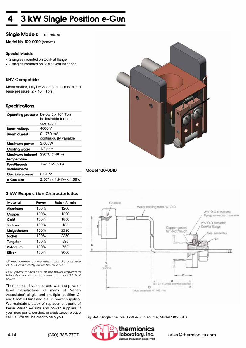
4-14 (360) 385-7707 [email protected]
4 3 kW Single Position e-Gun
Specifications
Single Models — standard
Model No. 100-0010 (shown)
Special Models
Operating pressure Below 5 x 10⁻⁵ Torr is desirable for best operation
Beam voltage 4000 V
Beam current 0 - 750 mA continuously variable
Maximum power 3,000W
Cooling water 1/2 gpm
Maximum bakeouttemperature
230°C (446°F)
Feedthrough requirements
Two 7 kV 50 A
Crucible volume 2.24 cc
e-Gun size 2.50”h x 1.94”w x 1.69”d
• 2 singles mounted on ConFlat flange• 3 singles mounted on 8” dia ConFlat flange
UHV CompatibleMetal-sealed, fully UHV compatible, measured base pressure: 2 x 10-11 Torr.
3 kW Evaporation Characteristics
Material Power Rate - Å minAluminum 100% 1260
Copper 100% 1220
Gold 100% 1550
Tantalum 100% 435
Molybdenum 100% 2290
Nickel 100% 2250
Tungsten 100% 590
Palladium 100% 750
Silver 100% 3000
All measurements were taken with the substrate 10” (25.4 cm) directly above the crucible.
100% power means 100% of the power required to bring the material to a molten state—not 3 kW of power
Thermionics developed and was the private-label manufacturer of many of Varian Associates’ single and multiple position 2- and 3-kW e-Guns and e-Gun power supplies. We maintain a stock of replacement parts of these Varian e-Guns and power supplies. If you need parts, service, or assistance, please call us. We will be glad to help you.
Model 100-0010
Fig. 4-4. Single crucible 3 kW e-Gun source, Model 100-0010.

43 kW Multiple Position Linear e-Gun
4-15(360) 385-7707 [email protected]
Model 100-0030
Standard Models
Specials
Operation
Model No. Crucibles100-0030 3
100-0040 4
100-0050 5
All multiple position e-Guns can be mounted on larger diameter ConFlat or rectangular PyraFlat flanges, single or back-to-back.
The operating principle of the multiple crucible e-Gun is identical to the single crucible source with the following advantages:
• Large supply of evaporant — When every crucible is filled with the same source material, an increased volume of evaporant can be evaporated in a single vacuum cycle.
• Deposition of up to five different materials in one vacuum cycle — A different material can be put in each crucible and deposited in any sequence during a single vacuum cycle. The deposition rates are the same as those of the single crucible model. Only one crucible is heated at a time. The single filament remains stationary and the crucible head is indexed into position by the drive handle. Therefore, the evaporation always originates from exactly the same position in the vacuum chamber. The inactive crucibles are shielded from the heated crucibles by the magnetic pole pieces, thereby eliminating contamination between crucibles.
PyraFlat flanges are manufactured and protected under one or more of the following patents: 5,640,751; 4,685,193
Specifications
Operating pressure Below 5 x 10⁻⁵ Torr is desirable for best operation
Beam voltage 4000 V
Beam current 0 - 750 mA continuously variable
Maximum power 3,000W
Cooling water 1/2 gpm
Maximum bakeouttemperature
230°C (446°F)
Feedthrough requirements
Two 7 kV 50 A
Crucible volume 2.24 cc
UHV CompatibleMetal-sealed, fully UHV compatible, measured base pressure: 2 x 10-11 Torr.

4-16 (360) 385-7707 [email protected]
4 3 kW Multiple Position Linear e-Gun
Fig. 4-5. 3 kW e-Gun source, model 100-0030.
Fig. 4-6. 3 kW e-Gun source, Model 100-0050.

43 kW Rod-Fed e-Gun
4-17(360) 385-7707 [email protected]
Introduction
Mounting and Configurations
The operation of the 3 kW rod-fed e-Gun is unique. The evaporant source material, in the form of a rod up to a 1/4” in diameter, is fed continuously into the crucible using an external linear feedthrough. Film thickness may be controlled using a rate monitor.
The e-Guns are available mounted on various flanges.
• The 3 kW rod-fed e-Gun may be mounted and operated in any orientation, including upside down (which is material dependent)
• The rod-fed e-Gun shown in the photo on the right can fit through a 2.5” I.D. tube
• An optional cryoshroud to surround the e-Gun is available
• Multiple rod-fed e-Guns can be mounted side- by-side
• Custom designs are available, please consult the factory
Knudsen Cell Replacemente-Guns can evaporate difficult materials, i.e.: carbon, niobium, and silicon.
A rod-fed e-Gun, complete with all the necessary utility and mechanical feedthroughs, installed on a 4.5” O.D. ConFlat mounting flange, is available as a direct replacement for existing Knudsen Cell furnaces on Varian/Intevac, Perkin-Elmer, Riber, EPI, and VG systems.
Please call to discuss your specific application requirements.
Rod-Fed e-Gun with motorized material feed and azimuthal material rotation.
UHV CompatibleMetal-sealed, fully UHV compatible, measured base pressure: 2 x 10-11 Torr.
Model No. Description100-0010R Rod-fed e-Gun only
100-0010R/SK Rod-fed e-Gun with all utility, electrical and mechanical feedthroughs
Specifications
Operating pressure Below 5 x 10⁻⁵ Torr is desirable for best operation
Beam voltage 4000 V
Beam current 0 - 750 mA continuously variable
Maximum power 3 kW @ 4 kV
Cooling water 1/2 gpm
Maximum bakeouttemperature
230°C (446°F)
Feedthrough requirements
Two 7 kV 50 A
Crucible volume 1/4” dia rod
e-Gun size 2.50”h x 1.94”w x 1.69”d
3 kW Rod-Fed e-Gun
Custom Special Rod-Fed e-Gun

4-18 (360) 385-7707 [email protected]
4 3 kW AccessoriesReplacement Parts
Feedthroughs and Connectors
Accessories
Sweep
Model No. Description22001-1 Ceramic insulator (6-32 x 3/8” dia x 3/4” length)
22001-2 Ceramic insulator (6-32x 1/4” dia x 1/2” length)
22009 Ceramic washer
21040 3 kW emitter assembly (includes filamentassembly two filaments, legs, hardware set,magnet, cathode shield, overspray shield, and two flange gaskets)
21015 Filament (.015 dia tungsten)
21007-1 Filament leg—neutral
21007-2 Filament leg—insulated
22013 Hardware set (includes all screws, ceramics and shims)
21005 Magnet
21011 Cathode shield
21013 Overspray shield
22008 Copper flat gasket (vacuum annealed), each
22015 Remote potentiometer with amphenol connector
310-6A18-1P Shorted plug
310-990009 Diode pack
Model No. DescriptionB111136-07 Two electrical feedthroughs mounted on a
2.75” ConFlat flange, 7 kV @70 A (use with connector/cable assembly HVC-D-12) Note: Please consult the factory for power supply installation information.
HVC-D-12 Dual feedthrough connector with interlock and 10’ dual cable assembly (use with dual feedthrough B111136-07)
8111137 One electrical feedthrough mounted on a 2.75” ConFlat flange, 7 kV@ 70 A, two are required for each e-Gun (use with connector/cable assemblies HVC-T-12 and HVC-V-12)
8111138 One electrical feedthrough mounted on a 1.33” ConFlat flange, 7 kV@ 70 A, two are required for each e-Gun (use with connector/cable assemblies HVC-T-12 and HVC-V-12)
HVC-T-12 Single feedthrough connector and 10’ cable assembly, two are required for each e-Gun (use with single feedthroughs B111137 and B111138)
HVC-V-12 Single feedthrough connector and 10’ cable assembly, two are required for each e-Gun (use with single feedthroughs B 111137 and B 111138), for Varian power supplies
A111489 Feedthrough connector, internal 1/4” rod to 10-32 screw connector
A086190 Feedthrough connector, internal 1/4” rod to 0.090” wire
Model No. Description210-SW Water interlock switch for all e-Guns
PS-GA Grounding rod
Model No. DescriptionXYS X-Y beam sweep controller
(see page 4-12 for specifications)XYCS Circular beam sweep controller
(see page 4-12 for specifications)180-1030 Beam adjust (requires 150-0030 or 150-0040)
180-8384 Set of two coils for multi-position guns
180-8385 Set of two coils for single-position guns
e-Gun Crucible Liners
Single Crucible, Single Position(60° wall angle)
Multiple Crucible, 3 and 5 Position(60° wall angle, old style)
Multiple Crucible, 3 and 5 Position(New style 15° wall angle)
Material Model No. Graphite 111455-GGlassy Carbon 111455-CGFabmate 111455-FMTantalum 111455-TAAlumina 111455-ALMolybdenum 111455-MOTungsten 111455-WBoron Nitride 111455-BN
Material Model No. Graphite 111449-GGlassy Carbon 111449-CGFabmate 111449-FMAlumina 111449-ALMolybdenum 111449-MOTungsten 111449-TABoron Nitride 111449-BN
Material Model No. Graphite 111460-GGlassy Carbon 111460-CGFabmate 111460-FMAlumina 111460-TAMolybdenum 111460-ALTungsten 111460-MOBoron Nitride 111460-W
(1) Please consult the factory if there is a special material that you need or(2) if you are unsure which liner fits your gun, we will send you a template.
See page 4-8 for instrumentation and other feedthroughs

44 kW High Voltage Power Supplies
4-19(360) 385-7707 [email protected]
See page 4-8 for instrumentation and other feedthroughs
Power Supply Specifications
Features
Input power 208 or 400 VAC
Output, high voltage -0kV to -8 kV
Output, current 500 mA
Response Time <50 microseconds
Source Filament 50 A max @ 8 VAC
Process Control Votage
+10 VDC
e-Gun filament leads 10 ft
Remote control cable 15 ft
Panel space 19”w x 8.7”h x 21.9”d
Weight 100 lbs
4 kW Power Supply and Sweep Controllers
Model No. DescriptionSVA-4 4 kW power supply
DSC-1.5A Digital Sweep Controller (see page 4-12 for specifications)
PSC-1.5A Programmable Sweep Controller (see page 4-13 for specifications)
Power Supply Remote Control
4 kW Power Supply
• All solid-state switch mode design• Rugged well overrated IGBT inverter for
superior reliability• Extensive ARC management for
outstanding performance: fastest ARC recovery, ARC counter and ARC duration sensor
• Constant emissions regulation• Full remote operation from PLC or optional
handheld for both high voltage and source• 19-inch rack mountable, ultra-compact
chassis• Air cooled

4-20 (360) 385-7707 [email protected]
4 6 kW High Voltage Power Supplies
See page 4-8 for instrumentation and other feedthroughs
Power Supply Specifications
Features
Input power 208 or 400 VAC
Output, high voltage -0kV to -10 kV
Output, current 600 mA
Response Time <50 microseconds
Source Filament 50 A max @ 8 VAC
Process Control Votage
+10 VDC
e-Gun filament leads 10 ft
Remote control cable 15 ft
Panel space 19”w x 8.7”h x 21.9”d
Weight 100 lbs
6 kW Power Supply and Sweep Controllers
Model No. DescriptionSVA-6 6 kW power supply
DSC-1.5A Digital Sweep Controller (see page 4-12 for specifications)
PSC-1.5A Programmable Sweep Controller (see page 4-13 for specifications)
Power Supply Remote Control
6 kW Power Supply
• All solid-state switch mode design• Rugged well overrated IGBT inverter for
superior reliability• Extensive ARC management for
outstanding performance: fastest ARC recovery, ARC counter and ARC duration sensor
• Constant emissions regulation• Full remote operation from PLC or optional
handheld for both high voltage and source• 19-inch rack mountable, ultra-compact
chassis• Air cooled

48 kW High Voltage Power Supplies
4-21(360) 385-7707 [email protected]
See page 4-8 for instrumentation and other feedthroughs
Power Supply Specifications
Features
Input power 208 or 400 VAC
Output, high voltage -0kV to -10 kV
Output, current 800 mA
Response Time <50 microseconds
Source Filament 50 A max @ 8 VAC
Process Control Votage
+10 VDC
e-Gun filament leads 10 ft
Remote control cable 15 ft
Panel space 19”w x 8.7”h x 21.9”d
Weight 100 lbs
8 kW Power Supply and Sweep Controllers
Model No. DescriptionSVA-8 8 kW power supply
DSC-1.5A Digital Sweep Controller (see page 4-12 for specifications)
PSC-1.5A Programmable Sweep Controller (see page 4-13 for specifications)
Power Supply Remote Control
8 kW Power Supply
• All solid-state switch mode design• Rugged well overrated IGBT inverter for
superior reliability• Extensive ARC management for
outstanding performance: fastest ARC recovery, ARC counter and ARC duration sensor
• Constant emissions regulation• Full remote operation from PLC or optional
handheld for both high voltage and source• 19-inch rack mountable, ultra-compact
chassis• Air cooled

4-22 (360) 385-7707 [email protected]
4 10 kW High Voltage Power Supplies
See page 4-8 for instrumentation and other feedthroughs
Power Supply Specifications
Features
Input power 208 or 400 VAC
Output, high voltage -0kV to -10 kV
Output, current 1000 mA (1 A)
Response Time <50 microseconds
Source Filament 50 A max @ 8 VAC
Process Control Votage
+10 VDC
e-Gun filament leads 10 ft
Remote control cable 15 ft
Panel space 19”w x 8.7”h x 25.7”d
Weight 100 lbs
10 kW Power Supply and Sweep Controllers
Model No. DescriptionSVA-10 10 kW power supply
DSC-1.5A Digital Sweep Controller (see page 4-12 for specifications)
PSC-1.5A Programmable Sweep Controller (see page 4-13 for specifications)
Power Supply Remote Control
10 kW Power Supply
• All solid-state switch mode design• Rugged well overrated IGBT inverter for
superior reliability• Extensive ARC management for
outstanding performance: fastest ARC recovery, ARC counter and ARC duration sensor
• Constant emissions regulation• Full remote operation from PLC or optional
handheld for both high voltage and source• 19-inch rack mountable, ultra-compact
chassis• Air cooled• Control up to two (2) e-Gun sources

412 kW High Voltage Power Supplies
4-23(360) 385-7707 [email protected]
See page 4-8 for instrumentation and other feedthroughs
Power Supply Specifications
Features
Input power 208 or 400 VAC
Output, high voltage -0kV to -10 kV
Output, current 1200 mA (1.2 A)
Response Time <50 microseconds
Source Filament 50 A max @ 8 VAC
Process Control Votage
+10 VDC
e-Gun filament leads 10 ft
Remote control cable 15 ft
Panel space 19”w x 8.7”h x 25.2”d
Weight 100 lbs
12 kW Power Supply and Sweep Controllers
Model No. DescriptionSVA-12 12 kW power supply
DSC-1.5A Digital Sweep Controller (see page 4-12 for specifications)
PSC-1.5A Programmable Sweep Controller (see page 4-13 for specifications)
Power Supply Remote Control
12 kW Power Supply
• All solid-state switch mode design• Rugged well overrated IGBT inverter for
superior reliability• Extensive ARC management for
outstanding performance: fastest ARC recovery, ARC counter and ARC duration sensor
• Constant emissions regulation• Full remote operation from PLC or optional
handheld for both high voltage and source• 19-inch rack mountable, ultra-compact
chassis• Air cooled• Control up to two (2) e-Gun sources

4-24 (360) 385-7707 [email protected]
4 Training ClassesGeneral Outline of One-Day Practical and Theoretical Training for e-Gun Technology
I. Physical Components II. Magnetic Field and Field Effects
III. Rate Power Definition
IV. Al-Cu Deposition Problems
Scheduled Classes:
1. CrucibleA. Water PassageB. Turbulence Sheet FlowC. Water Pressure
2. Emitter TheoryA. FilamentB. AnodeC. Beam FormerD. Space Charge Effects
1. Permanent MagnetA. Bar MagnetB. Modular MagnetC. Various Other Types of Magnets
2. Pole PieceA. MaterialsB. Hysteresis and Saturation
3. Beam TrajectoryA. Flat or HighB. Curvature of Radius of ElectronC. How the Magnetic Field Effects the Electrons
4. X-Y SweepA. High Frequency
1. Rate Power Curve Phenomena2. Tight Beam3. Diffused Beam
1. Erosion2. Thermal Shorts
Call factory for class schedules
Special classes at your plant on request
V. Summary
VI. Questions and Answers

4Evaporation Tables
4-25(360) 385-7707 [email protected]
Name SymbolMeltingPoint °C
Density gm/cm3
Temperature (°C) at Vap. Press. Evaporation Techniques
Remarks10-8 Torr 10-6 Torr 10-4 TorrElectron Beam Crucible Coil Boat Basket
Aluminum Al 660 2.7 677 812 1010 Xlnt.ZrB2BN
Vit. Carbon
W TiB2BNAl2O3
W Alloys and wets, Tungsten-stranded
AluminumCarbide Al4C3 1400 2.4 ~800 Fair
Aluminum Fluoride
AIFAIF3
Subl. 2.9 410Sublimes
490 Sublimes
700 Sublimes Poor W
TaLoses Fluorine. Disproportionates.
Aluminum Nitride AIN Subl. 3.3 ~1750 Fair Decomposes.
Alumina (a) Al2O3 2020 4.0 1045 1210 1325 Xlnt. W W W WSapphire Xlnt. in EB, Chemically deposit, Index may change.
Antimony Sb 630 6.7 279 345 425 Poor Al2O3
MoTa
Mo, TaAl2O3
Coated
MoTa
Antimony Trioxide Sb2O3 656 5.2 ~300 Good Al2O3
PtAl2O3
CoatedPt Toxic.
Antimony Trisulphide Sb2S3 550 4.6 ~200 Mo
TaMoTa
Arsenic As 814 5.7 107 Sublimes
150 Sublimes
210 Sublimes Poor
Al2O3BeO
Vit CarbonC Sublimes rapidly at low
temperature, toxic.
Arsenic Selenide As2Se3 360 4.5 Quartz
Barium Ba 725 3.5 545 627 735 Fair WWTaMo
W Wet without alloying. Reacts with ceramics.
Barium Fluoride BaF2 1280 4.9 ~700
Barium Oxide BaO 1923 5.7 ~1200 Poor Pt Pt
Barium Titanate BaTiO3 Dec. 6.0 Decomposes
Decomposes. Yields free Ba from Titanate single source-evaporate from two sources, flash from superheated W.
Beryllium Be 1278 1.9 710 878 1000 Xlnt.BeO
CVit Carbon
WWTaMo
W Wets W/Mo/Ta, Oxides are toxic.
Beryllium Fluoride BeF2 Subl. 2.0 ~200 Good Toxic.
Beryllium Oxide BeO 2530 3.0 ~1900 Good W Powders toxic.
Bismuth Bi 271 9.8 330 410 520 Good Al2O3Vit Carbon W
W, MoAl2O3
TaW
Vapors are Toxic. High resistivity. No shorting of baskets
Bismuth Fluoride BiF3 727 5.3
Bismuth Oxide Bi2O3 820 8.9 ~1400 Poor Pt Vapors are toxic.
Bismuth Selenide Bi2Se3 710 6.8 Good Quartz
Bismuth Telluride Bi2Te3 585 7.9 Quartz W
Mo
Bismuth Titanate BiTi2O7 Decomposes Decomposes, evaporate
from two sources.
Bismuth Trisulphide Bi2S3 685 7.5
The information in the tables has been compiled from a number of sources, some of which may be out of date. Should you find an error or be able to add new information, please contact us. A MORE COMPLETE LIST CONSISTING OF OVER 167 MATERIALS IS AVAILABLE UPON REQUEST.

Electrical and Fluid Feedthroughs
5
Electrical and Fluid Feedthroughs
5
Electrical Feedthroughs
Fluid Feedthroughs
FMC Medium Current.................FHV High Voltage.......................FHC High Current.......................FMH & FBN Instrumentation......FSH & FBSH Instrumentation.....FIM Coaxial.................................FEP Multi-Conductor..................PLC Push-On Connectors..........Thermocouple.............................Film Thickness Monitor...............
FCW Water Cooling....................FLN Cryogenic............................
5-15-25-35-45-65-75-85-85-95-10
5-115-12

5
5-1(360) 385-7707 [email protected]
FMC Series Medium Current Electrical Feedthroughs
FMC-133-1
FMC-275-1
FMC-275-2
PMC-150FMC-275-3
These feedthroughs are used in a variety of applications where a significant amount of power is to be transferred into a vacuum system. The feedthrough conductors are available in two styles, solid and hollow tube. The tube option (Model No. suffix “T”) allows for water cooling or special coaxial construction.
General SpecificationsFMC
Max. current 150 A solid 1/4” rod10 A 1/4” tube(0.032 wall)
Max. voltage 7,000 VConductor CopperTemperature range -200°C to 450°CMax. rate of change 25°C/min
Ordering Information —Medium Current Ultra High Vacuum Electrical Feedthroughs
Flange Size Conductor No. of Conductors Model No.
1.33” O.D Rod 1 FMC-133-12.75” O.D. Rod 1 FMC-275-12.75” O.D. Rod 2 FMC-275-22.75” O.D. Rod 3 FMC-275-32.75” O.D. Rod 4 FMC-275-41.33” O.D Tube 1 FMC-133-1T2.75” O.D. Tube 1 FMC-275-1T2.75” O.D. Tube 2 FMC-275-2T2.75” O.D. Tube 3 FMC-275-3T2.75” O.D. Tube 4 FMC-275-4T
ConnectorsPMC-150 Internal Connector• OFE copper, nickel plated• 150 A• 450°C max. temperature• For 1/4” O.D. conductor• Push-on connector

5-2 (360) 385-7707 [email protected]
5 FHV Series High Voltage Electrical Feedthroughs
FHV12-275-1
FHV28-275-1
FHV3-133-2
FHV.5-133-2
The FHV series feedthroughs provides HV access to the vacuum chamber. They include single or dual conductor models with mating exterior connector.
FHV12-275-1 High Voltage Feedthrough
FHV28-275-1 High Voltage Feedthrough
FHV3-133-2 High Voltage Feedthrough
FHV.5-133-2 High Voltage Feedthrough
/EL45 Elbow Mount Option
• 10 A• 12,000 V (below 10-4 Torr)• Temperature range: -200°C to 450°C, 25°C/
min max. rate of change• SS conductor• 2.75” O.D. flange• Internal attachment: 8-32 nut• External connector supplied
• 15 A• 28,000 V (below 10-4 Torr)• Temperature range: -200°C to 450°C, 25°C/
min max. rate of change• OFE copper conductor• 2.75” O.D. flange• Internal attachment: 4-40 nut• External attachment: 1/4-28 nut
• 1.33” O.D. flange1.5” O.D. body cylinder
• 2 conductors (plus safety ground contact)• Electrical ratings (with exterior connector):
Max. current: 15 AMax. voltage: 3,000 VDC
• Environmental ratings (with connector detached):
Temperature range: -200°C to 450°CMax. rate of change: 25°C/min
• Supplied with connector
• 1.33” O.D. flange• 2 conductors• Electrical ratings (with exterior connector):
Max. current: 10 AMax. voltage: 500 V
• Environmental ratings (with connector detached):
Temperature range: -200°C to 450°CMax. rate of change: 25°C/min
• Supplied with connector
• For 1.33” O.D. mounted feedthroughs• Angles connector or leads at 45° to flange
polar axis• Elbow installed between 1.33” O.D. flange
and electrical feedthrough core

5FHC Series High Current Electrical Feedthroughs
5-3(360) 385-7707 [email protected]
FHC-275-1
FHC-275-1WC
CMC-150
These feedthroughs provide high current path to the vacuum chamber. They include water cooled and solid conductor models.
FHC-275-1 High Current Feedthrough
FHC-275-1WCHigh Current Electrical Feedthrough
ConnectorsCMC-150 Internal/External Connector
FHC-275-1T
• 600 A• 3,000 V (below 10-4 Torr)• Temperature range: -200°C to 450°C,
25°C/min max. rate of change• 3/4” O.D. OFE copper conductor• 2.75” O.D. flange• Internal and external attachment: use
CMC-150
• Water cooled• Conductor: 0.75” O.D. OFE copper with
water channel• Max. current: 1,600 A• Max. voltage: 3.000 V below 1 x 10⁻⁴ Torr• 2.75” O.D. flange• Temperature range: -200°C to 450°C, 25°C/
min max. rate of change
• OFE copper• 450 A• 450°C max. temperature• For 3/4” O.D. to 1/4” O.D. conductor• Clamp-on connector
• Same as FHC-275-1 except 3/4” O.D. copper tube conductor
• 100 A max.

5-4 (360) 385-7707 [email protected]
5 FMH & FBN Instrumentation Series Electrical FeedthroughsFMH and FBN series feedthroughs provide UHV feedthrough accessfor MHV and BNC cables.
General Specifications
MHV BNCMax. current 3 A 3 AMax. voltage 5,000 V 500 VConductor 304 SS 304 SSTemperature range -200°C to 450°CMax. rate of change 25°C/minExternal connector 74868-932/U 74868UG-88/U
Ordering Information —Instrumentation Ultra High Vacuum Electrical FeedthroughsFlange Size Conductor No. of
ConductorsFloating Shield Model No.
1.33” O.D MHV 1 No FMH-133-1C2.75” O.D. MHV 1 No FMH-275-1C2.75” O.D. MHV 2 No FMH-275-2C2.75” O.D. MHV 1 Yes FMH-275-1CF1.33” O.D BNC 1 No FBN-133-1C2.75” O.D. BNC 1 No FBN-275-1C2.75” O.D. BNC 2 No FBN-275-2C2.75” O.D. BNC 1 Yes FBN-275-1CF
FMH-133-1C
FMH-275-1C
FMH-275-2C

5FMH & FBN Instrumentation Series Electrical Feedthroughs
5-5(360) 385-7707 [email protected]
FMH-275-1CF
FBN-133-1C FBN-275-1C
FBN-275-2C FBN-275-1CF

5-6 (360) 385-7707 [email protected]
5 FSH & FBSH Instrumentation Series Electrical Feedthroughs
FSH and FBSH series feedthroughs provide UHV feedthrough access for SHV and FBSH cables.
General Specifications
MHV BNCMax. current 3 A 3 AMax. voltage 5,000 V 7500 VConductor 304 SS 304 SSTemperature range -200°C to 450°CMax. rate of change 25°C/minExternal connector Kings 1705-1Supplied with mating external connector
Ordering Information —Instrumentation Ultra High Vacuum Electrical FeedthroughsFlange Size Conductor No. of
Conductors Model No.
1.33” O.D SHV 1 FSH-133-1C2.75” O.D. SHV 1 FSH-275-1C2.75” O.D. SHV 2 FSH-275-2C2.75” O.D SHV 3 FSH-275-3C2.75” O.D. SHV 4 FSH-275-4C1.33” O.D FBSH 1 FBSH-133-1C2.75” O.D. FBSH 1 FBSH-275-1C2.75” O.D. FBSH 2 FBSH-275-2C
FSH-133-1C
FBSH-133-1C
FSH-275-1C
FBSH-275-1C
FSH-275-2C
FBSH-275-2C

5FIM Series Coaxial Feedthroughs
5-7(360) 385-7707 [email protected]
FIM-275-2C
FIM-133-1C FIM-275-1C
FIM series feedthroughs provide UHV feedthrough access for type N cables.
General Specifications
FIMMax. current 3 AMax. voltage 5,000 VConductor 304 SSTemperature range -200°C to 450°CMax. rate of change 25°C/minExternal connector 74868-UG 21D/USupplied with mating external connector
Ordering Information —Instrumentation Ultra High Vacuum Electrical FeedthroughsFlange Size Conductor No. of Conductors Model No. 1.33” O.D FIM 1 FIM-133-1C1.33” O.D FIM 1 FIM-275-1C2.75” O.D. FIM 2 FIM-275-2C

5-8 (360) 385-7707 [email protected]
5 Multi-Conductor Instrumentation Feedthroughs
FEP series feedthroughs provide UHV feedthrough access for multi-conductor instrumentation. All units are supplied with external connector and ceramic interior spacer (except 8 tube).
Supplied with external connector and internal ceramic spacer (except for the 8 pin tubular which is supplied without connector).
General Specifications
FEPMax. current 7 A per solid pin
2 A per tubular pinMax. voltage 500 VAC, 700 VDCTemperature range -200°C to 450°CMax. rate of change 25°C/minExternal connector (10 pin)
MS 3106A-18-1S
Ordering Information — Multi-Conductor Instrumentation Feedthroughs
Flange Size Conductor No. of Conductors
External Connector Flange Model No.
2.75” O.D. Tubular 8 No FEP-275-8T1.33” O.D. Solid 10 Yes FEP-133-102.75” O.D. Solid 10 Yes FEP-275-102.75” O.D. Solid 20 Yes FEP-275-20
FEP-275-8T
FEP-133-10
FEP-275-20
FEP-275-10
FEP-10C Connector
FEP-20C Connector
PLC-100 Internal Push-on Connectors
PLC-150 Internal Push-on Connectors
Accessories
• External connector• 10 pin, with cable grip• Replacement for connectors supplied with
FEP-275-10 feedthroughs above
• External connector• 20 pin with cable grip• Replacement for connectors supplied with
FEP-275-20 feedthroughs above
• For pins 0.032” dia, or less• 200°C maximum temperature in vacuum• 10 amps maximum current
• For pins 0.062” dia. or less• 200°C maximum temperature in vacuum• 15 amps maximum current

5Thermocouple Instrumentation Feedthroughs
5-9(360) 385-7707 [email protected]
FETC series feedthroughs provide UHV feedthrough access for thermocouple instrumentation. All units are supplied with external connectors.
General Specifications
FETCTemperature range -200°C to 450°CMax. rate of change 25°C/minExternal connector SuppliedType K Chromel/alumelType C Tungsten 5%
Rhenium/tungsten26% rhenium
Ordering Information — Thermocouple Instrumentation Feedthrough
Flange Size Thermocouple Type
Number of Pairs Model No.
1.33” O.D K 1 FETC-133-K1.33” O.D K 2 FETC-133-2K1.33” O.D C 1 FETC-133-C1.33” O.D C 2 FETC-133-2C
FETC-133-2C

5-10 (360) 385-7707 [email protected]
5 Film Thickness Monitor Feedthroughs
The FWCX series feedthroughs provide for electrical and cooling water transfer required for film thickness monitors.
FWCX-275Film Thickness Monitor Feedthrough
FWCX-275/W
• 2.75” O.D. feedthrough• Two water cooling lines, 1/4” O.D.
External water connectors 1/4” female SwagelokInternal water connection 1/4” female Cajon 2VCR with mating connectors
• One electrical feedthroughMicrodot 051-0049-0001 interior connectorBNC exterior connector
• Max. temperature 125°C
• Same as FWCX-275, but without water cooling connectors
FWCX-275

5FCW Fluid UHV Feedthroughs
5-11(360) 385-7707 [email protected]
The FCW series feedthroughs provide for liquid transfer into UHV systems. Although they are capable of operation at cryogenic temperatures, they are designed for liquid and gas use at or above room temperature.
Temperature range for metal sealed units: -200°C to 450°C
Ordering Information — Thermocouple Instrumentation FeedthroughAll metal sealed
Flange Size TubeO.D.
No. ofTubes
TubeFittings Model No.
1.33” O.D 1/4” 1 Swagelok FCW-133-1-251.33” O.D 3/8” 1 Swagelok FCW-133-1-382.75” O.D 1/4” 2 Swagelok FCW-275-2-252.75” O.D 3/8” 1 Swagelok FCW-275-1-382.75” O.D 3/8” 2 Swagelok FCW-275-2-38
FCW-133-1-38
FCW-275-2-38
FCW-275-1-38
FCW-275-2D0/.38
De-mountable Fluid Feedthroughs• De-mountable from vacuum side• Metal sealed mounting flange• Viton elastomer de-mountable seal
Flange Size TubeO.D.
No. ofTubes
TubeFittings Model No.
2.75” O.D 1/4” 2 None FCW-275-2DO/.252.75” O.D 3/8” 2 None FCW-275-2DO/.38
Ordering Information

5-12 (360) 385-7707 [email protected]
5 FLN Fluid UHV Feedthroughs
FLN-133-1
FLN-133-2
FLN-275-1
FLN-275-2
The FLN series feedthroughs provide for cryogenic and heated liquid transfer into UHV systems. All incorporate a thermal barrier design.
General SpecificationsTemperature range -200°C to 450°CThermal barrier design
All metal sealed
FLN-133-1 LN2 Feedthrough
FLN-133-2 LN2 Feedthrough
FLN-275-1 LN2 Feedthrough
FLN-275-2 Dual LN2 Feedthrough
• 1 tube, 1/4” O.D.• Swagelok fittings, both ends• .33” O.D. flange• Thermal barrier design• Temperature range: -200°C to 450°C
• 2 tubes, 1/8” O.D.• VCR fittings, both ends• 1.33” O.D. flange• Thermal barrier design• Temperature range: -200°C to 450°C
• 1 tube, 3/8” O.D.• Swagelok fittings, both ends• 2.75” O.D. flange• Thermal barrier design• Temperature range: -200°C to 450°C
• 2 tubes, 3/8” O.D.• Swagelok fittings, both ends, both tubes• 2.75” O.D. flange• Thermal barrier design• Temperature range: -100°C to 450°C

5FLN Fluid UHV Feedthroughs
5-13(360) 385-7707 [email protected]
FLN-275-1DM/.75
FLN-133-2D LN2 Feedthrough
FLN-275-2DM/.25 Dual LiquidFeedthrough, De-mountable
FLN-275-2DM/.375 Dual LiquidFeedthrough, De-mountable
FLN-275-1DM/.75 Single LiquidFeedthrough, De-mountable
Re-entrant Seal
• 2 tubes, 1/8” O.D.• VCR fittings, both ends• 2.75” O.D. mounting flange• 1.33” O.D. flange seal
Reverse (de-mountable) sealingWith jacking nutRequires special mating flangeAllows removal of LN2 tubing from
inside the chamber• Thermal barrier design• Temperature range: -200°C to 450°C
• 2 tubes, 1/4” O.D.• 2.75” O.D. flange• De-mountable
Metal sealed de-mountableGK-212 copper gasket, supplied
• Temperature range: -100°C to 450°C• Thermal barrier design
• 2 tubes, 3/8” O.D.• 2.75” O.D. flange• De-mountable
Metal sealed de-mountableGK-212 copper gasket, supplied
• Temperature range: -100°C to 450°C• Thermal barrier design
• 1 tubes, 3/4” O.D.• 2.75” O.D. flange• De-mountable
Metal sealed de-mountableGK-212 copper gasket, supplied
• Temperature range: -200°C to 450°C• Thermal barrier design
• Allows Dewar to be connected to atmosphere without in-vacuum VCR fittings
• Fits on 1.33” O.D. flange
Ordering Information — Fluid UHV Feedthroughs
De-mountable Fluid FeedthroughsDe-mountable from vacuum side
Flange Size TubeO.D.
No. ofTubes
TubeFittings Model No.
1.33” O.D 1/8” 2 VCR FLN-133-21.33” O.D 1/4” 1 Swagelok FLN-133-12.75” O.D 3/8” 1 Swagelok FLN-275-12.75” O.D 3/8” 2 Swagelok FLN-275-2
Flange Size TubeO.D.
No. ofTubes
TubeFittings Model No.
1.33” O.D 1/8” 2 VCR FLN-133-2DM*2.75” O.D 1/4” 2 Swagelok FLN-275-2DM-252.75” O.D 3/8” 2 Swagelok FLN-275-2DM-382.75” O.D 3/4” 1 None FLN-275-1DM/.75
* Includes special mounting flange that must be welded into chamber wall.

Instrumentation 6

Instrumentation
6
Thermocouple Gauge Tubesand Controllers
Cold Cathode Ionization Gauges and Controllers
Bayard-Alpert Ionization Gauges
Liquid Nitrogen Level Controller
Pirani Gauges and Controllers
Technical Information.............Gauge Tube Ordering Information.............................
Technical Information.................Gauge Tube Ordering Information.................................Controller Ordering Information..
Glass Envelope Type.................Nude Type..................................Replacement Filaments..............
Technical Information.................Ordering Information...................LN2 Transfer Line........................
Technical Information.................Ordering Information...................
6-1
6-16-2
6-2
6-36-46-56-6
6-7
6-76-8
6-106-116-11
6-126-126-12
6-96-9
Gauge Tube Specifications....Cross Reference GuideEquivalency Table..................TC Gauge Controllers Analog........................ Battery Powered......... Digital.........................

6Thermocouple Gauges & Controllers
6-1(360) 385-7707 [email protected]
Every Thermionics thermocouple vacuum gauge tube is individually calibrated. Each tube is matched to perform as each and every other tube of the same model so tubes can be replaced without the need to recalibrate the gauge controller. Tubes from some manufacturers are not matched—every tube from Thermionics is MATCHED™.
MATCHED™ TC Gauges
Thermocouple Vacuum Gauges• Each tube is individually calibrated• Each tube is individually MATCHED™.• MilSpec models• Fast response time 1 second• Operating range: 1 mTorr-atm
Measuring range: 1 mTorr - 2,000 mTorr• Reliable, rugged, and low cost• O.E.M and quantity discounts• Private labeling• Strict quality control standards• Interchangeable with other manufacturers
tubes (see the table on the next page)• Controllers for multiple gauges
Thermocouple vacuum gauges offer an economical method of vacuum pressure measurement with accuracy suitable for many monitoring and control applications as well as general laboratory use. Simplicity of operation, low cost and the inherent ruggedness of these gauges has led to their widespread general use for “time proven” dependability and zero maintenance.
Thermionics offers a wide range of thermocouple gauges to suit demanding scientific, industrial and process control applications. Three basic units offer a choice in cost, materials, and power supply requirements. Additional models are available to satisfy specialized ranges and operating conditions as well as provide interchangeability with other manufacturers’ products.
All materials used in the tubes are vacuum compatible and satisfy moderate temperature and environmental requirements. Optional materials of construction are available to provide higher temperature excursions and greater resistance to environmental conditions.
We offer technical information and welcome consultation on the application of these gauges. Quantity discounts and private label packaging are available to OEM customers.
Thermocouple Vacuum Gauges (A gauge cross-reference guide, and specifications appear on page 6-2) Nickel-plated steel construction and 1/8” NPT vacuum connection are standard
Model Number Description/ApplicationTG-500M Direct replacement for the Varian 531. Noble metal alloy
thermocouple, excellent sensitivity and reproducibility. “Workhorse” for general use and easily calibrated for different gases.
TG-6343M Fast response, long-term stability, low filament contamination under normal use. Very low supply current requirements. Applications include battery operation, implantation and plasma systems
TG-6343/004M Same as TG-6343 except manufactured with tighter tolerances to achieve a high degree of repeatability from tube to tube
TG-7822M Very stable response, MilSpec vibration resistance, low filament contamination rate
TG-600M Direct replacement for Hastings DV-6M. Low heater current for low power controllers
TG-100 Extended range, low internal resistance, extended response time, ruggedized for harsh environments
TG-300M Extended range, low internal resistance, extended response time, high tolerance version of TG-100
TG-400M Extended range, good reproducibility at higher pressures. Applications: gas exposure systems, vacuum interlocks
Options/xx User-specified vacuum fitting
connection (ConFlat flange, VCR gas fitting, ISO/KF fittings, quick-disconnect, etc.)
/KF-16 Gauge tube with ISO/KF-16 flange
/KF-25 Gauge tube with ISO/KF-25 flange
/SS All stainless-steel construction — the thermocouple gauges above are available in stainless steel. To order, use the standard tube model number and add the suffix /SS, i.e.: TG-500M/SS. The complete price for each stainless-steel tube is
Thermocouple Tube

6-2 (360) 385-7707 [email protected]
6 Thermocouple Gauges & ControllersCross Reference Guide Equivalency Table (Consult the factory for cross reference for tubes not listed here)
Thermocouple Gauge Operating Characteristics
Model Number Ion Equip.Hughes Hastings Veeco Varian/NRC CVC MKS Granville-Phillips
TG-100 DV-1M
TG-300M DV-3M
TG-400M DV-4D DV-4M
TG-500M 531 TCIATG-600M DV-6M 270006
TG-6343M TG-6343
TG-6343/004M TG-6343/004 GTC-004
TG-7822M TG-7822M
ThermionicsModel Number
Range,mTorr
HeaterCurrent, mA
Nom. ColdHeater Resistance
Approx. mV Output at Atm.*
HeaterPins
TC Pins(Pos. 1st)
TG-100 0.1-100 130-150 1.50 3,5 1,7TG-300M 0.1-100 130-150 1.50 3,5 1,7
TG-400M 0.1-20,000 40.0 1.40 3,5 1,7
TG-500M 0.1-2,000 165.0 2.10 1,7 3,5TG-600M 0.1-1,000 20.0 1.5 1.85 1,7 5,3TG-6343M 0.1-1,000 16.6 8.5 1.20 1,7 5,3TG-6343/004M 0.1-1,000 16.4 8.5 1.00 1,7 5,3TG-7822M 0.1-1,000 74.5 2.5 1.20 1,5 7,3
M signifies that heater current, tube to tube is matched within 1% of scale. Shipping weight for all of the above tubes is 3/4 lb.
*Into a 55 ohm load. Output for all gauges at 0.1 mTorr is 10 mV. Gauge tubes fit Amphenol 78-PF8-11 or equal basing.
NOTES 1. Gauge tubes are individually calibrated and marked with the heater current required to provide 10 mV output. This is done across 55 ohms when the gauge is under vacuum and pressure is lower than 1 x 10⁻⁴ Torr. 2. For the TG-6343/004M high tolerance tube the calibration settings are 9.6 mV at 16.4 mA.
References tubes are used for the calibration of thermocouple vacuum gauge controllers or other measuring electronics. They provide an output which mimics the normal tube performance at a given pressure and therefore are a fast, accurate means of calibrating electronics or troubleshooting system functions. Standard models come factory set to 10 mV output with the appropriate tube current input.
Reference Tubes
Fig. 6-2. Typical circuit. Fig. 6-3. Physical outline.
Model Number DescriptionTGR-500 For TG-500M
calibrationTGR-6343 For TG-6343
calibrationTG R-6343/004 For TG-6343/004
calibrationTGR-7822 For TG-7822M
calibration
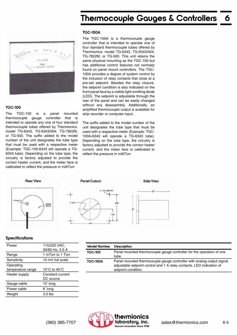
6Thermocouple Gauges & Controllers
6-3(360) 385-7707 [email protected]
The TGC-100 is a panel mounted thermocouple gauge controller that is intended to operate any one of four standard thermocouple tubes offered by Thermionics: model TG-6343, TG-6343/004, TG-7822M, or TG-500. The suffix added to the model number of the unit designates the tube type that must be used with a respective meter (Example: TGC-100-6343 will operate a TG-6343 tube). Depending on the tube type, the circuitry is factory adjusted to provide the correct heater current, and the meter face is calibrated to reflect the pressure in milliTorr.
The TGC-100A is a thermocouple gauge controller that is intended to operate one of four standard thermocouple tubes offered by Thermionics: model TG-6343, TG-6343/004, TG-7822M, or TG-500. This unit retains the same physical mounting as the TGC-100 but has additional control features not normally found on panel mount controllers. The TGC- 100A provides a degree of system control by the inclusion of relay contacts that close at a pre-set setpoint. Besides the relay closure, the setpoint condition is also indicated on the front panel face by a visible light-emitting diode (LED). The setpoint is adjustable through the rear of the panel and can be easily changed without any disassembly. Additionally, an amplified thermocouple output is available for strip recorder or computer input.
The suffix added to the model number of the unit designates the tube type that must be used with a respective meter (Example: TGC- 100A-6343 will operate a TG-6343 tube). Depending on the tube type, the circuitry is factory adjusted to provide the correct heater current, and the meter face is calibrated to reflect the pressure in milliTorr.
TGC-100
TGC-100A
SpecificationsPower 115/220 VAC,
50/60 Hz, 0.5 ARange 1 mTorr to 1 TorrSensitivity 10 mV full scaleOperatingtemperature range 10°C to 40°CHeater supply Constant current
DC sourceGauge cable 10’ longPower cable 6’ longWeight 3.0 lbs
Model Number DescriptionTGC-100 Panel mounted thermocouple gauge controller for the operation of one
tube. TGC-100A Panel mounted thermocouple gauge controller with analog output signal,
adjustable setpoint control and 1 A relay contacts, LED indication of setpoint condition.

6-4 (360) 385-7707 [email protected]
6 Thermocouple Gauges & Controllers
The TGC-100B is a battery powered thermocouple gauge controller that is intended to operate the TG-6343 or TG-6343/004 thermocouple tube offered by Thermionics. The unit comes in a compact chassis for easy portability and remote use. It employs inexpensive, easily replaced “C” cell batteries, and no complicated re-zeroing adjustment is required over the useful life of the batteries. The circuitry is factory adjusted to provide the correct heater current, and the meter face is calibrated to reflect the pressure in milliTorr. Battery lifetime is somewhat variable due to battery manufacturers’ specifications. However, factory tested units have lasted over 700 hrs (-30 days) with continuous operation. Periodic shutdown when not in use will significantly prolong useful operation with one battery set. Battery lifetime is easily monitored with a battery check on the front panel.
The TGC-100A is a thermocouple gauge controller that is intended to operate one of four standard thermocouple tubes offered by Thermionics: model TG-6343, TG-6343/004, TG-7822M, or TG-500. This unit retains the same physical mounting as the TGC-100 but has additional control features not normally found on panel mount controllers. The TGC- 100A provides a degree of system control by the inclusion of relay contacts that close at a pre-set setpoint. Besides the relay closure, the setpoint condition is also indicated on the front panel face by a visible light-emitting diode (LED). The setpoint is adjustable through the rear of the panel and can be easily changed without any disassembly. Additionally, an amplified thermocouple output is available for strip recorder or computer input.
The suffix added to the model number of the unit designates the tube type that must be used with a respective meter (Example: TGC- 100A-6343 will operate a TG-6343 tube). Depending on the tube type, the circuitry is factory adjusted to provide the correct heater current, and the meter face is calibrated to reflect the pressure in milliTorr.
TGC-100B
TGC-100C
Specifications
Specifications
Power 6 VDC(4 “C” cell batteries)
Range 1 mTorr to 1 TorrSensitivity 10 mV full scaleOperatingtemperature range 10°C to 40°CHeater supply Constant current
DC sourceGauge cable 10’ longPower cable 6’ longWeight 3.0 lbs
Power 115/220 VAC,50/60 Hz, 0.5 A
Range 1 mTorr to 1 TorrSensitivity 10 mV full scaleOperatingtemperature range 10°C to 40°CHeater supply Constant current
DC sourceGauge cable 10’ longPower cable 6’ longWeight 3.0 lbs
Model Number DescriptionTGC-100B Cabinet mounted, battery operated thermocouple gauge controller for
the operation of 1 TG-6343 or TG-6343/004 thermocouple gauge tube. Operates on four “C” cells.
Model Number DescriptionTGC-100B Same features as TGC-100A except in cabinet.

6Thermocouple Gauges & Controllers
6-5(360) 385-7707 [email protected]
The TGC-400 is a 4-channel thermocouple gauge controller that is intended to operate one of four standard types of thermocouple tubes offered by Thermionics: model TG-6343, TG-6343/004, TG-7822M, or TG-500. The suffix added to the model number of the unit designates the tube type that must be used with a respective controller (Example: TGC-400-6343 will operate four TG-6343 tubes). Depending on the tube type, the circuitry is factory adjusted to provide the correct heater current, and the meter face is calibrated to reflect the pressure in milliTorr. Additionally, the thermocouple signal is amplified and brought to the rear panel for strip chart or computer input.
TGC-400
SpecificationsPower 115/220 VAC,
50/60 Hz, 0.5 ARange 1 mTorr to 1 TorrSensitivity 10 mV full scaleOperatingtemperature range 10°C to 40°CHeater supply 4 independent
constant currentDC sources
Gauge cable 10’ longPower cable 6’ longWeight 3.0 lbs
Model Number DescriptionTGC-400 Cabinet mounted thermocouple gauge control for the operation of four
tubes.

6-6 (360) 385-7707 [email protected]
6 Thermocouple Gauges & ControllersThe digital gauges to the right run TC-500M tubes, or the Varian model 531. Each is supplied with one TC-500M tube, a 10 ft tc gauge connecting cable, a 6 ft power cable, and an instruction manual. Range is 0-1999 milliTorr.
Model Number DescriptionDTC-500 A portable, compact, rugged, low-cost, benchtop gauge with a large LCD
display. Includes a 115 VAC, 50/60 Hz wall adapter. DTC-505 A DTC-500 in a 1/8 DIN enclosure, will mount in your existing panel,
115/230 VAC, 50/60 Hz.DTC-510 A DTC-500 in a 1/8 DIN enclosure, will mount in your existing panel, with
one process control output to drive an optional, external solid-state relay, 115/230 VAC, 50/60 Hz.
DTC-801 A digital replacement for the most common analog tc gauge—the Varian 801. Featuring a large, bright, easy-to-read, red LED display, it mounts directly in an existing 801 mounting hole geometry, 115 VAC, 50/60 Hz. Options: a) 2 process outputs to drive external solid state relays, or b) a case.
DTC-500 DTC-505
DTC-801DTC-801

6Cold Cathode Ionization Gauges & Controllers
Cold Cathode Ionization Gauge Tubes
6-7(360) 385-7707 [email protected]
Model DG-8
Additional Terminations
Features• 2 gauge models and compatible control
model• Self cleaning, minimum maintenance• Rugged, all welded construction• With or without O-rings or gaskets on
standard models
• Viton O-ring on removable anode model• Long, uninterrupted service life• Small size• Connectable to glass or metal systems
Fig. 6-4. Pressure vs. current curve.
Cold cathode discharge gauges are an economical and durable alternative to hot filament ionization gauges in the high vacuum pressure regime. With no active components such as hot filaments, the discharge gauge is not destroyed in sudden or prolonged high pressure gas exposures. This feature and the relative simplicity of the gauge promotes its use in evaporation systems, heat treatment applications and plasma processing environments.
Thermionics offers two types of discharge tubes and a wide variety of connections to new and existing vacuum systems. The choice between the two gauges is based on the anticipated frequency of high pressure exposures and the nature of the residual gases in the vacuum. While these exposures will not often ruin the gauge, some deposition of foreign material may
occur on the internal electrodes. To prevent a cumulative degradation in tube performance, the electrodes may be removed and cleaned. This significantly prolongs the lifetime of the gauge operation, but is usually not a problem under typical vacuum environments. Thermionics offers a standard unit (DG-7) for typical operation and an additional unit with an easily removable anode assembly (DG-8) for the more austere applications.
Fig. 6-5. Gauge outlines
Model Number Description
DG-7 Standard tube with stainless steel (SS304) envelope, all welded construction and terminated with 3/4” tubulation. Bakeable to 250°C.
G-8 Same anode configuration as DG-7 except 0-ring assembly ring allows for removal of the anode for inspection and cleaning. Bakeable to 150°C (Viton limit).
Suffix Description-1/2SS 1/2” stainless steel tubulation-CF 3/4" tubulation with 2 3/4" ConFlat flange connection-OD 1/2” tubulation to quick disconnect fitting-KF 3/4” tubulation to KF-40 fitting-1/2G 1/2” glass tubulation

6-8 (360) 385-7707 [email protected]
6 TLI Cold Cathode Gauge Controllers
Features
Cold Cathode DischargeGauge Controllers
• Designed to operate DG-7 and DG-8 series gauge tubes
• Calibrated range: 1 x 10⁻⁷ to 1 x 10⁻⁴Torr• Operate from 115 VAC• Easy-to-read meter• Lightweight: approx. 7 lbs• Cabinet/half rack mounted
Thermionics provides a gauge controller that operates with all of our standard tubes. The almost indestructability of tube and the lack of hot filaments make it suitable for many applications. This controller includes large analog meters with voltage meter scale for system check.
Cold Cathode GaugeControl Specifications Ordering Information
Options
DGC-202Range 1 x 10⁻⁷ to 1 x 10⁻⁴
Power 115 VAC, 60 Hz, 1 AOutput 4,400 VDC (maximum)
5 mA (maximum)Dimensions 8” W x 5” H x 10” DWeight 5 lbsResponse 0.1 secPower Cord 8’Gauge Cord 10’
Model Number Description
DGC-202 Cabinet mounted discharge gauge control(pressure is displayed on logarithmic scale)
Suffix Description-RM Rack mount option to allow mounting in standard 19” electronic
“racks”-XX Additional cable length to be specified up to 50’
To Order: For example, to order a rack mounted DGC-202 with 30 ft cable length, one would write: DGC-202-RM-30.

6Pirani Gauge Tube & Controller
6-9(360) 385-7707 [email protected]
Pirani GaugesOperating on the same principles as the thermocouple gauge, the Pirani gauge provides additional range with better resolution. It is a rugged, dependable gauge which is not readily destroyed by high pressure exposures and can readily serve as the control transducer in protection circuits for diffusion and turbomolecular pumps.
Thermionics offers a Pirani gauge with a variety of fittings to allow ready connection to most vacuum systems. An analog controller with a wide view meter is available with setpoint and relay contacts for system control.
SpecificationsPower 115 VAC (60 Hz)/220 VAC
(50 Hz)Pressure 0.1-1,000 mTorr (meter will
indicate 1 atm at reduced accuracy)
Size 6” x 3 1/2” front panel and approximately 8” deep with cable connections
Heater Independent constant current DC sources
Fig. 6-6. Gauge outline.
Fig. 6-7 Controller mechanical.
PG-100 Pirani Gauges andPGC-100 ControllersControllers are shipped with a 10’ cable(s) and instruction manual. Longer cables can be supplied at a charge. Tubes are not included in controller prices and must be ordered separately.
Pirani Gauge Tube and ControllerModel Number DescriptionPG-100 Pirani gaugeIPGC-100 Controller
Controllers are shipped with 10’ cable(s) and instruction manual. Longer cables can be supplied at a charge. Tubes are not included in controller price and must be ordered separately.

6-10 (360) 385-7707 [email protected]
6 Glass Ionization Gauge Tubes
Features
Ionization Gauge Tube
• Bayard-Alpert design• Easily outgassed grid• Ease of connection• Nonex, Pyrex, or Kovar tubulation• Thoria-coated iridium filament (burnout
resistant) or dual tungsten filaments• Range: 10-3 to 10-10 Torr• High conductance 1.0” tubulation available
Bayard-Alpert Ionization Gauge Tube Specifications
Vacuum range 9.9 x 10⁻³ to 3 x 10⁻¹⁰ Torr
Filament voltage 3-5 VFilament bias 30 VDCFilament current 4-6 AGrid outgass 6.3-7.5 V at approx. 10 ACollector voltage 0 VDCLinearity 10-4 to 10-10 Torr at
10 mA emission10-3 to 10 Torr at1 mA emission
Fig. 6-8. Standard ionization gauge tube.
Ion Gauge Tubes-x refers to option suffixes below
Options
Model Number DescriptionIG-1-N-x Nonex glass encapsulated tube terminated with 1” tubulation.*
Dual filament assembly and choice of filament material.IG-1-P-x Pyrex glass encapsulated tube terminated with 1” tubulation.*
Dual filament assembly and choice of filament material.
Suffix Description-W Tungsten filaments-I Thoria-coated iridium filaments-K Kovar weldable transition termination-CF 2.75” ConFlat flange termination
To Order: For example, to order a Pyrex encapsulated tube with thoria-iridium filaments andterminated with a ConFlat flange, one would write: IG-1-P-I-CF.

6Nude Ionization Gauge and Flange Assemblies
6-11(360) 385-7707 [email protected]
Pirani GaugesTLI nude gauges are used when direct access to a vacuum chamber is needed. Nude gauges prevent errors which have been ascribed to glass envelopes and associated tubulations. They have a closed grid structure which minimizes gas reactions and improves sensitivity by a factor of 2 1/2. The improved sensitivity and a .005” collector results in a low x-ray limiting current corresponding to a pressure of about 2 x 10-11Torr.
The gauge is available mounted on a 2 3/4” O.D. UHV flange, greatly simplifying filament replacement. Standard filaments are made of tungsten. For long life in higher pressure and/ or active gas environments, we recommend use of the thoria-coated iridium filament.
Medium to UHV VacuumPressure Measurement• Range: 10-3 to 10-11 Torr• Linear response in 10-4 and 10-5 Torr ranges
with reduced emission• Nude configuration• Bayard-Alpert type
Fig. 6-9. Nude bakeable gauge tube.
Nude Bakeable Bayard-AlpertGaugeTube Specifications
Vacuum range 1 x 10⁻³ to 2 x 10-11 TorrFilament voltage 3-4.5VFilament bias 30 VDCFilament current 2.5-3.5 A with emission
current of 4 mAGrid voltage 180 VDCCollector voltage 0 VDCSensitivity 0.1 A/Torr @ 4 mA grid
current (N2 equivalent)Degas method Electron bombardment
(30-40 W@ approx. 500V)Flange 2.75” (70 mm) O.D. CF
flangeLength 4.12” overall, 3” insertion
lengthFilament Two tungsten filaments,
two thoria-coated iridium filaments or two tungsten rhenium filaments on replaceable filament assembly
Grid Tantalum grid on platinum-clad molybdenum supports with top and bottom caps
Ion Gauge Tubes-x refers to option suffixes below
Options
Model Number DescriptionIG-2-x Nude ionization gauge tube mounted on 2 3/4” ConFlat flange.IG-2F-x Replacement filaments for nude ion gauge tube.
Suffix Description-W Tungsten filaments-I Thoria-coated iridium filaments
To Order: For example, to order a Pyrex encapsulated tube with thoria-iridium filaments andterminated with a ConFlat flange, one would write: IG-1-P-I-CF.

6-12 (360) 385-7707 [email protected]
6 LN2 Controller
The LNC-400 provides monitoring and control of liquid nitrogen levels in cryogenic containers. The level sensing device is a special ruggedized solid-state transducer designed for LN2 immersion
Liquid Nitrogen Transfer LineModel LNT-500 liquid nitrogen transfer line assembly includes fittings, tubing, insulation, connectors and solenoid valve, for use with the LNC-400 controller.
Model LNC-400 Specifications
Cabinet Height 5.5”, Width 4.25”, Depth 9.5”Sensor Solid state encapsulated; 7/16” O.D. x 5/8” long (one each)Sensor Lead 8’ long, RG-188 coax (Teflon)Line Voltage 105-125 or 210-265 VAC, 50 or 60 HzPower Cord 6’ long, 3 wire detachable, polarized plugSolenoid Outlet 115 VAC, 3 wire receptacleSafety Fuse 3 ASwitch 3 position, manual/off/automaticLights (2) One on when filling; other on when power is onLevel Range Determined by sensor placementCycle Time Adjustable from 0.1 to 6 minBalance No calibration or balancing necessaryWarranty Fully guaranteed for one year; parts and laborWeight 3 lbs

Flanges 7
Flanges
7
A Word About Bolt and Nut Sets
OFHC and OFE Copper
If an ultra-high vacuum seal is to maintain its integrity, it must not be affected by the thermal stresses inherent in the bakeout process. Therefore, the bolt and nuts sets described on the following pages are made of series 300 stainless steel to match the thermal expansion co-efficient of the flanges. They are made from high strength steel to insure against failures due to plastic flow. Do not substitute ordinary bolts and nuts of these sets.
OFHC was a registered trademark of American Metals Climax, Inc. The trademark, propriety process, product line and production machinery were sold to Phelps Dodge retired the product, and discontinued manufacturing OFHC copper products.
ASTM F68 was the specification for proprietary OFHC copper product. The Copper Development Association, an industry trade organization, proposed and adopted specifications UNSC-10100. UNSC-10100 and ASTM F68 are identical specifications. OFHC copper is no longer being produced and has been replaced in the market with OFE copper products. OFE is produced as a generic copper product. OFHC and OFE are interchangeable.
Technical Information
PyraFlat Rectangular Flanges
ConFlat Flanges
Adapter Flanges (ConFlat)
Wire Seal Flanges
ASA Flanges
General Information....................Specifications..............................
Technical Information.................Ordering Information...................Assembly Hardware....................Applications................................
Technical Information.................Ordering Information...................Rotatable....................................Tapped Rotatable.......................Non-Rotatable............................Tapped Non-Rotatable...............Dimensinal Drawings..................Note: Assembly Hardware and Gasket are shown on the same page
Double Sided Flanges................Note: Assembly Hardware and Gasket are shown on the same pageReducing Flanges.......................
Bolt-Type Wire Seal Flanges......Clamp-Type Wire Seal Flanges..Note: Assembly Hardware and Gasket are shown on the same page
Standard ASA Flanges...............ASA/ConFlat Adapter Flanges...
7-17-1
7-27-27-37-4
7-27-67-67-87-107-127-14
7-16
7-18
7-207-22
7-247-25

7Ultra-High Vacuum Flanges
7-1(360) 385-7707 [email protected]
Description
Features
Round, Rectangular & Odd Shapes*
Specifications
General Information
The reliable sealing performance of PyraFlat and ConFlat flanges is due to the geometry which “captures” the gasket material. When the sealing edge of the flange is pressed into the OFE copper gasket, a lateral cold flow of the gasket material upon the slope occurs. This cold flow is limited by the vertical flange wall. Further material flow away from the seal area is severely limited and high interface pressures are developed. These pressures cause gasket material to fill surface imperfections and produce a highly reliable seal. At high temperatures, the “capturing” geometry maintains high pressures despite softening of the gasket.
Flanges, flange components, accessories, and basic tube fittings are detailed here in Section 7. Other vacuum system components mounted
The PyraFlat is the ideal metal seal for any rectangular vacuum connection. It is based on the same knife edge and captured flat copper gasket sealing principle used by the ConFlat flange and is equally reliable. Assembly, even with flange face vertical, is easy and fast. Your service people and technicians will welcome its use.
PyraFlats can be used for valve flange seals, too. A 2” by 10” rectangular gate valve is 8”
more compact than the equivalent 10” circular gate valve.
Guaranteed leak-free from atmosphere to 1 x 10-13 Torr from -196° to 500°C.
• Large selection of standard sizes• Identical mating flanges—no male and
female• Mate with all other PyraFlat and ConFlat
type flanges of same dimension• Easy repeated sealing• Leak-tight even with minor gasket nicks and
scratches• Offered in both rotatable and nonrotatable
versions• Components can be welded or brazed to
flanges
• Featuring the TLI PyraFlat flange• Certified leak-free to 10-13 Torr• Ideal for metal sealed valve bonnets!
• Flange and seal geometry totally compatible with Varian ConFlat
• Leak-free construction• Wide selection• Immediate shipment
• All flanges made of 304 stainless steel• Certified leak-free to 10-13 Torr**
• Vacuum range: to below 10-13 Torr• Temperature operating range:
-196°C to +500°C• Material:
Mini and 2 3/4” O.D.Vacuum melt type 304 SS
3 3/8” O.D. and larger and PyraFlatType 304 SS plate
• Maximum torque required to seal flanges:Mini and 2 3/4”: 16 ft-lbs3 3/8” and larger: 26 ft-lbs
Features
Standard ConFlat-Type
** Based upon the 10-11 Torr ion gauge x-ray limit and 5 x 10-13 Torr l/sec/cm2 outgassing rate of 304 SST

Standard Sizes
7-2 (360) 385-7707 [email protected]
7 PyraFlat FlangesPyraFlat seals use the ConFlat sealing principle in a rectangular flange. Result: The ease, convenience, and reliability of circular seals are now available for rectangular vacuum seals.
Standard and custom PyraFlat versions have been designed for and used in many applications including high power microwave components and plasma-fusion. Please call our engineering group with your requirements.
Applications
ApplicationsIntegral Flanges (bolt hole and sealing portion in one unit)
• Gate valve metal bonnet seals (replaces wire-sealed flanges)
• Close packed geometries• Fusion reactors
• Cassette seals• Wave guides• Drift tubes• Ion pumps
PyraFlat flanges are manufactured and protected under one or more of the following patents: 5,640,751; 4,685,193
Dimensions in inches
Model No.* A B C D E** F G H Holes (Qty./Dia)
Gaskets (5/pkg.)
026046 3.125 3.375 1.125 .274 .571 2.605 4.605 .125 12/.265 G026046026056 4.125 4.375 1.125 .274 .571 2 605 5.605 .125 14/.265 G026056035073 5.250 5.510 1.500 .524 .821 3.560 7.310 .125 18/.332 G035073035098 7.750 8.010 1.500 .524 .821 3.560 9.810 .125 22/.332 G035098043124 10.125 10.380 2.000 .524 .821 4.324 12.450 .125 24/.332 G043124The following flanges are designed to accept standard sizes of square tubing:029029 1.370 1.510 1.370 .194 .485 2.956 2.956 .093 8/.270 G029029034034 1.870 2.010 1.870 .210 .605 3.456 3.456 .093 8/.270 G034034044044 2.370 2.510 2.370 .360 ,665 4.450 4.450 .093 12/.332 G044044049049 2.870 3.010 2.870 .422 .735 4.950 4.950 .093 12/.332 G049049059059 3.834 4.010 3.834 .422 .765 5.952 5.952 .093 16/.332 G059059069069 4.834 5.010 4.834 .465 .825 6.952 6.952 .093 20/.332 G069069079079 5.834 6.010 5.834 .485 .855 7.952 7.952 .093 24/.332 G079079099099 7.834 8.010 7.834 .485 .985 9 952 9.952 .093 28/.332 G099099127127 9.760 10.010 9.760 .585 1.235 12.714 12.714 .093 36/.390 G127127147147 11.760 12 010 11.760 .587 1.235 14.714 14.714 .093 40/.390 G147147167167 3.375 14.010 13.760 .860 1.485 16.714 16.714 .093 48/.390 G167167
*Add suffixes as follows: T = Tapped Flange, B = Blank Flange (no extra charge), BT = Blank Tapped Flange**± .015” to dividing line of two flanges
Larger or other sizes and shapes available on request

7PyraFlat Flanges
7-3(360) 385-7707 [email protected]
Dimensions in inchesBolt Sets for PyraFlat FlangesModel No.* For Flange Model No. Size Oty.PBN-25-150N 029029
0340341/4-28 x 1 1/ 2 Pack of 25
PBN-25-175N 026046026056
1/4-28 x 1 3/4 Pack of 25
PBN-31-200N 044044049044049049
5/16-24 x 2.0 Pack of 25
PBN-31-225N 035073035098043124067069079079
5/16-24 x 2 1/4 Pack of 25
PBN-31-250N 099099 5/16-24 x 2 1/2 Pack of 50PBN-38-300N 127127
1471473/8-24 x 3.0 Pack of 50
PBN-38-350N 167167 3/8-24 x 3 1/ 2 Pack of 50
NOTE: Consult factory for tapped flange bolt set information.
PyraFlat flanges are manufactured and protected under one or more of the following patents: 5,640,751; 4,685,193
Examples of Possible PyraFlat Flange Geometries & Applications
ConFlat-Type Captured Gasket All Metal Seal Flange
Triangular flanges can yield maximum packing density when a large number of flanges must be placed on a single surface.
Odd-shaped flanges can be the best solution to a unique research problem.
Elliptical flanges are used when you wish to join two circular tubes at a flange angle of other than 90°. If the join angle is 45°, a 180° rotation produces a right-angle bend.
Trapezoidal flanges can be made in almost any ratio of height to base.
ConFlat-Type Captured GasketAll Metal Seal Flange

7-4 (360) 385-7707 [email protected]
7 Some Applications for PyraFlat FlangesPyreFlats and Valve Bonnets
PyraFlats in Custom Applications
The PyraFlat is an ideal metal seal for valve bonnets. This remarkable UHV flange makes any other rectangular metal valve bonnet seal obsolete. Its reliability and ease of assembly have been repeatedly proven, and its range of shapes and sizes will satisfy any non-circular UHV flange requirements.
Prior metal-sealed valve bonnets used wire gaskets. However, unconstrained gaskets are far less reliable than the knife edge/ captured flat copper gasket sealing principle. Wire gaskets are also difficult to install and almost impossible when sealing surfaces are vertical. Not so with PyraFlat. Assembly requires only minutes, not hours, regardless of the angle of installation. This is important when valve bodies must be left inline when systems are being serviced.
Recently, a National Laboratory conducted independent testing on valves. Thermionics’ gate valve with the PyraFlat bonnet seal won the competition. Like the ConFlat, its Varian ancestor, the PyraFlat will soon become a new standard in the industry.
Recently, we were asked to install two 5-crucible e-Guns in a 17” chamber. We wanted to provide our customer with optimal access for servicing—without disrupting the entire assembly. The PyraFlat was our solution. Its rectangular shape provided a 21% larger access opening than the equivalent circular flange could offer. Our customer was delighted.
PyraFlat flanges are manufactured and protected under one or more of the following patents: 5,640,751; 4,685,193
Valve Bonnet Assembly
Multiple e-Gun Assembly
Flange Face

7Some Applications for PyraFlat Flanges
7-5(360) 385-7707 [email protected]
PyraFlats and Ion PumpsWhat Do You Do When Your Small Ion Pump Fails or Dies?
PyraFlats for Ion Pumped Table Top Systems
For decades, there have been only two choices. You could buy a new pump or pay to have your old pump rebuilt. Either way, your system was out of service until the new or rebuilt pump could be delivered and installed. The PyraFlat now provides an alternative.
By using the PyraFlat in the construction of our ion pump bodies, we can offer users
In the system shown, the modular, removable sublimator and cryoshroud assembly is mounted on a PyraFlat flange. This also provides access to the inside of the pumping stack for hassle-free cleaning, repair or maintenance.
of small- to medium-sized ion pumps the same advantage enjoyed by users of larger ion pumps: immediate and total access for servicing your own pump elements, plates and insulators. This translates into a substantial savings in money and time, since ion pump elements can often be restored to satisfactory service by proper vacuum cleaning procedures.
PyraFlat flanges are manufactured and protected under one or more of the following patents: 5,640,751; 4,685,193
See Section 1 for futher information.
PyraFlat Access Port (see Section 9 for details)
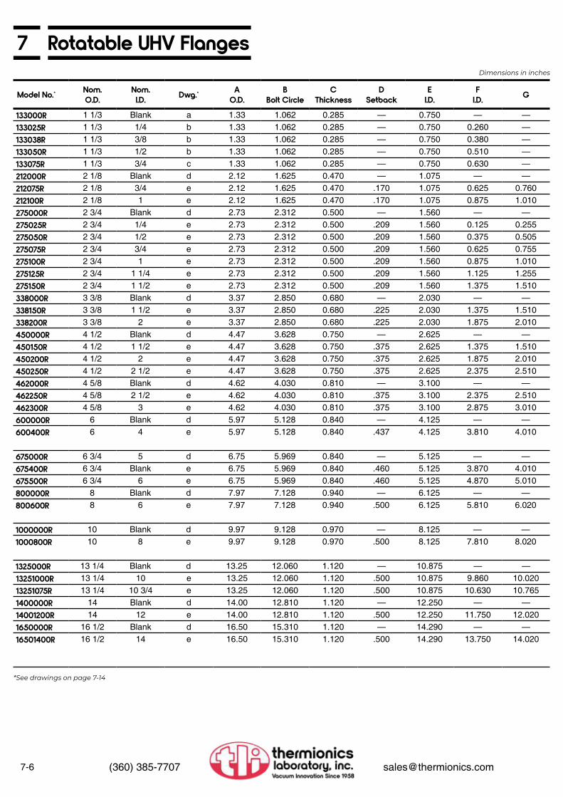
7-6 (360) 385-7707 [email protected]
7 Rotatable UHV Flanges
Model No.* Nom.O.D.
Nom.I.D. Dwg.* A
O.D.B
Bolt CircleC
ThicknessD
SetbackE
I.D.F
I.D. G
133000R 1 1/3 Blank a 1.33 1.062 0.285 — 0.750 — —133025R 1 1/3 1/4 b 1.33 1.062 0.285 — 0.750 0.260 —133038R 1 1/3 3/8 b 1.33 1.062 0.285 — 0.750 0.380 —133050R 1 1/3 1/2 b 1.33 1.062 0.285 — 0.750 0.510 —133075R 1 1/3 3/4 c 1.33 1.062 0.285 — 0.750 0.630 —212000R 2 1/8 Blank d 2.12 1.625 0.470 — 1.075 — —212075R 2 1/8 3/4 e 2.12 1.625 0.470 .170 1.075 0.625 0.760212100R 2 1/8 1 e 2.12 1.625 0.470 .170 1.075 0.875 1.010275000R 2 3/4 Blank d 2.73 2.312 0.500 — 1.560 — —275025R 2 3/4 1/4 e 2.73 2.312 0.500 .209 1.560 0.125 0.255275050R 2 3/4 1/2 e 2.73 2.312 0.500 .209 1.560 0.375 0.505275075R 2 3/4 3/4 e 2.73 2.312 0.500 .209 1.560 0.625 0.755275100R 2 3/4 1 e 2.73 2.312 0.500 .209 1.560 0.875 1.010275125R 2 3/4 1 1/4 e 2.73 2.312 0.500 .209 1.560 1.125 1.255275150R 2 3/4 1 1/2 e 2.73 2.312 0.500 .209 1.560 1.375 1.510338000R 3 3/8 Blank d 3.37 2.850 0.680 — 2.030 — —338150R 3 3/8 1 1/2 e 3.37 2.850 0.680 .225 2.030 1.375 1.510338200R 3 3/8 2 e 3.37 2.850 0.680 .225 2.030 1.875 2.010450000R 4 1/2 Blank d 4.47 3.628 0.750 — 2.625 — —450150R 4 1/2 1 1/2 e 4.47 3.628 0.750 .375 2.625 1.375 1.510450200R 4 1/2 2 e 4.47 3.628 0.750 .375 2.625 1.875 2.010450250R 4 1/2 2 1/2 e 4.47 3.628 0.750 .375 2.625 2.375 2.510462000R 4 5/8 Blank d 4.62 4.030 0.810 — 3.100 — —462250R 4 5/8 2 1/2 e 4.62 4.030 0.810 .375 3.100 2.375 2.510462300R 4 5/8 3 e 4.62 4.030 0.810 .375 3.100 2.875 3.010600000R 6 Blank d 5.97 5.128 0.840 — 4.125 — —600400R 6 4 e 5.97 5.128 0.840 .437 4.125 3.810 4.010
675000R 6 3/4 5 d 6.75 5.969 0.840 — 5.125 — —675400R 6 3/4 Blank e 6.75 5.969 0.840 .460 5.125 3.870 4.010675500R 6 3/4 6 e 6.75 5.969 0.840 .460 5.125 4.870 5.010800000R 8 Blank d 7.97 7.128 0.940 — 6.125 — —800600R 8 6 e 7.97 7.128 0.940 .500 6.125 5.810 6.020
1000000R 10 Blank d 9.97 9.128 0.970 — 8.125 — —1000800R 10 8 e 9.97 9.128 0.970 .500 8.125 7.810 8.020
1325000R 13 1/4 Blank d 13.25 12.060 1.120 — 10.875 — —13251000R 13 1/4 10 e 13.25 12.060 1.120 .500 10.875 9.860 10.02013251075R 13 1/4 10 3/4 e 13.25 12.060 1.120 .500 10.875 10.630 10.7651400000R 14 Blank d 14.00 12.810 1.120 — 12.250 — —14001200R 14 12 e 14.00 12.810 1.120 .500 12.250 11.750 12.0201650000R 16 1/2 Blank d 16.50 15.310 1.120 — 14.290 — —16501400R 16 1/2 14 e 16.50 15.310 1.120 .500 14.290 13.750 14.020
Dimensions in inches
*See drawings on page 7-14
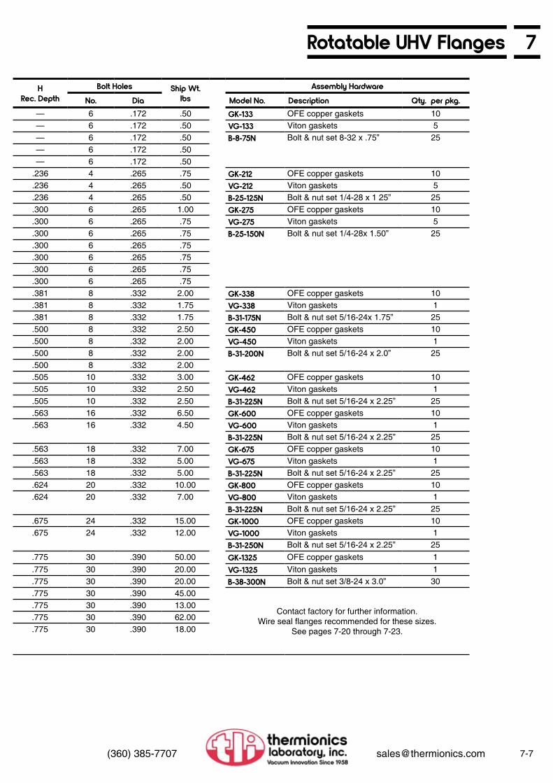
7Rotatable UHV Flanges
7-7(360) 385-7707 [email protected]
HRec. Depth
Bolt Holes Ship Wt.lbs
Assembly HardwareNo. Dia Model No. Description Qty. per pkg.
— 6 .172 .50 GK-133 OFE copper gaskets 10— 6 .172 .50 VG-133 Viton gaskets 5— 6 .172 .50 B-8-75N Bolt & nut set 8-32 x .75” 25— 6 .172 .50— 6 .172 .50
.236 4 .265 .75 GK-212 OFE copper gaskets 10
.236 4 .265 .50 VG-212 Viton gaskets 5
.236 4 .265 .50 B-25-125N Bolt & nut set 1/4-28 x 1 25” 25
.300 6 .265 1.00 GK-275 OFE copper gaskets 10
.300 6 .265 .75 VG-275 Viton gaskets 5
.300 6 .265 .75 B-25-150N Bolt & nut set 1/4-28x 1.50” 25
.300 6 .265 .75
.300 6 .265 .75
.300 6 .265 .75
.300 6 .265 .75
.381 8 .332 2.00 GK-338 OFE copper gaskets 10
.381 8 .332 1.75 VG-338 Viton gaskets 1
.381 8 .332 1.75 B-31-175N Bolt & nut set 5/16-24x 1.75” 25
.500 8 .332 2.50 GK-450 OFE copper gaskets 10
.500 8 .332 2.00 VG-450 Viton gaskets 1
.500 8 .332 2.00 B-31-200N Bolt & nut set 5/16-24 x 2.0” 25
.500 8 .332 2.00
.505 10 .332 3.00 GK-462 OFE copper gaskets 10
.505 10 .332 2.50 VG-462 Viton gaskets 1
.505 10 .332 2.50 B-31-225N Bolt & nut set 5/16-24 x 2.25” 25
.563 16 .332 6.50 GK-600 OFE copper gaskets 10
.563 16 .332 4.50 VG-600 Viton gaskets 1B-31-225N Bolt & nut set 5/16-24 x 2.25” 25
.563 18 .332 7.00 GK-675 OFE copper gaskets 10
.563 18 .332 5.00 VG-675 Viton gaskets 1
.563 18 .332 5.00 B-31-225N Bolt & nut set 5/16-24 x 2.25” 25
.624 20 .332 10.00 GK-800 OFE copper gaskets 10
.624 20 .332 7.00 VG-800 Viton gaskets 1B-31-225N Bolt & nut set 5/16-24 x 2.25” 25
.675 24 .332 15.00 GK-1000 OFE copper gaskets 10
.675 24 .332 12.00 VG-1000 Viton gaskets 1B-31-250N Bolt & nut set 5/16-24 x 2.25” 25
.775 30 .390 50.00 GK-1325 OFE copper gaskets 1
.775 30 .390 20.00 VG-1325 Viton gaskets 1
.775 30 .390 20.00 B-38-300N Bolt & nut set 3/8-24 x 3.0” 30
.775 30 .390 45.00
Contact factory for further information. Wire seal flanges recommended for these sizes.
See pages 7-20 through 7-23.
.775 30 .390 13.00
.775 30 .390 62.00
.775 30 .390 18.00

7-8 (360) 385-7707 [email protected]
7 Tapped Rotatable UHV Flanges
Model No.* Nom.O.D.
Nom.I.D. Dwg.* A
O.D.B
Bolt CircleC
ThicknessD
SetbackE
I.D.F
I.D. G
133000RT 1 1/3 Blank a 1.33 1.062 0.285 — 0.750 — —133025RT 1 1/3 1/4 b 1.33 1.062 0.285 — 0.750 0.260 —133038RT 1 1/3 3/8 b 1.33 1.062 0.285 — 0.750 0.380 —133050RT 1 1/3 1/2 b 1.33 1.062 0.285 — 0.750 0.510 —133075RT 1 1/3 3/4 c 1.33 1.062 0.285 — 0.750 0.630 —212000RT 2 1/8 Blank d 2.12 1.625 0.470 — 1.075 — —212075RT 2 1/8 3/4 e 2.12 1.625 0.470 .170 1.075 0.625 0.760212100RT 2 1/8 1 e 2.12 1.625 0.470 .170 1.075 0.875 1.010275000RT 2 3/4 Blank d 2.73 2.312 0.500 — 1.560 — —275025RT 2 3/4 1/4 e 2.73 2.312 0.500 .209 1.560 0.125 0.255275050RT 2 3/4 1/2 e 2.73 2.312 0.500 .209 1.560 0.375 0.505275075RT 2 3/4 3/4 e 2.73 2.312 0.500 .209 1.560 0.625 0.755275100RT 2 3/4 1 e 2.73 2.312 0.500 .209 1.560 0.875 1.010275125RT 2 3/4 1 1/4 e 2.73 2.312 0.500 .209 1.560 1.125 1.255275150RT 2 3/4 1 1/2 e 2.73 2.312 0.500 .209 1.560 1.375 1.510338000RT 3 3/8 Blank d 3.37 2.850 0.680 — 2.030 — —338150RT 3 3/8 1 1/2 e 3.37 2.850 0.680 .225 2.030 1.375 1.510338200RT 3 3/8 2 e 3.37 2.850 0.680 .225 2.030 1.875 2.010450000RT 4 1/2 Blank d 4.47 3.628 0.750 — 2.625 — —450150RT 4 1/2 1 1/2 e 4.47 3.628 0.750 .375 2.625 1.375 1.510450200RT 4 1/2 2 e 4.47 3.628 0.750 .375 2.625 1.875 2.010450250RT 4 1/2 2 1/2 e 4.47 3.628 0.750 .375 2.625 2.375 2.510462000RT 4 5/8 Blank d 4.62 4.030 0.810 — 3.100 — —462250RT 4 5/8 2 1/2 e 4.62 4.030 0.810 .375 3.100 2.375 2.510462300RT 4 5/8 3 e 4.62 4.030 0.810 .375 3.100 2.875 3.010600000RT 6 Blank d 5.97 5.128 0.840 — 4.125 — —600400RT 6 4 e 5.97 5.128 0.840 .437 4.125 3.810 4.010
675000RT 6 3/4 5 d 6.75 5.969 0.840 — 5.125 — —675400RT 6 3/4 Blank e 6.75 5.969 0.840 .460 5.125 3.870 4.010675500RT 6 3/4 6 e 6.75 5.969 0.840 .460 5.125 4.870 5.010800000RT 8 Blank d 7.97 7.128 0.940 — 6.125 — —800600RT 8 6 e 7.97 7.128 0.940 .500 6.125 5.810 6.020
1000000RT 10 Blank d 9.97 9.128 0.970 — 8.125 — —1000800RT 10 8 e 9.97 9.128 0.970 .500 8.125 7.810 8.020
1325000RT 13 1/4 Blank d 13.25 12.060 1.120 — 10.875 — —13251000RT 13 1/4 10 e 13.25 12.060 1.120 .500 10.875 9.860 10.02013251075RT 13 1/4 10 3/4 e 13.25 12.060 1.120 .500 10.875 10.630 10.7651400000RT 14 Blank d 14.00 12.810 1.120 — 12.250 — —14001200RT 14 12 e 14.00 12.810 1.120 .500 12.250 11.750 12.0201650000RT 16 1/2 Blank d 16.50 15.310 1.120 — 14.290 — —16501400RT 16 1/2 14 e 16.50 15.310 1.120 .500 14.290 13.750 14.020
Dimensions in inches
*See drawings on page 7-14
We reserve the right to substitute threaded inserts.
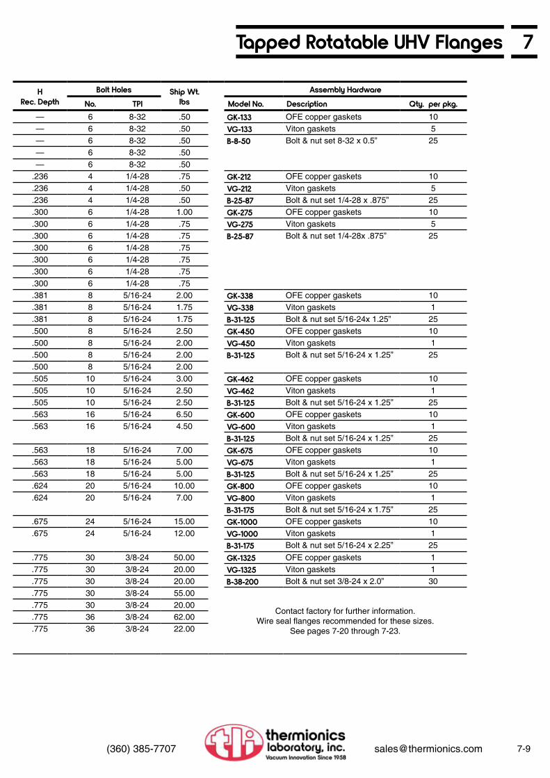
7Tapped Rotatable UHV Flanges
7-9(360) 385-7707 [email protected]
HRec. Depth
Bolt Holes Ship Wt.lbs
Assembly HardwareNo. TPI Model No. Description Qty. per pkg.
— 6 8-32 .50 GK-133 OFE copper gaskets 10— 6 8-32 .50 VG-133 Viton gaskets 5— 6 8-32 .50 B-8-50 Bolt & nut set 8-32 x 0.5” 25— 6 8-32 .50— 6 8-32 .50
.236 4 1/4-28 .75 GK-212 OFE copper gaskets 10
.236 4 1/4-28 .50 VG-212 Viton gaskets 5
.236 4 1/4-28 .50 B-25-87 Bolt & nut set 1/4-28 x .875” 25
.300 6 1/4-28 1.00 GK-275 OFE copper gaskets 10
.300 6 1/4-28 .75 VG-275 Viton gaskets 5
.300 6 1/4-28 .75 B-25-87 Bolt & nut set 1/4-28x .875” 25
.300 6 1/4-28 .75
.300 6 1/4-28 .75
.300 6 1/4-28 .75
.300 6 1/4-28 .75
.381 8 5/16-24 2.00 GK-338 OFE copper gaskets 10
.381 8 5/16-24 1.75 VG-338 Viton gaskets 1
.381 8 5/16-24 1.75 B-31-125 Bolt & nut set 5/16-24x 1.25” 25
.500 8 5/16-24 2.50 GK-450 OFE copper gaskets 10
.500 8 5/16-24 2.00 VG-450 Viton gaskets 1
.500 8 5/16-24 2.00 B-31-125 Bolt & nut set 5/16-24 x 1.25” 25
.500 8 5/16-24 2.00
.505 10 5/16-24 3.00 GK-462 OFE copper gaskets 10
.505 10 5/16-24 2.50 VG-462 Viton gaskets 1
.505 10 5/16-24 2.50 B-31-125 Bolt & nut set 5/16-24 x 1.25” 25
.563 16 5/16-24 6.50 GK-600 OFE copper gaskets 10
.563 16 5/16-24 4.50 VG-600 Viton gaskets 1B-31-125 Bolt & nut set 5/16-24 x 1.25” 25
.563 18 5/16-24 7.00 GK-675 OFE copper gaskets 10
.563 18 5/16-24 5.00 VG-675 Viton gaskets 1
.563 18 5/16-24 5.00 B-31-125 Bolt & nut set 5/16-24 x 1.25” 25
.624 20 5/16-24 10.00 GK-800 OFE copper gaskets 10
.624 20 5/16-24 7.00 VG-800 Viton gaskets 1B-31-175 Bolt & nut set 5/16-24 x 1.75” 25
.675 24 5/16-24 15.00 GK-1000 OFE copper gaskets 10
.675 24 5/16-24 12.00 VG-1000 Viton gaskets 1B-31-175 Bolt & nut set 5/16-24 x 2.25” 25
.775 30 3/8-24 50.00 GK-1325 OFE copper gaskets 1
.775 30 3/8-24 20.00 VG-1325 Viton gaskets 1
.775 30 3/8-24 20.00 B-38-200 Bolt & nut set 3/8-24 x 2.0” 30
.775 30 3/8-24 55.00
Contact factory for further information. Wire seal flanges recommended for these sizes.
See pages 7-20 through 7-23.
.775 30 3/8-24 20.00
.775 36 3/8-24 62.00
.775 36 3/8-24 22.00

7-10 (360) 385-7707 [email protected]
7 Non-Rotatable UHV Flanges
Model No.* Nom.O.D.
Nom.I.D. Dwg.* A
O.D.B
Bolt CircleC
ThicknessD
SetbackE
I.D.F
I.D.
133000 1 1/3 Blank f 1.33 1.062 0.285 — — —133025 1 1/3 1/4 g 1.33 1.062 0.285 — — 0.260133038 1 1/3 3/8 g 1.33 1.062 0.285 — — 0.380133050 1 1/3 1/2 g 1.33 1.062 0.285 — — 0.510133075 1 1/3 3/4 h 1.33 1.062 0.285 — 0.750 0.630212000 2 1/8 Blank i 2.12 1.625 0.470 — — —212075 2 1/8 3/4 j 2.12 1.625 0.470 .170 0.760 0.625212100 2 1/8 1 j 2.12 1.625 0.470 .170 1.010 0.875275000 2 3/4 Blank j 2.73 2.312 0.500 — — —275025 2 3/4 1/4 i 2.73 2.312 0.500 .209 0.255 0.125275050 2 3/4 1/2 j 2.73 2.312 0.500 .209 0.505 0.375275075 2 3/4 3/4 j 2.73 2.312 0.500 .209 0.755 0.625275100 2 3/4 1 j 2.73 2.312 0.500 .209 1.010 0.875275125 2 3/4 1 1/4 j 2.73 2.312 0.500 .209 1.255 1.125275150 2 3/4 1 1/2 j 2.73 2.312 0.500 .209 1.510 1.375338000 3 3/8 Blank i 3.37 2.850 0.680 — — —338150 3 3/8 1 1/2 j 3.37 2.850 0.680 .225 1.510 1.375338200 3 3/8 2 j 3.37 2.850 0.680 .225 2.010 1.875450000 4 1/2 Blank i 4.47 3.628 0.750 — — —450150 4 1/2 1 1/2 j 4.47 3.628 0.750 .375 1.510 1.375450200 4 1/2 2 j 4.47 3.628 0.750 .375 2.010 1.875450250 4 1/2 2 1/2 j 4.47 3.628 0.750 .375 2.510 2.375462000 4 5/8 Blank i 4.62 4.030 0.810 — — —462250 4 5/8 2 1/2 j 4.62 4.030 0.810 .375 2.510 2.375462300 4 5/8 3 j 4.62 4.030 0.810 .375 3.010 2.875600000 6 Blank i 5.97 5.128 0.840 — — —600400 6 4 j 5.97 5.128 0.840 .437 4.010 3.810
675000 6 3/4 5 i 6.75 5.969 0.840 — — —675400 6 3/4 Blank j 6.75 5.969 0.840 .460 4.010 3.870675500 6 3/4 6 j 6.75 5.969 0.840 .460 5.010 4.870800000 8 Blank i 7.97 7.128 0.940 — — —800600 8 6 j 7.97 7.128 0.940 .500 6.020 5.810
1000000 10 Blank i 9.97 9.128 0.970 — — —1000800 10 8 j 9.97 9.128 0.970 .500 8.020 7.810
1325000 13 1/4 Blank i 13.25 12.060 1.120 — — —13251000 13 1/4 10 j 13.25 12.060 1.120 .500 10.020 9.86013251075 13 1/4 10 3/4 j 13.25 12.060 1.120 .500 10.765 10.6301400000 14 Blank i 14.00 12.810 1.120 — — —14001200 14 12 j 14.00 12.810 1.120 .500 12.020 11.7501650000 16 1/2 Blank i 16.50 15.310 1.120 — — —16501400 16 1/2 14 j 16.50 15.310 1.120 .500 14.020 13.750
Dimensions in inches
*See drawings on page 7-15

7Non-Rotatable UHV Flanges
7-11(360) 385-7707 [email protected]
Bolt Holes Ship Wt.lbs
Assembly HardwareNo. Dia. Model No. Description Qty. per pkg.6 .172 .50 GK-133 OFE copper gaskets 106 .172 .50 VG-133 Viton gaskets 56 .172 .50 B-8-75N Bolt & nut set 8-32 x .75” 256 .172 .506 .172 .504 .265 .75 GK-212 OFE copper gaskets 104 .265 .50 VG-212 Viton gaskets 54 .265 .50 B-25-125N Bolt & nut set 1/4-28 x 1 25” 256 .265 1.00 GK-275 OFE copper gaskets 106 .265 .75 VG-275 Viton gaskets 56 .265 .75 B-25-150N Bolt & nut set 1/4-28x 1.50” 256 .265 .756 .265 .756 .265 .756 .265 .758 .332 2.00 GK-338 OFE copper gaskets 108 .332 1.75 VG-338 Viton gaskets 18 .332 1.75 B-31-175N Bolt & nut set 5/16-24x 1.75” 258 .332 2.50 GK-450 OFE copper gaskets 108 .332 2.00 VG-450 Viton gaskets 18 .332 2.00 B-31-200N Bolt & nut set 5/16-24 x 2.0” 258 .332 2.00
10 .332 3.00 GK-462 OFE copper gaskets 1010 .332 2.50 VG-462 Viton gaskets 110 .332 2.50 B-31-225N Bolt & nut set 5/16-24 x 2.25” 2516 .332 6.50 GK-600 OFE copper gaskets 1016 .332 4.50 VG-600 Viton gaskets 1
B-31-225N Bolt & nut set 5/16-24 x 2.25” 2518 .332 7.00 GK-675 OFE copper gaskets 1018 .332 5.00 VG-675 Viton gaskets 118 .332 5.00 B-31-225N Bolt & nut set 5/16-24 x 2.25” 2520 .332 10.00 GK-800 OFE copper gaskets 1020 .332 7.00 VG-800 Viton gaskets 1
B-31-225N Bolt & nut set 5/16-24 x 2.25” 2524 .332 15.00 GK-1000 OFE copper gaskets 1024 .332 12.00 VG-1000 Viton gaskets 1
B-31-250N Bolt & nut set 5/16-24 x 2.25” 2530 .390 50.00 GK-1325 OFE copper gaskets 130 .390 40.00 VG-1325 Viton gaskets 130 .390 40.00 B-38-300N Bolt & nut set 3/8-24 x 3.0” 3030 .390 50.00
Contact factory for further information. Wire seal flanges recommended for these sizes.
See pages 7-20 through 7-23.
30 .390 16.0036 .390 65.0036 .390 22.00

7-12 (360) 385-7707 [email protected]
7 Tapped Non-Rotatable UHV Flanges
Model No.* Nom.O.D.
Nom.I.D. Dwg.* A
O.D.B
Bolt CircleC
ThicknessD
SetbackE
I.D.F
I.D.
133000T 1 1/3 Blank f 1.33 1.062 0.285 — — —133025T 1 1/3 1/4 g 1.33 1.062 0.285 — — 0.260133038T 1 1/3 3/8 g 1.33 1.062 0.285 — — 0.380133050T 1 1/3 1/2 g 1.33 1.062 0.285 — — 0.510133075T 1 1/3 3/4 h 1.33 1.062 0.285 — 0.750 0.630212000T 2 1/8 Blank i 2.12 1.625 0.470 — — —212075T 2 1/8 3/4 j 2.12 1.625 0.470 .170 0.760 0.625212100T 2 1/8 1 j 2.12 1.625 0.470 .170 1.010 0.875275000T 2 3/4 Blank j 2.73 2.312 0.500 — — —275025T 2 3/4 1/4 i 2.73 2.312 0.500 .209 0.255 0.125275050T 2 3/4 1/2 j 2.73 2.312 0.500 .209 0.505 0.375275075T 2 3/4 3/4 j 2.73 2.312 0.500 .209 0.755 0.625275100T 2 3/4 1 j 2.73 2.312 0.500 .209 1.010 0.875275125T 2 3/4 1 1/4 j 2.73 2.312 0.500 .209 1.255 1.125
275150T 2 3/4 1 1/2 j 2.73 2.312 0.500 .209 1.510 1.375338000T 3 3/8 Blank i 3.37 2.850 0.680 — — —338150T 3 3/8 1 1/2 j 3.37 2.850 0.680 .225 1.510 1.375338200T 3 3/8 2 j 3.37 2.850 0.680 .225 2.010 1.875450000T 4 1/2 Blank i 4.47 3.628 0.750 — — —450150T 4 1/2 1 1/2 j 4.47 3.628 0.750 .375 1.510 1.375450200T 4 1/2 2 j 4.47 3.628 0.750 .375 2.010 1.875450250T 4 1/2 2 1/2 j 4.47 3.628 0.750 .375 2.510 2.375462000T 4 5/8 Blank i 4.62 4.030 0.810 — — —462250T 4 5/8 2 1/2 j 4.62 4.030 0.810 .375 2.510 2.375462300T 4 5/8 3 j 4.62 4.030 0.810 .375 3.010 2.875600000T 6 Blank i 5.97 5.128 0.840 — — —600400T 6 4 j 5.97 5.128 0.840 .437 4.010 3.810
675000T 6 3/4 5 i 6.75 5.969 0.840 — — —675400T 6 3/4 Blank j 6.75 5.969 0.840 .460 4.010 3.870675500T 6 3/4 6 j 6.75 5.969 0.840 .460 5.010 4.870800000T 8 Blank i 7.97 7.128 0.940 — — —800600T 8 6 j 7.97 7.128 0.940 .500 6.020 5.810
1000000T 10 Blank i 9.97 9.128 0.970 — — —1000800T 10 8 j 9.97 9.128 0.970 .500 8.020 7.810
1325000T 13 1/4 Blank i 13.25 12.060 1.120 — — —13251000T 13 1/4 10 j 13.25 12.060 1.120 .500 10.020 9.86013251075T 13 1/4 10 3/4 j 13.25 12.060 1.120 .500 10.765 10.6301400000T 14 Blank i 14.00 12.810 1.120 — — —14001200T 14 12 j 14.00 12.810 1.120 .500 12.020 11.7501650000T 16 1/2 Blank i 16.50 15.310 1.120 — — —16501400T 16 1/2 14 j 16.50 15.310 1.120 .500 14.020 13.750
Dimensions in inches
*See drawings on page 7-15.
We reserve the right to substitute threaded inserts.

7Tapped Non-Rotatable UHV Flanges
7-13(360) 385-7707 [email protected]
Bolt Holes Ship Wt.lbs
Assembly HardwareNo. Dia. Model No. Description Qty. per pkg.6 .172 .50 GK-133 OFE copper gaskets 106 .172 .50 VG-133 Viton gaskets 56 .172 .50 B-8-50 Bolt & nut set 8-32 x 0.5” 256 .172 .506 .172 .504 .265 .75 GK-212 OFE copper gaskets 104 .265 .50 VG-212 Viton gaskets 54 .265 .50 B-25-87 Bolt & nut set 1/4-28 x .875” 256 .265 1.00 GK-275 OFE copper gaskets 106 .265 .75 VG-275 Viton gaskets 56 .265 .75 B-25-87 Bolt & nut set 1/4-28x .875” 256 .265 .756 .265 .756 .265 .756 .265 .758 .332 2.00 GK-338 OFE copper gaskets 108 .332 1.75 VG-338 Viton gaskets 18 .332 1.75 B-31-125 Bolt & nut set 5/16-24x 1.25” 258 .332 2.50 GK-450 OFE copper gaskets 108 .332 2.00 VG-450 Viton gaskets 18 .332 2.00 B-31-125 Bolt & nut set 5/16-24 x 1.25” 258 .332 2.00
10 .332 3.00 GK-462 OFE copper gaskets 1010 .332 2.50 VG-462 Viton gaskets 110 .332 2.50 B-31-125 Bolt & nut set 5/16-24 x 1.25” 2516 .332 6.50 GK-600 OFE copper gaskets 1016 .332 4.50 VG-600 Viton gaskets 1
B-31-125 Bolt & nut set 5/16-24 x 1.25” 2518 .332 7.00 GK-675 OFE copper gaskets 1018 .332 5.00 VG-675 Viton gaskets 118 .332 5.00 B-31-125 Bolt & nut set 5/16-24 x 1.25” 2520 .332 10.00 GK-800 OFE copper gaskets 1020 .332 7.00 VG-800 Viton gaskets 1
B-31-175 Bolt & nut set 5/16-24 x 1.75” 2524 .332 15.00 GK-1000 OFE copper gaskets 1024 .332 12.00 VG-1000 Viton gaskets 1
B-31-175 Bolt & nut set 5/16-24 x 2.25” 2530 .390 50.00 GK-1325 OFE copper gaskets 130 .390 40.00 VG-1325 Viton gaskets 130 .390 40.00 B-38-200 Bolt & nut set 3/8-24 x 2.0” 3030 .390 50.00
Contact factory for further information. Wire seal flanges recommended for these sizes.
See pages 7-20 through 7-23.
30 .390 16.0036 .390 65.0036 .390 20.00

7-14 (360) 385-7707 [email protected]
7 Physical DimensionsMini Flanges—Rotatable and Tapped Rotatable Page 7-6 to 7-9
Drawing A
Drawing C (shown welded to tubing)
Drawing B
Standard Flanges—Rotatable and Tapped Rotatable Page 7-6 to 7-9
Drawing D Drawing E
Assembly Technique1. Check cleanliness of gasket and seal area. If necessary, clean
using UHV technique. Note: Gaskets are cleaned before packaging and are ready to use as received.
2. Inspect knife edges on both flanges for damage. Small nicks will not affect sealing, but large nicks can cause leaks.
3. Assemble joint with bolts finger tight. 4. Visually check that gasket is centered. 5. Tighten bolts evenly until flanges touch. Do not overtighten
Maximum torque required to seal flanges: Mini and 2 3/4”: 16 ft-lbs 3 3/8” and larger: 26 ft-lbs
6. After the initial bakeout, it is good practice to check the tightness of the bolts. It is not necessary on subsequent bakeouts.

7Physical Dimensions
7-15(360) 385-7707 [email protected]
Mini Flanges—Integral and Tapped Integral Page 7-10 to 7-13
Drawing F
Drawing H
Drawing G
Standard Flanges—Integral and Tapped Integral Page 7-10 to 7-13
Drawing I Drawing J

7-16 (360) 385-7707 [email protected]
7 Double-Sided FlangesDouble-sided flanges are designed to be inserted between two flanges of the same size, providing a simple method for adding both thermocouple gauge tubes and up-to-air valves to a system with virtually no change in conductance or pumping speed. Refer to Section 8, page 8-24 for special purpose flanges supplied with valves and tubes installed.
Model No.* AO.D.
BBolt Circle
CThickness
FI.D.
D-133000 1.33 1.062 0.285 blankD-133025 1.33 1.062 0.285 0.250D-133037 1.33 1.062 0.285 0.380D-133050 1.33 1.062 0.285 0.500D-212000 2.12 1.625 0.470 blankD-212075 2.12 1.625 0.470 0.750D-212100 2.12 1.625 0.470 1.000D-275000 2.75 2.312 0.750 blankD-275025 2.75 2.312 0.750 0.250D-275050 2.75 2.312 0.750 0.500D-275075 2.75 2.312 0.750 0.750D-275100 2.75 2.312 0.750 1.000D-275125 2.75 2.312 0.750 1.250
D-275150 2.75 2.312 1.000 1.500
D-275150-1 2.75 2.312 1.000 1.500D-338000 3.37 2.850 0.620 blankD-338150 3.37 2.850 0.620 1.500D-338200 3.37 2.850 0.620 2.000D-450000 4.50 3.628 0.680 blankD-450150 4.50 3.628 0.680 1.500D-450200 4.50 3.628 0.680 2.000D-450250 4.50 3.628 0.680 2.500D-462000 4.62 4.030 0.750 blankD-462250 4.62 4.030 0.750 2.500D-462300 4.62 4.030 0.750 3.000D-600000 6.00 5.128 0.780 blankD-600400 6.00 5.128 0.780 4.000
D-675000 6.75 5.969 0.840 blankD-675400 6.75 5.969 0.840 4.000D-675500 6.75 5.969 0.840 5.000D-800000 8.00 7.128 0.870 blankD-800600 8.00 7.128 0.870 6.000
D-1000000 10.00 9.128 0.970 blankD-1000800 10.00 9.128 0.970 8.000
D-1325000 13.25 12.060 1.120 blankD-13251000 13.25 12.060 1.120 10.00D-13251075 13.25 12.060 1.120 10.750D-1400000 14.00 12.810 1.120 blankD-14001200 14.00 12.810 1.120 12.000D-1650000 16.50 15.310 1.120 blankD-16501400 16.50 15.310 1.120 14.000
Dimensions in inches

7Double-Sided Flanges
7-17(360) 385-7707 [email protected]
Bolt Holes Nom.Size
Ship Wt.lbs
Assembly HardwareNo. Dia. Model No. Description Qty. per pkg.6 .172 1 1/3 .50 GK-133 OFE copper gaskets 106 .172 1 1/3 .50 VG-133 Viton gaskets 56 .172 1 1/3 .50 B-8-125D Bolt & nut set 8-32 x 1.25” 66 .172 1 1/3 .504 .265 2 1/8 .75 GK-212 OFE copper gaskets 104 .265 2 1/8 .50 VG-212 Viton gaskets 54 .265 2 3/4 .50 B-25-200D Bolt & nut set 1/4-28 x 2.0” 46 .265 2 3/4 .75 GK-275 OFE copper gaskets 106 .265 2 3/4 .75 VG-275 Viton gaskets 56 .265 2 3/4 .75 B-25-225D Bolt & nut set 1/4-28 x 2 25” 66 .265 2 3/4 .75 B-25-250D Bolt & nut set (for 1” thick
flange) 1/4-28 x 2 5”6
6 .265 2 3/4 .506 .265 2 3/4 .506 .265 2 3/4 .506 .265 2 3/4 .758 .332 3 /3/8 2.00 GK-338 OFE copper gaskets 108 .332 3 /3/8 1.50 VG-338 Viton gaskets 18 .332 3 /3/8 1.50 B-31-225D Bolt & nut set 5/16-24 x 2.25” 88 .332 4 1/2 3.00 GK-450 OFE copper gaskets 108 .332 4 1/2 2.50 VG-450 Viton gaskets 18 .332 4 1/2 2.50 B-31-250D Bolt & nut set 5/16-24 x 2.5” 88 .332 4 1/2 2.0010 .332 4 5/8 3.00 GK-462 OFE copper gaskets 1010 .332 4 5/8 2.00 VG-462 Viton gaskets 110 .332 4 5/8 2.00 B-31-275D Bolt & nut set 5/16-24 x 2.75” 1016 .332 6 6.00 GK-600 OFE copper gaskets 1016 .332 6 4.00 VG-600 Viton gaskets 1
B-31-275D Bolt & nut set 5/16-24 x 2.75” 1618 .332 6 3/4 7.00 GK-675 OFE copper gaskets 1018 .332 6 3/4 6.50 VG-675 Viton gaskets 118 .332 6 3/4 6.50 B-31-300D Bolt & nut set 5/16-24 x 3.0” 1820 .332 8 9.00 GK-800 OFE copper gaskets 1020 .332 8 6.00 VG-800 Viton gaskets 1
B-31-325D Bolt & nut set 5/16-24 x 3.25” 2024 .332 10 15.00 GK-1000 OFE copper gaskets 1024 .332 10 12.00 VG-1000 Viton gaskets 1
B-31-350D Bolt & nut set 5/16-24 x 3.5” 2430 .390 13 1/4 50.00 GK-1325 OFE copper gaskets 130 .390 13 1/4 40.00 VG-1325 Viton gaskets 130 .390 13 1/4 40.00 B-38-400D Bolt & nut set 3/8-24 x 4.0” 3030 .390 14 —
Contact factory for further information. Wire seal flanges recommended for these sizes.
See pages 7-20 through 7-23.
30 .390 14 —36 .390 16 1/2 —36 .390 16 1/2 —

7-18 (360) 385-7707 [email protected]
7 Reducing FlangesReducing flanges, also known as adapter flanges, offer the simplest and least expensive method of mating two different sized flanges. Details of various size combinations are machined on opposite sides of reducing flanges. To connect two sizes, the appropriate reducing flange is inserted between the two and bolted into place. Conductance and pumping speed remain virtually unchanged.
Custom sizes and geometries are available.
Model No.*
Mating Flange Side Smaller Flange Side
C
OrderingInformation
Nom.Size
AO.D. BC1 Nom.
Size I.D. BC2 ThreadBC2
Ship Wt.lbs
212 x 133T* 2.12 2.12 1.625 1.33 0.62 1.060 8-32 .470 .5275 x 133 2.75 2.73 2.312 1.33 0.62 1.060 8-32 .500 .5275 x 212T* 2.75 2.73 2.312 2.12 1.00 1.625 .25-28 .500 .5338 x 133 3.37 3.37 2.850 1.33 0.62 1.060 8-32 .620 2.0338 x 212 3.37 3.37 2.850 2.12 1.00 1.625 .25-28 .620 2.0338 x 275T* 3.37 3.37 2.850 2.75 1.50 2.312 .25-28 .620 1.5450 x 133 4.50 4.47 3.628 1.33 0.62 1.060 8-32 .680 3.5450 x 212 4.50 4.47 3.628 2.12 1.00 1.625 .25-28 .680 3.5450 x 275 4.50 4.47 3.628 2.75 1.50 2.312 .25-28 .680 3.0450 x 338T* 4.50 4.47 3.628 3.37 2.00 2.850 .31-24 .680 3.0462 x 133 4.62 4.62 4.030 1.33 0.62 1.060 8-32 .750 4.0462 x 212 4.62 4.62 4.030 2.12 1.00 1.625 .25-28 .750 4.0462 x 275 4.62 4.62 4.030 2.75 1.50 2.312 .25-28 .750 4.0462 x 338 4.62 4.62 4.030 3.37 2.00 2.850 .31-24 .750 3.5600 x 133 6.00 5.97 5.128 1.33 0.62 1.060 8-32 .780 6.5600 x 212 6.00 5.97 5.128 2.12 1.00 1.625 .25-28 .780 6.5600 x 275 6.00 5.97 5.128 2.75 1.50 2.312 .25-28 .780 6.5600 x 338 6.00 5.97 5.128 3.37 2.00 2.850 .31-24 .780 6.0600 x 450 6.00 5.97 5.128 4.50 2.50 3.628 .31-24 .780 6.0600 x 462 6.00 5.97 5.128 4.62 3.00 4.030 .31-24 .780 5.5675 x 133 6.75 6.75 5.969 1.33 0.62 1.060 8-32 .840 7.0675 x 212 6.75 6.75 5.969 2.12 1.00 1.625 .25-28 .840 7.0675 x 275 6.75 6.75 5.969 2.75 1.50 2.312 .25-28 .840 7.0675 x 338 6.75 6.75 5.969 3.37 2.00 2.850 .31-24 .840 6.5675 x 450 6.75 6.75 5.969 4.50 2.50 3.628 .31-24 .840 6.5675 x 462 6.75 6.75 5.969 4.62 3.00 4.030 .31-24 .840 6.0675 x 600T* 6.75 6.75 5.969 6.00 4.00 5.128 .31-24 .840 5.5
Dimensions in inches
*T indicates that both sets of bolt holes are threaded.

7Reducing Flanges
7-19(360) 385-7707 [email protected]
Model No.*
Mating Flange Side Smaller Flange Side
C
OrderingInformation
Nom.Size
AO.D. BC1 Nom.
Size I.D. BC2 ThreadBC2
Ship Wt.lbs
800 x 133 8.00 7.97 7.128 1.33 0.62 1.060 8-32 0.880 12.0800 x 212 8.00 7.97 7.128 2.12 1.00 1.625 .25-28 0.880 12.0800 x 275 8.00 7.97 7.128 2.75 1.50 2.312 .25-28 0.880 11.5800 x 338 8.00 7.97 7.128 3.37 2.00 2.850 .31-24 0.880 11.5800 x 450 8.00 7.97 7.128 4.50 2.50 3.628 .31-24 0.880 11.0800 x 462 8.00 7.97 7.128 4.62 3.00 4.030 .31-24 0.880 11.0800 x 600 8.00 7.97 7.128 6.00 4.00 5.128 .31-24 0.880 10.5800 x 675T* 8.00 7.97 7.128 6.75 5.00 5.969 .31-24 0.880 10.51000 x 133 10.00 9.97 9.128 1.33 0.62 1.060 8-32 0.970 22.01000 x 212 10.00 9.97 9.128 2.12 1.00 1.625 .25-28 0.970 22.01000 x 275 10.00 9.97 9.128 2.75 1.50 2.312 .25-28 0.970 22.01000 x 338 10.00 9.97 9.128 3.37 2.00 2.850 .31-24 0.970 21.01000 x 450 10.00 9.97 9.128 4.50 2.50 3.628 .31-24 0.970 20.01000 x 462 10.00 9.97 9.128 4.62 3.00 4.030 .31-24 0.970 20.01000 x 600 10.00 9.97 9.128 6.00 4.00 5.128 .31-24 0.970 19.01000 x 675 10.00 9.97 9.128 6.75 5.00 5.969 .31-24 0.970 18.01000 x 800 10.00 9.97 9.128 8.00 6.00 7.128 .31-24 0.970 18.01325 x 133 13.25 13.25 12.060 1.33 0.62 1.060 8-32 1.120 41.01325 x 212 13.25 13.25 12.060 2.12 1.00 1.625 .25-28 1.120 41.01325 x 275 13.25 13.25 12.060 2.75 1.50 2.312 .25-28 1.120 41.01325 x 338 13.25 13.25 12.060 3.37 2.00 2.850 .31-24 1.120 40.01325 x 450 13.25 13.25 12.060 4.50 2.50 3.628 .31-24 1.120 39.01325 x 462 13.25 13.25 12.060 4.62 3.00 4.030 .31-24 1.120 39.01325 x 600 13.25 13.25 12.060 6.00 4.00 5.128 .31-24 1.120 37.01325 x 675 13.25 13.25 12.060 6.75 5.00 5.969 .31-24 1.120 37.01325 x 800 13.25 13.25 12.060 8.00 6.00 7.128 .31-24 1.120 34.01325 x 1000 13.25 13.25 12.060 10.00 8.00 9.128 .31-24 1.120 30.0
Dimensions in inches
*T indicates that both sets of bolt holes are threaded.

7-20 (360) 385-7707 [email protected]
7 Bolt-Type Wire Seal FlangesReducing flanges, also known as adapter flanges, offer the simplest and least expensive method of mating two different sized flanges. Details of various size combinations are machined on opposite sides of reducing flanges. To connect two sizes, the appropriate reducing flange is inserted between the two and bolted into place. Conductance and pumping speed remain virtually unchanged.
Custom sizes and geometries are available.
Cross section drawing of wire seal gasket before compression.
Model No.
AFlange
O.D.
BBolt
Circle
No.of BoltHoles
CTubeO.D.
DFlange
I.D.
EThickness
BWS12-00M 12.375 11.343 24 10” blank 1.125BWS12-10F 12.375 11.343 24 10” 9.750 1.125BWS12-10M 12.375 11.343 24 10” 9.750 1.125BWS12-00F 12.375 11.343 24 10” blank 1.125BWS14-00M 14.625 13.593 32 12” blank 1.125BWS14-12F 14.625 13.593 32 12” 11.750 1.125BWS14-12M 14.625 13.593 32 12” 11.750 1.125BWS14-00F 14.625 13.593 32 12” blank 1.125BWS17-00M 17.250 15.718 36 14” blank 1.125BWS17-14F 17.250 15.718 36 14” 13.750 1.125BWS17-14M 17.250 15.718 36 14” 13.750 1.125BWS17-00F 17.250 15.718 36 14” blank 1.125BWS19-00M 19.562 17.875 36 16” blank 1.312BWS19-16F 19.562 17.875 36 16” 15.750 1.312BWS19-16M 19.562 17.875 36 16” 15.750 1.312
BWS19-00F 19.562 17.875 36 16” blank 1.312BWS22-00M 22.125 20.187 36 18” blank 1.500BWS22-18F 22.125 20.187 36 18” 17.750 1.500BWS22-18M 22.125 20.187 36 18” 17.750 1.500BWS22-00F 22.125 20.187 36 18” blank 1.500BWS27-00M 27.125 25.843 40 24” blank 1.750BWS27-24F 27.125 25.843 40 24” 23.750 1.750BWS27-24M 27.125 25.843 40 24” 23.750 1.750BWS27-00F 27.125 25.843 40 24” blank 1.750
Dimensions in inches
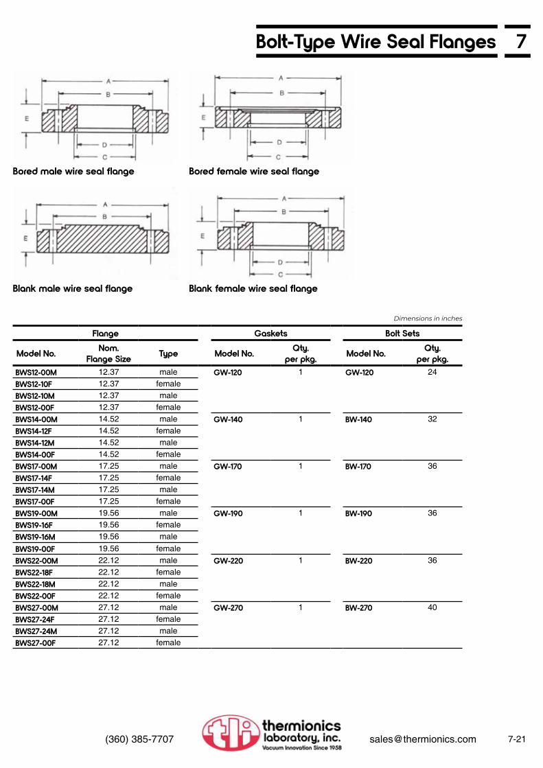
7Bolt-Type Wire Seal Flanges
7-21(360) 385-7707 [email protected]
Bored male wire seal flange
Blank male wire seal flange
Bored female wire seal flange
Blank female wire seal flange
Flange Gaskets Bolt Sets
Model No. Nom.Flange Size Type Model No. Qty.
per pkg. Model No. Qty.per pkg.
BWS12-00M 12.37 male GW-120 1 GW-120 24BWS12-10F 12.37 femaleBWS12-10M 12.37 maleBWS12-00F 12.37 femaleBWS14-00M 14.52 male GW-140 1 BW-140 32BWS14-12F 14.52 femaleBWS14-12M 14.52 maleBWS14-00F 14.52 femaleBWS17-00M 17.25 male GW-170 1 BW-170 36BWS17-14F 17.25 femaleBWS17-14M 17.25 maleBWS17-00F 17.25 femaleBWS19-00M 19.56 male GW-190 1 BW-190 36BWS19-16F 19.56 femaleBWS19-16M 19.56 male
BWS19-00F 19.56 femaleBWS22-00M 22.12 male GW-220 1 BW-220 36BWS22-18F 22.12 femaleBWS22-18M 22.12 maleBWS22-00F 22.12 femaleBWS27-00M 27.12 male GW-270 1 BW-270 40BWS27-24F 27.12 femaleBWS27-24M 27.12 maleBWS27-00F 27.12 female
Dimensions in inches

7-22 (360) 385-7707 [email protected]
7 Clamp-Type Wire Seal Flanges
TLI has flanges for the entire range of UHV applications. Clamp -type wire seal flanges are used where an existing flange must be matched or space requirements preclude the use of bolt-type flanges. Standard sizes vary from 12” tube to 36” pipe diameters. Custom flanges can be supplied.
As is the case with all TLI UHV flanges, the clamp-type wire seal flange is made of type 304 stainless steel . It is usually used with a .090” diameter OFF copper gasket for bakeout temperatures of up to 450°C. For leak checking or use at temperatures below 120°C, a reuseable Viton gasket may be used. Note that these gaskets are not interchangeable with bolt-type wire seal flange gaskets.
To ensure long-term seal reliability under repeated bakeout at elevated temperatures, super-high tensile strength clamping hardware is supplied, thus matching the thermal expansion coefficient of the flanges.
NOTE: Wire seal blank flanges with a domed head insert available at reduced prices. Consult factory for information.
Model No.A
FlangeO.D.
CTubeO.D.
EFlange
I.D
TubeI.D.
F Thickness
FlangeType
CWS-14-00M 14.0 — blank — 1.56 MaleCWS-14-12F 14.0 12.0 11.75 11.75 1.56 FemaleCWS-14-12M 14.0 12.0 11.75 11.75 1.56 MaleCWS-14-00F 14.0 — blank — 1.56 FemaleCWS-17-00M 16.0 — blank — 1.56 MaleCWS-17-14F 16.0 14.0 13.75 13.75 1.56 FemaleCWS-17-14M 16.0 14.0 13.75 13.75 1.56 MaleCWS-17-00F 16.0 — blank — 1.56 FemaleCWS-19-00M 18.0 — blank — 1.56 MaleCWS-19-16F 18.0 16.0 15.75 15.75 1.56 FemaleCWS-19-16M 18.0 16.0 15.75 15.75 1.56 MaleCWS-19-00F 18.0 — blank — 1.56 FemaleCWS-22-00M 20.0 — blank — 1.56 MaleCWS-22-18F 20.0 18.0 17.75 17.75 1.56 FemaleCWS-22-18M 20.0 18.0 17.75 17.75 1.56 Male
CWS-22-00F 20.0 — blank — 1.56 FemaleCWS-27-00M 26.0 — blank — 1.56 MaleCWS-27-24F 26.0 24.0 23.75 23.75 1.56 FemaleCWS-27-24M 26.0 24.0 23.75 23.75 1.56 MaleCWS-27-00F 26.0 — blank — 1.56 FemaleCWS-41-00M 41.0 — blank — 2.00 MaleCWS-41-36F 41.0 36.0 35.75 35.75 2.00 FemaleCWS-41-36M 41.0 36.0 35.75 35.75 2.00 MaleCWS-41-00F 41.0 — blank — 2.00 Female
Dimensions in inches
Clamp-Type Wire Seal Flange-Female Clamp-Type Wire Seal Flange-Male

7Clamp-Type Wire Seal Flanges
7-23(360) 385-7707 [email protected]
Clamp-Type HardwareModel No. DescriptionGWC-140 OFE copper gasketGWV-140 Viton gasketGWS-100 Clamp (each) -18 clamps requiredGWC-170 OFE copper gasketGWV-170 Viton gasketGWS-100 Clamp (each) - 20 clamps requiredGWC-190 OFE copper gasketGWV-190 Viton gasketGWS-100 Clamp (each) - 22 clamps requiredGWC-220 OFE copper gasketGWV-220 Viton gasketGWS-100 Clamp (each) - 24 clamps requiredGWC-270 OFE copper gasketGWV-270 Viton gasketGWS-100 Clamp (each) - 32 clamps required
GWC-410 OFE copper gasketGWV-410 Viton gasketGWS-100 Clamp (each) - 42 clamps required
Dimensions in inches
NOTE: Factory installation of a 6” skirt recommended. (Skirtshown with dotted lines.)
Clamp
NOTE: Clamp-type wire seal gaskets are made of .090” diameter OFE copper

7-24 (360) 385-7707 [email protected]
7 ASA Flanges
Blank Flange
Bored Flange (shown with tubing in place)
For optional O-ring grooves in ASA flanges,use suffix “/OR,” and add:
ASA-style smooth face flanges mate with standard ASA 150-lb 0-ring flanges for use to 10-8 Torr. These ASA flanges are fabricated from type 304 stainless steel with a surface finish of 32 micro-inches on both sides. All corners are chamfered 45°. Four flange sizes are offered, blank or bored, to fit four standard tube sizes.
Applications include use with various types of vacuum chambers, manifolds, furnaces, diffusion pump stations, valves, test equipment, pumps, special viewports, and a variety of experimental devices.
NOTE: Model No. ASA-5B matches the foreline connector for a 6” diffusion pump. ASA-6B matches the top flange of a 2” diffusion pump, while ASA-9B and ASA-11B match the top flange of 4” and 6” diffusion pumps, respectively. Flanges may be welded or brazed to the connecting tubulation.
Contact Thermionics for custom ASA assemblies.
Model No. Type AO.D.
BBolt
Circle
Bolt Holes CThickness
DBore
EI.D.
GStepNo. Dia.
ASA-5 blank 5.00 3.88 4 .625 .50 — — —ASA-5B bored 5.00 3.88 4 .625 .50 1.63 1.50 .340ASA-6 blank 6.00 4.75 4 .750 .50 — — —ASA-6B bored 6.00 4.75 4 .750 .50 3.50 3.34 .340ASA-9 blank 9.00 7.50 8 .687 .50 — — —ASA-9B bored 9.00 7.50 8 .687 .50 5.50 5.34 .340ASA-11 blank 11.00 9.50 8 .812 .75 — — —ASA-11B bored 11.00 9.50 8 .812 .75 7.50 7.34 .340
ASA 5” O.D. ASA 9” O.D.ASA 6” O.D ASA 11” O.D
Dimensions in inches

7ASA to UHV Adapter Flanges
7-25(360) 385-7707 [email protected]
For optional O-ring grooves in ASA flanges,use suffix “/OR,” and add:
Model No.ASA Flange Side Metal Seal Flange Side
CThickness
Ship. Wt.lbsA
O.D. BC1 Nom.Size I.D. BC2 BC2
Tap SizeASA5-133 5 3.880 1.33 0.625 1.062 8-32 .500 3.5ASA5-212 5 3.880 2.12 1.000 1.625 .25-28 .500 3.5ASA5-275 5 3.880 2.75 1.500 2.312 .25-28 .500 3.0ASA6-133 6 4.750 1.33 0.625 1.062 8-32 .500 4.0ASA6-212 6 4.750 2.23 1.000 1.625 .25-28 .500 4.0ASA6-275 6 4.750 2.75 1.500 2.312 .25-28 .500 3.5ASA6-338 6 4.750 3.37 2.000 2.850 5/16-24 .500 3.5ASA9-133 9 7.500 1.33 0.625 1.062 8-32 .500 7.5ASA9-212 9 7.500 2.12 1.000 1.625 .25-28 .500 7.0ASA9-275 9 7.500 2.75 1.500 2.312 .25-28 .500 7.0ASA9-338 9 7.500 3.37 2.000 2.850 5/16-24 .500 6.5ASA9-450 9 7.500 4.50 2.500 3.628 5/16-24 .500 6.5ASA9-462 9 7.500 4.62 3.000 4.030 5/16-24 .500 6.0ASA9-600 9 7.500 6.00 4.000 5.128 5/16-24 .500 6.0ASA11-133 11 9.500 1.33 0.625 1.062 8-32 .750 21.0ASA11-212 11 9.500 2.12 1.000 1.625 .25-28 .750 21.0ASA11-275 11 9.500 2.75 1.500 2.312 .25-28 .750 20.5ASA11-338 11 9.500 3.37 2.000 2.850 5/16-24 .750 20.0ASA11-450 11 9.500 4.50 2.500 3.628 5/16-24 .750 19.0ASA11-462 11 9.500 4.62 3.000 4.030 5/16-24 .750 19.0ASA11-600 11 9.500 6.00 4.000 5.128 5/16-24 .750 17.0ASA11-675 11 9.500 6.75 5.000 5.968 5/16-24 .750 17.0ASA11-800 11 9.500 8.00 6.000 7.128 5/16-24 .750 15.0
ASA 5” O.D. ASA 9” O.D.ASA 6” O.D ASA 11” O.D
Dimensions in inches

Fittings, Accessoriesand Hardware
8

Fittings, Accessories and Hardware
8
Fittings Accessories
Note: Bolt Sets for Standard Flanges are listed with the Flanges in Section 7
Hardware
CF (ConFlat) Fittings Tube Fittings.................. Half-Nipples, Nipples, Elbows, Tees................. 4-, 5-, and 6-Way Cubes............................ Flexible Couplings, Reducing Nipples.......... Viewports - Pyrex, Sapphire, and Quartz.... Adapters - Ceramic-to- Metal, Glass-to-Metal....ISO (KF) Flanges & Fittings Technical Information.... Flanges & Blanks........... Centering Rings, Clamps........................... Quick Clamp System..... Tube Fittings.................. Half-Nipples, Nipples, Tees............................... 4-, 5-, and 6-Way Crosses, Elbows, Flexible Couplings......... Hoses, Adapters, Reducing Nipples..........Fittings, Miscellaneous Metal Spherical Joints.... Quick Disconnects......... RL Fittings......................
Pyrex Bell Jars, Guards, and Accessories................................Feedthrough Collars...................Pinch-Off Tubes..........................Hoses, Flexible Stanless Steel...Double-Sides, Flanges with Valves and/or TC Tubes.............
12-Point Bolt Sets.......................Stud and Nut Sets......................Welded Bellows..........................Formed Bellows..........................Vacuum Tubing...........................Super Seal Epoxy Sealant..........Fel-Pro C-100 Lubricant.............Precision Shaft...........................Precision Bored Shaft.................
8-1
8-1
8-2
8-3
8-4
8-5
8-78-8
8-98-108-10
8-10
8-11
8-12
8-148-158-16
8-228-228-238-24
8-24
8-258-258-258-268-268-278-278-278-27
TrapsForeline, Optically Dense Type..Foreline, Molecular Sieve Type..
8-278-28

TLI UHV flanges and fittings are 100% compatible with ConFlat flanges.
Half-Nipples
Nipples
Elbows
Tees
8CF Fittings
Model No. TubeO.D. A Flange
O.D.Ship Wt.
lbsHN-075 0.75 1.50 1.33 0.75HN-100 1.00 2.09 2.12 1.0HN-150 1.50 2.46 2.75 1.5HN-200 2.00 3.21 3.37 2.0HN-250 2.50 4.12 4.50 6.0HN-300 3.00 3.53 4.62 8.0HN-400 4.00 5.31 6.00 11.0HN-500 5.00 4.93 6.75 12.0HN-600 6.00 6.56 8.00 19.0HN-800 8.00 8.00 10.00 25.0HN-1000 10.00 10.00 13.25 45.0
Model No. TubeO.D. A Flange
O.D.Ship Wt.
lbsNN-075 0.75 3.00 1.33 1.5NN-100 1.00 4.18 2.12 2.0NN-150 1.50 4.93 2.75 2.0NN-200 2.00 6.43 3.37 3.0NN-250 2.50 8.25 4.50 8.0NN-300 3.00 7.06 4.62 10.0NN-400 4.00 10.62 6.00 15.0NN-500 5.00 9.87 6.75 19.0NN-600 6.00 13.12 8.00 24.0NN-800 8.00 16.00 10.00 34.0NN-1000 10.00 20.00 13.25 75.0
Model No. TubeO.D. A Flange
O.D.Ship Wt.
lbsEL-075* 0.75 1.50 1.33 1.5EL-100 1.00 2.04 2.12 2.0EL-150* 1.50 2.46 2.75 2.0EL-200* 2.00 3.21 3.37 5.0EL-250* 2.50 4.12 4.50 8.0EL-300 3.00 3.34 4.62 13.0EL-400 4.00 5.31 6.00 15.0EL-500 5.00 4.93 6.75 20.0EL-600 6.00 6.56 8.00 24.0EL-800 8.00 8.00 10.00 34.0EL-1000 10.00 10.00 13.25 75.0
Model No. TubeO.D. A Flange
O.D.Ship Wt.
lbsTE-075 0.75 1.50 1.33 2.0TE-100 1.00 2.04 2.12 2.5TE-150 1.50 2.46 2.75 4.0TE-200 2.00 3.21 3.37 6.0TE-250 2.50 4.12 4.50 11.0TE-300 3.00 3.34 4.62 17.0TE-400 4.00 5.31 6.00 21.0TE-500 5.00 4.93 6.75 30.0TE-600 6.00 6.56 8.00 34.0TE-800 8.00 8.00 10.00 40.0TE-1000 10.00 10.00 13.25 100.0
Dimensions in inches
8-1(360) 385-7707 [email protected]
*Radius elbows. Other sizes are mitred.
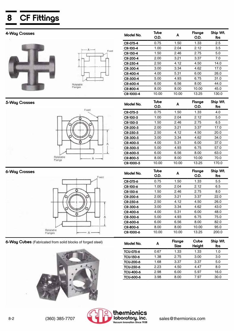
8-2 (360) 385-7707 [email protected]
8 CF Fittings4-Way Crosses
5-Way Crosses
6-Way Crosses
6-Way Cubes (Fabricated from solid blocks of forged steel)
Model No. TubeO.D. A Flange
O.D.Ship Wt.
lbsCR-075-4 0.75 1.50 1.33 2.5CR-100-4 1.00 2.04 2.12 3.5CR-150-4 1.50 2.46 2.75 5.0CR-200-4 2.00 3.21 3.37 7.0CR-250-4 2.50 4.12 4.50 14.0CR-300-4 3.00 3.34 4.62 17.0CR-400-4 4.00 5.31 6.00 26.0CR-500-4 5.00 4.93 6.75 31.0CR-600-4 6.00 6.56 8.00 44.0CR-800-4 8.00 8.00 10.00 45.0CR-1000-4 10.00 10.00 13.25 130.0
Model No. TubeO.D. A Flange
O.D.Ship Wt.
lbsCR-075-5 0.75 1.50 1.33 4.0CR-100-5 1.00 2.04 2.12 5.0CR-150-5 1.50 2.46 2.75 6.5CR-200-5 2.00 3.21 3.37 17.0CR-250-5 2.50 4.12 4.50 20.0CR-300-5 3.00 3.34 4.62 34.0CR-400-5 4.00 5.31 6.00 37.0CR-500-5 5.00 4.93 6.75 57.0CR-600-5 6.00 6.56 8.00 63.0CR-800-5 8.00 8.00 10.00 70.0CR-1000-5 10.00 10.00 13.25 170.0
Model No. TubeO.D. A Flange
O.D.Ship Wt.
lbsCR-075-6 0.75 1.50 1.33 5.5CR-100-6 1.00 2.04 2.12 6.5CR-150-6 1.50 2.46 2.75 8.0CR-200-6 2.00 3.21 3.37 22.0CR-250-6 2.50 4.12 4.50 26.0CR-300-6 3.00 3.34 4.62 43.0CR-400-6 4.00 5.31 6.00 48.0CR-500-6 5.00 4.93 6.75 75.0CR-600-6 6.00 6.56 8.00 82.0CR-800-6 8.00 8.00 10.00 95.0CR-1000-6 10.00 10.00 13.25 200.0
Model No. A Flange Size
Cube Height
Ship Wt.lbs
TCU-075-6 0.67 1.33 1.33 1.0TCU-150-6 1.38 2.75 3.00 3.0TCU-200-6 1.68 3.37 3.37 5.0TCU-250-6 2.23 4.50 4.47 8.0TCU-400-6 2.98 6.00 5.97 16.0TCU-600-6 3.98 8.00 7.97 30.0

8CF Fittings
8-3(360) 385-7707 [email protected]
Flexible Couplings
Reducing Nipples
ASA to UHV Reducing Nipples
Model No. Bellows I.D.
A (free)
B(Compressed)
Nom. Flange
Size
Ship Wt.lbs
FX-075 0.62 3.00 2.62 1.33 1.5FX-075-10 0.62 10.00 9.00 1.33 1.5FX-100 0.75 3.34 2.93 2.12 2.0FX-150 1.25 3.34 2.93 2.75 2.0FX-200 1.62 4.00 3.50 3.37 4.5FX-250 2.00 6.25 5.46 4.50 7.0FX-300 2.50 7.25 6.50 4.62 7.5FX-400 3.50 7.62 6.62 6.00 13.0FX-500 4.00 8.00 7.00 6.75 15.0FX-600 5.50 9.00 8.00 8.00 18.0FX-800 7.50 10.00 9.00 10.00 28.0FX-1000 10.00 11.00 10.00 13.25 80.0
Model No. Tube F-FRN-275x133 0.75 2.50RN-450x133 0.75 2.50RN-450x275 1.50 2.75RN-450x338 2.00 3.00RN-600x133 0.75 3.00RN-600x275 1.50 3.25RN-600x338 2.00 3.50RN-600x450 2.50 3.50RN-800x133 0.75 3.75RN-800x275 1.50 3.75
Model No. Tube F-FRN-ASA5x133 0.75 2.50RN-ASA5x275 1.50 2.75RN-ASA5x338 1.50 3.50RN-ASA5x450 1.50 3.75RN-ASA6x133 0.75 2.50RN-ASA6x275 1.50 2.75RN-ASA6x338 2.00 3.50RN-ASA6x450 2.50 3.75RN-ASA9x133 0.75 2.50RN-ASA9x275 1.50 2.75RN-ASA9x338 2.00 3.50RN-ASA9x450 2.50 3.75RN-ASA9x600 4.00 4.25
Model No. Tube F-FRN-800x338 2.00 4.00RN-800x450 2.50 4.00RN-800x600 4.00 4.25RN-1000x133 0.75 4.25RN-1000x275 1.50 4.25RN-1000x338 2.00 4.50RN-1000x450 2.50 4.50RN-1000x600 4.00 4.50RN-1000x800 6.00 4.50
Model No. Tube F-FRN-ASA9x800 5.00 4.25RN-ASA11x133 0.75 3.00RN-ASA11x275 1.50 3.25RN-ASA11x338 2.00 3.75RN-ASA11x450 2.50 4.25RN-ASA11x600 4.00 4.50RN-ASA11x800 6.00 4.50RN-ASA11x1000 6.00 5.00
Custom lengths available
For optional 0-ring grooves in ASA flanges, use suffix “/OR,” and add:ASA 5” O.D. ASA 9” O.D.ASA 6” O.D ASA 11” O.D

8-4 (360) 385-7707 [email protected]
8 Viewports
Useful Transmission Rangein Microns-80% Minimum
BakeoutTemperature
Window-to-SleeveTransition
Zero profilewide angle glass
0.32 to 2.7 400°C Matched-expansionseal
Nonmagneticglass
0.32 to 2.7 400°C Housekeeperseal
Quartz 0.29 to 2.0 200°C max. Lead alloy(melts at 300°C)
Sapphire 0.25 to 5.5 450°C Brazed joint
Viewport Specifications Thermionics viewports are mounted in UHV stainless steel flanges in the sizes noted below. Useable to below 1 x 10-11 Torr. Polished window surfaces offer a minimum of distortion and provide maximum light transmission.
The custom viewports are available for special applications, i.e., special materials and/or optical properties.
Refer to the flange section (Section 7) for assembly hardware information.
Zero Profile, Wide-Angle Viewports
Non-magnetic Viewports
Quartz Viewports
Sapphire Viewports
Model No.V
ViewingDia.
Nom.Flange
Size
AFlange
O.D.
BBolt
Circle
CFlange
Thickness
EGlass
Thickness
ShipWt.lbs
ZPV-075 0.625 1.33 1.33 1.062 0.285 0.062 1.0ZPV-100 0.625 2.12 2.12 1.625 0.470 0.062 1.0ZPV-150 1.40 2.75 2.75 2.312 0.625 0.105 1.0ZPV-200 1.40 3.37 3.37 2.850 0.625 0.105 2.0ZPV-250 2.69 4.50 4.50 3.628 0.680 0.175 4.0ZPV-300 2.69 4.62 4.62 4.030 0.750 0.175 5.0ZPV-400 3.88 6.00 6.00 5.128 0.780 0.200 6.0ZPV-500 3.88 6.75 6.75 5.969 0.840 0.200 7.0ZPV-600 5.38 8.00 8.00 7.128 0.880 0.375 9.0ZPV-800 5.38 8.00 10.0 9.128 0.970 0.375 10.0
Model No.
VViewing
Dia.
Nom.Flange
Size
AFlange
O.D.
BBolt
Circle
CFlange
Thickness
EGlass
Thickness
H Window Sleeve
Extension
ShipWt.lbs
NMV-150 1.37 2.75 2.75 2.312 0.50 0.120 1.75 1.0NMV-250 2.50 4.50 4.5 3.628 0.75 0.120 1.75 4.5NMV-400 3.50 6.00 6.0 5.128 0.84 0.220 1.75 6.0NMV-600 5.38 8.00 8.0 7.128 0.94 0.220 2.00 10.0
Model No.
VViewing
Dia.
Nom.Flange
Size
AFlange
O.D.
BBolt
Circle
CFlange
Thickness
EGlass
Thickness
H Window Sleeve
Extension
ShipWt.lbs
QVP-150 1.37 2.75 2.75 2.312 0.50 0.125 0.56 3.0QVP-250 2.37 4.50 4.5 3.628 0.75 0.250 0.78 6.0QVP-400 3.84 6.00 6.0 5.128 0.84 0.250 1.00 9.0QVP-600 5.78 8.00 8.0 7.128 0.94 0.375 1.31 13.0QVP-800 7.78 10.00 10.0 9.128 0.97 0.375 1.49 17.0
Model No.
VViewing
Dia.
Nom.Flange
Size
AFlange
O.D.
BBolt
Circle
CFlange
Thickness
EGlass
Thickness
H Window Sleeve
Extension
ShipWt.lbs
SVP-075 0.625 1.33 1.33 1.060 0.28 0.062 0.5SVP-100 1.000 2.75 2.75 2.312 0.50 0.062 2.0SVP-200 2.000 4.50 4.5 3.628 0.75 0.125 4.0
Dimensions in inches
7056 glass with Kovar sleeves and stainless steel flanges
7056 glass with stainless steel sleevesand flanges
With stainless steel sleeves and flanges
With Kovar sleeves and stainless steelflanges

8Ceramic-to-Metal Adapters
Glass-to-Metal Adapters
8-5(360) 385-7707 [email protected]
TLI ceramic-to-metal adapters for high and ultra-high vacuum system applications requiring high voltage insulation. Supplied with one rotatable and one non-rotatable metal
7052 glass to Kovar. Bakeable to 400°C. Pyrex or stainless steel available on request. Other lengths designed to customer’s specifications also available on request. Both flanges are non-rotatable unless otherwise specified.
seal flange for easy installation. Bakeable to 450°C. Feature high reliability, leak tight at 1 x 10⁻¹⁰ atm cc/sec helium. Maximum voltage ratings as noted in the tables below.
Model No.
VoltageRating
Nom.Flange A B C D E I
TCB-075 10 kV RMS 1 1/3 1.33 0.63 0.75 1.00 3.63 1.00TCB-125 15 kV RMS 2 3/4 2.75 1.21 1.25 1.63 4.20 2.00
Model No. CI
Nom I.D
GNom. GlassLength
DNom
Flange Size
I
TDEG-075 3.00 0.50 1.4 1.33 .500TDEG-100 3.00 0.75 1.0 2.12 .500TDEG-150 3.00 1.25 1.0 2.75 .500TDEG-200 4.50 1.62 1.0 3.37 .500TDEG-250 4.50 2.12 1.5 4.50 .750TDEG-300 4.50 2.50 1.5 4.62 .750TDEG-400 4.50 3.50 1.3 6.00 .750TDEG-500 4.50 4.37 1.3 6.75 .750TDEG-600 4.50 5.37 1.1 8.00 .750
Model No.
VoltageRating
Nom.Flange A B C I
MinTCE-250 7.5 kV RMS 4 1/2 1.5 2.50 4.50 0.75TCE-350 7.5 kV RMS 6 6.0 3.50 4.62 0.75TCE-600 15 kV RMS 8 8.0 6.00 5.50 1.50TCE-775 15 kV RMS 10 10.0 7.75 5.75 1.50
Dimensions in inches
Dimensions in inches
Double-Ended Glass Adapters
Sealed-Off Glass Adapters

8-6 (360) 385-7707 [email protected]
8 Glass-to-Metal AdaptersGlass-to-metal adapters for attachment of glass accessories to metal high vacuum systems and for mounting UHV flange devices to glass systems. Standard adapters offer a choice of 7052 glass/Kovar sleeve or 7740 Pyrex/type 304 stainless steel sleeve non-magnetic combination. Both types are bakeable to 400°C and are useable to below 10-10 Torr.
Note: All sizes are available with 7052 glass.
304 S.S.to 7740 Pyrex
Kovarto 7740 Pyrex
ANom.GlassO.D.
BGlass
Thickness
C304 S.S.to 7740Pyrex
CKovar
to 7740Pyrex
DFlange
O.D.Model No. Model No.
GAP-012P-S KAP-012P 1/8 .060 4.750 5.250 1.33GAP-018P-S KAP-018P 3/16 .060 4.750 5.250 1.33GAP-025P-S KAP-025P 1/4 .060 4.750 5.250 1.33GAP-031P-S KAP-031P 5/16 .060 4.750 5.250 1.33GAP-037P-S KAP-037P 3/8 .080 4.750 5.250 1.33GAP-050P-S KAP-050P 1/2 .080 4.750 5.250 1.33GAP-062 P-S KAP-062P 5/8 .080 4.750 5.250 1.33GAP-075P-S KAP-075P 3/4 .080 5.250 5.750 1.33GAP-087P-S KAP-087P 7/8 .080 4.920 5.420 2.12GAP-100P-S KAP-100P 1 .080 4.920 5.420 2.12GAP-112P-S KAP-112P 1 1/8 .080 4.960 5.460 2.75GAP-125P-S KAP-125P 1 1/4 .080 4.960 5.460 2.75GAP-137P-S KAP-137P 1 3/8 .080 4.960 5.460 2.75GAP-150P-S KAP-150P 1 1/2 .083 4.960 5.460 2.75GAP-162P-S KAP-162P 1 5/8 .083 4.975 5.475 3.37GAP-175P-S KAP-175P 1 3/4 .083 4.975 5.475 3.37GAP-200P-S KAP-200P 2 .083 4.975 5.475 3.37GAP-225P-S KAP-225P 2 1/4 .083 5.625 6.125 4.50GAP-250P-S KAP-250P 2 1/2 .115 5.625 7.750 4.50GAP-275P-S KAP-275P 2 3/4 .115 5.625 7.750 4.62GAP-300 P-S KAP-300P 3 .115 5.625 7.750 4.62GAP-325P-S KAP-325P 3 1/4 .115 5.690 8.062 6.00GAP-350P-S KAP-350P 3 1/2 .115 5.690 8.062 6.00GAP-375P-S KAP-375P 3 3/4 .115 5.690 8.062 6.00GAP-400P-S KAP-400P 4 .115 5.690 8.062 6.00GAP-500P-S KAP-500P 5 .200 5.710 10.460 6.75GAP-600P-S KAP-600P 6 .200 5.750 11.250 8.00
Dimensions in inches

8ISO Flanges & Fittings
8-7(360) 385-7707 [email protected]
Each assembly consists of two symmetrical flanges, a centering ring, an O-ring and a clamp. The connection is made without tools and is completed by simply tightening the wing nut on the clamp.
All components sold by Thermionics are clean and ready for immediate use. During assembly, all components are helium mass spectrometer leak-checked prior to shipment. The sealing surfaces are specially machined to ensure perfect repeat sealing. This surface quality enables the slightest damage to be detected by visual inspection. To ensure the cleanliness and quality of the components until they are put into use, TLI employs vacuum shrink wrapping of each component. This technique prevents damage in shipping and storage.
All TLI/ISO fittings are manufactured to the ISO standards, and therefore, are compatible with other vacuum components designed to the same standards. Thermionics offers as a convenience other TLI fittings, feedthroughs, vacuum components, and accessories with these fittings.
To order ISO fittings on any component in this catalog, add ISO + flange size. For example, if you are ordering an inline valve (L-1500-P) you would then add (IS0-40) to the end to get (L-1500-P-IS0-40).
Flanges for tube sizes greater than 2” (50mm) diameter are available. Please consult factory.
The flange dimensions shown here are the International Standard Flange dimensions. Rather than repeating them throughout the catalog, they will be referred to only by their ISO number (16, 25, 40, or 50).
Assembly
Clean and Leak Tested
Dimensions
Note
To OrderLarge ISO Flanges
Step 1 Step 2 Step 3

8-8 (360) 385-7707 [email protected]
8 ISO Flanges
Short Weld Stub
Long Weld Stub
Inside Weld Flange
Blank Weld Stub
Blank-Off
Model No. Flange Size
TubeSize A B C
108064-01 16 1/2” .50 (12.7)
.065 (1.7)
.50 (12.7)
108064-02 16 3/4” .75 (19.1)
.065 (1.7)
.50 (12.7)
108064-03 25 1” 1.00 (25.4)
.065 (1.7)
.50 (12.7)
108064-04 40 1 1/2” 1.50 (38.1)
.065 (1.7)
.75 (19.1)
108064-05 50 2” 2.00 (50.8)
.065 (1.7)
.75 (19.1)
Model No. Flange Size
TubeSize A B C
108065-01 16 1/2” .50 (12.7)
.065 (1.7)
1.575 (40)
108065-02 16 3/4” .75 (19.1)
.065 (1.7)
1.575 (40)
108065-03 25 1” 1.00 (25.4)
.065 (1.7)
1.575 (40)
108065-04 40 1 1/2” 1.50 (38.1)
.065 (1.7)
1.575 (40)
108065-05 50 2” 2.00 (50.8)
.065 (1.7)
1.575 (40)
Model No. Flange Size
TubeSize A B
108087-01 16 1/2” .51 (12.9) .56 (14.2)
108087-02 16 3/4” .76 (19.3) .56 (14.2)
108087-03 25 1” 1.01 (25.7) .47 (11.9)
108087-04 40 1 1/2” 1.51 (38.4) .50 (12.7)
108087-05 50 2” 1.62 (41.1) .62 (15.7)
Model No. Flange Size A B
108069-01 16 .50 (12.7) .75 (19.1)
108069-02 16 .75 (19.1) .75 (19.1)
108069-03 25 1.00 (25.4) .75 (19.1)
108069-04 40 1.50 (38.1) 1.00 (25.4)
108069-05 50 2.00 (50.8) 1.00 (25.4)
Model No. Flange Size A
108063-02 16 .19 (4.8)
108063-04 25 .19 (4.8)
108063-06 40 .19 (4.8)
108063-07 50 .19 (4.8)
Dimensions in inches (millimeters)
• Stainless steel• Butt weld• Standard inch stub
diameters
• Stainless steel• Butt weld• Standard inch stub
diameters
• Stainless steel• Standard inch
counter bore• Internal weld
• Stainless steel• Bore to desired
diameter or use as a blank-off
• Stainless steel• Use for closing off
unused ports• Not recommended
for welding

8Seals
8-9(360) 385-7707 [email protected]
O-Ring
Centering Ring Assembly
Adaptive Centering Ring Assembly
Overpressure Ring
Clamp
Model No. Flange Size
TubeSize A B
108092-01 16 2.314 .210 (5.3)
.725(18.4)
108092-02 25 2.320 .210 (5.3)
1.10(27.9)
108092-03 40 2.326 .210 (5.3)
1.60(40.6)
108092-04 50 2.330 .210 (5.3)
2.10(53.3)
Model No. Flange Size A B
108061-02 16 .63(16.0)
.210 (5.3)
108061-04 25 .98(25.0)
.210 (5.3)
108061-06 40 1.58(40.1)
.210 (5.3)
108061-07 50 1.97(50.1)
.210 (5.3)
Model No. Flange Size A B C
108062-01 16/10 .67 (17.0)
.47(11.9)
.39(9.9)
108062-02 25/20 1.02(25.9)
.87(22.1)
.83(21.1)
108062-03 40/32 1.61(40.9)
1.34(34.0)
1.26(32.0)
Model No. Flange Size A B C
108070-01 16 2.24(57)
1.69(43)
.63(16)
108070-02 25 2.76(70)
2.17(55)
.63(16)
108070-03 40 3.39(86)
2.76(70)
.63(16)
108070-04 50 4.33(110)
3.70(94)
.79(20)
Dimensions in inches (millimeters)
• Replaceable seal for centering ring
• Standard O-ring sizes
• Supplied in Viton (Buna and silicone available)
• Stainless steel• Supplied in Viton
(Buna and silicone available)
• 200°C max. baking temperature, 150°C continuous
• Stainless steel• Viton O-ring• To connect
obsolete bore sizes with current ISO sizes
• Stainless steel• Fits over O.D.
of O-ring
• Wing-nut and screw closure
Model No. Flange Size A B C
108093-01 16 2.24(57)
1.69(43)
.63(16)
108093-02 25 2.76(70)
2.17(55)
.63(16)
108093-03 40 3.39(86)
2.76(70)
.63(16)
108093-04 50 4.33(110)
3.70(94)
.79(20)

8-10 (360) 385-7707 [email protected]
8 ISO Quick Clamp System
ISO Fittings
Each Thermionics quick clamp system includes 2 flanges, a centering ring, an O- ring, and a clamp. Systems are available in sizes 3/4” to 2”.
Model No. Tube Size Ref. ISO
ISO-16 3/4” 16
ISO-25 1” 25
ISO-40 1 1/2” 40
ISO-50 2” 50
Half-Nipples
Nipples
Tees
Model No. Flange Size
Tube Size A
108089-02 16 0.75” 2.37(60)
108089-03 25 1.00” 2.37(60)
108089-04 40 1.50” 3.75(95)
108089-05 50 2.00” 3.75(95)
Model No. Flange Size
Tube Size A
108077-02 16 0.75” 3.15(80)
108077-03 25 1.00” 3.94(100)
108077-05 40 1.50” 5.12(130)
108077-07 50 2.00” 5.51(140)
Model No. Flange Size
Tube Size A B
108080-01 16 0.75” 1.57(40)
3.15(80)
108080-02 25 1.00” 1.97(50)
3.94(100)
108080-03 40 1.50” 2.56(65)
5.12(130)
108080-04 50 2.00” 2.76(70)
5.51(140)
• All stainless steel • All welds are either
inside or 100% penetration
• All dimensions are standard fitting measurements
• All fittings are available in special lengths as a special order
• All stainless steel • All welds are either
inside or 100% penetration
• All dimensions are standard fitting measurements
• All fittings are available in special lengths as a special order
• All stainless steel • All welds are either
inside or 100% penetration
• All dimensions are standard fitting measurements
• All fittings are available in special lengths as a special order
Dimensions in inches (millimeters)Fittings with ISO/pneurop flanges

8ISO Fittings
8-11(360) 385-7707 [email protected]
4-Way Crosses
5-Way Crosses
6-Way Crosses
Elbow
ISO/Pneurop Flexible Couplings
Model No. Flange Size
Tube Size A B
108081-01 16 0.75” 1.57(40)
3.15(80)
108081-02 25 1.00” 1.97(50)
3.94(100)
108081-03 40 1.50” 2.56(65)
5.12(130)
108081-04 50 2.00” 2.76(70)
5.51(140)
Model No. Flange Size
Tube Size A B
108090-01 16 0.75” 1.57(40)
3.15(80)
108090-02 25 1.00” 1.97(50)
3.94(100)
108090-03 40 1.50” 2.56(65)
5.12(130)
108090-04 50 2.00” 2.76(70)
5.51(140)
Model No. Flange Size
Tube Size A B
108091-01 16 0.75” 1.57(40)
3.15(80)
108091-02 25 1.00” 1.97(50)
3.94(100)
108091-03 40 1.50” 2.56(65)
5.12(130)
108091-04 50 2.00” 2.76(70)
5.51(140)
Model No. Flange Size
Tube Size A
108072-01 16 0.75” 1.57(40)
108072-02 25 1.00” 1.97(50)
108072-03 40 1.50” 2.56(65)
108072-04 50 2.00” 2.76(70)
Model No. Flange Size
Tube Size A B
108094-01 16 0.75” 3.00(76)
2.67(68)
108094-02 25 1.00” 3.40(86)
2.93(74)
108094-03 40 1.50” 3.40(86)
2.93(74)
108094-04 50 2.00” 4.00(102)
3.49(89)
• All stainless steel • All welds are either
inside or 100% penetration
• All dimensions are standard fitting measurements
• All fittings are available in special lengths as a special order
• All stainless steel • All welds are either
inside or 100% penetration
• All dimensions are standard fitting measurements
• All fittings are available in special lengths as a special order
• All stainless steel • All welds are either
inside or 100% penetration
• All dimensions are standard fitting measurements
• All fittings are available in special lengths as a special order
• Fittings are all stainless steel
• All welds are either inside or 100% penetration
• All dimensions are standard fitting measurements
• All fittings are available in special lengths as a special order
• For flexible connections• Formed bellows• All stainless steel• Quick and easy alignment
Dimensions in inches (millimeters)

8-12 (360) 385-7707 [email protected]
8 ISO FittingsHosesFlexible
Braided
• For roughing connections• As flexible tubing• Supplied in lengths as
shown• Special lengths on request• Supplied with or without
braid• All stainless-steel
construction
Base Model No.: 108075. Add suffix shown under price to denote length and flange size. -01 through -20 (Fig. 1), no braid. -21 through -40 (Fig. 2), braided.
• Same
Dimensions in inches (millimeters)
Flange Size A* 18” 24” 36” 48” 72”
16 0.75” (-01) (-02) (-03) (-04) (-05)
25 1.00” (-06) (-07) (-08) (-09) (-10)
40 1.50” (-11) (-12) (-13) (-14) (-15)
50 2.00” (-16) (-17) (-18) (-19) (-20)
Flange Size A* 18” 24” 36” 48” 72”
16 0.75” (-01) (-02) (-03) (-04) (-05)
25 1.00” (-06) (-07) (-08) (-09) (-10)
40 1.50” (-11) (-12) (-13) (-14) (-15)
50 2.00” (-16) (-17) (-18) (-19) (-20)
ConFlat Flange
Sargent-Welch Mechanical Pump
ASA Flange
Model No. Flange Size
Tube Size A B
108078-01 16/133 0.50” 2.08(52.7)
0.62(15.8)
108078-02 16/275 0.75” 1.78(45.3)
0.62(15.8)
108078-03 25/275 1.00” 1.78(45.3)
0.78(22.1)
108078-04 40/275 1.50” 1.78(45.3)
1.37(34.8)
108078-05 50/450 2.00” 1.95(49.5)
1.87(47.5)
Model No.
Flange Size
Corresp. Welch-Pump Model Nos. A B
108088-01 16 1339, 1400,1406, 1410
2.50(63.5)
3/8-18
108088-02 16 1405 2.00(50.8)
3/4-20
108088-03 25 1380, 1402, 1403,8806, 8811,8816, 8821
2.12(53.8)
1-20
108088-04 40 1373, 1376,8831
2.12(53.8)
1.5-12
108088-05 40 1397, 1374,8851
2.50(63.5)
1.75-20
Model No. Flange Size A B C
108079-01 40/2” 1.825(46.4
1.38(35.1)
6.00(152)
108079-02 40/3” 1.825(46.4)
1.38(35.1)
7.50(190)
108679-03 50/2” 1.825(46.4
1.88(47.8)
6.00(152)
108079-04 50/3” 1.825(46.4)
1.88(47.8)
7.50(190)
• ISO to ConFlat flange• Stainless steel
• Replaces inlet hose connector
• Stainless steel
• ISO to ASA• Standard without
O-ring groove• O-ring groove on
request*• Stainless steel
*Also available in other sizes and configurations.
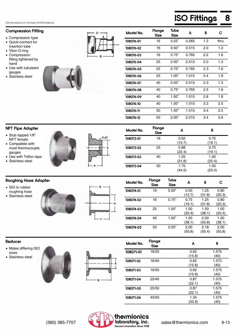
8ISO Fittings
8-13(360) 385-7707 [email protected]
Compression Fitting
NPT Pipe Adapter
Roughing Hose Adapter
Reducer
Model No. Flange Size
TubeSize A B C
108076-01 16 0.25” 0.265 1.3 thru
108076-02 16 0.50” 0.515 2.0 1.3
108076-03 16 0.75” 0.765 2.2 1.6
108076-04 25 0.50” 0.515 2.0 1.3
108076-05 25 0.75” 0.765 2.3 1.6
108076-06 25 1.00” 1.015 2.4 1.8
108076-07 40 0.50” 0.515 2.3 1.3
108076-08 40 0.75” 0.765 2.5 1.6
108076-09 40 1.00” 1.015 2.8 1.8
108076-10 40 1.50” 1.510 3.3 2.5
108076-11 50 1.50” 1.510 3.4 2.5
108076-12 50 2.00” 2.010 3.4 2.6
Dimensions in inches (millimeters)
• Compression type• Quick-connect for
insertion tube• Viton O-ring• Compression
fitting tightened by hand
• Use with tubulated gauges
• Stainless steel
• Stub tapped 1/8” NPT female
• Compatible with most thermocouple gauges
• Use with Teflon tape• Stainless steel
• ISO to rubber roughing hose
• Stainless steel
• Mates differing ISO sizes
• Stainless steel
Model No. Flange Size A B
108073-01 16 0.62(15.7)
0.75(19.1)
108073-02 25 0.88(22.4)
0.75(19.1)
108073-03 40 1.25(31.8)
1.00(25.4)
108073-04 50 1.75(44.5)
1.00(25.4)
Model No. Flange Size
Tube Size A B C
108074-01 16 0.50” 0.50(12.7)
1.25(31.8)
0.80(20.3)
108074-02 16 0.75” 0.75(19.1)
1.25(31.8)
0.80(20.3)
108074-03 25 1.00” 1.00(25.4)
1.50(38.1)
1.00(25.4)
108074-04 40 1.50” 1.50(38.1)
2.00(50.8)
1.50(38.1)
108074-05 50 2.00” 2.00(50.8)
2.18(55.4)
2.00(50.8)
Model No. Flange Size A B
108071-01 16/25 0.62(15.8)
1.575(40)
108071-02 16/40 0.62(15.8)
1.575(40)
108071-03 16/50 0.62(15.8)
1.575(40)
108071-04 25/40 0.87(22.1)
1.575(40)
108071-05 25/50 0.87(22.1)
1.575(40)
108071-06 40/50 1.34(33.9)
1.575(40)

8-14 (360) 385-7707 [email protected]
8 Metal Spherical JointsThermionics has supplied stainless steel ball and socket joints to the semiconductor industry since 1978. Connections are made with a ball and socket, an O-ring, and a clamp. These items can be brazed or welded to components or manifolding for difficult curves or adjustable angular connections.
The socket joints are manufactured from type 304 stainless steel to ASTM standards for ground glass joints. They will mate with standard quartz or Pyrex ball couplings and have a vacuum integrity to 5 x 10⁻⁹ Torr.
They feature the same ease of assembly as the ISO series, and the same elastomer seals are available on these fittings. There are no metal seals available, however.
Model No.PC-50
PC-65
PC-75
PC-102
Model No. Size A B CB-106140 50/30 1.00 1.25 2.92
B-106141 65/40 1.25 1.50 3.32
8-106142 75/50 1.75 2.00 4.00
B-106143 102/75 2.75 3.00 4.00
Model No. Size A BS-106136 50/30 2.00 2.58
S-106137 65/40 2.50 2.80
S-106138 75/50 3.00 2.86
S-106139 102/75 4.00 3.36
Pinch Clamp Ball
Socket
Dimensions in inches

8Vacuum Quick-Disconnects
8-15(360) 385-7707 [email protected]
Model No.Tube Size
(O.D.)
A Bore I.D.
B Body O.D.
C Knurled Nut O.D
Assembled Length
SQD-06 0.06 0.072 0.375 0.50 1.31SQD-12 0.12 0.135 0.375 0.50 1.31SQD-18 0.18 0.197 0.375 0.62 1.31SOD-25 0.25 0.260 0.375 0.62 1.31SQD-31 0.31 0.322 0.500 0.81 1.31SQD-38 0.37 0.385 0.500 0.81 1.31SQD-50 0.50 0.510 0.625 0.94 1.37SOD-62 0.62 0.635 0.750 1.19 1.50SQD-75 0.75 0.760 0.875 1.38 1.62SQD-87 0.87 0.885 1.000 1.44 1.75SQD-100 1.00 1.010 1.125 1.62 1.87SOD-112 1.12 1.130 1.250 1.88 2.00SOD-125 1.25 1.260 1.500 1.88 2.25SOD-138 1.37 1.380 1.625 2.12 2.37SOD-150 1.50 1.510 1.750 2.25 2.50SOD-162 1.62 1.630 1.875 2.38 2.56SOD-200 2.00 2.010 2.250 2.75 2.62
Model No.Tube Size
(O.D.)
A Bore I.D.
B Body O.D.
C Knurled Nut O.D
Assembled Length
BQD-06 0.06 0.072 0.375 0.50 1.31BQD-12 0.12 0.135 0.375 0.50 1.31BQD-18 0.18 0.197 0.375 0.62 1.31BQD-25 0.25 0.260 0.375 0.62 1.31BQD-31 0.31 0.322 0.500 0.81 1.31BQD-38 0.37 0.385 0.500 0.81 1.31BQD-50 0.50 0.510 0.625 0.94 1.37BQD-62 0.62 0.635 0.750 1.19 1.50BQD-75 0.75 0.760 0.875 1.38 1.62BQD-87 0.87 0.885 1.000 1.44 1.75BQD-100 1.00 1.010 1.125 1.62 1.87BQD-112 1.12 1.130 1.250 1.88 2.00BQD-125 1.25 1.260 1.500 1.88 2.25BQD-137 1.37 1.380 1.625 2.12 2.37BQD-150 1.50 1.510 1.750 2.25 2.50BQD-162 1.62 1.630 1.875 2.38 2.56BQD-200 2.00 2.010 2.250 2.75 2.62
Model No. Tube Size (O.D.)FQD-50 1/2
FQD-75 3/4
FQD-100 1
FQD-150 1 1/2
Model No. Tube Size (O.D.)
Nom.Flange(O.D.)
STF25-133 1/4 1 1/3
STF25-275 1/4 2 3/4
STF50-133 1/2 1 1/3
STF50-275 1/2 2 3/4
STF75-275 3/4 2 3/4
STF100-275 1 2 3/4
Stainless Steel Quick-Disconnects
Brass Quick-Disconnects
Dimensions in inches
Dimensions in inches
Other FQD sizes are available. Consult factory.
TLI quick-disconnects provide a fast and convenient method for coupling and uncoupling metal and glass tubing. They can be welded, brazed or soldered to flanges, manifolds, chambers or other vacuum equipment. Quick-disconnects are ideal for mounting ion gauges, thermocouple gauges, special test ports and feedthroughs. These fittings are also supplied mounted on UHV flanges for use on flanged ports. See FQD series below.
Standard quick-disconnects are available in a choice of stainless steel or brass in seventeen standard sizes from 1/16” through 2”. Custom quick-disconnects are available in a variety of other sizes, metals, wall thicknesses, and configurations.
Model No.
SQD-06SQD-12SQD-18SQD-25SQD-31SQD-38SQD-50SQD-62SQD-75SQD-87SQD-100SQD-112SQD-125SQD-138SQD-150SQD-162SQD-200
Model No.
QBB-06QBB-12QBB-18QBB-25QBB-31QBB-38QBB-50QBB-62QBB-75QBB-87QBB-100QBB-112QBB-125QBB-138QBB-150QBB-162QBB-200
Blank-Offs
Blank-Offs
FQD Stainless Steel Quick-Disconnects Mounted on 2.75” UHV Flanges.
Swagelok Tube Fitting Mounted on UHV Flanges

8-16 (360) 385-7707 [email protected]
8 RL Fittings• Bakeable to 200°C• Quick and easy—connect and disconnect• Versatile—many possible combinations
and uses• Both high-vacuum and pressure
applications• Hand-tight usable to 1 x 10⁻⁷ Torr
Since 1965, Thermionics Laboratory has manufactured RL vacuum and pressure fittings. The fittings were originally developed in the 1940’s by the Lawrence Radiation Laboratory. Initially they were used as connectors between leak detectors, mechanical pumps, and water lines through vacuum systems. However, in recent years, they have been found to be very versatile, with many uses in pressure environments. The fact that they are economical, dependable, and easy to install has been a major reason for their popularity in the vacuum industry.
All vacuum components manufactured by Thermionics come with a guarantee of excellence, reliability and longevity. RL fittings are manufactured from the highest quality materials available and meet the highest standards of workmanship. All fittings are individually inspected and packaged clean and ready for immediate use.
RL fittings are available in a choice of brass or stainless steel. (Please specify your choice when ordering.) They are machined from solid bar stock. They may also be specially ordered in Teflon, nylon or any machinable plastic. Brass fittings have been most popular, and a large inventory is maintained at the factory to ensure prompt shipment. All RL fittings are bakeable to 200°C (392°F). Bakeout is usually required to achieve pressures of 1 x 10⁻⁷ Torr. Assembly of RL fittings is quick and easy.
Assembly is accomplished by simply handtightening each fitting as it is added to the system. Some fittings may need to be brazed or soldered onto pipes or tubing to fit the demands of your system; however, no special tools are required with normal installation.
RL fittings are supplied in a large selection of sizes. The normal sizes used are: 1/8”, 3/16”, 1/4”, 3/8”, 1/2”, 5/8”, 3/4,7/8”, 1”, 1 1/8”; special sizes may be requested.
History GuaranteeMaterials
We are evaluating the types of RL fittings we manufacture. Some RL models and sizes may be discontinued, and may be available only as a special order

8RL Applications
8-17(360) 385-7707 [email protected]
There are several combinations in which RL fittings can be used—a few are described below. RL fittings have an added advantage over most other quick couplings. The nut is an integral part of the fitting and is therefore much less subject to failure under stress.
Loosen the #4 Union Nut and the fitting becomes a vent-valve. Tighten it down and it becomes a vacuum or pressure tight plug.
Interchangeable high pressure fittings are also available to connect to the permanently installed Half Union.
The #12 Female Pipe Feedthrough is welded to a flange plate. It may be replaced with a blank flange when the fitting is not in use.
We are evaluating the types of RL fittings we manufacture. Some RL models and sizes may be discontinued, and may be available only as a special order
Vent or Plug
Low Pressure Gas or Liquid
High Pressure Gas or Liquid
Metal Tube to Non-Metal Tube
A
B
C
D

8-18 (360) 385-7707 [email protected]
8 RL High-Vacuum & Pressure Fittings
Male Pipe Coupling
Solder Coupling
Hose Nipple
Union Knurled Nut
Model No. Nom. Size A NPT C
1-12 1/8” 0.06 1/8 1.381-18 3/16” 0.13 1/8 1.381-25 1/4” 0.19 1/8 1.381-37 3/8” 0.31 1/4 1.411-50 1/2” 0.44 3/8 1.531-62 5/8” 0.56 1/2 1.661-75 3/4” 0.69 3/4 1.661-87 7/8” 0.81 3/4 1.841-100 1” 0.94 1 1.911-112 1 1/8” 1.06 1 1.91
Model No. Nom. Size A B C
2-12 1/8” 0.06 0.13 0.882-18 3/16” 0.13 0.19 0.882-25 1/4” 0.19 0.25 0.882-37 3/8” 0.31 0.38 0.902-50 1/2” 0.44 0.50 0.902-62 5/8” 0.56 0.63 0.902-75 3/4” 0.69 0.75 0.902-87 7/8” 0.81 0.88 0.972-100 1” 0.94 1.00 1.032-112 1 1/8” 1.06 1.13 1.03
Model No. Nom. Size A BB C
3-12 1/8” 0.06 3/16 1.503-18 3/16” 0.13 1/4 1.503-25 1/4” 0.19 5/16 1.503-37 3/8” 0.31 7/16 1.503-50 1/2” 0.44 9/16 1.503-62 5/8” 0.56 11/16 1.503-75 3/4” 0.69 13/16 1.503-87 7/8” 0.81 15/16 1.503-100 1” 0.94 1 1/16 2.253-112 1 1/8” 1.06 1 3/16 2.25
Model No. Nom. Size B C
4-12 1/8” 0.56 0.754-18 3/16” 0.56 0.754-25 1/4” 0.63 0.754-37 3/8” 0.81 0.754-50 1/2” 1.00 0.754-62 5/8” 1.13 0.754-75 3/4” 1.25 0.754-87 7/8” 1.50 0.754-100 1” 1.75 0.754-112 1 1/8” 1.88 0.75
Dimensions in inchesPlease specify on order whether parts are of brass or stainless steel.
1
2
3
4

8RL High-Vacuum & Pressure Fittings
8-19(360) 385-7707 [email protected]
Solder Nipple
Plug Nipple
Female Pipe Nipple
Male Pipe Nipple
Model No. Nom. Size A B C
5-12 1/8” 0.06 0.13 0.755-18 3/16” 0.13 0.19 0.755-25 1/4” 0.19 0.25 1.005-37 3/8” 0.31 0.38 1.005-50 1/2” 0.44 0.50 1.005-62 5/8” 0.56 0.63 1.255-75 3/4” 0.69 0.75 1.255-87 7/8” 0.81 0.88 1.255-100 1” 0.94 1.00 1.505-112 1 1/8” 1.06 1.13 1.44
Model No. Nom. Size C
6-12 1/8” 1.006-18 3/16” 1.006-25 1/4” 1.006-37 3/8” 1.006-50 1/2” 1.006-62 5/8” 1.006-75 3/4” 1.006-87 7/8” 1.006-100 1” 1.006-112 1 1/8” 1.00
Model No. Nom. Size A F-NPT C
7-50 1/2” 0.34 1/8 1.007-62 5/8” 0.44 1/4 1.257-75 3/4” 0.58 3/8 1.507-87 7/8” 0.72 1/2 1.507-100 1” 0.72 1/2 1.507-112 1 1/8” 0.91 3/4 1.50
Model No. Nom. Size A NPT C
8-37 3/8” 0.25 1/8 1.508-50 1/2” 0.38 1/4 1.508-62 5/8” 0.50 3/8 1.508-75 3/4” 0.62 1/2 1.758-87 7/8” 0.62 1/2 1.758-100 1” 0.88 3/4 2.008-112 1 1/8” 0.88 3/4 2.00
Dimensions in inchesPlease specify on order whether parts are of brass or stainless steel.
5
6
7
8Dims according to print. I.D. must besmaller due to minor dia. of NPT.
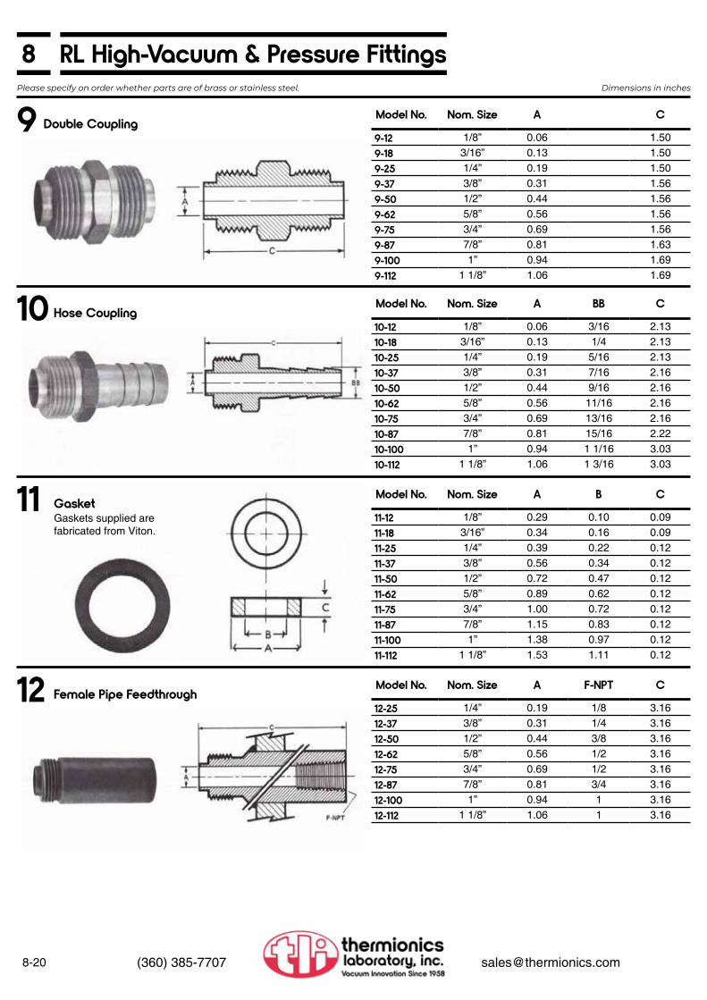
8-20 (360) 385-7707 [email protected]
8 RL High-Vacuum & Pressure Fittings
Double Coupling
Hose Coupling
Gasket
Female Pipe Feedthrough
Model No. Nom. Size A C
9-12 1/8” 0.06 1.509-18 3/16” 0.13 1.509-25 1/4” 0.19 1.509-37 3/8” 0.31 1.569-50 1/2” 0.44 1.569-62 5/8” 0.56 1.569-75 3/4” 0.69 1.569-87 7/8” 0.81 1.639-100 1” 0.94 1.699-112 1 1/8” 1.06 1.69
Model No. Nom. Size A BB C
10-12 1/8” 0.06 3/16 2.1310-18 3/16” 0.13 1/4 2.1310-25 1/4” 0.19 5/16 2.1310-37 3/8” 0.31 7/16 2.1610-50 1/2” 0.44 9/16 2.1610-62 5/8” 0.56 11/16 2.1610-75 3/4” 0.69 13/16 2.1610-87 7/8” 0.81 15/16 2.2210-100 1” 0.94 1 1/16 3.0310-112 1 1/8” 1.06 1 3/16 3.03
Model No. Nom. Size A B C
11-12 1/8” 0.29 0.10 0.0911-18 3/16” 0.34 0.16 0.0911-25 1/4” 0.39 0.22 0.1211-37 3/8” 0.56 0.34 0.1211-50 1/2” 0.72 0.47 0.1211-62 5/8” 0.89 0.62 0.1211-75 3/4” 1.00 0.72 0.1211-87 7/8” 1.15 0.83 0.1211-100 1” 1.38 0.97 0.1211-112 1 1/8” 1.53 1.11 0.12
Model No. Nom. Size A F-NPT C
12-25 1/4” 0.19 1/8 3.1612-37 3/8” 0.31 1/4 3.1612-50 1/2” 0.44 3/8 3.1612-62 5/8” 0.56 1/2 3.1612-75 3/4” 0.69 1/2 3.1612-87 7/8” 0.81 3/4 3.1612-100 1” 0.94 1 3.1612-112 1 1/8” 1.06 1 3.16
Dimensions in inchesPlease specify on order whether parts are of brass or stainless steel.
9
10
11
12
Gaskets supplied arefabricated from Viton.

8RL High-Vacuum & Pressure Fittings
8-21(360) 385-7707 [email protected]
Weld Neck Feedthrough
Female Pipe Coupling
Model No. Nom. Size A B C
13-12 1/8” 0.06 0.13 2.2213-18 3/16” 0.13 0.19 2.2213-25 1/4” 0.19 0.25 2.2213-37 3/8” 0.31 0.38 2.2213-50 1/2” 0.44 0.50 2.2213-62 5/8” 0.56 0.63 2.2213-75 3/4” 0.69 0.75 2.2213-87 7/8” 0.81 0.88 2.2213-100 1” 0.94 1.00 2.2213-112 1 1/8” 1.06 1.13 2.22
Model No. Nom. Size A F-NPT C
14-25 1/4” 0.19 1/8 0.8714-37 3/8” 0.31 1/4 0.9114-50 1/2” 0.44 3/8 0.9114-62 5/8” 0.56 1/2 0.9114-75 3/4” 0.69 1/2 0.9114-87 7/8” 0.81 3/4 0.9714-100 1” 0.94 1 1.0314-112 1 1/8” 1.06 1 1.03
Dimensions in inchesPlease specify on order whether parts are of brass or stainless steel.
13
14
Weld neck feedthrough is normally machined as a brass neck with a stainless steel tube brazed onto it. Other materials may be specially ordered.

8-22 (360) 385-7707 [email protected]
8 Glass Bell JarsPyrex glass bell jars are designed to be used with flat base plates. The rimless bottom edge of the jar is ground flat to accept a Viton L-shaped gasket and provide a positive seal of the jar to the base plate.
Pyrex glass has a strain point of 520°C and a coefficient of linear expansion of 32.5 x 10⁻⁷, in/°C. Bakeout temperatures above 150°C are not recommended. Infra-red heat lamps are recommended for bakeout. They distribute heat evenly and minimize uneven stress in the glass. Bell jar guards are made from an expanded lightweight metal which is reinforced at top and bottom. Use of a guard protects the jar from breakage and provides implosion protection for personnel and equipment.
Whenever bell jars and metal guards are assembled, we recommend a gasket or “strap” of Buna rubber be installed on the outside of the bell jar, between the bell jar and the metal guard. The strap is a cushion between the bell jar and the metal guard.
The strap is 1/8” thick x 1” wide, installed midway between the bottom and the top of the bell jar, and a clamping ring (which is supplied with the bell jar guard) is installed on the outside diameter of the guard, creating a clamp ring/guard/strap/bell jar “sandwich”.
Option: Bell Jar Strap
Model No. Bell Jar Dia.
BR-10 10”BR-12 12”BR-18 18”
Model No.Bell Jar Nom Size
Wt.
PBJ-1012 10 x 12 12.0PBJ-1212 12 x 12 15.0PBJ-1218 12 x 18 25.0PBJ-1818 18 x 18 40.0PBJ-1830 18 x 30 50.0
Viton L Gasket
Model No. Wt.BLG-10 1.0BLG-12 1.0BLG-12 1.0BLG-18 1.5BLG-18 1.5
Metal Guard
Model No. Wt.BLG-1012 4.0BLG-1212 5.0BLG-1218 7.0BLG-1818 8.0BLG-1830 10.0
Dimensions in inches
Bell Jar Feedthrough CollarsOur feedthrough collars are designed for inclusion between the bell jar and the baseplate of the vacuum system. Feedthrough collar ports accept equipment that is mounted on a mounting flange, i.e., electron beam guns, residual gas analyzers, gauges, valves, feedthroughs, etc. Ports not in use are blanked off with blank flanges.
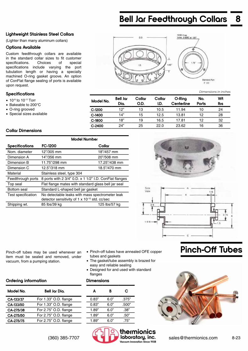
8Bell Jar Feedthrough Collars
8-23(360) 385-7707 [email protected]
(Lighter than many aluminum collars)
Custom feedthrough collars are available in the standard collar sizes to fit customer specifications. Choices of special specifications include varying the port tubulation length or having a specially machined O-ring gasket groove. An option of ConFlat flange sealing of ports is available upon request.
Pinch-off tubes may be used whenever an item must be sealed and removed, under vacuum, from a pumping station.
Lightweight Stainless Steel Collars
Options Available
Specifications
Collar Dimensions
Ordering information Dimensions
Dimensions in inches
• 10-9 to 10-11 Torr• Bakeable to 200°C• O-ring grooved• Special sizes available
Model No. Bell Jar Dia.
CollarO.D.
CollarI.D.
O-RingCenterline
No. Ports
Wtlbs
C-1200 12” 13 10.5 11.94 10 24C-1400 14” 15 12.5 13.81 12 28C-1800 18” 19 16.5 17.81 12 32C-2400 24” 25 22.0 23.62 16 36
Model NumberSpecifications FC-1200 CollarNom. diameter 12”/305 mm 18”/457 mmDimension A 14”/356 mm 20”/508 mmDimension B 11.75”/298 mm 17.25”/438 mmDimension C 12.5”/318 mm 18.5”/470 mmMaterial Stainless steel, type 304Feedthrough ports 8 ports with 2 3/4” 0.D. x 1 1/2” I.D. ConFlat flangesTop seal Flat flange mates with standard glass bell jar sealBottom seal Standard L-shaped bell jar gasketTest specification No detectable leaks with mass spectrometer leak
detector sensitivity of 1 x 10⁻¹⁰ std. cc/secShipping wt. 85 lbs/39 kg 125 lbs/57 kg
Pinch-Off Tubes• Pinch-off tubes have annealed OFE copper tubes and gaskets
• The gasket/tube assembly is brazed for easy and reliable sealing
• Designed for and used with standard flanges
Model No. Bell Jar Dia.
CA-133/37 For 1.33” O.D. flangeCA-133/50 For 1.33” O.D. flangeCA-275/38 For 2.75” O.D. flangeCA-275/50 For 2.75” O.D. flangeCA-275/75 For 2.75” O.D. flange
A B C
0.83” 6.0” .375”0.83” 6.0” .500”1.89” 6.0” .38”1.89” 6.0” .50”1.89” 6.0” .75”

8-24 (360) 385-7707 [email protected]
8 Roughing Accessories
Covering type 304 stainless steel thin wall bellows with a tough flexible metal braid of the same material provides great flexibility with maximum strength and durability. Use of flexible hose makes many system connections easier by eliminating some of the alignment problems involved with rigid tubing. Their high capacity for vibration damping makes them especially useful for connecting roughing pumps to UHV vacuum systems.
Hoses are bakeable to 450°C and can be used at temperatures as low as -196°C. They feature low outgassing, high conductance and are leak-tight to 10-11 Torr. A selection of standard lengths and flange combinations are listed here. Other sizes and flange configurations are available on special order. Can be supplied without braid upon request.
NOTE: Hoses are available with ISO flanges (refer to page 8-12) and in 2”, 3”, and 4” diameters.
Flexible Stainless Steel Hose
Flexible Stainless Hoses
Model No. Length* Description
SSH-180 18” 1.50” O.D. nipples both endsSSH-181 18” 2.75” O.D. flange one end onlySSH-182 18” 2.75” O.D. flange both endsSSH-182Q 18” 1.50” I. D. Viton sealed quick-disconnects both endsSSH-183 18” 2.75” O.D. flange and Welch 17.7 CFM adapterSSH-184 18” 2.75” O.D. flange and Welch 5 CFM adapterSSH-240 24” 1.50” O.D. nipples both endsSSH-241 24” 2.75” O.D. flange one end onlySSH-242 24” 2.75” O.D. flange both endsSSH-242Q 24” 1.50” I. D. Viton sealed quick-disconnects both endsSSH-243 24” 2.75” O.D. flange and Welch 17.7 CFM adapterSSH-244 24” 2.75” O.D. flange and Welch 5 CFM adapterSSH-360 36” 1.50” O.D. nipples both endsSSH-361 36” 2.75” O.D. flange one end onlySSH-362 36” 2.75” O.D. flange both endsSSH-362Q 36” 1.50” I. D. Viton sealed quick-disconnects both endsSSH-363 36” 2.75” O.D. flange and Welch 17.7 CFM adapterSSH-364 36” 2.75” O.D. flange and Welch 5 CFM adapterSSH-480 48” 1.50” O.D. nipples both endsSSH-481 48” 2.75” O.D. flange one end onlySSH-482 48” 2.75” O.D. flange both endsSSH-482Q 48” 1.50” I. D. Viton sealed quick-disconnects both endsSSH-483 48” 2.75” O.D. flange and Welch 17.7 CFM adapterSSH-484 48” 2.75” O.D. flange and Welch 5 CFM adapter
FL-275150-TC
FL-275150-V
Double-Sided Flanges
Model No. Description Wt. lbs
FL-1000 Double-sided 1.33” 0.0. flange 5/8” thick, no accessory holes 0.5FL-1000T Double-sided 1.33” 0.0. flange 5/8” thick, one 1/16”-NPT
tapped hole0.5
FL-275150 Double-sided 2 3/4 “ 0.0. flange 3/4” thick, no accessory holes 0.7FL-275150-1H Double-sided 2 3/4” 0.0. flange with one 1/8”-27NPT tapped hole 0.7FL-275150-2H Double-sided 2 3/4 “ 0.0. flange with two 1/8”-27NPT tapped
holes, 120° apart0.7
FL-275150-TC Double-sided 2 3/4” 0.0. flange with 7822M thermocouple gauge tube”
1.0
FL-275150-V Double-sided 2 3/4 “ 0.0. flange with Model BVV-025 bakeablevalve for up-to-air use
1.5
FL-275150-VTC Double-sided 2 3/4” 0.0. flange with TC tube and valve. 1.5FL-275000-V Blank 2 3/4 “ O.D. flange with BVV-025 bakeable up-to-air valve 1.5
Double-sided and blank flanges are supplied with thermocouple gauge tubes, up-to-air valves or combinations of the two for use as roughing accessories. Other configurations are readily available on special order.
Flanges

812-Point Head Bolt Sets
8-25(360) 385-7707 [email protected]
Thermionics Vacuum Products 12-point head bolts have increased surface area for greater contact with ordinary socket wrenches. Bolt head stripping due to higher torque is minimized. Made of high tensile strength, non-magnetic 300 series stainless steel. Bolt sets are supplied complete with flat washers and hex nuts. 25 sets per package.
High vacuum seals, leak-free motion feedthroughs, flexible joints, compensators, reservoirs, actuators, UHV valves, manipulators, etc.
Helium mass spectrometer leak-tight to 10-10 std. cc/sec.
Welded nested construction gives excellent flexibility and long stroke, compact envelope, and nested compressed length.
corrosion resistance, weldability and engineering properties appropriate for high vacuum applications.
Metallurgically stabilized stainless steel provides corrosion resistance and low or high temperature capability from cryogenic to 450°C and above. This means excellent
Are available in various sizes. Consult factory.
12-Point Head Bolt Sets For High Vacuum Flanges
Off-the-Shelf Stainless Steel Welded Metal Bellows
Applications
Leak Tightness
Long Stroke-Minimum Package LengthCorrosion Resistance-High Temperature
Dimensions in inches
Model No. Flange Size O.D..
Flange Type
Bolt Description
Pkg. Wt. lbs
DB-25-125N 2.75 Through 1/4-28x1.25 1.5DB-25-87N 2.75 Tapped 1/4-28x.87 1.0DB-25-200N 2.75 Thru/Dbi 1/4-28x2 2.0DB-31-175N 3.37 Through 5/16-24x1.75 1.5DB-31-125N 3.37 Tapped 5/16-24x1.25 1.5DB-31-200N 4.50 Through 5/16-24x2 2.0DB-31-125N 4.50 Tapped 5/16-24x1.25 1.5DB-31-225N 6 or 6.75 Thru/Dbi 5/16-24x2.25 2.0DB-31-200N 6 or 6.75 Thru/Non 5/16-24x2 2.0DB-31-125N 6 or 6.75 Tapped 5/16-24x1.25 1.5DB-31-225N 8 Through 5/16-24x2.25 2DB-31-175N 8 Tap 5/16-24x1.75 2DB-31-250N 10 Through 5/16-24x2.50 2.5DB-31-175N 10 Tapped 5/16-24x1.75 1.5
Stud and Nut Sets
Welded Bellows
• Normally 350 but also available in AM-347, 304L, 321 or 316L stainless steel.
Model No.A
Bellows O.D.
BBellows
I.D.
CFlange
O.D.
DFlange
Thickeness
E Free
Length
FCompressed
Length
GExtended
LengthStroke
WB-01 0.746 0.26 0.775 0.012 0.78 0.21 1.10 0.47WB-03 1.030 0.52 1.150 0.015 1.00 0.32 1.38 1.06WB-05 1.430 0.81 1.500 0.015 1.50 0.32 2.25 1.94WB-06 1.620 0.79 1.075 0.020 2.25 0.47 3.25 2.78WB-10 0.595 0.26 0.687 0.015 0.56 0.21 0.75 0.53WB-11 1.170 0.75 1.250 0.015 1.50 0.44 2.31 1.87WB-12 1.620 0.88 1.675 0.015 1.70 0.38 2.62 2.25WB-13 1.890 1.39 2.025 0.012 3.00 1.09 4.13 3.04
Other sizes available. Six different end flange styles are available. Please consult factory for further information.

8-26 (360) 385-7707 [email protected]
8 Formed BellowsType 321 stainless steel
Dimensions in inches
Model No. A B C D Deflection(+ or -)
MFB-6502 0.250 0.37 1.00 0.50 0.25MFB-6503 0.312 0.45 1.00 0.50 0.25MFB-6504 0.375 0.54 1.50 0.50 0.38MFB-6506 0.500 0.73 1.50 0.50 0.38MFB-6508 0.625 0.87 1.50 0.50 0.38MFB-6510 0.750 1.05 1.50 0.50 0.50MFB-6512 0.875 1.23 2.00 0.50 0.50MFB-6513 1.000 1.38 2.00 0.75 0.50MFB-6516 1.125 1.55 2.00 0.75 0.50MFB-6518 1.250 1.60 2.00 0.75 0.50MFB-6520 1.375 1.90 2.00 0.75 0.50MFB-6522 1.500 1.95 2.00 0.75 0.50MFB-6523 1.625 2.12 2.00 0.75 0.50MFB-6525 1.750 2.30 2.00 0.75 0.50MFB-6528 2.000 2.60 2.50 0.75 0.75MFB-6530 2.250 3.06 2.50 0.75 0.75MFB-6532 2.500 3.13 2.50 0.75 0.75MFB-6536 3.000 3.75 3.00 1.00 0.75MFB-6540 3.500 4.35 3.50 1.00 0.75MFB-6544 4.000 5.20 4.00 1.00 1.25MFB-6548 4.500 5.30 4.00 1.00 1.25MFB-6552 5.000 6.00 5.00 1.00 1.50MFB-6557 6.000 7.20 5.00 1.25 1.50MFB-6564 8.000 9.25 6.00 1.25 1.50MFB-6571 10.000 11.25 6.00 1.25 2.00MFB-6577 12.000 13.25 6.00 0.75 2.00
Model No. TubeO.D.
TubeI.D.
WallThickness
RecommendedFlange No.
Wt.Per Foot
SST-025 0.250 0.180 0.035 133025 0.125SST-037 0.375 0.305 0.035 133037 0.127SST-050 0.500 0.430 0.035 133050 0.173SST-075 0.750 0.680 0.035 133075 0.267SST-100 1.000 0.870 0.065 275100 0.649SST-125 1.250 1.120 0.065 275125 0.822SST-150 1.500 1.370 0.065 275150 0.966SST-200 2.000 1.870 0.065 388200 1.343SST-250 2.500 2.370 0.065 450250 1.690SST-300 3.000 2.870 0.065 458300 2.037SST-400 4.000 3.834 0.083 600400 3.472SST-500 5.000 4.834 0.083 675500 4.359SST-600 6.000 5.834 0.083 800600 5.245SST-800 8.000 7.834 0.083 100800 10.500SST-1000 10.000 9.760 0.120 13251000 12.500SST-1075 10.750 10.482 0.134 13251075 15.190
Vacuum TubingType 304 stainless steel

8Type 304 Stainless Steel Precision Ground Shafting
8-27(360) 385-7707 [email protected]
“All sizes within +.0000/-.0002
Model No. Dia.
PGS-125 0.1247”PGS-188 0.1872”PGS-250 0.2497”PGS-312 0.3122”PGS-375 0.3747”PGS-437 0.4372”PGS-500 0.4997”PGS-625 0.6247”PGS-750 0.7497”PGS-875 0.8747”PGS-1000 0.9997”
Model No. Description
PGS-125 1-oz tube lubricantPGS-188 4-oz tube lubricant
Description 3/4”Size
1”Size
1 1/2” Size
2”Size
2 1/2” Size
3” Size
4” Size
Hose connection both ends CT-075 CT-100 CT-150 CT-200 CT-250 CT-300 CT-400Flange one end Hose other end CT-076 CT-101 CT-151 CT-201 CT-251 CT-301 CT-401
Flange connection both ends CT-077 CT-102 CT-152 CT-202 CT-252 CT-302 CT-402Hose connection both ends with quick-disconnect head for easy bronze wool removal
CT-075/CD CT-100/CD CT-150/CD CT-200/CD CT-250/CD CT-300/CD CT-400/CD
Model No.
SS100
Type 304 Stainless Steel Precision Ground Shaft*
Tube, 304 Stainless Steel Precision Bored Shafts
Fel-Pro C-100 Lubricant
Super Seal: Epoxy Sealing
Optically-Dense Traps
For prices and sizes consult factory.
A high-temperature lubricant which contains a molydisulfide base to prevent seizing and galling in a temperature range of -200° F to +2,400° F. For use outside the vacuum with stainless steel, aluminum, titanium, brass and copper.
Permanent or temporary repair of leaks in ultra-high vacuum chambers, feedthroughs, tubing, valves, fittings, etc.
• Very low vapor pressure, outgassing rate lower than 1 x 10⁻⁸ Torr liters/sec/cm2
• +150°C to -60°C range. Cures overnight at room temp. or in two hours at 100°C
• A superior adhesive for metal, glass, ceramic or plastics
• Economical 7-gram packages
• Economical—Lowest price of any foreline trap.
• No maintenance—Eliminates bakeout, LN cooling and attention.
Foreline Traps
Operating Principles
Materials
Ordering Information
Trap Dimensions
The TLI optically-dense foreline trap is economical, and relies for its trapping effect on a large area of metallic adsorption characteristics.
A molecule can only pass through the optically-dense foreline trap by contacting the adsorbent material a great number of times, thereby greatly increasing the probability that it will be trapped.
The optically-dense traps are made of type 304 stainless, TIG welded. They are supplied in three different configurations — 1) hose connections only (unflanged), 2) hose connection one end, other end flanged, and 3) flanged at both ends. Flanges are coppergasketed compatible type, which mate with all other standard copper-gasketed flanges. Special flanges, such as ASA, can be supplied on request.
Type A B
075 3/4” 4”100 1” 4”150 1 1/2” 4”200 2” 4”250 2 1/2” 6”300 3” 6”400 4” 6”

8-28 (360) 385-7707 [email protected]
8 Foreline TrapsMolecular Sieve TrapsDescription SpecificationsTLI’s molecular sieve traps utilize synthetic zeolite with a high surface area per unit volume. Its design ensures effective trapping of hydrocarbons and water vapor, as well as preventing backsteaming of mechanical roughing pump oil. The molecular sieve trap operates at room temperature, thereby eliminating the necessity of any refrigerants. A built-in heater reprocesses the sieve material when necessary at a bakeout temperature of 375°C.
TLI molecular sieve traps are fabricated of type 304 stainless steel. An internal screen assembly serves to contain the sieve material, preventing it from entering other areas of the vacuum system. Baffles are arranged around the sieve container to insure the passage of all molecules into the sieve material area.
Inlet and outlet ports are available either 180° apart inline (or 90° apart right angles) with or without flanges.
Mech. PumpSize
RecommendedTrap Size
Gas Handling Load(50% Relative Humidity) Capacity 115V Heater
PowerTo 8 cfm 1” 60 cu. ft. 270 gms 75 W8-17 cfm 1 1/2” 125 cu. ft. 400 gms 125 W17-30 cfm 2” 125 cu. ft. 400 gms 125 WOver 30 cfm 3” 150 cu. ft. 500 gms 375 W
Dimensions in inches
Complete heater assembly and molecular sieve charge are provided with each trap.One molecular sieve charge is required for 1”,1 1/2” and 2” traps and three charges for the 3” traps.One heater assembly is required for 1”,1 1/2” and 2” traps and two heater assemblies for the 3” traps.
Model No. Size Description A B C D E F G H
MT-100 1 Hose connection both ends 4 1/2 1 2 1/8 1 11/16 5 1/4 6 3/8 4 1/2 9MT-101 1 Flange one end 4 1/2 1 2 1/8 1 11/16 5 1/4 6 3/8 4 1/2 9MT-102 1 Flanges both ends 4 1/2 1 2 1/8 1 11/16 5 1/4 6 3/8 4 1/2 9MT-150 1 1/2 Hose connection both ends 4 1/2 1 1/2 2 3/4 2 7 7/8 9 4 1/2 9MT-151 1 1/2 Flange one end 4 1/2 1 1/2 2 3/4 2 7 7/8 9 4 1/2 9MT-152 1 1/2 Flanges both ends 4 1/2 1 1/2 2 3/4 2 7 7/8 9 4 1/2 9MT-200 2 Hose connection both ends 4 1/2 2 3 3/8 2 7 7/8 9 4 1/2 9MT-201 2 Flange one end 4 1/2 2 3 3/8 2 7 7/8 9 4 1/2 9MT-202 2 Flanges both ends 4 1/2 2 3 3/8 2 7 7/8 9 4 1/2 9MT-300 3 Hose connection both ends 6 3 4 5/8 3 10 11 1/8 5 1/2 11MT-301 3 Flange one end 6 3 4 5/8 3 10 11 1/8 5 1/2 11MT-302 3 Flanges both ends 6 3 4 5/8 3 10 11 1/8 5 1/2 11MS-100 1 Replacement molecular sieve
chargeHS-100 1 Replacement heater assembly

Valves 9

Valves
9
Manual/Motorized ValvesTechnical Information.................Gate Valves................................Ordering Information...................Angle Valves...............................Ordering Information...................Inline Valves...............................Ordering Information...................Motor Operated Valves...............Ordering Information...................Bi-Pass Valves............................Ordering Information...................Inline Valves Model T.................Bakeable/All Metal Valves..........Butterfly Vales.............................
9-19-49-69-149-169-149-169-229-229-229-229-239-259-29

9Selecting A Valve
9-1(360) 385-7707 [email protected]
Full Conductance
Valve Choice Criteria
S = Q/P
Since 1958, Thermionics has manufactured over 65,000 qualified valves. Thermionics manufactures the broad est line of vacuum valves. They have been tested and judged the highest quality valves manufactured in the United States (details on page 9-5).
The figure of merit of a vacuum valve is its conductance, i.e., the amount of gas that passes from the plane of the inlet valve port to the plane of the outlet port of the valve in 1 sec per unit of pressure differential.
The inside diameter, the length of the tube, and any constrictions or obstructions can adversely affect conductance. Be cer tain that the gate or poppet of your valve opens fully and does not interfere with gas flow. The inside diameter of the port is al most meaningless as a specification unless full conductance is offered.
Valves that provide full conductance are qualified valves; those that do not might be referred to as unqualified or counterfeit valves. All Thermionics valves open fully and provide full conductance under all conditions.
We have included some computed conductances with some of our valve specifica tions. Because the short tube approximation to the conductance equation was used, ignoring the larger diameter in the valve body area, computed conductances are slightly understated.
where S = Pumping speed in the chamber (I/sec)
where 1/Sd = Pumping speed delivered to the chamber
Q = Chamber outgassing as calculated above (Torr I/sec)
P = Pressure in the chamber (Torr)
1/S = Pump speed C1 to Cn = Conductance of the
components 1 to n between the pump and the chamber
Cv = Valve conductange
1. When deciding to specify either manual or electro-pneumatic actuation for the valve, consider frequency of use, avail able utilities, and operator attention re quired when the valve is actuated.
2. Select a valve capable of withstanding the bakeout temperature required to reach the base pressure desired in the time required.
3. All Thermionics valves are designed and manufactured to reach and maintain very low vacuum pressures easily. To do this, valves are free of virtual leaks, they have the lowest particulate levels, greatly re-duced surface areas, less parts exposed to vacuum, have a smaller number of bearings exposed to vacuum, are smaller in size, weigh less, and are fully welded. Thermionics valves are welded intern-ally or with full penetration, eliminating the problems inherent with brazed assem blies, and further reducing the internal surface area and profile.
4. The outgassing rate of the materials from which the valve is manufactured must be considered. Materials affect the gas load, and thereby the pump size required. If a valve is to be used in a corrosive environ-ment, the appropriate material must be specified when the order is placed.
5. The smaller the seat or gate conduc tance leakage, the smaller the pump re quired. High leak rates make additional pump speed necessary to compensate for leakage through the seal. A valve is often sealed against atmosphere when equipment is shut down for the night or weekends; the leak rate must be small to prevent wasting pumping capacity.
6. Consider the number of cycles for which the valve is guaranteed and if the number is independently verifiable. Is the valve stem seal O-ring or bellows sealed? If bellows sealed. is a welded or formed bellows used? Viton-sealed gate and poppet valves are very forgiving, whereas metal-sealed bakeable valves must be manufactured with greater precision and they are more sensitive to contamination.
7. Determine whether the chamber pres sure requirements for your particular needs are met by your proposed system by comparing the gas load at designed base pressure with pumping speed as reduced by any conductance restrictions between pump and chamber. First, the outgassing load Q is simply the product of the outgassing rate(s) of the material or materials used in the system and the respective area or areas. Then, calculate the chamber pumping speed required to maintain the pressure necessary for your vacuum process,
A.If S appears excessively high, consider:1) Changing the chamber size or
configuration to decrease surface area.
2) Changing to a construction material with a lower outgassing rate.
3) Reducing the outgassing rate by baking the chamber or by special passivation, such as the TLI passiva tion process.
B.The delivered pumping speed, Sd (pump speed at the chamber port), is limited by component conductance between the pump and the port. Conductance, in turn, is a function of tube size, length and amount the poppet or gate opens. The higher the chamber speed needed, the larger the valve size needed, and the greater the need for full conductance. Usually the conductance of high vacuum valves should be greater than the rated pump speed.
C.Finalize the chamber design and deter mine how you will connect the valve and other component parts to the chamber system, keeping in mind how each com ponent will affect conductance and associated gas flow pattern.
D.After selecting your chamber, pump, valves, and plumbing, calculate the pumping speed delivered to the chamber as follows:
E. Compare the delivered chamber speed (Sd) to the required chamber speed S as calculated in step 7.
F. If the delivered speed is less than your required chamber speed, then consider:1) The alternatives in 7 A above;2) Shortening the distance between
pump and chamber;3) Increasing the pipe and valve size
between pump and chamber;4) Increasing the pump speed.
TLI valvesopen fully
Competitorsvalves may not
1/Sd = 1/S + 1/C1 + 1/C2 + 1/C3 + ... + 1/Cn + 1/Cv

9-2 (360) 385-7707 [email protected]
9 Selecting A ValveValve TerminologyActuator The external valve component which transfers motion to the valve stem in angle and in line valves or to the slide assembly in gate valves. Manual actuators are knobs, cranks, or levers. Pneumatic actua tors use compressed air controlled by a separate solenoid valve, while motor actua tors use an electric gear motor.
Buna Elastomer, nitrile rubber. A syn thetic rubber made by random polymeriza tion. Used for gaskets and O-rings. Maxi mum service temperature is 121°C/250°F.
Gasket The replaceable, deformable metal or elastomeric component which, when compressed, prevents the passage of gas from one side of the seal to the other. Gaskets are used in the bonnet seal, the clo sure seal and the flange seals (when flanges are used). Metal gaskets provide the best seal by virtue of their low permeability, low outgassing rate and higher bakeout temperature. Elastomeric gaskets, chiefly Viton, are used when vacuum requirements are less stringent. They are economical and within limitations are reuseable. Metal closure seals are reusable, but must be replaced more often than elastomeric closure seals.
Gate/Poppet The gasket carrier which moves the closure gasket into position with the valve seat and transfers the sealing force to the gasket. The gate/poppet in all TLI valves is fully retractable from the space between ports, ensuring full conductance.
Gate Valve (See “gate/poppet” above.) This type of valve has three advantages: It offers a full line of sight transmission from port to port; it has the best conductance available; and it can be made in large sizes at a reasonable price.
Indium A metal, element No. 49 in the Periodic Table. It is ductile and softer than lead with a very low vapor pressure. It is used for radiation resistant seals.
Inlet Port A tubular opening, usually flanged, through a chamber wall, permitting access or installation of a device into the chamber.
lnline Valve A valve with the outlet port parallel to, but not necessarily axial with, the inlet port.
Kalrez A carbon-black filled compound with good mechanical properties and ex cellent chemical resistance, manufactured by DuPont. A maximum intermittent operat ing temperature of 366°C is recommended. It is used as a gasket material in high tem perature applications.
KEL-F A polymer with high thermal stability, resistance to chemical corrosion, high dielectric strength, and high impact and tensile strengths. It is used for gaskets and seals.
Leak Detection The establishment by various detection methods that a leak is present and significant to system performance. Mass spectrometer helium leak detectors, offering sensitivity to about 5 x 10⁻¹⁰ Torr I/sec or better, are excellent for this purpose. NOTE: Teflon is permeable to helium, so care must be exercised to avoid saturating the Teflon tape used with thermocouple tubes. This permeation can sharply curtail the usefulness of a helium mass spectrometer.
Closure Seal Where prevention of gas passage between the outlet and inlet ports is achieved by means of a poppet or gate incorporating a gasket (the closure seal). Many types of gaskets are used, each with different capabilities. Fundamental to any closure is the application of force from the actuator through the bellows assembly to the seal assembly. At the end of the seal assembly is a gate or plug with a gasket which is deformed against the valve seat for seal ing purposes.
Conductance The figure of merit of a valve can be expressed as the maximum number of Torr I/sec of gas which can pass from the plane of the inlet port to the plane of the outlet port. To help you make compari sons, we have included some computed conductances with our valve specifications. Because the short tube approximation to the conductance equation was used which ig nores the larger diameter in the valve body area, computed conductances are slightly less than actual conductances.
Counterfeit Valves Vacuum valves that do not offer full conductance because of obstructions in the gas flow path such as gates or poppets that do no open fully. Unqualified valves are sometimes referred to as “coun terfeit” valves.
Desorption Release or outgassing of gases or vapors adsorbed by the interior walls of the vacuum envelope. Low desorp tion rates are made possible by selecting correct materials, cleaning processes, opti mum surface finish and proper engineering techniques.
Elastomers A general term for high polymers having the property of extensibility and elastic recovery, i.e., the ability to be stretched and to retract rapidly to approxi mately the original size. (See “polymer.”)
Electro-pneumatic A method of valve actuation utilizing a pneumatic cylinder and a solenoid valve to direct the air pressure to one end, or alternately to both ends of the pneumatic cylinder, thus opening or closing the gate or poppet.
Dielectric A substance with very low electrical conductivity, i.e., an insulator.
Bellows A flexible metal connector, usually made of stainless steel, to accommo date: the expansion of stem seal vacuum valve bellows; to seal feedthrough shafts; isolate vacuum envelopes; isolate vibration; or to protect sensitive components from mechanical stress. Bellows are made by roll forming, hydroforming, metal depositing, or welding of individual convolutions. The choice of bellows depends on applications: A) Welded bellows are made of two thin-contoured metal diaphragms welded on their inside diameter to form a section. The sections are then stacked and welded on their outside diameter to form a complete convolution. Welded bellows provide maxi mum flexibility and stroke with minimum size.B) Formed bellows are an alternative to welded bellows. They are good for applications requiring moderate flexibility and/or high-pressure resistance. They are made by corrugating walls of thin-walled tubing.(C) Deposited bellows are miniature, precise and thin-walled.
Bellows Assembly The valve mechanism which transfers motion from external drive components to vacuum side components through a metal bellows seal.
Bi-Pass A solenoid-controlled option fea ture which equalizes pressure on both sides of the valve seat before the valve is opened. The bi-pass mechanism protects delicate samples from damage caused by sudden pressure changes. It also permits gas to be bled into the system.
Bonnet The area where the actuator is joined with the case. This area provides access for valve maintenance. It consists of two flanges, a mechanism mounted on the top flange (such as a bellows assembly), and a gasket.
Adsorption Adherence of atoms or molecules of a gas or liquid to the surface of another substance.
Angle Valve Any valve with the inlet port at a right angle to the outlet port.

9Selecting A Valve
9-3(360) 385-7707 [email protected]
Macor A machineable glass-ceramic manufactured by Corning, which retains the usual hardness and strength of ordinary ceramics without needing to be fired after machining.
Polyimide A high molecular weight poly mer with high temperature stability (up to 375°C) and low outgassing at high tempera tures. It is used for gate, bonnet, poppet and other seals. It absorbs large amounts of water when exposed to air. Thus it should be avoided in systems which are frequently cycled using room air.
Tee Valve A valve with an extra port on the system side. It is useful for roughing manifolds.
Teflon A trademarked (DuPont) elastomer (tetrafluoroethylene) with good chemical resistance. It is used for seals, gaskets, O -rings, and recommended for temperatures up to 300°C. It is permeable to helium. It has no melting point, but turns into an amor phous jelly above 327°C. Above 400°C, it decomposes, releasing poisonous fluorine volatiles .
Venting of Valve Plate/Poppet Provision for venting of any gas which might be trapped in the seal groove by means of a pumpout opening.
Viton A trademarked fluoroelastomer used for bonnet, gate, poppet, and other seals. It can be used for 250°C continuous service, and is useful for ultra-high vacuum systems.
Poppet A gasket or O-ring carrier which moves the closure gasket or O-ring into position with the valve seat and transfers sealing force to the gasket or O-ring to effect a leak tight seal.
Qualified Valve A valve that provides full conductance (see page 9-2). All Thermion ics valves are qualified valves.
Seat The portion of the body which is polished and aligned to provide the docking/ receiving surface against or into which the gate or poppet seals.
Stem The axial shaft in angle and inline valves connecting actuator and bellows assembly. Many valve stems rise as the valve is opened, while other valves may have a non-rising feature.
Straight Through Valve This valve offers a line of sight valve opening (generally somewhat smaller than port I.D.) from inlet port to outlet port. It is a design particularly suited for metal closure seals.
Nitrile Rubber A synthetic rubber formed by random polymerization of acrylonitrile with butadiene used for gaskets and O-rings.
Outlet Port A tubular opening through a chamber wall, usually flanged, permitting access for pumping or the extraction of components from the chamber.
Over Center Locking A gate valve mechanical feature which ensures that the valve will remain closed in the event of loss of either air pressure or electrical power.
Pneumatic A pneumatic valve is supplied with the pneumatic actuator alone, without a solenoid valve. (See “electro-pneumatic.”)
Polymer A chemical compound or mixture consisting essentially of repeating structural units. Polymers with special elastic proper ties are called elastomers.
Permeability In high vacuum devices, the degree of vacuum that can be maintained depends, in part, upon the quantity of gas passing through (permeating) the wall or gasket from outside the chamber. Materials used for gaskets and chamber walls should be of low permeability.
Torr microns Pascal dyne/cm2 atm mbarTorr (mm Hg) 1 1,000 133 1,330 1.32 x 10⁻³ 1.32microns (milliTorr) 0.001 1 0.133 1.33 1.32 1.32 x 10⁻³
Pascal Newton/m2 7.5 x 10⁻³ 7.5 1 10 9.87 x 10⁻⁶ 9.87 x 10⁻³
dyne/cm2 7.5 x 10⁻⁴ 0.75 0.1 1 9.87 x 10⁻⁷ 9.87 x 10⁻⁴
atm std atmosphere
760 7.6 x 10⁵ 1.01 x 10⁵ 1.01 x 10⁶ 1 1,010
mbar 0.75 750 100 1,000 9.87 x 10⁻⁴ 1
Conversion Table for Various P ressure Units Used in High Vacuum Practice
Additional Conversions1 Bar (Bureau) = 750.0 mm Hg = 29.53” Hg

9-4 (360) 385-7707 [email protected]
9 Gate Valves—TLG Series
Metal & Valve Bonnets
Specifications
Design
Materials of Construction
Our rectangular metal flanges are an ideal metal seal for valve bonnets. This remarkable UHV flange makes any other rectangular metal valve bonnet seal obsolete. Its reliability and ease of assembly have been repeatedly proven, and its range of shapes and sizes will satisfy any non-circular UHV flange requirements. Refer to Section 7 for further flange information.
Other types of metal-sealed valve bonnets may use unconstrained wire or flat gaskets or may imitate our retangular seals. However, un constrained gaskets are much less reliable than the knife edge/captured copper gasket sealing principle. Wire gaskets are also difficult to install, and almost impossible when sealing surfaces are vertical. Not so with our flanges. Assembly requires only minutes, not hours, regardless of the angle of installation. This is important when valve bodies must be left inline when systems are being serviced.
Recently, a National Laboratory conduct ed independent testing on valves. Thermion ics’ gate valve with our rectangular flange bonnet seal won the competition. Like the ConFlat, its Varian ancestor, our flanges will soon become a new standard in the industry.
All gate, roughing, and bakeable valves have the following standard specifications. Customers may request other materials on special order.
“Roughing valves” refers to all inline and angle valves, although they are de signed and built for UHV applications they can be used in roughing applications.
No trapped volumes or virtual leaks.
VALVE BODYFabricated from type 304 stainless steel with all internal or back filled full penetra tion welds using GTAW (known also as TIG) gas welding process.
INTERNAL MECHANISMSFabricated from type 304 stainless steel, fully welded GTAW process.
BELLOWS SHAFT SEALSFabricated from special application 300 series stainless steels. Roughing and bakeable valves use fully nested welded bellows assemblies, gate valves may use nested welded or hydrofornied bellows with UHV furnace brazed transition pieces. All bellows have additional con volutions for longer operating life.
BODY SEALViton O-ring or OFE copper captured gasket, depending on model.
GATE/POPPET SEALViton O-ring for gate and roughing valves, bakeable valves use OFE copper gaskets.
BEARINGSNeedle and ball bearings, dry film lubricated.
CLEANINGValves are chemically cleaned for vacuum service.
PNEUMATIC ACTUATORSVirgin aluminum cast or drawn.
Bakeability
Orientation·
Leak Free
Heater Jackets
Bakeout temperatures are limited by seal material selection. Please consult the factory for specific temperature requirements. Following are temperature limits recommended by seal manufacturers
No detectable leak when tested in the vacuum adverse condition using a helium MSLD with a sensitivity of 2 x 10⁻¹⁰ std cc/sec.
May be mounted in any position.
Heater jackets are available for CVO and metal etch applications. Consult the factory for information.
Buna:Viton:
Kalrez:
All metal:Solenoids:
121°C/250°F maximum 250°C/482°F valve open/unloaded204°C/400°F valve closed/loaded366°C/680°F valve open/unloaded 316°C/600°F valve closed/loaded 450°C/842°F valve open or closed 65°C/149°F maximum

9Gate Valves—TLG Series
9-5(360) 385-7707 [email protected]
Since 1958, TLI has manufactured qualified gate valves.
Theory of Operation —TLG Series
Now the Improved TLG Series
• All stainless steel construction• Tested against the best gate valves in the
world by a national laboratory• Judged the only U.S. manufactured valve
qualified to meet exacting requirements
TLG Series valves are toggle action, linear travel gate valves. The gate carriage moves in the valve body on a set of wheels, moved back and forth by a manual or pneumatically-actuated valve stem which passes through a metal bellows.
To close the valve, the carriage moves forward on wheels until it reaches the end of the valve case. When the carriage stops, the toggle linkage continues to travel and extend. The gate does not move forward, only upward toward the port seal surface. There is no abrasion or damage to the O ring. The gate moves up to the port into its sealing position. The O-ring is compressed, making a leak-tight seal. The toggle linkage continues to move forward until the toggle knee passes center and locks, providing positive closure protection in the event control power, or air pressure, is lost.
The specifications above established minimum requirements for high vacuum gate valves for a major national research laboratory. Valves from all foreign and domestic manufacturers were tested for conformance.
Thermionics’ gate valves were the only domestic valves tested which satisfied these stringent specifications. Thermionics was the only domestic valve manufacturer qualified and certified as an acceptable source for valves. A copy of the report is available upon request.
They offer these additional design features: • New design and manufacturing process• Smaller number of bearings exposed to
vacuum• New longer life bearing interface materials• Longer cycle life• Lowest particulate levels• Lower base pressure• No virtual leaks• Greatly reduced surface areas• Less parts exposed to vacuum• Smaller internal mechanism• Weighs less• Seals and opens against atmosphere• Seals are easily replaced, lower
maintenance costs
Valve Specifications for National Laboratory Testing 1. Stainless steel fabrication consistent with
good vacuum practice.2. All metal sealed with the exception of dry
Viton gate seal.3. Helium leak rates at 1 aim differential:
4. Must seal with differential in either direction.5. Hydrocarbon-free interior.6. All-metal ConFlat-type port flanges.7. Electro-pneumatic operation with 110 VAC
solenoid, uses less than 25 W of electrical power at 80 psi air pressure.
8. Closed valves must remain sealed if air pressure is lost.
9. Valve closes with loss of electrical power. 10.Positive valve position indication available via electrical contacts.11.Closing and opening time of less than 3.5 sec.12.Capable of operating 10,000 cycles without maintenance.13.Valve actuation mechanism removeable with valve body in beamline.14.Metal bonnet seal must be positively held in position during assembly. 15.Valve cannot emit peak sound levels greater than 85 dB at 2 ft during opera tion at 80 psi.
16.Valve cannot generate peak vibration levels greater than 15,000 in/sec2 below 2,000 Hz during operation at 80 psi.17.Valve weight cannot exceed 45 lbs in the 6” I.D. size.
Across valveTo outsideenvironment
< 1 x 10⁻⁹ std cc/sec
< 1 x 10⁻¹⁰ std cc/sec
Test Procedures The valves were installed into a section of 6” beamline. The valves were cycled 10,000 times, stopping each 1,000 cycles for leak checking in both directions at 1 aim differen-tial. Difficulties in mounting, operation, etc. were looked for. After the cycle test, each unit was dismantled for inspection.
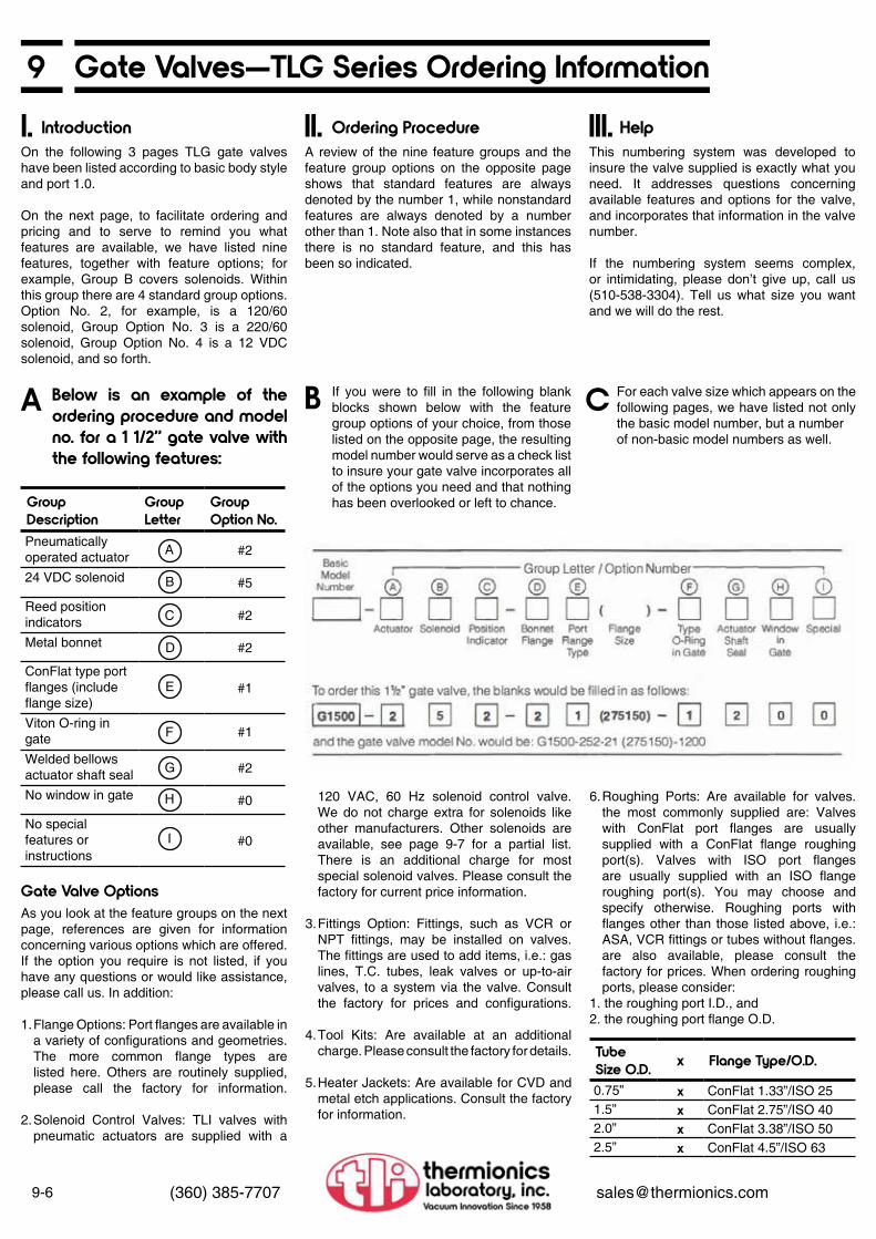
9-6 (360) 385-7707 [email protected]
9 Gate Valves—TLG Series Ordering InformationIntroduction Ordering Procedure HelpI. II. III.
On the following 3 pages TLG gate valves have been listed according to basic body style and port 1.0.
On the next page, to facilitate ordering and pricing and to serve to remind you what features are available, we have listed nine features, together with feature options; for example, Group B covers solenoids. Within this group there are 4 standard group options. Option No. 2, for example, is a 120/60 solenoid, Group Option No. 3 is a 220/60 solenoid, Group Option No. 4 is a 12 VDC solenoid, and so forth.
A review of the nine feature groups and the feature group options on the oppo site page shows that standard features are always denoted by the number 1, while non standard features are always denoted by a number other than 1. Note also that in some instances there is no standard feature, and this has been so indicated.
If you were to fill in the following blank blocks shown below with the feature group options of your choice, from those listed on the opposite page, the resulting model number would serve as a check list to insure your gate valve incorporates all of the options you need and that nothing has been overlooked or left to chance.
For each valve size which appears on the following pages, we have listed not only the basic model number, but a number of non-basic model numbers as well.
This numbering system was devel oped to insure the valve supplied is exactly what you need. It addresses questions con cerning available features and options for the valve, and incorporates that information in the valve number.
If the numbering system seems com plex, or intimidating, please don’t give up, call us (510-538-3304). Tell us what size you want and we will do the rest.
Below is an example of the ordering procedure and model no. for a 1 1/2” gate valve with the following features:
A B C
Group Description
Group Letter
Group Option No.
Pneumatically operated actuator #2
24 VDC solenoid #5
Reed position indicators #2
Metal bonnet #2
ConFlat type port flanges (include flange size)
#1
Viton O-ring in gate #1
Welded bellows actuator shaft seal #2
No window in gate #0
No special features or instructions
#0
A
B
C
D
E
F
G
H
I
Gate Valve OptionsAs you look at the feature groups on the next page, references are given for informa tion concerning various options which are offered. If the option you require is not listed, if you have any questions or would like assistance, please call us. In addition:
1. Flange Options: Port flanges are available in a variety of configurations and geometries. The more common flange types are listed here. Others are routinely supplied, please call the factory for information.
2. Solenoid Control Valves: TLI valves with pneumatic actuators are supplied with a
120 VAC, 60 Hz solenoid control valve. We do not charge extra for sole noids like other manufacturers. Other solenoids are available, see page 9-7 for a partial list. There is an additional charge for most special solenoid valves. Please consult the factory for current price information.
3. Fittings Option: Fittings, such as VCR or NPT fittings, may be installed on valves. The fittings are used to add items, i.e.: gas lines, T.C. tubes, leak valves or up-to-air valves, to a system via the valve. Consult the factory for prices and configurations.
4. Tool Kits: Are available at an addi tional charge. Please consult the factory for details.
5. Heater Jackets: Are available for CVD and metal etch applications. Consult the factory for information.
6. Roughing Ports: Are available for valves. the most commonly supplied are: Valves with ConFlat port flanges are usually supplied with a ConFlat flange roughing port(s). Valves with ISO port flanges are usually supplied with an ISO flange roughing port(s). You may choose and specify otherwise. Roughing ports with flanges other than those listed above, i.e.: ASA, VCR fittings or tubes without flanges. are also available, please consult the factory for prices. When ordering roughing ports, please consider:
1. the roughing port I.D., and2. the roughing port flange O.D.
Tube Size O.D. x Flange Type/O.D.
0.75” x ConFlat 1.33”/ISO 25 1.5” x ConFlat 2.75”/ISO 40 2.0” x ConFlat 3.38”/ISO 50 2.5” x ConFlat 4.5”/ISO 63

9Feature Groups & Feature Options
9-7(360) 385-7707 [email protected]
*Denotes the standard feature in each group.
Group Letter
Group Option No. Group Description
Actuator (see pages 9-2 and 9-8 for details)01*239
NoneStandard Manual PneumaticMotorizedSpecial/Describe
Solenoid01*23459
None Does not apply 120 VAC/60 Hz 220VAC/60Hz 12VDC 24VDC Special/Describe
Position Indicators (see page 9-11 for details)01*2349
None Does not apply Reed Microswitch Type A Microswitch Type B Special/Describe
Bonnet Flanges (see pages 9-2 and 9-4 for details)01*239
None Standard—Viton seal Metal Flange—flat copper gasket seal Wire seal Special/Describe
Port Flanges (see page 9-8 for details)01*2349
None Standard—ConFlat type Metal Flange—flat copper gasket seal ASA ISO Special/Describe
Type O-Ring in Gate01*2349
None Standard—Viton KalrezBunaPolyimide Special/Describe
Actuator Shaft Seal01*239
None Standard-formed bellows Welded bellowsO-ring sealSpecial/Describe
Window in Gate (see page 9-10 for details)01*2349
NoneDoes not apply Pyrex Quartz Sapphire Special/Describe
Special01*23456789
None 133-075 ConFlat roughing port275-150 ConFlat roughing port338-200 ConFlat roughing port450-250 ConFlat roughing port ISO 25-0.75 ISO roughing port ISO 40-1.5 ISO roughing port ISO 50-2.0 ISO roughing port ISO 63-2.5 ISO roughing port Special/Describe
A
B
C
D
E
F
G
H
I

9-8 (360) 385-7707 [email protected]
9 Gate Valves—TLG Series Ordering InformationPlease note: PORT FLANGES: Gate valves listed here, except for the G5000, are shown with Con-Flat port flanges. ISO port flanges are avail-able at no additional cost. The ISO flange face-to-face dimension may be different than the ConFlat dimension shown. Please consult factory for details. Please consult the factory for prices and dimensions for other port flange options listed on page 9-7.
Basic Model No. Standard Options Port
Size
Bonnet Viton/Metal
Manually Operated
Pneumatic Operated
Gasket Set Part No.
G0058- 100-11(133058)-1200 5/8” Viton x GH-G62G0058- 100-21(133058)-1200 5/8” Metal x GH-G62PG0058- 220-11(133058)-1200 5/8” Viton x GP-G62G0058- 220-21(133058)-1200 5/8” Metal x GP-G62PG1500- 100-11(275150)-1100 1 1/2” Viton x GH-G15G1500- 100-21(275150)-1100 1 1/2” Metal x GH-G15PG1500- 220-11(275150)-1100 1 1/2” Viton x GP-G15G1500- 220-21(275150)-1100 1 1/2” Metal x GP-G15PG2000- 100-11(338200)-1100 2” Viton x GH-G2G2000- 100-21(338200)-1100 2” Metal x GH-G2PG2000- 220-11(338200)-1100 2” Viton x GP-G2G2000- 220-21(338200)-1100 2” Metal x GP-G2PG2500- 100-11(450250)-1100 2.5” Viton x GH-G25G2500- 100-21(450250)-1100 2.5” Metal x GH-G25PG2500- 220-11(450250)-1100 2.5” Viton x GP-G25G2500- 220-21 (450250)-1100 2.5” Metal x GP-G25PG3000- 100-11(462300)-1100 3” Viton x GH-G3G3000- 100-21(462300)-1100 3” Metal x GH-G3PG3000- 220-11(462300)-1100 3” Viton x GP-G3G3000- 220-21(462300)-1100 3” Metal x GP-G3PTLG4000- 100-11(600400)-1100 4” Viton x GH-G4TLG4000- 100-21(600400)-1100 4” Metal x GH-G4PTLG4000- 220-11(600400)-1100 4” Viton x GP-G4TLG4000- 220-21(600400)-1100 4” Metal x GP-G4PG5000- 100-13(900525)-1100 5” Viton x GH-G5G5000- 100-23(900525)-1100 5” Metal x GH-G5PG5000- 220-13(900525)-1100 5” Viton x GP-G5G5000- 220-23(900525)-1100 5” Metal x GP-G5PTLG6000- 100-11(800600)-1200 6” Viton x GH-G6TLG6000- 100-21(800600)-1200 6” Metal x GH-G6PTLG6000- 220-11(800600)-1200 6” Viton x GP-G6TLG6000- 220-21(800600)-1200 6” Metal x GP-G6PTLG8000- 100-11(10 x 8)-1200 8” Viton x GH-G8TLG8000- 100-21(10 x 8)-1200 8” Metal x GH-G8PTLG8000- 220-11(10 x 8)-1200 8” Viton x GP-GSTLG8000- 220-21(10 x 8)-1200 8” Metal x GP-G8PTLG10000- 100-11(1325*x10)-1200 10” Viton x GH-G10TLG10000- 100-21(1325*x10)-1200 10” Metal x GH-G10PTLG10000- 220-11(1325*x10)-1200 10” Viton x GP-G10TLG10000- 220-21(1325*x10)-1200 10” Metal x GP-G10PG12000- 100-11(14 X 12)-1200 12” Viton x GH-G12G12000- 100-21(14 X 12)-1200 12” Metal x GH-G12PG12000- 220-11(14 X 12)-1200 12” Viton x GP-G12G12000- 220-21(14 X 12)-1200 12” Metal x GP-G12P
* Also available with 12” O.D. flangeLarger sizes on request
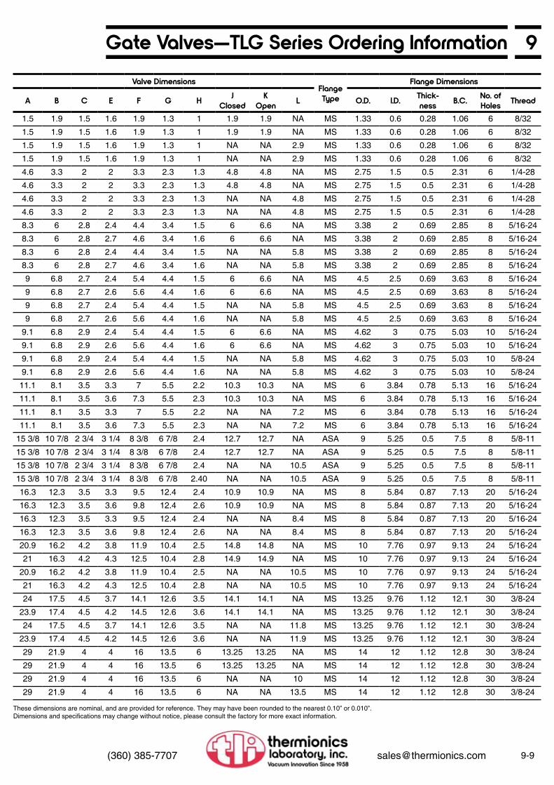
9Gate Valves—TLG Series Ordering Information
9-9(360) 385-7707 [email protected]
Valve DimensionsFlange Type
Flange Dimensions
A B C E F G H J Closed
KOpen L O.D. I.D. Thick-
ness B.C. No. of Holes Thread
1.5 1.9 1.5 1.6 1.9 1.3 1 1.9 1.9 NA MS 1.33 0.6 0.28 1.06 6 8/32
1.5 1.9 1.5 1.6 1.9 1.3 1 1.9 1.9 NA MS 1.33 0.6 0.28 1.06 6 8/32
1.5 1.9 1.5 1.6 1.9 1.3 1 NA NA 2.9 MS 1.33 0.6 0.28 1.06 6 8/32
1.5 1.9 1.5 1.6 1.9 1.3 1 NA NA 2.9 MS 1.33 0.6 0.28 1.06 6 8/32
4.6 3.3 2 2 3.3 2.3 1.3 4.8 4.8 NA MS 2.75 1.5 0.5 2.31 6 1/4-28
4.6 3.3 2 2 3.3 2.3 1.3 4.8 4.8 NA MS 2.75 1.5 0.5 2.31 6 1/4-28
4.6 3.3 2 2 3.3 2.3 1.3 NA NA 4.8 MS 2.75 1.5 0.5 2.31 6 1/4-28
4.6 3.3 2 2 3.3 2.3 1.3 NA NA 4.8 MS 2.75 1.5 0.5 2.31 6 1/4-28
8.3 6 2.8 2.4 4.4 3.4 1.5 6 6.6 NA MS 3.38 2 0.69 2.85 8 5/16-24
8.3 6 2.8 2.7 4.6 3.4 1.6 6 6.6 NA MS 3.38 2 0.69 2.85 8 5/16-24
8.3 6 2.8 2.4 4.4 3.4 1.5 NA NA 5.8 MS 3.38 2 0.69 2.85 8 5/16-24
8.3 6 2.8 2.7 4.6 3.4 1.6 NA NA 5.8 MS 3.38 2 0.69 2.85 8 5/16-24
9 6.8 2.7 2.4 5.4 4.4 1.5 6 6.6 NA MS 4.5 2.5 0.69 3.63 8 5/16-24
9 6.8 2.7 2.6 5.6 4.4 1.6 6 6.6 NA MS 4.5 2.5 0.69 3.63 8 5/16-24
9 6.8 2.7 2.4 5.4 4.4 1.5 NA NA 5.8 MS 4.5 2.5 0.69 3.63 8 5/16-24
9 6.8 2.7 2.6 5.6 4.4 1.6 NA NA 5.8 MS 4.5 2.5 0.69 3.63 8 5/16-24
9.1 6.8 2.9 2.4 5.4 4.4 1.5 6 6.6 NA MS 4.62 3 0.75 5.03 10 5/16-24
9.1 6.8 2.9 2.6 5.6 4.4 1.6 6 6.6 NA MS 4.62 3 0.75 5.03 10 5/16-24
9.1 6.8 2.9 2.4 5.4 4.4 1.5 NA NA 5.8 MS 4.62 3 0.75 5.03 10 5/8-24
9.1 6.8 2.9 2.6 5.6 4.4 1.6 NA NA 5.8 MS 4.62 3 0.75 5.03 10 5/8-24
11.1 8.1 3.5 3.3 7 5.5 2.2 10.3 10.3 NA MS 6 3.84 0.78 5.13 16 5/16-24
11.1 8.1 3.5 3.6 7.3 5.5 2.3 10.3 10.3 NA MS 6 3.84 0.78 5.13 16 5/16-24
11.1 8.1 3.5 3.3 7 5.5 2.2 NA NA 7.2 MS 6 3.84 0.78 5.13 16 5/16-24
11.1 8.1 3.5 3.6 7.3 5.5 2.3 NA NA 7.2 MS 6 3.84 0.78 5.13 16 5/16-24
15 3/8 10 7/8 2 3/4 3 1/4 8 3/8 6 7/8 2.4 12.7 12.7 NA ASA 9 5.25 0.5 7.5 8 5/8-11
15 3/8 10 7/8 2 3/4 3 1/4 8 3/8 6 7/8 2.4 12.7 12.7 NA ASA 9 5.25 0.5 7.5 8 5/8-11
15 3/8 10 7/8 2 3/4 3 1/4 8 3/8 6 7/8 2.4 NA NA 10.5 ASA 9 5.25 0.5 7.5 8 5/8-11
15 3/8 10 7/8 2 3/4 3 1/4 8 3/8 6 7/8 2.40 NA NA 10.5 ASA 9 5.25 0.5 7.5 8 5/8-11
16.3 12.3 3.5 3.3 9.5 12.4 2.4 10.9 10.9 NA MS 8 5.84 0.87 7.13 20 5/16-24
16.3 12.3 3.5 3.6 9.8 12.4 2.6 10.9 10.9 NA MS 8 5.84 0.87 7.13 20 5/16-24
16.3 12.3 3.5 3.3 9.5 12.4 2.4 NA NA 8.4 MS 8 5.84 0.87 7.13 20 5/16-24
16.3 12.3 3.5 3.6 9.8 12.4 2.6 NA NA 8.4 MS 8 5.84 0.87 7.13 20 5/16-24
20.9 16.2 4.2 3.8 11.9 10.4 2.5 14.8 14.8 NA MS 10 7.76 0.97 9.13 24 5/16-24
21 16.3 4.2 4.3 12.5 10.4 2.8 14.9 14.9 NA MS 10 7.76 0.97 9.13 24 5/16-24
20.9 16.2 4.2 3.8 11.9 10.4 2.5 NA NA 10.5 MS 10 7.76 0.97 9.13 24 5/16-24
21 16.3 4.2 4.3 12.5 10.4 2.8 NA NA 10.5 MS 10 7.76 0.97 9.13 24 5/16-24
24 17.5 4.5 3.7 14.1 12.6 3.5 14.1 14.1 NA MS 13.25 9.76 1.12 12.1 30 3/8-24
23.9 17.4 4.5 4.2 14.5 12.6 3.6 14.1 14.1 NA MS 13.25 9.76 1.12 12.1 30 3/8-24
24 17.5 4.5 3.7 14.1 12.6 3.5 NA NA 11.8 MS 13.25 9.76 1.12 12.1 30 3/8-24
23.9 17.4 4.5 4.2 14.5 12.6 3.6 NA NA 11.9 MS 13.25 9.76 1.12 12.1 30 3/8-24
29 21.9 4 4 16 13.5 6 13.25 13.25 NA MS 14 12 1.12 12.8 30 3/8-24
29 21.9 4 4 16 13.5 6 13.25 13.25 NA MS 14 12 1.12 12.8 30 3/8-24
29 21.9 4 4 16 13.5 6 NA NA 10 MS 14 12 1.12 12.8 30 3/8-24
29 21.9 4 4 16 13.5 6 NA NA 13.5 MS 14 12 1.12 12.8 30 3/8-24
These dimensions are nominal, and are provided for reference. They may have been rounded to the nearest 0.10” or 0.010”.Dimensions and specifications may change without notice, please consult the factory for more exact information.
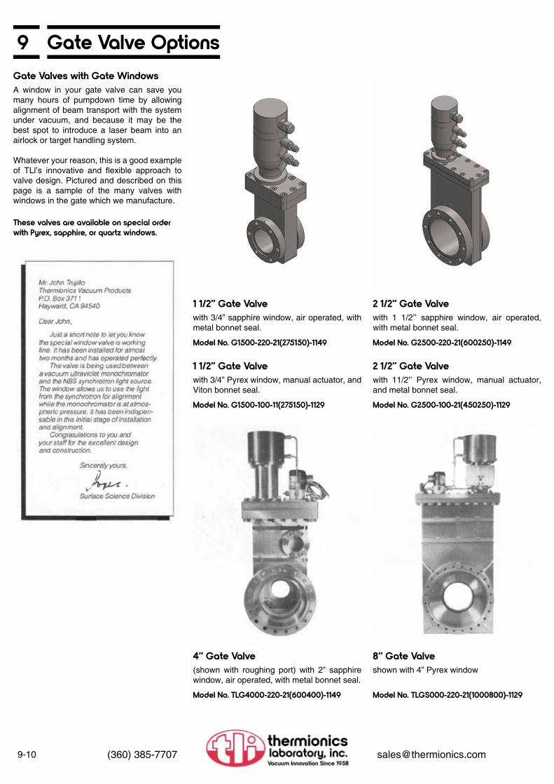
9-10 (360) 385-7707 [email protected]
9 Gate Valve OptionsGate Valves with Gate Windows
2 1/2” Gate Valve
2 1/2” Gate Valve
1 1/2” Gate Valve
1 1/2” Gate Valve
4” Gate Valve 8” Gate Valve
Model No. G1500-220-21(275150)-1149
Model No. G1500-100-11(275150)-1129
Model No. TLG4000-220-21(600400)-1149 Model No. TLGS000-220-21(1000800)-1129
Model No. G2500-220-21(600250)-1149
Model No. G2500-100-21(450250)-1129
These valves are available on special order with Pyrex, sapphire, or quartz windows.
A window in your gate valve can save you many hours of pumpdown time by al lowing alignment of beam transport with the system under vacuum, and because it may be the best spot to introduce a laser beam into an airlock or target handling system.
Whatever your reason, this is a good example of TLl’s innovative and flexible approach to valve design. Pictured and described on this page is a sample of the many valves with windows in the gate which we manufacture.
with 3/4” sapphire window, air operated, with metal bonnet seal.
with 3/4” Pyrex window, manual actuator, and Viton bonnet seal.
(shown with roughing port) with 2” sapphire window, air operated, with metal bonnet seal.
shown with 4” Pyrex window
with 1 1/2’’ sapphire window, air operated, with metal bonnet seal.
with 11/2’’ Pyrex window, manual actuator, and metal bonnet seal.

9Gate Valve Options
9-11(360) 385-7707 [email protected]
Position Indicators
External Mlcroswitch Position Indicator(Option A)
See page 3-7 for ordering information (under Group “C”)
• For stainless steel high vacuum gate valves
A selection of three position indicators are offered by TLI to fill a range of mechanical, electronic and economic requirements. Signals from the switches can be employed to activate a variety of external devices such as indicator lights, alarms or other instruments. A valve can be wired so that its acci dental opening would affect the shutdown of an entire system for its protection. These position indicators are very useful in auto .matic process control applications. Signals from the opening or closing of a valve can be employed to trigger complex procedures in computer controlled high vacuum systems.
External Microswitch Position Indicator
Bellows-Sealed Position Indicator
Proximity Reed Switch Position IndicatorA B C
This option employs two microswitches, A1 and A2, which are positioned in-line with a vertical stem extension of the pneumatic actuator piston. These positions correspond to the closed and open positions of the valve gate. A switch actuator collar on the moving stem mechanically triggers the appropriate switch when the valve is opened or closed.
The two microswitches, B1 and B2, are connected to bellows sealed rods which extend into the vacuum where they can be in actual contact with the valve gate. B1 is activated by contact with the extension rod when the gate is in the open position, and B2 is triggered in the closed position. The bellows sealed position indicator is the pre ferred choice in applications where it is essential to know at all times the status of the valve gate with the greatest possible certainty.
This option employs two reed switches: C1 and C2. They are placed on the side of the valve standpipe in the two positions corresponding to a fully open and fully closed valve. A magnet is attached to the top of the movable bellows inside the valves standpipe. When the gate is closed, the magnet is lowered to a position adjacent to the lower reed switch and its proximity causes the switch to close, providing one signal. When the valve is opened, the magnet is raised to a position adjacent to the upper switch and a second signal is generated. Proximity reed switch position indicators are also available for use on our stainless steel angle and in line vacuum valves, 1 1/2’’ and larger.

9-12 (360) 385-7707 [email protected]
9 Throttle Devices for High Vacuum Gate Valves
Throttle Device Options
Motorized, Set Mlcroswltch
Throttle devices are used in applications which require that the flow of gas-to or from the vacuum chamber-be impeded. The gate valve is partially reopened after pump down and purge. This allows the gas to escape from the chamber at a controlled rate to maintain atmospheric equilibrium within the chamber. These seven options, employed individually or in combination, fulfill most requirements. Others are available on special order.
Throttle devices control the pneumatic actuators of vacuum gate valves to limit the
extent of the valve opening and/or the timing of the valve opening. The piston within the pneumatic actuator is mechanically linked to the gate valve. Controlling the movement of the piston controls the position of the gate. Air is admitted to the inlet of the actuator in the usual manner, causing the piston to move. In options A through D, this motion is limited by a vertical shaft extending down from the top of the actuator housing. In E, F, and G, the motion is controlled by a vent valve which inhibits the expulsion of the compressed air above the piston.
Manual Set, ContinuousMotorized, Continuous with Revolution Counter
Time Delayed or Slow Opening
Momentary Open or Close
Continuous Position Indicator and Control
Manual Set, Fixed 3-Position
Motorized, Set Microswitches
A D
E
F
G
B
C
An impeding shaft, not illustrated but in the same position as the Acme screw shown, is manually screwed down to stop the piston at any point along its vertical traverse. This corresponds to the same position of the valve gate between fully opened and fully closed.
Same motor assembly and Acme screw impeder as in Option C but without microswitches. Operator manually controls the motor. Position of the impeder screw is indicated on a panel-mounted revolution counter. The counter penta nut trips the revolution counter five times per revolution. Percentage of gate opening being allowed is proportional to the total number of counts.
A vent valve (not illustrated) controls the movement of the piston by restricting the expulsion of the compressed air above the piston. The relay controlling this vent may be either fixed time-delayed opening or slow opening, depending on your requirement.
The delay or slow opening relay control of the vent valve in Option Eis replaced with an instantaneous contact switch which is man-ually controlled by the operator. Markers on a piston shaft extension allow him to visually observe the status of the valve. He can open or close it as much as the situation requires.
Same as Option F but with a proportional voltage signal for remote valve position indication. For configurations where the piston markers are not visible to the operator. A po tentiometer is attached to the shaft with a rack and pinion arrangement. A signal is generated which is proportional to the de gree of valve opening over a 100% range. The indicating meter is an additional option.
A sliding knife latch, not illustrated, attached to the top of the standpipe assembly can be manually set to engage in any one of three fixed, discrete grooves on a vertical impeding shaft. Normally, these positions correspond to 1/4, 1/2, and 3/4 open positions of the valve.
The assembly is enclosed in a cylinder con-nected to the top of the pneumatic actuator as illustrated. An electric motor rises and falls vertically as it turns an Acme screw. This screw protrudes down to inhibit the pneumatic actuator piston. The motor is mounted on a round mounting plate which is prevented from rotating by two guide shafts. A collar on the Acme screw actuates one microswitch in a pre-set, partially opened position and the other switch in the fully opened position. The collar and micro switches are not illustrated.
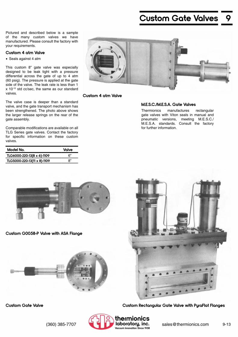
9Custom Gate Valves
9-13(360) 385-7707 [email protected]
Pictured and described below is a sample of the many custom valves we have manufactured. Please consult the factory with your requirements.
Custom 4 atm Valve
M.E.S.C./M.E.S.A. Gate Valves
Custom 4 atm Valve
Custom G0058-P Valve with ASA Flange
Custom Gate Valve Custom Rectangular Gate Valve with PyraFlat Flanges
• Seals against 4 atm
This custom 8” gate valve was especially designed to be leak tight with a pressure differential across the gate of up to 4 atm (60 psig). The pressure is applied at the gate side of the valve. The leak rate is less than 1 x 10⁻¹⁰ std cc/sec, the same as our standard valves.
The valve case is deeper than a standard valve, and the gate transport mechanism has been strengthened. The photo above shows the larger release springs on the rear of the gate assembly.
Comparable modifications are available on all TLG Series gate valves. Contact the factory for specific information on these custom valves.
Thermionics manufactures rectangular gate valves with Viton seals in manual and pneumatic versions, meeting M.E.S.C./ M.E.S.A. standards. Consult the factory for further information.
Model No. ValveTLG6000-220-13(8 x 6)-1109 6”TLGS000-220-13(11 x 8)-1109 8”

9-14 (360) 385-7707 [email protected]
9 Qualified Angle ValvesFeatures• Bellows stem seal• Opens and seals against atmosphere• Less than 2 x 10⁻¹⁰ std cc/sec leak rate• Mount in any position• GTAW welded construction• Stainless steel exposed to vacuum
Angle valves are available in a wide range of sizes, and with four choices for ac tuation: manual, pneumatic, air-to-open/ spring-to-close, or motorized. Actuation mechanisms are interchangeable, a feature that allows the user to upgrade valves as requirements change. Constructed of type 304 stainless steel, these valves are equip ped with either Viton or metal poppet seals, as well as a choice of either Viton or metal bonnet seals. Viton bonnet sealed valves are bakeable to 200°C; metal bonnet sealed to 250°C. All angle valves are available with a variety of flanges.
Manually-actuated angle valves have an Acme screw on the valve stem for rapid opening.
The unique motor-actuated valve allows remote control of the system without need for a source of compressed air. The standard motor operates on a 115 VAC 60 Hz power supply with power consumption of 15 W.
Specifications
Valve Construction
Materials of Construction
1. ActuatorsService Life
Design
Orientation
• Up to 100,000 closures with standard bellows seal, dependent on bellows type, poppet seal type, and application
• Special long life bellows available• Up to 500,000 closures with O-ring shaft
seal
All gate, roughing, and bakeable valves have the following standard specifi cations. Customers may request other materials on special order.
“Roughing valves” refers to all inline and angle valves, although they are designed and built for UHV applications they can be used in roughing applications.
Thermionics valve bodies are made of 304 stainless steel. All vacuum-exposed surfaces are 300 series stainless steel. They are engineered, manufactured, and intern ally or 100% full penetration GTAW (known also as TIG) welded, to insure the elimination of virtual leaks. Before assembly the valve parts are chemically cleaned and polished.
VALVE BODY-Fabricated from type 304 stainless steel with all internal or backfilled full penetration welds using GTAW gas welding process. INTERNAL MECHANISMS-Fabricated from type 304 stainless steel, fully welded GTAW process. BELLOWS SHAFT SEALS-Fabricated from special application 300 series stainless steels. Roughing and bakeable valves use fully nested welded bellows assemblies, gate valves may use nested welded or hydroformed bellows, with UHV furnace brazed transition pieces. All bellows have additional convolutions for longer operating life. BODY SEAL-Viton O-ring or OFE copper captured gasket, depending on model. GATE/POPPET SEAL-Viton O-ring for gate and roughing valves, bakeable valves use an OFE copper gasket. BEARINGS-Needle and ball bearings, dry film lubricated.CLEANING-Valves are chemically cleaned for vacuum service. PNEUMATIC ACTUATORS-Virgin aluminum cast or drawn.
The air cylinder piston shaft is coupled through a bellows shaft seal to the poppet seal. When air is introduced below the air cylinder piston, the valve opens. When air is introduced above the air cylinder piston the valve closes. Repair and Replacement: Not only can you remove, repair, and replace the pneu matic actuator without removing the valve from the system, but more importantly, you can do all of this while maintaining vacuum. Consult the factory for further details. C. Electro-Pneumatic Actuation: Pneu matic valves utilizing a solenoid valve to open or close the valve’s seal poppet. The solenoid automatically closes the valve in the event of a power failure, or if the user prefers, it can be engineered to open the valve in the event of a power failure. Solenoid Control Valves: TU valves with pneumatic actuators are supplied with a 120 VAC, 60 Hz solenoid control valve. We do not charge extra for these solenoids like other manufacturers. Because of their limited temperature range, solenoids are not sup plied on metal bonnet valves or on spring actuated valves. They may be ordered separately. Other solenoids are available, including: 12 and 24 VDC, and 24, 100 and 210-240 VAC, 50-60 Hz. There is an additional charge of $35 for most special solenoid valves. Please consult the factory for current price information and other options. D. Spring Loaded Actuation: A spring may be added to the pneumatic actuator to either close or open the valve when there is a power failure. The spring will insure that the valve remains in that position as long as the power is off. REMEMBER: A spring loaded valve can and should be designed to provide full con ductance; see page 3-2, “qualified valves.” Also it must keep the valve open or closed and sealed until you decide to change its position. Air-to-Open/Spring-to-Close Valves: TU air-to-open/spring-to-close valves offer two unique features other manufacturers valves do not: 1. TLI valves close, using only the spring, even against atmosphere, and are guaran teed to be leak-free.Each valve is leak-checked with a MSLD, and is certified to be leak-free when checked to a sensitivity of 2 x 10⁻¹⁰ standard cc/sec. Each valve is checked in the va cuum adverse condition, using only the spring for closing power, with vacuum pulled on the back side of the sealing poppet and atmosphere trying to force the poppet open. The result? The valve will seal even when both the electrical power and air supply fail. It is slightly more expensive, but it is a super ior product offering greater performance.2. These valves open fully, no portion of the bellows or poppet obstruct the valve port, allowing full conductance.E. Motorized Actuation: Operated solely by an electric motor.
A. Manual Actuation: Rotation of the hand knob which is connected to a coarse threaded Acme screw for fast full opening and closing of valve’s poppet seal. B. Pneumatic Actuation: A pneumatic actuator assembly is joined to the valve body flange.
No trapped volumes or virtual leaks.
May be mounted in any position.
Bakeability
Leak Free
Bakeout temperatures are limited by seal material selection. Please consult the factory for specific temperature requirements. Following are temperature limits recommended by seal manufacturers
No detectable leak when tested in the vacuum adverse condition using a helium MSLD with a sensitivity of 2 x 10⁻¹⁰ std cc/sec.
Buna:Viton:
Kalrez:
All metal:Solenoids:
121°C/250°F maximum 250°C/482°F valve open/unloaded204°C/400°F valve closed/loaded366°C/680°F valve open/unloaded 316°C/600°F valve closed/loaded 450°C/842°F valve open or closed 65°C/149°F maximum

9Qualified Angle Valves
9-15(360) 385-7707 [email protected]
Valve Terminology
“Qualified” Angle Valves
“Qualified” lnline Valves
“Qualified” Straight Through Valves
2. Position Indicators/Limit Switches
3. Flanges
5. Choice of Sealing Gasket
Valve Options
4. Retention of Gasket in Sealing Poppet
Most commonly used with pneumatic valves. Designed to show if the seal poppet is in a closed or open position. Thermionics offers both magnetically actuated reed switches and positively actuated micro switches. Both can be provided with lights located either at the valve or at a remote location.
All valves are available with flanges of your choice, be they ConFlat type, ISO, ASA, custom, etc.
Your choice of all metal, Viton, Kalrez, polyimide, and Teflon sealed valves.
Viton is the most common sealing gasket material used with the seal poppet or gate. Thermionics offers a wide range of alterna-tive sealing gaskets to users with special bakeout and/or chemical resistance require-ments, e.g., copper, Kalrez, polyimide, Teflon, Buna, aluminum, gold, etc.
1. Flange Options: Port flanges are avail-able in a variety of configurations and geometries. The more common flange types are listed here. Others are routinely supplied, please call the factory for information.2. Fittings Option: Fittings, such as VCR or NPT fittings, may be installed on valves. The fittings are used to add items, i.e.: gas lines, T.C. tubes, leak valves or up-to-air valves, to a system via the valve. Consult the factory for prices and configurations.3. Roughing Ports: Are available for valves, please refer to page 9-6 for details on gate valve roughing ports, those options also apply to angle/inline valves.4. Position Indicators: Please see page 9-11 for details on gate valve position indi cators, those options also apply to angle/inline valves. 5. Tool Kits: Are available at an additional charge. Consult the factory for details.6. Heater Jackets: Are available for CVD and metal etch applications. Consult the factory for information.
An elastomer gasket seal is held in a double dove-tailed groove to insure retention of the gasket when the vacuum seal is broken. This is particularly important after a bake, when pulling away the seal poppet, or gate, from the sealing surface (seat), or when there is a pressure differential across the seal.

9-16 (360) 385-7707 [email protected]
9 Qualified Angle ValvesValve Construction
Manual
Electro-Pneumatic
Air-to-Open/Spring-to-Close
See page 9-14 for specifications.
These dimensions are nominal, and are provided for reference. Theymay have been rounded to the nearest 0.10” or 0.010”.
Dimensions and specifications may change without notice, pleaseconsult the factory for more exact information.
Dimensions are given in inches
Port Size O.D.
A B C DClosed
E Open
BonnetF
VitonF
Metal1/2 2.25 2.42 2.09 1.65 2.77 3.0 3.375/8 2.25 2.42 2.09 1.65 2.77 3.0 3.373/4 2.25 2.42 2.09 1.65 2.77 3.0 3.371 2.25 2.4 2.09 1.65 2.77 3.0 3.371.25 2.25 2.46 2.09 1.65 2.77 3.0 3.371.5 2.25 2.47 2.25 2.00 3.5 3.38 3.372 3.00 3.23 2.34 1.82 3.57 4.0 4.622.5 3.37 3.75 2.75 2.28 4.48 4.62 4.623 3.71 4.0 4.11 5.83 8.64 6.0 6.04 3.81 4.25 4.95 6.51 10.51 6.43 6.756 5.5 6.0 5.86 6.90 12.9 10.0 10.008 6.44 6.94 7.46 8.68 16.44 12.24 13.2510 Consult Factory12 Consult Factory
Port Size O.D.
A B C DClosed
E Open
BonnetF
VitonF
Metal1/2 2.25 2.42 2.09 2.12 1.62 3.0 3.375/8 2.25 2.42 2.09 2.12 1.62 3.0 3.373/4 2.25 2.42 2.09 2.12 1.62 3.0 3.371 2.25 2.4 2.09 2.12 1.62 3.0 3.371.25 2.25 2.46 2.09 2.12 1.62 3.0 3.371.5 2.25 2.46 2.54 2.83 2.05 3.35 3.372 3.00 3.23 3.36 3.46 2.18 4.0 4.622.5 3.37 3.75 2.75 3.75 2.17 4.62 4.623 3.71 4.0 4.11 5.17 4.55 6.0 6.04 3.81 4.25 4.95 11.15 8.06 6.43 6.756 5.56 6 5.86 9.75 7.2 10.0 10.08 Consult Factory10 Consult Factory12 Consult Factory
Port Size O.D.
A B C DClosed
E Open
BonnetF
VitonF
Metal1/2 2.25 2.42 2.09 3.15 2.87 3.35 3.375/8 2.25 2.42 2.09 3.15 2.87 3.35 3.373/4 2.25 2.42 2.09 3.15 2.87 3.35 3.371 2.25 2.4 2.09 3.15 2.87 3.35 3.371.25 2.25 2.46 2.09 3.15 2.87 3.35 3.371.5 2.25 2.47 2.25 3.15 2.87 3.38 3.372 3.00 3.23 3.36 3.46 Con Fac 4.0 4.02.5 3.37 3.75 2.75 3.75 Con Fac 4.62 4.623 3.71 4.0 4.11 5.17 Con Fac 6.0 6.04 Consult Factory6 Consult Factory8 Consult Factory10 Consult Factory12 Consult Factory

9Angle Valves
9-17(360) 385-7707 [email protected]
Port Size O.D. Model No. ConFlat
SizeISO/KF
SizeGasket Set Model No.
1/2 A-500-H 1.33 16 GH-115/8 A-625-H 1.33 16 GH-113/4 A-750-H 1.33 16 GH-111 A-1000-H 2.12 25 GH-111.25 A-1250-H 2.75 40 GH-111.5 A-1500-H 2.75 40 GH-122 A-2000-H 3.38 50 GH-132.5 A-2500-H 4.50 63 GH-253 A-3000-H 4.62 80 GH-144 A-4000-H 6.00 100 GH-156 A-6000-H 8.00 160 GH-608 A-8000-H 10.00 200 GH-8010 A-10000-H 13.25 250 GH-10012 A-12000-H 14.00 320 GH-120
Port Size O.D. Model No. ConFlat
SizeISO/KF
SizeGasket Set Model No.
1/2 A-500-P 1.33 16 GP-115/8 A-625-P 1.33 16 GP-113/4 A-750-P 1.33 16 GP-111 A-1000-P 2.12 25 GP-111.25 A-1250-P 2.75 40 GP-111.5 A-1500-P 2.75 40 GP-122 A-2000-P 3.38 50 GP-132.5 A-2500-P 4.50 63 GP-253 A-3000-P 4.62 80 GP-144 A-4000-P 6.00 100 GP-156 A-6000-P 8.00 160 GP-608 A-8000-P 10.00 200 GP-8010 A-10000-P 13.25 250 GP-10012 A-12000-P 14.00 320 GP-120
Port Size O.D. Model No. ConFlat
SizeISO/KF
SizeGasket Set Model No.
1/2 A-500-AS 1.33 16 GAS-115/8 A-625-AS 1.33 16 GAS-113/4 A-750-AS 1.33 16 GAS-111 A-1000-AS 2.12 25 GAS-111.25 A-1250-AS 2.75 40 GAS-111.5 A-1500-AS 2.75 40 GAS-122 A-2000-AS 3.38 50 GAS-132.5 A-2500-AS 4.50 63 GAS-253 A-3000-AS 4.62 80 GAS-144 A-4000-AS 6.00 100 GAS-156 Consult Factory8 Consult Factory10 Consult Factory12 Consult Factory
Model No.
ConFlat Size
Gasket Set Model No.
MA-500-H 1.33 GH-11-MMA-625-H 1.33 GH-11-MMA-750-H 1.33 GH-11-MMA-1000-H 2.12 GH-11-MMA-1250-H 2.75 GH-11-MMA-1500-H 2.75 GH-12-MMA-2000-H 3.38 GH-13-MMA-2500-H 4.50 GH-25-MMA-3000-H 4.62 GH-14-MMA-4000-H 6.00 GH-15-MMA-6000-H 8.00 GH-60-MMA-8000-H 10.00 GH-80-MMA-10000-H 13.25 GH-100-MMA-12000-H 14.00 GH-120-M
Model No.
ConFlat Size
Gasket Set Model No.
MA-500-P 1.33 GP-11-MMA-625-P 1.33 GP-11-MMA-750-P 1.33 GP-11-MMA-1000-P 2.12 GP-11-MMA-1250-P 2.75 GP-11-MMA-1500-P 2.75 GP-12-MMA-2000-P 3.38 GP-13-MMA-2500-P 4.50 GP-25-MMA-3000-P 4.62 GP-14-MMA-4000-P 6.00 GP-15-MMA-6000-P 8.00 GP-60-MMA-8000-P 10.00 GP-80-MMA-10000-P 13.25 GP-100-MMA-12000-P 14.00 GP-120-M
Model No.
ConFlat Size
Gasket Set Model No.
MA-500-AS 1.33 GAS-11-MMA-625-AS 1.33 GAS-11-MMA-750-AS 1.33 GAS-11-MMA-1000-AS 2.12 GAS-11-MMA-1250-AS 2.75 GAS-11-MMA-1500-AS 2.75 GAS-12-MMA-2000-AS 3.38 GAS-13-MMA-2500-AS 4.50 GAS-25-MMA-3000-AS 4.62 GAS-14-MMA-4000-AS 6.00 GAS-15-MConsult FactoryConsult FactoryConsult FactoryConsult Factory
To Order Valves
Viton Bonnet
Viton Bonnet
Viton Bonnet
Metal Bonnet
Metal Bonnet
Metal Bonnet
OptionsPlease add the flange type at the end of the valve model number, i.e.: A-1500-H/275 or A-1500-H/ISO40.
Other options should be described, such as “with reed switch position indicators.” See page 9-15 for options.

9-18 (360) 385-7707 [email protected]
9 Qualified lnline ValvesFeatures
Specifications Valve Construction
SpecificationsMaterials of Construction
Design
3” lnline Valve shown with Optional Spring-to-Close
• Bellows stem seal• Opens and seals against atmosphere• Less than 2 x 10⁻¹⁰ std cc/sec leak rate• Mount in any position• GTAW welded construction• Stainless steel exposed to vacuum
lnline valves, like the angle valves, are available in a wide range of sizes, and with four choices for actuation: manual, pneumatic, air-to-open/spring-to-close, or motorized. Actuation mechanisms are interchangeable, a feature that allows the user to upgrade valves as requirements change. Constructed of type 304 stainless steel, these valves are equipped with Viton poppet seals and offer a choice of either Viton or metal bonnet seals. Viton bonnet sealed valves are bakeable to 200°C; metal bonnet sealed to 250°C. All inline valves are available with a variety of flanges.
Manually-actuated inline valves have an Acme screw on the valve stem for rapid opening.
The unique motor-actuated valve allows remote control of the system without need for an air inlet connection. The standard motor operates on a 115 VAC 60 Hz power supply with a 15 W power consumption.
Comparable modifications are available on all TLG Series gate valves. Contact the factory for specific information on these custom valves.
All gate, roughing, and bakeable valves have the following standard specifi cations. Customers may request other materials on special order.
“Roughing valves” refers to all inline and angle valves, although they are designed and built for UHV applications they can be used in roughing applications.
Thermionics valve bodies are made of 304 stainless steel. All vacuum-exposed surfaces are 300 series stainless steel. They are engineered, manufactured, and intern ally or 100% full penetration GTAW (known also as TIG) welded, to insure the elimination of virtual leaks. Before assembly the valve parts are chemically cleaned and polished.
valves use fully nested welded bellows assemblies, gate valves may use nested welded or hydroformed bellows, with UHV furnace brazed transition pieces. All bellows have additional convolutions for longer operating life. BODY SEALViton O-ring or OFE copper captured gasket, depending on model. GATE/POPPET SEALViton O-ring for gate and roughing valves, bakeable valves use an OFE copper gasket. BEARINGSNeedle and ball bearings, dry film lubricated. CLEANINGValves are chemically cleaned for vacuum service. PNEUMATIC ACTUATORSVirgin aluminum cast or drawn.
VALVE BODYFabricated from type 304 stainless steel with all internal or back-filled full penetration welds using GTAW gas welding process. INTERNAL MECHANISMSFabricated from type 304 stainless steel, fully welded GTAW process. BELLOWS SHAFT SEALSFabricated from special application 300 series stainless steels. Roughing and bakeable
• Up to 100,000 closures with standard bellows seal, dependent on bellows type, poppet seal type, and application
• Special long life bellows available• Up to 500,000 closures with O-ring shaft
seal
No trapped volumes or virtual leaks.

9Qualified lnline Valves
9-19(360) 385-7707 [email protected]
1. Actuators
Orientation
REMEMBER: A spring loaded valve can and should be designed to provide full con ductance; see page 3-2, “qualified valves.” Also it must keep the valve open or closed and sealed until you decide to change its position. Air-to-Open/Spring-to-Close Valves: TU air-to-open/spring-to-close valves offer two unique features other manufacturers valves do not: 1. TLI valves close, using only the spring, even against atmosphere, and are guaran teed to be leak-free.Each valve is leak-checked with a MSLD, and is certified to be leak-free when checked to a sensitivity of 2 x 10⁻¹⁰ standard cc/sec. Each valve is checked in the va cuum adverse condition, using only the spring for closing power, with vacuum pulled on the back side of the sealing poppet and atmosphere trying to force the poppet open. The result? The valve will seal even when both the electrical power and air supply fail. It is slightly more expensive, but it is a super ior product offering greater performance.2. These valves open fully, no portion of the bellows or poppet obstruct the valve port, allowing full conductance.E. Motorized Actuation: Operated solely by an electric motor.
A. Manual Actuation: Rotation of the hand knob which is connected to a coarse threaded Acme screw for fast full opening and closing of valve’s poppet seal. B. Pneumatic Actuation: A pneumatic actuator assembly is joined to the valve body flange. The air cylinder piston shaft is coupled through a bellows shaft seal to the poppet seal. When air is introduced below the air cylinder piston, the valve opens. When air is introduced above the air cylinder piston the valve closes. Repair and Replacement: Not only can you remove, repair, and replace the pneu matic actuator without removing the valve from the system, but more importantly, you can do all of this while maintaining vacuum. Consult the factory for further details. C. Electro-Pneumatic Actuation: Pneu matic valves utilizing a solenoid valve to open or close the valve’s seal poppet. The solenoid automatically closes the valve in the event of a power failure, or if the user prefers, it can be engineered to open the valve in the event of a power failure. Solenoid Control Valves: TU valves with pneumatic actuators are supplied with a 120 VAC, 60 Hz solenoid control valve. We do not charge extra for these solenoids like other manufacturers. Because of their limited temperature range, solenoids are not sup plied on metal bonnet valves or on spring actuated valves. They may be ordered separately. Other solenoids are available, including: 12 and 24 VDC, and 24, 100 and 210-240 VAC, 50-60 Hz. There is an additional charge for most special solenoid valves. Please consult the factory for current price information and other options. D. Spring Loaded Actuation: A spring may be added to the pneumatic actuator to either close or open the valve when there is a power failure. The spring will insure that the valve remains in that position as long as the power is off.
May be mounted in any position.
Bakeability
Leak Free
Bakeout temperatures are limited by seal material selection. Please consult the factory for specific temperature requirements. Following are temperature limits recommended by seal manufacturers
No detectable leak when tested in the vacuum adverse condition using a helium MSLD with a sensitivity of 2 x 10⁻¹⁰ std cc/sec.
Buna:Viton:
Kalrez:
All metal:Solenoids:
121°C/250°F maximum 250°C/482°F valve open/unloaded204°C/400°F valve closed/loaded366°C/680°F valve open/unloaded 316°C/600°F valve closed/loaded 450°C/842°F valve open or closed 65°C/149°F maximum
2. Position Indicators/Limit Switches
3. Flanges
5. Choice of Sealing Gasket
Valve Options
4. Retention of Gasket in Sealing Poppet
Most commonly used with pneumatic valves. Designed to show if the seal poppet is in a closed or open position. Thermionics offers both magnetically actuated reed switches and positively actuated micro switches. Both can be provided with lights located either at the valve or at a remote location.
All valves are available with flanges of your choice, be they ConFlat type, ISO, ASA, custom, etc.
Your choice of all metal, Viton, Kalrez, polyimide, and Teflon sealed valves.
Viton is the most common sealing gasket material used with the seal poppet or gate. Thermionics offers a wide range of alterna-tive sealing gaskets to users with special bakeout and/or chemical resistance require-ments, e.g., copper, Kalrez, polyimide, Teflon, Buna, aluminum, gold, etc.
1. Flange Options: Port flanges are avail-able in a variety of configurations and geometries. The more common flange types are listed here. Others are routinely supplied, please call the factory for information.2. Fittings Option: Fittings, such as VCR or NPT fittings, may be installed on valves. The fittings are used to add items, i.e.: gas lines, T.C. tubes, leak valves or up-to-air valves, to a system via the valve. Consult the factory for prices and configurations.3. Roughing Ports: Are available for valves, please refer to page 9-6 for details on gate valve roughing ports, those options also apply to angle/inline valves.4. Position Indicators: Please see page 9-11 for details on gate valve position indi cators, those options also apply to angle/inline valves. 5. Tool Kits: Are available at an additional charge. Consult the factory for details.6. Heater Jackets: Are available for CVD and metal etch applications. Consult the factory for information.
An elastomer gasket seal is held in a double dove-tailed groove to insure retention of the gasket when the vacuum seal is broken. This is particularly important after a bake, when pulling away the seal poppet, or gate, from the sealing surface (seat), or when there is a pressure differential across the seal.

9-20 (360) 385-7707 [email protected]
9 Qualified lnline Valves Model AValve Construction
Manual
Electro-Pneumatic
Air-to-Open/Spring-to-Close
See page 9-18 for specifications.
These dimensions are nominal, and are provided for reference. They may have been rounded to the nearest 0.10” or 0.010”.
Dimensions and specifications may change without notice, pleaseconsult the factory for more exact information.
Dimensions are given in inches
Port Size O.D.
A B C DClosed
E Open
BonnetGF
VitonF
Metal1/2 2.25 2.42 2.09 1.65 2.77 3.0 3.37 1.875/8 2.25 2.42 2.09 1.65 2.77 3.0 3.37 1.873/4 2.25 2.42 2.09 1.65 2.77 3.0 3.37 1.871 2.25 2.4 2.09 1.65 2.77 3.0 3.37 1.871.25 2.25 2.46 2.09 1.65 2.77 3.0 3.37 1.871.5 2.25 2.47 2.25 2.00 3.5 3.38 3.37 2.122 3.00 3.23 2.34 1.82 3.57 4.0 4.62 2.772.5 3.37 3.75 2.75 2.28 4.48 4.62 4.62 3.133 3.71 4.0 4.11 5.83 8.64 6.0 6.0 3.814 Consult Factory6 Consult Factory8 Consult Factory10 Consult Factory12 Consult Factory
Port Size O.D.
A B C DClosed
E Open
BonnetGF
VitonF
Metal1/2 2.25 2.42 2.09 2.12 1.62 3.0 3.37 1.875/8 2.25 2.42 2.09 2.12 1.62 3.0 3.37 1.873/4 2.25 2.42 2.09 2.12 1.62 3.0 3.37 1.871 2.25 2.4 2.09 2.12 1.62 3.0 3.37 1.871.25 2.25 2.46 2.09 2.12 1.62 3.0 3.37 1.871.5 2.25 2.46 2.54 2.83 2.05 3.35 3.37 2.122 3.00 3.23 3.36 3.46 2.18 4.0 4.62 2.772.5 3.37 3.75 2.75 3.75 2.17 4.62 4.62 3.133 3.71 4.0 4.11 5.17 4.55 6.0 6.0 3.814 Consult Factory6 Consult Factory8 Consult Factory10 Consult Factory12 Consult Factory
Port Size O.D.
A B C DClosed
E Open
BonnetGF
VitonF
Metal1/2 2.25 2.42 2.09 3.15 2.87 3.35 3.37 1.875/8 2.25 2.42 2.09 3.15 2.87 3.35 3.37 1.873/4 2.25 2.42 2.09 3.15 2.87 3.35 3.37 1.871 2.25 2.4 2.09 3.15 2.87 3.35 3.37 1.871.25 2.25 2.46 2.09 3.15 2.87 3.35 3.37 1.871.5 2.25 2.47 2.25 3.15 2.87 3.38 3.37 2.122 3.00 3.23 3.36 3.46 Con Fac 4.0 4.0 2.772.5 3.37 3.75 2.75 3.75 Con Fac 4.62 4.62 3.133 3.71 4.0 4.11 5.17 Con Fac 6.0 6.0 3.814 Consult Factory6 Consult Factory8 Consult Factory10 Consult Factory12 Consult Factory

9lnline Valves
9-21(360) 385-7707 [email protected]
Port Size O.D. Model No. ConFlat
SizeISO/KF
SizeGasket Set Model No.
1/2 L-500-H 1.33 16 GH-115/8 L-625-H 1.33 16 GH-113/4 L-750-H 1.33 16 GH-111 L-1000-H 2.12 25 GH-111.25 L-1250-H 2.75 40 GH-111.5 L-1500-H 2.75 40 GH-122 L-2000-H 3.38 50 GH-132.5 L-2500-H 4.50 63 GH-253 L-3000-H 4.62 80 GH-144 Consult Factory6 Consult Factory8 Consult Factory10 Consult Factory12 Consult Factory
Port Size O.D. Model No. ConFlat
SizeISO/KF
SizeGasket Set Model No.
1/2 L-500-P 1.33 16 GP-115/8 L-625-P 1.33 16 GP-113/4 L-750-P 1.33 16 GP-111 L-1000-P 2.12 25 GP-111.25 L-1250-P 2.75 40 GP-111.5 L-1500-P 2.75 40 GP-122 L-2000-P 3.38 50 GP-132.5 L-2500-P 4.50 63 GP-253 L-3000-P 4.62 80 GP-144 L-4000-P 6.00 100 GP-156 L-6000-P 8.00 160 GP-608 Consult Factory10 Consult Factory12 Consult Factory
Port Size O.D. Model No. ConFlat
SizeISO/KF
SizeGasket Set Model No.
1/2 L-500-AS 1.33 16 GAS-115/8 L-625-AS 1.33 16 GAS-113/4 L-750-AS 1.33 16 GAS-111 L-1000-AS 2.12 25 GAS-111.25 L-1250-AS 2.75 40 GAS-111.5 L-1500-AS 2.75 40 GAS-122 L-2000-AS 3.38 50 GAS-132.5 L-2500-AS 4.50 63 GAS-253 L-3000-AS 4.62 80 GAS-144 Consult Factory6 Consult Factory8 Consult Factory10 Consult Factory12 Consult Factory
Model No.
ConFlat Size
Gasket Set Model No.
ML-500-H 1.33 GH-11-MML-625-H 1.33 GH-11-MML-750-H 1.33 GH-11-MML-1000-H 2.12 GH-11-MML-1250-H 2.75 GH-11-MML-1500-H 2.75 GH-12-MML-2000-H 3.38 GH-13-MML-2500-H 4.50 GH-25-MML-3000-H 4.62 GH-14-MConsult FactoryConsult FactoryConsult FactoryConsult FactoryConsult Factory
Model No.
ConFlat Size
Gasket Set Model No.
ML-500-P 1.33 GP-11-MML-625-P 1.33 GP-11-MML-750-P 1.33 GP-11-MML-1000-P 2.12 GP-11-MML-1250-P 2.75 GP-11-MML-1500-P 2.75 GP-12-MML-2000-P 3.38 GP-13-MML-2500-P 4.50 GP-25-MML-3000-P 4.62 GP-14-MML-4000-P 6.00 GP-15-MML-6000-P 8.00 GP-60-MConsult FactoryConsult FactoryConsult Factory
Model No.
ConFlat Size
Gasket Set Model No.
ML-500-AS 1.33 GAS-11-MML-625-AS 1.33 GAS-11-MML-750-AS 1.33 GAS-11-MML-1000-AS 2.12 GAS-11-MML-1250-AS 2.75 GAS-11-MML-1500-AS 2.75 GAS-12-MML-2000-AS 3.38 GAS-13-MML-2500-AS 4.50 GAS-25-MML-3000-AS 4.62 GAS-14-MConsult FactoryConsult FactoryConsult FactoryConsult FactoryConsult Factory
To Order Valves
Viton Bonnet
Viton Bonnet
Viton Bonnet
Metal Bonnet
Metal Bonnet
Metal Bonnet
OptionsPlease add the flange type at the end of the valve model number, i.e.: L-1500-H/275 or L-1500-H/ISO40.
Other options should be described, such as “with reed switch position indicators.” See page 9-19 for options.
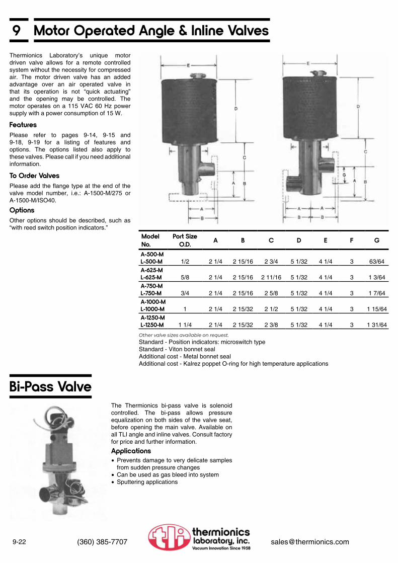
9-22 (360) 385-7707 [email protected]
9 Motor Operated Angle & lnline Valves
Features
Applications
To Order Valves
Options
Thermionics Laboratory’s unique motor driven valve allows for a remote controlled system without the necessity for compressed air. The motor driven valve has an added advantage over an air operated valve in that its operation is not “quick actuating” and the opening may be controlled. The motor operates on a 115 VAC 60 Hz power supply with a power consumption of 15 W.
The Thermionics bi-pass valve is sole noid controlled. The bi-pass allows pressure equalization on both sides of the valve seat, before opening the main valve. Available on all TLI angle and inline valves. Consult fac tory for price and further information.
Please refer to pages 9-14, 9-15 and 9-18, 9-19 for a listing of features and options. The options listed also apply to these valves. Please call if you need additional information.
Please add the flange type at the end of the valve model number, i.e.: A-1500-M/275 or A-1500-M/ISO40.
Other options should be described, such as “with reed switch position indicators.”
Other valve sizes available on request.Standard - Position indicators: microswitch typeStandard - Viton bonnet sealAdditional cost - Metal bonnet sealAdditional cost - Kalrez poppet O-ring for high temperature applications
Model No.
Port Size O.D. A B C D E F G
A-500-ML-500-M 1/2 2 1/4 2 15/16 2 3/4 5 1/32 4 1/4 3 63/64A-625-ML-625-M 5/8 2 1/4 2 15/16 2 11/16 5 1/32 4 1/4 3 1 3/64A-750-ML-750-M 3/4 2 1/4 2 15/16 2 5/8 5 1/32 4 1/4 3 1 7/64A-1000-ML-1000-M 1 2 1/4 2 15/32 2 1/2 5 1/32 4 1/4 3 1 15/64A-1250-ML-1250-M 1 1/4 2 1/4 2 15/32 2 3/8 5 1/32 4 1/4 3 1 31/64
Bi-Pass Valve
• Prevents damage to very delicate samples from sudden pressure changes
• Can be used as gas bleed into system• Sputtering applications

9Qualified lnline Valves Model T
9-23(360) 385-7707 [email protected]
Features
Electro-Pneumatic
Manual
To Order Valves
Options
Please refer to pages 9-14, 9-15, 9-18, 9-19 for a listing of features and options. The options listed also apply to these valves. Please call if you need additional information or further explanation.
Please add the flange type at the end of the valve model number, i.e.: TL-1500-H/275 or TL-1500-H/ISO40.
Other options should be described, such as “with reed switch position indicators.”
Port Size O.D.
A B C D
3/4 2.9 3.5 7.8 9.51 4.0 3.5 8.7 10.6
1.5 4.9 3.5 8.9 11.72 6.4 4.62 12.0 14.6
2.5 6.8 4.62 12.08 15.03 7.0 10.0 16.0 19.0
Port Size O.D.
A BOpen C D
3/4 2.9 3.0 7.5 9.51 4.0 3.2 8.4 10.4
1.5 4.9 3.2 8.6 11.12 6.4 4.0 11.5 14.3
2.5 6.8 4.0 11.5 14.83 7.0 4.0 11.5 16.2
• Prevents damage to very delicate samples from sudden pressure changes
• Can be used as gas bleed into system• Sputtering applications
Port Size O.D. Model No. ConFlat
SizeISO/KF
SizeGasket Set Model No.
3/4 TL-750-H 1.33 16 GH-111 TL-1000-H 2.12 25 GH-111.25 TL-1250-H 2.75 40 GH-111.5 TL-1500-H 2.75 40 GH-122 TL-2000-H 3.38 50 GH-132.5 TL-2500-H 4.50 63 GH-253 TL-3000-H 4.62 80 GH-14
Port Size O.D. Model No. ConFlat
SizeISO/KF
SizeGasket Set Model No.
3/4 TL-750-P 1.33 16 GH-111 TL-1000-P 2.12 25 GH-111.25 TL-1250-P 2.75 40 GH-111.5 TL-1500-P 2.75 40 GH-122 TL-2000-P 3.38 50 GH-132.5 TL-2500-P 4.50 63 GH-253 TL-3000-P 4.62 80 GH-14
Model No.
ConFlat Size
Gasket Set Model No.
MTL-750-H 1.33 GH-11-MMTL-1000-H 2.12 GH-11-MMTL-1250-H 2.75 GH-11-MMTL-1500-H 2.75 GH-12-MMTL-2000-H 3.38 GH-13-MMTL-2500-H 4.50 GH-25-MMTL-3000-H 4.62 GH-14-M
Model No.
ConFlat Size
Gasket Set Model No.
MTL-750-P 1.33 GP-11-MMTL-1000-P 2.12 GP-11-MMTL-1250-P 2.75 GP-11-MMTL-1500-P 2.75 GP-12-MMTL-2000-P 3.38 GP-13-MMTL-2500-P 4.50 GP-25-MMTL-3000-P 4.62 GP-14-M
Viton Bonnet
Viton Bonnet
Metal Bonnet
Metal Bonnet

9-24 (360) 385-7707 [email protected]
9 Qualified Straight Through Valves
Qualified SVV Viton Sealed Straight Through Valves Viton bonnet and Viton poppet seal
• All stainless steel construction
Specifications
Model No.
Clear Aperture
I.D.
Tube O.D.
Flange O.D. A B C D
SVV-075 0.63 0.75” 1.33 4.50 1.50 3.75 .50SVV-150 1.25 1.50” 2.75 7.70 2.47 5.00 .21SVV-200 1.75 2.00” 3.38 8.75 3.50 7.00 .23SVV-250 2.25 2.50” 4.50 10.00 3.50 8.50 .38SVV-400 3.75 4.00” 6.00 16.48 5.00 11.24 .43
Features To Order Valves OptionsPlease refer to pages 9-14, 9-15 and 9-18, 9-19 for a listing of features and options. The options listed also apply to these valves. Please call if you need additional information or further explanation.
Please add the actuator, bonnet seal, and flange type as a suffix to the valve model number, ie.: SVV-150-22-PVB-ISO 40 or SVV-150-33-HMB-275.
Other options should be described, such as “with reed switch position indicators .”
Valve Model No. Description
ManualOperator
Viton Bonnet
PneumaticOperator
Viton Bonnet
ManualOperator
Metal Bonnet
PneumaticOperator
Metal BonnetSVV-075-20 No flanges HVB PVB HMB PMBSVV-075-22 Flanges on all ports “ “ “ “SVV-075-30 No flanges with roughing port “ “ “ “SVV-075-33 Flanges with roughing port “ “ “ “SVV-150-20 No flanges “ “ “ “SVV-150-22 Flanges on all ports “ “ “ “SVV-150-30 No flanges with roughing port “ “ “ “SVV-150-33 Flanges with roughing port “ “ “ “SVV-200-20 No flanges “ “ “ “SVV-200-22 Flanges on all ports “ “ “ “SVV-200-30 No flanges with roughing port “ “ “ “SVV-200-33 Flanges with roughing port “ “ “ “SVV-250-20 No flanges “ “ “ “SVV-250-22 Flanges on all ports “ “ “ “SVV-250-30 No flanges with roughing port “ “ “ “SVV-250-33 Flanges with roughing port “ “ “ “SVV-400-20 No flanges “ “ “ “SVV-400-22 Flanges on all ports “ “ “ “SVV-400-30 No flanges with roughing port “ “ “ “SVV-400-33 Flanges with roughing port “ “ “ “

9Qualified UHV Bakeable Valves
9-25(360) 385-7707 [email protected]
Series Size ConductanceBVV-150 1 1/2” 38 l/secBVV-250 2 1/2” 118 I/sec
• All stainless steel construction
SpecificationsHigh Temperature
Mounting Requirements
Operating Pressures
Vacuum Materials
Bellows Sealed Drive
Connections
Leak Tightness
Gasket Life Gasket Replacement
Drive Lubrication
Bakeable Valve Mounting Bracket
High Conductance
The entire valve can be repeatedly baked to 450°C, in either the open or closed position.
The valve may be mounted and operated in any position. TLI bakeable valves with flanges are supplied with rotatable flanges to simplify mounting.
TLI bakeable valves used in typical all metal or glass/metal UHV systems are reliable to pressures of 10-12 Torr.
The valve is made of 300 series stainless steel. The seat gasket is a special copper alloy. Only 300 series stainless steel and OFE copper are exposed to the vacuum system.
The entire valve drive mechanism is iso lated from the vacuum system by a welded nesting stainless steel bellows. No sliding vacuum seals are used.
All TLI bakeable valves are available with flanges of your choice.
Before shipment, each valve is tested on a helium leak checker to insure leak tightness to 2 x 10⁻¹⁰ std cc/sec.
The life of the sealing gasket is depend ent on the temperature history and the cleanliness of the sealing surface. The seal ing gasket should remain reliable through forty 450°C cycles. If the system is not re peatedly baked or only baked mildly, many hundreds of cycles can be expected.
Gasket replacement is simple. No special tools are required. On some systems a tee style valve is used with one port blanked off. This port is used to change the seat without removing the valve from the system.
After high temperature bakeout, the threads of the drive mechanism must be lubricated to prevent galling and insure proper torque on the seat. The TLI valve drive is sealed from the vacuum system by the stainless steel bellows, and the valve does not have to be removed from the system to be lubricated.
Use of a mounting bracket is recom mended in installations where the connect ing tubulation will not support the sealing torque load. The bracket can be bolted to any flange of the valve. It can be used as a wrench fixture or can, in turn, be bolted to a rigid member for support. Each of these stainless steel brackets is shipped with the required number of special length bolts for the flange to bracket connection (shown below).
The TLI design allows the full retraction of the sealing gasket and the bellows assem bly. Seat constriction is held to a minimum, giving maximum conductance.
Calculated flange to flange conductance for air at 25°C is:
Bakeable Valve Mounting Bracket Specifications For Use With: A B C D E F G H I J K
1 1/2” valve 3 7/8 1 3/4 1/4 2 1/4 2 3/4 2 1/8 1 3/4 7/8 3 holes281 dia
4 holes 281 dia
2 1/2” valve 4 1 1/8 2 1/4 3/8 3 7/8 4 1/2 3 1/4 3 1 3/8 4 holes332 dia
4 holes343 dia

9-26 (360) 385-7707 [email protected]
9 Qualified UHV Bakeable ValvesFeatures• All stainless steel construction• Entire valve bakeable to 450°C• Bakeable in open or closed positions• High conductance• Replaceable metal alloy gasket• Leak tight to less than 2 x 10-11 Torr• Right angle or tee styles
Applications OperationTLI ‘s bakeable valves are for use in ultrahigh vacuum systems that are baked up to 450°C. The straightforward design gives maximum reliability and vacuum sealing to pressures below 10-11 Torr.
Since these valves can be baked in either the open or closed position, they can be used for any high temperature vacuum application.
In the TLI bakeable valve, the seal is formed by impressing a replaceable copper alloy gasket on a stainless steel seat. Repeatable, reliable seals are easily accomplished under the most adverse vacuum conditions.
BVV Series
Dimensions
Ordering Information
Model No. A B C D E F GBVV-150 Series 2 1/4 2 1/2 1 1/2 2 6 1/4 7 3/8 2 3/4BVV-250 3 3/4 4 1/8 2 1/2 3 1/4 10 5/8 11 7/8 4 1/2
New Sizes Model Weight5/8” straight through BVS-0625-22/133 83/4” right angle BVV-075-22/133 3
Description1 1/2” Valves 2 1/2” Valves
Model Weight Model WeightRight angle without flanges BVV-150 6 BVV-250 14Right angle with flanges BVV-152 7 BVV-252 17Tee configuration without flanges BVV-150T 7 BVV-250-T 17Tee configuration with flanges BVV-153T 8 BVV-253-T 20Replacement seat gaskets BVV-150S 1/2 BVV-250-S 1Drive lubricant DL-100 1/2 DL-100 1/2Mounting bracket MB-150 2 MB-250 4Flange gaskets (10/pkg) GK-275 1/2 GK-450 1 1/2Bolt-nut sets for flanges (25/pkg) B-25-100 1 1/2 B-31-125 2Torque wrench TW-100 4 TW-100 4
Note: All valve models are provided with ROTATABLE flanges.

9Qualified Angle Valves/UHV Bakeable
9-27(360) 385-7707 [email protected]
Bakeable Right-Angle Valves—Dimensions
AMV Dimensions
AMV-150-22BVV-025
Model No. Part O.D. Flange O.D A B C DAMV-075 Series 0.75 1.33 2.00 7.00 5.87 .50AMV-150 Series 1.50 2.75 2.45 8.87 7.25 .21AMV-200 Series 2.00 3.38 3.16 10.62 8.50 .23AMV-250 Series 2.50 4.50 4.13 11.12 9.62 .38
Bakeable Right-Angle Valve Gasket SetModel No. Gasket Description Model No.AMV-075-20 No flanges
AMV-075-GAMV-075-22 Flanges on both portsAMV-150-20 No flanges
AMV-150-GAMV-150-22 Flanges on both portsAMV-200-20 No flanges
AMV-200-GAMV-200-22 Flanges on both portsAMV-250-20 No flanges
AMV-200-GAMV-250-22 Flanges on both ports
• All stainless steel construction
TLI all metal valves feature OFE copper bonnet and seat seals that are easily replaceable. No need to use liquid nitrogen or risk damaging valve during maintenance. The initial low torque required will provide long seal life.
Model BVV-025
Port Options
1/4” bakeable valve
• 315°C bakeout• Bellows sealed• All stainless steel• 0.25” O.D. x0.156” I.D . port dimensions• Can be used in toxic or corrosive
applications
• Non-rotatable 1.33” mini-flanges• 1/4” O.D. weld stubs• VCR fittings

9-28 (360) 385-7707 [email protected]
9 Qualified UHV Bakeable Straight Through Valves• All stainless steel construction
Thermionics metal sealed bakeable straight through valves are available in the following sizes:
TLI all metal valves feature OFE copper bonnet and seat seals that are easily replaceable. No need to use liquid nitrogen or risk damaging valve during maintenance.
The initial low torque required will provide long seal life.
SMV-075SMV-150SMV-200SMV-250
0.75”1.50”2 00”2.50”
SMV Dimensions SMV-075-22 Valve
SMV Valve Dimensions
Model No. Clear ApertureI.D.
Flange O.D A B C D
SMV-075 0.63 1.33 4.50 1.50 5.25 .50SMV-150 1.25 2.75 6.65 2.47 7.47 .21SMV-200 1.75 3.38 8.75 3.50 8.50 .23SMV-250 2.25 4.50 10.00 3.50 12.00 .38

9Butterfly Valves
9-29(360) 385-7707 [email protected]
Butterfly Valve
Nom. O.D. Nom. I.D. Flange Type A B C D Model No.
1.33 0.75 ConFlat Consult Factory BFV-1332.75 1.50 ConFlat 4.00 2.73 1.38 1.25 BFV-2753.38 2.00 ConFlat Consult Factory BFV-338
ISO 16 0.75 ISO/KF Consult Factory BFV-16KISO 25 1.00 ISO/KF Consult Factory BFV-25KISO 40 1.50 ISO/KF Consult Factory BFV-40KISO 50 2.00 ISO/KF Consult Factory BFV-50K
Features
Options
• 1/4 turn fully open/fully closed• Viton O-ring main seal• Leak free to 2 x 10⁻¹⁰ std cc/sec , vacuum
adverse• 304 stainless steel, vacuum melt bar stock
main body• Most advanced, patented design
• Available with alternate elastomer seals• Available with O-ring or bellows shaft seals• Available with motorized and pneumatic
actuators

Systems 10

Systems
10
System Descriptions
Sorption Pumps
Sorption Pump Roughing Carts
Cold Wall Vacuum Furnace
Custom SystemsIon Pumped TTS Table Top Systems
Evaporators VE-80, VE-90, and VE-100 Series
General Information....................
Technical Information.................Specifications..............................Ordering information...................Sorption Pump Systems.............Specifications..............................Ordering Information...................
Technical Information.................Automatic Carts, Series SP 70...Ordering Information...................Manual Carts, Series SP-52.......Ordering Information...................Note: The Liquid Nitrogen Controller is located in Section 6
Technical Information.................Ordering Information...................
Ion Pumped................................Cryo Pumped..............................Turbo Pumped............................Diffusion Pumped........................Other...........................................
Applications & Features..............PyraFlat Rectangular Access Port Flange & Cryoshroud..........Technical Information.................Dimensions.................................Pumping Speed vs Pressure Curves.........................................Specifications.............................Ordering Information, Model Numbers & Features...................Options.......................................
General Information....................VE-80 Specifications, Ordering......................................VE-90 Specifications, Ordering......................................VE-100 Specifications, Ordering......................................
10-1
10-1710-1710-1710-1810-1810-18
10-2010-2010-2110-2110-21
10-1310-13
10-1410-1410-1510-1510-16
10-2
10-210-310-410-510-510-6
10-610-9
10-10
10-10
10-11
10-12

10Vacuum Systems
10-1(360) 385-7707 [email protected]
UHV Systems
TTS-SWC Series Ion Pumping Systems
Model SP-70 Super-SorbTLI ‘s challenge to the Varian Megasorb
TTS-200T-PF Series Pumping Stacks
Roughing Systems
At last, a table top system designed to give you ready access to the inside of your pumping stack by means of a 10 1/2” x 7 1/2” rectangular PyraFlat flange. The PyraFlat incorporates the Varian ConFlat flange sealing principle of a knife edge and a trapped copper gasket. See Section 7, pages 7-1 to 7-5.
Any pumping stack without a PyraFlat access port is obsolete.
PyraFlat flanges are manufactured and protected under one or more of the following patents: 5,640,751; 4,685,193
• Standard diode ion pumped• Noble/differential diode ion pumped• Triode ion pumped• Turbo pumped• Cryo pumped• Diffusion pumped
• Oil free• Manual• Automatic

10-2 (360) 385-7707 [email protected]
10 TTS Series Ion Pumped Table Top SystemsA pumping stack without a PyraFlat access port is an obsolete pumping stack.PyraFlat flanges are manufactured and protected under one or more of the following patents: 5,640,751; 4,685,193
Models PAP-560 and SS-560PyraFlat access port and cryoshroud
Basic Systems and Pyraflat Access Ports
PyraFlat Access Port and Model 560 Cryoshroud
The PyraFlat Advantage
At TLI we have over 50 years of experience in the design and fabrication of vacuum and gas-handling systems. We can draw upon our extensive knowledge of vacuum requirements, pumping characteristics, and specific gas-surface interactions to offer you:
The PyraFlat access port provides ready access to the inside of your pumping stack by means of a 10 1/2” x 7 1/4” rectangular PyraFlat flange which incorporates the Varian ConFlat flange sealing principle.
Maintenance and repair downtime are greatly minimized. Presently, it can take days or weeks to service your pumping stack, because the only access for purposes of maintenance or servicing is through the poppet. If you haven’t gone through the process of removing the bell jar, associated plumbing, and instruments, just check with someone who has. As one user said, “We all know that accidents happen. Somebody drops a sample down the valve or a pump shorts. What we cannot afford is a week’s shutdown for a complete disassembly.” The PyraFlat access port offers the perfect solution.
You have sufficient access to the inside of the pumping stack to allow easy servicing of the pump and poppet areas. You can remove and service the poppet and the pump elements without disturbing the bell jar, associated plumbing, instruments or your work.
The larger opening lets us put a larger cryopanel in the system. Our Model 560 has 560 sq in of cooled surface as compared to 500 in2 for competitor A, and approximately 200 in2 for competitor B.
First
Second
• Systems which are properly and promptly engineered, designed and delivered and which will meet or exceed your performance requirements.
• Systems which are manufactured from your drawings, from your sketches, or from a description of your operating requirements. (Final TLI drawings will be submitted for customer approval upon request.)
• Assistance in the selection of components, valves, pumps, gauges, and control circuitry best suited for your exact application.

10TTS Series Ion Pumped Table Top Systems
10-3(360) 385-7707 [email protected]
Model SS-560 PyraFlat Cryoshroudwith 560 in2 of cooling surface
Model No. SS-560—Modular and removable sublimator and cryoshroud assembly mounted on TLI PyraFlat access port also provides access to inside of pumping stack for cleaning, repair and maintenance.
PyraFlat flanges are manufactured and protected under one or more of the following patents: 5,640,751; 4,685,193
12”, 14” and 18” Table Top HighVacuum Systems
12”, 14” and 18” Table Top HighVacuum Systems
Features
• TTS pumping stack—the heart of the TTSSWC and US-SLC pumping systems. See pages 10-6 to 10-8 for sizes
• Integral ion pumps—diode or triode with speeds in excess of 1500 l/sec
• Surface research (Auger, ESCA, SAM, SIMS, ISS, HEED, RHEED, LEED, etc.)
• Material studies• High energy studies• Thin film sputtering and evaporation• Vacuum deposition• Residual gas analysis• Sputtering• Beam lead/lines studies• Space simulation• Environmental testing• Furnaces• Tube processing• Friction studies• Shadow casting
PUMPING• Roughing—dual sorption• Ion pumps—choice of diode, noble diode
(differential pumping), hydrogen diode, triode
• Sublimation-4 spiral filaments• Cryoshroud—Model 300 or Model 560BASE PLATE• Combination wire seal and Viton L gasket;
size dependent on stack diameterFEEDTHROUGH PORTS• 9 each 2 3/4” x 1 1/2” ConFlat type located
below poppet valvePOPPET VALVE• Hand operated, Viton sealed. Isolates
pumping stack from chamberBAKEOUT• 250°C (limited by elastomer). Consult
factory

10-4 (360) 385-7707 [email protected]
10 TTS Pump Stack/Options/TTS SystemsTTS Pumping Stack + Following Options = Table Top Ion Pump Systems Complete and Ready to Run• 1 each standard cabinet enclosure with or
without bakeout oven as option• 1 each electronics cabinet enclosure is 1
each nude ion gauge• 1 each ionization gauge control• 1 each thermocouple gauge is 1 each
bakeout option on ion pump control• 1 each bakeout option distribution box• 1 each bakeout blanket option• 1 each bakeout oven shroud option• 1 each metal seal isolation valve option
The series TTS-SWC and TTS-SLC ion pump systems incorporate the TTS ion pump stack together with components guaranteed to provide quick pumpdown of the system from atmosphere to less than 2 x 10-11 Torr. Optional vacuum chamber or bell jar is designed and manufactured to meet your specific applications
12”, 14”, and 16” standard. (Other sizes available as custom options.)
Diode, noble gas diode, hydrogen diode and triode.
TTS vacuum systems can, at customer request, be baked and pumped down to 2 x 10-11 or better, backfilled with nitrogen, pinched off, and shipped under vacuum.
60 l/sec to over 1,500 l/sec
Pumping Stack Sizes Available Model TTS-SWC Pumping System with Cabinet
Model TTS-SLC Pumping System without Cabinet
Types of Integral Ion Pumps Available
Options
Pumping Speeds Available

10TTS Dimensions and Typical Pumpdown Curves
10-5(360) 385-7707 [email protected]
Fig. 10-1. TTS-60N & TTS-80T
Fig. 10-3. TTC-60 Fig. 10-4. TTS-80T & TTS-200T Fig. 10-5. TTS-240N
Fig. 10-2. TTS-240N and TTS-200T

10-6 (360) 385-7707 [email protected]
10 TTS Basic Pumping Stacks
Shown with optional PAP-560 PyreFlat access port and optional SS-560 cryoshroud (see pages 10-2 and 10-3).
TTS Basic Pumping Stack
TTS Pumping Stacks
PyraFlat flanges are manufactured and protected under one or more of the following patents: 5,640,751; 4,685,193
Dimensions in inches
With Differentially Pumped Noble Diode Ion Pumps Triode PumpsModel No. TTS-60N TTS-240N TTS-300N TTS-400N TTS-80T TTS-200T TTS-300T TTS-400T
Includes:Integral ion pump pumping speed (l/sec) 60 240 300 400 80 200 300 400
Ion pump power supply PS 350 PS 1000 PS 1000 PS 1000 PS 350 PS 1000 PS 1000 PS 1000Basewell (inches) 12 x 26 12 x 26 12 x 26 18 x 36 12 x 26 12 x 26 12 x 26 18 x 36
Combination male wireseal and Viton gasketbaseplate 14.63” x 11.0” X X X X (18 x 22) X X X
X (18 x 22)
Viton gasket & wire seal X X X X X X X XIntegral 3-tab ledge & port for poppet actuator X X X X X X X X9 each 2.75” x 1.50”blanked off ports X X X (15 ea) X X X (15 ea)One bakeable roughingvalve on 2.75”x 1.50” port X X X X X X X XDouble-sided flange with air relief valve & TC gauge tube X X X X X X X XCryoshroud X X X X X X X XSublimator (4 fils.) SB-1000 X X X X X X X XSublimator control PS-500 X X X X X X X X2 each operating manuals X X X X X X X X8” poppet valve X X X X (12”) X X X X (12”)Spare Parts 10 each GK-275 gaskets; 1 each B-25-137N bolt set; 4 each TSP filaments
OptionsRecommended option: PyraFlat access port (see pp 10-2, 10-3)Dual sorption pump roughingsystem (refer to page 10-18for Sorption 2A)Top blank-off plateTop blank-off dished head

10Model TTS-SLC Table Top Systems Less Cabinet
10-7(360) 385-7707 [email protected]
TTS-SLC Table Top Systems (Bakeable)
Table Top Ion Pump Systems Bakeout Shroud
Options
Includes TTS pumping stack items from page 10-6 plus
TTS-60WSLC TTS-240N/SLC TTS-300WSLC TTS-400N/SLC TTS-80T/SLC TTS-200T/SLC TTS-300T/SLC TTS-400T/SLC
Enclosed electronics rack X X X X X X X X
Nude ion gauge X X X X X X X XIon gauge control X X X X X X X X
Console bakeoutshroudBakeout blanketInternal bakeoutRecommended option: PyraFlat access port (see pp 10-2, 10-3)Dual sorption Pump roughing system (refer to page 10-18 for Sorption 2A)Top blank-off plateTop blank-off dished head

10-8 (360) 385-7707 [email protected]
10 Model TTS-SWC Table Top Systems With Cabinets
PyraFlat flanges are manufactured and protected under one or more of the following patents: 5,640,751; 4,685,193
TTS-SWC Table Top Systems (Bakeable)
TTS-SWC/B Table Top Systems (Bakeable)
Options for TTS-SWC and TTS-SWC/B Table Top Systems
Includes TTS pumping stack items from page 10-6 plus
TTS-60N/SWC
TTS-240N/SWC
TTS-300N/SWC
TTS-400N/SWC
TTS-80T/SWC
TTS-200T/SWC
TTS-300T/SWC
TTS-400T/SWC
Enclosed electronics rack X X X X X X X X
Nude ion gauge X X X X X X X XIon gauge control X X X X X X X X
TTS pumping stack
TTC-60N/SWC/B
TTS-24N/SWC/B
TTS-300N/SWC/B
TTS-400N/SWC/B
TTS/80T/SWC/B
TTS-200T/SWC/B
TTS-300T/SWC/B
TTS-400T/SWC/B
Table topenclosed cabinet X X X X X X X X
Enclosedelectronics rack X X X X X X X X
Nude ion gauge X X X X X X X XIon gauge control X X X X X X X XIon pumpbakeout module X X X X X X X X
Bakeout powerdistribution box X X X X X X X X
Consolebakeout oven X X X X X X X X
Bakeout blanket X X X X X X X X
Recommended option: PyraFlat access port (see pp 10-2, 10-3)Dual sorption Pump roughing system (refer to page 10-18 for Sorption 2A)Top blank-off plateTop blank-off dished head

10Table Top Options
10-9(360) 385-7707 [email protected]
Adapter Plate Work Support Platform
Poppet Valvet
Integral Bakeout Source Model 275-8QH
16” O.D. stainless steel adapter plate to allow Viton-sealed bell jars up to 14” diameter to be used with the TTS-240N or TTS-200T systems.
Provides support for electron beam guns and other fixtures. Attaches to support tabs in basewell.
High conductance poppet valve provides rapid cycling and fast pumpdowns. The poppet valve isolates the entire selective pumping area from the bell jar. This allows the pumping system to maintain a vacuum level of 10-8 Torr or lower while the work area is at atmospheric pressure. In the open position, the poppet valve has a conductance equivalent to an 8” orifice. For maintenance purposes, or for high temperature application, the poppet sealing plate is easily removed through the basewell. The stem from the poppet valve is bellows sealed, and the actuator mechanism attaches to the 2” metal seal flange port located immediately below the poppet valve sealing ledge.
(a) Clam Shell Bakeout Shroud designed to fit your particular stainless steel chamber. Thermostatically controlled to achieve temperature uniformity at 200°C throughout chamber. Includes power bus.
(b) Fitted Bakeout Blanket Custom made.
(c) Integral Bakeout Source (with Variac)
Adapter Plate
Work Support Platform
Poppet Valve
Bakeout Systems
Efficient in situ quartz infrared heater assembly on a 2 3/4 “ ConFlat-type flange is used— to bakeout vacuum chambers and systems. Consists of a 1200 W, 120 VAC, 10A quartz infrared lamp, coupled to a 2 3/4 “ flange, on which is mounted a medium current feedthrough. Easy installation on any standard 2 3/4 “ ConFlat-type flange port. Can be kept on during chamber openings to reduce H2O adsorption on walls. Uses a powerstat power supply to allow bakeout at an upper temperature limit of 400°C. It is UHV compatible at a 2 x 10-11 Torr base pressure. Replacement lamps are available. Bulb life expectancy is 500 hours or longer. See Section 8 for more information. See page 10-17
Available with electronics incorporated or with separate electronics rack. See page 10-8, TTS-SWC.
Designed and fabricated to meet your particular needs.
See section 11 for more information
Contact us for more information
Pyrex Bell Jars & Implosion Guard Sorption Roughing
Mobile Cabinet—on CastersStainless Steel Custom Chambers Venturi Pump
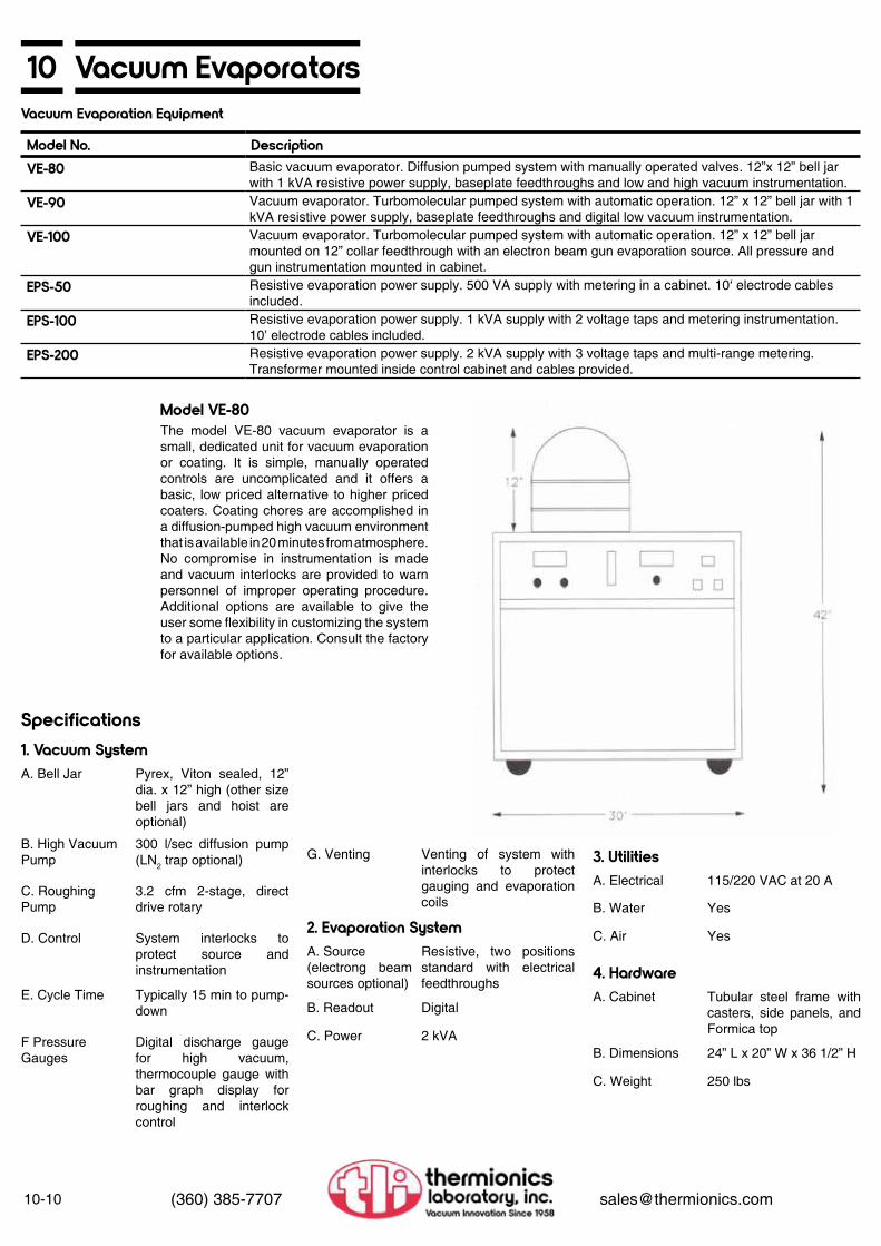
10-10 (360) 385-7707 [email protected]
10 Vacuum EvaporatorsVacuum Evaporation Equipment
Model No. DescriptionVE-80 Basic vacuum evaporator. Diffusion pumped system with manually operated valves. 12”x 12” bell jar
with 1 kVA resistive power supply, baseplate feedthroughs and low and high vacuum instrumentation.VE-90 Vacuum evaporator. Turbomolecular pumped system with automatic operation. 12” x 12” bell jar with 1
kVA resistive power supply, baseplate feedthroughs and digital low vacuum instrumentation.VE-100 Vacuum evaporator. Turbomolecular pumped system with automatic operation. 12” x 12” bell jar
mounted on 12” collar feedthrough with an electron beam gun evaporation source. All pressure and gun instrumentation mounted in cabinet.
EPS-50 Resistive evaporation power supply. 500 VA supply with metering in a cabinet. 10‘ electrode cables included.
EPS-100 Resistive evaporation power supply. 1 kVA supply with 2 voltage taps and metering instrumentation. 10’ electrode cables included.
EPS-200 Resistive evaporation power supply. 2 kVA supply with 3 voltage taps and multi-range metering. Transformer mounted inside control cabinet and cables provided.
The model VE-80 vacuum evaporator is a small, dedicated unit for vacuum evaporation or coating. It is simple, manually operated controls are uncomplicated and it offers a basic, low priced alternative to higher priced coaters. Coating chores are accomplished in a diffusion-pumped high vacuum environment that is available in 20 minutes from atmosphere. No compromise in instrumentation is made and vacuum interlocks are provided to warn personnel of improper operating procedure. Additional options are available to give the user some flexibility in customizing the system to a particular application. Consult the factory for available options.
A. Bell Jar
A. Source (electrong beam sources optional)
A. Cabinet
A. Electrical
B. Readout
B. Dimensions
B. Water
C. Power
C. Weight
C. Air
B. High VacuumPump
C. RoughingPump
D. Control
E. Cycle Time
F PressureGauges
G. Venting
Pyrex, Viton sealed, 12” dia. x 12” high (other size bell jars and hoist are optional)
Resistive, two positions standard with electrical feedthroughs
Tubular steel frame with casters, side panels, and Formica top
115/220 VAC at 20 A
Digital
24” L x 20” W x 36 1/2” H
Yes
2 kVA
250 lbs
Yes
300 l/sec diffusion pump (LN2 trap optional)
3.2 cfm 2-stage, direct drive rotary
System interlocks to protect source and instrumentation
Typically 15 min to pump-down
Digital discharge gauge for high vacuum, thermocouple gauge with bar graph display for roughing and interlock control
Venting of system with interlocks to protect gauging and evaporation coils
Model VE-80
Specifications1. Vacuum System
2. Evaporation System
4. Hardware
3. Utilities

10Vacuum Evaporators
10-11(360) 385-7707 [email protected]
The model VE-90 vacuum evaporator is the perfect answer to a requirement for vacuum evaporation or coating. Its simple controls and rapid cycle time facilitate uncomplicated productivity. Reliable coating chores are accomplished in an oil-free, high vacuum environment that is available in 10 minutes from atmosphere with the touch of a button. Greater control and more predictable film parameters are available, almost as fast as the material can be loaded. Additional options are available to give the user some flexibility in customizing the system to a particular application. Consult factory for available options.
Model VE-90
A. Bell Jar
B. High VacuumPump
C. RoughingPump
D. Control
A. High Vacuum A. Electrical
A. Cabinet
A. Source
E. Cycle Time
B. Low Vacuum B. Water
B. Dimensions
C. Air
C. Weight
D. Hoist
B. Power
C. Positions
D. Metering
Pyrex, Viton sealed, 12’ dia (optional height)
260 l/sec turbomolecularpump
3.2 cfm 2-stage, direct drive rotary
Automatic pumpdown, interlocks to protect source and instrumentation
Digital ionization gauge 115/220 VAC at 20 A
Tubular steel frame with casters, side panels, and Formica top
Resistive
Typically 10 min to pump-down
Digital convection gauge None
30” L x 20” W x 42” H
None
Approx. 250 lbs
Optional
1 kVA, nominal 75 A (optional 2 kVA, 200 A)
2 switch selectable pairs of baseplate feedthroughs (filament holders and carbon evaporation kit are optional)
Digital ammeter (100 A FS)
Specifications1. Vacuum System 2. Pressure Instrumentation 4. Utilities
5. Hardware3. Evaporation System

10-12 (360) 385-7707 [email protected]
10 Vacuum Evaporators
The model VE-100 extends the technology of the VE-90 by the addition of a 3 kW e-Gun evaporation source while retaining a philosophy of simple, uncomplicated operation. Unlike larger systems, the VE-100’s purpose is not overstated: It simply provides thin film coating—of virtually any material—quickly, cleanly and efficiently in a compact, dedicated system. With the additional technology of the source, a slightly larger bell jar and a collar, the optional flexibility of this system is almost boundless. To list just a few examples, many users add additional crucibles to assist in uninterrupted multi-coating operations, and the addition of a bell jar collar allows the user to introduce manipulators, additional electrical or water feedthroughs, and thin film instrumentation. Consult factory for available options.
Model VE-100
A. Bell Jar
B. High VacuumPump
C. RoughingPump
D. Control
A. High Vacuum A. Electrical
A. CabinetA. Source
E. Cycle Time
B. Low VacuumB. Water
B. Dimensions
C. Air
C. Weight
D. Hoist
B. Power
C. Positions
D. Metering
Pyrex, Viton sealed, 12” x 18” (optional stainless steel)
520 l/sec turbomolecularpump
3.2 cfm 2-stage, direct drive rotary
Automatic pumpdown, interlocks to protect source and instrumentation
Ionization gauge with digital controller
208/220 VAC at 20 A
Tubular steel frame with casters, side panels, and Formica top
Electron beam gun
Typically 10 min to pump-down
Digital convection gauge.5 cfm
36” L x 20” W x 54” H
None
Approx. 350 lbs
Standard
3 kW
1 pocket (multiple pocketguns optional)
Analog metering on handheld power controller
Specifications1. Vacuum System 2. Pressure Instrumentation 4. Utilities
5. Hardware3. Evaporation System

10Cold Wall Vacuum Furnaces
10-13(360) 385-7707 [email protected]
The TLI compact cold wall vacuum furnace was designed for use with existing vacuum systems. The 6” CWVF, with an effective heat zone of 6” diameter x 6” high, will work with 12” or larger bell jar systems. The 8” CWVF, with an 8” diameter x 8” high heat zone, can be used in any 14” or larger system. The 14” CWVF can be used in an 18” or larger system.
*Including one thermocouple (does not include power supply feedthroughs or vacuum system) *Stainless is standard, molybdenum price available
on request
An important design feature of the CWVF is the full opening lid. The lid can be easily opened and closed without disconnecting the water cooling lines.
The CWVF is easy to install. It requires only one dual water and two single filament power feedthroughs. A thermocouple feedthrough is optional.
Furnaces are constructed of OFE copper. Stainless steel heat shield liners are standard. Molybdenum shields are offered as an option at extra cost. Operation at 1200°C
requires a 4.5 kW low voltage supply for the 6” CWVF and 6 kW for the 8” model. The tungsten hairpin filaments can be replaced in minutes without dismantling the furnace. A type K Chromel/Alumel thermocouple is furnished with each furnace for temperature measurement. A thermocouple feedthrough is ordered separately, if needed.
Applications of the CWVF include the brazing of copper, nickel, gold, silver and other alloys. It is also used for annealing, bakeout and numerous other uses.
• Fits existing vacuum systems with 12” or larger bell jars
• Full opening hinged lid opens without disconnecting water lines
• Simple to install; requires only water and filament power feedthroughs
Furnaces* Feedthroughs
6” Water-Cooled Cold Wall Furnace with Copper Tubing
Power Supplies
Replacement Parts
Eft. Heat Zone6” CWVF 6” dia x 6” high8” CWVF 8” dia x 8” high10” CWVF 10” dia x 10” high12” CWVF 12” dia x 12” high14” CWVF 14” dia x 14” high
Description & Model No.Power Single conductor electrical
feedthrough mounted on 2.75” knife-edge flange. 600 A capacity. Two required. FHC-275-1
Water Dual water feedthrough mounted on 2.75” knife-edge flange. One required. FCW-275-2-38 FCW-275-2D0/38 (de-mountable)
Thermocouple Instrumentation feedthrough mounted on2.75” knife-edge flange.FEP-275-8T
Instrumentation feedthroughmounted on1.33” CF flange.FETC-133-2K
Model No. Power levelVFPS-5kVA 20 V at 250 AVFPS-10kVA 20 V at 500 AVFPS-14kVA 40 V at 350 A
Part Options6” SS* heat shield liner8” SS* heat shield liner6” filament electrodes, set of three8” filament electrodes, set of fourBellows, 6” or 8”, 2 req. per furnace, eachThermocouple, type K

10-14 (360) 385-7707 [email protected]
10 Custom Ion Pumped Systems2,000 l/sec Noble Ion Pump System 2,000 l/sec Noble Ion Pump System
with Electronics Rack• Dual sorption pump• Ionization gauge and control• Sublimation pump and control• Rack mounted controls
A custom UHV chamber with 240 l/sec ion pump stack and optional bakeable sorption pump Dewars. Includes a carbon vane pump, 20 l/sec appendage pump, Bourdon gauge and sequentially operated, heated lecture bottles for precise gas mixing. Also includes rack mounted control units.
Custom Vacuum SystemsCryo Pump Cart Mounted System• Manual Valving• Ionization gauge and control• Isolation gate valve• Dual sorption pump roughing assembly• Cryo pump high vacuum pumping• Special collar• 18” x 30” Pyrex bell jar & guard, with hoist• 1 x 10⁻⁷ Torr in 30 min from atmosphere• Cabinet mounted controllers and power
supplies
Cryo Pumped System with Counterbalanced Hoist

10Custom Vacuum Systems
10-15(360) 385-7707 [email protected]
Electric Hoist Hydraulic Hoist
Turbo Pump Cart Mounted System Diffusion Pump Cart Mounted System• Evaporation system with special collar for
mounting of 3-position e-Gun• Turbomolecular high vacuum pump• Rack mounted controls• Ionization gauge and control• 12” x 24” Pyrex bell jar, guard and hoist
• 6” D.P. for corrosive gas handling• 1 x 10⁻⁸ Torr from atmosphere in 10 min• Water cooled bell jar• Semi-automatic valving, sequencing and
monitoring• Hydraulic hoist• Isolation valve• Ionization gauge and control

10-16 (360) 385-7707 [email protected]
10 Custom Vacuum SystemsCustom System with Cryo Pump
Gas Inlet System
Dual 3 kW e-Gun with cross contamination shutters, dual sorption pump roughing, cyro high vacuum pump, automatic valving, ionization gauge and control, isolation gate valve, dual sorption pump assembly, special electron beam collar, 18” x 30” bell jar and guard with hoist, rack mounted controllers and power supplies. System achieves 1 x 10⁻⁷ Torr in 30 min from atmosphere.
A 20 valve microprocessor (or manually) operated inlet system for introduction of precise amounts of pure gases and gas mixtures into a mass spectrometer for quantitative analysis.
Includes front panel display, macro and micromanometer readout, temperature control readout, thermocouple readout, capacitance manometer readout, turbomolecular pump readout and control, and valve actuator display.
Front View Back View

10Sorption Pumps
10-17(360) 385-7707 [email protected]
Sorption Pump Diagram (dimensions in inches)
Application
Operating Principle
TLI SP series sorption pumps are recommended for all applications needing highspeed, contaminant-free pumping. They have no moving parts or oils. The advanced design insures high speed pumping with maximum conductance and heat transfer. SP pumps have high capacity, are economical to operate, and are easily regenerated.
Molecular sieve sorption pumps evacuate gas molecules from a volume by cryosorption, adsorbing them on a chilled surface. Because the adsorption process essentially takes place on a surface, a large surface area is required to adsorb appreciable quantities of gas. To satisfy this area requirement, a highly porous synthetic zeolite molecular sieve is commonly used as the sorbant material. The molecular sieve has an extremely high surface area to volume ratio (an SP-11 pump contains approximately 1.2 km2 of sorbant surface area), which allows large quantities of gas to be pumped by relatively small sorption pumps. (An SP-11 sorption pump has a theoretical capacity of approximately 100,000 Torr-liters of gas.)
To obtain maximum speed and capacity from a sorption pump, there are three important design characteristics that are taken into consideration: 1) efficient heat transfer to the cryogenic fluid; 2) maximum conductance to the molecular sieve; and 3) quantity of molecular sieve in contact with a chilled surface (cryogenic surface area to volume ratio). The SP series sorption pumps are designed for optimization of these characteristics.
Specifications
MaterialsBody and internal cooling fins AluminumPump neck and connecting flange Type 304 stainless steelDewar flask Standard: styrofoam
Option: stainless, type 304Base pressure 1 x 10⁻³ Torr, with normal useRecommended maximum pumping capacity SP-11 standard pump = 40 litersSieve requirements (Linde 5A) (SP-11) 3 lbsLiquid nitrogen required (approximate amount in liters/pumpdown from atmosphere) (SP-11)
5 liters
Heater power requirements 115 V, 50/60 Hz, 400 WNumber of heaters required per pump 1 heaterBakeout temperature 250°C
Ordering Information
Model No. Description Wt. lbsSorption pumps—All pumps include: one OFE copper gasket, Dewar mounting bracket kit, top screen, RV-11 relief valve, six each nuts, bolts and washers, one charge of molecular sieve, and instructions
SP-11 Single sorption pump 14.00SP-12 Double sorption pump 28.00SP-13 Triple sorption pump 42.00
SPD-11 Dewar, styrofoam 5.00SPD-11S Dewar, stainless steel 15.00SPD-12S Dewar, stainless steel 30.00SPD-13S Dewar, stainless steel 45.00SPHT-11 Heater, wraparound bakeout, 115 VAC 4.00MS-200 Sieve 5.00275150 Mating flange .50GK-275 Gaskets (10/pkg.) .50B-25-137N Bolt set .75RV-11 Viton relief valve .50TS-11 Top screen (old Model No. 4084) .50

10-18 (360) 385-7707 [email protected]
10 Sorption Roughing Systems
Option 1A Single Sorption Pump Roughing System
Option 1B Single Sorption Pump RoughingSystem with Mechanical Pump
Option 2A Dual Sorption Pump RoughingSystem
Option 1A—Single sorption pump roughing system includes:
Option 1B—Single sorption pump roughing system with mechanical pump includes:
Option 2A—Dual sorption pump roughing system includes:
1 ea A-1500-H 1 1/2” manual angle valve, Viton sealed, with 2 3/4” ConFlat flanges on both ports
1 ea SP-11 Pump assembly1 ea SPD-11 Styrofoam Dewar1 ea SPHT-11 Bakeout heater1 ea FL275150-VTC Double-sided
flange with TC tube and one up-to-air valve
1 ea Set of necessary nuts and bolts
1 ea FLP-1 Anti-seize lubricant
Partial assembly
1 ea A-1500-H 1 1/2” manual angle valve, Viton sealed, with 2 3/4” ConFlat flanges on both ports
1 ea SP-11 Pump assembly1 ea SPD-11 Styrofoam Dewar1 ea SPHT-11 Bakeout heater1 ea FL275150-VTC/S Double-sided
flange with TC tube and one isolation valve for dry-vane pump
1 ea Bourdon gauge1 ea Dry-vane
mechanical pump1 ea 10’ of 3/.8” copper
tubing with fittings1 ea Set of necessary
nuts and bolts1 ea FLP-1 Anti-seize
lubricantPartial assembly
3 ea A-1500-H 1 1/2” manual angle valve, Viton sealed, with 2 3/4” ConFlat flanges on both ports
2 ea SP-11 Pump assembly2 ea SPD-11 Styrofoam Dewar2 ea SPHT-11 Bakeout heater1 ea FL275150-VTC Double-sided
flange with TC tube and one up-to-air valve
1 ea TE-150/S Fitting1 ea Set of necessary
nuts and bolts1 ea FLP-1 Anti-seize
lubricantPartial assembly
Option LN2 Control
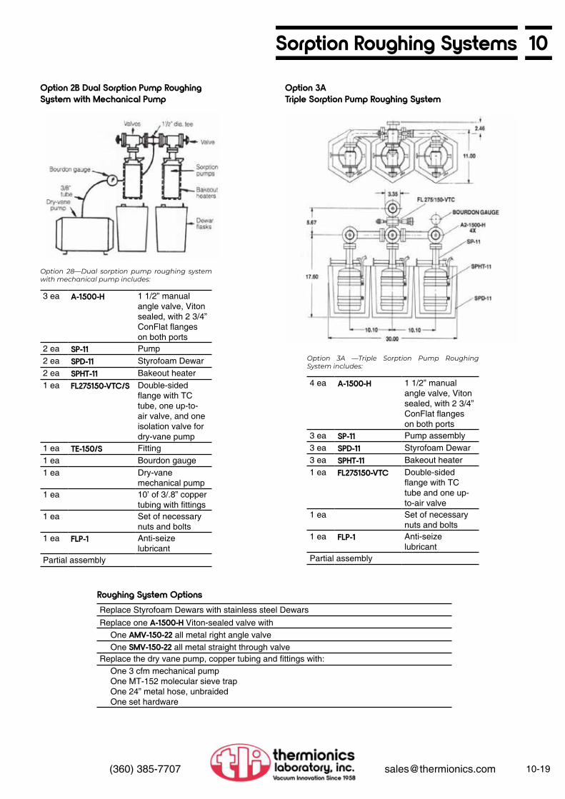
10Sorption Roughing Systems
10-19(360) 385-7707 [email protected]
Option 2B Dual Sorption Pump RoughingSystem with Mechanical Pump
Option 3ATriple Sorption Pump Roughing System
Option 28—Dual sorption pump roughing system with mechanical pump includes:
3 ea A-1500-H 1 1/2” manual angle valve, Viton sealed, with 2 3/4” ConFlat flanges on both ports
2 ea SP-11 Pump2 ea SPD-11 Styrofoam Dewar2 ea SPHT-11 Bakeout heater1 ea FL275150-VTC/S Double-sided
flange with TC tube, one up-to-air valve, and one isolation valve for dry-vane pump
1 ea TE-150/S Fitting1 ea Bourdon gauge1 ea Dry-vane
mechanical pump1 ea 10’ of 3/.8” copper
tubing with fittings1 ea Set of necessary
nuts and bolts1 ea FLP-1 Anti-seize
lubricantPartial assembly
Option 3A —Triple Sorption Pump Roughing System includes:
4 ea A-1500-H 1 1/2” manual angle valve, Viton sealed, with 2 3/4” ConFlat flanges on both ports
3 ea SP-11 Pump assembly3 ea SPD-11 Styrofoam Dewar3 ea SPHT-11 Bakeout heater1 ea FL275150-VTC Double-sided
flange with TC tube and one up-to-air valve
1 ea Set of necessary nuts and bolts
1 ea FLP-1 Anti-seize lubricant
Partial assembly
Roughing System OptionsReplace Styrofoam Dewars with stainless steel DewarsReplace one A-1500-H Viton-sealed valve with
One AMV-150-22 all metal right angle valveOne SMV-150-22 all metal straight through valve
Replace the dry vane pump, copper tubing and fittings with:One 3 cfm mechanical pumpOne MT-152 molecular sieve trapOne 24” metal hose, unbraidedOne set hardware

10-20 (360) 385-7707 [email protected]
10 Oil-Free Sorption Pump Roughing CartsSuper-Sorb—Oil-Free Sorption PumpRoughing Cart—Model SP-70
SP-70
• Pumps down a 100 ft3 vessel from atmosphere to less than 10 microns in less than 25 min
• 1.7 million Torr-liters of ultra-clean pumping
Thermionics’ portable sorption pump roughing carts are designed to meet the heavy gas loads associated with hydrocarbon- free high production applications. Three pumping stages, with a total of 43 lbs of molecular sieve, have the capacity to deliver multiple pumpdowns for multiple chambers prior to an automatic bakeout during nonworking hours. Caster-mounted cart complete with vacuum gauging and stainless-steel valves.
Comparisons of the Thermionics Super-Sorb to the Varian MegaSorb
Super-Sorb MegaSorbTime to evacuate 150 liter chamber from atmosphere to <10 microns <120 secTime to evacuate 100 ft3 (2,800 liter) chamber from atmosphere to <10 microns <25 minCapable of manual operation All modelsAutomatic temp. controlled bakeout YesSystem isolation valve YesUp-to-air valve YesVacuum read-out range continuous, atm
to 1 micronRequired utilities Power 20 A 220 VAC
or other as desired15 A 220 VAC
Air Control air only 9 scfm at 60 psi**
*The Varian data is fora crossover pressure of 200 Torr between stages 1 & 2. Thermionics data is for 75 Torr crossover on the Super-Sorb, increasing the life of the molecular sieve by over a factor of 2 before requiring bakeout**9 scfm at 60 psi requires approximately a 3 hp compressor.

10Oil-Free Sorption Pump Roughing Carts
10-21(360) 385-7707 [email protected]
Oil-Free Sorption Pump Roughing Cart—Model SP-70
Oil-Free Sorption Pump Roughing Cart—Model SP-52
• Pumps down a 100 ft3 vessel from atmosphere to less than 10 microns in less than 25 min
A large portable sorption roughing system, mounted on a cart with casters, for use on large, hydrocarbon-free chambers. Effective from atmosphere to less than 10 microns (1 x 10⁻² Torr) pressure with fast pumping speed and large total capacity. Vacuum insulated stainless steel construction.
This allows for sieve bakeout without removal from the cryostat. An insulated lid minimizes boil-off during operation.
All valves are manually-actuated stainless steel with Viton seals and bellows-sealed actuators. Port size is 1.5” with the exception of the vent valve.
The cart is 24” wide x 36” deep by 40” high and weighs 325 lbs. The cart comes complete with a 48” stainless steel flex hose.
208 V, 3 phase “Y,” 20 A max—standard. Available with other configurations at customer request. Control air pressure should be between 80 and 100 psi.
A vacuum gauge indicates pressure continuously between atmosphere and 1 micron. Bakeout time and temperature and stage crossover are adjustable. Presence of AC power and bakeout heater operation are also indicated. The main power switch is of the circuit breaker type.
Is fully automatic with time and temperaturecontrol.
relief to release trapped gases during bakeout or warm-up. Screens minimize accidental migration of the sieve material.
Stage #3—pumps from 90 microns to less than 10 microns. Consists of one large sorption pump identical to those in the second stage. Contains 8.5 lbs of sieve.
The pumping system consists of three stages.
Stage #1—Capable of evacuating 100 ft3
from atmosphere to 27” Hg in less than 15 min. Consists of a displacement type oil-free mechanical pump. Its free air capacity is 20 scfm at 25” of Hg. The pump is protected from overload.
Stage #2—pumps from 27” Hg to 90 microns. Consists of four large sorption pumps (24” high x 5” diameter) containing a total of 34 lbs of type 5A molecular sieve cooled in a bath of liquid nitrogen. Includes automatic pressure
General Description
Cryostat
Valving
Size
Utilities
Instrumentation/Control
Bakeout System
Pumping System
Model No.SP-70 Manual valving
SP-52M
• Pumps down a 100 ft3 vessel from atmosphere to less than 10 microns in less than 25 min
Portable, cart-mounted sorption roughing pump system for use on small and moderately sized hydrocarbon-free chambers.
Three manually-actuated bellows sealed 1.5” valves control pump isolation and input to the pumping manifold. Stage #1 pumping is controlled through a 1/4” port stainless valve. The same size valve is used to vent the manifold.
An adjustable timer allows unattended bakeout via electrical heaters installed on each sorption pump. These heaters are suitable for submergence in liquid nitrogen in everyday use.
A vacuum gauge indicates pressure continuously from atmosphere to 1 micron. Indicators on the control panel show the presence of AC power and operation of the bakeout heaters.
The cart is mounted on 2” casters and is 24” wide x 28” deep x 30” high. The cart comes complete with a 48” stainless steel flex hose. Weight is 95 lbs.
115 VAC at 15 A max is required. The cart is supplied with a 30 ft power cord.
The SP-52 cart consists of three pumping stages.
Stage #1—Mechanical displacement oil-free pump capable of 27.5” Hg with a speed of 4.2 cfm.
Stages #2 and #3— Two sorption pumps, one for each stage, containing 3 lbs of 5A sieve material each. These pumps are complete with stainless steel Dewars, sieve containment screens and pressure relief devices for gas release during bakeout or warmup.
General Description
Valving
Bakeout
Instrumentation/Control
Size
Utilities
Pumping
Model No.SP-52 Manual valving

Custom Chambers 11

Custom Chambers
11
Custom Vacuum ChambersTechnical Information.................Performace.................................Specifications..............................Engineering & Design.................Cleaning......................................Certification.................................Analysis.......................................Examples Deposition Chambers.... Surface Analysis Chambers...................... Water Cooled Chambers...................... Sample Introduction....... Laser Chambers............ Gate Valve Isolation....... e-Gun.............................
11-111-111-111-211-211-211-2
11-3
11-4
11-511-611-611-711-8

11Custom UHV Chambers
11-1(360) 385-7707 [email protected]
• Experienced engineering and up-to-date design
• Fast delivery. Order to shipment times as low as 4 weeks
• Optional qualifying pumpdown, bake and gas analysis
At your option and request, we can perform, certify, and document: • Qualification of ultimate base pressures
measured to 2 x 10-11 Torr, achieved with the system in our facility. Certification of bakeout and pumping techniques employed to achieve specified pressure
• RGA partial pressure analysis to 2 x 10-13 Torr from 0 to 200 AMU
• Choice of the conditions under which the system is shipped, e.g., blanked off, under vacuum, bagged with dry nitrogen or other gas of your choice, or a combination of the preceding
• Choice of materials used in fabrication • Chemical and mechanical processes
used to prepare systems and surfaces, such as passivation, electro-polishing, mechanical polishing (up to a #2-lap finish), or chemical removal of carbon and/or hydrogen from the surface
We can assist you with chamber concept, application, engineering, and design. We work from your rough sketches, and prepare complete production drawings on our CAD system using the latest version of SolidWorks. The following pages contain photographs and production drawings of chambers we have fabricated.
The cheapest chamber may not be the least expensive. To insure you receive exactly what you need, we provide you with complete production drawings for your review and written approval, before fabrication begins.
Whichever vendor you choose, we strongly recommend production prints be sent to you for final approval prior to manufacturing. Approved prints minimize the possibility of design and/or manufacturing errors.
Our many years of experience permit us to offer you the following advantages:
Custom Vacuum ChambersGuaranteed to Meet YourSpecial Requirements
Performance Options
Complete Production DrawingsPrepared and Submitted for CustomerApproval Before Fabrication Starts
Surface Analysis Chamber
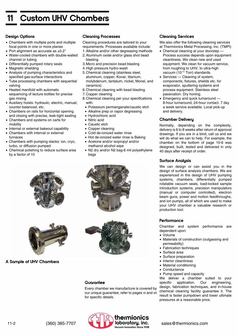
11-2 (360) 385-7707 [email protected]
11 Custom UHV Chambers
• Chambers with multiple ports and multiple focal points in one or more planes
• Port alignment as accurate as ±0.2° • Water-cooled chambers with double-walled
channel or tubing • Differentially pumped rotary seals • Magnetic shielding • Analysis of pumping characteristics and
specified gas-surface interactions • Tube processing chambers with sequential
valving • Heated manifold with automatic
sequencing of lecture bottles for precise gas mixing
• Auxiliary hoists: hydraulic, electric, manual, counter-balanced, etc.
• Chambers on rails for horizontal opening and closing with precise, leak-tight sealing
• Chambers and systems on carts for mobility
• Internal or external bakeout capability • Chambers with internal or external
furnaces • Chambers with pumping stacks: ion, cryo,
turbo, or diffusion pumped • Chemical polishing to reduce surface area
by a factor of 10
Chamber and system performance are dependent upon:• Volume• Materials of construction (outgassing and
permeability)• Fabrication techniques• Surface area• Surface preparation• Interior cleanliness• Material conditioning• Conductance• Pump speed and capacityWe deliver a chamber suited to your specific application. Our engineering, design, fabrication techniques, and in-house chemical cleaning facility guarantee it. The result is faster pumpdown and lower ultimate pressures at a reasonable price.
Every chamber we manufacture is covered by our unique guarantee; refer to pages vi and vii for specific details.
We also offer the following cleaning services at Thermionics Metal Processing, Inc. (TMPI) • Chemical cleaning at your doorstep —
Process success depends upon equipment cleanliness. We clean new and used equipment. We clean for vacuum service, from roughing to UHV, to ultra-high vacuum (10-11 Torr) standards.
• Services — Cleaning of system, components, fixtures, shields etc. for evaporator, sputtering systems and process equipment. Stainless steel passivation. Dry honing.
• Emergency and quick turnaround — 8-hour turnaround, 24-hour contact. 7 day a week service available. Local pick-up and delivery.
Normally, depending on the complexity, delivery is 6 to 8 weeks after return of approval drawings. If you are in a bind, call us and we will do what we can to help. For example, the chamber on the bottom of page 10-6 was designed, built, tested and delivered in only 40 days after receipt of order.
We can design or can assist you in the design of surface analysis chambers. We are experienced in the design of UHV pumping systems, chambers, differentially pumped rotatable vacuum seals, load-locked sample introduction systems, precision manipulators (manual or computer controlled), electron beam guns, power and motion feedthroughs, and ion pumps, all of which are used to make your UHV chamber a valuable research or production tool.
Cleaning procedures are tailored to your requirements. Processes available include:1. Alkaline and/or other degreasing methods2. Aluminum oxide and/or glass shot bead
blasting3. Micro and precision bead blasting4. High pressure hydro-wash5. Chemical cleaning (stainless steel,
aluminum, copper, Kovar, titanium, molybdenum, tantalum, nickel, Monel, and ceramics)
6. Chemical cleaning with bead blasting7. Copper cleaning8. Chemical cleaning per your specifications
with:• Potassium permanganate/caustic etch• Alkaline prep or vapor degreasing• Hydrochloric acid• Nitric acid• Caustic etch• Copper cleaning• Cold de-ionized water rinse• Hot de-ionized water rinse is Baking• Acetone and/or isopropyl and/or
methanol alcohol wipe• N2 dry and/or N2 bag-6 mil polyethylene
bags
Design Options
Performance
Guarantee
Cleaning Services
Chamber Delivery
Surface Analysis
Cleaning Processes
A Sample of UHV Chambers

11Custom UHV Chambers
11-3(360) 385-7707 [email protected]
Deposition Chamber
Laser Deposition Chamber

11-4 (360) 385-7707 [email protected]
11 Custom UHV Chambers
• 2 x 10-11 Torr chamber• 12” diameter x 12” high• 9 focal points on two planes
UHV Chamber for LEED-Auger and ESCA Surface Analysis
24” O.D. water-cooled UHV chamber with water channel, 27 1/8” O.D. wire seal flange
Water Cooled Chambers

11Custom UHV Chambers
11-5(360) 385-7707 [email protected]
36” O.D. diameter double wall, water-cooledchamber with 41” O.D. wire seal base flange
24” diameter double wall, water-cooled UHV chamber cover with 27 1/8” O.D. wire seal flange
304 stainless steel chamber, 24” O.D. by 46” long. 1/4” wall, full internal welds, chempolished and supplied with convenient lifting lugs
Water Cooled Chambers

11-6 (360) 385-7707 [email protected]
11 Custom UHV Chambers
The Thermionics load lock provides quick access to ultra-high vacuum chambers; no need to bring chamber up to atmosphere when loading sample! (Custom made to your specifications.) Refer to Section 3 for access doors, 2-access chambers and feedthrough details.
12” diameter x 27” long UHV chamber with 240 I/s noble ion pump and bakeout shroud qualified to 2 x 10-11 Torr from atmosphere. Flanges accurate to ±1/2° ±0.005”.
Sample Introduction System
2 x 10⁻¹⁰ Torr water-cooled custom chamber with rail support • Engineered and manufactured in 40 days • 24” diameter x 60” long • X, Y, Z adjustment for flange mating and
alignment

11Custom UHV Chambers
11-7(360) 385-7707 [email protected]
6.00” O.D. tube with 2.75” x 1.50” ports; 4.50” x 2.50” ports; multi-focal points on 2 planes
Angle-resolved ultra-violet photo emission spectrometer chamber
12” chamber with wire seal base flange; gate valve as poppet; multi-port and multifocal points
294 mm diameter LEED-Auger surface physics chamber with 64 mm offset focal point
Ultra-High Vacuum Chambers

11-8 (360) 385-7707 [email protected]
11 Custom UHV Chambers
All metal evaporation chamber with two (2) each three position 3 kW e-Guns with shutter. Refer to Section 4 for e-Gun information.
All Metal Evaporation Chamber
Front View
Side View
Side View Showing e-Guns

Material, Surface andMolecular Beam Sciences
12

Material, Surface and Molecular Beam Sciences
12
Molecular Beam Epitaxy
Reflection High Energy Electron Diffraction (RHEED)
Molecular Beam andSurface Chemistry Products
Pulsed Laser Deposition (PLD)
Technical Information.................MBE Systems/Specifications......Series VT-100.............................Series VT-105.............................Series VT-108.............................Series VT-110.............................Organic MBE, Series VV-301.....Ion Beam Sources......................Acessories: Sample Handling, Manipultators, e-Guns, etc.........MBE Components.......................
Technical Information.................RHEED Guns.............................Specifications..............................Dimensions.................................Ordering Information...................RHEED Power Supplies.............Specificaitons..............................Ordering Information...................Accessories.................................Phospor Screens........................Viewports....................................Viewport Shutters.......................Camera and Mount.....................Isolation Valves...........................
Laser Test Chamber, with Time-of-Flight Mass Spectrometer......Rotatable Time-of-Flight MassSpectrometer with Laser Window.......................................Molecular Beam Pulsed Nozzle Valve...........................................Heated/Chilled Molecular Beam Nozzle.........................................Differentially Pumped MolecularBeam Source Chamber..............Crystal Cleaver...........................Quick Change Manipulator Gearbox/Sample Holder.............Gearless Miniature SAM Manipulator.................................Modular Cart Systems................UHV Cold Trap Assembly...........Raman Cell.................................
Technical Information.................Specifications..............................Illustrations..................................
12-112-212-212-412-612-612-712-8
12-912-10
12-1112-1212-1212-1212-1212-1412-1412-1412-1512-1512-1512-1612-1612-16
12-20
12-22
12-24
12-2612-28
12-30
12-31
12-3212-3312-3412-34
12-1712-1812-18
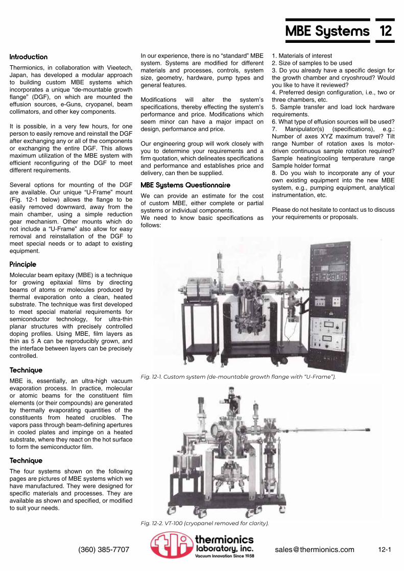
12MBE Systems
12-1(360) 385-7707 [email protected]
Molecular beam epitaxy (MBE) is a technique for growing epitaxial films by directing beams of atoms or molecules produced by thermal evaporation onto a clean, heated substrate. The technique was first developed to meet special material requirements for semiconductor technology, for ultra-thin planar structures with precisely controlled doping profiles. Using MBE, film layers as thin as 5 A can be reproducibly grown, and the interface between layers can be precisely controlled.
We can provide an estimate for the cost of custom MBE, either complete or partial systems or individual components. We need to know basic specifications as follows:
MBE is, essentially, an ultra-high vacuum evaporation process. In practice, molecular or atomic beams for the constituent film elements (or their compounds) are generated by thermally evaporating quantities of the constituents from heated crucibles. The vapors pass through beam-defining apertures in cooled plates and impinge on a heated substrate, where they react on the hot surface to form the semiconductor film.
The four systems shown on the following pages are pictures of MBE systems which we have manufactured. They were designed for specific materials and processes. They are available as shown and specified, or modified to suit your needs.
In our experience, there is no “standard” MBE system. Systems are modified for different materials and processes, controls, system size, geometry, hardware, pump types and general features.
Modifications will alter the system’s specifications, thereby effecting the system’s performance and price. Modifications which seem minor can have a major impact on design, performance and price.
Our engineering group will work closely with you to determine your requirements and a firm quotation, which delineates specifications and performance and establishes price and delivery, can then be supplied.
1. Materials of interest 2. Size of samples to be used 3. Do you already have a specific design for the growth chamber and cryoshroud? Would you like to have it reviewed? 4. Preferred design configuration, i.e., two or three chambers, etc. 5. Sample transfer and load lock hardware requirements. 6. What type of effusion sources will be used? 7. Manipulator(s) (specifications), e.g.: Number of axes XYZ maximum travel? Tilt range Number of rotation axes Is motor-driven continuous sample rotation required? Sample heating/cooling temperature range Sample holder format 8. Do you wish to incorporate any of your own existing equipment into the new MBE system, e.g., pumping equipment, analytical instrumentation, etc.
Please do not hesitate to contact us to discuss your requirements or proposals.
Thermionics, in collaboration with Vieetech, Japan, has developed a modular approach to building custom MBE systems which incorporates a unique “de-mountable growth flange” (DGF), on which are mounted the effusion sources, e-Guns, cryopanel, beam collimators, and other key components.
It is possible, in a very few hours, for one person to easily remove and reinstall the DGF after exchanging any or all of the components or exchanging the entire DGF. This allows maximum utilization of the MBE system with efficient reconfiguring of the DGF to meet different requirements.
Several options for mounting of the DGF are available. Our unique “U-Frame” mount (Fig. 12-1 below) allows the flange to be easily removed downward, away from the main chamber, using a simple reduction gear mechanism. Other mounts which do not include a “U-Frame” also allow for easy removal and reinstallation of the DGF to meet special needs or to adapt to existing equipment.
Principle
MBE Systems Questionnaire
Technique
Technique
Introduction
Fig. 12-1. Custom system (de-mountable growth flange with “U-Frame”).
Fig. 12-2. VT-100 (cryopanel removed for clarity).
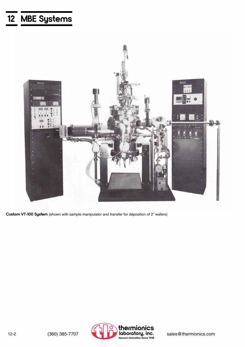
12-2 (360) 385-7707 [email protected]
12 MBE Systems
Custom VT-100 System (shown with sample manipulator and transfer for deposition of 2” wafers)

12MBE Systems
12-3(360) 385-7707 [email protected]
The VT-100 MBE system is a small research MBE system that can be configured to handle wafers up to 3” in diameter. With the Triad e-Gun source and optional effusion cells (up to three) the system may be used with the following materials:
1. Si semiconductor (Si, Ga, Al, Sb)2. High TC superconductor (Yt, Ba, Cu, St)3. Metal MBE (Au, Al, Ni, W)4. GaAs semiconductor (Ga, As, Al)
C. SOURCE FLANGE
Thermionics Triad e-Gun source mounted on a 19” O.D. bolt type wire sealed flange with an LN2 cryoshroud with debris/collimation shield surrounding the source(s). The Triad consists of three (3) 10 kW, 10 cc single crucible sources with beam sweep control. A tetrode power supply with gun controllers is included. There are also three 3.38” flanged (2” dia. tube) ports for use with effusion cells (cells and power supply are optional).
D. SAMPLE HANDLING
The standard manipulator supplied is a Thermionics FM series manipulator with the following specifications:
1. 4” Z travel, 1.88” I.D. bellows 2. ±0.5” X and Y travel 3. RNN differentially pumped rotary seal 4. Custom gearbox and drive, sample holder
with 1” square sample holder with radiant heater capable of 1,000°C operation
5. PID auto tuning sample heater controller, SPS-202/A
Motorized continuous sample rotation, larger sample sizes, oxygen environment heaters, sample cooling, RS-232 interface to PID controllers, and other manipulators available on request.
E. RHEED SYSTEM
A Vieetech VE-052NP-052 30 keV RHEED gun and power supply with a 5.68” dia. phosphor screen and screen shutter is standard.
F. OPTIONS
1. Thin film thickness monitoring/controlling may be accomplished via crystal sensors or flux monitors depending upon customer’s preference.
2. Bakeout capability is not included with standard system but may be configured into system per customer’s specifications.
3. Quadrupole mass analyzer may be provided per customer’s specification.
4. Process or gas flow control. 5. System may be expanded to include an
analysis chamber for HREELS, LEED/AES, etc.
A. GROWTH CHAMBER
A 16” diameter by 22” high bell jar constructed of 304 stainless steel with all metal seals. The surface has been electro-polished for a smooth UHV surface. Standard configuration includes:
1. Six 1.38” dia. source viewports, one 3.88” dia. sample viewport, and one 5.38” dia. RHEED screen viewport — all with shutters.
2. One manually actuated sample shutter. 3. Six electro-pneumatically actuated source
shutters. 4. Three 6” flanged e-Gun emitter access
ports. 5. Six 2.75” flanged ports for optional quartz
crystal monitors. 6. Three extra 2.75” flanged ports and two
extra 6.00” flanged ports (on line with sample).
Other configurations available on request.
B. PUMPING SYSTEM
Thermionics COV-1000 ion pump (200 l/sec ion pump with LN2 cryoshroud and titanium sublimation pump) is isolated from the main chamber via a manually actuated gate valve with a metal sealed bonnet.
Rough pumping via dual sorption pumps isolated from main system by an all-metal sealed poppet valve. Ultimate vacuum after bakeout in the 1040 Torr range (pressure during evaporation in the 10-8 Torr range). Other pumps (cryo, turbomolecular, etc.) available on request.
A. CHAMBER
Constructed of 304 stainless steel with all metal seals except for Viton sealed quick access door for sample loading. Chamber is electro-polished for a smooth UHV surface. Chamber is isolated from the main chamber by a manually actuated gate valve with metal bonnet seal.
B. PUMPING SYSTEM
200 l/sec magnetic turbomolecular pump with a two-stage mechanical rotary pump and molecular sieve foreline trap is standard. Oil-free pumps are optional. Pressure in the 10-7 Torr range without baking after 15 min of pumping from atmosphere.
C. SAMPLE HANDLING
A rack and pinion linear feedthrough, RPL, is standard with sample transfer fork for 1” square sample. Other feedthroughs and sample sizes available upon request. Cassette loading and sample heating also available.
D. OPTION
Chamber bakeout is optional.
The following electronics are housed in a standard 19” wide enclosure with 70” of rack space:
1. Ion pump and sublimator power supplies, PS-1000 and PS-500.
2. Turbo pump controller. 3. RHEED power supply, VP-052. 4. Ionization gauge controller with dual
ionization gauge (one for main chamber and one for load lock) and convection gauge (main system roughing and foreline of turbomolecular pump) capabilities. Also included is EB de-gas and UHV electrometer.
5. Sample heater power supply, SPS-202/A. 6. Shutter controller, VE-050-FB. 7. Optional equipment as needed.
Delivery: 16 weeks ARO
Introduction
SpecificationsI. Growth System
II. Load Lock System
Ill. Electronics

12-4 (360) 385-7707 [email protected]
12 MBE Systems
Standard specifications are listed on these two pages.
If you have a special requirement or a custom design for any part of a system, we would be pleased to discuss this with you.
Separate growth, analytical and entry chambers ensure the best possible physical configuration for film growth combined with optimum component layout for film characterization.
Our custom design cryogenic shrouds in the growth chamber and around each evaporation source minimize film impurity levels.
A custom designed load-lock system to facilitate rapid substrate introduction and replacement while maintaining optimum vacuum conditions in the growth chamber.
A crystal thickness monitor and RHEED system mounted in the growth chamber are used to monitor thickness and surface crystal structure during film growth.
VT-105 MBE System
3 Chamber Design
Minimum Contamination
Rapid Substrate Handling
In Situ Film Characterization
Fig. 12-3. VT-105 pumping system schematic.
VT-105

12MBE Systems
12-5(360) 385-7707 [email protected]
Film growth in the VT-105 is accomplished in a separate chamber which contains only an evaporation source flange, RHEED gun and screen, and thickness monitor. By minimizing the amount of equipment placed in the growth chamber, the substrate can be almost completely surrounded by a cryogenic shroud to ensure the cleanest possible environment for film growth. The RHEED and thickness monitor capabilities enable pertinent information about film growth, including surface structure and film thickness, to be collected during growth.
Surface analysis of substrate and films is an important adjunct to MBE, whether for basic research involving ultra-clean, ordered surfaces or for quality control during device production. In the VT-105, surface analysis is accomplished in a separate analytical chamber. Facilities for ESCA, including Auger, UVPS, EELS, etc , may be specified as options. Since these analyses are performed in a separate chamber, the problems of con-tamination or erosion of surface analytical equipment by source beams are eliminated. Furthermore, impurities from filament out-gassing from the analytical equipment will not deposit on the growing film.
Excessive pumping delays after sample introduction have proven to be a problem in many MBE systems. In the VT-105 an all-new substrate introduction system allows the rapid introduction (<30 min cycle time) of single substrates, while the pressure in the growth chamber is maintained in the 10-10 Torr range. The introduction system contains two sep-arately pumped entry lock chambers that can also be used for processing substrates or completed film structures.
Growth Chamber
Analysis Chamber
Entry Lock Chamber
Growth Chamber Specifications
Analysis Chamber Specifications
Manipulator 6-axis high precision rotating sample type (X, Y, Z, tilt, 1st rotary,2nd rotary coaxial)
Heated substrate 2” dia.Temp. range: room temp. to 1,000°C
Evaporation source Four K-cellsThree 1-position 3 kW e-Guns
Chamber size 16” dia., 20” heightPumping system 400 I/sec noble triode sputter-ion pump
Ti sublimation pump with LN2 shroud
Isolation valves 4” manual gate valve (separates the growth and analysis chambers)6” pneumatic gate valve (for ion pump)
Film characterization VE-052 30 keV RHEED system4 channel crystal thickness and rate monitor
Vacuum gauge Nude ion gauge
Manipulator 6-axis high precision type (X, Y, Z, tilt, 1st rotary, 2nd linear coaxial)Heated substrate 2” dia.
Temp. range: room temp. to 1,000°CChamber size 12” dia., 15” heightPumping system Combo-Vac model COV-1000, 1,000 I/sec combination pump
Isolation valves 4” manual gate valve (separates the analysis and entry lock chambers) 6” pneumatic gate valve (for combination pump)
Vacuum gauge Nude ion gauge
Entry Lock Chamber SpecificationsManipulator 2-axis (Z, R)Substrate 2 - 2” dia.Exchange port 6” I.D. load lock with Viton-sealed doorTransfer mechanism Magnetically coupled linear feedthroughChamber size 8” dia., 10” heightPumping system 150 I/sec turbomolecular pump
270 I/min oil rotary pump with foreline trapIsolation valves 4” pneumatic gate valve (for TMP)Vacuum gauge Nude ion gauge

12-6 (360) 385-7707 [email protected]
12 MBE Systems
• Separate growth, analysis and entry chambers
• Elaborate LN2 growth chamber cryoshrouds ensure ultra-high purity
• Simple K-cell and shutter programming (automatic or manual)
• High precision manipulator/ sample handling system
• Independent sample heaters on each manipulator
• Routine 5 x 10⁻¹⁰ Torr growing pressure • A unique combination “multipumping”
system allows rapid sample changing and maximum utilization of all facilities
• System may be easily reconfigured at any time to suit changing applications
• Two chamber configuration • 3 kW, 3-crucible electron-beam effusion
source • High speed turbo pumping of load lock
chamber permits maximum system utilization and high sample yield
• Ultra smooth substrate transfer system uses unique linear motion feedthrough
• Five axis manipulator with heating (1,100°C std.)
• Many options available for analysis and growth monitoring instrumentation
• “T-type” chamber and cryoshroud design (350 mm x 200 mm with 6” isolation valve)
VT-110
VT-108
VT-110
VT-108
Features
Main Features

12Organic MBE
12-7(360) 385-7707 [email protected]
VV-301Explanation
Capability
Special Knudsen Cell
Modular Design
MBE combined with UHV analysis techniques permits detailed investigation of the initial growth structure of ultra-thin films. These techniques are essential to understanding the growth mechanism and the interface formation between layers of different materials.
Until now, UHV MBE techniques have not been established for organic molecular systems. Such techniques are a prerequisite for realizing current molecular device designs in addition to fundamental interests.
This organic molecular beam epitaxy (OMBE) system has been designed and constructed with in-situ reflective high-energy electron diffraction (RHEED) specifically for the deposition of organic molecular layers under ultra-high vacuum (UHV).
Heteroepitaxial growth of organic ultra-thin layers on inorganic substrates has been accomplished in this UHV OMBE system with base pressures of about 2 x 10⁻¹⁰ Torr.
Difficulties in developing UHV MBE methods for organic molecular systems include inherent high vapor pressures which organic materials possess, as well as the combination of thermal instability and the impurities of any trace organic substances. A low-temperature Knudsen cell was specially designed for organic samples in this OMBE system. The temperature of the Knudsen cells can be controlled by electrical heating and by circulating liquid nitrogen.
The schematic shows that the OMBE system consists of three independent chambers connected through gate valves: a growth chamber, an entry chamber and a portable chamber. The portable UHV chamber allows easy transfer of the OMBE film samples to a separate UHV scanning tunneling microscopy (STM) system.
The combination of diffraction methods with real space imaging of STM allows direct studies of epitaxial layers at the atomic scale.
Fig. 12-4. Schematic diagram of the combined UHV OMBE system.
Cl Growth chamberC2 Entry chamber03 Portable chamberTR Sample transfer rodM ManipulatorVCP Color video copy processor

12-8 (360) 385-7707 [email protected]
12 Filamentless Ion Beam Sources
• Surface modification• Thin film stress relief• Oxiding• Nitriding• Ion assisted deposition• Ion beam insitu pre-cleaning• Chemically assisted ion beam etching• Reactive ion beam etching• Inert ion beam milling• Ion beam deposition
Applications
5 cm Source and Power Supply
3 cm Source
5 cm Source
3 cm Ion Beam System
5 cm Ion Beam System
Options
Options
Optics
Optics
Flange Mount
Flange Mount
Four Gas Feedthrough & Connections
Includes: 3 cm ion source, graphite or molybdenum ion optics, one inch baseplate feedthroughs with flexible internal utilities, and power supply
Includes: 5 cm ion source, graphite or molybdenum on optics, one inch baseplate feedthroughs with flexible internal utilities, and power supply
Convergent, divergent or collimated molybdenum (recommended) or graphite
Convergent, divergent or collimated molybdenum (recommended) or graphite
Option available
Option available
Option available

12Filamentless Ion Beam Sources
12-9(360) 385-7707 [email protected]
Specifications
STLD with heating and cooling
SPS-102/A
Ion Source
Power Supply
Beam diameter 5 cm at grid faceIon optics a) Material — graphite or
molybdenumb) Formation — collimated, defocused, focused
Output current Adjustable between .2 mA/cm2 and greater than 2 mA/cm2 at 6” from source optics set
Ion energy Adjustable between 35 eV and 130 eV 6” from source optics set
Cathode Patented filamentless Dynamic Electron EmitterTM Patent No. 4,739,214
Neutralizer Automatic filamentless neutralization under optimal conditions
Gas inlet Four gas capability; required gas (inert or reactive) into cathode electron emitter, auxiliary gas ports into anode discharge area, either reactive or inert species
Gas requirements
3-5 sccm inert or reactive species
Mountinginstallation
a) Ion source mounting bracket included b) Feedthroughs dual 1” baseplate or single 2-3/4” flange feedthrough with 18” internal flexible connections. Optional rigid mount to flange or O-ring seal flange
Type Switching with keyed plug/socket power boards
Dimensions 19” wide, 5-1/4” high,18” deep
Mounting Standard rack mounting,integral chassis slide system included
Read-outs Digital, light-emitting diodedisplays for each sourcefunction
Regulation 1. Constant voltage supply2. Constant current supplies
Connections Single keyed plug/socketconnectors with safety milspec type screw collar
Temperaturecompatibility
Bakeable to 300°C, operation to 80°C
Connections All connections from rear or ion source to feedthrough are singular keyed plug/socket mil spec type connectors
Magnets Alnico 5 permanent magnets
Construction Stainless steel and high temperature ceramics (exclusive of ion optics set)
Dimensions 5.5” long, 4.5” diameter, less than 8 pounds total weight
Pumpingrequirements
1,800 liters per second nominal
Cables 10 foot length standard,gun to power supply, otherlengths available
Control Manual individual potentiometer controls
Powerrequirements
120 volt single phase, 6 amp
Output energy 2,000 volts at 75 mA
• No heated filaments or tips• Continuous process life with 100% reactive
or inert species• Monoenergetic beam current densities• Stable beam currents from 2 mA to 50 mA
between 50 eV to 1,300 eV• Up to four gas or gas mixture capability
Unique Features
Sample Mounting, Heating, Cooling
Heater and Bias Power Supplies
Thermionics manufactures a wide variety of manipulators, feedthroughs, transfer devices, sample handling, heating, cooling, power supplies, and special components to be used with MBE systems. This page and the next show examples of the types of equipment we offer. Please consult the referenced sections for complete information about models and sizes currently available.
See Section 3 for further information about models available.
See Section 3 for further information about models available.

12-10 (360) 385-7707 [email protected]
12 MBE Components & AcessoriesManipulators 3, 6, 10, 15, and 20 kW All Metal Sealed e-Guns
EM Series
RNN Series
RPLR-.75
Hanks HM2 e-Gun
See Section 3 for further information about models available.
See Section 4 for further information about models available.
Differentially Pumped Rotary Seals
Positioning Devices
See Section 3 for further information about models available.
See Section 3 for further information about models available.

12RHEED Equipment & Accessories
12-11(360) 385-7707 [email protected]
RHEED gun and power supply, 15 keV, 30 keV, and 50 keV models available
IntroductionThe use of RHEED techniques for surface studies has become widespread with recent advances in materials synthesis, including, but not limited to, molecular beam epitaxy (MBE), high temperature super conductors, and CVD.
Since 1986, Thermionics has supplied our VE series of high energy RHEED sources and associated monitoring systems. Originally developed in Japan for MBE applications, this equipment offers unrivaled performance in the production of bright, high-definition and stable RHEED displays.
The Thermionics/Vieetech VE 50 series of electron guns represents the latest technology available commercially for RHEED applications. The VE series system utilizes an external electron gun source (i.e., it does not project into the vacuum chamber), and the magnetic electron optics make the gun
less vulnerable to unpredictable electrostatic interference which may produce display instability in other types of RHEED guns.
For studies involving RHEED intensity oscillation monitoring, a comprehensive range of accessories is available, which includes a sensitive opto-electronic converter and signal analyzer. This device may be used together with our shutter controller and a desktop computer, e.g., IBM PC, to control modes and growth rates in MBE experiments.
For applications requiring multi-angular manipulation of the RHEED source, a precision (motorized) virtual-axis tilt stage is available for various flange sizes.
If you have any specific questions about applications, do not hesitate to call us. We at Thermionics welcome your comments and suggestions.

12-12 (360) 385-7707 [email protected]
12 RHEED Guns 15 keV, 30 keV or 50 keVNew High Energy Electron Guns for RHEED ApplicationsDesigned specifically for molecular beam epitaxy applications, the VE series electron beam sources offer many advantages over other guns because of their compact design and ease of use.
Three models are available. The VE-026 covers the energy range from 1 to 15 keV, the VE-052 covers the energy range of 3 to 30 key, and the VE-056 covers the range 5 to 50 key. A remote control module simplifies
Fig. 11-5. Dimensional drawing of RHEED gun. screen observation during initial set-up adjustments. The versatile magnetic lens system provides precision focus and spot adjustment, ensuring well-defined diffraction patterns at high screen intensity. Models are fully bakeable and mounted on standard ConFlat flanges. A complete system includes the RHEED gun, power supply/control unit and remote control module. The guns are bakeable to 230°C (no elastomers).
• Small spot size gives sharp, high brilliance diffraction patterns
• Unique remote control module simplifies set-up
• Automatic overload protection • Compact size allows easy retrofit to
upgrade existing MBE systems from other manufacturers
• External mounting—no projections into chamber
Features
Fig. 12-5. Dimensional drawing of RHEED gun.
VE-052
RHEED Gun Dimensions
RHEED Gun Dimensions
VE-026 VE-052 VE-056A 14.6”
(370 mm)19.3”
(490 mm)19.3”
(490 mm)B 3.9”
(100 mm)3.9”
(100 mm)6”
(152 mm)Mounting Flange
2.75” 2.75” 4.5”
Weight (approx.)
13.2 lbs(6 kg)
15.4 lbs(7 kg)
15.4 lbs(7 kg)
VE-026 VE-052 VE-056Beam spot size 110 μm < 110 μm < 110 μmAcceleration voltage 15 keV 30 keV max. 50 keV max.Filament (tungsten) 0.1 mm wire 0.1 mm wire 0.1 mm wireBeam focus method Magnetic lens Magnetic lens Magnetic lensX-Y deflection system Magnetic Magnetic MagneticNormal working pressure range <2 x 10⁻⁶ Torr <2 x 10⁻⁶ Torr <2 x 10⁻⁶ TorrBaking temperature(HV cable removed)
230°C 230°C 230°C
Dimensions 14.6” x 3.9” 19.3” x 3.9” 19.3” x 6”Weight 13.2 lbs 15.4 lbs 15.4 lbsFlange size (standard) 2.75” 2.75” 4.5”
• Spare filaments (pack of 10)• Mounting gaskets (pack of 5)• Viewing screen not included (see page
12-15)
Cables and Accessories Included:
/D Differential Pumping Port optionThis is a factory option and must be specified when placing original order. For example, for the 30 keV system, order Model No. VE-052/D.

12RHEED Guns 15 keV, 30 keV or 50 keV
12-13(360) 385-7707 [email protected]
Fig. 12-9. RHEED gun layout.
1. Lens coil connector2. Chamber mounting flange3. Deflection coil lens (X, Y)4. Deflection alignment screws5. Focus lens alignment screws (A)6. Focus coil lens (Z)7. Focus lens alignment screws (B)8. Bellows flange screws9. Beam aperture10. Bellows cover screws11. Bellows flange12. Bellows cover13. Magnetic shield14. Anode tube15. Wehnelt cylinder16. Filament location17. Beam alignment flange18. Beam alignment screws19. Gun mounting flange20. HV connector
Precise RHEED Targeting—VXT Virtual Axis TiltA VXT series precision tilt mounted to an RHEED gun, provides precise targeting with five independent degrees of freedom. The VXT pivots the source about the target, with a location on the target surface becoming the focal or “virtual axis” point. For more information, please refer to page 3-26.
VXT-1.8/MS, shown with RHEED gun
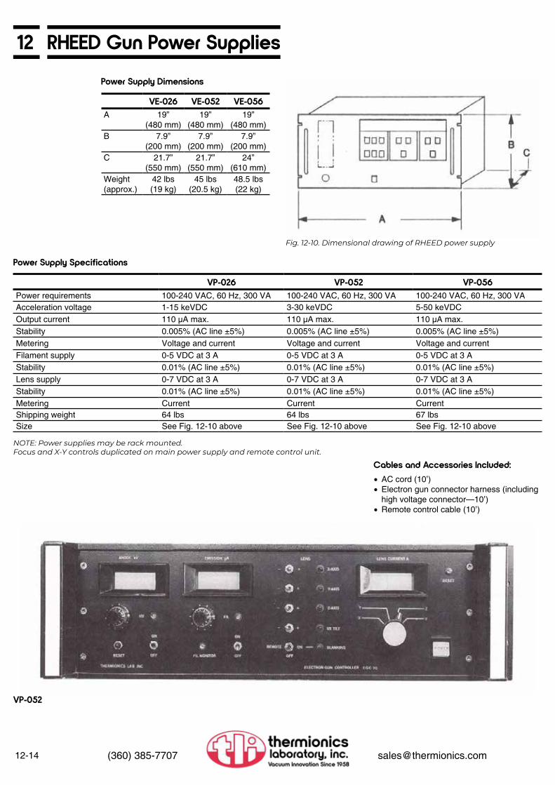
12-14 (360) 385-7707 [email protected]
12 RHEED Gun Power SuppliesPower Supply Dimensions
VE-026 VE-052 VE-056A 19”
(480 mm)19”
(480 mm)19”
(480 mm)B 7.9”
(200 mm)7.9”
(200 mm)7.9”
(200 mm)C 21.7”
(550 mm)21.7”
(550 mm)24”
(610 mm)Weight (approx.)
42 lbs(19 kg)
45 lbs(20.5 kg)
48.5 lbs(22 kg)
Fig. 12-10. Dimensional drawing of RHEED power supply
Power Supply Specifications
VP-026 VP-052 VP-056Power requirements 100-240 VAC, 60 Hz, 300 VA 100-240 VAC, 60 Hz, 300 VA 100-240 VAC, 60 Hz, 300 VAAcceleration voltage 1-15 keVDC 3-30 keVDC 5-50 keVDCOutput current 110 μA max. 110 μA max. 110 μA max.Stability 0.005% (AC line ±5%) 0.005% (AC line ±5%) 0.005% (AC line ±5%)Metering Voltage and current Voltage and current Voltage and currentFilament supply 0-5 VDC at 3 A 0-5 VDC at 3 A 0-5 VDC at 3 AStability 0.01% (AC line ±5%) 0.01% (AC line ±5%) 0.01% (AC line ±5%)Lens supply 0-7 VDC at 3 A 0-7 VDC at 3 A 0-7 VDC at 3 AStability 0.01% (AC line ±5%) 0.01% (AC line ±5%) 0.01% (AC line ±5%)Metering Current Current CurrentShipping weight 64 lbs 64 lbs 67 lbsSize See Fig. 12-10 above See Fig. 12-10 above See Fig. 12-10 above
NOTE: Power supplies may be rack mounted. Focus and X-Y controls duplicated on main power supply and remote control unit.
• AC cord (10’)• Electron gun connector harness (including
high voltage connector—10’)• Remote control cable (10’)
Cables and Accessories Included:
VP-052

12RHEED Accessories
12-15(360) 385-7707 [email protected]
Fig. 12-10. Dimensional drawing of phosphor screen shown with viewport in place.
Phosphor ScreensOur standard phosphor viewing screens utilize a short persistence (P31) zinc sulfide (Cu activated) phosphor which is deposited on low expansion lead safety glass. Screens are metallized prior to coating to minimize image distortion caused by electrostatic charging.
Model No. A BVE-050-SC4 3.8” 6”VE-050-SC6 5.5” 8”
Model No. DescriptionVE-050-SC4 4” phosphor screen with frame for mounting to 6” ConFlat-type flangeVE-050-SC6 6” phosphor screen with frame for mounting to 8” ConFlat-type flangeVE-050-GL Phosphor coated glass only, either sizeRecoating Recoating of screen with phosphor, either sizeBack Coat Aluminum back coat available, please consult the factory
ViewportsA viewport must be used in conjunction with the standard phosphor viewing screens. The Pyrex viewport permits unobstructed observation of the phosphor screen, offers limited physical protection, and provides the ultimate vacuum seal for the screen to atmosphere. For complete specifications, and for information on materials other than Pyrex, please refer to page 8-4.
Fig. 12-12. Dimensional drawing of zero-profile, wide-angle viewport.
Model No.V
ViewingDia.
Nom.Flange
Size
AFlange
O.D.
B Bolt Circle
Dia.
C Flange
Thickness
Glass Thickness
ShipWt. lbs
ZPV-400 3.88 6.00 5.97 5.128 0.780 0.210 6.0ZPV-600 5.38 8.00 7.97 7.128 0.880 0.365 9.0
Zero Profile, Wide-Angle Viewports7056 glass with Kovar sleeves and stainless steel flanges Dimensions in inches

12-16 (360) 385-7707 [email protected]
12 RHEED AccessoriesViewportsThermionics manufactures a series of rotary-actuated shutter assemblies. They are of the 90˚ shutter swing type, suitable for mounting behind “zero height” viewports. VRS series shutters are built into double-sided flanges. Refer to Section 3, page 3-76 for more information and additional viewport shutter models.
Fig. 12-13. Dimensional drawing of VRS viewport shutter
Fig. 12-14. Dimensional drawing of VE-050-CMP.
Model No. FlangeO.D. A B C
VRS-600 6.00” 7.10” 1.78” .781”VRS-800 8.00” 8.31” 2.53” .875”
Camera Mount and CameraFits 6” or 8” O.D. flange sizes
Model No. VE-050-CMP
Isolation Gate Valve
Roughing Valves See Section 9, pages 9-27, 9-28 for details
Tilt StagesSee Section 3, pages 3-24 for details
This gate valve is designed to isolate the RHEED gun from the chamber. The gate valve eliminates the requirement of venting the system, therefore simplifying filament replacement, and it allows the gun mounting to a tilt or goniometer stage.
For more information regarding valve specifications, please refer to Section 9, pages 9-1 through 9-12.
Isolation Gate Valve
Model No. DescriptionPFB-G-1500-H/R Gate valve, 1 1/2” I.D. PyraFlat bonnet, hand actuated, with mini
roughing port, and special port flangesPFB-G-1500-P/R Same, pneumatic actuationPFB-G-1500-H/R/G-11 Same with 4 1/2” x 1 1/2” flange on one side (Gen II)PFB-G-1500-P/R/G-II Same, pneumatic actuation
Model No.BVV-075-22/133AMV-075-22
Model No.TLT-1.5-2TLT-1.5-2/B-6 6” hole through base flange

12PLD-2200 Pulsed Laser Deposition System
12-17(360) 385-7707 [email protected]
Introduction
SpecificationsI. Growth System
The PLD-2200 is a platform for Pulsed Laser Deposition (PLD) systems. Since it is a platform, it can be built to meet current process requirements or budget constraints. Additional equipment and features may be added at a later time, to reflect changing requirements.
Some of our customers know exactly what they want the system to be, and we work with their specifications. Other customers know their process, but do not know what equipment is required. We work with them to develop a system that will meet their needs.
The system shown and described here is an example of a system designed, configured, modified, and built to accommodate specific customer requirements. This system has been combined with Physical Vapor Deposition (PVD) capabilities. It has two laser ports, one e-Gun source, and access ports for up to four additional evaporation sources. The integration of various tools and techniques allows flexibility, and it may be used with a variety of materials.
A. GROWTH CHAMBER The growth chamber is manufactured from 304 stainless steel. It measures 16” in diameter and 36” long. Fabrication methods meet or surpass UHV manufacturing standards. The chamber is electro-polished for a smooth UHV surface. Base pressures of 5 x 10⁻¹⁰ Torr are achieved.
The chamber pictured here has five port array levels, with a total of forty-three (43) ports. There are two laser ports mounted 45° to the target location. The e-Gun evaporation source flange is located on the side of the chamber.
The target manipulator flange, and four additional evaporation source flanges, are mounted to a large wire seal flange. A trolley system provides transport to remove, install, and align the demountable growth flange, target manipulator, and the LN2 cryoshroud from the main chamber.
B. PUMPING SYSTEMThe system uses a dry roughing and backing pump, isolated and controlled with a series of high vacuum angle valves. The high vacuum pump is a 520 l/s corrosive environment turbomolecular pump, mounted to the main chamber and isolated with a manually actuated UHV gate valve with a PyraFlat metal-sealed bonnet. Base pressures of 5 x 10⁻¹⁰ Torr are achieved. Pressure during
D. SAMPLE HANDLING 1. Substrate Manipulator/Heater The substrate manipulator mounting port is on top of the chamber, perpendicular to the horizontal axis of the load-lock and the ablation target mounting ports.
The sample manipulator is a Thermionics FM Series manipulator with the following specifications:
• 6” Z travel, 1.88” I.D. bellows • ±0.5” X and Y travel • Precision ±5° tilt, model TLTM-2.5-2 • FRMRE magnetically coupled rotary
feedthrough • Samples up to 1.5” O.D. can be heated
with a water-cooled quartz lamp heater assembly capable of continuous operation at 700°C, and up to 1,000°C peak in O2 • Motorized continuous sample rotation of 360° about the polar axis and continuous azimuthal rotation
• The substrate heater comes with an SPS- 232A power supply with PID auto tuning control and RS-232 computer interface
• Utility delivery ports
evaporation is material dependent, but typically it has been measured in the 10-8
Torr range. Other roughing and high vacuum pumps including standard turbomolecular, cryo, sputter ion, etc., are available to meet the customer’s requirements.
C. SOURCE FLANGETwo 45° laser ports are located on the main chamber. Four evaporation source mounting flanges and the target manipulator flange are mounted on a larger wire seal source flange. A trolley system provides transport to install, align, and remove the demountable source flange, target manipulator, and the LN2 cryoshroud from the main chamber.
A patented Hanks HM2 e-Gun electron beam evaporation source is supplied. This compact 6 kW source has a 7 cc crucible, and is mounted on an 8” O.D. ConFlat flange. A LN2 cryoshroud with a debris/collimation shield surrounds the source. A 6 kW tetrode power supply, gun control, triangular beam sweep controller, cables and accessories are included.
Additional sources, monitors, laser, and diagnostic equipment are available as options.
PyraFlat flanges are manufactured and pro-tected under one or more of the following patents: 5,640,751; 4,685,193
PLD-2200 Pulsed Laser Deposition System
• Larger sample sizes• Choice of heaters• Sample cooling• Other manipulators
Options

12-18 (360) 385-7707 [email protected]
12 PLD-2200 Pulsed Laser Deposition System2. Ablation Target Manipulator The standard manipulator supplied is a Thermionics FM Series manipulator, mounted horizontally, with the following specifications:
• 6” Z travel, 1.88” I.D. bellows • Horizontal mounting package • ±0.5” X and Y travel • Precision ±50 two axis tilt, model TLTM-
2.5-2 • FRMRE magnetically coupled rotary
feedthrough • WOA coaxial rotary feedthrough • The target holder accommodates four
1” targets. The targets clock and rotate continuously during ablation using a long-life motorized rare earth magnetic rotary drive. The targets are hidden behind a watercooled shroud with one target exposed to the laser at any given time. A target can be located and locked into position with the precision stepping motor rotary drive. Targets can be transferred without breaking vacuum through the load-lock. The manipulator comes complete with stepping motor controller and all utility delivery ports and accessories.
E. RHEED SYSTEM A Model VE-052NP-052 30 keV RHEED source and power supply with a 5.68” diameter phosphor screen and screen shutter is supplied.
F. CLEARVIEW HEATED VIEWPORTS AND LASER WINDOW EXCHANGE A ClearView heated viewport is provided for viewing. ClearView heated viewports eliminate problems associated with condensate clouding.
As an option, a gate valve isolated laser window can be provided. The gate valve has a roughing port built-in on the gate-seal side of the valve. A stainless steel tee connects to a roughing valve and a vent valve, to allow the removal of occluded laser ports for cleaning.
G. FRAME The chamber, source flange, load-lock, support equipment, pumping components, and controls are mounted on a stainless steel support frame. The frame has casters and leveling pads.
H. OPTIONS • Thin film thickness monitors and controllers
using crystal sensors or flux monitors • Bakeout capability per customer’s
specifications • Quadrupole mass spectrometer analyzer
may be provided per customer’s specification
• Process of gas flow control • The system may be expanded to include
an analysis chamber for HREELS, LEED/AES, etc.
• Ellipsometer • Larger substrates
Fig. 12-15. Diagram of PLD-2200 system; pumps not shown

12PLD-2200 Pulsed Laser Deposition System
12-19(360) 385-7707 [email protected]
Fig. 12-15a. Diagram of PLD-2200 introduction and transfer detail.
II. Load-Lock Substrate and Target System IV. System Testing and Installation
V. Pricing & AvailabilityIll. Electronics
Samples are introduced and removed from the main chamber through the loadlock system. The load-lock provides access, rapid pump-down and introduction to the main chamber from the transfer introduction system. The sample load-lock introduction port is opposite the ablation target manipulator port—both are on the horizontal plane.
A. CHAMBER The load-lock chamber is constructed of 304 stainless steel with metal seals. One exception—an elastomer-sealed quick access door for sample loading. The chamber is electro-polished for a smooth UHV surface. The chamber is isolated from the main chamber by a manually-actuated UHV gate valve with a metal-sealed bonnet utilizing a PyraFlat flange.
B. PUMPING SYSTEM Using an integral valve and ballast system, the load-lock utilizes the same dry roughing pump as the growth chamber. The load-lock assembly has a dedicated turbo-molecular high vacuum pump and a manually-actuated UHV gate valve with a metal-sealed PyraFlat bonnet flange. The load-lock typically reaches a base pressure in the mid 10-7 Torr range from atmosphere, without baking, in fifteen (15) minutes. Other pumps may be specified and supplied.
The system includes all necessary valves, blank-off flanges, viewports with shutters, and hardware. The system is assembled prior to shipment. Each component, sub-system, and the complete system, including the sample and target transfer, are fully tested along with all motion, electrical and water utilities, and control interlocks.
The system is pumped down and leakchecked at a minimum sensitivity of 2 x 10⁻¹⁰ std cc/sec with a helium MSLD. The system is not baked. The system is operated under UHV conditions. It is back-filled with dry nitrogen prior to shipment. The system is then disassembled and prepared for shipment.
Operator training is available.
Delivery—16 weeks ARO
Our engineering group will work closely with you to determine your requirements and then a firm quotation can be given.
The electronics for the system are mounted and integrated into the system frame. Included are:
• Turbomolecular pump controller• Roughing control system• e-Gun power supplies and controls• Gauge controls• RHEED power supply• Sample heater power supply• Stepping motor controller• Shutter controls
A separate electronics rack is available as an option.
C. SAMPLE HANDLING A 24” linear travel long stroke FLLRE rare earth linear-rotary feedthrough is supplied. Targets and samples are introduced, docked, transferred, and removed from the target manipulator or the substrate heating stage in the growth chamber using this feedthrough.
The feedthrough is mounted to a dual axis ±5° precision tilt with motion for alignment of the transfer fork to the substrate manipulator or the target manipulator. Other feedthroughs and sample sizes may be substituted. Cassette loading and sample heating are also available.
D. OPTION Chamber bakeout is optional.
PyraFlat flanges are manufactured and pro-tected under one or more of the following patents: 5,640,751; 4,685,193
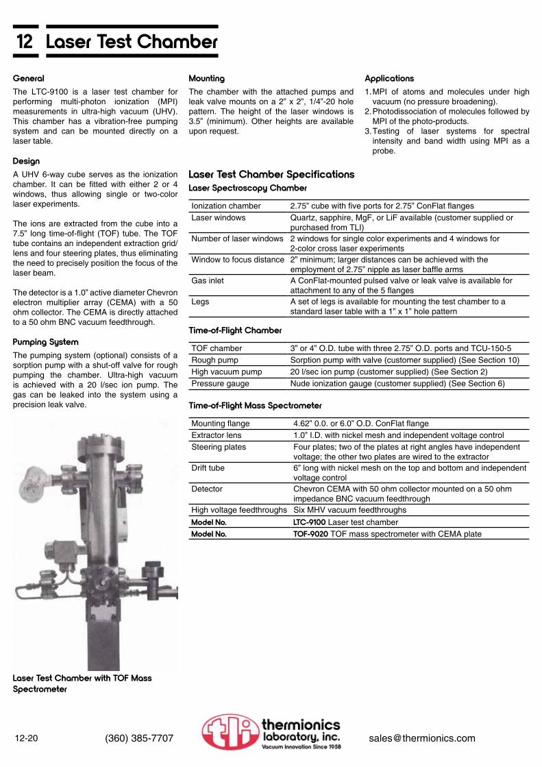
12-20 (360) 385-7707 [email protected]
12 Laser Test ChamberGeneral
Design
Mounting ApplicationsThe LTC-9100 is a laser test chamber for performing multi-photon ionization (MPI) measurements in ultra-high vacuum (UHV). This chamber has a vibration-free pumping system and can be mounted directly on a laser table.
A UHV 6-way cube serves as the ionization chamber. It can be fitted with either 2 or 4 windows, thus allowing single or two-color laser experiments.
The ions are extracted from the cube into a 7.5” long time-of-flight (TOF) tube. The TOF tube contains an independent extraction grid/ lens and four steering plates, thus eliminating the need to precisely position the focus of the laser beam.
The detector is a 1.0” active diameter Chevron electron multiplier array (CEMA) with a 50 ohm collector. The CEMA is directly attached to a 50 ohm BNC vacuum feedthrough.
The chamber with the attached pumps and leak valve mounts on a 2” x 2”, 1/4”-20 hole pattern. The height of the laser windows is 3.5” (minimum). Other heights are available upon request.
1. MPI of atoms and molecules under high vacuum (no pressure broadening).
2. Photodissociation of molecules followed by MPI of the photo-products.
3. Testing of laser systems for spectral intensity and band width using MPI as a probe.
Pumping SystemThe pumping system (optional) consists of a sorption pump with a shut-off valve for rough pumping the chamber. Ultra-high vacuum is achieved with a 20 l/sec ion pump. The gas can be leaked into the system using a precision leak valve.
Laser Test Chamber with TOF MassSpectrometer
Laser Test Chamber SpecificationsLaser Spectroscopy Chamber
Time-of-Flight Chamber
Time-of-Flight Mass Spectrometer
Ionization chamber 2.75” cube with five ports for 2.75” ConFlat flangesLaser windows Quartz, sapphire, MgF, or LiF available (customer supplied or
purchased from TLI)Number of laser windows 2 windows for single color experiments and 4 windows for
2-color cross laser experimentsWindow to focus distance 2” minimum; larger distances can be achieved with the
employment of 2.75” nipple as laser baffle armsGas inlet A ConFlat-mounted pulsed valve or leak valve is available for
attachment to any of the 5 flangesLegs A set of legs is available for mounting the test chamber to a
standard laser table with a 1” x 1” hole pattern
TOF chamber 3” or 4” O.D. tube with three 2.75” O.D. ports and TCU-150-5Rough pump Sorption pump with valve (customer supplied) (See Section 10)High vacuum pump 20 l/sec ion pump (customer supplied) (See Section 2)Pressure gauge Nude ionization gauge (customer supplied) (See Section 6)
Mounting flange 4.62” 0.0. or 6.0” O.D. ConFlat flangeExtractor lens 1.0” I.D. with nickel mesh and independent voltage controlSteering plates Four plates; two of the plates at right angles have independent
voltage; the other two plates are wired to the extractorDrift tube 6” long with nickel mesh on the top and bottom and independent
voltage controlDetector Chevron CEMA with 50 ohm collector mounted on a 50 ohm
impedance BNC vacuum feedthroughHigh voltage feedthroughs Six MHV vacuum feedthroughsModel No. LTC-9100 Laser test chamberModel No. TOF-9020 TOF mass spectrometer with CEMA plate

12Laser Test Chamber
12-21(360) 385-7707 [email protected]
Fig. 12-16. Diagram and photo of laser test chamber with time-of-flight mass spectrometer

12-22 (360) 385-7707 [email protected]
12 Rotatable Time-of-Flight Mass Spectrometer with Laser Window
Description
Technical DescriptionLaser Window
TOF Tube
Rotary Stage
Applications
The RTMS-9500 is an ultra-high vacuum-compatible time-of-flight mass spectrometer with a charged particle detector mounted on a UHV rotary stage along with a stress-free laser window. This permits the ionization of molecules and atoms using laser beams (MPI) and subsequent detection of the mass-selected ions with a Chevron electron multiplier array (CEMA). This device can be used for angle and mass-resolved detection of surface reaction/desorption products or gas-phase cross-beam experiments.
The laser window is 1/4” thick Suprasil quartz (standard; other materials available on request).The window is in a weldable adapter and is welded to the main assembly. The laser beam exits the chamber via a second window on the opposite side of the chamber.
The time-of-flight tube consists of (1) an extractor grid/lens; (2) four steering plates; (3) a TOF tube (6” standard length) and a 1.0” active diameter CEMA plate with a 50 ohm collector. The signal is fed via a UHV shielded BNC cable to a 50 ohm BNC feed through. The high voltage lines are connected to MHV feedthroughs. All the feedthroughs are on the same rotary stage which supports the ion optics and CEMA detector, thus al lowing 360° rotation.
The rotary stage is an 8” O.D., 6” I.D. platform which supports ( 1) the laser window, (2) the ion optics and detector, and (3) the electrical feedthroughs. It is attached to a worm gear to allow precise, repeatable positioning of the detector.
The detector allows low-cost angle and mass resolved detection. When combined with a suitable laser system, quantum state specific detection, as well as angle and mass resolved detection, can be performed. This detection should be of utility in (1) surface reaction/desorption chemistry, (2) two-color photodissociation experiments, and (3) cross-beam experiments
Rotatable Time-of-Flight Mass Spectrometer with Laser Window SpecificationsRotation Mechanism
Laser Window
Time-of-Flight Mass Spectrometer
Thermionics differentially pumped rotary seal, Model RNN-600/FAFlange Mates with 8” O.D. ConFlat
Materials Quartz, sapphire, MgF, LiFMounting The large windows are mounted on the center, while smaller
windows can be mounted off center or on centerWindow seal Braze, weld, O-ring, or ConFlat mounted windows depending
upon material
Extractor lens 1.0” I.D. with nickel mesh and independent voltage controlSteering plates Four plates; two of the plates are at right angles and have
independent voltage; the other two plates are wired to the extractor
Drift tube 4” long with nickel mesh on the top and bottom and independent voltage control
Detector Chevron CEMA with 50 ohm collector connected to a 50 ohm impedance BNC vacuum feedthrough via a 50 ohm UHV coax cable
High voltage feedthroughs Six MHV vacuum feedthroughsModel No. RTMS-9500 Rotatable time-of-flight mass spectrometer
with quartz laser window

Rotatable Time-of-Flight Mass Spectrometer with Laser Window 12
12-23(360) 385-7707 [email protected]
Fig. 12-17. Diagram of RTMS-9500 rotatable time-of-flight mass spectrometer with laser window
RTM S-9500

12-24 (360) 385-7707 [email protected]
12 Molecular Beam Pulsed Nozzle ValveDescription Controller
XYZ Mounting Stage
Technical DescriptionValve
The MB-9600 is a precision molecular beam source which utilizes a solenoid-activated pulsed valve (General Valve type) with an electronic controller, and is mounted on an XYZ stage. The Thermionics controller offers a significant cost savings and greater sophistication than other controllers, and the XYZ stage allows quick mounting and alignment of the pulsed valve with skimmers and other vacuum equipment.
The pulsed valve controller is impedance matched to the valve solenoid to produce smooth opening and closing of the valve without “bounce,” “ringing,” or extra pulses. The controller allows the user to vary the open time. In addition, a delay is included for synchronizing the opening of the valve with another device such as a chopper.
Frequently, a pulsed valve must be precisely aligned with an aperture, a skimmer, laser beams, or a molecular beam. This is easily accomplished with the supplied XYZ manipulator. The position of the nozzle is accurately varied using micrometers which can be locked once alignment is achieved.
The pulsed valve can produce pulses as short as 300 μsec or be operated in the open position. Pulses as short as 3 μsec can be achieved by employing a chopper wheel, also available from Thermionics. Aperture sizes of 100 microns to 2 mm are available. The valve consists of a Teflon or Delrin plunger which mates with a stainless steel aperture. The plunger is attached to a Teflon-coated magnet which is actuated by a solenoid outside the valve. The only materials in contact with the gas are stainless steel, Teflon, and the Teflon-coated magnet. A 1/4” or 1/8” Swagelok fitting connects the valve to an external gas supply.
Technical DescriptionThe pulsed source can be used for (1) time-resolved experiments and for (2) formation of high intensity molecular beams. The pulsed valve allows operation with a very low Knudsen number (compared to continuous sources) and hence produces beams with very low rotational temperatures which are nearly monoenergetic. This is most advantageous for (3) Doppler-free spectroscopy experiments and for (4) beam-surface reaction experiments. The high cooling rates can also be utilized for formation of cluster beams. The nozzle can be fitted with a heater (500°K). The heated source can produce high energy beams (0.75 eV for N2 in H2; 3.5 eV for Xe in H2).
Researchers in the fields of (1) cluster beams, (2) surface chemistry, (3) time-resolved surface infrared spectroscopy (FTIR), (4) surface electron energy loss spectroscopy (EELS), (5) molecular beam epitaxy, and (6) ultraviolet third harmonic generation will find this pulsed valve to be of interest.
Fig. 12-18. Schematic of molecular beam pulsed nozzle valve.

12Molecular Beam Pulsed Nozzle Valve
12-25(360) 385-7707 [email protected]
Pulsed Nozzle Valve SpecificationsNozzle Specifications
Electronics
Mounting Stage — EC 1600
Manufacturer General ValveValve type Solenoid activatedAperture size 100 microns to 2 mmMaterials All stainless steel except plunger (Teflon or Delrin) and the
magnet (Teflon-coated iron)Gas fitting 1/8” or 1/4” Swagelok
Opening time 30 μsec minimum to continous openVariation of opening time Open time is varied via a front panel knobSynchronization Three modes: (a) manual, (b) external, (c) delayManual mode The valve opens in response to a button on the control panelExternal mode The valve opens in response to an external TTL pulseDelay mode The valve opens after a finite delay after receiving an external
TTL pulse. The delays are user adjustable from the front panel
Purpose To align the pulsed valve with a skimmer or laser beamX-Y motion ±1/2” in each directionZ motion ±1” external to vacuum. Additional Z motion is achieved by
repositioning the pulsed valve on the manipulator shaftPosition indicators Micrometers with locking screwsModel No. MB-9600 Molecular beam pulsed valveModel No. PS-9600 Controller
MB-9600

12-26 (360) 385-7707 [email protected]
12 Heated/Chilled Molecular Beam Nozzle
Fig. 12-19. Diagram of heated/chilled molecular beam nozzle.

12Heated/Chilled Molecular Beam Nozzle
12-27(360) 385-7707 [email protected]
Description XYZ Mounting Stage
Applications
Nozzles
Heating
Cooling
The MBN-9700 is a heated/chilled molecular beam source which can produce continuous monoenergetic molecular beams (free-jets) with a stagnation temperature of +100°K to +1,600°K. This source can generate beams with very high transitional energies (3 eV for N2 seeded in H2, 14 eV for Xe seeded in H2) or rotationally cooled but vibrationally hot beams. By operating the nozzle at low pressure and high temperature, atomic beams can be formed from molecular gases. The nozzle can also be operated at low temperature with liquid nitrogen cooling, thus allowing the formation of cluster beams or very low energy molecular beams.
Short pulses (3 μsec) can be produced by employing a chopper in conjunction with the heated nozzle. A chopper with associated electronics is available from Thermionics.
Frequently, a heated nozzle jet must be precisely aligned with an aperture, skimmer, laser beams, or molecular beam. A low-cost bellows sealed XYZ stage is available with mounting hardware for the heated nozzle. The position of the nozzle is accurately varied using micrometers.
(1) Generation of energetic beams for chemical studies. (2) Formation of atomic beams (chlorine or fluorine) for etching of semiconductors. (3) Formation of vibrationally excited rotational cold species for spectroscopic studies. (4) Formation of cluster beams. (5) Generation of very low energy beam for diffraction and epitaxy studies.
Metallic nozzles are formed from molybdenum tubes with molybdenum electron microscope apertures welded onto one end. Aperture sizes as small as 25 microns are available. The gas connection to the tube is a VCR fitting.
Alumina tubes with apertures as small as 200 microns can also be provided. These tubes are cemented to a gas fitting. Ceramic nozzles are most advantageous when using halogens or oxygen.
The nozzle tubes are enclosed in a ceramic shield and are resistively heated. The gas temperature can be directly measured with a shielded thermocouple inserted inside the nozzle tubes (3/16” ID.). The heating can be regulated manually using a Variac or with a feedback circuit which employs the thermocouple.
For high temperature work, the entire nozzle assembly is enclosed in a water cooled copper shield. For low temperature, the shield is chilled by liquid nitrogen, and temperature regulation is achieved by mildly heating the nozzle.
Heat/Chilled Molecular Beam Source specificationsFor Metal Tubes
For Ceramic Tubes
Thermocouples
Heater
Material MolybdenumTube size 1/4” O.D.; 35/1000” wallAperture diameter 20 microns-400 micronsAperture thickness 10 micronsMaximum temperature 1,200°CGas connection 1/4” VCR brazed onto the tube
Material Alumina 99.8%Tube size 1/4” O.D.; 3/16” I.D.Aperture diameter 200 microns (min.)Aperture thickness 200 micronsMaximum temperature 1,400°CGas connection 1/4” VCR cemented onto the tube
Type Customer supplied or specifiedProtection tubes Alumina availableLocation of thermocouple junction In the nozzle gas about 1 cm behind the nozzle
Type Silicon carbidePower requirement 110 VAC at 15 AModel No. MBN-9700 Heated/chilled molecular beam nozzle
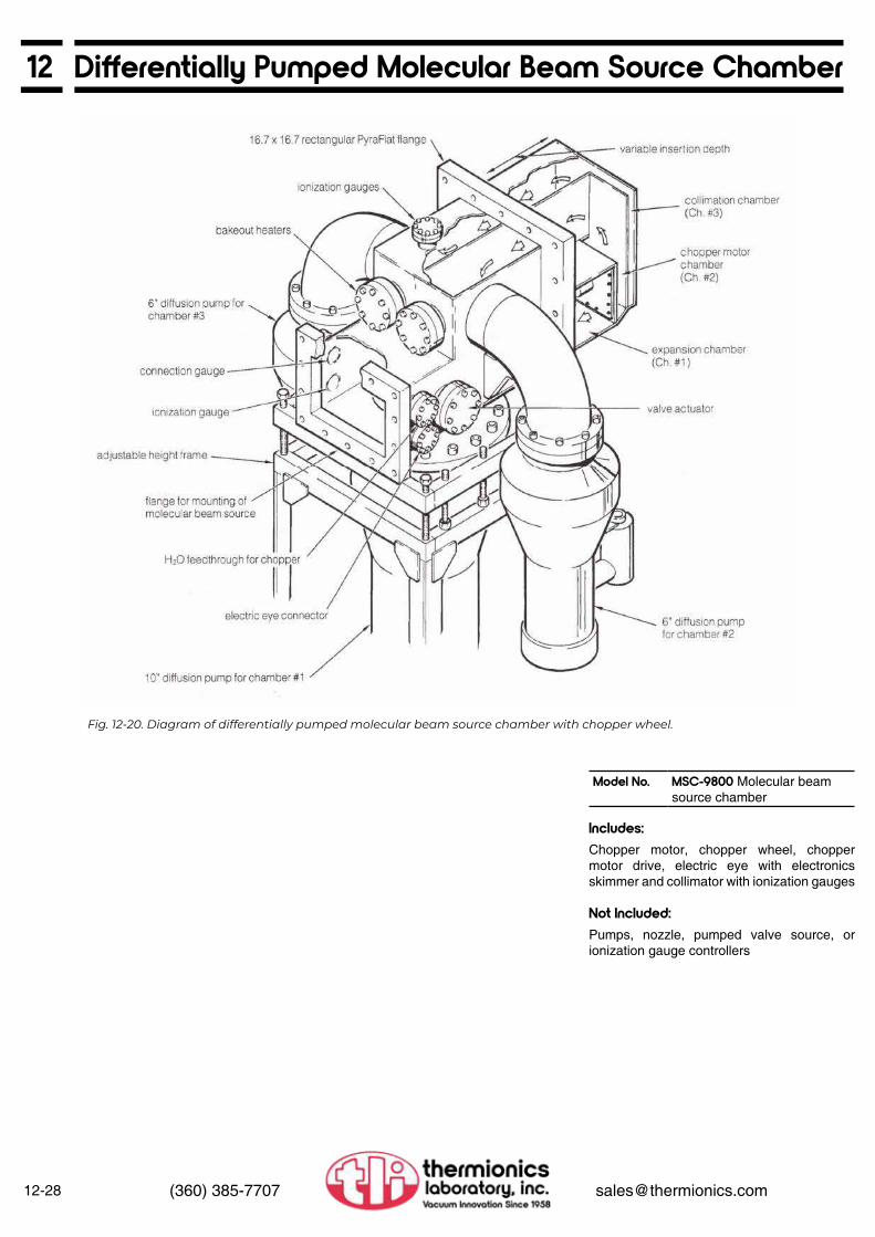
12-28 (360) 385-7707 [email protected]
12 Differentially Pumped Molecular Beam Source Chamber
Fig. 12-20. Diagram of differentially pumped molecular beam source chamber with chopper wheel.
Includes:
Not Included:
Chopper motor, chopper wheel, chopper motor drive, electric eye with electronics skimmer and collimator with ionization gauges
Pumps, nozzle, pumped valve source, or ionization gauge controllers
Model No. MSC-9800 Molecular beam source chamber

12Differentially Pumped Molecular Beam Source Chamber
12-29(360) 385-7707 [email protected]
Description
Pumps and Flange Sizes
Applications
The MSC-9800 is a differentially pumped molecular beam source. It consists of three chambers which are designed to minimize the distance between the nozzle and the final collimator (3.5”).
The first (expansion) chamber (1 x 10⁻⁷ Torr) is a high conductance chamber which directly pumps on the molecular beam source. The molecular beam leaves the expansion chamber via a skimmer and enters the second (chopper motor) chamber.
This second chamber (2 x 10⁻⁹ Torr) contains a water-cooled 400 Hz chopper which enables the beam to be chopped into microsecond- long pulses. The second chamber also contains a miniature gate valve which allows the first and second chambers to be independently brought up to atmospheric pressure. The molecular beam leaves the second chamber via a collimator inside the gate valve and enters the third (collimator) chamber.
A large rectangular source has been constructed which bolts onto a Thermionics 16.7” x 16.7” PyraFlat. This source has high conductance and thus permits the formation of intense molecular beams. The first chamber is pumped by a 10” pump via a 16” ASA flange, while the second and third chambers are pumped by 6” pumps via 8” O.D. ConFlats.
The chamber is compatible with the pulsed sources, heated nozzle, and chopper drive manufactured by TLI. Thus, this chamber is most useful for beam-surface experiments, as well as time-resolved experiments under UHV conditions.
The third chamber is typically maintained under very high vacuum (2 x 10⁻⁹ Torr); it serves as both a final collimation stage and to differentially pump the miniature gate valve. The beam leaves the collimation chamber via a removable collimator (1-10 mm dia.) and enters the UHV chamber.
Model No. CW-9810 Chopper wheel as separate item
Fig. 12-21. Diagram of chopper wheel.

12-30 (360) 385-7707 [email protected]
12 Crystal CleaverThe 0-9900 is a UHV cleaver which can cleanly cleave 3/8” wide samples. The cleaver has a specially designed backstop to prevent samples from being dislodged from their holder. The entire cleaver can be retracted by 2”, allowing it to be employed in close quarters. The cleaver blade is a standard razor blade and is easy to replace. Samples cleaved with this device have been “found flat” using atomically resolved scanning tunneling microscopy.
Heater
Blade travel ≈1”Blade and backstopretraction
≈2”
Blade metal StainlessLinear bearings StainlessMounting 2 3/4” ConFlatFlange to sample 9” standardSmoothly cleaved area
90% with good sample-to-blade alignment
Model No. C-9900 Crystalcleaver
C-9900
Fig. 12-22. Diagram of crystal cleaver

12Quick Change Manipulator Gearbox/Sample Holder
12-31(360) 385-7707 [email protected]
DescriptionThe quick change manipulator gearbox allows rapid sample exchange with a sample carousel or surface science spectrometer (STM, EELS, FTIR) without the use of transfer arms. In addition, the manipulator allows 1200 of flip rotation. The sample can be heated and cooled between 100°K and 1,300°K with precise temperature measurement.
DesignRotations
Translations
Cooling
Heating
Sample Exchange
Sample Size
360˚ rotation about the vertical axis by use of a rotary platform with 120˚ flip motion by means of worm gear drive.
Narrow neck allows use of 1.5” I.D. bellows for Z translation, thus making a long Z stroke manipulator quite affordable.
A liquid nitrogen reservoir is coupled to the sample by a large OFE copper ribbon.
Sample is conductively heated by a tantalum filament. The sample is electrically isolated from the heater as well as the manipulator. This allows for measurement of electron beam or ion beam current during Auger, LEED, etc.
The sample exchange is accomplished using the X-Y-Z motion of the manipulator.
3/8” standard, but a larger manipulator head can be made to accommodate larger sample.
ApplicationsManipulation of sample where heating, cooling, temperature measurement, and flip rotation, as well as sample exchange, are required.
Model No. GB-11 Quick changemanipulator gearbox
Includes:
Not Included:
Gearbox, cryostat and feedthroughs
RNN differentially pumped rotary seal, XYZ manipulator and rotary feedthroughs. Customer must supply; for complete information and assistance, contact the factory.
Fig. 12-23. Diagram of quick change manipulator gearbox/sample holder

12-32 (360) 385-7707 [email protected]
12 Miniature SAM (Six Axis) Manipulator GearboxDescriptionThe “SAM” miniature manipulator allows small samples (2-3 cm dia.) to be rotated over three orthogonal axes and translated in the XY- Z directions. The sample can be heated or cooled between +100°K and +2,100°K. The manipulator is only 2” wide, yet has six axes of motion plus heating and cooling. For more information, see Section 3.
Technical DescriptionRotations
Heating/Cooling
(1) Rotation about the vertical direction (manipulator shaft) is achieved using a UHV rotary stage (see Section 3). (2) Rotation about the horizontal axis is via the pantograph. This pantograph is directly rotated by a rotary motion feedthrough. The pantograph design removes the mechanical parts from the vicinity of the sample face, thus allowing the sample to be accessed by electron, molecular, or laser beams. (3) The azimuthal rotation about the sample normal is achieved by mounting the manipulator on the front of a customized rotary feedthrough.
The sample holder is electrically isolated by means of a thin sapphire washer. The sapphire washer sits directly upon a miniature (1.38” dia) molybdenum liquid nitrogen cooled cryostat. A miniature electron gun is positioned behind the sample holder, thus allowing electron bombardment heating of the sample. A thermocouple is attached either to the sample or sample holder. The temperature regulation is achieved by controlling either the bias of the electron gun or the filament current. This allows for stable temperature regulation both at high and low sample temperature.
Technical DescriptionSample manipulation over six axes of motion where pressure bursts cannot be tolerated.
Specifications for the Miniature SAM (Six Axis) ManipulatorRotations
Heating/Cooling
Sample Holders
Flip/tilt 105°-150° range depending upon application. Motion is controlled by a rotary feedthrough and a pantograph
On axis rotation 360° with a rotary seal (RNN)Polar aximuthal rotation ±30°. Rotation is achieved by mounting the manipulator on the
front of a special rotary feedthroughX-Y motion
Supplied by manipulatorZ motion
Heating element Electron bombardment heating on the back face of the crystal is achieved by heating tungsten filaments and biasing the power supply
Surface potential The sample is electrically isolated and can be grounded or negatively biased during heating
Cooling The sample sits directly on a liquid nitrogen cooled cryostat (NOCOPPER BRAID IS EMPLOYED)
Thermocouple A W-Re thermocouple is spot welded to the sample or sample holder
Type The sample holders are thin pressed disks with a platform for the sample. The electron gun sits inside the platform, thus shielding the sample from the electron gun.
Material Molybdenum is standardModel No. GB-8/0A Miniature SAM manipulator gearbox
GB-8/OA

12Modular Cart Systems
12-33(360) 385-7707 [email protected]
DescriptionPortable equipment carts permit modular assembly of complex UHV systems. They allow vacuum systems to be transported, raised and lowered for joining to existing systems and nested together when required. The carts are readily customized including such standard features as a heavy steel base plate, outrigger casters with wheel brakes, and counterbalancing. The base carries four support jack assemblies which are motor driven and lift equipment payloads up to 1,000 lbs. evenly.
Sample transfer from chamber 1 to chamber 2
Two modular carts in tandom (they are easily joined with the aid of guide pins—a bellows assembly completes the UHV channel)

12-34 (360) 385-7707 [email protected]
12 UHV Cold Trap Assembly
Fig. 12-25. LNT-701.
The LNT-700 is a cold trap which allows a diffusion pump to bring a well-baked chamber to the 10-11 Torr pressure range. This trap is designed to work with Edwards and Alcatel diffusion stacks which have built-in water baffles and ConFlat mating flanges. The TLI UHV trap is designed to eliminate the problem of evaporation off the LN2 reservoir as the liquid nitrogen level falls. A diffusion pump with a TLI UHV trap combines the advantages of (1) vibration-free pumping, (2) pumping of noble gasses, (3) low ultimate pressures, and (4) all ConFlat flange construction (no indium or Viton seals).
• Liquid nitrogen level controller—allows LN2 level to be maintained (see page 6-12)
• Integral bakeout lamp (see Section 10)• Steel stand for trap and pump
• 1.5” O.D. tube, 24” long, with 2.75” end flanges
• All metal, backfill valve• Two Suprasil quartz windows• Pressure gauge
Model RC-9300
Specifications
Options
Features
Baffle flange 13 1/4” ConFlatMating flange to pumping 13 1/4”, 10”, 8”, or 6” ConFlatMating flange to chamber 10” ConFlatReservoir LN2 life 9 hr standard (other sizes on request)Conductance 900 l/secBaffle material OFE copperModel No. LNT-700 UHV liquid nitrogen trapModel No. LNT-701 Same as LNT-700, with
additional port for TSP (see page 2-18 for TSP)
Raman CellThe model RC-9300 Raman cell is used to generate tunable UV and IR radiation from tunable dye lasers.
The Raman cell allows wave length shifting of laser radiation to both the red and blue on infinite laser beams. Orders as high 5th anti-Stokes have been achieved with this cell. The Raman cell is fabricated from stainless steel. A special chemical polishing process allows the cell to be pumped down to very low pressures prior to backfill, and minimizes outgassing from the cell after filling. Therefore, the contained is maintained at very high purity.
The cell is supplied with stress-free, laser feedthrough windows. Suprasil quartz windows are supplied standard, but the cell can be supplied with quartz, sapphire, magnesium fluoride, or lithium fluoride windows, at extra cost.
WARNING: Using this device with hydrogen or other volatile gases: OPERATIONS INVOLVING HYDROGEN ARE HAZARDOUS, including EXPLOSIVE. Materials commonly considered non-hazardous become dangerous in such environments.
We recommend that systems utilizing hydrogen be undertaken only by those persons properly skilled to perform such operations in a safe and cautious manner.

Thermionics Laboratory, Inc.
3118 Depot Road, Hayward, CA 94545Phone: (510) 225-6975 ext 100Toll Free: (800) 962-2310Email: [email protected]: thermionics.com
Thermionics Northwest, Inc.
231-B Otto Street, Port Townsend, WA 98368Phone: (360) 385-7707Toll Free: (800) 962-2310Email: [email protected]: thermionics.com
Vacuum Components & Systems