Vacuum Components & Systems - Thermionics
304
Vacuum Components & Systems 2021 Catalog
-
Upload
khangminh22 -
Category
Documents
-
view
0 -
download
0
Transcript of Vacuum Components & Systems - Thermionics

Vacuum Components & Systems 2021 Catalog

Copyright 1998, Thermionics Laboratory, Inc. Reproduction in whole or in part, in any language, without the prior written approval of Thermionics is prohibited. All rights reserved.
Ion Pumps Ion Pumps, Titanium Sublimation Pumps, Combo-Vac Pumps, Power Supplies, Rebuilding
Manipulators and Mechanical Feedthroughs XYZ Manipulators, ANN Rotary Seals, Linear and Rotary Feedthroughs, Heating and Cooling, Sample Transfer
•
Valves
e-Guns
Gate, Rectangular, M.E.S.C., Angle, Inline, Straight Through, All-Metal Bakeable
Electron Beam Evaporation Sources 6-20 kW, Hanks HM2 —Single and Multiple Crucibles, Co-Evaporation Hydra and Triad, 4 Crucible Rotary Guns 3 kW Single and Multiple Crucible; Power Supplies
Electrical and Fluid Feedthroughs Electrical, Instrumentation, RF and Liquid Feedthroughs
Instrumentation Gauges and Controls, Thermocouple, Cold Cathode, Pirani, LN
Flanges PyraFlat Rectangular, ConFlat, Adapters, ASA
Fittings, Accessories and Hardware Fittings-ConFlat and ISO, ISO Flanges, AL Fittings, Feedthrough Collars, Components, Hoses, Traps
Systems Ion Pumped TTS Systems, Evaporators, Custom Systems, Cold Wall Furnace, Sorption Pumps and Super-Sorb Carts
Custom Chambers Surface Analysis Chambers, Custom Designs and Modifications
Material, Surface and Molecular Beam Sciences
1
2
3
4
5
6
8
9
10
11 MBE, RHEED, PLO, Molecular Beam and Surface Chemistry
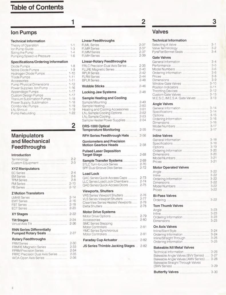
Table of Contents
1 Ion Pumps
Technical Information Theory of Operation 1-1 Ion Pump Guide 1-3 Sizing the Pump 1-4 Pumping Speed vs Pressure 1-6
Specifications/Ordering Information Diode Pumps 1-8 Noble Diode Pumps 1-9 Hydrogen Diode Pumps 1-10 Triode Pumps 1-11 Accessories 1-11 Pump Physical Dimensions 1-12 Power Supplies, Ion Pump 1-16 Appendage Pumps 1-17 Custom Design Pumps 1-17 Titanium Sublimation Pumps 1-18 Power Supply, Sublimation 1-18 Combo-Vac Pumps 1-19 LN2 Shroud 1-19 Pump Rebuilding 1-22
2 Manipulators and Mechanical Feedthroughs Introduction Terminology 2-2 Custom Equipment 2-3
XYZ Manipulators EC Series 2-4 EM Series 2-6 TPM Series 2-8 FM Series 2-10 FB Series 2-12
Z Motion Translators LMAB Series 2-14 EMT Series 2-16 FBT Series 2-18 ECT Series 2-20
XY Stages 2-22
Tilt Stages 2-24 Virtual Axis Tilt 2-26
RNN Series Differentially Pumped Rotary Seals 2-27
Rotary Feedthroughs FRM Series 2-30 FRMRE Magnetic Series 2-33 FPRM Precision Series 2-34 FRRC Precision Dual Axis Series 2-35 WOA Open Axis Series 2-36
2 3
Linear Feedthroughs
Valves
Technical Information FLML Series 2-37 Selecting A Valve 3-1 FLMR Series 2-37 Valve Terminology 3-2 FLMM Series 2-37 PyraFlat Bonnet Seals 3-4 FLMH Series 2-39
Gate Valves Linear-Rotary Feedthroughs General Information 3-4 FRLC Precision Dual Axis Series 2-35 Performance 3-5 FLLRE Magnetic Series 2-40 Model Numbers 3-6 RPLR Series 2-42 Ordering Information 3-6 FLRM Series 2-44 Prices 3-8 BPLR Series 2-48 Dimensions 3-9
Window Gate Valves 3-10 Wobble Sticks 2-46 Position Indicators 3 -11
Locking Jaw Systems 2-48 Throttling Devices 3-12 Custom Gate Valves 3-13
Sample Heating and Cooling M.E.S.C./M.E.S.A. Gate Valves 3-13 Sample Mounting Sample Heating
2-49 2-50 Angle Valves
Heating and Cooling Accessories 2-51 General Information 3-14
LN2 Sample Cooling Options 2-52 Specifications 3-14
LN2 Sample Cooling 2-53 Options 3-15
Sample Heater Power Supplies 2-54 Ordering Information 3-16 Dimensions 3-16
DRS-1000 Optical Model Numbers 3-17 Temperature Monitoring 2-55 Prices 3-17
RFH Series Feedthrough Hats . 2-56 Inline Valves
Goniometers and Precision Motion Gearbox Heads 2-58
General Information Specifications Options
3-18 3-18 3-19
Pulsed Laser Deposition Ordering Information 3-20 Target Stage 2-68 Dimensions 3-20
Model Numbers 3-21 Sample Transfer Systems 2-69 Prices 3-21 STLC Turn-to-Lock Series 2-70 SPF Dual Groove Disk Series 2-72 Motor Operated Valves
Load Lock Angle Inline
3-22 3-22
QAC Series Quick Access Caps 2-73 Ordering Information 3-22 LLC Series Load Lock Chambers 2-74 Dimensions 3-22 QAD Series Quick Access Doors 2-75 Model Numbers 3-22
Viewports, Shutters Prices 3-22
VRS Series Viewport Shutters 2-76 Bi-Pass Valves VLS Series Viewport Shutters 2-77 Ordering 3-22 ClearView Series Heated Viewports 2-78 Delta Shutters 2-78 Tom Thumb Valves
Motor Drive Systems Angle Inline
3-23 3-23
Motor Drive Options 2-79 Ordering Information 3-23 Accessories 2-80 Dimensions 3-23 SMC Series Stepping Motor Controllers 2-81 On Axis Valves YMC Series Synchronous Inline/Slant Style 3-24 Motor Controllers 2-81 Ordering Information 3-24
Faraday Cup Actuator 2-82 Inline/Straight Through Ordering Information
3-25 3-25
JS Series Thimble Jacking Stages . 2-82 Bakeable/All Metal Valves Technical Information 3-26 Bakeable Angle Valves (BVV Series) 3-27 Bakeable Angle Valves (AMV Series) 3-28 Bakeable Straight Through Valves (SMV Series) 3-29
Butterfly Valves 3-30

Table of Contents
4 e-Guns
Technical Information Theory of Operation 4-1 Custom e-Guns 4-1
Hanks HM2 e-Guns, 6-20 kW General Description 4-2 Single Crucible 4-3 Rotary, Multiple Crucibles 4-4 Hydra-2, Co-Evaporation, Dual Array, Multiple Crucibles/Emitters 4-5 Hydra-1, Co-Evaporation, Single Array, Multiple Crucibles/Emitters 4-6 Triad, Co-Evaporation, Three Crucibles 4-7 Accessories
Replacement Parts, Feedthroughs, Crucible Liners 4-8
6 kW Multiple Position Linear 3 and 4 Crucibles 4-9
6-20 kW Power Supplies Technical Information Specifications Prices
5 Electrical and Fluid Feedthroughs
Electrical Feedthroughs FMC Medium Current 5-1 FHV High Voltage 5-2 FHC High Current 5-3 FMH & FBN Instrumentation 5-4 FSH & FBSH Instrumentation 5-6 FIM Coaxial 5-7 FEP Multi-Conductor 5-8 PLC Push-On Connectors 5-8 Thermocouple 5-9 Film Thickness Monitor 5-10
Fluid Feedthroughs FCW Water Cooling 5-11 FLN Cryogenic 5-12
4-10 4-11 Instrumentation 4-11
Beam Sweep Controllers Triangular, X-Y 4-12 Circular 4-13
3 kW e-Guns Single Position 4-14 Multiple Position-3,4, and 5 Crucibles 4-15 Rod Fed 4-17 Accessories
Replacement Parts, Feedthroughs, Beam Sweep 4-18 Crucible Liners 4-18
3 kW Power Supply 4-19 Upgrade Retrofit 4-19
Repair and Rebuild Services
Training Classes 4-20
Evaporation Tables 4-21
Transformers and Magnetic Devices 4-22
6
Thermocouple Gauge Tubes and Controllers Technical Information Gauge Tube Ordering Information Gauge Tube Specifications Cross Reference Guide Equivalency Table T.C. Gauge Controllers, Analog T.C. Gauge Controllers, Battery Powered T.C. Gauge Controllers, Digital
7 Flanges
Technical Information General Information 7-1 Specifications 7-1
PyraFlat Rectangular Flanges Technical Information 7-2 Ordering Information 7-2 Assembly Hardware 7-3 Applications 7-4
ConFlat Flanges Technical Information Ordering Information Rotatable Tapped Rotatable Non Rotatable Tapped Non-Rotatable Dimensional Drawings Note: Assembly Hardware and Gaskets are shown on the same page
Adapter Flanges (ConFlat) Double-Sided Flanges 7-16
Reducing Flanges 7-18
6-1 Wire Seal Flanges 6-1 Bolt-Type Wire Seal Flanges 6-2 Clamp-Type Wire Seal Flanges
Note: Assembly Hardware and Gaskets are shown on the same page
ASA Flanges Standard ASA Flanges 7-24 ASA/ConFlat Adapter Flanges 7-25 Note: Roughing Accessories have been moved to Section 8
6-2 6-3 6-4 6-6
Cold Cathode Ionization Gauges and Controllers Technical Information 6-7 Gauge Tube Ordering Information 6-7
4-20 Controller Ordering Information 6-8
Pirani Gauges and Controllers Technical Information 6-9 Ordering Information 6-9
Bayard-Alpert Ionization Gauges Glass Envelope Type 6-10 Nude Type 6-11 Replacement Filaments 6-11
Liquid Nitrogen Level Controller Technical Information 6-12 Ordering Information 6-12 LN2 Transfer Line 6-12
7-2 7-6 7-6 7-8
7-10 7-12 7-14
Note: Assembly Hardware and Gaskets are shown on the same page
7-20 7-22

Table of Contents
8 Fittings, Accessories, and Hardware
Fittings CF (ConFlat) Fittings
Tube Fittings 8-1 Half-Nipples, Nipples, Elbows, Tees 8-1 4-, 5-, and 6-Way Crosses, 6-Way Cubes 8-2 Flexible Couplings, Reducing Nipples 8-3 Viewports—Pyrex, Sapphire, and Quartz 8-4 Adapters—Ceramic-to-Metal, Glass-to-Metal 8-5
ISO (KF) Flanges and Fittings Technical Information 8-7 Flanges and Blanks 8-8 Centering Rings, Clamps 8-9 Quick Clamp System 8-10 Tube Fittings 8-10 Half-Nipples, Nipples, Tees 8-10 4-, 5-, and 6-Way Crosses, Elbows, Flexible Couplings 8-11 Hoses, Adapters, Reducing Nipples 8-12
Fittings, Miscellaneous Metal Spherical Joints 8-14 Quick Disconnects 8-15 RL Fittings 8-16
Accessories Pyrex Bell Jars, Guards, and Accessories 8-22 Feedthrough Collars 8-22 Pinch-Off Tubes 8-23 Hoses, Flexible Stainless Steel 8-24 Double-Sided Flanges with Valves and/or T.C. Tubes 8-24
Hardware Note: Bolt Sets for Standard Flanges are listed with the Flanges in Section 7 12-Point Bolt Sets 8-25 Stud and Nut Sets 8-25 Welded Bellows 8-25 Formed Bellows 8-26 Vacuum Tubing 8-26 Super Seal Epoxy Sealant 8-27 Fel-Pro C-100 Lubricant 8-27 Precision Shaft 8-27 Precision Bored Shaft 8-27
Traps Foreline, Optically Dense Type 8-27 Foreline, Molecular Sieve Type 8-28
iv
9 Systems Systems Descriptions General Information 9-1
Ion Pumped TTS Table Top Systems Applications and Features 9-2 PyraFlat Rectangular Access Port Flange and Cryoshroud 9-2 Technical Information 9-4 Dimensions 9-5 Pumping Speed vs Pressure Curves 9-5 Specifications 9-6 Ordering Information, Model Numbers, and Features Options
Evaporators VE-80, VE-90, and VE-100 Series
General Information 9-10 VE-80 Specifications, Ordering 9-10 VE-90 Specifications, Ordering 9-11 VE-100 Specifications, Ordering 9-12
Cold Wall Vacuum Furnace Technical Information 9-13 Ordering Information 9-13
Custom Systems Ion Pumped 9-14 Cryo Pumped 9-14 Turbo Pumped 9-15 Diffusion Pumped 9-15 Others 9-16
Sorption Pumps Technical Information 9-17
f,Specifications 9-17Ordering Information 9-17 Sorption Pump Systems 9-18 Specifications 9-18 Ordering Information 9-18
Sorption Pump Roughing Carts Technical Information 9-20 Automatic Carts, Series SP-70 9-20 Ordering Information - 9-21 Manual Carts, Series SP-52 9-21 Ordering Information 9-21 Note. The Liquid Nitrogen Controller has been moved to Section 6
10 Custom Chambers
11 Material, Surface and Molecular Beam Sciences
Molecular Beam Epitaxy (MBE) Technical Information 11-1 MBE Systems/Specifications 11-2 Series VT-100 11-2 Series VT-105 11-4 Series VT-108 11-6 Series VT-110 11-6 Organic MBE, Series VV-301 11-7 Ion Beam Sources 11-8 Accessories: Sample Handling,
9-6 Manipulators, e-Guns, etc. 11-9 9-9 MBE Components 11-10
Reflection High Energy Electron Diffraction (RHEED) Technical Information 11-11 RHEED Guns 11-12 Specifications 11-12 Dimensions 11-12 Ordering Information 11-12 RHEED Power Supplies 11-14 Specifications 11-14 Ordering Information 11-14 Accessories 11-15 Phospor Screens 11-15 Viewports 11-15 Viewport Shutters 11-16 Camera and Mount 11-16 Isolation Valves 11-16
Pulsed Laser Deposition (PLD) Technical Information 11-17 Specifications 11-18 Illustrations 11-18
Molecular Beam and Surface Chemistry Products Laser Test Chamber, with Time-of-Flight Mass Spectrometer 11-20 Rotatable Time-of-Flight Mass Spectrometer with Laser Window 11-22 Molecular Beam Pulsed Nozzle Valve 11-24 Heated/Chilled Molecular Beam Nozzle 11-26 Differentially Pumped Molecular Beam Source Chamber 11-28 Crystal Cleaver 11-30 Quick Change Manipulator Gearbox/Sample Holder 11-31 Gearless Miniature SAM Manipulator 11-32 Modular Cart Systems 11-33 UHV Cold Trap Assembly 11-34 Raman Cell 11-34
Custom Vacuum Chambers Technical Information 10-1 Performance 10-1 Specifications 10-1 Engineering and Design 10-2 Cleaning 10-2 Certification 10-2 Analysis 10-2 Examples
Deposition Chambers 10-3 Surface Analysis Chambers 10-4 Water Cooled Chambers 10-5 Sample Introduction 10-6 Laser Chambers 10-6 Gate Valve Isolation 10-7 e-Gun 10-8

Ordering Information
vi
About the Company Ordering Information
Minority Statement
Products in Section 3 & 5
All Other Products
Thermionics Northwest, Inc.
Thermionics Laboratory, Inc.
Vacuum Training Courses Prices and Specifications
Course Description Terms of Payment
Discounts
Minimum Order
Delivery
FOB Point
Method of Shipment
Since 1958, Thermionics has designed, developed, and manufactured vacuum equipment for scientific and industrial applications. Our products are the result of careful research and development. rigorous testing, and continuing performance evaluation. Our commitment to quality and reliability is one reason researchers and OEM manufacturers specify Thermionics’ products
We listen to our customers. They are the best source for information about current and emerging processes and technologies. These discussions stimulate product development and ensure continuous improvement.
For new components and systems, or the modification and repair of existing equipment, Thermionics will deliver the best equipment and value to you.
Orders are placed directly with the company. Contact the office nearest you. If you cannot find the product you need, or if you have any questions, please do not hesitate to contact us. We will provide all the assistance you may need.
When you purchase products from Thermionics Laboratory, Inc., you fulfill the minority vendor requirements for all Government Institutions and Contractors.
231-B Otto Street, Port Townsend, WA 98368Phone: (360) 385-7707
Toll Free: (800) 962-2310Email: [email protected]
Website: thermionics.com
3118 Depot Road, Hayward, CA 94545Phone: (510) 225-6975 ext 100
Toll Free: (800) 962-2310Email: [email protected]
Website: thermionics.com
Three-day basic vacuum technology courses tailored to meet the needs of your personnel, and those individuals wanting to learn more about high and ultra-high vacuum technology.
Prices and specifications are subject to change without notice, please contact us for firm price quotations and current specifications.
An introduction to basic vacuum technology, theory and fundamentals, including, but not limited to: gas behavior, conductance, viscous flow, molecular flow, vap or pressure, vacuum measurement, mean free path, etc.
Familiarization with the physical construction, operation, and maintenance of mechanical, diffusion, ion, cryo, turbo and sorption pumps, mass spectrometer leak detectors, residual gas analyzers, deposition monitors, e-Guns, sputtering systems, etc.
Introduction to practical vacuum system design concepts using accessory vacuum equipment such as valves, traps, fanges, feedthroughs, viewports, pumps, chambers, etc.
As a rule, all classes are held at the Thermionics facility, located at 3118 Depot Rd, Hayward, CA 94545, but classes can be scheduled at your facility.
Courses can be customized to meet most special requirements. On-site training requires a suitable classroom, audiovisual equipment, and operating equipment.
Please contact us at [email protected] for further information about schedules and fees.
Domestic: Net 30 days upon approval of credit. Export: Letter of Credit on deposit prior to shipment.
OEM, quantity, and educational discounts are available, on request, to qualified customers, when applicable.
There is a $100.00 minimum order, for non-replacement parts.
An inventory level is maintained on all items shown in this catalog. Firm delivery will be quoted at the time the order is placed.
Shipments are FOB our plant, unless quoted otherwise.
Shipments are normally sent on a prepay and add basis. Firm shipment arrangements are quoted at the time of order.

vii
THIS PAGE
INTENTIONALLY
LEFT BLANK

Thermionics’ Commitment
viii
Thermionics’ One
Standard products manufactured by Thermionics Vacuum Products and its subsidiaries are guaranteed to be free of material and workmanship defects for a period of one (1) year. Expendable component parts are guaranteed for their expected service life.
Thermionics Laboratory, Inc. (herein called THERMIONICS) warrants to the original purchaser.
Scope
Expected Service Life
Standard catalog products manufactured by THERMIONICS against defects in workmanship for a period of one (1) year from the date goods are received at the customer’s facility
In-warranty repaired, or replaceable parts are warranted only for the remaining portion of the original warranty period, applicable to the parts which have been repaired or replaced, and the total equipment is warranted for the balance of the one (1) year period. After expiration of the applicable warranty period, the buyer shall be charged at THERMIONICS’ current prices for parts and labor, plus freight and per diem, when applicable
Expendable component parts, including, but not limited to pump elements, cold cathode gauges, bellows, thermo-couple gauges, hot cathode gauges, sublimator filaments, emissive filaments, heaters, elastomers, bearings and gasket, etc. are guaranteed for their expected service life. If the expendab1e component parts a to give reasonable service, as determined solely by THERMIONICS, they will be repaired or replaced at our discretion
Pump Elements Diode, Differential Diode Hydrogen and TriodeCold Cathode GaugesBellows Valves Manipulators Linear Actuation Rotary FeedthroughsThermocouple Gauges Hot Cathode Gauges Sublimator Filaments Emissive Filaments Heater, ElastomersBearings
Gaskets
40,000 hours at 2 x 101 Torr30,000 hours at 2 x 101 Torr40,000 hours at 2 x 101 Torr
10,000 full cycles
10,000 full cycles700,000 rotationsMeet specifications upon receipt. Life is dependent upon operating conditions
Life is dependent upon service conditions and maintenance One time use
Liability under this warranty is expressly limited to repair or replacement of defective part THERMIONICS, at its sole option, may at any time discharge its warranty as to any of its products by refunding the purchase price and taking back the product(s).
Special products and electronic components are covered for a period of one (1) year from the date goods are received at the customer’s facility
This warranty applies only to parts manufactured and labor provided by THERMIONICS.
Valid warranty claims must be received by THERMIONICS within the warranty period and are subject to the terms and conditions herein.
All warranty replacement or repair of parts shall be limited to equipment malfunctions which at the sole discretion of THERMIONICS, are due or traceable to defects in original materials or workmanship.
Malfunctions, which in the sole opinion of THERMIONICS, are caused by abnormal wear and tear, lack of maintenance, abuse, operation maintenance or care inconsistent with the product manual, accident, or neglect of equipment are expressly not covered by this warranty. It is the responsibility of the user to operate the equipment in a reasonable and prudent manner, consistent with the stated intended use
I.
II.
A.
F.
G.
A.
B.
B.
C.
D.
E.
If, for any reason, you are not completely satisfied with our products, let us know. We want to address your concerns.
Our relationship with the user does not end with the delivery of the equipment. We have a large stake in your new equipment operating up to your expecta-tions. Our goal is to be part of your success.

ix
Thermionics’ Commitment
Year Warranty
Conditions Procedures
THERMIONICS expressly disclaims responsibility for any loss or damage caused by the use of its products, when not used in accordance with proper operating and safety procedures in accordance with specifications, or if the equipment is used without the proper recommended maintenance. Reasonable care must be taken by the user to avoid hazards.
If you wish to return equipment for repair, contact the THERMIONICS DIVISION which sold you the product in question. You will be given an RMA Authorization Number and instructions on how and by what means to ship the product to the factory. NO SHIPMENT WILL BE ACCEPTED WITHOUT PRIOR APPROVAL and completed RMA Authorization Form.
Except as stated herein, THERMIONICS makes no warranty, express or implied, either in fact or by operation of law; and, as stated herein, THERMIONICS shall have no liability under any warranty, express or implied, either in fact or by operation of law.
In the first year, goods must be returned, freight prepaid, to the factory and will be returned, freight prepaid, to the customer. After the first year, all freight costs must be paid by the customer.
THERMIONICS shall have no liability for special or consequential damages of any kind, or from any cause arising out of the sale, installation, or use of any of its products. Statements made by any person, including representatives of THERMIONICS, which are inconsistent or in conflict with the terms of this warranty shall not be binding upon THERMIONICS unless reduced to writing and approved by an authorized officer of THERMIONICS.
This warranty does not cover normal maintenance requirements which are the customer’s responsibility.
This warranty does not extend to equipment that a) someone other than Thermionics approved personnel have disassembled or attempted to repair,b) has been modified or altered, orc) has been contaminated with hazardous material or induced activation
III. IV.
A. A.
B. B.
C.
D.
E.

Trademarks & Copyrights
x
The trademarks and registered trademarks listed below are the property of their respective companies.
Alberox Corp.AlcatelVacuumProducts, Inc.Hoskins Mfg. Co.Allied Corp.American Standards AssociationAmerican Society of Mechanical EngineersAmerican Society for Testing and MaterialsAutoDesk CorpThermionics Laboratory, Inc.Felt Products Mfg. Co.Swagelok Marketing Co.Wellman Thermal SystemsCeramxHoskins Mfg. CoThermionics Northwest, Inc.Thermionics Laboratory, Inc.Varian AssociatesWilbur B. Driver Co.
Helix Technology Corp.CVC Products, Inc.E.I. DuPont de Nemours & Co, Inc.Diversey Corp.Dow Corning Corp.Thermionics Northwest, Inc.Welch Vacuum, Thomas Industries. Inc.
Anatech, LtdEdwards High Vacuum InternationalThermionics Laboratory, Inc.EPI, Inc.Poca Graphite, Inc.Felt Products Mfg., Inc. Ferrofluidics CorpAusimont U.S.AFredricks Co.E.I. DuPont de Nemours & Co, Inc.Gast Mfg. Corp.
Omicron Corp GmbHPerkin-Elmer Corp.Thermionics Laboratory, Inc.Thermionics Laboratory, Inc.Corning, Inc.Instruments S.A.Thermionics Laboratory, Inc.Saes Getters S.p.A.Monsanto Co.Welch Vacuum Technology, Inc. Varian AssociatesThermionics Northwest, Inc.E.I. DuPont de Nemours & Co., Inc.
Superior ElectricThermionics Laboratory, Inc.Heraeus Amersil, Inc.Thermionics Laboratory, Inc.Swagelok Marketing Co.E.I. DuPont de Nemours & Co., Inc.Thermionics Laboratory, Inc.Thermionics Laboratory, Inc.Thermionics Laboratory, Inc.Thermionics Laboratory, Inc.Thermionics Laboratory, Inc.Swagelok Marketing Co.Technipower, Inc.Vanan AssociatesSwagelok Marketing Co.Swagelok Marketing Co.Veeco Instruments, Inc.Danaher ControlsE.I. DuPont de Nemours & Co., Inc.Vacuum Generators Ltd.DuPont Dow Elastomers L.L.C.Welch Vacuum, Thomas Industries, Inc.Varian AssociatesMicrosoft Corp.Microsoft Corp.
General Valve Corp.Granville-Phillips Co.
Thermionics Laboratory, Inc.Teledyne Hastings-Raydist, Inc.Haynes International, Inc.Heli-Coil Corp.Thermionics Laboratory, Inc.Thermionics Laboratory, Inc.
Thermionics Laboratory, Inc.International Business Machines Corp. International Business Machines Corp.International Nickel Co.Intevac, lnc./EPI, Inc.International Standards OrganizationDuPont Dow Elastomers L.L.C.E.I. DuPont de Nemours & Co., Inc.Leybold Vacuum Products. Inc.Newport/Klinger CorpWestinghouse Electric Corp.Thermionics Laboratory, Inc.Corning, Inc.Thermionics Laboratory, Inc.Varian AssociatesMicrodot Corp.MKS Instruments, Inc.International Nickel Co.Microsoft CorpNippon Electric CorpCorning, Inc.Varian AssociatesSwagelok Marketing Co.Copper Development Assn.Phelps-Dodge Specialty Copper Products; American Metals Climax, Inc.
AlberoxAlcatelAlumelAmphenolASA
ASME
ASTM
AutoCADBiMetlC-100CajonCalrodCeramasealChromelClearviewCombo-VacConFlatConstantanCTI-CryogenicsCVCDelrin
DiverseyDow CorningDRS-1000DuoSeal
Dynamic Electron EmitterEdwards
e-GunEPIFabmateFel-ProFerrofluidicsFomblinFredricksFreon
Gast
OmicronPerkin-ElmerPLD-2200PyraFlatPyrexRiberRNNSaes GettersSantovacSargent-Welch
StarCellSTLCStyrofoam
Superior ElectricSuper-SorbSuprasilSure-LokSwagelokTeflon
TogleLokTriadTriBondTriMetlTTS Table TopUltra-TorrVariacVarianVCOVCRVeecoVeeder-RootVespel
VGViton
Welch
WheelerWindowsWindows 95
General ValveGranville-PhilipsHanks HM2 e-GunHastings
Haynes AlloyHeli-CoilHM2 HydraHyper-Unimelt, Hyper-Unimelt, SweepIBM
IBM PC
InconelIntevacISO
Kalrez
Kel-F
KF
Klinger StageKovarLoad-LokMacormaTCedMegaSorbMicrodotMKSMonelMS-DOSNECNonexNRCNuproOFEOFHC
OFHC and OFE Copper
OFHC was a registered trademark of American Metals Climax. Inc. The trademark, proprietary process, product line and production machinery were sold to Phelps Dodge Phelps Dodge retired the product.
ASTM F68 was the specification for proprietary OFHC copper product The Copper De-velopment Association, a trade organization, proposed and adopted specification UNSC-10 100. UNSC-10100 and ASTM F68 are identical specifications.
In the market OFHC copper has been replaced by OFE copper products. Throughout this catalog references to OFHC have been replaced with OFE. OFE is produced as a generic copper product. OFHC and OFE are interchangeable.

1
Ion Pumps •
•

1 •
Ion Pumps
Technical Information Theory of Operation 1-1 Ion Pump Guide 1-3 Sizing the Pump 1-4 Pumping Speed vs Pressure 1-6
Specifications/Ordering Information Diode Pumps 1-8 Noble Diode Pumps 1-9 Hydrogen Diode Pumps 1-10 Triode Pumps 1-11 Accessories 1-11 Pump Physical Dimensions 1-12 Power Supplies, Ion Pump 1-16 Appendage Pumps 1-17 Custom Design Pumps 1-17 Titanium Sublimation Pumps 1-18 Power Supply, Sublimation 1-18 Combo-Vac Pumps 1-19 LN2 Shroud 1-19 Pump Rebuilding 1-22

Theory of Operation 1
Sputter ion pumps operate by ionizing gas within a magnetically confined cold-cathode discharge. The events that com-bine to enable pumping of gases under vacuum are:
1. Entrapment of electrons in orbit by a magnetic field.
2. Ionization of gas by collision with electrons.
3. Sputtering of titanium by ion bombard-ment.
4. Titanium gettering of active gases. 5. Pumping of heavy noble gases by ion
burial. 6. Diffusion of hydrogen and helium into
titanium. 7. Dissociation of complex molecules into
simple ones for pumping ease, e.g., CH, breaks down into C and 2H2. Hydrogen is pumped separately. Carbon is no longer part of the residual gas and resides in solid form.
Burial is the basic means of pumping heavy noble gases. Argon ions neutralized via glancing collisions with a sputter cath-ode impact the pump wall and are coated with sputtered titanium. Triode pumps are specially designed to maximize the kind of collisions that produce energetic neutrals.
Argon is permanently pumped on the wall behind the cathode in these pumps. The wall area receives titanium for inert gas burial but, because of a retarding electrical field between the cathode and the wall, it is not subjected to ion bombardment and thus gases are not resputtered.
Magnetic Field
Positive Ion Trapped Electron
Gas Molecule
Gas Ionization
Standard Diode Pump Fig. 1-1 is a sketch of a diode sputter ion
pump. The main elements are a vacuum tight envelope (2), external magnets (1), and an element consisting of multiple anode cells (4) and two cathodes (3). The application of a positive high voltage to the anode creates a plasma discharge. Ions are formed (Fig. 1-2) from the gas molecules present in the system. These ions are accelerated toward one of the cathodes. When they strike, they can be buried or reflected to be buried elsewhere. In addition, titanium is sputtered from the cath-ode to be deposited elsewhere in the pump where it acts as a getter for active gases. An ion pump, then, does not remove gas from the
vacuum system. It binds gases down chemi-cally and physically so they can no longer contribute to the pressure in the system. Diode pumps cover a very wide pressure range. Recommended starting pressure is 5 x 10⁻³ Torr or lower. Operation for extended periods of time at high pressure, other than starting, is not recommended because it shortens the pump life.
The ultimate pressure after bakeout is generally in the region of 2 x 10-" Torr. Pump-ing speeds fall at these pressures because wall effects diminish discharge intensity. Between this extreme and 10-5 Torr, discharge intensity is proportional to pressure and thus the pump can be used as a gauge.
1. Permanent magnets 2. Pump envelope 3. Titanium cathodes 4. Anode cell array 5. Positive high voltage lead
Fig. 1-1. Cutaway view of a typical diode sputter ion pump.
Positive Ion
Sputtered Titanium From Cathode Gettered Gas Molecule
Titanium Sputtering Chemical Combination for Active Gases
Fig. 1-2. Structure of diode ion pump pumping mechanism.
(209) 586-7890 thermionics FAX: (209) 586-7892 1-1

1 Theory of Operation
Triode Pumps
Fig. 1-3 is a sketch of a triode sputter ion pump. Item 1 refers to the external magnets which intensify the discharge. Item 2 is the stainless steel, internally welded pump enve-lope. Item 3 refers to the two sputter cathodes consisting of multiple strips of titanium held at a negative high voltage. Item 4 is an array of stainless steel anode cells which are at ground potential. As in the diode, a plasma discharge is created within the anode cells upon the application of high voltage to the cathode grid. The ions impinge upon the sputter cath-ode and dislodge titanium atoms as in the diode. At this point there is a significant differ-ence. Because the cathode grids are open (Fig. 1-4), considerable titanium reaches the pump walls where it cannot be further dis-turbed by ion bombardment. This has at least two favorable results: Undisturbed deposits mean less regurgitation of previously pumped gases; and deposits at the pump wall mean that titanium compounds are kept cooler in the starting mode.*
A further benefit of the open cathode grid structure is a higher production rate for ener-getic neutral atoms. These energetic neutrals are produced by glancing collisions at the cathode and are readily buried at the pump wall. This burial without reemission accounts for the triode's high speed for noble gases.
1. Permanent magnets 2. Pump envelope 3. Titanium strip cathodes 4. Anode cell array
Fig. 1-3. Cutaway view of a typical triode sputter ion pump.
Fig. 1-4. Argon (noble) pumping mechanism. Cross section views of single cells.
Magnetic Field
Magnetic Field
Anode
V+
Argon
Titanium Atoms
Entrapment of Buried Argon Ions
Standard Ion Pump
v -
Anode
TI Sputter Cathode
Sputtered Titanium Argon Atoms Buried Here
Pump Wall
Oblique lmpac Causes Maximum Sputtering
Triode Ion Pump
* JVST8 (Jan/Feb 1971): 283-285.
1-2 (209) 586-7890 therm tonics FAX: (209) 586-7892

Thermionics manufactures a full line of sputter ion pumps. These are:
■ Standard Diode Pumps (IP Series)■ Noble Diode Pumps (NP Series)■ Hydrogen Diode (HP Series)■ Triode Pumps (TP Series)
Each pump is:
■ Designed for a specific application
■ Able to provide continuous and contaminant free pumping
■ Reliable from 1 micron to 2 x 10·11 Torr(measured)
■ Free from backstreaming
■ Bakeable to 300°C assembled
■ Bakeable to 450°C magnets removed
■ Able to act as its own vacuum gauge
Choosing the Right Pump for Your Application
As a full line vacuum manufacturer, TU can recommend the best pump for your job without reservation or bias. We cover the full line of ion pumps. The table to the right gives a comparison between pumps for different pumping applications
Standard Diode Pumps use two titanium cathodes in each pumping element. They are the pump of choice for most applications for their long life, reliability and high speed per unit price. Not recommended when significant amounts of hydrogen or noble gases are to be pumped or where frequent high starting loads are encountered.
Noble Diode Pumps use one titanium and one tantalum cathode to improve pumping speed for noble gases. Increased speed eliminates the pressure and speed instabilities shown by standard diodes when pumping against a prolonged air leak while retaining the long life and reliability of the standard diode. Most stable pump for noble gas loads.
Noble diodes were developed to pump noble gases. In every instance but one they are identical to a standard diode. The difference is the use of one tantalum cathode in place of one of the two titanium cathodes in the standard pump (top, Fig. 1-4). The tantalum, because of its larger atomic number, produces a greater number of energetic neutrals which can now bury themselves in locations which are less subject to resputtering.
-
Ion Pump Guide 1
All pumps are manufactured to exacting UHV standards. Pump bodies, flanges and element anodes are made of 304 stainless steel, bakeable to 450°C. Double re-entrant electrical insulators are made of high-quality aluminum oxide, bakeable to 450°C, and are equipped with sputter shields. Pump magnets are high-strength ferrites bakeable to 300°C.
Pump Characteristics Normalized to the Standard Diode
Pump Air Argon Speed Type Speed (% of air)
Standard 100% 1% Diode
Noble 95% 61020% Diode
Hydrogen 100% 1% Diode
Triode 85% 21%
Tantalum is somewhat less effective than titanium as a getter. Therefore the speed of the noble jiode is approximately 5% lower than the standard diode. Another fact of note is the lessened solubility of hydrogen in tantalum at elevated temperatures. Since elevated temperatures will be encountered during prolonged starting, it would be wise to avoid applications which require this pump to handle large amounts of hydrogen. Naturally, applications differ. Should you have any questions about the applicability of a pump for your use, please give us a call. We have a wide variety of prior applications to draw upon.
Hydrogen Diode Pumps are also similar to standard diodes. There are two differences in construction. The first is a thicker cathode. Because hydrogen dilfuses into :itanium like water into a sponge, the more titanium, the more capacity for hydrogen the pump has. This absorption of hydrogen can lead to a structural problem, however. Titanium swells and distorts as it absorbs large amounts of hydrogen. Therefore, hydrogen pumps have special structural modifications to prevent distortion from causing electrical shorts.
Hydrogen Starting Life Time at Speed Performance 1 x 10 .. Torr
200-270% Average 5x 10• Light duty only 10µ hours
Not Below average 5 X 10' recommended 5µ hours
200-270% Average 7.5 X 10⁴
10µ hours
200-270%, Good 3.5 X 10⁴
Light duty only 50µ hours
These extra construction details make the hydrogen diode a good choice for long pump life applications. Examples might be pumps operating in radioactive environments or operating at remote locations. Recommended when major gas load is hydrogen or hydrogen-containing gases such as water vapor. Also pumps other non-noble gases.
Triode Pumps use reverse electrical polarity and a radically different cathode design to achieve two important advantages over the diode pumps: ( 1) an electri-cally isolated cathode allows the starting glow discharge to be confined at significantly higher pressures, resulting in shorter starting times: (2) the sputter cathode design allows noble and non-noble gases to be permanently buried without resputtering (bottom, Fig. 1-4 ). Triodes have the highest speeds for noble gases and freedom from argon instability in the event of an air leak. Disadvantage: because of the sputter cathode design, the triode pump requires more frequent seNice.
-
(209) 586-7890 ® therm1on1cs FAX: (209) 586-7892 1-3

-
1 Ion Pump Guide -
Starting Performance For many apoIIcations. starung perlorm
ance is not a criterion when choosing a pump because the system Is seldom brought up to air In other applications. such as surface anaIysIs equipment or process related equIprrent. the time lost waIt1ng for pumpdown to operaung pressures Is a very important consideration. In some cases the labor costs saved by shorter pumpdowns can earn back tre differential In the price of a triode pump In Iess than a mon:h Fig 1-5 demonstrates the value of the higher triode speed at higher pressures. Two pumps. a 60 I/sec triode and a
440 I/sec diode. were attached to the same 1arge vacuum chamber The smal1er triode pump first pumped the chamber down It was then released to air and pumped down by the larger diode. The triode, despite a 7 to 1 speed disadvantage, showed a very significant advantage over the diode n reaching the 10· region The diode despite ,ts larger rated speed at lower pressures, took more than three hours to match the pressure achieved by the smaller pump. Naturally, pumpdown performance depends on other var,ables such as the roughing system, prior chamber exposure, etc , but 1f pumpdown time Is important to your ion pumped system, a triode is the pump of choice.
Summary
Any of the ,on pumps will ao a good Job In a general pumping application. ( 1) I he diode pump is usually the choice when there is no requirement for pumping nob1e gases and when IniuaI price is an important cr•terion. (2) The noble d ode Is designed for pumpingnoble gases with longer life, and does so at a lower price (3) The hydrogen diode Is used not only where large amounts of hydrogen areexpected, such as tube processing, but also In applications where a longer lifetime ,sneeded ( 4) The triode Is the pump of choice when frequent pumpdowns are expected It is alsoexcellent for ncble gas pumping
1-4 (209) 586-7890
Sizing the Pump to Your Applications System Information Needed
After you have selected the type of pump you need for your application, you must then determine its size. This section gives sample computations for three common pumping applica11ons They are ( 1) pumping with no load other than wall outgass1ng, (2) pumping with an addIt1onal load. and (3) pumping with an additional pump of another type. If you are accustomed to the large speeds required by diffusion pumped systems. you may be surprised at the capab111ties of TU ion pumps Ion pumps do not need elaborate baffles to protect the system from contamination, hence effective speeds are not diminished by those conduc:ance considerations
-1 10
S
6
4
2
-1.
\
What species of gases w• I be found In your system and what is the anticipated outgassing rate? (This, In large part, can be determined from your expected bakeout temperature )
2 What Is the surface area of the system? 3. What addIt1onal gas load 11 any, wil be
introduced as a result of the work done In the system?
4 What Is the conductance between pump and system? (See Section 3 of this catalog for a selection of high conductance valves)
5. What Is the desired process pressure and/ or desired ultimate pressure?
-- - - t � - - - - Ion oumps turned en
t:::
{?. .5
�::, V, V,
2
2
� a.. 10 -4
8 6
4
2
2
-6 10
-
-
2
�.,
Y\.
- - -
601/s triode
' --
�
4 6810 20
.....
. -
\
"'--
'\ --�
-....._
- - -
�I
I
l
- Rough va!ve closed
I I 440 I/s diode
.............._\. ............
60 80 100 200 400 t 000
Minutes
-
4000 10,00
Fig. 1-5. Alternate pumpdown times for a diode and triode on large chamber.
® the,m1on1cs FAX: (209) 586-7892

-
Ion Pump Guide 1
Example 1
Speed Needed for Wall Outgassing Only
Example2
Speed Needed for Additional Gas Load
Example3
Pumping with an Ion Pump and a Titanium Sublimation Pump
Internal surface area A = 100.CX)()cm2
Bal<eout temperature T = 200"C Outgassing rate of 304 ss· A = 2 x 1 O '3 Torr I/sec cm
2
Desired base pressure P = 2 x 10 '' Torr Conductance between pump and chamber C = 4800 I/sec ..
A liters The speed needed at base pressure is g,ven by S = A x - -
P sec (2 x 10 ) x (1 x 10⁵) Inserting values. S = -'--------_..;..-----' = 100 Vsec
(2 X 10 1 )This is the speed needed a: the chamber To ad1us1 for conductance losses use the formula:
1 1 1 (C X Sc) (4800 X 100)
-- =-- + - S = --- ----- = 102 1/sec S �t>e< s
... C ... ,,.. (C - S ) (4800 100)
Looking at Fig 1-6. pumping speed as a function of pressure. we see that the speed at 2 x 10 1s 70% of nominal rated speed. Div1d1ng 102 by .7 yields a minimum nominal speed of 146 I/sec to achieve the desired base pressure A 150 I/sec pump would therefore meet this requirement.
Suppose that the operating pressure 1s to be 2 x 10 Torr with a nitrogen gas IOad of Q = 2.8 x 10 Torr liters/sec. The pump must handle the outgassing load as well as the process load S =
(Q + Ax A) <
p
Ad1ust1ng fOf' conductance as above:
s 1401/sec
S = (_C_x_S_c) )_4800 __ x_14_0)r (C - S ) (4800 - 140)
SP
= 144 I/sec
Looking once again at Fig 1-6, we see that the pump delivers rated speed at 2 x 10 7• Therefore a 140 to 150 I/sec pump would meet this requirement
Ion pumps are often used in combination with titanium sublimation pumps Sub1imat10n pumps used with properly designed depos1-t1on shrouds can have very high speeds for getterable gases such as H H
10. CO, CO.
N2
and 02
. They do not pump noble gases or saturated hydrocarbons, such as methane In fact. sublimation pumps. like ion gauges. can produce methane at their hot surfaces These non-getterable gases are pumped by 10n pumps For the purposes of speed calculation. it would be tempting to assume that the speeds are additive when app1 ed to the partial pressures of the getterable and nongetterable gases. For several reasons too complex to consider here this is not the case. As a practical matter sublimation pumps are
a maJO( help in pumpdown at high pressure and will lower the pressure by a factor of ten at low pressures
Thus, as a rule of thumb. you may reduce ion pump size by about hall 1f a sublimation pump 1s added to a system This will, in general, lower the initial cost of a system while still assuring the same base pressure T his rule of thumb may seem conservative 1n view of the high speeds achieved with sublimation pumping, but it can be qualitatively understood 11 it ,s realized that the ion pump 1s pumping a mixture of gases for which 11 has a lower speed at a lower pressure. For further information. please see the data sheets on our Combo-Vac pumps beginning on page 1-19 1n this section
Outgass,ng rates for 304 starnless steel 2 x 10 1 Torr I/sec cm2 alter an 850"-900"C bakeout in a vacuum furnace for 2 hrs Ref R L Samuel. Vacuum, Vol 20 1970. p 2953 x 10 '· Torr I/sec cm2 after a 2S(J'C bakeout for 30 hrs Ref JR Young JVST. � 6. 1969 p 398
• • This 1s the approximate conductance of a 6" full open,ng gate valve. Use of a valve is good practice on ion pumped systems which are often brought up to atmospheric pressure
(209) 586-7890 ® therm1on1cs FAX (209) 586-7892
-
1-5

1 Long-Term Pumping Speed
Long-Term Pumping Speed as a Percentage of Rated Ion Pump Gas
Triode Speed
Diode Speed Standard & Hydrogen
Noble Diodes
Speed for Various Gases Nitrogen 100% 100% 100%
Carbon Monoxide 100% 100% 108%
Water Vapor 100% 100% 100%
Carbon Dioxide 100% 100% 100%
Hydrogen 200 to 250% 200 to 250% 160%
Misc. Hydrocarbons 50 to 150% 50 to 150% 90%
Oxygen 1 50% 50% 70%
Helium 2 30% 10% 30%
Argon 21% 1% or less 3 6 to 20%
' Low oxygen speed is thought to be due to formation of a sputter-resistant oxide film on the cathode. Speed
for oxygen when other gases are present is undoubtedly much higher.
2 In all ion pumps, the pumping mechanism for helium limits the long-term pumping speed for helium. When
helium saturation occurs, which is a function of the load overtime, pumping speeds for helium will be less
than the percentages shown.
3 Diodes are quite satisfactory for pumpdown of systems backfilled with argon. They do exhibit instabilities
when pumping against air or pure argon leaks.
Air Pumping Speed as a Percentage of Rated Speed vs. Pressure
• 100 CU • Cll
CC CO 80 o_ u) cr)
60 E .c o CL z E 40
20
0 10." 10.10 10 9 0 8 13
Pressure — Torr
Fig. 1-6. Universal speed and throughput curves for all TL1 diode-type ion pumps. To find speed
in liters per second at a given pressure, multiply % speed at that pressure times rated speed.
10' 0 4
1-6 (209) 586-7890 thermionics FAX: (209) 586-7892

-
Long-Term Pumping Speed 1
Performance Curves, Triode Pumps
� 'C 100 nl Q)a: Q) .... ��
- I"',__ �
m/Ji 75.= en
5 ·[ 50 z E
o ir 25'cf.
0
L, i..-"-
10·'0
---
1Q·9 1Q·8 10·1 10-6
Pressure - Torr
Fig. 1-8. Percentage of nominal rated pumping speed vs. pressure 10·3
30 Years Experience in I on Pump Development and Manufacturing- 1000's Sold
■ Most complete line of ion pumps, powersupplies and accessories
■ Fastest, most reliable ion pumps available
■ Thermionics ion pumps are 100% compatible with your existing Varian or Perkin-Elmerpower supply.
■ We will even match the color of your oldpump, and custom colors are available!
Sizes
...
� I
� 1Q•5 ::::, VI VI
� a.
g, 1Q-6
·a.E::::,
a.
10·1
1 µA
i\ .._,,,_
10·•
10µA
1Q·3 10·2
Starting and Throughput Pumpdown /lme 1s determined by net pumping speed in the 1 O ·' to 10 • Torr range. Net pumping speed is rated speed minus outgassing due to power d1ss1pat1on in the pump. Thus net speed 1s time dependent. Any faccor such as a leak or a dlfty system which prolongs the time spent in the high power region can seriously Ieng/hen pumpdown times
100µA
Current
1 mA 10mA 100mA
■ 0.2 I/sec 10 1,000 I/secFig. 1-9. Pressure vs. current.
Models
■ Diode configurationsStandard (IP Series) Noble {D -I) (NP Series) Hydrogen (HP Series)
■ Triode configurationsStandard (TP Series) Greater (GT Series)
■ Combo-Vac Pumps,combining a Noble {D-I) or Triode ion pump, Titanium sublimation pump (TSP). and Cryo panel
Each pump is:
■ Able to provide continuous and contaminant free pumping
■ Reliable from 1 micron to 2 x 10·11 Torr(measured)
■ Free from backstreaming
■ Bakeable to 300°C assembled
■ Bakeable to 450°C magnets removed
■ Able to act as its own vacuum gauge
Construction
■ All pumps are manufactured to exactingUHV standards
■ Pump bo,jies, flanges and element anodesare made of 304 stainless steel
■ Double re-entrant electrical insulators are made of high-quality aluminum oxide, withsputter shields
■ Pump magnets are high-strength ferritesbakeable to 300°C
Choosing the Right Pump for Your Application,
■ As a full line vacuum manufacturer, TLI canprovide the best pump for your job withoutreservation or bias
■ We manufacture a full range of ion pumps
■ TLI will cLstom design pumps for a specificapplication
Service and Parts
We service, repair, and supply replacement parts for all pumps including: TLI, Varian, Perkin-Elmer, Ultek. Ion Equipment, Hughes, Ulvac, Anelva, etc.
Rebuilding
We rebuild and repair all sizes and manufacturers of ion pumps, elements, and power supplies. Please refer to page 1-22 for further information.
Power Supplies, Cables
We offer five power supply models: from a small power supply, which operates with an input voltage of either 110 Vac or 12 Vdc, and is capable of starting and operating small pumps or "holding" larger pumps: to a large, reliable, no frills, 1.0 A output power supply capable of starting and operating the largest ion pump.
We sell replacement cables for Varian and P-E power supplies.
(209) 586-7890 ® therm1on1cs FAX: (209) 586-7892 1-7
-

-
1 Diode Pump Specifications and Order Information -
Rated Flange Pump Speed• 1.O./O.D. ,.2 Wt.
Model No. I/sec inches l bs Dimensions
IP-011 11 1 5/2.75 14 Fig.A (page 1-12)
IP-020 20 1.5/2.75 26 Fig . B
IP-020/IH (page 1-12)
IP-025 25 2.0/3.375 31
IP-025/IH
Fig.C (page 1-12)
IP-050 80/50 5 4.9/8.0 94
IP-050/DE
Fig. D (page 1-12)
IP-100 150/100 5 6 0/8 .0 127 Fig. E
IP-100/DE 142 (page 1-13)
IP-140 140 5,6 6.0/8 .0 140
IP-140/DE 150 Fig . L
(page 1-14)
IP-150 220/150 5 6.0/8.0 145
IP-150/DE 160 Fig. F
(page 1-13)
IP-200 270/200 5 6.0/8.0 141
IP-200/DE 156 Fig.G
(page 1-13)
IP-270 270 5 6.0/8.0 250 Fig.M
IP-270/DE 290 (page 1-15)
IP-400 500/400 5 6.0/8.0 275
IP-400/DE 290 Fig.H
(page 1-13)
IP-500 500 5,6 6.0/8.0 400
IP-500/DE 460 Fig.N
(page 1-15)
IP-1000 1000 5,7 10 75/12.75 930 IP-1000/DE Wire seal 990
Fig .O (page 1-15)
flange
' See Section 7 for matching gasket and bolt and nut sets.
• All flanges ConFlat compatible except 1,000 I/sec pumps. 3 Heaters are model IH-100 Ca/rod heaters which fit into matching
interior heater wells in most pumps. See "Accessories,· page 1-11.
• IH signifies interior heater well available as option.
• DE specifies a double-ended option.
• No bakeout heaters available for this pump.
' Larger pumps available on special order.
• See "Accessories, • page 1-11.
'Pumping Speed Ratings for Ion Pumps Some pumps in this table have two pumping speeds shown, I.e.: 150/100. The lower number is observed when the measurement standard estabflshed by the American Vacuum Society (AVS) is followed. The higher number 1s observed when the same pump is measured under oprimum pumping speed cond1t1ons. Some manufacturers only report the optimum pumping speed number. Both ratings are provided here to allow the customer to make an informed choice.
1-8 (209) 586-7890 ® therm1on1cs
Bakeout Heater Replacement
Quantity 3 Elements •
0 Fact. repl.
0 Fact. repl. 1
0 Fact. repl. 1
2 PE-100 2ea
4 PE-100 4ea
0 DE-110 1 ea
4 PE-100 6ea
4 PE-100 Sea
0 DE-110 2ea
8 PE-100 16ea
0 DE-110 4ea
Bakeout DE-110 shr oud Sea
available
Ion Pump Power Supplies Please refer to page 1-16 for power supply
appl ications and s pecifications.
400 Vsec Pump (s how n w ith optional port)
FAX: (209) 586-7892

-
Noble Diode Pump Specifications and Order Information 1
Rated Flange Pump Speed* I.DJO.D. '•2
Model No. I/sec inches
NP-011 11 1 5/2.75
NP-020 20 1.5/2.75 NP-020/IH
NP-025 25 2.0/3.375 NP-025/IH
NP-050 60/50 5 4.9/8.0 NP-050/DE
NP-100 120/100 5 6.0/8.0 NP-100/DE
NP-140 115 5,6 6.0/8 0 NP-140/DE
NP-150 160/150 5 6.0/8.0 NP-150/DE
NP-200 220/200 5 6.0/8.0 NP-200/DE
NP-220 220 6.0/8.0 NP-220/DE
NP-400 400 6.0/8.0 NP-400/DE
NP-500 400 6.0/8.0 NP-500/DE
NP-1000 800 5,7 10.75/12.75 NP-1000/DE Wire seal
flange
' See Section 7 for matching gasket and bolt and nut sets.
2 All flanges ConFlat compatible except 1,000 I/sec pumps.
' Heaters are model IH-100 Ca/rod heaters which fit into matching interior heater wells in most pumps. See "Accessories,• page 1-11.
• IH signifies interior heater well available as option.
• DE specifies a double-ended option.
• No bakeout heaters available for this pump. 1 Larger pumps available on special order.
• See "Accessories," page 1-11.
'Pumping Speed Ratings for Ion Pumps Some pumps in this table have two pumping speeds shown. i.e.: 120/100. The lower number is observed when the measurement standard establtshed by the Amer,can Vacuum Society (AVS) is followed. The higher number is observed when the same pump is measured under optimum pumpmg speed conditions. Some manufacturers only report the optimum pumping speed number. Both ratings are provided here to allow the customer to make an informed choice.
Wt. lbs
14
26
27
82 94
127 142
143 154
145 160
145 160
250 290
276 290
402 460
932 990
Dimensions
Fig.A (page 1-12)
Fig. B (page 1-12)
Fig.C (page 1-12)
Fig. D (page 1-12)
Fig. E (page 1-13)
Fig . L (page 1-14)
Fig . F (page 1-13)
Fig.G (page 1-13)
Fig.M (page 1-15)
Fig .H (page 1-13)
Fig . N (page 1-15)
Fig.O (page 1-15)
Bakeout Heater Replacement
Quantity 3 Elements 8
0 Fact. repl.
0 Fact . repl. 1
0 Fact . repl . 1
2 PE-100N 2ea
4 PE-100N 4ea
0 DE-110N 1 ea
4 PE-100N Sea
4 PE-100N 8ea
0 DE-110N 2ea
8 PE-100N 16ea
0 DE-110N 4ea
Bakeout DE-110N shroud 8ea
available
Ion Pump Power Supplies Please refer to page 1-16 for power supply
applications and specifications.
50 I/sec Pumps after Test, Ready for Shipment
(209) 586-7890 ® therm1on1cs FAX: (209) 586-7892 1-9
-

-
1 Hydrogen Diode Pump Specifications and Order Information -
Rated Flange Pump Speed* I.DJO.O. 1.2
Model No. I/sec inches
HP-011 11 1.5/2.75
HP-020 20 1.5/2.75 HP-020nH
HP-025 25 , 2.0/3.375 HP-025nH
HP-050 80/50 s 4.9/8.0 HP-050/DE
HP-100 150/100 5 6.0/8.0
HP-100/DE
HP-140 140 5,6 6.0/8.0
HP-140/DE
HP-150 220/150 5 6.0/8.0 HP-150/OE
HP-200 270/200 5 6.0/8.0 HP-200/DE
HP-270 270 6.0/8.0 HP-270/DE
HP-400 500/400 5 6.0/8.0
HP-400/DE
HP-500 500 5,6 6.0/8.0 HP-500/DE
HP-1000 1000 S,7 10.75/12.75 HP-1000/DE Wire seal
fl ange
' See Section 7 for matching gasket and bolt and nut sets. 2 All flanges ConF!at compatible except 1,000 I/sec pumps. 3 Heaters are model IH-100 Ca/rod heaters which fit into matching
interior heater wells in most pumps. See "Accessories,• page 1-11.
' IH signifies interior heater well available as option.
• DE specifies a double-ended option.
• No bakeout heaters available for this pump. 7 Larger pumps available on special order.
• See "Accessories, • page 1-11.
'Pumping Speed Ratings for Ion Pumps Some pumps in this table have two pumping speeds shown, i.e.: 150/100. The lower number is obseNed when the measurement standard estab/Jshed by the American Vacuum Society (AVS) is followed. The higher number is obseNed when the same pump is measured under optimum pumping speed conditions. Some manufacturers only report the optimum pumping speed number. Both ratings are provided here to allow the customer to make an informed choice.
Wt. lbs
14
26
32
82 96
129 144
143 154
147 162
143 158
252 292
278 294
404 464
936 996
Bakeout Heater Replacement
Dimensions Quantity 3 Elements •
Fig.A 0 Fact. repl. (page 1-12)
Fig. B 0 Fact. repl. (page 1-12) 1
Fig .C 0 Fact. repl. (page 1-12) 1
Fig. D 2 PE-100H (page 1-12) 2ea
Fig. E 4 PE-100H (page 1-13) 4ea
Fig. L 0 DE-110H (page 1-14) 1 ea
Fig. F 4 PE-100H (page 1-13) 6ea
Fig . G 4 PE-100H (page 1-13) Sea
Fig.M 0 DE-110H (page 1-15) 2ea
Fig . H 8 PE-100H (page 1-13) 16ea
Fig .N 0 DE-110H (page 1-15) 4ea
Fig.O Bakeout DE-110H (page 1-15) shr oud Bea
available
Ion Pump Power Supplies
Please refer to page 1-16 for power s upply applications and s pecifications.
,_-COV-2000S: 400 Vsec Triode Pump with Cryoshroud and Ti Sublimation Pump
1-10 (209) 586-7890 ® therm1on1cs FAX: (209) 586-7892

-
Triode Pump Specifications and Order Information 1
Rated Pump Speed
Model No. I/sec
TP-020 20
TP-030 30
TP-060 60 3
TP-110 110 3
TP-220 220 3
TP-400 400 3
TP-800 800 3,6
Flange I.DJO.D. 1• 2
inches
1.5/ 2.75
2.84/ 4.50
4.26/6.0
6.0/8.0
6.0/8.0
6.0/8.0
10.75/ 12.75 Wire seal flange
' See Section 7 for matching gasket and bolt and nut sets.
• All flanges ConFlat compatible except 1,000 I/sec pumps.
' Double-ended pumps available on special order.
• Larger pump sizes available on special order.
• See "Accessories" below.
Ion Pump Power Supplies Please refer to page 1-16 for power supply
applications and specifications .
Description
Glow discharge screen used to improve diode pump starting performance
Insertion heaters
High voltage feedthrough
Replacement elements
Replacement diode cathodes
Element insulators
High voltage cable and connector
External bakeout shrouds (aluminum cans )
Model No.
GS-150
GS-200
GS-600
IH-100
HV-100
PE-100
PE-100H
PE-100N
DE-110
DE-110H
DE-110N
TE-60
TE-110
PE-75
RDC-100
RDC-110
REl-50
HC-100
HC-150
BK-100
BS-20
BS-30
BS-60
Wt.
lbs
27
34
56
164
249
398
927
Dimensions
Fig. I (page 1-14)
Fig.J (page 1-14)
Fig.K (page 1-14)
Fig . L (page 1-14)
Fig.M (page 1-15)
Fig.N (page 1-15)
Fig.O (page 1-15)
Replacement Elements 5
Fact . repl .
Fact . repl.
2ea TE-060
1eaTE-110
2ea TE-110
4ea TE-110
8 ea TE-110
New Model: Non-shorting triode pump available in all sizes (shown with optional PyraFlatflange)
PyraFlat flanges are manufactured and protected under one or more of the following patents: 5,640,751: 4,685.193
Accessories
Application
For 1.5" 0 .0. tubes; 11 & 20 I/sec pumps
For 20" O.D. tubes; 25I/sec pump
For 6.0" 0.0 . tubes; 60 to 500 I/sec pumps
125watt, 120VAC
On 21/s" 0 .0. f lange
For most diode pumps and systems
For most hydrogen diode pumps
For most noble diode pumps
For 140, 500 & 1,000 I/sec diode pumps
For 140, 500 & 1,000 I/sec hydrogen diodes
For 140, 500 & 1,000 I/sec noble diodes
For 60 I/sec triode pumps
For 110, 220, 400 & 800 I/sec triodes
For special 150 I/sec straight pump
For PE-100 element , 2 required, price each
For OE-110 element, 2 required, price each
For all elements , each pack of four
10 feet long; not bakeable
15 feet long; not bakeable
10 feet long; bakeable
For 20 I/sec pump
For 30 I/sec pump
For 60 I/sec pump
(209) 586-7890 ® therm1on1cs FAX: (209) 586-7892 1-11
-

1 Physical Dimensions of Diode/Noble/Hydrogen Pumps
A 11 l/sec P% Standard Pump
675 171.5
1,gt_ 128.5
178,11
_3.50 88.9
D 201/sec V Standard Pump
7. 9 182.6
5 13 130
114 - 28 Tapped hole 2 ea. aide for mtg.
11.50/292.1
675/1715
3 09 78.2
57.2
/1 251/sec Standard Pump
128.5
D 60 Usec Standard Pump V 501/sec Noble Pump
11 25 285.8
0
6.25/158.8 —
13.38 339.8
0
Double Ended
rcy-0
0
c0.1
H6.25/158.7 H
Single Ended
12 81 325.4
1-12 (209) 586-7890 thermionics FAX: (209) 586-7892

Physical Dimensions of Diode/Noble/Hydrogen Pumps 1 Dimensions in: inches
mm
IC 1201/sec Noble Pump G 150 Usec Standard Pump
15.62 396.7
0
0 0
9.25 235.0
Double Ended
9.00 I 228.6
9.25 235.0
Single Ended
160 Usec Noble Pump I — 220 Usec Standard Pump
9.62 244.35
15.75/400.05
14.56 369.82
Double Ended
•11-.
Ilf,711:111 6.5/165.1
Single Ended
13.9 353
G 2201/sec Noble Pump 270 l/sec Standard Pump
H 4001/sec Noble Pump 500 Usec Standard Pump
15 88 8.00 403.35 LO 203.2
10
Double Ended
01
13 50 342.9
Double Ended
(0
9.00/228.6
Single Ended
12 88
327.2
21.39 543.3
9.00/228.6
Single Ended
20 75 527.05
(209) 586-7890 thermionics FAX: (209) 586-7892 1 -13

1 Physical Dimensions of Triode/Diode Pumps
I 20 l/sec Triode Pump
840 214
5.20 2.60 132 68
' 00-
3.00
1.20 30.4
76
- .50 DIA. 12.7
6.00 152
9 228
2.75 OD 1.49 ID 70 38
CLEARANCE H.V. CONNECTOR
,,- REMOVAL
/ 2.06 ' 1 52
198
1/4-20 UNC 28 4 PLACES
50 W 12.7---
1 91 1 38 '4-8-g.
35
7 35 18 6 ",
30 l/sec Triode Pump
H.V. DEMOUNTABLE FEEDTHROUGH
20 30.4
450 OD 284 ID 114 72
.50 DIA 12.7 6.00
2.19 55.5
.50 12.7
I N_
ROTATABLE FLANGE
27500 .91 1D 70 23
5.57 142
-20 UNC 28
K 60 l/sec Triode Pump
14.00 353
CLEARANCE H.V CONNECTOR REMOVAL 12
305
DEMOUNTABLE H.V. FEEDTHROUGH
.91 r
1.06 1 27
840 214
23
4.88 124
6 OD 4.26 ID /- 152 108
.50 DIA 12.7
2.89 73.4
/4-20 UNC 28 4 PLACES
MOUNTING FEET ARE 4.50/114.3mm APART IN WIDTH
11.44
14 77 375.16
290
J
Double Ended
L 110 l/sec Triode Pump 140 l/sec Standard Pump
215.8
rio x 8"OD FLANGE
8.75 2.5063.6 -`
1.0 25.4
16875 428
Double Ended
21,75 698
18 5 457
25 08 637 03
1-14 (209) 586-7890 thermionics FAX: (209) 586-7892

Physical Dimensions of Triode/Diode Pumps 1 Dimensions in: inches
M 2201/sec Triode Pump 270 l/sec Standard Pump
1 4.002
12.250 312
6"I0 x 8"OD FLANGE 25.08
637.03
Ended
21 75 698
18.5 , 457
0 0
N 400 Vsec Triode Pump 500 Vsec Standard
6 10 x 8"00 FLANGE
508
1.0 25.4
1
16.87 25.08 428
637.03
16 0 406
w-- : 216 4.25 "- 108
Double Ended
O 8001/sec Triode Pump 1000I/sec Standard Pump
20.37 518
16.875 428
23.5 582
0 04-0
0
0 10 3/4"ID x 12 3/4"OD WIRE SEAL FLANGE
20.5 ,
_3.75 13.0 5°995 330 6.5
95 165
1.125 28.6
16.88 400
Double Ended
18 75
475
23.0 582
1 27.25 692.15
(209) 586-7890 thermionics FAX: (209) 586-7892 1-15

-
1 Ion Pump Control Units -
Features
■ Reliable -proven design■ Includes high voltage cable at no extra cost■ Recorder output
TLl 's ion pump control units providematched power and control for all the pumps listed in this brochure . When ordering, please specify diode or triode operation . Control units for triode pumps have the suffix "N " added to their model number.
-o
.... ,o
Front Panel: PS-10 Front Panel: PS-100 or PS-100N
• •
i i ··•-- -
Front Panel: PS-350 or PS-350N
Ion Pump Control Unit Specifications
--
••
"UV--
•
T ..
"
I
l
□ -·•-- -
.,
Front Panel: PS-1000 or PS-1 000N
_._ I•• -�-----�
Thermionics offers five different ion pump controllers to suit various pump sizes and operating conditions.
Model No. PPs-s• (Portable) PS-10 PS-100 (N}° PS-350 (N) .. PS-1000 (N) ..
Physical Rack mount No Yes (requires rack adapter) Yes (requires rack adapter) Yes Yes
H X w X D 9" x 8.1" X 14.125" 5 25" X 5" X 8.75" 5.5" X 8" X 14" 8" X 17' ' X 14" 8" X 17" X 14"'
Ship weight 30 lbs ( 24 lbs actual) 6.51b3 14 lbs 851bs 110 lbs
Electrical Input (Single phase) 95-240 VAC, 50/60 Hz or 12 VDC 120VA.C , 60 Hz 120 VAC, 60 Hz 50 /60 Hz 50 /60Hz
Voltage has internal batteries 230 VAC, 50 Hz available 120/ 230VAC 208/ 230VAC
Current (<50Watts) 5A 15/ 8A 25/ 22A
AC cord AC and DC cords included 15' with plug 15' with plug 15' with plug
Electrical Output Voltage 4.8kVDC@5mA 5kVDC@10mA 5kVDC 5kVDC
Current 5mA 120mA 350mA 1,000mA
Protection circuit Adjustable 20-25 mA trip 210-280 mA trip adj. 60-1,000 mA trip
HV coax cable 4' w /dual safety ground 1 o· w /connector 10' w/connector 1 o· w /connector straps and cable halyard both ends both ends both ends
Recorder Output No Yes Yes Yes
Display Digital Meter Digital Meter Meter Meter
230 VAC, 50 Hz available 0.5A 15'with plug
4.2kVDC@1 mA 10mA Current limit 12 mA 10· wlconnector both ends
Yes
LED
• Capable of mamtammg a pump for >48 hours ( < 1 mA draw) without external power. • • Triode pump suppltes (NJ provide(-) voltage, others provide ( +) 10/tage.
Ion Pump Controller
PPS-5
PS-10
PS-100 (N)
PS-350 ( N)
PS-1000(N)
1-16
Application (pump size, I/sec)
.2 2 20
Starting -Sustaining !ZZZl
,,,
200 1000
(209) 586-7890
Output
5mA
10mA
120mA
350mA
1,000mA
The table to the left indicates the range of controller sizes recommended for various pump sizes. For more specific application information, please contact the factory .
® therm1on1cs
Accessories
Rack Adaptor for the PS-10 and PS-100 (N) 19" rack adaptor, space for three PS-10 or two PS-100 ( N) PS-OSHRA
Recommended for All Power Supplies
OS-GR Grounding rod
Additional HV Coax Cable
Additional Bakeable HV Coax Cable
FAX: (209) 586-7892

Appendage pumps are available in 0.2 I/sec, 2 I/sec, and 8 I/sec sizes, with the following features:
■ Pumps are either vacuum processedand pinched off (after 400°C+ bake out)or shipped in up-to-air configuration
■ Inlet ports are 3/8", 3/4" 0.0. copper orSS tubes; 1.33" mini or 2.75" 0.0.ConFlat type flanges
■ High-voltage feedthroughs are TLI, P-E(Alberox type), Varian style or standardBNC type connectors
■ All pumps are tested for vacuum integrityand excessive electrical leakage current
AIP-0.2T
SP-150
-
Appendage Pumps 1
AIP-2/133
Appendage Pumps
Norn. Speed (I/sec)
Pump Inlet
0.2 90°, 3/8" ss
0.2 90°, 3/8" cu
0.2 90° , mini flange
2.0 180°, 3/4" ss
2.0 180°, mini flange
8.0 180° , 2. 75 flange
• Prices shown exclude magnets
TU Style
Model No,
AIP-0.2T
AIP-0.2TC
AIP-0.2/133
AIP-2T
AIP-2/133
AIP-8/233
Ion Pump Power Supplies
Please refer to page 1-16 for power supply applications and specifications.
Pump Design
Varian Style
Model No.
913-0032
913-5000
911-5005
"" TU pump performance is fully comparable to a Var1an pump
Magnets for TLI and Varian Appendage Pumps
Size (I/sec) Type Gauss Model No. (Varian No.)
0.2 Alnico 800+ MP-0.2 (913-0042)
2.0 Alnico 1200 MP-2 (913-0011)
2.0 Sm-Co- 1200 MEV-2 (913-00112)
8.0 Sm-Co- 1200 ME-8
8.0 Sm-Co- 1200 MEV-8 (913-0030)
• Long life Samarium-Cobalt magnet mounted in low stray field enclosure
To meet your special application requirements, any of our pumps can be built in a custom configuration. All of the pumps are manufactured in the USA. Prefab pump subassemblies are kept in stock. We can modify them, process, and ship your custom pump in two weeks or less.
In-Line, Tube Type Ion Pump
Straight Through, 150 Vsec, Line of Sight Ion Pump
This unusual ion pump illustrates TLl's ability to meet special needs. In this case, the need was for pumping on either side of the magnetic deflection sector of an ultra-high
Custom Design
vacuum mass spectrometer. Either of the large ports or the small ports can be attached to the system, providing good conductance and a savings in the cost of fittings.
This pump allows line-of-sight conductance for X-ray beams, laser beams, and high-energy particle beams. Because of the small magnetic fringing field, it is not recommended for low-energy particle beams.
Length 32 y4• Height 16 3/•
Large flange 8" O.D., 4.5" I.D. Small flange 6" O.D., 2.5" 1.0. Model No. SP-150
-
(209) 586-7890 ® therm1on1cs FAX: (209) 586-7892 1-17

-
I Titanium Sublimation Pumps -
Titanium Sublimation Pump
Titanium Sublimation Pumps (TSP's) are used to pump chemically reactive, getterable gases. Titanium is effective, is easily sublimed, and is inexpensive.
TSP's have high pumping speeds. At pressures below 10-6 Torr, pumping speed is dependent upon available surface area for condensation . Pumping speed is increased by cooling the substrate surfaces with water or liquid nitrogen.
The filaments of the titanium sublimation pump are 85% titanium and 15% molybde-num, a combination which prevents prema-ture filament "burnout."
SB-1000
TSP with 3.38" mounting flange .
f D
Model No.
SB-1000
SB-1020
' A
A' B C D
9.5" 2.26" 3.38" 1.625"
9.5" 3 07" 2.75" 1.312"
SB-1020 • Standard length. Special lengths on request.
TSP with 2. 75" mounting flange.
SB-1002B
Bakeable adapter with Amphenol female MS connector and bakeable cable
SB-1001
12 spiral filaments
PS-500 Sublimator Power Supply
Specify if used with sublimator with 2.75" or 3.38" flange. Example: PS-500/275 or PS-500/338.
Specifications
Material Length
Weight Usable TI
Physical Electrical Input 1
85% Ti, 15% Mo 85/a" before coiling; 45/e"coiled 3.6grams/filament 1.5grams/filament
'
'J
•
•
Electrical Output '
Rack Size 19' Voltage 115 VAC Voltage 12 VAC Max. current 50 A Chassis Dimensions
Ship weight AC cord
83/4" X 17" X 12"501bs 15 feet with plug
Frequency 60 Hz Selector switch for 4 filaments
ruC
I l B_j
Timer
OFF-time (range) 2 to 120 min ON-time 4 to 120 sec
Display
Analog meter, current
' 230/208 VAC and/or 50 Hz available as special order. Please specif
y on order. ' With SB-1001 spiral filaments.
1-18 (209) 586-7890 ® therm1on1cs FAX: (209) 586- 7892
75A

Liquid Nitrogen Shroud for Use with TSP
High-speed LN2cooled cryoshroud. Full-flood design keeps all surfaces at LN2
temperature. Readily removeable for maintenance purposes. All stainless steel construction.
Model SS400/275
with 8" 0.0. main flange and 2.75" mounting flange
Model S5400/338
with 8" O.D. main flange and 3.38" mounting flange
I f- 387 � I f-- ss1 o,a --j
-
Combo-Vac Pumps 1
LN2 Controller
For specifications, see Section 6. page 6-12.
Model LNC-400
.... 1..1.1.
.-.!-....... LN,CONTAOL e
-
Combo-Vac Pumps: Ion, Cryo and TSP Combined in One Pump
What is a Combo-Vac Pump?
Combo-Vac pumps are a combination of titanium sublimation pumps and noble diode ion pumps in one cryo-cooled package. (Model COV-500 is an exception, as it has an integral water-cooled jacket rather than a cryoshroud.) They are often used in factory processing of high power vacuum tubes, Xray sources, etc. It is well suited to the gases evolved by such devices in their initial processing. They are tremendously costeffective for certain applications. i.e .. where reliable. clean, contaminant-free pumping is a major consideration. Their high speed is the result of the ability of a freshly deposited titanium film in vacuum to chemisorb such gases as oxygen, nitrogen, water vapor, carbon monoxide, and carbon dioxide. When the walls on which titanium is deposited are water-cooled, speeds of 40 to 90 I/sec (depending upon gas species) for each square inch of substrate are obtained. Thus total pump speeds can be quite large for large deposition chambers. The ion pumps handle gases that are not pumped by the sublimation pump-more about this later.
Because you control the rate at which titanium is deposited on the walls, you can adjust pumping speeds to suit your needs. For example. if you must pump down to a certain pressure before starting a process, you can reach that pressure more quickly by increas-
(209) 586-7890
ing the sublimation rate. If your process liberates •;Jas. you will be able to speed the process with more speed at your disposal. Conversely, when the system is not in active use. the ion pump alone will maintain it at a low pressure indefinitely, thus conserving the titanium supply of the sublimation pump.
At this point, you might have a question about the ion pump: Since its speed is so much lower than that of the sublimation pump, why include it at all? One reason has already been mentioned. It's a reliable way to maintain a holding vacuum when the system is not in active use. The most important reason, however, is the noble ion pump's ability to pump t1e non-getterable gases such as methane and the noble gases. Since these gases are generally present in small quantities in most systems, a small ion pump is able to handle the load, providing it is specially designed to pump noble gases. Caution: If your process produces large quantities of non-getter able gases, this will determine the size of ion pump needed.
All Combo-Vacs use the SB-1000 sublimator assembly with a PS-500 control unit. (See page 1-18.) The sublimator assembly holds four separate spiral titanium filaments, each with 1.5 grams of usable titanium. In normal operations, power is supplied to the filament for 90 seconds and then removed for an
interval. The OFF interval 1s continuously selectable in the range of 2 to 120 minutes by means of a front panel control knob.
Pumping results are better with cyclic operation than with continuous operation. One reason has to do with the characteristics of heated surfaces in vacuum. The power dissipated has two undesirable effects. One is that it causes outgassing of interior substrates just as a bakeout does though in lesser degree. The second is the formation of methane at the hot filament. This is thought to be a catalyzed reaction between hydrogen or water vapor and carbon or carbon dioxide at the hot filament. Because methane is not pumped by the sublimator, it must be pumped by the ion pump. Obviously, intermittent operation produces less methane and less work for the sputter ion pump. What is observed during operation of the sublimation pump is a brief pressure rise as the filament comes up to sublimation temperature, followed by a gradual decline in pressure as the fresh titanium deposits and cools at the substrate. When the power is removed from the filament, the pressure will generally drop by an order of magnitude. No new titanium will be needed until the pressure begins to rise again. This last period of time is dependent on the rate of gas evolution in the system but is usually within the range of the sublimator control unit timer.
® therm1on1cs FAX: (209) 586-7892 1-19

-
1 Combo-Vac Pumps -
All Combo-Vacs consist of the ion pump, cryoshroud, and sublimation pump assembly together with the appropriate cooling mechanism, control units, cables, internal heaters, 6 spare Ti sublimation filaments, and 2 UHV copper gaskets. Bolt the Combo-Vac to your system in any position, rough it down, and it's ready for operation. The table on page 1-21 will help you to select the Combo-Vac you need for your application.
COV-500
The model COV-500 is the smallest combination pump ottered by Thermionics. It has an 8" O.D., 6" I.D., UHV flanged pumping port. A reducing flange can be used to interface the pump with a manifold or with small individual devices. The pump operates in any position and is easily disassembled for cleaning and/ or replacement of elements. This pump uses a water-cooled shroud.
See ta.ble on page 1-21 for more details.
COV-750
The model COV-750 otters an increase in speed and throughput for two reasons. First, there are 4 noble pump elements available to handle a larger throughput of non-getterable gases. Second, a liquid nitrogen cryoshroud is added. The lower temperature of the cryoshroud as a deposition surface improves the intrinsic speed of the pump. As is the case for all the Combo-Vacs, it is simple to operate and is field proven. It can be used in tube processing, vacuum deposition systems, ion accelerators, and surface research.
See page 1-21 for further details.
Features
■ High speed, filament-type titanium sublimator1baffle assembly works at a constantcurrert setting for reliable repetitive operation. Four separate, spiral titanium alloyfilaments are incorporated in the sublimatorassembly to allow continuous pumpingover a 120-hour period. Cycling the operation extends sublimator assembly life proportionally.
■ Replaceable noble ion pumps with demountable high-voltage feedthrough.
■ Can be supplied with diode, hydrogendiode, or triode elements in a range ofsizes. Please contact the factory forcustom details.
■ Pumping port(s) are fitted with metalgasketed flange and are blanked off forbakeout and shipment.
12.69
■ Separate power supplied for selectiveoperation of sublimator and noble ionpump(s).
■ Stainless steel construction.
■ Internal bakeout heaters.
■ Mounting brackets are attached to pumpbody for assembly and support.
■ Liquid nitrogen/water shroud standard.
■ Ideal for vacuum applications where manyditterent gases must be pumped.
■ Combo-Vacs integrate three standardcomponents in one unit for selective pumping: a noble ion pump, a cooling unit, and atitanium sublimator.
■ Combo-Vacs operate in any position.
6.75
DIA.
I 7. 75
COV-500
COV-750
13.93-------,
16.93----------1
•
•
� 13.38 -------
- 339.8 ------ 19.25 ______ ,
488.9
1-20 (209) 586-7890 ® therm1on1cs FAX: (209) 586-7892

COV-1000
The COV-1000 1s the pump of choice when the non-getterable gas load is larger than the COV-750 can comfortably handle
As with the other Combo-Vacs. It ,s sh pped complete with all the components needed to get your system operattona, You simply remove the blank-off flange and attach the Combo-Vac to your system. The control units are designed for rack mounting and are supplied with the high voltage and high current cables which attach to the oump. Filaments are already mounted ,n the subl1mator assembly. Rough the system down, add LN2 to the cryoshroud (or use TL! model LNC-400 liquid nitrogen level controller see Section 6, page 6-12), and turn on the cortroI units The final ad1ustment, made at operating pressure, is to adjust the sublimator interval so that the sublimator turns on after the pressure has risen 60 to 100% over its previous low value.
COV-2000
The COV 2000 offers additional throughput because the ,on pump's capacity Is double that of the COV-1000 That means add1t1onal speed for non-getterable gases The overall system speed is increased by use of a larger flange and a shorter pump neck
Combo-Vac Pumping Systems and Controls
15.!!0
COV-1000
COV-2000
COV-500
Nor, nitrogen speed, I/sec (sublimator & ion pump) S00 plus
Norn. a:r speed I/sec (10n pump) 30/60
Max. argon speed, I/sec (10n pump) 7
Sublimator control unit (see page 1-18) PS-500
Ion pump control unit (see page 1-16) PS-100
Number of Interna heaters 2
UHV flange size (I.D./O.D in inches) 6.0/8.0
Substrate coolant water
Shipping Weight (lbs) 85
-
Combo-Vac Pumps 1 -
----13,75
27.26 -------------
--- 692.4
COV-750 COV-1000 COV-2000
1000 1000 2000
120 220 400
28 56 112
PS-500 PS-500 PS-500
PS-350 PS-350 PS-1000
4 4 8
6.0/8.0 6.0/8.0 6.0/8.0
LN2 LN2 LN2
130 200 304
(209) 586-7890 ® therm1on1cs FAX: (209) 586-7892 1-21

-
1 Combo-Vac Pumps
Accessories
Description Part No. Qty./Pkg
OFE coi;per gaskets for 2.75" O.D. flanges GK-275 10/pkg.
OFE coi;per gaskets for 3 38- 0 D. flanges GK-338 10/pkg
OFE COJ:per gaskets for 8"' OD flanges GK-800 10/pkg
Titanium filaments SB-1001 12/pkg
Bakeout heater, 125 watt, 120 VAC IH-100 1 ea
Pump replacement elements See page 1 11
Automatic LNi level controller (see Sec 6, p 6-12) LNC-400 1 ea
Ion Pump Rebuilding: All Makes, All Sizes
We offer the following services: Price Includes:
■ Inspection■ Rebuild and repair all makes and sizes ofion pumps, elements and power supplies ■ Complete disassembly
■ Reconditioned ion pumps and powersupplies comply with new equipmentspecifications and carry a 90-dayguarantee
■ Chemical and mechanical cleaning of thepump body, elements, and ceramiccomponents
■ Reconditioned pumps are in stock for exchange or sale, please call for availability
■ Re-assembly
■ 400°C bakeout
■ TU, Varian and P-E pump elements, partsand accessories available. We rebuild theVarian StarCell pump, please call fordetails
■ Pinch-off under vacuum
■ Exterior refinishing
■ 24-hour bench test
■ 90-day guarantee
Pump TLI Varian
Size I/sec Model No. Model No.
8, 11 IP-11 911-505
20/25 IP-020/25 911-5030/36
30 911-5032/37
60/80 IP-050 911-5034/38
100 IP-100 912-7006
140 IP-140 912-7000
220 IP-200 912-7014
270 IP-270 912-7008
400 IP-400 912-7022
500 IP-500 912-7016
Price Does Not Include:
■ New pumping elements
■ New high voltage leadthroughs or ceramicinsulators
■ Replacement of damaged flanges ormagnets
■ Blank pinch-off flange
These items will be quoted separately after our incoming inspection.
Prior Authorization
Please call to receive authorization from Thermionics prior to shipment. No shipment can be accepted without prior authorization.
Pumps are to be securely crated with pinch-off flange and sent to Thermionics Laboratory, Inc., freight prepaid, to the attention of Customer Service.
Perkin-Elmer
Model No.
30800/90
32000/90
43000/10
70120/
Old 150 I/sec
70230/32
70280/82
70420/22
70500/02/04
HIQ
1-22 (209) 586-7890 ® therm1on1cs FAX: (209) 586-7892

Manipulators and Mechanical Feedthroughs • 2
•

■
2
■
Manipulators and Mechanical Feedthroughs
Introduction
Terminology........ ............. ...... .... .... . 2-2
Custom Equipment.......................... 2-3
XYZ Manipulators
EC Series .. .... .. .. .. .. .. .. ...................... 2-4
2-6EMC Series. .. .. . .. . .. . . .. . .. .. .. ..
EMX Series .. .. .. . . .. .. . . . .. .. . ..
. . .. .. . . .. . .. ...
2-8
FM Series........................................ 2-10
FB Series .. . .. .. . . .. .. .. .. .. .. .. .. .. .. . .. .. .. .. .. 2-12
Z Motion Translators
ZB Series ...................................... 2-16
FBT Series....................................... 2-18
ECT Series .. . .. .. .... ... ............ . .. .. .. .. .. 2-20
XY Stages . .. .. .. .. .. .. .. .. .. . ................ .... .. . 2-22
Tilt Stages . . .... .. .. .. .. .. .. .. .. ... ... .. ..... .. ... . .. . 2-24
Virtual Axis Tilt .. . ... . . .. . .... .. ... .. .... .. ... 2-26
RNN Differentially
Pumped Rotary Seals ....................... 2-27
Rotary Feedthroughs
FAM Series .. . .. .. .. .. .. .. .. . .. ... .. ..... ...... . 2-30
FA MAE Magnetic Series .. .. .. .. .. .. .. .... 2-33
FPAM Precision Series..................... 2-34
FAAC Precision Dual Axis Series...... 2-35
WOA Open Axis Series .. . .. .. . . . . . .. .. .. .. 2-36
Linear Feedthroughs
FLML Series .. .. . . .. . .. .. .. . .. . ... .. .. .. .. . . 2-37
FLMA Series .. . .. .. .. . .. .. . .. .. . .. .. .. .. . .. . .. . 2-37
FLMM Series . .. . ... .. .. .. . .. .. . ... .. .... .. .. .. 2-37
FLMH Series . .. .. . .... .... . .. . .. . .. .. .. .. .. .. .. 2-39
Linear-Rotary Feedthroughs
FALC Precision Dual Axis Series . . . 2-35
FLLAE Magnetic Series .. .. . .. .. .. .. .. . .. . 2-40
APLR Series .. .. . .. .. . .. .. .. .. . .. ..... .. .. ..... 2-42
FLAM Series.................................... 2-44
BPLR Series .. .. .. .. . .. . ..... .. . .. .. . .. . .. .. .... 2-48
Wobble Sticks .................. . . ............ . 2-46
Locking Jaw Systems .. .. . .. .. . .. .. .. .. . .. . 2-48
Sample Heating and Cooling
Sample Mounting . .. .. .. .. .. .. . .. . .. .. . .. .. . 2-49
Sample Heating . .. .. .. .. .. . .. .. . .. .. .. . .. .. . . 2-50
Heating and Cooling Accessories .. .. .. .. . . . .. . .. .. .. .. .. .. .. . .. . 2-51
LN2 Sample Cooling Options . . .. .. ... . . 2-52
LN2 Sample Cooling .. .. .. .. . .... . . .. .. ... .. 2-53
Sample Heater Power Supplies........ 2-54
DRS-1000 Optical
Temperature Monitoring . .. .. .. .. .. .. .. . . 2-55
RFH Series Feedthrough Hats... .... 2-56
Goniometers and Precision
Motion Gearbox Heads .. .. .. . .. .. .. . .. .. .. 2-58
Pulsed Laser Deposition Target Stage .. . .. .. ... .. .. .. . .. . . .. .. .. . .. .. .. . .. 2-68
Sample Transfer Systems .. .. .. .. . .... . . 2-69
STLC Turn-to-Lock Series ................ 2-70
SPF Dual Groove Disk Series 2-72
Load Lock
QAC Series Quick Access Caps...... 2-73
LLC Series Load Lock Chambers .. .. 2-7 4
QAD Series Quick Access Doors .. ... 2-75
Viewports, Shutters
VAS Series Viewport Shutters........... 2-76
VLS Series Viewport Shutters .. .. . .. .... 2-77
Clearview Series Heated View ports . 2-78
Delta Shutters.............. . ......... ..... ... 2-78
Motor Drive Systems
Motor Drive Options .. . .. .. .. .. .. . .. . .. . .. .. 2-79
Accessories .. .. .. .. .. .. .. .. .. .. . .. .. .. .. .. .. .. 2-80
SMC Series Stepping Motor Controllers............................ 2-81
YMC Series Synchronous Motor Controllers .......... . ................ 2-81
Faraday Cup Actuator..................... . 2-82
JS Series Thimble Jacking Stages............................. .. .. . 2-82

Ultra-High Vacuum Positioning
Thermionics Northwest manufactures the broadest line of UHV positioning equipment currently available. Our goal is to provide researchers with the high quality equipment needed in their endeavors by incorporating the greatest functional value at the lowest cost.
Thermionics' Commitment 5 YEAR GUARANTEE
Standard products manufactured by Thermionics Northwest are guaranteed to be free of material and workmanship defects for a period of five years. Special products and electronic components are guaranteed for a period of one year. Expendable component parts are guaranteed for their expected ser-vice life. See complete text on page vi.
If, for any reason, you are not completely satisfied with our products, let us know. We want to address your concerns.
In this manner, our relationship with the user does not end with the delivery of the equipment. We have a large stake in your new equipment operating up to your expec-tations. Our goal is to be part of your success.
Design Philosophy Our equipment is designed with a modular
framework. This permits the user to select the needed functional devices and have them work well together. This way, custom equip-ment, matching the requirements of the appli-cation, can be assembled efficiently. Changes in capability can also be made during the functional life of the equipment.
Equipment Selection We routinely manufacture several series of
equipment that perform the same basic task. Each series has its own characteristics with different performance levels.This is true for XYZ manipulators, translators, linear-rotary feedthroughs, etc. If in doubt, please contact us to discuss your particular application. Per-haps we can suggest a successful and more cost effective way to obtain the desired result.
In most manipulator applications, the sample size, degrees and range of freedom, and need of accuracy and rigidity determine the exact specifications of the equipment required. Increasing levels of versatility tend to increase the needed bellows size and thus the required superstructure. This can escalate into larger equipment and greater cost. Care-ful establishment of the needed requirements will minimize the cost of the equipment and assure performance consistent with your expectations.
Thermionics Northwest Catalog Thermionics Northwest expands its stan-
dard product line continually by developing new and custom products to meet the tech-nical needs of researchers worldwide. Con-tact Thermionics Northwest for its latest and most complete UHV sample manipulation catalog.
Layout Drawings Layout drawings are available for all our
standard products. These provide the dimen-sions required to ensure the equipment will fit in or on your system. Many of these drawings are shown in this catalog. Let us know if larger copies or more information is needed.
CAD Users We can supply layout drawings on disk for
your application. They are produced using AutoCAD release 12 by Autodesk. Many are in 30. Let us know if you would like to use these.
(360) 385-7707 thermionics FAX (360) 385-6617 2-1

-
2 -
Ultra-High Vacuum Positioning
Terminology
We have adopted the following functional definitions when used in reference to our equipment.
Manipulator (X, Y, Z) A manipulator is a 3-axis (X, Y, Z) positioning device. For most applications, the instrument hardware is mounted outside the vacuum chamber, with a welded bellows providing a flexible vacuum curtain. The X axis passes in front of the vertical, mechanical structure, or "backframe," with the Y axis moving to and away from the backframe. The Z axis is perpendicular to the X and Y axes and moves up and down directly against the vacuum pressure differential. The polar axis is the same as the Z axis. The polar axis is also referred to as theta (8).
The limit of X and Y travel is normally a circular pattern. The range is indicated as a vector sum. This means a± 1/2" range of X and Y allows the polar axis to be moved anywhere inside a 1" diameter circle. The sum of the X and Y vectors is limited to .5". Square pattern XY stages are available as options on some models.
Translator (Z) A translator is a single axis positioning device, utilizing a bellows as a vacuum seal. They are also referred to as a "Z only" stage. This axis is normally perpendicular to the chamber. This causes the Z axis to work directly against the force from the pressure differential.
tilt I Z-axis
motion (y)�
\
traveling flange
base flange (underneath)
Y-axis---
azimuthal rotation (cx)
:e
1
@ azimuthal axis"- __ lJ ) �-axis
(alpha) � �� cb flip motion ({J)
polar rotation (B)---)polar axis (theta)
Manipulator Terminology (FB Manipulator shown)
XV Stage The XY stage provides the X and Y axes only. No Z motion is available.
Polar Rotation (8) The polar axis is the same as the Z axis, above. Rotation about the polar axis is commonly achieved by mounting a rotary feedthrough at the center of the traveling flange of a manipulator or translator. This degree of freedom can also be achieved with a differentially pumped rotary seal.
Azimuthal Axis (a) The azimuthal axis(«) is perpendicular to the polar axis (8). Sample azimuthal rotation refers to rotation of the sample about an axis normal to the sample face and perpendicular to the polar axis.
Flip(�) Flip motion is the changing of an axis normal to the sample face from parallel ( or coaxial) to the polar axis to coaxial with the azimuthal axis. The range of this change of axis may be 90° , 180° or full 360° .
Tilt (y) Tilt refers to changing the polar axis with respect to the X, Y and Z axes. This is usually done at the traveling flange of a 3-axis manipulator ( or other exterior mounting stage). Tilt range is often limited by the bellows I.D. and the O.D. of the probe passing through the bellows. The maximum angle practical is about± 7° . When used in this manner, translation in X, Y and (slightly) Z will occur with adjustment of the tilt angle. Tilt stages are available in single or dual axis units.
Bolt Pattern Orientation Our equipment is manufactured with the primary axis straddling adjacent bolt holes on the mounting flange (American Standard). Most equipment can be supplied with the axis passing through a bolt hole axis (European Standard) on request. Some equipment is field adjustable.
primary oxis
AMERICAN STANDARD
Bolt Pattern Orientation
primary axis
EUROPEAN STANDARD
2-2 (360) 385-7707 ® therm1on1cs FAX: (360) 385-6617

Large Optic Soft X-ray Reflectometer
8-Axis Goniometer (close up view)
(360) 385-7707
Custom or Modified Equipment
® therm1on1cs
Our goal is to provide researchers with the high quality equipment needed in their -endeavor. Our modular design philosophy ,. allows us to tailor standard instruments to tit. a particular application at a minimum cost. -Often, fully meeting a customer's equipment requirements means making a modification to an existing instrument design. It may mean designing a new unit to the customer specifi-cations. We accept this challenge as being part and parcel of our commitment to assist the researcher. Indeed, many of our new equipment designs are outgrowths of re-sponding to specific customer needs. We have even interfaced our equipment and sample handling with that of many other manufacturers.
We strive to supply this design and manufacturing service as efficiently as possible, both in terms of price and delivery. We encourage you to fax us a hand sketch of your equipment needs. We are comfortable bidding to your specifications. Our standard policy is the customer reviews and approves the design drawings before custom equipment is manufactured.
A sampling of custom equipment is shown here. We can supply further information on these and many other existing designs if requested.
Performance
Polar, flip and detector angle resolution < 0.003°
repeatability < 0.002°
U, V and W axis position resolution < 0.003" repeatability < 0.003"
r'\
8-Axis Goniometer
FAX: (360) 385-6617 2-3

-
-
EC Series Precision Manipulators
EC-1.39-2/B-6M
2-4
Ordering Information - 3-Axis Ultra High Vacuum Precision Manipulators
Base Flange O.D.
2.75"
4.5"
Bellows l.D.
1.39"
1.39"
1.39"
1.87''
1.87''
1.87''
2 0"
2.0"
2.0"
2.5"
2.5''
2.5"
z
Travel Model No.
2" EC-1.39-2 *
4" EC-1.39-4
6" EC-1.39-6
2" EC-1.87-2
4" EC-1.87-4
6" EC-1.87-6
2" EC-2.0-2
4" EC-2.0-4
6" EC-2.0-6
2" EC-2.5-2
4" EC-2.5-4
6" EC-2.5-6
This model is equipped with micrometer Z drive. All other models are equipped with Acme drive.
(360) 385-7707 ® therm1on1cs
The EC series manipulators provide high precision positioning at minimum cost. They feature precision pre-loaded cross-roller stage control with pre-loaded micrometer-tostage coupling. The XY guide system is made of hardened carbon steel.
EC Series Specifications
Bellows ■ 1.39", 2" or 2.5" I.D. bellows
X&YAxes ■ ±0.5'' X and Y travel, circular pattern, pre
loaded micrometer-to-stage coupling,0.001" (or 0.0001 ") micrometer divisions
■ Micrometers bakeable to 200°C
ZAxis ■ 2" micrometer drive Z travel, 0.025"/turn,
0.001" divisions, 2" diameter drive knob( 1.39" I .D. only)
■ 2", 4" and 6" Acme Z travel, 0.100"/turnknob adjust
Traveling Flange ■ 2.75" O.D. traveling flange, tapped
Features ■ Bakeable to 200°c fully assembled; no
castings used in construction■ Hardened steel X and Y cross-roller guides■ Dual 0. 75" O.D. hardened stainless steel
Zguide rods■ Aluminum stage construction■ All position operation■ Stainless steel only material exposed
to vacuum
Motion Specifications
X axis resolution < 0.0001" (0.0025 mm) repeatability < 0.00015" (0.0038 mm) backlash < 0.00015" (0.0038 mm)
Y axis resolution < 0.0001" (0.0025 mm) repeatability < 0.00015" (0.0038 mm) backlash < 0.00015" (0.0038 mm)
2" Z range micrometer drive resolution < 0.0001" (0.0025 mm) repeatability < 0.00015" (0.0038 mm) backlash < 0.00015" (0.0038 mm) rigidity ( 1.39" I .D. bellows only)
< 0.001" change with 20 lb load change
2" to 6" Z range Acme drive resolution < 0.0005" (0.013 mm) repeatability < 0.0005" (0.013 mm) backlash < 0.0007" (0.018 mm) rigidity (1.39" I.D. bellows only)
< 0.001" change with 5 lb load change
FAX: (360) 385-6617

Options
Base Flange
/B-6 6" 0.D. base flange
/B-6M 6" 0.0. base flange with 5 mini-
ports
/LM XV Micrometers ■ Large micrometers with 0.0001" divisions
■ Set of two
/SSB Stainless Steel Bearings ■ Replaces carbon steel cross roller bearings
/FCL Traveling Flange Modification ■ Supplies traveling flange with clearance
holes■ Modifies traveling stage to allow screw
heads■ Allows direct mounting of tapped flange to
traveling stage (e.g., RNN-150)
NOTE: Traveling flange bolt pattern changed to "on axis"
/MSA Axial Stepping Motor Drive ■ Low cost drive for X and/or Y axes■ Direct Acme screw drive■ Axial drive stepping motors
■ No manual adjust on motors
/SMC Stepping Motor Controllers
See page 2-81
Other Options
Polar rotation Rotary seals Rotary feedthroughs Reducer feedthrough hats
Tilts Sample motion
Mounting Heating Cooling
Page No.
2-272-302-562-242-582-492-502-52
EC Series Precision Manipulators
EC-1.39-4 (shown with RNN-150/FA)
5 minis EC-1.39/B-6M
A
C
I
1-----8�
traveling flange
7 4.0" /102mm
l
-axis Z adjust
D
base flang � 4. 1'' /104mm 1-
EC-1.39-2/B-6M
(360) 385-7707 ® therm1on1cs FAX: {360) 385-6617 2-5
-
2 -

-
2 -
EM-200 Series Precision Manipulators
EM-201.39-1-1-2
Ordering Information - 3-Axis Ultra High vacuum Precision Manipulators with 2" of Z travel
Dimensions Model
The EM-200 series is the basic workhorse of our manipulator line. It can be easily and efficiently customized to meet a broad range of applications. The EM units have ±0.5'' of travel in X and Y, with Z travel of 2" standard. The EM series may be supplied with Z travels of up to 36" or more. They are available with 1.39" LO. or 1.87'' LO. bellows. They are supplied with 2.75", 4.5", 6" or 8" OD. base flanges.
EM Series Specifications
Bellows ■ 1.39" or 1.87'' ID. bellows
X&YAxes ■ ±0.5" X and Y travel, circular pattern, pre
loaded micrometer-to-stage coupling,0.0001" micrometer divisions, large drumdial micrometers (metric micrometersoptional)
ZAxis ■ 2" to 36+" Z travel, gearbox Acme drive,
0.100"/turn, 1 O turns/inch, 0.001" divisions,position lock
Base Flange ■ 6" OD. (standard), 2.75", 4.5" and 8"
optional■ 5 mini-ports on a 6" or 8" OD. base flange
(6 mini-ports with 1.39" LO. bellows available on special request)
Traveling Flange ■ 2. 75" OD. traveling flange
Bellows I.D. A Cmin* No. Features
■ 0.375" OD. hardened stainless steelX and Y guide rods 1.39" 11 A" 6.3" EM-201.39-1-1-2
1.87" 11.8" 6.7" EM-201.87-1-1-2
* NOTE: This equipment has the shortest possible minimum flange-to-flange "C min" dimension.This distance can be changed by a large number of possible options. The C min dimension shown is only for the exact model listed. Please consult the factory for further information.
** Available in 2 inch increments
2- 6 (360) 385-TT07 ® therm1on1cs
■ 0.500" OD. hardened stainless steelZguide rods
■ All linear bearings hardened stainlesssteel
■ Bakeable to 200°c fully assembled■ X micrometer can be ordered with either
left or right side mount■ Stainless steel only material exposed
to vacuum
Motion Specifications
Xaxis resolution < 0.0001" (0.0025mm) repeatability < 0.0001" (0.0025mm) backlash < 0.00015" (0.0038 mm)
Y axis resolution < 0.0001" (0.0025mm) repeatability < 0.0001" (0.0025 mm) backlash < 0.00015" (0.0038 mm)
Zaxis resolution < 0.0005" (0.0127 mm) repeatability < 0.0005" (0.0127 mm) backlash < 0.0007" (0.0178mm)
FAX: (360) 385- 6617

Options
EM series manipulators can be customized to meet your exact requirements. The following options can be incorporated at the time of manufacture. Some can be field retrofitted after delivery. Please consult the factory for further information.
Base Flange Change from 6" 0.0. to: ■ /8-2.75 2.75" 0.0., no mini-flanges ■ /8-4.5 4.5" 0.0., no mini-flanges ■ /8-8 8" 0.0., 5 mini-flanges
/SQ Square Pattern XV ■ Provides 1" square pattern of X and Y
motion for a 3/8" O.D. probe■ Requires a 1.87'' I.O. bellows
/FCL Traveling Flange Modification ■ Supplies traveling flange with clearance
holes■ Extends traveling flange nipple and
backframe■ Allows direct mounting of tapped flange to
traveling stage (e.g., RNN-150)
/ST-.75 Support Tube ■ Support tube, 0.75" O.D., end bearing
support■ Requires 1.87" I.D. bellows
MZD Micrometer Z Drive ■ Available on 2" travel, 1.39" I .D. bellows only■ 2" diameter dial■ 0.0001 '' divisions
/SM Small Micrometers with 0.001" Divisions ■ Set of two ■ ±0.5"travel
/MS Stepping or /MY Synchronous Motor Drive
See page 2-79
All stainless steel construction available. Please consult the factory.
EM-200 Series Precision Manipulators
5.6"/142mm
r E E
0 --'---!-------
� 'r--i r--.
2.75"</J flange
I
large micrometers
z position
1---- 7.95"/202mm ---l
pre-loaded micrometerto-stoge coupling
C
5 mini-ports
6.0"9} base flange_/
EM Layout
Other Options
Polar rotation Rotary seals Rotary feedthroughs Reducer feedthrough hats
Tilts Sample rrotion
Mounting Heating Cooling
Page No.
2-272-302-562-242-582-492-502-52
I- 5.0"/127mm-l
A
(360) 385-7707 ® therm1on1cs FAX: (360) 385-6617 2-7
-
2 -

-
2 -
FM Series Compound Precision Manipulators
•
FM-103-1.04-2-2-8/PLR-1 (shown with RFH-275-275-6 and FRLC-275-1/CUFA)
The FM series compound precision manipulator combines the XY stage from the FB manipulator series with the Z stage from the EMT precision translators. This combination works well vertically or horizontally. The FM series is available with horizontal mounting packages with custom-rated counterbalance springs to maintain "instrument" positioning. The Z stage can be separated from the XY stage.
The FM series compound precision manipulators are XYZ units utilizing two bellows. A large I. D. short bellows located at the base of the unit ia used to provide the XY operating range. A smaller l.D. bellows supplies the Z axis travel. XY bellows 1.O.s of 2 ", 2.5", 3 " and 4 " are standard, with inside diameters to 6.3 " 1.0. possible. These units are available with ±0.5" or± 1 " of X and Y travel. They can be supplied with Z travel of up to 36" or more, with Z bellows 1.O.s of 1.04", 1.39" and 1.87'' standard. This approach provides considerable savings over the single large 1.0. bellows systems, where a clear bore is not required and significant Z travel is needed.
•operating range of frame equals micrometer range
A
'
! ' I
s:
I
!
position lock
FM Layout
A
I
D
A non-rotating tubular probe can also be provided with a stabilizing linear bearing at the base of the Z stage. This results in a more stable probe assembly, with a shorter effec
tive "lever arm. " This probe option provides a centerless,
ground, hollow, stainless steel tube extending through the center of the manipulator bellows. This probe is mounted to the traveling flange with a double-sided flange and can be easily removed for equipment installation. This tube is stabilized by a stainless steel linear bearing mounted at the base of the Z travel system. This bearing dramatically improves the stability of the probe.
In addition, differentially pumped rotary seals can be fitted to these manipulators. They provide an additional degree of rotary freedom for the customers' equipment. The probe bearing can be modified to allow probe polar rotation as well as polar axis linear travel. This system provides an excellent method of utility delivery without utility line motion in a vacuum.
FM Series Specifications
X&YAxes ■ ±0.5" or± 1 " X and Y travel, circular pattern,
pre-loaded micrometer-to-stage coupling, 0.0001" micrometer divisions, large drum dial micrometers standard (metric micrometers optional)
ZAxls ■ 2" to 36+" Z travel, gearbox Acme drive,
0.100"/turn ( 10 turns/inch), 0.001" divisions,pre-loaded lead screw and worm shaft,position lock; comes with extendedbackframe
Base Flange ■ 4.5", 6 " (standard, tapped), 8" or 10 " 0.0.
base flange
Traveling Flange ■ 2.75" (standard, tapped), 3.38" and 4.5"
0.0. traveling flange
Features ■ /EB (standard) extended backframe■ Hardened stainless steel bearings and
guide rods throughout■ All XY bearings adjustable■ Maximum bakeout temperature: 200°C
Motion Specifications
Xaxis resolution < 0.0001 " (0.0025mm) repeatability < 0.0001 " (0.0025mm) backlash < 0.00015" (0.0038mm)
Y axis resolution < 0.0001" (0.0025mm) repeatability < 0.0001" (0.0025mm) backlash < 0.00015" (0.0038 mm)
Zaxis resolution <0.0005" (0.0127 mm) repeatability <0.0005" (0.0127 mm) backlash < 0.0007" (0.0178mm)
2-10 (360) 385-770 7 ® therm1on1cs FAX: (360) 385-6617

FM Series Compound Precision Manipulators
Ordering Information - 3-Axis Ultra High Vacuum Precision Manipulators with 2" of Z travel
xv z X&Y Dimensions
I.D. I.D. Travel A B Cmin* D Model No.
2" 1.04" ±0.5'' 11.0" 10.0" 6.50" 15.4" FM-102-1.04-1·1·2
2.5" 1.04" ±0.5" 11 O" 10.0" 6.58" 15.5" FM-102.5-1.04•1·1·2
+1" 13.5" 10.0" 7.29" 16.4" FM-102.5-1.04·2·2·2
1.39"*** ±0.5'' 11.0" 10.0" 6.58" 15.5" FM-102.5-1.39-1-1-2
3" 1.04" ±0.5" 11.0" 10.0" 6.79" 15.7" FM-103-1.04-1-1-2
±1" 13.5" 10.0" 7.67" 16.6" FM-103-1.04-2-2-2
1.39"*** ±0.5" 11.0" 10.0" 6.79" 15.7" FM-103-1.39-1-1-2
±1" 13.5" 10.0" 7.67" 16.6" FM-103-1.39-2-2-2
1.87'' ±0.5'' 11.0" 10.0" 6.58" 15.5" FM-103-1.87-1-1-2
±1" 13.5" 10.0" 7.29" 16.4" FM-103-1.87-2-2-2
2.25" ±0.5" 11.0" 10.0" 6.79" 16.6" FM-103-2.25-1-1-2
+1" 13.5" 10.0" 7.29" 17.4" FM-103-2.25-2-2-2
4" 1.04" ±0.5" 11.0" 10.0" 7.38" 16.3" FM104-1.04-1-1-2
±1" 13.8" 10.3" 8.47'' 17.4" FM· 104-1.04-2-2-2
1.39"*** ±0.5" 11.0" 10.0" 7.38" 16.3" FM-104-1.39-1-1-2
±1" 13.8" 10.3" 8.47'' 17.4" FM-104-1.39-2-2-2
1.87'' ±0.5" 11.0" 10.0" 6.79" 15.7" FM-104-1.87-1-1-2
±1" 13.8" 10.3" 8.47" 17.4" FM-104-1.87-2-2-2
2.25" ±0.5" 11.0" 10.0" 6.79" 15. 7" FM-104-2.25-1-1-2
±1" 13.8" 10.3" 8.47" 17.4" FM-104-2.25-2-2-2
Larger diameters upon request. * NOTE: This equipment has the shortest possible minimum flange-to-flange "C min" dimension.
This distance can be changed by a large number of possible options. The C min dimension shown is only for the exact model listed. Please consult the factory for further information.
..
Additional Z travel is available in 2" increments. *"* When Z stroke exceeds 12" this model is changed to a 1. 53" betiows t.O. at no additional charge.
/PL Probe Support Option Adds linear all stainless steel bearing at base of Z stage
Add to Tube "C" Model O.D. Dimension No.
0.75" 2.50" /PL-.75
1.00" 2.65" /PL-1
1.50" 2.25" /PL-1.5*
2.00" 2.50" /PL-2
/PLR or /PTF Probe Support Option Adds linear-rotary all stainless steel or Teflon bearing Commonly used with ANN series rotary platform and rotating support tube
Add to ss Teflon Tube uc11 Model Base Model O.D. Dimension No. Price No.
0.75" 2.25" /PLR-.75 sg95
1.00" 3.30" /PLR-1 51,150 /PTF-1
1.50" 2.63" /PLR-1.5* 51,775 /PTF-1.5*
2.00" 2.50" /PLR-2 51,840 /PTF-2
* NOTE: 1.87" bellows recommended for 1.5" probes
Options
FM series compound precision manipulators can be customized to meet your exact requirements. The following options can be incorporated at the time of manufacture. Some can be field retrofitted after delivery. Please consult the factory for further information.
Base Flange ■
■
■
6" O.D. (standard) base flange, tapped
(clearance available, without additional
charge)
/B-8T 8" O.D. base flange, tapped
/B-10T 10" O.D. base flange, tapped
Traveling Flange ■ /T-3.3T 3.38" O.D. traveling flange, tapped
■ /T-4.5T 4.5" O.D. traveling flange, tapped
/HMP Horizontal Mounting Package (Suitable for most FM models, up to 6" Z travel) ■ Base flanges modified as required■ Oversized guide rods■ Two force spring assemblies, custom force
level based on customer payload
/ST-.75 Custom Support Tube, 0.75" to 3"O.D. ■ End bearing support for rotary shaft
■ Length specified by customer
/SM Small Micrometers with 0.001" Divisions Set of two ■ ±0.5''travel
■ ± 1 "travel
/MS Stepping or /MY Synchronous Motor Drive See page 2-79
/LP Lifting Package ■ Stainless steel lifting eyes■ Custom sling assembly
■ Suitable for up to 200 lb systems
/LH Lifting Handles ■ Stainless steel lifting handles
■ Consult factory for application
(360) 385-7707 ® therm1on1cs FAX: (360) 385-6617 2-11
-
2 -

-
2 -
FB Series Precision Manipulators
FB-104-1-1-14
Ordering Information - 3-Axis Ultra High Vacuum Precision Manipulators with 2" of Z travel
Dimensions Bellows X&Y
1.0, Travel A B Cmin* Model No.
2" ±0.5" 11 O" 10 0" 4.66" FB-102-1-1-2
2.5" ±0.5" 11 o· 10 0" 4.66" FB-102.5-1-1-2
±1" 13.5" 10 0" 5.08" FB-102.5-2-2-2
3" ±0.5" 11.0" 10.0" 4.69" FB-103-1-1-2
±1" 13.5" 10.0" 5.57" FB-103-2-2-2
4" ±0.5" 11.0" 10.0· 5.30" FB-104-1-1-2
±1" 13.8" 10,3" 6.39" FB-104-2-2-2
Larger diameter bellows available upon request
• NOTE. This equipment has the shortest possible mm1mum flange-to-flange ·c mm· d1mensi0n. This distance can be changed by a large number of possible options. The C min dimension shown is only for the exact model listed. Please consult the factory for further Information,
FB series manipulators provide large I.D bellows and the mechanica' strength required for significant payloads. Bellows I .D.s of 2•·. 2.5", 3" and 4" are standard, with inside diameters to 6.3" I.D. possible. These manipulators are available with ±0.5" or± 1" X and Y travel. 2· Z travel is standard. Travels of up to 36" or more can be supplied.
The FB series can be ordered In the standard cantilever model or with the 3-lead screw option. The cantilever model has an 80 lb payload rating in the vertical orientation. and the 3-lead screw model has a 200 lb payload rating.
The FB series is available with horizontal mounting packages with custom-rated counterbalance springs to maintain "instrument" positioning.
Differentially pumped rotary seals provide an additional degree of rotary freedom for customers' equipment at full bellows I.D.
FB Series Specifications
X&YAxes ■ ±0.5'' or± 1" X and Y travel, circular pattern,
pre-loaded micrometer-to-stage coupling,0.0001" micrometer divisions. large drumdial micrometers standard (metric micrometers optional)
ZAxis ■ 2" to 36+ • Z travel, 4:1 worm Acme gear
box drive, 0.050"/turn (20 turns{lnch},0.001" divisions, pre-loaded lead scrAwand worm shaft, position lock
Base Flange ■ 4.5", 6" (standard}, 8" or 10· O.D. base
flange
Traveling Flange ■ 4.5". 6" (standard). or 8" O.D traveling
flange
Features ■ Super rigid 5-sided box construction■ Hardened stainless steel bearings and
guide rods throughout■ All bearings adjustable■ Wide spacing (7" to 9") on all guide rods ■ Wide spacing (6") of bearings on rods ■ Maximum bakeout temperature: 200°c
with micrometers attached
Motion Specifications
X axis resolution < 0.0001" (0.0025 mm) repeatability < 0.0001 • (0.0025 mm) backlash < 0.00015" (0.0038 mm)
Y axis resolution < 0 0001" (0.0025 mm) repeatability < 0.0001" (0.0025 mm) backlash < 0.00015" (0.0038 mm)
Z ax,s resolution < 0.0002" (0.0051 mm) repeatability < 0.0003" (0.0076 mm) backlash < 0.0006" (0.0152 mm)
2-12 (360) 385-7707 ® therm1on1cs FAX: (360) 385-6617

Options
Base Flange ■ 6" 0.0. (standard) base flange, tapped
(clearance available, without additional charge)
■ /B-8T 8" 0.0. base flange, tapped
■ /B-10T 10" 0.0. base flange, tapped
Traveling Flange ■ /T-4.5T 4.5" 0.0. traveling flange, tapped
8" 0.0. traveling flange, tapped ■ /T-8T
/ST-.75 Custom Support Tube, 0.75" to 3"O.D. ■ End bearing support for rotary shaft■ Length specified by customer
/3LS 3-Lead Screw ■ 3 Acme screw support to traveling flange■ Minimizes traveling flange deflection ■ Used for increased payload requirements■ Used for long Z stroke application ■ Required when mounting an RNN-400/FA
to the traveling flange
Z drive anti-backlash coupling available on al/drives
/TLT-4-2-FB Integral Tilt Stage ■ Provides ±5° tilt in two axes ■ Uncalibrated adjusting screws ■ Provides full manipulator bellows 1.0.
5
■ Base flanges modifie■
/HMP Horizontal Mounting Package
Z (Suitable
travel) for most FB models, up to 6"
d as required
Oversized guide rods ■ Two force spring assemblies, custom force
level based on customer payload
/FB-160 Long Stroke Horizontal Mounting Package ■ XY stage is mounted on the traveling flange■ Suitable for horizontal mounting of long
stroke, wide bore manipulators ■ All items in /HMP package above, except
only one spring assembly, as required ■ Stationary Z back, allowing simple addi
tional support ■ Traveling X & Y stages, with a maximum
throat diameter of 2.87" 1.0.
FB Series Precision Manipulators
CD
I
I
-- _____ J A I
X-axis
Z-oxis�
6.0" traveling 'Jflange, topped
holes (standard)
r C
6.0" base flange ./topped holes, (standard)
FB-104
/SM Small Micrometers with 0.001" Divisions Set of two ■ ±0.5"tnovel
■ ± 1 "travel
/LP Lifting Package ■ Stainless steel lifting eyes■ Custom sling assembly ■ Suitable for up to 200 lb systems
5
operating range of frame equals micrometer range
A ± 1 /2 OR ± 1" -
pre-loaded micrometer-tostoge coupling
r large micrometers(standard)
I ± 1/2" or ± 1" range II
\__ 1/2" or 5/8"¢ X-Y rods
/LH Lifting Handles ■ Stainless steel lifting handles
/MS Stepping or /MY Synchronous Motor Drive See page 2-79
(360) 385-7707 ® therm1on1cs FAX: (360) 385-6617 2-13
-
2 -

EMT Series Precision Translators
EMT series translators provide single axis (Z only) motion. These translators are based on the EM-200 series manipulator Z drive. They are calibrated in 0.001" increments with 0.100" travel per turn with a coarse side scale. They are available with four different bellows I.D.s. The standard base (stationary) flange is 2.75" 0.0., with larger C.D.s optional (re-quired on longer travel units). The traveling flange is 2.75" 0.0. Both flanges are supplied tapped as standard, but we can supply clear-ance holes with appropriate neck assemblies to accommodate those applications which require it.
Assemblies are available with or without axis tube probe/bearing assembly.
The 2.75" and 4.5" O.D. flanges are rigidly attached to the traveling and base structure in a special way. The "Super Grip System" holds the flange about its perimeter by means of a tongue and groove, providing positive, rigid attachment with the greatest lever arm pos-sible. The flange (and thus the bolt pattern) is adjustable to any orientation.
The EMTX Series translator is available for applications where longer strokes and/or larger payloads are required.
EMT-1.87-2
EMT Series Specifications • 1.04", 1.39, 1.87", 2.25" 0r2.5" I.D. bellows • 2" to 36+" Z travel, gearbox Acme drive,
0.100"/turn, 10 turns/inch, 0.001" divisions, position lock
Base Flange • 2.75" (standard), 4.5", 6" 0r8" 0.0. base
flange, tapped (except 2.5" I.D. bellows which have 4.5" 0.0. flanges standard)
Traveling Flange • 2.75" (standard), 3.3" or 4.5" 0.0. traveling
flange, tapped
Features • Hardened stainless steel Z guide rods • All linear bearings hardened stainless steel • Bakeable to 200°C fully assembled • Stainless steel only material exposed to
vacuum • Basic unit (includes 2" Z travel) • Additional Z travel available in 2" increments
Motion Specifications Z axis resolution <0.0005"
repeatability <0.0005" backlash <0.0007"
2.75" 0.0. base flange, tapped
1-111101 w r itmin /hardened stainless
2.8"/ 71.1mm
Z guide rods
(0.013 mm) (0.013 mm) (0.018 mm)
5.0/127mm
2.75" 0.0. traveling flange, tapped
bellows drum dial
Z adjust
steel
position lock
EMT Layout
2-16 (360) 385-7707 thermionics FAX: (360) 385-6617

EMT Series Precision Translators
Ordering Information -Single-Axis Ultra High Vacuum Precision Translators with 2" of Z travel
z Dimensions 1.0. A Cmin* Model No.
1.04" 9.5" 2.83" EMT-1.04-2
1.39"****9.5" 2.83" EMT-1.39-2
1.87" 9.5" 2.83'' EMT-1.87-2
2.25" 10.5" 2.83" EMT-2.25-2
2.5" 10.5" 2.83" EMT-2.5-2
* NOTE: This equipment has the shortest possible minimum flange-to-flange "C min" dimension.This distance can be changed by a large number of possible options. The C min dimension shown Is only for the exact model listed (both flanges tapped). Please consult the factory for further information.
•• Additional Z travel is available in 2"' increments ••• With 4.5" OD. base and traveling flange, and up to 6" stroke, maximum •••• When Z stroke exceeds 12" this model is changed to a 1.53" ID. bellows at no
additional charge
EMTX Extended Stroke Series For longer strokes or increased payload
■ OPN linear bearings on traveling stage■ Intermittent support for guide rods■ Longer bearing spacing on traveling stage■ Double Acme nut arrangement
Ordering lnformation-EMTX Single-Axis Ultra High Vacuum Precision Translators with 2" of Z travel
z Dimensions 1.0. A Crnin Model No.
1.04" Consult factory EMTX-1.04-2
1.39" Consult factory EMTX-1.39-2
1.87" Consult factory EMTX-1.87-2
2.25" Consult factory EMTX-2.25-2
2.5" Consult factory EMTX-2.5-2
• Additional Z travel is available in 2" increments
Base Flange
Dimensions 0.0. "B" "E" "F"
2.75" 3.50" 1.73' 5.00"
4.50" 3.50" 2.76'' 7.18"
6.00" 3.50'' 3.00" 6.78"
8.00" 5.00" 4.00" 8.78"
Options
/MZD Micrometer Z Drive ■ Available on 2" Z travel. 1.39" 1.0.
bellows only■ 2" diameter drum dial■ 0.0001" divisions
/EB Extended Backframe ■ Allows greater space about traveling flange■ Add 1.5" to "B" dimension
Base Flange Change from 2.75" 0.0. to: ■ /8-3.3 3.3" 0.0.
with /EB option
■ /8-4.5 4.5" 0.0. (includes /EB option)
■ /B--6 6" 0.0. (includes /EB option)
■ /8-8 8" 0.0. (includes/EB option)
Traveling Flange Change to: ■ /T-3.3 3.3" 0.0. (includes/EB option)
■ /T-4.5 4.5" 0.0. (includes /EB option)
/MS Stepping or /MY Synchronous Motor Drive See page 2-79
Other Options
Polar rotation Rotary seals Rotary feedthroughs Reducer feedthrough hats
Tilts Sample motion
Mounting Heating Cooling
Page No.
2-272-302-562-242-582-492-502-52
/PLR or/PTF Probe Support Option /PL Probe Support Option Adds linear-rotary all stainless steel or Teflon bearing Adds linear all stainless steel bearing at base of Z stage Commonly used with ANN series rotary platform and rotating support tube
Add to Add to Teflon Tube "C" Model Tube "C" Model Model 0.0. Dimension No. 0.0. Dimension No. No.
0.75" 2.50" /PL-.75 0.75" 2.25" /PLR-.75 /PTF-.75
1.00" 2.65" /PL-1 1.00" 3 30" /PLR-1 /PTF-1
1.50" 2.25" /PL-1.5* 1.50" 2.63" /PLR-1.5* /PTF-1.5*
2.00" 2.50" /PL-2 2.00" 2.50" /PLR-2 /PTF-2
• NOTE: 1.S"probe requires 1.87"be/lows * NOTE: 1.S"probe requires 1.87"bellows
(360) 385-7707 ® therm1on1cs FAX: (360) 385-6617 2-17
-
2 -

-
2 -
FBT Series Precision Translators
FBT-104-4
Ordering Information - Single-Axis Ultra High Vacuum Precision Translators with 2" of Z travel
Bellows Dimensions
I.D. Cmin* Model No.
2" 3.06" FBT-102-2
2.5" 3.06" FBT-102.5-2
3" 3.06" FBT-103-2
4" 3.06" FBT-104--2
6" Consult factory FBT-106-2 ..
8" Consult factory FBT-108-2 ..
Larger diameter bellows upon request
• NOTE: This equipment has the shortest possible minimum flange-to-flange "C min" dimension. This distance can be changed by a large number of possible options. The C min dimension shown is only for the exact model listed. Please consult the factory for further information.
** NOTE: Requires/3LS option
FBT series translators provide single-axis (Z only) motion. They are based on the FB-100 series manipulator Z drive. These units offer unparalleled mechanical support for customer payloads. They are available with bellows I.0.s of 2", 2.5", 3" and 4", with larger I.0.s available. Standard base and traveling flange sizes are 6" 0.0., with tapped or clearance holes, as required. Other flange diameters available. Options include 3-lead screw version for extra-heavy payloads (to 200 lbs) and 10" 0.0. base flange for horizontal mounting. The Z drive is an Acme screw with a precision 4: 1 gearbox. The stage position is indicated to 0.001" divisions.
FBT Series Specifications
ZAxis ■ 2" to 36+" Z travel, 4: 1 worm Acme gear
box drive, 0.050"/turn (20 turns/inch),0.001" divisions, pre-loaded lead screwand worm shaft, position lock
Base Flange ■ 4.5", 6" (standard), 8" or 10" 0.0. base
flange
Traveling Flange ■ 4.5", 6" (standard), or 8" 0.0. traveling
flange
Features ■ Super rigid 5-sided bux construction■ Hardened stainless steel bearings and
guide rods throughout■ All bearings adjustable■ Wide spacing (7" to 9") on all guide rods■ Wide spacing (6") of bearings on rods■ Maximum bakeout temperature: 200°c
Motion Specifications
Z axis resolution < 0.0002" repeatability < 0.0005" backlash < 0.0008"
(0.005 mm) (0.013mm) (0.020mm)
2-18 (360) 385-7707 ® therm1on1cs FAX: (360) 385-6617

Options
/3LS 3-Lead Screw ■ 3 Acme screw support to traveling flange■ Used for increased payload requirements■ Used for long Z stroke application
Z drive anti-backlash coupling available on al/drives
/LP Lifting Package
■ Stainless steel lifting eyes■ Custom sling assembly■ Suitable for up to 200 lb systems
/LH Lifting Handles
■ Stainless steel lifting handles
/MS Stepping or /MY Synchronous Motor Drive
See page 2-79
Other Options
Polar rotation Rotary seals Rotary feedthroughs Reducer feedthrough hats
Tilts Sample motion
Mounting Heating Cooling
Page No.
2-272-302-562-242-582-492-502-52
FBT Series Precision Translators
6.0" 0.0. base flange (standard), topped or cleoronce
FBTLayout
(360) 385-7707 ® the,m1on1cs FAX: (360) 385-6617 2-19
-
2 -

ECT Jacking Stages
ECT-1.87-2/2LS-2.75
base flange
Z drive
traveling flange
5-57140mm
guide rods
chain drive
worm drive
lead screws bellows
position lock
thrust bearings
chain tensioner
ECT series translators provide single axis (Z only) motion. This series provides short strokes of Z travel with a wide range of bellows I.D. All units employ two or three lead screws and two or three precision-ground stainless steel guide rods. These units offer excellent mechanical support. They are well suited to applications involving equipment insertion and withdrawal from investigative points where space is restricted. These jacking stages are all metal and bakeable. Adjust-able preset stops are optional.
The ECT series is designed to handle customer payloads up to 45 lbs standard, in a vertical orientation with the center of gravity on axis. Horizontal mounting and cantilever loads can be handled on many units. Please consult the factory for your particular application.
The stages are available with bellows I.D.s from 1.39" through 6" standard, with larger I.D.s available.
ECT Series Specifications • 2" to 6" Z travel, worm Acme gearbox drive,
pre-loaded lead screw and worm shaft, position lock
• /2LS 2-Lead Screw 2.75" or 4.5" 0.0. base flange detail 2.75" or 4.5" 0.0. traveling flange detail, tapped
• /3LS 3-Lead Screw 4.5", 6" or 8" 0.0. base flange detail 4.5", 6" or 8" 0.0. traveling flange detail, tapped
• Hardened stainless steel guide rods throughout
• Bronze bushings • Maximum bakeout temperature: 200°C in Without position indicator
Motion Specifications Z axis resolution <0.001" (0.025 mm) With /PI option readable to 0.01"
ECT/2LS Layout
2-20 (360) 385-7707 thermionics FAX: (360) 385-6617

ECT Jacking Stages
E E ,,,
� r--0-,
0-,
t---- l l .0" /279mm ---i chain driv�
travel limits ECT-4-2/3LS-6
lead screw
f·4"/112mm I
ECT/3LS Layout
ECT-3-2/3LS-6 with RNN-250/FA/MFD
Ordering Information - Single -Axis Ultra High Vacuum Precision Translators Options with 2" of Z travel /STOP Adjustable Preset Stop
Max.Z ■ Adjustable Acme screw stop with setBellows Lead Flange Travel screw lock
I.D. Screws Detail Available Model No.
1.39" /2LS 2.75" 6 ECT-1.39-2/2LS-2.75
1.87'' /2LS 2.75" 6 ECT-1.87-2/2LS-2.75 /Pl Position Indicator
2.50" /2LS 4.50" 6 ECT-2.5-2/2LS-4.5 ■ Scale and pointer
3.00" /3LS 6.00" 6 ECT-3-2/3LS-6
/3LS 8.00" 6 ECT-3-2/3LS-8
4.00" /3LS 6.00" 6 ECT-4-2/3LS-6
/3LS 8.00" 6 ECT-4-2/3LS-8
5.00" /3LS 8.00" 6 ECT-5-2/3LS-8
6.00" /3LS 8.00'' 6 ECT-6-2/3LS-8
(360) 385-7707 ® therm1on1cs FAX: (360) 385-6617 2-21
-
2 -

2 -
XV Stages With Bellows
XY stages use the standard manipulator Motion Specifications XY platforms to provide precise 2-axis posi-tioning . The stages are available in four ECXYSeries sizes . All include bellows . Stages are avail- X& YAxes
able with I.D.s from 1.39" to 6.3" (see be- resolution < 0.0001" (0.0025mm) low). Stage construction is of 6061 series repeatability < 0.00015" (0.0038mm) aluminum (300 series stainless steel avail- backlash < 0.00015" (0.0038mm) able). All feature pre-loaded micrometer-to-stage coupling and all stainless steel guide EMXYSeries rails and bearings (the EC and EB series use X& Y Axes hardened carbon steel cross-rollers). Larger resolution <0.0001" (0.0025mm) units incorporate fully adjustable bearings . repeatability < 0.0001" (0.0025mm) Maximum bakeout temperature: 200°c. backlash <0.00015" (0.0038mm)
..
•
ECXYB
EMXYB
FBXYB
XV Stage with Bellows
Dimensions xv
I.D. XV Range Mat B C Rods Model No.
1.39" ±05'' Al 4.70" ECXYB-1.39-1
1.39" ±0.5" Al 3.18" 3/8" EMXYB-1.39-A1
1.39" ±0.5" ss 3.18" 3/8" EMXYB-1.39-S-1
1.87" ±0.5" Al 4.20" 3/8" EMXYB-1.87-2A-1
1.87" ±0.5" ss 4.20" 3/8" EMXYB-1.87-2$-1
2.00" ±0.5" Al 10" 3.69" 1/2" FBXYB-2.0-A 1
2.50" ±0.5" Al 10" 4.09" 1/2" FBXYB-2.5-A 1
2.50" ±1" Al 10" 4.89" 1/2" FBXYB-2.5-A2
3.00" ±0.5" Al 10" 4.20" 1/2" FBXYB-3.0-A 1
3.00" ±1" Al 10" 5.08" 1/2" FBXYB-3.0-A2
4.00" ±0.5" Al 10" 4.81" 1/2" FBXYB-4.0-A1
4.00" ±1" Al 10.25" 5.78" 5/8" FBXYB-4.0-A2
5.00" ±1" Al EBXYB-5.0-A2
6 30" ±1'' Al EBXYB-6.3-A2
FBXYSeries X& Y Axes
resolution <0.0001" repeatability < 0.0001" backlash < 0.00015"
EBXYSeries X& YAxes
resolution <0 0001" repeatability <0 0001" backlash <0 00015"
Base Flange
ECXYB and EMXYB
(0.0025mm) (0.0025mm) (0.0038mm)
(0.0025mm) (0.0025mm) (0.0038mm)
■ 2. 75" O.D. base flange, tapped, on 1.39"I.D. bellows unit
■ 4.5" O.D. base flange, tapped, on 1.87"I.D. bellows unit
FBXYB ■ 6" O.D. (standard) base flange. tappedOther flange sizes available
EBXYB ■ 8" O.D. (standard) base flange, tappedOther flange sizes available
Traveling Flange
ECXYB and EMXYB ■ 2.75" O.D. traveling flange, tapped
FBXYB ■ 6" O.D. (standard) traveling flange, tappedOther flange sizes available
Features
■ Removable micrometers for bakeout■ All stainless steel guide rods and bearings■ Pre-loaded micrometer-to-stage coupling■ Large units incorporate fully adjustable
bearings■ Maximum bakeout temperature: 200°C
Options
/H MP Horizontal Mounting Package for ECXYB, EMXYB, FBXYB and EBXYB Units ■ Larger (up to 10" O.D.) base flange, as
required, flange face O.D. as per customer requirements
■ Oversized guide rods, as required■ Modified travel limit■ Two force spring assemblies, custom force
level based on customer payload
2- 22 (360) 385-7707 ® therm1on1cs FAX: (360) 385- 6617

XY Stages With Bellows
pre—loaded micrometer —to—stage coupling
i 4ll111111 w MEIN=
1116 '
2.75" base flange tapped only
ECXYB Layout
EBXYB Layout
2.75" flange tapped only
small micrometers
Ii
r 5.37,„mm
Y—axis \
+0.50713mm travel vector sum, X&Y
X—axis
A I pre—loaded A=7.4" with smal l hardened
micrometers (.001" divisions) carbon steel7cross—rollers
4.71
119mm
4.0/ 102mm
11111111111111
large 1" micrometers
FBXYB Layout
2.75" flange tapped only
Y—axis
r 5.6",142rnm
±0.50/13mm travel vector sum, X&Y
X—axis
A=7.93" with large micrometers (.0001" divisions)
2.75" base flange tapped only
EMXYB Layout
5.6' /142mm
pre—loaded micrometer—to —stage coupling
5.°727rnm- 1
operating range of frame equals micrometer range
11111 .111111r.
ME 1111111.1111111
1111
large micrometers
6.0" traveling flange tapped
— 8.0" /2o3rnrn
A
6.0" base flange tapped
(360) 385-7707 thermionics FAX: (360) 385-6617 2-23

-
2 -
Tilt Systems
Tilt stages allow a precise angle alignmentto be established (and repeated) between twoflanges. When the base flange of a tilt stage is attached to the chamber flange (or traveling stage of a positioning device) and a probe is attached to the tilting flange, probe angle andtip position can be changed.
Tilts can also be used as an inexpensive method to align docking systems and actuatesample transfers. The TLT series was designed for that purpose and is constructed for cantilever (horizontal) loads. TLT tilt stagesare available in single and dual axis units.
micrometer\adjust
± 7· --1
GBLM-1.5 Precision Tilt Stage
■ Dual micrometer adjust■ 1.5"10. ■ 2 75" 0.0. base flange, clearance holes■ 2. 75" 0.0. tilting flange, tapped ■ Demountable with independent. formed,
stainless steel bellows ■ Stainless steel ball bearing pivots ■ Bakeable to 200°c fully assembled ■ Up to± 7° tilt range (NOTE: When used with
an XYZ manipulator, actual angular range available for the tilt stage is limited by manipulator bellows 1.0., axial probe0.0.. and the flange-to-flange distance of Z range position)
■ Dual angle lock
4.25" /,osmm
I angle lock
1 2.63" /67mm
TLT-1.5-1 Single Axis Tilt Stage
■ 1.5" 1.0. formed bellows ■ 2. 75" 0.0. flanges, tapped■ Knob adjust on one axis ■ ±5° tilt range ■ Roller bearing pivots suitable for horizontal
mounting (cantilever) of payloads ■ Maximum bakeout temperature: 200°C
TLT-1.5-2 Dual Axis Tilt Stage
■ 1.5" 1.0. formed bellows ■ 2.75" 0.0. flanges, tapped■ Knob adjust on two axes ■ ±5° tilt range ■ Roller bearing pivots suitable for horizontal
mounting (cantilever) of payloads such as FLLRE and RPLR transfer units (consult factory for application)
■ Maximum bakeout temperature: 200°c
FLLRE linear-rotary feedthroughs are manufactured and protected under one or more of the following patents: 5,514,925
,.....__...,..............., _j 2.75" baseclearance
GBLM-1.5
6" flangedetail
bellows
TLTM-4.0-1
2-24
8"/203.2mm
±3"
4.65" /118.1mm
(360) 385-7707
I.D. bellows
4.5" or 6.0" flange detail,topped or clearance (6.0'' flange shown)
removable micrometer mounts(optional)
r E E
,t .,, N "-
b 0
L lash adjust
TLTM-2.5-2
® therm1on1cs FAX: (360) 385-6617
2.38" I.D. bellows

TLTM-4.0-1 Single Axis Tilt Stage
■ Micrometer adjust, bakeable■ 4.0" 1.0. formed bellows■ 6" O.D. flange faces, tapped, 8" flange■ ±5° tiltrange■ Roller bearing pivots■ Maximum bakeout temperature: 200°C
Other bellows I. D., dual axis and angle range available
TLTM-2.5-2 Dual Axis Tilt Stage
■ Micrometer adjust■ Heavy built for mounting manipulator on top■ 2.5" 1.0. formed bellows■ 6" base flange with clearance holes■ 6" top flange, tapped■ ±5° tilt range■ Suitable for vertical or horizontal ( cantilever)
payloads
2.75" flange detail, topped
TLT-1.5-1
Tilt Systems
TL TW-1.5-2 Dual Axis Ti It Stage Options
■ Wrench adjust on two axes (3-pointadjustment)
■ 1.5" I.J. formed bellows■ 2.75" O.D. flanges, tapped■ ±4° tiltrange
/B-6 Base Flange ■ For all TLT series■ Replaces 2.75" O.D. base with 6" O.D.■ Allows throughhale mounting
■ Suitable for horizontal mounting (cantilever)of payloads
■ Maximum bakeout temperature: 200°C /HMPT Horizontal Mounting Package
IE
(X)
-..::::: hJ "
■ Adds counter spring to tilt■ Relieves load on micrometers/MA Micrometer Adjust
2. 75" flonge,topped
4.5"/114mm
1 5"
0
'.
1
:
st
::,,o::���+ / '7mm
2.75" base flange, _j topped
TLTW-1.5-2
E E
(X)
� .......... '<0
(0
0
0
2. 75" flange,topped
� 6.0" base f lange, topped or cleara nee 2.75" flange detail,
topped
4.5"/114mm
0 I
!-�, ! §r2R
S
i7"/s,mm
2.75" flange, topped
TLT-1.5-2
r micrometer/ adjust
±55
l='----,r------'=�_-1-r .ll........r--�=:::::!:Ll�c�2. n" I 69mm
__ ..,___--L__---1-_ __J _I
TLT-1.5-2/8-6/MA
(360) 385-7707 ® therm1on1cs FAX: (360) 385-6617 2-25
-

-
2 -
VXT Series Virtual Axis Tilting/Positioning Assembly
2-26
VXT-1.87/MS
E E
,-..
N
N
'--. 1:n ci
) "c"
"B" ±2" lilt gun aim
4.73"/12omm flange-flange
traveling f lange
adjust
stepping
14. 12'' /357mm rod f----- 14.5" / 368mm
VXT-1.87/MS Layout
cross-rollers
rotation
pi,ot poict
�
steppicg mote, / u
VXT-1.87/MS (shown with RHEED gun)
(360) 385-7707 ® therm1on1cs
The VXT series precision tilt was developed to hold and position larger excitation sources or special detector systems.
Typical applications include positioning of larger electron guns, UV or X-ray sources, as in ESCA-XPS applications or RHEED studies. Extreme flexibility of positioning allows concise targeting.
This device provides five independent degrees of freedom. The critical freedom is the ability to "pivot" the source/detector about the target, with a point on the target surface becoming a focal point or "virtual axis" point of the motion of the VXT.
The arc radius guides are custom-made to suit specific target-to-flange distance requirements.
The stepping motor option can provide automated arc-scan motion.
The VXT is particularly suitable for payloads up to 35 lbs in vertical operation.
When using an X-ray slit source or a polarized excitation source, a differentially pumped rotary seal can be mounted to the VXT and the source on top. This configuration allows the source to be rotated about the polar axis and then scanned about the virtual axis focus point.
VXT Specifications
■ 4.5" O.D. mounting flange face, tapped■ 2.75" O.D. traveling flange, tapped■ 1.87" 1.0. stainless steel welded bellows■ Virtual axis to mounting flange face: Per
customer requirements■ Angle ranges:® Arc focal point aim ±2" ® Gun aim (2 axes, 3 pt. adj.) ±2" © Arc plane rotation @ Gun arc
Scale graduations Resolution
Adjustment
±15°
±3° (based on 12" radius) 0.1°
Better than 0.01°
Knob, approx. 6 turns/degree
Other flanging, bellows available
Options
/MS Custom Stepping Motor
■ Superior Electric stepping motorMO62-FC09E motor200 steps/revolution 100 oz-in holding torque
■ Ball screw driveAdjustable backlash0.001" travel/full step Approx. 0.005°/step
■ Ball bearing motor pivots
FAX: (360) 385-6617

RNN Series Differentially Pumped Rotary Seals
Differentially pumped rotary seals (RNNs) provide 360° of continuous rotary freedom through the vacuum wall of a UHV system. The RNN has two stages of differential pumping isolated by graphite-impregnated, expanded, Teflon seals on special sealing surfaces. A pre-loaded ball bearing set accurately con-trols the rotating stage position. This allows the unit to be successfully used with manipu-lators and other precision positioning devices.
RNNs are available with worm drive fine adjust option. This allows for easier and more accurate angle adjustment. RNNs are also available with anti-backlash stepping or synchronous motor drive.
RNNs with up to 12" I.D. are listed. Larger I.D.s have been built with excellent perfor-mance. Please consult factory for special applications.
Payloads The standard maximum payloads are indi-cated below. Larger loads may be handled under specific applications. Please consult the factory for custom applications. • The center of gravity of the payload is within
"X" of the polar axis of the unit, where X is equal to 10% of the RNN I.D.
• The center of gravity of the payload is within "Y" distance of the rotating flange on the horizontal mounted units, where Y is the flange I.D.
• The overall maximum size "A" of the payload outside vacuum is:
RNN Series Specifications • Models with clear inside diameters of 1.53"
to 10" standard (see table). Larger sizes on request. All units are bakeable to 150°C
• Stationary and rotation flanges, tapped • Flange face-to-flange face distance
approximately that of two ConFlat-type flanges of the corresponding size
• 2 stage differentially pumped • Base pressures in 10-liTorr range • 0-360° scale with Vernier, standard
Typical Performance Specifications for RNN-400 and larger models Resolution <0.004° Repeatability <0.008° Backlash <0.035°
Vertical operation 7 x flange O.D. Horizontal operation 5 x flange O.D. Inverted operation 7 x flange O.D.
Maximum Payload "W"
Model No. Vertical Horizontal Inverted RNN-150 54 lbs 30 lbs 45 lbs RNN-250 90 lbs 38 lbs 70 lbs RNN-400 144 lbs 66 lbs 110 lbs RNN-600 180 lbs 84 lbs 140 lbs RNN-800 200 lbs 91 lbs 160 lbs RNN-1000 370 lbs 160 lbs 280 lbs RNN-1200 430 lbs 200 lbs 350 lbs
Payload Location
Options • Fine adjust worm drive • Digital read-out on fine adjust
0.1° read-out, mechanical, non-resetable
• Anti-backlash stepping motor drive 0.018° per full step (0.0225°/full step on RNN-150/MS) With manual knob
• Custom pumpout tube lengths and crank shaft lengths on /FA units available
Readability Specifications Standard scale 1.0° Mechanical counter 0.1° Micro stepped motor drive required for
maximum resolution
(360) 385-7707 thermionics FAX: (360) 385-6617 2-27

RNN Series Differentially Pumped Rotary Seals
Ordering Information -
2 Differentially Pumped Rotary Seals (includes a removeable adjustment wrench) Dimensions in inches
- Flange I.D. O.D. A B C D E F G H Model No.
1.53 2.75 4.50 2.99 1.0 3.18 2.75 .49 .13 600 RNN-150
1.53 2.75/6· 6.00 2.99 1.34 3.33 2.75 .15 .13 45° RNN-150/6
2.53 4.5 5.75 3.64 1.36 3.58 4.50 .49 .03 45° RNN-250
2.53 4.5/6* 6.00 3.64 1.52 3.71 4.50 .33 .03 45° RNN-250/6
4 03 6 7.75 4.57 1.68 4.34 6.02 .37 .06 45° RNN-400
6 03 8 10.25 6.16 1.74 5.70 8.00 .42 .13 54° RNN-600
8.00 10 12.05 7.03 1.94 6.70 10.00 .42 .13 45° RNN-800
10.00 13.25 15.75 8.81 2.37 8.50 13.28 .29 .13 24° RNN-1000
12.00 14 20.00 2.25 RNN-1200
Differentially Pumped Rotary Seals with Fine Adjust ..
Flange Drive I.D. O.D. A B C D E F G H Ratio Model No.
1.53 2.75 5.13 3.38 1.00 4.95 2.75 .49 0.37 60° 3 80:1 RNN-150/FA
1.53 2.75/6* 6.00 3.84 1.34 5.32 2.75 .15 0.37 45° 3 100:1 RNN-150/6/FA
2.53 4.5 6.38 4.20 1.36 6.11 4.50 .49 0.41 45° 3 100:1 RNN-250/FA
2.53 4.5/6' 6.38 4.20 1.52 6.11 4.50 .33 0.41 45° 3 100:1 RNN-250/6/FA
4 03 6 8.50 8.25 1.68 9.28 6 02 .37 0.54 45° 4 100:1 RNN-400/FA
6 03 8 10.25 8.50 1.74 9.93 8 00 .42 1.10 54° 5 100:1 RNN-600/FA
8.00 10 12.75 9.56 1.94 11.50 10.00 .42 1.10 45° 5 100:1 RNN-800/FA
10.00 13.25 17.00 11.86 2.37 17.25 13.28 .29 .91 24° 7 100:1 RNN-1000/FA
12.00 14 Consult factory RNN-1200/FA
Differentially Pumped Rotary Seals with Anti-Backlash /MS Stepping or /MY Synchronous Motor Drive•••
Flange Drive
1.0. 0.0. A B C 0 E F G H Ratio Model No.
1.53 2.75 5 13 10.00 1.00 9.97 2.75 .49 0.74 60° 3.39 80:1 RNN-150/MS or /MY
1.53 2.75/6* 5.13 10.00 1.34 9 97 2.75 .15 0.74 45° 3 39 100:1 RNN-150/6/MS or /MY
2.53 4.5 6.38 10.10 1.36 8 30 4.50 .49 0.41 45° 3 39 100:1 RNN-250/MS or /MY
2.53 4.5/6* 6.38 10.10 1.52 8.30 4.50 .33 0.41 45° 3.39 100:1 RNN-250/6/MS or /MY
4.03 6 8.50 9.77 1.68 11.69 6.02 .37 0.54 45° 3.39 100:1 RNN-400/MS or /MY
6.03 8 10.20 10.13 1.74 11.69 8.00 .42 1.10 54° 3.39 100:1 RNN-600/MS or /MY
8.00 10 12.75 11.39 1.94 11.69 10.00 .42 1.10 45° 3.39 100:1
10.00 13.25 Consult factory
12.00 14 Consult factory
RNN-800/MS or /MY
RNN-1000/MS or /MY
RNN-1200/MS or /MY
18.00 24 Consult factory RNN-1800/MS
24.00 34 Consult factory RNN-2400/MS
• Signifies rotating/mounting flange sizes respectively•• The fine adjust units utilize worm drive and are dynamic anti-backlash on RNN-400 and larger models. They come with large knobs and crank handles.
••• The motor drive units utilize worm drive and are all dynamic anti-backlash with hand knobs at the rear of the motor.
2-28 (360) 385-7707 ® thermIon1cs FAX: (360) 385-6617

ANN Series Differentially Pumped Rotary Seals
Differentially pumped rotary seals (RNNs) provide 360° of continuous rotary freedom through the vacuum wall of a UHV system. The RNN has two stages of differential pumping isolated by graphite-impregnated, expanded, Teflon seals on special sealing surfaces. A pre-loaded ball bearing set accurately controls the rotating stage position. This allows the unit to be successfully used with manipulators and other precision positioning devices.
RNNs are available with worm drive fine adjust option. This allows for easier and more accurate angle adjustment. RNNs are also available with anti-backlash stepping or synchronous motor drive.
RNNs with up to 12" I.D. are listed. Larger I. D.s have been built with excellent performance. Please consult factory for special
ANN Series Specifications
■ Models with clear inside diameters of 1.53"to 10" standard (see table). Larger sizes on request. All units are bakeable to 150°C
■ Stationary and rotation flanges, tapped■ Flange face-to-flange face distance
approximately that of two ConFlat-typeflanges of the corresponding size
■ 2 stage differentially pumped■ Base pressures in 10·11 Torr range■ 0-360° scale with Vernier, standard
Typical Performance Specifications for RNN-400 and larger models Resolution Repeatability Backlash
< 0.004°
< 0.008°
< 0.035°
Options
■ Fine adjust worm drive■ Digital read-out on fine adjust
0.1 ° read-out, mechanical, nonresetable
■ Anti-backlash stepping motor drive0.018° per full step (0.0225°/full stepon RNN-150/MS) With manual knob
■ Custom pumpout tube lengths andcrank shaft lengths on /FA units available
Readability Specifications
Standard scale 1.0°
Mechanical counter 0.1 ° Micro stepped motor drive required for
maximum resolution applications.
�---------------------------------------7
Payloads
The standard maximum payloads are indicated below. Larger loads may be handled under specific applications. Please consult the factory for custom applications. ■ The center of gravity of the payload is within
"X" of the polar axis of the unit, where X isequal to 10% of the RNN I.D.
■ The center of gravity of the payload is within"Y" distance of the rotating flange on thehorizontal mounted units, where Y is theflange l.D.
■ The overall maximum size "A' of thepayload outside vacuum is:Vertical operation 7 x flange O.D. Horizontal operation 5 x flange O.D. Inverted operation 7 x flange O.D.
Maximum Payload "W"
Model No. Vertical Horizontal
RNN-150 54Ibs 30Ibs RNN-250 90Ibs 38Ibs RNN-400 144Ibs 66Ibs RNN-600 180 lbs 84Ibs RNN-800 200Ibs 91 lbs RNN-1000 370Ibs 160Ibs RNN-1200 430Ibs 200Ibs
(360) 385-7707
Inverted
45Ibs 70Ibs
110 lbs 140 lbs 160Ibs 280Ibs 350Ibs
center of gravity [flange O.D.
RNN customer's payload "W' lbs
t.....---+------1i
Payload Location
® therm1on1cs FAX: (360) 385-6617 2-27
-
2 -

RNN Series Differentially Pumped Rotary Seals
Ordering Information -
2 Differentially Pumped Rotary Seals (includes a removeable adjustment wrench) Dimensions in inches
- Flange I.D. 0.0. A B C D E F G H Model No.
1.53 2.75 4.50 2.99 1.0 3.18 2.75 .49 .13 60° RNN-150
1.53 2 75/6· 6.00 2.99 1.34 3.33 2.75 .15 .13 45° RNN-150/6
2.53 4.5 5.75 3.64 1.36 3.58 4.50 .49 .03 45° RNN-250
2 53 4.5/6* 6.00 3.64 1.52 3.71 4.50 .33 .03 45° RNN-250/6
4.03 6 7.75 4.57 1.68 4.34 6.02 .37 .06 45° RNN-400
6.03 8 10.25 6.16 1.74 5.70 8.00 .42 .13 54° RNN-600
8.00 10 12.05 7 03 1.94 6.70 10.00 .42 .13 45° RNN-800
10.00 13.25 15.75 8.81 2.37 8.50 13.28 .29 .13 24° RNN-1000
12.00 14 20.00 2.25 RNN-1200
Differentially Pumped Rotary Seals with Fine Adjust ..
Flange Drive 1.0. 0.0. A B C D E F G H Ratio Model No.
1.53 2.75 5.13 3.38 1.00 4.95 2.75 .49 0.37 60° 3 80:1 RNN-150/FA
1.53 2.75/6* 6.00 3.84 1.34 5.32 2.75 .15 0.37 45° 3 100:1 RNN-150/6/FA
2.53 4.5 6.38 4.20 1.36 6.11 4.50 .49 0.41 45° 3 100:1 RNN-250/FA
2.53 4.5/6* 6.38 4.20 1.52 6.11 4.50 .33 0.41 45° 3 100:1 RNN-250/6/FA
4.03 6 8.50 8.25 1.68 9.28 6.02 .37 0.54 45° 4 100:1 RNN-400/FA
6.03 8 10.25 8.50 1.74 9.93 8.00 .42 1.10 54° 5 100:1 RNN-600/FA
8.00 10 12.75 9.56 1.94 11.50 10.00 .42 1.10 45° 5 100:1 RNN-800/FA
10.00 13.25 17 00 11.86 2.37 17.25 13.28 .29 .91 24° 7 100:1 RNN-1000/FA
12.00 14 Consult factory RNN-1200/FA
Differentially Pumped Rotary Seals with Anti-Backlash /MS Stepping or /MY Synchronous Motor Drive•••
Flange Drive
1.0. 0.0. A B C D E F G H Ratio Model No.
1.53 2.75 5.13 10.00 1.00 9.97 2.75 .49 0.74 60° 3.39 80:1 RNN-150/MS or /MY
1.53 2.75/6* 5.13 10.00 1.34 9.97 2.75 .15 0.74 45° 3.39 100:1 RNN-150/6/MS or /MY
2.53 4.5 6.38 10.10 1.36 8.30 4.50 .49 0.41 45° 3.39 100:1 RNN-250/MS or /MY
2.53 4.5/6* 6.38 10.10 1.52 8 30 4.50 .33 0.41 45° 3.39 100:1 RNN-250/6/MS or /MY
4.03 6 8.50 9.77 1.68 11.69 6.02 .37 0.54 45° 3.39 100:1 RNN-400/MS or /MY
6.03 8 10.20 10.13 1.74 11.69 8.00 .42 1.10 54° 3.39 100:1 RNN-600/MS or /MY
8.00 10 12.75 11.39 1.94 11.69 10.00 .42 1.10 45° 3.39 100:1
10.00 13.25 Consult factory
12.00 14 Consult factory
RNN-800/MS or /MY
RNN-1000/MS or /MY
RNN-1200/MSor/MY
18.00 24 Consult factory RNN-1800/MS
24.00 34 Consult factory RNN-2400/MS
• Signifies rotating/mounting flange sizes respectively •• The fine adjust units utilize worm drive and are dynamic anti-backlash on RNN-400 and larger models. They come with large knobs and crank handles.
••• The motor drive units utilize worm drive and are all dynamic anti-backlash with hand knobs at the rear of the motor.
2-28 (360) 385-7707 ® therm1on1cs FAX: (360) 385-6617

ANN Series Differentially Pumped Rotary Seals
ANN
2nd stage (high vacuum port)
RNN-400/FA to ANN-1000/FA
F -r-+ g raduated dial"'
fixed\ Gf- Vernier""'-flange I scale
1st stage'\ (roughing
port)
2nd stag (high vacuum port)
rotating(
, flange
H
\✓ /
A
D
mot���J
ANN/MS Stepping or /MY Synchronous Motor Drive
ANN-600/FA/MFD/MC
Options
/MC Mechanical Counter ■ Add digital read-out to fine adjust or motor drive unit■ 0.1° read-out, mechanical, non-resetable ■ Viewable from the side■ Solution to difficulty caused by equipment mounted to
platform obstructing view of degree scale
When /MC option is selected the Vernier scale is
not included.
/MFD Valve Manifold System ■ Allows first stage pump to evacuate second stage pump■ Includes:
Two 1.33" 0.0. flange nipples, modified1.33" OD. hardware BW-025 bakeable valve (see page 3-28) Flexible metal plumbing
■ Assembled on RNN platform
/TC Thermocouple Access Tubes ■ Allows access to measure vacuum levels at each
differentially pumped zone
/EFA High Resolution Fine Adjust
■ RNN-150 only (includes digital read-out)■ 0.01° resolution ■ <0.1° backlash
(360} 385-7707 ® therm1on1cs FAX: (360) 385-6617 2-29
-
2 -

-
2 -
Rotary Motion Feedthroughs
FRM-133-25/MC
FRM-133-25
1.1'/ 43.2mm
I 2.03
" /s1.6mm
2.33"/ __l
59.2mmv
FRM-133-25/MC
FRM-133-25/MS
L .25"/6.4mm
.61"/15.Smm
6.1 "/154.9mm position lock
2.75
"/
1699mm
I
mechanical counter 1 step/10· feedthrough
1.33" O.D. mounting flange
rotation
58mm
_ 2
.
3"
/
r
. 6.4mm
.61" /15.Smm
2-30 (360) 385-7707 ·® therm1on1cs
Thermionics Northwest manufactures a full line of metal sealed rotary motion feedthroughs. These feedthroughs are designed and manufactured to the highest standard of quality and care in the industry. Our design is conservative, utilizing the same principles as those of our precision feedthrough line. We use welded bellows and all ball bearing construction.
Custom shaft lengths and shaft extensions are available.
1/4" Shaft Rotary Feedthroughs
FRM-133-25 Rotary Feedthrough ■ 1/4" O.D. output shaft■ Bellows sealed■ Maximum bakeout temperature: 200°C■ 1.33" O.D. flange with position lock■ Torque limit: 150 oz-in■ Maximum speed: 300 rpm■ Uses 7 ball bearings■ 2° graduations, 0° to 360°
/MC Mechanical Counter Option for FRM-133-25 ■ 5 digit Veeder Root mechanical counter,
metal case■ 3.6:1 spur gear drive■ Adjustable counter orientation■ 36 counts per feedthrough rotation■ Removable for bakeout■ Retrofit kit allows mounting without
breaking vacuum
FRMC-133-25 Rotary Shutter Feedthrough ■ 1/4" 0.D. output shaft■ 1 33" O.D. mounting flange■ Bellows sealed■ Maximum bakeout temperature: 200°c■ Mechanical torque limit: 150 oz-in■ This is a coarse positioning device
FRM-133-25/MS Stepping or /MY Synchronous Motorized Rotary Feedthrough ■ 1/4" O.D. output shaft■ Bellows sealed■ Maximum bakeout temperature: 200°C■ Mechanical torque limit: 15002-in■ Maximum speed: 300 rpm■ With integral motor drive■ 1.33" O.D. mounting flange■ /MS stepping or /MY synchronous motor
50 oz-in holding torque (higher torquemotors available)
■ Low inertia design■ Manual knob■ Without motor controller
FAX: (360) 385-6617

FRM-133-25/MS/W or /MY/W Motorized Rotary Feedthrough ■ 1/4" O.D. output shaft ■ 1.33" O.D. mounting flange■ Bellows sealed ■ Manual knob ■ Maximum bakeout temperature: 200°C■ Mechanical torque limit: 150 oz-in ■ Maximum speed: 300 rpm ■ High speed worm drive
Self locking /MS stepping or /MY synchronous motor 50 oz-in holding torque (higher available)
■ Without motor controller
/MC Mechanical Counter Option for FRM-133-25/MS or /MY■ Mounts to rear of stepping or synchronous
drive motors ■ Indicates step count, 200 counts/motor
revolution 100 counts on last digit wheel ( 100divisions)
■ Maximum motor speed: 2,500 pps■ 9,999,999 maximum count (50,000 motor
revolutions) ■ 5 digit Veeder Root mechanical counter,
metal case 2: 1 ratio gear drive Adjustable counter orientationRemoves with motor for bakeoutRetrofit kit available
FRM-133-25/SCC Speed Controlled Motorized Rotary Feedthrough with Controller ■ 1/4" O.D. output shaft ■ 1.33" O.D. mounting flange■ Bellows sealed ■ Low inertia design■ Manual knob ■ Maximum bakeout temperature: 200°c■ Mechanical torque limit: 150 oz-in ■ Maximum speed: 300 rpm ■ Speed control motor, with controller
5-95 RPM with 50 oz-in torque standardOptions available:
Higher torque motors Different speed rangesSwitchable direction
5
FRM-133-25/PNM Pneumatically Operated Rotary Feedthrough ■ 1/4" O.D. output shaft■ 1.33" O.D. flange ■ Bellows sealed ■ Torque limit: 150 oz-in• 90° rotation ■ 180° or 270° rotations available■ Adjustable stops available
Rotary Motion Feedthroughs
6
.
4" /162.8mm
5.9"/ 150.6mm
FRM-275-25/MS/W
9.2"/ 233.7mm
FRM-275-25/MS/W/MC
manual adjust -.._______
2
.
7
5"/
r 69.9mm
[Jr====�=::: ( .25"/6.4mm
.61
"
/15.Smm
mechanical�counter 1!1!!11111
J(shown 180- c5 oout of orientation) ::'
�
8.2"/ .,___l----.'2Q8.3mm motor�
2.
7
5"/
r 69.9mm
.61"/15.5mm
f-------- 9.
5
" /240mm -------l (depending on motor type)
2
.75"
/
r69.9mm
.50" /1::imm
2.4" /60mm 1.33" or 2
7
5" dio.mounting flange
.
2
5"/6.4mm
.61"/ismm
FRM-133-25/SCC
/ACV-24 Air Control Valve Option for FRM-133-25/PNM■ Mounted to feedthrough■ Valve-to-rotary actuator plumbing
installed ■ Control voltage 24 VDC standard or
per customer requirements ■ With flow controls, both directions
5
Options
FRM-133(275)-25 ■ 2. 75" mounting flange replaces 1.33"■ All other dimensions remain the same
/CL Custom Length Shaft
(360) 385-7707 ® therm1on1cs FAX: (360) 385-6617 2-31
-
2 -

-
2 -
Rotary Motion Feedthroughs
osition lock 7 I: 75" /7.1"/1ao.3mm -----j 3.75"/95.3mm
r
�mml11 ] �tm
-�� .375" /9.5mm
2.75" o.o. 1.1 3" /28.6mm mounting flange
FRM-275-38
7.3"/1ao.3mm monuol odjust
3.75"/ 95.3mm
2.75" 0.D._/ mounting flange
l375" /9.Sm"mn;-n� -1
1. 1 3" /28.6mm
FRM-275-38/MS/W
10 .43" /264.4mm (depending on motor
-,-2.4" /60mm
FRM-275-38/SCC
2.75" o.o! mounting flange
FRM-275-38/SCC Speed Controlled Motorized Rotary Feedthrough with Controller ■ 3/8" O.D. output shaft■ 2.75" O.D. flange■ Bellows sealed■ Employs 8 ball bearings■ Low inertia design■ Maximum bakeout temperature: 200°c■ Mechanical torque limit: 1,100 oz-in■ Maximum speed: 300 rpm■ Speed control motor, with controller
5-95 rpm with 50 oz-in torque standardOptions available:
Higher torque motors Different speed ranges Switchable direction
3.75"/
[ 95.3 mm
.75"/ 119.1mm
J_ ____ t .375"/9.Smm
1. 1 3" /28.6mm
FRM-275-38/MS/W or /MY/W Motorized Rotary Feedthrough ■ 3/8" O.D. output shaft■ 2.75"O.D. mounting flange■ Bellows sealed■ Manual knob■ Maximum bakeout temperature: 200°c■ Mechanical torque limit: 1,100 oz-in■ Maximum speed: 300 rpm■ Worm drive
Self locking/MS stepping or /MY synchronous motor 50oz-in holding torque (higher available)
■ Without motor controller
Options
/CL Custom Length Shaft Option
■ Upto24"
3/8" Shaft Rotary Feedthroughs
FRM-275-38 Rotary Feedthrough ■ 3/8" O.D. output■ 2.75" O.D. flange■ Bellows sealed■ Position lock■ Angledial■ Uses 8 ball bearings■ 2° graduations. 0° to 360°
■ Maximum bakeout temperature: 200°C■ Torque limit: 1,100 oz-in■ Maximum speed: 300 rpm
/MC Mechanical Counter Option for FRM-275-38 ■ 5 digit Veeder Root mechanical
counter. metal case■ 3.6: 1 spur gear drive■ Adjustable counter orientation■ 36 counts per feedthrough rotation■ Removable for bakeout■ Retrofit kit allows mounting without
breaking vacuum
FRM-275-38/MS Stepping or /MY Synchronous Motorized Rotary Feedthrough ■ nirect rlrivP.■ 3/8" O.D. output shaft■ 2.75" O.D. flange■ Bellows sealed■ Uses 8 ball bearings■ Manual knob■ Maximum bakeout temperature: 200°C■ Mechanical torque limit: 1 , 100 oz-in■ Maximum speed: 300 rpm■ With integral motor drive
/MS stepping or /MY synchronous motor100 oz-in holding torque (higher torque
motors available) Without motor controller Low inertia design
/MC Mechanical Counter Option for FRM-275-38/MS or /MY ■ Mounts to rear of stepping or synchronous
drive motors■ Read-out of step count, 200 counts/
motor revolution100 counts on last digit wheel (100 divisions)
■ Maximum motor speed: 2,500 pps■ 9,999,999 maximum count (50,000
motor revolutions)■ 5 digit Veeder Root mechanical counter,
metal case2: 1 ratio gear drive Adjustable counter orientation Removed with motor as an assembly
for bakeout Retrofit kit available
2-32 (360) 385-7707 ® therm1on1cs FAX: (360} 385-6617

The rare earth magnetic series single and dual rotary drives are designed to provide exceptional, long life performance. They are UHV compatible and are an excellent option to conventional bellows sealed and other rotary devices. They can be adapted to PLO target clocking and continuous rotation of targets and substrates, as well as applications which require small profiles and high performance.
There are no sliding seals or magnets in vacuum and stray magnetic fields are virtually nonexistent. The in-vacuum armature is made of paramagnetic materials with stainless steel and silicon nitride bearings and is capable of repeated bake-out to 200°c (with magnets removed). Out-of-vacuum bearings are accessible for lubrication and the magnet drive is easily removable.
FRMRE-275-38 Rare Earth Magnetic Rotary Feedthrough
■ 3/8" 0.0. rotating shaft ■ 2.75" 0.0. mounting flange■ Manual drive knob with position lock■ 4,000,000 revolutions before internal
bearing service■ 200°c bake-out (magnetic drive removed)■ Mechanical torque limit: 150 oz-in■ Maximum speed: 500 rpm■ Removable neodymium iron boron mag
netic drive for bake-out
Options
/SCC Speed Controlled Motor Drive with Controller
■ Speed control motor, with controller5-95 rpm with 50 oz-in torque standardOptions available:
Higher torque motors Different speed ranges Switchable direction
Higher torque drives available. Stepping motor drive option available.
FRRMRE-275-.75/.38/SCC Dual Axis Speed Controlled Motor Drive with Controller
■ Manual adjustment of 3/4" diameter shaft■ Ideal for PLO target gearboxes■ Speed control motor, with controller for
3/8" diameter shaft5-95 rpm with 50 oz-in torque standard Options available:
Higher torque motors Different speed ranges Switchable direction
FRMRE Series Rare Earth Rotary Feedthroughs
FRRMRE-275-.75/.38/SCC Dual Rotary Magnetic Drive
5.13"/1.30.2mm
_j2.75
"
/
r
I 69.9mm
�
FRMRE feedthroughs and FRRMRE motor drives are manufactured and protected under one or more of the following patents: 5,514,925
2.5"/6.3.Smm r l.375"/9.Smm
2.75"/69.9mm 2.75" dia. mounting f lange
FRMRE-275-38
- 4.6"/116.8mm 1-motor type) 2.75
L ��=
(depending on 6"/1s2.4mm j; .,
1 2.4"/ I 60nm
f 0
G l..375"/9.Smm
3"/76.2mm
FRMRE-275-38/SCC
9.61" /244 lmm
n 14.21"/J60.9mm
r 1
4.18" /,o<,mm
speed control noter drive f::>r 3/8" shaft
FRRMRE-275-.75/.38/SCC
magnet assembly}
for 3/ 4" probe shown with detent and position lock
options
2.75" dio. mounting flange
3.75"/95.3mm
83"j _J- 1"/25.4mm 21.1�m
l II ---11-+---'-
I .75"/19.lmm
\_2.75" dia mounting flange
(360) 385-7707 ® thermIon1cs FAX: (360) 385-6617 2-33
-
2 -

-
2 -
Precision Rotary Motion Feedthroughs
FPRM-275-38/MS/W
2.0"/ 51mm
� drum dial position lock
FPRM-133-25
I 4.7"/119mm
1.12" /28mm n•,---.,........_11----ll
r-- 9 O" / 230mm 7_l ------E--·-·➔·i36a3.13" /--
80mm
I drum dial
Jposition lock
FPRM-275-38
Options
/CL Custom Length Shaft ■ Up to 24", tip-to-flange face
/FA Fine Adjust ■ Utilizes a precision Klinger stage for rotary
actuation■ Resolution <0.1 °■ Three seconds on Klinger stage
I I � .375" O.D. shaft-I 1-
.75" /19mm
/FA/W Fine Adjust Worm Drive ■ Adds a precision worm gear to rotary
feedthrough■ FPRM-275-38 gear ratio 96: 1 (standard),
48:1, 24:1 optional gear ratios■ FPRM-133-25 gear ratio 100:1 (standard),
50: 1, 25: 1 optional gear ratios
2-34 (360) 385-7707 ® therm1on1cs
Precision rotary feedthroughs are commonly used to define a polar axis for a sample or probe. They provide 360° continuous rotation and are mounted on top of XYZ manipulators and other stages to provide polar axis freedom. They are also used separately where precision angular orientation is needed.
All our precision rotary feedthroughs are all metal sealed, utilizing welded bellows. All ball bearings are stainless steel.
All units have 0.1 ° resolution minimum. Standard feedthroughs have 1° graduated dials. The fine adjust option utilizes a tangential screw and is calibrated to one minute with a Vernier scale. All have position locks. The maximum acceptable output shaft runout is 0.005".
These feedthroughs are available with custom output shaft lengths for your specific application. Field-mountable shaft extensions are also available. All are available with optional anti-backlash stepping motor drive.
Motion Specifications
Angular resolution <0.1°
Shaft run-out 0.005" Three seconds with Klinger stage
Readability Specifications
Standard scale /FA with Vernier
FPRM-133-25
1 ° graduations 1 minute
Precision Rotary Feedthrough
■ 1/4" O.D. shaft■ 1.33" O.D. mounting flange■ 0.1 ° resolution, 1 ° graduations■ Position lock■ Maximum bakeout temperature: 200°C■ For sample rotation
FPRM-275-38 Precision Rotary Feedthrough
■ 3/8" O.D. shaft■ 2.75" O.D. mounting flange■ 0.1 ° resolution, 1 ° graduations■ Position lock■ Maximum bakeout temperature: 200°C■ For sample rotation
/MS/W Stepping or /MY/W Synchronous Motor Drive with Worm Gear ■ Self-locking■ 50 oz-in holding torque■ Manual knob
/MS Stepping or /MY Synchronous Motor Drive
See page 2-79
FAX: (360) 385-6617

FRLC-275-0.5 or FRLC-275-1 Precision Rotary Feedthrough
■ With coaxial linear-rotary shaft■ 3/8" O.D. outer shaft■ 1/8" O.D. inner shaft, micrometer adjust for
1/2" or 1" linear travel ■ 9" shaft length standard■ 0.1° resolution, 1° graduations■ Position lock■ Maximum bakeout temperature: 200°c
FRRC-275 Dual Precision Rotary Feedthrough
■ With coaxial rotary-rotary shafts■ 3/8" 0.0. outer shaft■ 1/8" 0.0. inner rotary coax■ 360° continuous rotation, both shafts,
independent■ 0.1 ° resolution, 1 ° graduations■ Lockable as dependent or independent
rotation■ Maximum bakeout temperature: 200°c■ Combines two FPRMs (see page 2-34)
Options
/FA Fine Adjust Option ■ Utilizes a precision Klinger stage for
rotary actuation■ 0. 1 ° resolution■ One minute Vernier reading
/CL Custom Length Shaft Option ■ Up to 24", tip-to-flange face
/MS Stepping or /MY Synchronous Motor Drive
See page 2-79
Retrofit Shaft Extensions
EXTS-FPRM-25 Shaft Extension ■ Precision 1/4" 0.0. stainless steel shaft■ Split clamp attachment to existing shaft■ Shaft extension length 2" to 24", as per
customer requirements■ Simple field installation or removal■ Mounts to 1/4" O.D. shaft FPRM-133,
FRM-133-25, FRM-275-25 and others
EXTS-FPRM-38 Shaft Extension ■ Same as above with precision 3/8" 0.0.
stainless steel shaft ■ Mounts to 3/8" 0.0. shaft FPRM-275.
FRM-275-38 and others
Precision Dual Axis Motion Feedthroughs
-0.5 = 8.8" 223.5mm-1.0 = 11'' /279.4mm
C position
�ck�5" /19mm
( -·-----�-1-1--
9.0"/228mm
� r -.50"/13mm
,-stroke
l �f:::./,2mm .375"/s.5mm
1.1" /29mm
FRLC-275-0.5 & 1
'------10.6"/269mm------,
3.2"/ 81mm
drum
FRRC-275
EXTS-FRLC-0.5 Shaft Extension ■ Precision 3/8" 0.0. stainless steel tube■ Includes 1/8" 0.D. center push rod
extension with return spring■ 1/2" push rod range■ Split clamp attachment to existing shaft■ Shaft extension length 3" to 24", as per
customer requirements■ Simple field installation or removal■ Mounts to 3/8'' O.D. shaft FRLC-275-0.5
and others
EXTS-FRLC-1 Shaft Extension ■ Same as above except for 1 " push
rod range
locks 9.0" /228mm
.75"/19mm -50"/
13mm
t:i1=..==-��-=-=:..�--1. 360'
l. 125" /3.2mm.375"/9.i'mm
1.33"/34mm
EXTS-FRRC Shaft Extension ■ Precision 3/8" 0.0. stainless steel tube■ Includes 1/8" 0.0. center rotational shaft
with end guide bearing■ Split clamp attachment to existing shaft■ Shaft extension length 3" to 24", as per
customer requirements■ Simple field installation or removal■ Mounts to 3/8" 0.0. shaft FRRC-275
and others
(360) 385-7707 ® therm1on1cs FAX: (360) 385-6617 2-35
-
2 -
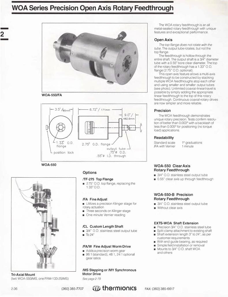
-
2 -
WOA Series Precision Open Axis Rotary Feedthrough
Tri-Axial Mount
WOA-550/FA
3.5" /s9mm
. O.D.flange
position lock
WOA-550
(two WOA-550/MS, one FRM-133-25/MS)
Options
fTF-275 Top Flange
■ 2.75" O.D. top flange, replacing the1.33"O.D.
/FA Fine Adjust
■ Utilizes a precision Klinger stage for rotary actuation■ Three seconds on Klinger stage■ One minute Vernier reading
/CL Custom Length Shaft
■ 3/4" 0.0. stainless steel output tube■ To24"
/FA/W Fine Adjust Worm Drive
■ Adds a precision worm gear■ 96:1 (standard), 48:1, 24:1 optional
gear ratios
/MS Stepping or /MY Synchronous Motor Drive
See page 2-79
2-36 (360) 385-7707 ® thermIon1cs
The WOA rotary feedthrough is an all metal-sealed rotary feedthrough with unique features and exceptional performance.
Open Axis
The top flange does not rotate with the tube. The output tube rotates, but not the top flange.
The feedthrough is hollow through the entire shaft. The output shaft is a 3/4" diameter tube with a 0.55" bore clear diameter. The top of the rotary feedthrough has a 1.33" O.D. flange (2. 75" O.D. optional).
This open axis feature allows a multi-axis feedthrough to be constructed by stacking multiple WOA feedthroughs atop each other and using smaller and smaller output tubes (see photo). Unlimited coaxial-linear travel is possible by simply adding the appropriate linear feedthrough to the top of this rotary feedthrough. Continuous coaxial-rotary drives are now simpler and more reliable.
Precision
The WOA feedthrough demonstrates unique rotary precision. Tests confirm resolution of better than 0.003° with a backlash of less than 0.005° for positioning (no torque load) applications.
Readability
Standard scale /FA with Vernier
1° graduations 1 minute
WOA-550 Clear Axis Rotary Feedthrough
■ 3/4" OD. stainless steel output tube■ 0.55" clear axis up through feedthrough
WOA-550-B Precision Rotary Feedthrough
■ 3/4" O.D. stainless steel output tube■ Without clear axis
EXTS-WOA Shaft Extension ■ Precision 3/4" O.D. stainless steel tube■ Split clamp attachment to existing shaft■ Shaft extension length 3" to 24", as per
customer requirements■ With end guide bearing, as required■ Simple field installation or removal■ Mounts to 3/4" OD. shaft WOA
and others
FAX: (360) 385-6617

Thermionics manufactures a full line of metal-sealed linear motion feedthroughs. They are designed and manufactured to a high level of quality. They are all metal, using welded bellows and stainless steel linear bearings. All manual units are bakeable to 200°c fully assembled. Higher bakeouts may be used with partial disassembly. These feedthroughs are available with a number of custom options, listed below.
Custom shaft lengths and shaft extensions are available.
FLML-133-25 Series Linear Vacuum Feedthroughs
■ 1/4" 0.0. shaft■ 1.33" 0.0. mounting flange■ 1", 2" or 3" stroke■ Stainless steel bellows sealed■ Coarse linear actuated■ Stainless steel linear shaft bearing
Stroke A
1" 7.25" 2" 8.75" 3" 10.85"
Custom shaft length
Model No.
FLML-133-25-1
FLML-133-25-2
FLML-133-25-3
Other strokes available
FLMR-133-25 Series Linear Vacuum Feedthroughs
■ 1/4" 0.0. shaft■ 1.33" 0.0. mounting flange■ 1", 2" or 3" stroke■ Stainless steel bellows sealed■ Rotary actuated, 28 turns/inch, all ball
bearing drive■ Stainless steel linear shaft bearing■ Includes position indicator
Stroke A Model No.
1" 5 6" FLMR-133-25-1
2" 7.1" FLMR-133-25-2
3" 9.2" FLMR-133-25-3
Custom shaft length Other strokes available
FLMM-133 Series Linear Vacuum Feedthroughs
■ 1/4" 0.0. shaft■ 1.33'' 0.0. mounting flange■ 1" or 2" stroke■ Stainless steel bellows sealed■ Micrometer actuated, 40 turns/inch, pre
loaded coupling ■ 3" minimum flange face to probe tip■ Stainless steel linear shaft bearing
Stroke A Model No.
1" 8.69" FLMM-133-1
2" 12.89" FLMM-133·2
Linear Feedthroughs
FLMR-133-25·2
A r position lock
.5"/12.7mm 13
j"/76.2mm
{ !stroke
FLML-133-25
FLMR-133-25
A 3" /76.2mm
.50"/1Jmm 71.5"/
i38.1m
C--.---117"
_.__ __ � I
.63" /16mm
FLMM-133-1 & 2
1 .33" DIA mounting flange
.25" /6.4mm .6l"/15mm
.75"/19.lmm
(360) 385-7707 ® therm1on1cs FAX: (360) 385-6617 2-37
-
2 -

-
2 -
Linear Feedthroughs
monuol adjust
encoder _/
(optional)
8.37" / 304.BmTI
.50"/13mm
14.75" /120.7mm 1 .5"/
8.1m 1---'---� I
"/
1.5" /38.lmm 2.24 56.9mm
3"/76.2mm
stroke
r .25" /6.4mm
.61" /15mm 1 .33" or 275" DIA
mounting flange .75" /19.lmm
FLMR-133-1/MS
FLML-133·25·1/PNM (with /ACV-24)
9.28" 235.7mm 12.28" /311.9mm
1.5" /3Bmm .5" /12.7mm
3.0"/�-76mm
I- stroke I-I J_ I I
D==�:5:··===------=�,
position lock T .25" /6.4mm
.62" /16mm
(.25" /6.4mm)
FLMLQA-133-25-3
FLMLQA-133-25-3 Fast Acting Linear Vacuum Feedthrough
FLMR-133/MS Stepping or /MY Synchronous Series Motorized Linear Vacuum Feedthroughs
■ 1/4"' O.D. shaft■ 1.33'" 0.0. mounting flange■ 1", 2" or 3" stroke■ Stainless steel bellows sealed■ Stainless steel linear shaft bearing■ Stepping motor actuated, 28 turns/inch■ Integral motor drive
/MS stepping or /MY synchronous motor100 oz-in holding torque (higher torque
motors available) Without motor controller Low inertia design
■ Manual knob
Stroke Model No.
1" FLMR-133-1/MS or /MY
2" FLMR-133-2/MS or /MY
3" FLMR-133-3/MS or /MY
Other strokes available
FLML-133-25/PNM Series Pneumatically Actuated Linear Vacuum Feedthroughs
■ 1/4" O.D. shaft■ 1.33" 0.0. mounting flange■ 1". 2" or 3" stroke■ Stainless steel bellows sealed■ Stainless steel linear shaft bearing■ Pneumatically actuated
3/4" I.D. cylinder50 to 150 psi air pressureStainless steel rod and cylinder with
bumpers, both ends ■ Performance (with optional /ACV-24 valve
below): <180 msec from coil energize to finish of 4" travel with 80 psi on an FLM-133-4/PNM with shutter
Stroke Model No,
1" FLML-133-25-1/PNM
2" FLML-133-25-2/PNM
3" FLML-133-25-3/PNM
As above, but mounted on a 2.75" O.D. flange Other strokes available
/ ACV-24 Air Control Valve Option for FLM-133-25/PNM series feedthroughs ■ Mounted to feed through■ Valve-to-actuator plumbing installed■ Control voltage 24 voe standard or per customer requirements■ With flow controls, both directions
Options
/CL Custom Length Shaft
SMC Stepping or YMC Synchronous Motor Controller
See Page 2-81
■ 1/4"' O.D. shaft■ 1.33" 0.0. mounting flange■ 3" stroke, 4 positions, 1" apart■ Excellent for sample positioning or indexing■ Stainless steel bellows sealed■ Stainless steel linear shaft bearing■ Position lock■ With tine adjust
2-38 (360} 385-7707 ® therm1on1cs FAX: (360) 385-6617

FLML-275-50 Series Linear Vacuum Feedthroughs
■ 1/2" O.D. main shaft■ 2.75" 0.0. mounting flange■ Up to 15" stroke or more■ Stainless steel bellows sealed■ Push-pull actuated, with adjustable position
stop ■ Position lock■ Linear bushings
Stroke A B Model No. 1" 6.26 1.40 FLML-275-50-1 2" 7.65 1.79 FLML-275-50-2
10" 20.77 4.91 FLML-275-50-10 Additional stroke. per inch
NOTE: The probe (1/2" dia.) supports itself beyond the mounting flange. In horizontal operation. depending on stroke, extension and payload, some deflection may occur
/FA Fine Adjust Option■ Knob adjustment ■ 10 turns/inch linear travel■ Ball bearing mountPrice
2" 1"
add add
5
FLMM-275-50 Series Linear Vacuum Feedthroughs
■ 1/2" O.D. main shaft■ 2.75" O.D. mounting flange■ 1 " or 2" stroke■ Stainless steel bellows sealed■ Micrometer actuated. with pre-loaded
micrometer-to-probe coupling ■ Linear bushings
Stroke A B C Model No. 1" 8.20 1 .40 4.34 FLMM-275-50-1 2" 10.00 1. 79 6.03 FLMM-275-50-2
FLMH-275-50 Series Hollow Linear Feedthroughs
■ 1/2" O.D. support tubeOpen through unit 1.33" O.D. flange
■ 2.75" O.D. mounting flange■ Up to 16" linear travel■ Push-pull linear (12 lb maximum force)■ Position stop (adjustable) and lock
Stroke Model No. 1" FLMH-275-50-1 4" FLMH-275-50-4 6" FLMH-275-50-6
Additional stroke, per inch
Linear Feedthroughs
R ,,trnk, .r="'---1
A
set collar_/ 2_75 .. _/
mount flange
FLML-275-50
FLMM-275-50
set collar
1.33" mini-flange
FLMH-275-50
.4"
1.38" /35mm
positon lock set collar
.5"0.D . 4"1.D. 1.38" /35mm _J
FLMH/R-275-50-2
/R Reversed Flange Option
t;jff7 "'• '--
LilJ
bellows
lock
bellows
2. 75" mounting f lange
■ 1.33" 0.0. flange mounted on vacuum side■ Liquid or gas feedthrough to mini-flange
in vacuum
(360) 385-7707 ® therm1on1cs FAX: (360) 385-6617 2-39
-
-

-
2 -
FLLRE Series Magnetically Coupled Linear-Rotary Feedthroughs
FLLRE-275-38/LD
8.04" /204.2mm +
magnet assembly
2.5" /63.Smm
I
graduated dial} /adjustable
linear limits
FLLRE-275/.25 Layout
stcoke 13.5" /M.Smm r
�I-+� .25"/6.4mm
\_2.75" dia. mounting f lange
10.95" /278. lmm + stroke -j1
5.47" /138.9mm
1 88_9mm
3.
5"/
r 2.75"/69.9mm
a.--11!1>1-----d"""", � � --t
___ -==-..-1-l
_/
_
µ---._._
_,,- \
. 75" / 19.1 mm
magnet assembly \_ including /LD standard 4.50" dia
mounting flange graduated dial cdjustable
linear limits
FLLRE-450/.75 Layout
FLLRE Series Specifications and Ordering Information
Probe Standard Max Size Stroke Stroke Model Number
1/4" 10" 24" FLLRE-275-10/.25
3/8" 12" 30" FLLRE-275-12/.38
1/2" 18" 36" FLLRE-275-18/.50
3/4" 24" 48" FLLRE-450·24/. 75
The FLLRE modular magnetic linear-rotary feedthroughs offer exceptional coupling with a small magnetic driver package. The driver is only 2.75" O.D. and 2" long. It provides more than 150 oz-in of torque and four lbs of linear force. Because of their small size, two drivers can be added together to double coupling strengths. Linear force can also be enhanced with the addition of the linear driver. The linear driver is a separate module that has been developed for its exceptional linear force.
The FLLRE stainless steel probe tube has a polished I.D. The inside traveler has no magnets, but it is made of magnetically• permeable material. The design uses eight all stainless steel bearings for long life even with repeated bakeout to 200°C (with magnets removed).
Four probe sizes are available-1 /4", 3/8", 1/2" and 3/4" O.D. The selection of the probe diameter will depend on the travel distance, mass of the sample, and physical constraints of the chamber and related equipment. Please call the factory to discuss your specific requirements.
FLLRE-275 Series Linear-Rotary Feedthrough
■ 1/4", 3/8" and 1/2" O.D. probe sizes■ 2.75" O.D. mounting flange■ Up to 36" stroke ( 1/2" O.D. probe model)■ Mechanical torque limit: 150 oz-in■ Linear force: 4 lbs■ Eight all stainless steel bearings■ 200°C bakeout (magnetic drive removed)■ Removeable neodymium iron boron
magenetic drive
FLLRE-450 Series Linear-Rotary Feedthrough
■ 3/4" O.D. probe size■ 4.50" O.D. mounting flange■ Up to 48" stroke (3/4" O.D. probe model)■ Mechanical torque limit: 150 oz-in■ Linear force: 15 lbs■ Eight all stainless steel bearings■ 200°C bakeout (magnetic drive removed)■ Removeable neodymium iron boron
magenetic drive
FLLRE linear-rotary feedthroughs are manufactured and protected under one or more of the following patents: 5,514,925
2-40 (360) 385-7707 ® therm1on1cs FAX: (360) 385-6617

FLLRE Series Magnetically Coupled Linear-Rotary Feedthroughs
FLLRRE Dual Linear-Rotary Feedthrough
■ Actuates jaws, pincers or other devicesrequiring dual rotational motion
■ May be used in place of expensive rackand pinion devices
Options
Optional Force Package Available on all units and recommended for high mass payloads and longer strokes
/LD Linear Magnet Driver ■ Adds a linear magnetic external driver■ Adds a linear internal traveler■ Torque: 150oz-in
/REM Remote Rotary Operation ■ For use on any FLLRE■ Linear and rotary actuation can be
performed from several feet away■ Allows practical single operator sample
transfer
lineor guide
4.81"/�
122.2mm�
i-f��/ � 76.2mm
FLLRE-275-12/.38/REM
11 .55" /293.4mm + stroke 15.47" /138.9mm
r odjustoble ineor limits 3.5"/
r 88.9mm _J_
remote linear/ rotary adjust
FLLRE-450/LD/REM (shown integrated on custom modular cart system) For more information about the Thermionics Northwest modular carts see page 11-33.
(360) 385-7707 ® the,m1on1cs FAX: (360) 385-6617 2-41
-
-

-
2 -
RPLR Series Rack & Pinion Linear-Rotary Feedthroughs
RPLR-.75
RPLR-.75
2-42
Ordering Information - Rack and Pinion Actuated Linear-Rotary Feedthroughs
Stroke Model No. 10" RPLR-.75-10 20" RPLR-.75-20 30" RPLR-.75-30 40" RPLR-.75-40 50" RPLR-.75-50 60" RPLR-.75-60
NOTE: Custom strokes between those listed are available
c--::,
The RPLR series of linear-rotary feedthroughs use a 3/4" diameter probe. The probe is actuated by a rack and pinion positive drive (rotary bellows sealed feedthrough). The independent rotary actuation is achieved by a second rotary feedthrough. Only the 3/8" diameter probe tip rotates, keyed with a ball bearing keyway. This allows mounting of jaw-type devices which are actuated by the rotary action. The standard mounting flange is a 2. 75" O.D. rotatable flange. The RPLR is an all position device with position locks on bothrotary feedthroughs. All metal constructionfor bakeability.
This unit is also available as a linear feedthrough only (RPL series).
Rack and Pinion Actuated Linear Feedthroughs Without Rotary Action
Stroke Model No. 10" RPL-.75-10 20" RPL-.75-20 30" RPL-.75-30 40" RPL-.75-40 50" RPL-.75-50 60" RPL-.75-60
NOTE: Custom strokes between those listed are available
-j 4.2"/107mm
FRM-133-25�
L 11"/2aomm I f-------- 13" /330mm + stroke�
1 .o" /25.4mm
7.7"/ 196mm
.375"/9.5mm/
1 rock
--J .6"/ .75"/19mm 15mm probe tube 2_75 .. O.D.
mounting flange
(360) 385-7707 ® therm1on1cs FAX: (360) 385-6617

RPLR Series Rack & Pinion Linear-Rotary Feedthroughs
C----:>
7 4.2"/107mm
FRM-133-25
rotary
position lock
L 6.1"/'55mm L11"/2aomm I
------- 13" /330mm + stroke ::.====i RPLR Layout (shown with remote rotary option)
Options
/MC Mechanical Counter -Manual Operation ■ 40 counts per feedthrough rotation
(approximately 0.034" linear travel percount on RPLR)
■ Removable for bakeout■ Retrofit kit allows mounting without break
ing vacuum
/MS Stepping or /MY Synchronous Motorized Rotary Feedthrough for RPLR rotary drive ■ With integral motor drive■ /MS stepping or /MY synchronous
motor drive■ 50 oz-in holding torque (higher torque
motors available) ■ Low inertia design■ Manual knob
NOTE: The IMS or /MY motor option is suitable for the rotary actuation on an RPLR and the linear actuation when the operation is horizontal. When the linear travel is other than horizontal, the /MS/W option should be used.
We strongly recommend the use of limit switches on this or any other motor drive being used to actuate the linear drive on the RPLR. The limit switch actuator assembly specified below ( or one similar) should be used to protect the RPLR from being overdriven. See the RLS-40/MS rotary limit switch option on page 2-80.
/MS/W Stepping or /MY/W Synchronous Motorized Rotating Feedthrough for RPL or RPLR linear drive ■ High speed worm drive■ Self locking■ /MS stepping or /MY synchronous
motor driveSupplied with motor Without controller
■ Capable of driving up to 16"/min minimumat 1,000 pps
■ May be field-mounted without breakingvacuum, or returned to the factory forinstallation
NOTE: ThlS motor drive is self-Jocking. This is necessary to protect the probe and associated equipment from spinning down if the power is removed from the motor. Because of the self-Jocking design, the drive can generate sign:ticant torque at the FRM, and thus do damage if overdriven.
/RLS-40/MS Rotary Limit Switch Actuator Assembly
See page 2-80
SMC Stepping or YMC Synchronous Motor Controller
See page 2-81
1.0" /25.4mm
-1 .6"/15mm .75"/19mm
probe tube 2.75" 0.0. mounting flange
/MC Mechanical CounterMotorized Operation ■ Mounts to rear of stepping or synchronous
drive motors■ Read-out of step count, 200 counts/motor
revolution100 counts on last digit wheel ( 100 divisions)
■ Maximum motor speed: 2,500 pps■ 9,999,999 maximum count (50,000 motor
revolutions)■ 5 digit Veeder Root mechanical counter,
metal case2: 1 ratio gear drive Adjustable counter orientation Removes with motor for bakeout Retrofit kit available
/SCC Speed Controlled Motorized Rotary Feedthrough with Controller ■ With integral motor drive■ Speed control motor, with controller
5-95 rpm with 50 oz-in torque standardOptions available:
Higher torque motors Different speed ranges (300 rpm max.) Switchable direction
/RAO Remote Rotary Operation ■ For use on long stroke RPLRs■ Locates a rotary actuator knob near the
linear actuator feedthrough■ Position lock
(360) 385-7707 ® therm1on1cs FAX: (360) 385-6617 2-43
-
2 -

-
2 -
FLRM Series Push-Pull Linear-Rotary Feedthroughs
FLRM-275
The FLRM series of linear-rotary feedthroughs are based on the FLM series pushpull linear feedthroughs The FLRM mounts on a standard 2.75" 0.0. flange. Other size flange mounts are available. The body length has been increased to provide greater spacing between the linear bearings, and the 1/2" 0.0. rod replaced with a 1/2" 0.0. tube. An FRM-133-25 rotary feedthrough is mounted on the axis of the 1/2" tube, providing rotary motion at the probe tip. Linear motion is push-pull against the pressure differential
Ordering Information - Push-Pull Linear-Rotary Feedthroughs
(' 2 lbs maximum). This unit is an all position device with position locks on both feedthroLJghs. Strokes of up to 36" are feasible, dependent upon payload, orientation and acceptable deflection. All metal construction for bakeabihty
Dimensions
Stroke A B
2" 3.3" 13.3" 4" 4 1' 15.3" 6" 4 9" 17.3" 8" 5.7" 19.3" 10" 6.5" 21.3"
NOTE: 0Jstom strokes available
Model No.
FLRM-275-2
FLRM-275-4
FLRM-275-6
FLRM-275-8
FLRM-275-10
t------------ ltBH -----------1
rotary lock
6.rJ
' /'52.<mm 7
� linear lock
1.s" /38.1mm
stop collor
FRM-133-25
FLRM-275-3
"A"
2-44 (360) 385-7707 ® therm1on1cs FAX: (360) 385-6617

FLAM Series Push-Pull Linear-Rotary Feedthroughs
Options
ROTARY OPTIONS
/MS Stepping or /MY Synchronous Motorized Rotary Feedthrough ■ With integral motor drive■ /MS stepping or /MY synchronous motor
50 oz-in holding torque (higher torquemotors available)
■ Low inertia design■ Manual knob
/MC Mechanical Counter Option for /MS or /MY Motorized Rotary Feedthrough
■ Digital read-out of motor drive location■ Mounts to rear of stepping or synchro
nous drive motors■ Read-out of step count, 200 counts/
motor revolution100 counts on last digit wheel(100 divisions)
■ Maximum motor speed: 2,500 pps■ 999,999 maximum count (5,000 motor
revolutions)■ 5 digit Veeder Root mechanical
counter, metal case2:1 ratio gear drive Adjustable counter orientation Removes with motor for bakeout Retrofit kit available
rotary position lock
FRM-133-25 _/
linear adjust knob
linear position
FLRM-275-8/LFA
(360) 385-7707
/SCC Speed Controlled Motorized Rotary Feedthrough with Controller ■ With integral motor drive■ Speed control motor, with controller
5--95 rpm50 oz-in torque minimum Options available:
Higher torque motors Different speed ranges Switchable direction
/MC Mechanical Counter Option for /SCC Motorized Rotary Feedthrough
■ m;iital read-out of motor drive location■ 5 digit Veeder Root mechanicalcounter, metal case■ 4:1 ratio bevel gear drive■ Adjustable gear lash■ Adjustable counter orientation■ 40 counts per feedthrough rotation■ Removable for bakeout
bellows
LINEAR OPTIONS
/LFA Fine Adjust ■ 10 threads/inch■ Ball bearing support■ Suitable for use up to 6"
Requires longer housing on longer travels
/LFA/MS/W Stepping or /LFA/MY/W Synchronous Motorized Fine Adjust ■ /MS stepping or /MY synchronous motor■ Worm drive■ Ball bearing support■ With manual knob■ Suitable for use up to 6"
Requires longer housing on longer travels
FLLM-275-2F-1 Linear/LinearCoaxial Feedthrough
1st LINEAR ■ 2" linear travel■ Linear travel via thread/collar adjust■ Position lock■ 1/2" 0.D. support tube, bearing/bushing mount■ Adjustable travel limit
2nd LINEAR■ 1" linear travel■ Rotary adjust■ Linear ball bearing nose support■ Eight lb force maximum■ Uses FRM-133-25 rotary feedthrough■ Position lock■ Custom shaft lengths on both linear probes
® therm1on1cs FAX: (360) 385-6617 2-45
-
2 -

-
2 -
Wobble Sticks
FWS-44R-275-4
linear
linear
FWS-15-275
--44•
limit _f',i.,._ -,t........_ L, .16" /29.5
j
m
position lock 1� .. 1W''------ _____ ::-----......,.__
.85 21.6mm -
--
-chamber flange
/
-
-----
1 .50" /38. 1 mm bellows 1.0. minimum
clearance required for full 44• working angle
FWS series wobble stick probes supply a combination of Z axis, polar rotation, and polar axis tilt to allow tip positioning inside the vacuum chamber. They can be fitted with clamp jaws, hooks, or forks to attach and release samples. The user can specify the required Z travel.
FWS-15-275-1 Wobble Stick
■ 3/8" O.D. shaft■ 2. 75" O.D. mounting flange■ ± 7 .5° angular range■ 1" linear travel (on axis)■ Without fork
FWS-44-275-1
Wobble Stick
■ ±22° angular range■ 1" Z stroke■ Independent bellows for Zand 6■ Special spherical bearing mount■ Z travel position lock■ Includes tip fitted with hook, per customer
requirements
FWS-44R-275-2
Wobble Stick
■ ± 22° angular range■ 2" Zstroke■ Independent bellows for Zand 0■ Special spherical bearing mount■ Z travel position lock■ 360° probe rotation via FRM-133-25
Removable unit ■ Includes tip fitted with hook, per customer
requirements
FWS-44-275-10
2-46
1.50" /38. lmm minimum
FRM-133-25 ///_ .. ---�=�, ,,, ..... ,_.,.. ... -- ... � .. ,,,,,.,,,.. 2.63" /66.Smrri"'
,.,.
_,.,.....,,.,.....
rotary position lock - _,.,..... 1 _,...'j.f _,.,.....,,.,..... 1 .1 6" /29.Smm ,, ' _,.,..... 44•
sompl + ,.../',,_ ............. hook
linear limit adjust ll' : -----/ 35·
1 ,,________ --------
linear
FWS-44R-275-4
position lock l-- ·,_____ - ---.
chamber flange �85"/21.smm _1·,, ____ --, .. :�� clearance required for ·--,full 44· working angle 1 / 4"0 / 6.4mm rotary shaft
3/S"i / 9.5mm linear shaft
(360) 385-7707 ® therm1on1cs FAX: (360) 385-6617

Wobble Sticks
FWS-44R-275-2/P Wobble Stick ■ ±22 ° angular range■ 2" Zstroke■ Independent bellows for Zand 0■ Special spherical bearing mount■ Z travel position lock■ 360° probe rotation■ Includes push knob with 0.20" of linear
actuation■ Order pincer below
Pincer Options
Thermionics Northwest offers a variety of pincers for your application. Custom pincers can be supplied on request.
/PW Standard Single Jaw Pincer
■ Single jaw action■ Suitable for thin wafers
/PDME DME Single Jaw Pincer ■ Single jaw action■ Handles DME rectangular platens
/PO Omicron Single Jaw Pincer ■ Single jaw action■ Handles Omicron brand platens
/POE Omicron Double Jaw Pincer ■ Handles Omicron brand platens■ Edge grip double jaw action
/PS Special Pincer
push knob for pincer release
FWS-44R-275-8/PW
/PDME Single Jaw Pincer
/POE Omicron Double Jaw Pincer
---------
rotary position
1. 50" / 38. 1 mm _,/'
1 m,n,m
�:3. /".,m,,;-·
-'::.::�_,.,-
·
--
· / samplelock
_J- ,,-,· 1 6,, 1 • i,,,-r-< _ _,- I . 1 ,O.Smm
44+
/,..t -,_
plate
j' ' ------linear limit adjust /
35·1 l··-...._ --.... . ...___
linear position lock I- ···
_1
··--... .. ___ ...._ __ :---....-...___...___
� gripping pincer
FWS-44R-275-4/PW
chamber flange .85"/21.Smm • ......________ --..... --------
c learance required for ··---full 44· working angle
(360) 385-7707 ® therm1on1cs FAX: (360) 385-6617 2-47
-
2 -

-
2 -
BPLR Baseplate Linear-Rotary Motion Feedthroughs
BPLR Linear-Rotary Baseplate Feedthrough
Ordering Information - High Vacuum High Vacuum Push-Pull Linear-Rotary
■ Differentially pumped Viton O-ring sealedlinear-rotary action
■ Linear travels to 24"■ 1/4" O.D. shaft
With clamp type stop collarHand knob
■ Baseplate mountFor 1" 1.0. holeMaximum baseplate thickness: 1"
■ Stainless steel construction■ Teflon body insert
Insert removable for O-ring servicewithout removal of body
Push-Pull Linear-Rotary Feedthroughs Elastomer-sealed
Stroke A Model No.
10" 15" BPLR-10
14" 19" BPLR-14
20" 25'' BPLR-20
24" 29" BPLR-24
pumping port 1" -1 4 thread /
set collar
- ·-·-·-· ·===¥J
pumping port ( vcr fitting)
I •" ,__ _ ,J LI l.25"/6.35mm
�mmAMox�
BPLR-10 BPLR-275-10
SLJ Series Locking Jaw Systems
The SLJ series systems allow for sample handling by simply gripping the sample or sample carrier with a jaw. The jaw has a capacity of over 1/2" thick and has a 1/2" deep throat. The jaw can easily generate over 20 lbs of clamping force. The jaw opens and closes under positive control, maintaining a constant centerline. This allows samples of various sizes and shapes to be handled with one gripper.
Gentle jaw assemblies for specific sample systems also available.
Features
■ Handles various sample shapes and sizes■ Easily adapts to magazine multiple loading■ Grips with clamping force
SLJ-0.75
Transfer Requirements for Actuation
Transfer probe requirements are a nonrotating probe with respect to a rotary-coaxial shaft. This action is supplied by: ■ RPLR series rack and pinion linear-rotary
feedthroughs■ FLRt-/ series push-pull linear-rotary
feedthroughs■ EMT series translators with rotary
feedthroughsTransfers of up to 80" can be obtained without intermediate support.
All the above systems can use a quick access door load lock chamber and tilt stages for precise alignment.
Feedthroughs Elastomer-sealed 2 75" 0.0. mounting flange with VCR-type differential pumping port
Stroke A Model No.
10" 15.2" BPLR-275-10
14" 19.2" BPLR-275-14
20" 25.2" BPLR-275-20
24" 29.2" BPLR-275-24
SLJ-0.75 Sample Jaw
■ Up to 3/4" thick sample■ Jaw depth: 3/4" ■ Minimum gripping force: 25 lbs■ With swivel jaw pads■ Requires RPLR or similar linear-rotary
feedthrough to operate■ Stainless steel construction■ Will pass through a 1.39" I.D. tube
SLJ-0.25 Sample Jaw
■ Up to 1/4" thick sample■ Jaw depth: 3/4"■ Minimum gripping force: 4 lbs■ With swivel jaw pads■ Spring grip/cam release■ Requires RPLR or similar linear-rotary
feedthrough to operate■ Stainless steel construction■ Will pass through a 1.39" 1.0. tube
2-48 (360) 385-7707 ® therm1on1cs FAX: (360) 385-6617

Thermionics sample mounts provide platen-based support for customer samples. They interface with the supporting structure (rod, gearbox, etc.) and provide mechanical support for the sample. All standard sample mounts provide the following:
■ Removable platen■ Clip sample restraint■ Electrically-isolated platen
A wide variety of options or modificationsare available for the sample mount to obtain the customers' exact requirements. They include:
■ Sample HeatingResistive
Standard Nude filament PBN Quartz lamp
e-Beam■ Sample Cooling
Direct LN2
Indirect LN2
Water ■ Sample transfer■ Sample bias, RF
These options are described more fully inthe following pages.
SMRSERIES
SMR-1 Sample Mount
■ 3/8" shaft or gearbox mounting■ "0" sample face offset to 4" offset. per
customer requirements■ Sample orientation per customer
requirements■ 1" diameter sample area, 1 .4" diameter
sample plate■ Clip sample mount■ Removable sample plate, electrically
isolated
Sample Mounting
SMR (shown with 1" sample heater, LN2 cooling, electrical isolation and GB-7 gearbox)
(360) 385-7707 ® therm1on1cs FAX: (360) 385-6617 2-49
-
2 -

-
2 -
UHV Environment Heater Options
The following heating options may be mounted to the SMR sample mounts.
/HR-1 Radiant Resistive Heater
■ Maintains electrical isolation■ Moly sample plate with three sample clips■ With all necessary feedthroughs, atmo
sphere side connectors, internal wiring,temperature thermocouple, and sparefilaments
■ Temperatures up to 1,000°C dependingupon application
Larger sizes available. Consult factory.
/HRN-1 Nude Filament
Radiant Resistive Heater
■ Maintains electrical isolation■ Moly sample plate with three sample clips■ With all necessary feedthroughs, atmo
sphere side connectors, internal wiring,temperature thermocouples, and sparefilaments
■ Temperatures up to 1,200°C dependingupon application
Larger sizes available. Consult factory.
/HRD Intrinsic Resistive Heater
■ Modifies STLC platen for direct heating■ Moly sample plate with two power
supply clips■ Sapphire sample electrical isolation■ With all necessary feedthroughs, atmo
sphere side connectors, internal wiring,and STLC moly platen
Price Consult factory
/ERH-0.6-1200 Electron Beam
Enhanced Resistive Heater
■ 0.6" 0.D. sample size■ 1,200°c maximum temperature■ Low power filament (approx. 40 watts)■ Suitable for 500 voe biasing■ With all necessary atmosphere side
connectors, internal wiring, temperaturethermocouples and spare filaments
■ Tungsten, moly, tantalum, alumina andstainless steel construction
/HEB Electron Beam Heater
■ Moly sample plate with three sample clips■ Electrically-grounded sample plate■ With all necessary feedthroughs, atmo
sphere side connectors, internal wiring,temperature thermocouples and sparefilaments
■ Temperatures up to 2,000°C dependingupon application
1200
1000 0
� 800
600 "'
1 400
200 E �
-200
�oten surfoce
Ro v,c, SA ). ~ V
\I J J L
y I 1-....._22 V,C, 7A
} cimbient
0 100 200 JOO '100 500 600 700 800 900 lime, secollds
/HR Graph
1400
/15"rnp 016V 1200
/_...
I \ I , ...
I I
0 0 i50 100 150 200 250 300 3® -4-00 450
lime, h'COl'ld•
/HRNGraph
NOTE' The performance ratings are for specific app/icat;ons, generally without sample cooling or sample transfer. Depending on parameters such as sample size, temperature reqwrements, and motions involved, cooling of the substrate or heater framework may be required. Please consult factory for your specific application.
STLC sample transfer systems are manufactured and protected under one or more of the following patents: 5,705, 128
2500
o 2000
f 1500
1.2kV O 4-20ml7 1kV O 220mA
"\
1.51<VO 500/
'/ v-',. ,,
I \. "
I .......
0 50 1 00 150 200 250 JOO J50 400 -150 500 Time, HCOfldS
/HEB Graph
/HR-1 Radiant Resistive Heater
/HRN-2 Nude Filament Heater
power terminals isolated split platen
sompl:_i )-.43,,
7!1,,,i:--'-----_;,,:11....., 1.�l----contact bar
J_ �eramic isolation access hole for power leads
access hole for TC leads
/HAD Intrinsic Resistive Heater
-, f-479" Jfilam_t_ I ·
w .6.3.3"¢ [I � i--- power\
terminals
/ERH-0.6 Electron Beam Heater
/HEB Electron Beam Heater
2-50 (360) 385-7707 ® therm1on1cs FAX: (360) 385-6617

Oxygen or Chemical Vapor Environment Heater Options
The following heating options may be mounted to the SMR sample mounts.
/SHQ-2 Radiant Quartz Lamp Heater *
■ For 2" 0.0. (standard) maximum samplesize (optional sizes to 5" 0.0.)
■ Electrically-isolated sample■ Haynes alloy sample plate with three
sample clips■ Best temperature uniformity: 1" 0.0.■ Maximum temperature: 700°C continuous
1,000°C peak ■ Utility requirements
Thermionics model SPS-232/M or SPS-232/A (page 2-54)
0 to 110 VAC, 8 A variable power supply
Requires 0.5 gallons per minute water cooling
■ Maintains electrical isolation■ Comes mounted to 2. 75" 0.0. and sup
port shaft up to 24" long, per customer requirements, dual bakeable electrical feedthroughs, re-entrant metal seal dual coolingfeedthrough and all necessary atmosphereside connectors
■ Supplied without thermocouples
/GS Gas Shower Ring Option ■ For chemical vapor (CV) applications■ Extends thermal shield above sample
plane■ Single gas shower ring, stainless
steel construction■ Gas ring clamped to heat shield
Price Consult factory
/SA Shutter Assembly Option ■ For evaporation or sputter applications
ACS-CR Copper Rope
■ Approximately 1/8" 0.0.■ OFEcopper■ Suitable for UHV cooling transfer■ Available in custom lengths
ACS-TS Tantalum Screws
■ Manufactured from tantalum/rhenium■ 0-80 screw size■ 3/16" tip to head base■ Filister head
Other sizes available. Consult factory
GB-30-5/SHQ-5/GS/SA (see page 2-67)
/PBN-1 Radiant Resistive Pyrolytic Boron Nitride Heater*
■ Heating to 1,200°c in UHV■ Heating to 800°C in oxygen environment
without heater degradation■ Maintains electrical isolation■ Includes all necessary feedthroughs,
atmosphere side connectors. and internalwiring
■ Heater outgassing above 1, 100°C
*WARNING
tricol terminals
\er support & jumper
BN heat ountin
;--7 ock � I
l 2.55"
1.38"
/PBN-1 Pyrolytic Boron Nitride Heater
Operatt0ns involving enriched oxygen environments can be hazardous, including explosive. Many materials commonly considered non-hazardous become dangerous in such environments. Simple mechanical pumps usmg oil can explode, putting both personnel and equipment at great risk. Many other common materials will react violently to oxygen. The SHQ series heater has not been tested in enriched oxygen environments and is not intended for that use. We recommend systems utilizing enriched oxygen environments be undertai(.en only by those properly skilled to perform such operations in a safe and cautious manner.
Heating and Cooling Accessories
ACS-Ag Silver Plated Screws
■ 300 series stainless steel screws■ Plated with silver■ Resists galling■ Improves heat transfer■ Available in all standard screw sizes
and head types■ Vented or unvented
ACS-SVS Slot Vented Screws
■ 300 series stainless steel screws■ Vent cut through screw threads and base
of head■ Allows pumpout of each thread■ Available in all standard screw sizes and
head types
SMRHR-HS Heater Spares Kit
■ Two replacement tungsten filaments■ Replacement ceramic insulators
(360) 385-7707 ® therm1on1cs FAX: (360) 385-6617 2-51
-
2 -

LN2 Sample Cooling Options
2
The following cooling options may be added to the SMR sample mounts.
LN2 Sample Cooling There are two basic methods of cooling
samples using LN2 for vacuum application, direct cooling and indirect cooling.
In most cases direct contact of the LN2 Dewar with the sample achieves the highest rate of heat transfer and the most rapid cool-ing to the lowest temperature. If the sample is mounted to a goniometer head or precision gearbox, the plumbing of the LN2 to the Dewar can restrict the motion. In such cases a clamping Dewar may be considered.
A clamping Dewar can allow certain de-grees of freedom, such as continuous rota-tion, and still achieve maximum cooling. A heated rotating sample can be cooled by stopping the motion and activating a Dewar that clamps to the sample platen.
Direct Cooling
SMR-1/CLND-1
1200
1000
900
800
6, 700
600
500
'3 400
t 300
t 200
100
0
1171 800T
// 1
IIIICEMEMMIll
BIM amp INAI MM=
=_11111 6 am stop cooling (-175c
5 Time,10s0eCConds
500 2000
/CLND-1 (temperature graph showing direct cooling of substrate between heating cycles)
Time-Temperature Test • SMR-1 sample mount • Resistive heating • Direct cooling • Screw platen attachment
The indirect cooling method cools the sample by conduction through a flexible copper rope to a remote LN2 Dewar. The copper rope can be an effective means of cooling. Sample motion and temperature are restricted by the length and number of copper ropes used to achieve the desired level of cooling.
The ability of a cooling system to cool the sample to its lowest temperature is limited by many factors: Direct versus indirect cooling, size of sample, sample heating attachments, limitations required by goniometer, number of copper ropes used, sample transfer re-quirements, electrical isolation requirements of the sample, and the ability to use a clamp-ing Dewar.
Indirect Cooling
SMR-1/CLNI-1
1400
1200
1000
800
600
400
200
0
0
950T
sample platen
ambient
1000 2000 3000 Time, seconds
4000
/CLNI-1 (Cooling using in-vacuum Dewar and copper rope connections to sample plate)
Time-Temperature Test • STLP-1 sample transfer • Molybdenum platen • Indirect cooling
2" x 6" copper rope Copper Dewar 8" x 1/8" feed lines
Dewar Materials
Dewars are fabricated from composite, explosively-bonded OFE copper to stainless steel. This material is formed in an explosive process that creates a high quality metallurgi-cal bond. A high explosive charge compress-es the copper and stainless plate material at supersonic speeds and at extreme pres-sures forming a plasma at the contact point. The plasma scours the surfaces to molten conditions as the plates collide and instanta-neously cool. The resulting knitted mechani-cal bond of copper-to-stainless has excellent mechanical and thermal properties for UHV LN2 Dewar applications.
Dewars fabricated of this composite ma-terial allow LN2 to flow in contact with high thermal transfer capacity copper, with stain-less steel plumbing (TIG welded) to the stain-less steel side of the bonded Dewar. No braz-ing is required reducing the possibility of contamination and virtual leaks.
copper flyer plate
stainless base plate
reaction zone
•-•-•
electric detonator
"HIGH EXPLOSIVES"
steel anvil
interface gap
''.<\ detonation front
•
MMP 111.1 metallurgically plasma jet bonded Cu/SS
Explosive Process
Dewar Design
Dewars have an internal phase separa-tor that maximizes thermal transfer. The liquid LN2 contacts the copper and is allowed to boil, releasing nitrogen gas that is separated and allowed to escape. This technique maxi-mizes contact of the copper with the liquid and keeps boiled-off nitrogen gas (a poor thermal transfer medium) away from the cop-per heat transfer surfaces. This dramatically lowers the temperature of the Dewar and increases its capacity for thermal transfer.
True OFE copper rope is clamped to the copper side of the Dewar for indirect cooling to the sample.
A 1.33" CF re-entrant seal, with plumbing made to length, may be used to connect the Dewar to the atmosphere side of the LN2source. The welded plumbing connected to the re-entrant seal eliminates the need for in-vacuum fittings and possible leaks. All Dew-ars are helium leak-tested at LN2 temper-atures prior to shipping.
2-52 (360) 385-7707 thermionics FAX: (360) 385-6617

The following cooling options may be added to the SM or SMR sample mounts.
/CLNl-1 LN2 Indirect Cooling
■ 1" 0.0. , 2" long■ Explosively-bonded OFE copper to
stainless steel ■ Two OFE copper ropes, 12" length■ Internal phase separator■ Electrically grounds sample■ With VCR fittings■ 1/8" 0.0. or0.093" 0.0. supply tubes■ Includes FLN-133-2 LN2 feedthrough (see
page 5-13) ■ Includes custom supply tube lengths, coils,
thermally-isolated mounting hardware, as required
/CLND-1 LN2 Direct Cooling
■ Annular Dewar mounted around 1"sample plate
■ Explosively-bonded OFE copper tostainless steel
■ Internal phase separator■ Electrically grounds sample■ With VCR fittings■ 1/8" 0.0. or 0.093" 0.0. supply tubes■ Includes FLN-133-2 LN2 feedthrough (see
page 5-13) ■ Includes custom supply tube lengths, coils,
thermally-isolated mounting hardware, asrequired
■ Application depends upon gearbox andrange of degrees of freedom
/CDC LN2 Clamping Direct Cooling
■ Actuated clamping annular Dewar■ Explosively-bonded OFE copper to
stainless steel ■ Internal phase separator■ Electrically grounds sample■ With VCR fittings■ 1/8" 0.0. or 0.093" 0.0. supply tubes■ Includes FLN-133-2 LN2 feedthrough (see
page 5-13)■ Includes custom supply tube lengths, coils,
thermally-isolated mounting hardware, asrequired
■ Application depends upon gearbox andrange of degrees of freedom
supply tubes �
cryo-breoks""""
bond line --...__
Cu
/CLNl-1/CEI-I
ss
supply tubes
VCR fittings
Cu bond line
Direct Cooling
ss
Cu
Clamping Dewar (with heater sample transfer and sample rotation)
(360) 385-7707 ® therm1on1cs
LN2 Sample Cooling
Options
/CEl-I Ceramic Electrical Isolation ■ Provides electrical isolation for
indirect cooling
/CEI-D Ceramic Electrical Isolation ■ Provides electrical isolation for
direct cooling
/RE-ENTRANT Re-entrant Seal ■ Allows Dewar to be connected to atmo-sphere without in-vacuum VCR fittings■ Fits on 1.33" 0.0. flange
supply tubes --...__
jocking nut
copper gasket
/RE-ENTRANT Seal
FAX: (360) 385-6617 2-53
-
2 -

-
2 -
SPS Series Sample Heater Power Supplies
SPS-252/A
SPS-202/M Sample Heater Power Supply-Manual Operation
Samples to 1" O.D. For /HR and /HRN radiant resistive heaters
Maximum output: 10 A at 50 VDC Input: 120 V 60 Hz AC input
(220 VAC units available) ■ Current limit■ Current meter■ Rack-mount chassis
SPS-202/A Sample Heater Power
Supply-Automatic Operation Adds these features to the SPS-202M:
■ Automatic PID temperature control■ Automatic system tuning■ Digital temperature read-out■ True phase-fired proportional control,
with adjustable bias (minimum outputcontrol)
■ Adjustable power limit■ To be used with Type "K" Chromel-Alumel
thermocouple (-200°C to 1,300°C)
SPS-232/M Sample Heater Power Supply-Manual Operation
Samples to 3" O.D. For /SHQ radiant quartz lamp heaters and
/HR and /HRN radiant resistive heaters
Maximum output: 1 o A at 120 voe
Input: 120 V 60 Hz AC input (220 VAC units available)
■ With isolation transformer■ With current limit
■ Current meter
* NOTE: These units do not include external plugsfor use with alternating current meters. This provision would access the high voltage circuitryto the outside chassis. We believe this design to be hazardous.
SPS-232/A Sample Heater Power Supply-Automatic Operation
Adds these features to the SPS-232/M:
■ With temperature read-out and PIOautomatic controlAccuracy: <3°CRepeatability: <0.3°CStabil ty: 3 µV/°C including compensationSet-point resolution: 1°c
■ Auto-tuning■ Includes thermocouple cable■ Requires system thermocouple■ To be used with Type "K" Chromel-Alumel
thermocouple (-200°C to 1,300°C)
SPS-252/M Sample Heater Power Supply-Manual Operation*
Consult factory for sample size capability For /HEB electron beam heater
Maximum output: 14 A at 60 VAC filament 0-2,000 VDC bias up to0.25 A emission
Input: 220 V 50/60 Hz AC
■ Adjustable power limits, filament andemission
■ Curre1t read-outs, filament and emission■ Voltage read-out, bias■ With safety ground cable
SPS-252/A Sample Heater Power
Supply-Automatic Operation* Adds these features to the SPS-252/M:
■ Automatic PID temperature control■ Digital temperature read-out■ True phase-fired proportional control of
filament or bias high voltage, switchablewith adjustable output bias (minimumoutput control)
■ To be used with Type "K" Chromel-Alumelthermocouple (-200°C to 1,300°C), (Type"C" thermocouple available)
SPS-253/A Sample Heater Power
Supply-Automatic Operation
For e-beam heater models ERH-0.6-1200 Maximum output: 8 A at 12 VAC filament
0-500 VDC bias up to0.2 A emission
Input: 120 V 60 Hz AC input (220 VAC units available)
■ Automatic PIO temperature control■ Automatic system tuning■ Digital temperature read-out■ True phase-fired proportional control of filament with stable bias (minimum output control)■ Adjustable current limit with read-out■ Adjustable bias at 0.25 A with current meter and on/off switch
■ Rack mount chassis
SPS-262/M Sample Heater Power Supply-Manual Operation*
Consult factory for sample size capability For /HEB electron beam heater
Maximum output: 15 A at 20 VAC filament 0-3,000 VDC bias up to0 .5 A emission
Input: 220 V 50/60 Hz AC
■ Adjustable power limits, filament andemission
■ Current meters, filament and emission■ Voltage meter, bias■ With safety ground cable
SPS-262/A Sample Heater Power Supply-Automatic Operation*
Consult factory for sample size capability For /HEB electron beam heater
Maximum output: 15 A at 20 VAC filament 0-3,ooo voe bias up to0.5 A emission
Input: 220 V 50/60 Hz AC
■ Automatic PID temperature control■ Digital temperature read-out■ True phase-fired proportional control of
filament or bias high voltage, switchablewith adjustable output bias (minimumoutput control)
■ Adjustable power limits, filament andemission
■ Current meters, filament and emission■ Voltage meter, bias■ With safety ground cable■ To be used with Type "K" Chromel-Alumel
thermocouple (-200°C to 1,300°C), (Type"C" thermocouple available)
Options
/Cl Computer Interface
■ Available on all automatic controllers■ RS-232 interface-to-PIO control■ Complete set-up and operational
commands
/RSC Ramp and Soak Process Controller
■ Available on all automatic controllers■ Computer interface capability■ Up to eight adjustable ramp and
soak periods
2-54 (360) 385-7707 ® the,m1on1cs FAX: (360) 385-6617

Model DRS-1000
In-situ Temperature Measurement, Temperature Control, Process Monitoring
This innovative patented optical technology provides accurate, real time temperature measurement and control for semiconductors. Unlike pyrometry, this process is not affected by emissivity or thin coatings. The noncontact, non-invasive system gives precise (± 0.5° C) readings with one second updates.
Diffuse Reflectance Spectroscopy Diffusely reflected light intensity as a func
tion of wavelength displays a characteristic absorption edge that is related to the bandgap of a semiconductor. This edge shifts with temperature. The technique can be used on bare wafers, patterned wafers and multilayer wafers.
DRS-1000 System The light output module is a broadband,
modulated light source that illuminates the wafer through an optical port. The collection module, located on a second (non-specular) port, focuses the diffusely scattered light onto a fiber optic bundle. The spectrum information is transmitted to the scanning monochromator /detector/lock-in amplifier module. A control computer running the DRS-1000 software measures the absorption edge and generates temperature values based on internal calibration information. The software runs under WINDOWS and is equipped with a user-friendly graphical interface.
computer
Temperature Monitoring
Specifications ■ Calibrations for substrate materials include:
GaAs 0-800°ClnP 0-700°CSilicon 0-600°C
■ ± 0.5°C resolution and repeatability■ One second updates■ Attaches to standard 2. 75" ConFlat flanges■ Temperature control feedback provided
with RS-232 communications or analogoutput voltage
Applications ■ Molecular Beam Epitaxy (MBE)■ Chemical Beam Epitaxy(CBE)■ Metal Organic Chemical Vapor Deposition
(MOCVD)■ Silicon Wafer Etching
The VHW series heated viewports (page 2-78) allow the DRS-1000 to operate continuously in deposition environments.
I DRS-1000 System (shown mounted on Test Chamber)
2.7� light collection module
4"
fiberoptic c
heate�ie-::����r (optional)
light input module�
r-::1:s·
/substrate
I
\
vacuum chomber/
Schematic of the DRS-1000 System Components
(360) 385-7707 ® the,m1on1cs FAX: (360) 385-6617 2-55
-
2 -

-
2 -
RFH Series Feedthrough Hats
Utility Delivery
Goniometers and precision gearboxes with heating and cooling have requirements for many types of utility feedthroughs: ■ Rotary and/or linear motion for goniom
eter actuation■ Electrical power for sample heaters■ Thermocouple for temperature mea-
surement■ Sample biasing for processing■ Water cooling for gearbox cooling■ LN2 cooling for sample cooling
Axial Utility Delivery
The Axial Utility Delivery method organizes the utilities to eliminate flexing and abrading. The RFH top hat delivers the entire utility package axially through a probe support tube assembly to the sample head
Polar rotation is achieved by mounting the entire utility package (top hat. probe support tube and sample head) through the center of a differentially pumped rotary seal (see page 2-27). This procedure organizes the entire invacuum sample assembly on to the rotatingtop flange of the platform. The package now
rotates as a unit with no in-vacuum utility line flexing or abrading. Flexing of utility lines occurs out of vacuum where you can deal with it.
The RFH series teedthrough hats are available on 2. 75", 4.5" and 6" O.D. base flanges. Top flanges are either 2. 75" or 1.33" O.D. flanges. The utility delivery ports are "crowned" to improve access, ease installation, and avoid kinking of utility lines.
Re-entrant seals are available for single piece LN2 systems (see page 2-53).
These assemblies are supplied without blank-off flanges. Polar rotation of the sample is a funda
mental requirement of most goniometers and precision gearboxes. When using base flange utility delivery, polar rotation causes utility lines to flex and abrade against one another in vacuum. Flexing can cause line failure and abrasion can cause particle contamination. To avoid these potential risks an axial utility delivery system can be used.
Ordering Information - Feedthrough Hat Assemblies
1
UTILITY DELIVERY SYSTEM (heating, thermocouple and LN2 lines delivered through RFH-275-133-3 top hat and EC-1.39-2/B-6M manipulator to GB-7 gearbox)
Base Top Flange 0.0. Flange 0.0.
2.75" 2.75"
none
1.33"
4.5' 2.75"
1.33"
6" 2.75"
Application Note
Number of Mini-Ports
2
3
4
5
6
3
3
4
2
4
6
4
2
4
6
8
A standard axial utility delivery assembly consists of the following components:
Utility Porting The RHF series feedthrough hat provides utility porting tor utility-intensive probe assemblies.
Probe Support Tube Delivery Channel Mounted to the top hat and attached to the sample head. Probes are typically a minimum of D. 75" and at least 1.5" O.D. when heating and LN2 utilities are required.
Large diameter probe support tubes add substantial stability to the sample head. Additional bearing support can be added to the probe a: the base flange of linear translators and FM style compound manipulators (see page 2-10).
Top Flange to Base Flange Dimension Model No.
5.0" RFH-275-275-2
5 0" RFH-275-275-3
5.0" RFH-275-275•4
5.0" RFH-275-275-5
5.0" RFH-275-275-6
0.0" RFH-275-0-3
3.75" RFH-275-133-3
5.75" RFH-275-133-4
4.5" RFH-450-275-2
4.5" RFH-450•275-4
4.5" RFH-450-275-6
4.5" RFH-450-133-4
4.5" RFH-600-275-2
4.0" RFH-600-275-4
4.0" RFH-600-275-6
4.0" RFH-600-275-8
Sample Head Any goniometer or precision gearbox with related sample heating and cooling or other sample environmental conditioning.
Polar Rotation The RNN series differentially pumped rotary seals (see page 2-27) provide 360° polar rotation.
2-56 (360) 385-7707 ® therm1on1cs FAX: (360) 385-6617

RFH Series Feedthrough Hats
Options
/ST-0.75 Custom Support Probe Tube ■ 0.75" 0.0. stainless steel construction■ End bearing support for rotary shaft■ Length specified by customer
/PP Parallel Mini-Port ■ Allows hat assembly to rotate with mini
mum effective radius■ Cannot be used with high voltage connec
tors or WOA feedthroughs■ Extends tubulations and installs elbows
under each mini-port flange■ Aligns mini-port polar axis parallel to
mounting flange axis
/PPE Extended Parallel Mini-Port Same as /PP above except:
1.33" mini-top flonge
E E
'en f'--
rri I
bose flange ■ Allows for high voltage connectors and
WOA feedthroughs RFH-275-133-3
RFH-600-275-8
RFH-275-275-4/PPE
- 4.50"/114..3mm I
/ Gq2.75" OD_/
FLANGE / 1 .33" MINl'S_/
8 EACH
2.97"/ 75.4mm
2.30"/ 58.4mm
2. 75" baseand topflanges
6" OD FLANGE
/PPE parallel ports, extended
5.0"/127mm
(360) 385-7707 ® therm1on1cs
5.1"/129.3mm
6 crowned mini-ports
12.75" top flange
base f lange
RFH-450-275-6
3.4" /s6.4mm
1.33" mini-top flange
2.75" base
flange
RFH-275-133-4/ST-1.5
FAX: (360) 385-6617
E E
''en f'--
11')
_,,,-/ST-1.5 support tube
2-57
-

-
2 -
Goniometers and Precision Motion Gearboxes
heater
GB-19-3 Continuous Polar Rotation
360'
�Azimuthal Rotation, Offset Flip
A goniometer head permits precision sample positioning and alignment motion at the sample location. Installation of a goniometer head i1creases the number of degrees of freedom of the sample. Rotations, translations and flip movements can be supplied with various accuracies.
Sample faces can be held on axis, allowing a single sample site to be investigated during a change of angle. Virtual axis goniometers allow unobstructed surface access for glancing angle studies.
Precision gearboxes are designed to provide motion for sample processing. Precision gearboxes can rotate the sample continuously during deposition, ablation or for other growth processing requirements.
All goniometer and precision gearboxes are suitable fer UHV use. All stainless steel construction, anti-backlash spring-loaded gearing is standard. Optional heating, cooling and sample transfer are available for most units.
/NM Non-Magnetic Option: Most goniometers and precision gearboxes can be constructed of non-magnetic materials. Beryllium Copper (BeCu) bearings and 300 series stainless steel are Jsed for basic non-magnetic applications and titanium is used for even lower Gauss levels. Please consult the factory for your application cost.
1" heater
�360'
.Gft!H Continuous Polar Rotation
PBN heater
fil!:H:1 Continuous Azimuthal Rotation
� R=.50"
GB-21 360° Continuous
Azimuthal Rotation
LN2 Dewar
0 heater
�Continuous Azimuthal Rotation
Offset Flip
3" heater
GB-25/0S Offset Continuous Rotation
The goniometers and precision gearboxes shown above are some of the models also available. Please consult the factory for details.
2-58 (360) 385-7707 ® therm1on1cs FAX: (360) 385-6617

GB-2/OA Open Axis Goniometer Head
Azimuthal and Polar Rotation
■ Up to 2" 0.D. samples■ Open azimuthal axis required for non
rotating heater ■ Requires coaxial rotary-linear drive■ Rack and pinion gear drive, adjustable
lash ■ All ball bearing drive■ Adjustable sample orientation
Specifications
Polar ■ 360° continuous without utility delivery,
or when mounted to support tube forheating and cooling utility delivery andby using an RNN series differentiallypumped rotary platform for polar rotation
■ ± 180° capability when utilities are delivered from the base flange, using a clearaxis rotary feedthrough such as the WOA or using a rotary-linear feedthrough such as the FRLC for polar and azimuthal rotation
Azimuthal ■ ±90° using a linear feedthrough such as
the FLMM-1 or the dual coaxial FRLC-1with 1.0" linear stroke
■ ± 180n with 2.0" linear stroke, lirnitec.J bythe cooling
Sample Offset ■ 0.8" standard sample offset
linear shaft rotory shaft
�
\ 1-�/1. 75" /44.5<nm
GB-2/0A (shown without options)
Goniometers and Precision Motion Gearboxes
Options
Sample Transfer
GB-2/0A/HA/
CLNI/STLC
(shown with options)
■ STLC Series (turn-to-lock-2-70)■ SPF Series ( dual groove-2-72)■ SMR ( direct mount, no sample transfer-
2-49)Heating ■ /HR (radiant resistive, 1,000°C-2-50)■ /HAN (nude filament, radiant resistive,
1,200°C-2-50)■ /PBN (pyrolytic boron nitride, above
1,200°C-2-51)■ May require gearbox cooling depending
upon applicationCooling ■ /CLNI (indirect, copper rope-2-53)■ /CWGB (water cooling to gearbox)■ /CEI (ceramic electrical isolation of
sample-2-53)Offset ■ /OS (custom offset sample available)
Consult factoryBias ■ /EBS (electrical bias of sample)Multiple Sample ■ /FSD (live sample drive)Non-Magnetic ■ /NM (beryllium copper bearings, bronze
gears, titanium construction-2-58)
\CEI ceramic cryogenic breaks
for electrical isolation /ST
support tube LN2Dewar
Cu
f.. cu rope �/STLCP sample platen clomps for Cu rope
GB-2/0A/HA/CLNI/STLC
(shown with options)
Typical Activation Components
Azim.
FRLC X
(page 2-35) FLMM-1 X
(page 2-37) WOA (page 2-36) FLMM-1 X
(page 2-37) RNN (page 2-27)
fLMM linear feedthrough
FM XYZ manipulator
Polar 1
X
X
X
GB-2/0A/HA/CLNI/STLC
Polar2
{shown with options mounted to FM XYZ manipulator)
Flip
STLC sample transfer systems are manufactured and protected under one or more of the following patents: 5,705,128
(360) 385-7707 ® the,m1on1cs FAX: (360) 385-6617 2-59
r
�-

-
2 -
Goniometers and Precision Motion Gearboxes
GB-4-1 Goniometer Head
Azimuthal, Polar Rotation
■ Up to 2" 0.0. sample (other sizes available, consult factory)■ 1: 1 gear ratio, standard■ Requires coaxial rotary-rotary drive■ All ball bearing drive, adjustable gear lash
■ Offset sample
Specifications
Polar ■ ± 180° capability when utilities are delivered
from the base flange, using clear axis rotaryfeedthrough such as the WOA or the coaxial rotary feedthrough model FRRC for polarrotation and azimuthal motion
■ 360° continuous when mounted to supporttube for heating and cooling utility deliverythat is mounted to a differentially pumpedrotary platform such as the RNN series
Azimuthal ■ 360° continuous with rotary such as the
FRM or by using the coaxial rotary teedthrough such as the FRRC tor the polaraxis rotation and the azimuthal rotation,limited by cooling
Sample Offset Consult factory
GB-4-1 :1 (shown without options)
Options
Sample Transfer ■ STLC Series (turn-to-lock-2-70)■ SPF Series ( dual groove-2-72)
Open Axis For Heating ■ JOA Allows a non-rotating heater with heat
ing utilities delivered along the azimuthalrotation axis. The sample can be heatedwhile rotating continuously
Heating ■ /HR (radiant resistive-2-50)■ /HRN (nude filament. radiant resistive-
2-50)■ /PBN (pyrolytic boron nitride-2-51)■ /SHO (quartz lamp--2-51)■ May require gearbox cooling depending
upon application
Cooling ■ /CLNI (indirect, copper rope-2-53)■ /CEI (ceramic electrical isolation-2-53)
Gear Ratio ■ /GR-4:1 replaces the 1:1 gear ratio with
a 4:1 gear ratio tor higher resolutionmovement
Offset Flip ■ /OF Offset flip available
Offset ■ /OS Custom offset sample available
Bias ■ /EBS (electrical bias of sample)
Non-Magnetic ■ /NM (beryllium copper bearings, bronze
gears, titanium construction-2-58)
...L. L_
�2.16"/54.9mm
\ .25" /6.35mm rotary shaft
90' � � i- j as required
.61" min./15.Smm
GB-4/OF (shown with flip option)
L
2-60 (360} 385-7707 ® therm1on1cs
Typical Actuation Components
Azim. Polar 1 Polar2 Flip
FRAC X X
(page 2-35)
FAM X
(page 2-30)
WOA X
(page 2-36)
FAM X
(page 2-30)
ANN (page 2-27)
+
+ Required for heating and cooling
FRM-133-25
GB-4-1/OA/HR-1/CLNI/CEI-I (shown mounted to FM XYZ manipulator with utility delivery support tube, top hat rotary drive components)
STLC sample transfer systems are manufactured and protected under one or more of the following patents: 5,705,128
FAX: (360) 385-6617

Goniometers and Precision Motion Gearboxes
GB-5 Gearbox
■ Provides fine 360° flip■ Requires WOA (or support tube) and FRM■ All ball bearing actuation, anti-backlash
gearing■ Sample platform surface 0.94" behind
rotational axis
GB-5/HA Gearbox
■ 0.312" hollow access through axis shaftsallowing 0° to 2° glancing angle studies
■ Provides fine 360° continuous flip rotation■ All ball bearing actuation, adjustable and
anti-backlash gearing■ Mounts to a 3/4" 0.0. shaft (WOA or
support tube)■ Driven by an FRM-133-25 rotary feedthrough■ Sample polar axis and azimuthal axis "O"
offset■ Sample mount 1" behind sample axis
.75"/19.lmm support tube
or WOA shaft
anti-backlash_/ spur gear
2.25" /s7.2m clearance radius
➔-
2. 75" /69.9mm
1.52" / 38.6mm
_L - � 1.02'' /25.9m----;:Tj0.
-"""'----�
GB-5
GB-6
linear Iactuation
�
�1.3"/33.0mm
_,,r.125" /3.2mm / linear shaft
...J
go· flip motion
.315"/s.Omm .50" /12.7mm
0 0
T 1.8" /25.4mm
I .75"/19mm 1 .O" /25.4mm
GB-5/HA
GB-6 Geared Flip
■ Provides over 90° of flip from perpendicularto parallel to main shaft axis
■ Requires FRLC-275-0.5 for actuation■ Linear response■ Sample flip axis and face not on polar axis
(360) 385-7707 ® therm1on1cs FAX: (360) 385-6617 2-61
-
2 -

-
2 -
Goniometers and Precision Motion Gearboxes
GB-7-1 Goniometer Head
Azimuthal, Polar Rotation
■ Up to 1.5" O.D. sample (other sizesavailable, consult factory)■ High resolution azimuthal rotation■ Requires coaxial rotary-rotary drive■ Open azimuthal axis for non-rotating heater■ All ball bearing drive, adjustable anti-backlash gearing
■ Adjustable to zero sample offset
Specifications
Polar ■ ± 180° limited when cooling utilities are
delivered from the base flange, using aclear axis rotary feedthrough such as theWOA for polar rotation
■ 360° continuous when utilities are deliveredby support tube and top hat mounted to anRNN series differentially pumped rotaryplatform for polar rotation
Azimuthal ■ 360° continuous orthogonal to the polar
axis by using a rotary feedthrough suchas the FRM
■ ± 180° limited by sample cooling■ 20:1 gear ratio for precision azimuthal angle
positioning
bevel drive spur dr
i
ve
.75"/19.lmm
.25" / 6.4mm
I
GB-7-1 (shown without options)
GB-7-1/HR-1/CLNI '--------� (shown with options)
Options
Sample Transfer
■ STLC Series (turn-to-lock-2-70)■ SPF Series ( dual groove-2-72)
Heating■ /HR (radiant resistive-2-50)■ /HRN (nude filament, radiant resistive-
2-50)■ /PBN (pyrolytic boron nitride-2-51)■ /SHO ( quartz lamp-2-51)■ /HEB (electron beam-2-50)■ May require gearbox cooling depending
upon application
Cooling ■ /CLND ( direct cooling-2-53)■ /CLNI (indirect, copper rope-2-53)■ /CWGB (water cooling to gearbox)■ /CEI (ceramic electrical isolatiorr-2-53)
Bias■ /EBS (electrical bias of sample)
Non-Magnetic■ /NM (beryllium copper bearings, bronze
gears, titanium construction-2-58)
Dual Polar ■ /DP (dual polar rotation)
25"/s7mm
'in
GB-7-1/HR-1/CLNI (shown with options)
/CLNI
2-62 (360) 385-7707 ® therm1on1cs
Typical Activation Components
Azim. Polar 1
FAM X
(page 2-30)
WOA X
(page 2-36)
FRM X
(page 2-30)
RNN X
(page 2-27)
Precision Azimuthal Motion FPRM x (page 2-34)
WOA x (page 2-36)
FPRM x (page 2-34)
ANN x (page 2-27)
Polar2
/FHV high voltage feedthrough
FM XYZ manipulator
_.:,.__J"L_..L.---1
0
LN2 Dewar
GB-7-1/HR-1/CLNI
Flip
(shown with options mounted to an FM XYZ manipulator and precision drive actuator)
STLC sample transfer systems are manufactured and protected under one or more of the following patents: 5,705,128
FAX: (360) 385-6617

Goniometers and Precision Motion Gearboxes
GB-8-2 Virtual Axis Goniometer Head
with Virtual Axis Flip
■ Up to 2" O.D. sample (other sizes available, consult factory)■ Zero sample offset all axes of movement■ Requires linear drive■ Open axis for non-rotation heater■ All ball bearing drive
Specifications
Polar ■ ± 180° limited by heating and cooling util
ities are delivered from the base flange,using clear axis rotary teedthrough suchas the WOA tor polar rotation
■ 360° continuous when using support tubeand top hat tor heating and cooling utilitydelivery mounted to an ANN seriesdifferentially pumped rotary platformtor polar rotation
Flip
■ +5°/-100° with clear surface virtual axisabout the intersection of the azimuthaland polar axes actuated by 1" linear drivesuch as the JS jacking stage (see page2-82)
R2.9" /. --
p,._� linear shaft for ('lip\ rotary shaft
for polor rotation 11
r---=--
' 100- i
--,
GB-8-2 (shown without options)
Options
Sample Transfer ■ STLC Series (turn-to-lock-2-70)■ SPF Series {dual groove-2-72)
Heating ■ /HR (radiant resistive-2-50)■ /PBN (pyrolytic boron nitride-2-51)■ May require gearbox cooling depending
upon aoplication
Cooling ■ /CLNI (indirect, copper rope-2-53)■ /CWGB (water cooling to gearbox)
Miniature ■ /MINI For small sample virtual axis
movement (see page 11-32)
Non-Magnetic ■ /NM {beryllium copper bearings, bronze
gears, titanium construction-2-58)
Bias ■ /EBS {electrical bias of sample)
Azimuthal ■ /AZ (azimuthal rotation)■ 360° continuous with rotary drive such as an FRM■ ±90° limited by cooling utility delivery
74�},;,9•
e
1..-.---
rotory s
/
oft (i for ozimutho
linear shaft for flip rotary shaft for polar
GB-8-1/AZ/HR-1/CLNl-1 (shown with options)
STLC sami:le transfer systems are manufactured and protected under one or more of the following patents: 5.705, 128
(360) 385-7707 ® therm1on1cs
Typical Activation Components
FLAM (page 2-44)
RNN (page 2-27)
JS
(page 2-82)
FRM (page 2-30)
RNN (page 2-27)
FLRM/M
linear fo
flip
FM 'XYZ manipulator
Azim. Polar 1
X
X
X
X
GB-8-1/AZ/HR-1/CLNl-1
Polar2 Flip
X
X
(shown with options mounted on an FM XYZ manipulator and actuation components)
FAX: (360) 385-6617 2-63
-
2 -

-
2 -
Goniometers and Precision Motion Gearboxes
rotary shaft for � sample rotation
bevel geors
SHQ heater
350·�
GB-14 (shown with SHQ heater)
1.5"/38.lmm support
! tube
.75"/19.lmm rotary shaft for polor rotation
bios
'lo
36U�t....._ . .., .... ,._ continuous rotation
spur gears Foradoy
E E
I 3.75"/95.3mm 1----
.....&...
1-1-�----1
� 1.38" /35.lmm
GB-15
50.8mm .5"/63.Smm
3. 63" /92.2mm
GB-14 Gearbox
■ Provides 360° continuous azimuthalrotation (perpendicular to polar axis)
■ All ball bearing actuation■ Mounts to a 3/4" O.D. shaft (WOA or
support tube)■ Driven by an FRM-133-25 feedthrough
Allows sample face on polar axisLarge hollow bore allowing stationary
heater Electrically-isolated sample
GB-15 Large Zero Offset Geared Flip
■ Provides 100° of flip from perpendicular toparallel to main shaft axis
■ Requires FRLC-275-1 or FLMM-133-1 withrotary coupling for actuation
■ Linear responseDual rack and pinion drive, with antibacklash adjustment
■ All ball bearing actuation■ Sample face on polar axis and flip axis
Allows glancing angle as small as 10°
2" square sample sizeAccommodates up to 0.5" thick
samples, easily positioning sample face on polar and flip axis
Removable sample plates Will install through standard 4" O.D. tube
� , .. 1 l 25.4mm
2-64 (360) 385-7707 ® therm1on1cs FAX: (360) 385-6617

GB-16 Virtual Axis Goniometer Head
Polar Rotation Azimuthal Rotation Flip
■ Virtual axis sample mount■ Up to 0.9" 0.0. samples■ All ball bearing drive■ Dynamic anti-backlash bevel and
spur gears deliver precision control
Applications
■ Non-destructive depth profiling■ Ion scattering■ Angle resolved electron or ion spectros
copy (XPS, Auger) ■ Photo electron diffraction
Specifications
Polar ■ 360° continuous with clear axis rotary
drive such as the WOA or ANN differentiallypumped rotary platform
■ ± 180° when heating and cooling utilitiesare delivered from the base flange
Azimuthal ■ 180° rotation of sampleFlip ■ +95°/-5° from the axis orthogonal to the
polar axis■ Actuated with precision micrometer-linear
feedthrough such as the FLMM linear feedthrough with 1" linear movement
Virtual Axis Sample Positioning ■ The precision polar rotation, azimuthal
rotation and flip motions move the sampleabout the virtual axis of the sample planewithout line of sight interference. Virtual axisallows glancing angle studies withoutgearbox shadow.
rotary shaft for sample flip
Goniometers and Precision Motion Gearboxes
GB-16 Azimuthal Goniometer (shown with STLC-TTC transferable thermocouple and intrinsic heating)
System Performance
Azimuthal Flip Polar Axis Axis Axis
Resolution < 0.018° < 0.025° 0.01°
Repeatability < 0.012° < 0.006°
Backlash < 0.040° <0.084° < 0.1°
Range 360+0
Options
Sample Transfer
±47°
■ STLC Series (turn-to-lock-2- 70)
360+0
■ SMR (direct mount, no sample transfer-2-49)
Heating ■ /HR (radiant resistive, 1,000°C-2-50)■ /HAN (nude filament. radiant resistive,
1,200°C-2-50)■ /PBN (pyrolytic boron nitride, above
1, 200°C-2-51)■ May require gearbox cooling depending
upon application Cooling ■ /CLNI (indirect, copper rope-2-53)■ /CEI (ceramic electrical isolation-2-53)Non-Magnetic ■ /NM (beryllium copper bearings, bronze
gears, titanium cons truction-2-58)
STLC sample transfer systems are manufactured and protected under one or more of the following patents: 5,705,128
support tube clearance radius in some flip positions (depends on performance specifications)
Utility lines may extend b��T
nE�\
azimuthal drive 2.81" rod
1 .5" -
assembly rotary shoft for azimuthal rotation flex bellows coupling
<,-t--=�i,,! mulhal for azimuthal rotation oto\ion
GB-16/AZ Dimensions
ix, v-rail cross roller<D i--.
bevel gears for azimuthal rotation
(360) 385-7707
0)
2.06"
® therm1on1cs
main
flip gear obstruction width = 3mm
FAX: (360) 385-6617
2.06"
2-65
-
2 -

-
2 -
Goniometers and Precision Motion Gearboxes
GB-17-.8 Goniometer Head Azimuthal, Polar Rotation with Flip
■ Up to 0.8" O.D. (standard) sample (optional1.5" O.D. available) (other sizes available,consult factory)
■ Requires tri-axial rotary-rotary-rotarydrive
■ Dynamic anti-backlash spur gears■ All ball bearing drive■ Zero sample offset
Specifications
Polar ■ 360° continuous with clear axis rotary
drive such as the RNN series differentially pumped rotary platform
■ ± 180° when heating and cooling utilitiesare delivered from the base flange
Azimuthal ■ 360° continuous with clear axis rotary
drive such as the WOA or by using adual rotary drive such as the FRRC
■ ±90° limited with the addition of cooling
Flip ■ Flip axis is aligned orthogonal to the
polar axis■ 360° capability actuated by rotary feed
through such as the FRM or using a dualrotary drive such as Iha FRRC
■ ± 130° limited when heating option isadded
■ ±90° limited when cooling option isadded
Sample Offset ■ Zero sample offset-samples' polar and
azimuthal rotation and flip motion are allon the sample plane
Rl.18"/:io
,,
m cleoronce
rodiu
I
,,,-/ST ' support tube
spur gears
36
0' G / nttnuous z,muthol
36
0" L m
continuous I flip -199"
25.1mm
.a· /20.= c_:::, O.D. somple JSO" continuous
poler
GB-17-.8 (shown without options)
GB-17-.8/HR-1/CLNI (shown with options)
Options
Sample Transfer ■ STLC Series (turn-to-lock-2-70)■ SMR (direct mount, no sample transfer-
2-49)
Heating ■ /HR (radiant resistive, 1,000°C-2-50)■ /HRN (nude filament, radiant resistive,
1.200°C-2-50)■ /PBN (pyrolytic boron nitride, above
1,200°C-2-51)■ May require gearbox cooling depending
upon application
Cooling ■ /CLNI (indirect, copper rope-2-53)■ /CEI [ceramic electrical isolation-2-53)
Non-Magnetic■ /NM (beryllium copper bearings, bronze
gears, titanium construction-2-58)
Bias ■ /EBS (electrical bias of sample)
,,,,-/ST support tube
spur geors
/SMR
GB-17-.8/HR-1/CLNI (shown with options)
2-66 (360) 385-7707 ® thermIon1cs
Typical Activation Components
Azim. Polar 1 Polar2 Flip
RNN X
(page 2-27)
FRM X
(page 2-30)
WOA X
(page 2-36)
FRRC X X
(page 2-35)
RNN X
(page 2-27)
FPRM rotory feedthrough
D WOA
clear axis rotary feedthrough
GB-17-1.5/HR-1/CLNI (shown with options mounted to FM XYZ manipulator with ANN differentially pumped rotary seal, utility delivery top hat and clear axis rotary feedthrough and rotary feedthrough)
STLC sample transfer systems are manufactured and protected under one or more of the following patents: 5,705,128
FAX: (360) 385-6617

Goniometers and Precision Motion Gearboxes
GB-30-2/SHQ/STLC Precision Gearbox Head with Oxygen Environment Heater and Sample Transfer
Motorized Continuous Polar Rotation
■ Provides continuous rotation duringdeposition
■ Complete sample drive-includes allheating, feedthroughs, flanges andconnectors
■ For 2" 0.0. (standard) maximum sample(optional sizes to 5" 0.0.)
■ Includes motorized rotary feedthroughand controller
■ Quartz lamp heater for oxygen or chemical vapor environments
■ Utilizes custom top hat motor drive■ Water-cooled gear drive for heater
assembly■ All ball bearing drive■ Edge clip turn-to-lock sample transfer
dock■ Sample face center on polar axis■ Electrically-isolated sample
Specifications
Polar ■ ±360° continuous with heating and
gearbox cooling
Sample Rotation Speed ■ 4.5-88 rpm using the FRM-SC integral
speed-control rotary drive feedthroughwith manual knob and motor controller
Heater ■ /SHO quartz lamp heater 1,000 watt
(standard), temperature to 700°C continuous, 1,000°C peak
■ Requires 110 VAC, 8 A variable powersupply with proper isolation and overloadprotection such as the SPS-232/A samplepower supply
Gearbox Cooling ■ /CWGB water cooling to back of heater to
protect heater and gear chain
Sample Transfer ■ STLC Series edge clip sample transfer
dock, platens, and fork
Electrical Isolation ■ /CEI (ceramic electrical isolation)
GB-30-5/SHQ-5 /STLC/SA
'------'---...J (shown with options)
Options
Sample Transfer ■ SMR (direct mount, no sample transfer
included-2-49)
Heating ■ /PBN (pyrolytic boron nitride, above
1,200°C-2-51)
Sample Cooling ■ Consult factory for options (also see 2-53)
Gas Shower■ /GS (gas shower ring to sample during
rotation-2-51)
Shutter ■ /SA (shutter assembly moves shutter
between sample and depositionsource-2-51)
Bias ■ /EBS (electrical bias of sample)
/STLC somple
tronsrer
GB-30-2/SHQ/STLC/SA/GS (shown with options)
/CWGB water cooling
/SA shutter assembly
(360) 385-7707 ® therm1on1cs
Typical Activation Components
Azim. Polar 1 Polar 2 Flip
FRM/SCC X X
Speed controlled motor drive (standard) (page 2-32)
FAM/MY X X Synchronous motor drive (page 2-31)
FAM/MS X X
Stepping motor drive (page 2-31)
FAM x (page 2-30)
ANN x Non-motorized (page 2-27)
/rRM/SCC / rotary feedthrou9h
GB-JO drive ,........;L....J=L...£.., ossembly
ff /RfH
u
top hot
0
fM XYZ manipulator
GB-30 heod ossembly
GB-30-2/SHQ/STLC/SA/GS (shown with options mounted to FM XYZ manipulator with utility delivery top hat and linear drive for shutter actuation with gas shower ring and feedthrough)
STLC sample transfer systems are manufactured and protected under one or more of the following patents: 5,705,128
FAX: {360) 385-6617 2-67
-
2 -

-
2 -
UHV/Pulsed Laser Deposition Target Stage
TGB-4-1 Target Gearbox for Laser Deposition
Azimuthal Target Rotation
The TGB is a target gearbox only. To be a complete target drive system it must be connected to two rotary feedthroughs, one for the target rotation and the second used for clocking the targets into position to face the laser from behind the protective shroud. ■ Provides continuous target rotation during ablation■ Holds 4 one-inch 0.0. targets■ Includes shroud/probe tube exposing one target at a time (shroud actuation requires RNN orWOA)
■ All stainless steel construction
Specifications
Target Rotation ■ 360° continuous target rotation
Target Wobble ■ +/- 0.1 ° about the azimuthal axis of the
target. This capability can be used tosweep the ablated plume across thesubstrate.
rotory shoft for geor box
rotation
target
TGB-6-.5/TT Layout
spur gears for target rotation
Typical Vacuum Chamber (shown with sample and target manipulator)
TGB-6-.5/TT (shown with options)
Options
Target Size and Number ■ TGB-6-0.5 Six 1/2" 0.0. targets
TGB-3-2 Three 2" 0.0. targets
Target Transfer (used to transfer the target through a load-lock)
■ m Bayonet target transfer system
Recommended Rotational Drivers
Target Rotation ■ FRMRE-275-25/SCC Magnetic rotary
drive designed for continuous operation,4,000,000 revolutions in vacuum conditions. Comes with speed control motor andhand-held controller.
Target Clocking ■ RNN-275/MS Differentially pumped rotary
seal. Used for the entire probe mountingwith shroud. Rotate the RNN and a freshtarget is clocked from behind the shroudinto position for ablation.
TGB-3-2, TGB-4-1, TGB-6-.5
FRMRE magnetic rotary feedthroughs are manufac:ured and protected under one or more of the following patents: 5,514,925
Typical Actuation Components
Positioning
EC Series manipulator
EM Series manipulator
LMAB Series translator
EMT Series translator
Target Rotation
FRMRE Rare earth rotary drives
WOA Hollow axis rotary drives
RNN Series Differentially pumped rotary seal
FRMRE-275-25/SCC
feedthrough hot"
xv z
X X
X X
X
X
Azimuthal Clocking
X
X X
X
X,Y,Z moniplllotor\
...,_,..,_'":_-:,7'.!'=.::=j--.--J
dual 0,ch1 till
Complete Target Positioning and Gear Drive Manipulator
2-68 (360) 385-7707 ® therm1on1cs FAX: (360) 385-6617

Sample Transfer Systems
There are many factors that influence the selection of a sample handling system. Ther-mionics NW manufactures several standard sample transfer systems, each with its own features and performance characteristics.
Factors that influence the selection of a sample transfer system vary by application. • Sample motion requirements • Heating requirements • Cooling requirements • Sample size • Size of chamber tubulations available • Geometry of the chambers relative to
manipulators and type of transfer trans-lator and load-lock
• Motion available for actuation • Compatibility with existing or planned
equipment • Ease and reliability of operation
When selecting a sample handling sys-tem, consideration must be given to its oper-ation with goniometers and precision gear-boxes. These devices typically require that the sample be solidly held and moved in a precise way. The sample plate must be docked to a goniometer so as not to limit the degrees of freedom or degrade the goniometer's resolution.
Sample Transfer and Heating Sample transfer reduces heating perform-
ance at the highest temperatures (see page 2-50). The ideal transfer system for heating the sample to the highest temperatures should use thin sample plates made of material to withstand the temperature, that can be placed as close to the heater as possible. Thick, high mass, sample plates reduce thermal response and lower peak heating temperatures.
Sample Transfer and Cooling Sample transfer reduces cooling perform-
ance at low operating temperatures. The ideal transfer system for cooling the sam-ple to the lowest temperatures should use thin, highly conductive, sample plates that contact the Dewar with a large surface area. Thick, high mass, sample plates reduce thermal response and reduce peak cooling performance.
Axial Fork
flip _____.--azimuthal rotation
transfer axis
Transfer Axes
Sample Transfer Terminology The following functional definitions can be
used in reference to sample transfer.
Types of Motion Used For Transfer Actuation • Linear Motion — linear movement of the
sample along any axis FLRM (see page 2-44) FLLRE (see page 2-40) Z motion translators (see pages 2-14,
2-16, 2-18) • Rotary Motion — rotary motion about
any axis FLRM (see page 2-44) RPLR (see page 2-42) FLLRE (see page 2-40) Rotary motion feedthroughs (see pages
2-30, 2-32, 2-34) • Tilt Motion — angular positioning move-
ment of the horizontal or orthogonal axis. The weight of the sample, plate, fork and translator can cause deflection that mis-aligns the axis of transfer. A tilt stage (see page 2-24) can be used to re-align the axis to enable a transfer.
FLLRE linear-rotary feedthroughs are manufactured and protected under one or more of the following patents: 5,514,925
Radial Fork
Transfer Components • Sample Platen — the transferable plate that
holds the sample • Sample Fork — attaches to a translator
arm from the load-lock and holds the sample platen
• Sample Dock — attaches to a work sta-tion (manipulator) and holds the platen for processing or positioning the sample
Fork and Dock Configurations • Axial Fork — a sample fork with the plane
of the sample platen face orthogonal to the axis of the translator on which the fork is mounted
• Radial Fork — a sample fork with the plane of the sample platen face paral-lel to the axis of the translator on which the fork is mounted
• Axial Dock — a sample dock with the plane of the sample platen face orthogonal to the axis of the manipulator on which the dock is mounted
• Radial Dock — a sample dock with the plane of the sample platen face parallel to the axis of the manipulator to which the dock is mounted
linear/rotary transfer rod
fork assembly
(360) 385-7707 thermionics FAX: (360) 385-6617 2-69

-
2 -
STLC Locking Clip Turn-To-Lock Sample Transfer System
The STLC sample transfer system uses thin (.040") sample plates with six, saw toothshaped ramps, profiled on the plate's edge. The sample transfer probe is fitted with a fork consisting of three, tab-shaped, spring fingers positioned radially on a barrel. The sample plate locks on to the fork by rotating the fork's fingers over three of the six ramps. When the fork is rotated, the locking fingers slide up the ramps to stops. The plate is gripped by the spring fingers holding it tight to the bar-rel of the fork.
Transferring the sample from the probe fork to a manipulator sample dock is done with a rotary motion. The dock has the same type of locking fingers as the fork. The plate is mated to the dock by orienting it so that the three unused ramps can receive the dock's fingers. Rotating the fork releases the plate at the same time the fingers on the dock grip and lock the plate to the manipulator. This rotary movement makes a smooth sample transfer from the fork to dock and back again.
SM sample mount ceramics for electrical or thermal isolation
locking fingers, 3 each
-+ j ©linear-rotary shaft
Jclomp STLCF transfer fork Lk locking fingers
STLCP sample platen
finger location during transfer _/
finger location in lock position / ,"J--.: .......... ,...
STLC Locking Clip System
Ordering Information - Sample Transfer SystemsSample platen with axial fork, radial dock Stainless steel construction Sample 0.0.
0.5"
1"
2"
3"
Description
Platen Fork Dock Platen Fork Dock Platen Fork Dock Platen Fork Dock
Model No.
STLCP-0.5
STLCF-0.5
STLCD-0.5
STLCP-1
STLCF-1
STLCD-1
STLCP-2
STLCF-2
STLCD-2
STLCP-3
STLCF-3
STLCD-3
Note: Consult factory for larger sizes to 12" 0. D.
sample clips
sample
Features
■ Available from 1.33" to 6" 0.0. sampleplatens
■ Easy, forgiving transfer operation■ Fast thermal response and greater
extremes■ Larger samples may be introduced
through smaller I.D. plumbing■ Wide range of sample sizes■ Excellent sample plane repeatability■ Adapts to most goniometers and pre
cision gearboxes■ Excellent performance for direct cooling
(see page 2-53)■ Transferable thermocouple, optional■ Transferable intrinsic direct heating
STLC System Basic Components
■ STLCP- sample platen, a thin sampleplate with three sample holding clipsscrewed to the plate
■ STLCD - sample dock, mounts to themanipulator SMR sample mount. The dockcomes in many configurations determinedby the requirements of the SMR (see page2-49). Standard configuration is radial
■ STLCF - sample fork, mounts to the lineartranslator
■ Standard configuration is axial
Types of Motion Used For Transfer Actuation
■ Linear Motion - linear movement of thesample about the horizontal axis
FLRM (see page 2-44) FLLRE (see page 2-40) Z motion translators (see pages 2-14,
2-16,2-18)■ Rotary Motion - rotary motion about
any axisFLRM (see page 2-44) RPLR (see page 2-42) FLLRE (see page 2-40) Rotary motion feedthroughs (see pages
2-30, 2-32, 2-34)■ Tilt Motion - angular positioning move
ment of the horizontal axis. The weight ofthe sample, plate, fork and translator cancause deflection that mis-aligns the axis oftransfer. A tilt stage (see page 2-24) can beuse to re-align the axis to enable a transfer.Flip motion at the goniometer head canprovide similar alignment of the axis oftransfer
STLC sample transfer systems are manufactured and protected under one or more of the following patents: 5,705, 128
FLLRE linear-rotary feedthroughs are manufactured and protected under one or more of the following patents: 5,514,925
2-70 (360) 385-7707 ® therm1on1cs FAX: (360) 385-6617

STLC Locking Clip Turn-To-Lock Sample Transfer System
Options
STLCF-1/DUAL Radially-Mounted Sample Forks
■ Holds two STLCP-1 sample platens■ Two sample forks back-to-back■ Three spring docking fingers■ Sample face parallel to axis of linear
translator■ Mounts to linear feedthrough■ Stainless steel construction
STLCF-1/CAROUSEL Four RadiallyMounted Forks ■ Holds three STLCP-1 sample platens■ Four sample forks radially-mounted
together■ Sample face parallel to axis of linear
translator■ 3/8" 0.0. mounting shaft■ Mounts to rotary feedthrough■ Stainless steel construction
/TTC Transferable Thermocouple
■ Modifies STLCP sample platen andSTLCD sample dock
■ Allows thermocouples to be placedon sample face
■ 1.3" 0.0. minimum■ Adds a second ramped locking ring with:
Electrical contact ramps for thermocoupleElectrically-isolated sample ramps
■ Stainless steel construction■ Chromel-Alumel materials for Type "K"
thermocouples
/HRD Intrinsic Resistive Heater - Transferable
■ Modifies STLCP sample platen and STLCD sample dock
■ Adds second ramped locking ring with:Electrical power connectionsElectrical contact ramps for heater
connection Electrically-isolated contact ramps Electrically-isolated sample
■ Molybdenum platen constructionPrice Consult factory
/LR High Thermal Performance Platen
■ Rapid heating ( 18° per second) andcooling to -172°C
1200 u
elOOOf------",,...,...�-------i
Jaoot----F-�f----=-":-::.:.��=---1 " 600+-----+----f------! � 5 400+----+----+----�
I 200+-----+----+-----!
] 01"'"".--+-====--_;:'-c---� -200-1--....:::::=�-�--=,,..,,.=:_.j
0 500 1000 1500 2000 2500 JOOO
Time, seconds
/LR Heating and Cooling Performance
STLCP and STLCD (shown mounted on heater head)
shaft mou�;J clomp collo/
/DUAL (holds two samples)
sample clips
sample
t
-=-I �o;g�� platens,
rotary shaft split clomp
lock finger 1.45" / 1 platens 36.8mm
t I I fork --,2.5"/sJ.5mm I-
/CAROUSEL (holds four samples)
ceramic isolators
olumel TC line
chrome! TC line
finger
chromel locking finger
/TTC Layout (transferable thermocouple platen and dock)
(360) 385-7707 ® therm1on1cs FAX: (360) 385-6617 2-71
-

-
2 -
SPF Series Dual Groove Disc System
-
I A
® I sample platen sample
B
SPFP-0.4
I 00 counter bore A
I
clips
I ��
The SPFP sample platen has two grooves around its perimeter. The SPFF sample fork has a counter-bored receiver machined into the fork's prongs. The prongs slide into the grooves of the platen and the platen is lowered into the counter-bored receiver. The SPFD has the same configuration as the fork and uses the second groove on the platen for docking. Docks using hold-down rails are also available.
Features
■ Available from 1" diameter to 6" diameteror larger puck
■ Sample lock onto transfer probe via gravityor spring load
Dual groove, allowing direct transfer of sample from one transfer arm to another, running at a different angle
■ Easily adapts to magazine multiple loading■ Requires sample disk thickness of
approximately 0.5"■ Usually limited to side loading only
Transfer Requirements for Actuation
.075" /1.9mm
Transfer probe requirement is a horizontal probe with SPF fork, capable of linear motion from the side of the sample. Short vertical travel is required to uncouple/recouple the sample. This can be supplied by a tilt stage at the linear probe mounting flange, or by vertical motion of the sample dock (i.e., manipulator). This action can be supplied by:
SPFF-0.4
/counter boreC...Ji.. ::. j
Equipment Selection Guide - SPF Series Sample Handling Systems
All stainless steel construction
Sample size: 0.4" Sample size: 1.0"
Type Model No. Type Model No.
Platen SPFP-0.4 Platen SPFP·1
Transfer Grip SPFF-0.4 Transfer Grip SPFF-1
Dock SPFD·0.4 Dock SPFD-1
2-72 (360) 385-7707 ® therm1on1cs
■ APL series rack and pinion linear feedthrough (see page 2-42)
■ Z motion translators (see pages 2-14, 2-16,2-18)
■ FLLRE series linear-rotary feedthroughs(see page 2-40)
■ APL or RPLR series rack and pinion linearrotary feedthroughs (see page 2-42)
■ FLAM series push-pull linear-rotaryfeedthroughs (see page 2-44)
Transfers of up to 60" can be easily obtained without intermediate support.
FLLRE linear-rotary feedthroughs are manufactured and protected under one or more of the following patents: 5,514,925
Sample size: 3.0" Type Model No.
Platen SPFP-3
Transfer Grip SPFF-3
Dock SPFD·3
FAX: (360) 385-6617

Quick access caps are designed to provide quick and easy covers for open ports. Capable of operating at 1 a.a Torr, quick caps can serve many applications when time and convenience are critical.
Only stainless steel is exposed to the vacuum, for excellent UHV vacuum compatibility. The seal is a spring-loaded Vilon O-ring which seals against the ports' ConFlat knifeedge detail. Sizes are available from 1.33" to 8"0.0.
Applications
■ Synchrotron beam lines, cap-off duringexperimental change
■ Load-lock chambers quick access doors■ Vacuum chamber maintenance, remove
equipment, cap and pumpdown■ Adapt as connector for vacuum hose to
portable roughing pumps■ Adapt with hollow access for feedthroughs
QAC-133
stoi nless steel locking bolls
captured Viton gasket seal
r E E � " "
" }...
QAC Series Quick Access Caps
QAC Series Quick Access Cap
■ Removal and replacement in seconds■ Cover ports for pumpdown during
maintenance■ Use as low-cost quick access door■ Vilon-sealed■ Vacuum to 1 a.a Torr■ Maximum bakeout temperature: 200°C
Flange Size Model No.
1.33" QAC-133
2.75" QAC-275
3.38" QAC-338
4.50" QAC-450
6.00" QAC-600
8.00" QAC-800 QAC-275
QAC-275
13.52" /89 4m
ti
�2.77'/
-7◊.rm
i 2"/ I-0.8mm1
-j 5.25"/13.3.4mm I-
captured Viton gasket seal
QAC-450
seal compressor actu ate after installing cap to flange
- ---<tt-➔H-
Quick Access Caps are manufactured and protected under one or more of the following patents: 5,228,587
l�6.3Y' / "'·'mm j
QAC-600
stainless steel locking balls
J? 7" /se.Smm�� 5.83"/148.lmm
(360) 385-7707 ® the,m1on1cs FAX: (360) 385-6617 2-73
-
-

-
2 -
LLC Series Quick Access Load Lock Chambers
LLC-4
Ordering Information - Quick Access Load Lock Chambers
Mounting HVPum�out Flange Tube Port Tube Dimensions
O.D. O.D. Flange O.D. A B C Model No.
6" 4" None None 3.8" 5.31" 8.31" LLC-4-0
6" 4" 4.5" 1.5" 3.8" 5.31" 8.31" LLC-4-1.5
6" 4" 6.0" 3.0" 3.8" 5.31" 8.31" LLC-4-3
8" 6" None None 4,5" 6.56" 11.06" LLC-6-0
8" 6" 6.0" 4.0" 4.5" 6.56" 11.06'' LLC-6-4
8" 6" 8.0" 6.0'' 4.5" 6.56" 11.06" LLC-6-6
10" 8" None None 6.2" 8.0C" 13.00" LLC-8-0
10" 8" 6.0" 4.0" 6.2" 8.00" 13.00" LLC-8-4
10" 8" 8.0" 6.0" 6.2" 8.00" 13.00" LLC-8-6
2-74 (360) 385-7707 ® therm1on1cs
Thermionics Northwest manufactures a full line of high vacuum load lock chambers. These include: ■ Mitered elbow body■ QAD access doors for ease and speed
of access where a Viton gasket seal toatmosphere is acceptable
■ One roughing port, 2.75" O.D. flange■ HV pumpout port (optional)■ One linear feedthrough port, 2. 75" O.D.
flange■ Chem-cleaned chamber
Available in three standard sizes. We willcustomize these units to meet the customer's specific need for such applications as magazine load, sample preparation, sample storage, dry box transfer, etc.
Gate valves with larger mounting flanges than standard are available. This permits the valve to be no larger than required for the actual transfer diameter.
\ mounting flange
LLC-4
FAX: (360) 385-6617

QAD Series Quick Access Doors
QAD-1000-F (shown mounted on LLC with FLLRE feedthrough)
Thermionics Northwest manufactures a full line of high vacuum doors. These are designed for use in load lock systems and other applications requiring ease and speed of access where a Viton gasket seal to atmosphere is acceptable. Our design incorporates a number of features which ensure a long, trouble-free life.
FLLRE linear-rotary feedthroughs are manufactured and protected under one or more of the following patents: 5,514,925
Available as a weld-on or bolt-on unit, the user has the option of constructing a permanent or adaptable assembly.
The bolt-on "F" Series design mates to the system via a standard ConFlat-type flange.
The "T" Series can be welded to a standard O.D. tube on a chamber.
Quick Access Caps are manufactured and protected under one or more of the following patents: 5,228,587
Ordering Information - Quick Access Vacuum Doors
Mounting
Flange Tube O.D. O.D.
2.75"
4.5"
6"
8 "
10"
4 "
6"
8"
QAD (F Series)
Dimensions
A 8 C
Use Quick Access Caps (see page 2-73)
3.63" 4.38"
4.68" 5.43"
5.71" 6.40"
3 69" 4.38"
4.75" 5.43"
5.71" 6.40"
I A
t-B
l
1.88"
1.9e"
2.19"
1.45"
1.52"
1.73"
customer flange
Model No.
QAD-275-F
QAD-450-F
QAD-600-F
QAD-800-F
QAD-1000-F
QAD-600-T
QAD-800-T
QAD-1000-T
QAD (T Series)
Features
■ Captured Vilon gasket (with gasketpumpout)
■ Swing-away clamp design with handoperated knob for speed and ease ofoperation. No parts are removedduring use
■ Axial force is applied to door for uniformsealing pressure
■ Extra rugged construction
Options
/DW Door Windows Consult factory
QAD/DW (with window)
A
customer tube
tube O.D.
B _____ u
L C
(360) 385-7707 ® therm1on1cs FAX: (360) 385-6617 2-75
-2-

-
2 -
VRS Series Viewport Shutters
Thermionics Northwest manufactures a series of rotary-actuated shutter assemblies. They are of the 90° shutter swing type, suitable for mounting behind "zero height" viewports. VRS Series shutters are built into double-sided flanges
Rota,y actuation is supplied by our FRMC-133-25 rotary feedthrough (included)-seepage 2-30. This supplies positive mechanicalcontrol of shutter position and does not introduce stray magnetic fields. This also makesa number of drive options available at competitive prices. The standard unit includes aposition lock.
Ordering Information - Rotary-Actuated Viewport Shutters
Mounting FlangeO.D. A B C Model No.
2.75" 6.05" 0.53" .750" VRS-275
4.50" 6.66" 1.16" .687" VRS-450
4.63" 6 69" 1.22" .812" VRS-463
6.00" 7.10" 1.78" .781" VRS-600
8.00" 8.31" 2.53"' .875" VRS-800
NOTE Shd1ng shutters with and �,thou/ housings are available. See page 2-77
VRS-600
Options
/MS Stepping or /MY Synchronous Motorized Rotary Feedthrough ■ Uses FRM-133-25 rotary feedthrough■ Integral motor drive■ /MS stepping or /MY synchronous motor
50 oz-In holding torque (higher torquemotors available)
■ Low inertia design■ Manual knob
/LSA-90 Limit Switch Package ■ Allows 90° actuation of FRM
■ For 110 VAC use
/MS/W or /MY/W
8
.I
VRS-600
Motorized Rotary- Self-Locking ■ Uses FRM-133-25 rotary feedthrough■ High speed worm drive■ Self-locking
/MS stepping or /MY synchronous motorSupplied with motor without controller
■ Can be retrofitted■ May be field mounted without breaking
vac1..um or returned to the factory forinstallation
Specifications
■ Double-sided flange mount■ Suitable for mounting behind viewport on
tube neck ■ All metal sealed■ Actuated with attached FRMC with position
lock■ All stainless steel ball bearing construction■ Attached shutter covers >80% of standard
viewport window■ Protects viewport from depositing materials
I I
customer's/----: chamber
side view closed shutter
/PNM Pneumatically Operated ■ 1/4" 0.0. output shaft■ Bellows sealed■ Torque limit: 150 oz-in■ 90° rotation■ Adjustable stops available
/ACV-24 Air Control Valve Option ■ Mounted to feedthrough■ Valve to actuator plumbing installed■ Control voltage 24 voe standard or per customer requirements■ With flow controls. both directions P
2-76 (360) 385-7707 ® therm1on1cs FAX: (360) 385-6617

Thermionics Northwest manufactures a series of linear-actuated shutter assemblies. They are of the "gate valve actuation" type. Linear actuation is supplied by our FLM-133-25 push-pull linear feedthrough (included). This supplies positive mechanical control of shutter position, and does not introduce stray magnetic fields. This also makes a number of drive options available at competitive prices.
Specifications
■ All metal sealed■ Actuated with attached FLM with position
lock■ All stainless steel construction■ Attached shutter covers 100% of standard
viewport window■ Protects viewport from depositing materials
Ordering Information -Linear-Actuated V iewport Shutter
Mounting Flange 0.0. 1.0. Model No.
2.75" 1.50" VLS-275
6.00" 3.75" VLS-600
Pneumatic actuation available
Other sizes available
E E
N
,....
� 1n N N
position stop
/" position lock
FLML-133-
3.75" I.D. 1 F===-=i -L EE
E E
,-.. '-...
l_
ciu • <I>
Oo.. a 0.. Oo (()....,
'o ...1...L...J<==(_J
� HT 3.05" lnmm
VLS-600
VLS Series Viewport Shutters
VLS-600/PNM/ ACV-24 (with pneumatic actuation)
Options
/PNM Pneumatically Operated ■ 1/4" 0.D. output shaft■ Bellows sealed
/ACV-24 Air Control Valve Option ■ Mounted to feedthrough■ Valve to actuator plumbing installed■ Control voltage 24 VDC standard or
per customer requirements ■ With flow controls, both directions
VLS-600
EE � .If) N 0
4.0" /102mm1---
1.37" I.D 3.0" /76mm
VLS-275
(360) 385-7707 ® therm1on1cs FAX: (360) 385-6617 2-77
-
2 -

-
2 -
Clearview VHW Series Self-Cleaning Optical Window
VHW Series Heated Window
Specifications
■ 1.37" diameter viewing area on 2 75"' O.Dmounting flange
■ Continuous operation up to 550°C■ Thin profile allows maximum viewing area■ Fused silica heated element■ 7056 glass vacuum v,ewport■ Forced air cooling of housing, DC brush
less fan■ Variable temperature control power �uµply
Delta Shutter
The VHW Series windows are self-cleaning v,ewports for use ,n depos1t1on environments. The windows consist of an in-vacuum heated quartz disk, thermally isolated behind a standard vacuum window. Material that would normally cloud or obscure the view through a vacuum window encounters the protective heated disk instead. The material will reevapora:e from the heated disk at a rate dependent upon its vapor pressure/temperature cur.e.
The sturdy filament-style construction of the Clea·View will withstand repeated temperature cycling and sustained temperatures to 550°C
ClearView VHW550°-275-G High Temperature Optical Viewport
■ 7056 glass vacuum viewport■ 1.37" diameter viewing area■ 2.75" O.D mounting flange■ Fused silica heated element■ Forced air cooling of housing■ Continuous operation up to 550°C■ Suitable for UHV environments■ Includes variable temperature power
supply
ClearView VHW550°-275-Q High Temperature Optical Viewport
■ Same as above but includes quartzvacuum viewport
The Delta v,ewport shutter assembly uses a pendulum-type shutter that is opened and closed by placing the removable magnetic actuator against the curved edge of the shutter body. It provides a completely unobstructed view and there is no stray magnetic field with the actuator removed from the body. There is no position lock provided.
Features
■ All metal-sealed, UHV compatible■ May be mounted in any axial position on
a chamber■ Unobstructed view■ Magnetically actuated with an external,
removable magnet assembly■ No stray field with the actuator removed■ Constructed of 304 and 400 stainless steel,
and Pyrex■ Pyrex viewport glass Is standard
sapphire, quartz, fused silica. etc., areavailable upon request, at additional cost
Applications
■ Metal Organic Chemical Vapor Deposition(MOCVD)
■ Molecular Beam Epitaxy (MBE)■ Chemical Beam Epitaxy (CBE)■ Pyrometry■ AHEED screen ports■ DRS-1000 temperature measurement
Options
/B-4.5 Mounting Flange ■ Viewport modified for mounting on a 4.5"
diameter chamber flange
PIO Temperature Control for VHW550°C Power Supply ■ Closed loop temperature control■ Actual temperature sensed by
thermocouple placed at heated element■ Allows variable temperature setting control■ Heated disc temperature display
Rack Mount Adaptor ■ 19· rack adaptor for mounting up to three
VHW550° power supplies
Ordering Information
Flange o.o. Model No.
1.33" ZPV-133-075-DS
2.12· ZPV-212-100-DS
2.75" ZPV-275-150-DS
3.38" ZPV-338-200-DS
4.50" ZPV-450-250-DS
4.62"' ZPV-462-300-DS
6.00" ZPV-600-400-DS
6.75" ZPV-675-500-DS
8.00" ZPV-800-600-DS
Poces Include Pyrex windows. Consult the factory If the shutter wl/1 be mounted to a flange of nonstandard thickness.
2-78 (360) 385-7707 ® therm1on1cs FAX: (360) 385-6617

Thermionics can provide motor drive to almost all motion systems. We commonly mount 200 steps/rev ( 400 steps/rev in half step) stepping motors or synchronous motors. Micro-step and speed control motors are also available. We use double-ended motors to provide hand knob adjustment and/or encoder read-out.
Manipulator Motor Drive
Motor Drive, each axis ■ /MS stepping or /MY synchronous■ X and Y axes motorized micrometer drive■ Zaxis
FB, FM, TPM, EM, FBT. EMT. LMAB■ Without motor controller
Worm Gear Rotary Drive Actuation
/MS/W or /MY/W Motor Drive ■ Worm gear drive■ With /MS stepping or /MY synchronous
motor■ Without motor controller■ Anti-backlash worm drive■ With manual knob
Ordering Information -Motor Drive Options
■ FPRM, FRLC, WOA and FRRC Series
Motor Type Model No.
Stepping /MSN/
Synchronous /MYNI
Linear Drive Actuation
/MS/Lor /MY /L Motor Drive ■ For FRLC coaxial-linear■ With /MS stepping or /MY synchronous
motor■ Without motor controller■ With manual knob■ Requires limit switch package
Ordering Information -Motor Drive Options
Motor Type Model No.
Stepping /MS/L
Synchronous /MY/L
SMC Stepping or YMC Synchronous Motor Controllers See page 2-81
Ordering Information - Motor Drive Options
■ FB, FM, TPM and EM Series manipulators■ FBT, EMT and LMAB Series translators■ FBXY, EMXY, EBXY and ECXY Series stages
Motor Drive Axis Type System
X Stepping Micrometer
X Synchronous Micrometer
y Stepping Micrometer
y Synchronous Micrometer
z Stepping Acme
z Synchronous Acme
FB-104/MS-XB/MS-YB/MS-Z with RNN/MS
(360) 385-7707 ® therm1on1cs FAX: (360) 385-6617
Motor Drives
Model No.
/MS-XM
/MY-XM
/MS-YM
/MY-YM
/MS-Z
/MY-Z
2-79
-
2 -

-
2 -
Motor Drives & Accessories
FPRM with /MS/W
Options
/LS Series Limit Switch Sets ■ Mounted on sub-plates far easy dismount
for bakeout■ We strongly recommend the use of limit
switches on any motor drive. Consult thefactory for custom limit switch applications
■ Suitable far logic voltage only
Ordering Information -Limit Switch Sets
Switch Axis System
X&Y Dual Axis z Single Axis
/EDR-200-0 Shaft Encoders
■ Mounted to rear of drive motors■ Five voe pulses, bi-directional
(sine/cosine)
Model No.
/LS-XV
/LS-Z
■ 200 pulses per revolution (other counts/revavailable)
■ With "zero" pulse location■ Other types and mounting available
/ZPI Zero Position Indicator
■ Slit/photo-diode principle■ Indicates stage position to within
approximately 0.Q15" ■ Couple with "zero" pulse from encoder to
establish unique system zero position■ Includes mounting and wire pigtail
/OPS Origin Position Indicator
■ Mechanical switch■ Located at mid-travel■ Includes mounting and wire pigtail■ Available for most motor drives
4.70"/ 119mm
.75"/19mm
drumdiol
FPRM-275-38/MS/W
1 . 5" /38. 1 mm
<D
w 3.6" /914mm
$ __J .42" /10.7mm
I
/RLS-40
9.0"/ 230mm 2.85"/
r 72.4mm
-E=E�r-8 360' .375"/9.7mm
'12" /2smm
/RLS Series Adjustable Rotary Limit Switch
■ Supplies limit switch protection to multi-turnrotary feedthroughs
■ Adjustable, one turn to maximum■ Switch contact ratings: 5 A■ Compact unit: 1.5" 0.0. stainless steel body
Length determined by maximumnumber of turns
■ 1/4" 0.0. input shaft■ /\II ball bearing operation■ Without mount
Maximum Turns Model No.
40 /RLS-40
100 /RLS-100
200 /RLS-200
500 /RLS-500
/AD Adaptor Option
■ Allows mounting of /RLS Seriesrotary limit switch to motorized FPRM-133/MS/W or /MY/W
■ Includes drive gear
/MO Mount Option ■ Allows mounting of /RLS Series
rotary limit switch to rear shaft ofMO60 Series stepping motor
■ Aluminum construction■ Includes shaft coupler
2-80 (360) 385-7707 ® therm1on1cs FAX: (360) 385-6617

The SMC Series stepping motor controllers are especially designed to give the researcher exceptional motion control. Precise motor positioning can be achieved with a remote manual controller or via a control computer. The quadrature encoder input option provides an additional level of control by offering closed loop positioning.
Manual motor control is accomplished with a remote hand held terminal which displays the current position, limit status and motion status for each axis. The remote unit allows the user to enter commands as well as manually position motors using the jog mode. It is equipped with a 15' cable.
A control computer can be connected via an RS-232 communications port. This allows the stepping motor controller to be operated using standard terminal software.
SMC controllers can be supplied with 3.5 and 7 amp drivers which can operate in full or half step modes Microstepping mode is standard on 7 amp driver modules and as an option with 3.5 amp units.
Ordering Information
No.of 3.SAmp Axes Model No.
1 SMC-3.5-1
2 SMC-3.5-2
3 SMC-3.5·3
4 SMC-3.5-4
5 SMC-3.5-5
6 SMC-3.5-6
The YMC synchronous motor controller powers fixed rpm (usually 72 rpm) instrument motors. These motors instantly stop and have 3.6° resolution. The hand controller is actuated by an up/down rocker switch. Users find this controller an excellent alternative to remote control without the equipment involved with stepping motor systems.
SMC Series Stepping Motor Controllers
Specifications
■ 1 to 6 axes per chassis■ RS-232 interface
1 inout will command all axesFull, half or microstepping modes Full line of commands (over 30) Non-volatile memory for variables Full simultaneous operation of all motors
■ Drive rates up to 4,000 pps and higher,depending on application
■ Remote manual control displays motorposition and limit switch status for each axis
■ Limit switch input ■ Rackmount■ Internal fan■ 120/240 V 50/60 Hz AC operation,
switchable■ With all necessary motor cabling (15')
fj
SMC-3.5
Options
n 7 Amp Driver ■ Replaces the 3.5 amp driver for higher
torque requirements
/E Encoder Input ■ 1--6 axis input of quadrature encoders■ Accurately updates the internal position
register for each axis■ Provides closed loop operation for accurate
positioning
/ZP Zero Position Input ■ Accepts input from zero position indicator
for precise home positioning■ Can be used with Z channel of the
quadrature encoder for unique homeposition
Synchronous Motor Controller
YMC-1 Synchronous Motor Controller
■ Controls one synchronous instrument motor■ Single speed (usually 72 rpm)■ Rocker up/down drive switch■ Instantaneous start/stop■ Hand-held■ 120V 60HzAC• \nc\uoes \()' gmunoec'i P--C C()1c'i,
15' motor cord (longer cords available)
YMC-1/LV Low Voltage Controller
■ Same specifications as YMC-1■ Low voltage controls for use with limit
switches
•
YMC-1
(360) 385-7707 ® therm1on1cs FAX: (360) 385-6617 2-81
-

-
2 -
Faraday Cup and Linear Actuator Assembly
AC-3/FD-1
FD-0.4
FD-0.4 Faraday Cup Assembly
■ Maximum active area: 1 cm diameter■ Cup face plate drilled per customer
requirements■ Tantalum face and cup lining■ With secondary electron suppression ring■ Stainless steel, tantalum and alumina
construction■ 1/4" shaft mount, orientation per customer
requirements■ Requires two electrical connections
(HV and signal)
AC-3/FD-1 Faraday Cup with Linear Actuator Assembly
Typically used as a remotely removable Faraday Cup in a charged particle accelerator beamline.
Consisting of: ■ Actuator AC-3
3" travel, bellows sealed6" 0.0. flange, mounted 1/2" diameter actuator shaft "In" position adjustable ±0.25" in
two axes Actuator reproducibility less than 0.010" Air operated, electro-pneumatic valve
installed Valve voltage optional 400 W maximum power (with optional
ceramic wire insulation, Teflon normally supplied)
With secondary electron suppression ring
Tantalum cup, face shield and screw covers to minimize induced activation
"Signal" and "B-" BNC feedthroughs ■ Mounting flange face to cup centerline (in
position) distance: 5.31" (standard 4" tee or cross suitable as operating chamber)
JS Series Clear Bore Linear Motion Thimble Jacking Stages
3. 1 3" /79.5mm
JS-275-1
2-82
Thimble jacking stages are precision linear motion devices with a clear bore flange/ bellows assembly. A knurled Acme screw threaded collar actuates the linear drive. The top flange slides up and down on three stainless steel guide pins maintaining a ridged mount.
Thimble jacking stages are ideal for precision linear probe positioning of distances less than 2". Rotating the Acme screw threaded collar jacks the top flange with a range of one or two inches. One rotation of the Acme threaded collar moves the top flange 0.1" (0.001" per gradation).
• 2.75" 0.0. rotatable top flange
■ 2.75" O.D. base flange
■ 1.39" 1.0. bellows
■ Bakeable to 200°c
■ 0.001' resolution per gradation
■ Available with optional guide bearing
Ordering Information -Thimble Jacking Stages
z Bore Model Travel I.D. No.
1" 1.0" JS-275-1
2" 1.0" JS-275-2
(360) 385-7707 ® therm1on1cs FAX: (360) 385-6617

e-Guns ■

■
4
■
e-Guns
Technical Information
Theory of Operation . . .... ......................... 4-1
Custom e-Guns ...... ..... ......... ... .. ............. 4-1
Hanks HM2 e-Guns, 6-20 kW
General Description .. .. .. .. .. .. .. . .. 4-2
Single Crucible .. .. .. .... . .. ................ 4-3
Rotary, Multiple Crucibles .. .... . .. ... 4-4
Hydra-2, Co-Evaporation, Dual Array, Multiple Cruc1bles/Em1tters .... .................. 4-5
Hydra-1, Co-Evaporation Single Array, Multiple Crucibles/Emitters ...... 4-6
Tnad, Co-Evaporation, Three Crucibles..... 4-7
Accessories Replacement Parts, Feedt1roughs, Crucible Liners.. .. .. .. .. .. .. .... .. ..... . 4-8
6 kW Multiple Position Linear
3 and 4 Crucibles . .............. ..
6-20 kW Power Supplies
Technical Information
4-9
4-10
Specifications........................................... 4-11
Prices. .. .. .. ................... .. .................. 4-11
Beam Sweep Controllers
Triangular, X-Y...... .. .. .. .. .. .. . .. .. .......... 4-12
Circular . ................ .................... 4-13
3kWe-Guns
Single Position ................ ... .............. 4-14
Multiple Position-3, 4, and 5 Crucibles.... 4-15
Rod Fed .. . . .. .. .. .... .. .. .. . .. .. .. . . . . . .. .. .. .. .. .. .. .. 4-17
Accessories Replacement Parts, Feedthroughs, Beam Sweep .. .. .. .... .. . . . 4-18
Crucible Liners .. ............................... 4-18
3 kW Power Supply .. .................. ..... 4-19
Upgrade Retrofit .... 4-19
Repair and Rebuild Services . . .... 4-20
Training Classes................................. 4-20
Evaporation Tables ....................... 4-21
Transformers and Magnetic Devices .... .. .. .. .. ......... 4-22

e-Guns Designed for Today's Technology
Custom Installation: Twin HM2 e-Guns Mounted on a Single Flange—Inside View (note. this e-Gun assembly is shown mounted on a 13.25" flange)
Introduction The Thermionics Laboratory e-Gun,
an electron beam evaporation source, is used to produce uniform high-purity films and optical coatings. The compact design and ease of maintenance make it useful in practically all vacuum systems and for many varied applications. It has been used to evaporate refractory and dielectric mater-ials, as well as the more common conduc-tive and semi-conductor materials. e-Gun evaporation sources are reliable and simple to operate. They are equally suited for re-search or production applications.
Theory of Operation Electron beam heating is an efficient
way of achieving temperatures in excess of 3500°C (6300°F) for uniform thin film, optical coating and vacuum metallurgic processes.The all metal sealed models are bakeable to 230°C (446°F). The e-Gun source and companion control power sup-ply have been designed to be part of any high or ultra-high vacuum system.
The e-Gun source is a self-accelerated electron beam device. A beam of electrons, held at a high negative potential, is pro-duced by the hot tungsten filament. The beam of electrons leaving the filament is magnetically focused and then deflected 270° by the integral permanent magnet. The electron beam is accelerated into the evaporant material contained within the water-cooled, grounded crucible. The beam strikes the evaporant material with a spot of approximately 1/8" diameter and an inten-sity of approximately 25 kW/cm2. Sweeping
Outside View Hanks HM2 e-Guns are manufactured and protected under one or more of the following patents: 4,835,789; 4,891,821; 4,947,404
the electron beam across the evaporant material contained in the crucible is per-formed by an electro-magnetic system, with either manual or automatic controls. Larger Thermionics e-Guns offer the sweep capa-bility as a standard feature, 3 kW model sweep capability is available as an option.
The focused electron beam is capable of producing temperatures over 3500°C in source materials, so virtually any material may be evaporated.
The rate at which source materials may be evaporated is dependent upon power input, charge size, charge shape, and the characteristics of the material to be evaporated. The highest evaporation rates are obtained with materials that have low evaporation temperatures and low thermal conductivity.
The evaporant vapor cannot become contaminated because the focused elec-tron beam strikes only the evaporant source material in the crucible. The beam deflec-tion and effective shielding keeps the fila-ment hidden from the evaporant vapor. The crucible is cooled so efficiently that its sur-face never gets warm enough to unite with the evaporant material.
The e-Gun source will operate in a system base pressure as low as 5 x 10-n Torr. The magnitude of pressure, which normally increases during evaporation, depends on the pumping capacity of the system and the cleanliness of the evaporant material. This pressure increase is mini-mized by the high thermal efficiency of the source. There is minimal outgassing of surrounding surfaces because only the evaporant is heated.
All of Thermionics' single, linear motion, three and five position e-Guns are 100% metal sealed, thus eliminating "0" ring outgassing. Outgassing could require additional pumping capacity and some-times result in sample contamination.
Mounting Configurations Each gun is available in three standard
mounting configurations: 1. e-Gun mounted on a PyreFlat or ConFlat
metal seal type flange, which uses a standard OFF copper gasket
2. e-Gun with a 1" diameter bolt-type mount, which mounts through a 1" diam-eter hole, and is sealed by a compres-sion 0-ring
3 e-Gun alone with no mounting flange
Ordering Information Please specify the mounting configura-
tion at the time the order is placed, the prices listed may not include the bolt-type or flange-type mount.
Other mounting flanges, configurations and geometries are routinely supplied, please call the factory for further information.
Custom e-Guns Any e-Gun can be designed and manu-
factured to fit existing or new systems. Please consult the factory with your special requirements.
PyraFlat flanges are manufactured and protected under one or more of the following patents: 5,640,751; 4,685,193
(510) 538-3304 (T?';' thermionics FAX: (510) 538-2889 4-1

The Revolutionary Hanks HM2 e-Gun with Modular Magnet Design and Hyper-Unimelt Sweep
Unique Electron Beam Heated Evaporation Sources
By means of a unique modular magnetic configuration, the Hanks HM2 e-Gun offers a more efficient electron beam heated source. It is 2/3 the size of traditional evaporation sources, yet provides the same crucible volume, evaporation rate, and power capa-bility of physically larger guns.
The Hanks HM2 e-Gun is approximately 350% more efficient magnetically, which is reflected in its reduced physical size. It is also markedly different from other e-Guns because of the unique method used to generate the magnetic field. e-Gun manufacturers that use a transverse field for beam focusing place the permanent magnet horizontally at the rear of the source and conduct the magnetic field lines through steel pole pieces. The use of this system results in an inherently high magnetic leakage flux and thus, larger magnets must be used.
In the Hanks HM2 e-Gun, the magnetic field generator is rotated 90° from a horizontal to a vertical position. It is made of two sets of a number of small individual magnets arranged vertically along the two sides of the crucible and the beam path. This allows placement of the top ends of the magnets at a position slightly above the crucible top, which is the optimum position from which to deliver the flux to the desired magnetic field area. This very short length path reduces leakage flux. Leakage flux is further reduced by the use of a steel plate which connects the bottom end of the magnets to form a unitized magnetic structure. The desired changes and shaping of the magnetic gradient along the beam path are accomplished by shaping and position-ing the individual magnets along the two sides of the beam path. The magnets can be either permanent magnets, electromagnets, or both, depending upon the application.
Hanks HM2 e-Guns are manufactured and pro-tected under one or more of the following patents: 4,835,789; 4,891,821; 4,947,404
New Features and Benefits • Elimination of beam curl — Electrons
impact the melt at a 90° angle providing maximum energy transfer with a minimum of energy-wasting secondary electrons. This is the result of a carefully graduated magnetic field which is stronger at the top of the crucible than at the bottom.
• Elimination of pole pieces — Vertically mounted magnets result in less magnetic flux leakage. This improves electron cap-ture, and it improves efficiency. Thus, the more compact a magnetic circuit is, the smaller its source footprint.
• Easy filament alignment—Filaments are quickly, easily, and very accurately aligned by simply removing the emitter assembly from the vacuum system. An alignment tool is included with each gun.
• More efficient electron collimation — Our new design produces a better collimated beam with fewer stray electrons.
• Minimal filament distortion — By clamping the filament adjacent to the spiral, filament movement is held to a minimum.
• Electron tails — Special filament shielding prevents low energy electrons from leaving the filament environ-ment, eliminating electron tails.
• Larger crucible size — 40 cc crucible volume in a footprint 2/3 the size of traditional evaporation sources.
200 Hz Sweep • The Hyper-Unimelt high frequency sweep
system virtually eliminates tunneling and source material eruptions. Operating from 0-200 Hz, it is over twice as fast as any other beam sweep system. Two models of sweep controllers deliver triangular or cir-cular sweep pattern geometries.
The high Hz sweep capability facilitates uniform heating of dielectric and sublimat-ing materials. Without it, tunnels will devel-op, producing high evaporation rates, but with restricted distribution. Uniform heating is essential for maintaining a uniform flat evaporant surface. Maintaining the uniform-ity of the surface of the material being evaporated produces superior results.
MTG. HOLES 10-32UNF-2B x .30 DP
(2) PLCS
Fig. 4-1. Dimensional diagram of single crucible, 15 cc Hanks HM2 e-Gun.
4-2 (510) 538-3304 thermiorucs FAX: (510) 538-2889

The Hanks HM2 Single Crucible, Single Emitter e-Gun
Hanks HM2 Single Crucible e-Gun
UHV Compatible
Metal-sealed. fully UHV compatible, measured base pressure: 2 x 10-11 Torr.
Specifications
Power output 6kW 7.5kV
0to800mA
Crucible volume 7110cc
Dimensions 2.50" h 325"w 4.50" I
Weight 51bs
Filament 12VAC 60A
Electron beam 270° deflection
10kW 15kW 10kV 10kV
Oto 1 0 A Oto 1.5A
10/15/40 cc 40/75/100/156 cc
2 50" h 2.50"h 3.25"w 3.50"w 4.50" I 5.00" I
51bs ?lbs
Evaporation rates (for aluminum)
1 gm /min at 10 kW 1.5 gm/min at 15 kW 3.6 microns at 25 cm 50,000 A min
Beam spot size
Crucible
Bakeout temperature
.25 · circular (approximate) (beam can be adjusted and located electrically with beam sweep controller)
OFE copper
230°C ( 446°F)
Water 3.0 gpm (filtered) at 70 psi
The Hanks HM2 e-Gun 6, 10, 15, 20 kW
Crucible Volumes-7, 10, 15, 40, 75, 100, and 156 cc
Single Crucible Models - Single Emitter
Model Crucible
No. Power Volume
0607 6kW 7cc
0610 6kW 10cc
1010 l0kW 10 cc
1015 l0kW 15 cc
1540 15kW 40cc
1575 15kW 75cc
15100 15kW 100cc
15156 15kW 156cc
20156 20kW 156cc
Twin-Two Single Crucible e-Guns (See photo on page 4- 1)
Model Crucible
No. Power Volume
D1010 l0kW 10cc
D1015 10kW 15cc
D1540 15kW 40cc
•Please note: These prices are estimates provid-ed for budgetary purposes. Actual pricca may be lower or higher. and are dependent upon mount• ing configurations. system geometry, and ut,hty requ,rements. Please contact the factory for further information.
20kW Hanks HM2 e-Guns are manufactured and pro-tected under one or more of the following patents:
10kV 4,835,789; 4,891,821: 4.947,404 0 to 2.0A
156cc
3 00"h 5 00"w 6.00" I
11 lbs
Mi
nimum water tube size 3/8" dia ( 6/10/15 kW) 1/2" dia ( 20 kW)
Pressure differential 50 psi minimum
XandYsweep Hyper-Unimelt sweep ( 0 to above 200 Hz)
(510) 538-3304 ® therm1on1cs FAX: (510) 538-2889 4-3
-
4 -

-
4 -
Hanks HM2 Rotary Pocket e-Gun
..,.
Hanks HM2 Rotary Pocket e-Gun
Hyper-Unimelt Sweep (Optimum Control on Low or High Rates)
High frequency sweep ( 0-200 Hz) provides the user with total flexibility in the operation of the a-Gun. By a twist of the knobs on the X-Y sweep controller. the beam can be varied in size to suit the material being
.....
,.._
,
/1/ t
evaporated. This is very beneficial for optical coatings and other materials, where beam size plays an important role in optimum control from 1-2 A to very high deposition rates.
Rotary, Multiple Crucible e-Guns
(Not all models appear in this pricing grid, please consult factory.)
Model Crucible Crucible
No. Power No. Volume
R0607-4 6kW 4 7cc R0610-4 6kW 4 10cc R0615-4 6kW 4 15cc R1010-4 10kW 4 10cc R1015-4 10kW 4 15cc R1025-4 10kW 4 25cc
Modular Magnets
The unique modular magnet concept is incorporated in the rotary pocket Hanks HM2 e -Gun design. This concept makes possible a very compact unit (see outline drawing). All of the Hanks HM2 unique features are incorporated in this model.
Hanks HM2 e-Guns are manufactured and protected under one or more of the following patents: 4,835,789: 4,891,821; 4,947,404
Top View
(3) INTERNAL MTG HOl.ES (W.0MTG TASS)
High Vacuum Compatible
Metal and elastomer seals, measured base pressure: 2 x 1 Q·9 Torr.
Specifications
Power output
Crucible volume
Filament
Electron beam
Evaporation rates (for aluminum)
Beam spot size
Crucible
Bakeout temperature
Water
Minimum water tube size
Pressure differential
XandYsweep
6kW 7.5kV
0to 800mA
7/10/15 cc
12VAC 60A
270° deflection
10kW 10kV
Oto 1.0A
7/10/15/25 cc
1 gm/min at 10 kW 3.6 microns at 25 cm
.25" circular (approximate) (beam can be adjusted and located electrically with beam sweep controller
OFEcopper
120°c ( 250°F)
3.0 gpm (filtered} at 70 psi
3/8" dia (6kW/10 kW)
50 psi minimum
Hyper-Unimelt sweep ( 0 to above 200 Hz)
Side View
Fig. 4-2. Dimensional drawing of Hanks HM2
rotary pocket e-Gun.
4-4 ( 510) 538-3304 ® therm1on1cs FAX: ( 510) 538-2889

PyraFlat flanges are manufactured and protected under one or more of the following patents: 5,640,751; 4,685,193
Hanks HM2 e-Guns aremanufacturedand protectedunder one ormore of thefollowingpatents:4,835,789;4,891,821;4,947,404
Hydra-2 (shown mounted on a PyraFlat flange, with an optional stand)
Specifications
Power output
Crucible volume Dimensions (Please refer to diagram on page 4-6 for reference dimensions)
Filament Electron Beam Evaporation rates (for aluminum) Beam Spot Size
Crucible Bakeout Temperature Water
Pressure Differential XandYSweep
10 kW 10 kV
Oto 1.0A 10 /15 cc 10/15 cc 6 25" h 11.0"w
15" I 12 VAC 60A 270° deflection
1 gm/min at 10 kW 3.6 microns at 25 cm
15 kW 10 kV
Oto 1.5A 40 cc 40 cc 6.25" h 11.5" w
15" I
1.5 gm/min at 15 kW 50 ,000Amin
. 25" circular (approximate) (beam can be adjusted and located electrica ly with beam sweep controller) OFE copper 230° C ( 446°F) 30 gpm (filtered) at 70 psi (each crucible has its own water supply, common returnH3 gpm/crucible) 50 psi minimum Hyper-Uni melt sweep (0 to above 200 Hz)
Hanks HM2 Hydra-2
A Breakthrough in Co-Evaporation Technology
The Hydra evaporation system is specifically designed to meet the current technological challenges posed by complex codeposition processes and "leading-edge" materials research. The Hydra design consists of a compact array of crucibles and electron emitters which translate linearly with respect to each other to provide for the codeposition of up to six different materials simultaneously. By the efficient utilization of space, four different combinations of six crucibles or up to forty-two permutations of two-material combinations are available for co-deposition in a single vacuum pumpdown.
Innovative technology and a creative approach to magnetic field concepts has been fostered by Thermionics to result in several new, unique electron emission configurations. The Hydra configuration eliminates adjacent source interactions without complex beam directions and bulky field shunting components. Thus, the design allows close source proximity for uniform coating and material interaction. Each source crucible is independently water cooled to prevent steam buildup. Each source crucible has separate sweep coils, insuring the independent operational integrity of each source, and eliminating cross talk interference from any adjacent source.
UHV Compatible
Metal-sealed, fully UHV compatible, measured base pressure: 2 x 10·11 Torr .
Prices
Prices are dependent upon many factors, i.e.: system, mounting flange, and e-Gunconfigurations, geometries, etc. Our engineering group will work closely with you to determine your requirements, then a firm quotationcan be given.
Inside View of Hydra-2 (shields removed for clarity) Overall View of Hydra-2 (shields removed for clarity)
(510) 538-3304 ® therm1on1cs FAX: (510) 538-2889 4-5
-
4 -

-
4 -
Hanks HM2 Hydra-2
EMITTER ARRAY 3 X 15kW
(3 x 10 kW) CRUCIBLE ARRAY
5, 40cc (5, 10/15 cc)
(6)
(2)
(2)
FEEDTHROUGHS REQ·D
���I
k�btt
1'WA) 2-314"
ConFlat 12 pin (min.} el&ctrical 2-314"
(700 VDC & SA) ConFlat Dual 5116" dia. rube 2-118" (eminer array H,O) $pl
c,,.oJ(9.00)
t+----------------,-1-31.00 -------"'1 (25.00)
VOLUME RESERVED FOR EMITTER REMOVAL (FILAMENT REPLACEMENT) ANO POWER WIRING
( (HI VOLT & BEAM SWP)
I
-- -i- ---,,,,.... I ...... / ' ...... ,-----16.00 M(N.-----'1
(14.00 MIN.)
c:__ 18 00 DIA FLANGE & 16 00 DIA PORT (MIN )
--.... ·7, :
,t-J !
;j ''.:::::�:7-1
FIGURES IN PARENTHESIS ( ) ' ......._ _., .,,-· ARE FOR 10/15 CC SYSTEM - � -
1.50 (1.25) .T
40cc Hydra System Dimensions Hanks HM' e-Guns are manufactured and protected under one or more of the following patents: 4,835,789; 4,891,821; 4,947,404
Hanks HM2 Hydra-1
Co-Evaporation Technology - Single Array Available with: ■ 5 crucibles• 1-3emitters
Prices are dependent upon many factors, i.e.: system, mounting flange, and e-Gun configurations, geometries, etc. Our engineering group will work closely with you to determine your requirements, then a firm quotation can be given.
Hydra-1 Single Array Gun
UHV Compatible Metal-sealed, fully UHV compatible, measured base pressure:
2 x 10·11 Torr .
Specifications
Power output
Crucible volume Dimensions (Please refer to the diagram above for reference dimensions)
Filament Electron Beam Evaporation rates (for aluminum)
10kW 10kV
Oto 1.0A 10/15 cc 10/15 cc
6.25" h 5.5"w 15" I
12VAC 60A 270° deflection
1 gm /min at 10 kW 3.6 microns at 25 cm
15kW 10kV
Oto 1.5A 40cc 40cc
6.25" h 5.75"w 15" I
1.5 gm /min at 15 kW 5o,oooAmin
Beam Spot Size .25" circular (approximate) (beam can be adjusted and located electrically with beam sweep controller)
Crucible OFE copper Bakeout Temperature 230°C ( 446°F) Water 15 gpm (filtered) at 70 psi
Pressure Differential XandYSweep
(each crucible has its own water supply, common return)-( 3 gpnn/crucible} 50 psi minimum Hyper-Unimelt sweep ( 0 to above 200 Hz)
4-6 (510) 538-3304 ® therm1on1cs FAX: (510) 538-2889

BEAM DEBRIS COVER
11.00
EMlmR ASS-Y
HIGH VOLTAGE TERMINAL
SWEEP COIL CONNECTOR
SWEEP COILS
lEFT & AlGHT-c:APAEl..E OF
SWEEPNG 200HZ
2.00
I �=%:::=�=#==�-t 2.50
LJ.....=i.l:::_��� u SWEEP COil TERMINAi.
Fig. 4-3. Dimensional diagram of Hanks HM2 Triad e-Gun{ 10 kW/15 cc).
UHV Compatible
Metal-sealed, fully UHV compatible, measured base pressure: 2 x 10·11 Torr.
Specifications
Power output
Crucible volume
Filament
Electron Beam
Dimensions
Weight
Evaporation Rates (for aluminum)
Beam Spot Size
6kW 7.5kV
0to 800mA
10cc, 15cc,or 40cc
12VAC 60A
270° deflection
See drawing
141bs
10kW 10kV
Oto 1.0A
1 gm/min at 10 kW 3. 6 microns at 25 cm
.25" circular (approximate) (beam can be adjusted and located electrically with beam sweep controller)
Hanks HM 2 Triad e-Gun
/'.
1/ ,, '
'� :./"\J .. • ..,�, y
✓
\ 'i,V , �
Hanks HM2 Triad e-Gun
Hanks HM2 e-Guns are manufactured and protected under one or more of the following patents: 4,835,789; 4,891,821; 4,947,404
Triad, Three Single Crucible e-Guns
(Not all models appear in this pricing grid, please consult the factory.)
Model Crucible
No. Power• Volume
T0610 6kW 10cc
T1010 10kW 10cc
T1015 10kW 15cc
T1040 10kW 40cc
*Please note: This is the power capacity of each crucible, multiply by three to determine the total system power requirement. ..·The Triad prices shown are estimates provided for budgetary purposes. Actual prices may be lower or higher. and are dependent upon mounting configurations, system geometry, and utility requirements. Please contact t/Je factory for further information.
Crucible OFE copper
Bakeout Temperature 230°C (446°F )
Water
Pressure Differential
XandYSweep
9 gpm (filtered) at 70 psi ( each crucible has its own water supply)
50 psi minimum
Hyper-Unimelt sweep (Oto above 200 Hz)
{510) 538-3304 ® therm1on1cs FAX: ( 510) 538-2889 4-7
-
4 -

-
4
Hanks HM2 e-Gun Accessories
Replacement Parts Feedthroughs and Connectors
Model No.
A111555 A111556 A112019-01 A111557 A111558 A111562-01 A111906 A111418-03 8111336 A526482-04
Description
Filament Beam deflector New beam deflector Beam former Insulator post Anode Main insulator Ceramic washer
Model No.
111139-04 111140-04 8111136-12
HVC-D-12
EBFT-100
Description
4-pin instrument feedthrough mounted on a 1.33" ConFlat flange4-pin instrument feedthrough mounted on a 2. 75" Con Flat flangeTwo electrical feedthroughs mounted on a 2.75" ConFlat fl ange, 12 kV@ 70 A (use with connector/cable assembly HVC-O-12) Dual feedthrough connector w/interlock and 10' dual cable assembly (use with dual feedthrough B 111136-12) One electrical feedthrough mounted on a 2. 75" ConFlat flange, 12 kV@ 70 A, two are required for each e-Gun (use with connector/cable assembly HVC-T-12)
Beam cover EBFT-100-18 One electrical feedthrough mounted on a 1" bolt-type baseplatefeedthrough, 12 kV@ 70 A, two are required for each e-Gun
C111540-01 Emitter assembly (use with connector/cable assembly HVC-T-12)
______ S_w
_e
_e.,_p _
c_o
_il
_ri..,,_g'--h _
t s_i_d
_e __ sa_a_o _E_B_F_T_-, -3 -3--0.:..._n _e _e_
le-c-tr-ic_a_l
-fe_e_d-'-th- ro_ u_g_h_ m_o-un_ t _e.<.,.d_o_n _a_1._3 _3.,_" -C-o-nF_l_a _t f- la_ n_g_e_, ---
Sweep coil left side 12 kV@ 70 A, two are required for each e-Gun C111540-02 A111366 (use with connector/cable assembly HVC-T-12)
HV<,-T-12 Single feedthrough connector and 10' cable assembly, two are required for each e-Gun
HM2 emitter rebuild kit - includes _screws, washers ceramic insulators and spacers, two filaments FT-100, EBFT-100-1 B. and EBFT-133) a�d a filament "'"e-8_F_T--2-0_0 __ ..:..D_u_a_
l p_a_s _s _w-=a::..te_ r_, -1 /-4- .. _O_ .D. t_u _b _e _s---'------'-------'--(use with single feedthroughs
.....:::. EB -
alignment tool Dual pass water, 3/8" O.D. tubes
Accessories
Model No. Description
210-SW Water interlock switch PS-GR Grounding rod
Hanks HM2 e-Guns are manufactured and protected under one or more of the following patents: 4,835,789: 4,891,821; 4,947,404
e-Gun Crucible Liners
1. The price of raw materials for l iners (*) isvery volatile, please call us to confirmcurrent prices.
2. Please consult the factory if there is aspecial material you need.
3. If you are unsure which liner fits yourgun, please contact the factory and wewill send you a template.
e-Gun Crucible Liners
10 cc Material Type Model No.
Graphite A111959-G Glassy carbon A111959-CG Fabmate A111959-FM Tantalum A111959-TA Alumina A111959-AL Molybdenum A111959-MO Tungsten A111959-W Boron nitride A111959-BN Copper A111959-CU
Instrumentation, 10-pin Rotary, 1/4" O.D. shaft Rotary, with right angle translation, 1/4" O.D. shaft Feedthrough Kit, for single crucible e-Gun Feedthrough Kit, for rotary multiple crucible e-Gun
E8FT-300 EBFT-400 EBFT-500 EBFT-600 E8FK-700 EBFK-800 EBFK-900
EBCR-4 A111489 A086190
Feedthrough Kit, for rotary multiple crucible e-Gun, with right angle translation Automatic Indexer, four crucible, rotary model
Feedthrough connector, internal 1/4" rod to 10-32 screw connector Feedthrough connector, internal 1/4" rod to 0.090" wire
Ordering information Each feedthrough is available in two mounting configurations: The model numbers listed are for the 1. A 1" diameter bolt-type mounts through
a 1· diameter hole, sealed by a compression O-ring;
2. A 2 75" O.D. ConFlat-type flange uses astandard copper gasket.
1" diameter boll-type baseplate feedthrough configuration. To specify the 2.75" flange mounting, please add the suffix /275 to the model number, i.e.: EBFT-200/275. The price is the same.
Starter Charges Other mounting flanges are routinelysupplied, please call the factory for information and prices. Please consult the factory for information
concerning starter charges.
15 cc 40 cc 156 cc Model No. Model No. Model No.
A111962-G A111368-G A 111466-G A111962-CG A111368-CG A111466-CG A111962-FM A111368-FM A111466-FM A111962-TA A111368-TA A111466-TA A111962-AL A111368-AL A111466-AL A111962-MO A111368-MO A111466-MO A111962-W A111368-W A111466-W A111962-BN A111368-BN A111466-BN A111962-CU A111368-CU A111466-CU
4-8 (510) 538-3304 ® therm1on1cs FAX: (510) 538-2889

6 kW Multiple Position Linear e-Gun
rr=····
. ii .. : : . I
J �
' �1�
2.12-I--'D'-customer specified max.
, ( 8.50 m!n. - (3) pos.) 10.50 min. - (4) pos.
4-5/8" dia UHV flange
.,,_,,, .,.J 10.32-(4)pos.----� ...
Fig. 4-7. Dimensional drawing of Model 600-0060-33 ( e-Gun shown fully retracted).
Specials
All multiple position e -Guns can be mounted on larger diameter ConFlat orrectangular PyraFlat flanges.
PyraFlat flanges are manufactured and protected under one or more of the following patents: 5,640,751; 4,685,193
Specifications
Operating pressure Below 5 x 10-s Torr is desirable for best operation
Beam voltage 6,000V
Beam current 0-1 Acontinuously variable
Maximum power 6,000W
Cooling water 2 gpm, minimum
Cooling water Two 3/8" stainless connection steel tubing
Maximum bakeout temperature 230°C ( 446 °F)
Electrical feedthrough Two 7 kV 50A
Filament current 0-40A
Filament voltage 0-10 VAC (filament isalso at high DC voltage)
Beam deflection 220°
Crucible volume 7cc
UHV Compatible
Metal -sealed, fully UHV compatible, measured base pressure: 2 x 10-11 Torr.
Standard Models
Model No. Description
See pages 4-10 and 4-11 for power supply information.
600-0060-30 3 crucible model, no sweep
600-0060-33 3 crucible model with X-Y sweep coils
600-006040 4 crucible model, no sweep
600-0060-44 4 crucible model with X-Y sweep coils
6 kW e-Gun Replacement Parts
Model No. Description
610-40 6 kW filament assembly
610-15 6 kW filaments, each
610-25 Anode shield, each
Special Repair 6 kW beam intensifier
6 kW e-Gun Accessories
Model No. Description
XYS X-Y beam sweep(See page 4-12 for specif ications)
XYCS Circular beam sweep (See page 4-13 for specifications)
680-1040 High current feedthrough(2 required)
210-S/W Water interlock switch
PS-GR Grounding rod
111139-04 4-pin instrument feedthrough on 1.33" ConFlat
111140-04 4-pin instrument feedthrough on 2.75" ConFlat
(510) 538-3304 ® therm1on1cs FAX: ( 510) 538-2889 4-9
-
4 -

Electron Beam Power Supplies
The electron beam power supplies incor-porate a proven series tube regulator design with a modern integrated circuit control.
The output of the "Main Power" circuit breaker is also applied to the high-voltage contactor which provides on/off control. The output of the contactor is applied to the delta-connected primary of the rectifier transfomer. This winding is tapped so that a range of in-put voltages may be accommodated. The transformer is also designed for either 50 or 60 Hz operation.
The rectifier transformer secondary is ter-minated so that its connection can be easily changed from wye to delta. This provides a convenient means of obtaining increased current output at lower voltage settings. The output of the transformer is rectified and its negative output provides the accelerating voltage for the electron beam gun. The pos-itive output is connected to the plate of a high-power tetrode tube.
Tetrode Control Circuits A power tetrode is used as the control ele-
ment in a conventional series tube regulator configuration and is connected between the power supply positive output and ground. Variation of the voltage drop across the tube results in a variation of the power supply output.
A voltage divider is connected across the output and its ground-referenced signal is compared to a reference signal by a summing amplifier, the output of which provides the error signal for the voltage regulating loop. This signal is applied to the base of the control grid drive transistor. This circuit drives the control grid of the tetrode. The output of the power supply is then held constant by action of the regulating loop.
The tetrode also provides a means of inter-rupting the short-circuit current, which results from high-voltage arcs to ground. A shunt
resistor connected in series with the cathode develops a signal which is proportional to the current passing through it. This signal is ap-plied to the current cutback circuit and if it is greater than a preset maximum, the cutback circuit takes control and will bias the tetrode off for a short period of time. At the end of this period, the regulator assumes control, and the high voltage is allowed to ramp to the output determined by the setting of the regulator loop. If the high-voltage short still exists, the cutback circuit takes control and the tube is biased off. In this manner, the system is com-pletely protected from the numerous high-voltage arcs which occur in electron beam systems.
Gun Filament Power Supply The gun filaments are operated tempera-
ture limited, therefore emission current is di-rectly proportional to the AC power applied to the filament transformer. Tight control of this power provides the required regulated emis-sion control. Following is a description of this operation.
On/off control is provided by an AC con-tactor, the output of which provides power to phase proportioning SCRs. Their output pro-vides the required AC control to the primary of the gun filament transformer. Its secondary is connected to the gun filaments and the center tap is connected to the negative output of the high voltage power supply.
Closed Loop System Operation The power supply is designed so that it
will operate several guns at the same time. In this event, the current passing through the shunt resistor in the ground return is the summation of the currents of all the guns. Therefore its signal cannot be used as the feedback signal for the emission controllers. A DC current transformer is used to provide this signal. When used in conjunction with its amplifier, this device provides a ground referenced DC signal that is proportional to
CONTROL
VAC
CAB MR
EXTERNAL
4.rik
KEY
READY
ARC
HIGH VOLTAGE
the DC current passing through the single turn primary. One of these devices is pro-vided for each gun in the system and its output provides the feedback signal for the emission regulator. It is compared with the reference signal provided by either the con-trol panel potentiometer or a conventional evaporation rate controller and the result is the error signal. This signal is then applied to the SCR control circuit and the AC power applied to the primary of the filament trans-former is adjusted accordingly.
When a high voltage arc occurs, the tetrode removes power to the gun and the arc is extinguished. While the high voltage is turned off, the emission current regulator is disengaged and filament current is re-duced to a quiescent level. When high volt-age is again applied, the emission current regulator again becomes active and normal operation resumes.
Remote Control — Dimensions: 02" w x 71/4" h x 21/8 "d
VAC
WATER
READY
fa
SOURCE 'I
OFT ON
4111) EMISSION
411)
AO'
Ik the•rmionics wxuan prockxti•
Power Supply Controller
4-10 (510) 538-3304 thermionics FAX: (510) 538-2889

6, 10, 15, 20 kW Electron Beam Power Supplies
Specifications
High Voltage Power Supply
Input voltage 208/240 V, 3-phase, 50/60 Hz, 70 A max. (Other input voltages available, consult factory.)
Output current 6kW 10kW 15kW 20kW 0-800 mA 0-1 A 0-1.5A 0-2A
Ripple Less than 100 V peak to peak
Current cutback level .2 to 3 A adjustable
Current cutback response Less than 100 msec
Filament Controller
Input voltage 208/240 V, single phase
Primary control SCA, phase control
Output voltage 0-200V
Output current 5A max.
Current regulation Less than 2%
Filament Transformer
Primary voltage 208 V, single phase
Secondary voltage 10V
Secondary current 70A max.
Features
■ Proven high reliability
■ Adjustable high voltage
■ Output ripple same at any voltage setting
■ Air-cooled
■ Optional H20 cooling
■ Rapid arc quenching
■ Tight emission regulation
■ Built-in multi-gun operation
Electron Beam Power Supplies Includes power supply, rack mountable
control panel, closed loop filament control-ler, enclosed filament transformer, and all -connecting cables.
4 Model No. Power -
EBPS6 6 kW
EBPS10 10 kW
EBPS15 15 kW
EBPS20 20 kW
Hand Held Remote Control
Insulation The secondary is insulated from the primary and core by 25 kVDC
Provides remote control of emission, high voltage off, and sweeper in hand-held control box. Remote control box is supplied with twelve foot cable (longer cable can be provided).
Control Panel
The remote control panel contains all the necessary controls and indicators for operation of the power supply, filament controllers and sweep generators.
Handheld Remote Control
A handheld remote control chassis may be provided as an option. It provides control of the emission current, emission on-off, lateral sweep amplitude, lateral sweep position, longitudinal amplitude and longitudinal position.
Physical Dimensions
Control panel
Control chassis Weight
Power supply Weight
9'/2'' wide x 5¼" high x 20" deep
8'/•' wide x 51/4" high x 20" deep Approximately 25 lbs
22·· wide x 311/2" high x 32'12" deep Approximately 300 lbs
Sweep Generator (See pages 4-12 and 4-13 for specifications)
Input power 115 V, single phase, 50/60 Hz
Output power Dual channel-horizontal/lateral, ±30 V, 2 A max.
Wave shape Triangular/circular
Frequency 0-200Hz
(510) 538-3304 ® therm1on1cs
Model No.
HHRC
Additional Gun, Filament Controllers
TU power supplies will operate more than one gun simultaneously. It is necessary to install an additional, independent filament controller and transformer for each extra gun.
Includes:
■ Closed-loop filament control
■ Enclosed transformer
■ All connecting cables
Model No.
CLFC
Beam Position Controller Includes 2 ampere current regulated
power supplies for positioning the beam anywhere in the crucible. Rack mountable.
Model No.
POBC
FAX: {510) 538-2889 4-11

Sweep Controllers
Triangular Beam Sweep Controller A triangular wave generator for driving
the horizontal and lateral coils of the gun. Frequency range of each channel is 1 to 200 Hz and the peak amplitude is +/- 2 amperes. Rack mountable and includes all interconnecting cables.
Features
■ Triangular output
■ Current regulated
■ Independent amp/frequency control
■ High 200 Hz frequency
- ■ +/- operation
4 -
Hyper-Unimelt Sweep
New Sweep Coil for Higher Frequencies
Present day e-Gun technology does not allow for a sweep above 60 Hz. When trying to sweep above these frequencies, the beam spot shrinks in size and the electromagnet core becomes saturated and cannot respond to frequencies above 60 Hz. In order to prevent hot spots and tunneling the sweep must be above these frequencies. Thermionics has just introduced the Hyper-Unimelt sweep that can respond up to 200 Hz. This entitles users of subliming materials, for example, chrome or quartz, an extremely uniform melt temperature over the entire crucible sweeping area. Thus, hot spots and tunneling are eliminated.
Electrical Specifications
Wave shape Triangular
Frequency 1-200 Hz
XYS Sweep Controller
Description
The Model XYS sweeper is designed to provide the required drive to the longitudinal and lateral coils of electron beam guns. The two outputs are independently variable such that the electron beam can be positioned anywhe·e over the entire surface of the crucible. In addition to this DC positioning, it also provides a variable amplitude/frequency to the coils so that the beam can be swept over the surface of the evaporant. The position, amplitude and frequency are continuously adjustable from the control panel. The table below provides a list of specifications for the unit.
Input power 115 VAC, 50/60 Hz, 2 A max.
Output power Dual channel, ±40 V, 2 A max.
Mechanical Specifications
Panel dimensions 91/2" wide x 5 ¼" high (rack mountable)
Chassis dimensions 8 1/4" wide X 5 ¼" high X 20" deep
Weight 301bs
Model No.
XYS
4-12 (510) 538-3304 ® therm1on1cs
Beam Position and Sweep
The electron beam gun uses electromagnets to position the beam in the crucible. The beam sweeper provides current for these electromagnets. Longitudinal and lateral position controls are capable of positioning the point of the beam impact anywhere in the crucible area. By changing the current in either one of the coils, the beam will traverse a straight line. The amplitude of the traverse is determined by the maximum and minimum currents delivered to the electromagnet. If the current is changed in both coils simultaneously, the beam can sweep over the entire area of the evaporant.
The wave shape provided by the sweeper is triangular; therefore, the current in the electromagnet changes from maximum to minimum at a constant rate. As a result, the electron beam spends equal amounts of time at all points along its traverse path. When the beam sweep is activated for both coils, the entire surlace of the evaporant is uniformly heated.
Accessories See page 4-8 for information.
FAX: (510) 538-2889

Circular Beam Sweep Controller Drives the beam in a circular path. In
cludes modulation for sweeping the beam over the entire surface of the crucible. Fixed 200 Hz circular frequency with a variable 5 to 50 Hz modulation. Rack mountable and includes all connecting cables.
Features ■ Circular output
■ Current regulated
■ Amplitude modulated
■ High 200 Hz frequency
■ +/- operation
Description With the model XYCS circular sweeper,
the entire surface of the e-Gun crucible can be swept, yielding a uniform melt with no discernible hot spots across the surface.
The XYCS sweeper supplies a sine wave drive to the longitudinal and lateral coils of electron beam guns. These waves are separated by 90 electrical degrees. As a result, the electron beam is driven in a circular pattern across the surface of the melt.
By adjusting the amplitude of the longitudinal and lateral sine waves, the diameter of the circle is changed. A triangular-shaped modulating wave is applied to the amplitude control, and the resulting beam expands and retracts in a concentric, linear manner.
Accessories See page 4-8 for information.
Sweep Controllers
XYCS Circular Beam Sweep
Electrical Specifications
Waveshape Circular
Maximum frequency 200Hz
Modulating frequency 5to 50 Hz
Input voltage 115 VAC, single phase, 50/60 Hz
Output +/- 30 volts, 2 amperes (per channel, peak)
Mechanical Specifications
Panel Dimensions 5.25" high x 9.5" wide x 20" deep•
Weight 20Ibs
Model No.
XYCS
• Half Rack AdaptorSpace for two XYS or XYCS controllers, to mount to standard 19" rack
Model No.
XYRA
(510) 538-3304 ® therm1on1cs FAX: (510) 538-2889 4-13
-
4 -

-
-
3 kW Single Position e-Gun
Single Models-standard
Model No. 100-0010 (shown)
Special Models
■ 2 singles mounted on ConFlat flange
■ 3 singles mounted on 8" dia ConFlat flange
UHV Compatible
Metal-sealed, fully UHV compatible, measured base pressure: 2 x 10·11 Torr .
Specifications
Operating pressure Below 5 x 1Q-5 Torr is desirable for best operation
Beam voltage 4,000V
Beam current 0-750mAcontinuously variable
Maximum power 3,000W
Cooling water 1/2 gpm
Maximum bakeout temperature 230°C ( 446°F)
Feedthrough requirements Two?kV 50A
Crucible volume 2.24cc
e-Gun size 2.50"h x 1.94"w x 1.69"d
3 kW Evaporation Characteristics
Material Power Rate-Amin
Aluminum 100% 1260
Copper 100% 1220
Gold 100% 1550
Tantalum 100% 435
Molybdenum 100% 2290
Model 100-0010
Crucible Water cooling tube, 'J," 0.0.
23/, O.D. metal seal
23/• O.D. rotatable Nickel 100% 2250
/ flange on vacuum system
/ ConFlat flange
Tungsten 100% 590
Palladium 100% 750
Silver 100% 3000
All measurements were taken with the substrate 10• (25. 4 cm) directly above the crucible.
100% power means 100% of the power required to bnng the matenal to a molten state-not 3 kW of power.
Thermionics developed and was the private-label manufacturer of many of Varian Associates' single and multiple position 2 and 3 kW e-Guns and e-Gun power supplies.
A
t
'i. of
.,.._ __ c____.,
'---·B 1 (B. c + 1 l..flless othel'Wlse specif«t) 1
0---------.
(Mus1bea11easl4", 102mn,1
We maintain a stock of replacement parts of these Varian e-Guns and power supplies. If you need parts, service, or assistance, please call us. We will be glad to help you. Fig. 4-4. Single crucible 3 kW e-Gun source, Model 100-0010.
4-14 (510) 538-3304 ® therm1on1cs FAX: ( 510) 538-2889
Seal assembly

Model 100-0030
Standard Models
Model No. Crucibles
100-0030 3
100-0040 4
100-0050 5
Specials
All multiple position e-Guns can be mounted on larger diameter ConFlat or rectangular PyraFlat flanges, single or backto-back.
PyraFlat flanges are manufactured and protected under one or more of the following patents: 5,640,751; 4,685,193
3 kW Multiple Position Linear e-Gun
Operation
The operating principle of the multiple crucible e-Gun is identical to the single
crucible source with the following - advantages:
- ■ Large supply of evaporant -When everycrucible is filled with the same source
material, an increased volume of evaporant can be evaporated in a single vacuun cycle.
■ Deposition of up to five different materials in one vacuum cycle -A different materialcan be put in each crucible and depositedin any sequence during a single vacuumcycle. The deposition rates are the same as those of the single crucible model. Only onecrucible is heated at a time. The singlefilament remains stationary and the cruciblehead is indexed into position by the drivehandle. Therefore, the evaporation alwaysoriginates from exactly the same position in the vacuum chamber. The inactivecrucibles are shielded from the heatedcrucibles by the magnetic pole pieces,thereby eliminating contamination betweencrucibles.
UHV Compatible
Metal-sealed, fully UHV compatible, measured base pressure: 2 x 10· 11 Torr.
Specifications
Operating pressure Below 5 x 1 o-s Torr is desirable for best operation
Beam voltage 4,000 V
Beam current 0--750 mA continuously variable
Maximum power 3,000 W
Cooling water 1/2 gpm
Maximum bakeout temperature 230°C (446°F)
Feedthrough requirements Two 7 kV 50 A
Crucible volume 2.24 cc
(510) 538-3304 ® therm10n1cs FAX: (510) 538-2889 4-15
-
4 -

-
4 -
3 kW Multiple Position Lineare-Gun
2 3/ 4" Con flat flange port on vacuum system
2 3/ 4" O.D. rotatable Conflot flange
2.24cc Crucibles
(33mm) 3.50" (89mm)
Viewing ports: Position crucible by viewing end of drive screw
D6ve screw
Water cooling tubes
Extends 3" (76mm)
I Drive Handle J JL Welded SS j 1.50" . (38mm)cc· f-- Bellows seal ,
Maximum
� 5.45" (13.9cm) 'D' 1.38"
Customer Specified Crucible 6.50" ( 1 6.50cm) Minimum
(35mm)
NOTE: The e-GUN source is shown in the fully retracted position
Fig. 4-5. Three crucible 3 kWe-Gun source. model 100-0030.
2 3/ 4" Conflot flange port on vacuum system 2.24cc Crucibles
2 3/ 4" O.D. rotatable Con flat Viewing ports: Position
\
crueible by viewing end of drive screw
Drive screw
Water cooling Itubes ,
Cop
L,Hond, f 1
1.50" (38mm) ·c· f--Maximum
8.45" (21 .5cm)
Welded SS Bellows seal
(38mm)
I
Extends (15.2cm)
'D' ------1'1 1.38" (35mm) Customer Specified
9.50" (24.13cm) Minimum It Crucible
NOTE: The e-GUN source is shown in the fully retracted position
Fig. 4-6. Five crucible 3 kW e-Gun source, Model 100-0050.
4-16 (510) 538-3304 ® therm1on1cs FAX: (510) 538-2889

Introduction
The operation of the 3 kW rod-fed e-Gun is unique. The evaporant source material, in the form of a rod up to a 1/4" in diameter, is fed continuously into the crucible using an external linear feedthrough. Film thickness may be controlled using a rate monitor.
The e-Guns are available mounted on various flanges.
Mounting and Configurations
■ The 3 kW rod-fed e-Gun may be mountedand operated in any orientation, includingupside down (which is material dependent)
■ The rod-fed e-Gun shown in the photo onthe right can fit through a 2.5" 1.0. tube
■ An optional cryoshroud to surround thee-Gun is available
■ Multiple rod-fed e-Guns can be mountedside- by-side
■ Custom designs are available, pleaseconsult the factory
Knudsen Cell Replacement e-Guns can evaporate difficult materials,
i.e.: carbon, niobium, and silicon.A rod-fed e-Gun, complete with all the
necessary utility and mechanical feedthroughs, installed on a 4.5" O.D. ConFlatmounting flange, is available as a direct replacement for existing Knudsen Cell furnaces on Varion/lntcvac, Perkin-Elmer, Riber,EPI, and VG systems.
Please call to discuss your specificapplication requirements
UHV Compatible
Metal-sealed, fully UHV compatible, measured base pressure: 2 x 10·11 Torr.
Model No. Description
100-0010R Rod-fed e-Gun only
100-0010RJSK Rod-fed e-Gunwith all utility, electrical and mechanical feedthroughs
• Please note: The poce shown ,s an estimate provided for budgetary purposes. Actual price may be lower or higher, and is dependent upon mounting configurations, system geometry, and utility requirements. Please contact the factory for further information.
Specifications
Operating presssure
Beam voltage
Below 5 x 10·5 Torr is desirable for best operation; fully UHV compatible design
4000V
Beam current 0-750 mA continuouslyvariable
Maximum power 3 kW@ 4 kV
Cooling water 1/2 gpm
Maximum bakeout temperature 230°C ( 446°F)
Feedthrough requirements Two 7 kV 50 A
Crucible volume 1/4" dia rod
e-Gun size 2.50"h x 1. 94 "w x 1.69"1
Model 100-001 OR/SK Rod-Fed e-Gun
3 kW Rod-Fed e-Gun
(shown with all utility, electrical and mechanical feedthroughs, mounted on a stand, in one of many possible mounting configurations)
{510) 538-3304 ® therm1on1cs FAX: (510) 538-2889 4-17
-
4 -

-
4 -
3 kW Accessories
Replacement Parts Accessories
Model No. Description Model No. Description
22001-1 Ceramic insulator (6-32 x 3/8" dia x 3/4" length) 210-SW Water interlock switch for all e-Guns
22001-2 Ceramic insulator (6-32 x 1/4" dia x 1/2" length) PS-GR Grounding rod
22009 Ceramic washer
21040 3 kW emitter assembly (includes filament assembly two filaments, legs, hardware set
Feedthroughs and Connectors magnet. cathode shield, overspray shield, and two flange gaskets) Model No. Description
21015 Filament (.015 dia tungsten) 8111136-07 21007-1 Filament leg-neutral
Two electrical feedthroughs mounted on a 2. 75·• ConFlat flange, 7 kV@ 70 A (use with connector/cable assembly HVC-O-12) 21007-2 Filament leg-insulated Note: Please consult the factory for power supply,--
22013 Hardware set (includes all screws, ceramics installation information. and shims)
HVC-D-12 Dual feedthrough connector with interlock 21005 Magnet and 10' dual cable assembly
21011 Cathode shield (use with dual feedthrough B111136-07)
21013 8111137 One electrical feedthrough mounted on a Overspray shield
22008 Copper flat gasket (vacuum annealed), eac'l 2. 75" ConFlat flange, 7 kV@ 70 A, two are required for each e-Gun (use with connector/cable
22015 Remote potentiometer with amphenol connector assemblies HVC-T-12 and HVC-V-12)
310-6A18-1 P Shorted plug 8111138 One electrical feedthrough mounted on a
310-990009 Diode pack 1.33" ConFlat flange, 7 kV@ 70 A, two are required for each e-Gun (use with connector/cable assemblies HVC-T-12 and HVC-V-12)
HVC-T-12 Single feedthrough connector and 10· cable
Sweep assembly, two are required for each e-Gun (use with single feedthroughs B111137
Model No. Description and B111138)
XYS X-Y beam sweep controller HVC-V-12 Single feedthrough connector and 1 O' cable
(see page 4-12 for specifications) assembly, two are required for each e-Gun
XYCS Circular beam sweep controller (use with single feedthroughs B111137 and B 111138), for Varian power supplies
(see page 4-13 for specifications) A111489 Feedthrough connector, internal 1/4" rod to
180-1030 Beam adjust (requires 150-0030 or 150-0040) 10-32 screw connector180-8384 Set of two coils for multi-position guns A086190 Feedthrough connector, internal 1/4" rod to 180-8385 Set of two coils for single-position guns 0.090"wire
See page 4-8 for instrumentation and other feedthroughs
e-Gun Crucible Liners
NOTE: ( 1) The price of raw materials for liners(*) is very volatile, please check with the factory to confirm current prices. (2) Please consult the factory if there is a special material that you need or (3) if you are unsure which liner fits your gun, we will send you a template
Single Crucible, Single Position Multiple Crucible, 3 and 5 Position (60° wall angle) (60° wall angle, old style)
Material Type Model No. Material Type Model No.
Graphite A111455-G Graphite A111449-G
Glassy Carbon A111455-CG Glassy Carbon A111449-CG
Fabmate A111455-FM Fabmate A111449-FM
Tantalum A111455-TA Alumina A111449-AL
Alumina A111455-AL Molybdenum A111449-MO
Molybdenum A111455-MO Tungsten A111449-TA
Tungsten A111455-W Boron Nilride A111449-8N
Boron Nitride A111455-8N
Multiple Crucible, 3 and 5 Position (New style 15° wall angle)
Material Type Model No.
Graphite A111460-G
Glassy Carbon A111460-CG
Fabmate A111460-FM
Tantalum A111460-TA
Alumina A111460-AL
Molybdenum A111460-MO
Tungsten A111460-W
4-18 (510) 538-3304 ® therm1on1cs FAX: (510) 538-2889

Application
Model 150-0040 is a 3 kW e-Gun power supply. Re-designed and upgraded, it replaces our 150-0030 power supply. All controls are remotely located in a hand-held remote control (including a meter to read both voltage and current). This unit features closed-loop filament control and beam stabilization that allow for better evaporation at lower emission rates. It can be operated manually or remotely by a rate or signal monitor. Interlocks are provided to assure power shut off in the case of water stoppage, vacuum failure, or high voltage access. NOTE: See page 4-8 for instrumentation and other feedthroughs.
Remote Control -Dimensions: 3'/2" w x 41/2" h x 21/4" d
We have developed a number of upgrades for the Thermionics Model 150-0030 3 kW e-Gun power supply. (This is the three kilowatt power supply that has been in the electron beam industry for many years.) Two of the recent upgrades have been very popular with our customers. The modifications increase the utility of the 3 kW power supply, particularly for those using multipocket sources with evaporation materials requiring a broad range of power. We offer these upgrades to any users of this type of power supply.
Modification turn-around is approximately two weeks. F.O.B. Hayward, CA
Description and cost are as follows:
3 kW High Voltage Power Supplies
Power Supply Specifications
Input power 208 or 240 V, 50 or 60 cycles, single phase, 30 A. NOTE: Maximum input current is 23 A during normal operation. The e-Gun source can draw line currents up to 30 A during arcing.
Output, high voltage 4,000 V (negative) DC, unregulated Output, current Variable 0-750 mA, regulated by feedback control Output, gun filament 0-6 VAC@ 25 A, both filament leads at high voltage
Metering Dual scale, 0-10 kV and 0-1 ampere, full scale; accuracy ±2% of full scale
Interlocks Interlock power (24 VDC) connected to terminal strip mounted on rear panel of PS cabinet 1) e-Gun water flow 2) HV access 3) vacuum
e-Gun filament leads 10 ft Remote control cable 15 ft Panel space 19"wx 101/2"hx 20"d
Weight 180Ibs
3 kW Power Supply and Sweep Controllers
Model Description
150-0040 3 kW power supply 180-1030 Beam adjust XYS X-Y beam sweep controller (see page 4-12 for specifications)
XYCS Circular beam sweep controller (see page 4-13 for specifications)
1. UPG-1-
Ii...• • •
•
Beam Stabilization ModificationLocates the beam in the crucible at startup of emission, enabling better control ofevaporation at lower emission. Allowsbetter use of multiple position e-Guns.
-
Power SupplyDimensions: 19"wx 10 1/2"hx 18"d
Retrofit Upgrade
2. UPG-2-Filament Control ModificationSolid state closed-loop filament control.All controls are remotely located in ahand-held remote control (including ameter to read both voltage and current).New front panel and control unit arepictured above.
(510) 538-3304 ® therm1on1cs FAX: (510) 538-2889 4-19
-
4 -

-
4 -
Repair and Rebuild Services
TLI can repair or rebuild your e-Gun power supply from any manufacturer, including Temescal CV-8, CV-10, CV-12, and CV-14. Please call for details and information.
Training Classes
Gener al Ou tline of One-Day Practical and T heore tical Training fore-Gun Technology
Physical Components 1. Crucible
A. Water PassageB. Turbulence Sheet FlowC. Water Pressure
2. Emitter TheoryA. FilamentB. AnodeC. Beam FormerD . Space Charge Effects
4-20
II Magnetic Field and Field Effects 1. Permanent Magnet
A Bar MagnetB. Modular MagnetC. Various Other Types of Magnets
2. Pole PieceA MaterialsB. Hysteresis and Saturation
3. Beam TrajectoryA. Flat or HighB. Curvature of Radius of ElectronC. How the Magnetic Field Effects
the Electrons4. X-YSweep
A High FrequencyB. Beam Pattern
111 Rate Power Definition 1. Rate Power Curve Phenomena2. Tight Beam3. Diffused Beam
(510) 538-3304 ® therm1on1cs
IV Al-Cu Deposition Problems 1. Erosion2. Thermal Shorts
V Summary
VI Questions and Answers
Scheduled Classes: Call factory for class schedules
Special classes at your plant on request
FAX: (510) 538-2889

Evaporation Tables
The information in the tables has been compiled from a number of sources, some of which may be out of date. Should you find an error or be able to add new information, please contact us. A MORE COMPLETE LIST CONSISTING OF OVER 167 MATERIALS IS AVAILABLE UPON REQUEST.
Temperature (°C) at yap. Press. Evaporation Techniques
Melting Point Density 104 104 104 Electron
Name Symbol °C gm/cm' Torr Torr Torr Beam Crucible Coil Boat Basket Remarks
Aluminum Al 660 2.7 677 812 1010 Xlnt. ZrB2, BN W 11B2, BN W Alloys and wets, Vit. Carbon AI,0, Tungsten-stranded
Aluminum A14C3 1400 2.4 -800 Fair Carbide
Aluminum AIF Subl. 2.9 410 490 700 Poor Fluoride AIF Sublimes Ta
Loses Fluorine. Disproportionates.
Aluminum AIN Subl. 3.3 -1750 Fair Decomposes. Nitride
Alumina (a) A1203 2020 4.0 1045 1210 1325 Xlnt. W W W W Sapphire XInt. in EB. Chemically deposit. Index may change.
Antimony Sb 630 6.7 279 345 425 Poor Al2O3 Mo Mo, Ta Mo Ta A1203 Ta
Coated
Antimony Sb203 656 5.2 -300 Good A1203 Pt Pt Toxic. Trioxide Al2O3
Coated
Antimony Sb2S3 550 4.6 Trisulphide
-200 Mo Mo Ta Ta
Arsenic As 814 5.7 107 150 210 Poor A1203Sublimes Be0
Vii. Carbon
Sublimes rapidly at low temperature, toxic.
Arsenic As2Se3 360 4.5 Quartz Selenide Barium Ba 725 3.5 545 627 735 Fair W W W Wet without alloying.
Ta Reacts with ceramics. Mo
Barium BaF2 1280 4.9 -700 Fluoride
Barium BaO 1923 5.7 Oxide
-1200 Poor Pt Pt
Barium BaTiO3 Dec. 6.0 Decomposes Decomposes. Yields free Titanate Ba from Titanate single
sourcc evaporate from two sources, flash from superheated W.
Beryllium Be 1278 1.9 710 878 1000 Xlnt. Be0 Ta
Vii. Carbon Mo
W Wets W/Mo/Ta. Oxides are toxic.
Beryllium BeF2 Subl. 2.0 -200 Good Toxic. Fluoride
Beryllium Be° 2530 3.0 -1900 Good W Powders toxic. Oxide
Bismuth Bi 271 9.8 330 410 520 Good A1203 W W, Mo W Vapors are Toxic. Vii. Carbon A1203 High resistivity.
Ta No shorting of baskets.
Bismuth BIF3 727 5.3 Fluoride
Bismuth Oxide
Bi203 820 8.9 -1400 Poor Pt Vapors are toxic.
Bismuth Bi2Se3 710 6.8 Good Quartz Selenide
Bismuth Bi2Te3 585 7.9 Telluride
Quartz Mo
Bismuth Bi2Ti207 Decomposes Decomposes, evaporate Titanate from two sources.
Bismuth Bi2S3 685 7.5 Trisulphide
(510) 538-3304 (ID thermionics FAX: (510) 538-2889 4-21

Transformers and Magnetic Devices
Introduction Thermionics offers design and manufac-
turing capabilities in the fabrication of magne-tic components. We are capable of delivering a large run of O.E.M. "standard" devices, or the design and manufacture of one unit to fulfill a special requirement.
With over 24 years experience in the mag-netics industry, our engineering and applica-tions personnel can help your development/ component engineers expedite the develop-ment of your product. We can provide design assistance and can recommend the trans-former or magnetic component best suited for your application.
Our Services and Magnetic Products Include:
Transformers • Custom designs, linear transformers • 3 phase and 1 phase • High voltage output • High voltage/high reactance • Low voltage/low current • Low voltage/high current nominal isolation • Low voltage/high voltage isolation • Line isolation • Auto transformers • Machine tool transformers • Buck-boost transformers
• Power switching transformers
Other Magnetic Products • Power inductors • Filter inductors • Line filters • Magnetic coils • Saturable reactors • Transducers • RF power coils • Current transducers
Replacement Transformers
We supply replacement transformers for: • e-Gun power supplies • Ion pump power supplies • Filament/resistance coaters • Special equipment
for equipment manufactured by: • Thermionics • Varian • Temescal • Perkin-Elmer/Ultek • Ion Equipment • other manufacturers
Specifications and Safety All designs meet or exceed customer
specifications. We manufacture and comply to UL, CSA, VDE, IEC, and ISO 9002 safety standards.
Quality, Delivery, and Price Our fully-equipped transformer manufac-
turing facility insures the quality and on-time delivery of our products. Please call for a quotation on your transformer needs.
4-22 (510) 538-3304 thermionics FAX: (510) 538-2889

Electrical and Fluid Feedthroughs •
5

U
Electrical and Fluid Feedthroughs
Electrical Feedthroughs
FMC Medium Current 5-1
FHV High Voltage 5-2
FHC High Current 5-3
FMH & FBN Instrumentation 5-4
FSH & FBSH Instrumentation 5-6
FIM Coaxial 5-7
FEP Multi-Conductor 5-8
PLC Push-On Connectors 5-8
Thermocouple 5-9
Film Thickness Monitor 5-10
Fluid Feedthroughs FCW Water Cooling 5-11
FLN Cryogenic 5-12
•

FMC Series Medium Current Electrical Feedthroughs
r----=- �� � I -� , r::_-: 102 l1-� .62 ::-=-=-== .25 T
15 .8 6·4
FMC-133-1
FMC-275-1
7.25 184
� -j I-- 4.00 62 12.7 --, 102
� ·;=.:-----·.::. .75
6.4 __ J 19
FMC-275-2
FMC-275-3
These feedthroughs are used in a variety of applications where a significant amount of power is to be transferred into a vacuum system. The feedthrough conductors are available in two styles, solid and hollow tube . The tube option (Model No . suffix 'T) allows for water cooling or special coaxial construction .
General Specifications
Max. current
Max. voltage
Conductor
FMC 150 A solid 1/4" rod 1 O A 1/4" tube
(0.032wall)
7,000V
Copper
Temperature range -200°C to 450°C
Max. rate of change 25°C /min
Ordering Information -Medium Current Ultra High Vacuum Electrical Feedthroughs
Flange No.of Size Conductor Conductors Model No. 1.33" 0.0. Rod FMC-133-1 2.75" 0.0. Rod FMC-275-1 2.75" 0.0. Rod 2 FMC-275-2 2.75" 0.0. Rod 3 FMC-275-3 2.75" O.D. Rod 4 FMC-275-4 1.33" 0.0. Tube FMC-133-1T 2.75" 0.0. Tube FMC-275-1T 2.75"O.D. Tube 2 FMC-275-2T 2.75"O.O. Tube 3 FMC-275-3T 2.75"O.D. Tube 4 FMC-275-4T
Connectors
PMC-150 Internal Connector ■ OFE copper. nickel plated■ 150A■ 450°C max. temperature■ For 1/4" 0.0. conductor■ Push-on connector
1.63
r 1�r 16 12.7
.L���_l .44111.1a (!��!:>-llzl��-] .311e.4o
1 f-1.62/41.16-1 1
PMC-150
(360) 385-7707 ® therm1on1cs FAX: (360) 385-6617 5-1
-
5 -

-
5 -
FHV Series High Voltage Electrical Feedthroughs
The FHV series feedthroughs provides HV access to the vacuum chamber. T hey include single or dual conductor models with mating exterior connector.
FHV12-275-1 High Voltage Feedthrough
■ 10A■ 12,000 V (below 10·• Torr)■ Temperature range: -200° C to 450°C,
25° C/min max. rate of change■ SS conductor■ 2 .75" 0.0. flange■ Internal attachment: 8-32 nut■ External connector supplied
FHV28-275-1 High Voltage Feedthrough
■ 15A■ 28.000 V (below 10·• Torr)■ Temperature range: -200° C to 450°C,
25° C/min max. rate of change■ OFE copper conductor■ 2.75" 0.0. flange■ Internal attachment: 4-40 nut ■ External attachment: 1/4-28 nut
FHVJ-133-2 High Voltage Feedthrough
■ 1.33" 0.0. flange1.5" O.D. body cylinder
■ 2 conductors (plus safety ground contact)■ Electrical ratings (with exterior connector):
Max. current: 15AMax. voltage: 3,000 VDC
■ Environmental ratings (with connector detached):Temperature range: -200° C to 450° CMax. rate of change: 25° C/min
■ Supplied with connector
FHV.5-133-2 High Voltage Feedthrough
■ 1.33" O.D. flange■ 2 conductors■ Electrical ratings (with exterior connector):
Max. current: 10AMax. voltage: 500 V
■ Environmental ratings (with connector detached):Temperature range: -200° C to 450° CMax. rate of change: 25° C/min
■ Supplied with connector
+-
FHV12-275-1
FHV28-275-1
BUSHING_,,,
CABLE CLAMP �
FHV3-133-2
5.7' /1•5mm
Q25
235
AMPHENOL -"
CONNECTORS
r 1.33"0 FLANGE
.09" COPPER CONDUCTOR
l.._ 1.5"/JSmm
----- 6.6" /168mm ------
1
1 .4" / -
5-2
/EL45 Elbow Mount Option
■ For 1.33" O.D. mounted feedthrougris■ Angles connector or leads at 45° to flange
polar axis ■ Elbow installed between 1.33" O.D. flange
and electrical feedthrough core
FHV.5-133-2
(360) 385-7707 ® therm1on1cs
36mm
FAX: (360) 385-6617

FHC Series High Current Electrical Feedthroughs
These feedthroughs provide high current path to the vacuum chamber. They include water cooled and solid conductor models.
FHC-275-1 High Current Feedthrough
■ 600A■ 3,000 V (below 10-• Torr)■ Temperature range: -200°C to 450°C,
25°C/min max. rate of change■ 3/4" 0.0. OFE copper conductor■ 2.75" 0.0. flange■ Internal and external attachment: use
CMC-150
FHC-275-1T
■ Same as FHC-275-1 except 3/4" 0.0.copper tube conductor
■ 100Amax.
FHC-275-1WC High Current Electrical Feedthrough
■ Water cooled■ Conductor: 0. 75" 0.0. OFE copper with
water channel■ Max. current: 1,600 A■ Max. voltage: 3.000 V below 1 x 10"' Torr■ 2.75" 0.0. flange■ Temperature range: -200°C to 450°C,
25°C/min max. rate of change
Connectors
CMC-150 Internal/ External Connector
■ OFE copper■ 450A■ 450°C max. temperature■ For 3/4" O.D. to 1/4" O.D. conductor■ Clamp-on connector
FHC-275-1
9.00
228.6
� � 3.50 12.7 --, 89 _j too
125.4 It--:_ _____ ----, _L
FHC-275-1 we
1.88/47.75
¼-20
l SCREW
CMC-150
_J .15 L ·119.05 1
r---__ ,
1.00 25.4
�19
(360) 385-7707 ® therm1on1cs FAX: (360)385-6617 5-3
-
5 -

5
FMH & FBN Instrumentation Series Electrical Feedthroughs
5-4
FMH and FBN series feedthroughs provide UHV feedthrough access for MHV and BNC cables.
General Specifications
MHV BNC
Max. current 3A 3A
Max. voltage 5,000V 500V
Conductor 304$S 304S$
Temperature range -200°c to 450°c
Max. rate of change 25°C/min
External connector 7 4868-932/U 74868UG-88/U
Ordering Information -Instrumentation Ultra High Vacuum Electrical Feedthroughs
Flange No.of Floating Size Connector Connectors Shield Model No. 1.33" O.D. MHV 1 No FMH-133-1C 2.75" 0.0. MHV 1 No FMH-275-1C 2.75"O.D. MHV 2 No FMH-275-2C 2.75" O.D. MHV Yes FMH-275-1 CF 1.33" 0.0. BNC No FBN-133-1C 2.75" O.D. BNC 1 No FBN·275-1C 2.75" O.D. BNC 2 No FBN-275-2C 2.75" O.D. BNC Yes FBN-275-1CF
(360) 385-7707 ® therm10n1cs
r 2.85
72.39
-IE!.U
�-a::(H?
4f.!.aa
,4i[ ,J��5 � 1.38 7.23
35.05 .29/7 .36
FMH-133-1C
2.85
r72.39
-UEmD- .094
2.38
-�
.495
12.57 l -"I 1--50/12.7
da�i6 .26/6.60
FMH-275-1C
.26/6.60
t-60112.7
FMH-275-2C
FAX: (360) 385-6617

FMH & FBN Instrumentation Series Electrical Feedthroughs
2.90 73.66
ill111011
.50/12.7-
.78/19.8 —
FMH-275-1CF
FBN-133-1C
2.40 r 60.96
le
.495/12.57
.875/22.23
1.38/35.05 --••
.094/2.38
- n/20.06
••-.97/ 24.63
.094/2.39
.50/12.7
FBN-275-1C
FBN-275-2C FBN-275-1CF
(360) 385-7707 thermionics FAX: (360) 385-6617 5-5

-
5 -
FSH & FBSH Instrumentation Series Electrical Feedthroughs
FSH and FBSH series feedthroughs provide UHV feedthrough access for SHV and FBSH cables.
General Specifications
FSH FBSH
Max. current 3A 3A
Max. voltage 5,000V 7,500V
Conductor 304SS 304 SS
Temperature range -200°C to 450°C
Max. rate of change 25°C/min
External connector Kings 1705-1
Supplied with mating external connector
SHV Mini Single Coax
1:t:2J -tatffilt-
�:4/2.38
.495
L -"i1t·
285
-- 1 69 7.23 12.57
42.93 .27/6.85
FSH-133-1C
FBSH Mini Single Bakeable Connector Coax
I5.16/131.06
] _J_�
- -l �--�
094/2.38 I _L
.88 1 22.35
L -1 t-.28517.23
3.15 _J 80.01
FBSH-133-1C
Ordering Information - Instrumentation Ultra High Vacuum Electrical Feedthroughs
Flange No.of Size Connector Connectors Model No. 1.33" O.D.
2.75" O.D.
2.75" O.D.
2.75" O.D.
2.75" O.D.
1.33" O.D.
2.75" O.D.
2.75"O.D.
SHV
SHV
SHV
SHV
SHV
FBSH
FBSH
FBSH
SHV Single Coax
r3.08/7a23
I .J .21,s.aa -H3J-e8)- I
.. .,E� ·OL.:T,, .. J t
-j .50/12.7
1.69/42.93 t FSH-275-1C
FBSH Single Bakeable Connector Coax
FBSH-275-1C
1
2
3
4
2
FSH-133-1C FSH-275-1C FSH-275-2C FSH-275-3C FSH-275-4C FBSH-133-1C FBSH-275-1C FBSH-275-2C
SHV Dual Coax
r 3.08/78.23
� 1 .27/6.86
···�r-•·_J__ -
.875/22.23 t -- t
I J. � t
.50112.1
1.69/42.93
FSH-275-2C
FBSH Dual Bakeable Connector Coax
FBSH-275-2C
5-6 (360) 385-7707 ® therm1on1cs FAX: (360) 385-6617

FIM series feedthroughs provide UHV feedthrough access for type N cables.
General Specifications
FIM
Max. current 3A Max. voltage 500V Conductor 3048S Temperature range -200°C to 450°CMax. rate of change 25°C/min External Connector 74868-UG 210/U Supplied with mating external connector
..J.._[2.32/58.93
¾ =m _J .20/6.08I j
.82/20.83 ...L.�-i.. �
-09-4/2.39
.a2, 151;L .,-f- .285/7 .2• 2.00 _j 60.8
FIM-133-1C
[2.32/68.93
t .82/20.8� :l .20/6.08 .62
�
16.76
.876/22� � - i. T - - r-09-4/2.39
FIM-275-2C
l -1 · t-.60/12.7 2.00 --l60.8
FIM Series Coaxial Feedthroughs
Ordering Information - Instrumentation Ultra High Vacuum Electrical Feedthroughs
Flange Size Connector
1.33" 0.D. FIM 2.75" 0.0. FIM 2.75" 0.0. FIM
.J._[2.32/58.93
� .20/5.08
.82/20.83 ====:: .09-4/2.39
.62/ 16.
FIM-275-1C
.50/12.7 2.00 60.8
No.of Connectors Model No.
FIM-133-1C
1 FIM-275-1C
2 FIM-275-2C
(360) 385-7707 ® therm1on1cs FAX: (360) 385-6617 5-7
-
5 -

-
5 -
Multi-Conductor Instrumentation Feedthroughs
FEP series feedthroughs provide UHV feedthrough access for multi-conductor instrumentation. All units are supplied with external connector and ceramic interior spacer (except 8 tube).
General Specifications FEP
Max. current 7 A per solid pin 2 A per tubular pin
Max. voltage 500 VAC, 700 voe
Temperature range -200°C to 450°C
Max. rate of change 25°C/min
Ordering Information - Multi-Conductor Instrumentation Feedthroughs
Flange No.of External Flange Size Conductor Conductors Connector Model No. 2.75" 0.D. Tubular 8 No FEP-275-ST 1.33" 0.0. Solid 10 Yes FEP-133-10 2.75" 0.0. Solid 10 Yes FEP-275-10 2.75" 0.0. Solid 20 Yes FEP-275-20
External connector ( 10 pin) MS 3106A-18-1S
Supplied with external connector and internal ceramic spacer (except for the 8 pin tubular which is supplied without connector).
1.38/35
8.00/203.2 =l 6.00/152.4
_j_ J_.69/17.5
.032/.81 ..L T
[ -1
1-29/7.35 I -2.50/63.5 ---j
2.53/64.3
.1s11g � F Tubes: \ .075/r;r FEP-133-10
FEP-275-ST
Accessories
FEP-10C Connector ■ External connector■ 10 pin
with cable grip
0.055" ID 0.076" OD
■ Replacement for connectors supplied withFEP-275-10 feed th roughs above
FEP-20C Connector ■ External connector■ 20 pin
with cable grip■ Replacement for connectors supplied with
FEP-275-20 feedthroughs above
PLC-100 Internal Push-on Connectors ■ For pins 0.032" dia. or less■ 200°c maximum temperature in vacuum■ 10 amps maximum current
PLC-150 Internal Push-on Connectors ■ For pins 0.062" dia. or less ■ 200°C maximum temperature in vacuum■ 15 amps maximum current
Ceramic Spacer
.L T
L .032/.81
2.3� f-.50/12.7 7 ----l- 2.93/74.459.7
FEP-275-20
2.75
1
.77/44.9
1 i-----, I 69.8 I
.56/14t• 1:.34/34.0 Ola.
FEP-275-10
Rubb8'
L Bushing 3. 70/94 I 3.25/82.5
.L T
L Macor spacer .032/.81
�-50/12.7
1.70/43.2
5-8 (360) 385-7707 ® therm1on1cs FAX: (360) 385-6617

Thermocouple Instrumentation Feedthroughs
FETC series feedthroughs provide UHV feedthrough access for thermocouple instrumentation. All units are supplied with external connectors.
General Specifications Ordering Information - Thermocouple Instrumentation Feedthrough
Temperature range
Max. rate of change
External Connectors
TypeK
TypeC
FETC-133-2C
FETC Flange
-200°C to 450°CSize
25°C/min 1.33" 0.0.
Supplied 1.33" 0.0.
Chromel/alumel 1.33" 0.0.
Tungsten 5% 1.33" 0.0.
Rhenium/tungsten 26% rhenium
5.62" /143mm ::J 4" / 102mm11 .68" /43m
7 ,,
1 13
/76mm
0 0
"'--1.33"0 FLANGE
lllennocouple
Type
K
K
C
C
(360) 385-7707 ® therm1on1cs
Number of Pairs Model No.
FETC-133-K
2 FETC-133-2K
1 FETC-133-C
2 FETC-133-2C
FAX: (360) 385-6617 5-9
-
5 -

-
5 -
Film Thickness Monitor Feedthroughs
The FWCX series feedthroughs provide for electrical and cooling water transfer required for film thickness monitors.
FWCX-275 Film Thickness Monitor Feedthrough
■ 2.75" O.D. feedthrough■ Two water cooling lines, 1/4" 0.0.
External water connectors 1/4" female Swagelok
Internal water connections 1/4" female Cajon 2VCR with mating connectors
■ One electrical feedthroughMicrodot 051-0049-0001 interior connectorBNC exterior connector
■ Max. temperature 125°C
FWCX-275/W ■ Same as FWCX-275, but without water
cooling connectors
1.20/30.481
FWCX-275
r--5-125 /130.181
5-10 (360) 385-7707 ® therm1on1cs FAX: (360) 385-6617

FCW Fluid UHV Feedthroughs
The FCW series feedthroughs provide for Ordering Information - Fluid UHV Feedthroughs liquid transfer into UHV systems. Although All metal sealed they are capable of operation at cryogenic
Flange Tube No.of Tube temperatures, they are designed for liquid and gas use at or above room temperature. Size O.D. Tubes Fittings Model No.
Temperature range for metal sealed units: 1.33" O.D. 1/4" Swagelok FCW-133-1-25 -200°C to 450°C
1.33" O.D. 3/8" 1 Swagelok FCW-133-1-38 2.75" O.D. 1/4" 2 Swagelok FCW-275-2-25 2.75"O.D. 3/8" 1 Swagelok FCW-275-1-38 2.75" O.D. 3/8" 2 Swagelok FCW-275-2-38
6.75/171.45
---- 6. 70/ 170.2
.285/7.24 7 t-3.21/81.5.,
.50/12.7 7 t 3.50/88.9 -
�-,
L-----
FCW-133-1-38
FCW-275-2-38
De-mountable Fluid Feedthroughs
■ De-mountable from vacuum side■ Metal sealed mounting flange■ Viton elastomer de-mountable seal
.so· (12.70 mm)
00 - T"� __ J
FCW-275-1-38
'---------10.25"(260.35 mm) .50"(12.7mm)
F s.1s·
--, (146.05 mm) I
'=-=---::::
- - _375•
,-------
' _,
- -- - (9.53 mm)
FCW-275-2DO/.38 Ordering Information
Flange Tube Size O.D.
2.75" O.D. 1/4"
2.75" O.D. 3/8"
Noof Tube Tubes Fittings
2 None
2 None
(360) 385-7707
Model No. FCW-275-2OO/.25 FCW-275-2OO/.38
® therm1on1cs FAX: (360) 385-6617 5-11
-
5 -

-5 -
FLN Fluid UHV Feedthroughs
5-12
UHV SIDE 1.33" MINI
1 /4" LINES
LvcR FITTINGS THERMAL BARRIER
3/4" OD L 25·1,:J 64mm
FLN-133-1
UHV SIDE 1 .33" MINI
1/8" LINES
'- VCR FITTINGS THERMAL BARRIER
3/4" OD
FLN-133-2
FLN-275-1
r 3.38/85.85
T4.00/101.6
1 � I----++-�-- � EOO
7 i- .so,12.7
8.88/225.55
� 4.88/123.9512.50/63.5
1
:� .75/19.1 l J� .50/12.7
3.38/85.85 r4.00/101.6
FLN-275-2
{360) 385-7707 ® ther(THOnlCS
The FLN series feedthroughs provide for cryogenic and heated liquid transfer into UHV systems. All incorporate a thermal barrier design.
General Specifications
Temperature range -200°C to 450°CThermal barrier design All metal sealed
FLN-133-1 LN2 Feedthrough
■ 1 tube, 1/4" 0.0.■ Swagelok fittings, both ends■ 1.33" O.D. flange■ Thermal barrier design■ Temperature range: -200°C to 450°C
FLN-133-2 LN2 Feedthrough
■ 2 tubes, 1/8" 0.0.■ VCR fittings, both ends■ 1.33"'0.0.flange■ Thermal barrier design■ Temperature range: -200°C to 450°C
FLN-275-1 LN2 Feedthrough
■ 1 tube, 3/8" 0.0.■ Swagelok fittings, both ends■ 2.75" 0.0. flange■ Thermal barrier design■ Temperature range: -200°C to 450°C
FLN-275-2 Dual LN2 Feedthrough
■ 2 tubes, 3/8" 0.0.■ Swagelok fittings, both ends, both tubes■ 2.75" OD. flange■ Thermal barrier design■ Temperature range: -100°c to 450°C
FAX: (360) 385-6617

FLN-133-2D LN2 Feedthrough
■ 2 tubes, 1/8" O.D. ■ VCR fittings, both ends ■ 2.75" O.D. mounting flange■ 1.33" O.D. flange seal
Reverse (de-mountable) sealingWith jacking nut Requires special mating flange Allows removal of LN2 tubing from
inside the chamber ■ Thermal barrier design■ Temperature range: -200°C to 450°C
FLN-275-2DM/.25 Dual Liquid Feedthrough, De-mountable
■ 2 tubes, 1/4" O.D.■ 2.75" O.D. flange■ De-mountable
Metal sealed de-mountableGK-212 copper gasket, supplied
■ Temperature range: -100°C to 450°C■ Thermal barrier design
FLN-275-2DM/.375 Dual Liquid Feedthrough, De-mountable
■ 2 tubes, 3/8" O.D.■ 2. 75" O.D. flange■ De-mountable
Metal sealed de-mountableGK-212 copper gasket, supplied
■ Temperature range: -100°C to 450°C■ Thermal barrier design
FLN-275-1DM/.75 Single Liquid Feedthrough, De-mountable
■ 1 tube, 3/4" O.D.■ 2.75" O.D. flange■ De-mountable
Metal sealed de-mountableGK-212 copper gasket, supplied
■ Temperature range: -200°C to 450°C■ Thermal barrier design
Re-entrant Seal
■ Allows Dewar to be connected to atmosphere without in-vacuum VCR fittings
■ Fits on 1.33' O.D. flange
FLN Fluid UHV Feedthroughs
THERMAL BARRIER
FLN-275-1 DM/.75
3 / 4" /19.1 mmO.D. 9 / 1 6" /14.3mml.D.
2.75" FLANGE
Ordering Information - Fluid UHV Feedthroughs
Flange Tube No.of Tube Size O.D. Tubes Fittings Model No.
1.33"O.D. 1/8" 2 VCR FLN-133-2
1.33" 0.0. 1/4" Swagelok FLN-133-1
2.75" 0.0, 3/8' 1 Swagelok FLN-275-1
2.75" 0.0. 3/8" 2 Swagelok FLN-275-2
De-mountable Fluid Feedthroughs De-mounrable from vacuum side
Flange Tube Number of Tube Size O.D. Tubes Fittings Model No.
1.33"O.0. 1/8" 2 VCR FLN-133-2DM
2.75" 0.0 1/4" 2 Swagelok FLN-275-2DM-25
2.75"O.D. 3/8" 2 Swagelok FLN-275-2DM-38
2.75" 0.0, 3/4" None FLN-275-1 DM/. 75
• Includes special mounting flange that must be welded into chamber wall.
(360} 385-7707 ® therm1ontes FAX: (360) 385-6617 5-13
-
-

Notes
(360) 385-7707 1111' thermionics FAX: (360) 385-6617

Instrumentation •
6
•

•
Instrumentation
Thermocouple Gauge Tubes and Controllers Technical Information 6-1 Gauge Tube Ordering Information 6-1 Gauge Tube Specifications 6-2 Tube Cross Reference Guide 6-2 T.C. Gauge Controllers, Analog 6-3 T.C. Gauge Controllers, Battery Powered 6-4 T.C. Gauge Controllers, Digital 6-6
Cold Cathode Ionization Gauges and Controllers Technical Information 6-7 Gauge Tube Ordering Information 6-7 Controller Ordering Information 6-8
Pirani Gauges and Controllers Technical Information 6-9 Ordering Information 6-9
Bayard-Alpert Ionization Gauges Glass Envelope Type 6-10 Nude Type 6-11 Replacement Filaments 6-11
Liquid Nitrogen Level Controller Technical Information 6-12 Ordering Information 6-12 LN2 Transfer Line 6-12
•
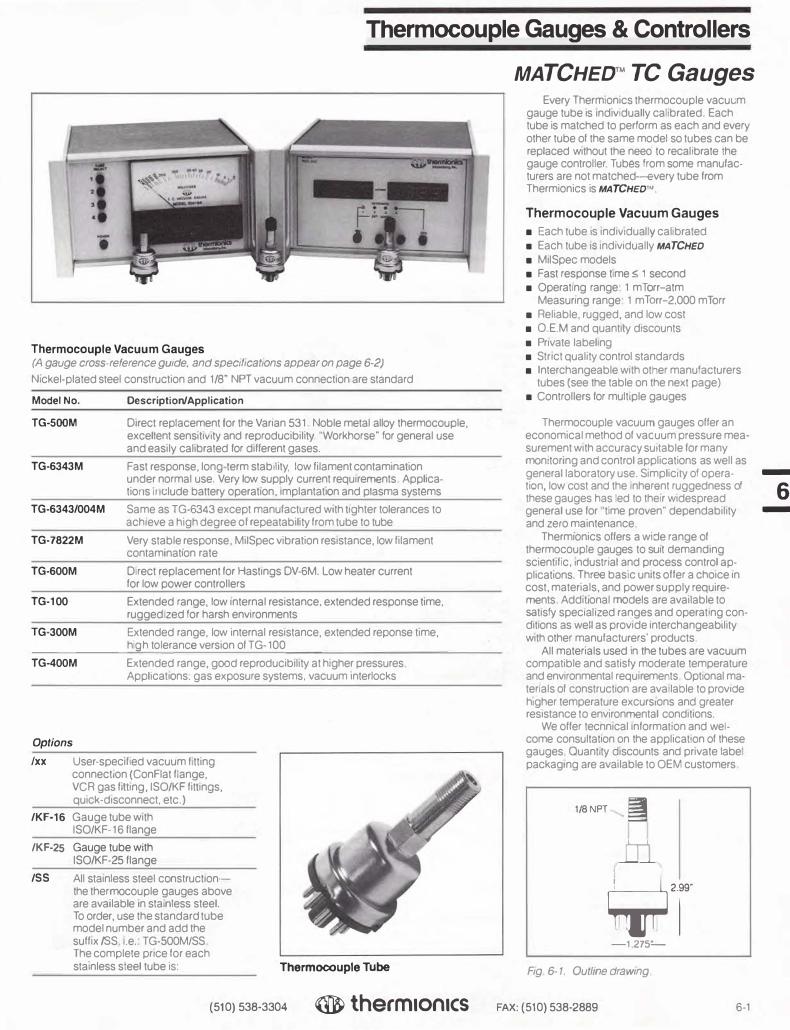
Thermocouple Gauges & Controllers
fl
Thermocouple Vacuum Gauges (A gauge cross-reference gwde, and spec,t,cat,ons appear on page 6-2)
Nickel-plated steel construction and 1 /8" NPT vacuum connection are standard
Model No. Description/Application
TG-SOOM Direct replacement for the Varian 531 Noble metal alloy thermocouple, excellent sensIt1v,ty and reproducibility 'Workhorse· for general use and easily calibrated for different gases.
TG-6343M Fast response, long term stability, low filament contamination under normal use. Very low supply current requirements Applications 11 <:lude battery operation, ,mplantat10n and plasma systems
TG-6343/004M Same as TG-6343 except manufactured w,th tighter tolerances to achieve a high degree of repeatability from tube to tube
TG-7822M Very stable response MilSpec vibration resistance, low filament contaminat,on rate
TG-600M Direct replacement for Hastings DV-6M. Low heater current for low power controllers
TG-100 Extended range, low internal resistance. extended response time. rugged zed for harsh environments
TG-300M Extended range, low internal resistance, extended reponse time, _______ hi__,,,g'-h_to_le�rance version of TG-100
TG-400M Extended range, good reproducib1!1ty at higher pressures Apphcat10ns. gas exposure systems. vacuum interlocks
Options
/xx User-specified vacuum I tting connection (ConFlat flange, VCR gas fitting. ISO/KF fittings, quick-disconnect. etc.)
/KF-16 Gauge tube w1th ISO/KF-16 flange
/KF-25 Gauge tube with ISO/KF-25 flange
/SS All stainless steel constructionthe thermocouple gauges above are available In stainless steel. To order. use the standard tube model number and add the suff1x/SS .e. TG-SOOM/SS The complete price for each stainless steel tube is: Thermocouple Tube
(510) 538-3304 ® therm1on1cs
MATCHED™ TC Gauges Every Therrtllon1cs thermocouple vacul.m
gauge tube is 1nd1vidually ca 1brated Each tube is matched to perform as each and every other tube of the same model so tubes can be replaced without the neeo to recalibrate the gauge controller Tubes from some manufacturers are not matched-every tube from Thermionics is MATCHED�'
Thermocouple Vacuum Gauges
■ Each tube Is 1nd1v1dua y cal brated■ Each tube IS 1nd1v1dually MATCHED■ M1ISpec models■ Fast response time� 1 second■ Operating range 1 mTorr-atm
Measuring range 1 mTorr-2,000 mTorr■ Reliable, rugged, and low cost■ 0 EM and quantity d1scou11ts■ Private label ng ■ Strict qual:ty control standards■ Interchangeable with other manufacturers
tubes (see the table on the next page)■ Controllers for multiple gauges
Thermocouple vacuum gauges offer aneconomical method of vacuum pressure measurement with accuracy suitable for many monitoring and control applications as well as general laboratory use. S1mplic,1y of opera- -tion, low cost ano the nherent ruggedness of
6 these gauges has led to their widespread general use for time proven" dependability -and zero maintenance
Thermionics offers a wi::Je range of thermocouple gauges to suit demanding scientific. ,ndustnal and process control applications. Three basic units offer a choice ,n cost. materials. and power supply requirements Additional models are available to satisfy spec1aI1zed ranges and operating con• d1t,ons as well as provide interchangeability with other manufacturers' products.
All materials used in the tubes are vacuum compatible and satisfy moderate temperature and environmental requ1remerts OptionaI materials of construction are ava lable to prov•oe higher temperature excursions and greater resistance to environmental conditions.
We offer tecnnical 1nforma:1on and welcome consultat,on on the application of these gauges Ouant,ty discounts and private labelpackaging are available to OEM customers
1/SNPT �
m
�T -1275=-
F,g 6-1. Ou//me drawing
FAX: (510) 538-2889 6-1

-
-
Thermocouple Gauges & Controllers
Cross Reference Guide Equivalency Table (Consult the factory for cross reference for tubes not listed here)
Thermionics Ion Equip. Granville-
Model No. Hughes Hastings Veeco Varian/NRe eve MKS Phillips
TG-100 DV-1M
TG-300M DV-3M
TG-400M DV-4O DV-4M
TG-500M 531 TCIA
TG-600M DV-6M 270006
TG-6343M TG-6343
TG-6343/004M TG-6343/004 GTC-004
TG-7822M TG-7822M
M signifies that heater current, tube to tube is matched within 1 % of scale. Shipping weight for all of the above tubes is 3/4 lb.
Thermocouple Gauge Operating Characteristics
Thermionics Range, Model No. mTorr
TG-100 0.1-100
TG-300M 0.1-100
TG-400M 0.1-20,000
TG-500M 0.1-2,000
TG-600M 0.1-1,000
TG-6343M 0.1-1,000
TG-6343/004M 0.1-1,000
TG-7822M 0.1-1,000
'Into a 55 ohm load. Output for all gauges at 0.1 mTorr is 10 mV. Gauge tubes fit Amphenol 78-PFB-11 or equal basing.
NOTES
Heater Current,
mA
130-150
130-150
40.0
165.0
20.0
16.6
16.4
74.5
1. Gauge tubes are individually calibrated and marked with the heater current required to provide10 mVoutput. This is done across 55 ohms when thegauge is under vacuum and pressure is lower than 1 x 10' Torr.2. For the TG-6343/004M high tolerance tube the calibration settings are 9.6 mVat 16.4 mA.
Norn.Cold Heater
Resistance
1.5
8.5
8.5
2.5
M.V.
0-10
Approx. mVOutput
atAtm.•
1.50
1.50
1.40
2.10
1.85
1.20
1.00
1.20
Heater Pins
3,5
3,5
3,5
1,7
1,7
1,7
1,7
1,5
1.281"'
TC Pins (Pos.1st)
1,7
1,7
1,7
3,5
5,3
5,3
5,3
7,3
Fig. 6-2. Typical circuit. Fig. 6-3. Physical outline.
Reference Tubes
References tubes are used for the calibration of thermocouple vacuum gauge controllers or other measuring electronics. They provide an output which mimics the normal tube performance at a given pressure and therefore are a fast, accurate means of calibrating electronics or troubleshooting system functions. Standard models come factory set to 1 0 mV output with the appropriate tube current input.
6-2 (510) 538-3304
Model No. Description
TGR-500 ForTG-500M calibration
TGR-6343 ForTG-6343 calibration
TGR-6343/004 For TG-6343/004 calibration
TGR-7822 For TG-7822M calibration
® therm1on1cs FAX: ( 510) 538-2889

Thermocouple Gauge Controllers
10
I I o
MllllfOll'II:
TGC-1OO
The TGC-100 is a panel mounted thermocouple gauge controller that is intended to operate any one of four standard thermocouple tubes offered by Thermionics: model TG-6343, TG-6343/004, TG-7822M, or TG-500. The suffix added to the model number of the unit designates the tube type that must be used with a respective meter (Example: TGC-100-6343 will operate a TG-6343 tube). Depending on the tube type, the circuitry is factory adjusted to provide the correct heater current, and the meter face is calibrated to reflect the pressure in milliTorr.
RearView
-Adjuot
' -♦-
I
fl S.00-
I -♦-
TGC-10OA
The TGC-1 DOA is a thermocouple gauge controller that is intended to operate one of four standard thermocouple tubes offered by Thermionics: model TG-6343, TG-6343/004, TG-7822M, or TG-500. This unit retains the same physical mounting as the TGC-100 but has additional control features not normally found on panel mount controllers. The TGC-1 00A provides a degree of system control by the inclusion of relay contacts that close at a pre-set setpoint. Besides the relay closure, the setpoint condition is also indicated on the front panel face by a visible light-emitting diode (LED). The setpoint is adjustable through the rear of the panel and can be easily changed without any disassembly. Additionally, an amplified thermocouple output is available for strip recorder or computer input.
The suffix added to the model number of the unit designates the tube type that must be used with a respective meter (Example: TGC-100A-6343 will operate a TG-6343 tube). Depending on the tube type, the circuitry is factory adjusted to provide the correct heater current, and the meter face is calibrated to reflect the pressure in milliTorr.
Panel Cutout Side View
---4"---
I 4"
---------� j
Specifications
Power
Range
Sensitivity
Operating temperature range
Heater supply
Gauge cable
Power cable
Weight
115/220 VAC, 50/60 Hz, 0.5 A
1 mTorr to 1 Torr
10 mV full scale
10°C to 40°C
Constant current DC source
10' long
6'1ong
3.0 lbs
Model No.
TGC-100
TGC-100A
Description
Panel mounted thermocouple gauge controller for the operation of one tube.
Panel mounted thermocouple gauge controller with analog output signal, adjustable setpoint control and 1 A relay contacts, LED indication of setpoint condition.
(510) 538-3304 ® therm1on1cs FAX: (510) 538-2889 6-3
-
6 -

-
6 -
Thermocouple Gauge Controllers
TGC-100B Front View
I Ir
----6"-----
RearVlew
I 4"
• I -----6"
Specifications
Power 6VDC
The TGC- 1008 is a battery powered thermocouple gauge controller that is intended to operate the TG-6343 or TG-6343/004 thermocouple tube offered by Thermionics. The unit comes in a compact chassis for easy portability and remote use. It employs inexpensive, easily replaced "C" cell batteries, and no complicated re-zeroing adjustment is required over the useful life of the batteries. The circuitry is factory adjusted to provide the correct heater current, and the meter face is calibrated to reflect the pressure in milliTorr. Battery lifetime is somewhat variable due to battery manufacturers ' specifications. However, factory tested units have lasted over 700 hrs (-30 days) with continuous operation. Periodic shutdown when not in use will sign
i
ficantly prolong useful operation with one battery set. Battery lifetime is easily monitored with a battery check on the front panel.
(4 "C" cell batteries)
TGC-100C
The TGC-1 DOC is a cabinet mounted thermocouple gauge controller that is intended to operate any one of four standard types of thermocouple tubes ottered by Thermionics: model TG-6343, TG-6343/004, TG-7822M, or TG- 500. The TGC-1 DOC is a bench-top version of the TGC-100A and provides a degree of system control by the inclusion of relay contacts that close at a pre-set setpoint. Besides the relay closure, the setpoint condition is also indicated on the front panel face by a visible light-emitting diode (LED). The setpoint is adjustable through the rear of the panel and can be easily changed without any disassembly. Additionally, an amplified thermocouple output is available for strip recorder or computer input.
The suffix added to the model number of the unit designates the tube type that must be used with a respective meter (Example: TGC-100C-6343 will operate a TG-6343 tube). Depending on the tube type, the circuitry is factory adjusted to provide the correct heater current, and the meter face is calibrated to reflect the pressure in milliTorr.
Model No.
TGC-100B
Model No_
TGC-100C
�( •
9
Description
Range
Sensitivity
Operating temperature range
Heater supply
Gauge cable
Power cable
Weight
1 mTorr to 1 Torr
10 mV full scale
10°C to 40°C
Constant current DC source
10' long
6'Iong
3.0lbs
Cabinet mounted, battery operated thermocouple gauge controller for the operation of 1 TG-6343 or TG-6343/004 thermocouple gauge tube. Operates on four "C" cells .
Front View RearView
11 I
I
(( @) e 0 11 4"
I • e I I •
6" 6"
Specifications
Power 115/220 VAC, 50/60 Hz, 0.5 A
Range 1 mTorr to 1 Torr
Sensitivity 10 mV full scale
Operating temperature range 10°C to 40°C
Heater supply Constant current DC source
Gauge cable 10' long
Power cable 6'Iong
Weight 3.0lbs
Description
Same features as TGC-1 OOA except in cabinet.
6- 4 (510) 538-3304 ® therm1on1cs FAX: ( 510) 538- 2889

TGC-400
The TGC-400 is a 4--channel thermocouple gauge controller that is intended to operate one of four standard types of thermocouple tubes offered by Thermionics: model TG-6343, TG-6343/004, TG-7822M, or TG-500. The suffix added to the model number of the unit designates the tube type that must be used with a respective controller (Example: TGC-400-6343 will operate four TG-6343 tubes). Depending on the tube type, the circuitry is factory adjusted to provide the correct heater current, and the meter face is calibrated to reflect the pressure in milliTorr. Additionally, the thermocouple signal is amplified and brought to the rear panel for strip chart or computer input.
Front Panel View
I I •
[2] •
S'i•'" •
I • •
8'h"
Model No. Description
-
·•
·•
·•
·•
•
Rear Panel View
0
It] m
I El B}l
•
•
•
•
TGC-400 Cabinet mounted thermocouple gauge control for the operation of four tubes.
Specifications
Power 115/220VAC, 50/60 Hz, 0.5 A
Range 1 mTorr to 1 Torr
Sensitivity 10 mV full scale
Operating temperature range 10°C to 40°C
Heater 4 independent constant current DC sources
Gauge cable 10' long
Power cable 6'1ong
Weight 3.0lbs
Thermocouple Gauge Controllers
Side View
I 5"l'
I 9•
(510) 538-3304 ® therm1on1cs FAX: (510) 538-2889 6-5
-
6 -

-
6 -
Thermocouple Gauge Controllers
The digital gauges to the right run TC-500M tubes, or the Varian model 531. Each is supplied with one TC-500M tube, a 10 ft tc gauge connecting cable, a 6 ft power cable, and an instruction manual. Range is 0-1999 milliTorr.
-
DTC-5OO
Model No.
DTC-50O
DTC-505
DTC-51O
DTC-801
--
Description
A portable, compact, rugged, low-cost, benchtop gauge with a large LCD display. Includes a 115 VAC, 50/60 Hz wall adapter.
A DTC-500 in a 1/8 DIN enclosure, will mount in your existing panel, 115/230VAC, 50/60 Hz.
A DTC-500 in a 1/8 DIN enclosure, will mount in your existing panel, with one process control output to drive an optional, external solid-state relay, 115/230 VAC, 50/60 Hz.
A digital replacement for the most common analog tc gauge-the Varian 801. Featuring a large, bright, easy-to-read, red LED display, it mountsdirectly in an existing 801 mounting hole geometry, 115 VAC, 50/60 Hz.Options: a) 2 process outputs to drive external solid state relays, or b) a case.
DTC-5O5
DTC-8O1
6-6 (510) 538-3304 ® therm1on1cs FAX: ( 510) 538-2889

Cold Cathode Ionization Gauges & Controllers
Features
■ 2 gauge models and compatible controlmodel
■ Self cleaning, minimum maintenance■ Rugged, all welded construction■ With or without O-rings or gaskets on
standard models
■ Viton O-ring on removable anode model ■ Long, Jninterrupted service life■ Smallsize■ Connectable to glass or metal systems
10000 I 3.0KVOC. ,....--
CD.II" ......... --·
i '
•• •
a:: a:: ::, u
1000
puv
Ill
C "10
f 1
C
0 a:: ui
.1 V /
/
,,,-'.01
.001
.5 MEGOHM LOAD'\ r--./
/ V
V /
V /
10-• PRESSURE, TORR. (MM HG.)
10-·
Fig. 6-4. Pressure vs. current curve.
10->
Cold Cathode Ionization Gauge Tubes
Cold cathode discharge gauges are an economical and durable alternative to hot filament ionization gauges in the high vacuum pressure regime. With no active components such as hot filaments, the discharge gauge is not destroyed in sudden or prolonged high pressure gas exposures. This feature and the relative simplicity of the gauge promotes its use in evaporation systems, heat treatment applications and plasma processing environments.
Thermionics offers two types of discharge tubes and a wide variety of connections to new and existing vacuum systems. The choice between the two gauges is based on the anticipated frequency of high pressure exposures and the nature of the residual gases in the vacuum. While these exposures will not often ruin the gauge, some deposition of foreign material may occur on the internal electrodes. To prevent a cumulative degrada-
Model
No.
DG-7
DG-8
Description
Standard tube with stainless steel (SS304) envelope, all welded construction and terminated with 3/4" tubulation. Bakeable to 250°C.
Same anode configuration as DG-7 except O-ring assembly ring allows for removal of the anode for inspection and cleaning. Bakeable to 150°C (Viton limit).
lion in tube performace, the electrodes may be removed and cleaned. This significantly prolongs the lifetime of the gauge operation, but is usually not a problem under typical vacuum environments. Thermionics offers a standard unit (DG-7) for typical operation and an additional unit with an easily removable anode assembly (DG-8) for the more austere applications.
ModelDG-8
Additional Terminations
Suffix Description
.750" '· ..1 .750" � -'
DG-7 DG-8
(Bakeable to 250°C) (Bakeable to 150°C)
Fig. 6-5. Gauge outlines
-1/2SS 1/2" stainless steel tubulation
-CF
-QD
-KF
3/4" tubulation with 23/4" ConFlatflange connection
1/2" tubulation to quick disconnect fitting
3/4" tubulation to KF-40 fitting
To Order: For example, to order a discharge gauge with an O-ring anode assembly for connection to a KF fitting, the following number would be specified: DG-8-KF.
-1/2G 1/2" glass tubulation
(510) 538-3304 ® therm1on1cs FAX: ( 510) 538-2889 6-7
-
6 -

-
6 -
TLI Cold Cathode Gauge Controllers
Features
■ Designed to operate DG-7 and DG-8series gauge tubes
■ Calibrated range: 1 x 10·1 to 1 x 10·• Torr■ Operate from 115 VAC■ Easy-to-read meter■ Lightweight: approx. 7 lbs■ Cabinet/half rack mounted
Cold Cathode Discharge Gauge Controllers
Thermionics provides a gauge controller that operates with all of our standard tubes. The almost indestructability of tube and the lack of hot filaments make it suitable for many applications. This controller includes large analog meters with voltage meter scale for system check.
Cold Cathode Gauge Control Specifications
DGC-202
Range 1 X 10·7 to 1 X 1 o-4 Power 115 VAC, 60 Hz, 1 A Output 4,400 voe (maximum)
5 mA (maximum) Dimensions 8"W x 5" Hx 10" D Weight 51bs Response 0.1 sec Power Cord 3· Gauge Cord 10'
i
-
Front Panel View
I . f / I
�------8'1,"----
Ordering Information
Model No. Description
' 511,"
•
Rear Panel View
• Im]
DGC-202 Cabinet mounted discharge gauge control (pressure is displayed on logarithmic scale)
Options
Suffix Description
5¼"
-RM Rack mount option to allow mounting in standard 19" electronic "racks"
-xx Additional cable length to be specified up to 50'
Side View
_J, ---6112"---
To Order: For example, to order a rack mounted DGC-202 with 30 ft cable length, one would write: DGC-202-RM-30.
6-8 (510) 538-3304 ® therm1on1cs FAX: ( 510) 538-2889

I--- 1 1/2" -l
Fig. 6-6. Gauge outline.
Pirani Gauge Tube & Controller
Pirani Gauges
Operating on the same principles as the thermocouple gauge, the Pirani gauge provides additional range with better resolution. It is a rugged, dependable gauge which is not readily destroyed by high pressure exposures and can readily serve as the control transducer in protection circuits for diffusion and turbomolecular pumps.
Shown with Standard Threaded Connector Thermionics offers a Pirani gauge with a variety of fittings to allow ready connection to most vacuum systems. An analog controller with a wide view meter is availble with setpoint and relay contacs for system control.
Specifications
Power 115 VAC (60 Hz)/220 VAC (50 Hz)
Pressure 0.1-1,000 mTorr (meter will indicate 1 aim at reduced accuracy)
Shown with Optional IS025 Aange Size 6" x 3 112" front panel and
approximately 8" deep with cable connections
4'12"
Heater Independent constant current DC sources
Front View
I IT
-----6"-----
Fig. 6-7. Controller mechanical.
PG-100 Pirani Gauges and PGC-100 Controllers
Controllers are shipped with a 10' cable(s) and instruction manual. Tubes are not included in controller prices and must be ordered separately.
Plrani Gauge Tube and Controller
Model No. Description
PG-100 Pirani gauge
IPGC-100
Rear View
6"
Controller Controllers are shipped with 10' cable(s) and instruction manual. Tubes are not included in controller price and must be ordered separately.
I 3112"
• I
(510) 538-3304 ® therm1on1cs FAX: ( 510) 538-2889 6-9
-
6 -

-
6 -
Glass Ionization Gauge Tubes
6-10
2.75 (69.91
COLLECTOR PIN 0.040" (1.02 mm) DIA
i---3.25
I
(82.6)
I 1.00 It-"125.41..,
MIN.
0.31 (7.9)
5.12 (1301
5.88 (149.41
Features
■ Bayard-Alpert design■ Easily outgassed grid■ Ease of connection■ Nonex, Pyrex, or Kovar tubulation■ Thoria-coated iridium filament (burnout
resistant) or dual tungsten filaments■ Range: 1Q-3 to 10·10Torr■ High conductance 1.0" tubulation
available
Bayard-Alpert Ionization Gauge Tube Specifications
Vacuum range 9.9 x 10⁻³ to 3 x 1o-'0Torr Filament voltage Filament bias 30 VDC Filament current 4-6 A Grid outgass 6.3-7.5 V at approx. 10 A
0.060" (1.52 mm) 0.44 (11.2) Collector voltage O VDC
PIN DIA (4) IN LINE-
DIMENSIONS INCHES
(MILLIMETERS)
--I I- 0.25 7 (6.4)
2.25 OD TYP (57.1)
Fig. 6-8. Standard ionization gauge tube.
Ion Gauge Tubes -x refers to option suffixes below
Model No. Description
Linearity 1Q-4 to 10·10Torr at10 mA emission 1 Q-3 to 10·9 Torr at1 mA emission
IG-1-N-x Nonex glass encapsulated tube terminated with 1" tubulation. • Dual filament assembly and choice of filament material.
IG-1-P-x Pyrex glass encapsulated tube terminated with 1" tubulation.* Dual filament assembly and choice of filament material.
• 0. 75" tubulation available. no extra charge. Show /075 as suffix.
Options
Suffix Description
-W Tungsten filaments
-I Thoria-coated iridium filaments
-K Kovar weldable transition termination
-CF 2. 75" ConFlat flange termination
To Order: For example, to order a Pyrex encapsulated tube with thoria-iridium filaments and terminated with a ConFlat flange, one would write: IG-1-P-I-CF.
(510) 538-3304 ® therm1on1cs FAX: ( 510) 538-2889

Nude Ionization Gauge and Flange Assemblies
Description
TU nude gauges are used when direct access to a vacuum chamber is needed. Nude gauges prevent errors which have been ascribed to glass envelopes and associated tubulations. They have a closed grid structure which minimizes gas reactions and improves sensitivity by a factor of 21/2. The improved sensitivity and a .005" collector results in a low x-ray limiting current corresponding to a pressure of about 2 x 10·11 Torr.
The gauge is available mounted on a 23/4" O.D. UHV flange, greatly simplifying filament replacement. Standard filaments are made of tungsten. For long life in higher pressure and/ or active gas environments, we recommend use of the thoria-coated iridium filament.
1 1.3126"
!
Fig. 6-9. Nude bakeab/e gauge tube.
Ion Gauge Tubes
-x refers to option suffixes below
Model No. Description
Medium to UHV Vacuum Pressure Measurement
■ Range: 10-3 to 10·11 Torr
■ Linear response in 10 ... and 10·5 Torr rangeswith reduced emission
■ Nude configuration
■ Bayard-Alpert type
1 1/e" --
IG-2-x Nude ionization gauge tube mounted on 23/4'' ConFlat flange.
IG-2F-x
Options
Suffix
-W
-I
Replacement filaments for nude ion gauge tube.
Description
Tungsten filaments
Thoria-coated iridium filaments
To Order: For example, to order a Pyrex encapsulated tube with thoria-iridium filaments and terminated with a ConFlat flange, one would write: IG-1-P-I-CF.
Nude Bakeable Bayard-Alpert Gauge Tube Specifications
Vacuum range
Filament voltage
Filament bias
Filament current
Grid voltage
Collector voltage
Sensitivity
Degas method
Flange
Length
Filament
Grid
1 x 10⁻³ to 2 x 10-11 Torr
3-4.5V
30VDC
2.5-3.5 A with emission current of 4 mA
180VDC
ovoc
0.1 A/Torr@ 4 mA grid current (N2 equivalent)
Electron bombardment (30-40 W@ approx. 500 V)
2.75" (70 mm) O.D. CF flange
4.12" overall, 3" insertion length
Two tungsten filaments, two thoria-coated iridium filaments or two tungsten rhenium filaments on replaceable filament assembly
Tantalum grid on platinumclad molybdenum supports with top and bottom caps
(510) 538-3304 ® therm1on1cs FAX: ( 510) 538-2889 6-11
-
6 -

-
6 -
LN2 Controller
-w, thermionics vocuum products
e s
AUTO
-OFF
MANUAL
0
The LNC-400 provides monitoring and control of liquid nitrogen levels in cryogenic containers. The level sensing device is a special ruggedized solid-state transducer designed for LN
2 immersion.
Front View Side View
•
5.18"
- 4.28" - ------- 9.45"
Model LNC-400 Specifications
Cabinet Height 5.5", Width 4.25", Depth 9.5"
Sensor Solid state encapsulated; 7/16" 0.0. x 5/8" long (one each)
Sensor lead 8' long, RG-188 coax (Teflon)
Line V oltage 105-125 or 210-265 VAC, 50 or 60 Hz
Power Cord 6' long, 3 wire detachable, polarized plug
Solenoid Outlet 115 VAC, 3 wire receptacle
Safety Fuse 3A
Switch 3 position, manual/off/automatic
Lights (2) One on when filling; other on when power is on
Level Range Determined by sensor placement
Cycle Time Adjustable from 0.1 to 6 min
Balance No calibration or balancing necessary
Warranty Fully guaranteed for one year; parts and labor
Weight 3Ibs
Liquid Nitrogen Transfer Line
Model LNT-500 liquid nitrogen transfer line assembly includes fittings, tubing, insulation, connectors and solenoid valve, for use with the LNC-400 controller.
Model No. LNT-500
6-12 (510) 538-3304 ® therm1on1cs FAX: ( 510) 538-2889

Flanges ■
t9 • • • • • • • • • •
7
■

•
Flanges
Technical Information General Information 7-1
Specifications 7-1
PyraFlat Rectangular Flanges Technical Information 7-2
Ordering Information 7-2
Assembly Hardware 7-3
Applications 7-4
ConFlat Flanges Technical Information 7-2
Ordering Information 7-6
Rotatable 7-6
Tapped Rotatable 7-8
Non-Rotatable 7-10
Tapped Non-Rotatable 7-12
Dimensional Drawings 7-14
Note: Assembly Hardware and Gaskets are shown on the same page
Adapter Flanges (Con Flat) Double-Sided Flanges 7-16 Note: Assembly Hardware and Gaskets are shown on the same page
Reducing Flanges 7-18
Wire Seal Flanges Bolt-Type Wire Seal Flanges 7-20
Clamp-Type Wire Seal Flanges 7-22
Note: Assembly Hardware and Gaskets are shown on the same page
ASA Flanges Standard ASA Flanges 7-24
ASA/ConFlat Adapter Flanges 7-25
Note: Roughing Accessories have been moved to Section 8
A Word About Bolt and Nut Sets If an ultra high vacuum seal is to maintain its inte-
grity, it must not be affected by the thermal stresses inherent in the bakeout process. Therefore the bolt and nut sets described on the following pages are made of series 300 stainless steel to match the thermal expan-sion co-efficient of the flanges. They are made from high strength steel to insure against failures due to plastic flow. Do not substitute ordinary bolts and nuts for these sets.
OFHC and OFE Copper OFHC was a registered trademark of American
Metals Climax, Inc. The trademark, proprietary pro-cess, product line and production machinery were sold to Phelps Dodge. Phelps Dodge retired the product, and discontinued manufacturing OFHC copper products.
ASTM F68 was the specification for proprietary OFHC copper product. The Copper Development Association, an industry trade organization, proposed and adopted specification UNSC-10100. UNSC-10100 and ASTM F68 are identical specifications. OFHC copper is no longer being produced and has been replaced in the market with OFE copper products. OFE is produced as a generic copper product. OFHC and OFE are interchangeable.
•

Ultra-High Vacuum Flanges
Round, Rectangular & Odd Shapes*
• Featuring the TLI PyraFlat flange
• Certified leak-free to 10-13 Torr
• Ideal for metal sealed valve bonnets!
The PyraFlat is the ideal metal seal for any rectangular vacuum connection. It is based on the same knife edge and captured flat copper gasket sealing principle used by the ConFlat flange and is equally reliable. Assem-bly, even with flange face vertical, is easy and fast. Your service people and technicians will welcome its use.
PyraFlats can be used for valve flange seals, too. A 2" by 10" rectangular gate valve
Standard ConFlat-Type
Features
• Flange and seal geometry totally compatible with Varian ConFlat
• Leak-free construction • Wide selection • Immediate shipment
is 8" more compact than the equivalent 10" circular gate valve.
Guaranteed leak-free from atmosphere to lx 10-13 Torr from -196° to 500°C.
* PyraFlat is available in triangular oval or trapezoidal shapes as well as in rectangular and square shapes. In fact, PyraFlat is avail-able in virtually any custom shape or size you may need in a bakeable, reliable, non-circular UHV flange.
PyraFlat flanges are manufactured and protected under one or more of the following patents: 5,640,751; 4,685,193
• All flanges made of 304 stainless steel • Certified leak-free to 10.13 Torr**
** Based upon the 10-" Torr ion gauge x-ray limit and 5 x 10, 3 Torrl/sec/cm2 outgassing rate of 304 SST
General Information
Description The reliable sealing performance of
PyraFlat and ConFlat flanges is due to the geometry which "captures" the gasket material. When the sealing edge of the flange is pressed into the OFE copper gasket, a lateral cold flow of the gasket material upon the slope occurs. This cold flow is limited by the vertical flange wall. Further material flow away from the seal area is severely limited and high interface pressures are developed. These pressures cause gasket material to fill surface imperfections and produce a highly reliable seal. At high temperatures, the "capturing" geometry maintains high pres-sures despite softening of the gasket.
Flanges, flange components, accesso-ries, and basic tube fittings are detailed here in Section 7. Other vacuum system compo-nents mounted on flanges are listed through-out the catalog.
Features
• Large selection of standard sizes • Identical mating flanges—no male and
female • Mate with all other PyraFlat and ConFlat
type flanges of same dimension • Easy repeated sealing • Leak-tight even with minor gasket nicks
and scratches • Offered in both rotatable and nonrotatable
versions • Components can be welded or brazed to
flanges
Specifications
• Vacuum range: to below 10-'3 Torr in Temperature operating range:
-196°C to +500°C • Material:
Mini and 23/4" 0.0. Vacuum melt type 304 SS
33/8" 0.0. and larger and PyraFlat Type 304 SS plate
• Maximum torque required to seal flanges: Mini and 23/4": 16 ft-lbs 33/8" and larger: 26 ft-lbs
(510) 538-3304 therm Ionics FAX: (510) 538-2889 7-1

-
7 -
PyraFlat Flanges
PyraFlat seals use the ConFlat sealing principle in a rectangular flange. Result: The ease, convenience, and reliability of circular seals are now available for rectangular vacuum seals.
Standard and custom PyraFlat versions have been designed for and used in many applications including high power microwave components and plasma-fusion. Please call our engineering group with your requirements.
@t
Applications
■ Gate valve metal bonnet seals (replaceswire-sealed flanges)
■ Close packed geometries
■ Fusion reactors
--:J � 8
• •
'�
Shown as a Welded Assembly
PyraFlat flanges are manufactured and protected
■ Cassette seals
■ Wave guides
■ Drift tubes
■ Ion pumps
D1 r-
T A G
1 --I E �
I"" F
--i
0 0
0 0
0 0
0 0
0 0
0 0
C
under one or more of the following patents: 5,640,751; 4,685,193 Integral Flanges (bolt hole and sealing portion
in one unit)
Standard Sizes Dimensions in inches
Model -Holes Gaskets
No.* "'t B C D E** F G H (Qty./Dla.) (5/pkg.)
026046 3.125 3.375 1.125 .274 .571 2.605 4.605 .125 12/.265 G026046
026056 4.125 4.375 1.125 .274 .571 2.605 5.605 .125 14/.265 G026056
035073 5.250 5.510 1.500 .524 .821 3.560 7.310 .125 18/.332 G035073
035098 7.750 8.010 1.500 .524 .821 3.560 9.810 .125 22/.332 G035098
043124 10.125 10.380 2.000 .524 .821 4.324 12.450 .125 24/.332 G043124
The following flanges are designed to accept standard sizes of square tubing.
029029 1.370 1.510 1.370 .194 .485 2.956 2.956 .093 8/.270 G029029
034034 1.870 2.010 1.870 .210 .605 3.456 3.456 .093 8/.270 G034034
044044 2.370 2.510 2.370 .360 .665 4.450 4.450 .093 12/.332 G044044
049049 2.870 3.010 2.870 .422 .735 4.950 4.950 .093 12/.322 G049049
059059 3.834 4.010 3.834 .422 .765 5.952 5.952 .093 16/.332 G059059
069069 4.834 5.010 4 834 .465 .825 6.952 6.952 .093 20/.332 G069069
079079 5.834 6.010 5.834 .485 .855 7.952 7.952 .093 24/.322 G079079
099099 7.834 8.010 7.834 .485 .985 9 952 9.952 .093 28/.332 G099099
127127 9.760 10.010 9.760 .585 1.235 12.714 12.714 .093 36/.390
147147 11.760 12.010 11.760 .587 1235 14.714 14.714 .093 40/.390
167167 13.760 14.010 13.760 .860 1.485 16.714 16.714 .093 48/.390
G127127
G147147
G167167
• Add suffixes as follows: T = Tapped Flange, B = Blank Flange (no extra charge), BT= Blank Tapped Flange
• "± .015" to dividing line of two flanges
Larger or other sizes and shapes available on request
7-2 (510) 538-3304 ® therm1on1cs FAX: (510) 538-2889

PyraFlat Flanges
Bolt Sets for PyraFlat Flanges Dimensions in inches
Model No. For Flange Model No. Size Qty.
PBN-25-150N 029029 1/4-28 X 11/2 Pack of 25 034034
PBN-25-175N 026046 1/•-28 X P/4 Pack of 25 026056
PBN-31-200N 044044 5/16-24 X 2.0 Pack of 25 049044 049049
PBN-31-225N 035073 5/16-24 X 2 1/4 Pack of 25 035098 043124 067069 079079
PBN-31-250N 099099 5/16-24 X 21/2 Packof 50
PBN-38-300N 127127 3/s-24x3.0 Pack of 50 147147 PyraFlat flanges are manufactured and protected
PBN-38-350N 167167 3/a-24x31/2 Pack of 50 under one or more of the following patents: 5.640, 751; 4,685, 193
NOTE: Consult factory for tapped flange bolt set information.
Examples of Possible PyraFlat Flange Geometries & Applications
ConFlat-Type Captured Gasket All Metal Seal Flange
Send us your special shape requirements, no matter how exotic, for quotation.
Triangular flanges can yield maximum packing density when a large number of flanges must be placed on a single surface.
Odd -shaped flanges can be the best solution to a unique research problem.
(510) 538-3304
Elliptical flanges are used when you wish to join two circular tubes at a flange angle of other than 90°. If the join angle is 45° , a 180" rotation produces a right -angle bend.
Trapezoidal flanges can be made in almost any ratio of height to base.
0
® therm1on1cs FAX: (510) 538- 2889
0
7-3
-
7 -

Some Applications for PyraFlat Flanges
PyreFlats and Valve Bonnets
The PyraFlat is an ideal metal seal for valve bonnets. This remarkable UHV flange makes any other rectangular metal valve bonnet seal obsolete. Its reliability and ease of assembly have been repeatedly proven, and its range of shapes and sizes will satisfy any non-circular UHV flange requirements.
Prior metal-sealed valve bonnets used wire gaskets. However, unconstrained gas-kets are far less reliable than the knife edge/ captured flat copper gasket sealing principle. Wire gaskets are also difficult to install and almost impossible when sealing surfaces are vertical. Not so with PyraFlat. Assembly requires only minutes, not hours, regardless of the angle of installation. This is important when valve bodies must be left inline when systems are being serviced.
Recently, a National Laboratory con-ducted independent testing on valves. Thermionics' gate valve with the PyraFlat bonnet seal won the competition. Like the ConFlat, its Varian ancestor, the PyraFlat will soon become a new standard in the industry.
PyraFlat flanges are manu-factured and protected under one or more of the following patents: 5,640,751; 4,685,193
Multiple e-Gun Assembly
Detail of Flange Face
PyreFlats in Custom Applications
Recently, we were asked to install two 5-crucible e-Guns in a 17" chamber. We wanted to provide our customer with opti-mal access for servicing—without disrupting the entire assembly. The PyraFlat was our solution. Its rectangular shape provided a 21% larger access opening than the equivalent circular flange could offer. Our customer was delighted.
Valve Bonnet Assembly
7-4 (510) 538-3304 thermionics FAX: (510) 538-2889

Some Applications for PyraFlat Flanges
See Section 1 for futher information.
PyraFlats and Ion Pumps
What Do You Do When Your Small Ion Pump Fails or Dies?
For decades, there have been only two choices. You could buy a new pump or pay to have your old pump rebuilt. Either way, your system was out of service until the new or rebuilt pump could be delivered and installed. The PyraFlat now provides an alternative.
By using the PyraFlat in the construction of our ion pump bodies, we can offer users of small- to medium-sized ion pumps the same
PyraFlats for Ion Pumped Table Top Systems
In the system shown, the modular, remov-able sublimator and cryoshroud assembly is mounted on a PyraFlat flange. This also provides access to the inside of the pumping stack for hassle-free cleaning, repair or maintenance.
PyraFlat flanges are manufactured and protected under one or more of the following patents: 5,640,751; 4,685,193
advantage enjoyed by users of larger ion pumps: immediate and total access for ser-vicing your own pump elements, plates and insulators. This translates into a substantial savings in money and time, since ion pump elements can often be restored to satisfactory service by proper vacuum clean-ing procedures.
1 1/2" ROUGHING VALVE
1.75
39.12
U TA VALVE 26.0
NEW!!!!
it
BELL JAR OR CHAMBER OF YOUR CHOICE
BASEPLATE 14.63" OD x 11.0" ID
POPPET VALVE LEDGE
ION PUMP
SB-1000 FILAMENT HOLDER
PyraFlat Access Port (see Section 9 for details)
(510) 538-3304 thermionics FAX: ( 510) 538-2889 7-5

Rotatable UHV Flanges
Dimensions in inches
Model No. Nom. 0.0.
Nom. I.D. Dwg.*
A O.D. Bolt Circle Thickness Setback Clear I.D. Rec. Depth
133000R 133 Blank a 1.33 1.062 0.285 0.750
133025R 11/3 1/4 b 1.33 1.062 0.285 0,750 0.260
133038R 11/3 3/8 b 1.33 1.062 0.285 0.750 0.380
133050R 11/3 1/2 b 1.33 1.062 0.285 0.750 0.510
133075R 11/3 3/4 c 1.33 1.062 0.285 0.750 0.630
212000R 21/8 Blank d 2.12 1.625 0.470 1.075 .236
212075R 21/8 3/4 e 2.12 1.625 0.470 .170 1.075 0.625 0.760 .236
212100R 21/8 1 e 212 1.625 0.470 .170 1.075 0.875 1.010 .236
275000R 23/4 Blank d 2.73 2.312 0.500 1.560 .300
275025R 23/4 1/4 e 2.73 2.312 0.500 .209 1.560 0.125 0.255 .300
275050R 2I4 1/2 e 2.73 2.312 0.500 .209 1.560 0.375 0.505 .300
275075R 23/4 3/4 e 2.73 2.312 0.500 .209 1.560 0.625 0.755 .300
275100R 23/4 1 e 273 2.312 0.500 .209 1.560 0.875 1.010 .300
275125R 23/4 11/4 e 2.73 2.312 0.500 .209 1.560 1.125 1.255 .300
275150R 23/4 11/2 e 2.73 2.312 0.500 .209 1.560 1.375 1.510 .300
338000R 3/8 Blank d 3.37 2.850 0.680 2.030 .381
338150R 33/8 11/2 e 3.37 2.850 0.680 .225 2.030 1.375 1.510 .381
338200R 33/8 2 e 3.37 2.850 0.680 .225 2.030 1.875 2.010 .381
450000R 41/2 Blank d 4.47 3.628 0.750 2.625 .500
450150R 41/2 11/2 e 4.47 3.628 0.750 .375 2.625 1.375 1.510 .500
450200R 41/2 2 e 4.47 3.628 0.750 .375 2.625 1.875 2.010 .500
450250R 41/2 21/2 e 4.47 3.628 0.750 .375 2.625 2.375 2.510 500
462000R 4V8 Blank d 4.62 4.030 0.810 3.100 .505
462250R 45/8 21/2 e 4.62 4.030 0.810 .375 3.100 2.375 2.510 .505
462300R 45/8 3 e 4.62 4.030 0.810 .375 3.100 2.875 3.010 .505
600000R 6 Blank d 5.97 5.128 0.840 4.125 .563
600400R 6 4 e 5.97 5.128 0.840 .437 4.125 3.810 4.010 .563
675000R 63/4 Blank d 6.75 5.969 0.840 - 5.125 .563
675400R 63/4 4 e 6.75 5.969 0.840 460 5.125 3.870 4.010 .563
675500R 63/1 5 e 6 75 5.969 0.840 460 5.125 4.870 5.010 .563
800000R 8 Blank d 7.97 7.128 0.940 6.125 .624
800600R 8 6 e 7.97 7.128 0.940 .500 6.125 5.810 6.020 .624
1000000R 10 Blank d 9.97 9.128 0.970 8 125 .675
1000800R 10 8 e 9.97 9.128 0.970 .500 8.125 7.810 8.020 .675
1325000R 131/4 Blank d 13.25 12.060 1.120 10.875 .775
13251000R 131/4 10 e 13.25 12.060 1.120 .500 10.875 9.860 10,020 .775
13251075R 131/4 103/4 e 13.25 12.060 1.120 .500 10.875 10.630 10.765 .775
1400000R 14 Blank d 14.00 12.810 1.120 12.250 .775
14001200R 14 12 e 14.00 12.810 1.120 500 12.250 11.750 12.020 775
1650000R 161/2 Blank d 16.50 15.310 1.120 14.290 .775
16501400R 161/2 14 e 16.50 15.310 1.120 .500 14.290 13.750 14.020 .775
*See drawings on page 7-14
7-6 (510) 538-3304 thermionics FAX: ( 510) 538-2889

Rotatable UHV Flanges
Bolt Holes Assembly Hardware
Sh Qty, No. Dia.
ip lbs
Wt. Unta
Model No. Description per pkg.
6 .172 .50 GK-133 OFE copper gaskets 10
6 .172 .50 VG-133 Vitongaskets 5
6 .172 .50 B-8-75N Bolt & nut set 8-32 x . 75" 25
6 .172 .50
6 . 172 .50
4 .265 .75 GK-212 OFE copper gaskets 10
4 .265 .50 VG-212 Vitongaskets 5
4 .265 .50 B-25-125N Bolt & nut set 'l•-28 x 1.25" 25
6 .265 1.00 GK-275 OFE copper gaskets 10
6 .265 .75 VG-275 Viton gaskets 5
6 .265 .75 B-25-150N Bolt & nut set 1/x•-28 x 1 . 50" 25
6 .265 .75
6 .265 .75
6 .265 .75
6 .265 .75
8 .332 2.00 GK-338 OFE copper gaskets 10
8 .332 1.75 VG-338 Vitongasket
8 .332 1.75 B-3H75N Bolt & nut set 5/16-24 x 1. 75" 25
8 332 2.50 GK-450 OFE copper gaskets 10
8 .332 2.00 VG-450 Vitongasket 1
8 .332 2.00 B-31-200N Bolt & nut set 5/16-24 x 2.0" 25
8 .332 2.00
10 .332 3.00 GK-462 OFE copper gaskets 10
10 .332 2.50 VG-462 Vitongasket 1
10 .332 2.50 B-31-225N Bolt & nut set 5/16-24 x 2.25" 25 -
16 .332 6.50 GK-600 OFE copper gaskets 10 7 16 .332 4 50 VG-600 Viton gasket 1 -
B-31-225N Bolt & nut set 5/16-24 x 2.25" 25
18 .332 7.00 GK-675 OFE copper gaskets 10
18 .332 5.00 VG-675 Viton gasket 1
18 .332 5.00 B-31-225N Bolt & nut set 5/16-24 x 2.25" 25
20 .332 10.00 GK-800 OFE copper gaskets 10
20 .332 7.00 VG-800 Vitongasket 1
B-31-225N Bolt & nut set 5/16-24 x 2.25" 25
24 .332 15.00 GK-1000 OFE copper gaskets 10
24 .332 12.00 VG-1000 Viton gasket 1
B-31-250N Bolt & nut set 5/16-24 x 2.5" 25
30 .390 50.00 GK-1325 OFE copper gasket
30 .390 20.00 VG-1325 Vitongasket 1
30 .390 20.00 B-38-300N Bolt & nut set 3/a-24 x 3.0" 30
30 .390 45.00
30 .390 13.00 Contact factory for f urther information.
36 .390 62.00 Wire seal flanges recommende d for these sizes.
See pages 7-20 thro ugh 7-23.
36 .390 18.00
(510) 538-3304 ® therm1on1cs FAX: (510) 538-2889 7-7

Tapped Rotatable UHV Flanges
Dimensions in inches
Model No. Nom. 0.0.
Nom. I.D. Dwg.*
A OA Bolt Circle Thickness Setback Clear I.D. Rec. Depth
133000RT 11/3 Blank a 1.33 1.062 0.285 0.750
133025RT 11/3 1/4 b 1.33 1.062 0.285 0.750 0.260
133038RT 11/3 3/8 b 1.33 1.062 0.285 0.750 0.380
133050RT 11/3 1/2 b 1.33 1.062 0.285 0.750 0.510
133075RT 11/3 3/4 c 1.33 1.062 0.285 0.750 0.630
212000RT 2 1/8 Blank d 2.12 1.625 0.470 1.075 .236
212075RT 21/8 3/4 e 2.12 1.625 0.470 .170 1.075 0.625 0.760 .236
212100RT 2 1/8 1 e 2.12 1.625 0.470 .170 1.075 0.875 1.010 .236
275000RT 23/4 Blank d 2.73 2.312 0.500 1.560 .300
275025RT 23/4 1/4 e 2.73 2.312 0.500 .209 1.560 0.125 0.255 .300
275050RT 23/4 1/2 e 2.73 2.312 0.500 .209 1.560 0.375 0.505 .300
275075RT 23/4 3/4 e 2.73 2.312 0.500 .209 1.560 0.625 0.755 .300
275100RT 23/4 1 e 2.73 2.312 0.500 .209 1.560 0.875 1.010 .300
275125RT 23/4 11/,1 e 2.73 2.312 0.500 .209 1.560 1.125 1.255 .300
275150RT 23/4 11/2 e 2.73 2.312 0.500 .209 1.560 1.375 1.510 .300
338000R1 3 3/8 Blank d 3.37 2.850 0.680 2.030 .381
338150RT 33/8 11/2 e 3.37 2.850 0.680 .225 2.030 1.375 1.510 .381
33800RT 33/8 2 e 3.37 2.850 0.680 .225 2.030 1.875 2.010 .381
450000R1 41/2 Blank d 4.47 3.628 0.750 2.625 .500
450150RT 41/2 1 1/2 0 4.47 3.628 0.750 .375 2.625 1.375 1.510 .500
450200RT 41/2 2 a 4.47 3.628 0.750 .375 2.625 1.875 2.010 .500
450250RT 41/3 272 0 4.47 3.628 0.750 .375 2.625 2.375 2.510 .500
462000RT 4/ Blank 5 4.62 4.030 0.810 3.100 .505
46225ORT 4.62 4.030 0.810 .375 3.100 2.375 2.510 .505
462300RT 44 3 e 4.62 4.030 0.810 .375 3.100 2.875 3.010 .505
600000RT 6 Blank d 5.97 5.128 0.840 4.125 .563
600400RT 6 4 e 5.97 5.128 0.840 .437 4.125 3.810 4.010 .563
675000RT 63/4 Blank d 6.75 5.969 0.840 5.125 .563
675400RT 63/4 4 e 6.75 5.969 0.840 .460 5.125 3.870 4.010 .563
675500RT 613/4 5 e 6.75 5.969 0.840 .460 5.125 4.870 5.010 .563
800000RT 8 Blank d 7.97 7.128 0.940 6.125 .624
800600RT 8 6 e 7.97 7.128 0.940 .500 6.125 5.810 6.020 .624
1000000RT 10 Blank ci 097 9.128 0.970 8.125 .675
1000800RT 10 8 097 9.128 0.970 .500 8 125 7 810 8.020 675
1325000RT 131/4 Blank d 13.25 12.060 1.120 10.875 .775
13251000RT 131/4 10 e 13.25 12.060 1.120 .500 10.875 9.860 10.020 .775
13251075RT 131/4 103/4 e 13.25 12.060 1.120 .500 10.875 10.630 10.765 .775
1400000RT 14 Blank d 14 00 12.810 1.120 12 250 775
14001200R1 14 12 a 14.00 12.810 1.120 .500 12.250 11.750 12.020 .775
1650000RT 161/2 Blank d 16.50 15.310 1.120 14.290 .775
16501400131 161/2 14 e 16.50 15.310 1.120 .500 14.290 13.750 14.020 .775
*See drawings on page 7-14. We reserve the right to substitute threaded inserts.
7-8 (510) 538-3304 thermionics FAX: (510) 538-2889

Tapped Rotatable UHV Flanges
Bolt Holes Assembly Hardware
Ship Wt. Price Qty, No. TPI lbs Tapped Model No. Description per pkg. per pkg.
6 8-32 .50 GK-133 OFE copper gaskets 10
6 8-32 .50 VG-133 Viton gaskets 5
6 8-32 .50 B-8-50 Bolt set 8-32 x o .5" 25
6 8-32 .50
6 8-32 .50
4 1/4·28 .75 GK-212 OFE copper gaskets 10
4 1/4·28 .50 VG-212 Viton gaskets 5
4 1/4-28 .50 B-25-87 Bolt set ¼-28x .875" 25
6 1/•·28 1.00 GK-275 OFE copper gaskets 10
6 1/•-28 .75 VG-275 Viton gaskets 5
6 1/4·28 .75 B-25-87 Bolt set '/•-28 x .875" 25
6 'l•-28 .75
6 1/4-28 .75
6 1/4-28 .75
6 1/4-28 .75
8 5/16-24 2 00 GK-338 OFE copper gaskets 10
8 5/16-24 1.75 VG-338 Viton gasket
8 5/16·24 1.75 8-31-125 Bolt set 5/16-24 x 1.25" 25
8 5/16-24 2.50 GK-450 OFE copper gaskets 10
8 5/t6·24 2.00 VG-450 Vitongasket
8 5/16·24 2.00 B-31-125 Bolt set 5/16-24 x 1.25" 25
8 "/16·24 2.00
10 5/16-24 3.00 GK-462 OFE copper gaskets 10
10 5/16-24 2.50 VG-462 Vitongasket 1
10 5/16-24 2.50 8-31-125 Bolt set 5/16-24 x 1.25" 25 -
16 5/16-24 6.50 GK-600 OFE copper gaskets 10 7 16 5/ts-24 4.50 VG-600 Vitongasket 1 -
B-31-125 Bolt set 5/ts-24 x 1 .25" 25
18 5/16-24 7.00 GK-675 OFE copper gaskets 10
18 5/ts-24 5.00 VG-675 Vitongasket 1
18 5/16·24 5.00 8-31-125 Bolt set 5/16-24 x 1.25" 25
20 5/ts-24 10.00 GK-800 OFE copper gaskets 10
20 5/16-24 7.00 VG-800 Vitongasket
B-31-175 Bolt set 5/16-24 x 1. 75" 25
24 5/16·24 15.00 GK-1000 OFE copper gaskets 10
24 5/ts-24 12.00 VG-1000 Viton gasket 1
8-31-175 Bolt set 5/16-24 x 1. 75" 25
30 3/s-24 50.00 GK-1325 OFE copper gasket 1
30 3/e-24 20.00 VG-1325 Viton gasket 1
30 3/-24 20.00 B-38-200 Bolt set 3/a-24 x 2.0" 30
30 3/a-24 55.00
30 3/e-24 20.00 Contact factory for fu rther information.
Wire seal flanges recommended for these sizes. 36 3/s-24 62.00 See pages 7-20 through 7-23.
36 3/s-24 22.00
(510) 538-3304 ® thermIon1cs FAX: (510) 538-2889 7-9

Non-Rotatable UHV Flanges
Dimensions in inches
Model No. Nom. O.D.
Nom. I.D. Dwg.*
A O.D. Bolt Circle Thickness Setback I.D.
133000 11/3 Blank f 1.33 1.062 0,285 -
133025 11/3 1/4 g 1.33 1.062 0.285 0.260
133038 173 3/8 g 1.33 1.062 0.285 0.380
133050 11/3 1/2 g 1.33 1.062 0.285 0.510
133075 173 3/4 h 1.33 1.062 0.285 0.750 0.630
212000 278 Blank 2.12 1.625 0.470
212075 21/8 3/4 2.12 1.625 0.470 .170 0.760 0.625
212100 21/B 2.12 1.625 0.470 .170 1.010 0.875
275000 23/4 Blank i 2.73 2.312 0.500 - -
275025 23/4 1/4 j 2.73 2.312 0.500 .209 0.255 0.125
275050 23/4 1/2 2.73 2.312 0.500 .209 0.505 0.375
275075 23/4 3/4 2.73 2.312 0.500 .209 0.755 0.625
275100 274 1 2.73 2.312 0.500 .209 1.010 0.875
275125 23/4 11/4 2.73 2.312 0.500 .209 1.255 1.125
275150 23/4 11/2 2.73 2.312 0.500 .209 1.510 1.375
338000 33/8 Blank 3.37 2.850 0.625
338150 33/8 11/2 3.37 2.850 0.625 .225 1.510 1.375
338200 3 3/2 2 3.37 2.850 0.625 .225 2.010 1.875
450000 4 1/2 Blank i 4.47 3.628 0.680
450150 41/2 11/2 j 4.47 3.628 0.680 .375 1.510 1.375
450200 41/2 2 4.47 3.628 0.680 .375 2.010 1.875
450250 472 21/2 4.47 3.628 0.680 .375 2.510 2.375
462000 45/8 Blank 4.62 4.030 0.750
462250 45/8 272 j 4.62 4.030 0.750 .375 2.510 2.375
462300 4'/, 3 i 4.62 4.030 0.750 .375 3.010 2.875
600000 6 Blank I 5.97 5.128 0.780
600400 6 4 i 5.97 5.128 0.780 .437 4.010 3.810
675000 Blank 6.75 5.969 0.840
675400 63/4 4 1 6.75 5.969 0.840 .460 4.010 3.870
675500 5 j 6.75 5.969 0.840 .460 5.010 4.870
800000 8 Blank i 7.97 7.128 0.880
800600 8 6 i 7.97 7.128 0.880 .500 6.020 5.810
1000000 10 Blank 9,97 9 128 0.970
1000800 10 8 9.97 9 128 0.970 500 8.020 7.810
1325000 1374 Blank i 13.25 12.060 1.120
13251000 131/4 10 j 13.25 12.060 1.120 .500 10.020 9.860
13251075 1374 103/4 I 13.25 12.060 1.120 .500 10.765 10.630
1400000 14 Blank 14.00 12 810 1 120
14001200 14 12 14.00 12.810 1.120 .875 12.020 11.750
1650000 1672 Blank i 16.50 15.310 1.120
16501400 16 1/2 14 j 16.50 15.310 1.120 .875 14.020 13.750
*See drawings on page 7-15
7-10 (510) 538-3304 thermionics FAX: ( 510) 538-2889

Non-Rotatable UHV Flanges
Assembly Hardware Bolt Holes Ship Wt. Qty.
No. Dia. lbs Model No. Description per pkg. 6 .172 .50 GK-133 OFE copper gaskets 10 6 .172 .50 VG-133 Vitongaskets 5 6 .172 .50 B-8-75N Bolt & nut set 8-32 x . 75" 25 6 .172 .50 6 .172 .50 4 .265 .75 GK-212 OFE copper gaskets 10 4 .265 .50 VG-212 Viton gaskets 5 4 .265 .50 B-25-125N Bolt & nut set ¼-28 x 1.25" 25 6 .265 1.00 GK-275 OFE copper gaskets 10 6 .265 .75 VG-275 Vitongaskets 5 6 .265 .75 B-2S-150N Bolt & nut set 1/4-28 x 1.50" 25 6 .265 .75 6 .265 .75 6 .265 .75 6 .265 .75 8 .332 2.00 GK-338 OFE copper gaskets 10 8 .332 175 VG-338 Vitongasket 1 8 .332 1.75 B-31-175N Bolt & nut set 5/16-24 x 1.75" 25 8 .332 2.50 GK-450 OFE copper gaskets 10 8 .332 2.00 VG-450 Vitongasket 1 8 .332 2.00 B-31-200N Bolt & nut set 5/,s-24 x 2.0" 25 8 .332 2.00 10 .332 3.00 GK-462 OFE copper gaskets 10 10 .332 2.50 VG-462 Vitongasket 1 10 .332 2.50 B-31-200N Bolt & nut set 5/,e-24 x 2.0" 25 -
16 .332 6.50 GK-600 OFE copper gaskets 10 7 16 .332 4.50 VG-600 Viton gasket 1
-
B-31-200N Bolt & nut set 5t,s-24 x 2.0" 25 18 .332 7.00 GK-675 OFE copper gaskets 10 18 .332 5.00 VG-675 Viton gasket 1 18 .332 5.00 B-31-225N Bolt & nut set 5/,e-24 x 2.25" 25 20 .332 10.00 GK-800 OFE copper gaskets 10 20 .332 7.00 VG-800 Viton gasket 1
B-31·225N Bolt & nut set 5/16-24 x 2.25" 25 24 .332 15.00 GK-1000 OFE copper gaskets 10 24 .332 12.00 VG-1000 Viton gasket 1
B-31·250N Bolt & nut set 5/16-24 x 2.5" 25 30 .390 50.00 GK-1325 OFE copper gasket 1 30 .390 40.00 VG-1325 Viton gasket 1 30 .390 40.00 B-38-300N Bolt & nut set 3/8-24 x 3.0" 30 30 .390 50.00 30 .390 16.00 Contact factory for further information.
36 .390 65.00 Wire seal flanges recommended for these sizes.
See pages 7-20 through 7-23. 36 .390 20.00
(510) 538-3304 ® therm1on1cs FAX: (510) 538-2889 7-11

Tapped Non-Rotatable UHV Flanges
Dimensions in inches
Model No. Nom. O.D.
Nom. I.D. Dwg.*
A O.D. Bolt Circle Thickness Setback I.D.
133000T 11/3 Blank f 1.33 1 062 0.285
133025T 11/3 1 / 4 g 1.33 1.062 0.285 0.260
133038T 11/3 3/8 g 1.33 1.062 0.285 0.380
1330501 11/3 1/2 g 1.33 1.062 0.285 0.510
1330751 11/3 3/4 h 1.33 1.062 0.285 0.750 0.630
2120001 2 1/8 Blank 2.12 1.625 0.470
2120751 21/8 3/4 j 2.12 1.625 0.470 .170 0.760 0.625
212100T 2 1/8 1 j 2.12 1.625 0.470 .170 1.010 0.875
275000T 23/4 Blank 2.73 2.312 0.500
275025T 23/4 1/4 j 2.73 2.312 0.500 .209 0.255 0.125
2750501 23/4 1/2 2.73 2.312 0.500 .209 0.505 0.375
2750751 23/4 3/4 2.73 2.312 0.500 .209 0.755 0.625
2751001 23/4 1 j 2.73 2.312 0.500 .209 1.010 0.875
2751251 23/4 11/4 j 2.73 2.312 0.500 .209 1.255 1.125
275150T 23/4 11/2 I 2.73 2.312 0.500 .209 1.510 1.375
338000T 33/8 Blank 3.37 2.850 0.625
338150T 33/8 11/2 3.37 2.850 0.625 .225 1.510 1.375
338200T 3 3/8 2 3.37 2.850 0.625 .225 2.010 1.875
4500001 4 1/2 Blank i 4.47 3.628 0.680
4501501 4 1/2 1 / 2 I 4.47 3.628 0.680 .375 1.510 1.375
4502001 4 1/2 2 I 4.47 3.628 0.680 .375 2.010 1.875
4502501 4 1/2 2 1/2 I 4.47 3.628 0.680 .375 2.510 2.375
462000T 4 5/8 Blank 4.62 4.030 0.750
462250T 45/8 2 1/2 j 4.62 4.030 0.750 .375 2.510 2.375
462300T 4 5/8 3 4.62 4.030 0.750 .375 3.010 2 875
6000001 6 Blank 5,97 5.128 0.780
6004001 6 4 i 5.97 5.128 0.780 .437 4.010 3.810
675000T 63/4 Blank 6.75 5.969 0.840
675400T 63/4 4 6.75 5.969 0.840 .460 4.010 3.870
675500T 6/.. 5 6.75 5.969 0.840 .460 5.010 4 870
800000T 8 Blank i 7.97 7.128 0.880
8006001 8 6 i 7.97 7.128 0.880 .500 6.020 5.810
10000001 10 Blank 9 97 9.128 0.970
10008001 10 8 9.97 9.128 0.970 .500 8.020 7.810
13250001 13 1/4 Blank 13.25 12.060 1.120
132510001 13 1/4 10 j 13.25 12.060 1.120 .500 10.020 9.860
132510751 1374 10 3/4 I 13.25 12.060 1.120 .500 10.765 10.630
14000001 14 Blank 14.00 12.810 1.120
140012001 14 12 14.00 12.810 1.120 .875 12.020 11.750
16500001 1672 Blank I 16.50 15.310 1.120
165014001 16 1/2 14 I 16.50 15.310 1.120 .875 14.020 13.750
'See drawings on page 7-15. We reserve the right to substitute threaded inserts.
7-12 (510) 538-3304 thermionics FAX: ( 510) 538-2889

Tapped Non-Rotatable UHV Flanges
Assembly Hardware Bolt Holes Ship. Wt. Qty.
No. TPI lbs Model No. Description per pkg.
6 8-32 .50 GK-133 OFE copper gaskets 10
6 8-32 .50 VG-133 Viton gaskets 5
6 8-32 .50 B-8-50 Bolt set 8-32 x 0.5" 25
6 8-32 .50
6 8-32 .50
4 1/4-28 .75 GK-212 OFE copper gaskets 10
4 ¼-28 .50 VG-212 Vitongaskets 5
4 ¼-28 .50 B-25-87 Bolt set ¼-28 x .875" 25
6 'l•-28 1.00 GK-275 OFE copper gaskets 10
6 1/4-28 .75 VG-275 Viton gaskets 5
6 ¼-28 .75 B-25-87 Bolt set ¼-28 x .875" 25
6 ¼-28 .75
6 'l•-28 .75
6 ¼-28 .75
6 ¼-28 .75
8 o/16-24 2.00 GK-338 OFE copper gaskets 10
8 o/1s-24 1.75 VG-338 Vitongasket 1
8 o/1s-24 1.75 B-31-125 Bolt set 5/ls-24 x 1.25" 25
8 o/1s-24 2.50 GK-450 OFE copper gaskets 10
8 o/1s-24 2.00 VG-450 Vitongasket 1
8 o/16-24 2.00 B-31-125 Bolt set 5/ls-24 x 1.25" 25
8 o/16-24 2.00
10 o/16-24 3.00 GK-462 OFE copper gaskets 10
10 o/1s-24 2.50 VG-462 Viton gasket 1
10 o/1s-24 2.50 B-31-125 Bolt set 5t,s-24 x 1.25" 25 -
16 o/1s-24 6.50 GK-600 OFE copper gaskets 10 7 16 o/1s-24 4.50 VG-600 Vitongasket 1 -
B-31-125 Bolt set 5/,s-24 x 1.25" 25
18 o/1s-24 7.00 GK-675 OFE copper gaskets 10
18 o/1s-24 5.00 VG-675 Viton gasket 1
18 1'16-24 5.00 B-31-125 Bolt set 5/ls-24 x 1.25" 25
20 1'1e-24 10.00 GK-800 OFE copper gaskets 10
20 1'1e-24 7.00 VG-800 Viton gasket 1
B-31-175 Bolt set '/ls-24 x 1. 75" 25
24 o/16-24 15.00 GK-1000 OFE copper gaskets 10
24 1'16-24 12.00 VG-1000 Vitongasket 1
B-31-175 Bolt set 5/16-24x 1.75" 25
30 3/s-24 50.00 GK-1325 OFE copper gasket
30 %-24 40.00 VG-1325 Viton gasket 1
30 3/e-24 40.00 B-38-200 Bolt set 3/s-24 x 2.0" 30
30 3/s-24 50.00
30 %-24 16.00 Contact factory for fu rther information.
36 3/s-24 65.00 Wire seal flanges recommended for these sizes.
See pages 7-20 through 7-23. 36 3/s-24 20.00
(510) 538-3304 ® therm1on1cs FAX: (510) 538-2889 7-13

Physical Dimensions
Mini Flanges—Rotatable and Tapped Rotatable Pages 7-6 to 7-9
Drawing a
Drawing c (shown welded to tubing)
Drawing b
Standard Flanges—Rotatable and Tapped Rotatable Pages 7-6 to 7-9
A
Nirk 'SAM FAWN
Drawing d
Assembly Technique
1. Check cleanliness of gasket and seal area. If necessary, clean using UHV technique. Note: Gaskets are cleaned before packaging and are ready to use as received.
2. Inspect knife edges on both flanges for damage. Small nicks will not affect seal-ing, but large nicks can cause leaks.
3. Assemble joint with bolts finger tight.
4. Visually check that gasket is centered.
5. Tighten bolts evenly until flanges touch. Do not overtighten. Maximum torque required to seal flanges: Mini and 23/4": 16 ft-lbs 33/e" and larger: 26 ft-lbs
6. After the initial bakeout, it is good practice to check the tightness of the bolts. It is not necessary on subsequent bakeouts.
7-14 (510) 538-3304
Drawing e
thermionics FAX: (510) 538-2889

Physical Dimensions
Mini Flanges—Integral and Tapped Integral Pages 7-10 to 7-13
N
A
im& t
Drawing f
Drawing h
B
Drawing g
Standard Flanges—Integral and Tapped Integral Pages 7-10 to 7-13
A
\ \ \
C
Drawing i
B i
(510) 538-3304
Drawing j
Q thermionics FAX: (510) 538-2889 7-15

Double-Sided Flanges
Double-sided flanges are designed to be inserted between two flanges of the same size, providing a simple method for adding both thermocouple gauge tubes and up-to-air valves to a system with virtually no change in conductance or pumping speed. Refer to Section 8, page 8-24 for special purpose flanges supplied with valves and tubes installed.
A
F
N
Model No.
D-133000
0-133025
D-133037
0-133050
D-212000
D-212075
D-212100
0-275000
D-275025
D-275050
D-275075
D-275100
D-275125
D-275150
D-275150-1
0-338000
0-338150
0-338200
D-450000
D-450150
D-450200
0-450250
0-462000
0-462250
0-462300
0-600000
D-600400
D-675000
0-675400
D-675500
0-800000
D-800600
D-1000000
D-1000800
D-1325000
0-13251000
D-13251075
D-1400000
D-14001200
D-1650000
D-16501400
7-16 (510) 538-3304 thermionics
Dimensions in inches
A 0.0. Bolt Circle Thickness I.D.
1.33 1,062 0.285 blank
1.33 1.062 0.285 0.250
1.33 1.062 0.285 0.380
1.33 1.062 0.285 0.500
2.12 1.625 0.470 blank
2.12 1.625 0.470 0.750
2.12 1.625 0.470 1.000
2.75 2.312 0.750 blank
2.75 2.312 0.750 0.250
2.75 2.312 0.750 0.500
2.75 2.312 0.750 0.750
2.75 2.312 0.750 1.000
2.75 2.312 0.750 1.250
2.75 2.312 0.750 1.500
2.75 2.312 1.000 1.500
3.37 2.850 0.620 blank
3.37 2.850 0.620 1.500
3.37 2.850 0.620 2.000
4.50 3.628 0.680 blank
4.50 3.628 0.680 1.500
4.50 3.628 0.680 2.000
4.50 3.628 0.680 2.500
4.62 4.030 0.750 blank
4.62 4.030 0.750 2.500
4.62 4.030 0.750 3.000
6.00 5.128 0.780 blank
6.00 5,128 0.780 4.000
6.75 5.969 0.840 blank
6.75 5.969 0.840 4.000
675 5 969 0.840 5.000
8.00 7.128 0.870 blank
8.00 7.128 0.870 6.000
10.00 9.128 0.970 blank
10.00 9.128 0.970 8.000
13.25 12.060 1.120 blank
13.25 12.060 1.120 10.000
13.25 12.060 1.120 10.750
14 00 12.810 1.120 blank
14.00 12.810 1 . 120 12.000
16.50 15.310 1.120 blank
16.50 15.310 1.120 14.000
FAX: ( 510) 538-2889

Double-Sided Flanges
Assembly Hardware Bolt Holes Norn. Wt. Qty.
No. Dia. Size lbs Model No. Description per pkg. 6 .172 1 1/3 .50 GK-133 OFE copper gaskets 10
6 .172 1 1/3 .50 VG-133 Vitongaskets 5
6 .172 11/3 .50 B-8-125D Bolt & nut set 8-32 x 1.25" 6
6 .172 11/3 .50
4 .265 2'/s .75 GK-212 OFE copper gaskets 10
4 .265 2 1/a .50 VG-212 Vitongaskets 5
4 .265 2'/s .50 B-25-200D Bolt & nut set 1 /4-28 x 2.0" 4
6 .265 2 3/4 .75 GK-275 OFE copper gaskets 10
6 .265 2 3/4 .75 VG-275 Vitongaskets 5
6 .265 2 3/4 .75 B-25-225D Bolt & nut set '/4-28 x 2 .25" 6
6 .265 23/4 .75 B-25-250D Bolt & nut set (for 1" thick flange)
6 .265 2¼ .50 1/4-28 X 2 .5'' 6
6 .265 23/4 .50
6 .265 2"/4 .50
6 .265 23/4 .75 8 .332 33/s 2.00 GK-338 OFE copper gaskets 10
8 .332 33/a 1 50 VG-338 Vitongasket 1
8 .332 33/s 1.50 B-31-225O Bolt & nut set 5/16-24 x 2.25" 8
8 .332 41/2 3.00 GK-450 OFE copper gaskets 10
8 .332 41/2 2.50 VG-450 Vitongasket
8 .332 41/2 2.50 B-31-250D Bolt & nut set 5/ts-24 x 2.5" 8
8 .332 41/2 2.00 10 .332 45/a 3.00 GK-462 OFE copper gaskets 10
10 .332 45/a 2.00 VG-462 Vitongasket 1
10 .332 45/s 2.00 B-31-275D Bolt & nut set 5/16-24 x 2. 75" 10 -
16 .332 6 6.00 GK-600 OFE copper gaskets 10 7 16 .332 6 4.00 VG-600 Vitongasket 1 -
B-31-275D Bolt & nut set 5/ts-24 x 2. 75" 16
18 .332 63/4 7.00 GK-675 OFE copper gaskets 10
18 .332 63/4 6.50 VG-675 Vitongasket
18 .332 63/4 6.50 B-31-300D Bolt & nut set 5t,e-24 x 3.0" 18
20 .332 8 9.00 GK-800 OFE copper gaskets 10 20 .332 8 6.00 VG-800 Vitongasket 1
B-31-325D Bolt & nut set 5/16-24 x 3.25" 20
24 .332 10 15.00 GK-1000 OFE copper gaskets 10
24 332 10 12.00 VG-1000 Vitongasket 1
B-31-350D Bolt & nut set 5hs-24 x 3.5" 24
30 .390 13 '/4 50.00 GK-1325 OFE copper gasket 30 .390 13 '/4 40.00 VG-1325 Vitongasket 1
30 .390 13 1/4 40.00 B-38-400D Bolt & nut set 3/s-24 x 4.0" 30
30 .390 14
30 .390 14 Contact factory for further information. Wire seal flanges recommended for these sizes.
36 .390 16'/2 See pages 7-20 through 7-23. 36 .390 16 112
(510) 538-3304 ® therm1on1cs FAX: ( 510) 538-2889 7-17
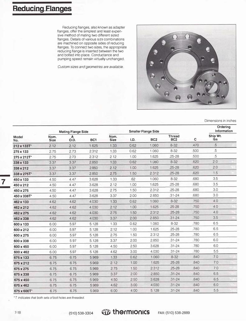
-
7
Reducing Flanges
Model Nom. No. Size
212x133r 2.12
275 X 133 2.75
21sx212r 2.75
338x 133 3.37
338 X 212 3.37
338x275r 3.37
450x 133 4.50
450x212 4.50
450x275 4.50
450x338r 4.50
462 X 133 4.62
462x212 4.62
462x275 4.62
462x338 4.62
600x 133 6.00
600x212 6.00
600x275 6.00
600x338 6.00
600x450 6.00
600x462 6.00
675 X 133 6.75
675 X 212 6 75
675x275 6.75
675x338 6.75
675x450 6.75
675x462 6.75
675x6oor 6.75
Reducing flanges, also known as adapter flanges, offer the simplest and least expensive method of mating two different sized flanges. Details of various size combinations are machined on opposite sides of reducing flanges. To connect two sizes, the appropriate reducing flange is inserted between the two and bolted into place. Conductance and pumping speed remain virtually unchanged.
Custom sizes and geometries are available.
Mating Flange Side A Nom.
0.0. BC1 Size
2.12 1.625 1.33
2.73 2.312 1.33
2.73 2.312 2.12
3.37 2.850 1.33
3.37 2.850 2.12
3.37 2.850 2.75
4.47 3.628 1.33
4.47 3.628 2.12
4.47 3.628 2.75
4.47 3.628 3.37
4.62 4.030 1.33
4.62 4.030 2.12
4.62 4.030 2.75
4.62 4.030 3.37
5.97 5.128 1.33
5.97 5.128 2.12
5.97 5.128 2.75
5.97 5.128 3.37
5.97 5.128 4.50
5.97 5.128 4.62
6.75 5.969 1.33
6.75 5.969 2.12
6.75 5.969 2.75
6.75 5.969 3.37
6.75 5.969 4.50
6.75 5.969 4.62
6.75 5.969 6.00
• T indicates that both sets of bolt holes are threaded.
Smaller Flange Side Thread
I.D. BC2 BC2
0.62 1.060 8-32
0.62 1.060 8-32
1.00 1.625 .25-28
0.62 1.060 8-32
1.00 1.625 .25-28
1.50 2.312 .25-28
.62 1.060 8-32
1.00 1 625 .25-28
1.50 2.312 .25-28
2.00 2.850 .31-24
0.62 1.060 8-32
1.00 1.625 .25-28
1.50 2.312 .25-28
2.00 2.850 .31-24
0.62 1.060 8-32
1.00 1.625 .25-28
1.50 2.312 .25-28
2.00 2.850 .31-24
2.50 3.628 .31-24
3.00 4.030 .31-24
0 62 1.060 8-32
1.00 1.625 .25-28
1.50 2.312 .25-28
2.00 2.850 .31-24
2.50 3.628 .31-24
3.00 4.030 .31-24
4.00 5.128 .31-24
7-18 (510) 538-3304 ® therm1on1cs FAX: (510) 538-2889
Dimensions in inches
Ordering Information
C ShigWt.
I s
.470 .5
.500 .5
.500 .5
.620 2.0
.620 2.0
.620 1.5
.680 3.5
.680 3.5
.680 3.0
.680 3.0
.750 4.0
.750 4.0
.750 4.0
.750 3.5
.780 6.5
.780 6.5
.780 6.5
.780 6.0
.780 6.0
.780 5.5
.840 7.0
.840 7.0
.840 7.0
.840 6.5
.840 6.5
.840 6.0
.840 5.5

Reducing Flanges
Mating flange side
A
BC1------
C
I I-- I.D .--l I--- BC 2 _____,_,.
T
Smaller/reduced flange side
Ordering Mating Flange Side Smaller Flange Side Information
Model Nom. A Nom. Thread Ship Wt. No. Size 0.0. BC1 Size 1.0. BC2 BC2 C lbs
800 X 133 8.00 7.97 7.128 1.33 0.62 1.060 8-32 0.880 12.0
800x212 8.00 7.97 7.128 2.12 1.00 1.625 .25-28 0.880 12.0
800x275 8.00 7.97 7.128 2.75 1.50 2.312 .25-28 0.880 11.5
800X338 8.00 7.97 7.128 3.37 2.00 2.850 .31-24 0.880 11.5
800x450 8.00 7.97 7.128 4.50 2.50 3.628 .31-24 0.880 11.0
800x462 8.00 7.97 7 128 4.62 3.00 4.030 .31-24 0.880 11.0 -
800x600 8.00 7.97 7 128 6.00 4.00 5.128 .31-24 0.880 10.5 7
800x675T' 8.00 7.97 7.128 6.75 5.00 5.969 31-24 0.880 10.5 -
1000x 133 10.00 9.97 9.128 1.33 0.62 1.060 8-32 0.970 22.0
1000x212 10.00 9.97 9.128 2.12 1.00 1.625 .25-28 0.970 22.0
1000x275 10.00 9.97 9.128 2.75 1.50 2.312 .25-28 0.970 22.0
1000 X 338 10.00 9.97 9.128 3.37 2.00 2.850 .31-24 0.970 21.0
1000 X 450 10.00 9.97 9.128 4.50 2.50 3.628 .31-24 0.970 20.0
1000 X 462 10.00 9.97 9.128 4.62 3.00 4.030 .31-24 0.970 20.0
1000x 600 10.00 9.97 9.128 6.00 4.00 5.128 .31-24 0.970 19.0
1000 X 675 10.00 9.97 9.128 6.75 5.00 5.969 .31-24 0.970 18.0
1000x 800 10.00 9.97 9.128 8.00 6.00 7.128 .31-24 0.970 18 0
1325x 133 13.25 13.25 12.060 1.33 0.62 1.060 8-32 1.120 41 0
1325x212 13.25 13.25 12.060 2.12 1.00 1.625 .25-28 1.120 41.0
1325x275 13.25 13.25 12.060 2.75 1.50 2.312 .25-28 1.120 41.0
1325x338 13.25 13.25 12.060 3.37 2.00 2.850 .31-24 1.120 40.0
1325 x450 13.25 13.25 12.060 4.50 2.50 3.628 .31-24 1.120 39.0
1325x462 13.25 13.25 12.060 4.62 3.00 4.030 .31-24 1 120 39.0
1325x600 13.25 13.25 12.060 6.00 4.00 5.128 .31-24 1 120 37.0
1325x675 13.25 13.25 12.060 6.75 5.00 5.969 31-24 1.120 37.0
1325 X 800 13.25 13.25 12.060 8.00 6.00 7.128 .31-24 1.120 34.0
1325x 1000 13.25 13.25 12.060 10.00 8.00 9.128 .31-24 1.120 30.0
'T indicares lhat both sets of bolt holes are rhreaded.
(510) 538-3304 ® therm1on1cs FAX: (510) 538-2889 7-19

Bolt-Type Wire Seal Flanges
Wire seal flanges provide a reliable and convenient method of metal-sealing relatively large volume vacuum chambers of various types. A .080" diameter OFE copper wire gasket is compressed between two mating flanges. The geometry of the beveled sealing surface confines the flow of the crushed gasket material, causing it to fill minor nicks and scratches in the seal area. These flanges are fabricated from type 304 stainless steel and can be repeatedly baked to 450°C without loss of vacuum integrity.
NOTES: I. Factory installation of a 6" skirt re-commended. Please contact factory for prices. 2. Wire seal blank flanges with a domed head insert available at reduced prices. Consult fac-tory for information.
Dimensions
Cross section drawing of wire seal gasket before compression.
Dimensions in inches
Model No.
A Flange 0.D.
B Bolt
Circle
No. of Bolt Holes
C Tube 0.0.
D Flange
I.D.
E Thickness
BWS12-00M 12.375 11.343 24 10" blank 1.125
BWS12-10F 12.375 11.343 24 10" 9.750 1.125
BWS12-10M 12.375 11.343 24 10" 9.750 1.125
BWS12-00F 12.375 11.343 24 10" blank 1.125
BWS14-00M 14.625 13.593 32 12" blank 1.125
BWS14-12F 14.625 13.593 32 12" 11.750 1.125
BWS14-12M 14.625 13.593 32 12" 11.750 1.125
BWS14-00F 14.625 13.593 32 12" blank 1.125
BWS17-00M 17.250 15.718 36 14" blank 1.125
BWS17-14F 17.250 15.718 36 14" 13.750 1.125
BWS17-14M 17.250 15.718 36 14" 13.750 1.125
BWS17-00F 17.250 15.718 36 14" blank 1.125
BWS19-00M 19.562 17.875 36 16" blank 1.312
BWS19-16F 19.562 17.875 36 16" 15.750 1.312
BWS19-16M 19.562 17.875 36 16" 15.750 1.312
BWS19-00F 19.562 17.875 36 16" blank 1.312
BWS22-00M 22.125 20.187 36 18" blank 1.500
BWS22-18F 22.125 20.187 36 18" 17.750 1.500
BWS22-18M 22.125 20.187 36 18" 17.750 1.500
BWS22-00F 22.125 20.187 36 18" blank 1.500
BWS27-00M 27.125 25.843 40 24" blank 1.750
BWS27-24F 27.125 25.843 40 24" 23.750 1.750
BWS27-24M 27.125 25.843 40 24" 23.750 1.750
BWS27-00F 27.125 25.843 40 24" blank 1.750
7-20 (510) 538-3304 therm ionics FAX: (510) 538-2889

Bolt-Type Wire Seal Flanges
Li=;� r , �:=:J ,
Bored male wire seal flange Bored female wire seal flange
t�l� 1• A�
t��i� Blank male wire seal flange Blank female wire seal flange
Ordering Information
Flange Gaskets Bolt Sets
Nom. Model Qty. Model Qty. Model No. Flange Size Type No. per pkg. No. per pkg.
BWS12-00M 12.37 male GW-120 1 BW-120 24
BWS12-10F 12.37 female
BWS12-10M 12.37 male
BWS12-00F 12.37 female -
BWS14--00M 14.52 male GW-140 BW-140 32 7 BWS14-12F 14.52 female -
BWS14-12M 14.52 male
BWS14--00F 14.52 female
BWS17-00M 17.25 male GW-170 BW-170 36
BWS17-14F 17.25 female
BWS17-14M 17.25 male
BWS17-00F 17.25 female
BWS19-00M 19.56 male GW-190 BW-190 36
BWS19-16F 19.56 female
BWS19-16M 19.56 male
BWS19-00F 19.56 female
BWS22-00M 22.12 male GW-220 BW-220 36
BWS22-18F 22.12 female
BWS22-18M 22.12 male
BWS22-00F 22.12 female
BWS27-00M 27.12 male GW-270 BW-270 40
BWS27-24F 27.12 female
BWS27-24M 27.12 male
BWS27-00F 27.12 female
(510) 538-3304 ® therm1on1cs FAX: (510) 538-2889 7-21

Clamp-Type Wire Seal Flanges
Dimensions in inches
TLI has flanges for the entire range of UHV A C applications. Clamp-type wire seal flanges Flange Tube Flange Tube F Flange are used where an existing flange must be Model No. O.D. O.D. I.D. I.D. Thickness Type matched or space requirements preclude the
CWS-14-00M 14.0 Blank 1.56 Male use of bolt-type flanges. Standard sizes vary from 12" tube to 36" pipe diameters Custom CWS-14-12F 14.0 12.0 11.75 11.75 1.56 Female flanges can be supplied.
CWS-14-12M 14.0 12.0 11.75 11.75 1.56 Male As is the case with all TLI UHV flanges,
the clamp-type wire seal flange is made of CWS-14-00F 14.0 Blank 1.56 Female
type 304 stainless steel. It is usually used CWS-17-00M 16.0 Blank 1.56 Male with a .090" diameter OFE copper gasket for bakeout temperatures of up to 450°C. CWS-17-14F 16.0 14.0 13.75 13.75 1.56 Female
For leak checking or use at temperatures CWS-17-14M 16.0 14 0 13.75 13.75 1.56 Male below 120°c, a reuseable Viton gasket may
CWS-17-00F 16.0 Blank 1.56 Female be used. Note that these gaskets are not interchangeable with bolt-type wire seal CWS-19-00M 18.0 Blank 1.56 Male flange gaskets.
CWS-19-16F 18.0 16.0 15.75 15.75 1.56 Female To ensure long-term seal reliability under
repeated bakeout at elevated temperatures, CWS-19-16M 18.0 16.0 15.75 15.75 1.56 Male
super-high tensile strength clamping hard- CWS-19-00F 18.0 Blank 1.56 Female ware is supplied, thus matching the thermal expansion coefficient of the flanges. CWS-22-00M 20.0 Blank 1.56 Male
CWS-22-18F 20.0 18.0 17.75 17.75 1.56 Female NOTE: Wire seal blank flanges with a domed head insert available at reduced prices. Consult factory CWS-22-18M 20.0 18.0 17.75 17.75 1.56 Male
for information. CWS-22-00F 20.0 Blank 1.56 Female
CWS-27-00M 26.0 Blank 1.56 Male
CWS-27·24F 26 0 24.0 23.75 23.75 1.56 Female
CWS-27-24M 26.0 24.0 23.75 23.75 1.56 Male
CWS-27-00F 26.0 Blank 1.56 Female
CW$-41-00M 41.0 Blank 2.00 Male
CW$-41-36F 41.0 36.0 35.75 35.75 2.00 Female
CW$-41-36M 41.0 36.0 35.75 35.75 2.00 Male
CW$-41-00F 41.0 Blank 2.00 Female
-
7 -
------c------
------E------
---------A---------
Clamp-Type Wire Seal Flange-Female Clamp-Type Wire Seal Flange-Male
7-22 (510) 538-3304 ® therm1on1cs FAX: (510) 538-2889

Clamp-Type Hardware
Model No. Description
GWC-140 OFE copper gasket
GWV-140 Vitongasket
GWS-100 Clamp (each}-18 clamps required
GWC-170 OFE copper gasket
GWV-170 Vitongasket
GWS-100 Clamp (each}-20 clamps required
GWC-190 OFE copper gasket
GWV-190 Vitongasket
GWS-100 Clamp (each}-22 clamps required
GWC-220 OFE copper gasket
GWV-220 Viton gasket
GWS-100 Clamp (each}-24 clamps required
GWC-270 OFE copper gasket
GWV-270 Vitongasket
GWS-100 Clamp (each}-32 clamps required
GWC-410 OFE copper gasket
GWV-410 Vitongasket
GWS-100 Clamp (each}-42 clamps required
NOTE: Clamp-type wire seal gaskets are made of .090" diameter OFE copper.
Clamp
7 2.0
__14.76
I 2.0
Clamp-Type Wire Seal Flanges
\
I
I
J
I
I
I
NOTE: Factory installation of a 6" skirt recommended. (Skirt shown with dotted lines.) Please contact factory for prices.
(510) 538-3304 ® therm1on1cs FAX: ( 510) 538-2889 7-23
-
7 -

-
7 -
ASA Flanges
Model No. Type
ASA-5 blank
ASA-5B bored
ASA-6 blank
ASA-6B bored
ASA-9 blank
ASA-9B bored
ASA-11 blank
ASA-11B bored
7-24
ASA-style smooth face flanges mate with standard ASA 150-lb O-ring flanges for use to 10-s Torr. These ASA flanges are fabricated from type 304 stainless steel with a surface finish of 32 micro-inches on both sides. All corners are chamfered 45°. Four flange sizes are offered, blank or bored, to fit four standard tube sizes.
Applications include use with various types of vacuum chambers, manifolds, furnaces, diffusion pump stations, valves, test equipment, pumps, special viewports, and a variety of experimental devices.
NOTE: Model No. ASA-5B matches the foreline connector for a 6" diffusion pump. ASA-6B matches the top flange of a 2" diffusion pump, while ASA-9B and ASA-11 B match the top flange of 4" and 6" diffusion pumps, respectively. Flanges may be welded or brazed to the connecting tubulation. Contact Thermionics for custom ASA assemblies.
Blank Flat Flange
G C
�D� T
Bored Flat Flange (shown with tubing in place)
A B Bolt
0.0. Circle
5.00 3.88
5.00 3.88
6.00 4.75
6.00 4.75
9.00 7.50
9.00 7.50
11.00 9.50
11.00 9.50
(510) 538-3304
Bolt Holes C
No. Dia. Thickness
4 .625 .50
4 .625 .50
4 .750 .50
4 .750 .50
8 .687 .50
8 .687 .50
8 .812 .75
8 .812 .75
Dimensions in inches
D E G
Bore 1.0. Step
1.63 1.50 .340
3.50 3.34 .340
5.50 5.34 .340
7.50 7.34 .340
For optional 0-ring grooves in ASA flanges, use suffix "/OR," and add:
ASA 5"O.D.
ASA 6" O.D.
ASA 9"O.D
ASA 11" O.D.
® therm1on1cs FAX: (510) 538-2889

Model No.
ASAS-133
ASAS-212
ASAS-275
ASA6-133
ASA6-212
ASA6-275
ASA6-338
ASA9-133
ASA9-212
ASA9-275
ASA9-338
ASA9-450
ASA9-462
ASA9-600
ASA11-133
ASA11-212
ASA11-275
ASA11-338
ASA11-450
ASA11-462
ASA11-600
ASA11-675
ASA11-800
Mating ASA flange side
-----BC1------
----sc2---�
A
Smaller metal-seal, flange side
ASA Flange Side
A O.D. BC1
5 3.880
5 3.880
5 3.880
6 4.750
6 4.750
6 4.750
6 4.750
9 7.500
9 7500
9 7.500
9 7.500
9 7.500
9 7.500
9 7.500
11 9.500
11 9.500
11 9.500
11 9.500
11 9.500
11 9.500
11 9.500
11 9.500
11 9.500
For optional 0-ring grooves in ASA flanges, use suffix "/OR," and add:
ASA5"O.D. ASA9"O.D.
ASA6"O.D. ASA 11" 0.0.
{510) 538-3304
ASA to UHV Adapter Flanges
C
Dimensions in inches
Metal Seal Flange Side Ordering Info.
Nom. BC2 C Ship. Wt. Size I.D. BC2 Tap Size Thickness lbs
1.33 0.625 1.062 8-32 .500 3.5
2.12 1.000 1.625 .25-28 .500 3.5
2.75 1.500 2.312 .25-28 .500 3.0
1.33 0.625 1.062 8-32 .500 4.0
2.12 1.000 1.625 .25-28 .500 4.0
2.75 1.500 2.312 .25-28 .500 3.5
3.37 2.000 2.850 5/16-24 .500 3.5
1.33 0.625 1.062 8-32 .500 7.5 7 2.12 1.000 1.625 .25-28 .500 7.0
2.75 1 500 2.312 .25-28 .500 7.0 -
3.37 2.000 2.850 5/16-24 .500 6.5
4.50 2.500 3.628 5/16-24 .500 6.5
4.62 3.000 4.030 5/16-24 .500 6.0
6.00 4.000 5.128 5/16-24 500 6.0
1.33 0.625 1.062 8-32 .750 21.0
2.12 1.000 1.625 .25-28 .750 21.0
2.75 1.500 2.312 .25-28 .750 20.5
3.37 2.000 2.850 5/16-24 .750 20.0
4.50 2.500 3.628 5/16-24 .750 19.0
4.62 3.000 4.030 5/16-24 .750 19.0
6.00 4.000 5.128 5/16-24 .750 17.0
6.75 5.000 5.968 5/16-24 .750 17.0
8.00 6.000 7.128 5/16-24 .750 15.0
® therm1on1cs FAX: (510) 538-2889 7-25

Notes
(510) 538-3304 Q therm ionics FAX: (510) 538-2889

Fittings, Accessories and Hardware •
8
•

Fittings, Accessories and Hardware
8
Fittings CF (ConFlat) Fittings
Tube Fittings 8-1
Half-Nipples, Nipples, Elbows, Tees 8-1
4-, 5-, and 6-Way Crosses, 6-Way Cubes 8-2
Flexible Couplings, Reducing Nipples 8-3
Viewports—Pyrex, Sapphire, and Quartz 8-4
Adapters—Ceramic-to-Metal, Glass-to-Metal 8-5
ISO (KF) Flanges and Fittings
Technical Information 8-7
Flanges and Blanks 8-8 Centering Rings, Clamps 8-9
Quick Clamp System 8-10
Tube Fittings 8-10
Half-Nipples, Nipples, Tees 8-10
4-, 5-, and 6-Way Crosses, Elbows, Flexible Couplings 8-11
Hoses, Adapters, Reducing Nipples 8-12
Fittings, Miscellaneous
Metal Spherical Joints 8-14
Quick Disconnects 8-15
RL Fittings 8-16
Accessories Pyrex Bell Jars, Guards, and Accessories 8-22 Feedthrough Collars 8-22 Pinch-Off Tubes 8-23 Hoses, Flexible Stainless Steel 8-24 Double-Sided Flanges with Valves and/or T.C. Tubes 8-24
Hardware Note: Bolt Sets for Standard Flanges are listed with the Flanges in Section 7
12-Point Bolt Sets 8-25 Stud and Nut Sets 8-25 Welded Bellows 8-25 Formed Bellows 8-26 Vacuum Tubing 8-26 Super Seal Epoxy Sealant 8-27 Fel-Pro C-100 Lubricant 8-27 Precision Shaft 8-27 Precision Bored Shaft 8-27
Traps Foreline, Optically Dense Type 8-27 Foreline, Molecular Sieve Type 8-28

TLI UHV flanges and fittings are 100% compatible with Con Flat flanges.
Half-Nipples
Nipples
Elbows
Tees
Fixed Flange
Rotatable Flange
Fixed Flange
lo-----A----.
'Radius elbows. Other sizes are mitred.
Fl)ced
Ro1a1able Flange
Tube Model No. O.D. HN-075 0 75
HN-100 1.00
HN-150 1.50
HN-200 2 00
HN-250 2.50
HN-300 3.00
HN-400 4.00
HN-500 5.00
HN-600 6.00
HN-800 8.00
HN-1000 10.00
Tube Model No. O.D.NN-075 0.75
NN-100 1.00
NN-150 NN-200 NN-250 NN-300 NN-400 NN-500 NN-600 NN-800 NN-1000
Model No. EL-075• EL-100 EL-150•
EL-200• EL-250•
EL-300 EL-400 EL-500 EL-600
EL-1000 Model No. TE-075 TE-100 TE-150 TE-200 TE-250 TE-300 TE-400 TE-500 TE-600 TE-800 TE-1000
1.50
2.00
2.50
3.00
4.00
5.00
6.00
8.00
10.00
Tube O.D. 0.75
1.00
1.50
2.00
2.50
3.00
4.00
5.00
6.00
8.00
10.00
Tube O.D.0.75
1.00
1.50
2.00
2.50
3.00
4.00
5.00
6.00
8.00
10.00
A 1.50
2.09
2.46
3.21
4.12
3.53
5.31
4.93
6.56
8.00
10.00
A 3.00
4.18
4.93
6.43
8.25
7.06
10.62
9.87
13.12
16.00
20.00
A 1.50
2.04
2.46
3.21
4.12
3.34
5.31
4.93
6.56
8.00
10.00
A 1.50
2.04
2.46
3.21
4.12
3.34
5.31
4.93
6.56
8.00
10.00
(510) 538-3304 ® therm1on1cs FAX: ( 510) 538·2889
CF Fittings
Dimensions in inches
Flange Ship Wt. O.D. lbs
1.33 0.75
2.12 1.0
2.75 1.5
3.37 2.0
4.50 6.0
4.62 8.0
6.00 11.0
6.75 12.0
8.00 19.0
10.00 25.0
13.25
Flange O.D.1.33
2.12
2.75
3.37
4.50
4.62
6.00
6.75
8.00
10.00
13.25
Flange O.D. 1.33
2.12
2.75
3.37
4.50
4.62
6.00
6.75
8.00
10.00
13.25
Flange O.D.1.33
2.12
2.75
3.37
45.0
Ship Wt. lbs 1.5
2.0
2.0
3.0
8.0
10.0
15.0
19.0
24.0
34.0
75.0
Ship Wt. lbs 1.5
2.0
2.0
8.0
13.0
15.0
20.0
24.0
34.0
75.0
Ship Wt. lbs 2.0
2.5
4.0
6 0
4.50 11.0
4.62 17.0
6.00 21.0
6.75 30.0
8.00 34.0
10.00 40.0
13.25 100.0
8-1
-
8 -

CF Fittings
Model Tube Flange Ship Wt. 4-Way Crosses No. O.D. A O.D. lbs
CR-075-4 0.75 1.50 1.33 2.5
CR-100-4 1.00 2.04 2.12 3.5 Fixed
CR-150-4 1.50 2.46 2.75 5.0
CR-200-4 2.00 3.21 3.37 7.0
CR-250-4 2.50 4.12 4.5 14.0
CR-300-4 3.00 3.34 4.62 17.0
CA-400-4 4.00 5.31 6.0 26.0
CA-500-4 5.00 4 93 6.75 31.0 Rotatable
CR-600-4 6.00 6,56 8.0 44.0 Flanges
CR-800-4 8.00 8.00 10.0 45.0
CR-1000-4 10.00 10.00 13.25 130.0
Model Tube Norn. Ship Wt. 5-Way Crosses No. O.D. A Flange Size lbs
Fixed CR-075-5 0.75 1.50 1.33 4.0
CR-100-5 100 2.04 2.12 5.0
CR-150-5 1.50 2.46 2.75 6.5
CR-200-5 2.00 3.21 3.37 17.0
CR-250-5 2.50 4.12 4.5 20.0
CR-300-5 3 00 3.34 4.62 34.0
CR-400-5 4.00 5.31 6.0 37.0
CR-500-5 5.00 4.93 6.75 57.0
CR-600-5 6.00 6.56 8.0 63.0
CR-800-5 8.00 8.00 10.0 70.0
CR-1000-5 10.00 10.00 13.25 170.0
Tube Flange Ship Wt. 6-Way Crosses Model No. O.D. A 0.0. lbs
F,xea CR-075-6 0.75 1.50 1 33 5.5
CR-100-6 1.00 2.04 212 6.5
CR-150-6 1.50 2.46 2.75 8.0
CR-200-6 2.00 3.21 3.37 22.0
CR-250-6 2.50 4.12 4.5 26.0
- CR-300-6 3.00 3.34 4.62 43.0
8 A CR-400-6 4.00 5.31 6.0 48.0
,=f -
CR-500-6 5.00 4.93 6.75 75.0
CA-600-6 8.0 6.00 6.56 82.0 Rotatable
Flanges CA-800-6 8.00 8.00 10.0 95.0
CR-1000-6 10.00 10.00 13.25 200.0
Flange Cube Ship Wt. 6-Way Cubes (Fabricated from solid blocks of forged steel) Model No. A Size Height lbs
TCU-075-6 0.67 1.33 1.33 1.0
TCU-150-6 1.38 2.75 3.00 3.0
TCU-200-6 1.68 3.37 3.37 5.0
TCU-250-6 2.23 4.50 4.47 8.0
TCU-400-6 2.98 6.00 5.97 16.0
TCU-600-6 3.98 8.00 7.97 30.0
8-2 ( 510) 538-3304 ® therm1on1cs FAX: ( 510) 538-2889

CF Fittings
Dimensions in inches
Flexible Couplings Norn. Ship.
Bellows A 8 Flange Wt.
Model No. I.D. (free) (compressed) Size lbs
FX-075 0.62 3.00 2.62 1.33 1.5
FX-075-10 0.62 10.00 9.00 1.33 1.5
FX-100 0.75 3.34 2.93 2.12 2.0
FX-150 1.25 3.34 2.93 2.75 2.0
FX-200 1.62 4.00 3.50 3.37 4.5
FX-250 2.00 6.25 5.46 4.50 7.0
FX-300 2.50 7.25 6.50 4.62 7.5
FX-400 3.50 7.62 6.62 6.00 13.0
FX-500 4.00 8.00 7.00 6.75 15.0
FX-600 5.50 9.00 8.00 8.00 18.0
FX-800 7.50 10.00 9.00 10.00 28.0
Rotatable Fixed FX-1000 10.00 11.00 10.00 13.25 80.0
Flange Flange Custom lengths available
---s--�
Reducing Nipples Model No. Tube F-F Model No. Tube F-F
RN-275x133 0.75 2.50 RN-800x338 2.00 4.00
RN-450x133 0.75 2.50 RN-800x450 2.50 4.00
RN-450x275 1.50 2.75 RN-800x600 4.00 4.25
RN-450x338 2.00 3.00 RN-1000x133 0.75 4.25
RN-600x133 0.75 3.00 RN-1000x275 1.50 4.25
RN-600x275 1.50 3.25 RN-1000x338 2.00 4.50
FFJ
RN-600x338 2.00 3.50 RN-1000x450 2.50 4.50 -
RN-600x450 2.50 3.50 RN-1000x600 4.00 4.50 8 RN-800x133 0.75 3.75 RN-1000x800 6.00 4.50
14----- RN-800x275 1.50 3.75
Model No. Tube F-F Model No. Tube F-FASA to UHV Reducing Nipples
RN-ASA5x133 0.75 2.50 RN-ASA9x800 5.00 4.25
RN-ASA5x275 1.50 2.75 RN-ASA 11x133 0.75 3.00
RN-ASA5x338 1.50 3.50 RN-ASA 11 x275 1.50 3.25
RN-ASA5x450 1.50 3.75 RN-ASA11x338 2.00 3.75
RN-ASA6x133 0.75 2.50 RN-ASA11x450 2.50 4.25
RN-ASA6x275 1.50 2.75 RN-ASA 11 x600 4.00 4.50
RN-ASA6x338 2.00 3.50 RN-ASA 11 x800 6.00 4.50
RN-ASA6x450 2.50 3.75 RN-ASA 11x1000 6.00 5.00
�.J RN-ASA9x133 0.75 2.50
RN-ASA9x275 1.50 2.75 For optional 0-ring grooves in ASA flanges,
RN-ASA9x338 2.00 3.50 use suffix "/OR," and add:
�
RN-ASA9x450 2.50 3.75 ASA5"O.D.: ASA 9" 0.0.:
RN-ASA9x600 4.00 4.25 ASA6"O.D.: ASA 11" 0.0.:
(510) 538-3304 ® therm1on1cs FAX:(510)538-2889 8-3
-

-
8 -
Viewports
Viewport Specifications
Useful Transmission Range in Microns-80% Minimum
Zero profile 0.3210 2.7 wide angle glass
Nonmagnetic 0.32 to 2.7 glass
Quartz 0.29102.0
Sapphire 0.25105.5
Zero Profile, Wide-Angle Viewports
7056 glass with Kovar sleeves and stainless steel flanges
' ' ' ' 'I' ' '
r-v
L=:
Non-magnetic Vlewports
7056 glass 1 V 7 � with stain-less steel sleeves and flanges
-t I __r_
A I
Quartz Vlewports With stainless steel sleeves and flanges
rv
7
�:�1
Sapphire Viewports
With Kovar sleeves and stainless steel flanges
rv
7
�:�
Bakeout Temperature
400°c
400°C
200°C max.
450°c
V
Model Viewing No. Dia.
ZPV-075 0.625
ZPV-100 0.625
ZPV-150 1.40
ZPV-200 1.40
ZPV-250 2.69
ZPV-300 2.69
ZPV-400 3.88
ZPV-500 3.88
ZPV-600 5.38
ZPV-800 5.38
V
Model Viewing No. Dia.
NMV-150 1.37
NMV-250 2.50
NMV-400 3.50
NMV-600 5.38
V
Model Viewing No. Dia.
QVP-150 1.37
QVP-250 2 37
QVP-400 3 84
QVP-600 5.78
QVP-800 7.78
V
Model Viewing No. Dia.
SVP-075 0.625
SVP-100 1.000
SVP-200 2.000
Thermionics viewports are mounted in UHV stainless steel flanges in the sizes noted
Window-to-Sleeve below. Useable to below 1 x 10 ·11 Torr.Transition Polished window surfaces offer a minimum of
Matched- distortion and provide maximum light trans-
expansion seal mission.
Housekeeper T he custom viewports are available for
special applications, i.e., special materials seal and/or optical properties.
Lead alloy Refer to the flange section (Section 7) for (melts at 300°C) assembly hardware information.
Brazed joint
Dimensions in inches
A B C Nom. Bolt Ship
Flange Flange Circle Flange Glass Wt. Size O.D. Dia. Thickness Thickness lbs
1.33 1.33 1.062 0.285 0.062 1.0
2.12 2.12 1.625 0.470 0.062 1.0
2.75 2.75 2.312 0.625 0.105 1.0
3.37 3.37 2.850 0.625 0.105 2.0
4.50 4.5 3.628 0.680 0.175 4.0
4.62 4.62 4.030 0.750 0.175 5 0
6.00 6.0 5.128 0.780 0.200 6.0
6.75 6.75 5.969 0.840 0.200 7.0
8.00 8.0 7.128 0.880 0.375 9.0
8.00 10.0 9.128 0.970 0.375 10.0
A B C E H
Norn. Bolt Window- Ship Flange Flange Circle Flange Glass Sleeve Wt.
Size O.D. Dia. Thickness Thickness Extension lbs
2.75 2.75 2.312 0.50 0.120 1.75 1.0
4.50 4.5 3.628 0.75 0.120 1.75 4.5
6 00 6.0 5.128 0.84 0.220 1.75 6.0
8.00 8.0 7.128 0.94 0.220 2.00 10.0
A B C H Nom. Bolt Window- Ship
Flange Flange Circle Flange Glass Sleeve Wt. Size 0.0. Dia. Thickness Thickness Extension lbs
2.75 2.75 2.312 0.50 0.125 0.56 3.0
4.50 4.5 3.628 0.75 0.250 0.78 6.0
6.00 6.0 5.128 0.84 0.250 1.00 9.0
8.00 8.0 7.128 0 94 0.375 1.31 13.0
10.00 10.0 9.128 0.97 0.375 1.49 17.0
A B C H Norn. Bolt Window- Ship
Flange Flange Circle Flange Glass Sleeve Wt. Size O.D. Dia. Thickness Thickness Extension lbs
1.33 1.33 1.060 0.28 0.062 0.5
2.75 2.75 2.312 0.50 0.062 2.0
4.50 4.5 3.628 0.75 0.125 4 0
8-4 (510) 538-3304 ® therm1on1cs FAX: ( 510) 538-2889

Non-rotatable flange
B
A
Double-Ended Glass Adapters
7052 glass to Kovar. Bakeable to 400°C. Pyrex or stainless steel available on request. Other lengths designed to customer's specifica-lions also available on request. Both flanges are non-rotatable unless otherwise specified.
Sealed-Off Glass Adapters
Ceramic-to-Metal Adapters
Rotatable flange
Rotatable flange
lnsuta10<
Kovar
Non-rotatable flange
TU ceramic-to-metal adapters for high and ultra-high vacuum system applications requiring high voltage insulation. Supplied with one rotatable and one non-rotatable
Voltage Model No. Rating
TCB-075 10 kV RMS
TCB-125 15 kV RMS
Voltage Model No. Rating
TCE-250 7.5kVRMS
TCE-350 7.5 kVRMS
TCE-600 15kVRMS
TCE-775 15kVRMS
Norn. Flange A
11/3 1.33
2 3/4 2.75
Norn. Flange A
4'f2 4.5
6 6.0
8 8.0
10 10.0
metal seal flange for easy installation. Bakeable to 450°C. Feature high reliability, leak tight at 1 x 10⁻¹⁰ atm cc/sec helium. Maximumvoltage ratings as noted in the tables below.
B C
0.63 0.75
1.21 1.25
B C
2.50 4.50
3.50 4.62
6.00 5.50
7.75 5.75
Dimensions in inches
D E
1.00 3.63 1.00
1.63 4.20 2.00
Min.
0.75
0.75
1.50
1.50
Glass-to-Metal Adapters
I r D
L
C
--------------
CG]l
C
-----------
---------- -
E
Model No.
TDEG-075
TDEG-100
TDEG-150
TDEG-200
TDEG-250
TDEG-300
TDEG-400
TDEG-500
TDEG-600
l Model No.
TSEG-075
D TSEG-100
J TSEG-150
TSEG-200
TSEG-250
TSEG-300
TSEG-400
TSEG-500
TSEG-600
(510) 538-3304 ® therm1on1cs
C G Norn.
Norn. Glass I.D Length
3.00 0 50 1.4
3.00 0.75 1.0
3.00 1.25 1.0
3.50 1.62 1.0
4.50 2.12 1.5
4.50 2.50 1.5
4.50 3.50 1.3
4.50 4.37 1.3
4.50 5.37 1.1
C
Norn. I.D
6.00 0.50
6.00 0.75
6.00 1.25
6.00 1.62
6.00 2.12
6.00 2.50
6.00 3.50
6.00 4.37
6.00 5.37
FAX: ( 510) 538-2889
Dimensions in inches
D E Norn.
Flange Size
1.33 .500
2.12 .500
2.75 .500
3.37 .500
4.50 .750
4.62 .750
6.00 .750
6.75 .750
8.00 .750
D E Norn.
Flange Size
1.33 .500
2.12 .500
2.75 .500
3.37 .500
4.50 .750
4.62 .750
6.00 .750
6.75 .750
8.00 .750
8-5
-
8 -

-
8
Glass-to-Metal Adapters
Glass-to-metal adapters for attachment of glass accessories to metal high vacuum systems and for mounting UHV flange devices to glass systems. Standard adapters offer a choice of 7052 glass/Kovar sleeve or 77 40 Pyrex/type 304 stainless steel sleeve non-magnetic combination. Both types are bakeable to 400°C and are useable to below 10·10 Torr.
sic
r+ --------------L -------------
304S.S. to n40 Pyrex
Model No.
GAP-012P-S
GAP-018P-S
GAP-025P-S
GAP-o31P-S
GAP-o37P-S
GAP-OS0P-S
GAP-062P-S
GAP-075P-S
GAP-087P-S
GAP-100P-S
GAP-112P-S
GAP·125P·S
GAP-137P-S
GAP-150P-S
GAP-162P-S
GAP-175P-S
GAP-200P-S
GAP-225P-S
GAP-250P-S
GAP·275P-S
GAP-300P-S
GAP-325P-S
GAP-350P-S
GAP-375P·S
GAP-400P-S
GAP-500P-S
Kovar ton40Pyrex
Model No.
KAP-012P
KAP-018P
KAP-025P
KAP-031P
KAP-037P
KAP-050P
KAP-062P
KAP-075P
KAP-087P
KAP-100P
KAP-112P
KAP-125P
KAP-137P
KAP-150P
KAP-162P
KAP-175P
KAP-200P
KAP-225P
KAP-250P
KAP•275P
KAP-300P
KAP-325P
KAP-350P
KAP-375P
KAP-400P
KAP-SOOP
GAP-600P-S KAP-600P
Note: All sizes are available with 7052 glass.
Dimensions in inches
A B C C D Nom. 304S.S. Kovar Glass Glass ton4o to7740 Flange 0.0. Thickness Pyrex Pyrex O.D.
1/8 .060 4.750 5.250 1.33
3/16 .060 4.750 5.250 1.33
1/4 .060 4.750 5.250 1.33
5/16 .060 4.750 5.250 1.33
3/8 .080 4.750 5.250 1.33
1/2 .080 4.750 5.250 1.33
5/8 .080 4 750 5.250 1.33
3/4 .080 5.250 5.750 1.33
7/8 .080 4 920 5.420 2.12
.080 4.920 5.420 2.12
11/e .080 4.960 5.460 2.75
1¼ 080 4.960 5.460 2.75
He .080 4.960 5.460 2.75
11/2 .083 4.960 5.460 2.75
15/e .083 4 975 5.475 3.37
H4 .083 4 975 5.475 3.37
2 .083 4.975 5.475 3.37
2 1/4 .083 5.625 6.125 4.50
2112 .115 5.625 7.750 4.50
23/4 .115 5.625 7.750 4.62
3 .115 5.625 7.750 4.62
31/4 .115 5.690 8.062 6.00
3'12 .115 5.690 8.062 6.00
33/• .115 5.690 8.062 6.00
4 .115 5.690 8.062 6.00
5 .200 5.710 10.460 6.75
6 .200 5.750 11.250 8.00
8-6 (510) 538-3304 ® therm1on1cs FAX: ( 510) 538-2889

ISO Flanges & Fittings
Assembly Each assembly consists of two symmetri-
cal flanges, a centering ring, an 0-ring and a clamp. The connection is made without tools and is completed by simply tightening the wing nut on the clamp.
Step 1
Clean and Leak Tested All components sold by Thermionics are
clean and ready for immediate use. During assembly, all components are helium mass spectrometer leak-checked prior to shipment. The sealing surfaces are specially machined to ensure perfect repeat sealing. This surface quality enables the slightest damage to be detected by visual inspection. To ensure the cleanliness and quality of the components until they are put into use, TLI employs vac-uum shrink wrapping of each component. This technique prevents damage in shipping and storage.
The flange dimensions shown here are the International Standard Flange dimensions. Rather than repeating them throughout the catalog, they will be referred to only by their ISO number (16, 25, 40, or 50).
Step 2
15016
15*
.10 AA 11 8
Ii (2.5) (17.2) (30)
0.12 (3.0)
150 40 15'
Dimensions
.10 (2.5) 142 2.16
OS) (41.2)
0.12
(3.0)
Note All TLI/ISO fittings are manufactured to the ISO standards, and therefore, are compatible with other vacuum components designed to the same standards. Thermionics offers as a convenience other TLI fittings, feedthroughs, vacuum components, and accessories with these fittings.
Large ISO Flanges Flanges for tube sizes greater than 2" (50mm) diameter are available. Please consult factory.
Step 3
150 25
0.12 (3.0)
15
.10
(2.5) 2.95 2.06 (75)
(52.2)
0.12 (3.0)
ISO 50
To Order To order ISO fittings on any component in
this catalog, add ISO + flange size. For example, if you are ordering an inline valve (L-1500-P) you would then add (IS0-40) to the end to get (L-1500-P-IS0-40).
(510) 538-3304 therm ionics FAX: ( 510) 538-2889 8-7

ISO Flanges
Dimensions in inches (millimeters)
Flange Tube
Short Weld Stub Model No. Size Size A B C
■ Stainless steel 108064-01 16 1/2"' .50 .065 .50
■ Buttweld(12. 7) (1. 7) (12.7)
■ Standard inch stub108064-02 16 3/4" .75 .065 .50
diameters(19.1) (1.7) (12. 7)
108064-03 25 1" 1.00 .065 .50 (25.4) (1.7) (12.7)
u 108064-04 40 11/2" 1.50 .065 .75
B (38.1) ( 1. 7) (19.1)
108064-05 50 2" 2.00 .065 .75 (50.8) ( 1. 7) (19.1
Flange Tube
Long Weld Stub Model No. Size Size A B C
■ Stainless steel'
10806S-01 16 1/2" 50 .065 1.575
■ Buttweld (12.7) (1. 7) (40)
■ Standard inch stub I 10806S-02 16 3/4" .75 .065 1.575
diameters ( 19.1) (1. 7) (40) A
4L,� 10806S-03 25 1" 1.00 .065 1.575
(25.4) (1.7) (40)
108065-04 40 11/2" 1.50 .065 1.575 (38.1) (1. 7) (40)
10806S-05 50 2" 2.00 .065 1.575 (50.8) (1.7) (40)
Inside Weld Flange Flange Tube
7 B
rModel No. Size Size A B
■ Stainless steel 108087-01 16 1/2" .51 .56
■ Standard inch ( 12.9) ( 14.2)
counter bore
I108087-02 16 3/4" .76 .56
■ Internal weld (19.3) ( 14.2)
108087-03 25 1" 1.01 .47 A (25.7) ( 11.9)
L 108087-04 40 11k'' 1.51 .50 (38.4) (12.7)
108087-05 50 2" .62 (51.1) (15.7)
Blank Weld Stub Model No. Flange
Size A B
- ■ Stainless steel 108069-01 16 .50 1.75
8 ■ Bore to desired(12. 7) ( 19.1)
diameter or use as 108069-02 16 .75 .75 - a blank-off (19.1) (19.1)
108069-03 25 1.00 .75 (25.4) (19.1)
108069-04 40 1.50 1.00 (38.1) (25.4)
B � 108069-05 50 2.00 1.00 (50.8) (25.4)
Blank-Off Model No. Flange
Size A
■ Stainless steel 108063-02 16 .19
■ Use for closing off (4.8)
unused ports 108063-04 25 .19
■ Not recommended (4.8)
for welding 108063-06 40 .19 (4.8)
108063-07 50 .19 (4.8)
8-8 (510) 538-3304 ® therm1on1cs FAX: ( 510) 538-2889

Seals
Flange Tube 0-Rlng Model No. Size Size A B
■ Replaceable seal 108092-01 16 2.314 .210 .725 for centering ring (5.3) (18.4)
■ Standard 0-ring 108092-02 25 2.320 .210 1.10 sizes (5.3) (27.9)
■ Supplied in Viton 108092-03 40 2.326 .210 1.60 (Buna and silicone (5.3) (40.6) available) 108092-04 50 2.330 .210 2.10
(5.3) (53.3)
Centering Ring Assembly Model No. Flange
Size A B
■ Stainless steel • 108061-02 16 .63 .210 ■ Supplied in Viton (Buna (16.0) (5.3)
and silicone available) 108061-04 25 --- .98 .210 ■ 200°C max. baking (25.0) (5.3)
temperature, 150°C A 108061-06 40 1.58 .210 continuous ( 40.1) (5.3)
108061-07 50 1.97 .210
8�
(50.1) (5.3)
Adaptive Centering Ring Assembly Flange
Model No. Size A B C
■ Stainless steel 108062-01 16/10 .67 .47 .39 ■ Viton 0-ring ( 17.0) ( 11.9) (9.9) ■ To connect obsolete 108062-02 25/20 1.02 .87 .83
bore sizes with (25.9) (22.1) (21.1) current ISO sizes 108062-03 40/32 1.61 1.34 1.26
(40.9) (34.0) (32.0)
Overpressure Ring Flange
-1 lcModel No. Size A B C
■ Stainless steel
r 108070-01 16 1.25 1.19 .35 -
■ Fits over 0.0. of 0-ring7
( 131) (30.3) (8.8)8 108070-02 25 1.88 1.58 .35
(42) (40.2) (8.8) -
B A 108070-03 40 2.25 2.17 .35
L (57) (55.1) (8.8)
108070-04 50 2 66 2.62 .15(69) (68.5) (3.7)
Clamp Model No. Flange
Size A B C
■ Wing-nut and screw
� w108093-01 16 2.24 1.69 .63
closure (57) (43) (16) 108093-02 25 2.76 2.17 .63
(70) (55) ( 16)
�A� 108093-03 - 40 3.39 2.76 .63
(86) (70) (16) 108093-04 50 4.33 3.70 .79
(110) (94) (20)
(510) 538-3304 ® therm1on1cs FAX: ( 510) 538-2889 8-9

-
8 -
ISO Quick Clamp System
Each Thermionics quick clamp system includes 2 flanges, a centering ring, an 0-ring, and a clamp. Systems are available in sizes 3/4" to 2".
Model No. Tube Size
1S0-16 3/4"
1SO-25 1"
1SO-40 11/2''
1$0-50 2"
ISO Fittings
Fittings with 1S0/pneurop flanges
Half-Nipples ■ All stainless steel
■ All welds are eitherinside or 100%penetration
■ All dimensions arestandard fittingmeasurements
■ All fittings are availablein special lengths as aspecial order
Nipples ■ All stainless steel
■ All welds are eitherinside or 100%penetration
■ All dimensions are standard fitting measurements
■ All fittings are availablein special lengths as aspecial order
Tees ■ All stainless steel
■ All welds are either inside or 100% penetration
■ All dimensions are standardfitting measurements
■ All fittings are available inspecial lengths as aspecial order
Ref.ISO
16
25
40
50
r� A
T-
A
1
Model No.
108089-02
108089-03
108089-04
108089-05
I Model No.
I- 1080TT-02
I 1080TT-03
� 1080TT-05
I 1080TT-07
I I
Model No.
I 108080-01
108080-02
B
1108080-03
108080-04
8-10 (510) 538-3304 ® therm1on1cs
Dimensions in inches (millimeters)
Flange Tube Size Size A
16 0.75" 2.37 (60)
25 1 00" 2.37 (60)
40 1.50" 3.75 (95)
50 2.00" 3.75 (95)
Flange Tube Size Size A
16 0.75" 3.15 (80)
25 1.00" 3.94 (100)
40 1 50" 5.12 (130)
50 2.00" 5.51 (140)
Flange Tube Size Size A B
16 0.75" 1.57 3.15 (40) (80)
25 1.00" 1.97 3.94 (50) (100)
40 1.50" 2.56 5.12 (65) (1.30)
50 2.00" 2.76 5.51 (70) (140)
FAX: ( 510) 538-2889

Dimensions in inches (millimeters)
4-Way Crosses■ All stainless steel■ All welds are either inside or
100% penetration I
■ PJI dimeosioos a,e staoda,
� fitting measurements
■ All fittings are available inspecial lengths as a special order
�
5-Way Crosses■ Same as 4-way cross
' I
� 4t 'W rt.
6-Way Crosses■ Sarne as 4- way cross
--
B
Elbow
■ Fittings are all stainless steel■ All welds are either inside or 100%
penetration■ All dimensions are standard fitting
measurements■ All fittings are available in special
lengths as a special order
1S0/Pneurop Flexible Couplings ■ For flexible connections■ Formed bellows■ All stainless steel■ Quick and easy alignment
(510) 538-3304
A
Model No.
108081-01
108081-02
108081-03
I 108081-04
Model No.
108090-01
108090-02
108090-03
108090-04 -A
■---
---•
Model No.
108091-01
108091-02
108091-03
108091-04
cal if- A_j
JI 4: Ill
J
Model No.
108094-01
108094-02
108094-03
108094-04
® therm1on1cs
ISO Fittings
Flange Tube Size Size A B
16 0.75" 1.57 3.15 (40) (80)
_ 25 1.00" 1.97 3.94 (50) (100)
40 1.50" 2.56 5.12 (65) (130)
50 2.00" 2.76 5.51 (70) (140)
Flange Tube Size Size A B
16 0.75" 1.57 3.15 (40) (80)
-25 1.00" 1.97 3.94 (50) (100)
40 1.50 2.56 5.12 (65) (130)
50 2.00" 2.76 5.51 (70) (140)
Flange Tube Size Size A B
16 0.75" 1.57 3.15 (40) (80)
25 1.00" 1.97 3.94 (50) (700)
40 1.50" 2.56 5.12 (65) (130)
50 2.00" 2.76 5.51 (70) (140)
Flange Tube Model No. Size Size A
108072-01 16 0.75" 1.57 -
(40)8
108072-02 - 25 1.00" 1.97 (50)
108072-03 40 1.50" 2.56 (65)
108072-04 50 2.00" 2.76 (70)
Flange Tube Size Size A B 16 0.75" 3.00 2.67 25 1.00" 3.40 2 93 40 1.50" 3.40 2.93 50 2.00" 4.00 3.49
FAX: ( 510) 538-2889 8-11

ISO Fittings
Dimensions in inches (millimeters)
Hoses Base Model No.: 108075. Add suffix shown under price to denote length and flange size. -01 through -20 (Fig. 1 ), no braid. -21 through -40 (Fig. 2), braided.
Flexible Flange
■ For roughing connections
rSize A• 18" 24" 36" 48" 72"
■ As flexible tubing 16 0.75"
■ Supplied in lengths as shown
(-01) (-02) (-03) (-04) (-05)
25 1.0" ■ Special lengths on request A
(-06) (-07) (-08) (-09) (-10)
■ Supplied with or without braid
L40 1.5"
■ All stainless steel construction(-11) (-12) (-13) (-14) (-15)
50 2.0" Fig. 1
(-16) (-17) (-18) (-19) (-20)
Braided
r 16 0.75"
■ Same(-21) (-22) (-23) (-24) (-25)
25 1.0" (-26) (-27) (-28) (-29) (-30)
A 40 1.5"
L(-31) (-32) (-33) (-34) (-35)
50 2.0" (-36) (-37) (-38) (-39) (-40)
Fig. 2 • Also available in other sizes and configurations.
Flange Tube
ConFlat Flange Model No. Size Size A B
■ ISO to ConFlat flange 108078-01 16/133 0.50" 2.08 0.62
■ Stainless steel (52.7) (158)
108078-02 16/275 0.75" 1.78 0.62 (45.3) 15.8)
108078-03 25/275 1.00" 1.78 0.87 (45.3) (22.1)
108078-04 40/275 1.50" 1.78 1.37 (45.3) (34.8)
108078-05 50/450 2.00" 1.95 1.87 (49.5) (47.5)
ASA Flange Model No. Flange
Size A B C
■ ISO to ASA 108079-01 40/2" 1.825 1.38 6.00
■ Standard without (46.4) (35.1) (152)
O-ring groove 108079-02 40/3" 1.825 1.38 7.50 - ■ O-ring groove on
I� (46.4) (35.1) (190)
8 request* 108079-03 50/2" 1.825 1.88 6.00
■ Stainless steelA (46.4) (47.8) (152)
-
� i i �J 50/3 108079-04 1.825 1.88 7.50
I (46.4) (47.8) (190)
[._,_J I *C
Sargent-Welch Mechanical Pump Corresp.
Flange Welch-Pump
■ Replaces inlet hose Model No. Size Model Nos. A B
connector 108088-01 16 1339, 1400, 2.50 3/8-18
■ Stainless steel
s1406, 1410 (63.5)
108088-02 16 1405 2.00 3/4-20 (50.8)
108088-03 25 1380, 1402, 2.12 1-201403, 8806, (53.8)
L A _J8811,8816,
8821
108088-04 40 1373, 1376, 2.12 1.5-12 8831 (53.8)
108088-05 40 1397, 1374, 2.50 1.75-20 8851 (63.5)
8-12 (510) 538-3304 ® therm1on1cs FAX: ( 510) 538-2889

ISO Fittings
Flange Tube
Compression Fitting Model No. Size Size A B C
■ Compression type 108076-01 16 0.25" 0.265 1.3 thru
■ Quick-connect for 109076-02 16 0.50" 0.515 2.0 1.3 insertion tube
109076-03 16 0.75" 0.765 2.2 1.6 ■ Viton O-ring 109076--04 25 0.50" 0.515 2.0 1.3 ■ Compression fitting
108076-05 25 0.75" 0.765 2.3 1.6 tightened by hand
108076-06 25 1.00" 1.015 2.4 1.8 ■ Use with tubulated
108076-07 40 0.50" 0.515 2.3 1.3 gauges
■ Stainless steel 108076-08 40 0.75" 0.765 2.5 1.6
108076-09 40 1.00" 1.015 2.8 1.8
108076-10 40 1.50" 1.510 3.3 2.5
108076-11 50 1.50" 1.510 3.4 2.5
108076-12 50 2.00" 2.010 3.4 2.6
NPT Pipe Adapter Flange
Model No. Size A B
■ Stub tapped 1/8" NPT 108073-01 16 0.62 0.75 female (15.7) (19.1)
■ Compatible with most 108073-02 25 0.88 0.75 thermocouple gauges
A (22.4) (19.1)
■ Use with Teflon tape 108073-03 40 1.25 1.00 ■ Stainless steel (31.8) (25.4)
108073-04 50 1.75 1.00
�8 (44.5) (25.4)
Flange Tube
Roughing Hose Adapter Model No. Size Size A B C
■ ISO to rubber
r-·7108074-01 16 0.50" 0.50 1.25 0.80
roughing hose (12.7) (31.8) (20.3)
■ Stainless steel
SJ 108074-02 16 0.75" 0.75 1.25 0.80
( 19.1) (31.18) (20.3)
108074-03 25 1.00" 1.00 1.50 1.00 (25.4) (38.1) (25.4)
L c _j 108074-04 40 1.50" 1.50 2.00 1.50 (38.1) (50.8) (38.1)
108074-05 50 2.00" 2.00 2.18 2.00 (50.8) (55.4) (50.8) -
Flange Tube 8 Reducer Model No. Size Size A B -
■ Mates differing ISO sizes 108071-01 16/25 0.62 1.575
■ Stainless steel (15.8) (40)
108071-02 16/40 0.62 1.575 (15.8) (40)
108071"°3 16/50 0.62 1.575 A
-1. (15.8) (40)
108071-o4 25/40 0.87 1.575 (22.1) (40)
8 108071-05 25/50 0.87 1.575
(22.1) (40)
108071-06 40/50 1.34 1.575 (33.9) (40)
(510) 538-3304 ® therm1on1cs FAX: (510) 538-2889 8-13

-
8 -
Metal Spherical Joints
Thermionics has supplied stainless steel ball and socket joints to the semiconductor industry since 1978. Connections are made with a ball and socket, an O-ring, and a clamp. These items can be brazed or welded to components or manifolding for difficult curvesoradjustableangularconnections.
The socket joints are manufactured from type 304 stainless steel to ASTM standards for ground glass jo
i
nts. They will mate with standard quartz or Pyrex ball couplings and have a vacuum integrity to 5 x 10⁻⁹ Torr.
They feature the same ease of assembly as the ISO series, and the same elastomer seals are available on these fittings. There are no metal seals available, however.
Pinch Clamp
Model No.
PC-50
PC-65
PC-75
PC-102
Ball
Model No.
8-106140
8-106141
B-106142
8-106143
Socket
Model No.
5-106136
5-106137
5-106138
5-106139
rs
A
J • o-ring groove optional
Size A
50/30 1.00
65/40 1.25
75/50 1.75
102/75 2.75
Size A
50/30 2.00
65/40 2.50
75/50 3.00
102/75 4.00
B
i
A
i
�
Dimensions in inches
B C
1.25 2.92
1 50 3.32
2.00 4.00
3.00 4.00
B
2.58
2.80
2.86
3.36
8-14 (510) 538-3304 ® therm1on1cs FAX: ( 510) 538-2889
C
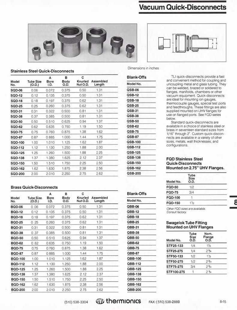
Vacuum Quick-Disconnects
Stainless Steel Quick-Disconnects Dimensions in inches
A B C Blank-Offs TL! quick-disconnects provide a fast
Model Tube Size Bore Body Knurled Assembled and convenient method for coupling and No. (0.0.) 1.0. 0.0. NutO.O. Length Model No. uncoupling metal and glass tubing. They
SQD-06 0.06 0.072 0.375 0.50 1.31 QSB-06 can be welded, brazed or soldered to
SQD-12 0.12 0.135 0.375 0.50 1.31 QSB-12 flanges, manifolds, chambers or other vacuum equipment. Quick-disconnects
SQD-18 0.18 0.197 0.375 0.62 1.31 QSB-18 are ideal for mounting ion gauges,
SQD-25 0.25 0.260 0.375 0.62 1.31 QSB-25 thermocouple gauges, special test ports and feedthroughs. These fittings are also
SQD-31 0.31 0.322 0.500 0.81 1.31 QSB-31 supplied mounted on UHV flanges for
SQD-38 0.37 0.385 0.500 0.81 1.31 QSB-38 use on flanged ports. See FOO series
SQD-50 1.37 below.
0.50 0.510 0.625 0.94 QSB-50 Standard quick-disconnects are
SQD-62 0.62 0.635 0.750 1.19 1.50 QSB-62 available in a choice of stainless steel or
SQD-75 0.75 0.760 0.875 1.38 1.62 QSB-75 brass in seventeen standard sizes from
SQD-87 0.87 0.885 1.000 1.44 1.75 QSB-87 1/16" through 2". Custom quick-discon-nects are available in a variety of other
SQD-100 1.00 1.010 1.125 1.62 1.87 QSB-100 sizes, metals, wall thicknesses, and
SQD-112 1.12 1.130 1.250 1.88 2.00 QSB-112 configurations.
SQD-125 1.25 1.260 1.500 1.88 2.25 QSB-125
SQD-138 1.37 1.380 1.625 2.12 2.37 QSB-138 FQD Stainless Steel SQD-150 1.50 1.510 1.750 2.25 2.50 QSB-150 Quick-Disconnects
SQD-162 1.62 1.630 1.875 2.38 2.56 QSB-162 Mounted on 2.75" UHV Flanges.
SQD-200 2.00 2.010 2.250 2.75 2.62 QSB-200 Tube Size
Model No. 0.0.
Brass Quick-Disconnects FQD-50 1/2
A B C Blank-Offs FQD-75 3/4
Model Tube Size Bore Body Knurled Assembled FQD-100 -
No. (O.D.) I.D. 0.0. NutO.D. Length Model No. FQD-150 11/2
BQD-06 0.06 0.072 0.375 0.50 1.31 QBB-06 -Other FOO sizes are available.
B00·12 0.12 0.135 0.375 0.50 1.31 QBB-12 Consult factory.
BQD-18 0.18 0.197 0.375 0.62 1.31 QBB-18
BQD-25 0 .25 0.260 0.375 0.62 1.31 QBB-25 Swagelok Tube Fitting BQD-31 0.31 0.322 0.500 0.81 1.31 QBB-31 Mounted on UHV Flanges
BQD-38 0 .37 0.385 0.500 0.81 1.31 QBB-38 Tube Norn. BQD-50 0.50 0.510 0.625 0.94 1.37 QBB-50 Size Flange
BQD-62 0 .62 0.635 0.750 1.19 1.50 Model No. O.D. O.D.
QBB-62
BQD-75 0.75 0.760 0.875 1.38 1.62 QBB-75 STF25-133 1/4 11/3
BQD-87 0.87 0.885 1.000 1.44 1.75 QBB-87 STF25-275 1/4 2 3/4
BQD-100 1.00 1.010 1.125 1.62 1.87 QBB-100 STFS0-133 1/2 H3
BQD-112 1.12 1.130 1.250 1.88 2.00 QBB-112 STFS0-275 1/2 2 3/4
BQD-125 1.25 1.260 1.500 1.88 2.25 QBB-125 STF75-275 3/4 2 3/4
BQD-138 1.37 1.380 1.625 2.12 2.37 QBB-138 STF100-275 23/4
BQD-150 1.50 1.510 1 750 2.25 2.50 QBB-150
BQD-162 1.62 1.630 1.875 2.38 2.56 QBB-162
BQD-200 2.00 2.010 2.250 2.75 2.62 QBB-200
(510) 538-3304 ® therm1on1cs FAX: ( 510) 538-2889 8-15

RL Fittings
History Since 1965, Thermionics Laboratory has
manufactured RL vacuum and pressure fittings. The fittings were originally developed in the 1940's by the Lawrence Radiation Lab-oratory. Initially they were used as connectors between leak detectors, mechanical pumps, and water lines through vacuum systems. However, in recent years, they have been found to be very versatile, with many uses in pressure environments. The fact that they are economical, dependable, and easy to install has been a major reason for their popularity in the vacuum industry.
Materials RL fittings are available in a choice of
brass or stainless steel. (Please specify your choice when ordering.) They are machined from solid bar stock. They may also be specially ordered in Teflon, nylon or any machinable plastic. Brass fittings have been most popular, and a large inventory is maintained at the factory to ensure prompt shipment. All RL fittings are bakeable to 200°C (392°F). Bakeout is usually required to achieve pressures of 1 x 10⁻⁷ Torr.
Assembly of RL fittings is quick and easy. Assembly is accomplished by simply hand-tightening each fitting as it is added to the system. Some fittings may need to be brazed or soldered onto pipes or tubing to fit the demands of your system; however, no special tools are required with normal installation.
RL fittings are supplied in a large selection of sizes. The normal sizes used are: 1/8", 3/16", 1/4", 3/8", 1/2", 5/8", 3/4,7/8", 1", 11/8"; special sizes may be requested.
NOTE: Please check with the factory for current RL fitting prices and availability We are evaluating the types of RL fittings we manufacture. Some RL models and sizes may be discontinued, and may be available only as a special order
• Bakeable to 200°C • Quick and easy—connect and disconnect • Versatile—many possible combinations
and uses • Both high-vacuum and pressure
applications • Hand-tight usable to 1 x 10⁻⁷ Torr
Guarantee All vacuum components manufactured by
Thermionics come with a guarantee of excel-lence, reliability and longevity. RL fittings are manufactured from the highest quality materials available and meet the highest standards of workmanship. All fittings are individually inspected and packaged clean and ready for immediate use.
8-16 (510) 538-3304 thermionics FAX: (510) 538-2889

RL Applications
There are several combinations in which RL fittings can be used—a few are described below. RL fittings have an added advantage over most other quick couplings. The nut is an integral part of the fitting and is therefore much less subject to failure under stress.
NOTE: Please check with the factory for current RL fitting prices and availability We are evaluating the types of RL fittings we manufacture. Some RL models and sizes may be discontinued, and may be available only as a special order
A Vent or Plug Loosen the #4 Union Nut and the fitting becomes a vent-valve. Tighten it down and it becomes a vacuum or pressure tight plug.
#1 #11 Male Pipe Gasket Coupling
#6 Plug
Nipple
#4 Union Nut
Low Pressure Gas or Liquid Interchangeable high pressure fittings are also available to connect to the permanently installed Half Union. ICII11#(.2 o)r #14 #11 #3
0 IME4
Coupling Gasket Hose Nipple
#4 Union Nut
C High Pressure Gas or Liquid The #12 Female Pipe Feedthrough is welded to a flange plate. It may be re-placed with a blank flange when the fitting is not in use. •
#12 Female Pipe
Feed-through
#11 Gasket
'Ft#5
Solder Nipple
#4 Union Nut
D Metal Tube to Non-Metal Tube
#5 Solder Nipple
(M) #11
Gasket #9
Double Coupling
1110 #11
Gasket #3
Hose Nipple
#4 Union Nut
(510) 538-3304 therm Ionics FAX: ( 510) 538-2889 8-17

-
8 -
RL High-Vacuum & Pressure Fittings NOTE: Please check with the factory for current RL fitting prices and availability
We are evaluating the types of RL fittings we manufacture. Some RL models and sizes may be discontinued, and may be available only as a special order.
Please specify on order whether parts are of brass or stainless steel. Dimensions in inches
1 Male Pipe Coupling
2 Solder Coupling
3 Hose Nipple
4 Union Knurled Nut
8-18
A ----
Part No.
1-12
1-18
1-25
1-37
1-50
1-62
1-75
1-87
1-100
1-112
Part No.
2-12
2-18
2-25
2-37
2-50
2-62
2-75
2-87
2-100
2-112
Part No.
3-12
Nom. Size
1/8" 3/16"1/4"3/8"1/2"5/8"3/4"7/8"1"
11/s"
Nom. Size
1/8"
3/16"1/4"3/8"1/2"5/8"3/4"7/8"1"
11/s"
Nom. Size
1/8"
A NPT
0.06 1/80.13 1/80.19 1/80.31 1/40.44 3/80.56 1/20.69 3/40.81 3/40.941.06
A B
0.06 0.130.13 0.190.19 0.250.31 0.380.44 0.500.56 0.630.69 0.750.81 0.880.94 1.001.06 1.13
A BB
0.06 3/16
C
1.381.381.381.411.531.661.661.841.911.91
C
0.880.880.880.900.900.900.900.971.031.03
C
1.503-18 3/16" 0.13 1/4 1.50 3-25 1/4" 0.19 5/16 1.50
-. 3-37 3/8" 0.31 7/16 1.50 _i BB 3-50 1/2" 0.44 9/16 1.50
��������==-1. 3-62 5/8" 0.56 11/16 1.50
""' ,----<C----3---
7-5
--3-/-4'-' --0-.6-9--1-3/_1 _6--1-.5-0--,1-7--'5_1_
3-87 7/8" 0.81 15/16 1.50
(510) 538-3304
3-100 1" 0.94 11(15 2.253-112 11/a" 1.06 P/rn 2.25
Part No.
4-12
4-18
4-25
4-37
4-50
4-62
4-75
4-87
4-100
4-112
® therm1on1cs
Nom. Size
1/8" 3/16"1/4"3/8"1/2"5/8"3/4"7/8"1.
13/a"
FAX: (510) 538-2889
B C
0.56 0.750.56 0.75 0.63 0.75 0.81 0.75 1.00 0.751.13 0.751.25 0.751.50 0.751.75 0.751.88 0.75

NOTE: Please check with the factory for current RL fitting prices
RL High-Vacuum & Pressure Fittings and availability We are evaluating the types of RL fittings we manufacture.
Some RL models and sizes may be discontinued, and may be available only as a special order.
Please specify on order whether parts are of brass or stainless steel. Dimensions in inches
Part Nom.
No. Size A B C
Solder Nipple 5-12 1/8" 0.06 0.13 0.75
5-18 3/16" 0.13 0.19 0.75
e:::IUJ 5-25 1/4" 0.19 0.25 1.00
5-37 3/8" 0.31 0.38 1.00
5-50 1/2" 0.44 0.50 1.00
5-62 5/8" 0.56 0.62 1.25
�c� 5-75 3/4" 0.69 0.75 1.25
5-87 7/8" 0.81 0.88 1.25
5-100 1" 0.94 1.00 1.50
5-112 111s" 1.06 1.13 1.44
Part Nom.
No. Size C
Plug Nipple 6-12 1/8" 1.00
Lei 6-18 3/16" 1.00
6-25 1/4" 1.00
-6-37 3/8" 1.00
6-50 1/2" 1.00
6-62 5/8" 1.00
6-75 3/4" 1.00
6-87 7/8" 1.00
6-100 1" 1.00
6-112 11/s" 1.00
Part Nom.
No. Size A F-NPT C
Female Pipe Nipple 7-50 1/2" 0.34 1/8 1.00
7-62 5/8" 0.44 1/4 1.25
7-75 3/4" 0.58 3/8 1.50
T 7-87 7/8" 0.72 1/2 1.50
7-100 1" 0.72 1/2 1.50 _l -
�C�""-F-NPT
7-112 11/s" 0.91 3/4 1.50 8 -
Part Nom.
No. Size A NPT C Male Pipe Nipple
8-37 3/8" 0.25 1/8 1.50 Dims according to print. I.D. must be 8-50 1/2" 0.38 1/4 1.50 smaller due to minor dia. of NPT.
8-62 5/8" 0.50 3/8 1.50
8-75 3/4" 0.62 1/2 1.75
�:J: 8-87 7/8" 0.62 1/2 1.75
0.88 3/4 8-100 1" 2.00
8-112 11/s" 0.88 3/4 2.00
,, C ::r-NPT
(510) 538-3304 ® therm1on1cs FAX: ( 510) 538-2889 8-19

-
8 -
RL High-Vacuum & Pressure Fittings
Please specify on order whether parts are of brass or stainless steel.
9 Double Coupling
10
11
Hose Coupling
Gasket Gaskets supplied are fabricated from V1ton
12 Female Pipe Feedthrough
�������
C
C
t
NOTE: Please check with the factory for current RL fitting prices and availability.
We are evaluating the types of RL fittings we manufacture. Some RL models and sizes may be discontinued, and may be available only as a special order.
Part No.
9-12
9-18
9-25
9-37
9-50
9-62
9-75
9-8
7
9-100
9-112
Nom. Size
1/8"
3/16"
1/4"
3/8"
1/2"
5/8"
3/4"
7/8"
1"
A
0.06
0.13
0.19
0.31
0.44
0.56
0.69
0.81
0.94
1.06
Dimensions in inches
C
1.50
1.50
1.50
1.56
1.56
1.56
1.56
1.63
1.69
1.69
Part Nom. No. Size A BB C
10-12 1/8" 0.06 3/16 2.13
10-18 3/16" 0.13 1/4 2.13
10-25 1/4" 0.19 5/16 2.13
10-37 3/8" 0.31 7/16 2.16
10-S7 7/8"
10-100 1"
10-112 11/e"
Part No.
11-12
Nom. Size
1/8"
11-18 3/16"
11-25 1/4"
11-37 3/8"
11-50 1/2"
11-62 5/8"
11-75 3/4"
11-87 7/8"
11-100 1"
11-112 11/e"
Part Nom No. Size
12-25 1/4"
12-37 3/8"
12-50 1/2"
12-62 5/8"
12-75 3/4"
12-87 7/8"
12-100 1"
12-112 11/e"
0.81 15/16 2.22
0.94 11/16 3.03
1.06 13/16 3.03
A B
0.29 0.10
0.34 0.16
0.39 0.22
0.56 0.34
0.72 0.47
0.89 0.62
1.00 0.72
1.15 0.83
1.38 0.97
1.53 1.11
A F·NPT
0.19 1/8
0.31 1/4
0.44 3/8
0.56 1/2
0.69 1/2
0.81 3/4
0.94
1.06
C
0.09
0.09
0.12
0.12
0.12
0.12
0.12
0.12
0.12
0.12
C
3.16
3.16
3.16
3.16
3.16
3.16
3.16
3.16
8-20 (510) 538-3304 ® therm1on1cs FAX: ( 510) 538-2889

NOTE: Please check with the factory for current RL fitting prices and availability. RL High-Vacuum & Pressure Fittings We are evaluating the types of RL fillings we manufacture. Some RL models and sizes may be discontinued, and may be available only as a special order.
Please specify on order whether parts are of brass or stainless steel.
Part
13 No. Weld Neck Feedthrough
13-12Weld neck feedthrough is normally
13-18machined as a brass neck with a stainless steel tube brazed onto it. 13-25Othet mate,�I, may be specially r:::;; c
I 13-37
ordered. 13-50
I��< ! 13-62
I B 13-75
;�t' 13-87
I -t 13-100
BRASS STAINLESS 13-112
14 Part No.
Female Pipe Coupling 14-25
14-37
14-50
14-62
F-NPT 14-75
_i_ 14-87
14-100
14-112
(510) 538-3304 ® therm1on1cs
Nom Size
1/8"
3/16"
1/4"
3/8"
1/2"
5/8"
3/4"
7/8"
1"
1 'ls"
Nom. Size
1/4"
3/8"
1/2"
5/8"
3/4"
7/8"
1"
11/s"
Dimensions in inches
A B C
0.06 0.13 2.22
0.13 0.19 2.22
0.19 0.25 2.22
0.31 0.38 2.22
0.44 0.50 2.22
0.56 0.63 2.22
0.69 0.75 2.22
0.81 0.88 2.22
0.94 1.()() 2.22
1.06 1.13 2.22
A F-NPT C
0.19 1/8 0.87
0.31 1/4 0.91
0.44 3/8 0.91
0.56 1/2 0.91
0.69 1/2 0.91
0.81 3/4 0.97
0.94 1.03
1.06 1.03
When ordering, please note part number and specify size required.
FAX: (510) 538-2889 8-21
-
8 -

-
8 -
Glass Bell Jars
Pyrex glass bell jars are designed to be used with flat base plates. The rimless bottom edge of the jar is ground flat to accept a Viton L-shaped gasket and provide a positive sealof the jar to the base plate.
Pyrex glass has a strain point of 520°C and a coefficient of linear expansion of 32.5 x 10·7
inl°C. Bakeout temperatures above 150°C are not recommended. Infra-red heat lamps are recommended for bakeout. They distribute heat evenly and minimize uneven stress in the glass. Bell jar guards are made from an expanded lightweight metal which is reinforced at top and bottom. Use of a guard protects the jar from breakage and provides implosion protection for personnel and equipment.
Option: Bell Jar Strap
Whenever bell jars and metal guards are assembled, we recommend a gasket or "strap" of Buna rubber be installed on the outside of the bell jar, between the bell jar and the metal guard. The strap is a cushion between the bell jar and the metal guard.
The strap is 1/8" thick x 1" wide, installed midway between the bottom and the top of the bell jar, and a clamping ring (which is supplied with the bell jar guard} is installed on the outside diameter of the guard, creating a clamp ring/guard/strap/bell jar "sandwich".
Model No. Bell Jar Dia.
BR-10 10"
BR-12 12"
BR-18 18"
C
Bell Jar Nom.
Model No. Size
PBJ-1012 10 X 12 .._,_
PBJ-1212 12 X 12
PBJ-1218 12 x 18
PBJ-1818 18 x 18
PBJ-1830 18x30
Bell Jar Feedthrough Collars
Our feedthrough collars are designed for inclusion between the bell jar and the baseplate of the vacuum system. Feedthrough collar ports accept equipment that is mounted on a mounting flange, i.e., electron beam guns, residual gas analyzers, gauges, valves, feedthroughs, etc. Ports not in use are blanked off with blank flanges.
Glass bell jar
Mating flange connection
Feedthrough oollar
Wt.
12.0
15.0
25.0
40 0
50.0
---
�.��' , i;;p;t
)
Viton L Gasket
Model No. Wt.
BLG-10
BLG-12
BLG-12
BLG-18
BLG-18
Vltonlgasl<et
Open access port
Viton L gasket
1.0
1.0
1.0
1.5
1 5
Baseplate
Dimensions in inches
Metal Guard
Model No. Wt.
BG-1012 4.0
BG-1212 5.0
BG-1218 7.0
BG-1818 8.0
BG-1830 10.0
8-22 {510) 538-3304 ® therm1on1cs FAX: { 510) 538-2889

Lightweight Stainless Steel Collars
(Lighter than many aluminum collars)
Options A val/able Custom feedthrough collars are available
in the standard collar sizes to fit customer specifications. Choices of special specifica-lions include varying the port tubulation length or having a specially machined O-ring gasket groove. An option of ConFlat flange sealing of ports is available upon request.
Specifications
■ 10-9 to 10-11 Torr
■ Bakeable to 200°c Model Bell Jar
■ O-ring grooved No. Size
■ Special sizes available C-1200 12"
C-1400 14"
C-1800 18"
C-2400 24"
Collar Dimensions
Model No. Specifications FC-1200 FC-1800
Norn. diameter 12"/305 mm 18"/457 mm
Dimension A 14"/356 mm 20"/508 mm
Dimension B 11. 75"/298 mm 17.25"/438 mm
Dimension C 12.5"/318 mm 18.5'/470 mm
Material Stainless steel, type 304 Feedthrough ports 8 ports with 2 3/•" 0.0. x 11/2" 1.0. ConFlat flanges
Top seal Flat flange mates with standard glass bell jar seal
Bottom seal Standard L-shaped bell jar gasket
Test specification No detectable leaks with mass spectrometer leak detector sensitivity of 1 x 10·10 std. cc/sec
Shipping wt. 85 lbs/39 kg 125 lbs/57 kg
Collar price
Viton L gasket
Pinch--Off Tubes
Pinch-off tubes may be used whenever an item must be sealed and removed, under vacuum, from a pumping station.
■ Pinch-off tubes have annealed OFE coppertubes and gaskets
■ The gaskeVtube assembly is brazed foreasy and reliable sealing
■ Designed for and used with standard flanges
Ordering Information
Model No. Bell Jar Dia.
CA-133/37 For 1.33" 0.0. flange CA-133/50 For 1.33" 0.0. flange CA-275/38 For 2.75" O.D. flan�e
CA-275/50 For 2.75' 0.0. flange
CA-21sns For 2. 75" 0.0. flange
Dimensions
A B C
0.83" 6.0" .375"
0.83" 6.0" .500"
1.89" 6.0" .38"
1.89" 6.0" .50"
1.89" 6.0" .75"
Bell Jar Feedthrough Collars
1Ql32 .,,, ..
OD l'lolN,,2128C'1t120•
.. , ..
S1MOIIN:1Por'I
3' OD
Dimensions in inches
Collar Collar 0-Rlng No. Wt.
O.D. I.D. Centerline Ports lbs
13 10.5 11.94 10 24
15 12.5 13.81 12 28
19 16.5 17.81 12 32
25 22.0 23.62 16 36
S1de A
1/� v,ew
B
• 1 I3/4
3
---. L.
�· j 1 .. C
I-++-�---- --F-c---+ !.------- a ---------..i-l
(510) 538-3304 ® therm1on1cs FAX: ( 510) 538-2889 8-23
-
8 -

-
8 -
Roughing Accessories
Flexible Stainless Steel Hose
Covering type 304 stainless steel thin wall bellows with a tough flexible metal braid of the same material provides great flexibility with maximum strength and durability. Use of flexible hose makes many system connections easier by eliminating some of the alignment problems involved with rigid tubing. Their high capacity for vibration damping makes them especially useful for connecting roughing pumps to UHV vacuum systems.
Hoses are bakeable to 450°C and can be used at temperatures as low as -196°C. They feature low outgassing, high conductance and are leak-tight to 1Cr" Torr. A selection of standard lengths and flange combinations are listed here. Other sizes and flange configurations are available on special order. Can be supplied without braid upon request.
NOTE: Hoses are available with ISO flanges (refer to page8-12)and in 2", 3", and 4• diameters.
FL-2751 SO-TC
Flexible Stainless Hoses
Model No. Length*
SSH-180 18"
SSH-181 18"
SSH-182 18"
SSH-182O 18"
SSH-183 18"
SSH-184 18"
SSH-240 24"
SSH-241 24•
SSH-242 24"
SSH-242O 24"
SSH-243 24"
SSH-244 24"
SSH-360 36"
SSH-361 36"
SSH-362 36"
SSH-362O 36"
SSH-363 36"
SSH-364 36"
SSH-480 48"
SSH-481 48"
SSH-482 48"
SSH-482O 48"
SSH-483 48"
SSH-484 48"
Description
1.50" 0.0. nipples both ends
2. 75" O.D. flange one end only
2.75" 0.0. flange both ends
1.50" I.D. Viton sealed quick-disconnects both ends
2.75" 0.0. flange and Welch 17.7 CFM adapter
2.75" O.D. flange and Welch 5 CFM adapter
1.50" O.D. nipples both ends
2.75" 0.0. flange one end only
2. 75" 0.0. flange both ends
1.50" I.D. Viton sealed quick-disconnects both ends
2.75" O.D. flange and Welch 17.7 CFM adapter
2. 75" 0.0. flange and Welch 5 CFM adapter
1.50" 0.0. nipples both ends
2.75" 0.0. flange one end only
2.75" O.D. flange both ends
1.50" I.D. Viton sealed quick-disconnects both ends
2.75" 0.0. flange and Welch 17.7 CFM adapter
2.75" O.D. flange and Welch 5CFM adapter
1.50" 0.0. nipples both ends
2.75"O.D. flange one end only
2. 75" O.D. flange both ends
1.50" 1.0. Viton sealed quick-disconnects both ends
2.75" 0.0. flange and Welch 17.7 CFM adapter
2. 75" 0.0. flange and Welch 5 CFM adapterFL-275150-V
Double-Sided Flanges ·Other lengrhs are available on special order. Consult factory
Wt. Model No. Description lbs
FL-1000 Double-sided 1.33" O.D. flange 5/8" thick, no accessory holes 0.5
FL-1000T Double-sided 1.33" O.D. flange 5/8" thick, one 1/16' -NPT 0.5 tapped hole
FL-275150 Double-sided 23/4" 0.0. flange 3/4" thick, no accessory holes 0 7
FL-275150-1 H Double-sided 2¾" 0.0. flange with one 1/8"-27NPT tapped hole 0.7
FL-275150-2H Double-sided 23/•' 0.0. flange with two 1/8"-27NPT tapped holes, 0.7 120° apart
FL-275150-TC Double-sided 2¾" 0.0. flange with 7822M thermocouple 1.0 gauge tube"
FL-275150-V Double-sided 23/4" 0.0. flange with Model BW-025 bakeable 1.5 valve for up-to-air use
FL-275150-VTC Double-sided 2¾" 0.0. flange with TC tube and valve. 1.5
FL-275000-V Blank 2¾" 0.0. flange with BW-025 bakeable up-to-air valve 1.5
·Refer to Section 6 for full listing of alternate rhermocouple gauges available.
8-24 (510) 538-3304 ® therm1on1cs
Flanges
Double-sided and blank flanges are supplied with thermocouple gauge tubes, up-to-air valves or combinations of the two for use as roughing accessories. Other configurations are readily available on special order.
1/8" NPT
FAX: ( 510) 538-2889

12-Polnt Head Bolt Sets ForHigh Vacuum Flanges
Thermionics Vacuum Products' 12- point head bolts have increased surface area for greater contact with ordinary socket wrenches. Bolt head stripping due to higher torque is minimized. M ade of high tensile strength, non- magnetic 300 series stainless steel. Bolt sets are supplied complete with flat washers and hex nuts. 25 sets per package.
A B Model Bellows Bellows No. O.D. I.D.
WB-01 0 .746 0.26
WB-03 1.030 0.52
WB-05 1.430 0.81
WB-o6 1.620 0.79
WB-10 0.595 0.26
WB-11 1. 170 0.75
WB-12 1.620 0.88
WB-13 1.890 1.39
12-Point Head Bolt Sets
Dimensions in inches
Model Flange Size Flange Bolt PkH; Wt. No. 0.0. Type Descr. I s
DB-25-125N 2.75 Through 1/4-28 x1 .25 1.5
DB-25-87N 2.75 Tapped 1/4-28 x.87 1.0
DB-25-200N 2.75 Thru/Dbl 1/4-28 x2 2.0
DB-31-175N 3.37 Through 5/16-24x1. 75 1.5
DB-31-125N 3.37 Tapped 5/16-24x1 .25 1 .5
DB-31-200N 4.50 Through 5/16-24x2 2.0
DB-31-125N 4.50 Tapped 5/16-24x1 .25 1.5
DB-31-225N 6 or6.75 Thru/Rot 5/16-24x2.25 2.0
DB-31-200N 6 or6.75 Thru/Non 5/16-24x2 2.0
DB-31-125N 6 or6.75 Tapped 5/16-24x1.25 1.5
O8-31-225N 8 Through 5/16 -24x2.25 2
DB-31-175N 8 Tap 5/16-24x 1. 75 2
DB-31-250N 10 Through 5/16-24x2.50 2.5
DB-31-175N 10 Tapped 5/16-24x 1. 75 1.5
Stud and Nut Sets
Are available in various sizes. Consult factory.
Welded Bellows
Off-the-Shelf Stainless Steel Welded Metal Bellows
■ Normally 350 but also available in AM-347 , 304L, 321 or 316L stainless steel.
Applications High vacuum seals, leak-free motion
feedthroughs, flex ible joints, compensators, reservoirs, actuators, UHV valves, manipulators, etc.
Corrosion Resistance-High Temperature
Metallurgically stabilized stainless steel provides corrosion resistance and low or high temperature capability from cry ogenic to 450°C and above. This means ex cellent
C D E F
corrosion resislance, weldability and engineering properties appropriate for high vacuum applications.
Leak Tightness Helium mass spectrometer leak- tight to
10-10 std. cc/ sec.
Long Stroke-Minimum Package Length Welded nested construction gives ex cel
lent flex ibility and long stroke, compact envelope, and nested compressed length.
Flange Flange Free Compressed Extended O.D. Thickness Length Length Length Stroke
0.775 0.012 0.78 0.21 1.10 0.47
1.150 0.015 1.00 0.32 1.38 1.06
1.500 0.015 1.50 0.32 2 .25 1.94
1.075 0.020 2.25 0.47 3.25 2.78
0.687 0.015 0.56 0.21 0.75 0.53
1.250 0.015 1.50 0.44 2.31 1.87
1.675 0.015 1.70 0.38 2.62 2.25
2.025 0.012 3.00 1.09 4.13 3.04
Other sizes available. Six different end flange styles are available. Please consult factory for further information.
(510) 538-3304 ® the,m1on1cs FAX: ( 510) 538-2889 8-25
-
8 -

Formed Bellows
Dimensions in inches
Type 321 stainless steel Deflection Model No. A B C D (+ or-)
MFB-6502 0.250 0.37 1.00 0.50 0.25
MFB-6503 0.312 0.45 1.00 0.50 0.25
MFB-6504 0.375 0.54 1.50 0.50 0.38
MFB-6506 0.500 0.73 1.50 0.50 0.38
---r MFB-6508 0.625 0.87 1.50 0.50 0.38
D MFB-6510 0.750 1.05 1.50 0.50 0.50
MFB-6512 0.875 1.23 2.00 0.50 0,50
MFB-6513 1.000 1.38 2.00 0.75 0.50
MFB-6516 1.125 1.55 2.00 0.75 0.50
MFB-6518 1.250 1.60 2.00 0.75 0.50 C MFB-6520 1.375 1 90 2.00 0.75 0.50
MFB-6522 1.500 1.95 2.00 0.75 0.50
MFB-6523 1.625 2.12 2.00 0.75 0.50
MFB-6525 1.750 2.30 2.00 0.75 0.50
MFB-6528 2.000 2.60 2.50 0.75 0.75
MFB-6530 2.250 3.06 2.50 0.75 0.75
MFB-6532 2.500 3.13 2.50 0.75 0.75
MFB-6536 3.000 3.75 3.00 1.00 0.75
MFB-6540 3.500 4.35 3.50 1.00 0.75
MFB-6544 4.000 5.20 4.00 1.00 1.25
MFB-6548 4.500 5.30 4.00 1.00 1.25
MFB-6552 5.000 6.00 5.00 1.00 1.50
MFB-6557 6.000 7.20 5.00 1.25 1.50
MFB-6564 8.000 9.25 6.00 1.25 1.50
MFB-6571 10.000 11.25 6.00 1.25 2.00
MFB-65TT 12.000 13.25 6.00 0.75 2.00
Vacuum Tubing
-
8 Type 304 stainless steel Tube Tube Wall Recommended Wt. Model No. O.D. I.D. Thickness Flange No. Per Foot
-
SST-025 0.250 0.180 0.o35 133025 0.125
SST-037 0.375 0.305 0.035 133037 0.127
SST-050 0.500 0.430 0.035 133050 0.173
SST-075 0.750 0.680 0.035 133075 0.267
SST-100 1.000 0.870 0.065 275100 0.649
SST-125 1.250 1.120 0.065 275125 0.822
SST-150 1.500 1.370 0.065 275150 0.966
SST-200 2.000 1.870 0.065 338200 1.343
SST-250 2.500 2.370 0.065 450250 1.690
SST-300 3.000 2.870 0.065 458300 2.037
Cutting Charges SST-400 4.000 3.834 0.083 600400 3.472
Size SST-500 5.000 4.834 0.083 675500 4.359
1/4 • through 3/4" SST-600 6.000 5.834 0.083 800600 5.245
1" through 2" SST-800 8.000 7.834 0.083 1000800 10.5
2 112• through 5" SST-1000 10.000 9.760 0.120 13251000 12.5
6 through 1Q3/4" SST-1075 10.750 10.482 0.134 13251075 15.190
8-26 (510) 538-3304 ® therm1on1cs FAX: ( 510) 5 38-2889

Type 304 Stainless Steel Precision Ground Shafting
Type 304 Stainless Steel Precision Ground Shaft*
Model No. Dia.•
PGS-125 0.1247" PGS-188 0.1872" PGS-250 0.2497" PGS-312 0.3122" PGS-375 0.3747" PGS-437 0.4372" PGS-500 0.4997" PGS-625 0.6247" PGS-750 0.7497" PGS-S75 0.8747" PGS-1000 0.9997"
• All sizes within +.0000/-.0002
Optically-Dense Traps
Per foot
Please consult factory
for prices
■ Economical-Lowest price of any forelinetrap.
■ No maintenance-Eliminates bakeout, LNcooling and attention.
Operating Principles The TU optically-dense foreline trap is
economical, and relies for its trapping effect on a large area of metallic adsorption characteristics.
A molecule can only pass through the optically-dense foreline trap by contacting the adsorbent material a great number of times, thereby greatly increasing the probability that it will be trapped.
Ordering Information
3/4" Description Size
Hose connection CT-075 both ends Flange one end CT-076 Hose other end Flange connection CT-077 both ends Hose connection both ends CT-075/CD with quick-disconnect head for easy bronze wool removal
i=====Dl=•m•�1•=• ====ii�
��==="&e���. -1
Tube, 304 Stainless Steel Precision Bored Shafts For prices and sizes consult factory.
Fel-Pro C-100 Lubricant
A high-temperature lubricant which contains a molydisulfide base to prevent seizing and galling in a temperature range of -200° F to +2,400° F. For use outside the vacuumwith stainless steel, aluminum, titanium, brass and copper.
Model No.
FLP-1
FLP-4
Materials
Description
1-oz tube lubricant4-oz tube lubricant
The optically-dense traps are made of type 304 stainless, TIG welded. They are supplied in three different configurations-1) hose connections only (unflanged), 2) hoseconnection one end, other end flanged, and3) flanged at both ends. Flanges are coppergasketed compatible type, which mate withall other standard copper-gasketed flanges.Special flanges, such as ASA, can be supplied on request.
Trap Dimensions
Type A B
075 3/4" 4" 100 1" 4" 150 1 Yl" 4" 200 2" 4" 250 21k" 6" 300 3" 6" 400 4" 6"
1" 1½" 2" Size Size Size
CT-100 CT-150 CT-200
CT-101 CT-151 CT-201
CT-102 CT-152 CT-202
Super Seal: Epoxy Sealing Permanent or temporary repair of leaks in
ultra high vacuum chambers, feedthroughs, tubing, valves, fittings, etc.
■ Very low vapor pressure, outgassing ratelower than 1 x 1 o.a Torr liters/sec/cm2
■ + 150°C to -60°C range. Cures overnight atroom temp. or in two hours at 100°C
■ A superior adhesive for metal, glass,ceramic or plastics
■ Economical 7-gram packages
Model No.
SS100
Foreline Traps
A DIA. --1-- --+-- B DIA.
'L 2 _j_ 4Vz __J=_J
2½" 3" 4" Size Size Size
CT-250 CT-300 CT-400
CT-251 CT-301 CT-401
CT-252 CT-302 CT-402
CT-100/CD CT-150/CD CT-200/CD CT-250/CD CT-300/CD CT-400/CD
(510) 538-3304 ® therm1on1cs FAX: { 510) 538-2889 8-27
-
8 -

-
8 -
Foreline Traps
Model No. Size
MT-100
MT101
MT-102
MT-150 11/2
MT-151 11/2
MT-152 11/2
MT-200 2
MT-201 2
MT-202 2
MT-300 3
MT-301 3
MT-302 3
MS-100
HS-100
Description
Molecular Sieve Traps
Description TLl's molecular sieve traps utilize synthetic
zeolite with a high surface area per unit volume. Its design insures effective trapping of hydrocarbons and water vapor, as well as preventing backsteaming of mechanical roughing pump oil. The molecular sieve trap operates at room temperature, thereby eliminating the necessity of any refrigerants. A built-in heater reprocesses the sieve material when necessary at a bakeout temperature of 375°C.
Specifications TLI molecular sieve traps are fabricated of
type 304 stainless steel. An internal screen assembly serves to contain the sieve material, preventing it from entering other areas of the vacuum system. Baffles are arranged around the sieve container to insure the passage of all molecules into the sieve material area.
Inlet and outlet ports are available either 180° apart inline (or 90° apart right angles) with or without flanges.
HEATER SEALED FILLER HOLE
Mech.Pump Recommended Gas Handling Load 115 VHeater Size Trap Size (50% Relative Humidity) Capacity Power
To 8 cfrr 1" 60 cu. ft. 270gms 75W
8-17 cfm 11/2" 125 cu. ft. 400gms 125W
17-30 elm 2" 125 cu. ft. 400gms 125W
Over 30cfm 3" 150 cu. ft. 500gms 375W
Dimensions in inches
A B C D E F G H
Hose connection both ends 4'/2 1 21/s 11 1/16 51/4 63/8 41/2 9
Flange one end 41/2 21/s 11 1/16 51/4 63/e 4 1/2 9
Flanges both ends 41/2 21/e 111/16 5¼ 63/e 41/2 9
Hose connection both ends 41/2 1 '/2 23/4 2 ?7/e 9 4 1/2 9
Flange one end 41/2 11/2 23/4 2 ?7/s 9 41/2 9
Flanges both ends 41/2 11/2 23/4 2 ?7/s 9 41/2 9
Hose connection both ends 41/2 2 33/a 2 ?7/s 9 41/2 9
Flange one end 41/2 2 33/a 2 ?7/s 9 41/2 9
Flanges both ends 41/2 2 33/a 2 ?7/s 9 41/2 9
Hose connection both ends 6 3 45/s 3 10 111/s 51/2 11
Flange one end 6 3 45/s 3 10 111/e 51/2 11
Flanges both ends 6 3 45/s 3 10 111/e 51/2 11
Replacement molecular sieve charge
Replacement heater assembly
Complete heater assembly and molecular sieve charge are provided with each trap.
One molecular sieve charge is required for 1 •, 1 '/2" and 2• traps and three charges for the 3" traps.
One heater assembly is required for 1", 11/2" and 2" traps and two heater assemblies for the 3" traps.
8-28 (510) 538-3304 ® therm1on1cs FAX: ( 510} 538-2889

Systems ■

Systems
Systems Descriptions General Information 9-1
Ion Pumped TTS Table Top Systems
Applications and Features 9-2 PyraFlat Rectangular Access Port and CryoShroud 9-2 Technical Information 9-4 Dimensions 9-5 Pumping Speed vs Pressure Curves 9-5 Specifications 9-6 Ordering Information, Model Numbers, and Features 9-6 Options 9-9
Evaporators VE-80, VE-90, and VE-100 Series
General Information 9-10 VE-80 Specifications, Ordering 9-10 VE-90 Specifications, Ordering 9-11 VE-100 Specifications, Ordering 9-12
Cold Wall Vacuum Furnace Technical Information 9-13 Ordering Information 9-13
9
Custom Systems Ion Pumped 9-14 Cryo Pumped 9-14 Turbo Pumped 9-15 Diffusion Pumped 9-15 Others 9-16
Sorption Pumps Technical Information 9-17 Specifications 9-17
Ordering Information 9-17
Sorption Pump Systems 9-18 Specifications 9-18 Ordering Information 9-18
Sorption Pump Roughing Carts Technical Information 9-20 Automatic Carts, Series SP-70 9-20 Ordering Information 9-21 Manual Carts, Series SP-52 9-21 Ordering Information 9-21 Note: The Liquid Nitrogen Controller has been moved to Section 6

Vacuum Systems
TTS-SWC Series Ion Pumping Systems
Model SP-70 Super-Sorb TLI's challenge to the Varian Megasorb
UHV Systems • Standard diode ion pumped • Noble/differential diode ion pumped • Triode ion pumped • Turbo pumped • Cryo pumped • Diffusion pumped
Roughing Systems • Oil free • Manual • Automatic
TTS-200T-PF Series Pumping Stacks At last, a table top system designed to give you ready access to the inside of your pump-ing stack by means of a 10 1/2" x 71/2" rectan-gular PyraFlat flange. The PyraFlat incorpo-rates the Varian ConFlat flange sealing prin-ciple of a knife edge and a trapped copper gasket. See Section 7, pages 7-1 to 7-5.
Any pumping stack without a PyraFlat access port is obsolete.
Cryoshroud with 650 in2 of cooling surface
PyraFlat flanges are manufactured and protected under one or more of the following patents: 5,640,751; 4,685,193
(510) 538-3304 thermionics FAX: (510) 538-2889 9-1

US Series Ion Pumped Table Top Systems
9
A pumping stack without a PyraFlat access port is an obsolete pumping stack.
PyraFlat flanges are manufactured and protected under one or more of the following patents: 5,640,751; 4,685,193
Models PAP-560 and SS-560 PyraFlat access port and cryoshroud
Basic Systems and Pyraflat Access Ports
At TLI we have 30 years of experience in the design and fabrication of vacuum and gas-handling systems. We can draw upon our extensive knowledge of vacuum requirements, pumping characteristics, and specific gas-surface interactions to offer you:
• Systems which are properly and promptly engineered, designed and delivered and which will meet or exceed your perform-ance requirements.
• Systems which are manufactured from your drawings, from your sketches, or from a description of your operating requirements. (Final TLI drawings will be submitted for customer approval upon request.)
• Assistance in the selection of components, valves, pumps, gauges, and control cir-cuitry best suited for your exact application.
PyraFlat Access Port and Model 560 Cryoshroud
The PyraFlat access port provides ready access to the inside of your pumping stack by means of a 101/2" x 71/4" rectangular PyraFlat flange which incorporates the Varian ConFlat flange sealing principle.
Maintenance and repair downtime are greatly minimized. Presently, it can take days or weeks to service your pumping stack, because the only access for purposes of maintenance or servicing is through the pop-pet. If you haven't gone through the process of removing the bell jar, associated plumbing, and instruments, just check with someone who has. As one user said, "We all know that accidents happen. Somebody drops a sample down the valve or a pump shorts. What we cannot afford is a week's shutdown for a com-plete disassembly." The PyraFlat access port offers the perfect solution.
The PyraFlat Advantage First You have sufficient access to the
inside of the pumping stack to allow easy servicing of the pump and poppet areas. You can remove and service the poppet and the pump elements without disturbing the bell jar, associated plumbing, instru-ments or your work.
Second The larger opening lets us put a larger cryopanel in the system. Our Model 560 has 560 sq in of cooled surface as compared to 500 in2 for competitor A, and approximately 200 in2 for competitor B.
9-2 (510) 538-3304 therm ionics FAX: (510) 538-2889

TTS Series Ion Pumped Table Top Systems
Model SS-560 PyraFlat Cryoshroud with 560 in2 of cooling surface
6. wide, 9 1/2' high, 9" deep
7.25' x 10.5" PyraFlat flange 10.18" x 13.5" outside dimensions
12'; 14" and 18" Table Top High Vacuum Systems • US pumping stack—the heart of the TTS-
SWC and US-SLC pumping systems. See pages 9-6 to 9-8 for sizes and prices.
• Integral ion pumps—diode or triode with speeds in excess of 1500 lisec
Sorption Pump Isolation Valve
Poppet Valve Actuator
Ion Pumps
Optional Model PAP-560
PyraFlat Access Port
Model No. SS-560—add $3,950
Modular and removable sublimator and cryoshroud assembly mounted on TLI PyraFlat access port also provides access to inside of pumping stack for cleaning, repair and maintenance.
11111
. ,1411,1,11Int• 01111
NEW!!!!
PyraFlat flanges are manufactured and protected under one or more of the following patents: 5,640,751; 4,685,193
Combination Baseplate
Feedthrough Ports
Optional Model SS-560 Shroud, see above.
BELL JAR OR CHAM-BER OF YOUR CHOICE
...--BASEPLATE 4.6300 0 ID.
POPPET VALVE LEDGE
ION PUMP
Applications
• Surface research (Auger, ESCA, SAM, SIMS, ISS, HEED, RHEED, LEED, etc.)
• Material studies • High energy studies • Thin film sputtering and evaporation • Vacuum deposition • Residual gas analysis • Sputtering • Beam lead/lines studies • Space simulation • Environmental testing • Furnaces • Tube processing • Friction studies • Shadow casting
Features
PUMPING • Roughing—dual sorption • Ion pumps—choice of diode, noble
diode (differential pumping), hydrogen diode, triode
• Sublimation-4 spiral filaments • Cryoshroud—Model 300 or Model 560
BASE PLATE • Combination wire seal and Viton L
gasket; size dependent on stack diameter
FEEDTHROUGH PORTS • 9 each 23/4" x 11/2" ConFlat type located
below poppet valve
POPPET VALVE • Hand operated, Viton sealed. Isolates
pumping stack from chamber
BAKEOUT • 250°C (limited by elastomer). Consult
factory
(510) 538-3304 OD therm ionics FAX: (510) 538-2889 9-3

TTS Pump Stack/OptionsiTTS Systems
ITS Pumping Stack + Following Options = Table Top Ion Pump Systems Complete and Ready to Run
• 1 each standard cabinet enclosure with or without bakeout oven as option
• 1 each electronics cabinet enclosure
is 1 each nude ion gauge
• 1 each ionization gauge control
• 1 each thermocouple gauge
is 1 each bakeout option on ion pump control
• 1 each bakeout option distribution box
• 1 each bakeout blanket option
• 1 each bakeout oven shroud option
• 1 each metal seal isolation valve option
The series TTS-SWC and TTS-SLC ion pump systems incorporate the US ion pump stack together with components guaranteed to provide quick pumpdown of the system from atmosphere to less than 2 x 10-11 Torr. Optional vacuum chamber or bell jar is de-signed and manufactured to meet your spe-cific applications.
Pumping Stack Sizes Available
12", 14", and 16" standard. (Other sizes available as custom options.)
Pumping Speeds Available
60 lisec to over 1,500 l/sec
Types of Integral Ion Pumps Available
Diode, noble gas diode, hydrogen diode and triode.
Options
US vacuum systems can, at customer request, be baked and pumped down to 2 x 10.11 or better, backfilled with nitrogen, pinched off, and shipped under vacuum.
Model TTS-SWC Pumping System with Cabinet (prices page 9-8)
9-4
Model TTS-SLC Pumping System without Cabinet (prices page 9-7)
(510) 538-3304 therm ionics FAX: ( 510) 538-2889

TTS Dimensions and Typical Pumpdown Curves
Work fixture brackets, 3 equally spaced with 3/8" dia. holes on 10.75" BCD.
Cryoshroud
(2 elements)
79.6,
-13.0 Closed 12.0 , i -15.0 Open
;
Outline of 'AF"' `-% 1poppet valve "
actuator
Fig. 9-1. ]TS-60N & TTS-80T
10-4
-a lo
-9 10 1 'nu es 10
=Si iiii MIMI III=
3; aimMINIM ;Mai; a laralariralEaVE MINIS II
1111111011.111.1111111111111
IIIIIIIM111•1111111111111111111MIENIMMEM IMIIIAIII111111111111•11111 11111•111911111111111111111111111 MIIIIMIIM1\EMINNIMMIN1111111111111
11111111111111101.11111111111111
MEMINNIMENI
1011111111111111111111111111111•111
TTS-60N
100
Fig. 9-3. 7TS-60N.
1000 10,000
PR
ES
SU
RE
IN
TO
RR
(m
. F
ig)
10-5
166
10-9
10-9
Id)*
Cryoshroud
Outline of poppet valve actuator
Fig. 9-2. 7TS-240N and 7TS-200T
' 200 1/s pump wIth poppet
Pressure measured with nude ionization gauge above poppet valve.
80 1/s pump without... poppet va ve
80 1/s pump with poppet valve
2 4 6 10 20 40 60 100 200 400 1000 TIME, MINUTES
4000 10000
Fig. 9-4. 7TS-80T & 7TS-200T
PR
ES
SU
RE
IN
TO
RR
(rn
m H
g)
Work fixture brackets, 3 equally spaced with 3/8" dia. holes on 10.75" B.CD.
-13.0 C osed -15.0 Open
10-5
166
10-7
10-9
10-'0
10-"
TTS-240N HOUR BAKEOUT AT 250°
NO BAKEOUT
1 minutes 10 100
Fig. 9-5. TTS-240N.
1000 10,000
(510) 538-3304 thermionics FAX: ( 510) 538-2889 9-5

-
9 -
TTS Basic Pumping Stacks
TTS Basic Pumping Stack
Shown with optional PAP-560 PyraF/at access port and optional SS-560 cryoshroud (see pages 9-2 and 9-3).
PyraFlat flanges are manufactured and protected under one or more of the following patents: 5,640,751; 4,685,193
TTS Pumping Stacks
With Differentially Pumped Noble Diode Ion Pumps
Model No. TTS-o0N TTS-240N TTS-300N TT5-400N
Includes: Integral ion pump pumping speed (I/sec) 60 240 300 400
Ion pump power supply PS350 PS 1000 PS 1000 PS1000
Basewell (inches) 12x26 12x 26 12x26 18x 36 (Larger size basewells on request)
Combination male wire seal and Viton gasket baseplate 14.63" x 11.0" X X X X(18x22)
Viton gasket & wire seal X X X X
Integral 3-tab ledge & port for poppet actuator X X X X
9 each 2. 75" x 1.50" blanked off ports X X X (15 ea.)
One bakeable roughing valve on 2. 75" x 1.50" port X X X X
Double-sided flange with air relief valve & TC gauge tube X X X X
Cryoshroud X X X X
Sublimator (4 fils.) SB-1000 X X X X
Sublimator control PS-500 X X X X
2 each operating manuals X X X X
8" poppet valve X X X X(12")
Dimensions in inches
Triode Pumps
TTS-80T TTS-200T TTS-300T TT5-400T
80 200 300 400 PS350N PS 1000N PS1000N PS 1000N 12x26 12x26 12x26 18x36
X X X X(18x22)
X X X X
X X X X
X X X ( 15 ea.)
X X X X
X X X X
X X X X
X X X X
X X X X
X X X X
X X X X(12")
Spare Parts 10 each GK-275 gaskets; 1 each B-25-137N bolt set; 4 each TSP filaments
Options
Recommended option: PyraFlat access port (see pp 9-2, 9-3)
Dual sorption pump roughing system (refer to page 9-18 for Sorption 2A)
Top blank-off plate
Top blank-off dished head
9-6 (510) 538-3304 ® therm1on1cs FAX: (510) 538-2889

Model TTS-SLC Table Top Systems Less Cabinet
Table Top Ion Pump Systems Bakeout Shroud
TTS-SLC Table Top Systems (Bakeable)
Includes TTS pumping stack TTS-60N/SLC TTS-240N/SLC items from
TTS-300N/SLC TTS-400N/SLC TTS-80T/SLC TTS-200T/SLC TTS-300T/SLC TTS-400T/SLC
page 9-6 plus
Enclosed electronics rack X X X X X X X X
X X X X X X X X
X X X X X X X X
Nude ion gauge
Ion gauge control
Options
Console bakeout shroud Prices on request. Consult factory.
Bakeout blanket Prices on request. Consult factory
Internal bakeout Prices on request. Consult factory. -
9 Recommended option: PyraFlat access port (see pp 9-2, 9-3) add
Dual sorption pump roughing system ( refer to page 9- 18 for Sorption 2A)
Top blank-off plate
Top blank-off dished head
(510} 538-3304 ® therm1on1cs FAX: (510) 538-2889 9-7

9
Model TTS-SWC Table Top Systems With Cabinets
PyraFlat flanges are manufactured and protected under one or more of the following patents: 5,640,751: 4,685,193
t 30"
!
◄ 45•
a
-
TTS-SWC Table Top Systems (Bakeable)
Includes TTS pumping stack TT5-60N/ TTS-240N/ items from swc swc
page 9-6 plus
Table top enclosed cabinet X X
Enclosed electronics rack X X
Nude ion gauge X X
Ion gauge control X X
TTS-SWC/B Table Top Systems (Bakeable)
TIS pumping TTS-60N/ TTS-240N/ stack SWC/8 SWC/8
Table top enclosed cabinet X X
Enclosed electronics rack X X
Nude ion gauge X X
Ion gauge control X X
Ion pump bakeout module X X
Bakeout power distribution box X X
Console bakeout oven X X
Bakeout blanket X X
Rack Space
19"
� X
51"l
59,25•
a
-
TTS-300N/ TT5-400N/ TTS-S0T/ TTS-200T/ swc swc swc swc
)( X X X
)( X X X
)( X X X
)( X X X
TTS-300N/ TTS-400N/ TTS-80T/ TTS-200T/ SWC/8 SWC/8 SWC/8 SWC/8
)( X X X
X X X X
X X X X
X X X X
X X X X
X X X X
X X X X
X X X X
Options for TTS-SWC and TTS-SWCIB Table Top Systems
Recommended option: PyraFlat access port (see pp 9-2, 9-3)
Dual sorption pump roughing system (refer to page 9-18 for Sorption 2A)
Top blank-off plate
Top blank-off dished head
9-8 (510) 538-3304 ® therm1on1cs FAX: (510) 538-2889
TTS-300T/ TTS-400T/ swc swc
X X
X X
X X
X X
TTS-300T/ TTS-400T/ SWC/8 SWC/8
X X
X X
X X
X X
X X
X X
X X
X X

Table Top Options
4 studs that bolt to combination flange
I
16. . . 5
Viton O-rrng ,n
-� fYi l 10.7 50 BCD 7.0
j
Adapter Plate
· dovetail groove
• I
3 holes 250 dia., equally spaced
Work Support Platform
1.25
�-- - ----7 �
---
! ,- - J,t------ ~ 13'' CLOSED
Poppet Valve
Integral Bakeout Source Model 275-SQH
Pyrex Bell Jars & Implosion Guard
See Section 8 for more information.
Stainless Steel Custom Chambers Designed and fabricated to meet your particular needs.
"'15°
0PEN
Sorption Roughing
See page 9-17
Mobile Cabinet-on Casters
Available with electronics incorporated or with separate electronics rack. See page 9-8, TTS-SWC.
Venturi Pump
(510) 538-3304 ® therm1on1cs
Adapter Plate
16" O.D. stainless steel adapter plate to allow Viton-sealed bell jars up to 14" diameter to be used with the TTS-240N or TTS-200T systems.
Work Support Platform
Provides support for electron beam guns and other fixtures. Attaches to support tabs in basewell.
Poppet Valve
High conductance poppet valve provides rapid cycling and fast pumpdowns. The poppet valve isolates the entire selective pumping area from the bell jar. This allows the pumping system to maintain a vacuum level of 1 o.a Torr or lower while the work area is at atmospheric pressure. In the open position, the poppet valve has a conductance equivalent to an 8" orifice. For maintenance purposes, or for high temperature application, the poppet sealing plate is easily removed through the basewell. The stem from the poppet valve is bellows sealed, and the actuator mechanism attaches to the 2" metal seal flange port located immediately below the poppet valve sealing ledge.
Bakeout Systems (a) Clam Shell Bakeout Shroud designed to fit your particular stainless steel chamber. Thermostatically controlled to achieve temperature uniformity at 200°C throughoutchamber. Includes power bus
(b) Fitted Bakeout Blanket Custom made.
(c) Integral Bakeout Source (with Variac)
Efficient in situ quartz infrared heater assembly on a 23/• • Con Flat-type flange is usedto bakeout vacuum chambers and systems.
Consists of a 1200 W, 120 VAC, 10 A quartz infrared lamp, coupled to a 23/•' flange,on which is mounted a medium current feedthrough.
Easy installation on any standard 23/,''
ConFlat-type flange port. Can be kept on during chamber openings to reduce H20 adsorption on walls. Uses a powerstat power supply to allow bakeout at an upper temperature limit of 400°C.
It is UHV compatible at a 2 x 10·11 Torr base pressure. Replacement lamps are available. Bulb life expectancy is 500 hours or longer.
FAX: (510) 538-2889 9-9
-
9 -

-
9 -
Vacuum Evaporators
Specifications
1. Vacuum System
A. Bell Jar
B. High VacuumPump
C. Roughing Pump
D. Control
E. Cycle Time
F. PressureGauges
9-10
Vacuum Evaporation Equipment
Model No. Description
VE-80 Basic vacuum evaporator. Diffusion pumped system with manually operated valves. 12"' x 12" bell jar with 1 kVA resistive power supply, baseplate feedthroughs and low and high vacuum instrumentation.
VE-90 Vacuum evaporator. Turbomolecular pumped system with automatic operation. 12" x 12" bell jar wi:h 1 kVA resistive power supply, baseplate feedthroughs and digital low vacuum instrumentation.
VE-100 Vacuum evaporator. Turbomolecular pumped system with automatic operation . 12" x 12" bell jar mounted on 12"' collar feedthrough with an electron beam gun evaporation source. All pressure and gun instrumentation mounted in cabinet.
EPS-50 Resistive evaporation power supply. 500 VA supply with metering in a cabinet. 10 · electrode cables included.
EPS-100 Resistive evaporation power supply. 1 kVA supply with 2 voltage taps and metering instrumentation. 10· electrode cables included.
EPS-200 Resistive evaporation power supply. 2 kVA supply with 3 voltage taps and multi-range metering. Transformer mounted inside control cabinet and cables provided.
ModelVE-80
The model VE-80 vacuum evaporator is a small dedicated unit for vacuum evaporation or coating. Its simple. manually-operated controls are uncomplicated and it offers a basic, low priced alternative to higher priced coaters. Coating chores are accomplished in a diffusion-pumped high vacuum environment that is available in 20 minutes from atmosphere. No compromise in instrumentation is made and vacuum interlocks are provided to warn personnel of improper operating procedure. Additional options are available to give the user some flexibility in customizing the system to a particular application. Consult the factory for available options.
Pyrex, Viton sealed , 12" dia x 12" high (other size bell jars and hoist are optional)
300 I/sec diffusion pump (LN2 trap optional)
G. Venting
1 12" I=====�
CJ
• •
CJ □ • D □
--------30· -------
Venting of system 3. Utilities
42"
3.2 cfm 2-stage, direct drive rotary
System interlocks to protect source and instrumentation
with interlocks to protect gauging and evaporation coils
A. Electrical
B. Water
C.Air
115/220 VAC at 20 A
Yes
Typically 15 min to pump-down
Digital discharge gauge for high vacuum, thermocouple gauge with bar graph display for roughing and interlock control
2. Evaporation System
A. Source (electron beamsou·cesoptional)
B. Readout
C. Power
Resistive, two positions standard with electrical feedthroughs
Digital
2 kVA
(510) 538-3304 ® therm1on1cs
4. Hardware
A. Cabinet
B. Dimensions
C. Weight
FAX: (510) 538-2889
Yes
Tubular steel frame with casters, side panels, and Formica top
24" Lx20"W x 36'!2'' H
2501bs

Specifications
1. Vacuum System
A. Bell Jar Pyrex, V iton sealed ,
B. High VacuumPump
C. RoughingPump
D. Control
E. Cycle Time
12" dia (optional height)
260 I/sec turbomolecular pump
3.2 cfm 2-stage, direct drive rotary
Automatic pumpdown, interlocks to protect source and instrumentation
Typically 10 min to pump-down
Vacuum Evaporators
ModelVE-90
The model VE-90 vacuum evaporator is the perfect answer to a requirement for vacuum evaporation or coating. Its simple controls and rapid cycle time facilitate uncomplicated productivity. Reliable coating chores are accomplished in an oil-free, high vacuum environment that is available in 10 minutes from atmosphere with the touch of a button. Greater control and more predictable film parameters are available, almost as fast as the material can be loaded. Additional options are available to give the user some flexibility in customizing the system to a particular applicar o for available options.
2. Pressure Instrumentation 4. Utilities
A. High Vacuum Digital ionization gauge A. Electrical
B. Low Vacuum Digital convection gauge B. Water
3. Evaporation SystemC. Air
A. Source Resistive 5. Hardware
8. Power 1 kVA, nominal 75 A A. Cabinet
(optional 2 kVA, 200A)
C. Positions 2 switch selectable pairs of baseplate feedthroughs
B. Dimensions(filament holders and car-bon evaporation kit are C. Weightoptional) D.Hoist
D. Metering Digital ammeter ( 100AFS)
115/220 VAC at 20 A
None
None
Tubular steel frame with casters, side panels, and Formica top
3 0" Lx20"W x 42" H
Approx. 250 lbs
Optional
(510) 538-3304 ® therm1on1cs FAX: (510) 538-2889 9-11
-
9 -

-
9 -
Vacuum Evaporators
Model VE-100
The model VE-100 extends the technology of the VE-90 by the addition of a 3 kW e-Gun evaporation source while retaining a philosophy of simple, uncomplicated operation. Un-like larger systems, the VE-100's purpose is not overstated: It simply provides thin film coating-of virtually any material-quickly, cleanly and efficiently in a compact, dedicated system. With the additional technology of the source, a slightly larger bell jar and a collar, the optional flexibility of this system is almost boundless. To list just a few examoles, many users add additional crucibles to assist in uninterrupted multi-coating operations, and the addition of a bell jar collar allows the user to introduce manipulators, additional electrical or water feedthroughs, and thin film instrumentation. Consult factory for avail-able options.
18"
0
• c=]
• • Dc=] □ •
D D
54"
\ I
----------- 36" ---------►
Specifications
1. Vacuum System
A Bell Jar
B. High VacuumPump
C. RoughingPump
D. Control
E. Cycle Time
9-12
Pyrex, Viton sealed, 12" x 18" (optional stainless steel)
520 I/sec turbomolecular pump
3.2 elm 2-stage, direct drive rotary
Automatic pumpdown, interlocks to protect source and instrumentation
Typically 10 min to pump-down
2. Pressure Instrumentation
A High Vacuum Ionization gauge with digital controller
B. Low Vacuum Digital convection gauge
3. Evaporation System
A Source Electron beam gun
B. Power 3 kW
C. Positions 1 pocket (multiple pocket guns optional)
D. Metering Analog metering on hand-held power controller
4. Utilities
A Electrical
B. Water
C.Air
5. Hardware
A. Cabinet
B. Dimensions
C. Weight
D. Hoist
(510) 538-3304 ® therm1on1cs FAX: (510) 538-2889
208/220 VAC at 20 A
.5 cfm
None
Tubular steel frame with casters, side panels, and Formica top
36" L x20"W x 54" H
Approx. 350 lbs
Standard

Cold Wall Vacuum Furnaces
■ Fits existing vacuum systems with 12" orlarger bell jars
■ Full opening hinged lid opens without disconnecting water lines
■ Simple to install; requires only water andfilament power feedthroughs
The TLI compact cold wall vacuum furnace was designed for use with existing vacuum systems. The 6" Cl/'NF, with an effective heat zone of 6" diameter x 6" high, will work with 12" or larger bell jar systems. The 8" Cl/'NF, with an 8" diameter x 8" high
Furnaces*
Eff.HeatZone
6"CWVF 6" dia x 6" high
S"CWVF 8" dia x 8" high
10"CWVF 10" dia x 10" high
12"CWVF 12· dia x 12" high
14"CWVF 14" dia x 14" high
"Including one thermocouple ( does not include power supply. feedthroughs or vacuum system)
Power Supplies
VFPS-SkVA 20Vat 250A
VFPS-10kVA 20Vat 500A
VFPS-14kVA 40Vat350A
heat zone, can be used in any 14" or larger system. The 14" Cl/'NF can be used in an 1 8" or larger system.
An important design feature of the Cl/'NF is the full opening lid. The lid can be easily opened and closed without disconnecting the water cooling lines.
The CWI/F is easy to install. It requires only one dual water and two single filament power feedthroughs. A thermocouple feedthrough is optional.
Furnaces are constructed of OFE copper. Stainless steel heat shield liners are standard. Molybdenum shields are offered as an option
Replacement Parts
6" ss• heat shield liner
8" ss· heat shield liner
6" filament electrodes, set of three
8" filament electrodes, set of four
Bellows, 6" or 8", 2 req. per furnace, each
Thermocouple, type K
• Stainless ,s standard, molybdenum price available on request
6" Water-Cooled Cold Wall Furnace with Copper Tubing
at extra cost. Operation at 1200°C requires a 4.5 kW low voltage supply for the 6" Cl/'NF and 6 kW for the 8" model. The tungsten hairpin filaments can be replaced in minutes without dismantling the furnace. A type K Chromel/Alumel thermocouple is furnished with each furnace for temperature measurement. A thermocouple feedthrough is ordered separately, if needed.
Applications of the Cl/'NF include the brazing of copper, nickel, gold, silver and other alloys. It is also used for annealing, bakeout and numerous other uses.
Feedthroughs
Power Single conductor electrical feedthrough mounted on 2. 75" knife-edge flange. 600 A capacity. Two required. FHC-275-1
Water Dual water feed-through mounted on 2. 75" knife-edgeflange. One requiredFCW-275-2-38FCW-275-2O0/38(de-mountable)
Thermocouple Instrumentation feed-through mounted on 2. 75" knife-edgeflange.FEP-275-ST
Instrumentation feed-through mounted on 1 33" CF flange. FETC-133-2K
(510) 538-3304 ® therm1on1cs FAX: (510) 538-2889 9-13
-
9 -

Custom Ion Pumped Systems
2,000 l/sec Noble Ion Pump System • Dual sorption pump • Ionization gauge and control • Sublimation pump and control • Rack mounted controls
Custom Vacuum Systems
Cryo Pump Cart Mounted System • Manual Valving
• Ionization gauge and control
• Isolation gate valve • Dual sorption pump roughing assembly
• Cryo pump high vacuum pumping
• Special collar • 18" x 30 " Pyrex bell jar & guard,
with hoist
• 1 x 10' Torr in 30 min from atmosphere
• Cabinet mounted controllers and power supplies
Ion Pumped Gas Inlet System with Electronics Rack
A custom UHV chamber with 240 l/sec ion pump stack and optional bakeable sorption pump Dewars. Includes a carbon vane pump, 20 l/sec appendage pump, Bourdon gauge and sequentially operated, heated lecture bottles for precise gas mixing. Also includes rack mounted control units.
9-14 (510) 538-3304
Cryo Pumped System with Counterbalanced Hoist
thermionics FAX: (510) 538-2889

Custom Vacuum Systems
Turbo Pump Cart Mounted System • Evaporation system with special collar for
mounting of 3-position e-Gun • Turbomolecular high vacuum pump • Rack mounted controls • Ionization gauge and control • 12" x 24" Pyrex bell jar, guard and hoist
am I
II it 111;ii IAmmo MUM! It !Nu!
Electric Hoist
Diffusion Pump Cart Mounted System • 6" D.P. for corrosive gas handling • 1 x 10⁻⁸ Torr from atmosphere in 10 min • Water cooled bell jar • Semi-automatic valving, sequencing and
monitoring • Hydraulic hoist
si Isolation valve • Ionization gauge and control
Hydraulic Hoist
(510) 538-3304 thermionics FAX: (510) 538-2889 9-15

-
9 -
Custom Vacuum Systems
Custom System with Cryo Pump Dual 3 kW e-Gun with cross contamina
tion shutters, dual sorption pump roughing, cyro high vacuum pump, automatic valving, ionization gauge and control, isolation gate valve, dual sorption pump assembly, special electron beam collar, 18" x 30" bell jar and guard with hoist, rack mounted controllers and power supplies. System achieves 1 x 10·1
Torr in 30 min from atmosphere.
Gas Inlet System
A 20 valve microprocessor (or manually) operated inlet system for introduction of precise amounts of pure gases and gas mixtures into a mass spectrometer for quantitative analysis.
Includes front panel display, macro and micromanometer readout, temperature control readout, thermocouple readout, capacitance manometer readout, turbomolecular pump readout and control, and valve actuator display.
L
Front View
9-16 ( 510) 538-3304 ® therm1on1cs
Back View
FAX: (510) 538-2889

+ L
I
i 11.00
'
4.5...,
5.4
--- SP-11/12/13
SPHT-11
SPD-11
Sorption Pump Diagram (dimensions in inches)
Specifications
Materials
Body and internal cooling fins Aluminum
SP-11 L=14.7 SP-12 L= 21.5 SP-13 L = 29.0
Pump neck and connecting flange Type 304 stainless steel
Dewar flask Standard: styrofoam Option: stainless, type 304
Base pressure 1 x 10·3 Torr, with normal use
Recommended maximum pumping capacity SP-11 standard pump= 40 liters
Sieve requirements (Linde SA) (SP-11) 3Ibs
Liquid nitrogen required (approximate amount in liters/pumpdown from atmosphere) (SP-11) 5 liters
Heater power requirements 115 V, 50/60 Hz, 400 W
Number of heaters required per pump 1 heater
Bakeout temperature 250°c
Ordering Information
M�� M No. Description lbs
Sorption pumps-All pumps include: one OFE copper gasket, Dewar mounting bracket kit, top screen, RV-11 relief valve, six each nuts, bolts and washers, one charge of molecJlar sieve, and instructions
SP-11 Single sorption pump 14 00
SP-12 Double sorption pump 28.00
SP-13 Triple sorption pump 42.00
SPD-11 Dewar, styrofoam 5.00
SPD-11S Dewar, stainless steel 15.00
SPD-12S Dewar, stainless steel 30.00
SPD-13S Dewar, stainless steel 45.00
SPHT-11 Heater, wraparound bakeout, 115 VAC 4.00
MS-200 Sieve 5.00
275150 Mating flange .50
GK-275 Gaskets (10/pkg.) .50
B-25-137N Bolt set .75
RV-11 V iton relief valve .50
TS-11 Top screen (old Model No. 4084) 50
Sorption Pumps
Application
TLI SP series sorption pumps are recommended for all applications needing highspeed, contaminant-free pumping. They have no moving parts or oils. The advanced design insures high speed pumping with maximum conductance and heat transfer. SP pumps have high capacity, are economical to operate, and are easily regenerated.
Operating Principle
Molecular sieve sorption pumps evacuate gas molecules from a volume by cryosorption, adsorbing them on a chilled surface. Because the adsorption process essentially takes place on a surface, a large surface area is required to adsorb appreciable quantities of gas. To satisfy this area requirement, a highly porous synthetic zeolite molecular sieve is commonly used as the sorbant material. The molecular sieve has an extremely high surface area to volume ratio (an SP-11 pump contains approximately 1.2 km2 of sorbant surface area), which allows large quantities of gas to be pumped by relatively small sorption pumps. (An SP-11 sorption pump has a theoretical capacity of approximately 100,000 Torrliters of gas.)
To obtain maximum speed and capacity from a sorption pump, there are three important design characteristics that are taken into consideration: 1) efficient heat transfer to the cryogenic fluid; 2) maximum conductance to the molecular sieve; and 3) quantity of molecular sieve in contact with a chilled surface (cryogenic surface area to volume ratio). The SP series sorption pumps are designed for optimization of these characteristics.
(510) 538-3304 ® therm1on1cs FAX: (510) 538-2889 9-17
-
9 -

-
9 -
Sorption Roughing Systems
Option 1A Single Sorptlon Pump Roughing System
Bakeout heater
Option 1A-Single sorption pump roughing system includes:
1 ea. A-1500-H 11/2" manual angle valve, Viton sealed, with 23/4'' ConFlat flanges on both ports
1 ea. SP-11 Pump assembly
1 ea. SPD-11 Styrofoam Dewar
1 ea. SPHT-11 Bakeout heater
1 ea. FL275150-VTC Double-sided flange with TC tube and one up-to-air valve
1 ea. Set of necessary nuts and bolts
1 ea. FLP-1 Anti-seize lubricant
Partial assembly
Option LN
2Control
..,., the<mlonks "0Cwm products
$ Sl
•
AUTO
.OFF
M X MANUAL
MINUTES
LN2CONTROL •
Refer to Section 6, page 6-12.
Option 18 Single Sorption Pump Roughing System with Mechanical Pump
....,,._._ Doubled sided flange withTC&UTA
flask Oewa
{J
-3/S"tube
Oryvane
pump
Option 1 a-Single sorption pump roughing system with mechanical pump includes:
1 ea. A-1500-H
1 ea. SP-11
1 ea. SPD-11
1 ea. SPHT-11
1 112· manual angle valve, Viton sealed, with 23/4" ConFlat flanges on both ports
Pump assembly
Styrofoam Dewar
Bakeout heater
1 ea. FL275150-VTC/S Double-sided flange with TC tube, one up-to-air valve, and one isolation valve for dry-vane pump
1 ea. Bourdon gauge
1 ea. Dry-vane mechanical pump
1 ea. 10' of 3/.8" copper tubing with fittings
1 ea.
1 ea. FLP-1
Partial assembly
Set of necessary nuts and bolts
Anti-seize lubricant
Option2A Dual Sorption Pump Roughing System
Sorption pumps
Bakeout heaters
flasks OQ Oewar
Option 2A-Dual sorption pump roughing system includes:
3 ea. A-1500-H 11/2" manual angle valve, Viton sealed, with 2314" ConFlat flanges on both ports
2ea. SP-11 Pump assembly
2ea. SPD-11 Styrofoam Dewar
2ea. SPHT-11 Bakeout heater
1 ea. FL275150-VTC Double-sided flange with TC tube and one up-to-air valve
1 ea. TE-150/S Fitting
1 ea. Set of necessary nuts and bolts
1 ea. FLP-1 Anti-seize lubricant
Partial assembly
9-18 (510) 538-3304 ® therm1on1cs FAX: (510) 538-2889

Option2B Dual Sorption Pump Roughing System with Mechanical Pump
3/8" tube
Dry.vane
Sorption pumps
Bakeout heaters
pump
DO �
�;�
Option 28-Oua/ sorption pump roughing system with mechanical pump includes:
3 ea. A-1500-H
2 ea. SP-11
2ea. SPD-11
11/2" manual angle valve, Viton sealed, with 2 3/4" ConFlat flanges on both ports
Pump
Styrofoam Dewar
2 ea. SPHT-11 Bakeout heater
1 ea. FL275150-VTC/S Double.sided flange with TC tube, one up-to•air valve, and one isolation valve for dry•vane pump
1 ea. Bourdon gauge
1 ea. Dry.vane mechanical pump
1 ea. 10' of 3/8" copper tubing with fittings
1 ea. TE-150/S
1 ea.
1 ea. FLP-1
Partial assembly
Fitting
Set of necessary nuts and bolts
Anti·seize lubricant
(510) 538·3304
Sorption Roughing Systems
Option3A Triple Sorption Pump Roughing System
Option 3A-Triple Sorption Pump Roughing System includes:
4ea. A-1500-H 11/2" manual angle valve, Viton sealed, with 23/a" ConFlat flanges on both ports
3ea. SP-11 Pump
3ea. SPD-11 Styrofoam Dewar
3ea. SPHT-11 Bakeout heater
1 ea. FL275150-VTC Double-sided flange with TC tube and one up•to•air valve
1 ea. TE-150/SRM Roughing manifold
1 ea. Set of necessary nuts and bolts
1 ea. FLP-1 Anti-seize lubricant
Partial assembly
Roughing System Options
Replace Styrofoam Dewars with stainless steel Dewars
Replace one A-1500-H Viton-sealed valve with
One AMV-150-22 all metal right angle valve
One SMV-150-22 all metal straight through valve
Replace the dry vane pump, copper tubing and fittings with:
One 3 cfm mechanical pump One MT-152 molecular sieve trap One 24" metal hose, unbraided One set hardware
Flange types. copper or Vitonseals, and valves can be configured to customers' require• ments; consult factory.
® therm1on1cs FAX: (510) 538·2889 9.19
-
9 -

-
Oil-Free Sorption Pump Roughing Carts
Super-Sorb-Oil-Free Sorption Pump Roughing Cart-Model SP-70 ■ Pumps down a 100113 vessel from atmos
phere to less than 10 microns in lessthan 25min
■ 1. 7 million Torr-liters of u tra-clean pumping
Thermionics' portable sorption pumproughing carts are designed to meet the heavy gas loads associated with hydrocarbon-free high production applications. Three pumping stages, with a total of 43 lbs of molecular sieve, have the capacity to deliver multiple pumpdowns for multiple chambers prior to an automatic bakeout during nonworking hours. Caster-mounted cart complete with vacuum gauging and stainless steel valves.
Comparisons of the Thermionics Super-Sorb to the Varian MegaSorb
Time to evacuate 150 liter chamber from atmosphere to <10microns
Time to evacuate 100 113 (2,800 liter) chamber from atmosphere to <10 microns
Capable of manual operation
Automatic temp. controlled bakeout
System isolation valve
Up-to-air valve
Vacuum read-out range
SP-70
Super-Sorb MegaSorb
<120 sec 195sec*
<25min >70min*
All models No
Yes Yes
Yes No
Yes No
continuous, atm atm to 30" + to 1 micron 2 Torr- 1 micron
- Required utilities Power 20A 220VAC 15A 220VAC or other as desired
Air Control air only 9 scfm at 60 psi ..
The Varian data is for a crossover pressure of 200 Torr between stages 1 & 2. Thermionics data is for 75 Torr crossover on the Super-Sorb, increasing the life of the molecular sieve by over a factor of 2 before requiring bakeout.
" 9 scfm at 60 psi requires approximately a 3 hp compressor.
9-20 (510) 538-3304 ® therm1on1cs FAX: {510) 538-2889

Oil-Free Sorption Pump Roughing Carts
Oil-Free Sorption Pump Roughing Cart-Model SP-70
■ Pumps down a 100 ft3 vessel fromatmosphere to less than 10 microns in lessthan 25 min
General Description A large portable sorption roughing
system, mounted on a cart with casters, for use on large, hydrocarbon-free chambers. Effective from atmosphere to less than 10 microns (1 x 10·2Torr) pressure with fast pumping speed and large total capacity.
Pumping System The pumping system consists of three
stages. Stage #1-Capable of evacuating 100 ft3
from atmosphere to 27" Hg in less than 15 min. Consists of a displacement type oil-free mechanical pump. Its free air capacity is 20 scfm at 25" of Hg. The pump is protected from overload.
Stage #2-pumps from 27" Hg to 90 microns. Consists of four large sorption pumps (24" high x s· diameter) containing a total of 34 lbs of type SA molecular sieve cooled in a bath of liquid nitrogen. Includes automatic
pressure ·elief to release trapped gases during bakeout or warm-up. Screens minimize accidental migration of the sieve material.
Stage #3-pumps from 90 microns to less than 10 microns. Consists of one large sorption pump identical to those in the second stage. Contains 8.5 lbs of sieve.
Cryostat Vacuum insulated stainless steel con
struction. This allows for sieve bakeout without removal from the cryostat. An insulated lid minimizes boil-off during operation.
Valving All valves are manually-actuated stainless
steel with Viton seals and bellows-sealed actuators Port size is 1.5" with the exception of the vent valve.
Bakeout System Is fully automatic with time and tempera
ture control.
Oil-Free Sorptlon Pump Roughing Cart-Model SP-52
SP-52M
■ Pumps down a 100 liter vessel from atmosphere to less than 1 0 microns in less than 25 min
General Description Portable, cart-mounted sorption roughing
pump system for use on small and moderately sized hyd•ocarbon-free chambers.
Pumping The SP-52 cart consists of three pumping
stages. Stage# 1-Mechanical displacement oil
free pump capable of 27 .5 • Hg with a speed of 4.2 cfm.
Stages #2 and #3- Two sorption pumps, one for each stage, containing 3 lbs of SA sieve material each. These pumps are complete with stainless steel Dewars, sieve containment screens and pressure relief devices for gas release during bakeout or warmup.
Valving Three manually-actuated bellows sealed
1.5" valves control pump isolation and input to the pumping manifold. Stage #1 pumping is controlled through a 1/4' port stainless valve. The same size valve is used to vent the manifold.
Instrumentation/Control A vacuum gauge indicates pressure
continuously between atmosphere and 1 micron. Bakeout time and temperature and stage crossover are adjustable. Presence of AC power and bakeout heater operation are also indicated. The main power switch is of the circuit breaker type.
Size The cart is 24" wide x 36" deep by 40"
high and weighs 325 lbs. The cart comes complete with a 48" stainless steel flex hose.
Utilities 208 V, 3 phase "Y," 20 A max-standard.
Available with other configurations at customer request. Control air pressure should be between 80 and 100 psi.
SP-70 Manual valving
Bakeout An adjustable timer allows unattended
bakeout via electrical heaters installed on each sorption pump. These heaters are suitable for submergence in liquid nitrogen in everyday use.
Instrumentation/Control A vacuum gauge indicates pressure
continuously from atmosphere to 1 micron. Indicators on the control panel show the presence of AC power and operation of the bakeout heaters.
Size The cart is mounted on 2" casters and is
24 • wide x 28" deep x 30" high. The cart comes complete with a 48" stainless steel flex hose. Weight is 95 lbs.
Utilities 115 VAC at 15 A max is required. The cart
is supplied with a 30 ft power cord.
SP-52 Manual valving
(510) 538-3304 ® therm1on1cs FAX: (510) 538-2889 9-21
-
9 -

Custom Chambers ■

Custom Chambers
Custom Vacuum Chambers
Technical Information 10-1
Performance 10-1
Specifications 10-1
Engineering and Design 10-2
Cleaning 10-2
Certification 10-2
Analysis 10-2
Examples Deposition Chambers 10-3
Surface Analysis Chambers 10-4
Water Cooled Chambers 10-5
Sample Introduction 10-6
Laser Chambers 10-6
Gate Valve Isolation 10-7
e-Gun 10-8
10

Custom UHV Chambers
Custom Vacuum Chambers Guaranteed to Meet Your Special Requirements
We can assist you with chamber concept, application, engineering, and design. We work from your rough sketches, and prepare complete production drawings on our CAD system using the latest version of AutoCAD. The following pages contain photographs and production drawings of chambers we have fabricated.
The cheapest chamber may not be the least expensive. To insure you receive exactly what you need, we provide you with complete production drawings for your review and written approval, before fabrication begins.
Whichever vendor you choose, we strongly recommend production prints be sent to you for final approval prior to manufac-turing. Approved prints minimize the possi-bility of design and/or manufacturing errors.
Our many years of experience permit us to offer you the following advantages:
Complete Production Drawings Prepared and Submitted for Customer Approval Before Fabrication Starts
Surface Analysis Chamber
• Experienced engineering and up-to-date design
• Fast delivery. Order to shipment times as low as 4 weeks
• Optional qualifying pumpdown, bake and gas analysis
Standard Performance Certification and Documentation Every chamber shipped is certified:
• To be leak-free, leak-checked with a he-lium mass spectrometer to a sensitivity of 2 x 10⁻¹⁰ std. cc/sec. A certificate of compli-ance is supplied.
• Port alignment accurate within ±1/2° • Focal point-to-flange distances accurate to
±0.010" • Fabricated from type 304 stainless steel • Only sulfur-free water-soluble oils used in
machining parts • Internal or full penetration welds made by
means of Gas Tungsten Arc Welding (GTAW), also known as TIG welding
• Cleaned, wrapped and packaged for installation upon receipt by the customer
Performance Options At your option and request, we can perform, certify, and document:
• Qualification of ultimate base pressures measured to 2 x 10-" Torr, achieved with the system in our facility. Certification of bakeout and pumping techniques employed to achieve specified pressure
• RGA partial pressure analysis to 2 x 10-13Torr from 0 to 200 AMU
• Choice of the conditions under which the system is shipped, e.g., blanked off, under vacuum, bagged with dry nitrogen or other gas of your choice, or a combination of the preceding
• Choice of materials used in fabrication • Chemical and mechanical processes used
to prepare systems and surfaces, such as passivation, electro-polishing, mechanical polishing (up to a #2-lap finish), or chemical removal of carbon and/or hydrogen from the surface
?WE,
21-i "E. — I —
MY= 11•••
Therrien_ Ina.
1(
(510) 538-3304 therrnionics FAX: (510) 538-2889 10-1

-
10 -
Custom UHV Chambers
Design Options
■ Chambers with multiple ports and multiplefocal points in one or more planes
■ Port alignment as accurate as ±0.2°
■ Water-cooled chambers with double-walledchannel or tubing
■ Differentially pumped rotary seals
■ Magnetic shielding
■ Analysis of pumping characteristics andspecified gas-surface interactions
■ Tube processing chambers with sequentialvalving
■ Heated manifold with automatic sequencingof lecture bottles for precise gas mixing
■ Auxiliary hoists: hydraulic, electric, manual,counter-balanced, etc.
■ Chambers on rails for horizontal openingand closing with precise, leak-tight sealing
■ Chambers and systems on carts for mobility
■ Internal or external bakeout capability
■ Chambers with internal or external furnaces
■ Chambers with pumping stacks: ion, cryo,turbo, or diffusion pumped
■ Chemical polishing to reduce surface area by a factor of 10
A Sample of UHV Chambers
Cleaning Processes
Cleaning procedures are tailored to your requirements. Processes available include:
1. Alkaline and/or other degreasing methods
2. Aluminum oxide and/or glass shot beadblasting
3. Micro and precision bead blasting
4. High pressure hydro-wash
5. Chemical cleaning (stainless steel,aluminum, copper, Kovar, titanium,molybdenum, tantalum, nickel, Monet,and ceramics)
6. Chemical cleaning with bead blasting
7. Copper cleaning
8. Chemical cleaning per your specificationswith:
■ Potassium permanganate/caustic etch■ Alkaline prep or vapor degreasing■ Hydrochloric acid■ Nitric acid■ Caustic etch■ Copper cleaning■ Cold de-ionized water rinse■ Hot de-ionized water rinse■ Baking■ Acetone and/or isopropyl and/or
methanol alcohol wipe■ N2 dry and/or N2 bag--6 mil polyethyl
ere bags
10-2 (510) 538-3304 ® therm1on1cs
Cleaning Services
We also offer the following cleaning services in a limited service area-contact the factory for specific information.
■ Chemical cleaning at your doorstepProcess success depends upon equipment cleanliness. We clean new and used equipment. We clean for vacuum service,from roughing to UHV, to ultra high vacuum ( 10- 11 Torr) standards. Call us withyour requirements.
■ Services--Cleaningofsystem, components, fixtures, shields etc. for evaporator, sputtering systems and process equipment. Stainless steel passivation. Dry honing.
■ Emergency and quick turnaround- 8 hourturnaround, 24 hour contact. 7 day a weekservice available. Pick-up and delivery.
Chamber Delivery
Normally, delivery is 6 to 8 weeks after return of approved drawings. If you are in a bind, call us and we will do what we can to help. For example, the chamber on the bottom of page 10-6 was designed, built, tested and delivered in only 40 days after receipt of order.
Surface Analysis
We can design or can assist you in the design of surface analysis chambers. We are experienced in the design of UHV pumping systems, chambers, differentially pumped rotatable vacuum seals, load-locked sample introduction systems, precision manipulators (manual or computer controlled), electron beam guns, power and motion feedthroughs, and ion pumps, all of which are used to make your UHV chamber a valuable research or production tool.
Performance
Chamber and system performance are dependent upon:
■ Volume
■ Materials of construction (outgassing and permeability)
■ Fabrication techniques
■ Surface area
■ Surface preparation
■ Interior cleanliness
■ Material conditioning
■ Conductance
■ Pump speed and capacity
We deliver a chamber suited to your specific application. Our engineering, design, fabrication techniques, and in-house chemical cleaning facility guarantee it. The result is faster pumpdown and lower ultimate pressures at a reasonable price.
Guarantee
Every chamber we manufacture is covered by our unique guarantee: refer to pages vi and vii for specific details.
FAX: (510) 538-2889

�
Deposition Chamber
270,0' �
-..t!:11
Laser Deposition Chamber
(510) 538-3304
0,0' .fllll!II
® therm1on1cs
Custom UHV Chambers
180' -
270' ---
90.0' J!l!ll:IL.Sll!
-- ....
Th4nni«llc• lobonltoriH, Inc.
CUSTOM UHV CHiWBER ASSEMEllY
!!_, "4'760-01 _
FAX: (510) 538-2889 10-3
-
10 -

-
10 -
Custom UHV Chambers
10-4
UHV Chamber for LEED-Auger and ESCA Surface Analysis
■ 2 x 10·11 Torr chamber■ 12" diameter x 12" high■ 9 focal points on two planes
Water Cooled Chambers
24" 0.0. water-cooled UHV chamber with water channel, 27'/a" O.D. wire seal flange
{510) 538-3304 ® therm1on1cs FAX: {510) 538-2889

Custom UHV Chambers
Water Cooled Chambers 36" 0.0. diameter double wall, water-cooled chamber with 41" 0.0. wire seal base flange
24" diameter double wall, water-cooled UHV chamber cover with 271/8" 0.D. wire seal flange
304 stainless steel chamber, 24" 0.D. by 46" long. 1/4" wall, full internal welds, chempol-ished and supplied with convenient lifting lugs
10
(510) 538-3304 (E6:, thermionics FAX: ( 510) 538-2889 10-5

-
10 -
Custom UHV Chambers
Sample Introduction System
The Thermionics load lock provides quick access to ultra high vacuum chambers; no need to bring chamber up to atmosphere when loading sample! (Custom made to your specifications.) Refer to Section 2 for access doors, 2-access chambers and feedthrough details.
12" diameter x 27" long UHV chamber with 240 I/s noble ion pump and bakeout shroud qualified to 2 x 10·11 Torr from atmosphere. Flanges accurate to± 1/2°±0.005".
2 x 10·10 Torr water-cooled custom chamber with rail support
■ Engineered and manufactured in 40 days
■ 24" diameter x 60" long
■ X, Y, Z adjustment for flange mating andalignment
10-6 (510) 538-33 04
Two 4" gate valves isolate access chamber
Right angle roughing valve
- Vent valve
11 Vsec ion pump Quick access, Viton sealed (power supply included) door is 6" in diameter
,,,, Linear-rotary teedthrough for substrate transport
A
1wi¥tfN
® therm1on1cs FAX: ( 510) 538-2889

Custom UHV Chambers
Ultra-High Vacuum Chambers 6.00" 0.D. tube with 2.75" x 1.50" ports; 4.50" x 2.50" ports; multi-focal points on 2 planes
12" chamber with wire seal base flange; gate valve as poppet; multi-port and multi-focal points
Angle-resolved ultra-violet photo emission 294 mm diameter LEED-Auger surface physics chamber with 64 mm offset focal point spectrometer chamber
1(
(510) 538-3304 thermionics FAX: (510) 538-2889 10-7

-
10 -
Custom UHV Chambers
Side View
All Metal Evaporation Chamber
All metal evaporation cha mber with two (2) each three position 3 kW e-Guns with s1utter. Refer to Section 4 fore-Gun information.
C
�
C
Front View
Side View Showing e-Guns
10-8 (510) 538-3304 ® therm1on1cs FAX: (510) 538-2889

Material, Surface and Molecular Beam Sciences ■

■
11
■
Material, Surface and Molecular Beam Sciences
Molecular Beam Epitaxy (MBE)
Technical Information .. ................... ........ .. 11-1
MB E Systems/Specifications .. . . . . . .. .. .. . ... 11-2
Series VT-100 . . . . . . . .. . . . . .. .. . . . . . .. .. . . . . . . .. . . .. . . ... 11-2
Series VT-105 .. .. .. . . .. .. . . .. .. .. .. .. .. .. .. . . .. . .. . . . ... 11-4
Series VT-108 . .. .. .. .. . . .. . . . . .. . .. .. .. .. . . . . .. .. . . . . ... 11-6
Series VT-110 .. .. . . . .. .. . . . . .. . . . . ... .. . . .. .. . . .. .. .. ... 11-6
Organic MBE, Series W-301 . .. . .. . . . ... . . . . . . .. 11-7
Ion Beam Sources .. .. .. .. .. . .. .. .. .. .. . .. .. .. .. ... 11-8
Accessories Sample Handling, Manipulators, e-Guns, etc. .... .. ................. 11-9
MBE Components .................................... 11-10
Reflection High Energy Electron Diffraction (RHEED)
Technical Information . .. . . . . . . . .. .. .. .. .. ... .. . .. ... 11-11
RHEED Guns .... . . . .. .. .. .. . . .. ..... .. .. .. .. .. .. .. .. .. . 11-12
Specifications .. .. .. . .. . . . .. . . . . . .. . . . .. . .. .. .. .. . 11-12
Dimensions . . .. .. .. . . .. .. .. . . .. .. . . . .. .. . .. . .. .. .. . . .. .. . 11-12
Ordering Information . . . .. . . . . . ... . .. . .. . . . . .. .. . ... . 11-12
RHEED Power Supplies . . . . . ... .. . . .. . .. .. . . .. .. .. 11-14
Specifications . . .. . .. .. . . . .. . .. . ... .. . . . . . .. .. . . . . . .. . 11-14
Ordering Information . . .. .. .. .. ... .. .... .. .. .. . . .. ... 11-14
Accessories .. .. . . . . . .. . . . . .. . . . . . . . .. .. . .. . . .. .. . . . . . .. . 11-15
Phospor Screens .. .. .. . . .. . .. .. ... .. . .. . . . .. . .. . . . .. . 11-15
View ports .. . .. .. .. .. . . . . . . . . . . . . . . . . . .. . . . . . . . .. . . . . . . . ... 11-15
View port Shutters .. . . . . . .. . . . . . . . ... . . . . . . . .. . . . . . . ... 11-16
Camera and Mount .. .. .. .. .. .. ......... .. .... . . . . ... 11-16
Isolation Valves . . .. . . . . . . . .. .. . . . .... . . . . . . .. . . . . . . .. . . 11-16
Pulsed Laser Deposition (PLO)
Technical Information .... . .. .... .... .. ...... ..... . .. 11-17
Specifications .. . . .. .. .. .. .. . .. . . . . . . .. .. .. . . .. .. .. . .. . 11-18
Illustrations ............................................... 11-18
Molecular Beam and Surface Chemistry Products
Laser Test Chamber, with T ime-of-Flight Mass Spectrometer ......................... 11-20
Rotatable T ime-of-Flight Mass Spectrometer with Laser Window . . . . . . . . . . . . . 11-22
Molecular Beam Pulsed Nozzle Valve ... . . . . 11-24
Heated/Chilled Molecular Beam Nozzle . .. .. . . .. . . . . .. .. . .. . . .. .. .. . .. .. . . . . . .. . .. 11-26
Differentially Pumped Molecular Beam Source Chamber .. . . . . . . . . . . . . .. . . . . .. .. .. .. 11-28
Crystal Cleaver .. . . .. . . . . .. . . . .. .. . . . .. . .. . .. . .. .. .. .. 11-30
Quick Change Manipulator
Gearbox/Sample Holder ....................... .. 11-31
Miniature SAM Manipulator .. . .. . . . .. . . . . . . .. .. .. 11-32
Modular Cart Systems .. . . . .. . . . . .. . . . . .. .. . . . .. .. . . 11-33
UHV Cold Trap Assembly .. . . . . .. .. .. .. .. .. . .. . . 11-34
Raman Cell .. . .. .. .. . .. .. . . .. .. . . . .. . . .. .. . .. . .. . . .. .. . .. 11-34

MBE Systems
Introduction Thermionics, in collaboration with
Vieetech, Japan, has developed a modular approach to building custom MBE systems which incorporates a unique "de-mountable growth flange" (DGF), on which are mounted the effusion sources, e-Guns, cryopanel, beam collimators, and other key components.
It is possible, in a very few hours, for one person to easily remove and reinstall the DGF after exchanging any or all of the components or exchanging the entire DGF. This allows maximum utilization of the MBE system with efficient reconfiguring of the DGF to meet different requirements.
Several options for mounting of the DGF are available. Our unique "U-Frame" mount (Fig. 11-1 below) allows the flange to be easi-ly removed downward, away from the main chamber, using a simple reduction gear me-chanism. Other mounts which do not include a "U-Frame" also allow for easy removal and reinstallation of the DGF to meet special needs or to adapt to existing equipment.
Principle Molecular beam epitaxy (MBE) is a tech-
nique for growing epitaxial films by directing beams of atoms or molecules produced by thermal evaporation onto a clean, heated substrate. The technique was first developed to meet special material requirements for semiconductor technology, for ultra-thin planar structures with precisely controlled doping profiles. Using MBE, film layers as thin as 5 A can be reproducibly grown, and the interface between layers can be precisely controlled.
Technique MBE is, essentially, an ultra-high vacuum
evaporation process. In practice, molecular or atomic beams for the constituent film elements (or their compounds) are generated by thermally evaporating quantities of the constituents from heated crucibles. The vapors pass through beam-defining aper-tures in cooled plates and impinge on a heated substrate, where they react on the hot surface to form the semiconductor film.
System Types The four systems shown on the following
pages are pictures of MBE systems which we have manufactured. They were designed for specific materials and processes. They are available as shown and specified, or modified to suit your needs.
In our experience, there is no "standard" MBE system. Systems are modified for dif-ferent materials and processes, controls, sys-tem size, geometry, hardware, pump types and general features.
Modifications will alter the system's speci-fications, thereby effecting the system's per-formance and price. Modifications which seem minor can have a major impact on design, performance and price.
The prices shown on the pictured systems are approximate. Our engineering group will work closely with you to determine your re-quirements and a firm quotation, which delineates specifications and performance and establishes price and delivery, can then be supplied.
MBE Systems Questionnaire We can provide an estimate for the cost of
custom MBE, either complete or partial sys-tems or individual components.
We need to know basic specifications as follows:
1. Materials of interest 2. Size of samples to be used 3. Do you already have a specific design
for the growth chamber and cryoshroud? Would you like to have it reviewed?
4. Preferred design configuration, i.e., two or three chambers, etc.
5. Sample transfer and load lock hard-ware requirements.
6. What type of effusion sources will be used?
7. Manipulator(s) (specifications), e.g.: Number of axes XYZ maximum travel? Tilt range Number of rotation axes Is motor-driven continous sample
rotation required? Sample heating/cooling temperature
range Sample holder format
8. Do you wish to incorporate any of your own existing equipment into the new MBE system, e.g., pumping equipment, analytical instrumentation, etc.
Please do not hesitate to contact us to discuss your requirements or proposals.
Fig. 11-1. Custom system (de-mountable growth flange with "U-Frame").
Fig. 11-2. VT-100 (cryopanel removed for clarity).
(510) 538-3304 fro thermionics FAX: (510) 538-2889
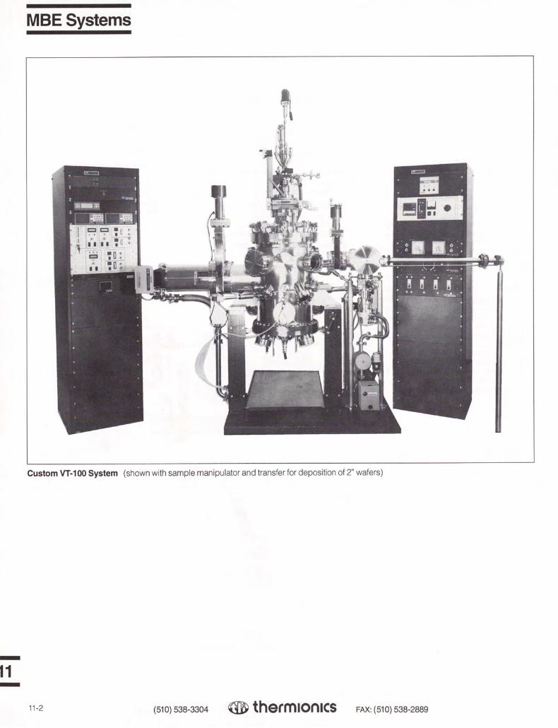
MBE Systems
Custom VT-100 System (shown with sample manipulator and transfer for deposition of 2" wafers)
11
11-2 (510) 538-3304 Q thermionics FAX: (510) 538-2889

VT-100 MBE System
The VT-100 MBE system Is a small research MBE system that can be configured to handle wafers up to 3" In diameter. With the Triad e-Gun source and optional effusion cells (up to three) the system may be used with the fol 1owIng materials
1 Si semiconductor (Si, Ga. Al, Sb) 2. High TC superconductor (YI. Ba, Cu, St)3 Metal MBE (Au, Al, Ni, W)4 GaAs semiconductor (Ga, As. Al)
Specifications
I. Growth System
A GROWTH CHAMBER A 16 · diameter by 22" high bell jar con
structed of 304 stainless steel with all metal seals. The surface has been electro-polished for a smooth UHV surface. Standard configuration includes:
1. Six 1.38" d1a. source viewports, one3.88" d1a sample viewport, and one5.38" d1a. RHEED screen viewportall with shutters
2 One manually actuated sample shutter. 3. Six electro-pneumatically actuated
source shutters 4. Three 6" flanged e-Gun emitter
access ports.5. Six 2.75" flanged ports for op11onal
quartz crystal monitors6 Three extra 2.75" flanged ports and
two extra 6 00" flanged ports (on line with sample).
Other conhgura11ons available on request.
B PUMPING SYSTEM Thermionics COV-1000 ion pump
(200 I/sec ion pump with LN1 cryoshroud andtitanium sublimation pump) Is isolated from the main chamber via a manually actuated gate valve with a metal sealed bonnet.
Rough pumping via dual sorptIon pumps isolated from main system by an all-metal sealed poppet valve. Ultimate vacuum after bakeout in the 10-10 Torr range (pressure during evaporation in the 10-11 Torr range). Other pumps (cryo, turbomolecular, etc ) available on request.
C. SOURCE FLANGEThermionics Triad e-Gun source mounted
on a 19" 0.0. bolt type wire sealed flange with an LNz cryoshroud with debris/collimation shield surrounding the source(s). The Triad consists of three (3) 10 kW, 10 cc single crucible sources with beam sweep control. A tetrode power supply with gun controllers is included There are also three 3.38" flanged (2" dia. tube) ports for use with effusion cells (cells and power supply are optional).
D SAMPLE HANDLING The slandard manipulator supplied is a
Thermionics FM series manipulator with the following specifications:
1 4 Z travel, 1.88" I D. bellows 2. ±0.5" X and Y travel3 ANN differentially pumped rotary seal 4. Cwstom gearbox and drive, sample
holder with 1 • square sample holderwilh radiant heater capable of 1,000°Coperation
5 PIO auto tuning sample heater CO""ltroller, SPS-202/A
Motorized continuous sample rota hon, larger sample sizes, oxygen environment heaters, sample c:,oling, RS-232 interface to Pl£? controllers, and other manipulators available on request.
E. RHEED SYSTEMA Viet:lech VE-052NP-052 30 keV RH EEO
gun and power supply with a 5.68" dia. phosphor screen and screen shutter is standard
F OPTIONS 1. Thin film thickness monitoring/con
trolling may be accomplished via crystal sensors or flux monitors dependingupon customer's preference.
2 Ba�eout capability is not included with standard system but may be configured into system per customer's specifications.
3. Quadrupole mass analyzer may beprcvided per customer's specification.
4 Precess or gas flow control 5. System may be expanded to include
an ;malysis chamber for HREELS,LEED/AES. etc.
(510) 538-3304 ® therm1on1cs
MBESystems
II. Load Lock System
A CHAMBER Constructed of 304 stainless steel with all
metal seals except for Viton sealed quick access door for sample loading Chamber Is electro-polished for a smooth UHV surface. Chamber is isolated from the main chamber by a manually actuated gate valve with metal bonnet seal
B. PUMPING SYSTEM200 I/sec magnetic turbomolecular pump
with a two-stage mechanical rotary pump a_ndmolecular sieve foreline trap is standard Oilfree pumps are optional. Pressure In the . 10·7 Torr range without baking after 15 min of pumping from atmosphere.
C SAMPLE HANDLING A rack and pinion linear feedthrough, RPL.
is standard with sample transfer fork for 1" square sample Other feedthroughs and sample sizes available upon request. Cassette loading and sample heating also available.
D. OPTIONChamber bakeout is optional.
Ill. Electronics
The following electronics are housed In a standard 19"' wide enclosure with 70" of rack space
1 Ion pump and sublimator power supplies, PS-1000 and PS-500.
2. Turbo pump controller3 RHEED power supply, VP-052.4. Ionization gauge controller with dual
ionization gauge (one for mainchamber and one for load lock) andconvection gauge (main systemroughing and foreline of turbomolecu:lar pump) capabilities. Also included IsEB de-gas and UHV electrometer
5. Sample heater power supply,SPS-202/A.
6 Shutter controller. VE-050-FB 7 Optional equipment as needed.
Price S368,000
Delivery: 16 weeks ARO
NOTE: This price is approximate. Our engineering group will work closely with you to determine your requirements and then a firm quotation can be given.
FAX: (510) 538-2889 11-3
-
11 -
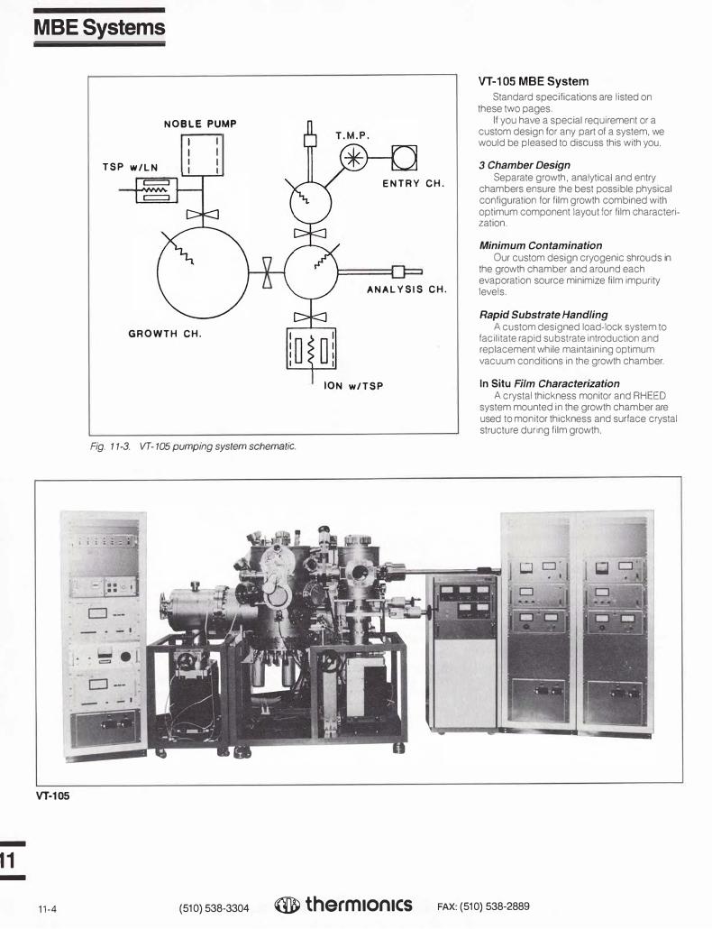
-
11 -
MBESystems
VT-105
TSP w/LN
NOBLE PUMP
I
I I
I
GROWTH CH.
Fig. 11-3. VT-105 pumping system schematic.
ENTRY CH.
ANALYSIS CH.
ION w/TSP
VT-105 MBE System
Standard specifications are listed on these two pages.
If you have a special requirement or a custom design for any part of a system. we would be pleased to discuss this with you.
3 Chamber Design Separate growth, analytical and entry
chambers ensure the best possible physical configuration for film growth combined with optimum component layout for film characterization.
Minimum Contamination Our custom design cryogenic shrouds in
the growth chamber and around each evaporation source minimize film impurity levels.
Rapid Substrate Handling A custom designed load-lock system to
facilitate rapid substrate introduction and replacement while maintaining optimum vacuum conditions in the growth chamber.
In Situ Film Characterization A crystal thickness monitor and RHEED
system mounted in the growth chamber are used to monitor thickness and surface crystal structure during film growth.
11-4 (510) 538-3304 ® therm1on1cs FAX: (510) 538-2889

Growth Chamber Film growth in the VT-105 is accomplished
in a separate chamber which contains only an evaporation source flange, RHEED gun and screen, and thickness monitor. By minimizing the amount of equipment placed in the growth chamber, the substrate can be almost completely surrounded by a cryogenic shroud to ensure the cleanest possible environment for film growth. The RHEED and thickness monitor capabilities enable pertinent information about film growth, including surface structure and film thickness. to be collected during growth.
Analysis Chamber Surface analysis of substrate and films is
an important adjunct to MBE, whether for basic research involving ultra-clean, ordered surfaces or for quality control during device production. In the VT-105, surface analysis is accomplished in a separate analytical chamber. Facilities for ESCA, including Auger, UVPS, EELS, etc., may be specified as options. Since these analyses are performed in a separate chamber, the problems of contamination or erosion of surface analytical equipment by source beams are eliminated. Furthermore, impurities from filament outgassing from the analytical equipment will not deposit on the growing film.
Entry Lock Chamber Excessive pumping delays after sample
introduction have proven to be a problem in many MBE systems. In the VT-105 an all-new substrate introduction system allows the rapid introduction ( <30 min cycle time) of single substrates, while the pressure in the growth chamber is maintained in the 10-10 Torr range.The introduction system contains two separately pumped entry lock chambers that can also be used for processing substrates or completed film structures.
NOTE: This price is approximate. Our engineering group will work closely with you to determine your requirements and then a firm quotation can be given.
MBESystems
Growth Chamber Specifications
Manipulator
Heated substrate
Evaporation source
Chamber size
Pumping system
Isolation valves
Film characterization
Vacuum gauge
6-axis high precision rotating sample type (X, Y. Z, tilt, 1 sI rotary,2nd rotary coaxial)
2"dia. Temp. range: room temp. to 1,000°C
Four K-cells Three 1-position 3 kW e-Guns
16" dia., 20" height
400 I/sec noble triode sputter-ion pump Ti sublimation pump with LN2 shroud
4" manual gate valve (separates the growth and analysis chambers) 6" pneumatic gate valve (for ion pump)
VE-052 30 keV RHEED system 4 channel crystal thickness and rate monitor
Nude ion gauge
Analysis Chamber Specifications
Manipulator
Heated substrate
Chamber size
Pumping system
Isolation valves
Vacuum Gauge
6-axis high precision type (X, Y, Z, tilt. 1st rotary, 2nd linear coaxial)
2" dia. Temp. range: room temp. to 1,000°C
12" dia., 15" height
Combo-Vac model COV-1000, 1,000 I/sec combination pump
4" manual gate valve (separates the analysis and entry lock chambers) 6" pneumatic gate valve (for combination pump)
Nude ion gauge
Entry Lock Chamber Specifications
Manipulat:ir 2-axis (Z, R)
Substrate 2- 2" dia.
Exchange port 6" I.D. load lock with Viton-sealed door
Transfer mechanism Magnetically coupled linear feedthrough
Chamber size 8" dia., 10" height
Pumping system 150 I/sec turbomolecular pump 270 I/min oil rotary pump with fore line trap
Isolation valve 4" pneumatic gate valve (for TMP)
Vacuum gauge Nude ion gauge
(510) 538-3304 ® therm1on1cs FAX: (510) 538-2889 11-5
-
11 -

MBESystems
VT-110
VT-108
-
11 -
11-6 (510) 538-3304 ® thermIon1cs
VT-110
Features
■ Separate growth, analysis andentry chambers
■ Elaborate LN2
growth chambercryoshrouds ensure ultra-highpurity
■ Simple K-cell and shutter programming (automatic or manual)
■ High precision manipulator/sample handling system
■ Independent sample heaters on each manipulator
■ Routine 5 x 10·10 Torr growingpressure
■ A unique combination "multipumping" system allows rapidsample changing and maximumutilization of all facilities
■ System may be easily reconfigured at any time to suit changingapplications
VT-108
Main Features
■ Two chamber configuration
■ 3 kW, 3-crucible electron-beameffusion source
■ High speed turbo pumping ofload lock chamber permitsmaximum system utilization andhigh sample yield
■ Ultra smooth substrate transfersystem uses unique linear motionfeedthrough
■ Five axis manipulator withheating (1,100°Cstd.)
■ Many options available foranalysis and growth monitoringinstrumentation
■ "T-type" chamber and cryoshroud design (350 mm x 200 mm with 6" isolation valve)
NOTE: These prices are approximate. Our engineering group will work closely with you to determine your requirements and then a firm quotation can be given.
FAX: (510) 538-2889

I
\ \
TR \
OrganicMBE
TR I
Portabl&\UHV Chamber
' '
'
\
......
\
' ......
r--,... __ ______ , ___ \,.._.,, __- - - - - -.- - - ,- -·-·J
l..- --·
a: ...
Noble
Fig. 11-4. Schematic diagram of the combined UHV OMBE system.
VV-301
Explanation MBE combined with UHV analysis
techniques permits detailed investigation of the initial growth structure of ultra-thin films. These techniques are essential to understanding the growth mechanism and the interface formation between layers of different materials.
Until now, UHV MBE techniques have not been established for organic molecular systems. Such techniques are a prerequisite for realizing current molecular device designs in addition to fundamental interests.
This organic molecular beam epitaxy (OMBE) system has been designed and constructed with in-situ reflective high-energy electron diffraction (RHEED) specifically for the deposition of organic molecular layers under ultra-high vacuum (UHV).
Capability Heteroepitaxial growth of organic ultra-thin
layers on inorganic substrates has been accomplished in this UHV OMBE system with
base pressures of a bout 2 x 10⁻¹⁰ Torr.
Special Knudsen Cell Difficulties in developing UHV MBE
methods for organic molecular systems include inherent high vapor pressures which organic materials possess, as well as the combination of thermal instability and the impurities of any trace organic substances.
A low-temperature Knudsen cell was specially designed for organic samples in this OMBE system. The temperature of the Knudsen cells can be controlled by electrical heating and by circulating liquid nitrogen.
Modular Design The schematic shows that the OMBE
system consists of three independent chambers connected through gate valves: a growth chamber, an entry chamber and a portable chamber The portable UHV chamber allows easy transfer of the OMBE film samples to a separate UHV scanning tunneling microscopy (STM) system.
The combination of diffraction methods with real space imaging of STM allows direct studies of epitaxial layers at the atomic scale.
NOTE: This price 1s approximate. Our engineering group will work closely with you to determine your requirements and then a firm quotation can be given.
(510) 538-3304
Growth chamber Entry chamber Portable chamber Sample transfer rod Manipulator
C1 C2 C3 TR M VCP Color video copy processor
® therm1on1cs FAX: (510) 538-2889 11-7
-
11 -

-
11 -
Filamentless Ion Beam Sources
5 cm Source and Power Supply
3 cm Ion Beam System Includes: 3 cm ion source, graphite or molybdenum ion optics, one inch baseplate feedthroughs with flexible internal utilities, and power supply
Options Optics Convergent, divergent or collimated molybdenum (recommended) or graphite
Flange Mount
5 cm Ion Beam System Includes: 5 cm ion source, graphite or molybdenum ion optics, one inch baseplate feedthroughs with flexible internal utilities, and power supply
Options
Optics Convergent, divergent or collimated
molybdenum (recommended) or graphite
Four Gas Feedthrough & Connections
Flange Mount
3cm Source
5cm Source
11-8 (510} 538-3304 ® therm1on1cs
Applications ■ Surface modification
■ Thin film stress relief
■ Oxiding
■ Nitriding
■ Ion assisted deposition
■ Ion bean insitu pre-cleaning
■ Chemically assisted ion beam etching
■ Reactive ion beam etching
■ Inert ion beam milling
■ Ion beam deposition
STANDARD 4-611" UHVFl.ANGE (f•RAHOt:°"10NALJ
SEALED, VOlTAGE FEEDTHROUGH OONNECTOA
Wltl.0£0VCR FITT1NG (�n.a«a)
,�,m:;1 HIGH O �� .-,
��1:�\0A
_...
o___ �.:�.-0
0
0
0
I ,- .33201A STANDARD I•
CONFLAT FLANGE
FAX: (510) 538-2889
\_ 20 HOLES EO SPACED ON 7,128 DIA e.c. (1W)

Filamentless Ion Beam Sources
Specifications
Ion Source
Beam diameter 5 cm at grid face Ion optics a) Material — graphite or
molybdenum b) Formation — collimated,
defocused, focused
Output current Adjustable between .2 mA/cm2 and greater than 2 mA/cm2 at 6" from source optics set
Ion Energy Adjustable between 35 eV and 130 eV 6" from source optics set
Cathode Patented filamentless Dynamic Electron Emitter TM
Patent No. 4,739,214 Neutralizer Automatic filamentless neu-
tralization under optimal conditions
Gas inlet Four gas capability; required gas (inert or reactive) into cathode electron emitter, auxiliary gas ports into anode discharge area, either reactive or inert species
Gas 3-5 sccm inert or reactive requirements species
Mounting installation
a) Ion source mounting bracket included
b) Feedthroughs dual 1" baseplate or single 2-3/4" flange feedthrough with 18" internal flexible con-nections. Optional rigid mount to flange or 0-ring seal flange
Ok A ictr44,,_ 1111•11 OHM. vad .40 ,
STLD with heating and cooling
Temperature compatibility
Bakeable to 300° C, opera-tion to 80° C
Connections All connections from rear or ion source to feedthrough are singular keyed plug/socket mil spec type connectors
MagnetsConstruction
Alnico 5 permanent magnets Stainless steel and high temperature ceramics (exclusive of ion optics set)
Dimensions 5.5" long, 4.5" diameter, less than 8 pounds total weight
Pumping requirements
1,800 liters per second nominal
Power Supply
Type Switching with keyed plug/ socket power boards
Dimensions 19" wide, 5-1/4" high, 18" deep
Mounting Standard rack mounting, integral chassis slide system included
Read-outs Digital, light-emitting diode displays for each source function
Regulation 1. Constant voltage supply 2. Constant current supplies
Connections Single keyed plug/socket connectors with safety mil spec type screw collar
Cables 10 foot length standard, gun to power supply, other lengths available
Control Manual individual pbten-tiometer controls
Power requirements
120 volt single phase, 6 amp
Output energy 2,000 volts at 75 mA
Unique Features
• No heated filaments or tips • Continuous process life with 100% reactive
or inert species • Monoenergetic beam current densities • Stable beam currents from 2 mA to 50 mA
between 50 eV to 1,300 eV • Up to four gas or gas mixture capability
Manufactured for Thermionics by ANATECH LTD
Thermionics manufactures a wide variety of manipulators, feedthroughs, transfer devices, sample handling, heating, cooling, power supplies, and special components to be used with MBE systems. This page and the next show examples of the types of equipment we offer. Please consult the referenced sections for complete information about models and sizes currently available.
Sample Mounting, Heating, Cooling See Section 2 for further information about models available.
Heater and Bias Power Supplies See Section 2 for further information about models available. 11
SPS-102/A
(510) 538-3304 thermionics FAX: (510) 538-2889 11-9

-
11 -
MBE Components & Acessories
11-10
Manipulators
See Section 2 for further information about models available.
EM Series
Differentially Pumped Rotary Seals
See Section 2 for further information about models available.
Positioning Devices
See Section 2 for further information about models available.
Hanks HMi e-Guns are manufactured and protected under one or more of the following patents: 4,835 789: 4,891,821: 4,947.404
(510) 538-3304
ANN Series
RPLR-.75
® thermIon1cs
3, 6, 10, 15, and 20 kW All Metal Sealed e-Guns See Section 4 for further information about models available.
Hanks HM2 e-Gun
FAX: (510) 538-2889
A u

RHEED Equipment & Accessories
RHEED gun and power supply, 15 keV, 30 keV, and 50 keV models available
Introduction
The use of RHEED techniques for surface studies has become widespread with recent advances in materials synthesis, including, but not limited to, molecular beam epitaxy (MBE), high temperature super conductors, and CVD.
Since 1986, Thermionics has supplied our VE series of high energy RHEED sources and associated monitoring systems. Originally developed in Japan for MBE applications, this equipment offers unrivaled performance in the production of bright, high-definition and stable RHEED displays.
The ThermionicsNieetech VE 50 series of electron guns represents the latest technology available commercially for RHEED applications. The VE series system utilizes an external electron gun source (i.e., it does not project into the vacuum chamber), and the magnetic electron optics make the gun less
vulnerable to unpredictable electrostatic interference which may produce display instability in other types of RHEED guns.
For studies involving RHEED intensity oscillation monitoring, a comprehensive range of accessories is available, which includes a sensitive Jpto-electronic converter and signal analyzer. This device may be used together with our shutter controller and a desktop computer, e.g., IBM PC, to control modes and growth rates in MBE experiments.
For applications requiring multi-angular manipulation of the RHEED source, a precision (motorized) virtual-axis tilt stage is available for various flange sizes.
If you '"lave any specific questions about applications, do not hesitate to call us. We at Thermiorics welcome your comments and suggestions.
(510) 538-3304 ® thermIonIcs FAX: ( 510) 538-2889 11-11
-
11 -

-
11 -
RHEED Guns 15 keV, 30 keV or 50 keV
New High Energy Electron Guns for RHEED Applications Features
Designed specifically for molecular beam epitaxy applications, the VE series electron beam sources offer many advantages over other guns because of their compact design and ease of use.
Three models are available . The VE-026 covers the energy range from 1 to 15 keV, the VE-052 covers the energy range of 3 to 30 keV, and the VE-056 covers the range 5 to 50 keV. A remote control module simplifies
B
A
F,g. 11-5. Dimensional drawing of RHEED gun.
VE-052
11-12 (510) 538-33 04
screen observation during initial set-up adjustments. The versatile magnetic lens system provides precision focus and spot adjustment , ensuring well-defined diffraction patterns at high screen intensity. Models are fully bakeable and mounted on standard ConFlat flanges. A complete system includes the RHEED ;iun, power supply/control unit and remote control module. The guns are bakeable to 230°C (no elastomers).
RHEED Gun Specifications
VE-026
Beam spot size 110µm
Acceleration voltage 15keV
■ Small spot size gives sharp, high brilliancediffraction patterns
■ Unique remote control module simplifiesset-up
■ Automatic overload protection
■ Compact size allows easy retrofit to upgrade existing MBE systems from othermanufacturers
■ External mounting-no projections intochamber
RHEED Gun Dimensions
VE-026
A 14.6" ( 370 mm)
B 3.9" (100 mm)
Mounting 2.75" flange
Weight 13.2Ibs (approx.) ( 6 kg)
VE-052
<100µm
30keV max .
VE-052
19.3" ( 490mm)
3.9" (100mm)
2.75"
15.4 lbs ( 7 kg)
VE-056
19.3" ( 490 mm)
6' (152 mm)
4.5"
15. 4 lbs( 7 kg)
VE-056
<100µm
50 keV max .
Filament (tungsten) 0.1 mm wire 0.1 mm wire 0.1 mm wire
Beam focus method
X-Y deflection system
Normal working pressure range
Baking temperature (HV cable removed)
Dimensions
Weight
Flange size (standard)
® thermIon1cs
Magnetic lens Magnetic lens Magnetic lens
Magnetic Magnetic Magnetic
<2 x 10·6 Torr <2 x 1Q-6 Torr <2 x 10·6 Torr
230°c
14.6" X 3.9"
13.2 lbs
2.75"
230°c 230°c
19.3" X 3.9" 19.3" X 6"
15.4 lbs 15.4 lbs
2.75" 4.5"
Cables and Accessories Included: ■ Spare filaments (pack of 1 0) ■ Mounting gaskets (pack of 5) ■ Viewing screen not included (see
page 11-15)
/0 Differential Pumping Port option This is a factory option and must be
specified when placing original order. For example, for the 30 keV system, order Model No. VE-052/D.
FAX: ( 510) 538-2889

Vacuum Side
- __ _J
High Voltage Side
(510) 538-3304
17
@
RHEED Guns 15 keV, 30 keV or 50 keV
Fig. 11-9. RHEED gun layout.
1. Lens coil connector2. Chamber mounting flange3. Deflection coil lens (X, Y)4. Deflection alignment screws5. Focus lens alignment screws (A)6. Focus coil lens (Z)7. Focus lens alignment screws (B)8. Bellows flange screws9. Beam aperture
10. Bellows cover screws11. Bellows flange12. Bellows cover 13. Magnetic shield 14. Anode tube15. Wehnelt cylinder16. Filament location17. Beam alignment flange18. Beam alignment screws19 Gun mounting flange20. HV connector
Precise RHEED TargetingVXT Virtual Axis Tilt
A VXT series precision tilt mounted to an RHEED gun, provides precise targeting with five independent degrees of freedom. The VXT pivots the source about the target, with a location on the target surface becoming the focal or "virtual axis" point. For more information, please refer to page 2-26.
cross-rollers
"B'' ± 2· tilt adjust for gun aim
VXT-1.8/MS, shown with RHEED gun
® therm1on1cs FAX: (510) 538-2889 11-13
-
11 -

-
11 -
RHEED Gun Power Supplies
Power Supply Dimensions
VE-026 VE-052 VE-056
A 19" 19" 19" ( 480mm) {480mm) ( 480 mm)
B 7.9" 7.9" 7. 9" (200 mm) (200mm) (200mm)
C 21.7" 21.7" 24" ( 550 mm) ( 550 mm) {610 mm)
Weight 421bs 451bs 48.5 lbs (approx.) ( 19 kg) (20.� kg) (22 kg)
Power Supply Specifications
VP-026
Power requirements 100-240 VAC, 60 Hz, 300 VA
Acceleration voltage 1- 15keVOC
Output current 100µA max.
Stability 0.005% (AC line±5%)
Metering Voltage and current
Filament supply 0- 5 voe at3A
Stability 0.01% (AC line±5%)
Lens supply 0-7VOCat3A
Stability 0.01% (AC line±5%)
Metering Current
Shipping weight 641bs
Size See Fig . 11-10 above
NOTE: Power supplies may be rack mounted. Focus and X-Y controls duplicated on mam power supply and remote control unit.
VP-052
I r··1
I' : ODD OD OD B
I I DOD D D
-vL .. J
0 □
� A �
Fig. 11-10. Dimensional drawing of RHEED power supply.
VP-052 VP-056
100-240 VAC, 60 Hz, 300 VA 100-240 VAC, 60 Hz, 300 VA
3-30keVOC
100µA max.
0.005% (AC line ±5%)
Voltage and current
0- 5VOCat3A
0.01% (AC line±5%)
0-7VOCat3A
0.01% (AC line±5%)
Current
641bs
See Fig . 11- 10 above
5-50keVOC
100µAmax.
0.005% (AC line ±5%)
Voltage and current
0- 5 voe at3A
0.01% (AC line ±5%)
0- 7 voe at 3A
0.01% (AC line ±5%)
Current
67 lbs
See Fig. 11-10 above
Cables and Accessories Included: ■ AC cord ( 10')■ Electron gun connector harness (including
high voltage connector-10')■ Remote control cable ( 1 O')
11-14 ( 510) 538-3304 ® therm1on1cs FAX: (510) 538-2889

A B
ZPV-XXX
Rg. 11-11. Dimensional drawing of phosphor screen shown with viewport in place.
Model No. Description
VE--050-SC4 4" phosphor screen with frame for mounting to 6" ConFlat-type flange
VE--050-SC6 6" phosphor screen with frame for mounting to 8" ConFlat-type flange
VE--050-GL Phosphor coated glass only, either size
Recoating Recoating of screen with phosphor, either s ze
Back Coat Aluminum back coat available, please consult the factory
C
Fig. 11-12. Dimensional drawing of zero-profile, wide-angle viewport.
Zero Profile, Wide-Angle Viewports 7056 glass with Kovar sleeves and stainless steel flanges Dimensions in inches
V A B C Nom. Bolt Ship
Model Viewing Flange Flange Circle Flange Glass Wt.
No. Dia. Size 0.0. Diam. Thickness Thickness lbs
ZPV-400 3.88 6.00 5.97 5.128 0.780 0.210 6.0
ZPV-600 5.38 8.00 7.97 7.128 0.880 0 365 9.0
RHEED Accessories
Phosphor Screens
Our standard phosphor viewing screens utilize a short persistence (P 31) zinc sulfide (Cu activated) phosphor which is deposited on low expansion lead safety glass. Screens are metallized prior to coating to minimize image distortion caused by electrostatic charging.
Model No. A B
VE--050-SC4 3.8" 6"
VE--050-SC6 5.5" 8"
Viewports
A viewport must be used in conjunction with the standard phosphor viewing screens. The Pyrex viewport permits unobstructed observation of the phosphor screen, offers limited physical protection, and provides the ultimate vacuum seal for the screen to atmosphere. For complete specifications, and for information on materials other than Pyrex, please refer to page 8-4.
(510) 538-3304 ® therm1on1cs FAX: (510) 538-2889 11 -1 5
-
1· -

-
11 -
RHEED Accessories
VRS Series Viewport Shutters
Thermionics Northwest manufactures a series of rotary-actuated shutter assemblies. They are ot the 90° shutter swing type, suitable tor mounting behind "zero height" viewports. VRS series shutters are built into double-sided flanges. Refer to Section 2, page 2-76 for more information and additional v1ewport shutter models.
Model Flange No. O.D. A B
VRS-600 6.00" 7.10" 1.78" VRS-800 8.00" 8.3 1" 2.53"
Camera Mount and Camera
Fits 6" or 8" 0.0. flange sizes Model No. VE-050-CMP
Isolation Gate Valve
Roughing Valves
See Section 3, pages 3-27, 3-28 for details. Model No.
BVV-075-22/133
AMV-075-22
B
I
I I
C
.781" customer's/ ____ L .875" chamber
side view closed shutter
Fig. 11-13. Dimensional drawing of VRS viewport shutter.
Fig. 11-14. Dimensional drawing of VE-050-CMP
Isolation Gate Valve
This gate valve is designed to isolate the RHEED gun from the chamber. The gate valve eliminates the requirement of venting the system, :herefore simplifying filament replacement, and it allows the gun mounting to a tilt or goniometer stage.
For more information regarding valve specifications, please refer to Section 3, pages 3-1 through 3-12.
Model No. Description
PFB-G-1500-H/R Gate valve, 1 1/2" 1.0. PyraFlat bonnet, hand actuated, with mini roughing port, and special port flanges
PFB-G-1500-P/R Same, pneumatic actuation PFB-G-1500-H/R/G-II Same with 4 1/2" x 1 112" flange on one side (Gen II)PFB-G-1500-P/R/G-II Same, pneumatic actuation
Tilt Stages
See Section 2, page 2-24 for details. Model No.
TLT-1.5-2
TLT-1.5-2/B-6 6" hole through base flange
PyraFlat flanges are manufactured and protected under one or more of the following patents: 5,640.751; 4,685,193
11-16 (510) 538-3304 ® therm1on1cs FAX: {510) 538-2889

Introduction
The PLD-2200 is a platform for Pulsed Laser Deposition (PLO) systems. Since it is a platform, it can be built to meet current process requirements or budget constraints. Additional equipment and features may be added at a later time, to reflect changing requirements.
Some of our customers know exactly what they want the system to be, and we work with their specifications. Other customers know their process, but do not know what equipment is required. We work with them to develop a system that will meet their needs.
The system shown and described here is an example of a system designed, configured, modified, and built to accommodate specific customer requirements. This system has been combined with Physical Vapor Deposition (PVD) capabilities. It has two laser ports, one e-Gun source, and access ports for up to four additional evaporation sources. The integration of various tools and techniques allows flexibility, and it may be used with a variety of materials.
Specifications
I. Growth System
A. GROWTH CHAMBER
The growth chamber is manufactured from304 stainless steel. It measures 16" in diameter and 36" long. Fabrication methods meet or surpass UHV manufacturing standards. The chamber is electro-polished for a smooth UHV surface. Base pressures of 5 x 10⁻¹⁰Torrare achieved.
The chamber pictured here has five port array levels, with a total of forty-three (43) ports. There are two laser ports mounted 45°
to the target location. The e-Gun evaporation source flange is located on the side of the chamber.
The target manipulator flange, and four additional evaporation source flanges, are mounted to a large wire seal flange. A trolley system provides transport to remove, install, and align the demountable growth flange, target manipulator, and the LN 2 cryoshroud from the main chamber.
8. PUMPING SYS TEM
The system uses a dry roughing andbacking pump, isolated and controlled with a series of high vacuum angle valves. The high vacuum pump is a 520 I/s corrosive environment turbomolecular pump, mounted to the main chamber and isolated with a manually actuated UHV gate valve with a PyraFlat metalsealed bonnet. Base pressures of 5 x 10⁻¹⁰
Torr are achieved. Pressure during evaporation is material dependent, but typically it has been measured in the 10·8 Torr range.Other roughing and high vacuum pumps including standard turbomolecular, cryo, sputter ion, etc., are available to meet the customer's requirements.
PLD-2200 Pulsed Laser Deposition System
PLD-220O Pulsed Laser Deposition System
C. SOURCE FLANGE
Two 45° laser ports are located on the mainchamber. Four evaporation source mounting flanges and the target manipulator flange are mounted on a larger wire seal source flange. A trolley system provides transport to install, align, and remove the demountable source flange, target manipulator, and the LN2
cryoshroud from the main chamber. A patented Hanks HM2 e-Gun electron
beam evaporation source is supplied. This compact 6 kW source has a 7 cc crucible, and is mounted on an 8" 0.0. ConFlat flange. A LN2 cryoshroud with a debris/collimation shield surrounds the source. A 6 kW tetrode power supply, gun control, triangular beam sweep controller, cables and accessories are included
Additional sources, monitors, laser, and diagnostic equipment are available as options.
PyraFlat flanges are manufactured and protected under one or more of the following patents: 5,640,751; 4,685,193
Hanks HM2 e-Guns are manufactured and protected under one or more of the following patents: 4,835,789; 4,891.821; 4,947,404
D. SAMPLE HANDLING
1. Substrate Manipulator/HeaterThe substrate manipulator mounting port is
on top of the chamber, perpendicular to the horizontal axis of the load-lock and the ablation target mounting ports.
The sample manipulator is a Thermionics FM Series manipulator with the following specifications:
■ 6" Z travel, 1.88" I.D. bellows
■ ±0.5" X and Y travel
■ Precision ±5° tilt, model TLTM-2.5-2
■ FRMRE magnetically coupled rotaryfeed through
■ Samples up to 1.5" O.D. can be heated witha water-cooled quartz lamp heater assembly capable of continuous operation at700°C, and up to 1,000°C peak in 02
■ Motorized continuous sample rotation of360° about the polar axis and continuousazimuthal rotation
■ The substrate heater comes with an SPS-232A power supply with PIO auto tuningcontrol and RS-232 computer interface
■ Utility delivery ports
Options
■ Larger sample sizes■ Choice of heaters■ Sample cooling■ Other manipulators
(510) 538-3304 ® therm1on1cs FAX: (510) 538-2889 11-17
-
11 -

PLD-2200 Pulsed Laser Deposition System
2. Ablation Target ManipulatorThe standard manipulator supplied is a
Thermionics FM Series manipulator, mounted horizontally, with the following specifications:
■ 6" Z travel, 1.88" I.D. bellows
■ Horizontal mounting package
■ ±0.5" X and Y travel
■ Precision ±5° two axis tilt, model TLTM-2.5-2
■ FRMRE magnetically coupled rotaryfeedthrough
■ WOA coaxial rotary feedthrough
■ The target holder accommodates four 1"targets. The targets clock and rotate continuously during ablation using a long-lifemotorized rare earth magnetic rotary drive.The targets are hidden behind a watercooled shroud with one target exposed tothe laser at any given time.
A target can be located and locked into position with the precision stepping motor rotary drive. Targets can be transferred without breaking vacuum through the load-lock.
The manipulator comes complete with stepping motor controller and all utility delivery ports and accessories.
FEEDTHROUGH HAT""
RN
GATE VALVE
\ LOAD LOCK CHAMBER
FLLRE
FRAME
E. RHEED SYSTEMA Model VE-052NP-052 30 keV RHEED
source and power supply with a 5.68" diameter phosphor screen and screen shutter is supplied.
F. CLEARVIEW HEATED VIEWPORTSANO LASER WINDOW EXCHANGEA Clearview heated viewport is provided
for viewing. ClearView heated viewports eliminate problems associated with condensate clouding.
As a1 option, a gate valve isolated laser window can be provided The gate valve has a roughing port built-in on the gate-seal side of the valve. A stainless steel tee connects to a roughing valve and a vent valve, to allow the removal of occluded laser ports for cleaning.
G. FRAMEThe chamber, source flange, load-lock,
support equipment, pumping components, and controls are mounted on a stainless steel suoport frame. The frame has casters and leveling pads.
SUBSTRATE �ANIPULATION
.stSlE.M
H. OPTIONS
■ Thin film thickness monitors and controllersusing crystal sensors or flux monitors
■ Bakeout capability per customer'sspecifications
■ Quadrupole mass spectrometer analyzermay be provided per customer's specification
■ Process of gas flow control
■ The system may be expanded to include ananalysis chamber for HREELS, LEED/AES,etc.
■ Ellipsometer
■ Larger substrates
ABLATION TARGET MANIPULATION SYSTEM
HAT
FRMRE
VERTICAL LIFT ANO HORIZONTAL L.,c;.:>,-------�1-.--.,::;;;;,.TRAVEL TRACK ANO TROLLY
LEVELING PADS�
O"'-.CASTERS 0
- Fig. 11-15. Diagram of PLO-2200 system; pumps not shown
11 -
11-18 (510) 538-3304 ® therm1on1cs FAX: (510) 538-2889

PLD-2200 Pulsed Laser Deposition System
TRANSFER FORK MATING TO SAMPLE DOCK WITH PLATEN
TARGETS ROTATED OUT OF FORKS PATH
Fig. 11-1 Sa. Diagram.of PLD-2200 introduction and transfer detail.
JI. Load-Lock Substrate and Target System Samples are introduced and removed
from the main chamber through the loadlock system. The load-lock provides access, rapid pump-down and introduction to the main chamber from the transfer introduction system. The sample load-lock introduction port is opposite the ablation target manipulator port-both are on the horizontal plane.
A. CHAMBERThe load-lock chamber is constructed
of 304 stainless steel with metal seals. One exception-an elastomer-sealed quick access door for sample loading. The chamber is electro-polished for a smooth UHV surface. The chamber is isolated from the main chamber by a manually-actuated UHV gate valve with a metal-sealed bonnet utilizing a PyraFlat flange.
B. PUMPING SYSTEMUsing an integral valve and ballast sys
tem. the load-lock utilizes the same dry roughing pump as the growth chamber. The load-lock assembly has a dedicated turbo-molecular high vacuum pump and a manually-actuated UHV gate valve with a metal-sealed PyraFlat bonnet flange. The load-lock typically reaches a base pressure in the mid 10·7 Torr range from atmosphere,without baking, in fifteen (15) minutes. Other pumps may be specified and supplied.
PyraFlat flanges are manufactured and protected under one or more of the following patents: 5,640.751; 4,685,193
C. SAMPLE HANDLINGA 24" linear travel long stroke FLLRE
rare earth linear-rotary feedthrough is supplied. Targets and samples are introduced, docked, transferred, and removed from the target manipulator or the substrate heating stage in the growth chamber using this feedthrough.
The feedthrough is mounted to a dual axis ±5° precision tilt with motion for alignment of the transfer fork to the substrate manipulator or the target manipulator.
Other feedthroughs and sample sizes may be substituted. Cassette loading and sample heating are also available.
D. OPTIONCharrber bakeout is optional.
Ill. Electronics The e ectronics for the system are
mounted and integrated into the system frame. Included are:
■ Turbomolecular pump controller
■ Roughing control system
■ e-Gun power supplies and controls
■ Gauge controls
■ RHEED power supply
■ Sample heater power supply
■ Stepping motor controller
■ Shutter controls
A separate electronics rack is available as an option.
IV. System Testing and InstallationThe system includes all necessary
valves. blank-off flanges. viewports with shutters, and hardware. The system is assembled prior to shipment. Eacl1 component, sub-system, and the complete system, including the sample and target transfer, are fully tested along with all motion. electrical and water utilities, and control interlocks.
The system is pumped down and leakchecked at a minimum sensitivity of 2 x 10·10
std cc/sec with a helium MSLD. The system is not baked. The system is operated under UHV conditions. It is back-filled with dry nitrogen prior to shipment. The system is then disassembled and prepared for shipment.
Operator training is available.
V. Price and Availability
Delivery-16 weeks ARONote: This price is approximate. Our
engineering group will work closely with you to determine your requirements and then a firm quotation can be given.
(510) 538-3304 ® therm1onIcs FAX: ( 510) 538-2889 11-19
-
11 -

-
11 -
Laser Test Chamber
General
The LTC-9100 is a laser test chamber for performing multi-photon ionization (MPI) measurements in ultra-high vacuum (UHV). This chamber has a vibration-free pumping system and can be mounted directly on a laser table.
Design
A UHV 6-way cube serves as the ionization chamber. It can be fitted with either 2 or 4 windows, thus allowing single or two-color laser experiments.
The ions are extracted from the cube into a 7.5" long time-of-flight (TOF) tube. The TOF tube contains an independent extraction grid/ lens and four steering plates, thus eliminating the need to precisely position the focus of the laser beam.
The detector is a 1.0" active diameter Chevron electron multiplier array (CEMA) with a 50 ohm collector. The CEMA is directly attached to a 50 ohm BNC vacuum feedthrough.
Pumping System
The pumping system (optional) consists of a sorption pump with a shut-off valve for rough pumping the chamber. Ultra-high vacuum is achieved with a 20 I/sec ion pump. The gas can be leaked into the system using a precision leak valve.
Laser Test Chamber with TOF Mass Spectrometer
Mounting Applications
The chamber with the attached pumps and leak valve mounts on a 2" x 2", 1/4"-20 hole pat:ern. The height of the laser windows is 3.5" (minimum). Other heights are available upon request.
1. MPI of atoms and molecules under highvacuum (no pressure broadening).
1. Photodissociation of molecules followedby MPI of the photo-products.
3. Testing of laser systems for spectral intensity and band width using MPI as a probe.
Laser Test Chamber Specifications
Laser Spectroscopy Chamber
Ionization chamber
Laser windows
Number of laser windows
Window to focus distance
Gas inlet
Legs
Time-of-Flight Chamber
TOF chamber
Rough pump
High vacuum pump
Pressure gauge
2 .75" cube with five ports for 2.75" ConFlat flanges
Quartz, sapphire, MgF, or LiF available (customer supplied or purchased from TU)
2 windows for single color experiments and 4 windows for 2-color cross laser experiments
2" minimum; larger distances can be achieved with the employment of 2. 75" nipple as laser baffle arms
A ConFlat-mounted pulsed valve or leak valve is available for attachment to any of the 5 flanges
A set of legs is available for mounting the test chamber to a standard laser table with a 1" x 1" hole pattern
3" or 4" 0.0. tube with three 2.75" 0.0. ports and TCU-150-5
Sorption pump with valve (customer supplied) (See Section 9)
20 I/sec ion pump ( customer supplied) (See Section 1)
Nude ionization gauge (customer supplied) (See Section 6)
Time-of-Flight Mass Spectrometer
Mounting flange
Extractor lens
Steering plates
Drift tube
Detector
High vo'tage feedthroughs
Model No.
Model No.
4.62" 0.0. or 6.0" 0.0. ConFlat flange
1.0" 1.0. with nickel mesh and independent voltage control
Four plates; two of the plates at right angles have independent voltage; the other two plates are wired to the extractor
6" long with nickel mesh on the top and bottom and independent voltage control
Chevron CEMA with 50 ohm collector mounted on a 50 ohm impedance BNC vacuum feedthrough
Six MHV vacuum feedthroughs
LTC-9100 Laser test chamber
TOF-9020 TOF mass spectrometer with CEMA plate
11-20 {510) 538-3304 ® therm1on1cs FAX: (510) 538-2889

Laser Test Chamber
50 Ohm BNC CONNECTOR
TO ION PUMP
TO ION GAUGE
EXTRACTOR
STEERING OPTICS
TO PULSED NOZZLE
MHV CONNECTOR
TOF MASS SPECTROMETER
50 Ohm BNC CONNECTOR
TO LEAK VALVE
UV WINDOWS BOTH SIDES
STEERING OPTICS
Fig. 11-16. Diagram and photo of laser test chamber with time-of-flight mass spectrometer
MHV CONNECTOR
TOF MASS SPECTROMETER
11
(510) 538-3304 thermionics FAX: (510) 538-2889 11-21

-
11 -
Rotatable Time-of-Flight Mass Spectrometer with Laser Window
Description
The RTMS-9500 is an ultra-high vacuumcompatible time-of-flight mass spectrometer with a charged particle detector mounted on a UHV rotary stage along with a stress-free laser window. This permits the ionization of molecules and atoms using laser beams (MPI) and subsequent detection of the massselected ions with a Chevron electron multiplier array (CEMA). This device can be used for angle and mass-resolved detection of surface reaction/desorption products or gas-phase cross-beam experiments.
Technical Description
Laser Window The laser window is 1/4" thick Suprasil
quartz (standard: other materials available on request).The window is in a weldable adapter and is welded to the main assembly. The laser beam exits the chamber via a second window on the opposite side of the chamber.
TOFTube The time-of-flight tube consists of (1) an
extractor grid/lens; (2) four steering plates: (3) a TOF tube (6" standard length) and a1.0" active diameter CEMA plate with a 50 ohm collector. The signal is fed via a UHV shielded BNC cable to a 50 ohm BNC feedthrough. The high voltage lines are connected to MHV feedthroughs. All the feedthroughs are on the same rotary stage which supports the ion optics and CEMA detector, thus allowing 360° rotation.
Rotary Stage The rotary stage is an 8" 0.0., 6" I.D.
platform which supports ( 1) the laser window, (2) the ion optics and detector, and (3) theelectrical feedthroughs. It is attached to aworm gear to allow precise, repeatablepositioning of the detector.
Applications
The detector allows low-cost angle and mass resolved detection. When combined with a suitable laser system, quantum state specific detection, as well as angle and mass resolved detection, can be performed. This detection should be of utility in (1) surface reaction/desorption chemistry, (2) two-color photodissociation experiments, and (3) cross-beam experiments.
11-22 (510) 538-3304
Rotatable Time-of-Flight Mass Spectrometer with Laser Window Specifications
Rotation Mechanism
Thermionics differentially pumped rotary seal, Model RNN-600/FA
Flange Mates with 8" 0.0. ConFlat
Laser Window
Materials
Mounting
Window seal
Quartz, sapphire, MgF, LiF
The large windows are mounted on the center, while smaller windows can be mounted off center or on center
Braze, weld, O-ring, or ConFlat mounted windows depending upon material
Time-Of-Flight Mass Spectrometer
Extractor lens
Steering plates
Drift tube
Detector
High voltage feedthroughs
Model No.
1.0" I.D. with nickel mesh and independent voltage control
Four plates; two of the plates are at right angles and have independent voltage; the other two plates are wired to the extractor
4" long with nickel mesh on the top and bottom and independent voltage control
Chevron CEMA with 50 ohm collector connected to a 50 ohm impedance BNC vacuum feedthrough via a 50 ohm UHV coax cable
Six MHV vacuum feedthroughs
RTMS-9500 Rotatable time-of-flight mass spectrometer with quartz laser window
® therm1on1cs FAX: ( 510) 538-2889
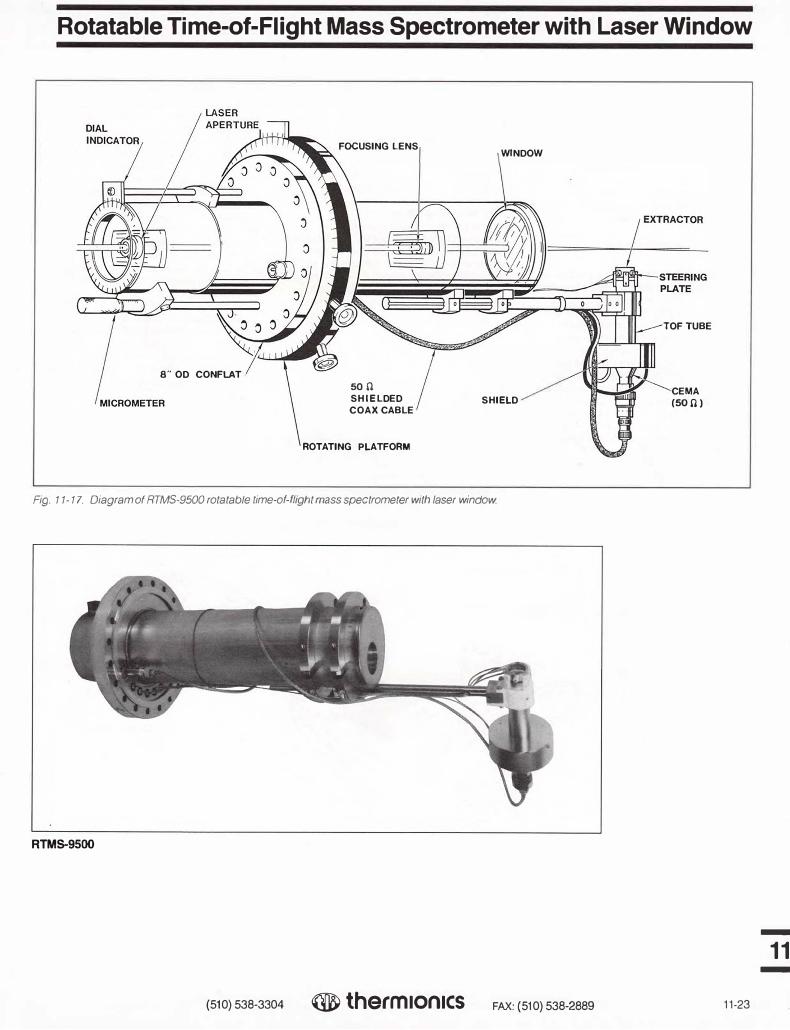
Rotatable Time-of-Flight Mass Spectrometer with Laser Window
8" OD CONFLAT
FOCUSING LENS
son
SHIELDED
COAX CABLE
ROTATING PLATFORM
WINDOW
SHIELD
Fig. 11-17. Diagram of RTMS-9500 rotatable time-of-flight mass spectrometer with laser window.
RTMS-9500
(510) 538-3304 ® therm1on1cs FAX: {510) 538-2889
TOFTUBE
CEMA
(500)
11-23
-
11 -

-
11 -
Molecular Beam Pulsed Nozzle Valve
Description
The MB-9600 is a precision molecular beam source which utilizes a solenoidactivated pulsed valve (General Valve type) with an electronic controller, and is mounted on an )('(Z stage. The Thermionics controller offers a significant cost savings and greater sophistication than other controllers, and the XYZ stage allows quick mounting and alignment of the pulsed valve with skimmers and other vacuum equipment.
Technical Description
Valve The pulsed valve can produce pulses as
short as 300 µsec or be operated in the open position. Pulses as short as 3 µsec can be achieved by employing a chopper wheel, also available from Thermionics. Aperture sizes of 100 microns to 2 mm are available. The valve consists of a Teflon or Delrin plunger which mates with a stainless steel aperture. The plunger is attached to a Tefloncoated magnet which is actuated by a solenoid outside the valve. The only materials in contact with the gas are stainless steel, Teflon, and the Teflon-coated magnet. A 1/4" or 1/8" Swagelok fitting connects the valve to an external gas supply.
Controller The pulsed valve controller is impedance
matched to the valve solenoid to produce smooth opening and closing of the valve without "bounce," "ringing," or extra pulses. The controller allows the user to vary the open time. In addition, a delay is included for synchronizing the opening of the valve with another device such as a chopper.
XYZ Mounting Stage Frequently, a pulsed valve must be
precisely aligned with an aperture, a skimmer, laser beams, or a molecular beam. This is easily accomplished with the supplied XYZ manipulator. The position of the nozzle is accurately varied using micrometers which can be locked once alignment is achieved.
Applications
The pulsed source can be used for ( 1) timeresolved experiments and for (2) formation of high intensity molecular beams. The pulsed valve allows operation with a very low Knudsen number (compared to continous sources) and hence produces beams with very low rotational temperatures which are nearly monoenergetic. This is most advantageous for (3) Doppler-free spectroscopy ex�eriments and for (4) beam-surface reaction experiments. The high cooling rates can also be utilized for formation of cluster beams. The nozzle can be fitted with a heater (500°K). The heated source can produce high energy beams (0. 75 eV for N
2 in H
2; 3.5
eV for Xe in HJ Researchers in the fields of ( 1 ) cluster
beams, (2) surface chemistry, (3) timeresolved surface infrared spectroscopy (FTIR), (4) surface electron energy loss spectroscopy (EELS), (5) molecular beam epitaxy, and (6) ultraviolet third harmonic generation will find this pulsed valve to be of interest.
CONFLAT WITH 5 MINI-PORTS
ULTRA-TORR FITTING
X-Y-Z MANIPULATOR
GAS INLET
Fig. 11-18. Schematic of molecular beam pulsed nozzle valve.
11-24 (510) 538-3304 ® thermIon1cs FAX: (510) 538-2889

Molecular Beam Pulsed Nozzle Valve
Pulsed Nozzle Valve Specifications
Nozzle Specifications
Manufacturer
Valve type
Aperture size
Materials
Gas fitting
Electronics
Opening time
Variation of opening time
Synchronization
Manual mode
External mode
Delay mode
Mounting Stage-EC 1600
Purpose
X-Y motion
Zmotion
Position indicators
Model No.
Model No.
MB-9600
General Valve
Solenoid activated
100 microns to 2 mm
All stainless steel except plunger (Teflon or Delrin) and the magnet (Teflon-coated iron)
1/8" or 1/4" Swagelok
30 µsec minimum to continous open
Open time is varied via a front panel knob
Three modes: (a) manual, (b) external, (c) delay
The valve opens in response to a button on the control panel
The valve opens in response to an external TTL pulse
The valve opens after a finite delay after receiving an external TTL pulse. The delays are user adjustable from the front panel
To align the pulsed valve with a skimmer or laser beam
±1/2" in each direction
± 1" external to vacuum. Additional Z motion is achieved by repositioning the pulsed valve on the manipulator shaft
Micrometers with locking screws
MB-9600 Molecular beam pulsed valve
PS-9600 Controller
(510) 538-3304 ® therm1on1cs FAX: (510) 538-2889 11-25
-
11 -
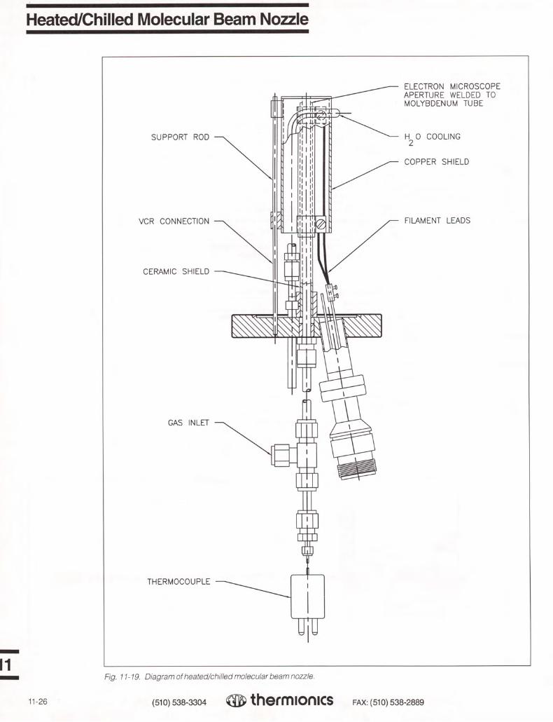
Heated/Chilled Molecular Beam Nozzle
11
SUPPORT ROD
VCR CONNECTION
CERAMIC SHIELD
GAS INLET
THERMOCOUPLE
ELECTRON MICROSCOPE APERTURE WELDED TO MOLYBDENUM TUBE
H2 0 COOLING
COPPER SHIELD
FILAMENT LEADS /—
Fig. 11-19. Diagram of heated/chilled molecular beam nozzle.
11-26 (510) 538-3304 thermionics FAX: (510) 538-2889

Description
The MBN-9700 is a heated/chilled molecular beam source which can produce continuous monoenergetic molecular beams (free-jets) with a stagnation temperature of + 100°K to+ 1,600°K. This source cangenerate beams with very high transitionalenergies (3 eV for Ni seeded in Hi, 14 eV forXe seeded in Hi) or rotationally cooled butvibrationally hot beams. By operating thenozzle at low pressure and high temperature,atomic beams can be formed from moleculargases. The nozzle can also be operated atlow temperature with liquid nitrogen cooling,thus allowing the formation of cluster beamsor very low energy molecular beams.
Short pulses (3 µsec) can be produced by employing a chopper in conjunction with the heated nozzle. A chopper with associated electronics is available from Thermionics.
Nozzles
Metallic nozzles are formed from molybdenum tubes with molybdenum electron microscope apertures welded onto one end. Aperture sizes as small as 25 microns are available. The gas connection to the tube is a VCR fitting.
Alumina tubes with apertures as small as 200 microns can also be provided. These tubes are cemented to a gas fitting. Ceramic nozzles are most advantageous when using halogens or oxygen.
Heating
The nozzle tubes are enclosed in a ceramic shield and are resistively heated. The gas temperature can be directly measured with a shielded thermocouple inserted inside the nozzle tubes (3/16" 1.0.). The heating can be regulated manually using a Variac or with a feedback circuit which employs the thermocouple.
Cooling
For high temperature work, the entire nozzle assembly is enclosed in a watercooled copper shield. For low temperature, the shield is chilled by liquid nitrogen, and temperature regulation is achieved by mildly heating the nozzle.
Heated/Chilled Molecular Beam Nozzle
XYZ Mounting Stage
Frequently, a heated nozzle jet must be precisely aligned with an aperture, skimmer, laser beao1s, or molecular beam. A low-cost bellows sealed XYZ stage is available with mounting hardware for the heated nozzle. The position of the nozzle is accurately varied using micrometers.
Applications
( 1) Generation of energetic beams forchemical studies. (2) Formation of atomic beams (chlorine or fluorine) for etching of semiconductors. (3) Formation of vibrationally excited rotational cold species for spectroscopic studies. (4) Formation of cluster beams (5) Generation of very low energy beam for diffraction and epitaxy studies.
Heat/Chilled Molecular Beam Source specifications
For Metal Tubes
Material
Tube size
Aperture diameter
Aperture thickness
Maximum temperature
Gas connection
For Ceramic Tubes
Material
Tube size
Aperture diameter
Aperture thickness
Maximum temperature
Gas connection
Thermocouples
Type
Protectio1 tubes
Location of thermocouple junction
Heater
Type
Power re:iuirement
Model No.
Includes: Two (2) nozzle tubes
Molybdenum
1/4" 0.0.; 35/1000" wall
20 microns-400 microns
10 microns
1,200°c
1/4" VCR brazed onto the tube
Alumina 99.8%
1/4" O.D; 3/16" I.D.
200 microns (min.)
200 microns
1,400°c
1/4" VCR cemented onto the tube
Customer supplied or specified
Alumina available
In the nozzle gas about 1 cm behind the nozzle
Silicon carbide
110 VAC at 15 A
MBN-9700 Heated/chilled molecular beam nozzle
Does not include: Manipulator mounting stage, heater power supply or thermocouples-prices on request
(510) 538-3304 ® therm1on1cs FAX: (510) 538-2889 11-27
-
11 -

-
11 -
Differentially Pumped Molecular Beam Source Chamber
16.7 x 16.7 rectangular PyraFlat flange\
bakeout heaters
6" diffusion pump for chamber#3
connection gauge
ionization gauge
adjustable height frame ----
flange for mounting of molecular beam source
ionization gauges
H20 feedthrough for chopper
II I electric eye connector
10" diHosioo pump to, chambe, #1 /
Fig. 11-20 Diagram of differentially pumped molecular beam source chamber with chopper wheel.
PyraFlat flanges are manufactured and protected under one or more of the following patents: 5,640,751; 4,685,193
Model No.
collimation chamber ,. --- (Ch. #3)
chopper motor chamber (Ch. #2)
expansion chamber (Ch. #1)
valve actuator
6" diffusion pump for chamber #2
MSC-9800 Molecular beam source chamber
Includes: Chopper motor, chopper wheel, chopper motor drive, electric eye with electronics skimmer and collimator with ionization gauges
Not Included: Pumps, nozzle, pumped valve source, or ionization gauge controllers
11-28 (510) 538-3304 ® therm10n1cs FAX: (510) 538-2889

Differentially Pumped Molecular Beam Source Chamber
Description The MSC-9800 is a differentially pumped
molecular beam source. It consists of three chambers which are designed to minimize the distance between the nozzle and the final collimator (3.5").
The first (expansion) chamber (1 x 10⁻⁷ Torr) is a high conductance chamber which direct-ly pumps on the molecular beam source. The molecular beam leaves the expansion cham-ber via a skimmer and enters the second (chopper motor) chamber.
This second chamber (2 x 10⁻⁹ Torr) con-tains a water-cooled 400 Hz chopper which enables the beam to be chopped into micro-second-long pulses. The second chamber also contains a miniature gate valve which allows the first and second chambers to be independently brought up to atmospheric pressure. The molecular beam leaves the second chamber via a collimator inside the gate valve and enters the third (collimator) chamber.
The third chamber is typically maintained under very high vacuum (2 x 10⁻⁹ Torr); it
LINEAR BEARING HOLDER
COLLIMATOR
CHAINIIER *3
VALVE ACTUATOR
VALVE PLUNGER
VALVE BODY
CHAMBER * 2
serves as both a final collimation stage and to differentially pump the miniature gate valve. The beam leaves the collimation chamber via
Model No. CW-9810 Chopper wheel as separate item
a removable collimator (1-10 mm dia.) and Price enters the UHV chamber.
Pumps and Flange Sizes A large rectangular source has been con-
structed which bolts onto a Thermionics 16.7" x 16.7" PyraFlat. This source has high con-ductance and thus permits the formation of intense molecular beams. The first chamber is pumped by a 10" pump via a 16" ASA flange, while the second and third chambers are pumped by 6" pumps via 8" O.D. ConFlats.
Applications The chamber is compatible with the
pulsed sources, heated nozzle, and chopper drive manufactured by TLI. Thus, this cham-ber is most useful for beam-surface experi-ments, as well as time-resolved experiments under UHV conditions.
PyraFlat flanges are manufactured and protected under one or more of the following patents: 5,640,751 4,685,193
CHOPPER WHEEL
SKIMMER
ELECTRIC EYE
400 HZ MOTOR
CHAMBER # 1
746)
PULSED VALVE
$3,900
11 Fig. 11-21. Diagram of chopper wheel.
(510) 538-3304 jJ thermionics FAX: ( 510) 538-2889 11-29

-
11 -
Crystal Cleaver
C-9900
The C-9900 is a UHV cleaver which can cleanly cleave 3/8" wide samples. The cleaver has a specially designed backstop to prevent samples from being dislodged from their holder. The entire cleaver can be retracted by 2", allowing it to be employed in close quarters. The cleaver blade is a standard razor blade and is easy to replace. Samples cleaved with this device have been "found flat" using atomically resolved scanning tunneling microscopy.
Specifications
Blade travel
Blade and backstop retraction
Blade metal
Linear bearings
Mounting
Flange to sample
Smoothly cleaved area
Model No.
BELLOW$ FOfl BLADE ACTION
CHAIN DRIVE
2 3/4" CON FLAT
BLADE HOLDER
"' 1•
2" "'
Stainless
Stainless
9" standard
90% with good sampleto-blade alignment
C-9900 Crystalcleaver
BELLOWS FOR TRANSLATION
11-30
BLADE
BACKSTOP
LINEAR
BEARINGS
Fig. 11-22. Diagram of crystal cleaver.
(510) 538-3304 ® therm1on1cs FAX: (510) 538-2889

Quick Change Manipulator Gearbox/Sample Holder
Description The quick change manipulator gearbox
allows rapid sample exchange with a sample carousel or surface science spectrometer (STM, EELS, FTIR) without the use of transfer arms. In addition, the manipulator allows 1200of flip rotation. The sample can be heated and cooled between 100°K and 1,300°K with precise temperature measurement.
Design Rotations
3600 rotation about the vertical axis by use of a rotary platform with 1200 flip motion by means of worm gear drive.
Translations Narrow neck allows use of 1.5" I.D. bel-
lows for Z translation, thus making a long Z stroke manipulator quite affordable.
Cooling A liquid nitrogen reservoir is coupled to the
sample by a large OFE copper ribbon.
Heating Sample is conductively heated by a
tantalum filament. The sample is electrically isolated from the heater as well as the manip-ulator. This allows for measurement of elec-tron beam or ion beam current during Auger, LEED, etc.
Sample Exchange The sample exchange is accomplished
using the X-Y-Z motion of the manipulator.
Sample Size 3/8" standard, but a larger manipulator
head can be made to accommodate larger sample.
Applications Manipulation of sample where heating,
cooling, temperature measurement, and flip rotation, as well as sample exchange, are required.
Model No. GB-11 Quick change manipulator gearbox
Price Consult factory
Includes: Gearbox, cryostat and feedthroughs
Not Included: ANN differentially pumped rotary seal, XYZ manipulator and rotary feedthroughs. Custo-mer must supply; for complete information and assistance, contact the factory.
1 " DIAM. MAIN SHAFT -----„
DRIVE SHAFT
LIQUID NITROGEN
CONDUIT
CRYOGENIC BOX
COPPER COOLING
RIBBON
FILAMENT CURRENT
THERMOCOUPLE
SAMPLE CLIPS
1/4 " D1AM. SAMPLE
DETACHABLE SAMPLE HOLDER 1"
SPUR GEARS
45 ROTATION
90' ROTATION
SAPPHIRE INSULATOR
SSTL WORM GEAR
Cu Be WHEEL GEAR
FILAMENT CURRENT RETURN
ELECTRICALLY ISOLATED
MOLY PLATE
Fig. 11-23. Diagram of quick change manipulator gearbox/sample holder
(510) 538-3304 thermionics FAX: ( 510) 538-2889 11-31

Miniature SAM (Six Axis) Manipulator Gearbox
11
Description
The "SAM" miniature manipulator allows small samples (2-3 cm dia.) to be rotated over three orthogonal axes and translated in the X-Y-Z directions. The sample can be heated or cooled between +100°K and +2,100°K. The manipulator is only 2" wide, yet has six axes of motion plus heating and cooling. For more information, see Section 2.
Technical Description
Rotations (1) Rotation about the vertical direction
(manipulator shaft) is achieved using a UHV rotary stage (see Section 2). (2) Rotation about the horizontal axis is via the panto-graph. This pantograph is directly rotated by a rotary motion feedthrough. The pantograph design removes the mechanical parts from the vicinity of the sample face, thus allowing the sample to be accessed by electron, mo-lecular, or laser beams. (3) The azimuthal rotation about the sample normal is achieved by mounting the manipulator on the front of a customized rotary feedthrough.
Heating/Cooling The sample holder is electrically isolated
by means of a thin sapphire washer. The sapphire washer sits directly upon a miniature (1.38" dia) molybdenum liquid nitrogen cooled cryostat. A miniature electron gun is positioned behind the sample holder, thus allowing electron bombardment heating of the sample. A thermocouple is attached either to the sample or sample holder. The temperature regulation is achieved by controlling either the bias of the electron gun or the filament current. This allows for stable temperature regulation both at high and low sample temperature.
Applications
Sample manipulation over six axes of motion where pressure bursts cannot be tolerated.
GB-8/0A
Specifications for the Miniature SAM (Six Axis) Manipulator
Rotations
Flip/tilt 105° -150° range depending upon application. Motion is con-trolled by a rotary feedthrough and a pantograph
On axis rotation 360° with a rotary seal (RN N)
Polar aximuthal rotation ±30°. Rotation is achieved by mounting the manipulator on the front of a special rotary feedthrough
X-Y motion
Z motion Supplied by manipulator
Heating/Cooling
Heating element Electron bombardment heating on the back face of the crystal is achieved by heating tungsten filaments and biasing the power supply
Surface potential The sample is electrically isolated and can be grounded or negatively biased during heating
Cooling The sample sits directly on a liquid nitrogen cooled cryostat (NO COPPER BRAID IS EMPLOYED)
Thermocouple A W-Re thermocouple is spot welded to the sample or sample holder
Sample Holders
Type The sample holders are thin pressed disks with a platform for the sample. The electron gun sits inside the platform, thus shielding the sample from the electron gun.
Material Molybdenum is standard
Model No. GB-8/0A Miniature SAM manipulator gearbox
Price Determined by configuration. Consult factory.
11-32 (510) 538-3304 therrnionics FAX: (510) 538-2889

Modular Cart Systems
Description Portable equipment carts permit modu-
lar assembly of complex UHV systems. They allow vacuum systems to be trans-ported, raised and lowered for joining to existing systems and nested together when required. The carts are readily customized including such standard features as a heavy steel base plate, outrigger casters with wheel brakes, and counterbalancing. The base carries four support jack assem-blies which are motor driven and lift equip-ment payloads up to 1,000 lbs. evenly.
Sample transfer from chamber 1 to chamber 2
Two modular carts in tandom (they are easily joined with the aid of guide pins—a bellows assembly completes the UHV channel)
(510) 538-3304 thermionics FAX: (510) 538-2889 11-33

-
11 -
UHV Cold Trap Assembly
Fig. 11-25. LNT-701.
Raman Cell
The model RC-9300 Raman cell is used to generate tunable UV and IR radiation from tunable dye lasers. The Raman cell allows wave length shifting of laser radiation to both the red and blue on infinite laser beams. Orders as high 5th anti-Stokes have been achieved with this cell.
The Raman cell is fabricated from stainless steel. A special chemical polishing process allows the cell to be pumped down to very low pressures prior to backfill, and minimizes outgassing from the cell after filling. Therefore, the contained is maintained at very high purity.
The cell is supplied with stress-free, laser feedthrough windows. Suprasil quartz windows are supplied standard, but the cell can be supplied with quartz, sapphire, magnesium fluoride, or lithium fluoride windows, at extra cost.
Features
The LNT-700 is a cold trap which allows a diffusion pump to bring a well-baked chamber to the 10-11 Torr pressure range. This trap is designed to work with Edwards and Alcatel diffusion stacks which have built-in water baffles and ConFlat mating flanges. The TLI UHV trap is designed to eliminate the problem of evaporation off the LN2 reservoir as the liquid nitrogen level falls_ A diffusion pump with a TLI UHV trap combines the advantages of ( 1) vibration-free pumping, (2) pumping of noble gasses, (3) low ultimate pressures, and (4) all ConFlat flange construction (no indiumor Viton seals).
Specifications
Baffle flange
Mating flange to pumping
Mating flange to chamber
Reservoir LN2 life
Conductance
Baffle material
Model No.
Model No.
Options
13 1/4" ConFlat
13 '/•', 10", 8", or 6" ConFlat
10" ConFlat
9 hr standard ( other sizes on request)
9001/sec
OFEcopper
LNT-700 UHV liquid nitrogen trap
LNT-701 Same as LNT-700, with additional port for TSP (see page 1-18 for TSP)
■ Liquid nitrogen level controller-allows LN2 level to be maintained ( see page 6-12)
■ Integral bakeout lamp (see Section 9) ■ Steel stand for trap and pump
■ 1.5" O.D. tube, 24" long, with 2.75" end
WARNING: Using this device with hydrogen or other volatile gases: OPERATIONS INVOLVING HYDROGEN ARE HAZARDOUS, including EXPLOSIVE. Materials commonly considered non-hazardous become dangerous in such environments.
flanges■ All metal, backfill valve■ Two Suprasil quartz windows■ Pressure gauge
Model RC-9300
We recommend that systems utilizing hydrogen be undertaken only by those persons properly skilled to perform such operations in a safe and cautious manner.
11-34 (510) 538-3304 ® therm1on1cs FAX: (510) 538-2889

Notes
(510) 538-3304 Q therm ionics FAX: (510) 538-2889

Index
A Accessories
Diffusion Pump, UHV Cold Trap Assembly 11-34 Double-Sided Flanges 8-24 e-Gun, 3 kW 4-18
Power Supplies 4-19 e-Gun, 6 kW 4-9
Power Supplies 4-11 Feedthrough Collars 8-22 Flexible Stainless Steel Hoses 8-24 Ion Pump 1-11 MBE 11-10 Pyrex Bell Jars, Guards, and
Accessories 8-22 RHEED 11-15
AC-3/FD-1 Faraday Cup 2-82 Adapter Flanges (ConFlat)
ASA/ConFlat Adapter Flanges 7-25 ASA/ConFlat Reducing Nipples 8-3 ConFlat to Ceramic/Glass Adapters 8-5 Double-Sided Flanges 7-16 (Assembly Hardware and Gaskets are shown on the page with the Range) Glass-to-Metal Adapters 8-5
All Metal Valves, Bakeable 3-26 Bakeable Angle (AMV Series) 3-28 Bakeable Angle (BVV Series) 3-27 Bakeable Straight Through
(SMV Series) 3-29 Technical Information 3-26
Analytical Chambers 10-2 Systems 9-1, 11-1
Angle Valves Bakeable, All Metal 3-26 Stainless Steel, Roughing 3-14
ASA Flanges Standard ASA Flanges 7-24 ASA/ConFlat Adapter Flanges 7-25 (Assembly Hardware and Gaskets are shown on the page with the Flange)
Appendage Ion Pumps 1-17 Assembly Bolt Sets, Flange
(see Flange listing) 7-1 Automatic Sorption Pump
Roughing Carts 9-20
Bakeable, All Metal Valves 3-26 Bakeable Angle (AMV Series) 3-28 Bakeable Angle (BVV Series) 3-27 Bakeable Straight Through
(SMV Series) 3-29 Technical Information 3-26
Bakeout Heaters 9-7, 9-9 Lamps 9-9 Shrouds 9-7
Ball Joints/Sockets 8-14
Bayard-Alpert Ionization Gauges Glass Envelope Type 6-10 Nude Type 6-11 Replacement Filaments 6-11
Beam Sweep Controllers Circular 4-13 Triangular, X-Y 4-12
Bell Jars Pyrex 8-22 Stainless Steel 10-1
Bellows Flexible Coupling with ConFlats 8-3 Flexible Coupling with ISO 8-11 Formed, Stainless Steel 8-26 Welded, Stainless Steel 8-25
Bi-Pass Valves 3-22 Bolts, Nuts and Washer Sets
(Shown in Section 7 with Flanges) 7-1 Bolt-Type Wire Seal Flanges 7-20 Bore, Wide (see Section 2—Manipulators) BPLR Linear-Rotary Feedthroughs 2-48 Butterfly Valves 3-30
Camera and Mount, (RHEED) 11-16 Carts, Sorption Pump Roughing 9-20 Ceramic/Glass Adapters 8-5 Chambers 10-1
Load Lock 2-74 Portable 2-41, 11-33 Quick Access Caps 2-73 Quick Access Doors 2-75 Surface Analysis 10-2
Chemistry (see Section 11—Molecular Beam and Surface Chemistry Products)
Clamp-Type Wire Seal Flanges 7-22 Cleaning, for Vacuum Application 10-2 ClearView Heated Viewports 2-78 Co-Evaporation
Hydra-1 4-6 Hydra-2 4-5 Triad 4-7
Cold Cathode Ionization Gauges, and Controllers 6-7
Cold Trap, UHV 11-34 Cold Wall Vacuum Furnace 9-13 Collars, Feedthrough 8-22 Combo-Vac Pumps 1-19 Compound Manipulators (see Section 2—
Manipulators, FM Series) ConFlat
Ceramic/Glass Adapters 8-5 Crosses 8-2 Elbows 8-1 Flanges (see Section 7—ConFlat Flanges) Flexible Couplings 8-3 Hoses 8-24 Nipples 8-1 Tees 8-1 Viewport Shutters 2-76
Viewports—Pyrex, Sapphire, and Quartz 8-4
ConFlat Flanges ASA/ConFlat Adapter Flanges 7-25 Dimensions 7-14 Double-Sided Flanges 7-16 (Gaskets/Hardware are shown on the page with the Flange) Non-Rotatable 7-10 Reducing Flanges 7-18 Rotatable 7-6 Tapped Rotatable 7-8 Tapped Non-Rotatable 7-12 (Assembly Hardware and Gaskets are shown on the page with the Flange) Technical Information 7-2
Controllers Cold Cathode Gauge 6-7 Liquid Nitrogen Level 6-12 Pirani Gauge 6-9 Stepping Motor 2-81 Synchronous Motor 2-81 Thermocouple Gauge 6-3
Cooling, Sample 2-52 Crosses-4-, 5-, 6-way
ConFlat 8-2 ISO 8-11
Cryo Pumped Systems 9-14 Cryogenic Sorption Pumps 9-17 Crystal Cleaver 11-30 Cubes, 6-way, ConFlat 8-2 Custom e-Guns 4-1 Custom Gate Valves 3-13 Custom Manipulators 2-3 Custom Vacuum Chambers 10-1 Custom Systems
Cryo Pumped 9-14 Diffusion Pumped 9-15 Ion Pumped 9-14 Others 9-16 Sample Handling 2-3 Turbo Pumped 9-15
Delta Shutters 2-78 Dewars, /CLND, /CLNI 2-52 Differentially Pumped Molecular
Beam Source Chamber 11-28 Differentially Pumped Rotary Seal 2-27 Diffusion Pump, UHV Cold Trap
Assembly 11-34 Diffusion Pumped Systems 9-10,9-15 Digital Thermocouple Gauge
Controllers Diode Ion Pumps Doors, Quick Access Double-Sided Flanges, ConFlat Double-Sided Flanges, ConFlat,
with T.C. and/or Valves 8-24 DRS-1000 Temperature Monitoring 2-55'
6-6 1-8
2-75 7-16
(510) 538-3304 thermionics FAX: (510) 538-2889

Index
Precision, FPRM 2-34 Tapped Non-Rotatable 7-12 EBXY Series Stages 2-22 Precision Dual Axis FRRC, FRLC ..•• 2-35 (Assembly Hardware and Gaskets are EC Series Manipulators 2-4 Open Axis, WOA 2-36 shown on the page with the Range) ECT Series Jacking Stages 2-20 RNN 2-27 PyraFlat Flanges 7-2 ECXY Series Stages 2-22 Feedthroughs, Linear-Rotary Assembly Hardware 7-3 e-Guns—Section 4 4-1 BPLR Series 2-48 Flexible Couplings
Beam Sweep Controllers FLLRE Series 2-40 ConFlat Flanges, with 8-3 Circular 4-13 FLRM Series 2-44 ISO Flanges, with 8-11 Triangular, X-Y 4-12 FRLC Series 2-35 Flexible Stainless Steel Hoses 8-24
Custom e-Guns 4-1 RPLR Series 2-42 ConFlat Flanges, with 8-24 Hanks HM2 Single Position,
6kW-20kW 4-2 Fel-Pro C-100 Lubricant FHC High Current Feedthroughs
8-27 5-3
ISO Flanges, with 8-12 FLLRE Series Linear-Rotary
Hanks HM2 Rotary 4-4 FHV High Voltage Feedthroughs 5-2 Feedthroughs 2-40 Hanks HM2 Accessories 4-8 Film Thickness Monitor Feedthrough • 5-10 FLM Series Linear Feedthroughs 2-37 Hydra, Multi-Position,
Co-Evaporation 4-5 FIM Coaxial Feedthrough Fittings, Tube
5-7 FLN Fluid Feedthroughs 5-12 FLRM Series Linear-Rotary
Triad, Three Position, Co-Evaporation 4-7
ConFlat Flanges, with ASA/ConFlat Reducing Nipples ••
8-1 8-3
Feedthroughs 2-44 FM Series Compound, Wide Bore
3 kW Single and Multiple Position 4-14 Ceramic/Glass Adapters 8-5 Manipulators 2-10
3 kW Accessories 4-18 Crosses-4-, 5-, 6-way 8-2 FMC Medium Current Feedthroughs 5-1 3 kW Rod Fed 4-17 Cubes, 6-way 8-2 FMH & FBN Instrument Feedthroughs.. 5-4 3 kW Power Supply 4-19 Elbows 8-1 FPRM Precision Rotary Feedthroughs 2-34
6 kW Multiple Position Linear 4-9 Flexible Couplings 8-3 FRLC Linear-Rotary Feedthroughs 2-35
6 kW Multiple Position Linear Flexible Stainless Steel Hoses 8-24 FRM Series Rotary Feedthroughs 2-30
Accessories 4-9 Half-Nipples 8-1 FRMRE Series Rotary Feedthroughs .. 2-33
Power Supplies Nipples 8-1 FRRC Dual Rotary Feedthrough 2-35
6-20 kW 4-10 Reducing Nipples 8-3 FSH & FBSH Instrument Feedthroughs. 5-6 Specifications 4-11 Tees 8-1 Foreline Traps Technical Data 4-10 ISO Flanges, with 8-8 Optically Dense 8-27 3 kW 4-19 ASA/ISO Adapter Nipples 8-12 Molecular Sieve 8-28 Sweep 4-12 Crosses-4-, 5-, 6-way 8-11 Formed Bellows, Stainless Steel 8-26
Elbows Elbows 8-11 Four-Way Crosses ConFlat 8-1 Flexible Couplings 8-11 CF 8-2 ISO 8-11 Flexible Stainless Steel Hoses 8-12 ISO 8-11
EM Series Manipulators 2-6 Half-Nipples 8-10 FWS Series Wobble Sticks 2-46 EMT Series Translators 2-16 ISO/ConFlat Adapter Nipples 8-12 EMXY Series Stages 2-22 ISO/Compression Fitting 8-13 Epoxy, Super Seal Sealant 8-27 Mechanical Pump Adapter 8-12 Evaporation Tables 4-21 Nipples 8-10 Gaskets (see Section 7—Range Gaskets, Evaporators Reducing Nipples 8-12 see Section 3—Valve Gaskets)
VE 80 9-10 Tees 8-10 Gate Valves 3-4 VE 90 9-11 Metal Spherical Joints 8-14 Custom Gate Valves 3-13 VE 100 9-12 Quick Disconnects 8-15 Dimensions 3-9
AL Fittings 8-16 General Information 3-4 Flanges M.E.S.C./M.E.S.A. Gate Valves 3-13
Adapter Flanges (ConFlat) Model Numbers 3-6 Faraday Cup Actuator Assembly 2-82 ASA/ConFlat Adapter Flanges 7-25 Ordering Information 3-6 FB Series Wide Bore Manipulators 2-12 Double-Sided Flanges 7-16 Performance 3-5 FBT Series Translators 2-18 (Assembly Hardware and Gaskets are Position Indicators 3-11 FBXY Series Stages 2-22 shown on the page with the Range) Prices 3-8 FCW Fluid UHV Feedthroughs 5-11 Reducing Flanges 7-18 Throttling Devices 3-12 Feedthrough Collars 8-22 ConFlat Flanges Window Gate Valves 3-10 Feedthrough Hats 2-56 ASA/ConFlat Adapter Flanges 7-25 Gauges Feedthroughs, Electrical 5-1 Dimensions 7-14 Bayard-Alpert Ionization Gauges, Feedthroughs, Fluid 5-11 Double-Sided Flanges 7-16 Glass Envelope Type 6-10 Feedthroughs, Rotary Motion (Gaskets/ Hardware are shown Nude Type 6-11
1/4" Shaft, FRM 2-30 on the page with the Flange) Cold Cathode Ionization Gauges 6-7 3/8" Shaft, FRM 2-32 Non-Rotatable 7-10 Pirani Gauges 6-9 FRMRE Series 2-33 Reducing Flanges 7-18 Thermocouple Gauges 6-1
Rotatable 7-6 GBLM Precision Tilt Stage 2-24 Tapped Rotatable 7-8
(510) 538-3304 therrnionics FAX: (510) 538-2889

Index
Gearboxes/Goniometers 2-58 Combo-Vac Pumps 1-19 Manipulators Getter Pumps Custom Design Pumps 1-17 EC Series 2-4
Ion Pumps 1-1 Diode Ion Pumps 1-8 EM Series 2-6 Titanium Sublimation Pumps 1-18 Hydrogen Diode Ion Pumps 1-10 FB Series, Wide Bore 2-12
Glass Bell Jars 8-22 Noble Diode Ion Pumps 1-9 FM Series, Compound, Wide Bore.. 2-10 Glass to Metal Adapters 8-5 Power Supplies 1-16 TPM Series 2-8 Glue, Super Seal Epoxy 8-27 Rebuilding 1-22 Manual Sorption Pump Roughing Carts 9-21 Goniometers/Gearboxes 2-58 Technical Information Material, Surface and Molecular Beam. Guards, Bell Jar 8-22 Ion Pump Guide 1-3 Sciences—Section11 11-1
Physical Dimensions 1-12 MBE (see Section 11—Molecular Beam Pumping Speed vs Pressure 1-6 Epitaxy) Sizing the Pump 1-4 M.E.S.C./M.E.S.A. Gate Valves 3-13
Half-Nipples Theory of Operation 1-1 Miniature SAM Manipulator 11-32 ConFlat 8-1 Triode Ion Pumps 1-11 Modular Cart Systems 11-33 ISO 8-10 Ion Pump Systems, Custom 9-14 Molecular Beam and Surface Chemistry
Hanks HM2 e-Guns 6-20kW Ion Pump Systems, Table Top 9-2 Products—Section 11 Hydra, Multi-Position,
Co-Evaporation 4-5 Rotary, Multiple Crucibles 4-4
Ionization Gauges Bayard-Alpert Ionization Gauges,
Glass Envelope Type 6-10
Crystal Cleaver 11-30 Differentially Pumped Molecular
Beam Source Chamber 11-28 Single Position 4-2 Nude Type 6-11 Heated/Chilled Molecular Triad, Three Position, Cold Cathode Ionization Gauges 6-7 Beam Nozzle 11-26
Co-Evaporation 4-7 Controllers 6-8 Laser Test Chamber, with Time-of-Hanks HM2 Accessories 4-8 ISO Fittings 8-10 Flight Mass Spectrometer 11-20 Hardware (Assembly Hardware for Flanges ISO Flanges 8-8 Miniature SAM Manipulator 11-32
are listed in Section 7) Isolation Valves Molecular Beam Pulsed Stud and Nut Sets 8-25 RHEED 11-16 Nozzle Valve 11-24 12-Point Bolt Sets 8-25 Valves, Standard 3-1 Quick Change Manipulator
Heated/Chilled Molecular Gearbox/Sample Holder 11-31 Beam Nozzle 11-26 Raman Cell 11-34
Heated Viewports, ClearView 2-78 Rotatable Time-of-Flight Mass Heating, Sample 2-50 JS Series Jacking Stages 2-82 Spectrometer and Laser Window. 11-22 Hoses, Flexible Stainless Steel 8-24 UHV Cold Trap Assembly 11-34
ConFlat 8-24 Molecular Beam Epitaxy (MBE) ISO 8-12 MBE Systems/Specifications 11-2
Hydra, Multi-Position, Co-Evaporation, e-Gun 4-5
Laser, Pulsed; Deposition Target Stages, TGB) 2-68
Series VT-100 11-2 Series VT-105 11-4
Hydrogen Diode Ion Pumps 1-10 Laser Test Chamber, with Time-of- Series VT-108 11-6 Flight Mass Spectrometer 11-20 Series VT-110 11-6
L-Gaskets, Bell Jar 8-22 Series VV-301, Organic MBE 11-7 Linear Feedthroughs 2-37 MBE Components 11-9
lnline Valves Linear-Rotary Feedthroughs Accessories 11-9 Bakeable, (Straight Through) 3-29 BPLR Series 2-48 Molecular Beam Pulsed Nozzle Valve ... 11-24 lnline/Slant Style 3-24 FLLRE Series 2-40 Molecular Sieve Traps 8-28 Inline/Straight Through 3-25 FLRM Series 2-44 Motor Controllers (see Controllers) Roughing 3-18 RPLR Series 2-42 Motor Drives 2-79 Slant Style 3-24 Liquid Nitrogen Dewars 2-52 Accessories 2-80 Straight Through 3-25 Liquid Nitrogen Level Controller 6-12 Motor Operated Valves 3-22
Instrumentation Liquid Nitrogen (LN2) Shroud 1-19 Mounts, Sample 2-49 Bayard-Alpert Ionization Gauges 6-10 Liquid Nitrogen Transfer Line 6-12 Multi-Conductor Instr. Feedthroughs 5-8
Nude Type 6-11 LLC Load Lock Chambers 2-74 Multiple Position/Pocket e-Guns Cold Cathode Ionization LMAB Series Translators 2-14 Hydra, Multi-Position,
Gauges/Controllers 6-7 Locking Jaw Systems 2-48 Co-Evaporation 4-5 DRS-1000 Temperature Monitoring ... 2-55 Lubricants Multiple Crucible, Rotary 4-4 Liquid Nitrogen Level Controller 6-12 Pirani Gauges/Controller 6-9
Fel-Pro C-100 8-27 Triad, Three Position, Co-Evaporation 4-7
Thermocouple Gauges/Controllers ... 6-1 3 kW Multiple Position 4-15 Ion Beam Sources 11-8 6 kW Multiple Position 4-9 Ion Pumps—Section 1 1-1 Magnetic Devices, Transformers 4-22
Accessories 1-11 Magnetic Feedthroughs, Rare Earth Appendage Ion Pumps 1-17 FLLRE Linear-Rotary Series 2-40
FRMRE Rotary Series 2-33
(510) 538-3304 ITO therrnionics FAX: (510) 538-2889

Index
Screen, Phospor, (RHEED) 11-15 Nipples QAC Quick Access Caps 2-73 Sieve
ConFlat 8-1 QAD Quick Access Doors 2-75 Molecular Sieve Traps 8-28 ISO 8-10 Qualification 10-2 Sorption Pumps 9-17
Nitrogen, Liquid, Dewars (see Dewars) Quartz Viewports 8-4 SLJ Locking Jaw Systems 2-48 Noble Diode Ion Pumps 1-9 Quick Change Manipulator SMC Stepping Motor Controllers 2-81 Non-Rotatable ConFlat Flanges 7-10 Gearbox/Sample Holder 11-31 SMR Series Sample Mount 2-49 Nude Ionization Gauge Tubes 6-11 Sorption Pumps 9-17 Nuts, Bolts, Washers (see Section 7) Sorption Pump Systems 9-18
Sorption Pump Roughing Carts 9-20 Raman Cell 11-34 Sources, Ion Beam 11-8
0 Rare Earth Magnetic Feedthroughs Spectrometer, Time-of-Flight On Axis Valves 3-24 (see Magnetic Feedthroughs) Laser Test Chamber, with 11-20 Open Axis Rotary Stages Rebuilding, Ion Pump 1-22 Rotatable with Laser Window 11-22
RNN Series 2-27 Reducing Flanges 7-18 SPF Series Dual Groove Disc Systems 2-72 WOA Series 2-36 Reducing Nipples SPS Series Sample Heater
Optical Temperature Monitoring 2-55 ConFlat 8-3 Power Supplies 2-54 0-Rings (refer to the specific Flange ISO 8-12 Stages, X-Y
or Valve— Section 7 or 3) Reflection High Energy Electron EBXYB 2-22 Organic MBE, Series VV-301 11-7 Diffraction (RHEED) ECXYB 2-22
RHEED Guns 11-12 EMXYB 2-22 Accessories 11-15 FBXYB 2-22
Camera and Mount 11-16 Stepping Motor Controllers 2-81 Phospor Screens, RHEED 11-15 Isolation Valves 11-16 STLC Sample Transfer Systems 2-70 Pinch-Off Tubes 8-23 Phospor Screens 11-15 Stud and Nut Sets 8-25 Pirani Gauges and Controller 6-9 Viewports 11-15 Sublimation Pumps PLD—Pulsed Laser Deposition Viewport Shutters 11-16 (see Titanium Sublimation Pumps).... 1-18
Target Stages 2-68 RHEED Power Supplies 11-14 Surface Chemistry Products Position Indicators, Valves RFH Series Feedthrough Hats 2-56 (see Section 11—Molecular Beam and
Angle Valves 3-15 Right Angle Valves 3-14 Surface Chemistry) Gate Valves 3-11 RNN Rotary Seals 2-27 Super Seal Epoxy Sealant 8-27 Inline Valves 3-19 Rod Fed e-Gun, 3 kW 4-17 Sweep, e-Gun, Beam
Power Supplies Rotary Motion Feedthroughs Circular 4-13 Cold Cathode Gauge 6-7 1/4" Shaft, FRM 2-30 Triangular, X-Y 4-12 e-Gun 3/8" Shaft, FRM 2-32 Synchronous Motor Controllers 2-81
3 kW 4-19 FRMRE Series 2-33 Systems 6-20 kW 4-10 Precision, FPRM 2-34 MBE 11-2 Specifications 4-11 Precision Dual Axis FRRC, FRLC . . . . 2-35 RHEED 11-12 Technical Data 4-10 Open Axis, WOA 2-36 Systems—Section 9 9-1 Sweep 4-12 RNN 2-27 Custom Systems
Ion Pump 1-16 Rotatable Time-of-Flight Mass Cryo Pumped 9-14 Liquid Nitrogen Level 6-12 Spectrometer with Laser Window 11-22 Diffusion Pumped 9-10,9-15 Pirani Gauge 6-9 Roughing Pumps Ion Pumped 9-14 Sample Heater 2-54 Sorption Pumps 9-17 Modular Cart 11-33
Precision Rotary Feedthroughs Sorption Pump Systems 9-18 Others 9-16 (see Rotary Feedthroughs) Sorption Pump Roughing Carts 9-20 Turbo Pumped 9-15
Precision Shaft 8-27 RPLR Series Linear-Rotary Evaporators Precision Shaft, Bored 8-27 Feedthroughs 2-42 VE 80 9-10 Precision Tilt Stage, GBLM 2-24 VE 90 9-11 Pulsed Laser Deposition (PLD) VE 100 9-12
Illustrations 11-18 Ion Pumped Table Top Systems Specifications 11-18 Sample Cooling 2-52 Applications and Features 9-2, Technical Information 11-17 Sample Heater Power Supplies 2-54 Optional Features 9-9
PyraFlat Access Port for Sample Heating 2-50 PyraFlat Port and Cryoshroud 9-2 Table Top Systems 9-2 Accessories 2-51 Specifications 9-6
PyraFlat, Bonnet Seals, Gate Valves 3-4 Sample Mounting 2-49 Roughing Systems PyraFlat Flanges 7-2 Sample Transfer Sorption Pumps 9-17 Pyrex Bell Jars 8-22 SLJ Locking Jaw Systems 2-48 Sorption Pump Roughing Carts 9-20 Pyrex Viewports 8-4 SPF Series Dual Groove Sorption Pump Systems 9-18
Disc Systems 2-72 STLC Turn-To-Lock 2-70
(510) 538-3304 ttyp therm ionics FAX: (510) 538-2889

Index
Tapped Flanges UHV Components (See specific item) Welded, Bellows, Stainless Steel 8-25
Non-rotatable ConFlat 7-12 UHV Cold Trap Assembly 11-34 Wide Bore (see Manipulators)
Rotatable ConFlat 7-8 Window Gate Valves 3-10
Target Stage, PLD 2-68 Wire
Technical Data V Wire Seal Flanges
e-Guns 4-1 Vacuum Evaporators Bolt-Type Wire Seal Flanges 7-20
Evaporation Tables 4-21 VE 80 Series Evaporators 9-10 Clamp-Type Wire Seal Flanges 7-22
Flanges 7-1 VE 90 Series Evaporators 9-11 (Assembly Hardware and Gaskets
Gauges 6-1 VE 100 Series Evaporators 9-12 are shown on the page with
Ion Pumps 1-1 Vacuum Furnace, Cold Wall 9-13 the Flange)
MBE 11-1 Vacuum Positioning 2-1 WOA Open Axis Rotary Feedthroughs 2-36
Motion Devices 2-1 Terminology 2-2 Wobble Sticks
RHEED 11-11 Vacuum Tubing 8-26 FWS Series 2-46
Valves 3-1 Valves—Section 3 3-1
Tees Angle Valves ConFlat 8-1 Model Numbers 3-17 XN
ISO 8-10 Options 3-15 X-Y Stages 2-22
Temperature Monitoring 2-55 Prices 3-17 X-Y Sweep, e-Gun 4-12
Terminology, Manipulators 2-2 Bakeable Valves, (Straight Through) . 3-29 XYCS Sweep, e-Gun 4-13
Sample Transfer 2-69 Butterfly Valves 3-30 YMC Synchronous Motor Controllers 2-81
TGB Target Gearboxes 2-68 Gate Valves Thermionics Northwest, Inc 2-1 Custom 3-13
Thermocouple Feedthroughs 5-9 Dimensions 3-9
Thermocouple Gauge Tubes 6-1 General Information 3-4 Zeolite, Replacement Sieve
Thermocouple Gauge Controllers 6-3 Model Numbers 3-6 Traps, Molecular 8-28
Throttling Devices, (Valve) 3-12 Ordering Information 3-6 Sorption Pumps 9-17
Tilt Systems Performance 3-5 Zero Length Viewports 8-4
GBLM Precision Tilt 2-24 Position Indicators 3-11 TLT Series 2-24 Prices 3-8 VXT Series 2-26 PyraFlat Bonnet Seals 3-4
Time-of-Flight Mass Spectrometer Throttling Devices 3-12
Laser Test Chamber, with 11-20 Window Gate Valves 3-10
Rotatable with Laser Window 11-22 Inline/Slant Style 3-24
Titanium Sublimation Pumps (TSP) 1-18 lnline/Straight Through 3-25
Power Supply 1-18 Inline Valves 3-18 TLT Series Tilt Stages 2-24 Motor Operated Valves 3-22
Tom Thumb Valves 3-23 On Axis Valves 3-24 TPM Series Manipulators 2-8 Roughing 3-14
Training, e-Gun 4-20 Selecting a Valve 3-1
Transformers 4-22 Slant Style 3-24 Translators Straight Through 3-25
ECT Series 2-20 Tom Thumb Valves 3-23 EMT Series 2-16 Valve Terminology 3-2 FBT Series 2-18 Window Gate Valves 3-10
JS Series 2-82 Valve, Molecular Beam Pulsed Nozzle.. 11-24
LMAB Series 2-14 Viewports—ConFlat, Pyrex, Sapphire,
Traps and Quartz 8-4
Foreline, Optically Dense Type 8-27 Viewports, Heated 2-78
Foreline, Molecular Sieve Type 8-28 Viewport Shutters
Triode Ion Pumps 1-11 Delta Shutters 2-78
TSP Power Supply 1-18 VLS Series 2-77
Tubing, Stainless Steel Vacuum 8-26 VRS Series 2-76
Turbomolecular Virtual Axis Goniometer 2-65
Pumped Custom Systems 9-15 Virtual Axis Tilt Assembly 2-26, 11-13
Pumped Evaporators 9-11 VLS Series Viewport Shutters 2-77
Twelve Point Bolt Sets 8-25 VRS Series Viewport Shutters 2-76 VXT Series
Positioning Assembly 2-26, 11-13
(510) 538-3304 thermionics FAX: (510) 538-2889

Thermionics Laboratory, Inc.
3118 Depot Road, Hayward, CA 94545Phone: (510) 225-6975 ext 100Toll Free: (800) 962-2310Email: [email protected]: thermionics.com
Thermionics Northwest, Inc.
231-B Otto Street, PortTownsend, WA 98368Phone: (360) 385-7707Toll Free: (800) 962-2310Email: [email protected]: thermionics.com
Vacuum Components & Systems