vector-ultra-3500-manual.pdf - Trillium – Vacuum Systems
158
ATMI, Incorporated 7 Commerce Drive Danbury, CT 06810 ATMI Central Services Technical Publications 830 Latour Court Napa,CA 94558 707-299-3939 Wet Exhaust Gas Conditioner Installation, Operation, & Maintenance Manual
-
Upload
khangminh22 -
Category
Documents
-
view
0 -
download
0
Transcript of vector-ultra-3500-manual.pdf - Trillium – Vacuum Systems
ATMI, Incorporated7 Commerce DriveDanbury, CT 06810
ATMI Central ServicesTechnical Publications830 Latour CourtNapa,CA 94558707-299-3939
Wet Exhaust Gas Conditioner
Installation, Operation, & Maintenance Manual

ATMI Corporation has prepared this manual for use by ATMI personnel and customers. The information contained herein is the property of ATMI Corporation.
The material in this manual is for informational purposes only and is subject to change without notice. ATMI Corporation assumes no responsibility for omissions or errors that may appear in this manual.
The following are the trademarks of ATMI Corporation and are not to be reproduced nor used in any fashion without written approval from ATMI:
ATMI Corporation®
Smart Scrubber®
Vector Technology®
Vector Ultra™ 3500
Any reference within this manual to other’s trademark and/or copyrighted material is unintentional.
All rights reserved. No part of this manual in part or in whole may be reproduced or transmitted in any form or by any means, electronic, mechanical or magnetic, including but not limited to photographing, photocopying, recording or any information storage and retrieval system, without the written permission from an officer of ATMI Corporation.
ATMI Corporation shall not, under any circumstances, be liable to buyer or any other party for lost profits, diminution of goodwill, or any other special or consequential damages with respect to any claim. In addition, ATMI Corporation’s liability for warranty claims shall not, in any event, exceed the invoice price of the product claimed defective, nor shall ATMI be liable for delays in replacement or repair of product.
ATMI Publication Number: 020-13342-01, Revision A
Copyright ©2002 by ATMI Corporation
Revision Page(s) Changes Date
A All Release Ultra 3500 04/29/02
2 Vector 3500 IO&M Manual 020-13342-01Rev A
Table Of Contents
Table of contents
Chapter 1: Safety ........................................................................................................ 1-11.1 Introduction ..................................................................................................... 1-11.2 Safety notices and terms ................................................................................ 1-11.3 End user responsibilities................................................................................. 1-21.4 Lockout and tag-out procedure....................................................................... 1-4
Chapter 2: Theory of operation ................................................................................. 2-12.1 Introduction ..................................................................................................... 2-12.2 Vector Ultra 3500 wet exhaust gas conditioners ............................................ 2-12.3 Entry device .................................................................................................... 2-3
2.3.1 Type 20 entry....................................................................................... 2-32.3.2 Inlet heater blanket .............................................................................. 2-32.3.3 Auto inlet water wash........................................................................... 2-42.3.4 Nitrogen, porous wall ........................................................................... 2-6
Chapter 3: Facilities requirements ............................................................................ 3-13.1 Site location requirements .............................................................................. 3-13.2 Environment.................................................................................................... 3-2
3.2.1 Interior location .................................................................................... 3-23.2.2 Exterior location................................................................................... 3-23.2.3 Roof installation ................................................................................... 3-3
3.3 Clearance ....................................................................................................... 3-33.4 Facilities requirements.................................................................................... 3-4
Chapter 4: Installing Vector 3500 .............................................................................. 4-14.1 Introduction ..................................................................................................... 4-14.2 Receipt............................................................................................................ 4-14.3 Unpacking....................................................................................................... 4-2
4.3.1 Preliminary shipment inspection .......................................................... 4-24.3.2 Opening the crate and inspecting the scrubber .................................. 4-34.3.3 Removal of shipping plugs................................................................... 4-4
4.4 Moving the system into position...................................................................... 4-44.5 Seismic mounting ........................................................................................... 4-54.6 Vector Ultra 3500 system installation ............................................................. 4-6
4.6.1 Installing the fume scrubber................................................................. 4-64.6.2 Type 20 entry set-up............................................................................ 4-84.6.3 Process chamber effluent .................................................................. 4-114.6.4 House exhaust................................................................................... 4-124.6.5 Water supply...................................................................................... 4-144.6.6 Waste water drain.............................................................................. 4-174.6.7 Nitrogen supply.................................................................................. 4-18
020-13342-01 Vector 3500 IO&M Manual TOC-iRev A

Table of Contents [continued]
Table Of Contents
4.6.8 Electrical power supply ...................................................................... 4-194.6.9 Alarm circuit ....................................................................................... 4-19
4.7 Scrubber system installation checkout ......................................................... 4-194.7.1 Three phase motor-rotation verification procedure............................ 4-214.7.2 Basic system checkout ...................................................................... 4-22
4.8 System controls ............................................................................................ 4-22
Chapter 5: Start-up and operation............................................................................. 5-15.1 Installation verification .................................................................................... 5-15.2 Operator controls ............................................................................................ 5-2
5.2.1 On/Off control (main power disconnect) .............................................. 5-25.2.2 Stop/Start switch.................................................................................. 5-25.2.3 Run/Reset pushbutton......................................................................... 5-35.2.4 Emergency Machine Off (EMO) pushbutton........................................ 5-35.2.5 Make-up water flow control.................................................................. 5-35.2.6 Waste water drain................................................................................ 5-35.2.7 Entry water check ................................................................................ 5-35.2.8 Photohelic® nitrogen purge flow control .............................................. 5-45.2.9 Auto water wash .................................................................................. 5-55.2.10 Heater blanket ................................................................................... 5-8
5.3 Initial start up procedure ............................................................................... 5-105.3.1 Required equipment and materials.................................................... 5-105.3.2 Testing Control Panel Power Supply ................................................. 5-105.3.3 Start-up supply flow and pump rotation ............................................. 5-125.3.4 Checking water systems.................................................................... 5-135.3.5 Photohelic® alarm set-up and adjustment......................................... 5-145.3.6 Inlet heaters ....................................................................................... 5-14
5.4 Testing alarms .............................................................................................. 5-155.4.1 Testing control panel power supply ................................................... 5-155.4.2 Testing water systems....................................................................... 5-165.4.3 Testing control panel ON/OFF and EMO........................................... 5-175.4.4 Testing pump cavity float ................................................................... 5-175.4.5 Make-up water flow............................................................................ 5-185.4.6 Entry pressure high/low alarms ......................................................... 5-185.4.7 Sump level switch .............................................................................. 5-195.4.8 Entry water check .............................................................................. 5-205.4.9 Heater low temp alarm (LTA) test...................................................... 5-205.4.10 Testing pump low pressure alarm.................................................... 5-205.4.11 Burn in ............................................................................................. 5-21
5.5 Normal start up procedure ............................................................................ 5-21
TOC-ii Vector 3500 IO&M Manual 020-13342-01Rev A
Table of Contents [continued]
Table Of Contents
5.6 Start-up check sheet..................................................................................... 5-22
Chapter 6: Operational status and alarms................................................................ 6-16.1 Introduction ..................................................................................................... 6-16.2 System alarms ................................................................................................ 6-1
6.2.1 Alarm display ....................................................................................... 6-26.2.2 Alarm light tower .................................................................................. 6-2
6.3 Alarm conditions ............................................................................................. 6-3
Chapter 7: Shutdown procedures ............................................................................. 7-17.1 Introduction ..................................................................................................... 7-17.2 Shut down procedures.................................................................................... 7-1
7.2.1 Emergency shut down procedure........................................................ 7-17.2.2 Short term shut down procedure ......................................................... 7-37.2.3 Long term shut down procedure .......................................................... 7-47.2.4 Safety shutdown .................................................................................. 7-6
Chapter 8: Preventative maintenance....................................................................... 8-18.1 Introduction ..................................................................................................... 8-18.2 Required maintenance equipment.................................................................. 8-1
8.2.1 Clothing................................................................................................ 8-18.2.2 Tools .................................................................................................... 8-1
8.3 Lockout/tagout procedure ............................................................................... 8-28.3.1 Installation............................................................................................ 8-28.3.2 Available types of “lockout” isolating devices ...................................... 8-28.3.3 Returning lockout equipment to operation ........................................... 8-3
8.4 Daily maintenance .......................................................................................... 8-48.5 Monthly maintenance...................................................................................... 8-58.6 Cleaning the type 20 entry.............................................................................. 8-5
8.6.1 Safety................................................................................................... 8-58.6.2 Materials .............................................................................................. 8-58.6.3 Tools .................................................................................................... 8-68.6.4 Cleaning procedure ............................................................................. 8-6
8.7 Periodic chemical cleaning ............................................................................. 8-98.8 Six-month maintenance ................................................................................ 8-10
8.8.1 Pump current draw ............................................................................ 8-118.8.2 Pump cavity ....................................................................................... 8-118.8.3 Testing nitrogen systems................................................................... 8-118.8.4 Testing water systems....................................................................... 8-128.8.5 Testing control panel ON/OFF and EMO........................................... 8-128.8.6 Pump cavity float ............................................................................... 8-13
020-13342-01 Vector 3500 IO&M Manual TOC-iiiRev A
Table of Contents [continued]
Table Of Contents
8.8.7 Make-up water flow............................................................................ 8-138.8.8 Test water-wash flow ......................................................................... 8-138.8.9 Photohelic high/low alarms................................................................ 8-148.8.10 Sump level switch............................................................................ 8-148.8.11 Media temperature switch................................................................ 8-158.8.12 Conclusion....................................................................................... 8-15
8.9 Annual maintenance ..................................................................................... 8-168.9.1 Spray bar inspection/cleaning............................................................ 8-168.9.2 Polishing scrubber replacement ........................................................ 8-178.9.3 Chemical cleaning ............................................................................. 8-178.9.4 Removing/replacing the pump........................................................... 8-178.9.5 Restarting .......................................................................................... 8-17
8.10 Decontamination/decommissioning procedures ......................................... 8-198.10.1 Purpose ........................................................................................... 8-198.10.2 Procedures ...................................................................................... 8-20
Chapter 9: Service operations................................................................................... 9-19.1 Introduction ..................................................................................................... 9-19.2 Field replaceable unit removal and replacement ............................................ 9-1
9.2.1 Removing the pump motor .................................................................. 9-29.2.2 Replacing the pump motor................................................................... 9-39.2.3 Pump motor seal and heat sink insert ................................................. 9-59.2.4 Removing the pump pressure switch .................................................. 9-79.2.5 Replacing the pressure switch............................................................. 9-89.2.6 Adjusting the pump pressure switch .................................................... 9-89.2.7 Removing the solenoid valve............................................................... 9-99.2.8 Removing the instrument panel flowmeter gauges............................ 9-109.2.9 Replacing the instrument panel flowmeter gauges............................ 9-109.2.10 Replacing entry heater and insulator ............................................... 9-109.2.11 Removing the scrubber top lid ......................................................... 9-119.2.12 Removing the scrubber lid o-ring..................................................... 9-129.2.13 Replacing the scrubber lid o-ring..................................................... 9-129.2.14 Sump overflow and sump level switches ......................................... 9-139.2.15 Removing sump liquid level switch.................................................. 9-139.2.16 Replacing liquid level switch............................................................ 9-149.2.17 Polishing column packing material replacement.............................. 9-14
Chapter 10: Troubleshooting guide ........................................................................ 10-110.1 Introduction ................................................................................................. 10-110.2 Troubleshooting guidelines......................................................................... 10-1
TOC-iv Vector 3500 IO&M Manual 020-13342-01Rev A
Table of Contents [continued]
Table Of Contents
Chapter 11: Parts lists.............................................................................................. 11-1
Chapter 12: Schematics and diagrams................................................................... 12-1
Appendix A: Air pollution control technology .........................................................A-1A.1 Particulate control technology ........................................................................A-1
A.1.1 Modification of particulate characteristics............................................A-1A.1.2 Cyclones..............................................................................................A-2A.1.3 Settling chambers................................................................................A-2A.1.4 Filters...................................................................................................A-2A.1.5 Electrostatic precipitators ....................................................................A-2A.1.6 Entrainment separators .......................................................................A-2A.1.7 Wet scrubbers .....................................................................................A-2
A.2 Gas and vapor control technology..................................................................A-2A.3 Wet scrubber technology................................................................................A-3
A.3.1 Spray chamber ....................................................................................A-3A.3.2 Mechanical ..........................................................................................A-3A.3.3 Packed bed .........................................................................................A-4A.3.4 Flooded bed ........................................................................................A-4A.3.5 Cyclonic...............................................................................................A-4A.3.6 Ejector .................................................................................................A-4A.3.7 Venturi .................................................................................................A-4
Appendix B: Options ..................................................................................................B-1B.1 Chemical injection unit ...................................................................................B-1
B.1.1 Integrated injection system..................................................................B-2B.1.2 External injection system.....................................................................B-2B.1.3 Injection system with pH probe checkout ...........................................B-4B.1.4 pH metering system calibration ...........................................................B-6B.1.5 Temperature calibration ......................................................................B-6B.1.6 pH probe calibration checkout.............................................................B-7B.1.7 Injection system without pH probe checkout .......................................B-8
B.2 Safety containment cage................................................................................B-9
Appendix C: Typical process gases .........................................................................C-1
Appendix D: Glossary ................................................................................................D-1
020-13342-01 Vector 3500 IO&M Manual TOC-vRev A

Table of Contents [continued]
Table Of Contents
TOC-vi Vector 3500 IO&M Manual 020-13342-01Rev A
Table Of Contents
List of figures
Figure 2-1: Vector Ultra 3500....................................................................................... 2-2Figure 2-2: Water-wash flow diagram........................................................................... 2-4Figure 2-3: Type 20 entry.............................................................................................. 2-6Figure 4-1: Angle iron stabilization supports................................................................. 4-5Figure 4-2: Connecting main power.............................................................................. 4-7Figure 4-3: Type 20 water flow check ........................................................................... 4-9Figure 4-4: Tip-over water........................................................................................... 4-10Figure 4-5: Type 20 inlet KF-40 flange ....................................................................... 4-11Figure 4-6: Entry/exhaust locations on top of scrubber .............................................. 4-12Figure 4-7: Control box and main power disconnect box............................................ 4-18Figure 4-8: Control box ............................................................................................... 4-20Figure 4-9: Motor/pump drain plug location ................................................................ 4-20Figure 5-1: Vector Ultra 3500 front panel controls ........................................................ 5-2Figure 5-2: Make-up water control valve....................................................................... 5-3Figure 5-3: Photohelic gauges...................................................................................... 5-4Figure 5-4: Water-wash flow diagram........................................................................... 5-5Figure 6-1: Alarm display .............................................................................................. 6-1Figure 6-2: Alarm light tower......................................................................................... 6-3Figure 7-1: Front control panel switches....................................................................... 7-2Figure 7-2: EMO circuit schematic................................................................................ 7-3Figure 9-1: Location of pressure switch and solenoid valve ......................................... 9-7Figure 9-2: Pressure switch .......................................................................................... 9-8Figure 9-3: Scrubber top lid ........................................................................................ 9-11Figure 9-4: Removing the top lid o-ring....................................................................... 9-12Figure 9-5: Sump overflow and sump level switches.................................................. 9-13Figure 9-6: Polishing column ...................................................................................... 9-15Figure 11-1: Vector Ultra 3500 tank (200-13345-00) .................................................. 11-4Figure 11-2: Pump assembly (6474-00) ..................................................................... 11-5Figure 11-3: Rear panel assembly (215-13364-00) .................................................... 11-6Figure 11-4: Instrument panel door assembly (6554-01)............................................ 11-7Figure 11-5: Control box (215-13238-00) ................................................................... 11-8Figure 11-6: Polishing scrubber (6720)..................................................................... 11-10Figure 11-7: Type 20 entry........................................................................................ 11-12Figure 11-8: Make-up water assembly (215-12508-00)............................................ 11-14
020-13342-01 Vector 3500 IO&M Manual TOC-viiRev A
Table Of Contents
List of tables
Table 3-1: Vector Ultra 3500 weight ............................................................................ 3-3Table 3-2: Equipment dimensions and clearance......................................................... 3-3Table 3-3: Electrical requirements ................................................................................ 3-4Table 3-4: Process inlet parameters ............................................................................. 3-4Table 3-5: Exhaust requirements.................................................................................. 3-4Table 3-6: Gas supply requirements............................................................................. 3-4Table 3-7: Water supply and drainage requirements.................................................... 3-4Table 4-1: Vector water quality limits .......................................................................... 4-16Table 5-1: Pre-start up verification checklist ................................................................. 5-1Table 6-1: Alarm display key functions ......................................................................... 6-2Table 6-2: Alarm conditions .......................................................................................... 6-4Table 10-1: Alarm conditions ...................................................................................... 10-1Table 10-2: Electrical problems .................................................................................. 10-2Table 10-3: Water problems ....................................................................................... 10-3Table 10-4: Spray Bar Malfunction Problems ............................................................. 10-3Table 10-5: Vibration and Sound Problems................................................................ 10-3Table 10-6: Low or High Sump Problems................................................................... 10-4Table 10-7: Packing Contamination Problem ............................................................. 10-4Table 10-8: Leak Problems......................................................................................... 10-4Table 10-9: PLC input vs. output ................................................................................ 10-5Table 11-1: Spare parts kit inventory (155-13234-00) ................................................ 11-2Table 11-2: PM parts kit (160-13235-00) ................................................................... 11-3Table 11-3: Vector Ultra 3500 tank (200-13345-00) ................................................... 11-4Table 11-4: Pump assembly (6474-00)....................................................................... 11-5Table 11-5: Rear panel assembly (215-13364-00) .................................................... 11-6Table 11-6: Instrument panel door assembly (6554-01) ............................................. 11-7Table 11-7: Control box (215-13238-00)..................................................................... 11-9Table 11-8: Polishing scrubber (6720)...................................................................... 11-11Table 11-9: Type 20 entry......................................................................................... 11-13Table 11-10: Make-up water assembly (215-12508-00) ........................................... 11-14
TOC-viii Vector 3500 IO&M Manual 020-13342-01Rev A
Vector 3500 Installation, Operation and Maintenance Manual
SafetyChapter 1
1.1 IntroductionThis safety section is designed to notify the end user of the Vector Ultra 3500 equipment that some physical and/or chemical hazards may exist in the operation and maintenance of the Vector Ultra 3500. The physical hazards are related to the servicing of the Vector Ultra 3500 while the chemical hazards are related to the process gases and their by-products, which are abated by the Vector Ultra 3500.
Air pollution regulations, employee health concerns, and growing awareness of toxic agents from manufacturing, demand increased improvements in process exhaust gas conditioning. The Vector Ultra 3500 Wet Exhaust Gas Conditioner reduces hazards associated with flammable, toxic, or corrosive gases, and vapors.
Vector Ultra 3500 systems provide controlled conditioning process exhaust gas(es). As with any processing system, malfunction and failure can occur due to unforeseen or uncontrollable circumstances. ATMI Corporation, its officers, managers, engineers, and representatives cannot be held responsible for such failure nor for the customer's negligence or misuse of this equipment. At the very least, follow procedures and recommendations outlined in this document for proper system functioning.
1.2 Safety notices and termsReview this manual carefully. Always follow approved safety procedures, including the use of lockout/tagout devices, proper clothing, and eye and face protection. Pay particular attention to warnings and precautions in this manual.
020-13342-01 Vector 3500 IO&M Manual 1-1Rev A
Safety
End user responsibilities
The following is an example of warnings used in this manual (Please read carefully instructions anywhere a Warning or Danger is used in the manual):
1.3 End user responsibilitiesUse only the most current revision of this manual. The information in ATMI Corporation's published engineering specifications, manuals, and guides are correct as of publication date. ATMI Corporation is not responsible for product application, including but not limited to compatibility with other equipment.
The end user and their subcontractors must be responsible to assure that their respective employees receive hazardous communication training which meet or exceed OSHA 29CFR 1910.120 (hazardous waste operations and emergence response). End users and their subcontractors who work on the Vector Ultra 3500 are required to assure that their respective employees are provided with material safety data sheets from their Environmental Health and Safety (EHS) department for all gases and/or chemicals which pass through or are treated by the Vector Ultra 3500.
DANGER!
Warns about hazards that will cause serious personnel injury, death or major property damage if ignored.
WARNING!The warning notice identifies potentially dangerous situations, where improper actions could cause death or serious injury to personnel, or major property damage.
CAUTION!
The Caution notice is a general hazard which identifies situations where improper actions could cause damage to the equipment or product.
Note
Indicates special instructions that are important but not related to hazards.
1-2 Vector 3500 IO&M Manual 020-13342-01Rev A
SafetySafetySafety
End user responsibilities
During maintenance of the Vector Ultra 3500 exposure to corrosive, flammable, combustible and/or toxic substances could occur. Therefore, personal protective equipment in the form of impervious clothing, gloves, and face shields (eight-inch minimum), should be worn to prevent any possibility of skin contact.
Proper ventilation for the Vector Ultra 3500 and the work area must be maintained to reduce a health or fire hazard.
If exposure to clothing occurs, remove contaminated clothing immediately and place contaminated clothing in closed containers pending disposal or cleaning. Splash-proof safety goggles are required if there is any possibility of eye contact with any of the above substances. Emergency eyewash fountains should be provided in the immediate work place. It is imperative that each end user follows the policy and procedure set up by their Environmental Health and Safety Department.
During preventative maintenance or any other form of maintenance on the Vector Ultra 3500, personnel must be made aware of the potential hazards associated with the Vector Ultra 3500.
An additional potential hazard exists in the cleaning of the Vector Ultra 3500 and any lines to and from the Vector Ultra 3500. In many cases the particulate formed may be or may contain a hazardous substance. Such substances must then be considered hazardous waste and treated as such. In the likely event that these substances are being vacuumed out of the Vector Ultra 3500 or lines to and/or from the Vector Ultra 3500, the proper equipment for vacuuming such substances must be utilized. Proper handling procedures defined by the end users Environmental Health and Safety Department and must be adhered to by servicing technicians.
Refer to Appendix C, "Typical process gases" for a partial listing of potential gases used and their by-products that may collect in the Vector Ultra 3500.
Safety related fault circuits and interlock connections as well as the EPO are listed and described in the Vector Ultra 3500 Operational Status and Alarm Indicators section of this manual. Related electrical schematics are in the Schematics and Diagrams section. It is imperative that these sections be read and understood by any end user or their subcontractor service technician prior to servicing the Vector Ultra 3500.
020-13342-01 Vector 3500 IO&M Manual 1-3Rev A
Safety
Lockout and tag-out procedure
It is most important that the Vector Ultra 3500 is installed according to the Vector Ultra 3500 manual, the recommendations of the process tool manufacturer, the pump manufacturer, and all federal, state and local codes and regulations. Connection of the interlock between the Ultra 3500 and process tool is essential for the continued operating safety of personnel and equipment. Placement of any additional labels required by local or state agencies must be done during installation of the Vector Ultra 3500.
During inspection of the Vector Ultra 3500 fault, interlock and EPO systems, testing and inspection of any end user inputs should be made. This includes, but is not limited to, gas detection systems, end point detection, exhaust control systems, exhaust line heat tracing, and exhaust line valving.
It is imperative that when working on any piece of equipment, the service technician follow all policies, practices and procedures established by the end users' Environmental Health and Safety group.
1.4 Lockout and tag-out procedureATMI requires Lockout/Tag-out to be performed before working on a specific piece of equipment. The equipment must be locked and tagged out of all the energy sources before beginning work. Each Factory on site may have additional controls. Follow specific customer and factory policies when performing Lockout/Tagout of the Vector Ultra 3500. Absolutely no “Group” or “Custodial” locks will be used. “Group” and “Custodial” locks infer one (1) lock representing all employees working on that particular tool or system. For detailed instructions refer to section 8.3, "Lockout/tagout procedure".
1-4 Vector 3500 IO&M Manual 020-13342-01Rev A

Vector 3500 Installation, Operation and Maintenance Manual
Theory of operationChapter 2
2.1 IntroductionEnvironmental regulations, and a growing awareness of the effects of toxic agents used or created in manufacturing, demand point of use process exhaust gas conditioning. The Vector Ultra 3500 Wet Exhaust Gas Conditioner reduces hazards associated with flammable, toxic, or corrosive gases.
2.2 Vector Ultra 3500 wet exhaust gas conditionersATMI Corporation’s Vector Ultra 3500 defines the state-of-the-art in safe, effective, and economical abatement of toxic, corrosive, water-reactive gases from process equipment gaseous effluent.
The Vector Ultra 3500 can be equipped with one to four entries to accept compatible process gases from up to four process chambers. Each patented entry provides a controlled moisture interface. This patented system inhibits reaction between process equipment effluent and the fume scrubber’s water vapor, preventing precipitates from forming and minimizing formation of inlet-clogging buildup in the entry. Non-uniform depositions commonly associated with high back-pressure exhaust are greatly reduced.
The Vector Ultra 3500 uses a two-stage scrubbing system for maximum scrubbing efficiency. The first stage of scrubbing occurs in the primary cylindrical scrubber chamber immediately below the entry section. Once process gases pass through the entries and enter the primary scrubber chamber, they are subjected to a high-flowrate shower of water from a set of rotating spray nozzles at the top of the chamber. The high flow rate of the recirculated water through the special packed-bed media in the chamber provides efficient scrubbing with minimal water use.
020-13342-01 Vector 3500 IO&M Manual 2-1Rev A
Theory of operation
Vector Ultra 3500 wet exhaust gas conditioners
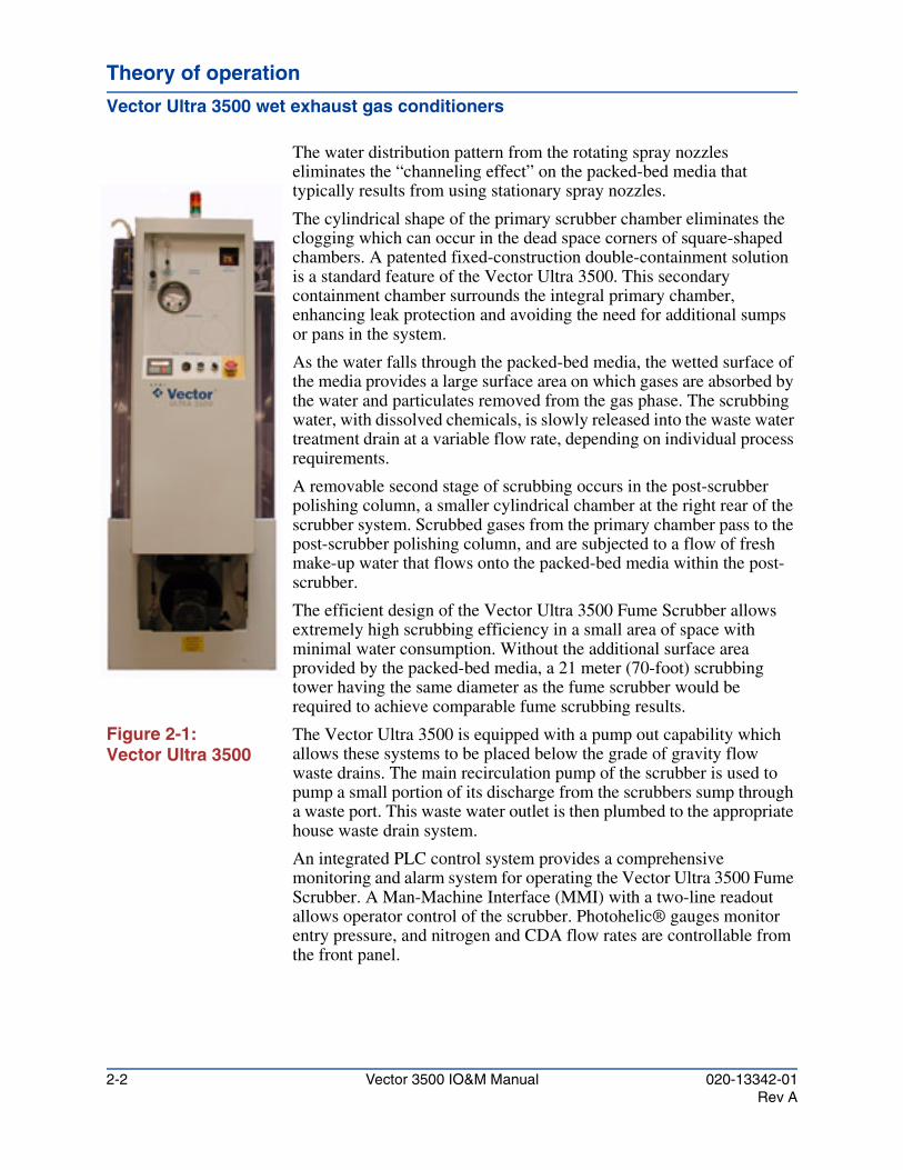
The water distribution pattern from the rotating spray nozzles eliminates the “channeling effect” on the packed-bed media that typically results from using stationary spray nozzles.
The cylindrical shape of the primary scrubber chamber eliminates the clogging which can occur in the dead space corners of square-shaped chambers. A patented fixed-construction double-containment solution is a standard feature of the Vector Ultra 3500. This secondary containment chamber surrounds the integral primary chamber, enhancing leak protection and avoiding the need for additional sumps or pans in the system.
As the water falls through the packed-bed media, the wetted surface of the media provides a large surface area on which gases are absorbed by the water and particulates removed from the gas phase. The scrubbing water, with dissolved chemicals, is slowly released into the waste water treatment drain at a variable flow rate, depending on individual process requirements.
A removable second stage of scrubbing occurs in the post-scrubber polishing column, a smaller cylindrical chamber at the right rear of the scrubber system. Scrubbed gases from the primary chamber pass to the post-scrubber polishing column, and are subjected to a flow of fresh make-up water that flows onto the packed-bed media within the post-scrubber.
The efficient design of the Vector Ultra 3500 Fume Scrubber allows extremely high scrubbing efficiency in a small area of space with minimal water consumption. Without the additional surface area provided by the packed-bed media, a 21 meter (70-foot) scrubbing tower having the same diameter as the fume scrubber would be required to achieve comparable fume scrubbing results.
Figure 2-1: Vector Ultra 3500
The Vector Ultra 3500 is equipped with a pump out capability which allows these systems to be placed below the grade of gravity flow waste drains. The main recirculation pump of the scrubber is used to pump a small portion of its discharge from the scrubbers sump through a waste port. This waste water outlet is then plumbed to the appropriate house waste drain system.
An integrated PLC control system provides a comprehensive monitoring and alarm system for operating the Vector Ultra 3500 Fume Scrubber. A Man-Machine Interface (MMI) with a two-line readout allows operator control of the scrubber. Photohelic® gauges monitor entry pressure, and nitrogen and CDA flow rates are controllable from the front panel.
2-2 Vector 3500 IO&M Manual 020-13342-01Rev A
Theory of operationTheory of operationTheory of operation
Entry device
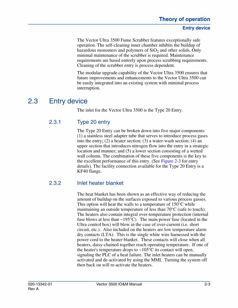
The Vector Ultra 3500 Fume Scrubber features exceptionally safe operation. The self-cleaning inner chamber inhibits the buildup of hazardous monomers and polymers of SiO2 and other solids. Only minimal maintenance of the scrubber is required. Maintenance requirements are based entirely upon process scrubbing requirements. Cleaning of the scrubber entry is process dependent.
The modular upgrade capability of the Vector Ultra 3500 ensures that future improvements and enhancements to the Vector Ultra 3500 can be easily integrated into an existing system with minimal process interruption.
2.3 Entry deviceThe inlet for the Vector Ultra 3500 is the Type 20 Entry.
2.3.1 Type 20 entry
The Type 20 Entry can be broken down into five major components: (1) a stainless steel adapter tube that serves to introduce process gases into the entry; (2) a heater section; (3) a water-wash section; (4) an upper section that introduces nitrogen flow into the entry in a strategic location and manner; and (5) a lower section consisting of a wetted wall column. The combination of these five components is the key to the excellent performance of this entry. (See Figure 2-3 for entry details). The facility connection available for the Type 20 Entry is a KF40 flange.
2.3.2 Inlet heater blanket
The heat blanket has been shown as an effective way of reducing the amount of buildup on the surfaces exposed to various process gasses. This option will heat the walls to a temperature of 150°C while maintaining an outside temperature of less than 70°C (safe to touch). The heaters also contain integral over-temperature protection (internal fuse blows at less than ~195°C). The main power fuse (located in the Ultra control box) will blow in the case of over-current (i.e. short circuit, etc.). Also included on the heaters are low temperature alarm dry contacts (LTA). This is the single white wire harnessed with the power cord to the heater blanket. These contacts will close when all heaters, daisy-chained together reach operating temperature. If one of the heater's temperature drops to ~105°C its contact will open, signaling the PLC of a heat failure. The inlet heaters can be manually activated and de-activated by using the MMI. Turning the system off then back on will re-activate the heaters.
020-13342-01 Vector 3500 IO&M Manual 2-3Rev A
Theory of operation
Entry device
2.3.3 Auto inlet water wash
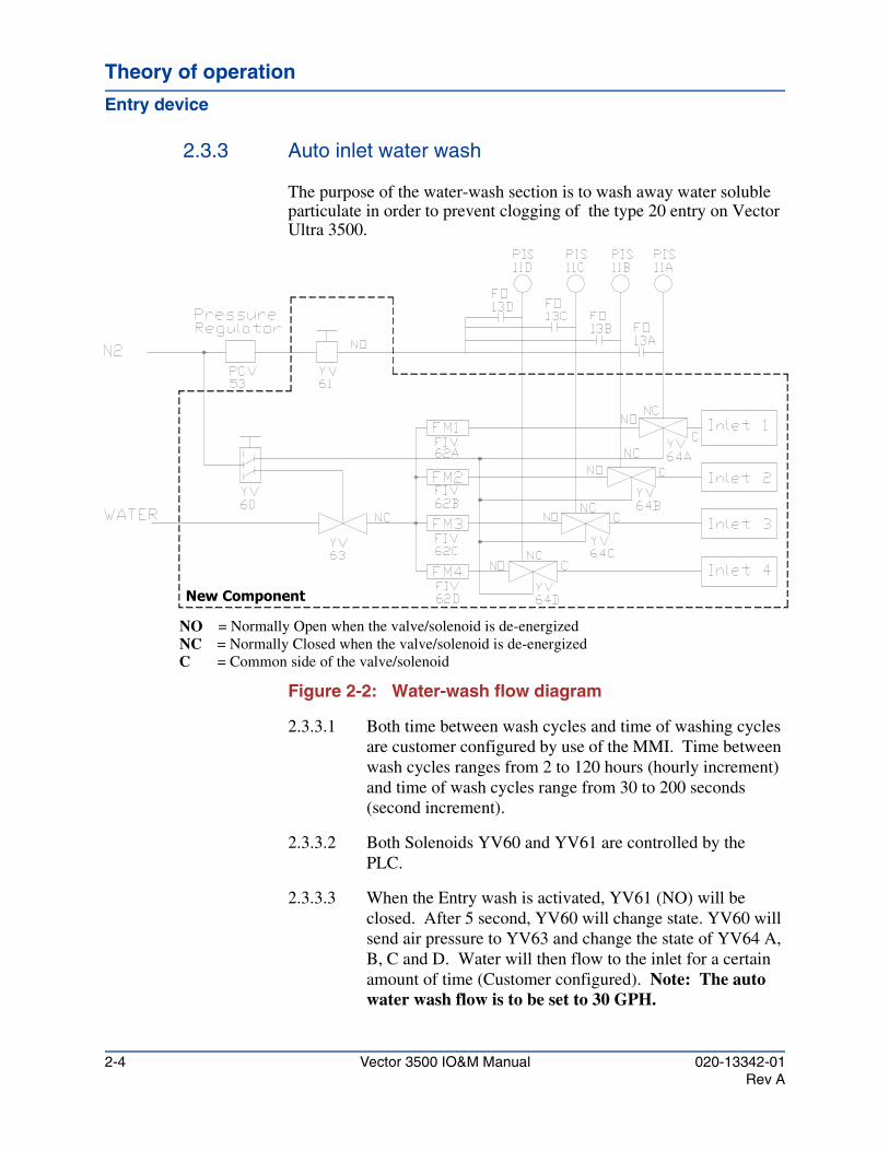
The purpose of the water-wash section is to wash away water soluble particulate in order to prevent clogging of the type 20 entry on Vector Ultra 3500.
Figure 2-2: Water-wash flow diagram
2.3.3.1 Both time between wash cycles and time of washing cycles are customer configured by use of the MMI. Time between wash cycles ranges from 2 to 120 hours (hourly increment) and time of wash cycles range from 30 to 200 seconds (second increment).
2.3.3.2 Both Solenoids YV60 and YV61 are controlled by the PLC.
2.3.3.3 When the Entry wash is activated, YV61 (NO) will be closed. After 5 second, YV60 will change state. YV60 will send air pressure to YV63 and change the state of YV64 A, B, C and D. Water will then flow to the inlet for a certain amount of time (Customer configured). Note: The auto water wash flow is to be set to 30 GPH.
New Component
NO = Normally Open when the valve/solenoid is de-energizedNC = Normally Closed when the valve/solenoid is de-energizedC = Common side of the valve/solenoid
2-4 Vector 3500 IO&M Manual 020-13342-01Rev A
Theory of operationTheory of operationTheory of operation
Entry device
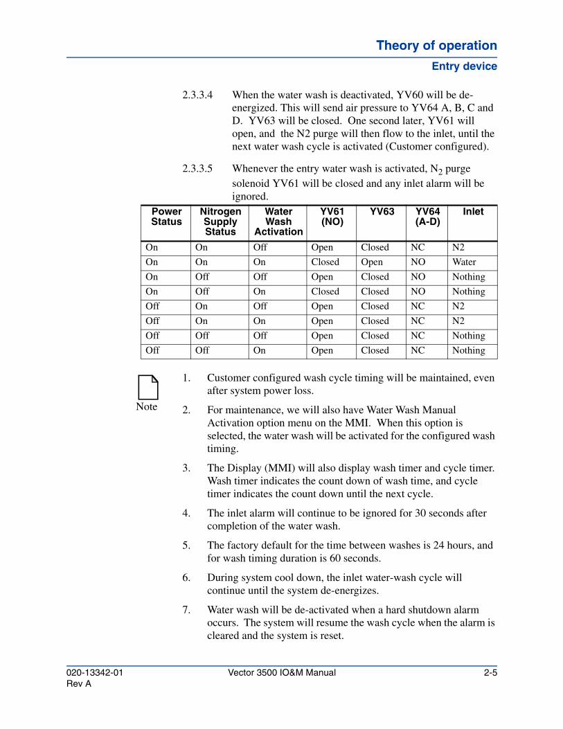
2.3.3.4 When the water wash is deactivated, YV60 will be de-energized. This will send air pressure to YV64 A, B, C and D. YV63 will be closed. One second later, YV61 will open, and the N2 purge will then flow to the inlet, until the next water wash cycle is activated (Customer configured).
2.3.3.5 Whenever the entry water wash is activated, N2 purge solenoid YV61 will be closed and any inlet alarm will be ignored.
Power Status
Nitrogen Supply Status
Water Wash
Activation
YV61 (NO)
YV63 YV64 (A-D)
Inlet
On On Off Open Closed NC N2
On On On Closed Open NO Water
On Off Off Open Closed NO Nothing
On Off On Closed Closed NO Nothing
Off On Off Open Closed NC N2
Off On On Open Closed NC N2
Off Off Off Open Closed NC Nothing
Off Off On Open Closed NC Nothing
Note
1. Customer configured wash cycle timing will be maintained, even after system power loss.
2. For maintenance, we will also have Water Wash Manual Activation option menu on the MMI. When this option is selected, the water wash will be activated for the configured wash timing.
3. The Display (MMI) will also display wash timer and cycle timer. Wash timer indicates the count down of wash time, and cycle timer indicates the count down until the next cycle.
4. The inlet alarm will continue to be ignored for 30 seconds after completion of the water wash.
5. The factory default for the time between washes is 24 hours, and for wash timing duration is 60 seconds.
6. During system cool down, the inlet water-wash cycle will continue until the system de-energizes.
7. Water wash will be de-activated when a hard shutdown alarm occurs. The system will resume the wash cycle when the alarm is cleared and the system is reset.
020-13342-01 Vector 3500 IO&M Manual 2-5Rev A
Theory of operation
Entry device
2.3.4 Nitrogen, porous wall
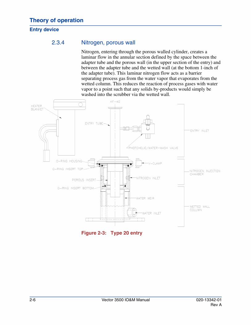
Nitrogen, entering through the porous walled cylinder, creates a laminar flow in the annular section defined by the space between the adapter tube and the porous wall (in the upper section of the entry) and between the adapter tube and the wetted wall (at the bottom 1-inch of the adapter tube). This laminar nitrogen flow acts as a barrier separating process gas from the water vapor that evaporates from the wetted column. This reduces the reaction of process gases with water vapor to a point such that any solids by-products would simply be washed into the scrubber via the wetted wall.
Figure 2-3: Type 20 entry
2-6 Vector 3500 IO&M Manual 020-13342-01Rev A
Vector 3500 Installation, Operation and Maintenance Manual
Facilities requirementsChapter 3
This chapter describes the proper location, site preparation, environment, clearances, and facilities requirements and connections for the Vector Ultra 3500 Wet Exhaust Gas Conditioner.
3.1 Site location requirementsLocate the Vector Ultra 3500 system in an area that is:
• Well-illuminated
• Well-ventilated
• Easily accessible to maintenance personnel
• Situated so that dust and/or particulate that may escape during maintenance will not contaminate other areas or equipment.
Site preparation should be completed prior to fume scrubber installation. Site preparation includes important system design considerations such as resource requirements, space requirements, floor/roof weight loading considerations, waste water treatment, and equipment alarms.
Plumbing requirements and plumbing installation instructions are provided for Scrubber-to-Process, Scrubber-to- Drain Line, Scrubber-to-Water Supply, and Scrubber-to-Nitrogen Line connections (refer to Section 3.4, "Facilities requirements" for more connection information).
Special site preparation considerations for installations requiring extra scrubber stabilization are discussed in Section 4.5, "Seismic mounting". Scrubber stabilization is required for building installations in earthquake-prone areas and for external-building installations in windy areas.
020-13342-01 Vector 3500 IO&M Manual 3-1Rev A

Facilities requirements
Environment
Site preparation begins with locating the site of the fume scrubber(s). Whether the fume scrubber will be located inside or outside the facility, essential resources must be supplied. The following resources are described in the indicated sections.
• Scrubber Inlet (Section 4.6.2)
• Scrubber Exhaust (Section 4.6.3)
• Water (Section 4.6.5)
• Waste Water Drain (Section 4.6.6)
• Nitrogen (Section 4.6.7)
• Electricity (Section 4.6.8)
3.2 EnvironmentThe optimal Vector Ultra 3500 environment should be maintained at a temperature of 25° C (±5° C), and a relative humidity of <70%.
The Vector Ultra 3500 Fume Scrubber is designed for all environments above 0o C (32o F). Scrubbers can be either installed indoors or outdoors. Specific system design considerations are necessary for either location. Scrubbers that are subject to freezing temperatures (below 0o C or 32o F) must be prevented from freezing by external heating.
3.2.1 Interior location
If the fume scrubber is to be located inside the facility and in close proximity to personnel, it is highly recommended to install the scrubber in a well ventilated area.
3.2.2 Exterior location
If the fume scrubber is to be located outside the building, ATMI requires installation in an enclosure to minimize the harmful effects of ultraviolet light on the scrubber’s PVC plastic materials and to keep rain off the system.
CAUTION!
In environments subject to freezing, the fume scrubber must not be allowed to freeze. The expansion of the ice formed may burst the tank or plumbing system.
3-2 Vector 3500 IO&M Manual 020-13342-01Rev A
Facilities requirementsFacilities requirementsFacilities requirements
Clearance
3.2.3 Roof installation
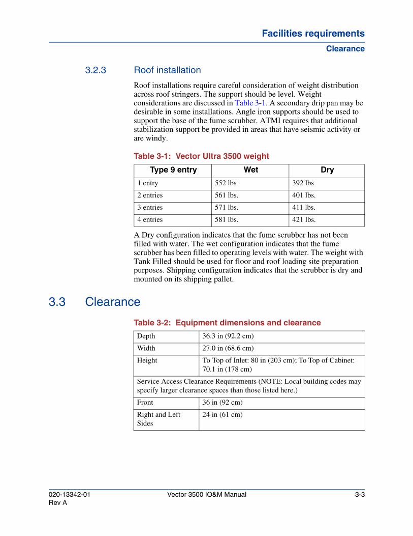
Roof installations require careful consideration of weight distribution across roof stringers. The support should be level. Weight considerations are discussed in Table 3-1. A secondary drip pan may be desirable in some installations. Angle iron supports should be used to support the base of the fume scrubber. ATMI requires that additional stabilization support be provided in areas that have seismic activity or are windy.
Table 3-1: Vector Ultra 3500 weight
A Dry configuration indicates that the fume scrubber has not been filled with water. The wet configuration indicates that the fume scrubber has been filled to operating levels with water. The weight with Tank Filled should be used for floor and roof loading site preparation purposes. Shipping configuration indicates that the scrubber is dry and mounted on its shipping pallet.
3.3 Clearance
Table 3-2: Equipment dimensions and clearance
Type 9 entry Wet Dry
1 entry 552 lbs 392 lbs
2 entries 561 lbs. 401 lbs.
3 entries 571 lbs. 411 lbs.
4 entries 581 lbs. 421 lbs.
Depth 36.3 in (92.2 cm)
Width 27.0 in (68.6 cm)
Height To Top of Inlet: 80 in (203 cm); To Top of Cabinet: 70.1 in (178 cm)
Service Access Clearance Requirements (NOTE: Local building codes may specify larger clearance spaces than those listed here.)
Front 36 in (92 cm)
Right and Left Sides
24 in (61 cm)
020-13342-01 Vector 3500 IO&M Manual 3-3Rev A
Facilities requirements
Facilities requirements
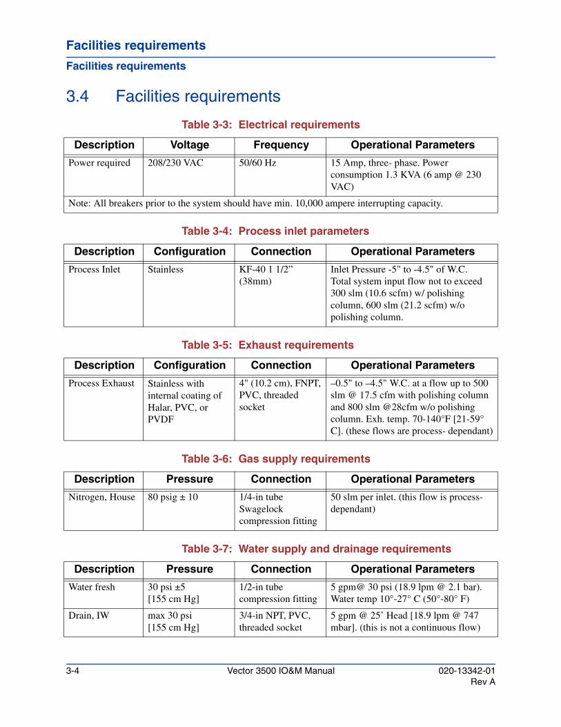
3.4 Facilities requirements
Table 3-3: Electrical requirements
Table 3-4: Process inlet parameters
Table 3-5: Exhaust requirements
Table 3-6: Gas supply requirements
Table 3-7: Water supply and drainage requirements
Description Voltage Frequency Operational Parameters
Power required 208/230 VAC 50/60 Hz 15 Amp, three- phase. Power consumption 1.3 KVA (6 amp @ 230 VAC)
Note: All breakers prior to the system should have min. 10,000 ampere interrupting capacity.
Description Configuration Connection Operational Parameters
Process Inlet Stainless KF-40 1 1/2” (38mm)
Inlet Pressure -5" to -4.5" of W.C.Total system input flow not to exceed 300 slm (10.6 scfm) w/ polishing column, 600 slm (21.2 scfm) w/o polishing column.
Description Configuration Connection Operational Parameters
Process Exhaust Stainless with internal coating of Halar, PVC, or PVDF
4" (10.2 cm), FNPT, PVC, threaded socket
–0.5" to –4.5" W.C. at a flow up to 500 slm @ 17.5 cfm with polishing column and 800 slm @28cfm w/o polishing column. Exh. temp. 70-140°F [21-59° C]. (these flows are process- dependant)
Description Pressure Connection Operational Parameters
Nitrogen, House 80 psig ± 10 1/4-in tube Swagelock compression fitting
50 slm per inlet. (this flow is process-dependant)
Description Pressure Connection Operational Parameters
Water fresh 30 psi ±5[155 cm Hg]
1/2-in tube compression fitting
5 gpm@ 30 psi (18.9 lpm @ 2.1 bar). Water temp 10°-27° C (50°-80° F)
Drain, IW max 30 psi[155 cm Hg]
3/4-in NPT, PVC, threaded socket
5 gpm @ 25’ Head [18.9 lpm @ 747 mbar]. (this is not a continuous flow)
3-4 Vector 3500 IO&M Manual 020-13342-01Rev A
Vector 3500 Installation, Operation and Maintenance Manual
Installing Vector 3500Chapter 4
4.1 IntroductionThis chapter provides the site preparation requirements, facility requirements and installation procedures for the Vector Ultra 3500 Fume Scrubber.
ATMI carefully inspects all systems through a rigorous quality control program prior to shipment. Inspect the Vector Ultra 3500 when un-crating to ensure that shock and trip indicators have not been tripped during shipment. Prior to installation ensure that flanges and fittings are tight and electrical components are still seated properly.
4.2 ReceiptVector Ultra 3500 systems and parts may be shipped in one or more containers. Each packing slip indicates the number of crates. Report any signs of rough handling or damage during shipment to the transportation carrier. Inspect all equipment and/or parts after removal from shipping containers.
WARNING!Certain processes may contain gases which possess toxic, flammable and/or corrosive characteristics. Consult with you local facilities/safety jurisdiction for handling requirements and regulations for these gases when installing the tool and process gas lines.
Note
Report any broken, damaged, or missing parts immediately to ATMI Corp., Central Services, at (888) 432-6797 or Internationally at (707) 299-3939.
020-13342-01 Vector 3500 IO&M Manual 4-1Rev A
Installing Vector 3500
Unpacking
4.3 UnpackingThis section provides instructions on how to properly unpack the Vector Ultra 3500 shipping crates, inspect for damage, and inventory the shipment. The total number of boxes you have received depends upon the options that you chose when you purchased your Vector Ultra 3500 Fume Scrubber system. Your shipment has arrived either fully crated or banded on an open skid. Your responsibility begins when the shipment arrives.
4.3.1 Preliminary shipment inspection
To perform the preliminary shipment inspection, follow these steps:
4.3.1.1 Inspect the Tip-N-Tell indicator(s) to determine if the shipment was improperly handled by the shippers. If any blue beads are found in the upper part of the arrow, the shipment was improperly tipped.
4.3.1.2 Inspect the crate(s) for visible damage.
4.3.1.3 If the shipment is on an open skid, open the shipping papers and use the shipping inventory to conduct a preliminary inspection and inventory of all visible components.
WARNING!The shipping containers are heavy. Do not attempt to move the containers manually.
CAUTION!
Do not store the fume scrubber in direct sunlight. Excessive heat can damage components. Shipping seals prevent sufficient ventilation if stored in the sun. The unit must be covered if it is un-crated and sitting in direct sunlight.
Note
Do not begin to unpack the shipment at this time. First perform a critical shipment inspection. If shipment inspection is not performed properly, warranties may be voided.
4-2 Vector 3500 IO&M Manual 020-13342-01Rev A
Installing Vector 3500Installing Vector 3500Installing Vector 3500
Unpacking
4.3.1.4 If any problems were found in Steps 4.3.1.1 to 4.3.1.3, immediately:
• Notify your ATMI representative,
• Notify the carrier, and
• Make certain that the carriers shipping papers indicate the problem.
4.3.2 Opening the crate and inspecting the scrubber
4.3.2.1 If the shipment is banded on an open skid, remove the plastic shipping cover material. Do not remove the shipping bands at this time.
4.3.2.2 If the shipment is full-crated, use a crowbar to first carefully remove the top of the wooden crate, then remove the sides. Try to minimize damage to the crate in the event that the fume scrubber has been damaged and will need to be reshipped in the same crate.
4.3.2.3 Continue unpacking the fume scrubber until the Cover Door located on the bottom of the base is exposed. Remove the Cover Door by grasping and pulling.
4.3.2.4 If the shipment was full-crated, open the shipping papers and use the shipping inventory to conduct a detailed inspection and inventory of all visible components. Report any discrepancies.
CAUTION!
When un-crating the shipment, extreme care should be used to ensure that unpacking tools do not protrude into the crate and damage the fume scrubber.
Note
It is normal to find moisture inside the fume scrubber when the crate is opened. This is residual clean water from pre-shipping tests conducted at the factory.
020-13342-01 Vector 3500 IO&M Manual 4-3Rev A
Installing Vector 3500
Moving the system into position
4.3.2.5 If any problems are evident in steps 4.3.2.1 through 4.3.2.4, immediately:
• Notify your ATMI representative
• Notify the carrier
• Make certain that the carriers shipping papers are modified to indicate the problem. If the shipment papers are not available, call the carrier and have him enter the required report information on the shipping papers.
4.3.3 Removal of shipping plugs
After the Vector Ultra 3500 has been un-crated, remove all shipping plugs (the plastic inserts that protect the inlet and outlet piping). Remove the packing tape located at the front-top-side ventilation slot. This slot must be open for motor cooling. If all of the components in your shipment have been safely received, the next step is to install and test your Vector Ultra 3500 Wet Exhaust Gas Conditioner.
4.4 Moving the system into position1. Move the Vector (still banded to its shipping pallet) to the
installation site. If the unit is to be mounted on the roof of the facility or lifted into position nylon lifting straps should be used. Use double nylon straps around the scrubber. Tie the nylon straps at four places so that they will not slip while lifting.
2. Remove the final packing supports and lift the fume scrubber to its prepared installation site.
Note
Do not remove the final strapping of the fume scrubber to the pallet until the unit has been moved to its installation site.
WARNING!
The fume scrubber is very heavy. Use two or more people to lift it from the palette to the prepared installation site.
CAUTION!
When lifting the fume scrubber from its palette, support the scrubber by its base only. Do not grip from the units pipes, valves, instrument panels, or any appendages.
4-4 Vector 3500 IO&M Manual 020-13342-01Rev A
Installing Vector 3500Installing Vector 3500Installing Vector 3500
Seismic mounting
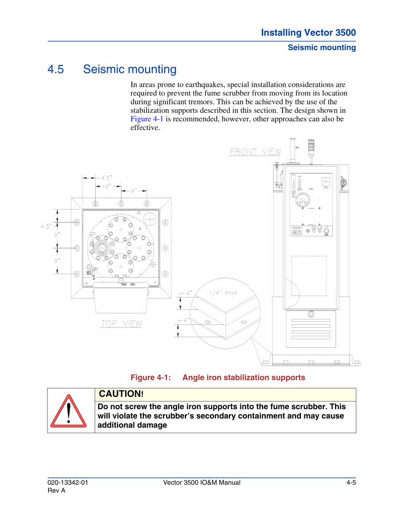
4.5 Seismic mountingIn areas prone to earthquakes, special installation considerations are required to prevent the fume scrubber from moving from its location during significant tremors. This can be achieved by the use of the stabilization supports described in this section. The design shown in Figure 4-1 is recommended, however, other approaches can also be effective.
Figure 4-1: Angle iron stabilization supports
3 Entry Pressure
Run / Reset Stop
EMO
4
Start
1
EntryN2 Purge
Entry Pressure
N2 PurgePhotohelics
ChemicalController
2
DisconnectPower
CAUTION!
Do not screw the angle iron supports into the fume scrubber. This will violate the scrubber’s secondary containment and may cause additional damage
020-13342-01 Vector 3500 IO&M Manual 4-5Rev A

Installing Vector 3500
Vector Ultra 3500 system installation
The primary concern during an earthquake is to prevent walking of the fume scrubber. Walking can be prevented by the use of angle iron supports (4" x 4" x 1/4" - shown in Figure 4-1). Angle iron brackets are positioned around the base of the fume scrubber so that they are touching, but are not attached to the fume scrubber. These angle irons are attached to the floor or roof using Hilti HVA adhesive anchors or its equivalent with the following specifications: anchor diameter 3/8", embedment depth 3.5".
The existing concrete slab on which the scrubber will sit should have a minimum od 2000 psi in compressive strength and a minimum thickness of 4". The steel angles must fit and touch the surface of the scrubber.
4.6 Vector Ultra 3500 system installationThis section provides installation and checkout procedures for the Vector Ultra 3500 Fume Scrubber. Before beginning the installation procedures, the procedures in Chapter 3, "Facilities requirements" and section 4.3, "Unpacking" must be completed. During installation, refer to Chapter 12 for schematics and diagrams when needed.
4.6.1 Installing the fume scrubber
WARNING!Certain processes may contain gases which possess toxic, flammable and/or corrosive characteristics. Consult with you local facilities/safety jurisdiction for handling requirements and regulations for these gases when installing the tool and process gas lines.
CAUTION!
Proper installation of the Vector Ultra 3500™ is absolutely essential!
CAUTION!
Many of the connections that you will be making during installation require the tightening of plastic pipe fittings. DO NOT use metal pipe nipples to connect the scrubber to the facilities piping. The plastic in the scrubber will crack if metal fittings are used and torqued too tight. Use Teflon Tape on all pipe fittings.
4-6 Vector 3500 IO&M Manual 020-13342-01Rev A
Installing Vector 3500Installing Vector 3500Installing Vector 3500
Vector Ultra 3500 system installation
4.6.1.1 Mount the Fume Scrubber level, i.e. 1o bubble.
4.6.1.2 Flush the facilities make-up water line to remove construction debris.
4.6.1.3 Install the make-up water to the fume scrubber’s 1/2-inch compression fitting makeup water inlet. Make sure the water pressure is regulated to 30 ± 5 PSI. Reference Section 4.6.5.2.
4.6.1.4 As part of the facility installation, the water supply line should have been installed with a local point-of-use connection valve, filter-strainer, regulator, and a supply pressure gauge.
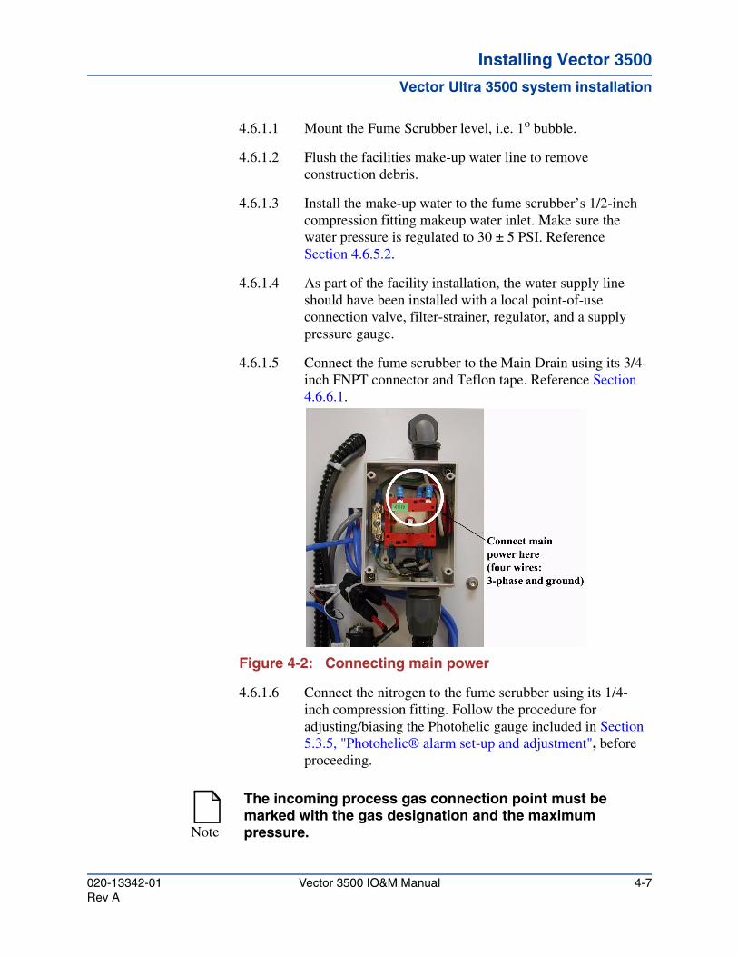
4.6.1.5 Connect the fume scrubber to the Main Drain using its 3/4-inch FNPT connector and Teflon tape. Reference Section 4.6.6.1.
Figure 4-2: Connecting main power
4.6.1.6 Connect the nitrogen to the fume scrubber using its 1/4-inch compression fitting. Follow the procedure for adjusting/biasing the Photohelic gauge included in Section 5.3.5, "Photohelic® alarm set-up and adjustment", before proceeding.
Note
The incoming process gas connection point must be marked with the gas designation and the maximum pressure.
020-13342-01 Vector 3500 IO&M Manual 4-7Rev A
Installing Vector 3500
Vector Ultra 3500 system installation
4.6.1.7 Connect the scrubber’s gas inlet(s) to the exhaust manifold of the reactor. Use the procedures described in Section 4.6.3, "Process chamber effluent".
4.6.1.8 Connect the scrubber’s exhaust port to the house scrubber exhaust system. Reference Section 4.6.4, "House exhaust"".
4.6.1.9 Install electrical power to the Fume Scrubber at the Main Power Disconnect Box (see Figure 4-2) using the Electrical Installation Drawing in Chapter 12, and the directions in Section 4.6.8, "Electrical power supply".
4.6.1.10 Connect the alarm interface as required.
4.6.1.11 Check Appendix B for information about any special installation procedures required for your Vector Ultra 3500 options. Perform all specified option installation procedures now.
4.6.2 Type 20 entry set-up
After the scrubber has been installed, the nitrogen supply can be adjusted. Make sure the scrubber is level in order to avoid dry spot formation in the wetted wall column.
4.6.2.1 Water
The tip-over water flow rate is set by the flow orifice provided. Confirm the water flow rate by observing the water flowing over the tip-over column, using the following procedure (see Figure 4-3).
1. Disconnect the Photohelic® water-wash tubing.
2. Disconnect the heater power cables.
CAUTION!An interlock between the scrubber and the process tool should be made in order to shut down the flow of gas from the tool in the event of a scrubber shutdown due to an alarm condition.
WARNING!Do not attempt to use the fume scrubber system with any process gases before performing the complete Checkout Procedure given in Section 4.7.
4-8 Vector 3500 IO&M Manual 020-13342-01Rev A
Installing Vector 3500Installing Vector 3500Installing Vector 3500
Vector Ultra 3500 system installation
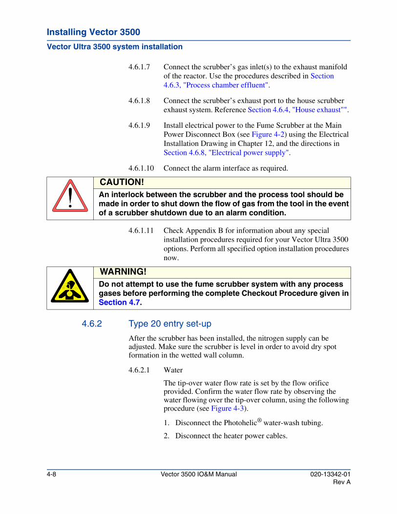
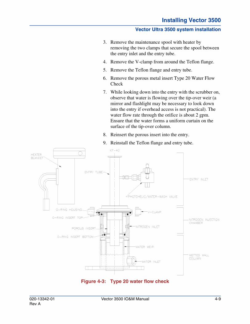
3. Remove the maintenance spool with heater by removing the two clamps that secure the spool between the entry inlet and the entry tube.
4. Remove the V-clamp from around the Teflon flange.
5. Remove the Teflon flange and entry tube.
6. Remove the porous metal insert Type 20 Water Flow Check
7. While looking down into the entry with the scrubber on, observe that water is flowing over the tip-over weir (a mirror and flashlight may be necessary to look down into the entry if overhead access is not practical). The water flow rate through the orifice is about 2 gpm. Ensure that the water forms a uniform curtain on the surface of the tip-over column.
8. Reinsert the porous insert into the entry.
9. Reinstall the Teflon flange and entry tube.
Figure 4-3: Type 20 water flow check
020-13342-01 Vector 3500 IO&M Manual 4-9Rev A
Installing Vector 3500
Vector Ultra 3500 system installation
10. Reinstall the V-clamp around the Teflon flange.
11. Reinstall the maintenance spool with heater and its two securing clamps.
12. Reconnect the power inputs.
13. Tighten all connections.
4.6.2.2 Inlet water-wash
The inlet water-wash system should be checked for flow and leaks. By using the MMI the operator can turn the inlet water-wash on and off. Refer to section 5.2.9, "Auto water wash" for how to control the inlet water wash using the MMI.
4.6.2.3 Nitrogen
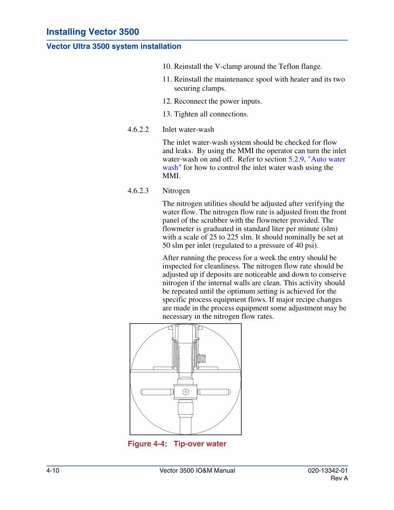
The nitrogen utilities should be adjusted after verifying the water flow. The nitrogen flow rate is adjusted from the front panel of the scrubber with the flowmeter provided. The flowmeter is graduated in standard liter per minute (slm) with a scale of 25 to 225 slm. It should nominally be set at 50 slm per inlet (regulated to a pressure of 40 psi).
After running the process for a week the entry should be inspected for cleanliness. The nitrogen flow rate should be adjusted up if deposits are noticeable and down to conserve nitrogen if the internal walls are clean. This activity should be repeated until the optimum setting is achieved for the specific process equipment flows. If major recipe changes are made in the process equipment some adjustment may be necessary in the nitrogen flow rates.
Figure 4-4: Tip-over water
4-10 Vector 3500 IO&M Manual 020-13342-01Rev A
Installing Vector 3500Installing Vector 3500Installing Vector 3500
Vector Ultra 3500 system installation
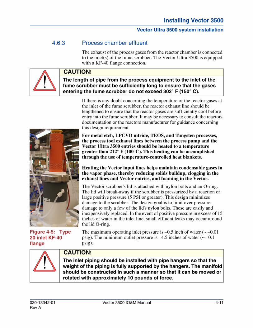
4.6.3 Process chamber effluent
The exhaust of the process gases from the reactor chamber is connected to the inlet(s) of the fume scrubber. The Vector Ultra 3500 is equipped with a KF-40 flange connection.
If there is any doubt concerning the temperature of the reactor gases at the inlet of the fume scrubber, the reactor exhaust line should be lengthened to ensure that the reactor gases are sufficiently cool before entry into the fume scrubber. It may be necessary to consult the reactors documentation or the reactors manufacturer for guidance concerning this design requirement.
For metal etch, LPCVD nitride, TEOS, and Tungsten processes, the process tool exhaust lines between the process pump and the Vector Ultra 3500 entries should be heated to a temperature greater than 212° F (100°C). This heating can be accomplished through the use of temperature-controlled heat blankets.
Heating the Vector input lines helps maintain condensable gases in the vapor phase, thereby reducing solids buildup, clogging in the exhaust lines and Vector entries, and foaming in the Vector.
The Vector scrubber's lid is attached with nylon bolts and an O-ring. The lid will break-away if the scrubber is pressurized by a reaction or large positive pressure (5 PSI or greater). This design minimizes damage to the scrubber. The design goal is to limit over pressure damage to only a few of the lid's nylon bolts. These are easily and inexpensively replaced. In the event of positive pressure in excess of 15 inches of water in the inlet line, small effluent leaks may occur around the lid O-ring.
Figure 4-5: Type 20 inlet KF-40 flange
The maximum operating inlet pressure is –0.5 inch of water (~ –0.01 psig). The minimum outlet pressure is –4.5 inches of water (~ –0.1 psig).
CAUTION!
The length of pipe from the process equipment to the inlet of the fume scrubber must be sufficiently long to ensure that the gases entering the fume scrubber do not exceed 302° F (150° C).
CAUTION!
The inlet piping should be installed with pipe hangers so that the weight of the piping is fully supported by the hangers. The manifold should be constructed in such a manner so that it can be moved or rotated with approximately 10 pounds of force.
020-13342-01 Vector 3500 IO&M Manual 4-11Rev A
Installing Vector 3500
Vector Ultra 3500 system installation
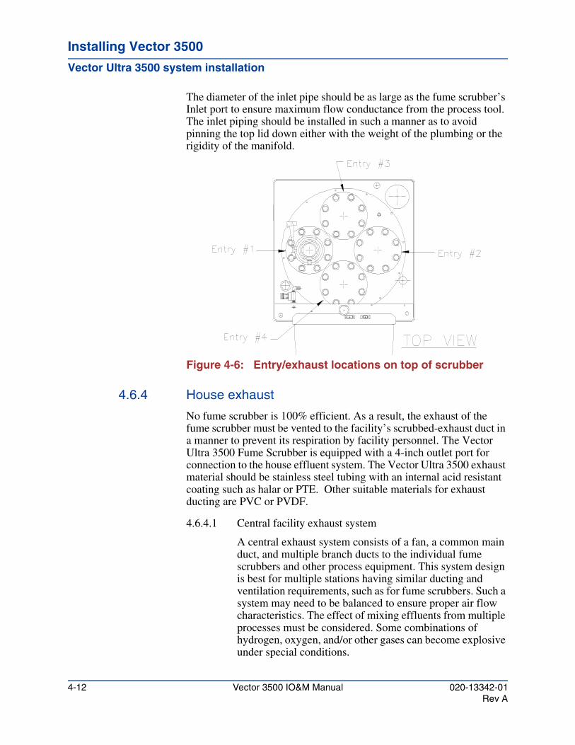
The diameter of the inlet pipe should be as large as the fume scrubber’s Inlet port to ensure maximum flow conductance from the process tool. The inlet piping should be installed in such a manner as to avoid pinning the top lid down either with the weight of the plumbing or the rigidity of the manifold.
Figure 4-6: Entry/exhaust locations on top of scrubber
4.6.4 House exhaust
No fume scrubber is 100% efficient. As a result, the exhaust of the fume scrubber must be vented to the facility’s scrubbed-exhaust duct in a manner to prevent its respiration by facility personnel. The Vector Ultra 3500 Fume Scrubber is equipped with a 4-inch outlet port for connection to the house effluent system. The Vector Ultra 3500 exhaust material should be stainless steel tubing with an internal acid resistant coating such as halar or PTE. Other suitable materials for exhaust ducting are PVC or PVDF.
4.6.4.1 Central facility exhaust system
A central exhaust system consists of a fan, a common main duct, and multiple branch ducts to the individual fume scrubbers and other process equipment. This system design is best for multiple stations having similar ducting and ventilation requirements, such as for fume scrubbers. Such a system may need to be balanced to ensure proper air flow characteristics. The effect of mixing effluents from multiple processes must be considered. Some combinations of hydrogen, oxygen, and/or other gases can become explosive under special conditions.
4-12 Vector 3500 IO&M Manual 020-13342-01Rev A
Installing Vector 3500Installing Vector 3500Installing Vector 3500
Vector Ultra 3500 system installation
All venting duct work should be sealed air tight. Dampers may be installed in the exhaust lines to regulate the draw through the duct. ATMI does not recommend the use of positive closing valves in the scrubbers exhaust duct. Accidental closure of the valve during operation of the process equipment's vacuum pump can over-pressure the scrubber's barrel and cause serious damage.
All exhaust plumbing should be installed with a negative slope, eliminating any horizontal pipe runs or low points, and preventing any potential condensate pooling or collection in the exhaust piping.
The fume scrubber can develop a slight positive pressure at the exhaust if exhaust from the fume scrubber is piped to a secondary high negative vent system, care should be taken not to exceed a 4.5-inch negative water column pressure at the fume scrubber’s vent.
4.6.4.2 Exhaust fans and duct work
Exhaust fans that handle the venting of fume scrubbers should always be located outside of occupied buildings and be as close as possible to the point of discharge. All venting duct work should be sealed air tight. The exhaust fans discharge should be connected to a vertical stack without connection to other exhaust vents. Dampers may be installed in the exhaust lines to regulate the draw through the duct. ATMI does not recommend the use of positive closing valves in the scrubbers exhaust duct. Accidental closure of the valve during operation of the process equipment's vacuum pump can over-pressure the scrubber's barrel and cause serious damage.
Discharged gases from the exhaust fan should enter a vertical stack that extends above the roof line in accordance with local code requirements. Exhaust fans should flow at a velocity in conformance with the facility air handling system.
System design should ensure that the discharged gases are directed away from all present and future fresh air intakes. Vertical stack terminators such as rain-caps should be avoided since these will re-direct the vented gases down toward the roof where fresh air intakes may be located. A tee termination is often used to terminate vertical stacks. All exhaust plumbing should be installed in such a manner as to eliminate any horizontal pipe runs and prevent any potential condensation blockage in the exhaust piping.
020-13342-01 Vector 3500 IO&M Manual 4-13Rev A
Installing Vector 3500
Vector Ultra 3500 system installation
The fume scrubber can develop a slight positive pressure at the exhaust if exhaust from the fume scrubber is piped to a secondary high negative vent system. Care should be taken not to exceed a 5-inch negative water column pressure at the fume scrubber’s vent.
4.6.5 Water supply
4.6.5.1 Water quality specification
This section contains information regarding source water quality requirements for the Vector Scrubbers, the justification for these requirements guide for managing water quality issues. Operationally, the Vector requires a continuous supply of fresh make-up water for abatement. Water quality can vary significantly between regions and sites around the world and can effect system reliability and time between maintenance. Waters high in mineral content, e.g. hard waters, and those that have sufficient nutrients to promote biological growth are examples of water quality issues. These issues can impact scrubber performance by creating conditions that can lead to solids precipitation (scaling) and/or biological fouling. Additionally, process tool operational conditions can create extreme pH levels in the Vector's recirculation sump solution. The sump pH may be continuously acidic or basic, or may cycle between the extremes. These operational conditions combined with water quality issues can exacerbate scaling or fouling of components.
As an example when the Vector 5001 is utilized on an plasma enhanced chemical vapor deposition (PECVD) silicon nitride process, the sump will typically be at a pH > 10 during deposition and will periodically go to pH <4 for a short periods during in-situ nitrogen trifluoride (NF3) chamber cleans. In the silicon nitride example, the high pH in combination with a hard source of make-up water will lead to excessive precipitation of solids, such as Ca (OH)2, CaCO3, MgCO3, in the Vector. This precipitation can lead to lowered destruction removal efficiency (DRE), system failure, or more frequent preventive maintenance (PM) requirements if left unchecked. Some examples of these potential scenarios are as follows:
4-14 Vector 3500 IO&M Manual 020-13342-01Rev A
Installing Vector 3500Installing Vector 3500Installing Vector 3500
Vector Ultra 3500 system installation
1. Clogged/Fouled Packing- Excessive scale accumulation or biological fouling of the packing material may lead to excessive pressure drop an/or channeling across the packing column. Destruction removal efficiency (DRE) may be reduced if the Vector is operated under these conditions. Lengthy downtime may be required to chemically clean or replace the packing material and/or other components.
2. Entry Clogging- The orifices that supply, and distribute, recirculated sump water to the entry tip over cup water can become clogged. When this occurs, flow rates may decrease and cause premature failure of the entries due to excessive particulate build-up on the wetted walls.
3. Recirculation Pump Seizure- The pump that feeds the spray bar and entry tip over cup may seize due to scale accumulation on the pump impeller. Additionally, the spray bar may cease to rotate or the spray nozzles may become clogged.
In order to negate or eliminate these types of failures, ATMI requires the use of make-up water that meets the specifications called out in Table 4-1.
In the event that an issue similar to those listed above, occurs as a result of not meeting ATMI's water quality specification, several courses of action are available. These actions include establishing regular preventive maintenance routines and/or working with a local water treatment professional to establish how best to mitigate any issues that arise as a result of using a water source that is not within ATMI's specification.
4.6.5.2 Make up water supply line
The water supply must be able to provide a minimum of 5 gallons per minute (18 liters per minute) for the Vector Ultra 3500. This flow rate is for filling and flushing the system.
The installation of an in-line pressure regulator before the fume scrubber connection point is required. The incoming water supply pressure must not exceed 35 psig or excessive hammering of the inlet manifold can occur.
If particulates are in the water supply, an in-line particulate filter must be used before the fume scrubber connection point.
020-13342-01 Vector 3500 IO&M Manual 4-15Rev A
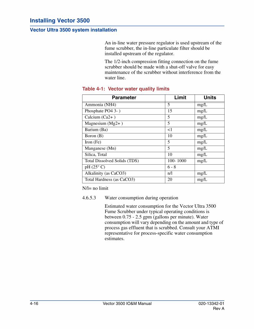
Installing Vector 3500
Vector Ultra 3500 system installation
An in-line water pressure regulator is used upstream of the fume scrubber, the in-line particulate filter should be installed upstream of the regulator.
The 1/2-inch compression fitting connection on the fume scrubber should be made with a shut-off valve for easy maintenance of the scrubber without interference from the water line.
Table 4-1: Vector water quality limits
N/l= no limit
4.6.5.3 Water consumption during operation
Estimated water consumption for the Vector Ultra 3500 Fume Scrubber under typical operating conditions is between 0.75 - 2.5 gpm (gallons per minute). Water consumption will vary depending on the amount and type of process gas effluent that is scrubbed. Consult your ATMI representative for process-specific water consumption estimates.
Parameter Limit UnitsAmmonia (NH4) 5 mg/LPhosphate PO4 3- ) 15 mg/LCalcium (Ca2+ ) 5 mg/LMagnesium (Mg2+ ) 5 mg/LBarium (Ba) <1 mg/LBoron (B) 10 mg/LIron (Fe) 5 mg/LManganese (Mn) 5 mg/LSilica, Total 10 mg/LTotal Dissolved Solids (TDS) 100- 1000 mg/LpH (25° C) 6 - 8Alkalinity (as CaCO3) n/l mg/LTotal Hardness (as CaCO3) 20 mg/L
4-16 Vector 3500 IO&M Manual 020-13342-01Rev A
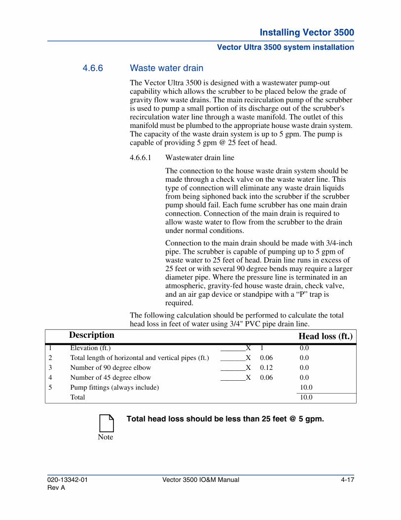
Installing Vector 3500Installing Vector 3500Installing Vector 3500
Vector Ultra 3500 system installation
4.6.6 Waste water drain
The Vector Ultra 3500 is designed with a wastewater pump-out capability which allows the scrubber to be placed below the grade of gravity flow waste drains. The main recirculation pump of the scrubber is used to pump a small portion of its discharge out of the scrubber's recirculation water line through a waste manifold. The outlet of this manifold must be plumbed to the appropriate house waste drain system. The capacity of the waste drain system is up to 5 gpm. The pump is capable of providing 5 gpm @ 25 feet of head.
4.6.6.1 Wastewater drain line
The connection to the house waste drain system should be made through a check valve on the waste water line. This type of connection will eliminate any waste drain liquids from being siphoned back into the scrubber if the scrubber pump should fail. Each fume scrubber has one main drain connection. Connection of the main drain is required to allow waste water to flow from the scrubber to the drain under normal conditions.
Connection to the main drain should be made with 3/4-inch pipe. The scrubber is capable of pumping up to 5 gpm of waste water to 25 feet of head. Drain line runs in excess of 25 feet or with several 90 degree bends may require a larger diameter pipe. Where the pressure line is terminated in an atmospheric, gravity-fed house waste drain, check valve, and an air gap device or standpipe with a “P” trap is required.
The following calculation should be performed to calculate the total head loss in feet of water using 3/4" PVC pipe drain line.
Description Head loss (ft.)1 Elevation (ft.) _______X 1 0.02 Total length of horizontal and vertical pipes (ft.) _______X 0.06 0.03 Number of 90 degree elbow _______X 0.12 0.04 Number of 45 degree elbow _______X 0.06 0.05 Pump fittings (always include) 10.0
Total 10.0
Note
Total head loss should be less than 25 feet @ 5 gpm.
020-13342-01 Vector 3500 IO&M Manual 4-17Rev A
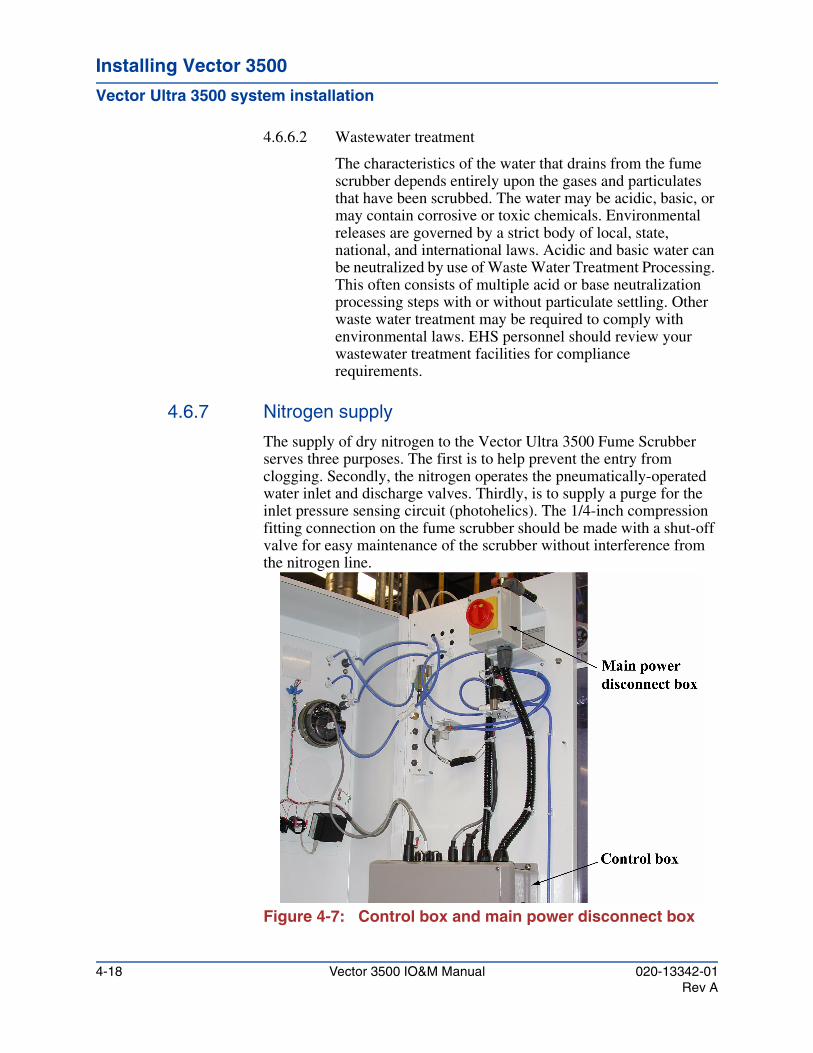
Installing Vector 3500
Vector Ultra 3500 system installation
4.6.6.2 Wastewater treatment
The characteristics of the water that drains from the fume scrubber depends entirely upon the gases and particulates that have been scrubbed. The water may be acidic, basic, or may contain corrosive or toxic chemicals. Environmental releases are governed by a strict body of local, state, national, and international laws. Acidic and basic water can be neutralized by use of Waste Water Treatment Processing. This often consists of multiple acid or base neutralization processing steps with or without particulate settling. Other waste water treatment may be required to comply with environmental laws. EHS personnel should review your wastewater treatment facilities for compliance requirements.
4.6.7 Nitrogen supply
The supply of dry nitrogen to the Vector Ultra 3500 Fume Scrubber serves three purposes. The first is to help prevent the entry from clogging. Secondly, the nitrogen operates the pneumatically-operated water inlet and discharge valves. Thirdly, is to supply a purge for the inlet pressure sensing circuit (photohelics). The 1/4-inch compression fitting connection on the fume scrubber should be made with a shut-off valve for easy maintenance of the scrubber without interference from the nitrogen line.
Figure 4-7: Control box and main power disconnect box
4-18 Vector 3500 IO&M Manual 020-13342-01Rev A
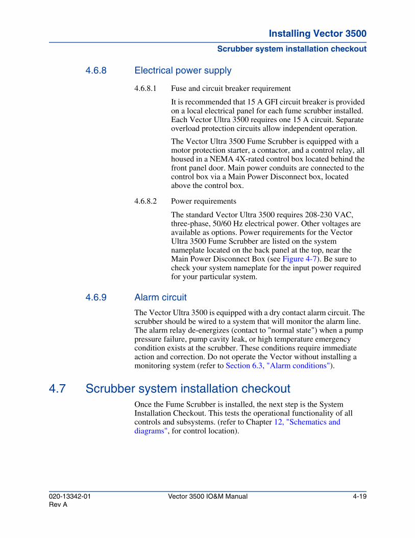
Installing Vector 3500Installing Vector 3500Installing Vector 3500
Scrubber system installation checkout
4.6.8 Electrical power supply
4.6.8.1 Fuse and circuit breaker requirement
It is recommended that 15 A GFI circuit breaker is provided on a local electrical panel for each fume scrubber installed. Each Vector Ultra 3500 requires one 15 A circuit. Separate overload protection circuits allow independent operation.
The Vector Ultra 3500 Fume Scrubber is equipped with a motor protection starter, a contactor, and a control relay, all housed in a NEMA 4X-rated control box located behind the front panel door. Main power conduits are connected to the control box via a Main Power Disconnect box, located above the control box.
4.6.8.2 Power requirements
The standard Vector Ultra 3500 requires 208-230 VAC, three-phase, 50/60 Hz electrical power. Other voltages are available as options. Power requirements for the Vector Ultra 3500 Fume Scrubber are listed on the system nameplate located on the back panel at the top, near the Main Power Disconnect Box (see Figure 4-7). Be sure to check your system nameplate for the input power required for your particular system.
4.6.9 Alarm circuit
The Vector Ultra 3500 is equipped with a dry contact alarm circuit. The scrubber should be wired to a system that will monitor the alarm line. The alarm relay de-energizes (contact to "normal state") when a pump pressure failure, pump cavity leak, or high temperature emergency condition exists at the scrubber. These conditions require immediate action and correction. Do not operate the Vector without installing a monitoring system (refer to Section 6.3, "Alarm conditions").
4.7 Scrubber system installation checkoutOnce the Fume Scrubber is installed, the next step is the System Installation Checkout. This tests the operational functionality of all controls and subsystems. (refer to Chapter 12, "Schematics and diagrams", for control location).
020-13342-01 Vector 3500 IO&M Manual 4-19Rev A
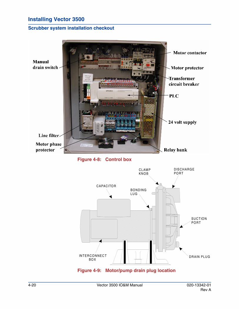
Installing Vector 3500
Scrubber system installation checkout
Figure 4-8: Control box
Figure 4-9: Motor/pump drain plug location
DR AIN PLUG
CAPACITO R
DIS CH ARG EPO RT
SUC T IO NPO RT
CLAM PKNO B
BO ND IN GLU G
IN TER CO N NEC T BO X
4-20 Vector 3500 IO&M Manual 020-13342-01Rev A
Installing Vector 3500Installing Vector 3500Installing Vector 3500
Scrubber system installation checkout
4.7.1 Three phase motor-rotation verification procedure
4.7.1.1 Make sure the facility has been wired with proper three phase power, and this power is currently in a Locked and Tagged-out condition.
4.7.1.2 Install the Vector fume scrubber, following installation instructions detailed in Section 4.6 of this manual.
4.7.1.3 Before filling the scrubber with water, check the pump motor rotation using the following procedure.
1. Remove the front pump cavity door and reach around to the pump end of the motor and remove the drain plug (see Figure 4-9). Water left in scrubber from factory testing will drain from the pump head into the pump cavity (a wet/dry vacuum will be needed for water clean-up). Do not reinstall the drain plug at this time.
2. Verify that the motor rotates freely by gently rotating the cooling blades located at the rear of the motor.
3. Engage the EMO on the Vector.
4. Open the Vector control panel. Remove Lock and Tag-out devices at house circuit breaker (in accordance with site specific safety protocol) and then energize house power to scrubber.
5. Switch ON the transformer circuit breaker. The scrubber alarm horn will sound; to silence the alarm horn, push the silence alarm button on the cover door.
6. Switch ON the motor protector. Press the black button on the motor contactor. If the fan blades are rotating, then the motor is phased correctly. The drain plug can be reinstalled and the installation procedure can continue.
WARNING!
Use proper lock-out and tag-out procedures, de-energize power to the Vector Ultra 3500 at the house circuit breaker before performing the following step.
020-13342-01 Vector 3500 IO&M Manual 4-21Rev A
Installing Vector 3500
System controls
7. If the fan blades do NOT turn, you must switch the power conductors coming from the house circuit breaker to the scrubber at the Main Power Disconnect box (Reference Figure 4-2). The “Power-In” leads L1 and L3 on the main power switch (located inside the Main Power Disconnect box) must be swapped. After swapping L1 and L3, repeat steps 3 through 7.
4.7.2 Basic system checkout
4.7.2.1 Open makeup water valve.
4.7.2.2 Set the Stop / Start switch on the scrubber control panel to the Start position.
4.7.2.3 The water will continue to rise in the sump until the high liquid level float switch is tripped. The waste water solenoid valve will then open.
4.7.2.4 Adjust the nitrogen flow rates as described in Section 5.3.5.
4.7.2.5 Check to ensure that all gas and water plumbing connections are leak free.
4.7.2.6 Perform the appropriate entry device set-up procedure for the entry device on your system. For Type 9 entries, perform the procedure described in Section 4.6.2, "Type 20 entry set-up".
4.7.2.7 Check Appendix B to see if any special checkout procedures are required for options installed on this unit.
4.8 System controlsAfter installation and checkout, the Vector Ultra 3500 Fume Scrubber is ready for full operational on-line processing of reactor gases. The Vector Ultra 3500 Fume Scrubber has only a few controls that need to be adjusted to achieve full operational capability, refer to Section 5.2, "Operator controls" for setting adjustments.
4-22 Vector 3500 IO&M Manual 020-13342-01Rev A
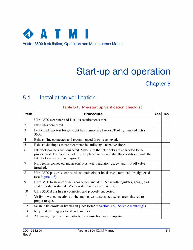
Vector 3500 Installation, Operation and Maintenance Manual
Start-up and operationChapter 5
5.1 Installation verification
Table 5-1: Pre-start up verification checklist
Item Procedure Yes No1 Ultra 3500 clearance and location requirements met.
2 Inlet lines connected.
3 Performed leak test for gas-tight line connecting Process Tool System and Ultra 3500.
4 Exhaust line connected and recommended draw is achieved.
5 Exhaust ducting is as per recommended utilizing a negative slope.
6 Interlock contacts are connected. Make sure the Interlocks are connected to the process tool. The process tool must be placed into a safe standby condition should the Interlocks relay be de-energized.
7 Nitrogen is connected and at 80±10 psi with regulator, gauge, and shut off valve installed.
8 Ultra 3500 power is connected and main circuit breaker and terminals are tightened (see Figure 4-8).
9 Ultra 3500 fresh water line is connected and at 30±5 psi with regulator, gauge, and shut off valve installed. Verify water quality specs are met.
10 Ultra 3500 drain line is connected and properly supported.
11 Verify power connections to the main power disconnect switch are tightened to proper torque.
12 Seismic tie downs or bracing in place (refer to Section 4.5, "Seismic mounting").
13 Required labeling per local code in place.
14 All testing of gas or other detection systems has been completed.
020-13342-01 Vector 3500 IO&M Manual 5-1Rev A
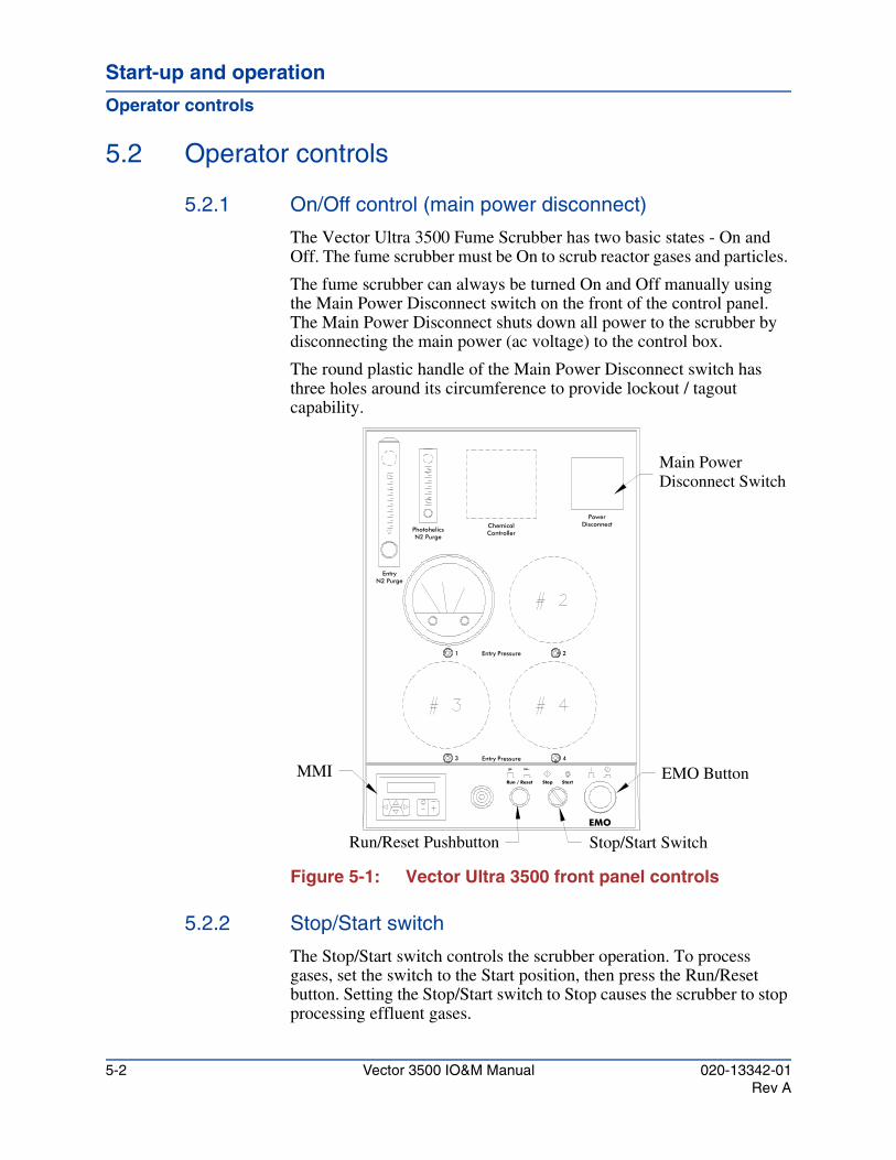
Start-up and operation
Operator controls
5.2 Operator controls
5.2.1 On/Off control (main power disconnect)
The Vector Ultra 3500 Fume Scrubber has two basic states - On and Off. The fume scrubber must be On to scrub reactor gases and particles.
The fume scrubber can always be turned On and Off manually using the Main Power Disconnect switch on the front of the control panel. The Main Power Disconnect shuts down all power to the scrubber by disconnecting the main power (ac voltage) to the control box.
The round plastic handle of the Main Power Disconnect switch has three holes around its circumference to provide lockout / tagout capability.
Figure 5-1: Vector Ultra 3500 front panel controls
5.2.2 Stop/Start switch
The Stop/Start switch controls the scrubber operation. To process gases, set the switch to the Start position, then press the Run/Reset button. Setting the Stop/Start switch to Stop causes the scrubber to stop processing effluent gases.
Main PowerDisconnect Switch
EMO Button
21 Entry Pressure
Entry Pressure3 4
Stop/Start SwitchRun/Reset Pushbutton
MMI
PhotohelicsN2 Purge
N2 PurgeEntry
Chemical
EMO
Stop Start
DisconnectPower
Controller
Run / Reset
5-2 Vector 3500 IO&M Manual 020-13342-01Rev A
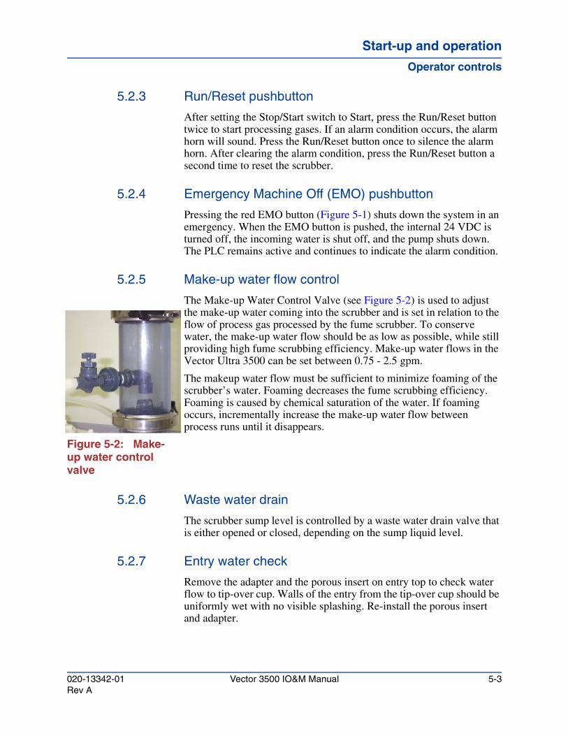
Start-up and operationStart-up and operationStart-up and operation
Operator controls
5.2.3 Run/Reset pushbutton
After setting the Stop/Start switch to Start, press the Run/Reset button twice to start processing gases. If an alarm condition occurs, the alarm horn will sound. Press the Run/Reset button once to silence the alarm horn. After clearing the alarm condition, press the Run/Reset button a second time to reset the scrubber.
5.2.4 Emergency Machine Off (EMO) pushbutton
Pressing the red EMO button (Figure 5-1) shuts down the system in an emergency. When the EMO button is pushed, the internal 24 VDC is turned off, the incoming water is shut off, and the pump shuts down. The PLC remains active and continues to indicate the alarm condition.
5.2.5 Make-up water flow control
The Make-up Water Control Valve (see Figure 5-2) is used to adjust the make-up water coming into the scrubber and is set in relation to the flow of process gas processed by the fume scrubber. To conserve water, the make-up water flow should be as low as possible, while still providing high fume scrubbing efficiency. Make-up water flows in the Vector Ultra 3500 can be set between 0.75 - 2.5 gpm.
The makeup water flow must be sufficient to minimize foaming of the scrubber’s water. Foaming decreases the fume scrubbing efficiency. Foaming is caused by chemical saturation of the water. If foaming occurs, incrementally increase the make-up water flow between process runs until it disappears.
Figure 5-2: Make-up water control valve
5.2.6 Waste water drain
The scrubber sump level is controlled by a waste water drain valve that is either opened or closed, depending on the sump liquid level.
5.2.7 Entry water check
Remove the adapter and the porous insert on entry top to check water flow to tip-over cup. Walls of the entry from the tip-over cup should be uniformly wet with no visible splashing. Re-install the porous insert and adapter.
020-13342-01 Vector 3500 IO&M Manual 5-3Rev A
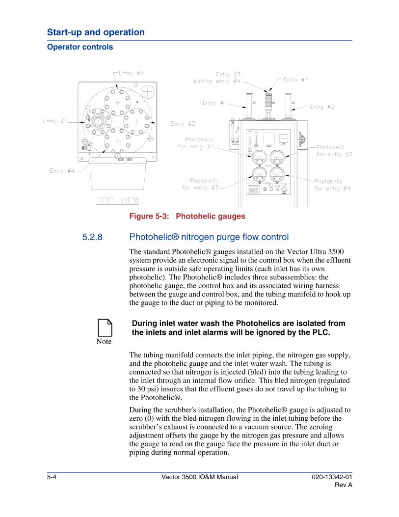
Start-up and operation
Operator controls
Figure 5-3: Photohelic gauges
5.2.8 Photohelic® nitrogen purge flow control
The standard Photohelic® gauges installed on the Vector Ultra 3500 system provide an electronic signal to the control box when the effluent pressure is outside safe operating limits (each inlet has its own photohelic). The Photohelic® includes three subassemblies: the photohelic gauge, the control box and its associated wiring harness between the gauge and control box, and the tubing manifold to hook up the gauge to the duct or piping to be monitored.
The tubing manifold connects the inlet piping, the nitrogen gas supply, and the photohelic gauge and the inlet water wash. The tubing is connected so that nitrogen is injected (bled) into the tubing leading to the inlet through an internal flow orifice. This bled nitrogen (regulated to 30 psi) insures that the effluent gases do not travel up the tubing to the Photohelic®.
During the scrubber's installation, the Photohelic® gauge is adjusted to zero (0) with the bled nitrogen flowing in the inlet tubing before the scrubber’s exhaust is connected to a vacuum source. The zeroing adjustment offsets the gauge by the nitrogen gas pressure and allows the gauge to read on the gauge face the pressure in the inlet duct or piping during normal operation.
3 Entry Pressure
Run / Reset Stop
EMO
4
Start
1
EntryN2 Purge
Entry Pressure
N2 PurgePhotohelics
2
DisconnectPower
ChemicalController
Note
During inlet water wash the Photohelics are isolated from the inlets and inlet alarms will be ignored by the PLC.
5-4 Vector 3500 IO&M Manual 020-13342-01Rev A
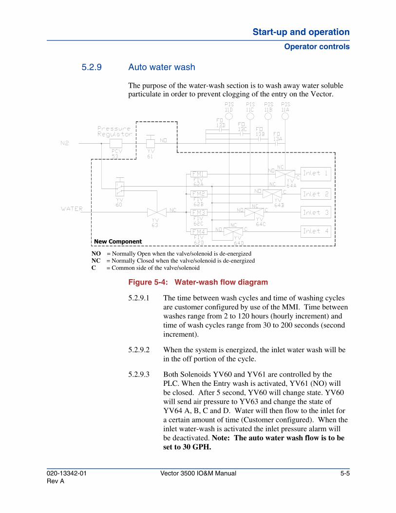
Start-up and operationStart-up and operationStart-up and operation
Operator controls
5.2.9 Auto water wash
The purpose of the water-wash section is to wash away water soluble particulate in order to prevent clogging of the entry on the Vector.
Figure 5-4: Water-wash flow diagram
5.2.9.1 The time between wash cycles and time of washing cycles are customer configured by use of the MMI. Time between washes range from 2 to 120 hours (hourly increment) and time of wash cycles range from 30 to 200 seconds (second increment).
5.2.9.2 When the system is energized, the inlet water wash will be in the off portion of the cycle.
5.2.9.3 Both Solenoids YV60 and YV61 are controlled by the PLC. When the Entry wash is activated, YV61 (NO) will be closed. After 5 second, YV60 will change state. YV60 will send air pressure to YV63 and change the state of YV64 A, B, C and D. Water will then flow to the inlet for a certain amount of time (Customer configured). When the inlet water-wash is activated the inlet pressure alarm will be deactivated. Note: The auto water wash flow is to be set to 30 GPH.
New Component
NO = Normally Open when the valve/solenoid is de-energizedNC = Normally Closed when the valve/solenoid is de-energizedC = Common side of the valve/solenoid
020-13342-01 Vector 3500 IO&M Manual 5-5Rev A
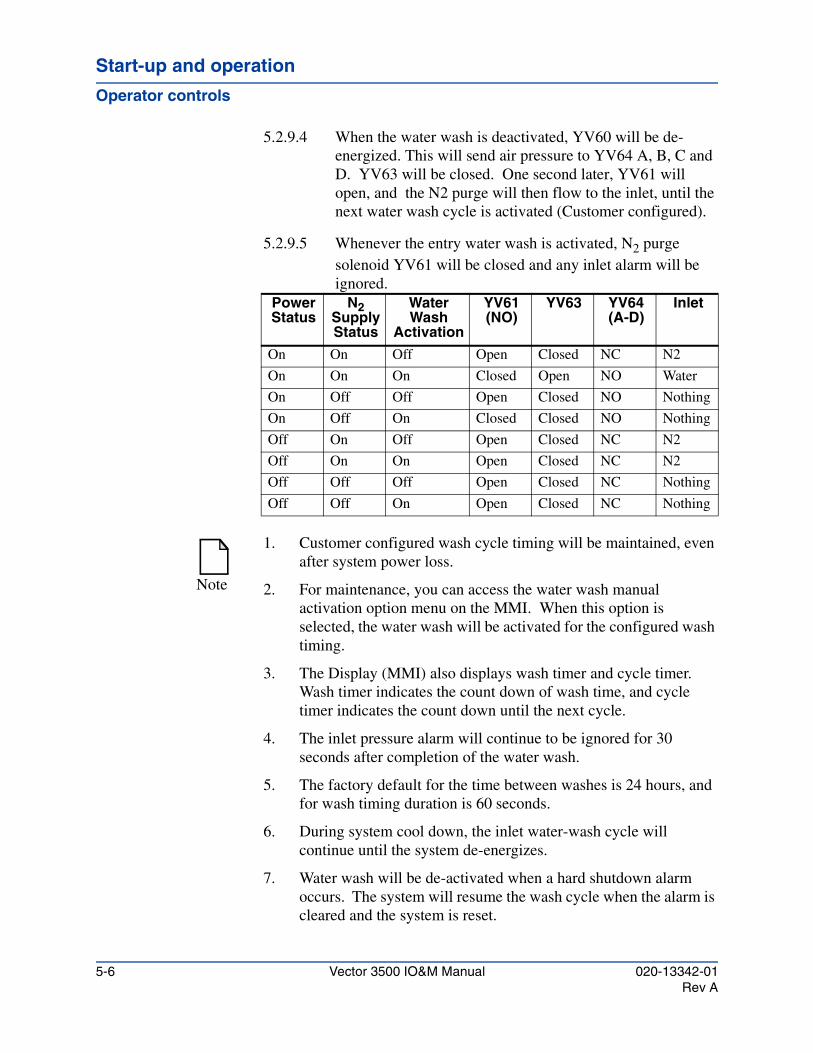
Start-up and operation
Operator controls
5.2.9.4 When the water wash is deactivated, YV60 will be de-energized. This will send air pressure to YV64 A, B, C and D. YV63 will be closed. One second later, YV61 will open, and the N2 purge will then flow to the inlet, until the next water wash cycle is activated (Customer configured).
5.2.9.5 Whenever the entry water wash is activated, N2 purge solenoid YV61 will be closed and any inlet alarm will be ignored.
Power Status
N2 Supply Status
Water Wash
Activation
YV61 (NO)
YV63 YV64 (A-D)
Inlet
On On Off Open Closed NC N2
On On On Closed Open NO Water
On Off Off Open Closed NO Nothing
On Off On Closed Closed NO Nothing
Off On Off Open Closed NC N2
Off On On Open Closed NC N2
Off Off Off Open Closed NC Nothing
Off Off On Open Closed NC Nothing
Note
1. Customer configured wash cycle timing will be maintained, even after system power loss.
2. For maintenance, you can access the water wash manual activation option menu on the MMI. When this option is selected, the water wash will be activated for the configured wash timing.
3. The Display (MMI) also displays wash timer and cycle timer. Wash timer indicates the count down of wash time, and cycle timer indicates the count down until the next cycle.
4. The inlet pressure alarm will continue to be ignored for 30 seconds after completion of the water wash.
5. The factory default for the time between washes is 24 hours, and for wash timing duration is 60 seconds.
6. During system cool down, the inlet water-wash cycle will continue until the system de-energizes.
7. Water wash will be de-activated when a hard shutdown alarm occurs. The system will resume the wash cycle when the alarm is cleared and the system is reset.
5-6 Vector 3500 IO&M Manual 020-13342-01Rev A
Start-up and operationStart-up and operationStart-up and operation
Operator controls
5.2.9.6 Controlling the inlet water-wash using the MMI
There are 2 timers that can be set using the MMI, as well as a manual inlet water-wash activation which can be used to check the water-wash flow and system for leaks.
Wash time determines the duration for the wash time (water flowing). Cycle time determines the duration between inlet water-washes. Manual start, starts the wash timer (water flowing) and will return to the programmed timers when the wash cycle is completed.
1. The factory default settings for the time between washes is 24 hours and for the wash cycle the duration is 60 seconds.
2. To change the time settings, use the down button on the MMI to scroll to the "wash cycle" to set the time between washes.
3. Use the scroll right button on the MMI to select the timer.
4. Use the "+" and "-" buttons on the MMI to select the duration. The range of this timer is 2 to 120 hours.
5. Use the down button to scroll to the "cycle timer".
6. Use the scroll right button to select the timer.
7. Use the "+" and "-" buttons to select the duration of the wash. This timer has a range of 30 to 200 seconds.
8. Manually starting the inlet wash can be used to confirm the proper flow and that there are no leaks during wash.
9. To manually start the inlet wash, press the down button on the MMI until "manual start" is reached.
10. Select "yes" to start the water flow. The water will flow for what ever the "cycle time" is set for and then the system will resume the programmed cycle timing.
Note
A longer cycle time and the shorter the wash cycle the less water used and the chances of corrosion in the inlet are reduced.
020-13342-01 Vector 3500 IO&M Manual 5-7Rev A
Start-up and operation
Operator controls
5.2.10 Heater blanket
The heat blanket option has been shown as an effective way of reducing the amount of buildup on the surfaces exposed to various process gasses. This option will heat the walls to a temperature of 150°C while maintaining an outside temperature of less than 70°C (safe to touch). The heaters also contain integral over-temperature protection (internal fuse blows at less than ~195°C). The main power fuse (located in the Ultra control box) will blow in the case of over-current (i.e. short circuit, etc.). Also included on the heaters are low temperature alarm dry contacts (LTA). This is the single white wire harnessed with the power cord to the heater blanket. These contacts will close when all heaters daisy-chained together reach operating temperature. If one of the heater's temperature drops to ~105°C its contact will open signaling a heat failure in the daisy chain.
The heat blankets receive power from the Vector Ultra control box. Two relays R8 and R9, which are controlled by the PLC, controls power to the heater. When a warning alarm occurs or the system goes into shutdown mode (due to critical alarm, manual shutdown, or EPO) power is removed from R8 and R9, the contacts will open removing power from the heat blankets. Also added is a fuse for each power source just ahead of the contacts of R8 and R9. The fuse used is dependent on the number of heaters connected in the daisy chain (not to exceed four). Refer to Table 11-7, "Control box", to determine what type of fuses should be used.
5.2.10.1 During start up of the unit, press reset to clear all the alarms. The inlet heater will turn on (default) only when all the alarms (excluding heater low temp. alarm) has been cleared.
5.2.10.2 When the inlet heater reaches 105°C, during the first hour of system operation, the unit will automatically reset the "Heater Lo Tmp" (LTA) alarm, until then, the warning alarm will remain activated.
5.2.10.3 At the end of an hour, if the LTA has not cleared, the system will then reset and alarm. This is to warn the user that there is a problem with the heater(s).
5.2.10.4 Inlet heaters will be off for all alarms (excluding heater low temp. alarm), and it will remain off until the alarms are cleared and system is reset.
5-8 Vector 3500 IO&M Manual 020-13342-01Rev A

Start-up and operationStart-up and operationStart-up and operation
Operator controls
5.2.10.5 The system also has an inlet heater activation/de-activation option controlled by the MMI.
5.2.10.6 To manually turn the heater(s) off, the MMI is used.
5.2.10.7 Press the down button until "Turn Off Htr" is reached. (This is below "Htr Status" during normal operation mode or below "Htr Warm Up" during warm up mode.)
5.2.10.8 Press the right arrow twice until the cursor is after "?" and press "+" button to turn on/off heater power.
5.2.10.9 Verify that the heater status has changed.
5.2.10.10 During system cooling (Stop/start button is turned from "start" position to "stop" position), inlet heater(s) will be deactivated. After 5 seconds the interlock relay will be de-energized and both the red and yellow lights will be on. The system will remain functional until 10 minutes after the inlet heater temp drops below 105°C, at which time the system will power down.
If after 1 hour of cooling, the inlet temperature remains above 105°C, the audible alarm will sound, the yellow light will continually blink, and the MMI will display "Heater Hi Tmp" to indicate heater shut down failure. The system will remain energized until inlet heater temp drops below 105°C.
This is to allow the user to inspect and troubleshoot the complete system for any outside heat sources.
Note
The default setting is to activate the inlet heater. Default setting will be restored every time the system is powered down and then turned on.
CAUTION
The Vector must not be powered down with external heat sources feeding the system (line heater still on). If the Vector is powered down while external heat sources are still on, the Vector will be damaged.
020-13342-01 Vector 3500 IO&M Manual 5-9Rev A
Start-up and operation
Initial start up procedure
5.3 Initial start up procedureYour new Ultra 3500 has been fully factory tested. All pressure alarm switches have been adjusted to factory specifications. To confirm complete functionality of the system, you must perform the following Initial Start-up Procedure. During this procedure, the customer will be able to adjust settings to meet site-specific operational requirements.
Do not start this procedure until you have read through the entire procedure. You must understand this procedure in its entirety, before performing it, to ensure a proper initial start-up of the Ultra 3500 system.
5.3.1 Required equipment and materials
5.3.1.1 Facilities
• Electrical Power per system requirements
• Water 30 ± 5 psig
• Compressed N2 at 80 psig
5.3.1.2 Equipment
• Digital Volt Meter
• Temperature calibration/simulator
5.3.2 Testing Control Panel Power Supply
5.3.2.1 Verify that all utilities are correctly hooked up to the Ultra 3500, according to Chapter 3, "Facilities requirements" and that all utilities are turned OFF. Utilities are electricity, make-up water, and house nitrogen.
5.3.2.2 Press the Ultra 3500’s EMO pushbutton to engage the Emergency Machine Off circuit.
WARNING!
The electronic control unit and pump motor contain high voltage. Exercise care when working within these areas.
CAUTION
The scrubber uses high pressure fluids. Exercise care when disconnecting any pneumatic or plumbing lines.
5-10 Vector 3500 IO&M Manual 020-13342-01Rev A
Start-up and operationStart-up and operationStart-up and operation
Initial start up procedure
5.3.2.3 Turn the Ultra 3500’s STOP/START switch to STOP.
5.3.2.4 Switch ON the Electrical Service Circuit Breaker at the power distribution panel.
5.3.2.5 Switch ON the POWER DISCONNECT switch, located on the front control panel.
5.3.2.6 Open Control Box and check.
5.3.2.7 Using a DVM, check incoming power to the motor protector and verify correct voltage per configuration.
• 208 vac ±5 vac or
• 380 vac ±10 vac or
• 460 vac ±20 vac
5.3.2.8 Disengage the Emergency Machine Off circuit by rotating the EMO pushbutton one-quarter turn clockwise, until it pops out.
5.3.2.9 Place CB1 to ON position.
5.3.2.10 Verify that the MMI alarm display is functional.
5.3.2.11 Press the Start button on MP1 in Electrical Control Box.
1. R6 should illuminate.
2. If R6 does not illuminate, swap incoming power wires at main power disconnect.
5.3.2.12 Using a DVM, measure the DC voltage at + and - of the power supply. Record results in Section 5.6, "Start-up check sheet".
5.3.2.13 Verify Pump Motor Rotation
1. Place CB1 to ON position.
2. Press START button on MP1 in Electrical box. R6 LED illuminates.
WARNING!
Lockout power before making any change to wiring.
020-13342-01 Vector 3500 IO&M Manual 5-11Rev A
Start-up and operation
Initial start up procedure
3. Momentarily depress the motor contactor while viewing the rear of the pump motor in the lower containment area. Motor rotation should be clockwise (CW) as viewed from opposite of motor shaft.
5.3.2.14 Close Control Box.
5.3.3 Start-up supply flow and pump rotation
5.3.3.1 Ensure the manual water inlet valve is closed.
5.3.3.2 Adjust the Exhaust Line Airflow damper to reading of -4.5" H2O on the Entry Photohelic Pressure Gauge. If -4.5" WC can not be achieved, then open the exhaust damper completely to eliminate any flow restrictions.
5.3.3.3 Turn ON the house nitrogen supply to 80 ± 10 psi.
5.3.3.4 Turn ON the water supply to 30 ± 5 psi.
5.3.3.5 Open pump suction valve.
5.3.3.6 Open manual discharge valves.
5.3.3.7 Verify Pump Motor Rotation.
1. Place CB1 to ON position.
2. Press START button on MP1 in Electrical box. R6 LED illuminates.
Note
If motor rotation is counter clockwise (CCW) change (2) wires in pump motor junction box.
WARNING!
Disconnect power before making any change to wiring.
CAUTION!
The damper should be equipped with a position locking device. This prevents the damper from accidentally closing during normal operation, which can create a high back-pressure condition to the process.
5-12 Vector 3500 IO&M Manual 020-13342-01Rev A
Start-up and operationStart-up and operationStart-up and operation
Initial start up procedure
3. Momentarily depress the motor contactor while viewing the rear of the pump motor in the lower containment area. Motor rotation should be clockwise (CW) as viewed from opposite of motor shaft.
5.3.3.8 Close Control Box.
5.3.3.9 Turn the Stop / Start switch to START.
5.3.3.10 Push the Reset button twice to reset the alarm conditions, and to start the scrubber system.
5.3.4 Checking water systems
5.3.4.1 Adjust make up water flow to 2 gpm. (system will alarm)
1. Sump begins to fill from the make-up water fill port.
5.3.4.2 Allow water to fill the sump to activate sump low level float. Adjust make up flow to 1.5 gpm. Press RUN/RESET to reset the sump level low alarm.
1. Sump level low alarm on MMI disappears.
2. Pump motor turns on.
3. Water is pumped to spray head.
4. Spray head rotates.
5.3.4.3 Press RUN/RESET to reset all the alarms.
5.3.4.4 Check for leaks in water plumbing lines.
5.3.4.5 Check barrel seams for leakage.
5.3.4.6 Using step 5.2.9.6, "Controlling the inlet water-wash using the MMI", to activate the inlet water-wash and set flow for 30 gph.
Note
If motor rotation is counter clockwise (CCW), change (2) wires in pump motor junction box.
WARNING!
Disconnect power before making any change to wiring.
020-13342-01 Vector 3500 IO&M Manual 5-13Rev A
Start-up and operation
Initial start up procedure
5.3.4.7 Inspect for leaks. When wash cycle times out the cycle will return to programmed settings.
5.3.5 Photohelic® alarm set-up and adjustment
The nitrogen should be adjusted after verifying the water flow.
5.3.5.1 Adjust the Vector on board nitrogen regulator to 30 psig on the regulator gauge.
5.3.5.2 Adjust Entry N2 Purge rotometer to 50 slm per inlet.
5.3.5.3 Set each Entry Photohelic low alarm needle to below 0".
5.3.5.4 Set each Entry Photohelic high alarm needle to -4.5".
5.3.5.5 Set Photohelic N2 Purge to 1 slm per inlet. (4 inlets = 4slm)
5.3.5.6 Disconnect the Photohelic/water wash valve at the entry of the Photohelic you are about to adjust.
5.3.5.7 Adjust Photohelic to 0.
5.3.5.8 Reconnect Photohelic/water wash valve to the entry.
5.3.5.9 Repeat steps 5.3.5.6 - 5.3.5.8 for each inlet Photohelic.
5.3.5.10 Photohelics are now set to read true inlet pressure.
5.3.6 Inlet heaters
5.3.6.1 During start up of the unit, press reset to clear all the alarms. The inlet heater will turn on (default) only when all the alarms (excluding heater low temp. alarm) has been cleared.
5.3.6.2 When the inlet heater reaches 105°C, during the first hour of system operation, the unit will automatically reset the "Heater Lo Tmp" (LTA) alarm, until then, the warning alarm will remain activated.
5.3.6.3 At the end of an hour, if the LTA has not cleared, the system will then reset and alarm. This is to warn the user that there is a problem with the heater(s).
5-14 Vector 3500 IO&M Manual 020-13342-01Rev A
Start-up and operationStart-up and operationStart-up and operation
Testing alarms
5.3.6.4 The operation of any one heater should is evident if the outside surface is warm to the touch (~65°C). All heaters when connected in the daisy chain are effectively wired in parallel such that any heater can fail and not effect the operation of the others. The low temperature alarm (LTA) contacts can be tested for closure to verify that each heater is operating at its setting. If R8 and R9 are not receiving power (R8 and R9 LED’s are off) then the heaters are also not receiving power; verify that the PLC Y6 LED has not been de-energized (shutdown condition). If so, then the system must be reset. Check heat blanket Fuse1 and Fuse2 to ensure that they have not blown. If they have blown, then the heaters should be checked for short circuit and replaced accordingly. Each heater has an internal fuseable link for over temp protection. When this link has blown, the heater must be replaced.
5.4 Testing alarms
5.4.1 Testing control panel power supply
5.4.1.1 Turn off main disconnect.
5.4.1.2 Using a DVM, check the Incoming Power to main disconnect (EPO) is correct Voltage.
• 208 vac ±5 vac or
• 380 vac ±10 vac or
• 460 vac ±20 vac
5.4.1.3 Turn on power to scrubber by placing the main disconnect (EPO) to ON position.
5.4.1.4 Place CB1 to ON position.
5.4.1.5 Press the Start button on MP1 in Electrical Control Box. NOTE: If R6 does not illuminate, swap incoming power wires at main disconnect.
WARNING!
Lockout power before making any change to wiring.
020-13342-01 Vector 3500 IO&M Manual 5-15Rev A
Start-up and operation
Testing alarms
5.4.1.6 Using a DVM, measure the DC voltage at + and - of the power supply.
• +24 vdc ±0.5 vdc
5.4.1.7 Momentarily depress the motor contactor while viewing the rear of the pump motor in the lower containment area. Motor rotation is CW as viewed from opposite motor shaft. NOTE: If motor rotation is CCW, swap the wires at the pump motor.
5.4.2 Testing water systems
5.4.2.1 Connect a suitable water supply to the Make Up Water and cooling water supply port. Connect a drain line to the main drain and cooling out ports.
5.4.2.2 Turn on the scrubber by placing the Start/Stop switch in Start mode. If there is no water in the sump, one of the alarms on MMI displayed will be "Sump Level low warning".
5.4.2.3 Adjust Make Up Water flow to full open. Sump begins to fill from the make-up water fill port.
5.4.2.4 Allow water to fill the sump to activate sump low level float. Press RUN/RESET to reset the sump level low alarm. Sump level low alarm on MMI disappears.
5.4.2.5 Allow water to fill the sump to activate the sump level open float.
• Pump motor turns on.
• Water is pumped to spray head.
• Spray head rotates.
• Normal Operation Green Tower Light ON.
5.4.2.6 Press RUN/RESET to reset all the alarms. MMI displays NORMAL with 0 Alarms.
5.4.2.7 Check for leaks in water plumbing lines.
Note
Flush water supply line before connecting to the Vector Ultra 3500.
5-16 Vector 3500 IO&M Manual 020-13342-01Rev A

Start-up and operationStart-up and operationStart-up and operation
Testing alarms
5.4.2.8 Check barrel seams for leakage.
5.4.2.9 In lower containment area, slowly increase Pump Pressure Switch setting adjustment knob until pump motor stops.
• Pump motor stops.
• Pump Pressure Shutdown Alarm.
• Red Tower light ON.
5.4.2.10 Press RUN/RESET once to silence horn. Alarm horn OFF.
5.4.2.11 Turn Pump Pressure Switch setting adjustment knob two (2) full turns (CCW) towards zero.
5.4.2.12 Press RUN/RESET to reset alarm.
• Pump motor is on.
• Spray head rotates.
5.4.2.13 Press Alarm Reset button. MMI displays NORMAL with 0 Alarms.
5.4.3 Testing control panel ON/OFF and EMO
5.4.3.1 Press EMO button. EMO Shutdown is displayed on MMI. Red Tower light is ON.
5.4.3.2 Disengage EMO button. Alarm Horn ON
5.4.3.3 Press RUN/RESET button once to silence horn. Alarm Horn OFF.
5.4.3.4 Press RUN/RESET button to restart. If no alarm exists, MMI will display "Normal Operation with 0 alarms" and Green Tower light is ON.
5.4.4 Testing pump cavity float
5.4.4.1 Lift and hold lower containment cavity float ball to activate.
• EMO Shutdown is displayed on MMI.
• Red Tower light is ON.
• Horn is ON.
5.4.4.2 Release ball float.
020-13342-01 Vector 3500 IO&M Manual 5-17Rev A
Start-up and operation
Testing alarms
5.4.4.3 Press RUN/RESET button to Silence Horn. Alarm Horn OFF.
5.4.4.4 Press RUN/RESET button. Scrubber Starts.
5.4.5 Make-up water flow
5.4.5.1 Adjust Make-Up Water flow slowly towards zero until the low make up water alarm sounds. MMI displays "MAKE-UP WATER" and indicates 0.50 gpm +/ - 0.10. The yellow tower light and horn is on. Press reset once to silence the alarm.
5.4.5.2 Adjust make up water flow to 1.5 GPM.
5.4.5.3 Press RUN/RESET button twice. Alarm horn is OFF. MMI displays "NORMAL."
5.4.5.4 Using step 5.2.9.6, "Controlling the inlet water-wash using the MMI", to activate the inlet water-wash and set flow for 30 gph.
5.4.5.5 Inspect for leaks. When wash cycle times out the cycle will return to programmed settings.
5.4.6 Entry pressure high/low alarms
5.4.6.1 Slowly adjust Entry Pressure Gauge #1 high alarm needle until it crosses the indicator. Entry warning is displayed on MMI. Alarm Horn is ON.
5.4.6.2 Set Entry Pressure Gauge #1 high needle to 0.5" W.C.
5.4.6.3 Press RUN/RESET button twice. No Entry warning is displayed on MMI. Alarm Horn is OFF.
5.4.6.4 Slowly adjust Entry Pressure Gauge #1 low alarm needle until it crosses the indicator. Entry warning is displayed on MMI. Alarm Horn is ON.
5.4.6.5 Set Entry Pressure Gauge #1 high needle to 4.5" W.C.
5.4.6.6 Press RUN/RESET button twice. No Entry warning is displayed on MMI. Alarm Horn is OFF.
5-18 Vector 3500 IO&M Manual 020-13342-01Rev A
Start-up and operationStart-up and operationStart-up and operation
Testing alarms
5.4.6.7 Repeat steps 5.4.6.1 through 5.4.6.6 above for Entry Pressure Gauge #2 and #3.
5.4.7 Sump level switch
5.4.7.1 Disconnect the wire to terminal X6 on the PLC. Setup. Disables the Sump High Level Float switch.
5.4.7.2 Close the manual discharge valve (HV-38 ) on the discharge line in Pump Cavity. Water level rises in sump.
5.4.7.3 Let the water level rise in the sump until Sump Overfill Float switch is activated. Make-Up Water Supply Valve closes. Yellow Tower light is ON. Alarm Horn is ON
5.4.7.4 Press RUN/RESET button to silence the horn. Alarm Horn is OFF.
5.4.7.5 Open the discharge valve (HV-38).
5.4.7.6 Reconnect the wire to terminal X6 on the PLC.
5.4.7.7 After the water level drops to normal, press the RUN/RESET button twice. Make-Up Water Supply Valve opens. Normal Green light is ON.
5.4.7.8 Wait till water drains to below Sump Close Float switch (Pneumatic valve will shut off), Close off the discharge valve (HV-38 )on the discharge line in Pump Cavity. Water level rises in sump
5.4.7.9 Let the water level rise in the sump until Sump High Level Float switch actuates. Make-Up Warning & Sump Hi Level Warning is displayed on MMI. Yellow Tower light is ON. Horn is ON. Make-up water is OFF.
5.4.7.10 Press RUN/RESET button to silence the horn. Alarm Horn is OFF.
5.4.7.11 Slowly open the discharge valve (HV-38 ) to drain water to below Sump Close Float switch. Press RUN/RESET button to reset the Alarm. No Sump High Level Alarm on MMI. Normal Green Tower light is ON. Make-up water is ON.
020-13342-01 Vector 3500 IO&M Manual 5-19Rev A
Start-up and operation
Testing alarms
5.4.7.12 Observe the water rise in the sump until the Sump Open Float switch is activated. Main Drain Discharge Valve opens.
5.4.7.13 Observe the water lower in the sump until the Sump Close Float switch is activated. Main Drain Discharge Valve closed.
5.4.8 Entry water check
5.4.8.1 Remove the top to entry #1 and check water flow over the tip-over cup. Walls of the entry from the tip-over cup should be uniformly wet with no visible splashing.
5.4.8.2 Re-install the entry top.
5.4.8.3 Repeat steps 1 through 2 above on entries #2 and #3.
5.4.9 Heater low temp alarm (LTA) test
5.4.9.1 After the heater(s) reach temp (no LTA), disconnecting any of the small white connectors, on any of the inlet heaters will put the system into an LTA state.
5.4.9.2 Reconnect the connector and reset the system, the alarms will be cleared.
5.4.10 Testing pump low pressure alarm
5.4.10.1 Slowly close the pump suction valve until the alarm sounds.
1. Pump motor stops.
2. Pump Pressure Shutdown Alarms and red tower light is ON.
3. Make up water alarms and yellow lights on.
5.4.10.2 Press RUN/RESET once to silence horn.
1. Alarm turns OFF.
5.4.10.3 Open Suction Valve.
5-20 Vector 3500 IO&M Manual 020-13342-01Rev A
Start-up and operationStart-up and operationStart-up and operation
Normal start up procedure
5.4.10.4 Press RUN/RESET to reset alarm.
1. Pump motor is on.
2. Spray head rotates.
5.4.10.5 Press Alarm Reset button.
1. MMI displays NORMAL with no alarms.
5.4.11 Burn in
5.4.11.1 Allow Scrubber to operate for at least 2 hours.
1. No Leaks visible in plumbing lines or barrel seams.
5.5 Normal start up procedureTo start up the ATMI Ultra 3500 unit, perform the following tasks:
1. Verify that all repair orders for the Ultra 3500 unit are completed and remove all tagouts/lockouts.
2. Close and secure all associated electrical cabinets and enclosures.
3. Verify that all manual valves are in the correct position for normal system operations.
4. If necessary, close (turn on) the Power Disconnect switch on the front panel.
5. If necessary, reset the EMO switch on the front panel.
6. Verify that there is electrical power present, by checking that the MMI alarm display is functional.
7. Turn the Stop / Start switch to the START position.
8. Push the Reset button twice to reset any alarm conditions, and to start the scrubber system warm up mode.
9. When the inlet heater reaches 105°C, during the first hour of system operation, the unit will automatically go to normal operation mode and reset the "Heater Lo Tmp" (LTA) alarm, until then, the warning alarm will remain activated.
10. At this point the Vector Ultra 3500 scrubber is operating normally and is able to scrub the residual process gases from the process effluent.
020-13342-01 Vector 3500 IO&M Manual 5-21Rev A

Start-up and operation
Start-up check sheet
5.6 Start-up check sheet
WARNING: Prior to performing any checks inside the electrical enclosure, ensure that power is isolated from the Ultra 3500. Steps 1 through 16 are to be performed with power isolated from the Ultra 3500.
NOTE: Refer to Chapter 6 for Interlock and System Status for configuration for each alarm.
Date: Model: Serial No.:
Customer:
Starting Test Time: Stopping Test Time:
Watlow Serial No.: Watlow MFG. Date:
Tank Serial No.: Customer POC:
Process Information:
Voltage: Current: Power:
Init Item Test Description Init Item Test Description1. Required clearance met 14. Electrical component inspection
2. Line connections to inlet 15. Inlet / body tube inspection
3. Exhaust connected 16. Secondary inspection
4. Drain connected 17. Set up plumbing valves
5. Fresh water connected @ 30 ± 5 PSI 18. Inspect tank plumbing for leaks
6. 100 Micron filter (fresh water) 19. Verify water flow alarms
7. Interlock connected to tool 20. Verify inlet pressure alarms
8. Life Safety connected to tool 21. Verify sump alarm
9. System Status connected to tool 22. Verify liquid level alarms
10. Nitrogen connected @ 80 ± 10 PSI 23. System setup
11. Reagent connected @ 25 PSI 24. Verify all flow settings
12. Power cable installed correctly 25. Verify low temp alarm (LTA)
13. Perform check of wires 26. Verify inlet wash functioning
NOTES:
5-22 Vector 3500 IO&M Manual 020-13342-01Rev A
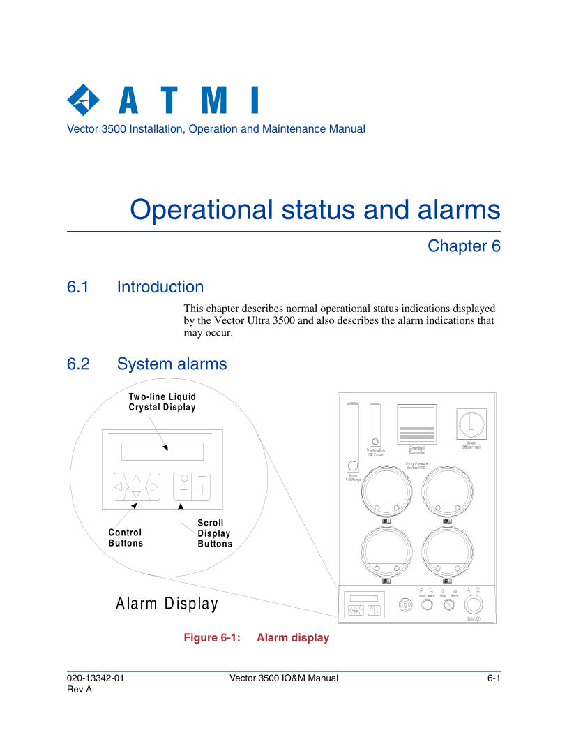
Vector 3500 Installation, Operation and Maintenance Manual
Operational status and alarmsChapter 6
6.1 IntroductionThis chapter describes normal operational status indications displayed by the Vector Ultra 3500 and also describes the alarm indications that may occur.
6.2 System alarms
Figure 6-1: Alarm display
A larm D isp lay
Tw o-line Liqu idCrystal D isplay
ControlButtons
Scroll DisplayButtons
020-13342-01 Vector 3500 IO&M Manual 6-1Rev A
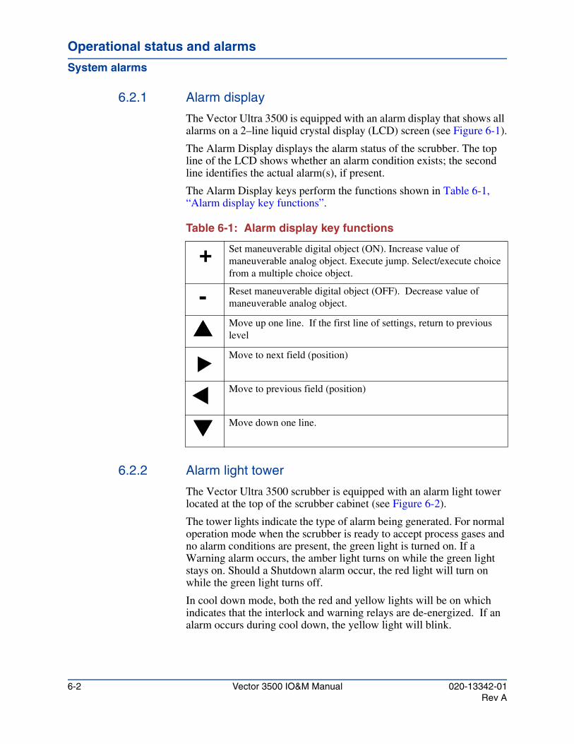
Operational status and alarms
System alarms
6.2.1 Alarm display
The Vector Ultra 3500 is equipped with an alarm display that shows all alarms on a 2–line liquid crystal display (LCD) screen (see Figure 6-1).
The Alarm Display displays the alarm status of the scrubber. The top line of the LCD shows whether an alarm condition exists; the second line identifies the actual alarm(s), if present.
The Alarm Display keys perform the functions shown in Table 6-1, “Alarm display key functions”.
Table 6-1: Alarm display key functions
6.2.2 Alarm light tower
The Vector Ultra 3500 scrubber is equipped with an alarm light tower located at the top of the scrubber cabinet (see Figure 6-2).
The tower lights indicate the type of alarm being generated. For normal operation mode when the scrubber is ready to accept process gases and no alarm conditions are present, the green light is turned on. If a Warning alarm occurs, the amber light turns on while the green light stays on. Should a Shutdown alarm occur, the red light will turn on while the green light turns off.
In cool down mode, both the red and yellow lights will be on which indicates that the interlock and warning relays are de-energized. If an alarm occurs during cool down, the yellow light will blink.
+ Set maneuverable digital object (ON). Increase value of maneuverable analog object. Execute jump. Select/execute choice from a multiple choice object.
- Reset maneuverable digital object (OFF). Decrease value of maneuverable analog object.
���� Move up one line. If the first line of settings, return to previous level
Move to next field (position)
Move to previous field (position)
���� Move down one line.
6-2 Vector 3500 IO&M Manual 020-13342-01Rev A
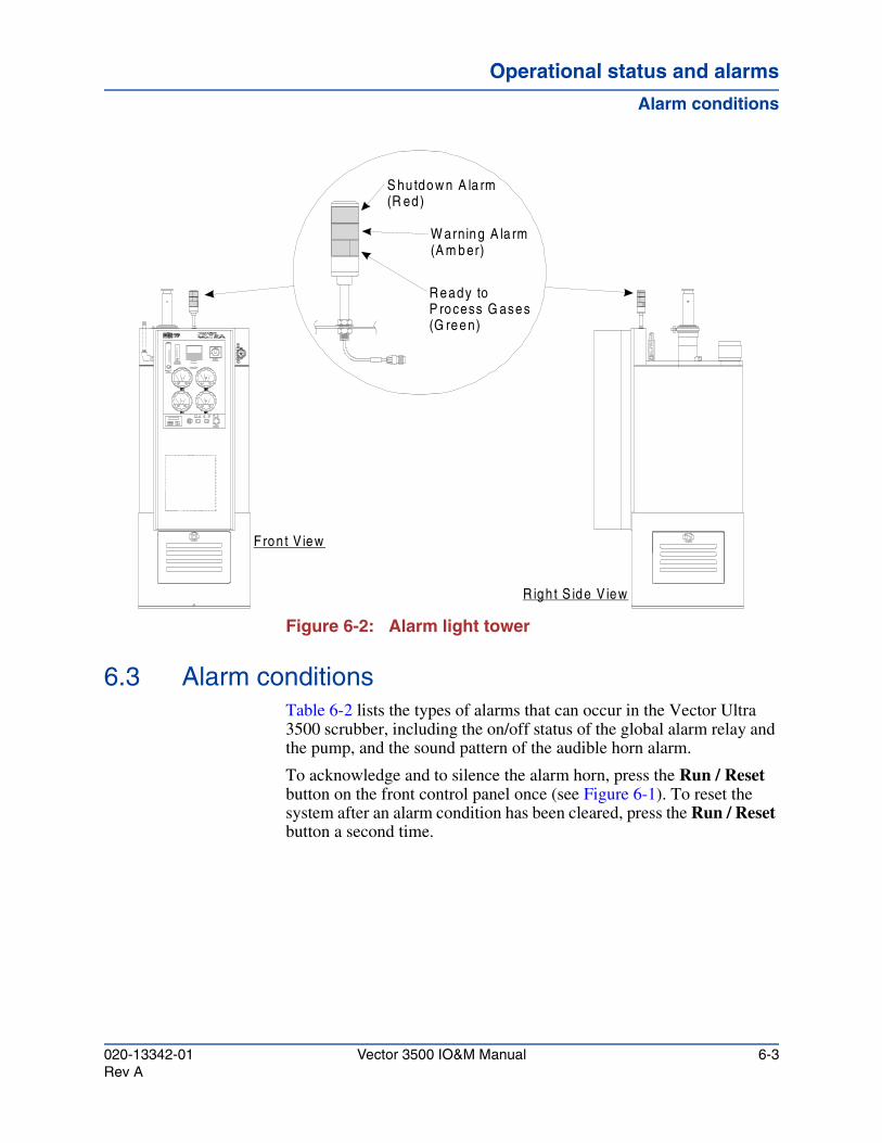
Operational status and alarmsOperational status and alarmsOperational status and alarms
Alarm conditions
Figure 6-2: Alarm light tower
6.3 Alarm conditionsTable 6-2 lists the types of alarms that can occur in the Vector Ultra 3500 scrubber, including the on/off status of the global alarm relay and the pump, and the sound pattern of the audible horn alarm.
To acknowledge and to silence the alarm horn, press the Run / Reset button on the front control panel once (see Figure 6-1). To reset the system after an alarm condition has been cleared, press the Run / Reset button a second time.
Fron t V iew
R igh t S ide V iew
S hu tdow n A la rm(R ed)
W arning A la rm(A m ber)
R eady to P rocess G ases(G reen)
020-13342-01 Vector 3500 IO&M Manual 6-3Rev A

Operational status and alarms
Alarm conditions
D
E
P
P
P
P
P
P
P
P
F
L
L
L
P
T
L
P
A
A
L
L
L
L
L
Table 6-2: Alarm conditions
Tag No. (Refer to wg 6182)
Description Setpoint Alarm MMI display
Type of Alarm
Warning Shutdown
MO Emergency Machine Off — EMO OFF Xa
SH-11A High pressure (vacuum) switch, Entry #1 –4.5" w.c. ENTRY 1 PRESS X
SL-11A Low pressure (vacuum) switch, Entry #1 –0.5" w.c. ENTRY 1 PRESS X
SH-11B High pressure (vacuum) switch, Entry #2 –4.5" w.c. ENTRY 2 PRESS X
SL-11B Low pressure (vacuum) switch, Entry #2 –0.5" w.c. ENTRY 2 PRESS X
SH-11C High pressure (vacuum) switch, Entry #3 –4.5" w.c. ENTRY 3 PRESS X
SL-11C Low pressure (vacuum) switch, Entry #3 –0.5" w.c. ENTRY 3 PRESS X
SH-11D High pressure (vacuum) switch, Entry #4 –4.5" w.c. ENTRY 4 PRESS X
SL-11D Low pressure (vacuum) switch, Entry #4 –0.5" w.c. ENTRY 4 PRESS X
SL-43 Low make-up water flow switch 0.5 gpm MAKE UP WATER
X
SL-23 Low sump level switch LO SUMP LVL X
SH-23 High sump level switch SUMP LVL HI X
SH-22 High-High sump level switch MAKE UP WATER
X
SL-33 Low pump pressure switch ≈ 5 psi LP PUMP PRESS
Xb
SH-34 High H2O temperature switch 110° F HI SUMP TEMP Xb
SH-21 High pump-cavity water level switch EMO OFF Xa
DSH-101 Low ventilation-air pressure (vac.) switch (optional)
–0.5" w.c. X
AH-167 High pH alarm (optional feature) pH 10 X
AL-167 Low pH alarm (optional feature) pH 5 X
SH-171 High chemical level switch (optional) X
SL-171 Low chemical level switch (optional) X
SH-174 Chemical leak detector switch (optional) X
TA-1A:1D Low inlet temp (during operation) <105° F HWATER LO TEMP
X
TA-1A:1D Low inlet temp (during system cool down)
>105° F HEATER HI TEMP
X
a. EMO Shutdownb. PLC Shutdown
6-4 Vector 3500 IO&M Manual 020-13342-01Rev A
Vector 3500 Installation, Operation and Maintenance Manual
Shutdown proceduresChapter 7
7.1 IntroductionThis chapter describes the different ways to shut down the Vector Ultra 3500 Wet Exhaust Gas Conditioner.
7.2 Shut down procedures
7.2.1 Emergency shut down procedure
The system is equipped with a red mushroom head EMO (Emergency Machine Off) pushbutton switch (see Figure 7-1) on the front control panel. In the event of an emergency that requires immediate shutdown of the system, press the EMO switch to shut down the system.
On an EMO Shut-Down, the system components revert to the following “Fail Safe” positions:
CAUTION!When heat damage occurs, it is usually the result of improper system shutdown practices. Routine preventive maintenance service or long term shutdown can lead to potential system damage due to increased gas and liquid temperatures and/or a result of improper procedural shut down of the Vector inlet heaters and/or foreline heaters. The hot gases entering the system will damage the system's packing material and main chamber barrel. The system, when shutdown, lacks the ability to cool those gases sufficiently to prevent component damage. Failure of the customer to observe proper shutdown procedures can void system warranty.
020-13342-01 Vector 3500 IO&M Manual 7-1Rev A
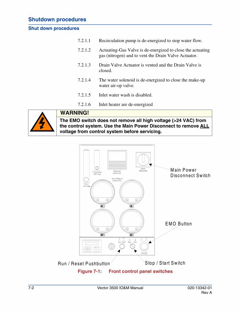
Shutdown procedures
Shut down procedures
7.2.1.1 Recirculation pump is de-energized to stop water flow.
7.2.1.2 Actuating-Gas Valve is de-energized to close the actuating gas (nitrogen) and to vent the Drain Valve Actuator.
7.2.1.3 Drain Valve Actuator is vented and the Drain Valve is closed.
7.2.1.4 The water solenoid is de-energized to close the make-up water air-op valve.
7.2.1.5 Inlet water wash is disabled.
7.2.1.6 Inlet heater are de-energized
Figure 7-1: Front control panel switches
WARNING!The EMO switch does not remove all high voltage (>24 VAC) from the control system. Use the Main Power Disconnect to remove ALL voltage from control system before servicing.
E M O B utton
M a in P ow erD isconn ect Sw itch
S to p / S tart S w itchR u n / R e set P ushbutton
7-2 Vector 3500 IO&M Manual 020-13342-01Rev A
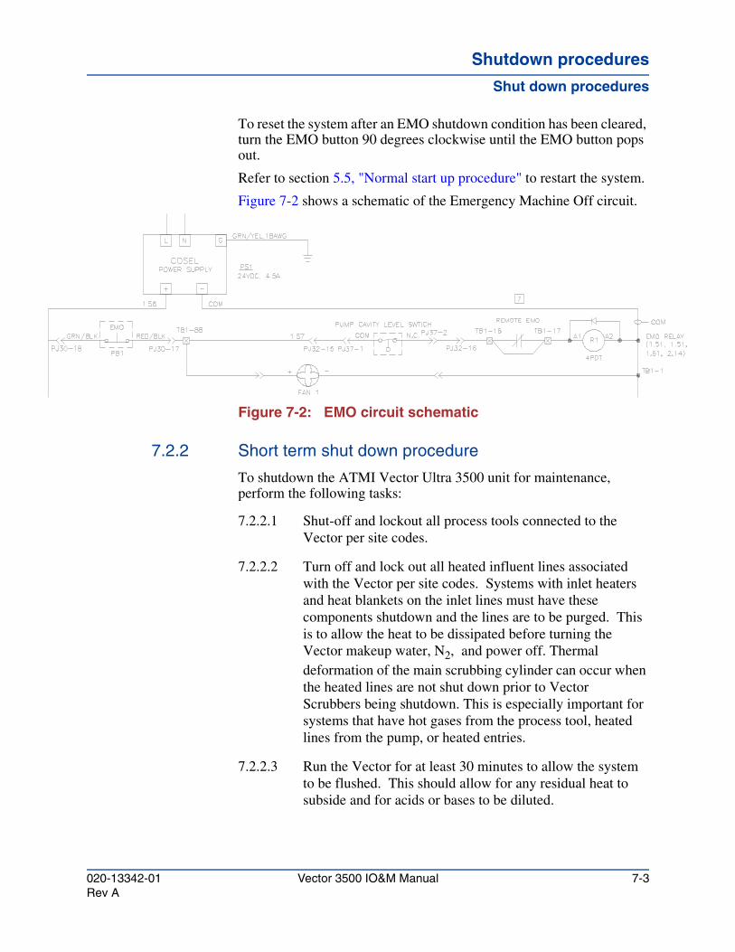
Shutdown proceduresShutdown proceduresShutdown procedures
Shut down procedures
To reset the system after an EMO shutdown condition has been cleared, turn the EMO button 90 degrees clockwise until the EMO button pops out.
Refer to section 5.5, "Normal start up procedure" to restart the system.
Figure 7-2 shows a schematic of the Emergency Machine Off circuit.
Figure 7-2: EMO circuit schematic
7.2.2 Short term shut down procedure
To shutdown the ATMI Vector Ultra 3500 unit for maintenance, perform the following tasks:
7.2.2.1 Shut-off and lockout all process tools connected to the Vector per site codes.
7.2.2.2 Turn off and lock out all heated influent lines associated with the Vector per site codes. Systems with inlet heaters and heat blankets on the inlet lines must have these components shutdown and the lines are to be purged. This is to allow the heat to be dissipated before turning the Vector makeup water, N2, and power off. Thermal deformation of the main scrubbing cylinder can occur when the heated lines are not shut down prior to Vector Scrubbers being shutdown. This is especially important for systems that have hot gases from the process tool, heated lines from the pump, or heated entries.
7.2.2.3 Run the Vector for at least 30 minutes to allow the system to be flushed. This should allow for any residual heat to subside and for acids or bases to be diluted.
020-13342-01 Vector 3500 IO&M Manual 7-3Rev A
Shutdown procedures
Shut down procedures
7.2.2.4 Turn the “STOP-START” switch to the STOP position to shut down the system. The system will only de-energize if the LTA circuit is open (inlet temperature is below 105° C).
7.2.3 Long term shut down procedure
When Vector scrubber systems are shutdown for an extended period of time (1 day or more), the customer should contact ATMI regional support office to assist in shutdown procedure on the POU abatement equipment.
Should the customer elect to shutdown equipment without ATMI support, the following shutdown procedures must be followed properly. If shutdown procedures are not followed, damage to the system will occur.
7.2.3.1 Shut-off and lockout all process tools connected to the Vector per site codes.
7.2.3.2 Turn off and lock out all heated influent lines associated with the Vector per site codes. Systems with inlet heaters and heat blankets on the inlet lines must have these components shutdown and the lines are to be purged. This is to allow the heat to be dissipated before turning the Vector makeup water, N2, and power off. Thermal deformation of the main scrubbing cylinder can occur when the heated lines are not shut down prior to Vector Scrubbers being shutdown. This is especially important for systems that have hot gases from the process tool, heated lines from the pump, or heated entries.
CAUTION!In situations with foreline and/or inlet heaters, potential for system damage arises if the Vector power is turned off while the referenced heaters remain on. The Vector relies on the recirculation of water, N2, and freshwater addition to mitigate the heat generated by the foreline and inlet heaters. If the Vector's power is turned off while the heaters continue to operate, there will not be sufficient water circulation to cool the incoming gas flow. Failure of the customer to observe proper shutdown procedures can void system warranty.
7-4 Vector 3500 IO&M Manual 020-13342-01Rev A
Shutdown proceduresShutdown proceduresShutdown procedures
Shut down procedures
7.2.3.3 Increase the make-up water to the Vector as much as allowable.
7.2.3.4 Run the Vector for at least 30 minutes to allow the system to be flushed. This should allow for any residual heat to subside and for dilution of acids or bases, which if left in the sump could corrode or otherwise damage parts.
7.2.3.5 Verify that all heaters are turned off and are at ambient temperature.
7.2.3.6 Turn the “STOP-START” switch to the STOP position to shut down the system. This will put the system into the cool down mode and it will stay in this mode until the LTA circuit is open (inlet temperature is below 105°C).
7.2.3.7 After the system stops turn off the Main Power Disconnect switch.
7.2.3.8 Close the N2 and H2O supply valves.
7.2.3.9 Switch the facilities circuit breaker to the OFF position.
CAUTION!In situations with foreline and/or inlet heaters, potential for system damage arises if the Vector power is turned off while the referenced heaters remain on. The Vector relies on the recirculation of water, N2, and freshwater addition to mitigate the heat generated by the foreline and inlet heaters. If the Vector's power is turned off while the heaters continue to operate, there will not be sufficient water circulation to cool the incoming gas flow. Failure of the customer to observe proper shutdown procedures can void system warranty.
CAUTION!Shutting off make up water, while continuing to operate the recirculation pump, can cause the temperature of the water to increase to a level that can damage the system over a short period of time (couple of hours). Failure of the customer to observe proper shutdown procedures can void system warranty.
020-13342-01 Vector 3500 IO&M Manual 7-5Rev A

Shutdown procedures
Shut down procedures
7.2.3.10 If the system is being shutdown for 7 days or more, the pump must be drained to prevent biological growth or deposits. This will help to insure Vector will come back online quickly.
7.2.4 Safety shutdown
7.2.4.1 The following devices initiate a safety shutdown:
• EMO (Emergency Machine Off)
• High pump cavity water level switch
• High-High sump water level switch
7.2.4.2 In a safety shutdown, these system components revert to “Fail Safe” positions:
• The recirculation pump is de-energized off to stop pumping.
• The actuating-gas valve is de-energized to close the actuating gas (nitrogen) and to vent the drain valve actuator.
• The drain valve actuator is vented and the drain valve is closed.
• The incoming water solenoid valve is de-energized to close the air-op valve.
• Inlet heaters are disabled.
• Inlet water-washes are disabled.
7-6 Vector 3500 IO&M Manual 020-13342-01Rev A
Vector 3500 Installation, Operation and Maintenance Manual
Preventative maintenanceChapter 8
8.1 IntroductionThis chapter provides routine Preventative Maintenance procedures to ensure continuous trouble-free performance of the Vector Ultra 3500 Wet Exhaust Gas Conditioner. Daily, Monthly, Six-Monthly, and Periodic preventative maintenance procedures are described.
8.2 Required maintenance equipment
8.2.1 Clothing
At a minimum, the following should be observed:
• Acid-proof/heat-resistant gloves
• Appropriate breathing apparatus
• Acid Apron
• Safety glasses
8.2.2 Tools
No special customer-supplied tools are required for service and maintenance of the Vector Ultra 3500 other than the standard tools to be found in a technician’s standard tool box.
020-13342-01 Vector 3500 IO&M Manual 8-1Rev A
Preventative maintenance
Lockout/tagout procedure
8.3 Lockout/tagout procedureBefore performing any maintenance on the system or its parts, all personnel should become familiar with correct lockout/tagout procedures. The purpose of “Lockout/Tagout” is for personnel protection during maintenance or service operations on machinery. It is used to ensure that the machinery is stopped and isolated from all potentially dangerous energy sources. OSHA regulations require that a method, device or technique be established to accomplish this. (The minimum lockout/tagout requirements are stated in OSHA 29CFR 1910.147 and 1910.331 through 335.)
8.3.1 Installation
For installation without an established lockout/tagout procedure, a model procedure which may be adopted is listed as follows:
8.3.1.1 Establish and maintain a lockout/tagout log, which list the date, time, purpose and the authorized person (originator) doing the lock-out.
8.3.1.2 Notify affected personnel of the shutdown of the equipment for maintenance or service.
8.3.1.3 Identify the originator of the tagout and the purpose of the lockout on the tag.
8.3.1.4 Perform system shutdown per section 7.2.2, "Short term shut down procedure".
8.3.1.5 Shut off all energy sources at the lockout station.
8.3.1.6 Securely attach “Lockout” isolating device, lock, or other device which cannot be readily removed.
8.3.1.7 Attached “Tagout” tag on the lockout device or in an easily observed location.
8.3.2 Available types of “lockout” isolating devices
8.3.2.1 Locks especially assigned for lockout use.
8.3.2.2 Grounding rods with electrically insulated handles to dissipate capacitors.
8-2 Vector 3500 IO&M Manual 020-13342-01Rev A
Preventative maintenancePreventative maintenancePreventative maintenance
Lockout/tagout procedure
8.3.2.3 Clamps or holding devices designed for compressed springs.
8.3.2.4 Support devices for elevated machines or elevated machine members.
8.3.2.5 Rotational blocking devices for rotating machinery members, such as flywheels.
8.3.2.6 Stopping devices for hydraulic systems.
8.3.2.7 Shutoff valves for compressed air, compressed gases, etc.
8.3.3 Returning lockout equipment to operation
8.3.3.1 Remove all tools and other items which were brought in for the maintenance or service work.
8.3.3.2 Verify that the equipment is ready to be returned to operating condition.
8.3.3.3 Notify affected personnel that equipment is to be restored to operation.
8.3.3.4 Verify that all personnel in the equipment area are in a safe location.
8.3.3.5 Remove all lockout devices and restore all energy sources to the equipment.
8.3.3.6 Notify affected personnel that maintenance or service work is completed and the equipment is ready for use.
8.3.3.7 Record in the lockout log the time the equipment was returned to operating status.
WARNING!If any maintenance activity requires the opening of any gas tight seal, the unit and the specific opened connection should be leak checked with an appropriate gas detector before the system is put back into service.
CAUTION!
Periodic inspection and cleaning of the Vector Ultra 3500 is absolutely essential.
020-13342-01 Vector 3500 IO&M Manual 8-3Rev A
Preventative maintenance
Daily maintenance
8.4 Daily maintenance1. Perform visual inspection of all plumbing and tank areas,
including front, sides, and back exterior and the interior of the pump compartment. Are there any water leaks? Repair all leaks.
2. Are the make-up water and nitrogen flows correct? Make necessary corrections. Confirm that all external parts of the scrubber are cool to the touch, if not, increase the make-up water flow and monitor the unit for 24 hours. Do not change the flow during a process run. Inlet heater will be warm to the touch, less than 70°C and increasing water flow will NOT effect this temperature.
3. Confirm that the spray bar is spinning and is not wobbling when the fume scrubber is on.
4. Confirm that excessive foaming is not occurring during process effluent scrubbing (below exhaust port of polishing column). If foaming is occurring, increase makeup water flow until foaming decreases. Do not change the flow during a process run.
5. Be suspicious of strange smells. Perform a leak check of the fume scrubber if a leak in the containment is suspected.
Note
The Preventative Maintenance schedule suggested in this chapter is only a suggested schedule. Frequency and duration of PM depends upon the Vector Ultra 3500 unit's specific application. Until a Preventative Maintenance schedule can be established for your system, follow the PM procedures and guidelines in this chapter.
Note
For potential process chemicals to which personnel may be exposed during normal maintenance activities refer to Appendix C, "Typical process gases".
Note
Pictorial Hazard Alert Symbols have been placed in the left hand margin to alert personnel of the potential hazards associated with that series of steps.
Address any problems, difficulties or questions by calling ATMI at (888) 432-6797 [(707) 299-3939 internationally] or by contacting your regional representative.
8-4 Vector 3500 IO&M Manual 020-13342-01Rev A
Preventative maintenancePreventative maintenancePreventative maintenance
Monthly maintenance
8.5 Monthly maintenance1. Turn Off the fume scrubber and confirm that the Waste Water
Valve Closes and that the vertical float switch operates properly.
2. Is the precipitate buildup in the Gas Entry Device excessive? Remove all excessive precipitate buildup. Perform section 8.6 and 8.7, "Periodic chemical cleaning" as needed.
8.6 Cleaning the type 20 entryPeriodic cleaning of the scrubber maybe required. Follow the procedures outlined here for normal cleaning. More frequent cleaning of the entry may required if the water and/or nitrogen flow are misadjusted or if there are very heavy flows of particulate laden gases. If necessary, the entry can simply be cleaned with a stiff bristled “bottle” brush about 2-inch in diameter. The bristles should be plastic or of a material soft enough not to scratch the lining of the entry. Metal brushes or screwdrivers should never be used.
Required personnel for this procedure is one person. Estimated duration to perform the procedure is 30 minutes.
8.6.1 Safety
All personnel are to be trained and qualified in Hazardous Waste Operations. Be sure to work in conformance with site lockout/tagout procedures.
8.6.2 Materials
• Proper Personal Protective Equipment (PPE)
• Five-gallon hazardous waste bag (HazMat bag)
• Plastic squeeze bottle filled with isopropyl alcohol
• Plastic squeeze bottle filled with DI water
• Absorbent wipes
WARNING!Wear safety-approved protective gloves, goggles, and other appropriate equipment as local safety requirements dictate when performing this procedure. Consult the factory EHS department for proper PPE equipment and procedures. At no time should ANY work be performed on the Vector with the house scrubber switched OFF.
020-13342-01 Vector 3500 IO&M Manual 8-5Rev A
Preventative maintenance
Cleaning the type 20 entry
8.6.3 Tools
• Plastic bristled bottle brush about 1" long, with the bristles having about a 1" diameter
• Small 1/4" diameter plastic bristle brush with a four-inch length
• Plastic Scraper
• 9/16" open-end wrench
• 1/2" open-end wrench
• six-foot ladder (to reach entry)
• Hazardous waste vacuum cleaner
• Lockout Tagout Kit
8.6.4 Cleaning procedure
8.6.4.1 Turn off all gas flows from the process equipment.
8.6.4.2 Lockout and tagout all connected tool pumps.
8.6.4.3 1 hour before beginning maintenance disconnect power to the heating blanket covering the Entry plumbing. The system inlet heater can be disabled using section 5.2.10.5 through 5.2.10.8.
8.6.4.4 Allow the Ultra 3500 system to run for 30 minutes after all process tools and pump are turned off to dilute any residual chemistry in the system.
8.6.4.5 Turn off the facility Nitrogen to the Vector Ultra 3500.
WARNING!
If the process equipment uses hydrogen gas, purge the scrubber and process exhaust with nitrogen from the process equipment for five minutes at full flow before shutting off the scrubber nitrogen. Shut off the entry water and nitrogen flow at the scrubber's front panel.
WARNING!ATMI recommends that the Vector remain ON and running, as this aids in the cleaning process. To prevent an inlet pressure alarm, turn down the low alarm set point on the Photohelic® to zero.
8-6 Vector 3500 IO&M Manual 020-13342-01Rev A
Preventative maintenancePreventative maintenancePreventative maintenance
Cleaning the type 20 entry
8.6.4.6 Use the six-foot ladder to reach the components of the entry section. Disconnect the Photohelic/inlet wash valve to the upper section of the entry, using both the 9/16" and 1/2" open-end wrenches to disconnect the 1/4" Swagelok fitting. (Reference Figure 2-3)
8.6.4.7 Remove the KF40 and V-clamp that secure the entry inlet then remove from nitrogen injection chamber.
8.6.4.8 Using the 1" diameter plastic bristled bottle brush and plastic scraper, clean from the entry opening down into the oxidizer area, allowing particulate buildup to fall into the scrubber.
8.6.4.9 Inspect the Photohelic®/water wash inlet port for particulate. If there is particulate, brush it back into the entry with the small 1/4" plastic bottle brush.
8.6.4.10 Rinse the entry with DI water using the DI squirt bottle.
8.6.4.11 Remove entry tube section by lifting upwards to clear the inlet body.
8.6.4.12 Inspect the upper-section for buildup. Hold the upper-section over the HazMat bag while cleaning the particulate using the 1" bottle brush.
8.6.4.13 Remove the porous insert from the entry.
8.6.4.14 Inspect the porous insert for cleanliness. In the unlikely event that solids are present, simply wipe them away with a paper towel. Ensure that the porous section of the insert does not become wetted while cleaning. If, for some reason, water does soak into the porous metal, contact your local ATMI Field Service Engineer.
Note
If any abnormal odors are present perform a gas check.
CAUTION!
Completely dry, with absorbent wipes, the inside of the entry and the ports.
020-13342-01 Vector 3500 IO&M Manual 8-7Rev A
Preventative maintenance
Cleaning the type 20 entry
8.6.4.15 Inspect and clean the O-rings to the KF-40 flanges. Change the O-rings, if necessary. Use clean wipes and isopropyl alcohol to clean the O-rings.
8.6.4.16 Inspect the wetted wall column located in the lower section of the entry. If solids are present, thoroughly wipe them away with a soft brush.
8.6.4.17 Install the upper-section by reconnecting the band clamp and KF clamp.
8.6.4.18 Reconnect the Photohelic/water wash valve line using the 9/16" and 1/2" open-end wrenches.
8.6.4.19 If necessary, use the hazardous waste vacuum cleaner to vacuum any contaminated particles on or around the Vector Ultra 3500 system.
8.6.4.20 Readjust the Photohelic® low alarm set point back to 0.5" H2O.
8.6.4.21 Turn on the N2 supply to the Vector Ultra 3500.
8.6.4.22 Remove the lockout / tagout devices from the system.
8.6.4.23 If the system heaters were unplugged, reconnect them at this time. If the heaters were disabled using the MMI, enable them at this time.
8.6.4.24 Check flow settings to ensure the proper set points:
• N2 photohelic purge: 1 slm per inlet
• N2 entry purge: 50 slm per inlet
• Make-up water: 1.5 gpm (city water)
8.6.4.25 During start up of the unit, press reset to clear all the alarms. The inlet heater will turn on (default) only when all the alarms (excluding heater low temp. alarm) has been cleared.
8.6.4.26 When the inlet heater reaches 105°C, during the first hour of system operation, the unit will automatically reset the "Heater Lo Tmp" (LTA) alarm, until then, the warning alarm will remain activated.
8-8 Vector 3500 IO&M Manual 020-13342-01Rev A
Preventative maintenancePreventative maintenancePreventative maintenance
Periodic chemical cleaning
8.7 Periodic chemical cleaningPeriodic chemical cleaning of the Vector Ultra Fume Scrubber is recommended to remove deposits of effluent by-products. Frequency will be between 1 to 12 months based on process and water count.
1. Run the scrubber for 30 minutes prior to cleaning (process gases should be turned off). Perform section 8.6, "Cleaning the type 20 entry" as needed.
2. Before any work is performed on the Vector verify that no process gas is being run and that you are able to completely turn off the system. Also verify that the house exhaust and the nitrogen are still on.
3. Verify that the system is not in an alarm state. If alarms are present trouble shoot and clear the faults prior to beginning maintenance on the system.
4. Visually inspect the system for leaks, correct as necessary.
5. Shut-off the scrubber (the nitrogen supply and house exhaust must stay ON). If the Entry Device is to be cleaned, refer to Chapter 9, "Service operations".
6. Visually inspect the spray bar; verify that the bar is spinning quickly without wobble and that the spray jets are not clogged.
7. Depending on the process, make 1.0 gallon of 20% concentration of either an acid solution (hydrochloric acid), HF (hydrofluoric), or a caustic solution (sodium hydroxide) in an appropriate container. Do not exceed 4 gallons. (Contact ATMI Service Department if more acid is required)
8. Add the cleaning solution to the scrubber via the 1/2-inch cleaning port in the cover, or it can be poured into the entry if the entry internals (i.e. stainless pieces and O-rings) have been removed.
9. Turn the unit on and run for 30 minutes with the make-up water turned off. A make up water alarm will occur during this step, but this alarm can be ignored.
WARNING!The exhaust draw must stay ON during this procedure.
020-13342-01 Vector 3500 IO&M Manual 8-9Rev A
Preventative maintenance
Six-month maintenance
10. After the 30-minute run, turn the make-up water on to a make-up rate of 2.5 gpm and allow the unit to run for another 20 minutes.
11. Inspect the scrubber for cleanliness and check to ensure that all sealing areas, especially the ceramic pump seal, for leakage.
12. Repeat Steps 7 through 11 if the unit is still not clean. Do not use a more concentrated level of acid or caustic to clean faster.
13. Put scrubber back into service, return the make-up water flowrate to the proper level.
14. Remove the process inlet piece immediately above the top entry flange.
15. Using water and a stiff plastic-bristle bottle brush (1-inch in diameter), scrub the top inside area of the scrubber, until all deposits have been removed. After cleaning, rinse the top of the inlet with clean water and reassemble the inlet piece.
16. When all PM functions are complete reassemble all components.
17. Turn on the facilities connections for water.
18. Verify that all manual valves are in the correct position for normal system operations.
19. Turn on the main power disconnect switch.
20. Reset the EMO, if necessary.
21. Verify that there is electrical power present by checking that the MMI alarm display is functional.
22. Turn the stop/start switch to the start position.
23. Push the reset button once to reset any alarm conditions; push the reset button a second time to start the scrubber system.
24. Visually inspect the system for leaks, correct as necessary.
8.8 Six-month maintenance1. Before any work is performed on the Vector verify that no
process gas is being run and that you are able to completely turn off the system.
2. Also verify that the house exhaust and the nitrogen are still running.
8-10 Vector 3500 IO&M Manual 020-13342-01Rev A
Preventative maintenancePreventative maintenancePreventative maintenance
Six-month maintenance
3. Perform monthly maintenance per section 8.6, "Cleaning the type 20 entry".
4. Perform section 8.7, "Periodic chemical cleaning", if needed.
8.8.1 Pump current draw
8.8.1.1 Lock out and tag out the main power disconnect.
8.8.1.2 Remove the pump cavity enclosure doors.
8.8.1.3 Remove the cover from the pump motor interconnect box.
8.8.1.4 Locate one of the black pump motor connection leads, and connect a clamp on ampmeter.
8.8.1.5 Remove the lock out and tag out and turn the system on.
8.8.1.6 Compare the current reading to the specification stamped on the motor casing.
8.8.1.7 If the constant current draw is off spec by more than 15% replace the pump.
8.8.1.8 Perform visual inspection of pump for leaks and abnormal vibrations.
8.8.1.9 Lock out and tag out the main power disconnect.
8.8.1.10 Remove the clamp on ampmeter, from the pump motor interconnect box and replace the cover.
8.8.1.11 Remove the lock out and tag out and turn the system on.
8.8.2 Pump cavity
Carefully inspect the pump cavity area and clean as necessary.
8.8.3 Testing nitrogen systems
8.8.3.1 Verify Nitrogen Supply Regulator (at the house supply) is set to 80 psig and the Nitrogen Supply gauge (inside the system door) is set to 30 psig.
8.8.3.2 Verify Purge Photohelic Nitrogen to predetermined spec. (See setting from facilities spec.)
020-13342-01 Vector 3500 IO&M Manual 8-11Rev A
Preventative maintenance
Six-month maintenance
8.8.3.3 Set each Entry Photohelic low alarm needle to 0.5" W.C.
8.8.3.4 Set each Entry Photohelic high alarm needle to -4.5" W.C.
8.8.4 Testing water systems
8.8.4.1 Turn on the scrubber by placing the Start/Stop switch in Start mode. If there is no water in the sump, one of the alarms on MMI displayed will be "Sump Level low warning".
8.8.4.2 Adjust Make Up Water flow to customer specifications. Sump begins to fill from the make-up water Fill port.
8.8.4.3 Press RUN/RESET to reset all the alarms. MMI displays NORMAL with 0 Alarms.
8.8.4.4 Check for leaks in water plumbing lines.
8.8.4.5 Check barrel seams for leakage.
8.8.5 Testing control panel ON/OFF and EMO
8.8.5.1 Switch Start/Stop button to Stop. Scrubber is OFF after LTA goes below 105°C for 10 minutes and water drains to below Sump level open float. Ensure make up water flow is OFF.
8.8.5.2 Switch Start/Stop button to Start. Scrubber is ON.
8.8.5.3 Press RUN/RESET button. The system will go to warm up mode. By using the MMI (reference 5.2.10.6 - 5.2.10.8) turn off the inlet(s) heater power. The system will go to normal operation mode. MMI displays Normal Operation with 0 alarms, if no alarm exists and Green Tower light is ON. (note: a make up water alarm may occur press the run/reset button again to clear this alarm)
8.8.5.4 Press EMO button. EMO Shutdown is displayed on MMI. Red Tower light is ON. Horn is ON. Pump is OFF. Make up water flow is OFF.
8.8.5.5 Press RUN/RESET button once to silence horn. Alarm Horn OFF.
8-12 Vector 3500 IO&M Manual 020-13342-01Rev A
Preventative maintenancePreventative maintenancePreventative maintenance
Six-month maintenance
8.8.5.6 Disengage EMO button.
8.8.5.7 Press RUN/RESET button to restart. If no alarm exists, MMI will display "Normal Operation with 0 alarms" and Green Tower light is ON.
8.8.6 Pump cavity float
8.8.6.1 Lift and hold pump cavity float ball to activate. (located in the pump cavity on the back left hand corner behind the pump) EMO Shutdown is displayed on MMI. Red Tower light is ON. Horn is ON. Pump is OFF. Make up water flow is OFF.
8.8.6.2 Release ball float.
8.8.6.3 Press RUN/RESET button to Silence Horn.Alarm Horn OFF.
8.8.6.4 Press RUN/RESET button. Scrubber Starts.
8.8.7 Make-up water flow
8.8.7.1 Record make up water flow rate. Adjust Make-Up Water valve slowly towards 0 until make up water alarm turns ON. MMI reading 0.5 gpm ±0.1. Low make-up water warning is displayed on MMI. Yellow Tower light is ON. Horn is ON.
8.8.7.2 Adjust Make-Up Water flow to back to its original position.
8.8.7.3 Press RUN/RESET button twice. Alarm Horn OFF. No Low make-up water alarm on MMI.
8.8.8 Test water-wash flow
8.8.8.1 Manually starting the inlet wash can be used to confirm the proper flow and that there are no leaks during wash.
8.8.8.2 To manually start the inlet wash, press the down button on the MMI until "manual start" is reached.
8.8.8.3 Select "yes" to start the water flow. The water will flow for what ever the "cycle time" is set for and then the system will resume the programmed cycle timing.
020-13342-01 Vector 3500 IO&M Manual 8-13Rev A
Preventative maintenance
Six-month maintenance
8.8.9 Photohelic high/low alarms
8.8.9.1 Slowly adjust Entry #1 Photohelic high alarm needle (red needle to the right) to less than the black indication needle. Entry warning is displayed on MMI. Alarm Horn is ON
8.8.9.2 Set Entry #1 Photohelic high needle to -4.5" W.C.
8.8.9.3 Press RUN/RESET button twice.No Entry warning is displayed on MMI. Alarm Horn is OFF
8.8.9.4 Slowly adjust Entry #1 Photohelic low alarm needle (red needle to the left) to more than the black indication needle.Entry warning is displayed on MMI. Alarm Horn is ON
8.8.9.5 Set Entry #1 Photohelic low needle to -0.5".
8.8.9.6 Press RUN/RESET button twice. No Entry warning is displayed on MMI. Alarm Horn is OFF.
8.8.9.7 Repeat steps 8.8.9.1 - 8.8.9.6 for each inlet.
8.8.10 Sump level switch
8.8.10.1 (note: secure power and lock/tag out where required). Disconnect the wire to terminal X6 on the PLC. Setup. Disables the Sump Hi Level Switch.
8.8.10.2 Close the manual discharge valve (HV-38 ) on the discharge line in Pump Cavity. Water level rises in sump.
8.8.10.3 Increase the make up water flow to maximum. Let the water level rise up in the sump till sump level Hi-Hi float activates. Make-Up Water Supply Valve closes (Flow decrease to 0 gpm). Yellow Tower light is ON and the alarm horn will be on.
8.8.10.4 Press RUN/RESET button to silence the horn. Alarm Horn is OFF.
8.8.10.5 Open the discharge valve (HV-38).
8.8.10.6 (note: secure power and lock/tag out where required) Reconnect the wire to terminal X6 on the PLC. Return the make up water flow rate to its original position. Make-Up Water Supply Valve opens. Normal Green light is ON.
8-14 Vector 3500 IO&M Manual 020-13342-01Rev A
Preventative maintenancePreventative maintenancePreventative maintenance
Six-month maintenance
8.8.10.7 Wait till water drains to below Sump Level open float (Pneumatic valve will shut off), Close the discharge valve (HV-38) on the discharge line in Pump Cavity. Water level rises in sump.
8.8.10.8 Let the water level rise up in the sump till sump level Hi float actuates. Sump Hi Level Warning is displayed on MMI. Yellow Tower light is ON. Horn is ON. Make-up water is OFF.
8.8.10.9 Press RUN/RESET button to silence the horn. Alarm horn is OFF.
8.8.10.10 Slowly open the discharge valve (HV-38) to drain water to below sump level open float. Press RUN/RESET button to reset the Alarm. No Sump Hi level Alarm on MMI. Normal Green Tower light is ON. Make-up water is ON.
8.8.11 Media temperature switch
8.8.11.1 Disconnect one of the connectors at the media temperature switch, located in the pump cavity on the piping. Alarm sounds within 2 seconds. Media Temperature Shutdown is displayed on MMI. Red Tower light is ON.
8.8.11.2 Press RUN/RESET button to Silence Horn. Alarm Horn OFF.
8.8.11.3 Reconnect the media temperature switch connector. Wait for temperature switch to reset.
8.8.11.4 Press RUN/RESET button to restart. Scrubber Starts. No Media Temperature alarm on MMI.
8.8.12 Conclusion
When all maintenance and verifications are complete, press reset to clear any remaining alarms, remove any lock out tag out still on system and place the system back
020-13342-01 Vector 3500 IO&M Manual 8-15Rev A
Preventative maintenance
Annual maintenance
8.9 Annual maintenance1. Before any work is performed on the Vector verify that no
process gas is being run and that you are able to completely turn off the system. Also verify that the house exhaust and the nitrogen are still running.
2. Verify that the system is not in an alarm state.
3. If alarms are present, clear the faults prior to beginning maintenance on the system.
4. Visually inspect the system for leaks, correct as necessary.
5. Note all flows for comparison after cleaning and maintenance.
6. Inspect the reaction chamber for any sign of foaming.
7. Presence of foam is an indication that more makeup water is necessary.
8. Perform section 8.6, "Cleaning the type 20 entry".
9. Perform section 8.7, "Periodic chemical cleaning", if needed.
10. Turned system power off and confirmed makeup water stops flowing.
11. Turn off the facilities connections for water and CDA.
12. DO NOT turn off the nitrogen and house exhaust.
8.9.1 Spray bar inspection/cleaning
8.9.1.1 Unscrew the 8 nylon bolts holding each entry and the 12 nylon bolts holding the round top lid of the system on.
8.9.1.2 Remove the spray bar by unscrewing the cap (NOTE: it has a reverse thread config). Inspect the spray jets attached to the bottom of the spray bar, replace if needed using part number 5421-04 from the PM kit.
8.9.1.3 Reassemble the spray bar, top lid and entry. (NOTE: when installing 12 nylon bolts hand tighten only, when installing entry bolts hand tighten + ¼ turn in a star pattern).
8-16 Vector 3500 IO&M Manual 020-13342-01Rev A
Preventative maintenancePreventative maintenancePreventative maintenance
Annual maintenance
8.9.2 Polishing scrubber replacement
8.9.2.1 Undo the two flanges on the exhaust connection.
8.9.2.2 slide off the exhaust spool piece.
8.9.2.3 Reach inside the polishing column and slowly pull out the packing cartridge.
8.9.2.4 Place the packing cartridge in the HAZMAT bag for storage.
8.9.2.5 Install the replacement packing cartridge into the polishing column, use part number 6733-00 from the PM kit.
8.9.2.6 Replace the exhaust spool piece.
8.9.2.7 Make sure that the flanges are clean and that the O-rings are properly installed.
8.9.2.8 Reconnect the two flanges on the exhaust connection.
8.9.3 Chemical cleaning
(NOTE: if the packing balls are clean omit this section)
Visually inspect the primary scrubbing chamber, if the packing balls have a precipitate build up, chemical cleaning should be performed as indicated in section 8.7, "Periodic chemical cleaning" otherwise proceed to step 8.9.4.
8.9.4 Removing/replacing the pump
Refer to sections 9.2.1 and 9.2.2, removing and replacing the pump.
8.9.5 Restarting
8.9.5.1 When all PM functions are complete reassemble all components.
8.9.5.2 Turn on the facilities water.
8.9.5.3 Verify that all manual valves are in the correct position for normal system operations (see system operational manual for valve config.)
8.9.5.4 Remove the lock from the main power disconnect switch.
020-13342-01 Vector 3500 IO&M Manual 8-17Rev A
Preventative maintenance
Annual maintenance
8.9.5.5 Turn on the main power disconnect switch.
8.9.5.6 Reset the EMO, if necessary.
8.9.5.7 Verify that there is electrical power present by checking that the MMI alarm display is functional.
8.9.5.8 Turn the stop/start switch to the start position.
8.9.5.9 Push the Reset button twice to reset any alarm conditions, and to start the scrubber system.
8.9.5.10 When the inlet heater reaches 105°C, during the first hour of system operation, the unit will automatically reset the "Heater Lo Tmp" (LTA) alarm, until then, the warning alarm will remain activated.
8.9.5.11 At this point the Vector Ultra 3500 scrubber is operating normally and is able to scrub the residual process gases from the process effluent.
8.9.5.12 Visually inspect the system for leaks, correct as necessary.
8.9.5.13 Verify Pump Rotation Verify and any Unusual Sounds from Pump/Motor.
8.9.5.14 Adjust the following flows to the levels noted prior to maintenance: make up water flow, inlet wash flow, and Nitrogen flow.
8.9.5.15 Visually inspect the spray bar; verify that the bar is spinning.
8.9.5.16 When all maintenance and verifications are complete, press reset to clear any remaining alarms and place the system back into service.
8-18 Vector 3500 IO&M Manual 020-13342-01Rev A
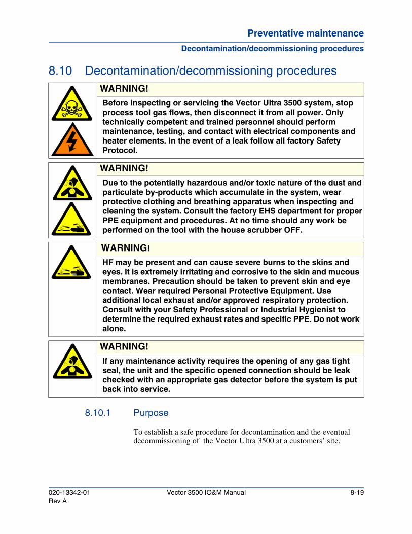
Preventative maintenancePreventative maintenancePreventative maintenance
Decontamination/decommissioning procedures
8.10 Decontamination/decommissioning procedures
8.10.1 Purpose
To establish a safe procedure for decontamination and the eventual decommissioning of the Vector Ultra 3500 at a customers’ site.
WARNING!Before inspecting or servicing the Vector Ultra 3500 system, stop process tool gas flows, then disconnect it from all power. Only technically competent and trained personnel should perform maintenance, testing, and contact with electrical components and heater elements. In the event of a leak follow all factory Safety Protocol.
WARNING!Due to the potentially hazardous and/or toxic nature of the dust and particulate by-products which accumulate in the system, wear protective clothing and breathing apparatus when inspecting and cleaning the system. Consult the factory EHS department for proper PPE equipment and procedures. At no time should any work be performed on the tool with the house scrubber OFF.
WARNING!
HF may be present and can cause severe burns to the skins and eyes. It is extremely irritating and corrosive to the skin and mucous membranes. Precaution should be taken to prevent skin and eye contact. Wear required Personal Protective Equipment. Use additional local exhaust and/or approved respiratory protection. Consult with your Safety Professional or Industrial Hygienist to determine the required exhaust rates and specific PPE. Do not work alone.
WARNING!If any maintenance activity requires the opening of any gas tight seal, the unit and the specific opened connection should be leak checked with an appropriate gas detector before the system is put back into service.
020-13342-01 Vector 3500 IO&M Manual 8-19Rev A
Preventative maintenance
Decontamination/decommissioning procedures
8.10.2 Procedures
8.10.2.1 Turn off all gas flows from the process equipment.
8.10.2.2 Lockout and tagout all connected tool pumps.
8.10.2.3 Turn off all inlet heaters.
8.10.2.4 Allow the Vector Ultra 3500 system to run for 30 minutes to dilute any residual chemistry in the system.
8.10.2.5 To prevent an inlet pressure alarm, turn down the low alarm set point on the Photohelic® to zero.
8.10.2.6 Turn off the facility Nitrogen and H20 to the Vector Ultra 3500.
8.10.2.7 Use the appropriate size ladder to reach the components of the entry section. Disconnect the Photohelic/water wash valve from the upper sections of each entry, using both the 9/16” and ½” open-end wrenches to disconnect the ¼” Swagelok fittings.
8.10.2.8 Remove the KF clamp and the band clamp on the spool assembly. Lift upward when removing the upper section .
8.10.2.9 Using the 1” diameter plastic bristled bottle brush, clean from the entry opening down into the oxidizer area, allowing particulate buildup to fall into the scrubber.
8.10.2.10 Inspect the Photohelic®/water wash inlet port for particulate. If there is particulate, brush back into the entry with small ¼” plastic bottle brush.
8.10.2.11 Rinse the entry with De-Ionized water using a DI squirt bottle.
8.10.2.12 Inspect the upper inlet assembly for buildup. Hold the assembly over a Hazardous Materials bag while cleaning the particulate using the 1" plastic bottle brush. Brush buildup from the inlet.
8.10.2.13 Inspect and decontaminate the O-rings to the KF flanges.
8.10.2.14 Install the spool assembly by reconnecting the KF flange and the band clamp.
8-20 Vector 3500 IO&M Manual 020-13342-01Rev A
Preventative maintenancePreventative maintenancePreventative maintenance
Decontamination/decommissioning procedures
8.10.2.15 Reconnect the Photohelic/water wash valve using the 9/16” and ½” open-end wrenches.
8.10.2.16 If necessary, use a hazardous waste vacuum cleaner to vacuum any contaminated particles on or around the Vector Ultra 3500.
8.10.2.17 Readjust the Photohelic® low alarm set point back to 0.5” H2O.
8.10.2.18 Turn on the N2 and water supply to the Vector Ultra 3500.
8.10.2.19 Remove the lockout/tagout devices from the system.
8.10.2.20 Press the reset button once to clear all alarms; this places the Vector Ultra 3500 in operation mode.
8.10.2.21 Run the scrubber for 30 minutes.
8.10.2.22 Visually inspect the primary scrubbing chamber, if the packing balls have a precipitate build up, chemical cleaning should be performed as indicated in section 8.7, "Periodic chemical cleaning".
8.10.2.23 Drain all the water from the tank by holding down PB4.
8.10.2.24 Wipe down all exterior surfaces using a pH neutralizing solution.
8.10.2.25 Using DI water, wet surfaces inside/outside the tank, inlets, gas exhaust and drain outlet, and check corrosivity levels using pH paper. Check for HF using a Spillfyter.
8.10.2.26 Once pH levels show neutral and no HF is present, it is now safe to dismantle and decommission the tool.
020-13342-01 Vector 3500 IO&M Manual 8-21Rev A
Preventative maintenance
Decontamination/decommissioning procedures
8-22 Vector 3500 IO&M Manual 020-13342-01Rev A
Vector 3500 Installation, Operation and Maintenance Manual
Service operationsChapter 9
9.1 IntroductionThis chapter describes the procedures for removing and replacing Field Replaceable Units (FRU) in the Vector Ultra 3500 system.
9.2 Field replaceable unit removal and replacementThis section provides step-by-step instructions for the removal and replacement of all major Field Replaceable Units (FRUs).
WARNING!
ATMI requires Lockout/Tagout to be performed before working on a specific piece of equipment. The equipment must be locked and tagged out of all the energy sources before beginning work. Each factory on site may have additional controls. Follow specific Factory policies when performing Lockout/Tagout of the Vector Ultra 3500.
Absolutely no “group” or “custodial” locks will be used. “Group” and “Custodial” locks infer one (1) lock representing all employees working on that particular tool or system.
WARNING!
This instrument uses HIGH VOLTAGE. Extreme care should be used when performing maintenance and adjustments while power is ON. Whenever possible, turn power to the fume scrubber OFF at the local circuit breaker before conducting any FRU removal or replacement.
020-13342-01 Vector 3500 IO&M Manual 9-1Rev A
Service operations
Field replaceable unit removal and replacement
9.2.1 Removing the pump motor
9.2.1.1 Lockout and tagout the main power at the main electrical panel. Ensure that both hot leads to the scrubber are disconnected.
9.2.1.2 Remove all access doors to pump cavity.
9.2.1.3 Shut OFF the suction ball valve located in the upper rear section of the pump cavity. The handle should be oriented perpendicular to the pipe when in the OFF position.
9.2.1.4 Shut off the discharge ball valve.
9.2.1.5 Remove the pump drain plug (see Figure 4-9).
9.2.1.6 Remove the cover from the motor interconnect box (4 screws).
9.2.1.7 Label all pump motor connection leads.
WARNING!
The fume scrubber you are servicing may process toxic gases. When performing maintenance, ensure that the process reactor cannot vent its exhaust to the scrubber. Wear protective rubber or vinyl gloves when working on internal surfaces that are normally exposed to reactor fumes. Run the scrubber for a minimum of 30 minutes before opening the containment to ensure that all residual reactor gases have been scrubbed and/or vented. Exhaust from the Vector Ultra 3500 to the house scrubber MUST REMAIN ON to provide safety ventilation.
WARNING!
The removal and replacement of equipment on the fume scrubber, either described or not described in this manual, may require heavy lifting. When lifting heavy equipment always use proper lifting techniques and use two or more people when needed.
WARNING!
Acid-resistant gloves and eye protection should be worn when servicing the pump-motor assembly. Before servicing the scrubber, the system should be allowed to operate for 10 minutes (with process OFF) to rinse out potentially toxic waste.
9-2 Vector 3500 IO&M Manual 020-13342-01Rev A
Service operationsService operationsService operations
Field replaceable unit removal and replacement
9.2.1.8 Disconnect each pump motor lead and remove the waterproof power line from the pump motor.
9.2.1.9 Remove the two hex head mounting bolts holding the pump stand to the scrubber floor.
9.2.1.10 Remove the large black pump band clamp knob. Remove the entire band clamp from the pump assembly.
9.2.1.11 Using only hand force, work the motor and half-pump assembly loose. The pump housing will separate into two parts at the seam where the band clamp joined them together.
9.2.1.12 Remove the pump motor and half-pump from the scrubber's pump cavity.
1. One person should reach behind the pump and push it towards the scrubber’s pump cavity opening. The second person should pull the pump toward the opening.
2. With the pump at the opening, both persons should lift the pump motor and half-pump together, out of the scrubber’s pump cavity.
9.2.2 Replacing the pump motor
9.2.2.1 Ensure that the body o-ring sealing both halves of the pump housing is in its proper place. Lubricate the diffuser to pump half o-ring with silicon grease.
CAUTION!
Do not pry the pump assembly apart. Do not allow the hard-plumbed half of the housing to place stress on the plumbing.
CAUTION!
Be sure to provide support for the hard-plumbed half of the pump while working the motor and half-pump out.
WARNING!The pump weighs 38 lbs. Use two people to remove the pump motor from the scrubber’s pump cavity. Use proper lifting techniques when lifting the pump motor.
020-13342-01 Vector 3500 IO&M Manual 9-3Rev A
Service operations
Field replaceable unit removal and replacement
9.2.2.2 Position the pump motor with its half-pump assembly in the pump cavity.
9.2.2.3 Use the same procedure (but in reverse) for positioning the pump motor and half-pump assembly in the pump cavity, that is described above in step 9.2.1.12 of removal.
9.2.2.4 Using only hand force and supporting the hard-plumbed half, press the pump housings together. If any restriction is experienced, remove the pump and inspect both parts for interference and/or damage.
9.2.2.5 Install the band clamp by positioning the clamp so that the tightening nut is on the bottom of the pump and to the right. Do not fully tighten the clamp at this time.
9.2.2.6 Install the two hex-head mounting bolts. Do not fully tighten the bolts at this time.
9.2.2.7 Hand-tighten the band clamp. Tighten until the band knob squeaks.
9.2.2.8 Tighten the two hex-head pump mounting bolts. Apply approximately 15 foot-pounds of torque. Use a torque wrench if available.
9.2.2.9 Install the waterproof power line to the motor and reconnect each lead.
9.2.2.10 Connect the main power breaker to the scrubber.
9.2.2.11 Check the motor phasing per procedure in Section 4.7.1.
9.2.2.12 Fully open the suction ball valve (pump inlet supply), located in the upper rear section of the pump cavity.
9.2.2.13 Turn the scrubber ON and inspect for leaks. Check and/or tighten any fittings where leaks occur.
9.2.2.14 Install the access door to the pump chamber.
9-4 Vector 3500 IO&M Manual 020-13342-01Rev A
Service operationsService operationsService operations
Field replaceable unit removal and replacement
9.2.3 Pump motor seal and heat sink insert
If the motor's shaft seal is worn or damaged, it must be replaced.
9.2.3.1 To replace the pump seals follow Section 9.2.1, steps 9.2.1.1 through 9.2.1.12.
9.2.3.2 With the motor and it’s mated pump half out, remove the five screws and washers holding the diffuser to the seal plate. Remove the diffuser.
9.2.3.3 Remove the motor fan cover, from the opposite end of the motor.
9.2.3.4 Hold the shaft with a 7/16-inch open-end wrench on the motor shaft flats.
9.2.3.5 Unscrew the pump impeller from the shaft (turn counter clockwise when facing it).
9.2.3.6 While holding the spring loaded seal with large pliers, rotate the motor fan by hand and pull the spring seal off the motor shaft.
9.2.3.7 Separate the motor from it’s pump housing by removing the four large allen screws.
9.2.3.8 Place the pump half face down on a flat surface and tap out the ceramic seat. Do not force out the heat sink insert. If the insert has moved, the pump will leak. If the heat sink insert moves or shifts, it must be removed and reinstalled. See directions below in this section.
9.2.3.9 Remove and discard the slinger (quarter sized rubber washer found on the motor shaft).
WARNING!
The fume scrubber you are servicing may process toxic gases. When performing maintenance, ensure that the process reactor cannot vent its exhaust to the scrubber. Wear protective rubber or vinyl gloves when working on internal surfaces that are normally exposed to reactor fumes. Run the scrubber for a minimum of 30 minutes before opening the containment to ensure that all residual reactor gases have been scrubbed and/or vented. Exhaust from the Vector Ultra 3500 to the house scrubber MUST REMAIN ON to provide safety ventilation.
020-13342-01 Vector 3500 IO&M Manual 9-5Rev A
Service operations
Field replaceable unit removal and replacement
9.2.3.10 Inspect the motor shaft bearing for rust. If rust or buildup is found, replace the pump motor.
9.2.3.11 Clean the seal cavity in the pump half and clean the motor shaft.
9.2.3.12 Place a new slinger on the motor shaft.
To install the new seal and reassemble the pump, follow this procedure:
9.2.3.13 The ceramic seat must be clean and free of dirt, grease, and dust. Wet the outer edge of the o-ring with a small amount of liquid detergent. Press the ceramic seat into the seal plate cavity firmly and squarely with finger pressure.
9.2.3.14 If the ceramic seat will not locate properly, remove it, place it face up on your work area, and re-clean the cavity. The ceramic seat should now press into the seal plate cavity.
9.2.3.15 If the seat still will not locate properly, place a cardboard washer over the polished face and use a piece of 3/4-inch standard pipe for pressing purposes. Do not scratch or mar the polished surface or the seal will leak.
9.2.3.16 Remount the pump half onto the motor. Tighten the Allen bolts to 60 inch-pounds of torque.
9.2.3.17 Apply a small amount of liquid detergent to the inside diameter of the rotating half of the seal (the part with the spring).
9.2.3.18 Slide the rotating member, polished black face first (stainless-steel end), over the threaded shaft end and shaft shoulder until the rubber drive ring hits the shaft shoulder. Be sure not to nick or scratch the polished black seal face. The seal face will leak if it is damaged.
9.2.3.19 Screw the impeller onto the shaft (clockwise). HAND-TIGHTEN ONLY. The installed impeller will automatically locate the seal in the seal plate.
9.2.3.20 Mount the diffuser on the seal plate. Tighten the screws to 10-14 inch-pounds of torque.
9.2.3.21 Perform the procedure described in Section 9.2.1, "Removing the pump motor", steps 9.2.1.1 through 9.2.1.12.
9-6 Vector 3500 IO&M Manual 020-13342-01Rev A
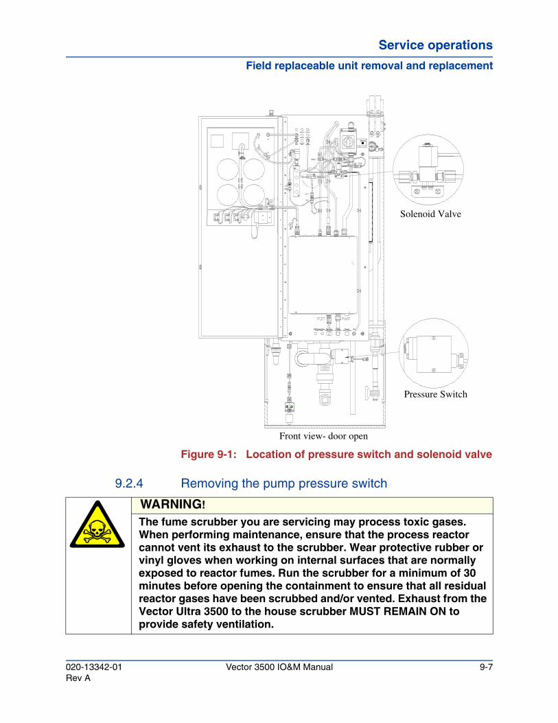
Service operationsService operationsService operations
Field replaceable unit removal and replacement
Figure 9-1: Location of pressure switch and solenoid valve
9.2.4 Removing the pump pressure switch
Entry #3 Entry #4
Entry #2Entry #1Manifold
Entry
FlowMeter
Chemical Inject Solenoid
N2
Pump ChamberHarness
Probe / PumpPH Controller N
Chem Inj PumpPower
Pump MotorPower 2
Pressure Switch
Solenoid Valve
Front view- door open
WARNING!
The fume scrubber you are servicing may process toxic gases. When performing maintenance, ensure that the process reactor cannot vent its exhaust to the scrubber. Wear protective rubber or vinyl gloves when working on internal surfaces that are normally exposed to reactor fumes. Run the scrubber for a minimum of 30 minutes before opening the containment to ensure that all residual reactor gases have been scrubbed and/or vented. Exhaust from the Vector Ultra 3500 to the house scrubber MUST REMAIN ON to provide safety ventilation.
020-13342-01 Vector 3500 IO&M Manual 9-7Rev A
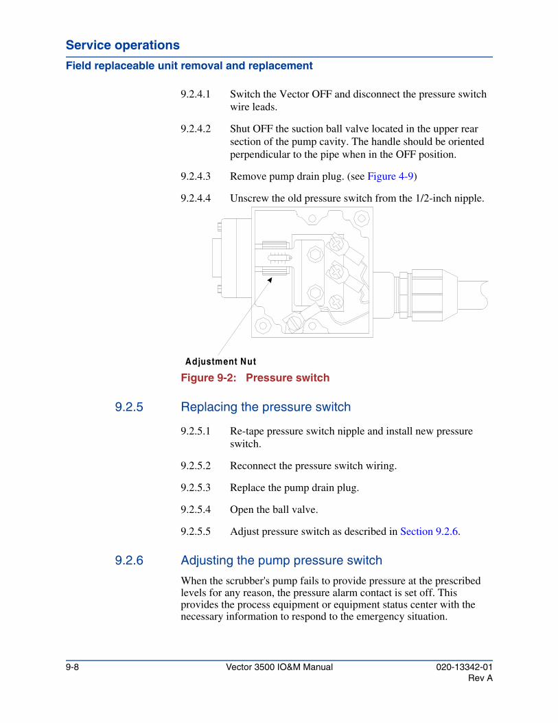
Service operations
Field replaceable unit removal and replacement
9.2.4.1 Switch the Vector OFF and disconnect the pressure switch wire leads.
9.2.4.2 Shut OFF the suction ball valve located in the upper rear section of the pump cavity. The handle should be oriented perpendicular to the pipe when in the OFF position.
9.2.4.3 Remove pump drain plug. (see Figure 4-9)
9.2.4.4 Unscrew the old pressure switch from the 1/2-inch nipple.
Figure 9-2: Pressure switch
9.2.5 Replacing the pressure switch
9.2.5.1 Re-tape pressure switch nipple and install new pressure switch.
9.2.5.2 Reconnect the pressure switch wiring.
9.2.5.3 Replace the pump drain plug.
9.2.5.4 Open the ball valve.
9.2.5.5 Adjust pressure switch as described in Section 9.2.6.
9.2.6 Adjusting the pump pressure switch
When the scrubber's pump fails to provide pressure at the prescribed levels for any reason, the pressure alarm contact is set off. This provides the process equipment or equipment status center with the necessary information to respond to the emergency situation.
Adjustment Nut
9-8 Vector 3500 IO&M Manual 020-13342-01Rev A
Service operationsService operationsService operations
Field replaceable unit removal and replacement
9.2.6.1 Turn the scrubber Off.
9.2.6.2 Install voltage meter leads to the terminal strip at the connection points of the pressure switch in the main control box. Set the meter to read 24 VAC.
9.2.6.3 Turn the adjustment nut on the pressure switch until it reads approximately “0”.
9.2.6.4 Turn the scrubber On. The scrubber should start and run continuously.
9.2.6.5 While watching the meter, turn the adjustment nut towards the 90 PSI setting until the circuit opens and the voltage goes to 24 volts. The scrubber should stop.
9.2.6.6 Set the adjustment screw by turning it clockwise until it is midway between the trip off point and the 0 psi point.
9.2.6.7 To test the adjustment, turn the scrubber OFF, then ON, and then press PUMP START. The scrubber should start and run continuously.
9.2.7 Removing the solenoid valve
Refer to Figure 9-1 for location of solenoid valve.
9.2.7.1 Disconnect the wiring at the solenoid by removing the DIN connector.
9.2.7.2 Disconnect the spin-type unions at the true union valve, and the union on the other side of the solenoid valve.
9.2.7.3 Remove the old solenoid valve. Replacing the solenoid valve.
9.2.7.4 Use Teflon tape on all threads.
9.2.7.5 Position the new solenoid valve.
CAUTION!
Do not operate the scrubber without the alarm installed. Failure to do so can cause scrubber effluent to pass through the scrubber and cause fouling of the entire scrubber and exhaust plumbing.
020-13342-01 Vector 3500 IO&M Manual 9-9Rev A
Service operations
Field replaceable unit removal and replacement
9.2.7.6 Reconnect the spin-type unions. Do NOT over-tighten!
9.2.7.7 Reattach the DIN connector to the solenoid.
9.2.8 Removing the instrument panel flowmeter gauges
9.2.8.1 Shut off the nitrogen and water supplies at house sources.
9.2.8.2 Open the instrument panel door.
9.2.8.3 Label wire leads and disconnect flexible plumbing lines or electrical leads connected to the instrument panel gauges or flowmeters.
9.2.8.4 Remove any fittings that may obstruct removal of Instrument panel gauge or flowmeter being removed.
9.2.8.5 Unscrew mounting hardware and remove the panel gauge or flowmeter.
9.2.9 Replacing the instrument panel flowmeter gauges
9.2.9.1 Insert new panel gauge or flowmeter and attach all mounting hardware.
9.2.9.2 Replace any fittings that were removed to provide room to install the new part.
9.2.9.3 Reconnect the wire leads to points indicated by the labels you made during removal.
9.2.9.4 Reconnect the flexible plumbing lines to the new Instrument panel gauges or flowmeters.
9.2.9.5 Turn on the nitrogen and water supplies.
9.2.10 Replacing entry heater and insulator
9.2.10.1 Insure heater power is disabled by following lockout tagout procedures.
9.2.10.2 Disconnect the connector(s) of the entry heater to be replaced.
9-10 Vector 3500 IO&M Manual 020-13342-01Rev A
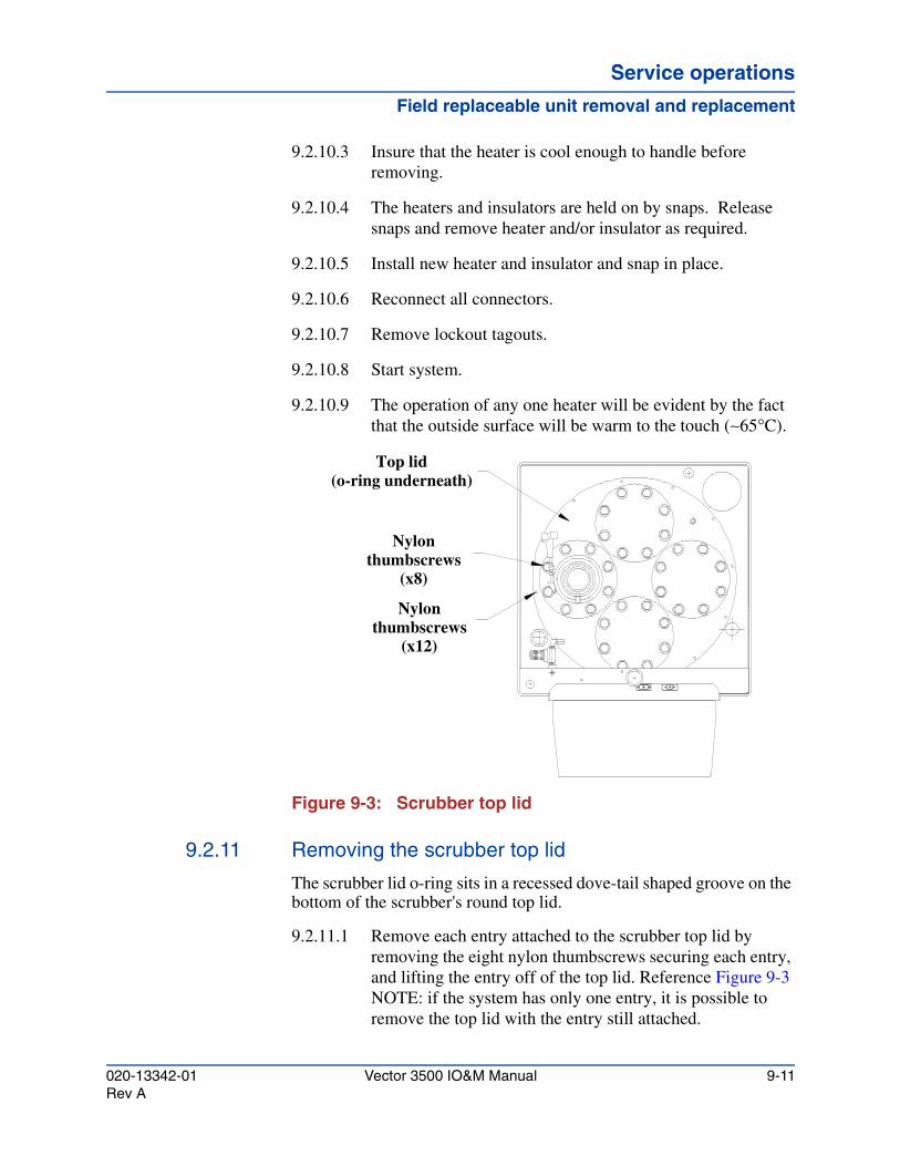
Service operationsService operationsService operations
Field replaceable unit removal and replacement
9.2.10.3 Insure that the heater is cool enough to handle before removing.
9.2.10.4 The heaters and insulators are held on by snaps. Release snaps and remove heater and/or insulator as required.
9.2.10.5 Install new heater and insulator and snap in place.
9.2.10.6 Reconnect all connectors.
9.2.10.7 Remove lockout tagouts.
9.2.10.8 Start system.
9.2.10.9 The operation of any one heater will be evident by the fact that the outside surface will be warm to the touch (∼65°C).
Figure 9-3: Scrubber top lid
9.2.11 Removing the scrubber top lid
The scrubber lid o-ring sits in a recessed dove-tail shaped groove on the bottom of the scrubber's round top lid.
9.2.11.1 Remove each entry attached to the scrubber top lid by removing the eight nylon thumbscrews securing each entry, and lifting the entry off of the top lid. Reference Figure 9-3NOTE: if the system has only one entry, it is possible to remove the top lid with the entry still attached.
Nylon thumbscrews
(x8)
Nylon thumbscrews
(x12)
Top lid(o-ring underneath)
020-13342-01 Vector 3500 IO&M Manual 9-11Rev A
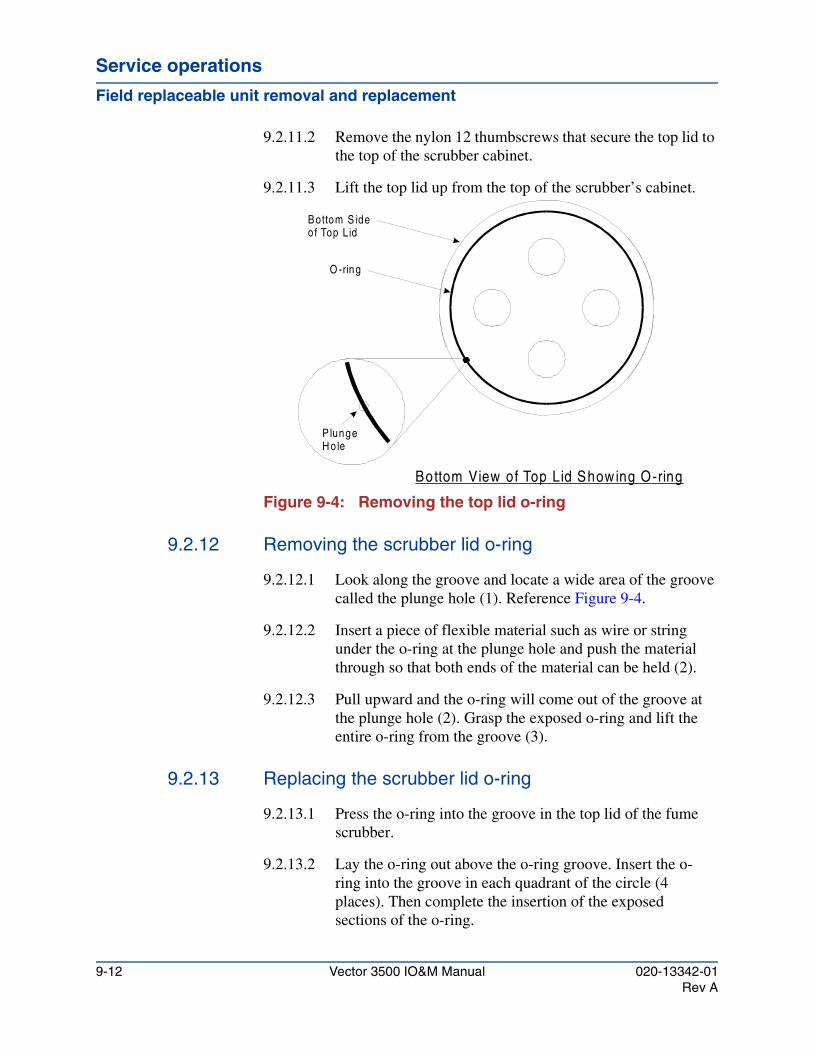
Service operations
Field replaceable unit removal and replacement
9.2.11.2 Remove the nylon 12 thumbscrews that secure the top lid to the top of the scrubber cabinet.
9.2.11.3 Lift the top lid up from the top of the scrubber’s cabinet.
Figure 9-4: Removing the top lid o-ring
9.2.12 Removing the scrubber lid o-ring
9.2.12.1 Look along the groove and locate a wide area of the groove called the plunge hole (1). Reference Figure 9-4.
9.2.12.2 Insert a piece of flexible material such as wire or string under the o-ring at the plunge hole and push the material through so that both ends of the material can be held (2).
9.2.12.3 Pull upward and the o-ring will come out of the groove at the plunge hole (2). Grasp the exposed o-ring and lift the entire o-ring from the groove (3).
9.2.13 Replacing the scrubber lid o-ring
9.2.13.1 Press the o-ring into the groove in the top lid of the fume scrubber.
9.2.13.2 Lay the o-ring out above the o-ring groove. Insert the o-ring into the groove in each quadrant of the circle (4 places). Then complete the insertion of the exposed sections of the o-ring.
Bottom View of Top Lid Show ing O-ring
Bottom S ideo f Top L id
O -ring
P lungeH o le
9-12 Vector 3500 IO&M Manual 020-13342-01Rev A
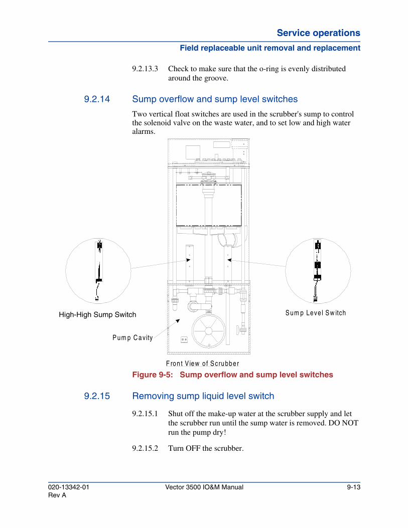
Service operationsService operationsService operations
Field replaceable unit removal and replacement
9.2.13.3 Check to make sure that the o-ring is evenly distributed around the groove.
9.2.14 Sump overflow and sump level switches
Two vertical float switches are used in the scrubber's sump to control the solenoid valve on the waste water, and to set low and high water alarms.
Figure 9-5: Sump overflow and sump level switches
9.2.15 Removing sump liquid level switch
9.2.15.1 Shut off the make-up water at the scrubber supply and let the scrubber run until the sump water is removed. DO NOT run the pump dry!
9.2.15.2 Turn OFF the scrubber.
F ron t V iew o f S cru bber
S um p O v erflow S w itch
P um p C a vity
S um p Leve l S w itchHigh-High Sump Switch
020-13342-01 Vector 3500 IO&M Manual 9-13Rev A
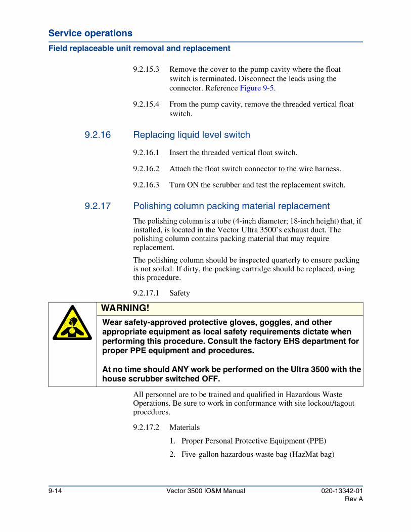
Service operations
Field replaceable unit removal and replacement
9.2.15.3 Remove the cover to the pump cavity where the float switch is terminated. Disconnect the leads using the connector. Reference Figure 9-5.
9.2.15.4 From the pump cavity, remove the threaded vertical float switch.
9.2.16 Replacing liquid level switch
9.2.16.1 Insert the threaded vertical float switch.
9.2.16.2 Attach the float switch connector to the wire harness.
9.2.16.3 Turn ON the scrubber and test the replacement switch.
9.2.17 Polishing column packing material replacement
The polishing column is a tube (4-inch diameter; 18-inch height) that, if installed, is located in the Vector Ultra 3500’s exhaust duct. The polishing column contains packing material that may require replacement.
The polishing column should be inspected quarterly to ensure packing is not soiled. If dirty, the packing cartridge should be replaced, using this procedure.
9.2.17.1 Safety
All personnel are to be trained and qualified in Hazardous Waste Operations. Be sure to work in conformance with site lockout/tagout procedures.
9.2.17.2 Materials
1. Proper Personal Protective Equipment (PPE)
2. Five-gallon hazardous waste bag (HazMat bag)
WARNING!Wear safety-approved protective gloves, goggles, and other appropriate equipment as local safety requirements dictate when performing this procedure. Consult the factory EHS department for proper PPE equipment and procedures.
At no time should ANY work be performed on the Ultra 3500 with the house scrubber switched OFF.
9-14 Vector 3500 IO&M Manual 020-13342-01Rev A
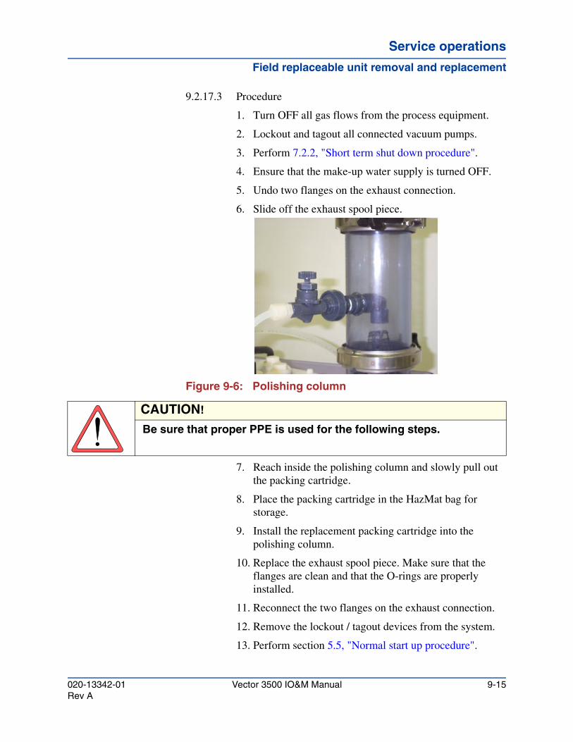
Service operationsService operationsService operations
Field replaceable unit removal and replacement
9.2.17.3 Procedure
1. Turn OFF all gas flows from the process equipment.
2. Lockout and tagout all connected vacuum pumps.
3. Perform 7.2.2, "Short term shut down procedure".
4. Ensure that the make-up water supply is turned OFF.
5. Undo two flanges on the exhaust connection.
6. Slide off the exhaust spool piece.
Figure 9-6: Polishing column
7. Reach inside the polishing column and slowly pull out the packing cartridge.
8. Place the packing cartridge in the HazMat bag for storage.
9. Install the replacement packing cartridge into the polishing column.
10. Replace the exhaust spool piece. Make sure that the flanges are clean and that the O-rings are properly installed.
11. Reconnect the two flanges on the exhaust connection.
12. Remove the lockout / tagout devices from the system.
13. Perform section 5.5, "Normal start up procedure".
CAUTION!
Be sure that proper PPE is used for the following steps.
020-13342-01 Vector 3500 IO&M Manual 9-15Rev A
Service operations
Field replaceable unit removal and replacement
9-16 Vector 3500 IO&M Manual 020-13342-01Rev A
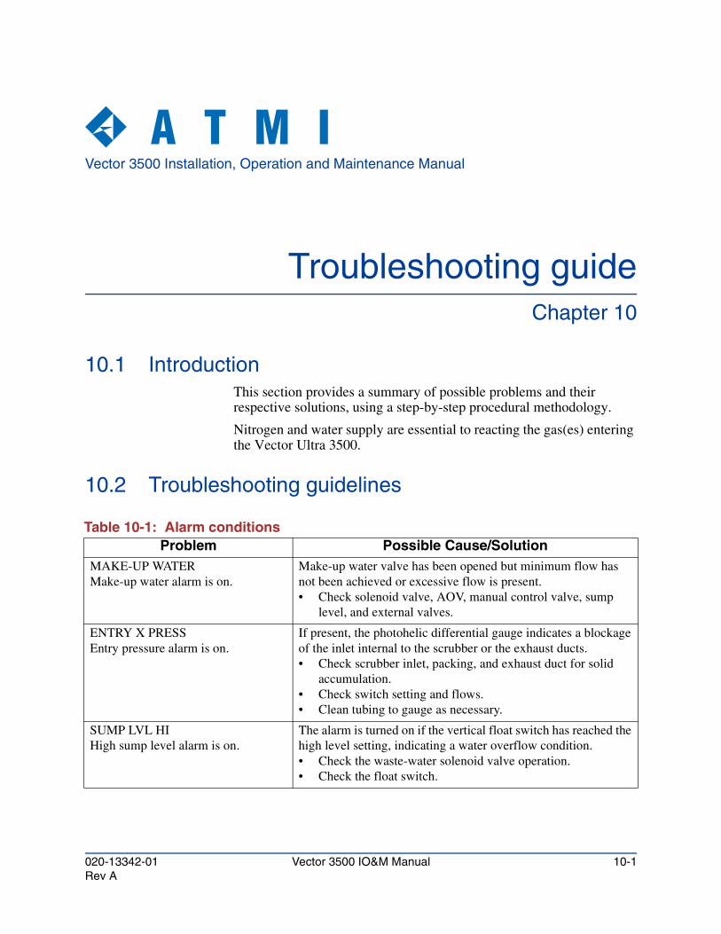
Vector 3500 Installation, Operation and Maintenance Manual
Troubleshooting guideChapter 10
10.1 IntroductionThis section provides a summary of possible problems and their respective solutions, using a step-by-step procedural methodology.
Nitrogen and water supply are essential to reacting the gas(es) entering the Vector Ultra 3500.
10.2 Troubleshooting guidelines
Table 10-1: Alarm conditionsProblem Possible Cause/Solution
MAKE-UP WATERMake-up water alarm is on.
Make-up water valve has been opened but minimum flow has not been achieved or excessive flow is present. • Check solenoid valve, AOV, manual control valve, sump
level, and external valves.
ENTRY X PRESSEntry pressure alarm is on.
If present, the photohelic differential gauge indicates a blockage of the inlet internal to the scrubber or the exhaust ducts. • Check scrubber inlet, packing, and exhaust duct for solid
accumulation. • Check switch setting and flows. • Clean tubing to gauge as necessary.
SUMP LVL HIHigh sump level alarm is on.
The alarm is turned on if the vertical float switch has reached the high level setting, indicating a water overflow condition. • Check the waste-water solenoid valve operation. • Check the float switch.
020-13342-01 Vector 3500 IO&M Manual 10-1Rev A
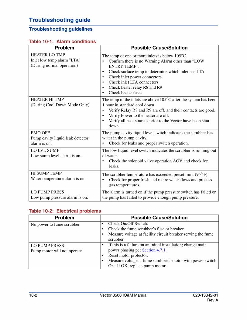
Troubleshooting guide
Troubleshooting guidelines
HEATER LO TMPInlet low temp alarm "LTA"(During normal operation)
The temp of one or more inlets is below 105oC.• Confirm there is no Warning Alarm other than “LOW
ENTRY TEMP”.• Check surface temp to determine which inlet has LTA• Check inlet power connectors• Check inlet LTA connectors• Check heater relay R8 and R9• Check heater fuses
HEATER HI TMP(During Cool Down Mode Only)
The temp of the inlets are above 105°C after the system has been 1 hour in standard cool down.• Verify Relay R8 and R9 are off, and their contacts are good.• Verify Power to the heater are off.• Verify all heat sources prior to the Vector have been shut
down.
EMO OFFPump cavity liquid leak detector alarm is on.
The pump cavity liquid level switch indicates the scrubber has water in the pump cavity. • Check for leaks and proper switch operation.
LO LVL SUMPLow sump level alarm is on.
The low liquid level switch indicates the scrubber is running out of water. • Check the solenoid valve operation AOV and check for
leaks.
HI SUMP TEMPWater temperature alarm is on.
The scrubber temperature has exceeded preset limit (95o F).• Check for proper fresh and recirc water flows and process
gas temperatures.
LO PUMP PRESSLow pump pressure alarm is on.
The alarm is turned on if the pump pressure switch has failed or the pump has failed to provide enough pump pressure.
Table 10-1: Alarm conditionsProblem Possible Cause/Solution
Table 10-2: Electrical problemsProblem Possible Cause/Solution
No power to fume scrubber. • Check On/Off Switch.• Check the fume scrubber’s fuse or breaker.• Measure voltage at facility circuit breaker serving the fume
scrubber.
LO PUMP PRESSPump motor will not operate.
• If this is a failure on an initial installation; change main power phasing per Section 4.7.1.
• Reset motor protector.• Measure voltage at fume scrubber’s motor with power switch
On. If OK, replace pump motor.
10-2 Vector 3500 IO&M Manual 020-13342-01Rev A
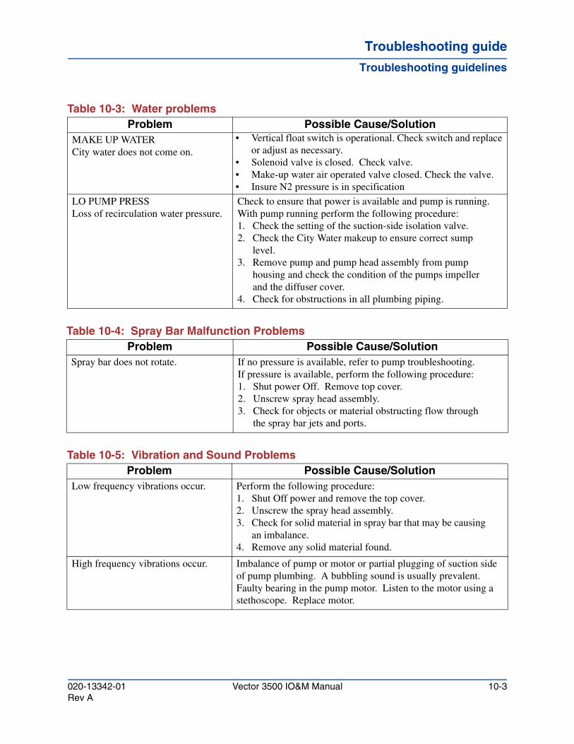
Troubleshooting guideTroubleshooting guideTroubleshooting guide
Troubleshooting guidelines
Table 10-3: Water problemsProblem Possible Cause/Solution
MAKE UP WATERCity water does not come on.
• Vertical float switch is operational. Check switch and replace or adjust as necessary.
• Solenoid valve is closed. Check valve.• Make-up water air operated valve closed. Check the valve.• Insure N2 pressure is in specification
LO PUMP PRESSLoss of recirculation water pressure.
Check to ensure that power is available and pump is running.With pump running perform the following procedure:1. Check the setting of the suction-side isolation valve.2. Check the City Water makeup to ensure correct sump
level.3. Remove pump and pump head assembly from pump
housing and check the condition of the pumps impeller and the diffuser cover.
4. Check for obstructions in all plumbing piping.
Table 10-4: Spray Bar Malfunction ProblemsProblem Possible Cause/Solution
Spray bar does not rotate. If no pressure is available, refer to pump troubleshooting.If pressure is available, perform the following procedure:1. Shut power Off. Remove top cover.2. Unscrew spray head assembly.3. Check for objects or material obstructing flow through
the spray bar jets and ports.
Table 10-5: Vibration and Sound ProblemsProblem Possible Cause/Solution
Low frequency vibrations occur. Perform the following procedure:1. Shut Off power and remove the top cover.2. Unscrew the spray head assembly. 3. Check for solid material in spray bar that may be causing
an imbalance.4. Remove any solid material found.
High frequency vibrations occur. Imbalance of pump or motor or partial plugging of suction side of pump plumbing. A bubbling sound is usually prevalent.Faulty bearing in the pump motor. Listen to the motor using a stethoscope. Replace motor.
020-13342-01 Vector 3500 IO&M Manual 10-3Rev A
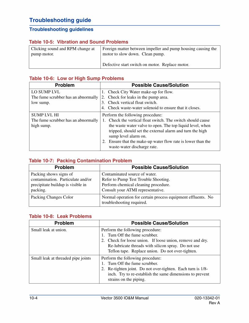
Troubleshooting guide
Troubleshooting guidelines
Clicking sound and RPM change at pump motor.
Foreign matter between impeller and pump housing causing the motor to slow down. Clean pump.
Defective start switch on motor. Replace motor.
Table 10-5: Vibration and Sound Problems
Table 10-6: Low or High Sump ProblemsProblem Possible Cause/Solution
LO SUMP LVLThe fume scrubber has an abnormally low sump.
1. Check City Water make-up for flow.2. Check for leaks in the pump area.3. Check vertical float switch.4. Check waste-water solenoid to ensure that it closes.
SUMP LVL HIThe fume scrubber has an abnormally high sump.
Perform the following procedure:1. Check the vertical float switch. The switch should cause
the waste water valve to open. The top liquid level, when tripped, should set the external alarm and turn the high sump level alarm on.
2. Ensure that the make-up water flow rate is lower than the waste-water discharge rate.
Table 10-7: Packing Contamination ProblemProblem Possible Cause/Solution
Packing shows signs of contamination. Particulate and/or precipitate buildup is visible in packing.
Contaminated source of water.Refer to Pump Test Trouble Shooting.Perform chemical cleaning procedure. Consult your ATMI representative.
Packing Changes Color Normal operation for certain process equipment effluents. No troubleshooting required.
Table 10-8: Leak ProblemsProblem Possible Cause/Solution
Small leak at union. Perform the following procedure:1. Turn Off the fume scrubber.2. Check for loose union. If loose union, remove and dry.
Re-lubricate threads with silicon spray. Do not use Teflon tape. Replace union. Do not over-tighten.
Small leak at threaded pipe joints Perform the following procedure:1. Turn Off the fume scrubber.2. Re-tighten joint. Do not over-tighten. Each turn is 1/8-
inch. Try to re-establish the same dimensions to prevent strains on the piping.
10-4 Vector 3500 IO&M Manual 020-13342-01Rev A
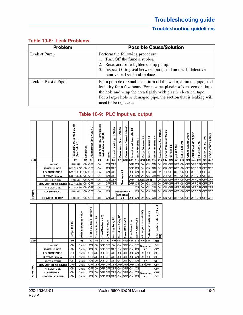
Troubleshooting guideTroubleshooting guideTroubleshooting guide
Troubleshooting guidelines
Table 10-9: PLC input vs. output
Leak at Pump Perform the following procedure:1. Turn Off the fume scrubber.2. Reset and/or re-tighten clamp pump.3. Inspect O-ring seal between pump and motor. If defective
remove bad seal and replace.
Leak in Plastic Pipe For a pinhole or small leak, turn off the water, drain the pipe, and let it dry for a few hours. Force some plastic solvent cement into the hole and wrap the area tightly with plastic electrical tape. For a larger hole or damaged pipe, the section that is leaking will need to be replaced.
Table 10-8: Leak ProblemsProblem Possible Cause/Solution
Sta
rt/S
top
Ala
rm/R
eset
(S
ee N
ote
# 2
)
EM
O
Liq
uid
Lev
el H
igh
LS
H-2
3
Dra
in V
alve
Op
en L
SO
-23
Dra
in V
alve
Clo
sed
LS
C-2
3
Liq
uid
Lev
el L
ow
LS
L-2
3
En
try
Pre
ssu
re #
1
En
try
Pre
ssu
re #
2
En
try
Pre
ssu
re #
3
En
try
Pre
ssu
re #
4
Med
ia T
emp
Sw
. TS
H-3
4
Pu
mp
Pre
ssu
re P
SL
-33
ST
AN
D-B
Y
pH
AL
AR
M
LO
CH
EM
LV
L
CH
EM
VA
LV
E O
PE
N
CH
EM
VA
LV
E C
LO
SE
HI C
HE
M L
VL
LE
AK
DE
TE
CT
OR
LO
SS
VE
NT
ILA
TIO
N
LED X2 X3 X5 X6 X7 X10 X11 X12 X13 X14 X15 X16 X17 X20 X21 X22 X23 X24 X25 X26 X27
ON OFF ON OFF OFF ON ON ON ON ON ON OFF OFF ON OFF OFF OFF OFF OFF
ON OFF ON OFF OFF ON ON ON ON ON ON OFF OFF ON OFF OFF OFF OFF OFF
ON OFF ON OFF OFF ON ON ON ON ON OFF OFF OFF ON OFF OFF OFF OFF OFF
ON OFF ON OFF OFF ON ON ON ON OFF OFF OFF OFF ON OFF OFF OFF OFF OFF
ON OFF ON OFF OFF ON ON OFF OFF ON OFF OFF OFF OFF OFF
ON OFF OFF OFF OFF ON ON ON ON ON OFF OFF OFF ON OFF OFF OFF OFF OFF
ON OFF ON ON ON ON ON ON ON OFF OFF OFF OFF OFF OFF OFF OFF
ON OFF ON ON ON ON ON ON ON OFF OFF ON OFF OFF OFF OFF OFF
ON OFF ON OFF OFF ON ON ON ON ON ON OFF OFF ON OFF OFF OFF OFF OFF
Pu
mp
Sta
rt R
2
Fre
sh H
2O M
ake-
Up
Val
ve
Ch
em In
j Pu
mp
R3
Ho
rn (
See
No
te #
6)
Ch
em In
j Val
ve
War
nin
g R
elay
R4
Sh
utd
ow
n R
elay
R5
Res
et R
7 L
SH
-22
Ru
n G
reen
Lit
e
War
n A
mb
er L
ite
N2
pu
rge
sole
no
id (
NO
)
Au
to w
ater
was
h v
alve
LED Y0 Y3 Y4 Y5 Y7 Y10 Y11 Y12 Y14 Y15 Y16 Y17
ON ON ON OFF OFF ON ON OFF ON OFF
ON ON ON OFF OFF OFF ON OFF ON ON
OFF OFF OFF OFF OFF OFF OFF OFF OFF ON ON OFF
OFF OFF OFF OFF OFF OFF OFF OFF OFF ON ON OFF
ON ON ON OFF OFF OFF ON OFF ON ON
OFF OFF OFF OFF OFF OFF OFF OFF OFF ON OFF OFF
ON OFF ON OFF OFF OFF ON OFF ON ON
ON ON ON OFF OFF OFF ON OFF ON ON
ON ON ON OFF ON OFF ON OFF ON ON
OFF
OFF
OFF
ON
OFF
See note #7
#7
See note #7
Cycle
Cycle
Cycle
Cycle
Cycle
Ultra OK Cycle
Cycle
Cycle
See Note # 3
See Note #5
See
No
te #
4
PULSE
NO PULSE
NO PULSE
NO PULSE
ON
ON
ON
ENTRY PRES
Fre
sh H
2O M
ake-
Up
FS
L-4
3 (S
ee N
ote
# 1
)
X0
PULSE
NO PULSE
NO PULSE
PULSE
Dra
in D
isch
arg
e V
alve
Y1
Ultra OK
HI SUMP LVL
ENTRY PRES
EMO OFF (pump cavity)
LO PUMP PRES
HI TEMP (Media)
HI SUMP LVL
LO SUMP LVL
HEATER LO TMP PULSESee Note
# 4INP
UT
S
HEATER LO TEMP CycleOU
TP
UT
S EMO OFF (pump cavity)
MAKEUP WTR
LO PUMP PRES
HI TEMP (Media)
MAKEUP WTR
LO SUMP LVL
Inle
t h
eate
r lo
w t
emp
erat
ure
sw
itch
(ab
ove
105
C)
X4
ON
ON
ON
ON
ON
OFF
ON
OFF
OFF
OFF
Inle
t h
eate
r -
rela
ys (
R8
and
R
9)
Y20
020-13342-01 Vector 3500 IO&M Manual 10-5Rev A
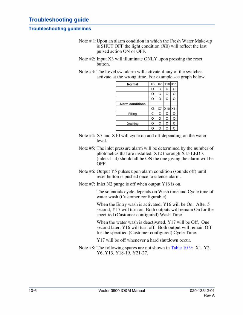
Troubleshooting guide
Troubleshooting guidelines
Note # 1:Upon an alarm condition in which the Fresh Water Make-up is SHUT OFF the light condition (X0) will reflect the last pulsed action ON or OFF.
Note #2: Input X3 will illuminate ONLY upon pressing the reset button.
Note #3: The Level sw. alarm will activate if any of the switches activate at the wrong time. For example see graph below.
Note #4: X7 and X10 will cycle on and off depending on the water level.
Note #5: The inlet pressure alarm will be determined by the number of photohelics that are installed. X12 thorough X15 LED’s (inlets 1- 4) should all be ON the one giving the alarm will be OFF.
Note #6: Output Y5 pulses upon alarm condition (sounds off) until reset button is pushed once to silence alarm.
Note #7: Inlet N2 purge is off when output Y16 is on.
The solenoids cycle depends on Wash time and Cycle time of water wash (Customer configurable).
When the Entry wash is activated, Y16 will be On. After 5 second, Y17 will turn on. Both outputs will remain On for the specified (Customer configured) Wash Time.
When the water wash is deactivated, Y17 will be Off. One second later, Y16 will turn off. Both output will remain Off for the specified (Customer configured) Cycle Time.
Y17 will be off whenever a hard shutdown occur.
Note #8: The following spares are not shown in Table 10-9: X1, Y2, Y6, Y13, Y18-19, Y21-27.
X6 X7 X10 X11
O C C O
O C O O
O O C O
X6 X7 X10 X11
C C C O
O O O O
O C C C
O O O C
Filling
Draining
Alarm conditions
Normal
10-6 Vector 3500 IO&M Manual 020-13342-01Rev A
Vector 3500 Installation, Operation and Maintenance Manual
Parts listsChapter 11
This chapter contains the following parts lists:
• Table 11-1, “Spare parts kit inventory (155-13234-00)”
• Table 11-2, “PM parts kit (160-13235-00)”
• Table 11-3, “Vector Ultra 3500 tank (200-13345-00)”
• Table 11-4, “Pump assembly (6474-00)”
• Table 11-5, “Rear panel assembly (215-13364-00)”
• Table 11-6, “Instrument panel door assembly (6554-01)”
• Table 11-7, “Control box (215-13238-00)”
• Table 11-8, “Polishing scrubber (6720)”
• Table 11-9, “Type 20 entry”
• Table 11-10, “Make-up water assembly (215-12508-00)”
020-13342-01 Vector 3500 IO&M Manual 11-1Rev A
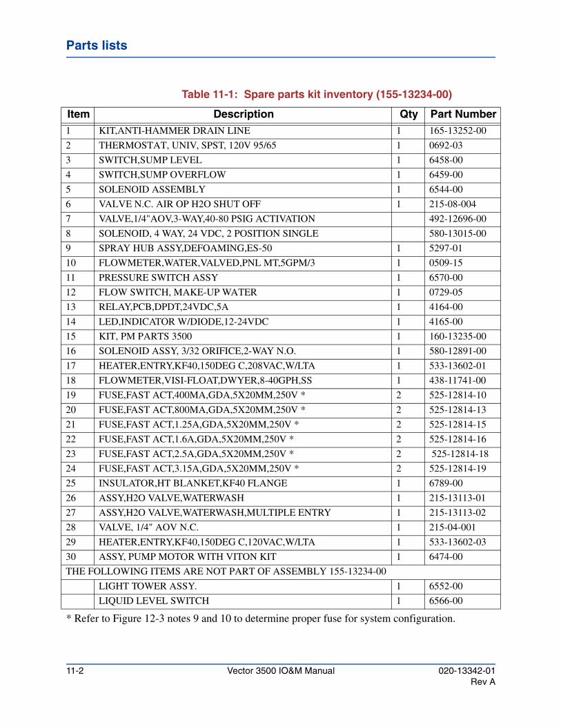
Parts lists
Table 11-1: Spare parts kit inventory (155-13234-00)
* Refer to Figure 12-3 notes 9 and 10 to determine proper fuse for system configuration.
Item Description Qty Part Number1 KIT,ANTI-HAMMER DRAIN LINE 1 165-13252-00
2 THERMOSTAT, UNIV, SPST, 120V 95/65 1 0692-03
3 SWITCH,SUMP LEVEL 1 6458-00
4 SWITCH,SUMP OVERFLOW 1 6459-00
5 SOLENOID ASSEMBLY 1 6544-00
6 VALVE N.C. AIR OP H2O SHUT OFF 1 215-08-004
7 VALVE,1/4"AOV,3-WAY,40-80 PSIG ACTIVATION 492-12696-00
8 SOLENOID, 4 WAY, 24 VDC, 2 POSITION SINGLE 580-13015-00
9 SPRAY HUB ASSY,DEFOAMING,ES-50 1 5297-01
10 FLOWMETER,WATER,VALVED,PNL MT,5GPM/3 1 0509-15
11 PRESSURE SWITCH ASSY 1 6570-00
12 FLOW SWITCH, MAKE-UP WATER 1 0729-05
13 RELAY,PCB,DPDT,24VDC,5A 1 4164-00
14 LED,INDICATOR W/DIODE,12-24VDC 1 4165-00
15 KIT, PM PARTS 3500 1 160-13235-00
16 SOLENOID ASSY, 3/32 ORIFICE,2-WAY N.O. 1 580-12891-00
17 HEATER,ENTRY,KF40,150DEG C,208VAC,W/LTA 1 533-13602-01
18 FLOWMETER,VISI-FLOAT,DWYER,8-40GPH,SS 1 438-11741-00
19 FUSE,FAST ACT,400MA,GDA,5X20MM,250V * 2 525-12814-10
20 FUSE,FAST ACT,800MA,GDA,5X20MM,250V * 2 525-12814-13
21 FUSE,FAST ACT,1.25A,GDA,5X20MM,250V * 2 525-12814-15
22 FUSE,FAST ACT,1.6A,GDA,5X20MM,250V * 2 525-12814-16
23 FUSE,FAST ACT,2.5A,GDA,5X20MM,250V * 2 525-12814-18
24 FUSE,FAST ACT,3.15A,GDA,5X20MM,250V * 2 525-12814-19
25 INSULATOR,HT BLANKET,KF40 FLANGE 1 6789-00
26 ASSY,H2O VALVE,WATERWASH 1 215-13113-01
27 ASSY,H2O VALVE,WATERWASH,MULTIPLE ENTRY 1 215-13113-02
28 VALVE, 1/4" AOV N.C. 1 215-04-001
29 HEATER,ENTRY,KF40,150DEG C,120VAC,W/LTA 1 533-13602-03
30 ASSY, PUMP MOTOR WITH VITON KIT 1 6474-00
THE FOLLOWING ITEMS ARE NOT PART OF ASSEMBLY 155-13234-00
LIGHT TOWER ASSY. 1 6552-00
LIQUID LEVEL SWITCH 1 6566-00
11-2 Vector 3500 IO&M Manual 020-13342-01Rev A

Parts listsParts listsParts lists
Table 11-2: PM parts kit (160-13235-00)
Item Description Qty Part Number1 KIT, VITON PUMP SEAL 1 6427-00
2 TAPE, PIPE JOINT, TEFLON 1 0080-01
3 GASKET, NEOPRENE, 1.0”ID, 2.75”OD, 1/16” THICK 1 5409-01
4 ORIFICE, ANTI-FOAM 1 5408-01
5 ORIFICE, ENTRY WATER 4 1566-01
6 POLISHING SCRUBBER CARTRIDGE 1 6733-00
7 NOZZLES, SPRAY 8 5421-04
8 O-RING,VITON,2 1/4"OD X 2"ID 2 464-11143-00
9 O-RING,VITON,3/32W,1-14"OD X 1-1/16"ID 2 464-11143-01
020-13342-01 Vector 3500 IO&M Manual 11-3Rev A
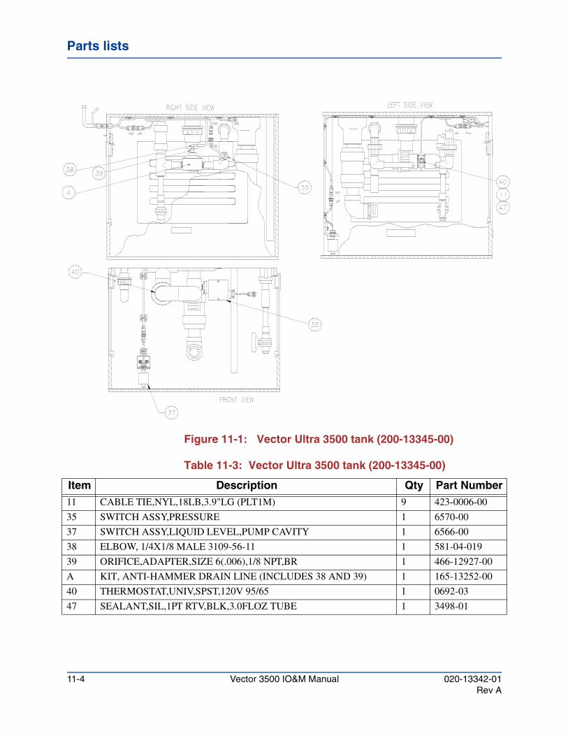
Parts lists
Figure 11-1: Vector Ultra 3500 tank (200-13345-00)
Table 11-3: Vector Ultra 3500 tank (200-13345-00)
Item Description Qty Part Number11 CABLE TIE,NYL,18LB,3.9"LG (PLT1M) 9 423-0006-00
35 SWITCH ASSY,PRESSURE 1 6570-00
37 SWITCH ASSY,LIQUID LEVEL,PUMP CAVITY 1 6566-00
38 ELBOW, 1/4X1/8 MALE 3109-56-11 1 581-04-019
39 ORIFICE,ADAPTER,SIZE 6(.006),1/8 NPT,BR 1 466-12927-00
A KIT, ANTI-HAMMER DRAIN LINE (INCLUDES 38 AND 39) 1 165-13252-00
40 THERMOSTAT,UNIV,SPST,120V 95/65 1 0692-03
47 SEALANT,SIL,1PT RTV,BLK,3.0FLOZ TUBE 1 3498-01
11-4 Vector 3500 IO&M Manual 020-13342-01Rev A
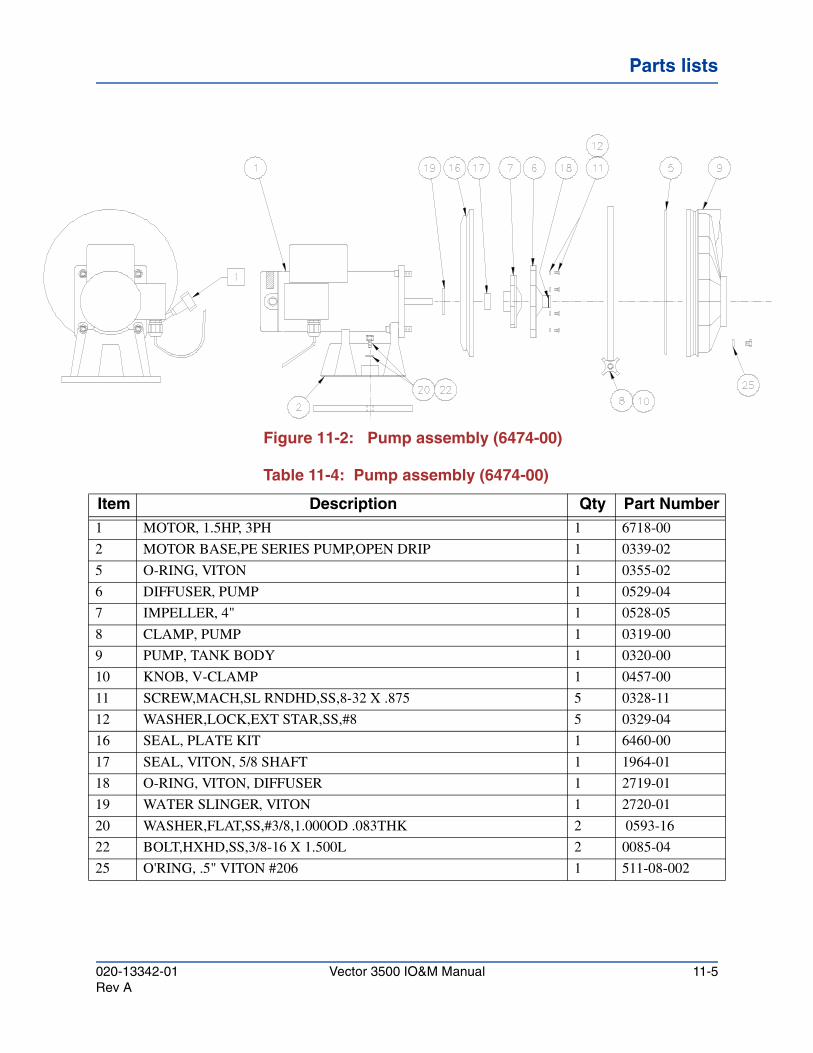
Parts listsParts listsParts lists
Figure 11-2: Pump assembly (6474-00)
Table 11-4: Pump assembly (6474-00)
Item Description Qty Part Number1 MOTOR, 1.5HP, 3PH 1 6718-00
2 MOTOR BASE,PE SERIES PUMP,OPEN DRIP 1 0339-02
5 O-RING, VITON 1 0355-02
6 DIFFUSER, PUMP 1 0529-04
7 IMPELLER, 4" 1 0528-05
8 CLAMP, PUMP 1 0319-00
9 PUMP, TANK BODY 1 0320-00
10 KNOB, V-CLAMP 1 0457-00
11 SCREW,MACH,SL RNDHD,SS,8-32 X .875 5 0328-11
12 WASHER,LOCK,EXT STAR,SS,#8 5 0329-04
16 SEAL, PLATE KIT 1 6460-00
17 SEAL, VITON, 5/8 SHAFT 1 1964-01
18 O-RING, VITON, DIFFUSER 1 2719-01
19 WATER SLINGER, VITON 1 2720-01
20 WASHER,FLAT,SS,#3/8,1.000OD .083THK 2 0593-16
22 BOLT,HXHD,SS,3/8-16 X 1.500L 2 0085-04
25 O'RING, .5" VITON #206 1 511-08-002
020-13342-01 Vector 3500 IO&M Manual 11-5Rev A
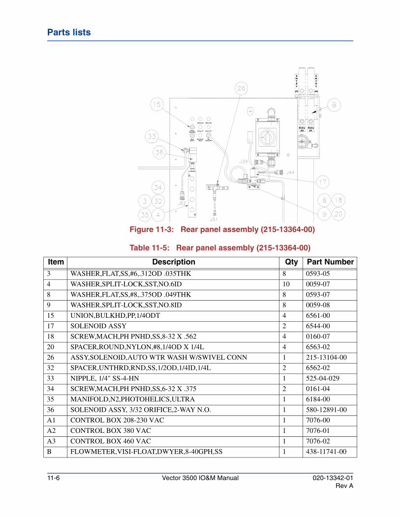
Parts lists
Figure 11-3: Rear panel assembly (215-13364-00)
Table 11-5: Rear panel assembly (215-13364-00)
Entry #4Entry #3
EntryManifold
Entry #1 Entry #2
N2Solenoid
Chemical Inject
FlowMeter
EntryEntry#2 #1
#4
N
Y
#3
RT
EN
YRT
E
Item Description Qty Part Number3 WASHER,FLAT,SS,#6,.312OD .035THK 8 0593-05
4 WASHER,SPLIT-LOCK,SST,NO.6ID 10 0059-07
8 WASHER,FLAT,SS,#8,.375OD .049THK 8 0593-07
9 WASHER,SPLIT-LOCK,SST,NO.8ID 8 0059-08
15 UNION,BULKHD,PP,1/4ODT 4 6561-00
17 SOLENOID ASSY 2 6544-00
18 SCREW,MACH,PH PNHD,SS,8-32 X .562 4 0160-07
20 SPACER,ROUND,NYLON,#8,1/4OD X 1/4L 4 6563-02
26 ASSY,SOLENOID,AUTO WTR WASH W/SWIVEL CONN 1 215-13104-00
32 SPACER,UNTHRD,RND,SS,1/2OD,1/4ID,1/4L 2 6562-02
33 NIPPLE, 1/4" SS-4-HN 1 525-04-029
34 SCREW,MACH,PH PNHD,SS,6-32 X .375 2 0161-04
35 MANIFOLD,N2,PHOTOHELICS,ULTRA 1 6184-00
36 SOLENOID ASSY, 3/32 ORIFICE,2-WAY N.O. 1 580-12891-00
A1 CONTROL BOX 208-230 VAC 1 7076-00
A2 CONTROL BOX 380 VAC 1 7076-01
A3 CONTROL BOX 460 VAC 1 7076-02
B FLOWMETER,VISI-FLOAT,DWYER,8-40GPH,SS 1 438-11741-00
11-6 Vector 3500 IO&M Manual 020-13342-01Rev A
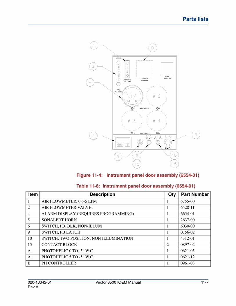
Parts listsParts listsParts lists
Figure 11-4: Instrument panel door assembly (6554-01)
Table 11-6: Instrument panel door assembly (6554-01)
Controller
Run / Reset
PhotohelicsN2 Purge
N2 PurgeEntry
Chemical
EMO
Stop Start
DisconnectPower
21 Entry Pressure
Entry Pressure3 4
Item Description Qty Part Number1 AIR FLOWMETER, 0.6-5 LPM 1 6755-00
2 AIR FLOWMETER VALVE 1 6528-11
4 ALARM DISPLAY (REQUIRES PROGRAMMING) 1 6654-01
5 SONALERT HORN 1 2637-00
6 SWITCH, PB, BLK, NON-ILLUM 1 6030-00
9 SWITCH, PB LATCH 1 0756-02
10 SWITCH, TWO POSITION, NON ILLUMINATION 1 4312-01
15 CONTACT BLOCK 2 0897-02
A PHOTOHELIC 0 TO -5" W.C. 1 0621-05
A PHOTOHELIC 5 TO -5" W.C. 1 0621-12
B PH CONTROLLER 1 0961-03
020-13342-01 Vector 3500 IO&M Manual 11-7Rev A
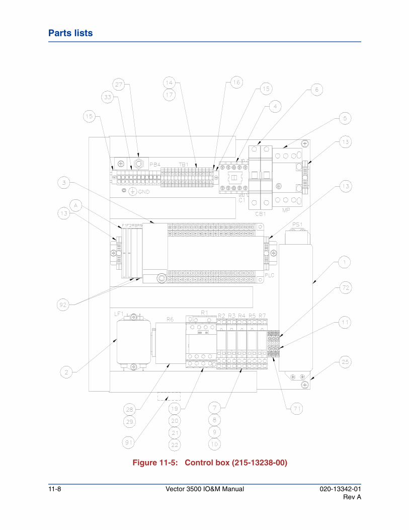
Parts lists
Figure 11-5: Control box (215-13238-00)
11-8 Vector 3500 IO&M Manual 020-13342-01Rev A
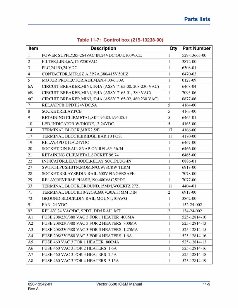
Parts listsParts listsParts lists
Table 11-7: Control box (215-13238-00)
Item Description Qty Part Number1 POWER SUPPLY,85-264VAC IN,24VDC OUT,100W,CE 1 529-13663-00
2 FILTER,LINE,6A,120/250VAC 1 3872-00
3 PLC,24 I/O,24 VDC 1 6308-01
4 CONTACTOR,MTR,SZ A,3P,7A,380/415V,50HZ 1 6470-03
5 MOTOR PROTECTOR,ADJ,MAN,4.00-6.30A 1 0127-09
6A CIRCUIT BREAKER,MINI,1P,4A (ASSY 7165-00, 208-230 VAC) 1 6468-04
6B CIRCUIT BREAKER,MINI,1P,4A (ASSY 7165-01, 380 VAC) 1 7093-06
6C CIRCUIT BREAKER,MINI,1P,4A (ASSY 7165-02, 460 230 VAC) 1 0877-06
7 RELAY,PCB,DPDT,24VDC,5A 5 4164-00
8 SOCKET,RELAY,PCB 5 4163-00
9 RETAINING CLIP,METAL,SKT 95.83.1/95.85.1 5 6465-01
10 LED,INDICATOR W/DIODE,12-24VDC 5 4165-00
14 TERMINAL BLOCK,MBK2,5/E 17 4166-00
17 TERMINAL BLOCK,BRIDGE BAR,10 POS. 11 4170-00
19 RELAY,4PDT,12A,24VDC 1 6467-00
20 SOCKET,DIN RAIL SNAP-ON,RELAY 56.34 1 6466-00
21 RETAINING CLIP,METAL,SOCKET 96.74 1 6465-00
22 INDICATOR,LED/DIODE,RELAY SOC,PLUG-IN 1 0886-01
27 SWITCH,PUSHBTN,MOM,N/O,W/SCRW TERM 1 6918-00
28 SOCKET,RELAY,8P,DIN RAIL,600V,FINGERSAFE 1 7078-00
29 RELAY,REVERSE PHASE,190-480VAC,SPDT 1 7077-00
33 TERMINAL BLOCK,GROUND,15MM,WOERTZ 2721 11 4404-01
71 TERMINAL BLOCK,10-22GA,600V,30A,35MM DIN 2 6917-00
72 GROUND BLOCK,DIN RAIL MOUNT,10AWG 1 3862-00
91 FAN, 24 VDC 1 152-24-002
92 RELAY, 24 VAC/DC, SPDT, DIM RAIL MT 2 134-24-002
A1 FUSE 208/230/380 VAC 3 FOR 1 HEATER 400MA 1 525-12814-10
A2 FUSE 208/230/380 VAC 3 FOR 2 HEATERS 800MA 1 525-12814-13
A3 FUSE 208/230/380 VAC 3 FOR 3 HEATERS 1.25MA 1 525-12814-15
A4 FUSE 208/230/380 VAC 3 FOR 4 HEATERS 1.6A 1 525-12814-16
A5 FUSE 460 VAC 3 FOR 1 HEATER 800MA 1 525-12814-13
A6 FUSE 460 VAC 3 FOR 2 HEATERS 1.6A 1 525-12814-16
A7 FUSE 460 VAC 3 FOR 3 HEATERS 2.5A 1 525-12814-18
A8 FUSE 460 VAC 3 FOR 4 HEATERS 3.15A 1 525-12814-19
020-13342-01 Vector 3500 IO&M Manual 11-9Rev A
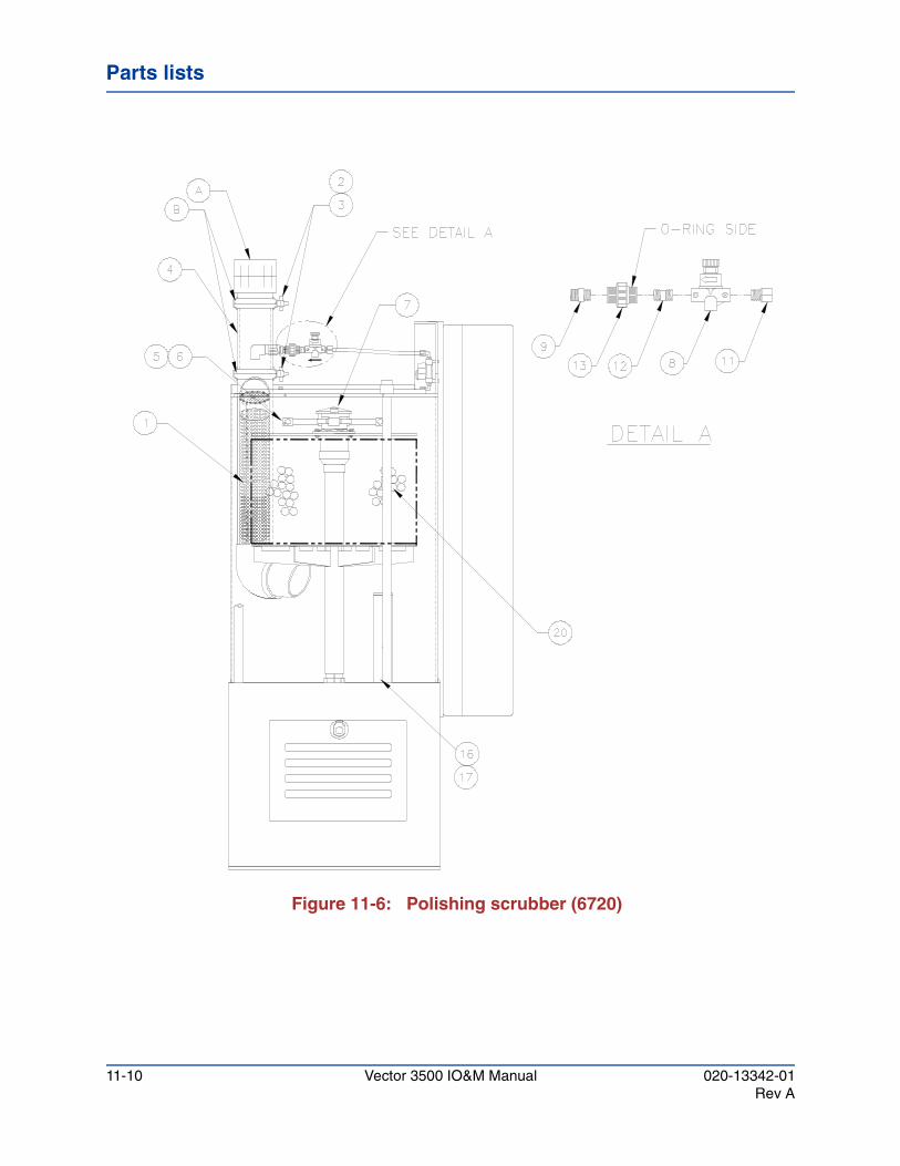
Parts lists
Figure 11-6: Polishing scrubber (6720)
11-10 Vector 3500 IO&M Manual 020-13342-01Rev A
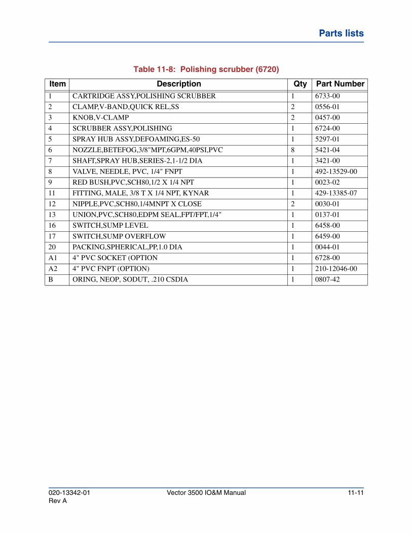
Parts listsParts listsParts lists
Table 11-8: Polishing scrubber (6720)
Item Description Qty Part Number1 CARTRIDGE ASSY,POLISHING SCRUBBER 1 6733-00
2 CLAMP,V-BAND,QUICK REL,SS 2 0556-01
3 KNOB,V-CLAMP 2 0457-00
4 SCRUBBER ASSY,POLISHING 1 6724-00
5 SPRAY HUB ASSY,DEFOAMING,ES-50 1 5297-01
6 NOZZLE,BETEFOG,3/8"MPT,6GPM,40PSI,PVC 8 5421-04
7 SHAFT,SPRAY HUB,SERIES-2,1-1/2 DIA 1 3421-00
8 VALVE, NEEDLE, PVC, 1/4" FNPT 1 492-13529-00
9 RED BUSH,PVC,SCH80,1/2 X 1/4 NPT 1 0023-02
11 FITTING, MALE, 3/8 T X 1/4 NPT, KYNAR 1 429-13385-07
12 NIPPLE,PVC,SCH80,1/4MNPT X CLOSE 2 0030-01
13 UNION,PVC,SCH80,EDPM SEAL,FPT/FPT,1/4" 1 0137-01
16 SWITCH,SUMP LEVEL 1 6458-00
17 SWITCH,SUMP OVERFLOW 1 6459-00
20 PACKING,SPHERICAL,PP,1.0 DIA 1 0044-01
A1 4" PVC SOCKET (OPTION 1 6728-00
A2 4" PVC FNPT (OPTION) 1 210-12046-00
B ORING, NEOP, SODUT, .210 CSDIA 1 0807-42
020-13342-01 Vector 3500 IO&M Manual 11-11Rev A
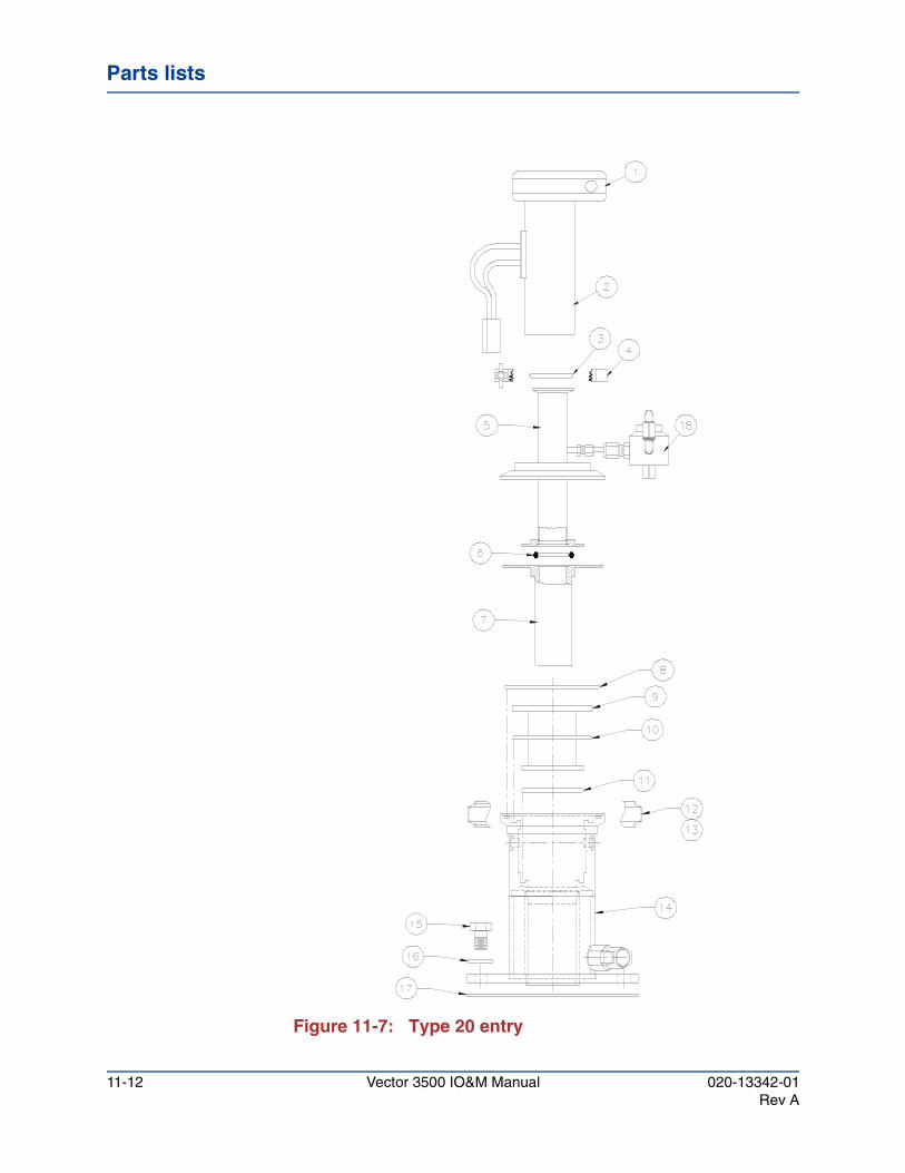
Parts lists
Figure 11-7: Type 20 entry
11-12 Vector 3500 IO&M Manual 020-13342-01Rev A
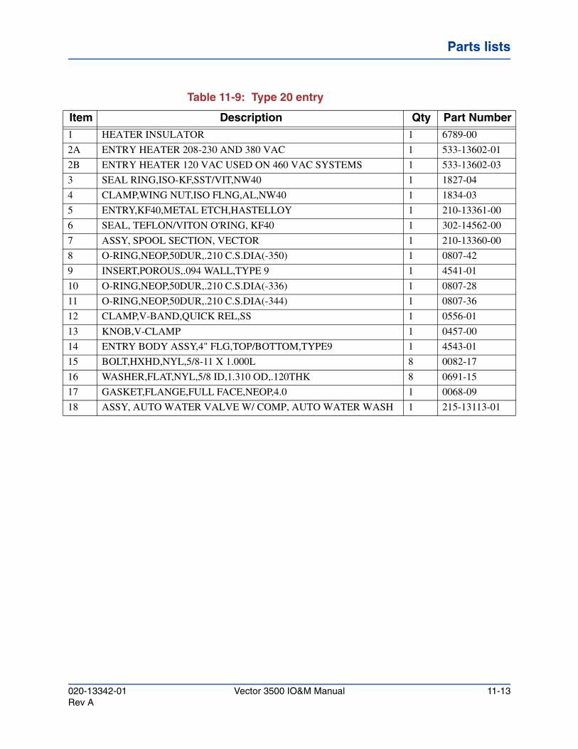
Parts listsParts listsParts lists
Table 11-9: Type 20 entry
Item Description Qty Part Number1 HEATER INSULATOR 1 6789-00
2A ENTRY HEATER 208-230 AND 380 VAC 1 533-13602-01
2B ENTRY HEATER 120 VAC USED ON 460 VAC SYSTEMS 1 533-13602-03
3 SEAL RING,ISO-KF,SST/VIT,NW40 1 1827-04
4 CLAMP,WING NUT,ISO FLNG,AL,NW40 1 1834-03
5 ENTRY,KF40,METAL ETCH,HASTELLOY 1 210-13361-00
6 SEAL, TEFLON/VITON O'RING, KF40 1 302-14562-00
7 ASSY, SPOOL SECTION, VECTOR 1 210-13360-00
8 O-RING,NEOP,50DUR,.210 C.S.DIA(-350) 1 0807-42
9 INSERT,POROUS,.094 WALL,TYPE 9 1 4541-01
10 O-RING,NEOP,50DUR,.210 C.S.DIA(-336) 1 0807-28
11 O-RING,NEOP,50DUR,.210 C.S.DIA(-344) 1 0807-36
12 CLAMP,V-BAND,QUICK REL,SS 1 0556-01
13 KNOB,V-CLAMP 1 0457-00
14 ENTRY BODY ASSY,4" FLG,TOP/BOTTOM,TYPE9 1 4543-01
15 BOLT,HXHD,NYL,5/8-11 X 1.000L 8 0082-17
16 WASHER,FLAT,NYL,5/8 ID,1.310 OD,.120THK 8 0691-15
17 GASKET,FLANGE,FULL FACE,NEOP,4.0 1 0068-09
18 ASSY, AUTO WATER VALVE W/ COMP, AUTO WATER WASH 1 215-13113-01
020-13342-01 Vector 3500 IO&M Manual 11-13Rev A
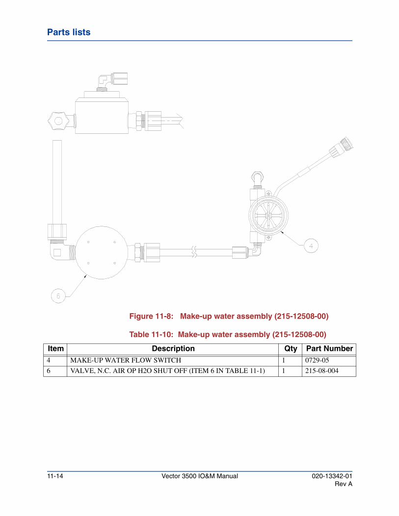
Parts lists
Figure 11-8: Make-up water assembly (215-12508-00)
Table 11-10: Make-up water assembly (215-12508-00)
Item Description Qty Part Number4 MAKE-UP WATER FLOW SWITCH 1 0729-05
6 VALVE, N.C. AIR OP H2O SHUT OFF (ITEM 6 IN TABLE 11-1) 1 215-08-004
11-14 Vector 3500 IO&M Manual 020-13342-01Rev A
Vector 3500 Installation, Operation and Maintenance Manual
Schematics and diagramsChapter 12
This chapter contains the following schematics and drawings for the Vector Ultra 3500 Fume Scrubber.
085-13228-00 Process and Instrumentation Diagram, Vector Ultra 3500 (two sheets)
080-13227-00 Electrical Schematic, Vector Ultra 3500 (four sheets)
6667 Installation Diagram (two sheets)
6848 Installation, External Chemical Injection, Vector Ultra 3500 (one sheet)
6529 Kit, Containment Shield (one sheet)
020-13342-01 Vector 3500 IO&M Manual 12-1Rev A
Schematics and diagrams
12-2 Vector 3500 IO&M Manual 020-13342-01Rev A
Vector 3500 Installation, Operation and Maintenance Manual
Air pollution control technologyAppendix A
The elimination of all process-induced air pollutants is the legal and moral responsibility of every user of hazardous chemicals. Environmental releases are controlled by a strict body of local, state, national, and international laws. The uncontrolled release of toxic or hazardous chemicals and particulates into the air contributes to the existing air pollution and can adversely affect the health of personnel and local citizens. If the release is detected by environmental regulators, penalties and/or fines may be levied.
A.1 Particulate control technologyParticulates are air-borne solids ranging in size from the maximum size that can be suspended in a gaseous environment 100 to 500 microns in diameter to small groups of molecules (less than 1 micron). These particulates must be removed from factory effluent streams. There are a wide number of devices and techniques that can be used to separate particulates from a gas stream. The following particulate control methods can be used individually or together:
A.1.1 Modification of particulate characteristics
This approach is used with one or more of the other techniques to increase the separation efficiency. The size and shape of the particle can be modified by particle conditioning, steam injection, particle agglomeration, and flocculation.
020-13342-01 Vector 3500 IO&M Manual A-1Rev A
Air pollution control technology
Gas and vapor control technology
A.1.2 Cyclones
This approach uses a gas stream to propel the particulates in a circular path. Particulates that reach the cyclonic collectors outer wall, as a result of their shape, density and size, are removed from the vortex and can be collected.
A.1.3 Settling chambers
This approach uses mechanical collectors that use the gravitational settling properties of the particulates to separate the particulates from the surrounding gas.
A.1.4 Filters
This approach uses materials that have a uniform small range of path sizes that the gas flow is directed through. Particles larger than the path size are prevented from passing through the filter. Particles smaller than the path size pass through the filter.
A.1.5 Electrostatic precipitators
This approach uses an electrode to charge the particulates and a collecting electrode to attract and hold the particulate.
A.1.6 Entrainment separators
This approach directs the particulate-laden gas through an area containing louvers, baffles, fibers, and/or wires to impact and interception the particulate and thereby remove it from the gas stream.
A.1.7 Wet scrubbers
This approach uses a scrubbing liquid, usually water, to separate particles from the gas stream. The scrubbing efficiency is high for a particulate size range that is very wide, from less than 1 micron to the largest particles that can be suspended in the gas phase.
A.2 Gas and vapor control technologyGases and vapors can be controlled by the utilization of absorption, adsorption, and combustion. Gas absorption occurs when a gas collides with either a liquid or solid (absorber) and becomes chemically dissolved in or on the absorber. The higher the solubility of the pollutant chemical in the absorber, the more efficiently it is removed from the gas phase.
A-2 Vector 3500 IO&M Manual 020-13342-01Rev A
Air pollution control technologyAir pollution control technologyAir pollution control technology
Wet scrubber technology
Gas adsorption is the capture and weak physical bonding of a molecule from the gas phase to the surface of an adsorbent solid. The solid is called the adsorbent. Combustion is the chemical reaction of the pollutant with oxygen to form other chemical products, such as water and oxides having less reactive chemical properties.
A.3 Wet scrubber technologyWet scrubbers have the unique distinction that they can simultaneously remove both particulates and soluble gases from gas streams containing pollutants. In addition, wet scrubbers can be used as reactors in which chemical additives oxidize or reduce pollutants to change their chemical and/or physical properties. The scrubber’s water effluent can also be treated with acids or bases to ensure that only neutral water enters the sewer lines, as often required by local regulations.
No other single scrubber device has the ability to provide simultaneous reactor, absorber, and particulate treatment of gaseous streams. When compared to other scrubbing methods, the wet scrubber is not only unique in its versatility, but is extremely cost-effective and safe to operate.
There are many types of wet scrubber designs. These include spray chamber, impingement baffle, packed bed, flooded bed, cyclonic, submerged orifice, packed cross-flow, ejector, venturi, mechanical, and charged droplet designs. The Vector Ultra 3500 Fume Scrubber combines the best features of many of the scrubber designs described below to achieve our basic patented design that can be optimized by the selection of options, such as entry devices for virtually any specific fume scrubbing application.
A.3.1 Spray chamber
This design uses nozzles to inject pressurized water into the gas stream. This category of scrubbers includes spray towers and spray chambers. This scrubber design has no moving parts and is most suitable for particulates of 5 to 8 micron size and larger. This design is rather inefficient for smaller-sized particles.
A.3.2 Mechanical
This design uses rotating vanes or plates to cause the formation of droplets and agitation. Power consumption and maintenance cost of this design is high.
020-13342-01 Vector 3500 IO&M Manual A-3Rev A
Air pollution control technology
Wet scrubber technology
A.3.3 Packed bed
This design uses a packing material to increase the efficiency of particulate separation from the gas stream. The gas stream enters the bottom of the scrubber, moves through the wet packing stages and out through the top. The agitation of the water flow effectively washes the surfaces of the packing and prevents buildup of deposits.
A.3.4 Flooded bed
This design combines the designs of spray towers and packed bed scrubbers. The dirty gas stream and the scrubber liquid are directed into the scrubber from the bottom. Water sprays are installed to flood the bed of packing which rests on the bottom. This design benefits by having a large wetted surface area. This significantly increases the efficiency for the removal of absorbing corrosive and toxic gases as well as achieving a high degree of particulate removal.
A.3.5 Cyclonic
This design combines the virtues of a spray chamber and a cyclone design. The gas stream is initially directed into a swirling film of water on the outside walls of the scrubber. Internal vanes maintain the cyclical motion through multiple washing stages. This design is highly effective for particulates greater than 5 microns in diameter.
A.3.6 Ejector
This design uses water pumped through water jets at a high velocity to form a turbulent mist in the scrubber. This design achieves a high efficiency for both soluble gases and particulates. Due to the high consumption of water with this design, the water is recycled to increase cost-effectiveness.
A.3.7 Venturi
This design combines the ejector design with venturi acceleration. A mechanical constriction is used to increase the velocity of the gas as it enters the scrubber. Water is injected above or into the gas stream and atomized to achieve a small droplet fog. The resulting vigorous turbulence results in efficient particulate and soluble gas removal.
A-4 Vector 3500 IO&M Manual 020-13342-01Rev A
Vector 3500 Installation, Operation and Maintenance Manual
OptionsAppendix B
This section describes options for the Vector Ultra 3500 Wet Exhaust Gas Conditioner.
B.1 Chemical injection unitATMI’ optional Chemical Injection System manually or automatically adds acids, bases, or anti-foaming agents to the scrubbing chamber of the Vector Ultra 3500 Scrubbers. Addition of acids or bases to the scrubbing chamber water, allows for efficient scrubbing of gases that are only slightly water soluble. The Vector Ultra 3500 comes equipped with an anti-foaming kit installed, and anti-foaming agents may be used to further minimize the amount of foaming that occurs with some chemical reactions of certain process gases in the scrubber’s chamber.
The unit comes in two styles: one is designed to inject the chemical solution at a predetermined rate set manually; the other style uses a feed-back signal from a pH meter to regulate the injection rate. Either style is available with an integrated tank (for customers having a chemical delivery pipeline) or with an external tank assembly with pump.
In the case where the injection is manually set, the flow rate is determined by the amount of make-up water flowing to the scrubber. The Vector Ultra 3500 displays the make-up water flow rate and the injection rate (pressure and stroke) can be adjusted accordingly for the desired process chemistry.
For a pH controlled system, a pH probe is installed in the plumbing of the scrubber and sends a signal to a pH meter installed in the scrubber's instrument panel. The user can set the pH level of the scrubber water and the injection rate will vary to maintain a constant pH.
020-13342-01 Vector 3500 IO&M Manual B-1Rev A
Options
Chemical injection unit
Interconnecting cables are provided between the pH meter/controller and the pump for this type of system.
B.1.1 Integrated injection system
The Integrated Injection System is completely installed and configured at the factory. The only additional connection needed is to connect the facility solution source to the 1/2-inch inlet tube in the secondary containment area at the top of the scrubber.
For an integrated system with a pH controller and pH probe, perform the procedures in Section B.1.3, "Injection system with pH probe checkout".
For an integrated system with a water flow pulse meter, check out the system using the procedures in Section B.1.7, "Injection system without pH probe checkout".
B.1.2 External injection system
The external chemical injection system consists of a primary plastic 30-gallon tank with a secondary safety containment enclosure. Mounted atop the primary tank is an electronic metering pump, a float-type level switch, and a mixer. The injection rate can be manually set or controlled by a signal from a pH meter/controller mounted on the scrubber. Check valves are provided both inside the tank and at the injection point in the scrubber's plumbing to prevent back flow. Depending on the process, the chemical injection system can add acids, bases, or anti-foaming agents to the scrubbing water.
A float switch installed in the external tank sends a warning signal to the scrubber's alarm connector when the chemical level drops too low. This warning signal can be used to alert the operator when the tank needs to be refilled. Refer to Appendix C for the electrical schematic.
B.1.2.1 Place the external tank and pump assembly in a location that is within 15 feet of the scrubber. The tank should be set up on a safe level surface. A length of power cable and chemical injection tubing are provided, pre-attached to the scrubber. Interconnecting cables for the low chemical level float switch and pump control (if applicable) are also provided.
B-2 Vector 3500 IO&M Manual 020-13342-01Rev A
OptionsOptionsOptions
Chemical injection unit
B.1.2.2 The chemical pump can be powered from either the scrubber or by a separate grounded source connected to the supplied switch box. The pump and mixer include standard single-phase U.S. specification power plugs. If it is desired to interconnect the pump to the scrubber so that it be turned on and off via the scrubber's controls, connect the pre-attached power cord from the scrubber to the switch box. Plug the power cords into the junction box.
B.1.2.3 Provisions for secondary containment of the high pressure chemical injection tubing are provided at the top of the scrubber. If necessary, plastic pipe may be attached to the scrubber and the tubing routed inside. Connect the end of the plastic tubing to the discharge port of the injection pump.
B.1.2.4 Connect the cable from the low chemical level switch on the top of the external tank to the connector numbered P45 at the top of the scrubber. If the system is pH controlled, connect the cable from the pH controller (terminals 1 and 2) to the external signal terminals on the metering pump. For the Iwaki-Walchem pump, the external signal terminals are numbers 4 and 6. For the LMI pump, a pre-wired interconnecting cable is provided. Proceed to Section B.1.3, "Injection system with pH probe checkout"
CAUTION!If the pre-attached power cable is not used, it must be removed from the scrubber. High voltage will be present at the unused cable end.
The power cable may be removed by disconnecting one end from the terminal blocks inside the scrubber control box and removing it from the scrubber.
Note
The formulation and mixing of the various chemical solutions is the responsibility of the customer and is dependent on the setting of the city make-up water on the scrubber, the process gas flows and the metering pump setting. Consult with one of ATMI’ staff chemical engineers for suggestions on the chemistry.
020-13342-01 Vector 3500 IO&M Manual B-3Rev A
Options
Chemical injection unit
B.1.2.5 Connect the alarm connector at the top of the scrubber for warning notification of a low tank chemical level. For additional information, refer to the electrical schematic and installation drawings.
B.1.2.6 Prior to operation, the pump head must be primed. It is recommended that the pump be primed with water first. With the pump on, set the stroke rate to 100% and the speed or frequency to 80%. Liquid should be pulled up from the tank and into the scrubber. It may be necessary to disconnect the tubing from the discharge port until the pump head is completely filled. Once the pump head fills, turn off the pump. Check for leaks after the tubing is reinstalled. The tank may then be emptied of water and refilled with the appropriate chemical. A door is provided on the top of the tank for refilling of chemical.
B.1.2.7 For a manually controlled system, the stroke rate (frequency) and length must be set using the adjustments on the pump depending on the desired process chemistry. In some pumps, the discharge pressure is also adjustable. The pressure should be adjusted only high enough to overcome the back pressure of the scrubber. Excessive pressure increases heat and shortens pump life.
B.1.3 Injection system with pH probe checkout
Three standardized solutions having pH values of 7.0, 10.0, and 4.0, or other values known to at least one decimal point are required for this procedure.
B.1.3.1 The pH meter must first be set to the correct temperature
standard. By pressing the TEMPoC key, the display should read between 20 and 30 degrees. If the settings have changed after the system left the factory, the meter must be reset. Contact your ATMI representative about adjustment procedures.
B.1.3.2 Place the pH probe into a cup of water and use a gentle stirring motion to rinse the pH probe.
B-4 Vector 3500 IO&M Manual 020-13342-01Rev A
OptionsOptionsOptions
Chemical injection unit
B.1.3.3 Place the pH probe in the pH = 7.0 solution. Press the pH key. The meter will display the pH of the solution. If the meter does not display a pH of 7.0 ± 0.5, the meter will require adjustment.
B.1.3.4 Place the pH probe into a cup of water and use a gentle stirring motion to rinse the pH probe.
B.1.3.5 Place the pH probe in the pH = 10.0 solution. Press the pH key. The meter will display the pH of the solution. If the meter does not display a pH of 10.0 ± 0.5, the meter will require adjustment.
B.1.3.6 Place the pH probe into a cup of water and use a gentle stirring motion to rinse the pH probe.
B.1.3.7 Place the pH probe in the pH = 4.0 solution. Press the pH key. The meter will display the pH of the solution. If the meter does not display a pH of 4.0 ± 0.5, the meter will require adjustment. Contact you ATMI representative about adjustment procedures.
B.1.3.8 The pH meter is now ready for operation.
B.1.3.9 Determine whether the chemical injection system will be used to neutralize acidic or basic drain effluent. If the scrubber’s effluent will be acidic, you will need to prepare a basic solution for the Injection System. If the scrubber’s effluent will be basic, you will need to prepare an acidic solution for the injection system.
B.1.3.10 Pour the injection solution into the Chemical Fill Port of the injection tank.
B.1.3.11 Turn on the fume scrubber and the Power Switch to the injection system.
WARNING!
When diluting acids, always slowly add the acid to the water. Never add the water to the acid. A violent reaction may cause acid to be thrown from the container.
020-13342-01 Vector 3500 IO&M Manual B-5Rev A
Options
Chemical injection unit
B.1.3.12 The pH meter should register the pH of the water at the scrubber's recirculation. Most commercial water supplies will have pH values between 6.00 (acidic) and 8.00 (basic). A pH of 7.0 is neutral, neither acidic nor basic.
B.1.3.13 If you are using an acidic injection solution, set the desired pH to 6.5 and confirm that the injection pump is delivering the acidic injection solution by noting that the pH monitored at the scrubber's drain starts to decrease and finally reaches 6.5. If you are using a basic injection solution, set the desired pH to 7.5 and confirm that the injection pump is delivering the basic injection solution by noting that the pH monitored at the scrubbers drain starts to increase and finally reaches 7.5.
B.1.3.14 Set the pH to the value required by the particular gas to be scrubbed. This is the normal setting. The pH should be set to about 4 when injecting acids, and to about 10 when injecting bases.
B.1.3.15 If there are more options to be installed, proceed to the installation of the options, otherwise proceed to Section 4.7, "Scrubber system installation checkout".
B.1.4 pH metering system calibration
The optional pH controlled chemical injection system comes with a pH feed-back system. The feed-back system measure the pH of the draining waste water and signals the metering pump on the chemical tank to add neutralizing liquid to the scrubber. In order to ensure that the waste water meets local governmental requirements, the pH system must be calibrated prior to use.
B.1.5 Temperature calibration
To ensure acute pH readings the system must be calibrate for temperature correction. Any time a probe is replace this procedure must be completed prior to pH calibration.
CAUTION!The following procedure must also be performed to complete the pH Meter checkout.
B-6 Vector 3500 IO&M Manual 020-13342-01Rev A
OptionsOptionsOptions
Chemical injection unit
B.1.5.1 Turn on the scrubber.
B.1.5.2 Carefully remove the probe from the drain tube assembly and place in a small reservoir of clean water. Place a centigrade thermometer in the reservoir. Wait 5 minutes, or until the thermometer settles. Record temperature.
B.1.5.3 Press the MOD keypad.
B.1.5.4 Using the arrow keypad enter the security code, if any.
B.1.5.5 Press the ENTER keypad.
B.1.5.6 Press the CAL keypad three (3) times. Temperature display
should be within ±1 1/2o C of the temperature recorded in step 2 above. If it is not, continue to step 7, otherwise skip to step 10.
B.1.5.7 Press the MOD keypad.
B.1.5.8 Enter the correct temperature using the arrow keypads.
B.1.5.9 Press the ENTER keypad.
B.1.5.10 Press the pH keypad.
B.1.6 pH probe calibration checkout
Sensor inputs require wet calibration using standard pH buffer solutions. Signet offers pH 4, 7, and 10 buffers. These buffers may be order directly from Signet or their distributor. The Signet part numbers are: 4 buffer - 3821-9904, 7 buffer 3821-9907, and 10 buffer - 3821-9910.
Use the following checkout procedure.
B.1.6.1 Turn on the scrubber.
B.1.6.2 Press the TEMP keypad. The display should be between 20 and 30 degrees.
B.1.6.3 Carefully remove the probe from the drain tube assembly.
CAUTION!Do not allow the electrode of the pH probe to come in contact of the reservoir sides or bottom. This may cause damage to the electrode.
020-13342-01 Vector 3500 IO&M Manual B-7Rev A
Options
Chemical injection unit
B.1.6.4 Place in a small reservoir of pH 4 buffer solution.
B.1.6.5 Press the pH keypad. PH display should be within ± 0.5 of the buffer solution. If not, go to step A below. If the pH display is correct, skip to step 6.
1 Press the MOD keypad.
2 Using the arrow keypad enter the security code, if any.
3 Press the ENTER keypad.
4 Press the CAL keypad.
5 Press the MOD keypad.
6 Enter the correct pH reading using the arrow keypads.
7 Press the ENTER keypad. Go to step 6 above.
B.1.6.6 Place the pH probe into a reservoir of clean water and use a gentle stirring motion to rinse the pH probe.
B.1.6.7 Repeat steps B.1.6.4 though B.1.6.6, except use buffer solutions 7 and 10.
B.1.7 Injection system without pH probe checkout
For a system with a make-up water controller, use the following checkout procedure.
B.1.7.1 Install all options and check out the scrubber and make sure it is running properly per Section 4.7, "Scrubber system installation checkout".
B.1.7.2 Plug in and turn on the mixer and liquid level sensor. Check to see that the injection pump is plugged into the liquid level head.
B.1.7.3 The mixer motor should rotate immediately and the low liquid level alarm should come on. The front panel of the scrubber should register the alarm as low caustic liquid level. The chemical injection pump should be Off.
B-8 Vector 3500 IO&M Manual 020-13342-01Rev A
OptionsOptionsOptions
Safety containment cage
B.1.7.4 Add enough clean water to the chemical tank to turn off the low liquid alarm. The alarm on the front panel should be reset with the alarm reset button. The injection pump should begin to cycle. Adjust the make-up water on the front of the scrubber to one (1) gallon per minute (gpm). The injection pump should be getting 20 pulses per minute from the in-line flowmeter. Adjust the make-up water on the front panel to five (5) gpm. Check the injection for a 100 pulse per minute rate. Readjust the make-up water flow on the scrubber to one (1) gpm or what ever the appropriate final flow setting.
B.1.7.5 Adjust the injection pump stroke to the recommended settings.
B.1.7.6 Remove the tubing from the scrubber at the check valve and place it into a small liquid measuring device. Measure the flow from the injection pump for a few minutes and check it against the total flow expected per hour. Adjust as necessary.
B.1.7.7 Reinstall the tubing to the scrubber.
B.1.7.8 Empty the water in the chemical injection tank and add the appropriate chemistry to the tank.
B.2 Safety containment cageThe optional Safety Containment Cage provides an additional measure of safety when scrubbing reactor gases that may be explosive. The steel cage fits around the water scrubbing tank and assists in containing scrubber materials within the scrubber in the event of an explosion.
Refer to the safety containment cage diagrams in Chapter 12 for additional information about this optional equipment.
020-13342-01 Vector 3500 IO&M Manual B-9Rev A
Options
Safety containment cage
B-10 Vector 3500 IO&M Manual 020-13342-01Rev A
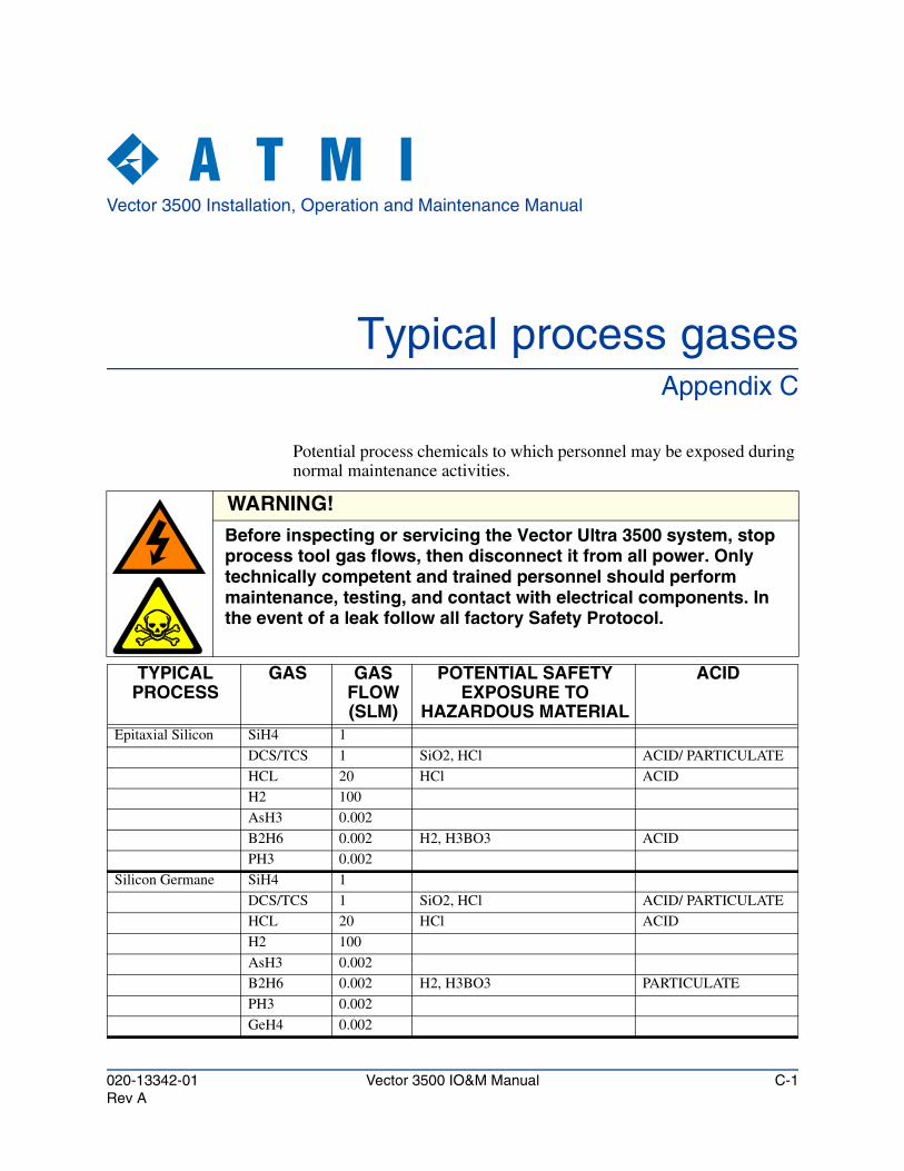
Vector 3500 Installation, Operation and Maintenance Manual
Typical process gasesAppendix C
Potential process chemicals to which personnel may be exposed during normal maintenance activities.
WARNING!
Before inspecting or servicing the Vector Ultra 3500 system, stop process tool gas flows, then disconnect it from all power. Only technically competent and trained personnel should perform maintenance, testing, and contact with electrical components. In the event of a leak follow all factory Safety Protocol.
TYPICALPROCESS
GAS GASFLOW(SLM)
POTENTIAL SAFETY EXPOSURE TO
HAZARDOUS MATERIAL
ACID
Epitaxial Silicon SiH4 1
DCS/TCS 1 SiO2, HCl ACID/ PARTICULATE
HCL 20 HCl ACID
H2 100
AsH3 0.002
B2H6 0.002 H2, H3BO3 ACID
PH3 0.002
Silicon Germane SiH4 1
DCS/TCS 1 SiO2, HCl ACID/ PARTICULATE
HCL 20 HCl ACID
H2 100
AsH3 0.002
B2H6 0.002 H2, H3BO3 PARTICULATE
PH3 0.002
GeH4 0.002
020-13342-01 Vector 3500 IO&M Manual C-1Rev A
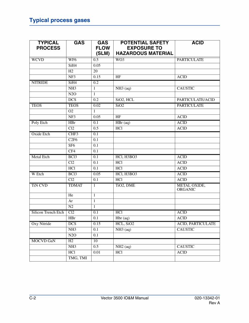
Typical process gases
WCVD WF6 0.5 WO3 PARTICULATE
SiH4 0.05
H2 20
NF3 0.15 HF ACID
NITRIDE SiH4 0.2
NH3 1 NH3 (aq) CAUSTIC
N2O 1
DCS 0.2 SiO2, HCL PARTICULATE/ACID
TEOS TEOS 0.02 SiO2 PARTICULATE
O2 1
NF3 0.05 HF ACID
Poly Etch HBr 0.1 HBr (aq) ACID
Cl2 0.5 HCl ACID
Oxide Etch CHF3 0.1
C2F6 0.1
SF6 0.1
CF4 0.1
Metal Etch BCl3 0.1 HCl, H3BO3 ACID
Cl2 0.1 HCl ACID
HCl 0.1 HCl ACID
W Etch BCl3 0.05 HCl, H3BO3 ACID
Cl2 0.1 HCl ACID
TiN CVD TDMAT 1 TiO2, DME METAL OXIDE, ORGANIC
He 1
Ar 1
N2 1
Silicon Trench Etch Cl2 0.1 HCl ACID
HBr 0.1 Hbr (aq) ACID
Oxy Nitride DCS 0.15 HCL, SiO2 ACID, PARTICULATE
NH3 0.1 NH3 (aq) CAUSTIC
N2O 0.1
MOCVD GaN H2 10
NH3 0.5 NH2 (aq) CAUSTIC
HCl 0.01 HCl ACID
TMG, TMI
TYPICALPROCESS
GAS GASFLOW(SLM)
POTENTIAL SAFETY EXPOSURE TO
HAZARDOUS MATERIAL
ACID
C-2 Vector 3500 IO&M Manual 020-13342-01Rev A
Vector 3500 Installation, Operation and Maintenance Manual
GlossaryAppendix D
Absolute Pressure A pressure measurement that is made relative to a standard pressure, such as the pressure required to support a column of 760 mm of mercury (Hg). All absolute pressures are traceable to measurements made by a standardization laboratory, such as the National Bureau of Standards in the United States. The international unit of absolute pressure is the Pascal. Other absolute pressure units include Atmosphere (atm), Torr, Bar, and Micron. Compare Relative Pressure and Partial Pressure.
Alphanumeric A character set that contains both the letters in the alphabet and numbers.
Atmosphere A unit of pressure equal to the pressure required to support a column of mercury that is 760 mmHg high. One standard atmosphere equals 760 Torr, 1.013 bar, and 101.3 kPa.
Bar A unit of pressure equal to 0.987 Atmosphere, 750 Torr and 105 Pascal. One thousand millibars (mBar) are equal to one Bar.
DWV Abbreviation for Drain Waste Vent. A drain design that ensures that water coming from the main drain of the Vector Ultra 3500 Fume Scrubber does not enter the auxiliary drain. See Chapter 2, Site Preparation.
Exhaust The exit port of a device where waste gases are expelled. A reactor’s exhaust is connected to the fume scrubber’s inlet. The fume scrubber’s exhaust is expelled to the surrounding air.
Fall The drop in inches per 100 feet of drainage pipe. The greater the fall, the more efficient the drainage system. The fall of a drainage system can be increased by mounting the Vector Ultra 3500 Fume Scrubber on a 12 or 24-inch stand.
020-13342-01 Vector 3500 IO&M Manual D-1Rev A
Glossary
Fume Entry Device
An optional inlet to the fume scrubber that adapts it to virtually any fume source. Entry Device Types 3, 4, 8, and 9 allow the fume scrubber to be connected to processes that require pressures from zero to -3 inches of water pressure at the scrubber. They also prevent water vapor from entering the line between the scrubber and the process reactor.
Fume Scrubber A device that removes both particulates and soluble gases from gas streams containing pollutants.
GPM Abbreviation for Gallons Per Minute.
Inlet The entrance to a device. A reactors exhaust is connected to the fume scrubber’s inlet.
LED Abbreviation for Light Emitting Diode, a type of lamp used for displaying information and system states.
Millibar A unit of pressure equal to 10-3 bar, 9.87 x 10⁻⁴ atm, 0.75 Torr, 100 Pascal, and 750 Micron.
Pallet The flat wooden platform that the fume scrubber and other components are shipped on.
Partial Pressure In a mixture of gases, each component gas exerts the same pressure, its partial pressure, as it would if it were alone and occupied the same volume. The sum of the partial pressures is the total pressure. P(total) = P1 + P2 + P3 +..., where P1, P2, and P3 are the partial pressures of the component gases.
Particulates Solid air-borne solids ranging in size from the maximum size that can be suspended in a gaseous environment (100 to 500 microns in diameter) to a small aggregation of molecules (less than 1 micron).
Pascal A unit of pressure equal to 9.87 x 10⁻⁶ atm, 7.5 x 10⁻³ Torr, 10-2 Millibar, and 7.5 Micron.
PPM Abbreviation for the concentration term parts-per-million, corresponding to a concentration of one specific type of atom or molecule in an environment of a million other atoms or molecules. The PPM is often calculated by dividing the partial pressure of the gas of interest by the total pressure (the sum of all of the
partial pressures of the gases in the system) and multiplying by 106. For example, a
helium partial pressure of 10-3 Torr in a process chamber at a total pressure of 10 Torr has a concentration of 100 PPM of helium.
Pressure The force per unit area exerted by gas molecules impacting on a surface. The international system of units for pressure is the Pascal. Other common units are the Atmosphere, Torr, Bar, and Millibar.
D-2 Vector 3500 IO&M Manual 020-13342-01Rev A
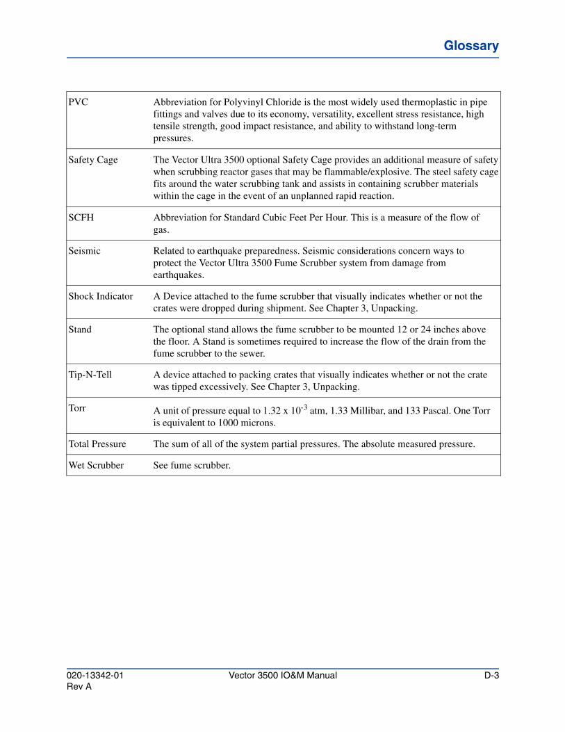
GlossaryGlossaryGlossary
PVC Abbreviation for Polyvinyl Chloride is the most widely used thermoplastic in pipe fittings and valves due to its economy, versatility, excellent stress resistance, high tensile strength, good impact resistance, and ability to withstand long-term pressures.
Safety Cage The Vector Ultra 3500 optional Safety Cage provides an additional measure of safety when scrubbing reactor gases that may be flammable/explosive. The steel safety cage fits around the water scrubbing tank and assists in containing scrubber materials within the cage in the event of an unplanned rapid reaction.
SCFH Abbreviation for Standard Cubic Feet Per Hour. This is a measure of the flow of gas.
Seismic Related to earthquake preparedness. Seismic considerations concern ways to protect the Vector Ultra 3500 Fume Scrubber system from damage from earthquakes.
Shock Indicator A Device attached to the fume scrubber that visually indicates whether or not the crates were dropped during shipment. See Chapter 3, Unpacking.
Stand The optional stand allows the fume scrubber to be mounted 12 or 24 inches above the floor. A Stand is sometimes required to increase the flow of the drain from the fume scrubber to the sewer.
Tip-N-Tell A device attached to packing crates that visually indicates whether or not the crate was tipped excessively. See Chapter 3, Unpacking.
Torr A unit of pressure equal to 1.32 x 10⁻³ atm, 1.33 Millibar, and 133 Pascal. One Torr is equivalent to 1000 microns.
Total Pressure The sum of all of the system partial pressures. The absolute measured pressure.
Wet Scrubber See fume scrubber.
020-13342-01 Vector 3500 IO&M Manual D-3Rev A
Glossary
D-4 Vector 3500 IO&M Manual 020-13342-01Rev A