
Vacuum Products - Hymatik
164
Catalogue PDE2654TCUK February 2012 Vacuum Products Cups, Generators, Sensors & Accessories
-
Upload
khangminh22 -
Category
Documents
-
view
0 -
download
0
Transcript of Vacuum Products - Hymatik

Catalogue PDE2654TCUK February 2012
Vacuum Products Cups, Generators, Sensors & Accessories

PDE2654TCUK
Warning, Offer of Sale
! WARNING FAILURE OR IMPROPER SELECTION OR IMPROPER USE OF THE PRODUCTS AND/OR SYSTEMS DESCRIBED HEREIN OR RELATED ITEMS CAN CAUSE DEATH, PERSONAL INJURY AND PROPERTY DAMAGE. This document and other information from Parker Hannifin Corporation, its subsidiaries and authorized distributors provide product and/or system options for further investigation by users having technical expertise. It is important that you analyze all aspects of your application including consequences of any failure, and review the information concerning the product or system in the current product catalog. Due to the variety of operating conditions and applications for these products or systems, the user, through its own analysis and testing, is solely responsible for making the final selection of the products and systems and assuring that all performance, safety and warning requirements of the application are met. The products described herein, including without limitation, product features, specifications, designs, availability and pricing, are subject to change by Parker Hannifin Corporation and its subsidiaries at any time without notice.
Offer of Sale The items described in this document are hereby offered for sale by Parker Hannifin Corporation, its subsidiaries or its authorized distributors. This offer and its acceptance are governed by the provisions stated on the separate page of this document entitled “Offer of Sale”.
© Copyright 2010 Parker Hannifin Corporation. All Rights Reserved
Parker Hannifin Corporation Pneumatic Division - Europe
2

3
Parker Hannifin Corporation Pneumatic Division - Europe
PDE2654TCUK
Vacuum Products
Pneumatic Control Components Product Selection Chart
AVacuum Cups www.parker.com/pneu/vaccup A
Vacuum Generators www.parker.com/pneu/vacgen B
Pressure Sensors www.parker.com/pneu/sensors C
Safety Guide, Offer of Sale D
Vacu
um
Acc
esso
ries
Sen
sors
G
ener
ator
s Va
cuum
Cup
s

4
Parker Hannifin Corporation Pneumatic Division - Europe
PDE2654TCUK
Vacuum Products
Pneumatic Control Components
- Think systems – create technical solutions!
A For paper handling... For robotic handling…

A
Vacuum Cups
Section A www.parker.com/pneu/vaccup
Parker Hannifin Corporation Pneumatic Division - Europe
A1

PDE2654TCUK Vacuum Cups Vacuum Products Product Selection
Technical Information Lifting Forces, Cup Diameters, Material Specifications A3 - A5
Cup Sizes: 5mm to 200mm
PFG Flat Precision molded single lip flat cup for smooth or slightly A6 - A19 curved surfaces. Low profile design makes flat pads ideal for fast response.
A
Cup Sizes: 10mm to 150mm
PBG Bellows Versatile bellows cup design provides a flexible sealing lip for A20 - A32 products with irregular, smooth, curved surfaces, and flexible products.
PAG Foil, Paper, Film These cups have an ultra thin edge that creates the vacuum A33 - A41 seal by conforming to the shape of the product. The complete foot pattern to the center of the cup prevents the vacuum from deforming or “puckering’ thin, flexible products.
P5V-CFS Flat Precision molded double lip flat cup for slightly curved surfaces. A42 Double lip for additional security. If outside lip bends and looses its seal, the inner lip remains sealed. Outer ribs prevent the cup lip from being cut.
Cup Sizes: 50mm to 300mm
PJG Short Bellows Versatile bellows cup design provides a flexible sealing lip for A43 - A56 products with irregular, smooth, curved surfaces, and slightly flexible products. Shorter stroke provides fast response.
Cup Sizes: 6mm to 80mm
A57 - A67PCG Multiple Bellows Versatile bellows cup design provides a flexible sealing lip for products with irregular, smooth, or curved surfaces. 2-1/2 bellows design minimizes contact pressure applied to products.
Cup Sizes: 5mm to 90mm
PUGB Flat Swivel 30° swivel single lip flat cup for smooth surfaces, slightly curved A68 - A72 surfaces, and flexible products. Rigid stem or level compensator provides good stability for horizontal lift.
Cup Sizes: 60mm to 100mm
Cup Screws Cup screws. A73
Cup Fitting Assemblies Cup / Fitting Cross Reference. A73 - A77
Parker Hannifin Corporation Pneumatic Division - Europe
A2

A3
Parker Hannifin Corporation Pneumatic Division - Europe
PDE2654TCUK
Vacuum Products
• • • • • • • • • • • • • • • • • • • • • • • • •
• • • • • • • • • • • • • • • • • • • • • • • • • • • • • • •
• • • • • • • • • • • • • • • • • • • • • • • • • • • • • • •
• • • • • • • • • • • • • • • • • • • • • • • • • • • • • • •
• • • • • • • • • • • • • • • • • • • •
• • • • • • • • • • • • • • • • • • • •
• • • • • • • • • • • • • • • • • • • • • • • • •
Vacuum Cups Technical Information
Specifications Cup material should be considered for temperature resistance, chemical resistance, oil resistance, abrasion resistance, markless properities and electrical properties. A
NBR NBRE CR SI SIE U
Suction cup Nitrile Silicon material Nitrile ESD* Chloroprene Silicon ESD* Urethane
Operating -20° -30° -30° -60° -60° -30° temperature (°C) to +120° to +120° to +140° to +250° to +250° to +120°
Black / Black /Color Black Green White BlueBlue Dot Red Dot
Hardness, 55 ±5 70 ±5 55 ±5 55 ±5 55 ±5 55 ±5shore A (°Sh)
Electrical 800 800 — — — — resistance (Ωm) to 1000 to 1000
Wear resistance
Tear strength • • • • • • • • • • • • • • • • • • • • •
Aging resistance
Ozone resistance
Gasoline resistance
Oil resistance • • • • • • • • • • • • • • • • • • • • • • • • • • • • • • • • • •
Acid resistance • • • • • • • • • • • • • • • • • •
Alkali resistance
Chemical resistance
Mechanical resistance
• • • • • • = excellent; • • • • • = very good; • • • • = good; • • • = medium; • • = poor; • = not recommended
* ESD: Electric Static Dissipative Material

A4
Parker Hannifin Corporation Pneumatic Division - Europe
PDE2654TCUK
Vacuum Products
Vacuum Cups Technical Information
Selecting the proper vacuum cup
! CAUTION:
A Selecting the type of vacuum cup, material, and size suitable for an application is important to the overall vacuum system. Calculating the forces involved for each application is recommended to determine the vacuum cup size. It should be noted that these calculations are basic theoretical guidelines and each application must be tested for actual results. With all vacuum applications, certain practical assumptions concerning cup materials, environmental conditions, and product characteristics to name a few, may not be consistent with the performance. Again, the user should determine the efficiency, performance, and safety factor of the cup selection.
Calculating pad diameter and forces
Mass The term mass is a quantity of matter and its ability to resist motion when acted on by an external force. The magnitude of an object is represented as a certain number of kilograms (kg) and is symbolized as “m”. The easiest way to determine the mass of an object is to measure the weight with a scale within the earth’s gravitational field (ag = 9.81m/sec2). Likewise, outside of any gravitational field, a mass could potentially be weightless.
Forces For vacuum applications, force is a vector quantity in a defined direction either horizontal or vertical. The standard international unit of force is measured in Newtons (N) which is the equivalent of (kgm/sec2). The force can be calculated by measuring the effect of a change in acceleration on a mass.
Newtons Law: F(N) = mass(kg) x ag(m/sec2)
Consider an object with a mass of 10kg. The gravitational force on this object would be:
F(N) = 10kg x 9.81m/sec2 = 98.1 N
Acceleration Acceleration is the change in velocity of a moving object. Acceleration is a vector, a directional quantity expressed in units of meters per second squared (m/sec2) and symbolized as “a”. To explain the magnitude of acceleration consider an object with a change in velocity of 2 meters per second (m/ sec) over a 4 second time frame. The acceleration can be calculated with: a = velocity a = 6m/sec a = 3m/sec2
time 2 sec
This is considered an average acceleration.
Coefficient of friction Certain values for coefficient of friction should be taken into consideration when calculating the combined forces in motion. Actual values between suction cups and surfaces are difficult to determine. Therefore, coefficient of friction values from published charts, should be used as a reference to adjust the safety factors accordingly.
Lifting forces When calculating lifting forces, safety factors of 2 for horizontal lifts and 4 for vertical lifts are minimum values. Applications with irregular shapes, difficult surfaces, and
FH: Horizontal Lift FV: Vertical Lift
backward motions will require increased safety factors.
Horizontal lifting force Apply Newtons Law to calculate the force on a 10kg mass with a change in acceleration of 3m/sec2 and a safety factor of 2.
FH(N) = mass(kg) x (ag+ a) x SH
FH(N) = 10kg x (9.81m/sec2 +3m/sec2) x 2
FH = 256.2 N 3m/sec2
FH
10kg
Vertical lifting force Apply Newtons Law to calculate the force on a 10kg mass with a dry surface, a change in acceleration of 3m/sec2 and a safety factor of 4.
FV(N) = mass(kg) x (ag+ a) x Sv
FV(N) = 10kg x (9.81m/sec2 +3m/sec2) x 4
FV = 512.4 N
3m/sec2
10kg
FV
Combined vertical lift and horizontal motion Calculate the force on a 10kg mass with a dry surface, a change in acceleration of 3m/sec2, and a change in travel acceleration of 2m/sec2.
FM(N) = FV2 + FH2
FM(N) = [(10kg x 2m/sec2) x 4]2 + [10kg x (9.81m/sec2 + 3m/sec2) x 2]2
FM(N) = (80kgm/sec2)2 + [256kgm/sec2]2
FM(N) = 6400kgm/sec2 + 65,536kgm/sec2
FM = 268.2 N
3m/sec2
FH
2m/sec2
10kg

PDE2654TCUK Vacuum Cups Vacuum Products Technical Information
Analyze the forces Using the previous examples, consider an application where 4 cups have been selected to transfer the product.
Take the Horizontal Lifting Force (FH) of 256.2 N and divide by the number of cups (4) to obtain the individual force for each cup.
256.2 (N) = 64.05 N / Cup 4
Referring to the chart below, at 60% vacuum, select a force greater than 64.05 N. The appropriate selection is a 40mm diameter cup which has a theoretical lifting force of 76.9 N.
The same calculation can be applied to the Vertical Lifting Force and the Forces in Motion examples to determine the cup diameter.
To convert Pounds (lbf) to Newton (N), multiply lbf x 4.4.
Theoretical lifting force per cup lbf (N)
Calculate the diameter of the cup Calculate the cup diameter for horizontal lift at 60% of full vacuum using the information from the previous page.
D = 35.7 m (ag + a) x S D (mm) = Diameter of Cup APv x n m (kg) = Mass
ag = 9.81m/sec2
a = Motion Acceleration D = 35.7 10 (9.81 + 3) x 2 S = Safety Factor
61 x 4 Pv (kPa) = Operating Vacuum Pressure n = number of Cups
D = 36.58 mm
Referring to the chart below, at 60% vacuum, select a cup diameter equal to or greater than 37mm. The appropriate selection is a 40mm diameter cup which has a theoretical lifting force of 76.9 N.
Cup Vacuum level
3 inHg 6 inHg 9 inHg 12 inHg 15 inHg 18 inHg 21 inHg 24 inHg 27 inHg
Diameter mm
Area cm2
-1.5 PSIG -3 PSIG -4.5 PSIG -6 PSIG -7.5 PSIG -9 PSIG -10.5 PSIG -12 PSIG -13.5 PSIG 10.2 kPa 20.3 kPa 30.5 kPa 40.6 kPa 50.8 kPa 61 kPa 71.1 kPa 81.3 kPa 91.4 kPa 10% 20% 30% 40% 50% 60% 70% 80% 90%
1.5 0.01 0.004 (0.02)
0.008 (0.04)
0.008 (0.04)
0.014 (0.06)
0.018 (0.08)
0.022 (0.10)
0.026 (0.12)
0.032 (0.14)
0.032 (0.14)
2 0.03 0.007 (0.03)
0.013 (0.06)
0.022 (0.10)
0.029 (0.13)
0.036 (0.16)
0.043 (0.19)
0.049 (0.22)
0.056 (0.25)
0.063 (0.28)
3.5 0.10 0.022 (0.10)
0.045 (0.20)
0.065 (0.29)
0.088 (0.39)
0.110 (0.49)
0.133 (0.59)
0.155 (0.69)
0.175 (0.78)
0.198 (0.88)
5 0.20 0.045 (0.20)
0.090 (0.40)
0.135 (0.60)
0.180 (0.80)
0.225 (1.00)
0.270 (1.20)
0.315 (1.40)
0.360 (1.60)
0.405 (1.80)
6 0.28 0.065 (0.29)
0.130 (0.58)
0.196 (0.87)
0.270 (1.20)
0.315 (1.40)
0.382 (1.70)
0.450 (2.00)
0.517 (2.30)
0.585 (2.60)
7 0.39 0.088 (0.39)
0.175 (0.78)
0.265 (1.18)
0.360 (1.60)
0.450 (2.00)
0.540 (2.40)
0.607 (2.70)
0.697 (3.10)
0.787 (3.50)
8 0.50 0.117 (0.52)
0.229 (1.02)
0.346 (1.54)
0.450 (2.00)
0.585 (2.60)
0.697 (3.10)
0.809 (3.60)
0.922 (4.10)
1.034 (4.60)
10 0.79 0.180 (0.80)
0.360 (1.60)
0.540 (2.40)
0.719 (3.20)
0.899 (4.00)
1.079 (4.80)
1.259 (5.60)
1.439 (6.40)
1.619 (7.20)
15 1.77 0.404 (1.80)
0.809 (3.60)
1.216 (5.41)
1.619 (7.20)
2.023 (9.00)
2.428 (10.8)
2.833 (12.6)
2.237 (14.4)
3.642 (16.2)
18 2.55 0.585 (2.60)
1.169 (5.20)
1.751 (7.79)
2.338 (10.4)
2.923 (13.0)
3.507 (15.6)
4.069 (18.1)
4.676 (20.8)
5.238 (23.3)
20 3.14 0.719 (3.20)
1.439 (6.40)
2.158 (9.60)
2.878 (12.8)
3.597 (16.0)
4.316 (19.2)
5.036 (22.4)
5.755 (25.6)
6.474 (28.8)
25 4.91 1.124 (5.00)
2.248 (10.0)
3.372 (15.0)
4.496 (20.0)
5.620 (25.0)
6.744 (30.0)
7.868 (35.0)
8.992 (40.0)
10.116 (45.0)
30 7.07 1.619 (7.20)
3.237 (14.4)
4.856 (21.6)
6.474 (28.8)
8.093 (36.0)
9.712 (43.2)
11.330 (50.4)
12.949 (57.6)
14.568 (64.8)
35 9.62 2.203 (9.80)
4.406 (19.6)
5.598 (29.4)
8.813 (39.2)
11.016 (49.0)
13.241 (58.9)
15.422 (68.6)
17.648 (78.5)
19.828 (88.2)
40 12.6 2.900 (12.9)
5.755 (25.6)
8.655 (38.5)
11.510 (51.2)
14.388 (64.0)
17.288 (76.9)
20.143 (89.6)
23.155 (103)
25.853 (115)
50 19.6 4.519 (20.1)
8.992 (40.0)
13.511 (60.1)
17.985 (80.0)
22.481 (100)
26.977 (120)
31.473 (140)
35.969 (160)
40.466 (180)
60 28.3 6.497 (28.9)
12.949 (57.6)
19.446 (86.5)
25.853 (115)
32.372 (144)
38.892 (173)
45.411 (202)
51.931 (231)
58.226 (259)
75 44.2 10.161 (45.2)
20.233 (90.0)
30.349 (135)
40.466 (180)
50.582 (225)
60.698 (270)
70.815 (315)
80.931 (360)
91.048 (405)
80 50.3 11.555 (51.4)
22.931 (102)
34.621 (154)
46.086 (205)
57.551 (256)
69.241 (308)
80.706 (359)
92.172 (410)
103.637 (461)
90 63.6 14.635 (65.1)
29.225 (130)
43.838 (195)
58.226 (259)
72.838 (324)
87.451 (389)
102.063 (454)
116.676 (519)
131.064 (583)
95 70.9 16.299 (72.5)
32.372 (144)
48.784 (217)
64.970 (289)
81.156 (361)
97.567 (434)
113.753 (506)
129.940 (578)
146.126 (650)
110 95.0 21.851 (97.2)
43.613 (194)
65.419 (291)
87.001 (387)
108.808 (484)
130.614 (581)
152.421 (678)
174.227 (775)
195.809 (871)
120 113.1 26.078 (116)
51.706 (230)
77.784 (346)
103.637 (461)
129.490 (576)
155.568 (692)
181.421 (807)
207.274 (922)
233.127 (1037)
150 176.7 40.690 (181)
80.931 (360)
121.622 (541)
161.862 (720)
202.328 (900)
243.019 (1081)
283.259 (1260)
323.950 (1441)
364.191 (1620)
200 314.2 72.164 (321)
143.878 (640)
216.041 (961)
287.531 (1279)
359.919 (1601)
432.083 (1922)
503.797 (2241)
575.961 (2562)
647.449 (2880
Parker Hannifin Corporation Pneumatic Division - Europe
A5

A6
Parker Hannifin Corporation Pneumatic Division - Europe
PDE2654TCUK
Vacuum Products
Vacuum Cups PFG Flat Vacuum Cup Series
Exceptional for any smooth flat or surface that will benifit from stability and fast response of the cup design. This is a multi-versatile and multi-industry cup. Typical
A applications could be chip mounting, electrical components, semiconductor chips, glass, injection mold, sheet metal, press transfer, fixtures, woodworking.
Features • Precision molded single lip flat cup for smooth or slightly
curved surfaces. • Universal flat design for most smooth surface applications • Stable vertical / horizontal lift • Strong low profile design for fast response needed for
short cycles • 5mm to 200mm diameters • Bottom cleats on 60 to 200mm diameters
Styles • PFTM series male thread connector • PFTF series female thread connector • PFTK series barbed bulkhead • PFYK series 90° barbed adapter • PFTYS series bulkhead level compensator
Specifications
Nitrile Silicon Cup material Nitrile ESD* Silicon ESD* Urethane
Material code NBR NBRE SI SIE U
Operating -20° -30° -60° -60° -30° temperature (°C) to +120° to +120° to +250° to +250° to +120°
Black / Black /Color Black White BlueBlue Dot Red Dot
Hardness, 55 ±5 70 ±5 55 ±5 55 ±5 55 ±5shore A (°Sh)
Electrical 800 800 — — — resistance (Ωm) to 1000 to 1000
* ESD: Electric Static Dissipative Material
How to order Cups Assemblies and replacement cups are specified by Cup Diameter and Material. Standard Nitrile and silicon are listed on the following pages. To specify an alternative material, replace the cup material with alternative cup material code.
Example: To specify a cup assembly with Urethane (U), replace (NBR) with (U) in the part number. PFTM-20B-NBR-G1 becomes PFTM-20B-U-G1. Inquire with factory for availability.
Application guide Flat - Smooth surface
Ø 120/200 only
Flat surface, Flat surface, Slightly bowed Slightly bowed Metal sheet Corrugated High lifting Vertical lift thin section any section surface, thin surface, any handling sheet handling force
section section

A7
Parker Hannifin Corporation Pneumatic Division - Europe
PDE2654TCUK
Vacuum Products
5
6
8
Vacuum Cups PFG Flat Vacuum Cup Series
PFTM Series Male Thread Connector
ATube I.D.
Mounting Thread
Installation Note: When installing cup assemblies, use a sealant material to secure the assembly and prevent vacuum leakage.
Simple male connection for low profile positions secured to a plate or bracket. BSPP, NPT metric threads. Fitting material: aluminum.
Cup Complete Replacement Complete Replacement diameter Vacuum assembly cup assembly cup Replacement (mm) port Nitrile (NBR) Nitrile (NBR) Silicon (SI) Silicon (SI) cup fitting
5 M5 PFTM-5A-NBR-M5 PFG-5A-NBR PFTM-5A-SI-M5 PFG-5A-SI FTM-5A-M5
1/8 BSPP PFTM-5A-NBR-G1 PFG-5A-NBR PFTM-5A-SI-G1 PFG-5A-SI FTM-5A-G1
6 M5 PFTM-6A-NBR-M5 PFG-6A-NBR PFTM-6A-SI-M5 PFG-6A-SI FTM-5A-M5
1/8 BSPP PFTM-6A-NBR-G1 PFG-6A-NBR PFTM-6A-SI-G1 PFG-6A-SI FTM-5A-G1
8 M5 PFTM-8A-NBR-M5 PFG-8A-NBR PFTM-8A-SI-M5 PFG-8A-SI FTM-5A-M5
1/8 BSPP PFTM-8A-NBR-G1 PFG-8A-NBR PFTM-8A-SI-G1 PFG-8A-SI FTM-5A-G1
10 M5 PFTM-10A-NBR-M5 PFG-10A-NBR PFTM-10A-SI-M5 PFG-10A-SI FTM-5A-M5
10 1/8 BSPP PFTM-10A-NBR-G1 PFG-10A-NBR PFTM-10A-SI-G1 PFG-10A-SI FTM-5A-G1
15 M5 PFTM-15A-NBR-M5 PFG-15A-NBR PFTM-15A-SI-M5 PFG-15A-SI FTM-5A-M5
15 1/8 BSPP PFTM-15A-NBR-G1 PFG-15A-NBR PFTM-15A-SI-G1 PFG-15A-SI FTM-5A-G1
20 1/8 BSPP PFTM-20B-NBR-G1 PFG-20B-NBR PFTM-20B-SI-G1 PFG-20B-SI FTM-20B-G1
20 1/4 BSPP PFTM-20B-NBR-G2 PFG-20B-NBR PFTM-20B-SI-G2 PFG-20B-SI FTM-20B-G2
20 M10 PFTM-20B-NBR-M10 PFG-20B-NBR PFTM-20B-SI-M10 PFG-20B-SI FTM-20B-M10
20 1/8 NPT PFTM-20B-NBR-N1 PFG-20B-NBR PFTM-20B-SI-N1 PFG-20B-SI FTM-20B-N1
30 1/8 BSPP PFTM-30-NBR-G1 PFG-30-NBR PFTM-30-SI-G1 PFG-30-SI FTM-20B-G1
30 1/4 BSPP PFTM-30-NBR-G2 PFG-30-NBR PFTM-30-SI-G2 PFG-30-SI FTM-20B-G2
30 M10 PFTM-30-NBR-M10 PFG-30-NBR PFTM-30-SI-M10 PFG-30-SI FTM-20B-M10
30 1/8 NPT PFTM-30-NBR-N1 PFG-30-NBR PFTM-30-SI-N1 PFG-30-SI FTM-20B-N1
40 1/8 BSPP PFTM-40-NBR-G1 PFG-40-NBR PFTM-40-SI-G1 PFG-40-SI FTM-20B-G1
40 1/4 BSPP PFTM-40-NBR-G2 PFG-40-NBR PFTM-40-SI-G2 PFG-40-SI FTM-20B-G2
40 M10 PFTM-40-NBR-M10 PFG-40-NBR PFTM-40-SI-M10 PFG-40-SI FTM-20B-M10
40 1/8 NPT PFTM-40-NBR-N1 PFG-40-NBR PFTM-40-SI-N1 PFG-40-SI FTM-20B-N1
50 1/8 BSPP PFTM-50-NBR-G1 PFG-50-NBR PFTM-50-SI-G1 PFG-50-SI FTM-50-G1
50 1/4 BSPP PFTM-50-NBR-G2 PFG-50-NBR PFTM-50-SI-G2 PFG-50-SI FTM-50-G2
50 1/8 NPT PFTM-50-NBR-N1 PFG-50-NBR PFTM-50-SI-N1 PFG-50-SI FTM-50-N1
60 1/4 BSPP PFTM-60-NBR-G2 PFG-60-NBR PFTM-60-SI-G2 PFG-60-SI FTM-60-G2
60 M10 PFTM-60-NBR-M10 PFG-60-NBR PFTM-60-SI-M10 PFG-60-SI FTM-60-M10
60 1/4 NPT PFTM-60-NBR-N2 PFG-60-NBR PFTM-60-SI-N2 PFG-60-SI FTM-60-N2
80 1/4 BSPP PFTM-80-NBR-G2 PFG-80-NBR PFTM-80-SI-G2 PFG-80-SI FTM-60-G2
80 M10 PFTM-80-NBR-M10 PFG-80-NBR PFTM-80-SI-M10 PFG-80-SI FTM-60-M10
80 1/4 NPT PFTM-80-NBR-N2 PFG-80-NBR PFTM-80-SI-N2 PFG-80-SI FTM-60-N2
95 1/4 BSPP PFTM-95-NBR-G2 PFG-95-NBR PFTM-95-SI-G2 PFG-95-SI FTM-60-G2
95 M10 PFTM-95-NBR-M10 PFG-95-NBR PFTM-95-SI-M10 PFG-95-SI FTM-60-M10
95 1/4 NPT PFTM-95-NBR-N2 PFG-95-NBR PFTM-95-SI-N2 PFG-95-SI FTM-60-N2

A8
Parker Hannifin Corporation Pneumatic Division - Europe
PDE2654TCUK
Vacuum Products
5
6
8
Vacuum Cups PFG Flat Vacuum Cup Series
PFTF Series Female Thread Connector
A Simple female connection for low profile positions secured to a plate or bracket. BSPP, NPT threads.
Fitting material: aluminum. Tube I.D.
Pipe I.D.
Mounting Thread
Installation Note: When installing cup assemblies, use a sealant material to secure the assembly and prevent vacuum leakage.
Cup Complete Replacement Complete Replacement diameter Vacuum assembly cup assembly cup Replacement (mm) port Nitrile (NBR) Nitrile (NBR) Silicon (SI) Silicon (SI) cup fitting
5 M5 PFTF-5A-NBR-M5 PFG-5A-NBR PFTF-5A-SI-M5 PFG-5A-SI FTF-5A-M5
1/8 BSPP PFTF-5A-NBR-G1 PFG-5A-NBR PFTF-5A-SI-G1 PFG-5A-SI FTF-5A-G1
6 M5 PFTF-6A-NBR-M5 PFG-6A-NBR PFTF-6A-SI-M5 PFG-6A-SI FTF-5A-M5
1/8 BSPP PFTF-6A-NBR-G1 PFG-6A-NBR PFTF-6A-SI-G1 PFG-6A-SI FTF-5A-G1
8 M5 PFTF-8A-NBR-M5 PFG-8A-NBR PFTF-8A-SI-M5 PFG-8A-SI FTF-5A-M5
1/8 BSPP PFTF-8A-NBR-G1 PFG-8A-NBR PFTF-8A-SI-G1 PFG-8A-SI FTF-5A-G1
10 1/8 BSPP PFTF-10A-NBR-G1 PFG-10A-NBR PFTF-10A-SI-G1 PFG-10A-SI FTF-5A-G1
10 M5 PFTF-10A-NBR-M5 PFG-10A-NBR PFTF-10A-SI-M5 PFG-10A-SI FTF-5A-M5
15 1/8 BSPP PFTF-15A-NBR-G1 PFG-15A-NBR PFTF-15A-SI-G1 PFG-15A-SI FTF-5A-G1
15 M5 PFTF-15A-NBR-M5 PFG-15A-NBR PFTF-15A-SI-M5 PFG-15A-SI FTF-5A-M5
20 1/8 BSPP PFTF-20B-NBR-G1 PFG-20B-NBR PFTF-20B-SI-G1 PFG-20B-SI FTF-20B-G1
30 1/8 BSPP PFTF-30-NBR-G1 PFG-30-NBR PFTF-30-SI-G1 PFG-30-SI FTF-20B-G1
30 1/4 BSPP PFTF-30-NBR-G2 PFG-30-NBR PFTF-30-SI-G2 PFG-30-SI FTF-20B-G2
40 1/8 BSPP PFTF-40-NBR-G1 PFG-40-NBR PFTF-40-SI-G1 PFG-40-SI FTF-20B-G1
40 1/4 BSPP PFTF-40-NBR-G2 PFG-40-NBR PFTF-40-SI-G2 PFG-40-SI FTF-20B-G2
50 1/8 BSPP PFTF-50-NBR-G1 PFG-50-NBR PFTF-50-SI-G1 PFG-50-SI FTF-50-G1
50 1/4 BSPP PFTF-50-NBR-G2 PFG-50-NBR PFTF-50-SI-G2 PFG-50-SI FTF-50-G2
60 1/4 BSPP PFTF-60-NBR-G2 PFG-60-NBR PFTF-60-SI-G2 PFG-60-SI FTF-60-G2
60 1/4 NPT PFTF-60-NBR-N2 PFG-60-NBR PFTF-60-SI-N2 PFG-60-SI FTF-60-N2
80 1/4 BSPP PFTF-80-NBR-G2 PFG-80-NBR PFTF-80-SI-G2 PFG-80-SI FTF-60-G2
80 1/4 NPT PFTF-80-NBR-N2 PFG-80-NBR PFTF-80-SI-N2 PFG-80-SI FTF-60-N2
95 1/4 NPT PFTF-95-NBR-N2 PFG-95-NBR PFTF-95-SI-N2 PFG-95-SI FTF-60-N2
95 1/4 BSPP PFTF-95-NBR-G2 PFG-95-NBR PFTF-95-SI-G2 PFG-95-SI FTF-60-G2
120 1/2 BSPP PFTF-120-NBR-G4 PFG-120-NBR PFTF-120-SI-G4 PFG-120-SI FTF-120-G4
120 1/2 NPT PFTF-120-NBR-N4 PFG-120-NBR PFTF-120-SI-N4 PFG-120-SI FTF-120-N4
150 1/2 NPT PFTF-150-NBR-G4 PFG-150-NBR PFTF-150-SI-G4 PFG-150-SI FTF-120-G4
150 1/2 NPT PFTF-150-NBR-N4 PFG-150-NBR PFTF-150-SI-N4 PFG-150-SI FTF-120-N4
200 1/2 BSPP PFTF-200-NBR-G4 PFG-200-NBR PFTF-200-SI-G4 PFG-200-SI FTF-120-G4
200 1/2 NPT PFTF-200-NBR-N4 PFG-200-NBR PFTF-200-SI-N4 PFG-200-SI FTF-120-N4

A9
Parker Hannifin Corporation Pneumatic Division - Europe
PDE2654TCUK
Vacuum Products
Vacuum Cups PFG Flat Vacuum Cup Series
PFTK Series Barbed Bulkhead
A Top stem connectors secured with jam nuts and allow tubing connections at the top side. Fitting material: nickel plated brass.
Tube I.D.
Mounting Thread
Cup Screw
Installation Note: When installing cup assemblies, use a sealant material to secure the assembly and prevent vacuum leakage.
Cup Complete Replacement Complete Replacement diameter Vacuum assembly cup assembly cup Replacement (mm) port Nitrile (NBR) Nitrile (NBR) Silicon (SI) Silicon (SI) cup fitting
5 Barb PFTK-5A-NBR PFG-5A-NBR PFTK-5A-SI PFG-5A-SI FTK-5A
6 Barb PFTK-6A-NBR PFG-6A-NBR PFTK-6A-SI PFG-6A-SI FTK-5A
8 Barb PFTK-8A-NBR PFG-8A-NBR PFTK-8A-SI PFG-8A-SI FTK-5A
10 Barb PFTK-10A-NBR PFG-10A-NBR PFTK-10A-SI PFG-10A-SI FTK-5A
15 Barb PFTK-15-NBR PFG-15-NBR PFTK-15-SI PFG-15-SI FTK-15
20 Barb PFTK-20-NBR PFG-20-NBR PFTK-20-SI PFG-20-SI FTK-20
30 Barb PFTK-30-NBR PFG-30-NBR PFTK-30-SI PFG-30-SI FTK-25
40 Barb PFTK-40-NBR PFG-40-NBR PFTK-40-SI PFG-40-SI FTK-25
50 Barb PFTK-50-NBR PFG-50-NBR PFTK-50-SI PFG-50-SI FTK-50
60 1/8 BSPP PFTK-60-NBR-G1 PFG-60-NBR PFTK-60-SI-G1 PFG-60-SI FTK-60-G1
60 1/8 NPT PFTK-60-NBR-N1 PFG-60-NBR PFTK-60-SI-N1 PFG-60-SI FTK-60-N1
80 1/8 BSPP PFTK-80-NBR-G1 PFG-80-NBR PFTK-80-SI-G1 PFG-80-SI FTK-60-G1
80 1/8 NPT PFTK-80-NBR-N1 PFG-80-NBR PFTK-80-SI-N1 PFG-80-SI FTK-60-N1
95 1/8 BSPP PFTK-95-NBR-G1 PFG-95-NBR PFTK-95-SI-G1 PFG-95-SI FTK-60-G1
95 1/8 NPT PFTK-95-NBR-N1 PFG-95-NBR PFTK-95-SI-N1 PFG-95-SI FTK-60-N1

A10
Parker Hannifin Corporation Pneumatic Division - Europe
PDE2654TCUK
Vacuum Products
Vacuum Cups PFG Flat Vacuum Cup Series
PFYK Series 90° Barbed Adapter Side stem connectors allow you to secure the stem with a bolt thru a plate or “L” bracket to allow the tube connection from
A the side port. Fitting material: nickel plated brass.
Installation Mounting
Tube I.D.
Thread
Cup Screw
Note: When installing cup assemblies, use a sealant material to secure the assembly and prevent vacuum leakage.
Cup Complete Replacement Complete Replacement diameter Vacuum assembly cup assembly cup Replacement (mm) port Nitrile (NBR) Nitrile (NBR) Silicon (SI) Silicon (SI) cup fitting
5 Barb PFYK-5A-NBR PFG-5A-NBR PFYK-5A-SI PFG-5A-SI FYK-5A
6 Barb PFYK-6A-NBR PFG-6A-NBR PFYK-6A-SI PFG-6A-SI FYK-5A
8 Barb PFYK-8A-NBR PFG-8A-NBR PFYK-8A-SI PFG-8A-SI FYK-5A
10 Barb PFYK-10A-NBR PFG-10A-NBR PFYK-10A-SI PFG-10A-SI FYK-5A
15 Barb PFYK-15-NBR PFG-15-NBR PFYK-15-SI PFG-15-SI FYK-15
20 Barb PFYK-20-NBR PFG-20-NBR PFYK-20-SI PFG-20-SI FYK-20
30 Barb PFYK-30-NBR PFG-30-NBR PFYK-30-SI PFG-30-SI FYK-25
40 Barb PFYK-40-NBR PFG-40-NBR PFYK-40-SI PFG-40-SI FYK-25
50 Barb PFYK-50-NBR PFG-50-NBR PFYK-50-SI PFG-50-SI FYK-50
60 1/8 BSPP PFYK-60-NBR-G1 PFG-60-NBR PFYK-60-SI-G1 PFG-60-SI FYK-60-G1
60 1/8 NPT PFYK-60-NBR-N1 PFG-60-NBR PFYK-60-SI-N1 PFG-60-SI FYK-60-N1
80 1/8 BSPP PFYK-80-NBR-G1 PFG-80-NBR PFYK-80-SI-G1 PFG-80-SI FYK-60-G1
80 1/8 NPT PFYK-80-NBR-N1 PFG-80-NBR PFYK-80-SI-N1 PFG-80-SI FYK-60-N1
95 1/8 BSPP PFYK-95-NBR-G1 PFG-95-NBR PFYK-95-SI-G1 PFG-95-SI FYK-60-G1
95 1/8 NPT PFYK-95-NBR-N1 PFG-95-NBR PFYK-95-SI-N1 PFG-95-SI FYK-60-N1
120 1/8 BSPP PFYK-120-NBR-G1 PFG-120-NBR PFYK-120-SI-G1 PFG-120-SI FYK-120-G1
120 1/8 NPT PFYK-120-NBR-N1 PFG-120-NBR PFYK-120-SI-N1 PFG-120-SI FYK-120-N1
150 1/8 BSPP PFYK-150-NBR-G1 PFG-150-NBR PFYK-150-SI-G1 PFG-150-SI FYK-120-G1
150 1/8 NPT PFYK-150-NBR-N1 PFG-150-NBR PFYK-150-SI-N1 PFG-150-SI FYK-120-N1
200 1/8 BSPP PFYK-200-NBR-G1 PFG-200-NBR PFYK-200-SI-G1 PFG-200-SI FYK-120-G1
200 1/8 NPT PFYK-200-NBR-N1 PFG-200-NBR PFYK-200-SI-N1 PFG-200-SI FYK-120-N1

A11
Parker Hannifin Corporation Pneumatic Division - Europe
PDE2654TCUK
Vacuum Products
Vacuum Cups PFG Flat Vacuum Cup Series
PFTYS Series Bulkhead Level Compensator 303 stainless steel construction secured with jam nuts. Spring biased compensators can absorb impacts of down-strokes and adjust for different levels of pick up points. 303 stainless Acorrosion resistant materials with drymet bushings increases the strength and life.
Inte
rcha
ngab
le*
Installation Note: When installing cup assemblies, use a sealant material to secure the assembly and prevent vacuum leakage.
PlugPushlock Tube Fitting
Barb Fitting
Mounting Thread
* Not included with assembly
Cup Spring compression Cup material Replacement Replacement dia. Vacuum Stroke Force lbf (N) Nitrile assembly cup Cup material Silicon cup Level (mm) port (mm) 0% 100% (NBR) Nitrile (NBR) assembly (SI) Silicon (SI) Compensator P/N
5 M5 10 .14 (.61) .26 (1.17) PFTYS5A10NBRM5 PFG-5A-NBR PFTYS5A10SIM5 PFG-5A-SI FTYS-5A-10-M5
5 M5 15 .15 (.64) .26 (1.17) PFTYS5A15NBRM5 PFG-5A-NBR PFTYS5A15SIM5 PFG-5A-SI FTYS-5A-15-M5
6 M5 10 .14 (.61) .26 (1.17) PFTYS6A10NBRM5 PFG-6A-NBR PFTYS6A10SIM5 PFG-6A-SI FTYS-5A-10-M5
6 M5 15 .15 (.64) .26 (1.17) PFTYS6A15NBRM5 PFG-6A-NBR PFTYS6A15SIM5 PFG-6A-SI FTYS-5A-15-M5
8 M5 10 .14 (.61) .26 (1.17) PFTYS8A10NBRM5 PFG-8A-NBR PFTYS8A10SIM5 PFG-8A-SI FTYS-5A-10-M5
8 M5 15 .15 (.64) .26 (1.17) PFTYS8A15NBRM5 PFG-8A-NBR PFTYS8A15SIM5 PFG-8A-SI FTYS-5A-15-M5
10 M5 10 .11 (.49) .13 (.59) PFTYS10A10NBRM5 PFG-10A-NBR PFTYS10A10SIM5 PFG-10A-SI FTYS-5A-10-M5
10 M5 15 .11 (.49) .13 (.59) PFTYS10A15NBRM5 PFG-10A-NBR PFTYS10A15SIM5 PFG-10A-SI FTYS-5A-15-M5
15 M5 10 .11 (.49) .13 (.59) PFTYS15A10NBRM5 PFG-15A-NBR PFTYS15A10SIM5 PFG-15A-SI FTYS-5A-10-M5
15 M5 15 .11 (.49) .13 (.59) PFTYS15A15NBRM5 PFG-15A-NBR PFTYS15A15SIM5 PFG-15A-SI FTYS-5A-15-M5
20 M5 15 .56 (2.5) .79 (3.4) PFTYS20B15NBRM5 PFG-20B-NBR PFTYS20B15SIM5 PFG-20B-SI FTYS-20B-15-M5
20 M5 30 .56 (2.5) 1.2 (4.9) PFTYS20B30NBRM5 PFG-20B-NBR PFTYS20B30SIM5 PFG-20B-SI FTYS-20B-30-M5
30 M5 15 .56 (2.5) .79 (3.4) PFTYS3015NBRM5 PFG-30-NBR PFTYS3015SIM5 PFG-30-SI FTYS-20B-15-M5
30 M5 30 .56 (2.5) 1.2 (4.9) PFTYS3030NBRM5 PFG-30-NBR PFTYS3030SIM5 PFG-30-SI FTYS-20B-30-M5
40 M5 15 .56 (2.5) .79 (3.4) PFTYS4015NBRM5 PFG-40-NBR PFTYS4015SIM5 PFG-40-SI FTYS-20B-15-M5
40 M5 30 .56 (2.5) 1.2 (4.9) PFTYS4030NBRM5 PFG-40-NBR PFTYS4030SIM5 PFG-40-SI FTYS-20B-30-M5
50 M5 15 .56 (2.5) 1.2 (4.9) PFTYS5015NBRM5 PFG-50-NBR PFTYS5015SIM5 PFG-50-SI FTYS-50-15-M5
50 M5 30 .67 (2.9) 1.4 (5.9) PFTYS5030NBRM5 PFG-50-NBR PFTYS5030SIM5 PFG-50-SI FTYS-50-30-M5
60 1/8 BSPP 30 1.6 (6.8) 3.6 (15.6) PFTYS6030NBRG1 PFG-60-NBR PFTYS6030SIG1 PFG-60-SI FTYS-60-30-G1
60 1/8 BSPP 50 1.9 (8.3) 4.5 (19.6) PFTYS6050NBRG1 PFG-60-NBR PFTYS6050SIG1 PFG-60-SI FTYS-60-50-G1
80 1/8 BSPP 30 1.6 (6.8) 3.6 (15.6) PFTYS8030NBRG1 PFG-80-NBR PFTYS8030SIG1 PFG-80-SI FTYS-60-30-G1
80 1/8 BSPP 50 1.9 (8.3) 4.5 (19.6) PFTYS8050NBRG1 PFG-80-NBR PFTYS8050SIG1 PFG-80-SI FTYS-60-50-G1
95 1/8 BSPP 30 1.6 (6.8) 3.6 (15.6) PFTYS9530NBRG1 PFG-95-NBR PFTYS9530SIG1 PFG-95-SI FTYS-60-30-G1
95 1/8 BSPP 50 1.9 (8.3) 4.5 (19.6) PFTYS9550NBRG1 PFG-95-NBR PFTYS9550SIG1 PFG-95-SI FTYS-60-50-G1
120 1/4 BSPP 20 3.6 (15.6) 6.8 (29) PFTYS12020NBRG2 PFG-120-NBR PFTYS12020SIG2 PFG-120-SI FTYS-120-20-G2
120 1/4 BSPP 50 3.4 (14.7) 6.8 (29) PFTYS12050NBRG2 PFG-120-NBR PFTYS12050SIG2 PFG-120-SI FTYS-120-50-G2
150 1/4 BSPP 20 3.6 (15.6) 6.8 (29) PFTYS15020NBRG2 PFG-150-NBR PFTYS15020SIG2 PFG-150-SI FTYS-120-20-G2
150 1/4 BSPP 50 3.4 (14.7) 6.8 (29) PFTYS15050NBRG2 PFG-150-NBR PFTYS15050SIG2 PFG-150-SI FTYS-120-50-G2
200 1/4 BSPP 20 3.6 (15.6) 6.8 (29) PFTYS20020NBRG2 PFG-200-NBR PFTYS20020SIG2 PFG-200-SI FTYS-120-20-G2
200 1/4 BSPP 50 3.4 (14.7) 6.8 (29) PFTYS20050NBRG2 PFG-200-NBR PFTYS20050SIG2 PFG-200-SI FTYS-120-50-G2

A12
Parker Hannifin Corporation Pneumatic Division - Europe
PDE2654TCUK
Vacuum Products
Vacuum Cups PFG Flat Vacuum Cup Series
Applications • Products with smooth surfaces
A • Products with minimum flex • Products that will not permanently deform
Main data for fat PFG cups
V
Volume
S
Cup deflection
R
Radius
Lifting force @60% (N)
Model Cup diameter Area Volume (V) Cup deflection Radius number mm cm2 liters (S) mm (R) mm
PFG-5A-* 5 0.20 0.000005 1.20 0.6 0.5 3.5
PFG-6A-* 6 0.28 0.000008 1.70 0.85 1.0 4.0
PFG-8A-* 8 0.50 0.00003 3.10 1.5 1.4 5.0
PFG-10A-* 10 0.79 0.00007 4.80 2.4 1.5 6.0
PFG-15-* 15 1.77 0.0004 10.8 5.4 1.9 6.0
PFG-15A-* 15 1.77 0.0004 10.8 5.4 1.9 6.0
PFG-20-* 20 3.14 0.0008 19.2 9.6 2.3 9.0
PFG-20B-* 20 3.14 0.0008 19.2 9.6 2.3 13.0
PFG-30-* 30 7.07 0.0018 43.2 21.6 2.0 26
PFG-40-* 40 12.60 0.004 76.9 38.5 3.5 37
PFG-50-* 50 19.60 0.007 120 60 4.0 41
PFG-60-* 60 28.30 0.0090 173 87 5.0 70
PFG-80-* 80 50.30 0.025 308 154 6.0 100
PFG-95-* 95 70.90 0.035 434 267 6.0 150
PFG-120-* 120 113.00 0.078 692 346 6.0 365
PFG-150-* 150 176.70 0.177 1081 541 9.0 380
PFG-200-* 200 314.20 0.425 1922 961 13.0 430
* Cup material

A13
Parker Hannifin Corporation Pneumatic Division - Europe
PDE2654TCUK
Vacuum Products
Vacuum Cups PFG Flat Vacuum Cup Series
PFG Series Replacement Cup Dimensions
PFG-5A PFG-15A
FA
D J B
C
EG H
D
B
PFG-50
H
A
DPFG-60 thru PFG-95 B
A
Dimensions (mm)
D B
PFG-15 thru PFG-40
H
A
C
PFG-120 thru
E
F
H
E
F
A E
FC
Model number ØA ØB ØC ØD E F G H ØJ
PFG-200
A
B D
4 Bolt Pattern 40mm Dia.
G Dia. Typ. 4 Places
C
E
H
F
PFG-5A-* 5 4 1.4 7.5 6.5 .8 4 2 6
PFG-6A-* 6 4 2 7.5 6.5 .8 4 2 6
PFG-8A-* 8 4 2 8 7 1.2 4 2 6
PFG-10A-* 10 4 2 8.5 7.5 1.5 4 2 6
PFG-15-* 15 — 7.8 12 8 1.9 — — —
PFG-15A-* 15 4 2 9 8 2 4 2 6
PFG-20-* 20 4.6 11 15 10 2.3 — 4.5 —
PFG-20B-* 20 6 11 15 12.5 2.3 — 7 —
PFG-30-* 30 6 11 14 12 2 — 7 —
PFG-40-* 40 6 11 24 14 4 — 7 —
PFG-50-* 50 8 20 27 15 3.5 — 7 —
PFG-60-* 60 M10x1.25 — 12.5 18.5 5 — 2.5 —
PFG-80-* 80 M10x1.25 — 12.5 20.5 6 — 2.5 —
PFG-95-* 95 M10x1.25 — 12.5 21 6 — 2.5 —
PFG-120-* 120 14 14 20 25.5 6 4xØ8.7xØ40 1.5 —
PFG-150-* 150 13 14 20 32.5 9 4xØ8.7xØ40 1.5 —
PFG-200-* 200 13 12 20 37.5 13 4xØ8.7xØ40 1.5 —
* Cup material

A14
Parker Hannifin Corporation Pneumatic Division - Europe
PDE2654TCUK
Vacuum Products
A
Dimensions
PFTM-5A thru PFTM-15A
M5: SW8 G1: SW13 (5A thru 15A Only)
D
M5: .14 (3.5) G1: .20 (5) (5A thru 15A Only)
PFTM-20B thru PFTM-50
20B thru 40: 1/2" 50: 9/16"
Dimensions (mm)
Vacuum Cups PFTM Series Assemblies
M5: M5 G1: 1/8" BSPP (5A thru 15A Only)
C
B
A E
N1: 1/8 NPT PFTM-60 thruG1: 1/8 BSPP N2: 1/4 NPT
M10: 10x1.25 PFTM-95 G2: 1/4 BSPP G2: 1/4 BSPP M10: 10x1.25
CC
D
BB
E
AEA
D 9/16"
Model C C C C C number ØA B (M3) (M5) (N1 / G1) (M10 / G2) (N2) D E
PFTM-5A-*-† 5 10 — 4.5 8 — — See Dwg. 8
PFTM-6A-*-† 6 10 — 4.5 8 — — See Dwg. 8
PFTM-8A-*-† 8 10.5 — 4.5 8 — — See Dwg. 1.2
PFTM-10A-*-† 10 11 — 4.5 8 — — See Dwg. 1.5
PFTM-15A-*-† 15 11.5 — 4.5 8 — — See Dwg. 2
PFTM-20B-*-† 20 17.5 — — 8 10 — 5 2.5
PFTM-30-*-† 30 17 — — 8 10 — 5 2
PFTM-40-*-† 40 19 — — 8 10 — 5 3.5
PFTM-50-*-† 50 20 — — 8 10 — 5 4
PFTM-60-*-† 60 23 — — — 10 15 7 5
PFTM-80-*-† 80 25 — — — 10 15 7 6
PFTM-95-*-† 95 25.5 — — — 10 15 7 6
* Cup material † Thread size

A15
Parker Hannifin Corporation Pneumatic Division - Europe
PDE2654TCUK
Vacuum Products
Vacuum Cups PFTF Series Assemblies
Dimensions
PFTF-5A thru PFTF-20B thru G1: 1/8 BSPP PFTF-15A PFTF-50 G2: 1/4 BSPP A
M5x0.8 20B thru 40: 1/2" G1: 1/8 BSPP 50: 9/16"
M5, G1: 1/8" B
B
EA E
A
PFTF-60 thru PFTF-120 thru PFTF-95 PFTF-200
A
B
E
N2: 1/4 NPT G2: 1/4 BSPP
9/16"
A
N4: 1/2 NPT G4: 1/2 BSPP
1/8 NPT or 1/8 BSPP
B
D
E
C
2.24 (57) O.D.
1.854 (48) Across Flats
M8 x 1.25 Mtg. Screws on 40mm Dia. Centerline
Dimensions (mm)
Model B number ØA B (M5) C D E
PFTF-5A-*-† 5 14.5 20.5 — — .8
PFTF-6A-*-† 6 14.5 20.5 — — .8
PFTF-8A-*-† 8 15 21 — — 1.2
PFTF-10A-*-† 10 14.5 20.5 — — 1.5
PFTF-15A-*-† 15 16 22 — — 2
PFTF-20B-*-† 20 26.5 — — — 2.5
PFTF-30-*-† 30 26 — — — 2
PFTF-40-*-† 40 28 — — — 4
PFTF-50-*-† 50 29 — — — 4
PFTF-60-*-† 60 35.5 — — — 5
PFTF-80-*-† 80 37.5 — — — 6
PFTF-95-*-† 95 38 — — — 6
PFTF-120-*-† 120 46.5 — 24 13 6
PFTF-150-*-† 150 53.5 — 24 13 9
PFTF-200-*-† 200 58.5 — 24 13 13
* Cup material † Thread size
A16
Parker Hannifin Corporation Pneumatic Division - Europe
PDE2654TCUK
Vacuum Products
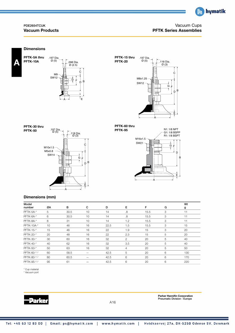
Vacuum Cups PFTK Series Assemblies
Dimensions
A PFTK-5A thru .197 Dia. PFTK-15 thru .197 Dia.
Ø (5)PFTK-10A .098 Dia. Ø (2.5)
FG
C
D B
EA
PFTK-20
M9 SW12
A
B FG
C
D
E
M8x1.25
SW12
Ø (5) .118 Dia. Ø (3)
PFTK-30 thru PFTK-60 thru
A
B FG
C
D
E
SW14
Ø (5) .118 Dia.
Ø (3)
N1: 1/8 NPT .197 Dia. PFTK-95PFTK-50 G1: 1/8 BSPP R1: 1/8 BSPT
M10x1.5 M5x0.8 D
B
E
A
SW21
M16x1.5
FG
Dimensions (mm)
Model Wt number ØA B C D E F G g
PFTK-5A-* 5 30.5 10 14 .8 15.5 3 11
PFTK-6A-* 6 30.5 10 14 .8 15.5 3 11
PFTK-8A-* 8 31 10 14 1.2 15.5 3 11
PFTK-10A-* 10 46 16 22.5 1.5 15.5 3 15
PFTK-15-* 15 46 16 22 1.9 15 3 20
PFTK-20-* 20 48 16 22 2.3 15 5 20
PFTK-30-* 30 60 16 32 2 20 5 40
PFTK-40-* 40 62 16 32 3.5 20 5 40
PFTK-50-* 50 63 16 32 4 20 5 50
PFTK-60-*-† 60 58.5 — 42.5 5 20 6 130
PFTK-80-*-† 80 60.5 — 42.5 6 20 6 170
PFTK-95-*-† 95 61 — 42.5 6 20 6 220
* Cup material † Vacuum port

PDE2654TCUK Vacuum Cups Vacuum Products PFYK Series Assemblies
Dimensions
PFYK-5A thru PFYK-15 thru M4x0.7 APFYK-10A PFYK-20
F
G
A
C
.197
Dia
.Ø
(5)
.1
18 D
ia.
Ø (
3)
E
F C
E.197
Dia
.Ø
(5)
.1
18 D
ia.
Ø (
3) G
A
M4x0.7
DD BB
PFYK-120 thru PFYK-200
PFYK-60 thru PFYK-95
PFYK-30 thru PFYK-50
B
F
G M6x1.0
C
D
E
.197
Dia
.Ø
(5)
.1
18 D
ia.
Ø (
3)
A A
M8x1.25
B
F
N1: 1/8 NPT G1: 1/8 BSPP
C
D
E
A
2.75 Dia. (70) (SW65)
G M16
N1: 1/8 NPT G1: 1/8 BSPP B
C
D
E
F
M8 x 1.25 Mtg. Screws on 40mm Dia. Centerline
Dimensions (mm)
Model Wt number ØA B C D E F G g
PFYK-5A-* 5 29 13 22.5 .8 6 16 16
PFYK-6A-* 6 29 13 22.5 .8 6 16 16
PFYK-8A-* 8 29.5 13 22.5 1.2 6 16 16
PFYK-10A-* 10 30 13 22.5 1.5 6 16 16
PFYK-15-* 15 30 14 22 1.9 6 16 20
PFYK-20-* 20 32 14 22 2.3 6 16 20
PFYK-30-* 30 44 20 32 2 8 16 40
PFYK-40-* 40 46 20 32 3.5 8 16 50
PFYK-50-* 50 47 20 32 4 8 16 55
PFYK-60-*-† 60 58.5 28 40 5 11 — 120
PFYK-80-*-† 80 60.5 28 40 6 11 — 160
PFYK-95-*-† 95 61 28 40 6 11 — 210
PFYK-120-*-† 120 75.5 12 50 6 20 Dia. 30 640
PFYK-150-*-† 150 82.5 12 50 9 20 Dia. 30 910
PFYK-200-*-† 200 87.5 12 50 13 20 Dia. 30 1200
* Cup material † Vacuum port
Parker Hannifin Corporation Pneumatic Division - Europe
A17
A18
Parker Hannifin Corporation Pneumatic Division - Europe
PDE2654TCUK
Vacuum Products
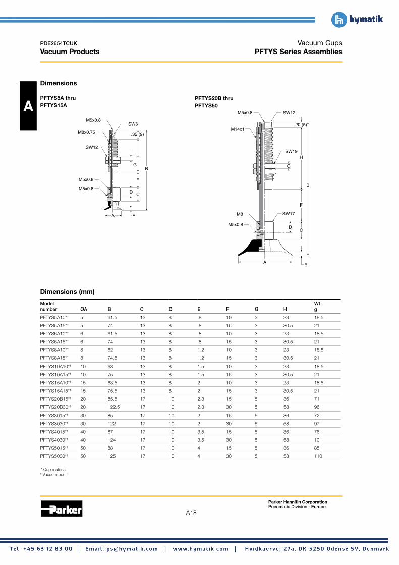
Vacuum Cups PFTYS Series Assemblies
Dimensions
PFTYS5A thru PFTYS20B thru
A PFTYS15A PFTYS50
M5x0.8 SW6
M8x0.75
SW12
M5x0.8
M5x0.8
B
D C
F
.35 (9)
H
G
EA
M5x0.8 SW12
SW19
SW17
M14x1
M5x0.8
B
D
E
C
H
.20 (5)
F
G
A
M8
Dimensions (mm)
Model Wt number ØA B C D E F G H g
PFTYS5A10*† 5 61.5 13 8 .8 10 3 23 18.5
PFTYS5A15*† 5 74 13 8 .8 15 3 30.5 21
PFTYS6A10*† 6 61.5 13 8 .8 10 3 23 18.5
PFTYS6A15*† 6 74 13 8 .8 15 3 30.5 21
PFTYS8A10*† 8 62 13 8 1.2 10 3 23 18.5
PFTYS8A15*† 8 74.5 13 8 1.2 15 3 30.5 21
PFTYS10A10*† 10 63 13 8 1.5 10 3 23 18.5
PFTYS10A15*† 10 75 13 8 1.5 15 3 30.5 21
PFTYS15A10*† 15 63.5 13 8 2 10 3 23 18.5
PFTYS15A15*† 15 75.5 13 8 2 15 3 30.5 21
PFTYS20B15*† 20 85.5 17 10 2.3 15 5 36 71
PFTYS20B30*† 20 122.5 17 10 2.3 30 5 58 96
PFTYS3015*† 30 85 17 10 2 15 5 36 72
PFTYS3030*† 30 122 17 10 2 30 5 58 97
PFTYS4015*† 40 87 17 10 3.5 15 5 36 76
PFTYS4030*† 40 124 17 10 3.5 30 5 58 101
PFTYS5015*† 50 88 17 10 4 15 5 36 85
PFTYS5030*† 50 125 17 10 4 30 5 58 110
* Cup material † Vacuum port

N1:
PDE2654TCUK Vacuum Cups Vacuum Products PFTYS Series Assemblies
Dimensions
PFTYS60 thru PFTYS120 thru PFTYS95 PFTYS200 A
1/8 NPTG1: 1/8 BSPPG1: 1/8 BSPP
SW19Shock Pad
5mm
M22x1.5
H
B
F
M14
N1: 1/8 NPT G1: 1/8 BSPPG1: 1/8 BSPP C
A E
SW30
SW24
D
J.28 (7)
G
A
N2: 1/4 NPT G2: 1/4 BSPP
N2: 1/4 NPT G2: 1/4 BSPP
SW26
SW36
M30x1.5
M18
B
D
E
C
J
.31 (8)
F
HG
M8 x 1.25 Mtg. Screws on 40mm Dia. Centerline
G2: 1/4 BSPP
G2: 1/4 BSPP
Dimensions (mm)
Model Wt number ØA B C D E F G H J g
PFTYS6030*† 60 153 32.5 20 5 45 10 50 12 282
PFTYS6050*† 60 178 32.5 20 5 70 10 50 12 316
PFTYS8030*† 80 155 32.5 20 6 45 10 50 12 310
PFTYS8050*† 80 180 32.5 20 6 70 10 50 12 344
PFTYS9530*† 95 156 32.5 20 6 45 10 50 12 350
PFTYS9550*† 95 181 32.5 20 6 70 10 50 12 384
PFTYS12020*† 120 192 32.5 18 6 35 10 60 35 1165
PFTYS12070*† 120 257 32.5 18 6 100 10 60 35 1246
PFTYS15020*† 150 199 32.5 18 9 35 10 60 35 1389
PFTYS15070*† 150 209 32.5 18 9 75 10 60 35 1471
PFTYS20020*† 200 204 32.5 18 13 35 10 60 35 1755
PFTYS20070*† 200 264 32.5 18 13 100 10 60 35 1836
* Cup material † Vacuum port
Parker Hannifin Corporation Pneumatic Division - Europe
A19

A20
Parker Hannifin Corporation Pneumatic Division - Europe
PDE2654TCUK
Vacuum Products
Vacuum Cups PBG Bellows Vacuum Cups
A
These cups are for curved, corrugated, lightly textured surfaces and flexible product. Under vacuum, the bellow cup will collapse on contact and lift the product for a short distance. This inherent performance facilitates lifting and destack operations by breaking the vacuum between stacked product. The bellow style adds level compensation for applications that have inconsistent stack heights or uneven surfaces. The inclusive 30-degree rotation of the bellow helps maintain the vacuum seal when lifting sheet products that flex. Because of it’s shape however the bellows suction cup is not very well suitable for applications involving lifting vertical surfaces.
Features • Bellows design for level compensation within restricted
clearances • Sheet separation for flexible and stacked products • Soft seal lip for flexible products • 10mm to 150mm diameters
Styles • PBTM series male thread connector • PBTF series female thread connector • PBTK series barbed bulkhead • PBYK series 90° barbed adapter • PBTYS series bulkhead level compensator
Specifications
Cup material Nitrile Silicon Urethane
Material code NBR SI U
Operating -20° -60° -30° temperature (°C) to +120° to +250° to +120°
Color Black White Blue
Hardness, 55 ±5 55 ±5 55 ±5shore A (°Sh)
How to order Cups assemblies and replacement cups are specified by cup diameter and material. Standard nitrile and silicon are listed on the following pages. To specify an alternative material, replace the cup material with alternative cup material code.
Example: To specify a cup assembly with urethane (U), replace (NBR) with (U) in the part number. PBTM-20B-NBR-G1 becomes PBTM-20B-U-G1. Inquire with factory for availability.
Application guide Bellows
Flat Flat Slightly Slightly Bowed Bowed Soft Differences Corrugated Not for Metal surface, surface, bowed bowed surface, surface, porous in heights sheet vertical lift sheet thin any surface, surface, thin any material, and levels handling handling section section thin any section section any
section section section

A21
Parker Hannifin Corporation Pneumatic Division - Europe
PDE2654TCUK
Vacuum Products
Vacuum Cups PBG Bellows Vacuum Cups
PBTM Series Male Thread Connector
A Simple male connection for low profile positions secured to a plate or bracket. BSPP, NPT metric threads. Fitting material: aluminum.
Tube I.D.
Mounting Thread
Note: When installing cup assemblies, use a sealant material to secure the assembly and prevent vacuum leakage.
Installation
Cup Complete Replacement Complete Replacement diameter Vacuum assembly cup assembly cup Replacement (mm) port Nitrile (NBR) Nitrile (NBR) Silicon (SI) Silicon (SI) cup fitting
10 M5 PBTM-10A-NBR-M5 PBG-10A-NBR PBTM-10A-SI-M5 PBG-10A-SI FTM-5A-M5
10 1/8 BSPP PBTM-10A-NBR-G1 PBG-10A-NBR PBTM-10A-SI-G1 PBG-10A-SI FTM-5A-G1
15 M5 PBTM-15A-NBR-M5 PBG-15A-NBR PBTM-15A-SI-M5 PBG-15A-SI FTM-5A-M5
15 1/8 BSPP PBTM-15A-NBR-G1 PBG-15A-NBR PBTM-15A-SI-G1 PBG-15A-SI FTM-5A-G1
20 1/8 BSPP PBTM-20B-NBR-G1 PBG-20B-NBR PBTM-20B-SI-G1 PBG-20B-SI FTM-20B-G1
20 1/4 BSPP PBTM-20B-NBR-G2 PBG-20B-NBR PBTM-20B-SI-G2 PBG-20B-SI FTM-20B-G2
20 M10 PBTM-20B-NBR-M10 PBG-20B-NBR PBTM-20B-SI-M10 PBG-20B-SI FTM-20B-M10
20 1/8 NPT PBTM-20B-NBR-N1 PBG-20B-NBR PBTM-20B-SI-N1 PBG-20B-SI FTM-20B-N1
30 1/8 BSPP PBTM-30-NBR-G1 PBG-30-NBR PBTM-30-SI-G1 PBG-30-SI FTM-20B-G1
30 1/4 BSPP PBTM-30-NBR-G2 PBG-30-NBR PBTM-30-SI-G2 PBG-30-SI FTM-20B-G2
30 M10 PBTM-30-NBR-M10 PBG-30-NBR PBTM-30-SI-M10 PBG-30-SI FTM-20B-M10
30 1/8 NPT PBTM-30-NBR-N1 PBG-30-NBR PBTM-30-SI-N1 PBG-30-SI FTM-20B-N1
40 1/8 BSPP PBTM-40-NBR-G1 PBG-40-NBR PBTM-40-SI-G1 PBG-40-SI FTM-20B-G1
40 1/4 BSPP PBTM-40-NBR-G2 PBG-40-NBR PBTM-40-SI-G2 PBG-40-SI FTM-20B-G2
40 M10 PBTM-40-NBR-M10 PBG-40-NBR PBTM-40-SI-M10 PBG-40-SI FTM-20B-M10
40 1/8 NPT PBTM-40-NBR-N1 PBG-40-NBR PBTM-40-SI-N1 PBG-40-SI FTM-20B-N1
50 1/8 BSPP PBTM-50-NBR-G1 PBG-50-NBR PBTM-50-SI-G1 PBG-50-SI FTM-50-G1
50 1/4 BSPP PBTM-50-NBR-G2 PBG-50-NBR PBTM-50-SI-G2 PBG-50-SI FTM-50-G2
50 1/8 NPT PBTM-50-NBR-N1 PBG-50-NBR PBTM-50-SI-N1 PBG-50-SI FTM-50-N1
75 1/4 BSPP PBTM-75-NBR-G2 PBG-75-NBR PBTM-75-SI-G2 PBG-75-SI FTM-60-G2
75 M10 PBTM-75-NBR-M10 PBG-75-NBR PBTM-75-SI-M10 PBG-75-SI FTM-60-M10
75 1/4 NPT PBTM-75-NBR-N2 PBG-75-NBR PBTM-75-SI-N2 PBG-75-SI FTM-60-N2

A22
Parker Hannifin Corporation Pneumatic Division - Europe
PDE2654TCUK
Vacuum Products
Vacuum Cups PBG Bellows Vacuum Cups
A Tube I.D.
Pipe I.D.
Mounting Thread
Note: When installing cup assemblies, use a sealant material to secure the assembly and prevent vacuum leakage.
PBTF Series Female Thread Connector Simple female connection for low profile positions secured to a plate or bracket. BSPP, NPT metric threads.
Fitting material: aluminum.
Installation
Cup Complete Replacement Complete Replacement diameter Vacuum assembly cup assembly cup Replacement (mm) port Nitrile (NBR) Nitrile (NBR) Silicon (SI) Silicon (SI) cup fitting
10 1/8 BSPP PBTF-10A-NBR-G1 PBG-10A-NBR PBTF-10A-SI-G1 PBG-10A-SI FTF-5A-G1
10 M5 PBTF-10A-NBR-M5 PBG-10A-NBR PBTF-10A-SI-M5 PBG-10A-SI FTF-5A-M5
15 1/8 BSPP PBTF-15A-NBR-G1 PBG-15A-NBR PBTF-15A-SI-G1 PBG-15A-SI FTF-5A-G1
15 M5 PBTF-15A-NBR-M5 PBG-15A-NBR PBTF-15A-SI-M5 PBG-15A-SI FTF-5A-M5
20 1/8 BSPP PBTF-20B-NBR-G1 PBG-20B-NBR PBTF-20B-SI-G1 PBG-20B-SI FTF-20B-G1
20 1/8 NPT PBTF-20B-NBR-N1 PBG-20B-NBR PBTF-20B-SI-N1 PBG-20B-SI FTF-20B-N1
30 1/8 BSPP PBTF-30-NBR-G1 PBG-30-NBR PBTF-30-SI-G1 PBG-30-SI FTF-20B-G1
30 1/8 NPT PBTF-30-NBR-N1 PBG-30-NBR PBTF-30-SI-N1 PBG-30-SI FTF-20B-N1
30 1/4 BSPP PBTF-30-NBR-G2 PBG-30-NBR PBTF-30-SI-G2 PBG-30-SI FTF-20B-G2
40 1/8 BSPP PBTF-40-NBR-G1 PBG-40-NBR PBTF-40-SI-G1 PBG-40-SI FTF-20B-G1
40 1/8 NPT PBTF-40-NBR-N1 PBG-40-NBR PBTF-40-SI-N1 PBG-40-SI FTF-20B-N1
40 1/4 BSPP PBTF-40-NBR-G2 PBG-40-NBR PBTF-40-SI-G2 PBG-40-SI FTF-20B-G2
50 1/8 BSPP PBTF-50-NBR-G1 PBG-50-NBR PBTF-50-SI-G1 PBG-50-SI FTF-50-G1
50 1/4 BSPP PBTF-50-NBR-G2 PBG-50-NBR PBTF-50-SI-G2 PBG-50-SI FTF-50-G2
50 1/8 NPT PBTF-50-NBR-N1 PBG-50-NBR PBTF-50-SI-N1 PBG-50-SI FTF-50-N1
75 1/4 BSPP PBTF-75-NBR-G2 PBG-75-NBR PBTF-75-SI-G2 PBG-75-SI FTF-60-G2
75 1/4 NPT PBTF-75-NBR-N2 PBG-75-NBR PBTF-75-SI-N2 PBG-75-SI FTF-60-N2
110 1/2 BSPP PBTF-110-NBR-G4 PBG-110-NBR PBTF-110-SI-G4 PBG-110-SI FTF-120-G4
110 1/2 NPT PBTF-110-NBR-N4 PBG-110-NBR PBTF-110-SI-N4 PBG-110-SI FTF-120-N4
150 1/2 BSPP PBTF-150-NBR-G4 PBG-150-NBR PBTF-150-SI-G4 PBG-150-SI FTF-120-G4
150 1/2 NPT PBTF-150-NBR-N4 PBG-150-NBR PBTF-150-SI-N4 PBG-150-SI FTF-120-N4

A23
Parker Hannifin Corporation Pneumatic Division - Europe
PDE2654TCUK
Vacuum Products
Vacuum Cups PBG Bellows Vacuum Cups
A Installation
PBTK Series Barbed Bulkhead Top stem connectors secured with jam nuts and allow tubing connections at the top side. Fitting materials: nickel plated brass.
Tube I.D.
Mounting Thread.
Cup Screw
Note: When installing cup assemblies, use a sealant material to secure the assembly and prevent vacuum leakage.
Cup Complete Replacement Complete Replacement diameter Vacuum assembly cup assembly cup Replacement (mm) port Nitrile (NBR) Nitrile (NBR) Silicon (SI) Silicon (SI) cup fitting
10 Barb PBTK-10A-NBR PBG-10A-NBR PBTK-10A-SI PBG-10A-SI FTK-5A
15 Barb PBTK-15A-NBR PBG-15A-NBR PBTK-15A-SI PBG-15-SI FTK-5A
20 Barb PBTK-20-NBR PBG-20-NBR PBTK-20-SI PBG-20-SI FTK-20
30 Barb PBTK-30-NBR PBG-30-NBR PBTK-30-SI PBG-30-SI FTK-25
40 Barb PBTK-40-NBR PBG-40-NBR PBTK-40-SI PBG-40-SI FTK-25
50 Barb PBTK-50-NBR PBG-50-NBR PBTK-50-SI PBG-50-SI FTK-50
75 1/8 BSPP PBTK-75-NBR-G1 PBG-75-NBR PBTK-75-SI-G1 PBG-75-SI FTK-60-G1
75 1/8 NPT PBTK-75-NBR-N1 PBG-75-NBR PBTK-75-SI-N1 PBG-75-SI FTK-60-N1

A24
Parker Hannifin Corporation Pneumatic Division - Europe
PDE2654TCUK
Vacuum Products
Vacuum Cups PBG Bellows Vacuum Cups
A
Tube I.D.
Mounting Thread.
Cup Screw
Note: When installing cup assemblies, use a sealant material to secure the assembly and prevent vacuum leakage.
PBYK Series 90° Barbed Adapter Side stem connectors allow you to secure the stem with a bolt through a plate or “L” bracket to allow the tube connection from the side port. Fitting material: nickel plated brass.
Installation
Cup Complete Replacement Complete Replacement diameter Vacuum assembly cup assembly cup Replacement (mm) port Nitrile (NBR) Nitrile (NBR) Silicon (SI) Silicon (SI) cup fitting
10 Barb PBYK-10A-NBR PBG-10A-NBR PBYK-10A-SI PBG-10A-SI FYK-5A
15 Barb PBYK-15A-NBR PBG-15A-NBR PBYK-15A-SI PBG-15A-SI FYK-15
20 Barb PBYK-20-NBR PBG-20-NBR PBYK-20-SI PBG-20-SI FYK-20
30 Barb PBYK-30-NBR PBG-30-NBR PBYK-30-SI PBG-30-SI FYK-25
40 Barb PBYK-40-NBR PBG-40-NBR PBYK-40-SI PBG-40-SI FYK-25
50 Barb PBYK-50-NBR PBG-50-NBR PBYK-50-SI PBG-50-SI FYK-50
75 1/8 BSPP PBYK-75-NBR-G1 PBG-75-NBR PBYK-75-SI-G1 PBG-75-SI FYK-60-G1
75 1/8 NPT PBYK-75-NBR-N1 PBG-75-NBR PBYK-75-SI-N1 PBG-75-SI FYK-60-N1
110 1/8 BSPP PBYK-110-NBR-G1 PBG-110-NBR PBYK-110-SI-G1 PBG-110-SI FYK-120-G1
110 1/8 NPT PBYK-110-NBR-N1 PBG-110-NBR PBYK-110-SI-N1 PBG-110-SI FYK-120-N1
150 1/8 BSPP PBYK-150-NBR-G1 PBG-150-NBR PBYK-150-SI-G1 PBG-150-SI FYK-120-G1
150 1/8 NPT PBYK-150-NBR-N1 PBG-150-NBR PBYK-150-SI-N1 PBG-150-SI FYK-120-N1

A25
Parker Hannifin Corporation Pneumatic Division - Europe
PDE2654TCUK
Vacuum Products
Vacuum Cups PBG Bellows Vacuum Cups
PBTYS Series Bulkhead Level Compensator 303 stainless steel construction secured with jam nuts. Spring biased compensators can absorb impacts of down-strokes and adjust for different levels of pick up points. 303 stainless Acorrosion resistant materials with drymet bushings increases the strength and life.
Inte
rcha
ngab
le*
Installation Note: When installing cup assemblies, use a sealant material to secure the assembly and prevent vacuum leakage. Shown are interchangable connectors & plugs for port connections.
Mounting Thread.
PlugPushlock Tube Fitting
Barb Fitting
* Not included with assembly
Cup Spring compression Cup material Replacement Cup material Replacement dia. Vacuum Stroke Force lbf (N) Nitrile assemlby cup Silicon assembly cup Level (mm) port (mm) 0% 100% (NBR) Nitrile (NBR) (SI) Silicon (SI) Compensator P/N
10 M5 10 .11 (.49) .13 (.59) PBTYS10A10NBRM5 PBG-10A-NBR PBTYS10A10SIM5 PBG-10A-SI FTYS-5A-10-M5
10 M5 15 .11 (.49) .13 (.59) PBTYS10A15NBRM5 PBG-10A-NBR PBTYS10A15SIM5 PBG-10A-SI FTYS-5A-15-M5
15 M5 10 .11 (.49) .13 (.59) PBTYS15A10NBRM5 PBG-15A-NBR PBTYS15A10SIM5 PBG-15A-SI FTYS-5A-10-M5
15 M5 15 .11 (.49) .13 (.59) PBTYS15A15NBRM5 PBG-15A-NBR PBTYS15A15SIM5 PBG-15A-SI FTYS-5A-15-M5
20 M5 15 .56 (2.5) .79 (3.4) PBTYS20B15NBRM5 PBG-20B-NBR PBTYS20B15SIM5 PBG-20B-SI FTYS-20B-15-M5
20 M5 30 .56 (2.5) 1.2 (4.9) PBTYS20B30NBRM5 PBG-20B-NBR PBTYS20B30SIM5 PBG-20B-SI FTYS-20B-30-M5
30 M5 15 .56 (2.5) .79 (3.4) PBTYS3015NBRM5 PBG-30-NBR PBTYS3015SIM5 PBG-30-SI FTYS-20B-15-M5
30 M5 30 .56 (2.5) 1.2 (4.9) PBTYS3030NBRM5 PBG-30-NBR PBTYS3030SIM5 PBG-30-SI FTYS-20B-30-M5
40 M5 15 .56 (2.5) .79 (3.4) PBTYS4015NBRM5 PBG-40-NBR PBTYS4015SIM5 PBG-40-SI FTYS-20B-15-M5
40 M5 30 .56 (2.5) 1.2 (4.9) PBTYS4030NBRM5 PBG-40-NBR PBTYS4030SIM5 PBG-40-SI FTYS-20B-30-M5
50 M5 15 .56 (2.5) 1.2 (4.9) PBTYS5015NBRM5 PBG-50-NBR PBTYS5015SIM5 PBG-50-SI FTYS-50-15-M5
50 M5 30 .67 (2.9) 1.4 (5.9) PBTYS5030NBRM5 PBG-50-NBR PBTYS5030SIM5 PBG-50-SI FTYS-50-30-M5
75 1/8 BSPP 30 1.6 (6.8) 3.6 (15.6) PBTYS7530NBRG1 PBG-75-NBR PBTYS7530SIG1 PBG-75-SI FTYS-60-30-G1
75 1/8 BSPP 50 1.9 (8.3) 4.5 (19.6) PBTYS7550NBRG1 PBG-75-NBR PBTYS7550SIG1 PBG-75-SI FTYS-60-50-G1
110 1/4 BSPP 20 3.6 (15.6) 6.8 (29) PBTYS12020NBRG2 PBG-110-NBR PBTYS11020SIG2 PBG-110-SI FTYS-120-20-G2
110 1/4 BSPP 50 3.4 (14.7) 6.8 (29) PBTYS12050NBRG2 PBG-110-NBR PBTYS11050SIG2 PBG-110-SI FTYS-120-50-G2
150 1/4 BSPP 20 3.6 (15.6) 6.8 (29) PBTYS15020NBRG2 PBG-150-NBR PBTYS15020SIG2 PBG-150-SI FTYS-120-20-G2
150 1/4 BSPP 50 3.4 (14.7) 6.8 (29) PBTYS15050NBRG2 PBG-150-NBR PBTYS15050SIG2 PBG-150-SI FTYS-120-50-G2

A26
Parker Hannifin Corporation Pneumatic Division - Europe
PDE2654TCUK
Vacuum Products
Vacuum Cups PBG Bellows Vacuum Cups
Applications • Round objects • Uneven surfaces • Flexible product
• Curved product • Soft seal lip
A • Level compensation
Main data for bellows PBG cups
V
Volume
S
Cup deflection
R
Radius
Lifting force @60% (N) Cup Model Cup diameter Area Volume (V) deflection (S) Radius (R)number mm cm2 liters mm mm
PBG-10A-* 10 0.79 .0002 4.80 — 4 4
PBG-15A-* 15 1.77 .0007 10.80 — 6 6
PBG-20-* 20 3.14 .001 19.20 — 9 8
PBG-20B-* 20 3.14 .001 19.20 — 9 8
PBG-30-* 30 7.07 .004 43.2 — 13 15
PBG-40-* 40 12.60 .009 76.9 — 13 30
PBG-50-* 50 19.60 .026 120 — 20 40
PBG-75-* 75 44.02 .076 270 — 22 70
PBG-110-* 110 95.00 .111 434 — 29 100
PBG-150-* 150 176.70 .260 1081 — 38 130
* Cup material
A27
Parker Hannifin Corporation Pneumatic Division - Europe
PDE2654TCUK
Vacuum Products
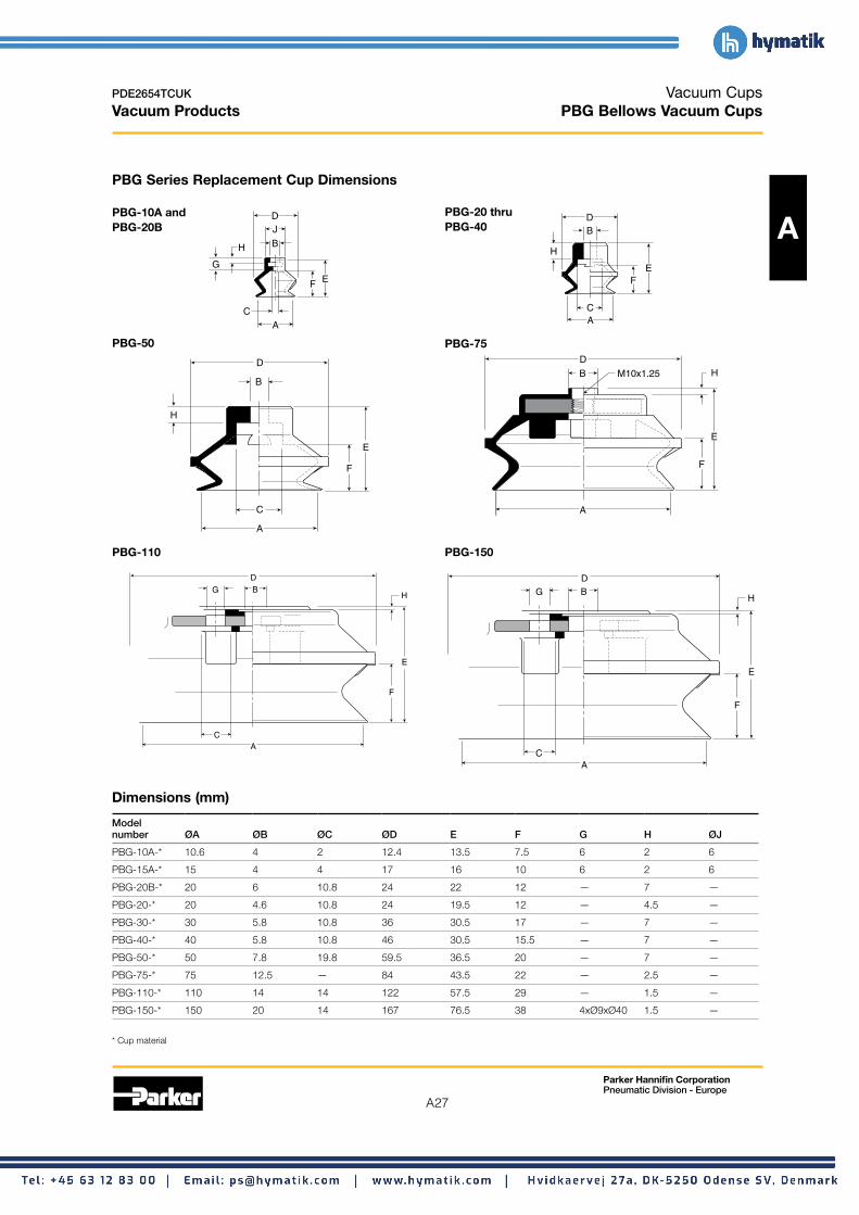
Vacuum Cups PBG Bellows Vacuum Cups
PBG Series Replacement Cup Dimensions
PBG-10A and PBG-20B
C
A
PBG-50
D
B
A
PBG-110
D G B
A
Dimensions (mm)
E
J D
B
F
G
H
C
E
F
H
C
H
PBG-20 thru PBG-40
E F
A C
D B
H
A
PBG-75 D
B
E
F
A
PBG-150
D G B
H
E E
F
F
A
M10x1.25 H
C
Model number ØA ØB ØC ØD E F G H ØJ
PBG-10A-* 10.6 4 2 12.4 13.5 7.5 6 2 6
PBG-15A-* 15 4 4 17 16 10 6 2 6
PBG-20B-* 20 6 10.8 24 22 12 — 7 —
PBG-20-* 20 4.6 10.8 24 19.5 12 — 4.5 —
PBG-30-* 30 5.8 10.8 36 30.5 17 — 7 —
PBG-40-* 40 5.8 10.8 46 30.5 15.5 — 7 —
PBG-50-* 50 7.8 19.8 59.5 36.5 20 — 7 —
PBG-75-* 75 12.5 — 84 43.5 22 — 2.5 —
PBG-110-* 110 14 14 122 57.5 29 — 1.5 —
PBG-150-* 150 20 14 167 76.5 38 4xØ9xØ40 1.5 —
* Cup material

A28
Parker Hannifin Corporation Pneumatic Division - Europe
PDE2654TCUK
Vacuum Products
Vacuum Cups PBTM Series Assemblies
Dimensions
PBTM-10A thru
A PBTM-15
M5: SW8 G1: SW13 (10A & 15A Only)
M5: .14 (3.5) G1: .20 (.5) (10A & 15A Only)
PBTM-75
Dimensions (mm)
M5: M5 G1: 1/8" BSPP (10A & 15A Only)
C D
B
E
A
9/16"
M10x1.25
PBTM-20B thru PBTM-50
50: 9/16"
N2: 1/4 NPT G2: 1/4 BSPP M10: 10x1.25
C
D
B
E
A
N1: 1/8 NPT G1: 1/8 BSPP M10: 10x1.25 G2: 1/4 BSPP
C
D
B
E
A
20B thru 40: 1/2"
Model C C C CØA B D Enumber (M5) (N1 / G1) (M10 / G2) (N2)
PBTM-10A-*-† 10 17 4.5 8 — — See Dwg. 7.5
PBTM-15A-*-† 15 19.5 4.5 8 — — See Dwg. 10
PBTM-20B-*-† 20 27 — 8 10 — 5 12
PBTM-30-*-† 30 35.5 — 8 10 — 5 17
PBTM-40-*-† 40 35.5 — 8 10 — 5 15.5
PBTM-50-*-† 50 41.5 — 8 10 — 5 20
PBTM-75-*-† 95 50.5 — — 10 15 7 22
* Cup material † Thread size

A29
Parker Hannifin Corporation Pneumatic Division - Europe
PDE2654TCUK
Vacuum Products
Vacuum Cups PBTF Series Assemblies
Dimensions
PBTF-10A thru PBTF-20B thru PBTF-15A PBTF 50 A
M5x0.8 G1: 1/8 BSPP G1: 1/8 BSPP G2: 1/4 BSPP
M5: 5/16" G1: 1/2"
E
C
B 50: 9/16 C
A
B
E
A
20B thru 40: 1/2"
PBTF-110 thru PBTF-150
2.24 (57) O.D.
1.854 (48) Across Flats
N4: 1/2 NPT G4: 1/2 BSPP
PBTF-75 D
CN2: 1/4 NPT G2: 1/4 BSPP
9/16" C
B
B
E E
AA
1/4 NPT 1/4 BSPP
Dimensions (mm)
Model B C number ØA B (M5) C (M5) D E
PBTF-10A-*-† 10 21.5 27.5 8 14 — 7.5
PBTF-15A-*-† 15 24 30 8 14 — 10
PBTF-20B-*-† 20 36 — 14 — — 12
PBTF-30-*-† 30 44.5 — 14 — — 17
PBTF-40-*-† 40 44.5 — 14 — — 15.5
PBTF-50-*-† 50 50.5 — 14 — — 20
PBTF-75-*-† 95 60.5 — 19.5 — — 22
PBTF-110-*-† 120 78 — 24 — 13 29
PBTF-150-*-† 150 97 — 24 — 13 38
* Cup material † Thread size

A30
Parker Hannifin Corporation Pneumatic Division - Europe
PDE2654TCUK
Vacuum Products
Vacuum Cups PBTK Series Assemblies
Dimensions
PBTK-10A thru PBTK-20
A .197 Dia. PBTK-15A Ø (5)
.197 Dia. Ø (5)
E
A
.098 Dia. Ø (2.5)
FG
C
D B
M8x1.25
SW10
M9x1.0 SW12
A
B
FG
C
D
.118 Dia. Ø (3)
E
PBTK-30 thru PBTK-75 .197 Dia.
PBTK-50 Ø (5) .118 Dia. Ø (3) N1: 1/8 NPT
G1: 1/8 BSPP M16x1.5
C
FG
M10x1.25
SW14 M5x0.8
SW21
D
D
BB
E E
AA
Dimensions (mm)
FG
Model Wt number ØA B C D E F G g
PBTK-10A-* 10 52 10 22.5 7.5 6 15.5 15
PBTK-15A-* 15 54.5 10 22.5 10 6 15.5 15
PBTK-20-* 20 57.5 16 22 12 6 15 21
PBTK-30-* 30 78.5 16 32 17 6 20 45
PBTK-40-* 40 78.5 16 32 15.5 6 20 48
PBTK-50-* 50 84.5 16 32 20 6 20 62
PBTK-75-*-† 95 83.5 — 42.5 22 11 — 186
* Cup material † Vacuum port

A31
Parker Hannifin Corporation Pneumatic Division - Europe
PDE2654TCUK
Vacuum Products
Vacuum Cups PBYK Series Assemblies
Dimensions
PBYK-10A thru PBYK-20 thru PBYK-15A PBYK-50
F C
E.197
Dia
.Ø
(5)
.1
18 D
ia.
Ø (
3) G
A
M4x0.7
20: M4x0.7
F
G
C
.197
Dia
.Ø
(5)
.1
18 D
ia.
Ø (
3)
A30 thru 50: M6x1.0
D D
B
B
E
A
PBYK-110 thru
PBYK-75
PBYK-150
M8x1.25
B
F
N1: 1/8 NPT G1: 1/8 BSPP
C
D
E
A
A
2.75 Dia. (70) (SW65)
G
M16x1.5
N1: 1/8 NPT G1: 1/8 BSPP
M8x1.25
BC
D
E
F
Dimensions (mm)
Model Wt number ØA B C D E F G g
PBYK-10A-* 10 36 13 22.5 7.5 6 16 16
PBYK-15A-* 15 38.5 13 22.5 10 6 16 16
PBYK-20-* 20 41.5 14 22 12 6 16 21
PBYK-30-* 30 62.5 20 32 17 6 16 45
PBYK-40-* 40 62.5 20 32 15.5 6 16 58
PBYK-50-* 50 68.5 20 32 20 6 16 67
PBYK-75-*-† 95 83.5 28 42.5 22 11 — 176
PBYK-110-*-† 120 106 12 50 29 20 Dia. 30 670
PBYK-150-*-† 150 125 12 50 38 20 Dia. 30 1180
* Cup material † Vacuum port

PDE2654TCUK Vacuum Cups Vacuum Products PBTYS Series Assemblies
Dmensions
PBTYS10A thru PBTYS20B thru PBTYS75 PBTYS110 thru
A PBTYS15A1 PBTYS50 PBTYS150
M5x0.8 SW6
B
D C
F
.35 (9)
H
G
E
A
M8x.75
SW12
M5x0.8
M5x0.8
M5x0.8
SW12
SW19
SW17
M14x1
B
D
E
C
H
.20 (5)
F
G
A
N1: 1/8 NPT
N1: 1/8 NPT
SW19
SW30
SW24
M22x1.5
B
D
A
E
C
H
J.28 (7)
F
G
Shock Pad
5mm
G1: 1/8 BSPP
G1: 1/8 BSPP
A M8x1.25
SW26
SW36
M30x1.5
B
D
E
C
J
.31 (8)
F
HG
N2: 1/4 NPT
N2: 1/4 NPT G2: 1/4 BSPP
G2: 1/4 BSPP
Dimensions (mm)
Model Wt number ØA B C D E F G H J g
PBTYS10A10* 10 68.5 13 8 7.5 10 3 23 — 18.5
PBTYS10A15* 10 81 13 8 7.5 15 3 30.5 — 21
PBTYS15A10* 15 71 13 8 10 10 3 23 — 18.5
PBTYS15A15* 15 83.5 13 8 10 15 3 30.5 — 21
PBTYS20B15* 20 99 17 10 12 15 5 36 — 72
PBTYS20B30* 20 136 17 10 12 30 5 58 — 97
PBTYS3015*† 30 103.5 17 10 17 15 5 36 — 97
PBTYS3030*† 30 140.5 17 10 17 30 5 58 — 102
PBTYS4015*† 40 103.5 17 10 15.5 15 5 36 — 83
PBTYS4030*† 40 140.5 17 10 15.5 30 5 58 — 108
PBTYS5015*† 50 109.5 17 10 20 15 5 36 — 97
PBTYS5030*† 50 146.5 17 10 20 30 5 58 — 122
PBTYS7530*† 75 178 32.5 20 22 45 10 50 12 339
PBTYS7550*† 75 203 32.5 20 22 70 10 50 12 373
PBTYS11020*† 110 224 30 18 29 35 10 60 35 1194
PBTYS11070*† 110 289 30 18 29 100 10 60 35 1276
PBTYS15020*† 150 243 30 18 38 35 10 60 35 1704
PBTYS15070*† 150 308 30 18 38 100 10 60 35 1786
* Cup material † Vacuum port
Parker Hannifin Corporation Pneumatic Division - Europe
A32

The PAG Cups are ideal for paper feeding,plastic bags and foil. The choice between the20A & 20B, 30 & 30B is application dependent.The 20A & 30B cups have a thinner lip designthan the 20B & 30 cups. This thinner lip designis more suited to products with micronthickness.
• Bellows design for level compensation withinrestricted clearances• Sheet separation for flexible and stacked products• Soft seal lip for flexible products• 10mm to 150mm diameters
• PATM Series Male Thread Connector• PATK Series Barbed Bulkhead• PAYK Series 90° Barbed Adapter
The PAG Cups are ideal for paper feeding,plastic bags and foil. The choice between the20A & 20B, 30 & 30B is application dependent.The 20A & 30B cups have a thinner lip designthan the 20B & 30 cups. This thinner lip designis more suited to products with micronthickness.
• Bellows design for level compensation withinrestricted clearances• Sheet separation for flexible and stacked products• Soft seal lip for flexible products• 10mm to 150mm diameters
Thin – Smooth Surfaces
• Bellows design for level compensation withinrestricted clearances• Sheet separation for flexible and stacked products• Soft seal lip for flexible products• 10mm to 150mm diameters
• PATM Series Male Thread Connector• PATK Series Barbed Bulkhead• PAYK Series 90° Barbed Adapter
Thin – Smooth Surfaces
A33
Parker Hannifin Corporation Pneumatic Division - Europe
PDE2654TCUK
Vacuum Products
A
Thin – Smooth Surfaces
• PATM Series Male Thread Connector • PATK Series Barbed Bulkhead • PAYK Series 90° Barbed Adapter
The PAG Cups are ideal for paper feeding, plastic bags and foil. The choice between the 20A & 20B, 30 & 30B is application dependent. The 20A & 30B cups have a thinner lip design than the 20B & 30 cups. This thinner lip design is more suited to products with micron thickness.
Vacuum Cups PAG Foil, Paper, Film Vacuum Cup Series
• Bellows design for level compensation within restricted clearances
• Sheet separation for flexible and stacked products • Soft seal lip for flexible products • 10mm to 50mm diameters
Features

CupDiameter(mm)
VacuumPort
CompleteAssemblyNitrile (NBR)
ReplacementCupNitrile (NBR)
CompleteAssemblySilicon (SI)
ReplacementCupSilicon (SI)
Replacementcup fitting
10 M5 PATM-10A-NBR-M5 PAG-10A-NBR PATM-10A-SI-M5 PAG-10A-SI FTM-5A-M515 M5 PATM-15A-NBR-M5 PAG-15A-NBR PATM-15A-SI-M5 PAG-15A-SI FTM-5A-M520 M5 PATM-20A-NBR-M5 PAG-20A-NBR PATM-20A-SI-M5 PAG-20A-SI FTM-5A-M525* M6 PAG-25-NBR PAG-25-SI30* M6 PAG-30-NBR PAG-30-SI40* M6 PAG-40-NBR PAG-40-SI50* M6 PAG-50-NBR PAG-50-SI
* : From diameter 25 to 50, the PAG cup include the cup fitting
PATM Series Male Thread ConnectorSimple male connection for low profilepositions secured to a plate or bracket.Fitting Material: Aluminium.
InstallationNote:When installing cup assemblies, usea sealant material to secure theassembly and prevent vacuumleakage.
A34
Parker Hannifin Corporation Pneumatic Division - Europe
PDE2654TCUK
Vacuum Products
A
PATM Series Male Thread Connector Simple male connection for low profile positions secured to a plate or bracket. Fitting Material: Aluminium.
Installation Note: When installing cup assemblies, use a sealant material to secure the assembly and prevent vacuum leakage.
Vacuum Cups PAG Foil, Paper, Film Vacuum Cup Series
Cup Diameter (mm)
Vacuum Port
Complete Assembly Nitrile (NBR)
Replacement Cup Nitrile (NBR)
Complete Assembly Silicon (SI)
Replacement Cup Silicon (SI)
Replacement cup fitting
10 M5 PATM-10A-NBR-M5 PAG-10A-NBR PATM-10A-SI-M5 PAG-10A-SI FTM-5A-M5 15 M5 PATM-15A-NBR-M5 PAG-15A-NBR PATM-15A-SI-M5 PAG-15A-SI FTM-5A-M5 20 M5 PATM-20A-NBR-M5 PAG-20A-NBR PATM-20A-SI-M5 PAG-20A-SI FTM-5A-M5 25* M6 PAG-25-NBR PAG-25-SI 30* M6 PAG-30-NBR PAG-30-SI 40* M6 PAG-40-NBR PAG-40-SI 50* M6 PAG-50-NBR PAG-50-SI
* : From diameter 25 to 50, the PAG cup include the cup fitting

CupDiameter(mm)
VacuumPort
CompleteAssemblyNitrile (NBR)
ReplacementCupNitrile (NBR)
CompleteAssemblySilicon (SI)
ReplacementCupSilicon (SI)
Replacementcup fitting
10 Bard PATK-10A-NBR PAG-10A-NBR PATK-10A-SI PAG-10A-SI FTK-5A15 Bard PATK-15A-NBR PAG-15A-NBR PATK-15A-SI PAG-15A-SI FTK-5A20 Bard PATK-20A-NBR PAG-20A-NBR PATK-20A-SI PAG-20A-SI FTK-5A25 Bard PATK-25-NBR PAG-25-NBR PATK-25-SI PAG-25-SI FTK-20B30 Bard PATK-30-NBR PAG-30-NBR PATK-30-SI PAG-30-SI FTK-20B40 Bard PATK-40-NBR PAG-40-NBR PATK-40-SI PAG-40-SI FTK-20B50 Bard PATK-50-NBR PAG-50-NBR PATK-50-SI PAG-50-SI FTK-20B
PATK Series Barbed BulkheadTop stem connectors secured with jam nutsand allow tubing connections at the top side.Nickel plated brass materials.
InstallationNote:When installing cup assemblies, usea sealant material to secure theassembly and prevent vacuumleakage.
A35
Parker Hannifin Corporation Pneumatic Division - Europe
PDE2654TCUK
Vacuum Products
A
PATK Series Barbed Bulkhead Top stem connectors secured with jam nuts and allow tubing connections at the top side. Nickel plated brass materials.
Installation Note: When installing cup assemblies, use a sealant material to secure the assembly and prevent vacuum leakage.
Vacuum Cups PAG Foil, Paper, Film Vacuum Cup Series
Cup Diameter (mm)
Vacuum Port
Complete Assembly Nitrile (NBR)
Replacement Cup Nitrile (NBR)
Complete Assembly Silicon (SI)
Replacement Cup Silicon (SI)
Replacement cup fitting
10 Bard PATK-10A-NBR PAG-10A-NBR PATK-10A-SI PAG-10A-SI FTK-5A 15 Bard PATK-15A-NBR PAG-15A-NBR PATK-15A-SI PAG-15A-SI FTK-5A 20 Bard PATK-20A-NBR PAG-20A-NBR PATK-20A-SI PAG-20A-SI FTK-5A 25 Bard PATK-25-NBR PAG-25-NBR PATK-25-SI PAG-25-SI FTK-20B 30 Bard PATK-30-NBR PAG-30-NBR PATK-30-SI PAG-30-SI FTK-20B 40 Bard PATK-40-NBR PAG-40-NBR PATK-40-SI PAG-40-SI FTK-20B 50 Bard PATK-50-NBR PAG-50-NBR PATK-50-SI PAG-50-SI FTK-20B

A36
Parker Hannifin Corporation Pneumatic Division - Europe
PDE2654TCUK
Vacuum Products
CupDiameter(mm)
VacuumPort
CompleteAssemblyNitrile (NBR)
ReplacementCupNitrile (NBR)
CompleteAssemblySilicon (SI)
ReplacementCupSilicon (SI)
Replacementcup fitting
10 Bard PAYK-10A-NBR PAG-10A-NBR PAYK-10A-SI PAG-10A-SI FYK-5A15 Bard PAYK-15A-NBR PAG-15A-NBR PAYK-15A-SI PAG-15A-SI FYK-5A20 Bard PAYK-20A-NBR PAG-20A-NBR PAYK-20A-SI PAG-20A-SI FYK-5A25 Bard PAYK-25-NBR PAG-25-NBR PAYK-25-SI PAG-25-SI FYK-20B30 Bard PAYK-30-NBR PAG-30-NBR PAYK-30-SI PAG-30-SI FYK-20B40 Bard PAYK-40-NBR PAG-40-NBR PAYK-40-SI PAG-40-SI FYK-20B50 Bard PAYK-50-NBR PAG-50-NBR PAYK-50-SI PAG-50-SI FYK-20B
PAYK Series 90° Barbed AdapteSide stem connectors allow you to secure the stem with abolt through a plate or “L” bracket to allow the tubeconnection from the side port. Nickel plated brass materials.
InstallationNote:When installing cup assemblies, usea sealant material to secure theassembly and prevent vacuumleakage.
Vacuum Cups PAG Foil, Paper, Film Vacuum Cup Series
PAYK Series 90° Barbed Adapte Side stem connectors allow you to secure the stem with a
A Installation Note: When installing cup assemblies, use a sealant material to secure the assembly and prevent vacuum leakage.
bolt through a plate or “L” bracket to allow the tube connection from the side port. Nickel plated brass materials.
Cup Complete Replacement Complete Replacement Diameter Vacuum Assembly Cup Assembly Cup Replacement (mm) Port Nitrile (NBR) Nitrile (NBR) Silicon (SI) Silicon (SI) cup fitting 10 Bard PAYK-10A-NBR PAG-10A-NBR PAYK-10A-SI PAG-10A-SI FYK-5A 15 Bard PAYK-15A-NBR PAG-15A-NBR PAYK-15A-SI PAG-15A-SI FYK-5A 20 Bard PAYK-20A-NBR PAG-20A-NBR PAYK-20A-SI PAG-20A-SI FYK-5A 25 Bard PAYK-25-NBR PAG-25-NBR PAYK-25-SI PAG-25-SI FYK-20B 30 Bard PAYK-30-NBR PAG-30-NBR PAYK-30-SI PAG-30-SI FYK-20B 40 Bard PAYK-40-NBR PAG-40-NBR PAYK-40-SI PAG-40-SI FYK-20B 50 Bard PAYK-50-NBR PAG-50-NBR PAYK-50-SI PAG-50-SI FYK-20B

A37
Parker Hannifin Corporation Pneumatic Division - Europe
PDE2654TCUK
Vacuum Products
Vacuum Cups PFG Flat Vacuum Cup Series
A

PAG Foil, Paper, Film Vacuum Cup Series
A38
Parker Hannifin Corporation Pneumatic Division - Europe
PDE2654TCUK
Vacuum Products
A
PAG Series Replacement Cup Dimensions
Vacuum Cups PAG Foil, Paper, Film Vacuum Cup Series
PATM Series AssembliesPATM Series Assemblies
Dimensions
A39
Parker Hannifin Corporation Pneumatic Division - Europe
PDE2654TCUK
Vacuum Products
A
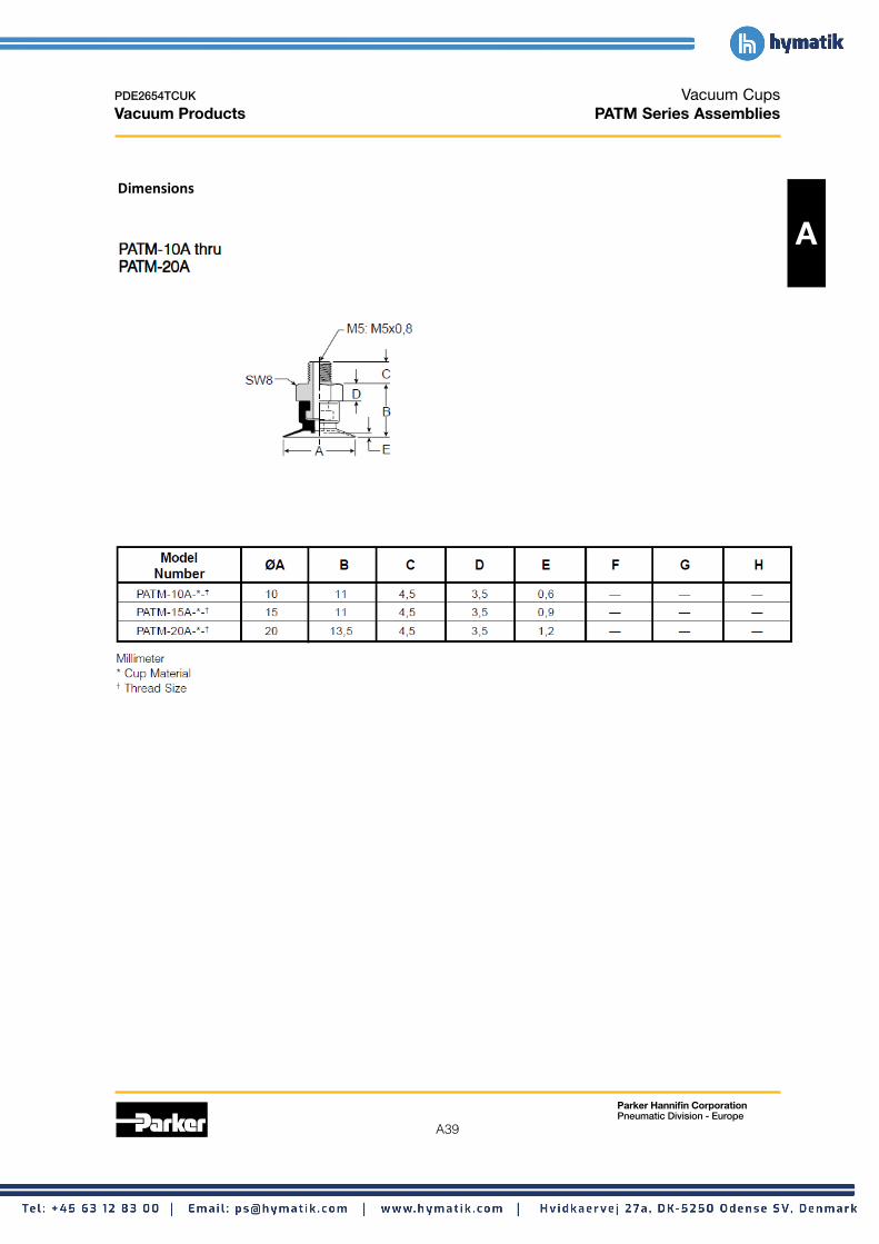
Dimensions
Vacuum Cups PATM Series Assemblies

A40
Parker Hannifin Corporation Pneumatic Division - Europe
PDE2654TCUK
Vacuum Products PATK Series Assemblies
Dimensions
PATK Series Assemblies
Dimensions
Vacuum Cups PATK Series Assemblies
Dimensions
A

A41
Parker Hannifin Corporation Pneumatic Division - Europe
PDE2654TCUK
Vacuum Products PAYK Series Assemblies
Dimensions
Vacuum Cups PAYK Series Assemblies
Dimensions
A

A42
Parker Hannifin Corporation Pneumatic Division - Europe
PDE2654TCUK
Vacuum Products
Vacuum Cups P5V-CFS Vacuum Cups
Features • Double sealing lips for flexible sheet handling • Vacuum cup grooves on underside increase holding area
A • Resists acceleration and deceleration shear forces • Strong low profile for fast response • Metal insert fitting for stable vertical and horizontal lifts
Applications These suction cups are ideal for applications where the product may flex when being lifted. All cups have a double sealing lip and cleats to increase holding capacity. The top of the cup has a ribbed outer lip to prevent it from rolling over the surface to be lifted.
Dual sealing lips provide 2 seals for vacuum. As the product flexes, the outer lip seal may break, but the inner lip seal will hold the degree of vacuum for continued lifting capacity. In these types of applications, sizing should be done on the inner diameter cup dimension.
Cup diameter Vacuum
Complete assembly Area*** Cup volume (V) Deflection (S) Radius R (mm)
(mm) port Nitrile (NBR) cm2 liters (mm) R1* R2**
50 1/8 BSPP P5V-CFS05011N 19.6 .001 4 98 80
100 3/8 BSPP P5V-CFS10013N 78.5 .0667 8 254 161
150 1/2 BSPP P5V-CFS15014N 176.7 .2083 11 309 252
* Minimum permissible radius for lifting using inner lip. ** Minimum permissible radius for lifting using outer lip. *** Area based on outer cup diameter
V
Volume
S
Cup deflection
R1
Radius
R2
A C
B
E D
F
G
2.76 (70)
H
G 1/2 (30018 Only)
Dimensions (mm) Model number ØA B ØC D E F G H
P5V-CFS50* 50 G1/8 35 11 18 2.2 13 3.7
P5V-CFS100* 100 G3/8 72 18 28 5 22 7.5
P5V-CFS150* 150 G1/2 106 26 42 7 27 11
* Cup material

A43
Parker Hannifin Corporation Pneumatic Division - Europe
PDE2654TCUK
Vacuum Products
Vacuum Cups PJG Short Bellows Vacuum Cups
Versatile bellow cup design provides increased sealing lip and level compensation for products with irregular, smooth, curved surfaces, or flexible sheets.
The short stroke bellow suction cup has an extra thin sealing edge and shorter stroke versus the traditional bellows for faster A response. The cups are good for corrugated and smooth surfaces.
Features • Short bellows for fast response • More lip seal contact for corrugated, textured surfaces • Soft sealing lip • 6mm to 80mm Styles
• PJTM series male thread connector • PJTF series female thread connector • PJTK series barbed bulkhead • PJYK series 90° barbed adapter • PJTYS series bulkhead level compensator
Specifications
Nitrile Silicon Cup material Nitrile ESD* Silicon ESD*
Material code NBR NBRE SI SIE
Operating -20° -30° -60° -60° temperature (°C) to +120° to +120° to +250° to +250°
Black / Black /Color Black WhiteBlue Dot Red Dot
Hardness, 55 ±5 70 ±5 55 ±5 55 ±5shore A (°Sh)
Electrical — 800 — 800 resistance (Ωm) to 1000 to 1000
* ESD: Electric Static Dissipative Material
How to order Cups assemblies and replacement cups are specified by cup diameter and material. Standard nitrile and silicon are listed on the following pages. To specify an alternative material, replace the cup material with alternative cup material code.
Example: To specify a cup assembly with silicon ESD (SIE), replace (NBR) with (SIE) in the part number. PJTM-20B-NBR-G1 becomes PJTM-20B-SIE-G1. Inquire with factory for availability.
Application guide Short Bellows
Flat surface, Flat surface, Slightly Slightly Bowed Soft porous Soft porous Metal sheet Corrugated Not for thin section any section bowed bowed surface, thin material, material, handling sheet vertical lift
surface, thin surface, any section thin section any section handling section section

A44
Parker Hannifin Corporation Pneumatic Division - Europe
PDE2654TCUK
Vacuum Products
6
8
Vacuum Cups PJG Short Bellows Vacuum Cups
PJTM Series Male Thread Connector
A
Tube I.D.
Mounting Thread
Installation Note: When installing cup assemblies, use a sealant material to secure the assembly and prevent vacuum leakage.
Simple male connection for low profile positions secured to a plate or bracket. BSPP, NPT metric threads. Fitting material: aluminum.
Cup Complete Replacement Complete Replacement diameter Vacuum assembly cup assembly cup Replacement (mm) port Nitrile Nitrile (NB) Silicon (SI) Silicon (SI) cup fitting
6 M5 PJTM-6-NBR-M5 PJG-6-NBR PJTM-6-SI-M5 PJG-6-SI FTM-5A-M5
1/8 BSPP PJTM-6-NBR-G1 PJG-6-NBR PJTM-6-SI-G1 PJG-6-SI FTM-5A-G1
8 M5 PJTM-8-NBR-M5 PJG-8-NBR PJTM-8-SI-M5 PJG-8-SI FTM-5A-M5
1/8 BSPP PJTM-8-NBR-G1 PJG-8-NBR PJTM-8-SI-G1 PJG-8-SI FTM-5A-G1
10 M5 PJTM-10-NBR-M5 PJG-10-NBR PJTM-10-SI-M5 PJG-10-SI TN-PF-15-M5
15 M5 PJTM-15-NBR-M5 PJG-15-NBR PJTM-15-SI-M5 PJG-15-SI TN-PF-15-M5
20 M5 PJTM-20-NBR-M5 PJG-20-NBR PJTM-20-SI-M5 PJG-20-SI TN-PF-20-M5
30 1/8 BSPP PJTM-30-NBR-G1 PJG-30-NBR PJTM-30-SI-G1 PJG-30-SI FTM-20B-G1
30 1/4 BSPP PJTM-30-NBR-G2 PJG-30-NBR PJTM-30-SI-G2 PJG-30-SI FTM-20B-G2
30 M10 PJTM-30-NBR-M10 PJG-30-NBR PJTM-30-SI-M10 PJG-30-SI FTM-20B-M10
30 1/8 NPT PJTM-30-NBR-N1 PJG-30-NBR PJTM-30-SI-N1 PJG-30-SI FTM-20B-N1
40 1/8 BSPP PJTM-40-NBR-G1 PJG-40-NBR PJTM-40-SI-G1 PJG-40-SI FTM-20B-G1
40 1/4 BSPP PJTM-40-NBR-G2 PJG-40-NBR PJTM-40-SI-G2 PJG-40-SI FTM-20B-G2
40 M10 PJTM-40-NBR-M10 PJG-40-NBR PJTM-40-SI-M10 PJG-40-SI FTM-20B-M10
40 1/8 NPT PJTM-40-NBR-N1 PJG-40-NBR PJTM-40-SI-N1 PJG-40-SI FTM-20B-N1
50 1/8 BSPP PJTM-50-NBR-G1 PJG-50-NBR PJTM-50-SI-G1 PJG-50-SI FTM-50-G1
50 1/4 BSPP PJTM-50-NBR-G2 PJG-50-NBR PJTM-50-SI-G2 PJG-50-SI FTM-50-G2
50 1/8 NPT PJTM-50-NBR-N1 PJG-50-NBR PJTM-50-SI-N1 PJG-50-SI FTM-50-N1
60 1/4 BSPP PJTM-60-NBR-G2 PJG-60-NBR PJTM-60-SI-G2 PJG-60-SI FTM-60-G2
60 M10 PJTM-60-NBR-M10 PJG-60-NBR PJTM-60-SI-M10 PJG-60-SI FTM-60-M10
60 1/4 NPT PJTM-60-NBR-N2 PJG-60-NBR PJTM-60-SI-N2 PJG-60-SI FTM-60-N2
80 1/4 BSPP PJTM-80-NBR-G2 PJG-80-NBR PJTM-80-SI-G2 PJG-80-SI FTM-60-G2
80 M10 PJTM-80-NBR-M10 PJG-80-NBR PJTM-80-SI-M10 PJG-80-SI FTM-60-M10
80 1/4 NPT PJTM-80-NBR-N2 PJG-80-NBR PJTM-80-SI-N2 PJG-80-SI FTM-60-N2

A45
Parker Hannifin Corporation Pneumatic Division - Europe
PDE2654TCUK
Vacuum Products
6
8
Vacuum Cups PJG Short Bellows Vacuum Cups
PJTF Series Female Thread Connector
A Installation Tube I.D.
Pipe
Mounting Thread
Note: When installing cup assemblies, use a sealant material to secure the assembly and prevent vacuum leakage.
Simple female connection for low profile positions secured to a plate or bracket. BSPP, NPT metric threads.
Fitting material: aluminum.
Cup Complete Replacement Complete Replacement diameter Vacuum assembly cup assembly cup Replacement (mm) port Nitrile Nitrile (NB) Silicon (SI) Silicon (SI) cup fitting
6 M5 PJTF-6-NBR-M5 PJG-6-NBR PJTF-6-SI-M5 PJG-6-SI FTF-5A-M5
1/8 BSPP PJTF-6-NBR-G1 PJG-6-NBR PJTF-6-SI-G1 PJG-6-SI FTF-5A-G1
8 M5 PJTF-8-NBR-M5 PJG-8-NBR PJTF--8-SI-M5 PJG-8-SI FTF-5A-M5
1/8 BSPP PJTF-8-NBR-G1 PJG-8-NBR PJTF--8-SI-G1 PJG-8-SI FTF-5A-G1
10 M5 PJTF-10-NBR-M5 PJG-10-NBR PJTF-10-SI-M5 PJG-10-SI FTF-5A-M5
10 1/8 BSPP PJTF-10-NBR-G1 PJG-10-NBR PJTF-10-SI-G1 PJG-10-SI FTF-5A-G1
15 M5 PJTF-15-NBR-M5 PJG-15-NBR PJTF-15-SI-M5 PJG-15-SI FTF-5A-M5
15 1/8 BSPP PJTF-15-NBR-G1 PJG-15-NBR PJTF-15-SI-G1 PJG-15-SI FTF-5A-G1
30 1/8 BSPP PJTF-30-NBR-G1 PJG-30-NBR PJTF-30-SI-G1 PJG-30-SI FTF-20B-G1
30 1/4 BSPP PJTF-30-NBR-G2 PJG-30-NBR PJTF-30-SI-G2 PJG-30-SI FTF-20B-G2
40 1/8 BSPP PJTF-40-NBR-G1 PJG-40-NBR PJTF-40-SI-G1 PJG-40-SI FTF-20B-G1
40 1/4 BSPP PJTF-40-NBR-G2 PJG-40-NBR PJTF-40-SI-G2 PJG-40-SI FTF-20B-G2
50 1/8 BSPP PJTF-50-NBR-G1 PJG-50-NBR PJTF-50-SI-G1 PJG-50-SI FTF-50-G1
50 1/4 BSPP PJTF-50-NBR-G2 PJG-50-NBR PJTF-50-SI-G2 PJG-50-SI FTF-50-G2
60 1/4 BSPP PJTF-60-NBR-G2 PJG-60-NBR PJTF-60-SI-G2 PJG-60-SI FTF-60-G2
60 1/4 NPT PJTF-60-NBR-N2 PJG-60-NBR PJTF-60-SI-N2 PJG-60-SI FTF-60-N2
80 1/4 BSPP PJTF-80-NBR-G2 PJG-80-NBR PJTF-80-SI-G2 PJG-80-SI FTF-60-G2
80 1/4 NPT PJTF-80-NBR-N2 PJG-80-NBR PJTF-80-SI-N2 PJG-80-SI FTF-60-N2

A46
Parker Hannifin Corporation Pneumatic Division - Europe
PDE2654TCUK
Vacuum Products
Vacuum Cups PJG Short Bellows Vacuum Cups
PJTK Series Barbed Bulkhead
A Tube I.D.
Mounting Thread.
Cup Screw
Note: When installing cup assemblies, use a sealant material to secure the assembly and prevent vacuum leakage.
Top stem connectors secured with jam nuts and allow tubing connections at the top side. Fitting material: nickel plated brass.
Installation
Cup Complete Replacement Complete Replacement diameter Vacuum assembly cup assembly cup Replacement (mm) port Nitrile Nitrile (NB) Silicon (SI) Silicon (SI) cup fitting
6 Barb PJTK-6-NBR PJG-6-NBR PJTK-6-SI PJG-6-SI FTK-5A
8 Barb PJTK-8-NBR PJG-8-NBR PJTK-8-SI PJG-8-SI FTK-5A
10 Barb PJTK-10-NBR PJG-10-NBR PJTK-10-SI PJG-10-SI FTK-15
15 Barb PJTK-15-NBR PJG-15-NBR PJTK-15-SI PJG-15-SI FTK-15
20 Barb PJTK-20-NBR PJG-20-NBR PJTK-20-SI PJG-20-SI FTK-20
30 Barb PJTK-30-NBR PJG-30-NBR PJTK-30-SI PJG-30-SI FTK-25
40 Barb PJTK-40-NBR PJG-40-NBR PJTK-40-SI PJG-40-SI FTK-25
50 Barb PJTK-50-NBR PJG-50-NBR PJTK-50-SI PJG-50-SI FTK-50
60 1/8 BSPP PJTK-60-NBR-G1 PJG-60-NBR PJTK-60-SI-G1 PJG-60-SI FTK-60-G1
60 1/8 NPT PJTK-60-NBR-N1 PJG-60-NBR PJTK-60-SI-N1 PJG-60-SI FTK-60-N1
80 1/8 BSPP PJTK-80-NBR-G1 PJG-80-NBR PJTK-80-SI-G1 PJG-80-SI FTK-60-G1
80 1/8 NPT PJTK-80-NBR-N1 PJG-80-NBR PJTK-80-SI-N1 PJG-80-SI FTK-60-N1

A47
Parker Hannifin Corporation Pneumatic Division - Europe
PDE2654TCUK
Vacuum Products
Vacuum Cups PJG Short Bellows Vacuum Cups
PJYK Series 90° Barbed Adapter Side stem connectors allow you to secure the stem with a bolt through a plate or “L” bracket to allow the tube connection from the side port. Fitting material: nickel plated brass. A Installation
Mounting
Note: When installing cup assemblies, use a sealant material to secure the Tube I.D. assembly and prevent vacuum leakage.
Thread
Cup Screw
Cup Complete Replacement Complete Replacement diameter Vacuum assembly cup assembly cup Replacement (mm) port Nitrile Nitrile (NB) Silicon (SI) Silicon (SI) cup fitting
6 Barb PJYK-6-NBR PJG-6-NBR PJYK-6-SI PJG-6-SI FYK-5A
8 Barb PJYK-8-NBR PJG-8-NBR PJYK-8-SI PJG-8-SI FYK-5A
10 Barb PJYK-10-NBR PJG-10-NBR PJYK-10-SI PJG-10-SI FYK-15
15 Barb PJYK-15-NBR PJG-15-NBR PJYK-15-SI PJG-15-SI FYK-15
20 Barb PJYK-20-NBR PJG-20-NBR PJYK-20-SI PJG-20-SI FYK-20
30 Barb PJYK-30-NBR PJG-30-NBR PJYK-30-SI PJG-30-SI FYK-25
40 Barb PJYK-40-NBR PJG-40-NBR PJYK-40-SI PJG-40-SI FYK-25
50 Barb PJYK-50-NBR PJG-50-NBR PJYK-50-SI PJG-50-SI FYK-50
60 1/8 BSPP PJYK-60-NBR-G1 PJG-60-NBR PJYK-60-SI-G1 PJG-60-SI FYK-60-G1
60 1/8 NPT PJYK-60-NBR-N1 PJG-60-NBR PJYK-60-SI-N1 PJG-60-SI FYK-60-N1
80 1/8 BSPP PJYK-80-NBR-G1 PJG-80-NBR PJYK-80-SI-G1 PJG-80-SI FYK-60-G1
80 1/8 NPT PJYK-80-NBR-N1 PJG-80-NBR PJYK-80-SI-N1 PJG-80-SI FYK-60-N1

A48
Parker Hannifin Corporation Pneumatic Division - Europe
PDE2654TCUK
Vacuum Products
Vacuum Cups PJG Short Bellows Vacuum Cups
PJTYS Series Bulkhead Level Compensator 303 stainless steel construction secured with jam nuts. Spring biased compensators can absorb impacts of down-strokes
A and adjust for different levels of pick up points. 303 stainless corrosion resistant materials with drymet bushings increases
Inte
rcha
ngab
le*
the strength and life.
Installation
Note: When installing cup assemblies, use a sealant material to secure the assembly and prevent vacuum leakage. Shown are interchangable connectors & plugs for port connections.
Mounting Thread.
PlugPushlock Tube Fitting
Barb Fitting
* Not included with assembly
Cup Spring compression Cup material Replacement Cup material Replacement Level dia. Vacuum Stroke Force lbf (N) Nitrile assemlby cup Silicon assembly cup Compensator (mm) port (mm) 0% 100% (NBR) Nitrile (NBR) (SI) Silicon (SI) P/N
10 M5 10 .56 (2.5) 1.2 (4.9) PJTYS1010NBRM5 PJG-10-NBR PJTYS1010SIM5 PJG-10-SI JTYS-10-10-M5
10 M5 15 .67 (2.5) 1.4 (5.9) PJTYS1015NBRM5 PJG-10-NBR PJTYS1015SIM5 PJG-10-SI JTYS-10-15-M5
15 M5 10 .56 (2.5) 1.2 (4.9) PJTYS15A10NBRM5 PJG-15A-NBR PJTYS15A10SIM5 PJG-15A-SI JTYS-10-10-M5
15 M5 15 .67 (2.5) 1.4 (5.9) PJTYS15A15NBRM5 PJG-15A-NBR PJTYS15A15SIM5 PJG-15A-SI JTYS-10-15-M5
30 M5 15 .56 (2.5) .79 (3.4) PJTYS3015NBRM5 PJG-30-NBR PJTYS3015SIM5 PJG-30-SI FTYS-20B-15-M5
30 M5 30 .67 (2.9) 1.4 (5.9) PJTYS3030NBRM5 PJG-30-NBR PJTYS3030SIM5 PJG-30-SI FTYS-20B-30-M5
40 M5 15 .56 (2.5) .79 (3.4) PJTYS4015NBRM5 PJG-40-NBR PJTYS4015SIM5 PJG-40-SI FTYS-20B-15-M5
40 M5 30 .67 (2.9) 1.4 (5.9) PJTYS4030NBRM5 PJG-40-NBR PJTYS4030SIM5 PJG-40-SI FTYS-20B-30-M5
50 M5 15 .56 (.25) 1.2 (4.9) PJTYS5015NBRM5 PJG-50-NBR PJTYS5015SIM5 PJG-50-SI FTYS-50-15-M5
50 M5 30 .67 (2.9) 1.4 (5.9) PJTYS5030NBRM5 PJG-50-NBR PJTYS5030SIM5 PJG-50-SI FTYS-50-30-M5
60 1/8 NPT 30 1.6 (6.8) 3.6 (15.6) PJTYS6030NBRN1 PJG-60-NBR PJTYS6030SIN1 PJG-60-SI FTYS-60-30-G1
60 1/8 NPT 50 1.9 (8.3) 4.5 (19.6) PJTYS6050NBRN1 PJG-60-NBR PJTYS6050SIN1 PJG-60-SI FTYS-60-50-G1
80 1/8 NPT 30 1.6 (6.8) 3.6 (15.6) PJTYS8030NBRN1 PJG-80-NBR PJTYS8030SIN1 PJG-80-SI FTYS-60-30-G1
80 1/8 NPT 50 1.9 (8.3) 4.5 (19.6) PJTYS8050NBRN1 PJG-80-NBR PJTYS8050SIN1 PJG-80-SI FTYS-60-50-G1

A49
Parker Hannifin Corporation Pneumatic Division - Europe
PDE2654TCUK
Vacuum Products
Vacuum Cups PJG Short Bellows Vacuum Cups
Applications • High speed • Level compensation • Flexible product
packaging for small electronic • Soft seal lip components A
Main data for short bellows PJG cups
V
Volume
S
Cup deflection
R
Radius
Lifting force @ 60% (N) Cup Radius Model Cup diameter Area Volume (V) deflection (S) R number mm cm2 liters mm mm
PJG-6-* 6 .28 0.000016 1.70 — 4.2 4.0
PJG-8-* 8 .50 0.00007 3.10 — 4.0 5.0
PJG-10-* 10 0.79 0.00017 4.80 — 3.0 6.0
PJG-15-* 15 1.77 0.0005 10.8 — 3.3 10.0
PJG-20-* 20 3.14 0.0012 19.2 — 5.5 13.0
PJG-30-* 30 7.07 0.003 43.2 — 7.0 26.0
PJG-40-* 40 12.6 0.005 76.9 — 7.2 37.0
PJG-50-* 50 19.6 0.008 120 — 9.0 41.0
PJG-60-* 60 28.3 0.020 173 — 8.0 70.0
PJG-80-* 80 50.3 0.040 308 — 9.5 100.0
*Cup material

A50
Parker Hannifin Corporation Pneumatic Division - Europe
PDE2654TCUK
Vacuum Products
Vacuum Cups PJG Short Bellows Vacuum Cups
PJG Series Replacement Cup Dimensions
PJG-6 and PJG-10 and
A PJG-8 PJG-15
D
C
DB B
EH EH
F
F
AA
PJG-20 PJG-30 thru PJG-40
D D
C
B B
H H E
E FF
AA
PJG-50 PJG-60 thru PJG-80
D
E
H
E
F
A
Dimensions (mm)
C
C
A
D
F
E
H BM10x1.25
Model number ØA ØB ØC ØD E F H
PJG-6-* 6 4 6 7.5 9 4.2 2
PJG-8-* 8 4 6 8 9 4 2
PJG-10-* 10 4.6 7.8 11 9.5 3 3.5
PJG-15-* 15 4.6 7.8 12 11 3.3 3.5
PJG-20-* 20 4.6 10.8 15 13 5.5 4.5
PJG-30-* 30 5.8 10.8 20 18 7 7
PJG-35-* 35 5.8 10.8 25 18 7 7
PJG-40-* 40 5.8 10.8 30 18 7.2 7
PJG-50-* 50 7.8 19.8 40 20 9 7
PJG-60-* 60 12.5 — 45 22.5 8 2.5
PJG-70-* 70 12.5 — 55 23.5 9.5 2.5
PJG-80-* 80 12.5 — 68 23.5 9.5 2.5
* Cup material
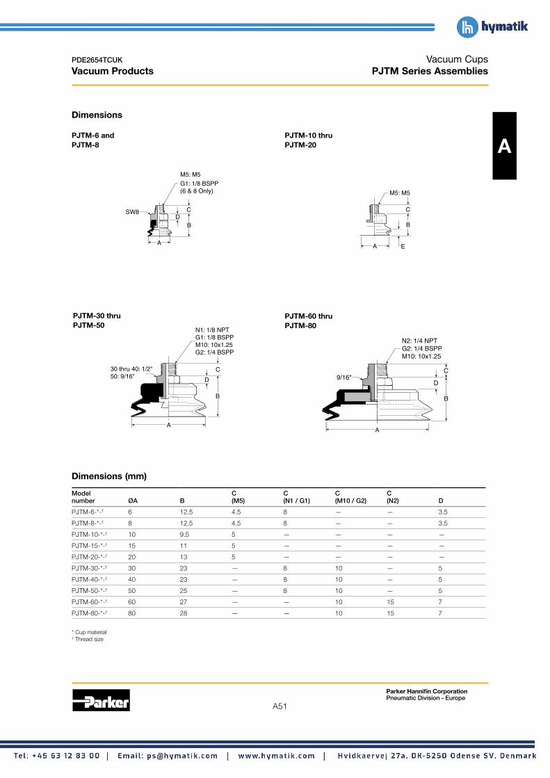
A51
Parker Hannifin Corporation Pneumatic Division - Europe
PDE2654TCUK
Vacuum Products
Vacuum Cups PJTM Series Assemblies
Dimensions
PJTM-6 and PJTM-8
M5: M5
G1: 1/8 BSPP (6 & 8 Only)
CSW8 D
B
A
PJTM-30 thru PJTM-50
30 thru 40: 1/2" 50: 9/16"
N1: 1/8 NPT G1: 1/8 BSPP M10: 10x1.25 G2: 1/4 BSPP
C
D
B
A
Dimensions (mm)
PJTM-10 thru PJTM-20 A
M5: M5
C
B
A E
PJTM-60 thru PJTM-80
N2: 1/4 NPT G2: 1/4 BSPP M10: 10x1.25
C 9/16"
D
B
A
Model C C C C number ØA B (M5) (N1 / G1) (M10 / G2) (N2) D
PJTM-6-*-† 6 12.5 4.5 8 — — 3.5
PJTM-8-*-† 8 12.5 4.5 8 — — 3.5
PJTM-10-*-† 10 9.5 5 — — — —
PJTM-15-*-† 15 11 5 — — — —
PJTM-20-*-† 20 13 5 — — — —
PJTM-30-*-† 30 23 — 8 10 — 5
PJTM-40-*-† 40 23 — 8 10 — 5
PJTM-50-*-† 50 25 — 8 10 — 5
PJTM-60-*-† 60 27 — — 10 15 7
PJTM-80-*-† 80 28 — — 10 15 7
* Cup material † Thread size

A52
Parker Hannifin Corporation Pneumatic Division - Europe
PDE2654TCUK
Vacuum Products
Vacuum Cups PJTF Series Assemblies
Dimensions
PJTF-6 and PJTF-30 thru
A PJTF-8 PJTF-50 G1: 1/8 BSPP G2: 1/4 BSPP
30 thru 40: 1/2" 50: 9/16"
M5x0.8 G1: 1/8 BSPP B
M5: 5/16" G1: 1/2"
EB
A A E
PJTF-60 thru PJTF-80
A
B
E
N2: 1/4 NPT G2: 1/4 BSPP
9/16"
Dimensions (mm)
Model B number ØA B (M5) E
PJTF-6-*-† 6 20 14 4
PJTF-8-*-† 8 20 14 4
PJTF-10-*-† 10 20 14 3
PJTF-15-*-† 15 20 14 3.3
PJTF-30-*-† 30 32 — 7
PJTF-40-*-† 40 32 — 7.2
PJTF-50-*-† 50 34 — 9
PJTF-60-*-† 60 39.5 — 8
PJTF-80-*-† 80 40.5 — 9.5
* Cup material † Thread size

A53
Parker Hannifin Corporation Pneumatic Division - Europe
PDE2654TCUK
Vacuum Products
Vacuum Cups PJTK Series Assemblies
Dimensions
PJTK-6 and PJTK-8
.197 Dia. Ø (5)
.098 Dia. Ø (2.5)
C M9x1.0
SW12 G F D B
EA
PJTK-30 thru PJTK-50 .197 Dia.
A
B
FG
C
D
E
M10x1.5
SW14
Ø (5) .118 Dia. Ø (3)
M5x0.8
Dimensions (mm)
PJTK-10 thru PJTK-20 A
.197 Dia. Ø (5) .098 Dia.
Ø (2.5)
C M8x1.25
SW12 G F BD
EA
PJTK-60 thru PJTK-80
N1: 1/8 NPT G1: 1/8 BSPP
M16x1.5
SW21 F
D
B
E
G
A
Model Wt number ØA B C D E F G g
PJTK-6-* 6 33 10 14 4.2 12 3 11
PJTK-8-* 8 33 10 14 4 12 3 11
PJTK-10-* 10 47.5 16 22 3 15 3 14
PJTK-15-* 15 49 16 22 3.3 15 3 15
PJTK-20-* 20 51 16 22 5.5 15 5 17
PJTK-30-* 30 66 16 32 7 20 5 42
PJTK-40-* 40 66 16 32 7.2 20 5 44
PJTK-50-* 50 68 16 32 9 20 5 58
PJTK-60-*-† 60 62.5 — 42.5 8 20 6 144
PJTK-80-*-† 80 63.5 — 42.5 9.5 20 6 190
* Cup material † Vacuum port
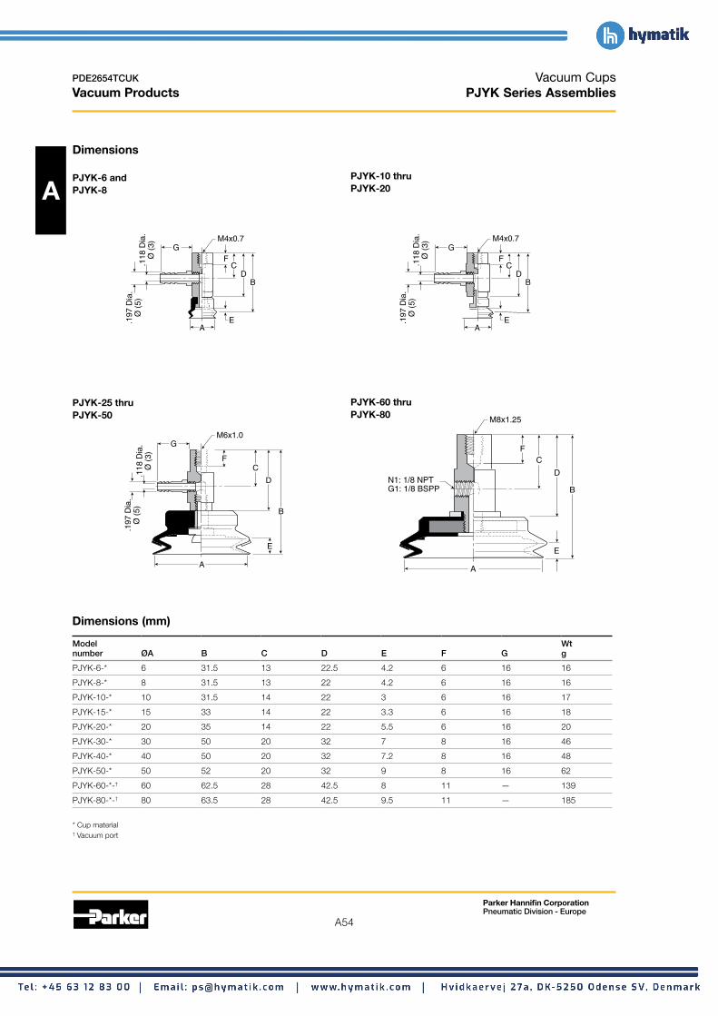
A54
Parker Hannifin Corporation Pneumatic Division - Europe
PDE2654TCUK
Vacuum Products
Vacuum Cups PJYK Series Assemblies
Dimensions
PJYK-6 and PJYK-10 thru
A PJYK-8 PJYK-20
PJYK-60 thru PJYK-80
PJYK-25 thru PJYK-50
F C
D B
E.197
Dia
.Ø
(5)
.1
18 D
ia.
Ø (
3) G
A
M4x0.7
F C
D B
E.197
Dia
.Ø
(5)
.1
18 D
ia.
Ø (
3) G
A
M4x0.7
M8x1.25
D N1: 1/8 NPT G1: 1/8 BSPP
D B
B
E E
F C
A
F
G
C
.197
Dia
.Ø
(5)
.1
18 D
ia.
Ø (
3)
M6x1.0
A
Dimensions (mm)
Model Wt number ØA B C D E F G g
PJYK-6-* 6 31.5 13 22.5 4.2 6 16 16
PJYK-8-* 8 31.5 13 22 4.2 6 16 16
PJYK-10-* 10 31.5 14 22 3 6 16 17
PJYK-15-* 15 33 14 22 3.3 6 16 18
PJYK-20-* 20 35 14 22 5.5 6 16 20
PJYK-30-* 30 50 20 32 7 8 16 46
PJYK-40-* 40 50 20 32 7.2 8 16 48
PJYK-50-* 50 52 20 32 9 8 16 62
PJYK-60-*-† 60 62.5 28 42.5 8 11 — 139
PJYK-80-*-† 80 63.5 28 42.5 9.5 11 — 185
* Cup material † Vacuum port
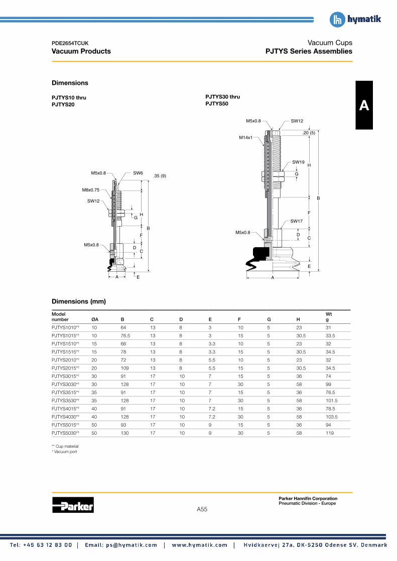
A55
Parker Hannifin Corporation Pneumatic Division - Europe
PDE2654TCUK
Vacuum Products
Vacuum Cups PJTYS Series Assemblies
Dimensions
PJTYS10 thru PJTYS30 thru PJTYS20 PJTYS50 A
M5x0.8 SW6
B
D C
F
HG
.35 (9)
M8x0.75
SW12
M5x0.8
A E
Dimensions (mm)
M5x0.8
M5x0.8
SW12
SW19
SW17
M14x1
B
D
E
C
H
.20 (5)
F
G
A
Model Wt number ØA B C D E F G H g
PJTYS1010*† 10 64 13 8 3 10 5 23 31
PJTYS1015*† 10 76.5 13 8 3 15 5 30.5 33.5
PJTYS1510*† 15 66 13 8 3.3 10 5 23 32
PJTYS1515*† 15 78 13 8 3.3 15 5 30.5 34.5
PJTYS2010*† 20 72 13 8 5.5 10 5 23 32
PJTYS2015*† 20 109 13 8 5.5 15 5 30.5 34.5
PJTYS3015*† 30 91 17 10 7 15 5 36 74
PJTYS3030*† 30 128 17 10 7 30 5 58 99
PJTYS3515*† 35 91 17 10 7 15 5 36 76.5
PJTYS3530*† 35 128 17 10 7 30 5 58 101.5
PJTYS4015*† 40 91 17 10 7.2 15 5 36 78.5
PJTYS4030*† 40 128 17 10 7.2 30 5 58 103.5
PJTYS5015*† 50 93 17 10 9 15 5 36 94
PJTYS5030*† 50 130 17 10 9 30 5 58 119
** Cup material † Vacuum port
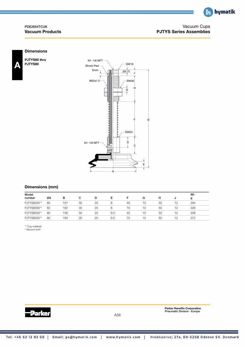
A56
Parker Hannifin Corporation Pneumatic Division - Europe
PDE2654TCUK
Vacuum Products
Vacuum Cups PJTYS Series Assemblies
Dimensions
A PJTYS60 thru PJTYS80
N1: 1/8 NPT
N1: 1/8 NPT
SW19
SW30
SW24
M22x1.5
B
D
E
C
H
J.28 (7)
F
G
A
Shock Pad
5mm
Dimensions (mm)
Model Wt number ØA B C D E F G H J g
PJTYS6030*† 60 157 30 20 8 45 10 50 12 294
PJTYS6050*† 60 182 30 20 8 70 10 50 12 328
PJTYS8030*† 80 158 30 20 9.5 45 10 50 12 338
PJTYS8050*† 80 183 30 20 9.5 70 10 50 12 372
** Cup material † Vacuum port

A57
Parker Hannifin Corporation Pneumatic Division - Europe
PDE2654TCUK
Vacuum Products
Vacuum Cups PCG Multiple Bellows Vacuum Cups
2-1/2 bellows design minimizes contact pressure applied to the product. The soft seal lip and touch allows the cup to conform to the product’s surface to make a vacuum seal.
These multiple bellow cups are designed for applications that require additional level compensation, more flexibility, A or minimum back pressure for a “soft touch”. The multiple bellow has a soft sealing edge good for a variety of sensitive applications; such as food packaging, CD / DVD, medical packaging, and highly irregular curved surfaces. Cups can also be used to assist with sheet separation in destack operations.
Features • Soft touch
• Extra level compensation
• Flexible sealing lip for irregular curved surfaces
• 5mm to 90mm in diameter
Styles • PCTM series male thread connector • PCTF series female thread connector • PCTK series barbed bulkhead
Specifications Nitrile Silicon
Cup material Nitrile ESD* Silicon ESD* Urethane
Material code NBR NBRE SI SIE U
Operating -20° -30° -60° -60° -30° temperature (°C) to +120° to +120° to +250° to +250° to +120°
Black / Black /Color Black White BlueBlue Dot Red Dot
Hardness, 55 ±5 70 ±5 55 ±5 55 ±5 55 ±5shore A (°Sh)
Electrical — 800 — 800 — resistance (Ωm) to 1000 to 1000
* ESD: Electric Static Dissipative Material
How to order Cups assemblies and replacement cups are specified by cup diameter and material. Standard nitrile and silicon are listed on the following pages. To specify an alternative material, replace the cup material with alternative cup material code.
Example: To specify a cup assembly with urethane (U), replace (NBR) with (U) in the part number. PCTM-20B-NBR-G1 becomes PCTM-20B-U-G1. Inquire with factory for availability.
Application guide 2-1/2 Bellows
Flat surface, Bowed Slightly Bowed Soft material Metal sheet Corrugated Differences in Not for any section surface, thin bowed surface, any handling sheet handling heights and vertical lift
section surface, any section levels section

A58
Parker Hannifin Corporation Pneumatic Division - Europe
PDE2654TCUK
Vacuum Products
Vacuum Cups PCG Multiple Bellows Vacuum Cups
PCTM Series Male Thread Connector Simple male connection for low profile positions secured to a plate or bracket. BSPP, NPT, metric threads.
A Fitting material: aluminum.
Tube I.D.
Installation Note: When installing cup Mounting
Thread.assemblies, use a sealant material to secure the assembly and prevent vacuum leakage.
Cup Complete Replacement Complete Replacement diameter Vacuum assembly cup assembly cup Replacement (mm) port Nitrile (NBR) Nitrile (NBR) Silicon (SI) Silicon (SI) cup fitting
5 M5 PCTM-5-NBR-M5 PCG-5-NBR PCTM-5-SI-M5 PCG-5-SI FTM-5A-M5
7 M5 PCTM-7-NBR-M5 PCG-7-NBR PCTM-7-SI-M5 PCG-7-SI FTM-5A-M5
10 M5 PCTM-10-NBR-M5 PCG-10-NBR PCTM-10-SI-M5 PCG-10-SI CTM-10-M5
10 1/8 BSPP PCTM-10-NBR-G1 PCG-10-NBR PCTM-10-SI-G1 PCG-10-SI CTM-10-G1
15 M5 PCTM-15-NBR-M5 PCG-15-NBR PCTM-15-SI-M5 PCG-15-SI CTM-10-M5
15 1/8 BSPP PCTM-15-NBR-G1 PCG-15-NBR PCTM-15-SI-G1 PCG-15-SI CTM-10-G1
20 M5 PCTM-20-NBR-M5 PCG-20-NBR PCTM-20-SI-M5 PCG-20-SI CTM-10-M5
20 1/8 BSPP PCTM-20-NBR-G1 PCG-20-NBR PCTM-20-SI-G1 PCG-20-SI CTM-10-G1
30 1/8 BSPP PCTM-30-NBR-G1 PCG-30-NBR PCTM-30-SI-G1 PCG-30-SI CTM-30-G1
30 1/4 BSPP PCTM-30-NBR-G2 PCG-30-NBR PCTM-30-SI-G2 PCG-30-SI CTM-30-G2
30 1/8 NPT PCTM-30-NBR-N1 PCG-30-NBR PCTM-30-SI-N1 PCG-30-SI CTM-30-N1
40 1/8 BSPP PCTM-40-NBR-G1 PCG-40-NBR PCTM-40-SI-G1 PCG-40-SI CTM-30-G1
40 1/4 BSPP PCTM-40-NBR-G2 PCG-40-NBR PCTM-40-SI-G2 PCG-40-SI CTM-30-G2
40 1/8 NPT PCTM-40-NBR-N1 PCG-40-NBR PCTM-40-SI-N1 PCG-40-SI CTM-30-N1
60 1/8 BSPP PCTM-60-NBR-G1 PCG-60-NBR PCTM-60-SI-G1 PCG-60-SI CTM-30-G1
60 1/8 NPT PCTM-60-NBR-N1 PCG-60-NBR PCTM-60-SI-N1 PCG-60-SI CTM-30-N1
90 1/4 BSPP PCTM-90-NBR-G2 PCG-90-NBR PCTM-90-SI-G2 PCG-90-SI CTM-90-G2
90 1/4 NPT PCTM-90-NBR-N2 PCG-90-NBR PCTM-90-SI-N2 PCG-90-SI CTM-90-N2

A59
Parker Hannifin Corporation Pneumatic Division - Europe
PDE2654TCUK
Vacuum Products
Vacuum Cups PCG Multiple Bellows Vacuum Cups
PCTF Series Female Thread Connector Simple female connection for low profile positions secured to a plate or bracket. BSPP, NPT metric threads.
Fitting material: aluminum. A Installation Note:
MountingWhen installing cup Thread
assemblies, use a sealant material to secure the assembly and prevent vacuum leakage.
Pipe I.D.
Tube I.D.
Cup Complete Replacement Complete Replacement diameter Vacuum assembly cup assembly cup Replacement (mm) port Nitrile (NBR) Nitrile (NBR) Silicon (SI) Silicon (SI) cup fitting
5 M5 PCTF-5-NBR-M5 PCG-5-NBR PCTF-5-SI-M5 PCG-5-SI FTF-5A-M5
7 M5 PCTF-7-NBR-M5 PCG-7-NBR PCTF-7-SI-M5 PCG-7-SI FTF-5A-M5
10 1/8 BSPP PCTF-10-NBR-G1 PCG-10-NBR PCTF-10-SI-G1 PCG-10-SI CTF-10-G1
15 1/8 BSPP PCTF-15-NBR-G1 PCG-15-NBR PCTF-15-SI-G1 PCG-15-SI CTF-10-G1
20 1/8 BSPP PCTF-20-NBR-G1 PCG-20-NBR PCTF-20-SI-G1 PCG-20-SI CTF-10-G1
30 1/8 BSPP PCTF-30-NBR-G1 PCG-30-NBR PCTF-30-SI-G1 PCG-30-SI CTF-30-G1
30 1/8 NPT PCTF-30-NBR-N1 PCG-30-NBR PCTF-30-SI-N1 PCG-30-SI CTF-30-N1
40 1/8 BSPP PCTF-40-NBR-G1 PCG-40-NBR PCTF-40-SI-G1 PCG-40-SI CTF-30-G1
40 1/8 NPT PCTF-40-NBR-N1 PCG-40-NBR PCTF-40-SI-N1 PCG-40-SI CTF-30-N1
60 1/8 NPT PCTF-60-NBR-N1 PCG-60-NBR PCTF-60-SI-N1 PCG-60-SI CTF-30-G1
60 1/4 NPT PCTF-60-NBR-N1 PCG-60-NBR PCTF-60-SI-N1 PCG-60-SI CTF-30-N1
90 1/4 BSPP PCTF-90-NBR-G2 PCG-90-NBR PCTF-90-SI-G2 PCG-90-SI CTF-90-G2
90 1/4 NPT PCTF-90-NBR-N2 PCG-90-NBR PCTF-90-SI-N2 PCG-90-SI CTF-90-N2

A60
Parker Hannifin Corporation Pneumatic Division - Europe
PDE2654TCUK
Vacuum Products
Vacuum Cups PCG Multiple Bellows Vacuum Cups
PCTK Series Barbed Bulkhead Top stem connectors secured with jam nuts and allow tubing connections at the top side. Fitting material: nickel plated brass.
A Tube I.D.
Installation Note: Mounting
ThreadWhen installing cup assemblies, use a sealant material to secure the assembly and prevent vacuum leakage. Cup Screw
Cup Complete Replacement Complete Replacement diameter Vacuum assembly cup assembly cup Replacement (mm) port Nitrile (NBR) Nitrile (NBR) Silicon (SI) Silicon (SI) cup fitting
5 Barb PCTK-5-NBR PCG-5-NBR PCTK-5-SI PCG-5-SI FTK-5A
7 Barb PCTK-7-NBR PCG-7-NBR PCTK-7-SI PCG-7-SI FTK-5A
10 Barb PCTK-10-NBR PCG-10-NBR PCTK-10-SI PCG-10-SI CTK-10
15 Barb PCTK-15-NBR PCG-15-NBR PCTK-15-SI PCG-15-SI CTK-10
20 Barb PCTK-20-NBR PCG-20-NBR PCTK-20-SI PCG-20-SI CTK-10
30 Barb PCTK-30-NBR PCG-30-NBR PCTK-30-SI PCG-30-SI CTK-30
40 Barb PCTK-40-NBR PCG-40-NBR PCTK-40-SI PCG-40-SI CTK-30
60 Barb PCTK-60-NBR PCG-60-NBR PCTK-60-SI PCG-60-SI CTK-30
90 NPT PCTK-90-NBR-N1 PCG-90-NBR PCTK-90-SI-N1 PCG-90-SI CTK-90-N1
90 BSPP PCTK-90-NBR-G1 PCG-90-NBR PCTK-90-SI-G1 PCG-90-SI CTK-90-G1
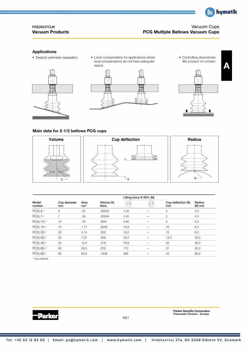
A61
Parker Hannifin Corporation Pneumatic Division - Europe
PDE2654TCUK
Vacuum Products
Vacuum Cups PCG Multiple Bellows Vacuum Cups
Applications • Destack perimeter separation • Level compensation for applications where • Controlling downstroke
level compensators do not have adequate lifts product on contact space A
Main data for 2-1/2 bellows PCG cups
V
Volume
S
Cup deflection
R
Radius
Lifting force @ 60% (N)
Model Cup diameter Area Volume (V) Cup deflection (S) Radius number mm cm2 liters mm (R) mm
PCG-5-* 5 .20 .00003 1.20 — 3 3.5
PCG-7-* 7 .39 .00004 2.40 — 3 4.0
PCG-10-* 10 .79 .0001 4.80 — 3 5.0
PCG-15-* 15 1.77 .0009 10.8 — 10 6.0
PCG-20-* 20 3.14 .002 19.2 — 10 8.0
PCG-30-* 30 7.07 .009 43.2 — 14.5 20.0
PCG-40-* 40 12.6 .018 76.9 — 22 30.0
PCG-60-* 60 28.3 .072 173 — 27 55.0
PCG-90-* 90 63.6 .1639 389 — 42 80.0
* Cup material

A62
Parker Hannifin Corporation Pneumatic Division - Europe
PDE2654TCUK
Vacuum Products
Vacuum Cups PCG Multiple Bellows Vacuum Cups
PCG Series Replacement Cup Dimensions Dimensions
PCG-5 and PCG-10 thru
A PCG-7 PCG-20 J
B H
E F
D J
C
B H
G E
F
A A
PCG-90 J
B
PCG-30 thru PCG-60 H
G
J B
E
HG
E F
F
A A
Dimensions (mm)
Model number ØA ØB ØC ØD E F G H J
PCG-5-* 5 4 2 7.5 9.5 3 4 2 6
PCG-7-* 7 4 2 7.5 10 3 4 2 6
PCG-10-* 9 5 — — 15 3 7 — 9
PCG-15-* 15.2 5 — — 22 10 9 — 10
PCG-20-* 20 5 — — 23 10 9 — 10
PCG-30-* 32 8 — — 37.5 14.5 17 13 18
PCG-40-* 42 8 — — 46 .22 17 13 20
PCG-60-* 62 8 — — 55 27 18 13 21.5
PCG-90-* 88 12 — — 87.5 42 26 20 25
* Cup material

A63
Parker Hannifin Corporation Pneumatic Division - Europe
PDE2654TCUK
Vacuum Products
Vacuum Cups PCTM Series Assemblies
Dimensions
PCTM-5 and PCTM-10 thru PCTM-7 PCTM-20 M5: M5 AG1: 1/8 BSPP
M5: M5
A
C5/16"
DCSW8
D B B E
AE
PCTM-90 N2: 1/4 NPT
C
PCTM-30 thru 9/16" D
PCTM-60
N1: 1/8 NPT G1: 1/8 BSPP G2: 1/4 BSPP
C 1/2"
BD
B E
E
A A
G2: 1/4 BSPP
Dimensions (mm)
Model C C C C number ØA B (M5) (N1 / G1) M10 / G2) (N2) D E
PCTM-5-*-† 5 13 4.5 — — — 3.5 3
PCTM-7-*-† 7 13.5 4.5 — — — 3.5 3
PCTM-10-*-† 9 17.5 4.5 8 — — 2.5 3
PCTM-15-*-† 15.2 25.5 4.5 8 — — 2.5 10
PCTM-20-*-† 20 25.5 4.5 8 — — 2.5 10
PCTM-30-*-† 32 42.5 — 8 10 — 5 14.5
PCTM-40-*-† 42 51 — 8 10 — 5 22
PCTM-60-*-† 62 60 — 8 10 — 5 27
PCTM-90-*-† 88 92.5 — — 10 15 5 42
* Cup material † Thread size

A64
Parker Hannifin Corporation Pneumatic Division - Europe
PDE2654TCUK
Vacuum Products
Vacuum Cups PCTF Series Assemblies
Dimensions
PCTF-5 and PCTF-10 thru
A PCTF-7 PCTF-20 G1: 1/8 BSPP
B CD
A
1/2" CM5
BSW8
E
AE
PCTF-90
N2: 1/4 NPT
D
9/16" CPCTF-30 thru PCTF-60
N1: 1/8 NPT G1: 1/8 BSPP G2: 1/4 BSPP
1/2" D BC
B
E
E
A A
D
G2: 1/4 BSPP
Dimensions (mm)
Model number ØA B C D E
PCTF-5*† 5 21.5 12 8 3
PCTF-7*† 7 22 12 8 3
PCTF-10*† 9 27 12 8 3
PCTF-15*† 15.2 35 12 8 10
PCTF-20*† 20 35 12 8 10
PCTF-30*† 32 51.5 14 8 14.5
PCTF-40*† 42 60 14 8 22
PCTF-60*† 62 69 14 8 27
PCTF-90*† 88 105 17.5 10 42
* Cup material † Thread size

A65
Parker Hannifin Corporation Pneumatic Division - Europe
PDE2654TCUK
Vacuum Products
Vacuum Cups PCTK Series Assemblies
Dimensions
PCTK-5 and PCTK-10 thru PCTK-7 PCTK-20 .197 Dia.
Ø (5) A.118 Dia. Ø (3)
.197 Dia. Ø (5)
EA
.098 Dia. Ø (2.5)
FG
C
D B
C
M8x1.25
GSW12 F DM9x1.0
SW12 B
E
A
PCTK-90 N1: 1/8 NPT G1: 1/8 BSPP R1: 1/8 BSPT PCTK-30 thru
M16x1.5 PCTK-60 SW21
.197 Dia. Ø (5) .118 Dia.
N1: 1/8 NPT G1: 1/8 BSPP R1: 1/8 BSPT
CM10x1.5 M5x0.8
SW14
Ø (3)
G F D
B
B
EE
A
A
FG
D
Dimensions (mm)
Model Wt number ØA B C D E F G g
PCTK-5-* 5 33.5 10 14 3 12 3 11
PCTK-7-* 7 34 10 14 3 12 3 11
PCTK-10-* 9 56.2 16 22.5 3 15 4 22
PCTK-15-* 15.2 64.2 16 22 10 15 4 22
PCTK-20-* 20 64.2 16 (22 10 15 4 22
PCTK-30-* 32 86.8 16 32 14.5 20 5 46
PCTK-40-* 42 95.3 16 32 22 20 5 55
PCTK-60-* 62 104.3 16 32 27 20 5 85
PCYK-90-* 88 144.8 23 55 42 11 — 300
* Cup material † Vacuum port

A66
Parker Hannifin Corporation Pneumatic Division - Europe
PDE2654TCUK
Vacuum Products
Vacuum Cups PUGB Flat Swivel Vacuum Cups
A
30° inclusive swivel, single lip cup for smooth, slightly curved surfaces and flexible products. Rigid construction provides good stability against acceleration and deceleration forces during product transfer.
The single edge swivel cup is for smooth surfaces with slightly curved surfaces or flexible sheets with substantial weights. Typically, lift capacities and break away forces are higher for flat cups which may be necessary for good stability during lift and transfer. The position of the internal swivel joint minimizes moments during lift and transfer. The swivel joint compensates for load and angular misalignment instead of the cup material, prolonging cup life. Maintenance costs are minimized by replacing only the cup portion of the assembly.
Features • Internal swivel joint design • 30° Inclusive angle for flexible products • Increased stability for horizontal lifts • Lower maintenance costs • 60mm to 100mm diameters
Specifications
Styles • PUTYK series barbed bulkhead • PUTYS series bulkhead level compensator
Suction cup Nitrile Silicon material (NBR) (SI)
Operating -20° -60° temperature (°C) to +120° to +250°
Color Black White
Hardness, 55 ±5 55 ±5shore A (°Sh)
Application guide Swivel Bellows
Flat surface, thin Flat surface, any Slightly bowed Slightly bowed Metal sheet handling Not for vertical lift section section surface, thin section surface, any section

A67
Parker Hannifin Corporation Pneumatic Division - Europe
PDE2654TCUK
Vacuum Products
Vacuum Cups PUGB Flat Swivel Vacuum Cups
PUTYK Series Barbed Bulkhead Top stem connectors secured with jam nuts and allow tubing connections at the top side. Fitting material: nickel plated brass.
AInstallation Mounting Thread
Note:
When installing cup assemblies, use a sealant material to secure the assembly and prevent vacuum leakage.
Cup Vacum Cup material Replacement PUGB Replacement cup only Cup size port Nitrile assembly (NBR) swivel with cup only (NBR) fitting
60 1/8 BSPP PUTYK-60-NBR-G1 PUGB-60-NBR PUG-60-NBR UTYK-60-G1
80 1/8 BSPP PUTYK-80-NBR-G1 PUGB-80-NBR PUG-80-NBR UTYK-60-G1
100 1/8 BSPP PUTYK-100-NBR-G1 PUGB-100-NBR PUG-100-NBR UTYK-60-G1
PUTYS Series Bulkhead Level Compensator 303 stainless steel construction secured with jam nuts. Spring biased compensators can absorb impacts of down-strokes and adjust for different levels of pick up points. 303 stainless corrosion resistant materials with drymet bushings increases the strength and life.
Installation Note: When installing cup assemblies, use a sealant material to secure the assembly and prevent vacuum leakage. Shown are interchangable connectors & plugs for port connections.
Mounting Thread.
PlugPushlock Tube Fitting
Barb Fitting
Inte
rcha
ngab
le*
* Not included with assembly
Cup Spring compression PUTYS Replacement diameter Vacum Stroke Force lbf (N) assemlby PUGB swivel Replacement Level compensator (mm) port (mm) 0% 100% (NBR) with cup only cup only NBR P/N
60 1/8 BSPP 30 1.6 (6.8) 3.6 (15.6) PUTYS6030NBRG1 PUGB-60-NBR PUG-60-NBR UTYS-60-30-G1
60 1/8 BSPP 50 1.9 (8.3) 4.5 (19.6) PUTYS6050NBRG1 PUGB-60-NBR PUG-60-NBR UTYS-60-50-G1
80 1/8 BSPP 30 1.6 (6.8) 3.6 (15.6) PUTYS8030NBRG1 PUGB-80-NBR PUG-80-NBR UTYS-60-30-G1
80 1/8 BSPP 50 1.9 (8.3) 4.5 (19.6) PUTYS8050NBRG1 PUGB-80-NBR PUG-80-NBR UTYS-60-50-G1
100 1/8 BSPP 30 1.6 (6.8) 3.6 (15.6) PUTYS10030NBRG1 PUGB-100-NBR PUG-100-NBR UTYS-60-30-G1
100 1/8 BSPP 50 1.9 (8.3) 4.5 (19.6) PUTYS10050NBRG1 PUGB-100-NBR PUG-100-NBR UTYS-60-50-G1

PDE2654TCUK Vacuum Cups Vacuum Products PUGB Flat Swivel Vacuum Cups
Applications
A
15° Max.
Mounting Thread
Mounting Thread
Mounting Thread
• Angles pickup • Fixtures for curved product
Main data for swivel bellows PUG cups
S
RV
Volume RadiusCup deflection
Lifting force @ 60% (N) Cup Model Cup diameter Area Volume (V) deflection (S) Radius Rnumber mm cm2 liters mm (mm)
PUGB-60-* 60 28.3 0.0090 173 — 5 70
PUGB-80-* 80 50.3 0.025 308 — 6 100
PUGB-100-* 100 78.5 0.045 480 — 6 150
* Cup material
Parker Hannifin Corporation Pneumatic Division - Europe
A68
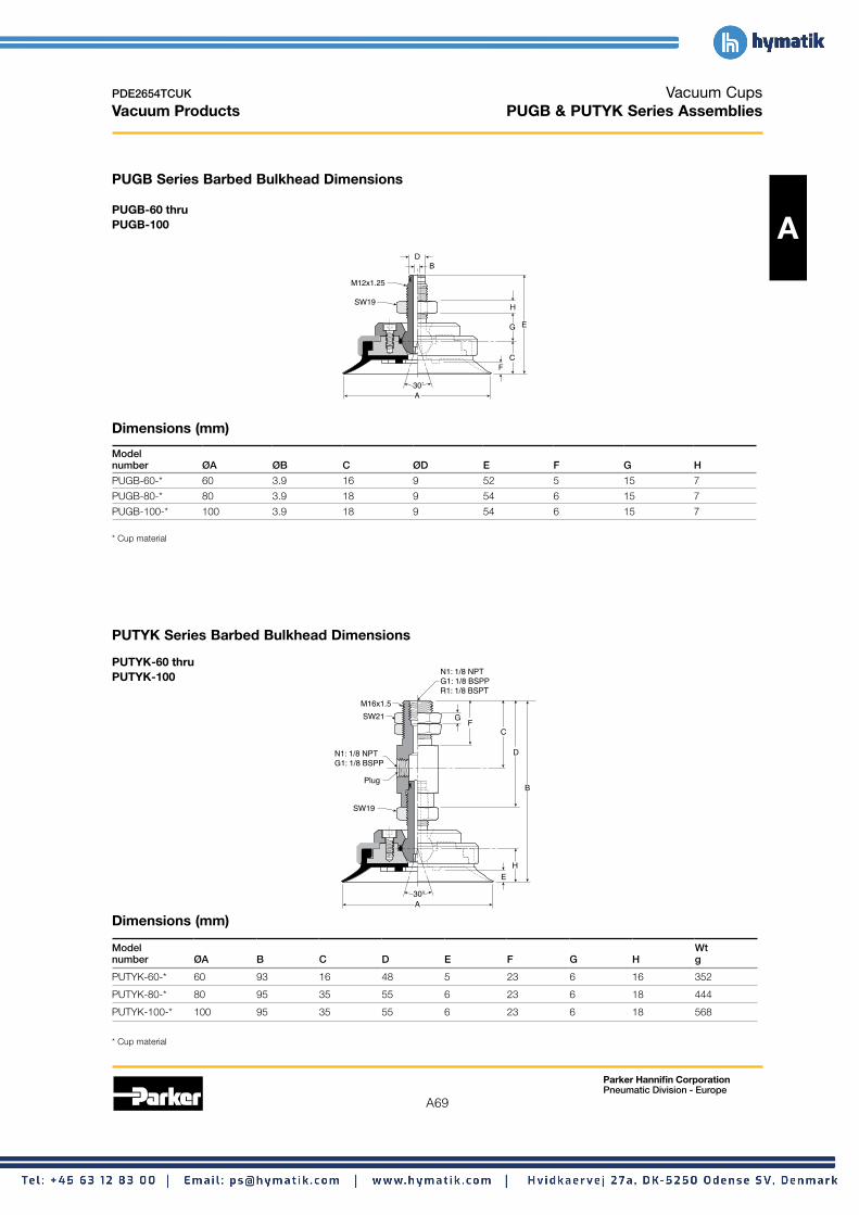
A69
Parker Hannifin Corporation Pneumatic Division - Europe
PDE2654TCUK
Vacuum Products
Vacuum Cups PUGB & PUTYK Series Assemblies
PUGB Series Barbed Bulkhead Dimensions
PUGB-60 thru PUGB-100 A
B D
E
F
G
C
H
A 30˚
SW19
M12x1.25
Dimensions (mm)
Model number ØA ØB C ØD E F G H
PUGB-60-* 60 3.9 16 9 52 5 15 7
PUGB-80-* 80 3.9 18 9 54 6 15 7
PUGB-100-* 100 3.9 18 9 54 6 15 7
* Cup material
PUTYK Series Barbed Bulkhead Dimensions
PUTYK-60 thru N1: 1/8 NPT PUTYK-100 G1: 1/8 BSPP
M16x1.5
SW21
N1: 1/8 NPT G1: 1/8 BSPP
Plug B
SW19
30° A
E H
R1: 1/8 BSPT
FG
D
C
Dimensions (mm)
Model Wt number ØA B C D E F G H g
PUTYK-60-* 60 93 16 48 5 23 6 16 352
PUTYK-80-* 80 95 35 55 6 23 6 18 444
PUTYK-100-* 100 95 35 55 6 23 6 18 568
* Cup material

A70
Parker Hannifin Corporation Pneumatic Division - Europe
PDE2654TCUK
Vacuum Products
Vacuum Cups PUTYS Series Assemblies
Dimensions
PUTYS60 thru
A PUTYS100
Dimensions (mm)
E
A 30˚
SW19
N1: 1/8 NPT
N1: 1/8 NPT
SW19
SW30M22x1.5
B
D
C
H
J.28 (7)
F
G
SW22
Shock Pad
5mm
Model Wt number ØA B C D E F G H J g
PUTYS6030* 60 185 40 20 5 45 10 50 12 487
PUTYS6050* 60 210 40 20 5 70 10 50 12 521
PUTYS8030* 80 187 40 20 6 45 10 50 12 559
PUTYS8050* 80 212 40 20 6 70 10 50 12 595
PUTYS10030* 30 187 40 20 6 45 10 50 12 729
PUTYS10050* 30 212 40 20 6 70 10 50 12 756
* Cup material

A71
Parker Hannifin Corporation Pneumatic Division - Europe
PDE2654TCUK
Vacuum Products
Vacuum Cups Cup Screws & Cup Fitting Assemblies
Cup screws
Dimensions (mm)
Part number A B C D E F G
D
Dia. A
Dia. B AG TN-PF-15-M5 2.5 5 8 5.5 1.5 2 M5
TN-PF-20-M5 2.5 5 11 6 3 2 M5
TN-PF-25-M6 3.5 8.5 14 6 11 2 M6
TN-PF-50-M6 3.5 8 20 6 6 2 M6E
TN-PF-50-M8 4 8 20 10 5 2 M8 F TN-PF-10-M5 2.5 3 6 5.5 2 2 M5
Dia. C TN-PF-30-M6 3.4 8 15 10.5 10.5 3 M6
TN-PC-30-M8 3.9 8 15 12 10 3 M8
TN-PC-90-M12 3.9 12 25 11 19 5 M12
Male threaded cup fittings Cup fitting Cup series Cup assembly Vacuum port
FTM-5A-M5 PFG / PBG / PJG / PCG PFTM / PBTM / PJTM / PCTM M5
FTM-5A-G1 PFG / PBG / PJG / PCG PFTM / PBTM / PJTM / PCTM 1/8 BSPP
FTM-20B-G1 PFG / PBG / PJG PFTM / PBTM / PJTM 1/8 BSPP
FTM-20B-G2 PFG / PBG / PJG PFTM / PBTM / PJTM 1/8 BSPP
FTM-20B-N1 PFG / PBG / PJG PFTM / PBTM / PJTM 1/8 NPT
FTM-20B-M10 PFG / PBG / PJG PFTM / PBTM / PJTM M10
FTM-50-G1 PFG / PBG / PJG PFTM / PBTM / PJTM 1/8 BSPP
FTM-50-N1 PFG / PBG / PJG PFTM / PBTM / PJTM 1/8 NPT
FTM-50-G2 PFG / PBG / PJG PFTM / PBTM / PJTM 1/8 BSPP
FTM-60-G2 PFG / PBG / PJG PFTM / PBTM / PJTM 1/8 BSPP
FTM-60-N2 PFG / PBG / PJG PFTM / PBTM / PJTM 1/4 NPT
FTM-60-M10 PFG / PBG / PJG PFTM / PBTM / PJTM M10
CTM-10-M5 PCG PCTM M5
CTM-10-G1 PCG PCTM 1/8 BSPP
CTM-10-N1 PCG PCTM 1/8 NPT

A72
Parker Hannifin Corporation Pneumatic Division - Europe
PDE2654TCUK
Vacuum Products
Vacuum Cups Cup Fitting Assemblies
Male threaded cup fittings Cup fitting Cup series Cup assembly Vacuum port
A CTM-30-G1 PCG PCTM 1/8 BSPP
CTM-30-N1 PCG PCTM 1/8 NPT
CTM-30-G2 PCG PCTM 1/8 BSPP
CTM-90-G2 PCG PCTM 1/8 BSPP
CTM-90-N2 PCG PCTM 1/4 NPT
Female threaded cup fittings Cup fitting Cup series Cup assembly Vacuum port
FTF-5A-M5 PFG / PBG / PJG PFTF / PBTF / PJTF M5
FTF-5A-G1 PFG / PBG / PJG PFTF / PBTF / PJTF 1/8 BSPP
FTF-20B-G1 PFG/ PBG / PJG PFTF / PBTF / PJTF 1/8 BSPP
FTF-20B-G2 PFG/ PBG / PJG PFTF / PBTF / PJTF 1/4 BSPP
FTF-50-G1 PFG / PBG / PJG PFTF / PBTF / PJTF 1/8 BSPP
FTF-50-G2 PFG / PBG / PJG PFTF / PBTF / PJTF 1/4 BSPP
FTF-60-G2 PFG / PBG / PJG PFTF / PBTF / PJTF 1/4 BSPP
FTF-60-N2 PFG / PBG / PJG PFTF / PBTF / PJTF 1/4 NPT
FTF-120-G4 PFG / PBG PFTF / PBTF 1/2 BSPP
FTF-120-N4 PFG / PBG PFTF / PBTF 1/2 NPT
CTF-10-G1 PCG PCTF 1/8 BSPP
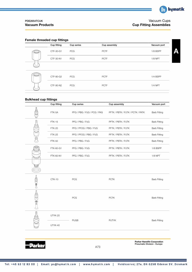
A73
Parker Hannifin Corporation Pneumatic Division - Europe
PDE2654TCUK
Vacuum Products
Vacuum Cups Cup Fitting Assemblies
Female threaded cup fittings
Cup fitting Cup series Cup assembly Vacuum port
ACTF-30-G1 PCG PCTF 1/8 BSPP
CTF-30-N1 PCG PCTF 1/8 NPT
CTF-90-G2 PCG PCTF 1/4 BSPP
CTF-90-N2 PCG PCTF 1/4 NPT
Bulkhead cup fittings Cup fitting Cup series Cup assembly Vacuum port
FTK-5A PFG / PBG / PJG / PCG / PAG PFTK / PBTK / PJTK / PCTK / PATK Barb Fitting
FTK-15 PFG / PBG / PJG PFTK / PBTK / PJTK Barb Fitting
FTK-20 PFG / PFOG / PBG / PJG PFTK / PBTK / PJTK Barb Fitting
FTK-25 PFG / PFOG / PBG / PJG PFTK / PBTK / PJTK Barb Fitting
FTK-50 PFG / PBG / PJG PFTK / PBTK / PJTK Barb Fitting
FTK-60-G1 PFG / PBG / PJG PFTK / PBTK / PJTK 1/8 BSPP
FTK-60-N1 PFG / PBG / PJG PFTK / PBTK / PJTK 1/8 NPT
CTK-10 PCG PCTK Barb Fitting
PCG PCTK Barb Fitting
UTYK-20
PUGB PUTYK Barb Fitting
UTYK-40

PDE2654TCUK Vacuum Cups Vacuum Products Cup Fitting Assemblies
Bulkhead cup fittings Cup fitting Cup series Cup assembly Vacuum port
A UTYK-60-R1 PUGB PUTYK 1/8 BSPT
UTYK-60-N1 PUGB PUTYK 1/8 NPT
UTYK-60-G1 PUGB PUTYK 1/8 BSPP
90° cup fittings Cup fitting Cup series Cup assembly Vacuum port
FYK-5A PFG / PBG / PJG / PCG PFYK / PBYK / PJYK / PCYK Barb Fitting
FYK-15 PFG / PBG / PJG PFYK / PBYK / PJYK
FYK-20 PFG / PBG / PJG PFYK / PBYK / PJYK Barb Fitting
FYK-25 PFG / PBG / PJG PFYK / PBYK / PJYK
FYK-50 PFG / PBG / PJG PFYK / PBYK / PJYK
FYK-60-G1 PFG / PBG / PJG PFYK / PBYK / PJYK 1/8 BSPP
FYK-60-N1 PFG / PBG / PJG PFYK / PBYK / PJYK 1/8 NPT
FYK-120-G1 PFG / PBG PFYK / PBYK 1/8 BSPP
FYK-120-N1 PFG / PBG PFYK / PBYK 1/8 NPT
Level compensators Assembly part Compensator number Cup series Cup assembly only Cup fitting
FTYS-2A-3-M3 TYS-M5-3-M5PFG / PBG / PFTYS / PBTYS / PJTYS FTY-2A-M5-M3 PJGFTYS-2A-15-M3 TYS-M5-15-M5
FTYS-5A-10-M5 TYS-M5-10-M5 PFG / PBG PFTYS / PBTYS FTY-5A-M5-M5
FTYS-5A-15-M5 TYS-M5-15-M5
FTYS-20B-15-M5 TYS-M8-15-M5PFG / PBG / PFTYS / PBTYS / PJTYS FTY-20B-M8-M5 PJGFTYS-20B-30-M5 TYS-M8-30-M5
FTYS-50-15-M5 TYS-M8-15-M5PFG / PBG / PFTYS / PBTYS / PJTYS FTY-50 PJGFTYS-50-30-M5 TYS-M8-30-M5
Parker Hannifin Corporation Pneumatic Division - Europe
A74

A75
Parker Hannifin Corporation Pneumatic Division - Europe
PDE2654TCUK
Vacuum Products
Vacuum Cups Cup Fitting Assemblies
Level compensators Assembly part number
FTYS-60-30-G1
Cup series Cup assembly Compensator only
TYS-M14-25-G1
Cup fitting
A
PFG / PBG / PJG PFTYS / PBTYS / PJTYS FTY-60/95
FTYS-60-50-G1 TYS-M14-45-G1
FTYS-120-20-G2 PFG / PBG PFTYS / PBTYS TYS110/200M1820 FTY-120-N2
FTYS-120-50-G2 PFG / PBG PFTYS / PBTYS TYS110/200M1870 FTY-120-N2
JTYS-10-10-M5 NAPJYS-10-10-K
PJG PJTYS TN-PF-15-M5
JTYS-10-15-M5 NAPJYS-10-15-K
UTYS-60-30-G1 TYS-M14-25-N
PUGB PUTYS UTY-60-M14-N1
UTYS-60-50-G1 TYS-M14-45-N

A76
Parker Hannifin Corporation Pneumatic Division - Europe
PDE2654TCUK
Vacuum Products
A

Vacuum Generators
Section B www.parker.com/pneu/vacgen

B
B2
PDE2654TCUK
Vacuum Products
Parker Hannifin Corporation Pneumatic Division - Europe

B
B3
Parker Hannifin Corporation Pneumatic Division - Europe
PDE2654TCUK
Vacuum Products
Generator Selection How to Select a Generator B4 - B9
Inline Vacuum Generators: Single Stage MCA, CV, CV-CK MCA is lightweight generator that can be located directly on the cup fitting for space savings.
Great for use with TYS level compensators. CV is a basic Venturi Generator with aluminum basic body. Includes exhaust muffler. CV-CK is a Venturi Generator with adjustable open contact mechanical switch for vacuum confirmation. Great for low cost vacuum confirmation. Additional Pneumatic Control Valve is required to create vacuum flow with these products.
B10 - B11
Integrated Vacuum Generators MC22 The MC22 has integrated vacuum generating and blow-off release pilot valves to minimize the
response time to achieve vacuum. The small foot print and lightweight body allows the unit to be located close to the suction cup for maximum performance. The MC22 has additional features; regulating blow-off needle, 37 micron mesh filter, The MC22 can be assembled into a maximum 8 station manifold. The unit can be ordered normally open or normally closed and with or without. Integrated check valves offer air economizing options with the MPS-23 and MVS-201 pressure sensors.
B12 - B17
MC72 The MC72 is perfect for non-porous applications such as material handling, critical applications involving glass, or general transfer applications. The MC72 has integrated vacuum pilot and blow-off release pilot valves to minimize response times. The MC72 has additional features; regulating blow-off needle, 130 micron filter, optional check valve. The
MC72 can be assembled into a maximum 5 station manifold. The unit can be ordered normally open or normally closed. Integrated check valves offer air economizing options with the MPS-23 and MVS-201 pressure sensors.
B18 - B23
CEK CEK Venturi Generator is a basic vacuum blow off integrated generator with the addition of a memory valve that maintains the last state of air during an emergency stop or power loss. The CEK Generator integrated components include valves for vacuum, air economizing, and blow-off functions, blow-off flow regulating valve, vacuum filters and a vacuum check valve. Optional pressure sensors reduce cycle time and can be used for air economizing to conserve air during part transfer. Inline versions can be mounted in manifolds up to 5 stations.
B24 - B29
CVXCEK CVXCEK Venturi Generator is a basic 2 station CEK Generator Manifold with the addition of Emergency Stop Functions that maintains the last state of air during an emergency stop or power loss. This unit can be used for high-speed pick and place and material handling systems. CVXCEK Generator integrated components include valves for vacuum and blow-off functions, blow-off flow regulating valve, exhaust ,vacuum filters and an optional vacuum check valve. Air economizing can be utilized with the vacuum check valve to conserve air during part transfer. No additional PLC programming is required for Air Economizing Functions because this function is built into the electrical unit.
B30 - B37
Generator Mount Sensors MPS23
-101.3 - 0 kPa -14.5 to 0 PSI
(2) NPN / PNP Air,
Non-corrosive gas
IP40 Variable,
100% F.S. Push
button LED display
(Red)
B38 - B41
MVS201
0 to -30 inHg -14.7 to 72.5 PSI
(1) NPN / PNP Air,
Non-corrosive gas
IP40 Variable,
100% F.S. Push
button LED display
(Red)
B42 - B47
Generator Accessories Filters, Check Valves, Silencers B48 - B55
Glossary B56 - B57
Vacuum Generators Basic Vacuum Generators

B
B4
PDE2654TCUK Vacuum Generators Vacuum Products Technical Data
Principle of venturi vacuum A vacuum generator is a single stage venturi that creates high vacuum with fast response using compressed air.
The ability to control this performance renders this technology as an excellent solution for factory automation.
In principle, compressed air is throttled as the air exits the nozzle and is discharged into the diffuser. This increased velocity of air lowers the pressure in the diffusion chamber. The volume of air within the closed vacuum system flows into the low pressure area of the diffusion chamber and is exhausted thru the diffuser. This effect increases the vacuum level and evacuates most of the air within the closed vacuum system at supersonic speeds.
Diffusion Nozzle Chamber Diffuser
Additional advantages to venturi generators • No moving components • Low maintenance • Long life • Responsive • Physically small • Cost effective
Applying the venturi generator 1. Design a system with basic venturi generators and
individual components to support the vacuum circuit.
Inlet Pressure
Vacuum Flow
Exhaust
Venturi
Normally Closed Air Supply
Filter
Cup Sensor
2. Design a system with all of the supporting components integrated into the venturi generator.
Normally Closed Vacuum Pilot Valve
Venturi
Check Valve
Normally Closed FilterBlow-off Pilot Valve
Sensor Cup
There are several advantages to an integrated venturi system. The response time of the vacuum and blow-off functions are greatly reduced compared to basic venturi generators, the installation time is also reduced which makes this a cost effective system and the compact size allows the integrated unit to be close to the suction cup.
Venturi generator with power loss circuits When designing a vacuum system that requires a Normally Open circuit or Emergency Stop circuits to avoid any hazard during a power failure, consider the circuits below and on the following page.
Normally open circuit
Normally Closed Vacuum Pilot Valve
Normally Open Master Valve
Venturi
Check Valve
Normally Closed Blow-off Pilot Valve Filter
Cup Sensor
Blow-off Flow Adjustment
Blow-off Flow Adjustment
Normally Closed Master Valve
Parker Hannifin Corporation Pneumatic Division - Europe

B
B5
PDE2654TCUK
Vacuum Products
Valve controlled emergency stop circuit (See CEK Vacuum Generator)
Vacuum AirValve
Economizing On Valve
Off
Sensor
VenturiN.C. Master Valve
N.C. Master Valve
Blow-off Pilot Valve
Filter
Flow Control
PFG Cup
The venturi system A closed vacuum system has a volume of air within all the components between the vacuum port of the venturi and the suction cup. The venturi’s ability to evacuate this volume of air when the suction cup forms a seal on the surface, creates the pressure differential required to force the suction cup onto the product.
The evacuated air creates a lower air pressure within the closed vacuum system, causing the atmospheric pressure to apply a uniform force on the surface of the cup. This holding force is proportional to the difference in pressures and area of the suction cup.
Vacuum Generators Technical Data
Selecting the appropriate supply valve If a basic venturi generator is selected, correct sizing of the air supply valve and supply line are critical to the performance of the unit.
Nozzle Minimum Tube I.D. Flow (Cv)Diameter mm 0.5 mm 4 0.16 1.0 mm 4 0.16 1.5 mm 6 0.379 2.0 mm 8 0.65 2.5 mm 8 0.95 3.0 mm 10 1.35
If pressure drops occur due to other pneumatic components or a manifold venturi system, it may be necessary to increase the valve and / or supply line tubing I.D..
Selecting the nozzle diameter with reference to suction cup diameter As a general guide, for most non-porous vacuum applications, the nozzle diameter can be selected based on the suction cup diameter previously determined in Section A.
Maximum suction cup diameterNozzle diameter
mm 0.5 mm 20 1.0 mm 50 1.5 mm 60 2.0 mm 120 2.5 mm 150 3.0 mm 200
Designing a system with a single suction cup dedicated to a single vacuum generator is ideal, however, it may not always be practical. It is recommended that the sum of the areas of multiple cups dedicated to a single venturi do not exceed the area of the diameter of the single suction cups shown above.
Parker Hannifin Corporation Pneumatic Division - Europe

PDE2654TCUK Vacuum Generators Vacuum Products Technical Data
Selecting a generator size
B
The choice of Generator Series depends on the system requirements for components and overall performance for the application. Inline Generators offer the basic function for creating vacuum flow. Adding integrated components such as automatic blow off Controls, Vacuum and Blow-off Solenoids, Pressure Sensors, Check Valves and Filters are options that can reduce overall mounting space, reduce cycle time and can offer air conservation functions as well as emergency stop modes. For guidelines on selecting Vacuum Generators by features, consult the highlight features in the Generator Index section for each Series Section.
A vacuum source can only achieve and hold a degree of vacuum that sustains the amount of leakage into the vacuum system. In most cases, it is the leakage through the product and by of the cup seal that limits the system degree of vacuum. Products with high product leakage are Porous Applications. The degree of vacuum that can be obtained with this type of product can vary and tends to be below 10 inHg. Products with low or no leakage are called Non-Porous Applications. It can be assumed that the maximum degree of vacuum of the system is the maximum degree of the vacuum generator. Due to design cycle time and safety requirements, a lower degree of vacuum is generally chosen other than the maximum obtainable degree of vacuum. Chart 1 lists different units of measure for vacuum with typical application levels The system degree of vacuum must be determined by product testing.
Evacuation time The size of the generator generally refers to either the Evacuation Time or the Vacuum Flow Rates of the generator and varies by the size of the nozzle / diffuser.
Evacuation Time is the time required to evacuate the air out of a vacuum system to specific degree of vacuum. Typically, this degree of vacuum is a value where it is safe to move a product in a pick and place application and is determined by the design engineer. Evacuation Time can also be considered response time of the system.
A typical Evacuation Time chart for a generator series is shown in Chart 2. The time to achieve a given degree of vacuum in a 1 cubic foot volume is listed in seconds for each Generator.
Example: A pick and place application requires a 0.25 secs
Chart 2: evacuation time
Chart 1: Basic vacuum pressure measurements units
Negative gauge Absolute Inches of mercury pressure pressure inHgPSIG PSIA
0 14.7 0
Atmospheric pressure at sea level
-1.5 13.2 3
-3.0 11.7 6
-4.5 10.2 9
Typical porous vacuum level
-6.0 8.7 12
-7.5 7.2 15
-9.0 5.7 18
-10.5 4.2 21
Typical non-porous vacuum level
-12.0 2.7 24
-13.5 1.2 27
-14.7 0 29.92
Perfect vacuum (zero reference pressure)
for creation of 18 inHg of vacuum in the vacuum system. The vacuum system volume, which includes tubing and cups, is 0.002 ft3.
The evacuation time charts are given for a 1 cubic foot (ft3) volume. To use these charts, convert the time requirement of the system to an equivalent time for a 1 cubic foot (ft3) volume. In this example, 1 cubic foot (ft3) is 500 times the system volume of 0.002 ft3. Multiply the system time requirement by 500 (500 x 0.25 secs = 125 seconds). Any generator with a evacuation time of less than 125 seconds to attain 18 inHg can be chosen for this application. A CV-15-HS will meet the requirements for this application. A (-) listed means the generator will not obtain a higher degree of vacuum than the level of the first (-).
Series / Air supply Air Evacuation time in sec / ft3 * to reach different vacuum levels (inHg) nozzle diameter pressure consumption
PSI SCFM 3 6 9 12 15 18 21 24
CV-05HS 70 0.46 24.3 57.3 101.0 160.5 231.1 305.1 433.1 597.7 —
CV-05LS 70 0.46 11.0 23.4 40.0 64.4 110.2 — — — —
CV-10HS 70 1.55 4.8 9.9 16.0 24.9 35.9 51.4 77.4 117.5 226.0
CV-10LS 70 1.55 3.7 7.6 13.0 20.3 33.1 — — — —
CV-15HS 70 3.53 2.5 4.8 7.0 11.0 15.5 22.0 31.9 46.6 112.1
CV-15LS 70 3.53 2.0 3.1 5.0 7.6 12.1 — — — —
CV-20HS 70 6.36 1.7 2.8 5.0 6.5 9.0 13.0 18.9 27.4 60.7
CV-20LS 70 6.36 1.3 2.5 4.0 5.9 11.3 — — — — * 1 ft3 = 28.31 liters
Parker Hannifin Corporation Pneumatic Division - Europe
B6
27

B
B7
PDE2654TCUK Vacuum Generators Vacuum Products Technical Data
Vacuum flow A typical Vacuum Flow chart for a generator series is listed in Chart 3. The vacuum flow rate at given degree of vacuum is listed in SCFM for each Generator. This chart is generally used to determine the change of degree of vacuum given a change in vacuum flow rate of a generator.
Example. A CV-15HS can only obtain 9 inHg. The vacuum flow rate at 9 inHg is 1.50 SCFM. This means that the cup seal and
Chart 3: Vacuum flow (SCFM)
product leaks 1.50 SCFM of air. This generator can maintain the leak rate of 1.50 SCFM. Choosing a generator with more flow at 9 inHg will increase the degree of vacuum in the system because the generator can overcome more leakage. In this case,the vacuum flow rates are linear since this CV generator is a single stage venturi generator. Replacing a CV-15HS with CV-20HS will increase the degree of vacuum in the system to approximately 16.2 inHg. The CV-20HS now maintains 16.2 inHg at a flow rate of 1.50 SCFM.
Nozzle inHg diameter 0 3 6 9 12 15 18 21 24 27 30 CV-05HS .21 .19 .17 .15 .13 .11 .09 .07 .05 .03 — CV-05LS .32 .27 .22 .17 .12 .06 — — — — — CV-10HS .95 .85 .75 .65 .55 .45 .35 .25 .15 .05 — CV-10LS 1.27 1.05 .83 .59 .38 .17 — — — — — CV-15HS 2.22 1.98 1.74 1.5 1.26 1.01 .76 .51 .25 .10 — CV-15LS 3.35 2.79 2.23 1.67 1.10 .53 — — — — — CV-20HS 3.88 3.45 3.02 2.59 2.16 1.73 1.30 .87 .44 .25 — CV-20LS 5.85 5.09 4.03 2.97 1.91 .85 — — — — —
Tubing reference Pad volume reference (pv)
Tubing ID Tubing length (L) PFG PBG PCG SAE mm In. M Ø in3 L Ø in3 L Ø in3 L 5/64 2 18 .457 2 .00004 .0000006 10 .013 .0002 5 .002 .00003 3/32 2.38 24 .610 3.5 .0001 .000002 15 .045 .0007 7 .003 .00004 1/8 3.17 30 .762 5 .0003 .000005 20 .070 .001 10 .010 .0001 5/32 4 36 .914 6 .00048 .000008 30 .28 .004 15 .060 .0009 3/16 4.76 42 1.07 8 .002 .00003 40 .56 .009 18 .082 .001 1/4 6.35 48 1.22 10 .004 .00007 50 1.60 .026 20 .123 .002 5/16 8 54 1.37 15 .012 .0002 75 4.63 .076 30 .595 .009 3/8 9.52 60 1.52 20 .03 .0005 110 6.77 .111 40 1.15 .018 7/16 11.1 66 1.67 25 .067 .0011 150 15.86 .26 60 4.40 .072
SAE x 25.4 = mm In. x 254 = M 30 35
.067
.14 .0011 .0023
90 10.00 .1639
40 .18 .003 50 .25 .0042 60 .57 .0094 80 95
1.28 1.95
.021
.032
1 ft3 = 28.31 liters 1 ft3 = 1728 in3
110 5.00 .082 150 10.80 .177 200 23.24 .381
Nozzle diameter to tubing diameter to cup diameter reference For each application, the size of the nozzle diameter, vacuum tubing I.D., and maximum cup diameter must be practical in relationship to each other. The chart to the right is a quick reference to aid in selecting the vacuum tubing I.D. and nozzle diameter given the maximum cup diameter.
As an example, one 60mm cup with 2 meters in tubing length would require a minimum 6mm I.D. vacuum tube and a 1.5mm nozzle. The same 60mm cup with 3.5 meters in tubing length would require a minimum 8mm I.D. vacuum tube and a 2.0mm nozzle to achieve an equivalent performance.
Tubing I.D. (mm)
12
14
3.0
Nozzle Dia. (mm)
Maximum Cup Diameter (mm)
200
300
2.5 10 150
2.0 8 120
1.5 6 60
1.0 4 50
0.5 2 20
0 0 1 2 3
Tubing Length (m) 4
Parker Hannifin Corporation Pneumatic Division - Europe

B
B8
PDE2654TCUK Vacuum Generators Vacuum Products Basic Vacuum Generators
Evacuation time
Air supply Air Evacuation time in sec / ft3 * to reach different vacuum levels (inHg)
Series / Nozzle pressure consumption diameter PSI SCFM 3 6 9 12 15 18 21 24 27
MCA10HS 70 1.68 5.1 11.0 18.0 28.2 41.0 58.2 83.1 123.2 —
MCA13HS 70 2.81 3.7 7.3 12.0 19.5 28.5 39.8 58.5 104.2 —
CV05HS 70 0.46 24.3 57.3 101.0 160.5 231.1 305.1 433.1 597.7 —
CV05LS 70 0.46 11.0 23.4 40.0 64.4 110.2 — — — —
CV10HS 70 1.55 4.8 9.9 16.0 24.9 35.9 51.4 77.4 117.5 226.0
CV10LS 70 1.55 3.7 7.6 13.0 20.3 33.1 — — — —
CV15HS 70 3.53 2.5 4.8 7.0 11.0 15.5 22.0 31.9 46.6 112.1
CV15LS 70 3.53 2.0 3.1 5.0 7.6 12.1 — — — —
CV20HS 70 6.36 1.7 2.8 5.0 6.5 9.0 13.0 18.9 27.4 60.7
CV20LS 70 6.36 1.3 2.5 4.0 5.9 11.3 — — — —
CV25HS 70 9.36 1.4 2.3 3.0 4.5 6.5 9.0 13.0 18.9 35.3
CV25LS 70 9.36 1.0 2.0 3.0 3.7 5.6 — — — —
CV30AHS 70 13.60 1.1 2.0 2.8 3.5 4.8 6.8 9.6 16.7 29.1
CV30ALS 70 13.60 0.9 1.5 2.7 3.4 5.1 — — — —
CV10HSCK 70 1.55 4.8 9.9 16.0 24.9 35.9 51.4 77.4 117.5 226.0
CV15HSCK 70 3.53 2.5 4.8 7.0 11.0 15.5 22.0 31.9 46.6 112.1
CV20HSCK 70 6.36 0.7 2.8 5.0 6.5 9.0 13.0 18.9 27.4 60.7
CHF20 80 6.5 0.21 0.64 1.70 4.03 7.63 11.65 19.28 33.48 94.50
CHF30 80 9.6 0.21 0.63 1.27 3.39 6.36 9.53 16.10 27.76 78.82
CHF40 80 14.0 0.17 0.42 1.27 2.33 4.03 5.93 9.75 16.95 47.67
* 1 ft3 = 28.31 liters
Vacuum flow (SCFM) nHg
Nozzle diameter 0 3 6 9 12 15 18 21 24 27 30
MCA10HS .88 .78 .68 .58 .47 .37 .26 .16 .06 — —
MCA13HS 1.26 1.11 .96 .81 .67 .53 .39 .25 .11 — —
CV05HS .21 .19 .17 .15 .13 .11 .09 .07 .05 .03 —
CV05LS .32 .27 .22 .17 .12 .06 — — — — —
CV10HS .95 .85 .75 .65 .55 .45 .35 .25 .15 .05 —
CV10LS 1.27 1.05 .83 .59 .38 .17 — — — — —
CV15HS 2.22 1.98 1.74 1.50 1.26 1.01 .76 .51 .26 .10 —
CV15LS 3.35 2.79 2.23 1.67 1.10 .53 — — — — —
CV20HS 3.88 3.45 3.02 2.59 2.16 1.73 1.30 .87 .44 .25 —
CV20LS 5.85 5.09 4.03 2.97 1.91 .85 — — — — —
CV25HS 5.65 5.11 4.57 4.03 3.49 2.94 2.39 1.85 1.31 .77 —
CV25LS 8.83 7.29 5.75 4.21 2.67 1.13 — — — — —
CV30AHS 7.94 7.16 6.38 5.62 4.84 4.06 3.28 2.50 1.17 .92 —
CV30ALS 12.36 10.24 8.12 6.00 3.89 1.48 — — — — —
CV10HSCK .95 .85 .75 .65 .55 .45 .35 .25 .15 .05 —
CV15HSCK 2.22 1.98 1.74 1.5 1.26 1.01 .76 .51 .25 .10 —
CV20HSCK 3.88 3.45 3.02 2.59 2.16 1.73 1.30 .87 .44 .25 —
CHF20 20.90 12.12 7.88 3.85 2.76 2.12 1.45 0.81 0.35 0.04 —
CHF30 26.30 15.27 9.89 4.84 3.46 2.68 1.83 1.02 0.42 0.05 —
CHF40 31.80 18.50 12.00 5.90 4.20 3.30 2.30 1.30 0.60 0.06 —
Parker Hannifin Corporation Pneumatic Division - Europe

B
B9
PDE2654TCUK Vacuum Generators Vacuum Products Integrated Vacuum Generators
Evacuation time
Air supply Air Evacuation time in sec / ft3 * to reach different vacuum levels (inHg) Series / Nozzle pressure consumption diameter PSI SCFM 3 6 9 12 15 18 21 24 27
MC2210HS 70 1.55 5.4 12.1 20.0 32.2 52.0 85.0 120.1 183.9 —
MC7215HS 70 3.53 2.59 5.39 8.99 13.89 20.66 29.36 45.16 69.6 208.23
MC7220HS 70 6.36 1.13 2.6 5.21 7.91 12.56 19.26 30.84 54.65 129.9
MC7225HS 70 10.42 0.66 2.19 3.29 6.14 9.3 14.55 23.21 46.13 —
CEK15HS 70 3.53 2.3 4.8 8.0 12.4 18.4 26.3 40.4 62.1 189.3
CEK20HS 70 6.36 1.1 2.5 5.0 7.6 12.1 18.6 29.9 53.4 129.9
CEK27HS 70 10.42 0.6 2.0 3.0 5.6 8.5 13.3 21.2 42.1 —
CVXCEK 70 10.42 0.6 2.0 3.0 5.6 8.5 13.3 21.2 42.1 —
* 1 ft3 = 28.31 liters
Vacuum flow (SCFM)
nHg
Nozzle diameter 0 3 6 9 12 15 18 21 24 27 30
MC2210HS 0.71 0.64 0.57 0.49 0.42 0.34 0.25 0.17 0.10 — —
MC7215HS 2.2 1.96 1.71 1.47 1.22 0.99 0.75 0.51 0.27 — —
MC7220HS 3.67 3.21 2.81 2.4 2.04 1.64 1.24 0.84 0.44 — —
MC7225HS 5.2 4.61 4.01 3.41 2.82 2.22 1.63 1.04 0.46 — —
CEK15HS 2.51 2.23 1.95 1.67 1.39 1.12 0.85 0.58 0.30 — —
CEK20HS 3.75 3.34 2.93 2.50 2.12 1.70 1.28 0.86 0.44 — —
CEK27HS 5.75 5.09 4.43 3.77 3.11 2.45 1.80 1.15 0.50 — —
CVXCEK 5.75 5.09 4.43 3.77 3.11 2.45 1.80 1.15 0.50 — —
Parker Hannifin Corporation Pneumatic Division - Europe

B
B10
V
PDE2654TCUK Vacuum Generators Vacuum Products MCA, CV, CV-CK
Parker Inline Single Stage Vacuum Generators is a compact design offering multiple vacuum flow ranges in 3 styles. These Generators are meant to be mounted near the vacuum application for improved vacuum response time. A Normally Open or Normally Closed 3 way valve can be used to control the supply pressure to obtain up to a 0.91 bar degree of vacuum.
Features • MCA:
- light weight vacuum generator - vacuum flow rates to 35 l/mn
• CV: - basic aluminum body generator with exhaust muffler - vacuum flow rates to 350 l/mn - degree of vacuum to 0.91 bar
• CV-CK - basic aluminum body generator with mechanical
vacuum switch - vacuum flow rates to 165 l/mn - degree of vacuum to 0.91 bar
Model numbers
Specifications
Media Non-lubricated air, non-corrosive gases
Operating 1 to 8 bar (14 to 114 PSI)pressure
Operating 0° to 50°C (MCA, CV) - 0° to 60°C (CV, CK) temperature
Polycarbonate, Aluminum fittings (MCA) Material Body: Aluminum (CV, CV-CK)
Nozzle: Nickel plated brass (CV, CV-CK)
Setting range: 0,2 to 0,5 bar, accuracy ± 0,05 bar
CV-CK Hysteresis: 37 to 132 mbar Switch
Switch output: N.O., AC125V; 5A, AC250V: 3A, DC250V: 0.2A
Port size Max. vacuum Max. degree Part number Part number flow Air consumption of vacuum
Symbol Pressure Vacuum Exhaust l/mn l/mn inHg BSPP NPT
MCA Series 1/8 1/8 1/4 47.6 47.6 24 MCA10HSG1G1G2 MCA10HSN1N1N2
1/4 1/4 1/4 79.6 79.6 24 MCA13HSG1G1G2 MCA13HSN1N1N2
P E
CV Series 1/8 1/8 Muffler 6 13 27 CV05HSG CV05HSN
1/8 1/8 Muffler 9 13 17 CV05LSG CV05LSN
1/8 1/8 Muffler 27 43.9 27 CV10HSG CV10HSN
1/8 1/8 Muffler 36 43.9 17 CV10LSG CV10LSN
1/4 3/8 Muffler 63 100 27 CV15HSG CV15HSN
1/4 3/8 Muffler 95 100 17 CV15LSG CV15LSN
1/2 3/4 Muffler 350 385 17 CV30ALSG CV30ALSN
CV-CK Series 1/8 1/8 — 27 44 27 CV10HSCKG CV10HSCKN
1/4 1/4 — 63 100 27 CV15HSCKG CV15HSCKN
P
V
P
1/4 3/8 Muffler 110 180 27 CV20HSG CV20HSN
1/4 1/2 Muffler 165 180 17 CV20LSG CV20LSN
3/8 1/2 Muffler 160 265 27 CV25HSG CV25HSN
3/8 1/2 Muffler 250 265 17 CV25LSG CV25LSN
1/2 3/4 Muffler 225 385 27 CV30AHSG CV30AHSN
1/4 3/8 — 110 180 27 CV20HSCKG CV20HSCKN
Parker Hannifin Corporation Pneumatic Division - Europe
V

B
B11
CV
PDE2654TCUK Vacuum Generators Vacuum Products MCA, CV, CV-CK Dimensions
Dimensions
MCA A
E
V
MCA Mounting bracket: MCA-B .13 .14 Dia. 2 Places
(3.5)P (3.25)
B .31 .57 (8) (14.5)
1.17 (29.6)
1.13 (28.8 )
MCA****N1N1N2 .41
(10.5)
Dimensions (mm)
Item A B
MCA10HS****** 70 29.5
MCA13HS****** 70 29.5
Dimensions (mm)
Item A B C D E F G H J K
CV05HS/LS 81 18.5 16 33 10 8 10 4.5 14 20
CV10HS/LS 81 18.5 16 33 10 8 10 4.5 14 20
CV15HS/LS 108.5 20 20 35 15 10 11 5 20 25
CV20HS/LS 145.5 30 30 40 20 13 15 7 28 32
CV25HS/LS 196 40 40 60 17 16 20 5.5 20 50
CV30AHS/ALS 214 40 40 60 20 20 20 5.5 33 50
CV-CK
Dimensions (mm)
Item A B C D E F G H J K
CV10HS/LSCK 81 18.5 16 33 10 8 10 4.5 4.2 20
CV15HS/LSCK 108.5 20 20 35 15 10 11 5 4.5 25
CV20HS/LSCK 145.5 30 30 40 20 13 15 7 6 32
Parker Hannifin Corporation Pneumatic Division - Europe

PDE2654TCUK Vacuum Generators Vacuum Products MC22 Vacuum Generators
The MC22 is a complete package for factory automation. The MC22 has integrated vacuum generating and blow-off release pilot valves to minimize the response time to achieve vacuum. The small foot print and lightweight body allows the unit to be located close to the suction cup for maximum performance. The MC22 has additional features; regulating blow-off needle, 37 micron mesh filter, and a sensor platform for vacuum confirmation. The MC22 can be assembled into a maximum 8 station manifold. The unit can be ordered normally open or normally closed, with or without MPS-23 or MVS-201 pressure sensors.
B Features • Vacuum generating pilot valve • Vacuum blow-off pilot valve • Vacuum sensor - filter - silencer available • Regulating blow-off adjustment • Manifold system Add-A-Fold Manifold • Short cycle times for high speed pick and place • Vacuum flow rates to 44 l/mn
Blow-off Flow Adjustment
Optional Sensor
Filter
Venturi
Blow-off Pilot Valve
Vacuum Pilot Valve
Normally Closed Master Valve
Normally Closed Master Valve
Blow-off Flow Adjustment
Optional Sensor
Filter
Venturi
Blow-off Pilot Valve
Vacuum Pilot Valve
Normally Open Master Valve
Normally Closed Master Valve
PFG Cup PFG Cup
Blow-off Flow Adjustment
Optional Sensor
Filter
Integrated Check Valve
Venturi
Blow-off Pilot Valve
Vacuum Pilot Valve
Normally Closed Master Valve
Normally Closed Master Valve
PFG Cup
MC2, Normally Closed MC2, Normally Open MC2, Normally Closed Vacuum Valve Vacuum Valve Vacuum Valve with
Integrated Check Valve Specifications Media Non-lubricated compressed air, non-corrosive gases
Operating pressure 1.5 to 5.8 bar (21 to 84 PSI)
Optimum operating pressure 4.8 bar (70 PSI)
Humidity 35 to 85%
Pressure port G: 1/8 BSPP female, N: 1/8 NPT female
Vacuum port M5 female
Operating temperature 5°C to 50°C
Material Aluminum, Polyamide, NBR
Vacuum generating and blow-off release pilot
Type of control valve
Manual operation
Pilot valve, includes 300mm clip wire connector
Non-locking manual override
Electrical connection Clip type connector with LED and surge protection
Power supply 24VDC ± 10%
Power consumption 1W
Pressure range 1.5 to 5.8 bar (21 to 84 PSI)
Pilot valve air supply Normally closed
Generator weight 117g without sensor
2-Station: 40g, 3-Station: 54g, 4-Station: 68g, Manifold weight 5-Station: 82g 6-Station: 96g, 7-Station: 110g,
8-Station: 124g
Parker Hannifin Corporation Pneumatic Division - Europe
B12

B
B13
PDE2654TCUK Vacuum Generators Vacuum Products MC22 Vacuum Generators
MC2 unit without integrated check valve, normally closed vacuum valve
Port size Max. degree of Part number Max. vacuum flow vacuum
Pressure Vacuum Exhaust l/mn inHg Sensor option NPT
1/8 M5 Muffler 44 24 None MC22S10HSZL4BLN
1/8 M5 Muffler 44 24 MPS-V23C-PC. PNP MC22S10HS42L4BLN
1/8 M5 Muffler 44 24 MVS-201-PCP, PNP MC22S10HS06L4BLN
1/8 M5 Muffler 44 24 MPS-V23C-NC, NPN MC22S10HS41L4BLN
1/8 M5 Muffler 44 24 MVS-201-NC, NPN MC22S10HS01L4BLN
MC2 unit without integrated check valve, normally open vacuum valve
Port size Max. degree of Part number Max. vacuum flow vacuum
Pressure Vacuum Exhaust l/mn inHg Sensor option NPT
1/8 M5 Muffler 44 24 None MC22S10HSZL4ALN
1/8 M5 Muffler 44 24 MPS-V23C-PC. PNP MC22S10HS42L4ALN
1/8 M5 Muffler 44 24 MPS-V23C-NC, NPN MC22S10HS41L4ALN
MC2 unit with integrated check valve, normally closed vacuum valve
Port size Max. degree of Part number Max. vacuum flow vacuum
Pressure Vacuum Exhaust l/mn inHg Sensor option NPT
1/8 M5 Muffler 44 24 None MC22S10HSZLC4BLN
1/8 M5 Muffler 44 24 MPS-V23C-PC. PNP MC22S10HS42LC4BLN
1/8 M5 Muffler 44 24 MVS-201-PCP, PNP MC22S10HS06LC4BLN
1/8 M5 Muffler 44 24 MPS-V23C-NC, NPN MC22S10HS41LC4BLN
1/8 M5 Muffler 44 24 MVS-201-NC, NPN MC22S10HS01LC4BLN
Parker Hannifin Corporation Pneumatic Division - Europe

B
B14
PDE2654TCUK Vacuum Generators Vacuum Products MC22 Sensor Options
MC22 with MPS-23 series The “V23” sensor has 2 independent NPN or PNP outputs available for vacuum confirmation. The output response time of this sensor is less than 2 msec.
The “V23” sensor is available with an M8, 4 Pin Connector, on 1M Cable. The mating M8, 4-Pin cable must be ordered separately.
Brown
MPS-23 Blue
Sensor Black
White
+24VDC (Connect to Power Supply)
- Ground (Connect to Common)
Output 1, N.O. or N.C. (Connect to PLC Input, Load, or Relay)
Output 2, N.O. or N.C. (Connect to PLC Input, Load, or Relay)
Basic System Air-Economizing System N.C. Output 1 - Air Economizing
N.O. Output 2 - Part Present Output + +
PNP
Vacuum Pilot Valve P O PBlow-Off Pilot Valve IL U LNC T C
-
The “201” sensor has one output NPN or PNP for vacuum confirmation and a control output that interfaces directly with the blow-off release pilot valve. With programmable time control features and a special chip driver, the sensor automatically activates the blow-off release when the NPN or PNP input vacuum signal from the PLC is discontinued. This eliminates a PLC output to activate the blow-off release. This new technology reduces PLC output requirements by 50% and reduces installation to a simple 4 wire system. The output response of the sensor is less than 2 msec.
The “201” sensor is available with an M8, 4-Pin electrical connector. The MC22-201 valve cable is included with the MVS-201 Sensor Option. The mating M8, 4-Pin cable must be ordered separately.
I N
O U T
Sensor Output 1 Sensor Output 2
PNP
Out 2 Out 1 Sensor
VAC Solenoid
Blow-Off Solenoid
-
MVS-201 Sensor
Brown
Blue
Black
White
+24VDC (Connect to Power Supply)
- Ground (Connect to Common)
Output 1, N.O. or N.C. (Connect to PLC Input, Load, or Relay)
+24VDC (Input to Activate Vacuum)
MC22 with MVS-201 series
Output Adjustment Sensor functions and outputs are programmed by touch panel.
2 1
Vacuum System Programming
( V )
( B )
Basic System with 201 Sensor Vacuum System Programming Output Adjustment+
P L C
-
I N
Sensor functions and outputs areSensor ( V ) programmed by touch panel.
O U T
Vacuum Part Present Output
2 1
Parker Hannifin Corporation Pneumatic Division - Europe

B
B15
PDE2654TCUK Vacuum Generators Vacuum Products MC22 Add-A-Fold Assemblies
Manifold part number
MC2 - M 08 N
Manifold Port Size
N 1/8 NPT G 1/8 BSPP R 1/8 BSPT
Stations 02 03 04 05 06 07 08
Station Station 1 2
Parker Hannifin Corporation Pneumatic Division - Europe

PDE2654TCUK Vacuum Generators Vacuum Products MC22 Add-A-Fold Assemblies
B
.71 (18)
.26 (6.5) .79
(20)
3.90 (99)
3.46 (88)
.79 (20)
1.44 (36.5)
.34 (8.6)
.30 (7.5)
1.12 (28.5)
.45 (11.5)
.49 (12.5)
Ø4 (2x) Mounting HolesM5x0.8
N: 1/8 NPT G: 1/8 BSPP
MC22 without check valve
MC22 with check valve
Generator
Manifold 3-Station manifold without check valve shown
.16 (4)
.16 (4)
.35 (8.8)
.43 (11)
.71 (18)
.81 (20.5)
A B
.71 (18)
.83 (21)
2.66 (67.5)
.53 (13.5)
x (n-1)
.17 (4.5) Dia. (4x)
N: 1/8 NPT G: 1/8 BSPP
Mounting Holes
n 2 3 4 5 6 7 8
A 56.5 77 97.5 118 138.5 159 179.5
B 48.5 69.0 89.5 110 130.5 151 171.5
n = Number of Stations
3 Station Manifold Shown
Pressure Port Block
Screw
O-ring
Screw
2 1
Manifold assembly
Remove Pressure Port Block and use existing o-ring and screw to secure the MC22 unit to the MC2 manifold.Dimensions (mm)
Parker Hannifin Corporation Pneumatic Division - Europe
B16

B
B17
1
3
8
9
PDE2654TCUK Vacuum Generators Vacuum Products MC22 Technical Information
Replacement components
Item Part number Description
MC2-S Silencer
2, 3, 4 MC2-F Filter kit
MC2-E Filter element
5, 7 CKV010-4E Vacuum pilot valve
6, 7 CKV010-4E Blow-off pilot valve
7 N/A 300mm clip lead
MC2-B Mounting kit
MPS-V23C-NC MPS-V23 (NPN) option
MPS-V23C-PC MPS-V23 (PNP) option
MVS-201-NC MVS-201 (NPN) option
MVS-201-PCP MVS-201 (PNP) option
Sensor
Screws (M1.6x12 mm)
Vacuum Pilot Valve
Pressure Port
Silencer
Mounting Kit
300mm Clip Lead
Blow-off Pilot Valve
Vacuum Port
Sensor Mounting Screws (M2.0x16 mm)
Valve Mounting
5
Filter Housing
4
8
7 Block
1
Filter Element 3
Filter Cap 2
+ - + -
2 1
9
Sensor O-Ring (P5)
7
6
MC22 Accessories
Description Part number
MC22 - C201G sensor / valve connector* (connects sensor to vacuum & blow-off release pilot valves) MC22-C201G* Included with MVS-201 sensor option 01 & 06.
MC2-MM manifold blank plate kit* MC2-M * includes blank plate, screws & gasket
Clip electrical connector, 600mm lead length CA2-V4-6
Clip electrical connector, 1500mm lead length CA2-V4-15
Parker Hannifin Corporation Pneumatic Division - Europe

B
B18
PDE2654TCUK Vacuum Generators Vacuum Products MC72 Vacuum Generators
The MC72 Series vacuum generator provides a complete solution for factory automation. The MC72 is perfect for non-porous applications such as material handling, critical applications involving glass, or general transfer applications. The MC72 has integrated vacuum pilot and blow-off release pilot valves to minimize response times. The MC72 has additional features; regulating blow-off needle, 130 micron filter, optional check valve, and a sensor platform for vacuum confirmation. The MC72 can be assembled into a maximum 5 station manifold. The unit can be ordered normally open or normally closed.
Features • Vacuum generating pilot valve • Vacuum release pilot valve option • Vacuum sensor - filter - silencer available • Regulating blow-off • Check valve option • Air-economizing controls • Manifold system • Vacuum flow rates from 60 to 155 l/mn • 3-Pin, EN175301-803, 15mm, 8mm 3-Pin
Blow-off Flow Adjustment
Optional Sensor
Filter
Check Valve
Venturi
Normally Closed Blow-off Pilot Valve
Normally Closed Vacuum Pilot Valve
Normally Closed Master Valve
Normally Closed Master Valve
Blow-off Flow Adjustment
Venturi
Normally Closed Blow-off Pilot Valve
Normally Closed Vacuum Pilot Valve
Normally Open Master Valve
Normally Closed Master Valve
Check Valve
PFG Cup
Optional Sensor
Filter
PFG Cup
Specifications
Add-A-Fold assembly (Silencer included)
Media Non-lubricated compressed air, non-corrosive gases
Optimum operating pressure 4.8 bar (70 PSI)
Humidity 35 to 85%
Pressure port G: 1/4 BSPP female N: 1/4 NPT female
Vacuum port G: 1/4 BSPP female N: 1/4 NPT female
Operating temperature 5°C to 50°C
Body (PA and PBT) with other internal components (Brass, AI.NBR, SUS, FKM), filter Material elements (PVF)
Manual operation Non-locking manual override
Electrical connection DIN connector with LED and surge protection
Power supply 24VDC ± 10%
Power consumption 1.8W
Operating pressure 4.8 bar (70 PSI)
Pilot valve air supply Normally closed
Generator weight 750g
2-Station: 680g, 3-Station: 880g, 4-Station: 1080g,Manifold weight 5-Station: 1280g
Parker Hannifin Corporation Pneumatic Division - Europe

B
B19
PDE2654TCUK Vacuum Generators Vacuum Products MC72 Vacuum Generators
MC72 unit with integrated check valve, normally closed vacuum valve
Port size Max. vacuum Max. degree Part number Part number flow of vacuum
Pressure Vacuum Exhaust l/mn inHg Sensor option BSPP NPT
1/4 3/8 Muffler 62 24 No sensor MC72S15HSZSC4BPG MC72S15HSZSC4BPN
1/4 3/8 Muffler 62 24 MPS-V23C-PC, PNP MC72S15HS42C4BPG MC72S15HS42C4BPN
1/4 3/8 Muffler 62 24 MVS-201-PCP, PNP MC72S15HS06C4BPG MC72S15HS06C4BPN
1/4 3/8 Muffler 62 24 MPS-V23C-NC, NPN MC72S15HS41C4BPG MC72S15HS41C4BPN
1/4 3/8 Muffler 62 24 MVS-201-NC, NPN MC72S15HS01C4BPG MC72S15HS01C4BPN
1/4 3/8 Muffler 104 24 No sensor MC72S20HSZSC4BPG MC72S20HSZSC4BPN
1/4 3/8 Muffler 104 24 MPS-V23C-PC, PNP MC72S20HS42C4BPG MC72S20HS42C4BPN
1/4 3/8 Muffler 104 24 MVS-201-PCP, PNP MC72S20HS06C4BPG MC72S20HS06C4BPN
1/4 3/8 Muffler 104 24 MPS-V23C-NC, NPN MC72S20HS41C4BPG MC72S20HS41C4BPN
1/4 3/8 Muffler 104 24 MVS-201-NC, NPN MC72S20HS01C4BPG MC72S20HS01C4BPN
1/4 3/8 Muffler 147 24 No sensor MC72S25HSZSC4BPG MC72S25HSZSC4BPN
1/4 3/8 Muffler 147 24 MPS-V23C-PC, PNP MC72S25HS42C4BPG MC72S25HS42C4BPN
1/4 3/8 Muffler 147 24 MVS-201-PCP, PNP MC72S25HS06C4BPG MC72S25HS06C4BPN
1/4 3/8 Muffler 147 24 MPS-V23C-NC, NPN MC72S25HS41C4BPG MC72S25HS41C4BPN
1/4 3/8 Muffler 147 24 MVS-201-NC, NPN MC72S25HS01C4BPG MC72S25HS01C4BPN
MC72 unit with integrated check valve, normally open vacuum valve
Port size Max. vacuum Max. degree Part number Part number flow of vacuum
Pressure Vacuum Exhaust l/mn inHg Sensor option BSPP NPT
1/4 3/8 Muffler 62 24 No sensor MC72S15HSZSC4APG MC72S15HSZSC4APN
1/4 3/8 Muffler 62 24 MPS-V23C-PC, PNP MC72S15HS42C4APG MC72S15HS42C4APN
1/4 3/8 Muffler 62 24 MPS-V23C-NC, NPN MC72S15HS41C4APG MC72S15HS41C4APN
1/4 3/8 Muffler 104 24 No sensor MC72S20HSZSC4APG MC72S20HSZSC4APN
1/4 3/8 Muffler 104 24 MPS-V23C-PC, PNP MC72S20HS42C4APG MC72S20HS42C4APN
1/4 3/8 Muffler 104 24 MPS-V23C-NC, NPN MC72S20HS41C4APG MC72S20HS41C4APN
1/4 3/8 Muffler 147 24 No sensor MC72S25HSZSC4APG MC72S25HSZSC4APN
1/4 3/8 Muffler 147 24 MPS-V23C-PC, PNP MC72S25HS42C4APG MC72S25HS42C4APN
1/4 3/8 Muffler 147 24 MPS-V23C-NC, NPN MC72S25HS41C4APG MC72S25HS41C4APN
Parker Hannifin Corporation Pneumatic Division - Europe

PDE2654TCUK Vacuum Generators Vacuum Products MC72 Sensor Options
MC72 with MPS-23 series The “V23” sensor has 2 independent NPN or PNP outputs available for vacuum confirmation. The output response time of this sensor is less than 2 msec.
The “V23” sensor is available with an M8, 4-Pin or grommeted (2M) electrical connector. The mating M8, 4-Pin cable is not included with the MPS-23 Sensor and must be ordered separately.
B Brown
MPS-23 Blue
Sensor Black
White
+24VDC (Connect to Power Supply) Output Adjustment Sensor functions and outputs are programmed by touch panel.
- Ground (Connect to Common)
Output 1, N.O. or N.C. (Connect to PLC Input, Load, or Relay)
Output 2, N.O. or N.C. (Connect to PLC Input, Load, or Relay)
Basic System Air-Economizing System N.C. Output 1 - Air Economizing
N.O. Output 2 - Part Present Output
2 1
P L C
I N
O U T
- Sensor Output 1 Sensor Output 2
PNP
Out 2 Out 1 Sensor
VAC Solenoid
Blow-Off Solenoid
-
MVS-201 Sensor
Brown
Blue
Black
White
+24VDC (Connect to Power Supply)
- Ground (Connect to Common)
Output 1, N.O. or N.C. (Connect to PLC Input, Load, or Relay)
+24VDC (Input to Activate Vacuum)
MC72 with MVS-201 series
The “201” sensor has one output NPN or PNP for vacuum confirmation and a control output that interfaces directly with the blow-off release pilot valve. With programmable time control features and a special chip driver, the sensor automatically activates the blow-off release when the NPN or PNP input vacuum signal from the PLC is discontinued. This eliminates a PLC output to activate the blow-off release. This new technology reduces PLC output requirements by 50% and reduces installation to a simple 4 wire system. The output response of the sensor is less than 2 msec.
The “201” sensor is available with an M8, 4-Pin electrical connector. The CVK-D201G valve cable is included with the MVS-201 Sensor Option. The mating M8, 4-Pin cable must be ordered separately.
+
P IL NC
Vacuum Pilot Valve O Blow-Off Pilot Valve U T
Basic System with 201 Sensor+
Sensor P L C
I N
O U T
- Vacuum Part
PNP +
Vacuum System Programming
( V )
Vacuum System Programming
( V )
( B )
Output Adjustment Sensor functions and outputs are programmed by touch panel.
2 1
Present Output
Parker Hannifin Corporation Pneumatic Division - Europe
B20

B
B21
Parker Hannifin Corporation Pneumatic Division - Europe
PDE2654TCUK
Vacuum Products Vacuum Generators
MC72 Add-A-Fold Assemblies
Manifold assembly
1. Assemble manifold sections to manifold end plates as shown.
2. Assemble vacuum generator by removing pressure block and exhaust muffler. Then install using screws from manifold kit and existing O rings on MC72 unit.
Manifold Assembly
Separated elements
Manifold part number (without MC72 vacuum generator)
Note) for complete Manifold including MC72 vacuum generators,please contact us.
Description Order code
End plate MC7-MB-G
Vacuum Generator Sub-base MC7-MB
Exhaust Port G3/4"
Pressure inlet Port G1/2"
Pressure inlet Port
Exhaust Port
Generator Mounting Screws
3 Station Manifold Shown
Exhaust Port
Pressure Inlet Port
3 Station Manifold Shown Generator
Mounting Screws
Remove Silencer Assembly
O-rings
Remove Pressure Port Block
Screws
Pressure Inlet Port
Exhaust Port
Manifold Stations Port Size
02 03 04 05
G 1/2 BSPP
MC72 - M 05 G

PDE2654TCUK Vacuum Generators Vacuum Products MC72 Add-A-Fold Assemblies
Generator
12
MO
DE
4.82 (122.5)
Vacuum Port 3/8 NPT Pressure Port 1.97
1/4 NPT3/8 BSPP (50) 1/4 BSPP
.75 (19)
.24 .59.87 .22 1.02 2.01 .59Dia. (2x)
B (6) (15)(22) (5.5) (26) (51) (15)
7.19 (182.5)
Manifold
3-Station manifold shown 70 50
4 5.5 5.5
E : Exhaust G3/4"
90
32.6
A
20
40
B
7.5
6 ( Z
S )
45 (
AB
)
12
n 2 3 4 5
A 82,5 105 127,5 150
B 64,5 87 109,5 132 40
55
109.
5
V : Vacuum G1/4"
19
P22.5* (n-1)3017.5 30 G1/2"
P : Pressure
182.5
Vacuum Generator Sub-base End Plates
2 - Ø4.5 Ø8
Ø14 5.5 5.5
20
402
5 71
90
20
40
Ø10
15
28
E : Exhaust G3/4"
90
70 50
17.5 11125
22.5 0 35- 0.1
19 18.5 P : Pressure 17.5 135G1/2"
Parker Hannifin Corporation Pneumatic Division - Europe
B22

B
B23
1
5
8
11
PDE2654TCUK Vacuum Generators Vacuum Products MC72 Technical Information
Replacement components
Item Part number Description
CVK-S Silencer
2 thru 7 CVK-F Filter kit
CVK-E Filter element
P8C-D26C DIN connector with LED
8, 9, 10 MC72-4PD Pilot valve kit
MPS-V23C-NC MPS-V23 (NPN) option
MPS-V23C-PC MPS-V23 (PNP) option
MVS-201-NC MVS-201 (NPN) option
MVS-201-PCP MVS-201 (PNP) option
Valve Mounting
Sensor
Sensor O-Ring (P5)
Sensor Mounting
Sensor Mounting Screws (M2x6)
Vacuum Port
Pressure Port Mounting Screws (M4x35)
Filter Base
Blow-off Pilot Valve
Vacuum Pilot Valve
Blow-off Flow Adjustment
DIN Connector
9
Filter Element
Filter Gasket
5
11
6
7
3
Filter Cap
Filter O-ring (M8x1.0)
4Filter Housing
2
Screws (M3x18)
9
10
1
8
Silencer
Pressure Port O-Ring (M14x1.5)
Pressure Port Block
Gasket
0
1
1
01
1
Sensor Mounting Brkt. Screws (M3x6)
Brkt.
CVK-D201G Valve Cable* (Connects Sensor to Vacuum & Blow-off Release Pilot Valves)
CVK-D201G
Generator Blank Plate Kit CVK-BLK Kit includes: Blank plate, screws & o-rings
Plate
6"Vacuum (152 mm)Valve
Vacuum 9"Blow-off Valve (229 mm)
* Included with MVS-201 Sensor Option 01 & 06.
Blank
O-rings Mounting Screws (M4x35)
Parker Hannifin Corporation Pneumatic Division - Europe

B
B24
PDE2654TCUK
Vacuum Products
The CEK is a Normally Closed Vacuum On / Off valve that maintains the last state of air during an emergency stop or power loss. In addition to this, an air-economizing valve has been added to interrupt the air supply by connecting the output signal from the sensor to minimize air consumption.
This unit is ideal for non-porous applications that require fast response of large vacuum and blow-off release flow.
Typically, with a normally closed air circuit, the user controls vacuum with a command signal. During an Emergency Stop Event or power failure event, the vacuum command signal is lost, but, the Vacuum valve (1) remains in the current operating position due to the construction of the valve. The air-economizing valve (5), in a Normally Open configuration, passes the air supply from the Vacuum On / Off valve (1). The Sensor (2) output activates the air-economizing valve (5) closing the air supply to the Normally Closed master valve. The Check Valve (3) maintains the achieved vacuum level until the hysteresis value of the Sensor (2) is reached or when the Vacuum valve (1) has been returned to the closed position to stop the vacuum operation.
Valve controlled emergency stop circuit
Vacuum Air1 Valve Economizing 5 On Valve
PFG Cup
Off
Check Valve
Sensor
VenturiN.C. Master Valve
N.C. Master Valve
Blow-off Pilot Valve
Filter
Flow Control
4
3
2
Model numbers
Vacuum Generators CEK Emergency Stop Vacuum Generators
Features • Integrated double solenoid for last state • Integrated vacuum pilot • Integrated blow-off pilot • Integrated filter, silencer • Air economizing capabilities • Manifolds for up to 5 units
Maximum Nozzle degree of size vacuum Sensor option Valve option Part number
No Sensor 24 VDC, PNP CEK15HSZC24PBLN
1.5mm 27 inHg MPS-V23 (NPN) 24 VDC, NPN CEK15HS41C24NBLN
MPS-V23 (PNP) 24 VDC, PNP CEK15HS42C24PBLN
No Sensor 24 VDC, PNP CEK20HSZC24PBLN
2.0mm 27 inHg MPS-V23 (NPN) 24 VDC, NPN CEK20HS41C24NBLN
MPS-V23 (PNP) 24 VDC, PNP CEK20HS42C24PBLN
No Sensor 24 VDC, PNP CEK27HSZC24PBLN
2.7mm 27 inHg MPS-V23 (NPN) 24 VDC, NPN CEK27HS41C24NBLN
MPS-V23 (PNP) 24 VDC, PNP CEK27HS42C24PBLN
Most popular.
Parker Hannifin Corporation Pneumatic Division - Europe

B
B25
PDE2654TCUK Vacuum Generators Vacuum Products CEK Emergency Stop Vacuum Generators
Specifications
Media Non-lubricated compressed air, non-corrosive gases
Operating pressure 4.8 bar (70 PSI)
Humidity 35 to 85%
Pressure port G: 1/4 BSPP female, N: 1/4 NPT female
Vacuum port G: 3/8 BSPP female, N: 3/8 NPT female
Operating temperature 5°C to 50°C
Material Aluminum, Brass, NBR
Air-economizing valve and blow-off release pilot Emergency stop valve
Type of control valve Pilot valve Double solenoid
Manual operation Manual override Manual overrides
Electrical connection Clip connector with LED and surge Clip connector with LED and surge
Power supply 24VDC ± 10% 24VDC ± 10%
Power consumption 0.9W 0.9W
Operating pressure 4.8 bar (70 PSI) 4.8 bar (70 PSI)
Air supply Normally closed Normally closed
Generator weight 750g
2-Station: 680g, 3-Station: 880g, 4-Station: 1080g,Manifold weight 5-Station: 1280g
Parker Hannifin Corporation Pneumatic Division - Europe

B
B26
PDE2654TCUK Vacuum Generators Vacuum Products CEK Add-A-Fold Assemblies
Manifold part number (without CEK vacuum generator)
Station Station Station Station Station 1 2 3 4 5
CVK - M 05 G
Manifold Stations 02 03 04 05
Port Size
G 1/8 BSPP R 1/8 BSPT N 1/8 NPT
Parker Hannifin Corporation Pneumatic Division - Europe

B
B27
PDE2654TCUK Vacuum Generators Vacuum Products CEK Add-A-Fold Assemblies
Generator
Vacuum Port 3/8 NPT 3/8 BSPP
12 M
OD
E
.87 (22)
2.42 (61.5)
6.98
1.02 (26)
.22 (5.5)
1.30 (33.1)
3.54 (90)
1.97 (50)
.69 (17.5)
.24 (6)
.59
Pressure Port
(15)Dia. (2x)
1/4 NPT 1/4 BSPP
(177.4)
Manifold 3-Station manifold shown
3.94 1.38
.71 (18)
.71 (18) 1.18
(30)
1.18 (30)
AB23x(n-1)
1.57 (40)
.69
.79 (20)
3.54 (90)
.59 (15)
.98 (25)
1.97 (50)
(100)
.35 (9)
.30 (7.5)
(35)
.22 (5.5)
(4x)(4x)
.47 .47
E
P
1.30 (33.1)
n 2 3 4 5
A 83 106 129 152
B 65 88 111 134
n = Number of Stations
Exhaust Port 3/4 NPT 3/4 BSPP
Pressure Port 1/2 NPT 1/2 BSPP
(12) (12) (17.5)
Pressure Inlet Port
Exhaust Port
Generator Mounting Screws (M4x35)
Remove Silencer Assembly
Remove Pressure Port Block
3 Station Manifold Shown
O-ring
Screws
Manifold assembly
Remove Pressure Port Block and Silencer Assembly. Use existing o-rings and manifold mounting screws to secure the CEK unit to the manifold.
Parker Hannifin Corporation Pneumatic Division - Europe

1
5
PDE2654TCUK Vacuum Generators Vacuum Products CEK Add-A-Fold Assemblies
Replacement components
Item Part number Description
CVK-S Silencer
2 thru 7 CVK-F Filter kit
CVK-E Filter element
8, 10 MC2-24-B-10-D Blow-off Pilot Valve
9, 10 MC2-24-B-10-V Air-Economizing Valve
10 MC2-5L 500mm clip lead
11,13 VA01PLC241PE Vacuum on / off valve, NPN
B 12,13 PCL241B-NB-D24UM Vacuum on / off valve, PNP
13 PCL2-D24-CL5 500mm clip lead
Item Part number Replacement sensor
MPS-V23C-NC MPS-V23 (NPN) option14
MPS-V23C-PC MPS-V23 (PNP) option
Pilot Valve Cable MC2-5L (500mm) Lead* (Connects Power Source to Vacuum & Blow-off Release Pilot Valves) Positive “+” (Red Wire) Negative “-” (Black Wire) * Included with Generator
500mm,1000mm or 1500mm
! Cautions Do not use or expose the CEK with fluids or corrosive gases. Vacuum Venturi’s are designed to be used with non-lubricated, non-corrosive, compressed air.
Do not operate CEK generators outside the temperature range and pressures listed in the specifications section of this catalog. Regulate the compressed air to 70PSI and filtrate with a maximum 40 micron filter. Non-lubricated compressed air will maintain the life and vacuum level of the generator.
Check the insulation of all lead wires after installation to avoid shorts. Properly secure all lead wires to avoid stress or repeated movement that may fray lead wires.
Some electrical components are diode or zener diode protected. When installing solenoids and sensors, check the polarity of the component before applying power. Apply the appropriate voltage to the solenoids and sensors. Inappropriate voltage, shorts, or surges may damage the circuitry.
Sensor
Sensor O-Ring (P5)
Sensor Mounting Brkt.
Sensor Mounting Brkt. Screws (M3x5)
Sensor Mounting Screws (M2x6)
Vacuum Port
Filter Base
Filter Element
Filter Gasket
5
14
6
7
3
Filter Cap
Filter O-ring (M8x1.0)
4Filter Housing
2
Valve Mounting Screws (M3x18)
1 Silencer
Blow-Off Pilot Valve
Vacuum On / Vacuum Off Valve
8 10
10
Air-Economizing Valve
9
11 12
13
Valve Mounting Screws (M3x18)
Pressure Port Block
O-ring
Screws
Black Red
White
PL1-CB10, Optional Booted Cable Black Wire, Solenoid B, Vacuum Off Red Wire, Common White Wire, Solenoid A, Vacuum On
PCL2-D24-CL5* Cable Black Wire, Solenoid B, Vacuum On Red Wire, Common Yellow Wire, Solenoid A, Vacuum Off *Included with Generator
Black Red
Yellow
500mm
1000mm .83 (21mm)
MC2-CB10 Valve Cable (Connects Power Source to Vacuum & Blow-off Release Pilot Valves) Positive “+” (Red Wire) Negative “-” (Black Wire)
1000mm
Parker Hannifin Corporation Pneumatic Division - Europe
B28

B
B29
PDE2654TCUK Vacuum Generators Vacuum Products CEK Emergency Stop Vacuum Generators
CEK - System logic
Vacuum ON Command from System Controls
Idle
Vacuum Begins Vacuum Mode
Continues
Maximum Setting Reached
(H-1)
Yes
Yes
Yes
No
No
Command Vac “Off” Blow “On”
No
Is Vacuum Level Maintained?
Air Conservation Begins Output 1 On
Check Valve Maintains Vacuum Level
Sensor Detects Hysteresis Level
Reached (H-1) minus (h-1)
Vacuum Level Restored To
Maximum Setting (H-1)
Emergency Stop System To Idle
Emergency Stop System
Vacuum Maintained
CEK - Emergency Stop Operating System (EOS) The Emergency Stop Operating System is designed to maintain The chart below illustrates the state of operation in different the last state of operation when an emergency stop or power modes. failure occurs.
Modes Vacuum On Vacuum Off Blow-Off EOS
Air-Economizing between Blow-Off On Normal Conditions Idle EOS Off 18-16 inHg Blow-Off Idle
Vacuum On Blow-Off
On or Idle Emergency Stop, Idle EOS OnPower Failure
Vacuum On Idle
Vacuum On Restore Power Air-Economizing Idle Idle EOS Off
Function Resumes
Parker Hannifin Corporation Pneumatic Division - Europe

B
B30
PDE2654TCUK
Vacuum Products
The CVXCEK vacuum generator creates vacuum and blow-off pressure in a vacuum system and has additional Air-economizing and emergency operating system functions.
Each CVXCEK unit consists of 2 independent vacuum generators labeled channel 1 and channel 2. Each vacuum generator has a vacuum ON / OFF solenoid pilot valve, blow-off solenoid pilot valve, Air-Economizing valve, blow-off needle control valve, pressure sensor, vacuum check valve, vacuum filter, and exhaust filter. Each Vacuum Generator is mounted to a 2-Station bar manifold with an optional electrical mounting kit. The pressure provided to inlet port of the bar manifold is common to both vacuum generators.
PFG Cup
On
Off
Air Economizing
Valve
Vacuum Valve
Check Valve
Sensor
VenturiN.C. Master Valve
N.C. Master Valve
Blow-off Pilot Valve
Filter
Flow Control
1 5
4
3
2
General operation of CVXCEK vacuum units A vacuum generator is a single stage Venturi that creates vacuum pressure using compressed air. In principle, compressed air is throttled as the air exits the nozzle and is discharged into the diffuser. This increased velocity of air lowers the pressure in the diffusion chamber. The volume of air within the closed vacuum system flows into the low-pressure area of the diffusion chamber and is exhausted thru the diffuser. This effect increases the vacuum level and evacuates most of the air within the closed vacuum. The vacuum generator will produce the specified degrees of vacuum as cataloged if the vacuum system is closed, inlet pressure is to design pressure, and there are no major restrictions in the exhaust flow.
Vacuum Generators CVXCEK Vacuum Generators
Features • Integrated double solenoid for hold last state conditions • Integrated vacuum pilot • Integrated blow-off pilot • Integrated filter, silencer • Air economizing capabilities • Manifolds for up to 5 units
Vacuum is created when the unit receives a momentary or maintained command vacuum “ON” signal, (high signal is sent to Vacuum Pilot Valve (1). Once a preset vacuum degree (H-1) of the pressure sensor (2) is achieved, the Air-Economizing Valve is enabled to conserve compressed air. The vacuum level will be maintained by the Check Valve (3) until the hysteresis switch point (H-1 minus h-1) of Sensor (2). At this point vacuum is turned back “ON” until the switch point (H-1) is achieved again. This cycle, which is called Air-economizing, will repeat until a blow-off signal is sent to the unit. When the Blow-off Pilot Valve (4) is activated to decay the vacuum pressure, the unit will release the part. Command vacuum “ON” should be turned “OFF” when command blow-off is turned “ON”. The Emergency Stop operating system provides Air-Economizing or maximum degree of vacuum at the time of disruption of Input and Output Power.
Parker Hannifin Corporation Pneumatic Division - Europe

B
B31
PDE2654TCUK Vacuum Generators Vacuum Products CVXCEK Vacuum Generators
Model Number Index
CVXCEK 27 D3 2 49 N A
Nozzle Electrical Enclosure Number of Channels Voltage Engineering Diameter LevelD1 M12, 110VAC 1 Generator 49 24VDC
27 27HS 2.7mm D3 M12, 24VDC, PNP w/ Blanking Plate 53 110VAC A Current
D4 M12, 110VAC, w/ Mtg. Plate 2 Generators
D6 M12, 24VDC, PNP w/ Mtg. Plate Port Threads N1 M18, 110VAC N NPT N3 M18, 24VDC, PNP G BSPP N4 M18, 110VAC, w/ Mtg. Plate N6 M18, 24VDC, PNP w/ Mtg. Plate
Specifications
Media
Operating pressure
Humidity
Pressure port
Non-lubricated compressed air, non-corrosive gases
4.8 bar (70 PSI)
35 to 85%
G: 1/4 BSPP female, R: 1/4 BSPT female, N: 1/4 NPT female
Vacuum port
Operating temperature
Material
G: 3/8 BSPP female, R: 3/8 BSPT female, N: 3/8 NPT female
5°C to 50°C
Aluminum, Brass, NBR
Air-economizing valve and blow-off release pilot Vacuum pilot valve Sensors
Type of control Single solenoid Double solenoid MPS-2 Pressure sensor
Manual operation Manual override Manual overrides N/A
Electrical connection Clip connector Clip connector M8, 4-pin
Power supply* 24VDC ± 10% 24VDC ± 10% 10.8 to 30VDC
Solenoid power consumption 0.6W with LED and surge 2.0W with LED and surge 125mA
Operating pressure 4.8 bar (70 PSI) 4.8 bar (70 PSI) -1 to 5 bar (-14.7 to 72.5 PSI)
Air supply Normally closed Normally closed N/A
Manifold weight 1-Station: 1758g, 2-Station: 2495g
* 110VAC units use 24VDC solenoids and sensors.
Performance Series / nozzle Nozzle diameter Vacuum degree Vacuum flow per channel Air consumption per channel diameter (mm) At 70 PSI (inHg) l/mn l/mn
CVXCEK27 2.7 27 160 295
Evacuation time
Series / nozzle Air supply pressure
Air consumption per channel
Evacuation time per channel in sec / ft3 * to reach different vacuum levels (inHg)
diameter bar l/mn 3 6 9 12 15 18 21 24 27
CVXCEK27 4.8 295 0.02 0.07 0.11 0.2 0.3 0.47 21.2 1.49 —
Vacuum flow (l/mn) mbar
Nozzle Dia. 0 100 200 300 400 500 600 700 800 900 1000
27HS 162 144 125 106 88 70 50 32 14 — —
Parker Hannifin Corporation Pneumatic Division - Europe

B
B32
PDE2654TCUK
Vacuum Products
Sensor output function Sensor outputs are open collector transistor type. Replacement Sensor MPS-V2C-NC is an NPN Sinking Sensor. When installed on the CVXCEK, the onboard electronics converts this sensor to a PNP circuit. Wiring circuit of the CVXCEK units is PNP, Sourcing. Each vacuum generator sensor has 2 outputs. Output 1 and Output 2 are independent of each other and have different factory set conditions. These settings can be changed with the touch pad programming.
Air economizing Minimizes air consumption by utilizing the built in check valve. Once a predetermined vacuum level has been achieved (H-1), the Air-Economizing valve is enabled and the check valve maintains the vacuum level within the system. The Air-Economizing valve is disabled at a vacuum level H-1 minus h-1. The hysteresis feature of the vacuum sensor can maintain the vacuum level of the system indefinitely when properly wired to the Air-Economizing valve and operating pressure is present.
inHg (H-2)
(h-1)
(H-1)
Vacuum* Solenoid
Sensor Output 1
Air-Economizing Solenoid
Compressed Air Savings
Blow-Off ON Solenoid OFF
PSI
ON OFF
ON OFF
ON OFF
ON OFF
* Vacuum Solenoid can be a maintained or momentary signal. Maintained shown.
Sensor Output 1 - Air economizing This sensor output does not interface with the input table of the PLC/PC. This sensor output interfaces with the Air-Economizing Valve on the CVXCEK Unit. The Vacuum Pilot Valve Solenoid is connected to the PLC/PC output table. The switch point setting, (H-1) on Output 1 of the sensor, enables the Air-Economizing Valve. No external PLC programming is required for Air-Economizing functions because this function is built into the CVXCEK Electrical Unit. The vacuum pilot signal from the vacuum ON/OFF valve is connected to the Air-Economizing Valve. It is this valve that toggles the vacuum pilot
Vacuum Generators CVXCEK Emergency Stop Vacuum Generators
signal to the Vacuum Poppet Valve on and off. The toggling of the vacuum pilot signal on and off creates the air-economizing mode. When the vacuum level in system achieves the preset valve of H-1, the sensor output switches to a Closed, Passing, state. This activates the Air-Economzing valve which inhibits the vacuum pilot signal from creating vacuum. In nonporous applications, the internal check valve maintains the vacuum level till the level drops through the Hysterisis Range (h-1) to the hysteresis switch point setting vacuum (H-1) minus (h-1). At this point, the sensor output switches to a open position, Non-passing state and de-activates the Air-Economzing Valve. This cycle will continue depending on the vacuum system and until blow-off function is enabled.
Sensor Output 2 - Vacuum confirmation – part presence signal Operates as an Output from the Sensor to provide a Part Presence Signal. This sensor output interfaces with the Input table on the PLC/PC. When the cup is adhered to the part, vacuum level increases and at the Switch Point Setting (H-2), the sensor changes state to indicate a part presence Signal.
Emergency stop condition An emergency stop condition for factory automation is an external override condition that is usually activated by the machine operator to temporarily shut down the equipment. It is the Loss of Output Power or the Loss of Output Power and Input Power to the CVXCEK Vacuum Generator. The relevance to vacuum is the ability of the vacuum equipment to maintain the last output state of the control circuit.
The Emergency Operating System (EOS) on the CVXCEK unit is designed to maintain and continue the current operation mode of the vacuum generator. The detent Vacuum Pilot Valve will maintain the last command of the PLC/PC. The Air-economizing Valve will still operate during loss of output power. The current operation mode of the vacuum generator will be maintained when operating pressure is present.
If an emergency event or power failure occurs any time the system is in the shaded area, vacuum will be maintained to hold the work piece. If an emergency event or power failure occurs any time the system operations are at idle or during blow-off “ON”, the system will remain or return to the idle state.
Parker Hannifin Corporation Pneumatic Division - Europe

B
B33
PDE2654TCUK Vacuum Generators Vacuum Products CVXCEK Emergency Stop Vacuum Generators
Idle
YES NO
NO
NO
YES
YES
Max. Setting Reached? (H-1)
PLC Command Vacuum "OFF" Blow-Off "ON"
Emergency Stop
System to Idle
Emergency Stop System Vacuum
Maintained
Is Vacuum Level Maintained? (H-1) - (h-1)
Sensor Detects Bottom Level Reached
Air-Economizing "ON" Output 1 "ON"
Check Valve Maintains Vacuum Level
Vacuum Level Restored to Max.Setting
Air-Economizing "OFF" Output 1 "OFF"
VAC "ON"
Vacuum Begins Vacuum
Mode Continues
Part Presence
Command VAC "ON"
Sensor Output 1 N.O. Preset, H-1 = 18 inHg
Sensor Output 2 N.C. (24VDC) Preset, H-2 = 10 inHg Sensor Output 2 N.O. (110VAC) Preset, H-2 = 10 inHg
(H-1) - (h-1) > H-2
Robot Controller
The Emergency Stop Operating System is designed to maintain the last state of operation when an emergency stop or power failure occurs.
The chart below illustrates the state of operation in different modes.
Modes Vacuum on Vacuum off Blow-off
Normal Air economizing Blow-off on IdleConditions 600 to 520 mbar Blow-off idle
Emergency stop event
On IdleInput power on Air economizing IdleOutput power off 600 to 520 mbar Idle Idle
Vacuum on On IdleInput power off IdleOutput power on Max. vacuum on Idle Idle
Vacuum on On IdleInput power off IdleOutput power off Max. vacuum on Idle Idle
Restore power Vacuum on Input power on Air economizing Idle Idle Output power on 600 to 520 mbar
Parker Hannifin Corporation Pneumatic Division - Europe

PDE2654TCUK Vacuum Generators Vacuum Products CVXCEK Emergency Stop Vacuum Generators
Blow Off Needle Dimensions
B
(300.2)
2.56 (65.0)
3.51 (89.2)
1.76 (44.6)
2.24 (57.0)
1.97 (50.0)
Blow Off Valve
Mounting Holes 4 - 5.5mm
Adjustment Vacuum Valve Air Economizing Valve
Vacuum Filter Housing
.67 (17.0)
1.25 (31.7)
11.82
6.38 (162.0)
Silencer
1.94 (49.4)
.91 (23.0)
1.30 (33.1)
6.09 (154.8)
Vacuum Sensors
2 Vacuum Ports
2 Pressure Ports 3/8 NPT3/8 BSPP
Output
Channel 1
Output
Input
Sensors
Channel 2
12 M
OD
E
12 M
OD
E
Optional mounting plate
.27 (6.85) Typ. 4 Places
12.18 (298.9)
2.00 (50.8)
.438 Dia. (11.13) Typ. 4 Places
.28 Dia. Thru (7.13) Typ. 4 Places
3/8 NPT 3/8 BSPP
3.50 (101.6)
1.00 (25.4)
13.00 (330.2)
.50 (12.7)
Parker Hannifin Corporation Pneumatic Division - Europe
B34

B
B35
PDE2654TCUK Vacuum Generators Vacuum Products CVXCEK Emergency Stop Vacuum Generators
M12, 24VDC Output - 4-Pin, M12, Keyed male
Input - 5-Pin, M12, Keyed male
Output Output 4 3 4 3
1 Not Used 1 Not Used 2 Out CH1 Blow Off 2 Out CH2 Blow Off 3 Common 3 Common 4 Out CH1 VAC 4 Out CH2 VAC1 2 1 2
Channel 1 Channel 2
Input 4 3 1 Power
2 CH2 Part Presence 5 3 Common
4 CH1 Part Presence 1 2 5 Not Used Sensors
M12, 110VAC Output - 4-Pin, M12, Double keyed male
Input - 5-Pin, M12, Double keyed male
Output Output
1 Out CH1 Blow Off / Vacuum Off 2 1 Out CH2 Blow Off / Vacuum Off
Channel 1
Input
Channel 2 4
1
2
1
3
2 12 Out CH1 Vacuum On 2 Out CH2 Vacuum On
3 Common 3 Common3
4 Ground 4 Ground4
1 CH1 Sensor Power 2 CH2 Sensor Power
5
4 3 Common 4 CH2 Part Presence3 5 CH1 Part Presence
Sensors
M18, 24VDC & 110VAC 18-Pin connector
24VDC 110VAC A CH2 Blow Off A CH2 Blow Off B CH2 Sensor Power B CH2 Sensor Power C CH2 Part Presence C CH2 Part Presence D CH2 VAC Control
J
K M N B
H S R D
G F
T U P C
E
L A
D CH2 VAC Control E CH1 Blow Off E CH1 Blow Off F CH1 Sensor Power F CH1 Sensor Power G CH1 Part Presence G CH1 Part Presence H CH1 VAC Control H CH1 VAC Control J DC Voltage Monitor J AC Voltage Monitor K Common K Common L Ground L Ground M Not Used M Not Used N Not Used N Not Used P Output Power P Not UsedFace View - Male 18-Pin ConnectorR Not Used R Not Used S Not Used S Not Used T Not Used T Output Power U Not Used U Not Used
Notes: Pin B & F are jumpered inside unit. Either pin can connect power to both sensors.
Pin P / T & J are jumpered inside unit. This is for monitoring power only. Pin P / T is not necessary
for operation of the unit.
Parker Hannifin Corporation Pneumatic Division - Europe

1
5
8
9
PDE2654TCUK
Vacuum Products
Replacement components
Item Part number
CVK-S
2 thru 7 CVK-F
CVK-E
MC2-24-B-10-D
MC2-24-A-10-V
10 MC2-CB10
B 11
12 PL1-CB10
13 MPS-V2C-NC
14 CB-M8-4P-2M
1 thru 9 CEK27HSZC24PBLN
1 thru 9, 13 CEK27HS21C24PBLN
Mounting Screw (M5x1)
M4x10 (4) Cover Mounting Screws (Cover Not Shown)
M4 Spring Lock Washers
O-Ring (M14x1.5)
Sensor
Sensor O-Ring (P5)
Sensor Mounting Brkt.
Sensor Mounting Brkt. Screws (M3x5)
Sensor Mounting Screws (M2x6)
Vacuum Port
Filter Base
Filter Element
Filter Gasket
5
6
7
3
Filter Cap
Filter O-ring (M8x1.0)
13
Filter Housing
2 Screws (M3x18)
1 Silencer
Blow-Off Pilot Valve
Vacuum On / Vacuum Off Valve
8 10
10
Air-Economizing Valve
9
11
Valve Mounting Screws (M3x18)
PCL241B-NB-D24UM Vacuum on / off valve, PNP
VAO1PLC241PE Vacuum on / off valve, NPN
Vacuum Generators CVXCEK Emergency Stop Vacuum Generators
Description
Silencer
Filter kit
Filter element
Blow-off pilot valve
Air-economizing valve
1000mm clip lead
1000mm clip lead
Pressure sensor
4-Pin, M8, sensor cable
CEK generator only
CEK generator & sensor
Valve Mounting 12
Parker Hannifin Corporation Pneumatic Division - Europe
B36

PDE2654TCUK Vacuum Generators Vacuum Products CVXCEK Emergency Stop Vacuum Generators
Discrete kits PSCEKD1A - M12, 110VAC PSCEKN1A - M18, 110VAC PSCEKN3A - M18, 24VDC PSCEKD3A - M12, 24VDC
J
K M N B
H S R D
EG F
L A
T U P C
Output
Channel 1
Input
Sensors
Output
Channel 2
Sensor (S2)
Output
Channel 1 Input
Sensors
Output
Channel 2
Sensor (S1)
Emergency Stop (AE1)
Blow-off (B1)
Vacuum (V1)
Vacuum (V2)
Blow-off (B2)
Emergency Stop (AE2)
B
PL1-CB10, Valve cable Black Wire, Solenoid B, vacuum off Red Wire, Common White Wire, Solenoid A, Vvacuum on
MC22-CB10 Valve Cable (Connects Power Source to the Air-Economizing & Blow-off Release Pilot Valves) Positive “+” (Red Wire) Negative “-” (Black Wire)
1000mm
Black Red
White
.83 (21mm)
1000mm
ENC244 ! Cautions Cover Do not use or expose the CEK with fluids or corrosive gases.
Vacuum Venturi’s are designed to be used with non-lubricated, non-corrosive, compressed air.
Do not operate CEK generators outside the temperature range and pressures listed in the specifications section of this catalog. Regulate the compressed air to 70PSI and filtrate with a maximum 40 micron filter. Non-lubricated compressed air will maintain the life and vacuum level of the generator.
Check the insulation of all lead wires after installation to avoid shorts. Properly secure all lead wires to avoid stress or repeated movement that may fray lead wires.
Some electrical components are diode or zener diode protected. When installing solenoids and sensors, check the polarity of the component before applying power. Apply the appropriate voltage to the solenoids and sensors. Inappropriate voltage, shorts, or surges may damage the circuitry.
Parker Hannifin Corporation Pneumatic Division - Europe
B37

B
B38
PDE2654TCUK Pressure Sensors Vacuum Products MPS-23 1-Color Generator Mount
Features • Pressure range:
Vacuum pressure: -1 to 0 bar
• Sensor output: 2 NPN or PNP open collector Transistor output, 30VDC, 125mA
• Switch Point and Window Comparator Mode
• Selectable units of measure
• Output response time less than 2.0 milliseconds
• RoHS
• Air and non-corrosive gases
• Error message
MPS-23 sensor only ordering numbers
Pressure range Port thread Electrical output Electrical connection Part number
-1 to 0 bar Ejector mount (2) PNP M8 on 1 m cable, 4-Pin MPS-V23C-PC
-1 to 0 bar Ejector mount (2) NPN M8 on 1 m cable, 4-Pin MPS-V23C-NC
MPS-23 Accessories
M8, 4-Pin, 2 meter cable CB-M8-4P-2M-PUR
M8, 4-Pin, 5 meter cable CB-M8-4P-5M-PUR
Sensor pin out Programming options Pin # Outputs change N.O. / N.C. 4
1 Brown: 24VDC 4 2 Units of measure change 4
2 White: PNP/NPN Open Collector Output 2 Hysteresis mode 4 3 Blue: 0VDC Window comparator mode 4 4 Black: PNP/NPN Open Collector Output 1 3 1 Auto teach mode 4
Output response time 4 Lockout option — Password lockout 4
Max. value display 4
Min. value display 4
Zero reset 4
Error output mode 4
Internal circuit for open collector and analog output wiring
PNP Output NPN Output
Sw
itch
mai
n ci
rcui
t
Sw
itch
mai
n ci
rcui
t
0V (Blue)
DC 12~24V ± 10%
Out 1 (Black)
Out 2 (White)
Load
Load
+V (Brown)
0V (Blue)
Out 1 (Black)
Out 2 (White)
+V (Brown)
+
− DC 12~24V
± 10%
+
−
Max. 80mA
Load
Load
Max. 80mA
Max. 80mA
Max. 80mA
Parker Hannifin Corporation Pneumatic Division - Europe

PDE2654TCUK Pressure Sensors Vacuum Products MPS-23 1-Color Generator Mount
Specifications Pressure range -1 to 0 bar (-14.5 to 0 PSI)
Proof pressure 3 bar (44 PSI)
0.1, kPa 0.001, kgf/cm2
0.001, barDisplay resolution, 0.01, PSIUnits of measure
0.1, inHg 1, mmHg 0.1, mmH2O
Media Air & non-corrosive gases, incombustible gases B Pressure port Generator mount only
Operating temperature 0 to 50°C
Storage temperature -20 to 60°C
Humidity 40 - 85% RH (no condensation)
Electrical connection (C) 4-pin, M8 connector on 1M lead wire
Power supply 12 to 24VDC ±10% or less, Ripple (Vp-p) 10% or less
Display 3 + 1/2 digit, 1 color, 7-segment RED LED
Display refresh .1 to 3.0 Seconds, Variable (factory set at 0.1)
Control output NPN (Sinking), PNP (Sourcing), Open collector, max 80mA, 2 output
Switch output Output signal, NPN or PNP, Normally open or closed, LED indicator
Output indicator Green LED (OUT1), Red LED (OUT2)
Output modes Hysteresis or Window Comparator
Response time ≤ 2.5ms (chattering-proof function: 24ms, 192ms, 786m selections)
Repeatability ± 0.2% of F.S. ± 1 digit or less
Thermal error ≤ ± 2% of F.S. or less at range of 0°C to 50°C
General protection IP40, CE marked, EMC-EN61000-6-2: 2001
Current consumption <55mA
Vibration resistance 10 to 150Hz, Double amplitude 1.5mm, XYZ, 2 hrs.
Shock resistance 980 m/s² (about 10G), 3 times/each directions X, Y, Z
Noise resistance Vp-p400V, 10 ms, 0.5μs noise simulator
Material Housing: ABS (black) , Pressure port: Zinc die-cast, Diaphragm: Silicone
Mass 80g (including cable)
Dimensions Generator mount
Switch (OUT 1) Switch (OUT 2)() Button
.65 (16.5)
.98 (25)
kPa
MODE
(Green LED)
Setting Button
Change setting mode and pre-set final desired value
3-1/2 digit LED display
Display the measured pressure value, each set content and error code.
(Red LED)
() Button
Use the button to change setting mode and pre-set desired value.
Use the button to change setting mode and pre-set desired value.
.65 (16.5)
.98 (25)
2.17 (55)
.43 (11)
For mounting on Generator
Ø 8 Ø 5
M2x0.4 38.9 (990)
Parker Hannifin Corporation Pneumatic Division - Europe
B39

B
B40
PDE2654TCUK Pressure Sensors Vacuum Products MPS-23 1-Color Generator Mount
Initial setting mode
Output Type: NO: Normal open mode NC: Normal closed mode
Model: MPS-V23
Use the or button to set desired pressure unit.
Use the or button to set OUT1 mode.
Output Type: NO: Normal open mode NC: Normal closed mode
Use the or button to set OUT1 mode.
NC ModeNO Mode
MpA bar psi inHg mmHg mmH2Okgf/cm2
3. Out 2 mode setting
2. Out 1 mode setting
NC ModeNO Mode
1. Unit setting
1x
1x
Press button for more than 3 seconds. 1x 4. Response time setting
2.5ms 24ms 192ms 768ms
Use the or button to select response time.
1x 5. Pressure value setting: auto / manual
Manual Auto Setting Setting Mode Mode
Use the or button to select auto / manual.
1x Measure mode
Zero point setting / the max. & min. display Key lock / unlock mode mode
Key lock / unlock mode Zero setting: Press button for less than 5 seconds. • press the button at the same time until the “00” is
shown. Release the button to end zero setting. Use the or button to Unlock Lock select Lock / Unlock Mode. The max. value display mode: Mode Mode
• Press button 2 seconds to enter the max. value mode, 1x Measure mode
pressure sensor will detect the max. value and keep max. • Key lock mode can prevent operation mistakes.
value displayed. • Press button 2 seconds to return to measure mode
display.
The min. value display mode: • Press button 2 seconds to enter the min. value mode,
pressure sensor will detect the min. value and keep min. value displayed.
• Press button 2 seconds to return to measure mode display.
Parker Hannifin Corporation Pneumatic Division - Europe

PDE2654TCUK Pressure Sensors Vacuum Products MPS-23 1-Color Generator Mount
Output type P1 (n1) > P2 (n2)
Hysteresis Mode P3 (n3) > P4 (n4)
Output Hysteresis value can be preset. Normal open mode
Vacuum (MPS-V23)
ON
OFF P_2 P_1 P_4 P_3
0 Vacuum Pressure
Normal close mode Vacuum (MPS-V23)
ON
OFF n_2 n_1 n_4 n_3
0 Vacuum Pressure
(Note) When hysteresis mode setting is within 2 digits, if the input and pre-set pressure is quite near, pressure sensor output might cause chattering.
Manual setting mode
The LED shows: (P_* at normal open mode and (n_*) at normal close mode. Pressure setting value is shown normally and will not lead to pressure sensor pause or stop working.
1x Unit setting Press button one time (1x).
OUTPUT 1 Mutually display
OUTPUT 2
Use the or button to set desired pressure setting.
1x
Mutually display Use the or button to set desired pressure setting.1x
Mutually display Use the or button to set desired pressure setting.
1x
Mutually display Use the or button to set desired pressure setting.
1x Measure mode
Error messages
P1 (n1) < P2 (n2)Window comparator Mode P3 (n3) < P4 (n4)
Within pressure setting range, pressure sensor output can be ON or OFF. Normal open mode
Vacuum (MPS-V23) H = 3 digits
H H ON
OFF P_1 P_2 P_3 P_4
0 Vacuum Pressure
Normal close mode Vacuum (MPS-V23) B
H H ON
OFF P_1 P_2 P_3 P_4
0 Vacuum Pressure
Auto setting mode *1. In case of without need of OUT1 pressure value setting, press + at the
same time to enter (AP2) / (An2). *2. In case of without need of OUT2 pressure value setting, press + at the
same time to enter measure mode. *3. The LED shows (AP*) at normal open mode and (An*) at normal closed mode.
1x Measure mode Press button one time (1x) after setting pressure value to Auto Setting Mode.
(*1)
(*3)
(*2)
(*3)
Prepare auto setting mode at OUTPUT1 switch.
Under this mode, the device needs to be set repeatedly in order to reach the auto setting value.
Under this mode, the device needs to be set repeatedly in order to reach the auto setting value.
Prepare auto setting mode at OUTPUT2 switch.
P2 (n2) P4 (n4)
A-B 4
= B
P1 (n1) P3 (n3)
A-B 4
= A Calculation of setting value A = The max. pressure value under auto setting mode. B = The min. pressure value under auto setting mode.
Measure mode
OUTPUT 1
OUTPUT 2
1x
1x
1x
1x
Error name Display Description Solutions
Excess load current error
OUT1
OUT2
Er1
Er2 Excess load current of 80 mA
Turn off power and check the cause of overload current or lower the current load under 80 mA, then restart
Residual pressure error Er3 During zero reset, ambient pressure is over ±3% F.S.
Change input pressure to ambient pressure and perform zero reset again
Applied pressure error – – –
– – – –
The applied pressure is excess the upper limit of pressure setting The applied pressure is excess the lower limit of pressure setting
Adjust the pressure within applied pressure range
Er4 Internal data error
System Error Er6 Internal system error Turn power off and then restart. If error condition remains, please return to factory for inspection
Er7 Internal data error
Parker Hannifin Corporation Pneumatic Division - Europe
B41

B
B42
PDE2654TCUK Pressure Sensors Vacuum Products MVS-201 Genius
The MVS-201 is a winning combination with the MC2, CVR-2, and CVK vacuum generators. The MVS-201 automatically provides an output signal for the blow-off function without the need of an additional output from the PLC. Begin the vacuum cycle with an output signal from the PLC to the “201” sensor. The “201” sensor has one NPN or PNP output for vacuum confirmation and a control output that interfaces directly with the blow-off release pilot valve. With programmable time control features and a special chip driver, the sensor automatically activates the blow-off release when the NPN or PNP vacuum signal from the PLC is discontinued. This eliminates, THE PREVIOUSLY REQUIRED, PLC output to activate the blow-off release This technology eliminates PLC output requirements by 50% and reduces installation to a simple 4 wire system by wiring the sensor only. There are 3 modes of operation for various applications. The output response time of the sensor is less than 2.5 msec. Peak limit prevention maintenance feature is automatically recorded internally.
Features • Time controlled sensor • Intelligent simple 4-wire system • Eliminate I/O for release valve • 2 functions with one rung of code • Automatic timer (0-9.9 Sec.) function by sensor control driver
for vacuum generating and release valves • Peak value preventative maintenance confirmation • Response time less than 2 milliseconds
Basic PLC System PLC System with 201 Sensor
Vacuum Pilot P OO Blow-Off Pilot PI IL U L UN NC T C T
Vacuum Pilot Sensor Output 1
- + - + Sensor Output 2 Vacuum Part Present, Blow-off Conformation
( V ) ( V )
( B )
MVS-201 Ordering numbers
For use with MC22 / MC72 generators
Programming options Outputs change N.O. / N.C. 4
Units of measure change 4
Hysteresis mode 4
Lockout option 4
Zero reset 4
Energy savings mode 4
Air conservation / blow-off timer 4
Vacuum timer option 4
Signal controlled vacuum 4
Blow-off activation timer 4
Blow-off timer 4
Vacuum confirmation signal 4
Blow-off confirmation signal 4
Peak vacuum error message 4
Vacuum response error message 4
Blow-off time error message 4
Pressure range Output circuit Input circuit Electrical connector * Part number
PNP sourcing PNP sourcing MVS-201-PCP -1 to 5 bar 4 Pin, M8
NPN sinking NPN sinking MVS-201-NC
* Requires sensor to valve electrical connector
Note: Output Circuit provides vacuum and blow-off confirmation signal (Input Signal to PLC). Input Circuit controls vacuum solenoid valve (Output Signal from PLC).
Sensor to valve electrical connector
Generator series Sensor connection Valve connection Part number
MC22 2 with clip type MC22-C201G 5 Pin Clip Type
MC72 2 wire leads CVK-D201G
Parker Hannifin Corporation Pneumatic Division - Europe

B
B43
PDE2654TCUK Pressure Sensors Vacuum Products MVS-201 Genius
Specifications
Pressure range Compound pressure: -1 to 5 bar (-14.7 to 72.5 PSI)
bar: 0.01 Units of measure kPa: 1 Display resolution kgf/cm2: 0.01
PSI: 0.1
Media Non-lubricated air and non-corrosive gases
Proof pressure 8 bar (116 PSI)
Operating temperature 0°C to 50°C
Storage temperature -10°C to 60°C
Humidity 35 to 85% RH
Electrical connection (C) 4-Pin, M8 connector
Power supply 10.8 to 30VDC, Ripple Vp-p 10% Max., Reverse voltage protection
Display 3-Digit, 7-Segment LED
Display frequency 5Hz
Circuit NPN (Sinking), PNP (Sourcing) open collector transistor
Digital output Individually selectable N.O. or N.C., max 125mA, 30V, with overcurrent protection
Mode OP1, OP2, OP3 hysteresis: 0 to 100% of switch point
Response time < 2ms
Repeatability ± 0.3% F.S.
Thermal error ±0.2% F.S. in temperature range: 0°C to 50°C
General protection IP40, CE marked, EMC-EN55011 Class B, EN50082-1
Current consumption < 45mA, < 25mA when utilizing screen saver option
Spike protection 350 Vp, 1, µs
Dielectric strength 1000 VAC 1 min.
Insulation resistance > 100M ohms at 500VDC
Vibration resistance 10 to 55Hz, 1.5mm, XYZ, 2 hrs.
Shock resistance 10 G, XYZ
Material Body: Polycarbonate
Mass 45g
Dimensions M8, 4-Pin V 1
.63 (16)
.14 (3.5)
.35 (9)
2.19 (55.5)
.98 (25)
.59 (15)
1.73 (44)
.12 (3)
.20 (5)
.35 (9)
.63 (16)
.98 (25)
.50 (12.7)
1234
Parker Hannifin Corporation Pneumatic Division - Europe
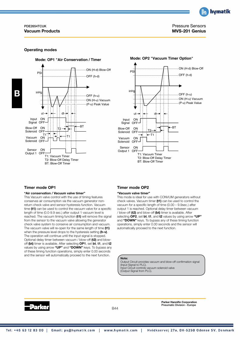
B
B44
PDE2654TCUK
Vacuum Products
Operating modes
Mode: OP1 "Air Conservation / Timer
ON (H-d) Blow-Off
OFF (h-d)
OFF (h-u)
ON (H-u) Vacuum (P-u) Peak Value
Input Signal
Blow-Off Solenoid
Vacuum Solenoid OFF
PSI
inHg
ON OFF
ON OFF
ON T1
ut
T1
dt
T2 BT
Sensor ON Output 1 OFF
T1: Vacuum Timer T2: Blow-Off Delay Timer BT: Blow-Off Timer
Timer mode OP1 “Air conservation / Vacuum valve timer” This Vacuum valve control with the use of timing features conserves air consumption via the vacuum generator non-return check valve and sensor hysteresis function. Vacuum time (t1) can be used to control the vacuum valve for a specific length of time (0.0-9.9 sec.) after output 1 vacuum level is reached. The vacuum timing function (t1) will remove the signal from the sensor to the vacuum valve allowing the generator check valve system to conserve air consumption and vacuum. The vacuum valve will re-open for the same length of time (t1) when the pressure level drops to the hysteresis setting (h-v). The operation will continue until the input signal is stopped. Optional delay timer between vacuum / blow-off (t2) and blow-off (bt) timer is available. After selecting OP1, set bt, t1, and t2 values by using arrow “UP” and “DOWN” keys. To bypass any of these timing function operations, simply enter 0.00 seconds and the sensor will automatically proceed to the next function.
Pressure Sensors MVS-201 Genius
Mode: OP2 "Vacuum Timer Option"
Sensor Output 1
Input Signal
ON OFF
ON OFF
ON OFF
ON OFF
Blow-Off Solenoid
Vacuum Solenoid
T1: Vacuum Timer T2: Blow-Off Delay Timer BT: Blow-Off Timer
PSI
inHg
(P-u) Peak Value ON (H-u) Vacuum
OFF (h-u)
OFF (h-d)
ON (H-d) Blow-Off
BT T2
T1
ut dt
Timer mode OP2 “Vacuum valve timer” This mode is ideal for use with CONVUM generators without check valves. Vacuum timer (t1) can be used to control the vacuum for a specific length of time (0.00 – 9.9sec.) after output 1 is reached. Optional delay timer between vacuum / blow-off (t2) and blow-off (bt) timer is available. After selecting OP2, set bt, t1, and t2 values by using arrow “UP” and “DOWN” keys. To bypass any of these timing function operations, simply enter 0.00 seconds and the sensor will automatically proceed to the next function.
Note: Output Circuit provides vacuum and blow-off confirmation signal (Input Signal to PLC). Input Circuit controls vacuum solenoid valve (Output Signal from PLC).
Parker Hannifin Corporation Pneumatic Division - Europe

B
B45
PDE2654TCUK
Vacuum Products
Operating modes
Mode: OP3 "Signal Controlled Vacuum"
H-V / H-d: Switchpoints h-v / h-d: Switchpoints P-V: Peak Value
Sensor Output 1
Input Signal
ON OFF
ON OFF
ON OFF
ON OFF
Blow-Off Solenoid
Vacuum Solenoid
PSI
OFF (h-u)
OFF (h-d)
T2 BT
ut dt
T2: Blow-Off Delay Timer BT: Blow-Off Timer
Timer mode OP3 “Signal controlled vacuum” The vacuum timer option (t1) is omitted and the PLC controls the input signal time for the vacuum operation. The delay timer between vacuum / blow-off (t2) and the blow-off (bt) timers are still available. After selecting OP3, set bt and t2 values by using arrow “UP” and “DOWN” keys. To bypass any of these timing function operations, simply enter 0.00 seconds and the sensor will automatically proceed to the next function.
ON (H-d) Blow-Off
inHg
ON (H-u) Vacuum (P-u) Peak Value
Pressure Sensors MVS-201 Genius
Additional sensor features (Available in all operating modes)
Screen saver function This reduces current consumption by 20mA and will activate after 10 seconds.
Peak value level (P-v)
V 1
The sensor records this value for preventative maintenace issues. If this value is not reached the sensor will display an error message (ALP) indicating leaks or wear in the system.
Vacuum level response time (ut)
V 1
The sensor records the time (sec) to reach Output 1 and will display an error message (ALu) indicating Output 1 has not been reached within the acceptable time (sec) set by the user.
Blow-off time (dt)
V 1
The sensor records the time (sec) to complete blow-off cycle and will display an error message (ALd) indicating (dt) has not reacting within the acceptable time (sec) set by the user.
Note: Output Circuit provides vacuum and blow-off confirmation signal (Input Signal to PLC). Input Circuit controls vacuum solenoid valve (Output Signal from PLC).
Parker Hannifin Corporation Pneumatic Division - Europe

B
B46
PDE2654TCUK Pressure Sensors Vacuum Products MVS-201 Genius
Wiring diagram Sensor male pin out M8 Pin #
1 Brown: 24VDC
2 White: Input; NPN (0VDC) / PNP (24VDC)
3 Blue: 0VDC
4 Black: Output; NPN / PNP Open Collector Output
201 Pin #
2
1
1 2 3 4
4
3
1 Red: Vacuum Solenoid Valve + V
2 Black: Gnd
3 Red: Blow-Off Solenoid Valve + V
4 Black: Gnd
Internal circuit
Mai
n C
ircu
it
(Brown) +V (DC 10.8 to 30V)
(Black) OUT 1
(Blue) OV
(White) Suction/Break Command Input
Digital IN
Lo
ad
Vacuum Solenoid
Valve
Break Solenoid
Valve
+
-
+
-
1 (Red)
2 (Black)
4 (Black)
3 (Red)
Connector for connection of solenoid valve Connection is finished when Convum is installed
Max. 125mA
+ +
- -
or TR or TR
Max. 125mA
Mai
n C
ircu
it
(Brown) +V (DC 10.8 to 30V)
(Black) OUT 1
(Blue) OV
1 (Red)
2 (Black)
4 (Black)
3 (Red)
Valve
+
(White) Suction/Break Command Input Digital IN
Load
Vacuum Solenoid
Solenoid Valve
-
Break+
-
Connector for connection of solenoid valve Connection is finished when Convum is installed
Output / Input NPN sinking Output / Input PNP sourcing
! Cautions The MVS-201 Pressure Sensor is designed to monitor pressure and is not a safety measure to prevent accidents.
The compatibility of the sensor is the responsibility of the designer of the system and specifications.
Operating environment • Parker Sensors have not been investigated for explosion-
proof construction in hazardous environments. • Do not use with flammable gases, liquids, or in hazardous
environments. • Avoid installing the sensor in locations where excessive
voltage surges could damage or affect the performance of the sensor.
Operations • Dedicate a power supply of 10.8 to 30VDC to the sensor
and set the ripple to Vp-p10% or less. Avoid excessive voltage. Avoid voltage surges.
• A small amount of internal voltage drop is possible. Ensure the power supply minus any internal voltage drop exceeds the operating load.
• Verify the operating media is compatible with the specified sensor. Check the chemical make-up, operating temperatures, and maximum pressure ranges of the system before installing.
• Installation of air dryer system is recommended to remove moisture.
Installation • Never insert an object into the pressure port other than an
appropriate fluid connector. • Avoid short-circuiting the sensor. Connect the brown lead to
V+ and blue lead to 0V. • Do not connect the output lead wires (black / white) to the
power supply. • Outputs not being used should be trimmed and insulated.
Error messages
Display Description Solutions
Reset zero below Err Zero reset error 3% of F.S.
Er1 System error (Internal) Contact factory
Load current exceeds CE1 Over current of Output 1 maximum 125mA. FFF Applied pressure exceeds Apply pressures within –FF pressure range the rating of the sensor
Parker Hannifin Corporation Pneumatic Division - Europe

PDE2654TCUK Pressure Sensors Vacuum Products MVS-201 Genius
1 Press 1x 2 1 Operating Mode 1 Operating Mode 2 Operating Mode 3
B
2 3 4 2 1 Switch Output 2 1 Outmode
Open or Closed
2 1 Screen Saver Peak Vacuum Level Vacuum Level Response Time Blow-off Time
Note: Ed9 setting Set to Lo for NPN Output Circuit or Hi for PNP Output Circuit.
5 Hold Hold Press Press
2 1 2 1
Lock Unlock
Programming symbols legend
Operation 1: Air Conservation / Timer Error Message - Blow-off Time
Operation 2: Vacuum Timer Option Output 1
Operation 3: Signal Controlled Vacuum Vacuum Valve (Leave NO)
Blow-Off Timer Blow-off Release Valve (Leave NO)
Controlled Vacuum Signal with Timer Screen Saver Function
Blow-Off Activation Timer Peak Vacuum Level Recorder (P-v)
Switch Output Value (H-v) Vacuum Response Time Recorder
Switch Output Hysteresis Value (h-v) Blow-Off Time Recorder
Blow-off Output Value (H-d) Normally Open
Blow-off Output Hysteresis Value (h-d) Normally Closed
Error Message - Peak Vacuum Level Low or High Signal to Vacuum Valve
Error Message - Vacuum Response Time
Parker Hannifin Corporation Pneumatic Division - Europe
B47

B
B48
PDE2654TCUK Generator Accessories Vacuum Products FSV Series – M5, G1, G2 & G3
Maintaining an acceptable level of vacuum is critical to the performance of vacuum systems that have a single source vacuum generator with multiple cups. The Parker Flow Sensing Valve assists in maintaining an acceptable vacuum level if the vacuum cup does not make a proper seal. The valve will automatically close if the cup loses the seal with the product during a pick and place motion. The Parker Flow Sensing Valve is a normally open valve that switches to a closed metered state when the vacuum flow rate from the cup side to the generator side is greater than the switching flow rate of the flow sensing valve. The Flow Sensing Valve “Checks” the vacuum flow. The vacuum flow rate of the generator must be more than the switching flow rate of the Flow Sensing Valve or it will not switch to a “Checked” position. When using multiple Flow Sensing Valves per generator, the flow rate of the generator must be more than the combined switching flow rates of the flow valves and any other leak path. For example, a CV20-HSN has a maximum flow rate of 110 l/mn and a 1/8 Flow Sensing Valve has a switching flow rate of 8 l/mn. Therefore 13 Flow Sensing Valves can be connected in parallel to a CV20-HSN. Once a Flow Sensing Valve is “Checked”, a small amount of bypass flow occurs. This leakage allows a generator to be turned on prior to the cup being in place on a product and is the flow path used to evacuate the cup volume. The by-pass flow will decrease the maximum degree of vacuum in a system, and is considered a leak path when the cup is not sealed on a product. Blow off functions will still operate by forcing the Flow Sensing Valve to a full open position, allowing the part to be blown off.
Features • Pick and place randomly placed products • Minimize vacuum loss when cup seal is lost • Direct mounting to cups • 1/8 to G3/8 connection • Integrated bronze filter
Normally Closed Air Supply
Operation When the flow of air from the cup side to the generator side is greater than the switching flow rate of the valve, the float is drawn back against the spring and seals on the housing. In this state, flow passes through an orifice on the float. Vacuum flow is “Checked”. (See Figure 1).
When the cup comes in contact and seals on a product, flow is reduced and the spring forces the float towards the cup side inlet. This breaks the seal at the float and the full open state is restored. (See Figure 2).
Housing
Suction Cup
Filter
Float
Meter Orifice
Spring
Figure 1 Figure 2 (Closed, Metered Flow) (Open, Full Flow)
Specifications
Description FSV-G1 FSV-G2 FSV-G3
Switching flow rate 8 l/mn 25 l/mn
Nominal size 4mm
Housing material Anodized aluminum
Filter material Al-Niro mesh
Temperature range -10° C to 60° C
Maximum pressure 10 bar (145 PSI) 8 bar (115 PSI)
Media Atmospheric air
Weight (grams) 9 16 29
D
D1 Generator
Side
Vacuum
Ordering information Dimensions (mm)
B1B L
Cup Side
D1
Description Part number B B1 D D1 L
1/8" BSPP FSV-G1 FSV-G1 6.5 11 4 G 36 13
1/4" BSPP FSV-G2 FSV-G2 8.5 11 4 G1/4 38 17
3/8" BSPP FSV-G3 FSV-G3 12 13 4 G3/8 42 22
Parker Hannifin Corporation Pneumatic Division - Europe

B
B49
PDE2654TCUK
Vacuum Products
The CH Check valve is used to hold a degree of vacuum downstream from the check valve when the vacuum generator upstream from the check valve is turned off. A separate blow-off connection downstream from the CH check valve is required to destroy the vacuum pressure and blow off the part.
This check valve is an open or passing flow path when there is a differential pressure from the pad side to the generator side.
Features • Poppet design • Low leakage • Low cracking pressure
Normally Closed Air Supply with Blow-off & Optional Sensor
CH-01G1
PFG Cup Optional MPS-23
CV
Ordering information
Description Part number
BSPP Ports CH-01G1
NPT Ports CH-01N1
Generator Accessories CH01 Series
Specifications
Temperature range
Operating vacuum
Port size
Leakage rate
Cracking pressure
Materials
Valve body / Fittings
Seals
Spring
Dimensions
0.51 (13)
0.75 (19)
0.63 (16)
0.75 (19)
1.81 (46)
1/4 NPT Pad Side
0°C to 60°C
-0.3 to -0.96 bar (-4.25 to -13.89 PSI)
Pad side = 1/4", Generator side = 1/8"
10 mbar / mn (0.2 PSI / mn)
0.2 bar (2.9 PSI)
Brass / Aluminum
BUNA
SUS
Dia.
1/8 NPT Pad Side
Parker Hannifin Corporation Pneumatic Division - Europe

B
B50
PDE2654TCUK Generator Accessories Vacuum Products VF & VFL Series Filters
Always filtrate the vacuum system to protect the components from damaging particles absorbed from the environment. Elements should be replaced periodically to prevent slower response and overall performance of the system.
Specifications
Media Non-corrosive air
Operating vacuum 0 to 0.95 bar
Maximum pressure 4 bar (60 PSI)
Operating temperature 0°C to 60°C
120 µm (VF-2);Filtration 130 µm (VFL-44, 66, 88, VF-3, VF-5, VF-6)
Materials
Part number Material housing Material element Weight (g)
Acrylic,VF-2G Aluminum 44Stainless steel
VF-3G Aluminum PC, Polyvinyl 88
VF-5G Aluminum PC, Polyvinyl 146
VF-6G Aluminum PC, Polyvinyl 234
VFL-44 Poly-carbonate PC, Polyvinyl 19
VFL-66 Poly-carbonate PC, Polyvinyl 21
VFL-88 Poly-carbonate PC, Polyvinyl 23
Ordering information
Male Replacement Replacement Application connection elements cover, o-ring Part number
CV-05, CV-10 G1/8" VF-2E — VF-2G
CV-05, CV-10 G1/8" VF-3E VF-3K VF-3G
CV-15, MCA-10/13 G1/4" VF-5E VF-3K VF-5G
CV-20/25/30 G3/8" VF-6E VF-3K VF-6G
General use 4mm - Tube VFL-E VFL-44K VFL-44
General use 6mm - Tube VFL-E VFL-66K VFL-66
General use 8mm - Tube VFL-88E VFL-88K VFL-88
Parker Hannifin Corporation Pneumatic Division - Europe

B
B51
PDE2654TCUK Generator Accessories Vacuum Products VF & VFL Series Filters
B
1.34 (34)C
0.75 (19) Dia.
VFL-46H Mtg. Bracket
0.12 (3)
0.177 Dia (Ø 4.5)
(33)
VF-2 0.31
G1/8"
SW14
0.63 (16)
0.87 0.98
0.39 (10)
(6)
0.79
0.63 (16)1.30
(33)
(8)
Dia.
G1/8
VF-3
Dimensions
0.71 (18) Dia. A Dia.
VFL Series VF-5
1.57 (40)
1.65 (42)
0.79 (20)
0.98 (25) 0.49
(12.5)
0.20 (5)
1.97 (50)
2.56 (65)
1.77 (45)
0.89 (22.5)
0.37 (9.5)
0.18 (4.5) Dia. (2x)
0.30 (7.5) Dia. (2x)
G1/4" G1/4"
Part number A B C
VFL-44 4 55 10.5
VFL-66 6 58 12
VFL-88 8 62 14
0.69 (17.5)
1.18 (30)
0.79 (20)
0.28 (7)
0.18 (4.5)
0.91 (23)
1.30
0.96 (24.5)
0.28 (7)
0.33 (8.5)
0.12 (3)
0.24
0.35 VF-6 (9)
0.47
(22) (25) (20)
0.18
0.30 (7.5) 1.57
(40)
1.30 (33)
0.79 (20)
0.63 (16)
0.31 (8)
0.20 (5)
1.99 (50.5)
2.26 (55.5)
1.77 (45)
0.89 (22.5)
0.38 (9.75)
(4.5) Dia. (2x)
Dia. (2x)
0.39 (10)
G1/8" G1/8"
1.57 (40)
1.85 (47)
0.79 (20)
1.18 (30) 0.59
(15)
0.24 (6)
2.36 (60)
1.77 (45) 2.76 (70)
0.89 (22.5)
(12)
0.22 (5.5) Dia. (2x)
Dia. (2x)
G3/8" G3/8"
Parker Hannifin Corporation Pneumatic Division - Europe
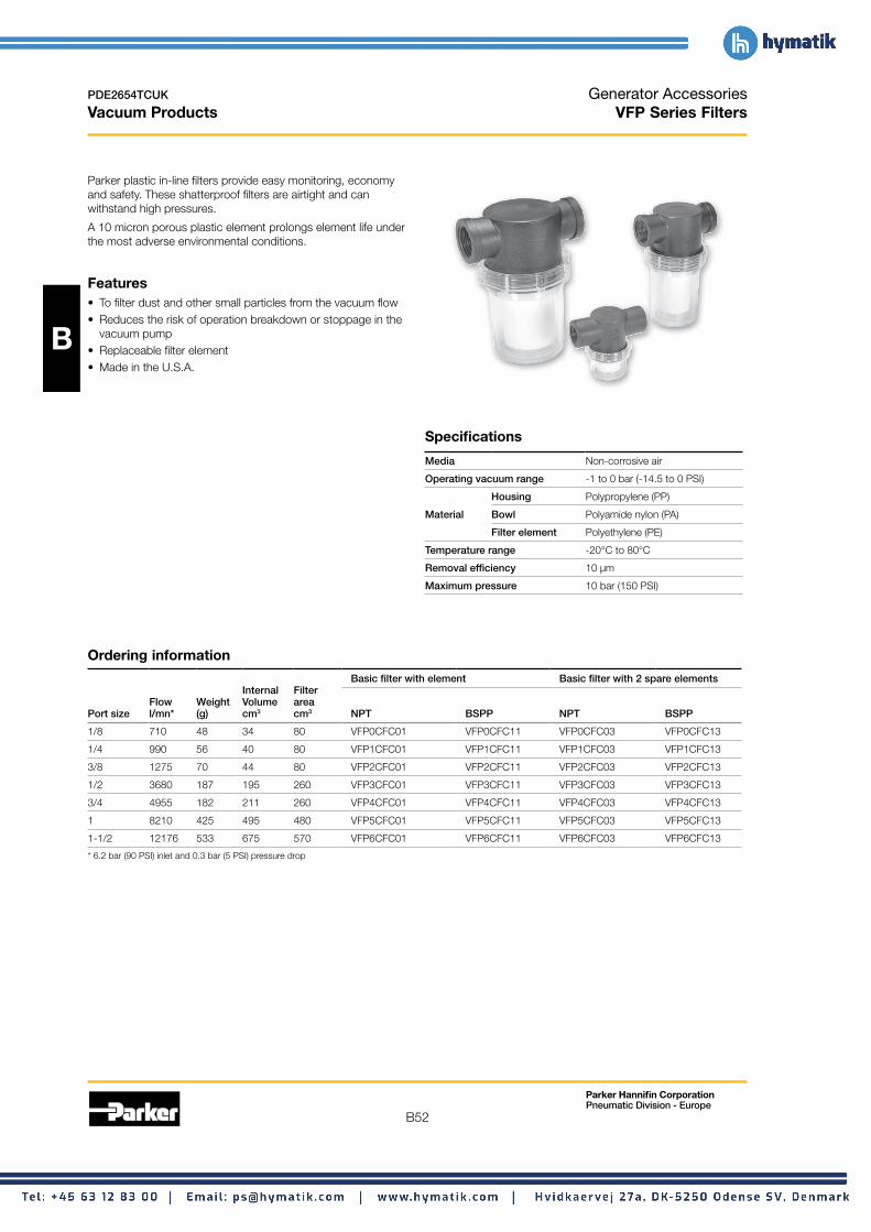
B
B52
PDE2654TCUK Generator Accessories Vacuum Products VFP Series Filters
Parker plastic in-line filters provide easy monitoring, economy and safety. These shatterproof filters are airtight and can withstand high pressures.
A 10 micron porous plastic element prolongs element life under the most adverse environmental conditions.
Features • To filter dust and other small particles from the vacuum flow • Reduces the risk of operation breakdown or stoppage in the
vacuum pump • Replaceable filter element • Made in the U.S.A.
Specifications
Media Non-corrosive air
Operating vacuum range -1 to 0 bar (-14.5 to 0 PSI)
Housing Polypropylene (PP)
Material Bowl Polyamide nylon (PA)
Filter element Polyethylene (PE)
Temperature range -20°C to 80°C
Removal efficiency 10 µm
Maximum pressure 10 bar (150 PSI)
Ordering information
Basic filter with element Basic filter with 2 spare elements Internal Filter
Flow Weight Volume area Port size l/mn* (g) cm3 cm3 NPT BSPP NPT BSPP
1/8 710 48 34 80 VFP0CFC01 VFP0CFC11 VFP0CFC03 VFP0CFC13
1/4 990 56 40 80 VFP1CFC01 VFP1CFC11 VFP1CFC03 VFP1CFC13
3/8 1275 70 44 80 VFP2CFC01 VFP2CFC11 VFP2CFC03 VFP2CFC13
1/2 3680 187 195 260 VFP3CFC01 VFP3CFC11 VFP3CFC03 VFP3CFC13
3/4 4955 182 211 260 VFP4CFC01 VFP4CFC11 VFP4CFC03 VFP4CFC13
1 8210 425 495 480 VFP5CFC01 VFP5CFC11 VFP5CFC03 VFP5CFC13
1-1/2 12176 533 675 570 VFP6CFC01 VFP6CFC11 VFP6CFC03 VFP6CFC13
* 6.2 bar (90 PSI) inlet and 0.3 bar (5 PSI) pressure drop
Parker Hannifin Corporation Pneumatic Division - Europe
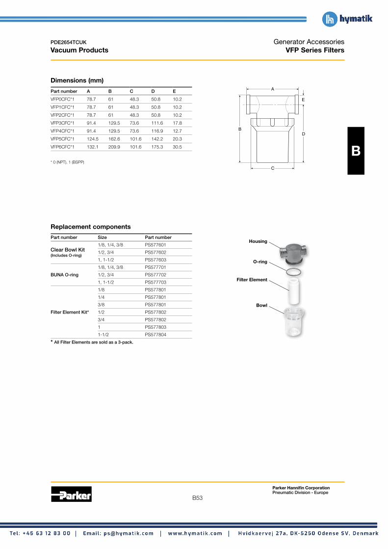
B
B53
PDE2654TCUK Generator Accessories Vacuum Products VFP Series Filters
Dimensions (mm)
Part number A B C D E
VFP0CFC*1 78.7 61 48.3 50.8 10.2
VFP1CFC*1 78.7 61 48.3 50.8 10.2
VFP2CFC*1 78.7 61 48.3 50.8 10.2
VFP3CFC*1 91.4 129.5 73.6 111.6 17.8
VFP4CFC*1 91.4 129.5 73.6 116.9 12.7
VFP5CFC*1 124.5 162.6 101.6 142.2 20.3
VFP6CFC*1 132.1 209.9 101.6 175.3 30.5
* 0 (NPT), 1 (BSPP)
A
E
C
B D
Replacement components
Part number Size Part number
1/8, 1/4, 3/8 PS577601 Housing
Clear Bowl Kit (Includes O-ring)
1/2, 3/4 PS577602
1, 1-1/2 PS577603 O-ring 1/8, 1/4, 3/8 PS577701
BUNA O-ring 1/2, 3/4 PS577702
1, 1-1/2 PS577703 Filter Element
1/8 PS577801
1/4 PS577801
3/8 PS577801 Bowl Filter Element Kit* 1/2 PS577802
3/4 PS577802
1 PS577803
1-1/2 PS577804
* All Filter Elements are sold as a 3-pack.
Parker Hannifin Corporation Pneumatic Division - Europe

B
B54
PDE2654TCUK Generator Accessories Vacuum Products Silencers
Protect the environment against harmful noise levels with quality silencers.
Ordering information Specifications
For generator series Male connection Part number Media Non-corrosive air
CV-05, CV-10 G1/8" MSS-01 Maximum pressure 8.8 bar (128 PSI)
CV-05, CV-10 G1/8" MSS-02 Operating temperature 5°C to 55°C
CV-15, MCA-10/13 G1/4" MSM-01 Silencing effect 20 dB
CV-20 G1/2" MSL-02
CV-25, CV-30 G3/4" MS6-01 Materials
Dimensions
Mode: OP1 "Air Conservation / Timer
ON (H-d) Blow-Off PSI
OFF (h-d)
inHg OFF (h-u)
ON (H-u) Vacuum (P-u) Peak Value
Input Signal
Blow-Off Solenoid
Vacuum Solenoid
ON OFF
ON OFF
ON OFF
T1
ut
T1
dt
T2 BT
Sensor ON Output 1 OFF
T1: Vacuum Timer T2: Blow-Off Delay Timer BT: Blow-Off Timer
MSS-01
0.12 SW14 (3)
1.67 (42.5)
0.35 (9) G1/4
0.79Dia.(20)
MSM-01
Material Material Weight Part housing element Media (g) number
Polyacetal Felt, Urethane Air 4.9 MSS-01
Polyacetal Stainless steel Oil 4.9 MSS-02
Polyurethane Felt Air 6.8 MSM-01
Nylon Vinyl Air 25 MSL-02
Nylon Polyvinyl Forma Air 57 MS6-01
0.31 (8)
2.38 (60.5)
1.18Dia.
SW32
G1/2 0.41 (10.5)
G3/4(30)
3.78 (96)
0.57 (14.5)
1.57 Dia.(40)
MSL-02 MS6-01
Parker Hannifin Corporation Pneumatic Division - Europe

B
B55
PDE2654TCUK
Vacuum Products
The plastic silencer is designed to give excellent noise reduction with a minimum effect on air efficiency. The “Trimline” design allows for locating the silencer in the tightest places without extra plumbing or fittings. Fits directly into the exhaust port of most commercial valves. Open surface area of element allows for rapid discharge of air without undesirable back pressure.
Features • Compact • Lightweight • Easy to install • Excellent noise reduction • Protects components from contamination • NPT & BSPT threads available
Ordering infornation,
Dimensions
Generator Accessories ASN Series – M5, 1/8”, 1/4”, 3/8” & 1/2”
Specifications
Pressure rating 0 to 10 bar (0 to 145 PSI)
Temperature rating -10°C to 60°C
Materials
Body Acetal (Plastic)
Element Polyethylene
B
A
Maximum flow Sound pressure level (dBA) Part number Thread (l/mn) size A B 100 PSIG inlet 20 PSIG inlet 100 PSIG inlet BSPT NPT
M5 11 8 425 69 79 AS-5
1/8” 40 16 1444 69 81 AS-6 ASN-6
1/4” 65 21 3500 67 84 AS-8 ASN-8
3/8” 85 25 7000 83 98 AS-10 ASN-10
1/2” 95 30 10480 69 96 AS-15 ASN-15
Parker Hannifin Corporation Pneumatic Division - Europe

B
B56
PDE2654TCUK Vacuum Generators Vacuum Products Glossary
__A__ Air consumption The amount of air in (measured in SCFM) consumed to achieve the maximum rated vacuum level of the venturi.
Air-economizing function Integrated vacuum generators have the capacity to minimize air consumption by utilizing the built in check valve. Once a predetermined vacuum level has been achieved (with a nonporous application) , the check valve can maintain the vacuum level within the system. The hysteresis feature of the vacuum sensor can maintain the vacuum level of the system indefinitely when properly wired to the vacuum solenoid pilot valve.
__B__ Blow-off needle This is a flow adjustment supplied on integrated units to control the flow rate of the blow-off release.
Blow-off time The amount of time required to break the vacuum and release the product in a pick and place application. This is signal controlled by the PLC or by the MVS-201 sensor.
Blow-off release master valve This is a shuttle valve that works by differential forces which is piloted by a 2-3 valve. This valve is always configured normally closed.
__E__ Emergency stop Emergency stop conditions for factory automation; this is an external override condition that is usually activated by the machine operator to temporarily shut the equipment down. The relevance to vacuum is the ability of the vacuum equipment to maintain the last output state of the control circuit. This feature would prevent part loss during this event as a normally closed system could maintain the current vacuum state without the presence of power.
__F__ Filtration Filtration between the pad and generator is recommended. Regular maintenance of filters maintains the efficiency of the system.
__I__ Integrated vacuum generator A vacuum venturi with integrated vacuum and blow-off release pilot valves built on the unit to minimize response times of the system. The unit may also incorporate filters, silencers, blow-off flow controls , and optional sensors.
__L__ Last output state During an emergency stop or power loss event, emergency stop circuits from Parker can maintain the current state of operation. This is referred to as maintaining the last output state from the system controls.
__P__ Part present signal Each sensor has an available NPN / PNP output and can be used for numerous purposes. One of them is a part present signal that usually signifies that a preset output for a vacuum level has been achieved and it is safe to proceed. The accuracy and repeatability of this signal can be critical to high speed applications. False or dropped signals can interrupt the systems operations. Therefore, stable vacuum levels and output settings near the “part-off” vacuum level are critical.
“Part-on” / “Part-off” vacuum differential You must determine the highs and lows of the vacuum system in order to properly set the sensor outputs. Typically with venturi systems at fixed operating pressures, the maximum vacuum level is known. The “Part-off” vacuum level of the system must be determined by operating the system “open” while the sensor displays the level of vacuum in the system. This is known as the “Part/on” / “Part-off” differential in vacuum levels. Once this window of vacuum is known, the part present signal could be set in the middle between these vacuum levels. Ideally, it would be best if this window was a big as possible to avoid any issues with the sensors. Yet, sometimes by design or necessity, this window is very small or insignificant due to a high speed operation. To maximize the speed of the machinery, reduce the response time of the sensor output by setting the output around 1 inHg above the open vacuum level. The system response time is minimized and thus the “Part-on” / “Part-off” window is insignificant.
-30 inHg “Part-On”
Vacuum Level
“Part-Off” Vacuum Level
Output Range
Upper Limit
Lower Limit
0 100 200 Output Response Time (msec)
Power loss This refers to loss of electrical power supply to the system.
Unlike other pneumatic components with safety features, loss of electrical power to a normally closed vacuum circuit could be catastrophic; possibly resulting in dropping the product. To prevent this situation, consider an E-stop circuit or a normally open vacuum circuit.
Parker Hannifin Corporation Pneumatic Division - Europe

B
B57
PDE2654TCUK
Vacuum Products
Pressure sensor A piezo resistive sensor used to monitor pressure levels in the system. The sensors supply NPN/PNP open collector transistor outputs back to the PLC for confirmation.
__R__ Response time The time to evacuate the air out of a closed system to a certain vacuum level. This is critical to the overall performance of the vacuum system.
__T__ Threads NPT (National Pipe Taper) BSPT (British Standard Pipe Taper) BSPP (British Standard Pipe Parallel) G (Gaus) M (Metric) NPS (Dry Seal American Standard Fuel Internal Straight Pipe)
__V__ Vacuum Any reference to vacuum or negative pressures could be defined as a force applied to a closed system by the difference in the number of air molecules within a chamber, enclosure, piping system, etc. to the number of air molecules outside of these systems or enclosures. The outside atmospheric pressure is larger and applies a force to the lesser pressures in the systems or enclosures. Therefore, vacuum is a differential pressure whereby atmosphere is the reference and external force.
Vacuum confirmation Term used to describe an output signal NPN/PNP from the sensor to the PLC when the suction cup has made a proper seal with the product before transfer. This verifies that the vacuum level is safe to proceed.
Vacuum flow Represented as l/mn, this is the rate at which air molecules can be evacuated through a venturi system.
Vacuum generator This is sometimes referred to as an ejector. The venturi generates vacuum with compressed air by evacuating air molecules from a closed system.
Vacuum release pilot valve Also referred to as Discharge valve, this valve pilots the Blow-off release master valve to effectively release the product during pick and place applications. This function is essential to high speed applications.
Vacuum Generators Glossary
Vacuum master valve This is a shuttle valve that works by differential forces which is piloted by a 2-3 valve. This valve can be configured normally closed or open.
Parker Hannifin Corporation Pneumatic Division - Europe

B
B58
PDE2654TCUK
Vacuum Products
Parker Hannifin Corporation Pneumatic Division - Europe

Pressure Sensors
Section C www.parker.com/pneu/sensors

C2
Parker Hannifin Corporation Pneumatic Division - Europe
PDE2654TCUK
Vacuum Products
BarbCouplingO-Ring
Ambient AirInlet Port
–INCLUDED–
Pipe Plug
Pneumatic Control Components Technical Data
! Cautions Pressure sensors are designed to monitor pressure and are not a safety measure to prevent accidents.
The compatibility of the sensor is the responsibility of the designer of the system and specifications.
Operating environment • Parker sensors have not been investigated for explosion-
proof construction in hazardous environments. • Do not use with flammable gases, liquids, or in hazardous
environments. • Avoid installing the sensor in locations where excessive
voltage surges could damage or affect the performance of the sensor.
Operations • Dedicate a power supply of 10.8 to 26.4VDC to the sensor
C and set the ripple to Vp-p10% or less. Avoid excessive voltage. Avoid voltage surges.
• A small amount of internal voltage drop is possible. Ensure the power supply minus any internal voltage drop exceeds the operating load.
• Verify the operating media is compatible with the specified sensor. Check the chemical make-up, operating temperatures, and maximum pressure ranges of the system before installing.
• Installation of air dryer system is recommended to remove moisture.
Installation • Never insert an object into the pressure port other than an
appropriate fluid connector. • Avoid short-circuiting the sensor. Connect the brown lead to
V+ and blue lead to 0V. • Do not connect the output lead wires (black / white) to the
power supply. • Outputs not being used should be trimmed and insulated. • Install as shown using the metal mounting bracket.
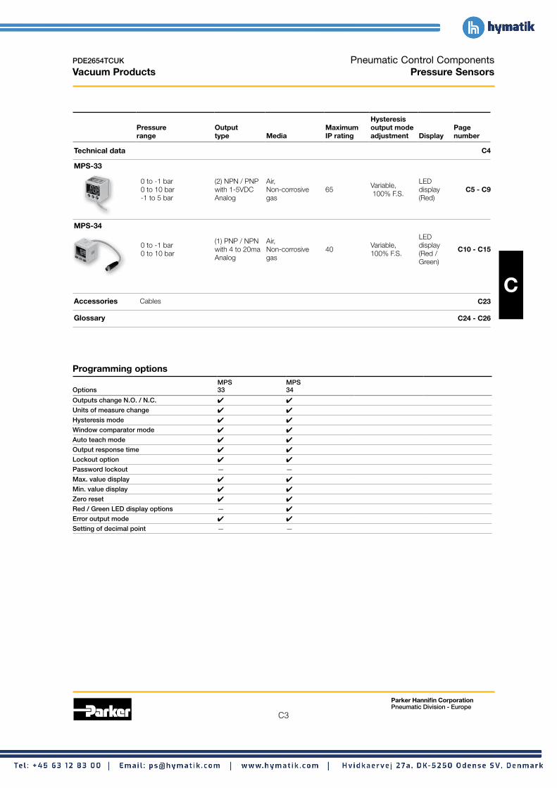
C3
Parker Hannifin Corporation Pneumatic Division - Europe
PDE2654TCUK
Vacuum Products
Pneumatic Control Components Pressure Sensors
Hysteresis Pressure Output Maximum output mode Page range type Media IP rating adjustment Display number
Technical data C4
MPS-33
0 to -1 bar (2) NPN / PNP Air, LEDVariable, 0 to 10 bar with 1-5VDC Non-corrosive 65 display C5 - C9 100% F.S. -1 to 5 bar Analog gas (Red)
MPS-34
0 to -1 bar 0 to 10 bar
(1) PNP / NPN with 4 to 20ma Analog
Air, Non-corrosive gas
40 Variable, 100% F.S.
LED display (Red / Green)
C10 - C15
C Accessories Cables C23
Glossary C24 - C26
Programming options MPS MPS
Options 33 34
Outputs change N.O. / N.C. 4 4
Units of measure change 4 4
Hysteresis mode 4 4
Window comparator mode 4 4
Auto teach mode 4 4
Output response time 4 4
Lockout option 4 4
Password lockout — —
Max. value display 4 4
Min. value display 4 4
Zero reset 4 4
Red / Green LED display options — 4
Error output mode 4 4
Setting of decimal point — —

C4
Parker Hannifin Corporation Pneumatic Division - Europe
PDE2654TCUK
Vacuum Products
Pneumatic Control Components Technical Data
Selecting the proper pressure sensor Selecting a Parker Pressure Sensor for an application is more than just selecting the correct operating range of the sensor. Electromechanical pressure sensors convert the applied pressure to an electrical signal. When pressure is applied, the diaphragm is deflected causing the diffused resistors to change resistance (piezoelectric effect), which yields an electrical signal proportional to the pressure change. Applications for pressure switches are numerous and important in today's high-tech manufacturing environment. Parker Pressure Sensors are solid state sensors and not mechanical switches. The outputs are either analog (1 –5vc, 4-20ma or 0-20ma) or PNP/NPN
C Programming options: Outputs change N.O. / N.C. The status of the Output at 0 bar is either Normally Open (Non-Passing) or Normally Closed (Passing) and can be set through programming.
Units of measure The units of measure on the display can be changed to suit the application. Some choices are PSI, inHg, Bar, Kpa, Mpa or mmHg and are dependent on the pressure range of the sensor.
Hysteresis mode This output mode provides one switch point and a reversing point When the switch point pressure is achieved, the output (NPN / PNP) changes state and will not change back until the reversing point pressure is achieved.
Window comparator mode This output mode provides two switch points These two points create a window that the sensor output holds it state (NO or NC ). This mode is also referred to as High/Low Setting. Anytime the pressure is higher or lower than the "window" the output changes state.
Auto setting mode Programming feature that automatically sets switch point and reversing points for the outputs of the sensor based upon the minimum and maximum pressure readings of the sensor over time.
Output response time Output response time is the time it takes for the output signal to change state after the pressure switch point is achieved. Sensor response time is typically less than 2.0 milliseconds and can be made slower by programming the response time in multiples of the standard sensor response time.
Open Collector Transistor Type Outputs. The application will determine if the Open Collector Output is used in a Hysteresis or Window Comparator Function. The output mode of the sensor, as well as whether the sensor is normally open (nonpassing) or normally closed (passing), can be programmed by you to fit your application. In addition to electrical outputs, most of these sensors have additional programming options that can be integrated into the system logic for additional benefits. These programming options are listed at the bottom of the page and are detailed on the next pages. Choose the best Pressure Sensor for the application based on Pressure Range, Output Type and additional programming options.
Lockout optionLockout option All sensor prAll sensor programming is locked out. Programming is locked out. Programming or LEDogramming or LED Display cannot be changed when the sensor is locked out.Display cannot be changed when the sensor is locked out.
PassworPassword lockoutd lockout Lockouts the sensor frLockouts the sensor from any prom any programming changes. Togramming changes. Too unlock the sensor a user prunlock the sensor a user programmed 4 digit code must beogrammed 4 digit code must be enterentered into the sensored into the sensor..
Max. valve displayMax. valve display Sensor will only display the maximum applied prSensor will only display the maximum applied pressuressure re readingeading until runtil reset to measuring mode. A helpful tool in system set up.eset to measuring mode. A helpful tool in system set up.
Min valve displayMin valve display Sensor will only display the minimum applied prSensor will only display the minimum applied pressuressure re readingeading until runtil reset to measuring mode. A helpful tool in system set up.eset to measuring mode. A helpful tool in system set up.
ZerZero ro reseteset Just like a prJust like a pressuressure gauge, a pre gauge, a pressuressure sensor measure sensor measures thees the system prsystem pressuressure in re in relation to the atmospheric prelation to the atmospheric pressuressure.e. PrPressuressure Sensors can be calibrated to the curre Sensors can be calibrated to the current atmosphericent atmospheric prpressuressure by using the Zere by using the Zero Reset Function.o Reset Function.
Red / GrRed / Green LED display optionseen LED display options Display LED’Display LED’s change frs change from Red to Grom Red to Green, or Green, or Green to Redeen to Red when the output changes state. This can be a grwhen the output changes state. This can be a great visualeat visual indicator on a plant floorindicator on a plant floor..
ErrError outputor output ErrError Message is displayed if the pror Message is displayed if the pressuressures, inputs, or outputses, inputs, or outputs exceed the parameters of the sensorexceed the parameters of the sensor
Setting of decimal pointSetting of decimal point Depending on the units of measurDepending on the units of measure, the decimal point can bee, the decimal point can be adjusted up to thradjusted up to three decimal points. (SCPSD onlyee decimal points. (SCPSD only

PDE2654TCUK Pressure Sensors Vacuum Products MPS-33 1-Color Panel Mount
Features • Sensor output:
2 NPN or PNP open collector Transistor output, 30VDC, 125mA with Analog output, 1 to 5VDC
• Output response time less than 2.0 milliseconds
• RoHS
• Air and non-corrosive gase
Programming options Outputs change N.O. / N.C. 4
Units of measure change 4
Hysteresis mode 4
Window comparator mode 4
Auto teach mode 4
Output response time 4
Lockout option 4 Password lockout — Max. value display 4
Min. value display 4
Zero reset 4 Red / Green LED display options — Error output mode 4
MPS-33 Sensor only ordering numbers
Part number Part number
Pressure range Electrical output Electrical connection 1/8 BSPP Female 1/8 NPSF Female
0 to -1 bar (2) PNP with (1) 1-5VDC 2 m 5 Wire Lead Wire MPS-V33G-PGAT MPS-V33N-PGAT
0 to -1 bar (2) NPN with (1) 1-5VDC 2 m 5 Wire Lead Wire MPS-V33G-NGAT MPS-V33N-NGAT
-1 to 5 bar (2) PNP with (1) 1-5VDC 2 m 5 Wire Lead Wire MPS-R33G-PGAT MPS-R33N-PGAT
-1 to 5 bar (2) NPN with (1) 1-5VDC 2 m 5 Wire Lead Wire MPS-R33G-NGAT MPS-R33N-NGAT
0 to 10 bar (2) PNP with (1) 1-5VDC 2 m 5 Wire Lead Wire MPS-P33G-PGAT MPS-P33N-PGAT
0 to 10 bar (2) NPN with (1) 1-5VDC 2 m 5 Wire Lead Wire MPS-P33G-NGAT MPS-P33N-NGAT
MPS-33 Accessories
Description Part Number
Panel mounting bracket MPS-ACCH8Note : Add “H” in suffex of Sensor Only Part Number to include with sensor
Surface mounting bracket MPS-ACCK8Note : Add “K” in suffex of Sensor Only Part Number to include with sensor
Example: MPS-P33N-PGATK, includes sensor MPS-P33N-PGA with bracket MPS-ACCK8
Internal circuit for open collector and analog output wiring PNP Output (Analog (1-5V) NPN Output (Analog: 1-5V)
Sw
itch
mai
n ci
rcui
t
Sw
itch
mai
n ci
rcui
t
0V (Blue)
DC 12~24V ± 10%
Out 1 (Black)
Out 2 (White)
Load
Load
+V (Brown)
Analog (Orange) (DC: 1-5V)
0V (Blue)
Out 1 (Black)
Out 2 (White)
+V (Brown)
Analog (Orange) (DC: 1-5V)
1KΩ 1KΩ
+
−
+
−
Max. 80mA
Load
Load
Max. 80mA
Max. 80mA
Max. 80mA
DC 12~24V ± 10%
Lead Wiring Brown 24VDC
White NPN / PNP Open Collector Output 2
Blue 0VDC
Black NPN / PNP Open Collector Output 1
Orange Analog (1-5V)
Parker Hannifin Corporation Pneumatic Division - Europe
C5
C

PDE2654TCUK Pressure Sensors Vacuum Products MPS-33 1-Color Panel Mount
Specifications Vacuum (V) Compound (R) Positive (P)
Pressure range -1 to 0 bar (-14.5 to 0 PSI) -1 to 5 bar (-14.5 to 72 PSI) 0 to 10 bar (0 to 145 PSI)
Proof pressure 3 bar (44 PSI) 8 bar (116 PSI) 15 bar (218 PSI)
Display resolution, Units of measure
0.1, kPa 0.001, kgf/cm2
0.001, bar 0.01, PSI 0.1, inHg 1, mmHg 0.1, mmH2O
1, kPa 0.01, kgf/cm2
0.01, bar 0.1, PSI — — —
0.001, Mpa 0.01, kgf/cm2
0.01, bar 0.1, PSI — — —
Media Air & non-corrosive gases, incombustible gases
Pressure port (G) 1/8" BSPP female, (N) 1/8" NPSF
Operating temperature 0°C to 50°C
Storage temperature -20°C to 60°C
Humidity 40 - 85% RH (no condensation)
C Electrical connection (G) Grommet open lead, 5 wire (0.15mm2)
Power supply 12 to 24VDC ±10% or less, Ripple (Vp-p) 10% or less
Display 3 + 1/2 digit, 1 color, 7-segment RED LED
Display refresh .1 to 3.0 Seconds, Variable (factory set at 0.1)
Control output NPN (Sinking), PNP (Sourcing), Open collector, max 80mA, 2 output
Analog output 1 to 5VDC ≤ ±2.5% F.S. Linearity ≤1% of F.S.;
Switch output Output signal, NPN or PNP, Normally open or closed, LED indicator
Output indicator Green LED (OUT1), Red LED (OUT2)
Output modes Hysteresis or Window Comparator
Response time ≤ 2.5ms (chattering-proof function: 24ms, 192ms, 786m selections)
Repeatability ± 0.2% of F.S. ± 1 digit or less
Thermal error ≤ ± 2% of F.S. or less at range of 0°C to 50°C
General protection IP65, CE marked, EMC-EN61000-6-2: 2001, with dust tube connection
Current consumption <55mA
Vibration resistance 10 to 150Hz, Double amplitude 1.5mm, XYZ, 2 hrs.
Shock resistance 980 m/s² (about 10G), 3 times/each directions X, Y, Z
Noise resistance Vp-p400V, 10 ms, 0.5μs noise simulator
Material Housing: ABS (gray) , Pressure port: Zinc die-cast, Diaphragm: Silicone
Mass 105g (including cable)
3-1/2 digit LED display Dimensions 1.22 (31)
White: OUT2
Cable Length: 1990mm
Brown: +V
Black: OUT1 Blue: 0V
Switch (OUT 2)
Setting Button
Change setting mode and pre-set final desired value
Display the measured pressure value, each set content and error code.
(Red LED)
() Button
Use the button to change setting mode and pre-set desired value.
() Button
Use the button to change setting mode and pre-set
OUT1 OUT2
(Green LED)
desired value. SET
Switch (OUT 1)
1.44 (36.7)
1/8" Female
1.22 (31)
G 1/8 BSPPN 1/8 NPSFN 1/8 NPSF
Orange: Analog 1-5V
Grommet Lead Dia. TUbe Connect .12 (3)
.61 (15.5)
.41 (10.5)
.43 (11)
.75 (19)
.49 (12.5)
Parker Hannifin Corporation Pneumatic Division - Europe
C6

C7
Parker Hannifin Corporation Pneumatic Division - Europe
PDE2654TCUK
Vacuum Products
Pressure Sensors MPS-33 1-Color Panel Mount
MPS-ACCH8 Panel mounting bracket
36 x 36 ± 0.3mm
Panel Adapter PA-1
Front Protective Lid FPC-1
Panel Adapter PA-2
FPC-1 PA-1 PA-2
C1.67
(42.4) .28 (7)
.18 (4.5)
1.67 (42.4)
1.87 (47.4)
1.57 (40)
1.57 (40)
1.40 (35.5)
MPS-ACCK8 L3 & F3 mounting brackets and screws included Mounting Bracket F3
M4
M4
Mounting Bracket L3
L3 F3
.17 (4.2)
.20 (5.0)
.20 (5.0)
1.03 (26.2)
.79 (20)
.51 (13)
.17 (4.2)
.51 (12.9)
1.46 (37.1)
.24 (6.1)
1.79 (45.5)
.98 (25)

C
PDE2654TCUK Pressure Sensors Vacuum Products MPS-33 1-Color Panel Mount
Initial setting mode
4. Response time setting
5. Pressure value setting: auto / manual
Measure mode
Output Type: NO: Normal open mode NC: Normal closed mode
Model: MPS-V33
Use the or button to set desired pressure unit.
Use the or button to select response time.
Use the or button to select auto / manual.
Use the or button to set OUT1 mode.
Output Type: NO: Normal open mode NC: Normal closed mode
Use the or button to set OUT1 mode.
NC ModeNO Mode
MpA bar psi inHg mmHg mmH2Okgf/cm2
2.5ms 192ms 768ms 24ms
3. Out 2 mode setting
2. Out 1 mode setting
NC ModeNO Mode
Manual Setting Mode
Auto Setting Mode
Model: MPS-P33, MPS-R33
MpA bar psikgf/cm2
1. Unit setting Press SET button for more than 3 seconds.
SET
1xSET
1xSET
1xSET
1xSET
1xSET
SET
SET
Unlock Mode
Lock Mode
Measure mode • Key lock mode can prevent operation mistakes.
Press SET button for less than 5 seconds. Key lock / unlock mode
Use the or button to select Lock / Unlock Mode.
1x
Dustproof protector Note: Required for IP65 rating protection and is included with sensor.
Dustproof Protector
OUT1
SET
OUT2
OUT1
SET
OUT2
OUT1
SET
OUT2
Zero point setting / the max. & min. display mode Zero setting: • press the button at the same time until the
“00” is shown. Release the button to end zero setting.
The max. value display mode: • Press button 2 seconds to enter the max.
value mode, pressure sensor will detect the max. value and keep max. value displayed.
• Press button 2 seconds to return to measure mode display.
The min. value display mode: • Press button 2 seconds to enter the min.
value mode, pressure sensor will detect the min. value and keep min. value displayed.
• Press button 2 seconds to return to measure mode display.
Key lock / unlock mode
Parker Hannifin Corporation Pneumatic Division - Europe
C8

PDE2654TCUK Pressure Sensors Vacuum Products MPS-33 1-Color Panel Mount
Output type
P1 (n1) > P2 (n2)Hysteresis Mode P3 (n3) > P4 (n4)
Output Hysteresis value can be preset. Normal open mode Positive / Compound Vacuum (MPS-V33) (MPS-P33 / MPS-R33) ON ON
OFF OFF P_2 P_1 P_2 P_1 P_4 P_3 P_4 P_3
0 0 Positive Pressure Vacuum Pressure
Normal close mode Positive / Compound Vacuum (MPS-V33) (MPS-P33 / MPS-R33) ON ON
OFF OFF n_2 n_1 n_2 n_1 n_4 n_3 n_4 n_3
0 0 Positive Pressure Vacuum Pressure
(Note) When hysteresis mode setting is within 2 digits, if the input and pre-set pressure is quite near, pressure sensor output might cause chattering.
Manual setting mode
The LED shows: (P_* at normal open mode and (n_*) at normal close mode. Pressure setting value is shown normally and will not lead to pressure sensor pause or stop working.
1x Unit setting Press SET button one time (1x).
OUTPUT 1 Mutually display
OUTPUT 2
Use the or button to set desired pressure setting.
1x
Mutually display Use the or button to set desired pressure setting.1x
Mutually display Use the or button to set desired pressure setting.
1x
Mutually display Use the or button to set desired pressure setting.
SET
SET
SET
SET
SET1x Measure mode
Error messages
P1 (n1) < P2 (n2)Window comparator Mode P3 (n3) < P4 (n4)
Within pressure setting range, pressure sensor output can be ON or OFF. Normal open mode Positive / Compound Vacuum (MPS-V33) (MPS-P33 / MPS-R33) H = 3 digits
H H H H ON ON
OFF OFF P_1 P_2 P_1 P_2 P_3 P_4 P_3 P_4
0 0 Positive Pressure Vacuum Pressure
Normal close mode Positive / Compound Vacuum (MPS-V33) (MPS-P33 / MPS-R33)
H H ON
H H ON
OFF OFF P_1 P_2 P_1 P_2 P_3 P_4 P_3 P_4
0 0 Positive Pressure Vacuum Pressure
Auto setting mode *1. In case of without need of OUT1 pressure value setting, press + at the
same time to enter (AP2) / (An2). *2. In case of without need of OUT2 pressure value setting, press + at the
same time to enter measure mode. *3. The LED shows (AP*) at normal open mode and (An*) at normal closed mode.
SET
SET
SET
SET
SET
1x Measure mode Press SET button one time (1x) after setting pressure value to Auto Setting Mode.
1x
1x
1x
1x
(*1)
(*3)
(*2)
(*3)
Prepare auto setting mode at OUTPUT1 switch.
Under this mode, the device needs to be set repeatedly in order to reach the auto setting value.
Under this mode, the device needs to be set repeatedly in order to reach the auto setting value.
Prepare auto setting mode at OUTPUT2 switch.
P2 (n2) P4 (n4)
A-B 4
= B
P1 (n1) P3 (n3)
A-B 4
= A Calculation of setting value A = The max. pressure value under auto setting mode. B = The min. pressure value under auto setting mode.
Measure mode
OUTPUT 1
OUTPUT 2
Error name Display Description Solutions
OUT1 Er1 Turn off power and check the cause of overload Excess load Excess load current of 80 mA current or lower the current load under 80 mA, current error OUT2 Er2 then restart
Change input pressure to ambient pressure and Residual pressure error Er3 During zero reset, ambient pressure is over ±3% F.S. perform zero reset again
The applied pressure is excess the upper limit of – – – pressure setting Applied pressure error Adjust the pressure within applied pressure range
The applied pressure is excess the lower limit of – – – – pressure setting
Er4 Internal data error
System error Er6 Internal system error Turn power off and then restart. If error condition remains, please return to factory for inspection
Er7 Internal data error
Parker Hannifin Corporation Pneumatic Division - Europe
C9
C

C10
Parker Hannifin Corporation Pneumatic Division - Europe
PDE2654TCUK
Vacuum Products
Pressure Sensors MPS-34 2-Color Panel Mount
Features • Sensor output:
1 NPN or PNP Open collector Transistor output, 30VDC, 125mA with Analog output, 4 to 20mA
• Output response time less than 2.0 milliseconds
• RoHS
• Air and non-corrosive gases
• Sensor face includes icons to show sensor programming status
Programming options Outputs change N.O. / N.C. 4
Units of measure change 4
Hysteresis mode 4
Window comparator mode 4
C Auto teach mode 4
Output response time 4
Lockout option 4 Password lockout — Max. value display 4
Min. value display 4
Zero reset 4
Red / Green LED display options 4
Error output mode 4
Green Display Red
Sensor pin out with analog output Pin #
4 21 Brown: 24VDC 2 White: 4 to 20mA 3 Blue: 0VDC 4 Black: PNP Open Collector Output 1
3 1
MPS-34 Sensor only ordering numbers
Part number Part number
Pressure range Electrical output Electrical connection 1/8 BSPP male 1/8 NPSF male
0 to -1 bar (1) PNP with (1) 4-20ma M8, 4 Pin MPS-V34G-PCI MPS-V34N-PCI
0 to 10 bar (1) PNP with (1) 4-20ma M8, 4 Pin MPS-P34G-PCI MPS-P34N-PCI
MPS-34 Accessories
Description Part number
Panel mounting bracket MPS-ACCH9Note : Add “H” in suffex of Sensor Only Part Number to include with sensor
Surface mounting bracket MPS-ACCK10Note : Add “K” in suffex of Sensor Only Part Number to include with sensor
Example: MPS-P34N-PCIK, includes sensor MPS-P34N-PCI witth bracket MPS-ACCK10
M8, 4-Pin, 2 meter cable CB-M8-4P-2M-PUR
M8, 4-Pin, 5 meter cable CB-M8-4P-5M-PUR
Internal circuit for open collector and analog output wiring
PNP Output (Analog (4-20mA)
Sw
itch
mai
n ci
rcui
t
0V (Blue)
DC 12~24V ± 10%
Out 1 (Black)
Load
+V (Brown)
Analog (White) (4-20mA)
+
−
Max. 80mA

PDE2654TCUK Pressure Sensors Vacuum Products MPS-34 2-Color Panel Mount
Specifications Vacuum (V) Positive (P)
Pressure range
Proof pressure
-1 to 0 bar (-14.5 to 0 PSI)
3 bar (44PSI)
0 to 10 bar (0 to 145 PSI)
15 bar (218 PSI)
0.1, kPa 1, kPa 0.001, kgf/cm2 0.01, kgf/cm²
Display resolution , Units of measure
0.001, bar 0.01, PSI
0.01, bar 0.1, PSI
0.01, inHg -1, mmHg -
Media Air & non-corrosive gases
Pressure port (G) 1/8 BSPP male, (N) 1/8" NPT male both with M5 female port
Operating temperature 0°C to 50°C
Storage temperature -20°C to 60°C
Humidity 35 to 85% RH (no condensation)
Electrical connection (C) 4-pin, M8 connector on 150mm lead wire
Power supply
Display
12 to 24VDC ±10%, Ripple (P-P) 10% or less
3 + 1/2 digit, 2 color, 7-segment RED / GREEN LED C Display refresh Timing update : 0.1 ~ 3 sec. (Factory Set Unit: 0.1 sec.)
Switch output Output signal, PNP, Normally open or closed, LED indicator, 125 mA max. output load
Output modes Hysteresis or Window Comparator
Response time ≤ 2.5ms (chattering-proof function: 24ms, 250ms, 500ms, 1000ms and 1500ms selections)
Repeatability ± 0.2% of F.S. ± 1 digit
Output current 4 to 20mA; Linearity ±1.0% of F.S.; Maximum load impedance 300Ω at power Output current supply of 12V; 600Ω at power supply of 12V; Minimum load impedance 50Ω
Thermal error 0°C to 50°C 25°C (77°C) + 2% of F.S. or less at range of 0°C to 50°C
General protection IP40, CE marked, EMC-EN61000-6-2: 2001
Current consumption 45mA (with no load)
Vibration resistance 10 to 150Hz, Double amplitude 1.5mm, XYZ, 2 hrs.
Shock resistance 980 m/s² (about 10G), 3 times/each directions X, Y, Z
Noise Resistance Vp-p400V, 10 ms, 0.5μs noise simulator
Material Housing: ABS (gray) , Pressure port: Zinc die-cast, Diaphragm: Silicone
Mass 45g with M8 connector
Dimensions
1/8" Male 1.22 (25.4)
5.51 (140)
1.18 (30)
N: NPT 1/8, with M5 female G: G1/8, with M5 female
M5 Female
Hex Flat 10
MAX WIN N.C. AUTO
mmHg inHg PSI BAR Kgf kPa
MAX HYS N.O. MANOUT
Setting Button
() Button () Button
Key Lock Indicator
Output Indicator
Pressure Ubnit Display Section
2 Colors, Main Display
Setting Mode Display Section
Parker Hannifin Corporation Pneumatic Division - Europe
C11

C12
Parker Hannifin Corporation Pneumatic Division - Europe
PDE2654TCUK
Vacuum Products
Pressure Sensors MPS-34 2-Color Panel Mount
MPS-ACCH9 Panel mounting bracket
FPC-2 PA-3 PA-4
Front Protective Lid FPC-2
Panel Adapter PA-4
Panel Adapter PA-3
31 x 31 ± 0.4mm
t ≤ 4.5mm
C
1.35 (34.4)
1.35 (34.4)
.16 (4)
1.30 (33) 1.19
(30.2)
1.30 (33)
1.19 (30.2)
.33 (8.5)
1.35 (34.4)
1.35 (34.4)
Mounting Bracket F3
Mounting Bracket L3
M3
M3
MPS-ACCK10 L3 & F3 mounting brackets and screws included
L3 F3
.17 (4.2)
.20 (5.0)
.20 (5.0)
1.03 (26.2)
.79 (20)
.51 (13)
.17 (4.2)
.51 (12.9)
1.46 (37.1)
.24 (6.1)
1.79 (45.5)
.98 (25)

C13
Parker Hannifin Corporation Pneumatic Division - Europe
PDE2654TCUK
Vacuum Products
Pressure Sensors MPS-34 2-Color Panel Mount
Initial setting mode
Use the or button to set output type.
Use the or button to set operating mode.
Use the or button to set display color.
Use the or button to set desired pressure unit.
NC ModeNO Mode
Window Comparator Mode
Hysteresis Mode
inHg(*1) mmHg(*1) kPa
ON: GREEN
ON: RED
ON / OFF: GREEN
ON / OFF: RED
bar psikgf/cm2
1. Unit setting
2. Display color setting
3. Operating mode setting
Press SET button for more than 3 seconds. SET
4. Output type setting
Note: *1: Only for MPS-V34
1xSET
SET
SET
SET
1xSET
1xSET
1x 5. Response time setting
1x
AutoManual
2.5ms 24ms 250ms 500ms 1000ms 1500ms
Use the or button to select auto / manual.
Use the or button to set response time.
6. Auto preset setting
1x 7. Measure mode
Zero point setting / the max. & min. Key lock / unlock mode display mode Zero setting: • press the button at the same time until the
“00” is shown. Release the button to end zero setting.
The max. value display mode: • Press button 2 seconds to enter the max.
value mode, pressure sensor will detect the max. value and keep max. value displayed.
• Press button 2 seconds to return to measure mode display.
The min. value display mode: • Press button 2 seconds to enter the min.
value mode, pressure sensor will detect the min. value and keep min. value displayed.
• Press button 2 seconds to return to measure mode display.
SET
SET
Unlock Mode
Lock Mode
Measure mode • Key lock mode can prevent operation mistakes.
Press SET button for less than 5 seconds. Key lock / unlock mode
Use the or button to select Lock / Unlock Mode.
1x
C

C
PDE2654TCUK
Vacuum Products
Pressure setting mode
Hysteresis Mode Output Hysteresis value can be preset. Normal open mode Positive (MPS-P34) Vacuum (MPS-V34)
H HON ON
OFF OFF
0 0
Positive Pressure Vacuum Pressure
Normal close mode Positive (MPS-P34) Vacuum (MPS-V34)
H H
ON ON
OFF OFF 0 0
Positive Pressure Vacuum Pressure (Note) In case hysteresis is set at less than or equal to 2 digits, switch output may chatter if input pressure fluctuates near the set point.
Manual setting mode The LED shows: (P_* at normal open mode and (n_*) at normal close mode. Pressure setting value is shown normally and will not lead to pressure sensor pause or stop working.
SET
SET
SET
SET
SET
SET
SET
1x Hysteresis Mode Press SET button one time (1x).
Mutually display Use the or button to set desired pressure setting.
1x
Mutually display Use the or button to set desired pressure setting.
1x Measure mode
1x Window Comparator Mode Press SET button one time (1x).
Mutually display
Mutually display
Mutually display
Use the or button to set desired pressure setting.
1x
Use the or button to set desired pressure setting.
1x
Use the or button to set desired pressure setting.
1x Measure mode
Pressure Sensors MPS-34 2-Color Panel Mount
Window comparator Mode Within pressure setting range, pressure sensor output can be ON or OFF. Normal open mode Positive (MPS-P34) Vacuum (MPS-V34)
H H H H
H HH H
Positive (MPS-P34) Vacuum (MPS-V34)
Positive Pressure Vacuum Pressure
Normal close mode
0 0
0 0 Positive Pressure Vacuum Pressure
Auto setting mode 1. The LED shows:
(AP1) at normal open mode and (An1) at normal close mode. 2. In case of without need of auto pressure value setting, press + at the same time to
enter measure mode.
SET
SET 1x Measure mode Press SET button one time (1x) after setting pressure value to Auto Setting Mode.
Prepare air for auto setting.
1x
Under this mode, the device needs to be set repeatedly in order to reach the auto setting value.
SET 1x Measure mode
Calculation of setting Value A = The max. pressure value under auto setting mode. B = The min. pressure value under auto setting mode.
A-B 4H = B
P1 (n1) A-B 4= A
Parker Hannifin Corporation Pneumatic Division - Europe
C14

PDE2654TCUK Pressure Sensors Vacuum Products MPS-34 2-Color Panel Mount
Press SET + button for more than 3 seconds.
Current measured value
Adjusted value (Percent)
Use or button to change the set value. Press SET when finished or make no button operation for more than 3 seconds after changing the set value to exit.
Mutually display
Mutually display
Fine adjustment mode
Measure mode
SET
SET
SET
+
1x
1x Measure mode
(Note) MPS-34 : When display unit is in “MPa”, setting resolution is 0.001 MPa. MPS-34 : When display unit is in “kPa”, setting resolution is 0.1 kPa.
Error messages
This function eliminates slight differences in the output values and allows uniformity in the numbers displayed. Displayed values of the pressure sensor can be calibrated to within ±5% for MPS-P34 and ±2.5% for series MPS-V34.
Dis
play
ed p
ress
ure
valu
e
Applied Pressure
0
±5% R.D. ±2.5% R.D.
:Factory setting display value set prior to shipment :Display calibration range
Error name Display Description Solutions
Turn off power and check the cause of overload Excess load oCP Output load current of 125 mA current or lower the current load under 125 mA, current error then restart
Residual pressure Change input pressure to ambient pressure and oUr During zero reset, ambient pressure is over ±3% F.S. error perform zero reset again
The applied pressure is excess the upper limit of HHH pressure setting Applied pressure Adjust the pressure within applied pressure range error The applied pressure is excess the lower limit of LLL pressure setting
Er4 Internal data error
Er6 Internal system error Turn power off and then restart. If error condition System Error remains, please return to factory for inspection Er7 Internal data error
Er8 Internal system error
Parker Hannifin Corporation Pneumatic Division - Europe
C15
C
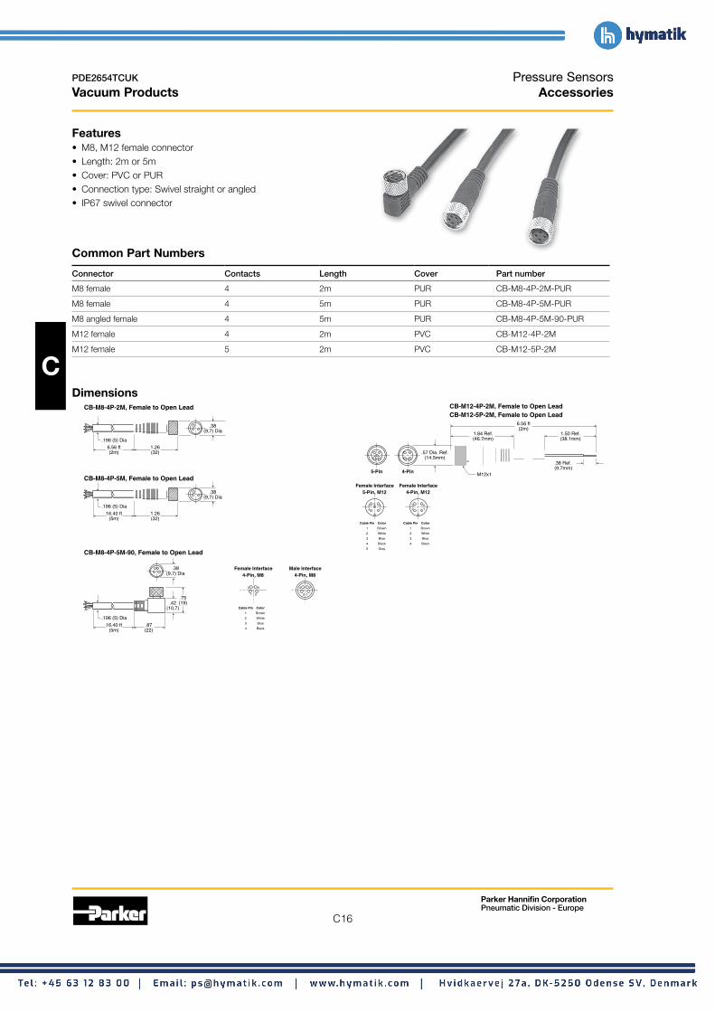
C16
Parker Hannifin Corporation Pneumatic Division - Europe
PDE2654TCUK
Vacuum Products
Pressure Sensors Accessories
Features • M8, M12 female connector • Length: 2m or 5m • Cover: PVC or PUR • Connection type: Swivel straight or angled • IP67 swivel connector
Common Part Numbers
Connector Contacts Length Cover Part number
M8 female 4 2m PUR CB-M8-4P-2M-PUR
M8 female 4 5m PUR CB-M8-4P-5M-PUR
M8 angled female 4 5m PUR CB-M8-4P-5M-90-PUR
M12 female 4 2m PVC CB-M12-4P-2M
M12 female 5 2m PVC CB-M12-5P-2M
C Dimensions
CB-M8-4P-2M, Female to Open Lead CB-M12-4P-2M, Female to Open Lead CB-M12-5P-2M, Female to Open Lead
6.56 ft .38 (2m)(9,7) Dia 1.84 Ref. 1.50 Ref.
(46.7mm) (38.1mm).196 (5) Dia
6.56 ft 1.26 (2m) (32)
(9.7mm)5-Pin 4-Pin M12x1
CB-M8-4P-5M, Female to Open Lead Female Interface Female Interface
.38
3 42 1
3 45
2 1
5-Pin, M12 4-Pin, M12 (9,7) Dia
.196 (5) Dia
16.40 ft 1.26 (5m) (32)
Cable Pin Color Cable Pin Color
1 Brown 1 Brown
2 White 2 White
3 Blue 3 Blue
4 Black 4 Black
5 Gray
CB-M8-4P-5M-90, Female to Open Lead
Male Interface 4-Pin, M8
.196 (5) Dia
.38 (9,7) Dia
16.40 ft .87
.42 (10,7)
.75 (19)
Female Interface 4-Pin, M8
2 4
1 3
Cable Pin Color
1 Brown
2 White
3 Blue
4 Black(5m) (22)
.38 Ref.
.57 Dia. Ref. (14.5mm)
24
13

C17
Parker Hannifin Corporation Pneumatic Division - Europe
PDE2654TCUK
Vacuum Products
Pressure Sensors Glossary
4 1
00 Max. Rating
Pressure__C__ Cable connector type 4-Pin, M8 cable connector referred to as PICO or Micro connector. 4-Pin, 5-Pin, M12 cable connector referred to as Mini connector.
Class 2 power supply Power source not exceeding 30VDC and 8 amps.
Connection port size Pressure port connections on the back or bottom of the sensor.
Current consumption Maximum current consumed during operation. Does not include the load current.
__D__ Display resolution Resolution is 1/1024. The least possible measurable unit to display on the display. This will vary with the units of measure and is adjustable on some sensors. Shown below are the different unit increments displayed for different pressures.
Compound Low pressure Vacuum Pressure
bar: 0.01 bar: 0.001 bar: 0.001 bar: 0.01
kPa: 1 kPa: 0.1 kPa: 0.1 mPa: 0.001
kgf/cm2: 0.01 kgf/cm2: 0.001 mmHg: 1 kgf/cm2: 0.01
PSI: 0.1 PSI: 0.1 inHg: 0.1 PSI: 1
Dielectric strength Sensors ability to withstand excess voltages.
Digital display unit Minimum unit displayed on the sensor.
__E__ Error message Error message is displayed if the pressures, inputs, or outputs exceed the parameters of the sensor.
__A__ Accuracy The PERCENTAGE difference between the true value and that indicated by an instrument is the measure of the instrument’s accuracy. It is expressed as a percentage of the full-scale value of the reading according to the type of instrument.
Analog output An analog output provides an output voltage that is proportional and linear to the pressure measured by the sensor. This output signal provides continuous feedback to the analog card of the PLC.
Analog Output
20 5
Ou
tpu
t (m
A)
Ou
tpu
t (V
olt
s)
__F__ Full scale Abbreviated as F.S. this is the operating pressure scale of the sensor.
__G__ Grommet type Electrical lead from the sensor.
__H__ Hysteresis The difference in pressure below the switch point pressure which controls the ON-OFF status of the output signal. (See Output modes)
__I__ Input impedance The source of the electrical response of the sensing element expressed in ohms.
IP ratings IP40 Protected against solid foreign objects of 0.04"
(1mm) and greater. Non-protected against the penetration of liquids.
IP65 Dust tight. Protected against water jets.
IP67 Dust tight. Protected against the effects of temporary immersion water.
Insulation resistance Resistance between electrical circuit and the body, expressed in ohms at a voltage rating.
Internal voltage drop Caused by the resistance of an electrical part in an electronic circuit. Example is a 2-wire pneumatic pressure switch.
__L__ LED Electronic Display Technology
Load current Amount of current flowing through the sensor once the output is activated.
Lock-out mode Prevents accidental changes to the sensor settings.
__M__ Maximum operating pressure Maximum operating pressure the sensor is rated for. Exceeding this pressure could damage the unit and will display FFF.
__N__ Noise resistance Amount of electrical noise in the surrounding environment that could affect the sensor performance.
NPN pressure sensor output NPN type open collector transistor outputs are solid state circuits that provide sinking output capabilities. When the transistor is on, the current for the load flows into the transistor. This output “sinks” toward 0VDC, 0mA.
C

C18
Parker Hannifin Corporation Pneumatic Division - Europe
PDE2654TCUK
Vacuum Products
__O__ ON / OFF output The electrical state of the output signal.
Open collector transistor Output circuit that sinks (NPN) or sources (PNP) at the pressure switch-point setting.
Operating humidity range Humidity range for proper operation of equipment.
Operating indicator light LED indicator is on when ON-OFF output is ON.
Operating pressure range The pressure range the unit was designed to operate in.
Operating temperature range Acceptable temperature range for the specifications listed in the catalog.
C Operating voltage Voltage range for normal operation.
Output modes Switch point with hysteresis settings This output mode provides one switch set point and a reversing point. The difference of these points is the hysteresis range (h). When the switch point pressure is achieved, the output (NPN / PNP) is activated if normally open or deactivated if normally closed. Typically, this mode is used for pressure
Pressure Sensors Glossary
Window comparator setting This output mode provides two switch points (A) and (b) that control the output signals (NPN / PNP) between the two pressures. This creates a “window” of operation and is sometimes referred to as “high / low” setting. The Window Comparator Mode provides an output or alarm when pressures exceed the upper or lower limit. The sensor in the below application monitors the pressure to the valve controlling a pneumatic gripper. If the pressure is below (A), the gripper may not have enough holding capacity for the application and the part could drop. If the pressure is above b, the gripper may excerpt too much force on the part and damage the part. If the pressure is in the window of operation, in-between (A) and (b), the application is within design specification.
100 PSIG off off Upper Limit
confirmation. For positive pressure applications, this operating Lower Limit mode does not provide any output or alarms beyond the switch point in the case of excessive pressures. In the Air Driven Cabinet Cooler application below, H=10 PSIG, h=2 PSIG The unit will function properly above 10 PSIG and given some pressure variations, the sensor output will remain “on” until 8 PSIG. Below 8 PSIG the output will change to “off”, which will be an indication that the cabinet is not being cooled efficiently or not at all.
21
Air Driven Cabinet Cooler
h Set Point
Reverse Point off off
0
100 PSIG
on on
off
0
on on
Output response time Response time of the output signal after the pressure switch point is achieved. Measured in milliseconds.
__P__ Panel mounting brackets Brackets used to panel mount the sensor.
PNP pressure sensor output PNP type open collector transistor outputs are solid state circuits that provide sourcing output capabilities. When the transistor is on, the current for the load flows out of the transistor. This output “sources” toward 24VDC, 125mA.
__R__ Repeatability The repeatability refers to the sensor’s ability to provide the same output with consecutive applications of the same pressure input.
Rep
eata
bili
ty +
Reading
P1
Pressure
Repeatability is represented as a percentage of the full scale value of the sensor. All Parker sensors are rated ± 0.2% F.S. P1 would be represented as 145 PSI x 0.002 = ±0.29 PSI.

C19
Parker Hannifin Corporation Pneumatic Division - Europe
PDE2654TCUK
Vacuum Products
Pressure Sensors Glossary
Reverse voltage protection Diode circuitry to prevent "cross-wire" damage during installation of the sensor.
__S__ Setpoints The number of the ON-OFF output signals in one product. Product with 2 setting points means 2 output type.
Shock resistance The amount of vibration the sensor can withstand without affecting performance.
Silicon diaphragm This type of sensor is used for air and non-corrosive gas applications.
Sensor Module
Silicon Diaphragm
Pressure
Base
__Z__ Zero reset The sensor technology is PSIA. Periodically, the sensor's atmospheric reference may need to be adjusted manually or automatically as a result of small changes in the atmospheric reference point.
Stainless steel diaphragm This type of sensor is used for liquids, non-corrosive to 316L or 630 stainless steel.
Semiconductor Pressure Element
Body SUS 316L
Pressure
Stainless Steel Diaphragm SUS 316L
or SUS 630
Switch output This is a reference to a digital or NPN / PNP open collector transistor output from the sensor. The technology is binary logic.
__T__ Thermal error Temperature characteristics vary with applications. The performance of the sensor can be affected by changes in ambient temperatures. The sensor rating is represented by a percentage of the F.S.
__W__ Wetted parts Sensor body parts that are in contact with process-type fluids are refered to as wetted parts.
C

C20
Parker Hannifin Corporation Pneumatic Division - Europe
PDE2654TCUK
Vacuum Products
C

D1
Parker Hannifin Corporation Pneumatic Division - Europe
PDE2654TCUK
Vacuum Products
Pneumatic Products Warnings
Safety Guide For Selecting And Using Pneumatic Division Products And Related Accessories
WARNING: FAILURE OR IMPROPER SELECTION OR IMPROPER USE OF PNEUMATIC DIVISION PRODUCTS, ASSEMBLIES OR RELATED ITEMS (“PRODUCTS”) CAN CAUSE DEATH, PERSONAL INJURY, AND PROPERTY DAMAGE. POSSIBLE CONSEQUENCES OF FAILURE OR IMPROPER SELECTION OR IMPROPER USE OF THESE PRODUCTS INCLUDE BUT ARE NOT LIMITED TO: • Unintended or mistimed cycling or motion of machine members or failure to cycle • Work pieces or component parts being thrown off at high speeds. • Failure of a device to function properly for example, failure to clamp or unclamp an associated item or device. • Explosion • Suddenly moving or falling objects. • Release of toxic or otherwise injurious liquids or gasses. Before selecting or using any of these Products, it is important that you read and follow the instructions below.
!
1. GENERAL INSTRUCTIONS 1.1. Scope: This safety guide is designed to cover general guidelines on the installation, use, and maintenance of Pneumatic Division
Valves, FRLs (Filters, Pressure Regulators, and Lubricators), Vacuum products and related accessory components. 1.2. Fail-Safe: Valves, FRLs, Vacuum products and their related components can and do fail without warning for many reasons. Design all
systems and equipment in a fail-safe mode, so that failure of associated valves, FRLs or Vacuum products will not endanger persons or property.
1.3 Relevant International Standards: For a good guide to the application of a broad spectrum of pneumatic fluid power devices see: ISO 4414:1998, Pneumatic Fluid Power – General Rules Relating to Systems. See www.iso.org for ordering information.
1.4. Distribution: Provide a copy of this safety guide to each person that is responsible for selection, installation, or use of Valves, FRLsor Vacuum products. Do not select, or use Parker valves, FRLs or vacuum products without thoroughly reading and understanding this safety guide as well as the specific Parker publications for the products considered or selected. D
1.5. User Responsibility: Due to the wide variety of operating conditions and applications for valves, FRLs, and vacuum products Parkerand its distributors do not represent or warrant that any particular valve, FRL or vacuum product is suitable for any specific end use system. This safety guide does not analyze all technical parameters that must be considered in selecting a product. The user, through its own analysis and testing, is solely responsible for:• Making the final selection of the appropriate valve, FRL, Vacuum component, or accessory. • Assuring that all user’s performance, endurance, maintenance, safety, and warning requirements are met and that the application presents no health or safety hazards.• Complying with all existing warning labels and / or providing all appropriate health and safety warnings on the equipment on which the valves, FRLs or Vacuum products are used; and,• Assuring compliance with all applicable government and industry standards.
1.6. Safety Devices: Safety devices should not be removed, or defeated. 1.7. Warning Labels: Warning labels should not be removed, painted over or otherwise obscured. 1.8. Additional Questions: Call the appropriate Parker technical service department if you have any questions or require any additional
information. See the Parker publication for the product being considered or used, or call 1-800-CPARKER, or go to www.parker.com, for telephone numbers of the appropriate technical service department.
2. PRODUCT SELECTION INSTRUCTIONS 2.1. Flow Rate: The flow rate requirements of a system are frequently the primary consideration when designing any pneumatic system.
System components need to be able to provide adequate flow and pressure for the desired application.2.2. Pressure Rating: Never exceed the rated pressure of a product. Consult product labeling, Pneumatic Division catalogs or the
instruction sheets supplied for maximum pressure ratings.2.3. Temperature Rating: Never exceed the temperature rating of a product. Excessive heat can shorten the life expectancy of a product
and result in complete product failure.2.4. Environment: Many environmental conditions can affect the integrity and suitability of a product for a given application. Pneumatic
Division products are designed for use in general purpose industrial applications. If these products are to be used in unusual circumstances such as direct sunlight and/or corrosive or caustic environments, such use can shorten the useful life and lead to premature failure of a product.
2.5. Lubrication and Compressor Carryover: Some modern synthetic oils can and will attack nitrile seals. If there is any possibility of synthetic oils or greases migrating into the pneumatic components check for compatibility with the seal materials used. Consult the factory or product literature for materials of construction.
2.6. Polycarbonate Bowls and Sight Glasses: To avoid potential polycarbonate bowl failures: • Do not locate polycarbonate bowls or sight glasses in areas where they could be subject to direct sunlight, impact blow, or temperatures outside of the rated range.• Do not expose or clean polycarbonate bowls with detergents, chlorinated hydro-carbons, keytones, esters or certain alcohols. • Do not use polycarbonate bowls or sight glasses in air systems where compressors are lubricated with fire resistant fluids such as phosphate ester and di-ester lubricants.

D2
Parker Hannifin Corporation Pneumatic Division - Europe
PDE2654TCUK
Vacuum Products
D
Pneumatic Products Warnings
2.7. Chemical Compatibility: For more information on plastic component chemical compatibility see Pneumatic Division technical bulletins Tec-3, Tec-4, and Tec-5
2.8. Product Rupture: Product rupture can cause death, serious personal injury, and property damage. • Do not connect pressure regulators or other Pneumatic Division products to bottled gas cylinders. • Do not exceed the maximum primary pressure rating of any pressure regulator or any system component. • Consult product labeling or product literature for pressure rating limitations.
3. PRODUCT ASSEMBLY AND INSTALLATION INSTRUCTIONS 3.1. Component Inspection: Prior to assembly or installation a careful examination of the valves, FRLs or vacuum products must be
performed. All components must be checked for correct style, size, and catalog number. DO NOT use any component that displays any signs of nonconformance.
3.2. Installation Instructions: Parker published Installation Instructions must be followed for installation of Parker valves, FRLs andvacuum components. These instructions are provided with every Parker valve or FRL sold, or by calling 1-800-CPARKER, or atwww.parker.com.
3.3. Air Supply: The air supply or control medium supplied to Valves, FRLs and Vacuum components must be moisture-free if ambient temperature can drop below freezing
4. VALVE AND FRL MAINTENANCE AND REPLACEMENT INSTRUCTIONS 4.1. Maintenance: Even with proper selection and installation, valve, FRL and vacuum products service life may be significantly reduced
without a continuing maintenance program. The severity of the application, risk potential from a component failure, and experience with any known failures in the application or in similar applications should determine the frequency of inspections and the servicing or replacement of Pneumatic Division products so that products are replaced before any failure occurs. A maintenance program must be established and followed by the user and, at minimum, must include instructions 4.2 through 4.10.
4.2. Installation and Service Instructions: Before attempting to service or replace any worn or damaged parts consult the appropriate Service Bulletin for the valve or FRL in question for the appropriate practices to service the unit in question. These Service and Installation Instructions are provided with every Parker valve and FRL sold, or are available by calling 1-800-CPARKER, or by accessing the Parker web site at www.parker.com.
4.3. Lockout / Tagout Procedures: Be sure to follow all required lockout and tagout procedures when servicing equipment. For more information see: OSHA Standard – 29 CFR, Part 1910.147, Appendix A, The Control of Hazardous Energy – (Lockout / Tagout)
4.4. Visual Inspection: Any of the following conditions requires immediate system shut down and replacement of worn or damaged components:• Air leakage: Look and listen to see if there are any signs of visual damage to any of the components in the system. Leakage is an indication of worn or damaged components. • Damaged or degraded components: Look to see if there are any visible signs of wear or component degradation. • Kinked, crushed, or damaged hoses. Kinked hoses can result in restricted air flow and lead to unpredictable system behavior. • Any observed improper system or component function: Immediately shut down the system and correct malfunction. • Excessive dirt build-up: Dirt and clutter can mask potentially hazardous situations. Caution: Leak detection solutions should be rinsed off after use.
4.5. Routine Maintenance Issues: • Remove excessive dirt, grime and clutter from work areas. • Make sure all required guards and shields are in place.
4.6. Functional Test: Before initiating automatic operation, operate the system manually to make sure all required functions operate properly and safely.
4.7. Service or Replacement Intervals: It is the user’s responsibility to establish appropriate service intervals. Valves, FRLs and vacuum products contain components that age, harden, wear, and otherwise deteriorate over time. Environmental conditions can significantly accelerate this process. Valves, FRLs and vacuum components need to be serviced or replaced on routine intervals. Service intervals need to be established based on: • Previous performance experiences. • Government and / or industrial standards. • When failures could result in unacceptable down time, equipment damage or personal injury risk.
4.8. Servicing or Replacing of any Worn or Damaged Parts: To avoid unpredictable system behavior that can cause death, personal injury and property damage: • Follow all government, state and local safety and servicing practices prior to service including but not limited to all OSHA Lockout Tagout procedures (OSHA Standard – 29 CFR, Part 1910.147, Appendix A, The Control of Hazardous Energy – Lockout / Tagout). • Disconnect electrical supply (when necessary) before installation, servicing, or conversion. • Disconnect air supply and depressurize all air lines connected to system and Pneumatic Division products before installation, service, or conversion. • Installation, servicing, and / or conversion of these products must be performed by knowledgeable personnel who understand how pneumatic products are to be applied. • After installation, servicing, or conversions air and electrical supplies (when necessary) should be connected and the product tested for proper function and leakage. If audible leakage is present, or if the product does not operate properly, do not put product or system into use. • Warnings and specifications on the product should not be covered or painted over. If masking is not possible, contact your local representative for replacement labels.
4.9. Putting Serviced System Back into Operation: Follow the guidelines above and all relevant Installation and Maintenance Instructions supplied with the valve FRL or vacuum component to insure proper function of the system.

D3
Parker Hannifin Corporation Pneumatic Division - Europe
PDE2654TCUK
Vacuum Products
Pneumatic Products Offer of Sale
The items described in this document and other documents and descriptions provided by Parker Hannifin Corporation, its subsidiaries and its authorized distributors (“Seller”) are hereby offered for sale at prices to be established by Seller. This offer and its acceptance by any customer (“Buyer”) shall be governed by all of the following Terms and Conditions. Buyer’s order for any item described in its document, when communicated to Seller verbally, or in writing, shall constitute acceptance of this offer. All goods or work described will be referred to as “Products”.
1. Terms and Conditions. Seller’s willingness to offer Products, or accept an order for Products, to or from Buyer is expressly conditioned on Buyer’s assent to these Terms and Conditions and to the terms and conditions found on-line at www.parker.com/ saleterms/. Seller objects to any contrary or additional term or condition of Buyer’s order or any other document issued by Buyer. 2. Price Adjustments; Payments. Prices stated on the reverse side or preceding pages of this document are valid for 30 days. After 30 days, Seller may change prices to reflect any increase in its costs resulting from state, federal or local legislation, price increases from its suppliers, or any change in the rate, charge, or classification of any carrier. The prices stated on the reverse or preceding pages of this document do not include any sales, use, or other taxes unless so stated specifically. Unless otherwise specified by Seller, all prices are F.O.B. Seller's facility, and payment is due 30 days from the date of invoice. After 30 days, Buyer shall pay interest on any unpaid invoices at the rate of 1.5% per month or the maximum allowable rate under applicable law. 3. Delivery Dates; Title and Risk; Shipment. All delivery dates are approximate and Seller shall not be responsible for any damages resulting from any delay. Regardless of the manner of shipment, title to any products and risk of loss or damage shall pass to Buyer upon tender to the carrier at Seller's facility (i.e., when it’s on the truck, it’s yours). Unless otherwise stated, Seller may exercise its judgment in choosing the carrier and means of delivery. No deferment of shipment at Buyers' request beyond the respective dates indicated will be made except on terms that will indemnify, defend and hold Seller harmless against all loss and additional expense. Buyer shall be responsible for any additional shipping charges incurred by Seller due to Buyer’s changes in shipping, product specifications or in accordance with Section 13, herein. 4. Warranty. Seller warrants that the Products sold hereunder shall be free from defects in material or workmanship for a period of twelve months from the date of delivery to Buyer or 2,000 hours of normal use, whichever occurs first. This warranty is made only to Buyer and does not extend to anyone to whom Products are sold after purchased from Seller. The prices charged for Seller's products are based upon the exclusive limited warranty stated above, and upon the following disclaimer: DISCLAIMER OF WARRANTY: THIS WARRANTY COMPRISES THE SOLE AND ENTIRE WARRANTY PERTAINING TO PRODUCTS PROVIDED HEREUNDER. SELLER DISCLAIMS ALL OTHER WARRANTIES, EXPRESS AND IMPLIED, INCLUDING MERCHANTABILITY AND FITNESS FOR A PARTICULAR PURPOSE. 5. Claims; Commencement of Actions. Buyer shall promptly inspect all Products upon delivery. No claims for shortages will be allowed unless reported to the Seller within 10 days of delivery. No other claims against Seller will be allowed unless asserted in writing within 60 days after delivery or, in the case of an alleged breach of warranty, within 30 days after the date within the warranty period on which the defect is or should have been discovered by Buyer. Any action based upon breach of this agreement or upon any other claim arising out of this sale (other than an action by Seller for any amount due to Seller from Buyer) must be commenced within thirteen months from the date of tender of delivery by Seller or, for a cause of action based upon an alleged breach of warranty, within thirteen months from the date within the warranty period on which the defect is or should have been discovered by Buyer. 6. LIMITATION OF LIABILITY. UPON NOTIFICATION, SELLER WILL, AT ITS OPTION, REPAIR OR REPLACE A DEFECTIVE PRODUCT, OR REFUND THE PURCHASE PRICE. IN NO EVENT SHALL SELLER BE LIABLE TO BUYER FOR ANY SPECIAL, INDIRECT, INCIDENTAL OR CONSEQUENTIAL DAMAGES ARISING OUT OF, OR AS THE RESULT OF, THE SALE, DELIVERY, NON-DELIVERY, SERVICING, USE OR LOSS OF USE OF THE PRODUCTS OR ANY PART THEREOF, OR FOR ANY CHARGES OR EXPENSES OF ANY NATURE INCURRED WITHOUT SELLER'S WRITTEN CONSENT, EVEN IF SELLER HAS BEEN NEGLIGENT, WHETHER IN CONTRACT, TORT OR OTHER LEGAL THEORY. IN NO EVENT SHALL SELLER'S LIABILITY UNDER ANY CLAIM MADE BY BUYER EXCEED THE PURCHASE PRICE OF THE PRODUCTS. 7. Contingencies. Seller shall not be liable for any default or delay in performance if caused by circumstances beyond the reasonable control of Seller. 8. User Responsibility. The user, through its own analysis and testing, is solely responsible for making the final selection of the system and Product and assuring that all performance, endurance, maintenance, safety and warning requirements of the application are met. The user must analyze all aspects of the application and follow applicable industry standards and Product information. If Seller provides Product or system options, the user is responsible for determining that such data and specifications are suitable and sufficient for all applications and reasonably foreseeable uses of the Products or systems. 9. Loss to Buyer's Property. Any designs, tools, patterns, materials, drawings, confidential information or equipment furnished by Buyer or any other items which become Buyer's property, may be considered obsolete and may be destroyed by Seller after two consecutive years have elapsed without Buyer placing an order for the items which are manufactured using such property. Seller shall not be responsible for any loss or damage to such property while it is in Seller's possession or control. 10. Special Tooling. A tooling charge may be imposed for any special tooling, including without limitation, dies, fixtures, molds and patterns, acquired to manufacture Products. Such special tooling shall be and remain Seller's property notwithstanding payment of any charges by Buyer. In no event will Buyer acquire any interest in apparatus belonging to Seller which is utilized in the manufacture of the Products, even if such apparatus has been specially converted or adapted for such manufacture and notwithstanding any charges paid by Buyer. Unless otherwise agreed, Seller shall have the right to alter, discard or otherwise dispose of any special tooling or other property in its sole discretion at any time.
11. Buyer's Obligation; Rights of Seller. To secure payment of all sums due or otherwise, Seller shall retain a security interest in the goods delivered and this agreement shall be deemed a Security Agreement under the Uniform Commercial Code. Buyer authorizes Seller as its attorney to execute and file on Buyer's behalf all documents Seller deems necessary to perfect its security interest. Seller shall have a security interest in, and lien upon, any property of Buyer in Seller's possession as security for the payment of any amounts owed to Seller by Buyer. 12. Improper use and Indemnity. Buyer shall indemnify, defend, and hold Seller harmless from any claim, liability, damages, lawsuits, and costs (including attorney fees), whether for personal injury, property damage, patent, trademark or copyright infringement or any other claim, brought by or incurred by Buyer, Buyer’s employees, or any other person, arising out of: (a) improper selection, improper application or other misuse of Products purchased by Buyer from Seller; (b) any act or omission, negligent or otherwise, of Buyer; (c) Seller’s use of patterns, plans, drawings, or specifications furnished by Buyer to manufacture Product; or (d) Buyer’s failure to comply with these terms and conditions. Seller shall not indemnify Buyer under any circumstance except as otherwise provided. 13. Cancellations and Changes. Orders shall not be subject to cancellation or change by Buyer for any reason, except with Seller's written consent and upon terms that will indemnify, defend and hold Seller harmless against all direct, incidental and consequential loss or damage. Seller may change product features, specifications, designs and availability with notice to Buyer. 14. Limitation on Assignment. Buyer may not assign its rights or obligations under this agreement without the prior written consent of Seller. 15. Entire Agreement. This agreement contains the entire agreement between the Buyer and Seller and constitutes the final, complete and exclusive expression of the terms of the agreement. All prior or contemporaneous written or oral agreements or negotiations with respect to the subject matter are herein merged. 16. Waiver and Severability. Failure to enforce any provision of this agreement will not waive that provision nor will any such failure prejudice Seller’s right to enforce that provision in the future. Invalidation of any provision of this agreement by legislation or other rule of law shall not invalidate any other provision herein. The remaining provisions of this agreement will remain in full force and effect. D17. Termination. This agreement may be terminated by Seller for any reason and at any time by giving Buyer thirty (30) days written notice of termination. In addition, Seller may by written notice immediately terminate this agreement for the following: (a) Buyer commits a breach of any provision of this agreement (b) the appointment of a trustee, receiver or custodian for all or any part of Buyer’s property (b) the filing of a petition for relief in bankruptcy of the other Party on its own behalf, or by a third party (c) an assignment for the benefit of creditors, or (d) the dissolution or liquidation of the Buyer. 18. Governing Law. This agreement and the sale and delivery of all Products hereunder shall be deemed to have taken place in and shall be governed and construed in accordance with the laws of the State of Ohio, as applicable to contracts executed and wholly performed therein and without regard to conflicts of laws principles. Buyer irrevocably agrees and consents to the exclusive jurisdiction and venue of the courts of Cuyahoga County, Ohio with respect to any dispute, controversy or claim arising out of or relating to this agreement. Disputes between the parties shall not be settled by arbitration unless, after a dispute has arisen, both parties expressly agree in writing to arbitrate the dispute. 19. Indemnity for Infringement of Intellectual Property Rights. Seller shall have no liability for infringement of any patents, trademarks, copyrights, trade dress, trade secrets or similar rights except as provided in this Section. Seller will defend and indemnify Buyer against allegations of infringement of U.S. patents, U.S. trademarks, copyrights, trade dress and trade secrets (“Intellectual Property Rights”). Seller will defend at its expense and will pay the cost of any settlement or damages awarded in an action brought against Buyer based on an allegation that a Product sold pursuant to this Agreement infringes the Intellectual Property Rights of a third party. Seller's obligation to defend and indemnify Buyer is contingent on Buyer notifying Seller within ten (10) days after Buyer becomes aware of such allegations of infringement, and Seller having sole control over the defense of any allegations or actions including all negotiations for settlement or compromise. If a Product is subject to a claim that it infringes the Intellectual Property Rights of a third party, Seller may, at its sole expense and option, procure for Buyer the right to continue using the Product, replace or modify the Product so as to make it noninfringing, or offer to accept return of the Product and return the purchase price less a reasonable allowance for depreciation. Notwithstanding the foregoing, Seller shall have no liability for claims of infringement based on information provided by Buyer, or directed to Products delivered hereunder for which the designs are specified in whole or part by Buyer, or infringements resulting from the modification, combination or use in a system of any Product sold hereunder. The foregoing provisions of this Section shall constitute Seller's sole and exclusive liability and Buyer's sole and exclusive remedy for infringement of Intellectual Property Rights. 20. Taxes. Unless otherwise indicated, all prices and charges are exclusive of excise, sales, use, property, occupational or like taxes which may be imposed by any taxing authority upon the manufacture, sale or delivery of Products. 21. Equal Opportunity Clause. For the performance of government contracts and where dollar value of the Products exceed $10,000, the equal employment opportunity clauses in Executive Order 11246, VEVRAA, and 41 C.F.R. §§ 60-1.4(a), 60-741.5(a), and 60-250.4, are hereby incorporated.

D4
Parker Hannifin Corporation Pneumatic Division - Europe
PDE2654TCUK
Vacuum Products
D

PDE2654TCUK
Vacuum Products
Parker Hannifin Corporation Pneumatic Division - Europe

Parker Worldwide
Europe, Middle East, Africa AE – United Arab Emirates, Dubai Tel: +971 4 8127100 [email protected]
AT – Austria, Wiener Neustadt Tel: +43 (0)2622 23501-0 [email protected]
AT – Eastern Europe, Wiener Neustadt Tel: +43 (0)2622 23501 900 [email protected]
AZ – Azerbaijan, Baku Tel: +994 50 2233 458 [email protected]
BE/LU – Belgium, Nivelles Tel: +32 (0)67 280 900 [email protected]
BY – Belarus, Minsk Tel: +375 17 209 9399 [email protected]
CH – Switzerland, Etoy Tel: +41 (0)21 821 87 00 [email protected]
CZ – Czech Republic, Klecany Tel: +420 284 083 111 [email protected]
DE – Germany, Kaarst Tel: +49 (0)2131 4016 0 [email protected]
DK – Denmark, Ballerup Tel: +45 43 56 04 00 [email protected]
ES – Spain, Madrid Tel: +34 902 330 001 [email protected]
FI – Finland, Vantaa Tel: +358 (0)20 753 2500 [email protected]
FR – France, Contamine s/Arve Tel: +33 (0)4 50 25 80 25 [email protected]
GR – Greece, Athens Tel: +30 210 933 6450 [email protected]
HU – Hungary, Budapest Tel: +36 1 220 4155 [email protected]
IE – Ireland, Dublin Tel: +353 (0)1 466 6370 [email protected]
IT – Italy, Corsico (MI) Tel: +39 02 45 19 21 [email protected]
KZ – Kazakhstan, Almaty Tel: +7 7272 505 800 [email protected]
NL – The Netherlands, Oldenzaal Tel: +31 (0)541 585 000 [email protected]
NO – Norway, Asker Tel: +47 66 75 34 00 [email protected]
PL – Poland, Warsaw Tel: +48 (0)22 573 24 00 [email protected]
PT – Portugal, Leca da Palmeira Tel: +351 22 999 7360 [email protected]
RO – Romania, Bucharest Tel: +40 21 252 1382 [email protected]
RU – Russia, Moscow Tel: +7 495 645-2156 [email protected]
SE – Sweden, Spånga Tel: +46 (0)8 59 79 50 00 [email protected]
SK – Slovakia, Banská Bystrica Tel: +421 484 162 252 [email protected]
SL – Slovenia, Novo Mesto Tel: +386 7 337 6650 [email protected]
TR – Turkey, Istanbul Tel: +90 216 4997081 [email protected]
UA – Ukraine, Kiev Tel +380 44 494 2731 [email protected]
UK – United Kingdom, Warwick Tel: +44 (0)1926 317 878 [email protected]
ZA – South Africa, Kempton Park Tel: +27 (0)11 961 0700 [email protected]
North America CA – Canada, Milton, Ontario Tel: +1 905 693 3000
US – USA, Cleveland Tel: +1 216 896 3000
Asia Pacific AU – Australia, Castle Hill Tel: +61 (0)2-9634 7777
CN – China, Shanghai Tel: +86 21 2899 5000
HK – Hong Kong Tel: +852 2428 8008
IN – India, Mumbai Tel: +91 22 6513 7081-85
JP – Japan, Tokyo Tel: +81 (0)3 6408 3901
KR – South Korea, Seoul Tel: +82 2 559 0400
MY – Malaysia, Shah Alam Tel: +60 3 7849 0800
NZ – New Zealand, Mt Wellington Tel: +64 9 574 1744
SG – Singapore Tel: +65 6887 6300
TH – Thailand, Bangkok Tel: +662 186 7000 99
TW – Taiwan, Taipei Tel: +886 2 2298 8987
South America AR – Argentina, Buenos Aires Tel: +54 3327 44 4129
BR – Brazil, Sao Jose dos Campos Tel: +55 800 727 5374
CL – Chile, Santiago Tel: +56 2 623 1216
MX – Mexico, Apodaca Tel: +52 81 8156 6000
European Product Information Centre
Free phone: 00 800 27 27 5374
(from AT, BE, CH, CZ, DE, DK, EE, ES, FI,
FR, IE, IL, IS, IT, LU, MT, NL, NO, PL, PT, RU,
SE, SK, UK, ZA)
© 2012 Parker Hannifin Corporation. All rights reserved. Catalogue PDE2654TCUK February 2012
Parker Hannifin Ltd Pneumatic Division Europe The Collins Centre, Lichfield South, Wall Island, Birmingham Road, Lichfield. WS14 0QP United Kingdom Tel.: +44 (0) 1543 483800 Fax: +44 (0) 1543 483801
Your local authorized Parker distributor www.parker.com