Applying Vacuum To The Diecasting Process
18
APPLYING V ACUUM TO THE DIECASTING PROCESS CHRIS HOSKYNS CONSULTANT DIECASTING ENGINEER ABSTRACT This paper describes the basic practical details and origins of a simple, reliable and successful method of using vacuum with the diecasting process. The technique minimises or eliminates porosity and blister faults and improves surface quality of diecastings. A major advantage of the method is that any liquid residues on the bolster faces or slide-way recesses are sucked away from the mould cavity by totally surrounding them with vacuum. The technique is robust and tolerant to all aspects of the typical diecasting environment. Even with die faces contaminated by metal flash particles it is possible to consistently achieve vacuum pressures in the die cavity close to zero. Based on rudimentary methods in use before 1985, the vacuum method was made into a powerful and reliable technique that does not need special gadgets. Developed in a leading UK foundry in 1990, the technique has been applied throughout two modern Chinese foundries in 2001 and 2002, on hot and cold chamber machines up to 1,000 tonne lock. The first application on a zinc alloy part arose from a client's need for zero rejects after powder painting. Using this vacuum method eliminated blister and porosity problems and fully satisfied the client. In house process rejects were also reduced from around 40%. to less than 1% Following the initial success, the method was extended to nearly all machines in the aluminium and zinc foundries of the company. Fundamental to success with the method was innovation of a new technique for measuring the vacuum pressure actually achieved in the die mould cavity each cycle. The insights facilitated measurable improvement of the sealing and ventilation techniques. KEY WORDS Vacuum, diecasting, aluminium, magnesium, zinc, copper, alloys, porosity, blisters. 1
-
Upload
independent -
Category
Documents
-
view
3 -
download
0
Transcript of Applying Vacuum To The Diecasting Process

APPLYING VACUUM TO THE DIECASTING PROCESS
CHRIS HOSKYNS
CONSULTANT DIECASTING ENGINEER
ABSTRACT This paper describes the basic practical details and origins of a simple, reliable and successful method of using vacuum with the diecasting process. The technique minimises or eliminates porosity and blister faults and improves surface quality of diecastings. A major advantage of the method is that any liquid residues on the bolster faces or slide-way recesses are sucked away from the mould cavity by totally surrounding them with vacuum. The technique is robust and tolerant to all aspects of the typical diecasting environment. Even with die faces contaminated by metal flash particles it is possible to consistently achieve vacuum pressures in the die cavity close to zero. Based on rudimentary methods in use before 1985, the vacuum method was made into a powerful and reliable technique that does not need special gadgets. Developed in a leading UK foundry in 1990, the technique has been applied throughout two modern Chinese foundries in 2001 and 2002, on hot and cold chamber machines up to 1,000 tonne lock. The first application on a zinc alloy part arose from a client's need for zero rejects after powder painting. Using this vacuum method eliminated blister and porosity problems and fully satisfied the client. In house process rejects were also reduced from around 40%. to less than 1% Following the initial success, the method was extended to nearly all machines in the aluminium and zinc foundries of the company. Fundamental to success with the method was innovation of a new technique for measuring the vacuum pressure actually achieved in the die mould cavity each cycle. The insights facilitated measurable improvement of the sealing and ventilation techniques. KEY WORDS Vacuum, diecasting, aluminium, magnesium, zinc, copper, alloys, porosity, blisters.
1

Introduction: In 1990, Dyson Diecastings Ltd., a leading commercial diecasting foundry in England encountered a major problem of porosity and gas blisters in a zinc alloy product. The faults could not be prevented by conventional techniques and vacuum seemed the only possible solution of last resort. The recommendations of earlier research were used as a starting point to develop a new method that had to be immediately effective, low cost, reliable, tolerant of diecasting conditions and did not need special gadgets. The vacuum method was applied to several almost identical dies for the product, which were cast on two 400 tonne hot chamber diecasting machines. Reliability was very important as the machines were being run on day and night shifts with minimal manning levels. The benefits to quality and productivity from applying vacuum were immediate and surprisingly good. The customer was fully satisfied and the problem job became an 'easy-runner'. To examine the effectiveness of vacuum, the castings were baked at extra high temperatures, typically 240°C in an oven for 24 hours. Castings made without vacuum became covered by hundreds of large blisters, while those made with vacuum had very few small blisters or none at all. The incidence of porosity was also eliminated from machined surfaces. Following the initial success, the vacuum methods were applied throughout the zinc and aluminium foundries on machines up to 700 tonnes lock. During that phase, different types of pump, valve and filter equipment were purchased and compared for best performance and reliability. Knowing the amount of vacuum actually achieved in the die as well as in the connecting pipe enabled rapid development and optimisation of the venting and sealing methods. Each development led to seeing better vacuum and improved quality levels. Earlier Research In 1980s the UK Government, foundry industry and associations jointly funded a research programme to investigate vacuum methods available and the benefits of using it with diecasting. The programme was managed by the British Non Ferrous Metals Technology Centre (BNF-MTC)(The company no longer exists)(refs. 1, 2, 3). BNF-MTC found that the most reliable and effective vacuum method was one with an annular vacuum groove in the die face and a chill vent connecting it to the die cavity. Their studies emphasised the importance of knowing the vacuum pressure obtained actually in the die mould cavity, demonstrated and concluded that there were benefits, suggested that further research should be made to seal the die and highlighted features requiring improvement for reliability.
2

Fundamentals of the New Technique
1. Prevent air and liquids leaking into the vacuum mould from all sources 2. Apply vacuum using largest possible vent areas, conduits and pipes 3. Measure vacuum in the mould cavity 4. Use strainers and valves with very high flow capacity
While looking at each of the fundamentals, refer also to illustrations in the Appendix: 1.0: Preventing Air Leaks Diecasters and toolmakers are familiar with tool assembly clearances adequate for containing molten metal, but have to learn that air can leak through the tiniest gap; even the roughness of die faces and assembly clearances can allow significant air passage. So, all sources of air leak into a die must be identified and sealed. 1.1: Bolster faces Bolster faces often have irregular, damaged surfaces and contamination by metal particles. They are sealed with precision-made peripheral silicone rubber O-Ring cord 6mm diameter with hardness of 60 Shore. The cord is placed into an accurately machined peripheral groove, which lightly grips the seal and provides 0.5 mm seal compression when the dies close. Careful control of O-Ring and groove sizes ensures satisfactory combination at maximum and minimum tolerances. ie:
cord 5.9/6.1 mm diameter groove 5.7/5.8 mm wide by 5.4/5.5 mm deep.
(The groove depth should be adjusted where bolster faces are set in relief and do not abut when dies close.) The seal must be gripped by the groove otherwise it will be 'sucked' from the groove when dies open. The groove must have square section to allow the seal to be squeezed down into the groove corners without being extruded between the closing bolster faces. The route of the peripheral silicone cord seal is chosen to exclude features that might leak air, such as guide pins and bushes. However, when such features have to be inside the seal periphery, they have to be made leak tight. 1.2: Impressions and other Inserts in the bolster The assembly clearances of the impression inserts and other items are a major source of air leak into a vacuum die. If they are not sealed they can allow water from leaky pipe connections to be sucked into the vacuum zone.
3

The simplest method of sealing was found to be by injecting two-part room temperature vulcanising (RTV) silicone rubber into a gallery of small grooves cut about 10 mm below the rim of the insert pockets in the bolster. To give example of potential leaks through the assembly consider the following: If a die has fixed and moving half impression inserts 400 mm square with 20 mm radiused corners. The total mating periphery between the sides of the bolster pockets and inserts in each die half would be about 1565mm, ie a total of 3070 mm. An average assembly clearance of only 0.02 mm per side could give a total potential leak area from both die halves of 61 sqmm. 1.3: Slideways Slideways are a major potential leak path into a vacuum die. They can allow airflow along their side clearances and they also become contaminated by particles lodging in hidden corners and on abutments which can prevent proper closing of slide shut-outs and die faces. The simplest and most reliable method for sealing sliding cores was found to be that of total enclosure of the slideways. The enclosures were included within the peripheral die face seal and had extra seals to prevent air leaks through the joints of their components. Advantages of this method:
• Slides can have ample operational clearances to allow for thermal expansion and reliable operation without seizure.
• Slide clearances add to the vent area for extracting the air out of the die • Liquids and lubricants that lodge in slide way recesses get sucked out away
from the cavity when vacuum applied. 1.4: Pouring Sleeve (Magazine) & Sprue Bush The pouring sleeves on cold chamber machines can leak air into the vacuum zone through the fixed bolster. Sleeves experience cyclic thermal expansion and contraction, and strain from extreme pressures. When a machine locks, the fixed platen face becomes concave and small gaps can be created in the central region between the fixed die bolster and platen face. Additionally, sleeves are held by separate blocks of steel placed in the usually rectangular register-hole in the fixed platen. Thus there are many potential avenues to allow air to access the vacuum zone via the assembly clearances around the sleeve as it passes through the die bolster. Silicone rubber O-Ring cord can be used for preventing air leak into the sleeve via its assembly joints, and where it passes through the impression or bolster. The seals must be placed so as to exclude water cooling pipe access holes from the vacuum zone.
4

If O-Ring cord can not be used, then room temperature curing two part liquid silicone rubber can be used. (Be aware that some single part air/moisture curing sealants produce corrosive by-products like acetic acid.) 1.5: Sealing The Cold Chamber Plunger Tip Plunger tips have clearance allowance for thermal expansion, especially copper types. If air flows into the sleeve via the tip diametrical clearance, there is risk of introducing air bubbles into the liquid metal. The clearance might be small enough to prevent molten metal entering, but air can easily pass through when vacuum is applied during the slow first phase of the injection sequence. The plunger tip is sealed by using 6.1/5.9 mm diameter Silicone O-Ring cord placed into a circumferential groove cut 5.7/5.8 mm wide by 5.7/5.8 mm deep. The depth is different to that for the seal grooves in the bolster. The groove is positioned at about 25 mm from the front face of the plunger tip. The ends of the pouring sleeve bore should have 0.5 mm chamfers to ensure that the seal rides the transition into the sleeve when the plunger advances and retracts. The method has been proven on plungers from 40 mm up to 100 mm diameter. 1.6: Sealing Ejector Pins Vacuum in the die cavity can be improved by up to100 millibar (10%) by sealing the ejector pins. This is achieved by using heavy grease resistant to high temperature, water and vacuum. Synthetic based grease with lithium sterate body has been found to very suitable. The grease is fed to each ejector pin via a manifold plate fixed to the rear of the moving half bolster. It is only necessary to have holes cut through the plate with normal sliding tolerance to the ejector pins. The plate requires an internal peripheral O-Ring seal, similar to that for the bolsters to keep the grease in and air out. The grease within the manifold is continually replenished by a reservoir. The bottom face of the bolster impression pocket and the underneath of the impression insert should be checked for surface features that might allow the ejector pin grease to
5
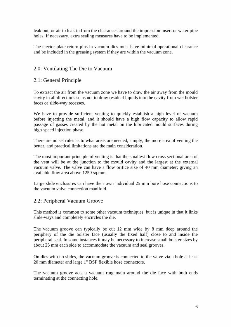
leak out, or air to leak in from the clearances around the impression insert or water pipe holes. If necessary, extra sealing measures have to be implemented. The ejector plate return pins in vacuum dies must have minimal operational clearance and be included in the greasing system if they are within the vacuum zone. 2.0: Ventilating The Die to Vacuum 2.1: General Principle To extract the air from the vacuum zone we have to draw the air away from the mould cavity in all directions so as not to draw residual liquids into the cavity from wet bolster faces or slide-way recesses. We have to provide sufficient venting to quickly establish a high level of vacuum before injecting the metal, and it should have a high flow capacity to allow rapid passage of gasses created by the hot metal on the lubricated mould surfaces during high-speed injection phase. There are no set rules as to what areas are needed, simply, the more area of venting the better, and practical limitations are the main consideration. The most important principle of venting is that the smallest flow cross sectional area of the vent will be at the junction to the mould cavity and the largest at the external vacuum valve. The valve can have a flow orifice size of 40 mm diameter; giving an available flow area above 1250 sq.mm. Large slide enclosures can have their own individual 25 mm bore hose connections to the vacuum valve connection manifold. 2.2: Peripheral Vacuum Groove This method is common to some other vacuum techniques, but is unique in that it links slide-ways and completely encircles the die. The vacuum groove can typically be cut 12 mm wide by 8 mm deep around the periphery of the die bolster face (usually the fixed half) close to and inside the peripheral seal. In some instances it may be necessary to increase small bolster sizes by about 25 mm each side to accommodate the vacuum and seal grooves. On dies with no slides, the vacuum groove is connected to the valve via a hole at least 20 mm diameter and large 1" BSP flexible hose connectors. The vacuum groove acts a vacuum ring main around the die face with both ends terminating at the connecting hole.
6

2.4: Air Vents: Zig Zag Vents Connecting the cavity to vacuum supply has in the past been by using special poppet valves or corrugated chill-vents which stop the flow of molten metal. They are expensive and require integration into both of the bolsters with great precision. They also require deep-connecting channels, which fill with a large volume of liquid metal. The liquid metal in the channel becomes highly pressurised when the vacuum valve shuts, so adding to the die opening forces. The BNF-MTC research of 1980's showed that vacuum could be obtained using standard die vents, so that was the start point for the new method. Monitoring the cavity vacuum showed that there was scope for reducing the time taken for the pressure to drop and that much lower vacuum pressure pressures were attainable before injecting the alloy. The first action was to ensure that the pressure response of the die cavity vacuum gauge was rapid and accurate. The original connecting channel was only 0.2 mm deep by 6 mm wide, so it was overlaid by a 0.5 deep zig zag groove, which was ground using pneumatic hand grinder tool while the die was on the machine. There was an immediate and big effect on vacuum gauge indicated cavity pressure. The metal froze in the zig-zags and did not go down the gauge connecting hole. With the rapid response gauge readings it was possible to see that there really was a need to reduce the time taken to achieve maximum vacuum before injection commenced. Increasing the flow area of the vents was an obvious solution and the zig-zag vent (ZZV) experiment with the gauge connection was replicated with precision cut vents in the dies. The ZZV channels were cut with acute corners so that the metal was caused to flow back upon itself at each turn and soon became chilled; preventing further flow. The tests were a great success and further experiments followed with various path geometries, widths up to 20 mm and depths up to 0.7 mm. The experiments led to a general design principle of channels 10mm wide, 0.5mm deep, with zig and zag centre line pitch and height of 40 mm; giving a corner angle of 53.13 degrees. Although the metal flow usually stopped before the fifth corner, it is recommended that there should be at least seven corners between the cavity and the vacuum groove. And of course the side edges of the channels must have as much draw taper as possible, typically 45°. Nesting the ZZVs together to get large flow areas, resulted in getting rapid and deep vacuum in the cavities. ZZVs also allowed easy and rapid exit of the gases created during the inrush of hot metal contacting the lubricated die surface. The high-speed injection of metal causes a
7
transient rise in absolute pressure in the cavity. That pressure was minimised with ZZVs and so minimised porosity. The ZZVs method was added retrospectively to hundreds of standard dies to improve venting and reduce porosity. When ZZVs were added to existing dies, it was observed that dimensions across the split line of the castings had less variance. The effect was attributed to the kinetic energy of the injection system being absorbed by the gradually increasing resistance to flow as the metal flowed along the ZZVs, wherein the metal was simultaneously freezing. The reduced impact pressure was also evident by less flash on the parting line. It seemed that the metal flowed and froze in the ZZV channels at low pressure, and did not significantly add to the forces on the die produced by the metal pressure created by the injection piston. Perhaps because the metal froze in the ZZV channels while still flowing freely with relatively little back pressure. 3.0: Measuring Vacuum Pressure In The Mould Cavity This is achieved by connecting a vacuum gauge to the die cavity or runner with a ZZV and hole drilled through the bolster. The gauge should have positive pressure capability of at least one bar, to cover possibility of metal injection without vacuum, which can cause high gas pressures. 4.0 Equipment There are many manufacturers of valves, filters, accumulators and pumps, so below the specifications are generalised, based on experience. 4.1 Filters and Strainers Filtration of air from the die is needed to prevent loose debris being ingested by the vacuum valve. Minimum pipe size is 25mm bore and strainers should be stainless steel pleated mesh types with 125 micron hole size in element area of about 45,000 sq mm. A typical 1inch hydraulic suction strainer would match the requirement. Very large dies with big slide enclosures would have individual connections to the vacuum valve manifold from each slide enclosure. Filtration would be via additional 1inch BSP size strainer units if there was risk of particulate contaminates being sucked into the vacuum pipes. 4.2: Valves Several vacuum valves from different manufacturers were tried. The best performance was achieved by using a standard large bore 'Industrial Process Valve'. Available world
8

wide, the prices of the valves were sufficiently economical to standardise on the 40 mm size (1.5inch BSP) for all machines. Having the valves remote from the die gives excellent reliability, and there have not been any known valve failures with the method. The preferred valve has an onboard solenoid pilot valve that applies vacuum to one side of the internal piston. Atmospheric pressure then lifts the poppet valve. Hence there is no need for compressed air or high current solenoids. 4.3: Pumps Some foundries use large amounts of water based die release agents which vacuum will suck from the die into the system. So, there have to be traps where liquids can be retained and evaporated. The rate of evaporation has to exceed the rate of liquid ingress, and that requires a system vacuum pressure to be well below 20 millibar. Experience has shown that dry operating pumps give superior reliability for diecasting applications. Claw type and screw types are available with good flow characteristics and with ultimate vacuum better than 7 millibar. 4.4: Receiver-Accumulators Vacuum accumulators serve two functions. 1. To help provide rapid reduction of pressure in the die. 2. To trap liquids and precipitate particles that might harm the pump The residue that builds up in accumulators can be very viscous, contaminated by particulate and by-products of thermally degraded oils and waxes. Thus, facilities are needed for periodically emptying any sediment, easily and quickly. 5.0: Conclusions 1. The experience of applying this technique to more than 85 dies in several foundries
leads the author to conclude that vacuum can greatly improve the quality of diecastings.
2. When high density, freedom from blisters and holes, consistent paint finishes and
'right-first-time' were specified, vacuum provided a powerful tool that could be further applied throughout the diecasting industry.
3. Key to success was measuring the vacuum pressure actually in the die cavity each
cycle, and then acting on that information to continuously improve the process. 4. The simplicity of the technique would enable its use on diecasting dies for
magnesium and copper alloys.
9
6.0 References 1. BNF Metals Technology Centre: Paper R427/T21, 1982.
NP Gregory, M.Cox, Dr.S.E.Booth; Injection Conditions For Aluminium Pressure Diecasting; Tests On A Hodler 'Optivac' System,
2. BNF Metals Technology Centre: Paper R482/T1, 1983.
NP Gregory, A.E.Weatherhill, Dr.S.E.Booth; Vacuum Diecasting Trials on a Small Heavy Section Casting.
3. BNF Metals Technology Centre: Paper R482/T4, 1984.
NP Gregory, M.Cox, Dr.S.E.Booth; Vacuum Diecasting Trials on a Small Engine Component Using A Die Face Groove.
The reports by BNF-MTC might still be available from 'The Light Metal Founders Association' of the United Kingdom or its successor, 'The Cast Metals Federation'. Otherwise, details can be obtained from the author.
4. Dr A.C.Street: THE DIECASTING BOOK, Portcullis Press
10

7.0: Appendix 7.1: Images illustrating vacuum Die Technique The series of images shows how to convert an existing die with four sliding cores to vacuum. The objective was to show how to apply the principals of the vacuum technique to an existing die with minimal changes. Thus the spring method of supporting the top slide was retained to demonstrate versatility of the method although an alternative method using slide retaining clips would have been used on a new die design. The die was designed and manufactured by Shanghai Skyrock Industry Co. Ltd., who have kindly permitted use the details for illustrating this report. The method takes a comprehensive approach to sealing, to obtain very low pressures in the die cavity.
Image 1: Perspective side view of closed die Image 2: Perspective view of the closed die from fixed bolster side. Image 3: Plan view of Fixed Half Bolster Image 4: Plan View of moving Half Bolster Image 5: Section view of closed die
8.0: About The Author Chris Hoskyns, a qualified engineer, started work at Dyson Diecastings Ltd in 1977 as Technical Manager and left as Technical Director in 1998. He now helps companies around the world and can be contacted via his personal email address:
11

IMAGE 1 The main functional changes to the die required: 1. addition of sealed enclosures to the four sliding cores with internal assembly seals 2. cutting peripheral vacuum groove 3. cutting Zig Zag Vents 4. cutting peripheral seal groove and adding O-Ring cord seal 5. adding O-Ring seals to injection sleeve and plunger tip 6. injecting seal around fixed half impression (normally also around moving half
impression) 7. cutting vacuum gauge monitoring ports 8. addition of ejector pin sealing manifold plate
12

IMAGE 2 View of die from injection end of machine to show all four slide enclosures
13
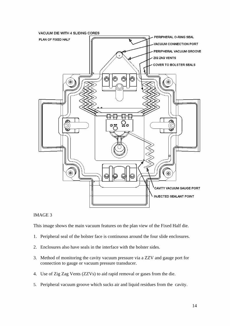
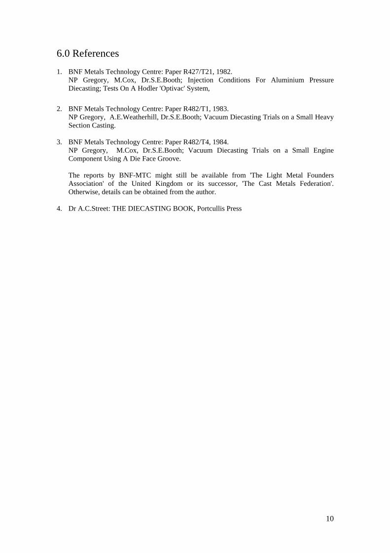
IMAGE 3 This image shows the main vacuum features on the plan view of the Fixed Half die. 1. Peripheral seal of the bolster face is continuous around the four slide enclosures. 2. Enclosures also have seals in the interface with the bolster sides. 3. Method of monitoring the cavity vacuum pressure via a ZZV and gauge port for
connection to gauge or vacuum pressure transducer. 4. Use of Zig Zag Vents (ZZVs) to aid rapid removal or gases from the die. 5. Peripheral vacuum groove which sucks air and liquid residues from the cavity.
14

IMAGE 4 Plan view of the moving half shows four slide enclosures and seals on water cooling pipes. The central moving half impression die did not have water-cooling pipes and so did not need an injected silicone seal. However, the ejector pin group was enclosed within an O-Ring seal between the rear of the impression and bottom of bolster pocket. The side slide enclosures were designed to allow easy removal of the slides for maintenance of the long core pins.
15
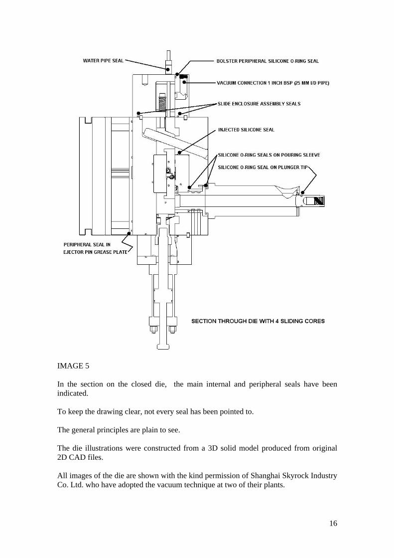
IMAGE 5 In the section on the closed die, the main internal and peripheral seals have been indicated. To keep the drawing clear, not every seal has been pointed to. The general principles are plain to see. The die illustrations were constructed from a 3D solid model produced from original 2D CAD files. All images of the die are shown with the kind permission of Shanghai Skyrock Industry Co. Ltd. who have adopted the vacuum technique at two of their plants.
16

INDEX
APPLYING VACUUM TO THE DIECASTING PROCESS
CHRIS HOSKYNS DIECASTING ENGINEER
真空技术在压铸中的应用
克力斯-霍斯根斯
压铸顾问工程师
ABSTRACT 摘要 page 1
Introduction Earlier Research
绪论 早期研究
page 2
Fundamentals of the New Technique 新技术的基本原理 Page3
1.0: Preventing Air Leaks 1.1: Bolster faces
1.0 密封 1.1 密封模架表面
Page 3
1.2: Impressions and inserts 1.3: Slideways 1.4: Pouring Sleeve (Magazine) & Sprue Bush
1.2 模仁及模架上的其它镶块 1.3 滑道 1.4 浇道和浇口衬套
page 4
1.5: Sealing The Cold Chamber Plunger Tip 1.6: Sealing Ejector Pins
1.5 密封冷室机冲头 1.6 密封顶杆
page 5
2.0: Ventilating The Die to Vacuum 2.1: General Principle 2.2: Peripheral Vacuum Groove
2.0 抽真空 2.1 一般原理 2.2 真空槽
page 6
2.4: Air Vents: Zig Zag Vents 2.4 Z形逃气槽 page 7 3.0: Measuring Vacuum Pressure In The Mould Cavity 4.0 Equipment 4.1 Filters and Strainers 4.2: Valves
3.0 测量模穴中的真空压力 4.0 设备仪器 4.1 过滤器和滤网 4.2 阀门
page 8
4.3: Pumps 4.4: Receiver-Accumulators 5.0: Conclusions
4.3 泵 4.4 接收器和储气罐 5.0 结论
page 9
6.0 References 6.0 参考书目 page 10
7.0: Appendix 7.1: Images illustrating vacuum Die Technique 8.0: About The Author
7.0 附录 7.1 真空技术的图片说明 8.0 关于作者 9.0 致谢
page 11
IMAGES 图片
page 12 page 13 page 14 page 15 page 16
Image 1: Main changes to die Image 2: Slide enclosures Image 3: Plan of Fixed Half Image 4: Plan of moving half Image 5: Section on die
图片1: 合模时模具的侧面透视图
图片2: 合模时定模侧的透视图
图片3: 定模模架平面图
图片4: 动模模架平面图
图片5: 合模时模具的剖面图
Translated by Ms Amber Song 本文由宋彩亚小姐担当翻译。
17

18