NSF Workshop on Large Ultrahigh-Vacuum Systems for ...
47
1 LIGO-P1900072-v1 Workshop Proceedings 1 March 2019 NSF Workshop on Large Ultrahigh-Vacuum Systems for Frontier Scientific Research Instrumentation LIGO Livingston Observatory January 29-31,2019 H.F. Dylla, R. Weiss and M. E. Zucker, eds. Distribution of this document: public release pending. This is a working note of the LIGO Laboratory. http://www.ligo.caltech.edu/ California Institute of Technology Massachusetts Institute of Technology LIGO Project LIGO Project
-
Upload
khangminh22 -
Category
Documents
-
view
3 -
download
0
Transcript of NSF Workshop on Large Ultrahigh-Vacuum Systems for ...
1
LIGO-P1900072-v1 Workshop Proceedings 1March2019
NSFWorkshoponLargeUltrahigh-VacuumSystemsforFrontierScientificResearchInstrumentation
LIGOLivingstonObservatory
January29-31,2019
H.F.Dylla,R.WeissandM.E.Zucker,eds.
Distributionofthisdocument:publicreleasepending.ThisisaworkingnoteoftheLIGOLaboratory.http://www.ligo.caltech.edu/CaliforniaInstituteofTechnologyMassachusettsInstituteofTechnologyLIGOProjectLIGOProject

2
WorkshopProceedings:NSFWorkshoponLargeUHVSystemsfor
FrontierScientificResearch*
LIGOLivingstonObservatory,LAJanuary28-31,2019
H.F.Dylla,R.WeissandM.E.Zucker,ProceedingsEditors
ExecutiveSummary
The NSF Workshop on Large Ultrahigh Vacuum Systems for Frontier Scientific Research
Instrumentation was held at the LIGO Livingston, LA site on Jan. 28 - 31, 2019. The purpose of theworkshop was primarily focused on the need to identify cost effective technologies for the design,constructionandoperationofthelargevacuumsystemsthatwouldberequiredforgravitationalwaveobservatories that are a factor of ten larger than the current generation systems in theU.S. (LIGO),Europe(Virgo)andJapan(KAGRA).The technologies thatwere developed and employed in the existing gravitationalwave observatorieshavebeenshowntomeetthestringentrequirementsofvacuumintegrity,verylowhydrogenandheavymoleculeoutgassing,minimalparticulategeneration, lowvibration,andappropriatestray lightopticalabsorbanceforsuccessfuloperation.However,straightforwardextrapolationofthecostsforextendingthe interferometer vacuum beam enclosures from the current lengths of 3-4km/arm to 40km/armindicatestheneedforinvestigationofawiderangeoftechnologiesandmaterialsthatcouldsignificantlylower the final costof next generationobservatories suchas theCosmic Explorer in theU.S. and theEinsteinTelescopeintheE.U.Theworkshopparticipantswereconfidentthattechnicalsolutionscouldbedevelopedthatwouldhavenon-trivialimpactonthecostofthedesign,constructionandlife-cycleoperationofvacuumsystemsfortheproposednextgenerationgravitationalwaveobservatories.Twoclassesofsolutionsforthevacuumenclosureswereexamined:thefirstdesignconceptisanextrapolationofthesingle-wallvacuumpipeinuse in the present generation of detectors (at LIGO, Virgo, and KAGRA). The second design conceptinvolvesdouble-walledornestedvacuumpipesthatwouldseparatetheatmosphericloadproblemfromthe stringent UHV properties needed for the inner wall. Vacuum pumping solutions and surfacetreatments were examined for both concept designs with an emphasis on potential hardware andtreatments that could lower total costs but stillmeet the stringent requirements for next generationgravitationalwaveinterferometricdetectors.*SponsoredbytheU.S.NationalScienceFoundationandtheCaltech/MITLIGOLaboratory.Reportissuedate:1March2019
3
TableofContents
1. Introductionandorganizationoftheworkshop-------------------------------------32. Designrequirements------------------------------------------------------------------------63. WorkingGroup1report--------------------------------------------------------------------94. WorkingGroup2report--------------------------------------------------------------------185. WorkingGroup3report--------------------------------------------------------------------256. WorkingGroup4report--------------------------------------------------------------------347. Conclusionsandrecommendations-----------------------------------------------------408. Acknowledgments---------------------------------------------------------------------------429. Appendices
A. Workshopparticipants----------------------------------------------------------------43B. Workshopagenda----------------------------------------------------------------------44
4
Workshop Proceedings: NSF Workshop on Large Ultrahigh Vacuum Systems for Frontier Scientif ic Research
Instrumentation LIGO Livingston Observatory, LA
January 29 - 31,2019
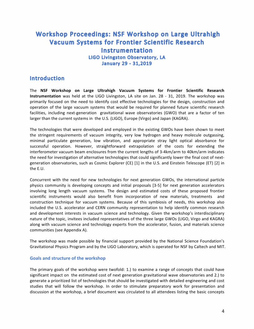
Introduction The NSF Workshop on Large Ultrahigh Vacuum Systems for Frontier Scientific Research
Instrumentation was held at the LIGO Livingston, LA site on Jan. 28 - 31, 2019. The workshop wasprimarily focusedon theneed to identify cost effective technologies for thedesign, construction andoperation of the large vacuum systems thatwould be required for planned future scientific researchfacilities, including next-generation gravitational wave observatories (GWO) that are a factor of tenlargerthanthecurrentsystemsintheU.S.(LIGO),Europe(Virgo)andJapan(KAGRA).Thetechnologies thatweredevelopedandemployed in theexistingGWOshavebeenshowntomeetthe stringent requirements of vacuum integrity, very low hydrogen and heavy molecule outgassing,minimal particulate generation, low vibration, and appropriate stray light optical absorbance forsuccessful operation. However, straightforward extrapolation of the costs for extending theinterferometervacuumbeamenclosuresfromthecurrentlengthsof3-4km/armto40km/armindicatestheneedforinvestigationofalternativetechnologiesthatcouldsignificantlylowerthefinalcostofnext-generationobservatories,suchasCosmicExplorer(CE)[1]intheU.S.andEinsteinTelescope(ET)[2]intheE.U.Concurrentwith the need for new technologies for next generationGWOs, the international particlephysics community is developing concepts and initial proposals [3-5] for next generation acceleratorsinvolving long length vacuum systems. The design and estimated costs of these proposed frontierscientific instruments would also benefit from incorporation of new materials, treatments andconstruction technique for vacuum systems. Because of this symbiosis of needs, this workshop alsoincluded theU.S. accelerator and CERN community representation to help identify common researchand development interests in vacuum science and technology. Given theworkshop’s interdisciplinarynatureofthetopic,inviteesincludedrepresentativesofthethreelargeGWOs(LIGO,VirgoandKAGRA)alongwithvacuumscienceandtechnologyexpertsfromtheaccelerator, fusion,andmaterialssciencecommunities(seeAppendixA).Theworkshopwasmadepossibleby financial supportprovidedby theNational Science Foundation’sGravitationalPhysicsProgramandbytheLIGOLaboratory,whichisoperatedforNSFbyCaltechandMIT.Goalsandstructureoftheworkshop
Theprimarygoalsof theworkshopwere twofold:1.) toexaminea rangeofconcepts thatcouldhavesignificantimpactontheestimatedcostofnextgenerationgravitationalwaveobservatoriesand2.)togenerateaprioritizedlistoftechnologiesthatshouldbeinvestigatedwithdetailedengineeringandcoststudies that will follow the workshop. In order to stimulate preparatory work for presentation anddiscussionattheworkshop,abriefdocumentwascirculatedtoallattendeeslistingthebasicconcepts
5
for the design of a 40km interferometer vacuum enclosure, on consideration of a double or nestedvacuum enclosure to separate the atmospheric loading problem from the more stringent UHVrequirements of an inner vacuumvessel, and a seconddesign concept involving themore traditionalsingle-walled vacuum vessel in use in the current generation GWOs. This concept document alsoincludes a preliminary list of keydesigndrivers thatwouldhave to be evaluated for eachof the twoclassesofdesignconcepts,suchasbasicrequirementsforhydrogenandheavierresidualgasoutgassing,optical properties of the inner wall, propensity for particle generation, fabrication, operational andmaintenanceissues-allofwhicheffectprocurementandlifetimeoperationalcosts.Sincethisworkshopprecedesany formalconceptualdesignphasethatwillnecessarily followfornextgenerationGWOsuchastheCosmicExplorerandtheEinsteinTelescope,theworkshoporganizersfeltitwas important to provide a very open structure for the workshop to encourage wide ranging andunconstraineddiscussionsforpotentialsolutionstothetwobasicdesignconcepts.Withthisscheme inmind, theorganizersproposedatwo-partstructuretotheworkshopagenda[seeAppendix B]. A call was issued to all attendees to submit topics for brief (~10 minutes) “blue sky”presentations to cover any topic that was deemed relevant for either or both design concepts.Followingthesepresentations,fourworkinggroups(WG)wereorganized.Thefirsttwoaddressedeachof the two basic design concepts. WG1 examined potential new solutions for the straight forwardextrapolationofthesinglevesseldesigncurrentlyinuseatLIGO,VirgoandKAGRAwithallconstraintslifted in choice of vessel material, structural design, fabrication, surface preparation and in-situpreparation.WG2examinedthedoublewalled,ornestedvacuumvesselconcept.Again,fewconstraintswereappliedtoencourageawiderangeofpotentialsolutions.Two other working groups were organized to examine important topics that would need to beincorporatedwithinthedesignprocessofthetwovesselconceptclasses.WG3addressednovelsurfacetreatments for both conventional and newUHV compatiblematerials. These treatments provide theprimary means of meeting hydrogen and water outgassing and other residual gas requirements, inaddition to being able to meet minimal particulate generation and desired stray light reflectionrequirements.WG4addressedvacuumpumpingforconventionalandnestedvacuumsystemconcepts.Topics included gettering options within the beam pipe UHV sections and means of maintainingdifferentialpressuresinthenestedsystemconcepts.The workshop agenda provided time for the working groups to meet individually and also with theentire workshop attendees. In the closing session of theworkshop, working group chairs provided apreliminarysummaryresults thatweresubsequentlyexpandedbypost-workshopcommunications fortheworkinggroupsummariespresentedinthefollowingsectionsofthisreport.Thisreportconcludeswithanoverallsummary,high levelrecommendationsforworktofollow,andastatementendorsedbyallparticipantsthatafollow-upworkshopshouldbescheduledwithinthenextyear.

6
Designrequirements
The design targets for this workshop are driven by the current concepts for the next generationgravitationalwaveobservatories:theCosmicExplorer(CE)intheU.S.andtheEinsteinTelescope(ET)intheE.U. Anoverviewof the fieldof gravitationalwavedetectionbasedon interferometric detectorswasgivenatthebeginningoftheworkshopbyM.ZuckerfromLIGO[6].Gravitationalwavedetectorsbased on laser interferometry observe themetric strain (h=ΔL/L) induced by a passing gravitationalwave. The differential displacement,ΔL registered between orthogonal interferometer arms ofmeanlengthLasaresultofapassingwavewithstrainamplitudehisgivenby:
∆ ! = ℎ! ~ ! ∙ 4!!!"!!!!"#!!!!
= 4 ∙ 10!!" ! ∙ !4000!
!!⊙
!!"#400 !"
! !20 !"
! 100 !"#!
wherewe'vetaken,asanexamplesource,acompactbinarysystemwithtwoequalcomponentmassesM separatedbyR,orbitingeachotherat frequency forb ,atdistance r fromEarth. Whenexpressed intermsofapparentΔL, the limitingnoise terms indetectorsof this typeareeither independentof,orvaryonlyweaklywith,overallinstrumentsize.Asaresult,themostdirectwaytoimprovethedistanceratwhichsourcescanbeobservedistoincreasethearmlengthL. It's importanttonoteherethatthenumberofdetectablesourcesvarieswiththevolumeobserved,andthustherateofeventdetectionsinitially scales as L3 (neglecting cosmological evolution of sources). Thus, the distance to which theproposedCEandETcouldseewouldexceedthehorizonwherestarsfirstformedintheearlyuniverse.
ResidualGasNoise
Thepowerspectraldensity1ofgas-inducedfluctuationsintheopticalpathlengthisgivenby:
wherefisthesignalfrequency,Listhephysicallength,ρ(z)isthenumberdensityofthemolecules,αiseachmolecule’sopticalpolarizability(proportionalton-1,wherenisthebulkrefractiveindexofthegasatstandardpressure),v0=(2kBT/m)1/2isthemostprobablespeedforthemoleculesgiventheirmassmand ambient temperature T, and w (z) is the laser beam’s Gaussian radius parameter [6-8]. Thecalculated limits for residual gas partial pressures are given in Table 1, showing that required partialpressuresofH2are10-9Torr,forwater10-10Torrandlowerforheavierhydrocarbons.
1Definedasmean-squareddeviationperunitbandwidth.
February 17, 2018 8:15 ws-rv961x669 Book Title Vol1 page 2
2 M. Zucker
boundary interacts with light scattered from and returning to the interferometer,an indirect but inevitable consequence of vacuum operation.
2.1. Refractive index fluctuation
Light scattering by residual gas molecules produces an apparent fluctuation in thedistance between test bodies. Each molecule passing through the interferometerbeam produces a transient phase shift through forward scattering. In aggregate,these pulses are equivalent to a stochastic fluctuation in the e↵ective “refractiveindex” of the medium2.
The magnitude of each impulse is governed by the molecule’s optical polarizabil-ity (related to the bulk gases’ refractive index). The rate of impulses depends uponthe local density; density variations within the system may also depend on thermalspeed, which is a function of molecular weight. The duration of each impulse isfurther governed by the ratio of the beam radius at the interaction point to themean thermal speed. These factors determine the noise contributed by molecules ofeach gas species, and also govern the frequency dependence of the resulting noise,since heavy molecules may interact with the beam over durations comparable tothe signal period.3
Integration of phase impulses over Maxwell velocity and Gaussian intensity dis-tributions yields the predicted power spectral density of fluctuations in the opticalpath length
SL (f) =(4⇡↵)2
v0
LZ
0
⇢ (z) exp [�2⇡f w (z) /v0]
w (z)dz (1)
where L is the physical length, ⇢ (z) is the number density of the molecules, ↵
is each molecule’s optical polarizability, v0 = (2kBT/m)1/2 is the most probablespeed for molecules of mass m at ambient temperature T, and w (z) is the beam’sGaussian radius parameter as a function of axial position z [Weiss (1989)]. Totalnoise power will be the sum of such contributions for each species present. Theapparent di↵erence in the lengths of the interferometer’s two arms will then havespectral density
S�L (f) = 2SL (f) . (2)
This model has been confirmed by introducing controlled gas samples in workinginterferometers. Results of such a test [Zucker and Whitcomb (1996)], employingxenon, nitrogen and carbon dioxide gases, are depicted in Figure 1 along with theprediction of Equation 1. add new test at LIGO for this?
Table 1 compares the approximate sensitivity for various gases to that forhydrogen at comparable pressure. Here we have taken the low-frequency limit2In situations of interest, gas density is low enough that the molecular mean free path exceeds thebeam diameter. We can thus consider molecules independently.3For many cases of interest this frequency dependence is weak, and it is sometimes ignored.
7
ParameterAchievedin
LIGORequiredfor
CE(1µm)
L(m) 4,000 40,000
w0(mm) 62 83
hgas(Hz-1/2) <5x10-25 <5x10-26
P[H2](Torr) <10-9 <10-9
P[H2O](Torr)
<10-10 <10-10
P[CO2](Torr)
<2x10-11 <2x10-11
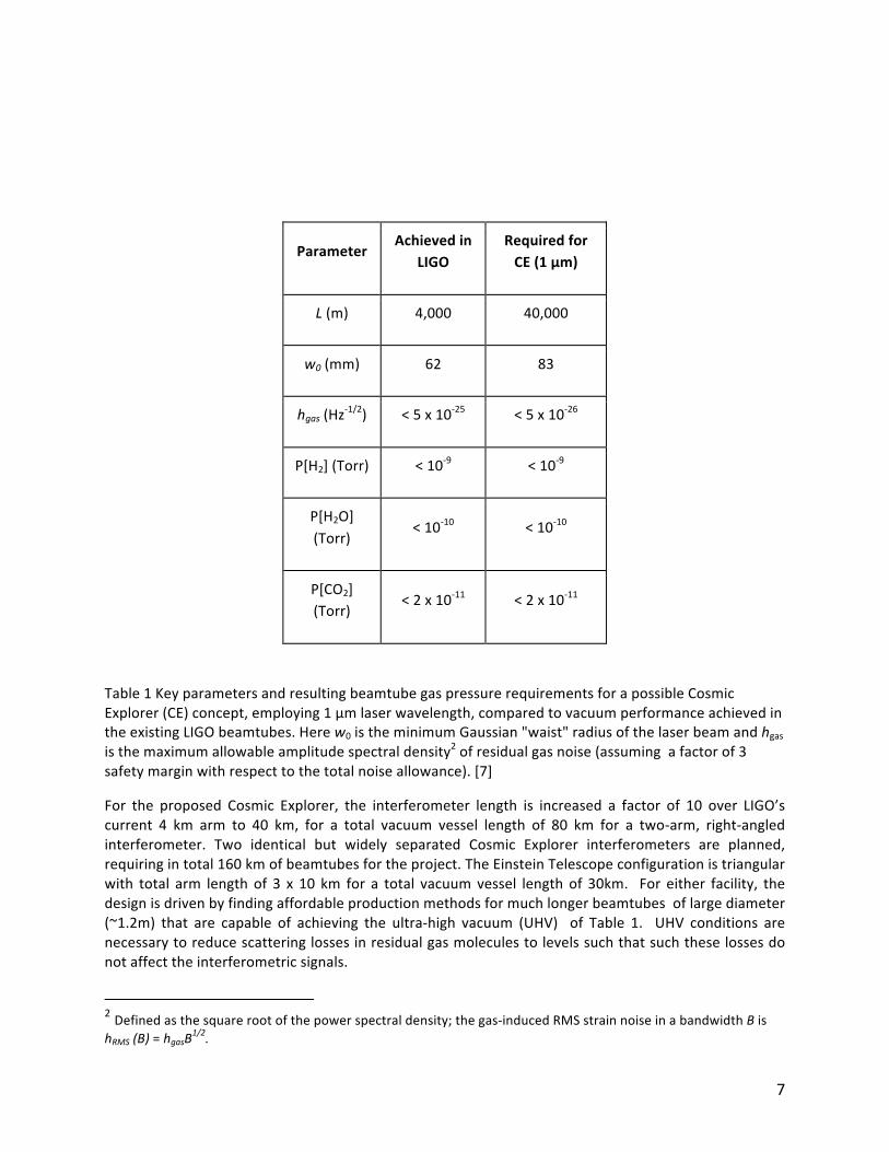
Table1KeyparametersandresultingbeamtubegaspressurerequirementsforapossibleCosmicExplorer(CE)concept,employing1µmlaserwavelength,comparedtovacuumperformanceachievedintheexistingLIGObeamtubes.Herew0istheminimumGaussian"waist"radiusofthelaserbeamandhgasisthemaximumallowableamplitudespectraldensity2ofresidualgasnoise(assumingafactorof3safetymarginwithrespecttothetotalnoiseallowance).[7]
For the proposed Cosmic Explorer, the interferometer length is increased a factor of 10 over LIGO’scurrent 4 km arm to 40 km, for a total vacuum vessel length of 80 km for a two-arm, right-angledinterferometer. Two identical but widely separated Cosmic Explorer interferometers are planned,requiringintotal160kmofbeamtubesfortheproject.TheEinsteinTelescopeconfigurationistriangularwith total arm length of 3 x 10 km for a total vacuumvessel length of 30km. For either facility, thedesignisdrivenbyfindingaffordableproductionmethodsformuchlongerbeamtubesoflargediameter(~1.2m) that are capable of achieving the ultra-high vacuum (UHV) of Table 1. UHV conditions arenecessarytoreducescatteringlossesinresidualgasmoleculestolevelssuchthatsuchtheselossesdonotaffecttheinterferometricsignals.
2Definedasthesquarerootofthepowerspectraldensity;thegas-inducedRMSstrainnoiseinabandwidthBishRMS(B)=hgasB
1/2.
8
The workshop goal is to examine design concepts and technologies that would feed into the firstdetailed design and engineering studies of the Cosmic Explorer and the Einstein Telescope. For theCosmicExplorer,anapproximateprojecttimescalehasbeenproposed.Theformaldesignphasecouldbegin in 2022, and the construction project could begin in 2026 for completion on or about 2035.Concurrentwith the early phases of this projectwould be crucial testing of laser technologies at theAdvanced LIGO (aLIGO) project including higher power lasers and optics to transition operation from1µmto2µm.[9].
References
1. TheCosmicExplorer:http://www.cosmicexplorer.org2. TheEinsteinTelescope:http://www.et-gw.eu3. LinearColliderCollaboration:http://www.linearcollider.org4. FutureCircularCollider:https://home.cern/science/accelerators/future-circular-collider5. CircularElectronPositronCollider:http://cepc.ihep.ac.cn6. R.Weiss,“ResidualgasinLIGOBeamtubes”,AVS(2003),LIGODocumentG0307017. M.Zucker,LIGODocumentG1900136,Jan.2019.8. S.WhitcombandM.Zucker,Proc.7thMarcelGrossmanMeetingonGeneralRelativity,R.Jantzen
andG.Keiser,eds,(WorldScientific,Singapore,1996).9. AdvancedLIGO(aLIGO):https://www.ligo.caltech.edu/page/about-
aligo?highlight=Advanced%20LIGOS. Whitcomb and MZ, Proc. 7th Marcel Grossmann Meeting on GR, R.
9
WorkingGroup1Report:ConventionalSingle-WallVacuumSystems
Co-chairs:CurtBaffes(FNAL)andDanielHenkel(RimkusConsultingGroup,Inc.)
Charge
Investigatecostreductionoptionsforconventionalbeamtubetechnologythatcouldimpactthedesign,construction and operation of the Cosmic Explorer, including the use of stainless steel,mild steel oraluminumsingle-walledtubing.Thegroupwasaskedtolookatnovelapplicationsofspiralweldingandotherpipelinetechnology.Summary
Working Group 1 was charged with investigating cost-reduction options for conventional, single-wallvacuum systems. Material, fabrication, and processing (i.e. baking) techniques were discussed.Stainless steel,mild steel,andaluminumoptionswereconsidered. Theperformanceandbehaviorofstainless-steelsystemsiswellestablished,butthematerialhasacomparativelyhighcost.Assuch,ourattentionwasfocusedonthelower-costmaterials.However,rawmaterialcostsavingsforthecheapermaterials may be offset by reduced performance or increased cost/complexity in other parts of thesystem (e.g. beamtubeexpansion joints). A set of studies and tests to address the challenges of thelower-costmaterialswillbepresentedintherecommendationssection.
DiscussionHighlights
Geometryfora3rdGenerationObservatoryThestraw-mangeometryunderconsiderationbythisworkinggroupwasasfollows:
• Configuration-Single-wallmetaltube• Diameter-1.2m(thoughdiametersassmallas1mandaslargeas2mwerediscussed)• Armlength–40kmperarm
MaterialChoicesStainlessSteel
Austenitic stainless steel (e.g. 304L) is well understood, having been successfully used in all existinggravitationalobservatorybeamtubes.Assuch,forthepurposesofthisreport,itwillbeconsideredthestraw-managainstwhichotheroptionsarecompared.CarbonSteel
Carbonsteel,sometimesreferredtoas“mildsteel”or“plaincarbonsteel,”isproposedasalower-costalternative to stainless steel. Carbon steel becomes attractive as a beam tube material due to theavailabilityofsteelthroughRuhrstahl-Hausenvacuumprocessduringsteelrefining,resultinginverylowhydrogencontentandextremely lowhydrogenoutgassing [1].Becauseof theuniquerequirements inthis vacuum system, there are hundreds of alloys to consider, classified by several organizationalstandardssuchasAmericanSocietyforTestingandMaterials(ASTM)andAmericanPetroleumInstitute(API). Both focuson structural shapesandpipe. Inaddition to thecompositionandcarboncontent,otherimportantfactorsmustbeconsidered.Afewincludethetypeofdeoxidizing,grainsizeandshape
10
(hot rolled or cold rolled), hardenability, weldability, and inclusion content. Closely controlledmicrostructuresandthelevelofsteelprocesscleanlinesscanhaveaprofoundinfluenceonoutgassing,surface finish, corrosion resistance and strength. Good weldability and high-yield strength can becontrolled,notonlybythecarbon level,butalsobymicroalloying,pre-andpost-weldheattreatmentandmechanicalwork-hardening.Appropriatesurfacetreatmentneedstobedevelopedtoavoidrustingand other forms of corrosion and to prevent water adsorption. Both plasma deposition and wetchemistrydepositionofvariouscoatingsshouldbeinvestigatedtofindtheoptimumtypeofcoating(seeWorkingGroup3section).The large amount of material required for this project provides the opportunity to go beyondcommerciallyavailablecarbonsteels. Thealloydoesnothavetobeselectedoff theshelf. Itcanbedesigned as a low cost, corrosion resistant, weldable pipelinematerial with optimized properties ofbothcarbonandstainlesssteel.ThereareU.S.mini-millsthatcouldworkwiththecollaborationinthedevelopmentofthebeamtubealloyandprocesses[2].Aluminum
Aluminumofferslowhydrogenoutgassingandrelativelylowmaterialcost.Fabricationofthick-wallAlpipeswasdiscussed.Extrusion,formingandweldingprocessesmaybeviable.Frictionstir-welding,usedinternallybylargecommercialaluminummanufacturersformakinglongsectionsofrolledandweldedpipe, is an option for aluminum. The welding of Al pipes to dissimilar-metal components, such asexpansionjointsandsideportflanges,willneedtobedeveloped.Bi-metaltransitionsmaybeneeded,withtheaddedcostandrisk,andmustbeevaluated.Exotics
Othermaterialsweresuggested,mostplausiblytitanium.However,aswillbediscussedbelow,aback-of-the-envelopecostassessmentquicklydisqualifiestitanium.MaterialThickness
For buckling stability and material robustness, a steel or stainless-steel tube should have materialthickness > ~3mm for pipeswithmeter-sizeddiameters. LIGO’s beamtube is nominally 3.2mm thick,withVirgoandKAGRAhavingchosentousethickershells.TherehavebeenoccasionswhentheLIGOconcreteenclosureshavebeenhitbybullets.Theconcreteenclosuresweresufficient toprotect thebeamtube.But for3rdgenerationobservatories,cheaperbutless-robust enclosures are envisioned. There is a proposed requirement that the beamtube be thickenough to surviveabullet strike. It is estimated thata thickness in theneighborhoodof9mm (forasteel)would be needed. Rawmaterial costs scale proportionally to thickness, andwelding costswillhave a positive correlation with thickness, so this proposed requirement will have significant costimplications, and should receive corresponding attention and debate. Costs associated with rawmaterials,whichwillbeestimatedbelow,canbeweighedagainstthecostofprovidingphysicalbarriers.Fortheabove-gradesectionsofbeamtube,a2m-highearthenbermcouldperhapsbeconstructedfromthecutmaterialremovedfromthebelow-gradesectionsofbeamtube.Suchabermmightalsoreducewindvibrationofthestructure.Forequivalentbucklingperformanceandbullet-resistance,analuminumtubewouldneedtobethickerthanastainlessone.Tofirstorder,bucklingcapabilityisproportionalto(Elasticmodulus*thickness3).Therefore,analuminumtubewillrequire~1.4Xthethicknessofitsstainlesscounterpart.Itislikelythatbullet resistance does not scale up as stronglywith thickness. A simple internet search on the bulletresistanceofaluminumisnotreassuring.
11
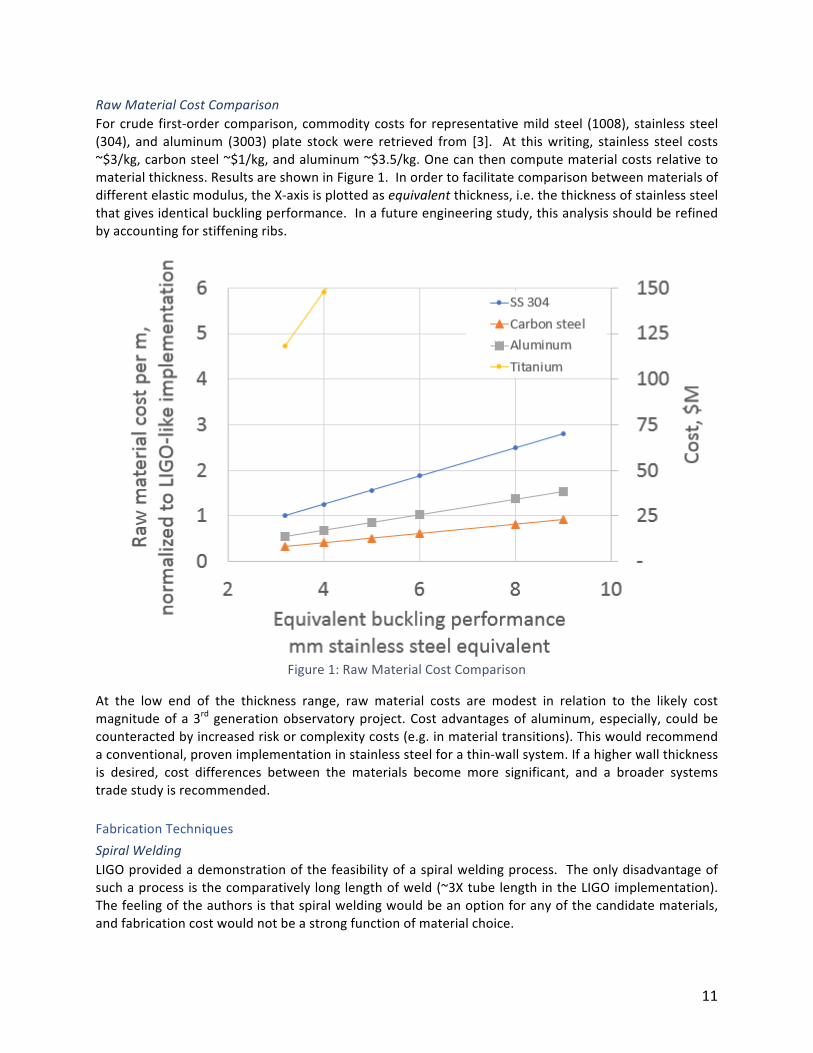
RawMaterialCostComparison
Forcrude first-ordercomparison,commoditycosts for representativemildsteel (1008), stainlesssteel(304), and aluminum (3003) plate stockwere retrieved from [3]. At thiswriting, stainless steel costs~$3/kg,carbonsteel~$1/kg,andaluminum~$3.5/kg.Onecanthencomputematerialcostsrelativetomaterialthickness.ResultsareshowninFigure1.Inordertofacilitatecomparisonbetweenmaterialsofdifferentelasticmodulus,theX-axisisplottedasequivalentthickness,i.e.thethicknessofstainlesssteelthatgivesidenticalbucklingperformance.Inafutureengineeringstudy,thisanalysisshouldberefinedbyaccountingforstiffeningribs.
Figure1:RawMaterialCostComparison
At the low end of the thickness range, raw material costs are modest in relation to the likely costmagnitudeofa3rdgenerationobservatoryproject.Costadvantagesofaluminum,especially, couldbecounteractedbyincreasedriskorcomplexitycosts(e.g.inmaterialtransitions).Thiswouldrecommendaconventional,provenimplementationinstainlesssteelforathin-wallsystem.Ifahigherwallthicknessis desired, cost differences between the materials become more significant, and a broader systemstradestudyisrecommended.FabricationTechniquesSpiralWelding
LIGOprovidedademonstrationofthefeasibilityofaspiralweldingprocess. Theonlydisadvantageofsuchaprocessisthecomparativelylonglengthofweld(~3XtubelengthintheLIGOimplementation).Thefeelingoftheauthorsisthatspiralweldingwouldbeanoptionforanyofthecandidatematerials,andfabricationcostwouldnotbeastrongfunctionofmaterialchoice.
12
LongitudinalWelding
BothVIRGOandKAGRAdemonstratedasuccessfullongitudinal-seamimplementation.This,also,isfelttobeanoptionforanyofthecandidatematerials.Fabricationcostswouldnotbeastrongfunctionofmaterialchoice.SeamlessPiping(Stainless,MildSteels)
It is believed that most leaks inherent in large-bore commercial piping (e.g. gas pipeline pipe) areassociatedwiththeweldseams.Itispossiblethatseamlesspipingcouldmitigatethisissue.Large-boreseamlesspipingisavailablefromatleastafewvendors,e.g.[4].CustomExtrusion(Aluminum)
For aluminum designs, a custom extrusion could be considered. This approach has been usedsuccessfully forcomplicatedbeamtubeshapesatmanyparticleaccelerators.Extrusionwouldbecost-effective, however, due to the largediameter and length, noextrudershavebeen identified yet, andsome amount of tooling development may be required. Due to the relative flexibility and ease ofextrudingaluminum,oncecouldconsiderco-extrudingother featuresbeneficial totheapplication, forexamplestiffeningribsorchannelsforawater-drivenbakeout(seealsobakeoutsectionbelow).CommercialOfftheShelf(COTS)Products
Large-borepiping is readily available from thepipeline industry in a varietyofmaterials.Anecdotally,thesematerials are said to have welds unsuitable for UHV service. This should be investigated andverified.Inanycase,itseemsoverwhelminglylikelythatadedicatedproductionrunwithUHV-suitableprocess control will be required. Linde offers a 1.2m spiral-welded aluminum tube as a standardproduct[5].SpiralrolledmildsteelpipingisavailablefromKorea.Pricingisapproximately$220USpermeterforthesteeltubeonly[6],withspecificationsasfollows:
• 1.2m(Dia.),8mm(t),5mtubefromahot-rolledcoil• Appliedspiralweldingtofromthesteeltube,whichischeaperthantheseamedtubefromthick,
hot-rolledplate.Thetotalweldinglengthislongerthanthelatter.Webelieveapplyingthistechniquemaybeapplicableforformingthetube.Butevaluationsforleaktightnessandoutgassingarenecessary.
• includingdescaling(eithericebeadblastingoracidpickling)• excludingjoints(flanges)+joiningwelding,• excludingvacuum-cleaning• excludinganti-corrosionpaintingfortheoutersurface• $1030+$60(transportationtoHouston)pereachsteeltube
JoiningofDissimilarMaterials
For a non-stainless system, a needmay arise to join dissimilarmaterials with stainless. This can beavoidedinsomeapplications(forexample,aluminumsystemswithaluminumConflat™flangesandsoftaluminumgaskets).However,inothercasesitmaynotbefeasibleoreconomicaltoavoidatransition.Itislikelythatthemostchallengingapplicationisatthebeamtubeexpansionjoints.In an aluminum system, hydroformed aluminum bellows may not be viable due to reliability andfabrication concerns. One could perhaps avoid a transition by accommodating a large-diameterdiaphragm(essentiallyasingle-convolutionedge-weldedbellows). However, itseemsunlikelythatamaterial transition can be avoided. Assuming a bake out at 120°C and a 20m section of beamtubebetweenexpansion joints, the3rd generationobservatorywouldneed4,000expansion joints,eachof
13
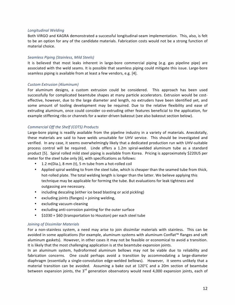
whichwouldneedtoprovide>40mmofstrokeduringthebake.Tomeetthis,onewouldlikelychoosetotransitiontoastainlesssteelexpansionjoint.4,000expansionjointswouldrequire8,0001.2mdiameterAl-SStransitions,aconsiderablenumberandconsiderablecost.Thiscostwouldbeweighedasapenaltyagainst raw material cost savings. (Note-that the potential for lower temperature bake outs underdiscussionfortherequiredwaterremovalwouldrelaxtheexpansionjointrequirements.)Whenusingaluminumalloysasbeamtubematerial,functionalcomponents(suchasflanges,bellows,etc.,usuallymadeofstainlesssteels)maybeweldedtothebeamtubesusingcladdedbi-metaltransitions.Therearetwotypesofbi-metaltransitionmaterialscommonlyusedintheparticleacceleratorvacuumsystems:explosionbonded(ExB)andhotisostaticpressing(HIP).Verylargeparts(exceeding48”x48”)areusuallymadeofExBmaterials,whilethesizeofthepartsfromHIPmaterialmaybelimitedbytheavailablevesselsatHIPvendors.ForExBparts,machiningwouldbenecessarytocreateweldinterfacegeometry.Reliabilityexperiencewiththistypeoftransitionhasbeenmixed.PartsmadeofExBmaterialsmaydevelopaleakduringtheweldingprocess.Mostoftheleaksarelikelyduetofilamentfracturesininterlayersheet(Ti,Cu,Nb,Ta,etc.)usedinthebonding(fromtheviolentshock-wave),owingtoinsufficientinterlayerthickness.(Ourexperiencesshowedthattheinterlayersheetneedstobemorethan0.5-mminthickness.)Thus,adequatequalityassurancetestsneedtobeinplacefortheExBpartsor/andplates.ThemosteffectiveQAtestistohaveaweldtestspecimenasshownbelow(Figure2).ACornellExBplatetechnicalspecificationisalsosuppliedasanappendix.
Figure2:Explosion-bondedtransitionweldtestcoupon
14
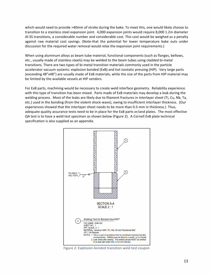
TransitioncomponentsmadeofHIPmaterialarecommonlyusedinmanyacceleratorsinAsiancountries,suchasSuperKEKBinJapan,TaiwanLightSourceinTaiwan.Theexperiencesoftheseacceleratorshavebeenverypositive.OneoftheadvantagesofHIPtransitionsisthatitcanbondthedissimilarmaterialsintothefinalformofthecomponents,thusnopost-bondingmachiningisrequired.MostHIPvendorsintheUShaveHIPvesselslessthan30”indiameter.However,aJapanesecompany,MetalTechnologyCo.Ltd, has HIP capacity to a maximum size of 2 m in diameter x 4 m in height. The cost of the HIPtransitionsiscompatiblewithExBtransitions,ifmultipletransitionscanbeproducedperbatch.Forlargecomponents,suchasbeamtubebellowassemblies,adhesivebondingmayalsobeconsidered.A concept design is shown below, in which the epoxy-bonded Alum/SST transitions could be massproducedwithsimpletooling.
Figure3:Adhesive-bondedtransitionconcept
In a mild steel system, transitions could potentially be avoided by using a steel expansion joint.Alternately,weld techniquesand fillermaterials are readily available to joinmildand stainless steels,withappropriateprocesscontrolssteel-stainlesssteeltransitionsshouldnotposeaproblem.SurfaceConsiderationsTominimizestray light,a smooth, specular, reflectivebeamtubesurface isundesirable. Foroptimumvacuumperformance, a smooth surface is verydesirable.Under thepresumption that a clever baffledesignand/orcoatingcanrelievestray lightrequirementsonthebeamtubesurface,weconsiderheretechniquesthatcanbeusedtooptimizevacuumperformance.Surfacedegradationsuchasmicro-crack,residualstress,microscopicdefectmayactasanabsorption/desorptionsite,causinghigheroutgassingrate.KAGRAchoseanelectrolyte-polishingfinish,aftertheproductionprocessoftube-forming(pressingand one-seam weld) and welding of bellows and flanges: hydro-formed bellows (0.8 mm thick) arechemicallywet-cleanedinadvance.IncaseofKAGRAstainless–steeltube,afewtensofmicrometerinoutermost surfaceshouldbe removedso thatnon-degradedsurface results. Inorder topassivate the
15
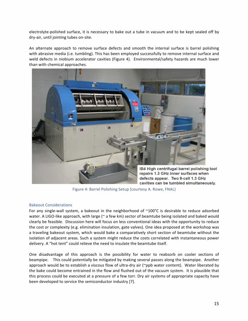
electrolyte-polishedsurface, it isnecessarytobakeoutatubeinvacuumandtobekeptsealedoffbydry-air,untiljointingtubeson-site.An alternate approach to remove surface defects and smooth the internal surface is barrel polishingwithabrasivemedia(i.e.tumbling).Thishasbeenemployedsuccessfullytoremoveinternalsurfaceandwelddefects inniobiumacceleratorcavities (Figure4). Environmental/safetyhazardsaremuch lowerthanwithchemicalapproaches.
Figure4:BarrelPolishingSetup(courtesyA.Rowe,FNAL)
BakeoutConsiderationsForany single-wall system,abakeout in theneighborhoodof~100°C isdesirable to reduceadsorbedwater.ALIGO-likeapproach,withlarge(~afewkm)sectorofbeamtubebeingisolatedandbakedwouldclearlybefeasible.Discussionherewillfocusonlessconventionalideaswiththeopportunitytoreducethecostorcomplexity(e.g.eliminationinsulation,gatevalves).Oneideaproposedattheworkshopwasatravelingbakeoutsystem,whichwouldbakeacomparativelyshortsectionofbeamtubewithouttheisolationofadjacentareas.Suchasystemmightreducethecostscorrelatedwithinstantaneouspowerdelivery.A“hottent”couldrelievetheneedtoinsulatethebeamtubeitself.One disadvantage of this approach is the possibility for water to reabsorb on cooler sections ofbeampipe.Thiscouldpotentiallybemitigatedbymakingseveralpassesalongthebeampipe.Anotherapproachwouldbetoestablishaviscousflowofultra-dryair(~ppbwatercontent).Waterliberatedbythebakecouldbecomeentrainedintheflowandflushedoutofthevacuumsystem.Itisplausiblethatthisprocesscouldbeexecutedatapressureofafewtorr.Dryairsystemsofappropriatecapacityhavebeendevelopedtoservicethesemiconductorindustry[7].
16
Duetohighthermalconductivity,analuminumbeamtubeoffersadditionaloptionsforbakeoutwithoutuniformheatdeposition.Forexample,co-extrudedwaterchannelscouldbeusedinconjunctionwithahot-water bake system. This technique has been used at CLASSE [8]. Discrete, inexpensive resistiveheaterscouldalsobeaffixedtothebeampipe.
ConclusionsOptionsformaterials, fabricationtechniques,andprocesseswereconsidered. Inthisearlyphase,thegreatest opportunity for cost reduction of conventional single-wall systems appears to be theinvestigationofalternatives tostainlesssteelasabeampipematerial. Recommendationswilladdressspecifictestsandstudiestoimproveourunderstandingofthecosts,benefitsandpitfallsofamildsteeloraluminumbeamtube.
RecommendationsforNextStepsBullet-resistancefieldtestingItisclearthatabullet-resistancerequirementmaydrivecost.Itwillnotbepossibletodesignasystemthatcanwithstandanyplausiblecondition.However,astrawmanrequirementshouldbeproposed.Anafternoonofcoupontestingmayaugmentintuitionandprovideguidanceforsucharequirement.MildSteelLiteratureSearchAmild steel system looks attractive.An initial task should be a thorough literature search to identifypromisingalloysand/orprocesses.Theresultshouldbeanidentificationofperhaps5-10alloystotestfurther.MildSteelCouponTestingIdentified alloys should undergo a test program to quantify performance. Water adsorption andhydrogencontentareofparticularinterest.NIST,JLab,CERN,VirgoandLIGOhaveexpressedinterestinparticipatinginthistestprogram.Aluminum-SystemExpansionJointStudyThe largest challenge to an aluminum system is believed to be the implementation of the expansionjoint. An engineering study to more formally assess the feasibility and quantify the costs of theidentifiedoptionswouldbeveryinformative.InvestigateCOTSoptionsCOTSseamlesspiping isavailable in largediametersandspiral-weldedproductsareavailable. If initialdiscussionsandinvestigationdonotdisqualifythevariousCOTSproducts,amoreformaldiscussionwithpotentialvendorsshouldoccurtogathercostinformationandidentifyopportunitiesfortests.
17
References
[1] ChongdoPark,et.El.,J.Vac.Sci.Technol.A34(2),021601-12016[2] ExamplesofU.S.steelmini-mills:Nucor,CommercialMetalsCompany,AKSteel,Crucible
Industries,OlympicSteel,andSteelDynamics.Europeanmillsspecializinginpipelinesteelandlongproductsteel:Italy–GruppoRiva,Tenaris,andMarcegaglia;UK–BritishSteel,Ltd.;Austria–Voestalpine;France–Vallourec.
[3] Onlinemetalpricingsitehttps://agmetalminer.com/metal-prices/[4] ReliantPipinghttps://www.reliantpipes.com/steel-pipetubes-tubing/36-inch-seamless-steel-
pipe.html[5] LindeSpiral-weldedaluminumpipingbrochurehttps://www.linde-
engineering.com/en/images/Spiral-welded-aluminium-pipes_tcm19-477111.PDF[6] ChongdoPark,privatecommunicationtoHsiao-ChaunHseuh,Jan312019[7] Exampleofpurifiedgaspurgesystems:fromPSBIndustriesDryAirSystems,
http://www.psbindustries.com/pdf/dryersystembulletin200712.pdfandSAES,http://www.saespuregas.com/Products/Gas-Purifier/PS22.html
[8] CornellLaboratoryforAccelerator-basedScienceandEducation–CLASSEhttps://www.classe.cornell.edu/

18
WorkingGroup2:Non-conventionalvacuumtechnology
Co-Chairs:JohnNoonan(ANL)andDennisManos(WilliamandMary)ChargeExaminecostreductionsoptionsusingnon-conventionalvacuumpipetechnologyforthedesignoftheCosmicExplorerincludingtheuseofnestedvacuumsystemswithathin,bakeableinnervacuumsystemandpotentialuseofcoatedsubstratesystemsSummary
Alternative conceptual designs for the 80km beamtube for Cosmic Explorer were considered. Onevariant would be to use a single tube, as the current LIGO does, but use advances in metalmanufacturing in an attempt to reduce the cost. Single-tube examples as discussed byWG1 includeusinglow-costaluminumalloysthatcanbemadeintosuitablepipingusingadvancedin-situtechniques.Itmightalsobepossibletoextrudesuchalloysinlongsectionswithalarge-diameter.Suchanapproachneedsnewmethodsforfabricationandwouldalsorequirefindingmethodstobondthesealloytubestodissimilarmetals,alsousingfield-worthymethods.AnothervariantdiscussedbyWG1includedtheuseofso-called“mild”steelstoreducecost,whichlikelywouldrequireadvancesinsurfacetreatmentstoreducewater, carbonoxide,andhydrogenoutgassing toacceptable levels. Theworkshop identifiedaneed for updated data on the vacuum performance ofmild steel, especially onmaterials that are incurrent production. The topics of treatments and coatings in connectionwith vacuum improvementsweretakenupWG3.WG2workedcloselywiththisgroupsincewebelievethatanydesignwillrequiresignificantdevelopmentoffinalsurfacetreatments infabrication,andcarefulconsiderationoftheuseof in-situ treatments for routinemaintenance, replacements, and repairs thatwill be requiredduringthemulti-decadelifeofthedevice.Atwo-concentric-tubevariantdesignwasexaminedindetail.Theprimaryrequirementforthisoptionisthattheoutervesselmusthaveverylowmanufacturingcosts.Materialchoicesforthesedesignsincludedconsiderationofbothsteelandplastics.Thetwo-tubedesigncallsfortheuseofathin-walledinnertubeforlaserbeamtransport,situatedcoaxiallyinsidealower-costoutertubewhichprovidestheneededmechanicalsupportagainstradialairpressure.Twomain(mechanical)subsetsofthisdesignarepresentedbelow.Timedidnotpermitequallycarefulexaminationofdesignswhereintheinnertubemightprovidesomedegreeofresilienceagainst(local)partiallossofvacuumintheoutertube.Two-tubeconcept1:InnerandOutervacuumspacesarecoupled.ThisdesignwasanalyzedindetailbyR.Weiss[1]andsummarizedinhispresentationatthisworkshop.Thekey featuresof theconceptaredescribedbelow.ExtendeddiscussionsbyWG2andothergroupsusingthisdesignasabenchmarkidentifiedseveralkeyitemsforfurtheranalysisandexamination.Thesearedescribedbrieflyinthenextfewparagraphs.As mentioned, the selection of an aluminum alloy and means to bond it will be important. Thediscussionoftheuseofsoft-sealvalvesforvacuumisolationledtotheproposalfordevisingshutterstolimitconductancebetweentheinnerandoutervacuumspaces.Thisapproachallowsasomewhatwider
19
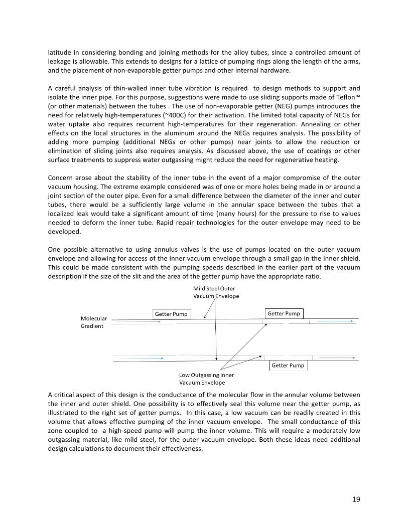
latitude in consideringbondingand joiningmethods for thealloy tubes, sincea controlledamountofleakageisallowable.Thisextendstodesignsforalatticeofpumpingringsalongthelengthofthearms,andtheplacementofnon-evaporablegetterpumpsandotherinternalhardware.A careful analysis of thin-walled inner tube vibration is required to designmethods to support andisolatetheinnerpipe.Forthispurpose,suggestionsweremadetouseslidingsupportsmadeofTeflon™(orothermaterials)betweenthetubes.Theuseofnon-evaporablegetter(NEG)pumpsintroducestheneedforrelativelyhigh-temperatures(~400C)fortheiractivation.ThelimitedtotalcapacityofNEGsforwater uptake also requires recurrent high-temperatures for their regeneration. Annealing or othereffects on the local structures in the aluminum around theNEGs requires analysis. The possibility ofadding more pumping (additional NEGs or other pumps) near joints to allow the reduction orelimination of sliding joints also requires analysis. As discussed above, the use of coatings or othersurfacetreatmentstosuppresswateroutgassingmightreducetheneedforregenerativeheating.Concernaroseabout the stabilityof the inner tube in theeventof amajor compromiseof theoutervacuumhousing.Theextremeexampleconsideredwasofoneormoreholesbeingmadeinoraroundajointsectionoftheouterpipe.Evenforasmalldifferencebetweenthediameteroftheinnerandoutertubes, there would be a sufficiently large volume in the annular space between the tubes that alocalized leakwould takeasignificantamountof time (manyhours) for thepressure to rise tovaluesneeded to deform the inner tube. Rapid repair technologies for the outer envelopemay need to bedeveloped.One possible alternative to using annulus valves is the use of pumps located on the outer vacuumenvelopeandallowingforaccessoftheinnervacuumenvelopethroughasmallgapintheinnershield.This could bemade consistentwith the pumping speeds described in the earlier part of the vacuumdescriptionifthesizeoftheslitandtheareaofthegetterpumphavetheappropriateratio.
Acriticalaspectofthisdesignistheconductanceofthemolecularflowintheannularvolumebetweenthe inner andouter shield.Onepossibility is to effectively seal this volumenear the getter pump, asillustrated to the right setof getterpumps. In this case, a lowvacuumcanbe readily created in thisvolume that allows effective pumping of the inner vacuum envelope. The small conductance of thiszone coupled to a high-speedpumpwill pump the inner volume. Thiswill require amoderately lowoutgassingmaterial, likemild steel, for theouter vacuumenvelope.Both these ideasneedadditionaldesigncalculationstodocumenttheireffectiveness.
20
Abriefsummaryofattributesandcostforconcept1aretablehere:
• Inneraluminumwallthicknessof½mm• Useofmildsteelreducesmaterialcosts• Moretolerantthanasinglesystemtoleakstotheatmosphere• Allowsoptimalpumpingstrategies• Reducescostandcomplexityofbakeout• Easiertocleanandmaintainsurfaceconditionsforthedetector• Toleranttoleaksbetweeninnerandoutersystems• Regulationofsharedvacuumusing“soft-sealingvalves”orshutters.
Theestimatedcostforconcept1is: Outertube $51M Innertube $1.6M Infieldfab $3M Total: $55.6M
Thecostestimateisforthebeampipeonlyinordertomakethecostcomparisontoequivalentlengthsofplasticpipe.Two-tubeconcept2:Independentinnerandoutervacuumspace.Thisvariantofthetwo-tubeconceptcallsforasealedinnerUHVvacuumtubeforlaserbeamtransport,concentricallydisposed insidean independentouter“guard”vacuumtube.The inner thin-wall tube isproposedtobefabricatedofeitheraluminumormildsteel,approximately1.5mmthick.Theoutgassingofmildsteel,asitiscurrentlybeingmanufacturedtoreducecarbon,isthoughttobesufficientlylowtopermit this; aswementioned above, further testsmay be required. In this design, the inner tube isthickerthanthe0.5mmofconcept1.Atube1.5mmthick,shouldbesufficienttogiveeitherAlorsteeltubingsomemechanicalstrengthtosustainsignificant lossofguardvacuum.Foraluminum1.5mmisprobablynotthickenoughtoserveasanindependentsingle-tubeagainstafull1atmospherepressuredifferential.WG2 examined the prospect ofmaking the outer tube from a fiber-glass reinforced plastic (FRP) [2].Manufacturers have been identifiedwho can fabricate an FRP tubes with up to 1.6m IDwith a wallthickness of 6.5cm, sufficient towithstand 1 atm [3 – 4]. The cost of such a structure has not beencarefullyanalyzed,butsomematerialsavingsmaybemadebyreducingthewallthicknessto~4cmbyaddingstiffenersevery0.6malongthelength.SuchanFRPtubecanbeevacuatedto~10-6torr,atwhichpressureawater-permeationbarrierontheinnerwallmaynotbeneeded.Sincethemainresidualgasiswater,adesiccantmightbeusedtofurtherreducethepartialpressure.Adifferentialpressureratioofguardtobeamtubechambersof>10,000issufficient toprotect theoperationof optical components in the innerbeam tube, allowingmoderateconductanceofgasbetweenthetubes.Alternativeplasticpipingmaterialswereexamined.Discussionswithpipeandvesselmanufacturers [5 -7] andconversationwithusersof large-scaleplastic vacuum
21
components [8] led us to reject unreinforced (extruded) plastic vacuum materials. The followingextrudedmaterialswererejectedaseitherbeingweaker,ormoreexpensive,orboth:PE(polyethyelene)[10–11],PPE(polyphenyleneether),PVC(polyvinylchloride)[2],FEP(fluorinatedethylenepropylene),PTFA(polytetrafluoroethylene),andPFA(perfluoroalkoxy).One supplier [7] haspreparedapreliminary cost [12]estimate for80kmof theguardvacuumpipe.TheestimatewasbasedonanFRPpipewitha1.6m I.D., assuminga1atm.pressuredifferential, atambient temperature, also assuming that the entire installation would be above-ground. Each outerpipe section is assumed to be 12 m in length, with wall thickness of 6.5 cm. (270 kg/m) for theunstiffenedcase,yieldingacostof$13,140persection.Asanalternative,each12msectionmayhaveawall thickness of 4 cm with stiffeners as above (200 kg/m), for a cost of $12,260 per section. Theestimatedtotalcostfor80kmofouterplastictubingisbetween$81Mand$86Mdollars,Aninnersteelvessel is estimated to cost $2.5M in materials plus ~$3M in fabrication for a total of $5.5M. Thecombinedtotalroughestimateis:Stiffened:$86.4M;Unstiffened:$92.2M. Thecostestimatesfortheplasticguardchamberandtheinnerbeamchambersincludeonlythecostofthepipematerials,anddonotincludeassemblyorotherrelatedcharges.It isimportanttonotethatthisouterFRPtubecostishigherthanthecostofsteelfornestedconceptabove[1]. Detailedcomparisonofsteelversusplasticfromthestandpointof lifetimeoperatingcosts,includingmaintenanceandrepairhasnotbeenperformed. Substantial industrialexperienceexists tocompare the environment degradation of metal versus plastic pipelines as a result of exposure totemperaturecycling,geo-environmentalweathering,biologicalagents,andsunlight.SurfaceTreatments
Theaboveconsiderationsdonotincludesurfacetreatmentstoimproveoutgassingoftheinnertubesorabsorptiveorothercoatingsthatmightbenecessaryordesirabletoimproveperformanceoftheopticalinterferometer. WG2 undertook discussions with coating suppliers and manufacturers to evaluate apossibility that emerged in theworkshop. Certain styles of deposited, or electrochemical conversion,coatings are used to create “blues” and “blacks” and other low-reflection finishes on metals. Thesefinishes, including nitrides [13], aluminides [14],metal oxides [15], glass [16], in addition to standardcarbides,oxynitrides,andothers,havealsobeenusedfor“passivation”,reducingcorrosionbycreatingbarrierlayersagainstincomingoxidizingspeciesatthesurface.Suchbarrierlayersalsomayreducethediffusionoflightermoleculargasescomingfromthedeeperstructuresonthemetalthatarereleasedasoutgassingcomponents.Manyof these coatings require activation to overcomeenergy barriers to their formation and so areproducedbyplasmaorelectrochemicalmeans,oralternatively,areproducedatelevatedtemperature.The ideawas to takeadvantageof thehigh temperatureassociatedwithmill hot-rollingof the sheetstock to be used for the inner chamber. At various points in that process, themetal temperature isbetweenambientand themeltingpoint, andby controllingexposure to reactive compounds, contacttime,pressure,andotherprocessvariables,onemightproduceanopticallyabsorptivesurfacelayeronthe stock that could also serves as a diffusion barrier, thereby lowering the outgassing. Possiblematerials thatmight be produced on amild steel as it comes off the rollersmight bemagnetite-like(Fe3O4),TiN,orothersuchlayers.
22
Such a process might be difficult to develop since the tolerance of the interferometer system forsuspendedparticlesisnearlyzero.Hotrollingproducesundesirablesurfacelayers(scale)thatareoftenremoved by harsh chemical means or post-treatments of stock, like electropolishing to smooth thesurface and reduce the depth of grain boundaries. These processes, which include high-temperaturebakes,electropolish,chemical-mechanicalpolish,andotherpassivationtreatmentdoindeedreducethedepthofgrainboundarycrevices,removevisibledefects,andleavemirror-likesurfacesthathavemuchbetter appearance than the mill finishes. Such high-cost treatments are frequently used insemiconductormanufacturingandotherprocessingchamberswheretheymaygiveawider latitudeinhandlingandoperationforprocessesthatcycletoairfrequently.However,thereislittleevidencethatthevacuumperformanceoftheseexpensivefinishesimprovestheshort-termoutgassingperformancecomparedtoproperlycleanedmill-finishedmetals[17].Conversioncoatingscreatedusingtheinherentheatofahot-rollingstepduringproductionofthemetalwould require a cooperative arrangement between a steel-mill and a national lab, or perhapswith auniversity, but suchaneffortmight returndividends for thisproject in the long-term indevelopingaprocess toenhance the sensitivityof the instrument. So, thepossibility forproductionofadepositedlayer or a conversion coatingwasdiscussed at lengthwith technical personnel at amajor supplier ofarchitecturalglassandwithasupplieroflarge-scalecoatedflexiblefilms.Thecurrentpracticeintheglassindustry[18]toproduceproprietarycoatings(mostlymultilayerstacks)onarchitecturalglasspanelsproducesaverywidevarietyofcoatings.SuchcoatingsaredonemainlybysputteringorPECVDon (optically smooth) flat glasspanels, thatbegin the coatingprocessesat roomtemperature.Thefloatglassfromwhichpanelstobecoatedarecut,comesoffamoltentinfloat-lineasa ribbon with a width of at least 130 inches (3.3m). Larger float-glass ribbon widths sufficient toproducea1–1.5mdiameter rolled tubecanbecoatedbyexistingequipment. In the roll-coated filmindustry[19],plasticsubstratesareprocessedinequipmentcapableofcoatingsimilarwidths.Themostcommon equipment for these films is sputtering or reactive sputtering to continuously producemultilayer stacks in roll-to-roll coater geometries. The energy required to overcome the reactionbarriersissuppliedbylargelychargedparticle(plasma)bombardment,allowinglowertemperaturestobe used where necessary. The adaption of these methods to using afterheat in a mill rollingenvironmentwasthoughttobeinterestingtobothsetsofmanufacturers.Thespecificationsandequipmentchoicesforprocessingareproprietarytoindustrialmanufacturers,asarethedetailedprocessconditionsrequired.Standardpracticeforlarge-scaleboxorroll-to-roll, inthefilm and plate markets is dominated by a small number of European firms [20-22]. Each makesequipmentthatcouldprocesssheetsteeloraluminuminwidthslargeenoughtofabricateacoatingontheinnerwalloftheinnertube.Conclusions
ThepurposeoftheWG2groupwastoevaluatewhethernestedchamber[1]designsareviableandcosteffective. The two-chambered coupled vacuum design is more completely described and discussedextensively.Thegroupconcludedthatitisaviabledesign.However,severalissuesneedmoreresearch.Softsealshutters,pumpringsasanalternativetoannularvalves,andactivatingZAOgettermodulesinanaluminumchamberneedmorestudy.
23
The two-chamber design with an inexpensive inner beam tube and an independent, guard vacuumchamberneedsmorestudy. Atthetimeoftheworkshop,severalplastics,e.g.PVC[2],HDPE[3],fiberreinforcedplastic[5-8],werediscussed.Onequestion,whetheranencapsulatingcoatingwasneededtoachievebasepressure,wasanswered.Manyplasticvacuummaterialsthatareproperlycuredachieveabase pressure ~10-6 torr, which is more than adequate. However, water is the main residual gas.Additionalpumpsforwaterwouldimprovetheguardchamberbasepressure.Subsequenttotheworkshop,technicaldiscussionsonthevariousplasticsdeterminedthatPVC,HDPE,and simple plastics would require a wall that would be too thick to make the guard chambereconomicallyviable.Fiberreinforcedplasticsareaviablealternative,however.Acostestimateofonlythepipeisincludedinthereport.SincebothconstructionandoperatingcostsareamajorconcernforCosmicExplorer,detailedcostanalyses, to includepipe, flexible joints, flanging,andothercomponentand their required assembly, should be performed as part of choosing one of the candidate vacuumchambergeometries.Thechoiceofasingle-wallbeampipe,oracoupledtwo-chambersystem[1]oratwo-chamber system with independent vacua needs to be made. If an independent two-chambersystemispreferred,thencostanalysiswillbeneededtodeterminewhetherthematerialfortheouterchambershouldbeplasticormetal.Recommendedactionitems• Developaconceptualdesignforsoftcloseshutters• Analyzepumpringsversusannularvalves• DesignworktoreducetheheatloadonthealuminumbeamtubeduringNEGactivation• Fabricatetwo-sectionsoftheFRPguardvacuumchamber.Performvacuumsystemtestingto
evaluatejoiningtechniques,basepressure,andvacuumintegrityagainstatmosphere• Studiesofanti-reflection,outgassingbarriercoatingsmaybeusefulfortheCosmicExplorer
References
1. R.Weiss,Presentationatthisworkshop,entitled,“Preliminarystudyanestedvacuumsystem
conceptfortheCosmicExplorer”,January2019,LIGODocumentT1900023-v1.2. https://www.ershigs.com/engineering-and-design-products/3. http://www.spencercomposites.com/wordpress/?page_id=94. https://www.franklinfibre.com/g-12-wound-tubes.html5. https://www.compositesworld.com/articles/new-steel-strip-reinforced-fiberglass-pipe-
handles-high-pressure-oilfield-applications6. MeyerTool:https://www.mtm-inc.com/av-20100827-plastics-in-vacuum-applications.html
http://www.harrisonplastic.com/index.html7. ErshigsInc.http://www.ershigs.com/wp-content/uploads/2012/07/FRPPowerIndustry.pdf8. NeutronElectricDipoleMomentExperimenthttps://www.phy.ornl.gov/nedm/contact:Dr.
JohnRamsey,PI9. http://www.harrisonplastic,com/index.html

24
10. https://plasticpipe.org/pdf/high_density_polyethylene_pipe_systems.pdf11. http://www.jmeagle.com12. RoughcostestimatefromMr.ChaunTrenary,Ershigs(seeref7above).13. http://creating-nanotech.com/en/product-thumbnail.html14. ASoleimaniDorchehandM.C.Galetz,SolarEnergyMaterialsandSolarCells,146,)8(2016).15. CalvinE.Hensler,“CharacterizingtheGrowthRateofaCorrosionLayeronStainlessSteelina
MoltenSaltEnvironment”,BSThesis,WilliamandMary(2017).16. PLiu,LWei,SYe,HXu,andYChen,SurfaceandCoatingsTechnology,205,3582,(2011).17. H.F.Dylla,D.M.Manos,andP.M.LaMarche,JVSTA11,2623(1993).18. Vitroarchitecturalglass(formerlyPPG)CheswickPA,https://www.vitrocom.com/Contact
name:PaulA.Medwick(seniorscientist)19. EastmanPerformanceFilms(formerlyCourtauldsInternational)MartinsvilleVA,
http://www.innovationlab.eastman.com/contactnameCharlesVanNutt,ApplicationsEngineer
20. VonArdenne(Dresden)https://www.vonardenne.biz/en/home/ 21. GrenzebachMaschinenbau(Asbach-Bäumenheim)
https://www.grenzebach.com/index.php?id=222. LeyboldGmbH(Cologne)https://www.leybold.com/en/applications/coating/
25
WorkingGroup3Report:Novelsurfacetreatmentsforconventional
andUHVmaterials
Co-Chairs:JamesFedchak(NIST),JonFeicht(LIGO)Charge
WorkingGroup3(WG3)ledadiscussionofnovelsurfacemodificationsand/orsurfacecoatingstomeetthe design requirements for hydrogen, water and contaminant outgassing in addition to meetingparticulateandreflectionrequirementsforthevacuumenclosuresfortheCosmicExplorer.Summary
ThecharterforWorkingGroup3wastodiscussbeamtubesurfaceprocessing,coatingmaterials,surfacecleaning techniques, acceptable particulate contamination levels and outgassing requirements forgravitational wave detectors. We were asked to review any novel surface coating materials for thepotentialtoachievefaster(water)pumpdownsandlowerhydrogendiffusionrates,andperhapsexhibitgood IR (1μ)opticalpropertiesaswell. Manypotential candidateswerepositedbut two results thatstoodoutwerethoseofParketal.(2014)[1]onthehydrogenoutgassingrateofmildsteel,andSaitoetal.(1999)[2]onTiNcoatedstainlesssteelbeingusedtopreclude(watervapor)baking.ParkreportedthatH2diffusioninmildsteelproducedbyvacuumdegassingwassubstantiallylowerthanthatproducedbyolder foundrytechniques.Park’sdatasuggeststhatmildsteelcouldbeusedfortheCosmic Explorer without having to perform thermal processing such as the air-bake that the LIGOstainlesssteelrequired.Thedownsideofmildsteeliscorrosion,howeveritwassuggestedbyD.HenkelthatconversioncoatingthesteelwithFe3O4(magnetite)orothercoatingsmaymitigatethis issueandmight improve the surface optical scattering properties using bidirectional reflectance (BRDF) at 1μwavelength.Y. Saito reported that a 1μm thick TiN coatingon surface-smoothed316 stainless steel is effective inminimizingwateradsorptionduringairexposure[2].Hereportedthatmicro-polishingtechniqueswereappliedtoTAMA300,aprototypegravitationalwaveinterferometersimilartoLIGO,duetotheinabilityof the TAMA300 system to be baked out following assembly.Micro-polishing alonewas found to beeffective,howeverthesurfacequicklyrechargedwithwaterwhenventedtoatmosphere.SaitonotedthatanadditionalTiN(or(TiOx)coatingwouldbeabetteroptionbutrequiresdevelopmentfor large-scale application. Poelker reported on their comparative outgassing studies [3] that showed TiNwasvery effective, reducing the apparent total outgassing rate by about four orders of magnitude vs.uncoated stainless steel, but cautioned that residual gas pumping by the Ti based coating is likelyoccurring,thusskewingthedata.One outcome of the WG3 session was an offer to arrange for additional investigations into theoutgassingofmildsteelandcoatedchambers,toincludeTiNanddiamond-likecarbon(DLC)usingthestandardizedchambergeometryofFedchaketal.(atNIST)viathespinningrotorgauge(SRG)technique.Optical measurements indicate DLC films perform well at 1μ wavelength [4]. LIGO also has recentexperiencewith304stainlesssteelbafflescoatedwithDLC,includingin-houseBRDFmeasurementsthatindicatethematerialhasexcellentopticalproperties.AplasmaCVDprocesswasusedtocoattheLIGObaffles, but since theprocess is proprietary to the vendor the exactmethod is not publicly available.Amorphoussilicon(a-Si)wasanothercandidatematerialdiscussed,howeverrecent[3]testingsuggests
26
that this material does not reduce outgassing but may preserve a low rate if the substrate is firstthermallyprocessed.DiscussionHighlights
Theimpliedgroundrulewasthatanyprocessbeingconsideredhadtobecompetitivewiththeexistingstate of the art (i.e., ~450C air prebake followed by in-situ water degas of the 304 stainless steelbeamtubedemonstratedatLIGO). Anynewproposedprocesshastoreducethehydrogenandwateroutgassingrateperthestatedrequirementsandbecostcompetitive.Anewprocesscouldpossiblybecost justified if it providedaunique property, such that a larger initial costwouldbe acceptable. Forexample,couldaDLCcoatingeliminatetheneedforsystembakesfollowingairexposures?ThehydrogenoutgassingofmildsteelmeasuredbyParketal.[1]wasmentionedrepeatedly,includingsomehistoricalnotesbyDyllaon(his)workonoutgassing[5]ofthismaterial.Dyllafurthernotedthathistorical data has errors that has precludedmild steel systems from being further investigated andconsidered.Regardingvacuumrequirementsforresidualgasspecies,R.WeissmentionedthatLIGO"overdidit”byrequiring such low H2O rates, so in the future a more modest bake might be sufficient. Updatedmaximum rates may possibly be higher depending on detailed calculations of the H2O adsorption-desorption dynamics based on the LIGO model developed by Weiss. The key metrics for residualmolecules are their polarizability and thermal speed. Largemolecules such as hydrocarbonsmust beeliminatedalmostentirely.TiNCoatings:Avarietyofphysicalvapordeposition(PVD)techniquesareusedtoapplyTiNcoatings.Abrief search of coating vendors shows that substrates can be successfully coated at substratetemperatures in the range of 450C [6]. Reactive sputtering and arc coating can be applied at nearambienttemperatures.Processparametershavetobecarefullycontrolledtoinsureproperbondingandpure TiN stoichiometry. [7] Itwas suggested that the steelwouldbe coated first, thenmanufacturedintoatube.Processing(webcoating)machinerysimilartoflatpanelorglasscoatinglinesthat includedifferential pumping input/output stages for processing sheet stock are in wide use and may beapplicable[8].DLC Coatings: The group spend considerable time discussing diamond-like carbon (DLC) films. Theyappear to have good outgassing characteristics, are relatively easy to apply, also have good opticalproperties.KEKhasreviewedthecoatingpropertiesfromseveralrelevantparameters[9].LIGOalsohasrecentexperiencecoatingbaffleswithDLC.Thedatawillbeprovidedas follow-up informationtothisworkshop.Wet (chemical solution,electroplating)processingofsteelwithcopperwasdiscussed,but thissystemneeds a Ni-strike layer for adhesion, and possible thermal treatment post-plating. There are bothelectrode and electro-less Ni systems. This approachwas discounted as impractical due to costs andrisks.D. Henkel mentioned that Fe3O4 (magnetite) may be a good coating candidate for mild steels. It istypicallyan“oxide+water”treatmentoritcanalternativelybeappliedwithanon-aqueousprocessathigher temperatures (>550C). Called "conversion coating”, these coatings help steel resist corrosion.Theprocesscreatesadiffuseblacksurfacethatmayhavegoodopticalproperties.ThematerialwouldneedBRDFmeasurementonsamplesforfurtherqualificationoftherequiredopticalproperties.
27
Abriefreviewofthemagnetiteprocess[10]indicatesthattheplatedsurfacemayhavelooseparticlescalled “smut” that needs to be removed by mechanical means. The plating smut would requireevaluationsinceLIGOissensitivetoparticlesfallingthroughthebeampathcreatingrandomnoise,orifdepositedonoptics,theparticlescancauselocalizedheating.
AlternateMaterialsandProcesses
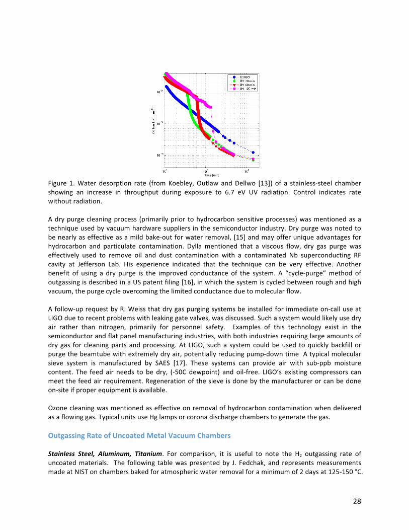
An alternate approach to reduce outgassing is mechanical surface modification. Surface smoothing(surfaceareareduction)canbedonebydiamondturningandhoning.Bothprocesseswerementionedas very effective, although the surface recharges with multi-monolayers of adsorbed water duringatmospheric venting (like all surfaces) but in proportion to the real surface area. Therefore, surfacesmoothing does have a quantitative effect of net water outgassing [11] when other surface andexposure conditions are controlled. A comparison of many of the surface smoothing and chemicalprocessingtechniquesusedtoprocessstainlesssteelandaluminumforUHVservicewasdonebyDylla,etal[12]withnetoutgassingafterairexposuresandsurfaceanalysisasthemetrics.Smalldifferenceswerenotedamonganyofthemoreextremetreatments(mirrorandelectropolishedsurfaces)comparedtonowstandardalkalinedetergentcleaningfollowedbyhot,cleanwaterrinsing.(Note:aversionofthelatterprocessingwasusedforLIGObeamtubes).Grainrefinedsteel.D.Henkelmentionedlow-alloysteelsmayhavebeneficiallowH2outgassingrates.This option requiresmore study of candidates, also a review of any other problems associatedwithusing this material. Cor-ten® steel was mentioned as an example, but it was also noted as havingcorrosion issues,even thoughgrain refining typicallyhelpswithcorrosion.This topic initiatedanotherdiscussion on the type of steel for fabrication of test samples. The selection of a tentative list willrequireadditionalliteraturereviewanddiscussionofcandidatematerials.R.Weissmentioned thatwatermoleculeswithadsorptionactivationenergies in the rangeof10,000-15,000Kelvinarethefractionofadsorbedmoleculesthatareimportanttogoafter(desorb),butdoubts“energywindowing”ispossible.Thethoughtbehindthisdiscussionwastoremindthegroupthathigherenergysiteshavesuchlongresidencetimesthattryingtodesorbthemisnotworththeenergyinput.UVlightsourceswereconsideredaspotentiallyusefulforoutgassingwaterfollowingairexposuresbutdiscounted as difficult to employ with the LIGO’s beam tube geometry. The energy level of typicalcommerciallyavailabledevices(Hgresonancelamps,Xearc)istoolow.Asourceontheorderof5-10eVis required to induce dissociation and desorption. A study by Koebley, Outlaw, and Dellwo [13]indicatedgoodresults (see the figurebelow),desorbing22monolayerswitha30minuteexposure to185nm(6.7eV)radiation,withthecaveatthattheradiationneedstobeprimarilyline-of-sightfromthesource. Examples of practical deep UV sources suitable to the LIGO beamtube geometry were notidentifiedbytheworkinggroupduringthecourseoftheworkshop.Thereareexamplesofelectrodelessgeometries(usingdielectricbarrier,RF,ormicrowaveexcitation)runningoninertgasesorinert-halogenmixturestocreateexcimeremissionsthathavebeendemonstratedtoproducekilowattsoflightintherangeof173–225nm.[14]However,practicalconcernsofthecostofdeliveringsufficientRFpowerandhandlingexpensiveinertgasesmaytipthescaletonovelvesselheatinganddrygaspurgingtechniquesforcost-effectivewaterremovaltechniques.
28
Figure 1.Water desorption rate (fromKoebley,Outlaw andDellwo [13]) of a stainless-steel chambershowing an increase in throughput during exposure to 6.7 eV UV radiation. Control indicates ratewithoutradiation.Adrypurgecleaningprocess (primarilyprior tohydrocarbonsensitiveprocesses)wasmentionedasatechniqueusedbyvacuumhardwaresuppliers inthesemiconductor industry.Drypurgewasnotedtobenearlyaseffectiveasamildbake-outforwaterremoval,[15]andmayofferuniqueadvantagesforhydrocarbon and particulate contamination. Dylla mentioned that a viscous flow, dry gas purge waseffectively used to remove oil and dust contamination with a contaminated Nb superconducting RFcavity at Jefferson Lab. His experience indicated that the technique can be very effective. Anotherbenefit of using a dry purge is the improved conductance of the system. A “cycle-purge”method ofoutgassingisdescribedinaUSpatentfiling[16],inwhichthesystemiscycledbetweenroughandhighvacuum,thepurgecycleovercomingthelimitedconductanceduetomolecularflow.Afollow-uprequestbyR.Weissthatdrygaspurgingsystemsbeinstalledforimmediateon-calluseatLIGOduetorecentproblemswithleakinggatevalves,wasdiscussed.Suchasystemwouldlikelyusedryair rather than nitrogen, primarily for personnel safety. Examples of this technology exist in thesemiconductorandflatpanelmanufacturingindustries,withbothindustriesrequiringlargeamountsofdry gas for cleaningparts andprocessing.At LIGO, sucha systemcouldbeused toquicklybackfill orpurgethebeamtubewithextremelydryair,potentiallyreducingpump-downtimeAtypicalmolecularsieve system is manufactured by SAES [17]. These systems can provide air with sub-ppb moisturecontent. The feed air needs to be dry, (-50C dewpoint) and oil-free. LIGO’s existing compressors canmeetthefeedairrequirement.Regenerationofthesieveisdonebythemanufacturerorcanbedoneon-siteifproperequipmentisavailable.Ozonecleaningwasmentionedaseffectiveonremovalofhydrocarboncontaminationwhendeliveredasaflowinggas.TypicalunitsuseHglampsorcoronadischargechamberstogeneratethegas.OutgassingRateofUncoatedMetalVacuumChambers
Stainless Steel, Aluminum, Titanium. For comparison, it is useful to note the H2 outgassing rate ofuncoatedmaterials. The following tablewaspresentedby J. Fedchak, and representsmeasurementsmadeatNISTonchambersbakedforatmosphericwaterremovalforaminimumof2daysat125-150°C.
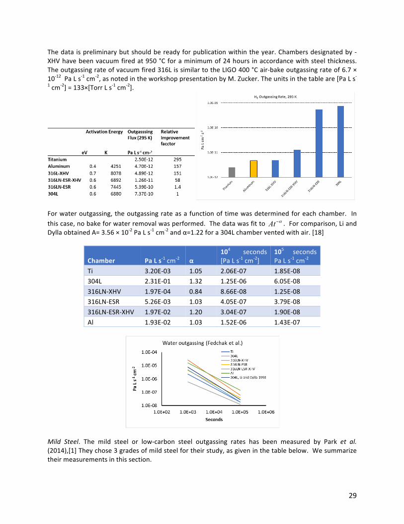
29
Thedata ispreliminarybutshouldbereadyforpublicationwithintheyear.Chambersdesignatedby-XHVhavebeenvacuumfiredat950°Cforaminimumof24hours inaccordancewithsteelthickness.Theoutgassingrateofvacuumfired316LissimilartotheLIGO400°Cair-bakeoutgassingrateof6.7×10-12PaLs-1cm-2,asnotedintheworkshoppresentationbyM.Zucker.Theunitsinthetableare[PaLs-1cm-2]=133×[TorrLs-1cm-2].
Forwateroutgassing, theoutgassingrateasa functionoftimewasdeterminedforeachchamber. Inthiscase,nobakeforwaterremovalwasperformed.Thedatawasfitto .Forcomparison,LiandDyllaobtainedA=3.56×10⁻²PaLs-1cm-2andα=1.22fora304Lchamberventedwithair.[18]
Chamber PaLs-1cm-2
α
104 seconds
[PaLs-1cm-2]10
5 secondsPaLs-1cm-2
Ti 3.20E-03 1.05 2.06E-07 1.85E-08304L 2.31E-01 1.32 1.25E-06 6.05E-08316LN-XHV 1.97E-04 0.84 8.66E-08 1.25E-08316LN-ESR 5.26E-03 1.03 4.05E-07 3.79E-08316LN-ESR-XHV 1.97E-02 1.20 3.04E-07 1.90E-08Al 1.93E-02 1.03 1.52E-06 1.43E-07
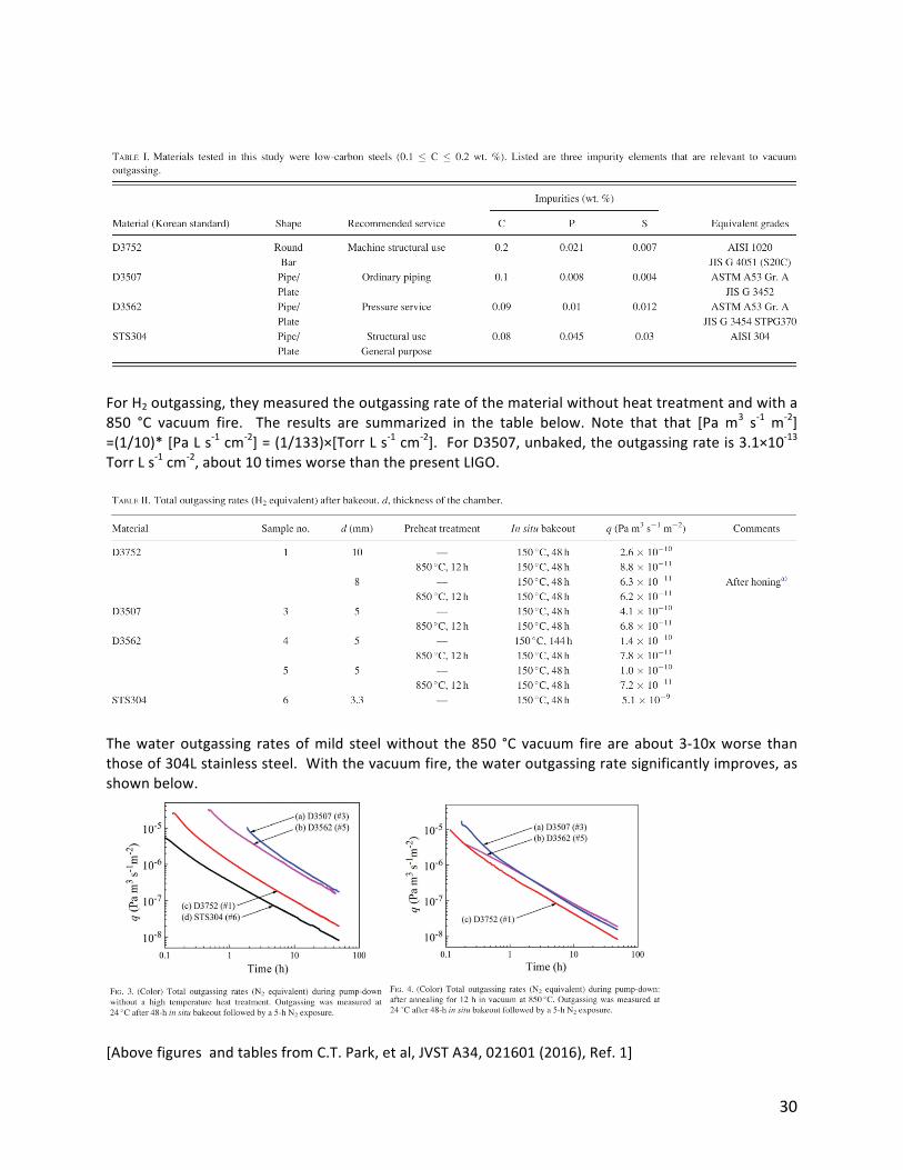
Mild Steel. The mild steel or low-carbon steel outgassing rates has been measured by Park et al.(2014),[1]Theychose3gradesofmildsteelfortheirstudy,asgiveninthetablebelow.Wesummarizetheirmeasurementsinthissection.
At α−
30
ForH2outgassing,theymeasuredtheoutgassingrateofthematerialwithoutheattreatmentandwitha850 °C vacuum fire. The results are summarized in the table below. Note that that [Pa m3 s-1 m-2]=(1/10)*[PaLs-1cm-2]=(1/133)×[TorrLs-1cm-2].ForD3507,unbaked,theoutgassingrateis3.1×10-13TorrLs-1cm-2,about10timesworsethanthepresentLIGO.
Thewateroutgassing ratesofmild steelwithout the850 °C vacuum fire are about3-10xworse thanthoseof304Lstainlesssteel.Withthevacuumfire,thewateroutgassingratesignificantlyimproves,asshownbelow.
[AbovefiguresandtablesfromC.T.Park,etal,JVSTA34,021601(2016),Ref.1]
31
OutgassingRateofCoatedSurfaces
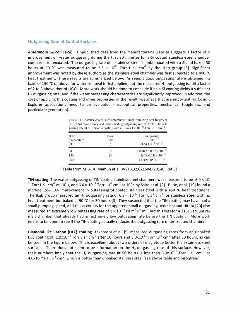
Amorphous Silicon (a-Si). Unpublished data from themanufacturer’s website suggests a factor of 9improvement onwater outgassing during the first 80minutes for a-Si coated stainless-steel chambercomparedtouncoated.Theoutgassingrateofastainless-steelchambercoatedwitha-Siandbaked30hours at 90 °C was measured to be 2.3 × 10⁻¹² Torr L s-1 cm-2 by the JLab group [3]. Significantimprovementwasnotedbytheseauthorsasthestainless-steelchamberwasfirstsubjectedtoa400°Cheattreatment.Theseresultsaresummarizedbelow.Asseen,agoodoutgassingrateisobtainedifabakeof150°Coraboveforwaterremovalisfirstapplied,butthemeasuredH2outgassingisstillafactorof2to3abovethatofLIGO.Moreworkshouldbedonetoconcludeifana-SicoatingyieldsasufficientH2outgassingrate,andifthewateroutgassingcharacteristicsaresignificantlyimproved.Inaddition,thecostofapplyingthiscoatingandotherpropertiesoftheresultingsurfacethatareimportantforCosmicExplorer applications need to be evaluated (i.e., optical properties, mechanical toughness, andparticulategeneration).
[TablefromM.A.A.Mamunetal,JVSTA32,021604,(20140,Ref.3]
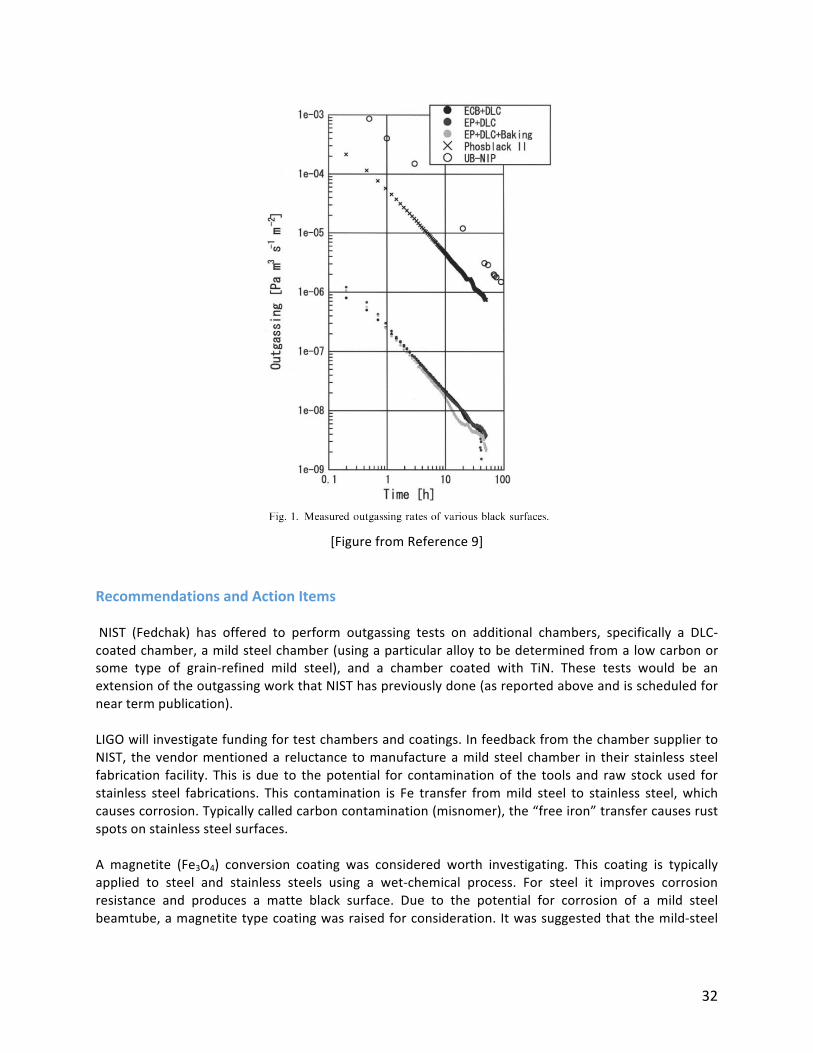
TiNcoating.ThewateroutgassingofTiNcoatedstainlesssteelchamberswasmeasuredtobe6.0×10-11TorrLs-1cm-2at104s,and6.0×10-12TorrLs-1cm-2at105sbySaitoetal.[2].P.He,etal.[19]foundamodest 15%-30% improvement in outgassing of coated stainless steelwith a 450 °C heat treatment.TheJLabgroupmeasuredanH2outgassingrateof6.3×10-12TorrLs-1cm-2forstainlesssteelwithnoheattreatmentbutbakedat90°Cfor30hours[3].TheysuspectedthattheTiNcoatingmayhavehadasmallpumpingspeed,andthisaccountsfortheapparentsmalloutgassing.AkimichiandHirata[20]alsomeasuredanextremelylowoutgassingrateof1×10−13Pam3s-1m-2,butthiswasfora316Lvacuumre-melt chamber thatalreadyhadanextremely lowoutgassing ratebefore theTiNcoating. MoreworkneedstobedonetoseeiftheTiNcoatingactuallyreducestheoutgassingrateofun-treatedchambers.Diamond-like Carbon (DLC) coating. Takahashi et al. [9]measuredoutgassing rates fromanunbakedDLCcoatingof,1.9x10-11TorrLs-1cm-2after10hoursand3.0x10-12TorrLs-1cm-2after50hours,ascanbeseeninthefigurebelow.Thisisexcellent,abouttwoordersofmagnitudebetterthanstainlesssteelsurfaces. Theredoesnotseemtobe informationon theH2outgassing rateof this surface.However,their numbers imply that the H2 outgassing rate at 50 hours is less than 3.0x10⁻¹² Torr L s-1 cm-2, or4.0x10-10PaLs-1cm-2,whichisbetterthanunbakedstainlesssteel(seeabovetableandhistogram).
32
[FigurefromReference9]
RecommendationsandActionItems
NIST (Fedchak) has offered to perform outgassing tests on additional chambers, specifically a DLC-coatedchamber,amildsteelchamber(usingaparticularalloytobedeterminedfromalowcarbonorsome type of grain-refined mild steel), and a chamber coated with TiN. These tests would be anextensionoftheoutgassingworkthatNISThaspreviouslydone(asreportedaboveandisscheduledforneartermpublication).LIGOwillinvestigatefundingfortestchambersandcoatings.InfeedbackfromthechambersuppliertoNIST, thevendormentioneda reluctance tomanufactureamild steel chamber in their stainless steelfabrication facility. This is due to thepotential for contaminationof the tools and raw stockused forstainless steel fabrications. This contamination is Fe transfer frommild steel to stainless steel,whichcausescorrosion.Typicallycalledcarboncontamination(misnomer),the“freeiron”transfercausesrustspotsonstainlesssteelsurfaces.A magnetite (Fe3O4) conversion coating was considered worth investigating. This coating is typicallyapplied to steel and stainless steels using a wet-chemical process. For steel it improves corrosionresistance and produces a matte black surface. Due to the potential for corrosion of a mild steelbeamtube,amagnetitetypecoatingwasraisedforconsideration. Itwassuggestedthatthemild-steel
33
chamber be conversion coated following as-received testing. This optionwill be added to the NISToutgassingtestinglist.
References
1. C.Park,T.Ha,andB.Cho,JVSTA34,021601(2016).2. Y.Saito,Y.Ogawa,G.Horikoshi,N.Matuda,R.Takahashi,andM.Fukushima,Vacuum53,353(1999).3. M.A.A.Mamun, A.A. Elmustafa,M.L. Stutzman, P.A. Adderley, andM. Poelker, JVSTA32, 021604
(2014).4. P.J.Kuzmenko,D.M.Behne,T.Casserly,W.Boardman,D.Upadhyaya,K.Boinapally,M.Gupta,Y.
Cao,“Hard,infraredblackcoatingwithverylowoutgassing”,SPIEAdvancedOpticalandMechanical
TechnologiesinTelescopesandInstrumentation,Marseille,France,June23-28,2008.Alsoinhttps://e-reports-ext.llnl.gov/pdf/361993.pdf
5. H.F.DyllaandW.R.Blanchard,“AComparisonofoutgassingratesfromstainlessandcarbonsteels”,AVS46thInternationalSymposium,Seattle,WA,25-29October1999(AVS,Cary,NC,1999).
6. https://www.calicocoatings.com/coating-data-sheets/titanium-nitride-pvd-tin-coating/7. PracticalNitridingandFerriticNitrocarburizing,ASMInternational(2003)
https://www.asminternational.org/documents/10192/1849770/06950G_Chapter_1.pdf8. Anexampleofamagnetron-basedwebcoatingsystem:
http://www.kobelco.co.jp/english/products/function/rollcoater/index.html9. R.Takahashi,Y.Saito,Y.Sato,T.Kubo,T.Tomaru,M.Tokunari,T.Sumiya,K.Takasugi,andY.Naito,
Vacuum73,145(2004).10. Fordetailsandmagnetiteconversioncoatings:https://www.anoplate.com/capabilities/anoblack-ss/11. M.Suemitsu,H.Shimoyamada,N.Miyamoto,T.Tokai,Y.Moriya,H.Ikeda,andH.Yokoyama,JVST
A10,570(1992).12. H.F.Dylla,D.M.Manos,andP.M.LaMarche,JVSTA11,2623(1993).13. S.R.Koebley,R.A.Outlaw,andR.R.Dellwo,JVSTA30060601,(2012).14. Anexampleofa2kWdeepUVexcimer(ArF)source,https://www.doctoruv.com/509252-p-
498.html.15. H.Ishimaru,K.Itoh,T.Ishigaki,M.Furutate,JVSTA10,547,(1992).16. Zhou,etal.,U.S.Patent5,879,467,IssuedMarch9,1999.17. Anexampleofapurgegassystem:http://www.saespuregas.com/Products/Gas-Purifier/PS22.html.18. M.LiandH.F.Dylla,JVSTA11,1702(1993).19. P.He,H.C.Hseuh,M.Mapes,R.Todd,andN.Hilleret,inProc.2003Bipolar/BiCMOSCircuitsTechnol.
Meet.(IEEECat.No.03CH37440)(IEEE,2003),pp.788–790.20. H.AkimichiandM.Hirata,Metrologia42,184(2005).
34
WorkingGroup4Report:Vacuumpumpingforconventional
andnestedsystems
Co-Chairs:YulinLi(Cornell)andPaoloChiggiato(CERN)
ChargeConsidervacuumpumpingschemesandpumpingscenariosforobtainingUHVconditionswithinthebeamtubeenclosureskeepinginmindconcernsformaintainingdifferentialpressureswithinnestedvacuumsystemsolutions.Summary
TheWorkingGroup4(WG4)convenedtodiscussvacuumpumpingfortheCosmicExplorer’s(CE)40-kmbeamtubes. The pumping systemwas considered for two CE beam tube designs, i.e. a conventionalsinglewalltubesimilartotheoneofLIGOasconsideredbyduringthisworkshopbyWG1,andanesteddouble-wall tube as presented by RainerWeiss [1] and further considered byWG2. There are threephasesofvacuumpumpingtobeconsidered:1).Roughingphasetoevacuateatmosphericgas;2).Bake-outphasetoremoveseveralmonolayersofwaterfrominnerwalls;3).Steady-statephasetomaintainUHVconditionsrequiredforphysicsruns,namelyinaveragePH2O<10-10TorrandPH2<10-9Torr.Thegoalofthediscussionwastogiveguidelinesforthechoiceofthepumpingsystem,takingintoaccountcostreduction,operationalefficiency,reliabilityandmarginforeachofthepumpingphase.
Pump-downprocess
RoughingphaseGeneralities
Given the reasonable design assumption of large gate valve incorporation able towithstand one bardifferentialpressure,the40-kmlongbeamtubescanbesectorizedinfour10-kmlongsegments;eachofthempumpeddownseparately.Theprocesswouldbringthetubesegmentfromatmosphericpressuredowntoa few10-2Torr (roughlya factor10abovetheultimatepressureof thepumps).Weconsiderlimitingpressures to this range tobeaprecautionwith respect to the riskof gasback-streamingandcontamination.Anaccidental ‘hydrocarbon’contaminationofthetubewallswouldbeverydifficult torecoverbytheforeseenmildbake-out,anditappearsasoneofthemajorriskstobeprevented.The time duration of the evacuation should not be a critical parameter; one-week long pumping, forinstance,couldbeacceptable.For thenested tubedesign, the followingrequirementswillhave tobeconsidered:
• Theinnercylindershouldbekeptpermanentlyataslightlyhigherpressurethantheouterone.Thefirstreasonispurelymechanical:theinnercylindercouldsufferbucklingataquitelow differential pressure, potentially at < 1 Torr depending on the detailed design. Inaddition, it is important toensure that the inner tubedoesnotbecomecontaminatedbygasesdesorbedfromtheouterpipe.
• Thesameconstraintswouldapplyfortheventingprocess.• Pumpsable tomanagea relativelyhigh loadofwatervaporshouldbeadopted incaseof
useofmultilayerthermalinsulationintheinnerspacebetweenthetwovacuumpipes.
35
Equipmentchoiceandprocedures
Singlewalldesign:Differentoptionscouldbeevaluatedforthechoiceofpumps:• severaldrypumpingsystems(20to40units)couldbeconnectedtothebeamtubebygate
valveportsspacedat250-mto500-mintervals;• justtwounitsprovidinglargethroughputcouldbeused,sincethespacingofpumpshas
relativelylowimportanceinthisphase.Forexample,rootspumpswithpumpingspeedsoftheorderof1000m3hr-1,backedbyproperdrypumps,couldbeused.
Aseriesofsuitablepressuregaugeswillmonitorthepressuregradientoverthetubelength.Aninterlocksystemwillprovidetheimmediateisolationofeachpumpincaseoffaultsandorlossofpower.Maintainingdifferentialpressuresinthenestedtubedesign:Inthenestedtubedesign,innertubesandoutertubesmaybeconnectedvia‘softannular’valvesinstalledat2kmintervalasproposedbyWeiss.During the roughing phase, these valves will be kept in open position to allow the simultaneousevacuation of the two volumes. The requirement is to avoid gas fluxmixing and tomaintain a givenoverpressure in the inner pipe over its entire length (the allowed overpressure range needs to bedetermined).AsimilarprocedureisbeingappliedfortheevacuationoftheVirgo‘towers’thatincludetwocontiguouscompartmentsseparatedbyarelativelythinKapton™membrane.Inthiscasetheallowedoverpressureisafewmbar.The geometryof the annular valves and the size andpositionof pumpsneed tobeoptimizedwith acomputational fluid dynamics (CFD) study, simulating the gas flow distribution in the system byaccountingforthedifferentvolumeandgasimpedanceofthetwocoaxialvessels.Shoulditturnoutnotto be practicable to meet the requirements, the other option would be to pump the two volumesseparately, controllingactively thedifferentialpressure (i.e.withapositivepressureofa fewmbar intheinnerpipe).Notethatnormallytherewillbenostrictmechanicalconstraintstohavetheinnertubeatrelativelyhigherinternalpressure.Subjectstoberesearchedandanalyzed
Singlewalltube:Arelativelylargeleakwoulddelaythepump-downanditwouldnotbeeasilylocalizedin viscous and transition regime flow. All welds should be fully qualified in advance via the provenmethodalreadydevelopedby LIGO; a similar pre-qualifyingprocedure should alsobe studied for theseveral‘minor’flangedjoints(forlocationofpumps,gauge,etc.).Nested tubesystem:theinnerpipewouldbemechanicallyvulnerabletoanaccidentalgasinlet intheoutervessel(forinstanceduetoafailureofamechanicalpumportoanimproperoperationduringthemechanical evacuation phase). A venting setup could be automatically operated in case of such‘emergencies’toincreasetheinnerpipepressure.Intermediatephaseandbake-outIntermediate
Inthisstagethe10-kmlongsegmentsshouldbebrokendownfurtherto2-kmlongsectionsbymeansofclosingthe‘softgate’valvesorashuttermechanismthatwouldlimitconductance.Theshortedsectors
36
simplify theprocess control; allowa reductionofnecessaryequipment (movable fromone section toanother);andreducetheelectricalpowerneededforthebake-out.The considered option is to make use of portable turbo-molecular pumping groups to evacuate thetubesfromthe10-2Torrdowntothe10-5Torrrange,drainingtheresidualairandgettingthetubesintoregime limited by the 1/t water outgassing. Hybrid turbos are an option. They can provide pumpingspeedhigherthan1000Ls-1andareabletostartworkingat0.1Torr inletpressure. Magneticbearingsuspensionshouldbepreferredforcleanlinessreasons.Forthenestedtubecase,the‘softannular’valvesarekeptopenandbothchambersareevacuatedbythe samepumpinggroups. As analternative, the twovolumes couldbepumped independently. TheCFDstudywillhelptosupportthefinalchoice.Bake-out
Oncethepressureisinthe1/tregime,thebake-outprocesscancommence.Forthesinglewalltube,itshallbeconvenienttoexploititslargeconductanceandusehighpumpingspeedpumpsforwatervapor.Cryopumpsmaybeusedforsuchaservice,sizeDN250mm,withtypicalnominalpumpingspeedlargerthan4000Ls-1 forwatervapor,asalreadyexperiencedbyLIGO.For thenestedcase, large ionpumpsanddistributedNEG(ZAOtypeoperatedaround200°C)wouldbeavalidoptionincombinationwithorin alternative to cryopumps. Simulations in the latter pumping configurationwere alsopresentedbyWeiss [1]. In both cases it will be advantageous to have the ‘soft gate’ valves closed to limit theprocessedtubelength,reducingtheamountofpumpingandheatingequipmentthatwillhavetoworkconcurrentlyandeasingatrouble-freeconclusionofthebake-out.Pumpspacingandotherparameters
Theprocessparametersaretemperature,timeduration,andpumpspacing.Thewaterloadonsurfaceswillbegivendependingonchoicesofmaterialsandconditioningtreatments.TheWeissmodel [2] forwateroutgassingshouldbethemaintoolusedtoevaluatethebesttradeoffforthedesigninordertoattain the desired water outgassing rate (nominally < 1x10-15 Torr Ls-1cm-2) since it has beenbenchmarked with LIGO performance. The choice of the baking temperature will require iterationsconcerning the design of the tube structure, the location and speed of the pumps, the design of thebakingsystemandthepre-conditioningofthebeampipes.Thepumpspacingshouldbedrivenbythenecessitytolimitthepeakwaterpartialpressure;probablyareducedpumpinterval(250mforinstance)willbeneededinthecaseofthechoiceofalowerbake-outtemperature. Finally, the timedurationwouldprobablybe less critical provided its compatibilitywiththeoverallprojectschedule.Someconsiderations
Theportsused forconnectingpumpsduringthebake-outcouldbeequippedwithvalveswithViton™sealsongates for reliability reasonsand for reducing thecost.Once thebaking is finished, thevalvesshouldbeclosedwithblindflangesandkeptunused.Becauseofapossiblethreatofleaksinthelong-termoperation,thenumberofpumpingportsshouldsubstantiallymorethantheminimumneededintheoptimumsituationasprescribedbysimulations.Duringthebakingprocessitshouldbepossibletomonitorthe leveloftheorganiccontaminantspresentamongtheresidualgases;thetimedurationofthebakingprocessshouldbedrivenalsobytheirevolution.
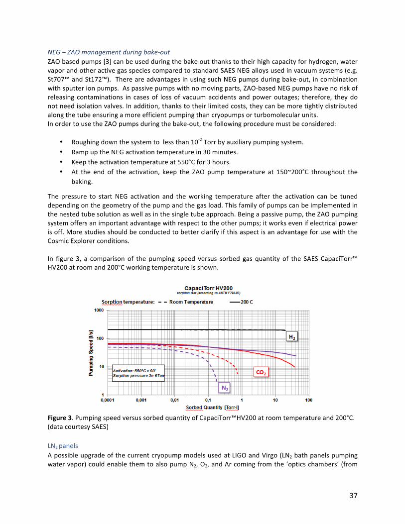
37
NEG–ZAOmanagementduringbake-out
ZAObasedpumps[3]canbeusedduringthebakeoutthankstotheirhighcapacityforhydrogen,watervaporandotheractivegasspeciescomparedtostandardSAESNEGalloysusedinvacuumsystems(e.g.St707™andSt172™).ThereareadvantagesinusingsuchNEGpumpsduringbake-out,incombinationwithsputterionpumps.Aspassivepumpswithnomovingparts,ZAO-basedNEGpumpshavenoriskofreleasing contaminations in casesof lossof vacuumaccidents andpoweroutages; therefore, theydonotneedisolationvalves.Inaddition,thankstotheirlimitedcosts,theycanbemoretightlydistributedalongthetubeensuringamoreefficientpumpingthancryopumpsorturbomolecularunits.InordertousetheZAOpumpsduringthebake-out,thefollowingproceduremustbeconsidered:
• Roughingdownthesystemtolessthan10-2Torrbyauxiliarypumpingsystem.• RampuptheNEGactivationtemperaturein30minutes.• Keeptheactivationtemperatureat550°Cfor3hours.• At the end of the activation, keep the ZAO pump temperature at 150~200°C throughout the
baking.
The pressure to start NEG activation and theworking temperature after the activation can be tuneddependingonthegeometryofthepumpandthegasload.Thisfamilyofpumpscanbeimplementedinthenestedtubesolutionaswellasinthesingletubeapproach.Beingapassivepump,theZAOpumpingsystemoffersanimportantadvantagewithrespecttotheotherpumps;itworksevenifelectricalpowerisoff.MorestudiesshouldbeconductedtobetterclarifyifthisaspectisanadvantageforusewiththeCosmicExplorerconditions.In figure 3, a comparison of the pumping speed versus sorbed gas quantity of the SAES CapaciTorr™HV200atroomand200°Cworkingtemperatureisshown.
Figure3.PumpingspeedversussorbedquantityofCapaciTorr™HV200atroomtemperatureand200°C.(datacourtesySAES)LN2panelsApossibleupgradeofthecurrentcryopumpmodelsusedatLIGOandVirgo(LN2bathpanelspumpingwatervapor)couldenablethemtoalsopumpN2,O2,andArcomingfromthe‘opticschambers’(from
38
materials, leaks,permeation,etc.).Thiswouldshortentherecoveryafteropticchambersmaintenanceinterventions (venting) and possibly improve the vacuum level in the beam tubes. Such an upgradecouldbeperhapsrealizedbyaddingacoldersectionworkingwithNe-Hecyclesoradsorbentmaterials(abletoworkat77K).
PumpingforSteady-StateOperationsIdealsteady-stateoperationsAfteraproperpumpdownandabake-out,theoutgassingratefrominteriorwalls(insinglebeamtubeandnestedbeamtubedesigns)isexpectedtobeverylow,oftheorderof10-15and10-14Torr⋅L/s⋅cm2forH2OandH2,respectively.Simulationsshowedthatpumpsofpumpingspeedof1000L/sspacedat1-kmintervals are sufficient tomaintain the requiredUHV conditions for the beam tubes, namely averagepartial pressures less than 10-10 and 10-9 Torr for H2O and H2, respectively. In the ideal steady-stateoperation,itisassumedthattheselimitingpressurescanbeobtainedbothwithasinglewalldesignpipefreeofairleaks,oranestedpipedesignwithsufficientlylowannularpressure(lessthan10-8torr).Singlewallbeamtubedesign
NEGpumpsaresuitableforthesteady-stateoperation.ZAO-typeNEGpumpshaveverylargepumpingcapacitiesforH2andH2Otohandleyearsofoperationwithoutre-activation. Theyearlygas loadsarerelativelyminor(oforderofmagnitudeof10Torr-LperyearperkmforH2,andtentimeslowerforH2O)whencomparedtoNEGgascapacities.Forinstance,theUHV1400™modulefromSAES(1360L/sforH2andsimilarforH2O)hasasingle-runcapacityof7200Torr-LforH2andlikelyatleast10Torr-LforH2O.Thehighvacuumversionofthepump,HV800™delivers10,500Torr-LforH2andsomehundredsofTorr-LforH2O.Therefore,thehydrogencapacitydoesnotneedtoberegeneratedandthepumpsshouldbereactivated every few years to refresh the water capacity. As usual, auxiliary ion pumps should beinstalledtopumptracesofnoblegasesandmethane.Thedistancebetweenthepumpswoulddependonpotentialsourcesofsuchgasesthatshouldbeattentivelyquantified.Nestedbeamtubedesign
The pumping in the inner tube can have a similar configuration as in the single wall design, thoughimplementationoftheNEGpumpsrequiressignificantlymoredesignwork.Relativelylargegasloadstotheannularspaceisexpected,fromeithertheunbakedoutertubeandairleaks.Ifthetotalgasloadcouldbelimitedtolessthan10-4TorrL/s/km,2000-L/s,ionpumpseverykmwould produce an annular pressure on the order of 5 x 10⁻⁸ Torr. However, pressure profiles in theannular space must be analyzed in detail to understand the impact of very high pressure ‘bumps’between ionpumpstaking intoconsiderationofthethermalradiationshield. Therefore,therequiredconductancelimitationof1L/sfromannularspaceto innertubewouldproduceagas loadof5x10-8TorrL/s/kminsidetheinnermostregion,whichisequivalenttothewatervaporoutgassingrateofthebakedinnertube.PumpingwithcontingenciesForlong-termoperations,variouscontingencysituationsmustbetakenintoaccountsuchassmallleaksor dry-air venting of the beam tubes (with no subsequent baking). More closely spacedpumps (lessthan 1 km) should be included, especially considering that the pumping system constitutes only arelativelysmallportionofthefacilitycosts.

39
Titanium sublimation pumping (TSP)may be considered as a lower cost option for distributed getterpumpingforhandlingcontingencies.TheuniquefeatureoftheLIGObeamtubesistheavailabilityofalarge interior surface for deposition of Ti thin films. For H2O pumping, TSP can provide very highpumping speedwith comparable pumping capacity toNEG pumps. For instance, 1-m2 of Ti film canprovideH2Opumpingspeedsof70,000L/swithasingle-runcapacityof10Torr⋅L[4].IncontrasttotheNEG re-activation process, re-deposition of a Ti film is amuch faster process (minutes vs hours) andproducesmuchlesspressureexcursionstothevacuumsystem.Long-termoperationsofTSPshadbeensuccessfully deployed in particle accelerators, such Fermi Lab and CESR [5, 6]. Optimal integrationshould be studied for the CE project. The long-term risk of dust productionmust be experimentallyassessed.VacuumInstrumentationDistributedvacuumgauges(100to250-minterval)shouldbeinstalledtomonitorthepressureprofileinthebeamtubeandprovidemeanstolocalizeleaks.
ConclusionsTheWorkingGroup4hasproposedastrategyforthepumpingofthe40-kmlongbeamtubesoftheCE.The pumping process leading to the required pressures has been subdivided in three phases: pumpdown, bake-out and steady state operation. For each of them there is no showstopper; a choice ofpumps based on previous experience has been presented. However, some crucial points should beinvestigatedindetail:• Theneededpumpingspeeddependsontheoutgassingrate,whichinturndependsonthe
effectivenessofthebake-outandmaterialchoice.Today,theeffectofthebake-outisbasedonpositiveexperiencesofLIGOandVirgo.Dedicatedsimulationsandexperimentalvalidationareanimportantsteptovalidatethenewchosentubedesignandtheglobalpumpingscenario.Theoutgassingpropertiesofthechosenmaterialsshouldbereliablymeasuredafterdifferentsurfacetreatments.
• Thepumpdowninthenestedtubeapproachneedsspecialattentiontoavoidbucklingofthealuminumliner.Dedicatedcalculationsarerecommended.
• TheNEGpumpingconfigurationandpropertiesshouldbeoptimizedforthespecificcaseoftheCE’sbeamtube.Theintegrationinthenestedtubehastobeevaluatedindetail.
• AdeeperfunctionalandcostanalysisoftheTisublimationpumpsshouldbetackled.
References
1. R.Weiss,“ApreliminarystudyofthevacuumsystemforthebeamtubesoftheCosmicExplorer”,
January2019,presentedatthisworkshop,LIGODocumentT1900023-v1.2. R.Weiss,“Reanalysisofaveragepressureinthebeamtube…”,LIGODocumentT080330-00-V
(2008)3.https://www.saesgetters.com/zao%C2%AE4.K.Welch,CapturePumpingTechnology,2ndEd.,(ElsevierScience,NewYork)2001,p.208
5. N.B.Mistry,etat,"MassivetitaniumpumpingintheCESRinteractionregion",Proceedingsofthe1997ParticleAcceleratorConference,Vancouver,B.C,(IEEE,NewYork,1997)p.3559

40
6. Y.Li,etal,“VacuumchamberwithdistributedtitaniumsublimationpumpingfortheG-line
wiggleratCornellHighEnergySynchrotronSource”,JVST,A21,1447(2003)
41
WorkshopConclusionsandRecommendations
Theworkshopparticipantswereconfidentthattechnicalsolutionscouldbedevelopedthatwouldhavenon-trivialimpactonthecostofthedesign,constructionandlife-cycleoperationofvacuumsystemsforthe proposed next generation gravitational wave observatories. The two potential projects beingdiscussedpresentlyby thegravitationalwavecommunityare theCosmicExplorer in theU.S. and theEinsteinTelescope intheEU.Bothprojects incorporate interferometerarmswithUHV-qualityvacuumenclosures that are 10-40 km in length — up to an order of magnitude larger than the presentgenerationofgravitationalwavedetectors.Two classes of solutions for the vacuum enclosures were examined: the first design concept is anextrapolation of the single-wall vacuum pipe in use in the present generation of detectors (at LIGO,Virgo, and KAGRA). The second design concept involves double-walled or nested vacuum pipes thatwouldseparatetheatmosphericloadproblemfromthestringentUHVpropertiesneededfortheinnerwall.Vacuumpumpingsolutionsandsurfacetreatmentswereexaminedforbothconceptdesignswithan emphasis on potential hardware and treatments that could lower total costs but still meet thestringent vacuum, vibration, particulate and optical characteristics required for next generationgravitationalwavedetectors.Conclusions
• Bothdesignconcepts(single-walledandnestedvacuumpipes)shouldbecarriedtothenextlevelofdetaileddesign,engineeringandcoststudies.Theworkshopidentifiednoseriousissuesthatwoulddisqualifyeitherdesignconceptatthisearlystage.
• Forthesingle-wallvessel,twootheradditionalmaterialsshouldbeconsideredforthevessel:alowcarbon,mildsteelalloyandaluminum,inadditiontokeepingthestainlesssteelasthecomparisonmaterialbasedontheexperienceoffirst-generationinstallations.Boththemildsteelandaluminumcouldoffersignificantcostsavings.Anumberofconcernsareraisedforfurtherstudyintheworkshopreporttoquantifyrealizedcostsinafinalsystem.Theseincludechoiceofthemildsteelalloy,potentialsurfacetreatmentsorcoatingsforthemildandstainlesssteelandthealuminumalloy,andthecostofincorporatingthemanytransitionelements(flangingandexpansionjoints)ifaluminumischosenasthebasevesselmaterial.
• Forthenestedvesselconcept:aluminumisconsideredasthebaselinematerialfortheinnervesselbecauseoftheeaseofin-situbakeoutandtheslightlybetterwateradsorptioncharacteristicscomparedtostainlesssteel.Fortheoutervesselmaterial:theuseofmildsteelandanumberofpolymercompositeswereconsideredandbothoptionsfortheoutervesselshouldremainunderconsiderationduringtheinitialdesignphase.
• Inordertominimizethecostofin-situbakeoutsystemsforremovalofadsorbedwaterfollowingtheinitialorsubsequentexposuretoair,anumberofpotentialsurfacecoatingswereidentifiedforstainlessandmildsteelsincludingTiC,diamond-likecarbon(DLC),amorphousSilicon(a-Si)andaclassofconversionscoatingssuchasmagnetite(Fe3O4)thatcouldbeappliedduringthemillprocessingofthesteel(so-calledconversioncoatings).AnumberofcharacteristicsofthesecoatingswereidentifiedforfurtherstudybeforetheircosteffectivenesscouldbequantifiedincludingadditionalH2Oadsorptionstudies,coatingdepositioncostsatscale,filmtoughness,particulategeneration,interferencewithvesselwelding,andopticalcharacteristics.
42
• Viablefirstorderpumpingschemeswereofferedforbothvacuumvesselconcepts.Specificpump-downroutineswereidentifiedfromatmosphericpressuretoUHVusingpumpsthatwouldminimizeoreliminatehydrocarbonorparticulatecontamination.Thecontinueduseoflargearealiquidnitrogenpanelswasrecommendedbasedonthehigh-waterpumpingspeedandsatisfactoryperformanceincurrentgenerationsystems.UHVperformancecanbemaintainedwithperiodicallyspacedgetterpumpsandionpumps.TheavailabilityofthenewgetteralloyfromSAES(ZAO)isparticularusefulforthisapplicationbecauseofitslargepumpingspeedandcapacityforH2OandH2.inaddition,conventionaltitaniumsublimationpumps(TSP)arenotruledoutforconsideration.
• Theuseofclean,ultra-dry(ppbwater),warmgaspurgingsystemscouldsignificantlyaffecttheneedforin-situbake-outsystemsforremovalofadsorbedwaterfollowingtheinitialorsubsequentpump-downsfromatmosphericpressure.TheincorporationforsuchsystemsforLIGOandtheotherfirst-generationgravitationalwaveobservatoriescansignificantlyshortendowntimeintheeventofaloss-of-vacuumincident.
• Thevalueofpartnershipswithindustrialcontractorswithrelevantexpertisewasdemonstratedthesuccessfuldesign,installationandoperationoftheLIGOvacuumvessels(andsimilarpartnershipsareevidentatVirgoandKAGRA).Suchpartnershipscanbevaluableinthepre-competitivephasetotesttheviabilityofconceptsproposedinthisworkshopandtheyarecertainlyvaluableinthefinaldesignandearlyconstructionsphasestotestprototypesoffullvesselsegments.
Recommendations
• Thetwoidentifiedvesselschemes(singlewalledandnested)shouldbecarriedfurthertoquantifythepotentialcostofconstruction,installationandoperationatscale.
• Aseriesofmaterialsandsurfacestudiesshouldbeundertakentoexamineparticularmildsteelalloysandaluminumfabricationtechniquesthatcouldbemostadvantageousandcosteffectiveforgravitationalwavedetectorvacuumvesseldesigns.(Specificrecommendationsonmaterial,studiesandsurfacetreatmentsaregivenintherecommendationsectionsoftheworkshopworkinggroupreports.)
• ThegravitationalwaveobservatorycommunityshouldtakeadvantageoftheoffersfromworkshopparticipantsfromNIST,JLabandCERNtoinvestigatetheH2Oadsorption/desorptioncharacteristicsoftheseveralpotentialsurfacecoatingsidentifiedbythesurfacetreatmentworkinggroup(TiC,DLC,a-Siandconversioncoatings).
• Recommendationsforspecificpumpplacementsforeithervacuumvesselconceptwouldbedependentonvacuummodelcalculationsbasedonmoredetailedvesseldesignswhenavailablelaterinthedesignphase.
• Workshopparticipantsrecommendthatafollow-upworkshopwithsimilarparticipationwouldbeadvantageoustotakeadvantageofthisgroup‘sexpertiseforguidanceoncontinuingdesignstudiesandrelatedtests.TheFallof2019isasuggestedtimeframeforthenextworkshop.
• Arecommendedgoalforthenextworkshopisthelayoutofaresearchagendaforshorttermresearchprojectsthatwouldfocusonquantifyingthecost-benefitofmaterialschoicesandsurfacetreatmentsidentifiedinthisworkshop.
43
Acknowledgements
ThisWorkshopwasmadepossiblebyU.S.NationalScienceFoundationawardPHY-1846124,issuedbytheGravitationalPhysicsPrograminthePhysicsDivisionoftheNSFDirectorateforMathematicalandPhysicalSciences.AdditionalsupportwasprovidedbyLIGOLaboratory,whichisoperatedforNSFunderNSFCooperativeAgreementPHY-1764464.TheorganizerswouldliketothankthestaffofLIGOLivingstonObservatoryfortheirsupportandhospitality.WewouldalsoliketoexpressourgratitudetoMarieWoods(LIGOMIT),MelanieMcCandless(LIGOLivingston),andCarolynPeterson(LIGOHanford)fortheireffortsonbehalfoftheWorkshop'sattendeesandguests.WeacknowledgetheactiveparticipationofalloftheattendeesduringtheWorkshopandappreciatethe efforts of our colleagues who travelled from Europe and Japan to participate. We give specialacknowledgement to theWorkingGroupCo-Chairs for their contributions, both during theworkshopandafterwardswiththeirinputtothissummaryreport.
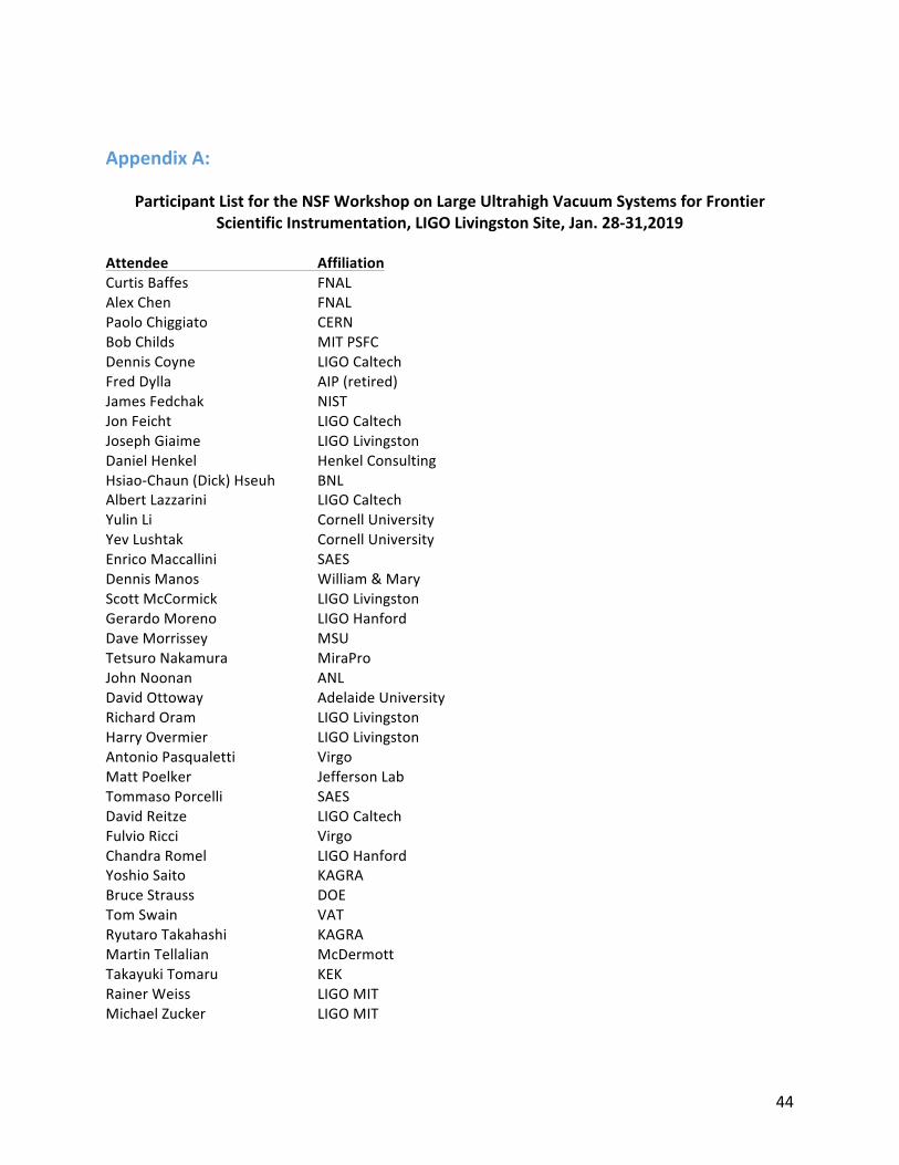
44
AppendixA:
ParticipantListfortheNSFWorkshoponLargeUltrahighVacuumSystemsforFrontier
ScientificInstrumentation,LIGOLivingstonSite,Jan.28-31,2019
Attendee Affiliation
CurtisBaffes FNALAlexChen FNALPaoloChiggiato CERNBobChilds MITPSFCDennisCoyne LIGOCaltechFredDylla AIP(retired)JamesFedchak NISTJonFeicht LIGOCaltechJosephGiaime LIGOLivingstonDanielHenkel HenkelConsultingHsiao-Chaun(Dick)Hseuh BNLAlbertLazzarini LIGOCaltechYulinLi CornellUniversityYevLushtak CornellUniversityEnricoMaccallini SAESDennisManos William&MaryScottMcCormick LIGOLivingstonGerardoMoreno LIGOHanfordDaveMorrissey MSUTetsuroNakamura MiraProJohnNoonan ANLDavidOttoway AdelaideUniversityRichardOram LIGOLivingstonHarryOvermier LIGOLivingstonAntonioPasqualetti VirgoMattPoelker JeffersonLabTommasoPorcelli SAESDavidReitze LIGOCaltechFulvioRicci VirgoChandraRomel LIGOHanfordYoshioSaito KAGRABruceStrauss DOETomSwain VATRyutaroTakahashi KAGRAMartinTellalian McDermottTakayukiTomaru KEKRainerWeiss LIGOMITMichaelZucker LIGOMIT
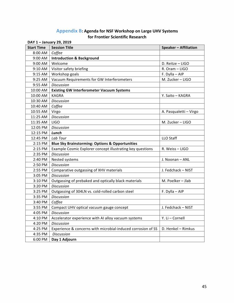
45
AppendixB:AgendaforNSFWorkshoponLargeUHVSystems
forFrontierScientificResearch
DAY1–January29,2019
StartTime SessionTitle Speaker–Affiliation
8:00AM Coffee 9:00AM Introduction&Background 9:00AM Welcome D.Reitze–LIGO9:10AM Visitorsafetybriefing R.Oram–LIGO9:15AM Workshopgoals F.Dylla–AIP9:25AM VacuumRequirementsforGWInterferometers M.Zucker–LIGO9:55AM Discussion
10:00AM ExistingGWInterferometerVacuumSystems 10:00AM KAGRA Y.Saito–KAGRA10:30AM Discussion 10:40AM Coffee 10:55AM Virgo A.Pasqualetti–Virgo11:25AM Discussion 11:35AM LIGO M.Zucker–LIGO12:05PM Discussion 12:15PM Lunch 12:45PM LabTour LLOStaff2:15PM BlueSkyBrainstorming:Options&Opportunities 2:15PM ExampleCosmicExplorerconceptillustratingkeyquestions R.Weiss–LIGO2:35PM Discussion 2:40PM Nestedsystems J.Noonan–ANL2:50PM Discussion 2:55PM ComparativeoutgassingofXHVmaterials J.Fedchack–NIST3:05PM Discussion 3:10PM Outgassingofprebakedandopticallyblackmaterials M.Poelker–Jlab3:20PM Discussion 3:25PM Outgassingof304LNvs.cold-rolledcarbonsteel F.Dylla–AIP3:35PM Discussion 3:40PM Coffee 3:55PM CompactUHVopticalvacuumgaugeconcept J.Fedchack–NIST4:05PM Discussion 4:10PM AcceleratorexperiencewithAIalloyvacuumsystems Y.Li–Cornell4:20PM Discussion 4:25PM Experience&concernswithmicrobial-inducedcorrosionofSS D.Henkel–Rimkus4:35PM Discussion 6:00PM Day1Adjourn
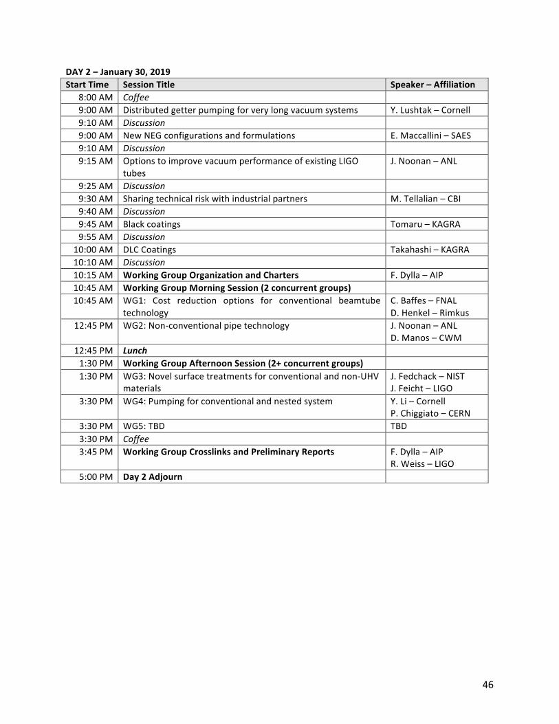
46
DAY2–January30,2019
StartTime SessionTitle Speaker–Affiliation
8:00AM Coffee 9:00AM Distributedgetterpumpingforverylongvacuumsystems Y.Lushtak–Cornell9:10AM Discussion 9:00AM NewNEGconfigurationsandformulations E.Maccallini–SAES9:10AM Discussion 9:15AM OptionstoimprovevacuumperformanceofexistingLIGO
tubesJ.Noonan–ANL
9:25AM Discussion 9:30AM Sharingtechnicalriskwithindustrialpartners M.Tellalian–CBI9:40AM Discussion 9:45AM Blackcoatings Tomaru–KAGRA9:55AM Discussion
10:00AM DLCCoatings Takahashi–KAGRA10:10AM Discussion 10:15AM WorkingGroupOrganizationandCharters F.Dylla–AIP10:45AM WorkingGroupMorningSession(2concurrentgroups) 10:45AM WG1: Cost reduction options for conventional beamtube
technologyC.Baffes–FNALD.Henkel–Rimkus
12:45PM WG2:Non-conventionalpipetechnology J.Noonan–ANLD.Manos–CWM
12:45PM Lunch 1:30PM WorkingGroupAfternoonSession(2+concurrentgroups) 1:30PM WG3:Novelsurfacetreatmentsforconventionalandnon-UHV
materialsJ.Fedchack–NISTJ.Feicht–LIGO
3:30PM WG4:Pumpingforconventionalandnestedsystem Y.Li–CornellP.Chiggiato–CERN
3:30PM WG5:TBD TBD3:30PM Coffee 3:45PM WorkingGroupCrosslinksandPreliminaryReports F.Dylla–AIP
R.Weiss–LIGO5:00PM Day2Adjourn
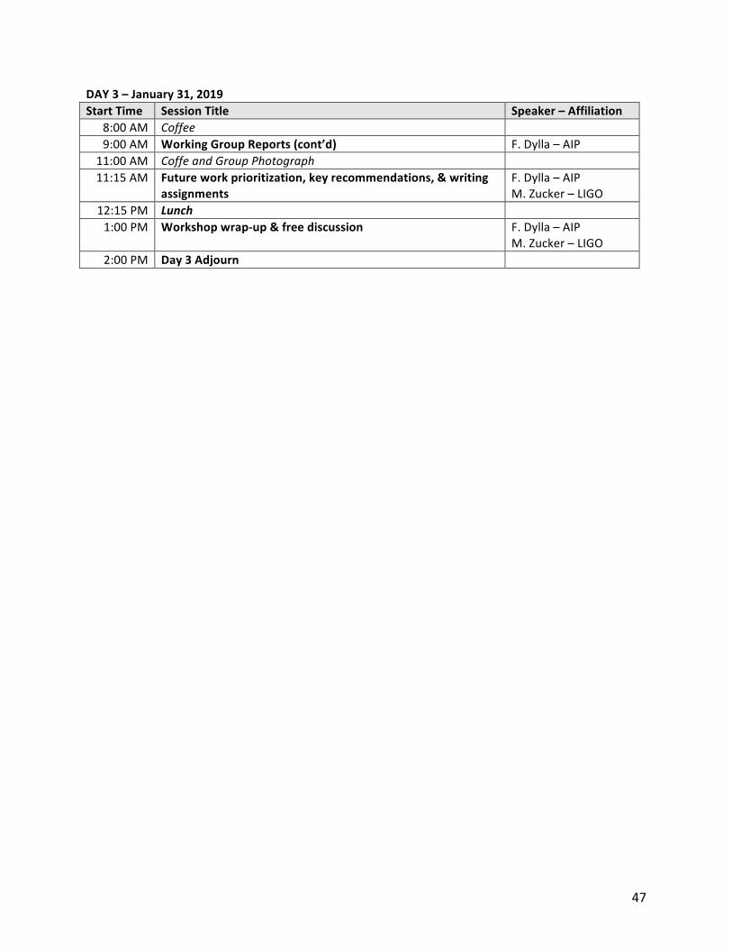
47
DAY3–January31,2019
StartTime SessionTitle Speaker–Affiliation
8:00AM Coffee 9:00AM WorkingGroupReports(cont’d) F.Dylla–AIP
11:00AM CoffeandGroupPhotograph 11:15AM Futureworkprioritization,keyrecommendations,&writing
assignments
F.Dylla–AIPM.Zucker–LIGO
12:15PM Lunch 1:00PM Workshopwrap-up&freediscussion F.Dylla–AIP
M.Zucker–LIGO2:00PM Day3Adjourn