ANSI EIAITIA-530-A - bitsavers.org
40
( In this report: Mechanical Characteristics .................... 2 Functional Description of Interchange Circuits ............ 2 Electrical Characteristics ..... 7 EIA-530-A Interchange Circuit Details ................................. 9 Note: The content of this report has been reviewed and revalidated. It is be- ing published with a new date to indicate that the infonnation is current. DATA PRO Data Networking 2747 Standards 1 ANSI EIAITIA-530-A Datapro Summary ANSI EWTIA-530-A (hereafter EIA-530-A) defines the mechanical interface characteris- tics between Data Termination Equipment (DTE) and Data Circuit-Terminating Equipment (DCE). It operates in conjunction with RS-422-A and RS-423-A, which define the electrical operation of the individual interchange circuits for balanced and unbalanced operation, re- spectively. EIA-530-A complements RS-232-D for data rates above 20K bps and replaces RS-449 for data rates above 20K bps. A revision of EIA-530, EIA-530-A was ap- proved in May 1992 and includes several rela- tively minor modifications to the previous stan- dard. The most significant change accounts for the alternative 26-position interface connector (Alt A). Other revisions comprise the following: • Addition of Circuits CJ (Ready for Receiv- ing), CE (Ring Indicator), and AC (Signal Common). • Use of Circuit CB (Clear to Send) for hard- ware flow control. • Use of Local Loopback for NBusy oue • Change of Circuits CC (DCE Ready) and CD (DTE Ready) to Category II Circuits. The new standard is compatible with EIA-530, but applications connecting versions of RS-449 or EIA-530 (with Category I Circuits CC and CD) with ElA-530-A (with Category II Circuits CC and CD) require an unbalanced/balanced converter between the interfaces (see Table NIn_ terconnecting EIA RS-530-A With EIA RS-449 N for circuitry connections). In 1977 the Electronic Industries Assn. (ElA) developed the RS-449, RS-422, and RS-423 standards to eventually replace RS-232-C. RS- 449, however, never really caught on and, in March 1987, EIA-530 was introduced as its in- tended replacement. RS-422 and RS-423 remain in the revised fonns of RS-422-A and RS-423-A. RS-232-C also outlasted RS-449 and, in January 1987, the EIA issued RS-232-D, a revision for RS-232-C. ElA-530-A governs the mechanical and elec- trical characteristics of the interface between Data Tenninal Equipment (DTE) and Data Cir- cuit-Tenninating Equipment (DCE). The stan- dard defines DTE as the hardware on the busi- ness machine side of the interface (teleprinters, display tenninals, front-end processors, central processing units, etc.), and DCE as the modem, signal converter, or other device between the DTE and the communications line. This report compares EIA-530-A with RS- 232-D, RS-449, and CCnT V.35. It also dis- cusses the mechanical and electrical characteris- tics and looks at the general classification of interchange circuits and outlines interchange cir- cuit details. Copies of EIA-530-A, RS-422-A, and RS- 423-A can be obtained from the Electronic In- dustries Assn., 2001 I Street NW, Washington, DC 20006. Analysis EIA-530-A operates in conjunction with either of two standards specifying electrical character- istics: RS-422-A, for balanced circuits; and RS- 423-A, for unbalanced circuits. When each inter- face circuit has its own ground lead, the circuit is balanced. When an interface uses a common or .shared grounding technique, it is unbalanced. EIA-530-A is used for data communications systems with the following characteristics: @ January 1995 McGraw-Hill. Incorporated. Reproduction Prohibited. Datapro Information Services Group. Delran NJ 08075 USA
-
Upload
khangminh22 -
Category
Documents
-
view
0 -
download
0
Transcript of ANSI EIAITIA-530-A - bitsavers.org

(
In this report:
Mechanical Characteristics .................... 2
Functional Description of Interchange Circuits ............ 2
Electrical Characteristics ..... 7
EIA-530-A Interchange Circuit Details ................................. 9
Note: The content of this report has been reviewed and revalidated. It is being published with a new date to indicate that the infonnation is current.
DATA PRO Data Networking 2747 Standards
1
ANSI EIAITIA-530-A
Datapro Summary
ANSI EWTIA-530-A (hereafter EIA-530-A) defines the mechanical interface characteristics between Data Termination Equipment (DTE) and Data Circuit-Terminating Equipment (DCE). It operates in conjunction with RS-422-A and RS-423-A, which define the electrical operation of the individual interchange circuits for balanced and unbalanced operation, respectively. EIA-530-A complements RS-232-D for data rates above 20K bps and replaces RS-449 for data rates above 20K bps.
A revision of EIA-530, EIA-530-A was approved in May 1992 and includes several relatively minor modifications to the previous standard. The most significant change accounts for the alternative 26-position interface connector (Alt A). Other revisions comprise the following:
• Addition of Circuits CJ (Ready for Receiving), CE (Ring Indicator), and AC (Signal Common).
• Use of Circuit CB (Clear to Send) for hardware flow control.
• Use of Local Loopback for NBusy oue
• Change of Circuits CC (DCE Ready) and CD (DTE Ready) to Category II Circuits.
The new standard is compatible with EIA-530, but applications connecting versions of RS-449 or EIA-530 (with Category I Circuits CC and CD) with ElA-530-A (with Category II Circuits CC and CD) require an unbalanced/balanced converter between the interfaces (see Table NIn_ terconnecting EIA RS-530-A With EIA RS-449N
for circuitry connections). In 1977 the Electronic Industries Assn. (ElA)
developed the RS-449, RS-422, and RS-423 standards to eventually replace RS-232-C. RS-449, however, never really caught on and, in March 1987, EIA-530 was introduced as its intended replacement. RS-422 and RS-423 remain in the revised fonns of RS-422-A and RS-423-A. RS-232-C also outlasted RS-449 and, in January 1987, the EIA issued RS-232-D, a revision for RS-232-C.
ElA-530-A governs the mechanical and electrical characteristics of the interface between Data Tenninal Equipment (DTE) and Data Circuit-Tenninating Equipment (DCE). The standard defines DTE as the hardware on the business machine side of the interface (teleprinters, display tenninals, front-end processors, central processing units, etc.), and DCE as the modem, signal converter, or other device between the DTE and the communications line.
This report compares EIA-530-A with RS-232-D, RS-449, and CCnT V.35. It also discusses the mechanical and electrical characteristics and looks at the general classification of interchange circuits and outlines interchange circuit details.
Copies of EIA-530-A, RS-422-A, and RS-423-A can be obtained from the Electronic Industries Assn., 2001 I Street NW, Washington, DC 20006.
Analysis
EIA-530-A operates in conjunction with either of two standards specifying electrical characteristics: RS-422-A, for balanced circuits; and RS-423-A, for unbalanced circuits. When each interface circuit has its own ground lead, the circuit is balanced. When an interface uses a common or
. shared grounding technique, it is unbalanced. EIA-530-A is used for data communications
systems with the following characteristics:
@ January 1995 McGraw-Hill. Incorporated. Reproduction Prohibited. Datapro Information Services Group. Delran NJ 08075 USA

2 2747 Standards
• DTE serializes data bits, and the DCE puts no restrictions on the DTE's bit sequence arrangements.
• Communication is binary, serial, synchronous, or asynchronous, and control information is exchanged on separate circuits.
• Equipment on one side of the DTElDCE interface connects . directly to equipment on the other side without additional tech
nical considerations.
• Communication is in half- and/or full-duplex modes in pointto-point or multipoint configurations over two- or four-wire facilities with data rates ranging from 20K bps to a nominal upper limit of2.IM bps. Point-to-point arrangements may operate on either switched or dedicated facilities. Dedicated lines connect multipoint arrangements.
Applications in which cable termination, signal wave shaping, interconnection cable distance, and the interface's mechanical configurations must be tailored to meet specific user needs are not precluded, but are generally not within the standard's scope. The EIA-530-A connector, also used for RS-232-D, uses electrical characteristics that, if improperly connected to some silicon devices designed to meet the RS-422-A and RS-423-A electrical characteristics specified in this recommendation, could damage those devices.
EIA·53G-A/RS.232-D These standards include a specification of the D-shaped 25-pin interface connector, which RS-232-C had only referenced in an appendix and never included as part of the standard. Both standards support testing of both local and remote DCEs through the Local Loopback, Remote Loopback, and Test Mode circuits. Circuit names for the first 8 pins in both standards are the same, but differ on pins 9, 10, and 11, which are not used in RS-232-D.
RS-530-A achieves higher data rates than RS-232-D (greater than 20K bps) by specifying the use of balanced signals, while sacrificing some secondary signals and the Ring Indicator. The Ring Indicator's elimination indicates that EIA-530-A is not for use in dial-up applications.
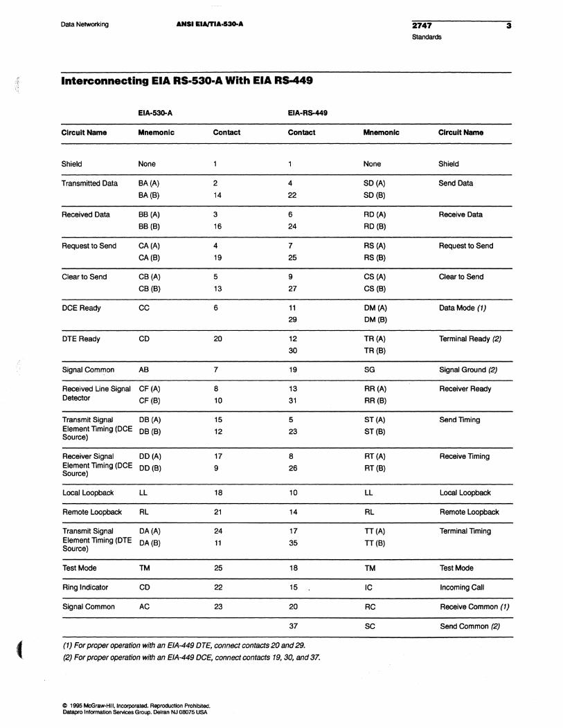
EIA-53Q.A/R5-449 The EIA-530-A standard has officially replaced RS-449 but, while both standards are in use, EIA-530-A can be interconnected with RS-449 devices through a connecting cable or adapter. Table "Interconnecting EIA RS-530·A With EIA RS-449" lists the circuit name and mnemonic, and connector contact pin for each interface.
EIA.53Q.A/CCITT V.35 EIA-530-A provides balanced (EIA-422-A) generators and receivers on interchange Circuits CA (Request to Send), CB (Clear to Send), and CF (Receive Line Signal Detector). The corresponding interchange circuits in a V.35 interface utilize CCI'IT V.28 (EIA-232-E) electrical characteristics. In applications connecting an EIA-422-A balanced generator with an EIA-232-E unbalanced receiver, a special balanced/unbalanced converter must be employed between the interfaces. Otherwise, EIA-530-A and CCI'IT V.35 are fully compatible.
Mechanical Characteristics The point of demarcation between the DTE and the DCE is at connector plugs on the DCE or at an interface point no further than ten feet (three meters) from the DCE. A 25-position connector was specified for all interchange circuits in EIA-530. EIA-530-A's alternative 26-position "Alt A" connector is specified for
ANSI EIAlTIA-530-A Data Networking
use when a smaller physical connector is required (it is approximately W' x 1/4"). In all cases, the DTE provides the cable (up to 200 feet), which has male (pin) contacts and a female shell (Plug connector); the DCE has a female connector. The connectors are equipped with a block that permits latching and unlatching without a tool. The latching block also permits the use of screws to fasten the connectors together. The mechanical configuration for connections of the interface cable at points other than the demarcation point is not specified.
When additional functions are offered in a separate unit that is inserted between the DTE and DCE, the female connector is associated with the DTE interface, while the male connector is a DCE interface.
Functional Description of Interchange Cireuits Interchange circuits fall into four general classifications: ground (or common return), data circuits, control circuits, and timing circuits. Table "EIA RS-530-A Interchange Circuits" outlines a list of EIA-530-A interchange circuits showing circuit mnemonic, circuit name, circuit direction, and circuit type. Table "RS-530 and Nearest Equivalent CCl1T V,35" compares the connector pin assignments and the functional interchange circuits along with an equivalency table showing the nearest equivalent CCI'IT V.35 functions in relation to each EIA-530-A function. A functional description of each of the EIA-530-A interchange circuits follows.
Ground or Common Return Circuits Circuit AB and AC (Signal Commons) connects the DTE circuit ground (signal common) to the DeE circuit ground (signal common) to provide a conductive route between the DTE and DCE signal commons.
Data Circuits Circuit BA (Transmitted Data) transfers the data signals originated by the DTE to the DeE. The DTE holds Circuit BA in the binary ONE (marking) condition unless an ON condition is present on all of the following circuits: CA (Request to Send), CB (Clear to Send), CC (DCE Ready), and CD (DTE Ready). The DeE disregards any signal appearing on Circuit BA when an OFF condition exists on one or more of these circuits. While an ON condition is maintained on each of the circuits, the DCE sends all data signals transmitted across the interface on Circuit BA to the communications channel. The term "data signals" includes the binary ONE (marking) condition, reversals, and other sequences, such as SYN coded characters that maintain timing synchronization.
Circuit BB (Received Data) transfers DCE-generated data signals to the DTE in response to line signals from a remote station. Circuit BB is held in the binary ONE (marking) condition while Circuit CF (Receive Line Signal Detector) is in the OFF condition. On half-duplex channels, Circuit BB is held in the marking condition when Circuit CA is ON and for a brief interval when Circuit CA makes the transition from ON to OFF. This allows for the completion of the transmission and for the decay of channel reflections.
TIming Circuits Circuit DA (Transmit Signal Element TIming-DTE Source) provides the DeE with transmit signal element timing data. The ON to OFF transition nominally indicates the center of each signal element on Circuit BA. When Circuit DA is implemented in the DTE, the DTE provides timing data on it whenever the DTE is
@ 1995 McGraw-Hili. Incorporated. Reproduction Prohibited. Datapro Information Services Group. Delran NJ 08075 USA
/
i$ \(
(
Data Networking ANSI EIAII'IA..s300A
Interconnecting EIA RS·530·A With EIA RS-449
EIA-53()'A EIA-R8-449
Circuit Name Mnemonic Contact Contact
Shield None
Transmitted Data BA(A) 2 4 BA(B) 14 22
Received Data BB (A) 3 6
BB(B) 16 24
Request to Send CA(A) 4 7 CA(B) 19 25
Clear to Send CB(A) 5 9 CB (B) 13 27
DCE Ready CC 6 11 29
DTEReady CD 20 12 30
Signal Common AS 7 19
Received Une Signal CF (A) 8 13 Detector CF (B) 10 31
Transmit Signal DS(A) 15 5 Element Timing (DCE DB (B) 12 23 Source)
Receiver Signal DD(A) 17 8 Element Timing (DCE DO (8) 9 26 Source)
Local Loopback LL 18 10
Remote Loopback RL 21 14
Transmit Signal DA(A) 24 17 Element Timing (DTE DA(B) 11 35 Source)
Test Mode TM 25 18
Ring Indicator CD 22 15
Signal Common AC 23 20
37
(1) For proper operation with an EIA-449 DTE, connect contacts 20 and 29.
(2) For proper operation with an EIA-449 DCE, connect contacts 19, 3D, and 37.
@ 1995 McGraw-Hili. Incorporated. Reproduction Prohibited. Datapro Information Services Group. Delran NJ 08075 USA
Mnemonic
None
SD (A)
SD (B)
RD (A)
RD (B)
RS (A)
RS (B)
CS (A)
CS (B)
DM (A)
OM (B)
TR (A)
TR (B)
SG
RR (A)
RR (B)
ST(A)
ST(B)
RT(A)
RT(B)
LL
RL
TT(A)
TT(B)
TM
IC
RC
SC
2747 Standards
Circuit Name
Shield
Send Data
Receive Data
Request to Send
Clear to Send
Data Mode (1)
Terminal Ready (2)
Signal Ground (2)
Receiver Ready
Send Timing
Receive Timing
Local Loopback
Remote Loopback
Terminal Timing
Test Mode
Incoming Call
3
Receive Common (1)
Send Common (2)

4 2747 Standards
EIA RS-S3G-A Interchange Circuits
Circuit Mnemonic Circuit Name
AB Signal Common
AC Signal Common
BA Transmitted Data
BB Received Data
DA Transmit Signal Element Timing (DTE Source)
DB Transmit Signal Element Timing (DCE Source)
DO Receiver Signal Element Timing (DCE Source)
CA Request to Send
CB Clear to Send
CF Received Line Signal Detector
CJ Ready for Receiving
CE Ring Indicator
CC DCE Ready
CD DTE Ready
LL Local Loopback
RL Remote Loopback
TM Test Mode
in a POWER ON condition. The DTE can withhold timing data on this circuit for short periods as long as Circuit CA is in the OfF condition.
Circuit DB (Transmit Signal Element TIming-DCE Source) provides the DTE with transmit element timing data. The DTE provides a data signal on Circuit BA in which the transitions between signal elements occur at the time of the transitions from OfF to ON condition of the signal on Circuit DB. The DCE provides timing data on Circuit DB whenever the DCE is in a POWER ON condition. The DeE can withhold timing data on this circuit if Circuit CC is in the OfF condition.
Circuit DD (Receiver Signal Element TIming-DCE Source) provides the DTE with receive signal element timing data. The DeE provides timing data on this circuit whenever the DeE is in a POWER ON condition. The DCE can withhold timing data on this circuit for short periods as long as Circuit CC is in the OfF condition.
Control Circuits Circuit CA (Request to Send) controls the transmit function of the local DCE and, on half-duplex channels, the direction of data transmission. On one-way-only (duplex) channels, the ON condition holds the DeE in the transmit mode; the OfF condition suppresses transmission. On a half-duplex channel, the ON condition holds the DeE in the transmit mode and suppresses the receive mode. The OFF condition holds the DeE in the receive mode. A transition from OfF to ON instructs the DCE to enter the transmit mode. The DeE responds by taking any necessary action and indicating completion of such action by turning ON Circuit CB (Clear .to Send), thereby permitting the DTE to transfer data across Circuit BA. A transition from ON to OfF instructs the
ANSI EIAI1'IA-530-A Data Networking
Circuit Direction Circuit Type
Does not apply Common
Does not apply Common
ToDCE Data
From DCE Data
ToDCE Timing
FromDCE Timing
From DCE Timing
ToDCE Control
From DCE Control
From DCE Control
ToDCE Control
From DCE Control
From DCE Control
ToDCE Control
ToDCE Timing
ToDCE Timing
From DCE Timing
DeE to complete transmission of all data previously transferred across the interface on Circuit BA (Transmitted Data) and then to assume a nontransmit, or receive mode, as appropriate. The DCE responds to this instruction by turning OfF Circuit CB.
When Circuit CA is turned OfF, it is not turned ON again until Circuit CB has been turned OfF by the DeE. An ON condition is required on Circuit CA, as well as on Circuits CB and CC, whenever data is transferred across the interface on Circuit BA by the DTE. Circuit CA may be turned ON at any time when Circuit CB is OFF, regardless of the status of any other interface circuit.
Circuit CB (Clear to Send) indicates that the DeE has been conditioned to transmit data over the communications channel. The ON condition, together with the ON on Circuit CA (Request to Send) and Circuit CC (DeE Ready), indicates to the DTE that signals on Circuit BA (Transmitted Data) will be transmitted to the communication channel. The OfF condition indicates that the DTE should not transfer data across the interface on Circuit BA, since this data will not be transmitted to the line. The ON condition of Circuit CB is a response to the occurrence of concurrent ON conditions on Circuits CC and CA, delayed as appropriate by the DeE, to allow the establishment of a data communications channel to a remote DTE. Circuit CB may be turned OfF during the data transfer or test phase, independent of Circuit CA's condition, to signal the DTE to interrupt the transfer of data on Circuit BA for a finite period of time. This capability, added in EJA-530-A, provides for OCE flow control or IX;EJDCE resynchronization.
Circuit CF (Received Line Signal Detector) indicates whether the receiver in the DCE is ready to receive data signals from the communication channel, but does not indicate the relative quality of the data signals received. An equalizer's condition
@ 1995 McGraw-Hili. Incorporated. Reproduction Prohibited. Datapro Infonnatlon SarviceB Group. Delran NJ 08075 USA
/'

J \ ~,
'"
(
Data Networking ANSI EIAlTIA-53O-A
R5-530 and Nearest Equivalent CCITT V.35
EIA-53Q-A
Circuit Name Mnemonic
Shield None
Transmitted Data BA(A)
Transmitted Data BA(B)
Received Data BB (A)
Received Data BB (B)
Request to Send CA(A)
Request to Send CA(B)
Clear to Send CB(A)
Clear to Send CB(B)
DCE Ready CC
DTE Ready CD
Signal Common AB
Received LineSignal CF (A) Detector
Received LineSignal CF (B) Detector
Transmit Signal DB (A) Element Timing (DCE Source)
Transmit Signal DB (B) Element Timing (DCE Source)
Receiver Signal DO (A) Element Timing (DCE Source)
Receiver Signal DO (B) Element Timing (DCE Source)
Local Loopback LL
Remote Loopback RL
Transmit Signal DA(A) Element Timing (DTE Source)
Transmit Signal DA(B) Element Timing (DTE Source)
C 1995 McGraw-HIli, Incorporated. Reproduction Prohibited. Datapro Information Services Group. Delran NJ 08075 USA
ccmV.35 Contact Contact
A
2 P
14 S
3 R
16 T
4 C
19 C
5 0
13
6 E
20 H
7 B
8 F
10 F
15 Y
12 AA
17 V
9 X
18 L
21 N
24 U
11 W
2747 Standards
Circuit Name Mnemonic
Shield None
Transmitted Data 103 (A)
Transmitted Data 103 (B)
Received Data 104 (A)
Received Data 104 (A)
Request to Send 105 (A)
(1)
Clear to Send 106
Data Set Ready 107
Data Terminal Ready 10811, 12 (2)
Signal Common 102
Data Channel 109 (1) Received Une Signal Detector
Transmitter Signal 114 (A)
Transmitter Signal 114 (B)
Receiver Signal 115 (A) Element Timing
Receiver Signal 115 (B) Element Timing
Local Loopback 141 (2)
Loopback/ 140 Maintenance (2)
Transmitter Signal 113 (A) (2) Element Timing
Transmitter Signal 113 (B)(2) Element Timing
5

• 2747 Standards
ANSI EIAII'IA-530-A Data Networking
R5-530 and Nearest Equivalent CCITT V.35 (Continued)
EIA-530-A CCITTV.35
Circuit Name Mnemonic Contact Contact Circuit Name Mnemonic
Test Mode TM 25 NN Test Indicator 142
Ring Indicator CE 22 J Calling Indicator 125 (2)
Signal Common AC 23 B Signal Common 102
(1) Special balanced/unbalanced circuitry required between these interfaces.
(2) Not included in CCITT V.35, but are provided in ISO 2593 as optional.
in a DCE does not affect Circuit CF. The ON condition indicates that the DCE is receiving a signal that meets its criteria, which the DeE manufacturer establishes. The OFF condition indicates that no signal is being received. Circuit CF's OFF condition causes Circuit BB (Received Data) to be clamped to the binary ONE (marking) condition.
On half-duplex channels, Circuit CF is held in the OFF condition whenever Circuit CA (Request to Send) is in the ON condition and for a brief interval of time following Circuit CA's transition from ON to OFF.
Circuit CC (DCE Ready) indicates the status of the local DeE; the ON condition does not indicate that a communication channel has been established to a remote data station nor does it indicate the status of any remote station equipment. The OFF condition indicates that the DTE should ignore signals appearing on all other interchange circuits with the exception of Circuit TM (Test Mode). Circuit CC remains in the OFF condition for DCE tests not completed through the DTElDeE interface. The circuit responds normally (i.e., not clamped OFF) for DCE tests conducted through the DTElDeE interface.
Figure Loop/Huk Test,
Facility Test
Center \ \
Circuit CD (DTE Ready) controls DCE switching to and from the communications channel. The ON condition prepares the DeE for connection to a communications channel and maintains the connection. The OFF condition removes the DeE from the communication channel following the completion of any "in processH transmission.
Circuit CJ (Ready for Receiving) controls data transfer (flow control) on Circuit BB (Received Data) when an intermediate function, such as error control, is being used in the DCE. The DTE is capable of receiving data when Circuit CJ is ON. When Circuit CJ is implemented, Circuit CA must be considered to be permanently in the ON condition.
Circuit CE (Ring Indicator) indicates when a ringing signal is being received on the communications channel. The ON condition appears approximately coincident with the audible ringing. Furthermore, the DCE may be configured to only respond to specific ringing signals in those systems employing custom ring patterns.
Circuit LL (Local Loopback) controls the local loopback test condition in the local DeE. (See Figure "Loopback Tests" for
\ \ \
\
\ \ \ \
\ \ \ \ \ \
Local ..... Local LL)
\ ... \ Remote RL)
.... .... DeE DTE .....
~ ......
Localloopback and remote loopback tests as seen from the local DTE.
\ .... DeE ....
, ..... ~
..... ...... ......
TeN @ , 995 tkGraw-Hill. lilcorporated. Reproduction Prohibited. Datapro Infonnati\ln ~ Gro\Jp, Delrll/l NJ080751,1$A
Remote
DTE
/ '
" Ji I,
~
(
Data Networking ANSI EIAlTIA0530-A
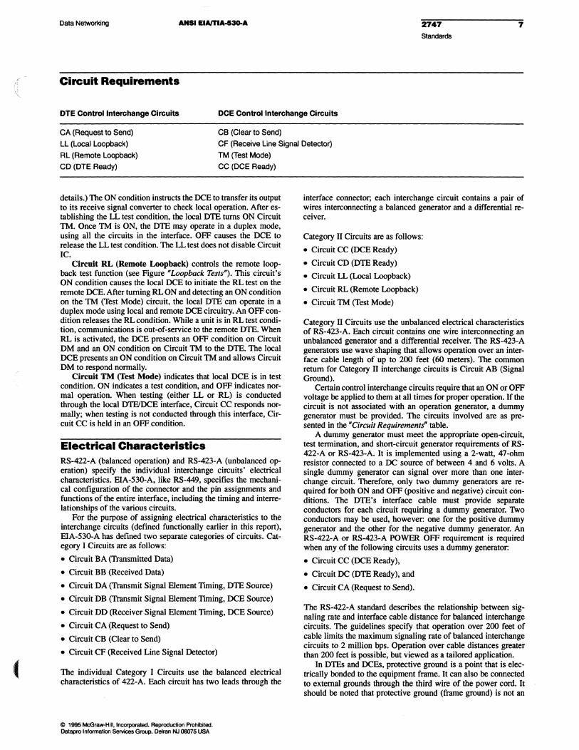
Circuit Requirements
2747 Standards
7
DTE Control Interchange Circuits DCE Control Interchange Circuits
CB (Clear to Send) CA (Request to Send) LL (Local Loopback) RL (Remote Loopback) CD (DTE Ready)
CF (Receive Line Signal Detector) TM (Test Mode) CC (DCE Ready)
details.) The ON condition instructs the DCE to transfer its output to its receive signal converter to check local operation. After establishing the LL test condition, the local DTE turns ON Circuit TM. Once TM is ON, the DTE may operate in a duplex mode, using all the circuits in the interface. OFF causes the DCE to release the LL test condition. The LL test does not disable Circuit IC.
Circuit RL (Remote Loopback) controls the remote loopback test function (see Figure HLoopback Tests"). This circuit's ON condition causes the local DCE to initiate the RL test on the remote DCE. After turning RLON and detecting an ON condition on the TM (Test Mode) circuit, the local DTE can operate in a duplex mode using local and remote DCE circuitry. An OFF condition releases the RL condition. While a unit is in RL test condition, communications is out-of-service to the remote DTE. When RL is activated, the DCE presents an OFF condition on Circuit DM and an ON condition on Circuit TM to the DTE. The local DCE presents an ON condition on Circuit TM and allows Circuit DM to respond normally.
Circuit TM (Test Mode) indicates that local DCE is in test condition. ON indicates a test condition, and OFF indicates normal operation. When testing (either LL or RL) is conducted through the local DTFlDCE interface, Circuit CC responds normally; when testing is not conducted through this interface, Circuit CC is held in an OFF condition.
Electrical Characteristics RS-422-A (balanced operation) and RS-423-A (unbalanced operation) specify the individual interchange circuits' electrical characteristics. EIA-530-A, like RS-449, specifies the mechanical configuration of the connector and the pin assignments and functions of the entire interface, including the timing and interrelationships of the various circuits.
For the purpose of assigning electrical characteristics to the interchange circuits (defined functionally earlier in this report), EIA-530-A has defined two separate categories of circuits. Category I Circuits are as follows:
• Circuit BA (Transmitted Data)
• Circuit BB (Received Data)
• Circuit DA (Transmit Signal Element Timing, DTE Source)
• Circuit DB (Transmit Signal Element Timing, DCE Source)
• Circuit DD (Receiver Signal Element Timing, DCE Source)
• Circuit CA (Request to Send)
• Circuit CB (Clear to Send)
• Circuit CF (Received Line Signal Detector)
The individual Category I Circuits use the balanced electrical characteristics of 422-A. Each circuit has two leads through the
C 1995 McGraw-Hili, Incorporated. Reproduction Prohibited. Datapro Information ServIces Group. Delran NJ 08075 USA
interface connector; each interchange circuit contains a pair of wires interconnecting a balanced generator and a differential receiver.
Category II Circuits are as follows:
• Circuit CC (DCE Ready)
• Circuit CD (DTE Ready)
• Circuit LL (Local Loopback)
• Circuit RL (Remote Loopback)
• Circuit TM (Thst Mode)
Category II Circuits use the unbalanced electrical characteristics of RS-423-A. Each circuit contains one wire interconnecting an unbalanced generator and a differential receiver. The RS-423-A generators use wave shaping that allows operation over an interface cable length of up to 200 feet (60 meters). The common return for Category II interchange circuits is Circuit AB (Signal Ground).
Certain control interchange circuits require that an ON or OFF voltage be applied to them at all times for proper operation. If the circuit is not associated with an operation generator, a dummy generator must be provided. The circuits involved are as presented in the "Circuit Requirements" table.
A dummy generator must meet the appropriate open-circuit. test termination, and short-circuit generator requirements of RS-422-A or RS-423-A. It is implemented using a 2-watt, 47-ohm resistor connected to a DC source of between 4 and 6 volts. A single dummy generator can signal over more than one interchange circuit. Therefore, only two dummy generators are required for both ON and OFF (positive and negative) circuit conditions. The DTE's interface cable must provide separate conductors for each circuit requiring a dummy generator. 1\\'0 conductors may be used, however: one for the positive dummy generator and the other for the negative dummy generator. An RS-422-A or RS-423-A POWER OFF requirement is required when any of the following circuits uses a dummy generator:
• Circuit CC (DCE Ready),
• Circuit DC (DTE Ready), and
• Circuit CA (Request to Send).
The RS-422-A standard describes the relationship between signaling rate and interface cable distance for balanced interchange circuits. The guidelines specify that operation over 200 feet of cable limits the maximum signaling rate of balanced interchange circuits to 2 million bps. Operation over cable distances greater than 200 feet is possible, but viewed as a tailored application.
In DTEs and DCEs, protective ground is a point that is electrically bonded to the equipment frame. It can also be connected to external grounds through the third wire of the power cord. It should be noted that protective ground (frame ground) is not an

8 2747 Standards
Connector Contact Assignments
Contact Number Circuit Interchange Points
1 Shield None
2 BA A-A'
3 BB A-A'
4 CAlCJ (1) A-A'
5 CB A-A'
6 CC (2) A-A'
7 AB C-C'
8 CF A-A'
9 DD B-B'
10 CF B-B'
11 DA B-B'
12 DB B-B'
13 CB B-B'
14 BA B-B'
15 DB A-A'
16 BB B-B'
17 DD A-A'
18 LL A-A'
19 CAlCJ (1) B-B'
20 CD (2) A-A'
21 RL A-A'
22 CE A-A'
23 AC C-C'
24 DA A-A'
25 TM A-A'
26 (3)
ANSlIIAI1'IA-S30-A Data Networking
Circuit Category Direction to DCE Direction from DCE
None Does not apply Does not apply
X
X
X
X
n X
None Does not apply Does not apply
X
X
X
X
X X
X
X
X
X n X
X n X
n X n X None Does not apply Does not apply
X
n X
(1) When hardware flow control is required, Circuit CA may take on the functionality of Circuit CJ.
(2) Interoperation between Category I and /I circuits requires balanced/unbalanced conversion circuitry.
(3) Contact 26 is contained on the Ait A connector only. No connection is to be made to this contact.
interchange circuit in EIA-530-A. If the DCE and OTE equipment frames must be bonded, a separate conductor that confonns to the appropriate national or local electrical codes should be used.
Interface connector pin number 1 facilitates the use of shield interconnecting cable, pennitting the DTE cable to carry tandem connectorized sections with shield continuity. The DCE does not connect to pin 1. except in some applications requiring electromagnetic interference (EMI) suppression. While additional provisions may be necessary, they are beyond the scope of this standard.
Proper operation of the interchange circuits requires a path between the DTE circuit ground (circuit common) and the DCE circuit ground. which is provided by Circuit AB (Signal Ground). Nonnally. both the DTE and DCE should have their circuit grounds connected to protective grounds (frame grounds), which.
in turn. may be connected to an external ground. usually associated with the power line plug.
For fail-safe operation. the receivers can detect a POWER OFF condition in the equipment across the interface or a disconnected cable. Detection of either of these conditions is interpreted as an OFF on any of the following interchange circuits:
• Circuit CC (DCE Ready)
• Circuit CA (Request to Send)
• Circuit CD (OTE Ready)
The receiver for each control circuit, except those control circuits specified above, interprets the situation in which the conductor is not implemented in the interconnecting cable as an OFFcortdition.
C 1995 McGraw-HiU, Incorporated. Reproduction Prohibited. Datapro Infonnation SeMces Group. Delran NJ 08075 USA

Data Networking ANSI EIAITIA-530-A 2747 Standards
9
( Standard Interfaces for Selected Communication System Configuration
~
I \
Interchange Circuit Configuration Type Sft Configuration Type SO Configuration Type ftO Configuration Type DT
AB Signal Ground M M
SA Transmitted Data M M
BB Received Data M
DA Transmit Signal 0 0 Element Timing (DTE Source)
DB Transmit Signal T T Element Timing (DCE Source)
DO Receiver Signal T Element Timing (DCE Source)
CA Request to Send M M
CB Clear to Send M M
CF Received Line Signal M Detector
cc DCE Ready M M
COOTE Ready S S
LL Local Loopback 0
RL Remote Loopback 0
TM Test Mode M M
M-Mandatory interchange circuits for a given configuration.
T-Additional interchange circuits required for synchronous operation.
S-Additional interchange circuit required for switched service.
O-Optional interchange circuits.
Genera. Signa. Characteristics Interchange circuits transferring data signals across the interface point hold the mark (binary ONE) and space (binary ZERO) conditions for the total nominal duration of each signal element. EIA-334-A, "Signal Quality at Interface Between Data Processing Terminal Equipment and Synchronous Data Communication Equipment for Serial Data Transmission," defines distortion tolerances for synchronous systems. EIA-363, "Standard for Specifying Signal Quality for Transmitting and Receiving Data Processing Terminal Equipment Using Serial Data Transmission at the Interface with Non-Synchronous Communication Equipment, n states standard naming procedures for specifying signal quality for nonsynchronous systems. Distortion tolerances for nonsynchronous systems are stated in EIA-404-A, "Standard for Start-Stop Signal Quality Between Data Terminal Equipment and Non-Synchronous Data Communication Equipment. n Interchange circuits sending timing signals across the interface point keep ON and OFF conditions for nominally equal amounts of time, in keeping with the acceptable tolerances specified in EIA-334-A.
The accuracy and stability of the timing data on Circuit DD (Receiver Signal Element Timing) are needed only when Circuit CF (Received Line Signal Detector) is ON. During the OFF condition of Circuit CF, drift is acceptable; however, once the OFF to ON transition of Circuit CF occurs, resynchronization of the timing data on Circuit DD must occur as quickly as possible.
o 1996 McGraw-H1li. Incorporated. Reproduction Prohibited. Datapro Infonnation Senrices Group. Delran NJ 08075 USA
M M
M M
M M
0
T
T T
M
M
S
M
Transfer of timing information across the interface is necessary whenever the timing source is capable of generating data, and it should not be restricted only to periods of actual data transmission. When timing data is not provided on a timing interchange circuit, the interchange circuit is clamped in the OFF condition. Tolerances on the relationship between data and associated timing signals follow the EIA-334-A recommendation.
EIA-530·A Interchange Circuit Details Listed below are details of EIA-530-A's additional functions.
Use of Circuits for Testing Three interchange circuits permit fault isolation testing done under DTE control: Circuit LL (Local Loopback), Circuit RL (Remote Loopback), and Circuit TM (Test Mode) (see Figure "Loopback Tests").
The EIA considers the (Circuit TM) and test control (Circuit LL and Circuit RL) status circuits a desirable step toward uniform methods of fault isolation. These circuits assist DTE and DCE users in tracking down a defective unit.
Local Loopback (LL Test): This test condition is equivalent to CCITI test loop *3. It provides a way in which a DTE can check the functioning of a DTE-to-DCE interface and the transmit and receive sections of the local DCE. One may also test the local DCE with a test set instead of through the DTE. The output of the •

10 2747 Standards
transmitting portion of the DCE is returned to the receiving station in the U. test through circuitry that is required for proper operation. In many DeEs, the signal transmitted is unsuitable for direct connection to the receiver. In such cases, an appropriate signal shaping or conversion in the loop-around circuitry may be included so that any element used in normal operations is checked in the test condition.
Remote Loopback (RL Test): This test, equivalent to CCnT test loop *2, allows a DTE or a facility test center to check the transmission path through the remote DeE to the DTE interface and the corresponding return path. In this test, Circuit SO and Circuit RD are either isolated or disconnected from the remote DTE at the interface and then connected to each other at the remote DCE. In synchronous DeEs, a suitable transmit clock may be necessary when the RL test condition is initiated. In some instances, buffer storage may be required between Circuit RO and Circuit SO.
Remote control of the RL test permits the automation of endto-end testing of any circuit from a central location. Primarily, test control is suitable in point-to-point applications, but may also be used in multipoint arrangements with the addition of an address detection feature in the DCE. Test RL enables circuit verification without the aid of a distant DCE, supported by an inherent remote loopback capability in many modern DeEs.
The ON states of Circuit RL and Circuit U. are mutually exclusive, because the two test conditions may not function simultaneously.
Equalizers Equalization is a process whereby a circuit's frequency and phase distortions are reduced to compensate for differences in time delay and attenuation of the varying frequencies in the transmission band. An equalizer associated with the DeE may require training, a process that produces a fixed number of equally spaced reference signals.
RS-449 outlines the procedures for equalizer training. The following example outlines a typical training sequence. DeE "E" (East) has an equalizer that requires training. DeE "W" (West) is
ANSI EIAI1'IA-53o.A Data Networking
transmitting toward DeE "E". Initial training ofDCE "Es" equalizer occurs during the interval between the ON condition of Circuit RS and the ON condition of Circuit CS of DeE "W". Initial training in the DeE "Es" receiver occurs prior to the ON condition of Circuit RR of DCE "E". Circuit SQ is placed in the ON condition no later than the OFF-to-ON transition of Circuit RR if the initial training is successful. Circuit SQ's state is undefined when Circuit RR is OFF.
If the equalizer requires a unique training signal from DCE "W" to achieve equalization, the states of specific interchange circuits are controlled during this process. When the normal flow of data toward DeE "W" is interrupted in order to cause DeE "W" to transmit this unique sequence, Circuit CS of DCE "E" is held in the OFF condition while the command signal is being sent. In this situation, Circuit SQ of DeE "W" should be placed in the OFF condition while receiving the command signal. Circuit RO of DCE "W" may be clamped to the marking condition while the command signal is received. In the reverse direction, Circuit CS of DeS "W" is in the OFF condition while the unique training signal is sent. Circuit RO of DeE "E" may be clamped to the marking condition when the unique training signal is received. When the equalizer attains proper adjustment, DCE liE" places Circuit SQ in the ON condition.
Standard Interfaces for Selected Configurations Standard sets of interchange circuits for data transmission configurations are defined as follows: Type SR (Send-Receive), Type SO (Send-Only), Type RO (Receive-Only), and Type DT (Data and TIming only). Table "Standard Interfaces for Selected Communication System Configuration" lists the interchange circuits that must be provided for each data transmission configuration. For a given type of interface, generators and receivers must be provided for every interchange circuit designated M (Mandatory) in Table "Standard Interfaces for Selected Communication System Configuration." In addition, generators and receivers are necessary for all interchange circuits designated S and T, where the service is switched and synchronous, respectively. -
C 1995 McGraw-Hill. Incorporated. Reproduction Prohibited. Oatapro InfOrmation ServIces Group. Delran NJ oeo~5 USA

(-
In this report:
Mechanical Characteristics .................... 3
Functional Description of Interchange Circuits ........ 3
Electrical Characteristics .................... 6
EIA-530-A Interchange Circuit Details .................... 10
Note: In June 1992 the Electronic Industries Assn. published ANSI EIAfIIA-530-A (1992), which is a revision of ANSI EIA-530 (1987).
DATAPRO Data Networking 2747 Standards
t
ANSI EIAITIA-530-A
Datapro Summary
ANSI EIAITIA-530-A (hereafter EIA-530-A) defines the mechanical interface characteristics between Data Termination Equipment (DTE) and Data CircuitTerminating Equipment (DCE). It operates in conjunction with RS-422-A and RS-423-A, which define the electrical operation of the individual interchange circuits for balanced and unbalanced operation, respectively. EIA-530-A complements RS-232-D for data rates above 20K bps and replaces RS-449 for data rates above 20K bps.
A revision of EIA-530, EIA-530-A was approved in May 1992 and includes several relatively minor modifications to the previous standard. The most significant change accounts for the alternative 26-position interface connector (Alt A). Other revisions comprise the following:
• Addition of Circuits CJ (Ready for Receiving), CE (Ring Indicator), and AC (Signal Common).
• Use of Circuit CB (Clear to Send) for hardware flow control.
• Use of Local Loopback for "Busy Out."
• Change of Circuits CC (DCE Ready) and CD (DTE Ready) to Category II Circuits.
The new standard is compatible with EIA-530, but applications cOnIlecting versions of RS-449 or EIA-530 (with Category I Circuits CC and CD) with EIA-530-A (with Category II Circuits CC and CD) require an unbalanced/balanced converter between the interfaces (see Table I for circuitry connections).
In 1977 the Electronic Industries Assn. (EIA) developed the RS-449, RS-422, and RS-423 standards to eventually replace RS-232-C. RS-449, however, never really
-By Vance Macdonald Research Analyst
caught on and, in March 1987, EIA-530 was introduced as its intended replacement. RS-422 and RS-423 remain in the revised forms of RS-422-A and RS423-A. RS-232-C also outlasted RS-449 and, in January 1987, the EIA issued RS-232-D, a revision for RS-232-C.
EIA-530-A governs the mechanical and electrical characteristics of the interface between Data Terminal Equipment (DTE) and Data Circuit-Terminating Equipment (DCE). The standard defines DTE as the hardware on the business machine side of the interface (teleprinters, display terminals, front-end processors, central processing units, etc.), and DCE as the modem, signal converter, or other device between the DTE and the communications line.
This report compares EIA-530-A with RS-232-D, RS-449, and CCITT V.35. It also discusses the mechanical and electrical characteristics and looks at the general classification of interchange circuits and outlines interchange circuit details.
Copies of EIA-530-A, RS-422-A, and RS-423-A can be obtained from the Electronic Industries Assn., 2001 I Street NW, Washington, DC 20006.
Analysis
EIA-530-A operates in conjunction with either of two standards specifying electrical
o 1993 McGraw-HIU. Incorporated. Reproduction Prohibited. Datapro Information Sarvlces Group. Dalran NJ 08076 USA
FEBRUARY 1993

2 2747 Standards
ANSI EIA/TIA-53G-A Data Networking
Table 1. Interconnecting EIA RS·530·A With EIA RS·449
EIA-530-A EIA-RS-449
Circuit Name Mnemonic Contact Contact Mnemonic Circuit Name
Shield None None Shield
Transmitted Data BA(A) 2 4 SD(A) Send Data BA(B) 14 22 SD(B)
Received Data BB(A) 3 6 RD(A) Receive Data BB(B) 16 24 RD(B)
Request to Send CA(A) 4 7 RS(A} Request to Send CA(B) 19 25 RS(B)
Clear to Send CB(A) 5 9 CS(A) Clear to Send CB(B) 13 27 CS(B)
DCE Ready CC 6 11 DM(A) Data Mode (1) 29 DM(B)
DTE Ready CD 20 12 TR(A) Terminal Ready (2) 30 TR(B)
Signal Common AB 7 19 SG Signal Ground (2)
Received Line CF(A) 8 13 RR(A) Receiver Ready Signal Detector CF(B) 10 31 RR(B)
Transmit Signal DB (A) 15 5 ST(A) Send Timing Element Timing DB (B) 12 23 ST(B) (DCE Source)
Receiver Signal DD(A) 17 8 RT(A) Receive Timing Element Timing DD(B) 9 26 RT(B) (DCE Source)
Local Loopback LL 18 10 LL Local Loopback
Remote Loopback RL 21 14 RL Remote Loopback
Transmit Signal DA(A) 24 17 TT(A) Terminal Timing Element Timing DA(B) 11 35 TT(B) (DTE Source)
Test Mode TM 25 18 TM Test Mode
Ring Indicator CE 22 15 IC Incoming Call
Signal Common AC 23 20 RC Receive Common (1)
37 SC Send Common (2)
(1) For proper operation with an EIA-449 DTE, connect contacts 20 and 29. (2) For proper operation with an EIA-449 DCE, connect contacts 19,30, and 37.
FEBRUARY 1993
Source: Electronic Industries Assn. EIAfTIA-530-A, 1992.
@ 1993 McGraw-Hili. Incorporated. Reproduction Prohibited. Datepro Information Services Group. Delran NJ 08075 USA

if
" ,~\
Data Networking ANSI EIA/TIA·S30·A
characteristics: RS-422-A, for balanced circuits; and RS-423-A, for unbalanced circuits. When each interface circuit has its own ground lead, the circuit is balanced. When an interface uses a common or shared grounding technique, it is unbalanced.
EIA-530-A is used for data communications systems with the following characteristics:
• DTE serializes data bits, and the DCE puts no restrictions on the DTE's bit sequence arrangements.
• Communication is binary, serial, synchronous, or asynchronous, and control information is exchanged on separate circuits.
• Equipment on one side of the DTE/DCE interface connects directly to equipment on the other side without additional technical considerations.
• Communication is in half- and/or full-duplex modes in point-to-point or multipoint configurations over two- or four-wire facilities with data rates ranging from 20K bps to a nominal upper limit of 2.1 M bps. Point-to-point arrangements may operate on either switched or dedicated facilities. Dedicated lines connect multipoint arrangements.
Applications in which cable termination, signal wave shaping, interconnection cable distance, and the interface's mechanical configurations must be tailored to meet specific user needs are not precluded,. but are generally not within the standard's scope. The EIA-530-A connector, also used for RS-232-D, uses electrical characteristics that, if improperly connected to some silicon devices designed to meet the RS-422-A and RS-423-A electrical characteristics specified in this recommendation, could damage those devices.
EIA·530·A/RS·232·D These standards include a specification of the D-shaped 25-pin interface connector, which RS-232-C had only referenced in an appendix and never included as part of the standard. Both standards support testing of both local and remote DCEs through the Local Loopback, Remote Loopback, and Test Mode circuits. Circuit names for the first 8 pins in both standards are the same, but differ on pins 9, 10, and 11, which are not used in RS-232-D.
RS-530-A achieves higher data rates than RS-232-D (greater than 20K bps) by specifying the use of balanced signals, while sacrificing some secondary signals and the Ring Indicator. The Ring Indicator's elimination indicates that EIA-530-A is not for use in dial-up applications.
EIA·530-A/RS-449 The EIA-530-A standard has officially replaced RS-449 but, while both standards are in use, EIA-530-A can be interconnected with RS-449 devices through a connecting cable or adaptor. Table 1 lists the circuit name and mnemonic, and connector contact pin for each interface.
EIA·530-A/CCITT V.35 EIA-530-A provides balanced (EIA-422-A) generators and receivers on interchange Circuits CA (Request to Send), CB (Clear to Send), and CF (Receive Line Signal Detector). The corresponding interchange circuits in a V.35 interface utilize CCITT V.28 (EIA-232-E) electrical characteristics. In applications connecting an EIA-422-A balanced generator with an EIA-232-E unbalanced receiver, a special balanced/unbalanced converter must be
@ 1993 McGraw·HIII, Incorporated. Reproduction ProhlbHed. Datapro Information Services Group. Delran NJ 08075 USA
2747 Standards
3
employed between the interfaces. Otherwise, EIA-530-A and CCITT V.35 are fully compatible.
Mechanical Characteristics The point of demarcation between the DTE and the DCE is at connector plugs on the DCE or at an interface point no further than ten feet (three meters) from the DCE. A 25-position connector was specified for all interchange circuits in EIA-530. EIA-530-A's alternative 26-position "Alt A" connector is specified for use when a smaller physical connector is required (it is approximately %" x 1f4"). In all cases, the DTE provides the cable (up to 200 feet), which has male (pin) contacts and a female shell (plug connector); the DCE has a female connector. The connectors are equipped with a block that permits latching and unlatching without a tool. The latching block also permits the use of screws to fasten the connectors together. The mechanical configuration for connections of the interface cable at points other than the demarcation point is not specified.
When additional functions are offered in a separate unit that is inserted between the DTE and DCE, the female connector is associated with the DTE interface, while the male connector is a DCE interface.
Functional Description of Interchange Circuits Interchange circuits fall into four general classifications: ground (or common return), data circuits, control circuits, and timing circuits. Table 2 outlines a list of EIA-530-A interchange circuits showing mnemonic name, circuit identification, circuit direction, and circuit type. Table 3 compares the connector pin assignments and the functional interchange circuits along with an equivalency table showing the nearest equivalent CCITT V.35 functions in relation to each EIA-530-A function. A functional description of each of the EIA-530-A interchange circuits follows.
Ground or Common Return Circuits Circuit AB and AC (Signal Commons) connects the DTE circuit ground (signal common) to the DCE circuit ground (signal common) to provide a conductive route between the DTE and DCE signal commons.
Data Circuits Circuit BA (Transmitted Data) transfers the data signals originated by the DTE to the DCE. The DTE holds Circuit BA in the binary ONE (marking) condition unless an ON condition is present on all of the following circuits: CA (Request to Send), CB (Clear to Send), CC (DCE Ready), and CD (DTE Ready). The DCE disregards any signal appearing on Circuit BA when an OFF condition exists on one or more of these circuits. While an ON condition is maintained on each of the circuits, the DCE sends all data signals transmitted across the interface on Circuit BA to the communications channel. The term "data signals" includes the binary ONE (marking) condition, reversals, and other sequences, such as SYN coded characters that maintain timing synchronization.
Circuit BB (Received Data) transfers DCE-generated data signals to the DTE in response to line signals from a remote station. Circuit BB is held in the binary ONE (marking) condition while Circuit CF (Receive Line Signal Detector) is in the OFF condition. On half-duplex channels, Circuit BB is held in the marking condition when Circuit CA is ON and for a brief interval when Circuit CA
FEBRUARY 1993

4 2747 Standards
Table 2. EIA RS·530·A Interchange Circuits
Circuit Circuit Name Circuit Circuit Type Mnemonic Detection
AB Signal Does not Common Common apply
AC Signal Does not Common Common apply
BA Transmitted ToDCE Data Data
BB Received Data From DCE Data
DA Transmit ToDCE Timing Signal Element Timing (DTE Source)
DB Transmit From DCE Timing Signal Element Timing (DCE Source)
DO Receiver From DCE Timing Signal Element Timing (DCE Source)
CA Request to ToDCE Control Send
CB Clear to Send From DCE Control CF Received Line From DCE Control
Signal Detector
CJ Ready for ToDCE Control Receiving
CE Ring Indicator From DCE Control CC DCEReady From DCE Control CD DTEReady ToDCE Control
LL Local ToDCE Timing Loopback
RL Remote ToDCE Timing Loopback
TM Test Mode FromDCE Timing
Source: Electronic Industries Assn. EIAJTlA~530-A, 1992.
makes the transition from ON to OFF. This allows for the completion of the transmission and for the decay of chan-nel reflections.
Timing Circuits Circuit DA (Transmit Signal Element Timing-DTE Source) provides the DCE with transmit signal element timing data. The ON to OFF transition nominally indi-cates the' center of each signal element on Circuit BA. When Circuit DA is implemented in the DTE, the DTE provides timing data on it whenever the PTE is in a
FEBRUARY 1993
ANSI EIAITIA-530-A Data Networking
POWER ON condition. The DTE can withhold timing data on this circuit for short periods as long as Circuit CA is in the OFF condition. "-
Circuit DB (Transmit Signal Element Timing-DCE Source) provides the DTE with tran.smit element timing data. The DTE provides a data signal on Circuit BA in which the transitions between signal elements occur at the time of the transitions from OFF to ON condition of the signal on Circuit DB. The DCE provides timing data on Circuit DB whenever the DCE is in a POWER ON condi-tion. The DCE can withhold timing data on this circuit if Circuit CC is in the OFF condition.
Cireuit DD (Receiver Signal Element Timing-DCE Source) provides the DTE with receive signal element tim-ing data. The DCE provides timing data on this circuit whenever the DCE is in a POWER ON condition. The DCE can withhold timing data on this circuit for short pe-riods as long as Circuit CC is in the OFF condition.
Control Circuits Circuit CA (Request to Send) controls the transmit fune-tion of the local DCE and, on half-duplex channels, the direction of data transmission. On one-way-only (duplex) channels, the ON condition holds the DCE in the transmit mode; the OFF condition suppresses transmission. On a half-duplex channel, the ON condition holds the DCE in the transmit mode and suppresses the receive mode. The OFF condition holds the DCE in the receive mode. A tran-sition from OFF to ON instructs the DCE to enter the transmit mode. The DCE responds by taking any neces-sary action and indicating completion of such action by turning ON Circuit CB (Clear to Send), thereby permitting the DTE to transfer data across Circuit BA. A transition from ON to OFF instructs the DCE to complete transmis-sion of all data previously transferred across the interface on Circuit BA (Transmitted Data) and then to assume a nontransmit, or receive mode, as appropriate. The DCE responds to this instruction by turning OFF Circuit CB.
When Circuit CA is turned OFF, it is not turned ON again until Circuit CB has been turned OFF by the DCE. An ON condition is required on Circuit CA, as well as on Circuits CB and CC, whenever data is transferred across the interface on Circuit BA by the DTE. Circuit CA may be turned ON at any time when Circuit CB is OFF, regardless of the status of any other interface circuit.
Circuit CB (Clear to Send) indicates that the DCE has been conditioned to transmit data over the communica-tions channel. The ON condition, together with the ON on Circuit CA (Request to Send) and Circuit CC (DCE Ready), indicates to the DTE that signals on Circuit BA (Transmitted Data) will be transmitted to the communica-tion channel. The OFF condition indicates that the DTE should not transfer data across the interface on Circuit BA, since this data will not be transmitted to the line. The ON condition of Circuit CB is a response to the occurrence of concurrent ON conditions on Circuits CC and CA, de-layed as appropriate by the DCE, to allow the establish-ment of a data communications channel to a remote DTE. Circuit CB may be turned OFF during the data transfer or test phase, independent of Circuit CA's condition, to sig-nal the DTE to interrupt the transfer of data on Circuit BA for a finite period of time. This capability, added in EIA-530-A, provides for DCE flow control or DCE/DCE resyn-chronization.
Circuit CF (Received Line Signal Detector) indicates ",-
whether the receiver in the DCE is ready to receive data
@ 1993 McGraw-Hili, Incorporated. Repl'O!luctlon Prohibited. Datapro Information Services Group. Delran NJ 08075 USA

(
(
Data Networking ANSI EIA/TIA·530·A 2747 Standards
s
Table 3. RS-530 and Nearest Equivalent CCITT V.35
EIA·S30-A CCITTV.3S
Circuit Name Mnemonic Contact Contact Circuit Name Mnemonic
Shield None A Shield None
Transmitted Data BA(A) 2 P Transmitted Data 103 (A)
Transmitted Data BA(B) 14 S Transmitted Data 103 (B)
Received Data BB(A) 3 R Received Data 104 (A)
Received Data BB(B) 16 T Received Data 104 (A)
Request to Send CA(A) 4 C Request to Send 105 (A)
Request to Send CA(B) 19 C (1)
Clear to Send CB(A) 5 D Clear to Send 106 Clear to Send CB(B) 13
DCE Ready CC 6 E Data Set Ready 107
DTE Ready CD 20 H Data Terminal 108/1, /2 (2) Ready
Signal Common AB 7 B Signal Common 102
Received Line CF(A) 8 F Data Channel 109 (1) Signal Detector Received Line
Signal Detector Received Line CF(B) 10 F Signal Detector
Transmit Signal DB (A) 15 Y Transmitter Signal 114 (A) Element Timing (DCE Source) Transmit Signal DB (B) 12 AA Transmitter Signal 114 (B) Element Timing (DCE Source)
Receiver Signal DD(A) 17 V Receiver Signal 115 (A) Element Timing Element Timing (DCE Source) Receiver Signal DD(B) 9 X Receiver Signal 115 (B) Element Timing Element Timing (DCE Source)
Local Loopback LL 18 L Local Loopback 141 (2)
Remote Loopback RL 21 N Loopback/ 140 Maintenance (2)
signals from the communication channel, but does not in- being received. Circuit CF's OFF condition causes Circuit dicate the relative quality of the data signals received. An BB (Received Data) to be clamped to the binary ONE equalizer's condition in a DCE does not affect Circuit CF. (marking) condition. The ON condition indicates that the DCE is receiving a On half-duplex channels, Circuit CF is held in the OFF signal that meets its criteria, which the DCE manufacturer condition whenever Circuit CA (Request to Send) is in the establishes. The OFF condition indicates that no signal is ON condition and for a brief interval of time following
Circuit CA's transition from ON to OFF.
@ 1993 McGraw-Hili, Incorporated. Reproduction Prohibited. FEBRUARY 1993 Datapro Information Servioas Group. Delran NJ 08075 USA

6 2747 Standards
ANSI EIAITIA·~O.A Data Networking
Table 3. RS-S30 and Nearest Equivalent CCITT V.3S',Continued)
EIA·530·A CCITTV.35
Circuit Name Mnemonic Contact Contact Circuit Name Mnemonic
Transmit Signal OA(A) 24 U Transmitter Signal 113 (A)(2) Element Timing Element Timing (OTE Source)
Transmit Signal OA(8) 11 W Transmitter Signal 113 (8) (2) Element Timing Element Timing (OTE Source)
Test Mode TM 25 NN Test Indicator 142
Ring Indicator CE 22 J Calling Indicator 125 (2)
Signal Common AC 23 8 Signal Common 102
(1) Special balanced/unbalanced circuitry required between these interfaces. (2) Not included in CCITT V.35, but are provided in ISO 2593 as optional.
Circuit CC (DCE Ready) indicates the status of the local DCE; the ON condition does not indicate that a communication channel has been established to a remote data station nor does it indicate the status of any remote station equipment. The OFF condition indicates that the DTE should ignore signals appearing on all other interchange circuits with the exception of Circuit TM (Test Mode). Circuit CC remains in the OFF condition for DCE tests not completed through the DTE/DCE interface. The circuit responds normally (i.e., not clamped OFF) for DCE tests conducted through the DTE/DCE interface.
Circuit CD (DTE Ready) controls DCE switching to and from the communications channel. The ON condition prepares the DCE for connection to a communications channel and maintains the connection. The OFF condition removes the DCE from the communication channel following the completion of any "in process" transmission.
Circuit CJ (Ready for Receiving) controls data transfer (flow control) on Circuit BB (Received Data) when an intermediate function, such as error control, is being used in the DCE. The DTE is capable of receiving data when Circuit CJ is ON. When Circuit CJ is implemented, Circuit CA must be considered to be permanently in the ON condition.
Circuit CE (Ring Indicator) indicates when a ringing signal is being received on the communications channel. The ON condition appears approximately coincident with the audible ringing. Furthermore, the DCE may be configured to only respond to specific ringing signals in those systems employing custom ring patterns.
Circuit LL (Local Loopback) controls the localloopback test condition in the local DCE. (See Figure 1 for details.) The ON condition instructs the DCE to transfer its output to its receive signal converter to check local operation. After establishing the LL test condition, the local DTE turns ON Circuit TM. Once TM is ON, the DTE may operate in a duplex mode, using all the circuits in the interface. OFF Causes the DCE to release the LL test condition. The LL test does not disable Circuit Ie.
FEBRUARY 1993
Source: Electronic Industries Assn. EIAfTIA-530-A, 1992.
Circuit RL (Remote Loopback) controls the remote loop back test function (see Figure 1). This circuit's ON condition causes the local DCE to initiate the RL test on the remote DCE. After turning RL ON and detecting an ON condition on the TM (Test Mode) circuit, the local DTE can operate in a duplex mode using local and remote DCE circuitry. An OFF condition releases the RL condition. While a unit is in RL test condition, communications is out-of-service to the remote DTE. When RL is activated, the DCE presents an OFF condition on Circuit DM and an ON condition on Circuit TM to the DTE. The local DCE presents an ON condition on Circuit TM and allows Circuit DM to respond normally.
Circuit TM (Test Mode) indicates that local DCE is in test condition. ON indicates a test condition, and OFF indicates normal operation. When testing (either LL or RL) is conducted through the local DTE/DCE interface, Circuit CC responds normally; when testing is not conducted through this interface, Circuit CC is held in an OFF condition.
Electrical Characteristics RS-422-A (balanced operation) and RS-423-A (unbalanced operation) specify the individual interchange circuits' electrical characteristics. EIA-530-A, like RS-449, specifies the mechanical configuration of the connector and the pin assignments and functions of the entire interface, including the timing and interrelationships of the various circuits.
For the purpose of assigning electrical characteristics to the interchange circuits (defined functionally earlier in this report), EIA-530-A has defined two separate categories of circuits. Category I Circuits ,are as follows:
• Circuit BA (Trimsmitted Data)
• Circuit BB (Received Pata)
• Circuit DA (Transmit Signal Element Timing, ,DTE Source)
© 1993 McGraw-Hili, Incprporated. Reproduction Prohibited. Datapro Information Services Group. Delran NJ 08075 USA
' . .. -

Data Networking
Figure 1. Loopbaek Tests
ANSI EIA/TIA·nO.A
Facility Test
Center , \ \ \ \ \ \
\ \ \
\
\ \ \ \
2747 Standards
7
Local .. Local LL) \ .. \ Remote R~
... Remote ~ ... \ ...... DTE ...... DeE
~ .,
TeN Localloopback and remote loopback tests as seen from the local DTE.
• Circuit DB (Transmit Signal Element Timing, DCE Source)
• Circuit DD (Receiver Signal Element Timing, DCE Source)
• Circuit CA (Request to Send)
• Circuit CB (Clear to Send)
• Circuit CF (Received Line Signal Detector)
The individual Category I circuits use the balanced electrical characteristics of 422-A. Each circuit has two leads through the interface connector; each interchange circuit contains a pair of wires interconnecting a balanced generator and a differential receiver.
Category II Circuits are as follows:
• Circuit CC (DCE Ready)
• Circuit CD (DTE Ready)
• Circuit LL (Local Loopback)
• Circuit RL (Remote Loopback)
• Circuit TM (Test Mode)
Category II Circuits use the unbalanced electrical characteristics ofRS-423-A. Each circuit contains one wire interconnecting an unbalanced generator and a differential receiver. The RS-423-A generators use wave shaping that allows operation over an interface cable length of up to 200 feet (60 meters). The common return for Category II interchange circuits is Circuit AB (Signal Ground).
Certain control interchange circuits require that an ON or OFF voltage be applied to them at all times for proper operation. If the circuit is not associated with an operation generator, a dummy generator must be provided. The circuits involved are as presented here:
@ 1993 McGraw-Hili. Incorporated. Reproduction Prohibited. Datapro Information Services Group. Delran NJ 08075 USA
DeE
OlE Control Interchange Circuits
CA (Request to Send)
LL(LocaILoopback)
RL (Remote Loopback)
CD (DTE Ready)
... ...oIIl DTE ""
DCE Control Interchange Circuits
CB (Clear to Send)
CF (Received Line Signal Detector)
TM (Test Mode)
CC (DCE Ready)
A dummy generator must meet the appropriate open-circuit, test termination, and short-circuit generator requirements of RS-422-A or RS-423-A. It is implemented using a 2-watt, 47 -ohm resistor connected to a DC source of between 4 and 6 volts. A single dummy generator can signal over more than one interchange circuit. Therefore, only two dummy generators are required for both ON and OFF (positive and negative) circuit conditions. The DTE's interface cable must provide separate conductors for each circuit requiring a dummy generator. Two conductors may be used, however: one for the positive dummy generator and the other for the negative dummy generator. An RS-422-A or RS-423-A POWER OFF requirement is required when any of the following circuits uses a dummy generator:
• Circuit CC (DCE Ready),
• Circuit DC (DTE Ready), and
• Circuit CA (Request to Send).
The RS-422-A standard describes the relationship between signaling rate and interface cable distance for balanced interchange circuits. The guidelines specify that operation over 200 feet of cable limits the maximum signaling rate of balanced interchange circuits to 2 million bps. Operation over cable distances greater than 200 feet is possible, but viewed as a tailored application.
FEBRUARY 1993

8 2747 Standards
ANSI EIA/TIA.I3O-A Data Networking
Table 4. Connector Contact Assignments
Con"~ Number Circuit Interchange Points Circuit Category Direction to DCE Direction from DCE
1 Shield None None Does not apply Does not apply
2 BA A·A' X
3 BB A-A' X
4 CA/CJ(1) A-A' X
5 CB A-A' X
6 CC(2) A-A' n X
7 AB e.C' None Does not apply Does not apply
8 CF A-A' X
9 DO B-B' X
10 CF B-B' X
11 DA B-B' X
12 DB B-B' X
13 CB B-B' X
14 BA B-B' X
15 DB A-A' X
16 BB B-B' X
17 DO A-A' X
18 LL A-A' n X
19 CA/CJ (1) B-B' X
20 CD (2) A-A' n X
21 RL A-A' n X
22 CE A-A' n X
23 AC C-C' None Does not apply Does not apply
24 DA A-A' X
25 TM A-A' n X
26 (3)
(1) When hardware flow control Is required, Circuit CA may take on the functionality of Circuit CJ. (2) Interoperatlon between Category I and II circuits requires belanced/unbalanced conversion circuitry. (3) Contact 26 Is contained on the Aft A connector only. No connection Is to be made to this contact.
In DTEs and DCEs, protective ground is a point that is electrically bonded to the equipment frame. It can also be connected to external grounds through the third wire of the power cord. It should be noted that protective ground (frame ground) is not an interchange circuit in EIA-530-A. If the DCE and DTE equipment frames must be bonded, a separate conductor that conforms to the appropriate national or local electrical codes should be used.
Interface connector pin number 1 facilitates the use of shield interconnecting cable, permitting the DTE cable to carry tandem connectorized sections with shield continuity. The DCE does not connect to pin 1, except in some applications requiring electromagnetic interference (EMI) suppression. While additional provisions may be necessary, they are beyond the scope of this standard.
FEBRUARY 1993
Source: Electronic Industries Assn. EIAJTIA-53O-A, 1992.
Proper operation of the interchange circuits requires a path between the DTE circuit ground (circuit common) and the DCE circuit ground, which is provided by Circuit AB (Signal Ground). Normally, both the DTE and DeE should have their circuit grounds connected to protective grounds (frame grounds), which, in tum, may be connected to an external ground, usually associated with the power line plug.
For fail-safe operation, the receivers can detect a POWER OFF condition in the equipment across the interface or a disconnected cable. Detection of either of these conditions is interpreted as an OFF on any of the following interchange circuits:
@ 1993 McGraw-HIH,lncorporated. Reproduction Prohibited. Oatapro Information Services Group. Delran NJ 08075 USA

Data Networking ANSI EIA/TIA-530-A 2747 Standards
•
Table 5. Standard Interfaces for Selected Communication SystelllConfiguration
Interchange Circuit Configuration Type SR Configuration Type SO Configuration Type RO Configuration Type DT
AB Signal Ground M M
BA Transmitted Data M M
BB Received Data M
DA Transmit Signal 0 0 Element Timing (DTE Source)
DB Transmit Signal T T Element Timing (DCE Source)
DO Receiver Signal T Element Timing (DCE Source)
CA Request to Send M M
CB Clear to Send M M
CF Received Line Signal M Detector
CC DCE Ready M M
COOTE Ready S S
LL Local Loopback 0
RL Remote Loopback 0
TMTestMode M M
M-Mandatory interchange circuits for a given configuration. T -Additional interchange circuits required for synchronous operation. S-Additional interchange circuit required for switched service. O-Optional interchange circuits.
• Circuit CC (DCE Ready)
• Circuit CA (Request to Send)
• Circuit CD (DTE Ready)
The receiver for each control circuit, except those control circuits specified above, interprets the situation in which the conductor is not implemented in the interconnecting cable as an OFF condition.
General Signal Characteristics Interchange circuits transferring data signals across the interface point hold the mark (binary ONE) and space (binary ZERO) conditions for the total nominal duration of each signal element. EIA-334-A, "Signal Quality at Interface Between Data Processing Terminal Equipment and Synchronous Data Communication Equipment for Serial Data Transmission," defines distortion tolerances for synchronous systems. EIA-363, "Standard for Specifying Signal Quality for Transmitting and Receiving Data Processing Terminal Equipment Using Serial Data Transmission at the Interface with Non-Synchronous Communication Equipment," states standard naming procedures for specifying signal quality for nonsynchronous systems. Distor-
@ 1993 McGraW-Hili, Incorporated. Reproduction Prohibited. Datapro Information Services Group. Dalran NJ 08075 USA
M M
M M
M M
0
T
T T
M
M
S
M
tion tolerances for nonsynchronous systems are stated in EIA-404-A, "Standard for Start-Stop Signal Quality Between Data Terminal Equipment and Non-Synchronous Data Communication Equipment." Interchange circuits sending timing signals across the interface point keep ON and OFF conditions for nominally equal amounts of time, in keeping with the acceptable tolerances specified in EIA-334-A.
The accuracy and stability of the timing data on Circuit DO (Receiver Signal Element Timing) are needed only when Circuit CF (Received Line Signal Detector) is ON. During the OFF condition of Circuit CF, drift is acceptable; however, once the OFF to ON transition of Circuit CF occurs, resynchronization of the timing data on Circuit DO must occur as quickly as possible.
Transfer of timing information across the interface is necessary whenever the timing source is capable of generating data, and it should not be restricted only to periods of actual data transmission: When timing data is not provided on a timing interchange circuit, the interchange circuit is clamped in the OFF condition. Tolerances on the relationship between data and associated timing signals follow the EIA-334~A recommendation.
FEBRUARY 1993

10 2747 Standards
EIA-$30-A Interchange Circuit Details Listed below are details of EIA-530-A's additional functions.
Use of Circuits for Testing Three interchange circuits permit fault isolation testing done under DTE control: Circuit LL (Local Loopback), Circuit RL (Remote Loopback), and Circuit TM (Test Mode) (see Figure 1).
The EIA considers the (Circuit TM) and test control (Circuit LL and Circuit RL) status circuits a desirable step toward uniform methods of fault isolation. These circuits assist DTE and DCE users in tracking down a defective unit.
Local Loopback (LL Test): This test condition is equivalent to CCITT test loop # 3. It provides a way in which a DTE can check the functioning of a DTE-to-DCE interface and the transmit and receive sections of the local DCE. One may also test the local DCE with a test set instead of through the DTE. The output of the transmitting portion of the DCE is returned to the receiving station in the LL test through circuitry that is required for proper operation. In many DCEs, the signal transmitted is unsuitable for direct connection to the receiver. In such cases, an appropriate signal shaping or conversion in the loop-around circuitry may be included so that any element used in normal operations is checked in the test condition.
Remote Loopback (RL Test): This test, equivalent to CCITT test loop # 2, allows a DTE or a facility test center to check the transmission path through the remote DCE to the DTE interface and the corresponding return path. In this test, Circuit SD and Circuit RD are either isolated or disconnected from the remote DTE at the interface and then connected to each other at the remote DCE. In synchronous DCEs, a suitable transmit clock may be necessary when the RL test condition is initiated. In some instances, buffer storage may be required between Circuit RD and Circuit SD.
Remote control of the RL test permits the automation of end-to-end testing of any circuit from a central location. Primarily, test control is suitable in point-to-point applications, but may also be used in multipoint arrangements with the addition of an address detection feature in the DCE. Test RL enables circuit verification without the aid of a distant DCE, supported by an inherent remote loopback capability in many modern DCEs.
The ON states of Circuit RL and Circuit LL are mutually exclusive, because the two test conditions may not function simultaneously.
FEBRUARY 1993
ANSI EIA/TIA-530-A Data Networking
Equalizers / Equalization is a process whereby a circuit's frequency and phase distortions are reduced to compensate for differ-ences in time delay and attenuation of the varying frequen-cies in the transmission band. An equalizer associated with the DCE may require training, a process that produces a fixed number of equally spaced reference signals.
RS-449 outlines the procedures for equalizer training. The following example outlines a typical training sequence. DCE "E" (East) has an equalizer that requires training. DCE "W" (West) is transmitting toward DCE "E". Initial training of DCE "Es" equalizer occurs during the interval between the ON condition of Circuit RS and the ON condition of Circuit CS ofDCE "W". Initial training in the DCE "Es" receiver occurs prior to the ON condition of Circuit RR of DCE "E". Circuit SQ is placed in the ON condition no later than the OFF-to-ON transition of Circuit RR if the initial training is successful. Circuit SQ's state is undefined when Circuit RR is OFF.
If the equalizer requires a unique training signal from DCE "W" to achieve equalization, the states of specific interchange circuits are controlled during this process. When the normal flow of data toward DCE "W" is interrupted in order to cause DCE "W" to transmit this unique sequence, Circuit CS of DCE "E" is held in the OFF condition while the command signal is being sent. In this situation, Circuit SQ of DCE "W" should be placed in the OFF condition while receiving the command signal. Circuit RD ofDCE "W" may be clamped to the marking condition while the command signal is received. In the reverse direction, Circuit CS ofDCS "W" is in the OFF condition while the unique training signal is sent. Circuit RD ofDCE "E" may be clamped to the marking condition when the unique training signal is received. When the equalizer attains proper adjustment, DCE "E" places Circuit SQ in the ON condition.
Standard Interfaces for Selected Configurations Standard sets of interchange circuits for data transmission configurations are defined as follows: Type SR (Send-Receive), Type SO (Send-Only), Type RO (Receive-Only), and Type DT (Data and Timing only). Table 5 lists the interchange circuits that must be provided for each data transmission configuration. For a given type of interface, generators and receivers must be provided for every interchange circuit designated M (Mandatory) in Table 5. In addition, generators and receivers are necessary for all interchange circuits designated Sand T, where the service is switched and synchronous, respectively .•
@ 1993 MCGraw-Hili. Inccrporated. Reproduction Prohibited. Datapro Information Services Group. Delran NJ 08075 USA

r i
In this report:
Mechanical Characteristics .................... 2
Functional Description of Interchange Circuits ........ 2
Electrical Characteristics .................... 5
EIA RS-530 Interchange Circuit Details ...................... 7
Note: The subject of this report is considered as a mature standard. No significant developments are anticipated, but because of its importance in the industry, coverage is being continued.
OATAPRO Data Networking
EIA RS-530
EIA RS-530, approved in March 1987, defines the mechanical interface characteristics between Data Termination Equipment (DTE) and Data Circuit-Terminating Equipment (DCE). It operates in conjunction with RS-422-A and RS-423-A, which define the electrical operation of the individual interchange circuits for balanced and unbalanced operation, respectively. EIA RS-530 complements EIA RS-232-D for data rates above 20K bps and will gradually replace RS-449 for data rates above 20Kbps.
Highlights In 1977, the Electronic Industries Association (EIA) developed the RS-449, RS-422, and RS-423 standards to eventually replace RS-232-C. RS-449, however, never really caught on and, in March 1987, EIA RS-530 was introduced as its intended replacement. RS-422 and RS-423 remain in the revised forms of RS-422-A and RS-423-A. RS-232-C also outlasted RS-449 and, in January 1987, the EIA issued RS-232-D, a revision for RS-232-C.
EIA RS-530 governs the mechanical and electrical characteristics of the interface between Data Terminal Equipment (DTE) and Data Circuit Terminating Equipment (DCE). The standard defines DTE as the hardware on the business machine side of the interface (teleprinters, display terminals, front-end processors, central processing units, etc.), and DCE as the modem, signal converter, or other device between the DTE and the communications line.
This report compares EIA RS-530 with RS-232-D and RS-449. It also discusses the mechanical and electrical characteristics and looks at the general classification of interchange circuits and outlines interchange circuit details.
Copies of EIA RS-530, 422-A, and 423-A can be obtained from the Electronic Industries Association, 2001 I Street, NW, Washington, DC 20006.
© 1991 McGraw-Hili, Incorporated. Reproduction Prohibited. Datapro In/ormation Services Group. Delran NJ 08075 USA
2747 Standards
Analysis
1
EIA RS-530 operates in conjunction with either of two standards specifying electrical characteristics: RS-422-A, for balanced circuits; and RS-423-A, for unbalanced circuits. When each interface circuit has its own ground lead, the circuit is balanced. When an interface uses a common or shared grounding technique, it is unbalanced.
RS-530 is used for data communications systems with the following characteristics:
• DTE serializes data bits, and the DCE puts no restrictions on the DTE's bit sequence arrangements.
• Communication is binary, serial, synchronous, or asynchronous, and control information is exchanged on separate circuits.
• Equipment on one side of the DTE/DCE interface connects directly to equipment on the other side without additional technical considerations.
• Communication is in half- andlor fullduplex modes in point-to-point or multipoint configurations over two- or fourwire facilities with data rates ranging from 20K bps to a nominal upper limit of 2M bps. Point-to-point arrangements may operate on either switched or dedicated facilities. Dedicated lines connect multipoint arrangements.
Applications in which cable termination, signal wave shaping, interconnection cable distance, and the interface's mechanical configurations must be tailored to meet specific user needs are not precluded, but are generally not within the standard's scope. The EIA RS-530 connector, also used for EIA RS-232-D, uses electrical characteristics that, if improperly connected to some silicon devices designed to
DECEMBER 1991

2 2747 Standards
EIARS-530 Data Networking
Table 1. Interconnecting EIA RS·530 with EIA RS·449
EIA-S30 Circuit, Name, and Mnemonic Contact
Shield
Transmitted Data BA (A) 2 BA (B) 14
Received Data BB (A) 3 BB (B) 16
Request to Send CA (A) 4 CA (B) 19
Clear to Send CB (A) 5 CB (B) 13
DCE Ready CC (A) 6 CC (B) 22
DTE Ready CD (A) 20 CD (B) 23
Signal Ground AB 7
Received Line CF (A) 8 Signal Detector CF (B) 10
Transmit Signal DB (A) 15 Element Timing DB (B) 12 (DCE Source)
Receiver Signal DD (A) 17 Element Timing DD (B) 9 (DCE Source)
Local Loopback LL 18
Remote Loopback RL 21
Transmit Signal DA (A) 24 Element Timing DA (B) 11 (DTE Source)
Test Mode TM 25
meet the RS-422-A and RS-423-A electrical characteristics specified in this recommendation, could damage those devices.
An RS-S30/RS-232-D Comparison These standards include a specification of the D-shaped 25-pin interface connector, which RS-232-C had only referenced in an appendix and never included as part of the standard. Both standards support testing of both local and remote DCEs through the Local Loopback, Remote Loopback, and Test Mode circuits. Circuit names for the first 8 pins in both standards are the same, but differ on pins 9, 10, and 11, which are not used in RS-232-D.
EIA RS-530 achieves higher data rates than RS-232-D (greater than 20K bps) by specifying the use of balanced signals, while sacrificing some secondary signals and the Ring Indicator. The Ring Indicator'S elimination indicates that EIA RS-530 is not for use in dial-up applications.
An EIA RS-S30/RS-449 Comparison The RS-530 standard will one day replace RS-449 but, while both standards are in use, RS-530 can be interconnected with devices using RS-449 through a connecting cable or device. Table 1 lists the Circuit Name and Mnemonic, and connector contact pin for each interface.
DECEMBER 1991
EIA-RS-449 Contact Circuit, Name, and Mnemonic
4 22
6 24
7 25
9 27
11 29
12 30
19
13 31
5 23
8 26
10
14
17 35
18
Shield
SD (A) Send Data SD (B)
RD (A) Receive Data RD (B)
RS (A) Request to Send RS (B)
CS (A) Clear to Send CS (B)
DM (A) Data Mode DM (B)
TR (A) Terminal Ready TR (B)
SG Signal Ground
RR (A) Receiver Ready RR (B)
ST (A) Send Timing ST (B)
RT (A) Receive Timing RT (B)
LL Local Loopback
RL Remote Loopback
TI(A) Terminal Timing TI (B)
TM Test Mode
Mechanical Characteristics The point of demarcation between the DTE and the DCE is at connector plugs on the DCE or at an interface point no further than 10 feet (three meters) from the DCE. A 25-position connector is specified for all interchange circuits. In all cases, the DTE provides the cable (up to 200 feet), which has male (pin) contacts and a female shell (plug connector); the DCE has a female connector. The connectors are equipped with a block that permits latching and unlatching without a tool. The latching block also permits the use of screws to fasten the connectors together. The mechanical configuration for connections of the interface cable at points other than the demarcation point is not specified.
When additional functions are offered in a separate unit that is inserted between the DTE and DCE, the female connector is associated with the DTE interface, while the male connector is a DCE interface.
Functional Description of Interchange Circuits Interchange circuits fall into four general classifications: ground (or common return), data circuits, control circuits, and timing circuits. Table 2 outlines a list of EIA RS-530 interchange circuits showing mnemonic name, circuit
@ 1991 McGraw-Hili, Incorporated. Reproduction Prohibited. Datapro Information Services Group. Delran NJ 08075 USA

( \
Data Networking EIARS-530
Table 2. EIA RS·530 Interchange Circuits
Circuit Mnemonic
AB
BA
BB
DA
DB
DD
CA
CB CF
CC CD
LL
RL
TM
Circuit Name Circuit Circuit Type Detection
Signal Ground
Transmitted To DCE Data Data Received Data From DCE Data
Transmit Sig- To DCE Timing nal Element Timing (DTE Source) Transmit Sig- From DCE Timing nal Element Timing (DCE Source) Receiver Sig- From DCE Timing nal Element Timing (DCE Source)
Request to To DCE Control Send Clear to Send From DCE Control Received Line From DCE Control Signal Detector DCE Ready From DCE Control DTE Ready To DCE Control
Local To DCE Control Loopback Remote To DCE Control Loopback Test Mode From DCE Control
identification, circuit direction, and circuit type. Table 3 compares the connector pin assignments and the functional interchange circuits along with an equivalency table showing the nearest equivalent EIA RS-232-D and ~CITT V.24 functions in relation to each EIA RS-530 functIon. A functional description of each of the EIA RS-530 interchange circuits follows.
Ground or Common Return Circuits Circuit AB (Signal Ground) connects the DTE circuit ground (circuit common) to the DCE circuit ground (circuit common) to provide a conductive route between the DTE and DCE signal commons.
Data Circuits Circuit BA (Transmitted Data) transfers the data signals originated by the DTE to the DCE. The DTE holds Circuit BA in the binary ONE (marking) condition unless an ON condition is present on all of the following circuits: CA (Request to Send), CB (Clear to Send), CC (DCE Ready), and CD (DTE Ready). The DCE disregards any signal appearing on Circuit BA when an O!,F condition ex;i~ts 0!1 one or more of these circuits. WhIle an ON condItIon IS maintained on each of the circuits, the DCE sends all data signals transmitted across the interface on Circuit BA to the communications channel. The term "data signals" includes the binary ONE (marking) condition, reversals, and
© 1991 McGraw·Hill, Incorporated. Reproduction Prohibited. Datapro Information Services Group. Delran NJ 08075 USA
2747 Standards
3
other sequences, such as SYN coded characters that maintain timing synchronization.
Circuit BB (Received Data) transfers DCE-generated data signals to the DTE in response to line signals from a remote station. Circuit BB is held in the binary ONE (marking) condition while Circuit CF (Receive Line Signal Detector) is in the OFF condition. On half-duplex channels Circuit BB is held in the marking condition when Circuit' CA is ON and for a brief interval when Circuit CA makes the transition from ON to OFF. This allows for the completion of the transmission and for the decay of channel reflections.
Timing Circuits Circuit DA (Transmit Signal Element Timing-DTE Source) provides the DCE with transmit signal element timing data. The ON to OFF transition nominally indicates the center of each signal element on Circuit BA. When Circuit DA is implemented in the DTE, the DTE provides timing data on it whenever th~ DTE is. i~ a POWER ON condition. The DTE can WIthhold tImmg data on this circuit for short periods as long as Circuit CA is in the OFF condition.
Circuit DB (Transmit Signal Element Timing-DCE Source) provides the DTE with transmit element timing data. The DTE provides a data signal on Circuit BA in which the transitions between signal elements occur at the time of the transitions from OFF to ON condition of the signal on Circuit DB. The DCE provides timing data o~ Circuit DB whenever the DCE is in a POWER ON condItion. The DCE can withhold timing data on this circuit if Circuit CC is in the OFF condition.
Circuit DD (Receiver Signal Element Timing-DCE Source) provides the DTE with receive signal ele~en~ ti~ing data. The DCE provides timing data on t~~s ClrcUlt whenever the DCE is in a POWER ON condItIon. The DCE can withhold timing data on this circuit for short periods as long as Circuit CC is in the OFF condition.
Control Circuits Circuit CA (Request to Send) controls the transmit function of the local DCE and, on half-duplex channels, the direction of data transmission. On one-way-only (duplex) channels the ON condition holds the DCE in the transmit mode; the OFF condition suppresses transmission. On a half-duplex channel, the ON condition holds the DCE in the transmit mode and suppresses the receive mode. The OFF condition holds the DCE in the receive mode. A transition from OFF to ON instructs the DCE to enter the transmit mode. The DCE responds by taking any necessary action and indicating completion of such acti~n. by turning ON Circuit CB (Clear to Send), thereby permIttmg the DTE to transfer data across Circuit BA. A transition from ON to OFF instructs the DCE to complete transmission of all data previously transferred across the interface on Circuit BA (Transmitted Data) and then to assume a nontransmit or receive mode, as appropriate. The DCE responds to this instruction by turning OFF Circuit CB.
When Circuit CA is turned OFF, it is not turned ON again until Circuit CB has been turned OFF by the DCE. An ON condition is required on Circuit CA, as well as on Circuits CB and CC, whenever data is transferred across the interface on Circuit BA by the DTE. Circuit CA may be turned ON at any time when Circuit CB is OFF, regardless of the status of any other interface circuit.
DECEMBER 1991

.4 2747 Standards
EIARS·S30 Data Networking
Table 3. RS·530 and Nearest Equivalent RS·232·C and CCITT V.24
EIA RS-530 Circuit
BA
BB
CA
CB
CC
AB
CF
DD
CF
DA
DB
CB
BA
DB
BB
DD
EIA RS-530 25 Pin Description
Shield 1
Transmitted Data 2
Received Data 3 Request to Send 4
Clear to Send 5 DCE Ready 6
Signal Ground 7
Received Line Signal 8 Detector
Receiver Signal Ele- 9 ment timing (DCE)
Received Line Signal 10 Detector
Transmit Signal Ele· 11 ment Timing (DTE)
Transmit Signal Ele· 12 ment Timing (DCE)
Clear to Send 13
Transmitted Data 14
Transmitter Signal 15 Element Timing (DC E)
Received Data 16
Receiver SignalEle- 17 ment Timing (DCE)
LL Local Loopback
Circuit CB (Clear to Send) indicates that the DCE has been conditioned to transmit data over the communications channel. The ON condition, together with the ON on Circuit CA (Request to Send) and Circuit CC (DCE Ready), indicates to the DTE that signals on Circuit BA (Transmitted Data) will be transmitted to the communication channel. The OFF condition indicates that the DTE should not transfer data across the interface on Circuit BA, since this data will not be transmitted to the line. The ON condition of Circuit CB is a response to the occurrence of concurrent ON conditions on Circuits CC and CA, delayed as appropriate by the DCE, to allow the establishment of a data communications channel to a remote DTE.
Circuit CF (Received Line Signal Detector) indicates whether the receiver in the DCE is ready to receive data signals from the communication channel, but does not indicate the relative quality of the data signals received. An equalizer's condition in a DCE does not affect Circuit CF. The ON condition indicates that the DCE is receiving a signal that meets its criteria, which the DCE manufacturer establishes. The OFF condition indicates that no signal is being received. Circuit CF's OFF condition causes Circuit BB (Received Data) to be clamped to the binary ONE (marking) condition.
On half-duplex channels, Circuit CF is held in the OFF condition whenever Circuit CA (Request to Send) is in the
DECEMBER 1991
CCITT V.24 Circuit EIA RS-232-D Circuit
103 BA
104 BB
105 CA
106 CB
107 CC
102 AB
109 CF
122/112 SCF/CI
121 SCB
118 SBA
114 DB
119 SBB
115 DD
EIA RS·232·D Description
Shield
Transmitted Data
Received Data
Request to Send
Clear to Send
DCE Ready
Signal Ground
Received Line Signal Detector
Reserved for Testing
Reserved for Testing
Unassigned
Secondary Received Line Signal Detector· IData Signal Rate Selector (DCE)
Secondary Clear to Send
Secondary Transmit· ted Data
Transmitter Signal Element Timing (DC E)
Secondary Received Data
Receiver Signal Ele· ment Timing (DCE)
ON condition and for a brief interval of time following Circuit CA's transition from ON to OFF.
Circuit CC (DCE Ready) indicates the status of the local DCE; the ON condition does not indicate that a communication channel has been established to a remote data station nor does it indicate the status of any remote station equipment. The OFF condition indicates that the DTE should ignore signals appearing on all other interchange circuits with the exception of Circuit TM (Test Mode). Circuit CC remains in the OFF condition for DCE tests not completed through the DTE/DCE interface. The circuit responds normally (i.e., not clamped OFF) for DCE tests conducted through the DTE/DCE interface.
Circuit CD (DTE Ready) controls DCE switching to and from the communications channel. The ON condition prepares the DCE for connection to a communications channel and maintains the connection. The OFF condition removes the DCE from the communication channel following the completion of any "in process" transmission.
Circuit LL (Local Loopback) controls the local loop back test condition in the local DCE. (See Figure I for details.) The ON condition instructs the DCE to transfer its output to its receive signal converter to check local operation. After establishing the LL test condition, the local DTE turns ON Circuit TM. Once TM is ON, the DTE may operate in a duplex mode, using all the circuits in the interface. OFF
© 1991 McGraw-Hili, Incorporated. Reproduction Prohibited. Datapro Information Sarvices Group. Delran NJ 08075 USA

Data Networking
Figure 1. Loopback Tests
EIARS-530
Facility Test
Center \ \
2747 Standards
5
\ \ \
\
\ \ \ \
\ \ \ \ \ \
Local .... Local
l~ \ .... \ Remote Rl) .... Remote ... ... ....
DTE ... DeE· \ ... DeE ... DTE ~ ""I """I
TeN Localloopback and remote loopback tests as seen/rom the local DTE.
causes the DCE to release the LL test condition. The LL test does not disable Circuit IC
Circuit RL (Remote Loopback) controls the remote loopback test function (see Figure 1). This circuit's ON condition causes the local DCE to initiate the RL test on the remote DCE. After turning RL ON and detecting an ON condition on the TM (Test Mode) circuit, the local DTE can operate in a duplex mode using local and remote DCE circuitry. An OFF condition releases the RL condition. While a unit is in RL test condition, communications is out-of-service to the remote DTE. When RL is activated, the DCE presents an OFF condition on Circuit DM and an ON condition on Circuit TM to the DTE. The local DCE presents an ON condition on Circuit TM and allows Circuit DM to respond normally.
Circuit TM (Test Mode) indicates that local DCE is in test condition. ON indicates a test condition, and OFF indicates normal operation. When testing (either LL or RL) is conducted through the local DTE/DCE interface, Circuit CC responds normally; when testing is not conducted through this interface, Circuit CC is held in an OFF condition.
Electrical Characteristics RS-422-A (balanced operation) and RS-423-A (unbalanced operation) specify the individual interchange circuits' electrical characteristics. EIA RS-530, like RS-449, specifies the mechanical configuration of the connector and the pin assignments and functions of the entire interface, including the timing and interrelationships of the various circuits.
For the purpose of assigning electrical characteristics to the interchange circuits (defined functionally earlier in this report), EIA RS-530 has defined two separate categories of circuits. Category I Circuits are as follows:
• Circuit BA (Transmitted Data)
• Circuit BB (Received Data)
© 1991 McGraw-Hili, Incorporated. Reproduction Prohibited. Datapro Information Services Group. Delran NJ 08075 USA
• Circuit DA (Transmit Signal Element Timing, DTE Source)
• Circuit DB (Transmit Signal Element Timing, DCE Source)
• Circuit DD (Receiver Signal Element Timing, DCE Source)
• Circuit CA (Request to Send)
• Circuit CB (Clear to Send)
• Circuit CF (Received Line Signal Detector)
• Circuit CC (DCE Ready)
• Circuit CD (DTE Ready)
The individual Category I circuits use the balanced electrical characteristics ofEIA-422-A. Each circuit has two leads through the interface connector; each interchange circuit contains a pair of wires interconnecting a balanced generator and a differential receiver.
Category II Circuits are as follows:
• Circuit LL (Local Loopback)
• Circuit RL (Remote Loopback)
• Circuit TM (Test Mode)
Category II Circuits use the unbalanced electrical characteristics of EIA-423-A. Each circuit contains one wire interconnecting an unbalanced generator and a differential receiver. The EIA-423-A generators use wave shaping that allows operation over an interface cable length of up to 200 feet (60 meters). The common return for Category II interchange circuits is Circuit AB (Signal Ground).
Certain control interchange circuits require that an ON or OFF voltage be applied to them at all times for proper operation. Ifthe circuit is not associated with an operation
DECEMBER 1991

6 2747 Standards
Table 4. Connector Contact Assignments
Contact Number Circuit Interchange Points
Shield
2 8A A-A1
3 88 A-A1
4 CA A-A1
5 C8 A-A1
6 CC A-A1
7 A8 C-C1
8 CF A-A1
9 DO 8-81
10 CF 8-81
11 DA 8-81
12 08 8-81
13 C8 8-81
14 8A 8-81
15 D8 A-A1
16 88 8-81
17 DD A-A1
18 LL A-A1
19 CA 8-81
20 CD A-A1
21 RL A-A1
22 CC 8-81
23 CD 8-81
24 DA A-A1
25 TM A-A1
Note:
EIARS-530 Data Networking
Circuit Category Direction to DCE Direction from DCE
X
X
X
X
X
X
X
X
X
X
X
X
X
X
X
X
X
X
X
X
X
X
X
X
Interchange Points A-A', B-B' for each Category I circuit should be assigned twisted pairs in interconnecting cables to minimize crosstalk. generator, a dummy generator must be provided. The circuits involved are:
DTE Control Interchange Circuits
CA (Request to Send)
LL(LocaILoopback)
RL (Remote Loopback)
CD (DTE Ready)
DCE Control Interchange Circuits
C8 (Clear to Send)
CF (Received Line Signal Detector)
TM (Test Mode)
CC (DCE Ready)
A dummy generator must meet the appropriate opencircuit, test termination, and short-circuit generator requirements ofEIA-422-A or EIA-423-A. It is implemented using a 2-watt, 47-ohm resistor connected to a DC source of between 4 and 6 volts. A single dummy generator can signal over more than one interchange circuit. Therefore, only two dummy generators are required for both ON and OFF (positive and negative) circuit conditions. The DTE's interface cable must provide separate conductors for each circuit requiring a dummy generator. Two conductors may be used, however, one for the positive dummy generator
DECEMBER 1991
and the other for the negative dummy generator. An RS-422-A or RS-423-A POWER OFF requirement is required when any of the following circuits uses a dummy generator:
• Circuit CC (DCE Ready),
• Circuit DC (DTE Ready), and
• Circuit CA (Request to Send)
The RS-422-A standard describes the relationship between signaling rate and interface cable distance for balanced interchange circuits. The guidelines specify that operation over 200 feet of cable limits the maximum signaling rate of balanced interchange circuits to 2 million bps. Operation over cable distances greater than 200 feet is possible, but viewed as a tailored application.
In DTEs and DCEs, protective ground is a point that is electrically bonded to the equipment frame. It can also be connected to external grounds through the third wire of the power cord. It should be noted that protective ground· (frame ground) is not an interchange circuit in EIA RS-530. If the DCE and DTE equipment frames must be bonded, a separate conductor that conforms to the appropriate national or local electrical codes should be used.
Interface connector pin number I facilitates the use of shield interconnecting cable, permitting the DTE cable to
@ 1991 McGraw-Hili, Incorporated. Reproduction Prohibited. Datapro Information Services Group. Delran NJ 08075 USA

('
Data Networking EIARS-530
carry tandem connectorized sections with shield continuity. The DCE does not connect to pin 1, except in some applications requiring electromagnetic interference (EMI) suppression. While additional provisions may be necessary, they are beyond the scope of this standard.
Proper operation of the interchange circuits requires a path between the DTE circuit ground (circuit common) and the DCE circuit ground, which is provided by Circuit AB (Signal Ground). Normally, both the DTE and DCE should have their circuit grounds connected to protective grounds (frame grounds), which, in turn, may be connected to an external ground, usually associated with the power line plug.
For fail-safe operation, the receivers can detect a POWER OFF condition in the equipment across the interface or a disconnected cable. Detection of either of these conditions is interpreted as an OFF on any of the following interchange circuits:
• Circuit CC (DCE Ready)
• Circuit CA (Request to Send)
• Circuit CD (DTE Ready)
The receiver for each control circuit, except those control circuits specified above, interprets the situation in which the conductor is not implemented in the interconnecting cable as an OFF condition.
General Signal Characteristics Interchange circuits transferring data signals across the interface point hold the mark (binary ONE) and space (binary ZERO) conditions for the total nominal duration of each signal element. EIA-334-A, "Signal Quality at Interface Between Data Processing Terminal Equipment and Synchronous Data Communication Equipment for Serial Data Transmission" defines distortion tolerances for synchronou~ systems. EIA-363, "Standard for Specifying Signal Quahty for Transmitting and Receiving Data Processing Terminal Equipment Using Serial Data Transmission at the Interface with Non-Synchronous Communication Equipment," states standard naming procedures for specifying signal quality for nonsynchronous systems. Distorhon tolerances for nonsynchronous systems are stated in EIA-404-A, "Standard for Start-Stop Signal Quality Between Data Terminal Equipment and Non-Synchronous Data Communication Equipment." Interchange circuits sending timing signals across the interface point keep ON and OFF conditions for nominally equal amounts of time in keeping with the acceptable tolerances specified in EIA: 334-A.
The accuracy and stability of the timing data on Circuit DD (R~cei,:er Signal Element Timing) are needed only whe~ CIrcUlt CF (Received Line Signal Detector) is ON. DUrIng the OFF condition of Circuit CF, drift is acceptable; however, once the OFF to ON transition of Circuit CF occurs, resynchronization of the timing data on Circuit DD must occur as quickly as possible.
Transfer of timing information across the interface is necessary whenever the timing source is capable of generating data, and it should not be restricted only to periods of actual data transmission. When timing data is not provided on a timing interchange circuit, the interchange circuit is clamped in the OFF condition. Tolerances on the relationship between data and associated timing signals follow the EIA-334-A recommendation.
© 1991 McGraw-Hili, Incorporated. Reproduction Prohibited. Datapro Information Services Group. Delran NJ 08075 USA
2747 Standards
7
EIA RS·530 Interchange Circuit Details Listed below are details ofRS-530's additional functions.
Use of Circuits for Testing Three interchange circuits permit fault isolation testing d?ne .under DTE control: Circuit LL (Local Loopback), CIrcUlt RL (Remote Loopback), and Circuit TM (Test Mode) (see Figure 1).
The EIA considers the (Circuit TM) and test control (Circuit LL and Circuit RL) status circuits a desirable step toward uniform methods of fault isolation. These circuits assist DTE and DCE users in tracking down a defective unit.
Local Loopback (LL Test): This test condition is equivalent to CCITT test loop # 3. It provides a way in which a DTE can check the functioning of a DTE-to-DCE interface and the transmit and receive sections of the local DCE. One may also test the local DCE with a test set instead of through the DTE. The output of the transmitting portion of the DCE is returned to the receiving station in the LL test through circuitry that is required for proper operation. In many DCEs, the signal transmitted is unsuitable for direct connection to the receiver. In such cases, an appropriate signal shaping or conversion in the loop-around circuitry may be included so that any element used in normal operations is checked in the test condition.
Remote Loopback (RL Test): This test, equivalent to CCITT test loop # 2, allows a DTE or a facility test center to check the transmission path through the remote DCE to the DTE interface and the corresponding return path. In this test, Circuit SD and Circuit RD are either isolated or disconnected from the remote DTE at the interface and then connected to each other at the remote DCE. In synchronous DCEs, a suitable transmit clock may be necessary when the RL test condition is initiated. In some instances, buffer storage may be required between Circuit RD and Circuit SD.
Remote control of the RL test permits the automation of end-to-end testing of any circuit from a central location. Primarily, test control is suitable in point-to-point applications, but may also be used in multipoint arrangements with the addition of an address detection feature in the DCE. Test RL enables circuit verification without the aid of a distant DCE, supported by an inherent remote loopback ability in many modern DCEs.
The ON states of Circuit RL and Circuit LL are mutually exclusive, because the two test conditions may not function simultaneously.
Equalizers Equalization is a process whereby a circuit's frequency and phase distortions are reduced to compensate for differences in time delay and attenuation ofthe varying frequencies in the transmission band. An equalizer associated with the DCE may require training, a process that produces a fixed number of equally spaced reference signals.
RS-449 outlines the procedures for equalizer training. The following example outlines a typical training sequence. DCE "E" (East) has an equalizer that requires training. DCE "W" (West) is transmitting toward DCE "E". Initial training of DCE "Es" equalizer occurs during the interval between the ON condition of Circuit RS and
DECEMBER 1991

8 2747 Standards
EIARS-530 Data Networking
Table 5. Standard Interfaces for Selected Communication System Configuration
Interchange Circuit Configuration Type SR Configuration Type SO Configuration Type RO Configuration Type DT
AB Signal Ground M M
BA Transmitted Data M M
BB Received Data M
DA Transmit Signal Ele- a a ment Timing (DTE Source)
DB Transmit Signal Ele- T T ment Timing (DCE Source)
DO Receiver Signal Ele- T ment Timing (DCE Source)
CA Request to Send M M
CB Clear to Send M M
CF Received Line Signal M Detector
CC DCE Ready M M
CD DTE Ready S S
LL Local Loopback 0
RL Remote Loopback a TM Test Mode M M
M-Mandatory interchange circuits for a given configuration. T -Additional interchange circuits required for synchronous operation. S-Additional interchange circuit required for switched service. O-Optional interchange circuits.
the ON condition of Circuit CS ofDCE "W". Initial training in the DCE "Es" receiver occurs prior to the ON condition of Circuit RR of DCE "E". Circuit SQ is placed in the ON condition no later than the OFF-to-ON transition of Circuit RR if the initial training is successful. Circuit SQ's state is undefined when Circuit RR is OFF.
If the equalizer requires a unique training signal from DCE "w" to achieve equalization, the states of specific interchange circuits are controlled during this process. When the normal flow of data toward DCE "w" is interrupted in order to cause DCE "w" to transmit this unique sequence, Circuit CS of DCE "E" is held in the OFF condition while the command signal is being sent. In this situation, Circuit SQ of DCE "w" should be placed in the OFF condition while receiving the command signal. Circuit RD ofDCE "w" may be clamped to the marking condition while the command signal is received. In the reverse
DECEMBER 1991
M M
M M
M M
a
T
T T
M
M
S
M
direction, Circuit CS ofDCS "w" is in the OFF condition while the unique training signal is sent. Circuit RD ofDCE "E" may be clamped to the marking condition when the unique training signal is received. When the equalizer attains proper adjustment, DCE "E" places Circuit SQ in the ON condition.
Standard Interfaces for Selected Configurations Standard sets of interchange circuits for data transmission configurations are defined as follows: Type SR (SendReceive), Type SO (Send-Only), Type RO (Receive-Only), and Type DT (Data and Timing only). Table 5 lists the interchange circuits that must be provided for each data transmission configuration. For a given type of interface, generators and receivers must be provided for every interchange circuit designated M (Mandatory) in Table 5. In addition, generators and receivers are necessary for all interchange circuits designated Sand T, where the service is switched and synchronous, respectively .•
@ 1991 McGraw-Hili, Incorporated. Reproduction Prohibited. Datapro Information Services Group. Delran NJ 08075 USA

(
In this report:
Mechanical
Characteristics ............ 2
Functional Description of Interchange 3
Electrical Characteristics ............ 7
EIA RS-530
Interchange Circuit Details ........... 11
DATAPRO Data Networking
EIA RS-530
Synopsis
Editor's Note EIA RS-530, approved in March 1987, defines the mechanical interface characteristics between Data Termination Equipment (DTE) and Data Circuit-Terminating Equipment (DCE). It operates in conjunction with RS-422-A and RS-423-A, which define the electrical operation of the individual interchange circuits for balanced and unbalanced operation, respectively. EIA RS-530 complements EIA RS-232-D for data rates above 20K bps and will gradually replace RS-449 for data rates above 20K bps.
Report Highlights In 1977, the Electronic Industries Association (EIA) developed the RS-449, RS-422, and RS-423 standards to eventually replace RS-232-C. RS-449, however, never really caught on and, in March 1987, EIA RS-530 was introduced as its intended replacement. RS-422 and RS-423 remain in the revised forms of RS-422-A and RS-423-A. RS-232-C also outlasted RS-449 and, in January 1987, the EIA issued RS-232-D, a revision for RS-232-C.
@ 1991 McGraw·HIII, Incorporated. Reproduction Prohibited. Oetepro Information Services Group. Dalran NJ 08075 USA
2747 Standards
1
EIA RS-530 governs the mechanical and electrical characteristics of the interface between Data Terminal Equipment (DTE) and Data Circuit Terminating Equipment (DCE). The standard defines DTE as the hardware on the business machine side of the interface (teleprinters, display terminals, front-end processors, central processing units, etc.), and DCE as the modem, signal converter, or other device between the DTE and the communications line.
This report compares EIA RS-530 with RS-232-D and RS-449. It also discusses the mechanical and electrical characteristics and looks at the general classification of interchange circuits and outlines interchange circuit details.
Copies ofEIA RS-530, 422-A, and 423-A can be obtained from the Electronic Industries Association, 2001 I Street, NW, Washington, DC 20006.
MARCH 1990

2 2747 Standards
Analysis
EIA RS-530 operates in conjunction with either of two standards specifying electrical characteristics: RS-422-A, for balanced circuits; and RS-423-A, for unbalanced circuits. When each interface circuit has its own ground lead, the circuit is balanced. When an interface uses a common or shared grounding technique, it is unbalanced.
RS-530 is used for data communications systems with the following characteristics:
• DTE serializes data bits, and the DCE puts no restrictions on the DTE's bit sequence arrangements.
• Communication is binary, serial, synchronous, or asynchronous, and control information is exchanged on separate circuits.
• Equipment on one side of the DTE/DCE interface connects directly to equipment on the other side without additional technical considerations.
• Communication is in half- and/or full-duplex modes in point-to-point or multipoint configurations over two- or four-wire facilities with data rates ranging from 20K bps to a nominal upper limit of 2M bps. Point-to-point arrangements may operate on either switched or dedicated facilities. Dedicated lines connect multipoint arrangements.
Applications in which cable termination, signal wave shaping, interconnection cable distance, and the interface's mechanical configurations must be tailored to meet specific user needs are not precluded, but are generally not within the standard's scope. The EIA RS-530 connector, also used for EIA R-232-D, uses electrical characteristics that, if improperly connected to some silicon devices designed to meet the RS-422-A and RS-423-A electrical characteristics specified in this recommendation, could damage those devices.
MARCH 1990
EIA R8-530 Data Networking
An RS-530/RS·232·D Comparison These new standards include a specification of the D-shaped 25-pin interface connector, which RS-232-C had only referenced in an appendix and never included as part of the standard. Both standards support testing of both local and remote DCEs through the Local Loopback, Remote Loopback, and Test Mode circuits. Circuit names for the first 8 pins in both standards are the same, but differ on pins 9, 10, and 11, which are not used in RS-232-D.
EIA RS-530 achieves higher data rates than RS-232-D (greater than 20K bps) by specifying the use of balanced signals, while sacrificing some secondary signals and the Ring Indicator. The Ring Indicator's elimination indicates that EIA RS-530 is not for use in dial-up applications.
An EIA RS-530/RS·449 Comparison The RS-530 standard will one day replace RS-449 but, while both standards are in use, RS-530 can be interconnected with devices using RS-449 through a connecting cable or device. Table 1 lists the Circuit Name and Mnemonic, and connector contact pin for each interface.
Mechanical Characteristics The point of demarcation between the DTE and the DCE is at connector plugs on the DCE or at an interface point no further than 10 feet (three meters) from the DCE. A 25-position connector is specified for all interchange circuits. In all cases, the DTE provides the cable (up to 200 feet), which has male (pin) contacts and a female shell (plug connector); the DCE has a female connector. The connectors are equipped with a block that permits latching and unlatching without a tool. The latching block also permits the use of screws to fasten the connectors together. The mechanical configuration for connections of the interface cable at points other than the demarcation point is not specified.
When additional functions are offered in a separate unit that is inserted between the DTE and DCE, the female connector is associated with the DTE interface, while the male connector is a DCE interface.
@ 1991 McGraw-Hili, Incorporated. Reproduction Prohibited. Datepro Information Services Group. Delran NJ 08075 USA
, /

(
Data Networking EIA RS·530 2747 Standards
3
Table 1. Interconnecting EIA RS-S30 with EIA RS-449
EIA-530
Circuit, Name, and Mnemonic Contact
Shield
Transmitted Data BA (A) 2 BA(B) 14
Received Data BB (A) 3 BB (B) 16
Request to Send CA (A) 4 CA (B) 19
Clear to Send CB (A) 5 CB (B) 13
DCE Ready CC (A) 6 CC (B) 22
DTE Ready CD (A) 20 CD (B) 23
Signal Ground AB 7
Received Line CF (A) 8 S~nal Detector CF (B) 10
Transmit Signal DB (A) 15 Element Timing DB (B) 12 (DCE Source)
Receiver Signal DO (A) 17 Element Timing DO (B) 9 (DCE Source)
Local Loopback LL 18
Remote Loopback RL 21
Transmit Signal DA (A) 24 Element Timing DA (B) 11 (DTE Source)
Test Mode TM 25
Functional Description of Interchange Circuits Interchange circuits fall into four general classifications: ground (or common return), data circuits, control circuits, and timing circuits. Table 2 outlines a list ofEIA RS-530 interchange circuits showing mnemonic name, circuit identification , circuit direction, and circuit type. Table 3 compares the connector pin assignments and the functional interchange circuits along with an equivalency table showing the nearest equivalent EIA RS-232-D and CCITT V.24 functions in relation to each EIA RS-530 function. A functional description of each of the EIA RS-530 interchange circuits follows.
@ 1991 MCGraw-Hili, Incorporated. Reproduction Prohibited. Datapro Information Services Group. Delran NJ 08075 USA
EIA-RS-449
Contact Circuit, Name, and Mnemonic
Shield
4 SO (A) Send Data 22 SO (B)
6 RD (A) Receive Data 24 RD (B)
7 RS (A) Request to Send 25 RS (B)
9 CS (A) Clear to Send 27 CS (B)
11 OM (A) Data Mode 29 OM ~B)
12 TR (A) Terminal Ready 30 TR (B)
19 SG Signal Ground
13 RR (A) Receiver Ready 31 RR (B)
5 ST (A) Send Timing 23 ST (B)
8 RT (A) Receive Timing 26 RT (B)
10 LL Local Loopback
14 RL Remote Loopback
17 TT (A) Terminal Timing 35 TT (B)
18 TM Test Mode
Ground or Common Return Circuits Circuit AD (Signal Ground) connects the DTE circuit ground (circuit common) to the DCE circuit ground (circuit common) to provide a conductive route between the DTE and DCE signal commons. See Figure 3 for grounding arrangements.
Data Circuits Circuit DA (Transmitted Data) transfers the data signals originated by the DTE to the DCE. The DTE holds Circuit BA in the binary ONE (marking) condition unless an ON condition is present on all of the following circuits: CA (Request to Send), CB (Clear to Send), CC (DCE Ready), and CD (DTE Ready). The DCE disregards any signal appearing on Circuit BA when an OFF condition exists on one or more of these circuits. While an
MARCH 1990

4 2747 Standards
Table 2. EIA RS·530 Interchange Cireuits
Circuit Mnemonic
AB
BA
BB
DA
DB
DO
CA
CB CF
CC CD
LL
RL
TM
Circuit Name Circuit Circuit Type Detection
Signal Ground
Transmitted ToDCE Data Data Received Data From DCE Data
Transmit Sig- ToDCE Timing nal Element Timing (DTE Source) Transmit Slg- From DCE Timing nal Element Timing (DCE Source) Receiver Slg- From DCE Timing nal Element Timing (DCE Source)
Request to ToDCE Control Send Clear To Send From DCE Control Received Line From DCE Control Signal Detector DCE Ready From DCE Control DTE Ready ToDCE Control
Local ToDCE Control Loopback Remote ToDCE Control Loopback Test Mode From DCE Control
ON condition is maintained on each ofthe circuits, the DCE sends all data signals transmitted across the interface on Circuit BA to the communications channel. The term "data signals" includes the binary ONE (marking) condition, reversals, and other sequences, such as SYN coded characters that maintain timing synchronization.
Circuit BB (Received Data) transfers DCEgenerated data signals to the DTE in response to line signals from a remote station. Circuit BB is held in the binary ONE (marking) condition while Circuit CF (Receive Line Signal Detector) is in the OFF condition. On half-duplex channels, Circuit BB is held in the marking condition when Circuit CA is ON and for a brief interval when Circuit CA makes the transition from ON to OFF. This allows for the completion of the transmission and for the decay of channel reflections.
MARCH 1990
EIAR$.AO Data Networking
. Timing Circuits Circuit DA (Transmit Signal Element TimingDTE Source) provides the DCE with transmit signal element timing data. The ON to OFF transition nominally indicates the center of each signal element on Circuit BA. When Circuit DA is implemented in the DTE, the DTE provides timing data on it whenever the DTE is in a POWER ON condition. The DTE can withhold timing data on this circuit for short periods as long as Circuit CA is in the OFF condition.
Circuit DB (Transmit Signal Element Timing-DCE Source) provides the DTE with transmit element timing data. The DTE provides a data signal on Circuit BA in which the transitions between signal elements occur at the time of the transitions from OFF to ON condition of the signal on Circuit DB. The DCE provides timing data on Circuit DB whenever the DCE is in a POWER ON condition. The DCE can withhold timing data on this circuit if Circuit CC is in the OFF condition.
Circuit DD (Receiver Signal Element Timing-DCE Source) provides the DTE with receive signal element timing data. The DCE provides timing data on this circuit whenever the DCE is in a POWER ON condition. The DCE can withhold timing data on this circuit for short periods as long as Circuit CC is in the OFF condition.
Control Circuits Circuit CA (Request to Send) controls the transmit function of the local DCE and, on half-duplex channels, the direction of data transmission. On one-way-only (duplex) channels, the ON condition holds the DCE in the transmit mode; the OFF condition suppresses transmission. On a half-duplex channel, the ON condition holds the DCE in the transmit mode and suppresses the receive mode. The OFF condition holds the DCE in the receive mode. A transition from OFF to ON instructs the DeE to enter the transmit mode. The DCE responds by taking any necessary action and indicating completion of such action by turning ON Circuit CB (Clear to Send), thereby permitting the DTE to transfer data across Circuit BA. A transition from ON to OFF instructs the DCE to complete transmission of all data previously transferred across the interface on Circuit BA
@ 1991 McGraw-Hili, Incorporated. Reproduction Prohibited. Datapro Information Services Group. Delran NJ 08075 USA

'\ ..
(
Data Networking
Figure 1. Loopback Tests
EIA AS-530
Facility Test
Center \ \
\ \ \
\ \ \
2747 Standards
5
\ \ , \
\ , , , \ \
Local ... Local
L~ \ ... \ Remote RL) ... Remote ~ ,'" ...
DTE ~ DeE ..... DeE ..... DTE ~ ..... .....
TeN Localloopback and remote loopback tests as seen from the local DTE.
(Transmitted Data) and then to assume a nontransmit, or receive mode, as appropriate. The DCE responds to this instruction by turning OFF Circuit CB.
When Circuit CA is turned OFF, it is not turned ON again until Circuit CB has been turned OFF by the DCE. An ON condition is required on Circuit CA, as well as on Circuits CB and CC, whenever data is transferred across the interface on Circuit BA by the DTE. Circuit CA may be turned ON at any time when Circuit CB is OFF, regardless of the status of any other interface circuit.
Circuit CD (Clear to Send) indicates that the DCE has been conditioned to transmit data over the communications channel. The ON condition, together with the ON on Circuit CA (Request to Send) and Circuit CC (DCE Ready), indicates to the DTE that signals on Circuit BA (Transmitted Data) will be transmitted to the communication channel. The OFF condition indicates that the DTE should not transfer data across the interface on Circuit BA, since this data will not be transmitted to the line. The ON condition of Circuit CB is a response to the occurrence of concurrent ON conditions on Circuits CC and CA, delayed as appropriate by the DCE, to allow the establishment of a data communications channel to a remote DTE.
@ 1991 McGraw-Hili, Incorporated. Reproduction Prohibited. Datapro Information Services Group. Delran NJ 08075 USA
Circuit CF (Received Line Signal Detector) indicates whether the receiver in the DCE is ready to receive data signals from the communication channel, but does not indicate the relative quality of the data signals received. An equalizer's condition in a DCE does not affect Circuit CF. The ON condition indicates that the DCE is receiving a signal that meets its criteria, which the DCE manufacturer establishes. The OFF condition indicates that no signal is being received. Circuit CF's OFF condition causes Circuit BB (Received Data) to be clamped to the binary ONE (marking) condition.
On half-duplex channels, Circuit CF is held in the OFF condition whenever Circuit CA (Request to Send) is in the ON condition and for a brief interval of time following Circuit CA's transition from ON to OFF.
Circuit CC (DCE Ready) indicates the status of the local DCE; the ON condition does not indicate that a communication channel has been established to a remote data station nor does it indicate the status of any remote station equipment. The OFF condition indicates that the DTE should ignore signals appearing on all other interchange circuits with the exception of Circuit TM (Test Mode). Circuit CC remains in the OFF condition for DCE tests not completed through the DTEI DCE interface. The circuit responds normally (i.e.,
MARCH 1990

• 2747 Standards
EIA RS-no Data Networking
Table 3. RS-530 and Nearest Equivalent RS-232-C and CCITT V.24
EIA R8-530 Circuit EIA RS-530 25 Pin Description
Shield 1
BA Transmitted Data 2
BB Received Data 3
CA Request to Send 4
CB Clear to Send 5
CC DCE Ready 6
AB Signal Ground 7
CF Received Une Sig- 8 nal Detector
DO Receiver Signal Ela- 9 ment timing (DCE)
CF Resceived Une Sig- 10 nal Detector
DA Transmit Signal Ele- 11 ment Timing (DTE)
DB Transmit Signal Ele- 12 ment Timing (DC E)
CB Clear to Send 13
BA Transmitted Data 14
DB Transmitter Signal 15 Element Timing (DCE)
BB Received Data 16
DO Receiver Signal Ela- 17 ment Timing (DCE)
LL Local Loopback
not clamped OFF} for DCE tests conducted through the DTE/DCE interface.
Circuit CD (DTE Ready) controls DCE switching to and from the communications channel. The ON condition prepares the DCE for connection to a communications channel and maintains the connection. The OFF condition removes the DCE from the communication channel following the completion of any "in process" transmission.
Circuit LL (Local Loopback) controls the local loopback test condition in the local DCE. (See Figure 1 for details.) The ON condition instructs the DCE to transfer its output to its receive signal converter to check local operation. After establishing the LL test condition, the local DTE turns ON Circuit TM. Once TM is ON, the DTE may operate in
MARCH 1990
CCITT V.24 Circuit EIA RS-232-D EIA RS-232-D Circuit Description
Shield
103 BA Transmitted Data
104 BB Received Data
105 CA Request to Send
106 CB Clear to Send
107 CC DCE Ready
102 AB Signal Ground
109 CF Received Line Sig-nal Detector
Reserved for Testing
Reserved for Testing
Unassigned
122/112 SCF/CI Secondary Received Line Signal Detec-tor IData Signal Rate Selector (DCE)
121 SCB Secondary Clear to Send
118 SBA Secondary Trans-mitted Data
114 DB Transmitter Signal Element Timing (DCE)
119 SBB Secondary Received Data
115 DO Receiver Signal Ele-ment Timing (DCE)
a duplex mode, using all the circuits in the interface. OFF causes the DCE to release the LL test condition. The LL test does not disable Circuit IC.
Circuit RL (Remote Loopback) controls the remote loopback test function (see Figure 1). This circuit's ON condition causes the local DCE to initiate the RL test on the remote DCE. After turning RL ON and detecting an ON condition on the TM (Test Mode) circuit, the local DTE can operate in a duplex mode using local and remote DCE circuitry. An OFF condition releases the RL condition. While a unit is in RL test condition, communications is out-of-service to the remote DTE. When RL is activated, the DCE presents an OFF condition on Circuit DM and an ON condition on Circuit TM to the DTE. The local DCE
@ 1991 McGraw·HiII, Incorporated. Reproduction Prohibited. Datapro Information Services Group. Delran NJ 08075 USA
"

Data Networking EIARS·lao
Figure 2. Generator and Receiver Connections at Inter/tu:e
(a) Category I Circuits
A
2747 Standards
7
.......... ~-----o-- - - - -0----... -----1
~:;.....-----_c)__ - - - -Q-------4 ... -----t 8
(b) Category II Circuits
A A1 ">--_0-- - - - -()--------..;..;...--t
Note: The A, A1 , 8, 81 , C, and C1 designations are those specified in EIA-422-A and EIA-423-A.
Category I circuits use the balanced electrical characteristics o!EIA·422·A, while Category II circuits use the unbalanced electrical characteristics o!EIA·422·A.
presents an ON condition on Circuit TM and allows Circuit DM to respond normally.
Circuit TM (fest Mode) indicates that local DCE is in test condition. ON indicates a test condition, and OFF indicates normal operation. When testing (either LL or RL) is conducted through the local DTE/DCE interface, Circuit CC responds normally; when testing is not conducted through this interface, Circuit CC is held in an OFF condition.
Electrical Characteristics RS-422-A (balanced operation) and RS-423-A (unbalanced operation) specify the individual interchange circuits' electrical characteristics. EIA RS-530, like RS-449, specifies the mechanical
@ 1991 McGraw-Hili, Incorporated. Reproduction Prohibited. Datepro Information Services Group. Delran NJ 08075 USA
configuration of the connector and the pin assignments and functions of the entire interface, including the timing and interrelationships of the various circuits.
For the purpose of assigning electrical characteristics to the interchange circuits (defined functionally earlier in this report), EIA RS-530 has defined two separate categories of circuits. Category I Circuits are as follows:
• Circuit BA (Transmitted Data)
• Circuit BB (Received Data)
• Circuit DA (Transmit Signal Element Timing, DTESource)
• Circuit DB (Transmit Signal Element Timing, DCE Source)
• Circuit DD (Receiver Signal Element timing, DCESource)
MARCH 1990

8 2747 Standards
Figure 3. Grounding A"angements
DTE r----
B
100 n, 1I2w
A
EIA RS-S30
Balanced Interchange
Circuit
Balanced Interchange
Circuit
Unbalanced Interchange
Circuit
Unbalanced Interchange
Circuit
Circuit SG (Signal Ground Shield)
r
~~----.-------;---------------------~-*
Circuit Ground
Frame Ground
GWG
"'Normally no connection to shield in DeE. Notes: GWG is green wire ground of power system.
Grounding provides a conductive route between the DTE and DeE signal commons.
L
Data Networking
DeE
A
A
100 n, 1I2w
GWG
MARCH 1990 @ 1991 McGraw-Hili, Incorporated. Reproduction Prohibited. Datapro Information Services Group. Delran NJ 08075 USA
/ "

Data Networking EIA RS-S30 2747 Standards
9
Table 4. Connector Contact Assignments
Contact Number Circuit
1 Shield 2 BA 3 BB 4 CA 5 CB 6 CC 7 AB 8 CF 9 DO 10 CF
11 DA 12 DB 13 CB 14 BA 15 DB
16 BB 17 DO 18 LL 19 CA 20 CD
21 RL 22 CC 23 CD 24 DA 25 TM
Note: Interchange Points A-AI, B-Bt for each Category I circuit should be assigned twisted pairs in interconnecting cables to minimize cross-talk.
• Circuit CA (Request to Send)
• Circuit CB (Clear to Send)
Intarchange Points
A-At A-At A-At A-At A-At C-Ct A-At B-Bt B-Bt
B-Bt B-Bt B-Bt B-Bt A-At
B-Bt A-At A-At B-Bt A-At
A-At B-Bt B-Bt A-At A-At
• Circuit CF (Received Line Signal Detector)
• Circuit CC (DCE Ready)
• Circuit CD (DTE Ready)
The individual Category I circuits use the balanced electrical characteristics of EIA-422-A. Each circuit has two leads through the interface connector; each interchange circuit contains a pair of wires interconnecting a balanced generator and a differential receiver.
Category II Circuits are as follows:
• Circuit LL (Local Loopback)
@ 1991 McGraw-HIli, Inccrporated. Reproduction Prohibited. Datapro Information Sarvlces Group. Delran NJ 08075 USA
Circuit Category Direction to DCE Direction From DCE
X
X
X
X
X
X
X
X
X
X
X
X
X
X
X
X
X
X
X
X
X
X
X
X
• Circuit RL (Remote Loopback)
• Circuit TM (Test Mode)
Category II Circuits use the unbalanced electrical characteristics ofEIA-423-A. Each circuit contains one wire interconnecting an unbalanced generator and a differential receiver. The EIA-423-A generators use wave shaping that allows operation over an interface cable length of up to 200 feet (60 meters). The common return for Category II interchange circuits is Circuit AB (Signal Ground).
Certain control interchange circuits require that an ON or OFF voltage be applied to them at all times for proper operation. If the circuit is not associated with an operation generator, a dummy generator must be provided. The circuits involved are:
MARCH 1990

10 2747 Standards
EIAII8-S30 Data Networking
Table 5. Standard Interfaces for Selected Communication System Configuration
Interchange Circuit Configuration Type SR Configuration Type SO Configuration Type RO· Configuration Type DT
AB Signal Ground M M M M
BA Transmitted Data M M M M
BB Received Data M M M
DA Transmit Signal Ele- 0 0 0 ment Timing (DTE Source)
DB Transmit Signal Ele- T T T ment Timing (DCE Source)
DO Receiver Signal Ele- T T T rnent Timing (DCE Source)
CA Request to Send M M
CB Clear to Send M M
CF Received Une Signal M M Detector
CC DCE Ready M M M
CD DTE Ready S S S
LL Local Loopback 0
RL Remote Loopback 0
TM Test Mode M M M
M-Mandatory Interchange circuits for a given configuration. T -Additional interchange circuits required for synchronous operation. S-Addltionsllnterchange circuit required for switched service. O-Options/lnterchange circuits.
DTE Control Interchange Circuits
CA (Request to Send)
LL (Local Loopback)
RL (Remote Loopback)
CD (DTE Ready)
DCE Control Interchange Circuits
CB (Clear to Send)
CF (Received Une Signal Detector)
TM (Test Mode)
CC (DCE Ready)
A dummy generator must meet the appropriate open-circuit, test termination, and short-circuit generator requirements of EIA-422-A or EIA-423-A. It is implemented using a 2-watt, 47-ohm resistor connected to a DC source of between 4 and 6 volts. A single dummy generator can signal over more than one interchange circuit. Therefore, only two dummy generators are required for both ON and OFF (positive and negative) circuit conditions. The DTE's interface cable must provide separate conductors for each circuit requiring a dummy generator. Two conductors may be used, however, one for the positive dummy generator and the
MARCH 1990
other for the negative dummy generator. An RS-422-A or RS-423-A POWER OFF requirement is required when any of the following circuits uses a dummy generator:
• Circuit CC (DCE Ready),
• Circuit DC (DTE Ready), and
• Circuit CA (Request to Send)
The RS-422-A standard describes the relationship between signaling rate and interface cable distance for balanced interchange circuits. The guidelines specify that operation over 200 feet of cable limits the maximum signaling rate of balanced interchange circuits to 2 million bps. Operation over cable distances greater than 200 feet is possible, but viewed as a tailored application.
In DTEs and DCEs, protective ground is a point that is electrically bonded to the equipment frame. It can also be connected to external grounds
@ 1991 McGraw-Hili, Incorporated. Reproduction Prohibited. Oetepro Information Services Group. Delran NJ 08075 USA

(
Data Networking IIA RS-530
through the third wire of the power cord. It should be noted that protective ground (frame ground) is not an interchange circuit in EIA RS-530. If the DCE and DTE equipment frames must be bonded, a separate conductor that conforms to the appropriate national or local electrical codes should be used.
Interface connector pin number 1 facilitates the use of shield interconnecting cable, permitting the DTE cable to carry tandem connectorized sections with shield continuity. The DCE does not connect to pin 1, except in some applications requiring electromagnetic interference (EMI) suppression. While additional provisions may be necessary, they are beyond the scope of this standard.
Proper operation of the interchange circuits requires a path between the DTE circuit ground (circuit common) and the DCE circuit ground, which is provided by Circuit AB (Signal Ground). Normally, both the DTE and DCE should have their circuit grounds connected to protective grounds (frame grounds), which, in turn, may be connected to an external ground, usually associated with the power line plug. The grounding arrangement is shown in Figure 3.
For failsafe operation, the receivers can detect a POWER OFF condition in the equipment across the interface or a disconnected cable. Detection of either ofthese conditions is interpreted as an OFF on any of the following interchange circuits:
• Circuit CC (DCE Ready)
• Circuit CA (Request to Send)
• Circuit CD (DTE Ready)
The receiver for each control circuit, except those control circuits specified above, interprets the situation in which the conductor is not implemented in the interconnecting cable as an OFF condition.
General Signal Characteristics Interchange circuits transferring data signals across the interface point hold the mark (binary ONE) and space (binary ZERO) conditions for the total nominal duration of each signal element. EIA-334-A, "Signal Quality at Interface Between Data Processing Terminal Equipment and Synchronous Data Communication Equipment for Serial Data Transmission" defines distortion tolerances for
e 1991 McGraw-Hili, Incorporated. Reproduction Prohibited. Datapro Information Services Group. Delran NJ 08075 USA
2747 Standards
11
synchronous systems. EIA-363, "Standard for Specifying Signal Quality for Transmitting and Receiving Data Processing Terminal Equipment Using Serial Data Transmission at the Interface with Non-Synchronous Communication Equipment," states standard naming procedures for specifying signal quality for nonsynchronous systems. Distortion tolerances for nonsynchronous systems are stated in EIA-404-A, "Standard for Start-Stop Signal Quality Between Data Terminal Equipment and Non-Synchronous Data Communication Equipment." Interchange circuits sending timing signals across the interface point keep ON and OFF conditions for nominally equal amounts of time, in keeping with the acceptable tolerances specified in EIA-334-A.
The accuracy and stability of the timing data on Circuit DD (Receiver Signal Element Timing) is needed only when Circuit CF (Received Line Signal Detector) is ON. During the OFF condition of Circuit CF, drift is acceptable; however, once the OFF to ON transition of Circuit CF occurs, resynchronization of the timing data on Circuit DD must occur as quickly as possible.
Transfer of timing information across the interface is necessary whenever the timing source is capable of generating data, and it should not be restricted only to periods of actual data transmission. When timing data is not provided on a timing interchange circuit, the interchange circuit is clamped in the OFF condition. Tolerances on the relationship between data and associated timing signals follow the EIA-334-A recommendation.
EIA RS·530 Interchange Circuit Details Listed below are details of RS-530's additional functions.
Use of Circuits for Testing Three interchange circuits permit fault isolation testing done under DTE control: Circuit LL (Local Loopback), Circuit RL (Remote Loopback), and Circuit TM (Test Mode) (see Figure 1).
The EIA considers the (Circuit TM) and test control (Circuit LL and Circuit RL) status circuits a desirable step toward uniform methods of fault isolation. These circuits assist DTE and DCE users in tracking down a defective unit.
MARCH 1990

12 2747 Standards
Local Loopback (LL Test): This test condition is equivalent to CCITT test loop # 3. It provides a way in which a DTE can check the functioning of a DTE-to-DCE interface and the transmit and receive sections of the local DCE. One may also test the local DCE with a test set instead of through the DTE. The output of the transmitting portion of the DCE is returned to the receiving station in the LL test through circuitry that is required for proper operation. In many DCEs, the signal transmitted is unsuitable for direct connection to the receiver. In such cases, an appropriate signal shaping or conversion in the loop-around circuitry may be included so that any element used in normal operations are checked in the test condition.
Remote Loopback (RL Test): This test, equivalent to CCITT test loop # 2, allows a DTE or a facility test center to check the transmission path through the remote DCE to the DTE interface and the corresponding return path. In this test, Circuit SD and Circuit RD are either isolated or disconnected from the remote DTE at the interface and then connected to each other at the remote DCE. In synchronous DCEs, a suitable transmit clock may be necessary when the RL test condition is initiated. In some instances, buffer storage may be required between Circuit RD and Circuit SD.
Remote control of the RL test permits the automation of end-to-end testing of any circuit from a central location. Primarily, test control is suitable in point-to-point applications, but may also be used in multipoint arrangements with the addition of an address detection feature in the DCE. Test RL enables circuit verification without the aid of a distant DCE, supported by an inherent remote loopback ability in many modem DCEs.
The ON states of Circuit RL and Circuit LL are mutually exclusive, because the two test conditions may not function simultaneously.
Equalizers Equalization is a process whereby a circuit's frequency and phase distortions are reduced to compensate for differences in time delay and attenuation of the varying frequencies in the transmission band. An equalizer associated with the DCE may require training, a process that produces a fixed number of equally spaced reference signals.
MARCH 1990
EIARS·530 Data Networking
RS-449 outlines the procedures for equalizer training. The following example outlines a typical training sequence. DCE "E" (East) has an equalizer that requires training. DCE "W" (West) is transmitting toward DCE "E". Initial training of DCE "Es" equalizer occurs during the interval between the ON condition of Circuit RS and the ON condition of Circuit CS of DCE "W". Initial training in the DCE "Es" receiver occurs prior to the ON condition of Circuit RR of DCE "E". Circuit SQ is placed in the ON condition no later than the OFF-to-ON transition of Circuit RR if the initial training is successful. Circuit SQ's state is undefined when Circuit RR is OFF.
If the equalizer requires a unique training signal from DCE "W" to achieve equalization, the states of specific interchange circuits are controlled during this process. When the normal flow of data toward DCE "W" is interrupted in order to cause DCE "W" to transmit this unique sequence, Circuit CS of DCE "E" is held in the OFF condition while the command signal is being sent. In this situation, Circuit SQ of DCE "W" should be placed in the OFF condition while receiving the command signal. Circuit RD of DCE "W" may be clamped to the marking condition while the command signal is received. In the reverse direction, Circuit CS of DCS "W" is in the OFF condition while the unique training signal is sent. Circuit RD of DCE "E" may be clamped to the marking condition when the unique training signal is received. When the equalizer attains proper adjustment, DCE "E" places Circuit SQ in the ON condition.
Standard Interfaces for Selected Configurations Standard sets of interchange circuits for data transmission configurations are defined as follows: Type SR (Send-Receive), Type SO (Send-Only), Type RO (Receive-Only), and Type DT (Data and Timing only). Table 5 lists the interchange circuits that must be provided for each data transmission configuration. For a given type of interface, generators and receivers must be provided for every interchange circuit designated M (Mandatory) in Table 5. In addition, generators and receivers are necessary for all interchange circuits designated Sand T, where the service is switched and synchronous, respectively .•
@ 1991 MCGraw-Hili, Inccrporated. Reproduction Prohibited. Datapro Information Services Group. Delran NJ 08075 USA