electronics@ - bitsavers.org
72
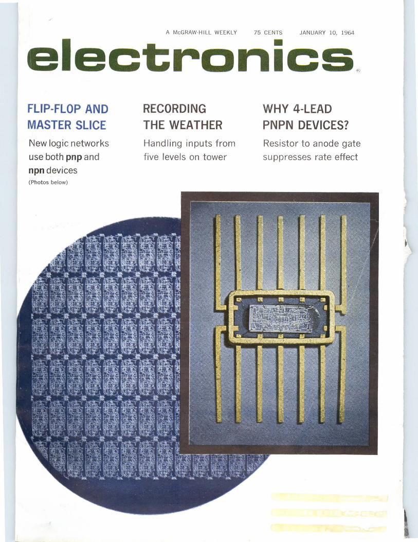
A McGRAW-HILL WEEKLY 75 CENTS JANUARY 10, 1964 electronics @ FLIP-FLOP AND MASTER SLICE New logic networks use both pnp and npn devices (Photos below) RECORDING THE WEATHER Handling inputs from five levels on tower WHY 4-LEAD PNPN DEVICES? Resistor to anode gate suppresses rate effect
-
Upload
khangminh22 -
Category
Documents
-
view
3 -
download
0
Transcript of electronics@ - bitsavers.org
A McGRAW-HILL WEEKLY 75 CENTS JANUARY 10, 1964
electronics@ FLIP-FLOP AND MASTER SLICE New logic networks
use both pnp and
npn devices (Photos below)
RECORDING THE WEATHER Handling inputs from
five levels on tower
WHY 4-LEAD PNPN DEVICES? Resistor to anode gate
suppresses rate effect
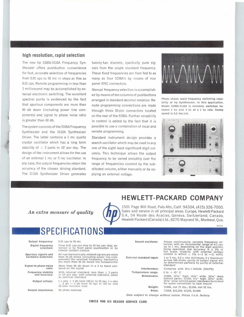
high resolution, rapid selection The new hp 5100A-5110A Frequency Syn
thesizer offers pushbutton convenience
for fast, accurate selection of frequencies
from 0.01 cps to 50 me in steps as fine as
0.01 cps. Remote programming in less than
1 milli second may be accomplished by ex
ternal electronic switching. The excellent
spectral purity is evidenced by the fact
that spurious components are more than
90 db down (including power line com
ponents) and signal to phase noise ratio
is greater than 60 db.
The system consists of the 5100A Frequency
Synthesizer and the 5110A Synthesizer
Driver. The latter contains a 1 me quartz
crystal oscillator which has a long term
stability of ± 3 parts in 10'' per day. The
design of the instrument a I lows for the use
of an external 1 me or 5 me oscillator. In
any case, the output frequencies retain the
accuracy of the chosen driving standard.
The 5110A Synthesizer Driver generates
Output frequency: 0.01 cps to 50 me
twenty-two discrete, spectrally pure sig
nals from the single standard frequency.
These fixed frequencies are then fed to as
many as four 5100A's by means of rear
panel BNC connectors.
Manual frequency selection is accomplish
ed by means of ten columns of pushbuttons
arranged in standard decimal notation. Re
mote programming connections are made
through three 50-pin connectors located
on the rear of the 5100A. Further versatility
in control is added by the fact that it is
possible to use a combination of local and
remote programming.
Standard instrument design provides a
search oscillator which may be used in any
one of the eight least significant digit col
umns. This technique allows the output
frequency to be varied smoothly over the
range of frequencies covered by the sub
stituted column, either manually or by ap
plying an external voltage.
Search oscillator:
Digital frequency selection:
From 0.01 cps per step to 10 me per step; selection is by front panel pushbutton or by remote contact closure
Spurious signals and harmonic distortion:
Signal-to-phase-noise ratio:
Frequency stability and accuracy:
Output voltage:
Output impedance:
All non-harmonically related signals are more than 90 db below (including power line components) the selected frequency; harmonics are more than 30 db below the fundamental
More than 60 db down in a 3 kc band centered on the sign a I
With internal standard, less than ± 3 parts in 10" per day; with external standard, same as external standard
1 v rm s ± 1 db from 100 kc to 50 me; 1 v rms -+- 2 db - 4 db from 50 cps to 100 kc into 50-ohm res is tive load
50 ohms nominal
External standard input:
Interference: Temperature range:
Dimensions:
Weight:
Price:
Photo shows rapid frequency switching capa
bility of hp Synthesizer. In this application,
Model 5100A-5110A is remotely switched be
tween 1 kc and 3 kc at a 1 kc rate. Sweep
speed is 0.5 ms / cm.
Allows continuously variable frequency selection with an incremental range of 0.1 cps up to 1 me, depending on the digit position being searched; dial accuracy is ± 3% of full scale; linearity with external voltage control is within ± 5% (-1 to -11 volts)
1 or 5 me, 0.2 v rms minimum, 5 v maximum across 500 ohms; purity of output signal will be determined partially by purity .of external standard
Complies with Mll-1-16910A (SHIPS)
0 to + 55° C
5100A, 103/4" high, 163/4" wide, 163/s" deep behind panel ; 5110A, 51/2" high, 163/4" wide, 163/s" deep behind panel; hardware furnished tor quick conversion to rack mount
5100A, net 75 lbs.; 5110A, net 52 lbs. 5100A, $10,250; 5110A, $5,000
Data subject lo change without notice. Prices f. o. b. factory.
CIRCLE 900 ON READER SERVICE CARD

W.W. MacDONALD, Editor Dial Direct: (971-2645)
Area Code 212
J. M. CARROLL, Managing Editor (2293)
SENIOR EDITORS Samuel Weber (2371) George W. Sideris (3444)
SENIOR ASSOCIATE EDITORS Michael F. Wolff (2600) John F. Mason (2666)
ASSOCIATE EDITORS Michael F. Tomaino (2071) William P. O'Brien (2297) George J. Flynn (2188) George V. Novotny (3151) Leon H. Dulberger (3446) Alexander A. McKenzie (2685)
ASSISTANT EDITORS Stephen B. Gray (2245) Barry A. Briskman (2306) Dan Smith (2467) Joel A. Strasser (2127) Vincent S. Acunto (2592) C. R. Whetstone (3495) Eric Valentine (2710) Louis S. Gomolak (2472) G. G. Tirellis (2187)
REGIONAL EDITORS Harold C. Hood,
1125 W. 6th St., Los Angeles 90017, Calif. (213-482-5450)
Laurence D. Shergalis, John Hancock Bldg., 255 California St., San Francisco 94111, Calif. (415-362-4600)
Thomas Maguire McGraw-Hill Bldg., 607 Boylston St., Boston 02116, Mass. (617-262-1160)
Cletus M. Wiley, Blair Bldg., 645 N. Michigan Ave., Chicago 60611, Ill. (312-664-5800)
ART DIRECTOR Howard R. Berry (2430)
ASSISTANT ART DIRECTOR John C. Wright, Jr. (3430)
EDITORIAL ASSISTANTS Lorraine Rossi, Virginia T. Bastian, Lynn Emery, Ann Mella, Lorraine Werner, Alice M. Moyer, Sharon Parks, Claire Benell, Kay Fontana, Sandra A. Le Mand, Mary Jo Jadin
FOREIGN NEWS BUREAU DIRECTOR, John Wilhelm, (2532);
Lawrence Mihlon (2997), Alyne Elias (2998)
LONDON-John Shinn, Derek Barlow, Nicholas Landon, 34 Dover St., London W.l, England
BONN-Richard Mikton, Silke McQueen, Mittelstrasse 39, Bad Godesberg, Germany
BRUSSELS-Arthur Erikson , 27 Rue Ducarle, Brussels, Belgium
PARIS-Robert Farrell, 17 Ave . Matignon, 3rd Fl., Paris 8, France
MILAN-Bruce Bendow, Via Manzoni No. 12, Milan, Italy
MEXICO CITY-Wesley Perry, Jr., Lafragua 4-314, Mexico 1 D.F. Mexico
RIO DE JANEIRO-Leslie Warren, Rua Mexico 3-S/ 1507 1509, Rio de Janeiro, Brazil
MOSCOW-Donald Winston, Kutuzovsky Prospekt 19, Apt. 28-29, Moscow, USSR
TOKYO-Richard Halloran, Charles Cohen, John Yamaguchi, Toranomon Sangyo Bldg., 1 Kotohiracho Shiba, Minato-Ku, Tokyo, Japan
CIRCULATION MANAGER Hugh J. Quinn (2310)
C. C. RANDOLPH, Publisher (2016)
JANUARY 10, 1964
electronics A McGRAW-HILL WEEKLY 75 CENTS
FLIP-FLOP LOGIC. The integrated circuit flip-flop by Texas Instruments Incorporated operates on a single-phase clock and performs J-K logic-simultaneous application of logic ONE's at the inputs results in a change of state. It uses a unique steering method that does not require input capacitors. The master slice in the background yields nearly 70 flip flops. The fiip fiop is packaged in a JO-lead fiat pack (four leads will later be trimmed of]). See p 25 COVER
TRACKING WITH LASERS. Being readied for moving-target tests is a new laser tracking system with angular precision better than radar. This low-power system using a semiconductor laser, may be followed by high-power ones for missile-decoy discrimination. Also in the works is a system to measure missile attitudes after launch 10
LASER WELDER. Ready for test use this week is a full-scale, automatic system for welding titanium and other aerospace metals with a pulsed laser. Positioning table moves the work-piece while an optical system shapes the beam 11
INFORMATION RETRIEVAL. Army Missile Command is planning to update its EDS-0009 information retrieval system by equipping it with optical input and output and providing for facsimile transmission of data . Eventually, developers hope, the system will accept spoken queries 14
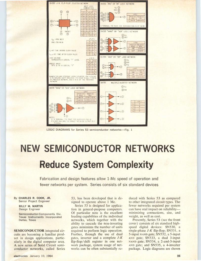
HIGH-DENSITY SEMICONDUCTOR NETWORKS. Six new integrated circuits-flip flop, 5-input NANO gate, 5-input AND gate, dual 3-input NANO gate, 2-and-3-input AND gate and 4-inverter package-reduce digital system complexity permitting 1-Mc speed of operation while using fewer networks in a system. Advantages result in part from wider application of "master slice" concept and use of both pnp and npn devices for current gain.
By C.R. Cook, Jr. , and B. M. Martin, Texas Instruments Incorporated 25
SUPPRESSING RATE EFFECT IN PNPN DEVICES. Rate effect is switching of a pnpn device into high conduction due to a sudden increase in anode voltage. Switching and power-line transients can cause spurious triggering of pnpn devices; even pnpn devices themselves can trigger other devices. New fourterminal pnpn devices allow connecting a resistor from anode gate to anode power supply to suppress rate effect.
By R. A. Stasior, GE Semiconductor Products Dept. 30
Contents continued
2
·electronics
January 10, 1964 Vol. 37, No. 2
Published weekly, with Electronics Buyers' Guide as part of the subscription, by McGraw-H ill, Inc. Founder: James H. McGraw (1860· 1948).
SUBSCRIPTIONS: Available only by paid subscription. Publisher reserves the right to refuse nonqualified subscriptions. Subscriptions to Electronics solicited only from those actively engaged in the field of the publication. Position and company connection must be indicated on subscription orders forwarded to address shown be· low. Subscription rates for individuals in the field of the publication: U. S. and possessions and Canada $6 one year, $9 two years, $12 three years (single copies 75¢). All other countries $20 one year (single copies $1.50) .
EXECUTIVE, EDITORIAL, CIRCU· LATION and ADVERTISING OF· FICES: McGraw-Hill Building, 330 West 42nd Street, New York, N . Y ., 10036. Telephone Area Code 212. 971 -3333. Teletype TWX N. Y. 212· 640-4646. Cable McGrawhill, N . Y. Printed in Albany, N. Y. Second class postage paid at Albany, N. Y . Title reg . ® in U. S. Patent Office. Copyright © 1964 by McGraw-Hill, Inc. All Rights Reserved . The contents of this publication may not be reproduced either in whole or in part without consent of copyright owner.
OFFICERS OF McGRAW-HILL PUBLICATIONS: Shelton Fisher, Presi· dent; Vice Presidents: Joseph H. Allen, Operations; John R. Callaham, Editorial; Ervin E. DeGraff, Circulation; Donald C. McGraw, Jr., Advertising Sales; Angelo R. Venezian, Marketing.
CORPORATION OFFICERS: Donald C. McGraw, President; L. Keith Goodrich, Hugh J. Kelly, Harry L. Waddell, Executive Vice Presidents; John J . Cooke, Vice President and Secretary; John L. McGraw, Treasurer.
UNCONDITIONAL GUARANTEE: The publisher, upon written request, agrees to refund the part of the subscription price applying to the remaining unfilled portion of the subscription if service is unsatisfactory.
SUBSCRIBERS: Please address al l correspondence regarding subscriptions, change of address notices, and subscription orders to Fulfillment Manager, Electronics, P. 0 . Box 430 Hightstown, N. J ., 08520. Change of address notices should be sent promptly; provide old as well as new address; in· elude zip code or postal zone number if any. If possible, attach address label from recent issue. Please allow one month for change of address to become effective.
POSTMASTER: Please send Form 3579 to Fulfillment Manager, Electronics, P. 0. Box 430, Hightstown, N. J., 08520.
Associated Business Puhllcatlons
Contents continued
DIGITAL SYSTEM RECORDS WEATHER DATA. This simplified system handles inputs from five wind and five temperature sensors mounted at different levels on a tower. It uses a stepping switch as a multiplexer, digital voltmeter as an analogdigital converter and one amplifier for all sensors. Thermistors compensate for nonlinearities in resistance thermometer bridge.
By F. J. Goldwater, Hebrew Univ., Jerusalem, Israel 34
LINEAR SCALES SHOW MIXER HARMONICS. Here is a way to locate spurious signals generated by the first six harmonics of two mixed signals. Some of these spurious signals may be at the desired output frequency and consequently cannot be filtered out. One scale is used for the sum of input frequencies , the other for the difference.
By R. T. Stevens, Sanders Associates 37
SOLAR FLARES. NASA is hoping to devise a technique for reliably predicting solar flares before the first manned lunar flight. Right now, the data base is being gathered with a variety of equip-ment, including two new satellite programs 40
DEPARTMENTS
Crosstalk. Those Sunspots Again 5
Comment. Atomic Power. Unity-Gain Buffer 6
Electronics Newsletter. DOD Unsnarling Procurement Rules 17
Meetings Ahead. Anti-Missile Research Advisory Council Meeting 18
Washington This Week. Military Spending Decline Seen in Fiscal 1965. Program Cuts Include Typhon Missile 20
Research and Development. Miniature Magnet Travels Through Body 44
Components and Materials. lnSb Detectors for Infrared Systems 49
Production Techniques. Resilient Rollers Form Leads 52
New Products. DVM Features Remote Readout 56
Literature of the Week 60
People and Plants. Burroughs Combines Two Divisions 62
Index to Advertisers 7 0
January 10, 1964 electronics
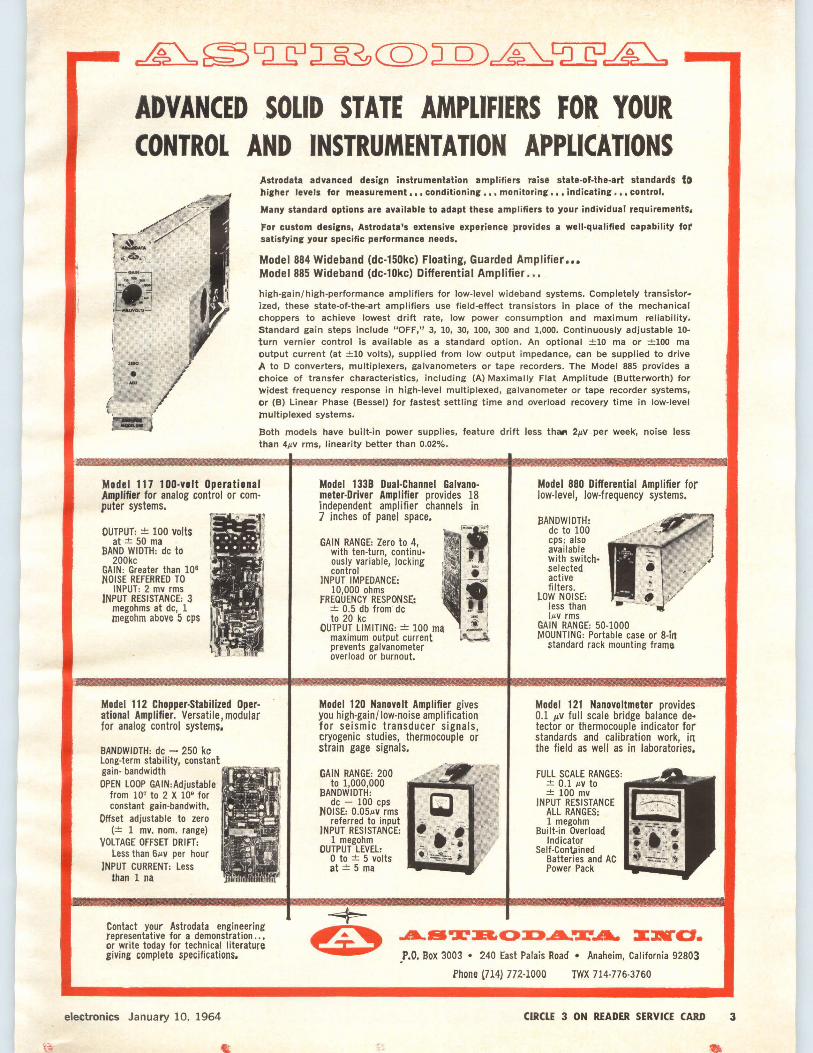
ADVANCED SOLID STATE AMPLIFIERS FOR YOUR CONTROL AND INSTRUMENTATION APPLICATIONS
Astrodata advanced design instrumentation amplifiers raise state-of-the-art standards to hieher levels for measurement,,, conditioning,,, monitoring,,. indicating,,, control.
Many standard options are available to adapt these amplifiers to your individual requirements.
For custom designs, Astrodata's extensive experience provides a well-qualified capability tor satisfying your specific performance needs,
Model 884 Wideband (dc-150kc) Floating, Guarded Amplifier ••• Model 885 Wideband (dc-10kc) Differential Amplifier •••
high-gain/ high-performance amplifiers for low-level wideband systems. Completely transistor· ized, these state-of-the-art amplifiers use field-effect transistors in place of the mechanical choppers to achieve lowest drift rate, low power consumption and maximum reliability. Standard gain steps include "OFF," 3, 10, 30, 100, 300 and 1,000. Continuously adjustable 10-turn vernier control is available as a standard option. An optional ±10 ma or ±100 ma output current (at ±10 volts), supplied from low output impedance, can be supplied to drive A to D converters, multiplexers, galvanometers or tape recorders. The Model 885 provides a choice of transfer characteristics, including (A) Maximally Flat Amplitude (Butterworth) for Widest frequency response in high-level multiplexed, galvanometer or tape recorder systems, or (BJ Linear Phase (Bessel) for fastest settling time and overload recove,y time in low-level multiplexed systems.
Both models have built-in power supplies, feature drift less th111 2µv per week, noise less than 4µV rms, linearity better than 0.02%.
Model 117 1 OD-volt Operational Amplifier for analog control or computer systems.
Model 1338 Dual-Channel Galvanometer-Driver Amplifier provides 18 independent amplifier channels in 7 inches of panel space.
Model 880 Differential Amplifier for low-level, low-frequency systems.
OUTPUT: ± 100 volts at± 50 ma
BAND WIDTH: de to 200kc
GAIN: Greater than 108
NOISE REFERRED TO INPUT: 2 mv rms
INPUT RESISTANCE: 3 megohms at de, 1 megohm above 5 cps
Model 112 Chopper-Stabilized Operational Amplifier. Versatile, modular for analog control systems.
llANDWIDTH: de - 250 kc Long-term stability, constant gain- bandwidth OPEN LOOP GAIN:Adjustable
from 107 to 2 X 10• for constant gain-bandwith,
Offset adjustable to zero (± 1 mv. nom. range)
VOLTAGE OFFSET DRIFT: Less than 6µv per hour
INPUT CURRENT: Less than 1 na
Contact your Astrodata engineering representative for a demonstration .. , or write today for technical literature giving complete specifications.
electronics January 10, 1964
GAIN RANGE: Zero to 4, with ten-turn, continU• ously variable, locking control
JNPUT IMPEDANCE: 10,000 ohms
FREQUENCY RESPONSE: ± 0.5 db from· de to 20 kc
OUTPUT LIMITING: ± 100 ma maximum output current prevents galvanometer overload or burnout.
Model 120 Nanovelt Amplifier gives you high-gain/ low-noise amplification for seismic transducer signals, cryogenic studies, thermocouple or strain gage signals.
GAIN RANGE: 200 to 1,000,000
llANDWIOTH: de - 100 cps
NOISE: 0.05µv rms referred to input
INPUT RESISTANCE: 1 megohm
OUTPUT LEVEL: 0 to ± 5 volts at± 5 ma
BANDWIDTH: de to 100 cps; also available with switchselected active filters.
LOW NOISE: less than IJLV rms
GAIN RANGE'.: 50-1000 MOUNTING: Portable case or 8-in
standard rack mounting frame
Model 121 Nanovoltmeter provides 0.1 µv full scale bridge balance de· tector or thermocouple indicator for standards and calibration work, in the field as well as in laboratories.
.P.O. Box 3003 • 240 East Palais Road • Anaheim, California 92803
Phone l714) 77.2-1000 TWX 714-776-3760
CIRCLE 3 ON RfADER SERVICE CARD 3
4
about today's most advanced solid state
telegraph relays
RADIATION INCORPORATED
CIRCLE 4 ON READER SERVICE CARD
Are all solid-state relays alike? No. Some are transistorized versions of mechanical units, while others are partially solid-state. Radiation Telegraph Relays are all solid-state. There are no moving parts. Why invest in solid-state relays? Because they eliminate routine maintenance, require no adjustments, and cut costly downtime and service calls. How long will they operate under normal conditions? Indefinitely.
APPLICATIONS .•.
Which mechanical relays can solid-state units replace? All known types .. . except those rare applications where no solid-state device can be used. How many kinds would I have to stock? Only three: Radiation supplies polar, neuh·al and universal types. Can I simply plug in your relays and expect them to work? Yes. But because there are so many different wiring options, an adapter plug may be required . to match your particular system. How do you power Radiation Relays? You don't. A unique circuit (patent applied for) allows the unit to operate on input current ... the signal itself supplies the power.
TECHNICAL ...
What are the features of Radiation Relays? Non-polarized output contacts, high MTBF ... 73,000 hours of actual field test without failure, high speed ... up to 2400 bits/ second, low dis-tortion ... less than 1 'lo at 1000 bauds, and low leakage . .. less than 5 µ.a at 130 volts. The units provide long operating life with extremely high reliability, and are designed with special protective circuitry. What type of protective circuitry? Thanks to a unique Radiation design, the units are highly resistant to spikes and overvoltages. Not only do they provide a cleaner telegraph signal, but they are also protected against destruction caused by abnormal line conditions. Suppose a Radiation Relay is badly overloaded •.. how do I check it out? We can supply our Model 7l10 Solid-State Relay Tester. Incidentally, it comes with an adapter for use with electromechanical units, too. What if the unit's actually damaged by abnormal conditions ... do I have to throw it away? Absolutely not! Due to modular construction Radiation Telegraph Relays are repairable.
QUALITY ASSURANCE •..
Are your relays guaranteed? They certainly are. Radiation warrants Neutral Model 9214 and Polar Model 9212 against all defects of performance for a year after shipment ... providing they're used under normal conditions. How can I prove the superiority of Radiation Solid-State Telegraph Relays? Simply phone or write Product Sales Manager at Radiation Incorporated, Products Division, Dept. EL-01, Melbourne, Florida. We will supply technical information, and, if you wish, have a Field Engineer provide a relay to test on the line of your choice. Why not call today? Prove to yourself that Radiation Relays assure higher circuit efficiency, lower cost operation and dependable service!
January 10, 1964 electronics

---------------CROSSTALK---Those Sunspots Again
"The fault, dear Brutus, is not in our stars, But in ourselves that we are underlings."
Shakespeare, Julius Caesar, Act l , Scene 2
But many faults do lie in our stars. And they work all manner of mischief with men's best laid plans. They may prevent man from reaching the moon, or at least make the journey more hazardous.
The faults in a star are, of course, sunspots. For centuries astronomers have studied and charted these fiery whirlwinds on the sun's face. Statisticians have sought and found interesting periodicity in their occurrence-a 27-day cycle, an annual cycle, an 11-year cycle and even a 101-year cycle.
Their effect on radio and cable communications has been amply demonstrated with cause linked to effect. Sunspots have also been correlated against weatherespecially hurricanes, floods and other dramatic phenomena-and against the activities of man-war, pestilence, mental illness, crime. In these latter studies there is as yet no link up between cause and effect although there may be one through the mechanism of positive ions.
Certain, but not all, sunspots spew out highly ionized particles. And these particles, some of them very energetic indeed, raise hob with the ionosphere and with the earth's magnetic field, adding, as it were, a fluctuating a-c component to the earth's ring current. Many highly competent scientists and engineers have devoted their life's work to predicting when these solar bombardments will occur. The problem is especially acute today because solar flares can kill future space travelers or disable their essential communications and navigation apparatus.
Naturally these bombardments occur most often when the sunspot cycle is at its maximum. And socalled bipolar or double-yoked sunspots are often more troublesome than unipolar ones. A sunspot that acted badly once will usually act up the second time around and this comes to about 27 days as the sun rotates. Furthermore, flares visible on the limb of the sun when photographed by a coronagraph are often precursors of trouble some 7 or 8 days later.
A blast of ionized particles is often preceded by a dose of ultraviolet radiation-the SID or sudden ionospheric disturbance. The particles follow one to three days later since they travel slower than the speed of light. Before the storm, the highest h-f radio signals drop into the mud, especially those on northerly paths, d-f signals behave erratically, often shifting several degrees southward, and the Aurora Borealis and Australis put on their pyrotechnic-like displays.
But these techniques are not going to help astronauts already embarked on long space voyages. Is there a better way?
Scientists and engineers the world over are searching for one by amassing astro and geophysical data and using all modern mathematical tools to discover new and useful relationships. One school of thought
electronics January 10, 1964
SOLAR FLARE shoots out more than 150,000 miles in these sequence photos made by the High Altitude Observatory of the University of Colorado, at Climax, Colorado
ascribes the occurrence of sunsp<'>ts to a particular conjunction of the major planets and at least one man has been rather successful in predicting ionospheric disturbances from a study of the planets.
But be the answer in the stars or not, the mystery of the solar flare bolds a very large key to man's exploration of the cosmos (see p 40) .
CONSTANT CONSTANTS-At a recent joint meeting of the IEEE Symbols Committee and a subcommittee of the American Standards Association Sectional Committee on Letter Symbols the discussion turned to considering some of the basic constants used in electrical engineering.
These are the familiar µ,o, the permeability of freespace, and Eo, the permittivity of free-space. It was pointed out, quite rightly, that these quantities are not measurable properties of free-space-if indeed there is really such a thing as free-space at all. Rather, they are properties of the system of units employed.
It has been suggested, therefore, that the terminology be altered and that we begin to speak about r ., the electric constant and rm, the magnetic constant. It may be argued that it may take some time to get used to seeing the well-known formulas
written
D = E0sE and B = fLoE H
D = r ,sE and B = I'mµ,H
but it another step towards helping the engineer to realize at all times exactly what he is doing. It seems time to do away with the fiction of properties of free-space that nobody can define much less measure and acknowledge that these properties of free-space are nothing more than convenient constants that make our system of units come out in manageable form.
5
Only from Sprague!
100 µJ!
LABORATORY CAPACITANCE STANDARDS ' to a certified accuracy of
±0.1%
Components for highly precise electronic equip· ment as well as laboratory standards of capaci· tance • Measurements are correlated with similar capacitors certified by National Bureau of Stand· ards • Maximum capacitance stability possible in the state of the art • Capacitance values from .001 to lOOµF • Specially-processed polystyrene dielectric • Hermetically-sealed.
STYRACON® DECADE CAPACITORS
Triple decade capaci· tors with direct in-line readout • Accurate to ± 0.5% of nominal capacitance for any dial setting • Two basic ranges of capaci tance - 0.0001 to 0.1099µF and 0.001 to l.099µF • Available in bench or panel mount· ing styles.
For complete technical data, write for Engineering Bulletins 90,600 and 90,605 to Technical Literature Service, Sprague Electric Company, 35 Marshal/St.,NorthAdams,Mass.
SPRllGUE® THE MARK OF RELIABILITY
'Sprague' and '@1 are registered trademarks of the Sprague Electric Co.
4SC·1 68·63R1
6 CIRCLE 6 ON READER SERVICE CARD
------COMMENT------
ATOMIC POWER
Your straw man in the editorial, Crossroads For Atomic Power (p 5, Dec. 6, 1963), seems nicely batted down, but hardly in keeping with your usual objective journalistic style.
Having read a li ttle and heard transcriptions of several hearings dealing with nuclear power plant proposals, I am frank ly not aware of anyone seriously questioning the proposal sites on the basis of the nuclear explosion hazard. What you fail to deal with is the statistical hazard of low-level radiation continuously or intermittently released in normal operation, the hazard of meltdown or other thermal excursion that could release heavier flux to a wide area but with no mechanical damage beyond the site boundaries, and the total environment contamination due to unsatisfactory solutions to the refuse disposal problem.
By all means remain dispassionate if you can, but speak to the question . Thousands of curies per month are released into the sea in England, where bathing in the ocean is not very popular anyway, but the greatest potential food supply may one day come from the sea. Davit E. Lilienthal, former AEC chairman, indicates that the waste disposal dilemma is extremely intractable with no solution in sight. We store high-level wastes in conta iners with a projected lifetime a fraction of the half-life of the waste.
In our country with ample fossil fuel reserves, there is no reason to rush into heavy nuclear power development when relatively clean controlled thermonuclear reactors may be realized soon. However, the AEC seems bent on promoting fission plants not just "in the midst of their customers" but 1,000 feet from active seismic faults, in the most scenically endowed suburban areas, or in the midst of a rich biological specimen preserve.
Certainly, as individuals and as citizens, we should insist in all forums available to us that public safety be given fu ll and open consideration. But let us do our homework first , taking into account the full history of reactor development and accidents, facts favorable to the proposal and unfavorable. Let us consider above all the legacy of contamination, the most vile and filthy refuse ever created on the face of the earth by man or God, we are leaving to our posterity.
Russ LINTON
San Diego, California
• Our homework in our own backyard-Queens, where a reactor is proposedindicates that residents there are most concerned about the possibility of a major accident-either an outright explosion or a contained accident that would release large amounts of radioactive material. Neither of these fears seems justified, in our view, by experience with atomic reactors.
Also, most of the recent arguments, pro and con, about nuclear power plants do revolve about the "catastrophe" question. Mr. Lilienthal , himself, brought up this argument at the Atomic Industrial Forum meeting in New York on Nov. 21, 1963; it was also discussed by other speakers at the meeting, and by AEC Chairman Seaborg on Nov. 7. We studied these statements carefully, in the light of our previous knowledge of the reactor safety question, before arriving at a conclusion.
The statistical radioactivity question and the waste disposal question were considered, but not discussed in the editorial. The apparently negligible hazard from the first seems to be cancelled out by the statistical hazard that can be attributed to air pollution caused by conventional power sources. Nor can we see how waste disposal should determine where an atomic power plant should be located. The AEC says that now it generally does not dispose of reactor wastes, but reprocesses them into new fuel elements, or stores them in tanks for later use.
UNITY-GAIN BUFFER
In my article of Dec. 20, 1963, Unity-Gain Buffer Acquires Precision By Feedback, (p 36), are the following errors:
In the first sentence, the word and should be removed from line 2. Equation l should read A.[(e, - e.)A, + e.] = e •. Equation 2 should read A = e.le, = A.A,/ (1 +A.A, - A . ). The last expression of Eq. 3 should be 1 / (h m + R el h 1,2 ). The last expression of Eq. 5 should be R .e,le.[ l - A~(l-Ai)] . The middle expression of Eq. 6 should be R .I( 1 - A . + A,A. ). Equation 7 should read i, = (e, - e.)[llR., + l/h.., + l/(rc + h.,2)]. Equation 8 should read ide, = l/Z, = (l-A)[l/R., + 1/hm + 1/(r. +
h .. 2)]. Equation 9 should read z, ~ h lbl/ (1 - A). In Fig. 2A, both e, before the first stage should be e,.
Operations Research Inc. Santa Monica, California
D AVID K. PHILLIPS
January 10, 1964 electronics
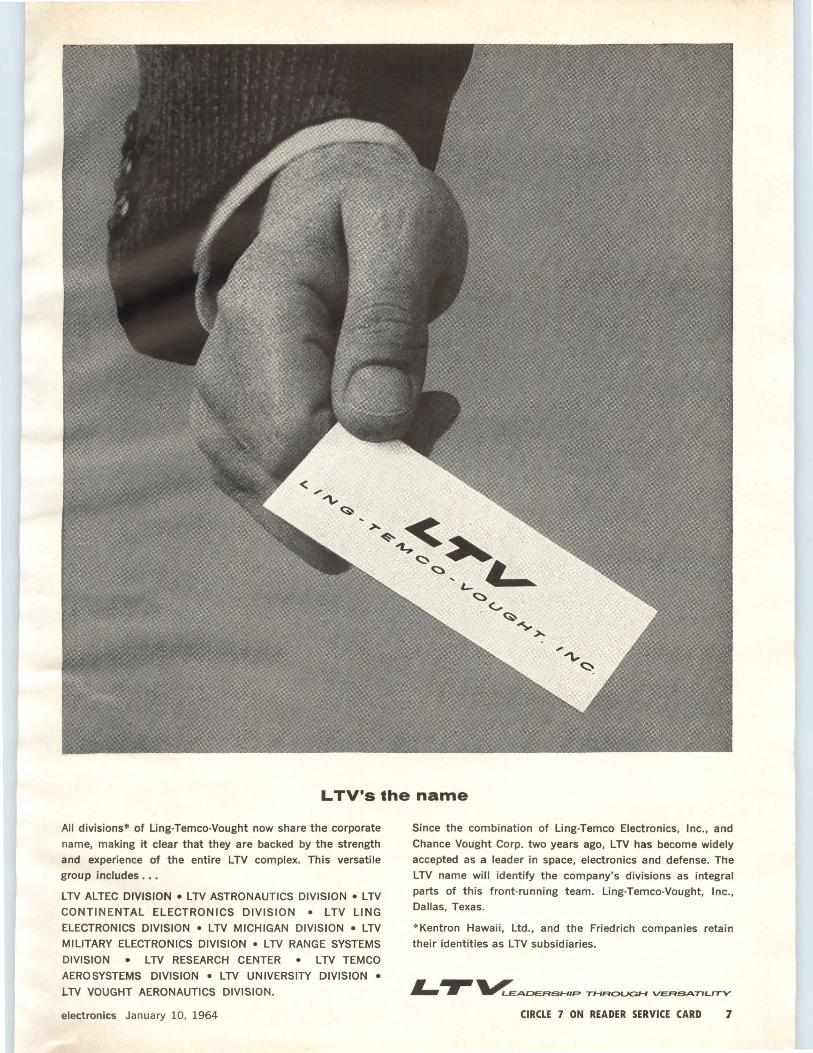
L TV's the name
All divisions* of Ling-Temco-Vought now share the corporate
name, making it clear that they are backed by the strength
and experience of the entire LTV complex. This versatile
group includes .••
LTV ALTEC DIVISION •LTV ASTRONAUTICS DIVISION •LTV
CONTINENTAL ELECTRONICS DIVISION • LTV LING
ELECTRONICS DIVISION • LTV MICHIGAN DIVISION • LTV
MILITARY ELECTRONICS DIVISION • LTV RANGE SYSTEMS
DIVISION • LTV RESEARCH CENTER • LTV TEMCO
AEROSYSTEMS DIVISION • LTV UNIVERSITY DIVISION •
LTV VOUGHT AERONAUTICS DIVISION.
electronics January 10, 1964
Since the combination of Ling-Temco Electronics, Inc., and
Chance Vought Corp. two years ago, LTV has become widely
accepted as a leader in space, electronics and defense. The
LTV name will identify the company's divisions as integral
parts of this front-running team. Ling-Temco-Vought, Inc., Dallas, Texas.
* Kentron Hawaii, Ltd., and the Friedrich companies retain
their identities as LTV subsidiaries.
L.,.. ~ADERSHIP THROUGH VERSATILITY
CIRCLE 7 ON READER SERVICE CARD 1
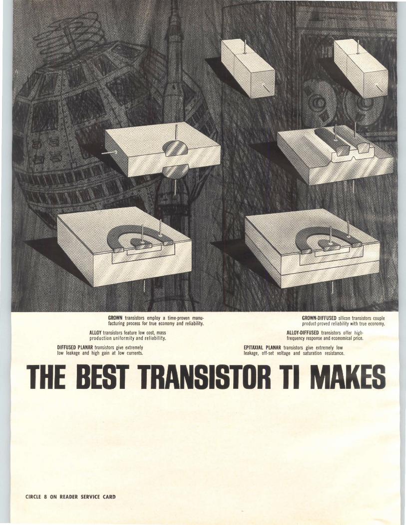
GROWN transistors employ a time-proven manu· facturing process for true economy and reliability.
ALLOY transistors feature low cost, mass production uniformity and reliability.
DIFFUSED PLANAR transistors give extremely low leakage and high gain at low currents.
GROWN-DIFFUSED silicon transistors couple product-proved reliability with true economy.
ALLOY-DIFFUSED transistors offer high· frequency response and economical price.
EPITAXIAL PLANAR transistors give extremely low leakage, off-set voltage and saturation resistance.
THE BEST TRANSISTOR Tl MAKES
CIRCLE 8 ON READER SERVICE CARD
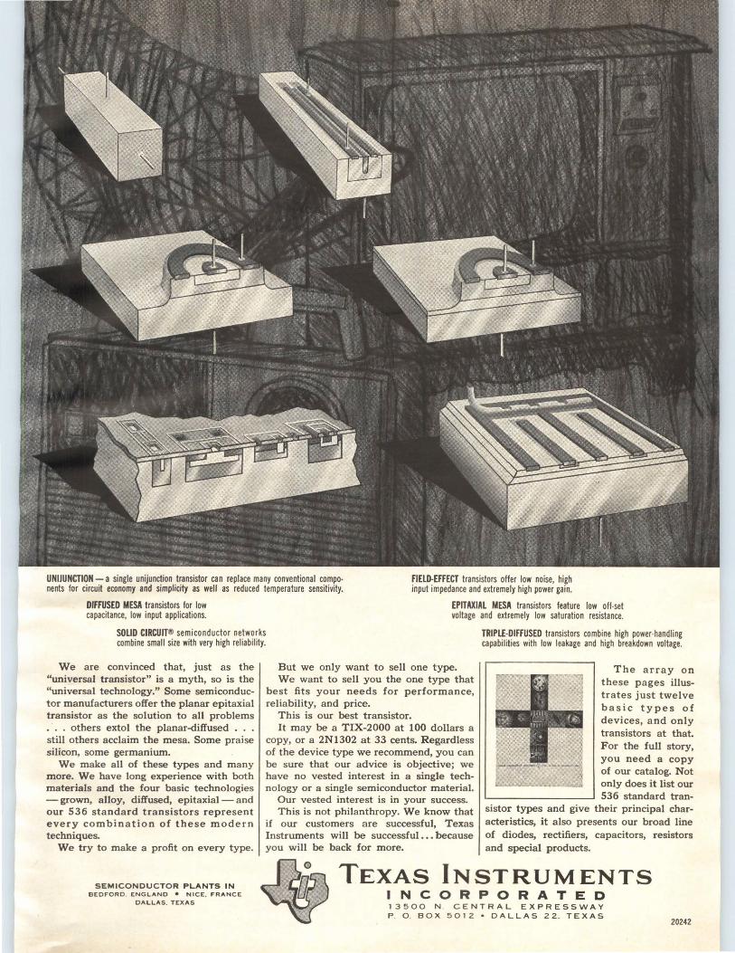
UNIJUNCTION-a single unijunction transistor can replace many conventional components for circuit economy and simplicity as well as reduced temperature sensitivity.
FIELD-EFFECT transistors offer low noise, high input impedance and extremely high power gain.
DIFFUSED MESA transistors for low capacitance, low input applications.
EPITAXIAL MESA transistors feature low off-set voltage and extremely low saturation resistance.
SOLID CIRCUIT® semiconductor networks combine small size with very high reliability.
TRIPLE-DIFFUSED transistors combine high power-handling capabilities with low leakage and high breakdown voltage.
We are convinced that, just as the "universal transistor" is a myth, so is the "universal technology." Some semiconductor manufacturers offer the planar epitaxial transistor as the solution to all problems . . . others extol the planar-diffused . . . still others acclaim the mesa. Some praise silicon, some germanium.
We make all of these types and many more. We have long experience with both materials and the four basic technologies - grown, alloy, diffused, epitaxial - and our 536 standard transistors represent every combination of these modern techniques.
We try to make a profit on every type.
SEMICONDUCTOR PLANTS IN BEDFORD . ENGLAND • NICE. FRANCE
DALLAS. TEXAS
But we only want to sell one type. We want to sell you the one type that
best fits your needs for performance, reliability, and price.
This is our best transistor. It may be a TIX-2000 at 100 dollars a
copy, or a 2N1302 at 33 cents. Regardless of the device type we recommend, you can be sure that our advice is objective; we have no vested interest in a single technology or a single semiconductor material.
Our vested interest is in your success. This is not philanthropy. We know that
if our customers are successful, Texas Instruments will be successful ... because you will be back for more.
The array on these pages illustrates just twelve basic types of devices, and only transistors at that. For the full story, you need a copy of our catalog. Not only does it list our 536 standard tran
sistor types and give their principal characteristics, it also presents our broad line of diodes, rectifiers, capacitors, resistors and special products.
TEXAS INSTRUMENTS INCORPORATED 13500 N . CENTRAL EXPRESSWAY P . 0 . BOX 5012 •DALLAS 22. TEXAS
20242
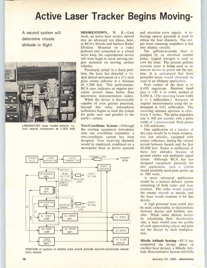
Active Laser Tracker Begins Moving-A second system will
determine missile
attitude in flight
LABORATORY laser model detects 114-inch lateral movement at 1,300 feet
MOORESTOWN, N. J.-Last week, an active laser tracker moved into an advanced test phase, here, at RCA's Missile and Surface Radar Division. Mounted on a radar pedestal and connected to a closed servo loop, the experimental device will soon begin to track moving targets mounted on moving surface vehicles.
Pre'-;.im-tsly t~st~d in a fixeq position, the laser has detectea a Y<i -inch lateral movement of a 21/2-inch glass corner reflector at a distance of 1,300 feet. This performance, RCA says, indicates an angular precision several times better than microwave instrumentation radars.
While the device is theoretically capable of even greater precision, beyond this value atmospheric turbulence begins to limit the system for paths near and parallel to the earth's surface.
Two-Coordinate System-Although the existing equipment determines only one coordinate (azimuth), a two-coordinate system has been designed. Four receiving channels would be employed, combined on a monopulse basis to derive azimuth
TRIGGER PULSE
LASER MODULATOR
LASER TRANSMIT L_EN_S ___ .,.TRANSMIT TRANSMITTER 1----<--t BEAM
N <1
SUM AMPL
P. E. CELL BEAM
SPLITTER>
P.E. CELL
,----------- -------, I ..,-----+------, :
: 1 TARGET
I ELEVATION~ 1 - RETURN I CHANNEL I RECEIVING : ...J i LENS IW I r----''"---.
:i; I
vii I
EL ERROR AMPL
RANGE TRACKING
----------, .------.1
EL SERVO i ----:
L------------------------------------__________ J
AZ VIDEO COMP
LASER RETURN
AMPL
AZ ERROR AMPL
AZ SERVO
"A" SCOPE
DISPLAY
PORTION of system in dotted area would provide second-coordinate (elevation) sensor
10
and elevation error signals. A reflecting optical pyramid is used to obtain the four channels. The output from summing amplifiers is fed into display circuits.
The gallium-arsenide laser is pumped by an electrical current pulse. Liquid nitrogen is used to cool the laser. The present gallium arsenide laser is being used as an interim device to prove out the system. It is anticipated that more powerful lasers would obviously be used in an ultimate application.
Peak output of the laser is at 8,450 angstroms. Receiver band pass is 100 A in width, peaked at 8,450 A. (The receiving beam width is -+- 1 milliradian.) Accuracy of angular measurements using the instrument is 0.01 milliradian. The receiving antenna aperture is effectively 5 inches. The pulse repetition rate is 300 per second, with a pulse width of 1 microsecond. Peak power is 100 milliwatts.
One application of a tracker of this type would be to track cooperative test missiles, equipped with corner reflectors, during the critical period between launch and the first 60,000 feet. Radar is ineffectual at these low altitudes because of ground clutter and multipath signal return. Although RCA has not designed equipment precisely for this application, such a system would probably need peak power up to 500 watts.
A more advanced application would be a tactical defense system consisting of both radar and laser trackers. The radar would acquire the enemy aircraft or missile, and the laser would examine it for fine details.
A high powered laser could also be used, conceivably, to discriminate between decoys and ballistic missiles. While radar detects decoys by calculating their deceleration rate, a laser would scan the profile of each approaching object and pick out the decoys by their configuration.
Missile Attitude Sensing-RCA has completed the design phase of another laser project, a Missile Attitude Determination System (MADS)
January 10, 1964 electronics
Target Tests By JOHN F. MASON, Senior Associate Editor
-this one under contract from USAF's Electronic Systems Division, Hanscom Field, Mass.
Objective of this work is to develop an advanced optical instrumentation system, external to a missile, which will provide measurements of the missile's attitude. The approach worked out uses lasers as illuminating sources and polarization-sensitive receivers to extract the attitude data.
Accurate determination changes in a missile's attitude in real time during its early launch phase is extremely important for evaluating guidance and control. Existing methods use on-board equipment to telemeter information to ground stations and also use ground-based optical gear to photograph the early launch stage.
MADS will measure in absolute
coordinates, the pitch, roll and yaw of a missile from lift-off to 50,000 feet, at a rate of at least ten measurements of all three parameters each second and to an accuracy of at least 0.1 degree for each parameter.
The ground station will be located approximately 25,000 feet from the launch pad. The beams from two lasers of different wave-lengths will be directed from this ground station to a retrorefl.ector package on the missile. This package will reflect its received light back to the ground station and will polarization modulate the beams in a manner determined by the orientation of the missile relative to the beams.
Lasers have been chosen over a conventional light source because at the anticipated range the light intensity on the reflector package is
several orders of magnitude higher than if a non-laser light source is used.
At the ground station, the returned light will be passed through a polarization analyzing system which will determine the polarization state of each beam-expressed in two parameters: the eccentricity and orientation of the polarization ellipse.
The system will be set up so that the ellipses of both beams will have the same orientation. They will, however, have eccentricities independent of one another. Thus, there will be three independent variables on the beams, two eccentricities and one orie:itation, to convey the three independent variables of pitch, roll and yaw. By this means, the attitude of the missile is determined in beam coordinates.
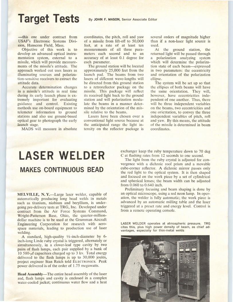
LASER WELDER exchanger keep the ruby temperature down to 70 deg C at fl.ashing rates from 12 seconds to one second.
MAKES CONTINUOUS BEAD
MELVILLE, N. Y.-Large laser welder, capable of automatically producing long bead welds in metals such as titanium, niobium and beryllium, is undergoing pre-delivery tests at TRG, Inc. Developed under contract from the Air Force Systems Command, Wright-Patterson Base, Ohio, the quarter-milliondollar machine is to be used at the Grumman Aircraft Engineering Corporation for research with aerospace materials, leading to production use of laser welding.
A standard, high-quality Vi-inch-diameter by 6-inch-long Linde ruby crystal is triggered, alternately or simultaneously, in a clover-leaf type cavity by two pairs of fl.ash lamps, each pair supplied by a bank of 10 580-p.f capacitors charged up to 3 kv. Total energy delivered to the fl.ash lamps is up to 30,000 joules, project engineer Stan Reich told ELECTRONICS. Peak power delivered is of the order of 1.75 megawatts.
Head Assembly-The entire head assembly of the laser rod, fl.ash lamps and cavity is enclosed in a complex water-cooled jacket; continuous water fl.ow and a heat
The light from the ruby crystal is adjusted for convergence with a dichroic roof prism and a movable cube-corner reflector. A dichroic mirror passes only the red light to the optical system. It is then shaped and focused on the work piece by a set of cylindrical and spherical lenses; the beam width can be adjusted from 0.060 to 0.640 inch.
Preliminary focusing and beam shaping is done by an optical microscope, using a red neon lamp. In operation, the welder is fully automatic; the work piece is advanced by an automatic milling table and the laser triggered at a preset rate and energy level. Control is from a remote operating console.
LASER WELDER operates at atmospheric pressure. TRG cites this, plus high power density of beam, as chief advantages, especially for thin -metal welds
. I
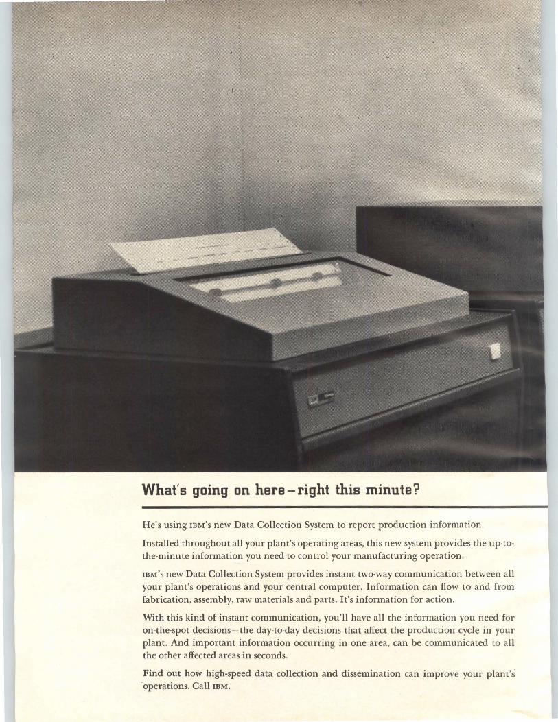
What's going on here-right this minute?
He's using IBM's new Data Collection System to report production information.
Installed throughout all your plant's operating areas, this new system provides the up-to, the-minute information you need to control your manufacturing operation.
IBM's new Data Collection System provides instant two-way communication between all your plant's operations and your central computer. Information can flow to and from fabrication, assembly, raw materials and parts. It's information for action .
With this kind of instant communication, you'll have all the information you need for on-the-spot decisions-the day-to-day decisions that affect the production cycle in your plant. And important information occurring in one area, can be communicated to all the other affected areas in seconds.
Find out how high-speed data collection and dissemination can improve your plant's' ·operations. Call IBM.
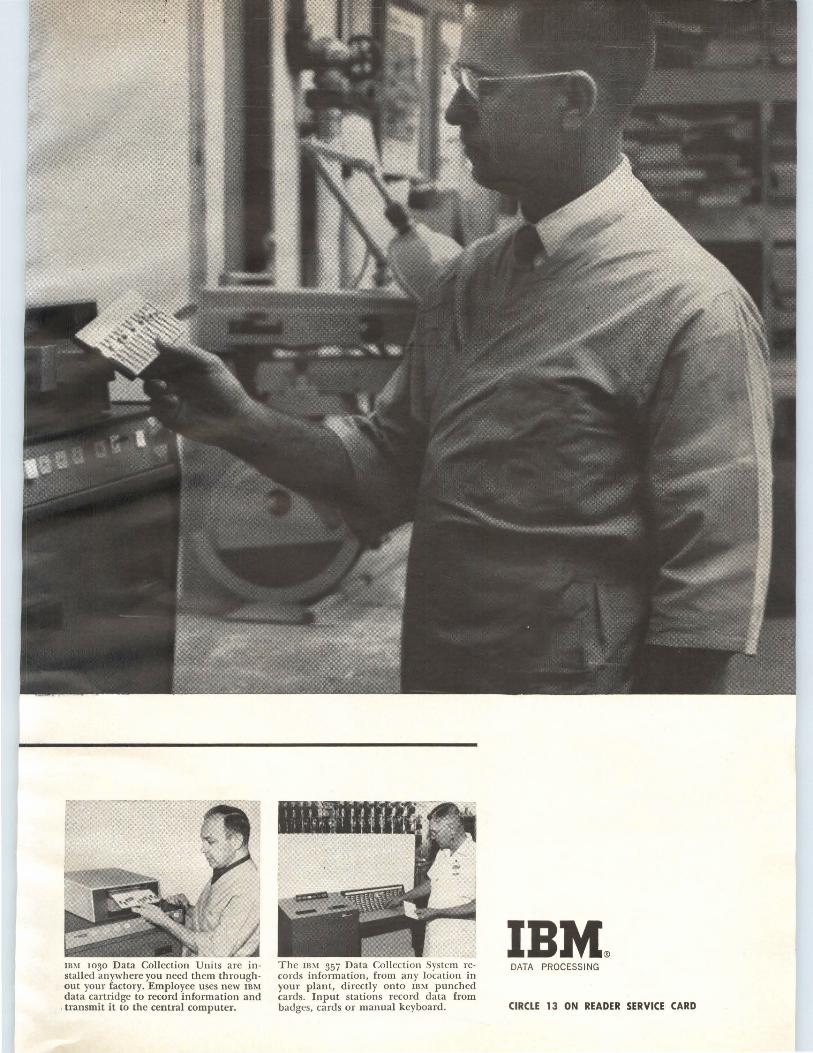
IBM 1030 Data Collection Units are installed anywhere you need them throughout your factory. Employee uses new IBM data cartridge to record information and
, transmit it to the central computer.
The IBM 357 Data Collection System records information, from any location in your plant, directly onto IBM punched cards. Input stations record data from badges, cards or manual keyboard.
DATA PROCESSING
CIRCLE 13 ON READER SERVICE CARD
ARMY SEEKS OPTICAL READERS
Wants equipment to scan
engineering data for
input to retrieval system
By R. J. WARD McGraw-Hill World News
HUNTSVILLE, ALA.-Army Missile Command plans to improve its EDS-0009 data retrieval system with optical input and output equipment and with provision for long-distance facsimile transmission of data sheets.
EDS-0009 is presently being considered for implementation by the Army Materiel Command within its subcommands, of which Army Missile Command (Amicom) is one of seven. Inquiries about the system also have been received from the Navy.
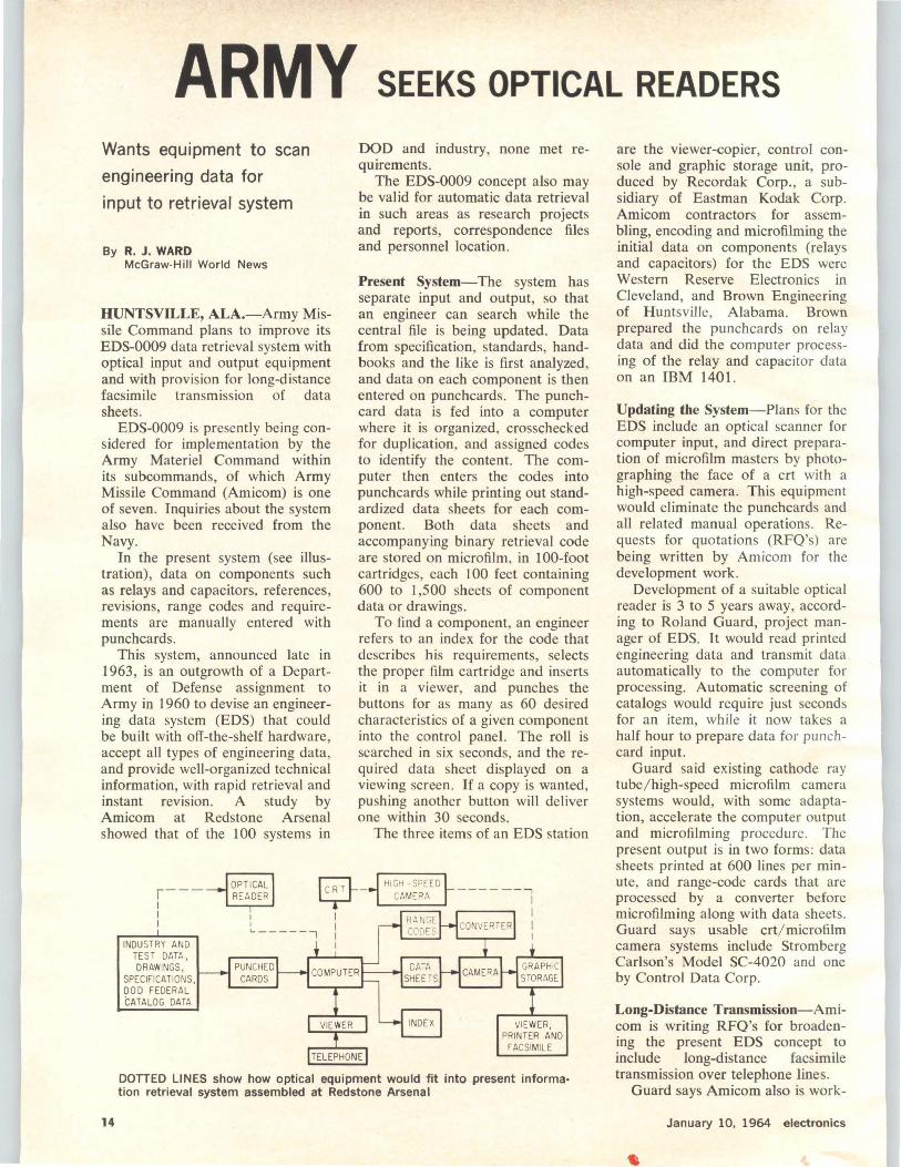
In the present system (see illustration), data on components such as relays and capacitors. references, revisions, range codes and requirements are manually entered with punch cards.
This system, announced late in 1963, is an outgrowth of a Department of Defense assignment to Army in 1960 to devise an engineering data system (EDS) that could be built with off-the-shelf hardware, accept all types of engineering data , and provide well-organized technical information, with rapid retrieval and instant rev1s1on. A study by Amicom at Redstone Arsenal showed that of ihe 100 systems in
DOD and industry, none met requkements.
The EDS-0009 concept also may be valid for automatic data retrieval in such areas as research projects and reports, correspondence files and personnel location .
Present System-The system has separate input and output, so that an engineer can search while the central file is being updated. Data from specification, standards, handbooks and the like is first analyzed, and data on each component is then entered on punchcards. The punchcard data is fed into a computer where it is organized, crosschecked for duplication, and assigned codes to identify the content. The computer then enters the codes into punchcards while printing out standardized data sheets for each component. Both data sheets and accompanying binary retrieval code are stored on microfilm, in 100-foot cartridges, each I 00 feet containing 600 to 1,500 sheets of component data or drawings.
To find a component, an engineer refers to an index for the code that describes his requirements, selects the proper film cartridge and inserts it in a viewer, and punches the buttons for as many as 60 desired characteristics of a given component into the control panel. The roll is searched in six seconds, and the required data sheet displayed on a viewing screen. If a copy is wanted, pushing another button will deliver one within 30 seconds.
The three items of an EDS station
r---1
OPTICAL rc-;;i.__ READER y
14
I I
INDUSTRY AND TEST DATA, DRAWINGS,
SPECIFICATIONS, DOD FEDERAL CATALOG DATA
I I L-------,
PUNCHED CARDS
TELEPHONE
DOTIED LINES show how optical equipment would fit into present informa· tion retrieval system assembled at Redstone Arsenal
are the viewer-copier, control console and graphic storage unit, produced by Recordak Corp., a subsidiary of Eastman Kodak Corp. Amicom contractors for assembling, encoding and microfilming the initial data on components (relays and capacitors) for the EDS were Western Reserve Electronics in Cleveland, and Brown Engineering of Huntsville, Alabama. Brown prepared the punchcards on relay data and did the computer processing of the relay and capacitor data on an IBM 1401.
Updating the System-Plans for the EDS include an optical scanner for computer input, and direct preparation of microfilm masters by photographing the face of a crt with a high-speed camera. This equipment would eliminate the punchcards and all related manual operations. Requests for quotations (RFQ's) are being written by Amicom for the development work.
Development of a suitable optical reader is 3 to 5 years away, according to Roland Guard, project manager of EDS. It would read printed engineering data and transmit data automatically to the computer for processing. Automatic screening of catalogs would require just seconds for an item, while it now takes a half hour to prepare data for punchcard input.
Guard said existing cathode ray tube/ high-speed microfilm camera systems would, with some adaptation, accelerate the computer output and microfilming procedure. The present output is in two forms: data sheets printed at 600 lines per minute, and range-code cards that are processed by a converter before microfilming along with data sheets. Guard says usable crt/ microfilm camera systems include Stromberg Carlson's Model SC-4020 and one by Control Data Corp.
Long-Distance Transmission-Amicom is writing RFQ's for broadening the present EDS concept to include long-distance facsimile transmission over telephone lines.
Guard says Amicom also is work-
January 10, 1964 electronics
ing with NASA's Marshall Space Flight Center, also here at Redstone Arsenal, in an effort to link EDS with Marshall's new data switching center. The center is used for automatic communications and data transmission between MSFC headquarters, its Michoud Operations (launch vehicle booster production site) at New Orleans, NASA's Cape Kennedy operations and other points. This would give engineers at these locations instantaneous retrieval of desired information. Heart of the Marshall system is an ITT ADX-7300. Considering the high cost of such computer time, use of EDS in this case would be restricted to inquiries regarding "major items," Guard notes.
20 Years from Now-Guard's staff envisions an ultimate EDS system that will allow a design engineer in California to speak his component requirements into an audio-to-digital converter beside his desk, automatically locate and retrieve the desired data from a master microfilm file in Massachusetts, for example, and present the data to the engineer either on a viewer or in facsimile-all in less than a minute.
However, Guard says that development of an audio-to-digital converter is "easily more than 20 years away."
Remote Maintenance
MINOTAUR I, built by General Mills for Los Alamos ultrahigh-temperature experiments, includes two ~lectro-mechanical manipulators, closedcircuit tv, 500-pound hoist, lights and audio system
electronics January 10, 1964
CERAMIC INSULATORS 1
SHORT TALL
BIG
SMALL
LAPP HAS BEEN SOLVING INSULATING PROBLEMS FOR OVER 45 YEARS . ..
Lapp pioneered the application of electrical porcelain and steatite to the radio / electronic field . We've solved thousands of knotty insulating problems with down-to-earth engineering ingenuity and production ability. • Tube supports, stand-off insulators, gas-filled condensers, entrance insulators, porcelain water coils, antenna strain and spreader insulators, tower insulators ... these are only a few of the many dependable insulators that bear the Lapp name. Hundreds and hundreds of special designs have been developed to meet tough specifications. • Send your next insulating problem to Lapp. We'll come up with an efficient answer quickly and economically. Lapp Insulator Co., Inc. Radio Specialties Division, 313 Sumner Street, LeRoy, N. Y. 14482.
CIRCLE 15 ON READER SERVICE CARD 15
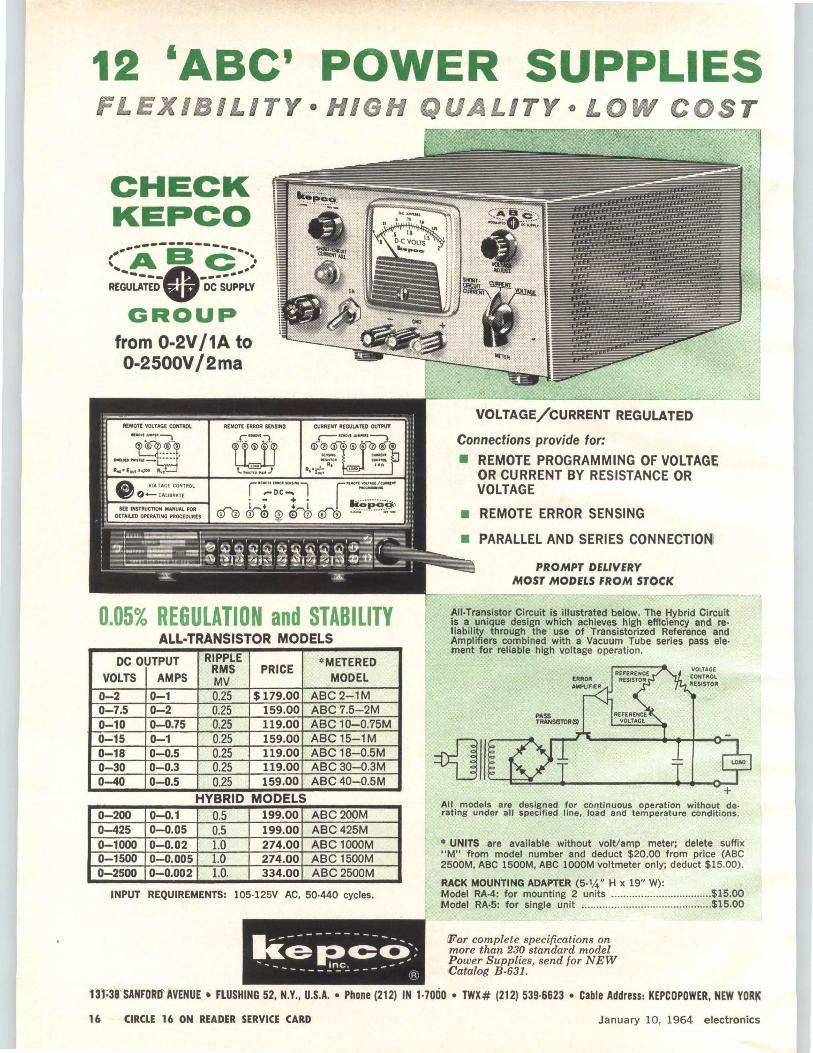
12 'ABC' POWER SUPPLIES FLEXIB I L I T Y • HIGH QUALITY L OW COS T
CHECK KEPCO
---------('-A a c --:. R;;,~-n;··o-c·;~;~v
GROUP' from 0-2V /1A to 0-2500V /2ma
~~:-::?:, ..a.OD ... Tu-·••••
R• •E°"' •....- Rwt
0.05% REGULATION and STABILITY ALL-TRANSISTOR MODELS
DC OUTPUT RIPPLE *METERED RMS PRICE VOLTS AMPS MV MODEL
0-2 0-1 0.25 $179.00 ABC2-1M 0-7.5 0-2 0.25 159.00 ABC7.5-2M 0-10 0-0.75 0.25 119.00 ABC 10-0.75M 0-15 0-1 0.25 159.00 ABC 15-1M 0-18 0-0.5 0.25 119.00 ABC 18-0.5M 0-30 0-0.3 0.25 119.00 ABC30-0.3M 0-40 0-0.5 0.25 159.00 ABC40-0.5M
HYBRID MODELS 0-200 0-0.1 0.5 199.00 ABC200M 0-425 0-0.05 0.5 199.00 ABC425M 0-1000 0-0.02 1.0 274.00 ABC 1000M 0-1500 0-0.005 1.0 274.00 ABC 1500M 0-2500 0-0.002 1.0. 334.00 . ABC 2500M
INPUT REQUIREMENTS: 105-125V AC, 50-440 cycles.
kel?-c<>:: .... - _ _ inc. _ - - .,..
--------- R
VOLTAGE/CURRENT REGULATED
Connections provide for:
• REMOTE PROGRAMMING OF VOLTAGE OR CURRENT BY RESISTANCE OR VOLTAGE
• REMOTE ERROR SENSING
• PARALLEL AND SERIES CONNECTIO~
PROMPT DELIVERY MOST MODELS FROM STOCK
All-Transistor Circuit is illustrated below. The Hybrid Circuit is a unique design which achieves high efficiency and reliability through the use of Transistorized Reference and Amplifiers combined with a Vacuum Tube series pass ele· ment for reliable high voltage operation.
PASS TRANSISTOR($)
All models are designed for continuous operation without de· rating under all specified line, load and temperature cond itions.
• UNITS are available without volt/amp meter; delete suffix "M" ftom model number and deduct $20.00 from price (ABC 2500M, ABC 1500M, ABC lOOOM voltmeter only; deduct $15.00).
RACK MOUNTING ADAPTER (5·1,4" H x 19" W): Model RA-4: for mounting 2 units ..... ...........................•. $15.00 Model RA·5: for single unit ....... ..................................... $15.00
!For complete specifications on more than 230 standard model Power S upplies, send for NEW Catalog B-631 .
1ll ;38'SANFORD' AVENUE • FLUSHING 52, N.Y., U.S.A. •Phone (212) IN 1-7000 • TWX# (212) 539·6623 • Cable Address: KEPCOPOWER, NEW YORIC
16 CIRCLE 16 ON READER SERVICE CARD January 10, 1964 elect ronics
----------electronics NEWSLETTER---
DOD Unsnarling Procurement Rules WASHINGTON-The Defense Dept, is attempting to reduce and simplify the profusion of separate and sometimes conflicting procurement instructions issued by the military services, the Defense Supply Agency and their subordinate units. DOD plans to screen procurement rules, pruning duplications and ~corporating what remains into the Armed Services Procurement Regulation (ASPR).
The profusion of separately issued directives has piled up because each service laid down its own detailed supplemental instructions on how to implement ASPR. The consolidation project aims at eliminating confusion and saving money. The project ties in with another effort aimed at developing uniform contract administration procedures.
DOD hopes the revision of ASPR can be completed by the end of the year. While the consolidation is under way, the services and DSA are under orders not to issue new instructions contrary to the objectives of the project. A DOD procurement circular will be issued, probably monthly, to take care of temporary changes.
Secty. McNamara also is pressuring industry to adapt similar costcutting programs so that it can quote lower prices. He wants more competitive bidding for subcontracts, better manpower utilization and lower overhead costs.
Government Uncovers
More Excess Profits
WASIIlNGTON-Comptroller General Joseph Campbell has added more fuel to the controversy over whether defense contractors have been making excess profits from negotiated contracts. Campbell told Congress that for the fiscal years 19S7 through 1963 his accountants found excess profits totaling $74 million on negotiated contracts involving 67 firms. More than $49 million of this amount has been recovered.
electronics January 10, 1964
Teamsters Recruiting Again
NEW YORK-The Teamsters Union's slumbering drive to organize a major share of workers in the electronics industry (p 7, Jan. 11, 1963 and p 24, Dec. 21, 1962) last week came dramatically to life when one of the largest locals of the AFL-CIO Communication Workers of America voted to withdraw from that union. A few days later the executive board of Local 1101 moved to affiliate its 10,000 members with the Teamsters.
At the beginning of the week, the CW A and the Teamsters were engaged in a bitter tug-of-war for the New York Telephone Co. employees, most of whom are equipment maintenance men. The outcome was uncertain but the struggle could have far-reaching consequences for the Teamsters and the electronics industry: if the Teamsters are successful in this drive, they will move on the rest of the Bell System, including the manufacturing plants, and eventuaJly the electronics industry as a whole. Teamster head James R. Hoffa emphasized the importance of the campaign to his union by promising to take personal charge of it once the National Labor Relations Board sets a date for a representational election.
...
. .. .. . .. .. ····:···· ....... .
Solid-State Switches
Will Pulse Radar
CAMBRIDGE, MASS.-A new approach to the generation of shortduration, high-power radar pulses will be introduced to government and industry specialists next Tuesday at MIT. MIT Electronics Systems Lab will demonstrate the modulator, which uses semiconductor and saturable magnetic switching instead of vacuum or gas tubes. Development of the technique was sponsored by the Air Force Avionics Lab, Wright-Patterson Air Force Base.
The solid-state switches operate with relatively low supply voltages. MIT expects they will have a longer lifetime and greater reliability than tubes. Size and weight savings are also expected. A circuit now in operation at MIT uses three highpower silicon-controlled rectifier
. ·=·· . . o; ....... . . , :>;
switches, five saturable magnetic switches and produces pulses of two microseconds duration at one megawatt peak power.
Flat Package Proposed
For Integrated Circuits
SUNNYVALE, CALIF. - Signetics has proposed a standard flat package for semiconductor integrated ~ircuits as a possible answer to the industry's search for one with the TO-S's ruggedness, reliability and hermeticity but without the limitations posed by the TO-S's shape. Signetics' new package is ~-inch square and is fabricated from Coming 70S2 hard glass and gold-plated Kovar.
The internal pattern of the leads, imbedded in the glass walls, is similar to the T0-5, allowing standard thermocompression ball bonding
17
---electronics NEWSLETTER-----------
and microwelding techniques to be used to connect the leads with the circuit on the chip. Internal lead length is shorter than T0-5 leads, adding shock and vibration strength.
Signetics says it has licensed suppliers to fabricate the package for any of its competitors. Coming, Ultra-Carbon Corp. and Glasstite Industries are making the packages, according to Signetics.
Relay I Transmitting
After Cut-Off Date
WASHINGTON - NASA's Relay I communications satellite, scheduled to turn itself off by Dec. 31, 1963, is still transmitting. RCA built the satellite with an electrolytic material that was to have eaten away the connection between the main power lead and the solar panels and believes abnormally low temperatures have slowed down the erosion proc-
ess. NASA, while lamenting the failure of the cut-off device, is making plans to launch Relay II Jan. 21-without a timer to permit the satellite to operate as long as possible.
Jodrell Bank Building
2nd Radio Telescope
LONDON - The elliptically-shaped dish on the new Jodrell Bank radio telescope is now under construction and is due for completion in early April. This second telescope, costing around $900,000, incorporates a 125-ft. elliptical bowl instead of the semicircular form used in the initial 250-ft bowl telescope. It will be computer controlled in both azimuth and elevation by a Ferranti "Argus" digital machine. Plans are in hand for a third radio telescope. This would be a transportable version with a 100-ft. elliptical bowl
----MEETINGS AHEAD----
INTEGRATED CIRCUITS SEMINAR, IEEE New York Chapter; Stevens Institute of Technology, Hoboken, New Jersey, Jan. 15.
CHARGE TRANSFER COMPLEX SYMPOSIUM, USAF Scientific Research Labs; Denver, Colo., Jan. 19-24.
ANTENNA RESEARCH APPLICATIONS FORUM, Midwest Electronics Research Center; University of Illinois, Urbana, Ill., Jan. 27-30.
MANAGEMENT CONFERENCE, ERA; New Orleans, La., Jan. 28-31.
ANNUAL MEETING-SEMINAR, Precision Potentiometer Manufacturers' Association, Hollywood Beach Hotel, Hollywood, Fla., Jan. 29-31.
INSTRUMENTATION °SYMPOSWM, ISA North Central Area; New Sheraton-Ritz Hotel, Minneapolis, Minn., Jan. 30-31.
MILITARY ELECTRONICS WINTER CONVEN• TION, IEEE-PTGMIL; Ambassador Hotel, Los Angeles, Calif., Feb. 5-7.
ELECTRONIC COMPONENTS INTERNATIONAL EXHIBITION, FNIE, SOSA; Paris Exhibition Park, Paris, France, Feb. 7-12.
INFORMATION STORAGE-RETRIEVAL INSTITUTE, American University; University, Washington, D. C., Feb. 17-2L
18
PHYSICAL METALLURGY OF SUPERCONDUCTORS MEETING, AIMMPE Metallurgical Society; Hotel Astor, New York, N. Y., Feb. 18.
INTERNATIONAL SOLID STATE CIRCUITS CONFERENCE, IEEE, University of Pennsylvania; Sheraton Hotel and University of Pennsylvania, Philadelphia, Pa., Feb, 19-21.
NUMERICAL CONTROL PRESIDENTS' CONFERENCE, Numerical Control Society; Hotel Plaza, New York, N. Y., Feb. 20-21.
SOCIETY FOR INFORMATION DISPLAY NATIONAL SYMPOSIUM, sm; El Cortez Hotel, San Diego, Calif,. Feb. 26-27.
SCINTILLATION-SEMICONDUCTOR COUNTER SYMPOSWM, IEEE, ABC, NBS; Hotel Shoreham, Washington, D. C., Feb. 26-28.
ADVANCE REPORT ANTI-MISBILlll REBlllARCH ADVISORY COUNCIL MllllllTING, Advanced ReBearch Projects Agenc31; U. S. Naval Postgraduate School, Montere31, Calif., April 117-119; Feb. 15 is deadline /or submitting three copies o/ manuacripts to Dr. J. Menkes Institute for Defena. Anal31ses, 1666 Connecticut Ave., N.W., Washington 9, D .C. Some topics include re-entr31 studies and experiments, environmental effects of ICBM defense, launch-phase ph31sics, arra31 radara, field measurements and discrimination; alao tentativel31 these: penetration a(ds (including maneuvering re-entrv vehicles), defense •-vstem e!fectivenesB terminal versus nonterminal defense s~stcm eonsiderationa.
Electronic Device
Displays Stock Quotes
NEW YORK-Trans-Lux, known for its ticker-tape projectors, last week announced an electronic display system using segmented matrix-type indicators. Called Electroquote I, the system has two 10-foot rows of indicators, each 3 inches high, the top row for stock codes, the lower for prices. The system uses sequential posting, erasing one stock at a time and then writing in a new one.
The solid-state electronics for driving the indicators includes a serial-to-parallel converter, diode matrix encoder and ring counters. The circuits, simplified because they drive only one indicator at a time, consist of less than two dozen cards.
Minuteman Contract
Totals $152.6 Million
NORTH AMERICAN Aviation's Autonetics Division has been awarded a $152.6-million prime contract for continued development of the guidance, flight control and ground equipment for the Air Force's improved Minuteman intercontinental ballistic missile. The cost-plus incentive contract runs through Dec. 1, 1965. The improved Minuteman uses microelectronic subsystems (p 14, Nov. 1). Autonetics expects to subcontract two-thirds of the award.
DOD Unifies Clearances
For Private Researchers
PENTAGON has made it easier for private citizens such as scholars and other researchers to gain access to classified defense information. Under a new standard ruling, private citizens will be treated as if they were civilian workers for DOD. Once they have passed a security check, including a search for criminal or subversive records or connections, they are eligible for admission to the files of any of the armed services or defense agencies. Formerly, each service section imposed its own code on outside researchers.
January 10, 1964 electronlcs

£%14
Cathodoluminescence Pu~ps Laser WESTINGHOUSE has demonstrated a cathodoluminescent pumping technique with a solid-state laser operating in a pulsed mode. The "pump" is a crt with an internal pipe about one-half inch in diameter. The laser crystal -in this case, calcium tungstate doped with neodymium-is inserted in the pipe.
The crt has standard electron tube cathode arranged in a coaxial design. The electrons are accelerated through a high potential and bombard a special phospher film deposited on the internal pipe. The technique results in a higher net efficiency then most other methods, Westinghouse says. It also provides a means of controlling a laser over a wide range of pulse lengths and, because it is free of large amounts of heat, will permit a pulse rate higher than any previously obtained, the company says.
Laser Gives 100 mw
Of Continuous Power
PERKINS-ELMER says it has developed a helium-neon laser that produces 100 mw of continuous power at 6,328 A. The parallel twinplasma tube configuration , was attributed to a research team led by John Atwood and J. Dane Rigden. Power output from one tube is coupled with the other by precision optical prisms to produce a single high-intensity beam. The unit is 72 inches long and weighs 35 pounds.
The laser operates in a mode with a divergence of only three times the diffraction limit. When focused by an f/ 1 lens it develops a power density approaching 1 megawatt per square centimeter.
Conelrad Successor
Goes Into Effect
WASIUNGTON-A revised plan for the Emergency Broadcast System became effective last week when it was adopted by the Federal Communications Commission with concurrence of the Department of Defense and Office of Emergency Planning. The revised plan follows closely the EBS interim plan adopted last July to replace Conel-
electronics January 10, 1964
rad. Under the new plan, only radio stations holding National Defense Emergency Authorizations continue on the air after declaration of an emergency. Using a combination of national, regional, state and local networks employing wire lines, f-m station relays and micro-wave circuits, appropriate levels of government have immediate access to the public in any time of stress.
Russians Complete
Huge Accelerator
MOSCOW-USSR State Atomic Energy Committee took possession last week of the world's largest linear electron accelerator, a 240-meterlong tube built in a concrete tunnel surrounded by earthwork. Located at Kharkov Physio-Technical Institue, it can generate pulses of up to two billion electron volts and will be used for theoretical studies into the structure of elementary particles.
Electrons are accelerated at a frequency of 50 cps to speeds approaching that of light; designed current of each pulse is 10 ma. An undisclosed number of copper resonators, machined to accuracy of 10 microns, provides the accelerating push. Accelerated electrons are conducted to the experimental chamber by vacuum tube.
-IN BRIEF RYAN Aeronautical Corp.'s design has
been selected by RCA for the land· ing radar to be used on LEM.
BRAZIL is now selling Mexico electron· ics equipment with preferential tariff treatment under a Latin American Free Trade Association agreement. Tv antennas and per· manent magnets are included.
NAVY has given Ling·Temco·Vought two contracts, one for $2,266,192 and the other for $1,139,770, for the Australian • developed Jindivik target drones.
HAYAKAWA has introduced a 16·1nch color tv set selling for about $553, a low for Japan.
PURDUE University engineers have developed a cable of thin inner and outer conductors backed up with thicker metals. Designed for the AEC, it can transmit a lot of in· formation before being destroyed by a test blast, Purdue says.
SINGER CO. and Gertsch Products have signed a tentative agreement under which Singer would acquire Gertsch. Fairchild Camera has purchased Electro-Sensitive Prod· ucts, Inc., effective Jan. 31. Boon· ton Electronics has bought Binary Eiectronics Inc.
ULTRASONIC device developed by Aeroprojects Inc. for the AEC quickly determines the position of the steam-water layer in a boiling water reactor, the company says. Only a corroson-resistant probe with a vibrating plate at its end extends into the reactor core.
BENDIX reports it has developed a "simple, inexpensive, multi-purpose satellite that can be adapted to a variety of experimental pack· ages." First of the 30·sided alumi· num structures went to the Uni· versity of Iowa for use in NASA's lnjun Explorer project.
NEW ENGLAND electronics, aerospace and nuclear propulsion industries reported declines in employment during 1963, according to the U. S. Dept. of Labor. About 7,400 jobs were lost in the electrical· electronics industries.
ELECTRONICS magazine will be one of the exhibitors at the International Electronic Components Show in Paris Feb. 7·12.
ECHO II is now scheduled for launch Jan. 23 from the Pacific Missile Range on a Thor-Agena 8.
19
------- WASHINGTON THIS WEEK
Military Spending Decline Seen in Next Fiscal Year
Military Program Cuts Include Typhon Missile
Nonlunar Space Programs Face A Tight Year
NAS To Advise House on Federal Science Programs
20
Military spending will begin to decline slightly in the new fiscal year starting July 1. Full details will be in the federal budget that goes to Congress January 21. The word is that the request for defense funds will be about $1 billion less than this year's $52-billion spending. Defense officials believe this marks a turning point. They foresee further small drops in defense spending over the next five years, barring some new crisis. This shift is attributed to a peaking of the strategic weapons buildup and Defense Secretary McNamara's cost-reduction program.
The turndown in spending could be upset by some expensive new breakthrough in military technology or new programs. However, in the coming fiscal year, the armed services face a scaling-down or rejection of a number of new programs they wanted.
Air Force wanted to begin development of two new planes: a manned, missile-firing, long-range bomber capable of low-altitude, high-speed dashes in target areas, and a new long-range aif-defense interceptor. It apparently will get only a small fund to continue studies on the bomber. Air Force asked for an additional 150 Minuteman missiles; it will get 50 more, for a total of 1,000.
The Nike X antimissile missile won't go into production as Army hoped. And Army's request for new money to finance weapons modernization has been cut sharply.
Navy's new Typhon air-defense missile will not be continued. Control and guidance problems are blamed. A start will be made on a revamped and simplified version. Nor will Navy get the three extra nuclear-powered attack submarines it wanted over the six already planned for fiscal 1965.
The Administration cut NASA's budget request of $5.5 billion to $5.3 billion for fiscal 1965. A supplemental request of $150-$200 million will be made early this year, however. NASA says it needs the extra money to carry it through fiscal 1964.
The hold-down on 1965 funds means that the manned lunar program, Apollo, will get a higher percentage of NASA funds than the previous 75 percent. Non-Apollo programs have been pared back sharply. Requests for new R&D facilities that don't support Apollo have been dropped. The squeeze may force NASA to get more mileage out of its advanced synchronous communications satellite program, by using the satellite for additional scientific data collection and equipment testing.
A new National Academy of Sciences agreement to advise and do studies for the House Science and Astronautics Committee elevates the 100-year-old quasi-governmental Academy to new influence over federal science programs.
The Academy has been drawn upon heavily in the past by the executive departments. NAS thinking is customarily very close to the views of the White House Office of Science and Technology. Federal programs originally proposed by NAS include the interagency oceanographic program and portions of the space program.
Instead of asking NAS to evaluate federal programs that NAS helped design, the Committee expects to ask NAS for such studies as: "How is federal sicence distorted and which areas are being neglected?" "How can basic research be better applied to new technology?" and "How can promising areas for new basic research be identified for increased budgetary support?"
January 10, 1964 electronics
CIRCUIT BREAKERS? /you came to the right place
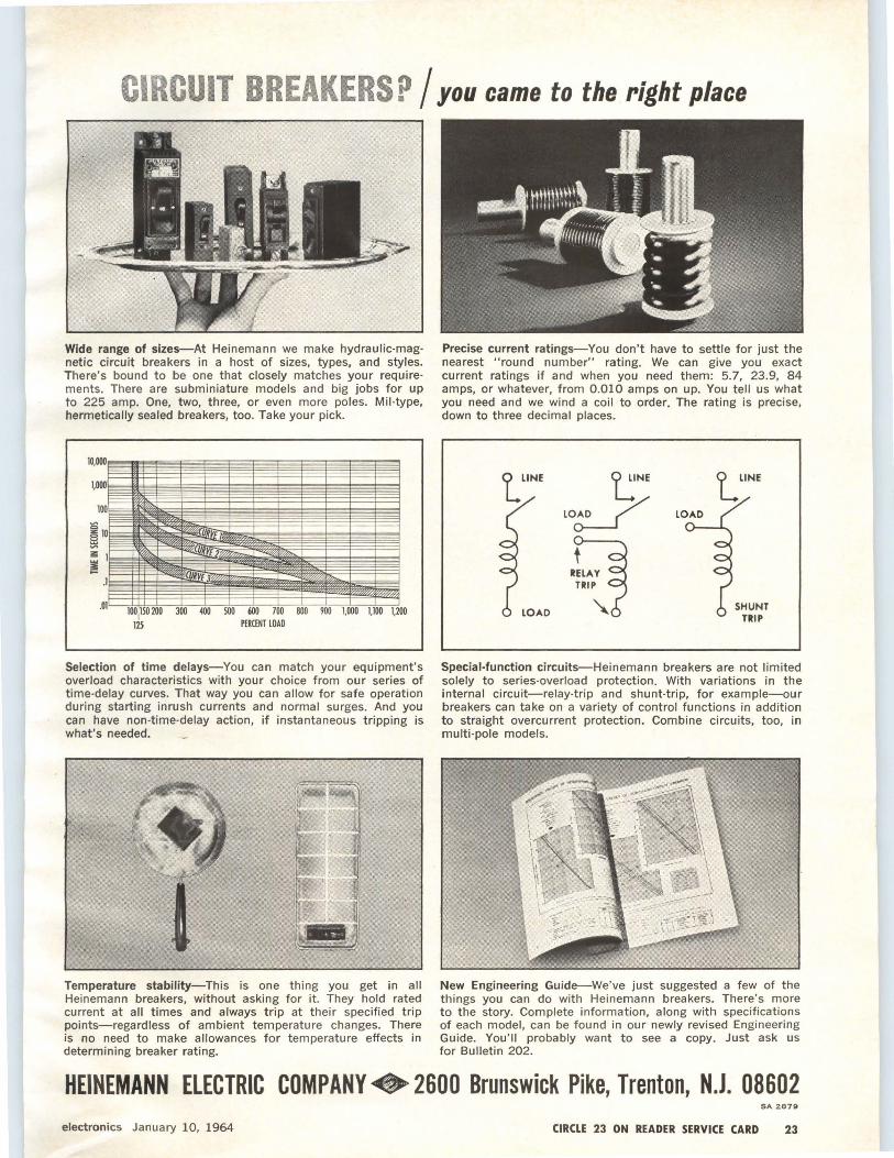
Wide range of sizes-At Heinemann we make hydraulic-mag· netic circuit breakers in a host of sizes, types, and styles. There's bound to be one that closely matches your require· ments. There are subminiature models and big jobs for up to 225 amp. One, two, three, or even more poles. Mil-type, hermetically sealed breakers, too. Take your pick.
Selection of time delays-You can match your equipment's overload characteristics with your choice from our series of time-delay curves. That way you can allow for safe operation during starting inrush currents and normal surges. And you can have non·time-delay action, if instantaneous tripping is what's needed.
1 Temperature stability-This is one thing you get in all Heinemann breakers, without asking for it. They hold rated current at all times and always trip at their specified trip points-regardless of ambient temperature changes. There is no need to make allowances for temperature effects in determining breaker rating.
Precise current ratings-You don't have to settle for just the nearest "round number" rating. We can give you exact current ratings if and when you need them: 5.7, 23.9, 84 amps, or whatever, from 0.010 amps on up. You tell us what you need and we wind a coil to order. The rating is precise, down to three decimal places.
RELAY TRIP
LOAD
SHUNT TRIP
Special-function circuits-Heinemann breakers are not limited solely to series-overload protection. With variations in the internal circuit-relay-trip and shunt-trip, for example-our breakers can take on a variety of control functions in addition to straight overcurrent protection. Combine circuits, too, in multi-pole models.
New Engineering Guide-We've just suggested a few of the things you can do with Heinemann breakers. There's more to the story. Complete information, along with specifications of each model, can be found in our newly revised Engineering Guide. You'll probably want to see a copy. Just ask us for Bulletin 202.
HEINEMANN ELECTRIC COMPANY+ 2600 Brunswick Pike, Trenton, N.J. 08602 SA 2679
electronics January 10, 1964 CIRCLE 23 ON READER SERVICE CARD 23

....... _,,,.
• • ... '"" • •~
THE COMPLETELY NEW MICROWELDER MARK n: VERSATILITY PLUS The advanced Microwelder Mark II brings a new degree of versatility- and a number of exclusive features - to microelectronic interconnection. It can weld a .0005" wire to a thin film of less than 200 angstroms as readily as it welds .020" wire to a printed circuit board. It's equally capable of attaching leads to micromodules, hybrid and integrated circuits and other micro-size components. • Unique features : A single point with as little as .002" diameter · solid state electronics · three ranges of weld power . precise control of AC weld energy • synchronous timing • dead weight pressure system as low as 10 grams.• Price: $5250- F.O.B. Azusa, California. Now available through leading electronic representatives across the country.
For complete information on the new Microwelder Mark Il -and a personal demonstration, write: Commercial Products, Dept. E, P.O. Box H, Azusa, California.
24 CIRCLE 24 ON READER SERVICE CARD
AEROJET COMM ER CIAL PR 0 DUCTS/ Azusa, California
GENERAL
January 10, 1964 electronics
SN530 J-K FLIP-FLOP COUNTER NETWORK SN532 "ANO" OR "OR" LOGIC NETWORK INPUT LOGIC
v,,@ COMBINATIONS
© @) t, tn.,.1 GNO@
J K J' K' 0 ©©~ v"® ii 0 0 I 0 0 o, [ LOGIC -]
l l ®®g v0 l POSITIV1 NEGATIVE t 0 0 0 il, ANO OR
@ J' "© I t 0 0 ii, ®@~ '( I A8CDE ~+B+C+O+E 0 I 0 I ii,
CD J K@ I I 0 t ii, X TERMINAL: TIE POINT FOR INCREASED FAN-JN OF SN531
ct PJ SET
I 0 t 0 a, I I I 0 il, SN 533 "NANO" OR "NOR" LOGIC NETWORK
0 ® I 0 0 I I 0 I I 0 0 @vee
r--------- --1 @GND Vee - PIN NO. 3 J•=K · =r
0 A~JJ-t>t~ GNO - PIN NO. 8 t, tnH @~±:J ' G(i) (J} C 1 LOGIC
J K 0 'fl~· 1"'"~1·~"" 0 0 o, @), D f.l 1 NANO NOR
0 I 0 @®~~b: 1 H@ Gj Ai!C j_A+B+C f 0 • BtT TIME BEFORE CLOCK PULSE I 0 I F , ___ -- - j Hj DEF j_if+E+I'
t 0 ""1~ BIT TIME ArTER CLOCK PULSE I I ii,
HIGH VOLTAGE J'K'O SN 534 "AND" OR "OR" LOGIC NETWORK
REPRESENTS A LOGICAL • 1 • LEVEL ,, fnH @vcc
PRE SET INPUT J' K' 0 r-----, @GNO
SETS 0 TO A LOGICAL "1" 0 0 ii, (i) A I I @VEE I G(!)
0 I I @B ' LOGIC ' I
I 0 Q o I I POSITIVfI NEGATIVE I I o, © ~~: ANO OR
®~=gj! "® Gj AB I A+B EXAMPLE OF LOGIC STEERING. R:PPLE COUNTER - TIE I, 2, 4, S @> E ' : HI COE Ic+o+E 5 TO GROUND; SHIFT REGISTER - TIE 2 8 4 TO Vee • I TO 10 L " OF PREVIOUS NETWORK, AND 5 TO 6 Of THE PREVIOUS NETWORK
SN535 MULTIPLE INVERTER NETWORK
SN53t "NANO" OR "NOR" LOGIC NETWORK @Vee
@GNO LOGIC r--------·
POSITIVE NEGATIVE : 1 NANO NOR ©• G,(i)
@Vee G ABra A+B+c i-0+£
@GNO y ABC OE A+B+C+ O+E
G' ABCOE+Y (HB +C+O+E)Y LOGIC
®®~ 0B G,0 G, ii
®c G, ii ®. 0
G Q) G3 c @@E ®c G3@) G• ll x
NOTES : v0
l) X TERMINAL: TIE POINT fOR lf.;CRE!ISED FAN-IN @lo G,@ 2l • LOGIC AVAILABLE BY CONNECTING SN5l2 OUTPUT ro y
TERMINAL --------.J
LOGIC DIAGRAMS for Series 53 semiconductor networks-Fig. 1
NEW SEMICONDUCTOR NETWORKS
Reduce System Complexity Fabrication and design featu res al low l·Mc speed of operat ion and
fewer networks per system. Series consists of six standard devices
By CHARLES R. COOK, JR. Senior Project Engineer
BILLY M. MARTIN Design Engineer
Semiconductor-Components Div. Texas Instruments Incorporated Dallas, Texas
53, has been developed that is designed to operate above 1 Mc.
Series 53 is designed for application in general-purpose computers. Of particular note is the excellent loading capabilities of the individual networks, which together with the ability to cascade the non-inverting gates minimizes the number of units required to perform logic operation. Further, through the use of dual gates, inverter and a complete J-K flip-flop/shift register in one network package, system usage of networks can be often substantially re-
duced with Series 53 as compared to other integrated circuit types. The fewer networks required per system can have real impact on reliabilityminimizing connections, size, and weight, as well as cost.
SEMICONDUCTOR integrated circuits are becoming a familiar product in design applications, particularly in the digital computer area . A new series of Solid Circuit semiconductor networks, called Series
electronics January 10, 1964
Presently, Series 53 (see the front cover) consists of six standard highs peed digital devices: SN530, a single-phase 1-K flip-fl.op; SN53 l, a 5-input NANO gate; SN532, a 5-input AND gate; SN533, a dual 3-input NANO gate; SN534, a 2-and-3-input AND gate; and SN535, a 4-inverter package. Logic diagrams are shown
25
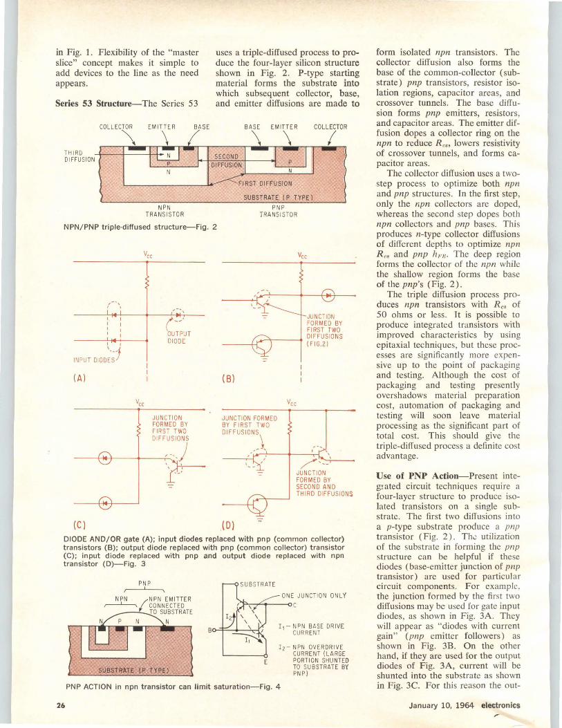
in Fig. 1. Flexibility of the "master slice" concept makes it simple to add devices to the line as the need appears.
Series 53 Structure-The Series 5 3
THIRD DIFFU SI ON
NPN TRANSi STOR
uses a triple-diffused process to produce the four-layer silicon structure shown in Fig. 2. P-type starting material forms the substrate into which subsequent collector, base, and emitter diffusions are made to
SECOND DIFFUSION
FIRST DIFFUSION
SUBSTRATE (P TYPE )
PNP TRANS IS TOR
NPN/PNP triple-diffused structure-Fig. 2
, ' I o
I I
INPUT D I OD~-~1 (A)
JUNCTION FORMED BY FIRST TWO DIFFUSIONS
~-~~--.. ) '-'---
{Cl
(Bl
JUNCTION FORMED BY FIRST TWO
DIFFUSION),
:
,(0)
' /·--' JUNCTION FORMED BY SECOND AND THIRD DIFFUSIONS
DIODE AND/OR gate (A); input diodes replaced with pnp (common collector) transistors (B); output diode replaced with pnp (common collector) transistor (C); input diode replaced with pnp and output diode replaced with npn transistor (D)-Fig. 3
26
PNP
SUBSTRtlTE ( P TYPE)
ONE JU NCTIO N ONLY "i='---..<:+----<i c
E
Ii- NPN BASE DRIVE CU RRENT
I z- NPN OVERDRIVE CURRENT (LARGE PORTION SHUNTED TO SU BSTRATE BY PNP)
PNP ACTION in npn transistor can limit saturation-Fig. 4
form isolated npn transistors. The collector diffusion also forms the base of the common-collector (substrate) pnp transistors, resistor isolation regions, capacitor areas, and crossover tunnels. The base diffusion forms pnp emitters, resistors, and capacitor areas. The emitter diffusion dopes a collector ring on the npn to reduce R e•• lowers resistivity of crossover tunnels, and forms capacitor areas.
The collector diffusion uses a twostep process to optimize both npn and pnp structures. In the first step, only the r.pn collectors are doped, whereas the second step dopes both npn collectors and pnp bases. This produces n-type collector diffusions of different dep~hs to optimize npn R es and pnp h1.'E· The deep region forms the collector of the npn while the shallow region forms the base of the pnp's (Fig. 2) .
The triple diffusion process produces npn transistors with R es of 50 ohms or less. It is possible to produce integrated transistors with improved characteristics by using epitaxial techniques, but these processes are significantly more expensive up to the point of packaging and testing. Although the cost of packaging and testing presently overshadows material preparation cost, automation of packaging and testing will soon leave material processing as the significant part of total cost. This should give the triple-diffused process a definite cost advantage.
Use of PNP Action-Present integrated circuit techniques require a four-layer structure to produce isolated transistors on a single substrate. The first two diffusions into a p-type substrate produce a pnp transistor (Fig. 2). Th0 utilization of the substrate in forming the pnp structure can be helpful if these diodes (base-emitter junction of pnp transistor) are used for particular circuit components. For example. the junction formed by the first two diffusions may be used for gate input diodes, as shown in Fig. 3A. They will appear as "diodes with current gain" (pnp emitter followers) as shown in Fig. 3B. On the other hand, if they are used for the output diodes of Fig. 3A, current will be shunted into the substrate as shown in Fig. 3C. For this reason the out-
January 10, 1964 electronics
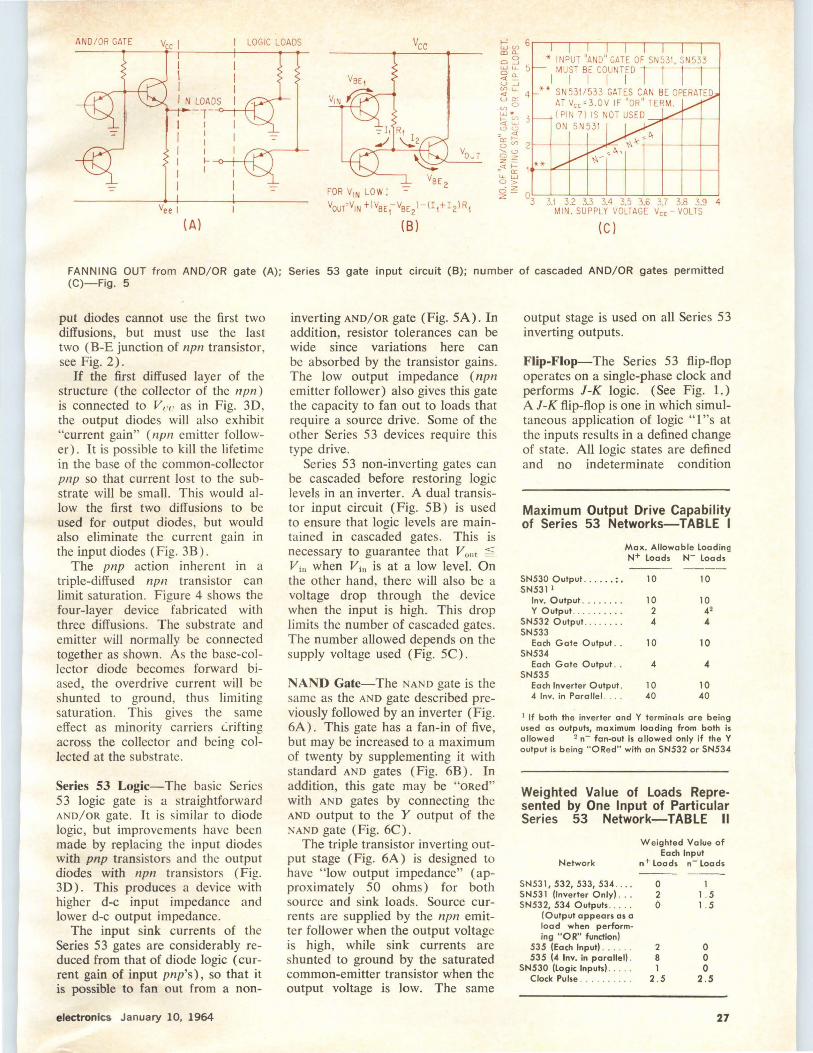
AN D/OR GATE Vee I LOGIC LOADS
FOR V1N LO W: -=-Vour'VIN t(VBE 1-VBE2)-(I 1+I2lR1
(A) (8)
* INPUT "AND" GATE OF SN531, SN533 MUST BE COUNTED
I I I I I '* SN 531 /533 GATES CAN BE OPERATED
AT V00 =3.0V IF "OR" TERM. (Pl N 7) IS NOT USED ----:;;o+""--+---+----1 ON SN531
(Cl
FANNING OUT from AND/OR gate (A); Series 53 gate input circuit (B); number of cascaded AND/OR gates permitted (C)-Fig. 5
put diodes cannot use the first two diffusions, but must use the last two (B-E junction of npn transistor, see Fig. 2).
If the first diffused layer of the structure (the collector of the npn) is connected to Ve(' as in Fig. 3D, the output diodes will also exhibit "current gain" (npn emitter follower). It is possible to kill the lifetime in the base of the common-collector pnp so that current lost to the substrate will be small. This would allow the first two diffusions to be used for output diodes, but would also eliminate the current gain in the input diodes (Fig. 3B).
The pnp action inherent in a triple-diffused npn transistor can limit saturation. Figure 4 shows the four-layer device fabricated with three diffusions. The substrate and emitter will normally be connected together as shown. As the base-collector diode becomes forward biased, the overdrive current will be shunted to ground, thus limiting saturation. This gives the same effect as minority carriers C.:rifting across the collector and being collected at the substrate.
Series 53 Logic-The basic Series S3 logic gate is a straightforward AND/OR gate. It is similar to diode logic, but improvements have been made by replacing the input diodes with pnp transistors and the output diodes with npn transistors (Fig. 3D). This produces a device with higher d-c input impedance and lower d-c output impedance.
The input sink currents of the Series S3 gates are considerably reduced from that of diode logic (current gain of input pnp's), so that it is possible to fan out from a non-
electronics January 10, 1964
inverting AND/OR gate (Fig. SA). In addition, resistor tolerances can be wide since variations here can be absorbed by the transistor gains. The low output impedance (npn emitter follower) also gives this gate the capacity to fan out to loads that require a source drive. Some of the other Series S3 devices require this type drive.
Series S3 non-inverting gates can be cascaded before restoring logic levels in an inverter. A dual transistor input circuit (Fig. SB) is used to ensure that logic levels are maintained in cascaded gates. This is necessary to guarantee that V0 11t ~ Vin when Vi 11 is at a low level. On the other hand, there will also be a voltage drop through the device when the input is high. This drop limits the number of cascaded gates. The number allowed depends on the supply voltage used (Fig. SC) .
NANO Gate-The NANO gate is the same as the AND gate described previously followed by an inverter (Fig. 6A). This gate has a fan-in of five, but may be increased to a maximum of twenty by supplementing it with standard AND gates (Fig. 6B). In addition, this gate may be "oRed" with AND gates by connecting the AND output to the Y output of the NAND gate (Fig. 6C).
The triple transistor inverting output stage (Fig. 6A) is designed to have "low output impedance" (approximately SO ohms) for both source and sink loads. Source currents are supplied by the npn emitter follower when the output voltage is high, while sink currents are shunted to ground by the saturated common-emitter transistor when the output voltage is low. The same
output stage is used on all Series 53 inverting outputs.
Flip-Flop-The Series S3 flip-flop operates on a single-phase clock and performs l-K logic. (See Fig. 1.) A J-K flip-flop is one in which simultaneous application of logic ''l''s at the inputs results in a defined change of state. All logic states are defined and no indeterminate condition
Maximum Output Drive Capability of Series 53 Networks-TABLE I
Max. Allowable Leading N+ Loads N- Loads ---- ----
SN530 Output .. .... : • 10 10 SN531 1
Inv. Output ........ 10 10 Y Output ... 2 42
SN532 Output ..... ... 4 4 SN533
Each Gate Output .. 10 10 SN534
Each Gate Output .. 4 4 SN535
Each Inverter Output. 10 10 4 Inv. in Pora llel . 40 40
1 If both the inverter and Y terminals are being used as outputs, maximum loading from both is allowed 2 n- fan-out is allowed only if the Y output is being "ORed" with on SN532 or SN534
Weighted Value of Loads Represented by One Input of Particular Series 53 Network-TABLE II
Weighted Value of Each Input
Network n+ Loads n- Loads
SN531, 532, 533, 534 .. . . 0 1 SN531 (Inverter Only) . . . 2 1 . 5 SN532, 534 Outputs ... . . 0 1 . 5
(Output appears os o load when perform-ing "OR" function)
535 (Each Input). . . . . 2 0 535 (4 Inv. in parallel) . 8 0
SN530 (Logic Inputs). 1 0 Clock Pulse .. 2. 5 2 .5
27

COMPONENT VALUES NOMINAL AT TA'25°C
G'ABCDE
x ®
(A)
2K 25
GNO
1®
A
SN531 ,---------, I I
I B § ===±~G:Jf-----.-----lli:lillll._-+~G
E :
F G
H I
____ __J
I
L ___ j G0 ABCOEFGH!_ ____ _
(8) SN531 NANO logic gate (A) can have fan-in increased by supplementing with AND gates (8). In addition, the gate may be as shown in (C)-Fig. 6
CLO CK CP
SN530 J-K flip-flop consists of bistable element, steering and and logic input sections-Fig. 7
exists. Such J-K flip-flops have been widely used in logic design, but have not previously been available in integrated form. Complementary inputs have also been provided, so that full l-K operation can be obtained for positive and negative logic. In practical designs, use of the complementary inputs will result in a substantial reduction in the number of gates or inverters required.
The l-K flip-flop has been designed to operate without the con- , ventional storage capacitors. Intermediate storage is provided by control of propagation through the input stages rather than a precise R-C circuit, permitting reliable operation at high speeds. Circuit operation can best be understood by dividing
28
the flip-flop into the three basic sections shown in Fig. 7-the bistable element, steering, and logic inputs.
Bistable Element - The bistable element is composed of two lowimpedance inverters with R-C cross coupling. Both Q and Q outputs, therefore, have good drive capabilities for both source and sink loads. Output stages of this type with large voltage swings not only provide good drive sources for other devices in Series 53, but also are excellent for driving capacitive loads and various interface loads.
Steering - The flip-flop uses a unique steering method that does not require input capacitors. Tum-on
switching action is controlled by the bases of common-collector transistors Q 1 and Q2-points A and B respectively. For analysis, assume that output Q is high. Since this is a turn-on circuit, the device may be switched by steering the clock pulse (CP) to apply drive current to the bases of Q 3 and Q 4 • In other words allowing point A to assume a level Va = V nE1 + V nr;2. Disregarding transistors Q 5 and Q6 , an equation may be written describing the logic for points A and B:
A=(/+/*) (Q) (CP) B = (K + K*) (Q) (CP)
Notice that switching is dependent
January 10, 1964 electronics
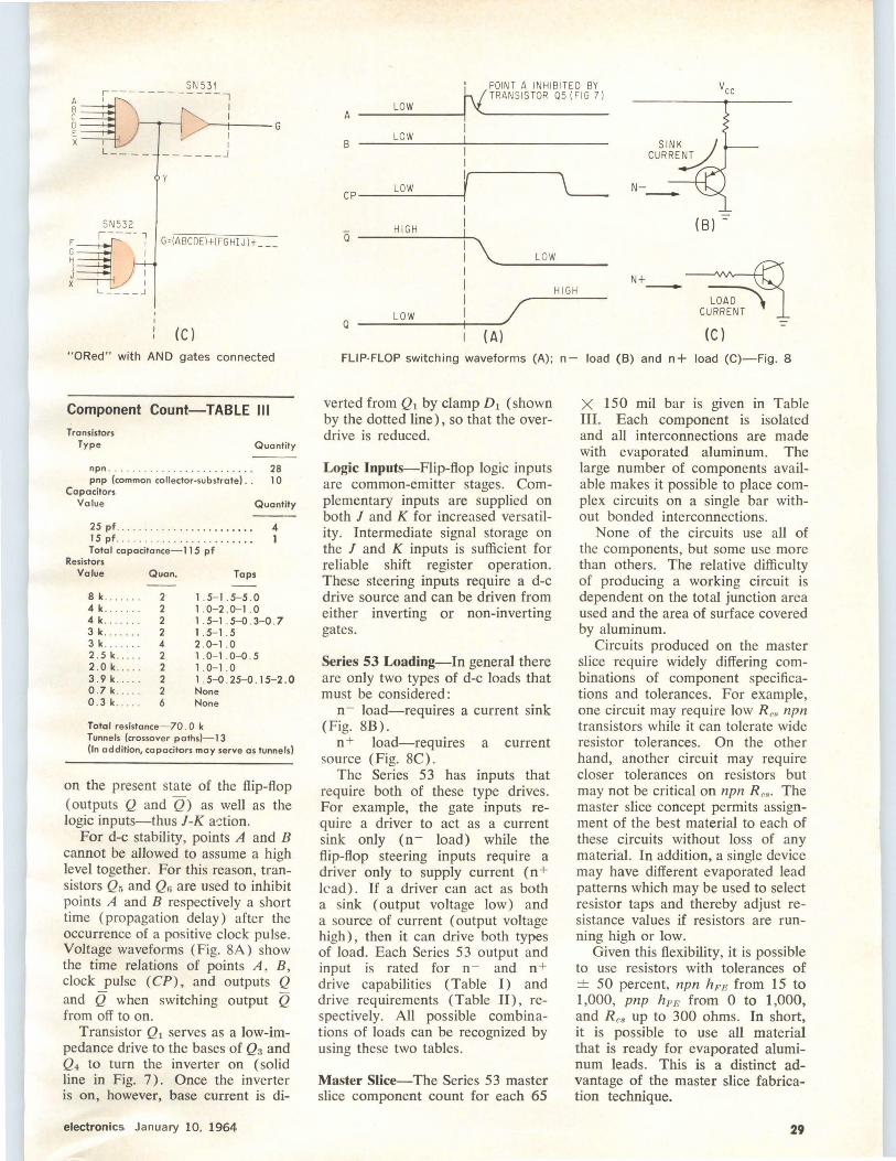
SN 53 1
~~r----------- -: D . >--+----G E I X I I
F G H I J x
L __ _ _____ __ J
y
G'(ABCDEl+(FGH!J)t __ _
(Cl "ORed" with AND gates connected
Component Count-TABLE Ill Transistors
Type Quantity
npn ........ .. . . . . . . . . . . . . . . . 28 pnp (common collector-substrate) . . 1 0
Capacitors Value Quantity
25 pf ... . . . . . . . . . . . . . . . . . . . . . 4 15 pf .' . .......... .... . ...... 1 Total capacitance-115 pf
Resistors Value Quan. Taps
8 k. . 2 4 k.. 2 4 k. . 2 3 k . 2 3 k . 4 2 .5 k.... . 2 2 . 0 k..... 2 3 .9 k.... . 2 0.7 k . 2 0.3 k.. . . 6
1 . 5-1 .5- 5 .0 1 .0-2 .0-1 . 0 1 . 5- 1 .5-0 . 3-0 . 7 1 . 5-1 .5 2 .0-1 . 0 1 .0-1 .0- 0.5 1 .0- 1 . 0 1 . 5-0.25-0.15-2 . 0 None None
Total resistonce- 70 . 0 k Tunnels (crossover paths)- 13 (In addition, capocitors may serve as tunnels)
on the present state of the flip-flop (outputs Q and Q) as well as the logic inputs-thus J-K a-;tion.
For d-c stability, points A and B cannot be allowed to assume a high level together. For this reason, transistors Q5 and Q6 are used to inhibit points A and B respectively a short time (propagation delay) after the occurrence of a positive clock pulse. Voltage waveforms (Fig. 8A) show the time relations of points A, B , clock pulse (CP) , and outputs Q and Q when switching output Q from off to on.
Transistor Q 1 serves as a low-impedance drive to the bases of Q3 and Q4 to turn the inverter on (solid line in Fig. 7). Once the inverter is on, however, base current is di-
electronics January 10, 1964
' POINT A INHIBITED BY ___ L_ow ___ -ity TRANSISTOR 05 (FIG 7)
A
B LOW
I
I I
CP ___ L_o_w ___ ~f~-----....... \_____ HIGH
LOW
a---..__~
-------N+
HIGH -Q ___ L_o_w ___ -+--~~
{Al {Cl FLIP-FLOP switching waveforms (A); n- load (B) and n+ load (C)-Fig. 8
verted from Q1 by clamp D1 (shown by the dotted line) , so that the overdrive is reduced.
Logic Inputs-Flip-flop logic inputs are common-emitter stages. Complementary inputs are supplied on both J and K for increased versatility. Intermediate signal storage on the J and K inputs is sufficient for reliable shift register operation. These steering inputs require a d-c drive source and can be driven from either inverting or non-inverting gates.
Series 53 Loading-In general there are only two types of d-c loads that must be considered:
n- load-requires a current sink (Fig. 8B).
n + load-requires a current source (Fig. 8C).
The Series 53 has inputs that require both of these type drives. For example, the gate inputs require a driver to act as a current sink only (n- load) while the flip-flop steering inputs require a driver only to supply current (n+ lead). If a driver can act as both a sink (output voltage low) and a source of current (output voltage high), then it can drive both types of load. Each Series 53 output and input is rated for n - and n + drive capabilities (Table I) and drive requirements (Table II), respectively. All possible combinations of loads can be recognized by using these two tables.
Master Slice-The Series 53 master slice component count for each 65
X 150 mil bar is given in Table III. Each component is isolated and all interconnections are made with evaporated aluminum. The large number of components available makes it possible to place complex circuits on a single bar without bonded interconnections.
None of the circuits use all of the components, but some use more than others. The relative difficulty of producing a working circuit is dependent on the total junction area used and the area of surface covered by aluminum.
Circuits produced on the master slice require widely differing combinations of component specifications and tolerances. For example, one circuit may require low R es npn transistors while it can tolerate wide resistor tolerances. On the other hand, another circuit may require closer tolerances on resistors but may not be critical on npn R es· The master slice concept permits assignment of the best material to each of these circuits without loss of any material. In addition, a single device may have different evaporated lead patterns which may be used to select resistor taps and thereby adjust resistance values if resistors are running high or low.
Given this flexibility, it is possible to use resistors with tolerances of ± 50 percent, npn hFE from 15 to 1,000, pnp h,,.FJ from 0 to 1,000, and R es up to 300 ohms. In short, it is possible to use all material that is ready for evaporated aluminum leads. This is a distinct advantage of the master slice fabrication technique.
29
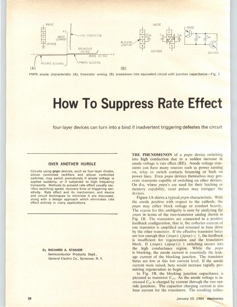
N +I
ANODE CURRENT ~
ANODE
CATHODE
HIGH CONDUCTION
BREA KOVER VOLTAGE
-V -::::::;=========:::f===;f=====;~~;;;-T.-,:c-+V ANODE VOLTAGE
(A) REVERSE BLOCKING -I FORWARD BLOCKING
BLOCKING JUNCTION
(8)
N
ANODE ANODE
CATHODE
PNPN anode characteristic (A) ; transistor analog (B) breakdown into equivalent circuit with junction capacitance-Fig. 1
How To Suppress Rate Effect four-layer devices can turn into a bind if inadvertent triggering defeates the circuit
OVER ANOTHER HURDLE
Circuits using pnpn devices, such as four-layer diodes, silicon controlled rectifiers and silicon controlled switches, may switch prematurely if anode voltage is applied suddenly, or if subjected to high frequency transients. Methods to prevent rate effect usually sacrifice switching speed, recovery time or triggering sen sitivity. Rate effect and its mechanism, and device and circuit techniques to minimize it are discussed , along with a design approach which eliminates rate effect entirely in many applications
30
By RICHARD A. STASIOR Semiconductor Products Dept., General Electric Co., Syracuse, N. Y.
THE PHENOMENON of a pnpn device switching into high conduction due to a sudden increase in anode voltage is rate effect (RE). Anode voltage transients can have many sources such as power turning on, relay or switch contacts bouncing or hash on power lines. Even pnpn devices themselves may generate transients capable of switching on other devices. On d-c, where pnpn's are used for their latching or memory capability, reset pulses may retrigger the devices .
Figure IA shows a typical pnpn characteristic. With the anode positive with respect to the cathode, the pnpn may either block voltage or conduct heavily. The reason for this ambiguity is seen by analyzing the pnpn in terms of the two-transistor analog shown in Fig. 1 B. The transistors are connected in a positive feedback configuration, that is, the collector current of one transistor is amplified and returned as base drive by the other transistor. If the effective transistor betas are low enough that ((:Jnpn) (f3pnp) < 1, the feedback is insufficient for regeneration and the transistors block. If ({3npn) (f3pnp) =::: 1 switching occurs into the high conductance region. While the pnpn is blocking, the anode current is essentially the leakage current of the blocking junction. The transistor betas are low at this low current level. If the anode current were raised, beta would increase rapidly permitting regeneration to begin.
In Fig. 1 B, the blocking junction capacitance is pictured as transistor C ob· As the anode voltage is increased Cob is charged by current through the two outside junctions. The capacitor charging current is also base current for the transistors . The resulting collec-
January 10, 1964 electronics
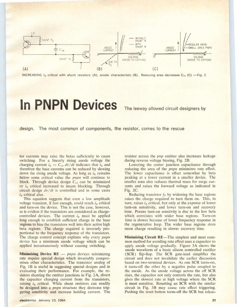
A
<NOOE t 1 CURRENT I /{
SHUNT R2 - WITHOUT
SHUNT R --- WITH
SHUNT R ANODE t CURRENT I ~
I I
I I
I -REGULAR PNPN --SMALL AREA ~NPN
' -~
SHUNT R1 /" VOLTAGE
/' ANODE-TO-CATHODE ( VOLTAGE
AN ODE- TO -CATHODE <_DUE TO
,/ R2
(A) c (Bl (C)
INCREASING IQ critical with shunt resistors (A); anode characteristic (8). Reducing area decreases c." (C) -Fig. 2
In PNPN Devices The leeway allowed circuit designers by
design. The most common of components, the resistor, comes to the rescue
tor currents may raise the betas sufficiently to cause switching. For a linearly rising anode voltage the charging current iQ = C ob dv I dt indicates that iQ and therefore the base currents can be reduced by slowing down the rising anode voltage. As Jong as iQ remains below some critical value the pnpn will continue to block. Through device design C ob can be minimized or iQ critical increased to insure blocking. Through circuit design dv/ dt is controlled and in some cases i0 critical also.
This equation suggests that even a low amplitude voltage transient, if fast enough, could reach iQ critical and turn-on the device. This is not the case, however, as is evident if the transistors are considered as chargecontrolled devices. The current i0 must be applied long enough to establish sufficient charge in the base regions to bias the transistors well into their active high beta regions. The charge required is inversely proportional to the frequency response of the transistors. The charge control concept explains why every pnpn device has a minimum anode voltage which can be applied instantaneously without causing switching.
Minimizing Device RE - pnpn devices minimizing rate require special design which invariably compromises other characteristics. The transistor analog of Fig. lB is useful in suggesting special designs and in evaluating their performance. For example, the resistors shunting the emitter junctions in Fig. 2A, divert the capacitor charging current from the transistors, raising iQ critical. While shunt resistors can readily be designed into a pnpn structure they decrease triggering sensitivity and increase holding current. The
electronics January 10, 1964
resistor across the pnp emitter also increases leakage during reverse voltage biasing, Fig. 2B.
Lowering the center junction capacitance through reducing the area of the pnpn minimizes rate effect. The lower capacitance is offset somewhat by beta peaking at a lower current in a smaller device. The smaller area also reduces thermal mass for surge currents and raises the forward voltage as indicated in Fig. 2C.
Reducing transistor fT by widening the base regions raises the charge required to turn them on. This, in turn, raises iQ critical, but only at the expense of lower turn-on sensitivity, and lower turn-on and recovery time. Poorer turn-on sensitvity is due to the low beta which correlates with wider base regions. Turn-on time is slower because of lower frequency response in the regenerative loop. The wider base regions store more charge resulting in slower recovery time.
Minimizing Circuit RE-The simplest and most common method for avoiding rate effect uses a capacitor to apply anode voltage gradually. Figure 3A shows the anode waveform of a basic silicon controlled rectifier (SCR) fiip-fiop. The SCR gate-lead simplifies the circuit and does not invalidate the earlier discussion based on two-terminal devices. As one SCR turns-on, it turns-off the other by a negative pulse coupled to the anode. As the anode voltage across the off SCR rises, the capacitor not only controls the rate, but also gives the slowest rate at high voltage where the SCR is most sensitive. Resetting an SCR with the similar circuit in Fig. 3B may cause rate effect triggering. Pushing the reset button turns-off the SCR but releas-
31
ing it raises the anode above the supply voltage instantaneously to a value dependent on the resistor ratio. This transient rise may turn-on the SCR either by rate effect or by exceeding the breakover voltage.
The pnpn devices can be designed to have shunt resistors across the emitter junctions, minimizing the gate-to-cathode impedance, which often improves performance. At high temperatures where leakage tends to turn-on a pnpn, an inductor from gate to cathode (Fig. 4A) shunts the leakage well. This is one reason for the popularity of transformer coupled triggering circuits. On the other hand, the transformer inductance does not shunt the gate during a rapid rise in anode voltage. A capacitor offers better rate-effect suppression, Fig. 4B.
A shunting impedance may prove ineffective in large-area devices since the shunting effect is limited only to the vicinity of the gate lead. The narrow layers of high-frequency devices exhibit high sheet resistance which also limits the shunting effect. In other cases the built-in shunting resistors are so effective that additional shunting is inconsequential.
A natural extension of shunting is to reverse bias the gate junction. Since the capacitor charging current must overcome the bias before regeneration can occur, IQ critical is raised considerably. More important, the entire junction can be reverse biased regardless of the gate layer sheet resistance.
Eliminating Rate Effect-A different approach to eliminating rate effect is made possible by using such silicon controlled switches as the 3NS8, 3NS9, and 3N60. These pnpn devices have leads connected to all four layers, allowing connection to the n region next to the anode which is not available in conventional SCR's. Figure 4C shows a typical SCR circuit with a capacitor (C) to control the rise of anode voltage. The waveform (Fig. 4D) shows the SCR triggered at A. At B the reset button is closed permitting the SCR to recover. Opening the button at C allows the anode voltage to rise. Regardless of the length of time between B and C the anode voltage must still be applied gradually. This is implied by the dotted waveform shown at C'.
Figure SA shows the same function performed by the four-leaded silicon controlled switch (SCS). The device is set and reset in identically the same manner as is the SCR in Fig. 4C. The only change is to add a single resistor (RaA) from then region to the anode voltage supply. For convenience, and by analogy to the SCR gate, this n region is referred to as the anode gate.
The SCS is triggered on at A, Fig. SB. At B the reset pulse is applied. At C the reset button is released allowing the anode voltage to rise abruptly. This is permissible because the blocking junction capacitance (2 C0 b) is charged up prior to the rise in anode voltage. The dashed anode-gate waveform superposed on the anode waveform indicates that the voltage drops simultaneously on both leads when the device is triggered on. The anode gate remains a fraction of a volt ( V sa t of the npn transistor) off ground while the device conducts. At point B recovery begins and is completed at B'.
The equivalent circuit at this time is as shown in
32
Fig. SC. With the anode grounded pnpn characteristics cannot exist. The npn portion is now in effect an npn transistor without base drive . Consequently the collector rises to the supply voltage. charging C0 h
as it does so. Releasing the anode results in a slight further charging of C.,,, by the anode junction capacitance, but this occurs before the device regains its pnpn characteristics. Thus the anode voltage may rise as abruptly as desired with rate effect problems nonexistant. This uses fewer components and is lower in cost than any other way of suppressing rate effect.
Practical Solutions-As a fringe benefit, completely charging C,,,, in this way allows the use of high frequency device geometry to give fast turn-on time and minimum charge storage volume for fast recovery. Resistor RaA is chosen to give a short time constant with the blocking junction capacitance. This capacitance is less than S-pf in the .3N58 series of silicon controlled switches permitting anode voltage to be reapplied within two microseconds of recovery if R0 •1 = 100,000-ohms. Since R(; 1 shunts the anode junction. its effect on triggering sensitivity must be considered. The 3N58, characterized to trigger at a maximum gate current of 1 µ.a. will trigger at less than 5-µ.a if R0 .1 = 100.000-ohms.
If positive transients on the anode power supply are a problem, returning R 0 .• 1 to a more positive voltage will suppress them. Using Ra A = 100,000-ohms and 10-volts reverse bias on the anode, the triggering current will not exceed 20-1,,a.
Some practical circuits will illustrate how rate effect can be eliminated. Figure 6A shows a basic SCR latching circuit such as might be used to latch on a lamp whenever an input-voltage level is exceeded. Resetting the circuit by opening the anode supply lead exposes the SCR to fast transients and possible turn-on due to rate effect. Adding the 100,-000-ohm resistor (Fig. 6B) and using a four-lead device permits the switch to reclose arbitrarily fast . By returning the 100,000-ohm resistor to +24 volts, Fig. 6C. spikes up to 12-volts amplitude on either supply cannot turn-on the SCS.
The natural extension of this circuit. to a multiplcinput voltage-sensing circuit. is shown in Fig. 6D. The voltage as several inputs can be monitored. If any input exceeds the threshold voltage the relay is pulledin to sound an alarm or to shut down the equipment. Simultaneously with the relay pulling-in, a lamp lights to indicate the input responsible for pulling in the relay. In this circuit the lamps reduce triggering sensitivity substantially but on the other hand they suppress rate effect. Using a 3N60 offers greater uniformity between devices, resulting in more uniform triggering.
Conclusion-By having all four layers of a pnpn structure accessible to the circuit designer the 3N58 series of silicon controlled switches permits complete suppression of inadvertant triggering by rate effect. This is accomplished without sacrificing device switching speed, recovery time, or triggering sensitivity. Total cost of suppressing rate effect is that of one low wattage resistor, whose value is independent of the other circuit parameters.
January 10, 1964 electronics

.---------------- + E .-----------------+E
R2
TRIGGER A
ANODE WAVEFORM
R R
c
TRIGGER B
CRO -~>-------~f------~
TRIGGER A
+E-----.
TRIGGER A
c
- E
TIME CONSTANT (R1+R2)C
TRI GG ER A __ __.. ______ ...!.... ______ _
TRIGGER B SWITCH OPEN _______ -L
(A) . (Bl - TIME CLOSES OPENS
SCR flip-flop avoids rate effect (A) which affects circuit with mechanical reset of silicon controlled rectifier (8)-Fig. 3
+E tE +E RC --~ TIME CONSTANT
- TIME
(Al (Bl (Cl ( Dl GATE BIASING of silicon controlled rectifier circuit for d-c stability at high temperature (A); suppression of rate effect (8). M~chanical reset for rate effect suppression (C) by using capacitor to control anode voltage rise; waveforms (D)-Fig. 4
+E +E +E
ANODE GATE I ,,.~ RGA
R WAVEFORM~
CRO GA A
TIME CONSTANT f (RGA)(2 Cobl I
ANODE
SET RESET ~ GATE
Ge c ' SET SET RESET :
OPENED VF -._ _______ J A s'
--0 B c
= (Bl - TIME
(Cl = (Al
SUPPRESSING rate effect using a four-lead pnpn (A), and waveforms (8). Equivalent circuit, switched closed (C)-Fig. 5
+12~
INPUT +0.4 IOK INPUT +0.5 TO 0.65 TO t 0.9V VOLTS TO IN TRIGGER
TO TRIGGER
(Al = (Bl = (Cl = = = = (Dl LATCHING CIRCUITS of basic SCR type (A); with rate effect suppressed (8); and with both transients and rate effect suppressed (C). Multiple-input voltage-sensing circuit (D) with both audible and lamp alarm provisions. Lamps reduce sensitivity substantially, but on the other hand they suppress any rate effect-Fig. 6
electronics January 10, 1964 33
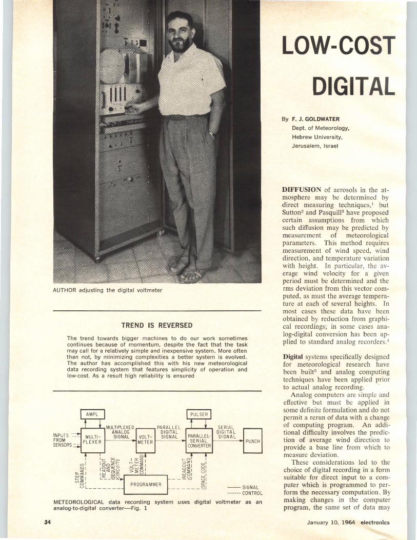
34
AUTHOR adjusting the digital voltmeter
TREND IS REVERSED
The trend towards bigger machines to do our work sometimes continues because of momentum, despite the fact that the task may call for a relatively simple and inexpensive system. More often than not, by minimizing complexities a better system is evolved. The author has accomplished this with his new meteorological data recording system that features simplicity of operation and low-cost. As a result high reliability is ensured
,...__..._.MULTIPLEXED PARALLEL ANALOG DIGITAL SIGNAL VOLT- SIGNAL PARALLEL-
SERIAL DIGITAL SIGNAL
METER o------- SERIAL 1------<" PUNCH
I cnl ~I
Cl. <1 I ~:::01 c.n~I
UL _____ _ PROGRAMMER
CONVERTER
I wl Cl\ 81 wl UI ti"1
------~ --SIGNAL ------ CONTROL
METEOROLOGICAL data recording system uses digital voltmeter as an analog-to-digital converter-Fig. 1
LOW-COST
DIGITAL By F. J. GOLDWATER
Dept. of Meteorology,
Hebrew University,
Jerusalem, Israel
DIFFUSION of aerosols in the atmosphere may be determined by direct measuring techniques, 1 but Sutton2 and Pasquill3 have proposed certain assumptions from which such diffusion may be predicted by measurement of meteorological parameters . This method requires measurement of wind speed, wind direction, and temperature variation with height. In particular, the average wind velocity for a given period must be determined and the rms deviation from this vector computed, as must the average temperature at each of several heights. In most cases these data have been obtained by reduction from graphical recordings; in some cases analog-digital conversion has been applied to standard analog recorders. 4
Digital systems specifically designed for meteorological research have been built5 and analog computing techniques have been applied prior to actual analog recording.
Analog computers are simple and effective but must be applied in some definite formulation and do not permit a rerun of data with a change of computing program. An additional difficulty involves the prediction of average wind direction to provide a base line from which to measure deviation .
These considerations led to the choice of digital recording in a form suitable for direct input to a computer which is programmed to perform the necessary computation. By making changes in the computer program, the same set of data may
January 10, 1964 electron1cs

SYSTEM Records Weather Data Medium-speed apparatus uses stepping switch as multiplexer, digital
voltmeter as a-d converter, one amplifier for all sensors.
Temperature is measured with a resistance bridge
be used as a basis for different computations; for example, the calculation of diffusion according to Pasquill3 or Sutton.2
Operation-Commercially available systems were found to be complex and costly. Therefore a simplified system was designed providing for inputs from five wind and five temperature sensors to be mounted at five different levels on a tower. The sensors have time constants ranging from 5 to 20 seconds and the scan time for a complete recording cycle is 15 seconds, providing a certain amount of preliminary filtering. The output of each sensor is connected to a digital voltmeter by a multiplexer. Then the output of the digital voltmeter is applied, through a parallel-serial code converter, to a paper-tape perforator that records the data. The same system may be used to drive a card-punch or automatic typewriter. Figure 1 shows system operation.
Components-A synchronous motor-driven multiple switch (programmer) provides both timing and programming. This device commands the multiplexer to advance to the next sensor.
For the multiplexer, a telephonetype stepping switch was chosen. The large number of switch points and levels provide flexibility and asynchronous operation allows for variation of the system program. The absence of offset voltages and the extremely high ratio of opento-closed circuit resistance allow
electronics January 10, 1964
such a switch to be used and thus permit the use of a single d-c amplifier for the entire system. Goldplated contacts are used for the lowlevel circuits to eliminate spurious emf's and corrosion problems. The high-level signal circuits handled by the switch look into the high-impedance voltmeter input, eliminating the effect of small changes in contact resistance.
A single d-c amplifier is used for amplifying the output of all the lowlevel sensors to the I -volt full scale range of the digital voltmeter. This unit (Airmec Model No. 855) has a relatively long time constant of 0.5 second and is connected to the thermometer outputs during the readout of the wind sensors to allow settling to the proper reading. Since the units are to be installed at levels on the tower with maximum temperature differentials of 3C, the provision of a settling time of 2.5 seconds assures a negligible error of 0.02C in the worst case. The wind sensors are adjusted to provide the required I -volt full-scale output and require no amplification.
Instrument-The voltmeter (Beckman/Berkeley Div. Model No. 5350RH) is keyed by the programmer. This voltmeter was chosen because of its relatively low price and fast operation. A reading is obtained within 20 msec and so this operation may be assigned a time interval during which no other operation is occurring thus reducing transient suppression problems. The voltmeter provides a sign code and
a binary-coded output of three decimal digits, 4 lines per digit. The sign code and these three 4-line groups are scanned one by one by relays operated by the programs. The output of this relay converter is applied to a switching and pulse generating network to provide the necessary driving pulses on the appropriate inputs of the tape punch. This unit (Tally Model No. 420) has an operational speed of 60 lines per second. The low punch time permits sequential code conversion and the code converter is restored to its non-operative state after punching.
The d-c power required by the stepping switch, relays and tape perforator is supplied by a regulated power supply consisting of four I 2.5 volt units connected in series. This construction reduces peak voltages and power dissipation for the transistors used.
Provision is made for a daily check to be performed manually, with appropriate test circuits for each section of the equipment selected by switches. Since five sensors are used for each parameter, and the values of these parameters must follow a definite curve, a sensor drifting badly out of calibration is quickly located.
Sensors - The choice of sensors posed certain problems. Even the smallest commercially available resistance thermometer elements have relatively Jong time constants. That used (Degussa P 4) consists of a platinum element sealed in a glass envelope 2 mm diameter by 25 mm
35
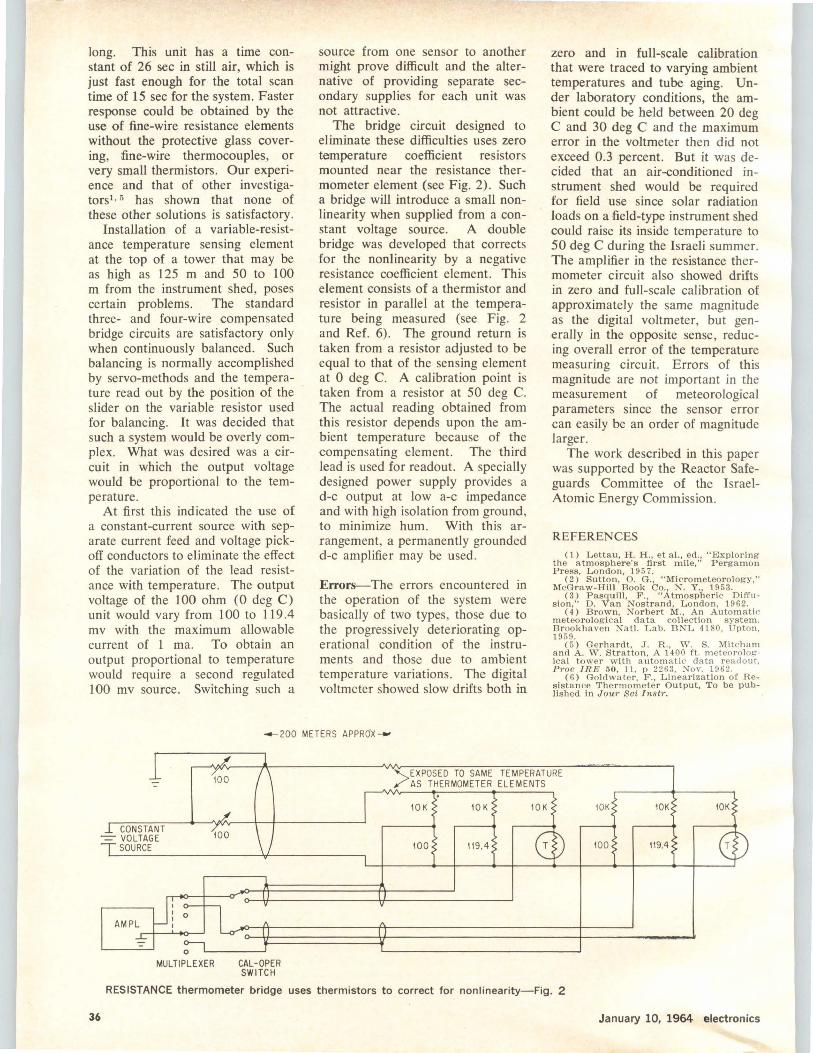
long. This unit has a time constant of 26 sec in still air, which is just fast enough for the total scan time of 15 sec for the system. Faster response could be obtained by the use of fine-wire resistance elements without the protective glass covering, fine-wire thermocouples, or very small thermistors. Our experience and that of other investigators1 · 5 has shown that none of these other solutions is satisfactory.
Installation of a variable-resistance temperature sensing element at the top of a tower that may be as high as 125 m and 50 to 100 m from the instrument shed, poses certain problems. The standard three- and four-wire compensated bridge circuits are satisfactory only when continuously balanced. Such balancing is normally accomplished by servo-methods and the temperature read out by the position of the slider on the variable resistor used for balancing. It was decided that such a system would be overly complex. What was desired was a circuit in which the output voltage would be proportional to the temperature.
At first this indicated the use of a constant-current source with separate current feed and voltage pickoff conductors to eliminate the effect of the variation of the lead resistance with temperature. The output voltage of the 100 ohm (0 deg C) unit would vary from 100 to 119 .4 mv with the maximum allowable current of 1 ma. To obtain an output proportional to temperature would require a second regulated I 00 mv source. Switching such a
source from one sensor to another might prove difficult and the alternative of providing separate secondary supplies for each unit was not attractive.
The bridge circuit designed to eliminate these difficulties uses zero temperature coefficient resistors mounted near the resistance thermometer element (see Fig. 2) . Such a bridge will introduce a small nonlinearity when supplied from a constant voltage source. A double bridge was developed that corrects for the nonlinearity by a negative resistance coefficient element. This element consists of a thermistor and resistor in parallel at the temperature being measured (see Fig. 2 and Ref. 6). The ground return is taken from a resistor adjusted to be equal to that of the sensing element at 0 deg C. A calibration point is taken from a resistor at 50 deg C. The actual reading obtained from this resistor depends upon the ambient temperature because of the compensating element. The third lead is used for readout. A specially designed power supply provides a d-c output at low a-c impedance and with high isolation from ground, to minimize hum. With this arrangement, a permanently grounded d-c amplifier may be used.
Errors--The errors encountered in the operation of the system were basically of two types , those due to the progressively deteriorating operational condition of the instruments and those due to ambient temperature variations. The digital voltmeter showed slow drifts both in
zero and in full-scale calibration that were traced to varying ambient temperatures and tube aging. Under laboratory conditions, the ambient could be held between 20 deg C and 30 deg C and the maximum error in the voltmeter then did not exceed 0.3 percent. But it was decided that an air-conditioned instrument shed would be required for field use since solar radiation loads on a field-type instrument shed could raise its inside temperature to 50 deg C during the Israeli summer. The amplifier in the resistance thermometer circuit also showed drifts in zero and full-scale calibration of approximately the same magnitude as the digital voltmeter, but generally in the opposite sense, reducing overall error of the temperature measuring circuit. Errors of this magnitude are not important in the measurement of meteorological parameters since the sensor error can easily be an order of magnitude larger.
The work described in this paper was supported by the Reactor Safeguards Committee of the IsraelAtomic Energy Commission.
REFERENCES
( 1) L etta u , H . H ., e t a l. , ed., "Exploring the a tmospher e' s first mile ," P ergamon Press, L o ndo n, 195 7.
( 2) Su t ton, 0. G., " Mi cr om eteor ology," McGr a w-Hill Book Co., N. Y ., 1 953.
( 3) P asq uill , F ., " Atmosph e ri c Di ffusio n, " D. V a n Nostra nd , L ondo n , 1962.
( 4 ) B r own, Norbert M., An Automatic m eteor ological d a t a collecti on system . Brookhaven Na tl. L ab. BNL 41 80, Upton, 1959.
( 5 ) Gerh a rdt, J . R., , V. S. Mitcham a nd A . W . Stra tto n , A 14 00 ft. m eteor olog-ica l tower w ith au tom>tt ic data r eadout, P roo IR E 5 0, 1 1, p 2263, Xov. 196 2.
( 6 ) Go ldwater , F ., L inearizat ion of Resis t a n ce The r mo me t er Output, T o b e published in Jou r S ci I ns tr .
4-200 METER S AP PR cJX --
36
CONSTANT -=- VOLTAGE
SOURCE 100
0
MULTIPLEXER CAL-OPER SWITCH
>EXPOS ED TO SAME TEMPERATURE AS THERMOMETER ELEMENTS
10 K 10 K
100 119. 4
RESISTANCE thermometer bridge uses thermistors to correct for nonlinearity-Fig. 2
10K
119.4
January 10, 1964 electronics
elec tro nic s
----------------REFERENCE SHEET--
Linear Scales
Show Mixer Harmonics
Simplified method locates spurious signals generated by
the first six harmonics of two mixed signals: one scale is for
the sum, the other for the difference, of input frequencies
By ROGER T. STEVENS, Sanders Associates, Inc., Nashua, N. H.
WHEN two r-f signals are mixed to produce a sum or difference frequency output, the mixing is inherently a nonl'inear process that produces harmonics of the two incoming signals, resulting in spurious outputs corresponding to these harmonics and the various combinations of their sums and differences. If the relation of the incoming signals and local oscillator frequencies is chosen unwisely, some of these spurious signals will be at the desired output frequency, so that they cannot be filtered out. In many cases, the resulting distortion of the i-f signal is intolerable.
Many charts and tables have been published that make it possible to determine where the spurious frequencies lie, but they all are so general and so complex that they do not substantially simplify the task of the design engineer. The two linear scales shown here quickly and easily locate and identify all of the spurious signals generated by the first six harmonics of the two incoming signals. One scale is for use when the desired output signal is the sum of the two input signals and the other scale is used when the output must be the difference of the two input signals. The only other information required is the ratio of the lower frequency input signal (FL) to the higher frequency input signal (Fu). For example, an input signal of 88 to 108 Mc is mixed with a local oscillator of 98.7 to 118.7 Mc to produce a 10.7-Mc i-f signal. The ratio F i./F 11 varies between 0.893 and 0.911. Looking at scale 2 (since the desired output is the difference frequency) we see that no spurious signals occur over
electronics January 10, 1964
this range and, therefore, the choice of local oscillator and i-f frequencies was satisfactory.
Equations-The derivation of the equations for these spurious signals is simple. The relation for the case of a desired difference signal output is
± (mFu - nFL) =Fu - F,,
where m and n are integers representing the particular harmonics of the desired signal. This equation can be rewritten in terms of the frequency ratio F d F JI
m-1 m+l F L/Fu = - -- or - --
n - l n+ l
To make up the scale, all combinations of the first six harmonics of each input were calculated, but solutions that gave F d Fu > 1 or negative were discarded since these cases are excluded by definition.
The corresponding equation for the case of the sum frequency being the desired output is
± (mFu - nF,J = Fu+ FL
This can be reduced to
m-1 m+l FL / Fu = --- or ---
n + 1 n-1
The scale was caJculated from this formula in the same way that the difference frequency scale was determined.
(continued on p 39)
37
38
A BENDIX/CORRELATED DATA PRODUCT
from Bendix-Pacific The latest from Bendix-Pacific-Model DDS·lOOOsolid·state Pulse Code Modulation ground station. This is a digital decommutation station capable of demodulating and processing all serial digital information. Outputs are available in a wide variety of serial or parallel digital formats, as well as analog signals for real time visual analysis of data. Flexibility is implemented with self.powered modular sub-assemblies for uni· versal applications, as well as mechanization for special requirements. Silicon semiconductor devices are used throughout the system for high reliability and optimum performance over a wide temperature range.
The DDS-1000 is adaptable to all bit, word, frame, and code formats now in use or planned for the future. The station incorporates an advanced bit synchronizer and signal conditioner for processing serial PCM video signals, as well as a signal simulator for complete self·check. The complete station occupies only a single seven-foot instrumentation rack.
Model DDS-1000 is a development of Correlated Data Systems Corporation and available exclusively from Bendix-Pacific. Contact Bendix-Pacific, North Hollywood, for complete information.
Bendix-Pacific Division ~ncfj/ CORPORATION
CIRCLE 38 ON READER SERVICE CARD January 10, 1964 electronics
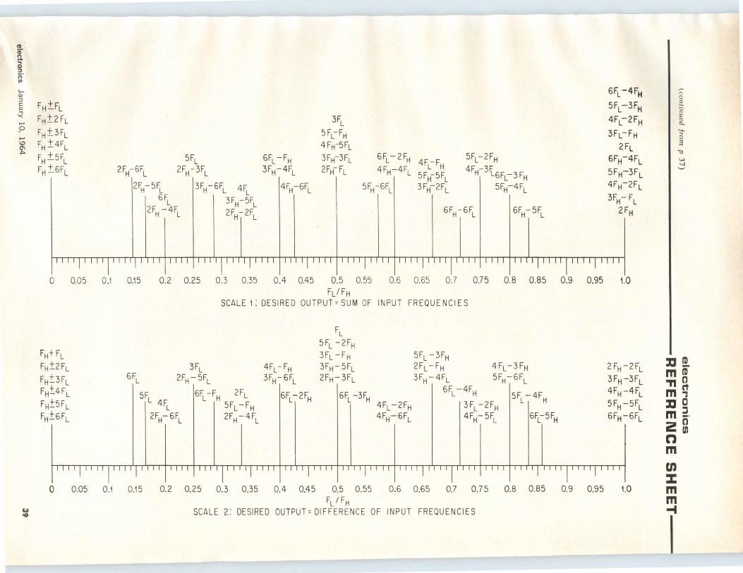
~
ID (;" n ..... 0 ::I
~·
..... Q) ::i c:: Q)
-< ...... p .... \0
~
FH±FL FH±.2 FL
FH±.3FL FH ±4FL
FH±.5FL FH ±.6FL 2FH-6FL
5FL 2FH-3FL
2FH-5FL 3FH-6FL 4FL
3FH-5FL
2FH~ 2FL
6FL 2FH -4FL
6FL -FH 3FH-4FL
4FH-6FL
3FL
5FcFH 4Fw5FL 3FH-3FL 2FH-FL
6FL-2FH 4FL-FH
4FH-4FL 5FH-5FL
I 3F -2FL 5FH-6FL H
5FL-2FH
4FH-3~6Fc3FH 5FH-4FL
6FH-6FL 6FH-5FL
6FL - 4FH
5Fc3FH
4Fc2FH
3FL-FH
2FL 6FH-4FL
5FH-3FL 4FH-2FL
3FH- FL 2FH
0 0.05 0.1 0.15 0.2 0.25 0.3 0.35 0.4 0.45 0.5 0.55 0.6 0.65 0.7 0.75 0.8 0.85 0.9 0.95 1.0
FH+ FL FH±2FL
FH±3FL FH±4FL
FH±5FL FH±6FL
6FL
FL/FH SCALE 1: DESIRED OUTPUT= SUM OF INPUT FREQUENCIES
5FL 4FL
3FL 2FH- 5FL
2FH-6FL
6~-~ 2~ 5FL-FH 2~-4~
4FL - FH 3FH-:-6FL
6FL-:-2FH
FL 5FL -2FH 3FL -FH 3FH-5FL 2FH-3FL
6FL -3FH 4FL -2FH 4FH-6FL
5FL -3FH 2FL -FH 3FH-4FL
4FL-3FH 5FH-:-6FL
. 6FL -4FH
3 FL -2FH 4FH- 5FL
5FL -4FH I 6Fc5FH
2FH-2FL 3FH-3FL 4FH-4FL
5FH-5FL 6FH-6FL
I ~
" "'--" c 3
"<:>
"" -.J
:a! m CD ,, 0 mq :a 0
J m -· zg n m en ::z:
0 0.05 0.1 0.15 0.2 0.25 0.3 0.35 0.4 0.45 0.5 0.55 0.6 0.65 0.7 0.75 0.8 0.85 0 - --0.95 9 1.0 FL /FH m
~ SCALE 2: DESIRED OUTPUT~ DIFFERENCE OF INPUT FREQUENCIES - _I --
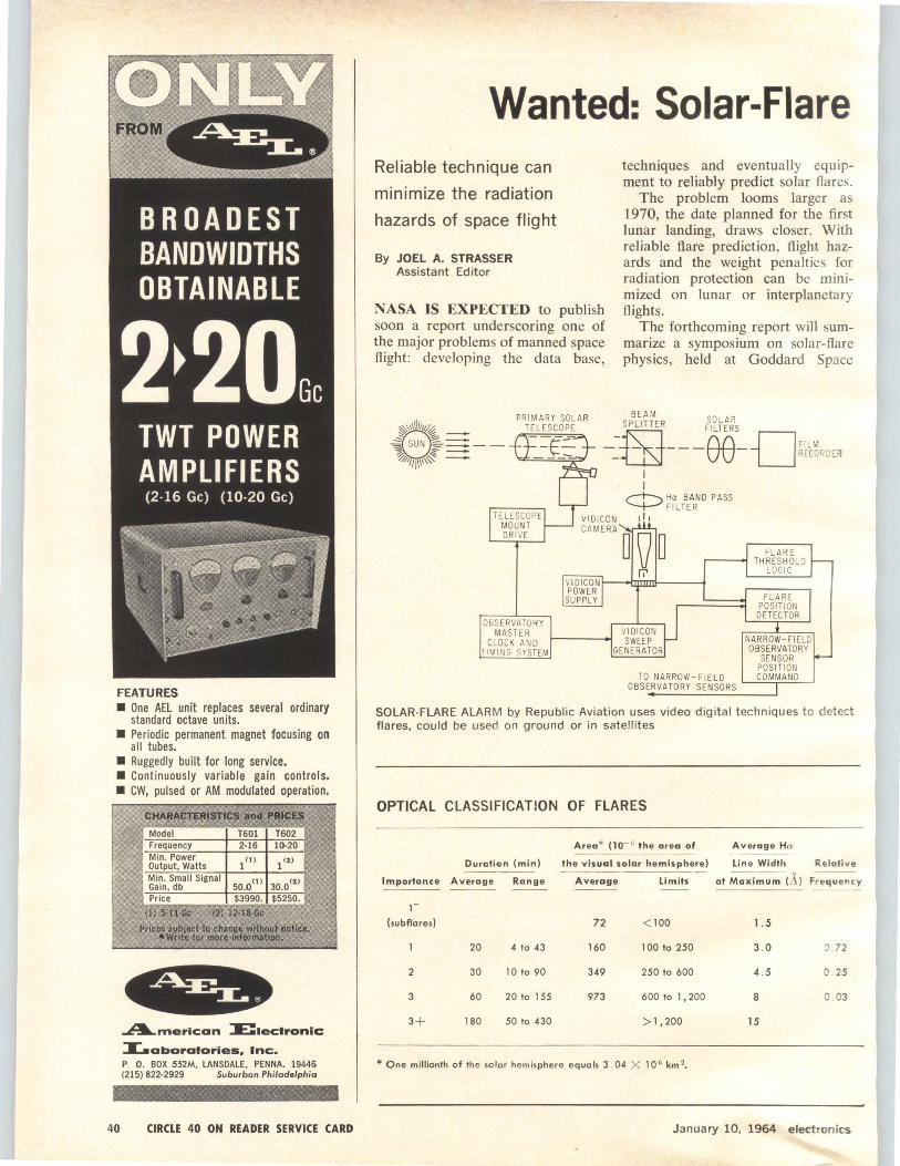
FEATURES • One AEL unit replaces several ordinary
standard octave units. • Periodic permanent magnet focusing 011
all tubes. • Ruggedly built for Jong service. • Continuously variable gain controls. • CW, pulsed or AM modulated operation.
40
CHARACTERISTIC$?'!'!~Q Model T601 T602 Frequency 2·16 10-20 Min. Power 1 (J) 1 (2) Output, Watts Min. Small Signal
50.0(1) 30.0' 2 > Gain , db Price $3990. $5250.
(!) 5-11 Ge (2) 12·18 Ge
Prices subject to chan1e wltbollt notice. •write for more lllfomlltlon. .
~merlcan lE:1ectronic
X.aboratories, Inc. P O. BOX 552M, LANSDALE, PENNA. 19446 (215) 822-2929 Suburban Philadelphia
CIRCLE 40 ON READER SERVICE CARD
Wanted: Solar-Flare Reliable technique can
minimize the radiation
hazards of space flight
By JOEL A. STRASSER Assistant Editor
techniques and eventually equipment to reliably predict solar flares.
NASA IS EXPECTED to publish soon a report underscoring one of the major problems of manned space flight : developing the data base,
The problem looms larger as 1970, the date planned for the first lunar landing, draws closer. With reliable flare prediction, flight hazards and the weight penalties for radiation protection can be minimized on lunar or interplanetary flights.
The forthcoming report will summarize a symposium on solar-flare physics, held at Goddard Space
~\\1\l/111~ 2§a~== ~ SUN :::---~ ~%111111\~ -
TELESCO PE MOUNT DRI VE
OBSERVATORY MA STER
CLOCK AND TIMI NG SYSTEM
BEAM SOLAR
fil FeelLTERS -DFI LM ~{__[:SJ- - - - RECORD ER
I I
,..---t--..., Ha BAND PASS "--+-"' F I LT ER ,1,
CAMERA D Q D
r.'
VI DICON SWEEP
GENERATOR
TO NARROW-FIELD OBSERVATORY SENSORS
FLARE THRESHOLD
LOGIC
FLARE PO SITION DETECTOR
NARROW-FIELD OBSERVATORY
SENSOR POSITION COMMAND
SOLAR-FLARE ALARM by Republic Aviation uses video digital techniques to detect flares, could be used on ground or in satellites
OPTICAL CLASSIFICATION OF FLARES
Duration (min)
Importance Average Range
1-
(subAores)
2
3
20
30
60
180
4 to 43
10 to 90
20 to 1 SS
SO to 430
Area* (10- o; the area of
the visual solar hemisphere)
Average limits
72 < 100
160 100 to 250
349 250 to 600
973 600 to 1, 200
>1 ,200
*One millionth of the solar hemisphere equals 3 . 04 X 10 6 km 2•
Average Ha
line Width Relative
al ~~ (A) Frequency
1.5
3.0 0 . 72
4 . S 0 . 25
8 0 . 03
15
January 10, 1964 electronics
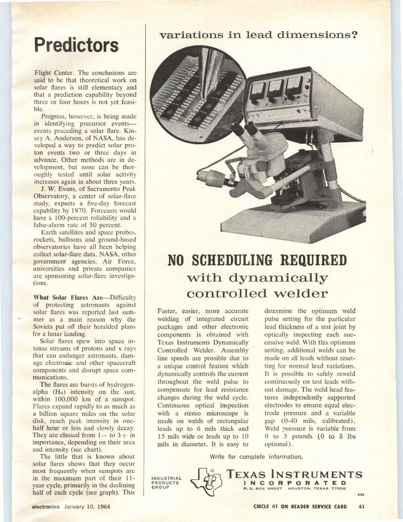
Predictors Flight Center. The conclusions are said to be that theoretical work on solar flares is still elementary and that a prediction capability beyond three or four hours is not yet feasible.
Progress, however, is being made in identifying precursor eventsevents preceding a solar flare. Kinsey A. Anderson, of NASA, has developed a way to predict solar proton events two or three days in advance. Other methods are in development, but none can be thoroughly tested until solar activity increases again in about three years.
J. W. Evans, of Sacramento Peak Observatory, a center of solar-flare study, expects a five-day forecast capability by 1970. Forecasts would have a 100-percent reliability and a false-alarm rate of 50 percent.
Earth satellites and space probes. rockets, balloons and ground-based observatories have all been helping collect solar-flare data. NASA, other government agencies, Air Force, universities and private companies are sponsoring solar-flare investigations.
What Solar Flares Are-Difficulty of protecting astronauts against solar flares was reported last summer as ~ main reason why the Soviets put off their heralded plans for a lunar landing.
Solar flares spew into space intense streams of protons and x rays that can endanger astronauts, damage electron4c and other spacecraft components and disrupt space communications.
The flares are bursts of hydrogenalpha (Ha) intensity on the sun, within 100,000 km of a sunspot. Flares expand rapidly to as much as a billion square miles on the solar disk, reach peak intensity in onehalf hour or less and slowly decay. They are classed from 1- to 3+ in importance, depending on their area and intensity (see chart) .
The little that is known about solar flares shows that they occur most frequently when sunspots are in the maximum part of their 11-year cycle, primarily in the declining half of each cycle (see graph). This
electronics January 10, 1964
variations in lead dimensions?
NO SCHEDULING REQUIRED with dynamically controlled welder
Faster, easier, more accurate welding of integrated circuit packages and other electronic components is obtained with Texas Instruments Dynamically Controlled Welder. Assembly line speeds are possible due to a unique control feature which dynamically controls the current throughout the weld pulse to compensate for lead resistance changes during the weld cycle. Continuous optical inspection with a stereo microscope is made on welds of rectangular leads up to 6 mils thick and 15 mils wide or leads up to 10 mils in diameter. It is easy to
determine the optimum weld pulse setting for the particular lead thickness of a test joint by optically inspecting each successive weld. With this optimum setting, additional welds can be made on all leads without resetting for normal lead variations. It is possible to safely reweld continuously on test leads without damage. The weld head features independently supported electrodes to ensure equal electrode pressure and a variable gap (0-40 mils, calibrated). Weld pressure is variable from 0 to 3 pounds (0 to 8 lbs optional).
Write for complete information.
INDUSTRIAL PRODUCTS GROUP
TEXAS INSTRUMENTS INCORPORATED P.o.eox 66027 HOUSTON , TEXAS 77006
630
CIRCLE 41 ON READER SERVICE CARD 41

~ oh~s.ooo
~. volts d. c.
125 2500
250
25
ew
25
FULL SCALE VALUES
Records Signals of 2.5 Millivolts Full Scale Accurately!
. . . a self-balancing, complete 5-inch strip-chart recorder ... brings you complete versatility ... without costly extras ... at one low price. Its higher sensitivity extends its usefulness in a great number of applications ... with the B&L Opacimeter-determine and record opacity of paper ... with the B&L Data Acquisition System-it extends the range of the Spectronic-20 to 340mµ ... many transducers can be ONLY
used directly with the V. 0. M .-6, no further amplification $70 o is normally required in gas chromatography applications.
COMPARE THESE EXCLUSIVE ADVANTAGES: COMPLETE
(Suggested Retail)
• Six voltage ranges, 2.5 millivolts to 125 volts
• Six linear ohms scales, 0.25 ohmsto-25,000 ohms full scale, with zener diode D. C. supply
• Five chart speeds, 400-to-1 range
• Event marker, with solenoid operated marking pens
• Function switch with mechanical pen letdown
• 5 D. C. current ranges, 2.5 micro- • Operates in flat, 30° tilt, or wall-amperes to 25 milliamperes mounted position
• Off balance input impedance- • Compact, only 4%"xl41/z"x11%" over 10 megohms • Portable, only 18 lbs.
For further information, write for Brochure ,, D-2054. Bausch & Lomb Incorporated, BAUSCH & LOMB • 61401 Bausch St., Rochester, N. Y. 14602
In Canada, write Bausch & Lomb Optical Co .. Ltd .. Dept. 614 Scientific Instrument Division, 16 Grosvenor St .. Toronto 5, Canada
42 CIRCLE 42 ON READER SERVICE CARD
seems the most reliable characteristic on which to base a prediction technique.
New Satellites-To add to the data gathered by several satellites, including Explorers and Orbiting Solar Observatory (OSO), NASA will launch seven Interplanetary Monitoring Platforms (IMP) and an Advanced OSO (AOSO).
The first IMP was launched in November into a 122,800-mile-high orbit (ELECTRONICS, p 40, Nov. 29, 1963, outlines solar-flare related ex-
16 240 VJ ...... "" UJ
<D
~ 12 MEAN SUNSPOT 180 ~
> z w NUMBER ..... "- 120 ~ 0
"' V) z
w :::> gj 4 60 ~ :::> z
0 0 1948 1960
SUNSPOT CYCLE'S relationship to solar-flare occurrence
periments). The IMP program's stated purpose is to develop "a solar-flare prediction capability for Apollo." Investigation of the solarflare mechanism will be the major mission in 1967 of AOSO. NASA is expected to announce details on AOSO shortly .
Ground Observatories-Ground observatories around the world have collected a significant amount of solar-flare data.
The goal of Sacramento Peak Observatory (SPO), part of AFCRL, is to study photo emission and understand it well enough to identify precursor features and to establish adequate solar-flare forecasting techniques.
New type of spectroscopic magnetometer at SPO will provide magnetic-field mapping by means of the Zeeman effect with a resolution of l to 2 sec. This year, construction will begin on a 30-inch evacuated solar tower telescope. Coupled with the Doppler-Zeeman Analyzer, this will provide the most advanced observational technique in existence for determining small detail on the sun.
At Harvard College Radio Observatory in Fort Davis, Texas,
January 10, 1964 electronics
<( UJ ::E
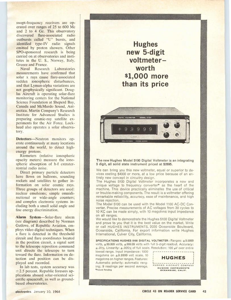
swept-frequency receivers are operated over ranges of 25 to 600 Mc and 2 to 4 Ge. This observatory discovered flare-associated radio outbursts called "U" bursts, and identified type-IV radio signals emitted by proton showers. Other SPO-sponsored research is being carried on at observatories and institutes in the U. S., Norway, Italy, Greece and France .
Naval Research Laboratories measurements have confirmed that solar x rays cause flare-associated sudden ionospheric disturbances. and that Lyman-alpha variations are not geophysically significant. Douglas Aircraft is operating solar-flare monitoring centers for the National Science Foundation at Sheperd Bay, Canada and McMurdo Sound, Antarctica. Martin Company's Research Institute for Advanced Studies is preparing cosmic-ray satellite experiments for the Air Force. Lockheed also operates a solar observatory.
Detectors-Neutron monitors operate continuously at many locations around the world, to detect highenergy protons.
Riometers (relative ionospheric opacity meters) measure the ionospheric absorption of h-f extraterrestrial radio noise.
Direct primary particle detectors have flown on balloons, sounding rockets and satellites to gather information on solar cosmic rays. Three groups of detectors are used: nuclear emulsions; simple omnidirectional or wide-angle counters; and complex electronic systems including both a small solid angle and fine energy discrimination.
Alarm System-Solar-flare alarm (see diagram) described by Norman Gutlove, of Republic Aviation, employs video digital techniques. When a flare is detected in the threshold circuit and flare coordinates located in the position circuit, a signal sent to the telescope reposition command unit directs the telescope to turn toward the flare. Information on detection and position can be displayed and recorded.
In lab tests, system accuracy was ±2.5 percent. Republic foresees applications aboard solar-oriented scientific spacecraft, as well as groundbased observatories.
electronics January 10, 1964
Hughes new 5-digit voltmeter
worth $1,000 more
than its price
-
+ q .~ 9 g ~)
The new Hughes Model 5100 Digital Voltmeter is an integrating 5 digit, all solid state instrument priced at $2695.
We can bring you this new voltmeter, equal or superior to devices costing $4000 or more, at a low price because of an entirely new concept in circuitry design. The Hughes 5100 Digital Voltmeter incorporates a new and unique voltage to frequency converter* as the heart of the machine. This device practically eliminates the use of critical or trouble-making components. The result is a voltmeter offering remarkable reliability, accuracy, ease of maintenance, and high noise rejection. The Model 5100 can be used with the Model 1100 AC-DC Converter. Precise measurements of AC voltages from 30 cycles to 10 KC can be made simply, with 10 megohms input impedance on all ranges. We would like to demonstrate the Hughes 5100 Digital Voltmeter and prove to you that it is the best value on the market. Write or call HUGHES INSTRUMENTS, 2020 Oceanside Boulevard, Oceanside, California. For export information write Hughes International, Culver City, California.
SPECIFICATIONS HUGHES 5100 DIGITAL VOLTMETER: Ranges: ±9.9999 volts, ±99.999 volts, ±999.99 volts with full 5-digit readout. Accuracy: ± .01 %. Linearity: ± .005% of full sca le. Resolution : 100 µV over entire lowest range. Input impedance : 1000 r--- ----------------, megohms on ±9.9999 volt scale. 10 1 '
megohms on higher ranges. Features: : HUGHES : I I Automatic polarity; automatic rang· L __________________ J
ing; 9 readings per second average. Hu::~~;~R.~R5~::~~:;5ANY *Patent Pending OCEANSIDE, CALIF.
CIRCLE 43 ON READER SERVICE CARD 43
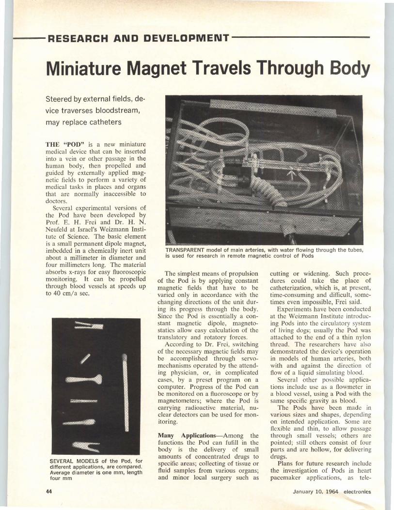
...__- RESEARCH AND DEVELOPMENT----------
Miniature Magnet Travels Through Body Steered by external fields, de
vice traverses bloodstream,
may replace catheters
THE "POD" is a new miniature medical device that can be inserted into a vein or other passage in the human body, then propelled and guided by externally applied magnetic fields to perform a variety of medical tasks in places and organs that are normally inaccessible to doctors.
Several experimental versions of the Pod have been developed by Prof. E. H. Frei and Dr. H . N. Neufeld at Israel's Weizmann Institute of Science. The basic element is a small permanent dipole magnet, imbedded in a chemically inert unit about a millimeter in diameter and four millimeters long. The material absorbs x-rays for easy fluoroscopic monitoring. It can be propelled through blood vessels at speeds up to 40 cm/ a sec.
SEVERAL MODELS of the Pod, for different applications, are compared. Average diameter is one mm, length four mm
44
TRANSPARENT model of main arteries, with water flowing through the tubes, is used for research in remote magnetic control of Pods
The simplest means of propulsion of the Pod is by applying constant magnetic fields that have to be varied only in accordance with the changing directions of the unit during its progress through the body. Since the Pod is essentially a constant magnetic dipole, magnetostatics allow easy calculation of the translatory and rotatory forces.
According to Dr. Frei, switching of the necessary magnetic fields may be accomplished through servomechanisms operated by the attending physician, or, in complicated cases, by a preset program on a computer. Progress of the Pod can be monitored on a fluoroscope or by magnetometers; where the Pod is carrying radioactive material, nuclear detectors can be used for monitoring.
Many Applications-Among the functions the Pod can fufill in the body is the delivery of small amounts of concentrated drugs to specific areas; collecting of tissue or fluid samples from various organs; and minor local surgery such as
cutting or widening. Such procedures could take the place of catheterization, which is, at present, time-consuming and difficult, sometimes even impossible, Frei said.
Experiments have been conducted at the Weizmann Institute introducing Pods into the circulatory system of living dogs; usually the Pod was attached to the end of a thin nylon thread. The researchers have also demonstrated the device's operation in models of human arteries, both with and against the direction of flow of a liquid simulating blood.
Several other possible applications include use as a flowmeter in a blood vessel, using a Pod with the same specific gravity as blood.
The Pods have been made in various sizes and shapes, depending on intended application. Some are flexible and thin, to allow passage through small vessels; others are pointed; still others consist of four parts and are hollow, for delivering drugs.
Plans for future research include the investigation of Pods in heart pacemaker applications, as tele-
January 10, 1964 electronics

EXCLUSIVE ... Monolithic Construction gives Ne\N' "VITRAMON" Capacitors greater reliability ... increased capacitance!
NEW! 100,000 pf! * 15,000 to 100,000 pf
* * -55°C to 125°C operation
solid state micromi niature ceramic capacitors
10
r-I "' f-:Z: ""' f-~
<..>
t--:=i f-~
-~ ,,,
This is no ordinary ceramic capacitor! The new VK 30 unit~ look like the familiar VK 30 capacitor outside but inside there's a dramatic difference. Their exclusive solid state monolithic construction gives them extraordinary reliability and increased capacitance. Insulation resistance is greater than 1000 megohms at 25°C ... capacitance range is 100,000 pf r-? ~
f-~ <..> .... (10 times greater than MIL specs).
Send for new data sheet. rj
NEW!
solid state microminiature ceramic capacitors
- ~
50 vdc * 1 0% and 20% tolerance * Conforms to MIL-C-11015
TIMPUATURI COlm<llNT AT 1 C
- 1 ...;ii"!
~
~MP_~RA~E l - l Ji so 7l ~ IS
* 1000 pf to 10,000 pf * -55°C to 125°C operation * 100 vdc * 1 0% and 20% tolerance * Conforms to MIL-C-11015
The "Vitramon V-LAM" Ceramic Capacitor represents a completely new concept in solid state design and performance. High quality ceramic dielectric and precious metal electrode materials are built up in alternate layers and molecularly fused to form a dense, homogeneous unit. This exclusive process, applied for the first time to a "high-K" capacitor, gives these tiny components a ruggedness and reliability not previously available in capacitors of this type. The "V-LAM" Capacitor is ideal for coupling and by-pass applications, and because of its geometric shape it is readily usable in cordwood packaging and tape reeling.
© Vi tramon, Inc . 1963
lsr- fl electronics January 10, 1964
l'~ BOX 544 • BRIDGEPORT !. CO NNECTICUT. U . S . A .
In United Kingdom contact: Vitramon Laboratories Limited 45 Holloway Lane Harmondsworth, Middlesex England
CIRCLE 45 ON READER SERVICE CARD 45

JUST PUBLISHED!
IMPACT OF
MICROELECTRONICS Edited by George T. Jacobi, llT Research Institute and Samuel Weber, electronics
The Proceedings of the Conference on the Impact of Microelectronics, co-sponsored by the Armour Research Foundation (now I IT Research Institute) and electronics, a McGraw-Hill Publication, has just been published by electronics. The Conference, held last June 26-27 at the Illinois Institute of Technology, was acclaimed by the attendees and the industry at large. Now, in book form, all the invited papers and talks presented at the con· ference are available to you.
To whet your appetite, here are some of the contents:
The Electronics Components Industry and Microelectronics by Robert c. Sprague, Chairman of the Board, Sprague Electric Company.
Profit and Loss in Microelectronics by Robert W. Galvin, President, Motorola Inc. Government Needs and Policies in the Age of Microelectronics by James M. Bridges, Director of Communications and Electronics, Department of Defense. Management of Research and Engineering for Microelectronics Systems by Dr. Peter B. Myers and Arthur P. Stern, Electron ic Systems and Products Division, Martin Company. In House or Not: The Changing Buyer-Vendor Interface by F. J. Van Poppelen, Jr., Vice President-Marketing, Signetics Corporation.
current Technical Status and Problems in Microelectronics by Jack S. Kilby , Integrated Circuits Dept., Texas Instruments, Inc.
Ultimate limits of Microelectronics by Dr. J. T. Wallmark, RCA Laboratories , David Sarnoff Research Center
Reliability in Microelectronics by Ernest R. Jervis, ARINC Research Corporation. Engineering Education in an Era of Changing Technology by Dr. John Bardeen, University of Illinois.
IMPACT OF MICROELECTRONICS is must reading for men with a marketing and technical interest in this dynamic field of activity. Crammed with useful information, this neatly designed, 120 page volume keeps you up-to-date on this fast moving technology. Order today. Only $3.50 per copy.
electronics Reprint Department McGraw-Hill Publishing Co., Inc. 330 West 42nd Street New York, N.Y. 10036
Dear Sirs:
ORDER FORM
Send me.__copies of IMPACT OF MICROELECTRONICS ($3.50 per copy)
I am enclosin (cash or check) Bill me later __ Bill my company __
I I I I I I I I MY NAM..._ ____________ POSITION--------
COMPANY---------~-------------- I I ADDRESS I L-------------------~ 46
metry pressure transducers, and for intracranial applications.
Biggest "Hi-Fi" Checks
Parts With 150 Decibels
LITCHFIELD PARK, ARIZ. - The "world's biggest and most precise hi-fi" set drives 48 circumferentially placed woofers and 64 mid-range tweeters from 37 to 10,000 cps, and generates sound levels up to 150 db in order to check aircraft and missile parts for resistance to vibration, shock, altitude and temperature.
The Arizona Division of Goodyear Aircraft Corporation, who built the equipment, says that the environmental tester is so powerful that a record played through its amplifier could be heard 20 miles away.
Sound actually used comes from a zener-diode noise source, controlled for sound type, intensity and frequency at a test console. An analyzer monitors the type of out-
OUTPUT END, top, of acoustic testing facility at Goodyear's Litchfield Park, Ariz., plant, has 48 circular woofers, placed circumferentially around 64 trumpet-shaped mid-range speakers. At bottom, reverberation chamber for omnidirectional sound bombardment of parts under test
January 10, 1964 electronics

put, its frequency and db level , while additional equipment records all test factors .
A urethane foam rubber-filled sound sink absorbs the unused audio energy from two square testing chambers and a third, reverberant chamber that resembles a plump submarine. The 'reverberant chamber's walls bounce the sound back and forth to hit the object under test from all directions.
Aurora Thickness Measured
By Polar-Orbit Satellite
SATELLITES IN POLAR orbit have shown that auroras of the northern hemisphere are much thicker than generally believed, according to Richard Sharp of Lockheed Missiles & Space Co. Observations of lowcnergy electrons and protons were made with eight specially designed instruments aboard a satellite that made six passes over the northern auroral zone. These measurements revealed that the profile of a typical aurora can extend up to several hundred miles in thickness, and clarified a divergence of opinion among experts concerning how much of the aurora was visible. The experiment also showed that most normal auroras are caused by electrons rather than protons since no protons were recorded by either the high-energy or low-energy proton counters.
Fiberscope Aids
Color Tv Surgery
A FIVE FOOT LONG fiber-optic bundle has beeen used to televise an ear operation in color. A color tv camera, a delicate operating microscope, and the fiberscope designed by American Optical Co., were combined to show the operation to physicians attending the annual meeting of the Southern Medical Association in New Orleans, La. A color picture measuring nine by twelve feet was made of an operating field smaller than a dime.
The fiber optic bundle, about the thickness of a garden hose, transmitted the image from the microscope to the tv camera using over 675,000 aligned glass fibers.
electronics January 10, 1964
/ .......................... ................................... \
NEW SOLID STATE CIRCUITRY
i LOW COST?? =
a.~m?c;?.:~ Q:reliable!~ ~·"'51...-1 ..._ =~ smaller cm ~SS.Y.S
i AN;~~~~~KS! I .. .. . .. ·· ........................................... ...... ............. .................................. ... ......................... /
··· ...... ·· A new Dual-limit controller
that sounds too good to be true
Design Engineer: "It does seem incredible, doesn't it? But I've seen it in operation and it really works! This new 'Ultra Comparator® Dual Limit Control' of Carter-Princeton's combines two 100 K input impedance comparators on one small size, computer-type, plug-in circuit card ... it provides 4 sets of relay contacts per comparator •.. and it has the fastest power relay output achieved yet."
Management: "What is the speed, exactly?"
Design Engineer: "Only 5 milliseconds from signal to full 2 ampere output, and it's sensitive to 3 millivolts."
Management: "Where do you need that much speed and sensitivity?0
Design Engineer: "One present application is control of a rocket engine test stand, to shut down the equipment when critical parameters go outside rated limits. But it 's also useful in alarm and check-out systems of many kinds-any place where you need band limit controls in multiples of two for any reason."
Management: "How about cost?"
Design Engineer: "That's another surprise-anywhere from 25% to 50% lower than any comparable unit, largely because of a new CarterPrinceton concept in circuitry. It does away with about half the transistors and two-thirds of the parts that would otherwise be required.'·'
Management: "If it's all that good, I'm right with you. Let's give it a try!0
( The Model 2020 circuit is one of a series of new Ultra-Comparator® units offering high sensitivity, compactness, reliability and adaptability at substantial savings. A limited number are available on free loan for trial. For details, contact Carter• Princeton, Electronics Division, Carter Products, Inc., 178-F Alexander St., Prince• ton, N.J., 08540. Phone (609) 921-2880. cR
CA.RTF.R -PRINCETON
CIRCLE 47 ON READER SERVICE CARD 47
48
PICO Miniature
actual size
FREQUENCY STANDARD Smallest size %" x lK/' x %",weighing less than
¥4 oz. Widest range Expanded frequency range is
from 2 kc to 50 kc and is available with accuracies from 0.001 % to 0.2% over temperature variations from -55°C to + 125°C. Designed for shock and vibration appli· cations. Ideal for space and aircraft use.
Write for PM Catalog
ACCURATE INSTRUMENT CO. P . O . BOX 19426 • HOUSTON 24 , TEXAS
Manufacturers of frequency standards and test instruments
CIRCLE 200 ON READER SERVICE CARD
HOLD MOTOR SPEED TO 1 % with d.c. power in all environments
Maintain motor speed accurately to ± 1 % at temperatures fluctuating from -55° C to + 75° C, at any speed from 3,600 to 24,000 rpm, and with voltage fluctuating from 22 to 32 v.d.c. Globe's new frequency controlled d.c. to a.c. device combines all advantages of brushless d.c. operation with unusually precise 1 % speed control over wide environment variations, and within 0.5% in a constant environment! Speed control weighs 10 ounces, measures lKt high x 2)4" wide x 3)4" long. Life can exceed 10,000 hours. Device has no moving parts or electrical contacts, and is designed to meet
MIL-E-5272 for environmental protection. Fits many sizes of motors. Reverse polarity protection and transient voltage protection are available. Request Bulletin OPC. Globe Industries, Inc., 1784 Stanley Avenue, Dayton, Ohio 45404.
CIRCLE 48 ON READER SERVICE CARD
Around the world ...
KYORITSU Measuring Instruments
ELECTRICAL INSTRUMENTS WORKS, LTD. 120, Nakane·cho, Meguro-ku, Tokyo, Japan
Cable address: KYORITSUKEIKI TOKYO Telex: TK 2849
CIRCLE 201 ON READER SERVICE CARD
TO ORDER REPRINTS
Fill in, cut out coupon below
insert in envelope and mail to:
electronics Reprint Dept.
330 W. 42nd Street, New York, N . Y. 10036
---------------------------~ REPRINT ORDER FORM
(To help expedite moiling of your reprints please send cash, check or money order with your order.)
For Listing of Reprints Available see the Reader Service Card.
For Reprints of the latest Special Report: What's Mew In Semiconductors
Send me ..... . .. Reprints of Key No. R-4S 1- 10, copies 75¢ ea . 10-24, 60¢ ea . 25 or more 50¢ ea .
For Repr ints of previous Special Reports or Feature Articles f ill in below:
Send me .. .... Reprints of Key No.(s) . .... . @ . . ... ¢ each. (For prices, see Reader Service Cord.)
*For orders of Bulk Reprints of other editor ial articles In this issue or post issues:
Send me .... Repr ints of page No.(s) .... of issue dote . ...
of article entitled .. . ..... •. . . . .•• . .. . ... . .. . . ....• .. ....
• Min imum bulk order 100 copies. You will be advised of costs by return mail.
Mame .. .. . .....••• • ••••••••••••••••••••••• · ••• • · ··· ·· ·
Number of Street. . • • • • • • • • • • • • • • • • • • • • • • • • • • • • . • . • • . . . . .
City, Zone Mo., State . .•..••. • •.• • .• .. . . . ...•. . . . . • . . . ..•
January 10, 1964 electronics
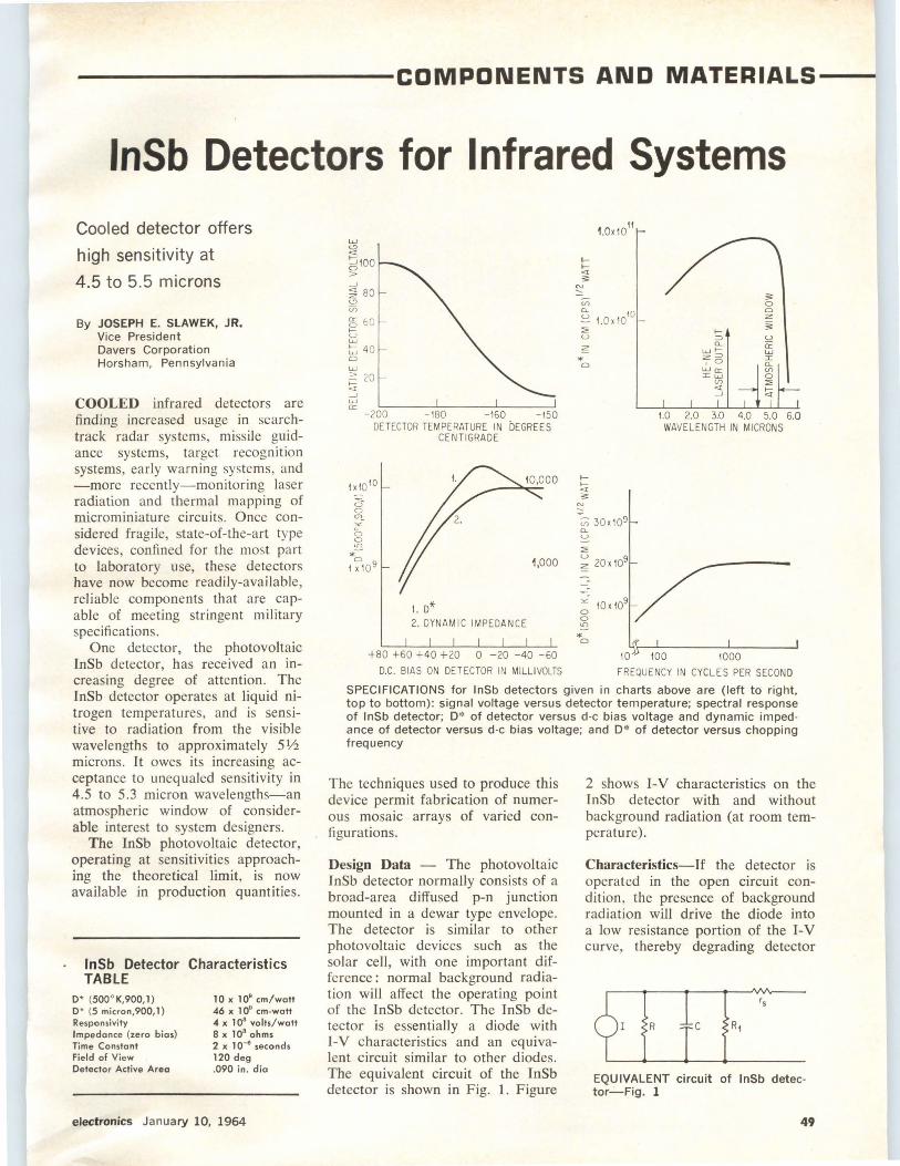
----------COMPONENTS AND MATERIALS---
lnSb Detectors for Infrared Systems
Cooled detector offers
high sensitivity at
4.5 to 5.5 microns
By JOSEPH E. SLAWEK, JR. Vice President Davers Corporation Horsham, Pennsylvania
COOLED infrared detectors are finding increased usage in searchtrack radar systems, missile guidance systems, target recognition systems, early warning systems, and -more recently-monitoring laser radiation and thermal mapping of microminiature circuits. Once considered fragile, state-of-the-art type devices , confined for the most part to laboratory use, these detectors have now become readily-available, reliable components that are capable of meeting stringent military specifications.
One detector, the photovoltaic InSb detector, has received an increasing degree of attention. The I nSb detector operates at liquid nitrogen temperatures, and is sensitive to radiation from the visible wavelengths to approximately 51/z microns. It owes its increasing acceptance to unequaled sensitivity in 4.5 to 5.3 micron wavelengths-an atmospheric window of considerable interest to system designers.
The InSb photovoltaic detector, operating at sensitivities approaching the theoretical limit, is now available in production quantities .
lnSb Detector Characteristics TABLE
D* (500° K,900, 1) D* (5 micron,900, 1) Responsivity Impedance (zero bias) Time Constant Field of View Detector Active Area
10 x 109 cm/watt 46 x 1 o• cm.watt 4 x 10³ volts/watt 8 x 10⁸ ohms 2 x 1 o-• seconds 120 deg .090 in. dia
electronics January 10, 1964
w
"' <I
~100 > -' ~ 80 ~ V)
!? 60 u w t;:; 40 0
~ 20 1-<I -' w 0::
-200 -180 -160 -150 DETECTOR TEMPERATURE IN DEGREES
CENTIGRADE
1xl0 10
6 0 en_ °i{-0 0 U')
*;; 1x10⁹
t. D* 2. DYNAMIC IMPEDANCE
+80 +60 +40 +20 0 -20 -40 -60
D.C. BIAS ON DETECTOR IN MILLIVOLTS
1.0x10¹¹
;;:;
~ 1.0x10¹⁰
::;, u z
* 0
II<[ ;;:
N ~
-u; 30x109 a_ u
::;,
~ 20x109
"" 0 0 U')
* 0
I=> a_
w>z :::> ,o WO: Iw
<J) <[
--'
1.0 2.0 3.0 4.0 5.0 6.0 WAVELENGTH IN MICRONS
100 1000
FREQUENCY IN CYCLES PER SECOND
SPECIFICATIONS for lnSb detectors given in charts above are (left to right, top to bottom): signal voltage versus detector temperature; spectral response of lnSb detector; D* of detector versus d-c bias voltage and dynamic impedance of detector versus d-c bias voltage; and D* of detector versus chopping frequency
The techniques used to produce this device permit fabrication of numerous mosaic arrays of varied configurations.
Design Data - The photovoltaic JnSb detector normally consists of a broad-area diffused p-n junction mounted in a dewar type envelope. The detector is similar to other photovoltaic devices such as the solar cell, with one important difference: normal background radiation will affect the operating point of the InSb detector. The JnSb detector is essentially a diode with J-V characteristics and an equivalent circuit similar to other diodes. The equivalent circuit of the InSb detector is shown in Fig. l. Figure
2 shows J-V characteristics on the lnSb detector with and without background radiation (at room temperature).
Characteristics-If the detector is operated in the open circuit condition, the presence of background radiation will drive the diode into a low resistance portion of the I-V curve, thereby degrading detector
EQUIVALENT circuit of lnSb detector-Fig. 1
49
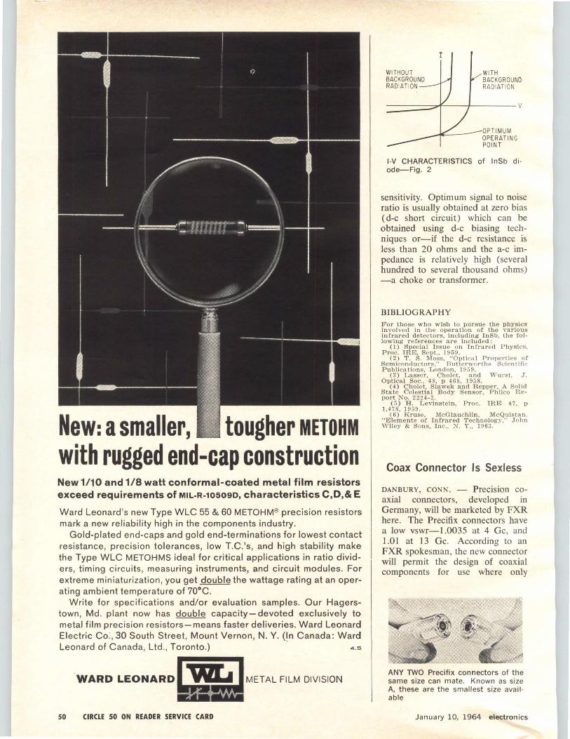
New: a smaller, tougher METOHM with rugged end-cap construction New 1/10and1/8 watt conformal-coated metal film resistors exceed requirements of MIL-R-105090, characteristics C,D,& E
Ward Leonard's new Type WLC 55 & 60 METOHM® precision resistors mark a new reliability high in the components industry.
Gold-plated end-caps and gold end-terminations for lowest contact resistance, precision tolerances, low T.C.'s, and high stability make the Type WLC METOHMS ideal for critical applications in ratio dividers, timing circuits, measuring instruments, and circuit modules. For extreme miniaturization, you get double the wattage rating at an operating ambient temperature of 70°C.
Write for specifications and/or evaluation samples. Our Hagerstown, Md. plant now has double capacity-devoted exclusively to metal film precision resistors-means faster deliveries. Ward Leonard Electric Co:, 30 South Street, Mount Vernon, N. Y. (In Canada: Ward Leonard of Canada, Ltd ., Toronto.) · 4.s
.WARD LEONARD
50 CIRCLE 50 ON READER SERVICE CARD
WITHOUT BACKGROUND RADIATION
r
WITH BACKGROUND RADIATION
OPTIMUM OPERATING POINT
l·V CHARACTERISTICS of lnSb di· ode-Fig. 2
sensitivity. Optimum signal to noise ratio is usually obtained at zero bias ( d-c short circuit) which can be obtained using d-c biasing techniques or-if the d-c resistance is less than 20 ohms and the a-c impedance is relatively high (several hundred to several thousand ohms) -a choke or transformer.
BIBLIOGRAPHY For those who wish to pursue the physics involved in the operation of the various infrared d etectors, including InSb , the fo llowing r e fer en ces are included:
( 1) Spec ial I ssue on Infra r ed Physics, Proc. IRE, Sept., 1959.
(2) T . S. Moss, "Optica l Properties of Semiconductors," Butterworths Sc:ientifk Publications, L ondon, 1959.
(3) Lasser, Cho.J et, and 'Vurst, J. Optical Soc., 4 8, p 4 68, 1958.
(4) Cholet, Slawek a nd Repper, A Solid State Celestial Body Sensor, Philco Report No. 2224-2.
( 5 ) H. Levinstein , Proc. IRE 47, p 1,47 8, 1959.
(6) Kruse, McGlauchlin, McQuistan. "Elements of Infra r ed Technology," J ohn 'Vil ey & Sons, Inc., X Y., 1963.
Coax Connector Is Sexless
DANBURY, CONN. - Precision coaxial connectors, developed in Germany, will be marketed by FXR here. The Precifix connectors have a low vswr-1.0035 at 4 Ge, and 1.01 at 13 Ge. According to an FXR spokesman, the new connector will permit the design of coaxial components for use where only
ANY TWO Precifix connectors of the same size can mate. Known as size A, these are the smallest size avail · able
January 10, 1964 electronics
waveguides were suitable previously.
Development - The Precifix connector was originally developed by Lothar Rohde-one of the partners of Rohde and Schwarz, a European electronics company - to fulfill a need for a good connector for measuring instruments operating at decimeter wavelengths. Thousands of these connectors have been used on Rohde and Schwarz instruments, and sold on the European market.
Mating Geometry-One of the features of the Precifix connector is that the geometrical line of connection is absolutely defined and repeatable. The connector mates at the same point, and always has the same electrical length. Also, the connector is "sexless"; that is, any two connectors can mate, since neither is male or female.
Large Size - Rohde and Schwarz have made large Precifix connectors capable of passing 60 kilowatts at 1 Ge. The devices have been used with six f-m transmitters, each of 10 Kw, feeding a single antenna.
Mass Production-FXR has started tooling up for mass production of both sizes of Precifix connectors. According to Matthew L. Devine, president of Amphenol-Borg, with mass production the connectors can sell for $15 to $20 in 4 uantity lots. This price, combined with high performance, is expected to make the connector useful for many applications in phased array radar systems.
Soviets Cite Improved Material for Cathodes
VIENNA-Soviet researchers found lanthanum boride (LaBG) the best material for cathodes whose emission is excited by an electric field.
Czech Technical Digest (No. 12, 1963) says that work function of LaB6 is 2.68 eV, its resistivity 27.2 X 10⁻⁶ ohm/ cm, its melting point 2,200 deg C.
LaB6 adds a ten-fold improved stability to cathode sputtering as compared with tungsten, report claims. Service life is about 1,000 hours. Best heating range was between 1,200 to 1,700 deg C.
electronics January 10, 1964
Attend ·1:he greatest annual meeting in the electronics industry
from February 7 to 12, 1964
Paris, Porte de Versailles
INTERNATIONAL EXHIBITION
OF
ELECTRONIC
COMPONENTS All components, tubes and semiconductors, measuring and control and electro-acoustic devices •••
for all information and forms:
S.D.S.A. 23 RUE DE LUBECK PARIS 16: (TEL.) PASSY 01 -16
CIRCLE 51 ON READER SERVICE CARD 51

NONMARRING resilient fingers grasp leads between component body and bending points. Rollers approach at a 15 deg angle and roll over lead. Shear and tensile stresses are avoided
Resilient Rollers Form Leads Metal-to-metal contact
avoided, preventing nicks,
scratches and stresses
By F. L. SI MPSON Chief Engineer . Develop·Amatic Engineering Palo Alto, Calif.
LEAD FLATTENING and scarring during forming of axial leads of electronic components usually indicates that tools used for bending exert concentrated pressure at the bend point. Burnishing action can
flatten the component lead and scarring can remove protective plating. High standards set by Department of Defense and the armed forces for the forming of leads are necessary because a scratch or nick cause malfunctions in costly equipment.
A new machine by DevelopAmatic uses nonmarring pads to hold leads gently in place during forming accomplished by roller action of the forming rollers. Both pressure pads and forming rollers are made of resilient material that has high lubricity and high memory. The roller arm approaches the lead wire at 15 degrees from the norm
to further reduce shear forces which can induce a tensile stress on the component body. This method meets rigid MIL specs, raises production output and cuts production costs.
Procedure-In this semiautomatic or fully automatic method, components are loaded into a feed chute on handling cards. The chute is adjustable to receive components 0.09 to 1.0 inch diameter by 1 to 2 inches length. Adjustment for body size of component is accomplished with a small Allen wrench and an adjusting knob. Adjustment of the trimming and forming tools is
CCTV Aids Inspection
CLOSED CIRCUIT TV and a direct image fluoroscope are used for inspection of hermetically sealed resistors. Image is magnified 12 to 15 times by the tv system pro· duced by Packard Bell Electronics, Los Angeles, Calif., and permits processing of 5,000 resistors per hour
also made with a small Allen wrench and adjusting knob.
When the machine is adjusted and the feed chute filled, the shuttles drop one component at a time into the trimming tool. The shuttles are fastened to the chute, one to a fixed member, the other to a movable member, and adjust with the chute. They accept all wire diameters to 0.045 inch, independent of component body size, because shuttles feed from the axial leads.
Solenoids activate the shuttles, which are coordinated with the trimming and bending tools through a cam-operated microswitch. The lead trimming tools are also solenoid operated and are adjustable for any length of cut. As the component is fed into the trimming tools, the axial leads are cut to length with no axial shock transmitted through the lead into the component body.
After trimming, the component is fed into the forming tools where the leads are formed to the desired bend configuration. For the high reliability MIL spec operation, the 90 degree bend is accurate to within 30 minutes of arc. This bend is normally a minimum of 0.125 in. from the body although in some cases it may be reliabily formed closer. It is during this operation that hand forming, or other conventional methods of forming when steel comes in contact with component leads, can cause marring or burnishing that contributes to the malfunction of the electronic component.
Hydrogen Made On-Site
Reduces Heat treating Cost PRODUCTION OF PURE HYDROGEN for the heat treating of magnetic parts is expected to save Magnetics, Inc., Butler Pa. $50,000 a year. A recently installed Drever ammonia dissociator feeds the system with impure hydrogen (75 percent Hand 25 percent N). It is then compressed, heated, and fed to a diffusion cell where the hydrogen is separated. The system is controlled by a gas
electronics January 10, 1964
analyzer manufactured by Hays Corp., Michigan City, Indiana. The remaining gas, a by product, is used as furnace atmosphere.
Vacuum Forming Aids P-C
Part Assembly and Soldering A METHOD OF holding and locating component parts, such as transistors and condensers on printed circuit boards during production that allows automatic soldering and assembly operations, has been developed by Atlas Vac-Machine Corp., Rochester, N. Y. It is used by several leading manufacturers of radios, television and military electronics, the company reports.
Procedure-A small templet is placed on the forming bed of an Atlas Vac Model R-12 , self-contained portable, up-drape vacuum forming machine. Smaller than the printed circuit board, templet keeps it raised approximately 1/s inch above the bed. A clear sheet of 0.005 gauge acetate is fed into the forming clamp of the machine and closed. The heater is drawn over the film until it becomes thoroughly softened and the forming bed is raised into the plastic sheet. The vacuum is drawn under the printed board to form the film around the board and components. After cooling, the encased printed circuit board is removed and may be trimmed.
Your Only Source Worthy Of The Name •••
LATING of
CRITICAL ELECTRONIC
COMPONENTS ••. DEMANDING:
e Purity of deposit e Completeness of coverage e Close tolerances • Tight quality controls • Rigid inspections
Our experienced staff specialize;; in hi~h reliability, heat resistant plating with Gold Silver, Rhodium and other pre· ciou~ metals. Prices on specific appli· cations submitted promptly. Deliveries of completed assignments are on time, too. Write, wire or phone:
PRECIOUS METAL PLATING DIVISION OF CHEMICAL PLATING COMPANY 120 Bruce Avenue, Stratford, Connecticut Phone: EOison 7-3376 TWX, 203·337-971 3
CIRCLE 53 ON READER SERVICE CARD 53
------
54
A MESSAGE TO AMERICAN INDUSTRY ONE OF A SERIES
Business Aid To Education: Let's Broaden The ·ease
The total amount of financial support that American business corporations are giving to our colleges and universities is increasing rather impressively. But the number of companies contributing to this expansion is woefully small. If business support of higher education is to attain the proportions it clearly should attain, there must he a large increase in the number of companies participating - and soon.
The Council for Financial Aid to Education estimates that business firms contributed about $200 million to education last year. This was up from a total of about $178 million in 1960; and preliminary indications are that business-giving will exceed $200 million this year. As a total, this is a relatively impressive figure. It becomes more impressive when viewed against the fact that it will be about two and one half times as much as business firms were giving to education ten years ago.
A Flaw In The Picture But there is a grave flaw in this picture
of business-giving to higher education. The giving is concentrated in relatively few business fiTms that provide large sums, while hundreds of thousands of firms do little or nothing at all. Of the $200 million contributed to education by business in 1962, the Council for Financial Aid to Education found that about $70 million, or more than a third of the total, came from only 150 companies, each of which contributed more than $100,000. In fact, increased giving by large corporate contributors accounted for most of the total increase in corporate giving between 1960 and 1962.
There are no figures comprehensive enough to determine precisely how many business firm s contribute to the support of higher education in the United States. But studies indicate that virtually all of this aid comes from less than one per cent of U.S. business establishments.
January 10, 1964 electronfcs
Unused Capacity For Business Giving
At the present time, there are more than four and three quarters million business establishments in the U.S. A great many of them, of course, are one-man establishments which are not able to help higher education financially. But there are tens of thousands of others which have unused capacity to help.
Inquiries by the Council for Financial Aid to Education indicate that almost half of the nation's 500 largest industrial corporations have no programs to help our colleges and universities financially. With combined profits after taxes of almost $2 billion in 1961, these firms represent an imposing, untapped potential for help. And so do tens of thousands of smaller companies. Their gifts would be smaller, but their numbers would compensate for necessarily smaller amounts by coming in much larger numbers.
The Council for Financial Aid to Education has set a goal of $500 million for annual corporate aid to our colleges and universities by 1970. Very conservatively estimated, the total expenditure for higher education at that time promises to be $9 billion to $11 billion a year. This makes $500 million a relatively modest share in the support of educational operations so vital to the welfare of the nation and the business community.
Needed-A Much Broader Base
But if this goal is to be reached, the base of corporate support must be broadened. This means more and more effective work by the colleges and universities in seeking support from smaller companies. It means more readiness by more firms to listen with understanding and sympathy, and then to use their capacity to give financial support accordingly.
Viewed narrowly, it is in the selfish interest of business firms to help our colleges and universities financially. By doing so, they give essential
electronics January 10, 1964
support to basic research, centered in the universities, upon which the business system depends heavily for the opening of new scientific frontiers. Financial support for higher education also helps to insure a continuing supply of well trained graduates which business firms must have to insure their own continuing success.
By making it tax exempt, the federal government, in effect, assumes half of the cost of financial aid for higher education by business. But this fiscal fact does not detract from both gratitude and respect which business firms can win for themselves by providing such aid. And in the last analysis, if financial aid is not provided voluntarily, it can confidently be expected that business will ultimately provide much of it involuntarily, through taxation.
Viewed in terms of the broad public interest, the business community has an opportunity to play a key role in providing our colleges and universities with the financial strength essential to assurance of their successful development which, in turn, is basic to the success of the nation.
There are few, if any, financial operations that can pay larger returns in advancing the national interest, as well as the more im1nediate interest of the business community, than that of seeing our colleges and universities receive steadily increasing financial support from more and more business firms.
T his message was prepared by my staff asso· ciates as part of our company-wide effort to report on major new developments in American business and industry. Permission is freely extended to newspapers, groups or individuals to quote or reprint all or part of the text.
PRESIDENT
McGRAW- H i ll , INC .
55
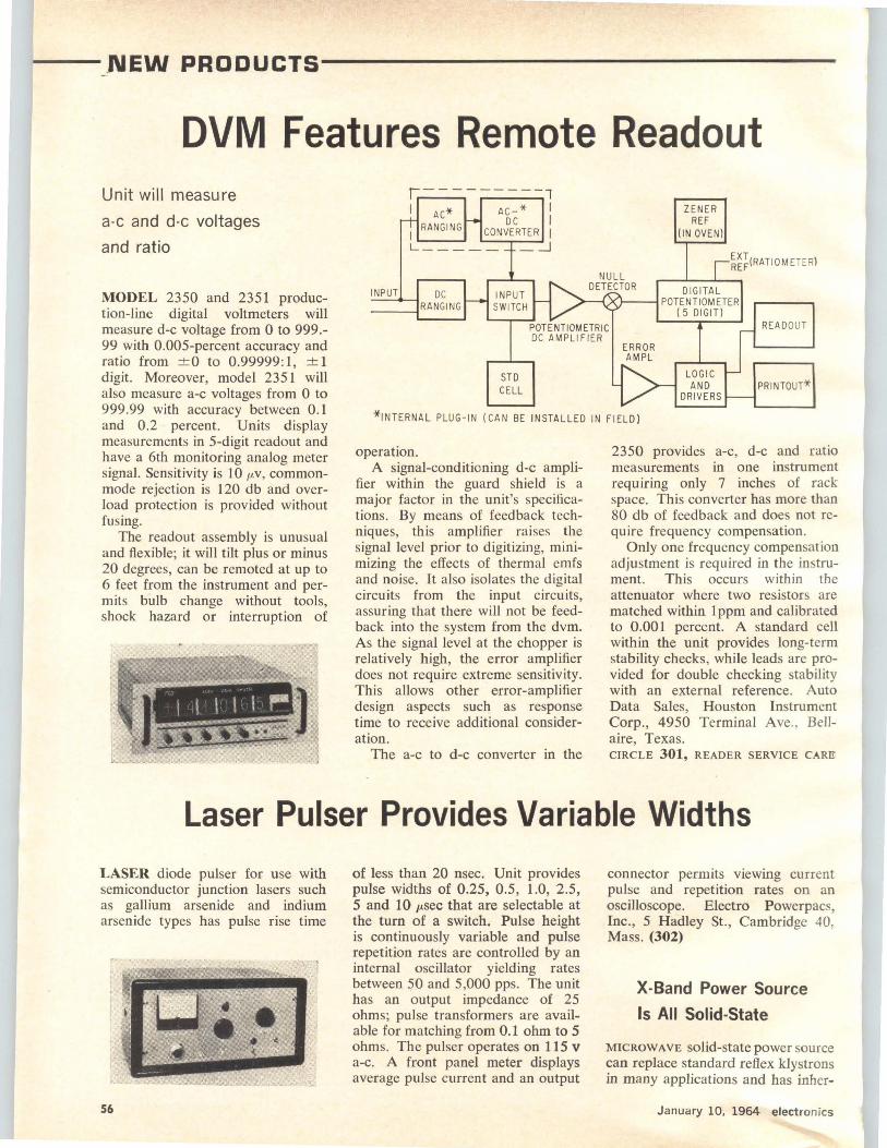
- - _NEW PRODUCTS----------------
DVM Features Remote Readout Unit will measure
a-c and d-c voltages
and ratio
MODEL 2350 and 2351 production-line digital voltmeters will measure d-c voltage from 0 to 999.-99 with 0.005-percent accuracy and ratio from ±0 to 0.99999:1, ±1 digit. Moreover, model 2351 will also measure a-c voltages from 0 to 999.99 with accuracy between 0.1 and 0.2 percent. Units display measurements in 5-digit readout and have a 6th monitoring analog meter signal. Sensitivity is 10 µv, commonmode rejection is 120 db and overload protection is provided without fusing.
The readout assembly is unusual and flexible; it will tilt plus or minus 20 degrees, can be remoted at up to 6 feet from the instrument and permits bulb change without tools, shock hazard or interruption of
r.---------1 I AC* AC-* I
DC I I RANGING CONVERTER I L ______ :=J
ZENER REF
(IN OVEN)
~~~(RATIO METER)
INPUT DC
----!RANGING INPUT SWITCH
DIGITAL ·~.~-~POTENTIOMETER
ST D CELL
POTENTIOMETRIC DC AMPLIF IER
ERROR AMPL
( 5 DIGIT)
LOGIC AND
DRIVERS
READOUT
PRINTOUT*
*INTERNAL PLUG-IN (CAN BE INSTALLED IN FIELD)
operation. A signal-conditioning d-c ampli
fier within the guard shield is a major factor in the unit's specifications. By means of feedback techniques, this amplifier raises the signal level prior to digitizing, minimizing the effects of thermal emfs and noise. lt also isolates the digital circuits from the input circuits, assuring that there will not be feedback into the system from the dvm. As the signal level at the chopper is relatively high, the error amplifier does not require extreme sensitivity. This allows other error-amplifier design aspects such as response time to receive additional consideration.
The a-c to d-c converter in the
2350 provides a-c, d-c and ratio measurements in one instrument requiring only 7 inches of rack space. This converter has more than 80 db of feedback and does not require frequency compensation.
Only one frequency compensation adjustment is required in the instrument. This occurs within the attenuator where two resistors are matched within 1 ppm and calibrated to 0.001 percent. A standard cell within the unit provides long-term stability checks, while leads are provided for double checking stability with an external reference. Auto Data Sales, Houston Instrument Corp., 4950 Terminal Ave. , Bellaire, Texas. CIRCLE 301, READER SERVICE CARE
Laser Pulser Provides Variable Widths
LASER diode pulser for use with semiconductor junction lasers such as gallium arsenide and indium arsenide types has pulse rise time
56
of less than 20 nsec. Unit provides pulse widths of 0.25, 0.5 , 1.0, 2.5, 5 and 10 µ.sec that are selectable at the turn of a switch. Pulse height is continuously variable and pulse repetition rates are controlled by an internal oscillator yielding rates between 50 and 5,000 pps. The unit has an output impedance of 25 ohms; pulse transformers are available for matching from 0.1 ohm to 5 ohms. The pulser operates on 115 v a-c. A front panel meter displays average pulse current and an output
connector permits viewing current pulse and repetition rates on an oscilloscope. Electro Powerpacs, Inc., 5 Hadley St., Cambridge 40, Mass. (302)
X-Band Power Source
Is All Solid-State
MICROWAVE solid-state power source can replace standard reflex klystrons in many applications and has inher-
January 10, 1964 electronics
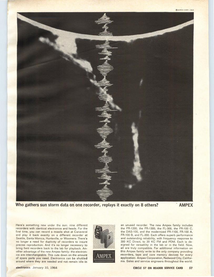
@A MPEX CO RP . 1963
Who gathers sun storm data on- one recorder, replays it exactly on 8 others? ' AMPEX
Here's something new under the sun ; nine different recorders with identical electronics and heads. For the first time, you can record a missile shot at Canaveral and play it back exactly on a different recorder at Seattle, Santa Monica, Huntsville, or Woomera. There's no longer a need for duplicity of recorders to insure precise reproduction. And it's no longer necessary to bring field recorders back to the lab for playback. Another advantage of the new Ampex family: the electronics are interchangeable. This cuts down on the amount of spare parts you need. Electronics can be shuttled around where they are needed and not remain idle in
electronics January 10, 1964
an unused recorder. The new Ampex family includes the FR-1200, the FR-1300, the FL-300, the FR-100 C, the DAS-100, and the modernized FR-1100, FR-100 A. FR-100 B, and FL-200. Each offers superb performance and outstanding reliability, with frequency response to 300 KC Direct, to 20 KC FM and PDM. Each is designed for versatility in the Jab or in the field. Now, all are truly compatible. For additional information on this Ampex family write to the only company providing recorders, tape and core memory devices for every application : Ampex Corporation, Redwood City, California. Sales and service engineers throughout the world.
CIRCLE 57 ON READER SERVICE CARD 57

ent advantages over vacuum tubes such as no warm-up time, low power requirements, wide operating temperature range, low noise and extended life. Units are simple to apply, ruggedly constructed and reportedly more stable than their conventional counterparts.
Model VPS-X has an easily mounted, metal case that provides protection as well as heat sinking for internal components. A crystalgenerated fundamental frequency assures extreme stability. The device uses only a single, unregulated d-c power source and eliminates multivoltage supplies.
Model VPS-X provides 120 mw of c-w output power, has stability within ± 1 db between 8.6 and 10.6
Ge, has bandwidth of 1 % and shortterm frequency stability of 1 part in 106 • It requires 45 v d-c at 450 ma. Varian Associates, Solid State Products, Beverly, Mass. CIRCLE 303, READER SERVICE CARD
Resistors Withstand
Heavy Duty
A HEAVY-DUTY heat-sink type resistor is available with the resistance winding embedded in a high grade potting compound in a steel casing with "L" bracket mounting. Origi-
nally developed as a ballast resistor for solid-state ignition circuits, it can be used in other resistor applications especially where severe duty is required or where one or more re-
sistors are desired in one case. Quick-connect terminals, standard tabs, or studs can be furnished. Sizes are 25 watts and up. Milwaukee Resistor Co. , 700 W. Virginia St., Milwaukee, Wisc. 53204 (304)
SSB Multiplex
Provides 12 Channels
SOLID-STATE, single sideband multiplex modules provide 12 direct channels in the 64 kc to 108 kc range. Featuring all-transistor modular design, units afford unusual design simplicity at lower cost.
Silicon transistors are used throughout each module as are
at the
NEW YORK COLISEUM
all 4 floors!
e ELECTRONICS EXHIBITS
e CONVENTION PAPERS
See the finest products of industry, hear famous men speak! Just one entrance
fee lets you visit both sections.
Buses to the N. Y. Hilton every few minutes
January 10, 1964 electronics
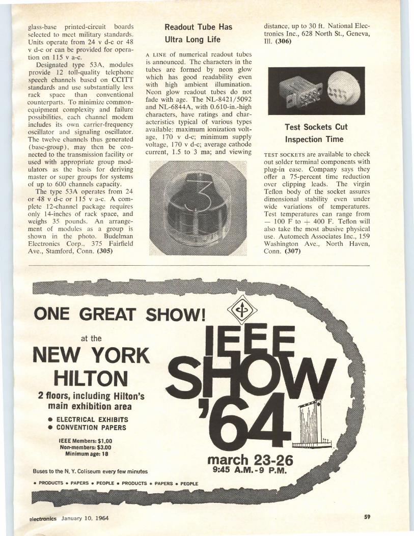
glass-base printed-circuit boards selected to meet military standards. Units operate from 24 v d-c or 48 v d-c or can be provided fo r operation on 115 v a-c.
Designated type 53A, modules provide 12 toll-quality telephone speech channels based on CCITT standards and use substantially less rack space than conventional counterparts. To minimize commonequipment complexity and failure possibilities, each channel modem includes its own carrier-frequency oscillator and signaling oscillator. The twelve channels thus generated (base-group), may then be connected to the transmission facility or used with appropriate group modulators as the basis for deriving master or super groups for systems of up to 600 channels capacity.
The type 53A operates from 24 or 48 v d-c or 115 v a-c. A complete 12-channcl package requires only 14-inches of rack space, and weighs 35 pounds . An arrangement of modules as a group is shown in the photo. Budelman Electronics Corp ., 375 Fairfield Ave., Stamford, Conn. (305)
at the
Readout Tube Has
Ultra Long Life
A LINE of numerical readout tubes is announced. The characters in the tubes are formed by neon glow which has good readability even with high ambient illumination. Neon glow readout tubes do not fade with age. The NL-8421/5092 and NL-6844A, with 0.61 0-in.-high characters, have ratings and characteristics typical of various types available: maximum ionization voltage, 170 v d-c; minimum supply voltage, 170 v d-c; average cathode current, 1.5 to 3 ma; and viewing
NEW YORK HILTON
2 floors, including Hilton's main exhibition area e ELECTRICAL EXHIBITS e CONVENTION PAPERS
IEEE Members: $1.00 Non-members: $3.00
Minimum age: 18
Buses to the N. Y. Coliseum every few minutes
electronics January 10, 1964
distance, up to 30 ft. National Electronics Inc., 628 North St., Geneva, Ill. (306)
Test Sockets Cut
Inspection Time
TEST SOCKETS are available to check out solder terminal components with plug-in ease . Company says they offer a 75-percent time reduction over clipping leads. The virgin Teflon body of the socket assures dimensional stability even under wide variations of temperatures. Test temperatures can range from - 100 F to + 400 F. Teflon will also take the most abusive physical use. Automech Associates Inc., 159 Washington Ave., North Haven, Conn. (307)
59
*Resistivity 8.0 n/cmf Temperature Coefficient of Resistance .00065
SIHCr,rm Tensile Strength 160,000 psi
LR Potentlori1eter Wire Brochure sent on request,
Sl~MUND COHN · Corp. 121 So. Columbus Avenue,· Mount Vernon, N. Y.
SIGMUND COHN CORP. OF CALIFORNIA, 151 c·. NORTH MAPLE STR,, BURBANK, CAL.
amp lex E-Z-GLIDE
LAMPS ••• with 1001 uses! 15·way better performance from lamps ideal for desk, work table or inspection area use. Write for free catalog.
tefl - Amp lex Combo·lites - Incandescent and incandescent-fluorescent models (as illustrate~) with universal brackets; gray, tan or white. Right-Amplex Magnifying Lamps-E·Z·Glide design with 3·diopter polished glass lens· 5 diopter lens available. Universal base~ gray, tan or white.
AP•136
~ amplex corporation ~ Glen Cove Rd., Carle Place, LI., N.Y.
CIRCLE 202 ON READER SERVICE CARD
How To Get Things Done Better And Faster
BOARDMASTER VISUAL CONTROL "{::( Gives Graphic Picture-Saves Time, Saves
Money, Prevents Errors "{::( Simple to operate-Type or Write on
Cords, Snap in Grooves "{::( Ideal for Production, Traffic, Inventory
Scheduling, Sales, Etc. "{::( Made of Metal. Compact and Attractive.
Over 750,000 in Use
Full price $4 gso with cards
f"CD"C'Cl24-PAGE BOOKLET NO. C-40
~ Without Obligation
Write for Your Copy Today
GRAPHIC SYSTEMS YANCEYVILLE, NORTH CAROLINA
CIRCLE 203 ON READER SERVICE CARD 60 CIRCLE 60 ON READER SERVICE CARD
--LITERATURE
PERMANENT MAGNETS Indiana General, Magnet Division, Valparaiso, Ind. Six-page bulletin 40 is entitled "Applying Indox Permanent Magnets to D-C Motors."
CIRCLE 360, READER SERVICE CARD
PRECISION RESISTANCE DECADES Shallcross Mfg. Co., Selma, N. C. Catalog RD550 supplies complete specifications for over 17 5 standard resistance decade models. (361)
A-M DETECTORS Spectran Electronics Corp., 146 Main St., Maynard, Mass. Circuits and components for a-m detectors capable of high dynamic range are described in a four-page application note and transformer catalog. (362)
FREQUENCY DISCRIMINATOR Helipot Division of Beckman Instruments, Inc., 2500 Harbor Blvd., Fullerton, Calif. Data sheet describes model 790 Hallefex frequency discriminator. (363)
PULSE TRANSFORMERS Gudeman Co. of California, Inc., 7473 Avenue 304, Visalia, Calif. Bulletin GB6340 covers a series of molded miniature pulse transformers. (364)
INSULATING MATERIALS 3M Company, 2501 Hudson Rd., St. Paul 19, Minn. Technical information on compatible basic insulating materials has been assembled for handy engineering reference. (365)
ULTRASONIC CLEANING SYSTEMS Westinghouse Electric Corp., P. 0. Box 868, Pittsburgh, Pa. 15230. A 4-page bulletin describing ultrasonic cleaning systems, generators, transducers, and tanks, is available. (366)
SWITCHES Micro Switch, a division of Honeywell, Freeport, Ill. Catalog 67e has been expanded to include the round as well as rectangular designs in the series 2 line of lighted display and pushbutton switch devices. (367)
INSTRUMENT HOUSINGS Zero Mfg. Co., 1121 Chestnut St., Burbank, Calif. Catalog C63 describes a standard line of deep-drawn aluminum instrument housings in 12 sizes. (368)
POWER SUPPLIES Sorensen, a unit of Raytheon, Richards Ave., South Norwalk, Conn. Operating techniques and special uses of the new DCP. constant current power supplies are discussed in an applications bulletin. (369)
LABORATORY SUPPLY Electronic Research Associates, Inc. , 67 Factory Place, Cedar Grove, N . J., has published a technical bulletin covering type TR040 wide-range, low-cost laboratory supply. (370)
SOLID-STATE RELAYS Tri-State Elec-tronics, Inc., 2734 Lee Highway, Falls Church, Va., offers two bulletins describing its polar solid-state and neutral solid-state electronic relays. (371)
TEST THERMOMETERS Atkins Technical, Inc. , P. 0. Box 14405, University Station, Gainesville, Fl a. A series of data sheets describes a line of general purpose test thermometers. (372)
January 10, 1964 electronics

OF THE WEEK-
PRECISION POTENTIOMETERS Polara Corp., 55 Milbar Blvd., Farmingdale, N. Y. A product bulletin describes the SM- I 8 precision slidewire potentiometers for servo applications. (373)
R-F COAXIAL CONNECTORS Applied Engineering Products Co., 375 Fairfield Ave. , Stamford, Conn., 06904. Catalog No. 164 describes a line of subminiature coaxial r-f connectors. (374)
MINIATURE PRECISION CONNECTORS Connector Division, Waltham Precision Instrument Co., Inc., 285 White St., Danbury, Conn., 06813. Catalog 1163 describes Gorn miniature precision connectors. (375)
D-C VOLT/ AMMETER Ballantine Labo-ratories, Boonton, N.J., has available a technical bulletin describing model 365 d-c volt/ammeter. (376)
TRANSIENT VOLTAGE DETECTOR Regent Controls Inc., Harvard Ave., Stamford, Conn. Bulletin I 03TD describes model TD763 automatic transient voltage detector. (3 77)
CRYSTAL-CAN RELAY General Electric Co., Schenectady 5, N. Y. Bulletin GEA-7650 describes type AV half-size crystal-can relay. (378)
L-F NOISE GENERA TOR Elgenco, Inc., 1231 Colorado Ave., Santa Monica, Calif. Bulletin EI-321A discusses a lowfrequency noise generator featuring solid-state chopper and highly regulated rms level. (379)
ANALYTICAL POLISHING DISKS Geoscience Instruments Corp., 110 Beekman St., New York, N. Y. 10038, offers a technical report, "Polishing Semiconductors and Electronic Materials." (380)
TIN-LEAD RATIO CHART Alpha Metals, Inc., 56 Water St., Jersey City 4, N. J., has available a simplified tin-lead ratio chart to assist in solder selection. (381)
TRIMMER POTENTIOMETERS MINELCO, Miniature Electronic Components Corp., 600 South St., Holbrook, Mass., offers a bulletin describing type HR, highly reliable microminiature trimmer potentiometers. (382)
COAXIAL CONNECTORS Micom Electronics, Inc., Zeckendorf Blvd., Garden City, N. Y., offers its 50-page catalog 103 describing several lines of coaxial connectors. (383)
TRANSISTOR CIRCUITS Sylvania Electric Products Inc., 1100 Main St., Buffalo, N.Y. , 14209, offers a brochure containing eight typical circuits for its npn germanium alloy transistors. (384)
R-F SHIELDING Nova Industries, Inc., 699 Castro St., San Leandro, Calif. A 4-page brochure describing the latest concept in radio-frequency shielding is now available. (385)
DATA TRANSMISSION SYSTEM Lenkurt Electric Co., Inc., 1105 County Road, San Carlos, Calif., has issued a pamphlet on the 25A data transmission system, which provides 200-bits-per-sec data transmission for virtually any intermediate-speed application. (386)
electronics January 10, 1964
SPACE NAVIGATION SYSTEMS ENGINEERS:
HELP ADVANCE THE ART
OF GOING FROM HERE
TO ••• e~Engineers, Physicists, and Mathematicians who can substantially contribute to our sophisticated Space Guidance and control capabilities are urged to consider career growth opportunities with Honeywell in Florida. We are actively engaged in creating airborne and spaceborne navigation systems for such programs as X-20A, Centaur, Gemini and many others of greater complexity. If you are a graduate engineer with experience and talent in one or more of the following areas, we would like to hear from you at once:
SYSTEMS ENGINEERING Operations Analysis, Systems Analysis and Systems Design and Integration for Inertial Systems, Weapons Systems and Star Trackers.
COMPUTER SYSTEMS Systems Analyst and Design, Circuit, Logic and Memory Design and Airborne Computer Programming.
We offer the inquisitive, imaginative scientist the growth and responsibility which comes only from working with an aggressive, engineering-oriented organization. Remember, too, our steady expansion constantly opens up rewarding professional opportunities AT EVERY LEVEL OF EXPERIENCE.
QUALIFIED APPLICANTS ARE INVITED TO VISIT our facilities, meet our people and discover for themselves the many added advantages of working and living here on Florida's Suncoast. Simply send a brief note describing your education, experience and specific job interest to M. F. Keese, Honeywell, 13350 U. S. Highway 19, St. Petersburg, Florida. We promise a prompt, confidential reply.
~~.~~~~¥····~·~Q Honeywell facilities, send resume to F. F. Laing, · Honeywell, Minneapolis 8, Minnesota,
61

--PEOPLE AND PLANTS--------------
Burroughs Combines Two Divisions BURROUGHS CORPORATION, Detroit, Mich., as part of an overall company realignment, has announced consolidation of two divisions which manufacture electronic components used in its systems and sold commercially.
The Electronic Instrument division in Philadelphia and the Electronic Components division, Plainfield , N. J., are being combined and called the Electronic Components division. It will occupy facilities in Plainfield.
The changes will be gradual , continuing until the Fall of this year. Construction of a 75,000-square foot addition to the present building at Plainfield will start in the Spring.
Saul Kuchinsky, who has been general manager of the Electronic Components division, becomes general manager of the combined operation.
Jacob J. Mayer, formerly general manager of the Electronic Instrument division, is named manager of manufacturing at Plainfield.
Each of the units involved in the new Electronic Components division employs about 400. When consolidation is completed, there will be more than 800 employed. Total Burroughs employment is about 25,000 in the U. S. and 36,000 world-wide.
S. KUCHINSKV
Dolan Accepts
New Position
PAUL R. DOLAN has been named president of Micro Systems, Inc., a Pasadena subsidiary of ElectroOptical Systems, Inc. He succeeds William V. Wright, Jr. , who has returned to the parent company as a corporate vice president.
Dolan was formerly president of Pioneer Mfg. Co., Los Angeles. At MSI, he will be responsible for all management activities including manufacturing and marketing. MSI is a producer of pressure and temp-
J, J, MAYER
erature transducers, sensors, strain gages and electronic support equipment.
GI Appoints
Two Executives
Two major appointments in the General Instrument Capacitor division have been announced by M. H. Benedek, GI board chairman :
Aniello A. DiGiacomo has been promoted to the post of vice president, R&D, of the Capacitor divi-
GE Realigns Industrial and International Groups
62
GENERAL ELECTRIC COMPANY president and chief executive officer Fred J. Borch has announced changes in the company's organizational structure "designed to align the company more closely with the markets which it serves."
The Industrial Group, under Hershner Cross as vice president and group executive, adds three divisions: • Supply Company division (Bridgeport, Conn., Reginald H. Jones, vice president & general manager) • Electronic Components division (Owensboro, Ky., L. Berkley Davis, vice president & general manager), formerly a part of the
Aerospace and Defense Group • Construction Industries division (Bridgeport, Conn., also headed by Jones) newly set up.
In other changes within the Industrial Group, the Industrial Sales Operation (Schenectady, N. Y., S. Wellford Corbin , vice president & general manager) becomes the Industrial Sales division; the Capacitor Department (Hudson Falls, N. Y.) is transferred from the Transformer division to the Electronic Components division; and the Industrial Heating Department is assigned to the Component Products divi· sion (Fort Wayne, Ind., Harold A. MacKinnon, vice president & gen·
eral manager) . Changes within the lnterna·
tional Group are as follows: Under vice president and group executive James H. Goss, the International Group will consist of four divisions-the IGE Export Division (formerly the International General Electric Company division, Wlliam C. Wichman, v ice president and general manager), and three new Area Divisions to be known as the Area DivisionEurope (Goss, acting general manager), Area Division-Far East (Wichman, acting general manager), and Area DivisionLatin America R. E. Whitmyer, general manager) .
January 10, 1964 electronics
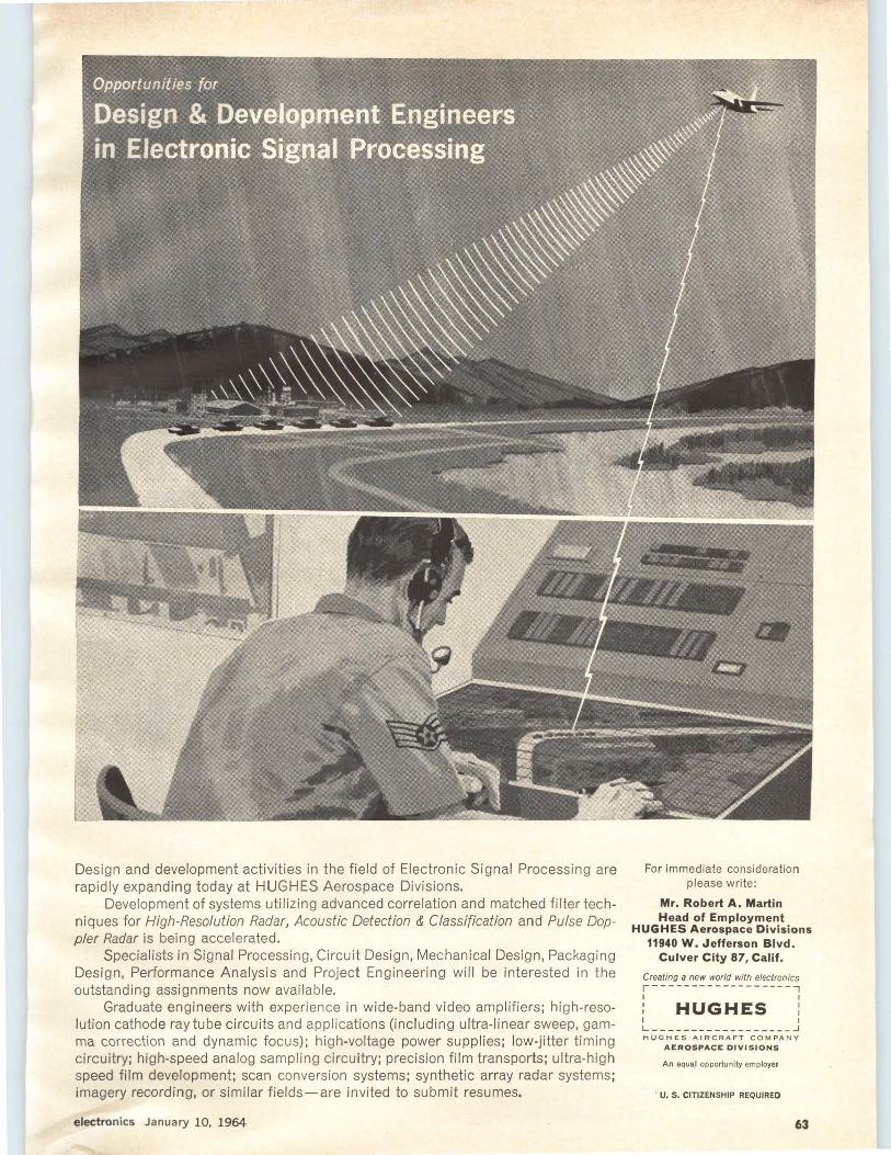
Design and development activities in the field of Electronic Signal Processing are rapidly expanding today at HUGHES Aerospace Divisions.
Development of systems utilizing advanced correlation and matched filter techniques for High-Resolution Radar, Acoustic Detection & Classification and Pulse Doppler Radar is being accelerated.
Specialists in Signal Processing, Circuit Design, Mechanical Design, Packaging Design, Performance Analysis and Project Engineering will be interested in the outstanding assignments now available.
Graduate engineers with experience in wide-band video amplifiers; high-resolution cathode ray tube circuits and applications (including ultra-linear sweep, gamma correction and dynamic focus); high-voltage power supplies; low-jitter timing circuitry; high-speed analog sampling circuitry; precision film transports; ultra-high speed film development; scan conversion systems; synthetic array radar systems; imagery recording, or similar fields-are invited to submit resumes.
electronics January 10, 1964
For immediate consideration please write:
Mr. Robert A. Martin Head of Employment
HUGHES Aerospace Divisions 11940 W. Jefferson Blvd.
Culver City 87, Calif.
Creating a new world with electronics r------------------, I I
: HUGHES : I I
L------------------~ HUGHES AIRCRAFT COMPANY
AEROSPACE DIVISIONS
An equal opportunity employer
U. S. CITIZENSHIP REQUIRED
63

Just Published RADIO RAY
PROPAGATION IN THE IONOSPHERE
Provid~s an intr~duction to geometri~al optics of radio propagation in the ionospbere. Specinl attention is given to tbe determination of electron denslt;v dist~ibution, ray paths in an anisotr!Jpic med.ium, and tbe principal axis eq uations for ionosphe ric propagation. Much material on whistler propagation is included. CovPrs such topics as: pb_,·sics of the ionosphere,. properties of the ionospherP, derivation of the basic equations e_ft'ects of a distorted ionosphere, non'. lrneur properties, rocket and sate llite problems, aspects of the ,·eloci ty of propagation, etc. By J. M. Uelso, Electro-Physics Laboratories, ACF. 475 pp., illus., $17.50
NONLINEAR MATHEMATICS Just Out. Shows how to construct so . lutlons of nonlinear p_robl?ms, b~~ by direct and approxuuat10n me . ods Deals with such topics as ~onJlne~r transformations, inequallt~es and programming, stability pertur atlon methods, control theory' etc. By
t George \Vashlngton T. L. Saa y, f Naval Univ. & J. Bram, Center or Anal. 384 pp., mus., $12.50
INERTIAL NAVIGATION SYSTEMS Just Out. Concisely describes the components of Inertial navigati on systems, possible ways of Interconnecting these components, and methods for predicting the behavio r of resultant systems. Includes suffic ient material for full theoretical performance evaluation of any inertial navigation system. By C. Broxmeyer llf.I.T. 270 pp., Illus •• $13.50 '
COLOR TELEVISION FUNDAMENTALS Just Out-2nd Ed. Covers basic principles of color television, operation of colo r r eceivers, and fundamentals of installation and servicing. Includes discussion of color t heory, FCC-approved color system, modern circuits and compone~1ts. an_d typical commercia l receivers, rncludrng alignment procedures. By !If. S. ){Iver. 2nd Ed., 320 pp., illus., $10.95
• 10 DAYS' FREE EXAMINATION ~ DIRECT FROM PUBLISHER II
McGraw-Hill Book Co., Dept. L-1-10 .mi 327 W. 41st St., New York, N. Y. 10036 ~
Send me book(s) checked below for 10 days' examination on approval. In LO days I will remit for book(s) I keep, plus fmv cents for delivery costs, and return unwanted book(s) Postpaid. err you remit with coupon. plus loca·l tax, we pay delivery costs-full refund and return privilege.) 0 Kelso-Radio Ray Prop. in the Ionosphere,
$17.50 D Saa.ty & Bram-Nonlin ear Math .. $12.50 O Rroxmeyer-lnertial Navioation Sys., $13.50 D Ki\'er- Color Television Fund ., $10.95
Name
Address .....• , ......... . Zip
City .............. . State .. ... .... Code . . .. . • ..
Company . ......•....... .. .............. . ...•• ••
Position ............. . . ..... .... ........... .. . . . For price and terms outside U.S. write McGraw-Hill lnt'I.. N. Y. 10036 L-1-10
~--------------------------64
sion. He will make his headquarters at General Instrument's Applied Research Laboratory at Newark, N. J. DiGiacomo was formerly vice president, engineering, of the division.
Archie Broodo has joined General Instrument as vice president, engineering, of the Capacitor division and will make his headquarters at the company's plant at Darlington, S. C. Broodo was previously manager of solid electrolyte tantalum capacitor engineering for General Electric Co. at Irmo, S. C.
Telonic Industries
Appoints Luksch
TELONlC INDUSTRIES, INC., Beech Grove, Ind., has appointed James A. Luksch to the post of director of engineering.
Luksch was formerly associated with Radio Corporation of America at the firm's Missile and Surface Radar facility in Moorestown, N. J.
Telonic, with plants in suburban
Indianapolis and Laguna Beach, Calif., manufactures electronic sweep generators, attenuators and allied equipment for use in testing r-f and microwave components and systems.
IBM Advances
Oldfield
BRUCE G. OLDFIELD has been appointed vice president, space programs and field operations, in the IBM Federal Systems division, Rockville, Md. His former position
Budd Electronics Names Two V-P's
R. 0. VOIGHT
ROBERT 0. VOIGHT has been appointed vice president-technical operations of The Budd Company's Electronics division. He was formerly director of the division's advanced development and planning center in Arlington, Va.
Frederick P. Pro was named vice president of marketing and contracts. He joined the division in
F. P.PRO
1958 as manager of contracts. The Electronics division has just
completed a new Research Center in McLean, Va., where advanced studies are being conducted in data processing, display, optics, and communications.
The division also has plants and offices in Arlington, Va., New Jersey and New York.
January 10, 1964 electronics
GRCtiny parts ~~) ~ die cast ZINC ALLOY
~~~ tV molded PLASTICS
~~ @ Jl
~ ~ ~
Coil Bobbins Gears & Pinions
Get GRC's fact filled brochures. GRC's methods give you quality and accuracy in small parts of die cast zinc alloy, Nylon, Delrin, other engineering thermoplastics. Exclusive automatic single cavity, techniques allow new designs, new production and assembly shortcuts. Write, wire, phone for samples and bulletins . Send prints for quotations.
GRIES REPRODUCER CORP •. MIMllldll-woricr a ForemoBt Producer of Small Die Castings
151 Beechwood Ave., New Rochelle, New York Phone (914) NEw Rochelle 3-8600
CIRCLE 204 ON READER SERVICE CARD
WAllT 1000 BUllllEll WITH THE SOllERlllfEllT ??????????? . . . . . . . . . . .
Then check the Military and Government Procurement Guide in the orange section of your ELECTRONICS B UYERS'
GUIDE.
ll//llllllll//llllll ·· ····· ·•· ······ ····
electronics January 10, 1964
was general manager of the FSD Washington Systems Center in Bethesda, Md.
The Federal Systems division is developing a number of advanced information systems projects. These range from guidance computers for Saturn launch vehicles to the computing complex now being installed near Houston, Texas, for ground monitoring of Project Gemini and Project Apollo flights.
PEOPLE IN BRIEF
Don B. Hamister and Chester J. Kawiecki promoted to g-m and asst. g-m, respectively, of Joslyn Electronic Systems div. of Joslyn Mfg. and Supply Co. Ernest W. Swift moves up to exec v-p of Wilbur B. Driver Co. George Eisler, former president of Eisler Associates, appointed director, advanced planning and design, for Scientific Data Systems. Elliot Ring advances at Martin Co. to director of design and development in the Orlando div. Thomas J. R ichardson, ex-Assembly Products, Inc., named asst. g-m of WacLine Meters. Roger S. Hewett leaves Honeywell to join the Industrial Controls div. of General Precision, Inc. 's Simulation & Controls Group as director of engineering. Arthur S. Rosenthal, previously with Teleregister Corp., now mgr.-systems and data processing at the Norden div_ of United Aircraft Corp. Howard D. Tindall, from H. K. Porter Co. to International Rectifier Corp. as product mgr. for high voltage stacks. Burnett G. Anderson raised to mgr., special programs, RCA Electronic Data Processing. Kennard H. Morganstern, former associate professor of E. E. at Purdue, appointed director of research at Radiation Dynamics, Inc. Howard C. Johnson advances to v-p, Pacific Sales div. of The Thomas & Betts Co. Robert M. Scarlett promoted to director, Shockley Research Laboratories. Conrad J . Rauch, ex-MIT Lincoln Laboratory, joins Cryonetics Corp. as mgr. of solid state physics research.
FLUKE MIGH VOLTAGE POWER
SUPPLIES OFFER COMPLETE
COVERAGE TO 30 KV
-AND ALL SEVEN MODELS PROVIDE
LONG TERM STABILITY AT COMPETITIVE PRICES
For CATALOG DI GES T: Write JOH N FLUKE MFG. CO., INC., Box 7428, Seattle, Wash. 98133
IFLUKEI
CIRCLE 205 ON READER SERVICE CARD
Gentlemen:
TYPIT ® is
type any tee foreign or
numerical symb Jl -- easy as TT.
Over 1,000 symb ls like f-1, ~. 0,
0, I:, ~, ~t, "" t.<. choose from. A
TYPIT ® is
inexpen-
TYPE ANY SYMBOL perfectly in 4 seconds
write toda y for free cata log --------T YPIT ® manufactured by mechanical enterprises. inc. 3127 EJ Colvin Street, Alexandria, Va.
Gentlemen: Send: o Catalog o Representative Name Title __ Company _________ _
Address __________ _
City Zone _State_ ---------CIRCLE 65 ON READER SERVICE CARD 65
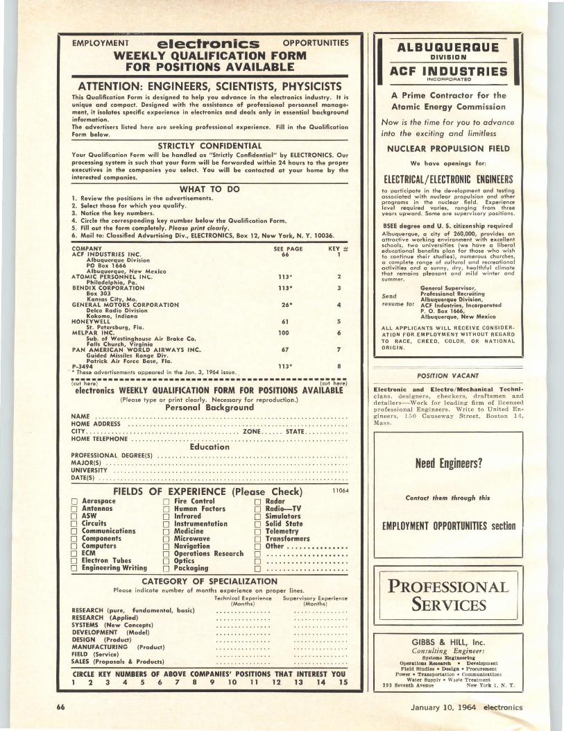
66
EMPLOYMENT electronics OPPORTUNITIES
WEEKLY QUALIFICATION FORM FOR POSITIONS AVAILABLE
ATTENTION: ENGINEERS, SCIENTISTS, PHYSICISTS This Qualification Form is designed to help you advance in the electronics industry. It is unique and compact. Designed with the assistance of professional personnel manage· ment, it isolates specific experience in electronics and deals only in essential background information. The advertisers listed here are seeking professional experience. Fill in the Qualification Form below.
STRICTLY CONFIDENTIAL Your Qualification Form will be handled as "Strictly Confidential" by ELECTRONICS. Our processing system is such that your form will be forwarded within 24 hours to the proper executives in the companies you select. You will be contacted at your home by the interested companies.
WHAT TO DO 1. Review the positions in the advertisements. 2. Select those for which you qualify. 3. Notice the key numbers. 4. Circle the corresponding key number below the Qualification Form. S. Fill out the form completely. Please print clearly. 6. Mail to: Classified Advertising Div., ELECTRONICS, Box 12, New York, N. Y. 10036.
COMPANY ACF INDUSTRIES INC.
Albuquerque Division PO Box 1666 Albuquerque, New Mexico
ATOMIC PERSONNEL INC. Philadelphia, Pa.
BENDIX CORPORATION Box 303 Kansas City, Mo.
GENERAL MOTORS CORPORATION Delco Radio Division Kokomo, Indiana
HONEYWELL St. Petersburg, Fla .
MELPAR INC. Sub. of Westinghouse Air Brake Co. Falls Church, Virginia
PAN AMERICAN WORLD AIRWAYS INC. Guided Missiles Range Div. Patrick Air Force Bose, Fla.
p.3494 * These advertisements appeared in the Jan . 3, 1964 issue.
SEE PAGE KEY# 66 1
113* 2
113* 3
26* 4
61 5
100 6
61 7
113* 8
·-------------------------------------------------(cut here ) (cut here) electronics WEEKLY QUALIFICATION FORM FOR POSITIONS AVAILABLE
(Please type or print clearly. Necessary for reproduction .) Personal Background
NAME . . . . . . .......... . . . .... · . . ... · · · · .. · · · · · · · · · · · · · · · · · · ·· · · · · · · · · · · · · · · HOME ADDRESS .. .. .. . ...... . ... . . . .. . ...... . .. . .. . . .. .............. . ..... . CITY ....... . ..... .. . . . . . ..•. ..... .. ... . ...... . ZONE . .. . . . STATE ... . •.. . . . .• HOME TELEPHONE . ... .. . ... .. ..... . . . ... . ...... . .. . ... • ..... . . . ............ .
Education PROFESSIONAL DEGREE(S) .. . . . .. ........... . .. . . . . . . . . . . . . .• • . . ..• . . . . .•.. .. . MAJOR(S) ... .. .. ....... . . .... .. .• .... .. .. . . .. . . ...•............. ... .... . .. . UNIVERSITY ..•.. .. . . .. .. . . . ... . . ... ... . ... . . . . ....• . .... • .. .. .• . .... . .. .. .. DATE(S) ... . .... . ..... . ..... . .. .. . . ..... .. . . .... . ... . . .. ............ .. . . . . . .
FIELDS OF EXPERIENCE (Please Check) 11064
D Aerospace D Fire Control D Radar D Antennas D Human Factors O Radio-TV 0 ASW D Infrared D Simulators D Circuits D Instrumentation O Solid State D Communications D Medicine D Telemetry D Components D Microwave D Transformers D Computers D Navigation D Other ...•••••••••••• O ECM D Operations Research D .................... D Electron Tubes D Optics D .................... D Engineering Writing D Packaging D ... ... ............. .
CATEGORY OF SPECIALIZATION Please indicate number of months experience on proper lines.
RESEARCH (pure, fundamental, basic) RESEARCH (Applied) SYSTEMS (New Concepts) DEVELOPMENT (Model) DESIGN (Product) MANUFACTURING (Product) FIELD (Service) SALES (Proposals & Products)
Technical Experience Supervisory Experience (Months) (Months)
CIRCLE KEY NUMBERS OF ABOVE COMPANIES' POSITIONS THAT INTEREST YOU 1 2 3 4 5 6 7 8 9 10 11 12 13 14 15
I ALBUGUERQUE I DIVIBIDN
ACF INDUSTRIES INCORPORATED
A Prime Contractor for the Atomic Energy Commission
Now is the time for you to advance into the exciting and limitless
NUCLEAR PROPULSION FIELD
We have openings for:
ELECTRICAL/ELECTRONIC ENGINEERS to participate in the development and testing associated with nuclear propulsion and other programs in the nuclear field . Experience level required varies , ranging from three years upward . Some are superv isory positions.
BSEE degree and U. S. citizenship required Albuquerque, a city of 260,000, provides an attractive working environment with excellent schools, two universities (we have a liberal educational benefits pion for those who wish to continue their studies), numerous churches, o complete range of cultural and recreat ional activities and a sunny, dry , healthful cl ima te that remains pleasant and mild w inter a nd summer.
Send resume to:
General Supervisor, Professional Recruiting Albuquerque Division, ACF Industries, Incorporated P. 0 . Box 1666, Albuquerque, New Mexico
ALL APPLICANTS WILL RECEIVE CONSIDER ATION FOR EMPLOYMENT WITHOUT REGARD TO RACE . CREED , COLOR, OR NATIONAL ORIGIN .
POSITION VACANT
Electronic and Electra/ Mechanical Technl· c ia n s. designers , c heckerS', draftsm en a n d det a ilers-Work (or leadi ng fi r m o f licensed profession a l Eng ineers . Wr it e t o U nited Eng ineers. 1 50 Ca u seway Street, Boston 14, Mass.
Need Engineers?
Contact them through this
EMPLOYMENT OPPORTUNITIES section
PROFESSIONAL SERVICES
GIBBS & HILL, Inc. Consulting Engineers
Sy1tem1 En1lneedn1 Operationa Reteareb • DeYelopment Field Studie11 • Destin • Procurement
Power • Tr101portat1on • Communications Water Supply • Waite Treatment
393 Seventh ATenue New Yorlr: I. N. Y.
January 10, 1964 electron ics
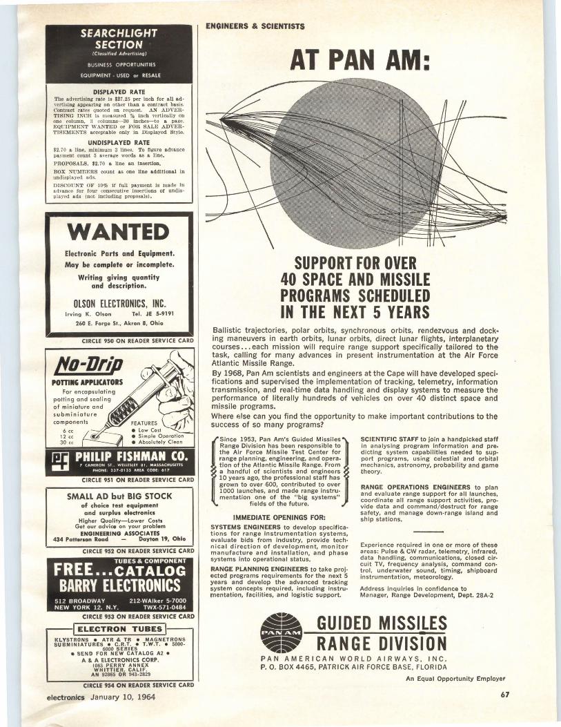
DISPLAYED RA TE The advertising rate is $27.25 per Inch for all ad''ertislng a.v:oea.ring on other than a contract basis. Contract rates quoted on request. AN ADVEltTISING INCH is measured % inch ve l'tiCa.lly on one column, 3 columns-30 inches-to a page. EQUIPMENT WANTED or FOR SALE ADVERTISEMENTS acceptable only In Displayed Style.
UNDISPLAYED RATE $2. 70 a llne, mlnlmwn 3 lines. To figure advance p&yment count 5 average words as a. line.
PROPOSALS, $2. 70 a llne an lllllertlon.
BOX NUMnERS count as one llne additional In undisplayed ads.
DISCOUNT OF 10% If full payment Is made In advance for four consecutive insertions Of undisplayed ads (not including vrovosals).
WANTED Electronic Parts and Equipment.
May be complete or incomplete.
Writing giving quantity and description.
OLSON ELECTRONICS, INC. Irving K. Olson Tel. JE 5-9191
260 E. Forge St., Akron 8, Ohio
CIRCLE 950 ON READER SERVICE CARD
No-Drip POmllG APPLICATORS
For encapsulating pott ing and sealing of miniature and subminioture components
6 cc 12 cc JO cc
CIRCLE 951 ON READER SERVICE CARD
SMALL AD but BIG STOCK of choice test equipment ond surplus electronics
Higher Quality-Lower Costs Get our advice on your problem
ENGINEERING ASSOCIATES 434 Patterson Road Dayton 19, Ohio
CIRCLE 952 ON READER SERVICE CARD
FREE TUBES & COMPONENT
••• CATALOG BARRY ELECTRONICS
512 BROADWAY 212-WAlker 5-7000 NEW YORK 12, N.Y. TWX-571-0484
CIRCLE 953 ON READER SERVICE CARD
I ELECTRON TUBES 1.--. KLYSTRONS • ATR & TR • MAGNETRON$ SUBMINIATURES • C. R.T. • T .W.T. • 5000-
6000 SERIES e SEND FOR NEW CATALOG A2 •
A & A ELECTRONICS CORP. 1063 PERRY ANNEX WHITTIER. CALIF.
AN 92865 OR 943-2829
CIRCLE 954 ON READER SERVICE CARD
electronics January 10, 1964
ENGINEERS & SCIENTISTS
AT PAN AM:
SUPPORT FOR OVER 40 SPACE AND MISSILE PROGRAMS SCHEDULED IN THE NEXT 5 YEARS
Ballistic trajectories, polar orbits, synchronous orbits, rendezvous and dock· ing maneuvers in earth orbits, lunar orbits, direct lunar flights, Interplanetary courses ... each mission will require range support specifically tailored to the task, calling for many advances in present instrumentation at the Air Force Atlantic Missile Range. By 1968, Pan Am scientists and engine~rs at the Cape will have developed speci· fications and supervised the implementation of tracking, telemetry, information transmission, and real-time data handling and display systems to measure the performance of literally hundreds of vehicles on over 40 distinct space and missile programs. Where eJse can you find the opportunity to make important contributions to the success of so many programs?
Since 1953, Pan Am's Guided Missiles Range Division has been responsible to the Air Force Missile Test Center for range planning, engineering, and operation of the Atlantic Missile Range. From a handful of scientists and engineers 10 years ago, the professional staff has grown to over 600, contributed to over 1000 launches, and made range instrumentation one of the " big systems"
fields of the future.
IMMEDIATE OPENINGS FOR:
SYSTEMS ENGINEERS to develop specifica· tions for range instrumentation systems, evaluate bids from industry, provide techn ica I direction of development, monitor manufacture and installation, and phase systems into operational status.
RANGE PLANNING ENGINEERS to take projected programs requirements for the next 5 years and develop the advanced tracking system concepts required, including instrumentation, facilities, and logistic support.
SCIENTIFIC STAFF to join a handpicked staff in analysing program information and predicting system capabilities needed to support programs, using celestial and orbital mechanics, astronomy, probability and game theory.
RANGE OPERATIONS ENGINEERS to plan and evaluate range support for all launches, coordinate all range support activities, provide data and command/ destruct for range safety, and manage down-range island and ship stations.
Experience required in one or more of these areas: Pulse & CW radar, telemetry, infrared, data handling, communications, closed circuit TV, frequency analysis, command control, underwater sound, timing, shipboard instrumentation, meteorology.
Address inquiries in confidence to Manager, Range Development, Dept. 28A-2
GUIDED MISSILES RANGE DIVISION
PAN AMERICAN WORLD AIRWAYS, INC . P. 0. BOX 4465, PATRICK AIR FORCE BASE, FLORIDA
An Equal Opportunity Employer
67
I·~
·~
.,
I?
SEARCHLIGHT SECTION
AUTOTRACK ANTENNA MOUNT TYPE SCR 584, MP 61 B 360 degree azimuth. 210 degree eleva.tloo sweep with better than 1 mil accuracy. Missile velocity acceleration and slewing rates. Amplidyne and servo control. Will handle up to 20 ft . dish. Supplied complete with control chassis. In stock-immediate delivery. Used world over by NASA. ABMA, USAF.
AIRBORNE AUTOTRACK X-Y MOUNT Gimbal mount. oompl. w/ all senos & drives for full sweep. $475. ·-SCR 584 RADARS AUTOMATIC TRACKING 3 CM & 10 CM Our 584s in Uke new condition, ready to go, and in stock for immediate delivery. Ideal for t elemetry research and development. missile tracking. satellite tracking, balloon tracking, weather forecasting, antiaircraft defense d efense tacUc&l &tr support. Used on Atlantia Missile Range, Pacific Missile Range, N .A.S.A. Wallops Island, A.B.111.A. Desc. MIT Rad. Lab. Compl. Inst. bk. available $25.00 ea. Serles. Vol. 1, pps. 207 -210, 228, 284-286.
PULSE MODULATORS
MIT MODEL 9 PULSER 1 MEGAWATI-HARD TUBE Output 25 kv 40 a.mp. Duty cycle, . 002. Pulse lengths . 25 to 2 mcirosec. Also .5 to 5 microsec. and .l to .5 msoo. Uses 6C21. Input !Hv 60 cycle AC. Mfr. GE. Complete with driver and high voltage vower supply. Ref: MIT Rad. Lab. Serles Yo!. 5 pps. 152-160. 500KW THYRATRON PULSER Output 22kv at 28 a.mp. Rep. rates : 2.25 m!cro•ec. 300 PPS. 1. 75 msec 550 PPS, .4 maec 2500 pps. Use• 5C22 hydrogen thyra.tron. Complete with driver a.nd high voltage power supply. Input 115v 60 OY AC. 2 MEGAWATI PULSER Output 30 kv at 70 &mp. Duty cycle .001. Rep rates: 1 m!crosec 600 ops, 1 or 2 msec 300 pps. Uses 59U h i·drogen th.vra.tron. Input 120/ 208 YAC 60 cycle. M t r. GE. Complete with high voltage power supply. 1 SKW PULSER-DRIVER Biased multlvibrator type puJse generator using 3E29. Output 3kv at 5 amp. Pulse lgtbs . 5 to 5 mlcrosec, easily adJ. to .1 to .5 msec. Input 115v 60 OY AC. $475. Ref: 1l1lT Rad. Lab. Serles Vol. 5 PPS. 157. MIT MODEL 3 PULSER Output: 144 kw (12 kv at 12 amp.) Duty ra.Uo: 001 max. Pulse duration: 5.1 and 2 mlcrosec. Input: 115 v 400 to 2000 ops and 24 vdc. $325 ea. Full desc. Vol. 5 MIT Rad. Lab. series pg. 140.
MICROWAVE SYSTEMS 300 TO 2400MC RF PKG. 300 to 2400MC CW. Tuneable. Transmitter 10 to 30 Watts. Output. As new $475.
X SAND DOPPLER SYSTEM AN/ APN-102 G.P.L. ANT/ RCYR/ XMTR PKG. 4 Ileam Pulsed Janus Planar Array-New $1600 .
AN/TPS-ID RADAR 500 kw 1220 -1359 mes. 160 n&ut!cal mile search ronge P .P . I. a.nd A Scopes. MTI. thyratron mod. 5J26 magnetron. Complete system.
10 CM. WEATHER RADAR SYSTEM Raytheon, 275 KW output S Band. Rota.ting yoke J'. P .I . Weather Band. 4. 20 and 80 mile range. 360 degree azimuth scan. Supplied bra.nd new complete \\1 th instruction books and lnstalJatlon drawings. Price $975 complete.
AN/APS-158 3 CM RADAR Airborne radar. 40 kw outout using 725A magnetron. Model 3 oulser. 30 -tn. oara.bola. stabilized &ntenna.. PPl scope. Comvlete system. $1200 each. New.
lOKW 3 CM. X SAND RADAR Comvlete RF head including transmi tter, receiver, modulator. Uses 2J-l2 magnetron. Fully descrtbed in MIT Rad. Lab. Serles Vol. I, PPS 61 6-625 and Vol. JI, pps. 171-185 $375. Complete System. $750.
AN/ APS-27 X SAND RADAR Complete 100 kw output airborne system with iliTI, 5C22 thyr. mod, 4J52 magnetron , PPI. 360 deg az sweep, 60 deg. elev. sweep, gyro stablllzer, bl-gain rm•r. Complete with all plugs and cables $2800.
M-33 AUTO-TRACK RADAR SYSTEM X band with plotting board, automatic range tracking, etc. Cornolete in 2 van complex incl. 1 meK&wntt acquisition radar.
AN / APS-45 HEIGHT FINDER Airborne system, 40.000 rt. altitude display on PPJ & RH!. 9375 mes. 400kw output using QK-172 mega t ren , 5622 thyratron.
L SAND RF PKG. 20 KW peak 990 to 1040 MC. Pulse width . 7 to I. 2 mlcrosec. Rep rate 180 to 420 pps. Input 115 vac. Incl. Rcoelver $1200.
200MC RF PKG 175 to 225 me. Output: 200 to 225 kw. 5 mlcrosec 60
l•pps. Input : l 15v 66 cycle AC. $750.
...
68
AN / UKR-5A TELEMETRY SET Mfr. Raymond Rosen Eng'g Co. 215-235 mo receiving termina l with rec.'Orders. $2400.00
CIRCLE 955 ON READER SERVICE CARO
CIRCLE 957 ON READER SERVICE CARD
(1) HONEYWELL VISICORDER 906CFOH 12 channel w /8 Galvas M-8000. Used less than 10 hrs! Perfect. Save $1,000.00
(1) CEC AMPLIFIER SYSTEM D. 12 channel # 1-112C Amp. & 1 Oscillator Power Supply 2-1 OSA. Excellent cond. New cost $7,000.00. Now: Complete: $2,750.00
Write or phone direct GIL DAGENAIS, 1600 Angelus Ave.
L. A. Calif. DU:2-1125
Circle cards wi/J not be acknowledqed.
CIRCLE 958 ON READER SERVICE CARD
CIRCLE 959 ON READER SERVICE CARD
Color DIAL TELEPHONES ll 0.95 Factory rebuilt W estern Elec tric in white. beige, Ivory, pink, green, or blue. If 4 prong plug Is re ~ ou!red add $2.00. Fully guaranteed. Write for free list. All shipm ents FOB.
SURPLUS SAVING CENTER Waymart Dept. E 11064 Penna.
.Complete .. --CIRCLE 960 ON READER SERVICE CARD
TOP BRAND ELECTRON TUBES * TERRIFIC SAVINGS * • FREE BUYERS' GUIDE •
METROPOLITAN SUPPLY CORP. 443 PARK AVE SOUTH e NEW YORK 16, N. Y.
212-M U 6-2834
~ CIRCLE 961 ON READER SERVICE CARD
SEARCHLIGHT EQUIPMENT
LOCATING SERVICE
No Cost or Obligation This service is designed to help you, the reeder of SEARCHLIGHT SECTION, to locate used or rebu i lt equipment not currently advertised.
HOW TO USE: Check the ads in this SEARCHLIGHT SECTION to see if what you want is advertised . If not, print clearly the specifications of the equipment and/ or components wanted on the coupon below, or on your own letterhead .
THIS IS A SERVICE TO OUR READERS. THIS PUBLICATION DOES NOT BUY, SELL OR STOCK EQUIPMENT OR MATERIALS OF ANY TYPE. Your requ irements wi ll be brought promptly to the attention of the used equipment dealers advertising in this section. You will receive replies d irectl y from them.
Obviously, the list of such advertisers is limited by comparison with the over 58,000 subscr ibers to ELECTRONICS, all directly engaged in the electronics industry. A small 'EQUIPMENT WANTED' advert isement in the SEARCHLIGHT SECTION will bring your needs ta the attention of ALL who read ELECTRONICS. The cost is low . . . just $27.25 per advertising inch¥s" x 2-3/ 16".
SEARCHLIGHT EQUIPMENT LOCATING SERVICE
CLASSIFIED ADVERTISING
c/ o Electronics
P.O. Box 12, New York, N. Y., 10036
Please help us ta locate the following used equipment:
NAME •••••••••••••••••••••••••••••••••••••••• -
TITLE .•••••••••••••••••••••••••••••••••••••••••
COMPANY_················· ·················-
STREET ··-·········-·····-·-·····-········ ·····
CITY .••••••••••••••••••••••••••• • •• ZONE ___ __ _
STATE ••••• ------ -· -·····-··-···--- -- - ······ •• .
January 10, 1964 electronics
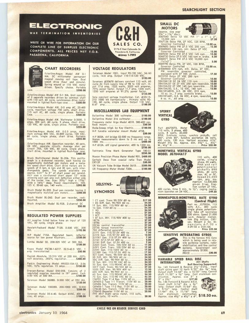
CHART RECORDERS Esterline-Angus Model AW 0-1 MA. DC milliameter permanent magnet moving coil type. Dual speed drive (hour and minute). Spring wound or 110 VAC motor driven. Specify choice. Portable
.. . ........................ $200.00
Esterline-Angus Model AW 0-1 MA. Unit consists o~ 2 separate recorders driven by common shaft with 110 volt, 60 cycle, synchronous drive motor mounted in lighted flush-type case ... _ . . $350.00
Esterline-Angus Model AW. 0-5 amp AC, 25-400 cycl e, maximum voltage 750 volts, chart drive, 115 volt AC, 60 cycle, single phase. Portable Case. . ....... . .... ...... ..... ... .. $200.00
Esterline-Angus Model AW. Wattmeter 0-3000, 3 amps, 300 volt, 60 cycle, 3 phase, chart drive 120 VAC, 60 cycle, single pha se. Portable case'.
$225.00
Esterline-Angus Model AW. 0-2 .5 amps, maximum voltage 800 VAC, 50-800 cycles, 120 VAC, 60 cycle, si ngle phase, chart drive. Portable case. . . ... . . . .. ......... .. ... . . .. . $225.00
Esterline-Angus AW. Operation recorder, 40 pens, 2.8 yoc, separate circuits. Average ohm per circuit .705, 120 VAC, 60 cycle, single phase, chart drive, mounted in lighted flush-type case.
$400.00
Brush Multichannel Model SL-206. This oscillograph is a 6-channel recorder, each having six magnetically matched pen motors and a variable speed chart drive. Chart drive motors are in speeds of 3 rpm, 6 rpm and 30 rpm, with interchangeable gears. The speeds available are approx. 0.01" to 5" of chart paper per second. Unit uses a six-channel chart paper 12" wide allowing each pen one inch deflection either side of the center line. Size : 201/4" high x 17%" wide x 1634" deep. Power requirements: 105-125 V, 50-60 cps, 140 watts ....... .. . $395.00
Brush Model BL-202. Dual pen recorder having 2 magnetically matched pen motors ... . .. $200.00
Brush Model BL-262. Dual pen recorder, ra ck-mounted, .. . .. . . . ........ .. ..... . .. $250.00
Brush Amplifier Model BL-928. 2-channel DC $50.00
REGULATED POWER SUPPLIES Al l supplies listed below have an input of 120 VAC, 60 cycle, sing le phase:
Hewlett-Packard Model 712B. 0-500 VDC. 200 MA ... ..... ....... . .. ... .......... $1 95.00
H-P Model 715A. Regulated beam, reflector source for low power Klystrons . . . ... .. $250.00
Lamba Model 32. 200-325 VDC at 300 MA. $100.00
Kepco Model PSC38-1-6217. 32.5-42.5 voe. 1 amp transistorized .... . .... . .......... $50.00
Kaylab Abso lute. 10-310 VDC at 250 MA .. 02% volt accuracy, .002% regulation . . ..... $400.00
Perkin Engineering Model MR532-15A-12. 2-36 VDC. V2% regulation. 15 amps ...... . . $150.00
Dressen-Barnes Model D50-05B. Consists of 2 regulated supplies mounted in 19" panel. Each o-50 voe at 500 MA _ . . ........... ... s 1 oo.oo Sorensen Model 56088. 0-500 VDC at 250 MA.
$1 50.00
Sorensen Model 10008B. 200-1000 VDC. 0-500 MA. .. ........ . .. _ ............. . .. $350.00
Sorensen Model DE-6-40. Output 6VAC, 400 cy-cles, 40 amps ...... . . ............... $100.00
electronics January IO 1964
C&H
VOLTAGE REGULATORS Sorensen Model 1001. Input 95-130 VAC, 56/ 60 cycle, 14.6 amp. Output 110-115-120 VAC.
$1 25.00 Sorensen #20678 delivers constant 115 volt, 60 cycle AC from supply line of 98 to 132 volt . Input 17.6 amp, 1525 watts, 2025 volt amperes, 75% power factor. Output 11.7 amp, 1230 watt, 1350 volt amperes at 91.2% power factor.
$125.00 Sola constant voltage transformer. Cat. #23-13-210 1000 VA harmonically . Primary volts 95-130, 60 cycle, single phase. Output 1 lB VAC, B.47 amp ...... . . ... . .............. $100.00
MISCELLANEOUS LAB EQUIPMENT Ballentine Model 300 voltmeter . . ... . . $1 00.00 Ballentine Model 316 voltmeter ........ $100.00 Frequency meter Arga Model 401 R. 380-420 cps. Rack mount .. . ..... . ... . .. . . ... . . . .. $50.00 Rada-Sweep mfgd. by Kay Electric . ..... $100.00 H-P tunable valometer mount Model 475B.
$50.00 H-P 803A. vhf bridge 52-500 me frequency range. Makes measurements down to 5 me and up to 1000 me ........... . . .............. $400.00 H-P 612A. uhf signal generator. 450 to 1230 me.
$750.00 Tektronix Time Mark Generator Type 1 BO-Sl
$250.00 Maxon Precision Phase Meter Model 901. $400.00 Gertsch Deca Tran coaxial ratio Tran Model CRT-3F ... _ . ... .... ... .. ........... . $50.00 GR Vacuum Tube Bridge Model 561 D . . . . $200.00 GR Frequency Meter Model 720A . . .. ... $100.00
SELSYNS-
SYNCH ROS
I CT cont. Trans 90/ 55V 60 cy. _. _ . . . . . $1 7.50 1 DG Di ff. Gen. 90/ 90V 60 cy .... .... . . 24.50 1 F Syn. Mir . I I 5/ 90V 60 cy .. .......... 24.50 JG Gen. I 15V 60 cy ... . .. . ...... _ .•... 24.50 1 HG . . . ... ....... .... .. .. . ..•..... 34.50 1 HOG .... ... .......... . ..... .. .. . . 27.50 1 HCT . ... . ....... . .... . . . . . . . .... .. 27.50 I SF Syn. Mtr. 115/ 90V 400 cy ... . .. - . . 12.50 18CT6 .... . ... . ... . . . . . ... . ... .. .... 37.50 I BTR6 ............. . ... .... _ ....... 37.50 23CX6 control transmitter . . . . . . . . .. _ . . 37.50 23TX6 torque transmitter ........ _ . . ... 37.50 7DG di fferential generator ........ _ .. . .. 37.50 2JIFJ Gen. 115/ 57.5V 400 cy .. ........ 7.50 2J1F3 Gen. 115/ 57 .5V 400 cy ..... ..... 10.00 2JIFA1Gen . 115/ 57.5V400cy ...... ... 7.50 2J1G1 57.5/ 57.5V 400 cy. - . . - . .. .. . .. . 5.00 2JJH1 Diff. Gen. 57.5V 400 cy . . ...... .. 7.50 2J5D1 Cont . Trans. 105/ 55V 60 cy ... . . . 17.50 2J5FJ Cont. Tran s. 105/ 55V 60 cy .... . . 17.50 2J5HI Gen. 115/ 105V 60 cy ....... .. .. 17.50 2Jl5MI Gen. 115/ 57.5V 400 cy .......... 17.50 5CT Cont. Trans. 90/ 55V 60 cy ......... 34.50 SD Di ff. Mir. 90/ 90V 60 cy ............ 34.50 SDG Di ff . Gen. 90/ 90V 60 cy . . . . . .. .. . . 34.50 SF Syn. Mir. I lS/ 90 VAC 60 cy ... . . . ... 34.50 5G Syn. Gen. 1 JS/ 90VAC 60 cy ..... - ... 34.50 SHCT Cont. Trans. 90/ SSV 60 cy ... . . . . . 37.50 SSDG Diff. Gen. 90/ 90V 400 cy ...... . . . 12.50 6DG Diff. Gen. 90/ 90V 60 cy . . ... . . . ... 25.00 6G Syn. Gen. 11S/ 90VAC 60 cy ... . ..... 34.50 7G Syn. Gen. 115/ 90 VAC 60 cy . . . ..... 42.50 CS6701 Type I I -4 Rep. 1 I SV 60 cy. . . . . . 20.00 C6940S-2 Type 1- I Transm. 115V 60 cy . . 20.00 (69406 Syn. Transm. I 1 SV 60 cy . ....... 20.00 (69406-1 Type 11-2 Rep. 11 SV 60 cy .. .. 20.00 C7B24B Syn . Transm. 115V 60 cy .... . . . . 12.50 (78410 Repeater 115V 60 cy. . . . . . . . . . . 20.00 FPE 49-7 Diehl servo motor, 115 volts,
60 cycle, 10 watts ...... _ .. . . . ...... 30.00
CIRCLE 962 ON READER SERVICE CARD
SEARCHLIGHT SECTION
(approx. size over 334" x 1 V4" dia.) : 5067043 Delco 12 voe PM 1" x 1" x 2"
10,000 rpm ............. . .... ... ... $7.50 5067126 Delco PM, 27 voe, 125 RPM,
Governor Controlled . ..... . .... , .. 15.00 ea. S069600 Delco PM 27.5 voe 250 rpm ... . 12.50 #506962S 120 rpm, mfr. Delco 27 VDC
Governor Controlled . . ... _ . .. ..... , . . 15.00 S069230 Delco PM 27.5 voe 145 rpm .... 15.00 S06B750 Delco 27.5 VDC 160 rpm w. brake . 6.50 506B571 Delco PM 27.5 VDC 10,000 rpm
(1xlx2") .. . . . . . . ... . . . ...... ..... . 5069790 Delco PM, 27 VDC, 100 RPM,
Governor Controlled .... .. . .. .. ... 15.00 ea. # 5069BOO 575 rpm, mfr. Delco, 27 VDC,
PM reversible governor control led, equipped with 27 voe clutch . ' ... '' ' ' '17.50
5072735 Delco 27 VDC 200 rpm Governor Controlled .... . . . . ... .. , , , , 15.00
SBA 1OA118 GE 24 voe 11 0 rpm ' .... " .. 10.00 5BA10AJ37 GE 27 voe 250 rpm reversible. 10.00 5BA10AJ52 27 voe 145 rpm reversib le . ... 12.50 5BA10AJSO, G.E., 12 voe, 140 rpm .... .. 15.00 SBA10FJ401B, G.E. 28 voe, 215 rpm,
10 oz. in., 7 amp. contains brake ...... 15.00 5BA10FJ421, G.E. 26 VDC, 4 rpm, reversible
6 oz. in., .65 amp ..... ... _ ...... .. . . 15.00
Part #673073, Motor 115 volts, 3 phase, 400 cycle, 8 watts, 20,000 RPM. 3-minute runup, synchro pickoffs, roll 360°, pitch as•. Synchro excitation 26 volts, 400 cycle, 150 m.a. Vertica l accuracy ±V2' Weight 3112 lbs . Approx . dim. 534" L., 4V2" W., 41/2" H ....... . ............. Price $35.00
HONEYWELL VERTICAL GYRO MODEL JG7044A 17
115 volts, 400 cycles, sing I e phase, 35 wa.tts. Pitch and r o 11 poten t i om e t er p ick o ffs 890 ohms, 40 volts max. AC or DC. Speed 20,000 rpm, ang . mo-
mentum 12,500,000 gm-cm 2/ sec. Erection system 27 VAC,
400 cycles, t ime 5 min. to 1f2°; caging mecha-nism operates on 24 VDC. . .... . ... . .... $49.50
MINNEAPOLIS·HONEYWELL RATE GYRO (Control Flight)
Part no. JG7005A, 115 volts A.C., 400 cycle single phase potentiometer take off resistance 530 ohms. Speed 21 ,000 r.p.m. Angular momentum 2V2 million, CM'/ sec. Weight 2 lbs. Dimensions 4 - 7 / 32 x 3-29/ 32 x 3-31 / 64.
Price $22.50
SENSITIVE INTEGRATING GYROS This is the famous HIG Gyro which is being used in missi le guidance systems, radar stab i lization and fine control systems. Government cost approximately $1500. PRICE ............. $50.00
VARIABLE SPEED BALL DISC INTEGRATORS (All Shaft s
Ball Bearing Supporte d ) No. 145 Forward & Reverse 2V4"-0-2V4. Input shaft spli ne gea r 12 teeth 9/ 32" dia . %" long . Output shaft 15/ 64" dia . x 1 S/ 32" long. Control shaft 11 / 32" x 3/a" long. Cast aluminum construct ion. Approx . size 3" x 3" x 234" ...... .. .... $17.50 No. 146 Forwa rd & Reverse 4-0-4. Input shaft 5/ 16" dia. x 34" '' - - ~' ;,; long : Output shaft 15/ 64" dia. '(! . { " x 9/ 16" long. Control shaft .._,: • ' 11 / 64" dia . x 11 / 16" long. Cast aluminum construction. $l S SO Approx. size 4112" x 4V2" x 4". • ea.
69
INDEX • AMP Incorporated . . . . . 4th cover • Accurate Instrument Co.. . . . 48
Aerojet General Commercial Products .... . .
American Electronic Labora-tories, Inc.
Ampex Corporation Amplex Corp. Astrodata Inc.
24
40 57 60
3
Bausch & Lomb, Inc. . . . . . . . . 42 Bendix Corporation, The
Bendix-Pacific Division . . . . . 38
• Carter-Princeton Electronics Div. . . . . . . . . . . 47
• Cohn Corp., Sigmund . . . . . . . . 60
• Federation Nationale des Indus-tries Electroniques . . . . . . . . 51
Fluke Mfg. Co., Inc., John . . . . . 65
• Globe Industries, Inc. . . . . . . . . 48 Graphic Systems, Inc. . . . . . . . . 60 Gries Reproducer Corp.. . . . . . . 65
' . Heinemann Electric Co . . Hewlett-Packard Company
inside front cover, 21, Honeywell Hughes Aircraft Co.
Aerospace Divisions Instruments Div. . . .. .... .
23
22 61
63 43
IBM Data Processing ...... 12, 13 IEEE ... 58, 59
electronics ,,,."' :'.\ I I •
...... ...• C'll'Ljo.'
Audit Bureau of Circulation
Aaeoctated Bu•ln•H Publtcatton1
AUDITED PAID CIRCULATION
JAMES T. HAUPTLI (2210) Advertising Sales Manager
HENRY M. SHAW (3485) Market Research Manager
DAVID M. TEMPEST (3139) Promotion Manager
electronics Buyers' Gulde
R. S. QUINT (2335) General Manager
RICHARD J. TOMLINSON (3191) Business Manager
THEODORE R. GEIPEL (2044) Production Manager
NEW YORK TELEPHONE: Dial Direct: 971 plus number in parenthesis, Area Code 212
70
TO ADVERTISERS • Kepco, Inc. 16
Kin Tel A Division of Cohu Electronics Inc. . . 3rd cover
• Kyoritsu Electrical Instruments Works, Ltd. . . . . . . . . . . 48
• Lapp Insulator Co., Inc. . 15 Ling-Temco·Vought, Inc. 7
McGraw-Hill Book Co. . 64 Mechanical Enterprises, Inc. . 65
Precious Metal Plating Div. of Chemical Plating Co. . 53
Radiation Inc. . . . . . . . . . . . . . 4
Sprague Electric Co ........ .
Texas Instruments Incorporated Industrial Products Group . Texas Instruments Incorporated Semiconductor Products Divi-
sion ...... 8,
• Vitramon, Inc . ..... ....... .
Ward Leonard Electric Co . ..
6
41
9
45
50
CLASSIFIED ADVERTISING F. J. Eberle, Business Mgr. (2557)
Professional Services 66
EMPLOYMENT OPPORTUNITIES 66, 67
EQUIPMENT (Used or Surplus New) For Sale .............. 67, 69
WANTED 67
CLASSIFIED ADVERTISERS INDEX • A & A Electronics Corp .
ACF Industries Inc . • Barry Electronics
67 66 67
• C & H Sales . . . . . . . . 69 Dagenais Gil Engineering Associates
• Fair Radio Sales Fishman Co., Philip Lifschultz Fast Freight Metropolitan Supply Co. Olson Electronics Inc. Pan American World Airways Inc
• Radio Research Instrument Co. Surplus Saving Center .
• Universal Relay Corp . .... . .. .
•
68 67 68 67 68 68 67 67 68 68 68
• See advertisement in the July 25, 1963 Issue of electronics Buyers' Guide for complete line of products or services.
Thi s Index and our Reader Service Numbers are pub· llshed as a service. Every precaution is taken to make them accurate, but electronics assum H no responsi .. bilities for errors or omissions .
ADVERTISING REPRESENTATIVES
ATLANTA, GA. 30309 Michael H. Miller, Robert C. Johnson 1375 Peachtree St. N.E., Trinity 5-0523 (area code 404)
BOSTON, MASS. 02116 William S. Hodgkinson McGraw-Hill Building, Copley Square, Congress 2-1160 (area code 617)
CHICAGO, ILL. 60611 Harvey W. Wernecke, Robert M. Denmead 645 North Michigan Avenue, Mohawk 4-5800 (area code 312)
CLEVELAND, OHIO 44113 Paul T. Fegley 55 Public Square, Superior 1-7000
(area code 216) DALLAS, TEXAS 75201
Frank Le Beau The Vaughn Bldg., 1712 Commerce St. Riverside 7-9721 (area code 214)
DENVER.COL0.80202 John W. Patten Tower Bldg., 1700 Broadway, Alpine 5-2981 (area code 303)
HOUSTON, TEXAS 77025 Kenneth George Prudential Bldo .. Halcombe Blvd .. Riverside 8-1280 (area code 713)
LOS ANGELES. CALIF. 90017 Ashley P. Hartman, John G. Zisch, 1125 W. 6th St., Huntley 2-5450
(area code 213) NEW YORK, N. Y. 10036
Donald H. Miller (212) 971 3615 Georqe F. Werner (212) 971 3617 Donald R. Furth (212) 971 3616 500 Fifth Avenue
PHILADELPHIA, PA. 19103 Warren H. Gardner, William J. Boyle 6 Penn Center Plaza, LOcust 8-6161 (area code 215)
SAN FRANCISCO. CALIF. 94111 Richard C. Alcorn 255 California Street. Douglas 2-4600 (area code 415)
LONDON WI: Edwin S. Murphy Jr. 34 Dover St.
FRANKFURT/ Main: Matthee Herfurth 85 Westendstrasse
GENEVA: Michael R. Zeynel 2 Place du Port
TOKYO: George Olcott, 1, Kotohiracho, Shiba, Minato-ku
January 10, 1964 electronics
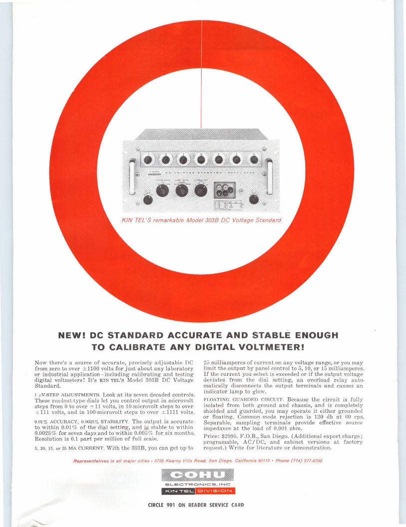
KIN TEL'S remarkable Model 3038 DC Voltage Standard
NEW! DC STANDARD ACCURATE AND STABLE ENOUGH TO CALIBRATE ANY DIGITAL VOLTMETER!
Now there's a source of accurate, precisely adjustable DC from zero to over ±1100 volts for just about any laboratory or industrial application-including calibrating and testing digital voltmeters! It's KIN TEL'S Model 303B DC Voltage Standard.
1 µV-STEP ADJUSTMENTS. Look at its seven decaded controls. These readout-type dials Jet you control output in microvolt steps from 0 to over ± 11 volts, in 10-microvolt steps to over ± 111 volts, and in 100-microvolt steps to over ± 1111 volts.
0.013 ACCURACY, 0.00253 STABILITY. The output is accurate to within 0.01 % of the di~! setting, aml is stable to within 0.0025 % for seven days and to within 0.005 % for six months. Resolution is 0.1 par t per million of full scale.
5, 10, 15, or 25 MA CURRENT. With the 303B, you can get up to
25 m illiamperes of current on any voltage range, or you may limit the output by panel control to 5, 10, or 15 milliamperes. If the current you select is exceeded or if the output voltage deviates from the dial setting, an overload relay automatically disconnects the output term inals and causes an indicator lamp to glow.
FLOATING GUARDED CIRCUIT. Because the circuit is fully isolated from both ground and chassis, and is completely shielded and guarded, you may operate it either grounded or floating. Common -mode rejection is 120 db at 60 cps. Separable, sampling terminals provide effective source impedance at the load of 0.001 ohm.
Price: $2995. F.O.B., San Diego. (Additional export charge; programable, AC/DC, and cabinet versions at factory request.) Write for literature or demonstration.
Representatives in all major cities • 5725 Kearny Villa Road, San Diego. California 92112 • Phone (714) 277-6700
EL-EC:TRC> N IC:S, INC
*#'§'331 1-IHH'-'f' CIRCLE 901 ON READER SERVICE CARD
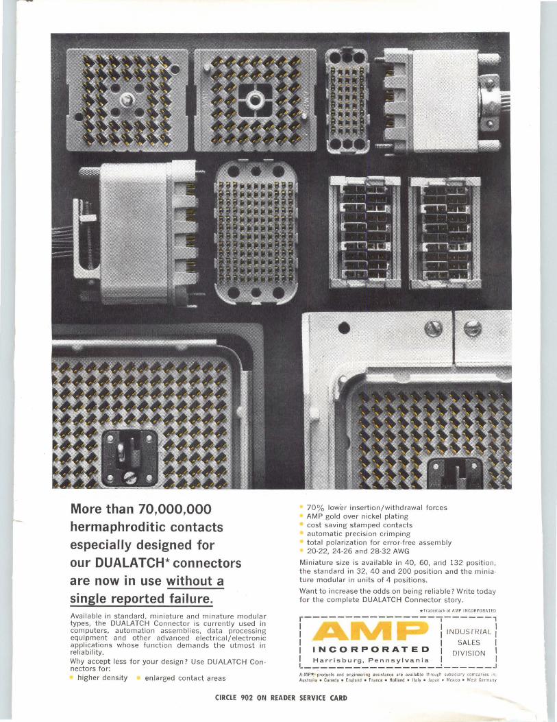
More than 70,000,000 hermaphroditic contacts especially designed for our DUALATCH* connectors are now in use without a single reported fail ure. Available in standard, miniature and minature modular types, the DUALATCH Connector is currently used in computers, automation assemblies, data processing equipment and other advanced electrical/electronic applications whose function demands the utmost in reliabi lity. Why accept less for your design? Use DUALATCH Con nectors for:
higher density enlarged contact areas
70% lower insertion/withdrawal forces AMP gold over nickel plating cost saving stamped contacts automatic precision crimping total polarization for error-free assembly 20-22, 24-26 and 28-32 AWG
Miniature size is available in 40, 60, and 132 position, the standard in 32, 40 and 200 position and the miniature modular in units of 4 positions.
Want to increase the odds on being reliable? Write today for the complete DUALATCH Connector story.
*Trademark of AMP INCORPORATED
r----------- -----,------, I I INDUSTRIAL I I I I I I SALES I I I N C 0 R P 0 RAT E D I DIVISION I I Harrisburg, Pennsylvania I I l----------------~------J A-MP*>•products and engineering assistance are available through subs1d1ary companres in: Austral ia • Canada • England • France • Holland • Italy • Japan • Mexico • West Germany
CIRCLE 902 ON READER SE RVICE CARD