
electronic - bitsavers.org
102
INFRARED TRACKING Finding missile plumes amid bright clouds, p 39 A McGraw- Hill Weekly 75 Cents Apnl l.'J, J!!l;:J electro nic SIMULATING NEW DOPPLER RADAR Phase-locked klystrons upg rade performance, p 44 BALLOON-BORNE RADIOSONDE Unit detects x-rays and ga1nma raus, p 4 7 LATEST ANTI-SUBMAR I NE W EAPON. Dron e helicopter packs nuclear punch, p 18 '1 ,. . .... ... -- . .U'lV:'.) SOJ.Tl . stn <IS t, O.t!>&!A(JQ ·-ate 1 4 ' ' ' '1 . . .. .
-
Upload
khangminh22 -
Category
Documents
-
view
4 -
download
0
Transcript of electronic - bitsavers.org

INFRARED TRACKING Finding missile plumes amid bright clouds, p 39
A McGraw-Hill Weekly 75 Cents Apnl l.'J, J!!l;:J
electronic SIMULATING NEW DOPPLER RADAR Phase-locked klystrons upgrade performance, p 44
BALLOON-BORNE RADIOSONDE Unit detects x -rays and ga1nma raus, p 4 7
LATEST ANTI-SUBMARI NE WEAPON. Drone helicopter packs nuclear punch, p 18
'1
,. . .... ...
--. .U'lV:'.) SOJ.Tl .stn
<IS t, O.t!>&!A(JQ ·-ate 1 4 ' ' ' '1
. . ... :·j~·~

MEASURE MILLIVOLTS at 1000 MC
hp 411A RF Millivoltmeter now available. Measure low level radio frequency, radio frequency and intermediate frequency stage gain, and radio frequency in coaxial lines from 500 kc to 1000 me, 10 mv to 10 volts. Measuring is simple, resolution is high, and thermal drift errors are virtually eliminated with the 41 lA Voltmeter. This remarkable instrument has true linear operation (no correcting networks) and readings are presented on a large, mirror-backed linear meter. Temperature stability is such that there is virtually no change from 10° to 40 ° C.
Specifications alongside indicate basic features of this important new, timesaving instrument. Other special features include: matched diodes protected against burnout; probe temperature compensated for low drift; amplifier photochopper eliminating contact noise, guaranteeing high sensitivity and zero-drift freedom; extra probe tips available including a 500 kc to 250 me UHF tip, 100:1 Capacity Divider tip for measurements up to 1000 v peak, and Type N Tee tip for coax use to 1000 me. Get a new 41 lA into action on your bench now!
HEWLETT PACKARD COMPANY
1501 Page Mill Rd., Palo Alto, California, Area Code 415, DA 6-7000. Sales and service representatives in all principal areas, Europe, Hewlett-Packard S.A., 54 Route des Acacias, Geneva; Canada, Hewlett-Packard (Canada) Ltd., 8270 Mayrand Street, Montreal
CIRCLE 900 ON READER SERVICE CARD

W. W. MacDONALD, Editor
J. M. CARROLL, Managing Editor
SENIOR EDITORS
Samuel Weber, George W . Sideris
SENIOR ASSOCIATE EDITORS
Michael F. Wolff, John F. Mason
ASSOCIATE EDITORS
Michael F. Tomaino, Sylvester P. Corter , William P. O'Brien, Sy Vogel, Leslie Solomon, George J. Flynn, Lourence D. Shergolis, George V. Novotny, Leon H. Dulberger
ASSISTANT EDITORS
Nilo Lindgren, Stanley Froud, Stephen B. Gray, Roy J. Bruun, Barry A . Briskmon
REGIONAL EDITORS
Harold C. Hood (Pacific Coast, Los Angeles ), Thomas Maguire (New England, Boston) , Cletus M . Wiley (Midwest, Chicago)
ART DIRECTOR
Howard R. Berry
ASSISTANT ART DIRECTOR
John C. Wright, Jr
EDITORIAL ASSISTANTS
Lorraine Rossi , Virg inia T. Bostian, Lynn Emery, Ann Mello, Lorraine Werner, Alice M . O' Brien, Sharon Porks, Patricio Mitchell , Claire Benell
FOREIGN MEWS BUREAU
DIRECTOR, John Wilhelm; Alyne Elias, Charles Obertonce
LONDON-John Shinn, Derek Barlow, Nicholas London
BONN-Bruce Bendow, Richard Mikton, Silke McQueen
BRUSSELS-Peter Forboth PARIS-Robert Farrell,
Arthur Erikson
MILAN-More A. Messina MEXICO CITY-Wesley Perry, Jr RIO DE JANEIRO-Leslie Warren MOSCOW-Stewart Ramsey TOKYO-Richard Holloran,
Charles Cohen, John Yamaguchi
CIRCULATION MANAGER
Hugh J. Quinn
W. W. GAREY, Publisher
April 19, 1968
electronics A McGraw-Hill Weekly 75 Cents
TORPEDO-TOTING drone helicopter is Navy's newest weapon against enemy submarines ( Gyrodyne Co. of America). It can leave a destroyer's deck, clobber a sub with torpedos or nuclear depth charges and return while the mother ship stands off at a safe distance. Landing assist device will automatically land the drone even in a 40-knot wind. Seep 18 COVER
ROBOT HELICOPTERS Join Navy's Antisubmarine Arsenal. Navy plans to install the weapons delivery system aboard some 300 ships. The program may run to $200 million over the next five years; estimated cost will be $50 million this fiscal year 18
SP ACECOM: $100-Million-a-Year Market. Here's a rundown of Air Force plans to upgrade its communications. Facilities include microwave, cable and troposcatter equipment, and point-topoint and ground/aerospace circuits. The systems will be wide-band, surv·ivable, secure 22
ION IMPLANTS Forge Tailor-Made Semiconductor Junctions. Particle accelerator precisely puts impurities into crystals. The technique is now being tried out on solar cells, but the big goal is microcircuits that can be made without masking and photo-etching 26
MEDICAL LASERS. Team of eye doctors and laser designers develop an ophthalmoscope-laser. It can weld retinal flaws in 1 msec, without pain to the patient 30
EUROPE PLANS SATELLITES. Eight countries are asked by 121 firms to join forces in Eurospace program. First proposals are for communications and navigational satellites. Meteorologi-cal satellites will be considered next 36
NEW INFRARED SYSTEM Tracks Missiles Against Bright Florida Sky. This equipment can distinguish a missile plume even when clouds reflect more energy. It is useful for shortrange tracking when spurious returns make conventional radar ineffective. By T. P . Dixon, ITT Federal Labs 39
PHASE-LOCKED KLYSTRONS Simulate Doppler Radar. Obtaining accurate results from simulation tests of modern doppler radar requires higher doppler range, cleaner frequency spectrum and better frequency stability than commonly available. This cr11stal-controlled phase-locked system can be applied to carrier frequencies from 1 to 40 Ge.
By A. Benjaminson, Hewlett Packard 44
RADIOSONDE Measures After Effects of Solar Flares. Balloonborne instrument uses both scintillation counter and counter telescope to study phenomena in the auroral zone inititated by solar flares . Equipment has been operated sucsessfflJ,lly in several flights over polar regions of Europe.
By E. Waibel, Max-Planck Institut 47
Contents Continued

2
t81ectronics April 19, 1963 Volume 36 No . 16
Published weekly, with Electronics Buyers' Guide as part of the subscription, by McGrow-Hill Publishing Company, Inc. Founder: James H. McGraw (1860-1948).
Title ® registered U.S. Patent Office; © copyright 1963 by McGraw-Hill Publishing Co., Inc. All rights reserved, including the right to reproduce the contents of this publication, in whole or in part.
Executive, editorial, circulation and advertising offices: McGraw-Hill Building, 330 West 42nd Street, New York 36, N. Y. Telephone Longacre 4-3000. Teletype TWX N.Y . 212-640-4646. Cable McGrawhill, N. Y. PRINTED IN ALBANY, N. Y.; second class postage poid at Albany, N. Y.
OFFICERS OF THE PUBLICATIONS DIVISION: Shelton Fisher, President; Vice Presidents: Joseph H. Allen, Operations; John R. Callaham, Editorial; Ervin E. DeGraff, Circulation; Donald C. McGraw, Jr., Advertising Sales; Angelo R. Venezion, Marketing.
OFFICERS Of THE CORPORATION: Donald C. McGraw, President; Hugh J. Kelly, Harry l. Waddell, Executive Vice Presidents; L. Keith Goodrich, Executive Vice President and Treasurer; John J. Cooke, Vice President
and Secretary.
Subscriptions are solicited only from those actively engaged in the field of the publication . Position and com· pony connection must be indicated on orders. Subscription rates: United States and Ponessions, $6.00 ane year, $9.00 two years, $12.00 three years. Canada: $10.00 one year. All other countries $20.00 one year. Single copies, United States and Possessions and Canada 7!$4. Single copies all other countries $1.50.
THE PUBLISHER, UPON WRIITEN REQUEST FROM ANY SUBSCRIBER TO OUR NEW YORK OFFICE AGREES TO REFUND THAT PART Of THE SUBSCRIPTION PRICE APPLYING TO COPIES NOT YET MAILED.
Subscribers: Please oddre11 change of address notices, subscription orders or complaints to Fulfillment Manager, Electronics, at above address. Change of address notices should provide old as well as new address, including postal .zone number if any . If pos· sible, attach address label from re· cent issue. Allow one month for change to become effective.
Postmaster: Please send form 3579 to Fulfillment Manager, Electronics, 330 West 42nd Street, New York 36, New York.
• Audited Paid Circulation
CONTENTS continued
SWEEP MEASUREMENTS In the Difficult Range. Basic measuring techniques change radically in the 5 to 220-Mc range but this is exactly the range of interest in many applications. One way to measure is to compare transmission through two paths using oscilloscope display. By K. Simons, Jerrold Electronics 52
SIMPLE TRANSISTOR TESTER: How to Build One. Here is a quick way to sort out good transistors from bad ones. The instrument will measure leakage current and common-emitter current amplification.
By G. F. Montgomery, National Bureau of Standards 56
DEPARTMENTS
Crosstalk. The Beneficent Laser 3
Comment. Microminiaturization. Decimal-to-Binary Switch 4
Electronics Newsletter. Thresher Probe Key to ASW's Future 7
Washington This week. Internal Revenue Service Cracks Down on Trade Associations 12
Meetings Ahead. Magnetism and Magnetic Ma-terials Conference 37
Research and Development. Packing a Half-Mil-lion Bits in a Cubic Inch 58
Components and Materials. Miniature Compo-nents for Mass Market 64
Production Techniques. Thin Film Production Perf armed Continuously 70
New Products. Noise Generator is Drift Free 76
Literature of the Week. 86
People and Plants. Hazeltine Reassigns Execu-fuu ~
Index to Advertisers. 98
April 19, 1963 • electronics

CROSSTALK
THE BENEFICENT LASER. One of the joys of being a reporter is the occasional awareness of witnessing an event that can alter many lives. That sense of revelation sustains the good reporter through all the intervening humdrum assignments. The other mark of a good reporter is an itch to get into print quickly what has been witnessed.
Of course, there are other reasons for the fourth estate, but more to the point of this page is the story that prompted these remarks on journalistic enthusiasm. When Ed Addeo, of the McGraw-Hill World News Bureau in San Francisco, submitted this week's report on a new ophthalmoscope-laser (p 30), he wrote this preamble:
"In the current excitement over lasers and the potentials thereof, researchers and press agents tend to get a little carried away with the 'death ray' aspects and other awe-inspiring applications. Burning through plate steel and blasting enemy satellites out of the sky are admittedly colossal prospects, but comparatively little heed is being paid to the more gentle and peaceful uses of the laser principle."
Ed's itch to get the story into print was showing, but we were glad to scratch it. In the last few years, we have paid particular heed to the laser application efforts being made by scientists and physicians (such as Drs. H. C. Zweng and Milton Flocks, shown in the photo experimenting on a rabbit with the ophthalmoscopelaser). In fact, one article in our 1961 series on lasers (p 54, Nov. 24, 1961) was devoted pri-
e lectronics • April 1 9 , 1963
marily to potential scientific and medical appliations, including the type of retinal surgery i·eported this week.
THE PEACEFUL ATOM. Akin to the laser story is the report on ion implantation, by New England Editor Maguire on p 26 this week.
For years, we have reported how atomic radiation damages semiconductors-a problem whose seriousness has been confirmed by the damage to Telstar and other satellites. Now, according to Ion Physics Corp., semiconductor device fabrication may be substantially improved by purposefully bombarding the semiconductor with ions. The bombardment tool is a particle accelerator-one of the breed that has belabored semiconductors in radiationdamage studies.
Appropriately, the component most harrassed by space radiation-solar cells-will probably be the first to benefit from the technique. This story, by the way, is one we have been after for a long time. It was just about two years ago (p 11, April 7, 1961) that we first learned that Ion Physic's parent corporation was working on ion bombardment.
Coming In Our April 26 Issue FAMILY TREE. If you have found it difficult to keep straight the relationship between the many branches of the semiconductor art-and who hasn't? -you'll want to tack on your wall the three-page _foldout chart of the semiconductor family tree we are publishing next week. Prepared by Managing Editor Carroll, it traces the growth and ramifications of semiconductor devices, starting with the discovery of the selenium photocell in 1876. The cover illustration uses the symbols for many modern semiconductor devices.
Another example of the merger of the electrical and electronic worlds is provided next week by an article, by F. Brunetto, of New York Naval Shipyard, on the gate-turn-off switch. This new semiconductor device combines the characteristics of transistors and silicon controlled rectifiers. It promises to find wide use in electrical power control applications.
Other features next week include: • Target-tracking tv systems • How r-f interference can be controlled • High-linearity multivibrator • Compact new telemetry antenna • New trigger circuit with low cost and high sensi
tivity.
3

OU/Cl( DELIVER'I FROM
SPRAGUE
THIS IS A ONE-WATT
BLUE JACKET
RESISTOR P. S. Big brothers available up to 11-watts power rating
P. P. S. For complete data, write for
Engineering Bulletin 7410 D
4
Axial-lead Blue Jackets, available in ratings from l through 11 watts are specially designed for use with point-topoint wiring or on printed boards in miniature electronic assemblies.
SPRAGUE ELECTRIC COMPANY 35 Marshall Street, North Adams, Mass.
SPRnGUE® THE MARK OF RELIABILITY
CIRClE 4 ON READER SERVICE CARD
COMMENT
Microminiaturization
I am presently project leader of project to convert our present printed-circuit boards to miniature module construction. In reviewing the advertisements and articles on microminiaturization, I have found your magazine very useful, and in the future I expect it to be even more useful.
RICHARD W. BURKENPAS Montronics, Inc. Bozeman, Montana
Decimal-to-Binary Switch
I would like to refer to the article, Contact Arrangement Simplifies Design (p 86, Feb. 8).
We will agree that the switch shown by Mr. Werden is simpler than the two-section switch versions used for decimal-to-binary conversions, but can't help wondering why he makes it so complicated.
The catalog sheet attached shows the layout of a switch wafer that we have had on the market for quite some time which is not only a onewafer switch but also eliminates the six jumpers used in wiring on Mr. Werden's switch.
L. H. FLOCKEN Oak Manufacturing Co. Crystal Lake, Illinois
Mr. Werden replies:
The Oak switch is indeed very simple wiring. I would have undoubtedly used it had it been available to me at the time I was designing the circuit and logic requiring decimal-to-binary manual controls.
3
4
FRONT
Laser Navigation
I would like to make the following friendly comment on Laser May Find New Role in Navigation, ELECTRONICS, Feb. 8 (p 7) :
This type of laser, suitable for gyro applications, is not necessarily radically new to those who are acquainted with Rosenthal's equation and his concept of the rotating laser cavity with two counter-rotating light beams (A. H. Rosenthal, Regenerative Circulatory Multiple-Beam Interferometry for the Study of Light Propagation Effects, J Optical Soc of America, Vol. 52, No. 10, pp 1143-1148, 1962) . Based on this principle, the following items had been proposed some time ago within The Boeing Company : a laser compass, a laser gyro, a laser navigation aid to determine geographical latitude and longitude, and a laser rotation detector.
Furthermore, a highly sensitive experiment on the problem of finity or infinity of space had been envisaged : a laser cavity that rests on the earth's surface is surrounded by a heavy cylindrical mass. The hollow cylinder may rotate clockwise, or counterclockwise, at a high angular velocity. Any decrease, or increase, in beat frequency of the two laser beams would indicate that the oblateness of planets is caused by their rotation with respect to the entirety of galaxies, and would manifest that space is finite, according to Mach's ideas (M. von Laue, "Die Relativitatstheorie," edited by F. Vieweg and Son, Brauschwieg 1956, Vol. 2, pp 6-7).
THEODORE F. HEITING Aero-Space Division The Boeing Company Seattle, Washington
INPUT
3
4
2
4
B
April 19, 1963 • electronics

Allen-Bradley hot molded resistors help achieve ...
• OPTIMUM PERFORMANCE CONTINUING RELIABILITY for Tektronix Oscilloscopes
A·B Type J variable resistor actual size, rated 2.25 watts at 70°C. Available in standar\i tapers and in standard total resistance values to 5 megohms. A-B engineers will be happy also to discuss your needs for special tapers and special, as well as, higher resistance values.
In designing oscilloscopes to meet the exceptionally high standards for laboratory work, Tektronix demands equally high performance from the components they use. Here, Allen-Bradley fixed and variable resistors are a natural choice.
The exclusive hot molding process-developed by Allen-Bradley-gives A-B fixed resistors such consistently uniform characteristics that their performance can be accurately predicted over long periods of time under various operating conditions . . . and catastrophic failures are unheard of!
Allen-Bradley's famous Type J variable resistors feature a solid resistance element-also made by A-B exclusive hot molding process-that assures smooth control at all times. There are never any abrupt changes in resistance during adjustment as in wirewound units. Also, the "noise" factor is extremely low initially, and it decreases with use.
You, too, can obtain optimum resistor performance and reliability by insisting on Allen-Bradley. For full details on the complete line of A-B quality components, please write for Publication 6024, today.
Type TR 1/10 Watt MIL Type RC 06
Type CB 1/4 Watt MIL Type RC 07
Type EB 1/2 Watt ~-~-=-=-=-=-=-=~
MIL Type RC 20
Type GB 1 Watt MIL Type RC 32
Type HB 2 Watt MIL Type RC 42
Allen-Bradley hot molded f ixed resistors (shown actual siz-e) are available in all standard EIA and MIL-R-11 resistance values and tolerances.
Allen-Bradley Co. , 110 W. Greenfield Ave., Milwaukee 4, Wisconsin • In Canada: Allen -Bradley Canada Ltd., Galt, Ontario
ALLEN-BRADLEY/ electronics • April 19, 1963 CIRCLE 5 ON READER SERVICE CARD 5

6
rt
Type FC-400 USv AC and 28v DC contacts
rated 10 amperes. Coils for 28v DC or 115v, 400
cycles AC. Solder hook terminals stand·
ard, others available.
AIR RE
nco FRAME LAV
4-pole OT balanced armature type for reliable space age circuit control
This newest addition to Struthers-Dunn's raPidly growing line of relays for critical missile and aircraft uses is made and tested to meet MS-25271-Dl and Al requirements in accordance with MIL-R-6106C.
The ultimate in contact reliability is obtained by strict quality control; by manufacture in ultra clean, contamination-free surroundings; and by comprehensive production testing.
Modifications designed for electronic and communications equipment as outlined under MIL-R-5757D can be supplied. Write for Bulletin FC-400 to: Struthers-Dunn, Inc., Pitman, N. J., U.S.A.
B STRUTHERS-DUNN ~J ANOTHER NOTABlE NEW PROOUCT BY THE MAKERS OF THE WORlO'S LJIRGEST ASSORTMENT Of RELJIY TYPES.
Member, National Association of Relay Manufacturers
Sales Engineering Offices in: Atlanta • 8oston • Buffalo • Charlotte • Chicago • Cincinnati • Cleveland • Dallas Dayton • Denver • Detroit • High Point • Kansas City • Los Angeles • Montreal • New York • Orlando • Pittsburgh St. Louis • San Diege> • San ¥ateo • Seattle • Toronto. (Export Department: 1505 ~ace St., Philadelphia 2, Pa., U.S.A.)
CIRCLE 6 ON READER SERVICE CARD April 19, 1963 • electron ics

electronics NEWSLETTER
Thresher Probe Key to ASW's Future PORTSMOUTH, N. H.-The future of antisubmarine warfare and the programs to probe the ocean depths-sometimes called inner space or hydrospace-may hinge on the search for the nuclear submarine Th resher. Facts learned from the Thresher probe are almost certain to affect the crusade by some in the Navy for an all-out effort to explore and exploit the ocean depths.
These factors were in the back-ground this week as most advanced sonar graphic equipment pressed into service the Thresher's wreck.
the nation's and oceanowas being to pinpoint
Two research vessels from the Woods Hole oceanographic institution, the Atlantis II and the Gillis, were mapping the topography of the ocean bottom some 8,000 feet down to pave the way for the bathyscape Trieste , which will be lowered to the bottom to photograph the hull.
In addition to sonar, the research vessels have gear to measure underwater current layers, temperature gradients to chart conditions for later dropping of underwater tv cameras and other surveillance devices. The Atlantis II, a brand-new 2,300-ton research ship steampowered to keep background noise at a minimum during underwater acoustic probes, was profiling the ocean floor in the area where oil slicks and debris indicate the Thresher's position. The Navy has indicated that it will make every possible effort to locate the Thresher and try to determine what happened to this first of a class of deep-diving, high-speed, quiet-running attack subs.
Supporters of an all-out effort to explore the ocean depths contend that Navy subs should eventually be flying through inner space as planes fly through the atmosphere and that advanced sonar would be the eyes and ears of these subs.
Meanwhile, in Washington it was being said that the Thresher tragedy pinpoints the difficulties still present in submarine commu-
electronics • April 19, 1963
nications. Before the Thresher was lost, the submarine rescue vessel USS Skylark, had difficulty understanding Thresher's communications over the underwater sound telephone.
Through ulf stations, the Navy is able to send messages to its submarines at great distances on a oneway basis. However, the submarines cannot transmit back over similar distances without raising antennas above the surface of the water.
Closed-Cycle A-Power Highlight at MHD Parley
BERKELEY, CALIF. - Shift toward closed-cycle nuclear systems for generating MHD power was in evidence at the Fourth Symposium on the Engineering Aspects of Magnetohydrodynamics here last week. Ionization in such systems would be by magnetic induction which has been shown possible by many calculations and a few experiments. Other reports included one from the French Centre d'Etudes Nucleaires on a new type of com-
bustion MHD generator that uses striations of high-temperature gas, and one from Avco showing it may be possible to reduce heat transfer during reentry by causing a shock layer to stand off a body in hypersonic flow. Avco also reported fabricating a 40-Kg superconducting niobium-zirconium coil with a 7-inch inner diameter.
Underwater Tests Show Laser Ranges up to 1,000 ft
EXPERIMENTS in the Navy's Taylor Model Basin reveal that ranges of about 150 feet are possible with a ruby laser operating underwater. Ranging and profiling could be done with high precision using undersea light techniques .
Navy scientists used two 5-inchdiameter periscopes to provide an underwater path. Pickup was an infrared-sensitive photodetector on one periscope. Maximum range is estimated at 45 meters. Radiant energy of the laser was 0.07 joule, peak power output roughly 200 w and beam wavelength 6,943 A.
The ruby rod was removed and
Scanner Is Working on the Railroad
SCANNER dev eloped by Sylvania identifies and r ecords number of m oving r ailroad car . Numb er is coded on colored, re flective strips on the side of the car. The scanner sends out white light ancl gets back colored light, which is then converted into electronic im pulses. The decoding and printing units are shown in the inset.
7

a blue-sensitive detector and new filters were employed to measure transmission of incoherent light at 4,900, 5,220 and 5,650 .A, in the green region. Estimated range of a 5,300 .A green laser, if one were available, would be about 300 meters (roughly 1,000 feet).
Why Zeus Won't Go Into Production
PROBABLE REASON Nike-Zeus was not voted into production at the secret Senate session, called by Senator Strom Thurmond last Thursday, was Defense Secretary McNamara's strong argument against it to the Senate Armed Services committee hearings.
Quick deployment of a Zeus system would require use of the existing Zeus discrimination radar, and modification of the Zeus missile to reduce the minimum altitude at which an incoming warhead can be intercepted.
McNamara told the committee that while we could deploy such a system by 1968, the Soviets would be able to introduce into their warheads-if they haven't already done so-the capability to penetrate the system by 1966.
Japan Asks Bids On Small "Sage"
TOKYO-Japan Defense Agency last week asked Litton, Hughes and GE for a third major bid on its proposed air defense control and warning system (p 7, March 8). Contractors must deliver bids by April 27 and a final decision is expected by the end of May. Japan thinks this will be in time for the U.S. to appropriate its share of the cost of the system in the fiscal 1964 budget.
The bid is for the third major configuration of the system, which is somewhat smaller than earlier configurations. The second configuration was based on a projected total of 600 fighter planes in Japan in 1967. The third configuration is designed for 500 planes.
Mojave Station To Link Satellites with Japan
PLANS are under way to convert
8
NASA's Mojave Station at Goldstone, Calif. for reception and transmission of communication satellite signals with the two Japanese stations now under construction. At present, a satellite would not be in line of sight with Japan and either U.S. station at Andover, Me., or Nutley, N. J. The first Japanese station is scheduled for operation in early 1964.
Higher Reliability Seen for Space Parts
ELECTRONICS INDUSTRY should be able to guarantee one-to-five-year reliability for spacecraft systems, GE said Monday. GE, conducting a study for the Air Force, first screened 14,950 present-day parts thoroughly to make sure they came up to military specifications, then subjected them to design-level vibration tests. Parts that passed this underwent thermal-vacuum tests, simulating space conditions. No failures were reported.
GE forced failures with other parts, analyzed the causes and wrote new specs. When parts were built to these, no failures occurred.
Airliner Electronics Are Passing Military Tests
CHICAGO-Testing of the airliner electronic equipment that will be used in the C-141 has been 90 percent completed by too manufacturers, it was reported last week at the Airlines Electronic Engineering Committee meeting. Only minor debugging problems have occurred.
The jet cargo transport is the first military plane planned from scratch to use Arinc-spec equipment (Arinc-Aeronautical Radio, Inc., Washington, D. C., is the parent organization of AEEC). Object is to provide equipment interchangeability when the plane goes into full production.
Air Force has ordered five C-141's from Lockheed, with the first to be delivered in August. Initial suppliers include: Collins, vhf and marker beacon receiver; Wilcox, vor and glide-slope; Bendix, adf; Sperry /Phoenix, gyro compass; Fairchild Camera & Instrument, flight-data recorder.
In Brief .
NEW YORK CITY police are using an IBM 1401 computer to process and search fingerprints, plan to use it to match physical descriptions against rogues gallery files.
TEXAS INSTRUMENTS Incorporated has a $U-million Air Force contract to develop airborne terrainclearance radar. Program may lead to multipurpose tactical navigation system.
ADMIRAL Corp.'s Ross D. Siragusa predicts that only a picture-tube shortage can prevent marketing of 700,000 color tv sets this year. Admiral would produce 75,000 to 100,000, he said.
RENAULT is factory-installing electronic gearshift on 1963 Dauphine models. Transistor unit coordinates gear changes, magnetic clutch and acceleration.
SYSTEM ANALYSES for the supersonic transport research program will be conducted by the Cornell Aeronautical Laboratory under a $399,669 contract from FAA.
RCA WILL SET UP a color tv display at the New York World's Fair.
INDOOR GOLF LINKS that use electronic devices to simulate actual playing conditions will be given a big push soon by Canada's Autofab, Ltd.
MAGNAVOX will build solid-state digital computers that will direct mortars, cannons and tactical guided missiles from forward battlefield positions. Firm received $4,173,619 contract from the Army.
HONEYWELL received $16-million contract from the Air Force for additional work on the DynaSoar guidance system.
COLLINS RADIO was awarded $2.6-million Navy contract for highfrequency, single-sideband transceivers for ship-to-ship and shipto-aircraft communications.
April 19, 1963 • electronics

R/leKFM I/Pl • EFFICIENTLY & INEXPENSIVELY
6340 SERIES MODULAR POWER SUPPLIES
CHALK UP H-LABS' NEW MODULAR POWER SUPPLY CONCEPT AS A MUST FOR YOUR SYSTEMS REQUIREMENTS.
Systems requirements for several DC power supplies at different voltages and currents can now be satisfied in a minimum amount of space using H-Labs' new plug-in modular concept. Each of the three modular sizes requires a mounting area exactly twice that of the next smaller module. All input and output power connections plus output voltage control are accomplished through the plug-in terminal connections. These sup-
plies feature the traditionally low H-Lab regulation and ripple figures as well as remote programming, remote sensing, adjustable current limiting and short-circuit-proof operation.
MODEL NO. SIZE 6343A A 634'A B 6345A c 6346A A 6347A B 6348A c
SIZE A 3"L x 211.z"W x 8"0 B 5"L x 3" W x 9"0 C 61/4"L x 5"W x 9"0
INPUT: 105-125 VAC
SPECIFICATIONS OUTPUT RATING WE IQ HT PRICE
0-18V@ 0-300 milliamps 6 lb. '120.00 0-18V@ 0-1 amp 16 lb. Sl66.00 0-18V@ 0-2.6 amps 26 lb. '226.00 0-36V@ 0-160 milllamps 6 lb. '120.00 0-36V@ 0-500 milliamps 15 lb. Sl65.00 0-36V@ 0-1.5 amps 26 lb. S225.00
LOAD REGULATION= Less than 3 mv or 0.02% LINE REGULATION : Less than 3 mv or 0.02% RIPPLE AND NOISE : Less than 1 mv rms OPERATING TEMPERATURE RANGE : o·c to 5o·c
Contact your local sales rep or write directly to factory for complete specifications on any of H-Lab"s complete line of re1ulated power supplies.
Write for new catalog describing the complete H-lab line.
HARRISON LABORATORIES A DIVISION OF !ti;.. HEWLETT-PACKARD ~
electronics • April 19, 1963
45 INDUSTRIAL ROAD e BERKELEY HEIGHTS, NEW JERSEY 464-1234 • Area Code 201 • TWX-201-464-2117
CIRCLE 9 ON READER SERVICE CARD 9

New generation of Shaped-Beam Tubes makes by: A.H. Wisdom,
Manager of Research and Engineering for Data Products
CHARACTRON® Shaped-Beam Tubes produced nearly 10 years ago, many of which are still being used in the display consoles of the SAGE program, have achieved 20,000 hours or more of rrliable pnformance. Today's CHARACTRON Tube represents a new generation of development, offering dozens of major improvements over the original tube. The principle, how· ever, remains essentially the same.
HOW IT W ORKS
Heart of the CHARACTRON Shaped· Beam Tube is the stencil-like matrix, a thin disc with alphanumeric and symbolic characters etched through it. This matrix is placed within the neck of the tube, in front of an electron gun. The stream of electrons emitted from the gun is extruded through a selected character in the matrix. When the beam impinges on the phosphor-coated face of the tube, the character is re· produced.
The standard matrix carries 64 char· acters. However, matrices have been made with 88, 128, and 132 characters. Coupled with new variable character size capabilities, the CH ARACTRON Tube offers a wide latitude in symbol generation. The beam is passed through one of the characters by ap· plying the proper voltage to the selec· tion plates. Electrostatic reference plates and /or magnetic deflection are then used to position the beam at any tube face location. In more compact tubes, the entire matrix is flooded with electrons generating a complete array of characters, while only the desired character is allowed Lo pass through a small masking aperture. A small di· ameter beam can be used to display data from analog inputs simultane· ously with the characters.
NEW GENERATION O F T UBES
Today's CHARACTRON Tube is rwt the same tube built ten years ago. While all major improvements cannot be discussed, following are some of the more significant:
Earlier tubes had some deformation of the characters at the screen edge. The modern tube is sharp to the edge, with much greater resolution. New bright phosphors have been developed including a pastel green which eliminates spot size variation or "bloom·
10
Time-share version of CHARACTRON Shaped-Beam Tube.
ing". When necessary, tube length can now be dramatically decreased. A tube 25 in. long now achieves the same re· suits once requiring a tube 45 in. long.
S PEED
Many optimistic goals have been claimed regarding the speed of char· acter writing tubes. Frequently, how· ever, these claims do not delineate the time required for the positioning of these generated characters but simply state the time necessary for generation. It is a simple mailer to blink a char· acter at tremendous speeds at the same place on the tube face. Generating dif. ferent characters and positioning them in different places on the tube is something else. The shaped-beam principle generates characters in a period of time independent of the complexity of the character. Complex symbols can be generated as simply as a dot. With high speed circuitry, selection can be accomplished at rates equivalent to oscilloscope deflection frequencies.
For example, characters could easily be generated at a million each second. However, today's magnetic deflection yokes require a minimum 5 to 8 microseconds to settle the magnetic domain
in the core and this is the limiting factor in positioning speeds. Using a high speed selection system and allowing five to ten micro-seconds for unblanking, CHARACTRON Tubes can provide realistic writing rates of 50,000 characters per second or more, even using random deflection. Electro· static deflection tubes now under development promise writing speeds of up to 200,000 characters per second.
ECONOMICS
A CHARACTRON Tube by itself ap· pears to be relatively expensive, but a system using this Lube can economic· ally justify itself easily. This is true because the CHARACTRON Tube re· places both the necessary character generator and much of the circuitry required by other systems.
In recent models, alignment proce· <lures have been simplified, and the tube holds alignment longer than other character writing systems. A CHARACTRON Tube can be set up by an experienced man in less than one hour. Tubes are available in a wide range of phosphors with practically any desired color or degree of persist• ence. Resolution of 1800 TV lines can
April 19, 1963 • electronics

advanced techniques possible in data display
he provided, the only limitation bein g th e g rain s i ze of th t> pho s phor. CHARACTRON Tubes are no more frag ile than any other ca thode ray tube. Th t>y havt> been exposed to a 32G shock for 52 milli seconds without harm, and can take just about any shock that docs not fracture the glass . In one application, the tube was used in a porta bl e ba ttl e fi eld di splay console.
PICTURE W INDOW TUBE
Frequently, it is necessary to continuously rt>peat certain data on the face of a tu be while changing other data.
This may be done easily with a new development called the " picture window" concept. In the " window" tube, changing da ta from computer, radar, or communications link, is presented in the usual manner. Repetitious da ta are projected through the " window" onto the faceplate using a slide or film p rojector (Figure I ). In a typical application, a geographic map of the area is projected on the face while the computer presen ts changin g data . As the area under surve illance changes, the operator pushes a button to select another map. In another appli cation, business or enginee ring forms are projected on the tube and fill ed in with data from the computer. Included in this option is a recordin g camera. By means of a beam splittin g half-silvered mirror, the camera maintains optical access to the entire tube face. A button actuated solenoid operates the camera, recording all da ta being displayed.
TIME- SHARE TUBE
A new " time-share" version of the Lube produces alphanumeric data and at the
same time performs beam writing to d raw curves and vec tors. In the d ra wing mode, electrons pass through a special la rge aperture so that none of the beam is blocked. Brighter beam drawin gs resul t. The name "timeshare" is deri ved from the fact that both the a lphanumeric and drawing mode share the beam.from one cathode for pa rt of the time. This tube is ideal for applications such as long ran ge radar where the antenna may turn at a rela ti vely low speed of six times a mi nute.
T WO- GUN TUBE
On short range radar requiring high rotati on speeds of perhaps 25 times a minute and many hits on small targets to build up an image, there may not be enough time left for formin g a lphanumeric symbols. With these appl ica tions, a two-gun tube (Figure II ) is suggested. This tube retains the beam shaping electron gun for producing characters and employs another gun to accomplish the video writing. This second gun , when coupled with video dri ving circuitry, can be used to generate high resolution TV images· incl uding scan converter readout or
raw radar data. These images, of cou rse, can occur at the same time as and without an y e ffec t on the alphan um n ic data suppli ed from the shaped-beam gun.
SYSTEMS
In addition to offering the CHAR ACTRON Tube as a display or recording cha racter generator, General DynamiesJ Electronics has a number of custom and standard di splay, printing and film recording systems which utilize the tube.
Custom installations include direc tview consoles as well as film recorders whi ch automatically process and p rojec t la rgt>-sc reen displays for group viewing.
T he S-C 1090 Display console (Figure II I ) presents alphanumeric, symbolic and graphi c data from computers
or other sources. It is a complete, " offthe-shelf" display unit. Optional equip· men t includes internal test routine, in put rt>gister, level converters, internal Horage of complete di splay frame, vector generator, expansion and offcente rin g, category selection and various da ta channel buffers. The console is 66 in. long, 321/z in. wide, and 47 in. high. It is recommended for a va ri ety of applica tions, includin g command a nd control systems, air traffic control, computer readout and data display fo r an y automated process.
The S-C 4020 records the output of la rge scale computers on film and/ or paper at equivalent speeds. Combinations of drawings and alphanumeric data may be recorded in fractions of a second.
The S-C 3070 provides high-speed asynchronous printing without impact on paper for communications or computer output appli cations.
WRIT E FOR MORE INF ORMATION
For technical information on the S-C 1090 Display, the S-C 4020 Compute r Reco rde r, the S-C 3070 Electronic Printers, or the new generation of CHARACTRON Shaped- Beam Tubes, write to General Dynamics !Electronics, Department D-14, P. 0. Box 127, San Diego 12, California.
G ENERAL. DYNAMICS I E L.EC:TRONICS G~ ll II ID SAN CIECiO
electronics • April 19, 196 3 CIRCLE 11 ON READER SERVICE CARD 11
INCOME TAX
CRACKDOWN
ON TRADE
ASSOCIATIONS
DOD BUDGET
"SAVINGS"
DWINDLING
DYNA-SOAR
SUBSTITUTE
IS SOUGHT
ALL-CHANNEL
IS THE WORD
-NOT UHF
UNEMPLOYMENT
TAX TO DROP
12
WASHINGTON THIS WEEK
TRADE SHOWS, publications and other profit-making activities of trade associations, are the target of a crackdown by the Internal Revenue Service. IRS is stepping up audits of all tax-exempt organizations, from an average of 2,000 a year to 10,000 this year. IRS wants to know whether a show furthers the business as a whole or whether it is clearly a profit-making service. To avoid question, many associations are incorporating their sidelines into tax-paying subsidiaries. Some are being tapped for back taxes. Association publications which earn income are under IRS scrutiny, but the service has not yet set out principles for taxing them.
Members of many associations, too, are finding part of their dues disallowed as a tax deduction as a result of the audits-if IRS finds a "substantial" amount of lobbying activity carried on by an association. Some associations say IRS is being arbitrary.
MILITARY SPENDING isn't the only thing being pared down by the Pentagon. Cost-cutting estimates seem to be getting the ax, too. Last month, Defense Secretary McNamara indicated that some $3.4 billion would be saved out of next year's defense budget (ELECTRONICS,
p 12, March 29). Then a figure of $2.7 billion was cited (p 12, April 12). Now, Deputy Defense Secretary Gilpatric predicts the Department of Defense will save-or avoid spending-$2 billion in fiscal 1964 and that the savings will swell to $3 billion a year from then on.
AIR FORCE is scrambling to find a replacement project that will maintain Air Force's foothold in space, now that Defense Secretary McNamara has made his negative position on Dyna-Soar abundantly clear (ELECTRONI CS, p 12, March 22). McNamara is offering Air Force new hope, suggesting that Air Force look at the overall capability being sought in space-to be able to send manned vehicles to detect, inspect and nullify enemy satellites-and come up with a program that would accomplish this.
EMPHASIS in the promotion of uhf broadcasting is to be on "allchannel," rather than on "uhf."
The first action of the executive committee of the new governmentindustry group for uhf promotion was to drop "uhf" from its name, and adopt "Committee for the Full Development of All-Channel Broadcasting." The idea is that all-channel is less confusing to the public.
Designated as permanent committee chairmen are: Ben Adler, of Adler Electronics, technical development, and Seymour N. Siegel, of Mutual Broadcasting, station operation.
TAX PAID by employers for unemployment compensation programs probably will be lowered this year. The Ways and Means Committee has approved legislation to drop the rate from 0.80 to 0.65 percent on the first $3,000 of an employee's wages. A Labor Department fund is becoming sufficient to pay off 1961 supplemental program advances.
April 19, 1963 • electronics

1963 SAAB ... built so well that it has a 24,000-mile/24-month written warranty*.
sure-traction, frisky front wheel drive
high capacity heater and defroster for full interior ventilation and year-round draft-free comfort
low steering factor (2V. turns lock-to-lock) fo r maximum responsiveness
4-speed transmission (standard equipment)
independent 4-wheel coil spring suspension with stru t-type shock absorbers provide comfort on any road
plastic-covered steel floor for roomy cargo area
revolutiona ry airstream deflector keeps rear window clear and clean
detai led touches: factory undercoating four coa ts of factory-ba ked enamel paint complete noise insulation throughout
'Take a critical look at the nevv 7-passenger SAAB station vvagon
Aircraft reliability and performance standards are blended with an entirely new approach to over-all automotive design in the Swedish SAAB 95 station wagon. This car was built to be better, not different ... built by one of Europe's leading aircraft manufac-
turers ... built for those who enjoy mechanical excellence, technical uniqueness, and extraordinary craftsmanship.
A critical look at all the facts and specifications will prove that the new SAAB 95 is one of the world's best engineered wagons.
*Engine, transmission and differential have a written warranty for 2 years or 24,000 miles.
SAAB WAGON PERFORMANCE is the envy of many sedans. Reasons: Sim pie, effective engine-a quiet, three-cylinder, two-stroke valveless unit-produces all the power of a conventional "6." At high speeds, it operates with gas turbine-like efficiency, yet delivers from 30 to 35 miles per gallon. Front wheel drive; eliminates sway, minimizes skidding, and optimizes over-all stability. Front wheels pull the rest of the car firmly and effortlessly-around curves and corners, over mud, ice, and snow.
SAAB COMFORT AND CONVENIENCE are extraordinary. You-and six passengers or more than Yz-ton of freight - ride in total comfort. Sleek aerodynamic design plus full major body panel and firewall insulation virtually eliminate noise. Unique air stream deflector-based on aerodynamic design -keeps rear window clear and clean. Efficient heating and ventilation system provides all-season comfort, keeps all windows fog-free. Bonus: You get $265 worth of accessories as standard equipment on a SAAB.
SAAB IS SAFETY ENGINEERED. Driver and passengers ride encased by a practically uncrushable steel airfoil on wheels. The rigid unitized body shell utilizes 18- to 20-gauge steel (heavier than most American cars)throughout. Additional steel panels brace the engine compartment. A builtin crash bar (usually on racing cars only) completely surrounds the windshield, providing tremendous extra strength where you need it most, making SAAB one of the safest station wagons you can drive.
lST OVERALL WINNER-MONTE CARLO RALLY, 1962-1963
Arrange a test drive at your nearest SAAB dealer. Or write for more information-and the SAAB North American Road Atlas, a 64-page comprehensive travel guide valued at $1.00, but yours for only 25¢ to cover postage and handling. SAAB Motors, Inc., Dept. 304, 405 Park Avenue, New York, New York.
$2345 P.O.E. (little enough for one of the world's best engineered station wagons)
SAAB MOTORS, INC.-NEW YORK • NEW HAVEN • JACKSONVILLE • ST. LOUIS FOR INFORMATION OTHER THAN ROAD ATLAS CIRCLE 299 ON READER SERVICE CARD
electronics • April 19, 1963 13

You'll save time, trouble ... by turning FIRST to BUSS
for fuses of unquestioned hig}1 quality
By relying on BUSS as your source for fuses, you can quickly and easily find the type and !!ize fuse you need. 'l'he complete BUSS line of fuses includes: dualelement "slow-blowing", single-element "quick-acting" and signal or visual indicating types ••• in sizes from 1 / 500 amp. up- plus a companion line of fuse clips, blocks and holders.
BUSS fuses are made to protectnot to blow needlessly
When you specify BUSS fuses- users of your equip· ment receive maximum protection against damage due to electrical faults. And just as important, users are safeguarded against irritating, useless shutdowns caused by faulty fuses blowing needlessly.
14 CIRCLE 14 O~ READER SERVICE CARD
A component part that operates as intended helps to maintain the reputation of your equipment for quality and service. That's why it pays to rely on dependable BUSS fuses.
If you should have a special problem in electrical protection ... the world's largest fuse research laboratory and its staff of engineers are at your servicebacked by over half a century of experience. Whenever possible, the fuse selected will be available in local wholesalers' stocks, so that your device can be easily serviced.
For more information on BUSS and FUSETRON Small Dimension Fuses and Fuseholders ••• Write for bulletin SFB.
BUSSMANN MFG. DIVISION McGraw-Edison Co. St. Louis 7, Mo.
• •• April 19, 1963 • electron ic s

The Greeks had a word for it ...
EPMA<l>POLiITIKO~ What this has to do with us is an understandable connection-plainly hermaphroditic and exclusive in the new miniature DUALATCH* Connector.
Here's a connector that stacks up against industry need with feature after feature-working features that come as a result of our longtime experience and production know how in solderless termina· tion products and techniques.
In this DUALATCH Connector, the crimped contacts of identical design can be quickly snapped into either half and because the controlled crimping is done on A-MP* Automachines at rates of up to 1500 term inations per hour, you gain three ways-higher density, maximum reliability and lowest possible installed cost. The flat design of the contact gives you additional advantages over conventional connectors-70% lower insertion and withdrawal forces , overall wip ing action for * Trademt1rkof ~ MP I Nr.Ol? PORATED
electro n ics • A p ril 19, 1963
greater contact redundancy and better mating and alignment. Available in 40, 60 and 132 position sizes, the DUALATCH Connector offers these additional features:
polarized for error-free assembly numerous keying possibilities cost-saving stamped and formed contacts AMP gold over nickel plating available for wire size ranges 20-22, 24-26 and 28-32 AWG
Send today for complete information.
CIRCLE 15 ON READER SERVICE CARD 15

16
Time after time engineers specify
Johnson sockets! Whatever the choice ••. a miniature 7-pin steatite wafer or a low-loss Kel-F socket for high power transmitting tubes .•• time and time again design and development engineers specify Johnson tube sockets! All sockets have been categorized under a socket standardization program, reducing the number of variations in each socket type. Standardization and immediately available stock shortens delivery cycles-permits fast selection of a Johnson socket for almost any application!
Standard: Commercial grade for general requirements. Bases are glazed porcelain or steatite. Etched aluminum shields or bayonet shells.
/11dustria/ : Superior in quality to "Standard" Grade. Glazed steatite bases, DC-200 treated. Phosphor bronze or beryllium copper contacts .0005 silver-plated. Aluminum shells and shields are iridite No. 14 treated. Fungus resistant cushion washers under contacts.
Military : Top quality to meet military requirements. Glazed L-4 steatite bases, DC-200 treated. Phosphor bronze or beryllium copper contacts heavily silver-plated. Hot tin dipped solder terminals. Brass bayonet shells .0003 nickel-plated. Aluminum shells and shields are iridite No. 14 treated. Fungus resistant cushion washers under contacts. Wafer sockets protected for 200 hour salt spray test.
[~ J. ~;. !;,~ ~.~! ~.~ ~ .~~.'.'!~~~'~
CIRCLE 16 OM READER SERVICE CARD
K£l-F SERIES-Molded of low dielectric loss-factor Ket·F plastic-designed for use with a wide selection of high power transmitting tubes such as: 4X150A; 4X150D; 4X250B; 4CX250B; 4X250F, 7034; 7035. Basic sockets are available in several designs-with or without screen grid by-pass capacitors, mounting saddles, or steatite chimney to direct air flow through tube cooling fins. Control grid contact "guide" is machined for greater alignment accuracy, and tapped for 6 -32 machine screw. All contacts are low resistance silver. plated beryllium copper. Tube pin contacts are heat treated to provide positive contact pressure as well as extended life; Annealed sold<>ring tabs may be easily bent or formed.
BAYONET TYPES-Includes Medium and Heavy Duty Medium, Jumbo and Super Jumbo 4-pin types. For use with tubes such as: 866A or 81 lA, E.1.A. Base No. A4-10; 872A, 211, and others with E.l.A . Base No. A4-29; and tubes such as: 8008, 5C22, FG104, GL146 and others with E.1.A. Base No. A4·18.
STEATITE WAFER TYPES-Available in 4, 5, 6, 7, and 8·pin standard socket types, as well as Super Jumbo 4-pin for tubes with E.1.A . Base Nos. A4·15, A4-16, and A4-18. Giant 5 and 7-pin models for tubes with E.l.A. Base Nos. A5 -1 9 and A 7-17. Septar Sockets for tubes such as the 7094 with E.l.A. Base No. E7-2; and VHF Septar Sockets for tubes such as: 5894, 6524, 6252 with E.1.A. Base No. E7-20; and 826, 832, 4032 with E.1.A. Base No. E7·2.
MINIATURE TYPES-All steatite, available in Standard Wafer Type or Shield Base Type for 7-pin miniatures such as the: lRS, 1S5, 6CB6, etc., with E. l .A. Base No. E7·1.
SPECIAL PURPOSE TYPES-Includes sockets for special purpose tubes such as the: 204A and 849; the 833 and 833A; 152TL;304TL; 750TL; 1500T;2-2000A; 5021, 705A and others.
NOTE: Detailed specifications on all Johnson tube sockets have been prepared for engineering department use in Socket Standardization Booklet 536. Should you wish a copy -please make your request on company letterheaq.
April 19, 1963 • electronics

OZALID NEWSLETTER NEW IDEAS TO HELP YOU WITH ENGINEERING REPRODUCTION AND DRAWING
New ITX line of intermediates by Ozalid offers finest-line pick-up and fastest
printing speed of any intermediates!
Three new diazo intermediates which fit their performance directly to your reproduction requirements are now available from Ozalid ! They require no special equipment or processing and can be exposed on any Ozalid w hiteprinteror similar machines.
Unmatched pencil-line pick-up power
The standard (402 ITX) and faster (404 ITX) intermediates reproduce faintest details faithfully. Their "pencil-line pick-up power" - the true measure of a good intermediate - is rated excellent by research and development technicians and by industry experts.
Improved 402 ITX-the standard intermediate in the new line, has greatest density and assures maximum readability in the final print.
All-new 404 ITX is a distinct im-
electronics • April 19, 1963
provement over other sepias and combines fast printing speed with high quality reprints. Its broad covering power results in sharpest images. The new 100% rag, transparentized and blue-tinted base gives faster printback speeds. 404 ITX narrows the gap between printing and reprint speeds; in many cases both speeds are identical.
Fastest intermediate you can get!
406 !TX-another new Ozalid intermediate, is twice as fast as 402 ITX. Density is a trifle less, but the remarkable increases in production, over 100%, offset its slight decrease in covering power.
New, easy-on-the-eyes, readability
The rich mahogany image color of the new ITX series contrasts sharply with the blue-tinted background, providing excellent visual acuity and exceptional readability.
Which to use? 402? 404? or 406?
402 !TX-because of its superior covering power-is of great value to architects, engineers and draftsmen who demand exceptional repro fidelity as well as good printback speed.
404 ITX (Fast Speed) and 406 ITX (Extra Fast Speed) increase productivity of slow speed machines. In production shops where the number of intermediates needed is consistently high, copies may be run off on both these new materials at far faster speeds.
The ITX intermediates, either separately or as a product family, offer important advantages to every diazo user.
Corrections are simple
Dye line eradications can be made quickly and easily with Ozalid® Intermediate Corrector. Special base stock readily accepts pencil and ink additions.
Repeated erasures don't ghost or lose "tooth"
The ITX product line has a 100% rag-tracing vellum stock as a base with a new plastic transparentizer. Even repeated erasures made on the same spot do not destroy the "tooth" or ghost in printbacks.
Get all the facts now!
For complete information about this new family of intermediates, write OZALID, Dept. 102, Bing-hamton, New York. ·
OZA LID WE REPEAT
OZA LID General Aniline & film Corporation
In Canada : Huahes-Owens Co .. ltd . . Montrnl.
CIRCLE 17 ON READER SERVICE CARD 17

Dash weapon system, set
to go operational, drops
torpedos 30 miles away
ROBOT, torpedo-carrying helicopters, Navy's newest weapon against enemy submarines, are set to achieve full operational status in June.
The unmanned drones are remotely commanded to leave decks of destroyers , fly over their targets, deliver torpedos or nuclear depth charges on an enemy submarine and return to their mother ships. The mother ships, meanwhile, remain safely beyond the submarine's retaliatory striking range.
Dash (Drone Anti-Submarine Helicopter ) will ultimately be installed aboard approximately 300 Navy ships, mostly destroyers, each having two drone helicopters plus one backup. Government costs will hit $50 million during this fiscal year, the Pentagon estimates. Other sources indicate that the program
FLIGHT A- F DE CK CODER
STATION TRANSMITTER
CONTROL
RELAY SHIP HEADING ASSEMBLY INFORMATION
COMBAT INFORMATION
CENTER TRANSMITTER A- F
CONTROL CODER
(A}
FIRST DRONE delivered to the Pacific Fleet was ff,own from S an Clemente Island to the USS Buck early this y ear
ROBOT COPTERS Join Navy's
Anti-Sub Arsenal
should run well into $200 million over the next five years. The system has maximum priority, a high-ranking Navy officer told ELECTRONICS.
Gyrodyne Company of America, Inc. is weapon system manager.
Landing assist device (Lad), newest part of the system, now under development, will automatically land the drone and secure it to the ship's deck on return from its mission under the most adv er s e weather conditions, including 40-knot winds.
Basic element of the Dash system is a drone, coaxial helicopter ( counter-rotating rotor, as opposed to a main-rotor/tail-rotor type). The QH-50C, formerly DSN-3, reportedly has a 100-knot top speed and can be remotely controlled over a 25 to 30-mile radius. It has a 300-hp Boeing engine. Navy selected Gyrodyne's coaxial type for development of the QH-50C because of its stability and maneuverability.
TAKEOFF-Using a control stick
RECEIVER DECODER
MEMORY-STATION CRUISE-MANEUVER
LAD SENSOR AND COUPLER
PITCH ROLL DISPLACEMENT GYROS YAW
to maneuver the drone in the roll and pitch axes and dial controls for altitude and heading, a deck transmitter control gives the vehicle in itial flight information. This sends the drone in the general direction of the target. Digital signals from the controllers are sent to a relay assembly for assignment to an audiofrequency coder. Digital audio command signals are then transmi tted by uhf directly to the drone using a line-of-sight antenna.
FLIGHT-Once in flight, vehicle control is transferred to a second shipboard transmitter control at the combat information center. Based on sonar information, the drone is sent over the enemy submarine to await further commands from the center.
The drone receives flight control information over a uhf link. Audio output from the transistor f-m receiver is applied to the drone's decoder. The decoder extracts the digital message from the audio out-
D-C RELAY ASSEMBLIES WEAPON ARM AND RELEASe
CABLE RELEASE ENGINE OFF
l ROT.ORS I I
ELECTRO- --Gill MECHANICAL - TRANSMISSION GEN ROTARY ACTUATOR
I
ALTITUDE I EN~ INE I BAROMETRIC ALTITUDE CONTROL ROTOR
CONTROL SIGNALS
(Bl
SHIPBOARD CONTROL system (A) guides the drone. Redundancy in coders and uhf transmitters provides r eliabili ty . Air borne electronics system (B) converts digital signals to analog for drone control. Amplifier controls attitude and altitu de servo clutches of electromechanical actuator in resvonse to commands from decoder and atti tu de sensors
18 April 19, 1963 • electronics

MODULAR control amplifier, built by Lear-Siegler, weighs 12~ lb and is 18 in. long
put of the receiver, decodes the command information, and provides analog output voltages and on-off switch closures for flight control e q u i pm en t and torpedo-release mechanisms.
These analog voltages together with inputs from roll, pitch and displacement gyros and the altitude control are fed into the electronic control amplifier. The amplifier controls the pitch, roll, yaw and altitude servo clutches of the drone's electromechanical actuator.
The amplifier uses transistor circuits and high-density packaging techniques developed by Astronics division of Lear-Siegler. A new sampling technique in the quadrature-rejection circuit lowers the amplifier time-constant to 2.5 msec. By using a large open-loop gain, closed-loop sensitivity is kept to 10 percent nominally, 20 percent max. Circuits are divided into modules (e.g., preamplifier, discriminator, demodulator) and housed in separate building blocks for convenient maintenance.
LANDING-On conclusion of the mission , the drone is brought back to the ship by remote control from the combat information center and control is transferred to the deck controller for final landing with the help of Lad.
As the drone approaches to within 40 feet of the deck, it drops a cable which is secured to a deck fitting. The drone is then commanded to a higher altitude pulling the cable taut and engaging Lad. Sensors in the drone measure cable tension and angle from the vertical.
electronics • April 19, 1963
This automatically maintains the drone'·s position over the landing site and causes it to follow the cable during reel-in. The Lad system is being supplied by Electronic Controls, Inc., to Gyrodyne's specifications.
The command control units and digital encoder and decoder are being supplied by Motorola. Babcock Electronics is producing the airborne command receiver.
OTHER USES-Successful use of drone helicopters in the Dash system hais provoked interest in other potential applications for drones as unmanned tv reconnaissance helicopters, for contamination studies during nuclear tests or war, as decoys for anti-helicopter weapons testing and for delivering supplies behind ·enemy lines. Babcock has applied similar guidance techniques to drone missile-target aircraft, including the Navy's KD2R-5, KDB, F6F and F9F.
Japan Hopes to Limit Tv Exports to U. S.
TOKYO-The Japan Machinery Exporters Association says it will try to put a ceiling on the export of tv sets to the United States this year. The ceiling would be 500,000. Japanese manufacturers are being swamped with orders not only from regular U. S. importers but also from leading department stores and jobbers, an association spokesman said. Last year Japan exported 273,-604 tv sets to the U.S.
ELECTRONIC COUNTERS,1Nc.
MODEL 960 DIGITAL RECORDER
provides permanent measurement records
• • . INSTANTLY! Do you require high speed permanent recording of binary coded information? Do you require both intermittent and continuous operation capabilities? If these are your requirements, the Potter Model 960 Digital Recorder is your answer. This highly reliable instrument uses the Potter developed 1-2· 4-8 coding format to provide an easily read permanent record of measurement data involving micro-second phenomena. Up to 150 eight-digit numbers per second can be permanently recorded-and the visible record is available instantly. No processing is required. For additional information and detailed specifications write today ...
ELECTRONIC
' .•.
COUNTERS .• NC
• Subsidiary of
CIRCLE 19 ON READER SERVICE CARD 19

out of the jumble of electronics buying directories
emerges the direct-route directory: :~~~:~~!'j~S: 63,000 electronics engineers and purchasing agents
use the electronics Buyers' Guide to specify products, day after day throughout the year. It's the only directory of products they need. And that's all right with them.
There are many, many purchasing directories for the electronics market. Some of them are complicated. The electronics Buyers' Guide is simple to use. Some of them are cryptic. The electronics Buyers' Guide is clear. Some of them force the user to go all around Robin Hood's barn
to find the product he needs. The electronics Buyers' Guide, through sensible product groupings, lets the purchaser " spec-shop" for his product (your product?) quickly.
Closes May 1 The electronics Buyers' Guide closes for plates on May 1. If your electronic product is not already represented in its pages, it should be. Call your nearest electronics Buyers' Guide representative now:
Atlanta: 875-0523: M. H. Miiier, R. C. Johnson I lllten: COn1ress 2·1160: Wm. S. Hod&klnson, D. R. Furth I Chlcalt: MOl'lawk 4-5800: H. Wernecke, R. M. Denmead I Clenland: Superior 1·7000: P. 1. Fe&ley I Dallas: Riverside 7·9721: Frank LeBeau / ..Dlllnt: Alplrtt 5·2981: J, W. Patten / He1111ton: Riverside 8·1280: Joseph Paae, Jr. / LH An&lllS: HUnttey 2·5450: Wm. Gries / New Jert: LOn1acre 4·3000: D. H. Miller, H. M. Shaw, Geor1e Werner J Pltll•"l"'la: LOcust 1-4330: W. H. Gardner, W. Boyle / SH frtM llCl l DOU&las 2-4600: R. C. Alcorn
20 April 19, 1963 • electro nics

I
going
Look at our "rate of climb" since 1960. Need we say more?
We could tell you about the wonderful living conditions in one of the most beautiful suburban areas of Long Island - fishing, bathing and boating on the broad expanse of Long Island Sound - golf courses nearby - our plant setting amidst tall trees and lakes on a 300 acre plot - our air conditioned buildings - BUT we are not building or selling housing developments. We ARE building helicopters, pilotless ones equipped with avionics which operate from the flight decks of Navy destroyers.
We could tell you about our employment and retirement benefits, but these exist in other companies in which competent individuals might be interested. Also, we are not offering in-plant, on-the-job retirement. We expect many years of work and accomplishment from those who join our team.
Make no mistake! We are not a social club but creativity and productive effort are well rewarded.
We invest in people! Are you willing to invest your future with us?
If you have a engineering degree applicable to one or more of the fields listed, why not accept our challenge by exploring our job opportunities? We have a number of senior and inter· mediate level positions open in each field of specialization. Send a confidential resume to our Personnel Director, St. James, L. I., N. Y.
RATE OF CLIMB (1960-1963)
EMPLOYMENT
are you? Systems Engineers: Experienced in integration of equipment with sub·systems, produced by subcontractors, into airborne and ground control sup· port systems, 5 years experience in any of the following fields: avionics, auto-pilots, flight con· trols, lorelei, transistor circuitry. Background in digital / analog computers and telemetry devices desirable. EE, ME, AERO or Physics major. Instrumentation Engineers: Design or establis!I specification for airborne, ground control and support instrumentation for development flight test activity. Must have background in system de· sign, signal conditioning, transducer cal ibration, PAM and PDM telemetry and oscillograph record• ing. EE background. Flight Test Engineers: For development testing of complete aircraft and components. Full scale fl ight testing and ground test-rig operations with emphasis on helicopter flying qualities. Minimum of 5 years experience in planning, execution and reporting of complete developmental flight and ground test program. Engineering degree required. Quality Control Engineers: Electronic Systems reliability, test analysis, statistical sampling, sub· contractor resident liaison programs. Positions available at L. I. Plant, Phoenix, Santa Monica, Cleveland locations. Minimum of 5 years heavy experience and EE degree required. Structures Engineers: Establish criteria for heli· copter design, stress and vibration analysis of structure and mechanical components. Conduct test analysis program. Minimum 5 years experi· ence and ME/ AE degree required. Test Analyst Engineers: Conduct electron ic, me· chanical, testing programs on all types of com· ponents including airframe structures, transmissions, power plant, blades, electronic ground equipment, avionic equipment, etc. Minimum 5 years experience plus Engineering degree. Transmissions Engineers: Design and layout of complete transmissions, complex mechanisms and high capacity gears (straight and helical spurs -straight and spiral bevels). Prepare assembly procedures, limits charts and service manuals. ME degree and minimum 3 to 5 years experience.
an equal opportunity employer

ALASKAN SWITCHING system built by Western Electric provides direct dialing without private line and manual switchboards. DCA wants USAF system modified to handle Army, Navy, and FAA
PROJECT BACKPORCH provides tropo system for South Vietnam. Radio Engineering Laboratories (REL) supplied basic f-m radio gear for prime contractor Page Communications Engineers
22
TROPO terminal in Greenland is part of 240-channel Dew East network linking northeast North America with Greenland and Iceland
SPACECOM:
$100-Million-a-Year
Market Air Force is buying
wideband, survivable secure communications
By JOHN F. MASON Senior Associate Editor
H ANSCOM F IELD, MASS.-Part of an old Army hops ital, a few miles from this Air Force installation, now serves as headquarters for a $100-million-a-year market for the electronics industry.
The operation is Spacecom, a program to modernize and expand USAF's world-wide Aircom communication system which includes both point-to-point and ground/ aerospace circuits. Spacecom, like the Army and Navy communication systems, is part of the integrated Defense Communication System (DCS) managed by the Defense Communications Agency (DCA). Hanscom Field is the Air Force Systems Command's Electronic Systems Division where more t han 15 command and control systems ("L" and "M") are being developed.
Spacecom is by far the biggest of the command and control system projects, and is still growing. Last October it was elevated fro m an "L" system ( 480L) to t he level of Directorate of Communications.
Soon, it will be graduated to the position of Deputy for Communications, equal to such comprehens ive offices as Deputy for Advanced Planning and Deputy for Systems Management. Besides headquarters here, Spacecom maintains field offices in Alaska, the West Coast, England, and Germany.
Spacecom, headed by Col. J. A. Plihal, currently manages more than 80 programs. These range from feasibility studies to R&D, to systems acquisition and installation. Approximately 35 of these programs can be considered major efforts-20 of which are already under contract, using more than 100 first-tier subcontractor firms.
Under USAF contract, ITT Communication Systems, Inc. provides system engineering analysis for Spacecom requirements. ITT also supplies DCA with long haul link studies.
SPACECOM'S NEEDS-About 80 percent of Spacecom's work is for long-haul circuits, calling for troposcatter, microwave and cable equipment-in that order. Twenty percent is for special application and for tributaries of long-haul circuits used only by USAF. These portions use 1-f, h-f, uhf, and vlf equipment. Tre long-haul portion, wh ich might be used by all three
Apr i l 19 , 1 96 3 • electronics

services is subject to approval by DCA, while the short-range circuits are not.
The new system will stress circuits that are wideband, survivable, and secure. Communication satellites will also be introduced into the system at a later date.
TROPOSCATTER-Over-the-horizon tropo systems now operate in the 400-Mc or the 800 to 1,100-Mc bands. Due to improved klystrons, higher frequency systems are being built. Within three years, Spacecom will have 4.4 to 5-Gc equipment in operation. And while no date has been set for installation of 8 to 10-Gc gear, it is being developed.
Blackout from nuclear detonation is not expected to be a severe problem. If a nuclear explosion occurs in the direct line of tropo communication, five to ten miles high, it could black out reception for two to three minutes. In case of massive nuclear attack this would probably be attempted south of our Ballistic Missile Early Warning System stations in Greenland and Alaska. The undersea cable would probably be cut simultaneously - an exercise Russian "fishermen" continue to find so stimulating when weather permits.
MAJOR PROGRAMS - Biggest efforts over the next two or three years include:
• 486L-System around the Mediterranean, from Spain to Turkey, and from northern Italy to Libya, will be expanded and integrated to meet DCA requirements. Big Rally II is an interim, transportable tropo system, and Euromed Tropo is the permanent system. Federal Electric Co. is prime for both.
• 490L-Installation of analog switches in the DCS. Proposals are in from bidders, and the contract will be awarded soon.
• Buildback - Air Reserve Recovery Communications System to provide a mobile post attack ground communication system to command airborne aircraft when normal communications are interrupted. Spacecom is putting the system package together, and will issue requests for proposals in the near future.
• Communications Upgrade -Modernization of equipment in Europe to meet DCA requirements.
electronics • April 19, 1963
Did you know Sprague makes ... ? MAGNETIC
LOGIC DEVICES
Core-diode and core transistor magnetic shift registers and magnetic counters for switching and storage applications in computer and logic circuitry. . . ... NANOSECOND PULSE TRANSFORMERS IN T0-5 TRANSISTOR CASES
Special design offers distinct advantages: (1) Minified size. (2) Welded hermetic seal. (3) Increased reliability. (4) Compatibility with transistor mounting techniques .
. .
MOLDED PULSE TRANSFORMERS
Miniature Pulse Transformers with tough molded cases for increased protection against physical damage and severe atmospheric conditions.
CIRCLE 278 ON READER SERVICE CARD
SOMETHING NEW IN COUNTING TECHNIQUES
Simple yet versatile, low-cost yet reliable counters available for predetermined (2 to 11) or selectable (5 through 10) counting cycles.
CIRCLE 280 ON READER SERVICE CARD
DYNACOR® BOBBIN CORES
HERMETICALLY-SEALED T0-5 ENCASED SWITCH CORES
2
Series· "300" Cores with logical flux values in popular .physical sizes are stocked in production quantities for fast delivery. They're value engineered for quality with economy!
Cl RCLE 282 ON READER SERVICE CARD
Designed especially for high-speed, low-power switching up to 100 kc, adaptability with conventional transistor packaging techniques, and performance under MIL-S-21038 environmental conditions.
CIRCLE 281 ON READER SERVICE CARD
ELECTRONIC MODUl.&S tO CUSTOMER REQUIREMENTS
-~ ~ ti:,;~ ,~ Ill Ill
Custom packaging is no novelty at Sprague's Special Products Division,
where "specials" ar,e continually being developed and produced with countless variations in electrical characteristics and mechanical configurations.
; . . . . . .
For application engineering assistance !without obligation, of course I on any of the above products, write or call the Special Products Division, Sprague Electric Company, 35 Union Street, North Adams, Massachusetts.
SPRAGUE® THE MARK OF RELIABILITY
.'Sprague' and '@'are registeted trademarks of the Spiague [lectric Co.
23

T\VO important
FIRSTS in
Magnetic Field
Measurement
Model 300 Bell Gaussmeter
Portable with laboratory accuracy • 1 % to 10,000 gauss or 2112 % to 30,000 gauss • Utilizes the new high linearity "Hall-Pak" probe • A.C. line or self-contained battery operated.
Model 350 Bell A.C. Gaussmeter
For time-varying fields from 10 to 30,000 cps • .1 to 3000 Gauss F.S. • Accuracy ±2% • Magna-probe provides 100 Gamma F.S. sensitivity • Selectable high and low pass filters • Provision for spectrum analysis.
24
Send for complete specifications
1356 Norton Avenue Columbus 12, Ohio Phone 614-294-4906
ELL INC.
CIRCLE 24 ON READER SERVICE CARD
Present system was designed to communicate locally. New system must tie in European net with the U.S. More power, better antennas and analog switches are needed. This work will be carried out on an incremental basis, falling under several program categories.
PROPOSED AND UNDERWAYOther projects include:
• W et Wash-Although no goahead has been received yet from USAF, Spacecom would like to tie in the tropo net in South Vietnam (called Backporch, which USAF installed for the Army) with the net in the Philippines. This is a long haul and Spacecom is not sure yet how it should be done. Whatever technique is used, it must be wideband.
•Seal Shell - Tests for feasibility of using ground currents for distances of 500 miles or more are still underway. Best results to date were limited to 40 miles.
•Haystack-No news is being released on when this powerful, precision radar might be stoked up again to bounce signals off a Lincoln Labs belt of orbiting needles. The first West Ford package didn't open, and the second was placed in such a perfect, slow-decaying orbit that the box of needles was never commanded to open. Electronics Systems Division paid for Haystack.
• SLFC-Survivable Low Frequency Communication for the Strategic Air Command is a pointto-point system. R&D feasibility study is underway at Space General Corp. Contract for system procurement will probably be awarded in fiscal year 1964. This will be a big contract.
•Pail (490M)-Post Attack Intercontinental Link is a classified project.
IMPROVEMENTS NEEDED -Considerable effort is going into providing secure and survivable communications. Although all techniques used for security are classified, Vocom is an important program in this category. Survivability is achieved by redundancy, alternate routes, and hardening.
Spacecom would like new techniques to extend the range of tropo communications, to increase capacity in long-haul equipment, and to provide more solid-state compo-
nents. Spacecom hopes that lasers will solve a number of existing problems.
Versatile Electron Beam System Set BOSTON, MASS.-Modular electron beam system permits a variety of applications. At fifth Electron Beam Symposium sponsored by Alloyd Electronics Corp., W. C. Nixon, of Cambridge University, England, reported on Intercol, an interchangeable electron beam column system. When used for microcircuit etching, system operates at 5Kv to 30 Kv and beam currents up to 2.5 ma. Lowest ranges are used for partial etching where it is desirable to remove only a few hundred angstrons from the surface. Point source applications also include X-ray for microscopy or analysis, electron diffraction work and magnifying.
Airborne Blind-Landing System Under Study
AN ALL-WEATHER aircraft approach and landing system that would be completely airborne is being studied by North American under a NASA contract. The company said the system will probably contain a radar altimeter, ranging radar, computer and an inertial sensing device.
Automatic Pharmacy
PREPACKAGED DRUGS are dispensed and the transaction recordod by this machine when plates (ide11tifying the drug desired, the nun1e and the patient) are inserted. Some 80 percent of prescriptions can be supplied f1·om stock of 96 drugs. Installation at Providence Hospital, Seattle, by B rewers Pharmacal Co., provides 24-hour control over drugs
April 19, 1963 • electronics

• Y2% FM DISTORTION
• SOLID-STATE POWER SUPPLY
• ELECTRONIC VERNIER TUNING
•AUTOMATIC RF LEVEL SET
• SHOCK-MOUNTED RF UNIT
FM-AM SIGNAL GENER~TC>R
RADIO FREQUENCY CHARACTERISTICS
RF RANGE: 54·216 MC RF ACCURACY: ±0.5% RF OUTPUT RANGE:
0.1 µv to 0.2 volts• *Across external 50 ohm load at panel jack ACCURACY:
±10%, 0.1 µv to 50 K µv ±20%, 50 K µv to 0.2 volts
AUTO LEVEL SET: Holds RF monitor meter to "red line" over band
IMPEDANCE: 50 ohms VSWR: <I.2
AMPLITUDE MODULATION CHARACTERISTICS
AM RANGE: Internal: 0·50% External: 0·100%
AM ACCURACY: ± 10% at 30% and 50% AM
AM DISTORTION: <5% at 30% <20% at 100% <8% at 50%
AM FIDELITY: ± 1 db, 30 cps to 200 KC
FREQUENCY MODULATION CHARACTERISTICS
FM RANGE: Internal: 0·250 KC in 4 ranges External : 0-250 KC in 4 ranges
FM ACCURACY: ±5% of full-scale• *For sine-wave FM DISTORTION:
<0.5% at 75 KC (100 MC and 400 cps modulation only)
<1 % at 75 KC (54·216 MC) <10% at 240 KC (54·216 MC)
FM FIDELITY: ±1 db, 5 cps to 200 KC
SIGNAL·TO·NOISE RATIO: >60 db below 10 KC
PULSE MODULATION CHARACTERISTICS
PM SOURCE: External PM RISE TIME: <0.25 µsec PM DECAY TIME: <0.8 µsec
MODULATING OSCILLATOR CHARACTERISTICS
OSC FREQUENCY: 50 cps 7.5 KC 1000 cps 15 KC
400 cps 10 KC 3000 cps 25 KC OSC ACCURACY: ±5% OSC DISTORTION: <0.5%
PHYSICAL CHARACTERISTICS MOUNTING: Cabinet for bench use:
readily adaptable for 19" rack FINISH: Gray engraved panel; green
cabinet (other finishes available on special order)
DIMENSIONS: Height: Width: Depth: 10%" 16¥4" 18%"
POWER REQUIREMENTS 202-H: 105-125/210·250 volts,
50·60 cps, 100 watts PRICE - 202·H: $1365.00
F.O.B. Rockaway, N. J.
electronics • April 19, 1963
TYPE 202-H
The Type 202-H FM-AM Signal Generator covers the frequency range'l from 54 to 216 MC and is designed for the testing and calibration of FM receiving systems in the areas of broadcast FM, VHF-TV, mobile, j and general communications. The generator consists of a three-stage ! RF unit, together with a modulating oscillator and power supply, all housed in a single cabinet which may be adapted for rack. mounting. The RF unit consists of a variable oscillator, a reactance tube modulator, a doubler, and an output stage. The modulator is specially designed for minimum distortion and operated in conjunction with the electronic vernier to provide incremental changes in RF output frequency as small as 1 KC. The RF output is fed through a precision, waveguide-below-cutoff variable attenuator; automatic RF level set is incorporated which maintains "red line" on the RF monitor meter over the entire band. The entire RF unit is shock-mounted for minimum microphonism. An internal audio oscillator provides a choice of eight frequencies which may be used for either FM or AM modulation. A modulation meter indicates either FM deviation or % AM and is calibrated for sine-wave modulation. A completely solid-state power supply furnishes all necessary operating voltages and may be switched for inputs of either 105-125 or 210-250 volts, 50-60 cps. Model 202.J is also available for the 215-260 MC telemetering band. ,
BOONTON RADIO COMPANY
A Division of Hewlett-Packard Company
GREEN POND ROAD, ROCKAWAY, NEW JERSEV Tel. 627-6400 (Area Code 201) TWX: 201·627-3912 Cable Address : Boonraco
CIRCLE 25 ON READER SERVICE CARD 25

PINPOINT BOMBING
Bombardment of solids with various ion species at accelerated energies is far from being a shotgun technique. On the contrary, its value lies specifically in the controllability of beam energy, current and irradiation times, plus the discrete-energy feature of ions. Ions can be inserted or implanted at varying depths in a material, and with accurately predetermined impurity concentrations.
SOLAR CELL fabricated by ion implantation technique drives small fan in demonstration
It shows promise of specialized benefits-different from those provided by diffusion, evaporation, epitaxy and sputtering. Among primary advantages: the rmal effects appear to be virtually negligible. Solar cells have been fabricated in the laboratory and three-layer-device action has been demonstrated, but ion implantation is still in the R&D stage
26
NEW IN Ion Implants Forge
SOLID-STATE Tailor-Made Junctions Charged-particle method
makes solar cells now;
big goal: microcircuits
By THOMAS MAGUIRE New England Editor
R-F ION SOURCE
ACCE;.rnATOR TUBE
BURLINGTON, MASS.-An extensive program is underway at Ion Physics Corp. to exploit ion implantation for solid-state device and circuit fabrication.
The company, which has been investigating the process for more than a year (ELECTRONICS, p 7, March 8), now has an Air Force Aeronautical Systems Division contract for further development.
Initial goal is forming p-n junctions for solar cell panels. Hopefully, the technique will yield more efficient, uniform-quality cells with higher radiation resistance-at the same or lower cost than present methods.
Ion implantation has even more important potentials in microcircuits and radiation detectors, says
ANALYZING MAGNET
BEAM SCANNER PLATES
SCANNED BEAM
--------~~2#-~--=-::::.:-=======
W. J . King, director of solid-state physics at Ion Physics. For thinwindow detectors ion implantation offers precise control of number of impurities, junction depth and implantation area. It is also a lowtemperature process, a useful characteristic in fabricating pin detectors with wide depletion regions.
For microcircuits, says King, ion implantation can work through passivated layers. The material need never see the atmosphere until it is time to make external contacts. The circuit would be written on the silicon block-eliminating masking, photoresist and etching processes.
SOLAR CELLS-The initial R&D target is a better solar cell.
ROT A TI ON SPEED of sample controls integrated flux at 71redetermined de71th below surface
Ap ril 19, 1963 • electronics
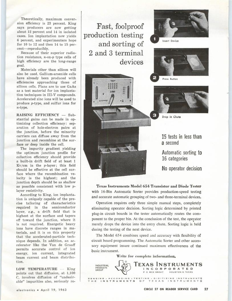
Theoretically, maximum conversion efficiency is 23 percent. King says producers are now getting about 12 percent and 14 in isolated cases. Ion implantation now yields 6 percent, and experimenters hope for 10 to 12 and then 14 to 15 percent-reproducibly.
Because of their superior radiation resistance, n-on-p type cells of high efficiency are the long-range goal.
Materials other than silicon will also be used. Gallium-arsenide cells have already been produced with efficiencies approaching those of silicon cells. Plans are to use GaAs as a test material for ion implantation techniques in III-V compounds. Accelerated zinc ions will be used to produce p-type, and sulfur ions for n-type.
RAISING EFFICIENCY - Substantial gains can be made in optimizing collection efficiency: separation of hole-electron pairs at the junction, before the minority carriers can diffuse away from the junction and recombine at the surface or deep inside the cell.
The impurity gradient yielding the optimum junction profile for collection efficiency should provide a built-in drift field of at least 1 Kv /cm in the p-layer; this field should be effective at the cell surface where the recombination velocity is the highest; and the junction depth should be as shallow as possible consistent with low player resistivity.
According to King, ion implantation is uniquely capable of the precise tailoring of characteristics required in the semiconductor layer, e.g., a drift field that is highest at the surface and tapers off toward the junction, where it is not required. Energetic heavy ions have discrete ranges in materials, and it is on this property that the accelerated-particle technique depends. In addition, an accelerator like the Van de Graaff permits accurate control of ion energy, ion current, integrated beam current and beam distribution.
LOW TEMPERATURE - King points out that diffusion, at 1,100 C, involves diffusion of "undesirable" impurities also, seriously re-
electronics • April 19, 1963
Fast, foolproof production testing
and sorting of 2 and 3 terminal
devices
15 tests in less than a second
Automatic sorting to 16 categories
No operator decision
Texas Instruments Model 654 Transistor and Diode Tester
with 16-Bin Automatic Sorter provides production-speed testing and accurate automatic grouping of two- and three-terminal devices.
Operation requires only three simple manual steps, completely
eliminating operator decision. Sorting logic determined by printed plug-in circuit boards in the tester automatically routes the component to the proper bin. At the conclusion of the test, the operator
' merely drops the device into the entry chute. Sorting logic is held during the testing of the next device.
The Model 654 combines speed and accuracy with flexibility of circuit board programming. The Automatic Sorter and other accessory equipment insure continued maximum effectiveness of the basic instrument.
INDUSTRIAL PRODUCTS GROUP
Write for complete information.
TEXAS INSTRUMENTS INCORPORATED P . 0 . BOX 66027 HOUSTON 6 . TEXAS
SENSING• RECORDING• Te:ST I NG •DIGITIZING INSTRUMENTS
THE INSTRUMENTS OF TEXAS INSTRUMENTS
CIRCLE 27 ON READER SERVICE CARD 27

Telemetry won't wait while you change reels These fwo recorders give you twice the recording time
CEC's VR-2800 (general lab) and VR-3300
(portable) record 100 kc telemetry at one•
half conventional speeds. Thus, recording time of a single reel is doubled-you get
top CEC performance at minimum cost.,, in critical blockhouse, lab, shipboard or
van applications. Bandwidth of direct recording/ repro
ducing is 100 cps to 200 kc; 0 to 20 kc with wideband FM techniques. CIRCLE 28 ON READER SERVICE CARD
Single cabinets of the VR-2800 and VR-3300 contain full 14-channel record and
reproduce systems. Six standard speeds in three pairs (60, 30 ips; 15, 7!>2 ips, and 3:J.4, 1.li; ips) are set by means of a simple belt and switch change. Both systems feature
solid state electronics for reliability and low power consumption.
Other features: all-metal-surface mag
netic heads, plug-in electronics, automatic
end-of- reel stop, and backlighted mode controls.
For complete information and specifica. tions, call your nearby CEC office, or write
for Bulletins CEC 2800V-X 1 and 3300Y-XJ.
C-EC Data Reco rders Division
CONSOLIDATED ELECTRODYNAMICS A Subsidiary of Bell & Howell • Pasadena, California

mosT versatile
high performance
recorder in its
class-
CEC's VR-2600 Working in environmental testing? Structural or transient studies? Radar recording? Telemetry? Consider CEC's VR-2600. Here's a multichannel system offering accuracy, reliability, simplicity, and room to grow into. Handling data in the 400 cps- 600 kc range via direct techniques, in the d-c - 80 kc with FM techniques, IRIG PDM via PDM electronics, and 1000 bit/ inch/each of 16 parallel tracks via saturation recording /reproducing techniques makes this recorder universally useable in both industrial and military applications. The VR-2600 employs solid state electronics for low power consumption, and full push-button controls. Six speeds, ranging from 1-7/8 to 120 ips are electrically selectable, with no adjustments required. For complete information, call CEC or write for Bulletin CEC 2600-XJO.
CEC Dato Recorders Division
CONS OLI DATED ELECTRODYNAMICS A Subsidiary of Bell & Howell• Pasadena, Calif.
CIRCLE 29 ON READER SERVICE CARD electronics • April 19, 1963
ducing the lifetime of generated carriers in the bulk region. Ion implantation, on the other hand, is done at room temperature. Heat treatment subsequently anneals out radiation damage, but this temperature never exceeds 800 C, so thermal diffusion of impurities can be avoided.
APPARATUS - Principal components of the ion implantation apparatus are illustrated. Boron ions from an r-f ion source are accelerated to an energy corresponding to the desired range in the silicon. The ion beam is passed through an analyzing magnet to remove impurities, yielding a spectroscopically pure boron beam that is then passed through horizontal and vertical scan plates.
This scanned beam strikes a slice of-typically-0.4 ohm/cm n-type silicon mounted so that it can be rotated continuously from a position normal to the beam to a parallel position. By rotating the sample continuously while the beam energy is held constant, a continuous implantation of ions is obtained from the surface to a depth
corresponding to the maximum range. Beam current is also held constant. Since incident flux decreases as the angle between the incident direction and the cell surface decreases, cam system controls the speed of sample rotation and therefore the integrated flux at any given depth below the surface.
In experimentation, the basic tool is the 2-Mev Van de Graaff made by Ion Physics' parent corporation High Voltage Engineering Corp. Researchers say that 2 Mev is probably not needed except for R&D where a broad range of energies permits a complete evaluation of the technique. Ion Physics, has reduced the energy level in solar cell work to 500 Kev, and theory says that 350 to 400 Kev would be sufficient-and less expensive.
For shallow junctions, ions can be produced by a plasma source such as HVEC's duoplasmatron, capable of delivering ion currents in the 100-ma range. This could reduce implantation times to fractional seconds and permit much greater freedom in studying impurity concentrations and gradients.
Seismic Observatory Opens FIFTH AND LARGEST seismic observatory built under the DOD's Vela program has gone into operations near Payson, Ariz. The observatories are designed to increase U.S. capabilities in underground nuclear detection. Smaller stations were previously established at Lawton, Okla.; Baker, Ore.; Vernal, Utah, and McMinnville, Tenn. (p 24, Feb. 22, 1963).
United ElectroDynamics designed and produced the equipment. The observatory has more than 60 seismometers of various types, buried in the ground in vaults. Fourteen miles of trails and 400 miles of electrical cable connect the seismometers with the recording and control center.
Concrete piers, resting on solid granite bedrock 41 feet below floor level of the observatory, pr·ovide a low-noise-level base for photo am-
plifiers which amplify electric signals from the seismometers to sufficient power to be recorded.
Seismogram Retrieva]
SCANNING cameras microfilm seismograms at U.S. Coast and Geodetic Survey's new Data Anal11-sis Center in Washington. Cameras, built b11 Itek, employ aerial photography techniques to retain detail
29

Write for detailed catalog sheet.
MARCONI INSTRUMENTS
DIVISION OF ENGL I S H EL E C TR IC C ORPOR A TION
111 CEDAR LA N E e E N GLEWOOD , NEW JERSEY
Mai" Plant: St . A lbans, £11g/wul
30 CIRCLE 30 ON READER SERVICE CARD
Lasers Fill Medical Need Ophthalmoscope-laser
to weld retinal flaws
gets human test soon
By ED ADDEO M c Graw-Hill World News
SAN F RANCISCO-The medical field, ophthalmology in particular, seems to have an inside track in the ra ce for practical uses of laser devices. Latest advance is about to be achieved by Optics Technology, I nc., of Belmont, Calif., and the Palo Alto Medical Research Foundation.
Now being developed under a National Health Institute grant of $115,000 to the Foundation is an ophthalmoscope with a built-in laser. The device can "weld" shut a retinal flaw in 1 msec (10-nsec devices have been tested ) , permitt ing treatment in an ophthalmologist's office with no anesthetic and no pain to the patient.
The ophthalmoscope-laser was designed by OTI to close pinpoint holes that develop in the retina. If left unattended, such holes can lead to complete retinal detachment from the choroid-and blindness. The 2-lb device reportedly offers the control and reliability required for medical use.
Chief investigator in the research is Narinder Kapany, presi-
TUNGSTEN ILLU MINATING
dent of OTI, and two OTI phys icists, Norman Peppers and Norman Silbertrust. Also in on the testing of the device are Drs. Milton Flocks and H. Christian Zweng, of Stanford School of Medicine's Division of Ophthalmology.
Drs. Flocks and Zweng have experimented on hundreds of r abbits with the OTI device and expect to perform the first human t ests "within a few months." The device has been described by Prof. Arthur L. Schawlow, of Stanford, co-discoverer of the laser principle, as "probably the first real application of the laser."
OTHER USES-Dr. Zweng sees laser t reatment soon developing to the point where lasers will be used to burn tumors and other vascula r diseases of the eye, and cure ma ny types of disorders of the iris. In a cataract operation, for example, removal of the cataract often results in the iris being peeled off the eyeball. The laser, in this ca se, cou ld conceivably "burn" a new pupil into the patient's eye, restoring his sight.
Areas of the retina where treatment is impossible due to the eye's curvature may soon be reach ed through fiber-optics attachments to the OTI device. Peppers r epor ts that OTI has already developed a fiber optics device, encased in a hypodermic needle, that allows
IL LU MIN ATED AREA
BULB\ TREATED SPOT
APERTURE-------------.~j !
,..-'--..
RETIN A AN D CHOROID
RUBY ROD
Ii
CROSS HAIR S---h I I I I I I I \
CONDENSING LENS----...1 1
\<=! \ I
I
EYE LENS CORNEA
VIEWING LENS
FUNCTIONAL ARRANGEMENT of the instrument. Crosshairs are used to aim the beam at the hole in the eye's r etina
Apr i l 19 , 1963 • e lectronics
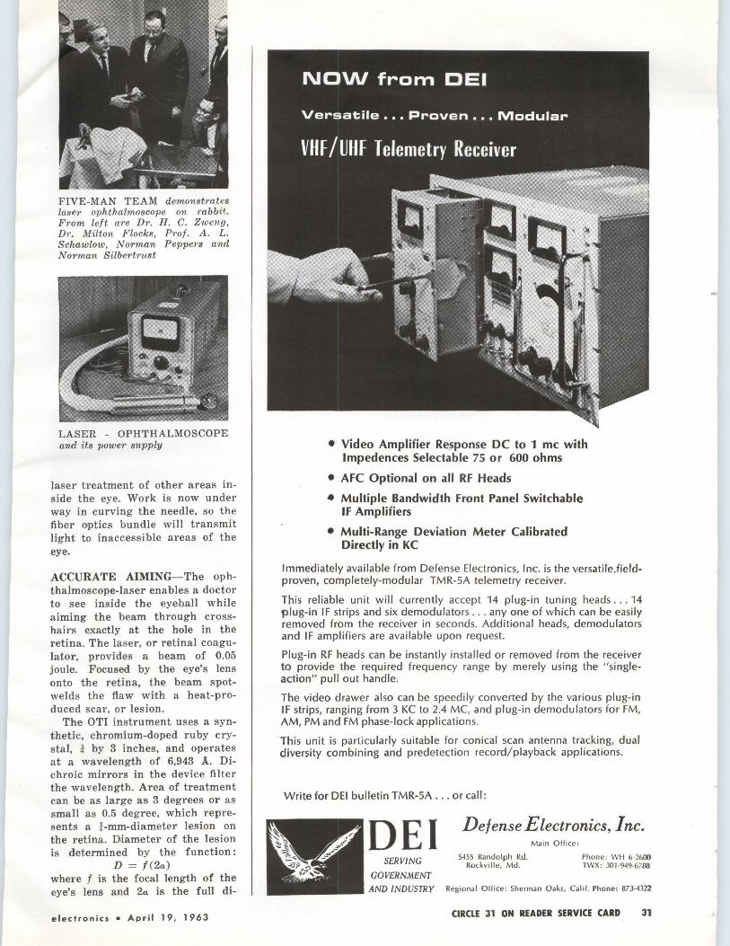
FIVE-MAN TEAM demonstrates laser ophthalmoscope on rabbit. From left are Dr. H. C. Zweng, Dr . Milton Flocks, Prof. A. L. Schawlow, Norman Peppers and Norman Silbertrust
LASER - OPHTHALMOSCOPE and its power supply
laser treatment of other areas inside the eye. Work is no,w under way in curving the needle, so the fiber optics bundle will transmit light to inaccessible areas of the eye.
ACCURATE AIMING-The ophthalmoscope-laser enables a doctor to see inside the eye,ball while aiming the beam through crosshairs exactly at the hole in the retina. The laser, or retinal coagulator, provides a beam of 0.05 joule. Focused by the eye's lens onto the retina, the beam spotwelds the flaw with a heat-produced scar, or lesion.
The OTI instrument uses a synthetic, chromium-doped ruby crystal, ! by 3 inches, and operates at a wavelength of 6,943 A. Dichroic mirrors in the device filter the wavelength. Area of treatment can be as large as 3 degrees or as small as 0.5 degree, which represents a ! -mm-diameter lesion on the retina. Diameter of the lesion is determined by the function:
D = f (2a) where f is the focal length of the eye's lens and 2a is the full di-
electronics • April 19, 1963
• Video Amplifier Response DC to 1 me with lmpedences Selectable 75 or 600 ohms
• AFC Optional on all RF Heads
• Multiple Bandwidth Front Panel Switchable IF Amplifiers
• Multi-Range Deviation Meter Calibrated Directly in KC
Immediately available from Defense Electronics, Inc. is the versatile,fieldproven, completely-modular TMR-SA telemetry receiver.
This reliable unit will currently accept 14 plug-in tuning heads ... 14 plug-in IF strips and six demodulators ... any one of which can be easily removed from the receiver in seconds. Additional heads, demodulators and IF amplifiers are available upon request.
Plug-in RF heads can be instantly installed or removed from the receiver to provide the 'required frequency range by merely using the " singleaction" pull out handle.
The video drawer also can be speedily converted by the various plug-in IF strips, ranging from 3 KC to 2.4 MC, and plug-in demodulators for FM, AM, PM and FM phase-lock applications.
'This unit is particularly suitable for conical scan antenna tracking, dual diversity combining and predetection record/playback applications.
Write for DEi bulletin TMR-SA ..• or call:
DEi Defense Electronics, Inc.
SERVING
GOVERNMENT
5455 Randolph Rd. Rockville, Md.
Main Office ;
Phone: WH 6-2600 TWX: 301-949-6788
AND INDUSTRY Regional Office : Sherman Oaks, Calif. Phone; 873-4322
CIRCLE 31 ON READER SERVICE CARD 31

32
t SIEMENS
Electron Tubes Power grid tubes for AM and FM radio broadcasting, VHF and UHF television transmitters, and communication and industrial heating equipment. Siemens external anode tubes are available for all classes of service including coaxial based tubes for high frequency operation up to 1000 Mc/s, and vapor cooled tubes with plate dissipation ratings up to 180 kWatts .
Internal anode radiation cooled glass types are available for frequencies up to 600Mc/s, and plate dissipation ratings up to 1.2kWatts.
Three widely used ceramic-metal tetrodes are described below.
Type Application Max. frequency Power Maximum Ratings at full/reduced Output ratings Syncron Plate Plate Dissi pation
Level Vol-tage Air Water
Cool- Cool-ed ed
Mc/s kWatts kV de. kWatts kWatts
RS 1032 C UHF TV Transmitter 790 10 5.2 10 960 7.5 4.1 10
RS 1052 C UHF TV Transmitter 790 2.2 3.8 3.5 960 1.6 3.1 3.5
RS 1082 C SSB Transmi tter 30 20· 10 25 30 250 25 30
•single tone power output, zero grid current
For further Information and application engineering assistance regarding these electron tubes manufactured by Siemens &. Halske AG • Germany, please write to their distributor in the u.s. A.:
SIEMENS AMERICA INCORPORATED
Vapor Cool-ed kWatts
45 45
350 Filth Avenue, New York 1, N. Y. · Tel : LOngacre 4-7674. Telex 01-2070, Cable: siemens newyork
In Canada:
SIEMENS HALSKE SIEMENS SCHUCKERT (CANADA) LTD. 407, McGill Street, Montreal 1, P.O.· Tel : 849-5783. Telex 012800, Cable: slemenscan
CIRCLE 32 ON READER SERVICE CARD
LESION formed on rabbit's retina by OTI laser
RETINAL cross section showing scar formation
LASER OUTPUT is set to produce a scar large enough to scar over the retinal hole without causing hemorrhaging
vergence angle of the crystal. Lesion diameter is a nonlinear function of incident energy-too high an output would cause hemorrhaging and too small an output would not effectively scar over the retinal hole (see graph).
A safety feature of the device is two isolated capacitors, each 175 µ.f, that cannot accidentally discharge together at full power because they are separated by 100-ohm resistors (see diagram p 36).
Price of the instrument, although not being seriously discussed until all testing is completed, will probably be around $2,000.
MEDICAL NEED - Each year, thousands of persons develop retinal detachment. When the fluid in the
(Continued on p 36)
April 19, 1963 • electronics

I I I I I I
t SIEMENS

MKH and MKL. .. t
the smallest metallized film capacitors SIEMENS
Siemens MKH and MKL capacitors set new standards for both small size and high reliability. Twenty years' experience in making metallized capacitors has resulted in advanced manufacturing techniques which closely control every capacitor property. And these capacitors are almost completely foolproof in service; their "self-healing" ability eliminates the possibility of any voltage breakdown.
TWO SELF-HEALING PROCESSES
1. There is very little probability of an internal voltage breakdown. Whenever it happens, however, the thin metal coatings at t he breakthrough point act as a fuse element and vaporize. The resulting gas pressure blows the vaporized metal away from the breakthrough point-interrupting the breakthrough within a few microseconds and eliminating any possibility of its recurrence.
Tests at nominal voltage show that the average probabilty is less than one self-healing breakdown per year and per mF. This value is for the first year. It is even less for following years. (The average total is 15 self-healing breakdowns in 20 years.) At lower than nominal voltages, the probability is far less .
Overload tests (at 2.2 times nominal voltage and at 85'C) show that decrease of capacitance as a result of self-healing is negligible, even after several years.
2. The second process, "electrochemical self healing," starts whenever and wherever insulation resistance decreases in the dielectric material. This process works at any voltage, even at 10 mV. It may continue for severa l hours or days. Its effect is to change the metal coating at the point of lowest insulation resistance to a non-conductive oxide .. . thus eliminating the point electrically.
There is pract ically no change in insulation resistance during or after an electrochemical self heal ... or after a self-healing breakdown.
MKH metallized polyester capaci tors-small size at low cost. MKH capacitors are available, with axial or radial leads, in a flat shape. See photo below. A round type will be available soon. Leads are soldered to metallized ends to ensure reliable contact. The dielectric is polyester film widely used for capacitors.
Operating temperatures : - 40 ' to+ 125'C.
Insulation resistance : At least 20,000 megohms for nominal capacitance up to .022 mF at + 20 ' C. For higher capacitance values: 10,000 megohms x mF (typical values) .
Temperature coefficient: Approx .. 04%/ C' between 0' and 70'C.
Dissipation factor: 0.5% at 1 kc; 1.5% at 10 kc (typical values).
Dimensions (in inches):
Capacitance Nominal Voltage Values (mF)Ol 250 VDC 400 VOC<2l
.01 ~ .21 x .36 x .56
.015 Rated for up to 630V .25 x .40 x .56
.022 .30 x .46 x .56
.033 .25 x .40 x .56
.047 .21 x .36 x .80
.068 .23X.38 X .56 .25 X .40 X .80
.10 .26X.42 X .56 .28 X .44 X .80
.15 .25X.38 X .80 .25 X .50Xl.09
.22 .25X.48 X .80 .30 X .54Xl.09
.33 .23X.48Xl.09 .32 X .70Xl.09
.47 .25X.62Xl.09 .32 X .82Xl.19
.68 .26X.76Xl.09 .40 X .89Xl.19 1.0 2.0
.36X.74Xl.09
.48X.99Xl.19 .52Xl.01 Xl.19
(1) Usual tolerance: ±20%. Closer tolerances and intermediate values on request. (2) All values from .033 to .22 mF also available at 630V ratings.
MKH capacitors (± 20% tolerance and axial leads) are in limited stock in White Plains, N. Y.
MKL miniature metallized lacquer capacitors - smallest film capacitor in mass production. The dielectric is a 1 /10 mil film of lacquer. A recent invention has substantially improved insulation resistance and allowed higher voltage ratings.
MKL standard type B 32110 capacitors are cased in an aluminum tube sealed with epoxy resin. MKL Type B 32120 capacitors are enclosed in a non-magnetic metal can hermetically sealed with glass. For both types, a plastic sleeve provides external insulation.
MKL capacitors are used for all types of circuits requiring high components density.
Operating temperatures: -40 to +85'C.
Insulation resistance: 5000 megohms x mF (typical value). 1000 megohms x mF (mini mum value).
Temperature coefficient : Approx . . 08%/ ' C for temperature above O' C.
Dissipation factor : 1 % at 100 cps; 1.5% at 1 kc; 2% at 10 kc. (All at 20'C.) Dimensions (Type B 32110) in inchesrn : Capacitance Nominal Voltage Values (mFJ<2i 50 VDC 100 VOC<Ji
0.1 .21 x .73" 0.22 .21 x .73" .25 x .73 0.47 .29 x .73 .29 x .83 1.0 .29 x .83 .37 x .83 2.2 .42 x .83 .42 x .98 4. 7 .42 X . 98 .46X 1.34
10.0 .50Xl.34 .66Xl.34
(1) Dimensions for Type B 32120 are slightly larger. (2) Usual tolerance: ±20%. Closer tolerances and intermediate values on request . (3) All values are also available in 160V rating.
MKH and MKL capacitors are distributed by Wi lliam Brand Electronic Components Inc. Services are available through sales representatives throughout the U. S. CIRCLE 264 ON READER SERVICE CARD.

See anything?
~
This new film did.
This new film saw something the eye couldn't: the rise time of a single pulse on a Textronix 519 scope at a sweep rate of 2 nanoseconds/ cm. The new film, Polaroid PolaScope Land Film, actually extends the usefulness of existing oscilloscopes by supplying "brightness" that the scope hasn't got!
The reason is that this PolaScope film has an ASA equivalent rating of 10,000, which means it can see things your eye cannot. It has about twice the writing rate of the Polaroid 3000-speed film, currently the standard for
high speed oscilloscope photography. (No other commercially available films come anywhere near the speed of PolaScope film.) And because it's made by Polaroid you get a finished usable print-see above-ten seconds after exposure.
PolaScope film will also give you better shots of slower pulses and stationary waveforms. So little light is required, camera aperture and scope intensity can be reduced considerably, and that's how to get reaIIy sharp oscilloscope pictures.
And wherever else light is at a premium - such as photomicrography and Kerr Cell photography -PolaScope film will make new applications possible, old applications more useful.
PolaScope Type 410 Film is packed 12 rolls to the carton. The price is about the same as the Polaroid 3000-speed film. For the name of the industrial photographic dealer nearest you, write to Technical Sales Department, Polaroid Corporation, Cambridge 39, Massachusetts. POLAR010®
New Polaroid L'and 10,000-speed film for <>scillography
electronics • April 19, 1963 CIRCLE 35 ON READER SERVICE CARD 35
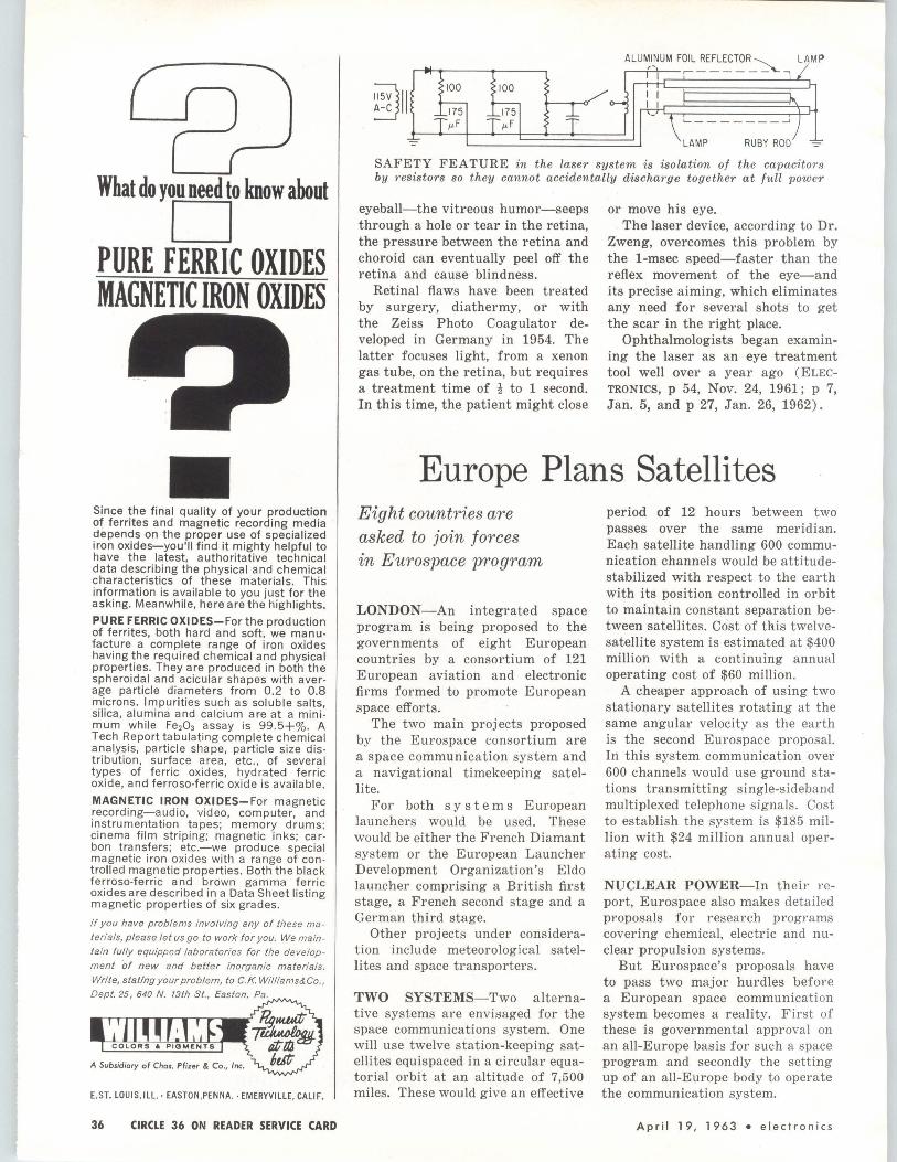
What do you need to know about
D PURE FERRIC OXIDES MAGNETIC IRON OXIDES
Since the final quality of your production of ferrites and magnetic recording media depends on the proper use of specialized iron oxides-you'll find it mighty helpful to have the latest, authoritative technical data describing the physical and chemical characteristics of these materials. This information is available to you just for the asking. Meanwhi le, here are the highlights.
PURE FERRI C OXI DES-For the product ion of ferrites, both hard and soft, we man ufacture a complete range of iron oxides having the required chemical and physical properties. They are produced in both the spheroidal and acicular shapes wi t h average particle diameters from 0.2 to 0 .8 microns. Impurities such as solub le salts, silica, alumina and calcium are at a mi nimum while Fe203 assay is 99.5+%. A Tech Report tabulating complete chemical analysis, particle shape, particle size distribution, surface area, etc., of several types of ferric oxides, hydrated ferric oxide, and ferroso-ferric oxide is available.
MAGNETIC IRON OXI DES-For magnetic recording-audio , video, computer, and instrumentation tapes; memory drums; cinema film striping; magnetic inks; carbon transfers; etc.-we produce special magnetic iron oxides with a range of con· trolled magnetic properties. Both the black ferroso-ferric and brown gamma fe rric oxides are described in a Data Sheet listing magnetic properties of six grades.
If you have problems involving any of these ma
terials, please let us go to work for you. We main
tain fully equipped laboratories for the develop
ment of new and better inorganic materials.
Write, stating your problem, to C.K. Williams&Co. ,
Dept. 25, 640 N. 13th St., Easton, Pa.
E.ST. LOUIS, ILL. · EASTON.PENNA.· EMERYVILLE, CALIF.
36 CIRCLE 36 ON READER SERVICE CARD
ALU~l~UM F~L~E~~~R_ ~.., /MP
;)11 100 100 t-
SAFETY FEATURE in the laser system is isolation of the capacitorB by resistors so they cannot accidentally discharge together at full power
eyeball-the vitreous humor-seeps through a hole or tear in the retina, the pressure between the retina and choroid can eventually peel off the retina and cause blindness.
Retinal flaws have been treated by surgery, diathermy, or with the Zeiss Photo Coagulator developed in Germany in 1954. The latter focuses light, from a xenon gas tube, on the retina, but requires a treatment time of t to 1 second. In this time, the patient might close
or move his eye. The laser device, according to Dr.
Zweng, overcomes this problem by the 1-msec speed-faster than the reflex movement of the eye-and its precise aiming, which eliminates any need for several shots to get the scar in the right place.
Ophthalmologists began examining the laser as an eye treatment tool well over a year ago ( ELECTRONICS, p 54, Nov. 24, 1961; p 7, Jan. 5, and p 27, Jan. 26, 1962).
Europe Plans Satellites Eight countries are asked to join forces in Eurospace program
LONDON-An integrated space program is being proposed to the governments of eight European countries by a consortium of 121 European aviation and electronic firms formed to promote European space efforts.
The two main projects proposed by the Eurospace consortium are a space communication system and a navigational timekeeping satellite.
For both systems European launchers would be used. These would be either the French Diamant system or the European Launcher Development Organization's Elda launcher comprising a British first stage, a French second stage and a German third stage.
Other projects under consideration include meteorological satellites and space transporters.
TWO SYSTEMS-Two alternative systems are envisaged for the space communications system. One will use twelve station-keeping satellites equispaced in a circular equatorial orbit at an altitude of 7,500 miles. These would give an effective
period of 12 hours between two passes over the same meridian. Each satellite handling 600 communication channels would be attitudestabilized with respect to the earth with its position controlled in orbit to maintain constant separation between satellites. Cost of this twelvesatellite system is estimated at $400 million with a continuing annual operating cost of $60 million.
A cheaper approach of using two stationary satellites rotating at the same angular velocity as the earth is the second Eurospace proposal. In this system communication over 600 channels would use ground stations transmitting single-sideband multiplexed telephone signals. Cost to establish the system is $185 million with $24 million annual operating cost.
NUCLEAR POWER-In their report, Eurospace also makes detailed proposals for research programs covering chemical, electric and nuclear propulsion systems.
But Eurospace's proposals have to pass two major hurdles before a European space communicati on system becomes a reality. First of these is governmental approval on an all-Europe basis for such a space program and secondly the setting up of an all-Europe body to operate the communication system.
April 19, 1963 • electronics

MEETINGS AHEAD
QUALITY CONTROL & RELIABILITY CONFERENCE, American Societv for Quality ·Control; Hofstra University, Hempstead, N. Y., April 20.
MOTION PICTURE & TELEVISION F.Nc:TNEERS CONVENTION, SMPTE; Trav more Hotel, Atlantic City, N. .T., April 21-26.
BIO-MEDICAL ENGINEERING SYMPOSIUM, TEEE, et al; Del Webb's Ocean House, San Diego, Calif., April 22-24.
MANNED RPACE FLTGHT MEETING. NASA, AIAA: Marriott Hotel, Dallas, Texas, Apr il 22-24.
WEATHER RADAR CONFERENCE. American Meteorolo!!ical Society; International Inn, Washington, D . C. April 22-25.
NATIONA'L ELECTROMAGNETIC RELAY CONFERENCE: Oklahoma State Univer~ity: OSU, Stillwater, Okla., A pr il 23-25.
POWER INDUSTRY COMPUTER CONFERF."1CE, IEEE: Westward-Ho Hotel, Phoenix, Ariz., April 24-26.
REGION 8 MEETING. IEEE; .John Marshall Hotel, Richmond, Va., A p r il 24 -26.
VALUE ENGTNEER!NG CONVENTION, Society of American Value Engineers; Americana Hotel, New York City, A pril 25 -26.
PHOTOGRAPHIC SCIENTISTS AND ENGIN"ERS CONFERENCE, SPSE and Army Research Office; Ambassador Hotel, Atlantic City, N. J., Apr il 29-May 3.
T"'CHNICAL ASPECTS OF COMMUNICATTONS SATELLIT!'S CONFERENCE, NASA, Illinois Institute of Technology, etc.; at IIT, Chicago, May 2-3.
ELF:CTRON!C COMPONENTS CONFERENCE, IEEE, EIA; International Inn, 14th & M Streets, N . W., Wash ington , D. C., May 7-9.
IMPACT OF M'CROELECTRONICS CONFERENCE, Armour Re>iearch Foundation and ELECTRONICS Magazine : Ill inois Institute of Technology, Ch icago, Ill., June 26-27.
WESTERN ELECTRONIC SHOW AND CONFERENCE, WEMA, IEEE; Cow P alace, San Francisco, Calif., A u g . 20-23.
ADV ANGE REPORT MAGNETISM AND MAGNETTC MATERIALS CONFERENCE, rE EE and American Insti tute of Phys ics; Atla.ntic City. N. J .. No'V. 12-15, 196 .~. Informati.on on submission of abstra.cts cm1 be olJtainrd f1·orn: William D. D oyle. Frcmklin Institute Lab-01·atories. Philadel1ihia. 3, Pct. Areas of interest include votcntictl engineering avpliorttions 'ltsing recent rul1Jances in rnagnetisin including those related to suvcrconrl1tctivity.
electroni c s • Apr i l 1 9, 196 3
''twofer'' With Heinemann's Type A Silic-0 -Netic®, you get two relays for the price of one: a time-delay relay and a load relay. In one small package (shown actual size above), you get a timedelay relay that can double, if you wish, as a load carrier, too. '(It's got a continuous-duty coil; you don't have to use aux· iliary lock-in circuits or slave relays.)
The Type A tips the scale-barely-at three ounces. It comes with any delay you spec, from a quarter-second to two minutes, can be supplied for use on any one of twenty standard AC or DC voltages. Contact capacities range up to three · amps. Maximum power consumption is two watts AC, three watts DC. Switching is SPOT or DPDT. Operating life is somewhere in the millions (the hydrau lic-magnetic delay element is hermetically-sealed, fatigue-free).
The Type A (and the entire line of Heinemann time-delay relays) is described in full in our Bulletin 5003. A copy is1
yours for the asking.
HEINEMANN ELECTRIC COMPANY • 2600 BRUNSWICK PIKE, TRENTON 2, NEW JERSEY 8A 0 2455
CIRCLE 37 ON READER SERVICE CARD 37

Who can deliver the most complete line of portable instrumentation recorders? AMPEX
And what a line it is. There's a portable for medical, for industrial, for research applications, for rugged applicat ions -for almost every data acquisition need . And there's a price to fit almost every budget. Behind each recorder stands the name of Ampex -to assure you true instrumentation performance all the time. On the top, above: the lowcost SP-300. It has four speeds, four tracks, push-button selection for FM or Direct recording, plus built-in attenuation, monitoring, calibration and erase. In the middle is the FR-1300. It offers 14 tracks, 300 cps to 300 KC capability on Direct, DC to 20 KC on FM and six speeds precisely controlled by a unique servo-driven capstan. On the
38 CIRCLE 38 ON READER SERVICE CARD
bottom: the rugged CP-100. It records Direct, FM -Carrie r and PDM. Has a closed loop drive, six standard speeds, 14 tracks, a frequency response of up to 250 KC on Direct, down to DC on FM. And it operates on almost any source of power- including batteries. In other word s, Ampex has a portable line so complete you can pick a recorder to fit your needs instead of having to modify you r requirements to fit the recorder. For more information write the only company providing recorders, tapes and core memory devices for every application : Ampex Corp., 934 Charter St., Redwood City, Calif. Term financing and JAMPEX J leasing available. Worldwide sales and service .
April 19 , 1963 • e l ectronics

INFRARED OPTICS package mounted on radar bowl's elevation trunnion to the right of bowl's rim and expanded view of optics package
electronics A McGraw-Hill Weekly April 19, 1963
NEW INFRARED SYSTEM TRACKS MISSILES
AGAINST BRIGHT FLORIDA SKY
Equipment distinguishes target from clouds
even when clouds reflect more energy.
Infrared optics package is mounted on
radar antenna trunnion and controls
tracking at short range when spurious
returns make conventional radar ine.ff ective
By T. P. DIXON, ITT Federal Laboratories, San Fernando, Calif.
THIS INFRARED TRACKER was designed for the early stages of missi le launching when ordinary radars suffer from interference due to false echoes. The infrared equipment was mounted on a radar antenna assembly a nd its signal fed into the existing radar control system. When a newly launched vehicle reaches burnout the same antenna is automatically switched-in to track the vehicle by radar operation rather than infrared.
For this application, high sensitivity is not important because there is sufficient energy from the missile plumes to provide a large signal-to-noise
39

ratio. The measured noise equivalent flux density (NEFD) of 10-10 watt/cm• has proven adequate. The problem was to provide a large enough tracking field to avoid the loss of close-range high-acceleration targets, and provide sufficient background suppression to permit operation in the brightly lighted cumulus clouds that are common in the Florida area. Also, it was desired to make the instrument simple and reliable, and to require a minimum of adjustment and maintenance. In addition, the tracker required a large dynamic range so that it would track small missiles to great range without needing gain adjustments, and yet would not saturate and lose track on large missiles from nearby launching pads.
These requirements were satisfied by using imaging optics that resolved 0.1 milliradian in a 70 x 70
DIMMING THE FLORIDA SKY
FLORIDA doesn't seem the best spot to locate an infrared tracking system because, according to Murphy's Law, if the sun could possibly interfere with the proceedings, then it will. Consequently, this system's designers have had to devise methods of eliminating interference from the sun's energy, which is drastically more intense than the plume of any target now envisaged.
Direct sunlight is taken care of by an automatic shutter that covers the aperture of the optic inlet. Indirect sunlight-reflections from clouds and so on, are the more troublesome source of interference: radiation from a large bright cloud adds up to much more energy than any missile's plume produces. Yet the infrared system can still distinguish between a missile and a bright cloud which forms the missile's background. The secret lies in the design of the reticle (chopper), which delivers a signal only when a small target is in view
40
MIRRORS are used in optical system to minimize absorption of infrared energy (A). Final opt ics stage uses condensing lense to define a .4 degree fi eld of v iew then a conical mirror to spread the infrared energy over the photocell surface (B)-Fig. 1
milliradian field and which made it possible to use a reticle that provided a high degree of space filtering, by further discriminating against the background with spectral filtering, and by the use of an age amplifier having a dynamic range of 10'. Specifications are given in the table p 42.
EQUIPMENT CONFIGURATION-The electronic unit consists of the control-display panel, signa l processing chassis and power supply. The electronic unit is in a cabinet inside the radar building, next to the radar control console. The control-display panel is arranged for easy access by the operator.
The output unit is mounted on the elevation t runnion alongside the boresight camera on the FPS-16 radar. The line-of-sight of the tracker is just outside the rim of the antenna. When precise tracking data are desired from the early launch phase, the 6 ~ foot azimuth parallax error may be corrected in subsequent data processing.
OPTICAL UNIT-An important design requi rement for the optical unit was minimum weight to avoid undue increase in the moment-of-inertia of the radar antenna about one or both axes. It was also necessary to maintain sufficient rigidity to avoid target image movement due to structural flexures when subjected to vibration and acceleration. These requirements were satisfied by mounting all optical elements on 1/2 inch thick aluminum tooling plate that had been "waffled" out on the underside. Approximately 60 percent of the weight was removed with little loss of rigidity in the optical path. Other advantages of the tooling plate are the precisely flat surface for mounting the optical elements, and its freedom from creep or cold flow that is common with other lightweight structural materials.
A simplified schematic of the optical unit is shown in Fig. 1. Infrared energy from the target enters the unit through the sealed Vycor window A. It is reflected by the pierced folding mirror B to the imag-
April 19, 1963 • electronics

RETICLE distinguishes target from such large area infrared sources as highly reftecting clouds. Missile plume covers optical axis while energy from cloud spans 3 sets of parallel spokes--'lnissile's energy is chopped by the group of opaque spokes but cloud energy is averaged over large area and produces no output signal-Fig. 2
ing spherical mirror C. This is a 41 inch diameter, 9 inch focal length mirror stopped down to f /3 by the entrance window that is located at twice the focal length from the spherical mirror. This field-stop makes it possible to maintain a small blur circle over the entire image field. Locating the image plane near the folding mirror improved the optical efficiency by making possible a small obscuration.
The target energy passes through the opening in the folding mirror B and forms a real image on the reticle (described in detail later ) D. The energy transmitted by the reticle is collected by the coated germanium condensing lens E that defines the 4 degree total field of view. The energy is further condensed into a small area perpendicular to the optical axis by a gold-plated condensing cone F . The use of such a cone increases the efficiency of the f / 3 primary optics to an effective ratio of slightly better than f / 1. The scrambled energy leaving the condensing cone strikes the uncooled lead sulfide detector G. The signal generated by the cell is carried by a coaxial cable to the signal preamplifier.
A 2.1-micron short-wavelength-cutoff interference filter H is placed in the optical path just ahead of the reticle. This filter improves the ratio of t arget to background energy for the majority of the targets. A sun shutter I actuated by a rotary solenoid is placed in the optical path to protect the detector cell when the sun is within the field of view. It is operated in a fail-safe mannerheld closed by spr ing force and opened only when current flows through the solenoid coil; it remains closed when the instrument is turned off. The sun sensor is a silicon solar cell that receives energy through a small entrance window J. A two-stage, silicon transistor amplifier driver K actuates the rotary solenoid. The sun sensor has a 50 percent greater field of view than the tracker to allow time for the sun-shutter to close before direct sunlight reaches the cell. Using a 6 degree field of view, direct irradiance from the sun is still a large multi-
electronics • April 19, 1963
II.It:~;_~--=-,--- MISS I LE PLUM E'S [)ttWl!l!l!tttll!ll COVERAGE
pie of the reflected energy from bright cloud banks, so that the threshold energy to trigger the sun shutter solenoid driver is not critical, and false alarm closures do not occur.
RETICLE-An illustration of the reticle used in the tracker is shown in Fig. 2. This offset reticle performs two important functions in addition to chopping the energy to permit a-c amplification. It provides an average space filtering of 357 waves per radian to aid in distinguishing the target from the background; it also generates a signal waveform that contains information on the position of the target within the field of view. In an instrument of this type, having a relatively large 4 degree x 4 degree field of view, the amount of near-ir energy that may be received from sunlit clouds can be much greater than that from the target that is being tracked. Without space filtering, such a cloud entering the field of view would cause the target to be lost.
The basic function of space filtering reticles is the enhancement of those components of the spatial radiance distribution in the scene which coincide with the periodicity of the reticle pattern, and the suppression of those which do not. The ideal reticle for discrimination in favor of a point target might be considered to be of the checkerboard type. This is rarely used, however, because of its inability to chop reliably target images along the boundaries of the checkerboard elements, and also because it is affected with virtually unavoidable phase jumps in the modulated signal whenever the target image moves from one row of elements to any of the neighboring rows. Due to these shortcomings the application of spoke reticles with radial or involute patterns, has become widely accepted wherever high degrees of space filtering are essential.
The problems of background suppression have been studied, and in recent years there have evolved a number of sophisticated reticle designs that offer improved performance for certain applications. The
41

reticle in Fig. 2 offers a significant improvement in performance with the particularly serious background condition consisting of long, clearly defined boundaries between brightly lighted clouds and a deep blue sky. It employs seven groups of parallel spokes deposited on a Vycor disk and arranged so that the center-line distance between adjacent spoke groups is exactly equal to the width of the groups. The space between the groups is coated to have an ir transmittance of 50 percent. Because of this coating the lead-sulphide (PbS) detector will receive the same average amount of energy from a large area source regardless of whether a group of spokes or the blank space is in the optical path. With the transmittance of the blank areas matched to the integrated transmittance of the spoke areas, there will be no frame-rate signal appearing in the output of the detector.
The center spoke in each group lies along a radial line, while the remainder of the spokes are at progressively increasing angles from radii through their centers. Because of this arrangement, each spoke within a group will chop the image from a slightly different angle. Therefore, if a straight cloud edge should appear in the field of view, regardless of its orientation, only one spoke in each group can chop it completely, while all the other spokes will cut diagonally across it. In this parallel-spoke reticle the degree of background rejection varies directly with the angular deviation of the spokes from radial lines. The limit to which such deviations can be used is imposed by the aspect ratio of the target. When tracking targets having a large vertical aspect-as do missiles in the early launch phase-an increase in the angular deviation of the spokes would cause the reticle to discriminate against the target as well as the background, and would provide no further improvement in the target-to-background ratio. A compromise was reached whereby some target discrimination was permitted during the early launch phase, where the target energy received by the tracker is greatest, to permit still further improvement in background rejection during the later phase when the target aspect ratio approaches unity.
Another function of the reticle is to generate a signal containing information on the position of the target image in the field of view. This reticle makes
TRACKING SYSTEM SPECIFICATIONS
Field of view Resolution Tracking accuracy NEFD (2.1 to 2.65µ) Dynamic range Error signal slope Error signal maximum
amplitude
Weight
Size
42
70 milliradians 0.1 milliradian 0.25 milliradian I 0-1
• watts/ cm• 106 (includes 102 limiting in preamp) 0-2 volts/ milliradian
0- 10 volts
j Optical unit, 17 pounds Electronic unit, 50 pounds Optical unit, 7 X 11 X 15 in. Electronic unit, 22 X 19 X 15 in.
it possible to generate azimuth and elevation angle error signals independently with a single detector. Each group of spokes in the reticle contains 25 spokes and 25 spaces. When a target is on the optical axis, its image will be chopped by the spokes, and a signal will be generated by the infrared detector consisting of a group of 25 cycles followed by an equal period of time at constant amplitude. If the target moves up in the field of view, it will be chopped for a shorter period of time and will occupy the blank space between adjacent groups of spokes for a longer period of time. This will result in a signal from the detector having a higher frequency, and with an envelope having a duty cycle of less than 50 percent. If the target should move toward the bottom of the field of view, the target will be chopped for a greater percentage of the reticle rotation, and a smaller percentage of time will be spent in the blank space between groups of spokes. The resulting signal will have a lower frequency, with an envelope having a duty cycle greater than 50 percent. A measurement, therefore, of either the signal frequency or the duty cycle in the envelope is a direct indication of the vertical position of the target within the field of view. If the target moves to the right or left from the optical axis, the frequency and duty cycle will remain unchanged, but the signal will be displaced in phase from a time reference. By using a reference signal generated by a magnetic pickup in the reticle hub_, a measurement of phase displacement will give an accurate indication of the horizontal position of the target within the field of view.
SIGNAL PROCESSING-Figure 3 is a simplified block diagram of the circuit. The blocks shown to the left of the dashed vertical line are contained in the optical unit which is mounted on the radar antenna. The blocks to the right are contained in the electronic unit which is mounted inside the radar building.
The signal from the lead sulfide detector is applied to the input of the transistor preamplifier. This preamplifier uses silicon semiconductors and will withstand a 10,000-percent overload without damage or blocking. This overload capacity is desirable to permit operation of the tracker with future high energy boosters at close range.
The pulses from the magnetic pickup are amplified in a similar, but smaller, preamplifier. The signal and reference voltages are connected to the electronic unit through coaxial slip rings on the radar pedestal. The signal is applied to a two-section, high gain, age amplifier which has a constant output amplitude with a 10' variation in input signal amplitude. By maintaining the peak amplitude of the signal constant with an age amplifier, the background signals are suppressed rather than accentuated, as with a conventional amplitude limiter.
The constant amplitude signal is rectified and filtered to extract the waveform envelope. At this point the signal is applied simultaneously to three channels. The upper channel Fig. 3, is a duty cycle detector which generates the elevation error signal. When the target is in the center of the field of view, the signal
April 19, 1963 •electronics

OPTICS package includes clock generator that provides reference signal for elevation and azimuth information. Electronic unit uses age that accommodates variations in target intensity over 10,000 :1 range-Fig. 3
envelope has a duty cycle of 50 percent. A Fourier analysis of this square-wave signal indicates that it contains no even-order harmonics. If this signal is applied to a circuit that extracts only the second harmonic, the output of the circuit will be zero when the target is on center. When the duty cycle of the signal increases or decreases, a second harmonic component will be present in an amount that varies with the deviation of the duty cycle from 50 percent, and of a phase that is determined by the direction of the deviation. A synchronous rectifier operating at twice the fundamental frequency derives a polarity reversible d-c signal from the phase reversible a-c signal. Circuit for extracting the second harmonic from the input signal contains a band-pass filter having a center frequency of twice the fundamental frequency of the signal envelope and a broad top to permit operation with variations in the reticle speed.
The azimuth error signal is generated by a conventional phase detector that uses the reference signal from the magnetic pickup in the optical unit. The azimuth and elevation error signals are indicated on panel meters which are calibrated in milliradians.
The error signals are applied to the radar antenna servos through a switching network that provides for manual and automatic switching. A trigger circuit provides an ENABLE voltage to the automatic portion of the switching network whenever a signal envelope at the fundamental frequency exists at the output of the rectifier-filter with amplitude sufficient to indicate the presence of a target.
In the automatic switching mode, control of the antenna servos is retained by the radar receiver or by other manual or designated sources at the option of the console operator, until the missile plume appears. At this time the switching network is energized automatically, and control of the antenna servos is transferred to the infrared tracker. This control is retained as long as the target produces sufficient irradiance to provide a tracking signal.
If the target is lost by obscuration or due to burnout, control of the antenna servos switches auto-
e lectronics • Ap ril 19 , 19 63
matically back to the radar receiver. At any time in the missile's flight, the console operator may press a button and switch manually from infrared to radar tracking. Lighted indicators on the control panel show whether a target is in the field of view, regardless of which tracking mode has been selected. Indications are given also of the selected tracking mode and further indicators show whether the infrared or radar tracker is actually controlling the antenna servos.
The boresight adjustments shown on the block diagram are front panel controls which permit the operator to compensate for any mechanical boresight errors that may exist prior to an operation. Compensation is accomplished by locking the radar tracker onto the boresight tower and adjusting the knobs for zero error signals on the panel meters while the infrared tracker is viewing an infrared lamp mounted on the boresight tower.
SYSTEM INTEGRATION-One of the problems generally encountered in integrating a new piece of equipment into an existing operational system is in providing a match in operating characteristics. This is particularly true when the existing system contains high velocity servos. By analysis and experiment, the critical parameters of volts per milliradian and phase lag of the infrared tracker were matched to those of the radar receiver for error signal rates to approximately twice the resonant frequency of the antenna servos. By making this match, the infrared tracker error signals could be introduced to a point in the radar servo system that permitted the same' servo bandwidth control to be used during both radar and infrared tracking.
ACKNOWLEDGEMENTS-The author acknowledges efforts of H. D. Coombes in the design and manufacture of the tracker, and the cooperation and support given by R. L. Carney, Pan American World Airways, Inc., especially in solving the complex infrared-to-radar interface problems. This work was performed under Contract AF08 ( 606 )-4621.
43

By AL BENJAMINSON Dym ec Div . of Hewlett-Packard Co., Palo A lto, Ca lif,
A UT HOR adjusting the sirnulator in the Dymec laboratory
FILLING MODERN NEEDS Phase-Locked DOPPLER RADAR is used extensively in missile systems to guide and control the vehicle to the target. The evolution of missiles and targets, with increased ranges, velocities and accelerations, has added to the design burdens of radar system and doppler-simulator system engineers. Resultant parameter changes have raised doppler offset ranges and produced requirements for simulator equipment with cleaner spectrums and higher frequency stability.
The familiar serrodyne technique consists of phase modulating a traveling-wave tube amplifier driven by a reflex-klystron oscillator. The modulation is a sawtooth waveform applied to the helix of the twt, and adjusted to produce a 27T radian phase-shift-per-cycle. This results in an output frequency that is offset from the klystron frequency by the repetition rate of the sawtooth generator; it also creates harmonics and image signal spectral components of the off set frequency that are due to the finite retrace time of practical sawtooth generators and the accuracy to which the 27T radian phase excursion can be held. Present requirements for higher doppler
44
offset frequencies and tighter specifications on permissible spurious components, makes the serrodyne technique inadequate for most modern applications.
The phase-lock technique employed in Dymec microwave frequency synchronizers and stabilized signal sources can be applied to doppler simulation to overcome many of the inherent limitations of serrodyne modulation systems. The simulator described combines a Dymec DY-2650A Oscillator-synchro-
nizer with other instruments t o test the practicality and performance of the approach.
DUAL KLYSTRONS-The ocillator-synchronizer phase locks a reflex-klystron oscillator tube to a harmonic of an r-f reference signal plus or minus a lower frequency i-f reference signal, as shown in Fig. 1. By combining two such systems with separate i-f reference oscillators and a common r-f reference, two crystal-controlled microwave
JUST LIKE THE REAL McCOY
Laboratory simulation of a system must accurately reproduce functional conditions. The author describes a test system that does this for a doppler radar. The method relies on synchronization of two reflex klystron oscillators to the sum of a common reference plus individual offset signals. Stable and spectrally pure carrier frequencies are obtained, also a low-j itter doppler difference virtually free from spurious content.
Doppler offset can be varied at rates from 0 to 100 Kc, while offsets can be adjusted to 4 Mc manually and 2 Mc electrically. Carrier frequency can be within the range of available klystrons from l to 40 Ge
Aoril 19 . 1963 • electronics

KLYSTRON SAMPLE (to) ill r--
1 ' --- ~ ----------------1
PHASE STABILIZING I '" ,___....__~
I I
HARMONIC GENERATOR
MIXER
COMPARATOR NETWORK t.c>-+--o-... REFLEX
KLYSTRON
I l trl R-F REFERENCE TOCHANNEL 200-240MC
j 2 HARMONIC
I GENERATOR MIXER
I I I l I
OSCILLATOR DOUBLER
CRYSTAL ANO OVEN
I OSCILLATOR
DOPPLER MIXER
Ui2l
LIMITER
LEVEL
(fd)
VFO
REACTOR
I-F REFERENCE
I I I I I I I I I I I L_ SYNCHRON~E~ -
FROM TO ------- --- J
CHANNEL2 ELECTRONIC I-F REFERENCE COUNTER
FROM DOPPLER FROM OR f-m KLYSTRON
PROGRAMMER POWER SUPPLY
CHANNEL 1 of the doppler-simulator. Channel 2 is identical, except as noted-Fig. 1
Klystrons Simulate Doppler Radar signals are produced that can be offset from each other by as much as 2 Mc. Each can be individually swept to peak deviations of 0.5 Mc at rates from d-c to 100 Kc. ~
The individual output frequencies of Fig. 1, are f . = Nf, ± f ,, where N is a suitable harmonic, typically 35 to 60 for X-band operation and f , can be varied from 29-31 Mc. The doppler frequency is then controlled by f d = !11 - f .,, or f ,. - f 11,
so that either channel 1 or channel 2 can be set to a higher frequency,
KLYSTR ON POWER
SUPPLY
R-F St'..M PLE
CON-OSCILLATOR TROL MICROWAVE
SYNCH-RON IZER OSCILLATOR
R-F f -m I- FR ELECTRONIC REFER ENC E INPUTS ~~CEE - COUNTER
KLYSTRON POWER
SU PP LY
R- F SAMPLE
and can be fixed or variable with regard to doppler programming.
Because phase-locking is used, the offset between channels is affected only by the frequencies assigned to the i-f reference oscillators, and is not influenced by drift in klystron cavities or other klystron or power supply parameter variations.
The system is shown in the photograph, and the block diagram of the complete simulator appears in Fig. 2. Both channels are identical
TWT AMPLIFIER
0- IOO db OUTPUT ATTENUATOR CHANNEL
l
AM/PULS E INPUT
B.2-12 .4 Ge 1 WATT MA X. fd ~ 2 Mc MAX .
AM / PU LSE trlPUT
TWT AMPLIFIER
0 - 100 .db OUTPUT ATTEr!UATOR CH ANNEL
2
BLOCK diagram of the complete system as shown in the photographFig. 2
electronics • April 19, 1963
in Fig. 2, except for minor modifications that permit either synchronizer's r-f reference to be used for both channels, and provisions for measuring F., the difference frequency between the two i-f references (and therefore the two microwave references). Each channel contains a klystron power supply. The reflector supply voltages pass through the oscillator-synchronizers and are modified by the phase-correcting voltages before being applied to the klystron reflectors. A sample of each klystron frequency is fed back to each synchronizer for comparison with the common r-f reference, and through each i-f amplifier for comparison with the i-f reference signals. The difference frequency Fa, was derived for measurement by mixing the two i-f oscillator signals together. The mixer output is coupled to a frequency meter for measurement and control.
SELECTION - The klystron was chosen to suit the system on the basis of power output, life, electronic-tuning range and frequency. Almost any reflex klystron can be used in this or any Dymec phaseJocked system, because the tight con-
45

trol imposed by the high loop-gain virtually eliminates independent klystron jitter and drift. Warmup drift is important only if it exceeds the control range of the synchronizer. However, a maximum control voltage of ±20 volts is available, so few klystrons fail to meet this requirement. The klystrons used in the DY-2655A Microwave Oscillator typically produce outputs in excess of 100 milliwatts over the range 8.2 to 12.4 Ge, and can be controlled over a 20 db range by internal power-set attenuators or external rotary-vane attenuators with a range of 0-100 db.
A twt Amplifier was added to each channel to provide limiting for a-m resulting from f-m, and to introduce an amplitude control program simulating antenna nutation signals and/ or noise modulation. The final output levels were at least 1 watt-per-channel.
PERFORMANCE - Tests were performed on the system to determine short-term and long-term stability of the microwave output and doppler offset frequencies.
Doppler-offset drift F "' was approximately 20 cps rms, averaged over one-second in a normal laboratory environment with normal line voltage fluctuations. After one hour of warm-up, the long-term drift was less than 200 cps-per-hour and was not continuous, but fluctuated in direction and magnitude.
Short-term drift of F., was similar to that of the individual oscillators, while long-term drift was considerably improved over the individual units. This is due to the fact that the two i-f reference oscillators are identical in design, although mounted on separate chass is within the same cabinet. Localized temperature changes affect each oscillator separately, while long-term temperature changes are the same for both oscillators.
The drift in F ., the separate microwave output frequencies, measured at approximately 8.6 Ge is shown in Fig. 3. These recordings were made with i-f reference oscillators in the crystal oscillator mode, and do not show the small additional drift due to the
.--~Tr-~--iTr-~--ir-~--,rr-...---,Tr-~~T.--~~T.---~---.o
46
I-
t- ;
t-
H
t-
t-.
-_l_
STEPS INDICATE 1-SECOND AVERAGING OF FREQUENCY
~ SYNCHRONIZER.........! 1. (;RYSTAL OVEN CYCLE I
n
1
..L
_J__ _, 10 50 KC REFERRED TO KLYSTRON FREQUENCY, EQUIVALENT TO -r 6 PARTS IN 106 -I 20
_, 30 I ,......-LOCKED OPERATION IL.__COMMENCES ~~~~~~~~~~~~~ 40
_, 50
- 60
-I 70
- 80 t--30 SEC-
- 90
.l.
KLYSTRON FREQUENCY= 8.6297 GC
_l_, 70 500 CPS REFERRED TO KLYSTRON FREQUENCY, EQUIVALENT TO -i-- 6 PARTS IN 108 80
90
STRIP-CHART recordings show the reduction in klystron frequency jitter when the phase lock is applied-Fig. 8
variations in the vfo's. The variations shown are due entirely to the short-term jitter and oven temperature cycling of the common r-f reference oscillator. The upper recording shows the frequency jitter of the unlocked klystron and the improvement that results when the phase-lock loop is closed.
Changes induced in the klystron spectrum by the wide-band phase lock were also measured by beating the two channel output signals together in a mixer and examining the spectrum around F. with a frequency discriminator and wave analyzer. Since each spectrum is produced by broad-band white noise, the individual spectrum can be assumed to be only 1/ y2 of the difference spectrum.
The spectrum produced by the phase-lock was measured with a number of different tubes in Xband and showed little variation between tubes. The reversal in noise versus modulation-frequency distribution is typical of phaselocked systems, and is due to thermal or other tube or mixer noises which phase-modulate the klystron within the phase-loop bandwidth. The spectra of the reference oscillators will effect the phase-locked spectrum only in the region close to the carrier. If extended to higher frequencies, the noise deviation will gradually level off and then fall to a low value outside the effective phase-control bandwidth. Since system noise is uniform, it produces a constant phase deviation within the system bandwidth. Frequency deviation , which is equal to the product of phase deviation and modulation frequency, produces an increasing characteristic with frequency.
CONCLUSIONS - Results have shown that doppler simulators with performance superior to that obtained from the serrodyne system, can now be assembled from slightly modified stock instruments, resulting in flexibility of design and selection of operating frequencies. Since standard reflex klystrons and twt Amplifiers (when required) can be used for frequencies from 2 to 18 Ge, the necessity for special serrodyne-type twt's is eliminated.
April 19, 1963 • electronics

RADIOSONDE Measures After-Effects of Solar Events Data on x-rays and particle radiation
at high altitudes in the auroral zone are
gathered by balloon-borne system.
New and modified circuits are used
in versatile, temperature-stable apparatus
By E. WAIBEL* Max-Planck-Institut fur Aeronomie I ns titut fur Stratosp haren Physik, Linclau / H arz, Germany
COPING WITH ENVIRONMENT
Environmental conditions often make contradictory demands on electronic equipment. A design that adequately meets one requirement may be completely unacceptable because of some other environmental factor. For example, a balloon-borne radiosonde must operate under on unusually difficult combination of conditions. The success of the system described here in meeting these requirements has been demonstrated in flight
electronics • April 19, 196 3
PREPARATIONS are made for balloon launching of equipment to explore x-rays and particle radirttion at high altitudes in the auroral zone
A BALLOON-BORNE radiosonde has been developed to explore phonemena initiated by solar events and accompanied by x-rays and particle radiation in the auroral zone. The system distinguishes between photons and charged particles, which is required because both kinds of radiation may occur after strong solar flares .
The equipment, which has operated successfully in several flights over the polar regions of Europe, uses both a scintillation counter and a counter telescope. Because of this combination, the radiosonde can be readily modified for a wide variety of radiation measurements in the upper atmosphere. The system is also easily adjusted and requires little time to make it ready for flight.
Design of the radiosonde was influenced by the conditions under which it would operate. For example, operation of the transistorized system is stable over a wide range of temperatures. The lightweight system is relatively inexpensive, and power requirements are practical for a balloon-borne system. To fulfill these requirements, some conventional circuits could not be used and others had to be modified.
RADIATION DE TECTION - The main radiation detector is the scin-
• Now at Physikalisch -Technische Bundesanstalt Braunschweig
47

SCINTILLATION counter, counter t elesco]Je and in1Jut circuits avvear at tov, while high-voltage suvvly can also be seen in vhoto below
tillation counter using a Tl-acti· vated Nal crystal. The counter telescope responds primarily to charged particles only above a pre· determined threshold level. The radiation measurements are tele· metered to an existing receiving station on the ground by a vhf fre. quency-modulated transmitter. Only five subcarriers are used to avoid interference among the audio-fre· quency channels. Because of this limitation, the kind of information that was to be transmitted had to be carefully considered.
It has been observed that x-ray
48
2.40KeV
3. 1 MeV
ION-4· 1zATION
GM-COUNTER 5· TELESCOPE
• PRESSURE 0
· GAGE (A}
IMPEDANCE TRANS
INPUT AND COINCIDENCE
CIRCUIT
PRESS TEMP
ALL TRANSISTORS AFIOI ON FIG. (B) AND (C).
MULTIPLIER PHOTO TUBE
OAl61
' ' I I
.J .• •T•
' I I I I I I I
DISC
DISC
DISC
DISC
SCALER 9 STAGES
SCALER 14 STAGES
SCALER 14 STAGES
SCALER II STAGES
SCALER 8 STAGES
MULTI
KE YING CIRCUIT
I. SUBCARRIER
osc
IOOK
MOD
OUT
(8 ) t4V L ___ ...._ __ .._ __________ .._ _______ ....J
3
-J
(Cl
MULTIPLIER vhototube outvut of system (A) is fed to impedance transforming circuit (B) and to amplifier (C) in two channels-Fig. 1
intensity usually decreases rapidly above 100 Kev/ Therefore, two channels were provided for trans· mitting energy losses in the scintil· lator below 100 Kev. Channel 1 is provided for energy losses of 20 Kev or greater and channel 2 for energy losses of 40 Kev or greater. A third threshold established on channel 3 for energies of 1 million electron-volts or more provides information about gamma rays. The average energy loss in the scin· tillator is indicated by channel 4. Temperature inside the gondola, air pressure and the coincidence
rate of the counter telescope are inc dicated by channel 5.
Charged particles can be disc tinguished from photons because of this selection of information chanQ nels. This approach also provides information about the average slope of the energy spectrum of x-rays, the occurrance of gamma rays above energies of 1 Mev and the average energies of the charged particles if the kind of particle is known. This restriction is not considered serious based on present knowledge since usually only protons need be considered in these measurements.
April 19 , 1963 o elec:tronics

-12V
IOK 25K
5nF
l.5nF IN --1
+2V
3.9K 15K 4K IOOK 5nF
3.9K
(A)
PHOTO TU BE
r-- ------------, I I I I -6V I I
I I
I I MEG I 85A2 I 0.04 I I I I
39K: I 200K I I I I I I I I L __
----- -- _____ .J
(Cl +210V
39K
39K
500pF IN -j
0Al61
OAl61
IOK 12K
(8)
+ 2V
5nF
MOD--} I
12 .5mA IZSV
(0)
SCALER
27K
0. 1
(Fl
4.7K
OC602 OC602
470 IOnF
I500pF
0.6pF
30pF
51K
-6V
-6V
OUT
39K
12K
DR DR
MOD
960-CPS osc
0.04
CIRCUITS are shown of discriminator (A) binary scaler stage (B) , ionization channel input circuit (C) , vhf trans. mitter (D), counter telescope (E) and subcarrier oscillator (F)-Fig. 2
EQillPMENT-The radiosonde is shown in Fig. IA. Pulses correspond·ing to the different energy losses are fed from the last dynode of the multiplier phototube to an impedance-transforming circuit. Pulses in channel 3 corresponding to energy levels of I Mev or more are fed directly to an amplitude discriminator, but those in channels I and 2 require additional amplifica· ti on.
Output from the amplifier shown in Fig. IC is connected to an attenuator in channel 2. The discriminators are followed by a series of
electronics • April 19, 1963
binary scaler circuits. The number of stages, indicated in Fig. IA, is chosen in accordance with the expected pulse rates. Mean anode current from the multiplier phototube, which represents mean energy loss in the crystal, is measured by an in· tegrating device. Outputs from the last flip-flops in these four channels control four subcarrier oscillators directly.
Pulses from the counter telescope are fed to the threefold coincidence circuit in Fig. 2E and then to a discriminator and binary scalers. The last stage triggers the monostable
multivibrator in Fig. 3, which key~ the fifth subcarrier oscillator on for more than twice the duration of a dash in the Morse signals from the pressure and temperature gage.° Because of the different keying times, no coincidence signal can be lost. The occasional loss of the slowly varying pressure and tern. perature signals, which are transmitted every half minute, is not im· portant.
The five audio-frequency signals are fed to a mixer that controls the vhf transmitter. The f-m signals are transmitted to a directional an-
49

tenna. The vhf receiver on the ground is followed by an audio-frequency amplifier and filter. After demodulation, the a-f signals are recorded by a multichannel pen recorder with time signals.
SCINTILLATOR - Since x-rays with quantum energies as low as 20 Kev must be measured, the crystal casing must be thin. The scintillator was therefore mounted outside of the pressure tank, while the multiplier phototube, high-voltage battery and electronic circuits are inside. The NaI (Tl) crystal is 4 cm in diameter and 4 cm high. The housing consists of aluminum (0.027 g/ cm2
) and of silicone paste and MgO (about 0.029 g/ cm') . The. surface facing toward the multiplier phototube is covered by a plexiglass disk.
The dynodes of the multiplier phototube (Valvo 53 AV) are connected directly to a series of small batteries shunted by capacitors. Because of the small load, the effect of temperature changes on battery voltage is negligible over a wide temperature ran2"e even at low temperatures.
IMPEDANCE TRANSFORMERInput impedance of the impedance transforming circuit in Fig. lB is much higher than the load resistance of the multiplier phototube, insuring adequate independence of pulse height and temperature. The circuit is characterized by two transistors in series and is similar to a previously reported hard tube circuit.• The circuit can be con-
0.01 I~
27K
24K
50
MULTIVIBRATOR PRESSURE GAGE
r~ r.. ~
l
h
SCINTILLATOR
PRESS. TANK
TRANSMITTER BATTERY SUPPLY--~
INLET TUBE
GM-COUNTER TELESCOPE
H-V BATTERY
SUB-CARRIER osc
CONSTRUCTION details of the radiosonde-Fig. 4
sidered an ideal impedance converter since both emitter and collector potentials follow base potential of the first transistor.
Total capacitance consisting of base-emitter and base-collector capacitances (about 150 pF and 7 pF) is reduced to a fraction of 1 pF. If small base resistors must be used, the circuit can be improved by connecting a capacitor from the emitter to the bottom of this resistor. Depending on input time constant, the circuit has good charge sensitivity (required in this case), or it may be used as an input stage for fast coincidence devices.
A clipping diode at the last dynode limits pulse height to 4 volts, which also reduces the influence of
CHANNELS MOD 740-CPS
osc CHM NELS
1-4 -6V
OC602 (5)
0.04 51K 4.7K
potential variations on the anode of the multiplier phototube. To achieve good stability in the main amplifier with respect to supply voltage and temperature changes, substantial amounts of d-c and a-c negative feedback are used in the two loops in Fig. lC.
DISCRIMINATORS-The ScJ:tmitttype discriminator in Fig. 2A is used for the three energy-loss channels. For temperature stability of the threshold, the d-c couplings usually used were replaced by R-C networks, which are particularly helpful in avoiding the effects of drift of the open-circuited transistor. Drift caused by collector leakage current of the biased transistor could be reduced substantially by an additional 1-volt bias for a 1.2-volt threshold.
The scalers inserted between discriminator and subcarrier oscillator consist of improved flip-flops, as shown in Fig. 2B. By using transistor pairs with collector cutoff currents matched within ±10 percent, the scalers work satisfactorily over the temperature range between -50 and 35 deg C.
SUBCARRIER oscillator for fifth channel is shown with modulator stage-Fig. 3
April 19, 1963 • electronics

0 z a 0 (.) z .... 0 V> 2. (.)
cr10 • .... V> .... . er Q. ..,
~ a.. V> z .... ::>
10'~ 0 (.) .... ~101 a
u .... z z 0 ::> 0 (.)
(.) .... z a.. 0 10°8 i== V>
:3100 .... ...J
...J .... i== .... z u V>
_, 1~poo eoo soo 400. 200 0
ATMOSPHERIC .PRESSURE
PULSE rates during the first ascent are shown as a function of atmospheric pressure-Fig. 5
In the ionization channel, anode current from the phototube charges a capacitor to the ignition voltage of a shunted neon tube as shown in Fig. 2C. The discharge pulses are then fed to an emitter follower in series with a discriminator and fUpflop~ .
Interference in the input of the impedance transforming circuit resulting from pickup through interelectrode and wiring capacitances is avoided by flattening the discharge pulses so that the decisive time constants of the channels differ markedly. The capacitor value used limited error in the discharge to 2.4 percent for maximum current pulses of 60 ma.
COUNTER TELESCOPE - The counter t elescope consists of pairs of Geiger-Muller counters (20th Century Electronics type GlO) in three layers, as in Fig. 2E. For vertically incident radiation, absorber thickness is at least 6.5 mm glass (about 1.55 g / cm2
) and 0.85 mm copper (about 0.75 g / cm2
). The corresponding kinetic cutoff energies are 42 Mev for protons and at least 3.8 Mev for electrons. Geometry factor of the telescope is 26.9 cm2
sterad for the isotropic flux and about 22.4 cm• sterad for cos• e distribution. High voltage for the counters is taken from the multi-
electronics • April 19, 1963
plier phototube power supply and filtered.
The subcarrier oscillators operating at 740, 960, 1,300, 1,700 and 2,300 cps are switched on and off by the last scaler stages except for channel 5. Essentially the circuits in Fig. 2F and 3 act as R..1C generators with substantial d-c and some audio-frequency negative feedback to ensure stability. The audio-frequency signals are fed to the modulator through decoupling resistors. These decoupling resistors are also used to adjust amplitude of the signals.
The vhf transmitter in Fig. 2D operates at 152.3 Mc and provides about 0.6 watt power. The matched antenna consists of a silver-coated spring wire that assumes its natural position after launching and ascent of the balloon.
CONSTRUCTION-Since the highvoltage supply for the multiplier phototube consists of a series of batteries with taps for each dynode and since all parts should be readily accessible (for example, without insulation coatings to prevent corona discharge), as much instrumentation as possible was put in the pressure tank. Only the pressure gage and the vhf transmitter were placed outside the tank. The inside parts were mounted in a frame fixed onto the cap of the tank, as shown in Fig. 4. All of the electronic circuits used in the system were built on printed-circuit boards.
Thermal isolation was obtained by using a casing of 2-cm styro~
foam surrounded by a stretched polyethylene foil at a distance of 8 cm from the styrofoam casing. With the styrofoam blackened about 20 percent, the apparatus warmed in day time to 10 deg C. The power supply was designed for an operating period of 30 hours. The complete radiosonde weighs 8.5 kilograms.
ADJUSTMENTS-Since the discriminator thresholds are equal, the amplification factor and input attenuation of the channels for different energy losses need only be fixed accordingly. This adjustment can readily be made with a suitable gamma-ray source such as Cs 13F using the 662-Kev line for refer-
ence. Pulse rate of the ionization channel can be calibrated in terms of mean energy loss in absolute units with the aid of a gamma-ray source.•
The equipment was designed to operate over a temperature range of -20 to +40 deg C. Temperature inside the gondola was expected to be above 0 deg C during day time, but in some flights extended through the night it was below -40 deg C. The system operated well, however, because of the large amount of negative feedback used in the design.
Under constant irradiation, pulse rates in channels 1, 2 and 3 decreased less than 5 percent for a temperature change from -22 to 40 deg C. The telescope channel was not affected by a change of -40 to 40 deg C, and the transmitter and subcarrier oscillator operated well. Ionization pulse rate changed not more than 5 percent when temperiiture was raised from -30 to 0 deg C and decreased about 8 precent from 0 to 40 deg C. However, since temperature was recorded throughout the flight, corrections could easily be made.
Pulse rates during an ascent are shown in Fig. 5. The pronounced decrease near the ground results from its natural radioactivity, which cannot affect coincidence rate. Distinct variations resulting from x-rays appeared in measurements taken during the first flight in the 20 and 40-Kev channel superimposed on the cosmic radiation. Temperature of the balloon-borne equipment during the day remained within the range between 7 and 10 deg. C.
This work was sponsored in part by the Office of Scientific Research, OAR, through the European Office of the Office of Aerospace Research, USAF, and by the Max-PlanckGesellschaft. The author acknowledges the contributions of Prof. A. Ehmert and G. Pfotzer and of G. Spitz.
REFERENCES ( 1 ) K. A . A nd erso n a nd D. C. Enem ark,
J Geophys R es, 65 , p 3,521, 19 60. (2 ) G. Pfotze r , A . Ehme rt a nd E. K e p
pler, Mittei lirn .l) en ems dem Max-PlanckI nstitut fur A er onomie, 9, 1962.
(3 ) A . E hm e rt a n d R. Mue hleisen , Z ang ew Physik, 5. p 43, 1 95 3.
( 4 ) E . W a ibe l, M i tteilungen aus dem M ax-Planck-Institut fur A eronomie, 10, in p r e ss.
51

CIRCUIT LOSSES can be determined rapidly with a minimum of equipment. One system permits loss to be read directly from a standard attenuator
52
SWEEP FREQUENCY GENERATOR
60CPS RATE
VAR STD ATT
30CPS COAXIAL DETECTOR i::: rEST =
~SSY NETWORK UNDER TEST
(A)
TIME - I--- 1/60 SEC----!
SCOPE
f.---1-+-2 3-+-4 + s--j
(ol FREOUEN°'OFSWEE'GEN:::AA/ ( b) AMPLITUDE OF SWEEP GEN OUT O .._I __ __,._ __ _.l ___ _.__ __ ......L __ __J
REF I I ( c) CO AX SWITCH POSITION TEST~------~-------....1... __ _
(d) DETECTOR OUTPUT :i'--------L....----L../\~----'-----J RIGHT+t;/\ /\ /
( e) SCOPE HORIZONTAL INPUT 0 \. / v LEFT- "-._/
(Bl
By KEN SIMONS Chief Engineer, Jerrold Electronics Corp., Philadelphia, Pa.
Sweep
Comparison techniques
have serious limitatfons
SWEEP FREQUENCY measurements in the range 5 to 220 Mc can be difficult to make because the upper end of this range is too high for techniques used for low-frequency measurements. Also, the lower end of the range is too high for standing-wave line measurements. A number of techniques have evolved to permit measurements in this awkward area.
COMPARISON CIRCUIT - One basic technique is that of comparing transmission through two paths. A source of test signal and an output indicator are connected to a dpdt switch so that in one position (test) , the signal passes through the network under test, while in the second (reference), it is connected through a calibrated variable attenuator. To make a measurement, the switch is thrown back and forth and the attenuator adjusted until the output indicator shows the same reading in both switch positions. The loss of the unknown is then equal to that of
COAXIAL comparison circuit measures high-frequency loss with sweep-frequency display (A ); waveforms show how display i.~ generated (B)-Fig. 1
April 19, 1963 • electronics

MEASURING IN AWKWARD RANGE
Inherent frequency characteristics and differences in measurement techniques between the high and low ends of the range 5 to 220 Mc often give engineers quite a tussle. The author points out the methods and applications of a simple comparison method that allows accurate and rapid sweep-frequency measurements with a minimum of equipment
Measurements MAKING THE TOUGH ONES EASY
improve sweep-frequency measurements between 5 and 220 Mc. Conventional methods
at either the high or low end of this range
the attenuator and can be read directly from it.
SWEEP DISPLAY - Comparison with sweep display represents a natural approach to sweep-frequency testing over wide bandwidths. Sweep generators and oscilloscopes are good in sensi ti vi ty and poor in calibration. Stable and accurate attenuators, however, are common. For high-frequency measurements, coaxial transmission lines require the comparison switch to be coaxial and have an impedance equal to that of the lines. Also, oscillosoopic display of a sweep-frequency response curve requires periodic repetition of the measurement about 60 times a second to let the eye see a single, steady presentation. The switch must also operate periodically so that calibration appears as part of the steady pattern. To achieve periodic switch operation, a high-speed coaxial relay is used. This unit operates at f1,igh speed with no bounce and has long life. Switches of this type have withstood full-time lab operation for up to five years with neg}ig>ible failures.
MEASURING LOSS- The methods used to measure and display the high-frequency loss of a network by the sweep-frequency com-
electronics • April 19, 1963
parison method are shown in Fig. IA. The output of a generator, swept across the desired band at a 60-cycle rate, is connected to one of two spdt coaxial switches; the other switch mates the input of a wideband detector. These switches transmit alternately through the network under test and the variable attenuator.
The way the display is generated is shown in Fig. IB. The frequency of the sweep output varies sinusoidally between an upper and a lower limit at a 60-cycle rate. The output is cut off during the return trace to form a zero trace. The coaxial switches are transferred at a 30-cycle rate allowing development of a full trace in the reference position followed by a full trace in the test position. As a re-
CURVE of the insertion loss of a triple-tuned bandpass filter with center marker at 125-Mc and side markers at ±9.5-Mc-Fig. 2
suit, the detector output goes through four conditions during each thirtieth of a second; first indicating reference output, second delivering zero output, third following the loss curve of the unknown and fourth repeating the zero output trace.
When the detector output is applied to the vertical input of an oscilloscope, and a voltage whose instantaneous magnitude is phased to match the instantaneous frequency of the generator is applied to the horizontal input, the scope shows a curve of the variation in the loss of the unknown with frequency, together with a base line showing zero response (infinite loss) and the reference trace showing the loss corresponding to the attenuator setting. The reference trace crosses the test trace at those frequencies where the loss of the unknown precisely equals that of the standard attenuator.
To measure the insertion loss of a triple-tuned band-pass filter, the attenuator was set at 1.0 db, and the point at which the reference trace cr.osses the response shows a loss of 1.0 db at a 7-Mc band-width centered on 125 Mc as shown in Fig. 2. Accuracy is not affected by the constancy of the sweep output across the band, the flatness of the detector, or by drift or other
53

changes in scope gain and centering.
Where small attenuation differences are to be observed, it is convenient to increase the vertical gain and recenter the trace to show a highly expanded view of part of the response pattern. This is illustrated in Fig. 3. A wideband generator was used to sweep between zero and 203 Mc with a short coaxial jumper connected between its output and a detector. The vertical gain of the scope was increased to about four times the level required to show the change from zero to full output, and the centering readjusted to bring the trace onto the screen. The screen showed a change of only 0.2 db per division and the trace showed the sweep output to be constant within ±0.2 db as shown in Fig. 3A. With the same sweep and scope settings, the sweep output was connected through two coaxial switches transferring between a short jumper and a variable attenuator by two, 2-foot coaxial cables.
Figure 3B compares jumper loss with attenuator insertion loss at zero setting, continuing with the
(A)
(Cl
same expanded vertical scale. The test ( upper) trace is slightly down at the high end, indicating that the coaxial switches and short jumper have added about 0.2 db Joss at 200 Mc, while the reference (lower) trace shows that the attenuator and its longer cables have added about 0.8 db Joss at the high end.
If precise measurements are to be made, it is not essential that either curve be precisely flat. It is essential, however, that the loss on the test side before inserting the unknown be the same as that on the reference side. This was accomplished by inserting additional cable totaling 137 inches on the test s ide so that the insertion 1losses in both circuits were nearly identical. The r esulting trace shows considerably less than 0.05 db difference between the two circuits over the entire frequency range up to 200 Mc as shown in Fig. 3C. Inserting an additional 0.5 db into the standard attenuator gave the result of Figure 3D, showing that this setup could be used for loss measurements involving small attenuation differences.
This approach was applied to a
(B)
( 0)
RESPONSE of sweep generator and sco pe alone (A); ou tpu t pattern of 0 to 200-Mc sweep through coaxial swit ch and a short jumper (u ppe1· curve) and w ith attenuator (lowe1· cu rve) (8); long j 1unpe 1· added on test side equals loss in the attenuato1· (C) and pattern with 0.5 db loss inserted in attenuator ( D )-Fig. 8
54
practical measuring problem as shown in Fig. 4A. A repeat er a mplifier for use in cascaded televis ion distribution systems was under evaluation . The amplifier, t ogether with its equalizer, is required to have gain equal as closely as possible to the loss of 2,000 feet of a particular coaxial cable between the frequencies of 5 and 95 Mc. To test this the cable, equalizer s and amplifier were connected, each following the other, on the test side of the comparison circuit with a jumper providing a zero-loss reference on the reference side. F igure 4B is the response showing that the combination of cable, equalizer and amplifier had zero Joss within about ± 0.25 db between 5 and 95 Mc. The fine-grained ripple is due prima rily to variations in the cable's transmission characteristic.
It would take many hours to make this measurement using point-by-point techniques and accuracy would be questionable. Furthermore, refined adjustments of the equalizer and amplifier can be carried out quickly and accurately while observing the display. This is impossible wi th a point-by-point approach.
MEASURING GAIN - The comparison t echnique can be used effectively for measuring ampli fi er gain. By us ing a jumper as a zeroloss reference and inserting the var iable attenuator ahead of the amplifier on the test side, the reference line is made t o cross t he ampli fier response curve at t he point where attenuator 1loss equ als amplifier gain.
Figure 5A shows the gain measurement of an amplifier designed to pass television channel 13 fo r r-f distribution systems. To obtain an enlarged view of the passband response, the scope gain was turned up and the trace recentered to give the result shown in Figure 5B. This shows that amplifier response is within 0.1 db across the band. Neither the measurement nor the alignment that preceded it could be readily carried out by any singlefrequency technique.
IMP EDANCE MATCH-In a ddition to gain and loss measurements, the comparison method can be used
A pril 19, 1963 • electron ics

SWEEP SOURCE
JUMPER
~~~~::~-----~~~~ 2poo EQUALIZER DISTRIBUTED FEET AMPLIFIER
REF
TEST I
OF COAXIAL CABLE (JERROLD LSA410)
(A)
~ TEST-1
(Bl EQUIPMENT SETUP to m easure the loss in 2 ,000 ft of coax cable (A) aud ?'espon se showing that losses in cable an d equalizer plus amplifier gain equal 0 ± 0.25 db from 5 to .95-Mc (B)-Fig. 4
with a bridge circuit to provide wide-band display of impedance match characteristics. The technique depends on the characteristics of a high-frequency bridge having six equal arms including the impedance of the source and detector. The insertion loss between the input and output terminals is equal to 12 db plus the return loss of that which is connected to the unknown terminal!. Return loss is the ratio of the reflected wave in a coaxial system to the incident wave, expressed in db. When a signal is introduced into the input terminal of the bridge, the output signal is the reflected wave from the unknown, diminished by 12 db. Thus, the bridge makes possible impedance measurements over a wide frequency band by converting impedance variations into loss variations that are then accurately measured by the comparison technique. It is, in effect, a directional coupler giving flat response over a wide band of frequencies in the 5 to 220-Mc range.
For impedance sweeping, the bridge is connected to the test terminals of the comparison switches and a fixed 12-db pad is used with the standard attenuator in the reference leg. To obtain adequate gain for the measurement of small reflections, a wide-band distributed amplifier is inserted before the detector. The reference trace crosses the unknown at a return loss level corresponding to the attenuator setting. The bridge permits measurement of return loss in the range 0 to 40 db, with an accuracy within ±1 db.
In measuring the input impedance of the band-pass filter shown
electronics • April 19, 1963
in Fig. 6A, the filter was aligned for maximum return loss of 12.5 db, maximum vswr of 1.6, with Tchebycheff or equal-ripple match characteristics. Adjustment and measurement were carried out rapidly with the comparison presentation. Measurement of the structural return loss impedance variations due to minor mechanical irregularities in a 1,000-ft. piece of unusually good coaxial cable shows that the maximum reflection spike a t about 150 Mc had a return-loss level of just over 40 db as shown in Fig. 6B. Measurement of such a complex characteristic over this frequency range would be a maddening if not impossible process by any point-by-point technique.
(A)
(8)
(Al
(Bl
RETURN LOSS of the triple-tuned bandpass filt er w ith 130-M c centn· marker ctnd side niar ke1·s at ± 3.5-Mc (A) and return loss at one end of a 1,000 ft length of good coax cable bet ween 4 and JOO-M c ( B)- F ig. 6
CHANNEL 13 tv amplifier with r ef erence trace at a gain lev el of 57 db (A) and the identical response with v ertical gain expanded 5 times (B)-Fig. 5
55

SPRING CLEANING TIME
Many engineers have transistors pi led up in a corner of their desk drawer, or in cardboard boxes, with nothing known about them but their type numbers. This lcEO and hFE tester, in conjunction with a simple hre tester (ELECTRONICS, p 198, May l , 1957) provides means of making parameter tests so that bad ones can be dumped and good ones put into another box. You can write the parameter values on l ittle tags, fasten them to the transistors and have a box of transistors with 3 parameters known
Building a Simple
TRANSISTOR TESTER Leakage current and common-emitter current
amplification of silicon or germanium transistors can
be measured on this easy-to-build tester
By G. FRANKLIN MONTGOMERY National Bureau of Standards, Washington 2r;, D.C.
IN DIRECT-COUPLED or switching circuits , two important transistor d-c parameters are leakage current I cEo and common-emitter current amplification h}"E". An in-
strument for measuring these parameters is a useful complement to equipment for measuring a-c amplification h 1 , (beta) .1
The d-c tester shown in the schematic is easy to operate, cheap to build and indicates I c,.0 and h n of both germanium and silicon transistors on linear meter scales with accuracy sufficient for most circuit development.
*ADJUST FOR 10 MA FULL: SCALE METER SENSITIVITY
THE h..,, push switch has two depth positions. First multiplies meter value by 100. Fully-depr·essed position multiplies value. by 1.000
56
THEORY OF OPERATION-The forward drop across two silicon rectifiers in series is used as a reference voltage. This drop is insensitive to small changes in current such as those due to battery aging. The reference voltage is also used as the source of 10-J.La base current for the transistor under test. The current is maintained constant by switching the series base resistance to correspond to the transistor type. For a fixed base current, h,.,, is directly proportional to col-
UNIT is clean both above and below the front panel
lector current. In this case, a collector current of 1 ma represents an hn of 100. If amplification is greater than 100, an additional contact on the h Fe switch is used to shunt the meter thus increasing its effective range to 10-ma full scale.
USING THE METER - Set the polarity switch (pnp-npn ) and type (Ge- Si) switch to the appropriate settings. Insert the transistor, depress the / ,.,,o switch and read current directly on the 1-ma meter scale.
Depress the h Fe switch to the first stop, note the numerical scale value and multiply by 100 to get h n:. If the meter goes off-scale during this measurement, depress the h ,.E switch to the lower stop. The increased pressure closes an additional contact that reduces meter sensitivity. The scale value must be multiplied by 1,000 to get h FE·
If the test transistor is shortcircuited, the SHORT lamp will ligh t and the meter will read off-scale when either the I cEo or hre switch is depressed.
The meter is protected against excessive overload by the lamp and a silicon rectifier. A zero-resistance short circuit produces a meter current of approximately 2 ma.
The two flashlight cells used in the device are tested in the BATTERY
position of the switch, and a meter reading of half-scale or greater indicates a satisfactory battery.
The author thanks H. D. Kratz for building and testing two models.
REFERENCE (1) G. F. Montgomery, Transistor Beta
f9~i~r, ELECTRONICS, 30, p 198, May 1,
April 19, 1963 • electron ics

This is Venus
~~s 85of these
Sigma Relays went there on Mariner II
Sigma Relays were specified for Mariner II because the designers knew they'd have no second chance. What had to be done, had to be done right the first time. Opening the solar panels, for example. Switching on the scanning devices as Venus was approached. Initiating timing sequences. Sampling data for telemetry. The designers of Mariner II needed assured reliability in spite of adverse operating conditions- both predictable and unpredictable. And they came to Sigma to get it.D Working together, Sigma Applicat ion Engineers and
Mariner's designers specified the Sigma Series 32's and 33's which performed so reliably on the Venus probe.
Come to Sigma when you have switching or controlling problems. The same Sigma reliability and Application Engineering is available to you, whether you're building space vehicles or commercial equipment. Sigmc: Application Engineers will work with you in selectine the right standard from over 100,000 available. Or, if a standard won't do, we'll create a special for you.
SIG~ DIVISION fi~ SIGM~ INSTRUMENTS INC - Braintree 85 Mass
electronics • April 19, 1963 CIRCLE 57 ON READER SERVICE CARD 57

RESEARCH AND DEVELOPMENT
Packing a Half-Million Bits in a Cubic Inch
INTERMAG conference shows latest advances in nonlinear magnetics
WASHINGTON, D.C.-N ewest international developments in the fields of magnetic logic, memories and recording, silicon controlled rectifiers in combination with saturable magnetic devices, and magnetic amplifiers were presented here this week at INTERMAG (International Conference on Nonlinear Magnetics).
A high-bit-density permalloy sheet transftuxor memory stack was described by G. R. Briggs and J. W. Tuska, of RCA Laboratories. The experimental memory stack has a bit density of 30,000 per cubic inch, and planes with a density capability of 500,000 per cubic inch have also been fabricated. The photoetched planes are stacked within one mil of each other, and the complete unit is operated by word-organized inhibited flux logic. The authors said their memory has a minimum practical cycle time of four microseconds, a low-drive current capability and an option of nondestructive readout. Operating temperature range is -70 to 150 deg C. The stack organization is shown for one element in Fig. 1.
The use of magnetic elements for switching of analog signals was discussed in a paper by H. D. Crane and W. K. English, of Stanford Research Institute. The several switching models presented yield high onoff ratios, with a linear transfer function between input and output in the ON state. A balanced switch arrangement, analogous to a vacuum tube circuit, is shown in Fig. 2.
TWISTOR MEMORY - An electrically alterable semi-permanent twistor memory, with nondestructive readout, was described by J. G.
58
WIRED WORD SELECTION WINDING
PHOTOETCHED INHIBIT WINDING
SHEET TRANSFLUXOR __J
lREAD
f WRITE
PHO TOETCHED SENSE WIND ING
CHANNEL
TRANSFLUXOR MEMORY with thin-film elements, described by Briggs and Tuska of RCA, achieves storage densities of up to 500,000 bits per cubic inch-Fig.1
I
V OUT
1I
SWITCHING ARRANGEMENT using magnetic elements, is analogo11 s to vacuum-tube circuit (right) . Toroids I and II represent two minor apertures of a multiaperture element-Fig. 2
Valassis, of Automatic Electric Co. Nondestructive readout of the twistor elements is accomplished by a set of bipolar solenoid current pulses, and can take place in less than three microseconds. Information is stored in the memory by a novel technique called the "orthogonal impulse write-in scheme", which makes use of the coincidence of what are normally the interrogate solenoid current pulses and the information bipolar digit current through the center conductors of the respective twistor wires.
The essential scheme is shown in Fig. 3. The twistors, together with return paths, are placed between the solenoids and the copper sheet having coded windows punched in it. Spacing is so chosen that the resulting transmission line has the required characteristic impedance. The word solenoids are printed on plastic film. The window-coded copper sheet can uniquely disturb the energizing fields distribution at distinct twistor portions in the solenoid region. Such disturbance is due to the effective amplification
April 19, 1963 a electronic~

con you use the or/vontoges of Kepco'S
AUTOMATIC VOLTAGE-CURRENT CROSSOVER
Vmax -------r--~E;~~~~~- ---v.~ :OSSOV~R i v
r
I ADJUSTABLE 0.5 to 100%
•I
IJJ
ah~ <o 1-0 (/)0
=>'"" ..., 0 o .... <o >
KEPCO Automatic Voltage-Current Crossover is the characteristic of a power supply that automatically changes the method of regulation from constantvoltage to constant-current (or vice-versa), as dictated by varying load conditions. The constantvoltage and constant-current levels can be independently adjusted within their specified voltage and current limits. The intersection of the constantvoltage and constant-current lines is called the crossover point (V,I, as shown in the graph above), and may be located anywhere within the voltampere range.
Kepco's KS Group of HIGH-POWER, highly regulated DC power supplies provides two panel control
for complete specifications on more than 250 standard models,
write for NEW Catalog B-631
electronics • April 19, 1963
~CURRENT REGULATED
I 1Imax I I I .. ,
POWER SUPPLIES knobs that allow automatic crossover to be set from less than 0.5 % to 100% of rated current and 0 to 100% of rated voltage. • Programming of output voltage • Programming of output current • Remote error signal sensing • High resolution adjustment • No voltage overshoot
DC OUTPUT MODEL RANGE PRICE
VOLTS AMPS
KS 8-lOOM 0-8 100 $1,395 KS 18-50M 0-18 50 $1,295 KS 36-30M 0-36 30 $1,195 KS 60-20M 0-60 20 $1,295
131·38 SANFORD AVENUE • FLUSHING 52, N.Y., U.S.A. N.Y. Phone (212) IN 1-7000 • TWX# (212) 539-6623
Cable Address: KEPCOPOWER NEWYORK
CIRCLE 59 ON READER SERVICE CARD 59

NO BLACK MAGIC HERE! just simple combinational (or is it per· mutational?) mathematics.
65 different HARMAN·KARDON Logic Modules .. . 19 different HARMAN·KARDON Flexi-Cards ... mix and combine to pro• vide 100,000 functional card combi· nations, delivered immediately and economically, assembled to your re· quirements. 250kc, 125°C, 5/ lOmc.
DIGITAL IOGIC
60
r:!l EC
Please send complete details on Digital Logic.
Name·-----~~~~~~ Company ______ ~~~~
CIRCLE 60 ON READER SERVICE CARD
COPPER SHEET CODING WINDOW
+ ~s
+ ~s
+ ~s
TWISTOR MEMORY PLANE with non-destructive readout, reported by Valassis of Automatic Electric, uses a novel write-in technique-Fig. 8
of the energizing fields resulting from the presence of virtual currents induced in the copper sheet when the solenoids are pulsed ; the twister portions opposite the copper sheet are thus energized with about 50 percent stronger fields than those opposite the windows.
ANGULAR TRANSDUCER - A paper presented by T. E. Hasty and T. C. Penn, Texas Instruments Incorporated described an ultrasensitive angular transducer, using ferromagnetic film resonance, that can measure angles of rotation as small as lo-• radians with respect to a reference plane. This angle corresponds to the thickness of this page seen at a distance of five miles.
The transducer is an application of a high-sensitivity vector magnetometer with excellent directional properties. A magnetometer has a very low output when a static field is applied perpendicularly to its sensitive direction; however, the slightest change of orientation of the magnetometer results in a field component along its sensitive axis, and hence in a significant output.
The magnetic sensor used by Hasty and Penn is a thin magnetic permalloy film. The internal field is measured by observing the lowfrequency ferromagnetic resonance of the film. An application seen for this magnetometer is as a readout device for a sensitive seismometer. Instrumentation includes a marginal oscillator, selective amplifier, phase detector, oscillator and power amplifier.
Ruby Laser Demodulator Uses Quartz Crystal
EXPERIMENT AL quartz demodulator for ruby laser is shown with inventor, Kenneth E. Niebuhr, of IBM Federal Systems Division
LASER LIGHT beams can be converted to microwave signals with a new technique developed by International Business Machines Co. Unlike previous schemes which used phototubes or photoconductive devices, the new technique makes use of crystalline quartz or electrooptic materials.
A quartz crystal is coupled to a ruby laser crystal, and converts two different frequencies in the laser beam to an S-band microwave signal by reactive mixing. In thi s process, the quartz crystal's index of refraction is changed by the intense laser beam. The microwave signal,
April 19, 1963 • electronics

NEW ULTRA-STABLE INSTRUMENT TO MEASURE FEMTOAMPERES Victoreen dynamic capacitor electrometer is an ultra-precise transistorized measuring instrument of great stability and ultimate sensitivity. At about 1/3 of full-scale, the Femtometer measures currents of less than I femtoamp (10·15 amp.), charges of less than I femtocoulomb (10· 15 C), and voltages from ultra-high-impedance sources. ir This remarkable capability makes the Femtometer the ideal measuring instrument in nuclear studies involving ion currents ... in electronics for measuring transistor base or tu.be grid currents, and contact
CONDENSED SPECIFICATIONS Ranges: 3 millivolts to 30 volts ; 3 x 10- 15 .. . 3 x!0-7 amps. Power Requirements: 115-230v , 50-60 cps; or 4 " D" flashlight batteries . Switches itself on to battery if AC fa ils. (No batteries needed for AC-only operation.) Input Connector : Adaptors furnished to fit std. MIL type connectors. Accuracy : 23 or better on panel meter or potentiometer recorder readout ; order of 0.253 with calibrated capacitor and rate of charge measurement with external potentiometer.
potentials ... in chemistry for pH and chromatography .. . in physics for serious research applications. if All the most desired deluxe features-unitized plug-in preamplifier for remote operation, multiple switch-selected input resistors, built-in remote shorting switch, etc. -are yours at the attractive base price . if Victoreen representatives will be demonstrating the Femtometer throughout the country this month. Write us on your professional letterhead for a demonstration at your convenience. A -so•9A
WORLD'S FIRST NUCLEAR COMPANY
~ VICTOREEN VICTOREEN
THE VICTOREEN INSTRUMENT COMPANY v 5806 HOUGH AVE. • CLEVELAND 3. OHIO
Victoreen European Office : The Hague
CIRCLE 61 ON READER SERVICE CARD

a pair of pliers is just a pair of pliers •. . unless it~s
UTICA THEN IT'S AN INSTRUMENT
' •
faster, with less effort. Utica designers have never forgotten this. Call your Utica distributor or write for further information.
DROP FORGE & TOOL DIVISION • KELSEY-HAYES COMPANY • ORANGEBURG, S. C.
62 CIRCLE 62 ON READER SERVICE CARD
a difference frequency between adjacent modes, i3 in the millimeter and submillimeter regions of the spectrum, where signals are difficult to generate with existing techniques.
The process is enhanced by placing the quartz crystal inside the ruby laser resonating system. Outer ends of both the quartz and the ruby are coated with reflective material to build up the conversion effect. Conversion efficiency was further increased by matching the microwave phase velocity and the light group velocity.
With the separation of the ruby and quartz reflectors so that adjacent axial Fabry-Perot modes were located about 423 Mc apart and the ruby axis oriented parallel with the quartz X-axis, detected microwave output was at 2.964 Ge .
Do Cells Surrounding Neurons "Bias" Them?
ELECTRON MICROGRAPH of area of frog retina shows how neural elements (VCN-visual cell nucleus and glial elements (MC -Muller cells) are intimately r elated; OLM is the outer limiting membrane
NEURONS, the information-processing elements of the nervous system, have come under increasing analysis in recent years (see ELECTRONICS,
Feb. 9, 1962, p 37). Researchers and engineers consider that electronic imitations of them will be important components in future intelligent machines (see ELECTRONICS,
March 1, p 46). Thus, an understanding of how neurons operate is a prime target of researchers. A new view on how neuron activities may be controlled by glial cells was
April 19, 1963 • electronics

brought forward at the 2nd Bionics Symposium at Dayton, Ohio, March 19. It was based on research carried out by Dr. Leo L. Lipetz and Thomas M. Richardson of the Ohio State University.
For a long time, brain researchers have believed that glial cells, which are whitish masses surrounding neurons throughout the nervous system and which form a large bulk of the central brain, were merely the "glue" that held everything structurally together. No function was attributed to them. Then, a few years ago, the suspicions grew that glia might have something to do with long-term memory, a problem which ranks high in the building of artificial intelligence.
Now, experimental evidence is growing that glia may in some way control the sensitivity and firing thresholds of individual neurons. It has been shown that there exists some form of ionic energy exchange between a neuron and the glial cells surrounding it (see photo). When heavy demands are made on an individual neuron, its metabolism increases and the energies of the glial cells around it diminish. Lipetz, who presented the accumulating evidence in favor of this new concept, said that though it had not been proved conclusively as yet, he believed that retinal light adaption (such as we all undergo when we go from a lighted room into relative darkness or vice-versa), which is a long-term process sometimes measured in minutes, is primarily a glial cell process. Some glial cells, which extend over relatively large areas within the retina, can add or difference or average over a spatial extent the activities of a number of neural or receptor circuits.
The new findings, if they prove true, will be especially important in pattern recognition work.
Japanese Government Pumping More into R&D TOKYO-Japanese government will spend $2 million on electronics R & D in fiscal 1963 (April, 1963 through March, 1964), a 15 percent increase. Although R & D by electronics firms here tops $100 million, much of this is applications work while government grants go almost wholly to basic research.
electronics • April 19, 1963
Instrumentation Sales Manager, North Atlantic Industries .
how North Atlantic's Phase Angle Voltmeters* solve
tough ac measurement problems ... in the lab or in the field.
Designed for critical tasks in circuit development, production and testing, North Atlantic's Phase Angle Voltmeters provide direct reading of phase angle, nulls, total, quadrature and in·phase voltages-with proven dependability even under field conditions. Your North Atlantic engineering representative can quickly demonstrate how they simplify ac measurement jobs from missile checkout to alignment of analog computers-from phasing servo motors to zeroing precision synchros anc;I transducers.
Shown below are condensed specifications for single-frequency Model VM-202. Other models include high sensitivity, three-frequency and broadband types.
Voltage Range ............................................ 1 mv to 300 v f.s., 12 ranges Voltage Accuracy ...................................................................... ±2% f.s. Phase Accuracy ............................ dial: ± 1°; meter: ±3% of F.S. degrees Signal Frequency .................................................. ! Freq., 30 cps-10 kc Input lmpedance ................................................................ 10 megohms Reference Input ......................................................... 10.0 K, 0.25 v min. Meter scale ......•...................•...••..•.•.....•...•............... 3·0·3, 10·0-10 linear Phase Angle Dial... .............•..••..............••....... 4 scales, 90° (elec.) apart Nulling Sensitivity ........•.....•.•......••..•........ 2 microvolts (phase sensitive) Harmonic Rejection .................................................... 55db (with filters) Dimensions ....•.•..•...........••.••••••••.•••••....•.•........... 51A"h. x 19"w. x 73"d,
The North Atlantic man in your area has full data on standard and special models for laboratory, production and ground support. Call today for his name, or request Bulletin VM-202.
•Trademark
NORTH ATLANT:CC industries, inc. TERMINAL DRIVE, PLAINVIEW, L. l.1 NEW YORK " OVerbrook 1·8600
CIRCLE 63 ON READER SERVICE CARD 63

COMPONENTS AND MATERIALS
MOTHERBOARD of a-m!f-m radio is considered as multiple female plug (left). Contact springs in waveguide switch are etched out of sheet metal (center). Plug-in waveguide switch (right) has 8 contacts arranged in two rows-Fig. 1
Miniature Components Aimed for Mass Market
Three-waverange pocket radio design proves out design standardization
By J. RODRIGUES de MIRANDA N. V . Philips ' Gloeilampenfabrieke n Eindhoven, Netherland s
EXPERIMENTATION with standardization techniques, proposed by Philips of Eindhoven last fall (ELECTRONICS, Sept. 28, p 86 ) has led the company to design portable radio sets that can be packed in small cabinets.
Techniques have led to mass production of small a-m, f-m radio set that measures 4-h- x 3 x 1 h inches.
Standard components all have same height, and projected surfaces are held to minimum.
TUNING - A capacitive tuning system is used on both a-m and f-m. A special a-m/f-m variable capacitor
COMPLICATED circuit of small am!fm radio is packed in 4-!ti-in. X 3-in. X 1-h-in. cabinet. Note ordered arrangement of components in cans - Fig. 2
64
was developed which includes 4 trimmers. One set is used for a-m and one set for f-m. Capacitor measures 20 x 20 x 18 mm.
On a-m, the circuit comprises a tuned ferrite aerial, a mixerstage, a two-stage i-f amplifier and a detector leading to the a-f part. On f-m, a telescopic aerial is followed by a high-frequency amplifier, a mixer, a 3-stage i-f amplifier limiter, a radio detector and, of course, the same a-f part as used on a-m.
The latter part consists of an a-f preamplifier and a complementary output stage (npn-pnp pair of transistors). An important part of this system is that no audio frequency transformers are required.
The output power of 70 mw, delivered by the final stage, is fed to a 2-inch loudspeaker. Voice coil of loudspeaker has an impedance of 100 ohms, necessary because of the direct coupling to the power transistors. Battery delivers a working current of 8 to 10 ma.
This complicated circuit could be built in such a restricted volume and is made possible by application of our miniaturization philosophy. Circuit has 24 coils, 30 capacitors, 39 resistors, 8 transistors, 3 diodes, a 3-position waverange switch with 16 contacts, 260 soldering connections, 160 soldering points.
PRINTED BOARD- Panel is based on thee-grid, with 1/40th of
an inch as unit distance, see Fig. 1. Minimum width of the copper tracks, as well as their minimum distance is 0.32 mm (approx 0.0125 inch ). Mass production of boards with that amount of detail necessitated a refined production technique. Photo-etching process is used. A new technique was also developed for soldering.
One difficulty in panel construction was to get small holes in center of soldering pads. Holes are 0.03-in. in diam, minimum diameter for soldering pads is standardized at approx 0.055-in. A close tolerance reference system was developed both for the photographic process and punching the holes. A strip on each side of the panel bears the reference system. Strips are removed before the completed panel is built into the cabinet.
COILS-All coils are consistent with standardization except the high-frequency f-m coils. Standard enclosures of coils measure t -in. x t-in. x !-in. Their terminals match the e-grid and are made of normal wire. Because of short length they can be considered as short rods. The metal enclosure, acting as screen, has two tapered feet that fit tightly in the panel holes to ensure proper fit. Quality factor of the coils, Q, can be as high as 140. Ferrite material easily allows for this, but it requires a well-closed magnetic circuit. This means that tolerances in the magnetic properties of the fer-
April 19, 1963 • electronics

Another Blue Ribbon
Product from
NEW, IMPROVED SERVO MOTORS to Help Solve Special Servo Problems
Do you have a particular servo motor problem such as Power Consumption? Torque? Starting Voltage? High Temperature? Efficiency? Single Phasing? Length?
Let Clifton Precision help you solve it! The new Clifton motors feature more torque for considerably
less power input. This results in a more efficient and cooler running motor.
Acceleration is increased up to 160,000 rad/sec' at between 2 and 3 watts per phase. This is such an improvement that in certain motor generator requirements a new Clifton motor will now suffice.
Starting voltage in our new motors is now guaranteed to be 13. New heat resistant materials and improvements· enable these
motors to withstand 200°C plus. Call Clifton for your special or standard servo motor needs!
CLIFTON PRECISION. PRODUCTS CO., INC. Clifton Heights, Pa. Colorado Springs, Colo.
c CIRCLE 65 ON READER SERVICE CARD

INDUSTRY'S MOST COMPLETE TANTALUM CAPACITOR LINE
Wet slug types rated up to 200°C, solid electrolyte types up to 50 volts, plain and etched foil types. All in many MIL sizes. Write for data.
Tantalum powder travels a long road until it assumes final form in a solid or wet slug capacitor. A minimum of 222 individual steps are required for complete electrical, chemical and physical evaluation of the powder before it is transformed into its usable capacitor form, the pellet. Someone is watching, measuring or testing ... before, during and after each operation. When the powder is pressed into pellets only the first plateau has been reached.
Throughout the entire manufacturing process, inspections and tests are conducted and recorded on every production lot of tantalum capacitors. If we seem fanatical about testing, it's because we know from over twelve years experience in making tantalum capacitors that this is essential to consistently high quality. And that's what you're always sure of getting in Mallory tantalum capacitors. They're the product of the most modern tantalum capacitor facility in the world. Visit us and see for yourself. Mallory Capacitor Company, Indianapolis 6, Indiana-a division of P. R. Mallory & Co. Inc.
SOLID, WET SLUG AND FOIL TANTALUM CAPACITORS MiilORY CIRCLE 66 ON READER SERVICE CARD

Mallory tantalum capacitors delivered from stock at factory prices by these distributors:
Baltimore, Md. Radio Electric Service
Binghamton, N.Y. Wehle Electronics
Birmingham, Ala. MG Electronics & Equipment Co.
Boston, Mass. Cramer Electronics DeMambro Radio Supply Co. Lafayette Radio QPL House, Inc.
Bridgeport, Conn. Westconn Electronics
Buffalo, N. Y. Summit Distributors, Inc.
Chicago, Ill. Allied Electronics Corp. Newark Electronics Corp.
Cincinnati, Ohio United Radio
Cleveland, Ohio Pioneer Electronics
Dallas, Texas Engineering Supply Co. Hall-Mark Electronic Corp.
Dayton, Ohio Stotts-Friedman Co.
Denver, Colo. Denver Electronics
Houston, Texas Harrison Equipment Co., Inc. Lenert Company
Indianapolis, Ind. Graham Electronics
Los Angeles, Calif. California Electronics Kierulff Electronics, Inc. Lynch Electronics Radio Product Sales
Minneapolis, Minn. Northwest Electronics Corp.
Montreal, Que. Canadian Electrical Supply Co.
Muskegon, Mich. Fitzpatrick Electric Co.
Nashville, Tenn. Electra Dist. Co.
Newark, N.J. Lafayette Radio
New York, N.Y. Harrison Radio Corp. Harvey Radio Co., Inc. Lafayette Radio Milo Electronics Terminal Hudson Electronics
Oakland, Calif. Elmar Electronics, Inc.
Oklahoma City, Okla. Radio, Inc.
Orlando, Fla. East Coast Electronics Hammond Electronics, Inc.
Ottawa, Ont. Wackid Radio-TV Lab.
Palo Alto, Calif. Zack Electronics
Perth Amboy, N.J. Atlas Electronics
Philadelphia, Pa. Herbach & Rademan Philadelphia Electronics
Phoenix, Ariz. Kierulff Electronics, Inc.
Pittsburgh, Pa. Radio Parts Co.
Salt Lake City, Utah Kimball Electronics
San Antonio, Texas Perry Shankle
San Francisco, Calif. Kierulff Electronics, Inc.
St. Louis, Mo. Olive Electronics
Seattle, Wash. F. B. Connelly Co.
Springfield, N.J. Federated Purchaser, Inc.
Tampa, Florida Thurow Electronics. Inc.
Toronto, Ont. Alpha Aracon Radio Co.
w~~t~~a~~n~~Ji~pl"l1ectronics Tulsa, Okla.
Engineering Supply Co. Washington, D.C.
Capitol Radio Wholesalers Electronic Industrial Sales
White Plains, N.Y. Westchester Electronic Supply Co., Inc.
Winston-Salem, N.C. Electronic Wholesalers Inc.
CIRCLE 67 ON READER SERVICE CARD electronics • April 19, 1963
rite appear heavily in the properties of the coils. Special ferrites are used to obtain consistent quality.
WAVELENGTH SWITCH - Unit is also consistent with dimensions of other standard parts. Switch, Fig. 1, is designed for mass production. All spring contacts are etched out of sheet metal and kept together by small strips of metal until they are molded in the plastic housing. Connecting strips are then cut away. The slider, in finished form, has two rows of contacts on each side. Adjacent contacts on each side can be connected, and top contacts on one side can be connected with corresponding ones on the other side. In this way, a multitude of switching possibilities are created. Switch measures 5 x 10 x 21.5 mm. With same production tools already set up, switches can be made with up to 2 x 36 contacts. All contacts are gold-plated and switches can stand at least 15,000 switching op-
erations. Waveranges for portable radio
shown in Fig. 2 are 260-150 Kc. 1,622-517 Kc, and 104-87.5 Mc.
Clean Surf ace Key To Epitaxial Growth
IN SOME quarters belief existed that epitaxial crystal growth was a highly specialized situation involving a close match of lattice dimensions and a narrow range of deposition temperatures.
Work at Union Carbide shows that epitaxial growth under proper clean conditions is the rule rather than the exception. The poorly controlled factor in early work, apparently, was the surface itself.
A truly clean surface results in crystal growth in an epitaxial manner, providing the temperature of the substrate is sufficiently high enough to allow a free surface mo-
More Precision for Gyro Measurements
NEW ultra-precise angle measuring instrument, delivered to NASA ,
was developed by Link Division of General Precision. Electro-optical device, called the Fringecount Gonimet, is said to measure drift of a gyro with greater precision than previously possible.
Prototype was used by Johns Hopkins to accurately determine
atomic dimensions of crystals. Future applications include aim
ing laser beams to specific spots on moon, and lining up telescopes and antennas to send and receive signals from space.
Photo shows R. A. Woodson aligning optical components. Precisely measured angles are read directly from electronic counter.
67

68
Who moved "Friendship 7" into the
Smithsonian? Bekins, of course!
When it comes to moving electronic equipment-even the most complex and delicate-Bekins engineers take up where yours left off. A case in point is this recent move in Washington, D. C. during which Bekins electronics specialists transported John Glenn's famous space capsule into the Smithsonian Institute.
How was it done? With a combination of first-class equipment and first-class brains. At Bekins, we're justifiably proud of our vans. We're prouder still of our men because we believe it's men who make the big difference. That's why we carefully train our people in the Bekins School of Certified Service. When they graduate, they're experts in every sense of the word. When they put their training to work, they're as exacting as your own engineers. Think about it! Doesn't the moving of your delicate equipment deserve this kind of brainpower?
111
BEKINS WORLD-WIDE MOVING & STORAGE Bekins offices and agents in all principal cities
CIRCLE 68 ON READER SERVICE CARD
bihty of the depositing atoms, according to company. The temperature was also found to be dependent on the arrival rate of the deposited material. Theory is that epitaxial growth may be concerned with the energetics of the mechanism of orientation.
Do Voids Cause Microwave Breakdown?
DIELECTRIC materials are prepared in their most pure form, and changed by controlled modification of composition and structure. Aim of work at Stanford Research Institute is to control failures of dielectrics used in microwave devices, a present source of great concern.
High r-f fields can induce ionization of gases within bonds of ceramic dielectrics. This can lead to stresses in the material and consequent breakdown.
Study of the probability of ionizaof residual gas in voids of window ceramics indicates there is a high probability of breakdown occurring in microwave fields when voids are 0.010 in. and larger.
There is some doubt whether similar breakdown can occur for smaller voids. Stanford experiments will show if this is true.
New Teflon Capacitors On Production Line
A LINE of metallized teflon capacitors, which reduce the volume per microfarad up to one-fourth that of conventional teflon-dielectric foil capacitors has been quality-quantity reproduced on a pilot production basis, according to Dearborn Electronic Labs, Orlando, Florida.
Capacitors have been successfully tested at 200 C for 1,000 hours at 140 percent of rated voltage. Range of values are between 0.001 to 1 microfarad; working voltages from 100 to 1,000-v d-c; operating range between -65 C and 200 C. The minimum product of insulation resistance and capacitance, at 25 C, is 2,500 megohm-microfarads. At 200 C minimum insulation resistance is 500 megohms. Maximum dissipation factor at 25 C is 0.005.
Sample units have been dis-
April 19, 1963 • elec tronics

tributed by Air Force to various military and civilian facilities. Dearborn contract was accomplished under the technical direction of the Electronic Branch, Manufacturing Technology Laboratory, WrightPatterson Air Force Base, Ohio.
Control Switch Simplifies Portable Recorder Design
SINGLE JOY STICK selector switch (circled in foreground) replaces five push buttons and their associated interlock devices. Small switch is used to control all operating modes of Ampex's new portable television tape recorder.
Five-position switch was developed by General Electric's General Purpose Control Department. Recorder is a low-cost unit, with fully transistorized audio and video circuits. Unit was designed for recording closed-circuit television programs.
Thin-Film Triode To Use Tunneling
STUDY begins at Philco to develop a metal oxide amplifier with a usable power gain that is relatively insensitive to temperature changes.
Thin-film, triode will use tunneling emission of hot electrons into a silver film, and collection over a silver-mixed sulfide barrier of controllable barrier height.
Present work suggest very low collection efficiencies, due to collector barrier height being larger than the hot electron energy.
electronics • April 19, 1963
FR OM WESTON
Weston's 20Mc, solid-state Universal Counter-Timer provides outstanding stability and flexibility through a combination of unique features:
• SO mv sensitivity • Time base frequency available on front panel •Powered from 110 or 220 v; SO, 60, or 400 cps • Standard crystal stability of ± 1 part 108/day
Optional extra ± 1 part in 1Q9 /day • Convenience of plug-in circuit cards • Bright in-line Nixie readout • Automatic unit and decimal display • Panel arrangement for ease of operation • Standard BCD output: 1-2-4-8 code • Light weight: 30 pounds • Rack or bench mounting • Outstanding flexibility through these exclusive accessories:
- Optional battery operation for field or flight use
- Direct reading 500 Mc converter
- Adjustable time base which permits direct readout in transducer input units
- Decimal divider for longer time base and period measurements
The Universal Counter-Timer offers reliability and dependability typical of fine Weston products. Write for detailed information on this and other Weston electronic test equipment. Our field representatives will be glad to supply a unit for evaluation.
WESTON ~ /g:;~~~:",,t Instruments & Electronics incorporated
614 F R E L I NGH UYSEN AV ENUE, NEWARK 14, NEW JERSEY
CIRCLE 69 ON READER SERVICE CARD 69

PRODUCTION TECHNIQUES
CONTROLS for setting vacuum and temperature in cham bers are located at output end of m achine. Diagr am shows how finished substrates are returned by conveyor to storag e table w here substrate holders are unloaded and reloaded.
Thin-Film Production Performed Continuously
Multi-chamber arrangement maintains constant vacuum needed for in-line production
CONTINUOUS VACUUM machine now enables uninterrupted production of thin-film circuits at Western Electric's Princeton, N. J. Engineering Research Center as against separate pump-down operation of vacuum evaporators required in batch type operations. Deposition steps for various types of passive thin film circuit elements can be performed using connecting vacuum stations into which substrates
TORR 3.5
HIGH VACWM VALVE
4XICi3 1Ci6 1Ci6
• 1 i_ Olf'FUSION PUMP
- ROUGHING VALVE
3x1o·i (ARGON)
PROCESS CHAt18ER
10·6
are carried on a special carrier-andtrack configuration that minimizes air leaks into each chamber. An automatic pumping system sensitive to very small pressure changes functions to evacuate each chamber, keeping six of them at a pressure of 10-• Torr-the first four chambers step down pressure from normal atmospheric pressure and also preheat substrates.
In fifth chamber evaporation and deposition of thin-film tantulum resistor elements is performed. In seventh chamber, gold conductor elements will be laid-down although presently not used. Remaining 4 chambers gradually bring sub-
----J(j6 10-6 10"6 4 XKf.3 3.5
8
T ANTUL UM resistors are now being deposited in first process (deposition) chambers. Second process chamber will be used to deposit gold conductors. When in use, pressures in process chambers are higher than in adjoining
70
strates and deposited films to normal pressure and room temperature.
CALIBRATED LEAKS-Machine deposits tantalum on 2 x 3-inch glass or ceramic substrates that a re fitted to s lide-holder carriers that continuously ride between top and bottom steel guide rail tracks through all chambers. Clearances between carriers and track are called "calibrated leaks"-they are large enough to allow free movement of carriers but provide sufficient resistance to incoming air flow needed in maintaining vacuum in deposition chambers.
GASES-First four chambers are fitted with iodine-cycle qua rtz lamps. Specially-built reflectors spread infra-red energy from lamps uniformly across passing substrates. High substrate temperatures obtained by this preheating removes absorbed and adsorbed (adhering) gases and other surface contaminants to provide chemically clean surfaces enabling film purity and adhesion. Preheat temperatures are higher in chambers 3 and 4 than temperature of sputtering (evaporation and deposition ) chamber to facilitate contaminant removal. Vacuum is also higher in these two chambers.
NITROGEN-A flow of argon in sputtering chamber provides inert
April 19, 1963 • electronics

::J! A MESSAGE FROM DU PONT ON ... J~
CLEANING A LOOK AT ITS TOTAL COST,
NOT JUST THE CLEANING AGENT
Over the past ten years, tightening product specifications and tightening profit margins have made cleaning of critical importance in manufacturing operations. This has involved the cleaning of manufactured products, in addition to the machinery that makes them. As a result, the contribution of the cleaning operation to total manufacturing costs is now mostly a matter of labor, equipment and product expenses - the cleaning agent itself becoming a small part of the total bill. In fact, in many industries today, it's vital to specify the very best cleaning agent available, despite its cost-because the potential losses in rejects, labor and equipment downtime could be far greater than the investment in agent.
Our own connection with this new concept stems from the FREON fluorocarbons, already familiar as refrigerants and aerosol propellents. From the same chemical family comes a group of FREON solvents with interesting cost-saving properties-at a price of $7.50/ gallon!
Here are the ways FREON can cut your costs:
Labor Savings-FREON solvents are selective, removing dirt, grease and contaminants but not affecting materials of construction - so complete assemblies can be cleaned whole in FREON without the cost of disassembly.
Also FREON is virtually non-toxic, so you get no downtime due to employee headaches and related complaints.
Investment Savings-Because FREON is nonflammable and virtually non-toxic, you can reduce or eliminate special air-handling facilities in your cleaning operation.
Production Savings-FREON cleans thoroughly and reliably, because of its solvent power and low surface tension. It cuts your rejects for lack of cleanliness way down, can also speed up production rates if cleaning is now your bottleneck.
Solvent Savings-Al though FREON costs $7. 50 /
FREON® cleaning solvents
electronics • April 19, 1963
gallon, it's so stable that you can recover it and use it over and over again endlessly, for maximum economy. Recovery of the solvent is easy in a simple still or activated charcoal adsorption unit.
The above cost savings have already made FREON solvents popular in the electronic, electrical and aerospace industries. Here's an actual situation in cleaning electric motor stators.
Manufacturer Solvent Price/ Total cleaning gallon cost per stator
A B
"Freon" $7 .50 Chlorinated solvent $1.80
3.0¢ 6.5¢
We think the unique properties of a FREON solvent system might improve cleaning operations and cut costs in your own plant. Write for full details. If you wish, we'll send a specialist to analyze your current cleaning setup. Du Pont Compan), FREON Products Div., N-2420£-4, Wi1m1ugton 98, Delaware.
~ .... Ll. M'r.DK
BETTER THINGS FOR BETTER LIVING •• . THROUGH CHEMISTRT
CIRCLE 71 ON READER SERVICE CARD 71

72
GO EAST.
YOUNG MAN for a new Plant site.
This free book tells why
r 1 I THE I
I WORLD'S
\' RICHE$T \ MARKET t
I [ r
\ NIAG ... R A ... O HAWI< POW£" C 0 1'1P01'1Jt.T!Of'I
t, I
e 45 million customers live within 250 miles of the Empire Upstate.
e This area accounts for 28% of the nation's income.
e It has nearly twice the population and 3 times the population density of the West Coast-and will still have in 1975.
Write for your FREE copy of "The World's Richest Market" on your company letterhead to: Richard F. Torrey, Director of Area Development, Niagara Mohawk Power Corporation, Dept. E-4, 300 Erie Blvd. West, Syracuse 2, N. Y.
NIAGARA MOHAWK INVelTO" OWN!D •TAIPAYIN8
CIRCLE 72 ON READER SERVICE CARD
THIN-FILM circuits (bottom) have replaced conv.entional circuits (top) in Bell System equipment. Thin-film circuits are claimed to be more reliable
shield to protect against contamination during deposition. To argon is added a small amount of nitrogen to impart stable electrical resistance characteristics of tantalum film. A normal argon flow of 23 std. cc per minute is combined with ± 0.03 std. cc per minute of nitrogen.
STORAGE TABLE-A storage table having a controlled atmosphere holds substrates for cleaning and loading carriers before they enter vacuum chambers. After cleaning, and loading, carriers are placed in an indexing mechanism that positions them_ at entrance of first vacuum chamber. A drive mechanism then pushes them into machine track. A return track enclosed and surrounded by a controlled atmosphere delivers outgoing carriers from end chamber to storage table where processed substrates are removed and carriers reloaded.
Controlled atmosphere at storage table and return track prevent carriers or substrates from contacting any particulate matter. Otherwise small dust particles of 5000 Angstroms would interfere with required continuous deposition of 1000-Angstrom thick film.
ORIENTATION - Carriers hold substrates in vertical position as they pass through preheat, sputtering, and post-sputtering chambers. Tantulum cathode source is also vertically oriented in sputtering chamber. Details giving further relative positional information on cathode and substrates were not made known.
Physical uniformity and thick-
SUBSTRATES (slides) mount vertically in holders that fit in bottom-and-top tracks (top). Track seal arrangement (bottom) 7J erm its free movement of holders bu t retards air flow into chambers
PREHEAT
CATHODE SHIELD CATHODE
WINDOW shows substrate passing through one of first four chambe1·s. Drawing shows infra-lamp refl ector in fourth chamber that directs heat onto substrates; also shown is tantulum source cathode in spu ttering (deposition) chamber
April 19, 1963 • electronics

0.05-2 IN/ SEC Time Base Zener Reference Voltages
Electric Pen Lift HR 96 Without Time Base. Zener Reference Supply and Pen Lift $725
LITERATURE AVAILABLE UPON RE QU EST
CIRCLE 200 ON READER SERVICE CARD
~"- electronics
IS EDITED
TO KEEP YOU
FULLY INFORMED
~-a :· well-rounded"
:.engmeer What's your present job in electronics? Do you work
on computers? ( electronics ran 158 articles on computers between July, 1961 and June, 1962!) Are you in semiconductors? (For the same period, electron ics had 99 articles, not including transistors, solid-state physics, diodes, crystals, etc. ) Are you in military electronics? ( electronics had 179 articles, not including those on aircraft, missiles, radar, etc.)
In all, electron ics ' 28-man editorial staff provided more than 3,000 editorial pages to keep you abreast of all the technical developments in the industry. o matter where you work today or in which job function(s), electron ics
will keep you fully informed. Subscribe today via the Reader Service Card in this issue. Only 7312 cents a copy at the 3 year rate.
electronics electronics • April 1 9 , 196 3
FOUR NEW WAYS TO HOUSE MICRO FUSES*
Front panel mount (hexagon nut rear of panel). Aluminum body, knurled cap; can be anodized in color. Fungus, shock resistant. Sealing" 0'' rings in cap, on body.
Front panel mount (hexagon nut rear of panel). Molded from dielectric material. Knurled cap. Rugged "Eye'' type brass terminals; barrier provides full insulation.
-Rear panel mount (round nut front of panel). Alumi· num body, knurled cap; can be anodized in color. Fungus and shock resistant. Sealing " 0 " rings in cap, on body.
Indicating Microfuse holder -when the fuse blows indicating bulb glows. Serrated, transparent knob. Molded from dielectric material. Volt· age ranges, 2Y, to 125 volts.
Microfuses achieve low fuse resistance values with high reliability in ultra-fast blowing characteristics. Microfuses can be hermetically sealed, suitable for potting applications. Glass enclosed visible filament. Microfuses available in 1/500 through 5 amps at 125V. Short circuit interrupting capacity 125 V-10,000 amps. DC.
LITTELFUSE DES PLAINES, ILLINOIS
•Products shown actual size
CIRCLE 73 ON READER SERVICE CARD 73

74
THE ,,~/:~~~.~ Industrial c:4l::J~ Airbrasive Unil We don't recommend slicing up the family's fine Limoge China, but this' does illustrate the precisely controlled cutting action of the S. S. White Airbrasive Unit. Note how clean the edge is, and how the delicate ceramic. decoration is unharmed.
The secret of the Airbrasive is an accurate stream of non-toxic abrasive, gaspropelled through a small, easy-to-use nozzle. The result is a completely cool and shockless cutting or abrading of even the most fragile hard materials.
Airbrasive has amazing flexibility of operation in the lab or on an automated production line. Use the same tool to frost a large area or to make a cut as nne as .008" ! ... printed circuits ... shaping and drilling of germanium and other crystals ... de bu iring fine needles ... cleaning off oxide coatings ... wire-stripping potentiometers ... engraving glass, minerals, ceramics. Jobs that , were previously thought impossible are now being done.
Send us samples of your WRITE FOR & .., "impossible" jobs and let us BULLETIN 6006. . Si· test them for you at no cost. Complete information. :':.:-
...If - .........
S. S. WHITE INDUSTRIAL DIVISION • - --Dept. . EU, ,10 East 40th St., New York 16, N. Y. • Telephone MU 3·3015 collect.
CIRCLE 74 ON READER SERVICE CARD
ness of films is measured with a direct-reading mechanical probe applied over various regions of substrate surface-thickness spread has been found to be less than ±150 Angstroms.
Product of thickness and sheet resistivity, which should be uniform, gives specific resistivity-a measure of film's chemical purity. This has been within ±23 ohm-cm (one Angstrom equal 10·• cm) . A four-point probe measures sheet resistivity.
Balls Provide Problem Solutions
PRECISION balls made in large economic quantities from steel, rare•earth metals and pure elements (platinum, gold, tantulum, tungsten, titanium) may help solve certain electronic production problems. Produced by Industrial Tectonics, diameters of balls range as low as 0.008 inch. Size and sphericity are held within ±0.000010 inch, and weight or specific gravity are predetermined. A major semiconductor manufacturer is reported to be using two differently sized steel balls in the production of a mesa transistor can and getter assembly. Balls are used to retain getters in transistor assembly and to act as a welding spacers in separating screens from getters and cans : ball is welded to the bottom of can; circular getter is slipped over ball and screen is welded to top of ball. Thus, ball acts as retainer and spacer, keeping getter separated from screen and can bottom. Reportedly, 800,000 balls per week provide assembly-time and cost savings. Diameters of balls for this application are available from 0.040 inch to 0.033 inch. Smaller-sized balls are being used for contact and relay points.
Vibratory Feeders for Micromin Parts
NEW SERIES of electrical vibratory feeder units ranging in size from 3! inches to 2t inches, for automatic handling of miniature and sub-miniature parts have been developed by Affiliated Manufac-
April 19, 1963 • electronics

THREE MODELS of miniatureparts vibratory feeders are available
turers. Claimed to have been thoroughly tested in productionline use, these feeders-both spiral and straight-line-reportedly can be adapted to feed, orient, and position at rates up to 10,000 parts per hour. Vibratory amplitudes are relative to size of part handled.
Fibreboard Pre-packing Aids Missile Reliability
TECHNIQUE for pre-packaging electronic components and affixing them to fibreboard lengths in order of assembly to circuit boards, is reported to promote missile reliability and to give promise of annual cost savings of $2 million in missile production. Developed by LockheeJ Missiles & Space Company, technique is based on "skinpackaging"-securing of parts by a transparent plastic film to the corrugated fibreboard .
Manager of package handling engineering, Bronson Baker, says the system has been in operation in one manufacturing area at Lockheed for the past few months. He says it has proved highly successful in that one area: projected annual savings is expected to total $600,000. Application to other electronic manufacturing areas will realize the total $2 million savings, says Bronson. With the old system, an assembler had to scramble through some 50 plastic bags to select proper components. Engineer. D. R. Pieri created the new assembly technique. With the assistance of B. W. Brown, a packaging and handling specialist, he packaged the parts in kits for sequential selection to provide the assembler with the required part at each assembly step. The technique is being used in Polaris production.
electronics • April 1 9, 1963
C TYPE MAGNETS FOR MICROWAVE APPLICATIONS
Available in a wide range of sizes to meet your design needs in *TRANSVERSE FIELD ISOLATORS *DIFFERENTIAL PHASE SHIRERS * DUPLEXERS
Arnold C-type Alnico Magnets are available in a wide selection of gap densities ranging from 1,000 to over 7,500 gausses. There are six different basic configurations with a wide range of stock sizes in each group.
The over-all size and gap density requirements of many prototype designs can be met with stock sizes of Arnold C Magnets on an immediate-shipment basis, or readily supplied in production quantities.
When used in transverse field isolators, Arnold C Magnets supply the magnetizing field to bias the ferrite into the region of resonance, thus preventing interaction between microwave networks and isolating the receiver from the transmitter. These magnets are also used in differential phase shifters and duplexers, and Arnold is prepared to design and supply tubular magnets to provide axial fields in circular wave guides.
A feature of all Arnold C Magnets is the excellent field uniformity along the length of the magnet. Versatility in design may be realized by using multiple lengths of the same size magnet stacked to accomplish the needs of your magnetic structure.
Let us work with you on any requirement for permanent magnets, including high coercive force Alnico VIII for TWT focusing applications. • For information on Arnold C Magnets, write for Bulletin PM-115. For data on Alnico VIII, ask.for Bulletin PM-119. .,..
ADDRESS DEPT. E-4
$A~.~GQ~.!?. THE ARNOLD ENGINEERING COMPANY, Main Office' MARENGO, ILL.
BRANCH OFFICES and REPRESENTATIVES in PRINCIPAL CITIES
CIRCLE 75 ON READER SERVICE CARD 75

NEW PRODUCTS
Random-Noise Generator Is Drift Free Feedback loop maintains accuracy at -+- 0.3 db and stability at 0.5 percent
CALIBRATION of sensitiv~ " receivers from 1 to 500 Mc can be made by the model NS-A portable random-noise generator ma'de· by Aerospace Research Inc., 130 Lincoln St., Boston 35, Massachusetts. Noise output of the device is presented on a single meter calibrated in noise in db and noise in antenna temperature. Range is 0 to 16 db and 290 to 12,000 K. Output impedance is 50 ohms, accuracy is ±0.3 db over entire frequency range and stability is 0.5 percent for line-voltage variations of 20 percent and
TEMP LIMITED
NOi SE DIODE
1----<>-- OUT
so,
=
temperature changes of 30 degrees C. The device uses a transistor feedback control circuit that stabilizes the noise diode plate current at a preset level. This level is independent of any physical factors and the feedback loop also compensates for
Multiple-Chip Amplifier
Has 20-Mc Bandwidth
6V
VIDEO AMPLIFIER linear microcircuit having 20 Mc bandwidth using multiple chips is being manufactured by General Instrument Semiconductor, 600 West John St., Hicksville, L. I., New York. The two-stage PC-101 operates between -55 and +I25 C with a supply voltage of 6 v, input impedance of I,200 ohms, output impedance of 500 ohms, voltage gain of 20 db and a current gain of 25 db. Output voltage is 4.5 v peak-to-peak, equivalent input noise with R" of 500 ohms and
76
RL of 1,000 ohms is 10 µ.V rms. Bandwidth at 3 db points is 20 Mc. The NClOI version comes in a JEDEC T0-5 case. Several amplifiers may be cascaded where additional gain is required and the feedback factor can be varied to increase gain at expense of bandwidth. (302)
Fast Switch Includes Semiconductor Protector FAST-ACTING push-pull or toggle switches combined with semiconductor devices to guard against transient and long-term overvoltages and overcurrents are announced by Metals and Controls Div., of Texas Instruments Inc., 34 Forest St., Attleboro, Massachusetts. Models 8 and 9MCI of the Klixon protector provide combined overcurrent and overvoltage protection while the 8
aging of the noise diode itself. The feedback control also eliminates warm-up drift in output noise level when the device is first turned on. Remote programming is also available.
CIRCLE 30I, READER SERVICE CARD
MC 1
----0
MC2
VOLTAGE REDUCER
VOLTAGE LIMITER
and 9MC2 provide voltage limiting and automatic system recovery for short transients. Ratings for the MCI are 20 to 60 v d-c, 0.050 to 15 amperes and 115-v a-c. The MC2 is for 6 to 50 v d-c. Ultimate trip hold is 110-percent rating indefinitely with trip at 135-percent of rating within IOO ms. Rupture is I,000 amperes at 32 v d-c, endurance cycling is 10,000 operations at 100-percent rating. Die I e ctr i c strength is I,500-v minimum and insulation resistance is IOO meg· ohms minimum. Applications in= elude protection of transistorized power supplies, computers, servo controls, mob i 1 e communication equipment and other solid-state electronic systems. A diode unit in the MCI acts as a voltage sensor
Apri l 1 9 , 1963 " ele ict rn r1cs

IF YOU ARE RESPONSIBLE
FOR CIRCUIT DESIGN AND WOULD LIKE TO
1. Reduce Breadboard Time
2. Cut Costs
3. Increase Reliability
here is a new, proven system that can help you!
IT IS CALLED SPARC-(System of Programs for Analysis by Recomp). SPARC has contributed importantly to such highly-complex projects as Minuteman, Saturn IV, Mariner, Polaris , and others . SP ARC allows simulation of electronic circuits on a computer. .. and achieves optimized design with minimum dependence on laboratory experimental work.
REOOMP Recomp is a product of
Autonetics Industrial Products Autonetics is a Division of North American Aviation
electronics • Ap·ril 19, · 1·963
SOME SOLUTIONS SPARC CAN GIVE YOU:
D. C. Analysis: Bias Change • Input Impedance • Output Impedance • Open Loop Gain • Closed Loop Gain• Normal and WorstCase Voltages • Power Dissipation • Temperature Characteristics• Statistical Specification Setting (Tolerance Narrowing).
A. C. Analysis: Frequency Response • Input Impedance • Output Impedance • Stability• Open Loop Gain and Phase Angle • Closed Loop Gain and Phase Angle o
Effects of Noise.
Transient Analysis: Open Loop Transient Response • Closed Loop Transient Response • Linear and Non-Linear :fhird Order Differential Equations.
AND YOU DON'T NEED A COSTLY COMPUTER TO USE SPARC!
SP ARC Systems were designed on and for the compact, moderately priced RECOMP® Computers. Three reasons behind their selection were: simplicity of operation, their capabilities, their reliability. Hundreds of engineers, with no previous computer operation experience, have learned how to effectively use SPARC Systems on RECOMP Computers after only two or three days indoctrination.
Here's how you can receive full information on this new, low-cost reliable method of circuit analysis. Just fill in and mail the coupon below. We will promptly send you an interesting, descriptive booklet, "SPARC-Automated Circuit Design Analysis."
Recomp Dept.s:24, 3400 East 70th St., Long Beach , Calif.
Please send me "SPARC-Automated Circuit Design Analysis."
Position--------------------------
Company _______________________ _
Address ________________________ _
City ____________ Zone _ _ state _______ _
----------------------------------------------------4
CIRCLE 17 ON READER SERVICE CARD 77

Hyperion PRECISION TIME
INDEXING and TAPE SEARCHING
EQUIPMENT
Hyperion's Model borne Time Code Generator System was designed and manufactured to meet essential functional requirements of MIL-E-5400 Specification. This system ... generates standard time code formats, suitable for recording on magnetic tape, oscillographs and data recording cameras ..• has a remote control box for time preset and display in addition to required auxilliary remote displays •.. has a time base stability of 1 part in 107 ••• power
input either 28 VDC or 110 VAC, 45 .•• 440 cps .•• weight 16 lbs. Write for
Technical Bulletin 580.
MIL-P-7788A MIL-C-6781 Panel Mounting
• w - ... - ....... 0 . .. -· ............ .,.._ •
MODEL HI-205 UNIVERSAL MAGNETIC TAPE SEARCH UNIT
78
Write or call Hyperl~n .for your precision range
time indexing and . search requirements.
Hyperion's Model HI-205 Universal Magnetic Tape Search Unit ... accepts any range time code format ..• searches at uncontrolled tape speeds for mooulated code formats .. . displays UPDATED time in decimal format .. . searches for pre-selected start and stop times • . • its parallel and serial outputs provide for remote data reduction ... automatically controls any instrumentation tape transport ••. compensates for input signal variations over the dynamic range of magnetic tape recording ... all solid state construction. Write for Technical Bulletin 505.
• DIGITAL PRODUCTS DIVISION 127 COOLIDGE HILL ROAD, WATERTOWN, MASSACHUSETTS
TWXN : WTWN MASS 860 TEL : WA 6-0140
CIRCLE 78 ON READER SERVICE CARD
and triggers the electromechanical portion of the protector to de-energize the system and in the MC2, the diode bypasses the voltage transient until the electromechanical portion has time to operate.
CIRCLE 303, READER SERVICE CARD
Solid-State Chopper Has Isolated Drive Input MANUFACTURED by Solid-Sta te Electronics Co., 15321 Rayen St., Sepulveda, California, the model 64 transistorized plug-in line-driven chopper incorporates a transformercoupled isolating drive network and clipping diodes so it can be driven from a 400 cps source or from a drive source common to the d-c volt age being chopped. Driving voltage can be nominal 10 to 130-v rms s ine from 70 cps to 10 Kc, or 40 to 300-v peak-to-peak square from 40 cps to 12 Kc. Driving input impedance is 3,000 ohms, input voltage dynamic range is from a fraction of a mv t o more than 10 v, source resist ance is less than 100 ohms for minimum noise. (304)
COLD JUNCTIONS
Temperature Reference From - 40 to + 212 F
0 u T
REFERENCE temperature within 0.25 F for any specified thermocouple material up to five years within the temperature range from -40 to +212 F is available with the selfpowered, high-performance, thermocouple reference junction com-
April 19, 1963 o electronics

pensator manufactured by Consolidated Ohmic Devices, 900 Third Avenue, New Hyde Park, N.Y. The unit features instantaneous warm up, total isolation and requires no external power supply. Expanded scale temperature measurements are made possible by selectable hot or cold reference temperature. The device is epoxy encapsulated, has a normal use life of three years and a continuous use life of 10,000 hours. Output impedance is 220 ohms. Basic circuit is shown in sketch (p 78) . Here, R, is a temperature-sensitive component thermally bonded to the cold junction thermocouples. Resistance/ temperature curve of R, matches the emf/ temperature curve of the thermocouple mater i a 1 . Change in voltage developed across R, is equal and opposite to cold junction thermal voltage over wide range of ambient temperature. Ratio R2! (R. + R2) is adjusted for reference temperature. (305)
IN PUT
GND
Solid-State Switch For 20-K w Pulsed Power SOLID-STATE modulator switch specifically designed to replace thyratrons in applications requiring high voltage at high peak currents is announced by Sectron, Inc., 1 Pingree St., Salem, Massachusetts. The SMllOO can switch 50 ampere pulses at 800 v in 0.2 µ,sec and operate at 20 Kc repetition rate at 100 C. The epoxy-encapsulated module is completely insensitive to extreme environments including shock, vibration, temperature altitude and corrosive atmospheres. (306)
Power Gate with Fan-Out of 20 NEW integrated power gate with a fan-out of 20, designed for digital systems operating in the 5 Mc
electronics • April 19, 1963
range, has been announced. It is available in either a modified T0-5 or a modular glass-Kovar flat package. Signetics Corp., 680 W. Maude Ave., Sunnyvale, Calif. (307)
Lamp Operator Is Epoxy Encapsulated THE Mili-Min No. 1375 lamp operator is a rugged, reliable module which operates a lamp in response to low level signals of either plus or minus polarity. By connecting an external jumper, the module becomes a one shot which extends the duration of a short pulse to give a visual indication. Pulses of less than 200 millisec are extended to 200 millisec. (Minimum pulse duration 10 µ,sec.) For pulses exceeding 200 millisec the output persists for the duration of the pulse. An output terminal is also provided to operate an external slave driver. Amtron Inc., 14631 S. Waverly Ave., Midlothian, Ill. (308)
Digital Electrometer Has Infinite Impedance NOW AVAILABLE is a digital electrometer capable of measuring both high and low d-c voltages without loading its signal source. Instrument uses an electrostatic voltage divider for its 100 v and 1,000 v ranges. This completely eliminates current drain which ordinary 10 meg resistive dividers of digital voltmeters create. An admittance neutralizer is inserted between the null-detecting chopper and the potentiometer-driving error amplifier. The admittance . neutralizer's infinite impedance constitutes the key to possible infinite impedance oper-
POWER SUPPLIES Hyperion has "custom engineered" power supplies to MIL Specs for many years. The Airborne Custom MIL Power Supply meets MIL-E-5400, MIL-T-5422 and MIL-1-6181 specifications. The Shipborne Custom MIL Power Supply meets MIL-E-16400 and all its associated specs. Both units are designed and manufactured to MIL-Q-9858 standards.
500 VOLT-AMPERE Regulated Excitation Supply
Input: 120/ 208 VAC ± lO o/o , 60 cps± So/o , 3 phase
Output: +250 VDC at 0-2 amps Regulation: ± O.So/o Ripple: 3.5 mv, rms Temperature: 0°C to +65°C
Airborne Multiple Output System Supply
Input: 107 VAC to 120 VAC@ 380 cps to 420 cps, 3 phase
Output: 11 regulated DC outputs from -50 VDC to +300 VDC, total output power 3 KW
Regulation: ± 0.25 o/o including temperature stability
Altitude: 50,000 ft. Temp.: -55°C to +ss°C
Our power supply capabilities are far ranging, including such diversified fields as satellite, ground support (MIL-E-4158), missile support (MIL-1-983) and other types which include TWT, Klystron, High Voltage, Computer and many others.
perion IN:DUSTRIES, INC.
• POWER EQUIPMENT DIVISION 127 COOLIDGE HILL ROAD, WATERTOWN, MASSACHUSETT8
TWXN : WTWN MASS 860 TEL: WA 8-0140
CIRCLE 79 ON READER SERVICE CARD 79

Two new series for digital readout, ideal for multiplex applications
SERIES 14000-FOR SOLID STATE LOGIC Character Size .......... ... . .......... %2'' x %" No. of Characters ..................... Up to 11 Leads ..... .. ... ............. 11 plus a common Watts ................. ... ................... 2.4 SERIES 15000-FOR RELAY LOGIC Character Size ........................ ~6" x 14• No. of Characters ..................... Up to 10 Leads ....................... 5 plus a common• Watts ................... ... ....... .. .. 1.3-1.7
• Requi7'f!B switching of lead in combination with reuersal of polarity to change indicator.
Units hold last reading without power. Totally enclosed, self-stacking housing for front or rear mounting. Jewel bearings, only one moving part. Standard voltages 6, 12, 24, or 28 V.D.C. Readability 12 feet at normal room lighting. Options include special voltage, special characters, and internal lighting for dark room applications.
T I~"
l External appearance of 14000 or 15000 series
Rear view of units showing stacking and
plug-in connectors
Write or teletype (203-753-9341) for free literature
Htmii• ELECTRONICS A DIVISION OP THC PATBNT BUTTON COMPANY
WATERBURY 20, CONNECTICUT CIRCLE 201 ON READER SERVICE CARD
Fastest check for radar dish contour Barr & Stroud Rangefinder gives Ya-inch accuracy at 22-foot range! In the application shown, a B. S. 8-inch rangefinder measures the distance of key targets. A simple mount with azimuth and elevation scales simplifies the observation of range measurements.
Easy to operate! No training required. Just sight through eyepiece ..• turn knob until two images of object coincide ... read range directly in feet or yards. No triangulation or computing!
Barr & Stroud Rangefinders, of various base lengths and magnifications, are widely used in surveying, engineering, construction and marine applications. Sold and serviced exclusively in the U. S. by Kollmorgen Corporation. Write for facts today to Kollmorgen Corporation, 347 King St., Northampton, Mass.
80
OLLMORGEN,NORTHAMPTON DIVISION OF KOLLM.OHGEN
CORPORATION
CIRCLE 80 ON RE-ADER SERVICE CARD
ation of the voltmeter. Micronia Amplifier Corp., Box 269, Port Washington, N. Y.
CIRCLE 309, READER SERVICE CARD
S-Band Paramp Has Low Noise Figure MICROWAVE PHYSICS CORP., 420 Kirby St., Garland, Texas. Coolable S-band parametric amplifier has typical noise figures, including circulator and filter losses, of 1.7 db at room temperature and 0.7 db at liquid nitrogen temperature. It is designed for space tracking, communications or radio astronomy applications and operates over a frequency range of 2.7-3.0 Ge. Bandwidth is 30 Mc at the 3 db points. Gain is 15 db ± 1 db over 24 hr operation, and phase stability is 5 deg for 24 hr. (310)
Multiplexing Switch For Low-Level Use THE Uni-Mods will provide low-cost channel switching for transducer input multiplexing and all types of low-level switching. They feature single, double and triple pole models for single channel switching. Units have extremely low-thermal switching circuitry, electromagnetic and electrostatic shielding and are adapted to high and low impedance circuits. Contacts are of a special gold alloy which provide an op-
. April 19, 1963 •electronics

erational life in excess of one billion operations. Operating speeds are less than 600 µ,sec with stable repeatability and close tolerance between units. James Electronics Inc., 4050 N. Rockwell, Chicago. ( (311)
L: Memory System Has High Speed A HIGH-SPEED nondestructive memory system has been developed. Method of nondestructive storage is based on the use of a minor loop for storage of the binary digit "l" and the saturated or major loop for the condition "O". To obtain bipolar outputs the scheme is extended to a two-core per bit scheme. Characteristics: word organized, up to 1024 word·s (modular in 64 word increments) ; word length, 40 bits; amplitude, ±25 mv nominal (bipolar) ; interrogate current, 250 ma (unipolar drive) ; speed, 1 µ,sec cycle time, 0.1 µ,sec access time. North Electric Co., Galion, 0. (312)
Tunable Loads for VSWR Measurements TUNABLE LOADS now available provide a very high degree of accuracy in vswr measurements and are highly versatile laboratory instruments. Units feature 1.02 max vswr for a full octave. Two models are offered covering the frequency range of 0.25 to 4 Ge. Power ban-
electronics• April 19, 1963
r
Aircraft flight simulator at Cornell Aeronautical Laboratory puts new aircraft designs through their paces, saving countless dollars of Air Force development costs. Analog computer circuitry ctan pre-evaluate stability and control characteristics in advance of flight.
Specified for reliability:
Bristol choppers help pre-test tomorrow's aircraft Finding out just what a new supers peed jet or rocket aircraft will do before it leaves the ground-even before it leaves the drawing boards-is the job of the aircraft simulator at Cornell Aeronautical Laboratory, Inc., Buffalo, New York.
This vital equipment, equivalent to a medium size analog computer, employs more than 600 transistors and hundreds of other components connected by more than five miles of wiring ... among them 46 Bristol Syncroverter* choppers. High reliability, low noise and long life are the qualities that are recommending these choppers to more and more designers of critical circuitry. More than 200 models available. Write for full specifications.
The Bristol Company, Aircraft Equipment Division, 1 52 Bristol Road, Waterbury 20, Conn. A Subsidiary of
Amori~• Ch•i• & C•blo Como•"Y, foe. :\
*T.M. Reg. U.S. Pat. Off.
BRISTOL ... engineers for
10 Bristol Syncroverter* choppers (foreground) are used in this unit which governs "pilot's" instrument display. 1.2s
precision, builds for reliability
CIRCLE 81 ON READER SERVICE CARD 81

82
ENGINEERS I SCIENTISTS I PHYSICISTS I MATHEMATICIANS
0 IBOD~rnmrn©rn @Tioorn~rn@ REQUIRING ADVANCED THINKING AT HONEYWELL IN FLORIDA!
• Application of geometrical and astronomical fundamentals to practical navigation of manned and
unmanned vehicles.
•Derivation and verification of aircraft
and missile guidance theories.
•Analysis of control systems, including
sampled data processes.
• Simulation of real-time devices.
• Application of digital computers to real-time
control of electronic systems.
•Statistical analysis of expected performance
of electro-mechanical systems.
TALENT l'ND EXPERIENCE IN ANY OF THESE
AREAS CAN MEAN IMMEDIATE AND REWARDING
CAREER ADVANCEMENT AT HONEYWELL'S
STEADILY EXPANDING FLORIDA FACILITY.
Our work on projects such as Polaris, Gemini, X·20A (Dyna-Soar), Centaur, plus others not cleared for publication, and our continuing expansion creates permanent assignment openings AT ALL LEVELS for guidance oriented engineers and scientists.
Help solve the precision guidance and space navigation problems of the '70s! Find out now about the challenging professional opportunity lwaiting you at Honeywell in Florida. A brief note describing your education, experience and special work interest will receive a prompt, confidential reply. Address L. F. Ericson, Honeywell, 13350 U. S. Highway 19, St. Petersburg, Florida.
Honeywell An Equa1 Opportunity Employer
"A Good Place to Work ... A Good Place to Live"
To investigate professional openings in other Honeywell facilities, send your resume to H. F. Eckstrom, Honeywell , Minneapolis 8, Minnesota .
HONEYWELL ENGINEERS ARE DOING THINGS IN FLORIDA
dling is 1 w c-w, 1 Kw peak. Nominal impedance is 50 ohms. Maury & Associates, 10373 Mills Ave., Montclair, Calif.
CIRCLE 313, READER SERVICE CARD
Tiny Soldering Iron Has Long Life AMERICAN ELECTRICAL HEATER CO.,
6110 Cass Ave., Detroit 2, Mich. The American Beauty B-series 3-oz soldering iron features a floating heating element. Core is pute alumina. Windings are resistance wire, finer than human hair, held at constant spacing and surface insulated by an adhesive. Entire element is sealed in steel, almost impervious to accidental damage. B-2000 operates at 22 ~ w input and provides 700 F heat at the ~ in. diameter tip. B-2500 provides 850 Fat 30 w input; tip is fa in. (314)
T-W Amplifier Fits Small Space TYPE RW103 medium power, c-w traveling-wave amplifier is designed for higher density applications in test equipment, radio relay links and microwave communications. Frequency characteristics are 1.5 to 3.0 Ge, typical output at saturation 15 w, gain 25 db, helix 1900 v, heater voltage 6.3 v and heater current 1.5 amp. Cathode is indirectly
April 19, 1963 • electron ics

Ideally suited for drilling exceptionally long holes and for drilling through a bushing. For complete information write for Catalog 62.
TEVIN;9
LOUIS LEVIN & SON, INC. 3573 Hayden Ave.,. Culver City, California
( (
SIZE
STRAIGHT SHANK MICRO-DRILLS
SPHINX straight shank precision micro·
drills are now stocked in the U.S.A. for the
first time. These Swiss drills are recognized as
the standard of quality wherever fine instru·
men! work is being done. .m S1ili n •' :: .:: i; is: _;;
IN STOCK FOR IMMEDIATE DELIVERY STRAIGHT SHANK DRILLS . . . . . . . . . . . . . . . . . . . . .15MM -1.00MM SPIREC PIVOT DRILLS . .... . . ... . ............. .lOMM-3.00MM FLAT PIVOT DRILLS . . . . . . .. . . . . . . . . . . . . . . . . . .04MM -1.00MM SPIREC PIVOT DRILLS- LEFT HAND. . . . . . . • . . . . .lOMM -1.00MM SPIREC CENTER DRILLS ... . .... .............. .lOMM- .70MM
CIRCLE 83 ON READER SERVICE CARD
Are you a COMPLETELY I NFORMED electronics engineer?
Today you may be working in microwaves. But on what project will you be working tomorrow? You co uld have read electronics this past year
and kept abreast of, say, microwave technology. There were 96 individual microwave articles between July, J961 and June, 1962!
But suppose tomorrow you work in some area of standard electronic components, in semiconductors, in systems? Would you be up-to-date in these technologies? Did you read the more than 3,000 editorial pages that electronics' 28-man editorial staff prepared last year?
electronics is edited to keep you current wherever you work in the industry, whatever your job function (s) . If you do not have your own copy of electronics, subscribe today via the Reader Service Card in this issue. Only 7112 cents a copy at the 3 year rate.
electronics electronics • April 19, 1963
Planning to change your address?
Use the form below to indicate a change of address. Because our issues are addressed in advance, please try to allow at least 5 weeks for chonge of address to become effective. Attach the address label from your most recent issue in the space provided below.
(Please print the following information for proper service)
Title or position . . ...••........•••....••.••••.•... •
Name ...................••.••••••.••.•.........•
Chief Job Responsibility .••..••••••••••••......... . . . Distributor O
ManufacturerO
Company and Div ..•••••••••••••••••••••••.•...••.. Product or Approx. No. Service . . ... ........•......•. .. ......... of Employees .. ..•....
Address ..... . ..... ...............•.•••••...•••••
City . . . . . . . . . . . . . . . . . . . . . Zone ..••• ~~~~~ 0~ •...•.••••
Mail to home address below:
Address ... .......... .....••.....•..••••.•.•••.•. . ~hm
City .... .. .. ....... , .... .. Zone ..... Prov. . .........•
Mail to: Fulfillment Manager, electronics 330 West 42nd Street, New York City 36, N. Y.
*Paste present mailing label or address
from wrapper or envelope here.
83

84
MN EMOTRON's Correlation Computer System (CC-1) consists of the COR-256 combined with the Computer of Average Transients (CAT 4008). This system performs real time auto- and crosscorrelation computations, thereby permitting the study of statistical properties of repetitive signals buried in random noise.
The Correlation Computer generates up to 256 points of the auto- or crosscorrelation functions. On-line
operation eliminates the need for time consuming and costly data analysis. Results computed by the system are immediately available as an oscilloscope pattern. Accessory units make results available as an analog plot or a printed or punched digital readout.
I NEMOTRON On• il U>" ol
TECHNICAL MEASUREMENT CORPORATION
Executive Sales Offices: 202 Mamaroneck Ave ., White Plains. N. v
CIRCLE 202 ON READER SERVICE CARD
HERE IS THE WORLD'S SMALLEST MOTOR YET IT'S SO POWERFUL . ..
MODEL Ml-1 00
Less than 20mm in diameter, the new Mitsumi Micramotor
provides a startling efficiency of over 50% , the barrier which
miniature motors are not allowed to poss.
A novel construction principle helped to make this accomplist.·
ment possible. Tt.e form is more simplified by setting all
the terminals ct one position. Because the enti re mechanism
is given full protection aga inst irregular revolution and above
all, electrical noise is entirely eliminated, you may call this
the mast perfect micromotor yet devised . Please write for
complete information on Mitsumi Micromotor, and we will
send you specifications and data .
MITSUMI PARTS MITSUMI ELECTRIC CO., LTD. TOKYO• OSAKA• NEW YORK
CIRCLE 84 ON READER SERVICE CARD
heated and oxide coated. Compact 13 ~ in. length, l 1"« in. capsule diameter and 2 lb net weight are possible because focusing is by integral periodic permanent magnets so no electromagnet is needed. Price ranges from $1,000 to $1,500 depending on quantity . Warnecke Electron Tubes, Inc., 175 W. Oakton St., Des Plaines, Ill.
CIRCLE 315, READER SERVICE CARD
V-T Voltmeter for Video Range BALLANTINE LABORATORIES INC.,
Boonton, N. J . Model 310B vtvm covers from 10 cps to 6 Mc, has a voltage range from 10 µ,v to 100 v, or to 1,000 or 10,000 v with optional accessories. Its 3 db bandwidth is 2 cps to 10 Mc. It may also be used as a broad band amplifier, 10 cps to 6 Mc. An indicating meter with logarithmic voltage scales makes it possible to use the full five-inch scale to the same accuracy and prec1s10n of reading anywher e on t he scale. (316)
Calibration System For Acoustic Devices SYSTEM is capa ble of pr ecise directivity and response measurements of underwater hydrophon es, transducers and other acoustic devices. It controls pulse length, frequency, bandwidth and r eceiving gates to prevent di stortion of measurement dat a due to refl ections. Specifica-
April 19, 1963 • el ectr o nics

tions: Frequency range, 500 cps to 150 Kc continuously variable; manual or automatic frequency sweep; dynamic range, 50 db ; response recording accuracy, 0.5 db or better; pulsed or c-w operation with variable pulse width from 10 µ,sec to 1 sec. Hazeltine Corp., Little N eek 62, N. Y. (317)
Phono Sockets Off er Long Life CONNECTOR CORP., 6025 North Keystone Ave., Chicago 46, Ill., announces series 107E, a line of compact long life phono sockets consisting of 3 snap-in printed circuit and 11 single hole mounting types for use with 0.125, 0.093 and 0.040 diameter plugs. Minimum contact resistance and maximum life with mating connecter are achieved by emphasis on contact and shell design. (318)
I
____ J Airborne Antenna For X-band NOW AVAILABLE is X-band airborne antenna, model X860, with csc2 elevation pattern, ±1.5db, from 6 to 40 deg; horizontal pattern beam width 13 deg, side lobe level 20 db. Polarization horizontal; gain 22 db; vswr < 1.2 max. Power handling capacity exceeds 100 Kw. Fits in 16 in. cube. Weight 8 lb. Delivery 90 days after receipt of order. TRG, Inc., 400 Border St., East Boston, Mass. (319)
electronics • April 19, 1963
J
i nine designs now cover 1-21 KMC! I I I I I...,
Stable, rugged, portable, accurately-calibrated antennas for every microwave application from precision field intensity, leakage, gain, and directivity measurements to the mpst demanding communications installation. Teflon windows, MIL fittings, compatible tripods and reflectors. Excellent directivity, high and uniform broadband gain, low VSWR ... CA Series.
Call your POLARAD Field Engineer ..• he is a Microwave Specialist!
POLARAD-· . -. I ELECTRONIC INSTRUMENTS
A Division of Polarad Electronics Corporation World Leader in Microwave Instrumentation
34-02W Queens Blvd., Long Island City 1, New York
CIRCLE 203 ON READER SERVICE CARD
30,000V SMA ±.053 REGULATION OFF-THE-SHELF POWER SUPPLIES
PSR Series offers these important features: 11 Models available • Range 5 to 30 KV, 2 to 30 MA• Regulation± .05% • Ripple .1 % RMS• Completely Solid State Circuitry • Light Weight • Rack Height 83/.i" maximum • Dry Insulation • Overload Protection • Reversible Polarity • Simplified Controls; coarse and fine voltage, ON-OFF meter reversing switch • Triple-Range Kilovoltmeter and Milliameter. Write for New 1963 High Voltage Bulletin.
f/ft'!lll/#lt'! /J/f/f/l/J' RESEARCH-COTTRELL, INC., BOUNO BROOK. NEW ,.RSEV
CIRCLE 85 ON READER SERVICE CARD 85

24-HOUR DELIVERY from our stock of magnets in all sizes, all shapes.all grades. Magnets also precision engineered and promptly fabricated to your needs.
MAGNETS PERMAG CORP. 88-06 VAN WYCK EXPRESSWAY, JAMAICA 18, N. Y. Olympia 7-1818 • TWX: 212 479-3654
PERMAG PACIFIC CORP. 6178 W. JEFFERSON BLVD., LOS ANGELES 16, CALIF. VErmont 7-4479 ° TWX: 213 836-0445
116
CIRCLE 204 ON READER SERVICE CARD
Unskilled Operator can number code 1000 pieces of wire/ hr. 120 pieces of tape cut with a flick of the wrist. Tape sizes range - 1/4" to 1" and %" to 21/4" long. Eliminates need of costly stocking of many different colors of wire ... Is less expensive than pre-printed, pre-cut pressure sensitive wire markers. Precision-Built Machine for Efficient, Accurate Operation.
For complete information write to
mas.Jc-o-ma'fic lna.
55 BELMONT AVENUE • PATERSON, N. J. (iii#\ AREA CODE 201 - &a4·5600 ~
CIRCLE 86 ON READER SERVICE CARD
Literature of the Week
STATIC SWITCHING CONTROLS The Clark Controller Co., 1146 E. 152 St., Cleveland 10, 0. A four-page technical brochure describes the bulletin 1010 transistorized static switching controls. CIRCLE 320, READER SERVICE CARD
INSTRUMENT SELECTION GUIDE NonLinear Systems, Inc., Del Mar, Calif. Short form catalog lists the complete line of NLS instruments, accessories and standard systems including their basic specifications and prices. (321)
CERAMICS PROPERTY CHART American Lava Corp., Manufacturers Road, Chattanooga 5, Tenn. Chart No. 631 contains mechanical and electrical properties of AlSiMag ceramics. (322)
VIDEO VTVM Ballantine Laboratories, Inc., Boonton, N. J. T echnical bulletin describes model 310B sensitive video electronic voltmeter. (323)
COAXIAL CABLE CONNECTORS Phelps Dodge Electronic Products Corp., 60 Dodge Ave., North Haven, Conn. A 24-page catalog deals with Wirelok and PDE connectors for the company's air dielectric, semi-flexible cables. (324)
WIRE CATALOG The Lewis Engineering Co., Naugatuck, Conn. A line of standard industrial thermocouple wire, thermocouple extension wires and typical multiconductor thermocouple cables is featured in a 10-page booklet. (325)
SWEEPING OSCILLATOR Kay Electric Co., Maple Ave., Pine Brook, N. J., has published a bulletin on the Multi-Sweep 121-A wide band sweeping oscillator. (326)
D-C MICROVOLTMETER & AMPLIFIER Cohu Electronics, Inc., KinTel division, 5725 Kearny Villa Road, San Diego 12, Calif. Data sheet 3-12 contains applications and specifications of the 202B d-c microvoltmeter and amplifier. (327)
MEMORY TEST SYSTEMS Digital Equipment Corp., 146 Main St., Maynard, Mass., has available a 20-page report covering a line of memory test systems. (328)
INSTRUMENTATION & CONTROL CABLES Gulton Industries, Inc., 212 Durham Ave., Metuchen, N. J., offers bulletin AlOl on radiation-, humidity-, and water-resistant instrumentation and control cables. (329)
POTENTIOMETER ENGINEERING REPORT Clarostat Mfg. Co., Inc., Dover, N. H. Actual test results on the series 62 ten-turn potentiometer are available. (330)
INSTANT GRAPHIC RECORDING Alden Electronic & Impulse Recording Co., Inc., Westboro, Mass., has published a news bulletin (Vol. VII, No. II) describing advances in instant graphic pulse presentation. (331)
REGULATED SUPPLIES Alpha Scientific Laboratories, Inc., P. 0. Box 333, Berkeley 1, Calif. Catalog literature describes precision regulated power supplies for magnets and general purposes. (332)
PIEZOELECTRIC ACCELEROMETERS Statham Instruments, Inc., 12401 West Olympic Blvd., Los Angeles 64, Calif. High performance piezoelectric accelerometers and companion amplifiers are described in a 4-page brochure. (333)
PHONO SOCKETS Connector Corp., 6025 N. Keystone Ave., Chicago 46, Ill. Four-page data sheet 22A is devoted to a line of compact long life phono sockets. (334)
ELECTRONIC CONTROL MODULES Sectron, Inc., One Pingree St., Salem, Mass. A new concept in modular electronic circuits for control applications is presented in a booklet. (335)
SYSTEM CAPABILITIES Canoga Elec. tronics Corp., 15330 Oxnard St.,
Van Nuys, Calif., offers a brochure on its systems capability in radar, telemetry trackers, digital data handling, antennas and pedestals, beacons and feeds. (336)
LIGHT BEAM OSCILLOGRAPHS Brush Instruments, Division of Clevite Corp., 37th and Perkins, Cleveland 14, 0. Catalog sheet describes the series 2300 eight or 16 channel light beam oscillographs. (337)
ELECTROLYTIC CAPACITORS Cornell-Dubilier Electronics, Division Federal Pacific Electric Co., 50 Paris St., Newark 1, N . J . Two 17 in. by 22 in. wall charts have been compiled to aid circuit designers select electrolytic capacitors for commercial, industrial and military use. (338)
WAVE ANALYZER Hewlett-Packard Co., 1501 Page Mill Road, Palo Alto, Calif. Vol. 14, No. 5-6 of the H-P Journal includes an article on a versatile wave analyzer for the Kc to 1.5 Mc range. (339)
SIGNAL MONITOR Communication Electronics, Inc., 4900 Hampden Lane, Bethesda, Md. Two-page bulletin covers a signal monitor designed for use with communication receivers having an i-f frequency of 500 Kc. (340)
VSWR TEST SET PRD Electronics, Inc., 202 Tillary St., Brooklyn 1, N. Y. Catalog sheet covers an automatic broadband vswr test set. (341)
SOLAR SIMULATOR Tenney Engineering, Inc., 1090 Springfield Road, Union, N. J ., has issued a bulletin on a model TIC-01 airborne time code generator. (342)
TIME CODE GENERATOR Correlated Data Systems Corp., 1007 Air Way, Glendale 1, Calif. Data sheet explains model TIM-01 airborne time code generator. (343)
April 19, 1963 <> electronics

J
The day when the designer selected his materials
all by his lonesome is past-especially in electronics.
Lots of engineers, from many departments, get into
the electronics buying act with the design engineer
today. Production engineers, for example, feel free
to bare their fangs at any specified product they
feel would snafu the production line. Procurement
people growl for their freedom to respecify for the
sake of better prices or delivery. Service engineers,
once burned by a faulty component or subassembly,
are twice shy and thrice loud about its inclusion in
future equipment. And management's oxen arc
notoriously goreablc. That's what makes electronics
marketers turn gray. The advertiser today must
reach the design engineer and everyone else in
electronics engineering. He can do so either through
a passel of 3plinter publications, or through
electronics.
Well, that's the price of progress.
electronics is the weekly, contemporary engineering
puhlication of the modern electronics industry. It
integrates the interests of 57,000 engineers in all
phases and functions of electronics-the people who
pass on your products before they arc bought. In a
field abounding with free publications, these 57,000
engineers pay up to $6 a year to subscribe to
electronics. They need electronics. You need them.
Advertise in electronics.
electronics: your basic buy for electronics advertising /A McGRAW-HILL PueucAr10N ;:~; (~ 33 0 Wes t 42nd St., New York :JG, N. Y.

PEOPLE AND PLANTS
Hazeltine Reassigns Executives
D. M. Stuart
HAZELTINE ELECTRONICS Division of Hazeltine Corp., Little Neck, N.Y., announces the reassignment of D. M. Stuart, vice president, to the Washington, D.C. office of the corporation.
In his new position, Stuart will coordinate the company's activities in civil aviation electronics. For the past four years, he has been vice president and general manager of the division's Technical Development Center in Indianapolis.
J. B . Winningham
The Electronics division also announces the election of J B. Winningham to the post of vice president. He succeeds Stuart as gen·eral manager of the Technical Development Center.
Since joining Hazeltine in 1956, Winningham has served as program manager of several important development and production programs, and his most recent assignment has been as head of the customer liaison department.
Sylvania Expands in Santa Cruz
CONSTRUCTION will soon get underway for 70,000 square feet of electronic manufacturing facilities in Santa Cruz, Calif., for the western operation of Sylvania Electronic Systems, a division of Sylvania Electric Products Inc. The expansion will more than triple Sylvania-owned operating space in Santa Cruz, according to Gordon McClure, manager of the western operation's systems manufacturing plant there. Space will increase from the present 34,000 sq ft to approximately 104,000 sq ft, he said.
Completion of the added facilities is expected by July 1963. McClure said "Employment-now a little over 600-is expected to increase to about 700 by July."
88
Examples of the role which the Santa Cruz facility plays in national defense are : (1) Production of special-purpose direction-finding equipment, developed in Mountain View under a $5 million U.S. Navy contract. (2) Production of electronic security systems to aid the U.S. Air Force's Atlas-Titan and Minuteman ICBM programs, under contracts totaling more than $7 million.
General Technology Promotes Solow
SAMUEL SOLOW has been promoted to chief electronics engineer for
General Technology Corp., Torrance, Calif. As senior engineer for the past two years in the company's e 1 e ctr on i cs engineering group, Solow has headed several frequency control equipment design and development programs.
Lockheed Sets Up New Division
LOCKHEED Missiles & Space Co., Sunnyvale, Calif., has announced formation of a new research and development division, to be headed by E . P . Wheaton, LMSC vice president and general manager.
The R&D division will consolidate several Lockheed groups: the former research and engineering group ; certain advanced design groups that have been part of product divisions ; personnel from company advanced planning staffs, and the Lockheed Research and Development Center in Huntsville, Ala.
It was also announced that Roy A. Smelt will succeed Wheaton in the space programs division.
Philco Elevates Oscar Simpson
'I'HE BOARD of directors of Philco Corporation has elected Oscar T. Simpson a vice president. He is general manager of the company's WDL division in Palo Alto, Calif.
Simpson has been awarded a patent for a directional antenna system and has numerous applications filed for electrical apparatus, f-m radio, color television and microwave circuitry.
Rawlings Receives Air Force A ward
VERNON R. RAWLINGS, vice president at Martin Company's Baltimore facility, has been honored by the Air Force for his "outstanding contribution to the deterrent strength and security of the United States and the Free World by insuring
April 19, 1963 • elec tr onics

Systems test engineers for airborne weapon systems
MISSILE SYSTEM TEST AND EVALUATION FIRE CONTROL SYSTEM TEST AND EVALUATION Responsibilities: The planning, performance, and evaluation of data resulting from laboratory functional and environmental eva lu · ation and testing of missile systems; the coordination and integration of systems tests with test programs on individual units of the missile system; the eng ineerin g solution of design problems
arising from the evaluation effort.
Responsibilities: The planning, performance and evaluation of
data resulting from laboratory functional eva luation and testing of
complex advanced fire control systems; the engineering solution
of design problems arising from the evaluation effort.
Experienc~: One year or more in one or more of the following
fi elds: System evaluation and test; system engineering involving
missile or fi re control systems; field engineering on missile or fire
control systems; flight testing of missi le or fire control systems_;
.« Experience: One year or more in one or more of th e fol lowing fields: System evaluation and test and environmental testing; system engineering involving missile or fire con· trol systems; field eng ineering on missile or fire contro l systems; flight testing of missile or fire control systems; radar systems, particularly pulse doppler, electrical power and armament control subsystems, fuze systems, autopilot and control systems and target tracking systems; microwave components and ci rcuit design.
Academic Background: A degree from an accredited university-B.S. in E.E .. M.E. or Physics. U. S. citizenship required.
For immediate consideration , please airmail your resume to:
MR. ROBERT A. MARTIN Head of Employment
Hughes Aerospace Divisions 11940 W. Jefferson Blvd. Culver City 65,California
Creating a new world with electronics r--------------_...._ _______ ._ _____ --i I I
l-------~-~-~-~-~-~----- _J t-IU G HE S AI RC RAFT C OMPANY
AEROSPACE OIVISfONS
An equal opportunity employer.
radar systems, particularly pulse doppler; micro
wave components; circuit design; electr ical power
subsystems; target tracking systems; digital com
puters, particularly airborne systems; analog com
puters; inertial components; infrared detection
and track systems; aircraft displays and controls;
navigation systems.
Academic requirements: B.S. in M.E., E.E., or
Physics degree from an accredited university.
U. S. citi zenship required .

GRCtiny parts !~~~
~ die cast ZINC ALLOY
~~; ~ @)$ molded PLASTICS
GEAR & PINION GUIDE BOOK
Gh•es full specs fo r hw1clreds or stock combinations or sma.11 t -pc. die cast zinc alloy gea.ri-; lmegral with pinions, shafts , spacers, etc. , .. . also combinations to specs.
~~ B>~ ~
GltC's excl11sh1e techniques give rou high quality in small parts of dlecast zinc a lloy, and engineering thermo-plastics at low cost! Write. fo r sampl es and literature. Send prin t..:.; for quota.• lion. No Minimum Size! Max: Zinc AJior -2" Jong, 1h oz. Plasti c- I*" lon g, .05 oz.
Coil Bobbins See us ~t e the Design Gears & Pinions Show-
Booth #624 • & 626
GRIES REPRODUCER CORP. World's Foremost Producers of Small Die Castings
151 Beechwood Ave. • New Rochelle, N. Y. phone: (941 ) NEw Rochelle 3-8600
90
CIRCLE 205 ON READER SERVICE CARD
NIMS
NATIONWIDE IMPROVED MAIL SERVICE PROGRAM
For Better Service
Your Post Office
Suggests
That You Mail Early
In The Day!
timely activation of the Titan I and Titan II weapon systems."
The award, given by General Bernard A. Schriever, commander of the Air Force Systems Command, is said to be the first conferred in defense contractor ranks.
Under Rawlings' direction, the five Titan I ICBM operational bases -in Colorado, South Dakota, Washington, Idaho and California-were completed and turned over to the Air Force, and the Titan II base program advanced to near-complete status at Arizona, Kansas and Arkansas.
Doorley Moves Up At Permali
PAUL A. DOORLEY has advanced from vice president and general manager to president of Permali, Inc., Mt. Pleasant, Pa. He succeeds A. S. Moseley, who has returned to England as a director of Permali, Ltd., in charge of foreign operations. Doorley will retain the title of general manager.
Permali is a manufacturer and fabricator of high voltage electrical insulating materials and components.
Ace Engineering Appoints Schaller
c. RANDALL SCHALLER has been appointed vice president in charge of
engineering at Ace Engineering & Machine Co., Huntingdon Valley, Pa. He was formerly chief engineer.
Ace Engineering manufactures shielded enclosures for radio frequency interference control. The company is also actively engaged in the design and construction of completely shielded buildings which are used mainly for military purposes.
Intertechnique Grants License to Packard
INTERTECHNIQUE S.A., BoulogneBillancourt (France) announces conclusion of an agreement with Packard Instrument Co., Inc., La Grange, Ill., whereby Packard will manufacture under license, in the USA, Intertechnique's line of multichannel analyzers of 400, 1024 and and 4096 channels.
First deliveries by Packard are expected this spring.
E lectronic Crystals Promotes Angove
ROBERT B. ANGOVE has been pl"Omoted to the new post of vice president of production at Electronic Crystals Corp., Orlando, Fla., a subsidiary of Systems, Inc. He was formerly crystals production manager.
Electronic Crystals Corporation manufactures a line of quality quartz crystals from 800 Kc to 200 Mc for both military and commercial applications.
Ess Gee Elects Vice President
ALVIN J. HAMMOND has been elected vice president of operations of Ess
April 19, 1963 • electronics

Are you a
COMPLETELY INFORMED
electronics engineer?
Today you may be working in microwaves. But on what project will you be working tomorrow? You could have read electronics this past year and kept abreast of, say, microwave technology. There were 9 6 individual microwave articles between July, 1961 and June, 1962!
But suppose tomorrow you work in some area of standard electronic components, in semiconductors, in systems? Would you be up-to-date in these technologies? Did you read the more than 3,000 editorial pages that electronics' 28-man editorial staff prepared last year?
electronics is edited to keep you current wherever you work in the industry, whatever your job function ( s). If you do not have your own copy of electronics. subscribe today via the Reader Service Card in this issue. Only '.7112 cents a copy at the 3 year rate.
electronics electronics • April 19, 1963
****************************** * * ! 100% Financing! Lowest monthly cost! :
iBRANDNEW i j ONE STORY i i PLANT $ 60 i * * I: Sq. Ft. :
I* * * * * * * * * * * in the East's finest industrial location * t THE PHILADELPHIA INDUSTRIAL PARK t ! 651 Acres surrounding the North Philadelphia ! * Airport. Suburban environment with all * * metropolitan utilities, services, conveniences. * * * * Developer: TISHMAN INDUSTRIAL PARKS, INC. * ! Exclusive Agent : ! $ BINSWANGER ! * CORPORATION • INDUSTRIAL LOCATION SPECIALISTS * ! 1420 Walnut St., Phila. 2, Pa . • PEnnypacker 5-0202 ! ******************************
CIRCLE 206 ON READER SERVICE CARD
r------------------------=-= Planning to change your address? Use the form below to indicate a change of address. Because our issues ore addressed in advance, please try to allow at least 5 weeks for change of address to become effective. Attach the address label from your most recent issue in the space provided below.
(Please print the fo llowing information for proper service)
Title or position _ .. .. .. . .......... _ .. . . ........... .
Name .. . .... . . ... ..............••..•.......... ..
Chief Job Respons ibility ....••.•....... ..... ....... . . Distributor O
Manufacturer 0
Company and Div .......••.••..•......... . ..... . . ..
~~~~i~~t ~~ . . . . . . . . . . . . . . . . . . . . .. . .. . ... . ~f PE~pl~:~es . . . ..... .
Address ..... . .. . ........ . .. .. . . .............•.. . . llihm
City . . . . . . . . . . . . . . . . . . . . . Zone ..... Prov. . .. .. .... . .
Moil to home oddrnss below:
Address . . . ... ...... .. .. . ............•...•.••••.. . llihm
City····- ·· ··· · · ·- - ······ · Zone .... . Prov . ..... . . .. . .
Moil to: Fulfillment Manager, electronics 330 West 42nd Street, New York City 36, N. Y.
*Paste present mailing label or address
from wrapper or envelope here.
---------------------------91

92
electronics IS EDITED
TO KEEP YOU FULLY INFORMED
- a "well-rounded" engineer
What's your present job in electronics? Do
you work on computers? (electronics ran 158
articles on computers between July, 1961 and
June, 1962 ! ) Are you in semiconductors? (For
the same period, electronics had 99 articles,
not including transistors, solid-state physics,
diodes, crystals, etc.) Are you in military elec·
tronics? ( electronics had 1 79 articles, not ill·
eluding those on aircraft, missiles, radar, etc.)
In all, electronics' 28-man editorial staff pro·
vided more than 3,000 editorial pages to keep
you abreast of all the technical developments in
the industry. No matter where you work today
or in which job function ( s), electronics will
keep you fully informed. Subscribe today via
the Reader Service Card in this issue. Only 71h cents a copy at the 3 year rate.
electronics
Gee, Inc., White Plains, N.Y. Prior to joining the company in
July 1960 as operations manager, Hammond had been associated with the Trumbull division of General Electric Co., the Philips Electronics Co., and General Precision Laboratory, Inc.
Ess Gee, Inc., designs, develops and fabricates electronics systems and equipment. Much of its business is from government contracts.
PEOPLE IN BRIEF
David Richardson, formerly with Melabs, named mgr. of research for Mitek Corp. Martin Co. promotes John P. Butterfield to exec director of technical operations at its Orlando div. Dan Goor, ex-GE, appointed mgr. of the new Advanced Component Operation at Laboratory For Electronics, Inc. Frank C. Dupre moves up to president of Kollsman Motor Corp. Vilar F. Kelly advances to mgr. of commercial development research on the corporate staff of IBM Corp. Ludwig Luft, formerly with Allied Research Associates, now director of research at Instrumentation Laboratory, Inc. Richard S. Frary, previously with RCA, appointed v-p and mgr. of the Service div. of Ultronic Systems Corp. Joseph Suarez, ex-California Technical Industries, named engineering mgr. of Genisco Systems, a div. of Genisco, Inc. John H. Baldwin leaves Honeywell Controls Ltd. to join Daystrom, Ltd., as president. Joseph Sacco, formerly with RCA Laboratories, becomes mgr. of ferrite mfg. and development at Burroughs' Electronic Instruments div. James J. Mullen, Jr., president of Moloney Electric Co., elected chairman of the board and chief exec officer. Ellis A. Johnson elevated to head of the Case Institute of Technology Systems Research Center. William O'Connor, previously with Southwestern Industrial Electronics Co., named director of mfg. at Hathaway Instruments, Inc. Robert E. Stoffels advances to senior supervisor-industrial systems for Automatic Electric Laboratories. Russel H. Kittel, from Paradynamics Inc. to Aero-Space Avionics, Inc., as v-p.
April 19, 1963 • electronics

EMPLOYMENT :bPPCJRTUNITIES-
electronics· WEEKLY QUALIFICATION FORM
FOR POSITIONS AVAILABLE
ATTENTION: ENGINEERS, SCIENTISTS, PHYSICISTS
This Qualification Form is designed to help yau advance in the elec
tronics industry. It is unique and compact. Designed with the assistance
of professional personnel management, it isolates specific experience
in electronics and deals only in essential background information.
The advertisers listed here are seeking professional experience. Fill in
the Qualification Farm below.
STRIC7LY CONFIDENTIAL
Your Qualiflcatlon form will be handled as "Strictly Confidential" by
ELECTRONICS. Our processing 1y1tem is such that yaur farm will be
forwarded within 24 hours to the proper executives in the companies
you select. You will be contacted at your home by the interested
companies.
WHAT TO DO 1 . Review the positions in the advertisements.
2. Select those for which you qualify.
3 . Notice the key numbers.
4. Circle the corresponding key number below the Qualification Farm.
5 . Fill out the form completely. PleaH print clearly.
COMPANY
ARMOUR RESEARCH FOUNDATION Illinois Institute of Technology Chicago, Illinois
ATOMIC PERSONNEL INC. Philadelphia, Penna .
COLLINS RADIO CORP. Cedar Rapids, Iowa
GENERAL DYNAMICS/ELECTRIC BOAT Groton, Conn .
GENERAL DYNAMICS/ELECTRONICS A Div . of General Dynamics Corp. Rochester, New York
GENERAL ELECTRIC COMPANY Apollo Support Department Daytona Beach, Florida
GYRODYNE COMPANY OF AMERICA INC. St . James, L. I., N. Y.
HONEYWELL St. Petersburg, Florida
LOCKHEED CALIFORNIA CO . A Div. of Lockheed Aircraft Corp. Burbank , California
NORDEN Div. of United Aircraft Corp. Norwalk, Conn.
PAN AMERICAN WORLD AIRWAYS INC. Guided Missiles Range Div. Patrick AFB, Fla .
REPUBLIC AVIATION CORPORATION Farmingdale, L. I., N. Y.
SEE PAGE
96
96
104•
146*
145•
95
21
82
135•
96
94
97
6 . Mail to : Classified Advertising Div., ELECTRONICS, Box 12, New
York 36, N. Y. (No charge, of course) . * These advertisements appeared in the April 12 issue.
KEY #
2
3
4
5
6
7
8
9
10
11
12
. -------------------... ------------..... (cut here) electronics WEEKLY QUALIFICATION FORM FOR POSITIONS AVAILABLE (cut here)
(Please type or print clearly. Necessary for reproduction.>
Personal Background Education NAME PROFESSIONAL DEGREE($) ...•••.•••••••••••••••••••••••••
HOME ADDRESS •••••••.•.•••••..••••.•.••••••••••••••.. MAJOR($) ..•••••••••••••••••••••••••••••••••••••••••••
UNIVERSITY ••••••••.•..••.•...•..•••.•••••••••••••••••
DATE(S) •.•.••.•.. • ••.....•.......••.••.••..•••••••••••
CITY .... . ............... ZONE ..••.. . STATE .••.••..••...
HOME nLEPHONE .. . ...... . . . ..............•••••...••..
FIELDS OF EXPERIENCE (Please Check) 41963
0 Aer..,.ce 0 Fire Contrel 01adar
DA•tH••• 0 Human FactOf'I 0Radi-TY
0ASW 0 Infrared 0 Slmulaten
0 Clrc•ltt 0 ln1trum1ntatlea 0 Selld State
Oco••••lc.tl ... OM1dlclne 0 Tele•etry
0 Ce111pe•e•tl 0Mlcrowawe 0 Tra111fen1en
0 Co•p•ferl 0 Nawlgatt .. 00ther ............. QECM 0 Operations 11 .. arch 0 ••••••••••••••.••••
0 Electr .. T•IM• 0 Optic• 0 .•••••••••••••.••••
0 Engineering Writln1 0 Packaging 0 •...•..••.••••.••..
CATEGORY OF SPECIALIZATION Please indicate number of months
experience on proper lines.
RESEARCH (pure, fundamental, hatlc)
RESEARCH (Applied) SYSTEMS (New Concept•) DEVELOPMENT (Model) DESIGN (Product) MANUFACTUllNI (Product) FIELD (Serwlce) SALES (Proposals & Productt)
Ttchnlul Su111rwlsory b11erl .. c1 lll11trl1He (Months) (Mellfll1)
CIRCLE KEY NUMBERS OF ABOVE COMPANIES' POSITIONS THAT INTEREST YOU 2 3 4 5 6 7 8 9 10 11 12 13 14 15 16 17 18 19 20 21 22 23 24 25
electronics • April 19, 1963 93

A practical solution to the problem of communications with the X-20 pilot-during launch and on his orbital path over the Atlantic Missile Range -has already been outlined by the engineers and scientists of PAN AM's Guided Missiles Range Division at Cape Canaveral.
Already a special staff of Engineering Program Managers at GMRD is preparing master plans for range development-en· compassing facilities and instrumentation systems for track· ing, telemetry and communications support of the X-20 space glider program. Working closely with the Air Force and X-20 contractors, they are tailoring range specifications to match the demanding requirements of orbital rendezvous and dock· ing techniques by a manned space glider.
As contractors for the development, engineering and operation of the Atlantic Missile Range for the Air Force, GMRD presents recommendations for new equipments, then writes the specifications for authorized new instrumentation and facilities, and monitors· their development by industry, their installation and acceptance testing.
Staff expansion is under way at GMRD to meet the range tech· nology needs of the next 15 years. You are invited to inquire about career opportunities for:
Systems Engineers-EE's, Physicists capable of assuming complete project responsibility for new range systems.
Instrumentation Planning Engineers- EE's, Physicists to be responsible for specific global range instrumentation concepts.
Advance Planning Engineers- EE's, Physicists to evaluate and project the state-of-the-art in all applications of range instrumentation.
Experience in one or more of these areas: Pulse radar, CW techniques, telemetry, infrared, data handling, communications, closed circuit TV, frequency analysis, command control, under· water sound, timing, shipboard instrumentation.
Why not write us today, describing your interests and qualifica· tions in any of the areas above. Address Dr. Charles Carroll, Dept. 280-3, Pan American World Airways, Inc., P.O. Box 4465, Patrick Air Force Base, Florida.
GUIDED MISSILES RANGE DIVISION -PATRICK AIR FORCE BASE, FLORIDA AN EQUAL OPPORTUNITY EMPLOYER
PAN AM is now creating the range technology for launches of DYNA·SOAR, GEMINI, APOLLO, ADVANCED SATURN BOOSTERS
94 April 19, 1963 • electronics

The National Aeronautics and Space Administration has assigned to General Electric a major role in designing and developing integrated,
automatic checkout and test equipment for the APOLLO program, in addition to supporting NASA in overall reliability of the entire system. High
level specialists and systems people are being drawn from many components of the company to contribute to the design and development of computerized semi-automatic and automatic checkout systems. Additional highly qualified engineers and scientists are needed now.
Assignments are at HUNTSVILLE, CAPE CANAVERAL and DAYTONA BEACH
Engineering experience required in SYSTEMS and SUB-SYSTEMS CHECKOUT and TEST PLANS, DESIGNS and OPERATIONS
Electrical • Electronics • Mechanical • Conversion and Guidance • Propulsion • Instrumentation and Communications • Telemetry • Pyrotechnic • Vehicle Systems • Systems Specifications and Designs • Digital Command Systems • PCM • Computers • Display • Analog and Digital Simu· lation • Test Simulation • Vibration Analysis • Space Mechanics • Operational Support Systems.
If you have experience in any of the listed areas, write us today (include salary requirements). Your inquiry will be held in strict confidence. Write to: Mr. P. W. Christos, Professional Placement, Section 69·T,Apollo Support Department, General Electric Co., Support Building, Daytona Beach, Florida.
APOLLO SUPPORT DEPARTMENT
GENERAL fj ELECTRIC An Equal Opportunity Employer

~~··
I ULTRASONIC ~ I I f NONDESTRUCTIVE '
TESTING
SPECIALISTS The Armour Research Foundation is an independent research organization which conduces research in virtually all of the major scientific disciplines. At ARF, a staff o f more than 800 engineers and sciencisrs work on projeccs sponsored by go vernment, industry and the Foundation itself.
~ The incroducrion of new macerials
~ and methods of fabrication has (1 (1.) created interesting and challeng- ~
t) for Project l eaders who desire ~
~~I~ :~~in~~obli'.'.':iti~ns n~~;de:~~~f:~'j~ (1~115
the opportunit~ of advancing ultrasonic techniques to meet its challenges .
88951{ :~:;;~;i:~~;;;::, '1~5 jl STUDIES OF t) INTERMODULATION TECHNIQUES
(
8!~ STUDIES OF LAMB AND (~!~ ~) RAYLEIGH WAVE TECHNIQUES ~;
96
SCHUEREN OPTICAL STUDIES
EXTENSION OF CONVENTIONAL NOT ULTRASONIC SPECTRUM INTO LOW 100 Mc/ s REGION
Positions require qualified special -ists wich the technical~ creative and leadership ability to initiate and lead projects from concept
ARF 's modern facilities , located at Technolo_gy Center with the Illinois Insutute of Technology and the John Crerar library, in clude UNIVAC 1105 and IBM 7090 computers and, in the Acouscics Section ~ the finest equipmenc for ultrasonic research. In com· bining the best features of academic and industrial research . ARF provides attraaive salaries.
Write in confidence to Ron C . Seipp. Your inquiry will receive a prompt reply.
ARMOUR RESEARCH
FOUNDATION TECHNOLOGY CENTER
10 W. 35th St., Chicago 16, Ill.
An Equal Opponunicy Employer
I ~
RELIABILITY ENGINEERS
Specific opportunities for R & D Reliability Engineers and Managers with the Quality Assurance Section at Norden. Applicants should have a degree or its equivalent and 3-10 years' experience applicable to the areas indicated below. Current expanding programs at Norden encompass computer techniques, display integration, radar and communications systems, special-purpose TV, IR, microelectronics, inertial systems for stabilization and navigation of aircraft and space vehicles, missiles, and marine vessels.
SYSTEM RELIABILITY Reliability design review, analysis and test of systems and subsystems for approval of designs. Prediction and determination of MTBF and failure effects, including recommendation of design modifications. BS or MS in EE desirable.
COMPONENT RELIABILITY Application, evaluation, test and selection of components for use on all systems. Authority to approve choice and applications of components on all systems. BS or MS in EE desirable.
ENVIRONMENTAL Dynamicists, Climatic and Interference Specialists required for R & D reliability reviews, environmental evaluation and test, and qualification tests of systems, subsystems and components. BS or MS in EE or ME desirable.
Please forward your resume to:
Mr. James E. Fitzgerald, Employ-111e11t Department, Norden, Helen Street, Norwalk, Connecticut.
Norden u
DIV ISION OF UNITED i=iRAFT CORPORATION
An Equal Opportuni ty Em ployer
WANTED Ingenious and Ambitious
Engineers and Scientists To form the technical nucleus of a new industrial applied research laboratory. Positions are available for Inorganic Chemists, Physical Chemists, Solid-State Physicists, Electrical Engineers. Opportunities and advantaqes are: 1) Freedom to initiate areas of investigation 2) Responsibility for technical programs 3) Top salaries for qualified people 4) Northern New Jersey location
CALL COLLECT (201)-HU 5-2100, Ask for Dr. Kaufman
E. E.'s for FEE-PAID Positions
WRITE US FIRST! Use our confidential application for professional, individual ized service . _ . a complete national technical employment agency.
ATOMIC PERSONNEL, INC. Sulle 1207L, 1518 Walnut St., Phlla. 2, Pa.
DISPLAYED RATE
The advertising rate Is $27.25 per i nch for all advertising appearing on other than a contract basis. Contract rates quoted on request. AN ADVERTISING INCH Is measured 'l8 Inch vert i cally on one column, 3 columns-30 Inches-to a page. EQUIPMENT WANTED or FOR SALE ADVERTISEMENTS acceptable only In Displayed Style.
UNDISPLAYED RATE
$2. 70 a line, minimum 3 lines. To figure advance payment count 5 a verage words as a line.
PROPOSALS, $2.70 a line an Insertion.
BOX NUMBERS count as one line a dditional In undisplayed ads.
DISCOUNT OP' 10% It full payment ls made In advance for four consecutive insertions of undisplayed ads (not In c l udl ng proposals) .
LOOKING FOR USED/SURPLUS ELECTRONIC
EQUIPMENT /COMPONENTS?
For an up-to-date listing of such
equipment see Searchlight
tion of April 12th issue.
April 19, 1963 • electronics

ELECTRONICS ENGINEERS &-SCIENTISTS: JOIN US IN GIVING A NEW DIRECTION TO AEROSPACE TECHNOLOGY
SYNCHRONOUS-ALTITUDE;METEOROLOGICAL SATELLITE (SMS)-Only One of the Many Space Studies at Republic's Paul Moore Research Center Requiring Advanced Electronics Research.
Republic is conducting broad systems studies for NASA to develop a satellite which will provide high-resolution day and night cloud cover data and IR measurements of the earth's heat budget. Positioning and maintaining the satellite in a 24-hour orbit and acquiring data with the required accuracy provide complex electronic problems to be resolved: high resolution imaging at the 22,240 mi . altitude, dynamic range demands on "night-and-day" sensors, filtering to prevent solar damage to photo sensitive surfaces, precise altitude stabilization controls, power supply, and ground station data links.
On this and other space programs .. . such as Space Station, Project Fire, Lunar Logistic System, and basic and applied research in many vital areas of space electronics ... opportunities are available for capable engineers and scientists at all degree levels.
communications / controls / navigation & guidance / trajectory / power supplies I optics / lR / computers & data processing / radar and radar crosssettion / antennas / telemetry / digital circuitry / microwave circuitry / inertial guidance / display components / detector circuitry / solid state components / sophisticated instrumentation concepts for hypervelocity testing (hypervelocity wind-tunnels, ballistic ranges and arc-jet tunnel) / experi· mental instrumentation (temperature, humidity, gas composition, pressure flow & data acquisition techniques).
Write in confidence to Mr. George R. Hickman, REPUBLIC Professional Employment AVIATION CORPORATION Manager, Dept. 110·4. An Equal Opportunity Employer FARMINGDALE. LONG 1st.ANO, NEW YORK
electronics • April 19, 1963 97

INDEX TO ADVERTISERS • AMP Incorporated . . .......•.. • .... .
Allen-Bradley Co .. . ... . ... . ..... .. . . 15
5 Ampex Corporation . . . . . . . . . . . . . . . . . 38 Arnold Engin eering Co., '!'he. . . . . . . . . 75 Autonetics, A Div. of
North American Aviation, Inc....... 77
Bekins Van Line . . . . . . . . . . . . . . . • . . . . 68 Bell Inc., F. W. . . . . . . • . . . . . . . . . • . . . . 24 Binswanger Corp. . ................. .
• Boonton Radio Co. Div. of Hewlett Packard
Bristol Company, The ...........•.. . • Bussmann Mfg. Co.
Div. of McGraw Edison Co . ..... . .••
91
25 81
14
• Clifton Precision Products Co., Inc . .. . 65 Consolidated Electrodynamics Corp . . 28, 29
Defense Electronics Inc. . . . . . . . . . . . . . 31 duPont de Nemours & Co., Inc. E. I.. . 71
General Dynamics/Electronics ...... 10, 11 Gries Reproducer Corp. . . . . . . . . . . . 90 Gyrodyne Co. of Am.erica Inc.......... 21
Harman Kardon Inc . Sub. of The J e rrold Corp.... ..... .. 60
• Harrison Laboratories Div. of Hewlett Packard .. .. .. .... .
Heinemann Elec tri c Co.......... 37 • Hewlett-Packard Company .. . . 2nd Cover
Honeywell . . . . . . . . . . . . 82 Houston Instrument Corp . .......... . . 73 Hughes Aircraft Co.
Aerospace Divisions. . . . . . . . . . . . . . . . 89 Hyperion Industries Inc ..... ...... 78, 79
.Johnson Company, E. F.. . . . . . . . . • . . . . 16
98
electronics ,, .. -/.\ • I • ... ..• .......
Audit Bureau Of Circulation
Associated BuslneH Publleatlons
Audited Paid Circulation
JAMES T. HAUPTLI Advertising Sales Manager
BEN ANELLO Market Services Manager
DAVID CUNNIFF Promotion Manager
• Electronics Buyers' Guide
R. S. QUINT Genera I Manager
• RICHARD J . TOMLINSON
Business Manager
• Kepco, Inc. K o llmorgen Corp.
59 80
Levin and Son, Inc., Louis. . . . . . • . . • . • 83 Littelfuse . . . . . . . . . . . • . . . . • . . . . . • • . • . 73
Mallory and Co., Inc .. P . R . ......•. 66, ·Marconi Instruments ... .. . . .. . . ... . . Mask-0-1\fatic Inc. . ... . ....... . Mitsumi Electric Co., Ltd ........ .. .. . Mnemotron Corp.
67 30 86 84
84
Niagara Mohawk Power Corp... ...... 72 • North Atlantic Industries, Inc......... 63
Ozal id A Div. of General Aniline & Film Corp. . . . . . . . . . . . . . . . . • • • • • • . . . • . . . 17
Pat win Electronics . . . . . . . . . . . . • . • . . . 80 • Permag Corp. . . . . . . . . . . . . . . . . . . . . . . . 86 • Polarad Electronic Tnstru111ents
Div . of Polaracl Electronics Corpo-ration . . . . . . . . . . . . . . . . . . . . . . . . . 85
Polariocl ('01·p. . . . . . . . . . . . . . . • • • • • • . . 35 • Potter Instrument C'>., Inc. ........... 19
• Ra<lio Corporation of America ... 4th Cover Research-Cottrell Tnc.
Electronic s Div. 85
S1\ AB :.\iolors lnc .............. ...... . 13 Sie1nens America Inc .. ......... 32, 33, 34
• Sigma Instruments, Inc.. ...... . ..... . 57 Spe rry Elec troni c Tube
Div. Sper1·y Rand Corp .. ...... . 3rd Cover Sprague El eC" tric Co ....... . ... . ..... 4, 23 Struthers-Dunn Inc .. ........ .. .... .
T exas Instruments Incorpor ated lncluslrial Products Group ...••• • •••••
• Utica Drop Forge & Tool
27
D ivision , Kelsey-Hayes Co.. ........ 62
Victoree n Instrument Co., The. ..... .. 61
Weston Instruments & Electronics A Division of Dayslrom Inc . . ...... .
White S. S. . .... . .............. . • '~Ti lli ams & Co., C. K ..
• CLASSIFIED ADVERTISING
F. J . Eberle. Business Mgr.
69 74 36
EMPLOYMENT OPPORTUNITI ES .. 94, 95 96. 97
EQUIPMENT (Used or Surplus New) For Sale ...................... . . . 96
INDEX TO CLASSIFIED ADVE RTISING
Armour Ref.{earch Foundation Illinois Institute of 1'echnology.
Atomic Personnel lnc .. Ge nera I Electri c Co ... Kaufman, Dr. ).J'orden Div. of Unitecl Aircraft Corp .. Pan American \Vorld Airways In c·.
Guicled 1\1issiles Range Di\"..... 94 • Rad io ReRC'ard1 Instrument Co... 96
Republic Avialion Corporation........ 97
• • See advertisement in the July 25, 1962 issue of Electronics Buyers ' Gu ide for complete line of products or services.
Thi s In dex an d our Reader Service Numbers are published as a service. Every precaution is taken to make them accurate. but electronics assumes no responsibilities for errors or omissions .
ADVERTISING REPRESENTATIVES
ATLANTA (9): Michael H. Miller, Robert C. Johnson 1375 Peachtree St. N.E., Trinily 5-0523
(area code 404)
BOSTON (16): William S. Hodgkinson, Donald R. Furth McGraw-Hill Building, Capley Square, Congress 2-1160 (area code 617)
CHICAGO (11 ): Harvey W . Wernecke, Robert M . Oenmead 645 North Michigan Avenue, Mohawk 4-5800
(area code 312)
CLEVELAND (13): Paul T. Fegley SS Public Square, Superior 1-7000
(area code 216)
DALLAS (1): Frank Le Beau The Vaughn Bldg., 1712 Commerce St • Riverside 7 -9721 (area code 214)
DENVER (2) : John W. Patten Tower Bldg ., 1700 Broadway, Alpine 5-2981 (area code 303)
HOUSTON (25) : Joseph C. Page, Jr. Prudential Bldg ., Holcombe Blvd., Rivers ide B-12BO (area code 713)
LOS ANGELES (17): Ashley P. Hartman , John G. Zisch, William C. Gries 1125 W. 6th St., Huntley 2-5450
(area code 213) NEW YORK (36):
Donald H. Miller, Henry M. Shaw, George f . Werner 500 Fifth Avenue, L0-4-3000
{a rea code 212) PHILADELPHIA (3):
Warren H. Gardner, William J. Boyle 6 Penn Center Plaza , LOcust 8-4330
(area code 215) SAN FRANCISCO (11):
Richard C. Alcorn 25S California Slreet, Douglas 2-4600
(area code 415)
LONDON Wl : Edwin S_ Murphy Jr. 34 Dover St.
FRANKFURT/ Main: Matthee Herfu rth SS Westendstrasse
GENEVA: Michael R. Zeynel 2 Place du Port
TOKYO: George Olcott, 1, Kotohiracho, Shiba , Minato-ku
April 19, 1963 • electro nics

120-DAY DELIVERY 10 TO 50 KW, CW
AT ANY FREQUENCY FROM 4.4 TO 11 GC
New Super Power Klystrons SAC-406 SERIES-at any frequency between 4.4 and 6 Ge, 120-day delivery.
SAC-417 SERIES-at any frequency between 6 and 8 Ge, 120-day delivery.
SAX-418 SERIES-at any frequency between 8 and 11 Ge, 120-day delivery.
ALL AT FIXED PRICES A free technical bulletin is available. Write Sperry, Gainesville, Florida, or contact your nearby Cain & Co. representative. In Europe, contact Sperry Europe Continental, Paris.
ELECTRONIC TUBE
DIVISION
SPERRY RAND CORPORATION GAINESVILL E, FL A . / GREAT NECK , N . Y.
CIRCLE 901 ON READER SERVICE CARD

RCA-Al226 -First really stable Hydraulically-Tuned Magnetron Coupled-cavity design means high .stability in X band
Outstanding performance stability in X band .. . that's RCA-A1226 Magnetron. Utilizing coupled-cavity constructionexclusive in RCA Magnetron designRCA-A1226 features exceptionally stable performance characteristics.
RCA-A1226 is hydraulically tunable, with a tuning rate in excess of 100,000 Mc / sec. This rapid tuning is achieved by hydraulically operated, non-contacting plungers located outside the interaction area. High reliability and Jong life result.
In other respects, RCA-A1226 uses the field-proved electrical design parameters
of the RCA-7008 and RCA-7111 Magnetrons, and is electrically interchangeable with these two types.
Significant features of RCA-Al 226 include: low thermal drift, essentially flat power-output characteristics, minimum frequency drift, and low inter- and intra-pulse frequency modulation.
RCA-Al226 is avai lable for Government end-use applications. For information on this hydraulically-tunable magnetron, see your RCA Field Representative, or write: Manager, Microwave Marketing, RCA Electron Tube Div., Harrison, N . J. \a The Most Trusted Name In Electronics
Typical Operation of RCA-Al226 Peak Anode Voltage 22 Kv Peak Anode Current 27 .5 Amp Rate of Voltage Rise 225 Kv / µsec Peak Power Output 220 Kw Pulse Width 0.1·2.5 psec Duty Cycle 0 .001 Frequency Range 8500-9400 Mc Stability (Missing Pulses) 0.01 % Pulling Figure 9 Mc
INDUSTRIAL TUBE PRODUCTS FIELD OFFICESOEM SALES, Newark 2, N . J., 32-36 Green St., (201) 485-3900 • Chicago 54, Ill., Suite 11 54, Merchandise Mori Plozo, 13121 527-2900 • Los Angeles 22, Calif.. 6801 E. Wosh;ngton Blvd., 1213 1 RA 3-8361 • GOVERNMENT SALES , Horr; son, N . J., 415 Sou th F;lth St. , (201) 485-3900 • Dayton 2, Ohio, 224 N. W;lk;n. son St., 1513) BA 6-2366 • Washington 6, D. C., 1725 "K" St. , N .W., {2021 FE 7-8500 • INT' L. SALES , RCA lnte rnoti ono t Div., Clark, N. J., 1201) 382-1000