IGEM GPL (52) - bitsavers.org
517
IGEM GPL for NOS Reference (52) CONTI\.OL DATA 60462520
-
Upload
khangminh22 -
Category
Documents
-
view
0 -
download
0
Transcript of IGEM GPL (52) - bitsavers.org

IGEM GPL for NOS
Reference
(52) CONTI\.OL
DATA
60462520

c c
(
c
(
<0 o
ICEM GPL
for NOS
Reference
This product is intended for use only as described in this document. Control Data cannot be responsible for the proper functioning of undescribed features and parameters.
Publication Number 60462520

Related Manuals
Background:
User's Guide
60456940
Manual Set:
Introduction and System Controls
Reference
60457130
Advanced Design
Reference
60461430
Data Management
Reference
60461410
Numerical Control
Reference
60461450
Additional References:
ICEM ICEM DON Tablet Instant Overlays
60458080 60457140
-Basic Construction
Reference
60461420
Reference
. '. ~".' .. -...... ', ... .
:::.:';":":-:::::><":'":":":';",: -::,":'
.·.·.·6D462s2D··.·.····:
-System Programmer's
Reference
60458560
@1985, 1987 by Control Data Corporation All rights reserved. Printed in the United States of America.
2 ICEM GPL for NOS
~
Drafting Functions
Reference
60461440
~yision C

(
(
(
(
(
c c
Manual History
Revision C documents GPL for ICEM DDN Version 1.62, printed in January 1987.
This revision includes the new commands MSTRNG and MSFILE for handling menu strings, enhancements to TLPATH, and miscellaneous technical and editorial changes. For clearer understanding, three commands were moved from chapter 6 to chapters where their operation is more functional. BLANKE and UNBLNK were moved to chapter 9; MODIFY was moved to chapter 14. Technical changes are indicated by change bars; change bars are not used on pages that have only editorial changes.
Revision System Level Version Date
A 1.57 May 1985
B 1.6 December 1985
C 1.62 January 1987
Revision C Manual History 3
- ;:@

rr -~
\\ fJ

(
c
(
(
(
c c
Contents About This Manual
Audience ... Organization Conventions . Additional Related Publications . Ordering Manuals " Submitting Comments
Introduction
11
11
11 13 14 14 14
1-1
Statement Elements 1-2 Statement Types . . 1-4 Program File Format 1-6 Restrictions . . . . . . 1-7 Syntax Conventions 1-9 Creating Geometry with GPL . 1-10 Filing GPL Program Results with
the Current Drawing . . . . 1-10 Running a GPL Program . . 1-11 Using the PAUSE Statement 1-11
Components of a GPL Statement. 2-1
Major Words ., Minor Words . . Defined Symbols Constants ... Named Entities. Variables ... Statement Labels Arithmetic Operators and
Expressions. . . . Functions ...... . Logical Operators .. . Punctuation Symbols . Character Strings ... Text Variable . . . . . GPL Vocabulary I (Major Words) GPL Vocabulary II (Minor,
Modal, and Positional Words).
2-1 2-1 2-2 2-3 2-4
2-6 2-11
2-12 2-13 2-16 2-17 2-18 2-18 2-19
2-20
Overview of Major Words . . . 3-1
Branching and Conditional Major Words. . . . . . . . 3-1
Modal Major Words ........ 3-1
Revision.C
Entity and Character String Management Major Words .
Variable Declaration, RTL 110, and File Major Words. . . .
Program Management Major Words ............ .
3-2
3-3
3-3 Display Control Major Words 3-4 Entity Definition Major Words 3-5 Entity Manipulation Major Words. . . . . . . . . . . . . . 3-6
Drafting Modal Major Words 3-7
Drafting Entity Definition Major Words ............. " 3-9
Numerical Control Major Words 3-10 Interactive Command Major
Words. . . . . . . . . . . . 3-10 Input/Output Major Words . 3-10
Branching and Conditional Statements. . . . 4-1
GOTO . . . . . . 4-1 Computed GOTO 4-2 IF .. 4-3 FOR . . . ~5
EOFI . . . 4-6 JUMPTO 4-6
Modal Statements
BLANK CURSOR. DISDEF DISTOL FONT LEVEL MSFILE PAINT. PEN .. RECOVR. REFRES. RESCAL. SELENT. SELGRP. SELMOD SPATHS STATUS SYSDEC
5-1
5-1 5-1 5-2
5-2
5-3 5-4 5-4
5-5 5-5 5-6
5-6
5-7 5-7 5-8 5-8
5-9 5-10 5-10
Contents 5

ZSURF ............. 5-11 Display Control Statements 9-1 ~ f
BLANKE · ..... 9-1 Entity and Character String CHANGE • CI •••• 9-3 Ii
Statements . . . . . . . 6-1 MAP .... 9-5
ASSIGN · .' ....... 6-1 REPANT .. · ..... 9-6 ATTRIB • •••••• (10 • 6-3 UNBLNK 9-7 CHECK · ..... 6-7 VBORDS .. 9-8 CLEAR · ...... 6-7 VIEW . .. 9-9 CMPCHR · ...... 6-8 VNAMES 9-11 CMPENT 6-9 VVECS 9-12 CONYER 6-10 WAIT. 9-12 DEFINE .. 6-12 ZOOM 9-13 DELETE .. 6-13 EVALC ... 6-14 POINT Statements . 10-1 EVALS ... 6-16
POINT ....... 10-1 MOVCHR ••• 0 •• 6-19 MOVENT 6-19 OBTAIN .. 6-20 LINE Statements. . 11-1
SETCHL. 6-32 CHAMFR (Bevel) . 11-1 TRIME ... 6-32 LINE ........ 11-3
Variable Declaration, RTL 11O, ARC/CIRCLE Statements 12-1 and File Statements. 7-1
CIRCLE ....... 12-1 CHAR · .. 7-1 FILLET 12-10 · ........ COMMON. 7-2 !J
CONST 7-3 Two-Dimensional Curve DATA · . 7-4 Statements .. 13-1 ENTITY 7-5
ELLIPS FILE. 7-6
13-1
GET 7-7 GCONIC. 13-2 ...
13-3 REAL 7-8
HYPERB
SAVE ......... 7-9 PARABO. 13-4 PTSET .... 13-5 SPLINE 13-7
Program Management STRING ... 13-11 Statemen ts . . . 8-1
CALL · .... 8-1 Entity Manipulation Statements 14-1 CaNTIN .... 8-1 DATE 8-2 ARRAY · .. ...... 14-1
FINI 8-2 GROUP · .. 14-10 . . . MAIN 8-3 MIRROR. 14-11 · ... MSTRNG 8-4 MODIFY. 14-12 · . PAUSE .... 8-5 PROJEC. 14-15
PROC 8-6 RTRIEV 14-17 · ... REMARK 8-7 TEMPLT. ........ 14-21 · . RETURN · . 8-7 « STOP 8-8 p
TIME · ... 8-8 ff \
6 ICEM GPL for NOS Revision C
( Three-Dimensional Curve ANSI 1973 Dimensioning and Statements . 15-1 Other Statements ....... 18-1
~ CMPCRV 15-1 CDIMEN. lS-1 MACCRV 15-2 CLINE. lS-3 SPCURV. 15-6 DDIMEN lS-5 VECTOR. 15-8 LABEL lS-6
LDIMEN. lS-S
Surface Statements 16-1 NOTE lS-10
CMSRF 16-1 RDIMEN. 18-12
CONE 16-2 SECTON. 18-14
CYLNDR 16-5 DEVSRF. 16-9 ANSI 1982 Drafting Modal
FILSRF 16-10 Statements . 19-1
HEXDRN 16-11 AHEAD 19-1
( LPSOID 16-13 ANGCTL 19-2
PLANE 16-14 ANUNIT. 19-3
REVSRF. 16-19 ARAUTO 19-3
RULSRF. 16-20 ARIN 19-4
SPHERE. 16-21 AROUT 19-4
TABCYL. 16-23 ARROW 19-5
TORUS 16-24 ATAIL 19-5 AUTOD 19-6
( ANSI 1973 Drafting Modal CDISPL 19-7
Statements. 17-1 CRES 19-8
AHEAD 17-1 CSET 19-9
ARIN 17-1 CSIZE 19-10
AROUT 17-2 DECMAL 19-11
ARROW 17-2 DIMOF. 19-12
AUTOD 17-3 DIMORG. 19-13
CDISPL 17-4 DSCALE. 19-14
CSET 17-5 DUAL 19-15
( CSIZE 17-6 FRACT 19-15
DECMAL 17-6 LDDIAM. 19-16
DIMOF. 17-7 LEADER. 19-16
DORIG. 17-8 MATERL 19-17
DSCALE. 17-9 PREFIX 19-18
DUAL 17-9 SECALN. 19-18
FRACT 17-10 SECVIS 19-19
KEYIN 17-10 SLANT 19-19
MATERL 17-11 TXTJUS 19-20
SLANT 17-12 TXTORG. 19-21
TXTANG 17-12 WLINE 19-22
TXTJUS . 17-13 WLINE 17-14 ANSI 1982 Dimensioning and
C Other Statements ........ 20-1
ADIMEN 20-2
C BALOON 20-3
Revision C Contents 7

CDIMEN. CLINE .. CURARR DATFEA. DATUM DDIMEN GEOTOL. LABEL LDIMEN. MAGNFY MODDFT NOTE .. SECARR. SECTON. SRFTEX. TAPER .. THIKNS.
20-4 20-5 20-6 20-8
20-10 20-15 20-16 20-22 20-24 20-27 20-28 20-31 20-33 20-35 20-36 20-39 20-40
Numerical Control Statements 21-1
SETGPG. TLPATH ....... .
Interactive Statements
DISPLA MENU ..
21-1 21-3
22-1
22-1 22-2
PARAMS . 22-4 POS . . . 22-6 QUERY 22-7 SELECT . 22-8 TEXT .. 22-11
GPL Input and Output. . 23-1
Conventions and Restrictions 23-1 File Formats ........ 23-2 Fixed Format Input/Output 23-3 BULK· . 23-4 CLOSE. 23-6 OPEN 23-7 READ 23-8 REWIND 23-10 USTRUC 23-10 WRITE . . 23-12 Using the EXEC Statement. 23-14
8 ICEM GPL for NOS
Compiling a GPL Program
GPL Control Statement . . . Library Format Under NOS
Menu 5.13 GPL
5.13 GPL
Glossary ..
Minor, Modal, and Positional Relationship Words. . . .
ICEM DDN Entity Types.
GPL Execution Error Messages
System 1/0 Commands
GTGT: GRAPL-to-GPL Translator. . . . . . . .
GPL Program Examples
Flange Program Bushing Program ....
24-1
24-1 24-4
25·1
25-1
A·1
B·1
C·1
D·1
E·1
F-l
G-l
G-I G-I6
Revision C
(I

(
C
(
(
(
c c
Figures
1-1. GPL File Structure 10-1. Vectored Point 10-2. Point on the End of a Curve 10-3. Point at the Intersection of
Two Curves. . .. .. 11-1. Chamfer .. 11-2. Tangent Indicators .. 11-3. Line Tangent to Two Curves 11-4. Line Through a Point and
Tangent to a Curve. 11-5. From a Point at an Angle. 11-6. Tangent to a Curve and
Perpendicular to a Line . 12-1. Fillet . .. .. . ..
1-11 10-3 10-5
10-7 11-2 11-5 11-5
11-7 11-8
11-13 12-11
12-2. Fillet with Automatic Trim 12-12 13-1. Parabola . . . . . . . . . . 13-4
Revision C
13-2. Spline ... .. 13-9 13-3. String .. 13-14 G-1. Standard Welding Neck
Flange. . . . G-1 G-2. Flange Layout G-2 G-3. First Variant of Welding Neck
Flange Generated by GPL Nominal Diameter 200 Units of Measure . . . G-15
G-4. Second Variant of Welding Neck Flange Generated by GPL Nominal Diameter 250 Units of Measure. . . G-15
G-5. Default Bushing Generated by BUCHSE. . G-21
G-6. Bushing Variant . G-21
Contents 9

, iJ

(0
(~
(
(
(
c c
About This Manual
This manual describes GPL, the graphics progrfjL~ming language of ICEM DDN. ICEM DDN is the CONTROL DATA@ Integrated Computer-aided Engineering and Manufacturing Design/Drafting/N umerical Control (ICEM DDN) software system.
Audience This manual is a reference source for design engineers and drafting personnel who have had initial training in the use of the ICEM DDN system. It is not intended to be a tutorial guide to ICEM DDN. New users should refer to the ICEM Design/Drafting User's Guide for a step-by-step introduction to the ICEM DDN system.
Organization This manual is organized as follows:
Chapter
1
2
3
4
5
6
7
8
9
10
11
12
13
14
15
16
17
18
Revision C
%6#4!! * %i¥ii#&L
Description
Introduces the GPL programming language and briefly describes the statement elements, statement types, program file format, restrictions, and syntax of the language.
Describes the components of a GPL statement. It is a more detailed discussion of each of the statement elements.
Is a brief overview of the operation of each major word statement.
Describes the operation of branching and conditional statements.
Explains the use of modal statements.
Tells how to manage data information.
Explains how to manage part information.
Describes how to manage program information.
Shows how to control the display of geometry.
Explains how to create points.
Describes how to create lines.
Shows how to create arcs and circles.
Explains how to create two-dimensional curves.
Tells how to manipulate entities.
Describes how to create three-dimensional entities.
Shows how to create different surfaces.
Explains how to set the ANSI 1973 drafting modals.
Tells how to create ANSI 1973 drafting entities.
About This Manual 11

Chapter Description
19 Explains how to set the ANSI 1982 drafting modals.
20 Tells how to create ANSI· 1982 drafting entities.
21 Shows the use of numerical contral functions.
22 Describes how to use interactive commands.
23 Describes GPL input and output.
24 Explains how a GPL program is compiled.
25 Describes the operation of menu 5.13 GPL.
This manual is part of the ICEM DDN manual set.
The ICEM. Design/Drafting Introduction and System Controls manual gives an overview of the major ICEM DDN concepts and describes menus 1 through 4 of the main menu: modals and fonts, blankJunblank operations, delete operations, and the file/terminate sequence.
The ICEM Design/Drafting Data Management manual describes menus 5 through 8 of the main menu: special functions, data base management operations, input/output operations, and display control.
The ICEM Design/Drafting Basic Construction manual describes menus 9 through 14 of the main menu: point construction, line construction, arc construction, special curve construction, entity manipulation, and data verification.
The ICEM Design/Drafting Drafting Functions manual describes menus 16, 18, and 19: drafting functions, analysis, and SIIUS resize.
The ICEM Advanced Design manual describes menu 15 ADVANCED DESIGN, which covers three-dimensional curves and surfaces.
The ICEM Numerical Control manual describes menu 17 NUMERICAL CONTROL, the numerical control programming part of ICEM DDN.
12 ICEM GPL for NOS Revision C
~ ~ -" F
{ ) )
(
(
c c
Conventions
In this manual, headings contain a series of numbers separated by periods. These numbers represent the selections available within the ICEM DDN menu hierarchy. The first number in the heading is the main menu choice, the second number is from the second-level menu, and so on. For example, menu choice 12.7.3 HEXAGON is from the third level of the menu hierarchy.
When the word system is used, it refers to the ICEM DDN software system. When the Network Operating System is referred to, it is called either NOS or the operating system.
All text that the system displays is printed in uppercase letters in a special typeface, for example:
PEN THICKNESS 1. ON 2.0FF 3.SET PEN/THICKNESS
Revision C About This Manual 13

Additional Related Publications You can rmd related information in the following publications:
Manual Title Publication Number
Network Products Interactive Facility Version 1 Reference Manual
Network Products Interactive Facility Version 1 User's Guide
NOS Version 1 Reference Manual, Volume 1
UNIPLOT Version 3 User's GuidelReference Manual
Automatically Programmed Tooling System (APT IV)
XEDIT Version 3 Reference Manual
60455250
60455260
60435400
60454730
17326900
60455730
Graphics Terminal Assist Version 1 User's GuidelReference 60476100 Manual
NOS 2 Reference Set, Volume 1 Introduction to Interactive Usage 60459660
NOS 2 Reference Set, Volume 2 Guide to System Usage 60459670
NOS 2 Reference Set, Volume 3 System Commands 60459680
ICEM Schematics Reference Manual 60456540
ICEM User-Defined Tablet Overlay 60457650
ICEM Engineering Data Library Version 1 Reference Manual 60459740
ICEM Design/Drafting GRAPL Programming Language Manual 60461460
Ordering Manuals Control Data manuals are available through Control Data sales offices or through Control Data Corporation Literature Distribution Services (308 North Dale Street, St. Paul, Minnesota 55103).
Submitting Comments The last page of this manual is a comment sheet. Please use it to give us your opinion of the manual's usability, to suggest specific improvements, and to report technical or typographical errors. If the comment sheet has already been used, you can mail your comments to:
Control Data Corporation Technology and Publications Division ARH219 4201 Lexington Avenue North St. Paul, Minnesota 55126-6198
Please indicate whether or not you would like a written response.
14 ICEM GPL for NOS Revision C
~ ; ~~}
f

(9)
0
0
o
o
o •
Introduction
Statement Elements . .
Statement Types . . . Major Word Statements Assignment Statements Branching Statements Conditional Statements
Program File Format
Restrictions. . . . .
Syntax Conventions
Creating Geometry with GPL
Filing GPL Program Results with the Current Drawing.
Running a GPL Program . . .
U sing the PAUSE Statement.
_caes,., as: & iM t iUPUiM
1
1-2
1-4 1-4 1-5 1-5 1-5
1-6
1-7
1-9
1-10
1-10
1-11
1-11
!4 . ?i ; puSEY 39&·)i!\,·;! lUi 4;a&

MJ , . "'_, it!
o o
o
o
o
o o

(
(
(
(
(
(~
C
Introduction 1
With Graphics Programming Language (GPL) , you can write programs that create and file ICEM DON part drawings. GPL statements are generally similar in operation to features in interactive ICEM DON. They are used to create entities, set modals, retrieve and store data base information, and perform other operations required to create and file drawings. GPL statement syntax is similar in many respects to Control Data's Automatically Programmed Tooling System (APT) programming language.
You can use GPL programs for a number of purposes. You can:
• Create your own customized menus.
• Write programs that create similar parts parametrically. Starting from one part, you can create a family of parts by running the same program using different values for the input variables. Refer to the example programs in appendix G.
• Create your own customized graphics process for a special application.
• Read and write to external data files.
• Execute FORTRAN binary code. Please note that the FORTRAN subroutines that GPL executes must be fully compiled.
• Make graphs and tables.
• Write customized tutorials.
• Calculate serial functions.
• Analyze data.
• Read information from the ICEM DDN database.
GPL is compiled externally from ICEM DDN (refer to chapter 24) and executed internally from ICEM DDN (refer to chapter 25).
A GPL program is a series of statements that performs the operations for creating a part drawing. Refer to appendix G for a complete program example.
The sequence of statements in the input file generally determines the sequence of operations to be performed. In addition, control statements in the GPL program can test for certain logical conditions, and the outcome of those tests directs the program to execute different program sequences.
The GRAPL-to-GPL Translator (GTGT) utility automatically translates GRAPL source programs to GPL source programs. A one-to-one correspondence between GRAPL and GPL does not exist; statements that cannot be translated are flagged with informative remarks in the GPL source. Refer to appendix F.
Revision C Introduction 1·1

Statement Elements
Statement Elements
A GPL statement consists of different elements. These elements are described in detail in chapter 2, Components of a GPL Statement. Briefly, a statement consists of the following elements:
Element
Major words
Minor words
Constants
Entity names
Variable names
Statement labels
Arithmetic operators
1·2 leEM GPL for NOS
Description
Statement elements that name the GPL operation to be performed. A major word that requires modifying parameters is followed by a slash (I). The slash separates the major word from its parameters.
Specially reserved modifier elements that follow a major word. Minor words indicate required information such as positional relationships, surface materials, geometrical dimensions, delta values, and other information. Appendix B lists and describes the minor words.
Numeric values that do not vary during program execution.
Names given to a geometric definition. Entity names in GPL are local unless intentionally assigned to the data base. Such assigned names are then available elsewhere in ICEM DDN.
Names given to any combination of mathematical variables, constants, function statements, and arithmetic expressions.
Optional integer fields, from 1 to 5 digits in length, which uniquely identify the GPL statement in which they appear. If present, the label appears as the first element in a GPL statement, and each label must be unique within a given program. At least one blank must appear between the label and the remainder of the statement.
A statement label is used to identify the statement to receive control from a branching or conditional statement. Refer to chapter 4, Branching and Conditional Statements, for more information on this feature.
The operations of addition, subtraction, exponentiation, multiplication, and division.
Revision C

Element
Logical operators
Functions
( Punctuation
Character strings
Lower case letters in text
(
( Text variable
Revision C
- §§ ?-
Statement Elements
Description
The conditional operations of equality, such as:
• Less than
• Less than or equal to
• Equal to
• Not equal to
• Greater than or equal to
• Greater than
Reserved keywords for standard trigonometric and arithmetic functions.
The use of symbols or spaces to delineate parts of GPL statements.
Strings of one or more contiguous text characters enclosed in single quotes.
Under NOS, lowercase letters may be input, output, and defined. For interactive input (via TEXT) the receiving character field must be made twice as large as the maximum number of characters expected. During execution of the GPL program, the user simply clears the keyboard LOCK key so that lowercase characters can be entered. The text that was entered can later be output via the NOTE statement. The definition of lowercase letters is somewhat more troublesome: first switch the terminal to ASCII, then edit your program that defines the strings (as constants or in DATA statements), then switch the terminal back to NORMAL, and finally replace all occurrences of fA, in the program by '['.
A variable name assigned to a character string.
Introduction 1·3

Statement Types
Statement Types
There are four types of GPL statements:
Type
Major word statement
Assignment statement
Branching statement
Conditional statement
Major Word Statements
Description
Describes an operation that the GPL program performs.
Links a name to a major word statement or an arithmetic expression.
Interrupts the normal sequential execution of the statements in a program and transfers control to another statement in the program.
Makes a logical decision. If the statement is true, the statement either assigns a variable or transfers control to another statement in the program. If false, the statement continues execution with the next statement following the conditional statement.
Major word statements are used for the following purposes:
Statement
Data management
Entity definition
Interactive commands
Modals and fonts
Part management
Program management
1-4 ICEM GPL for NOS
Description
Used to obtain entity data. These commands include operations similar to some operations in menu 5 SPECIAL FUNCTIONS.
Defines an entity. This statement can also be an assignment statement. Entity definitions are equivalent to the types and forms found in the interactive version of ICEM DDN. Refer to the ICEM DDN System Programmer's Reference Manual for descriptions of the types and forms as they are in the data base. Refer to appendix C for a list of entity types.
Provides for user interaction with the GPL program.
Controls system modals and fonts. These commands include operations similar to some operations in menus 1 MODALS AND FONTS and 16.1 DRAFTING MODALS.
Controls part management. This command includes the file operation similar to that in menu 4 FILE.
Controls program management.
Revision C
~ ... ~.
I

(
(
(
(
(
c c
Statement Types
Assignment Statements
Assignment statements are used for the following purposes:
Statement
Entity names
Text variable names
Variable names
Branching Statements
Description
Links a name to a major word entity defmition statement.
Links a name to a literal constant.
Links a name to a mathematical expression.
Branching statements are used to unconditionally transfer control from one part of the program to another part of the program. There are two unconditional branching statements, the GOTO statement and the JUMPTO statement.
Conditional Statements
Conditional statements are used to test for logical conditions and then perform some action. The conditional statements are:
Type
FOR statement
IF with assignment
IF with branching
Computed GOTO
NOTE
Description
Defines a conditional loop.
Tests a logical condition and assigns a variable if true.
Tests a logical condition and branches if true.
Branches from a numerical condition.
For the advanced programmer, several system va commands are available. Refer to appendix E.
Revision C Introduction 1·5

Program File Format
Program File Format The format requirements of a program file are:
• The fIrst word in a GPL statement must be one of the following:
Major word
Statement label
Entity name
Mathematical variable
• Variable assignment statements must precede any statements that reference those variables.
• A program statement can be written on more than one line. A dollar sign ($) is used to continue the statement to the next line. Statement elements should not be broken, with the exception of character strings, which may be broken.
Examples:
Correct Use
CIRCLE/CENTER,PT001,LARGE,$ TANTO,CIR001
NOTE/PT345,ANGLE,O,'WEIGHT=33.5$ GRAMS FOR ALL BEARINGS'
Incorrect Use
CIRCLE/CENTER,PT0013,LARGE,TAN$ TO,CIR001
• The last line of the program must contain a FIN! or STOP statement (for a description of these statements, refer to Major Word Statements, earlier in this chapter).
NOTE
TELEX users should use the FINI statement rather than the STOP statement. TELEX interprets a STOP statement as a user break and aborts a program.
1-6 ICEM GPL for NOS Revision C
Q -.
I

(
(
(
c c
Restrictions
Restrictions
The following restrictions apply to a GPL program:
• The length of a GPL statement is limited to a maximum of 80 characters per line. The statement can be continued on subsequent lines by using the $ (dollar sign) character. The number of continuation lines is limited to 19.
• The number of variables stored in the run-time library (RTL) is limited to 510.
• The total number of characters for simple entity names and simple variables is limited to a maximum of 6 characters. For subscripted variables, the total of 6 characters includes the characters, but not the parentheses and subscript.
• The maximum length of all strings and symbolic names taken together in a string is 1600 characters.
• The DELETE statement can delete only by using entity names. The exception is the DELETEIPOINTS statement which deletes all points whether they are named or unnamed. This is different from the interactive version of ICEM Design/Drafting where entities can be deleted by entity type.
• Use caution when using the same entity name for different definitions. A redefinition is accepted and the name is dropped from the previous entity.
• It takes more time to run a GPL program if any of the following are true:
PAINT/OFF is not used.
The GET statement is used.
The ASSIGN statement is used.
• Scientific notation is not available in GPL.
• Unlike FORTRAN, GPL does not differentiate between real and integer variables.
• All angles in entity definition statements must be in degrees.
• Angles can be in radians for internal calculations in the GPL program. Trigonometric functions are available for evaluating angles in radians.
• All angles, whether in degrees or radians, must be expressed in decimal fractions. Minutes and seconds are not allowed.
Examples:
20-112° is expressed in GPL as 20.5
10°, 45 min is expressed in GPL as 10.75
• The result of an entity construction is a pointer to the ICEM DDN data base. Such a pointer cannot be used in arithmetic statements.
Example:
PT=POINT/l0,10,50
The point PT cannot be used as a variable in arithmetic statements.
Revision C Introduction 1·7

Restrictions
• Expressions can be used as indices of arrays, as initial, step, and until values of a FOR statement, and as a value for the computed GOTO statement. Expressions can also appear in major word statements in place of real variables or constants. However, an expression that dermes an index cannot use another index expression in that definition. In GPL, an index is a valid index expression if it contains more than one constant or variable. For example, X(I(J» is a valid index expression; however, Y(1,2*J) is not valid.
• The order of declarative statements at the beginning of a program must be as follows:
MAIN or PROC
CONST
COMMON
ENTITY, REAL, CHAR!
END COM
ENTITY, REAL, CHAR!
Data
Executable statements
FINI or RETURN
• Blanks outside of character strings are ignored if they precede or follow a separator (the comma).
• Blanks cannot be used within keywords, symbolic names, or constants.
• Blanks must be used as separators with the reserved words FOR, GOTO, TO, STEP, and UNTIL.
For example:
Valid Use
GOTO 10
GO TO 20
FOR I=X, STEP Y, UNTIL Z
Invalid Use
GOT010
GOT020
FORI = X,STEPY UNTILZ
• Strings (enclosed by apostrophes) may contain all characters including apostrophes and $. However, as in standard FORTRAN, apostrophes within a string must appear as two consecutive apostrophes. To be recognized as part of the string, the $ must be followed by at least one non-blank character within the same line. If, on the other hand, the $ is the last non-blank character of a line, it is considered a continuation mark, and the string continues with the first non-blank character of the next line.
1. ENTITY, REAL, and CHAR can be in any order among themselves.
1-8 ICEM GPL for NOS Revision C

(
c
(
(
(
c c
Syntax Conventions
Syntax Conventions
In this manual the following conventions are used in defming allowable syntax for GPL statements:
• All angles used to defme an entity are expressed in degrees.
• The positive angular direction is counterclockwise.
• U nits of measure are either millimeters or inches.
All U.S. customary unit measurements are in inches.
- All SI unit measurements are in millimeters.
• All major and minor words are uppercase (for example, LINE, TANTO, and CIRCLE).
• Geometric entities are referred to by their entity type in lowercase (for example, line, point, and circle).
• Other names are represented by meaningful lowercase pseudonyms (for example, xcoord, radius, and angle).
• Items listed vertically within parentheses indicate that you must choose one of the items.
• All items enclosed in brackets are optional.
• Items arranged vertically within brackets indicate that you may choose one of the items.
• [, .. .] in a statement format indicates that the preceding parameter can be continued as an optional list of items.
Example:
Program Statement
SAVE/variable[, ... J
SAVE/A1,B1,C,OEFX
Revision C
Explanation
Indicates that a list of variables can be saved in the UTF.
Introduction 1·9

Creating Geometry with GPL
Creating Geometry with GPL
The following steps create geometry with GPL:
• A GPL program is written in a local file using the operating system text editor.
• The GPL compiler compiles the program using the local text file.
• ICEM DDN menu 5.13.3 executes this program and creates the part geometry in the part drawing. Refer to chapter 25. During execution, GPL may issue execution error messages (listed in appendix D).
Filing GPL Program Results with the Current Drawing How you file the GPL program output depends on whether or not you include the FILE statement in the program input file.
If the FILE statement is omitted from the program, the output drawing is displayed on the screen as a part of the current work view.
If the current work view is not blank, the GPL output drawing is superimposed on the current contents of the part drawing.
To make the GPL output drawing a permanent part or" the current part drawing, you must manually file the part, using the FilelExit menu operation 4.FILE CURRENT PARTIEXIT ICEM DDN, before logging out of ICEM DDN.
If the GPL program contains a FILE statement, the part drawing is filed automatically as the current part and sheet number when the FILE statement is encountered.
1·10 ICEM GPL for NOS Revision C
. \.

(
(
(
c~
r.~··~ ~
Running a GPL Program
Running a GPL Program
Using menu choice 5.13.3 RUN GPL PROGRAM, you can run your GPL program. When you enter 5.13.3, the system displays:
ENTER SIX CHARACTER NAME Enter the name of the program to be run.
The system checks for a local, external library that contains the name of the program. If found, the program is executed immediately.
The program to be executed must be compiled and the resulting object code must be put on a local external file named GPLLIB. It is not put there automatically after compilation. The GPL overlay library named GOLIB, another local external file, is also required. Refer to figure 1-1.
GOLIB (3)
ICEMDDNG) COMPILER(2)
NOTES:
COMPILER: To compile GPL source programs. IICEMDDN: Menu 5. 13.
GOLlB: GPL secondary overlay file (part of ICEMDDNI. 4 GPLLIB: Library of compiled GPL programs.
SOURCE: File containing GPL source programs (name not unique).
Figure 1-1. G PL File Structure
Using the PAUSE Statement
If the GPL program has a PAUSE statement, the program stops execution at the PAUSE statement. You can then perform other ICEM DDN operations. When you want to continue the program, select menu choice 5.13.2 CONTINUE GPL PROGRAM. The program resumes execution at the first line following the PAUSE command.
Revision C Introduction 1-11


I I
o o
o
o
o
o
Components of a GPL Statement
Major Words . .
Minor Words . .
Defmed Syinbols .
Constants ..... Conventions . . U sing the Assignment Statement to Create a Constant
Named Entities . . . . . . . . . . . . . . . Simple (N onsubscripted) Entity Names Subscripted (Array) Entity Names . . .
Variables .................. . U sing the Assignment Statement to Name Variables Simple (Nonsubscripted) Variables .......... . Subscripted (Array) Variables. . . . . . . . . . . . . . Creating Variables Using 5.2.1 VARIABLE CALCULATION Saving Variables in the RTL or the UTF . Using the SAVE Statement ........ . U sing the REAL Statements . . . . . . . . U sing the CHAR and ENTITY Statements Using the GET Statement.
Statement Labels . . . . . . .
Arithmetic Operators and Expressions
Functions .....
Logical Operators
Punctuation Symbols
Character Strings
Text Variable . .
GPL Vocabulary I (Major Words)
GPL Vocabulary II (Minor, Modal, and Positional Words)
'4 ; :u; ME
2
2-1
2-1
2-2
2-3 2-3 2-3
2-4 2-5 2-5
2-6 2-6 2-6 2-7 2-8 2-8 2-9 2-9
2-10 2-10
2-11
2-12
2-13
2-16
2-17
2-18
2-18
2-19
2-20
~ .. 25d!F

P N
o o
o
o
o
o o

(
(~
(
(
c c
Components of a GPL Statement 2
Major Words
Major words are the statement elements that name the GPL operation to be performed. A major word is followed by a slash (I) unless there are no modifier elements. Major words are reserved keywords, and may not be used as variable names.
Examples:
Program Statement
POINT/3,3,O
PT001=POINT/4,4,O
CIR1=CIRCLE/CENTER,$ PT001,RADIUS,2.S
Minor Words
Explanation
The major word POINT defines a point at coordinates (3,3,0).
Point PTOOI is defined at coordinates (4,4,0).
Circle CIRI is defined using point PTOOI as the center with a radius of 2.5 units of measure.
Minor words are modifier elements that follow a major word and indicate information such as positional relationships, surface materials, geometrical dimensions, and delta values. Minor words are also reserved keywords, and may not be used as variable names.
Examples:
Program Statement
POINT/DELTA,PT001,2,4
POINT/CENTER,CIRl
CIR1=CIRCLE/CENTER,PT001,$ RADIUS,2.S
Revision C
Explanation
A point is created delta from point PTOOl, 2 units of measure in the x positive direction and 4 units of measure in the y positive direction.
A point is created at the center of circle CIRI.
Circle CIRI is created using point PTOOI as the center with a radius of 2.5 units of measure.
Components of a GPL Statement 2·1

Defined Symbols
Defined Symbols You can define a symbol to represent a geometric entity or variable name. The symbol consists of up to 6 alphanumeric characters, starting with an alpha character. It may not be a GPL vocabulary word (that is, a reserved word). It may have subscripts up to three dimensions.
Geometric entity names should (must, if subscripted) be declared in an ENTITY statement. These entity names are defined by assignment (=) of major word statements which define the geometric entity, or by the interactive SELECT statement.
You can use variable names instead of constants or expressions. You can define a variable name in one of three ways: using an assignment statement, using one of the interacti ve commands such as a PARAMS or POS statement, or using the GET statement if the variable is defined in the run-time library (RTL). Such variables should (must, if subscripted) be declared in a REAL statement.
You can also use variable names to represent strings. These names are called text variables and must be declared in a CHAR statement. The CHAR statement must have at least one dimension which defines the maximum length in characters of the text variable. All text variables have two character counts: maximum and current. Both counts are preset to the number given in the CHAR statement.
While the maximum count does not change, the current count is redefined whenever the variable serves as receiving location (statements CONYER, DATE, TIME, TEXT, OBTAIN, MOVCHR, and READ). For MOVCHR, the current length of the target string is increased when necessary to include the last target character position of the move.
When the variable serves as the source (statements CLOSE, CMPCHR, DISPLA, EXEC, GET, MENU, MOVCHR, OPEN, PARAMS, PAUSE, POS, QUERY, SAVE, SELECT, STOP, TEXT, WRITE, and DRAFTING CREATION), only the current number of characters is available.
You can use the OBTAIN statement to retrieve the current length, and the SETCHL statement to set it (within the bounds of the maximum length).
2·2 ICEM GPL for NOS Revision C
I I

(
(
(
(
(
c c
Constants
Constants
Conventions
The following conventions apply to the use of numerical constants in GPL programs:
• Real constants are limited to 7 places to the left and 10 places to the right of the decimal point.
• The entire constant may not exceed a total of 15 decimal digits.
• The plus sign for positive numbers is optional.
• A decimal point need not be entered if the data has no fractional value.
• Preceding or trailing zeros need not be entered.
• Real or integer constants can be assigned to a symbolic name using the CONST statement. The symbolic name can then be used as real or integer constants.
U sing the Assignment Statement to Create a Constant
You can create a constant by using an assignment statement. A constant is a name given to specific numerical value.
Format:
name=value
Parameter Description
name The name as sighed to the constant.
value The value of the constant.
Examples:
Program Statement Explanation
A=3.5 A is created with a constant value of 3.5.
B=450 B is created with a constant value of 450.
C=12S*A+B-100 C is created with a constant value of (125* A + B-I00).
NOTE
Scientific notation is not available in the GPL language.
Revision C Components of a GPL Statement 2-3

Named Entities
Named Entities You can name an entity by. using an assignment statement when creating the entity. Entity names are optional. Note that entity names defined in a GPL program are local (unlike entity names defined interactively under ICEM DDN menu 5.11 NAMED ENTITIES) and cannot be referenced interactively after execution of the GPL program which defined the name.
NOTE
Entity names in GPL are local unless specifically defined in the data base using the ASSIGN statement.
All ICEM DDN major and minor word names are reserved and may not be used as entity names.
Entity names can be simple or subscripted.
Statement format:
name=descriptlon
Parameter
name
description
Description
The name assigned to the entity.
The entity description. It is a major word statement defining a geometric entity.
2-4 ICEM GPL for NOS Revision C
(
(
(
c~
c
Named Entities
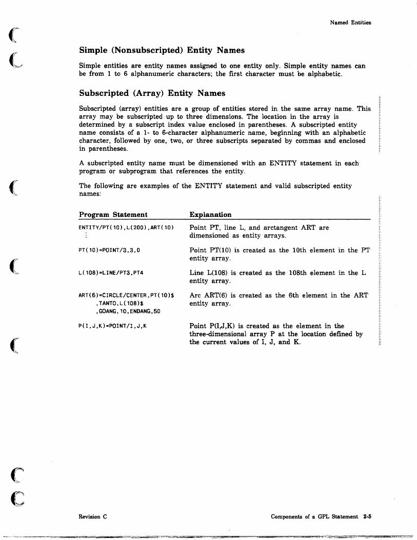
Simple (Nonsubscripted) Entity Names
Simple entities are entity names assigned to one entity only. Simple entity names can be from 1 to 6 alphanumeric characters; the first character must be alphabetic.
Subscripted (Array) Entity Names
Subscripted (array) entities are a group of entities stored in the same array name. This array may be subscripted up to three dimensions. The location in the array is determined by a subscript index value enclosed in parentheses. A subscripted entity name consists of a 1- to 6-character alphanumeric name, beginning with an alphabetic character, followed by one, two, or three subscripts separated by commas and enclosed in parentheses.
A subscripted entity name must be dimensioned with an ENTITY statement in each program or subprogram that references the entity.
The following are examples of the ENTITY statement and valid subscripted entity names:
Program Statement
ENTITY/PT(10),L(200),ART(10)
PT(10)=POINT/3,3,O
L(10B)=LINE/PT3,PT4
ART(6)=CIRCLE/CENTER,PT(10)$ ,TANTO,L(10B)$ ,GOANG,10,ENDANG,SO
P(I,J,K)=POINT/I,J,K
Revision C
Explanation
Point PT, line L, and arctangent ART are dimensioned as entity arrays.
Point PT(10) is created as the 10th element in the PT entity array.
Line L(108) is created as the 108th element in the L entity array.
Arc ART(6) is created as the 6th element in the ART entity array.
Point P(I,J ,K) is created as the element in the three-dimensional array P at the location defmed by the current values of I, J, and K.
Components of a GPL Statement 2·5

Variables
Variables
A variable is an assignment statement that assigns any combination of variables, constants, functions, and arithmetic expressions to a name. Variables can be assigned either real or integer values, but internally, all variables are stored as real values.
Using the Assignment Statement to Name Variables
You can name a variable by using an assignment statement. A variable name is a name given to any combination of variables, constants, function statements, and ari thmetic expressions.
Format:
name=value
Parameter Description
name The name assigned to the variable.
value The value of the variable.
Simple (Nonsubscripted) Variables
Simple variables are variable names assigned to a single value. Simple variable names can be from 1 to 6 alphanumeric characters; the first character must be alphabetic.
2-6 ICEM GPL for NOS Revision C

(
(
(
c c
Variables
Subscripted (Array) Variables
Subscripted (array) variables are a group of variables using the same name for an array of values. This array may be subscripted up to three dimensions. The location in the group is determined by a subscript enclosed in parentheses. A subscripted (array) variable name consists of a 1- to 6-character alphanumeric name that begins with an alphabetic character, which is followed by one, two, or three subscripts separated by commas and enclosed in parentheses.
• Subscripted variables must be dimensioned by a SIZE or REAL statement in each program that references the variable.
• Simple variables can be saved in the RTL using the SAVE statement.
• The number of all sUbscripted variable array elements is limited to a total of 2,097,152.
• The subscripted variable array is a one-, two-, or three-dimensional array.
• Subscripts can be simple variables, for example, ABCD(J).
• Major and minor word names are reserved and cannot be used as variable names.
The following are examples of correct and incorrect subscripted variable names:
Correct use:
Program Statement
ABCDEF=K+SIN(I)
ABCDE(6)=10.0
X(10,2,5)=Y(I,J,K)
Incorrect use:
Program Statement
ABCDEFG=47.1
POINT(3)=TOLDEF
RADIUS(3)=R
7ABCDE=ABCDE
Revision C
Explanation
Uses 6 characters.
Uses fewer than 6 characters not inc! uding the subscript.
Uses three-dimensional subscripts.
Explanation
Uses 7 characters.
Uses the major word POINT.
Uses the minor word RADIUS.
Uses numeral as first character.
Components of a GPL Statement 2-7

Variables
Creating Variables Using 5.2.1 VARIABLE CALCULATION
Using 5.2.1 VARIABLE CALCULATION, you can define a simple variable and assign a val ue to it. The variable name must be from 1 to 6 characters, the first of which must be an alphabetic character. The value can be specified as either a constant or an expression. Mter successful evaluation, the variable is automatically stored in the RTL. Any variables in the right-hand part of any statement in an expression must have been previously defined, and must exist in the RTL. Variables defined and saved with this menu choice are subsequently available to GPL programs using the GET statement.
Saving Variables in the RTL or the UTF
Variable values can be carried over from one GPL program to subsequent programs without having to repeat the assignment statement in each program. There are two variable storage areas in ICEM DDN:
• Run-Time Library (RTL)
The RTL is used to store variables for the duration of an ICEM DDN session and is stored with the part. These variables are available to all programs executed during the session. At the end of a session, variable assignments stored in the RTL are saved only if you file the current part drawing. If you do not file the drawing, the variables are lost when you log out of ICEM DDN. When you retrieve the part drawing for a future session, variable assignments saved with a part drawing are automatically placed in the RTL. Simple variables are stored in the RTL only if they are specified in a SAVE statement (refer to the SAVE major word description later in this section) or defined interactively under menu 5.1 VARIABLE CALCULATION (refer to the ICEM Design/Drafting Data Management manual) or via data capture. The GET statement must be used to return variables from the RTL before use in a GPL program.
• User Technology File (UTF)
You can globally save variable assignments stored in the RTL by moving them to the UTF using 5.3.2 MOVE VARIABLES FROM RTL TO UTF. You can retrieve variable assignments stored in the UTF for use in a GPL program executed at a later time. Programs, however, cannot access variable assignments directly from the UTF. For each subsequent session, variables stored in the UTF must be moved into
.Q.. fJ
the RTL for the session before the variables can be referenced in any program. d \
UTF variables are moved to the RTL using menu operation 5.3.1 MOVE ~ jl
VARIABLES FROM UTF TO RTL. A variable assignment stored in the UTF remains as originally defined until that variable is redefmed in a subsequent assignment statement and stored once again in the UTF.
2·8 ICEM GPL for NOS Revision C

(
(~
(
(
(
c c
Variables
Using the SAVE Statement
You must use the SAVE statement to save your simple variables before you use them in a subsequent program or subprogram. The SAVE statement reserves space in the RTL. For example, the following series of statements explains this process.
Program Statement
A=1
B=4
F=15
TAR=A+B
ABCD=TAR*F
SAVE/A,B,F,TAR,ABCD
Explanation
A is equal to the value of 1.
B is equal to the value of 4.
F is equal to the value of 15.
TAR is equal to the value of A plus B or 1 plus 4.
ABeD is equal to the value of TAR times F or 5 times 15.
This statement saves these variables in the RTL.
Using the REAL Statements
You must use the REAL statements to reserve storage space for your subscripted mathematical variables in the GPL program before you define them in the program. You must reserve this space before all statements in a given program except MAIN, REMARK, and other declarations.
These statements are used for the following purpose:
Statement Purpose
REAL Reserves space for calculated values.
Example:
Program Statement Explanation
REAL/A,B,C(S)
Revision C
Reserves space for variables A, B, and five spaces for variable C.
Components of a GPL Statement 2·9

Variables
Using the CHAR and 'ENTITY Statements
The CHAR statement declares the names as text variables and reserves space by character length in the GPL program. The ENTITY statement declares the names as entities and reserves, space in the GPL program for their pointers. Subscripted entity names must be dimensioned to the number of entities that are assigned.
These statements are used for the following purposes:
Statement Purpose
CHAR
ENTITY
Reserves space for text variables.
Reserves space for entity data base pointers.
Example:
Program Statement
CHAR/CHR1(10)
ENTITY/PT(10)
ENTITY/CIR(2)
Explanation
Declares text variable CHR1 and reserves space for 10 characters for CHR1.
Reserves space for 10 pointers named PT(1) through PT(lO).
Reserves space f~r 2 pointers named CIR(1) and CIR(2).
Using the GET Statement
You must use the GET statement in a subprogram to retrieve the values of variables if they are stored in the RTL. These values are only available if they were stored in the RTL using 5.2.1 VARIABLE CALCULATION or if they were stored in the RTL using a SAVE statement in a different program executed earlier.
Example:
Program Statement
GET/A,B,F,TAR,ABCD
2·10 ICEM GPL ,for NOS
Explanation
Retrieves the values of previously stored variables A, B, F, TAR, and ABCD.
Revision C
i I i

(
(
(
(
(
c c
Statement Labels
Statement Labels Statement labels are optional integer fields, from 1 to 5 digits in length, which uniquely identify the GPL statement in which the statement label appears. If present, the label appears as the first element in a GPL statement, and each label must be unique within a given program. At least one blank must appear between the label and the remainder of the statement.
• A statement label is used to identify the statement to receive control from a branching or conditional statement. Refer to chapter 4, Branching and Conditional Statements, for more information on this feature.
• Statement labels are not required on all GPL statements.
• One and only one statement label must exist somewhere for each transfer of control.
• Labels must be positive integers with 5 or fewer digits.
Example:
Program Statement Explanation
GOTO 250 Branch unconditionally to statement label 250.
250 CaNTIN Execution continues at the next statement.
Revision C Components of a GPL Statement 2·11

Arithmetic Operators and Expressions
Arithmetic Operators and Expressions
Arithmetic expressions use arithmetic operators to combine constants, variables, or functions in a sequence that can be reduced to a single arithmetic value.
The arithmetic operators available in GPL are:
+ Addition
Subtraction
** Exponentiation
* Multiplication
1 Division
Arithmetic expressions are evaluated from left to right in the following order of preference:
• Exponentiation
• Multiplication and division
• Addition and subtraction
Nested expressions (expressions within parentheses) are evaluated first, proceeding from the innermost expression to the outermost.
Example:
CALC=«3+7)/2-4)**3+5*6
Operation
The innermost nest (3 + 7) is evaluated first.
Division (10/2) is the first operation to be performed in the second-level nest.
Subtraction (5-4) is performed after division in the second-level nest.
Result
(10/2-4)**3 + 5*6
(5-4)**3 + 5*6
1**3+5*6
Exponentiation (1 **3) is the highest-order 1 + 5*6 operation.
Multiplication (5*6) is the next 1 + 30 highest-order operation.
Addition (1 + 30) is the last operation. 31 The final result is 31.
2·12 ICEM GPL for NOS Revision C
I i

(~
(
(
(
c c
Functions
Functions
Functions are elements that provide a quick and simple means of performing certain commonly used arithmetic/trigonometric operations. They can be used in variable assignment statements. There are two types of functions: those that require a single argument and those that require several arguments.
Format:
function(argument(s»
Parameter
function
(argument(s))
Description
The function name.
The argument(s) for the function. The argument(s) can be variable(s).
The following functions are available in GPL:
Function1
ABS or ABSF
ACOS
ACOSF
ASIN
ASINF
ATAN
ATANF
cos
COSF
COSH
EXP or EXPF
Description
Finds the value of a number without regard to sign (the absolute value).
Finds the arc cosine. The answer is returned in radians.
Finds the arc cosine. The answer is returned in degrees.
Finds the arc sine. The answer is returned in radians.
Finds the arc sine. The answer is returned in degrees.
Finds the arctangent given "the tangent of an angle. The answer is returned in radians.
Finds the arctangent given the tangent of an angle. The answer is returned in degrees.
Finds the cosine of an angle. The angle must be expressed in radians.
Finds the cosine of an angle. The angle must be expressed in degrees.
Finds the hyperbolic cosine of an angle.
Finds the value of e raised to a power.
1. Some functions have alternate forms, which have been provided for compatibility with Automated Programmed Tooling System (APT).
Revision C Components of a GPL Statement 2-13

Functions
Function2
GETBIT (var, pos, num)
Description
Gets the bit string of length 'num' from variable 'var', starting at position 'pos'.
NOTE
For GETBIT and SETBIT, the bit position (ranging from 1 to 48 in NOS) is the lower end of the bit string in the variable (after it has been converted to integer internally).
LOG or LOGF Finds the natural logarithm of a number (base e).
LOG10 Finds the common logarithm of a number (base 10).
MIN Finds the minimum value of a series (up to 64 arguments).
MAX Finds the maximum value of a series (up to 64 arguments).
ROUND Rounds a real number to its nearest integer (0.5 rounds up).
SETBIT Creates a new bit string by setting 'num' bits with the new bit (var,pos,num,val) representation of 'val' in variable 'var' starting at position 'pos'. The
SIGN
SIN
SINF
SINH
arguments remain unchanged. The new variable val ue is passed as the function value.
NOTE
For GETBIT and SETBIT, the bit position (ranging from 1 to 48 in NOS) is the lower end of the bit string in the variable (after it has been converted to integer internally).
Transfers the sign of the second argument to the first argument (similar to the FORTRAN SIGN function).
Finds the sine of an angle. The angle must be expressed in radians.
Finds the sine of an angle. The angle must be expressed in degrees.
Finds the hyperbolic sine of an angle.
SQRT or SQRTF Finds the square root of a number.
TRUNC Truncates a real number to its integer part.
TAN Finds the tangent of an angle. The angle must be expressed in radians.
TANH Finds the hyperbolic tangent of an angle.
2. Some functions have alternate forms, which have been provided for compatibility with Automated Programmed Tooling System (APT).
2·14 ICEM GPL for NOS Revision C

(
(
c·.··~·
~
C
Examples:
Program Statement
A=ATNF(O.S)
A=ATAN(O.S)
PZ=L*SINF(4S)
SKL=SIN(K*L)
PI=4*ATAN( 1)
B=SINF(ANGR)
C=L*COSF(ANG1)+$ K*SINF(ANG2)
IF(GETBIT(J,1,1).NE.O)$ GOT010
J=SETBIT(J,1,1,O)
Revision C
Functions
Explanation
The variable A is equal to 26.565°.
The variable A is equal to 0.4636 radians.
The variable PZ is equal to L times the sine of 45°.
The variable SKL is equal to the sine of K times L (K*L).
The variable PI is equal to four times the arctangent of 1. The answer is returned in radians.
The variable B is equal to the sine of AN GR.
The variable C is equal to L times the cosine of angle ANG1 plus K times the sine of angle ANG2.
If the bit string of length 1 from variable J at position 1 is not equal to 0 (if J is odd) go to 10.
Creates a new bit string by setting 1 bit to 0 J at position 1 (round J to next lower even number).
Components of a GPL Statement 2-15

Logical Operators
Logical Operators
Logical operators available in GPL are the conditional operations of equality. They are used within the IF statement only. The periods are not part of the operators; they are required to separate the operators from the objects being compared.
Symbol Description
.LE . Less than or equal to
. LT. Less than
.EQ. Equal to
.NE. Not equal to
.GE. Greater than or equal to
.GT. Greater than
.AND. Logical and
.O,R. Logical inclusive or
NOTE
.AND. and .OR. operators cannot be combined. A GPL program can use multiple
.AND.s, or it can use multiple .OR.s, but it cannot use combined .AND.s and .OR.s.
Examples:
Program Statement
IF (STAT.EQ.-1) GOTO 40
2·16 ICEM GPL for NOS
Explanation
If the variable STAT is equal to -1, jump to the line labeled 40.
Revision C
if '~

(
(
(
c c
Punctuation Symbols
Punctuation Symbols
The following punctuation marks and other special symbols are used in GPL statements:
Symbol
/
=
$$
( )
$
Blank (spaces)
Revision C
Description
Separates modifiers in major word statements and also separates multiple subscripts.
Separates a logical operator from the two values to be compared or acts as a decimal point.
Separates major words from following modifiers.
Assigns a name to an entity, a constant, an expression, or another name.
Indicates the end of a statement; comments can appear on the same line to the right of the double dollar signs ($$). This is equivalent to a REMARK statement if $$ appears in columns 1 and 2.
Encloses character strings.
Indicates nested expressions within arithmetic expressions or encloses a subscript.
Indicates that the statement is continued on the next line. Character strings can be continued on a subsequent line also in this manner; other statement elements, such as minor words, entity names, literal constants, variable names, and so forth, cannot be continued from line to line.
Generally, indicates spacing only. The compiler usually ignores blanks except in the GOTO and FOR statements. Blanks in character strings, which are used for display purposes are also significant.
Components of a GPL Statement 2-17

Character Strings
Character Strings
A character string is a string of one or more contiguous text characters enclosed in single quotes. It is used in many interactive and drafting statements.
Example:
Program Statement Explanation
MENU/'CREATE THE CONNECTING CURVE',$ 'LINE*ARC·SPLINE*' ,$ CHOICE,STAT
The character string CREATE THE CONNECTING CURVE is defined in the MENU command.
Text Variable
A variable name assigned to a character string. This variable name can be assigned using either the interactive TEXT command or the MOVCHR statement.
Examples:
Program Statement
MOVCHR/8,'CUT HERE' ,1,A,1
MOVCHR/S,'REF l' ,1,8,1
MOVCHR/1S,'CONSTANT$ RADIUS' , 1 ,C, 1
TEXT/'ENTER TEXT',TXT,STAT
MOVCHR/16,'TOLERANCE=$ o .0015' , 1, TXT, 1
NOTE
Explanation
Text variable A is defined with the text of CUT HERE.
Text variable B is defined with the text of REF 1.
Text variable C is defined with the text of CONSTANT RADIUS.
The variable TXT is assigned to the alphanumeric string you enter.
The variable TXT is assigned using the MOVCHR statement.
Text variables can be used in place of character strings in attributes, notes, labels, dimensions, and other statements.
2·18 ICEM GPL for NOS Revision C
I i

(
(~
(
(.
(
c c
GPL Vocabulary I (Major Words)
GPL Vocabulary I (Major Words) The following are GPL vocabulary words and must not be used as symbols:
1. Modals and Fonts
AHEAD CDISPL DORIG PAINT SELMOD TXTORG ANGCTL CRES DSCALE PEN SEQN03 TXTOUrr3 ANUNIT CSET DUAL PREFIX SLANT TXTROrr3 ARAUTO CSIZE FONT RECOVR SPATHS VBORDS ARIN CURSOR FRACT REFRES STATUS VNAMES AROUT DEC MAL KEYIN RESCAL SYSDEC VVECS ARROW DIMOF LDDIAM SECALN TXTANG WLINE ATAIL DIMORG LEADER SECVIS TXTIN3 WPLANE3
AUTOD DISDEF LEVEL SELENT TXTJUS ZSURF BLANK DISTOL MATERL SELGRP TXTLOC
2. Major Word Statements
ADIMEN CMSRF FILSRF MODDFT RDIMEN SRFTEX ARRAY CONE FIND3 MODIFY READ STRING ASSIGN CONYER GCONIC MOVCHR REPANT SYSTEM3
ATTRIB CURARR GEOTOL MOVENT REVSRF TABCYL BALOON CYLNDR GET MSFILE REWIND TAPER BEZIER DATE GROUP MSTRNG ROTATE3 TEMPLT BEZSRF3 DATFEA HEXDRN NOTE RTRIEV TEXT BLANKE DATUM HYPERB OBTAIN RULSRF THIKNS BULK DDIMEN HEXDRN OFSRF3 SAVE TIME CDIMEN DEFINE IMF3 OPEN SEARCH3 TLPATH CHAMFR DELETE LABEL PARABO SECARR TORUS CHANGE DEVSRF LDIMEN PARAMS SECTON TRANSL3
CHECK DISPLA LINE PARTN03 SELECT TRIME CIRCLE ELLIPS LPSOID PLANE SETCHL UNBLNK CLEAR EVALC MACCRV POINT SETGPG USTRUC CLINE EVALS MAGNFY POS SPCURV VECTOR CLOSE EXEC MAP PROJEC SPHERE VIEW CMPCHR FILE MENU PTSET SPLINE WRITE CMPCRV FILLET MIRROR QUERY SRCHD ZOOM CMPENT
3. Program Control and Declaratives
CALL DATA ENDIF G04 PAUSE STEP CHAR ELSE ENTITY GOTO PROC STOP COMMON ELSEIF EOFI IF REAL THEN CONST END FINI JUMPTO REMARK T04 CONTIN ENDCOM FOR MAIN RETURN UNTIL
3. Reserved for future use.
4. Reserved for compilation purposes.
Revision C Components of a GPL Statement 2-19

--- --- ._--
I GPL Vocabulary II (Minor, Modal, and
~ e f J GPL Vocabulary II (Minor, Modal, and
~ Positional Words) The following are GPL vocabulary words and must not be used as symbols:
f ABOVE CURVW GLOBAL NORMAL RUBBER UNIT ACYCLC CW GOANG NORPNT SCALAR UPATHS ADD CYCLIC GPATRN NORTH SCALE URIGHT AFTER DASHED HANGLE NORTRN SECDIS USER ALL DATMOD HORIZ NUMBER5 SECOND USTART ALUM DATREF INFIN NUMBRX SEQNUM UTERM ANGLE DECIM INPUT NUMBRY SHEET UWRITE ARCS DEFVW INSIDE NVARY SINGLE VDEF AREA DEGREE INSTNC OFF SLATE VDIREC AROUND DEGTOL INTOF ON SLOPE VECSUM ARRDO DEL IRON ORIGIN SMALL VERTCL ARRW DELANG JOG OUT SOLID VPATHS {j "l
ASPCT DELATR LARGE OUTPUT SOUTH WEST ATANGL DELTA LATHE PARAM SPHRIC WIDTH ATNAME DELTAX LEAD PARBLC START WITP AUTO DELTAY LEADR PARLA STD WITX AUX DELTAZ LEFT PARLEL STDVW XAXIS BASIC DETAIL LENGTH PARNOR STEEL XLARGE BEARDS DIFFER LEVL PARTNA SUBAT XMOVE BEFORE DIRECT LIMIT PATERN SUPP1 XSMALL BELOW DISP2 LIN PENNUM SUPP2 XSTART BLNK DISTNC LINES PERPTO SUPP11 XTROT if '1,1
BORDER DONT LLEFT PHANTM SUPP22 XVALUE ~ j}
BOTH DOWNSP LMC PIERCE SUPPB XYMOVE BRACKT DRILL LOCAL PLASTC SUPPB1 XYZMOV5
BRASS EAST LRIGHT POINTS SUPPB2 XZMOVE5
CCW EDGE MAGNES POSITN TAB 15 YAXIS CENLIN END MARBLE POSITV TAB25 YES CENTER ENDANG MATRIX POSN TAB35 YLARGE CHAIN ENTER MEMBER PTZ TABLET YMOVE CHARST ENTNAM MIDDLE RADANG TANTO YSMALL CIRC ENTPTR MINUTE RADIUS TEXTD YSTART ~ ~ CIRCUM ENTTY MMC RATIO THICK YTROT . fJ
COMPOS ENTTYP MODFY RECT THREAD YVALUE CONIC EQUATR MODVW REF TILTAN YZMOVE5
CONTUR ERRST NAME REGIN TOLER ZAXIS COORD FAST NECK REGOUT TOLMOD ZLARGE COPPER FILTER NEGATV RELAX TOLREF ZMOVE5
COpy FINE NFIXED RFS TOTAL ZSMALL CORNER FIRST NOAREA RIGHT TRIM ZSTART CREATE FLAT NONE ROUGH TYPIN ZTROT CRT GCHAR NOPROJ RTHETA UDIREC ZVALUE CURDEP GLASS ULEFT CURVE
5. Reserved for future use.
2-20 ICEM GPL for NOS Revision C

0 0 Overview of Major Words 3
Branching and Conditional Major Words 3-1
Modal Major Words . . . . . . . . . . . . 3-1
Entity and Character String Management Major Words 3-2
Variable Declaration, RTL 110, and File Major Words 3-3
Program Management Major Words. 3-3
Display Control Major Words 3-4
Entity DefInition Major Words. 3-5
Entity Manipulation Major Words . 3-6
0 Drafting Modal Major Words ... 3-7
Drafting Entity Defmition Major Words 3-9
Numerical Control Major Words. . 3-10
Interactive Command Major Words 3-10
Input/Output Major Words . . . . . 3-10
0
o
o a M $ 8bt,;9!P4Z1 i £l

w
tOO hJi »
o o
o
o
o
o o

(
(
(
c ~
c.· 0.-•• ",".
Overview of Major Words 3
Branching and Conditional Major Words
Use the following major words to test for logical conditions or to transfer control from one section of the program to another section:
Major Word
GOTO
Computed GOTO
IF
THEN
ELSE
ELSEIF
ENDIF
FOR
EOFI
JUMPTO
Description
Branches unconditionally to a statement label.
Branches conditionally to a statement label.
Branches conditionally or assigns a value.
Indicates that the following statements are executed only if the condition of the IF statement is true.
Indicates that the following statements are executed only if the condition of the IF statement is false.
Checks a secondary condition only if the first condition is false.
Ends an IF block.
Creates an iterative loop for repetitive operations.
Terminates a FOR loop.
Branches unconditionally to a statement label.
Modal Major Words
Use the following major words to set the modals for system operation:
Major Word
BLANK
CURSOR
DISDEF
DISTaL
FONT
LEVEL
MSFILE
PAINT
PEN
RECOVR
REFRES
Revision C
Description
Blanks all subsequent entities.
Dermes the input device for cursor control.
Displays subsequent entities only in the view of definition.
Sets the display tolerance.
Sets the line font for all subsequently created entities.
Assigns a level number to all subsequently created entities.
Changes the menu string file.
Sets the drawing of entities on or off.
Sets the pen number.
Sets GPL recovery file on or off.
Turns on the refresh buffer of the workstation.
Overview of Major Words 3-1
i !
Entity and Character String Management Major Words
Major Word
RESCAL
SELENT
SELGRP
SELMOD
SPATHS
STATUS
SYSDEC
ZSURF
Description
Sets the RESCALE? prompt on or off.
Selects the method of entity selection (single, chain, region in, or region out).
Turns on the ability to select single entities from a group.
Sets the method of entity selection on or off (sequence number, pointer, and entity names).
Sets the number of surface paths for a surface.
Suppresses fatal error messages.
Sets the system decimal places.
Sets the current transform coordinate depth (the zt-axis).
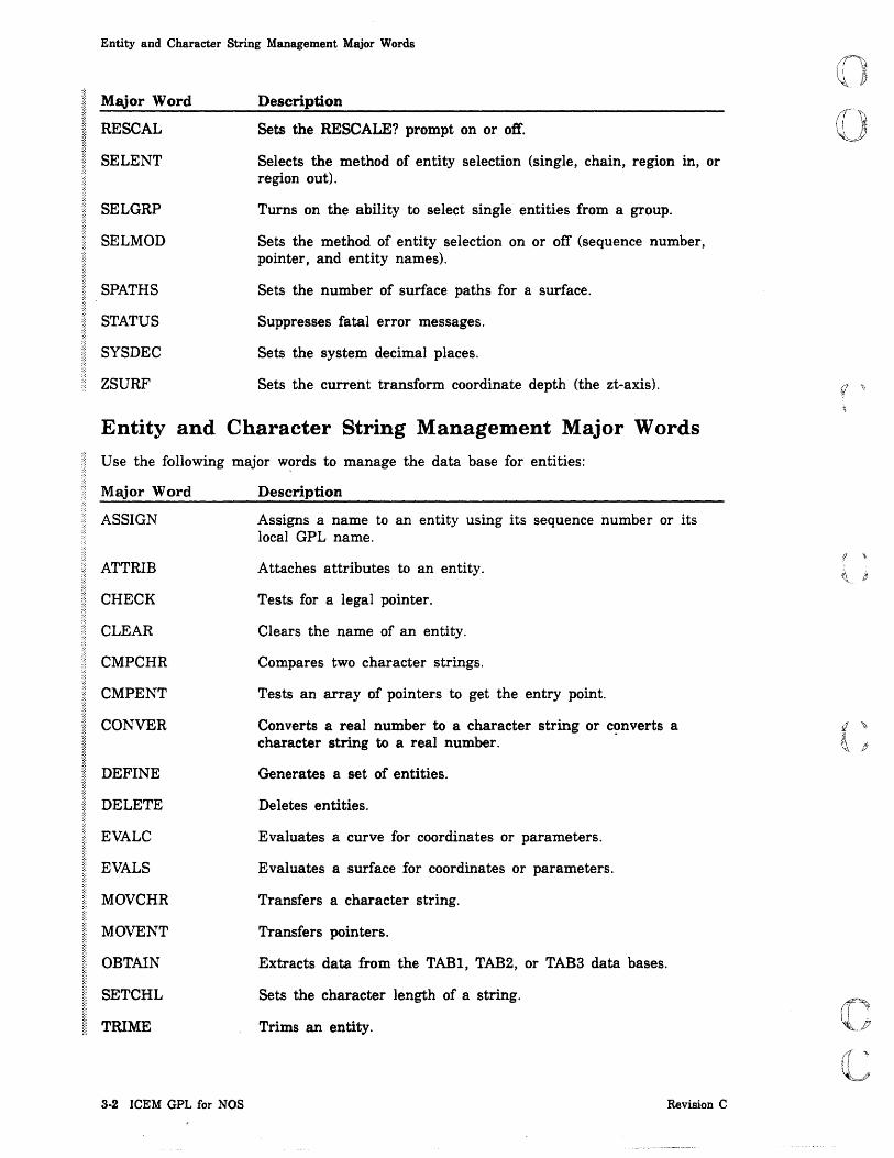
Entity and Character String Management Major Words
Use the following major w~rds to manage the data base for entities:
Major Word
ASSIGN
ATTRIB
CHECK
CLEAR
CMPCHR
CMPENT
CONVER
DEFINE
DELETE
EVALC
EVALS
MOVCHR
MOVENT
OBTAIN
Description
Assigns a name to an entity using its sequence number or its local GPL name.
Attaches attributes to an entity.
Tests for a legal pointer.
Clears the name of an entity.
Compares two character strings.
Tests an array of pointers to get the entry point.
Converts a real number to a character string or converts a character string to a real number. .
Generates a set of entities.
Deletes entities.
Evaluates a curve for coordinates or parameters.
Evaluates a surface for coordinates or parameters.
Transfers a character string.
Transfers pointers.
Extracts data from the TABl, TAB 2 , or TAB3 data bases.
SETCHL Sets the character length of a string.
TRIME Trims an entity.
3·2 ICEM GPL for NOS Revision C
f \

(
(
("
(
(
C~
C
Variable Declaration, RTL I/O, and File Major Words
Variable Declaration, RTL 110, and File Major Words
Use the following major words to declare text variables and entities, manage variables, and manage the part data base:
Major Word
CHAR
COMMON
CONST
DATA
ENDCOM
ENTITY
FILE
GET
REAL
SAVE
Description
Declares and reserves storage space for a text variable.
Declares a common block for any following variables.
Assigns numerical value to a symbolic name.
Initializes a variable to a value.
Terminates a common block.
Reserves storage space for entity data base pointers.
Catalogs the drawing for later modification or retrieval.
Retrieves simple variables from the RTL.
Reserves storage space for real variables.
Saves simple variables in the RTL.
Program Management Major Words
Use the following major words to manage the program:
Major Word
CALL
CONTIN
DATE
FIN I
MAIN
MSTRNG
PAUSE
PROC
REMARK
RETURN
Revision C
Description
Calls a GPL subroutine (refer to the PROC statement described below).
Continues program execution at the next GPL statement. Used as a labelled statement in structured programs.
Retrieves the current system date.
Indicates the end of a GPL program.
Indicates the first statement in a GPL program.
Executes a menu string from within a GPL program.
Halts the program run. The program can be resumed using menu 5.13.2 CONTINUE GPL PROGRAM.
Indicates the first statement in a GPL program used as a subroutine.
Adds descriptive comments to the part program.
Returns control from the subroutine to the calling program.
Overview of Major Words 3·3

Display Control Major Words
Major Word
STOP
TIME
Description
Terminates the execution of a GPL program. This is different from the FINI statement, which is always placed at the end of a GPL program.
Retrieves the current system time.
Display Control Major Words
Use the following major words to control the view display:
Major Word
BLANKE
CHANGE
MAP
REPANT
UNBLNK
VBORDS
VIEW
VNAMES
VVECS
ZOOM
3-4 ICEM GPL for NOS
Description
Blanks selected entities.
Changes current work view.
Maps transform coordinates from one view to another.
Repaints the display.
Unblanks an entity.
Sets view borders on or off.
Creates a new view.
Sets view names on or off.
Sets view vectors on or off.
Zooms a view.
Revision C i

(
(
(
c c
Entity Definition Major Words
Entity Definition Major Words Use the following major words to create entities:
Major Word
CIRCLE
CHAMFR
CMPCRV
CMSRF
CONE
CYLNDR
DEVSRF
ELLIPS
FILLET
FILSRF
GCONIC
HEXDRN
HYPERB
LINE
LPSOID
MACCRV
PARABO
PLANE
POINT
PTSET
REVSRF
RULSRF
SPCURV
Revision C
@
Description
Creates an arc or a circle.
Creates a bevel near the intersection of two lines.
Creates a composite curve.
Creates a curve mesh surface.
Creates a cone.
Crea tes a cylinder.
Creates a developable surface.
Creates an ellipse.
Creates a fillet near the intersection of two lines.
Creates a fillet surface.
Creates a general conic, that is, a circle, ellipse, hyperbola, or parabola.
Creates a hexahedron.
Creates a hyperbola.
Creates a line.
Creates an ellipsoid.
Creates a machining/draft curve.
Creates a parabola.
Creates a plane.
Creates a unique point.
Creates a point set.
Creates a surface of revolution.
Creates a ruled surface.
Creates the starting and ending conditions for a three-dimensional spline curve.
Overview of Major Words 3-5

Entity Manipulation Major Words
Major Word
SPHERE
SPLINE
STRING
TABCYL
TORUS
VECTOR
Description
Creates a sphere.
Creates a spline through a series of points.
Creates a string figure.
Creates a tabulated cylinder.
Creates a torus.
Creates a vector.
Entity Manipulation Major Words
Use the following major words to manipulate entities:
Major Word
ARRAY
GROUP
MIRROR
MODIFY
PROJEC
RTRIEV
TEMPLT
3-6 ICEM GPL for NOS
Description
Copies a geometric entity in a rectangular or circular array.
Creates a group of entities to be considered as a single logical unit (entity).
Creates a mirror (reversed) image of an entity or group of entities.
Modifies an entity.
Creates a three-dimensional figure by projecting a two-dimensional configuration onto a plane parallel to the original plane (ANSI 1973 and ANSI 1982).
Retrieves a pattern.
Creates a template ..
Revision C
I i

(
(
(
(
(
(~
C
Drafting Modal Major Words
Drafting Modal Major Words
Use the following major words to set the drafting modals for drafting operation:
Major Word
AHEAD
ANGCTL
AN UNIT
ARAUTO
ARIN
AROUT
ARROW
ATAIL
AUTOD
CDISPL
CRES
CSET
CSIZE
DECMAL
DIM OF
DIMORG
DORIG
DSCALE
DUAL
Revision C
Description
Modifies the arrowhead length (ANSI 1973 and ANSI 1982).
Controls the text angle (ANSI 1982).
Sets the method for angular dimension representation (ANSI 1982).
Determines the placement of arrows (ANSI 1982).
Sets arrows inside witness lines for all subsequent dimensions (ANSI 1973 and ANSI 1982).
Sets arrows outside witness lines for all subsequent dimensions (ANSI 1973 and ANSI 1982).
Switches arrowhead alignment on or off (ANSI 1973 and ANSI 1982).
Controls the entry point of the tail location (ANSI 1982).
Controls auto-dimensioning (ANSI 1973 and ANSI 1982).
Sets character display ratios (ANSI 1973 and ANSI 1982).
Selects the output representation for standard set type characters (ANSI 1982).
Sets the character set used (ANSI 1973 and ANSI 1982).
Varies the character size (ANSI 1973 and ANSI 1982).
Sets the number of decimal places displayed in dimensioning for decimal numbers; changes the system from using integers to using real numbers (ANSI 1973 and ANSI 1982).
Sets the dimension offset distance (ANSI 1973 and ANSI 1982).
Sets which side of a generated dimension specifies the dimension origin (ANSI 1982).
Sets the label and dimension origins (ANSI 1973).
Sets the drafting scale factor (ANSI 1973 and ANSI 1982).
Sets dual dimensions on or off (ANSI 1973 and ANSI 1982).
Overview of Major Words 3·7

Drafting Modal Major Words
Major Word
FRACT
KEYIN
LDDIAM
LEADER
MATERL
PREFIX
SECALN
SECVIS
SLANT
TXTANG
TXTJUS
TXTORG
WLINE
Description
Changes the dimensioning display from using decimal numbers to using fractional (integer) numbers (ANSI 1973 and ANSI 1982).
Permits manual entry of dimension texts (ANSI 1973).
Forces diameter symbol in linear dimensions (ANSI 1982).
Determines the placement of the label leader with respect to the label text (ANSI 1982).
Specifies the type of material for section lining (ANSI 1973 and ANSI 1982).
Changes the prefix character (ANSI 1982).
Controls the alignment of section lining (ANSI 1982).
Determines whether to display section lining in all views or the view of definition only (ANSI 1982).
Sets the slanted or vertical character set (ANSI 1973 and ANSI 1982).
Sets the text angle (ANSI 1973).
Sets the text justification (ANSI 1973 and ANSI 1982).
Determines the method of indicating the position of text.
Sets the display of witness lines for linear dimensions (ANSI 1973 and ANSI 1982).
The same word may operate slightly differently in ANSI 1973 and ANSI 1982. Check the appropriate chapter for complete details. ANSI 1973 statements are described in chapter 17 and ANSI 1982 statements are described in chapter 20.
3·8 ICEM GPL for NOS Revision C
i
I I

(
c c
Drafting Entity Definition Major Words
Drafting Entity Definition Major Words Use the following major words to create drafting entities:
Major Word
ADIMEN
BALOON
CDIMEN
CLINE
CURARR
DATFEA
DATUM
DDIMEN
GEOTOL
LABEL
LDIMEN
MAGNFY
MODDFT
NOTE
RDIMEN
SECARR
SEeTON
SRFTEX
TAPER
THIKNS
Description
Creates angular dimensions (ANSI 1982).
Draws a balloon with an arrow pointing to an entity (ANSI 1982).
Creates a circular dimension label with a leader line (ANSI 1973 and ANSI 1982).
Creates a centerline (ANSI 1973 and ANSI 1982).
Draws an arrowhead at any position along an existing entity (ANSI 1982).
Displays a datum feature symbol and associated text within a feature frame symbol (ANSI 1982).
Defines a datum target symbol (ANSI 1982).
Creates a diametric dimension label (ANSI 1973 and ANSI 1982).
Displays geometric tolerance or composite geometric tolerance symbols and associated text within a feature frame (ANSI 1982).
Creates a label with leader line (ANSI 1973 and ANSI 1982).
Creates a linear dimension label (ANSI 1973 and ANSI 1982).
Produces a magnified drawing of a circular area (ANSI 1982).
Modifies certain drafting entities without having to redefine those entities (ANSI 1982).
Creates a general note (ANSI 1973 and ANSI 1982).
Creates an angular dimension with circular witness lines (ANSI 1973).
Creates cross-section arrows (ANSI 1982).
Automatically creates section lining lines for any closed figure (ANSI 1973 and ANSI 1982).
Displays the standard basic symbol for surface texture (ANSI 1982).
Creates a slope or taper dimension drawn to two lines (ANSI 1982).
Produces a dimension between two curves (ANSI 1982).
The same word may operate differently in ANSI 1973 and ANSI 1982. Check the appropriate chapter for complete details.· ANSI 1973 statements are described in chapter 17 and ANSI 1982 statements are described in chapter 20.
Revision C Overview of Major Words 3·9

Numerical Control Major Words
Numerical Control Major Words
Use the following major words for numerical control operations.
Major Word
SETGPG
TLPATH
Description
Sets the N/C parameters in a generation parameter group (GPG).
Defines a toolpath from an existing entity, a list of entities or an entity array.
Interactive Command Major Words
, Use the following major words for operations that request input from the person who is running the program:
Major Word
DISPLA
MENU
PARAMS
POS
QUERY
SELECT
TEXT
Description
Displays text and real variables.
Requests a selection from displayed menu choices during a GPL program run.
Requests values for a list of displayed data entry items (the values can then be used in the program).
Requests a screen position selection using the graphics cursor.
Requests a YES or NO to a displayed question.
Request a selection from any entity displayed on the screen.
Requests character string input.
Input/Output Major Words
Use the following major words for input/output operations:
Major Word Description
BULK Transfers bulk data.
CLOSE Closes a previously opened file.
EXEC Executes a FORTRAN subroutine.
OPEN Opens a file.
READ Inputs a file.
REWIND Rewinds a file.
USTRUC Outputs a UNISTRUC file.
WRITE Outputs a file.
3·10 ICEM GPL for NOS Revision C
if ~
t\ p

-0 o
o
o
o
o o
Branching and Conditional Statements 4
GOTO. . . . . . . . . . . . . . . . . . . . . . . . . . . . . . . . . . . . . . . . . . . .. 4-1
Computed GOTO ...................................... 4-2
IF . . . . . . . . . . . . . . . . . . . . . . . . . . . . . . . . . . . . . . . . . . . . . .. 4-3 Executing Conditionally . . . . . . . . . . . . . . . . . . . . . . . . . . . . . . . .. 4-4
FOR ... '. . . . . . . . . . . . . . . . . . . . . . . . . . . . . . . . . . . . . . . . . .. 4-5
EOFI . . . . . . . . . . . . . . . . . . . . . . . . . . . . . . . . . . . . . . . . . . . .. 4-6
JUMPTO ........................................... 4-6
EJO :,¥MLlk

th@i Ufl£Qik ,. 5t\iiftU~il)i1PJtPUgll)j!!! lili
o o
o
o
o
o o

(
(~
(
(
(
c c
Branching and Conditional Statements
Branching and conditional statements control the execution of a GPL program.
Major Word
GOTO
IF
THEN
ELSE
ELSEIF
ENDIF
FOR
EOFI
JUMPTO
GO TO
Description
Either branches unconditionally or branches to specified statement labels (computed GOTO).
Either branches conditionally or conditionally executes one or more statements.
Indicates that the following block of code to the next ELSE, ELSEIF, or ENDIF is executed only if the condition in the IF statement is true.
Indicates that the following block of code to the next ENDIF is executed only if the condition on the IF statement is false.
Checks a secondary condition only if the first condition is false.
Ends an IF block.
Creates an iterative loop for repetitive operations.
Terminates a FOR loop.
Branches unconditionally.
The GOTO statement specifies an unconditional transfer of control.
Statement format:
GOTD statement label
Parameter
statement label
Example:
Description
The GPL statement at which the execution of the program should continue. It must be separated from the GOTO by a space.
Program Statement Explanation
GOTO 100
10 POINT/A,B
100 A=A+1
Unconditionally transfers control to statement label 100.
This statement is ignored.
The program continues execution at this statement.
4
Revision C Branching and Conditional Statements 4-1
==
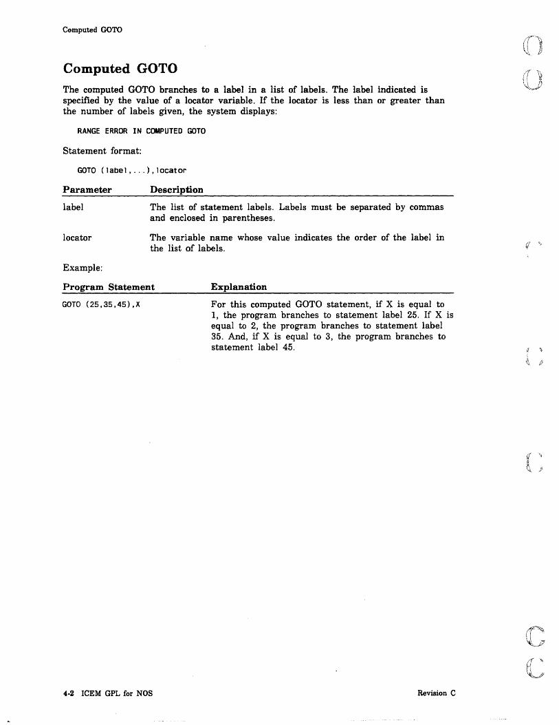
Computed GOTO
Computed GOTO The computed GOTO branches to a label in a list of labels. The label indicated is specified by the value of a locator variable. If the locator is less than or greater than the number of labels given, the system displays:
RANGE ERROR IN COMPUTED GOTO
Statement format:
GOTO (label, ... ), locator
Parameter
label
locator
Example:
Description
The list of statement labels. Labels must be separated by commas and enclosed in parentheses.
The variable name whose value indicates the order of the label in the list of labels.
Program Statement Explanation
GOTD (25,35,45),X
4·2 ICEM GPL for NOS
For this computed GOTO statement, if X is equal to 1, the program branches to statement label 25. If X is equal to 2, the program branches to statement label 35. And, if X is equal to 3, the program branches to statement label 45.
Revision C
;
I ~
I

(
(
(
(
(
c C.
··~ c:.=,-
IF
IF The IF statement conditionally transfers control of the GPL program or conditionally executes one or more statements. The IF statement contains a logical condition to be evaluated as either true or false. If the logical expression is true, the conditional transfer or variable assignment is executed. If the logical expression is false, the conditional action is ignored, and execution continues with the next statement unless a condition statement block is specified by a THEN keyword. If the logical condition is false, and a statement block is specified by a THEN keyword, execution continues following the next ELSE, ELSEIF, or ENDIF block control keyword.
The condition expression can also be one or more logical expressions using the . OR. and .AND. operators. For example:
IF (A.LT.1.0R.A.GT.9) GOTO 9 IF (I.NE. 1.AND.I .NE.S.AND.I.NE.11) THEN
The IF ... THEN statement block can be formatted for easy readability in the following manner.
IF (condition) THEN Statements
ELSEIF (condition) THEN Statements
ELSE Statements
ENDIF
The following reserved words are used for control in the IF statement block:
Block Control Keywords
THEN
ELSEIF
ELSE
ENDIF
NOTE
Description
Executes the following statements if the condition is true.
Checks a secondary condition in an IF statement only if the first condition is false.
Executes the following statements if none of the previous conditions are true.
Terminates a compound IF statement.
.AND. and .OR. operators cannot be combined. A GPL program can use multiple
.AND.s, or it can use multiple .OR.s, but it cannot use combined .AND.s and .OR.s.
Revision C Branching and Conditional Statements 4-3

IF
Executing Conditionally
Statement format:
IF (valuel.operator.value2) executable statement
Parameter
value
operator
executable statement
Examples:
Description
The variables or constants to be compared in the condition. The condition must be enclosed in parentheses.
The logical operation to be evaluated. The operator must have periods on both sides. The following keywords can be used as operators:
Logical Operator Definition
LT Less than
LE Less than or equal to
EQ Equal to
NE Not equal to
GE Greater than or equal to
GT Greater than
AND Logical and
OR Logical inclusive or
The condition may be compound; that is, two or more logical conditions associated by AND or OR.
Any executable statement (assignment, GOTO, or major word).
Program Statement Explanation
QUAD=2
IF (ANG.LT.90) QUAD=1
IF (QUAD.LT.2) GOTO 20
4-4 ICEM GPL for NOS
Set the variable QUAD to have the value of 2.
If the variable ANG is less than 90°, then set the variable QUAD to have the value of 1. This statement conditionally assigns a name to an expression.
If the variable QUAD is less than 2, then branch to statement label 20.
Revision C

(
(
(
(
(
c c
FOR
Program Statement Explanation
IF (I.EQ.1.AND.J.EQ.2) THEN If the compound condition is true (that is, 1=1 and J = 2), then the following block of statements is executed until the next ELSE, ELSEIF, or ENDIF.
IF (STAT.NE.D) $
DISPLA/'STATUS', STAT If the variable STAT is not equal to 0, then execute the DISPLA statement.
FOR The FOR statement and the EOFI statement are used to construct iterative loops. The FOR statement initiates the loop, and the EOFI statement terminates the loop.
The first time the loop is executed, the index variable has the initial value. Each time the loop is executed after that, the value of the index variable is changed by the step value until either:
• The index variable exceeds the final value (for a positive step value), or
• The index variable is exceeded by the value (for a negative value).
The program then terminates the loop and executes the next statement following the EOFI statement.
Statement format:
FOR index=initial value [,STEP step], UNTIL final value
Parameter
index
initial value
STEP
step
UNTIL
final value
Revision C
Description
Any simple variable name. It must be separated from the FOR word by a space. The index and the initial value must be joined by an equals sign.
The initial index value. It can be any integer value.
The minor word indicating that the next value is the step value of the statement.
The step, or increment, value. It can be any value; the default value is 1 if STEP is omitted.
The minor word indicating that the next value is the final value for the statement.
The final value. It can be any value. If the fmal value is less than the initial value, and the step value is positive, the loop executes zero times.
Branching and Conditional Statements 4·5

EOFI
EOFI
The EOFI statement is used to terminate an iterative loop initiated by a FOR statement.
Statement format:
EOFI
Example:
Program Statement
FOR 1=2, STEP 2, UNTIL 10
J=I**2
POINT/J,J
EOFI
JUMPTO
Explanation
The FOR loop with variable I as an index. The loop is repeated with values for I of 2, 4, 6, 8, and 10, then the program continues with the statement after EOFI.
The variable J is set up to have the value of I squared. Each time through the loop, the current value of I is used.
A point is created at the coordinates specified by J, J. Each time through the loop, a new point is created using the expression I squared where the value of I is squared.
The loop is ended. The loop creates points at the xand y-coordinates of (4,4), (16,16), (36,36), (64,64), and (100,100).
The JUMPTO statement branches unconditionally to the statement label indicated. Program execution continues at the specified statement label. This statement's function is identical to that of the GOTO statement.
Statement format:
JUMPTO/label
Parameter Description
label The number of the statement label.
Example:
Program Statement
JUMPTO/359
359 A=ll
4-6 ICEM GPL for NOS
Explanation
The program branches to statement label 359.
The program resumes execution at statement label 359.
Revision C

o o
o
o
o i8 I I
Modal Statements 5
BLANK. . . . . . . . . . . . . . . . . . . . . . . . . . . . . . . . . . . . . . . . . . .. 5-1
CURSOR. . . . . . . . . . . . . . . . . . . . . . . . . . . . . . . . . . . . . . . . . .. 5-1
DISDEF. . . . . . . . . . . . . . . . . . . . . . . . . . . . . . . . . . . . . . . . . . .. 5-2
DISTOL. . . . . . . . . . . . . . . . . . . . . . . . . . . . . . . . . . . . . . . . . . .. 5-2
FONT. . . . . . . . . . . . . . . . . . . . . . . . . . . . . . . . . . . . . . . . . . . .. 5-3
LEVEL. . . . . . . . . . . . . . . . . . . . . . . . . . . . . . . . . . . . . . . . . . .. 5-4
MSFILE ........................................... 5-4
PAINT .... . . . . . . . . . . . . . . . . . . . . . . . . . . . . . . . . . . . . . . .. 5-5
PEN. . . . . . . . . . . . . . . . . . . . . . . . . . . . . . . . . . . . . . . . . . . . .. 5-5
RECOVR . . . . . . . . . . . . . . . . . . . . . . . . . . . . . . . . . . . . . . . . . .. 5-6
REFRES . . . . . . . . . . . . . . . . . . . . . . . . . . . . . . . . . . . . . . . . . .. 5-6
RESCAL 5-7
SELENT. . . . . . . . . . . . . . . . . . . . . . . . . . . . . . . . . . . . . . . . . 5-7
SELGRP . . . . . . . . . . . . . . . . . . . . . . . . . . . . . . . . . . . . . . . . . .. 5-8
SELMOn. . . . . . . . . . . . . . . . . . . . . . . . . . . . . . . . . . . . . . . . . .. 5-8
SPATHS ........................................... 5-9
STATUS ........................................ . . . 5-10
SYSDEC . . . . . . . . . . . . . . . . . . . . . . . . . . . . . . . . . . . . . . . . . . . 5-10
ZSURF ............................................ 5-11
Mea $ J! Z$4 .. A Milk:: 4i Mit 2P

;SC F .ff'1M,il\!!! Pi
o o
o
o
0'
o o

(
(
(
(
c c
Modal Statements 5
Modal statements set parameters for creating entities.
BLANK The BLANK statement blanks all succeeding entities. The default value for BLANK is OFF.
Statement format:
BLANK/(ON ) OFF
Parameter
ON
OFF
Example:
Description
Blanks all succeeding entities.
Does not blank all succeeding entities.
Program Statement Explanation
BLANK/OFF
CURSOR
All succeeding entities are displayed as they are created.
The CURSOR statement determines the input device for graphics cursor control.
Statement format:
CURSOR/(CRT ) TABLET
Parameter
CRT
TABLET
Example:
Description
The input device for graphics cursor control is the graphics terminal.
The input device for graphics cursor control is the tablet and its stylus.
Program Statement Explanation
CURSOR/CRT
Revision C
The graphics terminal is the input device for the graphics cursor.
Modal Statements 5·1
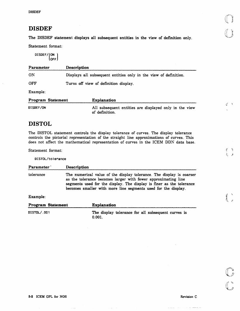
DISDEF
DISDEF
The DISDEF statement displays all subsequent entities in the view of definition only.
Statement format:
DISDEF/(ON ) OFF
Parameter
ON
OFF
Example:
Description
Displays all subsequent entities only in the view of definition.
Turns off view of definition display.
Program Statement Explanation
DISDEF/ON
DISTOL
All subsequent entities are displayed only in the view of definition.
The DISTaL statement controls the display tolerance of curves. The display tolerance controls the pictorial representation of the straight line approximations of curves. This does not affect the mathematical representation of curves in the ICEM DDN data base.
Statement format:
DISTOl/tolerance
Parameter'
tolerance
Example:
Description
The numerical value of the display tolerance. The display is coarser as the tolerance becomes larger with fewer approximating line segments used for the display. The display is finer as the tolerance becomes smaller with more line segments used for the display.
Program Statement Explanation
DISTOl/.OOl
5·2 ICEM GPL for NOS
The display tolerance for all subsequent curves is 0.001.
Revision C
" I
I i

(
(
(
(
(
c c
FONT
FONT The FONT statement defines the line font for subsequently defined lines and curves. The default font mode is normal weight and solid. Conics, splines, strings, labels, and dimensions are always normal weight and solid.
Statement format:
SOLID FONT/ DASHED
PHANTM CENLIN
Parameter
SOLID
DASHED
PHANTM
CENLIN
Example:
Description
The minor word indicating solid lines continuously over the entire length of the entity.
The minor word indicating dashed lines of equal segments separated by equal spaces. The segment is a nominal 3.16 mm (0.125 in) and the space is 0.79 mm (0.031 in). A dashed entity has a minimum of three parts, that is, two segments and a space. The dashed line is forced solid if the line length is less than 7.10 mm (0.281 in). A dashed circular line is segmented to generate approximate arc lengths of 3.16 mm (0.125 in) and spacing of 0.79 mm (0.031 in). A dashed arc always starts and ends with a segment. A dashed circle always has a segment centered about 0°.
The minor word indicating phantom lines made of a dashed line with a long segment, followed by two short segments. Spaces between all segments are equal. A phantom line starts and ends with a long segment. A phantom circle starts with a long segment centered at 0° and ends with short segments. The long segment is adjusted to assure proper closing. The segments are:
• Long: 19.0 mm nominal (0.75 in)
• Short: 3.16 mm (0.125 in)
• Space: 0.79 mm (0.031 in)
The minor word indicating a centerline made up of a long segment followed by a short segment. Spacing between elements is equal.
Program Statement Explanation
FONT/DASHED
Revision C
All subsequent entities are displayed in a dashed line font.
Modal Statements 5-3

LEVEL
LEVEL The LEVEL statement changes the level number that you are using. Until the level is changed again, all subsequent entities are defined on this level. Level numbers 0 through 1023 are allowed.
Statement format:
LEVEL/level number
Parameter Description
level number The number of the level where you want to create new entities.
Example:
Program Statement Explanation
LEVEL/3 All new entities are created on level number 3.
MSFILE The MSFILE statement changes the menu string file from which your external menu strings are executed. All subsequent references to external menu strings, whether from the MSTRING statement or from a tablet, will use this file.
The default file name is MSTRING.
You also have the option of loading the original mstring filename into a GPL text variable. You can then have the GPL program reset the filename name back to the original filename before terminating the program.
Statement format:
MSFILE/(text variable)],ofn text var] ('msl fn' )
Parameter
text variable
'mslfn'
ofn text var
Description
The name of a text variable containing the file name that contains the menu strings that are accessed by subsequent MSTRNG statements. This variable should be dimensioned to 7 characters.
The name of a local, external file (enclosed in single quotes) that contains the menu strings that are accessed by subsequent MSTRNG statements.
The name of a text variable that receives the original local mstring filename. This variable should be dimensioned to 7 characters.
The following error message is issued if the MSTRIN G file is not found or cannot be retrieved.
MENU STRING FILE CANNOT BE RETRIEVED
5-4 ICEM GPL for NOS Revision C

(
(
PAINT
Example:
Program Statement Explanation
CHAR/OLFIL(7) Dimension the variable that receives the old menu string file to 7.
MSFILE/'MSFL1' ,OLFIL Change the menu string file to 'MSFLl'. Save the name of the old file in OLFIL.
MSTRNG/NAME,TLPATH
MSFILE/OLFIL
PAINT
Execute the menu string TLPATH which resides on the current menu string file (MSFL1).
Change the menu string file back to the original file.
The PAINT statement turns on or off the display of entities at creation time. The default is ON.
Statement format:
PAINT/(ON J OFF
Parameter
ON
OFF
Example:
Description
Turns on the drawing of entities.
Turns off the drawing of entities. They are not drawn until a REPANT is done.
Program Statement Explanation
PAINT/ON
PEN
All subsequent entities are displayed as they are created.
The PEN statement sets a new pen number for all subsequent entities. The pen number remains in effect until a new pen number is selected.
Statement format:
PEN/pen number
Parameter
pen number
Example:
Description
The number of the pen used in drawing subsequent entities. Pens are numbered from 0 to 16.
Program Statement Explanation
PEN/l0
Revision C
All subsequent entities are drawn with pen number 10.
Modal Statements 5-5

RECOVR
RECOVR
The RECOVR statement writes the GPL recovery file to file GPLREC when a FILE statement is encountered. GPLREC will contain any geometry created after the last FILE statement up to the FINI statement or a program abort.
Statement format:
RECOVR/(ON ) OFF
Parameter
ON
OFF
REFRES
Description
W rites file GPLREC when a FILE statement is encountered.
Does not write file GPLREC when a FILE statement is encountered.
The REFRES statement places all entities created in the workstation refresh buffer. If the workstation is not used, this statement is ignored.
Statement format:
REFRES/(ON ) OFF
Parameter
ON
OFF
Example:
Description
Places all entities created in the workstation refresh buffer.
The refresh mode is not used.
Program Statement Explanation
REFRES/ON
5-6 ICEM GPL for NOS
The refresh buffer is used as storage for the created entities.
Revision C

(
(
(
c c
REseAL
REseAL The RESCAL statement suppresses the RESCALE? message during the display of an entity if part of the entity is located outside the current view area.
Statement format:
RESCAl/(ON ) OFF
Parameter
ON
OFF
Example:
Description
Displays the RESCALE? message if part of an entity is outside the current view area.
Does not display the RESCALE? message if part of an entity is outside the current view area.
Program Statement Explanation
RESCAl/ON
SELENT
The RESCALE? message is displayed if part of an entity is outside the current view area.
The SELENT statement indicates the form of entity selection.
Statement format:
SINGLE CHAIN
SElENT/ REGIN REGOUT USER
Parameter
SINGLE
CHAIN
REGIN
REGOUT
USER
Example:
Description
Selects single entities.
Selects chained entities.
Selects all the entities within a region.
Selects all the entities outside a region.
The user chooses the means of selection interactively, then selects.
Program Statement Explanation
SELENT/SINGLE Entities are selected singly.
Revision C Modal Statements 5-7

I
SELGRP
SELGRP The SELGRP statement allows selection of a group member or composite curve member.
Statement format:
SELGRP/(ON J OFF
Parameter
ON
OFF
Example:
Description
Indicates that an entity cannot be selected from a group or composite curve.
Indicates that an entity can be selected from a group or composite curve.
Program Statement Explanation
SELMOD/ON
SELMon
Entities cannot be selected from a group or composite curve. Only the group or composite curve can be selected.
The SELMOn statement sets the method of entity selection.
Statement format:
SELMOO/(ON ) OFF
Parameter
ON
OFF
Description
Allows for selection of entities by methods other than screen position (that is, entity name, entity pointer, sequence number, and so forth).
Allows for selection of entities by screen position.
5·8 ICEM GPL for NOS Revision C
i l i
I

(
(~~
(
(
(
c c
SPATHS
SPATHS
The SPATHS statement modifies the surface display path modals.
Statement format:
SPATHS/UPATHS,upaths,VPATHS,vpaths,UDIREC,upoints,VDIREC,vPoints
Parameter Description
UPATHS The minor word indicating the number of upaths.
upaths The number of paths in the u direction.
VPATHS The minor word indicating the number of vpaths.
vpaths The number of paths in the v direction.
UDIREC The minor word indicating the number of upoints.
upoints The number of points per upath.
VDIREC The minor word indicating the number of vpoints.
vpoints The number of points per vpath.
Example:
Program Statement Explanation
SPATHS/UPATHS,7,VPATHS,11,$ UDIREC,16,VDIREC,24
All subsequent surfaces are created with 7 upaths, 11 vpaths, 16 upoints, and 24 vpoints.
Revision C Modal Statements 5-9

STATUS
STATUS The STATUS statement suppresses fatal error messages during a GPL run. After entity construction statements, use the OBTAINIERRST command to check the error code for bad pointer errors. Bad pointer errors affect the creation of subsequent entities that use the bad pointers as references.
Statement format:
STATUS/tON 1 OFF
Parameter
ON
OFF
Example:
Description
Suppresses fatal error messages during a GPL run.
Displays fatal error messages during a GPL run.
Program Statement Explanation
STATUS/ON Fatal errors are not indicated during a GPL run.
SYSDEC The SYSDEC statement controls the number of decimal places after the decimal point for all displayed real number input and output.
Statement format:
SYSDEC/number
Parameter Description
number The number of decimal places after the decimal point.
Example:
Program Statement
SYSDEC/6
5·10 ICEM GPL for NOS
Explanation
All real number input and output is displayed with 6 decimal places.
Revision C

(
(
(
(
(
c c
ZSURF
ZSURF The ZSURF statement sets the current value of the Z plane so that only x- and y-coordinates are required.
Statement format:
ZSURF/depth
Parameter
depth
Example:
Description
The z depth or work plane where all subsequent entities are created.
Program Statement Explanation
ZSURF/1.S
Revision C
All subsequent two-dimensional entities are created at a z depth of 1.5 in.
Modal Statements 5·11

~ft 1
i

o o
-0
o
o
o o
Entity and Character String Statements ASSIGN ........ .
By Sequence Number By Entity
ATTRIB ... Creating and Associating Attributes and Subattributes with an Entity Deleting Attributes and Subattributes from an Entity . . . . . . . . . . Copying All Attributes and Subattributes from One Entity to Another
CHECK.
CLEAR.
CMPCHR.
CMPENT.
CONVER. Converting a Real Number into a Character String Converting a Character String into a Real Number
DEFINE ......... .
DELETE ......... . Deleting Single Entities Deleting from an Entity Array Deleting All Points in a Single Operation .
EVALC ........... . Parameter Returns Point Point Returns Parameter
EVALS ........... . Parameter Returns Point Point Returns Parameter
MOVCHR.
MOVENT.
OBTAIN . Coordinates N umber of Characters View Pointer . . . . . Definition View Pointer Current View Pointer Entity Name . . . . . . Entity Pointer ..... Parameters of an Entity . Latest Error Number .. Entity Type and Form . . Part Name and Sheet Number Members of a Group . Character String . Sequence Number .,
_ .. WltAh #ii iZMQ, _.a: nu.;;n4£t#s lAiHi Ii
6
6-1 6~1
6-2
6-3 6-3 6-5 6-6
6-7
6-7
6-8
6-9
6-10 6-10 6-11
6-12
6-13 6-13 6-13 6-13
6-14 6-14 6-15
6-16 6-16 6-18
6-19
6-19
6-20 6-20 6-21 6-22 6-23 6-23 6-24 6-25 6-27 6-27 6-28 6-28 6-28 6-29 6-29
. ,M es:;;;( i!4t.~

Attribute and Subattributes ...... . Pen, Level, Color, and Font Numbers .
SETCHL
TRIME .
tAU,! ''', i V! w« WiO. iIIIj .'1 ti ii@JBlltlW ! ._ \ _ ,I t9' WWJlll11utMfaeemtILll±L tim
6-30 6-31
6-32
6-32
o o
o
o
o
o o

(
(
(
(
(
c c
Entity and Character String Statements 6
Entity and character string statements perform different management functions. Several of these definitions are equivalent to types and forms found in menus 3 DELETE and 5 SPECIAL FUNCTIONS.
ASSIGN
The ASSIGN statement defines a name in the data base for an entity that is identified by its sequence number or its local GPL name. The name assigned can be either simple or subscripted. The sequence number can be expressed either as an integer value or by a variable name.
By Sequence Number
Statement format:
ASSIGN/SEQNUM,nUmber,( 'name' )[,status] text variable
Parameter
SEQNUM
number
'name'
text variable
status
Example:
Description
The minor word indicating sequence number assignment.
The sequence number assigned to the entity.
The name in single quotes assigned to the entity. This name must not exceed 10 characters.
A text variable that contains the entity name.
A variable that contains the status of the assignment. If status is provided, it can have the following values:
Value Description
o The assignment was successful.
-1 Another entity already has that name.
If status is not provided and the entity name already exists, it is detached from its previous use and is assigned to this entity.
Program Statement Explanation
ASSIGN/SEQNUM,25,$ 'ENT1' , STAT
Revision C
Entity with sequence number 25 is given the name ENT1 in the text.
Entity and Character String Statements 6·1

ASSIGN
By Entity
Statement format:
ASSIGN/ent;ty,( 'name' }[,status] text variable
Parameter
entity
'name'
text variable
status
Example:
Description
The entity name.
The name in single quotes assigned to the entity.
A text variable that co~tains the name of the entity.
A variable that contains the status of the assignment.
Value Description
o The assignment was successful.
-1 Another entity already has that name.
If status is not provided and the entity name already exists, it is detached from its previous use and is assigned to this entity.
Program Statement Explanation
ASSIGN/SN(3),ENT2
6·2 ICEM GPL for NOS
Entity SN(3) is given the name contained in the text variable ENT2.
Revision C

(
(-
(
c c
ATTRIB
ATTRIB
The ATTRIB statement attaches, copies, or deletes attributes from entities. Attributes consist of any textual information attached to an entity. Subattributes are combinations of text or numeric information.
The textual information can be entered directly using single quotes or indirectly using a text variable (refer to the TEXT command).
Creating and Associating Attributes and Subattributes with an Entity
Statement format:
[
NAME,name[, ... J 1 ATTRIB/(ent1tY[, ... J),ATNAME,('attr1bute name'),SUBAT, NUMBER,value[, ... J
LEVL, level text variable BOTH,name,value[, ... J
Parameter
entity
LEVL
level
ATNAME
'attribute name'
text variable
SUBAT
NAME
name
NUMBER
value
BOTH
Revision C
Description
The name or names of the entity assigned to this attribute. Names must be separated by commas. A maximum of 20 entities may be selected.
The minor word indicating that attributes are to be assigned by level numbers. The attributes are assigned to all entities on that level.
The level number of the entities to be assigned this attribute.
The minor word indicating the attribute name.
The attribute name enclosed in single quotes.
A text variable containing the attribute name.
The minor word indicating the sub attribute names or numbers.
The minor word indicating the subattribute names.
The subattribute name or names assigned to the attribute can be either a text variable containing the name or the name itself . enclosed in single quotes ('name'). Names must be separated by commas.
The minor word indicating the subattribute values.
The subattribute value or values assigned to the attribute. Values must be separated by commas.
The minor word indicating both subattribute names and values. The names and values must "be specified in the following order: name, value. Names and values must be separated by commas.
Entity and Character String Statements 6-3

ATTRIB
Examples:
Program Statement
ATTRIB/PT002,LN003,LN004$ ,LN005,SP005,SP006$ ,ATNAME,'CHANNEL'$ ,SUBAT,BOTH$ ,'WIDTH',12.0$ , 'HEIGHT' , 16.0$ ,'LENGTH' ,145.5$
ATTRIB/LEVL,104$ ,ATNAME,XTIME
Explanation
The attribute name 'CHANNEL' is assigned to the following entities: point PT002; lines LN003, LN004, and LN005; and splines SP005 and SP006.
In addition, the entities are assigned the following three subattributes of text and numerical data:
Text
WIDTH
HEIGHT
LENGTH
Numerical Data
12.0
16.0
145.5
All entities on level 104 have the attribute name stored in the variable XTIME.
The new attributes and subattributes are inserted at the end of the list of existing attributes and subattributes for that entity.
6-4 ICEM GPL for NOS Revision C

(
(
(
(
(
c c
ATTRIB
Deleting Attributes and Subattributes from an Entity
Statement format:
ATTRIB/OELATR.entlty[.ATNAME.atrank[ .... l[.SUBAT.SUbrank .... 1]
Parameter
DELATR
entity
ATNAME
at rank
SUBAT
subrank
Description
The minor word indicating that attributes are to be deleted.
The name of the entity from which the attributes are to be deleted.
The minor word indicating the numerical rank number of the attribute name. If ATNAME alone is specified, all attributes and subattributes are deleted.
The rank number of the attributes you want to delete. Ranks must be separated by commas. The rank refers to the numerical order of the attributes. If ATNAME is specified, only attributes indicated are deleted.
The minor word indicating the numerical rank number of the subattribute names or numbers. If omitted, all the subattributes of the indicated attribute are deleted.
The rank number or numbers of the subattributes to be deleted. Ranks must be separated by commas. The rank refers to the numerical order of the subattributes. If SUBAT is specified, only subattributes indicated are deleted.
If ATNAME is not specified, all attributes and subattributes associated with the given entity are deleted. If ATNAME, but not SUBAT is specified, the attribute and all associated subattributes are deleted. If both are specified, only subattributes are deleted.
Example:
Program Statement
ATTRIB/DELATR,PT003,PT006$ ,PT122,ATNAME,3$ ,SUBAT,S,6,7
Revision C
Explanation
Subattribute numbers 5, 6, and 7 are deleted from points PT003, PT006, and PT122.
Entity and Character String Statements 6·5
I I'

ATTRIB
Copying All Attributes and Subattributes from One Entity to Another
Statement format:
ATTRIB/copy,entit Yl,entitY2[,(BEFORE1] AFTER
Parameter
COpy
entityl
entity2
BEFORE
AFTER
Description
The minor word indicating that the attributes of the first entity are copied to the second entity.
The name of the entity whose attributes are copied.
The name of the entity that receives the copied attributes.
The minor word indicating that the copied attributes are to be placed before the attribute list of the second entity.
The minor word indicating that the copied attributes are to be placed after the attribute list of the second entity.
If neither BEFORE nor AFTER is specified, AFTER is assumed.
Example:
Program Statement
ATTRIB/COPY,LN145$ ,LN322,BEFORE
6-6 ICEM GPL for NOS
Explanation
All of the attributes of entity LNl45 are copied before the attribute list of entity LN322.
Revision C
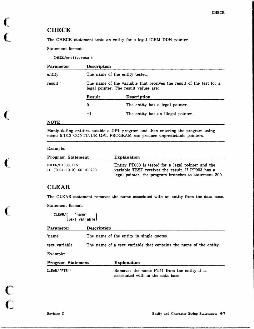
(
(
(
(
(
c c
CHECK
CHECK
The CHECK statement tests an entity for a legal ICEM DDN pointer.
Statement format:
CHECK/entitY,result
Parameter Description
entity The name of the entity tested.
result The name of the variable that receives the result of the test for a legal pointer. The result values are:
Result
o
-1
NOTE
Description
The entity has a legal pointer.
The entity has an illegal pointer.
Manipulating entities outside a GPL program and then entering the program using menu 5.13.2 CONTINUE GPL PROGRAM can produce unpredictable pointers.
Example:
Program Statement
CHECK/PT003,TEST IF (TEST.EQ.O) GO TO 200
CLEAR
Explanation
Entity PT003 is tested for a legal pointer and the variable TEST receives the result. If PT003 has a legal pointer, the program branches to statement 200.
The CLEAR statement removes the name associated with an entity from the data base.
Statement format:
CLEAR/( 'name' ) text variable
Parameter Description
'name' The name of the entity in single quotes.
text variable The name of a text variable that contains the name of the entity.
Example:
Program Statement Explanation
CLEAR/' PT51 '
Revision C
Removes the name PT51 from the entity it is associated with in the data base.
Entity and Character String Statements 6·7

CMPCHR
CMPCHR The CMPCHR statement compares one character string with another character string and returns a result indicating whether the two strings are equal.
Statement format:
CMPCHR/number,str1ng1,chpos1,string2,chpos2,result
Parameter
number
string 1
chpos1
string2
chpos2
result
Example:
Description
The number of characters to compare.
The name of the first text variable or the first character string.
The position of the first character to test in string1.
The name of the second text variable or the second character string.
The position of the first character to test in string2.
The name of the variable that receives the result of the test for the equality of the two character strings. The result values are:
Result Description
o The character strings are equal.
-1 The character strings are not equal.
Program Statement Explanation
CMPCHR/6,NOTE1~10,$
NOTE2 ,31 , TEST
6·8 ICEM GPL for NOS
Text variable NOTE2 is tested for a 6-character string that matches a 6-character string in NOTE1. The variable TEST receives the result of the test.
Text Variable
NOTE 1
Text
PART NO. 23-334.
NOTE2 O-RINGS ARE REQUIRED FOR PART 23-334.
For these two notes:
• The 6-character string in NOTE1 at character position 10 matches the 6-character string in NOTE2 at character position 31.
• The result value is O.
Revision C
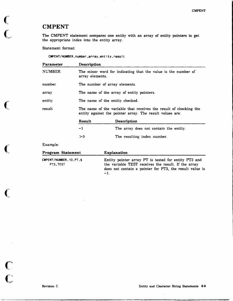
(
~
(
(
(
c c
CMPENT
CMPENT The CMPENT statement compares one entity with an array of entity pointers to get the appropriate index into the entity array.
Statement format:
CMPENT/NUMBER,number,arraY,ent1tY,result
Parameter
NUMBER
number
array
entity
result
Example:
Description
The minor word for indicating that the value is the number of array elements.
The number of array elements.
The name of the array of entity pointers.
The name of the entity checked.
The name of the variable that receives the result of checking the entity against the pointer array. The result values are:
Result Description
-1 The array does not contain the entity.
>0 The resulting index number.
Program Statement Explanation
CMPENT/NUMBER,10,PT,$ PT3,TEST
Revision C
Entity pointer array PT is tested for entity PT3 and the variable TEST receives the result. If the array does not contain a pointer for PT3, the result value is -1.
Entity and Character String Statements 6-9

CONVER
CONYER The CONYER statement either converts a real number into a character string or converts a character string into a real number. The maximum length of the character string is 10 characters.
Converting a Real Number into a Character String
Statement format:
CONVER/(POSITV),deCimal places,NUMBER,variable,text variable NEGATV
Parameter
POSITV
NEGATV
decimal places
NUMBER
variable
text variable
Example:
Description
The minor word indicating that the characters in the string are to be right-justified and may have leading blanks.
The minor word indicating that the characters in the string are to be left-justified.
The number of decimal places after the decimal point in the real number.
The minor word indicating that the following variable contains a real number that is to be converted to a character string and placed in the specified text variable.
The name of the variable that contains the real number.
The name of the text variable that receives the converted number.
Program Statement Explanation
CONVER/POSITV,4,NUMBER$ ,L,LENGTH
6·10 ICEM GPL for NOS
Real variable L is converted into a character string in text variable LENGTH. The number is stored in the character string positively to the value of four decimal places.
Revision C

(
(
(
c C',,'~ :
CONYER
Converting a Character String into a Real Number
Statement format:
CONVER/NUMBER,text variable,variable,status
Parameter
NUMBER
text variable
variable
status
Example:
Description
The minor word indicating that the following text variable is to be converted into a real number and placed in the specified variable.
The name of the text variable that contains the character string.
The name of the variable that receives the converted real number.
The name of the variable that receives the status of the conversion. The status values are:
Status Description
o The real number was converted correctly.
-1 The character string contained illegal characters.
Program Statement Explanation
CONVER/NUMBER,LENGTH,$ L,TEST
Revision C
Text variable LENGTH is converted to real variable L. The variable TEST receives the status.
Entity and Character String Statements 6-11

DEFINE
DEFINE The DEFINE statement generates a number of points, lines, or arcs with one statement. The coordinate array size must be a multiple of 3 (points), 6 (lines), or 9 (arcs) times the number of entities. If an entity array is specified, the array size must equal the number of entities given.
Statement format:
[
POINTS] DEFINE/ LINES ,number,coord array[,ent1ty array]
ARCS
Parameter
POINTS
LINES
ARCS
number
coord array
entity array
Example:
Description
The minor word for defining a number of points. Each three values in the coordinate array are the transform coordinates of a point.
The minor word for defining a number of lines. Each six values in the coordinate array are the transform coordinates of the endpoints of a line.
The minor word for defining a number of arcs. Each nine values in the· coordinate array are the transform coordinates of three points that define an arc (the arc extends from the first point through the second point and ends at the third point).
The number of entities defined.
The name of a coordinate array.
The name of an entity array that receives the newly defined entities.
Program Statement Explanation
REAL/PNTCOR( 12)
ENTITY/PNTENT(4)
DATA/PNTCOR,1,2,0,3,4,0$ 5,6,0,7,8,0
DEFINE/POINTS,4,PNTCOR(1)$ PNTENT( 1)
6·12 ICEM GPL for NOS
Reserve space for 12 elements of PNTCOR.
Receive space for 4 entities in PNTENT.
Initialize PNTCOR with 4 sets of point coordinates.
Define 4 points in the PNTENT array from the coordinates stored in PNTCOR. PNTENT(1) has the coordinates (1,2,0); PNTENT(2) has the coordinates (3,4,0); and so forth.
Revision C

(
(
(~
C
DELETE
DELETE The DELETE statement deletes entities not required for subsequent definitions.
Deleting Single Entities
Statement format:
'DELETE/name[, ... ]
Parameter Description
name The name or names of the entities that are to be deleted.
Example:
Program Statement Explanation
DELETE/PT1,LN1,CIR4 Point PT1, line LN1, and circle CIR4 are deleted.
Deleting from an Entity Array
Statement format:
DELETE/NUMBER,count,entityarray
Parameter
NUMBER
count
entity array
Example:
Description
The minor word indicating that a number of entities are to be deleted from an entity array.
The number of entities to be deleted from the entity array.
The name of the entity array.
Program Statement Explanation
DELETE/NUMBER, 10,ET( 1) The first 10 elements of entity array ET are deleted.
Deleting All Points in a Single Operation
Statement format:
DELETE/POINTS
Parameter
POINTS
NOTE
Description
The minor word indicating that all points are to be deleted from the part drawing.
We do not recommend using this statement if points have been used in the definition of other entities.
Revision C Entity and Character String Statements 6-13

i I
I ,
EVALC
EVALC
The EVALC statement evaluates a curve and returns either the coordinates of a point associated with a specified parameter or the value of a parameter for a specified point on the curve.
Parameter Returns Point
Statement format:
I MOOVW] EVALC/PARAM,entity,parameter, OEFVW ,arrayl,array2,status
Parameter
PARAM
entity
parameter
MODVW
DEFVW
CURVW
array 1
array2
status
CURVW
Description
The minor word indicating that point coordinates are to be returned from a specified parameter.
The name of the entity to be evaluated. Lines, arcs, conics, splines, three-dimensional splines, bezier curves, and machining curves are allowable entity types.
The parameter specified. Refer to the System Programmer's Reference Manual for allowable parameters.
The minor word indicating that the coordinates of the point are to be returned in model space.
The minor word indicating that the coordinates of the point are to be returned in the definition space of the indicated entity.
The minor word indicating that the coordinates of the point are to be returned in the current workspace.
The name of an array that receives the three-dimensional point coordinates.
The name of an array that receives the first derivative of the curve.
The name of a variable that receives the status of the evaluation. The status values are:
Value
o
1
-1
Description
The operation was successful.
The parameter was outside the defined interval of the curve.
The entity selected was an. illegal entity type.
6·14 ICEM GPL for NOS Revision C

(
(
(-
(
(
c c
EVALC
Point Returns Parameter
Statement format:
IMODVWj EVALC/POINTS,ent1tY,array, DEFVW ,parameter,status
Parameter
POINTS
entity
array
MODVW
DEFVW
CURVW
parameter
status
Revision C
CURVW
Description
The minor word indicating that a parameter is to be returned from a specified point.
The name of the entity to be evaluated. Lines, arcs, conics, splines, three-dimensional splines, bezier curves, and machining curves are allowable entity types.
The name of an array that contains the three-dimensional point coordinates.
The minor word indicating that the coordinates of the point are given in model space.
The minor word indicating that the coordinates of the point are given in definition space of the indicated entity.
The minor word indicating that the coordinates of the point are given in the current workspace.
The name of a variable that receives the parameter returned. Refer to the System Programmer's Reference Manual for allowable parameters.
The name of a variable that receives the status of the evaluation. The status values are:
Value Description
o The operation was successful.
-1 The entity selected was an illegal entity type.
-2 The point was not on the curve.
Entity and Character String Statements 6·15

EVALS
EVALS
The EVALS statement evaluates a surface and returns either the coordinates of a point associated with specified parameters or the values of the parameters of a specified point.
Parameter Returns Point
Statement format:
IMODVWj EVALS/PARAM,entitY,param array, DEFVW ,array1,array2,array3,array4,status
Parameter
PARAM
entity
param array
MODVW
DEFVW
CURVW
array1
array2
array3
array4
CURVW
Description
The minor word indicating that u and v point coordinates are to be returned from a specified parameter.
The name of the entity to be evaluated. All surfaces are allowed.
The name of an array that contains the u and v parameters specified. The parameter usually has a value between 0 and 1 (refer to the System Programmer's Reference Manual). This number may not always be a value between 0 and 1. For example, curve mesh surface has a value between 0 and the number of fixed curves minus 1.
The minor word indicating that the coordinates of the point are to be returned in model space.
The minor word indicating that the coordinates of the point are to be returned in the definition space of the indicated entity.
The minor word indicating that the coordinates of the point are to be returned in the . current workspace.
The name of an array that receives the three-dimensional point coordinates.
The name of an array that receives the unitized normal of the curve.
The name of an array that receives the first derivative of the curve in the u direction.
The name of an array that receives the first derivative of the curve in the v direction.
6·16 ICEM GPL for NOS Revision C
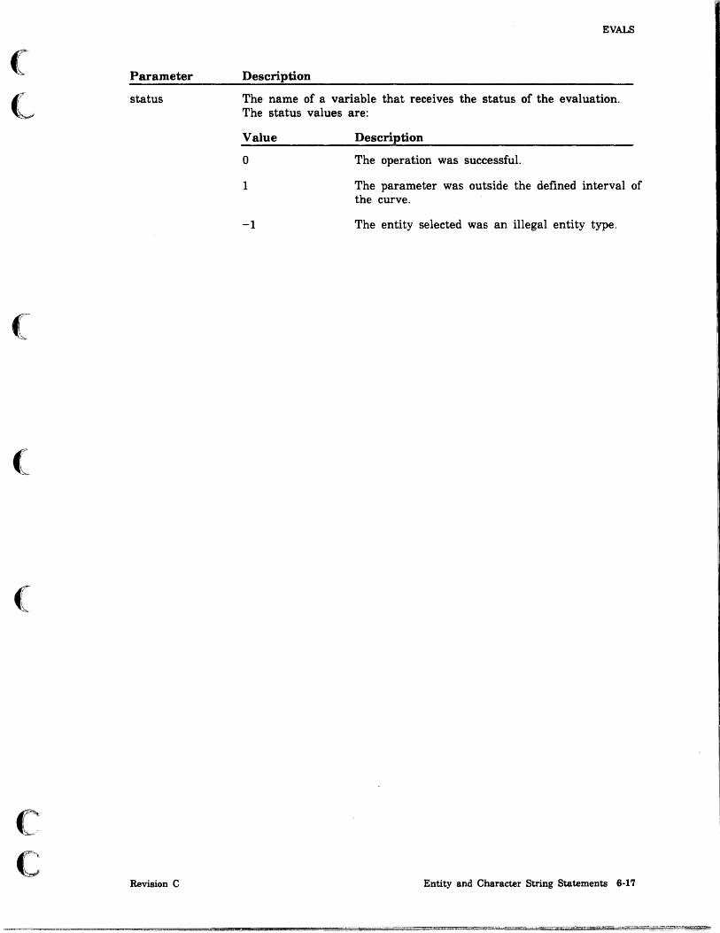
Parameter
status
(
(
Revision C
EVALS
Description
The name of a variable that receives the status of the evaluation. The status values are:
Value
o
1
-1
Description
The operation was successful.
The parameter was outside the defined interval of the curve.
The entity selected was an illegal entity type.
Entity and Character String Statements 6-17

EVALS
Point Returns Parameter
Statement format:
EVALS/POINTs.entjty.arraY.[~:~I.param.[arrl[.arr2[.arr3[.arr4111].status
Parameter
POINTS
entity
array
MODVW
DEFVW
CURVW
param
arr1
arr2
arr3
arr4
status
Description
The minor word indicating that a parameter is to be returned from a specified point.
The name of the entity to be evaluated.
The name of an array that contains the three-dimensional point coordinates.
The minor word indicating that the coordinates of the point are given in model space.
The minor word indicating that the coordinates of the point are given in the definition space of the indicated entity.
The minor word indicating that the coordinates of the point are given in the current workspace.
The name of the array that receives the u and v parameters returned. The parameter usually has a value between 0 and 1. Refer to the System Programmer's Reference Manual. This number may I)ot always be a value between 0 and 1. For example, curve mesh surface has a value between 0 and the number of fixed curves minus 1.
The name of the array that receives the three-dimensional point coordinates.
The name of the array that receives the unitized normal of the curve.
The name of the array that receives the rust derivative of the curve in the u direction.
The name of the array that receives the first derivative of the curve in the v direction.
The name of the variable that receives the status of the evaluation. It has the following values:
Value Description
o The operation was successful.
-1 The entity selected was an illegal entity type.
-2 The point was not on the curve.
6·18 ICEM GPL for NOS Revision C

(
(
(
c c
MOVCHR
MOVCHR
The MOVCHR statement creates a text variable by moving characters from one text variable or character string to another text variable.
Statement format:
MOVCHR/nChr,(textvar1),ChPOs1,textvar2,ChPOS2 'text'
Parameter Description
nchr The number of characters to be moved.
textvarl The name of the text variable containing the text to be moved.
'text' The character string to be moved enclosed in single quotes.
chposl The position of the first character to be moved.
textvar2 The name of the text variable receiving the text.
chpos2 The position at which to place the first moved character.
MOVENT
The MOVENT statement moves entities from one array to another array.
Statement format:
MOVENT/number,entity array1,entity array2
Parameter Description
number The number of entities to be moved.
entity array! The name of the source entity array.
entity array2 The name of the destination entity array.
Revision C Entity and Character String Statements 6-19

OBTAIN
OBTAIN
The OBTAIN statement obtains or retrieves information from the database. The information is extracted from the ICEM DDN common arrays. The information obtained is assigned to variables specified in the command for later use in the GPL program.
The common arrays from which data can be obtained are TABI (master entity list), TAB2 (entity-dependent integer and character string data), TAB3 (entity-dependent real data, TAB4 (View Information), and TAB5 (entity names and pointers). Refer to the System Programmer's Reference Manual for more information on the contents of the common arrays. Also, see appendix E for more information on database I/O.
There are 15 forms of this statement.
Coordinates
Statement format:
OBTAIN/COORD,entitY,array
Parameter
COORD
entity
array
NOTE
Description
The minor word for obtaining coordinate data.
The entity for which data is obtained. The entity types allowed are points, lines, circles, and all drafting entities.
The name of an array in which to store the data. The size of the array (the number of words required) is dependent upon the entity type selected. The number of elements for each entity is:
Entity Type
Points
Lines
Circles
Drafting entities
Number of Elements Explanation
3 Points require three elements per entity to store the coordinates of each point.
6
6
2
Lines require six elements per entity to store the coordinates of each line.
Circles require six elements per entity to store the start and end angles in radians (2), the coordinates of the center point (3), and the radius (1).
Drafting entities return the text origin (xt and yt).
The coordinates retrieved will be model space coordinates.
6·20 ICEM GPL for NOS Revision C

(
(
c c
OBTAIN
Example:
Program Statements Explanation
REAL/ARR(3)
LN1=LINE/l00,100,0$ ,200,200,0
LN2=LINE/100,200,0$ ,200,100,0
Sets up an array for the point coordinates.
Creates the first line.
Creates the second line.
PT1=POINT/INTOF,XLARGE$ ,LN1,LN2
Finds the point of intersection.
OBTAIN/COORD,PT1,ARR(1) Obtains the point coordinates and store them in array ARR.
Number of Characters
Statement format:
OBTAIN/NUMBER,[text variable),Variable 'text'
Parameter
NUMBER
text variable
'text'
variable
Example:
Description
The minor word for obtaining the number of characters in a text string.
The name of the text variable to be checked for the number of characters.
The text string enclosed in single quotes to be checked for the number of characters.
The name of the variable that receives the number of characters.
The following statement extracts the number of characters from the string given.
OBTAIN/NUMBER,'NUMBER OF CHARACTERS IN THIS STRING' ,XN
The value is returned to the variable XN.
Revision C Entity and Character String Statements 6-21
I'
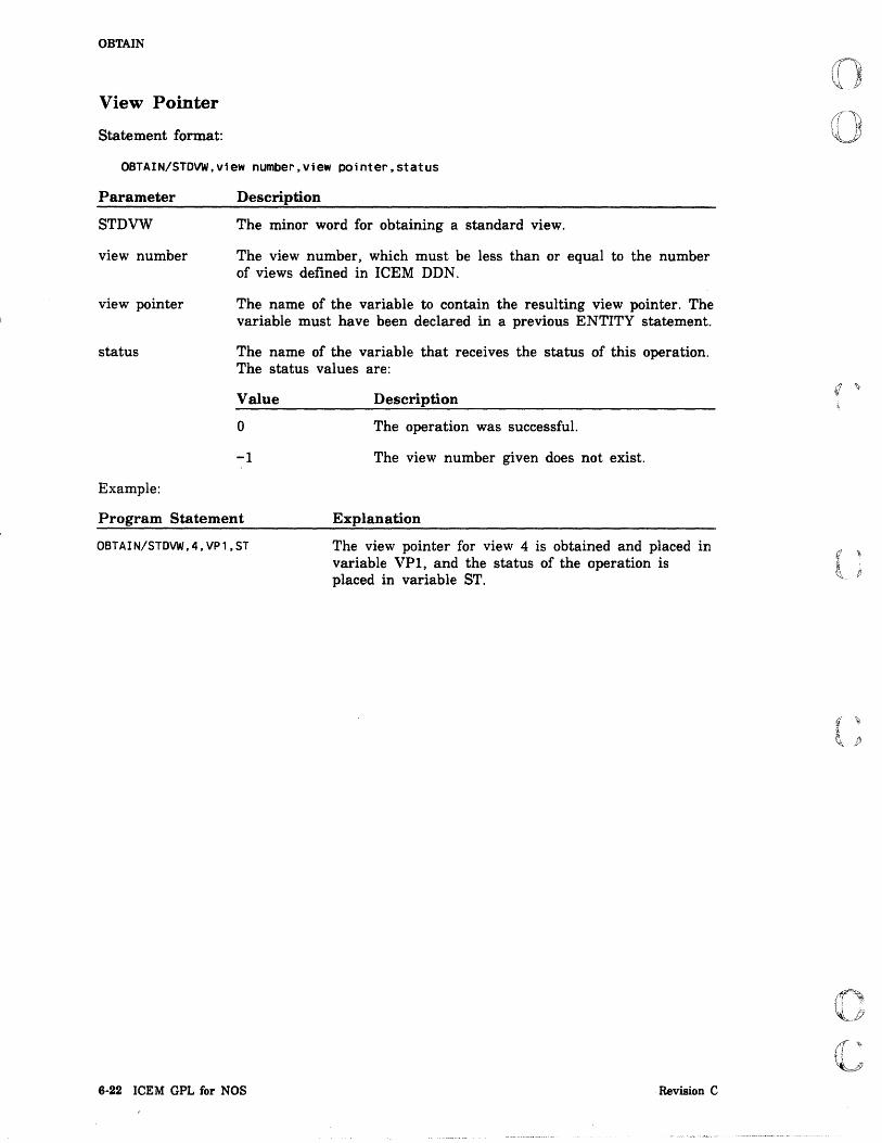
OBTAIN
View Pointer
Statement format:
OBTAIN/STDVW,view number,view pointer.status
Parameter
STDVW
view number
view pointer
status
Example:
Description
The minor word for obtaining a standard view.
The view number, which must be less than or equal to the number of views defined in ICEM DDN.
The name of the variable to contain the resulting view pointer. The variable must have been declared in a previous ENTITY statement.
The name of the variable that receives the status of this operation. The status values are:
Value Description
o The operation was successful.
-1 The view number given does not exist.
Program Statement Explanation
OBTAIN/STDVW,4,VP1,ST
6·22 ICEM GPL for NOS
The view pointer for view 4 is obtained and placed in variable VPl, and the status of the operation is placed in variable ST.
Revision C
(
(,
(
(
(
c c
OBTAIN
Definition View Pointer
Statement format:
OBTAIN/DEFVW,entitY,view pOinter
Parameter
DEFVW
entity
view pointer
Example:
Description
The minor word for obtaining the definition view pointer of an entity.
The name of the entity for which the view pointer is to be obtained.
The name of the variable to contain the resulting view pointer. The variable must have been declared in a previous ENTITY statement.
Program Statements Explanation
PT1=POINT/100,100,10 OBTAIN/DEFVW,PT1,DV
Current View Pointer
Statement format:
OBTAIN/CURVW,view pOinter
Parameter Description
Entity PTI is defined. The view pointer for entity PTI is obtained and placed in variable DV.
CURVW The minor word for obtaining the current view pointer.
view pointer
Revision C
The name of the variable to contain the resulting view pointer. The variable must have been declared in a previous ENTITY statement.
Entity and Character String Statements 6·23
pm

OBTAIN
Entity Name
Statement format:
OBTAIN/ENTNAM,entitY,text variable,status
Parameter
ENTNAM
entity
text variable
status
Example:
Description
The minor word for obtaining the ICEM DDN entity name of an entity from the data base. The data base entity name must have been defined interactively or by the ASSIGN statement, or else status will return a value of -1.
The local, GPL name of the entity for which the ICEM DDN entity name is to be obtained.
The name of the text variable to receive the ICEM DDN entity name (must be 10 characters in length).
The name of the variable that receives the status of this operation. The status values are:
Value Description
o The operation was successful.
-1 The entity name was not found.
Program Statements Explanation
CHAR/CHR1(10)
ENTITY/PT1
REAL/S
SELECT/'Indicates Point', PT1,S
OBTAIN/ENTNAM,PT1$ ,CHR 1,S
6·24 ICEM GPL for NOS
Sets up a text variable for the entity name.
Defines entity PTl.
Defines the status variable.
Selects the ICEM DDN entity and stores its pointer in PT1.
Obtains the entity name for PTI and stores it in CHRI.
Revision C

(
(
(
OBTAIN
Entity Pointer
There are two forms of the OBTAINIENTPTR statement. The first form is:
Statement format:
[
seq, number 1 OBTAIN/ENTPTR, text variable ,entitY,status
'text'
Parameter
ENTPTR
seq,number
text variable
'text'
entity
status
Example:
Description
The minor word for obtaining the entity pointer of an entity by way of its name defined in the data base or its sequence number.
The sequence number of the entity for which the program is searching.
The text variable that contains the data base name of the entity whose pointer is being obtained. This text variable must be declared as 10 characters in length.
The data base name, enclosed in single quotes, of the entity whose pointer is being obtained.
The name of the entity that receives the pointer.
The name of the variable that receives the status of this operation. The status values are:
Value Description
o The operation was successful.
-1 The entity name was not found.
Program Statements Explanation
ENTITY/PT1
REAL/S
OBTAIN/ENTPTR,'POINT1'$ ,PT1,S
Revision C
Defines the entity.
Defines the status variable.
Obtains the entity pointer for the ICEM DDN entity with the assigned name 'POINT1' and gives it to entity PTl.
Entity and Character String Statements 6·25
.1

OBTAIN
The second form of the OBTAINIENTPTR statement is:
Statement format:
OBTAIN/ENTPTR,[selection cr1teria,]NUMBER,number,arraY,var
Parameter
ENTPTR
selection criteria
NUMBER
number
array
var
Example:
Description
The minor word for obtaining the entity pointer of selected entities.
The criteria by which entities are selected. They can be anyone or more of the following keywords.
PENNUM Selects by pen number.
LEVNUM Selects by level number.
COLNUM Selects by color number.
FONNUM Selects by font number.
ENTTYP Selects by entity type.
Each criteria can be entered with up to ten numbers. For example:
PENNUM
COLNUM
1,2,3,4,5,6,7
3,9,16
The minor word indicating the total number of entities to be selected.
The total number of entities to be selected.
The name of the array into which the entity pointers are stored.
The name of a variable containing the actual number of entity pointers retrieved.
The following statement accumulates all entities of types 1, 2, or 3 (points, lines, and arcs) provided they use pen 0.
OBTAIN/ENTPTR,ENTTVP,1,2,3,PENNUM,O,NUMBER,20,E20,ST
6·26 ICEM GPL for NOS Revision C
r; "

(~
(l,
(
(
c C
·.·~· -
OBTAI~
Parameters of an Entity
Statement format:
OBTAIN/PARAM,ent1tY,array
Parameter
PARAM
entity
array
Example:
Description
The minor word for obtaining the parameters of an entity.
The name of the entity for which the parameters are to be obtained.
The name of the array in which the data is to' be stored. The size of the array (the number of words required) is dependent upon the entity type selected. The number of elements for each entity is:
Entity Type
Curves
Surfaces
Number of Elements Explanation
2 Curves require two elements per entity to store the start and end parameters of each curve.
4 Surfaces require four elements per entity to store the UMIN, VMIN, UMAX, and VMAX parameters.
Program Statements Explanation .
REAL/ARR(2) Defines the array for the parameters.
LN=LINE/10,10,20,20 Creates the line.
OBTAIN/PARAM,LN,ARR(1) Obtains the parameters of LN and stores them in array ARR(l).
Latest Error Number
Statement format:
OBTAIN/ERRST,error status [, line number]
Parameter
ERRST
error status
line number
Revision C
Description
The minor word for obtaining the latest error number that occurred during the current GPL run. This error check works only if the STATUS modal has been previously declared as on.
The name of the variable to receive the error number.
The name of the variable to receive the line number in which the error occurred.
Entity and Character String Statements 6·27

OBTAIN
Entity Type and Form
Statement format:
OBTAIN/ENTTVP,entity,type number[,form number]
Parameter
ENTTYP
entity
type number
form number
Description
The minor word for obtaining the entity type and form number of an entity.
The name of the entity for which the type and form number are to be obtained.
The name of the variable to receive the type number of the entity.
The name of the variable to receive the form number of the entity.
Part Name and Sheet Number
Statement format:
OBTAIN/PARTNA,text variable,sheet number
Parameter
PARTNA
text variable
sheet number
Description
The minor word for obtaining the part name and sheet number of the current part.
The name of the text variable to receive the part name of the current part. The text variable must be sized to receive at least 70 characters.
The name of the real variable to receive the sheet number of the current part.
Members of a Group
Statement format:
OBTAIN/MEMBER.ent1ty.number,ent1ty arraY,actual number
Parameter
MEMBER
entity
number
entity array
actual number
Description
The minor word for obtaining the members of a group.
The name of the entity (group or composite curve) for which the members of the group are to be obtained.
The size (dimension) of the entity array.
The name of the entity array to receive the members of the group.
The number of members actually in the group.
6·28 ICEM GPL for NOS Revision C

(
<-
(
(
c c
OBTAIN
Character String
Statement format:
OBTAIN/CHARST,entitY,text variable,status
Parameter
CHARST
entity
text variable
status
Description
The minor word for obtaining the character string associated with a dimensioning entity (LDlMEN, CDlMEN, DDlMEN, RDlMEN, LABEL, and NOTE).
The name of the entity for which the character string is to be obtained.
The name of the text variable to receive the character string.
The name of the variable to receive the number of characters in the dimensioning entity.
Sequence Number
Statement format:
OBTAIN/SEQNUM,entitY,Variable
Parameter
SEQNUM
entity
variable
Revision C
Description
The minor word for obtaining the sequence number of an entity.
The name of the entity for which the sequence number is to be obtained.
The name of the variable to receive the sequence number of the entity.
Entity and Character String Statements 6·29

OBTAIN
Attribute and Subattributes
Statement format:
OBTAIN/ATNAME,entltY,rankl,varlablel,text variablel
[ I NAME, text var i ab 1 e2 [ , v 1] I]
SUBAT,rank2, NUMBER,array[,v2] BOTH,text variable2,array[,vl,v2]
Parameter
ATNAME
entity
rank!
variable!
text variable!
SUBAT
rank2
NAME
NUMBER
BOTH
text variable2
array
v!
v2
Description
The minor word for obtaining the attributes of an entity.
The name of the entity for which the attributes are to be obtained.
The rank order of the attribute to be obtained.
The name of the variable to receive the number of attributes.
The name of the text variable to receive the name of the attribute.
The minor word for obtaining the subattributes of an entity.
Either:
• The rank order of the sub attribute to be obtained, if NAME or BOTH are requested, or
• The number of values to be obtained in the array, if NUMBER is requested.
The minor word for obtaining the name of a subattribute.
The minor word for obtaining the value of a subattribute.
The minor word for obtaining both the name and number of a subattribute.
The name of the text variable to receive the subattribute name.
The name of the array variable to receive the subattribute value.
The name of the variable to receive the number of subattribute names.
The name of the variable to receive the number of subattribute numbers.
6-30 ICEM GPL for NOS Revision C

(
c
(
(
(
c c
Pen, Level, Color, and Font Numbers
Statement Format:
PENNUM OBTAIN/ LEVNUM ,entitY,number
COLNUM FONNUM
Parameter Description
OBTAIN
PENNUM LEVNUM COLNUM FONNUM
The minor word indicating a pen, level, color, or font number.
entity The name of the entity for which the attributes are obtained.
number The number of the pen, level, color, or font.
Pen (0-15) and level (0-1023) numbers default to 0 or are assigned by the user. Color and font have preassigned default numbers as follows:
Font Number Font
0 Solid 1 Dashed 2 Phantom 3 Centerline
Color Number Color
0 White 1 Red 2 Green 3 Blue-cyan 4 Magenta 5 Yellow 6 Orange 7 Light orange 8 Light green 9 Dark cyan 10 Green-blue 11 Dark red 12 Light purple 13 Yellow-green 14 Dark pink
Revision C Entity and Character String Statements 6-31

SETCHL
SETCHL
The SETCHL statement changes the available length of a character string within the limits of the maximum declared length. Refer to Defined Symbols in chapter 2 for a discussion of maximum and current length.
Statement format:
SETCHL/textvar,value
Parameter Description
textvar The name of the character string whose available length is to be changed.
value The new available length of the character string.
TRIME
The TRIME statement trims the entity at the intersection of another entity.
Statement format:
TRIME/curve,intersect,xts,yts[,zts]
Parameter
curve
intersect
xts, yts, zts
Description
The name of the entity to be trimmed.
The name of the intersecting entity.
The transform coordinates that indicate which end is to be trimmed.
6·32 ICEM GPL for NOS Revision C
(j

o o
o
o
o
o o
Variable Declaration, RTL 110, and File Statements 7
CHAR. . . . . . . . . . . . . . . . . . . . . . . . . . . . . . . . . . . . . . . . . . . .. 7-1
COMMON .......................................... 7-2
CONST . . . . . . . . . . . . . . . . . . . . . . . . . . . . . . . . . . . . . . . . . . .. 7-3
DATA. . . . . . . . . . . . . . . . . . . . . . . . . . . . . . . . . . . . . . . . . . . .. 7-4
ENTITY ........................................... 7-5
FILE ............................................ , 7-6
GET. . . . . . . . . . . . . . . . . . . . . . . . . . . . . . . . . . . . . . . . . . . . .. 7-7
REAL ............................................ , 7-8
SAVE ............................................ , 7-9
Wi¥4M#Q#¢i( ( 44 U .3£+ * ; e au. g

o o
o
o
o
o o
. II
I

(
(~
(
(
c --=!i!Io
C'-.-·--
Variable Declaration, RTL 110, and File Statements 7
Variable declaration; RTL I/O, and file statements perform different management functions. Several of these definitions are equivalent to functions available under menus 4 FILE and 5 SPECIAL FUNCTIONS.
CHAR The CHAR statement declares a text variable or array. The name of a text variable can be referenced in any statement that allows text variables. Character arrays may have up to two dimensions besides the length declaration.
Statement format:
CHAR/name(nchar[,size][,size]), ...
Parameter
name
nchar
size
Examples:
Description
The name or names of the text variables.
The maximum number of characters required for the text variable (expressed as an integer).
The number of elements in the array's dimension. The number of characters and the dimension sizes must be enclosed in parentheses. A two-dimensional array can be specified.
Program Statement Explanation
CHAR/CHR1(10),CHR2(60)
CHAR/C1( 15,5)
Revision C
Text variable CRRl is set for a maximum of lO characters. Text variable CHR2 is set for a maximum of 60 characters.
Text variable Cl is set for a maximum of 15 characters in each of its 5 elements.
Variable Declaration, RTL 110, and File Statements 7·1

COMMON
COMMON
The COMMON statement defines a common block of data that can be used by the GPL programs. This must be declared after the MAIN or PROC statements and before the first executable statement. The common bloc~ can only be initialized using the DATA statement in a MAIN program.
The common block is defined by the modal words COMMON and ENDCOM. All declarations between these words have their addresses in the common block.
In order to use the data declared in common procedure, the same declarations from COMMON to ENDCOM (except DATA statements) must appear' at the start of both the main program and the procedure. For larger programs, common decks (blocks) can be created and maintained by using the NOS utility MODIFY. This is a recommended method for large GPL programs to ensure identical specification of data between various GPL programs and procedures.
Statement format:
COMMON declaration 1 declaration 2
declaration n ENDCOM
Parameter Description
COMMON
ENDCOM
Indicates the start of a common block of declarations.
Indicates the end of the common block.
Example:
Program Statement
COMMON REAL/VAL1,VAL2,STATS(10) ENTITY/PT5(10)
ENDCOM
7·2 ICEM GPL for NOS
Explanation
The real variables VALl and VAL2, real array STATS(lO), and entity array PT5(10) are assigned addresses in a common block.
Revision C I

(
(
c c
CONST
CONST
The CONST statement assigns numerical values to symbolic names. The symbolic name can be used as a real or integer constant. (Note that GPL stores integers internally as floating point numbers.) This is useful when declaring arrays and specifying the limits of a FOR loop.
Statement format:
CONST/name1=value1[,name2=value2, ... J
Parameter
name
value
Example:
Description
The symbolic name for a constant.
The value that is assigned to the symbolic name. This can be a simple expression consisting of constants (symbolic or real). The expression must not contain parentheses and must be developable from left to right (that is, 8**2*y/4+2-6 is correcxt, but x+y/2 is incorrect). Only exponentiation of integers below 524288 (2**19) is allowed.
Program Statement Explanation
CONST/ROWS=10,COLUMS=15
Revision C
The value 10 is assigned to ROWS, and the value 15 is assigned to COLUMS.
Variable Declaration, RTL I/O, and File Statements 7-3

DATA
DATA
The DATA statement initializes real, integer, or character variables or arrays. The DATA statement comes after all declarative statements and before any executable code. If more than one DATA statement is used to declare the elements of the same array, the indices should be entered in ascending order. The replication factor duplicates the same value for the number of elements specified. The replication factor can only be used with arrays.
Statement format:
DATA/name[(index)][,repl*]value1[,value2, ... ]
Parameter
name
(index)
repl
*
valuel,value2, ...
Example:
Description
The name of the real, integer, or character variable that is to be initialized.
The ordinal number of the array element. The index must be enclosed in parentheses.
The number of replications.
An operator indicating that the next value is duplicated for the number of elements specified.
The values to be assigned to the variable or array. The first value is assigned to the first element of the array; the second value is assigned to the second element; and so forth.
Program Statement Explanation
DATA/VAL,4.321
DATA/VALS(2),4*1.00,3.14
NOTE
The variable VAL is initialized to 4.321.
The second, third, fourth, and iIfth elements of variable VALS are initialized to 1.00. The sixth element is initialized to 3.14.
A maximum of 640 data statements are allowed with a total of 3000 individual data initializations. Only one array or simple variable may be initialized per DATA statement.
7 -4 ICEM GPL for NOS Revision C

(
(l,
(
(
c C.·.·'~·---
ENTITY
ENTITY
The ENTITY statement reserves storage for local, simple and subscripted entity names created during the GPL run. Once the entity is defined, its name can be referenced in any subsequent statement within the same routine that allows entity names. The maximum size of one array is 65,534. Entity arrays can have up to three dimensions.
Statement format:
ENTITY/name[<SiZe1[.SIZe2[.Slze311>] ....
Parameter Description
name The name of the entity being sized.
(size1,size2,size3) The sizes of the dimensions of the entity array (expressed in integers). At least one size must be given. The size parameters must be enclosed in parentheses.
Example:
Program Statements
ENTITY/PT(10)
PT(1)=POINT/100,100,O
PT(2)=POINT/PT(1),$ RTHETA,20,45
Revision C
Explanation
An entity array named PT is sized for 10 elements.
The first entity defined is assigned to the first position in the entity array.
The second entity defined is assigned to the second position in the entity array.
Variable Declaration, RTL 110, and File Statements 7·5
FILE
FILE The FILE statement stores the drawing in the ICEM DDN database (TAPE3) for later retrieval and/or modification. All variables saved in the RTL are filed with the drawing. The drawing is filed under the current part name and sheet number.
If the modal RECOVR is on, each FILE statement updates the recovery file (GPLREC). If the recovery file is saved, you can continue processing the GPL program after the last FILE statement (even though ICEM DDN has been terminated by a fatal error) by using menu 5.13.1 RECOVER LAST FILE.
Statement format:
FILE
Example:
Program Statement
FILE
7 -6 ICEM GPL for NOS
Explanation
The drawing you are currently working on is filed to TAPE3.
Revision C

(
<-
(
(
C: -F
C
GET
GET The GET statement retrieves simple variables from the RTL.
Statement format:
[variable I[ [Variable I]
GET/ var='name' ,var='name' [, ... ] var=textvar var=textvar
Parameter
variable
var='name'
var = textvar
NOTE
Description
The name or names of variables stored in the RTL. Names must be separated by commas.
A variable can be retrieved from the RTL and renamed using an equals sign followed by the RTL name enclosed in single quotes. The name is restricted to 6 characters.
A variable can be retrieved from the RTL and renamed using an equals sign followed by a text variable that contains the RTL name (6 characters maximum). The text variable is not enclosed in single quotes.
At least one option (variable, var = 'name', or var = text) must be specified.
Examples:
Program Statement
GET/A,B,F,TAB,ABCD
GET/SCT='TTL'
GET/NT1=PIN
Revision C
Explanation
Variables A, B, F, TAB, and ABCD are retrieved from the RTL.
The variable TTL is retrieved from the RTL and renamed SCT.
The variable whose name is contained in PIN is retrieved from the RTL and renamed NT1.
Variable Declaration, RTL I/O, and File Statements 7-7

REAL
REAL The REAL declaration statement reserves storage space for calculated real variables. The size of a real array is limited to 1,000,000 in the compiler, although this limit may exceed that imposed by the memory and disk space of the computer during execution. Real arrays can have up to three dimensions.
Statement format:
REAL/ var;able[<slzelL.slze2L.size311l] ....
Parameter Description
variable The name of the real variable that is declared.
(sizel,size2,size3) The sizes of the dimensions of the real variable array (expressed in integers). At least one size must be given. The size parameters must be enclosed in parentheses.
Example:
Program Statement
REAL/A,B(10),C,D(10)
NOTE
Explanation
Real variables A and C are declared. Real variable arrays Band D are sized as 10 elements.
As in FORTRAN, GPL allows the user to overflow an array during execution. This .may lead to undesirable results in other sections of the program. Be careful to set your dimensions to the maximum SUbscript used.
7·8 ICEM GPL for NOS Revision C
(/ '\
f
I \
(
L
(
(
(
..
c ( -•• ~
-.::::iF
SAVE
SAVE
The SAVE statement saves simple variables in the RTL. Saved simple variables can be listed under 5.3.4 LIST RUN TIME LIBRARY VARIABLES (refer to the ICEM Design/Drafting Data Management reference manual).
Statement format:
[variable ][ [Variable ]J
SAVEl var='narne' ,var='narne' [ , ... ] var=textvar var=textvar
Parameter
variable
var='name'
var = textvar
Example:
Description
The name or names of the variables to be saved in the RTL. The names must be separated by commas.
A variable can be saved in the RTL and renamed using an equals sign followed by the new name enclosed in single quotes. The name is restricted to 6 characters.
A variable can be saved in the RTL and renamed using an equals sign followed by a text variable that contains the new name (6 characters maximum). The text variable is not enclosed in single quotes.
Program Statement Explanation
SAVE/A,B,F,TAR,ABCD
SAVE/SCT='TTL'
SAVE/NT1=PIN
Revision C
Variables A, B, F, TAR, and ABCD are saved in the RTL.
The variable SeT is saved in the RTL as TTL.
The variable NTl is saved in the RTL as the name contained in the text variable PIN.
Variable Declaration, RTL 110, and File Statements 7·9


o o
o
o
o
o o
Program Management Statements 8
CALL. . . . . . . . . . . . . . . . . . . . . . . . . . . . . . . . . . . . . . . . . . . .. 8-1
CONTIN .... '. . . . . . . . . . . . . . . . . . . . . . . . . . . . . . . . . . . . . .. 8-1
DATE. . . . . . . . . . . . . . . . . . . . . . . . . . . . . . . . . . . . . . . . . . . .. 8-2
FIN! ............................................. 8-2
MAIN. . . . . . . . . . . . . . . . . . . . . . . . . . . . . . . . . . . . . . . . . . . .. 8-3
MSTRNG . ... ' ....................................... 8-4
PAUSE. . . . . . . . . . . . . . . . . . . . . . . . . . . . . . . . . . . . . . . . . . .. 8-5
PROC . ........................................... , 8-6
REMARK . .......................................... 8-7
RETURN. . . . . . . . . . . . . . . . . . . . . . . . . . . . . . . . . . . . . . . . . .. 8-7
STOP. . . . . . . . . . . . . . . . . . . . . . . . . . . . . . . . . . . . . . . . . . . .. 8-8
TIME. . . . . . . . . . . . . . . . . . . . . . . . . . . . . . . . . . . . . . . . . . . .. 8-8
•• W4 Ii #I =:"',_. J __ - £#$ ,ii: ;". @f _. _, ; ~~

Li -=~_"_i" ,-
o o
o
o
o
o o

(
(.
(
(
c c
Program Management Statements 8
Program management statements perform various management functions.
CALL
The CALL statement executes the subroutine named in a PROC statement and passes variables from the main program to the subroutine. The variables passed must agree in order and number in both the main program and the subroutine although their names may be different.
Entire arrays can be passed by specifying the array name with a subscript of 1, but must also be declared in the subroutine.
The number of arguments passed is limited to 62.
Statement format:
CALL/name,var1able, ...
Parameter Description
name The 1- to 6-character name of the subroutine.
variable The name of the variable that is passed to the subroutine.
Example:
Program Statement
CALL/TEST,A,B(10)
CONTIN
Explanation
The program branches to the subroutine named TEST and executes it. Variables A and BOO) are passed to the subroutine.
The CONTIN statement continues program execution at the next GPL statement. This can be used as a destination statement for branching. The CONTIN statement must be preceded by a label number of no more than five digits.
Statement format:
label number CONTIN
Parameter Description
label number The statement label number of the CONTIN statement.
Example:
Program Statement
IF (A.EQ.B) GOTO 10 A = A+1
10 CONTIN
Revision C
Explanation
Test if A equals B. If it does, jump to statement label 10. Execute the following statements only if the condition was false.
Program Management Statements 8-1

I i
I DATE
DATE
The DATE statement gets the current date from the operating system and stores it In a text variable. This text variable must be dimensioned by a CHAR statement prior to using the DATE statement. The data is stored in the form yy-mm-dd (yy is year, mm is month, and dd is day).
Statement format:
DATE/variable
Parameter Description
variable The name of the variable that receives the date from the operating system.
Example:
Program Statement
CHAR/DT(lO)
DATE/DT
FINI
Explanation
The variable that receives the date is dimensioned to 10 characters.
The current date is stored in variable DT.
The FINI statement indicates the end of a GPL program or subroutine. If it is at the end of a subroutine, this statement returns control to the calling program. If it is at the end of a main program, this statement returns control to menu 5 SPECIAL FUNCTIONS.
Statement format:
FINI
Example:
Program Statement Explanation
FINI The program has fInished executing.
8·2 ICEM GPL for NOS Revision C
(
(
(
c c
MAIN
MAIN The MAIN statement is the first statement in a GPL program. The name of the program given in the MAIN statement can be called from ICEM DDN for execution.
Descriptive text can be passed with the program. The text appears in source listing headers and is attached to the object code in a system-dependent fashion. For NOS, the text takes the form of a PIDL table (7700 table).
In the internal representation, this user-defined information is preceded by the compilation date and time and the compiler release level. System Utilities may be used to list this information.
Statement format:
MAIN/name[,'text']
Parameter Description
name The 1- to 6-character name of the program.
'text' Descriptive text (40 characters maximum) enclosed in quotes.
Example:
Program Statement
MAIN/GEAR1
MAIN/PRACT1,'FIRST PROGRAM'
Revision C
Explanation
The first statement of a program named GEARl.
The first statement of a program named PRACT1 with descriptive text FIRST PROGRAM.
Program Management Statements 8-3

MSTRNG
MSTRNG The MSTRNG statement executes an ICEM DDN menu string from within a GPL program. The menu string may either be defined explicitly within the GPL program or defined as a named menu string on the external menu string file.
If the menu string is specified in the GPL program, it can either be defined in a text variable or enclosed in single quotes on the MSTRNG statement line. The menu string syntax must be identical to tablet menu string syntax (see Tablet String Programming Format in the ICEM Design/Drafting Data Management reference manual). Specifically, menu choices must be separated by periods and the lowercase "t" used to enclose data or text. The string cannot exceed 127 characters in length. The menu string can also be in packed format as discussed under 7.13.1.4 STRING DISPLAY FORMAT.
If you specify the menu string from a local file, the menu string must first be defined in the local file declared by 1.16.4 CHANGE MSTRING FILE. The default name is MSTRING. The menu string file name can also be changed using the MSFILE statement.
The automatic return of an MSTRNG statement can be suppressed by using the NORTRN minor word. Mter using NORTRN, you must use 5.13.2 CONTINUE GPL PROGRAM to continue execution of the GPL program.
NOTE
The menu string to be executed will begin at the Special Functions menu. Therefore, you will usually want to begin each menu string with "rl to return to the main menu.
Alternate Screen Position Input (the I key) is available within your menu string.
Statement format:
'menu str1ng' MSTRNG/ menu str1ng text variable [,NORTN]
NAME, ' msname' NAME,msname text var
Parameter Description
'menu string' The explicit menu string enclosed in single quotes.
menu string text The name of a text variable that contains the menu string. variable
NAME The minor word for retrieving the named mstring file from the local file specified by the MSFILE modal.
'msname' The name of a menu string (enclosed in single quotes) that resides on the local file specified by the MSFILE modal.
8-4 ICEM GPL for NOS Revision C

(
(
(
PAUSE
Parameter Description
msname text var The name of a text variable containing the name of a menu string tha t resides on the local file specified by the MSFILE modal.
NORTN The minor word for suppressing automatic return from the execution of an MSTRNG statement to the next statement following the MSTRNG statement in the executing GPL program. If you use this minor word, you must use 5.13.2 CONTINUE GPL PROGRAM to resume execution at the next statement following the MSTRNG statement in the executing GPL program.
The following error messages can occur from incorrect use of the MSTRNG statement.
SYNTAX ERROR WITHIN MENU STRING
ERROR FOUND WHILE READING MSTRING FILE
MENU STRING NAME NOT ON FILE
Examples:
Program Statement
MSTRNG/'F.6.6.1.3.t]t.t]t'
MSTRNG/NAME,TPl
MSTRNG/'F.6.6.1.3.t]t',NORTRN
PAUSE
Explanation
Lists to the screen all entities by type.
Executes menu string TP1 residing on the current menu string file.
Lists entity types without returning to the next GPL statement.
The PAUSE statement interrupts the GPL program and returns you to the GPL menu. The program can be restarted using two different menus. Menu 5.13.2 CONTINUE GPL PROGRAM begins execution at the first statement after the PAUSE that caused the interrupt. Menu 5.13.3 RUN GPL PROGRAM restarts the program at its beginning.
Statement format:
PAUSE/[ 'text']
Parameter
'text'
Example:
Description
The text to be displayed when the program returns to the GPL menu. It must be enclosed in single quotes (10 characters maximum).
Program Statement Explanation
PAUSE/'WAITING'
Revision C
The current GPL program is interrupted and waits until either 5.13.2 CONTINUE GPL PROGRAM or 5.13.3 RUN GPL PROGRAM is executed.
Program Management Statements 8·5
-=s.

I f
PROC
PROC The PROC statement names the fIrst statement of a subroutine, and can receive variables from the main program. The variables passed must agree in order and number in both the main program and the subroutine. Arrays can be passed by specifying the array name without the subscript, but must be declared in both the main program and the subroutine. Subscripts are not allowed in the argument list.
This statement is executed when a CALL statement with the name of the PROC statement is encountered in the main program. The name of the subroutine must be unique to the GPL library.
Descriptive text can be passed with the program. The text appears in source listing headers and is attached to the object code in a system-dependent fashion. For NOS, the text takes the form of a PIDL table (7700 table).
In the internal representation, this user-defined information is preceded by the compilation date and time and the compiler release level. System Utilities can be used to list this information.
Statement format:
PROC/name,variable, ... [,'text']
Parameter
name
variable
'text'
Example:
Description
The 1- to 6-character name of the subroutine.
The name of a variable passed from the main program to the subroutine.
Descriptive text (40 characters maximum) enclosed in quotes.
Program Statement Explanation
PROC/TEST,A,B
PROC/COORDS,x,y,Z$ ,'FIND CLOSEST POINT'
8-6 ICEM GPL for NOS
The fIrst statement of a subroutine named TEST with the variables named A and B passed from the main program.
The first statement of a subroutine named COORDS with variables x, y, and z passed from the main program. The descriptive text is FIND CLOSEST POINT.
Revision C

(
~,
(
(
(
c c
REMARK
REMARK The REMARK statement adds descriptive comments to the part program. This information is not used, but is included for program readability. If more than one line is required for the comment, each line must start with a REMARK command. The REMARK statement must appear at the leftmost position of the program line.
Comments can also be added to any statement by placing them after $$. A statement that starts with $$ is equivalent to a REMARK command.
Statement format:
REMARK/ ... descriptive comment ...
Example:
Program Statement
REMARK/THE FOLLOWING REMARK/PROGRAM CREATES REMARK/A WHEEL BEARING
RETURN
Explanation
Descriptive comments preceding a program that creates the geometry for a wheel bearing.
The RETURN statement can occur anywhere in a subroutine except as the first or last statement. It returns control to the statement immediately after the CALL statement that invoked the subroutine. (A FIN! statement terminates the subroutine.)
Statement format:
RETURN
Example:
Program Statement
RETURN
Revision C
Explanation
The subroutine ends and execution starts at the statement immediately after the CALL statement that invoked the subroutine.
Program Management Statements 8-7

i I I ~
STOP
STOP The STOP statement terminates the GPL program. This command returns control to menu 5 SPECIAL FUNCTIONS.
Statement format:
STOP/[ 'text']
Parameter
'text'
NOTE
Description
The text to be displayed when the program returns to the GPL menu. It must be enclosed in single quotes (10 characters maximum).
This statement should not be used under TELEX. The program must always have a FINI statement to end the program, even if you use a STOP statement to stop executioll.
TIME The TIME statement returns the current time as hh:mm:ss (hh is hours, mm is minutes, and ss is seconds). The text variable must be dimensioned by a CHAR statement prior to using the TIME statement.
Statement format:
TIME/variable
Parameter Description
variable The name of the variable to receive the current time.
Example:
Program Statement
CHAR/TM(10)
TIME/TM
8·8 ICEM GPL for NOS
Explanation
The variable that receives the time is dimensioned to 10 characters.
The current time is stored in variable TM.
Revision C

o o
o
o
o
o o
Display Control Statements
BLANKE ......... . Blank Specified Entities Blank an Entity Array Blank All Except Specified Entities Blank All of a Level, Color, or Pen
CHANGE ..... Multiple Views Two Views .. Changing Current Work View
MAP ..
REPANT
UNBLNK Specified Entities . Entities from an Entity Array All Except Specified Entities On a Level
VBORDS .. .
VIEW .... . Auxiliary View by Rotation Angle Auxiliary View Parallel to a Plane Defined by Three Points. View by Matrix .
VNAMES.
VVECS
WAIT .
ZOOM Auto MAXMIN Diagonal Points . . Scale Factor with Origin or Center
9
9-1 9-1 9-1 9-2 9-2
9-3 9-3 9-4 9-4
9-5
9-6
9-7 9-7 9-7 9-7 9-7
9-8
9-9 9-9
9-10 9-10
9-11
9-12
9-12
9-13 9-13 9-13 9-14
WQ'_ Luae:.sua: iii M4M MMaC4\. MIZ AZAki H.L.

l!Illlt''''''
o o
o
o
o
o o
(
(
c c
Display Control Statements
Display control statements perform display control functions. Several of these definitions are equivalent to types and forms found in menu 8 DISPLAY CONTROL.
BLANKE The BLANKE statement blanks specified entities.
Blank Specified Entities
Statement format:
BLANKE/ent1ty[, ... J
Parameter
entity
Example:
Description
The names of the entities to be blanked. This list can contain a maximum of 64 entities.
Program Statement Explanation
BLANKE/PT1,LN2,CIR3 Entities PTl, LN2, and CIR3 are blanked.
Blank an Entity Array
Statement format:
BLANKE/NUMBER,count,entityarray
Parameter
NUMBER
count
entity array
Example:
Description
A minor word indicating that a number of entities are to be blanked.
The number of entities to be blanked in the entity array. This number must not exceed 250.
The array of entities to be blanked.
Program Statement Explanation
BLANKE/NUMBER,3,E(1) The three entities E(1), E(2), and E(3) are blanked.
9
Revision C Display Control Statements 9-1

BLANKE
Blank All Except Specified Entities
Statement format:
BLANKE/ALL[.entlty[ •... l] Parameter
ALL
entity
Example:
Description
The minor word indicating that all entities are to be blanked except those in the optional parameter list.
The names of the entities not to be blanked.
Program Statement Explanation
BLANKE/ALL,PT27,PT28,PT29 All entities are blanked except PT27, PT28, and PT29.
Blank All of a Level, Color, or Pen
Statement format:
[LEVNU~ [ ] BLANKE COLNUM ,number ,entlty[, ... J PENNUM
Parameter
LEVNUM
number
COLNUM
PENNUM
entity
Example:
Description
The minor word indicating that all entities on the given level number are to be blanked.
The number of the level, color, or pen of which entities are to be blanked.
The minor word indicating that all entities of the given color number are to be blanked.
The minor word indicating that all entities of the given pen number are to be blanked.
The names of the entities not to be blanked.
Program Statement Explanation
BLANKE/LEVL,3,PTSO,PTS1
9·2 ICEM GPL for NOS
All entities on level 3 are blanked except PT50 and PT51.
Revision C

(
(,
(
(
c c
CHANGE
CHANGE
The CHANGE statement changes the current work view, which must have been defined previously using the VIEW statement or obtained as a standard view using the OBTAIN statement. A maximum of 12 views can be used simultaneously.
Multiple Views
Statement format:
CHANGE/V1[.V2[ •... 1][.NORPNT l
Parameter
vI, v2 ...
NORPNT
Revision C
Description
A listing of view pointers. The first view is defined as the current work view. A maximum of 12 views can be used simultaneously.
The minor word for not repainting the display when the work view is changed.
Display Control Statements 9-3

)
! \ ) 1
CHANGE
Two Views
Statement format:
CHANGE/(VERTCL),Vl,V2[,NORPNTl HORIZ
Parameter
VERTCL
HORIZ
vI
v2
NORPNT
Description
The minor word for changing the top and bottom views.
The minor word for changing the right and left views.
The pointers of the view defined as the current work view. This is the top view for VERTCL and the left view for H ORIZ.
The pointers of the second view. This is the bottom view for VERTCL and the right view for HORIZ.
The minor word for not repainting the display when the work view is changed.
Changing Current Work View
Statement format:
CHANGE/CURVW,v1,status
Parameter
CURVW
vI
status
Description
The minor word for changing any displayed view as the current work view.
The view pointer entity defining the desired current work view.
The name of a variable that receives the status of the CHANGE operation. The status values are:
Value Description
o The operation was successful.
-1 - The view given is not on the screen.
9-4 ICEM GPL for NOS Revision C
(
(~
(
(
(
c c
MAP
The MAP statement maps a three-dimensional coordinate array from one view to another view.
Statement format:
MAP/vp1,array1,vp2,array2
Parameter Description
vpl The pointer of the view that sends the data.
arrayl The name of the array that sends the data.
vp2 The pointer of the view that receives the data.
array2 The name of the array receives the data.
MAP
Revision C Display Control Statements 9·5

I I r
REPANT
REPANT The REPANT statement repaints the screen. Deleted entities disappear from the display if you are using a storage tube terminal. Deleted and blanked entities are not displayed by the REPANT statement.
Statement format:
REPANT
Example:
Program Statement Explanation
REPANT The screen display of the part drawing is repainted.
9-6 ICEM GPL for NOS Revision C

(
(
(
c c
UNBLNK
UNBLNK The UNBLNK statement unblanks blanked entities.
Specified Entities
Statement format:
UNBLNK/entity[ •... ]
Parameter
entity
Description
The name of the entity to unblank. The total number of entities may not exceed 64.
Entities from an Entity Array
Statement format:
UNBLNK/NUMBER,count,ent1tyarray
Parameter
NUMBER
count
entity array
Description
The minor word for unblanking an entity from an array.
The number of entities to be unblanked from the array. The total number of entities cannot exceed 250.
The name of an entity array.
All Except Specified Entities
Statement format:
UNBLNK/ALL[,ent1ty, ... ]
Parameter
ALL
entity
On a Level
Statement format:
Description
The minor word for unblanking all except selected entities.
The name of the entity not to unblank. The total number of entities cannot exceed 63.
UNBLNK/LEVL, level number[,ent1ty, ... ]
Parameter
LEVL
level number
entity
Revision C
Description
The minor word for unblanking an entity from a level.
The number of the level from which to unblank..
The name of the entity that is left blanked. The total number of entities cannot exceed 62.
Display Control Statements 9·7

VBORDS
VBORDS The VBORDS statement turns on or off the display of view borders.
Statement format:
VBORDS/(ON )[,View ... J OFF
Parameter
ON
OFF
Description
Turns on view border display.
Turns off view border display.
view ... An optional list of views to receive borders. If omitted, all standard view borders are turned on.
Example:
Program Statement Explanation
VBORDS/ON All subsequent view borders are displayed.
9·8 ICEM GPL for NOS Revision C

("'
(,
(
(
(
c c
VIEW
VIEW
The VIEW statement creates a new view. The resulting view pointer can be used in the CHANGE statement to change the current work view and should be declared by an ENTITY statement. There are three definition forms: auxiliary view by rotation angle, auxiliary view parallel to a plane defined by three points, and view by matrix.
Auxiliary View by Rotation Angle
Statement format:
VIEW/AUX[,XTROT,xt angle][,YTROT,yt angle][,ZTROT,zt angle][,ORIGIN,xt,yt,zt]
Parameter
AUX
XTROT
xt angle
YTROT
yt angle
ZTROT
zt angle
ORIGIN
NOTE
Description
The minor word for creating a new auxiliary view.
The minor word for indicating rotation in the XT plane.
The xt angle in degrees.
The minor word for indicating rotation in the YT plane.
The yt angle in degrees.
The minor word for indicating rotation in the ZT plane.
The zt angle in degrees.
The minor word for indicating the origin of the view.
The xt-, yt-, and zt-coordinates of the view origin.
At least one minor word must be present after AUX.
Revision C Display Control Statements 9·9

VIEW
Auxiliary View Parallel to a Plane Defined by Three Points
Statement format:
VIEW/AUX,po1nt1,point2,point3[,ORIGIN,xt,yt,zt]
Parameter Description
AUX The minor word for creating a new auxiliary view.
point!, point2 Point! and point2 define the edge of the plane parallel to the x-axis.
poipt2, point3 Point2 and point3 define the edge of the plane parallel to the y-axis.
ORIGIN The minor word for indicating the view origin.
xt,yt,zt The xt-, yt-, and zt-coordinates of the view origin.
View by Matrix
Statement format:
VIEW/MATRIX,a11,a21,a31, ... ,a33,a14,a24,a34
Parameter Description
MATRIX The minor word for creating a view using a matrix.
all through a34 The values of the elements of a rotation matrix. The rotation matrix i~ in the form:
all a12 a13 a14
a2l a22 a23 a24
a3l a32 a33 a34
The matrix must be orthonormal and I det I = ± 1.
9-10 ICEM GPL for NOS Revision C
{ }

(
(
c c
VNAMES The VNAMES statement turns on or off the view names display.
Statement format:
VNAMES/(ON )[,Vlew ... ] OFF
Parameter
ON
OFF
Description
Turns on view name display.
Turns off view name display.
VNAMES
view ... An optional list of views to receive names. If omitted, all standard views are named.
Example:
Program Statement Explanation
VNAMES/ON All subsequent view names are displayed.
Revision C Display Control Statements 9·11

VVECS
VVECS The VVECS statement turns on or off the display of coordinate view vectors.
Statement format:
VVECS/(ON )[,View ... l OFF
Parameter
ON
OFF
Description
Turns on coordinate view vector display.
Turns off coordinate view vector display.
view ... An optional list of views to receive vectors. If omitted, all standard view vectors are turned on.
Example:
Program Statement Explanation
VVECS/ON All subsequent coordinate view vectors are displayed.
WAIT
The WAIT statement pauses the program so that the display of the drawing has time to catch up with the program.
Statement format:
WAIT
9·12 ICEM GPL for NOS Revision C
I i

(
(
(~
C
ZOOM
ZOOM The ZOOM statement zooms in and out of the part drawing.
Auto MAXMIN
Statement format:
ZQOM/MAXMIN
Parameter
MAXMIN
Description
The minor word for indicating automatic maximums and minimums. The whole part drawing is automatically displayed on the screen.
Diagonal Points
Statement format:
ZOOM/COORD,(P01nt),(POint) xt, yt xt, yt
Parameter
COORD
point
xt,yt
Revision C
Description
The minor word for zooming to the region defined by two corner points.
The name of a corner point.
The xt- and yt-coordinates of a corner point.
Display Control Statements 9·13

ZOOM
Scale Factor with Origin or Center
Statement format:
ZODM/SCALE,scale[,(ORIGINJ,( PD1nt)] CENTER xt,yt
Parameter
SCALE
scale
ORIGIN
CENTER
point
xt,yt
Description
The minor word for zooming to a specified scale factor.
The scale factor.
The minor word for using the origin of the drawing as a base for zooming.
The minor word for using the center of the drawing as a base for zooming.
The name of the origin or center point.
The xt- and yt-coordinates of the origin or center point.
9-14 ICEM GPL for NOS Revision C

o o
o
o
o
o
POINT Statements POINT ....... .
Coordinates . . . . Polar Coordinates . Delta Coordinates Vectored Point . . Center of a Circle On a Circle .... Curve Endpoint . . Intersection of Two Curves On a Line at an X, Y, or Z Value. Projection of a Point on a Curve . At a Bearing and Distance . On a Curve at a Parameter. Surface Normal. Pierce ..... Spherical Point .
M'.'" a la lAO: (I;.wl IX ; m..
10
10-1 10-1 10-2 10-2 10-3 10-4 10-4 10-5 10-6 10-8 10-9
10-10 10-11 10-11 10-12 10-12

it "!l,t. , Mil!,.. €4'i!!iliiWDt .. k
o o
o
o
o
o o

(
(~
(
(
c c
POINT Statements 10
POINT POINT statements create points in the part drawing. A point is a unique spatial position defined by coordinates, lines, angles, arcs, and intersections of two curves. Point definitions are equivalent to forms found in menu 9 POINT.
NOTE
The DEFINE statement can be used as an alternate way of producing a large number of points.
Coordinates
Statement format:
POINT/xcoord,ycoord[,zcoordl
Parameter
xcoord
ycoord
zcoord
Examples:
Description
The x-coordinate of the point being created.
The y-coordinate of the point being created.
The z-coordinate of the point being created. If zcoord is omitted, it is equal to the current depth value.
Program Statement Explanation
PT1=POINT/2,1,1.3
PT2=POINT/3.1, 1
PT3=POINT/X,Y,Z
Revision C
Point PTI is created at coordinates x = 2, y = 1, and z= 1.3.
Point PT2 is created at coordinates x=3.1, y=l, and z equals the current depth value.
Point PT3 is created at coordinates defined by variables X, Y, and Z.
POINT Statements 10·1

POINT
Polar Coordinates
Statement format:
POINT/point,RTHETA,radius,angle
Parameter
point
RTHETA
radius
angle
Example:
Description
The name of the reference point.
The minor word for defining a point using polar coordinates.
The radius in units of measure from the reference point to where you want to create the point.
The positive angle from the horizontal axis (xt-axis) of the reference point to where you want to create the point.
Program Statement Explanation
P345=POINT/PT2,RTHETA,1.5,45 Point P345 is created using polar coordinates at a radius of 1.5 units of measure and at an angle of 45° from point PT2.
Delta Coordinates
Statement format:
POINT/polnt,DELTA,deltax,deltaY,deltaz
Parameter Description
point The name of the reference point.
DELTA The minor word for defining a point using delta coordinates.
deltax
deltay
deltaz .
Example:
The delta x-coordinate of the point being created.
The delta y-coordinate of the point being created.
The delta z-coordinate of the point being created.
Program Statement Explanation
VDF=POINT/PT1,DELTA.2,1,O Point VDF is created at delta coordinates x=2, y= 1, and z = 0 from point PT1.
10-2 ICEM GPL for NOS Revision C
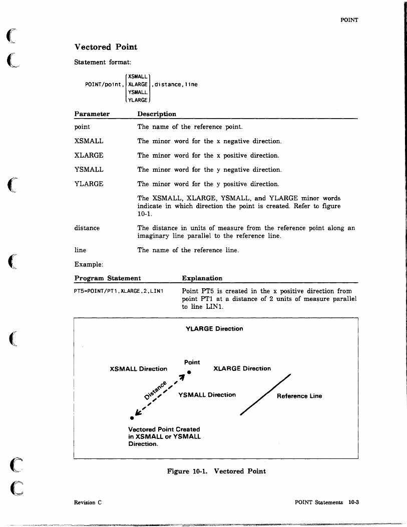
(
(
(
(
(
c c
POINT
Vectored Point
Statement format:
XSMALL POINT/point, XLARGE ,distance, line
YSMALL
Parameter
point
XSMALL
XLARGE
YSMALL
YLARGE
distance
line
Example:
YLARGE
Description
The name of the reference point.
The minor word for the x negative direction.
The minor word for the x positive direction.
The minor word for the y negative direction.
The minor word for the y positive direction.
The XSMALL, XLARGE, YSMALL, and YLARGE minor words indicate in which direction the point is created. Refer to figure 10-1.
The distance in units of measure from the reference point along an imaginary line parallel to the reference line.
The name of the reference line.
Program Statement Explanation
PT5=POINT/PT1,XLARGE,2,LIN1 Point PT5 is created in the x positive direction from point PTI at a distance of 2 units of measure parallel to line LINt.
Revision C
YLARGE Direction
Point XSMALL Direction
Vectored Point Created in XSMALL or YSMALL Direction.
XLARGE Direction
Figure 10-1. Vectored Point
POINT Statements 10-3

POINT
Center of a Circle
Statement format:
POINT/CENTER,circle
Parameter Description
CENTER The minor word for defining a point as the center of a circle.
circle The name of the circle.
Example:
Program Statement Explanation
P4578=POINT/CENTER,C789 Point P4578 is created in the center of circle C789.
On a Circle
Statement format:
POINT/circle,ATANGL,angle
Parameter Description
circle The name of the reference circle.
ATANGL The minor word for indicating the angle.
angle The positive angle from the horizontal axis (xt-axis) along the reference circle at which you want to create the point.
Example:
Program State men t
P29=POINT/CIR32,ATANGL,35.2
10-4 ICEM GPL for NOS
Explanation
Point P29 is created at a positive angle of 35.2° from the horizontal axis along the circumference of circle CIR32.
Revision C

(
(
(
(~
C
Curve Endpoint
Statement format:
XSMALL POINT/END, XLARGE ,curve
YSMALL
Parameter
END
XSMALL
XLARGE
YSMALL
YLARGE
curve
Example:
YLARGE
Description
The minor word for defining the point on the end of a curve.
The minor word for the x negative direction.
The minor word for the x positive direction.
The minor word for the y negative direction.
The minor word for the y positive direction.
The XSMALL, XLARGE, YSMALL, and YLARGE minor words indicate in which direction the point is created. Refer to figure 10-2.
The name of the reference curve.
Program Statement Explanation
POINT
PT104=POINT/END,YLARGE,C99 Point PT104 is created at the end of circle e99 in the y positive direction.
XSMALL Direction
Revision C
YLARGE Direction
YSMALL Direction
Point Created at End of Curve in XLARGE or YLARGE Direction.
XLARGE Direction
Figure 10-2. Point on the End of a Curve
POINT Statements 10-5

POINT
Intersection of Two Curves
Statement format:
POINT/INTOF[.
Parameter
INTOF
xt,yt,zt
XSMALL
XLARGE
YSMALL
YLARGE
curve 1
curve2
xt, yt [, zt] XSMALL XLARGE YSMALL YLARGE
].curvel.curve2
Description
The minor word for defining the point at the true intersection of two reference curves (as opposed to the current depth intersection).
The coordinates of a location at or near the intersection of the two reference curves. It is recommended that this coordinate method be used since the positional form may give an incorrect result if either the first entity is off or nearly off the screen or if PAINT is off.
The minor word for the x negative direction.
The minor word for the x positive direction.
The minor word for the y negative direction.
The minor word for the y positive direction.
The minor words XSMALL, XLARGE, YSMALL, and YLARGE indicate which of several possible intersections is specified. Refer to figure 10-3. A direction indicator is not required if only one intersection is possible, as in the case of the intersection of two lines.
The name of the first reference curve.
The name of the second reference curve. The second curve indicates which intersection point, if there is more than one intersection.
10-6 ICEM GPL for NOS Revision C

(
L
(
(
(
c c
Example:
Program Statement
P24=POINT/INTOF,L29,L30
PT10B=POINT/INTOF,XLARGE$ L42,C40B
This Intersection is
POINT
Explanation
Point P24 is created at the intersection of line L29 and line L30.
Point PT10B is created at the intersection of line L42 and circle C40B in the x positive direction.
Curve 1 YLARGE Direction
XSMALL or YLARGE ----...~~~-,
Revision C
XSMALL Direction
YSMAU Direction
XLARGE Direction
Point is Created at the XLARGE or YSMALL Intersection of the Two Curves.
Figure 10-3. Point at the Intersection of Two Curves
POINT Statements 10·7

POINT
On a Line at an X, Y, or Z Value
Statement format:
IXVALUE,XCOOrdj POINT/line, YVALUE,ycoord
ZVALUE.zcoord
Parameter Description
line The name of the reference line.
XVALUE
YVALUE
ZVALUE
The minor word for creating a point along the x-axis of the line.
The minor word for creating a point along the y-axis of the line.
xcoord
ycoord
zcoord
Example:
The minor word for creating a point along the z-axis of the line.
The x-coordinate of the point along the x-axis.
The y-coordinate of the point along the y-axis.
The z-coordinate of the point along the z-axis.
Program Statement Explanation
POINT/LN1,XVALUE,S.O
10-8 ICEM GPL for NOS
A point is created along the x-axis of line LNI at a distance of 5 units.
Revision C

(
(
(
C C: ..
POINT
Projection of a Point on a Curve
Statement format:
POINT/NOPROJ,point,curve
Parameter
NOPROJ
point
curve
Example:
Description
The minor word for projecting a point on a curve.
The name of the point that is to be projected.
The name of the curve on which the point is to be projected. Lines, arcs, conics, splines, point sets, three-dimensional splines, and machining curves are legal entities for this operation.
Program Statement Explanation
POINT/NOPROJ,X22,C34 Point X22 is projected on curve C34.
Revision C POINT Statements 10·9
POINT
At a Bearing and Distance
Statement format:
POINT/BEAROS,point,(NORTH),(EAST),anQle,distance SOUTH WEST
Parameter
BEARDS
point
NORTH
SOUTH
EAST
WEST
angle
distance
Example:
Description
The minor word for creating a point at a bearing and distance from a reference point.
The name of the point from which the bearing and distance are to be taken.
The minor word for a north bearing.
The minor word for a south bearing.
The minor word for an east bearing.
The minor word for a west bearing.
The angle from the reference point to the new point.
The distance from the reference point to the new point.
Program Statement Explanation
POINT/BEAROS,PT45,$ NORTH,EAST,45,1.0
10-10 ICEM GPL for NOS
A point is created at a bearing of 45° east of north of the reference point and a distance of 1 unit of measure.
Revision C

(
(:
c c
POINT
On a Curve at a Parameter
Statement format:
POINT/CURVE,curve,parameter
Parameter
CURVE
curve
parameter
Example:
Description
The minor word for creating a point along a curve at a parameter.
The name of the reference curve.
The parameter along the curve at which to create the point. The parameter must lie between the starting and ending parameters of the curve.
Program Statement Explanation
POINT/CURVE,CRV1,O.35
Surface Normal
Statement format:
POINT/NORMAL,point,5urface
Parameter Description
A point is created along curve CRVI at a parameter of 0.35 from the start end of the curve.
NORMAL The minor word for creating a surface normal point.
point The name of the base point.
surface The name of the surface.
Example:
Program Statement Explanation
POINT/NORMAL,Q3,SRF1
Revision C
A surface normal point is created on surface SRFI from the base point Q3.
POINT Statements 10·11

POINT
Pierce
Statement format:
POINT/PIERCE,polnt,surface,vector
Parameter
PIERCE
point
surface
vector
Example:
Description
The minor word for creating a pierce point.
The name of the base point.
The name of a drive surface.
The name of a vector. The surface is pierced by a line parallel to the vector. The pierce point is created as close as possible to the base point.
Program Statement Explanation
POINT/PIERCE,Q5,SF2,V3
Spherical Point
Statement format:
A pierce point is created at the intersection of surface SF2 and a line that is parallel to the vector V3 and passes through the base point Q5.
POINT/SPHRIC,radlus,anglez,anglex
Parameter
SPHRIC
radius
anglez
anglex
Example:
Description
The minor word for creating a spherical point.
The radius from the origin (0,0,0) to the point in units of measure.
The angle of the point from the z-axis.
The angle of the point from the x-axis.
Program Statement Explanation
POINT/SPHRIC,5,45,30
10·12 ICEM GPL for NOS
A spherical point is created at a radius of 5 units of measure from the origin, 45° from the z-axis, and 30° from the x-axis.
Revision C
o o
o
o
o
o o
LINE Statements CHAMFR (Bevel)
LINE ..... Coordinates Two Points Tangent to Two Curves Vertical or Horizontal through a Point Through a Point and Tangent to a Curve . From a Point for a Distance at an Angle to an Existing Line Through a Point and Parallel to a Line . . . . Through a Point and Perpendicular to a Line . . Offset Distance Parallel to a Line . . . . . . . . . Tangent to a Curve and Parallel to a Line . . . . Tangent to a Curve and Perpendicular to a Line Join Two Curve Endpoints Infinite Line Axis ............ .
I •• ii::
11
11-1
11-3 11-3 11-3 11-4 11-6 11-6 11-8 11-9 11-9
11-10 11-11 11-12 11-14 11-15 11-15
;U hl ····!llillilil a'iljDttttlJtlt !lW 1m" ! t.iWilHDWDP
o o
o
o
o
o o

(
c
(
(
(
c c
LINE Statements 11
LINE statements create lines in a part drawing. Line definitions are equivalent to forms found in menu lO LINE.
CHAMFR (Bevel)
Statement format:
XSMALL XSMALL CHAMFR/ XLARGE ,linel, XLARGE ,line2,distance,angle
Parameter
XSMALL
XLARGE
YSMALL
YLARGE
linel
line2
distance
angle
TRIM
Revision C
YSMALL YLARGE
YSMALL YLARGE
Description
The minor word for the x negative direction.
The minor word for the x positive direction.
The minor word for the y negative direction.
The minor word for the y positive direction.
The XSMALL, XLARGE, YSMALL, and YLARGE minor words indicate in which direction the line is to be created.
The ends of the two lines defined by the large and small indicators define in which quadrant the chamfer is constructed. The four quadrants are defmed by the intersection of the two lines.
Either the name of the first line to be used for the chamfer or the name of the line to be trimmed.
Either the name of the second line to be used for the chamfer or the name of the line to be trimmed.
The distance of the chamfer in units of measure from the intersection along line 1.
The angle of linel to the chamfer.
The minor word for indicating lines are to be trimmed.
LINE Statements 11·1
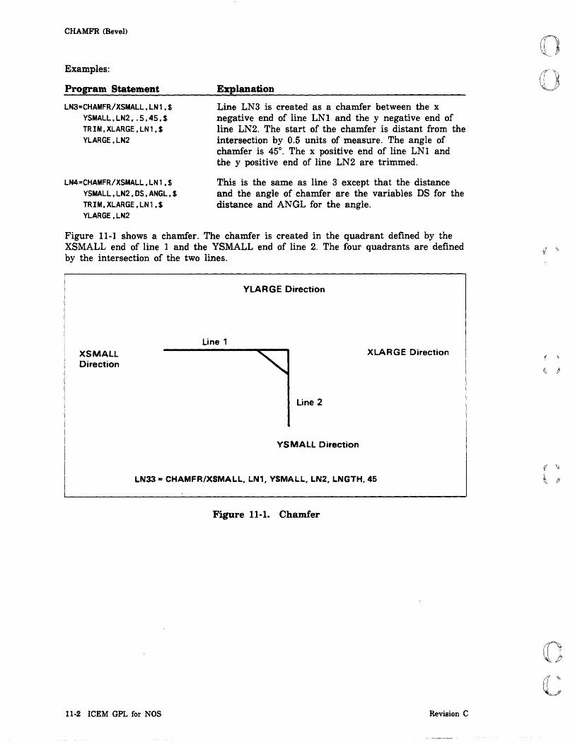
CHAMFR (Bevel)
Examples:
Program Statement
LN3=CHAMFR/XSMALL,LN1,$ YSMALL,LN2,.5,45,$ TRIM,XLARGE,LN1,$ YLARGE,LN2
LN4=CHAMFR/XSMALL,LN1,$ YSMALL,LN2,DS,ANGL,$ TRIM,XLARGE,LN1,$ YLARGE,LN2
Explanation
Line LN3 is created as a chamfer between the x negative end of line LNI and the y negative end of line LN2. The start of the chamfer is distant from the intersection by 0.5 units of measure. The angle of chamfer is 45°. The x positive end of line LNI and the y Positive end of line LN2 are trimmed.
This is the same as line 3 except that the distance and the angle of chamfer are the variables DS for the distance and ANGL for the angle.
Figure 11-1 shows a chamfer. The chamfer is created in the quadrant defined by the XSMALL end of line 1 and the YSMALL end of line 2. The four quadrants are defined by the intersection of the two lines.
XSMALL Direction
Line 1
YLARGE Direction
XLARGE Direction
Line 2
YSMALL Direction
LN33 = CHAMFR/XSMALl, LN1, YSMALL, lN2, LNGTH, 45
Figure 11·1. Chamfer
11·2 ICEM GPL for NOS Revision C

(
(;
(
(
(
c c
LINE
LINE
LINE statements create lines in the part drawing. A line is a curve defining the shortest distance between two points.
NOTE
The DEFINE statement can be used as an alternate way of producing a large number of lines.
Coordinates
Statement format:
LINE/X1,y1[,Z1],x2,y2[,z2]
Parameter
xl,yl,zl
x2,y2,z2
Description
The X-, y-, and z-coordinates of one end of the line being created.
The X-, y-, and z-coordinates of the second end of the line being created.
If zl and z2 are omitted, they are equal to the current depth value.
Example:
Program Statement
LIN23=LINE/2,1,3,4,1.5,2
LIN24=LINE/X1,Y1,Z1,X2,Y2,Z2
Two Points
Statement format:
LINE/point1,point2
Parameter Description
Explanation
Line LIN23 is created between coordinates x = 2, y = l, and z=3, and coordinates x=4, y=1.5, and z=2.
Line LIN24 is created between coordinates defined by variables Xl, Yl, and Zl, and coordinates defined by variables X2, Y2, and Z2.
pointl The name of the point to be used as one end of the line being created.
point2
Example:
The name of the point to be used as the other end of the line being created.
Program Statement Explanation
LIN32=LINE/PT1,PT2
Revision C
Line LIN32 is created between point PTl and point PT2.
LINE Statements 11-3

LINE
Tangent to Two Curves
Statement format:
LINE/TANTO, XLARGE ,curve1, XLARGE ,curve2 XSMALLj XSMALLj
Parameter
TANTO
XSMALL
XLARGE
YSMALL
YLARGE
curve1
curve2
Example:
YSMALL YSMALL YLARGE YLARGE
Description
The minor word indicating that a line is to be created tangentially from the specified side of curve1 to the specified side of curve2.
The minor word for the x negative direction.
The minor word for the x positive direction.
The minor word for the y negative direction.
The minor word for the y positive direction.
The XSMALL, XLARGE, YSMALL, and YLARGE minor words indicate in which direction the line is to be created. For example, in figure 11-2, a line is drawn from the YLARGE side of curve1 to the YSMALL side of curve2.
The name of the first curve.
The name of the second curve.
Program Statement Explanation
LIN10=LINE/TANTO,XSMALL,$ CUR1,YSMALL,CUR2
LIN12=LINE/TANTO,XLARGE,$ CUR1,YLARGE,CUR2
11-4 ICEM GPL for NOS
Line LINIO is created as a tangent from the XSMALL side of curve CURl to the YSMALL side of curve CUR2.
Line LIN12 is created as a tangent from the XLARGE side of curve CURl to the YLARGE side of curve CUR2.
Revision C

(
(
c c
V Large
XSmall
YSma11
Figure 11·2. Tangent Indicators
Figure 11-3 is an example of a tangent line.
C2
L 1 = LINEITANTO, YLARGE, C1, YSMALL, C2
LINE
Curve 2
X Large
Figure 11·3. Line Tangent to Two Curves
Revision C LINE Statements 11·5

UNE
Vertical or Horizontal Through a Point
Statement format:
LINE/po;nt,(VERTCL) HORIZ
Parameter
point
VERTCL
HORIZ
Example:
Description
The name of the point that you want to draw a line through.
The minor word indicating that the line is to be drawn parallel to the vertical axis.
The minor word indicating that the line is to be drawn parallel to the horizontal axis.
Program Statement Explanation
LIN15=LINE/PT1,VERTCl Line LIN15 is created vertically through point PTl.
Through a Point and Tangent to a Curve
Statement format:
XSMAll LINE/paint ,TANTO, XlARGE ,curve
YSMAll
Parameter
point
TANTO
XSMALL
XLARGE
YSMALL
YLARGE
curve
YLARGE
Description
The variable name of the point through which you want to draw a line.
The minor word indicating that a line is to be created tangential to the curve.
The minor word for the x negative direction.
The minor word for the x positive direction.
The minor word for the y negative direction.
The minor word for the y positive direction.
The XSMALL, XLARGE, YSMALL, and YLARGE minor words I
indicate in which direction the line is to be created. For example, in figure 11-4, a line is drawn from the point to the XSMALL side of the curve.
The name of the curve.
11-6 ICEM GPL for NOS Revision C

(
(
(
c c
LINE
VLARGE
XLARGE
XSMALL
Point
VSMALL
Figure 11-4. Line Through a Point and Tangent to a Curve
Example:
Program Statement
LIN18=LINE/PT1,TANTQ$ ,XSMALL,CURl
Revision C
ft' wm
Explanation
Line LIN1S is created through point PTl and tangent to the XSMALL side of curve CURl.
UNE Statements 11-7

)
LINE
From a Point for a Distance at an Angle to an Existing Line
Statement format:
LINE/polnt,ATANGL,angle,line,DISTNC,d1stance
Parameter Description
point The name of the point from which the line is to be drawn.
ATANGL The minor word for indicating the angle.
angle The positive angle from an imaginary line parallel to the reference line. Refer to figure 11-5.
line The name of the reference line.
DISTNC The minor word for indicating the length of the new line.
distance The length of the new line in units of measure.
Example:
Program Statement Explanation
LIN2=LINE/PT1,ATANGL,15,$ LIN1,DISTNC,8
Line LIN2 is created from point PT! at an angle of 150 to line LIN! for a distance of 8 units of measure.
Point
Figure 11·5. From a Point at an Angle
11·8 ICEM GPL for NOS Revision C

(
(
c c
LINE
Through a Point and Parallel to a Line
Statement format:
LINE/point,PARLEL, line
Parameter Description
point The name of the point through which the line is to be drawn.
PARLEL The minor word indicating that a line is to be created through the reference point and parallel to the reference line.
line The name of the reference line.
Example:
Program Statement Explanation
LIN2=LINE/PT1,PARLEL,LIN1 Line LIN2 is created through point PT1 and parallel to line LIN 1.
Thro~gh a Point and Perpendicular to a Line
Statement format:
LINE/point,PERPTO, line
Parameter
point
PERPTO
line
Example:
Description
The name of the point through which the line is to be drawn.
The minor word indicating that a line is to be created through the reference point and perpendicular to the reference line.
The name of the reference line.
Program Statement Explanation
LIN2=LINE/PT1,PERPTO,LIN1
Revision C
Line LIN2 is created through point PT1 and perpendicular to line LIN 1.
LINE Statements 11-9

I t
LINE
Offset Distance Parallel to a Line
Statement format:
XSMALL LINE/PARLEL, line, XLARGE ,offset
YSMALL
Parameter
PARLEL
line
XSMALL
XLARGE
YSMALL
YLARGE
offset
Example:
YLARGE
Description
The minor word indicating that a line is to be created parallel to and at an offset distance from the reference line.
The name of the reference line.
The minor word for the x negative direction.
The minor word for the x positive direction.
The minor word for the y negative direction.
The minor word for the y positive direction.
The XSMALL, XLARGE, YSMALL, and YLARGE minor words indicate on which side of the reference line the line is to be created.
The offset distance of the new line from the reference line (in units of measure).
Program Statement Explanation
LIN2B=LINE/PARLEL,LIN1,$ XLARGE, .5
11-10 ICEM GPL for NOS
Line LIN2B is created parallel to and on the x positive side of line LINI at an offset distance of 0.5 units of measure.
Revision C
I I <ij

(-
(
(
c~
c
LINE
Tangent to a Curve and Parallel to a Line
Statement format:
XSMALL LINE/TANTO, XLARGE ,curve,PARLEL, line
YSMALL YLARGE
Parameter
TANTO
XSMALL
XLARGE
YSMALL
YLARGE
curve
PARLEL
line
Example:
Description
The minor word indicating that a line is to be created tangent to a curve.
The minor word for the x negative direction.
The minor word for the x positive direction.
The minor word for the y negative direction.
The minor word for the y positive direction.
The XSMALL, XLARGE, YSMALL, and YLARGE minor words indicate on which side of the curve the line is to be created.
The name of the reference curve.
The minor word indicating that a line is to be created parallel to a reference line.
The name of the reference line.
Program Statement Explanation
L308=LINE/TANTO,$ XLARGE , CUR 1 , $ PARLEL,LIN2
Revision C
Line L30S is created tangent to curve CURl on the x positive side of the curve and parallel to line LIN2.
LINE Statements 11·11

UNE
Tangent to a Curve and Perpendicular to a Line
Statement format:
XSMALL LINE/TANTO, XLARGE ,curve,PERPTO, line
YSMALL YLARGE
Parameter Description
TANTO The minor word indicating that a line is to be created tangent to a curve. Refer to figure 11-6.
XSMALL
XLARGE
YSMALL
YLARGE
curve
PERPTO
line
The minor word for the x negative direction.
The minor word for the x positive direction.
The minor word for the y negative direction.
The minor word for the y positive direction.
The XSMALL, XLARGE, YSMALL, and YLARGE minor words indicate on which side of the curve the line is to be created.
The name of the reference curve.
The minor word indicating that a line is to be created perpendicular to a reference line.
The name of the reference line.
11-12 ICEM GPL for NOS Revision C
;
I i

(
(
(
(
(
(~
C
Example:
Program Statement
L309=LINE/TANTO,$ YLARGE , CUR 1 , $ PERPTO,LIN2
LINE
Explanation ,
Line L309 is created tangent to curve CURl on the y positive side of the curve and perpendicular to line LIN2.
YLARGE Direction
XSMALL Direction
Reference Line
;' ,,---,
I I , Curve
\ , '---
YSMALL Direction
XLARGE Direction
New Line is Created on the XLARGE Side of the Curve.
Figure 11-6. Tangent to 8 Curve and Perpendicular to 8 Line
Revision C LINE Statements 11·13

I f
LINE
Join Two Curve Endpoints
Statement format:
XSMALLj XSMALL LINE/END, XLARGE ,curvel, XLARGE ,curve2
YSMALL YSMALL YLARGE YLARGE
Parameter Description
END The minor word indicating that a line is to be created from the end of curve! to the end of curve2.
XSMALL
XLARGE
YSMALL
YLARGE
curve!, curve2
Examples:
The minor word for the x negative direction.
The minor word for the x positive direction.
The minor word for the y negative direction.
The minor word for the y positive direction.
The XSMALL, XLARGE, YSMALL, and YLARGE minor words indicate which ends of curve! and curve2 are to be joined by the new line.
The names of the curves being connected.
Program Statement Explanation
CDV=LINE/END,YSMALL,LN1,$ XLARGE,LN2
CDZ=LINE/END,YLARGE,LN1,$ XSMALL,LN2
11·14 ICEM GPL for NOS
Line CDV is created from the y negative end of line LNI to the x positive end of line LN2.
Line CDZ is created from the y positive end of line LNI to the x negative end of line LN2.
Revision C

(
c c
Infinite Line
Statement format:
LINE/INFIN, 1 i ne
Parameter
INFIN
line
Example:
Description
The minor word indicating that a line is to be modified to an infinite line.
The name of the line being modified.
Program Statement Explanation
LINE/INFIN,L2020
Axis
Statement format:
LINE/(XAXIS) YAXIS
Parameter
XAXIS
YAXIS
Example:
Line L2020 is modified to infinite status.
Description
The minor word indicating that the line is to be defined as the x-axis.
The minor word indicating that the line is to be defined as the y-axis.
Program Statement Explanation
FGH=LINE/XAXIS Line FGH is created as the x-axis.
LINE
Revision C LINE Statements 11-15

r ' .~

o o
o
o
o
o
ARC/CIRCLE Statements CIRCLE .............. .
Center Coordinates and Radius. Center Point and Radius .... Center Point and Tangent Line . Center Point and Tangent Circle . Center Point and Point on Circumference . Three Points on the Circumference Existing Arc ...... . Inscribed in Three Lines Normal to View
FILLET .... No Trim .. Auto Trim. Selective Trim Fillet Center by Coordinates
12
12-1 12-1 12-2 12-3 12-4 12-5 12-6 12-7 12-8 12-9
12-10 12-10 12-12 12-13 12-14
_Lucan; I IPQ MP Uk 4 ; i~
_ •• "t' "<MMII. SF
o o
o
o
o
o o

(
(
(
c c
ARC /CIRCLE Statements 12
ARC/CIRCLE statements create arcs and circles in the part drawing. Arc definitions are equivalent to forms found in menu 11 ARC/CIRCLEIFILLET.
NOTE
The DEFINE statement can be used as an alternative method of producing a large number of circles.
CIRCLE
A circle is the locus of points that are a constant distance (the radius) from a fixed point (the center). An arc is a portion of a circle. The default starting angle is 0.0°, and the default ending angle is 360.0°.
Center Coordinates and Radius
Statement format:
CIRCLE/CENTER.xcoord.ycoord.zcoord.RADIUS.radius[.GOANG.goang][.ENDANG.endang]
Parameter
CENTER
xcoord
ycoord
zcoord
RADIUS
radius
GOANG
goang
ENDANG
endang
Example:
Description
The minor word for indicating the center of the circle.
The x-coordinate of the center of the circle.
The y-coordinate of the center of the circle.
The z-coordinate of the center of the circle.
The minor word for indicating the radius of the circle.
The radius of the circle in units of measure.
The minor word for indicating the starting angle of the circle. The starting angle is determined relative to the x positive axis.
The starting angle of the circle in degrees. The default is 0°.
The minor word for indicating the ending angle of the circle.
The ending angle of the circle in degrees. The default is 360°.
Program Statement Explanation
CIR1=CIRCLE/CENTER.2,O,O,$ RADIUS,O.S
Revision C
Circle CIRI is created using coordinates x = 2, y = 0, and z=O as the center of the circle. The radius is 0.5 units of measure.
ARC/CIRCLE Statements 12·1

CIRCLE
Center Point and Radius
Statement format:
CIRCLE/CENTER,polnt,RADIUS,radlus[,GOANG,goang][,ENDANG,endang]
Parameter
CENTER
point
RADIUS
radius
GOANG
goang
ENDANG
endang
Example:
Description
The minor word for indicating the center of the circle.
The name of the center point.
The minor word for indicating the radius of the circle.
The radius of the circle in units of measure.
The minor word for indicating the starting angle of the circle. The starting angle is determined relative to the x positive axis.
The starting angle of the circle in degrees. The default is 0°.
The minor word for indicating the ending angle of the circle.
The ending angle of the circle in degrees. The default is 360°.
Program Statement Explanation
A122=CIRCLE/CENTER,PT1,$ RADIUS,O.5,$ GOANG,45,ENDANG,195
12-2 ICEM GPL for NOS
Arc A122 is created using point PTI as the center of the circle that defines the arc. The radius is 0.5 units of measure. The arc starts at 45° from the x positive axis and ends at 195°.
Revision C

(
(l,
(--
(
(
c c
CIRCLE
Center Point and Tangent Line
Statement format:
CIRCLE/CENTER,po1nt,TANTQ, 11ne[,GOANG,goang][,ENDANG,endang]
Parameter
CENTER
point
TANTO
line
GOANG
goang
ENDANG
endang
Example:
Description
The minor word for indicating the center of the circle.
The name of the center point.
The minor word indicating that a circle is to be created tangent to a line.
The name of the reference line.
The minor word for indicating the starting angle of the circle.
The starting angle of the circle in degrees. The default is 0°.
The minor word for indicating the ending angle of the circle.
The ending angle of the circle in degrees. The default is 360°.
Program Statement Explanation
C129=CIRCLE/CENTER,PT1,$ TANTO,LIN1
Revision C
Circle C129 is created using point PT1 as the center. The circumference is tangent to line LIN 1.
ARC/CIRCLE Statements 12-3

CIRCLE
Center Point and Tangent Circle
Statement format:
CIRCLE/CENTER.D01nt.TANTO.(LARGE).CirCle[.GOANG.gOang][.ENDANG.endang] SMALL
Parameter
CENTER
point
TANTO
LARGE
SMALL
circle
GOANG
goang
ENDANG
endang
Example:
Description
The minor word for indicating the center of the circle.
The name of the center point.
The minor word indicating that a tangent circle is to be used as a reference.
The minor word indicating that the larger of two possible circles is to be drawn.
The minor word indicating that the smaller of two possible circles is to be drawn.
The name of the reference circle.
The minor word for indicating the starting angle of the circle.
The starting angle of the circle in degrees. The default is 0°.
The minor word for indicating the ending angle of the circle.
The ending angle of the circle in degrees. The default is 360°.
Program Statement Explanation
C154=CIRCLE/CENTER.PT1.$ TANTO.LARGE.A448
12-4 ICEM GPL for NOS
Circle C154 is created using point PTI as the center. It is the largest of two possible circles tangent to circle A448.
Revision C
(( '+
t P

(
(~
("
(
(
c c
CIRCLE
Center Point and Point on Circumference
Statement format:
CIRCLE/CENTER.point1.point2[.GOANG.goang][.ENDANG.endang]
Parameter
CENTER
pointl
point2
GOANG
goang
ENDANG
endang
Example:
Description
The minor word for indicating the coordinate values for the center of the circle.
The name of the center point.
The name of the circumference point that determines the radius.
The minor word for indicating the starting angle of the circle.
The starting angle of the circle in degrees. The default is 0°.
The minor word for indicating the ending angle of the circle.
The ending angle of the circle in degrees. The default is 360°.
Program Statement Explanation
BQ12=CIRCLE/CENTER,PT1,PT2,$ ENDANG,135
Revision C
Circle BQ12 is created using point PTl as the center and point PT2 as a reference point for the radius. The arc starts at 0° from the x positive axis and ends at 135°.
ARC/CIRCLE Statements 12·5

CIRCLE
Three Points on the Circumference
Statement format:
CIRCLE/(xtl,Ytl,ztl,xt2,Yt2,zt2,xt3,Yt3,zt3) pOint,paint,point
Parameter Description
xt, yt, zt The coordinate values of three circumference points.
point The entity names of three circumference points.
The arc is defined through all three points. The endpoints are the first and last points specified. The actual direction of definition depends on the orientation of previously defined views.
Example:
Program Statement
A323=CIRClE/PT1,PT2,PT3
12-6 ICEM GPL for NOS
Explanation
Arc A323 is created using points PT1, PT2, and PT3 as three points on the circumference.
Revision C

(
(
c c
CIRCLE
Existing Arc
Statement format:
CIRCLE/circle[,GOANG,goang][,ENDANG,endang]
Parameter Description
circle The name of a reference circle.
GOANG The minor word for indicating the starting angle of the circle.
goang The starting angle of the circle in degrees. The default is 0°.
ENDANG The minor word for indicating the ending angle of the circle.
endang The ending angle of the circle in degrees. The default is 360°.
Example:
Program Statement Explanation
DB22=CIRCLE/DB10.$ GOANG,30,ENDANG,135
Revision C
Arc DB22 is created using arc DB10 as a reference. Arc DB22 starts at 30° from the x positive axis and ends at 135°.
ARC/CIRCLE Statements 12-7

CIRCLE
Inscribed in Three Lines
Statement format:
CIRCLE/line, line, line[,GOANG,goang][,ENDANG,endang]
Parameter
line
GOANG
goang
ENDANG
endang
Example:
Description
The entity names of the three reference lines. The arc is defined moving from the first line to the last line in a counterclockwise direction.
The minor word for indicating the starting angle of the circle.
The starting angle of the circle in degrees. The default is 0°.
The minor word for indicating the ending angle of the circle.
The ending angle of the circle in degrees. The default is 360°.
Program Statement Explanation
XX67=CIRCLE/LN1,LN2,LN3
12·8 ICEM GPL for NOS
Circle XX67 is created within the boundaries described by lines LNl, LN2, and LN3.
Revision C

(
~
(
(
c c
CIRCLE
Normal to View
Statement format:
CIRCLE/NORMAL,po1nt1,point2[,GOANG,goang][,ENDANG,endang]
Parameter
NORMAL
point!
point2
GOANG
goang
ENDANG
endang
Example:
Description
The minor word for generating a circle normal to view.
The name of the center point of the circle.
The name of a circumference point of the circle.
The minor word for indicating the starting angle of the circle.
The starting angle of the circle in degrees. The default is 0°.
The minor word for indicating the ending angle of the circle.
The ending angle of the circle in degrees. The default is 360°.
Program Statement Explanation
DB22=CIRCLE/NORMAL,PT1,PT2,$ GOANG,30,ENDANG,135
Revision C
Arc DB22 is created normal to view using PTI as the center point and PT2 as the circumference point. Arc DB22 starts at 30° from the x positive axis and ends at 135°.
ARC/CIRCLE Statements 12·9

FILLET
FILLET
A fillet is an arc tangential to any two geometric entities: point, line, circle, conic, or spline. The fillet is generated counterclockwise from the first entity to the second entity. There are two methods of indicating the fillet center:
• Specifying the coordinate of the center point.
• Indicating the center point using positional words.
The preferred method is to indicate the coordinates, as this avoids ambiguity and locates the center point factor.
The other method locates the center point by specifying the end points with positional words. The center point is the halfway point between the end points. In cases where this halfway point lands on one of the entities, this method fails, and you must specify coordinates.
No Trim
Statement format:
XSMALL XSMALL FILLET/ XLARGE ,entityl, XLARGE ,entity2,RADIUS,radius
Parameter
XSMALL
XLARGE
YSMALL
YLARGE
entity
RADIUS
radius
Example:
YSMALL YLARGE
YSMALL YLARGE
Description
The minor word for the x negative direction.
The minor word for the x positive direction.
The minor word for the y negative direction.
The minor word for the y positive direction.
The X8MALL, XLARGE, Y8MALL, and YLARGE minor words indicate in which quadrant the center point of the fillet is to be created .
. The names of the entities between which the fillet is to be created. The entities can be points, lines, circles, conics, or splines.
The minor word for indicating the fillet radius.
The fillet radius in units of measure.
Program Statement Explanation
F123=FILLET/XSMALL,Sl,XLARGE,$ Ll,RADIUS,O.S
12-10 ICEM GPL for NOS
Fillet F123 is created between spline Sl and line Ll. The center is located in the x negative direction from spline 81 and the x positive direction from line Ll. The fillet radius is 0.5 units of measure.
Revision C

(
(
c c
FILLET
Figure 12-1 shows a fillet. The fillet is created in the quadrant defined by the XSMALL end of entity 1 and the YSMALL end of entity 2. The four quadrants are defined by the intersection of the two lines.
XSMALL Direction
YLARGE Direction
Entity 1
----...
/ Radius
YSMALL Direction
Entity 2
XLARGE Direction
FILLET IYSMALL, Entity 2, XSMALL, Entity 1
Figure 12·1. Fillet
Revision C ARC/CIRCLE Statements 12·11

FILLET
Auto Trim
Statement format:
XSMALL XSMALL FILLET/ XLARGE ,entity1, XLARGE ,entity2,RADIUS,radius,TRIM
YSMALL YSMALL YLARGE YLARGE
Parameter Description
XSMALL The minor word for the x negative direction.
XLARGE The minor word for the x positive direction.
YSMALL The minor word for the y negative direction.
YLARGE The minor word for the y positive direction.
The XSMALL, XLARGE, YSMALL, and YLARGE minor words indicate in which quadrant the center point of the fillet is to be created.
entity
RADIUS
radius
TRIM
The names of the entities between which the fillet is to be created. The entities can be points, lines, circles, conics, or splines.
The minor word for indicating the fillet radius.
The fillet radius in units of measure.
The minor word indicating that both entities are to be trimmed or extended.
Program Statement Explanation
F124=FILLET/XSMALL,S1,XLARGE,$ L1,RADIUS,O.S,TRIM
Fillet 124 is created between spline S~ and line Ll. The center is located in the x negative direction from spline S1. The fillet radius is 0.5 units of measure, and it is automatically trimmed.
Figure 12-2 is an example of a fillet with automatic trim.
L1
x F1 = FILLET/YSMALL, S1, XSMALL, L 1, RADIUS, .5, TRIM
Figure 12·2. Fillet with Automatic Trim
12·12 ICEM GPL for NOS Revision C
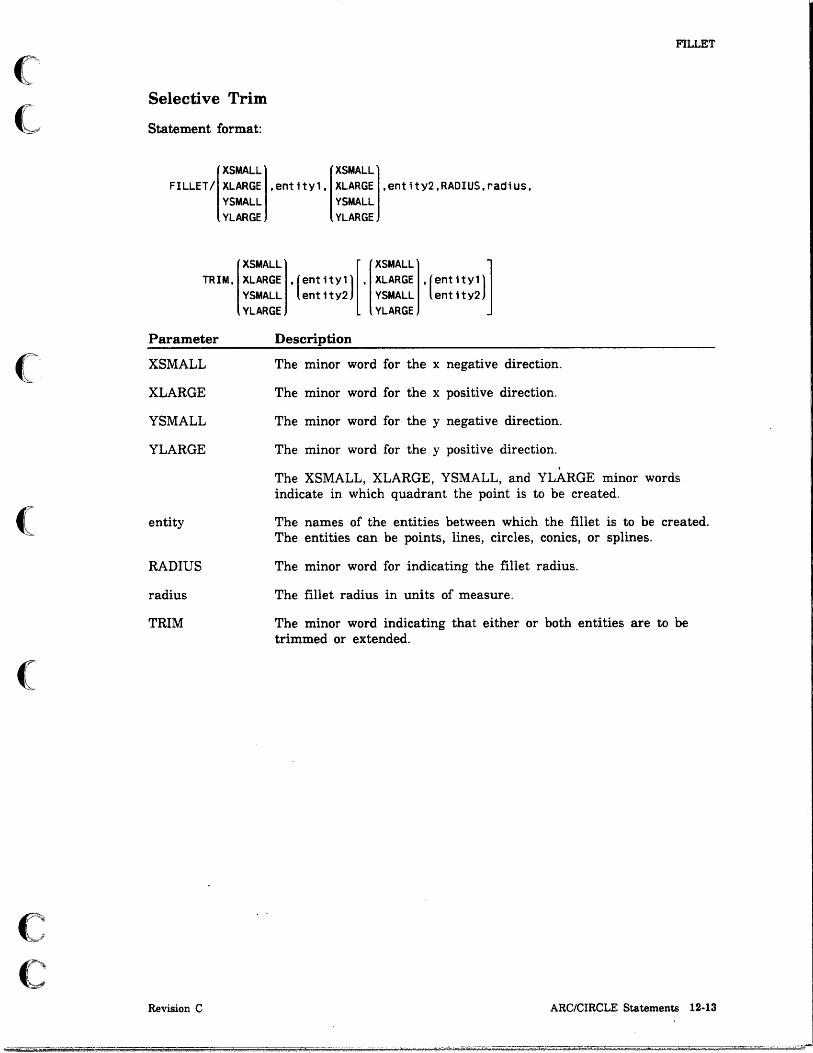
(~
~
(
(
(
c -,
C,'""""·
FILLET
Selective Trim
Statement format:
XSMALL XSMALL FILLET/ XLARGE ,entity1, XLARGE ,entity2,RADIUS,radius,
YSMALL YLARGE
YSMALL YLARGE
TRIM, XLARGE ,(entity,) ,XLARGE (entity,) XSMALL [ XSMALL ]
YSMALL entity2 YSMALL' entity2
Parameter
XSMALL
XLARGE
YSMALL
YLARGE
entity
RADIUS
radius
TRIM
Revision C
YLARGE YLARGE
Description
The minor word for the x negative direction.
The minor word for the x positive direction.
The minor word for the y negative direction.
The minor word for the y positive direction.
The XSMALL, XLARGE, YSMALL, and YLARGE minor words indicate in which quadrant the point is to be created.
The names of the entities between which the fillet is to be created. The entities can be points, lines, circles, conics, or splines.
The minor word for indicating the fillet radius.
The fillet radius in units of measure.
The minor word indicating that either or both entities are to be trimmed or extended.
ARC/CIRCLE Statements 12-13

FILLET
Fillet Center by Coordinates
Statement format:
FILLET/xcoord.ycoord.entity1.entlty2.RADIUS.radius .
Parameter
xcoord
ycoord
entity
RADIUS
radius
TRIM
XSMALL
XLARGE
YSMALL
YLARGE
XSMALL XLARGE YSMALL YLARGE
. (ent ~ ty1 1] [. entlty2
Description
XSMALL XLARGE YSMALL YLARGE
• (ent ity1 1] ent ity2
The x-coordinate of the center of the fillet.
The y-coordinate of the center of the fillet.
The names of the entities between which the fillet is created. The entities can be points, lines, circles, conics, or splines.
The minor word indicating the fillet radius.
The fillet radius in units of measure.
The minor word indicating that either or both entities are trimmed or extended.
The minor word for the x negative direction.
The minor word for the x positive direction.
The minor word for the y negative direction.
The minor word for the y positive direction.
The XSMALL, XLARGE, YSMALL, and YLARGE minor words indicate in which quadrant the center point of the fillet is created.
12·14 ICEM GPL for NOS Revision C

o o
o
o
o
o
Two-Dimensional Curve Statements ELLIPS.
GCONIC
HYPERB
PARABO
13 13-1
13-2
13-3
13-4
PTSET . 13-5 Minimum Number of Points to Approximate a Surface-to-Plane Intersection 13-5 Points on a Surface-Plane Intersection Curve Satisfying the Specified Tolerance. 13-6
SPLINE ..................... . Points, Coordinates, or Polar from Origin . N umber of Points
STRING ...... . Arcs or Lines . . . By Coordinate Array .
iSI 44li, qp;p
13-7 13-8
13-10
13-11 13-11 13-15
<4OWdHh h Q \ 51 . 1 I b! .I i !~hiWMLiJ IN til! Itt it t" "" ••••• !~ •• + !!hl.
o o
o
o
01
o o
I

(
(
c c
Two-Dimensional Curve Statements 13
Two-dimensional curve statements create curves in one plane in the part drawing. Two-dimensional curve definitions are equivalent to types and forms found in menu 12 OTHER CURVES.
ELLIPS An ellipse is a plane curve that is the locus of a point, which moves so that the sum of the distances from the point to two other points in the plane is a constant.
Statement format:
ELLIPS/CENTER,point,half major,half minor,axis angle[,GOANG,goang][,ENDANG,endang]
Parameter
CENTER
point
half major
half minor
axis angle
GOANG
goang
ENDANG
endang
Example:
Description
The minor word for indicating the center of the ellipse.
The name of the center point.
One-half the length of the major axis in units of measure.
One-half the length of the minor axis in units of measure.
The angle the major axis makes with the x-axis.
The minor word for indicating the starting angle.
The starting angle of the circumference of the ellipse in degrees. The default is 0°.
The minor word for indicating the ending angle.
The ending angle of the circumference of the ellipse in degrees. The default is 360°.
Program Statement Explanation
EL1=ELLIPS/CENTER,PT1,$ .87, .44,45,GOANG,45
Revision C
An ellipse is created with the point PT1 as the center. The major axis is 1.74 (2 x 0.87) units of measure. The minor axis is 0.88 (2 x 0.44) units of measure. The angle of the major axis to the x-axis is 45°. The ellipse starts at 45° from the major axis and ends at 360°.
Two-Dimensional Curve Statements 13·1

GCONIC
GCONIC
A general conic is a plane curve represented by the equation:
Ax2 + Bxy + Cy2 + Dx + Ey + F = 0
The circle, ellipse, hyperbola, and parabola can be defined in this way.
Statement format:
GCONIC/coeff A,coeff B,coeff C,coeff D,coeff E,coeff F
Parameter Description
coefl' The coefficients of the quadratic equation for conies.
Example:
Program Statement Explanation
GC1=GCONIC/.66,0.0, .93,$ -6.0,-6.8,8.56
General conic Gel is created with the following coefficients: A=O.66, B=O.O, C=O.93, D=-6.0, E = -6.8, and F = 8.56.
13-2 ICEM GPL for NOS Revision C

(
~.
(
(
(
c c
HYPERB
HYPERB A hyperbola is a plane curve that is the locus of a point, which moves so that the difference between the distances from the point to two other points in the plane is a constant. The curve is composed of two parts. All values of x for the hyperbola must. be positive (before rotation). The hyperbola is defined between -45° and +45°.
Statement format:
HVPERB/CENTER,point,half transverse,half conjugate,angle
Parameter
CENTER
point
half transverse
half conjugate
angle
Example:
Description
The minor word for indicating the vertex of the hyperbola.
The name of the vertex.
One-half the length of the transverse axis of the hyperbola in units of measure.
One-half the length of the conjugate axis of the hyperbola in units of measure.
The angle between the transverse axis and the x-axis.
Program Statement Explanation
HVP1=HVPERB/CENTER,PT1,$ .9, .5,0
Revision C
Hyperbola HYPI is created with point PTI as the vertex. The transverse axis is 1.8 (2 x 0.9) units of measure. The conjugate axis is 1.0 (2 x 0.5) units of measure. The hyperbola is not rotated in relation to the x-axis.
Two-Dimensional Curve Statements 13·3

PARABO
PARABO A parabola is the locus of a point, which moves so that its distance from a fixed point is equal to its distance from a flXed line not through the point.
Statement format:
PARABO/CENTER,pOint, length,angle,Y maximum,Y minimum
Parameter
CENTER
point
length
angle
y maximum
y minimum
Example:
Description
The minor word for indicating the vertex of the parabola.
The name of the vertex.
The distance from the vertex to the focus of the parabola in units of measure.
The angle between the principal axis and the x-axis.
The y maximum bound for the parabola.
The y minimum bound for the parabola.
Program Statement Explanation
PAR1=PARABOICENTER,PT1,$ 1.5,270,1,-1
Parabola PARI is created with point PTI as the vertex. The distance from the vertex to the focus of the parabola is 1.5 units of measure. The angle of the principal axis to the x-axis is 270°. In other words, the parabola is rotated 270°. The y maximum bound is + 1, and the y minimum bound is -1.
Figure 13-1 is an example of a parabola.
PAR1 == PARABO/CENTER, PT1, 1.5, 270, 1, -1
Figure 13-1. Parabola
13-4 ICEM GPL for NOS Revision C

(
(C,
(
(
(
c c
PTSET
PTSET A point set is a curve defined by the intersection of a surface and an infinite plane. The curve is defined in the view of the slicing plane. The starting point should be near an edge. Refer to menu 15.1.2 SURFACE EDGE CURVE in the ICEM Advanced Design manual.
Minimum Number of Points to Approximate a Surface-to-Plane Intersection
Statement format:
PTSET/surface,plane[,NUMBER,number ptsl,START,po;nt
Parameter
surface
plane
NUMBER
number pts
START
point
Revision C
Description
The name of the reference surface.
The name of the reference plane.
The minor word for indicating the minimum number of intersection points to be used to approximate the curve. The number of intersection points is translated into a tolerance using the following scheme:
Points Tolerance
<20 0.2540 mm (0.0100 in)
>20 0.1270 mm (0.0050 in)
>30 0.0254 mm (0.0010 in)
>50 0.0127 mm (0.0005 in)
The minimum number of intersection points to be used to approximate the curve.
The minor word for indicating the starting point of the intersection curve.
The name of the starting point of the intersection curve.
Two-Dimensional Curve Statements 13-5
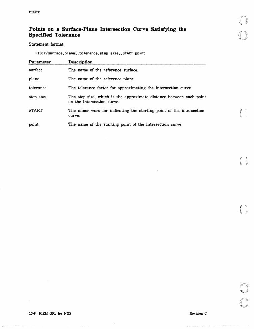
PTSET
Points on a Surface-Plane Intersection Curve Satisfying the Specified Tolerance
Statement format:
PTSET/surface,plane[,tolerance,step size],START,point
Parameter
surface
plane
tolerance
step size
START
point
Description
The name of the reference surface.
The name of the reference plane.
The tolerance factor for approximating the intersection curve.
The step size, which is the approximate distance between each point on the intersection curve.
The minor word for indicating the starting point of the intersection curve.
The name of the starting point of the intersection curve.
13-6 ICEM GPL for NOS Revision C

(
(
(
c c
SPLINE
SPLINE A spline is a free-form curve generated from a series of ordered points. The slope and curvature are contiguous at each given point of the spline.
All points or point coordinates are projected into transform space before processing. The depth coordinate is determined by ZSURF if the points are not coplanar. A minimum of three points and a maximum of 42 points can be specified. Refer to menu 12.1 SPLINE in the ICEM Design/Drafting Basic Construction manual for further information.
The spline start or end condition can be either circular (default) or parabolic. For circular start or end conditions, specified slopes are optional.
The optional parabolic start and end conditions provide for a third degree starting or ending parabolic segment in the spline. If parabolic conditions are not specified, the end segments are assumed to be circular.
The spline tolerance option specifies the maximum discontinuity in the curvature of the spline. Acceptable values are positive and greater than or equal to 0.000001. Small values slow the creation of the spline, and depending on the particular points, may prevent the spline from being created.
The optional circular start and end slopes force the angle of tangency of the spline at the first or last points. If the start and end slopes are not specified, a circular end condition is assumed.
The point movement option provides for a minimum of strain energy at each point. If the point movement option is used, the spline points are adjusted by the specified tolerance. The spline constrains to the first and last points, but is within tolerance of
. the intermediate points.
The spline can be defined by the following methods:
• Specifying existing points or coordinates individually
• Polar from origin
• Specifying the number of points with a point array
Revision C Two-Dimensional Curve Statements 13·7
~--

SPLINE
Points, Coordinates, or Polar from Origin
Statement format:
I
Point 1 IPoint 1 SPLINE/ xcoord.ycoord [.SLOPE,SlOpe]. xcoord.ycoord [ •... ]
RADANG.rad1us.radang PARBLC RADANG. radius. radang
[ .sLoPE,slope][,[~~~~El,point adj value][,TOLER.sPline tol value] PARBLC YMOVE
Parameter
point
xcoord
ycoord
RADANG
radius
radang
SLOPE
slope
PARBLC
XYMOVE, XMOVE, YMOVE
point adj value
TOLER
spline tol value
Description
The name of the spline's start point.
The x-coordinate of the spline's start point.
The y-coordinate of the spline's start point.
The minor word for specifying the points of the spline from the origin (0,0) using the radius and angle, a polar method.
The radius from the origin to a reference point in units of measure.
The angle of a reference point to the horizontal axis in degrees.
The minor word for indicating a slope angle for the starting or ending point.
The tangent angle at the starting or ending point.
The minor· word indicating that the first or last segment of the spline is a parabola.
The minor words indicating the direction of point adjustment value. XYMOVE allows the movement constraint in both the xt and yt directions. XMOVE allows movement only in the xt direction; YMOVE allows movement only in the yt direction.
Use movement constraint cautiously and only with very small values. Avoid movement constraint unless it is absolutely necessary.
The amount of allowable point movement to be used in approximating the curve.
The minor word for indicating the spline tolerance.
The maximum amount of discontinuity in the curvature of the spline.
13-8 ICEM GPL for NOS Revision C

(
("
(
(
C.·~ ~; -
C
Example:
Program Statement
Sl=SPLINE/1,1,SLOPE.30,$ 2.68,2,4,4,XMOVE,.005
SPLINE
Explanation
Spline SI is created starting at coordinates (1,1) with a slope angle of 30°. Additional points are at coordinates (2.68,2) and (4,4). The point adjustment allowed is 0.005 units of measure in the xt direction only.
Figure 13-2 shows the spline created in this example.
S1 = SPLlNE!1, 1, SLOPE, 30, 2.68, 2. 4, 4, XYMOVE, .005
Figure 13-2. Spline
Revision C Two-Dimensional Curve Statements 13·9

SPLINE
Number of Points
Statement format:
SPLINE/POint,NUMBER,number,(pOint array) coord array
Parameter Description
point The name of the starting point for the spline.
NUMBER The minor word for specifying a number of points in a point or coordinate array.
number The number of points in the point array, or the number of points the coordinate array defines.
point array The name of the point array.
coord array The name of the coordinate array.
Example:
Program Statement
REAL/CORDS(6)
ENTITY/PNTS(3),SPT
DATA/CORDS,2,4,3,9,4,16
SPT = POINT/Q,Q,Q
SPLINE/SPT,NUMBER,3,CORDS(3)
PNTS(l) = POINT/S,2S,Q PNTS(2) = POINT/6,36,Q PNTS(3) = POINT/7,49,Q
SPLINE/SPT,NUMBER,3,PNTS(1)
13·10 ICEM GPL for NOS
Description
Allocate space for the real array, CORDS.
Define and allocate space for the entities, PNTS and SPT.
Initialize the CORDS array.
Define the point SPT.
Create a spline starting at SPT and using the 3 sets of coordinates in CORDS.
Derme the points.
Creat a spline starting at SPT and using the 3 points in PNTS.
Revision C
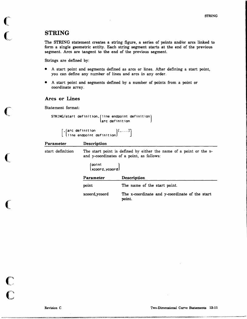
(
(
(
c c
STRING
STRING The STRING statement creates a string figure, a series of points and/or arcs linked to form a single geometric entity. Each string segment starts at the end of the previous segment. Arcs are tangent to the end of the previous segment.
Strings are defined by:
• A start point and segments defined as arcs or lines. After defining a start point, you can define any number of lines and arcs in any order.
• A start point and segments defined by a number of points from a point or coordinate array.
Arcs or Lines
Statement format:
STRING/start defin1tion,(line endpoint definitiOn) arc def1nition
[,(arc def1nition )[, ... 1]
line endpoint definit10n
Parameter
start definition
Revision C
Description
The start point is defined by either the name of a point or the xand y-coordinates of a point, as follows:
(point ) xcoord,ycoord
Parameter
point
xcoord,ycoord
Description
The name of the start point.
The x-coordinate and y-coordinate of the start point.
Two-Dimensional Curve Statements 13·11

STRING
Parameter
line endpoint definition
Description
The line endpoint is defined by either the name of a line endpoint, the x- and y-coordinates of the line endpoint, or delta values from the previous point, as follows:
pOint xcoord,ycoord DELTA,deltax,deltay DEL TAX, de ltax DELTAY, deltay
Parameter
point
xcoord,ycoord
DELTA
DELTAX
DELTAY
deltax
deltay
Description
The name of a point.
The x-coordinate and y-coordinate of the line endpoint.
The minor word indicating that the next field of information is the delta x and y values from the last defined point.
The minor word indicating that the next field is the deltax value from the last defined point.
The minor word indicating that the next field is the deltay value from the last defined point.
The delta x distance from the previous point.
The delta y distance from the previous point.
If either deltax or deltay is 0, it can be omitted by enclosing the changing delta value in parentheses.
13-12 ICEM GPL for NOS Revision C
c

(
(
(
c c
STRING
Parameter Description
arc definition The arc endpoint is defined by the clockwise or counterclockwise radius and angle from the previous point, as follows:
(CW },radiUS,anQle , ... CCW
Parameter
cw
ccw
radius
angle
Examples:
Program Statement
STR3=STRING/PT1,PT2,PT3,PT4
STR4=STRING/3,3,3,4,$ 4,4,3,3
STR5=STRING/PT1,DELTA, .5, .6,$ DELTA, .3, .4,
STR6=STRING/PT1,CW,$ 5,45
Revision C
Description
The minor word for indicating the clockwise radius:: and angle of the next point. The arc center is automatically generated, and the arc starts at the last defined point in a clockwise direction.
The minor word for indicating the counterclockwis~:: radius and angle of the next point. The arc center "" is automatically generated, and the arc starts at the last defined point in a counterclockwise direction.
The radius of the next point.
The positive angle from the horizontal axis in a counterclockwise (CCW) or clockwise (CW) direction to the next point.
Explanation
String STR3 is defined using PTI as the start point. Lines are drawn from PTI to PT2, from PT2 to PT3, and from PT3 to PT4.
A one-unit box is created using coordinates (3,3) as the start point. Lines are drawn from (3,3) to (3,4), from (3,4) to (4,4), and from (4,4) to (3,3).
String STR5 is defined using PTI as the start point. Lines are drawn from PTI to delta coordinates (.5,.6) and from delta coordinates (.5,.6) to delta coordinates (,3,.4).
String STR6 is an arc of 45° clockwise from PTI with a radius of 5 units of measure.
Two-Dimensional Curve Statements 13-13

STRING
Figure 13-3 is an example of a string.
v STR1 = STRING/2, 2, 2, 4, 4, 4, 4, 3, 3, 3, 2, 2
Figure 13-3. String
By Coordinate Array
Statement format:
STRING/(POint ),NUMBER,nUmber,(PO;nt array) xcoord,ycoord coord array
Parameter Description
point The name of the start point for the spline.
xcoord,ycoord The x-coordinate and y-coordinate of the start point.
NUMBER The minor word for specifying a number of points in a point or coordinate array.
number A number of points (coordinates) in the entity array.
point array The name of a point array.
coord array The name of a coordinate array.
Example:
Program Statement
STR9=STRING/PT1.NUMBER,16.$ APNT
13·14 ICEM GPL for NOS
Explanation
String STR9 is defined using the coordinates of 16 points stored in array APNT. Lines are drawn between the points starting from PT1 to the last point coordinate in APNT.
Revision C

o o
o
o
o
o o
Entity Manipulation Statements 14
ARRAY. . . . . . . . . . . . . . . . . . . . . . . . . . . . . . . . 14-1 Rectangular Array Defined by the Number of Rows and Columns. 14-1 Circular Array Defined by the Number of Copies . . . . . . . . . . 14-4 Circular Array Defined by the Number of Copies and the Delta Angle Between
Copies. . . . . . . . . . . . . . . . . . . . . . . . . . . . . . . 14-6 Circular Array Defined by the Delta Angle Between Copies 14-8
GROUP. . . . . . . . 14-10 By Entity Names. 14-10 By Entity Array . 14-10
MIRROR ...... . By Entity Names . By Entity Array .
MODIFY ...... . Point and Line Modifications Pen, Level, Color, and Font Modifications Circle Modifications
PROJEC ....... . Defming by Single Entities Defining with an Array of Entities
RTRIEV ................ . Retrieving a Two-Dimensional Pattern . Retrieving a Three-Dimensional Pattern.
TEMPLT ...... . By Entity Names. By Entity Arrays . As An Instance ..
_wad 2 14 i SUi N$ AU;
14-11 14-11 14-11
14-12 14-12 14-13 14-14
14-15 14-15 14-16
14-17 14-17 14-19
14-21 14-21 14-22 14-23
;+59. __ is
*'1.1 +4*1, Wi QUi
o o
o
o
o
o o

Co
(
(
c c
Entity Manipulation Statements 14
Entity manipulation statements are used to manipulate entities by array, group, mirror, template, projection, and retrieval. Entities are manipulated using definitions that are equivalent to types and forms found in menu 13 ENTITY MANIPULATION in the ICEM Design/Drafting Basic Construction manual.
ARRAY
The ARRAY statement reproduces geometric entities as displayed rectangular or circular arrays.
Rectangular Array Defined by the Number of Rows and Columns
Statement format:
ARRAY/name,RECT['( point )][,DELTAX,deltaX][,DELTAy.deltay] XSTART,xstart,YSTART,ystart
[,NUMBRX,numbrx][,NUMBRY,numbrY][,TILTAN,angle]
[,(~~:~O),element column number,element row number' ... J
Parameter Description
name
RECT
point
XSTART
xstart
YSTART
ystart
DELTAX
deltax
DELTAY
Revision C
The name of the entity to be reproduced as a displayed rectangular array.
The minor word indicating a rectangular array.
The name of the center point. If the center point is omitted, 0,0 is assumed.
The minor word for indicating the x-coordinate of the center point. If the center point is omitted, 0,0 is assumed.
The x-coordinate of the center point.
The minor word for indicating the y-coordinate of the center point. If the center point is omitted, 0,0 is assumed.
The y-coordinate of the center point.
The minor word for indicating the delta x value of the distance between array elements.
The delta x distance between array elements in units of measure.
The minor word for indicating the delta y value of the distance between array elements.
Entity Manipulation Statements 14·1
ARRAY
Parameter
deltay
NUMBRX
numbrx
NUMBRY
numbry
TILTAN
angle
ARRDO
DONT
element column number
element row number
Description
The delta y distance between array elements in units of measure.
The minor word for indicating the number of column array elements to be duplicated in the x direction. The x direction is . horizontal to the right before rotation.
The number of column array elements to be duplicated in the x direction. This is the number of columns created.
The minor word for indicating the number of row array elements duplicated in the y direction. The y direction is vertically up before rotation.
The number of row array elements duplicated in the x direction. This is the number of rows created.
The minor word for indicating the positive angle from the horizontal axis at which the array is created. The angle can be between 0° and 90°.
The positive angle from the horizontal axis where the array is to be created.
The minor word for indicating which row and column array element to generate. Elements must be specified by column and row pairs.
The minor word for indicating which row and column array element not to generate. Elements must be specified by column and row pairs.
The number of the rectangular array column containing the element.
The number of the rectangular array row containing the element.
14·2 ICEM GPL for NOS Revision C
I
I I

(
(
(
(:
(
c c
ARRAY
If the array created is to be a line, the entry for DELTAX, DELTAY, NUMBRX, or NUMBRY can be omitted entirely. An array is a line if DELTAX or DELTAY is 0, or if NUMBRX or NUMBRY is 1.
The maximum size of NUMBRX times NUMBRY is 100 minus the number of ARRDOs or DONTs given. The default TILTAN is 0.0.
ARRDO is used when only specific entities are to be generated. Each entity is listed by a pair of numbers. For example, ARRDO,3,2 means do the entity in the third column from the left, second row from the bottom.
DONT is used when specific entities are to be omitted.
Example:
Program Statement
AR12=ARRAY/GRP1,RECT.$ DELTAX,1.75,$ DELTAY, .75,NUMBRX,4,$ NUMBRY,3,DONT,2,2,3,2
Revision C
Explanation
Array AR12 is a rectangular array of group GRP1. The x distance between elements is 1.75 units of measure, and y distance is 0.75 units of measure. Four columns of group GRPI are created in the x direction, and three rows of the group are created in the y direction. The following array elements are excluded: the element in column 2, row 2 and the element in column 3, row 2.
Entity Manipulation Statements 14-3

ARRAY
Circular Array Deimed by the Number of Copies
Statement format:
ARRAY/name,CIRC[,( point 1],RADlus,radlus[,GOANG,90an9] XSTART,xstart,YSTART,ystart
'NUMBER,COPieS[,ENDANG.endang][,(~~:~O),element number, ... J
Parameter
name
CIRC
point
XSTART
xstart
YSTART
ystart
RADIUS
radius
GOANG
goang
NUMBER
copies
ENDANG
endang
ARRDO
DONT
element number
Description
The name of the entity to be reproduced as a displayed circular array.
The minor word indicating a circular array.
The name of the center point. If the center point is omitted, 0,0 is assumed.
The minor word for indicating the x-coordinate of the center point. If the center point is omitted, 0,0 is assumed.
The x-coordinate of the center point.
The minor word for indicating the y-coordinate of the center point. If the center point is omitted, 0,0 is assumed.
The y-coordinate of the center point.
The minor word for indicating the radius of the circular array.
The radius of the circular array in units of measure.
The minor word for indicating the starting angle of the circular array. The default is 0.
The starting angle of the circular array in degrees.
The minor word for indicating the number of copies of the entity. The number of copies determines the angle between copies. For example, for a circular array from 0° to 360° with 6 copies, each copy is placed 60° from the previous copy.
The number of copies of the entity.
The minor word for indicating the ending angle of the circular array.
The ending angle of the circular array in degrees.
The minor word for indicating which element to generate.
The minor word for indicating which element not to generate.
The number of the circular array element.
14-4 ICEM GPL for NOS Revision C i

(
(l"
(
ARRAY
For circular arrays, if the center point is omitted, 0,0 is assumed. If the starting angle is omitted, 0° is assumed. If the ending angle is omitted, 360° is assumed. The maximum number of duplications is 100 minus the number of ARRDOs or DONTs given.
ARRDO is used when only specific entities are to be generated. Each copy is indicated by a number. The first entity duplicated is 1, and, counting counterclockwise, the next copy is 2, the next is 3, and so forth. For example, ARRDO,2,5 means the second and fJith copies are to be generated.
DONT is used when specific sets of entities are to be omitted.
Example:
Program Statement
AR24=ARRAY/GRP1,CIRC,PT1,$ RADIUS, .75,NUMBER,8,$ DONT,6,7,8
Revision C
Explanation
Array AR24 is a circular array with point PTI as the center point of the array. Group GRPI is the element reproduced. The radius of the elements from the center point is 0.75 units of measure. There are eight elements in the array, and they are spaced 45° apart (360/8=45). Elements 6, 7, and 8 are excluded.
Entity Manipulation Statements 14·5

ARRAY
Circular Array Defined by the Number of Copies and the Delta Angle Between Copies
Statement format:
ARRAY/name,CIRC[,( point l],RADlus,radius[,GOANG,QoanQ] XSTART,xstart,YSTART,ystart
'NUMBER,coPies'DELANG,delang[,(~~:~O),element number, ... ]
Parameter
name
CIRC
point
XSTART
xstart
YSTART
ystart
RADIUS
radius
Description
The name of the entity to be reproduced as a displayed circular array.
The minor word indicating a circular array.
The name of the center point. If the center point is omitted, 0,0 is assumed.
The minor word for indicating the x-coordinate of the center point. If the center point is omitted, 0,0 is assumed.
The x-coordinate of the center point.
The minor word for indicating the y-coordinate of the center point. If the center point is omitted, 0,0 is assumed.
The y-coordinate of the center point.
The minor word for indicating the radius of the circular array.
The radius of the circular array in units of measure.
14-6 ICEM GPL for NOS Revision C
I i

(
(~
(
(
c c
Parameter
GOANG
goang
NUMBER
copies
DELANG
de lang
ARRDO
DONT
element number
Example:
ARRAY
Description
The minor word for indicating the starting angle of the circular array. The default is 0°.
The starting angle of the circular array in degrees.
The minor word for indicating the number of copies of the entity.
The number of copies of the entity.
The minor word for indicating the delta angle between copies. The delta angle determines the angle between copies. For example, a delta angle of 30° places e~ch copy 30° from the previous copy.
The delta angle between copies.
The minor word for indicating which element to generate.
The minor word for indicating which element not to generate.
The number of the circular array element.
Program Statement Explanation
AR33=ARRAY/CIR1,CIRC,$ RADIUS, .75,NUMBER,6,$ DELANG,30
Revision C
Array AR33 is a circular array with coordinates (0,0) as the center point of the array. Circle CIRI is the element duplicated. The radius of the elements from the center point is 0.75 units of measure. There are six elements in the array, and they are spaced 30° apart. The starting angle is 0° (the default).
Entity Manipulation Statements 14·7

I
ARRAY
Circular Array Defined by the Delta Angle Between Copies
This statement produces copies at every delta angle from the starting angle to the ending angle. In other words, the number of copies is determiried by the starting and ending angles and the delta angle between copies.
(start angle - end angle) / delta angle between copies = number of copies
Statement format:
ARRAY/name,CIRC[,( point )J,RADlus,radiUS[,GOANG,gOang] XSTART,xstart,YSTART,ystart
,DELANG,delang['ENDANG,endang][,(~~:~OJ,element number,. "J
Parameter
name
CIRC
point
XSTART
xstart
YSTART
ystart
RADIUS
radius
GOANG
goang
DE LANG
delang
Description
The name of the entity to be reproduced as a displayed circular array.
The minor word indicating a circular array.
The name of the center point. If omitted, 0,0 is assumed.
The minor word for indicating the x-coordinate of the center point.
The x-coordinate of the center point.
The minor word for indicating the y-coordinate of the center point.
The y-coordinate of the center point.
The minor word for indicating the radius of a circular array.
The radius of the circular array in units of measure.
The minor word for indicating the starting angle of the circular array. The default is O.
The starting angle of the circular array.
The minor word for indicating the delta angle between copies. The delta angle determines the angle between copies. For example, a delta angle of 30° places each copy 30° from the previous copy.
The delta angle between copies.
14·8 ICEM GPL for NOS Revision C
if' ~ pi

(
(
c c
Parameter
ENDANG
endang
ARRDO
DONT
element number
Example:
ARRAY
Description
The minor word for indicating the ending angle of the circular array. The default is 360°.
The ending angle of the circular array.
The minor word for indicating which entity to generate.
The minor word for indicating which entity not to generate.
The number of the circular array element.
Program Statement Explanation
PAT1=ARRAY/PT1,CIRC,PT2,$ RADIUS, .75,GOANG,15,$ DELANG,45,ENDANG,195
Revision C
Array PATl is a circular array with PT2 as the center point. Point PTl is the element reproduced. The radius of the elements from the center point is 0.75 units of measure. The first element of the array is created 15° from the x positive axis. The last element of the array is at 195°. There are four elements in the array. The number of elements is determined by the equation:
(ENDANG - GOANG) / DELANG
In this example:
The four elements are spaced 45° apart.
Entity Manipulation Statements 14·9

GROUP
GROUP The GROUP statement gathers all the components of a configuration into a logical unit, which is then treated as an entity. Entity types point, line, arc, conic, spline, and group are allowed. Groups can contain up to seven levels. No group can contain more than 240 entities.
By Entity Names
Statement format:
GROUP/name[, ... ]
Parameter Description
name The names of the entities to be defined as a group.
Example:
Program Statement
GRP1=GROUP/PT1,AR3,LNS
GRP24=GROUP/CIR1,CIR2,$ L1,L2,L3,L4,LS,L6,L7,L8
By Entity Array
Statement format:
Explanation
Group GRPI is composed of point PT1, array AR3, and line LN 5.
Group GRP24 is composed of circles CIRI and CIR2 and lines L1, L2, L3, L4, L5, L6, L7, and L8.
GROUP/NUMBER,number,entityarray
Parameter
NUMBER
number
entity array
NOTE
Description
The minor word for specifying a number of entities from an entity array.
The number of entities from the entity array.
The name of the entity array.
Individual entities cannot be manipulated if they are in a group. The GROUP status must first be deleted (DELETE/group name).
14·10 ICEM GPL for NOS Revision C

(.
(
(
MIRROR
MIRROR
The MIRROR statement copies a number of entities reflected about an axis. Entities can be entered using entity names or using an entity array. This axis can be the x-axis, y-axis, or any defined line. If more than one entity is reflected, the entities are defined as a group. A maximum of 240 entities can be mirrored. Entity types point, line, arc, conic, spline, and point set are allowed. A maximum of 64 entity names can be explicitly listed. If more are required, an entity array should be used.
By Entity Names
Statement format:
! 1; ne 1 MIRROR/ XAXIS ,entity[, ... ]
YAXIS
Parameter Description
line The line to be the axis of mirroring.
XAXIS The x -axis to be the axis of mirroring.
YAXIS The y-axis to be the axis of mirroring.
entity The name of the entity to be mirrored.
Example:
Program Statement Explanation
PLT2=MIRROR/YAXIS,LN1,$ LN2,LN3,LN4
A mirrored entity PLT2 is created by reflecting entities LNl, LN2, LN3, and LN4 about the y-axis.
By Entity Array
Statement format:
MIRROR/!~~~~Sl'NUMBER,number,entity array YAXIS
Parameter
line
XAXIS
YAXIS
NUMBER
number
entity array
Revision C
8§'j .Rl .. uWFF_?Jj""
Description
The line to be the axis of mirroring.
The x -axis to be the axis of mirroring.
The y-axis to be the axis of mirroring.
The minor word for specifying a number of entities from an entity array.
The number of entities from the entity array.
The name of the entity array.
Entity Manipulation Statements 14·11

MODIFY
MODIFY
The MODIFY statement can modify the following items:
• The coordinates of a point, line, or drafting entity
• An entity pen, level, color, or font number
• The radius, start or end angle, or center of a circle
Point and Line Modifications
Statement format:
MODIFY/ent1tY,COORD,number,array
Parameter
entity
COORD
number
array
NOTE
Description
The name of the entity to be modified (point or line).
The minor word for modifying coordinates.
The number of coordinates to be modified.
The name of the array in which the data is to be stored. The size of the array (the number of words required) is dependent upon the entity type selected. The number of elements for each entity is:
Entity Type
Points
Lines
Number of Elements
3
6
Explanation
Points require three elements per entity to store the coordinates of each point.
Lines require six elements per entity to store the coordinates of each line.
For point, line, and circle entities, you can use this statement only if the entities were created with the first definition form. For drafting entities, you can use this statement only in the same view in which those entities were created.
14·12 ICEM GPL for NOS Revision C
(0)

(
( .. ~
(
c c
Pen, Level, Color, and Font Modifications
Statement format:
MODIFY/entity, LEVNUM ,number [PENNU~
Parameter
entity
PENNUM
LEVNUM
COLNUM
FONNUM
number
COLNUM FONNUM
Description
The name of the entity being modified.
The minor word for modifying the pen number.
The minor word for modifying the level number.
The minor word for modifying the color number.
The minor word for modifying the font number.
The new value for the pen, level, font, or color.
MODIFY
Pen (0-15) and level (0-1023) numbers default to 0 or are assigned by the user. Color and font have preassigned default numbers as follows:
Font Number Font
0 Solid 1 Dashed 2 Phantom 3 Centerline
Color Number Color
0 White 1 Red 2 Geeen 3 Blue-cyan 4 Magenta 5 Yellow 6 Orange 7 Light orange 8 Light green 9 Dark Cyan 10 Green-blue 11 Dark red 12 Light purple 13 Yellow-green 14 Dark pink
Revision C Entity Manipulation Statements 14-13

MODIFY
Circle Modifications
Statement format:
MODIFY/circle [CENTER,x value.y value,z value][,RADIUS.radius] [,GOANG.goang][.ENDANG,endang]
Parameter Description
circle The name of the circle to be modified.
CENTER The minor word for modifying the center.
x value The new x value.
y value The new y value.
z value The new z value.
RADIUS The minor word for modifying the radius.
radius The radius in units of measure.
GOANG The minor word for the starting angle.
goang The starting angle in degrees.
ENDANG The minor word for the ending angle.
endang The ending angle in degrees.
NOTE
You must specify at least one of the options (RADIUS, GOANG, or ENDANG).
14·14 ICEM GPL for NOS Revision C

(
(
(
(
c c
PROJEC
PROJEC The PROJEC statement projects a two-dimensional geometric configuration normal to the work plane. The projected configuration is automatically duplicated at the delta depth specified, and connecting lines between the endpoints are created. The result of this statement will be a group if an entity name is assigned to the statement. Allowable projection entities are lines, arcs, general conics, two-dimensional splines, and three-dimensional splines.
Defining by Single Entities
Statement format:
PROJEC/entity1,entity2, ... ,entityn,delta dePth
Parameter Description
entityl, entity2,
The names of the entities to be projected. n can be:
O<n~64
entityn
delta depth The delta depth projected normal to the plane of defmition.
Example:
Program Statement
PROJEC/LINA,LINB,LINC,3
Explanation
An entity is created and projected normal to the plane of definition using entities LINA, LINB, and LINe for a depth of 3 units of measure.
The following message occurs if the number of entities exceeds 64.
ONLY 64 ENTITIES ALLOWED
The following message occurs if the number of entities is less than or equal to zero.
AT LEAST ONE ENTITY IS REQUIRED
Revision C Entity Manipulation Statements 14·15

i I I ~
PROJEC
Deiming with an Array of Entities
Statement format:
PROJEC/NUMBER,number.entity arraY,delta depth
Parameter Description
NUMBER The minor word for defining a projection by an array of entities.
number The number of entities from the array.
entity array The name of an array of entity pointers.
delta depth The delta depth projected normal to the plane of definition.
If the number of entities exceeds 64 or is less than or equal to 0, one of the following error messages is displayed:
ONLY 64 ENTITIES ALLOWED
AT LEAST ONE ENTITY IS REQUIRED
Example:
Program Statement
PROJEC/NUMBER,22,BOX(1),2
14·16 ICEM GPL for NOS
Explanation
A projected entity is created using 22 entities in array BOX for a depth of 2 units of measure.
Revision C

(
(
c c
RTRIEV
RTRIEV The RTRIEV statement retrieves a pattern from the local pattern library (PATERN). A pattern is defined as a group if the minor word YES is used or the pattern is named (PA = RTRIEV).
Retrieving a Two-Dimensional Pattern
Statement format:
RTRIEV /PATERN, ( , name' ) , ( POi nt ) text variable xcoord,ycoord,zcoord
[,SCALE,scale)[,ANGLE,angle)[,YES),status
Parameter
PATERN
'name'
text variable
point
xcoord
ycoord
zcoord
SCALE
scale
ANGLE
angle
YES
Revision C
Description
The minor word for retrieving a pattern from the local pattern library.
The name of the pattern enclosed in single quotes (64 characters maximum).
The name of the text variable that contains the name of the pattern (64 characters maximum).
The name of the point that locates the pattern in the part drawing.
The x-coordinate of the point that locates the pattern in the part drawing.
The y-coordinate of the point that locates the pattern in the part drawing.
The z-coordinate of the point that locates the pattern in the part drawing.
The minor word for indicating the scale factor of the pattern.
The scale factor of the pattern. The default is 1.0.
The minor word for indicating the rotation angle of the pattern.
The rotation angle of the pattern. The default is 0.0°.
The minor word that defines the pattern as a group.
Entity Manipulation Statements 14-17

RTRIEV
Parameter Description
status The name of the variable that is to receive the retrieval status.
Value Description
o Retrieval was completed.
-1 The pattern named was not found.
-2 Not applicable to two-dimensional patterns.
-3 Some or all entities could not be grouped.
14·18 ICEM GPL for NOS Revision C

(
(
(
c c
RTRIEV
Retrieving a Three-Dimensional Pattern
Statement format:
RTRIEV/PATERN, ( 'name' )' ( point )' text variable xcoord,ycoord,zcoord
COORD,point1,point2,point3[,SCALE,scalel[,ANGLE,anglel[,YES1,status
Parameter
PATERN
'name'
text variable
point
xcoord
ycoord
zcoord
COORD
pointl,point2,point3
SCALE
scale
YES
ANGLE
angle
Revision C
Description
The minor word for retrieving a pattern from the local pattern library.
The name of the pattern enclosed in single quotes (64 characters maximum).
The name of the text variable that contains the name of the pattern (64 characters maximum).
The name of the point that locates the pattern in the part drawing.
The x-coordinate of the point that locates the pattern in the part drawing.
The y-coordinate of the point that locates the pattern in the part drawing.
The z-coordinate of the point that locates the pattern in the part drawing.
The minor word for locating a pattern using three noncollinear points.
The names of the three noncollinear points that locate the pattern.
The minor word for indicating the scale factor of the pattern.
The scale factor of the pattern. The default is 1.0.
The minor word that defines the pattern as a group.
The minor word for indicating the rotation angle of the pattern.
The rotation angle of the pattern. The default is 0.0°.
Entity Manipulation Statements 14·19

RTRIEV
Parameter
status
14·20 ICEM GPL for NOS
Description
The name of the variable that is to receive the retrieval status.
Value
o
-1
-2
-3
-4
-5
Description
Retrieval was completed.
The pattern named was not found.
The points' given are collinear (three-dimensional only).
Some or all entities could not be grouped.
The maximum number of views was exceeded.
At least one new view was created.
Revision C

("
~
(
(
c c.--
""
TEMPLT
TEMPLT
The TEMPLT statement creates a master and instance template. The template is then stored in the UTF. The template entities are defined:
• In the UTF as a UTF template.
• As a master template in the current part.
• As a template instance in the current part.
The templates are defined by using entity names or an entity array, or by creating an instance. Allowable entities are points, lines, arcs, and pointsets.
NOTE
If a pointer is returned by the statement, it is an instance pointer.
By Entity Names
Statement format:
TEMPLT/CREATE,'template name',name[, ... ][,status]
Parameter
CREATE
'template name'
name
status
Example:
Description
The minor word indicating template creation.
The name to be given to the UTF template. The UTF name is carried with both the master template and the template instance.
The names of the entities that are to make up the template.
The name of a variable that is to receive the status of the template operation.
Value
o
1
Description
No error was found.
The CREATE option overwrote a master of the same name.
Program Statement Explanation
TEM1=TEMPLT/CREATE,$ 'GROMMET' ,LN004,LN005,$ CR006,SP009,LN012,LN020
Revision C
Template TEMI is created with the name GROMMET. It is made up of lines. LN004 and LN005, circle CR006, spline SP009, and lines LN012 and LN020.
Entity Manipulation Statements 14·21

TEMPLT
By Entity Arrays
Statement format:
TEMPLT/CREATE,'template name',NUMBER,number,entlty arraY[,status]
Parameter
CREATE
'template name'
NUMBER
number
entity array
status
Description
The minor word indicating template creation.
The name to be given to the UTF template. The UTF name is carried with both the master template and the template instance.
The minor word for spe~ifying a number of entities from an entity array.
The number of entities from the entity array.
The name of the entity array.
The name of a variable that is to receive the status of the template operation.
Value
o
1
Description
No error was found.
The CREATE option overwrote a master of the same name.
14·22 ICEM GPL for NOS Revision C
1
j
!

(.
(
c c
TEMPLT
As An Instance
Statement format:
NORTH,WEST SOUTH,WEST
TEMPLT/INSTNC,'template name', CENTER ,[ point ) NORTH, EAST xt,yt,zt SOUTH, EAST
[,SCALE,scale][,ANGLE,angle][,status]
Parameter
INSTNC
'template name'
NORTH ,WEST
SOUTH ,WEST
CENTER
NORTH ,EAST
SOUTH ,EAST
point
xt,yt,zt
SCALE
scale
ANGLE
angle
status
Revision C
Description
The minor word indicating template instance.
The name to be given to the UTF template. The UTF name is carried with both the master template and the template instance.
The minor words for locating the instance in the upper left of the origin point.
The minor words for locating the instance in the lower left of the origin point.
The minor words for locating the instance in the center of the origin point.
The minor words for locating the instance in the upper right of the origin point.
The minor words for locating the instance in the lower right of the origin point.
The name of the origin point.
The xt-, yt-, and zt-coordinates of the origin point.
The minor word for indicating the scale factor of the pattern.
The scale factor of the pattern. The default is 1.0.
The minor word for indicating the rotation angle of the pattern.
The rotation angle of the pattern. The default is 0.0°.
The name of the variable to receive the status of the template operation.
Value
o
2
3
Description
No error was found.
No master was found for TEMPLTIINSTNC.
Unlinked master was found for TEMPLTIINSTNC.
Entity Manipulation Statements 14·23

q ~.
\ }

o o
o
o
o
o
Three-Dimensional Curve Statements CMPCRV ....... .
MACCRV ....... . Surface Edge Curve Surface Intersection Curve Draft Curve to a Surface Draft Curve to a Depth ..
SPCURV ........... . Global and Local Methods. Filter Method .
VECTOR ... Coordinates Two Points Scalar Times Existing Vector . Cross Product of Two Vectors . Unit Normal of Existing Vector Surface Unit Normal. . . . . . . Through a Point at a Given Length and Angle Intersection of Two Planes Sum of Two Vectors . . . . . . . . . . . . . . . . Difference of Two Vectors . . . . . . . . . . . . . Through a Point at an Angle with a Line or Vector at a Length
sa i
15 IS-1
IS-2 IS-2 IS-3 15-4 15-S
15-6 15-6 15-7
15-8 15-8 IS-8 1S-9 IS-9 IS-9
15-10 IS-10 IS-II IS-II 15-12 IS-12
¥II .A i

Ji 1 dildS if ut in e~(L"m@! '" j ift ,,'~ ","""",,,,"d~ ___ --
, !.
o o
o
o
o

(
(
(
(
c c
Three-Dimensional Curve Statements
CMPCRV
The CMPCRV statement creates a composite curve, that is, an ordered set of contiguous curves (lines, arcs, conics, and splines). The limit of curves allowed in a composite curve is 100.
Statement format:
CMPCRV/( curve[, ... ] ) NUMBER,number,curve array
Parameter Description
15
curve The names of the curves to be used in creating a composite curve.
NUMBER
number
curve array
Example:
The minor word for specifying a number of curves from a curve array.
The number of curves from the curve array.
The name of the curve array.
Program Statement Explanation
CCUR1=CMPCRV/L445,C245,$ SPL9,L124
Revision C
Composite curve CCUR1 is created using line L445, circle C245, spline SPL9, and line L124.
Three-Dimensional Curve Statements 15·1

MACCRV
MACCRV
The MACCRV statement creates a machining curve, that is, a three-dimensional curve implied by a set of three-dimensional points. The default tolerance is 0.1 regardless of the unit of measure used. The user input tolerance must be greater than O.
Surface Edge Curve
Statement format:
MACCRV/EDGE,surface,point[,NUMBER,approx pts]
Parameter Description
EDGE The minor word for defining by the surface edge curve.
surface The name of the surface whose edge is intersected.
point The name of the point indicating the edge.
NUMBER The minor word indicating the minimum number of intersection points to be used to approximate the curve.
appro x pts The number of intersectio"n points.
15-2 ICEM GPL for NOS Revision C

(
(
(
(
(
c c
MACCRV
Surface Intersection Curve
Statement format:
MACCRV/INTOF.drive surface,check surface[,tolerance,step], PIERCE I (NORMAL) , POi nt 1
Parameter
INTOF
drive surface
check surface
tolerance
step
NORMAL
PIERCE
point
EDGE
Revision C
EDGE
Description
The minor word indicating the definition of an intersection curve.
The name of the surface to be used to create the machining curve.
The name of the surface at which the machining curve is to be created.
The tolerance factor in units of measure. The number of intersection points is translated into a tolerance using the following scheme:
Points
<20
>20
>30
>50
Tolerance
0.2540 mm (0.0100 in)
0.1270 mm (0.0050 in)
0.0254 mm (0.0010 in)
0.0127 mm (0.0005 in)
The step size in units of measure.
The minor word for definition using a normal point.
The minor word for definition using a pierce point.
The name of the starting point of the intersection curve.
The minor word for definition using an edge intersection. If the result is more than one machining curve, a group is defmed. The member of that group can be obtained using the OBTAINIMEMBER statement.
Three-Dimensional Curve Statements 15-3

I MACCRV
Draft Curve to a Surface
Statement format:
MACCRV/( curve[, ... J ),5UrfaCe[,ANGLE,an91e,polntJ[,toleranCeJ NUMBER,number,curve array
Parameter
curve
NUMBER
number
curve array
surface
ANGLE
angle
point
tolerance
Description
The name or names of the curves that are to be used to create the machining curves.
The minor word for specifying a number of curves from a curve array.
The number of curves from the curve array.
The name of the curve array.
The name of the surface at which the machining curve is to be created.
The minor word for indicating the projection angle at which the machining/draft curve is to be created.
The projection angle of the machining curve in degrees and fractions of a degree. The angle is measured from the curve projected normal to the surface to that angle. The default angle is 0.0°. The bounds for angle input are 0.0° up to but not including 90°.
The name of the starting point of the draft curve.
The tolerance factor of the curve in units of measure.
15-4 ICEM GPL for NOS Revision C

(
(
('-
(
c c
MACCRV
Draft Curve to a Depth
Statement format:
MACCRV/{ curve[, ... J ),CURDEP,depth,ANGLE,an91e,po;nt[,toleranCeJ NUMBER,number,curve array
Parameter
curve
NUMBER
number
curve array
CURDEP
depth
ANGLE
angle
point
tolerance
Revision C
Description
The name or names of the curves that are to create the machining curves.
The minor word for specifying a number of curves from a curve array.
The number of curves from the curve array.
The name of the curve array.
The minor word for creating a curve at a depth.
The depth at which the machine curve is created in units of measure.
The minor word for indicating the projection angle at which the machining/draft curve is created.
The projection angle of the machining curve in degrees and fractions of a degree. The angle is measured from the curve projected normal to the surface to that angle. The default angle is 0.0°. The bounds for angle input are 0.0° up to but not including 90°.
The name of the starting point of the draft curve.
The tolerance factor of the curve in units of measure.
Three-Dimensional Curve Statements 15·5

i I ~
SPCURV
SPCURV The SPCURV statement creates a three-dimensional spline curve, that is, a three-dimensional curve that passes through a number of specified points. If you do not specify a start or end condition, the condition is defaulted to relaxed.
Global and Local Methods
Statement format:
SPCURV/GLOBAL, number.(ent1ty array ), RELAX , RELAX I point£, ... J l[ (TANTO,line,)[ [TANTO, line2)] ]
coordinate array CYCLIC
Parameter
GLOBAL
ACYCLC
Description
The minor word for defining a spline curve with the global method, which is the second continuous derivative form.
point The names of the points that are to define the spline curve.
number The number of entities in the entity array.
entity array The name of the entity array.
coordinate array The name of the coordinate array.
TANTO
line
RELAX
CYCLIC
ACYCLC
The minor word for defining the start or end condition of the spline tangent to a given line. The direction of the given lines is used to calculate the start and end conditions.
The name of the line.
The minor word that defines the start or end condition of the spline as relaxed.
The minor word indicating that the endpoint has the identical slope of the start point.
The minor word indicating that the endpoint has the opposite slope of the start point.
15-6 ICEM GPL for NOS Revision C

(
(
(
(
(~
C
SPCURV
Filter Method
Statement format:
SPCURV/FILTER,number of pOints,( point array )tolerancer,output tolerance] coordinate array
Parameter Description
FILTER The minor word for defining a spline curve with the filter method.
number of points The number of points in the point or coordinate array. The maximum number of points is 1000.
point array The name of the point array.
coordinate array The name of the coordinate array. The coordinates must be given in model space.
tolerance The tolerance of the curve.
output tolerance The output tolerance of the curve.
Revision C Three-Dimensional Curve Statements 15·7
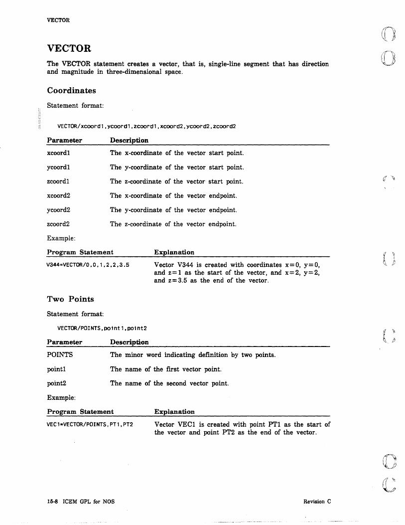
I i
I f
VECTOR
VECTOR The VECTOR statement creates a vector, that is, single-line segment that has direction and magnitude in three-dimensional space.
Coordinates
Statement format:
VECTOR/xcoord1,ycoord1,zcoord1,xcoord2,ycoord2,zcoord2
Parameter
xcoordl
ycoordl
zcoordl
xcoord2
ycoord2
zcoord2
Example:
Description
The x-coordinate of the vector start point.
The y-coordinate of the vector start point.
The z-coordinate of the vector start point.
The x-coordinate of the vector endpoint.
The y-coordinate of the vector endpoint.
The z-coordinate of the vector endpoint.
Program Statement Explanation
V344=VECTOR/O,O,1,2,2,3.5 Vector V344 is created with coordinates x=O, y=O, and z = 1 as the start of the vector, and x = 2, y = 2, and z= 3.5 as the end of the vector.
Two Points
Statement format:
VECTOR/POINTS,po1nt1.POint2
Parameter
POINTS
pointl
point2
Example:
Description
The minor word indicating definition by two points.
The name of the first vector point.
The name of the second vector point.
Program Statement Explanation
VEC1=VECTOR/POINTS,PT1,PT2 Vector VEe! is created with point PT! as the start of the vector and point PT2 as the end of the vector.
15·8 ICEM GPL for NOS Revision C

(
(;
(
(
c c
Scalar Times Existing Vector
Statement format:
VECTQR/vector,SCALAR,scalar
Parameter
vector
SCALAR
scalar
Example:
Description
The name of the existing vector.
The minor word indicating definition by scalar times existing vector.
The scalar of the vector in inches or millimeters.
Program Statement Explanation
VECTOR
VS01=VECTOR/VEC1,SCALAR,2 Vector V50l is created as the product of the reference vector, VECl, and a scalar of 2.
Cross Product of Two Vectors
Statement format:
VECTOR/vector1,vector2
Parameter Description
vectorl The name of the first vector.
vector2 The name of the second vector.
Example:
Program Statement Explanation
V22S=VECTOR/VEC1,V344 Vector V225 is created as the cross product of vector VECl and V344.
Unit Normal of Existing Vector
Statement format:
VECTOR/UNIT, vector
Parameter
UNIT
vector
Example:
Description
The minor word indicating the defmition of the unit normal of an existing vector.
The name of the reference vector.
Program Statement Explanation
VEC2=VECTOR/UNIT,VEC1
Revision C
Vector VEC2 is created as a unit normal vector of vector VECl.
Three-Dimensional Curve Statements 15·9

I I ,
VECTOR
Surface Unit Normal
Statement format:
VECTOR/NORMAL,surface.polnt
Parameter Description
NORMAL The minor word indicating the surface unit normal vector.
surface The name of a surface.
point The name of a point on the surface.
Through a Point at a Given Length and Angle
Statement format:
VECTOR/point,ANGLE.angle.LENGTH, length
Parameter
point
ANGLE
angle
LENGTH
length
Example:
Description
The name of the point.
The minor word for indicating the angle of the vector from the horizontal axis.
The angle of the vector from the horizontal axis in degrees and fractions of degrees.
The minor word for indicating the length of the vector from the reference point.
The length of the vector in units of measure.
Program Statement Explanation
V905=VECTOR/PT2.ANGLE.30.$ LENGTH,1
15·10 ICEM GPL for NOS
Vector V905 is created from point PT2 at an angle of 30° to the horizontal axis for a distance of 1 unit of measure.
Revision C

(
(~
(
(
c c
VECTOR
Intersection of Two Planes
Statement format:
VECTOR/INTOF,plane1,plane2
Parameter
INTOF
planel
plane2
Example:
Description
The minor word indicating that the vector is to be defined as the intersection of two nonparallel planes. The order in which the planes are selected determines the direction of the vector.
The name of the first plane.
The name of the second plane.
Program Statement Explanation
V405=VECTOR/INTOF,PL22,PL23
Sum of Two Vectors
Statement format:
VECTOR/VECSUM,vector1,vector2
Parameter Description
Vector V 405 is created at the intersection of planes PL22 and PL23.
VECSUM The minor word indicating that a vector is to be defined as the sum of two vectors.
vectorl The name of the first vector.
vector2 The name of the second vector.
Example:
Program Statement
VEC3=VECTOR/VECSUM,VEC1,VEC2
Revision C
Explanation
Vector VEC3 is created as the vector sum of vectors VECl and VEC2.
Three-Dimensional Curve Statements 15-11

VECTOR
Difference of Two Vectors
Statement format:
VECTOR/DIFFER,vector1,vector2
Parameter
DIFFER
vectorl
vector2
Example:
Description
The minor word indicating a vector defined as the difference of two vectors.
The name of the first vector.
The name of the second vector.
Program Statement Explanation
V299=VECTOR/DIFFER,VEC2,VEC3 Vector V299 is created as the vector difference of vectors VEC2 and VEC3.
Through a Point at an Angle with a Line or Vector at a Length
Statement format:
VECTOR/point,vector,ATANGL,angle,LENGTH, length
Parameter
point
vector
ATANGL
angle
LENGTH
length
Example:
Description
The name of the reference point.
The name of the reference line or vector.
The minor word for indicating the angle of the vector to the reference line or vector.
The angle of the vector in degrees or fractions of degrees.
The minor word for indicating the length of the vector.
The length of the vector in units of measure.
Program Statement Explanation
V32=VECTOR/P240,V344,$ ATANGL,30,LENGTH,10
15-12 ICEM GPL for NOS
Vector V32 is created with point P240 as the tail of the new vector at an angle of 30° to vector V344. The new is 10 units of measure in length.
Revision C
,
I
i

- .
e CD
o
o
o
o o
Surface Statements CMSRF
CONE. Line Coordinates Two Points Point and Delta Coordinates
CYLNDR .. . Line ... . Coordinates Two Points Point and Delta Coordinates
DEVSRF
FILSRF .
HEXDRN. Coordinates Point.
LPSOID.
PLANE. Coefficients Three N oncollinear Points . Through a Point and Parallel to a Plane Parallel to a Plane at a Distance .... Through a Point and Perpendicular to an Existing Vector Two Points and Perpendicular to a Plane . Point and Perpendicular to Two Planes Two Lines.
REVSRF
RULSRF
SPHERE Coordinates and Radius Point and Radius .
TABCYL ...... .
TORUS ....... . Coordinates and Radii Point and Radii . . . .
16
16-1
16-2 16-2 16-3 16-4 16-4
16-5 16-5 16-6 16-7 16-8
16-9
16-10
16-11 16-11 16-12
16-13
16-14 16-14 16-15 16-15 16-16 16-17 16-17 16-18 16-18
16-19
16-20
16-21 16-21 16-22
16-23
16-24 16-24 16-25
!E

.6
wUti\liL !e7tt:ltM't£i T I b i 'v i j!! ffifiH1itjUliUdUltliliji' ,4\!tMAhUMJ"''''hi@\ MrI, iIM!: i:::::!J2i!ili3llit::tlIZ
o o
o
o
o

(
(
(
c~
C.--~ ..
Surface Statements 16
Surface statements create three-dimensional surfaces. Surface definitions are equivalent to types and forms found in menu 15 EXTENDED GEOMETRY in the ICEM Design/Drafting Advanced Design manual.
CMSRF The CMSRF statement creates a curve mesh surface, that is, a generalized surface that meshes a family of variable curves with a family of opposing (but not necessarily orthogonal) fixed curves. No more than 30 fixed curves (nf) and 30 variable curves (nv) can be specified. The number of fixed curves times the number of variable curves is limited to 341.
Statement format:
CMSRF/NFIXED,nf,(fCUrVer, ... 1),NVARy,nV,(vcurver, ... J) fcurve array vcurve array
Parameter Description
NFIXED The minor word for indicating fixed curves.
fcurve The names of the fixed curves (maximum is 30).
fcurve array The name of the fixed curve array.
nf The number of fixed curves from the array (maximum is 30).
NVARY The minor word for indicating variable curves.
vcurve The names of the variable curves (maximum is 30).
vcurve array The name of the variable curve array.
nv The number of variable curves from the array (maximum is 30).
Example:
Program Statement Explanation
CSF44=CMSRF/NFIXED,2,$ CRV1, CRV2, $ NVARY,2,CRV3,CRV4
Revision C
Curve mesh surface CSF44 is created. The surface is bounded by two fixed curves, CRV1 and CRV2, and by two variable curves, CRV3 and CRY 4.
Surface Statements 16·1

I
CONE
CONE The CONE statement creates a cone, that is, a surface generated by revolving a line about an axis that lies in the same plane.
Line
Statement format:
CONE/l1ne,HANGLE,half-angle
Parameter
line
BANGLE
half-angle
Example:
Description
The name of a line representing the cone axis.
The minor word for indicating the half-angle of the cone. The half-angle is the angle of the surface to the axis of the cone.
The half-angle in degrees and fractions of degrees.
Program Statement Explanation
CN43=CONE/L344,HANGLE,25
16·2 ICEM GPL for NOS
Cone CN 43 is created around line L344 with a half-angle of 25°.
Revision C

(
(
(
C'" ...
C
CONE
Coordinates
Statement format:
CONE/xcoord1,YCoord1,zcoord1,xcoord2,ycoord2,zcoord2,HANGLE,half-angle
Parameter
xcoordl
ycoordl
zcoordl
xcoord2
ycoord2
zcoord2
HANGLE
half-angle
Example:
Description
The x-coordinate of the first cone axis endpoint.
The y-coordinate of the first cone axis endpoint.
The z-coordinate of the first cone axis endpoint.
The x-coordinate of the second cone axis endpoint.
The y-coordinate of the second cone axis endpoint.
The z-coordinate of the second cone axis endpoint.
The minor word for indicating the half-angle of the cone. The half-angle is the angle of the surface to the center line of the cone.
The half-angle in degrees and fractions of degrees.
Program Statement Explanation
CN52=CONE/3,4,20,12,4,20,$ HANGLE,15
Revision C
Cone CN52 is created around a line that extends from coordinates (3,4,20) to coordinates (12,4,20) with a half-angle of 15°.
Surface Statements 16-3
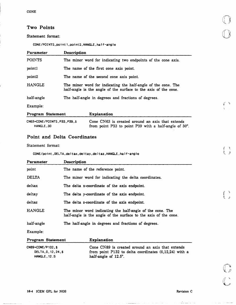
I CONE
Two Points
Statement format:
CONE/POINTS,polntl,po1nt2,HANGLE,half-angle
Parameter
POINTS
point!
point2
HANGLE
half-angle
Example:
Description
The minor word for indicating two endpoints of the cone axis.
The name of the first cone axis point.
The name of the second cone axis point.
The minor word for indicating the half-angle of the cone. The half-angle is the angle of the surface to the axis of the cone.
The half-angle in degrees and fractions of degrees.
Program Statement Explanation
CN63=CONE/POINTS,P33,P39,$ HANGLE,30
Cone CN63 is created around an axis that extends from point P33 to point P39 with a half-angle of 30°.
Point and Delta Coordinates
Statement format:
CONE/polnt,DELTA,deltax,deltaY,deltaz,HANGLE,half-angle
Parameter
point
DELTA
deltax
deltay
deltaz
HANGLE
half-angle
Example:
Description
The name of the reference point.
The minor word for indicating the delta coordinates.
The delta x-coordinate of the axis endpoint.
The delta y-coordinate of the axis endpoint.
The delta z-coordinate of the axis endpoint.
The minor word indicating the half-angle of the cone. The half-angle is the angle of the surface to the axis of the cone.
The half-angle in degrees and fractions of degrees.
Program Statement Explanation
CN89=CONE/P132,$ DELTA,O,12,24,$ HANGLE , 12 .5
16-4 ICEM GPL for NOS
Cone CN 89 is created around an axis that extends from point P132 to delta coordinates (0,12,24) with a half-angle of 12.5°.
Revision C
{j ~ i t\, }Y

(
(:
Cc C'
CYLNDR
CYLNDR The CYLNDR statement creates a cylinder, that is, a surface generated by revolving a line about a parallel axis.
Line
Statement format:
CYLNDR/line,RADIUS,radius[,GOANG,goang][,ENDANG,endang]
Parameter
line
RADIUS
radius
GOANG
goang
ENDANG
endang
Example:
Description
The name of the line representing the axis of the cylinder.
The minor word for indicating the cylinder radius.
The radius in units of measure.
The minor word for indicating the start angle of the cylindrical surface.
The start angle of the surface in degrees or fractions of degrees. The default is 0°.
The minor word for indicating the end angle of the cylindrical surface.
The end angle of the surface in degrees or fractions of degrees. The default is 360°.
Program Statement Explanation
CY23=CYLNDR/L342,$ RADIUS,4.25,$ GOANG,180,ENDANG,270
Revision C
Cylinder CY23 is created around line L342 at a radius of 4.25 units of measure. The start angle is 180°, and the end angle is 270°.
Surface Statements 16-5

CYLNDR
Coordinates
Statement format:
CYLNDR/xcoordl,ycoordl,zcoordl,xcoord2,ycoord2,zcoord2,RADIUS,radius
[,GOANG,goang][,ENDANG,endang]
Parameter
xcoordl
ycoordl
zcoordl
xcoord2
ycoord2
zcoord2
RADIUS
radius
GOANG
goang
ENDANG
endang
Example:
Description
The x-coordinate of the first cylinder axis endpoint.
The y-coordinate of the first cylinder axis endpoint.
The z-coordinate of the first cylinder axis endpoint.
The x-coordinate of the second cylinder axis endpoint.
The y-coordinate of the second cylinder axis endpoint.
The z-coordinate of the second cylinder axis endpoint.
The minor word for indicating the cylinder radius.
The radius in units of measure.
The minor word for indicating the start angle of the cylindrical surface.
The start angle of the surface in degrees or fractions of degrees. The default is 0°.
The minor word for indicating the end angle of the cylindrical surface. .
The end angle of the surface in degrees or fractions of degrees. The default is 360°.
Program Statement Explanation
CY46=CYLNDR/l0,S,lS,3.9,7.S,$ RADIUS,39.S,$ GOANG,90,ENDANG,180
16-6 ICEM GPL for NOS
Cylinder CY 46 is created around an axis that extends from coordinates (10,5,15) to coordinates (3,9,7.5) at a radius of 39.5 units of measure. The start angle is 90° and the end angle is 180°.
Revision C

(
(~~
C"'
(
c c
CYLNDR
Two Points
Statement format:
CYLNDR/POINTS,point1,po1nt2,RADIUS,radius[,GOANG,goang][,ENDANG,endang]
Parameter
POINTS
point!
point2
RADIUS
radius
GOANG
goang
ENDANG
endang
Example:
Description
The minor word for indicating the two cylinder axis endpoints.
The name of the first cylinder axis endpoint.
The name of the second cylinder axis endpoint.
The minor word for indicating the cylinder radius.
The radius of the cylinder in units of measure.
The minor word for indicating the start angle of the cylindrical surface.
The start angle of the surface in degrees or fractions of degrees. The default is 0°.
The minor word for indicating the end angle of the cylindrical surface.
The end angle of the surface in degrees or fractions of degrees. The default is 360°.
Program Statement Explanation
CY103=CYLNDR/P49,P64,$ RADIUS,24.75,$ GOANG,90,ENDANG,180
Revision C
Cylinder CY103 is created around an axis that extends from point P49 to point P64 at a radius of 24.75 units of measure. The start angle is 90° and the end angle is 180°.
Surface Statements 16-7

I I
I CYLNDR
Point and Delta Coordinates
Statement format:
CYLNDR/point,DELTA,deltax,deltaY,deltaz,RADIUS,radius
[,GOANG,goang][,ENDANG,endang]
Parameter
point
DELTA
deltax
deltay
deltaz
RADIUS
radius
GOANG
goang
ENDANG
en dang
Example:
Description
The name of the base reference point.
The minor word for indicating the delta coordinates.
The delta x-coordinate of the axis endpoint.
The delta y-coordinate of the axis endpoint.
The delta z-coordinate of the axis endpoint.
The minor word for indicating the cylinder radius.
The radius of the cylinder in units of measure.
The minor word for indicating the start angle of the cylindrical surface.
The start angle of the surface in degrees or fractions of degrees. The default is 0°.
The minor word for indicating the end angle of the cylindrical surfa.ce.
The end angle of the surface in degrees or fractions of degrees. The default is 360°.
Program Statement Explanation
CYL6=CYLNDR/P49,3,2,0,$ RADIUS, 10,$ GOANG,90,ENDANG,180
16·8 ICEM GPL for NOS
Cylinder CYL6 is created around an axis that extends from point P49 to delta coordinates (3,2,0) at a radius distance of 10 units of measure. The start angle is 90° and the end angle is 180°.
Revision C
(/ Y
(
(
(
(
c c
DEVSRF
DEVSRF The DEVSRF statement creates a developable surface, that is, a special ruled surface whose corresponding points on the two generating curves have the same tangent value. Refer to menu 15.2.5 in the ICEM Design/Drafting Advanced Design manual for a complete description.
Statement format:
DEVSRF/
Parameter
XSMALL
XLARGE
YSMALL
YLARGE
ZSMALL
ZLARGE
curve1
curve2
DEGTOL
degtol
Example:
XSMALL XLARGE YSMALL YLARGE ZSMALL ZLARGE
XSMALL ,curve1, XLARGE ,curve2[,DEGTOL,degtol]
YSMALL YLARGE ZSMALL ZLARGE
Description
The minor word indicating the x negative direction.
The minor word indicating the x positive direction.
The minor word indicating the y negative direction.
The minor word indicating the y positive direction.
The minor word indicating the z negative direction.
The minor word indicating the z positive direction.
The preceding minor words indicate which ends of curve1 and curve2 are to be connected.
The name of the first curve.
The name of the second curve.
The minor word for indicating the tolerance factor of the surface.
The tolerance factor of the surface in degrees.
Program Statement Explanation
DV22=DEVSRF/XLARGE,ARC6,$ XLARGE,ARC7,DEGTOL, .005
Revision C
Developable surface DV22 is created by connecting the x positive end of arc ARC6 to the x positive end of arc ARC7 (the two opposite ends are also connected) with a surface tolerance of 0.005°.
Surface Statements 16·9

FILSRF
FILSRF The FIL8RF statement creates a fillet surface, that is, a surface that provides a constant radius transition between two surfaces. Both surfaces cannot be infinite planes. The fillet surface follows the intersection of the two surfaces. For best results, the surfaces should not intersect along an edge.
The tolerance is used to determine the intersection path. Any tolerance greater than or equal to 0.005 mm (0.0002 in) is acceptable.
The starting point is used for two purposes. First, it is used to determine which quadrant formed by the two surfaces should contain the fillet. The point, therefore, should be slightly offset from each surface and within both boundaries. Second, it is used to define where the fillet should start. If an edge intersection of one surface with the other exists within one radius of the starting point, the fillet starts at this edge point. Otherwise, it starts at the closest surface intersection point to the starting point.
Statement format:
FILSRF/surface1.surface2.RADIUS.radius.tolerance.START.point
Parameter
surface 1
surface 2
RADIUS
radius
tolerance
START
point
Example:
Description
The name of the first surface at which the fillet is to be created.
The name of the second surface at which the fillet is to be created.
The minor word for indicating the radius of the fillet surface.
The radius of the fillet surface in units of measure.
The tolerance in degrees. The tolerance factor is used to approximate the intersection curve. The default tolerance is 0.127 mm (0.005 in). The tolerance must be greater than or equal to 0.005 mm (0.0002 in).
The minor word for indicating the start point of the fillet surface.
The name of the start point of the fillet surface.
Program Statement Explanation
FS1=FILSRF/S1.S2.$ RADIUS.1.5,$ O.05.START,P1
16·10 ICEM GPL for NOS
Fillet surface F81 is, created using surfaces Sl and 82. The fillet surface has a radius of 1.5 units of measure and a tolerance of 0.05°. The fillet surface starts at point Pl.
Revision C
«
(
(
c c
HEXDRN
HEXDRN The HEXDRN statement creates a hexahedron, that is, a solid defined by orthogonal planes.
Coordinates
Statement format:
HEXDRN/xcoord,ycoord,zcoord,DELTAX,deltax,DELTAY,deltaY,DELTAZ,deltaz
Parameter
xcoord
ycoord
zcoord
DELTAX
deltax
DELTAY
deltay
DELTAZ
deltaz
Example:
Description
The x-coordinate of the hexahedron center point.
The y-coordinate of the hexahedron center point.
The z-coordinate of the hexahedron center point.
The minor word for indicating the delta x-coordinate.
The delta x-coordinate to the center of the hexahedron face in inches or millimeters.
The minor word for indicating the delta y-coordinate.
The delta y-coordinate to the center of the hexahedron face in inches or millimeters.
The minor word for indicating the delta z-coordinate.
The delta z-coordinate to the center of the hexahedron face in inches or millimeters.
Program Statement Explanation
HEX22=HEXDRN/3.2S,S,O,$ DELTAX,12.2S,DELTAY,S.$ DELTAZ,O
Hexahedron HEX22 is created with the center point at coordinates (3.25,5,0) and the center of each face at delta coordinates (12.25,5,0).
Revision C Surface Statements 16·11

HEXDRN
Point
Statement format:
HEXDRN/point,DELTAX,deltax,DELTAY,deltaY,DELTAZ,deltaz
Parameter
point
DELTAX
deltax
DELTAY
deltay
DELTAZ
deltaz
Description
The name of the hexahedron center point.
The minor word for indicating the delta x-coordinate.
The delta x-coordinate to the center of the hexahedron face in inches or millimeters.
The minor word for indicating the delta y-coordinate.
The delta y-coordinate to the center of the hexahedron face in inches or millimeters.
The minor word for indicating the delta z-coordinate.
The delta z-coordinate to the center of the hexahedron face in inches or millimeters.
16·12 ICEM GPL for NOS Revision C
f ,
~ p

(
(l
(
(
c c
LPSOID
LPSOID The LPSOID statement creates an ellipsoid, that is, a solid defined by an ellipse rotated about its major axis.
Statement format:
LPSOID/e 11; pse
Parameter Description
ellipse The name of the ellipse used to create the ellipsoid.
Example:
Program Statement Explanation
LP30=LPSOIO/ELP44
Revision C
Ellipsoid LP30 is created by rotating ellipse ELP44 about its major axis.
Surface Statements 16-13
, i

PLANE
PLANE The PLANE statement creates a plane, that is, a right-angled flat surface in three-dimensional space.
Coefficients
Statement format:
PLANE/a,b,c,d,CENTER,center,CORNER,corner
Parameter
a
b
c
d
CENTER
center
CORNER
corner
Example:
Description
The fIrst coefficient of the planar equation Ax + By + Cz + D = o.
The second coefficient of the planar equation Ax + By + Cz + D = o.
The third coefficient of the planar equation Ax+By+Cz+D=O.
The fourth coefficient of the planar equation Ax + By + Cz + D = o.
The minor word for indicating the center of the plane.
The name of the center point of the plane.
The minor word for indicating the corner of the plane.
The name of the corner point of the plane.
Program Statement Explanation
PL33=PLANE/4,S,9,10,$ CENTER,P29,CORNER,P30
16-14 ICEM GPL for NOS
Plane PL33 is created using the planar equation where A=4, B=5, C=9, and D=10. The center point is P29 and the corner point is P30.
Revision C
i \}
~ p

("
c,
(
c c
Three Noncollinear Points
Statement format:
PLANE/POINTS,po1nt1,point2,point3,CENTER,center,CORNER,corner
Parameter
POINTS
pointl,point2, point3
CENTER
center
CORNER
corner
Example:
Description
The minor word indicating a plane defined by points.
The names of the points defining the plane.
The minor word for indicating the center of the plane.
The name of the center point of the plane.
The minor word for indicating the corner of the plane.
The name of the corner point of the plane.
Program Statement Explanation
PLANE
PL34=PLANE/POINTS,P55,$ P60,P65,$ CENTER,P31,CORNER,P32
Plane PL34 is created using points P55, P60, and P65 to define the plane. The center point is P3I and the corner point is P32.
Through a Point and Parallel to a Plane
Statement format:
PLANE/po1nt,PARLEL,Plane,CENTER,center,CORNER,corner
Parameter Description
point The name of the reference point.
PARLEL The minor word indicating a plane parallel to a plane.
plane The name of the reference plane.
CENTER The minor word for indicating the center of the plane.
center The name of the center point of the plane.
CORNER The minor word for indicating the corner of the plane.
corner The name of the corner point of the plane.
Example:
Program Statement Explanation
PL45=PLANE/P39,PARLEL,PL61,$ CENTER,P109,CORNER,P110
Revision C
Plane PL45 is created parallel to PL6I through point P39. The center point is PI09 and the corner point is PlIO.
Surface Statements 16-15

PLANE
Parallel to a Plane at a Distance
Statement format:
PLANE/PARLEL,plane,DISTNC,d1stance,CENTER,center,CORNER,corner
Parameter Description
PARLEL The minor word indicating a plane parallel to a plane.
plane The name of the reference plane.
DISTNC The minor word for indicating the distance from the reference plane.
distance The distance from the reference plane in units of measure.
CENTER The minor word for indicating the center of the plane.
center The name of the center point of the plane.
CORNER The minor word for indicating the corner of the plane.
corner The name of the corner point of the plane.
Example:
Program Statement Explanation
PL46=PLANE/PARLEL,PL62,$ DISTNC,5.25$ CENTER,Pl09,CORNER,P110
Plane PL46 is created parallel to PL62 at a distance of 5.25 units of measure. The center point is PI09 and the corner point is PlIO.
16·16 ICEM GPL for NOS Revision C
(~
(
(
c c
PLANE
Through a Point and Perpendicular to an Existing Vector
Statement format:
PLANE/point,PERPTO,vector,CENTER,center,CORNER,corner
Parameter Description
point The name of the reference point.
PERPTO The minor word indicating perpendicular to an existing vector.
vector The name of the reference vector.
CENTER The minor word for indicating the center of the plane.
center The name of the center point of the plane.
CORNER The minor word for indicating the corner of the plane.
corner The name of the corner point of the plane.
Example:
Program Statement Explanation
PL47=PLANE/P38,PERPTO,V62,$ CENTER,P109,CORNER,P110
Plane PL47 is created through point P38 and perpendicular to vector V62. The center point is PI09 and the corner point is PlIO.
Two Points and Perpendicular to a Plane
Statement format:
PLANE/POINTS,point1,point2,PERPTO,plane,CENTER,center,CORNER,corner
Parameter Description
POINTS The minor word indicating a plane defmed by points.
pointl,point2 The names of the points defIDing the plane.
PERPTO The minor word indicating perpendicular to a plane.
plane The name of the reference plane.
CENTER The minor word for indicating the center of the plane.
center The name of the center point of the plane.
CORNER The minor word for indicating the corner of the plane.
corner The name of the corner point of the plane.
Example:
Program Statement Explanation
PL48=PLANE/POINTS,P38,$ P62,PERPTO,PL23,$ CENTER,P109,CORNER,P110
Revision C
Plane PL48 is created through points P3S and P62 and perpendicular to plane PL23. The center point is PI09 and the corner point is PlIO.
Surface Statements 16-17

PLANE
Point and Perpendicular to Two Planes
Statement format:
PLANE/PERPTO.plane1.plane2.pOint.CENTER.center.CORNER.corner
Parameter
PERPTO
planel,plane2
point
CENTER
center
CORNER
corner
Example:
Description
The minor word indicating perpendicular to two planes.
The names of the planes defining the perpendicularity.
The name of the reference point.
The minor word for indicating the center of the plane.
The name of the center point of the plane.
The minor word for indicating the corner of the plane.
The name of the corner point of the plane.
Program Statement Explanation
PL49=PLANE/PERPTO,PL48,$ PL50,P38,CENTER,P109.$ CORNER,P110
Plane PL49 is created perpendicular to planes PL48 and PL50 through point P38. The center point is PI09 and the corner point is PlIO.
Two Lines
Statement format:
PLANE/line,llne,CENTER,center.CORNER,corner
'Parameter
line
CENTER
center
CORNER
corner
Example:
Description
The names of the lines defining the plane.
The minor word for indicating the center of the plane.
The name of the center point of the plane.
The minor word for indicating the corner of the plane.
The name of the corner point of the plane.
Program Statement Explanation
PL50=PLANE/L35.L36.$ CENTER,P44.CORNER,P55
Plane PL50 is created between lines L35 and L36. The center point is P44 and the corner point is P55.
16·18 ICEM GPL for NOS Revision C

(0
(-
(
(
c c
REVSRF
REVSRF The REVSRF statement creates a surface of revolution, that is, a surface generated by revolving a two-dimensional curve about a line at specified angles.
Statement format:
XSMALL XLARGE
REVSRF/curve, YSMALL ,line[,GOANG,goang][,ENDANG,enaang] YLARGE
Parameter
curve
XSMALL
XLARGE
YSMALL
YLARGE
ZSMALL
ZLARGE
line
GDANG
goang
ENDANG
endang
Example:
ZSMALL ZLARGE
Description
The name of the curve that creates the surface of revolution.
The minor word indicating the x negative direction.
The minor word indicating the x positive direction.
The minor word indicating the y negative direction.
The minor word indicating the y positive direction.
The minor word indicating the z negative direction.
The minor word indicating the z positive direction.
The preceding minor words indicate which end of the curve to use as a reference in determining the start and end angles.
The name of the line representing the axis at revolution.
The minor word for indicating the start angle of the surface of revolution.
The start angle of the surface in degrees and fractions of degrees. The default is 0°.
The minor word for indicating the end angle of the surface of revolution.
The end angle of the surface in degrees and fractions of degrees. The default is 360°.
Program Statement
RS45=REVSRF/ARC3,XSMALL,$ LINE2,GOANG,220,$ ENDANG,270
Revision C
A surface of revolution is created by revolving arc ARC3 around line LINE2. The starting angle of the surface is 220° and the ending angle is 270°. The angles are determined using the x negative end of ARC3.
Surface Statements 16-19
_ t .. _

RULSRF
RULSRF The RULSRF statement creates a ruled surface, that is, a surface generated by sweeping straight lines from the ends of one curve to the ends of another curve.
Statement format:
RULSRF/
Parameter
XSMALL
XLARGE
YSMALL
YLARGE
ZSMALL
ZLARGE
curvel
curve2
Example:
XSMALL XLARGE YSMALL YLARGE ZSMALL ZLARGE
XSMALL XLA~GE
,curvel, YSMALL ,curve2 YLARGE ZSMALL ZLARGE
Description
The minor word indicating the x negative direction.
The minor word indicating the x positive direction.
The minor word indicating the y negative direction.
The minor word indicating the y positive direction.
The minor word indicating the z negative direction.
The minor word indicating the z positive direction.
The preceding minor words indicate which ends of curve 1 and curve2 are to be connected.
The name of the first curve.
The name of the second curve.
program Statement Explanation
RLSF3=RULSRF/YSMALL,ARC9,$ XLARGE,ARC10
16-20 ICEM GPL for NOS
Ruled surface RLSF3 is created between the y negative end of arc ARC9 and the x positive end of arc ARCIO.
Revision C

(
(
(
(
(
c c
SPHERE
SPHERE The SPHERE statement creates a sphere, that is, a surface defined by all points at a specified distance from a preset point.
Coordinates and Radius
Statement format:
SPHERE/xcoord,ycoord,zcoord,RADIUS[,radius[,EQUATR[,GOANG,goang]
[,ENDANG,endang]][,CIRCUM[,GOANG,goang][,ENDANG,endang]]
Parameter
xcoord
ycoord
zcoord
RADIUS
radius
EQUATR
GOANG
goang
ENDANG
endang
CIRCUM
Example:
Description
The x-coordinate of the sphere center point.
The y-coordinate of the sphere center point.
The z-coordinate of the sphere center point.
The minor word for indicating the sphere radius.
The sphere radius in units of measure.
The minor word for indicating the equator of the sphere. The default goang for the equator is 0°. The default endang is 180°.
The minor word for indicating the start angle of the equator or circumference.
The start angle in degrees.
The minor word for indicating the circumference and end angle of the equator or circumference.
The end angle in degrees.
The minor word for indicating the sphere circumference. The default goang for the circumference is 0°. The default endang is 360°.
Program Statement Explanation
SPH4=SPHERE/3,3,9,RADIUS,10
Revision C
Sphere SPH4 is created with the center point at coordinates (3,3,9) and a radius of 10 units of measure. The equator and circumference start at 0° and end at 360° (the defaults).
Surface Statements 16-21
SPHERE
Point and Radius
Statement format:
SPHERE/point,RADIUS,radius[,EQUATR[,GOANG,goang][,ENDANG,endang]]
[,CIRCUM[,GOANG,goang][,ENDANG,endang]]
Parameter Description
point The name of the reference center point.
RADIUS The minor word for indicating the sphere radius.
radius The radius in units of measure.
EQUATR The minor word for indicating the equator of the sphere. The default goang for the equator is 0°. The default endang is 180°.
GOANG The start angle of the equator or circumference.
goang The start angle in degrees.
ENDANG The end angle of the equator or circumference.
endang The end angle in degrees.
CIRCUM The minor word for indicating the sphere circumference. The default goang for the circumference is 0°. The default endang is 360°.
Example:
Program Statement
SPH5=SPHERE/P338,RADIUS,10,$ EQUATR,GOANG,120,$ ENDANG,170,$ CIRCUM,GOANG,180,$ ENDANG,270
16·22 ICEM GPL for NOS
Explanation
Sphere SPH5 is created with point P338 as the center point and a radius of 10 units of measure. The equator starts at 120° and ends at 170°. The circumference starts at 180° and ends at 270°.
Revision C
f/ " 4 ~ j)

(
(
c c
TABCYL
TABCYL The TABCYL statement creates a tabulated cylinder, that is, a surface generated by moving a curve in the direction of a line or vector.
Statement format:
XSMALL XLARGE
TABCYL/curve, YSMALL ,line,PARAM,param1,param2 YLARGE ZSMALL ZLARGE
Parameter
curve
XSMALL
XLARGE
YSMALL
YLARGE
ZSMALL
ZLARGE
line
PARAM
paraml
param2
Example:
Description
The name of the curve that generates the surface (generatrix).
The minor word indicating the x negative direction.
The minor word indicating the x positive direction.
The minor word indicating the y negative direction.
The minor word indicating the y positive direction.
The minor word indicating the z negative direction.
The minor word indicating the z positive direction.
The preceding minor words indicate which end of the reference line the surface starts at.
The name of the direction line.
The minor word for indicating the parameter values of the length of the surface created.
The starting distance in units of measure from the curve at which the surface is created.
The ending distance in units of measure from the curve at which the surface is created.
Program Statement Explanation
TC93=TABCYL/ARC4,$ XSMALL,LINE8,$ PARAM,5,25
Revision C
NAb" .
Tabulated cylinder TC93 is created by moving curve ARC4 along line LINE8 from the x negative end of LINE8 to the x positive end. The surface is created 5 units of measure away from ARC4 to 25 units of measure away from ARC4.
Surface Statements 16·23

TORUS
TORUS The TORUS statement creates a torus, that is, a surface generated by revolving a circle about a line.
Coordinates and Radii
Statement format:
TORUS/xcoord,ycoord,zcoord,RADII,inrad,outrad
Parameter
xcoord
ycoord
zcoord
RADII
inrad
outrad
Description
The x-coordinate of the torus center point.
The y-coordinate of the torus center point.
The z-coordinate of the torus center point.
The minor word for indicating the torus radii.
The inside radius in units of measure from the center point to the inner side of the torus.
The outside radius in units of measure from the center point to the outer side of the torus.
The difference of the inrad from the outrad determines the diameter of the circle that creates the torus.
Example:
Program Statement
TOR67=TORUS/30,9,12,$ RADII ,5,15
16-24 ICEM GPL for NOS
Explanation
Torus TOR67 is created with the center point at coordinates (30,9,12). The inside radius of the torus is 5 units of measure, and the outside radius of the torus is 15 units of measure.
Revision C
c c
TORUS
Point and Radii
Statement format:
TORUS/point,RADII,inrad,outrad
Parameter
point
RADII
inrad
outrad
Example:
Description
The name of the center point of the torus.
The minor word for indicating the radii of the torus.
The inside radius in units of measure from the center point to the inner side of the torus.
The outside radius in units of measure from the center point to the outer side of the torus.
Program Statement Explanation
TOR68=TORUS/PT15,$ RADII ,6,12
Revision C
Torus TOR68 is created with point PT15 as the center point. The inside radius of the torus is 6 units of measure, and the outside radius of the torus is 12 units of measure.
Surface Statements 16·25


o o
o
o
o
o o
ANSI 1973 Drafting Modal Statements 17 AHEAD ............................................ 17-1
ARIN ............................................. 17-1
AROUT ............................................ 17-2
ARROW ............................................ 17-2
AUTOD ............................................ 17-3
CDISPL. . . . . . . . . . . . . . . . . . . . . . . . . . . . . . . . . . . . . . . . . . . . 17-4
CSET ..................................... ' ........ 17-5
CSlZE ............................. ' ................ 17-6
DECMAL . . . . . . . . . . . . . . . . . . . . . . . . . . . . . . . . . . . . . . . . . . . 17-6
DIM OF ............................................ 17-7
DORIG ................................ ' ............ 17-8
DSCALE . . . . . . . . . . . . . . . . . . . . . . . . . . . . . . . . . . . .' . . . . . . . 17-9
DUAL ................................... ' .......... 17-9
FRACT . . . . . . . . . . . . . . . . . . . . . . . . . . . . . . . . . . . . . . . . . . . 17-10
KEYIN . . . . . . . . . . . . . . . . . . . . . . . . . . . . . . . . . . . . . . . . . . . 17-10
MATERL .......................................... 17-11
SLANT . . . . . . . . . . . . . . . . . . . . . . . . . . . . . . . . . . . . . . . . . . . 17-12
TXTANG .......................................... 17-12
TXTJUS . . . . . . . . . . . . . . . . . . . . . . . . . . . . . . . . . . . . . . . . . . 17-13
WLINE ........................................... 17-14
-; La $ : ., : ,Si iSS U: U i Map, .. a ~~ M PM
PfiTI\\iMRtWj1fHUI!l u!" ipu!!!t !'" ytl ...... i'*' ,. IJ3iQ£EIE'lWiLi"'""""""" ___ -
o o
o
o
o

(
(,
(
(
(
c (C
ANSI 1973 Drafting Modal Statements 17
This chapter describes the drafting modal statements that work according to the 1973 ANSI standard.
Drafting modal statements set various parameters for the creation of drafting entities. Drafting modal definitions are equivalent to types and forms found in menu 16.1 DRAFTING MODALS.
AHEAD This modal statement modifies the arrowhead length.
Statement format:
AHEAD/length
Parameter
length
Example:
Description
The length of the arrowhead in units of measure. The width is one-third the length. This changes all subsequent label and dimension arrowheads.
Program Statement Explanation
AHEAD/2.1
ARIN
All subsequent arrowheads are created with a length of 2.1 and a width of 0.7 units of measure.
This modal statement defines subsequent dimension arrows to be inside the witness lines. This applies only to dimensions that are outside the witness lines.
Statement format:
ARIN
Example:
Program Statement
ARIN
Revision C
Explanation
All subsequent arrows are created inside the witness lines.
ANSI 1973 Drafting Modal Statements 17·1

AROUT
AROUT This modal statement defines subsequent dimension arrows to be outside the witness lines and pointing toward the witness lines. This applies only to dimensions that are inside the witness lines.
Statement format:
AROUT
Example:
Program Statement Explanation
AROUT
ARROW
All subsequent arrows are created outside the witness lines.
This modal statement switches on or off the arrowhead alignment of dimensions in linear dimensions. This modal affects linear dimensions in interactive ICEM DDN only. For arrowhead alignment, refer to chapter 18 for the use of the YES modifier in the LDIMEN statement.
Statement format:
ARROW/(ON ) OFF
Parameter
ON
OFF
Description
Switches on arrowhead alignment.
Switches off arrowhead alignment.
17-2 ICEM GPL for NOS Revision C

(
(
(
c (C
AUTOD
AUTon This modal statement controls automatic dimensioning. The dimensions for linear, angular, radial, and diametric dimensions are automatically calculated. This is the default mode, and can only be used in the interactive mode to switch off KEYIN.
Statement format:
AUTOD
Example:
Program Statement Explanation
AUTOD All subsequent dimensions are created automatically.
NOTE
This modal applies to interactive use only.
Revision C ANSI 1973 Drafting Modal Statements 17-3

CDISPL
CDISPL This modal statement controls character display ratios. Any or all of these ratios can be modified as desired. At least one minor word is required.
Statement format:
CDISPL/[DELTA,delta][,ASPCT,aspect][,DOWNSP,downspace]
Parameter
DELTA
delta
ASPCT
aspect
DOWNSP
downspace
Example:
Description
The minor word for indicating the delta ratio. The character height multiplied by the delta ratio determines the distance between the starts of characters.
The delta ratio expressed as a value or variable.
The minor word for indicating the aspect ratio. The aspect ratio is the ratio of character width to character height.
The aspect ratio expressed as a value or variable.
The minor word for indicating the downspace ratio. The downspace ratio, DOWNSP, multiplied by the character height determines the distance between lines of text.
The downspace ratio expressed as a factor.
Program Statement Explanation
CDISPL/DELTA,1.3,DOWNSP,.9
17 -4 ICEM GPL for NOS I
All subsequent characters are displayed. The distance between the start of one character and the start of another is 1.3 times the character height. The distance between one line and another is 0.9 times the character height.
Revision C
(
(
(
(
(
(0
C
CSET
CSET This modal statement selects character set type. The type can be fine, fast, standard, or user-defined. Refer to menu 5.4 USER-DEFINED SYMBOLS in the ICEM Design/Drafting Data Management manual for the user-defined character and symbol definition.
Statement format:
FINE CSET/ FAST
STO USER,character set
Parameter
FINE
FAST
STD
USER
character set
Example:
Description
The minor word indicating the use of the fine character set type.
The minor word indicating the use of the coarse character set type.
The minor word indicating the use of the standard character set type.
The minor word indicating the use of a user-defined character set.
The name of the user-defined character set. It can be a string or text variable of up to 4 characters.
Program Statement Explanation
CSET/FAST
Revision C
All subsequent characters are in the fast character set.
ANSI 1973 Drafting Modal Statements 17·5

CSIZE
CSIZE
This modal statement varies the character size. It remains in effect until a new CSIZE instruction is entered. The default is the character size of interactive ICEM DDN.
Statement format:
CSIZE/height
Parameter Description
height The height of the characters. The default is 2.5 mm (0.1 in).
Example:
Program Statement
CSIZE/.25
DECMAL
Explanation
The character size for all subsequent characters is 0.25 units of measure.
This modal statement sets the number of decimal places displayed in a dimension. If the current mode is fractional, it is changed to the decimal mode.
Statement format:
DECMAL/number
Parameter Description
number The number of decimal places, which can be from 0 through 6.
Example:
Program Statement
DECMAL/3
17 -6 ICEM GPL for NOS
Explanation
All subsequent dimensions are displayed with three decimal places.
Revision C

(
(
(
(
c (.--"."" j;
DIMOF
DIMOF
This modal statement changes the dimension offset distances.
Statement format:
DIMOF/[TEXTD,text offset][,WITP,witness offset][,WITX,witness extension]
Parameter
TEXTD
text offset
WITP
witness offset
WITX
witness extension
Example:
Description
The minor word for indicating the distance from the text of a dimension to its dimension lines.
The text offset distance in units of measure.
The minor word for indicating the distance a witness line is offset from the endpoint of the entity dimensioned.
The witness offset distance in units of measure.
The minor word for indicating the distance a witness line extends past a dimension line.
The witness extension distance in units of measure.
Program Statement Explanation
DlMOF/TEXTD,.2,$ WITP, .2 ,WITX, .4
NOTE
At least one option is required.
Revision C
All subsequent dimensions are created at an offset distance of 0.2 units of measure from the dimension line. Witness lines extend from 0.2 units of measure from the end of the entity dimensioned to 0.4 units of measure beyond the dimension line.
ANSI 1973 Drafting Modal Statements 17·7

DORIG
DORIG
This modal statement controls label and dimension origin. It determines the location on the screen where the lower left corner of the first character of a label or dimension is to be placed. Refer to 16.1.9 LABEL AND DIMEN ORIGIN in the ICEM Design! Drafting Functions manual to see how this modal is applied. DELTA, AUTO, and PARLA affect drafting entities created in GPL. The other two modes affect entities created in interactive ICEM DDN only.
Statement format:
POSN TYPIN
DORIG/ DELTA AUTO PARLA
Parameter
POSN
TYPIN
DELTA
AUTO
PARLA
Example:
Description
The minor word indicating that the label and dimension origin is supplied directly by the user by screen position when the statement is executed.
The minor word indicating that the label and dimension origin is supplied directly by the user by a data entry when the statement is executed.
The minor word indicating that the label and dimension origin is a delta distance from a point, label, or dimension.
The minor word indicating that the label and dimension origin is automatically centered for linear dimensions, or it joins the leader line and leader line extension of a circular dimension of the center of a selected arc.
The label and dimension origin is the lower left corner of the first character of labels and dimensions.
The minor word indicating that the dimension is parallel to a line or arc.
Program Statement Explanation
DORIG/DELTA
17 -8 ICEM GPL for NOS
All subsequent label and dimension origins are created a delta distance away from a specified point, label, or dimension.
Revision C
I I

(
(
(
(
(
c c
DSCALE
DSCALE This modal statement sets the drafting scale factor. The drafting scale factor is the output scale of the arrowhead size of all labels and dimensions.
DSCALE scales the following dimension parameters:
• The distance from the text to the dimension line.
• The distance the witness line is offset from the reference point.
• The distance the witness line extends past the dimension line.
• The spacing and dash size for the centerline.
• The preset balloon radius.
• Arrow head length.
Statement format:
DSCALE/factor
Parameter Description
factor The drafting scale factor. The default is 1.
Example:
Program Statement Explanation
DSCALE/.8
DUAL
The drafting scale factor is changed to 0.8 for all subsequent drafting entities.
This modal statement sets dual dimensioning. If dual dimensioning is off, the standard dimensions are created. If dual dimensioning is on, both U.S. customary unit and SI unit dimensions are created. This modal affects drafting entities created in interactive ICEM DDN only.
Statement format:
DUAL/(ON ) OFF
Parameter
ON
OFF
Example:
Description
Sets dual dimensioning on, and both U.S. customary unit and SI unit dimensions are used.
Sets dual dimensioning off, and standard dimensions are used.
Program Statement Explanation
DUAL/ON
Revision C
Dual dimensioning is set for all subsequent dimensions.
ANSI 1973 Drafting Modal Statements 17-9
FRACT
FRACT This modal statement changes the mode from decimal to fraction.
Statement format:
FRACT
Example:
Program Statement Explanation
FRACT All subsequent dimensions are displayed in fractions.
KEYIN
This modal statement is used to enter dimensions directly into a dimension (refer to 16.1.5 KEY-IN DIMENS in the ICEM Design/Drafting Drafting Functions manual for the application). In interactive mode only, this modal reverses the affect of AUTOD.
Statement format:
KEVIN
Example:
Program Statement
KEVIN
NOTE
Explanation
The user enters the diFension text directly into the label specified in the dimension statement.
This modal applies to interactive use only.
17 ·10 ICEM GPL for NOS Revision C

(
(
(
c c
MATERL
MATERL
This modal statement automatically creates the symbolic representation of different materials, that is, the section lines that correspond to the. material type selected for any closed configuration.
Statement format:
IRON STEEL BRASS COPPER RUBBER
MATERL/ REFRCT MARBLE SLATE LEAD MAGNES ALUM
Parameter
IRON
STEEL
BRASS
COPPER
RUBBER
REFRCT
MARBLE
SLATE
LEAD
MAGNES
ALUM
Example:
Description
The minor word indicating the material type for iron.
The minor word indicating the material type for steel.
The minor word indicating the material type for bronze, brass, and copper.
The minor word indicating the material type for bronze, brass, and copper.
The minor word indicating the material type for rubber and plastic.
The minor word indicating the material type for refractory material.
The minor word indicating the material type for marble, slate, and glass.
The minor word indicating the material type for marble, slate, and glass.
The minor word indicating the material type for lead, zinc, and babbitt.
The minor word indicating the material type for magnesium, aluminum, and aluminum alloys.
The minor word indicating the material type for magnesium, aluminum, and aluminum alloys.
Program Statement Explanation
MATERL/STEEL
Revision C
Sectioning lines for the next SECTON statement use the material type for steel.
ANSI 1973 Drafting Modal Statements 17-11

SLANT
SLANT
This modal statement sets the character slant.
Statement format:
SLANT/(ON ) OFF
Parameter
ON
OFF
Example:
Description
Indicates the characters are to be slanted.
Indicates the characters are to be vertical.
Program Statement Explanation
SLANT/ON All subsequent characters are slanted.
TXTANG
The TXTANG statement selects the type of units used in the dimensioning of angles (created by RDIMEN statements).
Statement format:
DECIM TXTANG/ DEGREE
MINUTE SECOND
Parameter
DECIM
DEGREE
MINUTE
SECOND
Example:
Description
All subs~quent angle dimensions are in decimal units.
All subsequent angle dimensions are in degrees only.
All subsequent angle dimensions are in degrees and minutes.
All subsequent angle dimensions are in degrees, minutes, and seconds.
Program Statement Explanation
TXTANG/DEGREE All subsequent angle dimensions are in degrees only.
17-12 ICEM GPL for NOS Revision C

('
(
(
(~
~
TXTJUS
TXTJUS The TXTJUS statement specifies which form of text justification is used for subsequent dimensioning statements.
Statement format:
ILEFT 1
TXTJUS/ CENTER RIGHT
Parameter
LEFT
CENTER
RIGHT
Example:
Description
Text is left-justified. The origin point of the text is the left corner of the last line of text.
Text is centered. The origin point of the text is the center of all lines of text:
Text is right-justified. The origin point of the text is the right corner of the last line 'of text.
Program Statement Explanation
TXT JUS/CENTER
Revision C
For all dimension text, each line of text is centered about the origin point. The origin point is located at the center of all lines of text.
ANSI 1973 Drafting Modal Statements 17·13

WLINE
WLINE
This modal statement sets witness line control for linear dimensions.
Statement format:
DISP2 SUPP1 SUPP2
WLINE/ SUPPB SUPP11 SUPP22 SUPPB1 SUPPB2
Parameter
DISP2
SUPPI
SUPP2
SUPPB
SUPPll
SUPP22
SUPPBl
SUPPB2
Example:
Description
Indicates no suppression (displays both witness lines). This is the default condition.
Suppresses the fIrst witness line (suppresses the display of the witness line associated with the fIrst selected entity).
Suppresses the second witness line (suppresses the display of the witness line associated with the second selected entity).
Suppresses both witness lines (displays no witness lines in this dimension) .
Suppresses the display of the witness and dimension line of the first selected entity.
Suppresses the display of the witness and dimension line of the second selected entity.
Suppresses the display of both witness lines and the dimension line of the first selected entity.
Suppresses the display of both witness lines and the dimension line of the second selected entity.
Program Statement Explanation
WLINE/DISP2
17·14 ICEM GPL for NOS
All subsequent witness lines are displayed. This statement shuts off one of the suppression conditions.
Revision C

· \!
o
o
o
o o
ANSI 1973 Dimensioning and Other Statements 18
CDIMEN . . . . . . . . . . . . . . . . . . . . . . . . . . . . . . . . . . . . . . . . . . . 18-1
CLINE ............................................ 18-3 Two Points ........................................ 18-3 Multiple Points . . . . . . . . . . . . . . . . . . . . . . . . . . . . . . . . . . . . . . 18-3 Circle . . . . . . . . . . . . . . . . . . . . . . . . . . . . . . . . . . . . . . . . . . . 18-4 Circles with Collinear Centers ............................. 18-4 Bolt Circle ........................................ 18-5
DDIMEN . . . . . . . . . . . . . . . . . . . . . . . . . . . . . . . . . . . . . . . . . . . 18-5
LABEL ............................................ 18-6
LDIMEN . . . . . . . . . . . . . . . . . . . . . . . . . . . . . . . . . . . . . . . . . . . 18-8
NOTE ............................................ 18-10
RDIMEN
SEeTON
... ::a «
18-12
18-14
4. AT UtU#PJI.i1tth.n;;. 1 ~. Sf" \ SS: fa =4£_. __ ! ¥ HS Fe !%

it i ". 'Mtt}! inti if 5 W P ft .1( .iiifiJilMt! li¥itiJJMiUIA\US3£f} ICJllll!lLEifiJEJ1lIWlIIliA
o o
o
o
o
0, o
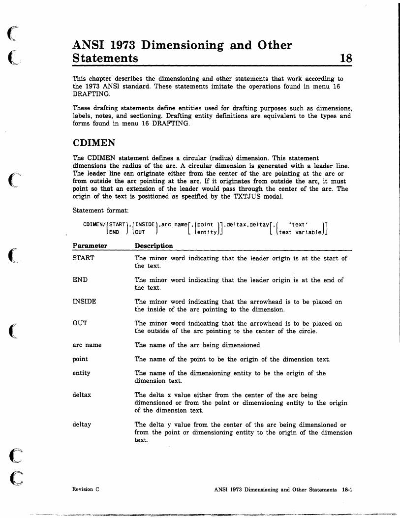
(
(~
(
c c
ANSI 1973 Dimensioning and Other Statements 18
This chapter describes the dimensioning and other statements that work according to the 1973 ANSI standard. These statements imitate the operations found in menu 16 DRAFTING.
These drafting statements defme entities used for drafting purposes such as dimensions, labels, notes, and sectioning. Drafting entity defmitions are equivalent to the types and forms found in menu 16 DRAFTING.
CDIMEN The CDIMEN statement defmes a circular (radius) dimension. This statement dimensions the radius of the arc. A circular dimension is generated with a leader line. The leader line can originate either from the center of the arc pointing at the arc or from outside the arc pointing at the arc. If it originates from outside the arc, it must point so that an extension of the leader would pass through the center of the arc. The origin of the text is positioned as specified by the TXTJUS modal.
Statement format:
CDIMEN/(START).(INSIDE).arc name[.(POint )].deltax.deltay[,( 'text' )] END OUT entity text variable
Parameter
START
END
INSIDE
OUT
arc name
point
entity
deltax
deltay
Revision C
Description
The minor word indicating that the leader origin is at the start of the text.
The minor word indicating that the leader origin is at the end of the text.
The minor word indicating that the arrowhead is to be placed on the inside of the arc pointing to the dimension.
The minor word indicating that the arrowhead is to be placed on the outside of the arc pointing to the center of the circle.
The name of the arc being dimensioned.
The name of the point to be the origin of the dimension text.
The name of the dimensioning entity to be the origin of the dimension text.
The delta x value either from the center of the arc being dimensioned or from the point or dimensioning entity to the origin of the dimension text.
The delta y value from the center of the arc being dimensioned or from the point or dimensioning entity to the origin of the dimension text.
ANSI 1973 Dimensioning and Other Statements 18-1

CDIMEN
Parameter Description
'text' The text of the dimension. The text must be enclosed in single quotes.
text variable The name of the text variable containing the text.
Examples:
Program Statement
CD1=CDIMEN/START,QUT,$ CIR1,3,2
CD2=CDIMEN/END,INSIDE,$ CIR2 ,PT1 ,0,0
18·2 ICEM GPL for NOS
Explanation
Circular dimension CDl is created for circle eIRl. The leader origin is at the start of the text. The arrowhead of the leader is placed on the outside of the circle pointing into the center of the circle. The text is placed at delta coordinates (3,2) from the center of the circle.
Circular dimension CD2 is created for circle CIR2. The leader origin is at the end of the text. The arrowhead of the leader is placed on the inside of the circle pointing away from the center of the circle. Text is placed at delta coordinates (0,0) from point PTl. In other words, it uses the actual coordinates of point PTl.
Revision C
\
I
j

(
(
(
c c
CUNE
CLINE The CLINE statement defines a centerline.
Two Points
Statement format:
CLINE/point1.point2
Parameter Description
point1 The name of the first point that defines the centerline.
point2 The name of the second point that defmes the centerline.
A dash is placed between two lines which extend through the two points for 2.5 mm (0.1 in).
Example:
Program Statement
CLN1=CLINE/PT1,PT2
Multiple Points
Statement format:
Explanation
Centerline CLN1 is created between points PT1 and PT2.
CLINE/point1,point2,point3, ... ,pointn
Parameter Description
point The names of the points that define the centerline. Up to 12 points can be entered.
A centerline is created through the points, and dashes are centered on all the points other than the endpoints.
Example:
Program Statement
SEC2=CLINE/PT1,PT2,PT3
Revision C
Explanation
Centerline SEC2 is created from point PT1 through point PT2 to point PT3.
ANSI 1973 Dimensioning and Other Statements 18-3

i I l
CUNE
Circle
Statement format:
CLINE/circle
Parameter Description
circle The name of the circle for which a crossed centerline is created.
A crossed centerline is automatically generated for one circle. Two linear centerlines are generated, one horizontal and one vertical, with the dashes crossing at the center of the circle and the endpoints extending 2.5 mm (0.1 in) outside the circle.
Example:
Program Statement
CLN3=CLINE/CIRl
Explanation
A crossed centerline CLN3 is created through the center of circle CIR!.
Circles with Collinear Centers
Statement format:
CLINE/circle1,clrcle2, ... ,circlen
Parameter Description
circle The names of the circles that deime the centerline. Up to six circles can be entered.
Crossed center lines are automatically generated for each circle in a line of circles that have collinear centers. The centerline places a dash at the centers of the circles, with the endpoints of the centerline extending 2.5 mm (0.1 in) outside the end circles. Each circle also has a crossed normal centerline with dashes crossing at the center of the circle and the endpoints extending 2.5 mm (0.1 in) outside the circle.
Example:
Program Statement
SEC4=CLINE/CIR1,CIR2,$ CIR3,CIR4
18-4 ICEM GPL for NOS
Explanation
Centerline SEC4 is created from circle CIR1 through circles CIR2 and CIR3 to circle CIR4.
Revision C
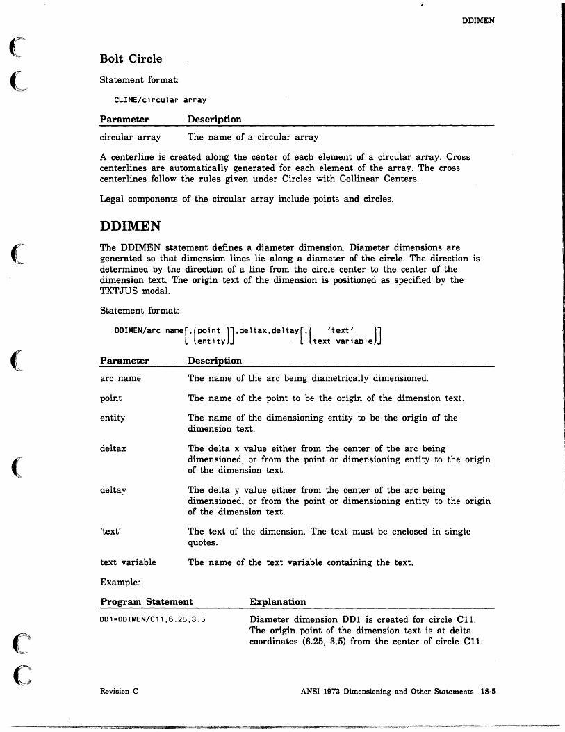
(C_
(~
(
(
c c
DDIMEN
Bolt Circle
Statement format:
CLINE/circular array
Parameter Description
circular array The name of a circular array.
A centerline is created along the center of each element of a circular array. Cross centerlines are automatically generated for each element of the array. The cross centerlines follow the rules given under Circles with Collinear Centers.
Legal components of the circular array include points and circles.
DDIMEN The DDIMEN statement defmes a diameter dimension. Diameter dimensions are generated so that dimension lines lie along a diameter of the circle. The direction is determined by the direction of a line from the circle center to the center of the dimension text. The origin text of the dimension is positioned as specified by the TXTJUS modal.
Statement format:
DOlMEN/arc name [, (PO; nt )], de 1 tax, de 1 tay [, ( , t ext ~ )] entity . text varlable
Parameter
arc name
point
entity
deltax
deltay
'text'
text variable
Example:
Description
The name of the arc being diametrically dimensioned.
The name of the point to be the origin of the dimension text.
The name of the dimensioning entity to be the origin of the dimension text.
The delta x value either from the center of the arc being dimensioned, or from the point or dimensioning entity to the origin of the dimension text.
The delta y value either from the center of the arc being dimensioned, or from the point or dimensioning entity to the origin of the dimension text.
The text of the dimension. The text must be enclosed in single quotes.
The name of the text variable containing the text.
Program Statement Explanation
DD1=DDIMEN/C11,6.2S,3.S
Revision C
Diameter dimension DDI is created for circle CIL The origin point of the dimension text is at delta coordinates (6.25, 3.5) from the center of circle CIL
ANSI 1973 Dimensioning and Other Statements 18·5

LABEL
LABEL The LABEL statement constructs labels. A general label consists of a string of characters with an associated leader .line generated from the label to an entity on the drawing. The leader includes a tail, which is a short horizontal bar extending from the beginning or end of the text. If the minor word END is specified, the tail is placed to the right of the text.
The vertical position of the leader line tail is determined by the modal statement LEADER. The leader touches the first text line by default. The leader line automatically terminates at the entity through one of the following options:
• Coordinate Method. Coordinates at or near the desired leader line termination point are entered. These coordinates need not be directly on the entity, as the leader line automatically intersects itself precisely with the entity. If the entity is a point, the leader terminates at the point.
• Slope Method. The angle of the leader line is entered. The leader line is generated to the entity indicated at the angle specified. The leader line automatically terminates at the intersection point on the entity.
• Midpoint Method. If no leader line termination control is used, the leader line automatically ends at the midpoint of the entity.
The text of the label is positioned by locating the origin (TXTJUS modal statement) either with the absolute coordinates or at a delta distance from either another dimensioning entity or a point. The text angle of the label can be varied by entering ANGLE and the text angle in degrees. The string of characters that form the text of the label can be replaced by a text variable.
Statement format:
LABEL/(START).[(POint )~~~~~ax'deltaYl,entity labeled END ent ity
[,(SLOPE,Slope )][,ANGLE,an9Ie][,( 'text: )]
termxt,termyt text varlable
Parameter
START
END
xt,yt
point
entity
Description
The minor word indicating that the leader origin is at the start of the text.
The minor word indicating that the leader origin is at the end of the text.
The absolute coordinates of the label text origin.
The name of the point to be the origin of the label text.
The name of the dimensioning entity to be the origin of the label text.
18-6 ICEM GPL for NOS Revision C
! I

(
(
c C.·~···
, .
Parameter
deltax
deltay
entity labeled
SLOPE
slope
termxt, termyt
ANGLE
angle
'text'
text variable
Example:
LABEL
Description
The delta x value from the point or the dimensioning entity to the origin of the dimension text.
The delta y value from the point or the dimensioning entity to the origin of the dimension text.
The name of the entity being labeled.
The minor word for indicating the angle of the leader from the positive x-axis. The leader line is generated to the entity indicated at the angle specified. The horizontal line length from the label center is fixed at 3.17 mm (0.125 in). The leader line automatically terminates at the point at which it intersects the entity.
The angle of the leader line from the positive x-axis.
The coordinates at or near the leader line termination point.
The minor word for indicating the text angle of the label.
The text angle in degrees.
The text of the label.
The name of the text variable containing the text for the label.
Program Statement Explanation
LAB1=LABEL/START,2.1,3.7,LN2,$ 'chamfer .0625 x 45 degrees'
Revision C
Label LAB1 is created for line LN2 at coordinates (2.1,3.7). The leader starts at the beginning of the text. The text is: chamfer .0625 x 45 degrees.
ANSI 1973 Dimensioning and Other Statements 18-7

LDIMEN
LDIMEN
The LDIMEN statement defmes linear dimensions which are horizontal, vertical, or parallel. The dimension text for horizontal dimensions is generated parallel to the x-axis with vertical witness lines. Dimension lines for vertical dimensions are generated parallel to the y-axis with horizontal witness lines.
Parallel dimensions are generated relative either to a given line, or to the apparent line that exists between any two points, and produce dimension lines parallel to the line. The witness lines for parallel dimensions are perpendicular to the dimension lines, the text is horizontal, and the dimension lines pass through its geometric center. The following two types of parallel dimensioning are available:
Dimension
PARLEL
PARNOR
Description
Generates a dimension relative either to a given line or to the apparent line that exists between two entity endpoints.
Generates a dimension to two parallel lines.
When selecting entities to dimension, includes a position indicator after the entity. The exceptions are:
• If the entity is a point.
• If only one entity is dimensioned (the entity's endpoints are used).
To align the arrowheads with the arrowheads of the previous dimension, use the YES parameter.
The dimension origin of the text can be entered in the following ways:
Origin
Coordinates
Delta from a point or dimensioning entity
Description
Imagine an arc drawn counterclockwise from the first entity endpoint through the dimension origin to the second entity endpoint. The first point of this arc is the one from which a delta xt value and delta yt value finds the dimension origin.
A point or dimensioning entity is specified and delta x and delta y points or coordinates are given from that point or entity.
The defInition form for this statement is:
dimension type,entity selection[,arrowhead alignment] ,dimension origin[,key-in text]
Statement format:
HORIZ LOIMEN/ VERTCL ,
PARLEL
PARNOR
point
[
XSMALL] ent it Y , XLARGE
YSMALL
YLARGE
entit~[:n[~::~ ] 1 YSMALL
YLARGE
[,YES][,Ori 9 inl,deltaxt,d91taYt[,( 'text' )] text variable
18·8 ICEM GPL for NOS Revision C
I I

(
(
c c
Parameter
HORIZ
VERTCL
PARLEL
PARNOR
point
entity
XSMALL
XLARGE
YSMALL
YLARGE
YES
origin
deltaxt, deltayt
'text'
text variable
Examples:
LDIMEN
Description
The minor word indicating a horizontal dimension.
The minor word indicating a vertical dimension.
The minor word indicating a parallel dimension relative to a given line.
The minor word indicating a parallel dimension normal to two given parallel lines.
The names of points being dimensioned.
The names of entities being dimensioned.
The minor word indicating the x negative direction.
The minor word indicating the x positive direction.
The minor word indicating the y negative direction.
The minor word indicating the y positive direction.
The XSMALL, XLARGE, YSMALL, and YLARGE minor words indicate which end of. the entity to dimension.
The minor word for aligning the arrowheads with the arrowheads of the previous dimension.
The name of a reference point or entity to be the origin of the dimension.
The delta xt- and yt-coordinates from the first entity endpoint or the reference point or entity.
The text of the dimension. The text must be enclosed in single quotes.
The name of the text variable containing the text.
Program Statement Explanation
LD1=LDIMEN/HORIZ,$ LN 1 , 3. 15, 2 . 5
LD2=LDIMEN/VERTCL,LN2, .5,1
LD3=LDIMEN/PARLEL,$ LN1,XLARGE,$ LN3,XLARGE,PT1,O,O
Revision C
Horizontal linear dimension L01 is created for line LNl. The dimension text starts at delta coordinates (3.15, 2.5) from line LNl.
Vertical linear dimension L01 is created for line LNl. The dimension text starts at coordinates (.5,1).
Parallel linear dimension L03 is created between line LN1 and line LN3. The dimension text starts a point PTl. The dimension is drawn from the x positive end of line LN1 to the x positive end of line LN2.
ANSI 1973 Dimensioning and Other Statements 18-9

NOTE
NOTE The NOTE statement enters notes to a part drawing. General notes consist of contiguous strings of characters including blanks. The note is entered as an alphanumeric string and can contain up to 200 characters. The \ (backs lash) starts a new line immediately below tl?e previous line.
A general note is positioned by locating the origin (TXTJUS modal) using either a point or dimensioning entity and delta coordinates or by specifying xt- and yt-coordinates.
Statement format:
(POSITV), line
xt,yt NEGATV
NOTEI (~~~~~y),deltax,deltay , (~cw),arc I 'text' l ' text variable
real variable
Parameter
xt,yt
point
entity
deltax
deltay
POSITV
line
NEGATV
(ANGLE) ,angle
Description
The absolute coordinates of the note origin.
The name of a point used as the origin of the note text.
The name of a dimensioning entity used as the origin of the note text.
The delta x value from the point or entity to the origin of the note text.
The delta y value from the point or entity to the origin of the note text.
The minor word for positioning the note text parallel to a given line in the positive direction from the x-axis. If the line is vertical, the text is displayed sideways and upwards.
The name of the reference line.
The minor word for positioning the note text parallel to a given line in the negative direction from the x-axis. If the line is vertical, the text is displayed sideways and downwards.
18·10 ICEM GPL for NOS Revision C
~
I
I

(
(-
('
(
(
(~
C
Parameter
CW
arc
CCW
ANGLE
angle
'text'
text variable
real variable
Examples:
NOTE
Description
The minor word for positioning the note text parallel to a given arc in a clockwise direction.
The name of the reference arc.
The minor word for positioning the note text parallel to a given arc in a clockwise direction.
The minor word for the text angle of the label.
The text angle in degrees.
The text of the note. The text must be enclosed in single quotes.
The name of a text variable containing the text.
The name of a real variable. The variable is converted to a text string and truncated. The current numeric mode must be DECMAL.
Program Statement Explanation
NT1=NOTE/1.5,2.75,ANGLE,O,$ 'THIS IS A GENERAL NOTE'
NT2=NOTE/PT1,O,O,ANGLE,O,$ 'THIS IS A GENERAL NOTE'
Revision C
Note NTI is created at coordinates (1.5,2.75).
Note NT2 is created at delta coordinates (0,0) from point PT1. The note is created at the coordinates of point PTl, but the delta coordinates are still required for this statement.
ANSI 1973 Dimensioning and Other Statements 18-11
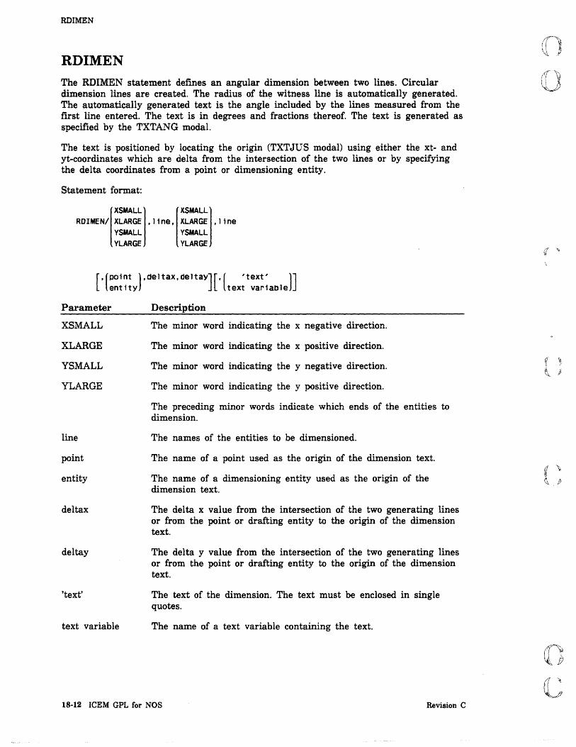
I
RDlMEN
RDIMEN The RDIMEN statement defmes an angular dimension between two lines. Circular dimension lines are created. The radius of the witness line is automatically generated. The automatically generated text is the angle included by the lines measured from the rust line entered. The text is in degrees and fractions thereof. The text is generated as specified by the TXTANG modal.
The text is positioned by locating the origin (TXTJUS modal) using either the xt- and yt-coordinates which are delta from the intersection of the two lines or by specifying the delta coordinates from a point or dimensioning entity.
Statement format:
RDIMEN/ XLARGE ,line, XlARGE ,line XSMALL [XSMALL
YSMALL YSMALL YLARGE YLARGE
[ .(P01~t ),deltax.deltay][,( 'text' )] entlty text variable
Parameter
XSMALL
XLARGE
YSMALL
YLARGE
line
point
entity
deltax
deltay
'text'
text variable
Description
The minor word indicating the x negative direction.
The minor word indicating the x positive direction.
The minor word indicating the y negative direction.
The minor word indicating the y positive direction.
The preceding minor words indicate which ends of the entities to dimension.
The names of the entities to be dimensioned.
The name of a point used as the origin of the dimension text.
The name of a dimensioning entity used as the origin of the dimension text.
The delta x value from the intersection of the two generating lines or from the point or drafting entity to the origin of the dimension text.
The delta y value from the intersection of the two generating lines or from the point or drafting entity to the origin of the dimension text.
The text of the dimension. The text must be enclosed in single quotes.
The name of a text variable containing the text.
18-12 ICEM GPL for NOS Revision C
I
I

(
(
c c
Example:
Program Statement
RD1=RDIMEN/XLARGE,LN1,$ YLARGE,LN2,PT1,O,O
Revision C
RDIMEN
Explanation
Angular dimension RDl is created from the x positive end of line LNl to the y negative end of line LN2. The dimension text starts at point PT1.
ANSI 1973 Dimensioning and Other Statements 18·13

SECTON
SECTON
The SECTON statement sections parts. Sectioning automatically generates section lines for any closed (apparent to view) configuration. Islands are automatically recognized if they are in the list of entities or the entity array.
Statement format:
SECTON/( entity(, ... J )(,SECDIS,distanCeJ[,ANGLE,anQleJ NUMBER,number,entity array
Parameter
entity
NUMBER
number
entity array
SECDIS
distance
ANGLE
angle
Description
The names of the entities sectioned. Entities allowed are lines, arcs, general conics, and splines.
The minor word for specifying a number of entities from an entity array.
The number of entities in the entity array.
The name of an entity array.
The minor word indicating the distance between sectioning lines. The spacing between the lines is adjustable, as is the angle at which the lines are generated. If the distance between lines is omitted, 2.5 mm (0.10 in) is assumed.
The distance between the sectioning lines in units of measure.
The minor word indicating the angle of the sectioning lines. If the angle for lines is omitted, 45° is assumed. The angle for a set of section lines can be varied between 0° and 180°.
The angle of the sectioning lines in positive degrees from the x-axis.
18·14 ICEM GPL for NOS Revision C
g • l

(
c c
Examples:
Program Statement
MATERL/IRON SEC1=SECTON/LN1,LN10,LN9,$
LN11,LN8,LN7,LN13,LN12,$ SECDIS, .25
MATERL/STEEL SEC2=SECTON/LN1,CIR1,CIR2,$
LN2,LN9,LN10,ANGLE,135
MATERL/BRASS SEC3=SECTON/LN3,CIR3,LN4,$
LN5,LN7,LN8,ANGLE,135
MATERL/ALUM SEC4=SECTON/LN7,LN6,LN12,$
LN13,SECDIS,.175,$ ANGLE,30
Revision C
SECTON
Explanation
Section SEC1 is created using the section lining symbol of iron. The distance between lines is modified to 0.25 units of measure.
Section SEC2 is created using the section lining symbol of steel. The angle of the lines is modified to 1350 from the x positive axis.
Section SEC3 is created using the section lining symbol of brass. The angle of the lines is modified to 1350 from the x positive axis.
Section SEC3 is created using the section lining symbol of aluminum. The distance between lines is modified to 0.175 units of measure. The angle is modified to 30° from the x positive axis.
ANSI 1973 Dimensioning and Other Statements 18-15


o o
o
o
o
o o
ANSI 1982 Drafting Modal Statements 19 AHEAD ............................................ 19-1
ANGCTL . . . . . . . . . . . . . . . . . . . . . . . . . . . . . . . . . . . . . . . . . . . 19-2
ANUNIT ........................................... 19-3
ARAUTO ........................................... 19-3
ARIN ............................................. 19-4
AROUT ............................................ 19-4
ARROW ............................................ 19-5
ATAIL ............................................ 19-5
AUTOD ............................................ 19-6
CDISPL. . . . . . . . . . . . . . . . . . . . . . . . . . . . . . . . . . . . . . . . . . . . 19-7
CRES ............................................. 19-8
CSET ............................................. 19-9
CSIZE. . . . . . . . . . . . . . . . . . . . . . . . . . . . . . . . . . . . . . . . . . .. 19-10
DECMAL .......................................... 19-11
DIM OF . . . . . . . . . . . . . . . . . . . . . . . . . . . . . . . . . . . . . . . . . . . 19-12
DIMORG .......................................... 19-13
DSCALE . . . . . . . . . . . . . . . . . . . . . . . . . . . . . . . . . . . . . . . . . . 19-14
DUAL ............................................ 19-15
FRACT . . . . . . . . . . . . . . . . . . . . . . . . . . . . . . . . . . . . . . . . . . . 19-15
LDDIAM . . . . . . . . . . . . . . . . . . . . . . . . . . . . . . . . . . . . . . . . . . 19-16
LEADER . . . . . . . . . . . . . . . . . . . . . . . . . . . . . . . . . . . . . . . . . . 19-16
MATERL .......................................... 19-17
PREFIX .......................................... 19-18
SECALN . . . . . . . . . . . . . . . . . . . . . . . . . . . . . . . . . . . . . . . . . . 19-18
SECVIS .................................. ~ . . . . . . .. 19-19
SLANT ........................................... 19-19
TXTJUS ......................................... , 19-20
TXTORG .......................................... 19-21
WLINE . . . . . . . . . . . . . . . . . . . . . . . . . . . . . . . . . . . . . . . . . .. 19-22
its:: ,\4_ .4AijL. __ q

"",.,t tij!DI U!IIDti!tii",,,q"!.! Mf.m .. ,! .1Il.! .. '·Mdl'
o· o
o
o
o

(
(
(
(
(
(~
C
ANSI 1982 Drafting Modal Statements 19
This chapter describes the drafting modal statements that work according to the 1982 ANSI standard. These statements imitate the operations found in menu 16.1 DRAFTING MODALS.
The same statement described elsewhere in this manual, works only with the 1973 ANSI standard. For example, AHEAD in this chapter applies to the 1982 ANSI standard. AHEAD as described in chapter 17 DRAFTING MODALS in this manual applies to the 1973 ANSI standard. In many of these statements, the commands appear to act exactly the same, however, there may be subtle differences. You should therefore be careful as you use these statements. Also, some commands described in this chapter do not work at all with the 1973 standard. For example, ANGCTL is not implemented in the 1973 ANSI standard.
AHEAD This modal statement sets the length of arrowheads and dimension origin circles. The width of arrowheads is one-third the length. The length is preset to 0.15 inches (3.81 mm). If the value entered is less than or equal to zero, the following error message is displayed:
VALUE MUST BE GREATER THAN ZERO
Changing this modal affects only dimensions and arrowheads subsequently created.
Statement format:
AHEAD/length
Parameter Description
length The length of the arrowhead in units of measure.
Example:
Program Statement Explanation
AHEAD/.3
Revision C
The length for all subsequent arrowheads is set to 0.3 units of measure. The width of the arrowhead is set to 0.1 units of measure.
ANSI 1982 Drafting Modal Statements 19·1

I ~
ANGCTL
ANGCTL
This modal statement controls the angle at which the text of a note or label is written. The default value for ANGCTL is HORIZ.
Statement format:
HORIZ ANGCTL/ ENTER
PARLEL TOTAL
Parameter
HORIZ
ENTER
PARLEL
TOTAL
NOTE
Description
The minor word for setting the text horizontally to the screen.
The minor word for displaying a menu that lets the user choose the method of setting the text angle.
The minor word for writing a note parallel to a line or arc.
The minor word for writing notes at a user-specified angle or parallel to a line or arc.
ANGCTL affects only notes and labels created interactively.
Example:
Program Statement
ANGCTL/PARLEL
19-2 ICEM GPL for NOS
Explanation
All subsequent text is written parallel to a line or arc.
Revision C
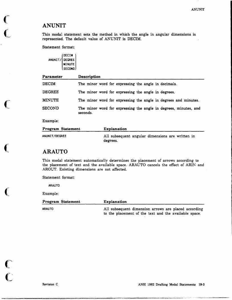
(
(,
(
(
(
c c
ANUNIT
ANUNIT
This modal statement sets the method in which the angle in angular dimensions is represented. The default value of ANUNIT is DECIM.
Statement format:
DECIM ANUNIT/ DEGREE
MINUTE SECOND
Parameter
DECIM
DEGREE
MINUTE
SECOND
Example:
Description
The minor word for expressing the angle in decimals.
The minor word for expressing the angle in degrees.
The minor word for expressing the angle in degrees and minutes.
The minor word for expressing the angle in degrees, minutes, and seconds.
Program Statement Explanation
ANUNIT/DEGREE
ARAUTO
All subsequent angular dimensions are written in degrees.
This modal state'ment automatically determines the placement of arrows according to the placement of text and the available space. ARAUTO cancels the effect of ARIN and AROUT. Existing dimensions are not affected.
Statement format:
ARAUTO
Example:
Program Statement
ARAUTO
Revision C
Explanation
All subsequent dimension arrows are placed according to the placement of the text and the available space.
ANSI 1982 Drafting Modal Statements 19·3

ARIN
ARIN This modal statement generates dimensions with the arrows inside (between) the entities or extension lines to which the dimensions extend. ARIN cancels the effect of ARAUTO and AROUT. Existing dimensions are not affected.
Statement format:
ARIN
Example:
Program Statement
ARIN
AROUT
Explanation
All subsequent arrows are placed inside the extension lines.
This modal statement generates dimensions with the arrows outside the entities or extension lines to which the dimensions extend. AROUT cancels the effect of ARAUTO and ARIN. Existing dimensions are not affected.
Statement format:
AROUT
Example:
Program Statement
AROUT
19-4 ICEM GPL for NOS
Explanation
All subsequent arrows are placed outside the extension lines.
Revision C
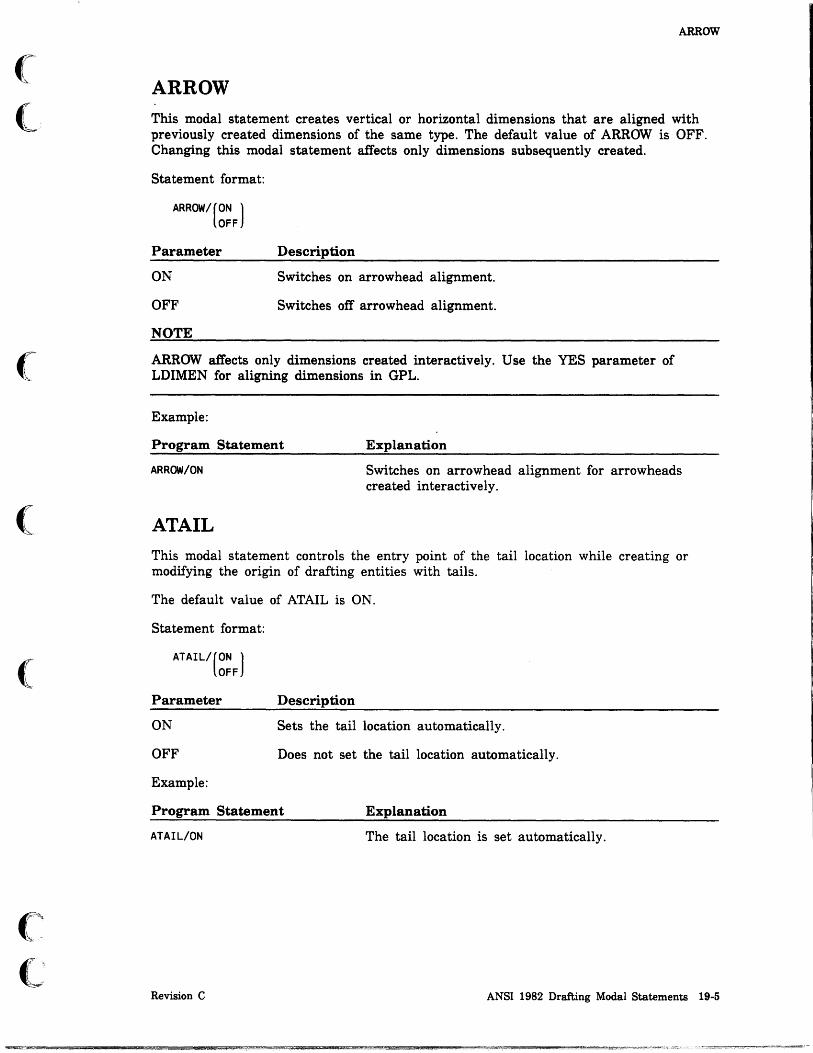
(
<-
(
(
c c
ARROW
ARROW This modal statement creates vertical or horizontal dimensions that are aligned with previously created dimensions of the same type. The default value of ARROW is OFF. Changing this modal statement affects only dimensions subsequently created.
Statement format:
ARROW/[ON ) OFF
Parameter
ON
OFF
NOTE
Description
Switches on arrowhead alignment.
Switches off arrowhead alignment.
ARROW affects only dimensions created interactively. Use the YES parameter of LDIMEN for aligning dimensions in GPL.
Example:
Program Statement Explanation
ARROW/ON
ATAIL
Switches on arrowhead alignment for arrowheads created interactively.
This modal statement controls the entry point of the tail location while creating or modifying the origin of drafting entities with tails.
The default value of ATAIL is ON.
Statement format:
ATAIL/(ON ) OFF
Parameter
ON
OFF
Example:
Description
Sets the tail location automatically.
Does not set the tail location automatically.
Program Statement Explanation
ATAIL/ON The tail location is set automatically.
Revision C ANSI 1982 Drafting Modal Statements 19-5

AUTon
AUTon This modal statement automatically calculates or prompts for dimensions for linear, angular, radius, and diameter dimensions. This statement affects only those dimensions created interactively.
Dimensions created in GPL are always automatically calculated unless a dimension text is specified in the GPL statement.
The default value of AUTOD is ON.
Statement format:
AUTOO/(ON ) OFF
Parameter
ON
OFF
Example:
Description
Dimension text is automatically generated.
Prompts to enter dimension text manually.
Program Statement Explanation
AUTOO/ON Dimension text is automatically generated and not entered interactively.
19-6 ICEM GPL for NOS Revision C

(
(
c c
CDISPL
CDISPL This modal statement modifies the ratios of character display. This modal statement affects only subsequently created dimensions and does not change existin'g' dimensions.
Statement format:
CDISPL/[DELTA,char space][,ASPCT,aspect][,DOWNSP, line space][,TOLER,tolerance]
Parameter
DELTA
char space
ASPCT
aspect
DOWNSP
line space
TOLER
tolerance
Description
The minor word indicating the spacing between the centers of consecutive characters.
The value multiplied by the character height that gives the spacing between the centers of consecutive characters. This value is preset to 1.1.
The minor word indicating the aspect ratio, which is the ratio between character width and character height.
The value of the aspect ratio. This value is preset to 1.
The minor word indicating the downspace ratio, which is the line spacing value multiplied by the character height that gives the distance between the bottom of lines of text.
The value of the downspace .ratio. This value is preset to 1.5.
The minor word indicating the tolerance ratio (the ratio between the character size for tolerance and fraction characters and the character size for main characters in dimensions).
The value of the tolerance ratio. This value is preset to 1.
If the value entered for any of these options is less than or equal to zero, the following error message is displayed:
VALUE MUST BE GREATER THAN ZERO
NOTE
At least one minor word is required.
Example:
The following statement sets the character display ratios. The spacing between characters is set to a ratio of 1.5 times the character height. The character width is set to a ratio of 0.9 of the character height. The spacing between lines is set to a ratio of 2 times the character height.
CDISPL/DELTA,1.5,ASPCT, .9,DOWNSP,2
Revision C ANSI 1982 Drafting Modal Statements 19-7

CRES
CRES This modal statement selects a method of output representation for .standard set type characters. This modal statement affects all existing standard characters generated. Lowercase characters appear as uppercase in FAST mode. The default value for CRES is FINE.
Statement format:
CRES/(FINE) FAST
Parameter
FINE
FAST
Example:
Description
The minor word indicating the fine character set type.
The minor word indicating the coarse character set type.
Program Statement Explanation
CRES/FINE
19·8 ICEM GPL for NOS
The character set type is set to the FINE representation mode.
Revision C

(
.(
(
(:
(
c c
CSET
CSET This modal statement selects the character set to be used in defining text. This modal statement does not affect the text in any existing dimensions, labels, or notes.
If you try to access a user-defmed character set and the character set is not found, the system displays:
CHARACTER SET NOT FOUND IN UTF
If the character variable for the character set name is more than four characters long, the system displays:
CHARACTER SET NAME TOO LONG
Standard characters are used for any characters not defined in the character set.
Statement format:
CSET/(STD ) USER,character set name
Parameter
STD
USER
character set name
Example:
Description
The minor word indicating the standard character set.
The minor word indicating a user-defined character set.
The name of a user-defined character set (maximum 4 characters in length).
Program Statement Explanation
CSET/USER,'MYCH' The user-defined character set MYCH is selected.
Revision C ANSI 1982 Drafting Modal Statements 19-9

! i
CSIZE
CSIZE This modal statement specifies the height of the characters that are written by the dimension, label, and note operations. Existing dimensions are not affected. This value is preset to 0.125 inches (3.18 mm).
If the value entered is less than or equal to zero, the following error message is displayed.
VALUE MUST BE GREATER THAN ZERO
Statement format:
CSIZE/character height
Parameter Description
character height The height of the characters.
Example:
Program Statement
CSIZE/.2S
19-10 ICEM GPL for NOS
Explanation
The height of all subsequent characters is set to 0.25 units of measure.
Revision C

(
(
(
c c
DECMAL
DECMAL This modal statement sets the number of decimal places in the display of dimensions. It can also be used to return to the decimal mode from the fraction mode. If dual dimensioning has been set, the user can set the number of decimal places to be used in the regular units text and/or the alternate units text. The number of decimal places for regular dimensions is preset to 4 (9 maximum). The number of decimal places for alternate dimensions is preset to 3 (6 maximum). This modal statement does not affect existing dimensions.
Statement format:
OECMAL/[regular unit decimal places][,SECONO,alternate unit decimal places]
Parameter
regular unit decimal places
SECOND
alternate unit decimal places
Example:
Description
The value of the regular unit decimal places.
The minor word indicating alternate unit decimal places.
The value of the alternate unit decimal places.
Program Statement Explanation
OECMAL/3,SECONO,4
NOTE
The regular unit decimal places is set to 3 and the alternate unit decimal places is set to 4.
No parameters are required to return to decimal mode from fraction mode. The number of decimal places for regular units text and alternate units text are the previous values set.
Revision C ANSI 1982 Drafting Modal Statements 19-11

I
DIMOF
DIMOF This modal statement sets the dimension offset distances.
If the value entered for any of these options is less than or equal to zero, the following error message is displayed:
VARIABLE OR CONSTANT MUST BE GREATER THAN ZERO
Statement format:
DIMOF/[TEXTD,text offset][,WITP,witness offset][,WITX,w1tness extension]
Parameter
TEXTD
text offset
WITP
witness offset
WITX
witness extension
Example:
Description
The minor word indicating the distance from the text to the dimension lines.
The value of the distance from the text to the dimension lines, which is preset to 0.1 inch (2.54 mm). This parameter affects only newly created dimensions.
The minor word indicating the distance from an extension line to the entity from which it extends.
The value of the distance from an extension line to the entity from which it extends, which is preset to 0.0625 inch (1.59 mm). This parameter affects only newly created dimensions.
The minor word indicating the distance that an extension line extends beyond a dimension line.
The value of the distance that an extension line extends beyond a dimension line, which is preset to 0.125 inch (3.17 mm). This parameter affects only newly created dimensions.
Program Statement Explanation
DIMOF/TEXTD,.3,WITP,$ .2,WITX, .4
NOTE
The text is set 0.3 units from the dimension line. Witness lines start at 0.2 units from the entity, and they end at 0.4 units beyond the entity.
At least one minor word is required.
19·12 ICEM GPL for NOS Revision C

(
(
((~
C
DIMORG
DIMORG This modal statement sets which side, if any, of a generated dimension specifies a. dimension origin. A dimension origin is graphically represented as a circle instead of an arrowhead at the end of a dimension line. The diameter of the dimension origin circle is determined by the arrowhead length. This modal statement applies to horizontal, vertical, parallel, and thickness dimensions. The default value of DIMORG is NONE.
Statement format:
DIMORG/ SECOND I
FIRST 1
Parameter
FIRST
SECOND
NONE
Example:
NONE
Description
Indicates the first side selected as the dimension origin.
Indicates the second side selected as the dimension origin.
Indicates that neither side is selected as the dimension origin.
Program Statement Explanation
DIMORG/FIRST The first side selected is the dimension origin.
Revision C ANSI 1982 Drafting Modal Statements 19-13

DSCALE
DSCALE This modal statement sets the scale factor used in generating dimensions, labels, and notes. The following are affected:
• The character size.
• The arrowhead size of all dimensions and labels.
• The distance from the text of a dimension to the dimension line.
• The distance that an extension line is offset from a reference point.
• The distance that the extension line extends past the dimension line.
• The spacing and dash size for centerlines.
• The preset balloon and datum target symbol radius.
This statement affects all newly created dimensions. If the drafting scale is halved, the above drafting modal statements are doubled. Conversely, if the drafting scale is doubled, the above drafting modal statements are halved.
Alternately, a ratio to the current draft scale may be entered which will proportionally affect the drafting scale factor.
Statement format:
DSCALE/(draft1ng scale factor) RATIO,ratio
Parameter
drafting scale factor
Description
The drafting scale factor. The value is preset to 1.
. RATIO The minor word indicating a ratio to the current drafting scale.
ratio The ratio expressed as a value.
Example:
Program Statement
DSCALE/.8
19·14 ICEM GPL for NOS
Explanation
The drafting scale factor is set to 0.8 for all subsequent entities.
Revision C

(
(
(
(
(
('
C
DUAL
DUAL
This modal statement determines whether the dimension operations are in both SI and U.S. customary units or in SI or U.S. customary units as set for the particular part.
The default value of DUAL is OFF.
Statement format:
OFF DUAL/ BOTH
BRACKT POSN
Parameter
OFF
BOTH
BRACKT
POSN
Example:
Description
The minor word indicating no dual dimensioning.
The minor word for producing dual dimensions with the alternate dimensions inside square brackets and a line separating upper and lower text.
The minor word for producing dual dimensions with the alternate dimensions inside square brackets and no line separating upper and lower text.
The minor word for producing dual dimensions with a line separating upper and lower text and no brackets around the alternate dimensions.
Program Statement Explanation
DUAL/BOTH
FRACT
Dimensions are written using both SI and U.S. customary units.
This modal statement sets the fraction mode for automatically generated dimension text. The system writes dimensions as common or mixed fractions displayed with an accuracy of up to 1/64.
Statement format:
FRACT
Example:
Program Statement Explanation
FRACT All subsequent dimensions are written in fractions.
Revision C ANSI 1982 Drafting Modal Statements 19·15

LDDIAM
LDDIAM This modal statement controls the automatic insertion of a diameter symbol with the text automatically generated for certain dimensions. This symbol applies to horizontal, vertical, parallel, and thickness dimensions. Note that automatically generated diameter dimensions always have diameter symbols.
The preset value of LDDIAM is OFF.·
Statement format:
LDDIAM/(ON J OFF
Parameter
ON
OFF
Example:
Description
Indicates all subsequent linear dimension have a diameter symbol as the fIrst character of the text.
Turns off the forced diameter symbol.
Program Statement Explanation
LDDIAM/ON
LEADER
The diameter symbol is inserted in the dimension text.
This modal statement determines the placement of the label leader with respect to the label text. Existing labels are not affec~ed.
The default value of LEADER is FIRST.
Statement format:
LEADER/(FIRST J MIDDLE
Parameter
FIRST
MIDDLE
Example:
Description
The label leader line starts from the first text line.
The label leader line starts from the middle text line.
Program Statement Explanation
LEADER/FIRST The leader line starts from the first line of the text.
19-16 ICEM GPL for NOS Revision C

(
(
(
c (,
MATERL
MATERL
This modal statement selects the type of section lining.
The default value of MATERL is IRON.
Statement format:
MATERL/mater1al type
Parameter Description
material type The material type, which is one of the following minor words.
Example:
Minor Word
IRON
STEEL
BRASS or COPPER
RUBBER or PLASTC
REFRCT
MARBLE, SLATE or GLASS
LEAD
MAGNES or ALUM
Description
Iron
Steel
Bronze, brass, copper
Rubber, plastic
Refractory material
Marble, slate, glass
Zinc, lead, babbitt
Magnesium, aluminum, aluminum alloys
Program Statement Explanation
MATERL/STEEL
Revision C
The symbol for steel is used for subsequent section lining.
ANSI 1982 Drafting Modal Statements 19-17

PREFIX
PREFIX This modal statement changes the character used to preflx a special symbol character set. Entering the prefix character followed by certain preassigned characters allows entry of drafting symbols into notes, labels, and dimensions.
The reverse slant (\) is the default prefix character.
Statement format:
PREFIX/'character'
Parameter
, character'
Example:
Description
The prefix character, which is a string or character variable of 1 character enclosed in single quotes.
Program Statement Explanation
PREFIX/'·'
SECALN
The preflX character is changed to the asterisk symbol *
This modal statement controls the alignment of new section lining to existing section lining.
The default value of SECALN is OFF.
Statement format:
SECALN/(ON ) OFF
Parameter
ON
OFF
NOTE
Description
Subsequent section lining is aligned with the previous section lining.
Subsequent section lining is not aligned with the previous section lining.
SECALN affects only section lining created interactively. Use the YES,entity parameters with SECTON for aligning section lining in GPL.
Example:
Program Statement
SECALN/ON
19·18 ICEM GPL for NOS
Explanation
Subsequent section lining is aligned with previous section lining.
Revision C
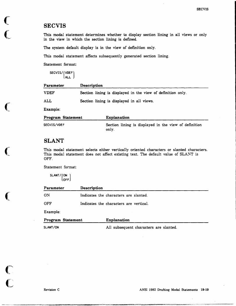
(
(
(
(
(
c' c
SECVIS
SECVIS This modal statement determines whether to display section lining in all views or only in the view in which the section lining is defined.
The system default display is in the view of definition only.
This modal statement affects subsequently generated section lining.
Statement format:
SECVIS/(VDEF) ALL
Parameter
VDEF
ALL
Example:
Description
Section lining is displayed in the view of definition only.
Section lining is displayed in all views.
Program Statement Explanation
SECVIS/VDEF
SLANT
Section lining is displayed in the view of definition only.
This modal statement selects either vertically oriented characters or slanted characters. This modal statement does not affect existing text. The default value of SLANT is OFF.
Statement format:
SLANT/(ON ) OFF
Parameter
ON
OFF
Example:
Description
Indicates the characters are slanted.
Indicates the characters are vertical.
Program Statement Explanation
SLANT/ON All subsequent characters are slanted.
Revision C ANSI 1982 Drafting Modal Statements 19·19

TXTJUS
TXTJUS This modal statement specifies the text origin (in relation to the text) and the text justification. This modal statement does not affect existing text.
The default value of TXTJUS is LEFT.
Statement format:
[LEFT 1
TXT JUS/ CENTER RIGHT
Parameter
LEFT
CENTER
RIGHT
Example:
Description
Text is left justified. The origin point of the text is the lower left corner of the first character.
Text is centered. The origin point of the text is the center of the full text.
Text is right justified. The origin point of the text is the lower right corner of the last character of the frrst line.
Program Statement Explanation
TXTJUS/RIGHT
19-20 ICEM GPL for NOS
All subsequent text is right-justified and the origin is the lower right corner of the last character of the first line.
Revision C

(
(
c c
TXTORG
TXTORG This modal statement presets the method of indicating the position of text.
The default value for TXTORG is POSN.
Statement format:
POSN TXTORGI ENTER
DELTA AUTO
Parameter
POSN
ENTER
DELTA
AUTO
NOTE
Description
In interactive mode: use the graphics cursor to indicate a screen position.
In GPL: the x and y values specify absolute coordinates.
In interactive mode: enter the coordinates of a position.
In GPL: the x and y values specify absolute coordinates.
In interactive mode: enter horizontal and vertical displacements from an existing point, note, label, or dimension.
In GPL: the x and y values specify a delta distance from a given point or predefmed location (dependent on the type of dimension).
The minor word to automatically center horizontal, vertical, and parallel dimensions; to join the leader line extension of a circular dimension at the center of an arc. Same effect as ENTER for angular and diameter dimensions.
TXTORG does not affect notes and labels created in GPL.
Example:
Program Statement
TXTORG/DELTA
Revision C
Explanation
All subsequent text origins are a delta displacement from another location.
ANSI 1982 Drafting Modal Statements 19-21

WLINE
WLINE
This modal statement controls the generation of extension lines and dimension lines. The extension line extends from an entity; it is the line to which a dimension is measured. A dimension line is the arrow from the text to the extension line; it is the line that shows the dimension being measured.
The default value of WLINE is DISP2.
Statement format:
DISP2 SUPP1 SUPP2
WLINE/ SUPPB SUPP11 SUPP22 SUPPB1 SUPPB2
Parameter
DISP2
SUPP1
SUPP2
SUPPB
SUPP11
SUPP22
SUPPBl
SUPPB2
Description
The minor word for generating dimension and extension lines to both entities.
The minor word for suppressing the extension line that extends from the first entity selected.
The minor word for suppressing the extension line that extends from the second entity selected.
The minor word for suppressing both extension lines.
The minor word for suppressing the dimension arrow and associated extension line for the first entity selected.
The minor word for suppressing the dimension arrow and associated extension line for the second entity selected.
The minor word for suppressing both extension lines and the dimension arrow for the first entity selected.
The minor word for suppressing both extension lines and the dimension arrow for the second entity selected.
19·22 ICEM GPL for NOS Revision C

o o
o
o
o
o o
ANSI 1982 Dimensioning and Other Statements ADIMEN ...... .
BALOON ..... .
CDIMEN ..... .
CLINE ....... . Linear - Multiple Points . . . . . . . . Circular - Multiple Circles .... . . Bolt Circle - Circular Array .. .
CURARR ................... . Arrowhead at Curve End . . . . . . . Arrowhead on Curve at a Parameter ..
DATFEA ................. .
DATUM .................. . Point without Area ............ . Point with Area ........... . Line .................. . Circle ................. . Existing Entity . . . . . . . . . . . . .
DDIMEN
GEOTOL
LABEL.
LDIMEN
MAGNFY '"
MODDFT ... . BASIC ...... . REF ....... . TOLER ..... .
NOTE ........ .
SECARR
SECTON
SRFTEX Basic Symbol Attached to Arrow. Basic Symbol Attached to Entity . . . . .
TAPER.
THIKNS
E::a, . $ q
20 ... 20-2-
20-3
20-4
· . . . .. 20-5 · ...... 20-5 · ...... 20-5 · ...... 20-6
· ...... 20-6 · ...... 20-6
. 20-7
. 20-8
20-10 20-10 20-11 20-12 20-13 20-14
20-15
20-16
20-22
20-24
20-27
20-28 20-28 20-29 20-30
20-31
20-33
20-35
20-36 20-36 20-38
20-39
20-40
;0

"
I
ii
95* 1.1.7 Mnlttmo.,uJt!!IiMWJln 1 j I" II"" 'W., !! •• M * • ,W',t 0,,) !'tiM
o o
o
o
o
o o

(
(
c c
ANSI 1982 Dimensioning and Other Statements 20
This chapter describes the dimensioning and other statements that work according to the 1982 ANSI standard. These statements imitate the operations found in menu 16 DRAFTING.
The same statement described elsewhere in this manual works only with the 1973 ANSI standard. For example, CDIMEN in this chapter applies to the 1982 ANSI standard. CDIMEN as described in chapter 18, ANSI 1973 Dimensioning and Other Statements, applies to the 1973 ANSI standard.
Also, some commands described in this chapter do not work at all with the 1973 standard. For example, DATUM is not implemented in the 1973 ANSI standard.
Revision C ANSI 1982 Dimensioning and Other Statements 20-1

I r
ADIMEN
ADIMEN The ADIMEN statement creates angular dimensions. Angular dimensions are generated so as to result in circular dimension lines with the radius automatically determined. The automatically generated label is the angle included by the lines measured in a counterclockwise direction from the first line entered. The label is generated as specified by the AUNITS modal statement. The text of the dimension is positioned by locating the origin (TXTJUS modal statement) with either absolute coordinates or as a delta distance from either another dimensioning entity or a point. If the TXTORGIDELTA modal statement is set, specifying only coordinates will position the origin a delta distance from the intersection of the two generating lines.
Statement format:
ADIMENI YLARGE .line 1. YLARGE .line 2.(entity.xt.yt)[.('text' )] XLARGEj IXLARGE
XSMALL XSMALL xt.yt text variable YSMALL YSMALL
Parameter
XLARGE YLARGE XSMALL YSMALL
line 1,line 2
entity,xt,yt
xt,yt
'text'
text variable
Example:
Description
The minor words for defining a location in the x positive, y positive, x negative, and y negative directions.
The names of the two lines that are dimensioned.
The name of an entity and the xt- and yt-coordinates for the text origin of the text of the dimension.
The xt- and yt-coordinates for the text origin of the text of the dimension.
The text of the dimension. The text must be enclosed in single quotes.
The name of a text variable containing the text.
The following statement creates an angular dimension starting at the x positive end of LIN1 and ending at the y positive end of LIN2. The text origin is set at the absolute coordinates, x = -0.5 and y = 0.75.
AD1=ADIMEN/XLARGE.LIN1.YLARGE.LIN2. 0.5.0.75
NOTE
ADIMEN replaces the RDIMEN statement of the 1973 ANSI standard.
20·2 ICEM GPL for NOS Revision C
~
! I

(
(
(
(
c c
BALOON
BALOON The BALOON statement draws a balloon with an arrow pointing to an entity in the current drawing. A detail number and a sheet number can be displayed in the balloon.
The arr()w from the balloon will touch the entity chosen at the parameter supplied after the entity name. Allowable entities are points, lines, arcs, conics and splines. If no radius is given, the last system default of (initially 0.5 in 12.7 mm) is used for the radius of the balloon. The center of the balloon is positioned with either absolute coordinates or as a delta distance from another dimensioning entity or point.
Statement format:
BALOON/entity,parameter[,RADIUs,rad1US],( entity,xt,ytJ ,DETAIL,detail number xt,yt
[,SHEET,Sheet number]
Parameter
entity
parameter
RADIUS
radius
entity,xt,yt
xt,yt
DETAIL
detail number
SHEET
sheet number
Example:
Description
The name of the entity to which a balloon is attached.
The parameter along the entity at which the balloon is attached.
The minor word indicating the radius of the balloon.
The radius of the balloon in units of measure.
The name of an entity and the xt- and yt-coordinates for the text origin of the text of the dimension.
The xt- and yt-coordinates for the text origin of the text of the dimension.
The minor word indicating the detail number of the balloon.
The detail number which is a string or character variable of up to nine characters.
The minor word indicating the sheet number of the balloon.
The sheet number which is a string or character variable of up to nine characters.
The following statement creates a balloon attached at 0.25 units of measure along LN1. The balloon has a radius of 0.75 units of measure. The center of the balloon is set at delta coordinates from PT1 of x = 2 and y = 2. The detail number is 1.
BALOON/LN1, .25,RADIUS, .75,PT1,2,2,DETAIL,'1'
Revision C ANSI 1982 Dimensioning and Other Statements 20·3

~ I f
CDlMEN
CDIMEN The CDIMEN statement creates circular dimensions. A circular dimension label is generated with a leader line which can originate from the center of the arc pointing at the arc or can originate outside the. arc pointing at the arc such that an extension or lea.der would pass through the center of the arc.
The text of the dimension is positioned by locating the origin (TXTJUS modal statement) with either absolute coordinates or as a delta distance from either another dimensioning entity or a point. If the TXTORG/DELTA modal statement is set, specifying only coordinates will position the origin a delta distance from the center of the circle being dimensioned.
The leader line includes a tail, which is a short horizontal bar extending from the beginning or end of the text. If the minor word START is specified, the tail is placed to the left of the text. If the minor word END is specified, the tail is placed to the right of the text.
If the modal ATAIL is set ON, the modifiers START and END are ignored and the leader origin is set automatically.
Statement format:
CDIMEN/(START),arC,(entity,xt,yt)[,('text' )] END xt,yt text variable
Parameter
START
END
arc
entity,xt,yt
xt,yt
'text'
text variable
Examples:
Description
The minor word indicating the leader origin at the start of text.
The minor word indicating the leader origin at the end of text.
The name of the arc being dimensioned.
The name of an entity and the xt- and yt-coordinates for the text origin of the text of the dimension.
The xt- and yt-coordinates for the text origin of the text of the dimension.
The text of the dimension. The text must be enclosed in single quotes.
The name of a text variable containing the text.
The following statement creates a circular dimension CDI circle CIR1. The leader starts at the start of text. The text origin is set at absolute coordinates, x=3 and y=2.
CD1=CDIMEN/START,CIR1,3,2
The following statement creates a circular dimension CD2 for circle CIR2. The leader starts at the end of text. The text origin is set at delta coordinates, x=-2 and y= 1.25 from point PTI.
CD2=CDIMEN/END,CIR2,PT1, 2,1.25
20-4 ICEM GPL for NOS Revision C
J f
I

(
(~
(
(
c C
-~
.. .:
CLINE
The CLINE statement constructs centerlines.
Linear - Multiple Points
The following format creates a centerline between a series of up to 12 points. The effect will be a line, through the points, in which dashes are placed exactly at the midpoints.
If the points entered are not linear, the system displays:
CLINE POINTS NOT COINCIDENT
Statement format:
CLINE/po1nt1,po1nt2, ... ,pointn
Parameter Description
CLINE
point! through pointn
The names of the points through which the centerline is defined.
Example:
Program Statement
CLN1=CLINE/PNT1,PNT2
Explanation
Centerline CLNI is created through points PNTI ·and PNT2.
Circular - Multiple Circles
The following format creates a centerline between a series of one to six circles. Crossed centerlines are automatically generated for each circle of a line of circles with colinear centers. The centerline through the centers places a dash at each center with the endpoints extending 0.1 in (2.54 mm) outside the end circles. Each circle also has a centerline generated normal to the line through all of the centers.
Statement format:
CLINE/circle1,circle2, ... ,circle
Parameter Description
circle 1 through circlen
The names of the circles through which the centerline is defined.
Example:
Program Statement
CLN2=CLINE/CIR2,CIR3,$ CIR4,CIRC5
Revision C
Explanation
Centerline CLN2 is created through circles CIR2, CIR3, CIR4, and CIRC5.
ANSI 1982 Dimensioning and Other Statements 20·5

CURARR
Bolt Circle . Circular Array
The following format creates a centerline through a circular array. A centerline is created along the center of each element of a circular array. Crossed centerlines are automatically generated for each element just as in the multi-circle case.
Statement format:
CLINE/circular array
Parameter Description
circular array The name of the circular array.
Examples:
Program Statement Explanation
CLN3=CLINE/AR Centerline CLN3 is created through circular array AR.
CURARR The CURARR statement draws an arrowhead at any position along an existing curve. Arrowheads created by this operation are considered triangles by the system and can be used the same way that a triangle is used.
Arrowhead at Curve End
The following format places the arrowhead at the indicated curve end. Valid entities are lines, arcs, conics, splines, composite curves, pointsets, three-dimensional splines, and machining curves.
Statement format:
XLARGEj CURARR/ YLARGE ,entity
XSMALL YSMALL
Parameter
XLARGE YLARGE XSMALL YSMALL
entity
Example:
Description
The minor words for defining a location in the x positive, x negative, y positive, and y negative directions.
The name of the entity.
Program Statement Explanation
CURARR/XLARGE,ARC1 An arrowhead is set at the x positive end of ARCl.
20-6 ICEM GPL for NOS Revision C
( \.
.~.
I I

(
(
c c
CURARR
Arrowhead on Curve at a Parameter
The following format places the arrowhead along a two-dimensional curve at a specified parameter. The position indicator after the entity determines the direction along the curve at which the arrowhead is to point. Valid entities are lines, arcs, conics, and splines.
Statement format:
XLARGE CURARR/PARAM,parameter,ent1ty, YLARGE
XSMALL YSMALL
Parameter
PARAM
parameter
entity
XLARGE YLARGE XSMALL YSMALL
Example:
Description
The minor word indicating a parameter along a curve.
The parameter expressed as a ratio along the curve.
The name of the entity.
The minor words for defining a location in the x positive, x negative, y positive, and y negative directions.
Program Statement Explanation
CURARR/PARAM,.7S,LN1,XLARGE
Revision C
An arrowhead is set on curve LNI at a ratio of 0.75 along the curve. The arrowhead points in the x positive direction.
ANSI 1982 Dimensioning and Other Statements 20-7

DATFEA
DATFEA
The DATFEA statement displays a datum feature symbol and associated text within a feature frame on the drawing. If a connecting leader is to be produced, a datum reference entity must be given. Points, lines, arcs, splines, conics, and dimensions are allowable entities. The connection to the entity will be at a given parameter on the entity.
The connection line will join the feature frame at the midpoint of the left edge of the frame, the midpoint of the right edge of the frame, the lower left corner of the frame, the lower right corner of the frame, the upper left corner of the frame, or the upper right corner of the frame. An arrowhead can be drawn at the end of the connecting leader if desired.
The lower left corner of the datum feature symbol can be positioned with absolute coordinates, with an existing point, or above or below existing text of a note, label, dimension, or feature frame.
Statement format:
LEFT RIGHT
DATFEA/ LEADR,entitY,parameter, ULEFT URIGHT LLEFT LRIGHT
[JOG 1
' DIRECT [,ARRW], MODFY
Parameter
LEADR
entity
parameter
LEFT
RIGHT
ULEFT
URIGHT
entitY,(ABOVEJ ,('text' ) BELOW text variable
xt, yt point
Description
The minor word for producing a leader line.
The name of the entity to which the datum feature is attached.
A parameter expressed as a ratio at which the leader line is attached to the entity.
The minor word for attaching the leader to the midpoint of the left side of the feature frame.
The minor word for attaching the leader to the midpoint of the left side of the feature frame.
The minor word for attaching the leader to the upper left corner of the feature frame.
The minor word for attaching the leader to the upper right corner of the feature frame.
20·8 ICEM GPL for NOS Revision C

(
(
(
(
(
c c
Parameter
LLEFT
LRIGHT
JOG
DIRECT
MODFY
ARRW
xt,yt
point
ABOVE
BELOW
'text'
text variable
Example:
DATFEA
Description
The minor word for attaching the leader to the lower left corner of the feature frame.
The minor word for attaching the leader to the lower right corner of the feature frame.
The minor word indicating that a horizontal line is drawn that is two times the text dimension distance followed by a line directly connected to the datum.
The minor word indicating a straight line is drawn from the datum to the feature frame.
The minor word indicating that the position of the frame may be modified so that a horizontal or vertical line can be drawn.
The minor word to produce an arrowhead at the end of the leader.
The absolute coordinates where the lower left corner of the datum feature symbol is placed.
The name of a point where the lower left corner of the datum feature symbol is placed.
The minor word indicating the datum feature symbol goes above existing text.
The minor word indicating the datum feature symbol goes below existing text.
The datum feature that is a string of 1 character enclosed in single quotes.
The datum feature that is a text variable of 1 or 2 characters.
Program Statement Explanation
OATFEA/LEAOR,PT1,LEFT,$ MOOFY,2,2'A'
Revision C
A datum feature symbol is attached to PTI. The leader is attached to the midpoint of the lower left side of the feature frame. The lower left corner is set at coordinates, x = 2 and y = 2. The datum feature symbol is A.
ANSI 1982 Dimensioning and Other Statements 20·9

) I
I i
DATUM
DATUM
The DATUM statement defines a datum target symbol. The symbol is composed of arcs, pointsets, section lining, and notes all joined into one group entity.
The datum target may be specified by a point, line, circular area, or an existing entity. A reference "number must be given to be placed in the lower half of the datum symbol circle. The target circle center can be positioned by locating the origin with absolute coordinates. If no radius is supplied, the default of 0.5 in (12.7 mm) is used.
The pen number used in drawing the datum target may be set differently than the current pen. However, the target symbol (circle, notes, and leader line) is always defined using the current pen number. The target pen number can be changed only for point with or without area, line, or circle target.
Point without Area
If a point without area is the target, a point must be given at which the target should be placed.
Statement format:
DATUM/NOAREA[,radius][,PENNUM,pen nUmber],point,xt,yt,('text' ) text variable
Parameter Description
NOAREA The minor word indicating a datum target symbol without an area.
radius
PENNUM
pen number
point
xt,yt
'text'
The radius of the datum target symbol.
The minor word indicating the datum target pen number.
The pen number used to create the datum target.
The name of the point at which the datum target is placed.
The absolute coordinates of the datum target symbol.
The target identifier that is a string of 9 characters or less enclosed in single quotes.
text variable The target identifier that is a text variable of 9 characters or less.
Example:
The following statement creates a datum target of a large X. The datum target symbol has a radius of 0.75 units. The target symbol is drawn with the number 2 pen. The target symbol is placed at point PTl. The target identifier is placed at absolute coordinates of x = 3 and y = 4. The target identifier is C.
DATUM/NOAREA, .75,PENNUM,2,PT1,3,4,'C'
20·10 ICEM GPL for NOS Revision C
"I
I I

(
(
(
(
(
c c
DATUM
Point with Area
If a point with area is the target, a point must be given at which the target should be placed and a diameter of the represented area to be written in the note above the line in the target symbol also must be given.
Statement format:
DATUM/AREA[,radiuS][,PENNUM,pen number],point,diameter,
xt,yt,('text' 1 text variable
Parameter
AREA
radius
PENNUM
pen number
point
diameter
xt,yt
'text'
text variable
Example:
Description
The minor word for a datum target symbol with an area.
The radius of the datum target symbol.
The minor word for the datum target pen number.
The pen number used to create the datum target.
The name of the point at which the datum target is placed.
The diameter of the represented area.
The absolute coordinates of the datum target symbol.
The target identifier that is a string of 9 characters or less enclosed in single quotes.
The target identifier that is a text variable of 9 characters or less.
The following statement creates a datum target of a large X. The datum target symbol has a radius of 0.25 units. The target symbol is placed at point PTl. The diameter of the area represented is 2.5 units. The target identifier is placed at absolute coordinates of x= 3 and y=4. The target identifier is B.
DATUM/AREA,.25,PT1,2.5,3,4,'B'
Revision C ANSI 1982 Dimensioning and Other Statements 20·11
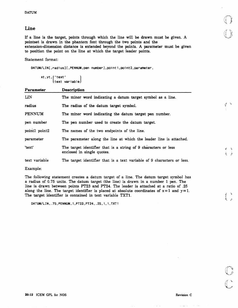
DATUM
Line
If a line is the target, points through which the line will be drawn must be given. A pointset is drawn in the phantom font through the two points and the extension-dimension distance is extended beyond the points. A parameter must be given to position the point on the line at which the target leader points.
Statement format:
DATUM/LIN[,radlus][,PENNUM,pen number],point1,point2,parameter,
xt , yt , (' text' ) text variable
Parameter
LIN
radius
PENNUM
pen number
point! point2
parameter
'text'
text variable
Example:
Description
The minor word indicating a datum target symbol as a line.
The radius of the datum target symbol.
The minor word indicating the datum target pen number.
The pen number used to create the datum target.
The names of the two endpoints of the line.
The parameter along the line at which the leader line is attached.
The target identifier that is a string of 9 characters or less enclosed in single quotes.
The target identifier that is a text variable of 9 characters or less.
The following statement creates a datum target of a line. The datum target symbol has a radius of 0.75 units. The datum target (the line) is drawn in a number 1 pen. The line is drawn between points PT23 and PT24. The leader is attached at a ratio of .25 along the line. The target identifier is placed at absolute coordinates of x= 1 and y= l. The target identifier is contained in text variable TXTl.
DATUM/LIN, .75,PENNUM,1,PT23,PT24, .25,1,1,TXTl
20-12 ICEM GPL for NOS Revision C
.f(.

(
(
(
(
c c
DATUM
Circle
If a circle is the target, the target circle center point must be supplied and the diameter of the target circle must be given. The angle of sectioning and the distance between section lines may be given otherwise the system default values will be used. The diameter value will be written in the upper half of the symbol circle.
Statement format:
DATUM/CIRC[,radius][,PENNUM,pen number],point,d1ameter[,ANGLE,angle]
[,SECDIS,d1stanCe],xt,yt,('text' ) text variable
Parameter
eIRC
radius
PENNUM
pen number
point
diameter
ANGLE
angle
SECDIS
distance
xt,yt
'text'
text variable
Example:
Description
The minor word indicating a datum target symbol as a section lined phantom circle.
The radius of the datum target symbol.
The minor word indicating the datum target pen number.
The pen number used to create the datum target.
The name of a point used at the target circle center.
The diameter of the target circle.
The minor word indicating the angle of the section lines.
The angle of the section lines.
The minor word indicating the distance between section lines.
The distance between section lines in units of measure.
The absolute coordinates of the datum target symbol.
The target identifier that is a string of 9 characters or less enclosed in single quotes.
The target identifier that is a text variable of 9 characters or less.
The following statement creates a datum target of a section lined phantom circle. The datum target symbol has a default radius of 0.5 units. The datum target (the section lined phantom circle) is drawn in a number 4 pen. The target circle center is point PT12. The diameter of the target circle is 1. 5 units. The angle of the section lines is 20 degrees. The distance between the section lines is 0.2 units. The target identifier is placed at absolute coordinates of x = 4 and y = 6. The target identifier is contained in text variable TXT2.
DATUM/CIRC,PENNUM,4,PT12,1.5,ANGLE,20,SECDIS,.2,4,6,TXT2
Revision C ANSI 1982 Dimensioning and Other Statements 20-13

DATUM
Existing Entity
If an existing entity is the target, an entity name and a parameter must be given. The parameter determines the point on the entity at which the leader points. Valid entities are points, lines, arcs, conics, and splines.
Statement format:
DATUM/ENTTY[,radiUS],entity,parameter,xt,yt,('text' ) text variable
Parameter
ENTTY
radius
entity
parameter
xt,yt
'text'
text variable
Example:
Description
The minor word indicating the datum target symbol as an existing entity.
The radius of the datum target symbol.
The name of an existing entity.
The parameter along the entity at which the leader line is attached.
The absolute coordinates of the datum target symbol.
The target identifier that is a string of 9 characters or less enclosed in single quotes.
The target identifier that is a text variable of 9 characters or less.
The following statement creates a datum target of an existing entity. The datum target symbol has a radius of 0.5 units (because the radius is not given, the system default is used). The parameter on the line where the leader line starts is 0.35. The leader line points at the start end of LNl. The target identifier is placed at absolute coordinates of x=5 and y=7. The target identifier is contained in text variable TXT2(1).
DATUM/ENTTY,LN1,.35,5,7,'D'
20-14 ICEM GPL for NOS Revision C
I
i

(
(
(
c c
DOlMEN
DDIMEN The DDIMEN statement creates diameter dimensions. Diameter dimensions are generated so that dimension lines lie along a diameter of the circle. The direction is determined by the direction of a line from the circle center to the origin of the label (TXTJUS modal statement.)
The text of the dimension is positioned by locating the origin (TXT JUS modal statement) with either absolute coordinates or as a delta distance from either another dimensioning entity or a point. If the TXTORG/DELTA modal statement is set, specifying only coordinates will position the origin a delta distance from the center of the circle being dimensioned.
Statement format:
DDIMEN/arC,(ent1ty,xt,yt)[,{'text' )] xt,yt text variable
Parameter
arc
entity,xt,yt
xt,yt
'text'
text variable
Example:
Description
The name of the arc being diametrically dimensioned.
The name of an entity and the xt- and yt-coordinates for the text origin of the text of the dimension.
the xt- and yt-coordinates for the text origin of the text of the dimension.
The text of the dimension. The text must be enclosed in single quotes.
The name of a text variable containing the text.
Program Statement Explanation
DDS=DDIMEN/CR1,6.25,3.5
Revision C
Diametric dimension DDS is created using CRl. The dimension is placed at absolute coordinates x = 6.25 and y=3.5.
ANSI 1982 Dimensioning and Other Statements 20·15

GEOTOL
GEOTOL The GEOTOL statement displays geometric tolerance or composite geometric tolerance symbols and associated text within a feature frame on the drawing.
If the frame is to be connected to an entity with a connecting leader, a datum reference entity must be given. Points, lines, arcs, conics, splines, and dimensions are allowable entities. The connection to the entity will be at a given parameter on the entity.
The connection line will join the feature frame at the midpoint of the left edge of the frame, the midpoint of the right edge of the frame, the lower left corner of the frame, the lower right corner of the frame, the upper left corner of the frame, or the upper right corner of the frame. An arrowhead may be drawn at the end of the connecting leader if desired.
The lower left corner of the feature frame symbol can be positioned by locating the origin with absolute coordinates, with an existing point, or above or below existing text of a note, label, dimension, or feature frame.
A geometric characteristic and symbol may be selected which will be drawn in the leftmost section of the frame.
If Profile of a Surface is chosen for the geometric characteristic and a leader line is desired, a symbol may be attached to the leader line signifying that the profile applies to surfaces all around the part. Using the minor word, AROUND, accomplishes this.
Tolerance and datum references can be entered. A total of five references may be entered with not more than one tolerance reference and not more than five datum references.
The modifiers are as follows:
• MMC - Maximum material condition.
• LMC - Least material condition.
• RFS - Regardless of feature size.
• PTZ - Projected tolerance zone.
If the minor word, COMPOS, is specified, the first datum references and tolerances will be entered in the top frame, and the datum references and tolerances following COMPOS will be entered in the bottom frame. Again, a total of five references may be entered in the bottom frame with not more than one tolerance reference and not more than five datum references. The modifiers are the same as above.
20·16 ICEM GPL for NOS Revision C
I
i
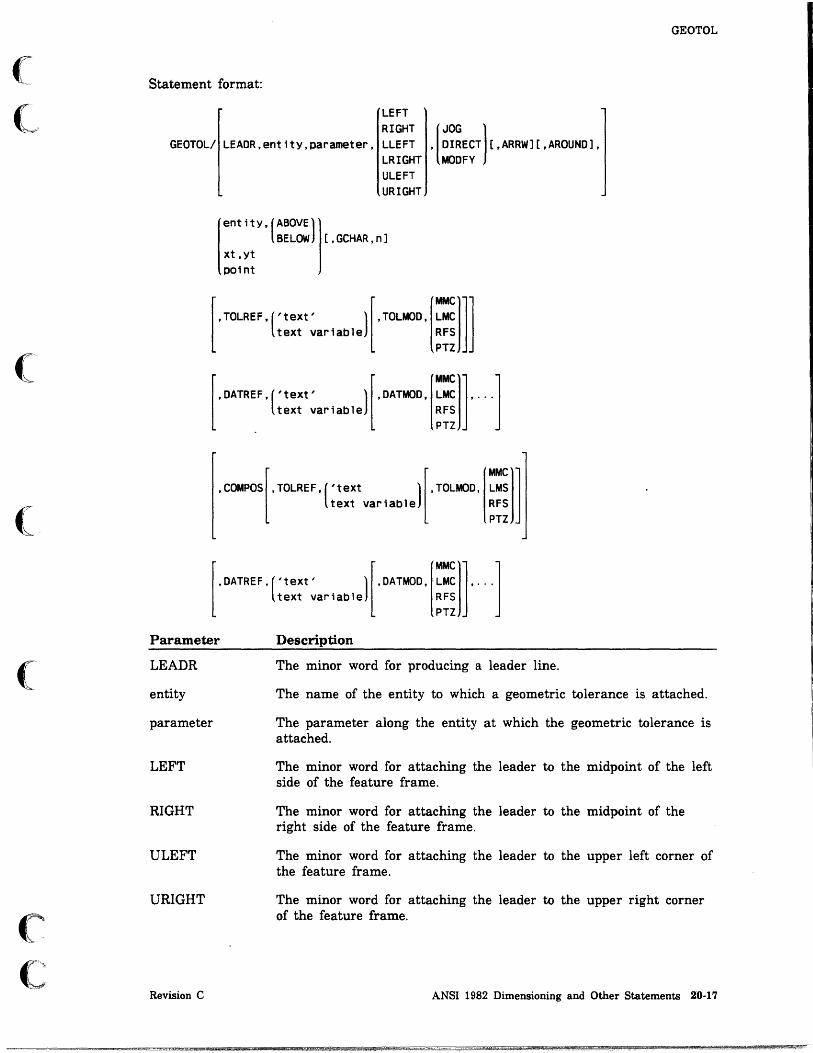
(
(
(
C C -"
Statement format:
LEFT RIGHT
GEOTOL
GEOTOL/ LEADR,entitY,parameter, LLEFT LRIGHT ULEFT URIGHT
[JOG 1 ' DIRECT [,ARRW][,AROUND], MODFY
ent ity, (ABOVE 1 BELOW [,GCHAR,n]
xt ,yt point
[
,TOLREF,('text' 1 [,TOLMOD, ::~ ]J text variable RFS
PTZ
[
,DATREF,('text' 1 [,DATMOD, ~:~ ], ... J text variable RFS
PTZ
,COMPOS[,TOLREF,('text 1 [,TOLMOD, ~:~ J text variable RFS
PTZ
[,DATREF,('text' l[,DATMOD, ~:~ J, ... J
text variable RFS PTZ
Parameter Description
LEADR
entity
parameter
LEFT
RIGHT
ULEFT
URIGHT
Revision C
The minor word for producing a leader line.
The name of the entity to which a geometric tolerance is attached.
The parameter along the entity at which the geometric tolerance is attached.
The minor word for attaching the leader to the midpoint of the left side of the feature frame.
The minor word for attaching the leader to the midpoint of the right side of the feature frame.
The minor word for attaching the leader to the upper left corner of the feature frame.
The minor word for attaching the leader to the upper right corner of the feature frame.
ANSI 1982 Dimensioning and Other Statements 20-17

GEOTOL
Parameter
LLEFT
LRIGHT
JOG
DIRECT
MODFY
ARRW
AROUND
entity
ABOVE
BELOW
xt,yt
point
GCHAR
Description
The minor word for attaching the leader to the lower left corner of the feature frame.
The minor word for attaching the leader to the lower right corner of the feature frame.
The minor word indicating a horizontal line that is two times the text dimension distance followed by a line directly connected to the datum.
The minor word indicating a straight line from the datum to the feature frame.
The minor word indicating that the position of the frame may be modified so that a horizontal or vertical line can be drawn.
The minor word to produce an arrowhead at the end of the leader.
The minor word indicating that the geometric characteristic is PROFILE and that the symbol indicating this is attached to the leader line.
The name of the entity to which the geometric tolerance is attached.
The minor word indicating that the feature control frame is placed above an existing note, label, dimension or feature control frame.
The minor word indicating that the feature control frame is placed below an existing note, label, dimension or feature control frame.
The absolute coordinates of the location of the lower left corner of the feature frame.
The name of a point used as the location of the lower left corner of the feature frame.
The minor word indicating the geometric characteristic.
20-18 ICEM GPL for NOS Revision C

(
(
(
(~
C
Parameter
n
Revision C
GEOTOL
Description
The number of geometric characteristic. It is one of the following numbers.
Number Characteristic·
1 Straightness
2 Flatness
3 Circularity
4 Cylindricity
5 Profile of a line
6 Profile of a surface
7 Angularity
8 Perpendicularity
9 Parallelism
10 Position
11 Concentricity
12 Circular Runout
13 Total Runout
ANSI 1982 Dimensioning and Other Statements 20-19

I
GEOTOL
Parameter
TOLREF
'text'
text variable
TOLMOD
MMC
LMC
RFS
PTZ
DATREF
DATMOD
COMPOS
Description
The minor word indicating the' tolerance reference.
The text of. the tolerance or datum reference enclosed in single quotes. The text can be a maximum of 20 characters.
The name of a variable that contains the text of the tolerance or datum reference. The text can be a maximum of 20 characters.
The minor word indicating the tolerance modifier.
The minor word indicating maximum material condition (MMC) for a tolerance or datum reference.
The minor word indicating least material condition (LMC) for a tolerance or datum reference.
The minor word indicating regardless of feature size (RFS) for a tolerance or datum reference.
The minor word indicating projected tolerance zone (PTZ) for a tolerance or datum reference.
The minor word indicating a datum reference.
The minor word indicating a datum modifier.
The minor word indicating that all references and modifiers before this word are entered in the top frame, and all references and modifiers after this word are entered in the bottom frame.
20·20 ICEM GPL for NOS Revision C

(
(
(
(
(
c c
GEOTOL
Examples:
The following statement creates a geometric tolerance symbol for entity NTl.
GEOTOL/NT1,BELOW,GCHAR,2,DATREF,'ABC',DATMOD,MMC
The feature control frame is placed below the existing entity. The geometric characteristic is 2, indicating flatness. The datum reference is ABC and the datum modifier is MMC.
The following statement creates a geometric tolerance symbol with a leader line for entity LNl.
GEOTOL/LEADR,LN1, .5,LEFT,MODFY,ARRW,AROUND,$ PT1,GCHAR,6,TOLREF,TXT1,TOLMOD,MMC,$ DATREF,TXT2,DATMOD,MMC,COMPOS,DATREF,$ TXT3,DATMOD,LMC,DATREF,TXT4
The leader is attached to the entity at a ratio of 0.5 along the entity and attached to the left side of the feature frame. The position of the feature frame can be modified so that either a horizontal or vertical line can be drawn. The leader has an arrowhead. The geometric characteristic is PROFILE and that symbol is used.
The geometric characteristic is 6 indicating the profile of a surface. The text for the tolerance reference is contained in text variable TXTl, and the tolerance modifier is MMC. The datum reference is contained in text variable TXT2, and the datum modifier is MMC. All this information is placed in the top frame. The following information is placed in the bottom frame: a datum reference that is contained in text variable TXT3, a datum modifier LMC, and a datum reference that is contained in text variable TXT4.
The geometric characteristic is in both the top and bottom frames.
For example:
lUi A I B®I c
A® I B@
t GEOMETRIC CHARACTERISTICS
NOTE
At least one characteristic or reference is required for geometric tolerances. For composite geometric tolerances, one characteristic and at least one reference on the top and one reference on the bottom are· required.
Revision C ANSI 1982 Dimensioning and Other Statements 20-21

LABEL
LABEL The LABEL statement constructs labels. A general label consists of a string of characters with an associated leader line generated from the label to an entity on the drawing. The leader includes a tail, which is a short horizontal bar extending from the beginning or end of the text. If the minor word START is specified, the tail is placed to the left of the text. If the minor word END is specified, the tail is placed to the right of the text. If modal statement ATAIL has been set to ON, the tail is placed automatically.
The vertical position of the leader line tail is determined by the modal statement LEADER. The leader touches the first text line by default. The leader line automatically terminates at the entity through one of the following options:
• Coordinate method - Coordinates at or near the desired leader line termination point may be entered. These coordinates need not be directly on the entity, as the leader line will automatically intersect itself precisely with the entity. If the entity is a point, the leader will terminate at the point.
• Slope method - The angle of the leader line is entered. The leader line will be generated to the entity indicated at the angle specified. The leader line automatically terminates at the intersection point on the entity.
• Parameter method - A parameter is entered. The leader line automatically terminates at the parameter entered for the entity.
• Midpoint method - If no leader line termination control is used, the leader line will automatically end at the midpoint of the entity.
The text of the label is positioned by locating the origin (TXTJUS modal statement) with either the absolute coordinates, or a delta distance from either another dimensioning entity or a point. The text angle of the label may be varied by entering ANGLE and the text angle in degrees. The string of characters which form the text of the label may be replaced by a text variable.
Statement format:
LABEL/(START),(entity,xt,yt),ent1ty END xt1,yt1
[
,[SLOPE,SlOpe]][,ANGLE,an9lel,('text' ) xt,yt text variable
parameter
Parameter
START
END
entity,xt,yt
xtl,ytl
SLOPE
Description
The minor word indicating the leader origin at the start of text.
The minor word indicating the leader origin at the end of text.
The name of an entity and the xt- and yt-coordinates for the text origin of the text of the dimension.
The xt- and yt-coordinates for the text origin of the text of the dimension.
The minor word indicating the angle of the leader from the positive x-axis.
20·22 ICEM GPL for NOS Revision C

(
(
(
c c
Parameter
slope
xt,yt
parameter
ANGLE
angle
'text'
text variable
Example:
LABEL
Description
The angle of the slope of the leader.
The absolute coordinates of the point at or near the point on the entity to which the leader is attached.
A parameter expressed as a ratio at which the leader is attached.
The minor word indicating the angle of the dimension text.
The angle of the dimension text.
The text of the dimension. The text must be enclosed in single quotes.
The name of a text variable containing the text.
The following statement creates a label LAB 1. The leader line starts at the beginning of text. The text origin is at absolute coordinates (2,4). The entity that is labeled is line LN2.
LAB1=LABEL/START,2,4,LN2,'CHAMFER .625 X 45 DEGREES'
Revision C ANSI 1982 Dimensioning and Other Statements 20·23

---------~~-,-,- -------=~
LDIMEN
LDIMEN The LDIMEN statement creates linear dimensions. Linear dimensions are horizontal, vertical, or parallel. Horizontal dimensions measure the horizontal distance between the ends of two entities. Vertical dimensions measure the vertical distance between the ends of two entities.
There are two types of parallel dimensions.
The regular kind, designated PARLEL, measures the two-dimensional distance between the ends of two entities. This type of parallel dimension is generated relative to a given line or the apparent line that would exist between these two entity endpoints.
The second type of parallel dimension measures the normal distance between two parallel lines. This type of parallel dimension is designated PARNOR. When selecting the entities to dimension, a position indicator must follow the entity. The two exceptions to this rule are first, if the entity is a point, no position indicator is needed and second, if only one entity is being dimensioned, then just the entity need be used, as the entity's endpoints are used for the dimension.
If it is desirable to align the arrowheads of this dimension with those of a previously defined dimension, a YES followed by the drafting entity that the new dimension is to be aligned with must be entered.
The text of the dimension is positioned by locating the origin (TXTJUS modal statement) with either absolute coordinates or as a delta distance from either another dimensioning entity or a point. If the TXTORG/DELTA modal statement is set, the coordinates used are not relative to the origin 0,0. Rather, they are relative to one of the two entity endpoints which form the dimension.
Consider a counterclockwise arc drawn through three points, the entity endpoints and the text origin point, such that the text origin point is the second or middle point. The first point of this arc is the one from which a delta xt value and delta yt value (the input coordinates) are used to find the dimension origin.
The text of the dimension may be either a string of characters or -a text variable if it is being entered manually,
Definition form:
Dimension tYoe,entity selection[,arrowhead alignment], dimension orig1n[,dimension text]
20·24 ICEM GPL for NOS Revision C

(
(
('
(
(
c c
Statement format:
HORIZ VERTCL
LDIMEN/ PARLEL , PARNOR
point,point entitY,position ind,entity,position ind
entitY,position indicator,pOint point,entity,position indicator
entity
LDIMEN
[,YES,ref entity],(entity,xt,yt)[,('text )] xt,yt text variable
Parameter
HORIZ
VERTCL
PARLEL
PARNOR
point,point
entity
pos ind
YES
ref entity
entity,xt,yt
xt,yt
'text'
text variable
Revision C
Description
The minor word for a horizontal dimension.
The minor word for a vertical dimension.
The minor word for a parallel dimension relative to a given line.
The minor I word for a parallel dimension normal to two given parallel lines.
The names of the points that are dimensioned.
The name of the entity that is dimensioned.
The position indicator showing at which end of an entity the dimension is taken. It can be any of the following minor words.
Word
XSMALL
XLARGE
YSMALL
YLARGE
Description
Indicates the x negative end.
Indicates the x positive end.
Indicates the y negative end.
Indicates the y positive end.
The minor word for aligning the arrowheads.
The name of an entity used to align the arrow heads.
The name of an entity and the xt- and yt-coordinates for the text origin of the text of the dimension.
the xt- and yt-coordinates for the text origin of the text of the dimension.
The text of the dimension. The text must be enclosed in single quotes.
The name of a text variable containing the text.
ANSI 1982 Dimensioning and Other Statements 20-25

LDIMEN
Examples:
The following statement creates a horizontal linear dimension for LNI. The text origin is at absolute coordinates (-1.5,1.75).
LD1=LDIMEN/HORIZ,LN1,-1.5,1.75
The following statement creates a horizontal linear dimension between the XLARGE end of LNI to PT7. The arrowheads are aligned to the reference entity (YES). The text origin is at absolute coordinates (-2,2). The reference entity is ENT3.
LD2=LDIMEN/HORIZ,LN1,XLARGE,PT7,YES,ENT3,-2,2
The following statement creates a vertical linear dimension between PT7 and the YSMALL end of SPL3. The text origin is at a delta distance (5,-3) from LD2.
LD3=LDIMEN/VERTCL,PT7,SPL3,YSMALL,LD2,5,-3
20-26 ICEM GPL for NOS Revision C

(
(
(
(
c c
MAGNFY
MAGNFY
The MAGNFY statement produces a magnified drawing of a circular area. The entities that can be magnified are points, lines, arcs, conics, splines, pointsets, center lines , and section lining. Automatic dimensioning performed on magnified entities· reflects the size of the original, unmagnified entities.
The area to be· magnified may be within an existing circle or within an area defined by a center and a radius. In the latter case, a circle is created around the area to be magnified.
The magnified reproduction may be drawn within an existing circle, within an area defmed by a center and a radius, or within an area defined by a center and a magnification size.
For the last two options, a border is drawn around the magnified drawing if the minor word BORDER is specified.
Statement format:
[
CIRC,CirCle2 1 MAGNFY/(CIRC,C1rC~e1)' xt,yt,(RADIUS,radiU5)[,BORDERl
xt,yt,radlU5 ratio
Parameter Description
CIRC The minor word indicating a circle parameter.
circlel The name of a circle defining the area to magnify.
xt,yt The absolute coordinates of a circle center.
RADIUS The minor word indicating a radius parameter.
radius The radius in units of measure.
circle2 The name of a circle defining the magnified reproduction.
BORDER The minor word for drawing a border around the reproduction.
ratio The magnification size of the the reproduction.
Example:
The following statement reproduces and magnifies the area defined in ARCl and places the center of the magnified reproduction at absolute coordinates x = 2.5 and y = 3. The magnification ratio is 2. A border is drawn around the magnified drawing.
MAGNFY/CIRC,ARC1,2.5,3,2,BORDER
Revision C ANSI 1982 Dimensioning and Other Statements 20-27

MODDFT
MODDFT The MODDFT statement modifies certain drafting entities without havmg to redefine those entities.
BASIC
Using the minor word BASIC, a rectangle can be added or deleted around the text in a dimension.
Statement format:
MODDFT/BASIC,(ADD),d1menS10n entity DEL
Parameter Description
BASIC The minor word for adding or deleting a rectangle around text in a dimension.
ADD The minor word to add a rectangle around the dimension text.
DEL The minor word to delete a rectangle from around the dimension text.
dimension entity The name of the dimensioning entity at which the text is altered.
Example:
The following statement creates a linear dimension LDl.
LD1=LDIMEN/VERTCL,LN1,PT1,3,1
The next statement modifies LDI by adding a rectangle around the dimension text.
MODDFT/BASIC,ADD,LDl
20-28 ICEM GPL for NOS Revision C

(
(
(
(~
C
MODDFT
REF
U sing the minor word REF, you can add or delete parentheses to or from the text in a dimension.
Statement format:
MODDFT/REF,(ADD),dlmenSl0n entity DEL
Parameter
REF
ADD
DEL
Description
The minor word for adding or deleting parentheses from the dimension text.
The minor word to add parentheses around the dimension text.
The minor word to delete parentheses from around the dimension text.
dimension entity The name of the dimensioning entity at which the text is altered.
Example:
The following statement creates a linear dimension LD2.
LD2=LDIMEN/HORIZ,PT1,PT2,3,5
The next statement adds parentheses around the dimension text of LD2.
MODDFT/REF,ADD,LD2
Revision C ANSI 1982 Dimensioning and Other Statements 20-29

MODDFT
TOLER
Using the minor word TOLER, you can add a tolerance to the text in a dimension. The tolerance can be entered in any of the following formats:
+ tolerance 1 A positive value is entered as the top part of the tolerance.
-tolerance 1 A negative value is entered as the top part of the tolerance.
+ tolerance 1, -tolerance 2
The tolerances are written one above the other immediately following the text in the dimension.
± tolerance 1 A positive/negative value is entered as the bottom part of the tolerance.
The tolerances are entered as characters but stored as real numbers in the database. If any characters following the plus or minus sign are not numerals, the following error message will be displayed:
CONVERSION ERROR OCCURRED
Tolerance characters are displayed with the height determined by the tolerance ratio (CDISPLlTOLER,n).
If limits are chosen instead of a tolerance, the upper limit is the dimension and the positive value, and the lower limit is the remainder after subtracting the negative val ue from the dimension.
NOTE
CDISPL/TOLER, n (tolerance ratio) does not affect the ± tolerance.
Statement format:
MODDFT/TOLER,d1mension ent1tY,'tolerance l' ,[,'tolerance 2'][,LIMIT]
Parameter Description
TOLER The minor word for adding a tolerance value to a dimension text.
dimension entity The name of the dimensioning entity at which the text is altered.
'tolerance l' The first tolerance value enclosed in quotes. It is entered as the top part of the tolerance.
'tolerance 2' The second tolerance value enclosed in quotes. It is entered as the bottom part of the tolerance.
LIMIT The minor word for adding limits to the dimension text.
Example:
Program Statement
MODDFT/TOLER,LD3,' .05',' .05'
20-30 ICEM GPL for NOS
Explanation
A tolerance of ±O.05 (character strings) is added after dimension LD3.
Revision C

(
(
(
(
c c
NOTE
NOTE The NOTE statement creates general notes. General notes consist of continuous strings of characters. The note is entered as a string of characters and may contain up to 200 characters. The character string may be replaced by a text variable or a real variable.
A general note is positioned by locating the origin (TXTJUS modal statement) with either the absolute coordinates or as a delta distance from either another dimensioning entity or a point.
The text of the note may be varied by entering ANGLE and the text angle in degrees. If a real variable is given instead of a text variable, the real number is truncated and converted into a text string.
The note may be parallel to a line by entering the line and the direction with respect to the Xt-axis. POSITV is for the positive Xt direction and NEGATV is for the negative Xt direction. For a vertical line, POSITV will cause the text to be drawn upwards. .
The note may be parallel to an arc by entering the arc and the direction of rotation of the text. CW is for clockwise and CCW is for counterclockwise.
Statement format:
POSITV ,1 i ne NEGATV
NOTE/(entity,xt,yt), xt,yt
CW ,arc CCW
[
, text' 1 ' text variable
real variable
Parameter
entity,xt,yt
xt,yt
POSITV
line
NEGATV
CW
arc
CCW
Revision C
ANGLE,angle
Description
The name of an entity and the xt- and yt-coordinates for the text origin of the text of the note.
The xt- and yt-coordinates for the text origin of the text of the note.
The minor word for positioning the note parallel to a reference line in the positive direction from the x-axis.
The name of the reference line.
The minor word for positioning the note parallel to a reference line in the negative direction from the x-axis.
The minor word for positioning the text parallel to a given arc in the clockwise direction.
The name of the reference arc.
The minor word for positioning the text parallel to a given arc in the counterclockwise direction.
ANSI 1982 Dimensioning and Other Statements 20-31

NOTE
Parameter
ANGLE
angle
Description
The minor word for the angle of the dimension text.
The angle of the dimension text.
'text' The text of the note. The text must be enclosed in single quotes.
text variable The name of a text variable containing the text.
real variable The name of a real variable that is converted to text.
Examples:
The following statement creates a note at absolute coordinates (5,5) parallel to line LNOI with the text GENERAL NOTE.
NT1=NOTE/S,S,POSITV,LN01,'GENERAL NOTE'
The following statements prompt for text that is entered in text variable TXT, and if a ] is entered, note NT2 is placed at a delta distance (0,-2.5) from note NTl. The text angle is 10 degrees and the text is retrieved from text variable TXT. If something other than a ] is entered, the program goes to statement label 50.
TEXT/'ENTER STRING',TXT,STAT IF(STAT.EQ.O)GOTO 50 NT2=NOTE/NT1,O, 2.5,ANGLE,10,TXT
20-32 ICEM GPL for NOS Revision C
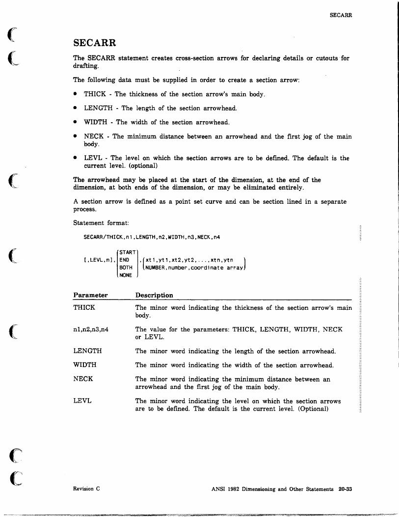
(
(~
(
(
(
c~
c
SECARR
SECARR The SECARR statement creates cross-section arrows for declaring details or cutouts' for drafting.
The following data must be supplied in order to create a section arrow:
• THICK - The thickness of the section arrow's main body.
• LENGTH - The length of the section arrowhead.
• WIDTH - The width of the section arrowhead.
• NECK - The minimum distance between an arrowhead and the first jog of the main body.
• LEVL - The level on which the section arrows are to be defmed. The default is the current level. (optional)
The arrowhead may be placed at the start of the dimension, at the end of the dimension, at both ends of the dimension, or may he eliminated entirely.
A section arrow is defined as a point set curve and can be section lined in a separate process.
Statement format:
SECARR/THICK,n1,LENGTH,n2,WIOTH,n3,NECK,n4
START [ , LEVL , n ], E NO
BOTH NONE
, ( xt 1 , yt 1 , xt 2 , yt 2, ... , xt n , yt n ) NUMBER,number,coordinate array
Parameter
THICK
nl,n2,n3,n4
LENGTH
WIDTH
NECK
LEVL
Revision C
Description
The minor word indicating the thickness of the section arrow's main body.
The value for the parameters: THICK, LENGTH, WIDTH, NECK or LEVL.
The minor word indicating the length of the section arrowhead.
The minor word indicating the width of the section arrowhead.
The minor word indicating the minimum distance between an arrowhead and the first jog of the main body.
The minor word indicating the level on which the section arrows are to be defined. The default is the current level. (Optional)
ANSI 1982 Dimensioning and Other Statements 20-33
SECARR
I :::ew END
Description
The minor word for placing an arrowhead at the start of the dimension.
The minor word for placing an arrowhead at the end of the dimension.
I
BOTH
NONE
xt,yt
NUMBER
number
coordinate array
Example:
The minor word for placing an arrowhead at both the start and the end of the dimension.
The minor word indicating no section arrowheads.
The absolute coordinates of a series of points. There must be between 4 and 50 absolute coordinates.
The minor word indicating the number of entities in an array.
The number of elements in the array. It is a value of at least 4 and not more than 50.
The name of a real coordinate array.
The following statement creates a section arrow with a thickness of 0.7 units of measure, a length of 2 units, a width of 3 units, and a neck of 2 units. The section arrow is assigned to level 1. Arrows are placed at both ends of the entity. The jog positions are at absolute coordinates (3,3) and (4,7).
SECARR/THICK,.7,LENGTH,2,WIDTH,3,NECK,2,LEVL,1,BOTH,3,3,4,7
20-34 ICEM GPL for NOS Revision C
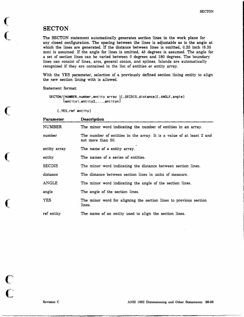
(
(
(
(
(
SECTON
SECTON The SECTON statement automatically generates section lines in the work plane for any closed configuration. The spacing between the lines is adjustable as is the angle at which the lines are generated. If the distance between lines is omitted, 0.25 inch (6.35 mm) is assumed. If the angle for lines is omitted, 45 degrees is assumed. The angle for a set of section lines can be varied between 0 degrees and 180 degrees. The boundary lines can consist of lines, arcs, general conics, and splines. Islands are automatically recognized if they are contained in the list of entities or entity array.
With the YES parameter, selection of a previously defined section lining entity to align the new section lining with is allowed.
Statement format:
SECTON/(NUMBER,number,entitY array )[,SECDIS,distanCe][,ANGLE,anQlel entity1,entity2, ... ,entityn
[,YES,ref entity]
Parameter
NUMBER
number
entity array
entity
SECDrs
distance
ANGLE
angle
YES
ref entity
Revision C
Description
The minor word indicating the number of entities in an array.
The number of entities in the array. It is a value of at least 2 and not more than 50.
The name of a entity array.
The names of a series of entities.
The minor word indicating the distance between section lines.
The distance between section lines in units of measure.
The minor word indicating the angle of the section lines.
The angle of the section lines.
The minor word for aligning the section lines to previous section lines.
The name of an entity used to align the section lines.
ANSI 1982 Dimensioning and Other Statements 20-35

SRFTEX
Examples:
The following statements create section lines.
First, the material is set to brass.
MATERL/BRASS
Then, the section areas are defined.
The first section area is defined by LN3, CIR3, LIN4, LIN5, LIN7, and LIN8. The section lines are drawn at an angle of 135 degrees.
SEC1=SECTON/LIN3,CIR3,LIN4,LINS,LIN7,LINB,ANGLE,135
The second section area is defined by LIN7, LIN6, LIN2, and LINI3. The distance between section lines is 0.18 units of measure, and the lines are drawn at an angle of 30 degrees.
SEC2=SECTON/LIN7,LIN6,LIN2,LIN13,SECDIS,.1B,ANGLE,30
SRFTEX The SRFTEX statement displays the standard basic symbol for surface texture either displaced from an entity or entities and joined to the entities by arrows, or attached directly to the entity.
The value of Ra (roughness) can be in micrometers for SI units or microinches for U.S. customary units. When using SI units, the system displays the number of decimal places specified by DEC MALIn. When using U.S. customary units, Ra is displayed as a whole number. Entering 0 produces a symbol with no text.
The position where the arrow or arrows attach to the symbol base can be determined with absolute coordinates.
Basic Symbol Attached to Arrow
Using the minor words BASIC and ARRW, a surface texture symbol and its base can be displayed, displaced from an entity or entities or joined to entities with one or more arrows.
A parameter must be given with each two-dimensional curve to indicate the approximate position of the end point of the arrow on the curve. Up to ten entities and parameters can be specified.
The surface texture symbol can be displayed above a horizontal base or to the left of a vertical base. If the minor word LEFT is specified, the starting point of the arrow will be to the left of the symbol base if it is horizontal, or at the bottom of the symbol base if it is vertical. If the minor word RIGHT is specified, the starting point of the arrow will be to the right of the symbol base if it is horizontal, or at the top of the symbol base if it is vertical.
20·36 ICEM GPL for NOS Revision C

(
(-
(
(
(
c c
SRFTEX
Statement format:
SRFTEX/BASIC.ARRW.roughness.entity1.parameter1.ent1ty2.parameter2 •...•
entityn.parametern.(HORIZ ).(LEFT ).xt.yt VERTCL RIGHT
Parameter
BASIC
ARRW
roughness
entity
parameter
HORIZ
VERTCL
LEFT
RIGHT
xt,yt
Example:
Description
The minor word for adding a surface texture symbol.
The minor word for adding arrows to the surface texture symbol.
The value of roughness (Ra).
The names of a series of entities to which the surface texture symbol is attached. The number of entities can be less than or equal to 10.
A parameter expressed as a ratio at which the surface texture symbol is attached. The number of parameters must equal the number of entities given.
The minor word indicating a horizontal base.
The minor word indicating a vertical base.
The minor word for placing the starting point of the arrow to the left of the entity for a horizontal base and below the entity for a vertical base.
The minor word for placing the starting point of the arrow to the right of the entity for a horizontal base and above the entity for a vertical base.
The absolute coordinates of the starting point of the arrow.
The following statement creates a surface texture symbol with arrows for CIR1, CIR2, and LNI ending at the parameters given after each entity. The roughness factor (Ra) is 63. The symbol has a horizontal base and the starting point of the arrow is placed to the left of the entity at absolute coordinates (8,10).
SRFTEX/BASIC.ARRW.63,CIR1,3.14.CIR2,1.57,LN1 •. 5,HORIZ,LEFT,8,10
Revision C ANSI 1982 Dimensioning and Other Statements 20·37

SRFTEX
Basic Symbol Attached to Entity
U sing the minor words BASIC and ENT, a symbol can be displayed direetly attached to an entity. The symbol can be displayed horizontally above the entity, vertically to the left of the entity, or vertically to the right of the entity. A parameter must be given with the entity to determine the position of the symbol on the entity.
Statement format:
[ABOVE]
SRFTEX/BASIC,ENTTY,roughness. RIGHT ,entitY,parameter
Parameter
BASIC
ENTTY
roughness
ABOVE
RIGHT
LEFT
entity
parameter
Example:
LEFT
Description
The minor word for adding a surface texture symbol.
The minor word for attaching a surface texture symbol to an ent~ty.
The value of roughness (Ra).
The minor word for placing the symbol horizontally above the entity.
The minor word for placing the symbol vertically to the right of the entity.
The minor word for placing the symbol vertically to the left of the entity.
The name of an entity to which the surface texture symbol is attached.
A parameter expressed as a ratio at which the surface texture symbol is attached. The number of parameters can be less than or equal to zero.
The following creates a surface texture symbol attached to LNl. The roughness factor (Ra) is 63. The symbol is placed horizontally above the entity. The symbol is attached on the entity at a point that is a ratio of 0.5 along the entity.
SRFTEX/BASIC,ENTTY.63,ABOVE.LN1, .5
20-38 ICEM GPL for NOS Revision C
Jl

(
c
(
c· C'
~.- ... -
TAPER
TAPER
The TAPER statement creates a slope or taper dimension drawn to two lines. Either a flat or conical taper dimension can be specified. The first line specified is opposite the side where the taper dimension will be placed. The second line specifies the line to which the dimension arrow points. To draw an arrow that points to the second line, give a parameter to position the arrow. The slope of the leader can be entered instead of a parameter. The leader angle is measured in a counterclockwise direction.
The text of the dimension is positioned by locating the origin (TXTJUS modal statement) with either absolute coordinates or as a delta distance from either another dimensioning entity or a point.
Statement format:
TAPER/(CONIC), line1, l1ne2,{parameter ),(ent1ty,xt,yt)[,('text' )] FLAT SLOPE,angle xt,yt text variable
Parameter
CONIC
FLAT
linel
line2
parameter
SLOPE
angle
entity,xt,yt
xt,yt
'text'
text variable
Example:
Description
The minor word indicating a conical taper dimension.
The minor word indicating a flat taper dimension.
The first line being dimensioned.
The second line being dimensioned.
The parameter along the second line at which the arrow is drawn from the first line to the second line.
The minor word for specifying the slope method of drawing an arrow from the first line to the second line.
The angle of the slope of the arrow.
The name of an entity and the xt- and yt-coordinates for the text origin of the text of the dimension.
the xt- and yt-coordinates for the text origin of the text of the dimension.
The text of the dimension. The text must be enclosed in single quotes.
The name of a text variable containing the text.
The following statement creats a conical taper dimension between LN1 and LN2. The arrow is placed using slope method and an angle of 45 degrees. The text origin is set using PTl and delta coordinates (0,1).
TAPER/CONIC,LN1,LN2,SLOPE,45,PT1,Q,1
Revision C ANSI 1982 Dimensioning and Other Statements 20·39

THIKNS
THIKNS The THIKNS statement produces a thickness dimension between two curves. The dimension is taken from a point on the IIrst curve to an imaginary point on the second curve. The point on the second curve is located by dropping an imaginary line from the point on the first curve normal to the second curve. The point at which the imaginary line intersects the second curve is the second point of the dimension. When selecting entities to be dimensioned, coordinates must be entered as close as possible to the point on the first curve where the measurement is to be made. A parameter on this curve may be entered instead of coordinates.
The text of the dimension is positioned by locating the origin (TXTJUS modal statement) with either absolute coordinates or as a delta distance from either another dimensioning entity or a point. If the TXTORG/DELTA modal statement is set, specifying only coordinates will position the origin a delta distance from the point on the first curve where the measurement was made.
Statement format:
THIKNS/entitYl,(parameter),entltY2,(entlty,xt,yt)[,('text' )] xtl,ytl xt,yt text variable
Parameter
entity1
parameter
xt1,yt1
entity2
entity,xt,yt
xt,yt
'text'
text variable
Example:
Description
The name of the first entity being dimensioned.
The parameter expressed as a ratio along the first entity at which the dimension is taken.
The absolute coordinates at which the dimensioned is taken.
The name of the second entity being dimensioned.
The name of an entity and the xt- and yt-coordinates for the text origin of the text of the dimension.
The xt- and yt-coordinates for the text origin of the text of the dimension.
The text of the dimension. The text must be enclosed in single quotes.
The name of a text variable containing the text.
The following statement creates a thickness dimension between SPL1 and CIR1. The dimension is taken at or near the absolute coordinates of x = 5 and y = 3 for SPL1 and the normal from this point to CIR!. The origin of the text is at coordinates (1,2). The dimension text is DISTANCE FROM SPLINE TO ARC.
THIKNS/SPL1,5,3,CIR1,l,2,'DISTANCE FROM SPLINE TO ARC'
20-40 ICEM GPL for NOS Revision C

o o
o
o
o
o o
Numerical Control Statements 21
SETGPG . . . . . . . . . . . . . . . . . . . . . . . . . . . . . . . . . . . . . . . .... 21-1 Using a Local Text File GPG .............................. 21-1 Using an Existing Toolpath GPG ............................ 21-2
TLPATH .... . . . . . . . . . . . . . . . . . . . . . . . . . . . . . . . . . . . . . . . 21-3 CONTUR . . . . . . . . . . . . . . . . . . . . . . . . . . . . . . . . . . . . . .... 21-4 ROUGH .......................................... 21-5 DRILL ........................................... 21-5 THREAD ......................................... 21-6
no 411 .. i:aa ":,,,mM up. as! g;U!_i li!5Se.:!5! ! ! '4$5* Q$, :_ _ z;:

•• * ,W *" 'M.U,niM
o o
o
o
o
o o

(
Numerical Control Statements 21
This chapter describes statements that control numerical control functions. These statements are similar in operation to some functions found in menu 17 NUMERICAL CONTROL.
SETGPG
The SETGPG statement modifies the N/C parameters in the Generation Parameter Group (GPG) used during tool path generation. The GPG parameters being changed:
• Must have been previously created, and
• Must be either in a local text file or attached to an existing toolpath.
All GPG parameters can be defmed with this statement. Refer to the ICEM Numerical Control manual for more information.
Using a Local Text File GPG
Statement format:
CONTUR ROUGH
SETGPG/LATHE, DRILL ,('gpg name')[,('lOCal file')] THREAD gpgvar lfnvar
Parameter
LATHE
CONTUR
ROUGH
DRILL
THREAD
'gpg name'
gpgvar
'local file'
lfnvar
Revision C
Description
The minor word indicating lathe toolpath parameters.
The minor word indicating a lathe contouring GPG.
The minor word indicating a lathe roughing GPG.
The minor word indicating a lathe drilling PGP.
The minor word indicating a lathe threading GPG.
The name of the GPG to retrieve from the local text file.
A text variable that contains the name of the GPG to retrieve from the local text file.
The name of an external local text file. The name must be enclosed in quotes.
A text variable containing the name of an external local text file.
Numerical Control Statements 21-1

SETGPG
The following self-explanatory error messages can occur from improper use of the SETGPO statement and an external local file.
GPG FILE READ ERROR
GPG NOT COMPATIBLE WITH ENTITY TYPE
GENERATION PARAMETER GROUP NOT FOUND
GPG STATEMENT ERRORS, SEE FILE - GPGERR
Example:
Program Statement Explanation
SETGPG/LATHE,THREAD,'GPG2' ,'THO' The thread generation parameter group is named GPG2 and is located in local file THD.
Using an Existing Toolpath GPG
Statement format:
CONTUR SETGPG/LATHE, ROUGH ,toolpath
DRILL
Parameter
LATHE
CONTUR
ROUGH
DRILL
THREAD
toolpath
THREAD
Description
The minor word indicating lathe toolpath parameters.
The minor word indicating a lathe contouring GPO.
The minor word indicating a lathe roughing GPG.
The minor word indicating a lathe drilling GPO.
The minor word indicating a lathe threading GPG.
The local GPL name of an existing toolpath entity.
The following self-explanatory error messages can occur from improper use of the SETGPG statement using an existing toolpath.
ENTITY NOT FOUND
INCOMPATIBLE ENTITY USED IN DEFINITION
21·2 ICEM GPL for NOS Revision C

(
(
(
(
Co
C
Example:
Program Statement
ENTIl'Y/T143
REAL/S
OBTAIN/ENTPTR,'TL143'$ ,T143,S
SETGPG/LATHE,DRILL,T143
TLPATH
TLPATH
Explanation
Define entity T143.
Define status variable.
Obtain the pointer of existing tool path TL143 and assign it to T143.
Replace the current drilling GPG with the GPG from toolpath TL143.
The TLPATH statement provides the ability to define toolpath entities for lathe contouring, roughing, drilling, or threading operations. Contouring, roughing, and threading toolpaths are generated along part geometry (specified as a list of entities). Drilling toolpaths do not require any geometric entities. Each toolpath reflects the current GPG settings for that operation. Interactive prompts are not allowed with this statement. Therefore, any GPG settings of PROMPT are changed to default values.
The following self-explanatory error messages can occur from improper use of the TLPATH statement.
BLANK ENTITY NOT FOUND
CONTOUR ENTITY NOT FOUND
NO CLOSED BOUNDARIES COULD BE FOUND INDETERMINATE
ENTITY NOT FOUND
INCOMPATIBLE ENTITY USED IN DEFINITION
DEFINITION START
INVALID NUMBER SUPPLIED
GPG NOT COMPATIBLE WITH ENTITY TYPE
Revision C Numerical Control Statements 21-3

I ~.
TLPATH
CONTUR
Statement format:
tpname=TLPATH/LATHE ,CONTUR, (ent 1 ,ent2, ... ,entn )o[ ,START, (xt, yt)] NUMBER,number,ent array point
Parameter
tpname
LATHE
CONTUR
ent! through entn
NUMBER
number
ent array
START
xt,yt
point
Example:
Description
The name assigned to the defined toolpath.
The minor word indicating lathe toolpath parameters.
The minor word indicating a lathe contouring toolpath.
A list of entities used to create a toolpath. The entities can be lines, arcs, conics, two-dimensional and three-dimensional splines, bezier curves, point sets, and machine curves. The limit of the total number of entities is 64.
The minor word indicating the number of entities in the entity array.
The number of entities in the entity array. The maximum number of entities is 100.
The name of an entity array.
The minor word indicating the starting entity selection point.
A space location expressed in transform coordinates indicating the starting entity selection point.
The name of a point indicating the starting entity selection point.
The following statement creates a lathe contour tool path using 21 entities contained in the entity array AR33. The new toolpath is named T322.
T322=TLPATH/LATHE,CONTUR,NUMBER,21,AR33(1)
21-4 ICEM GPL for NOS Revision C
,
I t
I

(
(,c
(
(
(
("
C
TLPATH
ROUGH
Statement format:
tpname=TLPATH/LATHE.ROUGH
BLNK(ent1,ent2, ...• entn ) NUMBER,number,ent array
CONTUR(ent1,ent2, ... ,entn ) NUMBER.number,ent array
Parameter
tpname
LATHE
ROUGH
BLNK
entI through entn
NUMBER
number
ent array
CONTUR
DRILL
Statement format:
Description
The name assigned to the defined toolpath.
The minor word indicating lathe toolpath parameters.
The minor word indicating a lathe roughing toolpath.
The minor word indicating the blank (original material boundary) entities.
A list of entities used to creat~ a toolpath. The entities can be lines, arcs, conics, two-dimensional and three-dimensional splines, bezier curves, point sets, and machine curves. The limit of the total number of entities is 64.
The minor word indicating the number of entities in the entity array.
The number of entities in the entity array. The maximum number of entities is 100.
The name of an entity array.
The minor word indicating a lathe contouring toolpath.
tpname=TLPATH/LATHE.DRILL
Parameter
tpname
LATHE
DRILL
Example:
Description
The name assigned to the defined toolpath.
The minor word indicating lathe toolpath parameters.
The minor word indicating a lathe drilling toolpath.
The following statement creates a lathe drilling tool path named TP134. All the parameters needed to create the toolpath must be specified in the GPG.
TP134=TLPATH/LATHE.DRILL
Revision C Numerical Control Statements 21-5

I
TLPATH
THREAD
Statement format:
tpname=TLPATH/LATHE,THREAD,entl[,START,(xt:yt)] pOlnt
Parameter
tpname
LATHE
THREAD
entl
START
xt,yt
point
Example:
Description
The name assigned to the defined toolpath.
The minor word indicating lathe toolpath parameters.
The minor word indicating a lathe threading toolpath.
The entity used to create the toolpath.
The minor word indicating the starting entity selection point.
A space location expressed in transform coordinates indicating the starting entity selection point.
The name of a point indicating the starting entity selection point.
The following statement creates a lathe threading toolpath using the entity LN52 with the starting entity selection location at point PTI0. The new toolpath is named T413.
T413=TLPATH/LATHE,THREAD,LN52,START,PT10
21-6 ICEM GPL for NOS Revision C

o o
o
o
o
o
Interactive Statements 22
DISPLA. . . . . . . . . . . . . . . . . . . . . . . . . . . . . . . . . . . . . . . . . . . . 22-1
MENU ............................................ 22-2
PARAMS . . . . . . . . . . . . . . . . . . . . . . . . . . . . . . . . . . . . . . . . . . . 22-4
POS .............................................. 22-6
QUERY ............................................ 22-7
SELECT . . . . . . . . . . . . . . . . . . . . . . . . . . . . . . . . . . . . . . . . . . . 22-8 One Entity ........................................ 22-8 A Number of Entities of a Specific Type . . . . . . . . . . . . . . . . . . . . . . . 22-9
TEXT ............................................ 22-11
_i1MPliO

·t* ""L.l'II!M§(iM t.1 iA_L,~¥ • 5' ~ 00 'I! !« i ' ... ..,UIi/l!! ,+ iIf ".!!liimi!! ,men
o o
o
o
o
o o

(
(
(
(
c c
Interactive Statements 22
Interactive statements display text, variables, prompts, and menus. Except for DISPLA, these statements require input from the person running the GPL programs.
DISPLA The DISPLA statement displays text and real variables during an interactive GPL program.
Statement format:
CISPLA/( 'text' ][,Var1able, ... ] text variable
Parameter
'text'
text variable
variable
Example:
Description
The displayed text in single quotes. The number of characters can be less than or equal to 200.
The name of a text variable containing the text to be displayed.
The name of a real variable containing the numerical value to be displayed. Up to 64 real variables can be listed in one statement.
Program Statement Explanation
CISPLA/'X,Y,Z VALUES'$ ,X,Y,Z
NOTE
When this statement is executed, ICEM DDN displays the message X,Y,Z VALUES and the actual values of the real variables X, Y, and Z.
There must be a field in the text area. For example, if you used
CISPLA/" ,x, y, 2
the empty field in the single quotes would cause unpredictable results.
Revision C Interactive Statements 22-1

MENU
MENU
The MENU statement displays a predefined menu header and menu choices, and requires an entry to the displayed menu.
Statement format:
(menu head var).(,menu iteml*menu item2* ... *' ).ChOice.status
MENU/ 'menu head' menu item varl* menu item var2* ... *
Parameter
menu head var
'menu head'
menu item
*
menu item var
choice
status
Description
The name of a variable containing the text of the menu header (=!E 40 characters).
The displayed text of the menu header. The text must be enclosed in single quotes and cannot contain more than 40 characters.
The displayed text of the menu choice. The complete list of menu choices must be enclosed in single quotes. Each menu choice, including the last one, must be followed with an asterisk. The maximum number of choices is 19 with a maximum of 40 characters per choice.
A delimiter that separates the menu items and indicates the end of menu item listing.
The name of a variable containing the text of the menu choice. Each menu choice, including the last one, must be followed with an asterisk. The maximum number of choices is 19 with a maximum of 40 characters per choice.
The name of a variable that receives the menu choice entered. The choice is numerically equal to the following values:
Value Description
1 Indicates the first menu item.
2 Indicates the second menu item.
3 Indicates the third menu item.
n Indicates the nth menu item.
The name of a variable that receives the entry status. The numerical values of the status variable are:
Value Description
-1 Indicates a valid menu choice.
o Indicates a [.
1 Indicates a ].
2 Indicates a ? (help).
22·2 ICEM GPL for NOS Revision C
I

(
(
(
cc
Examples:
Program Statement
MENU/'ENTITY CONSTRUCTION',$ 'POINT*LINE*ARC*SPLINE*',$ ISW,STAT
IF (STAT.GE.O) GOTO 500 IF (ISW.EQ.1 ) GOTO 100 IF (ISW.EQ.2 ) GOTO 200
Revision C
MENU
Explanation
A menu is created with a header of ENTITY CONSTRUCTION and four choices, POINT, LINE, ARC, and SPLINE. The number of the menu choice is stored in the variable ISW, and the status is stored in the variable STAT.
Input from the person using the program determines the setting of ISW and STAT. The results can be used to branch from the regular sequential execution of the program.
Interactive Statements 22-3

PARAMS
PARAMS
The PARAMS statement provides the capability of modifying default data values. The statement displays a list of variables and their corresponding default values. The user may accept those values or enter new values.
Statement format:
(prompt array )
PARAMS/'head' ,number of elements, 'prompt l' ,'prompt2' , ... ,real arraY,status
Parameter
'head'
number of elements
prompt array
'prompt'
real array
status
Description
The displayed text of the data entry header. The text must be enclosed in single quotes and cannot contain more than 40 characters.
The number of data entry elements. If this number is preceded by a minus sign, the PARAMS statement is for data display only.
The name of a text array containing the prompts for the corresponding elements (1 to 10 characters in length).
The displayed text for the element. The text must be enclosed in single quotes and is from 1 to 10 characters in length. The equals sign is provided in the display and should not be included in the text.
A subscripted variable array which contains the real values input by the user. This array must have been set up in a REAL statement. If only one variable location is required, a simple (nonsubscripted) variable can be used. Preassigned values, if any, must be entered in this array.
The name of a variable for the entry status. The numerical values of the status variable are:
Value
-2
o
-1
Description
Indicates a ] without data entry.
Indicates a [.
Indicates valid values followed by a ].
22-4 ICEM GPL for NOS Revision C

(
(
c c
Examples:
Program Statement
PARAMS/'POINT COORDS' ,3,$ , XVAL' , , YV AL' , , ZVAL' , $' RVAL ( 1 ) , ST AT
IF (STAT.EQ. 2) GOTO 300 PT1=POINT/RVAL(1),$ RVAL(2),RVAL(3)
PARAMS/'REVSRF ANGLES' ,2,$ 'GOANG' ,$ 'ENDANG' ,$ RVAL(1),STAT
SR1=REVSRF/CR1,LN1,XLARGE,$ GOANG, RVAL( 1) , $ ENDANG,RVAL(2)
Revision C
PARAMS
Explanation
An interactive prompt is created with a display header that says POINT COORDS. Three real values are requested, l.XVAL, 2. YVAL, and 3.ZVAL. The real values are stored in an array RVAL. The status is stored in STAT.
If STAT equals -2 (a carriage return), then the program branches to the statement labeled 300. Otherwise, point PTl is created using the X-, y-, and z-coordinates stored in RVAL(l), RVAL(2), and RVAL(3).
An interactive prompt is created with a display header that says REVSRF ANGLES. Two preassigned real values are displayed. These values are stored in RVAL. The status is stored in STAT.
A surface of revolution is created using curve CRI and line LNl. The starting and ending angles of the surfaceare the values stored in RVAL(l) and RVAL(2).
Interactive Statements 22·5
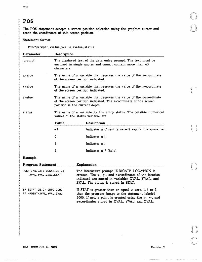
POS
POS The POS sta~e.ment accepts a screen position selection using the graphics cursor and reads the coordinates of this screen position.
Statement format:
POS/'prompt' ,xvalue,yvalue,zvalue,status
Parameter
'prompt'
xvalue
yvalue
zvalue
status
Example:
Description
The displayed text of the data entry prompt. The text must be enclosed in single quotes and cannot contain more than 40 characters.
The name of a variable that receives the value of the x-coordinate of the screen position indicated.
The name of a variable that receives the value of the y-coordinate of the screen position indicated.
The name of a variable that receives the value of the z-coordinate of the screen position indicated. The z-coordinate of the screen position is the current depth.
The name of a variable for the entry status. The possible numerical values of the status variable are:
Value
-1
o
1
2
Description
Indicates a C (entity select) key or the space bar.
Indica tes a [.
Indica tes a ].
Indicates a ? (help).
Program Statement Explanation
POS/'INDICATE LOCATION',$ XVAL,YVAL,ZVAL,STAT
IF (STAT.GE.O) GOTO 2000 PT1=POINT/XVAL,YVAL,ZVAL
22-6 ICEM GPL for NOS
The interactive prompt INDICATE LOCATION is created. The X-, y-, and z-coordinates of the location indicated are stored in variables XVAL, YVAL, and ZVAL. The status is stored in STAT.
If STAT is greater than or equal to zero, ], [ or ?, then the program jumps to the statement labeled 2000. If not, a point is created using the X-, y-, and z-coordinates stored in XVAL, YVAL, and ZVAL.
Revision C

(
(
(
(
(
QUERY
QUERY The QUERY statement requires a YES or NO answer to a displayed question.
Statement format:
QUERY/'prompt' ,response[,status]
Parameter
'prompt'
response
status
Example:
Description
The displayed text of the query prompt. The text must be enclosed in single quotes and cannot contain more than 40 characters.
The name of a variable that receives the answer. This variable is set to 1 if Y or YES is entered; it is set to 2 if N or NO is entered. It is set to 0 for any other entry.
The name of a variable for the entry status. The numerical values of the status variable are:
Value Description
-1 Indicates a valid response.
o Indicates a [.
1 Indicates a ].
2 Indicates a ? (help).
Program Statement Explanation
QUERY/'DO YOU WANT TO DELETE$ ALL POINTS?' ,IANS,ISW
IF (ISW. NE. 1) GOTO 50
IF (IANS.NE.1) GOTO 50
DELETE/POINTS
50 STOP
Revision C
An interactive prompt that says DO YOU WANT TO DELETE ALL POINTS? is . displayed. The YES or NO response is stored in IANS, and the status is stored in ISW.
If no choice is made, the program jumps to the statement labeled 50.
If N is entered, the program jumps to the statement labeled 50.
Otherwise, all points are deleted.
Interactive Statements 22-7

SELECT
SELECT The SELECT statement displays a message and requires an entity selection from the entities displayed on the screen. The method of entity selection (single, chain, region in, region out, graphics cursor, pointer, name, and so forth) is controlled by the entity selection modals. These are set with the SELENT and SELMOD statements. The defaults are single entity by graphics cursor.
One Entity
Statement format:
SELECT/'prompt' ,entity,status[,coord array]
Parameter
'prompt'
entity
status
coord array
Example:
Description
The displayed text of the select prompt. The text must be enclosed in single quotes and may not contain more than 40 characters.
The name to be given to the entity selected.
The name of a variable for the entry status. The possible numerical values of the status variable are:
Value Description
-1 Indicates that an entity was selected.
0 Indicates a [.
1 Indicates a ].
2 Indicates a ? (help).
The name of a coordinate array in which the coordinates of the graphics cursor are stored.
Program Statement Explanation
SELECT/'INDICATE CURVE',$ CV1,STATE,CRV(1)
NOTE
The interactive prompt INDICATE CURVE is displayed. The curve selected is named CV1, and the status is stored in STATE. The coordinates of the graphics cursor are stored in array CRV.
There is a limit of 250 entities selectable with each SELECT statement.
22-8 ICEM GPL for NOS Revision C
q
~
I
I
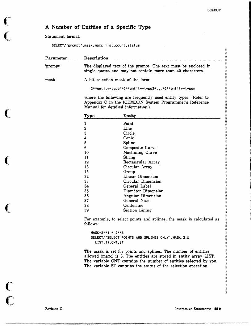
(
(
('"
(
c C·.··.~ .;;
SELECT
A Number of Entities of a Specific Type
Statement format:
SELECT/'prompt',mask,maxc,11st,count,status
Parameter
'prompt'
mask
Revision C
Description
The displayed text of the prompt. The text must be enclosed in single quotes and may not contain more than 40 characters.
A bit selection mask of the form:
2**entity-type1+2**ent1ty-type2+ ... +2**ent1ty-typen
where the following are frequently used entity types. (Refer to Appendix C in the ICEMDDN System Programmer's Reference Manual for detailed information.)
Type Entity
1 2 3 4 5 6 10 11 12 13 15 32 33 34 35 36 37 38 39
Point Line Circle Conic Spline Composite Curve Machining Curve String Rectangular Array Circular Array Group Linear Dimension Circular Dimension General Label Diameter Dimension Angular Dimension General Note Centerline Section Lining
For example, to select points and splines, the mask is calculated as follows:
MASK=2**1 + 2**5 SELECT/'SELECT POINTS AND SPLINES ONLY',MASK,3,$
LIST(1),CNT,ST
The mask is set for points and splines. The number of entities allowed (maxc) is 3. The entities are stored in entity array LIST. The variable CNT contains the number of entities selected by you. The variable ST contains the status of the selection operation.
Interactive Statements 22·9

i I
I
SELECT
Parameter
maxc
list
count
status
NOTE
Description
The maximum number of entity selections allowed. This number may not exceed 250 entities.
An entity array for storing entities. As in the previous example, the array LIST contains one entity in each element of the array. That is, LIST(1) is the first entity, LIST(2) is the second entity, and so on. The variable name chosen can be used anywhere that an entity name can be used.
A variable that contains the number of entities selected for this operation.
The name of a variable for the entry status. The possible numerical values of the status variable are:
Value Description
-1 Indicates that entities were selected.
o Indicates a [.
1 Indicates a ].
2 Indicates a ? (help).
There is also an extended mask capability for selecting entity types whose flag bits exceed the size of the mantissa of a single precision real (OS dependent). The extended mask consists of a real array, usually of length 4, whereby the first element contains the negative of the number of elements following (typically -3). The following elements (that is, mask(2) through mask(4» contain 16 bit slices of the total mask. Mask(2) can select entity types 1-15 (0 not used), mask(3) can select entity types 16-31, and mask(4) can select entity types 32-47. For example, to select linear (type 32) and circular (type 33) dimensions, the following mask. is calculated:
MASK(4) = 2**0 + 2**1
o 2 3 4 5 6 7 8 9 10 11 12 13 14 15
(2) 0 1 2 3 4 5 6 7 8 9 10 11 12 13 14 15 (3) 16 17 18 19 20 21 22 23 24 25 26 27 28 29 30 31 (4) 32 33 34 35 36 37 38 39 40 41 42 43 44 45 46 47
22·10 ICEM GPL for NOS Revision C
1
I I

(
(
(
c c
TEXT
TEXT The TEXT statement displays a message and requires character input. The TEXT statement assigns a variable' name to the characters entered. A text variable defined by a TEXT statement can be used, for example, as the text of an attribute, note, label, or dimension. This is done by referencing the variable name in an ATTRIB, NOTE, LABEL, or LDIMEN statement, respectively.
The text entered can be up to 200 characters. The displayed prompt appears before the text is entered. A back slash (\) entered anywhere in the text causes a down space (line feed) in subsequent displays of the entered text. Terminate text entry by entering a second carriage return, an operation complete, or an operation reject. Characters entered can be uppercase and lowercase, and do not have to be enclosed in single quotes.
Statement format:
TEXT/'prompt' ,name,status
Parameter
'prompt'
name
status
Example:
Description
The displayed text of the text prompt. The text for prompt must be enclosed in single quotes and can be up to 40 characters in length.
The name of a variable that receives the text entered. The name can be either a simple or a subscripted variable name. The variable must be dimensioned by a CHAR statement.
The name of a variable for the entry status. The possible numerical values of the status variable are:
Value Description
-1 Indicates valid text input.
o Indicates a L
1 Indicates a ].
Program Statement Explanation
TEXT/'ENTER NOTE' ,TXT1,STAT
IF (STAT.EQ.O) GOTD 200
NT1=NOTE/5,5,ANGLE,0,TXT1
Revision C
An interactive prompt is displayed that says ENTER NOTE. The text entered is assigned the variable name TXTl, and the status is stored in STAT.
If [ is entered, the program jumps to the statement labeled 200.
A note is created at coordinates (5,5) using TXTl.
Interactive Statements 22-11


0 GPL Input and Output 23 0 Conventions and Restrictions 23-1
File Formats . . . . . . . . . 23-2
Fixed Format Input/Output . 23-3
BULK 23-4
CLOSE 23-6
OPEN. 23-7
READ. 23-8 Sequential Access . 23-8 Direct Access 23-9
0 REWIND .... 23-10
USTRUC .... 23-10 USTART Parameter 23-10 UWRITE Parameter 23-11 UTERM Parameter . 23-11
WRITE ........ 23-12 Sequential Access. 23-12
0 Direct Access . . . 23-13
U sing the EXEC statement 23-14
o
o a.a IA$# a IUU PM1A#4I$4 JEW 3M; _4:: USSeS!!!'

'UIC!!G 'h Wi !!IMI
o o
o
o
o
0, o

(
~,
(
(
(
C~
.,-'."
C
GPL Input and Output 23
Conventions and Restrictions
The following limitations and conventions apply to the use of files in GPL input and output:
• A file must be opened before it is used, and a file must be closed after it is used. The OPEN command opens the file and the CLOSE command closes the file.
• The PAUSE, STOP, and FINI statements automatically close all open files.
• REWIND works only with sequential access. It does not work for word addressable files.
• Input/output statements are more efficient if they are grouped together.
Revision C GPL Input and Output 23-1

File Formats
File Formats The following types of files are supported for input/output in GPL:
Type
INPUT, OUTPUT
BININ, BINOUT
BINDIR
NOTE
Description
Formatted files, coded sequential input/output. These files are formatted as free-formatted text records. They are defined as follows:
• Only four files can be in use simultaneously in a GPL program.
• A record is defined as a maximum of 128 characters.
• All numbers are treated as decimal numbers. A decimal point is automatically placed after the last digit of an integer.
• In output files, the decimal point is automatically placed as specified in the SYSDEC statement.
• Legal separators are the blank or the comma.
• Leading blanks are ignored.
• The single quote (') defines the beginning and ending of a string of characters. If quotes are needed in a string of characters, two consecutive quotes are used.
Unformatted, binary sequential input/output. These files are not converted when they are transferred. For bulk data, binary input/output has significant performance increases as compared to coded input/output.
Only four files can be in use simultaneously in a GPL program.
Binary direct access word addressable. Direct access input/output is virtual in that it uses page buffers. Physical READ occurs when the file address is not found in a buffer. Physical WRITE occurs when all the buffers are full, or when a CLOSE statement is executed.
Only two direct access files can be open simultaneously.
BININ or BINDIR files created externally to GPL must be unformatted and should not have a header record. The following NOS statement
FILE, filename, RT=U, BT=C
should immediately precede the file's creation.
23·2 ICEM GPL for NOS Revision C

('
(
(
c c
Fixed Format Input/Output
Fixed Format Input/Output When a file is opened for input or output, text items can be read or written in fixed rather than in free format.
In fixed format, the length of a text item is no longer determined by the current length of the character variable in the UO statement. To distinguish fixed from free format, the count must be negative on the UO statement.
On input, the length is the maximum length specified in the CHAR declaration.
On output, the length is the current length, which may be smaller than the maximum, depending on previous use of the variable. (The current length can be set by the SETCHL statement.)
To use fixed format for input of real numbers, the following must apply:
1. The line must be read into a text variable.
2. The part of the line that contains the number must be moved into a different field.
3. This field must be converted into a real variable (CONVER).
On output this must be done in reverse order.
Example:
REAL/Rcao, ST CHAR/FILE7(7),CaO(ao), LaOTMP(10) DATA/FILE7, 'FILE7' OPEN/FILE7,INPUT,ST READ/FILE7,ST,-1,cao MOVCHR/a, caD, 1, LaOTMP, 1 CONVER/NUMBER, LaOTMP, RcaD, ST $$ RcaD will contain the a digit real number from FILE7
Revision C GPL Input and Output 23-3

BULK
BULK The BULK statement transfers data into or out of either the current part's run-time library (RTL) or the global user technology file (UTF). This allows big application programs a fast means of recovery without using additional files.
Statement format:
[
entity array] BULK/(GLOBAL),name,(INPUT ),count, real array ,status
LOCAL OUTPUT text array
Parameter
GLOBAL
LOCAL
name
INPUT
OUTPUT
count
entity array
real array
Description
The minor word for addressing the UTF.
The minor word for addressing the current part.
A text variable or character string containing the name of the record addressed. It must be a unique character string (10 characters maximum) that identifies the record.
The minor word for handling the bulk data file as an input file.
The minor word for handling the bulk data file as an output file.
The number of words or strings transferred. It can have the following values:
Value
1024
512
o
Description
The maximum number of real data words that can be transferred.
The maximum number of entity data words that can be transferred.
Zero is a special control number. If count equals 0 and the file is INPUT, the system checks if a record is present and, if found, sets the status to o.
If count equals 0 and the file is OUTPUT, the compiler checks if a record is present and deletes it.
The entity array name. Data is input or output depending on whether INPUT or OUTPUT is used.
The name of a real data array. Data is input or output depending on whether INPUT or OUTPUT is used.
23-4 ICEM GPL for NOS Revision C

(
(
c c
Parameter
text array
status
NOTE
BULK
Description
The text array name. Data is input or output depending on whether INPUT or OUTPUT is used.
The variable name that contains the operation status. It can have the following values:
Value
-1
-2
-3
o
>0
Description
Truncates the record because the record exceeds the value given in the count variable.
Indicates the record named not found on INPUT.
Indicates the wrong type of record found on INPUT. That is, the type of array or text variable did not match the type of record found.
Indicates the output operation was successful, or if the count equals 0, the input operation was successful.
Indicates the number of items that were read in.
Only experienced programmers should use this statement, as the new data base entities may overwrite the old data base entities with the same name.
Use GLOBAL with care. The overwriting or deleting a record that was not the last record created is very slow.
Revision C GPL Input and Output 23-5

CLOSE
CLOSE The CLOSE statement closes a file that was previously opened with an OPEN command.
The CLOSE statement writes an end-of-file (EOF) at the current position for files that were previously opened as BIN OUT or OUTPUT.
Statement format:
CLOSE/( 'file name' ),status text variable
Parameter
'file name'
text variable
status
Description
The name of a local file enclosed in single quotes (7 characters maximum).
The name of a text variable that contains a string of characters that names the local file (7 characters maximum).
A variable that contains the condition of the file used for input/output. The condition is expressed as one of the following values:
Value Description
o The close operation was successful.
-1 The file was not opened.
23-6 ICEM GPL for NOS Revision C
( '\

(
(.
(
c c
OPEN
OPEN The OPEN statement opens a file for input or output. The file is' positioned at the beginning-of-information (BOl).
Statement format:
BININ BINOUT
OPEN/( 'file name' ), BINDIR ,status text variable INPUT
Parameter
'file name'
text variable
BININ
BIN OUT
BINDIR
INPUT
OUTPUT
status
Revision C
OUTPUT
Description
The name of a local file enclosed in single quotes (7 characters maximum).
The name of a text variable that contains a string of characters that names the local file (7 characters maximum).
The file is used for input. The file is formatted as a binary sequential file.
The file is used for output. The file is formatted as a binary sequential file.
The file is used for input or output. The file is formatted as a binary direct access word addressable file.
The file or text variable is used for input. The file is formatted as a coded sequential file.
The file or text variable is used for output. The file is formatted as a coded sequential file.
A variable that contains the condition of the file used for inputJoutput. The condition is expressed as one of the following values:
Value
o
-1
-2
-3
>0
Description
The OPEN operation was successful.
The file is already opened.
There are too many open files.
File is empty.
The highest word address (BINDIR file only).
GPL Input and Output 23-7

READ
READ The READ statement reads character strings or numbers according to their variable types. The number of variables is limited to a maximum of 60 variables. The reading operation continues until the count specified is reached regardless of line terminators. If a new line is read and no more input is required (that is, no more variables are requested), the rest of the line is ignored.
Sequential Access
This form is for both INPUT and BININ type files.
Statement format:
REAO/( 'file name' ),status,count,( array J text variable variable, ...
Parameter
'file name'
text variable
status
count
array
variable
Description
The name of a local file enclosed in single quotes (7 characters maximum).
The name of a text variable that contains a string of characters that names the local file (7 characters maximum).
A variable that indicates the condition of the file being read after executing the READ statement. The condition is expressed as one of the following values:
Value Description
0 The read operation was successful.
1 EOF marker is encountered.
-1 The .file is not open.
-2 The file is opened for output.
-3 A conversion error has occurred.
-4 Illegal count.
Either the number of items (CHAR or REAL) in the array or the number of variables listed. A negative count indicates fixed format.
The name of an array to be read. It is recommended that the count for the array does not exceed 4000 for performance reasons.
A listing of the variables to be read (REAL or CHAR).
23-8 ICEM GPL for NOS Revision C
( ~ i ~ p

(
(
(
(
~~
C
READ
Direct Access
This form is for use only with BINDIR type files. The READ statement has the additional parameter, address.
Statement format:
REAO/( 'file name' ),status,count,addreSS,( array ) text variable variable, ...
Parameter
'file name'
text variable
status
count
address
array
variable
Revision C
Description
The name of a local file enclosed in single quotes (7 characters maximum).
The name of a text variable that contains a string of characters that names the local file (7 characters maximum).
A variable that contains the condition of the file used for input. The condition is expressed as one of the following values:
Value Description
>0 The read operation was successful (indicates the next word address).
-1 The file is not open.
-2 The file is opened for output.
-3 A conversion error has occurred.
-4 Illegal count.
Either the number of items (CHAR or REAL) in the array or the number of variables listed. A negative count indicates fixed format.
The address of the frrst word of the file read.
The name of an array to be read. It is recommended that the count for the array does not exceed 4000 for performance reasons.
A listing of the variables to be read (REAL or CHAR).
GPL Input and Output 23·9

REWIND
REWIND The REWIND statement rewinds a sequential file.
Statement format:
REWINO/( 'file name' ),status text variable
Parameter
'file name'
text variable
status
USTRUC
Description
The name of a local file enclosed in single quotes (7 characters maximum).
The name of a text variable that contains a string of characters that names the local file (7 characters maximum).
A variable that contains the condition of the file used for input/output. The condition is expressed as one of the following values:
Value Description
o The rewind operation was successful.
-1 The file does not exist.
The USTRUC statement creates a file which can be used as input to the UNISTRUC program.
USTART Parameter
The USTRUCIUSTART statement generates a DEFBLK card in the UNISTRUC program.
Statement format:
USTRUC/USTART,n
Parameter Description
USTART The minor word for generating a DEFBLK card in a UNISTRUC program.
n The block number of the DEFBLK card.
23·10 ICEM GPL for NOS Revision C

(
(
(
(.
(~
C
USTRUC
UWRITE Parameter
The USTRUCIUWRITE statement defines the number of points per curve and the number of entities to be transferred to the UNISTRUC program. If lines are specified, only two points are generated for each line.
Statement format:
USTRUC/UWRITE,np,ne,entity array
Parameter
UWRITE
np
ne
entity array
Description
The minor word for transferring entities to the UNISTRUC program.
The number of points to be generated per curve.
The number of entities in the entity array.
The name of the entity array to be transferred.
UTERM Parameter
The USTRUCIUTERM statement flushes the data buffers and writes an end-of-record (EOR) to the UNISTRUC program. The resulting file is not rewound.
Statement format:
USTRUC/UTERM
Parameter
UTERM
Revision C
Description
The minor word for flushing the data buffers and writing an EOR to a UNISTRUC program.
GPL Input and Output 23·11

i I iii
I ~
WRITE
WRITE The WRITE statement writes the specified variables to the file indicated. For coded files, the SYSDEC statement determines the number of decimal places for REAL variables. A maximum of 128 characters per line are written to the output file. A new line is written per each 128 characters.
Sequential Access
This form is for both OUTPUT and BINOUT type files.
Statement format:
WRITE/( 'file name' ),status,count.( array ] text variable variable ....
Parameter
'file name'
text variable
status
count
array
variable
Description
The name of a local file enclosed in single quotes (7 characters maximum).
The name of a text variable that contains a string of characters that names the local file (7 characters maximum).
A variable that indicates the condition of the file being written after executing the WRITE statement. The condition is expressed as one of the following values:
Value Description
o The write operation was successful.
-1 The file is not open.
-2 The file is opened for input.
-3 A conversion error has occurred.
-4 Illegal count.
>0 In binary mode, this is the next write address.
Either the number of items (CHAR or REAL) in the array or the number of variables listed. A negative count indicates fixed format.
The name of an array to be written.
A listing of the variables to be written. Character strings can be written out by enclosing them in single quotes in the variable listing. .
23·12 ICEM GPL for NOS Revision C

(
(
(
c" c
WRITE
Direct Access
This form is for use only with BINDIR type files. The WRITE statement has the additional parameter, address.
Statement format:
WRITE/( 'file name' ),status,count,addreSS,( array ) text variable variable, ...
Parameter
'file name'
text variable
status
count
address
array
variable
Revision C
Description
The name of a local file enclosed in single quotes (7 characters maximum).
The name of a text variable that contains a string of characters that names the local file (7 characters maximum).
A variable that contains the condition of the file used for output. The condition is expressed as one of the following values:
Value Description
>0 The write operation was successful (this is the next write address).
-1 The file is not open.
-2 The file is opened for input.
-3 A conversion error has occurred.
-4 Illegal count.
Either the number of items (CHAR or REAL) in the array or the number of variables listed. A negative count indicates fixed format.
The address of the first word of the file at which to write.
The name of an array to be written.
A listing of the variables to be written.
GPL Input ~nd Output 23·13

U sing the EXEC Statement
Using the EXEC Statement
The EXEC statement executes a subroutine written in FORTRAN. Only variables of type REAL can be passed as parameters. The subroutine must be in a library (default is named UCLIB) and must be of the type CAP (capsule).
Statement format:
EXEC/[ 'FTN name'1[,('11b name' 1]' ftn variable lib variable
number,array
Parameter Description
'FTN name' The name of the FORTRAN subroutine enclosed in single quotes.
ftn variable The name of a variable that contains a string of characters that names the FORTRAN subroutine.
'lib name' The name of the library enclosed in single quotes (default is named UCLIB).
lib variable The name of a text variable containing a string of characters that names the library.
number The number of parameters in the parameter array.
array The name of a real array that contains the parameters to be passed to the FORTRAN subroutine.
The following limitations must be observed:
• The capsule library must be created by the NOS utility GTR with the D parameter, or by using LIBEDIT if you replace a capsule in an existing library or use the BUILD directive. The following procedure is the kind used to generate a capsule library from a subroutine. The subroutine is called SUB123 on local file COMPILE.
FTN5,I,L=LIST. CAPSULE,SUB123. LOAD,LGO. NOGO. GTR,ABS,UCLIB,D.CAP/*
• The subroutine cannot use any FORTRAN input/output statements.
• The subroutine called must start with the following two statements:
SUBROUTINE name (N,A) DIMENSION A(N)
The subroutine can then call other subroutines within the same capsule. The total size of the capsule including ~~ray A is limited to 40,000 octal (16,384 decimal) words. This is a maximum size, but for reasons of efficiency, a capsule size of 20,000 octal (8,192 decimal) with an array size of 10,000 octal (4,096 decimal) should not be exceeded.
23·14 ICEM GPL for NOS Revision C

o o
o
o
o
o o
Compiling a GPL Program 24
GPL Control Statement. . . . . . . . . . . . . . . . . . . . . . . . . . . . . . . . . . . 24-1
Library Format Under NOS . . . . . . . . . . . . . . . . . . . . . . . . . . . . . . . . 24-4
.h;
.... M.,. i •. i @U;.M~W 9. if elltl \ !I'M tlRltimJllJiiWl1b!DtlJ!J "Q M • 'Nt ,I", JUl.' i'WWtlilliWlIIJIl
o o
o
o
o
o o

(
(
c c
Compiling a GPL Program 24
GPL Control Statement
The GPL control statement, which is entered from NOS, calls the compiler. Opening and closing parentheses enclose the parameters. The parentheses are special symbols, which are used to indicate the start and end of the parameters. You may use commas instead of parentheses. These parentheses must be included in the control statement. The parameters in the control statement are order independent. Parameters cannot be repeated in a control statement. If the statement is entered in interactive mode, a carriage return is sufficient to end the statement.
Statement format:
GPL(I=input,L=list,B=objfil,E=errfil,LO,EL,ET,PS,IL)
Parameter
I = input
L=list
B=objfil
Revision C
Description
The file name (1 to 7 characters) that contains the source input text.
Parameter Description
I omitted Default: The file name is INPUT.
I alone Special case: The file name is COMPILE.
The file name (1 to 7 characters) that contains listable compiler output.
Parameter
L omitted
Lalone
L = 0
Description
Default: The file name is OUTPUT.
Special case: The file name is LIST.
Special case: Suppress listable compiler output. Only error statistics for the programs compiled are listed on the file named OUTPUT.
The file name (1 to 7 characters) that contains the object code output.
Parameter Description
B omitted Default: The file name is GPLOBJ.
B alone Special case: The file name is LGO.
B=O Special case: Suppress object code output.
Compiling a GPL Program 24-1

GPL Control Statement
Parameter
E=errfil
LO
EL
ET
PS
1L
Description
The file name (1 to 7 characters) that contains the faulty statements and error messages.
Parameter Description
E omitted Default: suppress error message file.
E alone Special case: the file name is ERRS.
E=O Special case: same as E omitted.
List Options (simply concatenated, any sequence). S stands for source listing, R for reference map. (For maintenance, 0 and Q display object code proper and the complete object code file, respectively, and Z, P, A, M, and Dn (with n= 1 to 4) permit intermediate debug output for various components of the compiler.
Parameter
LO omitted
LO alone
Description
Default: S, source listing only.
Special case: SR, source listing and reference map only.
Level of error messages to be put on output file; T means all, F means FATAL ones only.
Parameter Description
EL omitted Default: T, all error messages.
EL only Special case: F, FATAL error messages only.
ErrQr Terminate Flag; if present, the compiler terminates on a fatal error.
The page size in number of lines of the output listing.
Parameter
PS omitted
PS only
Description
Default: page size is 60 lines.
Special case: Page size is 40 lines.
The source input line length to be scanned.
Parameter Description
IL omitted Default: line length is 80 columns.
IL only Special case: line length is 72 columns.
24-2 ICEM GPL for NOS Revision C
I

(
(
(C
C
GPL Control Statement
When the compiler terminates, it passes information at the control level as to how successfully it ran. This information is system dependent.
The CCL error flag (EF) is set in the following manner:
Flag Description
o No errors.
1 Trivial errors (warnings).
2 Fatal errors.
3 Catastrophic errors (compilation terminates, for example, because of table overflow).
CCL register Rl is set to the number of programs compiled successfully.
If there are no catastrophic errors, and no fatal errors with EL = F specified as an execution parameter, the system displays:
GPL COMPLETED: xx TRIVIAL, yy FATAL ERRORS; zz PROGRAMS COMPILED
If there are catastrophic errors, or fatal errors with EL = F set, the system displays:
GPL ABORTED: xx TRIVIAL, yy FATAL ERRORS; zz PROGRAMS COMPILED
On all systems, this message is also put at the end of either list output.
Revision C Compiling Ii GPL Program 24·3

Library Format Under NOS
Library Format Under NOS The source to be compiled must be available in a local, sequential file. Use the NOS utility MODIFY both to:
• Maintain the source of larger program packages.
• Select one or more of the decks used for compilation under control of a procedure.
The object code delivered by the compiler must be put into a standard format library before ICEM DDN can execute it. Achieve this by using the NOS utilities GTR or LIBEDIT.
Example
GET,FN.
ATTACH,GPL.
GPL,I=FN,L=GPLLIST.
ATTACH,GPLLIB/M=W.
LIBEDIT,B=GPLOBJ,P=GPLLIB,Z./*BUILO GPLO
REWIND,·. COPY,NEW,GPLLIB.
NOTE
Explanation
Get the GPL source program.
Attach the GPL compiler.
Compile program FN with listing put on GPLLIST.
Attach GPL library.
Place compiled programs on GPL library.
ICEM DDN Version 1.6 contains a new version of the GPL compiler. Unlike the old compiler, which kept source and object code together in a library in a special format, the new compiler doesn't do any library handling. Newly compiled programs do not work on versions of ICEM DDN created prior to version 1.6. Therefore, do not insert the object code from the new compiler into libraries created prior to version 1.6.
24·4 ICEM GPL for NOS Revision C I

o o
o
o
o
o o
Menu 5.13 GPL
5.13 GPL ............ . 5.13.1 Recover Last File .. . 5.13.2 Continue GPL Program 5.13.3 Run GPL Program .. 5.13.4 List GPL Names . . . 5.13.5 Change Library Name ..
25
25-1 25':'1 25-1 25-1 25-1
. 25-1

~ , , . t Ii t i tiI!,,»«!, :J\iiX&Jiif1U1Lnmm:iltJlJHii!5
o o
o
o
o
o o

(
(
(
Cc Cc
Menu 5.13 GPL
5.13 GPL
With this choice, you can execute precompiled GPL programs. These programs are custom applications ranging from family of parts generators to interactive tutorials. These programs must be contained in a local GPL library.
The menu for this section is:
GPL 1.RECOVER LAST FILE 2.CONTINUE GPL PROGRAM 3.RUN GPL PROGRAM 4.LIST GPL NAMES 5.CHANGE LIBRARY NAME
The following sections describe the choices in this menu.
5.13.1 Recover Last File
25
With this choice, you can continue program execution following a FILE command in a GPL program (refer to chapter 7 for a description of the FILE command). Execution continues at the next statement following the last FILE command.
5.13.2 Continue GPL Program
With this choice, you can continue program execution following a PAUSE statement in the GPL program. Choosing this menu item if there is no PAUSE statement in the current GPL program returns you to 5 SPECIAL FUNCTIONS.
5.13.3 Run GPL Program
With this choice, you can execute the GPL program.
ENTER SIX CHARACTER NAME
5.13.4 List GPL Names
Enter the name of the GPL program to run. This name can be 1 to 6 characters long.
With this choice, you can display the names of GPL programs and subprograms which are contained in a local GPL library.
5.13.5 Change Library Name
With this choice, you can change the name of the local GPL library to use in your program. The default name of this library is GPLLIB.
CURRENT GPL LIBRARY IS name ENTER NEW GPL LIBRARY NAME
Revision C
Enter the name of the local GPL library that you want to access. The name of the library can be 1 to 7 characters long.
Menu 5.13 GPL 25-1

i
i
I

o o
o
o
o
o o
Appendixes
Glossary ....... .
Minor, Modal, and Positional Relationship Words .
ICEM DON Entity Types. . . .
GPL Execution Error Messages
System 110 Commands . . . . .
GTGT: GRAPL-to-GPL Translator ..
GPL Program Examples . . . . . .
A:I&UI$
A-I
B-I
C-I
D-I
E-I
F-l
G-I
,.9##4; P . <L(~ L _ ... .
... U .. '.1M' U JIU Mih ilIIgryMihifUM onJ
o o
o
o
o
o o

(
(~
(
(
C
Alphanumeric Auxiliary View
Glossary
A
Alphanumeric
The letters of the alphabet (A through Z) and the digits (0 through 9).
Angular Dimension
The entity type showing the angular distance between two lines.
ANSI
American National Standards Institute. English (U.S. customary) dimensions are specified in feet and/or inches. Metric dimensions ,are specified in millimeters.
Approximation
A process of computing a curve that interpolates the given point set.
APT
A
The Automated Programmed Tooling system, a language for defining part geometry and numerically controlled toolpaths.
Arithmetic Operator
Any of these operations: addition, subtraction, exponentiation, multiplication, and division.
Aspect Ratio
The ratio between the character width and the character height in dimensions.
Assignment Statement
A statement that assigns a name to an entity or a mathematical expression.
Attention Indicator
A small oval that the system displays on an entity to indicate that the entity has been selected.
Attribute Text
User-assigned alphanumeric text associated with an entity. Attribute text is used to identify and describe an entity.
Automatic Dimensioning
The system capability that calculates the distance or angle of a dimension and automatically writes the text for that distance or angle in the dimension.
Auxiliary View
A view that can be user-defined. The standard views (top, bottom, right, left, front, back, isometric, and auxiliary) are defmed by the system.
Revision C Glossary A·I
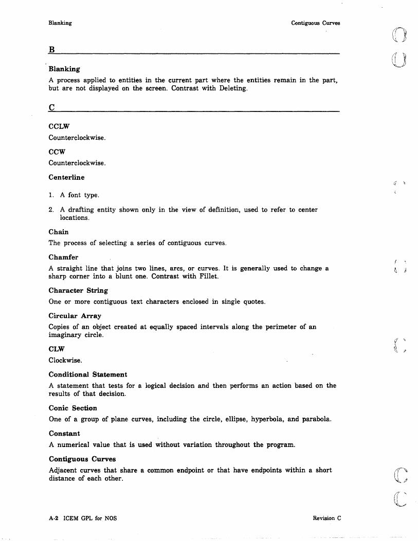
Blanking Contiguous Curves
B
Blanking
A process applied to entities in the current part where the entities remain in the part, but are not displayed on the screen. Contrast with Deleting.
c
CCLW
Counterclockwise.
CCW
Counterclockwise.
Centerline
1. A font type.
2. A drafting entity shown only in the view of definition, used to refer to center locations.
Chain
The process of selecting a series of contiguous curves.
Chamfer
A straight line that joins two lines, arcs, or curves. It is generally used to change a sharp corner into a blunt one. Contrast with Fillet.
Character String
One or more contiguous text characters enclosed in single quotes.
Circular Array
Copies of an object created at equally spaced intervals along the perimeter of an imaginary circle.
CLW
Clockwise.
Conditional Statement
A statement that tests for a logical decision and then performs an action based on the results of that decision.
Conic Section
One of a group of plane curves, including the circle, ellipse, hyperbola, and parabola.
Constant
A numerical value that is used without variation throughout the program.
Contiguous Curves
Adjacent curves that share a common endpoint or that have endpoints within a short distance of each other.
A·2 ICEM GPL for NOS Revision C
(j .~

(
(
(
(
(
r(~
Coordinate Axes Depth
Coordinate Axes
The lines that form a right-handed, three-dimensional frame of reference. The model axes (x, y, and z) and the transform axes (xt, yt, and zt) are referenced from a shared origin point in which x = 0, y = 0, and z = O.
Coordinate Space
A space created by the position (rotation and translation) of the coordinate axes. There are two types of coordinate space: model and transform.
Coordinates
The position of a point in relation to the X-, y-, and z- or xt-, yt-, and zt-axes.
Curve
A line, arc, conic, or two-dimensional spline. In some cases, it also includes points, three-dimensional splines, strings, composite curves, machining curves, and Bezier curves.
CW
Clockwise.
D
Data Base
An integrated set of files, tables, arrays, and other data structures.
Data Capture
The systelll capability to save as a variable either a default parameter value or a previously entered parameter value displayed on the screen.
Datum Feature Symbol
One or two characters in a rectangular frame that identifies a part feature.
Datum Target
A specific point, line, or area identified on a drawing by a datum target symbol. It establishes datum planes commonly used for manufacturing or inspection repeatability.
Default Value
A value used by the system if] is entered in response to a data entry prompt. It is also the initial value assigned to a modal until it is changed.
Definition Form
Each entity in ICEM DDN is defined with a SpeCifiC entity type and form. The types and forms are described in the ICEM Design/Drafting System Programmer's Reference Manual.
Deleting
The removal of entities from the data base. Contrast with Blanking.
Depth
The current value of the workplane along the z- or zt-axis of the workspace.
Revision C Glossary A-3

Dimension Extension Lines
Dimension
An entity used to show a geometric characteristic of a part, such as the diameter, length, angle, or center distance.
Dimension Lines
Arrows from dimension text to extension lines that indicate the dimension being measured.
DIN
Deutsche Industrie Norme (German industry standards).
Direct Access File
Permanent file that can be attached directly to a job without any local copy being generated. All changes to this file are made to the file itself.
Dormant Entity
An entity created by the system for the purpose of defining another entity. Dormant entities cannot be displayed or manipulated. All dormant entities have sequence numbers.
Downspace Ratio
The distance from the bottom of one line of dimension text to the bottom of the next line.
Dual Dimensioning
The system capability to produce dimensions containing both SI and U.S. customary units.
E
Entity
The representation of a geometric construction in the ICEM DDN data base. Examples are points, lines, arcs, and spheres.
Entity Name
A name given to a geometric definition.
Entity Type Numbers
System-assigned code numbers used to identify specific entity types such as line, group, and copious data.
EOF End of file.
EOR End of record.
Extension Lines
Lines extending from entities between which dimensions are given. The distance measured is indicated.
A-4 ICEM GPL for NOS Revision C

(
(J
(
(
(
c c
Feature ICEMDDN
F
Feature
A specific component of a part such as a notch, the sides of a hole, or the flat side.
Feature Frame
The entity type used for datum feature, geometric tolerance, or composite geometric tolerance symbols.
Fillet
An arc that joins two lines, arcs, or curves. It begins and ends at a point of tangency on each of the two lines.
Font
The method used to represent a line or curve in a display. Examples of fonts are solid, dashed, phantom, and centerline.
Function Control Key/Square
A keyboard/tablet character that has a special function in ICEM DDN such as menu and entity selection.
Functions
Commonly used arithmetic/trignometric operations, such as absolute value, sine, and cosine.
G
Graphics Cursor
The cursor symbol used to locate or define entities by screen position. The graphics cursor can be crosshairs or some other cursor symbol.
Group
A set of entities defmed and treated as a unit such as a balloon or a surface texture entity.
H
Hidden Lines
Line segments that are obscured from view in display of a three-dimensional object.
I
ICEM DDN
Control Data's integrated computer-aided engineering and manufacturing software application for design, drafting, and numerical control.
ICEMDDN
The name of the direct access file that contains ICEM DDN.
Revision C Glossary A-5

Interpolation Modal
Interpolation
A process of computing a curve that satisfies all the conditions imposed; for example, a curve that passes through all given points.
L
Label
Text and a leader with an arrow from the text to an entity on the drawing.
Leader
A line leading from a dimension value or an explanatory note to a selected entity.
Level Management
A method of assigning entities to different levels for management purposes.
Level Number
A number assigned to a collection of entities.
Local File
Any file that is currently associated with a job.
Logical Operators
The conditional operations of equality, such as less than, less than or equal to, equal to, greater than or equal to, or, greater than.
M
Major Word
A statement element that names the operation to be performed.
Major Word Statement
A statement that describes a GPL operation.
Menu
A list of options used to perform operations in ICEM DDN.
Message
Text written by the system to display information, errors, or warnings. See also Prompt.
Minor Word
A modifier element that follows a major word.
Mirror
An operation that enables you to produce a copy of a set of entities in the part by rotating them 180 degrees around a selected line.
Modal
A user-assigned status or value that controls the operation of ICEM DDN. Examples are modals for setting system decimal places and for activating the grid.
A-6 ICEM GPL for NOS Revision C

(
(,"
(
(
(
c c
Model Coordinate Space Pattern
Model Coordinate Space
The space created by the position of the X-, y-, and z-axes. This space is displayed as the front view, view 1. See Transform Coordinate Space.
N
N/C
Numerical control.
Normal
Perpendicular.
NOS
Network Operating System.
Note
An entity that contains graphics text for drawings.
o
Object Code
The executable code of the GPL program.
Operating System
The set of system programs that controls the execution of user programs and commands.
Operation Complete (])
A keyboard/tablet operation that completes the current operation.
Operation Reject (D
A keyboard/tablet operation that rejects the previous operation. The system returns to the preceding prompt.
p
Parameter
A variable whose values determine the operation or characteristics of a system.
Part Name
A series of alphanumeric characters that identify a part or drawing used in conjunction with a sheet number.
PATTERN
Default primary pattern library.
Pattern
A named set of entities that can be selected and saved in a pattern library. They can be retrieved and copied into a part at a specified point.
Revision C Glossary A·7

Permanent File Rotate
Permanent File
A file saved by the system between terminal sessions.
Point
A geometric construction located by X-, y-, and z-coordinates.
Point-Set Curve
A piecewise linear or polynomial approximation to an actual curve. It is a series of points stored as transform coordinates.
Pointer Number
The number assigned to an entity that describes the location in the data base of that entity's parameters.
Polar Line
A line extending from an existing point in a specified direction for a specified distance.
Polar Point
A point at a specified distance and angle from a selected base point.
Program File
The text version of the program. See also Source Code.
Projection
An operation for copying entities at a specified distance from the original entities. The projected entities are connected to the original entities with lines.
Prompt
A screen display requiring user action. See also Message.
PRU
Physical record unit.
Punctuation
Common punctuation marks, such as the comma and the period, and other special symbols used to delineate the format of a statement.
R
Rectangular Array
Copies of an object at equally spaced intervals, arranged in rows and columns.
Region Select
A process of selecting all the entities within or outside of a specified region.
Rescale
To change the scale factor and redraw a part using the new scale so that all entities in the part are displayed.
Rotate
To revolve a construction about an axis.
A-8 ICEM GPL for NOS Revision C

(
(
(
(C
C
RTL Statement Label
RTL
See Run-Time Library.
Run-Time Library (RTL)
The storage area for all variables defined by data capture, variable calculation, and program execution.
s
Scalar
A quantity that has magnitude only. Contrast with Vector.
Scale Factor
Ratio of the current display with respect to the data base.
Section Lining
An entity type defining patterned representations for material types including iron, steel, brass/copper, rubber/plastic, refractory, glass/slate, lead, or aluminum/magnesium. Section lining was formerly called cross hatching.
Sequence Number
A unique sequential number associated with each entity.
Sheet Number
A subdivision of a part name. Sheets can be numbered from 0 to 9,999 with a part name.
SI
Systeme International d'Unites (international system of units). Dimensions are calculated in metric units. Lengths have units of millimeters. Areas have units of millimeters squared unless otherwise specified.
Single Select
A process of selecting individual entities one at a time.
Source Code
The text version of the program. See also Program File.
Spacing
The distance between the centers of consecutive characters.
Spline
A curve that passes through and remains smooth between data points.
Standard Views
The system-generated coordinate systems from which the user can view a display of the part surfaces from these view points: front, back, top, bottom, right, left, isometric, and auxiliary.
Statement Label
A unique integer identifier for a statement.
Revision C Glossary A-9

String
String
A single entity that is displayed as a connected set of lines and arcs. A string, however, is not lines and arcs and cannot be used in place of lines and arcs.
Subscript
Tolerance
An array identifier that uniquely identifies an element's position within an array.
Surface Normal Point
A point on a surface located at the intersection of the surface and a surface normal vector.
Surface of Revolution
Surface produced by the rotation of a curve around an axis through a specified angular displacement.
Surface Parameters
A pair of numbers (u,v) that specify positions on a surface.
Surface Pierce Point
The intersection between a surface and a line parallel to a vector and passing through a selected base point.
System
The ICEM DDN software system.
T
Tabulated Cylinder
Surface generated by the translation of a curve along a specified direction with upper and lower limits on the distance of translation.
TAPE3
A local file on which parts are filed and from which parts are retrieved.
Template
A named set of geometric entities that have two forms, masters and instances. A master is the shape to which the instances conform.
Temporary File
A nonpermanent file associated with a job only during job processing.
Text
Alphanumeric characters and symbols used in notes, labels, and dimensions.
Text Variable
A string of one or more characters assigned a variable name.
Tolerance
The range of variation allowed in maintaining a specified dimension.
A·I0 ICEM GPL for NOS Revision C

(
(
(~
c" c
Tolerance Ratio Vector
Tolerance Ratio
The ratio between the character size for tolerance characters and the character size for main characters in dimensions.
Transform Coordinate Space
The space created by the position of the xt-, yt-, and zt-axes. This space is displayed in any view other than view 1. See Model Coordinate Space.
Transformation of Coordinates
The mapping of the xt-, yt-, and zt-coordinates into the X-, y-, and z-coordinates.
Translate
To relocate entities on the screen display by assigning them different origin coordinates.
Trimming
To delete or extend a segment of an entity to a prescribed boundary.
u
U Path
A curve on a surface in one of two parametric directions. See V Path.
Unblank
A procedure for making visible entities that have been blanked by the user.
Units of Measurement
Acceptable units of measurement for GPL are either millimeters, inches, or inches/feet.
User Technology File (UTF)
The storage area for various products of 5 SPECIAL FUNCTIONS including defined character sets and level tables.
v
V Path
A curve on a surface in one of two parametric directions. See U Path.
Variable Calculation
An operation in 5.2 GRAPL that calculates the value of an arithmetic expression and assigns that value to a user-specified variable.
Variable Name
A name given to a mathematical expression.
Vector
A quantity that has magnitude and direction. It is commonly represented by a line segment with directionality. The line's length represents the magnitude and its orientation in space represents the direction. Contrast with Scalar.
Revision C Glossary A·ll

View Zoom
View
A display of coordinate space.
w
Work Plane
A specific plane in workspace on which two-dimensional entities are constructed.
Work View
The view in which screen input is accepted.
Workspace
The space in which entity construction and specification occurs.
z
Zoom
To enlarge or decrease the size of the display proportionately.
A·12 ICEM GPL for NOS Revision C
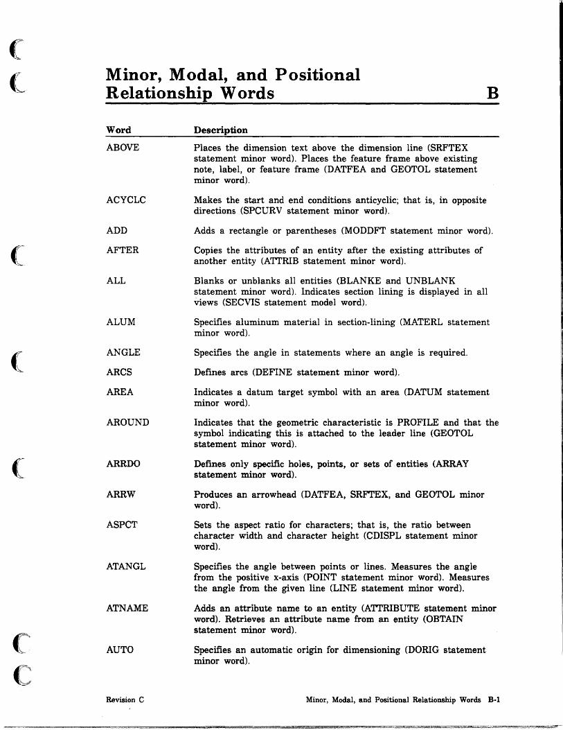
(
(
(
(
(
('
C
Minor, Modal, and Positional Relationship Words B
Word
ABOVE
ACYCLC
ADD
AFTER
ALL
ALUM
ANGLE
ARCS
AREA
AROUND
ARRDO
ARRW
ASPCT
ATANGL
ATNAME
AUTO
Revision C
Description
Places the dimension text above the dimension line (SRFTEX statement minor word). Places the feature frame above existing note, label, or feature frame (DATFEA and GEOTOL statement minor word).
Makes the start and end conditions anticyclic; that is, in opposite directions (SPCURV statement minor word).
Adds a rectangle or parentheses (MODDFT statement minor word).
Copies the attributes of an entity after the existing attributes of another entity (ATTRIB statement minor word).
Blanks or unblanks all entities (BLANKE and UNBLANK statement minor word). Indicates section lining is displayed in all views (SECVIS statement model word).
Specifies aluminum material in section-lining (MATERL statement minor word).
Specifies the angle in statements where an angle is required.
Defines arcs (DEFINE statement minor word).
Indicates a datum target symbol with an area (DATUM statement minor word).
Indicates that the geometric characteristic is PROFILE and that the symbol indicating this is attached to the leader line (GEOTOL statement minor word).
Defines only specific holes, points, or sets of entities (ARRAY statement minor word).
Produces an arrowhead (DATFEA, SRFTEX, and GEOTOL minor word).
Sets the aspect ratio for characters; that is, the ratio between character width and character height (CDISPL statement minor word).
Specifies the angle between points or lines. Measures the angle from the positive x-axis (POINT statement minor word). Measures the angle from the given line (LINE statement minor word).
Adds an attribute name to an entity (ATTRIBUTE statement minor word). Retrieves an attribute name from an entity (OBTAIN statement minor word).
Specifies an automatic origin for dimensioning (DORIG statement minor word).
Minor, Modal, and Positional Relationship Words B·l

Word
AUX
BASIC
BEARDS
BEFORE
BELOW
BINDIR
BININ
BINOUT
BLNK
BORDER
BOTH
BRACKT
BRASS
CCW
CENLIN
CENTER
Description
Creates an auxiliary view (VIEW statement minor word).
Adds or deletes rectangle around dimension text (MODDFT statement minor word). Adds a surface texture symbol (SRFTEX statement minor word).
Defines a point at a bearing and distance (POINT statement minor word).
Copies the attributes of one entity before the existing attributes of another entity (ATTRIB statement minor word).
Places the feature frame below existing note, label, or feature frame (DATFEA and GEOTOL statement minor word).
Declares a binary direct access word addressable file (OPEN statement minor word.
Declares a binary sequential input file (OPEN statement minor word).
Declares a binary sequential output file (OPEN statement minor word).
Indicates the blank (original material boundary) entities (SETGPG and TLPATH statement minor word).
Draws a border around the reproduced, magnified section of drawing (MAGNFY statement minor word).
Adds subattribute names and numbers to an entity (ATTRIB statement minor word). Retrieves the subattribute name and number (OBTAIN statement minor word). Produces dual dimensions (DUAL statement modal word). Places arrows at both ends of a dimension (SECARR statement minor word).
Produces dual dimensions with alternate dimensions in brackets with no line separating upper and lower text (DUAL statement modal word).
Specifies BRASS material in section-lining (MATERL statement minor word).
Indicates the counterclockwise arc direction (STRING statement minor word). Aligns a note in the counterclockwise direction parallel to a given arc (NOTE statement minor word).
Defines all subsequent curves in the center line mode until a new font is entered (FONT statement minor word).
Defines a circle center (POINT and CIRCLE statement minor word). Defines a point center for plane (PLANE, ELLIPS, HYPERB, and PARABO statement minor word). Locates a template instance from a given origin (TEMPLT statement minor word). Generates a centered character string (TXTJUS statement minor word). Defmes the center of a drawing (ZOOM statement minor word).
B·2 ICEM GPL for NOS Revision C
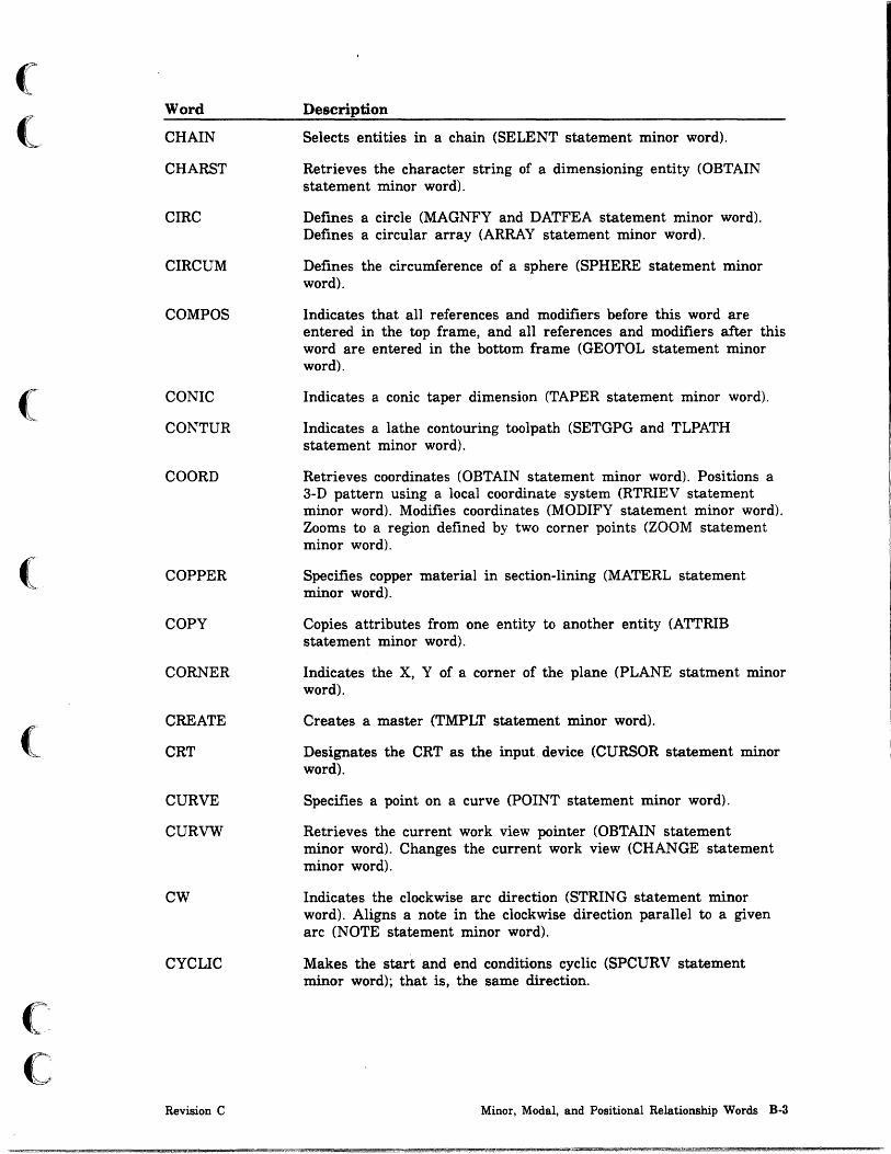
(
(
(
(
c C
····~
•• -.<1:
Word
CHAIN
CHARST
CIRC
CIRCUM
COMPOS
CONIC
CONTUR
COORD
COPPER
COpy
CORNER
CREATE
CRT
CURVE
CURVW
CW
CYCLIC
Revision C
Description
Selects entities in a chain (SELENT statement minor word).
Retrieves the character string of a dimensioning entity (OBTAIN statement minor word).
Defines a circle (MAGNFY and DATFEA statement minor word). Defines a circular array (ARRAY statement minor word).
Defines the circumference of a sphere (SPHERE statement minor word).
Indicates that all references and modifiers before this word are entered in the top frame, and all references and modifiers after this word are entered in the bottom frame (GEOTOL statement minor word).
Indicates a conic taper dimension (TAPER statement minor word).
Indicates a lathe contouring toolpath (SETGPG and TLPATH statement minor word).
Retrieves coordinates (OBTAIN statement minor word). Positions a 3-D pattern using a local coordinate system (RTRIEV statement minor word). Modifies coordinates (MODIFY statement minor word). Zooms to a region defined by two corner points (ZOOM statement minor word).
Specifies copper material in section-lining (MATERL statement minor word).
Copies attributes from one entity to another entity (ATTRIB statement minor word).
Indicates the X, Y of a corner of the plane (PLANE statment minor word).
Creates a master (TMPLT statement minor word).
Designates the CRT as the input. device (CURSOR statement minor word).
Specifies a point on a curve (POINT statement minor word).
Retrieves the current work view pointer (OBTAIN statement minor word). Changes the current work view (CHANGE statement minor word).
Indicates the clockwise arc direction (STRING statement minor word). Aligns a note in the clockwise direction parallel to a given arc (NOTE statement minor word).
Makes the start and end conditions cyclic (SPCURV statement minor word); that is, the same direction.
Minor, Modal, and Positional Relationship Words B-3

Word
DASHED
DATMOD
DATREF
DECIM
DEFVW
DEGREE
DEGTOL
DEL
DELANG
DELATR
DELTA
DELTAX
DELTAY
DELTAZ
DETAIL
DIFFER
DIRECT
DISP2
DISTNC
Description
Defines all subsequent curves in the dashed mode until a new font is entered (FONT statement minor word).
Indicates a datum modifier (GEOTOL statement minor word).
Indicates a datum reference (GEOTOL statement minor word).
Indicates that the angle text of a radial dimension is decimal (TXTANG and ANUNIT statement minor word).
Retrieves the definition view of an entity (OBTAIN statement minor word).
Indicates that the angle text of a radial dimension is in degrees only (TXTANG statement minor word) (ANUNIT statement minor word in ANSI 82).
Indicates the degree of tolerance (DEVSRF statement minor word).
Deletes a rectangle or parenthesis (MODDFT statement minor word).
Specifies the delta angle for all statements which require incremental angular information.
Deletes an attribute (ATTRIB statement minor word).
Defines a delta distance from a given origin (POINT, TXTORG, CDISPL, and DORIG statement minor word).
Specifies the delta distance from an x-coordinate for all statements which require incremental x-coordinate information.
Specifies the delta distance from a y-coordinate for all statements which require incremental y-coordinate information.
Specifies the delta distance from a z-coordinate for all statements which require incremental Z information.
Indicates the detail number of the balloon (BALOON statement minor word).
Indicates the difference of two vectors (VECTOR statement minor word).
Indicates a straight line from the datum to the feature frame (DATFEA and GEOTOL minor word).
Displays both witness lines of a linear dimension (WLINE statement minor word).
Specifies the distance or length of a line (parallel PLANE statement minor word and LINE statement minor word).
B-4 ICEM GPL for NOS Revision C

(
(
(
(
(-
cr c
Word
DONT
DOWNSP
DRILL
EAST
EDGE
END
ENDANG
ENTER
ENTNAM
ENTPTR
ENTTY
ENTTYP
ERRST
FAST
FILTER
FINE
Revision C
Description
Suppresses specific holes, points, or sets of entities (ARRAY statement minor word).
Specifies the downspace ratio for characters; that is, the distance between lines of text (CDISPL statement minor word).
Indicates a lathe drilling toolpath (SETGPG and TLPATH statement minor word).
Indicates an east bearing (bearing/distance POINT statement minor word). Locates a template instance from a given origin (TEMPLT statement minor word).
Defines a machine curve as a surface edge curve (MACCRV statement minor word).
Indicates that the leader starts at the end of the label (CDIMEN and LABEL statement minor word). Joins two curve endpoints (LINE statement minor word). Defines a point at the end of a curve (POINT statement minor word). Places arrowhead at end of dimension (SECARR statement minor word).
Specifies the ending angle for any statement in which a terminating angle value is required.
Indicates that the user chooses the method of angle control (ANGCTL statement minor word), or the method of text origin (TXTORG statement minor word).
Retrieves the name of an entity (OBTAIN statement minor word).
Retrieves the pointer of a named entity (OBTAIN statement minor word).
Indicates a datum target symbol as an existing entity (DATUM statement minor word). Attaches a surface texture symbol to an enitity (SRFTEX statement minor word).
Retrieves the type and subtype of an entity (OBTAIN statement minor word).
Retrieves the error and line number if an error was encountered and STATUS is ON (OBTAIN statement minor word).
Sets the character set to fast (CSET statement minor word) (CRES statement minor word in ANSI 82).
Indicates that the filter method is used to calculate the spline coefficients (SPCURV statement minor word).
Sets the character set to fine (CSET minor word) (CRES statement minor word in ANSI 82).
Minor, Modal, and Positional Relationship Words B·5

Word
FIRST
FLAT
GCHAR
GLASS
GLOBAL
GOANG
GPATRN
HANGLE
HORIZ
INFIN
INPUT
INSIDE
INSTNC
INTOF
IRON
JOG
Description
Indicate that the leader starts from the fust text line (LEADER statement modal word). Indicates the first side selected as the dimension origin (DIMORG statement modal word).
Indicates a flat taper dimension (TAPER statement minor word).
Indicates geometric characteristic (GEOTOL statement minor word).
Specifies glass material in section lining (MATERL statement minor word in ANSI 1982).
Indicates that the second derivative continuous method is used to calculate the spline coefficients (SPCURV statement minor word). Addresses the UTF (BULK statement minor word).
Specifies the start angle for any statement in which the initial angle value is required.
Reads a pattern from the global pattern library (RTRIEV statement minor word).
Indicates the half-angle of a cone (CONE statement minor word).
Defines a horizontal line through a point (LINE statement minor word). Generates the dimension parallel to the x-axis (LDIMEN and ANGCTL statement minor word). Changes the view to the left or right view (CHANGE statement minor word). Sets a horizontal base for a surface texture symbol (SRFTEK statement minor word).
Toggles on the infinite status of a line (LINE statement minor word).
Declares the file as an input file (OPEN and BULK statement minor word).
Indicates the dimension line to be generated inside of the arc or circle (CDIMEN statement minor word).
Creates an instance (TEMPLT statement minor word).
Indicates the intersection of two curves. Defines a point which is the intersection of two plane curves (POINT statement minor word). Defmes a machine curve as surface intersection curve (MACCRV statement minor word).
Specifies iron material in section-lining (MATERL statement minor word).
Indicates a horizontal line that is two times the text dimension distance followed by a line directly connected to the datum (DATFEA and GEOTOL minor word).
B-6 ICEM GPL for NOS Revision C
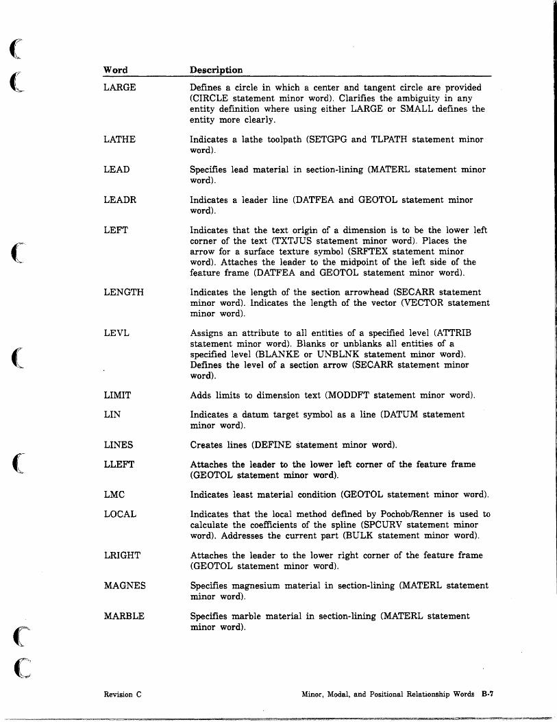
(
( ..
(
(
(
c c
Word
LARGE
LATHE
LEAD
LEADR
LEFT
LENGTH
LEVL
LIMIT
LIN
LINES
LLEFT
LMC
LOCAL
LRIGHT
MAGNES
MARBLE
Revision C
Description
Defines a circle in which a center and tangent circle are provided (CIRCLE statement minor word). Clarifies the ambiguity in any entity definition where using either LARGE or SMALL defines the entity more clearly.
Indicates a lathe toolpath (SETGPG and TLPATH statement minor word).
Specifies lead material in section-lining (MATERL statement minor word).
Indicates a leader line (DATFEA and GEOTOL statement minor word).
Indicates that the text origin of a dimension is to be the lower left corner of the text (TXTJUS statement minor word). Places the arrow for a surface texture symbol (SRFTEX statement minor word). Attaches the leader to the midpoint of the left side of the feature frame (DATFEA and GEOTOL statement minor word).
Indicates the length of the section arrowhead (SECARR statement minor word). Indicates the length of the vector (VECTOR statement minor word).
Assigns an attribute to all entities of a specified level (ATTRIB statement minor word). Blanks or unblanks all entities of a specified level (BLANKE or UNBLNK statement minor word). Defines the level of a section arrow (SECARR statement minor word).
Adds limits to dimension text (MODDFT statement minor word).
Indicates a datum target symbol as a line (DATUM statement minor word).
Creates lines (DEFINE statement minor word).
Attaches the leader to the lower left comer of the feature frame (GEOTOL statement minor word).
Indicates least material condition (GEOTOL statement minor word).
Indicates that the local method defined by PochoblRenner is used to calculate the coefficients of the spline (SPCURV statement minor word). Addresses the current part (BULK statement minor word).
Attaches the leader to the lower right corner of the feature frame (GEOTOL statement minor word).
Specifies magnesium material in section-lining (MATERL statement minor word).
Specifies marble material in section-lining (MATERL statement minor word).
Minor, Modal, and Positional Relationship Words B·7

Word
MATRIX
MAXMIN
MEMBER
MIDDLE
MINUTE
MMC
MODFY
MODVW
NAME
NECK
NEGATV
NFIXED
NOAREA
NONE
NOPROJ
NORMAL
Description
Creates an auxiliary view from the given matrix elements (VIEW statement minor word).
Sets the view to automatic maximum and minimums (ZOOM statement minor word).
Retrieves the members (entities) which form a group or composite curve (OBTAIN statement minor word).
Places the text of a dimensioning entity between the dimension line (TXTLOC statement minor word). The leader line starts from the middle text line (LEADER statement modal word in ANSI 82).
Indicates that the angle text of a radial dimension is in degrees and minutes (TXTANG statement modal word) (ANUNIT statement modal word in ANSI 82).
Indicates maximum material condition (GEOTOL statement minor word).
Indicates that the position of the frame may be modified so that a horizontal or vertical line can be drawn (DATFEA and GEOTOL statement minor word).
Indicates that the point coordinates are given in modal space (EVALC or EVALS statement minor word).
Defines or extracts subattribute name(s) from an entity (ATTRIB and OBTAIN statement minor word). Retrieves the named mstring file (MSTRNG statement minor word).
Indicates the minimum distance between the arrowhead and the first jog of the main body (SECARR statement minor word).
Establishes in note parallel to a line a negative x-direction (NOTE statement minor word). Left-justifies the generated character string (CONYER statement minor word).
Indicates number of flXed curves for curve mesh surface (CMSRF statement minor word).
Indicates a datum target symbol without an area (DATUM statement minor word).
Indicates that neither side is selected as the origin (DIMORG statement modal word). Indicates that no section arrows are drawn (SECARR statement minor word).
Indicates a normal projection of a point on a curve (POINT statement minor word).
Specifies a point normal to a surface (POINT and MACCRV statement minor word). Defmes a circle normal to the work view (CIRCLE statement minor word).
B·8 ICEM GPL for NOS Revision C
(j '~
l

(
(
c C~
Word
NORPNT
NORTN
NORTH
NUMBER
NUMBRX
NUMBRY
NVARY
OFF
ON
ORIGIN
OUT
OUTPUT
PARAM
Revision C
Description
Indicates no repaint during a view change (CHANGE statement minor word).
Suppresses automatic return from execution of MSTRNG (MSTRNG statement minor word).
Indicates a north bearing (bearing/distance POINT statement minor word). Locates a template instance from a given origin (TEMPLT statement minor word).
Defines a number. For example, a number of points is defined (entity definition minor word). Defines or extracts subattribute number(s) from an entity (ATTRIB statement minor word). Converts a real number into a character string (CONVER statement minor word). Deletes a number of entities from an entity array (DELETE statement minor word). Retrieves the number of characters in a character string (OBTAIN statement minor word). Unblanks a number of entities (UNBLANK statement minor word). Defines an entity array (PROJEC, SECTON, TLPATH, and SECARR statement minor word).
Indicates number of times an entity or group of entities is to be repeated in the x-direction (ARRAY statement minor word).
Indicates number of times an entity or group of entities is to be repeated in the y-direction (ARRAY statement minor word).
Indicates number of variable curves for curve mesh surface (CMSRF statement minor word).
Turns a modal statement off.
Turns a modal statement on.
Indicates the origin of the auxiliary view (VIEW statement minor word). Defmes the origin of a drawing (ZOOM statement minor word).
Generates the dimension line outside of the circle or arc, pointing toward the arc (CDIMEN statement minor word).
Declares a file as an output file (OPEN and BULK statement minor word).
Indicates the start and end parameters of a direction line (TABCYL statement minor word). Indicates the parameters of an entity are to be returned (OBTAIN statement minor word). Returns point coordinates from a specified parameter (EVALC and CURARR statement minor word). Returns u and v point coordinates from a specified parameter (EVALS statement minor word).
Minor. Modal. and Positional Relationship Words B·9

Word
PARLA
PARLEL
PARNOR
PARTNA
PATERN
PENNUM
PERPTO
PHANTM
PIERCE
PLASTC
POINTS
POSITV
POSN
Description
Indicates that the witness line is parallel to the corresponding line or circle (dimension statement minor word).
Defines a line parallel to an existing line (LINE statement minor word). Generates the desired dimension parallel to the given line or the line that would exist between the given points (LDIMEN and ANGCTL statement minor word).
Generates the desired dimension normal to a set of parallel lines (LDIMEN statement minor word).
Retrieves the current part and sheet number (OBTAIN statement minor word).
Retrieves a pattern from the local pattern library (RTRIEV statement minor word).
Indicates the datum target pen number (DATUM statement minor word).
Defines a line perpendicular to a given line (LINE statement minor word). Specifies a plane perpendicular to another plane or a vector (PLANE statement minor word).
Defines all subsequent curves as phantom until a new font is entered (FONT statement minor word).
Defmes a surface pierce point (POINT and MACCRV statement minor word).
Specifies plastic material in section lining (MATERL statement minor word in ANSI 82).
Creates points (DEFINE statement minor word). Deletes all points (DELETE statement minor word). Returns the parameter of a specified point (EVALC and EVALS statement minor word). Indicates plane defInition using three edge points (PLANE statement minor word).
Establishes a positive x-direction for a note parallel to a line (NOTE statement minor word). Generates a character string right-justified in a lO-character array with leading blanks (CONVER statement minor word).
Indicates the origin position. The origin coordinates are supplied directly by the user's graphic input (screen position) (DORIG and TXTORG statement minor word). Produces a dual dimension with a line separating the upper and lower dimensions (DUAL statement minor word).
B-I0 ICEM GPL for NOS Revision C
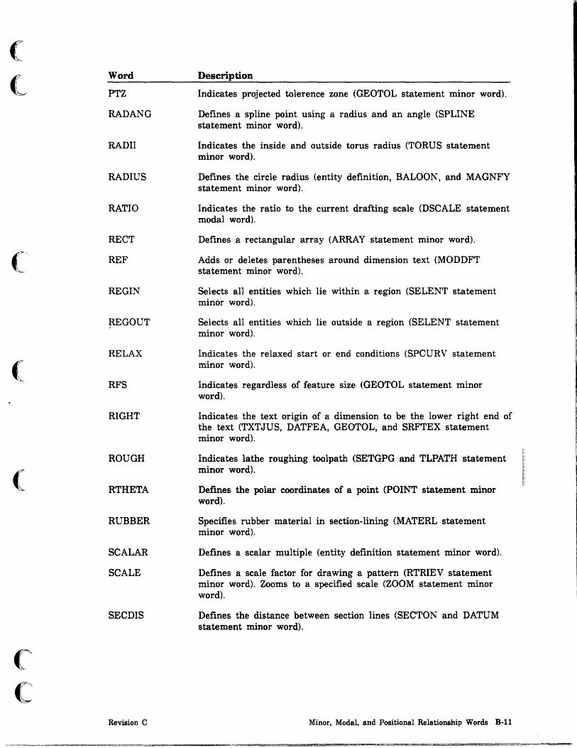
(
<-
(
(
(~.
C
Word
PTZ
RADANG
RADII
RADIUS
RATIO
RECT
REF
REGIN
~EGOUT
RELAX
RFS
RIGHT
ROUGH
RTHETA
RUBBER
SCALAR
SCALE
SECDIS
Revision C
Description
Indicates projected tolerence zone (GEOTOL statement minor word).
Defines a spline point using a radius and an angle (SPLINE statement minor word).
Indicates the inside and outside torus radius (TORUS statement minor word).
Defines the circle radius (entity definition, BALOON, and MAGNFY statement minor word).
Indicates the ratio to the current drafting scale (DSCALE statement modal word).
Defines a rectangular array (ARRAY statement minor word).
Adds or deletes parentheses around dimension text (MODDFT statement minor word).
Selects all entities which lie within a region (SELENT statement minor word).
Selects all entities which lie outside a region (SELENT statement minor word).
Indicates the relaxed start or end conditions (SPCURV statement minor word).
Indicates regardless of feature size (GEOTOL statement minor word).
Indicates the text origin of a dimension to be the lower right end of the text (TXTJUS, DATFEA, GEOTOL, and SRFTEX statement minor word).
Indicates lathe roughing toolpath (SETGPG and TLPATH statement minor word).
Deimes the polar coordinates of a point (POINT statement minor word).
Specifies rubber material in section-lining (MATERL statement minor word).
Defines a scalar mUltiple (entity definition statement minor word).
Defines a scale factor for drawing a pattern (RTRIEV statement minor word). Zooms to a specified scale (ZOOM statement minor word).
Defines the distance between section lines (SECTON and DATUM statement minor word).
Minor, Modal, and Positional Relationship Words 8-11

Word
SECOND
SEQNUM
SHEET
SINGLE
SLATE
SLOPE
SMALL
SOLID
SOUTH
SPHRIC
START
STD
STDVW
STEEL
Description
Indicates that the second side is selected as the dimension origin (DIMORG statement modal word). Indicates that the angle text of a radial dimension is in degrees, minutes, and seconds (TXTANG and DECMAL statement minor word) (AN UNIT statement minor word).
Retrieves the sequence number of an entity (OBTAIN statement minor word). Names the entity with that sequence number (ASSIGN statement minor word).
Indicates the sheet number of the balloon (BALOON statement minor word).
Selects single entities (SELENT statement minor word).
Specifies SLATE material in section-lining (MATERL statement minor word).
Supplies a slope at either a spline start or spline end (SPLINE statement minor word). Indicates the angle of the leader line (LABEL and TAPER statement minor word).
Deflnes a circle in which the center and tangent circle are provided (CIRCLE statement minor word). Clarifies the ambiguity in any entity deflnition where using either LARGE or SMALL deflnes the entity more clearly.
Defmes all subsequent curves as solid lines (FONT statement minor word).
Indicates a south bearing (bearing/distance POINT statement minor word). Locates a template instance from a given origin (TEMPLT statement minor word).
Deflnes spherical coordinates (POINT statement minor word).
Indicates that the leader line starts at the start of the label (CDIMEN and LABEL statement minor word). Indicates the start point for the start of the intersection (PTSET statement minor word). Indicates the start point of the intersection curve (FILSRF statement minor word). Indicates that the start point of the leader line is at the beginning of the dimension (SECARR statement minor word).
Sets the character set to standard (CSET statement minor word).
Retrieves the view pointer of a standard view (OBTAIN statement minor word).
Specifies steel material in section-lining (MATERL statement minor word).
B·12 ICEM GPL for NOS Revision C

(
(
("
C
Word
SUBAT
SUPPB
SUPPBl
SUPPB2
SUPPI
SUPP2
SUPPll
SUPP22
TABLET
TANTO
TEXTD
THICK
THREAD
TILTAN
TOLER
TOLMOD
TOLREF
Revision C
Description
Defines or deletes a subattribute of an entity (ATTRIB statement minor word). Retrieves a subattribute from an entity (OBTAIN statement minor word).
Suppresses the display of both witness lines (dimension and WLINE statement minor word).
Suppresses the display of both witness lines and the first dimension line (dimension and WLINE statement minor word).
Suppresses the display of both witness lines and the second dimension line (dimension and WLINE statement minor word).
Suppresses the display of the first witness line (dimension and WLINE statement minor word).
Suppresses the display of the second witness line (dimension and WLINE statement minor word).
Suppresses the display of the first dimension line and the first witness line (dimension and WLINE statement minor word).
Suppresses the display of the second dimension line and the second witness line (dimension and WLINE statement minor word).
Designates the tablet as the input device (CURSOR statement minor word).
Defines a line where the line is tangent to circles, or through a point and tangent to a circle (LINE statement minor word).
Sets the distance from the text of a dimension to its dimension lines (DIMOF statement minor word).
Indicates the thickness of the section arrow's main body (SECARR statement minor word).
Indicates a lathe threading toolpath (SETGPG and TLPATH statement minor word).
Defines a rectangular array at an angle with the horizontal axis CARRA Y statement minor word).
Specifies the tolerance ratio (CDISPL statement minor word).
Indicates the tolerance modifier (GEOTOL statement minor word).
Indicates the tolerance reference (GEOTOL statement minor word).
Minor, Modal, and Positional Relationship Words B-13

Word
TOTAL
TRIM
TYPIN
UDIREC
ULEFT
UNIT
UPATHS
URIGHT
USER
USTART
UTERM
UWRITE
VDEF
VDIREC
VECSUM
VERTCL
VPATHS
Description
Writes notes at a user-specified angle parallel to a line or arc.
Trims the lines which bound the fillet ,or chamfer at the fillet tangent points, or chamfer section point (FILLET and CHAMFR statement minor word).
Indicates the user enters origin coordinates (DORIG statement minor word).
Sets the number of points per U -path for surface display (SPATHS statement minor word).
Attaches a leader to the upper left corner of the feature frame (GEOTOL statement minor word).
Sets the unit normal vector (VECTOR statement minor word).
Sets the number of U -paths for surface display (SPATHS statement minor word).
Attaches the leader to the upper right corner of the feature frame (GEOTOL statement minor word).
Sets the character set to user defined (CSET statement minor word). Sets entity selection to user input (SELENT statement minor word).
Writes a new DEFBLK card (USTRUC statement minor word).
Terminates a UNISTRUC program (USTRUC statement minor word).
Writes entity data (USTRUC statement minor word).
Indicates section lining is displayed in the view of definition only (SECVIS statement modal word).
Sets the number of points per V -path for surface display (SPATHS statement minor word).
Adds two vectors (VECTOR statement minor word).
Defines a vertical line through a point (LINE statement minor word). Generates the desired dimension parallel to the y-axis (LDIMEN statement minor word). Changes the view to the top or bottom view (CHANGE statement minor word). Indicates a vertical base (SRPTEX statement minor word).
Indicates number of V -paths for surface display (SPATHS statement minor word).
B·14 ICEM GPL for NOS Revision C

(
(
c c
Word
WEST
WIDTH
WITP
WITX
XAXIS
XLARGE
XMOVE
XSMALL
XSTART
XTROT
XYMOVE
XYVALUE
YAXIS
YES
YLARGE
YMOVE
YSMALL
Revision C
Description
Indicates a west bearing (bearing/distance POINT statement minor word). Locates a template instance from a given origin (TEMPLT statement minor word).
Indicates the width of the section arrowhead (SECARR statement minor word).
Indicates that the distance of a witness line is offset from the endpoint of the entity at which it is pointing (DIMOF statement minor word).
Indicates that the distance of a witness line extends past the dimension line (DIMOF statement minor word).
Defines an x-axis (LINE statement minor word). Specifies the mirror axis (MIRROR statement minor word).
Clarifies in any ambiguous entity definition that the desired point has the larger of two possible x-coordinate values.
Allows point movement in the xt direction only (SPLINE statement minor word).
Clarifies in any ambiguous entity definition that the desired point has the smaller of two possible x-coordinate values.
Defines the initial x-value in entity definition statements.
Performs a rotation about the x-axis to create an auxiliary view (VIEW statement minor word).
Allows point movement in the xt and yt directions (SPLINE statement minor word).
Defines an x-value on a line (POINT statement minor word).
Defines a y-axis (LINE statement minor word). Defines the mirror axis (MIRROR statement minor word).
Aligns the present linear dimension arrowheads with those of the previous or user-selected dimension (LDIMEN statement minor word) (SECTON statement minor word in ANSI 82). Defines a group (RTRIEV statement minor word).
Clarifies in any ambiguous entity definition that the desired point has the larger of two possible y-coordinate values.
Allows point movement in yt direction only (SPLINE statement minor word).
Clarifies in any ambiguous entity definition that the desired point has the smaller of two possible y-coordinate values.
Minor, Modal, and Positional Relationship Words B·15
!§!~ .. _ 2r2L_

Word
YSTART
YTROT
YVALUE
ZAXIS
ZLARGE
ZSMALL
ZSTART
ZTROT
ZVALUE
Description
Defmes the initial y value in entity definition statements.
Performs a rotation about the y-axis to create an auxiliary view (VIEW statement minor word).
Defines a y value on a line (POINT statement minor word).
Defines a z-axis in entity definition statements.
Indicates the desired point has the larger of two (2) possible z-coordinate values for surface definition statements.
Indicates the des'ired point has the smaller of two (2) possible z-coordinate values for surface definition statements.
Defines the initial z value in entity definition statements.
Performs a rotation about the z-axis to create an auxiliary view (VIEW statement minor word).
Defines a z-value on a line (POINT statement minor word).
B-16 ICEM GPL for NOS Revision C

(
(
(
(
(
c c
ICEM DDN Entity Types C
The following lists the entity types that can be used in GPL.
Type Description
1 Point 2 Line 3 Arc/circle/fillet 4 General conic 5 2-D spline 6 Composite curve 7 Vector 8 Point set 9 3-D spline 10 Machining curve 11 String 12 Rectangular array 13 Circular array 14 Copious data 15 Group 16 Real variable 18 Plane 19 Surface of revolution 20 Tabulated cylinder 21 Ruled/developable surface 22 Curve mesh surface 23 Fillet surface 26 Bezier surface 28 Offset surface 29 Composite surface 30 Curve driven surface 31 Bezier curve 32 Linear dimension 33 Circular dimension 34 General label 35 Diameter dimension 36 Angular (radial) dimension 37 General note 38 Centerline 39 Cross hatching 40 True position symbol 41 Template 45 Systems GPG, Inserts, and NC modal 46 Toolpath 47 Composite toolpath 48 Toolpath GPG and inserts 49 Tool 50 Systems entity
Revision C ICEM DDN Entity Types C-l


(
( GPL Execution Error Messages D
The following messages can occur during execution.
Message Description
1 Error in read program file 2 Error in read data file 3 Error in write data file 4 Illegal key 5 Illegal major word 6 Illegal position word 7 Illegal modal or minor word 8 Illegal control byte 9 Illegal data file address 10 Undefined entity
(' 11 Illegal entity type 12 Variable used as entity 13 Entity used as variable 14 Illegal variable or constant 15 Illegal entity subtype 16 End of statement not found 17 Math error: no unique solution 18 Subroutine not in library 19 N umber of parameters inconsistent 20 Variable not found in RTL
( 21 Variable table overflow 22 Modal word missing 23 DO/DONT index out of bounds 24 Invalid conic 25 MIRROR line length too small 26 Too few or too many entities 27 Too few or too many spline points 28 Character set not found in UTF 29 Illegal scale factor 30 SQRT called with negative argument
( 31 No intersection point found 32 Distance too small 33 Angle out of range 34 Area not uniquely defined 35 Boundary not closed 36 Boundary too complex 37 Maximum iteration count exceeded 38 Division by nearly zero 39 Entities must be of same type 40 Curves not contiguous 41 The planes are parallel 42 No edge point found to start 43 Both lines have zero length 44 Lines are parallel 45 Plane dermition is not unique 46 Axis length too small
(~ 47 Directrix length too small
C Revision C GPL Execution Error Messages D-l

Message
48 49 50 51 52 53 54 55 56 57 58 59 60 61 62 63 64 65 66 67 68 69 70 71 72 73 74 75 76 77 78 79 80 81 82 83 84 85 86 87 88 89 90 91 92 93 94 95 96 99 100 101 102 103
Description
Character set name too long CLINE points not coincident No plane between the lines selected Distance too large for FILLET Bad count for data file I/O Internal error: cannot find any PTE (GLRDF) Buffer conflict in GLFLDF Curve(s) is/are outside of view Line is parallel to coordinate Text center is outside limit Membership count is too high Statement not yet implemented View matrix is not orthonormal Data input for SPCURV incorrect Two consecutive points are coincident Tangent for SPCURV is zero PATTERN disk read error Sequence number not found Error on file MESHFIL Too many views selected Could not match curvatures Cannot file part Range error in computed GOTO Function argument out of range Too many attribute data Vector has zero length Entity name already exists in RTL Overlay or capsule library search fails Overlay or capsule too large Overlay or capsule cannot be linked Modify in wrong view Tried to read past EOF No intersection point found (TOL) TMPLT: Master undefined our unlinked TMPLT: Master already defmed Cannot derme machining draft curve Tolerance too small for draft curve Angle for draft curve out of range Register denotation out of range Character variable too short Character variable too long Cannot restore buffer' from cache Error indicator return from ICEM DDN Too many fixed curves (CMSRF) Too many variable curves (CMSRF) N umber of curves (F*V) exceeds limit Surface could not be defmed (DEVSRF) Both surfaces are infinite planes Array index is not positive Drafting entity cannot be completed Aligning with nonsimilar dimension Illegal geometric characteristic Only 64 entities allowed At least one entity is required
D-2 ICEM GPL for NOS Revision C

(
(
(
(
(
(
(
Message
104 105 106 107 108 109 110 111 112 113 114 115 116 117 118 119 120 121 122 123 124 125 131 132 133 134 141 142 143 144 145 151 152 154
Revision C
Description
Value must be greater than zero Negative value not allowed At least two points required Conversion error occurred Same circle for MAG and MAG area Ten-entity limit attached to arrow At least two JOG positions are required Only 50 JOG positions are allowed Y coord not supplied with X coord Illegal number of datums and tolerances Geometric characteristic required for composite Group member illegal in composite curve File not found GPG not compatible with entity type Generation parameter group not found Definition start indeterminate Invalid number supplied Condition requiring prompt encountered Entity not found Incompatible entity used in definition GPG statement errors, see file - GPGERR GPG file read error Sytax error within menu string Error found while reading MSTRING file Menu string name not on file Menu string file cannot be retrieved No closed boundary can be determined No cut passes could be generated Material to be removed outside boundary Blank entity not found Contour entity not found GPLIS file index or header incorrect Blanked entity is not selectable Cannot fmd normal/pierce point
GPL Execution Error Messages D·3
f

(
(
System 1/0 Commands E
CAUTION
The statements documented in this appendix are recommended for experienced users only. If you use the statements improperly, you could destroy the TAPE3 part file. Refer to the ICEM DDN System Programmer's Reference Manual for information about the ICEM DDN COMMON arrays.
EC(3) and EC(4) are not accessible by this command. A value of 0 will be returned without error if an attempt is made to access them.
The statement:
SEQNO/value
sets the next sequence number to be assigned by ICEM DDN in EC(27) to the specified value, with the restrictions that:
• Value must not be below the current content of EC(27).
• Value must not be above 2**16.
The statement:
SYSTEM/type,indicator,index,count,variable[,entity]
permits the transfer of data between the system COMMON arrays and GPL variables.
Parameter
type
indicator
index
Description
A number from 1 to 4 that defines the type of operation as follows:
1 Read from integer COMMON array
2 Read from real COMMON array
3 Write to integer COMMON array
4 Write to real COMMON array
A number from 1 to 20 (according to ICEM DDN menu 6.7.1 display) that indicates which COMMON array is to be addressed.
A number from 1 to the size of the addressed array that gives the starting index for the transfer.
Revision C System I/O Commands E-l

Parameter
count
variable
entity
The statement:
Description
The number of words to be transferred, if positive. If this quantity is negative, the number is assumed to be 1, and count is used as a mask to select certain bit fields, the contents of which are shifted to the right-justified position.
For example:
count =-6
reads what is in bits 1 and 2 (note that 2**1 + 2**2 = 6) and shifts the contents down to positions 0 and 1. A negative count is valid only if type = 1.
The name of a GPL real variable, or if cnt/m is greater than 1, the array to receive or give the values transferred.
GPL entity variable containing a valid entity pointer. This parameter is only required if type is 1 or 3 and indicator is 5 (meaning the EC array).
[TAB ']
OBTAIN/ TAB2 ,entity,1ndex,count,(Variable) TAB3 entity
obtains common data from TAB1, TAB2, or TAB3.
Count words are obtained from the indicated array, starting at the specified index for the defined entity; the count words are transferred to the variable.
If the indicator is TAB2, an entity (or entity array) may alternatively be specified as receiving field if the TAB2 content at the specified index consists of entity pointers.
E-2 ICEM GPL for NOS Revision C

(
(
(
(
GTGT: GRAPL-to-GPL Translator F
This utility will execute, external to ICEM DDN, via a typical control language program call from within a batch job or 'procedure, or interactively from the terminal.
Example:
GTGT.
GTGT will have the capability of substituting local file names for the input, output, and list files.
Example:
GTGT (I=INPF, O=OUTF, L=LISTF)
If these local file names are not supplied, as in the former example above, the default local file names GRAIOF, COMPILE, and GPLLIST will be assumed for input, output, and list respectively. (GRAIOF and COMPILE are also default input file names for GRAPL and GPL source, respectively, in ICEM DDN and the GPL compiler.)
The input file (default GRAIOF) may be a multi-record file. Each record of GRAIOF contains one GRAPL program preceded by a header (the program name) of from one to six alphanumeric characters. This header will be translated to a "PROC/progname" statement in GPL, where "progname" is the header, and written to the output file as line 1. Line 2 written to the output file will contain the REMARK: $$CAUTION- IF PROGRAM, CHANGE "PROC" TO "MAIN".
Some statements do not translate. In these cases informative remarks are written to the output file.
Revision C GTGT: GRAPL-to-GPL Translator F-l

t. ,

(
(
(
(
(
(
(
GPL Program Examples
Flange Program
Figure G-l depicts a flange, which is a standard part in the mechanical design environment. Usually, the dimensions are defined as variables, and in practice, the variables are replaced by dimensions that meet the total design criteria.
h1
I I I \. I I, ...--. --
Figure G-l. Standard Welding Neck Flange
This example explains how the flange is defined using the GPL language. In this example, you can modify all of the dimensions in an interactive mode. The variables are input via the READ feature of GPL. The input file is defined as FLANSCH.
The program documentation explains the programming techniques used to defme the part.
You are encouraged to study the enclosed program listing to gain a better understanding of GPL and the programming techniques used in this example.
G
Revision C GPL Program Examples G-l

Flange Program
Figure G-2 shows the layout used for FLANSCH.
I
XO. YO +
9 8 8
7
9
1 1(101
7 18
6
6 5
3 2 3
2
5
4
4
Figure G-2. Flange Layout
The definition of variables for figure G-2 follows.
X( 1) 01/2-5 Y( 1) 0 X(2) 04/2 Y(2) 0 X(3) X(2)+F Y(3) F
X(4) (K-02)/2 Y(4) F xeS) X(4) yes) B X(6) 03/2 Y(6) B X(7) 01/2 $$ Y(7) Hl-H2 $$ MIRROR ABOUT Y-AXIS xes) 01/2 $$ yes) = Hl FOR 1=1, UNTIL 10 X(9) = X(l) X(I) = X(I) Y(9) = Hl EOFI X(10) = X(l) $$ Y(10) = Y(l) 10 CONTIN
G·2 ICEM GPL for NOS
17
14 1 3
13 I 14 12
11
11 (15) 1 2
iT "
iJ
\
(
~
Revision C
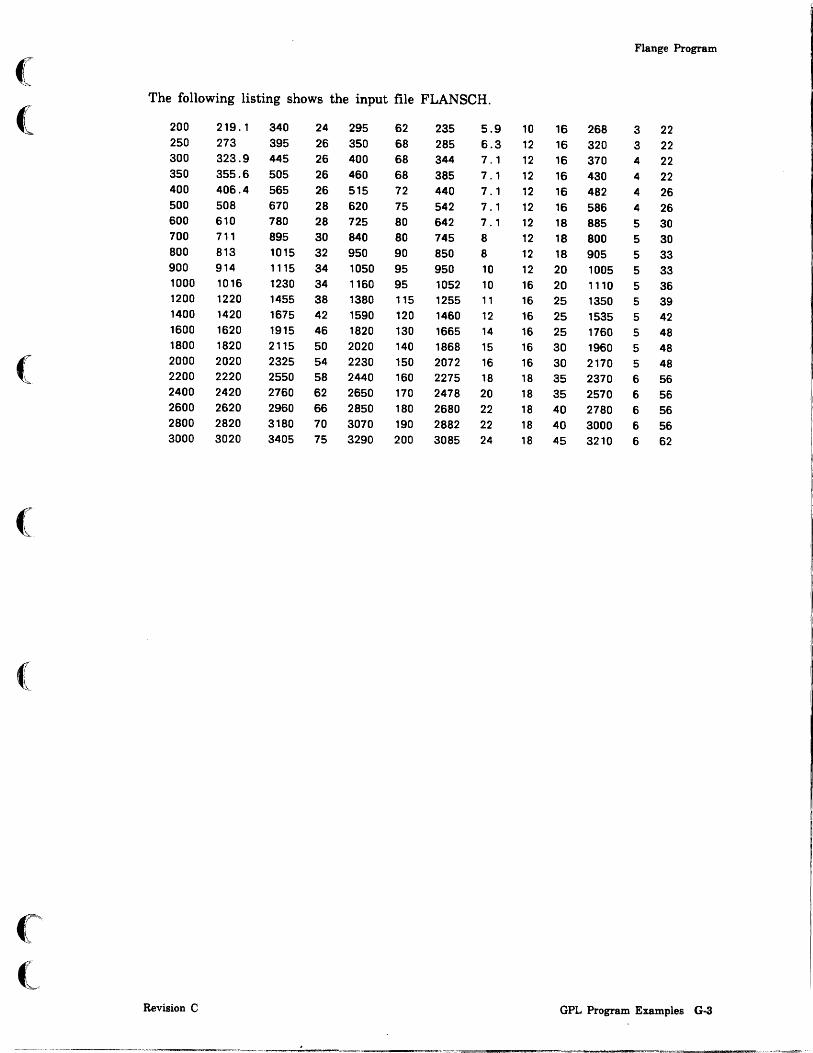
Flange Program
( The following listing shows the input file FLANSCH.
( 200 219.1 340 24 295 62 235 5.9 10 16 268 3 22 250 273 395 26 350 68 285 6.3 12 16 320 3 22 300 323.9 445 26 400 68 344 7.1 12 16 370 4 22 350 355.6 505 26 460 68 385 7.1 12 16 430 4 22 400 406.4 565 26 515 72 440 7.1 12 16 482 4 26 500 508 670 28 620 75 542 7.1 12 16 586 4 26 600 610 780 28 725 80 642 7.1 12 18 885 5 30 700 711 895 30 840 80 745 8 12 18 800 5 30 800 813 1015 32 950 90 850 8 12 18 905 5 33 900 914 1115 34 1050 95 950 10 12 20 1005 5 33 1000 1016 1230 34 1160 95 1052 10 16 20 1110 5 36 1200 1220 1455 38 1380 115 1255 11 16 25 1350 5 39 1400 1420 1675 42 1590 120 1460 12 16 25 1535 5 42 1600 1620 1915 46 1820 130 1665 14 16 25 1760 5 48 1800 1820 2115 50 2020 140 1868 15 16 30 1960 5 48
( 2000 2020 2325 54 2230 150 2072 16 16 30 2170 5 48 2200 2220 2550 58 2440 160 2275 18 18 35 2370 6 56 2400 2420 2760 62 2650 170 2478 20 18 35 2570 6 56 2600 2620 2960 66 2850 180 2680 22 18 40 2780 6 56 2800 2820 3180 70 3070 190 2882 22 18 40 3000 6 56 3000 3020 3405 75 3290 200 3085 24 18 45 3210 6 62
(
Revision C GPL Program Examples G-3

Flange Program
The following is a listing of the program FLANGE. This program requires that the input data file FLANSCH is also attached.
MAIN/FLANGE $$ $$ • • • • • • • • • • • • • • • • • • • • • • • • • •
$$ • MAIN PROGRAM FOR FLANGE • $$ • • • • • • • • • • • • • • • • • • • • • • • • • •
$$ $$ ••• MAIN PROGRAM FOR DRAWING AND DIMENSIONING $$ ••• A FLANGE UTILIZING THE READ FEATURE OF GPL $$ ••• TO GET THE DIMENSIONS FOR THE FLANGE TO $$ ••• BE CREATED. $$ $$ ••• LOCAL DECLARATIONS---$$ REAL/E(2),ARR(3),STAT,XPOS,YPOS,ZPOS,ANS $$ $$ ••• ASK USER FOR NOMINAL DIAMETER AND ROTATION ANGLE $$ 1000 CONTIN PARAMS/'··· PLEASE TYPE IN ••• ' ,2,'NOM. DIAM.' ,'ANGLE' ,E(1),STAT NENN E( 1)
WINKEL = E(2) $$ $$ ••• DETERMINE THE BASE COORDINATES OF THE FLANGE $$ 10 CALL/GRPOS,XPOS.YPOS,ZPOS XD = XPOS YD = YPOS $$ $$ ••• READ DIMENSIONS ACCORDING TO NOMINAL DIAMETER $$ 20 CALL/TABELE.NENN.D,01.D2,D3,D4,S.K.H1,H2,F,B,R $$ $$ ••• DRAW THE FLANGE AND DISPLAY THE DIMENSIONS $$ CALL/GEOMET,D.D1.D2.D3,D4.S.K.H1.H2.F.B.R.WINKEL.XD.YD $$ $$ ••• ALL DONE, ASK IF USER WANTS ANOTHER FLANGE $$ QUERY/'ANOTHER FLANGE (Y/N)? '.ANS IF ( ANS . EQ . 1. ) GO TO 1000 $$ $$ ••• TERMINATE PROGRAM. USER ANSWERED NO $$ STOP/'ALL DONE' FIN!
G-4 ICEM GPL for NOS Revision C

(
(
(
(
(
TABELE Subprogram
The following is a listing of the subprogram TABELE.
PROC/TABELE.NENN.D.D1.D2.D3.D4.S.K.H1.H2.F.B.R $$ $$ • • • • • • • • • • • • • • • • • • • • • • • •
$$ • PROCEDURE TABELE $$ • • • • • • • • • • • • • • • • • • • • • • • •
$$
• • •
• •
$$ ••• PROCEDURE TO READ THE DIMENSIONS OF THE FLANGE $$ ••• GIVEN THE NOMINAL DIAMETER (NENN). $$ REAL/NENN.NW.D.D1.D2.D3.D4.B.H1.H2.S.K.R.F CHAR/LFN(7) $$ $$ ••• OPEN DATA FILE $$
MOVCHR/7.'FLANSCH' .1.LFN.1 OPEN/LFN.INPUT.STAT $$ $$ ••• CHECK FOR ERRORS $$ IF ( STAT . NE. O. ) $$
GO TO 8000
$$ ••• SET COUNT OF VARIABLES TO READ $$ COUNT = 13 $$ $$ ••• READ DATA FILE UNTIL NOMINAL DIAMETER FOUND. $$ ••• IF EOF GO TO ERROR EXIT AND PRINT MESSAGE. $$ 1000 READ/LFN,STAT.COUNT.NW.D1.D.B.K.H1.D3.S.R.H2.$
D4.F.D2 $$ $$ ••• CHECK FOR EOF $$ IF ( STAT . EQ . 1. ) GO TO 8100 $$ $$ ••• CHECK FOR OTHER ERROR (CONVERSION) $$ IF ( ST AT . NE. O. ) GO TO 8200 $$ $$ ••• CHECK IF VALUES FOUND $$ IF ( NW . NE. NENN ) GO TO 1000 $$
Revision C
Flange Program
GPL Program Examples G·5

Flange Program
$$ ••• NOMINAL DIAMETER OF FLANGE FOUND IN DATA FILE $$ ••• CLOSE DATA FILE, AND RETURN TO CALLING $$ ••• PROGRAM. $$ CLOSE/LFN,STAT JUMPTO/9000 $$ $$ • • • • • • • • • • • • • • • • • • • • • • " " " • • •
$$ " ERR 0 R SEC T ION " $$ • • " • • • • • • • • • • • • • • " " • • • • • • • • •
$$ 8000 DISPLA/'OPEN ERROR'
CLOSE/LFN,STAT STOP/'OPEN ERROR'
8100 DISPLA/'NOMINAL DIAMETER NOT FOUND ON FILE' CLOSE/LFN,STAT STOP/'NOT FOUND'
8200 DISPLA/'CONVERSION ERROR/CORRECT DATA FILE !' CLOSE/LFN,STAT STOP/'CONV ERROR'
$$ $$ " • "
$$ "
. " . " . . . " " " " . " " . . . " " " " " " " . NOR MAL E X I T •
$$ " " " . " . " " . " " . " " " " " " " " " " " " " " " " $$ 9000 RETURN
FINI
G-6 ICEM GPL for NOS Revision C

(
(
(
(
(
(
GEOMET Subprogram
The following is a listing of the subprogram GEOMET.
PROC/GEOMET,0,01,02,03,D4,S,K,H1,H2,F,B,R,WINKEL,XO,YO $$
$$ * - - - * * * - - * - - - * * - - * * - * * - * - - -$$ * PROCEDURE GEOMET *
$$ * - - - - - * - * * - - - * - - - * * - * * - - * - -$$
$$ --- PROCEDURE TO CALCULATE THE CONTOURS OF THE FLANGE $$ REAL/X(40),Y(40),R ENTITY/LN(40) $$ $$ * ** PRESET X AND Y ARRAYS $$ X( 1) = 01/2-S Y( 1) = 0 X(2) = 04/2 Y(2) 0 X(3) = X(2)+F Y(3) F X(4) (K-02)/2 Y(4) F XeS) X(4) yes) = B X(6) = 03/2 Y(6) = B X(7) = 01/2 Y(7) = H1-H2 X(8) = 01/2 Y(8) = H1 X(9) = X(1) Y(9) = H1 X(10) = X( 1)
Y(10) = y( 1)
X(1l) = (K + 02) / 2 Y(ll) '"' F X(12) = 0/2 Y(12) = F X(13) = 0/2 Y(13) = B X(14) = X( 11) Y(14) = B X(lS) = X( 11) Y(lS) = F X(16) = K/2 Y(16) '"' O. X(17) = K/2 Y(17) = B + F X(18) = 04/2 Y(18) = B + 6. *F
Revision C
Flange Program
GPL Program Examples G-7
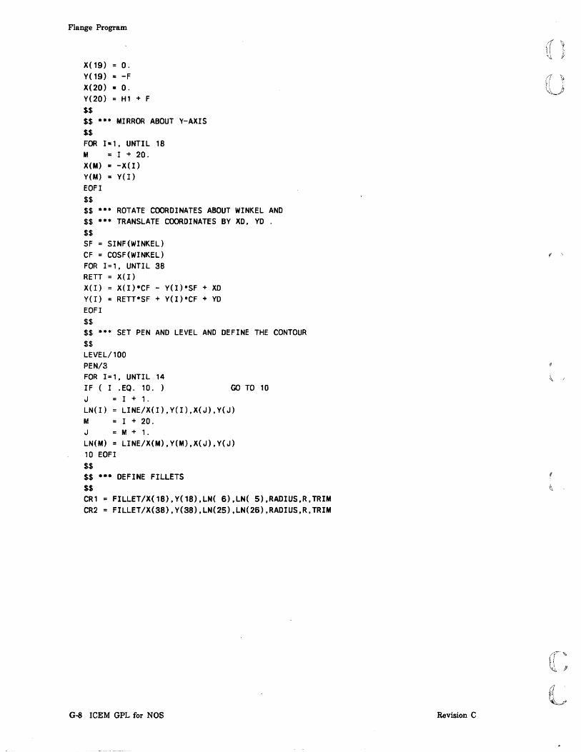
Flange Program
X(19) = O.
Y(19) = -F
X(20) = O. Y(20) = H1 + F $$ $$ **. MIRROR ABOUT Y-AXIS $$ FOR 1=1, UNTIL 18 M = I + 20. X(M) = -X(I) Y(M) = y(I) EOFI $$ $$ **. ROTATE COORDINATES ABOUT WINKEL AND $$ **. TRANSLATE COORDINATES BY XD, YO . $$ SF = SINF(WINKEL) CF = COSF(WINKEL) FOR 1=1, UNTIL 38 RETT = X(I) X(I) = X(I)*CF - Y(I)*SF + XD Y(I) = RETT*SF + Y(I)*CF + YO EOFI $$ $$ * •• SET PEN AND LEVEL AND DEFINE THE CONTOUR $$ LEVEL/100 PEN/3 FOR 1=1, UNTIL 14 IF ( I .EQ. 10. ) GO TO 10 J I + 1.
LN(I) LINE/X(I),Y(I),X(J),Y(J) M I + 20. J M + 1.
LN(M) LINE/X(M),Y(M),X(J),Y(J) 10 EOFI $$ $$ •• * DEFINE FILLETS $$ CRl FILLET/X(18),Y(18),LN( 6),LN( S),RADIUS,R,TRIM CR2 FILLET/X(38),Y(38),LN(2S),LN(26),RADIUS,R,TRIM
G-8 ICEM GPL for NOS Revision C
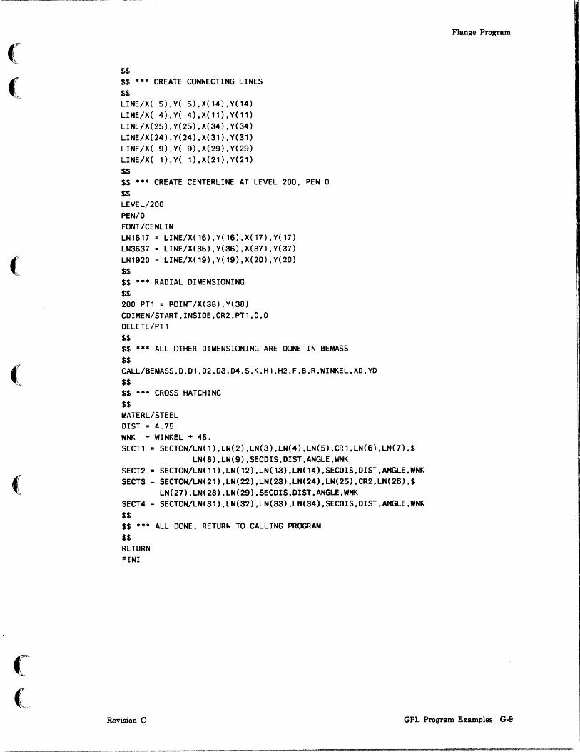
(
(
(
(
(
$$ $$ *** CREATE CONNECTING LINES $$ LINE/X( 5),Y( 5),X(14),Y(14) LINE/X( 4),Y( 4),X(11),Y(11) LINE/X(25),Y(25),X(34),Y(34) LINE/X(24),Y(24),X(31),Y(31) LINE/X( 9),Y( 9),X(29),Y(29) LINE/X( 1),Y( 1),X(21),Y(21) $$ $$ *** CREATE CENTERLINE AT LEVEL 200, PEN 0 $$ LEVEL/200 PEN/O FONT/CENLIN LN1617 LINE/X(16),Y(16),X(17),Y(17) LN3637 LINE/X(36),Y(36),X{37),Y(37) LN1920 LINE/X(19),Y(19),X(20),Y(20) $$ $$ *** RADIAL DIMENSIONING $$ 200 PT1 = POINT/X(38),Y(38) CDIMEN/START,INSIDE,CR2,PT1,0,0 DELETE/PT1 $$ $$ *** ALL OTHER DIMENSIONING ARE DONE IN BEMASS $$ CALL/BEMASS.D.D1.D2,D3,D4.S,K.H1,H2,F,B,R.WINKEL.XD,YD $$ $$ *** CROSS HATCHING $$ MATERL/STEEL DIST = 4.75 WNK = WINKEL + 45. SECT1 SECTON/LN(1),LN(2),LN(3),LN(4),LN(5),CR1,LN(6),LN(7),$
LN(8),LN(9),SECDIS,DIST,ANGLE,WNK SECT2 = SECTON/LN(11),LN(12),LN(13),LN(14),SECDIS,DIST,ANGLE,WNK SECT3 = SECTON/LN(21),LN(22),LN(23),LN(24),LN(2S),CR2,LN(26),$
LN(27),LN(28),LN(29),SECDIS,DIST,ANGLE,WNK SECT4 = SECTON/LN(31),LN(32),LN(33),LN(34),SECDIS,DIST,ANGLE,WNK $$ $$ *** ALL DONE, RETURN TO CALLING PROGRAM $$ RETURN FINI
Flange Program
Revision C GPL Program Examples G·9

:.; :.:
~~~
Flange Program
BEMASS Subprogram
The following is a listing of the subprogram BEMASS.
PROC/BEMASS,0,01,02,03,D4,S,K,H1,H2,F,B,R,WINKEL,XO,YO $$ $$ • • • • • • • • • • • • • • • • • • • • • • • • • • • •
$$ • PROCEDURE FOR DIMENSIONING • $$ • • • • • • • • • • • • • • • • • • • • • • • • • • • •
$$ $$ ••• HORIZONTAL AND VERTICAL DIMENSIONING $$ REAL/X(33),Y(33) $$ $$ ••• $$ ••• $$ ••• $$ •••
$$ OIS1 OIS2 OIS3 OIS4 X( 1)
y( 1)
X(2) Y(2) X(3) Y(3) X(4) Y(4) xeS) yes) X(6) Y(6) X(7) Y(7) xes) yes) X(9) Y(9) X(10) Y(10) X( 11) Y(ll) X(12) Y(12) X(13) Y(13) X(14) Y(14) X(lS) Y(lS) X(16) Y(16) X(17)
VARIABLE DESCRIPTIONS---X(I) Y(I)
X(I+1) Y(I+1) X(I+2) Y(I+2)
B
1.5 • B 2.0 • B
= ·2.5 • B -01/2
= H1 01/2 H1 0 H1 + OIS1 -01/2 H1 -01/2 + S Hl Xes) + 3.·S Hl + DISl
= -K/2 -02/2 = B
= -K/2 + 02/2 == B == -K/2
B + OISl -03/2 B 03/2 B o. -OISl -04/2 o. 04/2 o. O.
== -0152 -K/2 O.
== K/2
G-IO ICEM GPL for NOS
FIRST COORDINATE SECOND COORDINATE CENTER OF TEXT
;
Revision C

(
(
(
(
(
(
(-
Y(17) X(18) Y(18) X(19) Y( 19) X(20) Y(20) X( 21 ) Y(21) X(22) Y(22) X(23) Y(23) X(24) Y(24) X(25) Y(25) X(26) Y(26) X(27) Y(27) X(28) Y(28) X(29) Y(29) X(30) Y(30) X(31) Y(31 ) X(32) Y(32) X(33) Y(33) $$
= O. = O. = -0153
-0/2 O. 0/2 O. O. -0154
= 01/2 = H1 - H2 = 01/2 = H1 = 01/2 + 0151 = H1 - H2/2
0/2 O. 0/2 F
0/2 + 0151 4.*F
0/2 O. 0/2 B 0/2 + 0152 B/2 01/2 O. 01/2
= H1 = 0/2 + 0153 = H1/2
$$ *** ROTATE COORDINATES ABOUT WINKEL AND $$ *** TRANSLATE COORDINATES BY XO, YO . $$ SF = SINF(WINKEL) CF = COSF(WINKEL) FOR 1=1, UNTIL 33 RETT = X(I) X(I) = X(I)*CF - Y(I)*SF + XO Y(I) = RETT*SF + Y(1)*CF + YO EOFI
Revision C
Flange Program
GPL Program Examples G-ll

Flange Program
$$ $$ *** DIMENSIONING $$ FOR 1=1, STEP 3, UNTIL 31 J I + 1.
M I + 2. XDIF X(J) - XCI) YDIF Y(J) - Y(I) DIFF = SQRT(XDIF*XDIF+YDIF*YDIF) ARIN IF ( DIFF .GT. 30. ) GO TO 10 AROUT 10 CONTIN PT1 POINT/X(I),Y(I) PT2 = POINT/X(J),Y(J) PT3 = POINT/X(M),Y(M) LDIMEN/PARLEL,PT1,PT2,PT3,0,0 DELETE/PT1,PT2,PT3 EOFI $$ $$ .*. ALL DONE, RETURN TO CALLING PROGRAM $$
RETURN FINI
G·12 ICEM GPL for NOS Revision C

(
(
(
(
(
GRPOS Subprogram
The following is a listing of the subprogram GRPOS.
PROC/GRPOS, XPOS, VPOS ,ZPOS $$ $$ • • • • • • • • • • • • • • • • • • • • • * • • • • $$ • PROCEDURE GRPOS • $$ • • • • • • • • • • • * • • • • • • • • • * • • • • $$ $$ ••• PROCEDURE TO GET THE BASE COORDINATES FOR $$ ••• THE FLANGE. $$ $$ ,. SELECT SCREEN POSITION $$ 2. KEVIN SCREEN COORDINATES $$ 3. SELECT EXISTING POINT $$ REAL/KOOR(3),XPOS,VPOS,ZPOS,STAT,CNT,ISW ENTITV/ENT(2) $$ $$ ••• GIVE USER THE CHOICE TO SELECT COORDINATES $$ 5 MENU/'·· FLANGE BASE COORDINATES •• ' ,'SCREEN POSITION·S KEVIN CooRDINATES·EXISTING POINT·' ,ISW,STAT $$ $$ ••• CHECK FOR REJECT $$ IF STAT .GE. O. GO TO 9999 I F I SW . NE. 1. GO TO 20 $$ $$ ••• SELECT SCREEN POSITION $$ 10 POS/'·· INDICATE SCREEN POSITION •• ' ,XPOS, VPOS , ZPOS ,STAT IF ( STAT .GE. O. ) GO TO 5 JUMPTO/9999 $$ $$ ••• KEVIN COORDINATES $$ 20 IF ( ISW .NE. 2 ) GO TO 30 PARAMS/'·· ENTER COORDINATES ··',3,'X-COORD' ,'V-COORD' ,'Z-COORD' ,$
KOOR{'), STAT IF ( STAT .EQ. O. XPOS KOOR(1) VPOS = KOOR(2) ZPOS = KOOR(3) JUMPTO/9999
GO TO 5
Flange Program
Revision C GPL Program Examples G·13
Flange Program
$$ $$ ••• SELECT EXISTING POINT $$ 30 IF ( ISW .NE. 3. ) GO TO 5 SELECT/'·· SELECT EXISTING POINT •• ' ,2,1,ENT(1),CNT,STAT IF ( STAT .NE. 1.) GO TO 5 $$ $$ ••• GET COORDINATES OF POINT FROM DATABASE $$ OBTAIN/COORD,ENT(l),KOOR(l) XPOS = KOOR( 1) YPOS = KOOR(2) ZPOS = KOOR(3)
$$ $$ ••• ALL DONE, RETURN TO CALLING PROGRAM $$ 9999 RETURN
FINI
G·14 ICEM GPL for NOS
f
Revision C
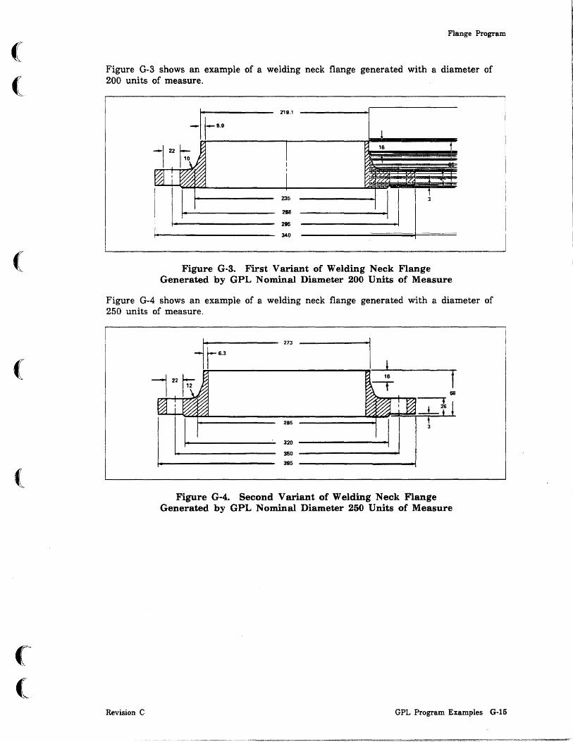
(
(
(
(
(
(~
(
Flange Program
Figure G-3 shows an example of a welding neck flange generated with a diameter of 200 units of measure.
219.1
235
268
295
340
16
-~I,I,II
Figure G-3. First Variant of Welding Neck Flange Generated by GPL Nominal Diameter 200 Units of Measure
Figure G-4 shows an example of a welding neck flange generated with a diameter of 250 units of measure.
Revision C
273
285
320
350
395
Figure G-4. Second Variant of Welding Neck Flange Generated by GPL Nominal Diameter 250 Units of Measure
GPL Program Examples G-15

Bushing Program
Bushing Program This example defines the automated design of a bushing (figure G-5). The program with which the bushing is generated is named BUCHSE. The program documentation is self-explanatory. The following is a listing of the program BUCHSE.
MAIN/BUCHSE $$ $$ ••• RESERVE STORAGE FOR VARIABLES $$ REAL/VARI(8),COOR(3),IANS,STAT,XM,YM,ZM $$ $$ ••• DEFINE DEFAULT VALUES $$ A = 40. B = 16. C = 32. 0 = 39. E = 5.5 F = 3.5 G = 30. THRD = 36. $$ $$ ••• PRESET ARRAY WITH DEFAULTS $$ VARI ( 1) = A VARI(2) = B VARI(3) = c VARI(4) = D VARI(5) = E VARI(6) = F VARI(7) = G VARI(S) = THRD COOR( 1) o. COOR(2) o. COOR(3) = o. $$ $$ ••• ASK USER IF HE WANTS TO SEE AN EXAMPLE OF THE 'BUCHSE' $$ 5 QUERY/'·· DO YOU WANT AN EXAMPLE (Y/N) ?' ,IANS IF ( IANS .EQ. 1 ) GOTO 20 $$ $$ ••• ASK USER FOR SCREEN LOCATION TO POSITION THE PATTERN $$ POS/'·· INDICATE POSITION OF BUCHSE ',XM,YM,ZM,STAT IF ( STAT .GE. O. ) GO TO 1000 $$ $$ ••• ASK FOR 2 VIEWS (TOP/SIDE) $$ QUERY/'·· TWO VIEWS (Y/N) ?' ,IANS IF ( IANS .NE. 1. ) GO TO 10
G·16 ICEM GPL for NOS Revision C
1 ,

(
(
(
(
(
(
(
$$ $$ •• * NOW RETRIEVE THE PATTERN FROM THE LOCAL PATTERN $$ •• * LIBRARY, PATTERN WANTED AS A GROUP (IND. BY YES) $$ RTRIEV/PATERN,'BM2' ,XM,YM,ZM,YES,STAT IF ( STAT .LT. O. ) GO TO 1000 JUMPTO/20 $$ $$ •• * ONLY ONE VIEW WANTED, SO GET OTHER PATTERN $$ 10 RTRIEV/PATERN,'BM1' ,XM,YM,ZM,YES,STAT IF ( STAT .LT. O. ) GO TO 1000 $$ $$ •• * ASK USER IF HE WANTS TO SEE THE DEFAULT VALUES $$ 20 QUERY/'·* LIST AND CHANGE DEFAULTS (Y/N) ?' ,IANS IF ( IANS .NE. 1. ) GO TO 50 $$ $$ •• * USER WANTS TO CHANGE THE DEFAULTS $$
Bushing Program
30 PARAMS/'LIST OF VARIABLES: ',8,'A','B','C','D','E','F','G',$ 'THRD' ,VARI(1),STAT
IF ( STAT .EO. O. ) GO TO 1000 $$ $$ *.* THE SELECTION OF THE SCREEN COORDINATES TO $$ *.* POSITION THE PATTERN IS DONE BY PROCEDURE 'SEL'. $$ CooR1 CooR2 CooR3
CooR( 1)
CooR(2) CooR(3)
BEEND 0 CALL/SEL,CooR1,COOR2,COOR3,BEEND $$ $$ *.* IF NOT ANOTHER 'BUCHSE' WANTED, EXIT PROGRAM $$ IF BEEND .EQ. 1. ) $$ XB COOR1 YB COOR2 ZB CooR3 $$
GO TO 1000
$$ *.* SET PEN NUMBER 3 AND LINE STYLE TO SOLID $$ PEN/3 FONT/SOLID A1 VARI(1)/2. YB1 = YB+A 1
Revision C GPL Program Examples G-17

Bushing Program
$$ $$ *** $$ LINl XBl LIN2 YB2
CREATE LINES
LINE/XB,YB,ZB,XB,YB1,ZB XB+VARI(5) LINE/XB,YB1,ZB,XB1,YB1,ZB YB1-«VARI(1)/2)-(VARI(3)/2»
LIN3 LINE/XB1,YB1,ZB,XB1,YB2,ZB XB2 = XBl + VARI(S) LIN4 LINE/XB1,YB2,ZB,XB2,YB2,ZB WINKEL = 90 - VARI(7) VARI(7) = WINKEL WINKEL = VARI(7) TANWIN SINF(WINKEL)/COSF(WINKEL) XHILF (VARI(8)-VARI(3»*0.5/TANWIN XB3 XB2 + XHILF YB3 YB + VARI(8)/2. LINS XB4 LIN6 LIN7 BHILF LIN8
LINE/XB22,YB2,ZB,XB3,YB3,ZB XB + VARI(4) LINE/XB3,YB3,ZB,XB4,YB3,ZB LINE/XB4,YB3,ZB,XB4,YB,ZB YB + VARI(2)/2. LINE/XB,BHILF,ZB,XB4,BHILF,ZB
PEN/1 FONT/DASHED LINg = LINE/PARLEL,LIN6,YSMALL,1.0 FONT/CENLIN XPl XB - 10. XP2 LIN10 PEN/3 FONT/SOLID
XB + VARI(4) + 10. LINE/XP1,YB,ZB,XP2,YB,ZB
YYBl LINll LIN12 YYB2 LIN13 LIN14 YYB3 LIN15 LIN16 LIN17 BBHILF
YB - Al LINE/XB,YB,ZB,YYB1,ZB LINE/XB,YYB1,ZB,XB1,YYB1,ZB YYBl + VARI(1)/2 - VARI(3)/2 LINE/XB1,YYB1,ZB,XB1,YYB2,ZB
= LINE/XB1,YYB2,ZB,XB2,YYB2,ZB YB - VARI(8)/2
= LINE/XB2,YYB2,ZB,XB3,YYB3,ZB LINE/XB3,YYB3,ZB,XB4,YYB3,ZB LINE/XB4,YYB3,ZB,XB4,YB,ZB YB - VARI(2)/2
LINE18 = LINE/XB,BBHILF,ZB,XB4,BBHILF,ZB FONT/DASHED PEN/l LIN19 = LINE/PARLEL,LIN16,YLARGE,1.0
G-18 ICEM GPL for NOS Revision C
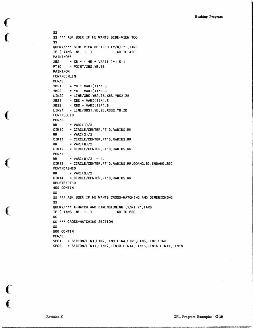
(
(
(
(
$$ $$ ••• ASK USER IF HE WANTS SIDE-VIEW TOO $$ QUERY/'·· SIDE-VIEW DESIRED (Y/N) ?' ,IANS IF ( IANS .NE. ,. ) GO TO 400 PAINT/OFF XBS XB - ( 45 + VARI(1)·'.5 PT10 POINT/XBS,YB,ZB PAINT/ON FONT/CENLIN PEN/O YBS' YBS2 LIN20 XBS' XBS2 LIN21 FONT/SOLID PEN/3
YB + VARI(1)·'.5 YB - VARI(1)·'.5 LINE/XBS,YBS,ZB,XBS,YBS2,ZB XBS + VARI(1)·'.5 XBS - VARI(1)*1.5 LINE/XBS1,YB,ZB,XBS2,YB,ZB
RR = VARI(1)/2. CIR10 = CIRCLE/CENTER,PT10,RADIUS,RR RR = VARI(2)/2. CIR'l = CIRCLE/CENTER,PT10,RADIUS,RR RR = VARI(8)/2. CIR'2 = CIRCLE/CENTER,PT10,RADIUS,RR PEN/' RR = VARI(8)/2. - 1. CIR13 = CIRCLE/CENTER,PT10,RADIUS,RR,GOANG,60,ENDANG,390 FONT/DASHED RR = VARI(3)/2. CIR14 = CIRCLE/CENTER,PT10,RADIUS,RR DELETE/PT10 400 CONTIN $$ $$ •• * ASK USER IF HE WANTS CROSS-HATCHING AND DIMENIONING $$ QUERY/'·· X-HATCH AND DIMENSIONING (Y/N) ?' ,IANS IF ( IANS . NE. 1. ) GO TO 600 $$ $$ ••• CROSS-HATCHING SECTION $$ 500 CONTIN PEN/O SEC1 SECTON/LIN1,LIN2,LIN3,LIN4,LIN5,LIN6,LIN7,LIN8
Bushing Program
SEC2 = SECTON/LIN11,LIN12,LIN13,LIN14,LIN15,LIN16,LIN17,LIN18
Revision C GPL Program Examples G-19

Bushing Program
$$ $$ *** DIMENSIONING SECTION $$ ARROW/ON AUTOO OSCALE/1 .25 ARIN DO = VARI(4)/2. LOIMEN/HORIZ,LIN1,YLARGE,LIN7,YLARGE,DO,30 AROUT DO = VARI(5)/2. + 22. LOIMEN/HORIZ,LIN1,YLARGE,LIN3,YLARGE,OD,15. DO = VARI(2)/2. LOIMEN/VERTCL,LIN18,XLARGE,LIN8,XLARGE,30.,00 ARIN DO = VARI(8)/2. LOIMEN/VERTCL,LIN16.XLARGE,LIN6,XLARGE,40. ,DO DO = VARI(3)/2. LOIMEN/VERTCL,LIN14,XSMALL,LIN4,XSMALL, 35.,00 DO = VARI(1)/2. LOIMEN/VERTCL,LIN12,XSMALL,LIN2,XSMALL, 40.,00 DO VARI(1)/2. + 5. EE = -DO AROUT LOIMEN//HORIZ.LIN14, 15.,EE PAINT/OFF PT100 DO LIN20 PT10l PAINT/ON ARIN
POINT/INTOF,XLARGE,LIN14,LIN1S VARI (1)/2. LINE/PT100,ATANGL,90.,LIN14,DISTNC,DD POINT/PT100,RTHETA,DO,240.
WW -DO ROl ROIMEN/YSMALL,LIN20,YSMALL,LIN15,PT101,0,WW DELETE/PT100,PT10l,LIN20 $$ $$ *** ASK USER IF HE WANTS ANOTHER nBUCHSEH $$ 600 CONTIN QUERY/'** ANOTHER nBUCHSE" (Y/N) ?' ,IANS IF ( IANS .EQ. 1. ) GO TO 5
$$ $$ *** TERMINATE PROGRAM $$ 1000 CONTIN FIN!
G·20 ICEM GPL for NOS Revision C

(
(
(
(
(
(
Bushing Program
Figure G-5 shows a bushing generated by program BUCHSE.
~~-+f ---+-- 8=16 THRD=36
i 1
Figure G-5. Default Bushing Generated by BUCHSE
Figure G-6 shows a bushing generated with different dimensions.
11=39 4-5.5
t i f 40 16 36
1 t
1
Figure G-6. Bushing Variant
Revision C GPL Program Examples G-21

)

o o _In_de_x ____________________ _
o
o
o o

o o
o
o
o
o o

(
(
(
(
(
(
Index
A
ABS 2-13 ABSF 2-13 ACOS 2-13 ACOSF 2-13 Addition 2-12 ADIMEN 20-2 AHEAD 17-1; 19-1 ANGCTL 19-2 Angle notation 1-7 Angular dimension 19-3; 20-2 ANSI 1973 17-1; 18-1 ANSI 1982 19-1; 20-1 AN UNIT 19-3 ARAUTO 19-3 ARIN 17-1; 19-4 Arithmetic operators 1-2; 2-12
Addi tion 2-12 Di vision 2-12 Exponentiation 2-12 Multiplication 2-12 Subtraction 2-12
AROUT 17-2; 19-4 Array
Circular array 14-4 Rectangular array 14-1
ARRAY 14-1 Array entity names 2-5 Array variables 2-6 ARROW 17-2; 19-5 Arrow alignment 17-2; 19-3 Arrow on curve 20-6 Arrow tail aligment 19-5 Arrowhead length 17-1; 19-1 Arrows in 17-1; 19-4 Arrows out 17-2; 19-4 ASIN 2-13 ASINF 2-13 Assign
By entity 6-2 By sequence number 6-1
ASSIGN 6-1 Assignment
Constant 2-3 Entity names 2-5 Variables 2-6
Assignment statement 1-4 ATAIL 19-5 ATAN 2-13 ATANF 2-13 ATTRIB 6-3 Attribute
Copy 6-6 Create 6-3 Delete 6-5
Revision C
Level 6-3 Attribute, Obtain 6-30 Auto dimensioning 17-3; 19-6 AUTOD 17-3; 19-6 Axis 11-15
B
B (Object file) 24-1 Balloon 20-2 BALOON 20-2 Bearing and distance 10-10 BINDIR 23-2 BININ 23-2 BIN OUT 23-2 BLANK 5-1 BLANKE 9-1
All except 9-2 Color 9-2 Entity array 9-1 Level 9-2 Pen 9-2 Specified entities 9-1
Blanks 1-8 Branching statement 1-4; 4-1
EOFI 4-6 GOTO 4-1 GOTO (computed) 4-2 IF 4-3 JUMPTO 4-6
BULK 23-4
c
CALL 8-1 CDIMEN 18-1; 20-4 CDISPL 17-4; 19-7 Center coordinates and radius 12-1 Center of a circle 10-4 Center point and tangent circle 12-4 Center point and tangent line 12-3 Centerline
Circle 18-4; 20-6 Circles 18-4; 20-5 Multiple points 18-3; 20-5 Two points 18-3
Chamfer 11-1 CHAMFR 11-1 CHANGE 9-3,4
Two views 9-4 Two views views 9-3
Change library name 25-1 CHAR 2-10; 7-1 Character length, Obtain 6-29
ICEM GPL for NOS Index-}

Character length, Set
Character length, Set 6-32 Character string 1-3; 2-18
Compare 6-8 Convert
Real to string 6-11 String to real 6-10
Character string, Obtain 6-29 Character string statements 6-1 Character strings
MOVCHR 6-19 Characters
Display ratios 17-4; 19-7 Resolution 19-8 Size 17-6; 19-10 Slant 17-12; 19-19 User-defined 17 -5; 19-9 Vertical 17-12; 19-19
CHECK 6-7 Circle
Center coordinates and radius 12-1 Center point and point on
circumference 12-5 Center point and radius 12-2 Center point and tangent circle 12-4 Center point and tangent line 12-3 Existing arc 12-7 Fillet 12-10 Inscribed in three lines 12-8 Modify 6-22 Normal to veiw 12-9 Three points on circumference 12-6
CIRCLE 12-1 Circle/arc/fillet 12-1 Circular array
Delta angle 14-6 Number copies/delta angle 14-6 N umber of copies 14-4
Circular dimension 18-1; 20-4 CLEAR 6-7 CLINE 18-3; 20-5 CLOSE 23-6 CMPCHR 6-8 CMPCRV 15-1 CMPENT 6-9 CMSRF 16-1 Coefficients of plane 16-14 Commands, interactive 22-1 COMMON 7-2 Compiling
B (Object file) 24-1 Control statement 24-1 E (Error file) 24-2 EL (Error message level) 24-2 ET (Error terminate flag) 24-2 I (Input) 24-1 IL (Input line length) 24-2 L (List) 24-1 LO (List options) 24-2 PS (Page size) 24-2
Conditional branch 4-3 Conditional end statement 4-6
Index-2 ICEM GPL for NOS
Conditional statement 1-4,5; 4-3 Cone
Curve
Coordinates of line about axis 16-3 Line about axis 16-2 Point and delta coordinates of line
about axis 16-4 Two points of line about axis 16-4
CONE 16-1 CONST 7-3,4 Constant
Assignment 2-3 Constants 1-2; 2-3 CONTIN 8-1 Continue GPL program 25-1' Control statement 24-1 Conventions, syntax 1-9 CONYER 6-10 Coordinates
Center and radius 12-1 Hexahedron 16-11 Line 11-3 Obtain 6-20 Point 10-1 Vector 15-8
Coordinates and radii of torus 16-24 Coordinates and radius of sphere 16-21 Coordinates of line about axis
Cone 16-3 Cylinder 16-6
Copy Attribute 6-6
COS 2-13 COSF 2-13 COSH 2-13 Create
Attribute 6-3 Creating geometry 1-10 CRES 19-8 Cross product of two vectors 15-9 Cross-section arrows 20-33 CSET 17-5; 19-9 CSIZE 17-6; 19-10 CURARR 20-6 Current view pointer, Obtain 6-23 CURSOR 5-1 Curve
Chamfer 11-1 Circle 12-1 Composite 15-1 Cross product of two vectors 15-9 Difference of two vectors 15-12 Draft curve to depth 15-5 Draft curve to surface 15-4 Ellipse 13-1 Evaluate
Parameter returns point 6-14 Point returns parameter 6-15
Fillet 12-10 General conic 13-2 Intersection of two planes 15-11 Line 11-2
Revision C

(
(
(
{
(
Curve endpoint
Machine 15-2 Point set 13-5 Scalar times existing vector 15-9 String 13-11 Sum of two vectors 15-11 Surface edge curve 15-2 Surface intersection curve 15-3 Surface unit normal 15-10 Through point at angle with line or
vector 15-12 Through point at given length and
angle 15-10 Two points 15-8 Unit normal of an existing
vector 15-9 2-D spline 13-7 3-D spline 15-6
Curve endpoint 10-5 Curve mesh surface 16-1 Cylinder
Coordinates of line about axis 16-6 Delta coordinates of line about
axis 16-8 Line about axis 16-5 Two points of line about axis 16-7
CYLNDR 16-5
D
DATA 7-4 DATE 8-2 DATFEA 20-8 DATUM 20-10 Datum feature symbol 20-8 Datum target symbol 20-10 DDIMEN 18-5; 20-15 Decimal
Numbers 17-6; 19-11 Places 17-6; 19-11
DECMAL 17-6; 19-11 Define
COMMON 7-2 CaNST 7-3 DATA 7-4 Entity 7-5 Text variable 7-1
DEFINE 6-12 Defined symbols 2-2 Definition view pointer, Obtain 6-23 Delete
Attribute 6-5 DELETE 1-7; 6-13 Delta coordinates
Line about axis for cone 16-4 Point 10-2
Delta coordinates of line about axis Cylinder 16-8
Depth 5-11 Detail magnification 20-27
Revision C
Developable surface 16-9 DEVSRF 16-9
Drafting modal
Diameter dimension 18-5; 20-15 Diameter symbol 19-16 Difference of two vectors 15-12 Dimensions
Angular 20-2 Arrow on curve 20-6 Auto 17-3; 19-6 Circular . 18-1; 20-4 Cross-section arrows 20-33 Datum feature symbol 20-8 Datum target symbol 20-10 Decimal 17-6; 19-11 Detail magnification 20-27 Diameter 18-5; 20-15 Dual 17-9; 19-15 Fractional 17-10; 19-15 Geometric tolerance 20-16 Linear 18-8; 20-24 Manual entry 17 -10 Modify drafting entity 20-28 Offset 17-7; 19-12 Origin 17-8; 19-13 Radial 18-12 Section lining 20-33 Surface texture 20-36 Taper 20-39 Thickness 20-40 Witness lines 17-14; 19-22
DIMOF 17-7; 19-12 DIMORG 19-13 DISDEF 5-2 DISPLA 22-1 Display
Blank entity 9-1 Change 9-3 Create view 9-9 Map 9-5 Repaint 9-6 U nblank entities 9-7 View borders 9-8 View names 9-11 View vectors 9-12 Wait 9-12 Zoom 9-13
Display, PAINT 5-5 Display tolerance 5-2 DISTaL 5-2 Division 2-12 DORIG 17-8 Draft curve to depth 15-5 Draft curve to surface 15-4 Drafting entity definition
statements 18-1; 20-1 Drafting modal
Angular dimensions 19-3 ANSI 1973 17-1 ANSI 1982 19-1 Arrow alignment 17-2; 19-3,4 Arrow tail aligment 19-5
ICEM GPL for NOS Index-3

Drafting scale factor
Arrowhead length 17-1; 19-1 Arrows in 17-1; 19-4 Arrows out 17-2; 19-4 Auto dimensioning 17·3; 19-6 Character display ratios 17-4; 19-7 Character resolution 19-8 Character set 17-5; 19-10 Character size 17 -6; 19-9 Character slant 17-12 Decimal 17-6; 19-11 Diameter symbol 19-16 Dimension offset 17 -7; 19-12 Dimension origin 17-8; 19-13 Drafting scale factor 17-9; 19-14 Dual dimensioning 17·9; 19-15 Fractional numbers 17-10; 19-15 Key-in mode 17-10 Leader line 19-16 Material type 17-11; 19-17 Prefix character 19-18 Section alignment 19-18 Section lining display 19-19 Text angle 17-12; 19-2 Text justification 17-13; 19-20 Text location 17-13 Text origin 19-21 Witness line 17-14; 19-22
Drafting scale factor 17-9; 19-14 Drafting standard
ANSI 1973 18-1 ANSI 1982 20-1
Drawing, store 7-6 DSCALE 17-9; 19-14 DUAL 17-9; 19-15 Dual dimensioning 17-9; 19-15
E
E (Error file) 24-2 EL (Error message level) 24-2 ELLIPS 13-1 End program 8-8 ENDCOM 7-2 Entities
Array 14-1 Chamfer 11-1; 12-1 Clear 6-7 Compare 6-9 Composite curve 15-1 Cone 16-2 Curve mesh surface 16-1 Cylinder 16-5 Data 6-20 Define 6-12 Delete 6-13 Developable surface 16-9 Ellipse 13-1 Ellpsoid 16-13 Fillet 12-10
Index-4 ICEM GPL for NOS
Existing arc
Fillet surface 16-10 General conic 13-2 Group 14-10 Hexahedron 16-11 Hyperbola 13-3 Level 5-4 Line 11-2 Machine curve 15-2 Mirror 14-11 Modify 6-21; 14-12 MOVENT 6-19 Parabola 13-4 Plane 16-14 Point 10-1 Point set 13-5 Project 14-15 Retrieve pattern 14-17 Ruled surface 16-20 Sphere 16-21 String 13-11 Surface of revolution 16-19 Tabulated cylinder 16-23 Template 14-21 Test for pointer 6-7 Torus 16-24 Trim 6-32 Vector 15-8 2-D spline 13-7 3-D spline 15-6
Entity Assignment statement 1-5 Blank 5-1 Manipulation 14-1 Redefinition 1-7
ENTITY 2-10; 7-5 Entity array
Delete 6-13 Entity definition statements 1-4 Entity management statements 6-1 Entity manipulation Entity name, Obtain 6-24 Entity name statements 1-4 Entity names 1-2,7; 2-4
Array 2-5 Assignment 2-4 Nonsubscripted 2-5 Simple 2-5 Subscripted 2-5
Entity parameters, Obtain 6-27 Entity pointer, Obtain 6-25 Entity selection mode 5-7,8 Entity type and form, Obtain 6-28 Entity types C-l EOFI 4-6 Equal to, logical operator 2-16 Error messages, execution D-l ET (Error terminate flag) 24-2 EVALC 6-14 EVALS 6-16 EXEC 23-14 Existing arc 12-7
Revision C

(
(
(
(
(
(
EXP
EXP 2-13 EXPF 2-13 Exponentiation 2-12 Expressions 1-8
F
FILE 7-6 File formats 23-2
BINDIR 23-2 BININ 23-2 BINOUT 23-2 INPUT 23-2 OUTPUT 23-2
Filing program 1-10 FILLET 12-10 Fillet surface 16-10 FILSRF 16-10 FINI 1-6; 8-2 First word, program 1-6 FONT 5-3 FOR 4-5 FOR statement 1-5 Format, program file 1-6 FORTRAN subroutine 23-14 FRACT 17-10; 19-15 Fractional numbers 17-10; 19-15 From point for distance at angle to a
line 11-8 Functions 1-3; 2-13
G
GCONIC 13-2 Geometric tolerance 20-16 GEOTOL 20-16 GET 1-7; 2-10; 7-7 GETBIT 2-13 Glossary A-I GOLIB 1-11 GOTO 4-1 GO TO (computed) 4-2 GOTO statement 1-5
Computed 1-5 GPL vocabulary
Major words 2-19 Minor words 2-20 Modal words 2-20 Modals and fonts 2-19 Positional 2-20 Program control 2-19
GPLLIB 1-11 Graphics input device 5-1 Grapl-to-GPL translator F-l Greater than, logical operator 2-16 Greater than or equal to, logical
operator 2-16
Revision C
GROUP 14-10 Group members, Obtain 6-28 Group selection 5-8 GTGT F-l
H
Hexahedron Coordinates 16-11 Point 16-12
HEXDRN 16-11 Horizontal through point 11-6 HYPERB 13-3
I
I (Input) 24-1 IF 4-3 IF statement 1-5 IL (Input line length) 24-2 Infinite line 11-15 INPUT 23-2 Input file Input/output 23-1
Bulk 23-4 Close file 23-6 File formats 23-2 Fixed format 23-3 FORTRAN subroutine 23-14 Open file 23-7 Read file 23-8 Rewind file 23-10 system E-l UNISTRUC file 23-10 Write file 23-12
Inscribed in three lines 12-8 Integer values 1-7 Interactive
Data entry 22-4 Display message 22-1 Entity select 22-8 Menu 22-2 Query 22-7 Screen position 22-6 Text entry 22-11
JUMPTO
Interactive command statements 1-4; 22-1
Intersection of two curves 10-6 Intersection of two planes
Vector 15-11
J
JUMPTO 4-6
ICEM GPL for NOS Index-5

KEYIN
K
KEYIN 17-10
L
L (List) 24-1 LABEL 18-6; 20-22 Label dimensions 17-8 Latest error number, Obtain 6-27 LDDIAM 19-16 LDIMEN 18-8; 20-24 LEADER 19-16 Leader line placement 19-16 Length of statement 1-7 Less than, logical operator 2-16 Less than or equal to, logical
operator 2-16 LEVEL 5-4 Level, Attribute 6-3 Limits
Angles 1-7 Blanks 1-8 Degrees 1-7 Entity names 1-7 Expressions 1-8 FOR 1-7 IF 1-7 Inches 1-7 Length of statement 1-7 Millimeters 1-7 N umber of characters 1-7 N umber of variables 1-7 Order of statements 1-8 RTF variables 1-7 Running time 1-7 Scientific notation 1-7 Strings 1-7,8
Line 11-1 Axis 11-15 Chamfer 11-1 Coordinates 11-3 From point for distance at angle to a
line 11-8 Horizontal through point 11-6 Infinite line 11-15 Modify 6-21 Offset distance parallel to line 11-10 Tangent to curve and parallel to
line 11-11 Tangent to curve and perpendicular to
line 11-12 Tangent to two curves 11-4 Through point and parallel to
line 11-9 Through point and perpendicular to
line 11-9
Index-6 ICEM GPL for NOS
Through point and tangent to curve 11-6
Two curve ends 11-14 Two points 11-3 Vertical through point 11-6
LINE 11-1 Line about axis
Cone 16-3 Cylinder 16-5
. Line continuation 1-6 Line font 5-3 Linear dimension 18-8; 20-24 List GPL names 25-1 LO (List options) 24-2 LOG 2-13 LOGF 2-13 Logical operators 1-3; 2-16
Equal to 2-16 Greater than 2-16 Greater than or equal to 2-16 Less than 2-16 Less than or equal to 2-16 Not equal to 2-16
LOGI0 2-13 Looping 4-5 LPSOID 16-13
M
MACCRV 15-2 Machine curve
Draft curve to depth 15-5 Draft curve to surface 15-4 Surface edge curve 15-2 Surface intersection curve 15-2
MAGNFY 20-27 MAIN 8-3 Major word statement 1-4 Major words 1-2; 2-1 Major words overview 3-1 MAP 9-5 Material type 17-11; 19-17 MATERL 17-11; 19-17 MAX 2-13 Measure Menu
Change library name 25-1 Continue GPL program 25-1 List GPL names 25-1 Recover last file 25-1 Run GPL program 25-1
MENU 22-2 Menu string file 5-4 MIN 2-13 Minimum number of points 13-5 Minor word 1-2; 2-1; B-1 MIRROR 14-11 Modal
Drafting 17-1; 19-1
Modal
Revision C
(j

(
(.
(
«
(
(
Modal and font statements
Modal and font statements 1-4 Modal statements 5-1 Modal words B-1 MODDFT 20-28 MODIFY 6-21; 14-12 Modify drafting entity 20-28 MOVCHR 6-19 MOVENT 6-19 MSFILE 5-4 MSTRNG 8-4 Multiplication 2-12
N
N onsubscripted entity names 2-5 N onsubscripted variables 2-6 Normal to veiw, circle 12-9 Not equal to, logical operator 2-16 NOTE 18-10; 20-31 Number of characters, Obtain 6-21 Numerical Control
o
SETGPG 21-1 TLPATH 21-3
Obtain Attribute 6-30 Character length 6-29 Character string 6-29 Color number 6-31 Coordinates 6-20 Current view pointer 6-23 Definition view pointer 6-23 Entity name 6-24 Entity parameters 6-27 Entity pointer 6-25 Entity type and form 6-28 Font number 6-31 Group members 6-28 Latest error number 6-27 Number of characters 6-21 Part name 6-28 Pen number 6-31 Sequence number 6-29 Sheet number 6-28 Subattribute 6-30 View pointer 6-22
OBTAIN 6-20 Offset distance parallel to line 11-10 On a circle 10-4 On a line at x, y, or z 10-8 On curve at parameter 10-11 OPEN 23-7 Order of statements 1-8 OUTPUT 23-2 Output file
Revision C
OutpuVinput 23-1
p
Bulk 23-4 Close file 23-6 File formats 23-2 Fixed format 23-3 FORTRAN subroutine 23-14 Open file 23-7 Read file 23-8 Rewind file 23-10 system E-l UNISTRUC file 23-10 Write file 23-12
PAINT 5-5 PARABO 13-4 Parallel
Line 11-9
Point
Plane at distance from plane 16-16 PARAMS 22-4 Part name, Obtain 6-28 PAUSE 8-5 PEN 5-5 Pen number 5-5 Perpendicular
Line 11-9 Pierce point 10-12 Plane
Coefficients 16-14 Parallel to plane at distance 16-16 Point and perpendicular to two
planes 16-18 Three noncolinear points 16-15 Through point and parallel to
plane 16-15 Through point and perpendicular to
vector 16-17 Two lines 16-18 Two points and perpendicular to
plane 16-17 PLANE 16-14 Point 10-1
Bearing and distance 10-10 Center of a circle 10-4 Circle center 12-5 Circle center and radius 12-2 Coordinates 10-1 Curve endpoint 10-5 Delete all 6-13 Delta coordinates 10-2 Hexahedron 16-12 Intersection of two curves 10-6 Modify 6-21 On a circle 10-4 On a line at x, y, or z 10-8 On curve at parameter 10-11 Parallel to plane 16-16 Perpendicular to two planes 16-18
ICEM GPL for NOS Index-7

POINT
Perpendicular to vector 16-17 Pierce 10-12 Polar coordinates 10-2 Project on curve 10-9 Spherical 10-12 Surface normal 10-11 Vectored point 10-3
POINT 10-1 Point and delta coordinates of line about
axis Cone 16-4
Point and radii of torus 16-25 Point and radius of sphere 16-22 Point set curve
Minimum number of points 13-5 Points with tolerance 13-6
Pointer Points with tolerance 13-6 Polar coordinates
Point 10-2 POS 22-6 Positional words B-1 PREFIX 19-18 Prefix character 19-18 PROC 8-6 Program
Call 8-1 Change library name 25-1 Continue 25-1 Continue execution 8-1 Date 8-2 End 8-8 List GPL names 25-1 Main 8-3 MSTRNG 8-4 Pause 8-5 Remarks 8-7 Return control 8-7 Run GPL program 25-1 Stop 8-2,8 Time 8-8
Program control statements 1-4 Program example G-l Program file format 1-6 PROJEC 14-15 Project on curve 10-9 PS (Page size) 24-2 PTSET 13-5 Punctuation 1-2 Punctuation symbols 2-17
Q
QUERY 22-7
Index-8 ICEM GPL for NOS
Simple entity names
R
Radial dimension 18-12 RDIMEN 18-12 READ 23-8 REAL 2-9; 7-8 Real values 1-7 Recover last file 25-1 Recovery file 5-6 RECOVR 5-6 Rectangular array 14-1 Redefintion, entity 1-7 REFRES 5-6 Refresh file 5-6 REMARK 8-7 Repaint 9-6 REP ANT 9-6 RESCAL 5-7 Restrictions 1-7 Retrieve variables 7-7 RETURN 8-7 REVSRF 16-19 REWIND 23-10 ROUND 2-13 RTF variables 1-7 RTL
Variables 2-8 RTRIEV 14-17 RULSRF 16-20 Run GPL program 25-1 Running time 1-7
s
SAVE 2-9; 7-9 Sa ve variables 7-9 Scalar times existing vector 15-9 Scientific notation 1-7 SECALN 19-18 SECARR 20-33 Section alignment 19-18 Section lining 18-14; 20-35 Section lining display 19-19 SECTON 18-14; 20-35 SECVIS 19-19 SELECT 22-8 SELENT 5-7 SELGRP 5-8 SELMOD 5-8 Sequence number, Obtain 6-29 .sETBIT 2-13 SETCHL 6-32 SETGPG 21-1
Existing toolpath GPG 21-2 Local text file 21-1
Sheet number, Obtain 6-28 SIGN 2-14 Simple entity names 2-5
Revision C

(
(
(
(
(
(
Simple variables
Simple variables 2-6 SIN 2-14 SINF 2-14 SINH 2-14 SLANT 17-12; 19-19 SPATHS 5-9 SPCURV 15-6 Special function statements 1-4; 5-1; 6-1 Sphere
Coordinates and radius 16-21 Point and radius 16-22
SPHERE 16-21 Spherical point 10-12 SPLINE 13-7 Spline curve SQRT 2-14 SQRTF 2-14 SRFTEX 20-36 Statement elements 1-2 Statement label 1-2; 2-11 Statement types 1-4 STATUS 5-10 STOP 1-6; 8-8 Store drawing 7-6 STRING 13-11 Strings 1-7,8 Subattribute, Obtain 6-30 Subprogram
Call 8-1 PROC 8-6 Stop 8-4
Subscripted entity names 2-5 Subscripted variables . 2-7 Subtraction 2-12 Sum of two vectors 15-11 Suppress fatal messages 5-10 Surface
Evaluate Parameter returns point 6-16 Point returns parameter 6-18
Surface edge curve 15-2 Surface intersection curve 15-3 Surface normal 10-11 Surface paths 5-9 Surface texture 20-36 Surface unit normal 15-10 Surfaces
Cone 16-2 Curve mesh 16-1 Cylinder 16-5 Developable 16-9 Fillet 16-10 Hexahedron 16-11 Plane 16-14 Revolution 16-19 Ruled 16-20 Sphere 16-21 Tabulated cylinder 16-23 Torus 16-24
Symbols, defined 2-2 Syntax 1-9
Revision C
Two-dimensional curves
SYSDEC 5-10 System decimal places 5-10
T
TABCYL 16-23 TAN 2-14 Tangent
Circle 12-4 Line 11-6
Tangent to curve and parallel to line 11-11
Tangent to curve and perpendicular to line 11-12
Tangent to two curves 11-4 TANH 2-14 TAPER 20-39 Taper dimension 20-39 TELEX 1-6 TEMPLT 14-21 Text
Label 18-6; 20-22 Note 18-10; 20-31
TEXT 22-11 Text angle 17-12; 19-2 Text justification 17 -13; 19-20 Text origin 19-21 Text variable 1-2 Text variable, define 7-1 Text variables 2-18 Thickness dimension 20-40 THIKNS 20-40 Three-dimensional curves 15-1 Three noncolinear points of plane 16-15 Three points on circumference 12-6· Through point and parallel to line 11-9 Through point and parallel to
plane 16-15 Through point and perpendicular to
line 11-9 Through point and tangent to
curve 11-6 Through point at given length and
angle 15-10 TIME 8-8 TLPATH 21-3
CONTUR 21-4 DRILL 21-5 ROUGH 21-5 THREAD 21-6
Torus Coordinates and radii 16-24 Point and radii 16-25
. TORUS 16-24 Trignometric functions 2-13 TRIME 6-32 TRUNC 2-14 Two curve ends 11-14 Two-dimensional curves 13-1
ICEM GPL for NOS Index-9

Two lines define a plane
Two lines define a plane 16-18 Two points
Line 11-3 Perpendicular to plane 16-17 Vector 15-8
Two points of line about axis Cone 16-4 Cylinder 16-7
TXTANG 17-12 TXTJUS 17-13; 19-20 TXTORG 19-21
u
UNBLNK 9-7 All except 9-7 Level 9-7 Specified entities 9-7
Unit normal of an existing vector 15-9 USTRUC 23-10 UTF
Variables 2-8
v
Variable Array 2-7 Assignment statement 1-5; 2-6 Calculation 2-8 Entity 7-2 Menu 5.2.1 2-8 Name 1-2 Name statements 1-4 N onsubscripted 2-6 Real 7-8 Retrieve 7-7 Save 7-9 Simple 2-6 Subscripted 2-7 Text 7-1 Text variable 1-5
VBORDS 9-8
Index-10 ICEM GPL for NOS
ZSURF
Vector Coordinates 15-8 Cross product of two vectors 15-9 Difference of two vectors 15-12 Intersection of two planes 15-11 Scalar times existing vector 15-9 Sum of two vectors 15-11 Surface unit normal 15-10 Through point at angle with line or
vector 15-12 Through point at given length and
angle 15-10 Two points 15-8 U nit normal of an existing
vector 15-9 VECTOR 15-8 Vectored point 10-3 Vertical through point 11-6 VIEW 9-9
Auxiliary by rotation 9-9 Auxiliary parallel to plane 9-10 Matrix 9-10
View of definition 5-2 View pointer, Obtain 6-22 VNAMES 9-11 VVECS 9-12
w
WAIT 9-12 Witness lines 17-14; 19-22 WLINE 17-14; 19-22 WRITE 23-12
z
ZOOM 9-13 Auto maxmin 9-13 Diagonal points 9-13 Scale factor 9-14
ZSURF 5-11
Revision C

(
(
(
(
o c
ICEM GPL for NOS 60462520 C
We value your comments on this manual. While writing it, we made some assumptions about who would use it and how it would be used. Your comments will help us improve this manual. Please take a few minutes to reply.
Who are you? How do you use this manual?
o Manager o As an overview o Systems analyst or programmer o To learn the product or system o Applications programmer o For comprehensive reference o Operator o For quick look-up o Other
What programming languages do you use? ________ ---'-_________________ _
How do you like this manual? Check those questions that apply.
Yes Somewhat No 0 0 0 Is the manual easy to read (print size, page layout, and so on)?
0 0 0 Is it easy to understand?
0 0 0 Does it tell you what you need to know about the topic?
0 0 0 Is the order of topics logical?
0 0 0 Are there enough examples?
0 0 0 Are the examples helpful? (0 Too simple? o Too complex?>
0 0 0 Is the technical information accurate?
0 0 0 Can you easily find what you want?
0 0 0 Do the illustrations help you?
Comments? If applicable, note page and paragraph. Use other side if needed.
Would you like a reply? 0 Yes o No
From:
Name Company
Address Date
Phone
Please send program listing and output if applicable to your comment.

Comments <continued from other side)
Please fold on dotted line; ~e~l _e<!.g~s _ wjtE .!-B-.P:" ~n!'y:..
FOLD
BUSINESS REPLY MAIL First-Class Mail Permit No. 8241 Minneapolis, MN
POSTAGE WILL BE PAID BY ADDRESSEE
CONTROL DATA Technology & Publications Division ARH219 4201 N. Lexington Avenue Arden Hills, MN 55126-6198
1.1.1111.1.11.11111.1.1111.111111.111.1 •• 1111.1.1111
NO POSTAGE NECESSARY IF MAILED
FOLD
IN THE UNITED STATES

(
(
Command Index
The following indexes the GPL major words by page numbers.
ADIMEN (ANSI 1982) . . . . . .. 20-2 AHEAD (ANSI 1973) . . . . . . .. 17-1 AHEAD (ANSI 1982) . . . . . . .. 19-1 ANGCTL (ANSI 1982) . . . . . .. 19-2 ANUNIT (ANSI 1982) ....... 19-3 ARAUTO (ANSI 1982) . . . . . .. 19-3 ARIN (ANSI 1973) .. . . . . . .. 17-1 ARIN (ANSI 1982) . . . . . . . .. 19-4 AROUT (ANSI 1973) . . . . . . .. 17-2 AROUT (ANSI 1982) . . . . . . .. 19-4 ARRAY. . . . . . . . . . . . . . .. 14-1 ARROW (ANSI 1973) . . . . . . .. 17-2 ARROW (ANSI 1982) . . . . . . .. 19-5 ASSIGN ................ 6-1 ATAIL (ANSI 1982) ....... " 19-5 ATTRIB. . . . . . . . . . . . . . . .. 6-3 AVTOD (ANSI 1973) . . . . . . .. 17-2 AUTOD (ANSI 1982) . . . . . . .. 19-6 BALOON (ANSI 1982) . . . . . .. 20-3 BININ ................ 23-2 BINDIR. . . . . . . . . . . . . . .. 23-2 BIN OUT . . . . . . . . . . . . . .. 23-2 BLANK ................. 5-1 BLANKE ................ 9-1 BULK ................ 2~4
CALL . . . . . . . . . . . . . . . . .. ~1
CDIMEN (ANSI 1973) ....... 18-1 CDIMEN (ANSI 1982) ....... 20-4 CDISPL (ANSI 1973) . . . . . . .. 17-4 CDISPL (ANSI 1982) . . . . . . .. 19-7 CHAMFR" . . . . . . . . . . . . .. 11-1 CHANGE .............. " 9-3 CHAR .................. 7-1 CHECK ................. ~7 CIRCLE ............... 12-1 CLEAR. . . . . . . . . . . . . . . .. 6-7 CLINE (ANSI 1973). . . . . . . .. 18-3 CLINE (ANSI 1982). . . . . . . .. 20-5 CLOSE. . . . . . . . . . . . . . .. 23-6 CMPCHR ................ 6-8 CMPCRV . . . . . . . . . . . . . .. 15-1 CMPENT ................ 6-9 CMSRF . . . . . . . . . . . . . . .. 16-1
COMMON ............... 7-2 CONE ....... " . . . . . . . . .. 16-2 CONSTANT . . . . . . . . . . . . .. 7-3 CONTIN . . . . . . . . . . . . . . .. 8-1 CONVER . . . . . . . . . . . . . .. 6-10 CRES (ANSI 1982) . . . . . . . .. 19-8 CSET (ANSI 1973) . . . . . . . .. 17-5 CSET (ANSI 1982) . . . . . . . .. 19-9 CSIZE (ANSI 1973) . . . . . . . .. 17-6 CSIZE (ANSI 1982) . . . . . . . . . 19-10 CURARR (ANSI 1982) . . . . . .. 20-6 CURSOR. . . . . . . . . . . . . . .. 5-1 CYLNDR . . . . . . . . . . . . . .. 16-5 DATA .................. 7-4 DATE. . . . . . . . . . . . . . . . .. 8-2 DATFEA (ANSI 1982) ....... 20-8 DATUM (ANSI 1982) . . . . . . 20-11 DDIMEN (ANSI 1973) . . . . . 18-5 DDIMEN (ANSI 1982) . . . . . 20-15 DECMAL (ANSI 1973) . . . . . 17-6 DECMAL (ANSI 1982) . . . . . . . 19-11 DEFINE ............. .. 6-12 DELETE ............. '" 6-13 DEVSRF . . . . . . . . . . . . . .. 16-9 DIMOF (ANSI 1973) ...... .. 17-7 DIMOF (ANSI 1982) .-..... . . 19-12-DIMORG (ANSI 1982) ....... 19-13 DISDEF. . . . . . . . . . . . . . . .. 5-2 DISPLA. . . . . . . . . . . . . . .. 22-1 DISTOL. . . . . . . . . . . . . . . .. 5-2 DORIG (ANSI 1983) ........ 17-8 DSCALE (ANSI 1973) ....... 17-9 DSCALE (ANSI 1982) ....... 19-14 DUAL (ANSI 1973) . . . . . . . .. 17-9 DUAL (ANSI 1982) . . . . . . . . . 19-15 ELLIPS . . . . . . . . . . . . . . .. 13-1 ENTITY . . . . . . . . . . . . . . .. 7-5 EOFI . . . . . . . . . . . . . . . . .. 4-6
EVALC . . . . . . . . . . . . . . .. 6-14 EVALS . . . . . . . . . . . . . . .. 6-16 EXEC ................. 23-14 FILE . . . . . . . . . . . . . . . . .. 7-6 FILLET ................ 12-10 FILSRF ................ 16-10 FINI .. ........... 8-2 FONT. . . . . . . . . . . . . . . . .. 5-3
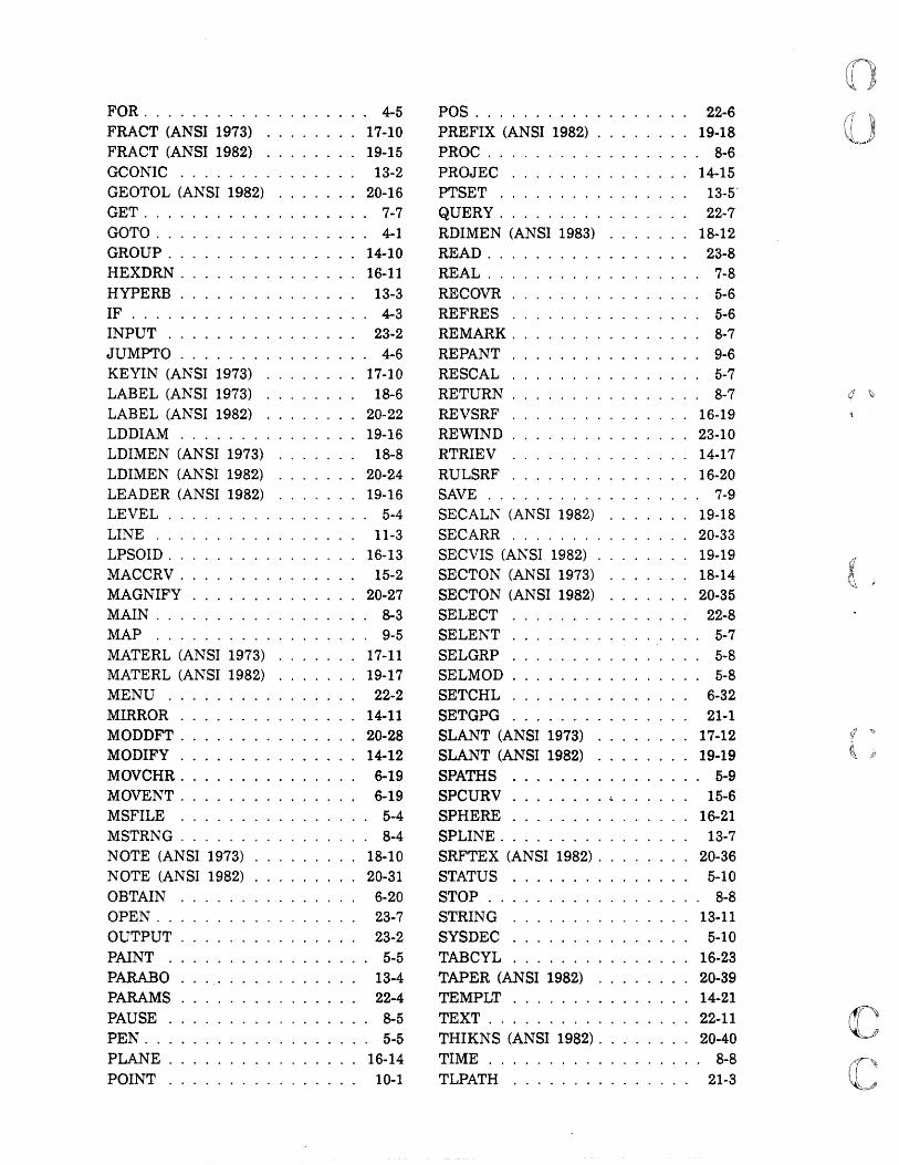
FOR. . . . . . . . . . . . . . . . . .. 4-5 FRACT (ANSI 1973) ........ 17-10 FRACT (ANSI 1982) ........ 19-15 GCONIC . . . . . . ....... " 13-2 GEOTOL (ANSI 1982) ....... 20-16 GET .................. , 7-7 GOTO ................. , 4-1 GROUP ................ 14-10 HEXDRN . . . . . . . . . . . . . . . 16-11 HYPERB . . . . . . . . . . . . . .. 13-3 IF . . . . . . . . . . . . . . . . . . .. 4-3 INPUT . . . . . . . . . . . . . . .. 23-2 JUMPTO ............... , 4-6 KEYIN (ANSI 1973) · ....... 17-10 LABEL (ANSI 1973) · ..... 18-6 LABEL (ANSI 1982) • ••••• 10 • 20-22 LDDIAM ....... · ....... 19-16 LDIMEN (ANSI 1973) ....... 18-8 LDIMEN (ANSI 1982) ....... 20-24 LEADER (ANSI 1982) ....... 19-16 LEVEL. . . . . . . . . . . . . . . .. 5-4 LINE . . . . . . . . . . . . . . . .. 11-3 LPSOID. . . . . . . . . . . . . . . . 16-13 MACCRV . . . . . . . . . . . . . .. 15-2 MAGNIFY . . . . . . . . . . . . . . 20-27 MAIN. . . . . . . . . . . . . . . . .. 8-3 MAP .................. 9-5 MATERL (ANSI 1973) . . . . . . . 17-11 MATERL (ANSI 1982) . . . . . . . 19-17 MENU . . . . . . . . . . . . . . .. 22-2 MIRROR . . . . . . . . . . . . . . . 14-11 MODDFT ............... 20-28 MODIFY ............... 14-12 MOVCHR. . . . . . . . . . . . . .. 6-19 MOVENT. . . . . . . . . . . . . .. 6-19 MSFILE ................ 5-4 MSTRNG ............... , 8-4 NOTE (ANSI 1973) . . . . . . . . . 18-10 NOTE (ANSI 1982) ......... 20-31 OBTAIN .. . . . . . . . . . . . .. 6-20 OPEN ....... . OUTPUT ..... .
23-7 23-2
PAINT ................. 5-5 PARABO . . '.' . . . . . . . . . .. 13-4 PARAMS . . . . . . . . . . . . . .. 22-4 PAUSE ................ , 8-5 PEN ................... 5a 5 PLANE ...... . 16-14 POINT . . . . . . . . . . . . . . .. 10-1
POS . . . . . . . . . . . . . . . . .. 22-6 PREFIX (ANSI 1982) . . . . . . . . 19-18 PROC . . . . . . . . . . . . . . . . .. 8-6 PROJEC ......... . 14-15 PTSET .......... . 13-5' QUERY .......... . 22-7 RDIMEN (ANSI 1983) .. 18-12 READ ........... . 23-8 REAL ........... . 7-8 RECOVR ............... . 5-6 REFRES ............... . 5-6 REMARK ............... . 8-7 REPANT ............... . 9-6 RESCAL ............... . 5-7 RETURN ......... . 8-7 REVSRF ......... . 16-19 REWIND .............. . 23-10 RTRIEV .............. . 14-17 RULSRF . . . . . . . . . . . . . . . 16-20 SAVE. . . . . . . . . . . . . . . . .. 7-9 SECALN (ANSI 1982) ....... 19-18 SECARR . . . . . . . . . . . . . . . 20-33 SECVIS (ANSI 1982) . . . . . . . . 19-19 SECTON (ANSI 1973) ....... 18-14 SECTON (ANSI 1982) ....... 20-35 SELECT . . . . . . . . . . . . . ., 22-8 SELENT .............. " 5-7 SELGRP . . . . . . . . . . . . . . .. 5-8 SELMOD .............. " 5-8 SETCHL . . . . . . . . . . . . . .. 6-32 SETGPG . . . . . . . . . . . . . .. 21-1 SLANT (ANSI 1973) . . . . . . . . 17-12 SLANT (ANSI 1982) ....... . 19-19 SPATHS ................ 5-9 SPCURV ........•..... , 15-6 SPHERE . . . . . . . . . . . . . . . 16-21 SPLINE ............... , 13-7 SRFTEX (ANSI 1982) . . . . . .. 20-36 STATUS ... . . . . . . . . . . .. 5-10 STOP. . . . . . . . . . . . . . . . .. 8-8 STRING ............... 13-11 SYSDEC . . . . . . . . . . . . . .. 5-10 TABCYL ............... 16-23 TAPER (ANSI 1982) ........ 20-39 TEMPLT . . . . . . . . . . . . . . . 14-21 TEXT ................. 22-11 THIKNS (ANSI 1982) ........ 20-40 TIME ................ " 8-8 TLPATH ............... 21-3
(] \J

(
(
(
(
(
(
TORUS ........ . TRIME ....... . TXTANG (ANSI 1973) TXTJUS (ANSI 1973) .. TXTJUS (ANSI 1982) .. TXTORG (ANSI 1982) UNBLNK ....... . USTRUC VBORDS VECTOR
16-24 6-32
17-12 17-13 19-20 19-21
9-7 23-10
9-8 15-8
VIEW .. VNAMES. VVECS WAIT ......... . WLINE (ANSI 1973) WLINE (ANSI 1982) WRITE ZOOM ZSURF
9-9 9-11 9-12 9-12
17-14 19-22 23-12
9-13 5-11