NEC Electronics Inc. - bitsavers.org
242
NEC Electronics Inc. - Product Selection Guide 1988 NEC
-
Upload
khangminh22 -
Category
Documents
-
view
2 -
download
0
Transcript of NEC Electronics Inc. - bitsavers.org

NEC Electronics Inc. -Product Selection Guide
1988
NEC

NEC
1988 PRODUCT SELECTION
GUIDE
November 1987 NECEL-000260
Stock No. 900009 ©1987 NEC Electronics lnc./Printed in U.S.A.
No part of this document may be copied or reproduced in any form or by any means without the prior written consent of NEC Electronics Inc. The information in this document is subject to change without notice. Devices sold by NEC Electronics Inc. are covered by the warranty and patent indemnification provisions appearing in NEC Electronics Inc. Terms and Conditions of Sale only. NEC Electronics Inc. makes no warranty, express, statutory, implied, or by description, regarding the information set forth herein or regarding the freedom of the described devices from patent infringement. NEC Electronics Inc. makes no warranty of merchantability or fitness for any purpose. NEC Electronics Inc. assumes no responsibility for any errors that may appear in this document. NEC Electronics Inc. makes no commitment to update or to keep current the information contained in this document.

t\'EC
ii

t-IEC
GENERAL INFORMATION
QUALITY AND RELIABILITY
MEMORY PRODUCTS
MICROCOMPUTER PRODUCTS
MICROPROCESSOR PRODUCTS
ASIC PRODUCTS
CAPACITORS
FLUORESCENT INDICATOR PANEL DISPLAYS (FIPs)
OPTOELECTRONIC DEVICES
INDUSTRIAL LINEAR PRODUCTS
POWER MOSFETs
CONSUMER ICs
TELECOM AND DATACOM FIBER OPTICS
OFFICE AUTOMATION BEAM LASERS
TELECOMMUNICATION ICs
m m
iii

TABLE OF CONTENTS NEC Section 1 - General Information Page
Introduction . . . . . . . . . . . . . . . . . . . . . . . . . . . . . . . . . . . . . . . . . . . . . . . . . . . . . . . . . . . . . . . . . . . . . . . . . . . . . . . . . . . 1-3 Memory Products . . . . . . . . . . . . . . . . . . . . . . . . . . . . . . . . . . . . . . . . . . . . . . . . . . . . . . . . . . . . . . . . . . . . . . . . . . . . . . 1-3 Single-Chip Microcomputer Products (4-bit, 8-bit, or 16-bit) . . . . . . . . . . . . . . . . . . . . . . . . . . . . . . . . . . . . . . . 1-3 Microprocessor Products . . . . . . . . . . . . . . . . . . . . . . . . . . . . . . . . . . . . . . . . . . . . . . . . . . . . . . . . . . . . . . . . . . . . . . . 1-3 ASIC Products . . . . . . . . . . . . . . . . . . . . . . . . . . . . . . . . . . . . . . . . . . . . . . . . . . . . . . . . . . . . . . . . . . . . . . . . . . . . . . . . . 1-3 Capacitors . . . . . . . . . . . . . . . . . . . . . . . . . . . . . . . . . . . . . . . . . . . . . . . . . . . . . . . . . . . . . . . . . . . . . . . . . . . . . . . . . . . . . 1-4 Fluorescent Indicator Panel Displays (FIPs) .. .. .. .. .. .. .. .. .. .. .. .. .. .. .. .. .. .. .. .. .. .. .. .. .. .. .. 1-4 Optoelectronic Devices . . . . . . . . . . . . . . . . . . . . . . . . . . . . . . . . . . . . . . . . . . . . . . . . . . . . . . . . . . . . . . . . . . . . . . . . . 1-4 Industrial Linear Products . . . . . . . . . . . . . . . . . . . . . . . . . . . . . . . . . . . . . . . . . . . . . . . . . . . . . . . . . . . . . . . . . . . . . . 1-4 Power MOSFETs (Discrete Products) . . . . . . . . . . . . . . . . . . . . . . . . . . . . . . . . . . . . . . . . . . . . . . . . . . . . . . . . . . . . 1-4 Consumer ICs . . . . . . . . . . . . . . . . . . . . . . . . . . . . . . . . . . . . . . . . . . . . . . . . . . . . . . . . . . . . . . . . . . . . . . . . . . . . . . . . . 1-5 Telecom and Datacom Fiber Optics . . . . . . . . . . . . .. . .. . .. . . . .. . .. .. .. .. . . . . . .. . . .. . .. . . . . . . .. . . . . . . 1-5 Office Automation Beam Lasers . . . . . . . . . . . . . . . . . . . . . . . . . . . . . . . . . . . . . . . . . . . . . . . . . . . . . . . . . . . . . . . . . 1-5 Telecommunication ICs . . . . . . . . . . . . . . . . . . . . . . . . . . . . . . . . . . . . . . . . . . . . . . . . . . . . . . . . . . . . . . . . . . . . . . . . . 1-5
Section 2 - Quality and Reliability
Introduction . . . . . . . . . . . . . . . . . . . . . . . . . . . . . . . . . . . . . . . . . . . . . . . . . . . . . . . . . . . . . . . . . . . . . . . . . . . . . . . . . . . 2-3 Technology Description . . . . . . . . . . . . . . . . . . . . . . . . . . . . . . . . . . . . . . . . . . . . . . . . . . . . . . . . . . . . . . . . . . . . . . . . . 2-3 Reliability Testing . . . . . . . . . . . . . . . . . . . . . . . . . . . . . . . . . . . . . . . . . . . . . . . . . . . . . . . . . . . . . . . . . . . . . . . . . . . . . . 2-3 Failure Rate Calculation and Prediction . . . . . . . . . . . . . . . . . . . . . . . . . . . . . . . . . . . . . . . . . . . . . . . . . . . . . . . . . . 2-6 Reliability Test Results . . . . . . . . . . . . . . . . . . . . . . . . . . . . . . . . . . . . . . . . . . . . . . . . . . . . . . . . . . . . . . . . . . . . . . . . . 2-7 NEC's Goals on Failure Rates . . . . . . . . . . . . . . . . . . . . . . . . . . . . . . . . . . . . . . . . . . . . . . . . . . . . . . . . . . . . . . . . . . . 2-7 Infant Mortality Failure Screening . . . . . . . . . . . . . . . . . . . . . . . . . . . . . . . . . . . . . . . . . . . . . . . . . . . . . . . . . . . . . . . 2-8 Life Tests . . . . . . . . . . . . . . . . . . . . . . . . . . . . . . . . . . . . . . . . . . . . . . . . . . . . . . . . . . . . . . . . . . . . . . . . . . . . . . . . . . . . . . 2-8 Built-in Quality and Reliability . . . . . . . . . . . . . . . . . . . . . . . . . . . . . . . . . . . . . . . . . . . . . . . . . . . . . . . . . . . . . . . . . . . 2-10 Approaches to Total Quality Control . . . . . . . . . . . . . . . . . . . . . . . . . . . . . . . . . . . . . . . . . . . . . . . . . . . . . . . . . . . . . 2-10 Summary and Conclusion . . . . . . . . . . . . . . . . . . . . . . . . . . . . . . . . . . . . . . . . . . . . . . . . . . . . . . . . . . . . . . . . . . . . . . 2-12
Section 3 - Memory Products
Part Numbering System . . . . . . . . . . . . . . . . . . . . . . . . . . . . . . . . . . . . . . . . . . . . . . . . . . . . . . . . . . . . . . . . . . . . . . . . 3-3 Memory Product Overview . . . . . . . . . . . . . . . . . . . . . . . . . . . . . . . . . . . . . . . . . . . . . . . . . . . . . . . . . . . . . . . . . . . . . . 3-5 Application-Specific Devices . . . . . . . . . . . . . . . . . . . . . . . . . . . . . . . . . . . . . . . . . . . . . . . . . . . . . . . . . . . . . . . . . . . . 3-6 RAM Modules . . . . . . . . . . . . . . . . . . . . . . . . . . . . . . . . . . . . . . . . . . . . . . . . . . . . . . . . . . . . . . . . . . . . . . . . . . . . . . . . . . 3-7 Dynamic RAMs . . . . . . . . . . . . . . . . . . . . . . . . . . . . . . . . . . . . . . . . . . . . . . . . . . . . . . . . . . . . . . . . . . . . . . . . . . . . . . . . 3-8 XRAMs . . . . . . . . . . . . . . . . . . . . . . . . . . . . . . . . . . . . . . . . . . . . .. . . . . . . . . . . . . . . . . . . . . . . . . . . . .. . . . . . . . . . . . . . 3-8 MOS Static RAMs . . . . . . . . . . . . . . . . . . . . . . . . . . . . . . . . . . . . . . . . . . . . . . . . . . . . . . . . . . . . . . . . . . . . . . . . . . . . . . 3-9 ECL RAMs . . . . . . . . . . . . . . . . . . . . . . . . . . . . . . . . . . . . . . . . . . . . . . . . . . . . . . . . . . . . . . . . . . . . . . . . . . . . . . . . . . . . . 3-10 EPROMs . . . . . . . . . . . . . . . . . . . . . . . . . . . . . . . . . . . . . . . . . . . . . . . . . . . . . . . . . . . . . . . . . . . . . . . . . . . . . . . . . . . . . . . 3-11 EEPROMs . . . . . . . . . . . . . . . . . . . . . . . . . . . . . . . . . . . . . . . . . . . . . . . . . . . . . . . . . . . . . . . . . . . . . . . . . . . . . . . . . . . . . 3-11 Mask-Programmable ROMs ..................................................................... 3-12
Section 4 - Microcomputer Products
iv
Part Numbering System . . . . . . . . . . . . . . . . . . . . . . . . . . . . . . . . . . . . . . . . . . . . . . . . . . . . . . . . . . . . . . . . . . . . . . . . 4-3 4-bit, Single-Chip CMOS Microcomputers . . . . . . . . . . . . . . . . . . . . . . . . . . . . . . . . . . . . . . . . . . . . . . . . . . . . . . . 4-3 8-bit, Single-Chip NMOS/CMOS Microcomputers . . . . . . . . . . . . . . . . . . . . . . . . . . . . . . . . . . . . . . . . . . . . . . . . 4-7 16-bit, Single-Chip CMOS Microcomputers . . . . . . . . . . . . . . . . . . . . . . . . . . . . . . . . . . . . . . . . . . . . . . . . . . . . . . 4-9 CMOS LCD Controller/Drivers . . . . . . . . . . . . . . . . . . . . . . . . . . . . . . . . . . . . . . . . . . . . . . . . . • . . . . . . . . . . . . . . . . 4-10 µPD7500 Series Hardware Development Tools .................................................... 4-10 µPD75000 Series Hardware Development Tools . . . . . . . . . . . . . . . . . . . . . . . . . . . . . . . . . . . . . . . . . . . . . . . . . . . 4-11 µPD7800 Series Hardware Development Tools . .. .. . . .. . .. . . .. . . . .. . .. . . . . . .. .. . .. . .. . . .. . . . .. . . .. 4-11 µPD78000 Series Hardware Development Tools ................................................... 4-11 µPD70320/322 (V25) Hardware Development Tools ............................................... 4-11 µPD8048 Series Hardware Development Tools .................................................... 4-12

NEC TABLE OF CONTENTS
Section 4 - Microcomputer Products (cont) Page
EV-9001/EV-9002 Conversion Boards ........................................................... . 4-12 MD-086 Series Microcomputer Development Systems ........................................... . 4-12 MD-910TM Character Display Terminal Development System ..................................... . 4-12 PG1000 PROM Programmers ................................................................... . 4-12
Section 5 - Microprocessor Products
Part Numbering System ....................................................................... . 5-3 CMOS Microprocessors ....................................................................... . 5-3 NMOS and HMOS Microprocessors ............................................................ . 5-5 Digital Signal Processor and Speech ........................................................... . 5-5 Intelligent Peripheral Controllers ............................................................... . 5-6 CMOS System Support Products ............................................................... . 5-8 NMOS System Support Products ............................................................... . 5-9 µPD7720 Hardware Development Tool .......................................................... . 5-10 µPD70208/216 Hardware Development Tools .................................................... . 5-10 µPD7281 Software Development Tools .......................................................... . 5-10 µPD7720 Software Development Tools .......................................................... . 5-11 µPD70108/116/208/216 Software Relocatable Assembler Development Tools ....................... . 5-11 µPD70108/116/208/216 Software C Compiler Development Tools ................................. . 5-11 MD-086 Series Microcomputer Development Systems ........................................... . 5-11 MD-910TM Character Display Terminal Development Tool ........................................ . 5-11 PG1000 PROM Programmers ................................................................... . 5-11
Section 6 - ASIC Products
ECL .......................................................................................... . 6-3 CMOS-2,-3 ................................................................................... . 6-4 CMOS-4 ...................................................................................... . 6-4 CMOS-4A .................................................................................... . 6-5 CMOS-4R .................................................................................... . 6-5 BiCMOS-4 .................................................................................... . 6-6 Standard Cell ................................................................................ . 6-6 TTL .......................................................................................... . 6-7
Section 7 - Capacitors
Capacitors Cross Reference ................................................................... . 7-3 Part Numbering System ....................................................................... . 7-3 A-Series Subminiature, Molded Axial, Solid Tantalum Capacitors ................................. . 7-7 C-Series Unencapsulated Chip, Solid Tantalum Capacitors ...................................... . 7-9 D-Series Resin Dipped Radial, Solid Tantalum Capacitors ....................................... . 7-10 P-Series Miniature Epoxy Dipped, Solid Tantalum Capacitors .................................... . 7-12 Q-Series Resin Solid Dipped Tantalum Capacitors .............................................. . 7-14 A-Series Miniature Encapsulated Chip, Solid Tantalum Capacitors ............................... . 7-15 U-Series Subminiature Metal Can, Epoxy End Seal, Axial Solid Tantalum Capacitors .............. . 7-17 FA-Series Supercap Electric Double Layer Capacitors ........................................... . 7-18 FS-Series Supercap Electric Double Layer Capacitors ........................................... . 7-18 FZ-Series Supercap Electric Double Layer Capacitors ........................................... . 7-19 High-Capacitance, Multilayer Ceramic Capacitors ............................................... . 7-20
Section 8 - Fluorescent Indicator Panel Display (FIPs)
Part Numbering System ....................................................................... . 8-3 Abbreviations ................................................................................. . 8-4 Data Terminal and Others (Dot Type and Graphic Type) .......................................... . 8-6 Display Configuration Table .................................................................... . 8-10
v

TABLE OF CONTENTS NEC Section 8 - Fluorescent Indicator Panel Display (FIPs) (cont) Page
Data Terminal and Others (Alpha-Numeric Type) . . .. . . . .. . . . .. . . . . . . . . . . . .. . . . . . .. . . . . . . . . . . .. . . . 8-12 Automotive and Others . . . . . . . . . . . . . . . . . . . . . . . . . . . . . . . . . . . . . . . . . . . . . . . . . . . . . . . . . . . . . . . . . . . . . . . . . 8-14 Audio, Analog Instruments, and Others . .. . . .. . . .. . . . . . . . . . . . .. . . . . .. . .. .. . . . .. . . . . . . .. . . .. . .. . .. 8-16 Digital Clock, Timer, Measuring Meter, and Others ............................................... 8-18 ECR and Others . . . . . . . . . . . . . . . . . . . . . . . . . . . . . . . . . . . . . . . . . . . . . . . . . . . . . . . . . . . . . . . . . . . . . . . . . . . . . . . . 8-20 Calculator and Others .......................................................................... 8-22 Dot Type Fluorescent Indicator Modules . . . . . . . . . . . . . . . . . . . . . . . . . . . . . . . . . . . . . . . . . . . . . . . . . . . . . . . . . 8-24 Chip-in-Glass FIP Modules ..................................................................... 8-26
Section 9 - Optoelectronic Devices
Part Numbering System . . . . . . . . . . . . . . . . . . . . . . . . . . . . . . . . . . . . . . . . . . . . . . . . . . . . . . . . . . . . . . . . . . . . . . . . 9-3 Optoelectronics Cross Reference . . . . . . . . . . . . . . . . . . . . . . . . . . . . . . . . . . . . . . . . . . . . . . . . . . . . . . . . . . . . . . . . 9-4 Red - Light Emitting Diodes . . . . . . . . . . . . . . . . . . . . . . . . . . . . . . . . . . . . . . . . . . . . . . . . . . . . . . . . . . . . . . . . . . . . 9-8 Green - Light Emitting Diodes . . . . . . . . . . . . . . . . . . . . . . . . . . . . . . . . . . . . . . . . . . . . . . . . . . . . . . . . . . . . . . . . . 9-8 Amber/Yellow - Light Emitting Diodes . . . . . . . . . . . . . . . . . . . . . . . . . . . . . . . . . . . . . . . . . . . . . . . . . . . . . . . . . . 9-9 Infrared - Light Emitting Diodes .. .. . .. .. . .. . .. .. .. .. .. .. .. .. .. .. . .. .. .. .. .. .. .. .. .. . .. .. .. .. . .. 9-9 Photo Couplers . . . . . . . . . . . . . . . . . . . . . . . . . . . . . . . . . . . . . . . . . . . . . . . . . . . . . . . . . . . . . . . . . . . . . . . . . . . . . . . . 9-9 Photo Couplers - SCR Type .................................................................... 9-10 Photo Transistors ..... : . . . . . . . . . . . . . . . . . . . . . . . . . . . . . . . . . . . . . . . . . . . . . . . . . . . . . . . . . . . . . . . . . . . . . . . . 9-10 Photo Interrupters . . . . . . . . . . . . . . . . . . . . . . . . . . . . . . . . . . . . . . . . . . . . . . . . . . . . . . . . . . . . . . . . . . . . . . . . . . . . . . 9-10 Photo Diodes . . . . . . . . . . . . . . . . . . . . . . . . . . . . . . . . . . . . . . . . . . . . . . . . . . . . . . . . . . . . . . . . . . . . . . . . . . . . . . . . . . 9-10
Section 10 - Industrial Linear Products
Part Numbering System . . . . . . . . . . . . . . . . . . . . . . . . . . . . . . . . . . . . . . . . . . . . . . . . . . . . . . . . . . . . . . . . . . . . . . . . 10-3 Linear Cross Reference . . . . . . . . . . . . . . . . . . . . . . . . . . . . . . . . . . . . . . . . . . . . . . . . . . . . . . . . . . . . . . . . . . . . . . . . . 10-4 Operational Amplifiers . . . . . . . . . . . . . . . . . . . . . . . . . . . . . . . . . . . . . . . . . . . . . . . . . . . . . . . . . . . . . . . . . . . . . . . . . . 10-5
Single Operational Amplifiers . . . . . . . . . . . . . . . . . . . . . . . . . . . . . . . . . . . . . . . . . . . . . . . . . . . . . . . . . . . . . . . . . 10-5 Dual Operational Amplifiers . . . . . . . . . . . . . . . . . . . . . . . . . . . . . . . . . . . . . . . . . . . . . . . . . . . . . . . . . . . . . . . . . . . 10-6 Quad Operational Amplifiers . . . . . . . . . . . . . . . . . . . . . . . . . . . . . . . . . . . . . . . . . . . . . . . . . . . . . . . . . . . . . . . . . . 10-7
Comparators . . . . . . . . . . . . . . . . . . . . . . . . . . . . . . . . . . . . . . . . . . . . . . . . . . . . . . . . . . . . . . . . . . . . . . . . . . . . . . . . . . . 10-8 Voltage Regulators . . . . . . . . . . . . . . . . . . . . . . . . . . . . . . . . . . . . . . . . . . . . . . . . . . . . . . . . . . . . . . . . . . . . . . . . . . . . . 10-9 Digital to Analog Converters .................................................................... 10-10 Analog to Digital Converters .................................................................... 10-10 Functional Blocks .............................................................................. 10-10 Charge Coupled Devices (CCD Image Sensors) .................................................. 10-11
Section 11 - Power MOSFETs
Part Numbering System . . . . . . . . . . . . . . . . . . . . . . . . . . . . . . . . . . . . . . . . . . . . . . . . . . . . . . . . . . . . . . . . . . . . . . . . 11-3 Power MOSFET Cross Reference . . . . . . . . . . . . . . . . . . . . . . . . . . . . . . . . . . . . . . . . . . . . . . . . . . . . . . . . . . . . . . . . 11-4 N-Channel Power MOSFET ..................................................................... 11-42 P-Channel Power MOSFET ..................................................................... 11-43 Power MOSFET Quad Arrays ................................................................... 11-43
Section 12 - Consumer ICs
vi
Consumer IC Cross Reference . . . . . . . . . . . . . . . . . . . . . . . . . . . . . . . . . . . . . . . . . . . . . . . . . . . . . . . . . . . . . . . . . . 12-3 Audio I Cs . . . . . . . . . . . . . . . . . . . . . . . . . . . . . . . . . . . . . . . . . . . . . . . . . . . . . . . . . . . . . . . . . . . . . . . . . . . . . . . . . . . . . . 12-4
Low Noise Amplifiers . . . . . . . . . . . . . . . . . . . . . . . . . . . . . . . . . . . . . . . . . . . . . . . . . . . . . . . . . . . . . . . . . . . . . . . . . 12-4 Audio Power Amplifiers . . . . . . . . . . . . . . . . . . . . . . . . . . . . . . . . . . . . . . . . . . . . . . . . . . . . . . . . . . . . . . . . . . . . . . . 12-6 High Power Amplifiers ........................................................................ 12-12 Tape Recorders ..........................................................................•... 12-12 AM Tuners ................................................................................... 12-13 RF IF Amplifiers .............................................................................. 12-14 FM Multiplex Stereo Demodulators ............................................................ 12-17

NEC TABLE OF CONTENTS
Section 12 - Consumer ICs (cont) Page
TV I Cs ......................................................................................... 12-20 VTR ICs ....................................................................................... 12-23 TV/VTR/Audio System Optional Devices ......................................................... 12-26 Digital Tuning System: µPD1700 Series .......................................................... 12-27
Section 13 - Telecom and Datacom Fiber Optics
Emitters and Detectors . . . . . . . . . . . . . . . . . . . . . . . . . . . . . . . . . . . . . . . . . . . . . . . . . . . . . . . . . . . . . . . . . . . . . . . . . 13-3 Laser Diodes (LD} . . . . . . . . . . . . . . . . . . . . . . . . . . . . . . . . . . . . . . . . . . . . . . . . . . . . . . . . . . . . . . . . . . . . . . . . . . . . 13-3 Light Emitting Diodes (LED} . . . . . . . . . . . . . . . . . . . . . . . . . . . . . . . . . . . . . . . . . . . . . . . . . . . . . . . . . . . . . . . . . . 13-4 Avalanche Photo Diodes (APD} . . . . . .. . .. . . .. . . . . .. . . . . . . .. . . . . . .. .. .. . . .. .. .. . .. . . . . . . . . . . . . . 13-5 PIN Photo Diodes (PIN} . . . . . . . . . . . . . . . . . . . . . . . . . . . . . . . . . . . . . . . . . . . . . . . . . . . . . . . . . . . . . . . . . . . . . . 13-5
Fiber Optic Data Links . . . . . . . . . . . . . . . . . . . . . . . . . . . . . . . . . . . . . . . . . . . . . . . . . . . . . . . . . . . . . . . . . . . . . . . . . . 13-6 Connectors . . . . . . . . . . . . . . . . . . . . . . . . . . . . . . . . . . . . . . . . . . . . . . . . . . . . . . . . . . . . . . . . . . . . . . . . . . . . . . . . . . . . 13-6
Cable Assemblies . . . . . . . . . . . . . . . . . . . . . . . . . . . . . . . . . . . . . . . . . . . . . . . . . . . . . . . . . . . . . . . . . . . . . . . . . . . . 13-6 Fiber Optic Connector Parts . . . . . . . . . . . . . . . . . . . . . . . . . . . . . . . . . . . . . . . . . . . . . . . . . . . . . . . . . . . . . . . . . . 13-6 Connector Assembly Equipment, Tools, Polish Film . . . . . . . . . . . . . . . . . . . . . . . . . . . . . . . . . . . . . . . . . . . . . 13-7
Passive Devices . . . . . . . . . . . . . . . . . . . . . . . . . . . . . . . . . . . . . . . . . . . . . . . . . . . . . . . . . . . . . . . . . . . . . . . . . . . . . . . . 13-8 Optical Isolators . . . . . . . . . . . . . . . . . . . . . . . . . . . . . . . . . . . . . . . . . . . . . . . . . . . . . . . . . . . . . . . . . . . . . . . . . . . . . 13-8 Attenuators . . . . . . . . . . . . . . . . . . . . . . . . . . . . . . . . . . . . . . . . . . . . . . . . . . . . . . . . . . . . . . . . . . . . . . . . . . . . . . . . . . 13-8 Couplers . . . . . . . . . . . . . . . . . . . . . . . . . . . . . . . . . . . . . . . . . . . . . . . . . . . . . . . . . . . . . . . . . . . . . . . . . . . . . . . . . . . . 13-8 Line Monitor/Band Pass Filter . . . . . . . . . . . . . . . . . . . . . . . . . . . . . . . . . . . . . . . . . . . . . . . . . . . . . . . . . . . . . . . . . 13-8 Wavelength Division Multiplexers . . . . . . . . . . . . . . . . . . . . . . . . . . . . . . . . . . . . . . . . . . . . . . . . . . . . . . . . . . . . . . 13-9 Switches . . . . . . . . . . . . . . . . . . . . . . . . . . . . . . . . . . . . . . . . . . . . . . . . . . . . . . . . . . . . . . . . . . . . . . . . . . . . . . . . . . . . 13-9
Acousto-Optic Modulators . . . . . . . . . . . . . . . . . . . . . . . . . . . . . . . . . . . . . . . . . . . . . . . . . . . . . . . . . . . . . . . . . . . . . . 13-9
Section 14 - Office Automation Beam Lasers
HeNe Laser Tubes . . . . . . . . . . . . . . . . . . . . . . . . . . . . . . . . . . . . . . . . . . . . . . . . . . . . . . . . . . . . . . . . . . . . . . . . . . . . . . 14-3 HeNe Laser Integrated Heads . . . . . . . . . . . . . . . . . . . . . . . . . . . . . . . . . . . . . . . . . . . . . . . . . . . . . . . . . . . . . . . . . . . 14-3 HeNe Cylindrical Heads . . . . . . . . . . . . . . . . . . . . . . . . . . . . . . . . . . . . . . . . . . . . . . . . . . . . . . . . . . . . . . . . . . . . . . . . 14-3 HeNe High Power Systems . . . . . . . . . . . . . . . . . . . . . . . . . . . . . . . . . . . . . . . . . . . . . . . . . . . . . . . . . . . . . . . . . . . . . . 14-4 Air Cooled Argon Lasers . . . . . . . . . . . . . . . . . . . . . . . . . . . . . . . . . . . . . . . . . . . . . . . . . . . . . . . . . . . . . . . . . . . . . . . . 14-4
Section 15 - Telecommunication ICs
CMOS Combos . . . . . . . . . . . . . . . . . . . . . . . . . . . . . . . . . . . . . . . . . . . . . . . . . . . . . . . . . . . . . . . . . . . . . . . . . . . . . . . . 15-3 SLICS ......................................................................................... 15-3 POTS ......................................................................................... 15-4 Crosspoint Switches . . . . . . . . . . . . . . . . . . . . . . . . . . . . . . . . . . . . . . . . . . . . . . . . . . . . . . . . . . . . . . . . . . . . . . . . . . . 15-4
vii

TABLE OF CONTENTS NEC
viii

NEC GENERAL INFORMATION
1-1

GENERAL INFORMATION
Section 1 - General Information
Introduction ............................................................ . Memory Products ....................................................... . Single-Chip Microcomputer Products (4-bit, 8-bit, or 16-bit) ................ . Microprocessor Products ................................................ . ASIC Products .......................................................... . Capacitors .............................................................. . Fluorescent Indicator Panel Displays (FIPs) ............................... . Optoelectronic Devices .................................................. . Industrial Linear Products ................................................ . Power MOSFETs (Discrete Products) ..................................... . Consumer ICs ........................................................... . Telecom and Datacom Fiber Optics ....................................... . Office Automation Beam Lasers .......................................... . Telecommunication ICs .................................................. .
1-2
NEC
Page
1-3 1-3 1-3 1-3 1-3 1-4 1-4 1-4 1-4 1-4 1-5 1-5 1-5 1-5

NEC Introduction
NEC, the world's largest semiconductor supplier, offers one of the most diversified product lines in the industry. This Selection Guide provides a major listing of all the following NEC products. Contact your local NEC sales representative or use the toll free literature line, listed on the back cover of this book, for additional product information.
Memory Products
N EC's total memory line is the broadest in the industry. NEC memories give you a wider selection of device types and various configurations and process technologies within a specific type of device. The variety of NEC memories offers greater design alternatives and the choice of a part that truly fits your product. Product listings are given for each of NEC's major memory groups: Application-Specific Devices (ASDs), RAM Modules, DRAMs, XRAMs, MOS SRAMs, EPROMs, EEPROMs, and Masked ROM. New products in development include application-specific devices for video, data processing, and other specialized requirements. Dynamic RAM modules based on 1 Mb DRAMs are being introduced in 1987. Higher-density products will be available for DRAMs, XRAMs, MOS Static RAMs, and all other product areas.
Single-Chip Microcomputer Products [4-bit, 8-bit, or 16-bit]
NEC offers a wide variety of single-chip microcomputer products that range from 4-bit, 8-bit, or 16-bi~ microcomputers, plus LCD peripheral products, m both NMOS and CMOS technology and in a variety of packages.
The µPD7500 series of 4-bit, single-chip CMOS microcomputers is a broad line of devices designed for a variety of applications including electronic games, home electronic devices and automotive applications. The 75000 series and the cost-effective, low-end 755x/756x series known as mini-microcomputers complete this product line. The 8-bit products include the popular 80xx/87xx and 80Cxx series together with the high end 7800 and 78000 series. The µPD70320/ 70322 (V25™) are high performance, 16-bit, single-chip microcomputers with an 8-bit external data bus. Peripherals include LCD controller-driver products for alphanumeric, dot-addressable, and large-area LCD displays.
V20, V30 are registered trademarks of NEC Corporation.
V25, V40, V50, V60 and V70 are trademarks of NEC Corporation.
GENERAL INFORMATION
A comprehensive line of development hardware and software tools support NEC's single-chip microcomputer families. This extraordinary selection provides greater design alternatives that truly fit your needs in data processing, communication, instrumentation, automotive, and consumer applications.
Microprocessor Products
NEC is a leading supplier of high quality, multifunctional peripherals and processors. These are divided into six groups: 1. standard NMOS and CMOS 8-bit and 1-bit processors/peripherals; e.g., µPD8088, µPD70108 (V20®), 82XX and 710XX; 2. communicati~ns controllers; e.g., µPD7201A, µPD72001; 3. graphics controllers; e.g., µPD7220A, advanced graphics display controller (µPD72120); 4. magnetic media controllers; e.g., floppy disk controllers µPD9765A, µPD72065 (CMOS 765A) and hard disk controllers (ESDI, ST506, SMD, ESMD); 5. digital signal processors (µPD7720A, µPD77C20A, µPD77230); and 6. speech cont~~llers (775X-speech generation, 776X speech recognition). All NEC microprocessor products provide users with cost effective system solutions in silicon.
The V-Series is a family of CMOS microprocessors designed for high performance and low-power consumption. The µPD78108/78116 (V20/V30®) provide immediate performance gain over the 8086/88. The µPD70208/78216 (V40"'/V50TI') combine CPU and many peripheral devices into a single device which results in great savings for a total system. The µPD70616/70632 (V60™/V70™) are designed with the new 32-bit architecture and memory management aimed at more sophisticated applications.
ASIC Products
NEC is committed to becoming the leading supplier of Application Specific Integrated Circuits (ASICs). Our semiconductor technology is second to none, and we offer gate array products in 1.5 micron CMOS, exciting Bi CMOS, and high performance ECL. NEC's packagi~g technology is leading the way in the ASIC industry with advanced packages like 160-pin flat, 84-pin PLCC, 280-pin pin grid arrays, and Tape Automated B~ndi~g (TAB). NEC will soon lead the technology again with 1.2 micron CMOS and 45,000 gate densities. ASIC
1-3

GENERAL INFORMATION
product technology, coupled with state of the art design tools and CAD systems, will give your products a leading edge.
Capacitors
NEC is an innovator in the capacitor market, offering high volume, high quality products. NEC's tantalum R Series molded chip capacitors, dipped radial and molded axial capacitors offer advanced technological design and excellent performance characteristics for filtering, bypassing, coupling, decoupling, blocking, filtering and RC timing circuits. These capacitors are used exclusively in industrial, commercial, entertainment, and medical electronic equipment. NEC's super capacitors (SupercapsT") are used for applications requiring battery back-up for CMOS SRAMs and microprocessors. NEC's new product line, multilayer ceramic capacitors, offers a high capacitance, resin dipped, multilayer capacitor for high-frequency switching power supplies.
Fluorescent Indicator Panel Displays [FIPs]
NEC offers vacuum fluorescent indicator panel (FIP®) displays for all major market applications. With lowvoltage operation and large, bright characters in blue, green and all other visible colors, FIPs are a more effective and reliable display than most LEDs and gas discharge displays. NEC's FIPs are available in a wide variety of standard sizes, characters and number of digits.
NEC's FIP module line has recently been expanded to include the new Chip-in-Glass which offers low power, compact, and inexpensive display modules. A full character set, power supply, electronics to drive the FIP, and an on-board microprocessor are features of these modules. The mounting of the driver chips inside the glass envelope and the use of surface mount technology make the NEC Chip-in-Glass modules one of the most compact and inexpensive vacuum fluorescent display modules available.
Optoelectronic Devices
The wide variety of NEC optoelectronic devices offers designers and manufacturers greater alternatives and the abi I ity to choose the parts that truly fit their product
Supercaps is a trademark of NEC Corporation.
FIP is a registered trademark of NEC Corporation.
1-4
t-IEC needs. Designed to satisfy industrial, communication, instrumentation, and consumer applications, NEC's broad line includes both fashion and standard LEDs (in red, green, amber and infrared wavelengths), photo interrupters in standard and unique sizes, and a wide variety of photo couplers, photo transistors, and photo diodes. All NEC optoelectronic components have superior efficiency, stability and operating characteristics.
Industrial Linear Products
NEC has an extensive line of linear products to meet virtually any need. This includes hard to find pin and performance compatible surface mount opamps, which eliminate design and hardware changes when changing from feed through to surface mount technology. NEC also offers 9-pin SIP packages for higher packing density dual opamp requirements.
In addition to our standard linear items (opamps, comparators, timers and regulators), our bipolar and CMOS D/A converters have conversion speeds of up to 50 MHz, and A/D converters with input multiplexing, full microprocessor control, serial or parallel output or both. NEC has new 6-bit and 8-bit flash converters ideal for video conversion or any high-speed signal processing.
NEC is a leader in cost effective high performance CCD products. Our advanced product line includes Charge Coupled Devices (CCDs), both linear and array image sensors, used in fax, optical character reader (OCR), document scanning and video cameras.
Power MOSFETs [Discrete Products]
NEC's newest product line, Power MOSFETs, includes N-channel devices from 30 V to 900 V, P-channel devices through -100 V, N- and P-channel arrays (four devices per single-in-line package) through ±100V, 1.5 amp Nand P-channel surface mount packages (MP-3), isolated power plastic packages with ratings up to 40 amps, and a family of devices of 4 V gate drives with breakdown voltages of up to 100 V.
Computer simulation and the most advanced processing technologies have enabled NEC to produce a family of Power MOSFETs with 4 V gate drives. These devices can be driven using an IC with an operating voltage of 5 V, which results in a simplified, small sized, lower cost drive circuit.

~EC Other discrete products available from NEC include bipolar transistor arrays, isolated power plastic bipolars, UHF and VHF tuner diodes.
Consumer ICs
NEC offers a complete line of consumer I Cs geared to the entertainment market which include: digital tuning systems (DTS); prescalers; phase-locked loops (PLLs); audio, radio, TV, CATV, VCR, compact disk, watch and clock I Cs; infrared (IR) remote control circuits; display drivers; and monolithic and hybrid broadband amplifiers.
The µPD1700 series (DTS) is a family of single-chip 4-bit CMOS microprocessors with built-in PLLs. PLLs employing a pulse swallowing method in frequency dividing allows higher frequency operation. The µPD1700 series is suitable for audio, video, automotive, and portable radio applications.
The infrared remote control family includes a wide variety of receivers, receiver pre-amplifiers and transmitters. NEC's GaAs LEDs and PIN photo diode families complete the remote control circuit requirements.
NEC's CMOS display driver family includes clock, latch, and driver circuits for LCD, FIP (vacuum fluorescence), plasma and electroluminescent displays.
GENERAL INFORMATION
Telecom and Datacom Fiber Optics
NEC offers all the high reliability fiber optic components (emitters, detectors and passive components) needed to build long-haul and loop telecommunications and local area network data communications equipment.
NEC's commitment to advanced fiber optic technology and high volume manufacturing techniques provides a complete framework for your fiber optic needs.
Office Automation Beam Lasers
NEC is a leading manufacturer of Helium-Neon and Argon Ion gas lasers, including types ranging from 0.5 mW to 50 mW output power. A line of high reliability power supplies completes the offering.
In development are beam laser diodes covering a range of wavelengths from 830 to the visible.
Telecommunication ICs
NEC offers a line of custom and commodity CMOS telecom ICs for telephone sets, terminals, pagers, mobile telephones, telephone exchanges, switching and data communications along with fiber optic components.
1-5

GENERAL INFORMATION NEC
1-6

ttiEC
QUALITY AND RELIABILITY
2-1

QUALITY AND RELIABILITY
Section 2 - Quality and Reliability
Introduction ............................................................ . Technology Description .................................................. . Reliability Testing ........................................................ . Failure Rate Calculation and Prediction ................................... . Reliability Test Results .................................................. . NEC's Goals on Failure Rates ............................................ . Infant Mortality Failure Screening ........................................ . Life Tests ............................................................... . Built-in Quality and Reliability ............................................ . Approaches to Total Quality Control ...................................... . Summary and Conclusion ................................................ .
2-2
tttrEC
Page
2-3 2-3 2-3 2-6 2-7 2-7 2-8 2-8
2-10 2-10 2-12

NEC Introduction
As large-scale integration reaches a higher level of density, reliability of devices imposes a profound impact on system reliability. And as device reliability becomes a major factor, test methods to assure acceptable reliability become more complicated. Simply performing a reliability test according to a conventional method cannot satisfy the demanding requirements for higher reliability. At these new, higher levels of LSI density, it is increasingly difficult to activate all the elements in the internal circuits. A different philosophy and methodology is needed for reliability assurance. Moreover, as integration density increases, the degradation of internal elements in an LSI device is seldom detected by measuring characteristics across external terminals.
In order to improve and guarantee a certain level of reliability for large-scale integrated circuits, it is essential to build quality and reliability into the product. Then, the conventional reliability tests are followed to ensure that the product demonstrates an acceptable level of reliability.
NEC has introduced the concept of total quality control (TQC) across its entire semiconductor product line. By adopting TQC, NEC can build quality into the product and thus assure higher reliability. The concept and methodology of total quality control are companywide activities involving workers, engineers, quality control staffs, and all levels of management.
NEC has also introduced a prescreening method into the production line that helps eliminate potentially defective units. The combination of building quality in and screening projected early failures out has resulted in superior quality and excellent reliability.
Technology Description
Most large-scale integrated circuits utilize high-density, MOS technology. State-of-the-art high performance has been achieved by introducing fine-line generation techniques. By reducing physical parameters, circuit density and performance increase while active circuit power dissipation decreases. The data presented here shows that this advanced technology yields products as reliable as those from previous technologies.
QUALITY AND RELIABILITY
Reliability Testing
Reliability is defined as the characteristics of an item expressed by the probability that it will perform a required function under stated conditions for a stated period of time. This involves the concept of probability, definition of required function(s), and the critical time used in defining the reliability.
Definition of a required function, by implication, treats the definition of a failure. Failure is defined as the termination of the ability of a device to perform its required function. Furthermore, a device is said to have failed if it shows inability to perform within quaranteed parameters as given in an electrical specification.
Discussion of reliability and failure can be approached in two ways: with respect to systems or to individual devices. The accumulation of normal device failure rates constitutes the expected failure rate of the system hardware. Important considerations here are the constant failure period, the early failure (infant mortality) period, and overall reliability level. With regard to individual devices, areas of prime interest include specific failure mechanisms, failures in accelerated tests, and screening tests.
Some of these failure considerations pertain to both systems and devices. The probability of no failures in a system is the product of the probability of no failure in each of its components. The failure rate of system hardware is then the sum of the failure rates of the components used to construct the system.
Figure 1. Reliability Life (Bathtub) Curve
Random Failure Period
Time-83-003939A
2-3

QUALITY AND RELIABILITY
Life Distribution
The fundamental principles of reliability engineering predict that the failure rate of a group of devices will follow the well-known bathtub curve in figure 1. The curve is divided into three regions: infant mortality, random failures, and wearout failures.
Infant mortality, as the name implies, represents the early-life failures of devices. These failures are usually associated with one or more manufacturing defects.
After some period of time, the failure rate reaches a low value. This is the random failure portion of the curve, representing the useful portion of the life of a device. During this random failure period, there is a decline in the failure rate due to the depletion of potential random failures from the general population.
The wearout failures occur at the end of the device's useful life. They are characterized by a rapidly rising failure rate over time as devices wear out both physically and electrically.
Thus, for devices that have very-long life expectancies compared to those of systems, the areas of concern will be the infant mortality and the random failure portions of the population.
The system failure rates are related to the collective device failure rates. In a given system, after elimination of the early failures, the system will be left to the failure rate of its components. In order to make proper projections of the failure rate in the operating environment, time-to-failure must be accelerated in tests in a predictable way.
Failure Distribution at NEC
Integrated circuits returned to NEC from the field underwent extensive failure analysis at NEC's Integrated Circuit Division.
First, approximately 50 percent of the field returns were found to be damaged either from improper handling or misuse of the devices. These units were eliminated from the analysis. The remaining failed units were classified by their failure mechanisms as depicted in figure 2. These failures were then related to the major integrated circuit failure mechanisms and to their origins in a particular manufacturing step.
As shown in figure 2, the first four failure mechanisms accounted for more than 90 percent of total failures. As a result, NEC improved processes and material to reduce these failures. Additionally, NEC introduced screening procedures to detect and eliminate defective devices.
2-4
NEC Temperature, humidity, and bias tests are used for testing the moisture resistance of plastic encapsulated integrated circuits. NEC developed a special process to improve the plastic encapsulation material. As a resu It, moisture-related-th us packag i ng-related-fai 1-u res have been drastically reduced.
As a preventive measure, NEC has introduced a special screening procedure embedded in the production line. A burn-in at an elevated temperature is performed for 100 percent of the lots. This burn-in effectively removes the potentially defective units. In addition, improvement of the plastic encapsulation material has lowered the failures in a high-temperature and high-humidity environment.
Figure 2. Failure Distribution of MOS Integrated Circuits
Oxide Destroyed
Si02 Pattern Defects
Bond-Wire Peel or Cut
Metalization Defects
Moisture Penetration
Parameter Degradation
Scratch
Chip/Peel/ Crack
Metalization Corrosion
Other
20
Percent Failures
40 60 80
Percent Cumulative Failures
100
83·003940A

t\'EC Accelerated Reliability Testing
As an example, assume that an electronic system contains 1000 integrated circuits and can tolerate 1 percent system failures per month. The failure rate per component is:
0.01 Failures
720K Device Hours
13.888 x 10⁻⁹ Failures/Hour or 13.8888 FITS
where FIT= Failure units per 109 device hours
To demonstrate this failure rate, note that 13.8888 FITs corresponds to one failure in about 7000 devices during an operating test of 10,000 hours. It is quickly apparent that a test condition is required to accelerate the time-to-failure in a predictable and understandable way. The implicit requirement for the accelerated stress test is that the relationship between the accelerated stress testing condition and the condition of actual use be known.
A most common time-to-failure relationship involves the effect of temperature, which accelerates many physiochemical reactions leading to device failure. Other environmental conditions are voltage, current, humidity, vibration, or some combination of these. Table 1 lists the reliability assurance tests performed at NEC for integrated circuits.
Table 1. Monthly NEC Rel/ability Tests
Test
Life Test High-temperature, operating
High-temperature, storage
High-temperature, high-humidity test
Pressure cooker test
Environmental Test Soldering heat test
Temperature cycle
Thermal shock
Lead fatigue
Solderability
MIL-STD-883 Method
1005
1008
Test Conditions
TA= 100 to 125°C for 1000 hours
TA= 150°C for 1000 hours
TA = 85 °C at 85% RH for 1000 hours
TA= 125°C at 2.3 atm for 168 hours
2031 T = 260°C for 10 s (MIL-STD-750) without flux
1010 T = -65 to +150°C for 10 cycles
1011 T = o to 100°c for 15 cycles
2004 at 250 gm: 3 leads, 3 bends
2003 T = 230°C for 5 s with flux
QUALITY AND RELIABILITY
Temperature Effect. The effect of temperature that concerns us is that which responds to the Arrhenius relationship. This relates the reaction rate to temperature.
R = R0 exp(-Ea/kT)
where R0 = Constant Ea = Activation energy in eV k = Boltzmann's constant
= 8.617 x 10-s eV/K T =Absolute temperature in kelvin (K)
The significance of this relationship is that the failure mechanisms of semiconductor devices are directly applicable to it. A linear relationship between failure mechanism and time is assumed.
Activation Energy. Associated with each failure mechanism is an activation energy value. Table 2 lists some of the more common failure mechanisms and the associated activation energy of each.
Table 2. Activation Energy and Detection of Failure Mechanisms
Failure Mechanism
Oxide defect
Silicon defect
Ionic contamination
Electromigration
Charge injection
Gold-aluminum interface
Metal corrosion
Activation Energy
0.3 eV
0.3 eV
1.0-1.35 eV
0.4-0.8 eV
1.3 eV
0.8 eV
0.7 eV
Detection
High-temperature operating life test
High-humidity operating life test
High-Temperature Operating Life Test. This test is used to accelerate failure mechanisms by operating the devices at an elevated temperature of 125 °C. The data obtained is translated to a lower temperature by using the Arrhenius relationship.
High-Temperature and High-Humidity Test. Semiconductor integrated circuits are highly sensitive to the general accelerating effect of humidity in causing electrolytic corrosion between biased lines. The hightemperature and high-humidity test is performed to detect failure mechanisms that are accelerated by these conditions. This test is effective in accelerating leakage-related failures and drifts in device parameters due to process instability.
2-5
QUALITY AND RELIABILITY
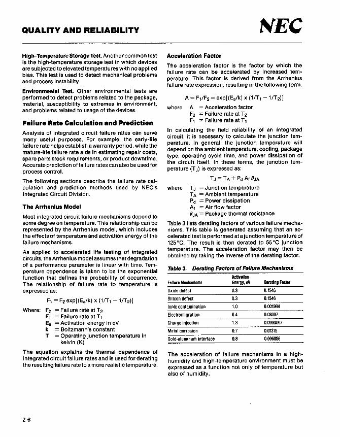
High-Temperature Storage Test. Another common test is the high-temperature storage test in which devices are subjected to elevated temperatures with no applied bias. This test is used to detect mechanical problems and process instability.
Environmental Test. Other environmental tests are performed to detect problems related to the package, material, susceptibility to extremes in environment and problems related to usage of the devices. '
Failure Rate Calculation and Prediction Analysis of integrated circuit failure rates can serve many useful purposes. For example, the early-life failure rate helps establish a warranty period, while the mature-life failure rate aids in estimating repair costs, spare parts stock requirements, or product downtime. Accurate prediction of failure rates can also be used for process control.
The following sections describe the failure rate calculation and prediction methods used by NEC's Integrated Circuit Division.
The Arrhenius Model
Most integrated circuit failure mechanisms depend to some degree on temperature. This relationship can be represented by the Arrhenius model, which includes the effects of temperature and activation energy of the failure mechanisms.
As applied to accelerated life testing of integrated circuits, the Arrhenius model assumes that degradation of a performance parameter is linear with time. Temperature dependence is taken to be the exponential function that defines the probability of occurrence. The relationship of failure rate to temperature is expressed as:
F1 = F2 exp[(Ea/k) x (1/T1 -1/T2)]
Where: F2 = Failure rate at T 2 F1 = Failure rate at T 1 Ea = Activation energy in eV k = Boltzmann's constant T =Operating junction temperature in
kelvin (K)
The equation explains the thermal dependence of integrated circuit failure rates and is used for derating the resulting failure rate to a more realistic temperature.
2-6
NEC Acceleration Factor
The acceleration factor is the factor by which the failure rate can be accelerated by increased temperature. This factor is derived from the Arrhenius failure rate expression, resulting in the following form.
A= F1/F2 = exp[(Ea/k) x (1/T1 -1/T2)]
where A = Acceleration factor F2 = Failure rate at T 2 F1 = Failure rate at T 1
In calculating the field reliability of an integrated circuit, it is necessary to calculate the junction temperature. In general, the junction temperature will depend on the ambient temperature, cooling, package type, operating cycle time, and power dissipation of the circuit itself. In these terms, the junction temperature (T J) is expressed as:
TJ=TA+PdAt8JA
where T J =Junction temperature TA = Ambient temperature Pd =Power dissipation At = Air flow factor 8JA = Package thermal resistance
Table 3 lists derating factors of various failure mechanisms. This table is generated assuming that an accelerated test is performed at a junction temperature of 125°C. The result is then derated to 55°C junction temperature. The acceleration factor may then be obtained by taking the inverse of the derating factor.
Table 3. Deratlng Factors of Failure Mechanisms
Activation Failure Mechanisms Energy, eV aerating Factor
Oxide defect 0.3 0.1546
Silicon defect 0.3 0.1546
Ionic contamination 1.0 0.001984
Electromigration 0.4 0.08307
Charge injection 1.3 0.0003067
Metal corrosion 0.7 0.01315
Gold-aluminum interface 0.8 0.006886
The acceleration of failure mechanisms in a highhumidity and high-temperature environment must be expressed as a function not only of temperature but also of humidity.

t\'EC According to the reliability test statistics, the acceleration factor in such an environment can best be approximated with Peck's model as follows.
A= exp[(E8/k) x (1/T1 - 1/T 2)] x (H2/H1)4.5
where Ea = Activation energy k = Boltzmann's constant T =Junction temperature H = Relative humidity
For example, the acceleration factor for high-humidity and high-temperature or pressure cooker tests ranges from 100 to 1000 times that of the normal operating environment.
Failure Rate Calculation
As an example, suppose that product samples are submitted to a 1000-hour life test at 125°C junction temperature and two failures are encountered: one oxide and one metalization defect. The sample size is 885 units.
Thus, the oxide failure rate is 0.11 percent per 1000 hours and the metalization failure rate is 0.11 percent per 1000 hours. Therefore, the total failure rate at 125 °C sums to 0.22 percent per 1000 hours at 1 K hours.
Failure Rate Prediction
To derate these failure rates to a normal operating environment, use the derating factors listed in table 3.
Oxide failures= 0.11x0.1546 = 0.01701% per 1K hrs Metal failures= 0.11x0.01315 = 0.00145%
per 1 K hrs Total failures= 0.01846% per 1 K hrs
Note that the example above is a snapshot of the hightemperature life test performed on a particular lot. It is not accumulated data that can be used to represent overall reliability. This conservative illustration, however, shows that the failure rate in a normal operating environment is approximately one-twelfth the failure rate in a higher-temperature environment.
The failure rate prediction takes different activation energies into account whenever the causes of failures are known through performing failure analysis. In some cases, however, an activation energy is assumed in order to accomplish a quick first-order approximation. To yield a conservative estimate of failure rates, NEC assumes an average activation energy of 0.7 eV whenever the exact failure mechanism is not known.
QUALITY AND RELIABILITY
Reliability Test Results
Before introducing new technologies or products, NEC's internal reliability goals must be attained. Several categories of testing are used in the internal qualification program to assure that product reliability meets NEC's reliability goals. Once the product is qualified, its reliability level is regularly monitored in a monthly reliability test.
NEC'• Goals on Failure Rates
NEC's approach to achieving high reliability is to build quality into the product, as opposed to merely screening out defective units. The use of distributed control methods embedded in the production line, in conjunction with conventional screening methods, results in the highest reliability at the lowest cost.
NEC's maximum failure rate goals for infant mortality and long-term device operation are listed in table 4.
Table 4. Infant Mortality and Long-Term Failure Rates
Type
Infant mortality
Long-term 1.2M device hours average 3.0M device hours average
Infant Mortality Failure Rate
Failure Rate Percent/1000 Hours
0.10 max
0.02 max 0.01 max
The infant mortality goal for each product group is set at 0.10 percent maximum. When a failure rate exceeds this level, there is prompt remedial action.
Long-Term Failure Rate
The long-term failure rate goal is based on the following conditions:
• A minimum of 1.2 million device hours at 125 °C is accumulated to resolve 0.02 percent per 1000 hours at 55 °C with a 60-percent confidence level.
• A minimum of 3 million device hours at 125 °C is accumulated to resolve 0.01 percent per 1000 hours at 55 °C with a 60-percent confidence level.
2-7

QUALITY AND RELIABILITY
Infant Mortality Failure Screening
It is logical to assume the integrated circuit that fails at one temperature would also fail at another temperature, except it would fail sooner at a higher temperature. As can be expected, the failure rate is a function of activation energy. Establishing infant mortality screening, therefore, requires knowledge of the likely failure mechanisms and their associated activation energy.
The most likely mechanisms associated with infant mortality failures are generally manufacturing defects and process anomalies. These generally consist of contamination, cracked chips, wire bond shorts, or bad wire bonds. Since these describe a number of possible mechanisms, any one of which might predominate at a given time, the activation energy for infant mortality might be expected to vary considerably.
The effectiveness of a screening condition, preferably at some stress level in order to shorten the time, varies greatly with the failure mechanism being screened for. Another factor is the economics of the screening process introduced into the production line. Optimal conditions and duration of a screening process will be a compromise of these two factors.
For example, failures due to ionic contamination have an activation energy of approximately 1.0 eV. Therefore, a 15-hour stress at 125 °C junction temperature would be the equivalent of approximately 90 days of operation at a junction temperature of 55°C. On the other hand, failures due to oxide defects have an activation energy of approximately 0.3 eV, and a 15-hour stress at 125°C junction temperature would be the equivalent of approximately one week's operation at 55°C junction temperature. As indicated by this, the condition and duration of infant mortality screening would be a strong function of the allowable component failures, hence the system failure, in the field.
Empirical data, gathered over more than a year at NEC, indicates that early failure does occur after less than 4 hours of stress at 125°C ambient temperature. This fact is supported by the life test of the same lot, where the failure rate shows random distribution, as opposed to a decreasing failure rate that then runs into the random failure region.
NEC has adopted the initial infant mortality burn-in at 125 °C as a standard production screening procedure. As a result, the field reliability of NEC devices is an order of magnitude higher than the goals set for NEC's integrated circuit products.
2-8
NEC Life Tests
The most significant difference between NEC's products and those of other integrated circuit manufacturers is that NEC's have been prescreened for their infant mortality defects. The products delivered to customers are operating at the beginning of the random failure region of the life curve. The life test data also reflects this fact, as will be shown.
The failure mechanism distribution from field failures, as previously shown in figure 2, also contains a very low percentage due to infant mortality. The majority of failures are long-term life failures, and these can be eliminated by stringent process control. Usually, these failure mechanisms have low activation energy associated with them.
Another significant improvement devised by NEC is plastic encapsulation and passivation. As a result, NEC products show excellent reliability in both highhumidity and high-temperature environments. Following is life test data accumulated over more than a year for large-scale integrated circuits.
High-Temperature Operating Life Test
This test is used to accelerate failure mechanisms by operating the devices at an elevated temperature. For large-scale integrated circuits, the failure rate is 0.242 percent per 1000 hours at 125°C. This is equivalent to 0.0071 percent per 1000 hours in an operating environment of 55°C (table 5).
Table 5. High-Temperature Operating Life Test
Number of Samples
3317
Number of Failures at
48 hrs 96 hrs 168 hrs 500 hrs 1 K hrs
0 0 1 4 3
Total number of failures at 1K hrs = 8 Failure rate at 1K hrs at 125°C = 0.242% per 1K hrs Projected failure rate at 1K hrs at 55°C = 0.007% per 1K hrs
High-Temperature and High-Humidity Life Test
This test is used to accelerate failure mechanisms by operating the devices at high temperature and high humidity. Leakage-related failures and device parameter drift are accelerated by this test. For these large-scale integrated circuits, the failure rate is 0.091 percent per 1000 hours. This is equivalent to 0.0027 percent per 1000 hours in an operating environment of 55°C. The test conditions are TA= 85°C and relative humidity (RH)= 80% (table 6).

NEC Table 6. High-Temperature and High-Humidity Life
Test
Number of Failures at Number of Samples 48 hrs 96 hrs 168 hrs 500 hrs 1 K hrs
2190 0 0 0
Total number of failures at 1K hrs = 2 Failure rate at 1K hrs at 85°C/80% RH = 0.091% per 1K hrs Projected failure rate at 1K hrs at 55°C/60% RH = 0.003% per 1K hrs
High-Temperature Storage Life Test
2
This test is effective in accelerating the failure mechanisms related to mechanical reliability problems and process instability. For these LSI devices, the failure rate is 0.207 percent per 1000 hours at 125°C. This is equivalent to 0.0061 percent per 1000 hours in an operating environment of 55 °C (table 7).
Table 7. High-Temperature Storage Life Test
Number of Failures at Number of Samples 48 hrs 96 hrs 168 hrs 500 hrs 1 K hrs
2410
Total number of failures at 1K hrs Failure rate at 1K hrs at 125°C Projected failure rate at 1K hrs at 55°C
Pressure Cooker Test
0 0 1 4
=5 = 0.207% per 1K hrs
= 0.006% per 1 K hrs
This test is effective in accelerating failure mechanisms related to metalization corrosion due to moisture. The failure rate is 0.52 percent per 1000 hours at TA= 125 °C and 2.3 atm at 100 percent humidity. This is equivalent to 0.0013 percent per 1000 hours at 55°C and an environment of 60 percent humidity (table 8).
Table 8. Pressure Cooker Test
Number of Number of Failures at
Samples 48 hrs 96 hrs 168 hrs 500 hrs 1 K hrs
1718 0 4 5 No test performed
Total number of failures at 168 hrs = 9 Failure rate at 125°C = 0.54% per 1K hrs Projected failure rate at 55°C = 0.001% per 1K hrs
Life Test Data Summary
Table 9 summarizes the life test results and projected failure rates in the normal operating environment. The failure rate shows random distribution as opposed to a decreasing failure rate. This is a result of infant mortality screening.
QUALITY AND RELIABILITY
Table 9. Life Test Data
Number of Number of Failures at
Test Time Samples 96 hrs 168 hrs 500 hrs lK hrs
High-temperature 3317 0 1 4 3 life test
High-humidity 2190 0 0 0 2 life test
High-temperature 2410 0 0 4 storage life test
Pressure 1718 4 5 No test cooker test performed
Total 9635 4 6 5 9
Total Number of Failures
8
5
9
24
The projected failure rate in the normal operating environment is calculated assuming that the average activation energy is 0.7 eV.
Figure 3 shows the life distribution of NEC integrated circuits as a form of the bathtub curve.
This life test data shows improvements of approximately an order of magnitude better than NEC's goal. The hours of operation are equivalent to the normal operating environment. Wear-out failures, which had been the main target for reliability improvement, have also been significantly reduced. This result comes mainly from process improvements and stringent manufacturing process control.
NEC's main goal has been to improve reliability with respect to infant mortality and long-term life failures. This can be achieved by introducing an effective screening method for infant mortality and building quality into the product.
Figure 3. Plot of Life Test Results
o.10 +------- Infant Mortality Failure Rate Goal 0.10 percent per 1000 hours maximum
0.05
-+--+------- Long-Term Life Failure Rate Goal 0.02 percent per 1000 hours maximum
0.01
0.005
O.SK 1K 2K 3K 4K SK 10K 20K 30K 40K
Hours--+
2-9

QUALITY AND RELIABILITY
Thermal Stress Tests
Temperature cycling and thermal shock test the thermal compatibility of material and metal used to make integrated circuits. Table 10 lists the reliability test results of thermal stress tests.
Table 10. Thermal Stress Tests
Number of Number of Test Item Samples Fallures
Soldering heat test 1891 0 TA= 260°C for 10 seconds
Temperature cycle 1891 0 TA= -65 to +150°C, 10 cycles
Thermal shock test 1891 0 TA= o to +100°C, 15 cycles
Mechanical Stress Tests
In addition to the device life test, NEC performs mechanical stress tests to detect reliability problems related to the package, material, and device susceptibility to an extreme environment. Table 11 lists mechanical stress test results.
Table 11. Mechanical Stress Tests
Number of Test Item Samples
Mechanical shock test 315 at 15 kg, 3 axis
Vibration test 315 at 100 Hz to 2 kHz, 20 g
Constant acceleration 315 at 20 kg, 3 axis
Lead fatigue test 538 at 240 grams
Solderability test 638 at 230°C for 5 seconds
Built-In Quality and Reliability
Number of Fallures
0
0
0
0
As large-scale integration reaches even higher levels of density, simple quality inspections cannot assure adequate levels of product quality and reliability. In order to ensure the reliability of state-of-the-art VLSI, NEC has adopted another approach. Highest reliability and superior quality of a device can only be achieved by building these characteristics into the product at each process step. NEC, therefore, has introduced the notion of total quality control (TQC) into its entire semiconductor production line. Quality control is distributed into each process step and then summed to form a consolidated system.
2-10
t\'EC Approaches to Total Qua I ity Control
First, the quality control function is embedded into each process. This method enables early detection of possible causes of failure and immediate feedback.
Second, the reliability and quality assurance policy is an integral part of the entire organization. This enables a companywide quality control activity. At NEC, everyone in the company is involved with the concept and methodology of total quality control.
Third, there is an ongoing research and development effort to set even higher standards of device quality and reliability.
Fourth, extensive failure analysis is performed periodically and corrective actions are taken as preventive measures. Process control is based on statistical data gathered from this analysis.
The goal is to maintain the superior product quality and reliability that has become synonymous with the NEC name. The new standard is continuously upgraded and the iterative process continues.
Implementation of Distributed Quality Control
Building quality into a product requires early detection of possible causes of failure at each process step. Then, immediate feedback to remove the causes is a must. A fixed station quality inspection is often lacking in immediate feedback. It is, therefore, necessary to distribute quality control functions to each process step, including the conceptual stage. NEC has implemented a distributed quality control function at each step of the process. Following is a breakdown of the significant steps:
• Product development phase • Wafer processing • Chip mounting and packaging • Electrical testing and thermal aging • Incoming material inspection
Product Development Phase. The product development phase includes conception of a product, review of the device proposal, organization and physical element design, engineering evaluation, and finally, transfer of the product to manufacturing. Quality and reliability are considered at every step. More significantly, at the design review stage and prior to product transfer, the quality and reliability requirements have to be examined and determined to be satisfactory. This often adds 2 to 3 months to the product development cycle. Building in high reliability, however, cannot be sacrificed.

t-IEC Wafer Processing Stage Inspection. The in-process quality inspections that occur at the wafer fabrication stage are listed in table 12.
Table 12. Wafer Processing Inspection
Process
Wafer
Mask
Photolithography
Cleaning
Diffusion and oxidation
Inspection Item
Resistivity, dimension, and appearance, (lot sampling inspection)
Alignment and etching (100% inspection)
Oxide thickness, sheet resistivity (lot sampling inspection)
Metalization and passivation Thickness, V1h, C-V characteristics (lot sampling)
Wafer sort and scribe De parameters (100% inspection)
Die sort 100% visual inspection
Chip Mounting and Packaging. The in-process quality inspections done at the chip mounting and packaging stage are listed in table 13.
Table 13. Chip Mounting and Packaging Inspection
Process Inspection Item
Die Incoming material Inspection
Die attach Appearance (lot sampling inspection)
Wire bonding Bond strength, appearance (lot sampling)
Packaging 100% appearance inspection
Fine leak* Lot sampling
Gross leak* 100% inspection
*For ceramic package devices only.
Electrical Testing and Screening. Electrical testing and infant mortality screening are performed at this stage. A flowchart of the process is depicted in figure 4.
At the first electrical test, de parameters are tested according to the electrical specifications on 100% of each lot. This is a prescreening prior to the infant mortality test. At the second electrical test, ac functional tests as well as de parameter tests are performed on 100% of the subjected lot. If the percentage of defective units exceeds the limit, the lot is subjected to an additional burn-in. During this time, the defective units are undergoing a failure analysis, the results of which are then fed back into the process for corrective action.
QUALITY AND RELIABILITY
Figure 4. Electrical Testing and Screening
1st Electrical Test
100 Percent Lot Burn-In TA= 12s 0 c
No
2nd Electrical Test
Warehouse Finished Goods Stored
Reliability Assurance Test [RAT) Sampling
DC Parameters
DC Parameters, AC Functional
Electrical, Appearance, and Dimensions
83·003942A
Incoming Material Inspection. Prior to warehouse storage, lots are subjected to an incoming inspection according to the following sampling plan.
• Electrical test: De parameters Functional test
• Appearance
Reliability Assurance Test
LTPD LTPD
LTPD
3% 3%
3%
Samples are continually taken from the warehouse and subjected to monthly reliability tests as discussed previously. They are taken from similar process groups so that it can be assumed that any device is representative of the reliability of the group.
2-11

QUALITY AND RELIABILITY
In-Process Screening
Perhaps the most significant preventive measure that NEC has implemented is the introduction of 100% burn-in as an integral part of the standard production process. Most of the potential infant failures are effectively screened from every lot, thereby improving reliability. Assuming average activation energy of 0.7 eV, burn-in at TA= 125°C for 4 hours is equivalent to a week's operation in a normal operating environment. This appears to be ample time for accelerating the time-to-failure mechanisms for early failures.
Process automation, as previously mentioned, has also contributed a great deal toward improving reliability. Since its introduction, assembly related failure mechanisms have been substantially reduced. And, in combination with in-process screening and materials improvement, it has helped establish quality and reliability above NEC's initial goals.
2-12
NEC Summary and Conclusion
As has been discussed, building quality and reliability into products is the most efficient way to ensure product reliability. NEC's approach of distributing quality control functions to process steps, then forming a consolidated quality control system, has produced superior quality and excellent reliability.
Prescreening, introduced as an integral part of largescale integrated circuit protection, has been a major factor in improving reliability. The most recent year's production clearly demonstrates continuation of NEC's high reliability and the effectiveness of this method.
Reliability assurance tests (RATs), performed monthly, have ensured high outgoing quality levels. The combination of building quality into products, effective prescreening of potential failures, and the reliability assurance test has established a singularly high standard of quality and reliability for NEC's large-scale integrated circuits.
With a companywide quality control program, NEC is committed to building superior quality and highest reliability into all its products. Through continuous research and development activities, extensive failure analysis, and process improvements, a higher standard of quality and reliability will continuously be set and maintained.

NEC
MEMORY PRODUCTS
3-1

MEMORY PRODUCTS
Section 3 - Memory Products
Part Numbering System .................................................. . Memory Product Overview ............................................... . Application-Specific Devices ............................................. . RAM Modules ........................................................... . Dynamic RAMs .......................................................... . XRAMs ................................................................. . MOS Static RAMs ....................................................... . ECL RAMs .............................................................. . EPROMs ................................................................ . EEPROMs .............................................................. . Mask-Programmable ROMs .............................................. .
3-2
fttf EC
Page
3-3 3-5 3-6 3-7 3-8 3-8 3-9
3-10 3-11 3-11 3-12

NEC Part Numbering System
Monolithic
µP D 43 256 GU -12 L
T j T.... Low-power indicator
~Speed selection
Package type
MEMORY PRODUCTS
B = Ceramic flatpack C = Plastic DIP
CU = Plastic shrink DIP CX = Plastic slim DIP
D = Cerdip or ceramic DIP G or GU = Plastic miniflat
K = Ceramic leadless chip carrier L = Plastic leaded chip carrier
LA = Plastic small outline J-lead R = Ceramic pin grid array V = Plastic zig-zag inline package
......_ ______ Device identifier (1 to 5 characters)
,___ ________ Product class
......__ __________ Device type
10 = 10K ECL RAM 100 = 100K ECL RAM
23C = CMOS ROM 27 = NMOS EPROM
27C = CMOS EPROM 28C = CMOS EEPROM
4 = Bipolar PROM 41 = NMOS dynamic device 42 = CMOS dynamic device 43 = Mix-MOS static device 44 = CMOS static RAM
B = Digital bipolar D = Digital MOS
.__------------NEC monolithic silicon integrated circuit
3-3

MEMORY PRODUCTS
Part Numbering System
Module
MC- 41 256 A 8 B -12
3-4
Speed selection
Package
Number of output bits
~-----DRAM operation
---------Word depth
...__ _________ Product class
-------------NEC Module
t-IEC
A Leaded SIMM B Socket mountable SIMM
A Page or fast page mode B Nibble mode c Static column mode
256 256K words 1000 1M words
1xx Special module 41 NMOS dynamic RAM 42 CMOS dynamic RAM

NEC MEMORY PRODUCTS
Memory Product Overview
Application RAM EPROM
Density Specific Module Dynamic XRAM MOS Static EGL UV OTP EEPROM ROM
1K µP810422 µP8100422
4K µP810470 µP810474 µP8100470 µP8100474
BK µP041101 µP041102
16K µP0446 µP810480 µPD449 µP810484
µPD4311 µP8100480 µP04314 µP8100484
40K µPD42505
64K µP043608 µPD4168 µP04361 µPD28C64 µPD4362 µP04363 µPD4364
256K µP041221 µP041256 µPD42832 µPD43254 µPD27256 µP027256A µPD23C256E µP041264 µP041257 µPD43256 µPD27256A µP027C256 µP023C256EA µPD42232 µPD41464 µPD43257 µPD27C256 µPD27C256A µP042264 µPD27C256A µP042532
512K µPD27512 µPD27512 µPD23C512E µPD27C512 µPD27C512
1M µPD42270 µPD421000 µPD27C1000 µPD23C1000 µPD42601 µPD421001 µPD27C1001 µPD23C1010
µPD421002 µPD27C1024 µP0424256 µPD424258
2M MC-41256A8 µPD23C2000 MC-41256A9 µPD23C2001 E
4M MC-421000A4 µP023C4000 MC-42100084 µPD23C4001 E MC-421000C4 MC-421000A5 MC-42100085 MC-421000C5
8M MC-421000A8 MC-42100088 MC-421000C8 MC-421000A9 MC-42100089 MC-421000C9
3-5

MEMORY PRODUCTS NEC Application-Specific Devices
Maximum Power
Access Cycle Supply Dissipation tmWJ
Device Organization Process Time Ins) Time Ins) Voltage Standby Active Package Pins
µPD41101-3 910 x 8 NMOS 27 34 +5 495 C/G 24 µPD41101-2 27 34(R)/69(W) µPD41101-1 49 69
µPD41102-1S 1135 x 8 NMOS 27 34 +5 495 C/G 24 µPD41102-1 40 56
µPD41221-70 224K x 1 NMOS 55 70 +5 83 385 c 14 µPD41221-90 75 90
µPD41264-12 64K x4 NMOS 120 Port A 220 Port A +5 66 853 C/V 24 with 40 Port B 40 Port B
µPD41264-15 dual 150 Port A 270 Port A 715 ports 60 Port B 60 Port B
µPD42232-12 32K x 8 CMOS 120 Port A 230 Port A +5 16.5 495 cu 40 with 40 Port B 40 Port B
µPD42232-15 triple 150 Port A 270 Port A 440 ports 60 Port B 60 Port B
µPD42264 64K x 4 CMOS 100 Port A 190 Port A +5 28 660 C/LA/V 24 with 30 Port B 30 Port B dual 120 Port A 220 Port A 550 ports 40 Port B 40 Port B
150 Port A 260 Port A 440 60 Port B 60 Port B
µPD42270 910 x 263 x 4 CMOS 40 60 +5 440 c 28
µPD42505-50 5048 x 8 CMOS 40 50 +5 660 c 24 µPD42505-75 55 75
µPD42532 32K x 8 CMOS 50 100 +5 440 c 40
µPD42601 1M x 1 CMOS 600 (Single) 1000 (Single) +5 0.165 66 C/LA/V C=18, 100 (Sector) 200 (Sector) LA= 26/20,
V=20
µPD43608 512 x 32 x 4 Mix-MOS 85 125 +5 1485 R 132 or
1Kx16x4
Note:
(1) Packages: C =plastic DIP; CU= plastic shrink DIP; G =plastic miniflat package; R =ceramic pin grid array; LA= small outline J-lead package; V =zig-zag inline package
3-6

NEC MEMORY PRODUCTS
RAM Modules Maximum Power
Access Cycle Supply Dissipation (mW)
Device Organization Process Time (ns) Time (ns) Voltage Standby Active Package Pins
MC-41256A8-10 256K x 8 NMOS 100 200 +5 220 3652 A/8 30 MC-41256A8-12 (page) 120 220 3080 MC-41256A8-15 150 260 2640
MC-41256A9-10 256K x 9 NMOS 100 200 +5 248 4109 A/8 30 MC-41256A9-12 (page) 120 220 3465 MC-41256A9-15 150 260 2970
MC-421000A4-80 1M x4 CMOS 80 160 +5 22 1540 A/8 20 MC-421000A4-10 (fast page) 100 190 1320 MC-421000A4-12 120 220 1100
MC-42100084-80 1M x4 CMOS 80 160 +5 22 1540 A/8 20 MC-42100084-10 (nibble) 100 190 1320 MC-42100084-12 120 220 1100
MC-421000C4-80 1M x4 CMOS 80 160 +5 22 1540 A/8 20 MC-421000C4-10 (stat clmn) 100 190 1320 MC-421000C4-12 120 220 1100
MC-421000A5-80 1M x5 CMOS 80 160 +5 27.5 1925 A/8 20 MC-421000A5-10 (fast page) 100 190 1650 MC-421000A5-12 120 220 1375
MC-42100085-80 1M x5 CMOS 80 160 +5 27.5 1925 A/8 20 MC-42100085-10 (nibble) 100 190 1650 MC-42100085-12 120 220 1375
MC-421000C5-80 1M x5 CMOS 80 160 +5 27.5 1925 A/8 20 MC-421000C5-10 (stat clmn) 100 190 1650 MC-421000C5-12 120 220 1375
MC-421 OOOA8-80 1M x8 CMOS 80 160 +5 44 3080 A/8 30 MC-421000A8-10 (fast page) 100 190 2640 MC-421000A8-12 120 220 2200
MC-42100088-80 1M x8 CMOS 80 160 +5 44 3080 A/B 30 MC-42100088-10 (nibble) 100 190 2640 MC-42100088-12 120 220 2200
MC-421000C8-80 1M x 8 CMOS 80 160 +5 44 3080 A/B 30 MC-421OOOC8-10 (stat clmn) 100 190 2640 MC-421000C8-12 120 220 2200
MC-421000A9-80 1M x 9 CMOS 80 160 +5 49.5 3465 A/B 30 MC-421000A9-10 (fast page) 100 190 2970 MC-421000A9-12 120 220 2475
MC-42100089-80 1M x9 CMOS 80 160 +5 49.5 3465 A/B 30 MC-42100089-10 (nibble) 100 190 2970 MC-42100089-12 120 220 2475
MC-421000C9-80 1M x 9 CMOS 80 160 +5 49.5 3465 A/8 30 MC-421000C9-10 (stat clmn) 100 190 2970 MC-421000C9-12 120 220 2475
Note:
(1) Packages: A= single inline memory module (SIMM), leaded, glass-epoxy substrate; 3A =SIMM, leaded, reduced height; B =SIMM, socket mountable
3-7

MEMORY PRODUCTS NEC Dynamic RAMs
Maximum Power
Access Cycle Supply Dissipation (mW)
Device Organization Process Time (ns) Time (ns) Voltage Standby Active Package Pins
µPD41256-10 256K x 1 NMOS 100 200 +5 28 457 C/L/V c = 16, µPD41256-12 (page) 120 220 385 L = 18, µPD41256-15 150 260 330 V= 16 µPD41256-20 200 330 330
µPD41257-12 256K x 1 NMOS 120 220 +5 28 413 C/L/V c = 16, µPD41257-15 (nibble) 150 260 385 L = 18, µPD41257-20 200 335 330 V= 16
µPD41464-10 64K x4 NMOS 100 200 +5 28 440 C/L/V C= 18, µPD41464-12 120 220 413 L = 18, µPD41464-15 150 260 385 V=20
µPD421000-80 1Mx 1 CMOS 80 160 +5 5.5 385 C/LA/V C= 18, µPD421000-10 (fast page) 100 190 330 LA= 26/20, µPD421000-12 120 220 275 V=20
µPD421001-80 1M x 1 CMOS 80 160 +5 5.5 385 C/LA/V c = 18, µPD421001-10 (nibble) 100 190 330 LA= 26/20, µPD421001-12 120 220 275 V=20
µPD421002-80 1Mx 1 CMOS 80 160 +5 5.5 385 C/LA/V C= 18, µPD421002-10 (stat clmn) 100 190 330 LA= 26/20, µPD421002-12 120 220 275 V=20
µPD424256-80 256K x 4 CMOS 80 160 +5 5.5 385 C/LA/V C=20, µPD424256-10 (fast page) 100 190 330 LA= 26/20, µPD425256-12 120 220 275 V=20
µPD424258-80 256K x 4 CMOS 80 160 +5 5.5 385 C/LA/V C=20, µPD424258-10 (stat clmn) 100 190 330 LA= 26/20, µPD425258-12 120 220 275 V=20
Note:
(1) Packages: C =plastic DIP; L =plastic leaded chip carrier; V =zig-zag inline package; LA= small outline J-lead package
XRAMs Maximum Power
Access Cycle Supply Dissipation (mW)
Device Organization Process Time [ns) Time (ns) Voltage Standby Active Package Pins
µPD4168-12 SK x 8 NMOS 120 220 +5 28 358 c 28 µPD4168-15 150 260 330 µPD4168-20 200 330 303
µPD42832-12 32K x 8 CMOS 120 190 +5 2.8 275 C/GU 28 µPD42832-15 150 235 220
Note:
(1) Packages: C = plastic DIP; GU = plastic miniflat package
3-8

NEC MEMORY PRODUCTS
MOS Static RAMs Maximum Power
Access Cycle Supply Dissipation (mW)
Device Organization Process Time (ns) Time (ns) Voltage Standby Active Package Pins
µPD446-3 2K x8 CMOS 150 150 +5 0.055 209 C/G 24 µPD446-2 (CS, OE) 200 200 (Note 2) 165 µPD446-1 250 250 143
µPD449-3 2K x 8 CMOS 150 150 +5 0.055 209 c 24 µPD449-2 (CE1. CE2) 200 200 (Note 2) 165 µPD449-1 250 250 143
µPD4311-35 16K x 1 Mix-MOS 35 35 +5 11 440 c 20 µPD4311-45 45 45 µPD4311-55 55 55
µPD4314-35 4Kx4 Mix-MOS 35 35 +5 11 440 c 20 µPD4314-45 45 45 µPD4314-55 55 55
µPD4361-40 64K x 1 Mix-MOS 40 40 +5 11 660 K 22 µPD4361-45 45 45 C/K µPD4361-55 55 55 C/K µPD4361-70 70 70 c µPD4362-25 16K x4 Mix-MOS 25 25 +5 11 495 c 22 µPD4362-35 (CS only) 35 35 µPD4362-45 45 45 µPD4362-55 55 55 µPD4362-70 70 70
µPD4363-45 16K x 4 Mix-MOS 45 45 +5 11 495 c 24 µPD4363-55 (CS.OE) 55 55 µPD4363-70 70 70
µPD4364-10 8Kx 8 Mix-MOS 100 100 +5 11/0.55 248 C/CX/G 28 µPD4364-12 120 120 220 C/CX/G µPD4364-15 150 150 220 C/CX/G µPD4364-20 200 200 193 C/G
µPD4464-12 8K x 8 CMOS 120 120 +5 0.055 220 C/G 28 µPD4464-15 150 150 (Note 2) 220 µPD4464-20 200 200 193
µPD43254-35 64K x 4 Mix-MOS 35 35 +5 11 660 c 24 µPD43254-45 45 45 µPD43254-55 55 55
µPD43256-10 32K x8 Mix-MOS 100 100 +5 11/0.55 385 C/CX/GU 28 µPD43256-12 (CS, OE) 120 120 µPD43256-15 150 150
µPD43257-10 32Kx 8 Mix-MOS 100 100 +5 0.55 385 C/GU 28 µPD43257-12 (CE1, CE2) 120 120 µPD43257-15 150 150
Notes:
(1) Packages: C =plastic DIP; CX =plastic slim DIP; G or GU= plastic miniflat package; K =ceramic leadless chip carrier (LCC)
(2) Lower power version available; refer to the data sheet for more detail.
3-9

MEMORY PRODUCTS NEC ECLRAMs
Address Chip Select Access Acceas Supply Maximum Power
Device Organization Process Time (nal Time (nsl Voltage Dlaslpatlon (mWI Package Pina
µPB10422-7 256x4 10K 7 5 (Note 2) -5.2 1144 D 24 µPB10422-10 10 5 (Note 2)
µPB10470-10 4K x 1 10K 10 6 -5.2 1144 D 18 µPB10470-15 15 8
µPB10474-8 1K x 4 10K 8 5 -5.2 1144 D 24 µPB10474-10 10 6 µPB10474-15 15 8
µPB10480-10 16K x 1 10K 10 5 -5.2 1352 B/D 20 µPB10480-15 15 8 1248
µPB10484-10 4K x4 10K 10 6 -5.2 1352 B/D 28 µPB10484-15 15 8 1248
µPB100422-7 256 x 4 100K 7 5 (Note 2) -4.5 990 B/D 24 µPB100422-10 10 5 (Note 2)
µPB100470-10 4Kx 1 100K 10 6 -4.5 990 D 18 µPB100470-15 15 8
µPB 10047 4-4.5 1Kx 4 100K 4.5 4 -4.5 2025 K 24 µPB100474-6 6 4 2025 B/K µPB100474-8 8 5 990 B/D µPB100474-10 10 6 990 B/D µPB100474-15 15 8 990 B/D
µPB100480-10 16K x 1 100K 10 5 -4.5 1170 B/D 20 µPB100480-15 15 8 1080
µPB100484-10 4K x 4 100K 10 6 -4.5 1170 B/D 28 µPB100484-15 15 8 1080
Notes:
(1) Packages: D =ceramic DIP; B =ceramic flat package; K =ceramic leadless chip carrier (LCC)
(2) Block Select Access Time (ns).
3-10

tt/EC MEMORY PRODUCTS
EPROMs Maximum Power
Access Programming Supply Dissipation (mW)
Device Organization Process Time (ns) Option Voltage Standby Active Package Pins
µPD27256 32Kx 8 NMOS 250 UV +5 210 604 D 28
µPD27256A-2 32K x 8 NMOS 200 UV +5 132 526 CID 28 µPD27256A 250 UV/OTP (Note 2)
µPD27512-2 64K x 8 NMOS 200 UV +5 131 525 D 28 µPD27512 250 UV/OTP (Note 2) CID µPD27C256-15 32K x 8 CMOS 150 UV +5 0.55 165 D 28 µPD27C256-20 200 UV/OTP CID µPD27C256-25 250 UV/OTP CID µPD27C256A-12 32K x 8 CMOS 120 UV +5 0.55 165 D/K 28 µPD27C256A-15 150 UV/OTP (Note 2) C/D/G/K (except µPD27C256A-20 200 UV/OTP C/D/G/K K=32)
µPD27C512-15 64K x 8 CMOS 150 UV/OTP +5 0.55 165 C/D/G/K 28 µPD27C512-20 200 (Note 2) (except µPD27C512-25 250 K =32)
µPD27C1000-15 128K x 8 CMOS 150 UV +5 0.55 275 D 32 µPD27C1000-20 (ROM Comp.) 200 (Note 2) µPD27C1000-25 250
µPD27C1001-15 128K x 8 CMOS 150 UV +5 0.55 275 D 32 µPD27C1001-20 (JED EC) 200 (Note 2) µPD27C1001-25 250
µPD27C1024-15 64K x 16 CMOS 150 UV +5 0.55 275 D 40 µPD27C1024-20 200 (Note 2) µPD27C1024-25 250
Notes:
(1) Packages: C =plastic DIP for OTP (one time programmable) EPROMs; G =plastic miniflat package for OTP; D =ceramic DIP with quartz window; K =ceramic leadless chip carrier with quartz window
(2) Programming voltage= 12.5 V ±0.3
EEPROMs Maximum Power
Access Cycle Supply Dissipation [mW)
Device Organization Process Time [ns) Time [ns) Voltage Standby Active Package Pins
µPD28C64-20 BK x 8 CMOS 200 200 +5 0.55 275 c 28 µPD28C64-25 250 250
Note:
(1) Package: C =plastic DIP
3-11

MEMORY PRODUCTS NEC Mask-Programmable ROMs
Maximum Power
Access Cycle Supply Dissipation (mW)
Device Organization Process Time (ns) Time (ns) Voltage Standby Active Package Pins
µPD23C256E· 1 32K x 8 CMOS 150 150 +5 0.165 165 C/G 28 µPD23C256E 200 200 138
µPD23C256EA 32K x 8 CMOS 200 200 +5 0.55 138 C/G 28
µPD23C512E 64K x 8 CMOS 200 200 +5 0.55 193 C/G 28
µPD23C1000· 1 128K x 8 CMOS 200 200 +5 0.55 220 C/G 28/52 µPD23C1000 (CE) 250 250
µPD23C1010 128K x 8 (OE) CMOS 250 250 +5 NIA 220 c 28
µPD23C2000 128K x 16 or CMOS 250 250 +5 0.55 220 C/G 40/52 256K x 8
µPD23C2001 E 256K x 8 CMOS 250 250 +5 0.55 220 c 32
µPD23C4000 256K x 16 or CMOS 250 250 +5 0.55 220 C/G 40/64 512K x 8
µPD23C4001E 512K x 8 CMOS 250 250 +5 TBD TBD c 32
Note:
(1) Packages: C =plastic DIP; G =plastic miniflat package
3-12

t\'EC
MICROCOMPUTER PRODUCTS
4-1

MICROCOMPUTER PRODUCTS
Section 4 - Microcomputer Products
Part Numbering System .................................................. . 4-bit, Single-Chip CMOS Microcomputers ................................ . 8-bit, Single-Chip NMOS/CMOS Microcomputers ......................... . 16-bit, Single-Chip CMOS Microcomputers ............................... . CMOS LCD Controller/Drivers ........................................... . µPD7500 Series Hardware Development Tools ............................. . µPD75000 Series Hardware Development Tools ............................ . µPD7800 Series Hardware Development Tools ............................. . µPD78000 Series Hardware Development Tools ............................ . µPD70320/322 (V25) Hardware Development Tools ......................... . µPD8048 Series Hardware Development Tools ............................. . EV-9001/EV-9002 Conversion Boards ..................................... . MD-086 Series Microcomputer Development Systems ...................... . MD-910TM Character Display Terminal Development System ............... . PG1000 PROM Programmers ............................................. .
4-2
NEC
Page
4-3 4-3 4-7 4-9
4-10 4-10 4-11 4-11 4-11 4-11 4-12 4-12 4-12 4-12 4-12

NEC MICROCOMPUTER PRODUCTS
Part Numbering System
µP D 7810H cw -c:... Packagetype Plastic DIP = C
Plastic shrink DIP= CS, CT, CU, CW Cerdip = D Shrink cerdip = OW Plastic SO = G Plastic miniflat = G-00, G-12, G-22, G-R, G-F, G-1 B, GJ, GJ-8 Plastic QUIP= G-36
Device identifier (alphanumeric)
Device type: D = Digital MOS
NEC monolithic silicon integrated circuit
4-Bit, Single-Chip CMOS Microcomputers Supply
Clock Voltage ROM RAM Device Description (MHz) (VJ (XB) (X4) 1/0 Package Pins
µPD7500HG-36 Microcomputer 0.7 4.5 to 5.5 External 256 46 Plastic QUIP 64
µPD7500H-EG-36 Microcomputer 0.2 4.5 to 5.5 External 256 46 Plastic QUIP 64
µPD7501G-12 Microcomputer with 0.4 2.5 to 6.0 1K 96 24 Plastic miniflat 64 LCD controller I driver
µPD7502G-12 Microcomputer with 0.4 2.7 to 6.0 2K 128 23 Plastic miniflat 64 LCD controller/driver
µPD7503G-12 Microcomputer with 0.4 2.7 to 6.0 4K 224 23 Plastic miniflat 64 LCD controller/driver
µPD7506C Microcomputer 0.4 2.5 to 6.0 1K 64 22 Plastic DIP 28
µPD7506CT Microcomputer 0.4 2.5 to 6.0 1K 64 22 Plastic shrink DIP 28
µPD7506G-OO Microcomputer 0.4 2.5 to 6.0 1K 64 22 Plastic miniflat 52
µPD7507C Microcomputer 0.4 2.5 to 6.0 2K 128 32 Plastic DIP 40
µPD7507CU Microcomputer 0.4 2.5 to 6.0 2K 128 32 Plastic shrink DIP 40
µPD7507G-OO Microcomputer 0.4 2.5 to 6.0 2K 128 32 Plastic miniflat 52
µPD7507HC Microcomputer 4.19 2.7 to 6.0 2K 128 32 Plastic DIP 40
µPD7507HCU Microcomputer 4.19 2.7 to 6.0 2K 128 32 Plastic shrink DIP 40
µPD7507HG-22 Microcomputer 4.19 2.7 to 6.0 2K 128 32 Plastic miniflat 44
µPD7507SC Microcomputer 0.4 2.2 to 6.0 2K 128 20 Plastic DIP 28
µPD7507SCT Microcomputer 0.4 2.2 to 6.0 2K 128 20 Plastic shrink DIP 28
µPD7508C Microcomputer 0.4 2.5 to 6.0 4K 224 32 Plastic DIP 40
µPD7508CU Microcomputer 0.4 2.5 to 6.0 4K 224 32 Platic shrink DIP 40
µPD7508G-OO Microcomputer 0.4 2.5 to 6.0 4K 224 32 Plastic miniflat 52
µPD75CG08E Piggyback EPROM 0.4 4.5 to 5.5 4K 224 32 Ceramic DIP 40 microcomputer
µPD7508HC Microcomputer 4.19 2.7 to 6.0 4K 224 32 Plastic DIP 40
4-3

MICROCOMPUTER PRODUCTS NEC 4-Bit, Single-Chip CMOS Microcomputers {cont)
Supply Clock Voltage ROM RAM
Device Description (MHzl (VI (XBI (X41 1/0 Package Pins
µPD7508HCU Microcomputer 4.19 2.7 to 6.0 4K 224 32 Plastic shrink DIP 40
µPD7508HG-22 Microcomputer 4.19 2.7 to 6.0 4K 224 32 Plastic miniflat 44
µPD75CG08HE Piggyback EPROM 4.19 4.5 to 5.5 4K 224 32 Ceramic DIP 40 microcomputer
µPD7508AC Microcomputer with 0.4 2.7 to 5.5 4K 208 32 Plastic DIP 40 FIP driver
µPD7514G-12 Microcomputer with 0.5 2.7 to 6.0 4K 256 31 Plastic miniflat 80 LCD controller I driver
µPD7516HG-12 Microcomputer with 6.55 2.5 to 6.0 6K 256 53 Plastic miniflat 64 FIP controller I driver
µPD7516HG-36 Microcomputer with 6.55 2.5 to 6.0 6K 256 53 Plastic QUIP 64 FIP controller/driver
µPD7516HCW Microcomputer with 6.55 2.5 to 6.0 6K 256 53 Plastic shrink DIP 64 FIP controller/driver
µPD75CG16HE Piggyback EPROM 6.55 4.5 to 5.5 6K 256 53 Ceramic QUIP 64 microcomputer with FIP controller/driver
µPD7519G-12 Microcomputer with 4.19 2.5 to 6.0 4K 256 53 Plastic miniflat 64 FIP controller/driver
µPD7519G-36 Microcomputer with 4.19 2.5 to 6.0 4K 256 53 Plastic QUIP 64 FIP controller/driver
µPD7519CW Microcomputer with 4.19 2.5 to 6.0 4K 256 53 Plastic shrink DIP 64 FIP controller/driver
µPD75CG19E Piggyback EPROM 4.19 4.5 to 5.5 4K 256 53 Ceramic DIP 64 microcomputer with FIP controller/driver
µPD7519HG-12 Microcomputer with 6.55 2.5 to 6.0 4K 256 53 Plastic miniflat 64 FIP controller/driver
µPD7519HG-36 Microcomputer with 6.55 2.5 to 6.0 4K 256 53 Plastic QUIP 64 FIP controller/driver
µPD7519HCW Microcomputer with 6.55 2.5 to 6.0 4K 256 53 Plastic shrink DIP 64 FIP controller/driver
µPD75CG19HE Piggyback EPROM 6.55 4.5 to 5.5 4K 256 53 Ceramic DIP 64 microcomputer with FIP controller/driver
µPD7527AC Microcomputer with 0.6 2.7 to 6.0 2K 128 35 Plastic DIP 42 FIP display
µPD7527ACU Microcomputer with 0.6 2.7 to 6.0 2K 128 35 Plastic shrink DIP 42 FIP display
µPD7528AC Microcomputer with 0.6 2.7 to 6.0 4K 160 35 Plastic DIP 42 FIP display
µPD7528ACU Microcomputer with 0.6 2.7 to 6.0 4K 160 35 Plastic shrink DIP 42 FIP display
µPD75CG28E Piggyback EPROM 0.5 4.5 to 5.5 4K 160 35 Ceramic DIP 42 microcomputer with FIP display
µPD7533C Microcomputer with 0.5 2.7 to 6.0 4K 160 34 Plastic DIP 42 AID converter
4-4

t-IEC MICROCOMPUTER PRODUCTS
4-Bit, Single-Chip CMOS Microcomputers (cont) Supply
Clock Voltage ROM RAM Device Description (MHz) (VJ (XB) (X4) 1/0 Package Pins
µPD7533CU Microcomputer with 0.5 2.7 to 6.0 4K 160 34 Plastic shrink DIP 42 A/D converter
µPD7533G-22 Microcomputer with 0.5 2.7 to 6.0 4K 160 34 Plastic miniflat 44 AID converter
µPD75CG33E Piggyback EPROM 0.5 4.5 to 5.5 4K 160 34 Ceramic DIP 42 microcomputer with A/D converter
µPD7537AC Microcomputer with 0.6 2.7 to 6.0 2K 128 35 Plastic DIP 42 FIP driver
µPD7537ACU Microcomputer with 0.6 2.7 to 6.0 2K 128 35 Plastic shrink DIP 42 FIP driver
µPD7538AC Microcomputer with 0.6 2.7 to 6.0 4K 160 35 Plastic DIP 42 FIP driver
µPD7538ACU Microcomputer with 0.6 2.7 to 6.0 4K 160 35 Plastic shrink DIP 42 FIP driver
µPD75CG38E Piggyback EPROM 0.5 4.5 to 5.5 4K 160 35 Ceramic DIP 42 microcomputer with FIP driver
µPD7554CS Microcomputer with 0.7 2.5 to 6.0 1K 64 16 Plastic shrink DIP 20 serial 1/0
µPD7554G Microcomputer with 0.7 2.5 to 6.0 1K 64 16 Plastic SO 20 serial 1/0
µPD7556CS Microcomputer with 0.7 2.5 to 6.0 1K 64 20 Plastic shrink DIP 24 comparator
µPD7556G Microcomputer with 0.7 2.5 to 6.0 1K 64 20 Plastic SO 24 comparator
µPD7564CS Microcomputer with 0.7 2.7 to 6.0 1K 64 15 Plastic shrink DIP 20 serial 1/0
µPD7564G Microcomputer with 0.7 2.7 to 6.0 1K 64 15 Plastic SO 20 serial 1/0
µPD7566CS Microcomputer with 0.7 2.7 to 6.0 1K 64 19 Plastic shrink DIP 24 comparator
µPD7566G Microcomputer with 0.7 2.7 to 6.0 1K 64 19 Plastic SO 24 comparator
µPD75P54CS011 Microcomputer with 0.7 2.5 to 6.0 1K 64 16 Plastic shrink DIP 20 on-chip OTPROM with RC clock
µPD75P54CS012 Microcomputer with 0.7 2.5 to 6.0 1K 64 16 Plastic shrink DIP 20 on-chip OTPROM with external clock
µPD75P54G511 Microcomputer with 0.7 2.5 to 6.0 1K 64 16 Plastic small outline 20 on-chip OTPROM with RC clock
µPD75P54G512 Microcomputer with 0.7 2.5 to 6.0 1K 64 16 Plastic small outline 20 on-chip OTPROM with external clock
µPD75P64CS011 Microcomputer with 0.7 2.5 to 6.0 1K 64 15 Plastic small outline 20 on-chip OTPROM with ceramic clock
4-5

MICROCOMPUTER PRODUCTS NEC 4-Bit, Single-Chip CMOS Microcomputers (cont)
Supply Clock Voltage ROM RAM
Device Description (MHz) (VJ (XBJ (X4) 1/0 Package Pins
µPD75P64G512 Microcomputer with 0.7 2.5 to 6.0 1K 64 15 Plastic small outline 20 on-chip OTPROM with ceramic clock
µPD75104CW Microcomputer 4.19 2.5 to 6.0 4K 320 5B Plastic shrink DIP 64
µPD75104G-1 B Microcomputer 4.19 2.5 to 6.0 4K 320 5B Plastic miniflat 64
µPD75106CW Microcomputer 4.19 2.5 to 6.0 (6016) 320 5B Plastic shrink DIP 64
µPD75106G-1B Microcomputer 4.19 2.5 to 6.0 (6016) 320 5B Plastic miniflat 64
µPD7510BCW Microcomputer 4.19 2.5 to 6.0 BK 512 5B Plastic shrink DIP 64
µPD751 OBG-1 B Microcomputer 4.19 2.5 to 6.0 BK 512 5B Plastic miniflat 64
µPD75P10BCW Microcomputer with 4.19 2.5 to 6.0 BK 512 5B Plastic shrink DIP 64 on-chip OTPROM
µPD75P1 OBDW Microcomputer with 4.19 2.5 to 6.0 BK 512 5B Plastic shrink DIP 64 on-chip EPROM
µPD75P1 OBG-1 B Microcomputer with 4.19 2.5 to 6.0 BK 512 5B Plastic miniflat 64 on-chip OTPROM
µPD75206CW Microcomputer with 4.19 2.7 to 6.0 6K 369 55 Plastic shrink DIP 64 FIP driver
µPD75206G Microcomputer with 4.19 2.7 to 6.0 6K 369 55 Plastic miniflat 64 FIP driver
µPD7520BCW Microcomputer with 4.19 2.7 to 6.0 BK 497 55 Plastic shrink DIP 64 FIP driver
µPD7520BG Microcomputer with 4.19 2.7 to 6.0 BK 497 55 Plastic miniflat 64 FIP driver
µPD75216CW Microcomputer with 4.19 2.7 to 6.0 16K 512 55 Plastic shrink DIP BO FIP driver
µPD75216AGF Microcomputer with 4.19 2.7 to 6.0 16K 512 55 Plastic miniflat BO FIP driver
µPD75CGOBE Piggyback EPROM with 4.19 4.5 to 5.5 BK 497 55 Ceramic DIP 64 FIP driver
µPD7530BGF Microcomputer with 4.19 2.7 to 6.0 BK 512 32 Plastic miniflat BO LCD driver
µPD75P30BK LCC EPROM with LCD 4.19 2.7 to 6.0 BK 512 32 Ceramic DIP BO
µPD75P30BG F Microcomputer with 4.19 2.7 to 6.0 BK 512 32 Plastic miniflat BO on-chip EPROM with LCD
4-6

NEC MICROCOMPUTER PRODUCTS
8-Bit, Single-Chip NMOS/CMOS Microcomputers Supply
Clock Voltage ROM RAM Device Description (MHz) (VJ (XBJ (XBJ 1/0 Package Pins
µPD7807CW NMOS microcomputer 12 4.5 to 5.5 External 256 2B Plastic shrink DIP 64 with comparator
µPD7807G-36 NMOS microcomputer 12 4.5 to 5.5 External 256 2B Plastic QUIP 64 with comparator
µPD780BCW NMOS microcomputer 12 4.5 to 5.5 4K 256 40 Plastic shrink DIP 64 with comparator
µPD?BOBG-36 NMOS microcomputer 12 4.5 to 5.5 4K 256 40 Plastic QUIP 64 with comparator
µPD7809CW NMOS microcomputer 12 4.5 to 5.5 BK 256 40 Plastic shrink DIP 64 with comparator
µPD7809G-36 NMOS microcomputer 12 4.5 to 5.5 BK 256 40 Plastic QUIP 64 with comparator
µPD78P09R NMOS microcomputer 12 4.5 to 5.5 EPROM 256 40 Ceramic QUIP 64 with comparator BK with window
µPD78C10CW CMOS microcomputer 15 4.5 to 5.5 External 256 . 32 Plastic shrink DIP 64 with A/D converter
µPD78C10G-1 B CMOS microcomputer 15 4.5 to 5.5 External 256 32 Plastic miniflat 64 with AID converter
µPD78C10G-36 CMOS microcomputer 15 4.5 to 5.5 External 256 32 Plastic QUIP 64 with A/D converter
µPD78C10L CMOS microcomputer 15 4.5 to 5.5 External 256 32 PLCC 68 with A/D converter
µPD7810HCW NMOS microcomputer 15 4.5 to 5.5 External 256 32 Plastic shrink DIP 64 with A/D converter
µPD7810HG-36 NMOS microcomputer 15 4.5 to 5.5 External 256 32 Plastic QUIP 64 with A/D converter
µPD7811HCW NMOS microcomputer 15 4.5 to 5.5 4K 256 44 Plastic shrink DIP 64 with A/D converter
µPD7811 HG-36 CMOS microcomputer 15 4.5 to 5.5 4K 256 44 Plastic QUIP 64 with A/D converter
µPD78C11CW CMOS microcomputer 15 4.5 to 5.5 4K 256 44 Plastic shrink DIP 64 with AID converter
µPD78C11 G-36 CMOS microcomputer 15 4.5 to 5.5 4K 256 44 Plastic miniflat 64 with A/D converter
µPD78C11 G-36 CMOS microcomputer 15 4.5 to 5.5 4K 256 44 Plastic QUIP 64 with AID converter
µPD78C11L CMOS microcomputer 15 4.5 to 5.5 4K 256 44 PLCC 68 with AID converter
4-7

MICROCOMPUTER PRODUCTS t\'EC 8-Bit, Single-Chip NMOS/CMOS Microcomputers (cont)
Supply Clock Voltage ROM RAM
Device Description I MHz) IVI IXBJ IXBJ 1/0 Package Pins
µPD78PG11E Piggyback EPROM 12 4.5 to 5.5 4K 256 44 Ceramic QUIP 64 NMOS microcomputer with A/D converter
µPD78PG11HE Piggyback EPROM 15 4.5 to 5.5 4K 256 44 Ceramic QUIP 64 NMOS microcomputer with A/D converter
µPD78C14CW CMOS microcomputer 15 4.5 to 5.5 16K 256 44 Plastic shrink DIP 64 with A/D converter
µPD78C14G-1 B CMOS microcomputer 15 4.5 to 5.5 External 256 44 Plastic miniflat 64 with A/D converter
µPD78C14G-36 CMOS microcomputer 15 4.5 to 5.5 External 256 44 Plastic QUIP 64 with AID converter
µPD78C14L CMOS microcomputer 15 4.5 to 5.5 External 256 44 PLCC 68 with AID converter
µPD78310CW CMOS microcomputer 12 4.5 to 5.5 External 256 28 Plastic shrink DIP 64
µPD7831 OG-1 B CMOS microcomputer 12 4.5 to 5.5 External 256 28 Plastic miniflat 64
µPD78310G-36 CMOS microcomputer 12 4.5 to 5.5 External 256 28 Plastic QUIP 64
µPD78310L CMOS microcomputer 12 4.5 to 5.5 External 256 28 PLCC 68
µPD78312CW CMOS microcomputer 12 4.5 to 5.5 8K 256 40 Plastic shrink DIP 64
µPD78312G-1 B CMOS microcomputer 12 4.5 to 5.5 8K 256 40 Plastic minifiat 64
µPD78312G-36 CMOS microcomputer 12 4.5 to 5.5 8K 256 40 Plastic QUIP 64
µPD78312L CMOS microcomputer 12 4.5 to 5.5 8K 256 40 PLCC 68
µPD78P312G-36 EPROM microcomputer 12 4.5 to 5.5 8K 256 40 Plastic QUIP 64
µPD8035HLC HMOS microcomputer 6 4.5 to 5.5 External 64 27 Plastic DIP 40
µPD8039HLC HMOS microcomputer 11 4.5 to 5.5 External 128 27 Plastic DIP 40
µPD80C39HC CMOS microcomputer 12 2.5 to 6.0 External 128 27 Plastic DIP 40
µPD80C40HC CMOS microcomputer 12 2.5 to 6.0 External 256 27 Plastic DIP 40
µPD8041AHC NMOS microcomputer 11 4.5 to 5.5 1K 64 18 Plastic DIP 40 with universal PPI
µPD80C42C CMOS microcomputer 12 4.5 to 5.5 2K 128 18 Plastic DIP 40 with universal PPI
µPD80C42G-22 CMOS microcomputer 12 4.5 to 5.5 2K 128 18 Plastic miniflat 44 with universal PPI
µPD8048HC HMOS microcomputer 6 4.5 to 5.5 1K 64 27 Plastic DIP 40
µPD80C48G-OO CMOS microcomputer 6 2.5 to 6.0 1K 64 27 Plastic miniflat 52
µPD48G-22 CMOS microcomputer 6 2.5 to 6.0 1K 64 27 Plastic miniflat 44
µPD8049HC HMOS microcomputer 11 4.5 to 5.5 2K 128 27 Plastic DIP 40
µPD80C49HC CMOS microcomputer 12 2.5 to 6.0 2K 128 27 Plastic DIP 40
µPD80C49G-OO CMOS microcomputer 12 2.5 to 6.0 2K 128 27 Plastic minifiat 52
µPD49HG-22 CMOS microcomputer 12 2.5 to 6.0 2K 128 27 Plastic minifiat 44
4-8

NEC MICROCOMPUTER PRODUCTS
8·Bit, Single·Chi.P NMOS/CMOS Microcomputers (cont) Supply
Clock Voltage ROM RAM Device Description (MHz) (VJ (XB) (XB) 1/0 Package Pins
µPD80C50HC CMOS microcomputer 12 2.5 to 6.0 4K 256 27 Plastic DIP 40
µPD50HG-22 CMOS microcomputer 12 2.5 to 6.0 4K 256 27 Plastic miniflat 44
µPD8741AD NMOS microcomputer 6 4.5 to 5.5 1K 64 18 Cerdip with 40 with universal PPI window
µPD8748HC NMOS microcomputer 11 4.5 to 5.5 1K 64 27 Plastic DIP 40 with UV EPROM
µPD8748HD NMOS microcomputer 11 4.5 to 5.5 1K 64 27 Cerdip with 40 with UV EPROM window
µPD8749HC HMOS microcomputer 11 4.5 to 5.5 2K 128 27 Plastic DIP 40
µPD8749HD HMOS microcomputer 11 4.5 to 5.5 2K 128 27 Cerdip with 40 window
16-Bit, Single-Chip CMOS Microcomputers Supply
Clock Voltage ROM RAM Device Description (MHz) (VJ (XB) (XBJ 1/0 Package Pins
µPD70320L CMOS microcomputer, 5 4.5 to 5.5 256 32 PLCC 84 ROM-less
µPD70320L-8 CMOS microcomputer, 8 4.5 to 5.5 256 32 PLCC 84 ROM-less
µPD70320GJ CMOS microcomputer, 5 4.5 to 5.5 256 32 Plastic miniflat 94 ROM-less
µPD70320GJ-8 CMOS microcomputer, 8 4.5 to 5.5 256 32 Plastic miniflat 94 ROM-less
µPD70322L CMOS microcomputer, 5 4.5 to 5.5 16K 256 32 PLCC 84 mask ROM
µPD70322L-8 CMOS microcomputer, 8 4.5 to 5.5 16K 256 32 PLCC 84 mask ROM
µPD70322GJ CMOS microcomputer, 5 4.5 to 5.5 16K 256 32 Plastic miniflat 94 mask ROM
µPD70322GJ-8 CMOS microcomputer, 8 4.5 to 5.5 16K 256 32 Plastic miniflat 94 mask ROM
µPD70P322L CMOS microcomputer, 5 4.5 to 5.5 16K 256 32 PLCC 84 OTP EPROM
µPD70P322K CMOS microcomputer, 5 4.5 to 5.5 16K 256 32 Ceramic LCC 84 UV erasable EPROM
4-9

MICROCOMPUTER PRODUCTS NEC CMOS LCD Controller/Drivers
Supply Power Dissipation
No. of No. of Clock Voltage Active Standby Device Description Rows Column (MHz) (VJ (mAI (mA) Package Pins
µPD6307G-F LCD row driver 32 2.5 4.5 to 5.5 Plastic miniflat 54
µPD6307G-R LCD row driver 32 2.5 4.5 to 5.5 Plastic miniflat, 54 reverse leads
µPD6308G-F LCD column driver 40 2 4.5 to 5.5 1.2 Plastic miniflat 54
µPD6308G-R LCD column driver 40 2 4.5 to 5.5 1.2 Plastic miniflat, 54 reverse leads
µPD7225G-OO LCD controller I driver 4 32 0.2 2.7 to 5.5 0.1 Plastic miniflat 52
µPD7227G-12 LCD controller I driver 8 40 1 +5 0.2 Plastic miniflat 64
µPD7228G-12 LCD controller/driver 8/16 42/50 1.1 +5 0.2 0.02 Plastic miniflat 80
µPD72030G-12 LCD display controller 6 +5 5 0.001 Plastic miniflat 64
µPD7500 Series Hardware Development Tools Part Add-On Board System EPROM Number Emulator (Required) Evaluation Board Device
µPD7501 EVAKIT-75008 EV7514 SE-7514A
µPD7502 EVAKIT-75008 EV7514 SE-7514A
µPD7503 EVAKIT-75008 EV7514 SE-7514A
µPD7506 EVAKIT-75008 SE-7508
µPD7507 EVAKIT-75008 µPD75CG08E
µPD7507H EVAKIT-75008 EV7508H µPD75CG08HE
µPD7507S EVAKIT-75008 SE-7508
µPD7508 EVAKIT-75008 µPD75CG08E
µPD7508A EVAKIT-75008 SE-7508
µPD7508H EVAKIT-75008 EV7508H µPD75CG08HE
µPD7514 EVAKIT-75008 EV7514 SE-7514A
µPD7516H EVAKIT-75008 EV7500FIP µPD75CG16HE
µPD7519 EVAKIT-75008 EV7500FIP µPD75CG19E
µPD7519H EVAKIT-75008 EV7500FIP µPD75CG19HE
µPD7527 EVAKIT-75008 EV7528 µPD75CG28E
µPD7528 EVAKIT-75008 EV7528 µPD75CG28E
µPD7533 EVAKIT-75008 EV7533 µPD75CG33E
µPD7537 EVAKIT-75008 EV7528 µPD75CG38E
µPD7538 EVAKIT-75008 EV7528 µPD75CG38E
µPD7554 EVAKIT-75008 EV7554A SE-7554A µPD75P54
µPD7556 EVAKIT-75008 EV7554A SE-7554A
µPD7564 EVAKIT-75008 EV7554A SE-7554A µPD75P64
µPD7566 EVAKIT-75008 EV7554A SE-7554A
4-10

t\'EC µPD7 5000 Series Hardware Development Tools Part Number Emulator
Add-on Board (Required)
Emulation Probe (Required)
µD75104CW EVAKIT-75X EV-75108
µD75106CW EVAKIT-75X EV-75108
µD75108CW EVAKIT-75X EV-75108
µ0751046 EVAKIT-75X EV-75108 EP-751086
µ0751066 EVAKIT-75X EV-75108 EP-751086
µ0751086 EVAKIT-75X EV-75108 EP-751086
µD75206CW EVAKIT-75X EV-75216A
µD75208CW EVAKIT-75X EV-75216A
µ0752066 EVAKIT-75X EV-75216A EP-75216A6
µ0752086 EVAKIT-75X EV-75216A EP-75216A6
µD75216ACW EVAKIT-75X EV-75216A
µD75216A6 EVAKIT-75X EV-75216A EP-75216A6
µ0753086-F EVAKIT-75X EV-75308
µPD7800 Series Hardware Development Tools
Part Number Emulator
µPD78C05A EVAKIT-87LC [Note 1]
µPD78C06A EVAKIT-87LC
µPD7807 IE-7809-M
µPD7808 IE-7809-M
µPD7809 IE-7809-M
µPD7810 EVAKIT-87AD [Note 1] IE-87AD-M
µPD7810H IE-7811H
µPD7811 EVAKIT-87AD [Note 1] IE-87AD-M
µPD7811H IE-7811H
µPD78C10/11 IE-78C11-M
µPD78C14 IE-78C11-M
Notes:
Real-time Trace Board
EV87LCRTT
EV87LCRTT
EV87ADRTT
EV87ADRTT
(1) Addresses 0-0FFFH access memory on the Evakit only.
Add-on Board
EV78C06A
EV78C06A
MICROCOMPUTER PRODUCTS
System Software (Note 21 Evaluation EPROM Absolute Relocatable
Board Device Assembler Assembler
SE-78C06 ASM87-XXX RA87-XXX
SE-78C06 ASM87-XXX RA87-XXX
µPD78P09R RA87-XXX
µPD78P09R RA87-XXX
µPD78P09R RA87-XXX
ASM87-XXX RA87-XXX ASM87-XXX RA87-XXX
ASM87-XXX RA87-XXX
µPD78P611E ASM87-XXX RA87-XXX µPD78P611E ASM87-XXX RA87-XXX
µPD78P611HE ASM87-XXX RA87-XXX
µPD78CG14E RA87-XXX
µPD78CG14E RA87-XXX
(2) Software can be supplied on a variety of media as defined by the suffix "XXX" [i.e. XXX = D52 (MS-DOS 5-1/4" diskette), XXX = M81 (CPM-86 8" diskette), XXX = U81 (ISIS-11 8" diskette), XXX = F9T (Fortran IV ANSI 1966 x 3.9 for mainframes) plus many others.]
(3) µPD7800 Series additional tools: product number DDK-78C10 - Design/development kit for the 78C10/C11/C14 and 781 OH/11 H
(4) 7800 Series Development Systems are also available from Tektronix, Inc. (503) 629-1143 and Sophia Systems 1-800-824-9294.
µPD7 8000 Series Hardware Development Tools Device Description
µPD70320/322 (V25) Hardware Development Tools Device Description
IE-310-R Stand-alone in-circuit emulator IE-70320 Portable stand-alone in-circuit emulator
DDK-78310 Design/development kit EBIBM-V25 MINI-IE PC based mini ICE for 70320 (V25)
4-11

MICROCOMPUTER PRODUCTS
µPD8048 Series Hardware Development Tools
System Part Evaluation EPROM Number Emulator Board Device
µPD8035H EVAKIT-84C-1
µPD8048H EVAKIT-84C-1 µPD8748H (Note 1)
µPD8039H EVAKIT-84C-1
µPD8049H EVAKIT-84C-1 µPD8749H (Note 1)
µPD80C39H EVAKIT-84C-1
µPD80C48 EVAKIT-84C-1 SE-80C50H
µPD80C35 EVAKIT-84C-1
µPD80C49H EVAKIT-84C-1 SE-80C50H
µPD80C40H EVAKIT-84C-1
µPD80C50H EVAKIT-84C-1 SE-80C50H
µPD80C42 EVAKIT-80C42 µPD8741A
Note:
(1) µPD8748H and µPD8749H are both available in erasable windowed packages or in the economical one time programmable plastic package.
EV-9001 /EV-9002 Conversion Boards Conversion Board Function
EV-9001-64 64-pin QUIP to 64-pin shrink DIP
EV-9002-42 42-pin standard DIP to 42-pin shrink DIP
EV-9002-40 40-pin standard DIP to 40-pin shrink DIP
EV-9002-28 28-pin standard DIP to 28-pin shrink DIP
EV-9200G-64 64-pin LCC to miniflat conversion
EV-9200G-80 80-pin LCC socket with 80-pin miniflat leads
MD·088 Series Microcomputer Development Systems Device Description
MD-086FD-10 MD-086 series, floppy-disk based system
MD-086HD-10 MD-086 series, floppy-hard-disk based system
MD-086DK Hard-disk upgrade for MD-086FD-10
MD-910TM Character display terminal
4-12
NEC MD-91 OTM Character Display Terminal Development System Device Description
MD-910TM Character display terminal
PG1000 PROM Programmers Device Description
PG1000 Main frame programmer
PG1003 Plug-in personality module
PG1005A Plug-in personality module for 755X/75X OTP devices
PG2000 Main frame programmer
PA-75P54/64CS Program adapter for µD75P54/64
PA-75P108G Program adapter for µD75P108G-1B
PA-75P108CW Program adapter for µD75P108CW/DW
PA-75P308K Program adapter for µD75P308K
PA-75P308G Program adapter for µD75P308G-F

NEC
MICROPROCESSOR PRODUCTS
5~

MICROPROCESSOR PRODUCTS
Section 5 - Microprocessor Products
Part Numbering System .................................................. . CMOS Microprocessors ................................................. . NMOS and HMOS Microprocessors ...................................... . Digital Signal Processor and Speech ...................................... . Intelligent Peripheral Controllers ......................................... . CMOS System Support Products ......................................... . NMOS System Support Products ......................................... . µPD7720 Hardware Development Tool .................................... . µPD70208/216 Hardware Development Tools .............................. . µPD7281 Software Development Tools .................................... . µPD7720 Software Development Tools .................................... . µPD70108/116/208/216 Software Relocatable
Assembler Development Tools .......................................... . µPD70108/116/208/216 Software C Compiler Development Tools ............ . MD-086 Series Microcomputer Development Systems ...................... . MD-910TM Character Display Terminal Development Tool .................. . PG1000 PROM Programmers ............................................. .
5-2
NEC
Page
5-3 5-3 5-5 5-5 5-6 5-8 5-9
5-10 5-10 5-10 5-11
5-11 5-11 5-11 5-11 5-11

t-IEC Part Numbering System
µP D 71054 C
L_ Package type:
MICROPROCESSOR PRODUCTS
Plastic DIP= C, C-1, C-2, C-4, C-5, C-6, C-8 Plastic shrink DIP= CT Plastic skinny DIP= CX Ceramic DIP= D, D-1, D-2, D-5, D-8, D-10, D-18 Cerdip DIP= D, D-2 (make sure you have pointed out Cerdip.) Plastic SO = G Plastic miniflat = G, G-4, G-5, G-6, G-8 PLCC = L, L-5, L-8 PGA = R, R-8
Device identifier (alphanumeric)
Device type: D = Digital MOS B =Bipolar
NEC monolithic silicon integrated circuit
CMOS Microprocessors
Supply Power Dissipation
Data Clock Voltage Active Standby Device Description Bits (MHz) (VJ (mA) (typ) (mA) Package Pins
µPD70008C Microprocessor 8 4 +5 30 .5 Plastic DIP 40 (CMOS Z80)
µPD70008AC-4 Microprocessor 8 4 +5 30 .4 Plastic DIP 40 (CMOS Z80)
µPD70008AG-4 Microprocessor +5 30 .4 Plastic miniflat 44 (CMOS Z80)
µPD70008AL-4 Microprocessor 8 4 +5 30 .4 PLCC 44 (CMOS Z80)
µPD70008AC-6 Microprocessor 8 6 +5 30 .4 Plastic DIP 40 (CMOS Z80)
µPD70008AG-6 Microprocessor 6 +5 30 .4 Plastic miniflat 44 (CMOS Z80)
µPD70008AL-6 Microprocessor 8 6 +5 30 .4 PLCC 44 (CMOS Z80)
µPD70008AC-8 Microprocessor 8 +5 30 .4 Plastic DIP 40 (CMOS Z80)
µPD70008AG-8 Microprocessor 8 8 +5 30 .4 Plastic miniflat 44 (CMOS Z80)
µPD70008AL-8 Microprocessor 8 +5 30 .4 PLCC 44 (CMOS Z80)
µPD70108C-5 Microprocessor 8/16 5 +5 45 6 Plastic DIP 40
µPD70108C-8 Microprocessor 8/16 +5 45 6 Plastic DIP 40
µPD70108C-10 Microprocessor 8/16 10 +5 45 6 Plastic DIP 40
µPD70108D-5 Microprocessor 8/16 5 +5 45 6 Ceramic DIP 40
µPD70108D-8 Microprocessor 8/16 8 +5 45 6 Ceramic DIP 40
µPD701080-10 Microprocessor 8/16 10 +5 45 6 Ceramic DIP 40
µPD70108G-5 Microprocessor 8/16 5 +5 45 6 Plastic miniflat 52
µPD70108G-8 Microprocessor 8/16 8 +5 45 6 Plastic miniflat 52
5-3

MICROPROCESSOR PRODUCTS NEC CMOS Microprocessors (cont)
Supply Power Dissipation
Data Clock Voltage Active Standby Device Description Bits I MHz) (VJ lmA) ltyp) lmA) Package Pins
µPD70108L-5 Microprocessor 8/16 5 +5 45 6 PLCC 44
µPD70108L-8 Microprocessor 8/16 8 +5 45 6 PLCC 44
µPD70116C-5 Microprocessor 16 5 +5 45 6 Plastic DIP 40
µPD70116C-8 Microprocessor 16 8 +5 45 6 Plastic DIP 40
µPD70116C-10 Microprocessor 16 10 +5 45 6 Plastic DIP 40
µPD70116D-5 Microprocessor 16 5 +5 45 6 Ceramic DIP 40
µPD70116D-8 Microprocessor 16 8 +5 45 6 Ceramic DIP 40
µPD70116D-10 Microprocessor 16 10 +5 45 6 Ceramic DIP 40
µPD70116G-5 Microprocessor 16 5 +5 45 6 Plastic miniflat 52
µPD70116G-8 Microprocessor 16 8 +5 45 6 Plastic miniflat 52
µPD70116L-5 Microprocessor 16 5 +5 45 6 PLCC 44
µPD70116L-8 Microprocessor 16 8 +5 45 6 PLCC 44
µPD70208R-8 Microprocessor 8/16 8 +5 50 10 PGA 68
µPD70208R-10 Microprocessor 8/16 10 +5 50 10 PGA 68
µPD70208L-8 Microprocessor 8/16 8 +5 50 10 PLCC 68
µPD70208L-10 Microprocessor 8/16 10 +5 50 10 PLCC 68
µPD70208G-8 Microprocessor 8/16 8 +5 50 10 Plastic miniflat 80
µPD70216R-8 Microprocessor 16/16 8 +5 50 10 PGA 68
µPD70216R-10 Microprocessor 16/16 10 +5 50 10 PGA 68
µPD70216L-8 Microprocessor 16/16 8 +5 50 10 PLCC 68
µPD70216L-10 Microprocessor 16/16 10 +5 50 10 PLCC 68
µPD70216G-8 Microprocessor 16/16 8 +5 50 10 Plastic miniflat 80
µPD70616R-16 Microprocessor 16/32 16 +5 200 NA PGA 68
µPD70632R-20 Microprocessor 32/32 20 +5 200 NA PGA 132
5-4

NEC MICROPROCESSOR PRODUCTS
NMOS and HMOS Microprocessors
Supply Power Dissipation
Data Clock Voltage Active Standby Device Description Bits I MHz) IV) (mA) (mA) Package Pins
µPD780C NMOS Microprocessor 8 2.5 +5 150 Plastic DIP 40
µPD780C-1 NMOS Microprocessor 8 4 +5 200 Plastic DIP 40
µPD780C-2 NMOS Microprocessor 8 6 +5 200 Plastic DIP 40
µPD8085AC-2 NMOS Microprocessor 5 +5 170 Plastic DIP 40
µPD8085AHC HMOS Microprocessor 8 3 +5 135 Plastic DIP 40
µPD8085AHC-2 HMOS Microprocessor 8 5 +5 135 Plastic DIP 40
µPD8086D HMOS Microprocessor 16 5 +5 340 Ceramic DIP 40
µPD8086D HMOS Microprocessor 16 5 +5 340 Cerdip 40
µPD8086D-2 HMOS Microprocessor 16 8 +5 350 Cerdip 40
µPD8088D HMOS Microprocessor 8 5 +5 340 Ceramic DIP 40
µPD8088D-2 HMOS Microprocessor 8 8 +5 350 Ceramic DIP 40
Digital Signal Processor and Speech
Supply Power Dissipation
Data Clock Voltage Active Standby Device Description Bits I MHz) IV) lmA) lmA) Package Pins
µPD7281D NMOS Image 16 5 +5 500 Ceramic DIP 40 Pipelined Processor
µPD9305R CMOSIMPP 8/16 10 +5 100 PGA 132 Support Chip
µPD7720AC NMOS Digital 16 8 +5 120 Plastic DIP 28 Signal Processor
µPD7720AD NMOS Digital 16 +5 120 Ceramic DIP 28 Signal Processor
µPD7720D NMOS Digital 16 +5 180 Ceramic DIP 28 Signal Processor
µPD77C20AC CMOS Digital 16 8 +5 24 Plastic DIP 28 Signal Processor
µPD77C20AL CMOS Digital 16 +5 24 PLCC 44 Signal Processor
µPD77P20D NMOS/EPROM Digital 16 8 +5 270 Cerdip 28 Signal Processor
µPD77C25C CMOS Digital 16 +5 24 12 Plastic DIP 28 Signal Processor
µPD77C25L CMOS Digital 16 +5 24 12 PLCC 28 Signal Processor
µPD7761D NMOS Speech 218 +5 180 Ceramic DIP 28 Analyzer
µPD7762G-36 NMOS Speech Recogni- 4 +5 110 QUIP 64 tion System Controller
MC4760C Hybrid Speech +5, +12, -12 200 Plastic DIP 24 Analog Interface
µPD7763C CMOS Speech 8 +5 35 Plastic DIP 28 Spectrum Analyzer
5-5

MICROPROCESSOR PRODUCTS NEC Digital Signal Processor and Speech (cont)
Supply Power Dissipation
Data Clock Voltage Active Standby Device Description Bits (MHz) (VJ lmA) lmA) Package Pins
µP077640 NMOS Speech 16 8 +5 280 Ceramic DIP 40 Recognition
µPD77230R CMOS Advanced 32 13.3 +5 160 PGA 68 Signal Processor
µPD7730C NMOS ADPCM Speech 8 8 +5 210 Plastic DIP 28 Encoder I Decoder
µPD77C30C CMOS ADPCM Speech 8 8 +5 210 Plastic DIP 28 Encoder I Decoder
µPD7755C CMOS ADPCM Speech .7 2.7 to 5.5 0.6 Plastic DIP 18 Synthesizer
µPD7756C CMOS ADPCM Speech .7 2.7to5.5 0.6 Plastic DIP 18 Synthesizer
µPD7759C CMOS ADPCM Speech .7 2.7 to 5.5 0.6 Plastic DIP 40 Synthesizer
Intelligent Peripheral Controllers
Supply Power Dissipation
Data Clock Voltage Active Standby Device Description Bits (MHz) IVI lmA) lmA) Package Pins
Magnetic Media Controllers
µPD765AC NMOS Single/ 8 8 +5 150 Plastic DIP 40 Double Density FDC
µPD765AC-2 NMOS Single/ 8 8 +5 150 Plastic DIP 40 Double Density FDC
µPD7265C NMOS Single/ 8 8 +5 150 Plastic DIP 40 Double Density FDC
µPD7265C-2 NMOS Single/ 8 8 +5 150 Plastic DIP 40 Double Density FDC
µPD72065C CMOS Single/ 8 8 +5 10 .5 Plastic DIP 40 Double Density FDC
µPD72065G CMOS Single/ 8 8 +5 10 .5 Plastic Miniflat 52 Double Density FDC
µPD72065L CMOS Single/ 8 8 +5 10 .5 PLCC 44 Double Density FDC
µPD72066C CMOS Single/ 8 8 +5 10 .5 Plastic DIP 40 Double Density FDC
µPD72066G CMOS Single/ 8 8 +5 10 .5 Plastic Miniflat 52 Double Density FDC
µPD72066L CMOS Single/ 8 8 +5 10 .5 PLCC 44 Double Density FDC
µPB9201C Bipolar Floppy 16 +5 270 Plastic DIP 40 Disk Interface
5-6

NEC MICROPROCESSOR PRODUCTS
Intelligent Peripheral Controllers (cont)
Supply Power Dissipation
Data Clock Voltage Active Standby Device Description Bits (MHz) (VJ (mA) (mA) Package Pins
Magnetic Media Controllers [cont]
µPD71065G CMOS Analog 19.2 +5 25 Plastic SO 28 Phase-Locked Loop
µPD71066CT CMOS Analog 19.2 +5 25 Plastic Shrink DIP 30 Phase-Locked Loop
µPD7261AD NMOS Hard Disk 8 12 +5 320 Ceramic DIP 40 Controller
µPD7261 BD-18 NMOS Hard Disk 8 18 +5 320 Ceramic DIP 40 Controller
µPD7261 BD-23 NMOS Hard Disk 8 23 +5 320 Ceramic DIP 40 Controller
µPD9306C CMOS Hard Disk 10 +5 30 Plastic DIP 28 Interface
µPD7262D NMOS ESDI 8 18 +5 320 Ceramic DIP 40 Controller
Communications Controllers
µPD7201AC NMOS MPS 8 4 +5 230 Plastic DIP 40 Communications Controller
µPD7201AD NMOS MPS 8 4 +5 230 Ceramic DIP 40 Communications Controller
µPD72001C CMOS MPS 8 8 +5 40 2 Plastic DIP 40 Communications Controller
µPD72001L CMOS MPS 8 8 +5 40 2 PLCC 44 Communications Controller
µPD72105C CMOS Omninet 8 8 +5 40 2 Plastic DIP 48 Local Network Controller
µPD72105L CMOS Omninet 8 8 +5 40 2 PLCC 52 Local Network Controller
µPD7210C NMOS Intelligent 8 8 +5 180 Plastic DIP 40 GPIB Controller
Graphics Controllers µPD7220AD NMOS Graphics 8 6 +5 270 Ceramic DIP 40
Display Controller
µPD7220AD-1 NMOS Graphics 8 7 +5 270 Ceramic DIP 40 Display Controller
µPD7220AD-2 NMOS Graphics 8 8 +5 270 Ceramic DIP 40 Display Controller
5-7

MICROPROCESSOR PRODUCTS NEC CMOS System Support Products
Supply Power Dissipation
Data Clock Voltage Active Standby Device Description Bits (MHz) (VJ (mA) (mA) Package Pins
µPD71011C Clock Pulse 20 4.5 to 5.5 30 Plastic DIP 18 Generator I Driver
µPD71011 C-10 Clock Pulse 20 4.5 to 5.5 30 Plastic DIP 18 Generator I Driver
µPD71011G Clock Pulse 20 4.5 to 5.5 30 Plastic SO 20 Generator I Driver
µPD71011G-10 Clock Pulse 20 4.5 to 5.5 30 Plastic SO 20 Generator I Driver
µPD71051C/C-10 Serial Control Unit 8 8/10 4.5 to 5.5 10 .05 Plastic DIP 28
µPD71051G/GF-10 Serial Control Unit 8 8/10 4.5 to 5.5 10 .05 Plastic Miniflat 44
µPD71051L/L-10 Serial Control Unit 8/10 4.5 to 5.5 10 .05 PLCC 28
µPD71054C Programmable 8 8/10 4.5 to 5.5 30 .05 Plastic DIP 24 Timer I Counter
µPD71054G Programmable 8 8/10 4.5 to 5.5 30 .05 Plastic Miniflat 44 Timer/Counter
µPD71054L Programmable 8/10 4.5 to 5.5 30 .05 PLCC 28 Timer /Counter
µPD71055C Parallel Interface Unit 8 8/10 4.5 to 5.5 15 .05 Plastic DIP 40
µP071055G Parallel Interface Unit 8 8/10 4.5 to 5.5 15 .05 Plastic Miniflat 44
µPD71055L Parallel Interface Unit 8/10 4.5 to 5.5 15 .05 PLCC 44
µPD71059C Interrupt Control Unit 8 8/10 4.5 to 5.5 9 .05 Plastic DIP 28
µPD71059G Interrupt Control Unit 8/10 4.5 to 5.5 9 .05 Plastic Miniflat 44
µPD71059L Interrupt Control Unit 8 8/10 4.5 to 5.5 9 .05 PLCC 28
µPD71071C OMA Controller 8/16 8/10 4.5 to 5.5 30 .01 Plastic DIP 48
µPD71071D OMA Controller 8/16 8/10 4.5 to 5.5 30 .01 Ceramic DIP 48
µPD71071G OMA Controller 8/16 8/10 4.5 to 5.5 30 .01 Plastic Miniflat 52
µPD71071L OMA Controller 8/16 8/10 4.5 to 5.5 30 .01 PLCC 52
µPD71082C Transparent Latch 8 8 4.5 to 5.5 20 .08 Plastic DIP 20
µPD71082G Transparent Latch 8 8 4.5 to 5.5 20 .08 Plastic SO 20
µPD71083C Transparent Latch 8 8 4.5 to 5.5 20 .08 Plastic DIP Inverted 20
µPD71083G Transparent Latch 8 8 4.5 to 5.5 20 .08 Plastic SO 20
µPD71084C Clock Pulse 25 4.5 to 5.5 30 Plastic DIP 18 Generator I Driver
µPD71084G Clock Pulse 25 4.5 to 5.5 30 Plastic SO 20 Generator I Driver
µPD71086C Bus Buffer/Driver 8 8 4.5 to 5.5 40 .08 Plastic DIP 20
µPD71086G Bus Buffer/Driver 8 8 4.5 to 5.5 40 .08 Plastic SO 20
µPD71087C Bus Buffer/Driver 8 8 4.5 to 5.5 40 .08 Plastic DIP Inverted 20
µPD71087G Bus Buffer/Driver 8 8 4.5 to 5.5 40 .08 Plastic SO 20
µPD71088C/C-10 System Bus Controller 8/10 4.5 to 5.5 20 .08 Plastic DIP 20
µPD71088G/G-10 System Bus Controller 8/10 4.5 to 5.5 20 .08 Plastic SO 20
µPD82C43C Input/Output Expander 5 4.5 to 5.5 40 Plastic DIP 24
µPD82C43CX Input/Output Expander 5 4.5 to 5.5 40 Plastic Skinny DIP 24
5-8

NEC MICROPROCESSOR PRODUCTS
NMOS System Support Products
Supply Power Dissipation
Data Clock Voltage Active Standby Device Description Bits (MHz) (V) (mA) (mA) Package Pins
µPD8155C 256 x 8 RAM with 8 3 4.5 to 5.5 180 Plastic DIP 40 110 Ports and Timer
µPD8155C-2 256 x 8 RAM with 5 4.5 to 5.5 180 Plastic DIP 40 110 Ports and Timer
µPD8155HC 256 x 8 RAM with 8 3 4.5 to 5.5 180 Plastic DIP 40 110 Ports and Timer
µPD8155HC-2 256 x 8 RAM with 8 5 4.5 to 5.5 180 Plastic DIP 40 1/0 Ports and Timer
µPD8156C 256 x 8 RAM with 8 3 4.5 to 5.5 180 Plastic DIP 40 110 Ports and Timer
µPD8156C-2 256 x 8 RAM with 8 5 4.5 to 5.5 180 Plastic DIP 40 1/0 Ports and Timer
µPD8156HC 256 x 8 RAM with 8 3 4.5 to 5.5 180 Plastic DIP 40 1/0 Ports and Timer
µPD8156HC-2 256 x 8 RAM with 8 5 4.5 to 5.5 180 Plastic DIP 40 110 Ports and Timer
µPD8216C Parallel Bidirectional 4 4.5 to 5.5 130 Plastic DIP 16 Bus Driver
µPB8226C Parallel Bidirectional 4 4.5 to 5.5 120 Plastic DIP 16 Bus Driver
µPD8237 AC-5 Programmable 5 4.5 to 5.5 150 Plastic DIP 40 OMA Controller
µPD8243C Input/Output 5 4.5 to 5.5 20 Plastic DIP 24 Expander
µPD8243HC HMOS input/Output 5 4.5 to 5.5 20 Plastic DIP 24 Expander
µPD8251AC Programmable 8 3/5 4.5 to 5.5 100 Plastic DIP 28 Communication interface
µPD8251AFC Programmable 8 3/5 4.5 to 5.5 100 Plastic DIP 28 Communication interface
µPD8253C-2 Programmable 8 5 4.5 to 5.5 140 Plastic DIP 24 Internal Timer
µPD8253C-5 Programmable 8 4 4.5 to 5.5 140 Plastic DIP 24 Internal Timer
µPD8255AC-2 Programmable 8 5 4.5 to 5.5 120 Plastic DIP 40 Peripheral interface
µPD8255AC-5 Programmable 8 4 4.5 to 5.5 120 Plastic DIP 40 Peripheral Interface
µPD8257C-2 Programmable 8 5 4.5 to 5.5 100 Plastic DIP 40 OMA Controller
µPD8257C-5 Programmable 8 3 4.5 to 5.5 120 Plastic DIP 40 OMA Controller
µPD8259AC Programmable 8 4 4.5 to 5.5 85 Plastic DIP 28 Interrupt Controller
5-9

MICROPROCESSOR PRODUCTS
NMOS System Support Products (cont)
Data Clock Device Description Bits I MHz)
µPD8259AC-2 Programmable 8 5 Interrupt Controller
µPD8279C-2 Programmable 5 Keyboard I Display Interface
µPD8279C-5 Programmable 3 Keyboard I Display Interface
µPB8282C Octal Latch 8 8
µPB8283C Octal Latch 8 8
µPB8284AD Clock Generator I 24 Driver
µPB8286C Octal Bus 8 8 Transceiver
µPB8287C Octal Bus 8 8 Transceiver
µPB8288D CPU System 10 Bus Controller
µPB8289D Bus Arbiter 8
µPD7720 Hardware Development Tool Device
EVAKIT-7720B
Description
Stand-alone Evakit for µPD7720 Digital Signal Processor
µPD70208/216 Hardware Development Tools Device
IE-70208-S008
IE-70216-$008
IE-70208-1008
IE-70216-1008
IE-70216-1508
I E-70208-A008
I E-70216-A008
I E-70208-2008
I E-70216-2008
IE-70000-2954
I E-70000-2958
I E-70000-2959
IE-70616-A016
EP-9100-R68
5-10
Description
In-circuit emulator for µPD70208 (with V40 pod)
In-circuit emulator for µPD70216 (with V50 pod)
Optional pod unit for IE-70208-S008
Optional pod unit for IE-70216-S008
Converts IE-70108/70116-S to IE-70208/70216-S008
In-circuit emulator for µPD70208 (Anritsu type, new model)
In-circuit emulator for µPD70216 (Anritsu type, new model)
Optional pod unit for IE-70208-A008
Optional pod unit for IE-70216-A008
Logic probe for Anritsu IE
PLCC socket attachment for Anritsu IE
PGA socket attachment for Anritsu IE
In-circuit emulator for µPD70616
PGA socket attachment for IE-70616-A016
NEC
Supply Power Dissipation
Voltage Active Standby (VJ lmA) (mA) Package Pins
4.5 to 5.5 85 Plastic DIP 28
4.5 to 5.5 120 Plastic DIP 40
4.5 to 5.5 120 Plastic DIP 40
4.5 to 5.5 160 Plastic DIP 20
4.5 to 5.5 160 Plastic DIP 20
4.5 to 5.5 140 Cerdip 18
4.5 to 5.5 160 Plastic DIP 20
4.5 to 5.5 130 Plastic DIP 20
4.5 to 5.5 230 Cerdip 20
4.5 to 5.5 165 Cerdip 20
µPD7281 Software Development Tools Device Description
SW7281-D52 MS-DOS, 5-1 /4" double-density floppy diskette
SW7281-M52 CP/M-86, 5-114" double-density floppy diskette
SW7281-M81 CP/M-86, 8" single-density floppy diskette
CP/M-86 is a registered trademark of Digital Research Corporation.
MS-DOS is a registered trademark of Microsoft Corporation.

NEC µPD7 7 20 Software Development Tools Device
ASM77-C81
ASM77-D52
ASM77-181
ASM77-182
ASM77-M52
ASM77-M81
ASM77-F9T1
SIM77-C81
SIM77-D52
SIM77-181
SIM77-182
SIM77-M52
SIM77-M81
Description
CP/M-80, 8" single-density floppy diskette
MS-DOS, 5-1/4" double-density floppy diskette
ISIS-11, 8" single-density floppy diskette
ISIS-11, 8" double-density floppy diskette
CP/M-86, 5-114" double-density floppy diskette
CP/M-86, 8" single-density floppy diskette
Fortran IV ANSI X3.9-1966 source program 9-track 1600 BPI magnetic tape
CP/M-80, 8" single-density floppy diskette
MS-DOS, 5-1/4" double-density floppy diskette
ISIS-11, 8" single-density floppy diskette
ISIS-11, 8" double-density floppy diskette
CP/M-86, 5-1/4" double-density floppy diskette
CP/M-86, 8" single-density floppy diskette
µPD70108/116/208/216 Software Relocatable Assembler Development Tools Device Description
RA70116-D52 MS-DOS, 5-1/4" double-density floppy diskette
RA70116-181 ISIS-11, 8" single-density floppy diskette
RA70116-182 ISIS-11, 8" double-density floppy diskette
RA70116-M52 CP/ M-86, 5-1I4" double-density floppy diskette
RA70116-M81 CP/M-86, 8" single-density floppy diskette
RA70116-VVT1 VAX/VMS, 9-track 1600 BPI magnetic tape
RA70116-VXT1 VAX/UNIX, 9-track 1600 BPI magnetic tape
MICROPROCESSOR PRODUCTS
µPD70108/116/208/216 Software C Compiler Development Tools Device Description
CC70116-D52 MS-DOS, 5" double-density floppy diskette
CC70116-181 ISIS-11, 8" single-density floppy diskette
CC70116-182 ISIS-11, 8" double-density floppy diskette
CC70116-M52 CP/M-86, 5" double-density floppy diskette
CC70116-M81 CP/M-86, 8" single-density floppy diskette
CC70116-VVT1 VAX/VMS, 9-track 1600 BPI magnetic tape
CC70116-VXT1 VAX/UNIX, 9-track 1600 BPI magnetic tape
UNIX is a trademark of AT&T.
VAX and VMS are trademarks of Digital Equipment Corporation.
MD-086 Series Microcomputer Development Systems Device Description
MD-086FD-10 MD-086 series, floppy-disk based system
MD-086HD-10 MD-086 series, floppy-/hard-disk based system
MD-086DK Hard-disk upgrade for MD-086FD-10
MD-910TM Character display terminal
MD·910TM Character Display Terminal Development Tool Device Description
MD-910TM Character display terminal
PG1000 PROM Programmers Device Description
PG1003 Plug-in personality module
PG1005 Plug-in personality module
5-11

MICROPROCESSOR PRODUCTS NEC
5-12

t-IEC
ASIC PRODUCTS
6-1

ASIC PRODUCTS t-IEC
6-2
Section 6 - ASIC Products Page
ECL . . . . . . . . . . . . . . . . . . . . . . . . . . . . . . . . . . . . . . . . . . . . . . . . . . . . . . . . . . . . . . . . . . . . . 6-3 CMOS-2,-3 . . . . . . . . . . . . . . . . . . . . . . . . . . . . . . . . . . . . . . . . . . . . . . . . . . . . . . . . . . . . . . . 6-4 CMOS-4 . . . . . . . . . . . . . . . . . . . . . . . . . . . . . . . . . . . . . . . . . . . . . . . . . . . . . . . . . . . . . . . . . 6-4 CMOS-4A . . . . . . . . . . . . . . . . . . . . . . . . . . . . . . . . . . . . . . . . . . . . . . . . . . . . . . . . . . . . . . . . 6-5 CMOS-4R . . . . . . . . . . . . . . . . . . . . . . . . . . . . . . . . . . . . . . . . . . . . . . . . . . . . . . . . . . . . . . . . 6-5 BiCMOS-4 . . . . . . . . . . . . . . . . . . . . . . . . . . . . . . . . . . . . . . . . . . . . . . . . . . . . . . . . . . . . . . . 6-6 Standard Cell . . . . . . . . . . . . . . . . . . . . . . . . . . . . . . . . . . . . . . . . . . . . . . . . . . . . . . . . . . . . 6-6 TTL . . . . . . . . . . . . . . . . . . . . . . . . . . . . . . . . . . . . . . . . . . . . . . . . . . . . . . . . . . . . . . . . . . . . . 6-7

t\'EC ECL
Integration Device (Gate I tOOK (ECL-2) (Note 11
µP06301 (Note 4) 300
µPD6310 (Note 5) 1200
µP06320 (Note 5) 2000
tOKH (ECL-31 (Note 21
µP06311 (Note 5) 1200
µP06321 (Note 5) 2000
µP06330 (Note 5) 3000
tOOKH, tOKH, TTL (ECL-3AI (Note 31
µP06340 (Note 6) 4000
µP06350 (Note 6) 5000
Notes:
(1) Power source: -4.5 V ±10%
(2) Power source: -5.2 V ±10%
Gate (nsl
0.5
0.7
0.7
0.7
0.7
Delay Time
Output Input Buffer Buffer
(nsl (nsl
0.8 0.5
0.6
0.6
1.7
1.7
1.7
1.6 (EGL) 0.7 (EGL) 4.8 (TTL) 0.9 (TTL)
1.6 (EGL) 0.7 (EGL) 4.8 (TTL) 0.9 (TTL)
(3) Power source: -4.5 V ±10% (100K); -5.2 V ±10% (10KH); +5 V ±5% (TTL)
(4) Number of macros: 55
(5) Number of macros: 70
(6) Number of macros: 72
(7) Ambient temperature: Oto 70°C
(8) Technology: advanced bipolar process
(9) All gate delay is under the loading of fan-out of 3 and 3 mm wiring.
ASIC PRODUCTS
Number of Buffers
Output Input
28 56
48 88
48 108
48 88
48 108
80 180
72 156
80 172
Power Dissipation
5.4mW
1.9mW
1.1 mW
1.9 mW
6-3

ASIC PRODUCTS NEC CMOS-2,·3
Delay Time
Output Input Number of Buffers Integration Gate Buffer Buffer Power Device (Gate) (ns) (ns) (ns) Output Input Dissipation
CMDS-2 (3-mlcron)
µPD65003 400 3 12 5 36 38 30µW/MHz/gate
µPD65002 800 3 12 5 48 48
µPD65010 1300 3 12 5 64 64
µPD65020 2100 3 12 5 78 78
CMOS-3 (2-micron)
µPD65004 888 2 10 3 60 60 20 µWI MHz/ gate
µPD65011 1598 2 10 3 69 71
µPD65021 2160 2 10 3 69 71
µPD65030 3312 2 10 3 94 111
µPD65040 4104 2 10 3 116 120
µPD65060 6528 2 10 3 136 144
µPD65080 8056 2 10 3 148 160
µPD65100 11,250 2 10 3 168 188
Notes:
(1) Number of macros: 140
(2) Ambient temperature: -40 to +85 °C
(3) Power source: 5 V ±10% single (5 V ±5% tor TTL interface)
(4) Input/output interface: TTL/CMOS compatible
(5) Technology: silicon gate CMOS, two-layer Al metalization
CMOS·4 Delay Time
Output Input Number of Buffers Integration Gate Buffer Buffer Power
Device (Gate) (ns) (ns) (ns) Output Input Dissipation
CMOS-4 (1.5-micron)
µPD65022 2128 1.4 4.2 2 84 84 15µW/gate
µPD65031 3575 1.4 4.2 2 108 108
µPD65042 4727 1.4 4.2 2 124 124
µPD65050 5742 1.4 4.2 2 142 142
µPD65070 7164 1.4 4.2 2 152 152
µPD65081 8510 1.4 4.2 2 180 180
µPD65101 10,496 1.4 4.2 2 198 198
µPD65150 14,943 1.4 4.2 2 234 234
µPD65200 19,551 1.4 4.2 2 266 266
Notes:
(1) Number of macros: 180
(2) Ambient temperature: -40 to 85°C
(3) Power source: 5 V ±10% (5 V ±5% tor TTL interface)
(4) Input/output interface: TTL/CMOS compatible
(5) Technology: silicon gate CMOS, two-layer Al metalization
6-4

NEC CMOS-4A
Delay Time
Output Integration Gate Buffer
Device (Gate) (ns) (ns)
CMOS-4A (1.5-mlcron)
µPD65005 320 1.4 4
µPD65006 504 1.4 4
µPD65012 1088 1.4 4
µPD65013 1584 1.4 4
µPD65024 2360 1.4 4
Notes:
(1) Number of macros: 180
(2) Ambient temperature: -40 to 85°C; (0 to 70°C for TTL interface)
(3) Power source: 5 V ±10% (5 V ±5% for TTL interface)
(4) Input/output interface: TTL/CMOS compatible
(5) Technology: silicon gate CMOS, two-layer Al metalization
CMOS-4R Delay Time
Output Integration Gate Buffer
Device (Gate) [ns) [ns)
CMOS-4R (1.5-micron)
µPD65023 2240 1.4 4.2
µPD65043 4440 1.4 4.2
Notes:
(1) Number of macros: 180
(2) Ambient temperature: -40 to 85 °C
(3) Power source: 5 V ±5% (TTL level); 5 V ±10% (CMOS level)
(4) Technology: silicon gate CMOS, two-layer Al metalization
Input Buffer (ns)
2
2
2
Input Buffer (ns)
2
2
ASIC PRODUCTS
Number of Buffers
Output Input
54 54
62 62
82 82
100 100
108 108
Number of Buffers
Output Input
120 120
180 180
Power Dissipation
15µW/gate
Power Dissipation
15µW/gate
6-5

ASIC PRODUCTS
BiCMOS·4 Delay Time
Integration Device (Gate)
µPD67001 624
µPD67010 1124
µP067020 2248
µPD67030 3140
Notes:
(1) Number of macros: 146
(2) Ambient temperature: 0 to 85°C
(3) Power source: 5 V ±0.5 V
Output Gate Bulfer (ns) (ns)
0.8 3
0.8 3
0.8 3
0.8 3
(4) Input/output interface: CMOS, ALS-TTL (input/output)
(5) Technology: 1.5 µCMOS and Bipolar with fT = 4 GHz
Standard Cell Delay Time
Output Input Integration Gate Buller
Device (Gate) (ns) (ns)
(1.5-mlcron)
µPD91000 17,000 (25,000) 1.4 4 (Note 6)
µPD92000 17 ,000 (25,000) 1.4 4 (Note 6)
Notes:
(1) Number of macros: 180
(2) Ambient temperature: -40 to 85°C
(3) Power source: 5 V ±10% tor CMOS; 5 V ±5% tor TTL
(4) Input/output interface: TTL, CMOS compatible
Buller (ns)
2
2
(5) Technology: silicon gate CMOS, two-layer Al metalization
(6) 25,000 available during second quarter 1987
6-6
Input Bulfer Number ol Bullers
(ns) Output Input
1.2 64 64
1.2 84 84
1.2 120 120
1.2 140 140
Number ol Bullers Power Input/Output Total Dissipation
256 15µW/gate
256 15µW/gate
NEC
Power Dissipation
18 mW/MHz (F/O = 3, L = 3 mm)
RAM ROM
1 port: 64 Kb max; None 2 port: 16 Kb max
1 port: 64 Kb max; 256 Kb 2 port: 16 Kb max max

ttiEC TTL
Integration Device (Gate)
TTL-2A (Note 1 I µPB6104 250
µPB6105 550
µPB6106 850
TTL-3 (Note 2)
µPB6111 1000
µPB6120 2000
Notes:
(1) Number of macros: 30
(2) Number of macros: 109
(3) Ambient temperature: 0 to 85°C
(4) Power source: 5 V ±10%
Gate (ns)
2.5
2.5
2.5
2
2
(5) Input/output interface: 74 ALS compatible
(6) Technology: ALS
Delay Time
Output Input Buffer Buffer (ns) (ns)
7 2.3
7 2.3
7 2.3
7 2
7 2
ASIC PRODUCTS
Number of Buffers
Output Input
32 42
52 64
52 64
48 100
60 116
Power Dissipation
1 mW/gate
1 mW/gate
6-7

ASIC PRODUCTS t\'EC
6-8

NEC
CAPACITORS
7-1

CAPACITORS
Section 7 - Capacitors
Capacitors Cross Reference .............................................. . Part Numbering System .................................................. . A-Series Subminiature, Molded Axial, Solid Tantalum Capacitors ........... . C-Series Unencapsulated Chip, Solid Tantalum Capacitors ................ . D-Series Resin Dipped Radial, Solid Tantalum Capacitors .................. . P-Series Miniature Epoxy Dipped, Solid Tantalum Capacitors .............. . Q-Series Resin Solid Dipped Tantalum Capacitors ......................... . A-Series Miniature Encapsulated Chip, Solid Tantalum Capacitors .......... . Li-Series Subminiature Metal Can, Epoxy End Seal,
Axial Solid Tantalum Capacitors ........................................ . FA-Series Supercap Electric Double Layer Capacitors ..................... . FS-Series Supercap Electric Double Layer Capacitors ..................... . Fl-Series Supercap Electric Double Layer Capacitors ..................... . High-Capacitance, Multilayer Ceramic Capacitors ......................... .
7-2
NEC
Page
7-3 7-3 7-7 7-9
7-10 7-12 7-14 7-15
7-17 7-18 7-18 7-19 7-20

t\'EC Capacitors Cross Reference AVX NEC
TAP D-Series (ND) TAM P-Series (NP) TAR A-Series (NA) TAR/TAJ R-Series (NE)
Kem et NEC
T350 D-Series (ND) T360 D-Series (ND) T411 C-Series (NC) T421 C-Series (NC) T322 U-Series (NU) T322 A-Series (NA) T310 A-Series (NA) T491 R-Series (NR)
Part Numbering System
A-Series
NA A 104 - 35 M I T
Mallory NEC
TDC D-Series (ND) TDL D-Series (ND) TDM Q-Series (NQ) TAC A-Series (NA)
Matsuo NEC
221L D-Series (ND) 202 D-Series (ND) 267 R-Series (NR) 268 R-Series (NR)
MEPCO NEC
41DS D-Series (ND) 41GS D-Series (ND) 49BC R-Series (NR) 40CS U-Series (NU) 40CS A-Series (NA) 40ES A-Series (NA) 49MC R-Series (NR)
L_ M only if bulk/Tape and reel (if required)
Voltage
Capacitance tolerance: M =±20% K = ±10% J=±5%
.__ _______ Capacitance (pF)
----------- Case size
'------------- NEC A-Series
C·, P-, U-Series
NC A 225 - 20 11 Voltage
Capacitance tolerance: M =±20% K = ±10%
....._ _____ Capacitance (pF)
...__ _______ Case size
'---------- NEC C-, P-, or U-Series
CAPACITORS
Panasonic NEC
SQ D-Series (ND) TE R-Series (NR) YE R-Series (NR)
Sprague NEC
199D D-Series (ND) 196D Q-Series (NQ) 186D P-Series (NP) 195D R-Series (NR) 193D R-Series (NR) 182D U-Series (NU) 188D U-Series (NU) 162D A-Series (NA) 173D A-Series (NA) 293D R-Series (NR)
7-3

CAPACITORS
Part Numbering System
D-Series
ND A 104 - 35 S
ttiEC
T T T_ Lead configuration (S, C, F, K, T) lead style ''T" tape and reeled
~Voltage Capacitance tolerance:
M =±20% K=±10% J=±5%
...__ ______ Capacitance (pF)
...__ ________ Case size
,__ _________ NEC D-Series
Q-Series
(BULK) NQ G 106 - 35 S
L Lead form: S = Straight leads C = Crimped .250 K =Kinked .125 F = Snap-fit .200
DC working voltage in volts
Capacitance tolerance: M =±20% K = ±10%
Capacitance (pF): First two digits represent significant figures. Third digit specifies number of zeros to follow.
Case size ,___ _________ NEC Q-Series
Note: Crimped, kinked, and snap-fit leads are available.
7-4

t-IEC CAPACITORS
Part Numbering System
Q-Series (cont)
(TAPING) NQ G 106 - 35 DTP
L Packaging DTP= Taping on reel. Positive lead is first to leave reel with negative lead to leave last.
DTN = Taping on reel. Negative lead is first to leave reel with positive lead to leave last.
DTB = Fan fold box .
......__ ___ DC working voltage in volts
......__ ____ Capacitance tolerance: M =±20% K = ±10%
Capacitance (pf): First two digits represent significant figures. Third digit specifies number of zeros to follow.
'---------- Case size .....__ _________ NEC Q-Series
Note: Parts are taped per EIA standard RS-488.
A-Series
NR A 105 16 * * (*Omit if bulk pack)
1 T...._ _____ 8 = 8 mm tape 12 = 12 mm tape
R-7 inch R** L-7 inch L **
N-13 inch L** S-Stick C-Cartridge
•*Polarity direction in taping.
P-13 inch R**
Rated voltage: 35 V; 25 V; 20 V; 16 V; 10 V; 06 V; 04 V
Capacitance tolerance: M =±20% K = ±10%
Capacitance (pf)
Case size A s (82) B
NEC A-Series
c T (D2) D
7-5

CAPACITORS
Part Numbering System
FA-Series
FA OH 105 Z
L Capacitance tolerance: z = +80%,
-20%
Capacitance:
t\'EC
First two digits represent significant figures. Third digit specifies number of zeros to follow Microfarad code .
....._ ____ Rated voltage: OH =5.5 V DC 1A = 11 V DC
..__ ______ Supercap series
FS-, FZ·Series FS OH 473 Z
L Capacitance tolerance: z = +80%,
-20%
Capacitance: First two digits represent significant figures. Third digit specifies number of zeros to follow Microfarad code .
.._ ____ Rated voltage: OH =5.5 V DC
..__ ______ Supercap series
High-Capacitance, Resin Dipped
DB YSV 1 N 106 Z 1
7-6
1 l New design
Capacitance tolerance: z = +80%,
-20%
.....____ Capacitance (pF): First two digits represent significant figures. Third digit specifies number of zeros to follow.
------ Working voltage: 1N =75 V DC 1H =50 V DC 1E = 25 V DC
.....__ _______ Temperature characteristic
Case size

NEC A-Series Subminiature, Molded Axial, Solid Tantalum Capacitors Standard Ratings
Part Capacitance Number (Note 1. 2) (µF) Case
50 V Rating at 85°C, 33 V Rating at 125°C NAA 104 _ SOM* 0.1 A
NAA124 _SOM 0.12 A
NAA154_SOM* 0.1S A
NAA184 _SOM 0.18 A NAA224 _SOM* 0.22 A
NAA274 _SOM 0.27 A NAB334 _ SOM* 0.33 B
NAB394 _SOM 0.39 B
NAB474 _SOM* 0.47 B NABS64 _SOM O.S6 B NAB684 _ SOM* 0.68 B NAB824 _SOM 0.82 B NAB10S _SOM* B NAC12S _SOM 1.2 c NAC1SS _SOM* 1.S c NAC18S _SOM 1.8 c NAC22S _ SOM* 2.2 c NAD27S _SOM 2.7 D NAD33S _SOM* 3.3 D NAD39S _SOM 3.9 D NAD47S _SOM* 4.7 D
35 V Rating at 85°C, 23 V Rating at 125°C
NAA 104 _ 3SM* 0.1 A
NAA124_3SM 0.12 A
NAA154 _ 3SM* 0.1S A NAA184 _ 3SM 0.18 A NAA224 _ 3SM* 0.22 A
NAA274 _3SM 0.27 A NAA334 _ 3SM* 0.33 A
NAA394 _3SM 0.39 A
NAA474 _ 3SM* 0.47 A
NABS64 _3SM O.S6 B
NAB684 _ 3SM* 0.68 B
NAB824 _3SM 0.82 B NAB10S _ 3SM* B NAB12S _3SM 1.2 B
NAB1SS _ 3SM* 1.S B
NAC18S _3SM 1.8 c
Leakage Current @25°C µA Max
o.s O.S
O.S
O.S
O.S
o.s o.s o.s O.S
O.S
O.S
O.S
O.S
0.6
0.7
0.9
1.1
1.3
1.6
1.9
2.3
o.s O.S
O.S O.S
O.S
o.s o.s o.s o.s o.s o.s o.s O.S
O.S
O.S
0.6
Dissipation Factor
@ 25°C, 120 Hz % Max
3
3
3
3
3
3
3
3
3
3
3
3
3
4
4
4
4 4
4
4 4
3
3
3
3
3
3
3
3
3
3
3
3
3
4
4
4
Part Capacitance Number (Note 1, 2) (µF) Case
CAPACITORS
Leakage Current @25°C µA Max
Dissipation Factor
@25°C. 120 Hz % Max
35 V Rating at 85 °C, 23 V Rating at 125 °C (cont)
NAC22S _ 3SM* 2.2 C 0.6 4 NAC27S _3SM 2.7 c 0.9 4 NAC33S _ 3SM* 3.3 c 1.1 4 NAC39S _3SM 3.9 c 1.3 4
NAC47S _ 3SM* 4.7 c 1.6 NADS6S _3SM S.6 D 1.9
NAD68S _ 3SM* 6.8 D 2.3 6 NAD82S _3SM 8.2 D 2.8 6 NAD106 _ 3SM* 10 D 3.S 6
25 V Rating at 85°C, 17 V Rating at 125°C NAA474 _ 2SM 0.47 A O.S 3 NAAS64 _ 2SM O.S6 A O.S 3
NAA684 _2SM 0.68 A o.s 3
NAA824 _2SM 0.82 A o.s 3
NAA10S _ 2SM* A o.s 3
NAB12S _2SM 1.2 B o.s 4
NAB1SS _2SM 1.S B o.s 4 NAB18S _2SM 1.8 B O.S 4 NAB22S _2SM 2.2 B O.S 4 NAB27S _2SM 2.7 B 0.6 4 NAB33S _ 2SM* 3.3 B 0.8 4
NAC39S _2SM 3.9 c 0.9
NAC47S _2SM 4.7 c 1.1 4 NACS6S_2SM S.6 c 1.4 4
NAC68S _ 2SM* 6.8 c 1.7 6 NAC82S _2SM 8.2 c 2.0 6
NAC106 _ 2SM* 10 c 2.S 6
NAD126 _2SM 12 D 3.0 6 NAD1S6 _ 2SM* 1S D 3.7 6
20 V Rating at 85 °C, 13 V Rating at 125 °c NAA10S _ 20M 1 A O.S 3
NAA12S _20M 1.2 A o.s 4
NAA1SS_20M* 1.S A o.s 4
NAB18S _20M 1.8 B o.s 4
Notes:
(1) To complete part number, insert capacitance tolerance symbol M = ±20%, K = ±10%, J = ±5%.
(2) Part numbers with (*) are standard values; others are available upon request.
7-7

CAPACITORS
A-Series Subminiature, Molded Axial, Solid Tantalum Capacitors Standard Ratings [cont]
Leakage Current
Part Capacitance @ 25 °C Number [Note 1, 2) [µFJ Case µA Max
20 V Rating at 85 °C, 13 V Rating at 125 °C [cont)
NAB225 _ 20M 2.2 B 0.5
NAB275 _20M 2.7 B 0.5
NAB335 _20M 3.3 B 0.6
NAB395 _20M 3.9 B 0.7
NAB475 _ 20M* 4.7 B 0.9 NAC565 _20M 5.6 c 1.1
NAC685 _20M 6.8 c 1.3
NAC825 _20M 8.2 c 1.6 NAC106 _ 20M* 10 c 2.0
NAD126 _20M 12 D 2.0 NAD156 _ 20M* 15 D 3.0
NAD186 _20M 18 D 4.4 NAD226 _ 20M* 22 D 4.4
15 V Rating at 85°C, 10 V Rating at 125°C
NAA155 _ 15M 1.5 A 0.5 NAA185 _ 15M 1.8 A 0.5 NAA225 _ 15M* 2.2 A 0.5 NAB275 _ 15M 2.7 B 0.5 NAB335 _ 15M 3.3 B 0.5 NAB395 _ 15M 3.9 B 0.5 NAB475 _ 15M 4.7 B 0.7
NAB565_ 15M 5.6 B 0.8 NAB685 _ 15M* 6.8 B 1.0 NAC825 _ 15M 8.2 c 1.2 NAC106 _ 15M 10 c 1.5 NAC126 _ 15M 12 c 1.8 NAC156 _ 15M* 15 c 2.2 NAD186_ 15M 18 D 2.7 NAD226 _ 15M 22 D 3.3 NAD276 _ 15M 27 D 4.0 NAD336 _ 15M* 33 D 4.9
10 V Rating at 85°C, 7 V Rating at 125°C
NAA225 _ 10M 2.2 A 0.5 NAA275 _ 10M 2.7 A 0.5 NAA335 _ 10M* 3.3 A 0.5 NAB395 _ 10M 3.9 B 0.5 NAB475 _ 10M 4.7 B 0.5 NAB565 _ 10M 5.6 B 0.5 NAB685 _ 10M 6.8 B 0.6
7-8
Dissipation Factor
@25°C, 120 Hz % Max
4
4
4
4
4
4
6
4
4
4
4
4
4
4
4
4
4
4
4
4
4
6
6
6
6
6
6
6
6
6
4
4
4
4
4
4
6
Part Capacitance Number (Note 1, 2) [µFJ Case
10 V Rating at 85°C, 7 V Rating at 125°C [cont)
NAB825 _ 10M 8.2 B
NAB106 _ 10M* 10 B NAC126 _ 10M 12 c NAC156 _ 10M 15 c NAC186 _ 10M 18 c NAC226 _ 10M* 22 c NAC276 _ 10M 27 c NAC336 _ 10M 33 c NAD396 _ 10M 39 D
NAD476 _ 10M* 47 D
6 V Rating at 85 °c. 4 V Rating at 125 °C
NAA335 _ 06M 3.3 A
NAA395 _ 06M 3.9 A
NAA475 _ 06M* 4.7 A
NAB565 _06M 5.6 B NAB685 _06M 6.8 B
NAB825 _06M 8.2 B NAB106 _06M 10 B
NAB126 _06M 12 B NAB156 _ 06M* 15 B NAC186 _06M 18 c NAC226 _06M 22 c NAC276_06M 27 c NAC336 _ 06M* 33 c NAD396 _06M 39 D NAD476 _06M 47 D
NAD566 _06M 56 D NAD686 _ 06M* 68 D 4 V Rating at 85°C, 2.7 V Rating at 125°C
NAA475 _ 04M 4.7 A
NAA565 _ 04M 5.6 A
NAA685 _ 04M* 6.8 A NAB825 _04M 8.2 B NAB106 _04M 10 B
NAB126 _04M 12 B
NAB156_04M 15 B NAB186 _Q4M 18 B NAB226 _ 04M* 22 B
Notes:
t-IEC
Leakage Current @25°C µA Max
0.8
1.0
1.2
1.5
1.8
2.2
2.7
3.3
3.9
4.7
0.5
0.5
0.5
0.5
0.5
0.5
0.6
0.7
0.9
1.0
1.3
1.6
2.0
2.3
2.8
3.3
4.0
0.5
0.5
0.5
0.5
0.5
0.5
0.6
0.7
0.8
Dissipation Factor
@25°C, 120 Hz %.Max
6
6
6
6 6
6
6
6
6
6
4
4
4
4
6
6
6
6
6
6
6
6
6
6
6
6 6
8 8
8
8
8 8 8
8 8
(1) To complete part number, insert capacitance tolerance symbol M = ±20%, K = ±10%, J =±5%.
(2) Part numbers with (*) are standard values; others are available upon resquest.

NEC CAPACITORS
A-Series Subminiature, Molded Axial, Solid Tantalum Capacitors
Standard Ratings [cont]
Leakage Dissipation Leakage Dissipation Current Factor Current Factor
Part Capacitance @25°C @25°C, 120 Hz Part Capacitance @25°C @25°C, 120 Hz Number (Note 1, 21 (µFJ Case µA Max %Max Number !Note 11 (µFl Case µA Max % Max
4 V Rating at 85°C, 2.7 V Rating at 125°C (cont) 35 V Rating (cont) NAC276 _Q4M 27 c 1.0 8 NCC155 _35 1.5 c 1.0 6 NAC336_ Q4M 33 c 1.3 8 NCC225_35 2.2 c 1.5 6 NAC396 _Q4M 39 c 1.5 8 NCC335 _35 3.3 c 2.3 6 NAC476 _ 04M* 47 c 1.8 8 25 V Rating NAD566 _Q4M 56 D 2.2 8
NCA474 _25 0.47 A 1.0 4 NAD686 _ 04M* 68 D 2.7 8
NCB155 _25 1.5 B 1.0 6 Notes:
NCC475 _25 4.7 c 2.3 6 (1) To complete part number, insert capacitance tolerance symbol
20 V Rating M = ±20%, K = ±10%, J =±5%.
(2) Part numbers with (*) are standard values; others are available NCA684 _20 0.68 A 1.0 4 upon resquest. NCB225 _20 2.2 B 1.0 6
Case Size Dimensions NCC685 _20 6.8 c 2.7 6
Case Size Diameter !Max) Length (Max) Lead Diameter 16 V Rating
NCA105 _ 16 1.0 A 1.0 4 A 2.41 6.60 0.51
(0.095) (0.260) (0.020) NCB335 _ 16 3.3 B 1.1 6
B 2.79 7.37 0.51 NCC106 _ 16 10 c 3.2 6 (0.110) (0.290) (0.020) 10 V Rating
c 4.57 8.76 0.51 NCA155 _ 10 1.5 A 1.0 6 (0.180) (0.345) (0.020)
NCB475 _ 10 4.7 B 1.0 6 D 4.57 10.67 0.51
(0.180) (0.420) (0.020) NCC156 _ 10 15 c 3.0 6
Note: 6.3 V Rating
(1) Dimensions: mm (inch) NCA225 _06 2.2 A 1.0 6
NCB685 _06 6.8 B 1.0 6 C-Series Unencapsulated Chip, NCC226 _06 22 c 2.7 6 Solid Tantalum Capacitors
Note: Standard Ratings (1) To complete part number, insert capacitance tolerance symbol
Leakage Dissipation M = ±20%, K = ±10%.
Current Factor Part Capacitance @25°C @ 25°C, 120 Hz Case Size Dimensions Number (Note 1) (µF) Case µA Max % Max
H Case Size w M 35 V Rating
A 4.2 2.1 1.7 1.8 NCA104 _35 0.1 A 1.0 4 (0.165) (0.083) (0.067) (0.071) NCA154 _35 0.15 A 1.0 4 B 5.5 3.6 1.8 2.3 NCA224 _35 0.22 A 1.0 4 (0.217) (0.142) (0.071) (0.091)
NCA334 _35 0.33 A 1.0 4 c 6.5 3.7 2.2 2.3
NCB474 _35 0.47 B 1.0 4 (0.265) (0.146) (0.087) (0.091)
Note: NCB684 _35 0.68 B 1.0 4 (1) Dimensions: mm (inch) NCB105 _35 1.0 B 1.0 4
7-9

CAPACITORS NEC D-Series Resin Dipped Radial, Solid Tantalum Capacitors
Standard Ratings
Leakage Dissipation Leakage Dissipation Current Factor Current Factor
Part Capacitance @25°C @ 25°C, 120 Hz Part Capacitance @25°C @25°C. 120 Hz Number !Note 1. 21 lµFI Case µA Max % Max Number !Note 1. 21 lµFI Case µA Max % Max
50 v Rating 25 V Rating !cont)
NDA104_5Q _ 0.1 A 0.5 4 NDK226 _25 _ 22 K 5.5 8
NDA154 _5Q _ 0.15 A 0.5 4 NDL336 _25 _ 33 L 8.2 8
NDA224 _5Q _ 0.22 A 0.5 4 NDN476_25_ 47 N 10.0 8
NDB334 _5Q _ 0.33 B 0.5 4 NDP686_25_ 68 p 10.0 8
NDB474 _5Q _ 0.47 B 0.5 4 20 V Rating
NDC684 _5Q _ 0.68 c 0.5 4 NDA155_20_ 1.5 A 0.5 6
NDD105 _5Q _ 1.0 D 0.5 4 NDB225 _20 _ 2.2 B 0.5 6
NDE155 _50 _ 1.5 E 0.7 6 NDC335_20_ 3.3 c 0.6 6
NDF225 _50 _ 2.2 F 1.1 6 NDD475_20 _ 4.7 D 0.9 6
NDG335 _50 _ 3.3 G 1.6 6 NDE685_20 _ 6.8 E 1.3 6
35 V Rating NDF106_20 _ 10 F 2.0 8
NDA104 _ 35 _ 0.1 A 0.5 4 NDG156_20 _ 15 G 3.0 8
NDA154 _35 _ 0.15 A 0.5 4 NDH226 _20 _ 22 H 4.4 8
NDA224 _35_ 0.22 A 0.5 4 NDJ336 _2Q _ 33 J 6.6 8
NDA334 _35 _ 0.33 A 0.5 4 NDK476_20_ 47 K 9.4 8
NDA474 _35 _ 0.47 A 0.5 4 NDL686 _20 _ 68 L 10.0 8
NDA684 _35_ 0.68 A 0.5 4 NDN107 _20_ 100 N 10.0 10
NDA105 _ 35 _ 1.0 A 0.5 4 16 V Rating
NDB155 _35 _ 1.5 B 0.5 6 NDA225_ 16_ 2.2 A 0.5 6
NDC225 _35 _ 2.2 c 0.7 6 NDB335_ 16_ 3.3 B 0.5 6
NDD335 _ 35 _ 3.3 D 1.1 6 NDC475_ 16_ 4.7 c 0.7 6
NDE475 _35 _ 4.7 E 1.6 6 NDD685_ 16_ 6.8 D 1.0 6
NDF685 _35 _ 6.8 F 2.3 6 NDE106_ 16_ 10 E 1.6 8
NDG106 _35 _ 10 G 3.5 8 NDF156 _ 16_ 15 F 2.4 8
NDK156_35 _ 15 K 5.0 8 NDG226_ 16_ 22 G 3.5 8
NDK226_35 _ 22 L 7.0 8 NDH336_ 16_ 33 H 5.0 8
NDK336_35 _ 33 N 10.0 8 NDJ476 _ 16 _ 47 J 7.5 8
NDK476 _35 _ 47 p 10.0 8 NDK686_ 16_ 68 K 10.0 8
25 V Rating NDL107 _ 16 _ 100 L 10.0 10
NDA105_25_ 1.0 A 0.5 4 NDN157 _ 16 _ 150 N 10.0 10
NDA155_25_ 1.5 A 0.5 6 Notes:
NDB225 _25 _ 2.2 B 0.5 6 (1) In the first dash to complete part number, insert capacitance
NDC335_25 _ 3.3 c 0.8 6 tolerance symbol M = ±20%, K = ±10%, J = ±5%.
NDD475 _25 _ 4.7 D 1.1 6 (2) In the second dash add lead type S, C, K, F, SIT for tape and
reeling with negative lead coming off reel first and STP for NDE685 _25 _ 6.8 E 1.7 6 positive lead coming off reel first. Use SIP for ammo pack.
NDF106 _25 _ 10 F 2.5 8
NDJ156 _25 _ 15 J 3.7 8
7-10

t-IEC CAPACITORS
D-Series Resin Dipped Radial, Solid Tantalum Capacitors
Standard Ratings [cont]
Leakage Dissipation Leakage Dissipation Current Factor Current Factor
Part Capacitance @25°C @25°C, 120 Hz Part Capacitance @25°C @25°C, 120 Hz Number (Note 1, 2) lµF) Case µA Max %Max Number (Note 1, 2) lµF) Case µA Max % Max
10 V Rating 4 V Rating (cont)
NDA335 _ 10 _ 3.3 A 0.5 6 NDF686 _04 _ 68 F 2.7 8
NDB475_ 10_ 4.7 B 0.5 6 NDG107 _04 _ 100 G 4.0 10
NDC685 _ 10 _ 6.8 c 0.6 6 Notes:
NDD106 _ 10_ 10 D 1.0 8 (1) In the first dash(-) to complete part number, insert capacitance
NDE156 _ 10_ 15 E 1.5 8 tolerance symbol M = ±20%, K =± 10%, J = ±5%.
NDF226 _ 10 _ 22 F 2.2 (2) In the second dash, add lead type S, C, K, F, SIT for tape and
reeling with negative lead coming off reel first and STP for NDG336 _ 10_ 33 G 3.3 8 positive lead coming off reel first. Use S/P for ammo pack.
NDH476 _ 10 _ 47 H 4.7 8 Case Size Dimensions NDJ686 _ 10 _ 68 J 6.8 Height Maximum Diameter Lead Spacing NDK107 _ 10 _ 100 K 10.0 10 Case Maximum H1 H2 H3 H4 s ±0.020 NDL157 _ 10_ 150 L 10.0 10 A 4.5 7.0 10.5 9.0 10.5 2.5 NDM227 _ 10 _ 220 M 10.0 10 (0.18) (0.28) (0.41) (0.35) (0.41) (0.098)
6.3 V Rating B 5.0 7.5 11.0 9.5 11.0 2.5
NDA475_06_ 4.7 A 0.5 6 (0.20) (0.30) (0.43) (0.37) (0.43) (0.098)
NDB685 _06 _ 6.8 B 0.5 6 c 5.5 8.0 11.5 10.0 11.5 2.5
(0.22) (0.32) (0.45) (0.39) (0.45) (0.098) NDC106 _06 _ 10 c 0.6 8 D 5.5 8.5 12.0 10.5 12.0 2.5 NDD156 _06_ 15 D 0.9 8 (0.22) (0.34) (0.47) (0.41) (0.47) (0.098)
NDE226 _06 _ 22 E 1.3 5.5 9.0 12.5 11.0 12.5 2.5
NDF336 _06 _ 33 F 2.0 8 (0.22) (0.35) (0.49) (0.43) (0.49) (0.098)
NDG476_06 _ 47 G 2.9 8 F 6.5 9.5 13.0 11.5 13.0 2.5
(0.26) (0.37) (0.51) (0.45) (0.51) (0.098) NDH686 _06 _ 68 H 4.2 8 G 7.0 10.0 13.5 12.0 13.5 2.5 NDJ107 _06 _ 100 6.3 10 (0.28) (0.39) (0.53) (0.47) (0.53) (0.098)
NDK157 _06_ 150 K 9.4 10 H 7.5 11.0 14.5 2.5
NDL227 _06 _ 220 10.0 10 (0.30) (0.43) (0.57) (0.098)
NDM337 _06 _ 330 M 10.0 10 7.5 11.0 14.5 2.5
(0.30) (0.43) (0.57) (0.098) 4 V Rating K 9.0 14.5 18.0 5.0 NDA685 _04 _ 6.8 A 0.5 6 (0.35) (0.57) (0.71) (0.20)
NDA106 _04 _ 10 A 0.5 8 L 10.0 14.5 18.0 5.0
NDB156_04_ 15 B 0.6 8 (0.39) (0.57) (0.71) (0.20)
NDC226_04_ 22 c 0.8 8 M 11.0 17.0 20.5 5.0
(0.43) (0.67) (0.81) (0.20) NDD336_04_ 33 D 1.3 8 N 11.0 17.0 20.5 5.0 NDE476 _04 _ 47 E 1.8 8 (0.43) (0.67) (0.81) (0.20)
p 11.0 17.0 20.5 5.0 (0.43) (0.67) (0.81) (0.20)
Note
(1) Dimensions: mm (inch)
7-11

CAPACITORS
P-Series Miniature, Epoxy Dipped, Solid Tantalum Capacitors Standard Ratings
Leakage Dissipation Current Factor
NEC
Leakage Dissipation Current Factor
Part Capacitance @25°C @25°C, 120 Hz Part Capacitance @25°C @25°C, 120 Hz Number (Note 1) (µFJ Case
35 V Rating
NPA103 _35 0.01 A
NPA153 _35 0.015 A
NPA223 _ 35 0.022 A
NPA333 _35 0.033 A
NPA473 _35 0.047 A
NPA683 _35 0.068 A
NPA104 _35 0.10 A
NPB154 _35 0.15 B
NPB224 _ 35 0.22 B
NPC334 _ 35 0.33 c NPD474 _35 0.47 D
NPE684 _35 0.68 E
NPF105 _35 1.0
25 V Rating
NPC334 _25 0.33 c NPC474 _ 25 0.47 c NPD684 _ 25 0.68 D
NPE105 _25 1.0 E
NPF155 _25 1.5 F
20 V Rating
NPC474 _20 0.47 c NPD684 _20 0.68 D
NPE105 _20 1.0 E NPF155 _20 1.5 F
NPG225 _20 2.2 G
16 V Rating
NPC684 _ 16 0.68 c NPD105 _ 16 1.0 D
NPE155 _ 16 1.5 E NPF225 _ 16 2.2 F
NPG335 _ 16 3.3 G
NPH475 _ 16 4.7 H
NPJ685 _ 16 6.8
NPK106 _ 16 10 K
NPL156 _ 16 15 L
NPM226 _ 16 22 M
7-12
µA Max % Max Number (Note 1 J (µFJ Case µA Max % Max
0.5 4
0.5 4
0.5 4
0.5 4
0.5 4
0.5 4
0.5 4
0.5 4
0.5 4
0.5 4
0.5 4
0.5 4
0.5 4
0.5 4
0.5 4
0.5 4
0.5 4
0.5 6
0.5 4
0.5 4
0.5 4
0.5 6
0.5 6
0.5 4
0.5 4
0.5 6
0.5 6
0.5 6
0.7 6
1.0 6
1.6 8
2.4 8
3.5 8
~~~~~~~~~~~~~~~~~~~
10 V Rating
NPB105 _ 10 1.0 B 0.5 4
NPC155 _ 10 1.5 c 0.5 6
NPD225 _ 10 2.2 D 0.5 6
NPE335 _ 10 3.3 E 0.5 6
NPF475 _ 10 4.7 F 0.5 6
NPG685 _ 10 6.8 G 0.6 6
NPH106 _ 10 10 H 1.0 8
NPJ156 _ 10 15 1.5 8
NPK226 _ 10 22 K 2.2 8
NPL336 _ 10 33 L 3.3 8
NPM476 _ 10 47 M 4.7 8
6.3 V Rating
NPB155 _06 1.5 B 0.5 6
NPC225 _06 2.2 c 0.5 6
NPD335 _ 06 3.3 D 0.5 6
NPE475 _ 06 4.7 E 0.5 6
NPF685 _06 6.8 F 0.5 6
NPG106 _06 10 G 0.6 8
NPH156 _06 15 H 0.9 8
NPJ226 _ 06 22 1.3 8
NPK336 _06 33 K 2.0 8
NPL476 _ 06 47 2.9 8
NPM686 _06 68 M 4.2 8
4 V Rating
NPB225 _ 04 2.2 B 0.5 6
NPC335 _04 3.3 c 0.5 6
NPD475 _04 4.7 D 0.5 6
NPE685 _ 04 6.8 E 0.5 6
NPF106 _04 10 0.5 8
NPG156 _04 15 G 0.6 8
NPH226 _ 04 22 H 0.8 8
NPJ336 _04 33 1.3 8
NPK476 _04 47 K 1.8 8
NPL686 _04 68 L 2.7 8
NPM107 _04 100 M 4.0 10
Note:
(1) To complete part number, insert capacitance tolerance symbol M = ±20%, K = ±10%.

t\'EC CAPACITORS
Case Size Dimensions
Case Code D1 Dz H
A 2.0 3.0 4.3 (0.079) (0.118) (0.170)
B 2.3 3.0 4.5 (0.091) (0.118) (0.177)
c 2.3 3.2 4.8 (0.091) (0.126) (0.189)
D 2.5 3.2 5.0 (0.098) (0.126) (0.197)
E 2.6 3.2 5.0 (0.102) (0.126) (0.197)
F 2.8 3.2 5.1 (0.110) (0.126) (0.201)
G 3.0 3.4 5.2 (0.118) (0.134) (0.205)
H 3.4 3.8 5.4 (0.134) (0.150) (0.213)
3.7 4.1 5.6 (0.146) (0.162) (0.220)
K 4.0 4.3 6.2 (0.157) (0.170) (0.244)
L 4.5 4.5 6.4 (0.177) 0.177) (0.252)
M 4.7 4.7 7.0 (0.185) (0.185) (0.276)
Note
(1) Dimensions: mm (inch)
7-13

CAPACITORS NEC Q·Series Resin Solid Dipped, Tantalum Capacitors Standard Ratings
Capacitance Leakage Dissipation Capacitance Leakage Dissipation at 25°C, Current Factor at 25°C, Current Factor
Part 120 Hz @25°C @25°C, 120 Hz Part 120 Hz @25°C @ 25°C, 120 Hz Number (Note 1, 2) (µF) Case µA Max % Max Number (Note 1, 2) (µF) Case µA Max % Max
35 V Rating at 85°C, 22 V Rating at 125°C 16 V Rating at 85°C, 10 V Rating at 125°C (cont)
NQA104 _35_ 0.1 A 0.3 4 NQG226_ 16_ 22 G 1.7 6
NQA154 _35_ 0.15 A 0.3 4 NQH336_ 16_ 33 H 2.6 6
NQA224_35_ 0.22 A 0.3 4 10 V Rating at 85°C, 6.3 V Rating at 125°C
NQA334 _35_ 0.33 A 0.3 4 NQA335_ 10 _ 3.3 A 0.3 6
NQA474_35_ 0.47 A 0.3 4 NQB475_ 10 _ 4.7 B 0.3 6
NQA684_35_ 0.68 A 0.3 4 NQC685_ 10 _ 6.8 c 0.3 6
NQA105_35_ 1.0 A 0.3 4 NQD106_ 10 _ 10 D 0.5 6
NQB155 _35_ 1.5 B 0.3 6 NQE156_ 10 _ 15 E 0.7 6
NQC225 _35_ 2.2 c 0.3 6 NQF226_ 10 _ 22 F 1.1 6
NQD335 _35_ 3.3 D 0.5 6 NQG336_10 _ 33 G 1.6 6
NQE475 _35 _ 4.7 E 0.8 6 6.3 V Rating at 85°C, 4 V Rating at 125°C
NQF685 _35 _ 6.8 F 1.1 6 NQA475_06_ 4.7 A 0.3 6
NQG106_35_ 10 G 1.7 6 NQB685 _06 _ 6.8 B 0.3 6
25 V Rating at 85°C, 15 V Rating at 125°C NQC106_06_ 10 c 0.3 6
NQA105_25_ 1.0 A 0.3 4 NQD156 _ 06 _ 15 D 0.4 6
NQA155_25_ 1.5 A 0.3 6 NQE226 _06 _ 22 E 0.6 6
NQB225_25_ 2.2 B 0.3 6 NQF336_06_ 33 F 1.0 6
NQC335 _25_ 3.3 c 0.4 6 NQG476 _06_ 47 G 1.4 6
NQD475 _25_ 4.7 D 0.5 6 Notes:
NQE685 _25_ 6.8 E 0.8 6 (1) In the first dash(-) to complete part number, insert capacitance
NQF106 _25 _ 10 F 1.2 6 tolerance symbol M = ±20%, K = ±10%.
20 V Rating at 85 °c. 13 V Rating at 125 °c (2) In the second dash(-), add lead type C, K, F, DTP, DTN, or OTB.
NQA155_20_ 1.5 A 0.3 6 Case Size Dimensions
NQB225_20_ 2.2 B 0.3 6 Case Code ¢0 H
NQC335_20_ 3.3 c 0.3 6 A 4.5 7.0
NQD475_20_ 4.7 D 0.4 6 (0.177) (0.276)
NQE685 _20 _ 6.8 E 0.6 6 B 5.0 7.5
(0.197) (0.295) NQF106 _20 _ 10 F 1.0 6 c 5.0 8.0 NQG156 _20 _ 15 G 1.5 6 (0.197) (0.315)
16 V Rating at 85°C, 10 V Rating at 125°C D 5.0 8.5
NQA225_ 16_ 2.2 A 0.3 6 (0.197) (0.335)
E 5.5 9.0 NQB335_ 16_ 3.3 B 0.3 6 (0.217) (0.354) NQC475_ 16_ 4.7 c 0.3 6 F 6.0 9.5 NQD685_ 16_ 6.8 D 0.5 6 (0.236) (0.374)
NQE106_ 16_ 10 E 0.8 6 G 6.5 10.5
NQF156 _ 16 _ 15 F 1.1 6 (0.258) (0.413)
H 7.5 12.0 (0.295) (0.472)
Note: Dimensions: mm (inch) 7-14

NEC CAPACITORS
A-Series Miniature Encapsulated Chip, Solid Tantalum Capacitors
Standard Ratings
Leakage Dissipation Leakage Dissipation Current Factor Current Factor
Part Capacitance @25°C @25°C. 120 Hz Part Capacitance @25°C @25°C, 120 Hz Number (Note 1, 2) (µF) Case µA Max % Max Number (Note 1, 2) (µF) Case µA Max % Max
35 V Rating at 85 °c. 22 V Rating at 125 °c 20 V Rating at 85°C, 13 V Rating at 125°C
NRA103_35 0.01 A 0.5 4 NRA474 _20 0.47 A 0.5 4
NRA153_35 0.015 A 0.5 4 NRA684 _20 0.68 A 0.5 4
NRA223 _35 0.022 A 0.5 4 NR8225 _20 2.2 8 0.5 4
NRA333 _35 0.033 A 0.5 4 NRS225 _20 2.2 82 0.5 4
NRA473 _35 0.047 A 0.5 4 NRC475 _20 4.7 c 0.9 4
NRA683 _35 0.068 A 0.5 4 NRC685 _ 20 6.8 c 1.4 6
NRA104 _35 0.10 A 0.5 4 NRT106 _20 10.0 D2 2.0 6
NRA154 _35 0.15 A 0.5 4 NRD156 _20 15.0 D 3.0 6
NRA224 _35 0.22 A 0.5 4 NRT156 _20 15.0 D2 3.0 6
NR8334 _35 0.33 A,8 0.5 4 NRD226 _ 20 22.0 D 4.4 6
NR8474 _35 0.47 8 0.5 NRT226 _20 22.0 D2 4.4 6
NRS474 _35 0.47 82 0.5 16 V Rating at 85°C, 10 V Rating at 125°C
NR8684 _35 0.68 8 0.5 NRA684 _ 16 0.68 A 0.5 4
NRS684 _35 0.68 82 0.5 4 NRA105 _ 16 1.0 A 0.5 4
NR8105 _35 1.0 8 0.5 NRA155 _ 16 1.5 A 2.4 4
NRS105 _35 1.0 82 0.5 4 NR8225 _ 16 2.2 8 0.5 4
NRC155 _35 1.5 c 0.5 4 NR8335 _ 16 3.3 8 0.5 4
NRC225 _35 2.2 c 0.7 4 NRS335 _ 16 3.3 82 0.5 4
NRD335 _35 3.3 C,D 1.2 4 NRC475 _ 16 4.7 c 0.7 4
NRD475 _35 4.7 D 1.6 4 NRC685 _ 16 6.8 c 1.0 6
NRT475 _35 4.7 D2 1.6 4 NRD106 _ 16 10.0 C,D 1.6 6
NRD685 _35 6.8 D 2.3 6 NRT156 _ 16 15.0 D2 2.4 6
NRT685 _35 6.8 D2 2.3 6 NRD226 _ 16 22.0 D 3.5 6
25 V Rating at 85°C, 16 V Rating at 125°C NRT226 _ 16 22.0 D2 3.5 6
NRA334 _25 0.33 A 0.5 4 NRD336 _ 16 33.0 D 5.2 6
NRA474 _25 0.47 A 0.5 4 NRT336 _ 16 33.0 D2 5.2 6
NR8155 _25 1.5 8 0.5 10 V Rating at 85°C, 6.3 V Rating at 125°C
NRS155 _25 1.5 82 0.5 4 NRA105 _ 10 1.0 A 0.5 4
NRC335 _25 3.3 c 0.8 4 NRA155 _ 10 1.5 A 0.5 4
NRC475 _25 4.7 c 1.1 4 Note:
NRD685 _25 6.8 D 1.7 6 (1) To complete part number, insert capacitance tolerance symbol
NRT685 _25 6.8 D2 1.7 6 M = ±20%, K = ±10%.
NRD106 _25 10.0 D 2.5 6
NRT106 _25 10.0 D2 2.5 6
7-15

CAPACITORS NEC R·Series Miniature Encapsulated Chip, Solid Tantalum Capacitors Standard Ratings [cont]
Leakage Dissipation Leakage Dissipation Current Factor Current Factor
Part Capacitance @25°C @25°C, 120 Hz Part Capacitance @25°C @25°C, 120 Hz Number (Note 11 (µFl Case µA Max %Max Number (Note 1. 21 (µFl Case µA Max %Max 10 V Rating at 85°C, 6.3 V Rating at 125°C (contl 6.3 V Rating at 85°C. 4 V Rating at 125°C (cont!
NRA225 _ 10 2.2 A 2.2 4 NR0336 _06 33.0 0 2.0 6
NR8335_ 10 3.3 8 0.5 4 NRT336 _06 33.0 02 2.0 6
NR8475 _ 10 4.7 8 0.5 4 NR0476 _06 47.0 0 3.0 6
NRS475 _ 10 4.7 82 0.5 4 NRT476 _06 47.0 02 3.0 6
NRC685 _ 10 6.8 c 0.7 6 NR0686 _06 68.0 0 4.2 6
NRC106 _ 10 10.0 c 1.0 6 NRT686 _06 68.0 02 4.2 6
NR0156 _ 10 15.0 C,O 1.5 6 4 V Rating at 85°C, 2.5 V Rating at 125°C
NR0226 _ 10 22.0 0 2.2 6 NRA225 _04 2.2 A 0.5 4
NRT226 _ 10 22.0 02 2.2 6 NRA335 _04 3.3 A 0.5 4
NR0336 _ 10 33.0 0 3.3 6 NRA475 _04 4.7 A 1.9 4
NRT336 _ 10 33.0 02 3.3 6 NR8685 _04 6.8 8 0.5 6
NR0476 _ 10 47.0 0 4.7 6 NR8106 _04 10.0 8 0.5 6
NRT476 _ 10 47.0 02 4.7 6 NRS106 _04 10.0 82 0.5 6
6.3 V Rating at 85°C, 4 V Rating at 125°C NRC156 _04 15.0 c 0.6 6
NRA155 _06 1.5 A 0.5 4 NRC226 _04 22.0 c 0.6 6
NRA225 _06 2.2 A 0.5 4 NRC336 _04 33.0 c 1.3 6
NRA335 _06 3.3 A 2.1 4 NR0476 _04 47.0 0 1.9 6
NR8475 _06 4.7 8 0.5 4 NRT476 _04 47.0 02 1.9 6
NR8685 _06 6.8 8 0.5 6 NR0686 _04 68.0 0 2.7 6
NRS685 _06 6.8 82 0.5 6 NRT686 _04 68.0 02 2.7 6
NRC106 _06 10.0 c 0.6 6 NR0107 _04 100.0 0 4.0 6
NRC156 _06 15.0 c 0.9 6 NRT107 _04 100.0 02 4.0 6
NRC226 _06 22.0 c 1.4 6 Note:
(1) To complete part number, insert capacitance tolerance symbol M = ±20%, K = ±10%.
Case Size Dimensions
Case Size W1 Wz z y Taping
3.2 ± 0.2 1.6 ± 0.2 1.2±0.1 1.6 ± 0.2 0.8± 0.3 W8mm A 0. 126 ± 0.008 0.063 ± 0.008 0.047 ± 0.004 0.063 ± 0.008 0.031 ± 0.012 Q2000P
3.5 ± 0.2 2.8 ± 0.2 2.3±0.1 1.9±0.2 0.8 ± 0.3 W8mm 82 (S) 0.138 ± 0.008 0.110 ± 0.008 0.091 ± 0.004 0.075 ± 0.008 0.031 ± 0.012 Q 2000P
4.7 ± 0.3 2.6 ± 0.3 1.4 ± 0.1 2.1 ±0.3 0.8 ± 0.3 0.4C W12mm 8 0.185 ± 0.012 0.102 ± 0.012 0.055 ± 0.004 0.083 ± 0.012 0.031 ± 0.012 0.016C Q 1500P
6.0 ± 0.3 3.2 ± 0.3 1.8 ± 0.1 2.5 ± 0.3 1.3 ± 0.3 0.4C W12mm c 0.236 ± 0.012 0.126 ± 0.012 0.071 ± 0.004 0.098 ± 0.012 0.051 ± 0.012 0.016C Q500P
5.8 ± 0.3 4.6 ± 0.3 2.4±0.1 3.2 ± 0.3 1.3 ± 0.3 W12mm 02 (T) 0.228 ± 0.012 0.181±0.012 0.095 ± 0.004 0.126 ± 0.012 0.051 ± 0.012 Q 500P
7.3 ± 0.3 4.3 ± 0.3 2.4 ± 0.1 2.8 ± 0.3 1.3 ± 0.3 0.5C W12mm 0 0.287 ± 0.012 0.169 ± 0.012 0.095 ± 0.004 0.110 ± 0.012 0.051 ± 0.012 0.020C Q500P
Note:
(1) Dimensions: mm (inch)
7-16

NEC CAPACITORS
U-Series Subminiature Metal Can, Epoxy End Seal, Axial Solid Tantalum Capacitors
Standard Ratings
Leakage Dissipation Leakage Dissipation Current Factor Current Factor
Part Capacitance @25°C @25°C. 120 Hz Part Capacitance @25°C @25°C, 120 Hz Number (Note 1, 2) (µF) Case µA Max % Max Number (Note 1, 2) (µF) Case µA Max % Max
35 V Rating 10 V Rating
NUA103M35* 0.010 A 0.05 3 NUA334 _ 10 0.33 A 0.05 3
NUA153M35* 0.015 A 0.05 3 NUB155 _ 10 1.5 B 0.07
NUA223M35* 0.022 A 0.05 3 NUC475 _ 10 4.7 c 0.23 4
NUA333M35* 0.033 A 0.05 3 6 v Rating
NUA473M35* 0.047 A 0.05 3 NUA474 _06 0.47 A 0.05 3
NUA683 _35 0.068 A 0.05 3 NUB225 _ 06 2.2 B 0.06 4
NUA104 _ 35 0.10 A 0.05 3 NUC685 _06 6.8 c 0.02 6
NUB154 _ 35 0.15 B 0.05 3 3 V Rating
NUB224 _35 0.22 B 0.05 3 NUA684 _03 0.68 A 0.05 3
NUB334 _35 0.33 B 0.05 3 NUB335 _03 3.3 B 0.05 4
NUB474 _35 0.47 B 0.08 3 NUC106 _03 10 c 0.15 6
NUC684 _35 0.68 c 0.11 3 Notes:
NUC105 _35 1.0 c 0.17 3 (1) K tolerance parts are not available for part number with(*).
NUC155 _ 35 1.5 c 0.26 4 (2) To complete part number, insert capacitance tolerance symbol
25 V Rating M = ±20%, K = ±10%.
NUA154 _ 25 0.15 A 0.05 3 Case Size Dimensions NUB684 _25 0.68 B 0.08 3 Case Length Diameter NUC225 _25 2.2 c 0.27 4 A 3.0 1.1 15 V Rating (0.118) (0.043)
NUA224 _ 15 0.22 A 0.05 3 B 3.5 1.6
NUB105 _ 15 1.0 B 0.07 3 (0.138) (0.063)
NUC335 _ 15 3.3 c 0.24 4 c 4.5 2.0
(0.177) (0.079)
Note
(1) Dimensions: mm (inch)
7-17

CAPACITORS NEC FA-Series Supercap Electric Double Layer Capacitor
Specifications
Catalog Capacitance Rated V Max WV Max ESR Dimensions mm !Inches) Weight
NBR (farads) [VDC) (VDC) (n at 1 kHz) D H Max p di dz Ii g [oz.)
16.0 15.5 5 0.6 1.2 5.0 6.2 FAOH473Z 0.047 5 5.5 20 (0.630) (0.610) (0.197) (0.024) (0.047) (0.197) (0.219)
21.5 15.5 7.5 0.6 1.2 5.5 12 FAOH104Z 0.1 5 5.5 8 (0.846) (0.610) (0.295) (0.024) (0.047) (0.217) (0.423)
28.5 16.5 10 1.0 1.4 9.5 25 FAOH224Z 0.22 5 5.5 5 (1.122) (0.650) (0.394) (0.039) (0.055) (0.374) (0.882)
36.5 16.5 15 0.6 1.7 9.5 42 FAOH474Z 0.47 5 5.5 3.5 (1.437) (0.650) (0.591) (0.024) (0.067) (0.374) (1.482)
44.5 18.5 20 1.0 1.4 9.5 65 FAOH105Z 1.0 5 5.5 2.5 (1.752) (0.728) (0.787) (0.039) (0.055) (0.374) (2.293)
16.0 25.0 5 0.6 1.2 5.0 7.5 FA1A223Z 0.022 10 11 20 (0.630) (0.984) (0.197) (0.024) (0.047) (0.197) (0.265)
28.5 25.5 10 1.0 1.4 9.5 32 FA1A104Z 0.1 10 11 8 (1.122) (1.004) (0.394) (0.039) (0.055) (0.374) (1.129)
36.5 27.5 15 1.0 1.4 9.5 55 FA1A224Z 0.22 10 11 6 (1.437) (1.083) (0.591) (0.039) (0.055) (0.374) (1.940)
44.5 28.5 20 1.0 1.4 9.5 83 FA1A474Z 0.47 10 11 4 (1.752) (1.122) (0.787) (0.039) (0.055) (0.374) (2.928)
Notes:
(1) Capacitance tolerance: +80%, -20%
(2) Weight is typical
FS-Series Supercap Electric Double Layer Capacitor
Specifications
Catalog Capacitance Rated V Max WV Max ESR Dimensions mm (Inches) Weight
NBR (farads) (VDCJ (VDC) (Oat 1 kHz) D H Max p di dz Ii g [oz.)
13.0 8.5 5.08 0.4 1.2 2.2 2.6 FSOH473Z 0.047 5 5.5 40 (0.512) (0.335) (0.200) (0.016) (0.047) (0.087) (0.092)
16.5 8.5 5.08 0.4 1.2 2.7 4.1 FSOH104Z 0.1 5 5.5 25 (0.650) (0.335) (0.200) (0.016) (0.047) (0.106) (0.145)
16.5 13.0 5.08 0.4 1.2 2.7 5.3 FSOH224Z 0.22 5 5.5 25 (0.650) (0.512) (0.200) (0.016) (0.047) (0.106) (0.187)
21.5 13.0 7.62 0.6 1.2 3.0 10 FSOH474Z 0.47 5.5 13 (0.846) (0.512) (0.300) (0.024) (0.047) (0.118) (0.353)
28.5 14.0 10.16 0.6 1.4 6.1 18 FSOH105Z 5 5.5 7 (1.122) (0.551) (0.400) (0.024) (0.055) (0.240) (0.635)
Notes:
(1) Capacitance tolerance: +80%, -20%
(2) Weight is typical
7-18

t-{EC CAPACITORS
FZ-Series Supercap Electric Double Layer Capacitor
Specifications
Catalog Capacitance Rated V Max WV Max ESR Dimensions mm (Inches) Weight
NBR (Farads) (VDCJ (VOCI (n at 1 kHz) D ff Max p dt d2 ,, g (oz.)
13.0 15 5.1 0.4 1.2 3.9 3.0 FZOH223Z 0.022 5 5.5 50 (0.512) (0.591) (0.201) (0.016) (0.047) (0.154) (0.106)
14.0 15 5.1 0.4 1.2 4.2 3.5 FZOH473Z 0.047 5 5.5 40 (0.571) (0.591) (0.201) (0.016) (0.047) (0.165) (0.123)
14.5 24 5.1 0.4 1.2 4.6 7.0 FZOH104Z 0.1 5 5.5 45 (0.571) (0.945) (0.201) (0.016) (0.047) (0.181) (0.247)
16.5 25 5.1 0.4 1.2 5.2 8.0 FZOH224Z 0.22 5 5.5 25 (0.650) (0.984) (0.201) (0.016) (0.047) (0.205) (0.282)
21.5 25 7.6 0.6 1.2 5.9 14.0 FZOH474Z 0.47 5 5.5 13 (0.846) (0.984) (0.299) (0.024) (0.047) (0.232) (0.494)
28.5 25 10.2 0.6 1.4 9.5 24.0 FZOH105Z 1.0 5 5.5 7 (1.122) (0.984) (0.402) (0.024) (0.055) (0.374) (0.847)
Notes
(1) Capacitance tolerance: +80%, -20%
(2) Weight is typical
7-19

CAPACITORS NEC High-Capacitance, Resin Dipped Multilayer Ceramic Capacitors Standard Ratings
Insulation Dissipation Capacitance Resistance Factor
Part at 25°C, 1 kHz (25°CJ (25 °C, 1 kHz) Number lµF) Case MO Min %Max
75 V Rating
DBY5V1N106Z1 10 DB 50 5
DBY5V1N156Z1 15 DB 33 5
DBY5V1 N226Z1 22 DB 22 5
DCY5V1 N336Z1 33 DC 15 5
DCY5V1 N476Z1 47 DC 10 5
50 V Rating
DAY5V1H106Z1 10 DA 50 5
DBY5V1H156Z1 15 DB 33 5
DBY5V1 H226Z1 22 DB 22 5
DBY5V1 H336Z1 33 DB 15 5
DBY5V1 H476Z1 47 DB 10 5
DCY5V1 H686Z1 68 DC 7 5
DCY5V1H107Z1 100 DC 5 5
25 V Rating
DAY5V1 E106Z1 10 DA 50 5
DAY5V1E156Z1 15 DA 33 5
DBY5V1 E226Z1 22 DB 22 5
DBY5V1 E336Z1 33 DB 15
DBY5V1 E476Z1 47 DB 10 5
DBY5V1 E686Z1 68 DB 7 5
DCY5V1E107Z1 100 DC 5 5
7-20

NEC
FLUORESCENT INDICATOR PANEL DISPLAYS (FIPs)
8-1

FIPs
8-2
NEC
Section 8 - Fluorescent Indicator Panel Display (FIPs) Page
Part Numbering System . . . . . . . . . . . . . . . . . . . . . . . . . . . . . . . . . . . . . . . . . . . . . . . . . . . 8-3 Abbreviations . . . . . . . . . . . . . . . . . . . . . . . . . . . . . . . . . . . . . . . . . . . . . . . . . . • . . . . . . . . . 8-4 Data Terminal and Others (Dot Type and Graphic Type) . . . . . . . . . . . . . . . . . . . . . 8-6 Display Configuration Table . . . . . . . . . . . . . . . . . . . . . . . . . . . . . . . . . . . . . . . . . . . . . . . 8-10 Data Terminal and Others (Alpha-Numeric Type) . . . . . . . . . . . . . . . . . . . . . . . . . . . . 8-12 Automotive and Others . . . . . . . . . . . . . . . . . . . . . . . . . . . . . . . . . . . . . . . . . . . . . . . . . . . 8-14 Audio, Analog Instruments, and Others . . . . . . . . . . . . . . . . . . . . . . . . . . . .. . . . . . . . 8-16 Digital Clock, Timer, Measuring Meter, and Others . . . . . . . . . . . . . . . . . . . . . . . . . . 8-18 ECR and Others . . . . . . . . . . . . . . . . . . . . . . . . . . . . . . . . . . . . . . . . . . . . . . . . . . . . . . . . . . 8-20 Calculator and Others .................................................... 8-22 Dot Type Fluorescent Indicator Modules . . . . . . . . . . . . . . . . . . . . . . . . . . . . . . . . . . . 8-24 Chip-in-Glass FIP Modules ................................................ 8-26

t-IEC Part Numbering System
FIP 5 A - 15 A S
L Special classification: Use following alphabets according to the structure of the FIP
R =Alpha-numeric type S =Static driving type
Multiplex driving type of FIP has no letter T = Graphic type } . X = Dot-matrix type Old numbering system
Y =Bar-graphic type Serial number of minor change:
Use in alphabetical order from A to N (The original FIP has no letters.)
,__ ___ Character height or pattern height: Use Arabic numerals with unit in mm
.__ ____ Special classification: Use "M" only for multidisplay type of FIP Use "W" only for multidisplay (level meter) type of FIP
'-------- Special number of development: Use in alphabetical order. (I, M, 0, U, V, Wand Z are not used.)
--------- Number of digits: Use Arabic numerals
---------- NEC's abbreviation for fluorescent indicator panel
FIP 20 X - 1 A A
Serial number of minor change: Use in alphabetical order from B to N (The original FIP has A.)
Special number of development: Use in alphabetical order (I, M, 0, U, V, Wand Z are not used.)
Number of line:
FIPs
Use arabic numerals. (Use perpendicular dot numbers in case of graphic type.)
.__ ____ Special classification: Use "M" only for multidisplay type of FIP
------ Classification X = Dot matrix type
GX =Graphic type
.._ _______ Number of digits/line: Use arabic numerals for number of digits per one line. (Use horizontal dot numbers in case of graphic type.)
------------ NEC's abbreviation for fluorescent indicator panel
8-3

FIPs NEC Abbreviations used in these tables
Mode of Fil. = Et= It=
Mode of Oper. = eb, ec = Eb, Ee = Duty=
8-4
Ek ib/dig.
ic/dig.
L =
Mode of filament (AC or DC) Filament voltage (AC: unit in Vrms. DC: unit in Vdc) Filament current (AC: unit in mArms• DC: unit in mAdc) Mode of operation (static driving or multiplex driving) Peak anode voltage and peak grid voltage DC anode voltage and DC grid voltage Duty cycle or duty factor Cathode bias voltage or cut-off bias voltage Peak anode current per digit or per bar (in case of multiplex operation mode) DC anode current per digit or per bar (in case of static operation mode) Peak anode current per segment (in case of multiplex operation mode} DC anode current per segment (in case of static operation mode) Peak grid current per digit (in case of multiplex operation mode) DC grid current per panel (in case of static operation mode} Brightness in cd/m2 (SI unit} Bright value (cd/m2} shown in the table is the calculated value according to the equation. 1 (ft. L} = 3.43 ( cd/m2)

t'tiEC FIPs
8-5

FIPs
Data Terminal and Others (Dot Type and Graphic Type)
Type No. (Note 1 I
FIP16X1EA
FIP16X1CA
FIP16XBA/FIP1686X
FIP16X1FA
FIP16X1KA
FIP16XM1BA/FIP16B11X
FIP16XM1CA/FIP16C11X
FIP16XM1DA/FIP16011X
FIP17X1AA
FIP10XM2AA
FIP20X1LB
FIP20X1AA/FIP20A5X
Fl P20X 1 EA I Fl P2009X
Fl P20X 1 CA/ Fl P20B9X
FIP20X1DB
FIP20X1KA
FIP20X1MA
FIP20XM1AA
FIP20XM1BA
FIP12XM2AA
FIP24X1AA/FIP24A7X
FIP26X1AA/FIP26A9X
FIP16XM2AA/FIP32A11X
FIP32X1BA/FIP32B5X
Fl P32X1 CA/ Fl P32A9X
FIP18X2AA
FIP20X2AA/FIP40C5X
FIP20X2CA
FIP20X2BA
Notes:
No. of Digits
16
16
16
16
16
16
16
16
17
20
20
20
20
20
20
20
20
20
20
24
24
26
3216x2 line
32
32
3618x2 line
40 20x2 line
40 20x2 line
40 20x2 line
Character Format, Symbol
5x7
5x7
5x7, DP
5x7
5x7
5x7, DP, COMMA
5x7, DP, COMMA, CURSOR
5x7, DP, COMMA, CURSOR
5x7
5x7, DP, COMMA, OCT
5x7
5x7, CURSOR
5x12
5x12
5x7
5x12
5x7
5x7, DP, OCT
5x7, DP, COMMA, OCT
5x7, DP, COMMA, OCT
5x7
5x12
5x7, DP, COMMA, 2 line
5x7, CURSOR
5x12
5x7, DP, COMMA, 2 line
5x7, 2 line
5x7, DP, COMMA, 2 line
5x12, 2 line
Display Conflg
Drawing (Note 2)
A
A
B
A
A
c D
D
A
E
A
F
G
G
A
G
A
H
D
A
G
F
G
A
G
Character
Height Width
3.95 2.3
5.05 3.3
6.0 4.2
9.1 6.28
5.0 3.22
11.3 7.25
11.3 7.25
11.3 7.25
6.0 3.8
11.3 7.25
5.0 3.5
5.05 3.55
8.75 3.5
8.8 3.55
9.0 6.3
15.85 6.4
8.99 6.3
11.3 7.25
11.3 7.25
8.15 5.25
6.75 4.75
8.75 3.0
11.3 7.25
5.35 3.55
8.8 3.55
9.1 6.4
5.05 3.55
11.3 7.25
15.85 6.4
NEC
Outline Dimensions (In millimeters)
Height
26 0 +0-8 . -0.3
34 0 +0.8 . -0.3
34.0 ±1.0
41 0 +0·8 . -0.5
19.5 ±0.5
41 0 +0·8 . -0.3
43.2 max
43.2 max
19.6 ±1.0
70.0 ±1.0
20 5 +o.7 . -0.5
34 0 +1.0 . -0.5
33.0 ±1.0
41 0 +o.8 . -0.3
41.0 ±0.5
42.4 ±1.0
41.0±0.5
49.0 ±1.0
42.4 ±1.0
58.0 ±1.0
33.0 ±1.0
43.0 ±0.5
60.0 ±1.0
34 0 +1.5 . -0.5
41 0 +o.8 . -0.3
60.0 ±1.0
41 0 +o.8 . -0.3
Panel
Length Thickness
82 O +o.8 7.4 max . -0.3
100 0 +o.8 8.5 max . -0.3
125.0 ±1.0 9.5 max
170.0 ±1.0 8.5 max
96.7 ±0.5 6.5 ±0.5
208.0 ~:~ 9.85 max
208 0 +o.8 9.85 max . -0.3
208.0 ~:~
118.0 ±1.0
140.0 ±1.0
1157 +o.8 . -0.5
138.0 ±0.7
144.0 ±1.0
138.0 ~~:~ 208 0 +1.0
. -0.5
208.0 ±1.0
202 5 +o.8 . -0.3
244.0 ±1.0
244.0 ±1.0
130.0 ±1.0
185.0 ±1.0
160.5 ±0.5
208.0 ±1.0
185.0 ±0.5
208.0 ±1.0
208.0 ±1.0
125 0 +0·8 . -0.3
9.9 max
6.5 ±0.7
12.3 ±0.7
6.1 ±0.7
8.5 max
7 8 +1.5 . -0.5
8 3 +1.0 . -0.8
8.0 ±0.7
9.5 ±0.7
8.0 ±0.7
11.3±0.7
9.2 ±0.7
11.3 ±0.7
85 +1.0 . -0.7
10.0 max
13.0 max
10.0 max
10.2 max
11.3 ±0.7
7.8±0.7
Lead
Pitch Length
2.54 14.0
2.54 14.0
2.54 14.0
2.54 14.0
2.54 6.2
2.54 14.0
2.54 14.0
2.54 14.0
2.54 9.5
2.54 7.4
2.54 6.2
2.54 14.0
2.54 5.5
2.54 7.4
2.54 14.0
2.54 14.0
2.54 14.0
2.54 14.0
2.54 14.0
2.54 14.0
2.54 13.0
2.54 14.0
2.54 14.0
2.54 14.0
2.54 14.0
2.54 14.0
2.54 14.0
60.0 ±1.0 252.0 ±1.0 12.0 max 2.54 16.0
68.0 ±1.0 208.0 ±1.0 12.3 ±0.7 2.54 14.0
(1) These characteristics are given when the panels are turned on at the recommended electrical ratings and in case of AC filament mode when eb or ec is also supplied from the center tap of the filament transformer.
(2) See the display configuration drawing table that follows to match the example of the display with the letter codes in the display configuration drawing column.
8-6

t\'EC
Mode of Fil.
AC
AC
AC AC
AC AC
AC
AC
AC AC AC
AC
AC
AC
AC
AC AC
AC AC AC AC
AC AC
AC
AC
AC
AC
AC
AC
4.2
5.2
4.3
4.8
5.2
8.3
8.3
8.3
4.4
5.0
5.6
5.7
5.0
5.1
6.4
8.3
6.4
9.6
9.6
4.6
6.5
5.7
8.3
6.8
8.4
8.0
6:0
9.5
8.0
It (mArmsl
22
23
78
120
34
106
133
133
78
260
38
56
78
78
120
130
120
156
130
189
75
78
212
78
78
208
125
212
260
Mode of
Oper.
dynamic
dynamic
dynamic
dynamic
dynamic
dynamic
dynamic
dynamic
dynamic
dynamic
dynamic
dynamic
dynamic
dynamic
dynamic
dynamic
dynamic
dynamic
dynamic
dynamic
dynamic
dynamic
dynamic
dynamic
dynamic
dynamic
dynamic
dynamic
dynamic
Recommended Electrical Ratings
eb = Be (Vp-p) *Eb= Ee Duty
(Vdel (-)
22 1/18
28 1/20
35 1/20
35 1/20
25 1/20
35 1/20
43 1/38
43 1/38
50 1/20
35 1/23
27 1/25
35 1/24
25 1/25
35 1/24
35 1/24
35 1/24
45 1/76.8
45 1/25
45 1/25
45 1/26
40 1/30
40 1/32
35 1/20
45 1/35
42 1/40
45 1/45
50 1/45
35 1/24
45 1/50
4.5
5
5
5.5
5.0
7
8
8
7
6
6
5.5
5.5
6
8.5
9
10.0
10.0
10.0
6
13
7
10
7
8.5
9
5
10
9
lb/dig. (mA)
*ib/1 seg
1.6
2.5
2.3
10.0
2.5
20.0
28.0
26.0
6.0
10.0
2.7
3.5
4.5
10.0
9.0
16.0
21.0
20.0
20.0
15.0
5.4
5.0
30.0
3.0
8.0
14.0
4.0
30.0
20.0
FIPs
le/dig. (mAJ (cd/m2J (ft.LI
1.4 690 (200}
2.0 690 (200}
2.4 690 (200}
10.0 690 (200}
2.5 860 (250)
12.0 1030 (300)
20.0 1720 (500)
23.0 1720 (500)
7.0 2740 (800)
10.0 1200 (350)
2.9 690 (200)
3.5 1030 (300)
5.5 690 (200)
6.0 690 (200)
9.0 1030 (300)
14.0 690 (200)
15.0 860 (250)
25.0 1710 (500)
25.0 1710 (500)
22.0 1710 (500)
6.6 690 (200)
3.0 690 (200)
25.0 1030 (300)
2.4 690 (200)
7.0 690 (200)
15.0 690 (200}
4.0 860 (250)
25.0 860 (250}
18.0 690 (200)
8-7

FIPs NEC Data Terminal and Others (Dot Type and Graphic Type)
Display Outline Dimensions (In mllllmeters) Config Character Panel Lead No. of Character Drawing
Type No. !Note 1 I Digits Format, Symbol !Note 2) Height Width Height Length Thickness Pitch Length
FIP40X1 AA/FIP40A5X 40 5x7, CURSOR K 5.05 3.55 34 0 +1.0 . -0.5 220.0 ±0.7 10.0 max 2.54 7.0
FIP40X1DA/FIP40E5X 40 5x7 A 5.05 3.55 34 0 +1.0 . -0.5 220.0 ±0.7 10.0 max 2.54 8.76
FIP40X1HB 40 5x7, CURSOR F 5.05 3.55 340 +0.8 . -0.5 220.0 ±0.7 8.0 ±0.7 2.54 14.0
FIP40X1 FB/FIP40B9AX 40 5x12 G 8.8 3.55 41 0 +o.5 . -0.3
240 0 +o.5 . -0.3
10 0 +1.0 . -0.8 2.54 14.0
Fl P40X1 GA/FIP40C9X 40 5x12, CURSOR L 8.8 3.55 41 0 +o.5 . -0.3
240 0 +o.5 . -0.3 11.0 max 2.54 9.5
Fl P20X3AA I Fl P60A5X 60 5x7, 3 line A 5.05 3.55 49.0 ±1.0 138.0 ±1.0 11.0 max 2.0 10.2 20x3 line
FIP32X2AA 64 5x7, CURSOR, F 5.35 3.55 50.0 ~~:~ 185.0 ±0.7 10.3 ±0.7 2.54 14.0 32x2 line 2 line
FIP20X4AA 80 5x7, 4 line A 11.3 7.25 90.0 ±1.0 240.0 ±1.0 13.3 ±0.7 2.54 10.0 20x4 line
FIP40X2CB 80 5x7, CURSOR, F 5.35 3.55 50.0 ~:~ 220.0 ±0.7 12.2 max 2.54 14.0 40x2 line 2 line
FIP40X2CC 80 5x7, CURSOR F 5.05 3.55 49 0 +o.5 . -0.3 220.0 ±0.7 12.2 max 2.54 14.0
Fl P40X2BA/ Fl P80A9X 80 5x12, 2 line G 9.35 3.55 60.0 ±1.0 238.0 ±1.0 12.0 max 2.54 14.0 40x2 line
FIP42X2AA 84 5x7, CURSOR, F 5.35 3.55 67.0 ±1.0 228.75 ±1.0 11.0±0.7 2.54 14.0 42x2 line 2 line
Fl P80X 1 AA/Fl P80A6X 80 5x12 G 6.29 1.8 44 0 +o.5 . -0.3
298 0 +o.5 . -0.3 10.0 ±0.5 2.54 7.0
Fl P80X2AA/ Fl P160A4X 160 5x7, CURSOR, F 3.55 2.05 44 0 +o.5 298 0 +o.5 10.0 ±0.7 2.54 7.0 80x2 line 2 line . -0.3 . -0.3
FIP40X6AA 240 5x7, CURSOR, A 5.0 3.5 90.0 max 250.0 ±1.0 14.0 max 2.0 20.0 40x6 line 6 line
FIP48GX7 AA/FIP48A8XT 48x7, GRAPHIC 7.9 57.1 34.0 ±1.0 93.0 ±1.0 9.5 max 2.54 7.4
FIP72GX7AA 72x7, GRAPHIC 7.9 85.9 32.7 ±1.0 122.5 ±1.0 9.5 max 2.54 14.0
FIP128GX20AA/ 128x20, GRAPHIC 29.7 191.7 60.0 ±1.0 238.0 ±1.0 13.0 max 2.54 14.0 FIP36A10XT
FIP180GX48BA 180x48, GRAPHIC 29.54 111.38 60.0 ±1.0 156.0 ±1.0 11.0 max 1.27 20.0
Fl P280GX60AA/ 280x60, GRAPHIC 38.75 181.75 70.0 ±1.0 265.0 ±1.0 12.0 max 1.27 20.0 FIP240A4XT
Notes:
(1) These characteristics are given when the panels are turned on at the recommended electrical ratings and in case of AC filament mode when eb or ec is also supplied from the center tap of the filament transformer.
(2) See the display configuration drawing table that follows to match the example of the display with the letter codes in the display configuration drawing column.
8-8

NEC FIPs
Recommended Electrical Ratings
Mode Mode eb = Be (Vp-p) lb/dig. of E1 1, of *Eb= Ee Duty Ek (mAJ le/dig. Fil. (Vrmsl (mArmsl Oper. (Vdel (-) (Vdcl *ib/1 seg (mA) (cd/m2J (ft.LI
AC 8.9 78 dynamic 45 1/50 8 4.4 3.5 690 (200)
AC 8.9 78 dynamic 45 1/50 10 7.0 6.0 690 (200)
AC 9.0 78 dynamic 45 1/50 7 7.5 7.0 690 (200)
AC 9.7 78 dynamic 45 1/50 9 15.0 10.0 690 (200)
AC 9.7 104 dynamic 43 1/50 9 15.0 12.0 690 (200)
AC 4.8 156 dynamic 48 1/25 9 5.0 15.0 1270 (400)
AC 6.8 156 dynamic 45 1/40 8 15.0 15.0 860 (250)
AC 9.0 432 dynamic 35 1/24 10 14.0 60.0 600 (175)
AC 9.0 156 dynamic 45 1/50 8 15.0 15.0 860 (250)
AC 9.0 156 dynamic 45 1 /45 8.0 15.0 690 (200)
AC 9.7 156 dynamic 45 1/50 8 15.0 15.0 860 (250)
AC 9.2 156 dynamic 45 1/50 10 6.0 22.0 690 (200)
AC 9.3 160 dynamic 55 1/113 15 10.0 max 5.0 690 (200)
AC 8.2 200 dynamic 48 1/100 10 7.0 max 11.0 max 510 (150)
AC 8.8 312 dynamic 50 1/50 10 4.5 27.0 690 (200)
AC 3.0 78 dynamic 35 1/18 5 0.2* 4.0 1030 (300)
AC 4.2 78 dynamic 36.2 1/24 6 4.8 4.3 820 (240)
AC 9.2 234 dynamic 60 1/75 12 0.7* 15.0 690 (200)
AC 5.3 312 dynamic 52 1/100 6 4.0 4.0 690 (200)
AC 8.9 450 dynamic eb = 100 1/175 12 0.1* 6.0 690 (200) ec =50
8-9

FIPs
Display Configuration Table
..... ..... ..... ..... ..... ..... .....
11111 11111 11111 11111 11111 11111 11111
FIP16X1EA
FIP16X1CA
••••• ••••• ••••• ••••• ••••• ••••• ••••• FIP16X1FA
11111 11111 11111 1•••• 1111•
::::: FIP16X1 KA
••••• ••••• ••••• ••••• ••••• ::::: FIP17X1AA
••••• ••••• ..... ••••• ••••• ::::: FIP20X1LB
••••• ••••• ••••• ••••• ••••• ••••• ••••• FIP20X1DB
8-10
• •••• • •••• • •••• • •••• ••••• ••••• ••••• FIP20X1MA
••••• ••••• ••••• ••••• ••••• •••••
FIP24X1AA/FIP24A7X FIP20X4AA
FIP20X2AA/FI P40C5X Fl P20X3AA/FIP60A5X FIP40X1 DA/FIP40E5X
.. .. : FIP16XM1BA/FIP16B6X
c
11111, 11111 11111 11111 11111 11111 11111•
,. FIP16XM1BA/FIP16B11X
NEC
D ~~~~~~~~~~~~-11111 • ••••• • •••• • •••• • •••• ••••• •••••• ,.
..... • •••• ••••• ••••• ••••• ••••• ••••• ••••••
• •••• • •••• ••••• •••••
,.
••••• ••••• •••••• ,.
FIP16XM1 CA/Fl P16C11X FIP16XM1 DA/FIP16011X/ FIP16011AX FIP20XM1BA
~ FIP10XM2AA

~EC
Display Configuration Table (cont)
..... ..... ..... ..... ..... ..... .....
Fl P20X1 AA/FIP20ASX FIP32X1 BA/FIP32BSX FIP40X1HB FIP32X2AA FIP40X2CB FIP40X2CC FIP80X2AA/FIP160A4X FIP42X2AA FIP40X6AA
G ___________ _
FIP20X1 EA/FIP20 D9X FIP20X1 CA/Fl P20B9X FIP26X1AA FIP26A9X FIP32X1 CA/FIP32A9X FIP40X1 FB/FIP40B9AX
H ____________ _
••••• ••••• ••••• ••••• ••••• ••••• ••••• ••••• ••••• FIP20X1KA ••••• FIP20X2BA ••••• ••••• FIP40X2BA/FIP80A9X
Fl P80X1 AA/FIP80A6X
J _________ _ .......... ••••• ••••• ••••• ••••• ••••• ••••• ••••••
...._..... FIP20XM1AA
K ---------~ ••••• ••••• ••••• ••••• ••••• ••••• ••••••
• •••• • •••• ••••• • ••••
,..
• •••• ••••• • ••••• ,.. FIP12XM2AA
••••• ••••• ••••• ••••• ••••• ••••• •••••• ,,
FIPs
FIP16M2AA/FIP32A 11 X FIP18X2AA FIP20X2CA
M ----------••••• ••••• ••••• • •••• • •••• • •••• • •••• • ••••
Fl P40X1 AA/FIP40ASX, FIP40A5AX
N ---------~ ••••• ••••• ••••• ••••• ••••• ••••• • •••• . .... • •••• ••••• • •••• • •••• ~ FIP40X1 GA/FIP40C9X
8-11

FIPs t\'EC Data Terminal and Others {Alpha-Numeric Type)
Outline Dimensions (In mllllmeters)
No. of Character Character Panel Lead
Type No. I Note 1 I Digits Format. Symbol Height Width Height Length Thickness Pitch Length
FIP6A8R 6 llli:t1i 8.15 4.4 28.0 ±1.0 78.0 ±1.0 7.5 ±0.7 2.54 20.0
FIP8A5R 8 I I I I I I I I 5.0 3.0 24.5 +o.5 65.5 max 7.3 max 2.54 14.0
FIP8A5AR -0.3 7.0
FIP8A6R 8 '''''''' 5.5 3.0 20.0 ±1.0 70.0. ±1.0 65 +o.5 . -1.0 2.54 9.2
FIP9A5AR 9 .1.1.1.1.1.1.1.1.1 5.0 3.0 23.0 ~~:~ 71.5 max 7.5 max 2.54 7.0
FIP10A6R 10 ·m. 'I. I. 'I. 'I I. I. I. I. ·1. 6.0 3.0 22.8 ±1.0 75.2 ±0.7 7.2 max 2.54 24.0
FIP12A11R 12 1.11.IHl.IJ.IJ.HW. 10.7 6.35 31.0 ±1.0 160.0 ±1.5 10.0 max 2.54 14.0
FIP16A5R 16 :;:®::;;;::::::: 5.0 3.0 20.0 ±1.0 110.0 ±1.5 8.0 max 2.54 10.0 FIP16A5CR
FIP16A11R 16 1111111111111111 10.7 6.35 31.0 ±1.0 200.0 ±1.5 8.0 ±0.7 2.54 7.4
FIP16B13R 16 unnu.:::u:n 12.5 7.0 33.0 ±1.0 205.0 ±1.0 10.0 max 5.08 10.0
FIP20B6R 20 11111111111111111111 6.0 3.0 22.8 ±1.0 134.0 ±1.0 9.2 max 2.54 14.0
FIP20B9AR 20 ..................... 9.0 5.0 33.0 ±1.0 205.0 ±1.0 9.6 max 2.54 14.0
FIP32A6R 32 s:: ::::: :::::.c::::: :: ; ::: :; : ~:: ::: 6.0 3.0 30.0 ±1.0 202.0 ±1.5 9.2 max 2.54 14.0
FIP3286R 32 llllllllllllllllllllllllllllllU 6.0 3.5 41 0 +o.B . -0.3
208 0 +o.3 . -0.3 10.2 max 2.54 14.0
FIP3206R 32 ................................ 6.0 3.2 41 0 +o.3 . -0.3 208.0 ~:~ 10.2 max 2.54 14.0
8085R 80 14 segment, 5.0 3.0 39.0 ±1.0 250 ±1.0 9.7 ±0.7 2.54 10.0 40x2 line CURSOR, COMMA, 2 line
Notes:
(1) These characteristics are given when the panels are turned on at the recommended electrical ratings and in case of AC filament mode when eb or ec is also supplied from the center tap of the filament transformer.
8-12

NEC FIPs
Recommended Electrical Ratings
Mode Mode eb = ee (Vp-p) lb/dig. of Er 1, of *Eb= Ee Duty Ek (mA) le/dig. Fil. IVrmsl (mArmsl Oper. (Vdel (-) (Vdcl *ib/1 seg (mAJ (cd/m2J (ft.LI
AC 2.4 125 dynamic 26 1/20 4.0 4.5 9.8 620 (180)
AC 3.0 22 dynamic 24 1/20 3.0 2.5 2.5 690 (200)
AC 2.3 78 dynamic 30 1/20 3.5 0.3* 6.0 1370 (400)
AC 3.4 22 dynamic 24 1112 3.5 3.0 3.0 690 (200)
AC 3.9 16.5 dynamic 26 1/16 5.0 2.5 2.5 860 (250)
AC 5.9 104 dynamic 28 1/20 6.0 1.5* 8.5 1200 (350)
AC 5.5 16.5 dynamic 24 1/20 6.0 2.5 3.0 690 200 4.8 40.0 3.0 1230 (360)
AC 8.0 104 dynamic 28 1/20 7.0 1.0* 8.5 1200 (350)
AC 7.2 75 dynamic 47 1/20 15.0 8.0 9.0 1030 (300)
AC 5.8 37 dynamic 32 1/24 7.0 3.5 3.5 1030 (300)
AC 7.2 130 dynamic 35 1/24 8.5 9.0 9.0 690 (200)
AC 7.5 50 dynamic 38 1/40 10.0 5.0 5.0 860 (250)
AC 6.8 80 dynamic 45 1/40 7.0 5.0 5.0 890 (260)
AC 8.4 78 dynamic 45 1/40 8.0 7.0 7.0 890 (260)
AC 9.5 162 dynamic 40 1/48 8.5 5.0 12.0 690 (200)
8-13

FIPs ttiEC Automotive and Others
Outline Dimensions lln mllllmetersl
No. of Character Character Panel Lead
Type No. !Note 11 Digits Format, Symbol Height Width Height Length Thickness Pitch Length
FIP4C5 4 I 8:8. 8 5.0 2.4 14.5 ±1.0 41.0 ±1.0 6 0 +o.5 . -0.7 2.0 6.0
FIP4B6S 4 a 8:8.B 6.0 3.0 18.5 ±1.0 44.0 ±1.0 6.5 max 2.0 8.7
FIP4F6S 4 aB:BB 6.0 3.0 18.5 ±1.0 44.0 ±1.0 6.5 max 2.0 5.21
LD8164/FIP4A8S 4 BB:BB 7.6 4.0 24.5 ±1.0 55.4 ±1.0 6 5 +o.5 . -1.0 2.54 8.7
FIP4B8 4 88:88 7.6 4.0 24.5 ±1.0 55.4 ±1.0 6 5 +o.5 . -1.0 2.54 10.5
FIP4B8AS 4 88:88 7.6 4.3 24.5 ±1.0 55.4 ±1.0 6 5 +o.5 . -1.0 2.54 8.7
FIP4E8S 4 tB:BB 7.6 4.0 20.0 ±1.0 48.0±1.0 6 5 +o.5 . -1.0 2.54 8.7
FIP4E8BS 4 tB:BB 7.6 4.0 20.0 ±1.0 48.0 ±1.0 6.1 ±0.5 2.54 8.2
FIP4Y8S 4 :S:BB 7.6 4.0 20.0 ±1.0 48.0 ±1.0 6.5 ±0.7 2.54 8.7
FIP4S8S 4 HB;BB (Note 2) 7.6 4.0 24.5 ±1.0 55.4 ±1.0 65 +o.7 . -1.0 2.54 8.2
FIP4Q8S 4 :S:BB (Note 2) 8.0 4.4 20.0 ±1.0 48.0 ±1.0 6.5 ±0.7 2.54 8.2
FIP4E13S 4 BB:BB 12.6 6.6 29.0 max 79.0 max 7.5 ±1.0 2.0 10.0
FIP5C8S 5 /:BB.BB. 7.6 3.6 24.5 ±1.0 55.4 ±1.0 6 5 +o.5 . -1.0 2.54 8.7
FIP6F6 6 RM I 8:8.B ~ 6.0 2.7 17.0 ±1.0 62.5 ±1.0 6.5 max 2.54 8.0 FM
FIP6F8 6 BB:BB.88 7.6 4.0 22.8 ±1.0 75.2 ±1.0 7.7±1.0 2.54 10.5
Notes:
(1) These characteristics are given when the panels are turned on at the recommended electrical ratings and in case of AC filament mode when eb or ec is also supplied from the center tap of the filament transformer.
(2) White back
8-14

NEC FIPs
Recommended Electrical Ratings
Mode Mode Bb = Be (Vp.p) lb/dig. of E1 ,, of *Eb= Ee Duty Ek (mA) le/dig. Fil. IVrmal (mArmsl Oper. (Vdel (-) (Vdel *lb/1 seg (mA) (cd/m2) (ft.LI
AC 1.2 52 dynamic 22 1/6 2 1.2 1.5 1710 (500)
DC 1.6 57 static 12* 0.7 4.0 2060 (600)
DC 1.3 90 static 10.5* 0.9 7.0 2740 (800)
DC 1.7 78 static 12* 0.8 6.0 1370 (400)
DC 1.7 78 dynamic 24 1/7.5 3.2 4.5 1440 (420)
AC 1.7 78 static 18* 1.5 8.5 2570 (750)
DC 1.4 78 static 12* 0.8 5.0 1370 (400)
DC 1.4 78 static 12* 0.8 5.0 2060 (600)
DC 1.5 110 static 12* 1.4 8.0 2740 (800)
DC 1.7 104 static 12* 1.4 7.5 2740 (800)
DC 1.5 110 static 12* 1.9 8.0 2740 (800)
AC 2.3 108 static 12* 1.0 13.0 1030 (300)
DC 1.7 78 static 12* 1.1 6.0 1370 (400)
DC 2.3 85 dynamic 21 1/7.5 3 1.6 2.0 1540 (450)
DC 2.3 78 dynamic 24 1/7.5 3 2.6 3.6 1710 (500)
8-15

FIPs t-IEC Audio, Analog Instrument, and Others
Outline Dimensions (In millimeters)
No. of Character Character Panel Lead
Type No. (Note 1 J Digits Format. Symbol Height Width Height Length Thickness Pitch Length
FIP2A13 2 ·BB 12.5 6.6 28 0 ±1.0 . -0.5 50.0 ±1.0 7.5 ±1.0 2.54 10.0
FIP2A15S 2 88 15.0 8.0 33.0 ±1.0 55.0 ±1.0 80 +1.5 . -0.5 2.54 10.0
FIP4H5 4 c: 8 8 8 5.0 2.5 14.5 ±1.0 41.0±1.0 6.5 ±0.7 2.54 8.0
FIP6A8B 6 : / a:a.EJ ;~ 7.62 3.8 22.8 ±1.0 75.2 ±1.0 7.7±1.0 2.54 10.0
FIP6A8S 6 Ill I Cf Cf Cf MN1 AM , D LI.LI t#1 8.0 4.8 28.0 ±1.0 78.0 ±1.0 7.5 ±1.0 2.0 7.5
FIP7A8S 7 f= I B BB :3':Z~ 8.0 4.8 28.0 ±1.0 78.0 ±1.0 7.5 ±1.0 2.0 7.5 FIP7A8AS 3.5
FIP7B8S 7 ~~ I BB.Bar.: 8.0 4.8 28.0 ±1.0 78.0 ±1.0 7.5 ±1.0 2.0 7.5
FIP7B8AS 3.5
FIP708 7 8.0 4.6 28.0 ±1.0 78.0±1.0 7.5 ±1.0 2.54 7.5 FIP708A Fii I Cl Cl Cl-.-=
All I LI LI. LI b •Hz 2.7 FIP708F 3.2
FIP7E8S 7 :Z-IBB.BB:::- (Note 2) 8.0 4.5 24.5 ±1.0 85.0 ±1.0 7.5 ±0.7 2.0 7.7
FIP7F8S 7 :Z- I BB.BB!= (Note 2) 8.0 4.5 24.5 ±1.0 85.0 ±1.0 7.5 ±0.7 2.0 7.7
FIP7G8 7 8.0 4.6 28.0 ±1.0 78.0 ±1.0 7.5 ±1.0 2.54 7.5 FIP7G8A :~I 0 Cl 0-,'"= 3.2 LW I 1:1 u.u \:. kHz
FIP7G80 3.2
FIP7P8 Series 7 FU I Cl u '-'.-·'"= All I LI LI.LI c. •Hz 8.0 4.6 24.5 ±1.0 76.0 ±1.0 6.1 ±0.7 2.54 15.0 to 3.2
FIP7Q8 Series 7 f! 18 El.EIB1i 8.0 4.6 24.5 ±1.0 76.0 ±1.0 6.1 ±0.7 2.54 15.0 to 3.2
FIP7A13 7 12.5 6.0 28.5 ±1.0 102 0 +1.0 7 5 +1.0 2.54 10.0 FIP7A13A '::88.B.8.8: . -0.5 . -0.7
5.2
FIP7C13 7 ::B 8 IIJ.13 8~ 12.5 6.0 28.0 ±1.0 102.0 ±1.0 8.0 ±0.7 2.54 10.2
FIP9B6 9 ,-, ,-, ,-, non n n ,-, 5.5 2.65 20 70 6.5 2.54 3.5 FIP9B6A o. o. 0. 0. u. o. o. Cl. 0. 9.0
FIP9LM6 9 .... , ......... ~· 1111'"1 ... RI
2.5 24.5 76 6.1 2.54 7.5 i!!W 38888 ril'B
FIP9BM12 9 alPl-llllllff (lllQt _ .. M!
7 3 28 98 7.5 2.54 13.7 ~!WB8888ril'B
FIP10AW19Y 10 1111111111 18.5 70.0 33.0 ±1.0 98.0 ±1.0 8.0 ±0.7 2.54 9.5
FIP12AW7YS 12 z:n;; !12 ,. 2• •• 15 10llllUJ.~ ---lllllUfUffmmllUHHWffffllllHHU 7.0 71.05 20.0 ±1.0 98.0 ±1.0 7.5 ±0.7 2.54 7.5
FIP24A15YS 24 .. ' ....... - 15.0 71.7 33.0 ±1.0 98.0 ±1.0 8.5 max 2.54 7.0 HI ' •• M .. llOI
FIP24AW16YS 24 16.0 73.7 33.0 ±1.0 98.0±1.0 8.3 ±0.7 2.54 8.0
FIP24BW16YS 24 '·-·.' ... '' '. (Note 2) 16.0 73.7 33.0 ±1.0 98.0 ±1.0 8.3 ±0.7 2.54 8.0
FIP48AW14YS 48 11111111mm~m~m1mm1mi1111 14.0 71.3 28.0 ±1.0 102.0 ±1.0 8.0 ±0.7 2.54 13.5
FIP60B30T 60 35.0 50.0 55.0 ±1.0 91.0 ±1.0 12.0 max 2.0 4.5
FIP101B8AY 101 11111111111111111111111111111111111111111111!1111111111111!111111111111111111111111111111111111111111 7.6 127.5 24.5 ±1.0 158.8 ±1.5 10.0 max 5.08 12.5
Notes:
(1) These characteristics are given when the panels are turned on at the recommended electrical ratings and in case of AC filament mode when eb or ec is also supplied from the center tap of the filament transformer.
(2) Green/amber
8-16

t\'EC FIPs
Recommended Electrical Ratings
Mode Mode Bb = Be (Vp-p) lb/dig. of E1 1, of *Eb= Ee Duty Ek (mA) le/dig. Fil. (Vrmsl (mArmsl Op er (Vdel (-) (Vdel *lb/1 seg (mA) (cd/m2J (ft.LI
AC 1.7 58 dynamic 24 1/4 3 2.0 4.5 860 (250)
AC 1.5 75 static 18* 1.5 4.0 750 (220)
DC 1.5 40 dynamic 22 1/4 2 0.5 1.0 1030 (300)
AC 2.6 53 dynamic 24 1/7.5 3.3 3.2 4.5 690 (200)
AC 2.3 75 static 15* 0.4 6.0 860 (250)
AC 2.3 75 static 15* 0.4 6.0 860 (250)
AC 2.3 75 static 26* 0.4 6.0 860 (250)
AC 2.3 75 dynamic 26 1/7 4 1.8 3.0 690 (200)
AC 3.0 78 static 15* 0.7 10.0 2400/120 (700/35)
AC 3.0 78 static 15* 0.7 10.0 2400/120 (700/35)
AC 2.6 78 dynamic 24 1/9 3.5 1.5 2.5 690 (200)
AC 2.3 106 dynamic 26 1/7 4 2.5 4.5 1370 (400)
AC 2.3 106 dynamic 24 1/9 4 2.5 4.5 890 (260)
AC 3.2 100 dynamic 26 1/8 4 2.5 5.0 690 (200)
AC 3.4 104 dynamic 25 1/10 5 4.0 4.0 690 (200)
AC 4.4 14 dynamic 22 1/12.5 5 1.1 1.8 580 (170)
AC 2.8 106 dynamic 26 1/10 4 1.3 2.5 960 (280)
AC 3.6 135 dynamic 26.5 1/10 5.5 3.0 5.5 690 (200)
AC 3.2 130 dynamic 19 1/12 5 0.6* 5.0 510 (150)
AC 3.3 52 static 15* 0.4* 9.0 1030 (300)
AC 3.0 100 static 16* 0.35* 13.0 620 (180)
AC 3.2 100 static 16* 0.35* 13.0 620 (180)
AC 3.2 100 static 19* 0.45* 17.0 1030/70 (300/20)
AC 3.7 136 static 14* 0.75* 16.0 1370 (400)
AC 2.7 196 dynamic eb=30 1/3 3 0.9* 10.0 690 (200) ec = 15
AC 5.4 78 dynamic 24 1/3 6 0.42* 4.2 1370 (400)
8-17

FIPs
Digital Clock, Timer, Measuring Meter, and Others
Type No. !Note 1)
FIP4A6
FIP4B8B
FIP4F8S
FIP489
FIP4C9
FIP4C9B
LD8213/FIP4A13S
LD8241 /FIP4B13
FIP4C13A FIP4C13C
FIP4F13S
FIP4A15A
FIP4815S
FIP4C15
FIP5A8B
FIP5D8S
FIP5D8
FIP5F8S
FIP5813S
FIP5D13A
FIP5H13S
FIP5B15
FIP5D15S
FIP5D15AS
FIP5E15S
FIP5H15
FIP5K15S
FIP6F13
FIP6L13
FIP6C15 FIP6C15A
FIP6D15A FIP6D15B
FIP7825
FIP9D7
Notes:
No. of Digits
4
4
4
4
4
4
4
4
4
4
4
4
4
5
5
5
5
5
5
5
5
5
5
5
5
5
6
6
6
6
7
9
Character Format, Symbol
EIEl:BEI 1ril·CICI Cl Cl. !.,.I LI
8.8:8.8
BB:BB "m.B:BIB.
BB:BB
'BB.BB ffJ. B.:B. ffJ. BB:BB 'BB:BB 8.8.&.8.8 tR I BB 8.
'88BB 188:8.8
·~:/ B.B B li1.B.ta.B.B. ~/B:BB
~I B: BB ~I B: B 8 ERB.BBJR taa:aa maaaam BBB.BBi
EH, 8,8, 8, 8, fl, (Note 2)
:BB BBB IJl.IB BJ /JI.BJ BJ BJ 8. 8. B. 8. B. 8. 8. 8. 8.
Character
Height Width
5.5 2.7
7.6 4.0
7.6 3.6
8.5 5.0
8.5 5.0
8.5 5.0
12.6 6.6
12.6 6.6
12.5 7.0
12.5 6.8
15.0 8.4
15.0 8.4
15.0 8.4
7.6 3.6
7.6 3.6
7.6 3.6
7.6 3.6
12.6 6.0
12.5 6.6
12.5 6.8
15.0 8.0
15.0 8.4
15.0 8.4
15.0 8.4
15.0 8.0
15.0 8.0
12.5 6.8
12.5 6.8
15.0 8.0
15.0 7.5
25.4 12.0
6.5 3.4
t\'EC
Outline Dimensions lln millimeters)
Height
20.0 ±1.0
24.5 ±1.0
24.5 ±1.0
28.5 ±1.0
28.0 ±1.0
28.5 ±1.0
29.0 max
28.0 ±1.0
28.0 ±1.0
28.0 ±1.0
33.0 ±1.0
33.0 ±1.0
33.0 ±1.0
24.5±1.0
24.5 ±1.0
24.5 ±1.0
24.5 ±1.0
28.5 ±1.0
28 0 +1·5 . -0.8
28.0 ±1.0
33.0 ±1.0
33.0 ±1.0
33.0 ±1.0
33.0 ±1.0
33.0 ±1.0
33.0 ±1.0
33.0 ±1.0
33.0 ±1.0
33.0 ±1.0
Panel
Length
48.0 ±1.0
55.4 ±1.0
55.4 ±1.0
78.2 ±1.0
78.0 ±1.0
78.2 ±1.0
79.0 max
78.0 ±1.0
78.0 ±1.0
78.0 ±1.0
98.0 ±1.0
98.0 ±1.0
98.0 ±1.0
55.4 ±1.0
55.4 ±1.0
55.4 ±1.0
55.4 ±1.0
78.2 ±1.0
78 0 +1·2 . -0.8
78.0 ±1.0
98.0 ±1.0
98.0 ±1.0
98.0 ±1.0
98.0 ±1.0
98.0 ±1.0
98.0 ±1.0
98.0 ±1.0
98.0 ±1.0
110.0 ±1.0
Thickness
6.5 ±0.7
6 5 +o.5 . -1.0
6 5 +0.5 . -1.0
7.5 ±0.7
7.5 ±0.7
7.5 ±0.7
7.5 ±1.0
7.5 ±1.0
8.5 max
7.5 ±0.7
7.8 ±0.7
7.8 ±0.7
7.8 ±0.7
6 5 +o.5 . -1.0
6 5 +o.5 . -1.0
65 +0.5 . -1.0
65 +0.5 . -1.0
7.5 ±1.0
7.5 ±1.0
7.5 ±0.7
7.8 ±0.7
7.8 ±0.7
7.8 ±0.7
7.8 ±0.7
7.8 ±0.7
7.8 ±0.7
7.8 ±0.7 7 8 +1.0
. -0.8
7.8 ±0.7
Lead
Pitch Length
2.54 12.5
2.54 10.5
2.54 8.7
2.54 20.0
2.54 16.0
2.54 20.0
2.0 10.0
2.54 10.0
2.54 9.7 20.5
2.0 8.2
2.54 6.2
2.54 10.5
2.54 10.5
2.54 10.5
2.54 8.7
2.54 10.8
2.54 8.7
2.0 10.0
2.54 9.7
2.0 8.2
2.54 5.2
2.54 10.5
2.54 10.5
2.54 8.25
4.0 10.5
2.54 10.5
2.54 5.2
2.54 10.0
4.0 10.5
33.0 ±1.0 98.0 ±1.0 8.3 ±0.7 2.54 15.0 6.5
48.0 ±1.0 164.0 ±1.0 10.5 ±1.0 4.0 10.5
20.0 ±1.0 86.0 ±1.0 6.1 ±0.7 2.54 6.5
(1) These characteristics are given when the panels are turned on at the recommended electrical ratings and in case of AC filament mode when eb or ec is also supplied from the center tap of the filament transformer.
(2) Gray back
8-18

Mode of Fil.
DC AC
DC
AC AC AC AC AC AC
AC AC AC AC DC
DC
AC
DC
AC AC
AC AC AC AC AC AC AC AC AC
AC
AC
AC AC
NEC
Et IVrmsl
1.5
1.7
1.7
2.4
2.3
2.4
2.3
2.3
2.34 2.4
2.4
3.0
3.0
3.0
1.7
1.7
1.7
1.7
3.0
2.3
2.4
3.3
3.0
3.0
3.0
3.2
3.0
3.2
3.0
3.7
3.3
5.5
4.4
11 (mArmsl
52
78
78
75
75
75
75
75
100
75
75
75
75
78
78
78
78
58
75
75
100
75
75
75
150
75
100
75
150
100
125
23
Mode of
Op er.
dynamic
dynamic
static
dynamic
dynamic
dynamic
static
dynamic
dynamic
static
dynamic
static
dynamic
dynamic
static
dynamic
static
static
dynamic
static
dynamic
static
static
static
dynamic
static
dynamic
dynamic
dynamic
dynamic
dynamic
dynamic
Recommended Electrlcal Ratings
eb = ee IVp.p) *Eb= Ee
IVdel
19
24
12*
26
24
24
15*
30
26
15*
30
18*
25
24
12*
30
12*
24*
26
15*
38
18*
18*
18*
30
18*
42
26
30
35
34.5
22
Duty 1-1 1/4
1/8
1/8
1/6
1/8
1 /5
1/6
1 /5
1/7
1/5.33
1/12
1/6
1/18
1/7.5
1 /21
1/7.5
1/7.5
1/16
1/7.5
1/12.5
5
4
4
3.5
6
5
2
4
1.5
4
2.5
5
4
2
4
1.5
1.5
1.5
5
1.5
4
6
5
5
8
5
lb/dig. lmA)
*ib/1 seg
1.0
3.2
1.1
2.6
3.0
2.6
1.0
4.5
3.0
1.3
4.0
1.5
5.7
3.0
0.8
3.2
1.1
1.2
3.0
1.3
8.0
1.5
1.5
1.5
20.0
1.5
9.5
3.8
10.0
9.0
17.5
2.9
le/dig. lmAJ
1.2
4.5
6.0
5.0
4.5
4.9
7.0
6.6
4.5
10.0
7.0
10.0
7.0
4.0
6.0
4.0
6.0
12.0
4.0
10.0
15.0
10.0
10.0
15.0
20.0
10.0
11.0
4.2
13.0
11.0
14.0
2.9
FIPs
(cd/m2J llt.LJ
1030 (300)
1370 (400)
1370 (400)
620 (180)
620 (180)
620 (180)
690 (200)
860 (250)
690 (200)
690 (200)
690 (200)
750 (220)
620 (180)
2060 (600)
1370 (400)
1370 (400)
1370 (400)
860 (250)
620 (180)
690 (200)
620 (180)
750 (220)
750 (220)
750 (220)
2400 (700)
750 (220)
1230 (360)
690 (200)
2400 (700)
1030 (300)
690 (200)
580 (170)
8-19

FIPs t\'EC ECR and Others
Outline Dimensions (In millimeters)
No. of Character Character Panel Lead
Type No. (Note 1 J Digits Format, Symbol Height Width Height Length Thickness Pitch Length
FIP6C13 6 /J./J.8.8./J.~ 12.5 6.8 33.0 ±1.0 98.0±1.0 7.8 ±0.7 4.0 10.5
FIP6A13 6 ,, ,, ,-, u ,, ,,,
13.0 6.5 39.0 ±1.0 108 0 +2·0 10.0 max 2.54 10.0 qi, q1, q1 ,~1,q1' ig1, . -0.5
FIP7B13 7 $.$.$.$.$.$.$ 13.0 6.0 33.0 ±1.0 98.0±1.0 8.0 ±0.7 2.54 7.4
FIP8B11 8 ????~~?,~ 10.5 5.0 33.0 ±1.0 98.0±1.0 7 8 +1.2 . -0.7 2.54 5.2
LD8217/FIP8A11 8 8.8.8.8.8.8.8.8. 11.0 5.3 31.0 ±1.0 112.0 ±1.5 7.8 ±1.0 5.08 10.0
FIP9J5 9 8. 8. 8. 8. 8. 8. 8. 8. 8. 5.0 2.4 20.0 ±1.0 65.8±1.0 6.5 max 2.54 10.0
FIP9K5A 9 'El. El. El. 8. El. El. El. El. El. 5.0 2.4 21.0 max 66.0 max 6.5 max 2.54 14.0
FIP9B8 9 B,'8,'8,B,'ElR'ElRHl 7.6 4.0 24.5 ±1.0 100.0 ±1.0 8.5 max 2.54 16.5 FIP9B8B 12.5
FIP9F8 9 'o 'g 'o 'o '8 'r:1 ·g 'n 'm p. C.0. D. I .0.L. 0. I I, 7.6 4.0 26.0 ±1.0 93 0 +1.5 . -0.5 7.8 ±0.7 2.54 35.0
FIP9C10 9 78,8,8,8,8,8,8,11/, 9.5 4.0 380 +o.5 . -0.3
100 0 +o.5 . -0.3 7.8 ±0.7 2.54 14.0
FIP9B10 9 8, 8, 8, 8, 8, 8, 8, a. m. 10.0 4.8 31.0 ±1.0 112.0±1.5 7.8 ±1.0 2.54 11.0
LD8185/FIP9A12 9 B.B.8.B.8.8.8.~. ~
12.4 5.2 31.0 ±1.0 127.0±1.5 7.8 ±1.0 5.08 10.5 FIP9A12A 3.7
FIP9A13A 9 nonoooo1-1iI.1 12.5 6.8 33.0 ±1.0 135.0±1.0 75 +1.0 4.0 10.0 o.o.o.o.u.u.u.ci.w. . -0.5
FIP9C13 9 ,-, ,-, ,-,. ,-, ,-, ,-, n ,-, m Q, Q, Q, q, Q, Q, Q, Q, qi, 12.5 6.2 39.0 ±1.0 125.0±1.5 9.0 max 2.54 14.0
LD8221 /FIP10B13 10 ?,q1 1 9,9,q!?,?,,St,~:,~1i 13.0 6.5 39.0 ±1.0 160 0 +2·0 10.0 max 5.08 10.0 FIP10B13A
. -0.5 5.0
FIP10013 10 ?.?.?.?.?.?.?.?.?.@. 13.0 6.5 40.0 ±0.7 160.0±0.7 10.0 max 2.54 14.0
FIP10A20 10 gggggggggi 20.0 10.0 48.0 ±1.0 196.0±1.5 14.0 max 4.0 10.0
FIP11F10 11 1 '8. '8. '8. '8. '8. '8. '8. '8. i t 9.6 4.2 24.5 ±1.0 113.0±1.0 7.5 ±0.7 2.54 16.0
FIP11A13 11 B, B,B, B.B. B, B, B. BJ/, E 12.5 6.1 33.0 ±1.0 147.0±1.0 8.5 max 4.0 10.0
FIP11B13 11 ?.?. ?.?. ?. ?.?. ?.?. ?.$ 13.0 6.0 36.0 ±1.0 147.0±1.0 8.0 ±0.7 2.54 7.4
FIP11A15 11 ?.??.???????W 15.0 8.0 39.0 ±1.0 185.0±1.0 10.0 ±1.5 4.0 15.0
FIP12A13 12 ql.?.?.?.ql.~l.?.ql,ql.?.?. ~. 13.0 6.0 40.0 ~:~ 160 0 +o.5 . -0.3 10.0 max 2.54 14.0
FIP13K10 13 :: 8. 8. 8. 8. 8. 8. 8. 8. B. 8. Ii, :: 9.5 4.3 39.0 ±1.0 138 0 +z.o . -0.5 12.5 max 2.54 36.0
FIP13B13 13 ~lG n ,-, ,-, ,-, ,-, , 1 ,-, ,-, n ,-, rn: x.z q1, 9, 9, qt, ft: fl: fl: fl: fl: ft: ~I:: 13.0 6.5 39.0 ±1.0 166.0±1.5 10.0 max 25.4 5.2
Note:
(1) These characteristics are given when the panels are turned on at the recommended electrical ratings and in case of AC filament mode when eb orec is also supplied from the center tap of the filament transformer.
8-20

NEC FIPs
Recommended Electrical Ratings
Mode Mode eb = ee (Vp-p) lb/dig. of Er Ir of *Eb= Ee Duty Ek (mA) le/dig. Fil. IVrmsl [mArmsl Oper. [Vdel 1-1 (Vdel *lb/1 seg [mA) [cd/m2J [It.LI
AC 3.0 100 dynamic 26 1/7 4 2.7 4.5 690 (200)
AC 3.2 120 dynamic 35 1/16 7 5.0 8.0 690 (200)
AC 3.3 104 dynamic 35 1 /19 4 5.5 6.5 860 (250)
AC 3.0 100 dynamic 45 1/29 8 6.0 8.0 620 (180)
AC 3.5 78 dynamic 42 1/16.5 5 5.0 8.0 550 (160)
AC 2.4 38 dynamic 32 1/24 5 1.6 2.2 1030 (300)
AC 3.0 23 dynamic 24 1/16 3 1.1 2.0 690 (200)
AC 3.2 75 dynamic 25 1/18 5 2.3 4.0 620 (180) 1/14 1030 (300)
AC 3.2 75 dynamic 25 1/14 5 3.5 4.5 1030 (300)
AC 3.8 58 dynamic 33 1/30 7 6.0 7.0 750 (220)
AC 3.5 75 dynamic 30 1/16 6 3.2 4.5 580 (170)
AC 4.6 54 dynamic 45 1/8 6 6.0 8.0 550 (160) 1230 (360)
AC 4.6 75 dynamic 45 1/12.5 10 3.6 7.0 690 (200)
AC 3.9 140 dynamic 29 1/16 5 7.5 7.5 690 (200)
AC 5.0 120 dynamic 35 1/16 7 5.0 8.0 690 (200)
AC 5.0 120 dynamic 35 1/16 4.5 5.0 8.0 1200 (350)
AC 6.0 180 dynamic 43 1/16 9 12.0 16.0 860 (250)
AC 4.8 78 dynamic 25 1 /15 9.5 4.0 4.0 690 (200)
AC 4.8 120 dynamic 35 1/16 7 5.0 7.0 690 (200)
AC 5.5 78 dynamic 35 1/19 7 5.5 6.5 860 (250)
AC 6.3 125 dynamic 45 1/29 8 11.5 15.5 620 (180)
AC 5.9 106 dynamic 28 1/16 6 6.5 8.0 1200 (350)
AC 5.5 55 dynamic 30 1/16 5.5 6.0 6.0 1200 (350)
AC 5.2 120 dynamic 42 1/16 7 6.0 12.0 1200 (350)
8-21

FIPs
Calculator and Others
Type No. (Note 1)
LD8225/FIP8A5
LD8228/FIP885
FIP9D5
LD8191/FIP9A5
LD8231/FIP9C5
FIP11A6A
FIP11D6A
FIP11F6
FIP11B8A
FIP11C8A/ FIP11C8B
FIP11B10A
LD8197A/FIP12A4
FIP12A5A/ FIP12A5B
FIP13E5A
FIP13F5
FIP13A7B
FIP13C7
FIP13F7
FIP13B8
FIP13C8/ FIP13C8A
FIP13E8
FIP13H8
LD8214/FIP13A10
FIP13C10C
FIP13D10A
FIP13D10B
FIP13H10
LD8232/FIP14A5
FIP15B7
FIP17A5
LD8230/FIP17A10
Notes:
No. of Digits
8
8
9
9
9
11
11
11
11
11
11
12
12
13
13
13
13
13
13
13
13
13
13
13
13
13
13
14
15
17
17
Character Format. Symbol
•JDDDDODD LI. LI. LI. LI. LI. !.I. !.I. !.1.
OCIOCIC•CIOOCI (I. (I. (I. !.I. !.I. (I. (I. !.I. !.I.
'8. 8. 8. 8. 8. 8. 8. 8. 8.
: EW 8. 8 B;EI, E!,8 8. 8 MOC/00000000 A. U, U1 LI: LI: LI: U, LI: Ll1 LI: LJ.
'W, 8, 8, 8, 8, 8, 8, 8, 8, 8,
8. 8. 8. 8. 8. 8. 8. 8. 8. 8. 8. 8.
8.8.8.8.8.Et. 8. Et. E/.E/;8.8.
~a a c:. '8. aac;. c:.a Et.a a
118. 8, 73, 73, 8. 8, 8, 8, 8, 8, 8. 8,
~ '8, 'B. '8. '8. 'B. '8,8, 'B.'B. 'B. 'B. '8.
ms. 8, 8. 8.8. P~ 8.8.8. 8.R
Character
Haight Width
4.5 2.3
5.0 2.0
4.5 2.3
5.0 2.4
5.0 2.4
5.5 2.45
6.01 2.4
6.0 2.4
8.0 3.6
8.0 3.6
9.5 4.0
4.2 2.08
5.2 2.4
5.2 2.4
5.3 2.4
6.5 3.0
7.0 2.8
6.5 2.9
8.0 3.3
8.0 3.3
'Ul.B. 8, 8. 8. 8, 8. 8. RR RR 8.o 3.3
~ 'B. 'B. '8. '8. 'B. 'B. 'B. '8. '8. 'B. 'B. '8. (Note 2) 7.6 3.55
ii B. B. '8. B. B.B. B. B. B. B. B. B. 9.5 4.3
!!B.B.B.B.B.B.B.B.B.B.B.B. 9.5 4.2
~ R 8, B,B, RR 8, R 8, B,'8, B, 9.5 4.0
9.5 4.0
9.5 4.2
'8. 'Et. 'Et. 'El. c:. c:. '8. 'El. '8. c:. '8. '8. '8. c:. 5.2 2.4
6.5 2.9
8,8,8,8,8.8,8.8.8.8,8,8,8,8,8,8,8, 4.5 1.9
~BBBBBBB888BBBB88 9.5 4.0
NEC
Outline Dimensions (In millimeters)
Height
17.0 ±1.0
19.0±1.0
17.0 ±1.0
20.0 ±1.0
21.0 max
22.8 ±1.0
20.0 ±1.0
22.8 ±1.0
25 5 +1.5 . -1.0
25.5 ~~:~
39.0 ±1.0
17.0 ±1.0
20.0 ±1.0
20.0 ±1.0
20 0 +1·2 . -0.5
24.5 ±1.0
25 5 +1·5 . -1.0
250 +o.5 . -0.3
25 5 +1·5 . -0.5
25.5 ~~:~
25 0 +1.0 . -0.3
24.5 ±1.0
31.0 ±1.0
31.0 ±1.0
39.0 ±1.0
39.0 ±1.0
31.0 ±1.0
20.0 ±1.0
250 +1·0 . -1.0
20.0 ±1.0
30.0 ±1.0
Panel
Length
58.0 ±1.0
55 3 +o.B . -1.0
62.5±1.0
65.8 ±1.0
66.0 max
75.2±0.7
76.0±1.0
75.2 ±1.0
93 0 +1·5 . -0.5
93 0 +1·5 . -0.5
138 0 +2·0 . -0.5
70.0 ±1.0
81.0 ±1.0
86.5 ±1.5
86 0+1.5 . -0.5
113.0±1.5
93 0 +1.5 . -0.5
94.5 max
112 o+t5 . -1.0
1120+1.5 . -1.0
112 0+1.5 . -0.5
114.4±1.0
138.0 ±1.0
138.0±1.0
138 0 +2·0 . -0.5
138 0 +2·0 . -0.5
138.0 ±1.0
90 5 +1.5 . -1.0
112 0 +1·5 . -0.5
92.0 ±1.0
164.0±2.0
Lead
Thickness Pitch Length
6.5 max 2.54 6.2
7.2 max 2.54 7.0
6.5 max 2.54 6.2
6.5 max 2.54 10.0
6.5 max 2.54 15.0
7.2 max 2.54 25.0
6.1 ±0.5 2.54 16
7.5 max 2.54 21.5
9.5 max 2.54 14.0
9.5 max 2.54 14.0 36.0
12.5 max 2.54 14.0
6.5 max 2.54 5.8
8.0 max 2.54 9.5 11.0
7.5 max 2.54 35.0
7.5 max 2.54 34.0
8.5 max 2.54 24.0
9.5 max 2.54 36.0
9.5 max 2.54 34.0
9.5 max 2.54 34.0
7.6±1.0 2.54 36.0
9.5 max
6.5 ±1.0
7.8 ±1.0
7.8 ±0.7
9.0 ±1.0
9.0 ±1.0
7.8 ±1.0
7 0 +o.5 . -0.7
9.5 max
65 +o.5 . -1.0
11.0 max
14.0
2.54 34.0
2.54 15.5
2.54 11.0
2.54 24.0
2.54 36.0
2.54 36.0
2.54 24.0
2.54 10.0
2.54 34.0
2.54 16.0
2.54 10.0
(1) These characteristics are given when the panels are turned on at the recommended electrical ratings and in case of AC filament mode when eb or ec is also supplied from the center tap of the filament transformer.
(2) Green/amber
8-22

NEC
Mode of Fii.
AC AC
AC AC AC AC AC AC AC
AC
AC
AC AC
AC AC
AC AC
AC
AC
AC
AC
AC AC AC AC
AC
AC AC
AC
AC
AC
E1 IVrmsl
2.8
3.0
3.2
3.4
3.3
3.9
4.0
3.5
4.5
4.5
5.5
3.7
4.5
4.0
4.2
5.4
4.5
4.2
4.2
4.2
4.2
6.1
5.5
5.5
5.5
5.5
5.5
3.8
4.7
4.5
6.0
11 (mArmsl
12
12
16
12
13
16.5
18
22
22
22
55
16
16
23
22
22
22
58
55
55
55
23
55
55
55
55
55
38
37
22.4
81
Mode of
Oper.
dynamic
dynamic
dynamic
dynamic
dynamic
dynamic
dynamic
dynamic
dynamic
dynamic
dynamic
dynamic
dynamic
dynamic
dynamic
dynamic
dynamic
dynamic
dynamic
dynamic
dynamic
dynamic
dynamic
dynamic
dynamic
dynamic
dynamic
dynamic
dynamic
dynamic
dynamic
Recommended Electrical Ratings
22 1/12 3
24 1 /12 3
22 1/12 3
24 1/12 4
24 1/12 3
24 1/16 4
20 1/15 5
24 1/12 4
26 1/12 4.5
26 1 /14 4
30 1/16 5.5
24 1/14 4
22 1 /14 4
24 1/14 4
24 1/16 4.5
26 1/16 6
26 1/14 4
18 1/16 3.5
26 1 /16 4
26 1/16 4
26 1/16 3
21.5 1/17.5 6.5
30 1/16 5.5
30 1/16 5.5
26 1/16 5
26 1/16 5
30 1/16 5.5
24 1/17 4
26 1/18 5
22 1/20 7
38 1/23 6
lb/dig. (mA)
*lb/1 seg
0.6
0.7
0.6
0.8
0.8
1.2
1.3
1.8
2.0
2.5
2.8
0.6
0.7
1.0
1.5
2.0
2.0
2.1
3.0
3.0
3.0
3.5
2.8
3.0
4.0
4.0
3.0
0.7
2.0
1.3
2.8
le/dig. (mA)
0.8
0.9
0.9
1.3
1.2
1.4
1.8
1.8
2.5
2.5
3.6
0.9
1.5
2.0
2.0
3.0
2.5
2.0
3.0
3.0
3.0
3.5
3.8
4.0
4.0
4.0
4.0
1.5
2.5
1.8
5.6
(cd/mZJ
580
690
620
580
580
690
690
690
750
690 860
690
690
690
690
860
580
860
860
690
690
690
580/60
580
860
690
690
860
580
690
690
580
FIPs
(ft.LI
(170)
(200)
(180)
(170)
(170)
(200)
(200)
(200)
(220)
(200) (250)
(200)
(200)
(200)
(200)
(250)
(170)
(250)
(250)
(200)
(200)
(200)
(170117
(170)
(250)
(200).
(200)
(250)
(170)
(200)
(200)
(170)
8-23

FIPs NEC Dot Type Fluorescent Indicator Modules
Mechanical Characteristics
Character Dot Pitch No of Display Height Character Pitch Vertical x Outline
Character Dots xWidth Row x Column Horizontal Dot Size Dimensions Weight Device No of Character Format Row x Column (mm) (mm) (mm) W x H (mm) H x W x D (mm) IOI Character Type Modules
FM20X1AA-D 20 (20 char., 5 x 7 dot, 5.05 x 3.55 -x 5.2 0.75 x 0.75 0.55 x 0.55 70 x 180 x 20 160 typ 1 line) with cursor max
FM20X1 DB-AC 20 (20 char., 5 x 7 dot 9.0 x 6.3 -x8.3 1.35 x 1.35 cf>0.9 73 x 240 x 20 250 typ 1 line) max
FM20X2AA-DA 40 (20 char., 5 x 7 dot 5.05 x 3.55 12.62 x 4.75 0.75 x 0.75 0.55 x 0.55 55 x 146 x 37 200 typ 2 line) max
FM40X1AA-B 40 (40 char., 5 x 7 dot, 5.05 x 3.55 - x 4.75 0.75 x 0.75 0.55 x 0.55 70x250x20 250 typ 1 line) with cursor max
FM40X1FB-B 40 (40 char., 5 x 12 dot 8.80 x 3.55 -x 5.2 0.75 x 0.75 0.55 x 0.55 76.2 x 320 x 24 300 typ 1 line) max
FM40X2CB-AA 80 (40 char., 5 x 7 dot, 5.35 x 3.55 11.94 x 4.75 0.8 x 0.75 0.55 x 0.55 76 x 294 x 37 360 typ 2 line) with cursor max
FM40X6AA-A 240 (40 char., 5 x 7 dot, 5.0 x 3.5 8.0 x 4.75 0.75 x 0.75 0.5 x 0.5 110 x 264 x 45 880 typ 6 line) with cursor max
FM80X2AA-A 160 (80 char., 5 x 7 dot, 3.5 x 2.05 5.25 x 3.2 0.55 x 0.45 0.25 x 0.25 66x388x43 520 typ 2 line) with cursor max
Graphic Type Module
FM180GX48BA-A 48 x 180 0.6 0.4 90x200x45 400 typ (total dots max
8640)
General Characteristics
Temperature Relative Range Vibration Humidity Mating
Brightness Color Operation Storage (10-55 Hz) Shock Operation Storage Connector
Device BL cd/m2 (ft•L) (without filter) Top oc Tsm °C G G RHop % RHsm % Power Signal
Character Type Modules
FM20X1AA-D 1030 typ (300) Blue-green -5 to 60 -20 to 70 2 40 0 to 85 Oto 95 (Note 1) 172083-4
FM20X1 DB-AC 1030 typ (300) Blue-green -5 to 60 -20 to 70 2 40 o to 85 Oto 95 (Note 1) 172083-4
FM20X2AA-DA 856 typ (250) Blue-green -5 to 60 -20 to 70 2 40 0 to 85 0 to 95 (Note 1) 172083-4
FM40X1AA-B 685 typ (200) Blue-green -5 to 60 -20 to 70 2 40 Oto 85 o to 95 (Note 1) 172083-4
FM40X1FB-B 685 typ (200) Blue-green -5 to 60 -20 to 70 2 40 Oto 85 o to 95 (Note 1) 172083-5
FM40X2CB-AA 685 typ (200) Blue-green -5 to 60 -20 to 70 2 40 Oto 85 Oto 95 (Note 1) 172083-5
FM40X6AA-A 685 typ (200) Blue-green -5 to 60 -20 to 70 2 25 Oto 85 0 to 95 (Note 1) 172083-5
FM80X2AA-A 514 typ (150) Blue-green -5 to 60 -20 to 70 2 40 Oto 85 Oto 95 (Note 1) 172083-5
Graphic Type Modules
FM180GX48BA-A 685 typ (200) Blue-green -5 to 60 -20 to 70 2 40 0 to 85 Oto 95 (Note 1) 172083-4
Note:
(1) Housing 171822-2, pin 170204-2
8-24

NEC Dot Type Fluorescent Indicator Modules (cont)
Electrical Characteristics
Display
Voltage Current
Device Min Typ Max Min Typ Max
Character Type Modules
FM20X1AA-D 4.75 5.0 5.25 0.6 0.8
FM20X1 DB-AC 4.75 5.0 5.25 0.8 1.0
FM20X2AA-DA 4.75 5.0 5.25 1.0 1.2
FM40X1AA-B 4.75 5.0 5.25 1.0 1.2 (Note 1)
FM40X1FB-B 4.75 5.0 5.25 1.0 1.5
FM40X2CB-AA 4.75 5.0 5.25 1.3 1.5
FM40X6AA-A 4.75 5.0 5.25 2.5 3.5
FM80X2AA-A 4.75 5.0 5.25 1.3 1.5
Graphic Type Modules
FM180GX48BA-A 4.75 5.0 5.25 1.2 1.8
Note:
(1) Power polarity is different from other modules.
Display Functions
Device Data Data Write Command Write Data Read
Character Type Modules
FM20X1AA-D CPU data bus • • • compatible, TIL level
FM20X1DB-AC CPU data bus • • • compatible, TIL level
FM20X2AA-DA CPU data bus compatible, TIL level
FM40X1AA-B CPU data bus compatible, TIL level
FM40X1FB-B CPU data bus compatible, four kinds
of serial input, TTL level
FM40X2CB-AA CPU data bus
FM40X6AA-A
FM80X2AA-A
compatible, TTL level
CPU data bus compatible, serial input 1200 baud,
TTL level
CPU data bus compatible, serial input 1200 baud,
TTL level
Graphic Type Modules
FM180GX48BA-A 8-bit parallel, TTL level
• • •
• • •
• • •
• • •
• • •
• • •
•
Reset
•
•
•
FIPs
Display Blanking Test Mode Refresh Memory
•
•
•
•
• •
•
• •
• •
• with one frame memory (RAM)
8-25

FIPs NEC Chip-in-Glass FIP Modules Mechanical Characteristics
Character Dot Pitch Height Character Pitch Vertical x Outline
Character xWldth Row x Column Horizontal Dot Size Dimensions Weight Device No of Character Format (mm) (mm) Imm) W x H (mm) ff xW x D (mm) IOI
Character Type Modules
FC20X1JA- 20 (20 char., 5 x 7 dot 5.05 x 3.55 -x 5.2 0.75 x 0.75 0.55 x 0.55 29 x 153 x 24 80 typ AA/AB 1 line) with cursor (Note 1)
FC20X1NA- 20 (20 char., 5 x 7 dot 9.0 x 6.3 -x8.3 1.35 x 1.35 t/>0.9 30 x 259 x 24 120 typ AA/AB 1 line)
FC20X2FA- 40 (20 char., 5 x 7 dot 5.05 x 3.55 12.62 x 4.75 0.75 x 0.75 0.55 x 0.55 34 x 194 x 24 100 typ AA/AB 2 line)
FC40X1KA- 40 (40 char., 5 x 7 dot 5.05 x 3.55 - x 4.75 0.75 x 0.75 0.55 x 0.55 29x280x29 150 typ AA/AB 1 line) with cursor
FC40X2DA- 80 (40 char., 5 x 7 dot 5.35 x 3.55 11.94 x 4.75 0.8 x 0.75 0.55 x 0.55 40x270x28 240 typ AA/AB 2 line) with cursor
General Characteristics
Temperature Vibration Relative Mating Range 110-55 Hz) Humidity Connector
Brightness Color Operation Storage Displacement Shock Operation Storage Signal Device BL cd/m2 (ft•L) (without filter) Top oc TSTG °C Imm) IGJ Rffop% RHsm % Power (Note 3)
Character Type Modules
FC20X1JA- (150) Green -5 to 60 -20 to +70 .5 40 0 to 85 Oto 95 (Note 2) HIF3BA-AA/AB 26D-2.54R
FC20X1NA- (150) Green -5 to 60 -20 to +70 .5 40 Oto 85 0 to 95 (Note 2) HIF3BA-AA/AB 26D-2.54R
FC20X2FA- (150) Green -5 to 60 -20 to +70 .5 40 0 to 85 Oto 95 (Note 2) HIF3BA-AA/AB 26A-2.54R
FC40X1KA- (150) Green -5 to 60 -20 to +70 .5 40 Oto 85 0 to 95 (Note 2) HIF3BA-AA/AB 26D-2.54R
FC40X2DA- (150) Green -5 to 60 -20 to +70 .5 40 0 to 85 Oto 95 (Note 2) HIF3BA-AA/AB 34D-2.54R
Notes:
(1) AA ending is for English and Japanese characters. AB ending is for English and European characters.
(2) Housing AMP 171822-2, Pin AMP 170204-2
(3) Signal connectors: contact Hirose U.S.A.
8-26

NEC Chip-in-Glass FIP Modules (cont)
Electrical Characteristics
Display
Voltage Current
Device Min Typ Max Min Typ
Character Type Modules
FC20X1JA-AA/ AB 4.75 5.0 5.25 0.3
FC20X1 NA-AA/ AB 4.75 5.0 5.25 0.4
FC20X2FA-AA/ AB 4.75 5.0 5.25 0.3
FC40X1 KA-AA/ AB 4.75 5.0 5.25 0.4
FC40X2DA-AA/ AB 4.75 5.0 5.25 0.8
Display Functions
Device Data Write Command Write
Character Type Modules
FC20X1JA-AA/ AB • • FC20X1NA-AA/AB • • FC20X2FA-AA/ AB • • FC40X1 KA-AA/ AB • • FC40X2DA-AA/ AB • •
FIPs
Max
0.4
0.5
0.4
0.6
1.0
Data Read Reset Display Blanking Test Mode Status Read
• • • • • • • • • • • • • • • • • • • •
8-27

FIPs t-IEC
8-28

t-IEC
OPTOELECTRONIC DEVICES
9-1

OPTOELECTRONIC DEVICES
Section 9 - Optoelectronic Devices
Part Numbering System .................................................. . Optoelectronics Cross Reference ......................................... . Red - Light Emitting Diodes ............................................. . Green - Light Emitting Diodes ........................................... . Amber/Yellow - Light Emitting Diodes ................................... . Infrared - Light Emitting Diodes ......................................... . Photo Couplers ......................................................... . Photo Couplers - SCR Type ............................................. . Photo Transistors ........................................................ . Photo Interrupters ....................................................... . Photo Diodes ........................................................... .
9-2
t-IEC
Page
9-3 9-4 9-8 9-8 9-9 9-9 9-9
9-10 9-10 9-10 9-10

!\'EC Part Numbering System
Type code
Color code
R =Red G=Green Y =Yellow or amber E =Infrared
Color and material
1 =Red, GaAsP/GaAs .A= 660 nm 2 = Green, GaP/GaP .A = 565 nm 3 =Infrared, GaAs .A= 940 nm 4 =Yellow, GaAsP/GaP .A= 585 nm 5 = Red, GaP/GaP .A = 695 nm 6 = Red, GaAsP/GaP .A = 630 nm 8 = Green, GaP/GaP .A = 555 nm 9 =Yellow, GaP/GaP .A = 570 nm
10 =Infrared, GaAIAs .A= 950 nm
s y 4 03
J
OPTOELECTRONIC DEVICES
D A
L Revision
The letters A to J are designated for changes in parameter or production process.
Lens type
D = Diffused, tinted T =Transparent, tinted C = Clear, colorless W= White, diffused
'----- Style codes
03, 13 = T1 3/4, 5 mm lamp 25, 15 = T1, 3 mm lamp 3X, 4X, 6X = Fashion flat top LED
9-3

OPTOELECTRONIC DEVICES NEC Optoelectronics Cross Reference Photo Couplers
General Electric NEC Notes General Electric NEC Notes Hewlett-Packard NEC Notes
CYN17 I PS2031 2, 3 4N25 PS2010 3 6N135 PS20068 2, 3 CNY17 II PS2031 2, 3 4N25A PS2021 1 6N136 PS2006B 2, 3 CNY17 Ill PS2031 2, 3 4N26 PS2021 1 6N137 PS20078 1 CNYIV PS2031 2, 3 4N27 PS2021 1 HCPL-2502 PS2006B 2 CNY30 PS3001 (1) 1 4N28 PS2021 1 HCPL-2601 PS2007B 4 CNY31 PS2022 3 4N29 PS2022 2, 3 SL5505 PS2006B CNY32 PS2021 3 4N29A PS2022 2, 3 JED EC NEC Notes CNY34 PS3002 (1) 1 4N30 PS2022 2, 3 CNY47 PS2010 1 4N31 PS2022 2, 3 4N25 PS2010 2, 3 CNY47A PS2010L/K 1 4N32 PS2022 2, 3 4N25A PS2021 1 CNY48 PS2022 1 4N33 PS2022 2, 3 4N26 PS2021 1 CNY51 PS2021K 2, 3 4N35 PS2021 1 4N27 PS2021 1 C2Y80 PS2021K, L 2, 3 4N36 PS2010K 1 4N28 PS2021 1 GEPS2001 PS2010K, L 2, 3 4N37 PS2010K 2 4N29 PS2022 2, 3 GFH600 I PS2031L 2, 3 4N38 PS2011 2, 3 4N29A PS2022 2, 3 GFH600 II PS2031L 2, 3 4N38A PS2031 2, 3 4N30 PS2022 2, 3 GFH600 Ill PS2031K 2, 3 4N39 PS3001 (1) 1 4N31 PS2022 2, 3 GFH601 I PS2031M 2, 3 4N40 PS3002 (1) 1 4N32 PS2022 2, 3 GFH601 II PS2031L, M 2, 3 General Instrument NEC Notes 4N33 PS2022 2, 3 GFH601 Ill PS2031L, K 2, 3 4N35 PS2021K 2, 3 GFH601 IV PS2031K 2, 3 CNX35 PS2021 2, 3 4N36 PS2010 1 H11A1 PS2021 1 CNX36 PS2021 2, 3 4N37 PS2010 1 H11A2 PS2010 1 H1183 PS2022 2, 3 4N38 PS3001 (1) 1 H11A3 PS2010 1 H11D1 PS2031 2, 3 4N39 PS3001 (1) 1 H11A4 PS2021 1 H11D2 PS2031 2, 3 4N40 PS3002 (1) 1 H11A5 PS2010 1 H11D3 PS2031 2, 3 Siemens NEC Notes H11A520 PS2021L 2, 3 H1104 PS2031 2, 3 H11A550 PS2021L 2, 3 MCA230 PS2022 3 CNY18-2 PS1001 4 H11A5100 PS2021L 2, 3 MCA231 PS2022 3 CNY18·3 PS1001 4 H1181 PS2022 1 MCA255 PS2022 2 CNY18·4 PS1001 4 H1182 PS2022 1 MCA2230 PS2022 2, 3 CNY18-5 PS1001 4 H118255 PS2022 4 MCA2231 PS2022 2, 3 IL-1 PS2010 1 H11BX522 PS2022 4 MCA8 PS4001 IL-18 PS2021 2, 3 H11C1 PS3001 (1) 1 MCA81 PS4001 IL-5 PS2021 2, 3 H11C2 PS3001 (1) 1 MCS2 PS3001 (1) 1 IL-12 PS2010 2 H11C3 PS3001 (1) 1 MCS21 PS3001 (1) 1 IL-16 PS2010 2 H11C4 PS3002 (1) 1 MCS2401 PS3002 (1) 1 IL-30 PS2022 2, 3 H11C5 PS3002 (1) 1 MCT2 PS2010 1 IL-74 PS2021 2, 3 H11C6 PS3002 (1) 1 MCT2E PS2021 1 IL-100 PS2007B 4 H1101 PS2031 1 MCT26 PS2010 1 IL-101 PS2007B 4 H11D2 PS2031 1 MCT210 PS2021K 2 IL-400 PS3002(1) 2, 3 H11D3 PS2031 1 MCT271 PS2021M 2 ILA-30 PS2022 1 H11D4 PS2031 1 MCT272 PS2021L 2 ILA-55 PS2022 2, 3 H15A1 PS2021 3 MCT273 PS2021L 1 ILCA2-30 PS2022 1 H15A2 PS2021 3 MCT275 PS2021 2, 3 ILCA2-55 PS2022 2, 3 H1581 PS2022 3 MCT276 PS2021 2, 3 ILCT-6 PS2401A-2 4 H1582 PS2022 3 MCT2200 PS2021 2, 3 ILD-74 PS2401A-2 4 MCA230 PS2022 3 MCT2201 PS2021 2, 3 ILQ-74 PS2401A·4 4 MCA231 PS2022 3 MCT2202 PS2021 SFH600 PS2031 2, 3 MCS2 PS3001 (1) 2, 3 MCT4 PS1001 4 SFH600·1 PS2031 2, 3 MCS2400 PS3002 (1) 2, 3 MCT4R PS1001 4 SFH600-2 PS2031 2, 3 MCS21 PS3001 (1) 2, 3 MCT6 PS2401A-1 1 SFH600-3 PS2031 2, 3 MCT2E PS2021 2, 3 MCT66 PS2401A-2 4 SFH601-1 PS2031 2, 3 MCT26 PS2021 2, 3 MCT8 PS4014 SFH601·2 PS2031 2, 3 MCT210 PS2021 2, 3 MCT81 PS4014 SFH601-3 PS2031 2, 3
Notes:
(1) Direct replacement
(2) Equivalent (minor electrical difference)
(3) Equivalent (minor mechanical difference)
(4) Different (significant difference, electrical or mechanical)
9-4

NEC OPTOELECTRONIC DEVICES
Photo Couplers [cont] Sensors and IR Emitters
Siemens NEC Notes General Instruments NEC Notes Toshiba NEC Notes
SFH601-4 PS2031 2, 3 MEK730 SE303A 2, 3 TLN101 SE301A 2, 3 SFH609-1 PS2031 2, 3 MEK760 SE303A 2, 3 TLN103 SE301A 2, 3 SFH609-2 PS2031 2, 3 MTS360 PH108 2, 3 TRW NEC Notes SFH609-3 PS2031 2, 3 MTS460 PH108 2, 3 SFH610-2 PS2401A-1 4 MTS361 PH108 2, 3 OP135 SE301A 2, 3 SFH610-3 PS2401A-1 4 MTS461 PH108 2, 3 OP135W SE301A 2, 3 SFH610-4 PS2401A-1 4 ME60 SE302A 2, 3 OP136 SE301A 2, 3 SFH611-2 PS2401A-1 4 ME61 SE302A 2, 3 OP136W SE301A 2, 3 SFH611-3 PS2401A-1 4 ME7161 SE302A 2, 3 OP140 SE308 2, 3 SFH611-4 PS2401A-1 4 OP168F SE308 2, 3
Motorola NEC Notes OP169 SE310 2, 3 Spectronlcs NEC Notes OP240 SE312 2, 3 MLED60 SE302A 2, 3 SCD1181 PS2022 3 MLED90 SE302A 2, 3 OP260 SE1003 2, 3 SCD1182 PS2022 3 OP500 PH105 2, 3 SCD1183 PS2022 3 OKI NEC Notes OP501 PH108 2, 3 SPX-103 PS2021L, K 2, 3 OLD122 SE301A 2, 3 OP508 PH108 2, 3 SPX-2 PS2021 3 OLD124 SE301A 2, 3 OP509 PH110 2, 3 SPX-2E PS2021 3 OP530 PH103 2, 3 SPX-26 PS2021 3 Sharp NEC Notes OP538 PH108 2, 3 SPX-33 PS2021 3 OP550 PH112 2, 3 SPX-35 PS2021 3 GL503 SE301A 2, 3 OP556 PH108 2, 3 SPX-4 PS2021 3 GL504 SE301A 2, 3 SPX-5 PS2021 3 GL50G SE301A 2, 3 SPX-53 PS2021 3 GLE503 SE301A 2, 3 Visible LE Os SPX-6 PS2021 2, 3 GLE503F SE301A 2, 3
Di alight NEC Notes Texas Instruments NEC Notes Siemens NEC Notes
521-9165 SR503D 1 TIL 102 PS1001 4 IRL-60 SE302A 2, 3 521-9166 SR503C 1 TIL 103 PS1001 4 IRL-61 SE302A 2, 3 521-9179 SR503D 1 TIL 111 PS2010 1 IRL-80 SE308 2, 3 521-9186 SR106D 1 TIL112 PS2022 2 IRL-81 SE308 4 521-9189 SR503D 1 TIL113 PS2022 2 LD-271 SE303A 2, 3 521-9190 SR503W 1 TIL114 PS2021 1 LD-274 SE307 2, 3 521-9195 SR515D 2, 3 TIL115 PS2021 2 SFH-400 SE301A 2, 3 521-9200 SR503D 2, 3 TIL116 PS2021 1 SFH-401 SE301A 2, 3 521-9202 SG203TA 2, 3 TIL117 PS2021 1 Telefunken NEC Notes 521-9203 SG203DA 2, 3 TIL118 PS2021 1 521-9204 SY403TA 2, 3 TIL119 PS2022 2 CQY32 SE301A 2, 3 521-9205 SY403DA 2, 3
TRW NEC Notes CQY34 SE301A 2, 3 521-9206 SG215D 2, 3 CQY35 SE301A 2, 3 521-9207 SY415D 2, 3
OP12100 PS2021K 2, 3 CQY37 SE302A 2, 3 521-9217 SR503D 2, 3 OP12150 PS2010 2, 3 521-9185 SR106C 2, 3 OP12250 PS2021 2, 3 Texas Instruments NEC Notes
General Instrument NEC Notes OP12151 PS2010 2, 3 TIL38 SE313 2, 3 OP12152 PS2010 2, 3 TIL39 SE307 2, 3 MV50 SR106D 2, 3 OP12252 PS2021 2, 3 TIL40 PH302/PH302C 2, 3 MV52 SR206D 2, 3 OP12153 PS2010 2, 3 TIL411 PH104 2, 3 MV53 SY406D 2, 3 OP12253 PS2021 2, 3 TIL412 PH103 2, 3 MV54 SR106D 2, 3 OP13150 PS2004B 2, 3 TIL413 PH309 2, 3 MV55 SY406D 2, 3 OP13250 PS2004B 2, 3 TIL415 PH108 2, 3 MV5020 SR503C 2, 3 OP13151 PS2004B 2, 3 TIL416 PH103 2, 3 MV5021 SR503W 2, 3 OP13251 PS2004B 2, 3 MV5023 SR503D 2, 3
MV5024 SR503D 2, 3 MV5025 SR503D 2, 3
Notes: MV5026 SR503D 2, 3
(1) Direct replacement
(2) Equivalent (minor electrical difference)
(3) Equivalent (minor mechanical difference)
(4) Different (significant difference, electrical or mechanical)
9-5

OPTOELECTRONIC DEVICES NEC Visible LEDs [cont]
General Instrument NEC Notes Hewlett-Packard NEC Notes Sharp NEC Notes
MV5050 SR503C 2, 3 HLMP-3500 SG203DA 2, 3 GL-3PR1 SR515D 2, 3 MV5051 SR503W 2, 3 HLMP-3501 SG203DA 2, 3 GL-3PR2 SR515D 2, 3 MV5053 SR503D 2, 3 HLMP-3517 SG203TA 2, 3 GL-5PR1 SR503D 2, 3 MV5054-1 SR503D 2, 3 HLMP-3519 SG203TA 2, 3 GL-5PR2 SR503D 2, 3 MV5054-2 SR503D 2, 3 HLMP-4610 SR613D 2, 3 GL-30PR3 SR515W 2, 3 MV5054-3 SR503D 2, 3 HLMP-4700 SR603DB 2, 3 GL-30PR8 SR515C 2, 3 MV5055 SR503D 2, 3 HLMP-4719 SR603DB 2, 3 GL-31AR SR515D 2, 3 MV5056 SR503D 2, 3 HLMP-6400 SY406D 2, 3 GL-31AR8 SR515C 2, 3 MV50748/C SR515D 2, 3 HLMP-6500 SG206D 2, 3 GL-32AR SR515D 2, 3 MV50758/C SR515D 2, 3 HLMP-7000 SR106D 2, 3 GL-30PG SG203DA 2, 3 MV5152 SY403TA 2, 3 HLMP-7019 SY406D 2, 3 GL-32PG SR215D 2, 3 MV5153 SY403DA 2, 3 OKI NEC Notes GL-52PG SR203DA 2, 3 MV5154 SY403DA 2, 3 GL-52AY SY403DA 2, 3 MV5252 SG203TA 2, 3 OLD415 SR515C 2, 3 Siemens NEC Notes MV5253 SG203DA 2, 3 OLD415T SR515C 2, 3 MV5254 SG203DA 2, 3 OLD416 SR106C 2, 3 GL56 SG203D 2, 3 MV5352 SY403TA 2, 3 OLD416LD SR106D 2, 3 LDG1201 SG203DA 2, 3 MV5353 SY403DA 2, 3 OLD416LT SR106C 2, 3 LDG1231 SG203DB 2, 3 MV5354 SY403DA 2, 3 OLD4101D SR503D 2, 3 LDG1251 SG813DB 2, 3 MV5752 SR603D 2, 3 OLD41011 SR503C 2, 3 LDG3571 SG215D 2, 3 MV5753 SR603D 2, 3 OLD315D SG215D 2, 3 LDG3900 SG240D 2, 3 MV52748/C SG215D 2, 3 OLD316LC SG206T 2, 3 LDG5171 SG813D 2, 3 MV53748/C SY415D 2, 3 OLD3101C SG203TA 2, 3 LDG5172 SG203DA 2, 3 MV57748/C SR603D 2, 3 OLD2101D SG203DA 2, 3 LDG5591 SG213T 2, 3
Hewlett-Packard NEC Notes OLD715D SY415D 2, 3 LDR3501 SR515D 2, 3 OLD716LC SY406T 2, 3 LDR3600 SR540D 2, 3
HLMP-0202 SR503D 2, 3 OLD7101C SY403TA 2, 3 LDR3700 SR540D 2, 3 HLMP-0220 SR503C 2, 3 OLD7101D SY403DA 2, 3 LDR5000 SR503D 2, 3 HLMP-0240 SR503W 2, 3 Panasonic NEC Notes LDR5001 SR503D 2, 3 HLMP-0242 SR503W 2, 3 LDR5020 SR503D 2, 3 HLMP-1000 SR515D 2, 3 LN21RPHL SR503D 2, 3 LDR5091 SR503C 2, 3 HLMP-1002 SR515D 2, 3 LN21RPH SR513D 2, 3 LDR5092 SR503C 2, 3 HLMP-1071 SR515C 2, 3 LN21WPH SR513W 2, 3 LDR5093 SR503C 2, 3 HLMP-1080 SR515W 2, 3 LN21CPH SR513C 2, 3 LDR5101 SR603D 2, 3 HLMP-1301 SR615D 2, 3 LN31GPH SG213DA 2, 3 LDR5102 SR603D 2, 3 HLMP-1350 SR525D 2, 3 LN31GCPH SG213TA 2, 3 LDR5103 SR513D 2, 3 HLMP-1401 SY415D 2, 3 LN41YPH SY413D 2, 3 LDR5121 SR603D 2, 3 HLMP-1450 SY425D 2, 3 LN41YCPH SY413T 2, 3 LDR5122 SR503D 2, 3 HLMP-1501 SG215D 2, 3 LN28RP SR525D 2, 3 LDR5600 SR531D 2, 3 HLMP-1550 SG225D 2, 3 LN38GP SG225D 2, 3 LDR5700 SR531D 2, 3 HLMP-1700 SR525D 2, 3 LN48YP SY425D 2, 3 LDY3561 SY415D 2, 3 HLMP-1719 SY425D 2, 3 LN222RP SR539D 2, 3 LDY3800 SY440D 2, 3 HLMP-3000 SR603D 2, 3 LN322GP SG239D 2, 3 LDY5060 SY440D 2, 3 HLMP-3001 SR603D 2, 3 LN422YP SY439D 2, 3 LDY5161 SY403DA 2, 3 HLMP-3002 SR603D 2, 3 LN230RPP SR539D 2, 3 LDY5162 SY403DA 2, 3 HLMP-3003 SR603D 2, 3 LN330GPP SG239D 2, 3 LDY5163 SY403DA 2, 3 HLMP-3300 SR603D 2, 3 LN430YPP SY439D 2, 3 LDY5391 SY403TA 2, 3 HLMP-3301 SR603D 2, 3 LN25RP SR607D 2, 3 LDY5392 SY403TA 2, 3 HLMP-3315 SR603C 2, 3 LN35GP SG207D 2, 3 LDY5393 SY403TA 2, 3 HLMP-3316 SR603C 2, 3 LN45YP SY407D 2, 3 LDY5600 SY413D 2, 3 HLMP-3400 SY403DA 2, 3 LN247RP SR106D 2, 3 RL50 SR106C 2, 3 HLMP-3401 SY403DA 2, 3 LN247CP SR506C 2, 3 RL50-01 SR106D 2, 3 HLMP-3415 SY403TA 2, 3 LN347GP SG206D 2, 3 RL54 SR106D 2, 3 HLMP-3416 SY403TA 2, 3 LN447YP SY406D 2, 3 RL55 SR106D 2, 3
YL56 SY406D 2, 3
Notes:
(1) Direct replacement
(2) Equivalent (minor electrical difference}
(3) Equivalent (minor mechanical difference}
(4) Different (significant difference, electrical or mechanical)
9-6

NEC OPTOELECTRONIC DEVICES
Visible LEDs [cont]
Stanley NEC Notes Telefunken NEC Notes Toshiba NEC Notes
GD-2-301C SR106C 1 CQX10 SR503D 1 TLR102 SR515D 2, 3 GD-2-301G SR206T 1 CQX40L SR503D 2, 3 TLR104 SR503D 2, 3 GD-4-204RD SR503D 2, 3 CQX40/5VL SR503D 2, 3 TLR106 SR503W 2, 3 GD-4-204CD SR503W 2, 3 CQX40/12VL SR503D 2, 3 TLR108 SR515C 2, 3 GD-4-204GD SG203DA 2, 3 CQX41 SR106D 1 TLR109 SR515W 2, 3 GD-4-204YD SY403DA 2, 3 CQY85 SR515D 2, 3 TLR110 SR503C 2, 3 GD-4-205RD SR503D 2, 3 V136PL SR503C 2, 3 TLR113 SR503C 2, 3 GD-4-205CD SR503W 2, 3 V137PL SR503W 2, 3 TLR114 SR503D 2, 3 GD-4-205GD SG203DA 2, 3 V138P SR106C 2, 3 TLR120 SR503C 2, 3 GD-4-205YD SY403DA 2, 3 V169 SR503D 2, 3 TLG102 SG215D 2, 3 GD-4-505RD SR515D 2, 3 CQX11 SG203DA 2, 3 TLG103 SG203TA 2, 3 GD-4-505CD SR515W 2, 3 CQY73 SG206D 2, 3 GD-4-505GD SG215D 2, 3 CQY86 SG215D 2, 3 GD-4-505YD SY415D 2, 3 V179P SG215D 2, 3 SG2-04B SR515D 2, 3 CQX12 SY403DA 2, 3 SG2-05B SG215D 2, 3 CQY74L SY403DA 2, 3 SG2-06B SY415D 2, 3 V170P SY403DA 2, 3
CQ75 SY406D 2, 3
Notes: CQY87 SY415D 2, 3 V180P SY415D 2, 3
(1) Direct replacement
(2) Equivalent (minor electrical difference)
(3) Equivalent (minor mechanical difference)
(4) Different (significant difference, electrical or mechanical)
9-7

OPTOELECTRONIC DEVICES NEC Red - Light Emitting Diodes Green - Light Emitting Diodes
Po If Typical
Po If Typical
Part (mW) (mAJ VF IR Iv Wavelength Part (mW) (mA) VF IR Iv Wavelength Number (Max) (Max) (VJ (µA) (med) (nm) Number (Max) (Max) (VJ (µA) (med) (nm)
SR106D/C 80 40 1.6 0.01 1.5/2.5 660 SG203TA/DA 100 40 2.0 0.01 13/8 565
SR503D/C/W 60 30 2.0 0.01 5/10/5 695 SG206D/T 100 40 2.0 0.01 1.5/3 565
SR506D/C 60 30 2.0 0.01 1/2 695 SG213D/T 100 40 2.0 0.01 15/45 565
SR513D/C/W 60 30 2.0 0.01 5/10/5 695 SG215D/T 100 40 2.0 0.01 10/20 565
SR515D/C/W 60 30 2.0 0.01 3.5/10/3.5 695 SG225D 100 40 2.0 0.01 5 565
SR525D 60 30 2.0 0.01 1.0 695 SG231D 100 40 2.0 0.01 1.0 565
SR531D 60 30 2.0 0.01 0.5 695 SG233D 100 40 2.0 0.01 1.0 565
SR533D 60 30 2.0 0.01 0.5 695 SG235D 100 40 2.0 0.01 1.0 565
SR5350 60 30 2.0 0.01 0.5 695 SG236D 100 40 2.0 0.01 1.0 565
SR536D 60 30 2.0 0.01 0.5 695 SG237D 100 40 2.0 0.01 1.0 565
SR537D 60 30 2.0 0.01 0.5 695 SG238D 100 40 2.0 0.01 1.0 565
SR538D 60 30 2.0 0.01 0.5 695 SG239D 100 40 2.0 0.01 1.0 565
SR5390 60 30 2.0 0.01 0.5 695 SG240D 100 40 2.0 0.01 1.5 565
SR540D 60 30 2.0 0.01 0.7 695 SG241D 100 40 2.1 0.01 4.5 565
SR603D/C/W 100 50 2.0 0.01 31613 630 SG261D 100 40 2.0 0.01 1.5 565
SR613D/C/W 100 50 2.0 0.01 7/20/7 630 SG813D/T 100 40 2.0 0.01 5/9 555
SR615D/C/W 100 50 2.0 0.01 8/16/8 630 SG815D/T 100 40 2.0 0.01 2.2/5 555
SR6250 100 40 2.0 0.01 3.0 630 SG825D 100 40 2.0 0.01 1.0 555
SR632D 100 40 2.0 0.01 1.2 630 Notes:
SR641D 100 40 2.1 0.01 3 630 (1) VF measured at IF= 10 mA
SR6610 100 40 2.0 0.01 1.0 630 (2) IA measured at VA= 4.5 V
Notes: (3) Iv measured at IF= 10 mA
(1) VF measured at IF= 10 mA, except SR106, IF= 20 mA (4) Wavelength measured at IF= 10 mA
(2) IA measured at VA= 4.5 V, except SR106, VA= 3 V
(3) Iv measured at IF= 10 mA, except SR106, IF= 20 mA
(4) Wavelength measured at IF= 10 mA
9-8

t\'EC Amber/Yellow - Light Emitting Diodes
Po IF Typical
Part (mW) (mA) VF IR Iv Wavelength Number [Max) (Max) (VJ (µA) [med) (nm)
SY403DA/TA 100 40 2.0 0.01 10/30 590
SY406D/T 100 40 2.0 0.01 3/4 590
SY413D/T 100 40 2.0 0.01 10/30 590
SY415D/T 100 40 2.0 0.01 10/20 590
SY425D 100 40 2.0 0.01 5 590
SY 431 D 100 40 2.0 0.01 1.0 500
SY432D 100 40 2.0 0.01 1.2
SY433D 100 40 2.0 0.01 1.0
SY435D 100 40 2.0 0.01 1.0 SY436D 100 40 2.0 0.01 1.0
SY437D 100 40 2.0 0.01 1.0
SY438D 100 40 2.0 0.01 1.0
SY439D 100 40 2.0 0.01 1.0
SY440D 100 40 2.0 0.01 1.5
SY441D 100 40 2.1 0.01 5.5
SY461D 100 40 2.0 0.01 1.5
SY913D/T 100 40 2.0 0.01 30/80
SY915D/T 100 40 2.0 0.01 15/30
SY925D/T 100 40 2.0 0.01 6
SY941D 100 40 2.1 0.01 8.5
Notes: (1) VF measured at IF= 10 mA (2) IR measured at VR = 4.5 V (3) Iv measured at IF= 10 mA (4) Wavelength measured at IF= 10 mA
Infrared - Light Emitting Diodes
Part Number
SE301A
SE302A
SE303A
SE306
SE307
SE308
SE310
SE312
SE313
SE1003
Notes:
Po IF Typical
(mW) (mA) VF [Max) (Max) (VJ
IR Po (µA) (mW)
150 100 1.2/50 0.01 6
75 50 1.2/30 0.01 1.5
150 100 1.25/50 0.01 6.5
100 50 1.1/10 10 0.5
150 100 1.45/50 n/a 15
100 50 1.14/20 10 0.85
100 50 1.1/50 0.01 11
100 50 1.1/50 0.01 11
150 100 1.27/50 2.1 25
150 50 1.25/50 0.01 20
(1) IR tested at VR = 3 V
(2) Po tested at IF= 30 mA
(3) Wavelength tested at IF= 30 mA
(4) TA= 25 °C for all data
590
590
590
590
590
590
590
590
590
590
570
570
570 570
Wavelength (nm)
940
940
940
940
940
940
940
940
940
950
OPTOELECTRONIC DEVICES
Photo Couplers If le V1so VF/If Im CTR/If VcE(sat) BVcEo
Part (mAJ (mA) (VACI (V/mA) (nAI (%/mA) (IC = 2 mAJ (VJ Number (Max) (Max) (Max) (Max) (Max) (Min) (Max) (Min)
4N25 80 100 2500 1.4/10 50 20/20 0.3 30
MCT2 80 100 2000 1.4/10 50 20/20 0.3 30
PS2002B 50 50 2500 1.9/5 400 100/5 1.2 (Note 1)
PS2004B 50 200 2000 1.4/20 400 1300/5 1.2
PS2005B 150 50 2000 2.0/10 200 10/100 0.3
PS2006B 25 8 3000 1. 7/16 n/ a 15/16 (Note 1)
PS2007B 10 50 3000 1.7/10 TTL 600/5 (Note 1)
PS2010 80 100 2000 1.4/10 50 20/20
PS2021 80 100 4000 1.4/10 50 50/10
PS2022 80 100 4000 1.4/10 100 200/10
PS2031 80 100 2000 1.4/10 50 20/20
PS2401A 80 80 5000 1.4/10 100 80/5
PS2101 50 30 2000 1.4/10 100 200/5
PS2041 25 n/a 2500 2.2/16 n/a 22/16
PS2042 25 n/a 2500 2.2/16 n/a 22/16
PS2043 25 n/a 2500 2.2/16 n/a 22/16
PS2044 25 n/a 2500 2.2/16 n/a 22/16
PS2501 80 80 5000 1.1/10 100 150/5
PS2502 80 200 5000 1.1/10 400 2000/1
PS2505 80 80 5000 1.1/10 100 150/5
PS2506 80 200 5000 1.1/10 400 2000/1
Notes:
(1) In DC volts; all others in AC volts
(2) lcEo measured at VcE = 10 V and IF= O
n/a
TTL out
0.3
0.3
1.0
0.3
0.3
0.3
n/a
n/a
n/a
n/a
0.1
0.1
0.1
1.0
30
40
40
200
40
9-9

OPTOELECTRONIC DEVICES NEC Photo Couplers - SCR Type Photo Interrupters
VoRM 11 V1so loRM IFT IF VcED le Part (VJ (mA) (VRMSI VFllF (µA) VTM (mA) Part (mA) (VJ (mA) VF lcEO VcE(sat) CTR Number !Max) (Max) (Max) (V/mA) (Max) (VJ (Max) Number (Max) (Max) (VJ (mA) (nA) IVI (%)
PS3001 200 300 2500 1.4/20 100 1.3 12 PS4001 50 30 50 1.1 400 1.2 20 (Note 1)
PS4003 50 30 50 1.1 400 1.2 15 PS3002 400 11 2500 1.4/20 100 1.3 12
PS4005 50 30 50 1.1 400 1.2 20 Notes: PS4007 50 30 50 1.1 400 1.2 20 (1) loRM with RGK = 27 kO and TA= 100°c PS4008 50 30 40 1.1 100 0.3 0.5 (2) VTM with IT = 300 mA
PS4009 50 30 50 1.1 400 1.2 20 (3) IFT with Vo= 6 v and RGK = 27 0
PS4010 50 30 50 1.1 400 1.2 20
Photo Transistors PS4011 50 30 50 1.1 100 0.3 20
Pc le VcEo IL PS4014 50 30 40 1.1 100 0.3 0.5
Part (mW) (mA) (VI le ED VcE (sat) (mAI PS4501 50 30 40 1.1 100 0.3 n/a Number (Max) (Max) (Max) (nA) (VI (Mini
PS4502 50 30 40 1.1 100 1.2 n/a PH101 100 50 20 500 1.5 4
PS6001A 50 30 40 1.4 n/a 0.3 n/a PH102 100 40 30 200 0.3 0.050
PH103 100 50 30 400 1.5 2 Notes:
PH104 100 40 30 100 0.3 0.020 (1) VF tested at IF= 20 mA, except PS6001A IF= 30 mA
150 50 30 200 0.3 2 (2) lcEO tested at VcE = 10 V and IF= o
PH105 (3) VcE (sat) tested at IF= 10 mA and le= 0.5 mA
PH106 100 40 30 100 0.3 0.060 (4) CTR tested at IF= 10 mA and VcE = 2 V PH108 100 40 30 100 0.3 0.3 (5) PS4008/PS6001A VcE(sat) tested at IF= 10 mA and le= 50 µA
(Note 4) (Note 5)
PH110 100 40 30 100 0.3 400µA (6) The PS6001 A is a photo reflective sensor
PH112 100 40 30 100 0.3 400µA Photo Diodes Notes: VR lo (1) lcEO tested at VcE = 10 V and L = O Part (VI Pc If Sensitivity (PAI tr
Number (Max) {mW) {mA) {nA)/lx (Max) Ins) (2) V CE (sat) tested at L = 1000 Ix
PH302 32 150 n/a 50 30 50 (3) IL tested at VcE = 2 V and 100 Ix (Note 4) (4) IC= 0.5 mA, H = 5.0 mW/cm2 PH302B/C 32 150 n/a 32 30 50 (5) VcE = 5 V, H = 5.0 mW/cm2
PH309 20 150 n/a 50 30 30
PH310 32 150 n/a 32 30 30
PH314 20 20 10 0.52A/W 4 1
Notes:
(1) tr tested at AL = 1 kO
(2) 10 tested at VR = 10 V
(3) Wavelength of maximum sensitivity is 940 nm
(4) Measured in nA
9-10

t\'EC
INDUSTRIAL LINEAR PRODUCTS
10-1

INDUSTRIAL LINEAR PRODUCTS NEC
10-2
Section 10 - Industrial Linear Products Page
Part Numbering System . . . . . . . . . . . . . . . . . . . . . . . . . . . . . . . . . . . . . . . . . . . . . . . . . . . 10-3 Linear Cross Reference . . . . . . . . . . . . . . . . . . . . . . . . . . . . . . . . . . . . . . . . . . . . . . . . . . . 10-4 Operational Amplifiers . . . . . . . . . . . . . . . . . . . . . . . . . . . . . . . . . . . . . . . . . . . . . . . . . . . . 10-5
Single Operational Amplifiers . . . . . . . . . . . . . . . . . . . . . . . . . . . . . . . . . . . . . . . . . . . 10-5 Dual Operational Amplifiers . . . . . . . . . . . . . . . . . . . . . . . . . . . . . . . . . . . . . . . . . . . . . 10-6 Quad Operational Amplifiers . . . . . . . . . . . . . . . . . . . . . . . . . . . . . . . . . . . . . . . . . . . . 10-7
Comparators . . . . . . . . . . . . . . . . . . . . . . . . . . . . . . . . . . . . . . . . . . . . . . . . . . . . . . . . . . . . . 10-8 Voltage Regulators . . . . . . . . . . . . . . . . . . . . . . . . . . . . . . . . . . . . . . . . . . . . . . . . . . . . . . . 10-9 Digital to Analog Converters .............................................. 10-10 Analog to Digital Converters .............................................. 10-10 Functional Blocks ........................................................ 10-10 Charge Coupled Devices (CCD Image Sensors) ............................ 10-11

t-IEC Part Numbering System
µPC 1234 - C
INDUSTRIAL LINEAR PRODUCTS
Package type B Ceramic flatpack c Plastic molded DIP D Ceramic DIP/CERDIP
G2 Plastic miniflat H T0-220
HA Plastic SIP J T0-92
Device number
Product family µPC Bipolar linear circuits µPD MOS circuits
10-3

INDUSTRIAL LINEAR PRODUCTS NEC Linear Cross Reference
National NEC SGS NEC AMO NEC DAC 08 µPC624 LM324 µPC324* AM 6012 µPC6012 LM 1458 µPC1458* LM339 µPC339* DAC 08 µPC624 LM 301A µPC301A LM 358 µPC358*
Fairchild NEC LM 305 µPC305* LM393 µPC393* LM311 µPC311* LS 4558 µPC4558*
UA 1458 µPC1458* LM317 µPC317 NE 555 µPC1555* UA301A µPC301A LM319 µPC319* LM 741 µPC741* UA305 µPC305* LM 320TX µPC79XX L 78XX µPC78XX UA 311 µPC311* LM 324 µPC324 L 78MXX µPC78MXX UA 324 µPC324* LM 336-2.5 µPC1093J* L 79XX µPC79XX UA339 µPC339* LM 337 µPC337
Slgnetlcs NEC LM 358 µPC358* LM 339 µPC339* UA 393 µPC393* LM 340T µPC78XX AM 6012 µPC6012 UA398 µPC398 LF 351 µPC811* DAC 08 µPC624 UA 4558 µPC4558* LM 353 µPC812* MC 1408-8 µPC624 UA 494 µPC494* Lf 356 µPC356 MC 1458 µPC1458* UA 555 µPC1555* LM 358 µPC358* LM 311 µPC311* UA 733 µPC1663 LM 359 µPC4359* LM 319 µPC319* UA 741 µPC741* LM 385-2.5 µPC1093J* LM 324 µPC324* UA 78XX µPC78XX LM 393 µPC393* LM339 µPC339* UA 78LXX µPC78LXX LM 398 µPC398 MC 3403 µPC3403* UA 78MXX µPC78MXX LF 411 µPC811* LM393 µPC393* UA 79XX µPC79XX LF 412 µPC812* LF 398 µPC398 UA 79LXX µPC79LXX LM 4250 µPC4250* NE4558 µPC4558* UA 79MXX µPC79MXX LM 555 µPC1555* NE555 µPC1555*
Inters ii NEC LM741 µPC741* NE 5532 µPC4570* LM 78XX µPC78XX UA 741 µPC741*
ICM 7555 µPD5555* LM 78LXX µPC78LXX Texas Inst. NEC ICM 7556 µPD5556* LM 78MXX µPC78MXX
Motorola NEC LM 79XX µPC79XX TL 061 µPC4061* LM 79LXX µPC79LXX TL062 µPC4062*
DAC 08 µPC624 LM 79MXX µPC79MXX TL 064 µPC4064* TL 071 µPC4071* PMI NEC TL 071 µPC4071* TL 072 µPC4072* TL072 µPC4072* TL 074 µPC4074* DAC 01C µPC603 TL 074 µPC4074* TL 081 µPC4081* DAC 02 µPC610 TL 081 µPC4081* TL 082 µPC4082* DAC08 µPC624 TL082 µPC4082* TL 084 µPC4084 RCA NEC TL084 µPC4084 MC 1403 µPC1060 TL 431 µPC1093 MC 1408-8 µPC624 CA 081 µPC4081* MC 1458 µPC1458* MC 1455 µPC1555* CA 082 µPC4082* LM 301A µPC301A MC 1458 µPC1458* CA084 µPC4084 LM 311 µPC311* UA 301A µPC301A CA 1458 µPC1458* LM 319 µPC319* LM 305 µPC305* CA 301A µPC301A LM 324 µPC324* LM 311 µPC311* CA311 µPC311* LM339 µPC339* LM 317 µPC317 CA324 µPC324* LM 358 µPC358* LM 324 µPC324* CA339 µPC339* LM 393 µPC393* LM 339 µPC339* CA358 µPC358* TL431 µPC1093J* MC 3403 µPC3403* CA 393 µPC393* RC 4558 µPC4558* MC 34072 µPC842 CA 555 µPC1555* RC 4559 µPC4559* MC 34074 µPC844 CA 741 µPC741* TL494 µPC494* LM 358 µPC358* SGS NEC NE 555 µPC1555* MC 4558 µPC4558* UA 741 µPC741* MC 4741 µPC4741* MC 1458 µPC1458* UA 78XX µPC78XX LM 741 µPC741* L 2605 µPC2605 UA 78LXX µPC78LXX MC 78XX µPC78XX L 2610 µPC2610 UA 78MXX µPC78MXX MC 78LXX µPC78LXX LS 301A µPC301A UA 79XX µPC79XX MC 78MXX µPC78MXX LM 317 µPC317 UA 79LXX µPC79LXX MC 79XX µPC79XX UA 79MXX µPC79MXX
Note:
*Available in Surface Mount Package.
10-4

~EC INDUSTRIAL LINEAR PRODUCTS
Operational Amplifiers Temperature range: C Package (plastic molded DIP) -40 to +85°C
G2 Package (plastic molded SO) -40 to +85°C • Unless otherwise specified, V± = ±15 V, TA= 25 °C
Ice V10 110 lb AvoL Bn (Note 2) luNITY Slew Rate Part No. Package Generic V±(V) (mAI (mV) (nA) (nAI (dB) (nV/JiiZ) (MHz) (V/µsl
(Note 1) Max Max Max Max Min Typ Typ Typ
Single Operational Amplifiers µPC301A C/8 LM301A 5-16 3 7.5 50 250 88 25 prog prog
µPC318 C/8 LM318 5-16 10 10 200 500 88 15 10 70
µPC356 C/8 LF356 5-16 10 5 0.05 0.2 88 20 5 12
µPC357 C/8 LF357 5-16 10 5 0.05 0.2 88 20 20 50 (Av2::5) (Av2::5)
(GBW at 10 kHz)
µPC741 C/8 µA741 7-16 2.8 6 200 500 88 25 0.6 0.5 G2/8
µPC811 C/8 LF411 5-16 3.5 2.5 0.05 0.2 88 20 4 15 G2/8
µPC813 C/8 LF412 5-16 3.5 2.5 0.05 0.2 88 20 8 25 G2/8
µPC4061 C/8 TL061 2-16 0.25 10 0.1 0.2 69 30 3 G2/8
µPC4061B C/8 TL061B 2-16 0.25 3 0.1 0.2 69 30 3 G2/8
µPC4071 C/8 TL071 5-16 2.7 10 0.1 0.2 88 18 3 13 G2/8
µPC4071B C/8 TL071B 5-16 2.7 3 0.1 0.2 88 18 3 13 G2/8
µPC4081 C/8 TL081 5-16 2.8 15 0.2 0.4 88 25 3 13 G2/8
µPC4250 C/8 LM4250 1-16 prog 6 prog prog 96 25 prog prog G2/8
Notes:
(1) Recommended supply voltage range.
(2) Input equivalent noise density at 1 kHz (Rs= 100 0).
10-5

INDUSTRIAL LINEAR PRODUCTS t-IEC Operational Amplifiers (cont) Temperature range: C Package (plastic molded DIP) -40 to +85°C
G2 Package (plastic molded SO) -40 to +85°C HA Package (single in line)
*Unless otherwise specified, V± = ±15 V, TA= 25°C
Ice V10 110 lb Awl en !Note 2) fuNITY Slew Rate Part No. Package Generic V±IVJ Im A) Im VJ lnA) lnA) Id BJ lnV/v'Hzl IMHz) IV/µa)
!Note 1) Max Max Max Max Min Typ Typ Typ
Dual Operatlonal Ampllflers
µPC358 C/8 LM358 3-30 1.2 7.0 50 250 88 32 0.5 0.2 G2/8 (Single
supply) *Specified at V± = +5 V
µPC812 C/8, G2/8 Orig 5-16 6.8 3.0 0.05 0.2 88 20 4 15
µPC814 C/8 Orig 5-16 6.8 3.0 0.05 0.2 88 20 8 25
µPC842 C/8, MC34072 3-36 5.5 4.5 75 500 86 N/A 3.5 8.5 G2/8 (Single
supply)
µPC1458 C/8 MC1458 7-16 5.6 6 200 500 88 25 0.6 0.5 G2/8
µPC4062 C/8 TL062 2-16 0.50 10 0.1 0.2 69 30 1 3
µPC4062B G2/8 TL062B 2-16 0.50 3.0 0.1 0.2 69 30 1 3
µPC4072 C/8 TL072 5-16 5.0 10 0.1 0.2 88 18 3 13
µPC4072B G2/8 TL072B 5-16 5.0 3.0 0.1 0.2 69 17 3 13 HA/9
µPC4082 C/8 TL082 5-16 5.6 15 0.2 0.4 88 25 3 13 G2/8
µPC4359 C/14 LM339 5-22 22 1500 70 15 60
µPC4556 C/8 Orig 4-16 5.6 6.0 200 500 86 12 20 5.0 G2/8 (Ave::10) (Av;:::: 10)
(GBW at 10 kHz)
µPC4557 C/8 Orig 4-16 5.6 6.0 200 500 86 12 2
µPC4558 C/8 RC4558 4-16 5.6 6.0 200 500 86 12 2 G2/8
µPC4559 C/8 RC4559 4-16 5.6 6.0 200 500 86 12 3 2
µPC4560 C/8 Orig 4-16 5.6 6.0 200 500 86 7 10 2.8 G2/8 (GBW at 10 kHz)
µPC4570 C/8 Orig 4-16 8.0 5.0 200 1000 90 4.5 15 7 G2/8 (GBW at 10 kHz) HA/9
µPC4572 C/8 Orig 4-15 7.0 5.0 100 400 80 4.5 16 6 G2/8 (Single HA/9 supply)
Notes:
(1) Recommended supply voltage range.
(2) Input equivalent noise density at 1 kHz (Rs= 100 0).
10-6

NEC INDUSTRIAL LINEAR PRODUCTS
Operational Amplifiers (cont) Temperature range: C Package (plastic molded DIP) -40 to +85°C
G2 Package (plastic molded SO) -40 to +85°C *Unless otherwise specified, V± = ±15 V, TA= 25°C
Ice V10 110 lb AvoL en (Note 2) fuNITY Slew Rate Part No. Package Generic V±(V) (mA) (mV) (nA) (nA) (dB) (nV/JiiZJ (MHz) (V/µsl
(Note 11 Max Max Max Max Min Typ Typ Typ
Quad Operational Amplifiers µPC324 C/14 LM324 3-30 2.0 7.0 50 250 88 32 0.5 0.25
G2/14 (Single supply)
*Specified at V± = +5 V
µPC844 C/G2 MC34074 3-36 5.0 75 500 70 3.5 8.5 (Single supply)
µPC3403 C/14 MC3403 3-32 7.0 7.0 50 250 88 32 0.6 G2/14 (Single
supply) *Specified at V± = +5 V
µPC4064 C/14 TL064 2-16 1.0 10 0.1 0.2 69 30 3
µPC4064B C/14 TL064B 2-16 1.0 3.0 0.1 0.2 69 30 3 G2/14
µPC4074 C/14 TL074 5-16 10 10 0.1 0.2 88 18 3 13
µPC4074B G2/14 TL074B 5-16 10 3.0 0.1 0.2 88 18 3 13
µPC4084 C/14 TL084 5-16 10 15 0.2 0.4 88 25 3 13
µPC4574 C/14 Orig ±15 12 5.0 200 1000 90 5 7 6 G2/14
µPC4741 C/14 HA4741 2-16 7.0 5.0 50 300 88 10 3 1.6 G2/14
Notes:
(1) Recommended supply voltage range.
(2) Input equivalent noise density at 1 kHz (Rs= 100 0).
10-7

INDUSTRIAL LINEAR PRODUCTS NEC Comparators Temperature range: C Package (plastic molded DIP) -40 to +85°C
G2 Package (plastic molded SO) -40 to +85°C *Unless otherwise specified, V± = ±15 V, TA= 25°C
Ice V10 110 lb AvoL ls1NK Response Part No. Package Generic V±IVJ lmA) lmV) lnA) lnA) ldB) lmA) Time !Note 3)
!Note 1) Max Max Max Max Typ Typ !Note 2) Ins)
µPC311 C/8 LM311 4-18, 7.5 7.5 50 250 106 8.0 200 (Single) G2/8 5-36
(Single supply)
µPC319 C/14 LM319 5-18 12.5 8.0 200 1000 92 3.2 80 (Dual) G2/14 5 to 18
(Single supply)
µPC339 C/14 LM339 2-32 2.0 5.0 50 250 106 4.0 1300 (Quad) G2/14 (Single
supply) *Specified at V+ = +5 V
µPC393 C/8 LM393 2-32 1.0 5.0 50 250 106 4.0 1300 (Dual) G2/8 (Single
supply) *Specified at v+ = +5 V
Notes:
(1) Recommended supply voltage range.
(2) v+ = +s v, Vol= o.4 v.
(3) 100 mV input step with 5 mV overdrive.
10-8

NEC Voltage Regulators
Part No.
µPC305C/G2
µPC317H
µPC337H
µPC2600H
µPC78L05J
µPC78L08J
µPC78L 12J
µPC78L 15J
µPC78M05H
µPC78M08H
µPC78M10H
µPC78M12H
µPC78M15H
µPC78M18H
µPC78M24H
µPC7805H
µPC7808H
µPC7812H
µPC7815H
µPC7818H
µPC7824H
µPC79L05J
µPC79L08J
µPC79L12J
µPC79L15J
µPC79M05H
µPC79M08H
µPC79M12H
µPC79M15H
µPC79M24H
µPC7905H
µPC7908H
µPC7912H
µPC7915H
µPC7918H
µPC7924H
µPC1093J
µPC1093G2
Notes:
Generic
LM305
LM317
LM337
L2605 L2610
78L05
78L08
78L12
78L15
78M05
78M08
78M10
78M12
78M15
78M18
78M24
7805
7808
7812
7815
7818
7824
79L05
79L08
79L12
79L15
79M05
79M08
79M12
79M15
79M24
7905
7908
7912
7915
7918
7924
TL431CP
TL431CD
(1) Junction temperature
Operating Temperature Range I °C) Vout [VJ
Oto +70 4.5 to 30
- 20 to +80 +1.3 to +30
-20 to +80 +1.3to +30
-30 to +85 5, 10
- 20 to +150 (1) 5 (2)
- 20 to +150 (1) 8 (2)
- 20 to +150 (1) 12 (2)
- 20 to +150 (1) 15 (2)
- 20 to +80 5 (2)
-20 to +80 8 (2)
-20 to +80 10 (2)
-20 to +80 12 (2)
-20 to +80 15 (2)
-20 to +80 18 (2)
-20 to +80 24 (2)
- 20 to +80 5 (2)
-20 to +80 8 (2)
- 20 to +80 12 (2)
- 20 to +80 15 (2)
-20 to +80 18 (2)
-20 to +80 24 (2)
- 20 to +125 (1) -5 (2)
- 20 to +125 (1) -8 (2)
- 20 to +125 (1) -12 (2)
- 20 to +125 (1) -15 (2)
- 20 to +150 (1) -5 (2)
- 20 to +150 (1) -8 (2)
- 20 to +150 (1) -12 (2)
- 20 to +150 (1) -15 (2)
- 20 to +150 (1) -24 (2)
-20 to +80 -5 (2)
-20 to +80 -8 (2)
-20 to +80 -12 (2)
-20 to +80 -15 (2)
-20to +80 -18 (2)
-20 to +80 -24 (2)
-20to +85 2.5-36 v -20 to +85 2.5-36 v
(2) Output voltage accuracy ±5%
INDUSTRIAL LINEAR PRODUCTS
V1N [VJ
Min Max
8.0 40
4.3 40
4.3 40
12 28
7 30
10.5 30
14.5 35
17.5 35
7 35
10.5 35
12.5 35
14.5 35
17.5 35
21 35
27 40
35
10.5 35
14.5 35
17.5 35
21 35
27 40
-7 -20
-10.5 -23
-14.5 -27
-17.5 -30
-7 -25
-10.5 -25
-14.5 -30
-17.5 -30
-27 -38
-7 -35
-10.5 -35
-14.5 -35
-17.5 -35
-21 -35
-27 -40
Vref 37
Vref 37
lo Max [A)
0.05
1.5
1.5
0.5
0.1
0.1
0.1
0.1
0.5
0.5
0.5
0.5
0.5
0.5
0.5
1.0
1.0
1.0
1.0
1.0
1.0
0.07
0.07
0.07
0.07
0.35
0.35
0.35
0.35
0.35
1.0
1.0
1.0
1.0
1.0
1.0
0.1
0.1
Pt Max [W)
0.35
20
20
20
0.8
0.8
0.8
0.8
20
20
20
20
20
20
20
20
20
20
20
20
20
0.7
0.7
0.7
0.7
20
20
20
20
20
20
20
20
20
20
20
.22
.10
Package
8-pin DIP
T0-220
T0-220
T0-220
T0-92
T0-92
T0-92
T0-92
T0-220
T0-220
T0-220
T0-220
T0-220
T0-220
T0-220
T0-220
T0-220
T0-220
T0-220
T0-220
T0-220
T0-92
T0-92
T0-92
T0-92
T0-220
T0-220
T0-220
T0-220
T0-220
T0-220
T0-220
T0-220
T0-220
T0-220
T0-220
T0-92
8-pin miniflat
10-9

INDUSTRIAL LINEAR PRODUCTS
Digital to Analog Converters Part No. Generic Resolution Non-Linearity Conversion Speed Supply Voltage
µPC603D OP-01 6-bit 0.4% 3µS ±15
µPC610D OP-02 10-bit 0.2% 6µs ±15
µPC624C DAC-08 8-bit 0.19% 150 ns ±15
µPC6012C AM-6012 12-bit 0.05% 400 ns ±15
µPD6900C Orig 8-bit 1/2 LSB 20 x 106 +5 samples/ sec
µPD7011C Orig 8-bit 0.4% 3µs +5
Analog to Digital Converters Part No. Generic Resolution Non-Linearity Conversion Speed Supply Voltage
µPC650D Orig 12-bit 0.05% 45µs +5-15
µPD6950C/G Orig 8-bit ±1112 LSB 15 x 106 +5
µPD7001C Orig 8-bit
µPD7002C Orig 10-bit
µPD7002C-1 Orig 10-bit
µPD7003C Orig 8-bit
µPD7004C Orig 10-bit
Functional Blocks Part No. Generic
µPC398C LF398N
µPC494C (Note 2) TL494
µPC494G TL494
µPC751B SSl104
µPC754D Orig
µPC1042C Orig
µPC1060C MC-1403
µPC1555C/G2 NE-555
µPC1571C
µPC1663C
µPC1664C
µPC3423C MC-3423
µPD5555C/G2 ICL5555/TLC555
µPD5556C/G2 ICL5556/TLC556
Notes:
(1) Contact manufacturer for specifications.
(2) For automotive temperature range.
10-10
samples/sec
0.8% 140µs +5
0.2% 15 ms +5
0.1% 15 ms +5
0.49% 4µs +5
0.15% 104µs +5
Description (Note 1)
Monolithic sample and hold circuit
Switching regulator (SMPS) controller
Switching regulator (SMPS) controller
Quad read/write amp for hard disk media
Magnetic servo head preamp
Switching regulator (SMPS) controller
2.5 V precision voltage reference, for use with DI A and AID converters
Precision timer (NE-555 direct replacement)
Dual gain control circuit
Ultra-wideband differential amplifier
Ultra-wideband differential amplifier
Overvoltage "crowbar" sensing circuit
CMOS 555 timer
CMOS 556 dual timer
t\'EC
Features Package
Onboard VREF 14-pin ceramic DIP -Output buffer
Onboard VREF 18-pin ceramic DIP -Output buffer
Current output 16-pin plastic DIP
Current output 20-pin plastic DIP
Current output 22-pin plastic DIP
Current output 18-pin plastic DIP
Output Package
Parallel 28-pin ceramic DIP
Parallel 24-pin plastic DIP/SO
Serial 16-pin plastic DIP
Three state 28-pin plastic DIP
Three state 28-pin plastic DIP
Three state 24-pin plastic DIP
Serial/ 28-pin plastic DIP parallel
Package
8-pin plastic DIP
8-pin plastic DIP
16-pin plastic SO
24-pin ceramic flatpack
8-pin ceramic DIP
16-pin plastic DIP
8-pin plastic DIP
8-pin plastic DIP/SO
16-pin plastic DIP
8-pin plastic DIP
14-pin plastic DIP
8-pin plastic DIP
8-pin plastic DIP/SO
14-pin plastic DIP/SO

NEC Charge Coupled Devices (CCD Image Sensors) Part No. Description
µPD791D 4096 pixel line array
µPD795D 1024 pixel line array
µPD799D 2048 pixel line array
µPD3520D 427 x 492 pixel area array (color)
µPD3570D 2592 pixel line array
Package
24-pin ceramic DIP
20-pin ceramic DIP
24-pin ceramic DIP
20-pin ceramic shrink DIP
20-pin ceramic shrink DIP
INDUSTRIAL LINEAR PRODUCTS
10-11

INDUSTRIAL LINEAR PRODUCTS t\'EC
10-12

NEC
POWER MOSFETs m
11-1

POWER MOSFETs t\'EC
Section 11 - Power MOSFETs Page
Part Numbering System . . . . . . . . . . . . . . . . . . . . . . . . . . . . . . . . . . . . . . . . . . . . . . . . . . . 11-3 Power MOSFET Cross Reference . . . . . . . . . . . . . . . . . . . . . . .. . . . . . . . . . . . . . .. . . . 11-4 N-Channel Power MOSFET ............................................... 11-42 P-Channel Power MOSFET ............................................... 11-43 Power MOSFET Quad Arrays .............................................. 11-43
11-2

NEC Part Numbering System
2SK 739 - Z
1 T~--- Package type ~ - Device number
Product family 1S, 1SS, 1SV 2SA, 2SB
Note:
(1) Not all products are listed. Contact discrete product marketing for further information.
2SC, 2SD 2SK, V
2SJ 3SK RD
UPA
POWER MOSFETs
SIP Surface mountable MP-3
Tuner/Mixer Diode PNP transistor NPN transistor N-Channel power MOS or JFET P-Channel power MOS or JFET Dual-Gate JFET Zerner Diode Power MOS or transistor Array
11-3

POWER MOSFETs t-IEC Power MOSFET Cross Reference
Ind. Part No. BVoss (VJ Ros(ONJ (Q) lo (A) Pkg. NEC Part No. BVoss (VJ Ros10NJ tnJ lo (A) Pkg. Notes
2N6656 35 1.800 2.000 T0-3 0 0.000 0.000
2N6657 60 3.000 2.000 T0-3 0 0.000 0.000
2N6658 90 4.000 1.900 T0-3 0 0.000 0.000
2N6659 35 1.800 1.400 T0-39 0 0.000 0.000
2N6660 60 3.000 1.100 T0-39 0 0.000 0.000
2N6661 90 4.000 0.900 T0-39 0 0.000 0.000
2N6755 60 0.250 12.000 T0-3 0 0.000 0.000
2N6756 100 0.180 14.000 T0-3 0 0.000 0.000
2N6757 150 0.600 8.000 T0-3 0.000 0.000
2N6758 200 0.400 9.000 T0-3 0 0.000 0.000
2N6759 350 1.500 4.500 T0-3 0 0.000 0.000
2N6760 400 1.000 5.500 T0-3 0 0.000 0.000
2N6761 450 2.000 4.000 T0-3 0 0.000 0.000
2N6762 500 1.500 4.500 T0-3 0 0.000 0.000
2N6763 60 0.080 31.000 T0-3 0 0.000 0.000
2N6764 100 0.055 38.000 T0-3 0 0.000 0.000
2N6765 150 0.120 25.000 T0-3 0 0.000 0.000
2N6766 200 0.085 30.000 T0-3 0 0.000 0.000
2N6767 350 0.400 12.000 T0-3 0 0.000 0.000
2N6768 400 0.300 14.000 T0-3 0.000 0.000
2N6769 450 0.500 11.000 T0-3 0.000 0.000
2N6770 500 0.400 12.000 T0-3 0 0.000 0.000
2N6781 60 0.600 3.500 T0-39 0 0.000 0.000
2N6782 100 0.600 3.500 T0-39 0 0.000 0.000
2N6783 150 1.500 2.250 T0-39 0 0.000 0.000
2N6784 200 1.500 2.250 T0-39 0 0.000 0.000
2N6785 350 3.600 1.250 T0-39 0 0.000 0.000
2N6786 400 3.600 1.250 T0-39 0 0.000 0.000
2N6787 60 0.300 6.000 T0-39 0 0.000 0.000
2N6788 100 0.300 6.000 T0-39 0 0.000 0.000
2N6789 150 0.800 3.500 T0-39 0 0.000 0.000
2N6790 200 0.800 3.500 T0-39 0 0.000 0.000
2N6791 350 1.800 2.000 T0-39 0 0.000 0.000
2N6792 400 1.800 2.000 T0-39 0 0.000 0.000
2N6793 450 3.000 1.500 T0-39 0 0.000 0.000
2N6794 500 3.000 1.500 T0-39 0 0.000 0.000
Notes:
These notes apply to all of the following tables.
(1) Check data sheet for package differences (isolated package).
(2) Four devices per package, check Power MOSFET Array family (µPA1500 Series).
(3) N-and P-channel devices in same package.
(4) 4-pin DIP package, check MP-3 family.
11-4

NEC POWER MOSFETs
Power MOSFET Cross Reference [cont]
Ind. Part No. BVoss (VJ Ros10NJ (nJ lo (A) Pkg. NEC Part No. BVoss (VJ Ros(ONJ (n) lo (Al Pkg. Notes
2N6795 60 0.180 8.000 T0-39 0 0.000 0.000
2N6796 100 0.180 8.000 T0-39 0.000 0.000
2N6797 150 0.400 5.500 T0-39 0.000 0.000
2N6798 200 0.400 5.500 T0-39 0.000 0.000
2N6799 350 1.000 3.000 T0-39 0.000 0.000
2N6800 400 1.000 3.000 T0-39 0.000 0.000
2N6801 450 1.500 3.500 T0-39 0 0.000 0.000
2N6802 500 1.500 3.500 T0-39 0 0.000 0.000
2SJ101 -40 0.400 -5.000 T0-220AB 2SJ136 -60 0.300 -12.000 T0-220
2SJ102 -60 0.200 -10.000 T0-220AB 2SJ140 -60 0.250 -19.000 T0-220
2SJ112 -100 0.350 -10.000 T0-3 0 0.000 0.000
2SJ113 -100 0.350 -10.000 T0-3P 0 0.000 0.000
2SJ114 -200 0.800 -8.000 T0-3P 0 0.000 0.000
2SJ115 -160 0.700 -8.000 T0-3P 0.000 0.000
2SJ116 -400 2.250 -8.000 T0-3 0.000 0.000
2SJ117 -400 7.000 -3.000 T0-220AB 0.000 0.000
2SJ118 -140 0.500 -8.000 T0-3P 0.000 0.000
2SJ119 -160 0.500 -8.000 T0-3P 0 0.000 0.000
2SJ120L -40 1.500 -2.000 MP-3 2SJ133 -60 0.800 -2.000 MP-3
2SJ120S -40 1.500 -2.000 MP-3S 2SJ133-Z -60 0.800 -2.000 MP-3S
2SJ122 -60 0.200 -10.000 T0-220AB 0 0.000 0.000
2SJ123 -70 0.200 -10.000 T0-220AB 2SJ142 -100 0.200 -13.000 MP-45
2SJ124 -60 0.000 -10.000 T0-220AB 2SJ137 -60 0.300 -10.000 MP-45
2SJ127 -120 0.250 -10.000 T0-220AB 0.000 0.000
2SJ128 -100 1.000 -2.000 MP-3 2SJ128 -100 1.000 -2.000 MP-3
2SJ128-Z -100 1.000 -2.000 MP-3 2SJ128-Z -100 1.000 -2.000 MP-3
2SJ132 -30 0.400 -2.000 MP-3 2SJ132 -30 0.400 -2.000 MP-3
2SJ132-Z -30 0.400 -2.000 MP-3S 2SJ132-Z -30 0.400 -2.000 MP-3S
2SJ133 -60 0.800 -2.000 MP-3 2SJ133 -60 0.800 -2.000 MP-3
2SJ133-Z -60 0.800 -2.000 MP-3 2SJ133-Z -60 0.800 -2.000 MP-3
2SJ134 -100 0.600 -6.000 T0-220 2SJ134 -100 0.600 -6.000 T0-220
2SJ135 -100 0.600 -5.000 MP-45 2SJ135 -100 0.600 -5.000 MP-45
2SJ136 -60 0.300 -12.000 T0-220 2SJ136 -60 0.300 -12.000 T0-220
2SJ137 -60 0.300 -10.000 MP-45 2SJ137 -60 0.300 -10.000 MP-45
2SJ138 -100 0.300 -12.000 T0-220 2SJ138 -100 0.300 -12.000 T0-220
2SJ139 -100 0.300 -10.000 MP-45 2SJ139 -100 0.300 -10.000 MP-45
2SJ140 -60 0.250 -19.000 T0-220 2SJ140 -60 0.250 -19.000 T0-220
2SJ141 -60 0.250 -15.000 MP-45 2SJ141 -60 0.250 -15.000 MP-45
2SJ142 -100 0.200 -13.000 MP-45 2SJ142 -100 0.200 -13.000 MP-45
2SJ143 -60 0.150 -24.000 MP-45 2SJ143 -60 0.150 -24.000 MP-45
2SJ47 -100 1.710 -7.000 T0-3 0 0.000 0.000
2SJ48 -120 1.700 -7.000 T0-3 0 0.000 0.000
11-5

POWER MOSFETs NEC Power MOSFET Cross Reference [cont]
Ind. Part No. BVoss (VJ Ros(ON) (OJ lo [AJ Pkg. NEC Part No. BVoss (VJ Ros(ON) (OJ lo (AJ Pkg. Notes
2SJ49 -140 1.700 -7.000 T0-3 0 0.000 0 000
2SJ50 -160 1.700 -7.000 T0-3 0 0.000 0.000
2SJ54 -210 1.000 0.000 T0-220 0.000 0.000
2SJ55 -180 1.700 -8.000 T0-3 0.000 0.000
2SJ56 -200 1.700 -8.000 T0-3 0.000 0.000
2SJ56(H) -200 1.700 -8.000 T0-3 0.000 0.000
2SJ76 -140 0.000 -.500 T0-220AB 0.000 0.000
2SJ77(K) -160 0.000 -.500 T0-220AB 0.000 0.000
2SJ78 -180 0.000 -.500 T0-220AB 0 0.000 0.000
2SJ79 -200 0.000 -.500 T0-220AB 0 0.000 0.000
2SJ79(K) -200 0.000 -.500 T0-220AB 0.000 0.000
2SK132 100 1.710 7.000 T0-3 0.000 0.000
2SK133 120 1.700 7.000 T0-3 0.000 0.000
2SK134 140 1.700 7.000 T0-3 0.000 0.000
2SK135 160 1.700 7.000 T0-3 0.000 0.000
2SK173 210 1.000 0.000 T0-220 V3088 250 0.670 5.000 T0-220
2SK175 180 1.700 8.000 T0-3 0 0.000 0.000
2SK176 200 1.700 8.000 T0-3 0.000 0.000
2SK176(H) 200 1.700 8.000 T0-3 0.000 0.000
2SK196(H) 160 15.000 0.500 T0-39 0.000 0.000
2SK213 140 0.000 0.500 T0-220AB V3088 250 0.670 5.000 T0-220
2SK214 160 0.000 0.500 T0-220AB V3088 250 0.670 5.000 T0-220
2SK214(K) 160 0.000 0.500 T0-220AB V3088 250 0.670 5.000 T0-220
2SK215 180 0.000 0.500 T0-220AB V3088 250 0.670 5.000 T0-220
2SK216 200 0.000 0.500 T0-220AB V3088 250 0.670 5.000 T0-220
2SK216(K) 200 0.000 0.500 T0-220AB V3088 250 0.670 5.000 T0-220
2SK220 160 1.500 8.000 T0-3 0 0.000 0.000
2SK220(H) 160 1.500 8.000 T0-3 0.000 0.000
2SK221 200 1.500 8.000 T0-3 0.000 0.000
2SK221(H) 200 1.500 8.000 T0-3 0.000 0.000
2SK258(H) 250 1.100 8.000 T0-3 0.000 0.000
2SK259 350 3.000 5.000 T0-3 0 0.000 0.000
2SK259(H) 350 3.000 5.000 T0-3 0 0.000 0.000
2SK260 400 3.000 5.000 T0-3 0 0.000 0.000
2SK260(H) 400 3.000 5.000 T0-3 0.000 0.000
2SK277 350 1.500 7.000 T0-3 0.000 0.000
2SK278 400 1.500 7.000 T0-3 0.000 0.000
2SK293 300 1.300 7.000 T0-3 0.000 0.000
2SK294 80 0.560 5.000 T0-220AB 2SK702 100 0.450 5.000 T0-220
2SK295 100 0.560 5.000 T0-220AB 2SK702 100 0.450 5.000 T0-220
2SK296 300 4.000 1.000 T0-220AB 0.000 0.000
2SK298 400 2.250 8.000 T0-3 0.000 0.000
11-6

t-IEC POWER MOSFETs
Power MOSFET Cross Reference [cont]
Ind. Part No. BVoss (VJ Ros(ONI (Cl) lo (A) Pkg. NEC Part No. BVoss (VJ Ros(ONI (Cl) lo (A) Pkg. Notes
2SK299 450 1.750 8.000 T0-3 0 0.000 0.000
2SK308 120 0.300 10.000 T0-3 0 0.000 0.000
2SK310 400 7.000 3.000 T0-220AB 2SK854 450 1.400 5.000 T0-220
2SK311 450 4.000 3.000 T0-220AB 2SK854 450 1.400 5.000 T0-220
2SK312 400 0.900 12.000 T0-3 0 0.000 0.000
2SK313 450 0.900 12.000 T0-3 0.000 0.000
2SK317 180 1.250 8.000 RFPAK 0 0.000 0.000
2SK318 180 2.500 4.000 RF PAK 0 0.000 0.000
2SK320 450 1.830 5.000 T0-220AB 2SK854 450 1.400 5.000 T0-220
2SK324 400 0.450 10.000 T0-3 0 0.000 0.000
2SK325 450 0.500 10.000 T0-3 0 0.000 0.000
2SK338 400 1.500 5.000 T0-220 2SK338 400 1.500 5.000 T0-220
2SK339 100 0.500 5.000 T0-220 2SK339 100 0.500 5.000 T0-220
2SK345 40 0.400 5.000 T0-220AB 2SK704 60 0.250 5.000 T0-220
2SK346 60 Q.400 5.000 T0-220AB 2SK704 60 0.250 5.000 T0-220
2SK349 400 0.900 10.000 T0-3P 2SK735 450 0.800 10.000 MP-88
2SK350 450 0.900 10.000 T0-3P 2SK735 450 0.800 10.000 MP-88
2SK351 800 3.000 5.000 T0-3 0 0.000 0.000
2SK355 150 0.120 12.000 T0-3 0 0.000 0.000
2SK356 250 0.200 12.000 T0-3 0 0.000 0.000
2SK357 150 0.550 5.000 T0-220AB V3088 250 0.670 5.000 T0-220
2SK358 250 0.700 5.000 T0-220AB V3088 250 0.670 5.000 T0-220
2SK375L 300 4.000 1.000 MP-3 0.000 0.000
2SK375S 300 4.000 1.000 MP-3S 0 0.000 0.000
2SK379 400 1.500 8.000 T0-3 0 0.000 0.000
2SK380 450 1.500 8.000 T0-3 0 0.000 0.000
2SK382 500 4.000 2.000 T0-220AB 2SK855 500 1.500 5.000 T0-220
2SK383 100 0.180 10.000 T0-220AB 2SK810 100 0.180 15.000 T0-220
2SK384L 500 50.000 0.300 MP-3 V3080B 500 4.100 1.500 MP-3
2SK384S 500 50.000 0.300 MP-3S V3080B 500 4.100 1.500 MP-3S
2SK385 400 0.450 10.000 T0-3P(L) 2SK827 450 0.380 18.000 MP-88
2SK386 450 0.500 10.000 T0-3P(l) 2SK825 450 0.500 15.000 MP-88
2SK387 150 0.120 12.000 T0-3P(L) 0 0.000 0.000
2SK388 250 0.200 12.000 T0-3P(L) 2SK707 250 0.150 25.000 MP-88
2SK398 100 0.350 10.000 T0-3 0 0.000 0.000
2SK399 100 0.350 10.000 T0-3P 0 0.000 0.000
2SK400 200 0.800 8.000 T0-3P V3087 250 0.450 8.000 MP-88
2SK401 250 0.400 10.000 T0-3 0 0.000 0.000
2SK402 400 1.750 8.000 T0-3P 2SK873 450 1.100 8.000 MP-88
2SK403 450 1.750 8.000 T0-3P 2SK873 450 1.100 8.000 MP-88
2SK405 160 0.500 8.000 T0-3P V3087 250 0.450 8.000 MP-88
2SK408 180 9.000 2.000 T0-220AB 0.000 0.000
11-7

POWER MOSFETs t-IEC Power MOSFET Cross Reference [cont]
Ind. Part No. BVoss [VJ Ros(ONJ [n) lo (A) Pkg. NEC Part No. BVoss (V) Ros(ONJ (n) lo (A) Pkg. Notes
2SK409 180 9.000 2.000 T0-220AB 0 0.000 0.000
2SK410 180 1.500 8.000 RF PAK 0 0.000 0.000
2SK412 250 0.400 10.000 T0-3P V3086 250 0.370 10.000 MP-88
2SK413 140 0.500 8.000 T0-3P V3087 250 0.450 8.000 MP-88
2SK414 160 0.500 8.000 T0-3P V3087 250 0.450 8.000 MP-88
2SK415 800 6.000 3.000 T0-3P V3075 900 4.500 4.000 MP-88
2SK416L 40 1.500 2.000 MP-3 2SK739 60 0.250 2.000 MP-3
2SK416S 40 1.500 2.000 MP-3S 2SK739-Z 60 0.250 2.000 MP-3S
2SK417 60 0.100 10.000 T0-220BS 2SK659 60 0.075 12.000 MP-45
2SK418 400 2.200 2.000 T0-220BS 2SK854 450 1.400 5.000 T0-220
2SK419 450 2.600 2.000 T0-220BS 2SK854 450 1.400 5.000 T0-220
2SK420 400 1.000 5.000 T0-220BS 2SK735 450 0.800 10.000 T0-220
2SK421 450 1.100 5.000 T0-220BS 2SK873 450 1.100 8.000 T0-220
2SK422 60 1.400 0.700 T0-92M 0.000 0.000
2SK423 100 2.400 0.500 T0-92M 0.000 0.000
2SK428 60 0.200 10.000 T0-220AB 2SK659 60 0.075 12.000 T0-220
2SK429L 100 0.700 3.000 MP-3 2SK612 100 0.450 2.000 MP-3
2SK429S 100 0.700 3.000 MP-3S 2SK612-Z 100 0.450 2.000 MP-3S
2SK430L 150 1.000 3.000 MP-3 0 0.000 0.000
2SK430S 150 1.000 3.000 MP-3S 0 0.000 0.000
2SK440 200 0.500 6.000 T0-220AB 0 0.000 0.000
2SK442 70 0.200 10.000 T0-220AB 2SK810 100 0.180 15.000 T0-220
2SK446 20 0.400 2.000 MP-3 2SK446 20 0.400 2.000 MP-3
2SK446-Z 20 0.400 2.000 MP-3S 2SK446-Z 20 0.400 2.000 MP-3S
2SK447 250 0.180 15.000 T0-3P(L) 2SK707 250 0.150 25.000 MP-88
2SK459 200 0.500 10.000 T0-220 2SK459 200 0.500 10.000 T0-220
2SK462 60 0.500 2.000 MP-3 2SK462 60 0.500 2.000 MP-3
2SK462-Z 60 0.500 2.000 MP-3S 2SK462-Z 60 0.500 2.000 MP-3S
2SK463 60 0.300 5.000 T0-220 2SK463 60 0.300 5.000 T0-220
2SK464 60 0.200 10.000 T0-220 2SK464 60 0.200 10.000 T0-220
2SK468 100 1.000 2.000 MP-3 2SK468 100 1.000 2.000 MP-3
2SK468-Z 100 1.000 2.000 MP-3S 2SK468-Z 100 1.000 2.000 MP-3S
2SK470 100 0.300 10.000 T0-220 2SK470 100 0.300 10.000 T0-220
2SK479 250 0.400 15.000 MP-80 2SK479 250 Q.400 15.000 MP-80
2SK482 450 2.000 5.000 T0-220 2SK482 450 2.000 5.000 T0-220
2SK484 450 1.000 8.000 MP-80 2SK484 450 1.000 8.000 MP-80
2SK490 400 0.800 10.000 MP-80 2SK490 400 0.800 10.000 MP-80
2SK495 60 0.200 5.000 T0-220 2SK659 60 0.075 12.000 T0-220
2SK496 60 0.200 5.000 Full Pack 0 0.000 0.000
2SK497 50 0.180 5.000 T0-220 2SK659 60 0.075 12.000 T0-220
2SK498 50 0.180 5.000 N Pack 0 0.000 0.000
2SK499 50 0.180 5.000 Full Pack 0 0.000 0.000
11-8

NEC POWER MOSFETs
Power MOSFET Cross Reference [cont]
Ind. Part No. BVoss (VJ Ros(ONJ (OJ lo (AJ Pkg. NEC Part No. BVoss (VJ Ros(ONJ (OJ lo (AJ Pkg. Notes
2SK500 60 0.080 10.000 T0-3P(NC) 0 0.000 0.000
2SK501 400 0.800 8.000 T0-3P(NC) 2SK735 450 0.800 10.000 MP-88
2SK502 400 2.500 3.000 T0-220 2SK854 450 1.400 5.000 T0-220
2SK503 400 2.500 3.000 Full Pack 0 0.000 0.000
2SK511 250 50.000 0.300 T0-126 0 0.000 0.000
2SK512 500 0.650 12.000 T0-3 0 0.000 0.000
2SK513 800 6.000 3.000 T0-220AB 0 0.000 0.000
2SK532 60 0.060 12.000 T0-220BS 2SK817 60 0.055 26.000 MP-45
2SK534 800 4.000 5.000 T0-3P 2SK833 900 4.000 5.000 MP-88
2SK535L 400 6.000 1.500 MP-3 V3080A 450 3.800 1.500 MP-3
2SK535S 400 6.000 1.500 MP-3S V3080A 450 3.800 1.500 MP-3S
2SK537 900 7.000 1.000 T0-220BS 2SK786 900 7.000 3.000 T0-220
2SK538 900 3.700 3.000 T0-3P V3076 900 2.000 6.000 MP-88
2SK539 900 1.900 5.000 T0-3PL 2SK787 900 1.600 8.000 MP-88
2SK542 150 1.500 2.000 T0-220 2SK542 150 1.500 2.000 T0-220
2SK549 60 0.150 10.000 T0-220AB 2SK659 60 0.075 12.000 T0-220
2SK551 120 0.250 10.000 T0-220AB V3088 250 0.670 5.000 T0-220
2SK552 450 1.400 5.000 T0-220AB 2SK854 450 1.000 0.000 T0-220
2SK553 500 1.500 5.000 T0-220AB 2SK855 500 1.100 0.000 T0-220
2SK554 450 0.850 7.000 T0-220AB 0 0.000 0.000
2SK555 500 1.000 7.000 T0-220AB 0 0.000 0.000
2SK556 450 0.550 12.000 T0-3P 2SK825 450 0.500 15.000 MP-88
2SK557 500 0.600 12.000 T0-3P 2SK829 500 0.600 15.000 MP-88
2SK559 450 0.360 15.000 T0-3P 2SK784 450 0.350 20.000 MP-88
2SK560 500 0.400 15.000 T0-3P 2SK785 500 0.400 18.000 MP-88
2SK561 100 0.070 30.000 T0-3 0 0.000 0.000
2SK579L 450 5.500 1.500 MP-3 V3080A 450 3.800 1.500 MP-3
2SK579S 450 5.500 1.500 MP-3S V3080A 450 3.800 1.500 MP-3S
2SK580L 500 6.000 1.500 MP-3 V3080B 500 4.100 1.500 MP-3
2SK580S 500 6.000 1.500 MP-3S V3080B 500 4.100 1.500 MP-3S
2SK591 60 0.055 15.000 MP-45 2SK591 60 0.055 15.000 MP-45
2SK600 60 0.055 25.000 T0-220AB 2SK817 60 0.055 26.000 MP-45
2SK611 100 5.000 1.000 MP-3 2SK611 100 5.000 1.000 MP-3
2SK611-Z 100 5.000 1.000 MP-3S 2SK611-Z 100 5.000 1.000 MP-3S
2SK612 100 0.450 2.000 MP-3 2SK612 100 0.450 2.000 MP-3
2SK612-Z 100 0.450 2.000 MP-3S 2SK612-Z 100 0.450 2.000 MP-3S
2SK654 100 3.000 1.000 MP-3 2SK654 100 3.000 1.000 MP-3
2SK654-Z 100 3.000 1.000 MP-3S 2SK654-Z 100 3.000 1.000 MP-3S
2SK659 60 0.075 12.000 MP-45 2SK659 60 0.075 12.000 MP-45
2SK679 30 1.000 0.500 T0-92 2SK679 30 1.000 0.500 T0-92
2SK680 30 1.000 1.000 SOT-89 2SK680 30 1.000 1.000 SOT-89
2SK681 30 1.000 1.000 SP-8 2SK681 30 1.000 1.000 SP-8
11-9

POWER MOSFETs NEC Power MOSFET Cross Reference [cont]
Ind. Part No. BVoss IV) Ros(ONJ 101 lo IAJ Pkg. NEC Part No. BVoss IV) Ros(ONJ 101 lo IAJ Pkg. Notes
2SK698 450 0.650 10.000 MP-80 2SK698 450 .650 10.000 MP-80
2SK699 100 1.200 2.000 T0-126 2SK699 100 1.200 2.000 T0-126
2SK700 80 0.800 2.000 T0-126 2SK700 80 0.800 2.000 T0-126
2SK701 60 0.600 2.000 T0-126 2SK701 60 0.600 2.000 T0-126
2SK702 100 0.450 5.000 T0-220 2SK702 100 0.450 5.000 T0-220
2SK703 100 0.450 5.000 MP-45 2SK703 100 0.450 5.000 MP-45
2SK704 60 0.250 5.000 T0-220 2SK704 60 0.250 5.000 T0-220
2SK705 60 0.250 5.000 MP-45 2SK705 60 0.250 5.000 MP-45
2SK707 250 0.150 25.000 MP-80 2SK707 250 0.150 25.000 MP-80
2SK719 900 4.000 5.000 MP-80 2SK719 900 4.000 5.000 MP-80
2SK720A 250 0.230 20.000 MP-80 2SK720A 250 0.230 20.000 MP-80
2SK735 450 0.800 10.000 MP-88 2SK735 450 0.800 10.000 MP-88
2SK736 100 0.080 15.000 MP-45 2SK736 100 0.080 15.000 MP-45
2SK737 100 0.150 12.000 MP-45 2SK737 100 0.150 12.000 MP-45
2SK738 30 0.170 2.000 MP-3 2SK738 30 0.170 2.000 MP-3
2SK738-Z 30 0.170 2.000 MP-3S 2SK738-Z 30 0.170 2.000 MP-3S
2SK739 60 0.250 2.000 MP-3 2SK739 60 0.250 2.000 MP-3
2SK739-Z 60 0.250 2.000 MP-3S 2SK739-Z 60 0.250 2.000 MP-3S
2SK773 500 0.600 12.000 MP-80 2SK773 500 0.600 12.000 MP-80
2SK774 500 0.450 18.000 MP-80 2SK774 500 0.450 18.000 MP-80
2SK784 450 0.350 20.000 MP-85 2SK784 450 0.350 20.000 MP-85
2SK785 500 0.400 20.000 MP-85 2SK785 500 0.400 20.000 MP-85
2SK786 900 7.000 3.000 MP-25 2SK786 900 7.000 3.000 MP-25
2SK787 900 1.600 8.000 MP-88 2SK787 900 1.600 8.000 MP-88
2SK797 60 0.018 40.000 MP-88 2SK797 60 0.018 40.000 MP-88
2SK798 100 0.031 40.000 MP-88 2SK798 100 0.031 40.000 MP-88
2SK799 450 0.500 12.000 MP-80 2SK799 450 0.500 12.000 MP-80
2SK800 450 0.380 18.000 MP-80 2SK800 450 0.380 18.000 MP-80
2SK801 30 0.350 2.000 MP-3 2SK801 30 0.350 2.000 MP-3
2SK802 30 0.350 2.000 T0-126 2SK802 30 0.350 2.000 T0-126
2SK810 100 0.180 15.000 T0-220 2SK810 100 0.180 15.000 T0-220
2SK811 100 0.180 12.000 MP-45 2SK811 100 0.180 12.000 MP-45
2SK812 60 0.085 27.000 T0-220 2SK812 60 0.085 27.000 T0-220
2SK813 60 0.085 21.000 MP-45 2SK813 60 0.085 21.000 MP-45
2SK815 100 0.085 21.000 MP-45 2SK815 100 0.085 21.000 MP-45
2SK817 60 0.055 26.000 MP-45 2SK817 60 0.055 26.000 MP-45
2SK819 500 1.000 10.000 MP-88 2SK819 500 1.000 10.000 MP-88
2SK821 250 0.230 20.000 MP-88 2SK821 250 0.230 20.000 MP-88
2SK823 250 0.150 22.000 MP-88 2SK823 250 0.150 22.000 MP-88
2SK825 450 0.500 15.000 MP-88 2SK825 450 0.500 15.000 MP-88
2SK827 450 0.380 18.000 MP-88 2SK827 450 0.380 18.000 MP-88
2SK829 500 0.600 15.000 MP-88 2SK829 500 0.600 15.000 MP-88
11-10

NEC POWER MOSFETs
Power MOSFET Cross Reference [cont]
Ind. Part No. BVoss (VI Ros[ONJ 1n1 lo (Al Pkg. NEC Part No. BVoss (VI Ros(ONJ 1n1 lo (Al Pkg. Notes
2SK831 500 0.450 18.000 MP-88 2SK831 500 0.450 18.000 MP-88
2SK833 900 4.000 5.000 MP-88 2SK833 900 4.000 5.000 MP-88
2SK854 450 1.400 5.000 T0-220 2SK854 450 1.400 5.000 T0-220
2SK855 500 1.500 5.000 T0-220 2SK855 500 1.500 5.000 T0-220
BUZ10 50 0.080 20.000 T0-220 2SK659 60 0.075 12.000 MP-45 ·~~~~~~~~~~~~~~~~~~~~~~~~~~~~~~~~~~~~~
BUZ10A 50 0.100 12.000 T0-220 2SK659 60 0.075 12.000 MP-45
BUZ11 50 0.040 30.000 T0-220 0 0.000 0.000
BUZ11A 50 0.060 25.000 T0-220 2SK817 60 0.055 26.000 MP-45
BUZ11S2 50 0.040 30.000 T0-220 0.000 0.000
BUZ14 50 0.040 39.000 T0-3 0 0.000 0.000
BUZ15 50 0.030 45.000 T0-3 0 0.000 0.000
BUZ17 50 0.040 32.000 T0-238 0 0.000 0.000
BUZ171 -50 0.400 -7.000 T0-220 2SJ136 -60 0.300 -12.000 T0-220
BUZ172 -100 0.800 -5.000 T0-220 2SJ134 -100 0.600 -6.000 T0-220
BUZ173 -200 2.000 -3.000 T0-220 0 0.000 0.000
BUZ18 50 0.030 37.000 T0-238 0 0.000 0.000
BUZ20 100 0.200 12.000 T0-220 2SK810 100 0.180 15.000 MP-45
BUZ201 400 0.400 12.500 T0-3 0 0.000 0.000
BUZ202 400 0.500 11.500 T0-3 0 0.000 0.000
BUZ205 400 1.000 6.000 T0-220 0 0.000 0.000
BUZ206 400 1.500 5.000 T0-220 2SK854 450 1.400 5.000 T0-220
BUZ21 100 0.100 19.000 T0-220 2SK736 100 0.080 15.000 MP-45
BUZ210 500 0.600 10.500 T0-3 0 0.000 0.000
BUZ211 500 0.800 9.000 T0-3 0 0.000 0.000
BUZ213 500 0.600 8.500 T0-238 0 0.000 0.000
BUZ214 500 0.800 7.000 T0-238 0 0.000 0.000
BUZ215 500 1.500 5.000 T0-220 2SK855 500 1.500 5.000 T0-220
BUZ216 500 2.000 4.400 T0-220 2SK855 500 1.500 5.000 T0-220
BUZ220 800 1.500 6.500 T0-3 0 0.000 0.000
BUZ221 800 2.000 5.500 T0-3 0 0.000 0.000
BUZ23 100 0.200 10.000 T0-3 0 0.000 0.000
BUZ230 1000 2.000 5.500 T0-3 0 0.000 0.000
BUZ231 1000 2.600 4.900 T0-3 0 0.000 0.000
BUZ24 100 0.060 32.000 T0-3 0 0.000 0.000
BUZ25 100 0.100 19.000 T0-3 0 0.000 0.000
BUZ27 100 0.060 26.000 T0-238 0 0.000 0.000
BUZ28 100 0.100 18.000 T0-238 0 0.000 0.000
BUZ30 200 0.500 7.000 T0-220 0 0.000 0.000
BUZ307 800 3.000 3.000 T0-218 V3076 900 2.000 6.000 MP-88
BUZ308 800 4.000 2.600 T0-218 2SK833 900 4.000 5.000 MP-88
BUZ31 200 0.200 12.500 T0-220 0 0.000 0.000
BUZ310 1000 5.000 2.500 T0-218 0 0.000 0.000
11-11

POWER MOSFETs t\'EC Power MOSFET Cross Reference [cont]
Ind. Part No. BVoss IV) Ros(ONJ 1n1 lo IAI Pkg. NEC Part No. BVoss IV) Ros(ONJ 1n1 lo IAI Pkg. Notes
BUZ311 1000 6.000 2.300 T0-218 0 0.000 0.000
BUZ32 200 0.400 9.500 T0-220 0 0.000 0.000
BUZ326 400 0.500 10.500 T0-218 2SK825 450 0.500 15.000 MP-88
BUZ33 200 0.500 7.200 T0-3 0 0.000 0.000
BUZ330 500 0.600 9.500 T0-218 2SK829 500 0.600 15.000 MP-88
BUZ331 500 0.800 8.000 T0-218 2SK876 500 0.700 12.000 MP-88
BUZ34 200 0.200 14.000 T0-3 0 0.000 0.000
BUZ347 50 0.030 40.000 T0-218 2SK797 60 0.018 40.000 MP-88
BUZ348 50 0.040 39.000 T0-218 2SK797 60 0.018 40.000 MP-88
BUZ349 100 0.060 32.000 T0-218 2SK798 100 0.031 40.000 MP-88
BUZ35 200 0.400 9.900 T0-3 0 0.000 0.000
BUZ350 200 0.120 22.000 T0-218 0 0.000 0.000
BUZ351 400 0.400 11.500 T0-218 2SK827 450 0.380 18.000 MP-88
BUZ353 500 0.600 9.500 T0-218 2SK829 500 0.600 15.000 MP-88
BUZ354 500 0.800 8.000 T0-218 2SK876 500 0.700 12.000 MP-88
BUZ355 800 1.500 6.000 T0-218 0 0.000 0.000
BUZ356 800 2.000 5.000 T0-218 V3076 900 2.000 6.000 MP-88
BUZ357 1000 2.000 5.000 T0-218 0 0.000 0.000
BUZ358 1000 2.600 4.500 T0-218 0 0.000 0.000
BUZ36 200 0.120 22.000 T0-3 0 0.000 0.000
BUZ360 800 3.000 3.600 T0-218 V3076 900 2.000 6.000 MP-88
BUZ361 800 4.500 2.900 T0-218 2SK833 900 4.000 5.000 MP-88
BUZ37 200 0.200 13.000 T0-238 0 0.000 0.000
BUZ38 200 0.120 18.000 T0-238 0 0.000 0.000
BUZ380 1000 2.000 5.500 T0-218 0 0.000 0.000
BUZ381 1000 2.600 4.900 T0-218 0 0.000 0.000
BUZ382 400 0.400 12.500 T0-218 2SK827 450 0.380 18.000 MP-88
BUZ383 400 0.500 11.500 T0-218 2SK825 450 0.500 15.000 MP-88
BUZ384 500 0.600 10.500 T0-218 2SK829 500 0.600 15.000 MP-88
BUZ385 500 0.800 9.000 T0-218 2SK876 500 0.700 12.000 MP-88
BUZ40 500 3.000 2.500 T0-220 2SK855 500 1.500 5.000 T0-220
BUZ41 500 0.900 5.500 T0-220 0 0.000 0.000
BUZ41A 500 1.500 4.500 T0-220 2SK855 500 1.500 5.000 T0-220
BUZ42 500 2.000 4.000 T0-220 2SK855 500 1.500 5.000 T0-220
BUZ43 500 3.000 2.800 T0-3 0 0.000 0.000
BUZ44 500 0.900 5.600 T0-3 0 0.000 0.000
BUZ44A 500 1.500 4.800 T0-3 0 0.000 0.000
BUZ45 500 0.600 9.600 T0-3 0 0.000 0.000
BUZ45A 500 0.800 8.300 T0-3 0 0.000 0.000
BUZ45B 500 0.500 10.000 T0-3 0 0.000 0.000
BUZ45C 450 0.400 10.000 T0-3 0 0.000 0.000
BUZ46 500 1.800 4.200 T0-3 0 0.000 0.000
11-12

t-IEC POWER MOSFETs
Power MOSFET Cross Reference [cont]
Ind. Part No. BVoss (VJ Ros[ONJ (OJ lo (AJ Pkg. NEC Part No. BVoss (VJ Ros[ONJ (OJ lo (AJ Pkg. Notes
BUZ47 500 0.900 4.500 T0-238 0 0.000 0.000
BUZ47A 500 2.000 3.900 T0-238 0 0.000 0.000
BUZ48 500 0.600 7.800 T0-238 0.000 0.000
BUZ48A 500 0.800 6.800 T0-238 0 0.000 0.000
BUZ48C 450 0.400 8.500 T0-238 0 0.000 0.000
BUZ50 1000 3.000 3.000 T0-220 0 0.000 0.000
BUZ50A 1000 5.000 2.500 T0-220 0 0.000 0.000
BUZ50B 1000 8.000 2.000 T0-220 0 0.000 0.000
BUZ50C 1000 6.000 2.300 T0-220 0 0.000 0.000
BUZ53 1000 3.000 3.000 T0-3 0.000 0.000
BUZ53A 1000 5.000 2.600 T0-3 0 0.000 0.000
BUZ53B 1000 7.000 2.000 T0-3 0.000 0.000
BUZ53C 1000 6.000 2.300 T0-3 0 0.000 0.000
BUZ54 1000 2.000 5.100 T0-3 0.000 0.000
BUZ54A 1000 2.600 4.500 T0-3 0.000 0.000
BUZ57 1000 3.000 2.500 T0-238 0 0.000 0.000
BUZ57A 1000 4.000 2.100 T0-238 0.000 0.000
BUZ58 1000 2.000 4.200 T0-238 0 0.000 0.000
BUZ58A 1000 2.600 3.600 T0-238 0.000 0.000
BUZ60 400 1.000 5.500 T0-220 2SK735 450 0.800 5.000 T0-220
BUZ60B 400 1.500 4.500 T0-220 2SK854 450 1.400 5.000 T0-220
BUZ63 400 1.000 5.900 T0-3 0 0.000 0.000
BUZ63B 400 1.200 4.500 T0-3 0.000 0.000
BUZ64 400 4.000 11.500 T0-3 0.000 0.000
BUZ67 400 0.400 9.600 T0-238 0 0.000 0.000
BUZ71 50 0.100 14.000 T0-220 2SK659 60 0.075 12.000 MP-45
BUZ71A 50 0.120 13.000 T0-220 2SK659 60 0.075 12.000 MP-45
BUZ71L 50 0.100 14.000 T0-220 2SK812 60 0.085 27.000 T0-220
BUZ72 100 0.200 10.000 T0-220 2SK810 100 0.180 15.000 T0-220
BUZ72A 100 0.250 9.000 T0-220 2SK810 100 0.180 15.000 T0-220
BUZ73 200 0.400 7.000 T0-220 0.000 0.000
BUZ73A 200 0.600 5.800 T0-220 0 0.000 0.000
BUZ74 500 3.000 2.400 T0-220 2SK855 500 1.500 5.000 T0-220
BUZ74A 500 4.000 2.000 T0-220 2SK855 500 1.500 5.000 T0-220
BUZ76 400 1.800 3.000 T0-220 2SK854 450 1.400 5.000 T0-220
BUZ76A 400 2.500 2.600 T0-220 2SK854 450 1.400 5.000 T0-220
BUZ78 800 8.000 1.500 T0-220 2SK786 900 7.000 3.000 T0-220
BUZ80 800 4.000 2.600 T0-220 0 0.000 0.000
BUZ80A 800 3.000 3.000 T0-220 0 0.000 0.000
BUZ83 800 4.000 2.900 T0-3 0 0.000 0.000
BUZ83A 800 3.000 3.400 T0-3 0 0.000 0.000
BUZ84 800 2.000 5.300 T0-3 0 0.000 0.000
11-13

POWER MOSFETs t\'EC Power MOSFET Cross Reference [cont]
Ind. Part No. BVoss (VJ Ros10N1 (nJ lo (AJ Pkg. NEC Part No. BVoss (VJ Ros(ON) (nJ lo (AJ Pkg. Notes
BUZ84A 800 1.500 6.000 T0-3 0 0.000 0.000
BUZ88 800 2.000 4.300 T0-238 0 0.000 0.000
BUZ88A 800 1.500 5.000 T0-238 0 0.000 0.000
BUZ90 600 2.000 4.000 T0-220 0 0.000 0.000
BUZ90A 600 2.500 3.500 T0-220 0 0.000 0.000
BUZ94 600 0.900 7.800 T0-3 0 0.000 0.000
D84CK1 50 0.300 8.000 T0-220 2SK704 60 0.250 5.000 T0-220
D84CK2 60 0.300 8.000 T0-220 2SK704 60 0.250 5.000 T0-220
D84CL1 80 0.300 8.000 T0-220 2SK810 100 0.180 15.000 T0-220
D84CL2 100 0.300 8.000 T0-220 2SK810 100 0.180 15.000 T0-220
D84CM1 120 0.800 5.000 T0-220 V3088 250 0.670 5.000 T0-220
D84CM2 150 0.800 5.000 T0-220 V3088 250 0.670 5.000 T0-220
D84CN1 180 0.800 5.000 T0-220 V3088 250 0.670 5.000 T0-220
D84CN2 200 0.800 5.000 T0-220 V3088 250 0.670 5.000 T0-220
D84CR1 450 3.000 2.500 T0-220 2SK854 450 1.400 5.000 T0-220
D84CR2 500 3.000 2.500 T0-220 2SK855 500 1.500 5.000 T0-220
D84DK1 50 0.180 14.000 T0-220 2SK812 60 0.085 27.000 T0-220
D84DK2 60 0.180 14.000 T0-220 2SK812 60 0.085 27.000 T0-220
D84DL 1 80 0.180 14.000 T0-220 2SK810 100 0.180 15.000 T0-220
D84DL2 100 0.180 14.000 T0-220 2SK810 100 0.180 15.000 T0-220
D84DM1 120 0.400 9.000 T0-220 0 0.000 0.000
D84DM2 150 0.400 9.000 T0-220 0 0.000 0.000
D84DN1 180 0.400 9.000 T0-220 0 0.000 0.000
D84DN2 200 0.400 9.000 T0-220 0 0.000 0.000
D84DR1 450 1.500 4.500 T0-220 2SK854 450 1.400 5.000 T0-220
D84DR2 500 1.500 4.500 T0-220 2SK855 500 1.500 5.000 T0-220
D84EK1 50 0.085 27.000 T0-220 2SK812 60 0.085 27.000 T0-220
D84EK2 60 0.085 27.000 T0-220 2SK812 60 0.085 27.000 T0-220
D84EL1 80 0.085 27.000 T0-220 2SK815 100 0.085 21.000 MP-45
D84EL2 100 0.085 27.000 T0-220 2SK815 100 0.085 21.000 MP-45
D84EM1 120 0.180 18.000 T0-220 0 0.000 0.000
D84EM2 150 0.180 18.000 T0-220 0 0.000 0.000
D84EN1 180 0.180 18.000 T0-220 0 0.000 0.000
D84EN2 200 0.180 18.000 T0-220 0 0.000 0.000
D84ER1 450 0.850 8.000 T0-220 0 0.000 0.000
D84ER2 500 0.850 8.000 T0-220 0 0.000 0.000
D88FK1 50 0.055 40.000 T0-218 2SK797 60 0.018 40.000 MP-88
D88FK2 60 0.055 40.000 T0-218 2SK797 60 0.018 40.000 MP-88
D88FL 1 80 0.055 40.000 T0-218 2SK798 100 0.031 40.000 MP-88
D88FL2 100 0.055 40.000 T0-218 2SK798 100 0.031 40.000 MP-88
D88FM1 120 0.085 30.000 T0-218 0.000 0.000 .
D88FM2 150 0.085 30.000 T0-218 0 0.000 0.000
11-14

~EC POWER MOSFETs
Power MOSFET Cross Reference [cont]
Ind. Part No. BVoss (VJ Ros10NJ 1n1 lo (Al Pkg. NEC Part No. BVoss (VJ Ros(DNJ (OJ lo (AJ Pkg. Notes
D88FN1 180 0.085 30.000 T0-218 0 0.000 0.000
D88FN2 200 0.085 30.000 T0-218 0 0.000 0.000
D88FQ1 350 0.300 15.000 T0-218 0 0.000 0.000
D88FQ2 400 0.300 15.000 T0-218 0 0.000 0.000
D88FR1 450 0.400 13.000 T0-218 2SK784 450 0.350 20.000 MP-88
D88FR2 500 0.400 13.000 T0-218 2SK785 500 Q.400 20.000 MP-88
HPWR-6501 450 0.850 6.000 T0-3 0 0.000 0.000
HPWR-6502 400 0.740 6.000 T0-3 0 0.000 0.000
HPWR-6503 450 1.000 5.000 T0-3 0.000 0.000
HPWR-6504 400 1.000 5.000 T0-3 0 0.000 0.000
IRF120 100 0.300 8.000 T0-3 0 0.000 0.000
IRF121 60 0.300 8.000 T0-3 0 0.000 0.000
IRF122 100 0.400 7.000 T0-3 0 0.000 0.000
IRF123 60 0.400 7.000 T0-3 0 0.000 0.000
IRF130 100 0.180 14.000 T0-3 0 0.000 0.000
IRF131 60 0.180 14.000 T0-3 0.000 0.000
IRF132 100 0.250 12.000 T0-3 0 0.000 0.000
IRF133 60 0.250 12.000 T0-3 0 0.000 0.000
IRF140 100 0.085 27.000 T0-3 0 0.000 0.000
IRF141 60 0.085 27.000 T0-3 0 0.000 0.000
IRF142 100 0.110 24.000 T0-3 0 0.000 0.000
IRF143 60 0.110 24.000 T0-3 0 0.000 0.000
IRF150 100 0.055 40.000 T0-3 0 0.000 0.000
IRF151 60 0.055 40.000 T0-3 0 0.000 0.000
IRF152 100 0.080 33.000 T0-3 0 0.000 0.000
IRF153 60 0.080 33.000 T0-3 0 0.000 0.000
IRF220 200 0.800 5.000 T0-3 0 0.000 0.000
IRF221 150 0.800 5.000 T0-3 0 0.000 0.000
IRF222 200 1.200 4.000 T0-3 0 0.000 0.000
IRF223 150 1.200 4.000 T0-3 0 0.000 0.000
IRF230 200 0.400 9.000 T0-3 0 0.000 0.000
IRF231 150 0.400 9.000 T0-3 0.000 0.000
IRF232 200 0.600 8.000 T0-3 0 0.000 0.000
IRF233 150 0.600 8.000 T0-3 0 0.000 0.000
IRF240 200 0.180 18.000 T0-3 0 0.000 0.000
IRF241 150 0.180 18.000 T0-3 0 0.000 0.000
IRF242 200 0.220 16.000 T0-3 0 0.000 0.000
IRF243 150 0.220 16.000 T0-3 0 0.000 0.000
IRF250 200 0.085 30.000 T0-3 0.000 0.000
IRF251 150 0.085 30.000 T0-3 0 0.000 0.000
IRF252 200 0.120 25.000 T0-3 0.000 0.000
IRF253 150 0.120 25.000 T0-3 0 0.000 0.000
11-15

POWER MOSFETs NEC Power MOSFET Cross Reference [cont]
Ind. Part No. BVoss (VJ Ros(ON) (OJ lo (A) Pkg. NEC Part No. BVoss (VJ Ros(ON) (OJ lo (AJ Pkg. Notes
IRF320 400 1.800 3.000 T0-3 0 0.000 0.000
IRF321 350 1.800 3.000 T0-3 0 0.000 0.000
IRF322 400 2.500 2.500 T0-3 0 0.000 0.000
IRF323 350 2.500 2.500 T0-3 0 0.000 0.000
IRF330 400 1.000 5.500 T0-3 0 0.000 0.000
IRF331 350 1.000 5.500 T0-3 0 0.000 0.000
IRF332 400 1.500 4.500 T0-3 0 0.000 0.000
IRF333 350 1.500 4.500 T0-3 0 0.000 0.000
IRF340 400 0.550 10.000 T0-3 0 0.000 0.000
IRF341 350 0.550 10.000 T0-3 0 0.000 0.000
IRF342 400 0.800 8.000 T0-3 0 0.000 0.000
IRF343 350 0.800 8.000 T0-3 0 0.000 0.000
IRF350 400 0.300 15.000 T0-3 0 0.000 0.000
IRF351 350 0.300 15.000 T0-3 0 0.000 0.000
IRF352 400 0.400 13.000 T0-3 0 0.000 0.000
IRF353 350 0.400 13.000 T0-3 0 0.000 0.000
IRF420 500 3.000 2.500 T0-3 0 0.000 0.000
IRF421 450 3.000 2.500 T0-3 0 0.000 0.000
IRF422 500 4.000 2.000 T0-3 0 0.000 0.000
IRF423 450 4.000 2.000 T0-3 0 0.000 0.000
IRF430 500 1.500 4.500 T0-3 0 0.000 0.000
IRF431 450 1.500 4.500 T0-3 0 0.000 0.000
IRF432 500 2.000 4.000 T0-3 0 0.000 0.000
IRF433 450 2.000 4.000 T0-3 0 0.000 0.000
IRF440 500 0.850 8.000 T0-3 0 0.000 0.000
IRF441 450 0.850 8.000 T0-3 0 0.000 0.000
IRF442 500 1.100 7.000 T0-3 0 0.000 0.000
IRF443 450 1.100 7.000 T0-3 0 0.000 0.000
IRF450 500 0.400 13.000 T0-3 0 0.000 0.000
IRF451 450 0.400 13.000 T0-3 0 0.000 0.000
IRF452 500 0.500 12.000 T0-3 0 0.000 0.000
IRF453 450 0.500 12.000 T0-3 0 0.000 0.000
IRF510 100 0.600 4.000 T0-220 2SK702 100 0.450 5.000 T0-220
IRF511 60 0.600 4.000 T0-220 2SK704 60 0.250 5.000 T0-220
IRF512 100 0.800 3.500 T0-220 2SK702 100 0.450 5.000 T0-220
IRF513 60 0.800 3.500 T0-220 2SK704 60 0.250 5.000 T0-220
IRF520 100 0.300 8.000 T0-220 2SK810 100 0.180 15.000 T0-220
IRF521 60 0.300 8.000 T0-220 2SK704 60 0.250 5.000 T0-220
IRF522 100 0.400 7.000 T0-220 2SK810 100 0.180 15.000 T0-220
IRF523 60 0.400 7.000 T0-220 2SK704 60 0.250 5.000 T0-220
IRF530 100 0.180 14.000 T0-220 2SK810 100 0.180 15.000 T0-220
IRF531 60 0.180 14.000 T0-220 2SK812 60 0.085 27.000 T0-220
11-16

NEC POWER MOSFETs
Power MOSFET Cross Reference [cont]
Ind. Part No. BVoss (VJ Ros[DNJ (Cl) lo (A) Pkg. NEC Part No. BVoss (VJ Ros(DNJ (Cl) lo (A) Pkg. Notes
IRF532 100 0.250 12.000 T0-220 2SK810 100 0.180 15.000 T0-220
IRF533 60 0.250 12.000 T0-220 2SK704 60 0.250 5.000 T0-220
IRF540 100 0.085 27.000 T0-220 2SK815 100 0.085 21.000 MP-45
IRF541 60 0.085 27.000 T0-220 2SK812 60 0.085 27.000 T0-220
IRF542 100 0.110 24.000 T0-220 2SK815 100 0.085 21.000 MP-45
IRF543 60 0.110 24.000 T0-220 2SK812 60 0.085 27.000 T0-220
IRF610 200 1.500 2.500 T0-220 V3088 250 0.670 5.000 T0-220
IRF611 150 1.500 2.500 T0-220 V3088 250 0.670 5.000 T0-220
IRF612 200 2.400 2.000 T0-220 V3088 250 0.670 5.000 T0-220
IRF613 150 2.400 2.000 T0-220 V3088 250 0.670 5.000 T0-220
IRF620 200 0.800 5.000 T0-220 V3088 250 0.670 5.000 T0-220
IRF621 150 0.800 5.000 T0-220 V3088 250 0.670 5.000 T0-220
IRF622 200 1.200 4.000 T0-220 V3088 250 0.670 5.000 T0-220
IRF623 150 1.200 4.000 T0-220 V3088 250 0.670 5.000 T0-220
IRF630 200 0.400 9.000 T0-220 V3086 250 0.370 10.000 MP-88
IRF631 150 0.400 9.000 T0-220 V3086 250 0.370 10.000 MP-88
IRF632 200 0.600 8.000 T0-220 V3087 250 0.450 8.000 MP-88
IRF633 150 0.600 8.000 T0-220 V3087 250 0.450 8.000 MP-88
IRF640 200 0.180 18.000 T0-220 2SK707 250 0.150 25.000 MP-80
IRF641 150 0.180 18.000 T0-220 2SK707 250 0.150 25.000 MP-80
IRF642 200 0.220 16.000 T0-220 2SK707 250 0.150 25.000 MP-80
IRF643 150 0.220 16.000 T0-220 2SK707 250 0.150 25.000 MP-80
IRF710 400 3.600 1.500 T0-220 2SK854 450 1.400 5.000 T0-220
IRF711 350 3.600 1.500 T0-220 2SK854 450 1.400 5.000 T0-220
IRF712 400 5.000 1.300 T0-220 2SK854 450 1.400 5.000 T0-220
IRF713 350 5.000 1.300 T0-220 2SK854 450 1.400 5.000 T0-220
IRF720 400 1.800 3.000 T0-220 2SK854 450 1.400 5.000 T0-220
IRF721 350 1.800 3.000 T0-220 2SK854 450 1.400 5.000 T0-220
IRF722 400 2.500 2.500 T0-220 2SK854 450 1.400 5.000 T0-220
IRF723 350 2.500 2.500 T0-220 2SK854 450 1.400 5.000 T0-220
IRF730 400 1.000 5.500 T0-220 0 0.000 0.000
IRF731 350 1.000 5.500 T0-220 0.000 0.000
IRF732 400 1.500 4.500 T0-220 2SK854 450 1.400 5.000 T0-220
IRF733 350 1.500 4.500 T0-220 2SK854 450 1.400 5.000 T0-220
IRF740 400 0.550 10.000 T0-220 0 0.000 0.000
IRF741 350 0.550 10.000 T0-220 0 0.000 0.000
IRF742 400 0.800 8.000 T0-220 0.000 0.000
IRF743 350 0.800 8.000 T0-220 0 0.000 0.000
IRF820 500 3.000 2.500 T0-220 2SK855 500 1.500 5.000 T0-220
IRF821 450 3.000 2.500 T0-220 2SK854 450 1.400 5.000 T0-220
IRF822 500 4.000 2.000 T0-220 2SK855 500 1.500 5.000 T0-220
IRF823 450 4.000 2.000 T0-220 2SK854 450 1.400 5.000 T0-220
11-17

POWER MOSFETs NEC Power MOSFET Cross Reference [cont]
Ind. Part No. BVoss (VJ Ros(ONJ (Cl) lo (A) Pkg. NEC Part No. BVoss (VJ Ros(ONJ (Cl) lo (A) Pkg. Notes
IRF830 500 1.500 4.500 T0-220 2SK855 500 1.500 5.000 T0-220
IRF831 450 1.500 4.500 T0-220 2SK854 450 1.400 5.000 T0-220
IRF832 500 2.000 4.000 T0-220 2SK855 500 1.500 5.000 T0-220
IRF833 450 2.000 4.000 T0-220 2SK854 450 1.400 5.000 T0-220
IRF840 500 0.850 8.000 T0-220 0 0.000 0.000
IRF841 450 0.850 8.000 T0-220 0 0.000 0.000
IRF842 500 1.100 7.000 T0-220 0 0.000 0.000
IRF843 450 1.100 7.000 T0-220 0 0.000 0.000
IRF9120 -100 0.600 -1.000 T0-3 0.000 0.000
IRF9121 -60 0.600 -1.000 T0-3 0 0.000 0.000
IRF9122 -100 0.800 0.000 T0-3 0.000 0.000
IRF9123 -60 0.800 0.000 T0-3 0 0.000 0.000
IRF9130 -100 0.300 -12.000 T0-3 0.000 0.000
IRF9131 -60 0.300 -12.000 T0-3 0 0.000 0.000
IRF9132 -100 Q.400 -10.000 T0-3 0.000 0.000
IRF9133 -60 0.400 -10.000 T0-3 0.000 0.000
IRF9140 -100 0.200 0.000 T0-3 0 0.000 0.000
IRF9141 -60 0.200 0.000 T0-3 0.000 0.000
IRF9142 -100 0.300 0.000 T0-3 0 0.000 0.000
IRF9143 -60 0.300 0.000 T0-3 0.000 0.000
IRF9230 -200 0.800 -6.500 T0-3 0 0.000 0.000
IRF9231 -150 0.800 -6.500 T0-3 0.000 0.000
IRF9232 -200 1.200 -5.500 T0-3 0 0.000 0.000
IRF9233 -150 1.200 -5.500 T0-3 0 0.000 0.000
IRF9510 -100 1.200 -3.000 T0-220 2SJ135 -100 0.600 -5.000 T0-220
IRF9511 -60 1.200 -3.000 T0-220 V2994A -60 0.450 -6.000 T0-220
IRF9512 -100 1.600 -2.500 T0-220 2SJ135 -100 0.600 -5.000 T0-220
IRF9513 -60 1.600 -2.500 T0-220 V2994A -60 0.450 -6.000 T0-220
IRF9520 -100 0.600 -6.000 T0-220 2SJ134 -100 0.600 -6.000 T0-220
IRF9521 -60 0.600 -6.000 T0-220 V2994A -60 0.450 -6.000 T0-220
IRF9522 -100 0.800 -5.000 T0-220 2SJ134 -100 0.600 -6.000 T0-220
IRF9523 -60 0.800 -5.000 T0-220 V2994A -60 0.450 -6.000 T0-220
IRF9530 -100 0.300 -12.000 T0-220 2SJ138 -100 0.300 -12.000 T0-220
IRF9531 -60 0.300 -12.000 T0-220 2SJ136 -60 0.300 -12.000 T0-220
IRF9532 -100 0.400 -10.000 T0-220 2SJ138 -100 0.300 -12.000 T0-220
IRF9533 -60 0.400 -10.000 T0-220 2SJ136 -60 0.300 -12.000 T0-220
IRF9540 -100 0.200 -19.000 T0-220 2SJ142 -100 0.200 -13.000 MP-45
IRF9541 -60 0.200 -19.000 T0-220 2SJ143 -60 0.150 -24.000 MP-45
IRF9542 -100 0.300 -15.000 T0-220 2SJ138 -100 0.300 -12.000 T0-220
IRF9543 -60 0.300 -15.000 T0-220 2SJ136 -60 0.300 -12.000 T0-220
IRF9610 -200 3.000 -1.750 T0-220 0.000 0.000
IRF9611 -150 3.000 -1.750 T0-220 0 0.000 0.000
11-18

1ttf EC POWER MOSFETs
Power MOSFET Cross Reference [cont]
Ind. Part No. BVoss (VJ Ros10NJ (nJ lo (AJ Pkg. NEC Part No. BVoss (VJ Ros[ONJ (nJ lo (AJ Pkg. Notes
IRF9612 -200 4.500 -1.500 T0-220 0 0.000 0.000
IRF9613 -150 4.500 -1.500 T0-220 0.000 0.000
IRF9620 -200 1.500 -3.500 T0-220 0.000 0.000
IRF9621 -150 1.500 -3.500 T0-220 0.000 0.000
IRF9622 -200 2.400 -3.000 T0-220 0.000 0.000
IRF9623 -150 2.400 -3.000 T0-220 0.000 0.000
IRF9630 -200 0.800 -6.500 T0-220 0.000 0.000
IRF9631 -150 0.800 -6.500 T0-220 0.000 0.000
IRF9632 -200 1.200 -5.500 T0-220 0.000 0.000
IRF9633 -150 1.200 -5.500 T0-220 0.000 0.000
IRF9640 -200 0.500 -11.000 T0-220 0.000 0.000
IRF9641 -150 0.500 -11.000 T0-220 0.000 0.000
IRF9642 -200 0.700 -9.000 T0-220 0.000 0.000
IRF9643 -150 0.700 -9.000 T0-220 0 0.000 0.000
IRFD110 100 0.600 1.000 4-Pin DIP 0.000 0.000 4
IRFD113 60 0.800 0.800 4-Pin DIP 0.000 0.000
IRFD120 100 0.300 1.300 4-Pin DIP 0.000 0.000 4
IRFD123 60 0.400 1.100 4-Pin DIP 0.000 0.000
IRFD1ZO 100 2.400 0.500 4-Pin DIP 0.000 0.000 4
IRFD1Z3 60 3.200 0.400 4-Pin DIP 0.000 0.000
IRFD210 200 1.500 0.600 4-Pin DIP 0 0.000 0.000 4
IRFD213 150 2.400 0.450 4-Pin DIP 0.000 0.000
IRFD220 200 0.800 0.800 4-Pin DIP 0.000 0.000 4
IRFD223 150 1.200 0.700 4-Pin DIP 0.000 0.000 4
IRFD9110 -100 1.200 -0.700 4-Pin DIP 0 0.000 0.000 4
IRFD9113 -60 1.600 -0.600 4-Pin DIP 0.000 0.000 4
IRFD9123 -60 0.800 -0.800 4-Pin DIP 0 0.000 0.000
IRFD9210 -200 3.000 -0.400 4-Pin DIP 0.000 0.000 4
IRFD9213 -150 4.500 -0.300 4-Pin DIP 0 0.000 0.000 4
IRFD9220 -200 1.500 -0.600 4-Pin DIP 0 0.000 0.000 4
IRFD9223 -150 2.400 -0.450 4-Pin DIP 0.000 0.000 4
IRFF110 100 0.600 3.500 T0-39 0 0.000 0.000
IRFF111 60 0.600 3.500 T0-39 0 0.000 0.000
IRFF112 100 0.800 3.000 T0-39 0 0.000 0.000
IRFF113 60 0.800 3.000 T0-39 0 0.000 0.000
IRFF120 100 0.300 6.000 T0-39 0 0.000 0.000
IRFF121 60 0.300 6.000 T0-39 0 0.000 0.000
IRFF122 100 0.400 5.000 T0-39 0 0.000 0.000
IRFF123 60 0.400 5.000 T0-39 0 0.000 0.000
IRFF130 100 0.180 8.000 T0-39 0 0.000 0.000
IRFF131 60 0.180 8.000 T0-39 0 0.000 0.000
IRFF132 100 0.250 7.000 T0-39 0 0.000 0.000
11-19

POWER MOSFETs NEC Power MOSFET Cross Reference [cont]
Ind. Part No. BVoss (VJ Ros(ON) (OJ lo (AJ Pkg. NEC Part No. BVoss (VJ Ros(ON) (OJ lo (AJ Pkg. Notes
IRFF133 60 0.250 7.000 T0-39 0 0.000 0.000
IRFF9210 -200 3.000 -1.600 T0-39 0 0.000 0.000
IRFF9211 -150 3.000 -1.600 T0-39 0 0.000 0.000
IRFF9212 -200 1.500 -1.300 T0-39 0 0.000 0.000
IRFF9213 -150 1.500 -1.300 T0-39 0.000 0.000
IRFF9220 -200 1.500 -2.500 T0-39 0 0.000 0.000
IRFF9221 -150 1.500 -2.500 T0-39 0 0.000 0.000
IRFF9222 -200 2.400 -2.000 T0-39 0 0.000 0.000
IRFF9223 -150 2.400 -2.000 T0-39 0 0.000 0.000
IRFF9230 -200 0.800 -4.000 T0-39 0 0.000 0.000
IRFF9231 -150 0.800 -4.000 T0-39 0 0.000 0.000
IRFF9232 -200 1.200 -3.500 T0-39 0 0.000 0.000
IRFF9233 -150 1.200 -3.500 T0-39 0 0.000 0.000
IRFG110 100 0.800 1.000 14-Pin DIP 0 0.000 0.000 2
IRFG1ZO 100 2.600 0.500 14-Pin DIP 0 0.000 0.000 2
IRFG5110-N 100 0.800 1.000 14-Pin DIP 0 0.000 0.000 2
IRFG5110-P -100 0.800 -1.000 14-Pin DIP 0.000 0.000 2
IRFG6110-N 100 0.800 0.950 14-Pin DIP 0 0.000 0.000 2
IRFG6110-P -100 0.800 -0.750 14-Pin DIP 0.000 0.000 2
IRFG9110 -100 1.200 -0.700 14-Pin DIP 0 0.000 0.000 2
IRFH150 100 0.060 30.000 T0-61 0.000 0.000
IRFH250 200 0.090 30.000 T0-61 0 0.000 0.000
IRFH350 400 0.300 15.000 T0-61 0 0.000 0.000
IRFH450 500 0.400 13.000 T0-61 0.000 0.000
IRFH9140 -100 0.200 0.000 T0-61 0 0.000 0.000
IRFH9240 -200 0.500 0.000 T0-61 0.000 0.000
IRFJ130 100 0.180 10.000 T0-66 0 0.000 0.000
IRFJ140 100 0.085 15.000 T0-66 0 0.000 0.000
IRFJ230 200 0.400 8.000 T0-66 0 0.000 0.000
IRFJ240 200 0.180 13.000 T0-66 0.000 0.000
IRFJ330 400 1.000 4.500 T0-66 0 0.000 0.000
IRFJ340 400 0.550 7.500 T0-66 0.000 0.000
IRFJ430 500 1.500 3.800 T0-66 0.000 0.000
IRFJ440 500 0.850 6.000 T0-66 0 0.000 0.000
IRFJ9130 -100 0.300 0.000 T0-66 0 0.000 0.000
IRFJ9140 -100 0.200 0.000 T0-66 0 0.000 0.000
IRFJ9230 -200 0.800 0.000 T0-66 0.000 0.000
IRFJ9240 -200 0.500 0.000 T0-66 0 0.000 0.000
IRFK2D150 100 0.000 72.000 Module 0.000 0.000
IRFK2D151 60 0.000 72.000 Module 0 0.000 0.000
IRFK2D250 200 0.000 54.000 Module 0.000 0.000
IRFK2D251 150 0.000 54.000 Module 0.000 0.000
11-20

NEC POWER MOSFETs
Power MOSFET Cross Reference [cont]
Ind. Part No. BVoss (VJ Ros[ONJ (OJ lo (AJ Pkg. NEC Part No. BVoss (VJ Ros10N1 [nJ lo [AJ Pkg. Notes
IRFK20350 400 0.000 25.000 Module 0 0.000 0.000
IRFK20351 350 0.000 25.000 Module 0.000 0.000
IRFK20450 500 0.000 22.000 Module 0 0.000 0.000
IRFK20451 450 0.000 22.000 Module 0.000 0.000
IRFK4H150 100 0.000 145.000 Module 0 0.000 0.000
IRFK4H151 60 0.000 145.000 Module 0 0.000 0.000
IRFK4H250 200 0.000 108.000 Module 0.000 0.000
IRFK4H251 150 0.000 108.000 Module 0.000 0.000
IRFK4H350 400 0.000 50.000 Module 0 0.000 0.000
IRFK4H351 350 0.000 50.000 Module 0 0.000 0.000
IRFK4H450 500 0.000 44.000 Module 0.000 0.000
IRFK4H451 450 0.000 44.000 Module 0.000 0.000
IRFP140 100 0.085 29.000 T0-3P 2SK798 100 0.031 40.000 MP-88
IRFP143 60 0.110 26.000 T0-3P 2SK797 60 0.018 40.000 MP-88
IRFP150 100 0.055 41.000 T0-3P 2SK798 100 0.031 40.000 MP-88
IRFP153 60 0.080 34.000 T0-3P 2SK797 60 0.018 40.000 MP-88
IRFP240 200 0.180 19.000 T0-3P 2SK707 250 0.150 25.000 MP-80
IRFP243 150 0.220 17.000 T0-3P 2SK707 250 0.150 25.000 MP-80
IRFP250 200 0.085 31.000 T0-3P 0.000 0.000
IRFP253 150 0.120 26.000 T0-3P 0.000 0.000
IRFP340 400 0.550 9.200 T0-3P 2SK825 450 0.500 15.000 MP-88
IRFP343 350 0.800 7.700 T0-3P 2SK735 450 0.800 10.000 MP-88
IRFP350 400 0.300 16.000 T0-3P 0.000 0.000
IRFP353 350 0.400 14.000 T0-3P 2SK784 450 0.350 20.000 MP-88
IRFP440 500 0.850 8.100 T0-3P 2SK876 500 0.700 12.000 MP-88
IRFP443 450 1.100 7.100 T0-3P 2SK873 450 1.100 8.000 MP-88
IRFP450 500 0.400 14.000 T0-3P 2SK785 500 0.400 20.000 MP-88
IRFP453 450 0.500 12.000 T0-3P 2SK825 450 0.500 15.000 MP-88
IRFS1ZO 100 2.400 0.900 SOT-89 0 0.000 0.000
IRFS1Z3 60 3.200 0.750 SOT-89 0 0.000 0.000
IRFT001 60 0.000 3.800 SIP Array 0.000 0.000
IRFT002 50 0.000 7.500 SIP Array 0.000 0.000
IRFT003 50 0.000 7.500 SIP Array 0 0.000 0.000
IRFT004 50 0.000 3.500 SIP Array 0 0.000 0.000
IRFZ10 50 0.200 7.500 T0-220 2SK812 60 0.085 27.000 T0-220
IRFZ12 50 0.250 6.000 T0-220 2SK704 60 0.250 5.000 T0-220
IRFZ20 50 0.100 15.000 T0-220 2SK812 60 0.085 27.000 T0-220
IRFZ22 50 0.120 14.000 T0-220 2SK812 60 0.085 27.000 T0-220
IRFZ30 50 0.050 30.000 T0-220 0.000 0.000
IRFZ32 50 0.070 25.000 T0-220 2SK817 60 0.055 26.000 MP-45
IRFZ40 50 0.028 51.000 T0-220 0 0.000 0.000
IRFZ42 50 0.035 46.000 T0-220 0 0.000 0.000
11-21

POWER MOSFETs ~EC Power MOSFET Cross Reference [cont]
Ind. Part No. BVoss (VI Ros(ON) IOI lo (Al Pkg. NEC Part No. BVoss (VI Ros(ON) (Q) lo (Al Pkg. Notes
IVN5000ANO 40 2.500 0.000 T0-237 0 0.000 0.000
IVN5000ANE 60 2.500 0.000 T0-237 0 0.000 0.000
IVN5000ANF 80 2.500 0.000 T0-237 0 0.000 0.000
IVN5000ANH 100 2.500 0.000 T0-237 0 0.000 0.000
IVN5000SNO 40 2.500 0.000 T0-52 0 0.000 0.000
IVN5000SNE 60 2.500 0.000 T0-52 0 0.000 0.000
IVN5000SNF 80 2.500 0.000 T0-52 0 0.000 0.000
IVN5000SNH 100 2.500 0.000 T0-52 0 0.000 0.000
IVN5000TNO 40 2.500 0.000 T0-39 0 0.000 0.000
IVN5000TNE 60 2.500 0.000 T0-39 0 0.000 0.000
IVN5000TNF 80 2.500 0.000 T0-39 0 0.000 0.000
IVN5000TNH 100 2.500 0.000 T0-39 0 0.000 0.000
IVN5001ANO 40 2.500 0.000 T0-237 0 0.000 0.000
IVN5001ANE 60 2.500 0.000 T0-237 0 0.000 0.000
IVN5001ANF 80 2.500 0.000 T0-237 0 0.000 0.000
IVN5001ANH 100 2.500 0.000 T0-237 0 0.000 0.000
IVN5001SNO 40 2.500 0.000 T0-52 0 0.000 0.000
IVN5001SNE 60 2.500 0.000 T0-52 0 0.000 0.000
IVN5001SNF 80 2.500 0.000 T0-52 0 0.000 0.000
IVN5001SNH 100 2.500 0.000 T0-52 0 0.000 0.000
IVN5001TNO 40 2.500 0.000 T0-39 0 0.000 0.000
IVN5001TNE 60 2.500 0.000 T0-39 0 0.000 0.000
IVN5001TNF 80 2.500 0.000 T0-39 0 0.000 0.000
IVN5001TNH 100 2.500 0.000 T0-39 0 0.000 0.000
IVN5200HND 40 0.500 0.000 T0-66 0 0.000 0.000
IVN5200HNE 60 0.500 0.000 T0-66 0 0.000 0.000
IVN5200HNF 80 0.500 0.000 T0-66 0 0.000 0.000
IVN5200HNH 100 0.500 0.000 T0-66 0 0.000 0.000
IVN5200KND 40 0.500 0.000 T0-3 0 0.000 0.000
IVN5200KNE 60 0.500 0.000 T0-3 0 0.000 0.000
IVN5200KNF 80 0.500 0.000 T0-3 0 0.000 0.000
IVN5200KNH 100 0.500 0.000 T0-3 0 0.000 0.000
IVN5200TND 40 0.500 0.000 T0-39 0 0.000 0.000
IVN5200TNE 60 0.500 0.000 T0-39 0 0.000 0.000
IVN5200TNF 80 0.500 0.000 T0-39 0 0.000 0.000
IVN5200TNH 100 0.500 0.000 T0-39 0 0.000 0.000
IVN5201CND 40 0.500 0.000 T0-220 2SK704 60 0.250 5.000 T0-220
IVN5201CNE 60 0.500 0.000 T0-220 2SK704 60 0.250 5.000 T0-220
IVN5201CNF 80 0.500 0.000 T0-220 2SK702 100 0.450 5.000 T0-220
IVN5201CNH 100 0.500 0.000 T0-220 2SK702 100 0.450 5.000 T0-220
IVN5201HND 40 0.500 0.000 T0-66 0 0.000 0.000
IVN5201HNE 60 0.500 0.000 T0-66 0 0.000 0.000
11-22

t-IEC POWER MOSFETs
Power MOSFET Cross Reference [cont]
Ind. Part No. BVoss [VJ Ros10NJ (nJ lo [AJ Pkg. NEC Part No. BVoss [VJ Ros(ON) (nJ lo (AJ Pkg. Notes
IVN5201HNF 80 0.500 0.000 T0-66 0 0.000 0.000
IVN5201HNH 100 0.500 0.000 T0-66 0 0.000 0.000
IVN5201KND 40 0.500 0.000 T0-3 0 0.000 0.000
IVN5201KNE 60 0.500 0.000 T0-3 0 0.000 0.000
IVN5201KNF 80 0.500 0.000 T0-3 0 0.000 0.000
IVN5201KNH 100 0.500 0.000 T0-39 0 0.000 0.000
IVN5201TND 40 0.500 0.000 T0-39 0.000 0.000
IVN5201TNE 60 0.500 0.000 T0-39 0 0.000 0.000
IVN5201TNF 80 0.500 0.000 T0-39 0 0.000 0.000
IVN5201TNH 100 0.500 0.000 T0-39 0.000 0.000
IVN6000CNS 400 3.500 0.000 T0-220 2SK854 450 1.400 5.000 T0-220
IVN6000CNT 450 3.500 0.000 T0-220 2SK854 450 1.400 5.000 T0-220
IVN6000CNU 500 4.000 0.000 T0-220 2SK855 500 1.500 5.000 T0-220
IVN6000KNR 350 3.000 0.000 T0-3 0 0.000 0.000
IVN6000KNS 400 3.000 0.000 T0-3 0 0.000 0.000
IVN6000KNT 450 3.000 0.000 T0-3 0 0.000 0.000
IVN6000KNU 500 4.000 0.000 T0-3 0 0.000 0.000
IVN6100TNS 400 15.000 0.000 T0-39 0 0.000 0.000
IVN6100TNT 450 15.000 0.000 T0-39 0 0.000 0.000
IVN6100TNU 500 15.000 0.000 T0-39 0 0.000 0.000
IVN6200CND 40 0.350 0.000 T0-220 2SK704 60 0.250 5.000 T0-220
IVN6200CNE 60 0.250 0.000 T0-220 2SK704 60 0.250 5.000 T0-220
IVN6200CNF 80 0.250 0.000 T0-220 2SK810 100 0.180 15.000 T0-220
IVN6200CNH 100 0.250 0.000 T0-220 2SK810 100 0.180 15.000 T0-220
IVN6200CNM 200 0.500 0.000 T0-220 0 0.000 0.000
IVN6200CNP 250 0.500 0.000 T0-220 0 0.000 0.000
IVN6200CNR 395 2.500 0.000 T0-220 2SK854 450 1.400 5.000 T0-220
IVN6200CNS 400 1.500 0.000 T0-220 2SK854 450 1.400 5.000 T0-220
IVN6200CNT 450 1.500 0.000 T0-220 2SK854 450 1.400 5.000 T0-220
IVN6200CNU 500 2.000 0.000 T0-220 2SK855 500 1.500 5.000 T0-220
IVN6200KND 40 0.250 0.000 T0-3 0 0.000 0.000
IVN6200KNE 60 0.250 0.000 T0-3 0 0.000 0.000
IVN6200KNF 80 0.250 0.000 T0-3 0 0.000 0.000
IVN6200KNH 100 0.250 0.000 T0-3 0 0.000 0.000
IVN6200KNM 200 0.500 0.000 T0-3 0 0.000 0.000
IVN6200KNP 250 0.500 0.000 T0-3 0 0.000 0.000
IVN6200KNS 400 1.500 0.000 T0-3 0 0.000 0.000
IVN6200KNT 450 1.500 0.000 T0-3 0 0.000 0.000
IVN6200KNU 500 2.000 0.000 T0-3 0 0.000 0.000
IVN6300ANE 60 7.500 0.000 T0-237 0 0.000 0.000
IVN6300ANF 80 7.500 0.000 T0-237 0 0.000 0.000
IVN6300ANH 100 7.500 0.000 T0-237 0 0.000 0.000
11-23
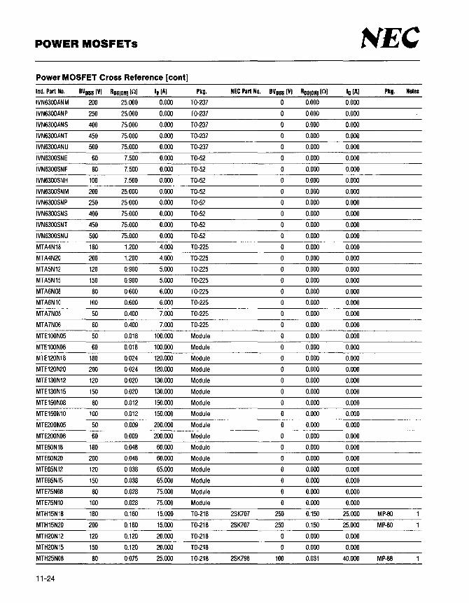
POWER MOSFETs NEC Power MOSFET Cross Reference [cont]
Ind. Part No. BVoss (VI Ros(ON) (Cl) lo (A) Pkg. NEC Part No. BVoss (VI Ros(ON) (Cl) lo (A) Pkg. Notes
IVN6300ANM 200 25.000 0.000 T0-237 0 0.000 0.000
IVN6300ANP 250 25.000 0.000 T0-237 0 0.000 0.000
IVN6300ANS 400 75.000 0.000 T0-237 0 0.000 0.000
IVN6300ANT 450 75.000 0.000 T0-237 0 0.000 0.000
IVN6300ANU 500 75.000 0.000 T0-237 0 0.000 0.000
IVN6300SNE 60 7.500 0.000 T0-52 0 0.000 0.000
IVN6300SNF 80 7.500 0.000 T0-52 0 0.000 0.000
IVN6300SNH 100 7.500 0.000 T0-52 0 0.000 0.000
IVN6300SNM 200 25.000 0.000 T0-52 0 0.000 0.000
IVN6300SNP 250 25.000 0.000 T0-52 0 0.000 0.000
IVN6300SNS 400 75.000 0.000 T0-52 0 0.000 0.000
IVN6300SNT 450 75.000 0.000 T0-52 0 0.000 0.000
IVN6300SNU 500 75.000 0.000 T0-52 0 0.000 0.000
MTA4N18 180 1.200 4.000 T0-225 0 0.000 0.000
MTA4N20 200 1.200 4.000 T0-225 0 0.000 0.000
MTA5N12 120 0.900 5.000 T0-225 0 0.000 0.000
MTA5N15 150 0.900 5.000 T0-225 0 0.000 0.000
MTA6N08 80 0.600 6.000 T0-225 0 0.000 0.000
MTA6N10 100 0.600 6.000 T0-225 0 0.000 0.000
MTA7N05 50 0.400 7.000 T0-225 0 0.000 0.000
MTA7N06 60 0.400 7.000 T0-225 0 0.000 0.000
MTE100N05 50 0.018 100.000 Module 0 0.000 0.000
MTE100N06 60 O.D18 100.000 Module 0 0.000 0.000
MTE120N18 180 0.024 120.000 Module 0 0.000 0.000
MTE120N20 200 0.024 120.000 Module 0 0.000 0.000
MTE130N12 120 0.020 130.000 Module 0 0.000 0.000
MTE130N15 150 0.020 130.000 Module 0 0.000 0.000
MTE150N08 80 0.012 150.000 Module 0 0.000 0.000
MTE150N10 100 0.012 150.000 Module 0 0.000 0.000
MTE200N05 50 0.009 200.000 Module 0 0.000 0.000
MTE200N06 60 0.009 200.000 Module 0 0.000 0.000
MTE60N18 180 0.048 60.000 Module 0 0.000 0.000
MTE60N20 200 0.048 60.000 Module 0 0.000 0.000
MTE65N12 120 0.038 65.000 Module 0 0.000 0.000
MTE65N15 150 0.038 65.000 Module 0 0.000 0.000
MTE75N08 80 0.028 75.000 Module 0 0.000 0.000
MTE75N10 100 0.028 75.000 Module 0 0.000 0.000
MTH15N18 180 0.160 15.000 T0-218 2SK707 250 0.150 25.000 MP-80
MTH15N20 200 0.160 15.000 T0-218 2SK707 250 0.150 25.000 MP-80
MTH20N12 120 0.120 20.000 T0-218 0 0.000 0.000
MTH20N15 150 0.120 20.000 T0-218 0 0.000 0.000
MTH25N08 80 0.075 25.000 T0-218 2SK798 100 0.031 40.000 MP-88
11-24

NEC POWER MOSFETs
Power MOSFET Cross Reference [cont]
Ind. Part No. BVoss IV) Ros(ONJ 101 lo IAJ Pkg. NEC Part No. BVoss IV) Ros(ONJ 101 lo IAJ Pkg. Notes
MTH25N10 100 0.075 25.000 T0-218 2SK798 100 0.031 40.000 MP-88
MTH35N05 50 0.055 35.000 T0-218 2SK797 60 0.018 40.000 MP-88
MTH35N06 60 0.055 35.000 T0-218 2SK797 60 0.018 40.000 MP-88
MTH6N55 550 1.200 6.000 T0-218 0 0.000 0.000
MTH6N60 600 1.200 6.000 T0-218 0 0.000 0.000
MTH7N45 450 0.800 7.000 T0-218 2SK735 450 0.800 10.000 MP-88
MTH7N50 500 0.800 7.000 T0-218 2SK876 500 0.700 12.000 MP-88
MTH8N35 350 0.550 8.000 T0-218 2SK825 450 0.500 15.000 MP-88
MTH8N40 400 0.550 8.000 T0-218 2SK825 450 0.500 15.000 MP-88
MTM10N08 80 0.330 10.000 T0-3 0 0.000 0.000
MTM10N10 100 0.330 10.000 T0-3 0 0.000 0.000
MTM10N12 120 0.300 10.000 T0-3 0 0.000 0.000
MTM10N15 150 0.300 10.000 T0-3 0 0.000 0.000
MTM12N05 50 0.200 12.000 T0-3 0 0.000 0.000
MTM12N06 60 0.200 12.000 T0-3 0 0.000 0.000
MTM12N08 80 0.250 12.000 T0-3 0.000 0.000
MTM12N10 100 0.250 12.000 T0-3 0.000 0.000
MTM15N05 50 0.160 15.000 T0-3 0.000 0.000
MTM15N06 60 0.160 15.000 T0-3 0 0.000 0.000
MTM15N35 350 0.400 15.000 T0-3 0 0.000 0.000
MTM15N40 400 0.400 15.000 T0-3 0.000 0.000
MTM15N45 450 0.500 15.000 T0-3 0.000 0.000
MTM15N50 500 0.500 15.000 T0-3 0 0.000 0.000
MTM1N100 1000 10.000 1.000 T0-3 0 0.000 0.000
MTM1N95 950 10.000 1.000 T0-3 0 0.000 0.000
MTM2N45 450 4.000 2.000 T0-3 0 0.000 ' 0.000
MTM2N50 500 4.000 2.000 T0-3 0 0.000 0.000
MTM2N85 850 8.000 2.000 T0-3 0 0.000 0.000
MTM2N90 900 8.000 2.000 T0-3 0 0.000 0.000
MTM2P45 -450 6.000 -2.000 T0-3 0 0.000 0.000
MTM2P50 -500 6.000 -2.000 T0-3 0 0.000 0.000
MTM3N35 350 3.300 3.000 T0-3 0 0.000 0.000
MTM3N40 400 3.300 3.000 T0-3 0 0.000 0.000
MTM3N55 550 2.500 3.000 T0-3 0 0.000 0.000
MTM3N60 600 2.500 3.000 T0-3 0 0.000 0.000
MTM4N45 450 2.000 4.000 T0-3 0 0.000 0.000
MTM4N50 500 2.000 4.000 T0-3 0 0.000 0.000
MTM5N35 350 1.500 5.000 T0-3 0 0.000 0.000
MTM5N40 400 1.500 5.000 T0-3 0 0.000 0.000
MTM6N55 550 1.500 6.000 T0-3 0 0.000 0.000
MTM6N60 600 1.500 6.000 T0-3 0 0.000 0.000
MTM7N45 450 1.200 7.000 T0-3 0 0.000 0.000
11-25

POWER MOSFETs NEC Power MOSFET Cross Reference [cont]
Ind. Part No. BVoss (VJ Ros10NJ (nJ lo (AJ Pkg. NEC Part No. BVoss (VJ Ros(ONJ (OJ lo (AJ Pkg. Notes
MTM7N50 500 1.200 7.000 T0-3 0 0.000 0.000
MTM814 80 0.400 0.000 T0-3 0 0.000 0.000
MTM815 100 0.400 0.000 T0-3 0 0.000 0.000
MTM8N12 120 0.500 8.000 T0-3 0 0.000 0.000
MTM8N15 150 0.500 8.000 T0-3 0 0.000 0.000
MTM8N18 180 0.400 8.000 T0-3 0 0.000 0.000
MTM8N20 200 0.400 8.000 T0-3 0 0.000 0.000
MTM8N35 350 0.800 8.000 T0-3 0.000 0.000
MTM8N40 400 0.800 8.000 T0-3 0.000 0.000
MTP10N05 50 0.280 10.000 T0-220 2SK704 60 0.250 5.000 T0-220
MTP10N06 60 0.280 10.000 T0-220 2SK704 60 0.250 5.000 T0-220
MTP10N08 80 0.330 10.000 T0-220 2SK470 100 0.300 10.000 T0-220
MTP10N10 100 0.330 10.000 T0-220 2SK470 100 0.300 10.000 T0-220
MTP10N12 120 0.300 10.000 T0-220 0 0.000 0.000
MTP10N15 150 0.300 10.000 T0-220 0 0.000 0.000
MTP10N25 250 0.450 10.000 T0-220 0 0.000 0.000
MTP12N05 50 0.200 12.000 T0-220 2SK812 60 0.085 21.000 T0-220
MTP12N06 60 0.200 12.000 T0-220 2SK812 60 0.085 21.000 T0-220
MTP12N08 80 0.180 12.000 T0-220 2SK810 100 0.180 15.000 T0-220
MTP12N10 100 0.180 12.000 T0-220 2SK810 100 0.180 15.000 T0-220
MTP12N18 180 0.350 12.000 T0-220 0 0.000 0.000
MTP12N20 200 0.350 12.000 T0-220 0 0.000 0.000
MTP15N05 50 0.160 15.000 T0-220 0 0.000 0.000
MTP15N06 60 0.160 15.000 T0-220 0.000 0.000
MTP15N12 120 0.250 15.000 T0-220 0 0.000 0.000
MTP15N15 150 0.250 15.000 T0-220 0.000 0.000
MTP1N100 1000 10.000 1.000 T0-220 0.000 0.000
MTP1N45 450 8.000 1.000 T0-220 2SK854 450 1.400 5.000 T0-220
MTP1N50 500 8.000 1.000 T0-220 2SK855 500 1.500 5.000 T0-220
MTP1N55 550 12.000 1.000 T0-220 2SK786 900 7.000 3.000 T0-220
MTP1N60 600 12.000 1.000 T0-220 2SK786 900 7.000 3.000 T0-220
MTP1N95 950 10.000 1.000 T0-220 0 0.000 0.000
MTP20N08 80 0.150 20.000 T0-220 2SK737 100 0.150 12.000 MP-45
MTP20N10 100 0.150 20.000 T0-220 2SK737 100 0.150 12.000 MP-45
MTP25N05 50 0.080 25.000 T0-220 2SK659 60 0.075 12.000 MP-45
MTP25N06 60 0.080 25.000 T0-220 2SK659 60 0.075 12.000 MP-45
MTP2N18 180 1.800 2.000 T0-220 V3088 250 0.670 5.000 T0-220
MTP2N20 200 1.800 2.000 T0-220 V3088 250 0.670 5.000 T0-220
MTP2N35 350 5.000 2.000 T0-220 2SK854 450 1.400 5.000 T0-220
MTP2N40 400 5.000 2.000 T0-220 2SK854 450 1.400 5.000 T0-220
MTP2N45 450 4.000 2.000 T0-220 2SK854 450 1.400 5.000 T0-220
MTP2N50 500 4.000 2.000 T0-220 2SK855 500 1.500 5.000 T0-220
11-26

NEC POWER MOSFETs
Power MOSFET Cross Reference [cont]
Ind. Part No. BVoss (VJ Ros[ONJ (OJ lo (AJ Pkg. NEC Part No. BVoss (VJ Ros[ON) (OJ lo (AJ Pkg. Notes
MTP2N85 850 8.000 2.000 T0-220 2SK786 900 7.000 3.000 T0-220
MTP2N90 900 8.000 2.000 T0-220 2SK786 900 7.000 3.000 T0-220
MTP2P45 -450 6.000 -2.000 T0-220 0 0.000 0.000
MTP2P50 -500 6.000 -2.000 T0-220 0 0.000 0.000
MTP3N12 120 1.300 3.000 T0-220 V3088 250 0.670 5.000 T0-220
MTP3N15 150 1.300 3.000 T0-220 V3088 250 0.670 5.000 T0-220
MTP3N35 350 3.300 3.000 T0-220 2SK854 450 1.400 5.000 T0-220
MTP3N40 400 3.300 3.000 T0-220 2SK854 450 1.400 5.000 T0-220
MTP3N55 550 2.500 3.000 T0-220 0 0.000 0.000
MTP3N60 600 2.500 3.000 T0-220 0 0.000 0.000
MTP3N75 750 7.000 3.000 T0-220 2SK786 900 7.000 3.000 T0-220
MTP3N80 800 7.000 3.000 T0-220 2SK786 900 7.000 3.000 T0-220
MTP4N08 80 0.800 4.000 T0-220 2SK702 100 0.450 5.000 T0-220
MTP4N10 100 0.800 4.000 T0-220 2SK702 100 0.450 5.000 T0-220
MTP4N45 450 1.500 4.000 T0-220 2SK854 450 1.400 5.000 T0-220
MTP4N50 500 1.500 4.000 T0-220 2SK855 500 1.500 5.000 T0-220
MTP5N05 50 0.600 5.000 T0-220 2SK704 60 0.250 5.000 T0-220
MTP5N06 60 0.600 5.000 T0-220 2SK704 60 0.250 5.000 T0-220
MTP5N18 180 1.000 5.000 T0-220 V3088 250 0.670 5.000 T0-220
MTP5N20 200 1.000 5.000 T0-220 V3088 250 0.670 5.000 T0-220
MTP5N35 350 1.000 5.000 T0-220 0 0.000 0.000
MTP5N40 400 1.000 5.000 T0-220 0 0.000 0.000
MTP7N12 120 0.700 7.000 T0-220 V3088 250 0.670 5.000 T0-220
MTP7N15 150 0.700 7.000 T0-220 V3088 250 0.670 5.000 T0-220
MTP7N18 180 0.700 7.000 T0-220 V3088 250 0.670 5.000 T0-220
MTP7N20 200 0.700 7.000 T0-220 V3088 250 0.670 5.000 T0-220
MTP8N08 80 0.500 8.000 T0-220 2SK702 100 0.450 5.000 T0-220
MTP8N10 100 0.500 8.000 T0-220 2SK702 100 0.450 5.000 T0-220
MTP8N12 120 0.500 8.000 T0-220 0 0.000 0.000
MTP8N15 150 0.500 8.000 T0-220 0 0.000 0.000
MTP8N18 180 0.400 8.000 T0-220 0 0.000 0.000
MTP8N20 200 0.400 8.000 T0-220 0 0.000 0.000
MTP8P08 -80 0.400 -8.000 T0-220 2SJ138 -100 0.300 -12.000 T0-220
MTP8P10 -100 0.400 -8.000 T0-220 2SJ138 -100 0.300 -12.000 T0-220
PM1210B 120 0.000 10.000 Module 0 0.000 0.000
PM1220B 120 0.000 20.000 Module 0 0.000 0.000
PM4550C 450 0.000 50.000 Module 0 0.000 0.000
RCA9192A 100 0.300 0.000 T0-3 0 0.000 0.000
RCA9192B 150 0.300 0.000 T0-3 0 0.000 0.000
RCA9195A 100 0.150 0.000 T0-3 0 0.000 0.000
RCA9195B 150 0.150 0.000 T0-3 0 0.000 0.000
RCA9196A 100 2.500 0.000 T0-39 0 0.000 0.000
11-27

POWER MOSFETs NEC Power MOSFET Cross Reference [cont]
Ind. Part No. BVoss (VI Ros(ONJ (OJ lo (Al Pkg. NEC Part No. BVoss (VI Ros(ONJ (OJ lo (Al Pkg. Notes
RCA91968 150 2.500 0.000 T0-39 0 0.000 0.000
RCA9212A 100 0.300 0.000 T0-220 2SK811 100 0.180 12.000 MP-45
RCA9212B 150 0.300 0.000 T0-220 0 0.000 0.000
RCA9213A 100 2.500 0.000 T0-220 2SK702 100 0.450 5.000 T0-220
RCA9213B 150 2.500 0.000 T0-220 V3088 250 0.670 5.000 T0-220
RCA9230A 100 0.150 0.000 T0-220 2SK737 100 0.150 12.000 MP-45
RCA9230B 150 0.150 0.000 T0-220 0 0.000 0.000
RFP10N12L 120 0.300 10.000 T0-220 0 0.000 0.000
RFP10N15L 150 0.300 10.000 T0-220 0 0.000 0.000
RFP12N08L 80 0.200 12.000 T0-220 2SK810 100 0.180 15.000 T0-220
RFP12N10L 100 0.200 12.000 T0-220 2SK810 100 0.180 15.000 T0-220
RFP15N05L 50 0.150 15.000 T0-220 0 0.000 0.000
RFP15N06L 60 0.150 15.000 T0-220 0 0.000 0.000
RFP2N08L 80 1.250 2.000 T0-220 2SK702 100 0.450 5.000 T0-220
RFP2N10L 100 1.250 2.000 T0-220 2SK702 100 0.450 5.000 T0-220
RFP2N12L 120 2.000 2.000 T0-220 V3088 250 0.670 5.000 T0-220
RFP2N15L 150 2.000 2.000 T0-220 V3088 250 0.670 5.000 T0-220
RFP2N18L 180 3.500 2.000 T0-220 V3088 250 0.670 5.000 T0-220
RFP2N20L 200 3.500 2.000 T0-220 V3088 250 0.670 5.000 T0-220
RFP4N05L 50 0.800 4.000 T0-220 2SK704 60 0.250 5.000 T0-220
RFP4N06L 60 0.800 4.000 T0-220 2SK704 60 0.250 5.000 T0-220
RFP8N18L 180 0.600 8.000 T0-220 0 0.000 0.000
RFP8N20L 200 0.600 8.000 T0-220 0 0.000 0.000
SGSP101 100 1.400 1.500 T0-39 0 0.000 0.000
SGSP102 100 1.400 1.500 T0-39 0 0.000 0.000
SGSP151 100 0.600 5.000 T0-39 0 0.000 0.000
SGSP154 450 6.000 1.500 T0-39 0 0.000 0.000
SGSP155 400 5.000 1.500 T0-39 0 0.000 0.000
SGSP201 100 1.400 1.500 SOT-82 0 0.000 0.000
SGSP211 100 0.300 7.000 SOT-82 0 0.000 0.000
SGSP212 80 0.300 7.000 SOT-82 0 0.000 0.000
SGSP216 250 1.200 6.000 SOT-82 0 0.000 0.000
SGSP217 200 0.750 6.000 SOT-82 0 0.000 0.000
SGSP218 550 4.500 2.000 SOT-82 0 0.000 0.000
SGSP219 500 3.800 2.000 SOT-82 0 0.000 0.000
SGSP221 60 0.130 10.000 SOT-82 0 0.000 0.000
SGSP222 50 0.130 10.000 SOT-82 0 0.000 0.000
SGSP230 450 3.000 3.000 SOT-82 0 0.000 0.000
SGSP231 400 2.500 3.000 SOT-82 0 0.000 0.000
SGSP232 350 2.500 3.000 SOT-82 0 0.000 0.000
SGSP238 550 11.000 1.200 SOT-82 0 0.000 0.000
SGSP239 500 8.500 1.200 SOT-82 0 0.000 0.000
11-28

NEC POWER MOSFETs
Power MOSFET Cross Reference [cont]
Ind. Part No. BVoss (VJ Ros10NJ [nJ lo (AJ Pkg. NEC Part No. BVoss (VJ Ros[DNJ [nJ lo (AJ Pkg. Notes
SGSP240 450 20.000 0.600 SOT-82 0 0.000 0.000
SGSP241 400 20.000 0.600 SOT-82 0 0.000 0.000
SGSP242 350 20.000 0.600 SOT-82 0 0.000 0.000
SGSP248 550 40.000 0.500 SOT-82 0 0.000 0.000
SGSP249 500 40.000 0.500 SOT-82 0 0.000 0.000
SGSP251 100 0.450 5.000 SOT-82 0 0.000 0.000
SGSP252 80 0.450 5.000 SOT-82 0.000 0.000
SGSP254 450 6.500 1.500 SOT-82 0.000 0.000
SGSP255 400 5.000 1.500 SOT-82 0 0.000 0.000
SGSP256 350 5.000 1.500 SOT-82 0 0.000 0.000
SGSP257 60 0.300 7.000 SOT-82 0 0.000 0.000
SGSP258 50 0.300 7.000 SOT-82 0.000 0.000
SGSP301 100 1.400 1.500 T0-220 2SK702 100 0.450 5.000 T0-220
SGSP302 80 1.400 1.500 T0-220 2SK702 100 0.450 5.000 T0-220
SGSP311 100 0.300 7.000 T0-220 2SK810 100 0.180 15.000 T0-220
SGSP312 80 3.500 7.000 T0-220 2SK702 100 0.450 5.000 T0-220
SGSP316 250 1.200 6.000 T0-220 V3088 250 0.670 5.000 T0-220
SGSP317 200 0.750 6.000 T0-220 V3088 250 0.670 5.000 T0-220
SGSP318 550 4.500 2.000 T0-220 0 0.000 0.000
SGSP319 500 3.800 2.000 T0-220 2SK855 500 1.500 5.000 T0-220
SGSP321 60 0.130 10.000 T0-220 2SK812 60 0.085 21.000 T0-220
SGSP322 50 0.130 10.000 T0-220 2SK812 60 0.085 21.000 T0-220
SGSP330 450 3.000 3.000 T0-220 2SK854 450 1.400 5.000 T0-220
SGSP331 400 2.500 3.000 T0-220 2SK854 450 1.400 5.000 T0-220
SGSP332 350 2.500 3.000 T0-220 2SK854 450 1.400 5.000 T0-220
SGSP338 550 11.000 1.200 T0-220 0 0.000 0.000
SGSP339 500 8.500 1.200 T0-220 2SK855 500 1.500 5.000 T0-220
SGSP340 450 20.000 0.600 T0-220 0.000 0.000
SGSP341 400 20.000 0.600 T0-220 0 0.000 0.000
SGSP342 350 20.000 0.600 T0-220 0 0.000 0.000
SGSP348 550 40.000 0.500 T0-220 0 0.000 0.000
SGSP349 500 40.000 0.500 T0-220 0 0.000 0.000
SGSP351 100 0.450 5.000 T0-220 2SK702 100 0.450 5.000 T0-220
SGSP352 80 0.450 5.000 T0-220 2SK702 100 0.450 5.000 T0-220
SGSP354 450 6.500 1.500 T0-220 2SK854 450 1.400 5.000 T0-220
SGSP355 400 5.000 1.500 T0-220 2SK854 450 1.400 5.000 T0-220
SGSP356 350 5.000 1.500 T0-220 2SK854 450 1.400 5.000 T0-220
SGSP357 60 0.300 7.000 T0-220 2SK704 60 0.250 5.000 T0-220
SGSP358 250 0.300 7.000 T0-220 0 0.000 0.000
SGSP361 100 0.150 16.000 T0-220 2SK737 100 0.150 12.000 MP-45
SGSP362 80 0.150 16.000 T0-220 2SK737 100 0.150 12.000 MP-45
SGSP363 50 0.450 10.000 T0-220 2SK704 60 0.250 5.000 T0-220
11-29

POWER MOSFETs NEC Power MOSFET Cross Reference [cont]
Ind. Part No. BVoss (VJ Ros(ON) (OJ lo (AJ Pkg. NEC Part No. BVoss (VJ Ros(ON) (OJ lo (AJ Pkg. Notes
SGSP364 450 1.500 6.000 T0-220 2SK854 450 1.400 5.000 T0-220
SGSP365 400 1.200 6.000 T0-220 0 0.000 0.000
SGSP366 350 1.200 6.000 T0-220 0 0.000 0.000
SGSP367 200 0.600 10.000 T0-220 0 0.000 0.000
SGSP368 550 2.500 5.000 T0-220 0 0.000 0.000
SGSP369 500 1.900 5.000 T0-220 2SK855 500 1.500 5.000 T0-220
SGSP381 60 0.060 24.000 T0-220 2SK817 60 0.055 26.000 MP-45
SGSP382 50 0.060 24.000 T0-220 2SK817 60 0.055 26.000 MP-45
SGSP421 60 0.130 10.000 T0-218 2SK797 60 0.018 40.000 MP-88
SGSP422 50 0.130 10.000 T0-218 2SK797 60 0.018 40.000 MP-88
SGSP461 100 0.150 16.000 T0-218 2SK798 100 0.031 40.000 MP-88
SGSP462 80 0.100 16.000 T0-218 2SK798 100 0.031 40.000 MP-88
SGSP463 250 0.450 10.000 T0-218 V3087 250 0.450 8.000 MP-88
SGSP464 450 1.500 6.000 T0-218 2SK873 450 1.100 8.000 MP-88
SGSP465 400 1.000 6.000 T0-218 2SK735 450 0.800 10.000 MP-88
SGSP466 350 1.000 6.000 T0-218 2SK735 450 0.800 10.000 MP-88
SGSP467 200 0.330 10.000 T0-218 V3085 250 0.250 15.000 MP-88
SGSP468 550 2.500 5.000 T0-218 0 0.000 0.000
SGSP469 500 1.500 5.000 T0-218 2SK874 500 1.200 8.000 MP-88
SGSP471 100 0.070 30.000 T0-218 2SK798 100 0.031 40.000 MP-88
SGSP472 80 0.070 30.000 T0-218 2SK798 100 0.031 40.000 MP-88
SGSP473 250 0.220 20.000 T0-218 2SK707 250 0.150 25.000 MP-80
SGSP474 450 0.700 12.000 T0-218 2SK875 450 0.600 12.000 MP-88
SGSP475 400 0.550 12.000 T0-218 2SK825 450 0.500 15.000 MP-88
SGSP476 350 0.550 12.000 T0-218 2SK825 450 0.500 15.000 MP-88
SGSP477 200 0.170 20.000 T0-218 2SK707 250 0.150 25.000 MP-80
SGSP478 550 1.000 10.000 T0-218 0.000 0.000
SGSP479 500 0.700 10.000 T0-218 2SK876 500 0.700 12.000 MP-88
SGSP481 60 0.060 24.000 T0-218 2SK797 60 0.018 40.000 MP-88
SGSP482 50 0.060 24.000 T0-218 2SK797 60 0.018 40.000 MP-88
SGSP491 60 0.050 40.000 T0-218 2SK797 60 0.018 40.000 MP-88
SGSP492 50 0.033 40.000 T0-218 2SK797 60 0.018 40.000 MP-88
TN0102N2 20 1.500 3.500 T0-39 0 0.000 0.000
TN0102N3 20 1.500 3.500 T0-92 0 0.000 0.000
TN0104N2 40 1.500 3.500 T0-39 0 0.000 0.000
TN0104N3 40 1.500 3.500 T0-92 0 0.000 0.000
TN0106N2 60 3.000 2.000 T0-39 0 0.000 0.000
TN0106N3 60 3.000 2.000 T0-92 0 0.000 0.000
TN0110N2 100 3.000 2.000 T0-39 0 0.000 0.000
TN0110N3 100 3.000 2.000 T0-92 0 0.000 0.000
TN0202N2 20 1.000 5.000 T0-39 0 0.000 0.000
TN0202N3 20 1.000 5.000 T0-92 0 0.000 0.000
11-30

NEC POWER MOSFETs
Power MOSFET Cross Reference [cont]
Ind. Part No. BVoss IVJ Ros10N1 1n1 lo IA) Pkg. NEC Part No. BVoss IV) Ros(ONJ 1n1 lo IA) Pkg. Notes
TN0204N2 40 1.000 5.000 T0-39 0 0.000 0.000
TN0204N3 40 1.000 5.000 T0-92 0 0.000 0.000
TN0520N2 200 10.000 0.300 T0-39 0 0.000 0.000
TN0520N3 200 10.000 0.300 T0-92 0 0.000 0.000
TN0524N2 240 10.000 0.300 T0-39 0.000 0.000
TN0524N3 240 10.000 0.300 T0-92 0 0.000 0.000
TN0602N2 20 0.750 5.000 T0-39 0 0.000 0.000
TN0602N3 20 0.750 5.000 T0-92 0.000 0.000
TN0604N2 40 0.750 5.000 T0-39 0 0.000 0.000
TN0604N3 40 0.750 5.000 T0-92 0 0.000 0.000
TN0620N2 200 6.000 1.000 T0-39 0 0.000 0.000
TN0620N3 200 6.000 1.000 T0-92 0.000 0.000
TN0620N5 200 6.000 1.000 T0-220 V3088 250 0.670 5.000 T0-220
TN0624N2 240 6.000 1.000 T0-39 0 0.000 0.000
TN0624N3 240 6.000 1.000 T0-92 0 0.000 0.000
TN0624N5 240 6.000 1.000 T0-220 V3088 250 0.670 5.000 T0-220
TP0102N2 -20 4.000 -.850 T0-39 0 0.000 0.000
TP0102N3 -20 4.000 -.850 T0-92 0 0.000 0.000
TP0104N2 -40 4.000 -.850 T0-39 0.000 0.000
TP0104N3 -40 4.000 -.850 T0-92 0.000 0.000
TP0202N2 -20 2.000 -3.500 T0-39 0 0.000 0.000
TP0202N3 -20 2.000 -3.500 T0-92 0 0.000 0.000
TP0204N2 -40 2.000 -3.500 T0-39 0 0.000 0.000
TP0204N3 -40 2.000 -3.500 T0-92 0.000 0.000
TP0602N2 -20 1.500 -3.500 T0-39 0 0.000 0.000
TP0602N3 -20 1.500 -3.500 T0-92 0.000 0.000
TP0604N2 -40 1.500 -3.500 T0-39 0 0.000 0.000
TP0604N3 -40 1.500 -3.500 T0-92 0 0.000 0.000
TP0606N2 -60 3.500 -2.000 T0-39 0.000 0.000
TP0606N3 -60 3.500 -2.000 T0-92 0 0.000 0.000
TP0606N5 -60 3.500 -2.000 T0-220 V2994A -60 0.450 -6.000 T0-220
TP0606N6 -60 3.500 -2.000 14-Pin DIP 0.000 0.000 2
TP0606N7 -60 3.500 -2.000 14-Pin DIP 0 0.000 0.000 2
TP0610N2 -100 3.500 -2.000 T0-39 0.000 0.000
TP0610N3 -100 3.500 -2.000 T0-92 0 0.000 0.000
TP0610N5 -100 3.500 -2.000 T0-220 2SJ134 -100 0.600 -6.000 T0-220
TP0616N2 -160 12.000 -.750 T0-39 0.000 0.000
TP0616N3 -160 12.000 -.750 T0-92 0 0.000 0.000
TP0616N5 -160 12.000 -.750 T0-220 0 0.000 0.000
TP0620N2 -200 12.000 -.750 T0-39 0 0.000 0.000
TP0620N3 -200 12.000 -.750 T0-92 0 0.000 0.000
TP0620N5 -200 12.000 -.750 T0-220 0 0.000 0.000
11-31

POWER MOSFETs NEC Power MOSFET Cross Reference [cont]
Ind. Part No. BVoss (VJ Ros(ONJ (OJ lo (AJ Pkg. NEC Part No. BVoss (VJ Ros(ONJ (OJ lo (AJ Pkg. Notes
VN0104N1 40 4.000 2.000 T0-3 0 0.000 0.000
VN0104N2 40 4.000 0.800 T0-39 0 0.000 0.000
VN0104N3 40 4.000 0.500 T0-92 0 0.000 0.000
VN0104N4 40 4.000 0.500 T0-202 0 0.000 0.000
VN0104N5 40 4.000 1.500 T0-220 0 0.000 0.000
VN0104N6 40 4.000 0.700 14-Pin DIP 0 0.000 0.000 2
VN0104N7 40 3.000 0.700 14-Pin DIP 0 0.000 0.000 2
VN0106N1 60 4.000 2.000 T0-3 0 0.000 0.000
VN0106N2 60 4.000 0.800 T0-39 0 0.000 0.000
VN0106N3 60 4.000 0.500 T0-92 0 0.000 0.000
VN0106N4 60 4.000 0.500 T0-202 0 0.000 0.000
VN0106N5 60 4.000 1.500 T0-220 0 0.000 0.000
VN0106N6 60 4.000 0.700 14-Pin DIP 0 0.000 0.000 2
VN0106N7 60 3.000 0.700 14-Pin DIP 0 0.000 0.000 2
VN0108N1 80 4.000 2.000 T0-3 0 0.000 0.000
VN0108N2 80 4.000 0.800 T0-39 0 0.000 0.000
VN0108N3 80 4.000 0.500 T0-92 0 0.000 0.000
VN0108N4 80 4.000 0.500 T0-202 0 0.000 0.000
VN0108N5 80 4.000 1.500 T0-220 0 0.000 0.000
VN0108N6 80 4.000 0.700 14-Pin DIP 0 0.000 0.000 2
VN0109N1 90 4.000 2.000 T0-3 0 0.000 0.000
VN0109N2 90 4.000 0.800 T0-39 0 0.000 0.000
VN0109N3 90 4.000 0.500 T0-92 0 0.000 0.000
VN0109N4 90 4.000 0.500 T0-202 0 0.000 0.000
VN0109N5 90 4.000 1.500 T0-220 0 0.000 0.000
VN0109N6 90 4.000 0.700 14-Pin DIP 0 0.000 0.000 2
VN0116N2 160 10.000 Q.400 T0-39 0 0.000 0.000
VN0116N3 160 10.000 0.400 T0-92 0 0.000 0.000
VN0116N5 160 10.000 Q.400 T0-220 0 0.000 0.000
VN0120N2 200 10.000 0.400 T0-39 0 0.000 0.000
VN0120N3 200 10.000 0.400 T0-92 0 0.000 0.000
VN0120N5 200 10.000 0.400 T0-220 0 0.000 0.000
VN0204N1 40 2.000 3.000 T0-3 0 0.000 0.000
VN0204N2 40 2.000 1.500 T0-39 0 0.000 0.000
VN0204N5 40 2.000 3.000 T0-220 2SK704 60 0.250 5.000 T0-220
VN0204N6 40 2.000 1.000 14-Pin DIP 0 0.000 0.000 2
VN0204N7 40 2.000 1.000 14-Pin DIP 0 0.000 0.000 2
VN0206N1 60 2.000 3.000 T0-3 0 0.000 0.000
VN0206N2 60 2.000 1.500 T0-39 0 0.000 0.000
VN0206N3 60 2.000 0.800 T0-92 0 0.000 0.000
VN0206N5 60 2.000 3.000 T0-220 2SK704 60 0.250 5.000 T0-220
VN0206N6 60 2.000 1.000 14-Pin DIP 0 0.000 0.000 2
11-32

t\'EC POWER MOSFETs
Power MOSFET Cross Reference [cont]
Ind. Part No. BVoss (VJ Ros(ONI (OJ lo (AJ Pkg. NEC Part No. BVoss (VJ Ros(ONJ (OJ lo (AJ Pkg. Notes
VN0206N7 60 2.000 1.000 14-Pin DIP 0 0.000 0.000
VN0208N1 80 2.000 3.000 T0-3 0 0.000 0.000
VN0208N2 80 2.000 1.500 T0-39 0 0.000 0.000
VN0208N5 80 2.000 3.000 T0-220 2SK702 100 0.450 5.000 T0-220
VN0208N6 80 2.000 1.000 14-Pin DIP 0 0.000 0.000
VN0209N1 90 2.000 3.000 T0-3 0 0.000 0.000
VN0209N2 90 2.000 1.500 T0-39 0 0.000 0.000
VN0209N5 90 2.000 3.000 T0-220 2SK702 100 0.450 5.000 T0-220
VN0209N6 90 2.000 1.000 14-Pin DIP 0 0.000 0.000 2
VN0210N2 100 2.000 1.500 T0-39 0 0.000 0.000
VN0210N3 100 2.000 0.800 T0-92 0 0.000 0.000
VN0210N5 100 2.000 1.000 T0-220 2SK702 100 0.450 5.000 T0-220
VN0216N2 160 6.000 1.000 T0-39 0 0.000 0.000
VN0216N3 160 6.000 1.000 T0-92 0 0.000 0.000
VN0216N5 160 6.000 1.000 T0-220 V3088 250 0.670 5.000 T0-220
VN0220N2 200 6.000 1.000 T0-39 0 0.000 0.000
VN0220N3 200 6.000 1.000 T0-92 0 0.000 0.000
VN0220N5 200 6.000 1.000 T0-220 V3088 250 0.670 5.000 T0-220
VN0300D 30 1.200 2.500 T0-220AB 2SK704 60 0.250 5.000 T0-220
VN0300M 30 1.200 0.700 T0-237 0 0.000 0.000
VN0330N1 300 2.500 3.500 T0-3 0 0.000 0.000
VN0330N2 300 2.500 1.000 T0-39 0 0.000 0.000
VN0330N5 300 2.500 2.100 T0-220 2SK854 450 1.400 5.000 T0-220
VN0335A1 350 1.000 0.000 T0-3 0 0.000 0.000
VN0335N1 350 2.500 3.500 T0-3 0 0.000 0.000
VN0335N2 350 2.500 1.000 T0-39 0 0.000 0.000
VN0335N5 350 2.500 2.100 T0-220 2SK854 450 1.400 5.000 T0-220
VN0340A1 400 1.000 0.000 T0-3 0 0.000 0.000
VN0340N1 400 2.500 3.500 T0-3 0 0.000 0.000
VN0340N2 400 2.500 1.000 T0-39 0 0.000 0.000
VN0340N5 400 2.500 2.100 T0-220 2SK854 450 1.400 5.000 T0-220
VN0345A1 450 1.000 0.000 T0-3 0 0.000 0.000
VN0345N1 450 4.000 2.500 T0-3 0 0.000 0.000
VN0345N2 450 4.000 0.350 T0-39 0 0.000 0.000
VN0345N5 450 4.000 1.500 T0-220 2SK854 450 1.400 5.000 T0-220
VN0350A1 500 1.000 0.000 T0-3 0 0.000 0.000
VN0350N2 500 4.000 2.500 T0-3 0 0.000 0.000
VN0350N3 500 4.000 0.350 T0-39 0 0.000 0.000
VN0350N5 500 4.000 1.500 T0-220 2SK855 500 1.500 5.000 T0-220
VN0355N1 550 6.000 1.500 T0-3 0 0.000 0.000
VN0355N5 550 6.000 1.500 T0-220 0 0.000 0.000
VN0360N1 600 6.000 1.500 T0-3 0 0.000 0.000
11-33

POWER MOSFETs NEC Power MOSFET Cross Reference [cont]
Ind. Part No. BVoss (VJ Ros10N1 (nJ lo (AJ Pkg. NEC Part No. BVoss (VJ Ros10NJ (nJ lo (AJ Pkg. Notes
VN0360N5 600 6.000 1.500 T0-220 0 0.000 0.000
VN0400A 40 0.120 18.000 T0-3 0 0.000 0.000
VN0400D 40 0.120 18.000 T0-220AB 2SK659 60 0.075 12.000 MP-45
VN0401A 40 0.150 16.000 T0-3 0 0.000 0.000
VN0401D 40 0.150 16.000 T0-220AB 2SK659 60 0.075 12.000 MP-45
VN0430N1 300 0.800 0.000 T0-3 0 0.000 0.000
VN0435N1 350 0.800 0.000 T0-3 0 0.000 0.000
VN0440N1 400 0.800 0.000 T0-3 0 0.000 0.000
VN0445N1 450 0.800 0.000 T0-3 0 0.000 0.000
VN0535N2 350 35.000 0.250 T0-39 0 0.000 0.000
VN0535N3 350 35.000 0.250 T0-92 0 0.000 0.000
VN0540N2 400 35.000 0.250 T0-39 0 0.000 0.000
VN0540N3 400 35.000 0.250 T0-92 0 0.000 0.000
VN0545N2 450 60.000 0.150 T0-39 0 0.000 0.000
VN0545N3 450 60.000 0.150 T0-92 0 0.000 0.000
VN0550N2 500 60.000 0.150 T0-39 0 0.000 0.000
VN0550N3 500 60.000 0.150 T0-92 0 0.000 0.000
VN0600A 60 0.120 18.000 T0-3 0 0.000 0.000
VN0600D 60 0.120 18.000 T0-220AB 2SK659 60 0.075 12.000 MP-45
VN0601A 60 0.150 16.000 T0-3 0 0.000 0.000
VN0601D 60 0.150 16.000 T0-220AB 2SK659 60 0.075 12.000 MP-45
VN0606M 60 3.000 0.400 T0-237 0 0.000 0.000
VN0610L 60 5.000 0.200 T0-92 0 0.000 0.000
VN0635N2 350 8.000 1.500 T0-39 0 0.000 0.000
VN0635N3 350 8.000 1.500 T0-92 0 0.000 0.000
VN0635N5 350 8.000 1.500 T0-220 0 0.000 0.000
VN0640N2 400 8.000 1.500 T0-39 0 0.000 0.000
VN0640N3 400 8.000 1.500 T0-92 0 0.000 0.000
VN0640N5 400 8.000 1.500 T0-220 0 0.000 0.000
VN0645N2 450 15.000 0.800 T0-39 0 0.000 0.000
VN0645N3 450 15.000 0.800 T0-92 0 0.000 0.000
VN0645N5 450 15.000 0.800 T0-220 0 0.000 0.000
VN0650N2 500 15.000 0.800 T0-39 0 0.000 0.000
VN0650N3 500 15.000 0.800 T0-92 0 0.000 0.000
VN0650N5 500 15.000 0.800 T0-220 0 0.000 0.000
VN0655N2 550 20.000 0.500 T0-39 0 0.000 0.000
VN0655N3 550 20.000 0.500 T0-92 0 0.000 0.000
VN0655N5 550 20.000 0.500 T0-220 0 0.000 0.000
VN0660N2 600 20.000 0.500 T0-39 0 0.000 0.000
VN0660N3 600 20.000 0.500 T0-92 0 0.000 0.000
VN0660N5 600 20.000 0.500 T0-220 0 0.000 0.000
VN0800A 80 0.180 14.000 T0-3 0 0.000 0.000
11-34

NEC POWER MOSFETs
Power MOSFET Cross Reference [cont]
Ind. Part No. BVoss IVJ Ros10NJ 1n1 lo (Al Pkg. NEC Part No. BVoss (VI Ros(ONJ 1n1 lo (Al Pkg. Notes
VN08000 80 0.180 14.000 T0-220AB 2SK810 100 0.180 15.000 T0-220
VN0801A 80 0.250 12.000 T0-3 0 0.000 0.000
VN0801D 80 0.250 12.000 T0-220AB 2SK810 100 0.180 15.000 T0-220
VN0808M 80 4.000 0.350 T0-237 0 0.000 0.000
VN1000A 100 0.180 14.000 T0-3 0 0.000 0.000
VN10000 100 0.180 14.000 T0-220AB 2SK810 100 0.180 15.000 T0-220
VN1001A 100 0.250 12.000 T0-3 0 0.000 0.000
VN1001D 100 0.250 12.000 T0-220AB 2SK810 100 0.180 15.000 T0-220
VN10KE 60 5.000 0.200 T0-52 0 0.000 0.000
VN10KM 60 5.000 0.300 T0-237 0 0.000 0.000
VN10KN3 60 5.000 0.500 T0-92 0 0.000 0.000
VN10KN9 60 5.000 0.500 T0-52 0 0.000 0.000
VN10LE 60 5.000 0.200 T0-52 0 0.000 0.000
VN10LM 60 5.000 0.300 T0-237 0 0.000 0.000
VN1106N1 60 0.700 8.000 T0-3 0 0.000 0.000
VN1106N2 60 0.700 8.000 T0-39 0 0.000 0.000
VN1106N5 60 0.700 8.000 T0-220 2SK704 60 0.250 5.000 T0-220
VN1110N1 100 0.700 8.000 T0-3 0 0.000 0.000
VN1110N2 100 0.700 8.000 T0-39 0 0.000 0.000
VN1110N5 100 0.700 8.000 T0-220 2SK702 100 0.450 5.000 T0-220
VN1116N1 160 3.000 2.000 T0-3 0 0.000 0.000
VN1116N2 160 3.000 2.000 T0-39 0 0.000 0.000
VN1116N5 160 3.000 2.000 T0-220 V3088 250 0.670 5.000 T0-220
VN1120N1 200 3.000 2.000 T0-3 0 0.000 0.000
VN1120N2 200 3.000 2.000 T0-39 0 0.000 0.000
VN1120N5 200 3.000 2.000 T0-220 V3088 250 0.670 5.000 T0-220
VN1200A 120 0.180 14.000 T0-3 0 0.000 0.000
VN1200D 120 0.180 14.000 T0-220AB 2SK720A 0 0.000 0.000
VN1201A 120 0.250 12.000 T0-3 0 0.000 0.000
VN1201D 120 0.250 12.000 T0-220AB V3085 0 0.000 0.000
VN1204N1 40 0.400 0.000 T0-3 0 0.000 0.000
VN1204N2 40 0.400 0.000 T0-39 0 0.000 0.000
VN1204N5 40 0.400 0.000 T0-220 2SK704 60 0.250 5.000 T0-220
VN1206B 120 6.000 0.800 T0-39 0 0.000 0.000
VN1206D 120 6.000 1.400 T0-220AB 0 0.000 0.000
VN1206L 120 6.000 0.210 T0-92 0 0.000 0.000
VN1206M 120 6.000 0.300 T0-237 0 0.000 0.000
VN1206N1 60 0.400 0.000 T0-3 0 0.000 0.000
VN1206N2 60 0.400 0.000 T0-39 0 0.000 0.000
VN1206N5 60 0.400 0.000 T0-220 2SK704 60 0.250 5.000 T0-220
VN1208N1 80 0.400 0.000 T0-3 0 0.000 0.000
VN1208N2 80 0.400 0.000 T0-39 0 0.000 0.000
11-35

POWER MOSFETs ~EC
Power MOSFET Cross Reference [cont]
Ind. Part No. BVoss (VJ Ros(ONJ (OJ lo [AJ Pkg. NEC Part No. BVoss (VJ Ros(ONJ (OJ lo (AJ Pkg. Notes
VN1208N5 80 0.400 0.000 T0-220 2SK810 100 0.180 15.000 T0-220
VN1209N1 90 0.400 0.000 T0-3 0 0.000 0.000
VN1209N2 90 0.400 0.000 T0-39 0 0.000 0.000
VN1209N5 90 0.400 0.000 T0-220 2SK810 100 0.180 15.000 T0-220
VN1210L 120 10.000 0.160 T0-92 0 0.000 0.000
VN1210M 120 10.000 0.250 T0-237 0 0.000 0.000
VN1304N2 40 10.000 0.000 T0-39 0 0.000 0.000
VN1304N3 40 10.000 0.000 T0-92 0 0.000 0.000
VN1304N6 40 10.000 0.000 14-Pin DIP 0 0.000 0.000 2
VN1304N7 40 8.000 0.500 14-Pin DIP 0 0.000 0.000 2
VN1306N2 60 10.000 0.000 T0-39 0 0.000 0.000
VN1306N3 60 10.000 0.000 T0-92 0 0.000 0.000
VN1306N6 60 10.000 0.000 14-Pin DIP 0 0.000 0.000 2
VN1306N7 60 8.000 0.500 14-Pin DIP 0 0.000 0.000 2
VN1308N2 80 10.000 0.000 T0-39 0 0.000 0.000
VN1308N3 80 10.000 0.000 T0-92 0 0.000 0.000
VN1308N6 80 10.000 0.000 14-Pin DIP 0 0.000 0.000 2
VN1309N2 90 10.000 0.000 T0-39 0 0.000 0.000
VN1309N3 90 10.000 0.000 T0-92 0 0.000 0.000
VN1309N6 90 10.000 0.000 14-Pin DIP 0 0.000 0.000 2
VN1310N2 100 8.000 0.500 T0-39 0 0.000 0.000
VN1310N3 100 8.000 0.500 T0-92 0 0.000 0.000
VN1316N2 160 40.000 0.250 T0-39 0 0.000 0.000
VN1316N3 160 40.000 0.250 T0-92 0 0.000 0.000
VN1320N2 200 40.000 0.250 T0-39 0 0.000 0.000
VN1320N3 200 40.000 0.250 T0-92 0 0.000 0.000
VN1706B 170 6.000 0.800 T0-39 0 0.000 0.000
VN1706D 170 6.000 1.400 T0-220AB 0 0.000 0.000
VN1706L 170 6.000 0.210 T0-92 0 0.000 0.000
VN1706M 170 6.000 0.300 T0-237 0 0.000 0.000
VN1710L 170 10.000 0.160 T0-92 0 0.000 0.000
VN1710M 170 10.000 0.250 T0-237 0 0.000 0.000
VN2222KM 60 7.500 0.250 T0-237 0 0.000 0.000
VN2222L 60 7.500 0.150 T0-92 0 0.000 0.000
VN2222LM 60 7.500 0.250 T0-237 0 0.000 0.000
VN2406B 240 6.000 0.800 T0-39 0 0.000 0.000
VN2406D 240 6.000 1.400 T0-220AB 0 0.000 0.000
VN2406L 240 6.000 0.210 T0-92 0 0.000 0.000
VN2406M 240 6.000 0.300 T0-237 0 0.000 0.000
VN2410L 240 10.000 0.160 T0-92 0 0.000 0.000
VN2410M 240 10.000 0.250 T0-237 0 0.000 0.000
VN3500A 350 1.000 6.000 T0-3 0 0.000 0.000
11-36

NEC POWER MOSFETs
Power MOSFET Cross Reference [cont]
Ind. Part No. BVoss (VJ Ros10NJ (nJ lo (Al Pkg. NEC Part No. BVoss (VJ Ros(ONJ (Cl) lo (A) Pkg. Notes
VN35000 350 1.000 6.000 T0-220AB 0 0.000 0.000
VN3501A 350 1.500 5.000 T0-3 0 0.000 0.000
VN3501D 350 1.500 5.000 T0-220AB 2SK854 450 1.400 5.000 T0-220
VN35AA 35 2.500 2.000 T0-3 0 0.000 0.000
VN35AB 35 2.500 1.200 T0-39 0 0.000 0.000
VN4000A 400 1.000 6.000 T0-3 0 0.000 0.000
VN40000 400 1.000 6.000 T0-220AB 0.000 0.000
VN4001A 400 1.500 5.000 T0-3 0.000 0.000
VN40010 400 1.500 5.000 T0-220AB 2SK854 450 1.400 5.000 T0-220
VN40AD 40 5.000 1.500 T0-220AB 0 0.000 0.000
VN40AF 40 5.000 1.300 T0-202AA 0 0.000 0.000
VN4501A 450 1.500 4.500 T0-3 0 0.000 0.000
VN45010 450 1.500 4.500 T0-220AB 2SK854 450 1.400 5.000 T0-220
VN4502A 450 2.000 4.000 T0-3 0 0.000 0.000
VN4502D 450 2.000 4.000 T0-220AB 2SK854 450 1.400 5.000 T0-220
VN46AD 40 3.000 1.900 T0-220AB 0.000 0.000
VN46AF 40 3.000 1.600 T0-202AA 0 0.000 0.000
VN5001A 500 1.500 4.500 T0-3 0 0.000 0.000
VN5001D 500 1.500 4.500 T0-220AB 2SK855 500 1.500 5.000 T0-220
VN5002A 500 2.000 4.000 T0-3 0 0.000 0.000
VN5002D 500 2.000 4.000 T0-220AB 2SK855 500 1.500 5.000 T0-220
VN64GA 60 0.400 10.000 T0-3 0 0.000 0.000
VN66AD 60 3.000 1.900 T0-220AB 0 0.000 0.000
VN66AF 60 3.000 1.700 T0-202AA 0 0.000 0.000
VN67AA 60 3.500 2.000 T0-3 0 0.000 0.000
VN67AB 60 3.500 1.000 T0-39 0.000 0.000
VN67AD 60 3.500 1.800 T0-220AB 0 0.000 0.000
VN67AF 60 3.500 1.600 T0-202AA 0 0.000 0.000
VN80AF 80 5.000 1.300 T0-202AA 0 0.000 0.000
VN88AD 80 4.000 1.700 T0-220AB 0 0.000 0.000
VN88AF 80 4.000 1.500 T0-202AA 0 0.000 0.000
VN89AD 80 4.500 1.600 T0-220AB 0.000 0.000
VN89AF 80 4.500 1.400 T0-202AA 0 0.000 0.000
VN90AA 90 5.000 1.700 T0-3 0 0.000 0.000
VN90AB 90 5.000 0.800 T0-39 0 0.000 0.000
VN99AA 90 4.500 1.800 T0-3 0 0.000 0.000
VN99AB 90 4.500 0.900 T0-39 0 0.000 0.000
VNL001A 350 1.000 8.000 T0-3 0 0.000 0.000
VNM001A 400 1.000 8.000 T0-3 0 0.000 0.000
VNN002A 450 1.500 6.500 T0-3 0.000 0.000
VNP002A 500 1.500 6.500 T0-3 0 0.000 0.000
VP0104N1 -40 8.000 0.000 T0-3 0 0.000 0.000
11-37

POWER MOSFETs NEC Power MOSFET Cross Reference [cont]
Ind. Part No. BVoss (VJ Ros(ONJ IOI lo (Al Pkg. NEC Part No. BVoss (VJ Ros(ON) (OJ lo (AJ Pkg. Notes
VP0104N2 -40 8.000 0.000 T0-39 0 0.000 0.000
VP0104N3 -40 8.000 0.000 T0-92 0.000 0.000
VP0104N5 -40 8.000 0.000 T0-220 0.000 0.000
VP0104N6 -40 8.000 0.000 14-Pin DIP 0.000 0.000 2
VP0104N7 -40 8.000 -.500 14-Pin DIP 0.000 0.000 2
VP0104N9 -40 8.000 -.500 T0-52 0.000 0.000
VP0106N1 -60 8.000 0.000 T0-3 0.000 0.000
VP0106N2 -60 8.000 0.000 T0-39 0.000 0.000
VP0106N3 -60 8.000 0.000 T0-92 0.000 0.000
VP0106N5 -60 8.000 0.000 T0-220 0.000 0.000
VP0106N6 -60 8.000 0.000 14-Pin DIP 0.000 0.000 2
VP0106N7 -60 8.000 -.500 14-Pin DIP 0.000 0.000 2
VP0106N9 -60 8.000 -.500 T0-52 0.000 0.000
VP0108N1 -80 8.000 0.000 T0-3 0.000 0.000
VP0108N2 -80 8.000 0.000 T0-39 0.000 0.000
VP0108N3 -80 8.000 0.000 T0-92 0.000 0.000
VP0108N5 -80 8.000 0.000 T0-220 0.000 0.000
VP0108N6 -80 8.000 0.000 14-Pin DIP 0.000 0.000 2
VP0109N1 -90 8.000 0.000 T0-3 0.000 0.000
VP0109N2 -90 8.000 0.000 T0-39 0.000 0.000
VP0109N3 -90 8.000 0.000 T0-92 0.000 0.000
VP0109N5 -90 8.000 0.000 T0-220 0.000 0.000
VP0109N6 -90 8.000 0.000 14-Pin DIP 0.000 0.000 2
VP0109N9 -90 8.000 -.500 T0-52 0.000 0.000
VP0116N2 -160 25.000 -.250 T0-39 0.000 0.000
VP0116N3 -160 25.000 -.250 T0-92 0.000 0.000
VP0116N5 -160 25.000 -.250 T0-220 0.000 0.000
VP0120N2 -200 25.000 -.250 T0-39 0 0.000 0.000
VP0120N3 -200 25.000 -.250 T0-92 0 0.000 0.000
VP0120N5 -200 25.000 -.250 T0-220 0 0.000 0.000
VP0204N1 -40 4.000 0.000 T0-3 0 0.000 0.000
VP0204N2 -40 4.000 0.000 T0-39 0 0.000 0.000
VP0204N5 -40 4.000 0.000 T0-220 V2994A -60 0.450 -6.000 T0-220
VP0204N6 -40 4.000 0.000 14-Pin DIP 0 0.000 0.000 2
VP0204N7 -40 4.000 -1.000 14-Pin DIP 0 0.000 0.000 2
VP0206N1 -60 4.000 0.000 T0-3 0 0.000 0.000
VP0206N2 -60 4.000 0.000 T0-39 0.000 0.000
VP0206N5 -60 4.000 0.000 T0-220 V2994A -60 0.450 -6.000 T0-220
VP0206N6 -60 4.000 0.000 14-Pin DIP 0.000 0.000 2
VP0206N7 -60 4.000 -1.000 14-Pin DIP 0.000 0.000 2
VP0208N1 -80 4.000 0.000 T0-3 0.000 0.000
VP0208N2 -80 4.000 0.000 T0-39 0.000 0.000
11-38

NEC POWER MOSFETs
Power MOSFET Cross Reference [cont]
Ind. Part No. BVoss [VJ Ros(ONJ [Cl) lo [A) Pkg. NEC Part No. BVoss [VJ Ros(ONJ [OJ lo [A) Pkg. Notes
VP0208N5 -80 4.000 0.000 T0-220 2SJ134 -100 0.600 -6.000 T0-220
VP0208N6 -80 4.000 0.000 14-Pin DIP 0 0.000 0.000 2
VP0209N1 -90 4.000 0.000 T0-3 0 0.000 0.000
VP0209N2 -90 4.000 0.000 T0-39 0 0.000 0.000
VP0209N5 -90 4.000 0.000 T0-220 2SJ134 -100 0.600 -6.000 T0-220
VP0209N6 -90 4.000 0.000 14-Pin DIP 0 0.000 0.000 2
VP0216N2 -160 16.000 -.800 T0-39 0.000 0.000
VP0216N3 -160 16.000 -.800 T0-92 0 0.000 0.000
VP0216N5 -160 16.000 -.800 T0-220 0 0.000 0.000
VP0220N2 -200 16.000 -.800 T0-39 0 0.000 0.000
VP0220N3 -200 16.000 -.800 T0-92 0 0.000 0.000
VP0220N5 -200 16.000 -.800 T0-220 0 0.000 0.000
VP0300B -30 2.500 -1.300 T0-39 0 0.000 0.000
VP0300L -30 2.500 -.300 T0-92 0 0.000 0.000
VP0300M -30 2.500 -.480 T0-237 0 0.000 0.000
VP0335N1 -350 6.000 -1.500 T0-3 0 0.000 0.000
VP0335N2 -350 6.000 -1.500 T0-39 0 0.000 0.000
VP0335N5 -350 6.000 -1.500 T0-220 0 0.000 0.000
VP0340N1 -400 6.000 -1.500 T0-3 0 0.000 0.000
VP0340N2 -400 6.000 -1.500 T0-39 0 0.000 0.000
VP0340N5 -400 6.000 -1.500 T0-220 0 0.000 0.000
VP0345N1 -450 7.500 -1.000 T0-3 0 0.000 0.000
VP0345N2 -450 7.500 -1.000 T0-39 0 0.000 0.000
VP0345N5 -450 7.500 -1.000 T0-220 0 0.000 0.000
VP0350N1 -500 7.500 -1.000 T0-3 0 0.000 0.000
VP0350N2 -500 7.500 -1.000 T0-39 0 0.000 0.000
VP0350N5 -500 7.500 -1.000 T0-220 0 0.000 0.000
VP0535N2 -350 75.000 -.200 T0-39 0 0.000 0.000
VP0535N3 -350 75.000 -.200 T0-92 0 0.000 0.000
VP0540N2 -400 75.000 -.200 T0-39 0 0.000 0.000
VP0540N3 -400 75.000 -.200 T0-92 0 0.000 0.000
VP0545N2 450 125.000 -.100 T0-39 0 0.000 0.000
VP0545N3 -450 125.000 -.100 T0-92 0 0.000 0.000
VP0550N2 -500 125.000 -.100 T0-39 0 0.000 0.000
VP0550N3 -500 125.000 -.100 T0-92 0 0.000 0.000
VP0635N2 -350 15.000 -.400 T0-39 0 0.000 0.000
VP0635N3 -350 15.000 -.400 T0-92 0 0.000 0.000
VP0635N5 -350 15.000 -.400 T0-220 0 0.000 0.000
VP0640N2 -400 15.000 -.400 T0-39 0 0.000 0.000
VP0640N3 -400 15.000 -.400 T0-92 0 0.000 0.000
VP0640N5 -400 15.000 -.400 T0-220 0 0.000 0.000
VP0645N2 -450 20.000 -.200 T0-39 0 0.000 0.000
11-39

POWER MOSFETs NEC Power MOSFET Cross Reference [cont]
Ind. Part No. BVoss (VJ Ros(ONJ (OJ lo (AJ Pkg. NEC Part No. BVoss (VJ Ros(ON) (OJ lo (AJ Pkg. Notes
VP0645N3 -450 20.000 -.200 T0-92 0 0.000 0.000
VP0645N5 -450 20.000 -.200 T0-220 0.000 0.000
VP0650N2 -500 20.000 -.200 T0-39 0.000 0.000
VP0650N3 -500 20.000 -.200 T0-92 0 0.000 0.000
VP0650N5 -500 20.000 -.200 T0-220 0.000 0.000
VP0808B -80 5.000 -.900 T0-39 0.000 0.000
VP0808L -80 5.000 -.230 T0-92 0.000 0.000
VP0808M -80 5.000 -.370 T0-237 0.000 0.000
VP1008B -100 5.000 -.900 T0-39 0.000 0.000
VP1008L -100 5.000 -.230 T0-92 0 0.000 0.000
VP1008M -100 5.000 -.370 T0-237 0 0.000 0.000
VP1106N1 -60 2.000 -5.000 T0-3 0 0.000 0.000
VP1106N2 -60 2.000 -5.000 T0-39 0 0.000 0.000
VP1106N5 -60 2.000 -5.000 T0-220 V2994A -60 0.450 -6.000 T0-220
VP1110N1 -100 2.000 -5.000 T0-3 0 0.000 0.000
VP1110N2 -100 2.000 -5.000 T0-39 0 0.000 0.000
VP1110N5 -100 2.000 -5.000 T0-220 2SJ134 -100 0.600 -6.000 T0-220
VP1116N1 -160 5.000 -1.500 T0-3 0 0.000 0.000
VP1116N2 -160 5.000 -1.500 T0-39 0.000 0.000
VP1116N5 -160 5.000 -1.500 T0-220 0.000 0.000
VP1120N1 -200 5.000 -1.500 T0-3 0.000 0.000
VP1120N2 -200 5.000 -1.500 T0-39 0 0.000 0.000
VP1120N5 -200 5.000 -1.500 T0-220 0.000 0.000
VP1204N1 -40 0.800 0.000 T0-3 0.000 0.000
VP1204N2 -40 0.800 0.000 T0-39 0.000 0.000
VP1204N5 -40 0.800 0.000 T0-220 V2994A -60 0.450 -6.000 T0-220
VP1206N1 -60 0.800 0.000 T0-3 0.000 0.000
VP1206N2 -60 0.800 0.000 T0-39 0.000 0.000
VP1206N5 -60 0.800 0.000 T0-220 V2994A -60 0.450 -6.000 T0-220
VP1208N1 -80 0.800 0.000 T0-3 0.000 0.000
VP1208N2 -80 0.800 0.000 T0-39 0 0.000 0.000
VP1208N5 -80 0.800 0.000 T0-220 2SJ134 -100 0.600 -6.000 T0-220
VP1209N1 -90 0.800 0.000 T0-3 0 0.000 0.000
VP1209N2 -90 0.800 0.000 T0-39 0 0.000 0.000
VP1209N5 -90 0.800 0.000 T0-220 2SJ134 -100 0.600 -6.000 T0-220
VP1210N1 -100 0.800 -6.000 T0-3 0 0.000 0.000
VP1210N2 -100 0.800 -6.000 T0-39 0 0.000 0.000
VP1210N5 -100 0.800 -6.000 T0-220 2SJ134 -100 0.600 -6.000 T0-220
VP1216N1 -160 2.500 -4.000 T0-3 0 0.000 0.000
VP1216N2 -160 2.500 -4.000 T0-39 0 0.000 0.000
VP1216N5 -160 2.500 -4.000 T0-220 0.000 0.000
VP1220N1 -200 2.500 -4.000 T0-3 0.000 0.000
11-40

~EC POWER MOSFETs
Power MOSFET Cross Reference [cont]
Ind. Part No. ev088 (VJ Ros(ON) (OJ lo (AJ Pkg. NEC Part No. BVoss (VJ Ros(ON) (OJ lo (AJ Pkg. Notes
VP1220N2 -200 2.500 -4.000 T0-39 0 0.000 0.000
VP1220N5 -200 2.500 -4.000 T0-220 0 0.000 0.000
VP1304N2 -40 25.000 -.250 T0-39 0 0.000 0.000
VP1304N3 -40 25.000 -.250 T0-92 0 0.000 0.000
VP1304N6 -40 25.000 -.250 14-Pin DIP 0 0.000 0.000 2
VP1304N7 -40 25.000 -.250 14-Pin DIP 0 0.000 0.000 2
VP1306N2 -60 25.000 -.250 T0-39 0 0.000 0.000
VP1306N3 -60 25.000 -.250 T0-92 0 0.000 0.000
VP1306N6 -60 25.000 -.250 14-Pin DIP 0 0.000 0.000 2
VP1306N7 -60 25.000 -.250 14-Pin DIP 0 0.000 0.000 2
VP1310N2 -100 25.000 -.250 T0-39 0 0.000 0.000
VP1310N3 -100 25.000 -.250 T0-92 0 0.000 0.000
VP1316N2 -160 100.000 -.100 T0-39 0 0.000 0.000
VP1316N3 -160 100.000 -.100 T0-92 0 0.000 0.000
VP1320N2 -200 100.000 -.100 T0-39 0 0.000 0.000
VP1320N3 -200 100.000 -.100 T0-92 0 0.000 0.000
VQ1000J 60 5.500 0.225 14-Pin DIP 0 0.000 0.000 2
VQ1000P 60 5.500 0.225 14-Pin DIP 0 0.000 0.000 2
VQ1001J 30 1.000 0.850 14-Pin DIP 0 0.000 0.000 2
VQ1001P 30 1.000 0.850 14-Pin DIP 0 0.000 0.000 2
VQ1004J 60 3.500 0.460 14-Pin DIP 0 0.000 0.000 2
VQ1004P 60 3.500 0.460 14-Pin DIP 0 0.000 0.000 2
VQ1006J 90 4.500 0.400 14-Pin DIP 0 0.000 0.000 2
VQ1006P 90 4.500 0.400 14-Pin DIP 0 0.000 0.000 2
VQ2001J -30 2.000 0.600 14-Pin DIP 0 0.000 0.000 2
VQ2001P -30 2.000 0.600 14-Pin DIP 0 0.000 0.000 2
VQ2004J -60 5.000 0.410 14-Pin DIP 0 0.000 0.000 2
VQ2004P -60 5.000 0.410 14-Pin DIP 0 0.000 0.000 2
VQ2006J -90 5.000 0.410 14-Pin DIP 0 0.000 0.000 2
VQ2006P -90 5.000 0.410 14-Pin DIP 0 0.000 0.000 2
VQ3001J -30 3.000 1.500 14-Pin DIP 0 0.000 0.000 2, 3
VQ3001P -30 3.000 1.500 14-Pin DIP 0 0.000 0.000 2, 3
VQ7254J -20 3.000 1.500 14-Pin DIP 0 0.000 0.000 2, 3
VQ7254P -20 3.000 1.500 14-Pin DIP 0 0.000 0.000 2, 3
11-41

POWER MOSFETs tttf EC N-Channel Power MOSFET
N-Channel Power MOSFET 30V N-Channel Power MOSFET 250V
Part Ros (ON) Part Ros (ON) lo IAJ Number 1n1 Package lo IA) Number 1n1 Package
0.5 2SK679 1.0 T0-92 5.0 V3088 0.67 T0-220
1.0 2SK680 1.0 SOT-89 8.0 V3087 0.45 MP-88 2SK681 1.0 SP-8 10.0 V3086 0.37 MP-88
2.0 2SK738 0.17 MP-3 15.0 V3085 0.25 MP-88 2SK801 0.35 MP-3 2SK802 0.35 MP-5 20.0 2SK720A 0.23 MP-85
2SK821 0.23 MP-88
N-Channel Power MOSFET 60V 25.0 2SK707 0.15 MP-80
Part Ros (ON) N-Channel Power MOSFET 450V lo IA) Number 1n1 Package
2.0 2SK739 0.25 MP-3 Part Ros (ON)
2SK701 0.6 MP-5 lo (Al Number 1n1 Package
5.0 2SK704 0.25 T0-220 1.5 V3080A 3.8 MP-3
2SK705 0.25 MP-45 5.0 2SK854 1.4 T0-220
12.0 2SK659 0.075 MP-45 8.0 2SK873 1.1 MP-88
21.0 2SK813 0.085 MP-45 10.0 2SK735 0.8 MP-88
26.0 2SK817 0.055 MP-45 12.0 2SK799 0.5 MP-80 2SK875 0.6 MP-88
27.0 2SK812 0.085 T0-220 15.0 2SK825 0.5 MP-88
40.0 2SK797 0.018 MP-88 18.0 2SK800 0.38 MP-80
2SK827 0.38 MP-88 N-Channel Power MOSFET 80V 20.0 2SK784 0.35 MP-88
Part Ros (ONI lo (Al Number 1n1 Package N-Channel Power MOSFET SOOY
2.0 2SK700 0.8 T0-126 Part Ros (ON) lo (Al Number 1n1 Package
N-Channel Power MOSFET 100V 1.5 V3080B 4.1 MP-3
Part Ros (ON) 5.0 2SK855 1.5 T0-220 lo IAJ Number (Cl) Package 8.0 2SK874 1.2 MP-88
1.0 2SK611 5.0 MP-3 10.0 2SK819 1.0 MP-88 2SK654 3.0 MP-3
12.0 2SK773 0.6 MP-80 2.0 2SK612 0.45 MP-3 2SK876 0.7 MP-88
2SK699 1.2 MP-5 15.0 2SK829 0.6 MP-88
5.0 2SK702 0.45 T0-220 18.0 2SK774 0.45 MP-80 2SK703 0.45 MP-45
2SK831 0.45 MP-88 12.0 2SK737 0.15 MP-45
20.0 2SK785 0.4 MP-88 2SK811 0.18 MP-45
15.0 2SK810 0.18 T0-220 2SK736 0.08 MP-45 N-Channel Power MOSFET 900V
21.0 2SK815 0.085 MP-45 Part Ros (ON)
40.0 2SK798 0.031 MP-88 lo (A) Number (Cl) Package
3.0 2SK786 7.0 T0-220
4.0 V3075 4.5 MP-88
5.0 2SK719 4.0 MP-80 2SK833 4.0 MP-88
6.0 V3076 2.0 MP-88
8.0 2SK787 1.6 MP-88
11-42

NEC POWER MOSFETs
P·Channel Power MOSFET Power MOSFET Quad Arrays
P-Channel Power MOSFET -30V Power MOSFET Quad Arrays 30 V
Part Ros (ON) Part Ros (ON) lo (AJ Number (OJ Package lo (AJ Number (OJ Package Type
-2.0 2SJ132 0.4 MP-3 2.0 µPA1520H 0.17 SIP(H) N-Ch µPA1570H 0.35 SIP(H) N-Ch
P-Channel Power MOSFET -60V
Part Ros (ON) Power MOSFET Quad Arrays 60V
lo (AJ Number (OJ Package Part Ros (ON)
-2.0 2SJ133 0.8 MP-3 lo (AJ Number (OJ Package Type
-6.0 V2994A 0.45 T0-220 2.0 µPA1522 0.25 SIP N-Ch
V2994B 0.45 MP-45 µPA1572 0.6 SIP N-Ch
-10.0 2SJ137 0.3 MP-45 -2.0 µPA1523 0.8 SIP P-Ch
-12.0 2SJ136 0.3 T0-220 3.0 µPA1552 0.3 SIP N-Ch
-15.0 2SJ141 0.25 MP-45
-19.0 2SJ140 0.25 T0-220 Power MOSFET Quad Arrays 80V
-24.0 2SJ143 0.15 MP-45 Part Ros ION) lo (AJ Number IOI Package Type
2.0 µPA1524 0.8 SIP N-Ch P-Channel Power MOSFET -100V
Part Ros (ON) Power MOSFET Quad Arrays 100V lo (Al Number (OJ Package
-2.0 2SJ128 1.0 MP-3 Part Ros (ON) lo (Al Number (OJ Package Type
-5.0 2SJ135 0.6 MP-45 2.0 µPA1526 0.4 SIP N-Ch -6.0 2SJ134 0.6 T0-220 µPA1576 1.2 SIP N-Ch
-10.0 2SJ139 0.3 MP-45 -2.0 µPA1527 1.0 SIP P-Ch
-12.0 2SJ138 0.3 T0-220 5.0 µPA1556 0.45 SIP N-Ch
-13.0 2SJ142 0.2 MP-45
11-43

POWER MOSFETs NEC
11-44

NEC
CONSUMER ICs
12-1

CONSUMER ICs NEC
Section 12- Consumer ICs Page
Consumer IC Cross Reference ............................................ 12-3 Audio I Cs . . . . . . . . . . . . . . . . . . . . . . . . . . . . . . . . . . . . . . . . . . . . . . . . . . . . . . . . . . . . . . • . 12-4
Low Noise Amplifiers . . . . . . . . . . . . . . . . . . . . . . . . . . . . . . . . . . . . . . . . . . . . . . . . . . . 12-4 Audio Power Amplifiers . . . . . . . . . . . . . . . . . . . . . . . . . . . . . . . . . . . . . . . . . . . . . . . . . 12-6 High Power Amplifiers .................................................. 12-12 Tape Recorders ......................................................... 12-12 AM Tuners ............................................................. 12-13 RF IF Amplifiers ........................................................ 12-14 FM Multiplex Stereo Demodulators ...................................... 12-17
TV ICs ................................................................... 12-20 VTR ICs ................................................................. 12-23 TV/VTR/Audio System Optional Devices .................................... 12-26 Digital Tuning System: µPD1700 Series ..................................... 12-27
12-2

tttrEC CONSUMER ICs
Consumer ICs Cross Reference Fujitsu NEC Motorola NEC Sanyo NEC
MB3202 µPC1028H MHW1224 MC5822 L5630* µPC574J
Hitachi NEC MHW1244 MC5824 LA1130 µPC1216V2 MHW3171 MC5381 LA1150* µPC1028H
HA1124 µPC1382C MHW3172 MC5382 LA1210 µPC1222C HA1199 µPC1216V2 MHW3342 MC5383 LA1357N* µPC1356C2 HA1366W µPC1241H MHW5120 MC5120 LA2100* µPC1176C HA1377A µPC1185H2 MHW5121 MC5121 LA2101 µPC1176C HA1388A µPC1230H2 MHW5171 MC5264 LA2110 µPC1176C HA1392 µPC1277H MHW5172 MC5265 LA3161* µPC1032H HA1398 µPC1185H2 MHW5181 MC5384 LA3200 µPC1158HA2 HA11219 µPC1176C MHW5182 MC5385 LA3360 µPC1197C HA11227* µPC1197C MHW5222 MC5814 LA3370 µPC1227V HA11251F µPC1356C2 MHW5222 MC5815 LA4110 µPC1212C HA11412A µPC1352C MHW5342 MC5386 LA4112 µPC1213C HA12413 µPC1222C MHW6181 MC5387 LA4125 µPC1277H HD43019A µPD6122G-001 MHW6181 MC5819 LA7600 µPC1352C HD43109 µPD6121G-002 MHW6182 MC5388 LA7700 µPC1382C HD44042 µPC1373HA MHW6182 MC5820 SGS NEC HZT33 µPC574J MHW6222 MC5816 TBA810 µPC1213C MHW6222 MC5817 TDA1170 µPC1378H TDA2002* µPC2002H/V MHW6342 MC5389 TDA2002* µPC2002V
ITT NEC MHW6342 MC5821 TDA2005* µPC2005V
TDA2006* µPC1238H/V PHI NEC SA5010 µPD6121G-002 ZKT33 µPC574J PHA3317-1 MC5381 Toshiba NEC
Matsushita NEC PHA3317-2 MC5382 TA7130P* µPC1028H PHA3334-2 MC5383 TA7137P µPC1158HA2
AN101* µPC1176C PHA4517-1 MC5264 TA7207P µPC1212C AN115 µPC1026C PHA4517-2 MC5265 TA7208P µPC1213C AN5010 µPC1361C PHA4518-1 MC5384 TA7215P µPC1227H AN5010 µPC1363C PHA4518-2 MC5385 TA7227P µPC1185H2 AN5020 µPC1373H2 PHA4534 MC5386 TA7240P µPC1185H2 AN5111 µPC1356C2 PHA5018-1 MC5387 TA7240P µPC1230H2 AN5215 µPC1391H PHA5018-2 MC5388 TA7604P* µPC1197C AN5310* µPC1352C PHA5034 MC5389 TA7606P µPC1356C2 AN5350 µPC1397C Philips NEC TA7608CP µPC1352C AN5352 µPC1397C TA7614 µPC1222C AN5512 µPC1378H BGY54 MC5381 TA7616P µPC1216V AN6130 µPC1176C BGY55 MC5382 TA7628P µPC1350C AN7110 µPC1212C BGYSBA MC5383 TA7632P µPC1382C AN7120 µPC1213C BGY61 MC5813 TC9132P µPD6121G-002 AN7140 µPC1241H BGY65 MC5818 TRW NEC AN7145 µPC1277H BGY67 MC5822 AN7156 µPC1185H2 BGY67A MC5824 CA3100 MC5381 AN7166 µPC1185H2 BGY78 MC5386 CA3200 MC5382 AN7222 µPC1222C BGY84 MC5264 CA4411 MC5813 AN7310* µPC1032H BGY84A MC5384 CA4418 MC5818 AN7410 µPC1197C BGY85 MC5265 CA4422 MC5822 AN7414 µPC1227V BGY85A MC5385 CA4424 MC5824 AN7417 µPC1227V SAB3209 µPD6121G-002 CA5101 MC5384 AN7510 µPC1216V2 TDA1001* µPC1176C CA5170 MC5264 MN6024 µPD6120C-101 TDA3560 µPC1397C CA5201 MC5385 MN6027 µPD6121G-002 TDA3570* µPD1352C CA5270 MC5265
Mitsubishi NEC Rohm NEC CA5300 MC5814 CA5301 MC5815
M5152L * µPC1032H BA328* µPC1032H CA5600 MC5386 M5185P µPC1356C2 BA403* µPC1028H CA6101 MC5819 M50110P µPD6120C-101 BA527 µPC1212C CA6201 MC5820 M50115P µPD6121G-002 BA534 µPC1213C M51103L µPC1241H BA535 µPC1185H2 *These devices are pin compati-M51515L µPC1185H2 BA536 µPC1277H ble with NEC devices; all others M51517L µPC1185H2 BA542 µPC1185H2 are functional equivalents.
Motorola NEC BA1330 µPC1197C BA1350 µPC1227V
MHW1134 MC5813 BA3203 µPC1216V MHW1184 MC5818 BA4210 µPC1222C
12-3

CONSUMER ICs NEC Audio ICs Low Noise Amplifiers
Part Supply Package Number Use Description Voltage (VJ Electrical Characteristics Information
µPC1217G Micro cassette Recording/playback 1.8 to 6 Ta= 25°C, Vee= 3 V, f = 1 kHz, RL = 10 kn 20-pin amplifier Playback amplifier flatpack
Ice 6.5 to 10.5 mA Vi=O
Avo 72 dB
Vom 0.5 to 0.8 V THO= 1%
THO 0.065 to 0.7% Vo= 0.3 V
Ri 36kn
Vnin 1.0 to 1.6 µV RG = 2.2 kn 10 Hz to 10 kHz BPF
Microphone amplifier
Ice 8.5 to 13.5 mA Vi=O
Avo 52 dB
Vom 0.4 to 0.7 V THO= 1%
THO 0.3 to 0.7% Vo=0.3V
Ri 36 kn
Vnin 1.0 to 1.6 µV RG = 2.2 kn 10 Hz to 10 kHz BPF
Recording amplifier
Avo 70 dB
Vom 0.5 to 0.9 V THO= 1%
THO 0.2 to 0.7% Vo= 0.3 V
ALC circuits: ALC1 2.6 to 9 dB Vi= -70 to
-40dBm
ALC2 45 to 64 dB TH03%
µPC1281G Headphone, tape 2 channel recording Vee= 1.8 Ta= 25°C, Vee= 3 V, f = 1 kHz 24-pin recorder and playback to 6 Overall flatpack
amplifier with switch Ice 5to 9to 14 mA Vi =O
Vo rec 330 to 400 to 470 mV Vi mic = -50 dBV
THO rec 0.7to1.5% Vi mic = -50 dBV
Vee min 1.8 to 2.1 V Vi mic = -50 dBV Non clip
P/B amplifier
Vom 0.5 to 0.7 V THD = 1%
Vnin 1.3 to 2µV RG = 2.2 kn 15 Hz to 30 kHz BPF
THO 0.1to0.6% Vo= 0.3 V
Zin 35 to 50 kn
MIC amplifier
Vom 0.5 to 0.7 V THD = 1%
Vnin 2 to 3µV RG =2.2 kn 15 Hz to 30 kHz BPF
THO 0.1to0.6% Vo =0.3 V
12-4

NEC CONSUMER ICs
Audio ICs (cont)
Low Noise Amplifiers [cont]
Part Supply Package Number Use Description Voltage (VJ Electrical Characteristics Information
µPC1281G Headphone, tape 2 channel recording Vee= 1.8 Ta= 25°C, Vee= 3V,f=1 kHz 24-pin recorder and playback to 6 Line amplifier flatpack
amplifier with switch Av 37 to 39 to 41 dB Vo= 0.3 V
Vom 0.5 to 0.8 V THO =1%
µPC566HA3 Car stereo set, Pre-amplifier with 5to13 Ta= 25°C, Vee= 8 V, f = 1 kHz, RL = 22 kn 7-pin SIP cassette tape high input
Ice 1.2 to 1.5 to 1.9 mA recorder, home impedance, emitter-stereo follower output Avo 67 to 72.5 dB RNF =22 kn
Av 41.5 to 46.5 dB RNF =22 kn
VoM 1.2 to 1.75 V NAB, RG = 22 kn
Vnin 1.2 to 2.0µV
µPC1032HA Car stereo set, Direct coupled 8to17 Ta= 25°C, Vee= 13.2V,f=1 kHz, RL = 10 kn 8-pin SIP cassette tape 2 channel amplifier,
Ice ?to 11 mA recorder, stereo emitter follower output Avo 70 to 81 dB
Av 33.5 to 35 to 35.5 aB RNF = 1.8 kn
VoM 1.1to1.7 V NAB =35 dB
THO 0.1to0.3% NAB, Vo = 0.3 V
Vnin 1.4 to 2.0 µV NAB, RG = 2.2 kn
Ri 50 to 100 kn
µPC1228HA Car stereo set, Direct coupled 6to16 Ta= 25°C, Vee= 10V,f=1 kHz, RL = 10 kn 8-pin SIP cassette tape 2 channel amplifier,
Ice 2.5 to 3.3 to 4.88 mA recorder, home S.E.P.P. output stereo set Avo 90 to 100 dB
Av 40 dB
VoM 1.0 to 2.0 V NAB, THO= 1%
THO 0.02 to 0.3% NAB, Vo = 0.3 V
Vnin 1.1to1.7 µV NAB, RG = 2.2 kn
Ri 50 to 100 kn
µPC1313HA Stereo cassette 2 channel pre- 4to15 Ta= 25°C, Vee= 8V,f=1 kHz, NAB, RL = 10 kn 9-pin SIP tape recorder amplifier with ALC
Ice 2.5 to 4 to 6 mA
Avo 80 to 90 dB Vo= 0.3 V
Av 46 dB Vo= 0.3 V
VoM 1.2 to 1.8 V THO =1%
THO 0.05 to 0.3% Vo= 0.3 V
Vnin 1.3 to 4.0 µV RG = 2.2 kn
Ri 25 to 45 kn
CT -50 to -65 dB Vo= 1 V, other channel, RG = 2.2 kn
THO 0.2 to 1.0% Vi= -50 dBV
ALC ~ALC 0 to 2.5 dB Vi= -50 dBV
ALC 40 to 50 dB from Vi= -70 dBV to THO= 10%
12-5

CONSUMER ICs NEC Audio ICs {cont)
Low Noise Amplifiers [cont] Part Supply Package Number Use Description Voltage (VJ Electrical Characteristics Information
µPC1350C Cassette tape Direct coupled 3.5 to 10 Ta= 25°C, Vee= 6V,f=1 kHz, NAB, RL = 10 kn 14-pin DIP recorder 2-stage amplifier, (pre), RL = 8 n (Po) with TAB
ALC stage, audio Overall power stage Ice 10 to 20 to 33 mA
Po 400 to 450 mW THO= 10%
THO 0.8 to 2.0% Po= 50 mW
ALC range 60 dB THD=3%
Pre amp stage
Ava 55 to 65 dB
Av 3.08 dB
VoM 0.6 v THO= 1%
Ri 20 kn
Power amp stage
Ava 70 to 81 dB Po= 50 mW
Av 46.8 dB Po= 50 mW
Ri 20 to 28 kn
Audio Power Amplifiers Part Supply Package Number Use Description Voltage (VJ Electrical Characteristics Information
µPC575C2 Cassette tape Power amplifier 9 to 17 Ta= 25°C, Vee= 13.2 V, f = 1 kHz, RL = 8 n 8-pin DIP recorder, car Ice 8 to 12 to 16 mA stereo, car radio, stereo, record player Po 1.5 to 2.0 W THO= 10%
Av 51to56 dB Po= 0.5 W
THO 0.5 to 1.5% Po= 0.5 W
NL 0.4 to 0.08 mV RG = 0 0
µPC1188H Stereo, tape Power amplifier ±17 to ±23 Ta= 25°C, Vee= ±22V,f=1 kHz, RL = 8 n, 10-pin SIP recorder, radio with built-in short Av= 40 dB receiver, (Po= 20 W protection circuit
Ice 30 to 60 to 120 mA at8n) Po 16to 18W THO= 0.5%,
P0 =3 W
Ava 65 to 75 dB
THO 0.1to0.3% P0 =10 W
NVV 0.4 to 1.0 mV RG = 2.2 kn
VoFF -100 to 0 to 100 mV
µPC1238V Stereo, tape Power amplifier ±6to ±16 Ta= 25°C, Vee= ±13V,f=1 kHz, RL = 8 n, 5-pin V-DIP recorder, recorder Av= 35 dB player, (Po= 10 W
Ice 30 to 60 to 130 mA at8n) Po 7to8.4W THD = 1%
Ava 83 dB Po =0.1 W
THO 0.2to1.0% Po= 0.1to7 w
12-6

NEC CONSUMER ICs
Audio ICs (cont)
Audio Power Amplifiers [cont]
Part Supply Package Number Use Description Voltage (VJ Electrical Characteristics Information
µPC1238V Stereo, tape Power amplifier ±6to ±16 Ta= 25°C, Vee= ±13V,f=1 kHz, RL =8 n, 5-pin V-DIP (cont) recorder, recorder Av= 35 dB
player, (Po= 10 W NV 3 to 10µV RG = 2.2 kn at8n) Ri 20 kn
SVR 45 to 51 dB RG = 2.2 kn, f = 100 Hz ripple input 300 mVpp
µPC1212C Tape recorder, Power amplifier Vee= Ta= 25°C, Vee= 6 V, f = 1 kHz, RL = 4 o 8-pin DIP radio receiver 3.5 to 9
Ice 8 to 15 to 25 mA Vj=O with TAB
(Po= 1 w at4n) Avo 55 to 65 dB Po= 0.25 W
Av 41to45 to 48 dB Po= 0.25 W
Po 0.7to 1 W THD= 10%
THD 0.4to1.5% Po= 0.25 W
NL 0.2 to 0.8 mV RG =0
Ri 10 to 20 kn
SVR 40 to 55 dB RG= 0, f(ripple) = 100 Hz, V(ripple) = 0.3 V
µPC1213C Radio receiver, Power amplifier Vee= Ta= 25°C, Vee= 9 V, f = 1 kHz, RL = 4 o 8-pin DIP tape recorder 4.5 to 11
Ice 8 to 15 to 25 mA Vi=O with TAB
(Po= 2.4 W at4n) Avo 55 to 65 dB Po= 0.25 W
Av 41 to 45 to 48 dB Po= 0.25 W
Po 1.8 to 2.4 W THD = 10%
THD 0.4 to 1.5% Po= 0.25 W
NL 0.2 to 0.8 mV RG=O
Ri 10 to 20 kn
SVR 40 to 55 dB RG=O, f(ripple) = 100 Hz, V(ripple) = 0.3 V
µPC1277H Radio receiver, 2 channel power Vee= Ta= 25°C, Vee= 12 V, f = 1 kHz, RL = 4 n 12-pin SIP tape recorder amplifier 5 to 16
Ice 20 to 45 to 90 mA Vi =0 (Po= 4.2 Wx2 at4n) Av 42 to 45 to 48 dB Po=1 W
Po 1.8 to 2.2 dB THD = 10%, 9 V/4 n
2.5to3dB THD = 10%, 9 V/3 n
3.2 to 4.2 W THD = 10%, 12V/4 O
4to 5W THD = 10%, 12V/3 o
THD 0.2to1% Po=1 W
NL 0.6 to 2 mV RG = 10 kn
CT 45 to 55 dB Po= 1 W, other RG = 10 kn
12-7

CONSUMER ICs
Audio ICs {cont)
Audio Power Amplifiers [cont]
Part Number
µPC1277H (cont)
µPC1278H
µPC1263C2
µPC1260G
12-8
Use
Radio receiver, tape recorder (Po= 4.2 Wx2 at4 n)
Radio receiver, tape recorder
Radio receiver, tape recorder
Head phone, tape recorder, radio receiver
Description
2 channel power amplifier
2 channel power amplifier
2 channel power amplifier
2 channel power amplifier with mute and dual/BTL switch
Supply Voltage (VJ
Vee= 5 to 16
Vee= 5 to 16
Vee= 3 to 16
Vee= 1.8 to 5
NEC
Electrical Characteristics
Ta= 25°C, Vee= 12 V, f = 1 kHz, RL = 4 n
Ch. B -2 to 0 to 2 dB Po = 1 w 30 to 50 kn
SVR 40 to 50 dB RG=O, f(ripple) = 100 Hz, V(ripple) = 0.3 V
Ta =25°C, Vcc=9V, f= 1 kHz, RL =4n
Ice 43 to 80 mA Vi =0
Av 42 to 45 to 48 dB Po=1 W
Po 1.8 to 2.5 W THD = 10%
THD 0.2to 1% Po=1 W
NL 0.6 to 1.5 mV RG = 10 kn
Ri 50 kn
SVR 40 to 50 dB RG =0, f(ripple) = 100 Hz, V(ripple) = 0.3 V
Ta= 25 °C, Vee= 9 V, f = 1 kHz, RL = 8 n
Ice 10 mA Vj=O
Av 44 dB Po= 0.25 W, RNF = 33 n
Po 0.9to1.2 W THD = 10%
THD 0.8% Po= 0.5 W
NL 0.6 mV RG = 10 kn
Ri 5Mn
SVR 50 dB RG=O, f(ripple) = 100 Hz, V(ripple) = 0.3 V
Ta= 25°C, Vee= 3 V, f = 1 kHz, RL = 32 n (dual), RL = 8 n (BTL)
Ice 8 to 15 mA Vi=O
Av 39 to 42 to 45 dB Po= 10 mW
Po1 30 to 40 mW THD = 10%
Po2 0.35 to 0.43 W THD = 10%, BTL
THD 0.6to1.5% Po= 10 mW
NL 0.3 to 0.8 mV RG=O, 20 Hz to 15 kHz BPF
Ri 30 to 50 kn
Package Information
12-pin SIP
12-pin SIP
14-pin DIP with TAB
20-pin flatpack

tt/EC CONSUMER ICs
Audio ICs (cont)
Audio Power Amplifiers [cont]
Part Supply Package Number Use Description Voltage (VI Electrical Characteristics Information
µPC1185H2 Car stereo set, 2 channel power 9.5to18 Ta= 25°C, Vee= 13.2V,f=1 kHz, RL =4 n 12-pin SIP car radio receiver amplifier
Ice 30 to 80 to 180 mA Vi =O (Po= 8.5 w at2n) Po 7.0W THD = 10%,
Vee= 14.4 v 5.0 to 5.8 W THD = 10%
8.5W THD = 10%, RL =2n
THD 0.3to1.0% Po= 0.5 W
THD 0.4% Po= 2W, RL =2n
Av 51 to 54 to 58 dB Po= 0.5 W
Ch.B -1.5 to Oto 1.5 dB Po= 0.5 W
NL 1.4 to 4.0 mV RG = 10 kn
µPC1230H2 Car stereo set, BTL-OCL power 9 to 16 Ta= 25°C, Vee= 13.2 V, f = 1 kHz, RL = 4 n 12-pin SIP car radio receiver amplifier
Ice 35 to 90 to 180 mA Vi =0 (Po= 25 w at4n) Votfset -150 to 0 to 150 mV Vi =O
Po 25 w THD =10%, Vee= 14.4 v
16 to 20 W THD =10%
THD 0.15 to 1.0% Po=2W
Av 53 to 55 to 56 dB Po=2W
NL 0.65 mV RG=On
Ri 45 kn
SVR 34 to 45 dB RG =on, f(ripple) = 100 Hz, V(ripple) = 0.5 V
µPC1241H Car stereo set, Power amplifier 9.5to16 Ta= 25°C, Vee= 13.2V,f=1 kHz, RL =4 n 8-pin SIP µPC1242H car radio receiver
Ice 25 to 45 to 80 mA Vi =0 (Po= 9.2 W at2n) Po 5.0 to 5.8 W THD =10%
7W THD =10%, Vee= 14.4 v
9.2W THD =10%, RL =2n
11W THD =10%, Vee= 14.4 v, RL =20
THD 0.1to1% Po= 0.5 W
THD 0.4% Po= 1 W, RL = 2 n
Av 49 to 51.5 to 53 dB Po= 0.5 W
NL 1.4 to 4 mV RG = 10 kn
12-9

CONSUMER ICs NEC Audio ICs (cont)
Audio Power Amplifiers [cont]
Part Supply Package Number Use Description Voltage (VJ Electrical Characteristics Information
µPC1288V Radio receiver, DUAL/BTL 6 to 20 Ta= 25°C, Vee= 15 V, f = 1 kHz, RL = 4 n DUAL 14-pin V-DIP stereo set power amplifier
Ice 23 to 36 mA (Po =20W atBn) Av 46 to 48 to 50 dB Po=4W
Po 6to7W THO= 10%
20W BTL, THO= 10%
THO 0.2to1% Po= 1 W
NL 0.25 to 0.6 mV RG = 0, DIN AUDIO
SVR 45 to 55 dB RG=O, f(ripple) = 100 Hz, V(ripple) = 0.3 V
Ri 20 to 30 kn
µPC2002V Car stereo set, Power amplifier 8 to 18 Ta = 25 °C, f = 1 kHz 5-pin V-DIP car radio receiver Vee= 14.4 v Vee= 13.2 v V-type (Po= 9.0 W H-type at2 n) Ice 35 to 55 to 85 54 mA Vi=O
Po 5.4 w 4.5W THO= 10%, RL =40
9.0W 7.5W THO= 10%, RL =20
THO 0.05 to 1.0% 0.05% Po=0.5W, RL =4n
0.06to1.0% 0.06% Po= 1 W, RL=20
Avo 80 dB 78 dB RL =40
Av 39.5 to 40 to 40 dB RL =40, 40.5 dB Po =0.5 W
NL 0.6 to 3.0 mV 0.6 mV RG = 10 kn
Ri 70to150 kn 150 kn
SVR 30 to 39 dB 39 dB RL =4 n, RG = 10 kn, f(ripple) = 100 Hz, V(ripple) = 0.5 V
µPC1218H Tape recorder, BTL power amplifier 1.8 to 5.0 Ta= 25°C, Vee= 3 V, f = 1 kHz, RL = 8 n, 8-pin SIP radio receiver Av= 45 dB (Po =0.25 W
Ice 1 O to 23 to 36 mA at8 n) Avo 65 to 75 dB Po= 50 mV
Av 45 dB Po= 50 mV
Po 200 to 250 mW THO= 10%
THO 1.3to3% Po= 50 mV
Ri 10 to 17 kn
NL 0.2 to 0.8 mV RG = 2.2 kn
12-10

NEC CONSUMER ICs
Audio ICs (cont)
Audio Power Amplifiers [cont]
Part Supply Package Number Use Description Voltage IVJ Electrical Characteristics Information
µPC1274V Car stereo set, BTL-OCL power 9 to 16 Ta =25°C, Vee= 13.2V,f=1 kHz, RL =4 n 14-pin V-OIP car radio receiver amplifier
Ice 35 to 90 to 180 mA Vj=O (Po= 20 w at4n) Votfset -150 to 0 to Vi=O
+150 mV
Av 53 to 54 to 56 dB Po=2W
Po 16 to 20 W THO =10%
THO 0.15 to 1.0% Po=2W
Vn 1.2to4mV RG = 10 kn
SVR 34 to 45 dB RG =on. f(ripple) = 100 Hz, V(ripple) = 0.5 V
Rin 45 kn
µPC1280V Car stereo set, BTL-OCL power 9 to 16 Ta= 25°C, Vee= 13.2V,f=1 kHz, RL =4 n 14-pin V-DIP car radio receiver amplifier with
Ice 35 to 90 to 180 mA Vi=O (Po =2 W muting circuit at4n) Votfset -150 to Oto 150 mV Vi=O
Av 51 to 52 to 54 dB Po=1W
Po 16 to 20 W THO =10%
THO 0.2 to 1.0% Po= 1W
Vn 0.9 to 2 mV RG= 10 kn
SVR 34 to 45 dB RG=O, f(ripple) = 100 Hz, V(ripple) = 0.5 V
Rin 50 kn
ATTmute 40 to 50 dB VM = 5V, RM= 33 kn
µPC2005V Car stereo set, OUAL/BTL power 8 to 16 Ta =25°C, Vee= 14.4V,f=1 kHz, RL =4 n 11-pin V-DIP car radio receiver amplifier
DUAL BTL (Po= 20 w at4n) Ice 75 mA 75mA
Po 6W 20W
THD1 0.2% 0.2% Po= 1 W
Vnin 1.5µV 3µV RG= 10 kn
SVR 45 dB 55 dB RG=O, f(ripple) = 100 Hz, V(ripple) = 0.5 V
12-11

CONSUMER ICs NEC Audio ICs (cont) High Power Amplifiers Part Number
µPC1225H
µPC1270H
µPC1298V
µPC1237H
Supply Use Description Voltage (VJ Electrical Characteristics
Stereo set receiver Power amplifier ±25 to ±36 Ta= 25°C, Vee= ±36 V, Av= 40 dB driver for 30 to 50 W
Ice 20 to 40 mA
VoFF -100 to 5 to 100 mW
VoM 20 to 23 V THO= 0.05%
Avo 80 to 95 dB Vo= 1.5 V
SVR 55 to 70 dB RG =2 kn, f = 100 Hz
Stereo set receiver Power amplifier ±18 to ±36 Ta= 25°C, Vee= ±36 V, Av= 30 dB, f =kHz driver for 30 to 50 W
Ice 20 to 40 mA
VoFF -100 to 5 to 100 mV
VoM 20 to 23 V THO= 0.05%
Avo 80 to 95 dB Vo= 1.5 V
SVR 55 to 70 dB RG =2 kn, f = 100 Hz
Stereo set receiver Power amplifier ±36to ±46 Ta= 25°C, Vee= ±46 V, Av= 30 dB, f =kHz driver for 50 to 80 W
Ice 20 to 40 mA
VoFF -50 to 5 to 50 mV
VoM 25 to 28 V THD =0.05%
Avo 80 to 95 dB Vo= 1.5 V
SVR 55 to 70 dB RG =2 kn, f = 100 Hz
Stereo set receiver Power amplifier 25 to 60 Ta= 25°C, Vee= ±45 V protector
V1h+ 0.54 to 0.62 to 0.7 V No. 6 pin on
Vih- -0.12 to -0.17 to No. 6 pin on -0.23 v
IGmax 80 mA For relay
Tape Recorders Part Number
µPC1210C
Use Description
Cassette tape recorder Dolby-B™ type noise reduction (Note 1)
Dolby is a trademark of Dolby Laboratories Licensing Corporation.
12-12
Electrical Characteristics
Ta= 25°C, Vee= 12 V, dolby level= 580 mv
Ice 7 to 13.5 to 20 mA
15.5 to 17.0 dB
12 to 16 dB
THO 0.05 to 0.2%
0.05 to 0.3%
S/N 63 to 67 dB
Ri 100 kn
Encode
THO= 0.5%, RL = 2 kn
10 dB, RL = 2 kn
RG = 10 kn, encode
Package Information
12-pin SIP
12-pin SIP
14-pin V-DIP
7-pin SIP
Package Information
16-pin DIP

~EC CONSUMER ICs
Audio ICs (cont)
Tape Recorders [cont]
Part Number Use Description Electrical Characteristics
µPC1284G Car stereo set 2 channel Dolby-B Ta= 25°C, Vee= 8 V, dolby level= 450 mV type noise reduction
Ice 20 to 29 mA
Av 25 to 26.5 to 28 dB NR off, V0 = 0 dB
Vom 12 to 13 dB THD = 0.5%, Vee= 7.5 v
THD 0.05 to 0.2% Vo= 0 dB
0.1to0.3% Vo=+10dB
S/N 65 to 70 dB RG = 10 kn (CCIR/ARM)
SVR 34 dB f(ripple) = 100 Hz, RG = 10 kn, NR off
Ri 50 to 65 kn
CT 50 to 53 dB Vo= O dB, other channel, RG = 10 kn
µPC1290C Stereo cassette 2 channel head SW Ta= 25°C, Vee= 9 V tape recorder
lcc1 2mA SW off
lcc2 15mA SW on
RR 5to 10n IR= ±1 mA
Rp 10 to 20 n Ip= ±1 mA
Vinp 100 Vpp f = 100 kHz
µPC1297CA Stereo cassette 2 channel Dolby Ta= 25°C, Vee= 15 V tape recorder HX PRO™ circuit
Ice 7mA
IBIAS 12 to 16 to 20 mA
VsT 4.1to4.4 to 4.7 V
HX PRO is a trademark of Dolby Laboratories Licensing Corporation.
AM Tuners Part Number
µPC1215V
Supply Use Description Voltage (VI Electrical Characteristics
Car radio receiver, Mixer, oscillator, IF 8 to 15 Ta= 25°C, Vee= 10 V, f = 1 MHz, fmod = 400 Hz, car stereo set amplifier, detector, m = 30%
AGC amplifier, OSC ----------------ice 10 to 14 to 21 mA Vi=O buffer amp, and on
channel det MS
S/N
Vo
THD
V19-L
V19.H
14 to 21 to 28 dBµV V0 =30mV
8 to 13 dB Vi =21 dBµV
70 to 100 to 130 mV Vi= 74 dBµV
0.5 to 1.0% Vi= 120 dBµV
0.5 v Vi =OdBµV, RL = 18 kn
BV Vi =74dBµV, RL = 18 kn
Package Information
20-pin flatpack
14-pin DIP
18-pin S-DIP
Package Information
19-pin V-DIP
12-13

CONSUMER ICs
Audio ICs (cont} AM Tuners [cont]
Supply Part Number Use Description Voltage (VJ
µPC1216V2
µPC1248V
µPC1296G
Car radio receiver, RF amplifier, mixer, 9 to 16 car stereo set oscillator, IF
amplifier, detector and AGC amplifier
Car radio receiver, RF amplifier, mixer, car stereo set oscillator, IF
amplifier, detector, AGC amplifier, OSC buffer amp and on channel det
Car radio receiver, RF amplifier, mixer car stereo set oscillator, osc. buffer
amp, IF amplifier, detector, AGC circuit, single meter circuit, AGC clear circuit, LO/DX switch
7to16
9to16
RF IF Amplifiers
Part Supply Number Use Description Voltage (VJ
µPC577H IF amplifier Differential direct- 7 to 13 coupled 3-stage amplifier
12-14
ftiEC
Electrical Characteristics
Ta= 25°C, Vee= 13 V, f = 1 MHz, fmod = 400 Hz, m=30%
Ice 10.5 to 15 to 19.5 mA vi = o MS 13 to 20 dBµV Vo = 40 mV
S/N 15 to 20 dB vi = 23 dBµV
Vo 110 mV Vi= 74dBµV
THO 0.4 to 3% Vi= 126 dBµV
Ta= 25°C, Vee= 8 V, f = 1 MHz, fmod = 400 Hz, m=30%
ice 10 to 16 to 22 mA Vi =0
MS 10 to 17 to 24 dBµV Vo =25 mV
S/N1 16 to 20 dB Vi= 26dBµV
S/N2 47 to 52 dB Vi= 74dBµV
THO 0.8 to 2.0% Vi= 125 dBµV
V19.L 0.5 v Vi= 0 dBµV, RL =22 kn
V19.H 7V Vi= 74 dBµV, RL =22 kn
Ta= 25°C, Vee= 13 V, f = 1 MHz, fmod = 400 Hz, m = 30%, RL = 10 kn
Ice 16 to 22 to 30 mA Vi= 0 dBµV
MS 10 to 16 to 22 dBµV Vo =40 mv
S/N1 15to19dB Vi =24dBµV
S/N2 47 to 52 dB Vi= 74 dBµV
VoAF 110 to 150 to 180 mV Vi =74dBµV
THD1 0.4 to 1.0% Vi =74dBµV
THD2 0.6 to 3.0% Vi= 126 dBµV
SS1 17 to 23 to 29 dBµV V24 = 5 V, SDout = 0.5 Vpp
SS2 42 to 48 to 54 dBµV V24=1.6 V, SDout = 0.5 Vpp
Vs1 0.1to0.5 V Vi =0 dBµV
Vs2 1.4 to 2.0 to 2.6 V Vi =40dBµV
V53 4.2 to 5.2 to 6.2 V Vi =74 dBµV
Electrical Characteristics
Ta= 25°C, Vee= 10 V, RL = 1 kn
Ice 8 to 12.5 to 17 mA
louT 0.9 to 1.6 to 2.3 mA
Av 60 to 66 to 72 dB f = 10.7 MHz
Ai 4.4 to 5.1 to 5.8 V
Package Information
19-pin V-DIP
19-pin V-DIP
24-pin minifiat
Package Information
7-pin SIP

NEC CONSUMER ICs
Audio ICs (cont)
RF IF Amplifiers [cont]
Part Supply Package Number Use Description Voltage (VJ Electrical Characteristics Information
µPC1018C Portable FM/ AM AM block: RF 2.5 to 6.0 Ta=25°C,Vcc=4V 16-pin DIP radio receiver, amplifier, mixer,
Ice (AM) 4.5 to 8.0 to 11.5 mA AM cassette-recorder, oscillator, AGC stereo set circuit. FM block: Av (MIX) 7.5 to 11.5 to 15.5 dB AM-MIX
2-stage IF amplifier Av (IF) 44 to 50 to 56 dB AM-IF and 3-stage direct coupled differential Ice (FM) 5 to 9to13 mA FM amplifier Av (F1) 38 to 42 to 46 dB FM-IF1
Av (F2) 27 to 33 to 39 dB FM-IF2
µPC1222C Portable FM/ AM AM tuner, AM/FM IF Vee= Ta= 25°C, Vee= 4 V, f(mod) = 400 Hz 16-pin DIP radio receiver, amplifier, AM/FM 2 to 6 AM; f = 1 MHz, mod = 30% cassette tape detector FM; f = 10.7 MHz, f(div) = 22.5 kHz recorder, stereo set
FM stage
Ice 6.5 to 10 to 15 mA Vj=O
Vo 35 to 50 to 70 mV Vi= 80 dBµV
Vi 33 to 39 to 45 dBµV Limiting sensitivity
SIN 50 to 60 dB Vi= 80 dBµV
THO to 0.2 to 0.8% Vi= 80 dBµV
AMR 25 to 35 dB Vi= 80 dBµV, m=30%
Vi 1.5 to 5 dB Vee =4 to 2 V, V0 = 5mV
AM stage
Ice 6 to 12 to 18 mA Vi=O
Vi 28 to 35 to 42 dBµV Vo= 10 mV
Vo 25 to 34 to 50 mV Vi= 100 dBµV
S/N 45 to 51 dB Vi= 100 dBµV
Vose 150 mV fosc = 1,455 kHz
THO 0.5 to 2% Vi= 100 dBµV
Vi 5 to 10 dB Vee =4 to 2 V, Vo= 10 mv
µPC1262G Portable FM/ AM AM tuner, AM/FM 1.8 to 5 Ta= 25°C, Vee= 3 V 20-pin radio receiver, IF amplifier, AM/FM FM stage: f = 10.7 MHz, af = 22.5 kHz Dev flatpack cassette tape detector recorder Ice 7.8 to 12 to 17 mA Vi =0
Vo 34 to 48 to 67 mV Vi= 80 dBµV
vi(lim) 33 to 39 to 45 dBµV
SIN 53 to 63 dB Vi= 80dBµV
THO 0.2 to 0.8% Vi= 80dBµV
AMR 30 to 35 dB Vi= 80 dBµV
12-15

CONSUMER ICs
Audio I Cs (cont)
RF IF Amplifiers [cont]
Part Number
µPC1262G (cont)
µPC1028H µPC1028HA
µPC1163H
µPC1211V
12-16
Use
Portable FM I AM radio receiver, cassette tape
Car stereo set, car radio receiver, home stereo
IF amplifier
Car stereo set, car radio receiver, home stereo set
Supply Description Voltage (VI
AM tuner, AM/FM 1.8 to 5 IF amplifier, AM/FM detector
Direct-coupled 8 to 15 3-stage IF amplifier and detector
Differential 1-stage 10 to 15 amplifier
Direct coupled 7.5 to 12 3-stage IF amplifier, PLL detector, muting circuit, AGC circuit, AFC circuit, tuning meter circuit and station detector
NEC
Electrical Characteristics
Ta=== 25°C, Vee=== 3 V
AM Stage: f === 1 MHz, mod === 30%, fmod === 400 Hz
Ice 8 to 13 to 18 mA Vi=== 0
MS 28 to 35 to 42 dBµV Vo=== 10 mv
Vo 28 to 38 to 55 mV Vi=== 100 dBµV
S/N 44 to 50 dB Vi=== 100 dBµV
THD 0.5 to 2.0% Vi=== 100 dBµV
Ta=== 25°C, f === 10.7 MHz, fmod === 400 Hz, .t.f === ±22.5 kHz Dev, Vee=== 10 V
Ice 8 to 12 to 16 mA Vj=O
Av 67 dB
vi(lim) 41 to 48 to 55 dB Vo=== -3 dB
AMR 25 to 40 dB Vi=== 80 dBµV, AM =30%
VooET 110 to 165 to 210 mV Vi=== 80 dBµV
THD 0.1to0.5% Vi=== 80 dBµV
S/N 65 dB Vi=== 80 dBµV
Ta=== 25°C, Vee=== 12 V, RL === 1 kn
Ice 3.6 mA
lout 2.1 mA
Av 30 dB f === 10.7 MHz
Ta=== 25°C, Vee=== 9 V, f === 10.7 MHz, fmod === 400 Hz, .t.f === ±75 kHz Dev ·
Ice 15 to 23 to 31 mA vi=== 30 dBµV
Vi (mute) 31 to 41 to 51 dBµV Vo=== -3 dB
ATT (mute) 20 to 40 to 60 dB Vi=== Vi(mute) -10 dBµV
Vo 180 to 250 to 350 mV AM =30%
AMR 45 to 55 dB Vi=== 100 dBµV
THD 0.1to0.5% Vi=== 100 dBµV
S/N1 52 dB Vi=== 30 dBµV
S/N2 70 to 82 dB Vi=== 100 dBµV
VAFC 5.25 v Vi=== 0 dBµV
Package Information
20-pin flatpack
7-pin SIP
7-pin SIP
19-pin V-DIP

NEC CONSUMER ICs
Audio ICs (cont)
RF IF Amplifiers [cont] Part Number Use
Supply Description Voltage (VJ Electrical Characteristics
Package Information
µPC1245V Car stereo set, car radio receiver, home stereo set
Direct coupled 7 to 15 3-stage IF amplifier,
Ta= 25°C, Vee= 10 V, f = 10.7 MHz, fmod = 400 Hz, 19-pin V-DIP .t.f = ±22.5 kHz Dev
µPC1265G
peak detector, muting circuit, AGC circuit, AFC circuit, tuning meter circuit and station detector
Car stereo set, car Differential 5-stage radio receiver IF amplifier, peak
detector, muting circuit, AGC circuit, AFC circuit, tuning meter circuit and station detector
Ice 12 to 18 to 25 mA vi= o Vi(lim)1 38 to 44 to 50 dBµV Vo= -3 dB,
mute off
Vi(lim)2 42 to 50 to 58 dBµV Vo= -3 dB, mute on
Vo 85 to 130 to 175 mV Vi= 80dBµV
AMR 30 to 42 dB Vi= 80dBµV
THD 0.1to0.5% Vi= 80 dBµV
S/N 60 to 67 dB Vi= 80dBµV
VAFC 4.6 to 5.2 to 5.8 V Vi= 80dBµV
7.5 to 10 Ta= 25°C, Vee= 8.5 V, f = 83 MHz, fmod = 400 Hz, .t.f = ±22.5 kHz Dev
Ice 31 to 42 mA vi= o vi(lim) 33 to 43 to 53 dBµV Vo= VoAF -3 dB
Vo 90 to 140 to 185 mV Vi= 100 dBµV
AMR 28 to 40 dB Vi= 100 dBµV
THD 0.2to1.2% Vi= 100 dBµV
S/N1 25 to 30 dB Vi= 45 dBµV
S/N2 58 to 65 dB Vi= 100 dBµV
FM Multiplex Stereo Demodulators Part Number
µPC587C2
Use
Car stereo set, home stereo, FM tuner
Supply Description Voltage (VJ Electrical Characteristics
Stereo demodulator, 7 to 15 Ta= 25°C, Vee= 10 V, f = 1 kHz, Vi= 300 mV PLL system: VCO, phase detector, divider, DC amplifier. Stereo indicator driver
Ice
Sep
Ch. B
THD
Lamp-on
Ri
CR
7 to 13 to 18 mA
35 to 45 dB f = 1 kHz
-9 to -6 dB
-1.5 to 0to1.5 dB
0.07 to 0.5% Monaural
12 to 16 to 20 mV Pilot level
50 kn
±1.5 to ±3%
28-pin flatpack
Package Information
14-pin DIP
12-17

CONSUMER ICs
Audio ICs {cont)
FM Multiplex Stereo Demodulators [cont] Part Number
µPC1026C
µPC1161C3
µPC1197C
12-18
Use
Car stereo set, home stereo, FM tuner
Home stereo set, FM tuner
Portable radio receiver
Supply Description Voltage (VJ
Stereo demodulator, 7 to 16 PLL system: VCO, phase detector, divider, DC amplifier. Stereo indicator driver
Stereo demodulator, 9 to 15 PLL system: VCO, phase detector, divider, DC amplifier. Stereo/monaural switch, stereo indicator driver, post amplifier
Stereo demodulator, 4 to 16 PLL system: VCO, phase detector, divider, DC amplifier. Stereo/monaural switch, stereo indicator driver
t-IEC
Package Electrical Characteristics Information
Ta= 25°C, Vee= 10V,f=1 kHz, Vi= 150 mV 14-pin DIP
Ice 7 to 13 to 18 mA
Sep 35 to 45 dB f = 1 kHz
Av -4.5 to 1.5 to 2 dB
Ch.B -1.5 to Oto 1.5 dB
THO 0.15 to 0.5%
Lamp-on 5 to 8 to 11 mV Pilot level
Ri 50 kn
CR ±1.5 to ±3%
Ta= 25°C, Vee= 12V,f=1 kHz, Vi= 300 mV 16-pin DIP
Ice 12 to 20 to 30 mA
Sep 45 to 55 dB f = 1 kHz
Av 9 to 13 to 17 dB
Ch. B ±1.5 to Oto +1.5 dB
THO 0.01to0.1%
Lamp-on 6 to 12 to 20 mV
S/N 76 to 82 dB
CR ±1.5 to ±3%
Ta= 25°C, Vee= 9 V, Vi= 200 mV, L = 45%, R = 45%, 16-pin DIP pilot= 10%
Ice 7 to 12 to 16 mA Vi=O
Sep 40 to 55 dB f = 1 kHz
THO 0.3 to 0.5% vi= 200 mV, monaural
0.2 to 0.5% Vi= 200 mV, stereo
Vo 120 to 170 to 240 mV Vi= 200mV, monaural
Ch.B -2 to Oto 2 dB Vi= 200mV, monaural
Lamp-on 4 to 8 to 12 mV Vi= pilot
Hys 4 dB vi= pilot 4
CR ±1.5 to ±4% Vi (pilot) = 20 mV
Vi (max) 500 mV THO =2%
S/N 86 dB Vi= 200 mV

NEC CONSUMER ICs
Audio ICs (cont)
FM Multiplex Stereo Demodulators [cont]
Part Supply Package Number Use Description Voltage (VJ Electrical Characteristics Information
µPC1227V Car stereo set, Stereo demodulator, 6 to 14 Ta= 25°C, Vee= 8 V, f = 1 kHz, Vi= 300 mV 19-pin V-DIP home stereo, FM PLL system: VCO,
Ice 12 to 20 to 28 mA tuner phase detector, divider, DC amplifier. Sep 40 to 55 dB f = 1 kHz Stereo/monaural
Av -3.5 to -0.6 to switch, stereo indicator driver 2.5 dB
Ch. B -2.0 to 0 to 2.0 dB
THD 0.05 to 0.3%
Lamp-on 4 to 8to12 mV Pilot level
Ri 50 kn
CR ±2 to ±4%
S/N 70 to 80 dB
µPC1223C Home stereo set, Stereo demodulator, 9to15 Ta= 25°C, Vee= 13 V, Vin= 400 mV 22-pin DIP FM tuner PLL system: VCO,
Ice 15 to 23 to 36 mA phase detector, divider, DC amplifier. Sep 50 to 63 dB f = 1 kHz stereo indicator driver,
Av 6.5 to 9 to 11.5 dB stereo/monaural switch, pilot Ch. B -0.8 to Oto 0.8 dB signal cancel THD 0.006 to 0.02% Monaural
Lamp-on 7 to 13 to 20 mV
S/N 90 to 97 dB
CR ±1.5 to ±3%
19 kHz Rej 72 to 82 dB Sine wave
µPC1235C Home stereo set, Stereo demodulator, 9 to 15 Ta= 25°C, Vee= 12 V, Vin= 300 mV 16-pin DIP FM tuner PLL system: VCO,
Ice 12 to 20 to 30 mA phase detector, divider, DC amplifier, Sep 45 to 55 dB f = 1 kHz Stereo indication
Av 8 to 12 to 16 dB driver, stereo/ monaural switch Ch.B -1.5to0to1.5dB
THD 0.02 to 0.08% Monaural
Lamp-on 6 to 12 to 20 mV
S/N 81to89 dB
CR ±1.5to ±3%
12-19

....... TVICs n I\:) I 0 I\:)
Part Supply Package 0 z Application Number Use Description Voltage (VJ Electrical Characteristics Information ua Channel µPC574J Voltage stabilizer 33 V voltage stabilizer - Stabilized voltage 33V±2V 2-pin T0-92 c selector Temperature drift ±1 mV/°C !I
µPC1362C 12 channel select LED, neon indicate, 12 Supply current Ice =5 mA 20-pin DIP m initial channel settable Output saturation voltage IK=5mA, :a -V5at = 40 mV typ n
µPC1363CA 16 channel select LED, neon indicate, 12 Supply current Ice= 15 mA S-DIP • initial channel settable Output saturation voltage IK= 15mA, V5at = 40 mV typ
DTS interface µPC1484CA DTS interface for VCR 33 V voltage stabilizer, 8.1to13.2 Supply current 11 mA typ S-DIP µPC1485CA 4 band decoder and driver, Zener stabilized voltage 33V±2V error amp, H.OSC and
H.SYNC detector Band output saturation voltage 0.3 v typ
µPC1486C DTS interface for TV 33 V voltage stabilizer, 8.1to13.2 Supply current 6 mA typ 16-pin DIP µPC1487C 4 band decoder and driver, Zener stabilized voltage 33V±2V error amp, H.SYNC detector
Band output saturation voltage 0.3 v typ
PIF µPC1366C2 PIF process for IF amp, IF AGC, RF AGC, 9to15 Input sensitivity 30 dBµtyp 14-pin DIP B/WTV picture detector Picture output voltage 1.5 Vpp typ
Maximum input voltage 100 dBµ min
Picture detector band width 5.5 MHz min
µPC1356C2 PIF process for IF amp IF AFT detector, 10 to 15 Input sensitivity 30 dBµtyp 22-pin DIP color TV IF AGC, RF AGC, picture Maximum input voltage 100 dBµ typ
detector Signal to noise ratio 55 dB typ
AFT band width 1.5 MHz typ
SIF µPC1353C Sound detector and SIF amp, peak differential 9to15 Input sensitivity 46 dBµ typ 14-pin DIP power amp detector, DC attenuator, AM rejection -50 dB typ
power amp DC control maximum attenuation -80 dB typ
Output power (Vee = 12 V) 1.2 w typ
Overall THO (Po= 0.5 W) 1.5% typ
µPC1391HA Sound detector for SIF amp, quadrature 9to15 Input sensitivity 46 dBµtyp 8-pin SIP
~ multi-sound TV detector Detector output voltage 200 mVrms typ
Output THO 0.2% typ
AM rejection -55 dBtyp
~

TV ICs (cont)
~ Part Supply Package Application Number Use Description Voltage (VJ Electrical Characteristics Information
SIF (cont) µPC1382C Sound detector and SIF amp., quadrature 9 to 15 Input sensitivity 46 dBµ typ 14-pin DIP DC attenuator detector, DC attenuator (soft Detector output voltage 600 mVrms typ ~ curve), SRPP output driver
Output THD 0.2% typ
AM rejection -55 dB typ
DC control maximum attenuation -75 dB typ
DC attenuator control voltage Oto 5 V
µPC1406HA DC attenuator DC attenuator x 2 regulator 8to15 Circuit current 10.5 mA typ 9-pin SIP
Channel separation 64 dB typ
THD 0.5% typ
Luminance µPC1352C NTSC system, Automatic color killer, 12 v typ Luminance input level DC restored 75% 28-pin DIP Chrominance luminance, automatic control of color 12V±20% 1 Vpp Interface chrominance and tint Chrominance input level
µPC1372C 150 mVpp (burst) DC restored 100% 28-pin DIP RGB output level 3 Vpp
µPC1365C3 PAL system, Dual (tripple) system, 12 v typ Luminance input level DC restored 100% 28-pin DIP (NTSC system), PAL (NTSC)/SECAM, 12V ±20% 1 Vpp R/B = 0.56 luminance, automatic system SW Chrominance input level Changing black level by chrominance of PAL/SECAM,
100 mVpp (burst) contrast 0 mV IH delay line using µPC1384C commonly RGB output level DC restored 75% 28-pin DIP
3 Vpp R/B = 0.78 Changing black level by contrast 400 mV
µPC1364C2 SECAM system, Chrominance input level 200 mVpp (burst) 28-pin DIP chrominance RGB output level 3 Vpp
Crosstalk level 43 dB
µPC1397C RGB interface, Analog input system, 12 v typ Analog (digital) input level 22-pin DIP TEL text, video test white peak level clipper 12 v ±10% 1 Vpp/75 n terminated
µPC1417CA system Analog and digital Analog input level 1 Vpp/75 n 28-pin S-DIP n input system terminated 0
Digital input level TIL level z en MPX µPC1480CA US multisound, Pre-amp, stereo-decoder, 8 to 13.2 V L +R, L -R, SAP output level 430 mVrms typ 30-pin S-DIP c
decoder SAP-detector, stereo-matrix L, R matrix output level 500 mVrms typ I: Standard input level (100% modulation) 30 mVrms (pilot) m :a
..... µPC1481CA US multisound, 50P-amps, 2 VCAs, 2 RMSs, 8to15 V Standard input level (no gain) 10 mVrms, 300 Hz 28-pin S-DIP -~ dbx™ NR decoder regulator Noise level -96 dBV typ n ~ • Distortion 0.1%typ
dbx is a trademark of dbx, a division of North America Ltd.

....... TV ICs {cont) n I\) I 0 I\)
I\) Part Supply Package z Application Number Use Description Voltage (VJ Electrical Characteristics Information • Deflection µPC1031H2 Vertical deflection Vertical oscillator, 12 v typ Circuit current 30 mA typ 10-pin SIP c for B/W TV and sawtooth shaper, Vertical oscillation frequency 50/60 Hz typ !I small size color TV vertical output
Free-running frequency 60 Hz typ m µPC1379C B/W TV and small Vertical and horizontal 12 v typ Power supply current for vertical part 85 mA typ 16-pin DIP :II
size color TV deflection circuit -Power supply current for horizontal part 12 mA typ n Vertical free-running frequency 50 Hz typ •
µPC1377C Synchronization Hand V synch. separator 12 v typ Power supply current for horizontal part 14 mA typ 22-pin shrink signal processor of vertical and horizontal Power supply current for vertical part 15 mA typ DIP color TV deflection circuit
Vertical free-running frequency 50 Hz typ
µPC1378H Vertical output of Vertical output, voltage 24 v typ Deflection current 1.2 A typ 7-pin SIP color TV booster Middle voltage of deflection output 11.5 v typ
Regulator µPC1394C/G Switching regulator Error amplifier, comparator, 6.6V Supply voltage 6.6 v typ 14-pin DIP/ control current limiter (shunt reg) Output drain current -5.0 mA typ miniflat
Synchronizing oscillation frequency 15.75 kHz typ
PIF and SIF µPC1414CA PIF and SIF for PIF amp, AGC 8 to 13 V Circuit current 45 mA typ 30-pin B/WTV picture detector, SIF amp., Input sensitivity (PIF) 30 dBµtyp shrink DIP
DC ATT, quadrature detector Input sensitivity (SIF) 46 dBµtyp
µPC1411CA PIF and SIF for PIF amp, AGC, picture 8 to 13 V Circuit current 30 mA typ 30-pin color TV detector, SIF amp, DC Input sensitivity (PIF) 30 dBµtyp shrink DIP
quadrature detector Input sensitivity (SIF) 46 dBµtyp
Luminance, µPC1401CA NTSC system, Automatic color killer, 12 v typ Video input signal level 1 Vpp 42-pin Chrominance µPC1402CA luminance, automatic control of 12V±1 V Chrominance input signal level 200 mVpp
shrink DIP and µPC1409CA chrominance, color and tint, Deflection deflection automatic control of Chroma demodulation output ratio R-Y /B-Y 0.75 typ,
V-hold and H-hold G-Y /B-Y 0.25 typ
Chroma demodulation angle LR-Y 98° typ, LG-Y 240° typ
µPC1420CA PAL/NTSC system, Video input signal level 1 Vpp 16-pin µPC1421CA luminance, Chrominance input signal level 200 mVpp
shrink DIP
~ chrominance, deflection Chroma demodulator output ratio R-Y /B-Y 0.6 typ,
G-Y /B-Y 0.37 typ
Chroma demodulation angle LR-Y 90° typ, LG-Y 233° typ
~

VTRICs
~ Part Supply Package Application Number Use Description Voltage (V) Electrical Characteristics Information
Video µPC1521HA Video signal playback 2 channel pre-amps, 5 v typ Voltage gain 55.5 dB typ 9-pin SIP pre-amp head switch, output buffer 4.5 to 5.5 V Frequency response 10 MHz min ~ Equivalent input noise voltage 1.5 µVrms typ
µPC1522HA Video signal recording Chroma/luminance 9 v typ Recording current 15 mApp/ch typ 9-pin SIP amp mixer, rec amp, head driver 8 to 10 V 2nd harmonic distortion -45 dB typ
Cross modulation distortion -50 dB typ
µPC1524C Video signal Video amp (AGC), 9 v typ FM demodulator sensitivity 0.26 V/MHz typ 28-pin DIP processor (I) EE amp (squelch SW), FM 8 to 10 V FM demodulator linearity 0%typ limit/demo d. deemph,
N.C., C/L mixer P.B. chroma gain 16.5 dB typ
µPC1534C Video signal Pre-amp., RF AGC, 9 v typ Pre amp gain 61.8 dB typ 28-pin DIP processor (II) DOC main/dynamic 8 to 10 V AGC amp gain 26.5 dB typ pre-emph, W /D clip,
FM mod, rec amp Rec amp gain 20.5 dB typ
µPC1536C Color signal Rec/PB main conv, 9 v typ Supply current 70 mA typ 28-pin DIP processor sub conv, killer amp, ACC. 8 to 10 V ACC control range 15 to 450 mVpp typ 160 fH VCO, 3.58 MHz VCO,
4-phase sifter Burst emphasis gain 6 dB typ
µPC1517CA Compensation Video AM modulator/demo, 5 v typ Supply current 15 mA/34 mA 22-pin skew response 1 /2 H DL drive, clamp, 4.7 to 5.3 V Video output voltage 2.0 Vpp typ shrink DIP
2fH VCO with AFC
Audio µPC1513HA Audio head SW Audio head switches 9 v typ Supply current 2 mA max 7-pin SIP 4.5 to 14.4 V High voltage head SW 130 Vpp max
Low operating resistor 5nmax
µPC1533HA Audio head & Audio head switches, 9 v typ High voltage head SW 130 Vpp max 9-pin SIP bias OSC SW bias oscillator switch 4.5 to 14.4 V Low operating resistor 5nmax
OSC driving current (sink) 3 mA min
µPC1514CA Audio signal Line amp with AGC P.B. 9 v typ Equivalent input noise voltage -127 dBV typ 18-pin n processor rec equalizer, mute amps 5 to 12 V Attaching time 5 ms typ shrink DIP 0
Output power (RL = 100 n) 57 mWtyp z µPC1520CA Audio signal Line amp. with AGC 9 v typ Low operating resistor (equalizer SW) 13 n typ 22-pin en
processor & P.B. rec. equalizer, mute 5 to 11 V Equivalent input noise voltage -127 dB typ shrink DIP c equalizer SWs amps. equalizer SWs ii
Output power (RL = 100 n) 57 mWtyp m FM audio µPC1522HA FM audio signal L/R channels mixer, 9 v typ Recording current 15 mApp/Ch typ 8-pin SIP :D
...... recording amp rec amp, head driver 8 to 10 V 2nd harmonic distortion -45 dB typ -":-' n I\) 3rd harmonic distortion -50 dB typ • VJ

...... VTR ICs (cont) n I\) I 0 I\) Part Supply Package ~ z Application Number Use Description Voltage (VJ Electrical Characteristics Information
FM audio µPC1531HA FM audio signal L channel pre-amp 5 Vtyp Voltage gain 56 dB typ 9-pin SIP en c (cont) playback pre-amp R channel pre-amp 4.5 to 5.5 V Frequency response 10 MHz min I:
Equivalent input noise voltage 1.5 µVrms typ m µPC1540CA FM audio signal Line amp (AGC), clip 5 v typ Dynamic range 95 dB max 30-pin :II
processor FM mod/demo, pre-amp 4.8 to 5.5 V shrink DIP -limit, DOC, PB amp S/N ratio 90 dB max n Voltage gain (pre-amp/limiter) (30 dB/70 dB) •
Servo µPC1504C Cylinder servo PG/FG high sens amp, 9 v typ Supply current 12mA 22-pin DIP schmitt, mono multi x 4 TPZ to 12 V
FG frequency 240 Hz waveformer, CTLOSC PG/FG input ±30/±40 mV
µPC1505C Capstan servo High gain CTL amp, 9 v typ Supply current 12 mA typ 22-pin DIP (NTSC 2H/4H/6H) capstan phase control, to 12 V FG frequency 1440/720/480 Hz
capstan speed control, FG/CTL signal dividing CTL amp gain 70 dB typ
µPC1525C Capstan servo ratio control 9V typ Supply current 12 mA typ 22-pin DIP (NTSC 2H/4H, to 12 V FG frequency 720/360/240 Hz PAL3H)
CTL amp gain 70 dB typ
µPC1526C Capstan servo 9 v typ Supply current 12 mA typ 22-pin DIP (PAL 3H/6H) to 12 V FG frequency 1200/600 Hz typ
CTL amp gain 70 dB typ
µPC1515CA Compensating Cylinder error amp, 5 v typ Supply current 3.8 mA typ 14-pin capstan gain (NTSC) capstan error amp with 4.0 to 6.0 V Capstan gain switching modes 27 modes shrink DIP
with gain control Variable total gain More than 0 dB
µPC1516CA Compensating 5 v typ Supply current 3.8 mA typ 14-pin capstan gain (PAL) 4.0 to 6.0 v Capstan gain switching modes 27 modes shrink DIP
Variable total gain More than 0 dB
µPC1503C Index for Write amp/driver, Vee 5 v typ Supply current 4 mA typ 16-pin DIP playback/recording read amp, schmitt/delay Ve 9 V typ Voltage gain (read amp) 72 dB typ with TAB
ckt, output buffer Vee 4.5 to 14.4 v Maximum output voltage (write amp) 16 Vpp typ
Ve 10 to 24 v
~ µPD6110CA Fine slow control Capstan control, 5 v typ Supply current 2 mA typ 42-pin video head amp control, 4.5 to 5.5 V CTL input level 0.3 Vpp min shrink DIP building vertical sync
CLK frequency 3.58/ 4.43 MHz
~

...... I\) I
I\) 01
VTR I Cs (cont) Part
Application Number
Servo (cont) µPC6111G
µPC1246C/G
RF modulator µPC1527C
Use Description
One-chip servo control Cylinder/capstan control, compensating gain/fine slow-controls
3 phase motor drive Inputs comparator x 3, rotary direction SW, output driver x 3
Supply Voltage IV)
5 v typ 4.5 to 6.3 V
12 v typ 9to 15 V
VHF RF modulator Video clamp, white clip 5 V typ AM modulator, sound FM modulator, carrier OSC with SAW, channel select SW
Electrical Characteristics
Supply current 20 mA min
PG/FG input level 30 to 100 mVpp typ
CLK frequency 3.58/4.43 MHz
Supply current 4.5 mA typ
Input/output phase error ±5 deg max
Maximum output drive current more than -50 mA, +37 mA
Supply current 20 mA typ
Differential gain (mod = 80%) 8% max
S/N ratio 50 dB min
Package Information
64-pin flatpack
16-pin DIP/ miniflat
16-pin DIP
~ ~
n 0 z en c I: m :a n •

...... TV /VTR/ Audio System Optional Devices n I\.) I 0 I\.) Part Supply Package O> z Application Number Description Voltage (VJ Electrical Characteristics Information
On screen display µPD6104C/G 12 alphanumeric characters (6x2), 5 v ±10% Oscillation frequency 5.2 MHz max 16-pin DIP (µPD6104C) en c character set for 16 characters Supply current 15 mA max 16-pin miniflat I: (µPD6014G)
µPD6105C/G 70 alphanumeric characters (14x5}, Oscillation frequency 5.5 MHz max 22-pin DIP (µPD6105C) m :a character set for 64 characters Supply current 10 mA max 24-pin miniflat (µPD6015G) -n
µPD6142C/G 288 alphanumeric characters (24x12}, Oscillation frequency 7.0 MHz max 16-pin DIP (µPD6142C) • character set for 64 characters Supply current 10 mA max 16-pin miniflat (µPD6142G)
IR remote control µPC1373HA Active "low" 6 to 14.4 V Supply current 3.5 mA max 8-pin SIP pre-amplifier
µPC1473HA Active "low" 5 v ±10% Supply current 3.5 mA max 8-pin SIP
µPC1474HA Active "low", immune to light 5 v ±10% Supply current 3.5 mA max 9-pin SIP interference
µPC1475HA Active "high", immune to light 5V±10% Supply current 3.5 mA max 9-pin SIP interference
µPC1490HA Active "low", on-chip band-pass filter 5 v ±10% Supply current 2.5 mA max 8-pin SIP (Rs= 0 Cl} Supply voltage 11.0 to 13.0 V
(Rs= 1.5 kn)
µPC1491HA Active "high", on-chip band-pass filter 5V±10% Supply current 2.8 mA max 8-pin SIP (Rs =0 n) Supply voltage 11.0 to 13.0 V
(Rs= 1.5 kn)
IR remote control µPD6120C µPD1913C modification, 16-bit customer 2.0 to 3.3 V Oscillation frequency 400 to 500 kHz 16-pin DIP transmitter code, 20 keys
Supply current 1 (run) 1.0 mA max
Supply current 2 (standby) 1 µA max
µPD6121G µPD1943C modification, 16-bit customer 20-pin miniflat code, 32 keys
µPD6122G µPD6102G modification, 16-bit customer 24-pin miniflat code, 64 keys
µPD6125G/CA Programmable remote control IC, ROM 2.0 to 6.0 V Oscillation frequency 400 to 500 kHz 24-pin miniflat 1K steps (10 bit), RAM 32 words, 1/0 12, Supply current (run) 1.0 mA max (µPD6125G) input 4 24-pin shrink DIP
Supply current (OSC stop) 1 µA max (µPD6125CA)
µPD6126G Programmable remote control IC, ROM 28-pin miniflat
~ 1K steps (10 bit), RAM 32 words, 1/0 15, input 4
Real-time clock µPD4990AC µPD1990AC modification, sec, min, 2.0 to 5.5 V Oscillation frequency 32.768 kHz 14-pin DIP hour, week, month, year counter,
Supply current (Voo = 5.5 V, no load) 100µA max
~ automatic leap year counter Supply current (Voo = 3.6 V, no load) 20µA max

Digital Tuning Systems: µPD1 700 Series
~ Type No. µPD1701 µPD1703 µP01704 µP01705 µP01706 µPD1707 µP01708
Main use Radio, tuner Radio, tuner Radio, tuner TV, CATV Portable radio, Hi-Fi tuner, TV, CATV Car radio tunder radio cassette
Package 28-pin DIP (400 mil) 28-pin DIP (400 mil) 42-pin DIP. (600 mil) 42-pin DIP (600 mil) 64-pin flatpack 52-pin flatpack 52-pin flatpack ~ Supply voltage 5V±10% 5V ±10% 5 v ±10% 5 v ±10% 3V±10% 5 v ±10% 5 v ±10%
Supply current (CPU) 500µA typ 500µA typ 600µA typ 600µA typ 85µA typ 500µA typ 400µA typ
ROM 760 steps x 16 bits 760 steps x 16 bits 1016 steps x 16 bits 1016 steps x 16 bits 1148 steps x 16 bits 2040 steps x 16 bits 1528 steps x 16 bits
RAM 64 words x 4 bits 64 words x 4 bits 128 words x 4 bits 64 words x 4 bits 80 words x 4 bits 128 words x 4 bits 96 words x 4 bits
No. of commands 55 55 78 77 71 85 77
Display LED (FIP) FIP (LED) FIP (LED) FIP (LED) LCD (1 /3 duty) FIP (LED) LCD (1 /2 duty)
Segment 7 (CMOS) 7 (P-ch open drain) 7 (P-ch open drain) 7 (P-ch open drain) LCD driver 7 (P-ch open drain) LCD driver
Digit 6 6 7 6 incorporated
6 incorporated Segment: 20 Segment: 23 Common: 3 Common: 2
Input port 5 (SD, Ko to K3) 5 (SD, Ko to K3) 5 (SD, Ko to K3) 4 (Ko to K3) 5 (SD, Ko to K3) 4 (Ko to K3) 4 (Ko to K3)
Output port 0 0 0 0 16 11 8
1/0 port 0 0 11 12 4 4 (Serial 1/0 4 incorporated)
VDP (D/ A converter) 0 0 1 3 0 1 0
A/ D converter 0 0 0 0 0 3 0
Crystal oscillator 4.5 MHz 4.5 MHz 4.5 MHz 4.5 MHz 150 MHz 4.5 MHz 4.5 MHz
PLL reference frequency 1, 5, 9, 10, 25 kHz 1, 5, 9, 10, 25 kHz 1, 5, 9, 10, 12.5, 1, 5, 6.25, 9, 10, 1, 3, 5, 6.25, 25 kHz 1, 5, 6.25, 9, 10, 12.5, 1, 5, 6.25, 9, 10, 12.5, 25 kHz 25kHz 25 kHz 25 kHz
Application prescaler µPB553AC µPB553AC µPB553AC µPB553AC µPB566A µPB553AC Incorporated (130 MHz), (130 MHz), (130 MHz), (130 MHz), (130 MHz) (130 MHz), (50 MHz) µPB562AC µPB562AC µPB562AC µPB562AC µPB562AC (1 GHz) (1 GHz) (1 GHz) (1 GHz) (1 GHz)
Support tool EVA-KIT EVA-KIT 1700 EVA-KIT 1700 EVA-KIT 1700 EVA-KIT 1700 EVA-KIT 1700 EV A-KIT 1700 EVA-KIT 1700
SE board SE-1701 SE-1701 SE-1704 SE-1705 SE-1706 SE-1700 SE-1700 n Option board - - EV-1707 EV1708 0 Assembler Cross-assembler CP/M-80™ MP/M-86™
z en
CP/M-80, MP/M-86 are trademarks of Digital Research Inc., U.S.A. c I: m :a
......
I -I\:) n I
I\) • ........

...... Digital Tuning Systems:µPD1700 Series (cont) () I\:) I 0 I\:)
Type No. µPD1709 µPD1710 µPD1711 µPD1712 µPD1713 µPD1714 µPD1715 CX> z Main use TV, CATV Car radio Radio, TV, CATV Tuner, TV, CATV Car radio, tuner Hi-Fi tuner, car radio Portable radio, en
radio cassette c Package 28-pin shrink DIP 52-pin flatpack 42-pin shrink DIP 42-pin shrink DIP 52-pin flatpack 64-pin flatpack 54-pin flatpack I: Supply voltage 5 V±10% 5 v ±10% 5 v ±10% 5 v ±10% 5 v ±10% 5 v ±10% 2.2 to 3.5 V m Supply current (CPU) 600µA typ 600µA typ 500µA typ 500µA typ 400µA typ 500µA typ 30µA typ
:a en ROM 1526 steps x 16 bits 1016 steps x 16 bits 1016 steps x 16 bits 2040 steps x 16 bits 1528 steps x 16 bits 2040 steps x 16 bits 1528 steps x 16 bits -RAM 64 words x 4 bits 128 words x 4 bits 128 words x 4 bits 128 words x 4 bits 96 words x 4 bits 128 words x 4 bits 96 words x 4 bits
()
• No. of commands 82 78 84 84 79 94 76
Display LED LED (FIP) FIP (LED) FIP (LED) LCD (1/2 duty) LCD (1/2 duty) LCD (1/3 duty)
Segment 7 (LED driver 7 (CMOS output) 7 (P-ch open drain) 7 (P-ch open drain) LCD driver LCD driver LCD driver incorporated) incorporated incorporated incorporated
Digit 2 7 6 6 Segment: 21 Segment: 28 Segment: 16 Common: 2 Common: 2 Common: 3
Input port 0 5 (SD, Ko to K3) 4 (Ko to K3) 4 (Ko to K3) 4 (Ko to K3) +2 4 (Ko to K3) 4 (Ko to K3)
Output port 2 0 8 8 7 12 9
1/0 port 6 (Serial 1/0 11 4 (Serial 1/0 4 (Serial 1/0 4 8 (Serial 1/0 4 incorporated) incorporated) incorporated) incorporated)
VDP (D/A converter) 1 1 1 1 0 1 1
A/D converter 1 0 1 1 0 1 0
Crystal oscillator 4.5 MHz 4.5 MHz 4.5 MHz 4.5 MHz 4.5 MHz 4.5 MHz 7.5 MHz
PLL reference frequency 1, 5, 6.25, 9, 10, 1, 5, 7, 10, 12.5, 1, 5, 6.25, 9, 10, 12.5, 1, 5, 6.25, 9, 10, 12.5; 1, 5, 6.25, 9, 10, 12.5, 1, 5, 6.25, 9, 10, 12.5, 1, 3, 5, 6.25, 12.5, 12.5, 25 kHz 25 kHz 25 kHz 25 kHz 25 kHz 25 kHz 25 kHz
Application prescaler µPB553AC (130 MHz), µPB553AC (130 MHz), µPB553AC (130 MHz), µPB553AC (130 MHz), Incorporated Incorporated Incorporated µPB562AC (1 GHz) µPB562AC (1 GHz) µPB562AC (1 GHz) µPB562AC (1 GHz) (150 MHz) (150 MHz) (130 MHz)
Support tool EVA-KIT EVA-KIT 1700 EVA-KIT 1700 EVA-KIT 1700 EVA-KIT 1700 EVA-KIT 1700 EVA-KIT 1700 EVA-KIT 1700
SE board SE-1700 SE-1704 SE-1700 SE-1700 SE-1700 SE-1700 SE-1700
Option board EV-1709 - EV-1707 EV-1707 EV1713 EV-1714 EV-1715
Assembler Cross-assembler CP/M-80 MP/M-86
I
~ ~

Digital 'IUning Systems: µPD1700 Series (cont)
~ Type No. µPD1716 µPD1717* µPD1719* µPD1720 µPD1730
Main use VTR, TV, car radio, TV, CATV Hi-fi tuner, Car radio (AM only) TV, VTR Hi-fi tuner car radio
Package 28-pin shrink DIP 40-pin shrink DIP 64-pin flatpack 52-pin flatpack 30-pin shrink DIP ~ Supply voltage 5v±10% 5v±10% 5v±10% 5v±10% 5v±10%
Supply current (CPU) 500µA typ. 500µA typ. 500µA typ. 400µA typ. 500µA typ.
ROM 1016 steps x 16 bits 2040 steps x 16 bits 2040 steps x 16 bits 1016 steps x 16 bits 1008 steps x 16 bits
RAM 64 words x 4 bits 64 words x 4 bits 256 words x 4 bits 64 words x 4 bits 48 words x 4 bits EEP ROM 64 x 8
Number of commands 82 87 94 78 67
Display - LED LCD (1/3 duty) LCD (1/3 duty) LED
Segment - 7 LCD driver LCD driver 7 (LED driver
Digit - 3 incorporated incorporated incorporated) Segment: 28 Segment: 21 2 Common: 2 Common: 2
Input port 0 0 4 (Ko to K3) 4 (Ko to K3) 0
Output port 5 4 12 7 8
1/0 port 8 8 8 (Serial 1/0 4 5 incorporated)
VDP (D/A converter) 0 1 1 0
A/D converter 1 1 1 0
Crystal oscillator 4.5 MHz 4.5 MHz 4.5 MHz 4.5 MHz 4.5 MHz (Ceramic oscillator)
PLL reference frequency 1, 5, 6.25, 9, 10, 12.5, 1, 5, 6.25, 9, 10, 12.5, 1, 5, 6.25, 9, 10, 12.5, 1, 5, 6.25, 9, 10, 12.5, Voltage synthesizer 25 kHz 25 kHz 25 kHz 25 kHz (13 bits D/A
incorporated)
Application prescaler Incorporated (150 MHz), Incorporated (150 MHz), Incorporated µPB567HA (1 GHz) µPB567HA (1 GHz)
Support tool () EVA-KIT EVA-KIT 1700 EVA-KIT 1700 EVA-KIT 1700 EVA-KIT 1700 EVA-KIT 1700 0 SE board SE-1700 SE-1700 SE-1700 SE-1700 SE-1700 z Option board EV-1709 EV-1717 EV-1714 EV-1713 EV-1730 en c Assembler Cross-assembler under CP/M-80 and MP/M-86 I:
* Under development m :21 en
~ I -()
I\) • co

CONSUMER ICs NEC
12-30

NEC
TELECOM AND DATACOM FIBER OPTICS
13-1

TELECOM AND DATACOM FIBER OPTICS
Section 13 - Telecom and Datacom Fiber Optics
Emitters and Detectors ................................................... . Laser Diodes (LD) ..................................................... . Light Emitting Diodes (LED) ........................................... . Avalanche Photo Diodes (APD) ......................................... . PIN Photo Diodes (PIN) ................................................ .
Fiber Optic Data Links ................................................... . Connectors ............................................................. .
Cable Assemblies ..................................................... . Fiber Optic Connector Parts ............................................ . Connector Assembly Equipment, Tools, Polish Film ...................... .
Passive Devices ......................................................... . Optical Isolators ....................................................... . Attenuators ........................................................... . Couplers .............................................................. . Line Monitor/Band Pass Filter .......................................... . Wavelength Division Multiplexers ....................................... . Switches .............................................................. .
Acousto-Optic Modulators ............................................... .
13-2
NEC
Page
13-3 13-3 13-4 13-5 13-5 13-6 13-6 13-6 13-6 13-7 13-8 13-8 13-8 13-8 13-8 13-9 13-9 13-9

NEC TELECOM AND DATACOM FIBER OPTICS
Emitters and Detectors
Laser Diodes [LO]
Output Threshold Rise Time/ Wavelength Power Current Fall Time Operating
Device Description (nm) (Typ) (mW) (Typ) (mA) (Typ) (ns) (Typ) Temperature
NDL5003 lnGaAsP laser diode 1300 8.0 20 0.510.7 -40 to +70°C
NDL5004 lnGaAsP laser diode 1300 8.0 20 0.510.7 -40 to +70°C
NDL5004P lnGaAsP laser module with 1300 2.5 20 0.5/0.7 -20 to +65°C multi mode fiber pigtail
NDL5005P lnGaAsP laser diode with 1300 3.0 20 0.510.7 -20 to +65°C multimode fiber pigtail
NDL5007P lnGaAsP laser diode with 1300 3.0 20 0.510.7 -20 to +65°C multimode fiber pigtail
NDL5008 lnGaAsP laser diode 1200 7.0 25 0.510.7 -20 to +60°c
NDL5009 lnGaAsP laser diode 1310 8.0 20 0.2/0.3 -10 to +70°C
NDL5009C lnGaAsP laser diode 1310 8.0 20 0.2/0.3 -10 to +70°C surface mount
NDL5030P lnGaAsP laser diode with 1310 2.0 20 0.2/0.3 -20 to +70°C single mode fiber pigtail
NDL5031P lnGaAsP laser diode with 1310 2.0 20 0.3/0.4 -20 to +70°C single mode fiber pigtail
NDL5034P lnGaAsP laser diode with 1310 2.0 20 0.5/0.7 -20 to +70°C single mode fiber pigtail
NDL5035P lnGaAsP laser diode with 1300 0.7 20 0.510.7 Oto +60°C single mode fiber pigtail
NDL5036P lnGaAsP laser diode with 1300 0.2 20 0.510.7 Oto +60°C single mode fiber pigtail
NDL5050A lnGaAsP laser diode 1550 5.0 40 0.510.7 -40 to +70°C
NDL5600 lnGaAsP DFB laser diode 1310 8.0 25 0.2/0.2 -20 to +60°c
NDL5600C lnGaAsP DFB laser diode 1310 8.0 25 0.2/0.2 Oto +60°C surface mount
NDL5650 lnGaAsP DFB laser diode 1550 5.0 30 0.2/0.2 -20 to +60°C
NDL5650C lnGaAsP DFB laser diode 1550 5.0 30 0.2/0.2 Oto +60°C surface mount
008325 AIGaAs laser diode with 800-890 1.3 20 0.5/0.5 -10 to +60°C multi mode fiber pigtail
13-3

TELECOM AND DATACOM FIBER OPTICS NEC Emitters and Detectors
Light Emitting Diodes [LED]
Optical Rise Time/ Spectral Wavelength Power Output Fall Time Half Width
Device Description (nm) (Typ) (Typ) (ns) ITyp) (nm) !Max)
NDL4103A AIGaAs LED 850 2.0mW 10.0/10.0 50
NDL4103P AIGaAs LED with fiber pigtail 850 50µW 10.0/10.0 50
NDL4105A AIGaAs LED 850 3.5mW 10.0/10.0 50
NDL4105B AIGaAs LED with ball lens 850 55µW 10.0/10.0 50
NDL4105-78 AIGaAs LED 780 3.5mW 10.0/10.0 50
NDL4105-88 AIGaAs LED 880 3.5 mW 10.0/10.0 50
NDL4201A AIGaAs LED 850 1.0mW 10.0/10.0 50
NDL4201B AIGaAs LED with ball lens 850 15µW 10.0/10.0 50
NDL5300 lnGaAsP LED 1300 0.6mW 12.0/12.0 140
NDL5300P lnGaAsP LED with multimode fiber pigtail 1300 30µW 12.0/12.0 140
NDL5302 lnGaAsP LED 1300 0.7mW 3.0/4.0 150
NDL5302P lnGaAsP LED with multimode fiber pigtail 1300 25µW 3.0/4.0 150
NDL5303P lnGaAsP LED with multimode fiber pigtail 1300 25µW 2.0/3.0 150
NDL5310 lnGaAsP LED 1300 1.5 mW 4.0/8.0 130
NDL5312 lnGaAsP LED 1300 1.0mW 1.0/2.0 150
OD8358 lnGaAsP LED 850 80µW 15.0/15.0 50
OD8363 lnGaAsP LED 1300 25µW 12.0/12.0 140
OD8364 AIGaAs LED - plastic 865 30µW 15.0/15.0 50
OD8365 AIGaAs LED with multimode fiber pigtail 780, 850, 880 100µW 15.0/15.0 50
OD8366 lnGaAsP LED with multimode fiber pigtail 1300 25µW 12.0/12.0 140
OD8367 lnGaAsP LED 1300 20µW 3.0/3.0 130
OD836B lnGaAsP LED with multimode fiber pigtail 1300 20µW 3.0/3.0 130
13-4

NEC TELECOM AND DATACOM FIBER OPTICS
Avalanche Photo Diodes [APO]
Quantum Rise Time/ Dark Efficiency Fall Time Current
Device Description Wavelength (nml (%)(Typ) (nsl (Typ) (nAI (Maxi
NOL1102 Silicon avalanche photo diode 850 65 10.0/10.0 1.0
NOL 1202 Silicon avalanche photo diode 850 70 1.0/1.0 1.0
NOL1202P Silicon avalanche photo diode with 850 70 1.0/1.0 1.0 multimode fiber pigtail
NOL5100 Germanium avalanche photo diode 1300 75 0.2/0.4 500
NOL5100P Germanium avalanche photo diode with 1300 75 0.2/0.4 500 multimode fiber pigtail
NOL5102 Germanium avalanche photo diode 1300 75 0.3/0.3 200
NOL5102P Germanium avalanche photo diode with 1300 75 0.5/0.5 200 single mode fiber pigtail
NOL5500 lnGaAs avalanche photo diode 1300/1550 80/70 0.3/0.3 100
008406 Silicon APO 850 75 1.5/1.5 1.0
008409 Germanium APO 1300 75 0.5/0.5 500
008412 Germanium APO with multimode fiber 850 75 1.5/1.5 1.0 pigtail
008413 Germanium APO with multi mode fiber 1300 75 0.5/0.5 500 pigtail
PIN Photo Diodes [PIN]
Quantum Rise Time/ Dark Efficiency Fall Time Current
Device Description Wavelength (nm) (%) (Typ) (ns) (Typ) (nAJ (Max)
NOL2102 Silicon PIN photo diode 600-1100 70 1.0/1.0 1.0
NOL2104 Silicon PIN photo diode 600-1100 70 4.0/4.0 1.0
NOL2208 Silicon PIN photo diode 600-1100 85 10.0/10.0 1.0
NOL5200 Germanium PIN photo diode 1000-1600 75 1.5/1.5 1.0µA
NOL5405 lnGaAs PIN photo diode 1000-1600 80 0.3/0.3 10
008454 Silicon PIN 600-1100 65 1.5/1.5 1.0
008456 Silicon PIN - plastic 600-1100 85 10.0/10.0 1.0
008457 Silicon PIN with multimode fiber 600-1100 65 1.5/1.5 1.0 pigtail
008461 lnGaAs PIN 1000-1600 75 0.5/0.5
008462 lnGaAs PIN with multimode fiber pigtail 1000-1600 75 0.5/0.5 5
13-5

TELECOM AND DATACOM FIBER OPTICS NEC Fiber Optic Data Links Device Description
ODN0101R Receiver, DC to 1M8/s, TTL
ODN0101T-D Transmitter, DC to 1 M8/s, TTL, 50/ 125 µm
ODN0101T-J Transmitter, DC to 1 M8/s, TTL, 80/125 µm
ODN0201 Transceiver, DC to 2M8/s, TTL, for T1
ODN02B1-XXX Transceiver, DC to 20k8/s, RS-232C
ODN0301R Receiver, DC to 3M8/s, TTL
ODN0301T-FT Transmitter, DC to 3M8/s, TTL, 200/250 µm
ODN0301T-J Transmitter, DC to 3M8/s, TTL, 80/125 µm
ODN1311R Receiver, 10 to 130M8/s, ECL, for FOOi
ODN2011R Receiver, 50 to 200M8/s, ECL
ODN2011T Transmitter, DC to 200M8/s, ECL, 1300 nm
ODN2012R Receiver, 40 to 200M8/s, ECL
ODN2012T Transmitter, DC to 200M8/s, ECL, for FOOi
ODN3501R Receiver, DC to 35M8/s, TTL
ODN3501T Transmitter, DC to 35M8/s, TTL, 850 nm
Connectors
Cable Assemblies
Device
00937083805Y
OD937083805Y-M
009370PC83805Y
OD9370PC83805Y-M
00937183805Y
OD937183805Y-M
009371 PC83B05Y
009371 PC83805Y-M
00937383805Y
OD937383805Y-M
009373PC83805Y
OD9373PC83805Y-M
OD937483805Y
OD937483805Y-M
OD9374PC83805Y
009374PC83805Y-M
0094388183805Y
OD947083805Y
OD947083805Y-M
OD9470PC83805Y
OD9470PC83805Y-M
OD947483805Y
13-6
Description
Patchcord, FC, MM, 5 m
Patchcord, FC, MM, 5 m, master
Patchcord, FC, MM, 5 m, PC
Patchcord, FC, MM, 5 m, PC, master
Patchcord, FC, SM, 5 m
Patchcord, FC, SM, 5 m, master
Patchcord, FC, SM, 5 m, PC
Patchcord, FC, SM, 5 m, PC, master
Patchcord, 03, MM, 5 m
Patchcord, 03, MM, 5 m, master
Patchcord, 03, MM, 5 m, PC
Patchcord, 03, MM, 5 m, PC, master
Patchcord, 03, SM, 5 m
Patchcord, 03, SM, 5 m, master
Patchcord, 03, SM, 5 m, PC
Patchcord, 03, SM, 5 m, PC, master
Patchcord, DX, MM, 5 m, plastic
Patchcord, 04, MM, 5 m
Patchcord, 04, MM, 5 m, master
Patchcord, 04, MM, 5 m, PC
Patchcord, 04, MM, 5 m, PC, master
Patchcord, 04, SM, 5 m
Device Description
OD947483805Y-M Patchcord, 04, SM, 5 m, master
00947 4PC83805Y Patchcord, 04, SM, 5 m, PC
00947 4PC83805Y-M Patchcord, 04, SM, 5 m, PC, master
00947683805Y Patchcord, 04, MM, 5 m, plastic
OD947883805Y Patchcord, SX, MM, 5 m, plastic
ODS03505Y Patchcord, FC/04, SM, 5 m
ODS035PC05Y Patchcord, FC/04, SM, 5 m, PC
ODS05505Y Patchcord, 03/04, SM, 5 m
ODS055PC05Y Patchcord, 03/04, SM, 5 m, PC
ODS05605Y Patchcord, 03/04, MM, 5 m
ODS056PC05Y Patchcord, 03/04, MM, 5 m, PC
ODS07005Y Patchcord, FC/04, MM, 5 m
ODS070PC05Y Patchcord, FC/04, MM, 5 m, PC
ODS10905Y Patchcord, 5 m, for Neolink ODN0201
ODS12105Y Patchcord, SX/04, MM, 5 m
ODS1488105Y Patchcord, SX/DX, MM, 5 m, plastic
Fiber Optic Connector Parts
Device Description
0093118F Ferrule, FC, MM, 125 µm (needs 009321)
OD9312BE Ferrule, 03, SM, 125 µm
0093138F Ferrule, 03, MM, 125 µm
OD9313GG Ferrule, 03, MM, 140 µm
009313HH Ferrule, 03, MM, 250 µm
OD93148E Ferrule, FC, SM, 125 µm (needs 009321)
009321 Housing, FC, MM or SM
009384 Through adapter, 03 or FC, MM or SM
009390 Receptacle, 03 or FC, MM
OD94118F Ferrule, 04, MM, 125 µm (needs 009420)
OD9411GG Ferrule, 04, MM, 140 µm (needs 009420)
OD9411HH Ferrule, 04, MM, 250 µm (needs 009420)
0094148E Ferrule, 04, SM, 125 µm (needs 009424)
0094168 Ferrule, 04, MM, 125 µm, plastic
OD9416G Ferrule, 04, MM, 140 µm, plastic
009416H Ferrule, 04, MM, 250 µm, plastic
0094188 Ferrule, SX, MM, 125 µm, plastic
OD9418G Ferrule, SX, MM, 140 µm, plastic
OD9418H Ferrule, SX, MM, 250 µm, plastic
009420 Housing, 04, MM
009421 Housing, 04, MM, bulkhead mount
009424 Housing, 04, SM

NEC TELECOM AND DATACOM FIBER OPTICS
Connectors
Fiber Optic Connector Parts [cont]
Device Description Device Description
OD942881 Ferrule, DX, MM, 125 µm, plastic OD95088 Termination kit, SX/DX, MM, 125µm
OD9428G1 Ferrule, DX, MM, 140 µm, plastic OD9508G Termination kit, SX/DX, MM, 140 µm
OD9428H1 Ferrule, DX, MM, 250 µm, plastic OD9508H Termination kit, SX/DX, MM, 250 µm
OD9430 Housing, auto plug, D4, MM or SM OD9610CBB Polish machine, for 03
OD9431 Housing, auto socket, D4, MM OD9610DBB Polish machine, for 04, SX, DX
OD9432 Housing, auto socket, D4, SM OD9610FBB Polish machine, for FC
OD9440-12 MLTPLG housing, D4, MM, RND, 12-channel OD9620 Epoxy curing oven, for FC, D3, D4, SX, DX
OD9440-4 MLTPLG housing, D4, MM, RND, 4-channel OD9640 Hand polish kit, for FC, D3, D4, SX, DX
OD9441-12 MLTSKT housing, D4, MM, RND, 12-channel OD9641A Machine polish kit, for D3, D4, SX, DX
OD9441-4 MLTSKT housing, D4, MM, RND, 4-channel OD9641B Machine polish kit, for FC
OD9450-12 MLTPLG housing, D4, MM, SQR, 12-channel OD9641E Machine polish kit, for D3PC, D4PC
OD9450-4 MLTPLG housing, D4, MM, SQR, 4-channel ODS044 Collet chuck, 2.5 mm, for FC, D3
OD9451-12 MLTSKT housing, D4, MM, SQR, 12-channel ODS045 Hand polish tool, for DX
OD9451-4 MLTSKT housing, D4, MM, SQR, 4-channel ODS046 Assembly jig, for plastic D4, SX ferrule
OD9480 Through adapter, D4, MM ODS047 Epoxy, for FC, D3, D4 Kevlar bonding
OD9481 Through adapter, FC female/D4 male ODS048 Crimp tool, for plastic D4, SX
OD9482 Through adapter, FC male/D4 female ODS050 Ferrule selector, for FC, D3, D4
OD9483M Through adapter, FC male/D4 male ODS058 Crimp tool, for DX (DIB cable only)
OD9483S Through adapter, FC male/D4 male, SM ODS059 Polish machine adapter, for DX
OD9484 Through adapter, D4, SM ODS060 Assembly jig, for SX housing
OD9485 Through adapter, D4, MM, plastic ODS061 Assembly jig, for OD9430
OD9486 Through adapter, DX, MM, plastic ODS063 Assembly jig, for D4 housing
OD9487 Through adapter, SX/DX, MM, plastic ODS064 Assembly jig, for D4 ferrule
OD9488 Through adapter, SX, MM, plastic ODS066 Collet chuck, 2.0 mm, for D4, SX
OD9489D Through adapter, D4, MM, hermetic ODS067 Hand polish tool, for D4, SX
OD9490 Receptacle, D4, MM (for 11 mm OD max) ODS068 Hand polish tool, for D3
OD9490L Receptacle, D4, MM (for 12.5 mm OD max) ODS069 Assembly jig, for plastic D4 housing
OD9495 Receptacle, D4, MM, plastic ODS071 Assembly jig, for OD9495, OD9498
OD9498 Receptacle, SX, MM, plastic ODS074 Epoxy, for FC, D3, D4, SX, DX fiber bonding
ODS001 Through adapter, D4/SMA, MM ODS088 Polish machine disk, for FC, D3, D4, SX
ODS101 Assembly jig, for D3 housing
Connector Assembly Equipment, Tools, Polish Film ODS102 Assembly jig, for D3 ferrule
Device Description ODS103 Buff polish powder, for D3PC, D4PC
OD9500A Termination kit, D4, MM, 150 µm ODS110 Hand polish film, for D3, D4, SX, DX
OD95008 Termination kit, D4, MM, 125 µm ODS111 Hand polish buff film, for D3, D4
OD95068 Termination kit, D4, MM, 125 µm, plastic ODS112 Buff polish powder, for D3, D4
OD9506G Termination kit, D4, MM, 140 µm, plastic ODS113 Machine polish film, for FC
OD9506H Termination kit, D4, MM, 250 µm, plastic ODS114 Machine polish film, for D3, D4, SX, DX
ODS115 Machine polish buff film, for FC, D3, D4
13-7

TELECOM AND DATACOM FIBER OPTICS
Passive Devices
Optical Isolators
Device Description
008312 Optical isolator
0083138 Optical isolator
008313C Optical isolator
Attenuators
Device Description
008501 Step optical attenuator
008511 Continuous optical attenuator, multimode fiber
008511DSB Continuous optical attenuator, single mode fiber
009701 Fixed optical attenuator
009704 SM fixed optical attenuator
Couplers
Center Wavelength (nm)
Center
850
1300
1550
Center Wavelength (nm)
850, 1300
850, 1300
1300
850, 1300
1300
Device Description Wavelength (nm)
008601 Optical directional coupler 850, 1300 3 port
008602 Optical directional coupler 850, 1300 4 port
NEC
Isolation Insertion Loss (dB) (Typ) (dB) (Typ)
>25 <1.5
>20 <1.5
>20 <1.5
Attenuation Insertion Loss (dB) (Typ) (dB) (Typ)
3.0-50 3.0
0-65 <3.0
0-60 <5.5
3.0-30 Included
5.0-20 Included
Isolation Insertion Loss Splitting (dB) (Typ) (dB) (Typ) Ratio
15 at1:1 <2 1:1 20 at 10:1 10:1
15 at 1:1 <2 1:1 20at10:1 10:1 30at100:1 100:1
008606 Optical directional coupler with fiber pigtails, 3 port
008607 Optical directional coupler with single mode fiber pigtails, 3 port
Line Monitor/Band Pass Filter
Device Description
008650 Line monitor
008670 Optical band pass filter
Note:
(1) Contact manufacturer
13-8
850, 1300
1300
Center Wavelength (nm)
850
(Note 1)
>35
43
Insertion Loss (dB) (Typ)
<5
<3.5
<1.5
1.5
1:1 10:1
1:1 10:1
Splitting Ratio
1:1 10:1
100:1

ttiEC TELECOM AND DATACOM FIBER OPTICS
Passive Devices (cont)
Wavelength Division Multiplexers
Device Description Specifications
008674 Wavelength division multiplexers with multi mode fiber pigtails (Note 1)
008677 Wavelength division multiplexers
008678 Wavelength division multiplexers with multimode fiber pigtails
OOS169 Wavelength division multiplexers with single mode fiber pigtails
Note:
(1) Contact manufacturer
Switches
Insertion Center Repeatability Rise/Fall Loss
Device Description Wavelength (nm) (Typ) Time (Typ) (dB) (Typ)
008752 1x2 optical switch 850, 1300 0.03 2 1.2
008754 1x2 optical switch 850, 1300 0.03 2 1.4
008756 1x2 optical switch with multimode fiber pigtail 850, 1300 0.03 3 0.8
008764 2x2 optical switch 850, 1300 0.04 4 1.6
008766 2x2 optical switch
008767 2x2 optical switch with multimode fiber pigtail 850, 1300 0.05 1.0
Acousto-Optic Modulators Wavelength Active Center Carrier Rise Time DC Contrast
Device Description (nm) Aperature (mm) Frequency (MHz) (Typ) Ratio
008802 Driver for acousto-optic modulator (Note 1)
008810 Acousto-optic modulator 633 2 80 <170 ns >1000:1
008811 Acousto-optic modulator 633 80 <40 ns >1000:1
008813 Acousto-optic modulator 633 140 <15 ns >1000:1
008823 Acousto-optic modulator /driver 633 80 <50 ns >1000:1
Note:
(1) Contact manufacturer
13-9

TELECOM AND DATACOM FIBER OPTICS NEC
13-10

NEC
OFFICE AUTOMATION BEAM LASERS m
14-1

OFFICE AUTOMATION BEAM LASERS NEC
Section 14 - Office Automation Beam Lasers Page
HeNe Laser Tubes . . . . . . . . . . . . . . . . . . . . . . . . . . . . . . . . . . . . . . . . . . . . . . . . . . . . . . . . 14-3 HeNe Laser Integrated Heads .. . . . . . . . . . . . . . . . .. . . . . .. . . . . . . . . . . . . . . . .. . . . 14-3 HeNe Cylindrical Heads .................................................. 14-3 HeNe High Power Systems . . . . . . . . . . . . . . . . . . . . . . . . . . . . . . . . . . . . . . . . . . . . . . . . 14-4 Air Cooled Argon Lasers . . . . . . . . . . . . . . . . . . . . . . . . . . . . . . . . . . . . . . . . . . . . . . . . . . 14-4
14-2

NEC OFFICE AUTOMATION BEAM LASERS
HeNe Laser Tubes Power Beam Diameter Beam Divergence Applicable
Part No. Wavelength [nm) Polarization (mW) (mm) (mrad) Power Supply
GLT172B 632.8 Random 0.5 0.66 1.22 GLS5230, GLS5245
GLT2390 632.8 Random 0.5 0.34 2.4 GLS9900
GLT179 632.8 Random 0.5 0.52 1.54 GLS5230
GLT172 632.8 Random 0.8 0.66 1.22 GLS5230, GLS5245
GLT2310 632.8 Random 1.0 0.65 1.23 GLS5246
GLT2320 632.8 Random 2.0 0.65 1.23 GLS5246
GLT2150 632.8 Random 5.0 0.83 0.96 GLS5270, GLS5290
GLT2330 632.8 Linear 1.0 0.65 1.23 GLS5246
GLT2340 632.8 Linear 1.5 0.65 1.23 GLS5246
GLT2080 632.8 Linear 2.0 0.75 1.08
GLT2140 632.8 Linear 5.0 0.83 0.96 GLS5270, GLS5290
GLT2180 632.8 Multi mode 5.0 1.2 6.0 GLS5230, GLS5246
GLT2350 632.8 Multi mode 7.0 0.9 4.0 GLS5270, GLS5290
HeNe Laser Integrated Heads Power Beam Diameter Beam Divergence Applicable
Part No. Wavelength (nm) Polarization (mW) (mm) (mrad) Power Supply
GLG5091 632.8 Random 0.5 0.66 1.22 Self-contained
GLG5031 632.8 Random 1.0 0.65 1.23 Self-contained
GLG5041 632.8 Random 2.0 0.65 1.23 Self-contained
GLG5071 632.8 Linear 1.0 0.65 1.23 Self-contained
GLG5081 632.8 Linear 1.5 0.65 1.23 Self-contained
HeNe Cylindrical Heads Power Beam Diameter Beam Divergence Applicable
Part No. Wavelength [nm) Polarization (mW) [mm) (mrad) Power Supply
GLG5230 632.8 Random 1.0 0.65 1.23 GLS5246A, GLS5371
GLG5240 632.8 Random 2.0 0.65 1.23 GLS5246A, GLS5371
GLG5260 632.8 Random 5.0 0.83 0.96 GLS5271, GLS5292, GLS5361
GLG5400 632.8 Random 10.0 0.7 1.2 GLS5400, GLS5411
GLG5370 632.8 Linear 1.0 0.65 1.23 GLS5246A, GLS5371
GLG5380 632.8 Linear 1.5 0.65 1.23 GLS5246A, GLS5371
GLG5360 632.8 Linear 5.0 0.83 0.96 GLS5271, GLS5292, CLS5361
GLG5270 632.8 Multi mode 7.0 0.9 4.0 GLS5271, GLS5292, GLS5361
14-3

OFFICE AUTOMATION BEAM LASERS NEC HeNe High Power Systems
Power Beam Diameter Beam Divergence Applicable Part No. Wavelength (nm) Polarlzatlon (mW) (mm) (mrad) Power Supply
GLG5600 632.8 Linear 15.0 1.1 0.73 GLS5601
GLG5601 632.8 Linear 15.0 1.1 0.73 GLS5601
GLG5730 632.8 Linear 25.0 1.2 0.7 GLS5721, GLS5731
GLG5731 632.8 Linear 25.0 1.2 0.7 GLS5721, GLS5731
GLG5800 632.8 Linear 50.0 1.7 0.47 GLS5801
GLG5610 1.15µm Linear 5.0 1.5 1.0 GLS5601
GLG5611 1.15µm Linear 5.0 1.5 1.0 GLS5601
GLG5732 1.15µm Linear 7.0 1.7 1.0 GLS5721, GLS5731
GLG5733 1.15µm Linear 7.0 1.7 1.0 GLS5721, GLS5731
GLG5810 1.15µm Linear 15.0 2.3 0.6 GLS5801
GLG5820 1.53µm Linear 1.5 2.7 0.8 GLS5801
Air Cooled Argon Lasers Power Beam Diameter Beam Divergence Appllcable
Part No. Wavelength Polarlzatlon (mW) (mmJ (mrad) Power Supply
GLG3020 488 nm Linear 15.0 0.65 1.0 GLS3020 (AC 95-110 V
GLG3021 488 nm Linear 5.0 0.65 1.0 input) GLS3021
GLG3025 514.5 nm Linear 5.0 0.65 1.0 (AC 110-127 V input)
GLG3026 Multi line Random 15.0 0.65 1.0
GLG3027 Multi line Linear 15.0 0.65 1.0
14-4

NEC
TELECOMMUNICATION ICs m
15-1

TELECOMMUNICATION ICs t\'EC
Section 15 - Telecommunication ICs Page
CMOS Combos . . . . . . . . . . . . . . . . . . . . . . . . . . . . . . . . . . . . . . . . . . . . . . . . . . . . . . . . . . 15-3 SLICS ................................................................... 15-3 POTS .................................................................... 15-4 Crosspoint Switches . . . . . . . . . . . . . . . . . . . . . . . . . . . . . . . . . . . . . . . . . . . . . . . . . . . . . . 15-4
15-2

NEC CMOS Combos
Part No.
µPD9513AD (Direct replacement for Intel 29C13/2913)
µPD9514AD (Direct replacement for Intel 29C14/2914)
µPD9516AD (Direct replacement for Intel 29C16/2916)
µPD9517AD (Direct replacement for Intel 29C17/2917)
µPD9601AD (Compatible replacement for Hitachi 44233C/44237C)
µPD9602AD (Compatible replacement for Hitachi 44234C/44238C)
µPD9604AD
µPD9605AD
µPD9621L
µPD9622L
µPD9624L
µPD9625L
Notes:
Description
1 master clock; 1.536 or 1.544 or 2.048
Separate transmit/ receive clock
2.048 master clock
2.048 master clock
On-chip PLL
On-chip PLL
Digital gain set capability (Note 1)
Digital gain set capability (Note 1)
PLCC version of µPD9601AD
PLCC version of µPD9602AD
PLCC version of µPD9604AD
PLCC version of µPD9605AD
(1) From Oto 15 dB in 0.5 dB steps
(2) Contact manufacturer for specifications
SLICS Part No. Description
µPC7059K -48 V SLIC; constant resistance feed
µPC7062K -24 v sue for key telephone
µPC7069K -48 V SLIC; constant current feed
µPC7051L PLCC version of µPC7059K
µPC7063L PLCC version of µPC7062K
µPC7061L PLCC version of µPC7069K
Note:
(1) Contact manufacturer for specifications
TELECOMMUNICATION ICs
Sync/Async Loopback Companding Law Operation Signaling Capability Package
A orµ law Sync only No None 20-pin CERDIP
A orµ law Both Yes Yes 24-pin CERDIP
µlaw Sync only No None 16-pin CERDIP
A law Sync only No None 16-pin CERDIP
A law Both No Yes 16-pin CERDIP
µlaw Both No Yes 16-pin CERDIP
µlaw Both No Yes 16-pin CERDIP
A law Both No Yes 16-pin CERDIP
A law Both No Yes 18-pin PLCC
µlaw Both No Yes 18-pin PLCC
µlaw Both No Yes 18-pin PLCC
A law Both No Yes 18-pin PLCC
Key Features Package
Battery feed, supervision, 2 wire to 4 wire conversion 28-pin LCC
Battery feed, supervision, 2 wire to 4 wire conversion 28-pin LCC
Battery feed, supervision, 2 wire to 4 wire conversion 28-pin LCC
Battery feed, supervision, 2 wire to 4 wire conversion 32-pin PLCC
Battery feed, supervision, 2 wire to 4 wire conversion 32-pin PLCC
Battery feed, supervision, 2 wire to 4 wire conversion 32-pin PLCC
15-3

TELECOMMUNICATION ICs
POTS Part No. Description
µPD784G Single chip telephone
µPD9702AG Repertory tone/pulse dialer
µPD9705GU Repertory tone/pulse dialer
µPC9705C Repertory tone/pulse dialer
Note:
(1) Contact manufacturer for specifications
Crosspoint Switches
Part No. Description
Key Features
DTMF generator, speaker, side tone protection
Switchable tone/pulse, one touch dialing, abbreviated dialing, 32-digit redial
Switchable tone/pulse, one touch dialing, abbreviated dialing, 32-digit redial, loud speaker hearing mode function
Switchable tone/pulse, one touch dialing, abbreviated dialing, 32-digit redial, loud speaker hearing mode function
Key Features
µPD22100C 4 x 4 analog crosspoint switch 16 crosspoint switches with control memory
µPD22148CA 4 x 8 analog crosspoint switch 32 crosspoint switches with control memory
Note:
(1) Contact manufacturer for specifications
15-4
t-IEC
Package
64-pin plastic flatpack
28-pin miniflat
28-pin miniflat
28-pin shrink DIP
Package
16-pin DIP
24-pin DIP

t\'EC Notes:

NEC Notes:

NEC Notes:

t\'EC Notes:

NEC Notes:

NEC --
Notes:

NEC Notes:

Field Sales Offices NORTHEAST REGION
Twenty Burlington Mall Road Suite 449 Burlington, MA 01803 TEL: 617-272-1774 TWX: 710-348-6515
200 Perinton Hills Office Park Fairport, NY 14450 TEL: 716-425-4590 TWX: 510-100-8949
2 Jefferson St. Suite 103 Poughkeepsie, NY 12601 TEL: 914-452-4747 TWX: 510-248-0066
SOUTHERN REGION
Radice Corporate Center 600 Corporate Drive Suite 412 Ft. Lauderdale, FL 33334 TEL: 305-776-0682 TLX: 759839
ASIC Design Centers WEST
401 Ellis Street P.O. Box 7241 Mountain View, CA 94039 TEL: 415-960-6000, x6142 FAX: 415-965-6130
10220 S.W. Greenburg Rd., Suite 125 Portland, OR 97223 TEL: 503-245-1600 FAX: 503-245-3716
200 E. Sandpointe, Bldg 8, Suite 450 Santa Ana, CA 92707 TEL: 714-546-0501 FAX: 714-432-8793
SOUTHERN REGION [cont]
5720 Peachtree Pkwy. Suite 120 Norcross, GA 30092 TEL: 404-447-4409 TWX: 910-997-0450
2525 Meridian Parkway Suite 320 Durham, NC 27713 TEL: 919-544-4132
16475 Dallas Parkway Suite 380 Dallas, TX 75248 TEL: 214-931-0641 EZLINK: 62901906
Echelon Bldg. 2, 9430 Research Blvd. Suite 330 Austin, TX 78759 TEL: 512-346-9280 EZLINK: 62811181
MIDCONTINENT REGION
1500 West Shure Drive Suite 250 Arlington Heights, IL 60004 TEL: 312-577-9090 TWX: 910-687-1492
SOUTH CENTRAL/SOUTHEAST
16475 Dallas Parkway, Suite 330 Dallas, TX 75248 TEL: 214-931-0640 FAX: 214-931-1182
Research Triangle Park 2525 Meridian Parkway, Suite 320 Durham, NC 27713 TEL: 919-544-4132 FAX: 919-544-4109
MIDCONTINENT REGION [cont]
340 E. Big Beaver Road Suite 210 Troy, Ml 48083 TEL: 313-680-0506 TWX: 810-224-4625
Busch Corporate Center 6480 Busch Blvd., Suite 121 Columbus, OH 43229 TEL: 614-436-1778 TWX: 510-101-1771
8030 Cedar Avenue South Suite 229 Bloomington, MN 55420 TEL: 612-854-4443 TWX: 910-997-0726
200 Broadhollow Road Suite 302, Route 110 Melville, NY 11747 TEL: 516-423-2500 TWX: 510-224-6090
Neshaminy lnterplex Suite 203 Trevose, PA 19047 TEL: 215-638-8989 TWX: 510-224-6090
t-IEC
WESTERN REGION
Two Lincoln Center 10220 S.W. Greenburg Road Suite 125 Portland, OR 97223 TEL: 503-245-1600
5445 OTC Pkwy. Suite 218 Englewood, CO 80111 TEL: 303-694-0041 TWX: 510-600-5666
200 E. Sandpointe, Bldg. 8 Suite 460 Santa Ana, CA 92707 TEL: 714-546-0501 TLX: 759845
10080 North Wolfe Rd., SW3 Suite360 Cupertino, CA 95014 TEL: 408-446-0650 TLX: 595497
NORTHEAST/NORTH CENTRAL
One Natick Executive Park Natick, MA 01760 TEL: 617-655-8833, x4374, x4370 FAX: 617-872-8692
1500 W. Shure Drive, Suite 240 Arlington Heights, IL 60004 TEL: 312-398-3600

tt{EC NEC Electronics Inc. CORPORATE HEADQUARTERS
401 Ellis Street P.O. Box 7241 Mountain View. CA 94039 TEL 415-960-6000 TWX 910-379-6985
' ._kj,j ~A@,,\lilrifi~j!ii!\inl£";~;;; Ji f,~~~1.•
88 Select Guide -09-87-USA STOCK NO. 900009
©1987 NEC Electronics lnc./Printed in U.S.A.